Cover SAT 450 Service Manual Rev.00
User Manual:
Open the PDF directly: View PDF ![]() .
.
Page Count: 173 [warning: Documents this large are best viewed by clicking the View PDF Link!]
SAT 450
Service Manual
Via E. Barsanti 17/A
00012 Guidonia – ROMA (ITALIA)
www.ams-analyzers.com
DRAFT

INDEX
SAT 450 Service Manual Rev.00 03 July 2008 Page 1
TABLE OF CONTENTS
Chapter 01 INSTALLATION
Chapter 02 SYSTEM DESCRIPTION
Chapter 03 ELECTRICAL SCHEMES AND DRAWINGS
Chapter 04 DIAGNOSTIC PROGRAM
Chapter 05 SETTINGS & ADJUSTMENTS
Chapter 06 MAINTENANCE
Chapter 07 HOST COMMUNICATION
Chapter 08 ERROR SIGNALING AND TROUBLESHOOTING

Chapter 01 - INSTALLATION
SAT450 Service Manual Rev.00 03 July 2008 Page 1
CHAPTER 01
- INSTALLATION -
INDEX
1 INSTALLATION ......................................................................................................................2
1.1 UNPACKING.........................................................................................................................2
1.2 INSTRUMENT INSTALLATION .......................................................................................4
1.2.1 ENVIRONMENT OF THE INSTALLING SITE...............................................................4
1.2.2 ELECTRICAL POWER SUPPLY......................................................................................5
1.2.3 ACCESSORIES: CONNECTIONS ................................................................................5
1.2.3.1 Power supply ....................................................................................................................5
1.2.3.2 Instrument-Computer: connections ..................................................................................5
1.2.3.3 Liquid Reservoir Bottles Container: installation ..............................................................5
1.2.3.4 Liquid Reservoir Bottles: connections .............................................................................8
1.2.3.5 Waste Tanks: connections ..............................................................................................9
1.2.4 LABELS AND SYMBOLS..............................................................................................10
1.2.5 LEGEND AND SYMBOLS............................................................................................11
1.2.6 WARRANTY ...................................................................................................................12
1.2.7 APPLICABLE REGULATIONS ......................................................................................13
1.2.8 USAGE LIMITATIONS ..................................................................................................13
1.2.9 REAGENTS AND SAMPLES BAR CODE READERS ................................................13
1.2.10 ISE MODULE ..................................................................................................................13
APPENDIX A : Software Installation Procedure………………………………….14
Chapter 01 - INSTALLATION
SAT450 Service Manual Rev.00 03 July 2008 Page 2
1 INSTALLATION
1.1 UNPACKING
The SAT450 is packed and delivered in two separate wooden crates: one containing the
analyzer and the other the computer along with its accessories. In the event that the order not
include the PC, packing and delivery will involve one wooden crate plus a corrugated cardboard
box.
This packing modality has been expressly studied and designed to insure maximum protection
of the contents during shipping and handling. It is therefore extremely important that the crates
or crate/box combo be carefully inspected upon delivery in order to ascertain their integrity.
Special attention should be dedicated to examining the color of the ShockWatch ® glued to
the crates: it must be white. A ‘red’ ShockWatch ® indicates that the crate(s) have experienced
some sort of mishandling (shock) during transport and/or delivery. This fact must be recorded by
the courier on the delivery note, as must any and all visible external damage to the packing
crates/box (e.g.: holes, dents, rips or tears, water marks, etc.) evident at the moment of
consignment. This serves to simplify matters in the event of any future claims for damages.
PLEASE NOTE: THE SHIPPER ASSUMES TOTAL RESPONSIBILITY FOR THE CRATES
AND/OR BOX AND THEIR CONTENTS ONCE THE GOODS HAVE LEFT THE
FACTORY UNTIL THE MOMENT THEY ARE CONSIGNED AT DESTINATION.
FURTHERMORE, THE SHIPPER IS RESPONSIBLE FOR ANY AND ALL DAMAGES
ARISING DURING HANDLING, STORAGE AND/OR TRANSPORT. ANY AND ALL
DAMAGE CLAIMS MUST BE TAKEN UP WITH THE SHIPPER IMMEDIATELY
UPON DISCOVERY.
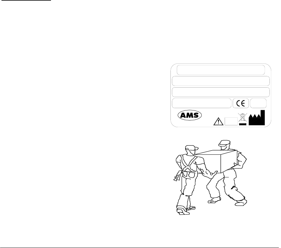
MAKE SURE THAT UNPACKING IS CARRIED OUT BY TWO PEOPLE.
Medical
Analyzer
System
350W
Rome-Italy
S/N
P/N
100 - 230V~ 47 - 63Hz
IVD
Upon consignment of the crate(s)/box, take
out the delivery note and make sure that all
the items on the packing list are included i
n
the crates/box and that they are undamaged.
Check that the serial number on the delivery
note/packing list corresponds to tha
t
impressed on the plate on the right side of the
instrument.
Open the crate(s)/box from the top and ver
y
carefully take out:
the instrument;
the computer and other accessories.

Chapter 01 - INSTALLATION
SAT450 Service Manual Rev.00 03 July 2008 Page 3
Do not discard the delivery crate(s)/box or the packing material until the correct functioning
of the instrument has been ascertained.
Remove all the items from the crate(s)/box very carefully.
Remove the adhesive tape from the cover of the samples and reagents housings, from the
front panels, and from the samples and reagents racks.
Before connecting the SAT450 instrument, remove the protective packing material placed
under the Sampling Arm and under the Washing Station group.
Warning: in the event that it is necessary to repack any or all of the delivered items, the below-
listed procedure must be carefully followed:
⇒ Reposition the protective packing material under the Sampling Arm and under the
Washing Station group.
⇒ Tape down (using masking tape is possible) the cover of the samples and reagents
housings.
⇒ Remove the Probe from the Sampling Arm and place it inside a cuvette, cap the cuvette
and tape the cap in place.
⇒ Be very careful to not bend the Washing Station probes when repositioning the packing
material.
⇒ Fill all the empty spaces around the accessories packed in the crate using pluriballs or
other suitable packing material.
In the event that the repacking is carried out after clinical diagnostic use of the instrument, it
is necessary to first perform the decontamination procedure as outlined in Chapter 7 of this same
manual.
Ambient-climatic conditions for transportation, warehousing and storing the instrument
inside its packing crate:
- Temperature: between –20° and +70°C
- Humidity: 10% ÷ 90%
- Warehoused: INDOOR
- Maximum length of warehousing: 6 months (after which length of time, preventive
maintenance regarding certain components is required - e.g.: membranes)

Chapter 01 - INSTALLATION
SAT450 Service Manual Rev.00 03 July 2008 Page 4
1.2 INSTRUMENT INSTALLATION
The SAT450 instrument must be installed only by authorized, specialized technical personnel.
During instrument installation, the system will be checked once again to make sure that it
functions correctly. The SAT450 is for professional use only; therefore, the operators who use the
instrument (in addition to the academic qualifications and state certification required to meet
government regulations) must be trained in its proper use and this training must also regard
ordinary instrument maintenance practices. Maintenance activities are described in Chapter 7 of
this same manual.
In order to preclude risks of potential biological hazards, it is absolutely necessary that good
practices regarding the handling of biological samples, consumables and waste/refluents be
scrupulously adhered to.
The SAT450 is a complex system and, as such, it is of utmost importance that the installation
procedure be executed correctly in order to guarantee optimum levels of performance. In the event that
the indications reported herein (in this manual) and/or relevant safety norms are not followed, AMS
cannot and does not guarantee proper instrument functioning. Furthermore, user safety may be placed at
risk.
1.2.1 ENVIRONMENT OF THE INSTALLING SITE
Make sure that the SAT450 instrument is not installed where it is in direct sunlight, subject to
drafts, dust or strong magnetic fields. Observe the conditions outlined in the below-illustrated
table regarding the installing site:
USE Indoors and dry
POLLUTION DEGREE 2
ISOLATION CLASS I
INSTALLATION CATEGORY II
USAGE: TEMPERATURE between 18°C and 30°C
HUMIDITY 20% ÷ 85%
ALTITUDE Maximum: 3000 m
PLACEMENT
Counter-top or table: minimum surface area 110 x 70
cm. Stable surface with no vibrations. Position the
instrument in such a manner that it can be easily
disconnected.
VENTILATION
Leave a space of at least 10 cm around the instrument
in order to allow air circulation. Make sure that the fans
(located under the reagents housing) are not obstructed.

Chapter 01 - INSTALLATION
SAT450 Service Manual Rev.00 03 July 2008 Page 5
1.2.2 ELECTRICAL POWER SUPPLY
The electrical power tension/voltage for the instrument is indicated on the right-hand side of
the instrument (see the label in Page 2). This same information is also reported on the label
located above the input line socket. Make sure that power supply used conforms to that here-
indicated and that it is properly grounded:
VOLTAGE 100 : 230Vac 47/63Hz ±10%
PLEASE NOTE: IT IS IMPORTANT THAT THE LABORATORY’S ELECTRICAL POWER SOURCE BE
EXTREMELY STABLE. IF SAID STABILITY CANNOT BE GUARANTEED, THE USE OF
THE FOLLOWING DEVICES IS STRONGLY SUGGESTED:
ELECTRONIC STABILIZER
Used to stabilize the power source voltage in the laboratory. Any stabilizer available on
the market can be used (power not less than 0.5 kW).
NO-BREAK MODULE (UPS - Uninterrupted Power Supply)
This module offers two important functions:
stabilizes the power voltage;
powers the instrument in the event of a power failure.
1.2.3 ACCESSORIES: CONNECTIONS
1.2.3.1 Power supply
Use the power supply cable that is provided to connect the instrument to the power source.
1.2.3.2 Instrument-Computer: connections
The SAT450 instrument and the Personal Computer are connected via a RS232 standard serial
cable and/or USB standard cable, which constitutes the hardware for the exchange protocol.
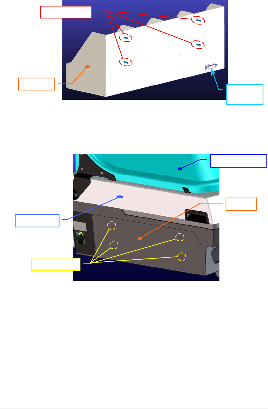
1.2.3.3 Liquid Reservoir Bottles Container: installation
Install the container of the four liquid reservoir bottles on the SAT450 instrument in the
following way:
1. Make sure that the instrument is turned off.
2. Unscrew the two captive screws on the front underside of the instrument and lift up
the Raising Top.
3. Take the container, unscrew the four screw nuts from the respective threaded pins
(Fig. 1) and take off the four washers.
Chapter 01 - INSTALLATION
SAT450 Service Manual Rev.00 03 July 2008 Page 6
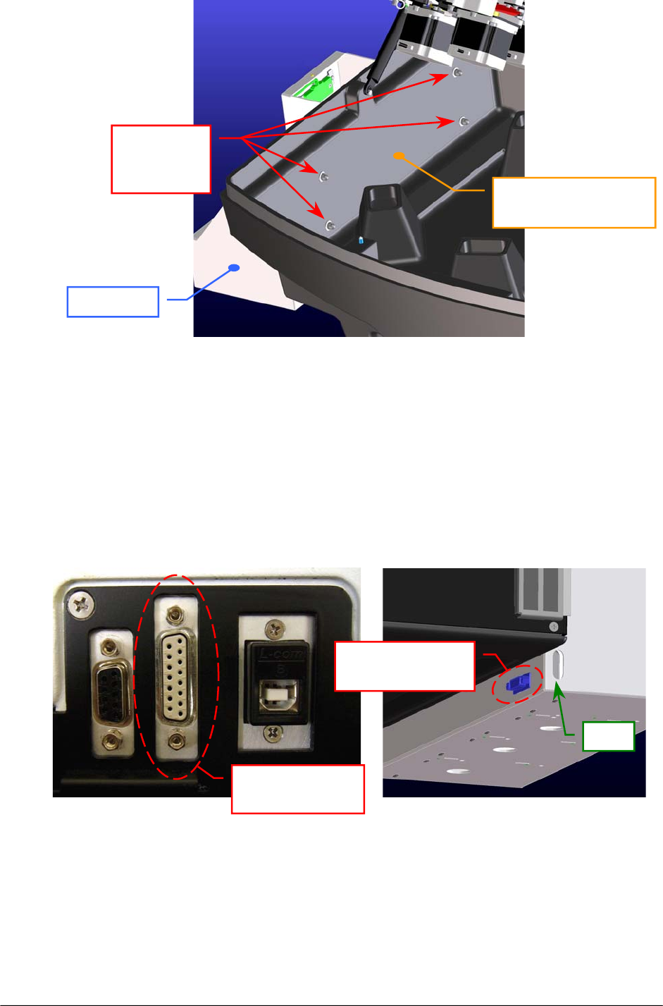
4. Draw up the container to the left-hand side of the instrument and put on completely
the four threaded pins in the four through holes located on the chassis (Fig. 2).
5. Put the four washers on the threaded pins from the left-hand interior side of the
instrument (Fig. 3).
6. Screw completely the four screw nuts on the threaded pins from the left-hand interior
side of the instrument (Fig. 3).
Fig. 1 – Four threaded pins of the container
Fig. 2 – Four through holes located on the chassis
Throu
g
h holes
Chassis
Raising Top
Threaded
p
ins
Containe
r
15-pin
connecto
r
Instrument cover
Chapter 01 - INSTALLATION
SAT450 Service Manual Rev.00 03 July 2008 Page 7
7. Bring down the Raising Top and screw the two captive screws on the front underside
of the instrument.
8. Take the “Bottles Connection Cable” (P/N: 50-02684-00) and plug its 15-pin male
connector in the 15-pin connector (showed in the Fig. 4-a) located on the back side of
the instrument (Bottles Sensors Connector).
9. Plug the 15-pin female connector of the “Bottles Connection Cable” in the 15-pin
connector of the container (showed in the Fig. 4-b) located on its back side.
Fig. 4 [(a), (b)] – Connectors to plug the “Bottles Connection Cable”
Fig. 3 – Container installed on the instrument
(a) (b)
Bottles Sensors
Connecto
r
15-pin connector
of the containe
r
Container
Instrumen
t
Chassis
(
lef
t
-hand interior side
)
Containe
r
Screw nuts
and
washers
Slot
Chapter 01 - INSTALLATION
SAT450 Service Manual Rev.00 03 July 2008 Page 8
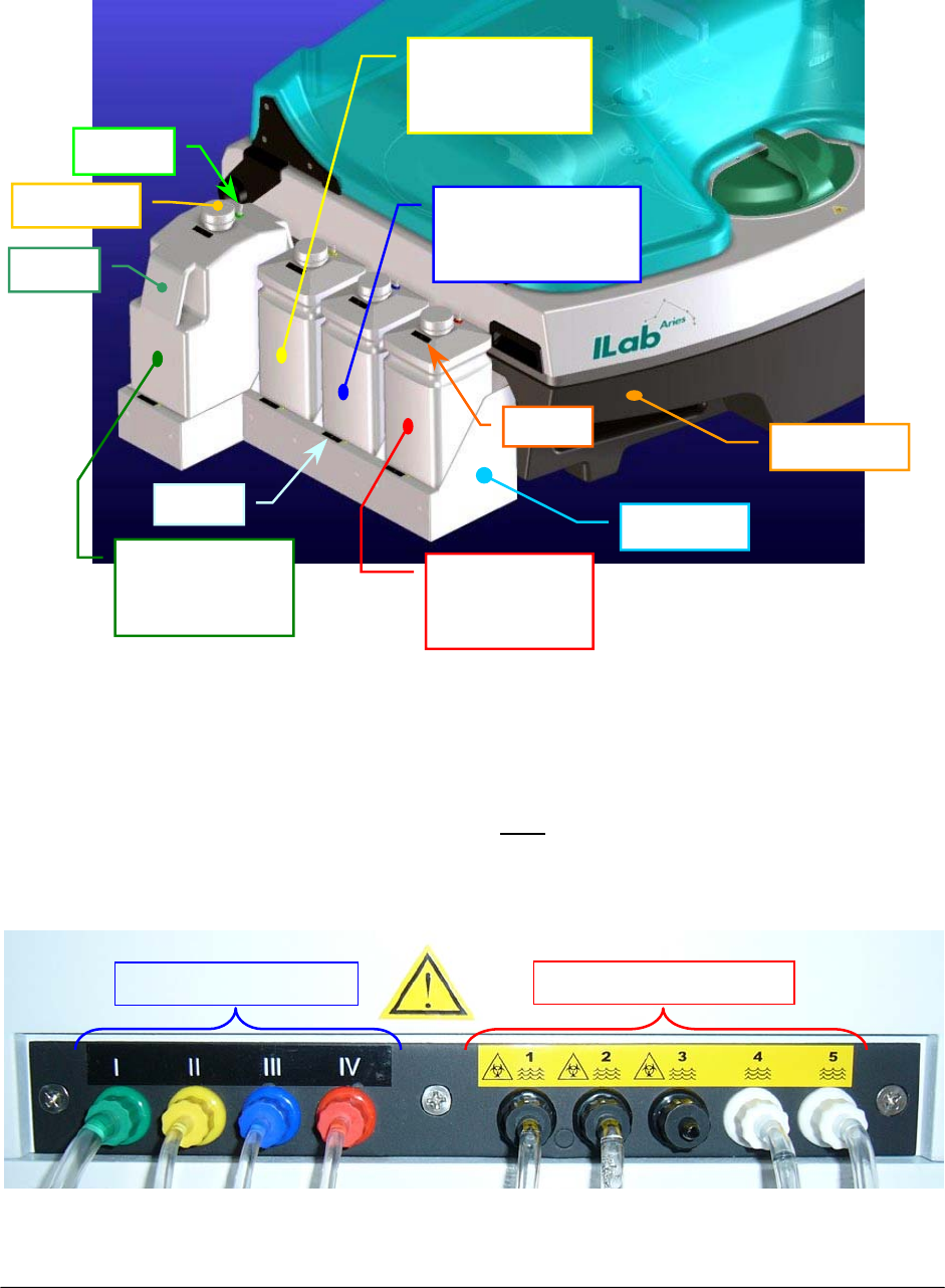
1.2.3.4 Liquid Reservoir Bottles: connections
Carry out the following steps:
1. Position the four bottles on the container in the order indicated and illustrated
here-below (Fig. 5):
2. Connect the fittings of the four loading tubes on their respective fittings located on the
back of the instrument (Loading connections). The loading connections on the back of
the instrument are clearly labeled (Fig. 6). Note: the fittings of the connections dedicated
to loading are the same color as their respective bottles and are also numbered
accordingly.
Fig. 5 – Four Liquid Reservoir Bottles
Rinse Solution
I
(Green)
Acid Solution
IV
(
Red
)
Distilled Water
II
(
Yellow
)
Cleaning Solution
III
(
Blue
)
Container
Instrument
Fig. 6 – Loading and discharge connections
Loadin
g
connectio
n
s Dischar
g
e connections
Fitting
Bottle
Bottle to
p
Label
Label

Chapter 01 - INSTALLATION
SAT450 Service Manual Rev.00 03 July 2008 Page 9
3. Push the four loading tubes through the slot of the container ( Fig. 4 (b) ) and pull them
into the container.
4. Insert the other extremities of the four loading tubes in the fittings of the bottles
according to the indications dictated by Figures 5 and 6.
1.2.3.5 Waste Tanks: connections
Carry out the following steps:
1. Connect the fittings of the discharge tubes on their respective fittings located on the
back of the instrument (Discharge connections). The discharge (Waste) connections on
the back of the instrument are clearly labeled. They are numbered (Fig. 6) and must be
connected as specified following:
⇒ tubes having black fitting on discharges 1 and 2 from Washing Wells, and on
discharge 3 from the ISE module (if installed as optional device);
⇒ tubes having white fitting on discharges 4 and 5 coming from the Washing
Station for those liquids which do not constitute a biological hazard.
2. Insert the other extremities of the discharge tubes in the two waste tanks as specified
following:
tubes having black fitting – discharges 1, 2 (and 3) – in the biohazard waste tank;
tubes having white fitting – discharges 4 and 5 – in the waste tank.
The instrument does not come with the waste tanks. Laboratory personnel
must see to acquiring the appropriately sized containers suited to their
needs. The biohazard waste tank should be properly identified and labeled
using the biological hazard symbol (please see the following paragraph).
Note

Chapter 01 - INSTALLATION
SAT450 Service Manual Rev.00 03 July 2008 Page 10
1.2.4 LABELS AND SYMBOLS
CAUTION
The below-illustrated label can be found on the back on the instrument:
PLEASE NOTE: NEVER OPEN THE INSTRUMENT WITHOUT HAVING FIRST TURNED IT OFF AND
DISCONNECTED IT FROM ITS POWER SOURCE (UNPLUG THE POWER SUPPLY
CABLE).
CAREFULLY FOLLOW THE CLEANING AND MAINTENANCE PROCEDURES AS
OUTLINED IN CHAPTER 7 OF THIS SAME MANUAL.
Chapter 01 - INSTALLATION
SAT450 Service Manual Rev.00 03 July 2008 Page 11
1.2.5 LEGEND AND SYMBOLS
CAUTION! READ INSTRUCTIONS IN OPERATOR’S MANUAL
EARTH GROUND
BIOLOGICAL HAZARD
(Placed next to the Samples Plate and the waste discharge black fittings)
Wear proper protective clothing/equipment and handle all biological
samples, consumables and waste liquids produced during analysis with
extreme care. The disposal of the used consumables and the waste liquids
produced must conform to all applicable government laws and regulations.
Furthermore, to prevent overflow of the discharge tanks, make sure to
periodically check the level of the waste liquids collected.
MANUFACTURING COMPANY
This symbol is placed next to the name of the company that has
produced/manufactured the item.
This “crossed-out wheelie bin/trash can symbol” can be found on the label
and reports information indicating that the instrument and parts are not to be
disposed of with ordinary household waste/garbage. They must be disposed
of according to applicable government regulations regarding electrical and
electronic equipment (Directive 2002/96/EC WEEE).

Chapter 01 - INSTALLATION
SAT450 Service Manual Rev.00 03 July 2008 Page 12
1.2.6 WARRANTY
AMS guarantees the replacement of all defective components and/or materials for a period up
to 12 (twelve) months from the date of invoice.
This warranty, as for all Technical Assistance in general, is intended as provided ex works,
Rome, Italy.
This warranty does not cover consumables or those parts of the instrument in direct contact
with liquids. A detailed list of the individual components excluded from and not covered by this
warranty is provided in the table below.
Moreover, this warranty is not valid in those cases in which damage/s to the SAT450 arise
from or are the result of:
improper use of the instrument (or use in any manner not in conformance with
instructions provided by the Manufacturer or the Seller);
mishandling and/or transportation errors;
insufficient (or lack of) ordinary maintenance on the part of the User.
More in detail, any and all damages arising from mishandling or caused during transport must
be immediately reported to the Shipping Company upon delivery of the goods.
LIST OF CONSUMABLES AND ACCESSORIES EXCLUDED FROM WARRANTY:
Description
Reagents bottles
Samples cups
Reaction Racks
Loading bottles
Tubes
Sampling Probe
Drying Pad
Photometer Lamp (6V – 10 W)
Interferential filters
Washing Station Probes
Micropumps
Electrovalves

Chapter 01 - INSTALLATION
SAT450 Service Manual Rev.00 03 July 2008 Page 13
1.2.7 APPLICABLE REGULATIONS
The SAT450 conforms to the following government regulations:
• Directive 98/79/CE relative to In-Vitro Diagnostic Devices
This compliance is certified by the here-illustrated symbols placed on the instrument:
1.2.8 USAGE LIMITATIONS
The SAT450 cannot be used by the blind as the user must interact with the instrument by
reading/writing on the monitor.
Furthermore, the SAT450 must be used with extreme care by color-blind users as the user
interface graphics employs and associates different colors to provide the user with important
information.
1.2.9 REAGENTS AND SAMPLES BAR CODE READERS
Two bar code readers can be installed (optionals) for reagents and samples on the SAT450.
1.2.10 ISE MODULE
An ISE module can be installed (optional) on the SAT450.

Chapter 02 – SYSTEM DESCRIPTION
SAT450 Service Manual Rev.00 03 July 2008 Page 1
CHAPTER 02
– SYSTEM DESCRIPTION –
INDEX
2 DESCRIPTION OF THE SYSTEM………………………………………………….…………2
2.1 Introduction……………………………………………………………………………………2
2.2 Sampling Arm…………………………………………………………………………………2
2.3 Diluter……………………………………………………………………………………….…2
2.4 Reactions Plate………………………………………………………………………………....3
2.5 Samples Plate……………………………………………………………………………….….3
2.6 Reagents Plate………………………………………………………………………………….3
2.7 Photometer………………………………………………………………………………….…..4
2.8 Washing Station…………………………………………………………………………….…..4
2.9 Electronic Boards.........................................................................................................................4
2.9.1 Introduction...............................................................................................................................4
2.9.2 Analytical Control Board [P/N: 30-02188-00] .......................................................................5
2.9.3 Stepper Motors Driver Board [P/N: 30-01284-02].................................................................5
2.9.4 Reagents Plate Interface Board [P/N: 30-02190-00] ..............................................................6
2.9.5 Samples Plate Interface Board [P/N: 30-02191-00] ...............................................................7
2.9.6 Reactions Plate Interface Board [P/N: 30-02192-00] .............................................................7
2.9.7 Arm Interface Board [P/N: 30-02193-00]...............................................................................8
2.9.8 Electrovalves Control Board [P/N: 30-02194-00] ..................................................................9
2.9.9 “Pre-Ampl. / ADC” Boards [P/N: 30-00107-XX]................................................................10
2.9.10 Photometer Lamp Board [P/N: 30-01576-01] ....................................................................10
2.9.11 Level Sensor Board [P/N: 30-02365-00] ............................................................................10

Chapter 02 – SYSTEM DESCRIPTION
SAT450 Service Manual Rev.00 03 July 2008 Page 2
2 DESCRIPTION OF THE SYSTEM
2.1 INTRODUCTION
The SAT450 is a benchtop, fully automatic, random access, open analyzer for clinical and
immunoturbidimetric assays.
It communicates with a computer through a USB and/or RS 232 port.
The SAT450 instrument is composed of the following main parts:
Sampling Arm;
Diluter;
Reactions Plate;
Samples Plate;
Reagents Plate;
Photometer;
Washing Station;
Electronic Boards.
2.2 SAMPLING ARM
One mechanical Arm performs all sampling operations. It is able to reach the aspiration point
of the Reagents Plate, the aspiration point of the Samples Plate, the delivery point of the
Reactions Plate and the two Washing Wells.
A specific sampling Probe is connected on its head (compare the scheme MA-15-02339-00).
The Sampling Arm can move vertically and horizontally with respect to the Raising Top of the
instrument by means of two stepper motors, respectively. The horizontally movement take place
along a arch of circumference.
A Pre-Heater Assy allows a reagent pre-warming at 37.0 °C. Moreover, one Level Sensor
Board - opportunely connected to the Sampling Probe - allows a liquid level (capacitive) sensing.
2.3 DILUTER
The Diluter allows to perform all the operations of aspiration and delivery of the liquid up till
the capacity of 1000 µl. It is connected to the Sampling Arm and to its electrovalve and
micropump as showed in the scheme MA-15-02339-00. It is able to sample volumes of 0.25 µl,
with a CV less than 1%.
The device is actioned through the movement of a unique central piston for the operations of
aspiration and delivery of the liquid. The piston is moved through a stepper motor without use of
step-down gears to minimize the backlash. Moreover, in this device are implemented some
solutions to avoid the presence of air microbubble inside it and inside the hydraulic circuit.

Chapter 02 – SYSTEM DESCRIPTION
SAT450 Service Manual Rev.00 03 July 2008 Page 3
2.4 REACTIONS PLATE
The Reactions Plate of the instrument contains 4 disposable racks with 20 reaction cuvettes each,
for a total of 80 cuvettes. Each of them has a optical path of 6 mm. The reactions racks can be
removed individually. The plate is covered by a specific plate cover.
The plate can rotate through a stepper motor (compare the scheme MA-15-02353-00). This motor
assures a high precision of positioning, superior to ± 0.1°.
The basic operating cycle includes: aspiration and dispensing of the reagents and the samples by
the Sampling Arm in the reaction cuvettes, optic reading of the cuvettes in incubation by the
Photometer - along with the relative positioning of the Reactions Plate -, washing of the filled
cuvettes by a Washing Station.
The incubation temperature in the reactions cuvettes is controlled at 37° C ± 0.3 by a controlled
heating unit (Reactions Plate Resistor) placed inside the Reactions Plate .
2.5 SAMPLES PLATE
The Samples Plate is composed from a main plate that revolves around its axis and from the four
Satellite Racks (“A”, “B”, “C” and “D”) which, each of them, revolve at the same time around to
own axis. Therefore, the Samples Plate is apt to describe a substantially hypocycloidal motion.
The main plate can rotate through a stepper motor, whereas the four Satellite Racks can rotate
through another stepper motor (compare the scheme MA-15-02338-00). This two motors assure a
high precision of positioning. The two different rotations are controlled through the respective
Home Sensors.
The four separate Satellite Racks (“A”, “B”, “C” and “D”) are universal racks for continuous
loading of samples, calibrators and controls. Each Satellite Rack contains up to 15 cups and/or tubes
with 10÷16 mm of diameter and 40÷100 mm of height. Moreover, 8 extra positions - for the same
cups and/or tubes - are positioned on the main plate for urgent samples, calibrators and controls.
The Samples Plate is covered by means of two covers: Samples Plate cover and Samples Plate
safety protection. Removing only the Samples Plate safety protection allows the replacement of the
Satellite Racks for continuous loading. A urgent sample execution is allowed at any time.
2.6 REAGENTS PLATE
The Reagents Plate is composed from a main plate that revolves around its axis and from the four
Satellite Racks (“A”, “B”, “C” and “D”) which, each of them, revolve at the same time around to
own axis. Therefore, the Reagents Plate is apt to describe a substantially hypocycloidal motion.
The main plate can rotate through a stepper motor, whereas the four Satellite Racks can rotate
through another stepper motor (compare the scheme MA-15-02348-00). This two motors assure a
high precision of positioning. The two different rotations are controlled through the respective
Home Sensors.
Each of four removable universal racks (“A”, “B”, “C” and “D”) contains 4 positions for rounded
bottles of 10/20 ml and 4 positions for trapezoidal bottles of 50 ml. Each of four trapezoidal bottles
of 50 ml can be substituted with two trapezoidal bottles of 25 ml or, by a adaptor, with one rounded
bottle of 10/20 ml or with one squared bottle of 17 ml. Moreover, 8 extra positions for rounded

Chapter 02 – SYSTEM DESCRIPTION
SAT450 Service Manual Rev.00 03 July 2008 Page 4
bottles of 10/20 ml are positioned on the main plate. Each of eight rounded bottles of 10/20 ml can
be substituted, by a adaptor, with one cup of 2 ml.
All the bottles inside the Reagents Plate are cooled by four Cooler Modules positioned on its
border. Each module is composed from two Peltier cells and two fans (as showed in the scheme
MA-10-02536-XX) opportunely powered. One of them has a Cooler Temperature Sensor in order to
control the refrigeration temperature.
The plate is covered by a specific plate cover.
2.7 PHOTOMETER
The Photometer allows the direct reading of the Optic Density (O.D.) of the reaction that take
place in any cuvette of the Reactions Plate.
The device is composed from two reading channels: Sample Channel for the direct reading of the
O.D. value and Reference Channel for its reference value. Each of them is provided of a
Pre-Ampl./ADC board for the conversion in a digital signal of the light beam that pass through the
cuvette.
The light source is a halogen lamp (6V/10W). It is powered by a Photometer Lamp Board.
The device contains a Filters Wheel for the reading of the reaction at different wavelengths. The
wavelengths of the 9 narrow band interferential filters placed on the wheel are the following:
340 nm, 380 nm, 405 nm, 492 nm, 510 nm, 546 nm, 577 nm, 620 nm and 690 nm. Moreover, the
Filters Wheel has a dark position (compare the scheme MA-15-02448-00).
The Filters Wheel can rotate through a stepper motor. The selection of the exact reading filter
is controlled by means of the Filters Wheel Home Sensor and its reference on the wheel.
2.8 WASHING STATION
The Washing Station allows the washing operations of the Reactions Plate cuvettes.
The Washing Station is made up of a series of five small probes (compare the scheme
MA-10-02181-00). It is situated on a part of the Reactions Plate and each probe can goes down into
a single cuvette.
This said five probes are opportunely connected to the washing station electrovalves and
micropumps (as showed in the hydraulic diagram SI-16-01873-00) for the emptying, washing and
drying operations of the cuvettes. In particular, the last probe has a pad for the drying operations.
The vertical movement of the Washing Station on the Reactions Plate is allowed by its
leadscrew connected to a stepper motor.
2.9 ELECTRONIC BOARDS
2.9.1 Introduction
The Electronic Diagram of the SAT450 instrument is reported on the document having the code
SC-16-01873-XX. This scheme shows all the electronic boards of the instrument and the electric
interconnessions between them.
The power supply is connected through a input line to the power grid (90 ÷ 250 VAC,
47 ÷ 63 Hz), whereas through a dedicated wiring to the electronic boards. The power supply has
three output voltage modules: + 24 V, + 12 V and + 8 V (as showed in the scheme MA-46-02636-00).
All the electronics boards are following described.

Chapter 02 – SYSTEM DESCRIPTION
SAT450 Service Manual Rev.00 03 July 2008 Page 5
2.9.2 Analytical Control Board [P/N: 30-02188-00]
The Analytical Control Board, integrated in the SAT450 instrument, is the heart of the low level,
realtime and processing management. This board, on which is present the microcontroller Hitachi
H8SX/1663 (compare the scheme SE-30-02188-00 – sheet 1 of 2), permits to manage all the
input/output analogical and digital signals need to the instrument functionality.
Components, switchs and integrated circuits dedicated to the signals processing, to the
microcontroller programming, to the microcontroller communication and those for I/O micro-
controller ports protection are present on the board (compare the scheme SE-30-02188-00).
The microcontroller Hitachi H8SX/1663 is a high-speed CPU with an internal 32-bit architecture
and a FP-144LV package (with 144 pins). It has sixteen 16-bit general registers, can handle a 4
Gbyte linear address space, and is ideal for a realtime control system. It has six independent serial
communication interface (SCI) channels, a 40 Kbyte on-chip high-speed static RAM (the RAM is
connected to the CPU by a 32-bit data bus) and 384 Kbytes of Flash Memory.
The Analytical Control Board is connected to the Stepper Motors Driver Board by a 64 pin
frontal clutch connector by which transmits all the command signals for the 9 stepper motor drivers
(compare the scheme SE-30-02188-00 – sheet 2 of 2).
The following further boards are directly connected to the Analytical Control Board by specific
cables and connectors (as showed in the scheme SC-30-02188-00):
the “Samples Plate Interface Board”, the ”Reagents Plate Interface Board”, the
“Reactions Plate Interface Board”, the “Arm Interface Board” and the “Electrovalves
Control Board” by which it communicates all the correspondent analogic and digital
signals;
the “Pre-Ampl./ADC Board (Sample Channel)” and the “Pre-Ampl./ADC Board
(Reference Channel)” for reading the digital signals from main and reference channels of
the Photometer.
The board is connected to the ISE Module (option), to the bottles liquid sensors connector, to the
RS 232 port and to the USB port (ports by which it communicates with the computer) through the
specific cables and connectors.
The fan needed for the electronic vain cooling (vain wherein are placed the Analytical Control
Board and the Stepper Motors Driver Board) is powered directly from this board.
The two stepper motors drivers U3 and U6 (Toshiba TA8435H or NMB SDI-C403) – compare
the scheme SE-30-02188-00 / sheet 1 of 2 – control the Washing Station Motor and a “spare”
motor, respectively. The Washing Station Motor is connected to the “Electrovalves Control Board”.
Finally, the power supply is connected to the Analytical Control Board by a wiring and a header
connector to power it the GND and the following voltages: + 24 Vdc, + 12 Vdc. The +5 Vdc,
+3.3 Vdc and the –12 Vdc voltages needed to the board components are generated on the same board
by voltage regulators.
2.9.3 Stepper Motors Driver Board [P/N: 30-01284-02]
The Stepper Motors Driver Board is the interface between the Analytical Control Board and the
stepper motors (excluding the Washing Station stepper Motor).
On the boards are present nine bipolar stepping motor drivers (Toshiba TA8435H or NMB SDI-
C403) as showed in the scheme SE-30-01284-02. Each driver is dedicated to drive one stepper
motor and has its heatsink.

Chapter 02 – SYSTEM DESCRIPTION
SAT450 Service Manual Rev.00 03 July 2008 Page 6
Components and switchs dedicated to the nine drivers are present on the board (compare the
scheme SE-30-01284-02).
The Stepper Motors Driver Board is connected to the Analytical Control Board by a 64 pin
frontal clutch connector by which receives all the command signals for its 9 stepper motor drivers
(compare the scheme SE-30-01284-02).
The following four boards are directly connected to the Stepper Motors Driver Board by specific
cables and connectors (as showed in the scheme SC-30-01284-02): the “Samples Plate Interface
Board”, the ”Reagents Plate Interface Board”, the “Reactions Plate Interface Board” and the “Arm
Interface Board”. They receive from it all the phase signals for the respective stepper motors.
The following table describes which are the stepper motors – with the relative board – controlled
from its nine stepper drivers U1 … U9 (compare the scheme SE-30-01284-02):
Driver ref. Stepper Motor Board (P/N)
U1 Reactions Plate Motor 30-02192-..
U2 Vertical Mov. Arm Motor 30-02193-..
U3 Samples Plate Motor 30-02191-..
U4 Filters Wheel Motor 30-02192-..
U5 Horizontal Mov. Arm Motor 30-02193-..
U6 Satellites Mov. Samples Plate Motor 30-02191-..
U7 Diluter Motor 30-02193-..
U8 Reagents Plate Motor 30-02190-..
U9 Satellites Mov. Reagents Plate Motor 30-02190-..
Finally, the power supply is connected to the Stepper Motors Driver Board by a wiring and a
header connector to power it the GND and the following voltages: + 24 Vdc, + 12 Vdc. The +5 Vdc
voltage needed to the driver components is generated on the same board by a positive voltage
regulator.
2.9.4 Reagents Plate Interface Board [P/N: 30-02190-00]
This board is the hardware interface between the Analytical Control Board and the Stepper
Motors Driver Board with all devices pertinent to the Reagents Plate of the instrument (compare the
scheme SC-30-02190-00).
The Reagents Plate Interface Board is connected to the Analytical Control Board through a
specific cable and connector (as showed in the scheme SC-30-02190-00) by which communicates
all needed input/output signals. It is connected to the Stepper Motors Driver Board through another
specific cable and connector (as showed in the scheme SC-30-02190-00) by which receives the
phase signals for the two following stepper motors: the Reagents Plate Motor and the Satellites
Mov. Reagents Plate Motor.
All the bottles inside the Reagents Plate are cooled by four Cooler Modules positioned on its
border. Each module is composed from two Peltier cells and two fans (as showed in the scheme
MA-10-02536-XX). The Reagents Plate Interface Board is connected to each module through a
dedicated wiring and four specific connectors (as showed in the scheme SC-30-02190-00) for the
command signals and the needed power supply.

Chapter 02 – SYSTEM DESCRIPTION
SAT450 Service Manual Rev.00 03 July 2008 Page 7
It is possible choose the fans power supply by the switch SW1. The lighting of the two yellow
leds LD1 and LD2 show the power up to the Peltier cells Assy 1 and to the Peltier cells Assy 2,
respectively (compare the scheme SE-30-02190-00). Components and integrated circuits dedicated
to the devices management are all present on the board.
The Reagents Plate Cover Switch is connected to the Reagents Plate Interface Board by the same
dedicated Cooler Modules cabling but by another connector. The Cooler Temperature Sensor, the
Reagents Plate Motor, the Reagents Plate Home Sensor, the Satellites Mov. Reagents Plate Motor
and the Satellites Mov. Reagents Plate Home Sensor are connected to the board by relative
connectors.
Finally, the power supply is connected to the Reagents Plate Interface Board by a wiring and a
header connector to power it the GND and the following voltages: + 24 Vdc, + 12 Vdc, +8 Vdc. The
necessary +5 Vdc voltage is generated on the same board by a positive voltage regulator.
2.9.5 Samples Plate Interface Board [P/N: 30-02191-00]
This board is the hardware interface between the Analytical Control Board and the Stepper
Motors Driver Board with all devices pertinent to the Samples Plate of the instrument (compare the
scheme SC-30-02191-00).
The Samples Plate Interface Board is connected to the Analytical Control Board through a
specific cable and connector (as showed in the scheme SC-30-02191-00) by which communicates
all needed input/output signals. It is connected to the Stepper Motors Driver Board through another
specific cable and connector (as showed in the scheme SC-30-02191-00) by which receives the
phase signals for the two following stepper motors: the Samples Plate Motor and the Satellites Mov.
Samples Plate Motor.
The Samples Barcode Reader and the Reagents Barcode Reader are needed to read the barcodes
on the cups/tubes of the Samples Plate and on the bottles of the Reagents Plate, respectively. They
are connected to the Samples Plate Interface Board through two distinct connectors for the
respective tx/rx signals, the GND and the +5 V voltage (as showed in the scheme SE-30-02191-00).
The Luminous Detector, the Samples Plate Cover Switch, the Samples Plate Motor, the Samples
Plate Home Sensor, the Satellites Mov. Samples Plate Motor and the Satellites Mov. Samples Plate
Home Sensor are connected to the Samples Plate Interface Board by relative connectors. Instead,
the J9, J10 and J11 are unused connectors (as showed in the scheme SE-30-02191-00).
Components, transistors and integrated circuits dedicated to the devices management are all
present on the board (compare the scheme SE-30-02191-00).
Finally, the power supply is connected to the Samples Plate Interface Board by a wiring and a
header connector to power it the GND and the following voltages: + 24 Vdc, + 12Vdc. The necessary
+5 Vdc voltage is generated on the same board by a positive voltage regulator.
2.9.6 Reactions Plate Interface Board [P/N: 30-02192-00]
This board is the hardware interface between the Analytical Control Board and the Stepper
Motors Driver Board with all devices pertinent to the Reactions Plate of the instrument (compare
the scheme SC-30-02192-00).
The Reactions Plate Interface Board is connected to the Analytical Control Board through a
specific cable and connector (as showed in the scheme SC-30-02192-00) by which communicates

Chapter 02 – SYSTEM DESCRIPTION
SAT450 Service Manual Rev.00 03 July 2008 Page 8
all needed input/output signals. It is connected to the Stepper Motors Driver Board through another
specific cable and connector (as showed in the scheme SC-30-02192-00) by which receives the
phase signals for the two following stepper motors: the Reactions Plate Motor and the Filters Wheel
Motor.
The Photometer Lamp Board (described into the successive Section 2.9.10) is connected to the
Reactions Plate Interface Board through a header connector (compare the scheme SC-30-02192-00).
The EV7 and EV8 waste electrovalves and the P8 and P9 waste micropumps, showed in the
“Waste” area of the hydraulic diagram SI-16-01873-00, are connected to the Reactions Plate
Interface Board through four connectors (compare the scheme SC-30-02192-00).
The Reactions Plate Resistor (compare the Section 2.4) is connected to the Reactions Plate
Interface Board through a header connector, whereas the Temperature Sensor of the Reactions Plate
is connected to the board by another connector (compare the scheme SC-30-02192-00).
The Instrument Cover Switch is connected to the Reagents Plate Interface Board by a dedicated
cable and connector. The Reactions Plate Motor, the Reactions Plate Home Sensor, the Filters
Wheel Motor, the Filters Wheel Home Sensor, the Reactions Plate Leak Sensor, the Photometer Fan
and the Instrument Cover Interlock are connected to the board by relative connectors (compare the
scheme SC-30-02192-00). Instead, the J15 connector for the Reactions Plate Cover Switch is spare
(compare the scheme SE-30-02192-00).
It is possible choose between two control signals of the Photometer Lamp Board by the switch
SW1. The lighting of the yellow led LD1 shows the power up to the Reactions Plate Resistor.
Instead, the lighting of the red led LD2 shows the activation of the Reactions Plate Leak Sensor
(compare the scheme SE-30-02192-00). Components and integrated circuits dedicated to the
devices management are all present on the board.
Finally, the power supply is connected to the Reactions Plate Interface Board by a wiring and a
header connector to power it the GND and the following voltages: + 24 Vdc, + 12 Vdc, +8 Vdc. The
necessary +5 Vdc voltage is generated on the same board by a positive voltage regulator.
2.9.7 Arm Interface Board [P/N: 30-02193-00]
This board is the hardware interface between the Analytical Control Board and the Stepper
Motors Driver Board with all devices pertinent to the Sampling Arm and the Diluter of the
instrument (compare the scheme SC-30-02193-00).
The Arm Interface Board is connected to the Analytical Control Board through a specific cable
and connector (as showed in the scheme SC-30-02193-00) by which communicates all needed
input/output signals. It is connected to the Stepper Motors Driver Board through another specific
cable and connector (as showed in the scheme SC-30-02193-00) by which receives the phase
signals for the three following stepper motors: the Horizontal Mov. Arm Motor, the Vertical Mov.
Arm Motor and the Diluter Motor.
The Pre-Heater Assy of the Sampling Arm is connected to the Arm Interface Board through a
connector and to the Level Sensor Board - described into the successive Section 2.9.11 - by two
connectors (compare the scheme SC-30-02193-00).
The EV1 Diluter Electrovalve, the EV6 Arm Washing Well Electrovalve, the P1 Diluter
Micropump and the P7 Arm Washing Well Micropump - showed in the “Arm assy” area of the
hydraulic diagram SI-16-01873-00 - are connected to the Arm Interface Board through four
connectors (compare the scheme SC-30-02193-00).
The Horizontal Mov. Arm Motor, the Horizontal Mov. Arm Home Sensor, the Vertical Mov.
Arm Motor, the Vertical Mov. Arm Home Sensor, the Diluter Motor, the Diluter Home Sensor and

Chapter 02 – SYSTEM DESCRIPTION
SAT450 Service Manual Rev.00 03 July 2008 Page 9
the Arm Leak Sensor are connected to the Arm Interface Board by relative connectors (compare the
scheme SC-30-02193-00).
It is possible choose the Pre-Heater power supply by the switch SW1 (compare the scheme
SE-30-02193-00). The lighting of the yellow led LD1 shows the power up to the Pre-Heater Assy.
The lighting of the yellow led LD2 shows the activation of the Level Sensor. Instead, the lighting of
the red led LD3 shows the activation of the Arm Leak Sensor (compare the scheme SE-30-02193-00).
Components and integrated circuits dedicated to the devices management are all present on the
board.
Finally, the power supply is connected to the Arm Interface Board by a wiring and a header
connector to power it the GND and the following voltages: + 24 Vdc, + 12 Vdc, +8 Vdc. The
necessary +5 Vdc voltage is generated on the same board by a positive voltage regulator.
2.9.8 Electrovalves Control Board [P/N: 30-02194-00]
This board is the hardware interface between the Analytical Control Board with all devices
pertinent to the Washing Station of the instrument (compare the scheme SC-30-02194-00).
The Electrovalves Control Board is connected to the Analytical Control Board through a two
cables and connectors (as showed in the scheme SC-30-02194-00) by which – respectively –
communicates all needed input/output signals and receives the phase signals for the two following
stepper motors: the Washing Station Motor and a “spare” motor (compare the previous Section 2.9.2).
The EV2, EV3, EV4 and EV5 electrovalves of the Washing Station - indicated in the
“Washing Station pumps assy” area of the hydraulic diagram SI-16-01873-00 - are directly welded
on the Electrovalves Control Board in the relative four small areas showed on the scheme
SC-30-02194-00. Instead, the P2, P3, P4, P5 and P6 micropumps of the Washing Station –
indicated in the “Washing Station pumps assy” area of the hydraulic diagram SI-16-01873-00 – are
connected to the board by five connectors (compare the scheme SC-30-02194-00).
The Washing Station Motor, the Washing Station Home Sensor and the Ambient Temperature
Sensor are connected to the Electrovalves Control Board by relative connectors (compare the
scheme SC-30-02194-00).
The J8 connector is used for the Temperature Service Probe (kit) and the J7 connector for the
"spare” stepper motor (compare the scheme SE-30-02194-00).
Components and integrated circuits dedicated to the devices management are all present on the
board.
Finally, the power supply is connected to the Electrovalves Control Board by a wiring and a
header connector to power it the GND and the following voltages: + 24 Vdc, +12 Vdc. The necessary
+5 Vdc voltage is generated on the same board by a positive voltage regulator.

Chapter 02 – SYSTEM DESCRIPTION
SAT450 Service Manual Rev.00 03 July 2008 Page 10
2.9.9 “Pre-Ampl. / ADC” Boards [P/N: 30-00107-XX]
The “Pre-Ampl./ADC Board (Sample Channel)” and the “Pre-Ampl./ADC Board (Reference
Channel)” are two boards for reading from main and reference channels of the Photometer,
respectively.
The Pre-Ampl./ADC Board allows the conversion in a digital signal of the light beam that pass
through the reaction cuvette. They are mounted on the Photometer (as showed in the scheme
MA-15-02448-00) and are connected to the Analytical Control Board by one flat cable and two
connectors (as showed in the scheme SC-30-02188-00) with which – respectively – communicate
all needed input/output signals and receive the two voltages +12 Vdc and –12 Vdc. The other
necessary voltages are generated on the board by voltage regulators.
On the Pre-Ampl./ADC Board, the FD1 photodiode senses the light beam that pass through the
reaction cuvette, the U2 amplifier amplifies the correspondent analogic signal, the U1 Analog–to–
Digital Converter (ADS 1250) performs its Analogic-Digital conversion (compare the scheme
SE-30-00107-XX). The TR1 and TR2 trimmers allow the adjusting of the Gain and Offset,
respectively.
The components and integrated circuits dedicated to the signal amplification and to its digital
conversion are all present on the same board.
2.9.10 Photometer Lamp Board [P/N: 30-01576-01]
This board is connected to the Reactions Plate Interface Board through its cable and a header
connector (compare the scheme SC-30-02192-00). This board receives from the Reactions Plate
Interface Board the control signal (coming from the Analytical Control Board) to regulate the light
intensity of the Photometer Halogen Lamp. Moreover, it receives from the interface board the
+ 8 Vdc voltage (VL) which is then opportunely converted on the same board by a positive
adjustable regulator (U1) to power the halogen lamp.
The R6 trimmer (compare the scheme SE-30-01576-01) allows the adjusting of the Halogen
Lamp voltage. The two wires of the Halogen Lamp are connected on the J2 feed clamp.
The needed components and integrated circuits are present on the board.
2.9.11 Level Sensor Board [P/N: 30-02365-00]
This board is connected to the Pre-Heater Assy by two connectors (compare the scheme
SC-30-02193-00) and relative wires.
A connector allows the connection, through the Pre-Heater Assy, to the Arm Interface Board.
In fact, it receives from the Pre-Heater Assy (coming from the Arm Interface Board) the + 24 Vdc
voltage and the GND which is then opportunely converted on the Level Sensor Board by a
positive voltage regulator (U5) to power the integrated circuits on it. The Level Sensor Board
transmits the Level Sensor signal to the Pre-Heater Assy which, through the Arm Interface Board,
transfers the signal to the Analytical Control Board.
Other connector allows the connection of the Level Sensor Board to the Sampling Probe.
The Level Sensor Board, through two timer (U3 and U4) and a operational amplifier (U2),
effects a capacitive liquid level sensing (compare the scheme SE-30-02365-00). The needed
components and integrated circuits are present on the board.

Chapter 03 – ELECTRICAL SCHEMES AND DRAWINGS
SAT450 Service Manual Rev. 00 03 July 2008 Page I
CHAPTER 03
- ELECTRICAL SCHEMES AND DRAWINGS -
INDEX
Electronic Diagram SAT450…………………………….. SC-16-01873-XX Rev. A
Hydraulic Diagram SAT450……………………………... SI-16-01873-00 Rev. 0
Analytical Control Board (connections scheme)……………... SC-30-02188-00 Rev. 0
Analytical Control Board (electrical scheme - sheet: 1 of 2)……
SE-30-02188-00 Rev. A
(1 of 2)
Analytical Control Board (electrical scheme - sheet: 2 of 2)….... SE-30-02188-00 Rev. A
(2 of 2)
Stepper Motors Driver Board (connections scheme)………….. SC-30-01284-02 Rev. 0
Stepper Motors Driver Board (electrical scheme)……………. SE-30-01284-02 Rev. 0
Reagents Plate Interface Board (connections scheme)………... SC-30-02190-00 Rev. 0
Reagents Plate Interface Board (electrical scheme)…………... SE-30-02190-00 Rev. 0
Samples Plate Interface Board (connections scheme)……….... SC-30-02191-00 Rev. 0
Samples Plate Interface Board (electrical scheme)………….... SE-30-02191-00 Rev. 0
Reactions Plate Interface Board (connections scheme)……….. SC-30-02192-00 Rev. B
Reactions Plate Interface Board (electrical scheme)………….. SE-30-02192-00 Rev. 0
Arm Interface Board (connections scheme)………..………….. SC-30-02193-00 Rev. 0
Arm Interface Board (electrical scheme)…………..…………. SE-30-02193-00 Rev. 0
Electrovalves Control Board (connections scheme)………..…. SC-30-02194-00 Rev. 0
Electrovalves Control Board (electrical scheme)…………..…. SE-30-02194-00 Rev. 0
Photometer Lamp Board (electrical scheme)…………..……... SE-30-01576-01 Rev. 0
Pre-Ampl./ADC Board (electrical scheme)…………..………. SE-30-00107-XX Rev. B
Level Sensor Board (electrical scheme)…………..…….…….. SE-30-02365-00 Rev. 0

Chapter 03 – ELECTRICAL SCHEMES AND DRAWINGS
SAT450 Service Manual Rev. 00 03 July 2008 Page II
SAT450 instrument (drawing)…………………………... MA-16-01873-00 Rev. 0
Washing Station (drawing)………………………………… MA-10-02181-00 Rev. 0
Plate Support (drawing)….………………………………… MA-05-02271-XX Rev. 0
Samples Plate (drawing)…………………………………… MA-15-02338-00 Rev. 0
Sampling Arm and Diluter (drawing)……………………… MA-15-02339-00 Rev. 0
Reagents Plate (drawing)…………………………………... MA-15-02348-00 Rev. 0
Raising Top and Reactions Plate (drawing)……………….. MA-15-02353-00 Rev. 0
Photometer [double channel Photometer] (drawing)……… MA-15-02448-00 Rev. 0
Cooler Modules (drawing)…………………………………. MA-10-02536-XX Rev. 0
Power Supply (drawing)………………………………….... MA-46-02636-00 Rev. 0

Chapter 04 – DIAGNOSTIC PROGRAM
SAT450 Service Manual Rev.00 03 July 2008 Page 1
CHAPTER 04
- DIAGNOSTIC PROGRAM -
INDEX
4 DIAGNOSTIC PROGRAM 3
4.1 DIAGNOSTIC FOLDERS 6
4.2 “ARM” FOLDER 6
4.2.1 “VERTICAL” COMMAND AREA 7
4.2.2 “HORIZONTAL” COMMAND AREA 7
4.2.3 “STATUS COMMAND” AREA 8
4.2.4 “ARM SETTING” COMMAND AREA 8
4.2.5 “SENSOR STATUS” AREA 8
4.3 “DILUTER” FOLDER 9
4.3.1 “OPERATIONS” AREA 9
4.3.2 “SENSOR STATUS” AREA 9
4.3.3 “USER” AREA 10
4.3.4 “STATUS COMMAND” AREA 10
4.4 “OPTIC” FOLDER 10
4.4.1 “OPERATIONS” AREA 11
4.4.2 “SENSOR STATUS” AREA 11
4.4.3 “FILTERS” AREA 11
4.4.4 “DIGITAL CONVERSION” AREA 11
4.4.5 “STATUS COMMAND” AREA 11
4.5 “PLATE” FOLDER 12
4.5.1 “OPERATIONS” AREA 12
4.5.2 “ALL MOTORS ON/OFF” AREA 13
4.5.3 “STATUS COMMAND” AREA 13

Chapter 04 – DIAGNOSTIC PROGRAM
SAT450 Service Manual Rev.00 03 July 2008 Page 2
4.6 “TEMPERATURES” FOLDER 14
4.6.1 “TEMPERATURES” AREA 14
4.6.1.1 "Temperatures Test" form 15
4.6.2 "STATUS COMMAND"AREA 15
4.7 “WASH” FOLDER 16
4.7.1 “OPERATIONS” AREA 16
4.7.2 “TEST” AREA 17
4.7.3 “STATUS COMMAND” AREA 17
4.8 “MISCELLANEOUS” FOLDER 17
4.8.1 “GENERAL RESET” AREA 18
4.8.2 “CONTINUOUS TEST RUN” AREA 18
4.8.3 “BARCODE” AREA 18
4.8.4 “LOG RAW DATA” AREA 18
4.9 “CONFIGURATION” FOLDER 19
4.9.1 “GAP” AREA 20
4.9.2 “BACKLASH DIL.” AREA 20
4.9.3 “HEATER - ARM” AREA 20
4.9.4 “HEATER - PLATE” AREA 21
4.9.5 “COLD - REFRIGERATOR” AREA 21
4.9.6 “DOWNLOAD BARCODE” AREA 21
4.10 “ISE” FOLDER 21
Chapter 04 – DIAGNOSTIC PROGRAM
SAT450 Service Manual Rev.00 03 July 2008 Page 3
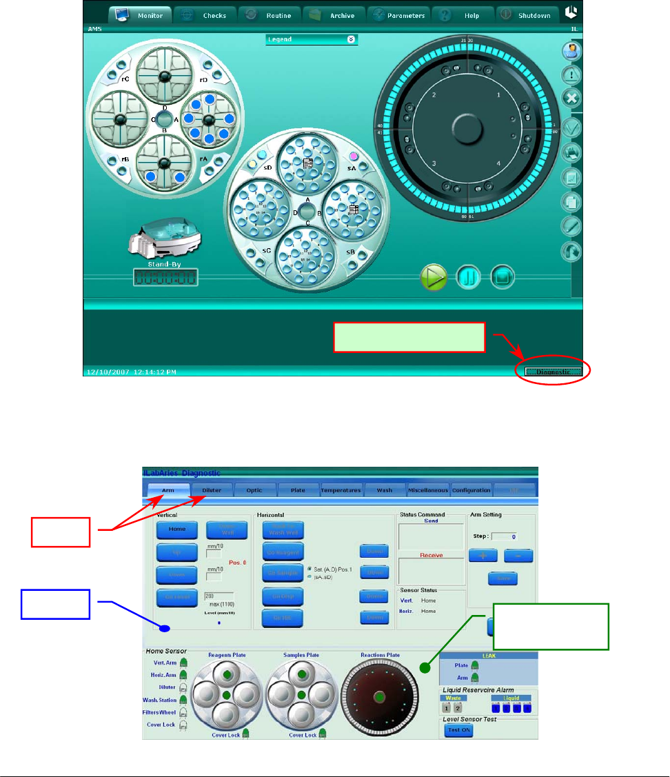
4 DIAGNOSTIC PROGRAM
The Diagnostic program enables the operator to perform a complete check of each of the modules
of the SAT450 instrument.
This program has a folder structure, with each folder containing functions pertaining to the specific
module. To launch the program the operator has to click with the left side of the mouse, on the
Diagnostic area located on the lower right side of the screen of the System Monitor (Fig. 1).
The SAT450 instrument must be in the stand-by state to access this area.
Fig. 1 – System Monitor
Once the “Diagnostic” program starts, the following folder appears (Fig. 2).
“Dia
g
nostic” button
Fig. 2 – Diagnostic program
Folde
r
Tabs
Home Sensors
status area
Chapter 04 – DIAGNOSTIC PROGRAM
SAT450 Service Manual Rev.00 03 July 2008 Page 4
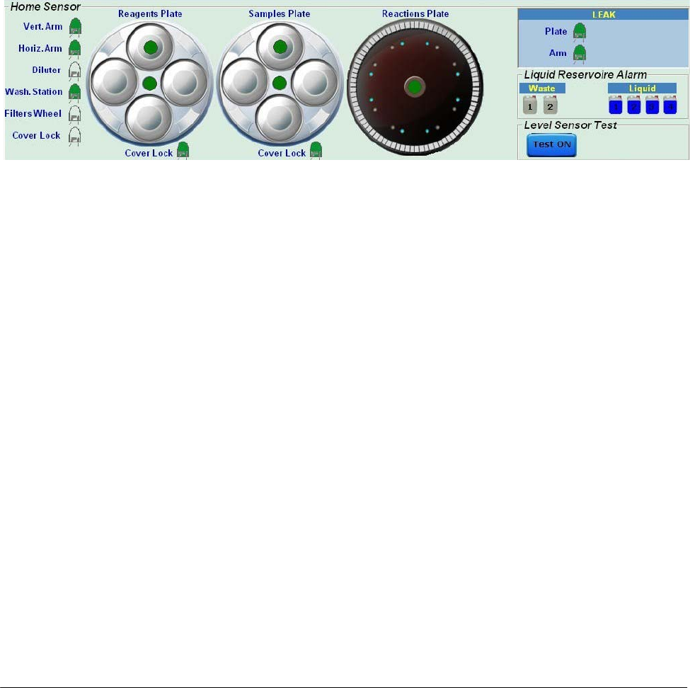
The Diagnostic program is subdivided into two distinct areas: Folder Test and Home Sensors
status. This two areas are present on every diagnostic windows and enable the operator to verify
multiple functions as specified below:
Folder Tests: checks the functionality of the various sub-systems. The individual functions are
illustrated later on.
Home Sensors Status: visualizes the home sensor status that controls the Sampling Arm, the
Diluter, the Washing Station, the Filters Wheel, the Reactions Plate, the
Samples Plate, the Reagents Plate and the two Cover Locks, as well as the
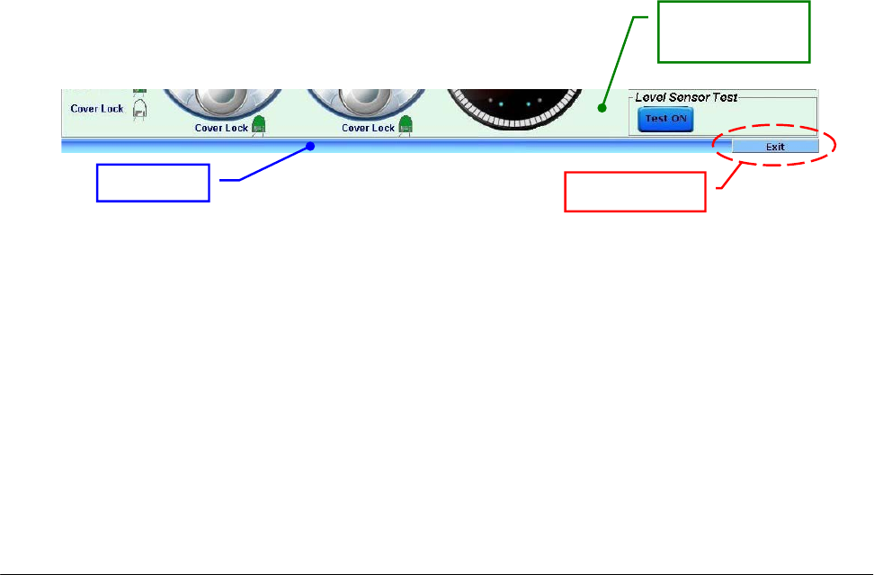
Liquid Reservoire Alarm and the Level Sensor Test (Fig. 3).
Fig. 3 – Home Sensors Status in the Diagnostic program
The Home Sensor:
o Vertical Arm Home Sensor
o Horizontal Arm Home Sensor
o Diluter Home Sensor
o Washing Station Home Sensor
o Filters Wheel Home Sensor
o Reagents Plate Home Sensor
o Satellites Mov. Reagents Plate Home Sensor
o Samples Plate Home Sensor
o Satellites Mov. Samples Plate Home Sensor
o Reactions Plate Home Sensor
turn green when the specific device is in the home position.
The Cover Lock Home Sensor is green when the Instrument Cover is closed.
The Home Sensor:
o Reagents Plate Cover Lock
o Samples Plate Cover Lock
turn green when the specific cover is positioned on its plate.
Chapter 04 – DIAGNOSTIC PROGRAM
SAT450 Service Manual Rev.00 03 July 2008 Page 5
The following six fields signal the alarms for the two waste tanks and the four liquid bottles:
• Waste1 - Liquid Reservoire Alarm
• Waste2 - Liquid Reservoire Alarm
turn blue when the correspondent waste tank is full;
• Liquid 1 - Liquid Reservoire Alarm
• Liquid 2 - Liquid Reservoire Alarm
• Liquid 3 - Liquid Reservoire Alarm
• Liquid 4 - Liquid Reservoire Alarm
disappear the blue if the liquid quantity is below the predetermined minimum level (the bottle is almost
empty).
Button Test ON: if pushed, on the right of it will be showed a red drop that becomes temporarily green
when the liquid is detected with the Sampling Probe (Level Sensor Test).
The “Exit” button (Fig. 4) allows to exit from the Diagnostic program.
Fig. 4 – “Exit” button
Status ba
r
“Exit” button
Home Sensors
status area
Chapter 04 – DIAGNOSTIC PROGRAM
SAT450 Service Manual Rev.00 03 July 2008 Page 6
4.1 DIAGNOSTIC FOLDERS
The Diagnostic program is subdivided into 8 folders:
Arm: allows to perform and check the adjustments of the Sampling Arm;
Diluter: checks the accurate functioning of the Diluter;
Optic: checks the accurate functioning of the Photometer;
Plate: checks the accurate functioning of the Reactions Plate, Samples Plate and Reagents Plate;
Temperatures: checks the temperature of the Pre-Heater and Reactions Plate;
Wash: checks the accurate functioning of the Washing Station;
Miscellaneous: checks the accurate functioning of the Barcode Readers and allows to perform
the General Reset of the instrument;
Configuration: allows to adjust specific parameters of the instrument (the access in this folder
is restricted by password).
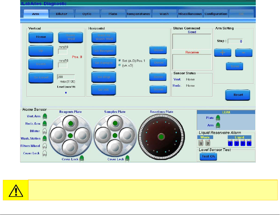
4.2 “ARM” FOLDER
Fig. 5 – “Arm” folder
The wrong use of the functions described in this folder can damage the Sampling Probe.

Chapter 04 – DIAGNOSTIC PROGRAM
SAT450 Service Manual Rev.00 03 July 2008 Page 7
The “Arm” folder is subdivided into five areas:
VERTICAL
HORIZONTAL
STATUS COMMAND
ARM SETTING
SENSOR STATUS
4.2.1 “VERTICAL” COMMAND AREA
(5 commands)
Home: brings the Sampling Arm vertically to a home position;
Down Well: brings the Arm’s axis “z” to the height of the Washing Well;
Up: raises the Sampling Arm tenths of a millimeter as preset in the square found immediately
on the right, with relation to the previous down movement; the box becomes active when
the Sampling Arm is positioned on a sample, a reagent, a standard or a cuvette;
Down: lowers the Sampling Arm tenths of a millimeter as pre-determined by the square found
immediately on the right; the box becomes active when the Sampling Arm is
positioned on a sample, a reagent, a standard or a cuvette;
Go Level: brings the Sampling Probe to either the reagent level, the sample or the standard and
reads the level. Before giving this command, it is necessary to set the parameter for
the Probe’s maximum lowering level in the max area (mm).
4.2.2 “HORIZONTAL” COMMAND AREA
(5 commands)
Back to Wash Well: brings the Sampling Arm back to the home position;
Go Reagent: brings the Sampling Arm to the reagent position;
Go Sample: brings the Sampling Arm to the sample position; moreover, it’s possible choose
between two different positions: the first [ Sat (A..D) Pos.1 ] allows to bring the
Sampling Probe in correspondence of the position #1 of one of four Satellite
Racks, instead the second [ (sA..sD) ] allows to bring the Sampling Probe in
correspondence of the Peripheral Racks.
Go Disp.: brings the Sampling Arm to the dispense position.
Go ISE: to be defined.
The "Down" button allows to the Sampling Probe go down at the right height.

Chapter 04 – DIAGNOSTIC PROGRAM
SAT450 Service Manual Rev.00 03 July 2008 Page 8
4.2.3 “STATUS COMMAND” AREA
Send: visualizes the commands sent from the program to the instrument’s hardware;
Receive: visualizes the answers of the instrument’s hardware to the commands sent by the
program.
4.2.4 “ARM SETTING” COMMAND AREA
(5 commands)
Step: visualizes the number of steps;
+ : performs the counter-clockwise rotation of the Sampling Arm (to adjust the position);
- : performs the clockwise rotation of the Sampling Arm (to adjust the position);
Save: saves the adjustment data;
Reset: completely resets the Sampling Arm.
In this area the boxes can be activated when the Sampling Arm is positioned on a sample, a
reagent, a standard, a control or a reaction cuvette.
4.2.5 “SENSOR STATUS” AREA
Sensor Status: indicates the home sensors status relative to the Sampling Arm’s vertical axis
(Vertical) and the Sampling Arm’s latitudinal motion (Horizontal).
Chapter 04 – DIAGNOSTIC PROGRAM
SAT450 Service Manual Rev.00 03 July 2008 Page 9
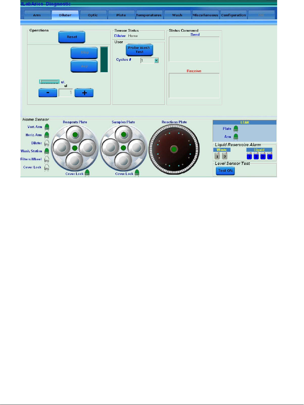
4.3 “DILUTER” FOLDER
The “Diluter” folder is subdivided into four areas:
OPERATIONS
SENSOR STATUS
USER
STATUS COMMAND
4.3.1 “OPERATIONS” AREA
(3 commands)
Reset: brings the Diluter to the home position;
Asp: aspirates the micro-litres as predetermined in the “ul.” box (may be set manually through
+ and – or by using the cursor located immediately above);
Disp.: dispenses the micro-litres as predetermined in the “ul.” box (may be set manually
through + and – or by using the cursor located immediately above).
4.3.2 “SENSOR STATUS” AREA
In the Sensor Status area the Diluter home sensor status is indicated.
Fig. 6 – “Diluter” folder
Chapter 04 – DIAGNOSTIC PROGRAM
SAT450 Service Manual Rev.00 03 July 2008 Page 10
4.3.3 “USER” AREA
(1 command)
Probe Wash Test: activates/deactivates the Probe Wash Test. The number of the cycles for this
test can be chosen with the field “Cycles #”.
4.3.4 “STATUS COMMAND” AREA
Send: visualizes the commands sent by the program to the instrument’s hardware;
Receive: visualizes the instrument hardware’s response to the commands sent by the program.
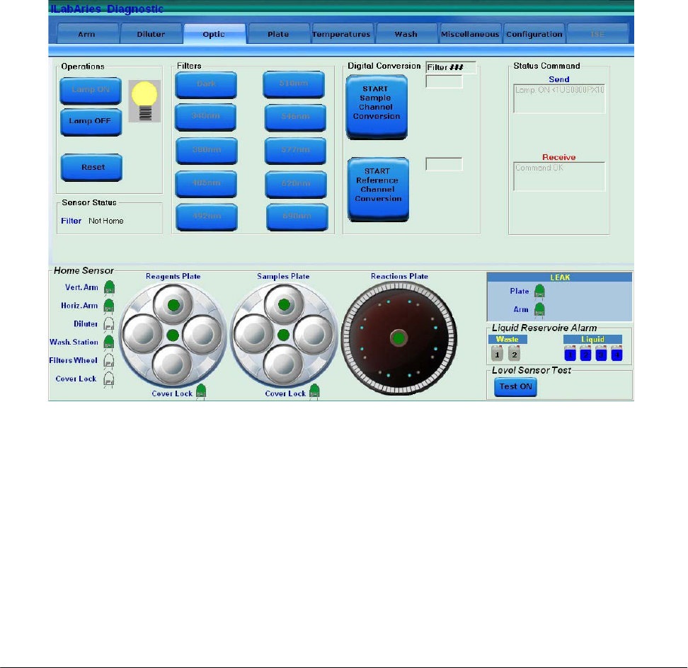
4.4 “OPTIC” FOLDER
The “Optic” folder is subdivided into five areas:
OPERATIONS
SENSOR STATUS
FILTERS
DIGITAL CONVERSION
STATUS COMMAND
Fig. 7 - “Optic” folder

Chapter 04 – DIAGNOSTIC PROGRAM
SAT450 Service Manual Rev.00 03 July 2008 Page 11
4.4.1 “OPERATIONS” AREA
(3 commands)
Lamp ON: turns on the Photometer Halogen Lamp;
Lamp OFF: turns off the Photometer Halogen Lamp,
Reset: brings the Filters Wheel of the Photometer to the home position.
4.4.2 “SENSOR STATUS” AREA
This area indicates the status of the Filters Wheel home sensor.
4.4.3 “FILTERS” AREA
(10 commands)
Dark: positions the Filters Wheel in dark position;
340 nm: positions the int. filter n° 1 (340 nm) in front of the reading sensor;
380 nm: positions the int. filter n° 2 (380 nm) in front of the reading sensor;
405 nm: positions the int. filter n° 3 (405 nm) in front of the reading sensor;
492 nm: positions the int. filter n° 4 (492 nm) in front of the reading sensor;
510 nm: positions the int. filter n° 5 (510 nm) in front of the reading sensor;
546 nm: positions the int. filter n° 6 (546 nm) in front of the reading sensor;
577 nm: positions the int. filter n° 7 (577 nm) in front of the reading sensor;
620 nm: positions the int. filter n° 8 (620 nm) in front of the reading sensor;
690 nm: positions the int. filter n° 9 (690 nm) in front of the reading sensor.
4.4.4 “DIGITAL CONVERSION” AREA
(2 commands)
START/STOP Sample Channel Conversion: performs an analogical/digital conversion of the
Sample Channel (counts);
START/STOP Reference Channel Conversion: performs an analogical/digital conversion of
the Reference Channel (counts).
Moreover, a Output Box is present that shows the selected interferential filter.
4.4.5 “STATUS COMMAND” AREA
Send: visualizes the commands sent by the program to the instrument’s hardware;
Receive: visualizes the instrument hardware’s response to the commands sent by the program.
Chapter 04 – DIAGNOSTIC PROGRAM
SAT450 Service Manual Rev.00 03 July 2008 Page 12
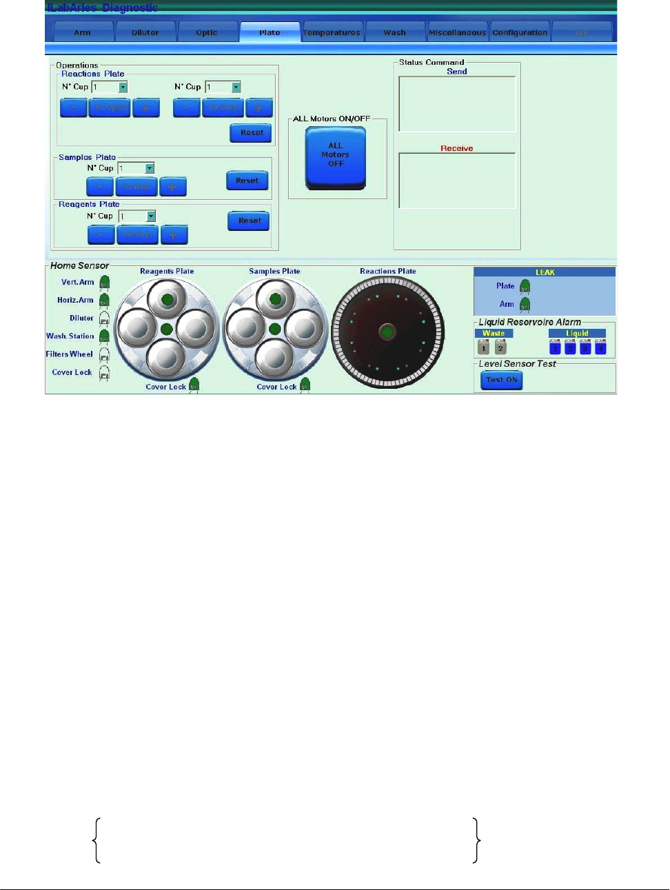
4.5 “PLATE” FOLDER
The “Plate” folder is subdivided into three areas:
OPERATIONS
ALL MOTORS ON/OFF
STATUS COMMAND
4.5.1 “OPERATIONS” AREA
“Reactions Plate” area:
(3 commands)
To Optic: automatically positions the reaction cuvette, selected on the Pull Down Menu above,
in front of the Photometer;
To Disp.: automatically positions the reaction cuvette, selected on the Pull Down Menu above,
under the dispensing position;
Reset: performs the reset of the Reactions Plate by positioning the reaction cuvette #1 in the
reading position (in front of the Photometer).
+ : automatically positions the next reaction cuvette;
- : automatically positions the previous reaction cuvette.
Fig. 8 – “Plate” folder
(*)
(*)
(*)

Chapter 04 – DIAGNOSTIC PROGRAM
SAT450 Service Manual Rev.00 03 July 2008 Page 13
“Samples Plate” area:
(2 commands)
To Asp.: automatically brings the sample cup, selected on the Pull Down Menu above, under
the aspiration position;
+ : automatically positions the next position;
- : automatically positions the previous position.
Reset: performs the reset of the Samples Plate by positioning the position #1 of the Satellites
Rack A under the aspiration position.
“Reagents Plate“ area:
(2 commands)
To Asp.: automatically brings the reagent bottle, selected on the Pull Down Menu above, under
the aspiration position;
+ : automatically positions the next position;
- : automatically positions the previous position.
Reset: performs the reset of the Reagents Plate by positioning the position #1 of the Satellites
Rack A under the aspiration position.
4.5.2 “ALL MOTORS ON/OFF” AREA
(1 command)
ALL Motors ON/OFF: engages/disengages the motors to allow a manual movement of the
modules (Sampling Arm, Reactions Plate, Reagents Plate, Samples
Plate, Washing Station, Photometer Filters Wheel).
4.5.3 “STATUS COMMAND” AREA
Send: visualizes the commands sent by the program to the instrument’s hardware;
Receive: visualizes the instrument hardware’s response to the commands sent by the program.
Chapter 04 – DIAGNOSTIC PROGRAM
SAT450 Service Manual Rev.00 03 July 2008 Page 14
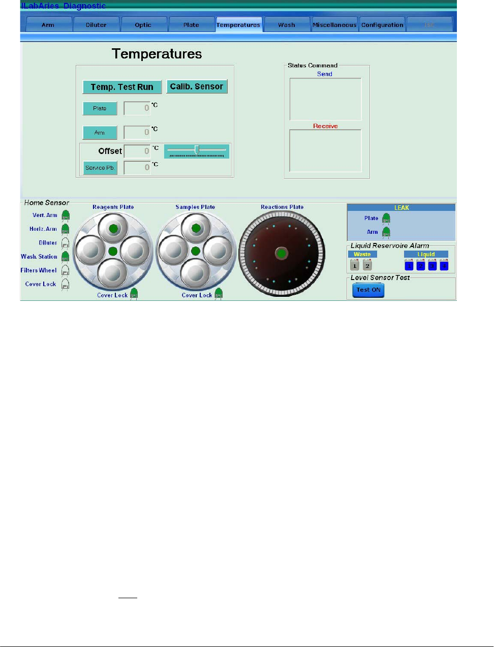
4.6 “TEMPERATURES” FOLDER
The “Temperatures” folder is subdivided into two areas:
TEMPERATURES
STATUS COMMAND
4.6.1 “TEMPERATURES” AREA
(6 commands)
Temp. Test Run: allows to get in the “Temperature Test” form (Fig. 10) and performs the
Temperature Test;
Plate: performs a temperature reading (°C) in the Reactions Plate compartment;
Arm: performs a temperature reading (°C) in the Pre-Heater of the Sampling Arm;
Calib. Sensor: allows to perform the calibration procedure of the Service Probe included in the
kit having P/N: 55-01204-00.
Offset: allows to enter (using the cursor located immediately to the right) the temperature
offset value (°C) between the reference thermometer reading and the Service Probe
reading (note: the offset value resets to zero when exit to the Diagnostic program).
Service Pb.: performs a temperature reading (°C) with the Service Probe.
Fig. 9 – “Temperatures” folder

Chapter 04 – DIAGNOSTIC PROGRAM
SAT450 Service Manual Rev.00 03 July 2008 Page 15
4.6.1.1 “Temperature Test” form
(3 commands)
START: allows to start the Temperature Test;
WASH: allows to empty the five reaction cuvettes used in the Temperature Test;
EXIT: allows to exit from the “Temperature Test” form.
Service Probe: text box that shows the temperature reading (°C) with the Service Probe.
# Cycles = 5: number of reaction cuvettes used in the Temperature Test;
Reagent =1: indicates the position (position #1 of the Satellites Rack A of the Reagents Plate)
where take place the aspiration of the Sampling Arm.
4.6.2 “STATUS COMMAND” AREA
Send: visualizes the commands sent by the program to the instrument’s hardware;
Receive: visualizes the instrument hardware’s response to the commands sent by the program.
Fi
g
. 10 – “Tem
p
erature Test” form
Chapter 04 – DIAGNOSTIC PROGRAM
SAT450 Service Manual Rev.00 03 July 2008 Page 16
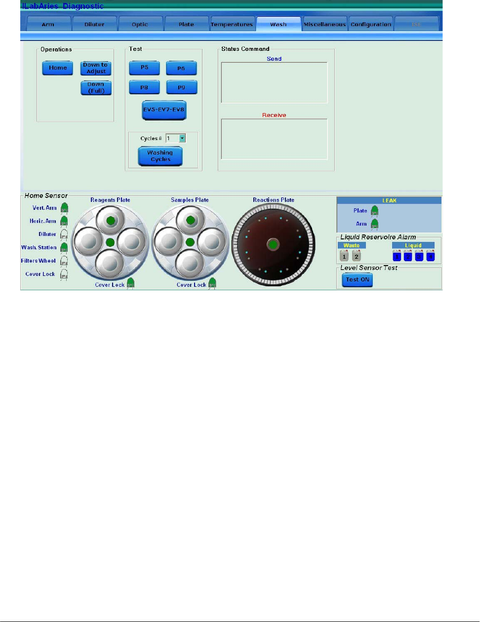
4.7 “WASH” FOLDER
The “Wash” folder is subdivided into three areas:
OPERATIONS
TEST
STATUS COMMAND
4.7.1 “OPERATIONS” AREA
(3 commands)
Home: brings the washing device of the Washing Station to the home position;
Down to Adjust: makes the washing device go down to the position for adjusting operations;
Down (Full): makes the washing device go down to the washing position.
Fi
g
. 11 – “Wash” folder
Chapter 04 – DIAGNOSTIC PROGRAM
SAT450 Service Manual Rev.00 03 July 2008 Page 17
4.7.2 “TEST” AREA
(6 commands)
P5: actives the P5 µ-pump and automatically turns it off after a period of 0,5 seconds;
P6: actives the P6 µ-pump and automatically turns it off after a period of 0,5 seconds;
P8: actives the P8 µ-pump and automatically turns it off after a period of 0,5 seconds;
P9: actives the P9 µ-pump and automatically turns it off after a period of 0,5 seconds;
EV5-EV7-EV8: actives the EV5, EV7 and EV8 electrovalves and automatically turns them off
after a period of 0,5 seconds.
Washing Cycles: allows to perform the Functional Check of the Washing Station. The number
of cycles is selectable on the Pull Down Menu “Cycles #”.
4.7.3 “STATUS COMMAND” AREA
Send: visualizes the commands sent by the program to the instrument’s hardware;
Receive: visualizes the instrument hardware’s response to the commands sent by the program.
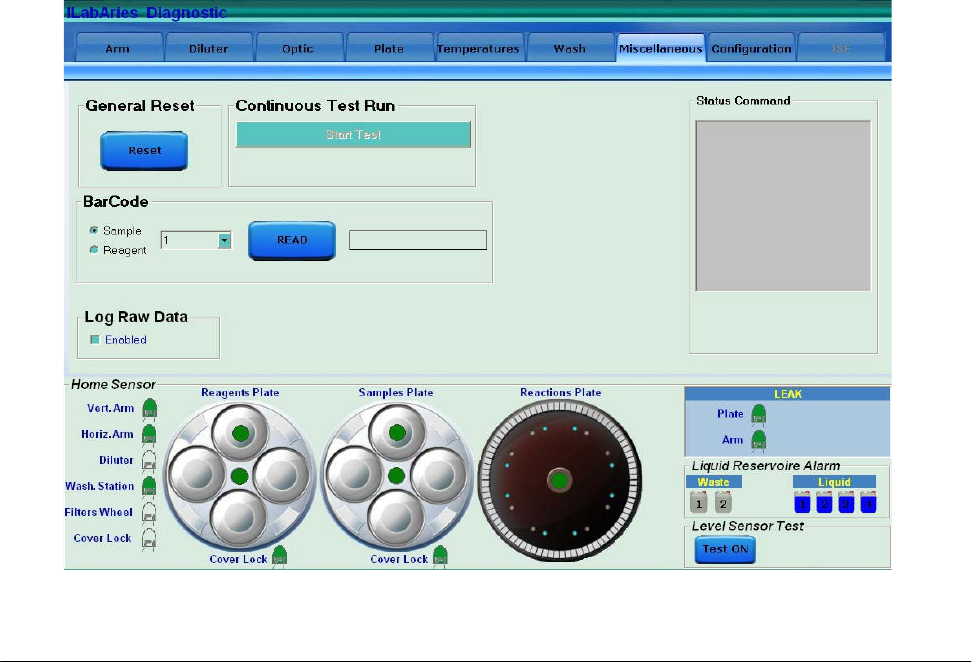
4.8 “MISCELLANEOUS” FOLDER
Fig. 12 – “Miscellaneous” folder

Chapter 04 – DIAGNOSTIC PROGRAM
SAT450 Service Manual Rev.00 03 July 2008 Page 18
The “Miscellaneous” folder is subdivided into five areas:
GENERAL RESET
CONTINUOUS TEST RUN
BARCODE
LOG RAW DATA
4.8.1 “GENERAL RESET” AREA
(1 command)
Reset: performs the reset procedure of the general system.
4.8.2 “CONTINUOUS TEST RUN” AREA
(1 command)
Start Test: allows to start an automatic test during which the modules of the system are moved
to all the different positions.
4.8.3 “BARCODE” AREA
(1 command)
Read: allows to read the barcode (visualized to its right) present on the bottle/cup in a specific
position of the Samples Plate or Reagents Plate.
(2 options)
Sample: option to select the Samples Plate upon which read the barcode in the position choosed
in the near Pull Down Menu;
Reagent: option to select the Reagents Plate upon which read the barcode in the position
choosed in the near Pull Down Menu.
4.8.4 “LOG RAW DATA” AREA
(1 check box)
Enabled: if selected, allows to save a copy of the files for the technical diagnosis in case of
malfunctions of the instrument. The files are memorized in a specific folder.
Chapter 04 – DIAGNOSTIC PROGRAM
SAT450 Service Manual Rev.00 03 July 2008 Page 19
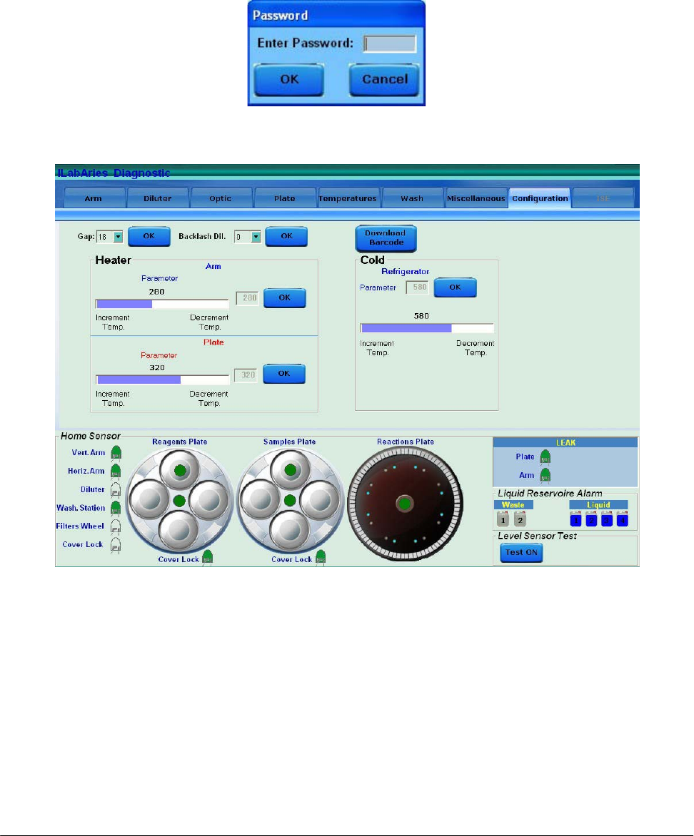
4.9 “CONFIGURATION” FOLDER
This folder must be accessible only by qualified technical operators.
It is necessary insert a password in the “Password” form (Fig. 13) to access in this folder.
The “Configuration” folder is subdivided into six areas:
GAP
BACKLASH DIL.
HEATER - ARM
HEATER - PLATE
COLD – REFRIGERATOR
DOWNLOAD BARCODE
Fig. 13 – “Password” form
Fig. 14 – “Configuration” folder

Chapter 04 – DIAGNOSTIC PROGRAM
SAT450 Service Manual Rev.00 03 July 2008 Page 20
4.9.1 “GAP” AREA
(1 command)
OK: allows to save the volume (in µL), selected in the relative Pull Down Menu, of the air
bubble that separates the Rinse (the liquid column into the Sampling Arm tube) from the
sampled Reagent. The default value is 18.
4.9.2 “BACKLASH DIL.” AREA
(1 command)
OK: allows to save the redress value for the sampling imprecision generated by the Diluter
motor when it inverts the rotation of its shaft. The setting value in the relative Pull Down
Menu is expressed in µL. It is obtained by using the following procedure:
1. Select "Arm” folder and request an Sampling Arm reset. Wait until the reset
Sampling Arm procedure has been completed.
2. Select “Diluter” folder and request an Diluter reset. Wait until the reset Diluter
procedure has been completed.
3. Select the number “4” in the Pull Down Menu “Cycles #” and push “Probe Wash
Test” in order to fill the hydraulic sampling line. Wait until the requested cycles
have been completed.
4. Select “Arm” folder and push “Go Sample” button in order to move the Sampling
Probe to sample position #1.
5. Put a sample cup containing distilled water (about 1ml) under the Sampling Probe.
6. Select “Diluter” folder and aspirate 300 µL of distilled water from the cup.
7. Remove the sample cup containing distilled water.
8. Select 1 µL to dispense and press “Disp.” button consecutively until water appears
on the tip of the Sampling Probe.
9. Substract 1 from the number of times that you pressed the “Disp” button. The
obtained number has to be introduced in the relative Pull Down Menu as
BACKLASH value.
10. Push “OK” button in the “Backlash Dil.” area to save the inserted value.
11. Select "Arm” folder and request an Sampling Arm reset. Wait until the reset
Sampling Arm procedure has been completed.
4.9.3 “HEATER - ARM” AREA
(1 command)
OK: allows to save the parameter to adjust the heating temperature of the Sampling Arm’s
Pre-Heater. This parameter is selectable in the relative slide and the value is visualized
near to it.

Chapter 04 – DIAGNOSTIC PROGRAM
SAT450 Service Manual Rev.00 03 July 2008 Page 21
4.9.4 “HEATER - PLATE” AREA
(1 command)
OK: allows to save the parameter to adjust the heating temperature of the Reactions Plate
resistor. This parameter is selectable in the relative slide and the value is visualized near
to it.
4.9.5 “COLD - REFRIGERATOR” AREA
(1 command)
OK: allows to save the parameter to adjust the cooling temperature of the Reagents Plate
refrigerator. This parameter is selectable in the relative slide and the value is visualized
above to it.
4.9.6 “DOWNLOAD BARCODE” AREA
(1 command)
Download Barcode: allows to download in the hardware of the instrument the firmware for the
two BarCode Readers.
4.10 “ISE” FOLDER
[to be defined]

Chapter 05 – SETTINGS AND ADJUSTMENTS
SAT450 Service Manual Rev.00 03 July 2008 Page I
CHAPTER 05
- SETTINGS AND ADJUSTMENTS -
INDEX
5 SETTINGS AND ADJUSTMENTS……………………………….. 1
5.1 Sampling Arm……………………………………………………….. 1
5.1.1 Alignments and adjustments of the Sampling Probe………………… 1
5.1.2 Replacement of the Sampling Arm Assy…………………………….. 7
5.1.3 Replacement of the Sampling Probe…………………………….…… 8
5.1.4 Replacement of the Horizontal Mov. Arm Motor……………….…… 9
5.1.5 Replacement of the Vertical Mov. Arm Motor………………….…… 10
5.1.6 Replacement of the Horizontal Mov. Arm Home Sensor …………… 12
5.1.7 Replacement of the Vertical Mov. Arm Home Sensor ……………… 13
5.1.8 Replacement of the Horizontal Mov. Arm Belt ……………...……… 15
5.2 Diluter………………………………………………………………... 17
5.2.1 Replacement of the Diluter Assy……….……………………………. 17
5.2.2 Replacement of the Diluter Home Sensor……………………….…… 18
5.2.3 Replacement of the Diluter Micropump (P1)………………………… 19
5.2.4 Replacement of the Arm Washing Well Micropump (P7)…………… 19
5.2.5 Replacement of the Diluter Electrovalve (EV1)……………………... 20
5.2.6 Replacement of the Arm Washing Well Electrovalve (EV6)………... 21
5.3 Pre-Heater…………………………………………………………… 22
5.3.1 Replacement of the Pre-Heater Assy………………………………… 22
5.4 Photometer…………………………………………………………... 27
5.4.1 Electronic adjustments of the Photometer……………………….…… 27
5.4.2 Replacement of the Optic Assy………………………………….…… 30
5.4.3 Replacement of the Filters Wheel Motor…………………………….. 31
5.4.4 Replacement of the Filters Wheel Home Sensor…………………….. 34
5.4.5 Replacement of the Photometer Halogen Lamp……………………... 35
5.4.6 Replacement of the “Pre-Ampl./ADC Board” of the Sample Channel.. 36
5.4.7 Replacement of the “Pre-Ampl./ADC Board” of the Ref. Channel….. 37
5.4.8 Replacement of the Interferential Filters….………………………….. 38

Chapter 05 – SETTINGS AND ADJUSTMENTS
SAT450 Service Manual Rev.00 03 July 2008 Page II
5.5 Reagents Plate……………………………………………………….. 40
5.5.1 Mechanical adjustments of the Reagents Plate………………….…… 40
5.5.2 Remotion of the Reagents Plate Assy from the Raising Top………… 42
5.5.3 Mechanical alignments of the Satellite Racks of the Reagents Plate… 43
5.5.4 Replacement of the Reagents Plate Motor…………………………… 48
5.5.5 Replacement of the Satellites Mov. Reagents Plate Motor…………... 50
5.5.6 Replacement of the Reagents Plate Home Sensor…………………… 52
5.5.7 Replacement of the Satellites Mov. Reagents Plate Home Sensor…... 53
5.5.8 Replacement of the Reagents Plate Belt……………………………... 53
5.5.9 Replacement of the Satellites Mov. Reagents Plate Belt…………….. 54
5.5.10 Replacement of the Cooler Module………………………………….. 55
5.5.11 Replacement of the Cooler Module with Temperature Sensor………. 56
5.5.12 Replacement of the Cooler Temperature Sensor……………………... 57
5.6 Samples Plate………………………………………………………... 58
5.6.1 Mechanical adjustments of the Samples Plate……………………….. 58
5.6.2 Remotion of the Samples Plate Assy from the Raising Top…………. 60
5.6.3 Mechanical alignments of the Satellite Racks of the Samples Plate…. 61
5.6.4 Replacement of the Samples Plate Motor……………………………. 63
5.6.5 Replacement of the Satellites Mov. Samples Plate Motor…………… 65
5.6.6 Replacement of the Samples Plate Home Sensor…………………….. 66
5.6.7 Replacement of the Satellites Mov. Samples Plate Home Sensor…… 67
5.6.8 Replacement of the Samples Plate Belt………………………………. 68
5.6.9 Replacement of the Satellites Mov. Samples Plate Belt……………... 69
5.7 Reactions Plate………………………………………………………. 70
5.7.1 Mechanical adjustment of the Reactions Plate……………………….. 70
5.7.2 Replacement of the Reactions Plate Motor…………………………... 72
5.7.3 Replacement of the Reactions Plate Home Sensor…………………... 74
5.7.4 Replacement of the Reactions Plate Belt…………………………….. 76
5.8 Washing Station……………………………………………………... 77
5.8.1 Mechanical adjustments of the Washing Station…………………….. 77
5.8.2 Replacement of the Washing Station Assy…………………………... 79
5.8.2.1 Functional check of the Washing Station………………………………….. 81
5.8.3 Replacement of the Washing Station Motor…………………………. 83

Chapter 05 – SETTINGS AND ADJUSTMENTS
SAT450 Service Manual Rev.00 03 July 2008 Page III
5.8.4 Replacement of the Washing Station Home Sensor………………….. 84
5.9 Temperatures Adjustments………………………………………… 87
5.9.1 Procedure for the adjustment of the Reaction Cuvettes Temperature... 87
5.9.2 Procedure for the check of the Reagents Cooling Temperature……… 90
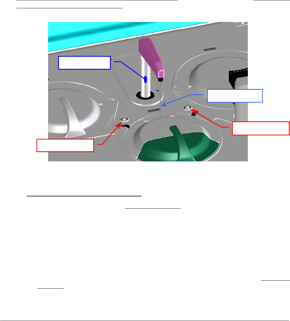
Chapter 05 – SETTINGS AND ADJUSTMENTS
SAT450 Service Manual Rev.00 03 July 2008 Page 1
5 SETTINGS AND ADJUSTMENTS
5.1 SAMPLING ARM
5.1.1 Alignments and adjustments of the Sampling Probe
1. Turn on the SAT450 system (instrument and computer) and launch the “Diagnostic” program.
2. Select "Miscellaneous” folder and request an Instrument General reset. Wait until the reset
instrument procedure has been completed.
3. Make sure that all the Home Sensors of the Sampling Arm, Reactions Plate, Reagents Plate and
Samples Plate light up in green.
4. Make sure that the Sampling Probe is vertically aligned (like show in the Fig. 4) and centered
with respect to the Washing Well 1 (well places between Reagents Plate and Samples Plate
indicated in the Fig. 1). If it not be so, adjust in the following way:
o Sampling Probe horizontal alignment:
a. if the Sampling Probe is not latitudinal centered with respect to the Washing Well 1
(Fig. 5), adjust in the following way:
b. select "Arm” folder and request an Arm reset. Wait until the reset Sampling Arm
procedure has been completed;
c. make sure that all the Home Sensors of the Sampling Arm (Vertical and Horizontal)
light up in green;
d. loosen slightly the two set screws of the Sampling Arm (Fig. 2);
e. rotate slightly the Sampling Arm in the right toward in order to obtain the latitudinal
centering with respect to the Washing Well 1 (Fig. 5);
f. tighten the two set screws of the Sampling Arm (Fig. 2);
Fig. 1 – Sampling Arm and Washing Well 1
Sam
p
lin
g
Probe
Sam
p
lin
g
Ar
m
Washin
g
Well 1
Washing Well 2
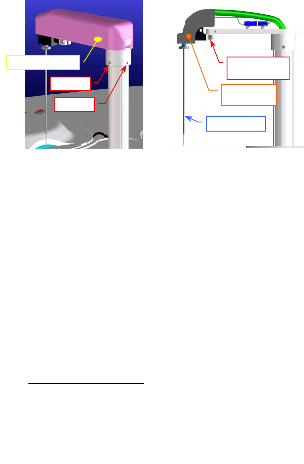
Chapter 05 – SETTINGS AND ADJUSTMENTS
SAT450 Service Manual Rev.00 03 July 2008 Page 2
Fig. 2 – Set screws of the Sampling Arm Fig. 3 – Probe adjustment screw
g. select "Arm” folder and request an Arm reset. Wait until the reset Sampling Arm
procedure has been completed;
h. if the Sampling Probe is not longitudinal centered with respect to the Washing Well 1
(Fig. 5), adjust in the following way:
i. select "Arm” folder and request an Arm reset. Wait until the reset Sampling Arm
procedure has been completed;
j. remove the Sampling Arm cover (Fig. 2);
k. loosen slightly the Probe adjustment screw places on the Sampling Arm head
(Fig. 3);
l. rotate slightly the Sampling Arm in the right toward in order to obtain the
longitudinal centering with respect to the Washing Well 1 (Fig. 5);
m. tighten the Probe adjustment screw (Fig. 3);
n. replace the Sampling Arm cover (Fig. 2);
o. select "Arm” folder and request an Arm reset. Wait until the reset Sampling Arm
procedure has been completed;
p. make sure that the Sampling Probe is centered with respect to the Washing Well 1.
o Sampling Probe vertical adjustment:
q. make sure that all the Home Sensors of the Sampling Arm (Vertical and Horizontal)
light up in green;
r. remove the Reagents Plate and the Samples Plate covers (Fig. 7);
s. position a setscrew wrench with diameter equal to 2.5 mm between the point “A” (on
mezzanine edge of the Reagents Plate) and the point “B” (on mezzanine edge of the
Samples Plate) and with its midpoint centered with respect to the center of the Washing
Well 1 (Fig. 4).
Set screw
Set screw
Sam
p
lin
g
Arm cove
r
Sampling Probe
Probe adjustment
screw
Sampling Arm
hea
d
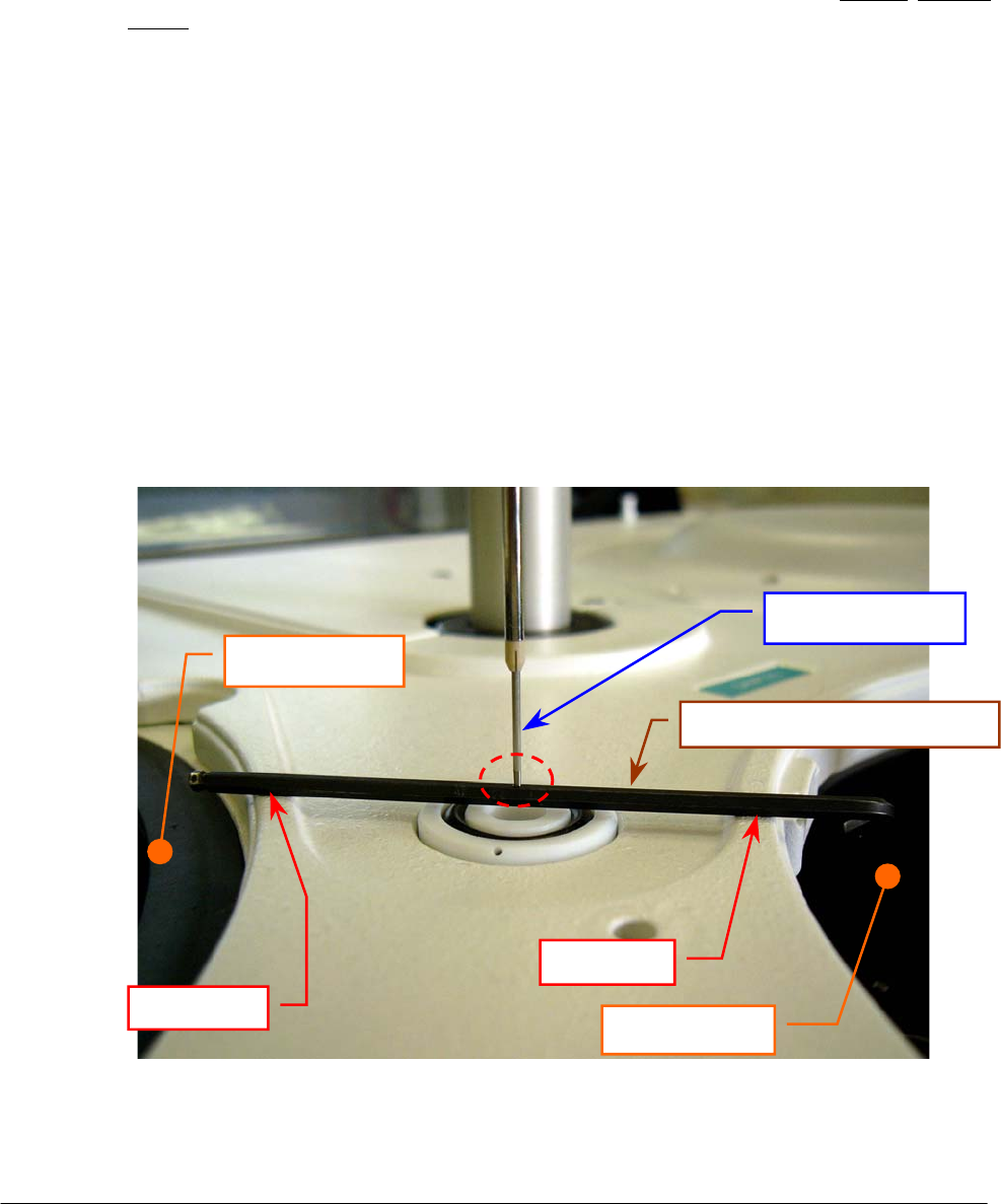
Chapter 05 – SETTINGS AND ADJUSTMENTS
SAT450 Service Manual Rev.00 03 July 2008 Page 3
t. make sure that the tip of the Sampling Probe touch strictly the upper side of the setscrew
wrench (like show in the Fig. 4). If it not be so, adjust in the following way:
u. turn off the SAT450 instrument and remove the setscrew wrench;
v. unscrew the two captive screws on the front underside of the instrument (Fig. 6) and lift
up the Raising Top (Fig. 7);
w. measure the length “L” (Fig. 9) in the Sampling Arm Assy (Fig. 8);
x. loosen the two fastening screws of the Vertical Mov. Arm Home Sensor (Fig. 9);
y. move slightly the Vertical Mov. Arm Home Sensor to the right vertically toward in
order to increase/decrease opportunely the length “L” and obtain the correct vertical
height of the Sampling Probe;
z. tighten the two fastening screws of the Vertical Mov. Arm Home Sensor (Fig. 9);
aa. bring down the Raising Top (Fig. 7) and screw the two captive screws on the front
underside of the instrument (Fig. 6);
bb. turn on the SAT450 instrument and launch the “Diagnostic” program;
cc. select “Arm” folder and request an Arm reset. Wait until the reset Sampling Arm
procedure has been completed;
dd. repeat the above steps “q”, “s” and “t”;
ee. remove the setscrew wrench and replace the Reagents Plate and the Samples Plate
covers (Fig. 7);
ff. select “Arm” folder and request an Arm reset. Wait until the reset Sampling Arm
procedure has been completed.
Sampling Probe
Reagents Plate
Samples Plate
Washing Well 1
Point “A”
Point “B”
Setscrew wrench
(
∅
2.5 mm
)
Fig. 4 – Vertical adjustment of the Sampling Probe
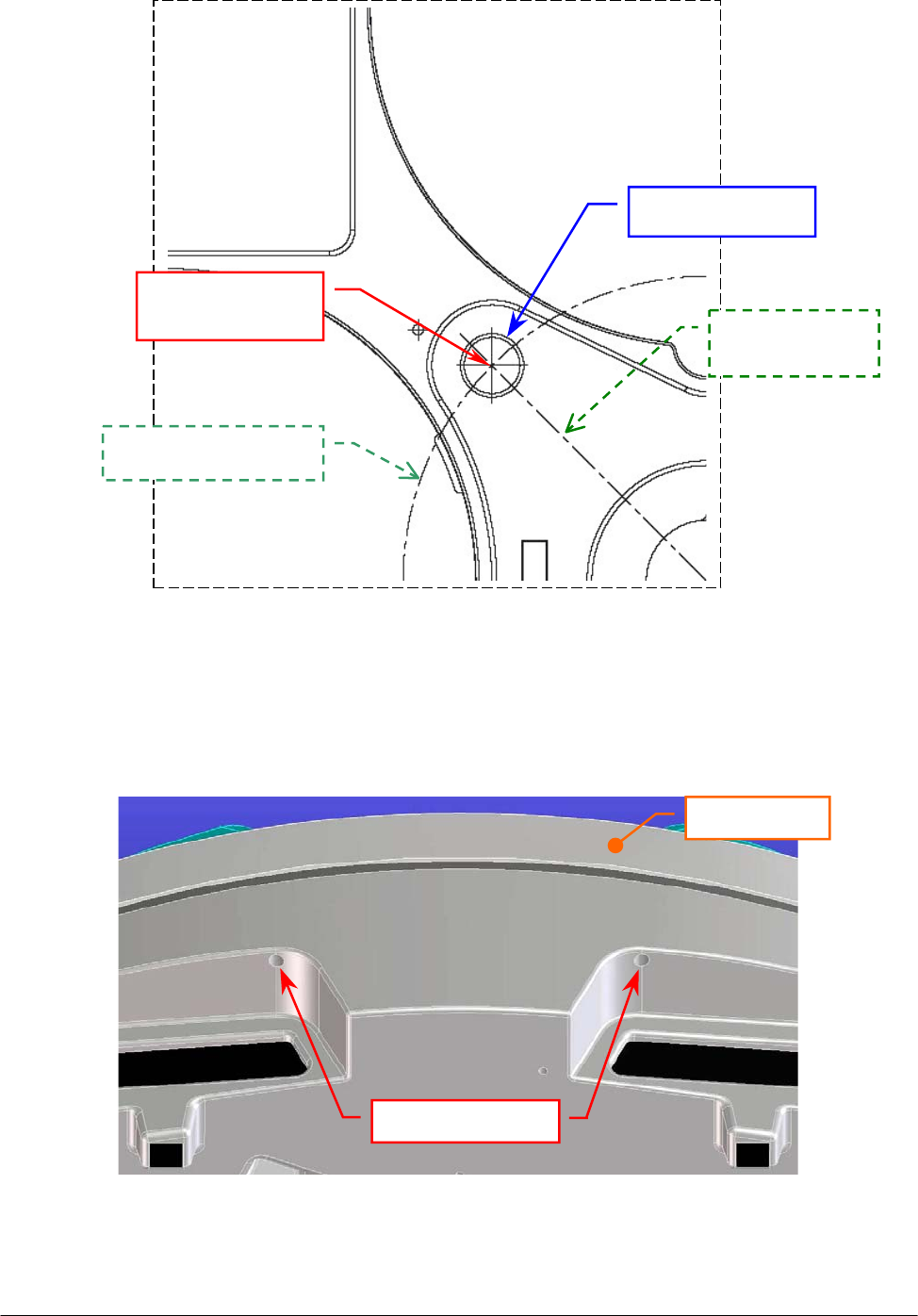
Chapter 05 – SETTINGS AND ADJUSTMENTS
SAT450 Service Manual Rev.00 03 July 2008 Page 4
Fig. 5 – Longitudinal and latitudinal motion of the Sampling Probe
Washing Well 1
Latitudinal motion
Longitudinal
motion
Washin
g
Well 1
center
Fig. 6 – Captive screws on the front underside of the instrument
Captive screws
Raising Top
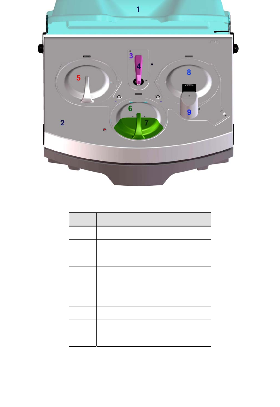
Chapter 05 – SETTINGS AND ADJUSTMENTS
SAT450 Service Manual Rev.00 03 July 2008 Page 5
Fig. 7 – Covers of the SAT450 instrument
Rif. Description
1 Instrument cover
2 Raising Top
3 Diluter cover
4 Sampling Arm cover
5 Reagents Plate cover
6 Samples Plate cover
7 Samples Plate safety protection
8 Reactions Plate cover
9 Washing Station cover
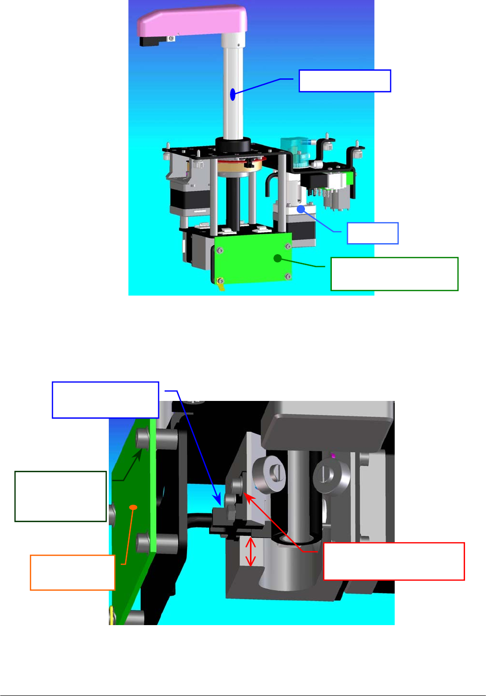
Chapter 05 – SETTINGS AND ADJUSTMENTS
SAT450 Service Manual Rev.00 03 July 2008 Page 6
Fig. 8 – Sampling Arm Assy
Fig. 9 – Vertical Mov. Arm Home Sensor [P/N: 9-10-0024-00]
Arm Interface Board
[
P/N: 30-02193-00
]
Diluter
Sam
p
lin
g
Ar
m
Vertical Mov.
Arm Home Sensor
Arm Interface
Board
LVertical Mov. Arm Home
Sensor fastening screw
Arm Interface
Board
fastening screw
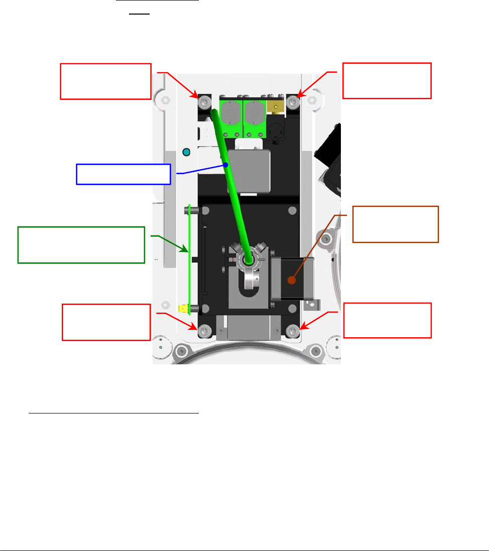
Chapter 05 – SETTINGS AND ADJUSTMENTS
SAT450 Service Manual Rev.00 03 July 2008 Page 7
5.1.2 Replacement of the Sampling Arm Assy
1. Make sure that the SAT450 instrument is turned off.
2. Remove the Sampling Probe from its housing performing the relative procedure described into
the successive Section 6.1.3.
3. Unscrew the two fastening screws of the Diluter cover (Fig. 7), remove it from its housing,
unscrew the two captive screws on the front underside of the instrument (Fig. 6) and lift up the
Raising Top (Fig. 7).
4. Unplug the J1, J2 and J3 connectors and the ground wire from the Arm Interface Board
(compare the scheme SC-30-02193-00).
5. Remove the tube with “16” label text and the tube with “17” label text from the “EV6”
electrovalve and remove the tube with “G” label text from the “Y” fitting (compare the scheme
SI-16-01873-00), making attention to the spillage of the Probe Rinse solution from the tubes
and from the fitting (note: the Probe Rinse solution is NOT a dangerous liquid).
6. Unscrew the four Sampling Arm captive screws (Fig. 10) and pull down – moving carefully –
the Sampling Arm Assy from its housing.
To replace the Sampling Arm Assy (Fig. 8) perform the following steps:
7. Repeat the above steps in inverse order: from 6 to 2.
8. Perform the procedure “Alignments and adjustments of the Sampling Probe” described into the
previous Section 6.1.1.
9. Select “Diluter” folder in the “Diagnostic” program and perform – with the selection of the
“Probe Wash Test” button – at least four successive Probe Wash Test to fill the hydraulic
circuit with the liquid.
10. Verify the absence of liquid leakage from the hydraulic circuit.
Sampling Arm
ca
p
tive screw
Sampling Arm
ca
p
tive screw
Sampling Arm
ca
p
tive screw
Sampling Arm
captive screw
Pre-Heater tube
Vertical Mov.
Arm Moto
r
Arm Interface Board
[P/N: 30-02193-00]
Fig. 10 – Sampling Arm (bottom view)
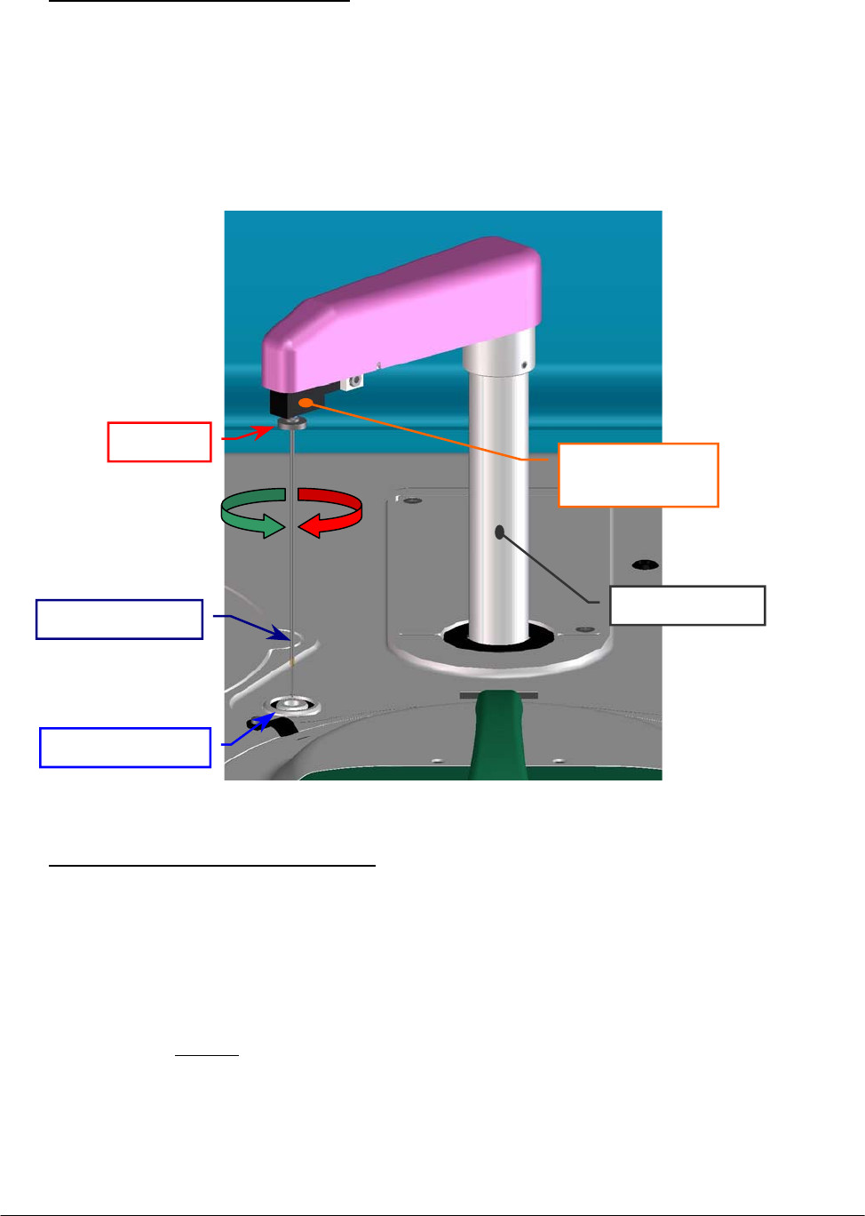
Chapter 05 – SETTINGS AND ADJUSTMENTS
SAT450 Service Manual Rev.00 03 July 2008 Page 8
5.1.3 Replacement of the Sampling Probe
o Removing of the Sampling Probe:
1. Turn on the SAT450 system (instrument and computer) and launch the “Diagnostic”
program.
2. Select "Miscellaneous” folder and request an Instrument General reset. Wait until the reset
instrument procedure has been completed.
3. Turn off the SAT450 instrument and lift up the instrument cover (Fig. 7).
4. Remove the Sampling Probe from its housing by unscrewing (clockwise) its ring nut (Fig. 11).
o Replacement of the Sampling Probe:
5. Turn on the SAT450 system (instrument and computer) and launch the “Diagnostic”
program.
6. Select "Miscellaneous” folder and request an Instrument General reset. Wait until the reset
instrument procedure has been completed.
7. Turn off the SAT450 instrument and lift up the instrument cover (Fig. 7).
8. Attach the (straight) Sampling Probe to the Sampling Arm head (Fig. 11).
9. Rotate slowly (counter clockwise) the Sampling Probe ring nut in its thread hold until you
feel the stop (Fig. 11), then screw tight.
10. Perform the procedure “Alignments and adjustments of the Sampling Probe” described
into the previous Section 6.1.1.
Fi
g
. 11 – Sam
p
lin
g
Probe
Sam
p
lin
g
Probe
Sampling Arm
hea
d
Rin
g
nut
Sam
p
lin
g
Arm
Washin
g
Well 1
CW
CCW
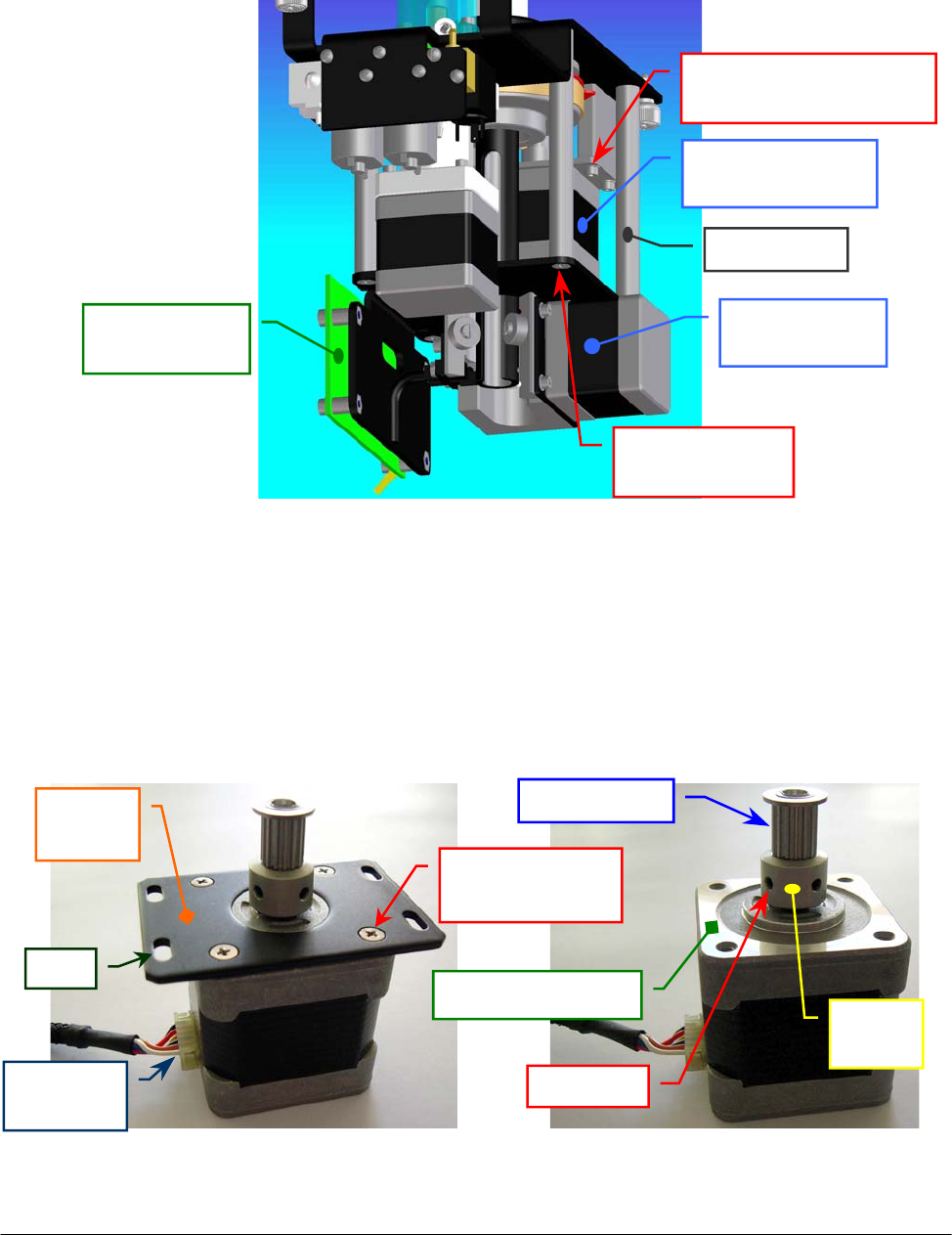
Chapter 05 – SETTINGS AND ADJUSTMENTS
SAT450 Service Manual Rev.00 03 July 2008 Page 9
5.1.4 Replacement of the Horizontal Mov. Arm Motor
1. Remove the Sampling Arm Assy from its housing performing the relative procedure described
into the previous Section 6.1.2, from step 1 to step 6.
2. Unplug the J7 connector from the Arm Interface Board (compare the sch. SC-30-02193-00).
3. Unscrew the four fastening screws of the Horizontal Mov. Arm Motor (Fig. 12).
4. Remove the belt from the pulley of the Horizontal Mov. Arm Motor and take out it from its
housing.
5. Unscrew the four fastening screws of the Horizontal Mov. Arm Motor anchor plate (Fig. 13)
and take out the anchor plate from the motor.
6. Loosen the two set screws of the pulley clamp and extract the pulley clamp and the pulley
(Fig. 14) from the motor shaft.
Fig. 13 – Horizontal Mov. Arm Motor
anchor plate
Fig. 14 – Horizontal Mov. Arm Motor
[P/N: 10-00399-00]
Anchor
plate
Anchor plate
fastening screw
Motor
p
ulle
y
Upper motor plane
Motor
connecto
r
Slot
Fig. 12 – Horizontal Mov. Arm Motor fastening screws
Pulley
clam
p
Set screw
Arm Interface
Board
Vertical Mov.
Arm Moto
r
Horizontal Mov.
Arm Moto
r
Horizontal Mov. Arm
Motor fastenin
g
screw
Spacing bar
fastenin
g
screw
S
p
acin
g
ba
r
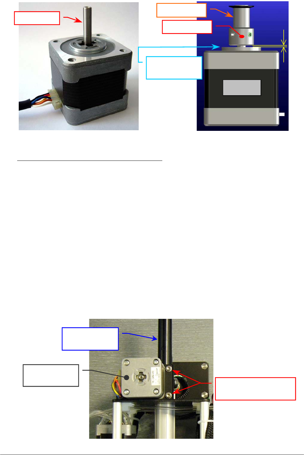
Chapter 05 – SETTINGS AND ADJUSTMENTS
SAT450 Service Manual Rev.00 03 July 2008 Page 10
To replace the new Horizontal Mov. Arm Motor (Fig. 15) perform the following steps:
7. Insert the pulley clamp completely on the motor pulley and then insert all two on the motor
shaft (Fig. 14).
8. Position the motor pulley to 1.00 mm with respect to circular upper motor plane (Fig. 16), then
tighten the two pulley clamp set screws (Fig. 14).
9. Position the anchor plate on the upper plane of the new Horizontal Mov. Arm Motor (Fig. 14)
with either anchor plate slots sides on the side of the motor connector (as showed in the
Fig. 13) and screw its four fastening screws.
10. Repeat the above steps in inverse order: from 4 to 2.
11. Replace the Sampling Arm Assy in its housing performing the relative procedure described
into the previous Section 6.1.2, from step 7 to step 10.
5.1.5 Replacement of the Vertical Mov. Arm Motor
1. Remove the Sampling Arm Assy from its housing performing the relative procedure described
into the previous Section 6.1.2, from step 1 to step 6.
2. Unplug the J4 connector from the Arm Interface Board (compare the scheme SC-30-02193-00).
3. Unscrew the four fastening screws of the Vertical Mov. Arm Motor (Fig. 17) and take out it
from its housing.
Fig. 17 – Vertical Mov. Arm Motor fastening screws
Vertical Mov. Arm
Motor fastening screws
Vertical Mov.
Arm Moto
r
Rack of the
Sampling Arm
Fig. 15 – Horizontal Mov. Arm Motor
[P/N: 10-00399-00]
Fig. 16 – Plate Motor (scheme)
Motor
Pulle
y
clam
p
Motor
p
ulle
y
1 m
m
Circular upper
motor plane
Motor shaft
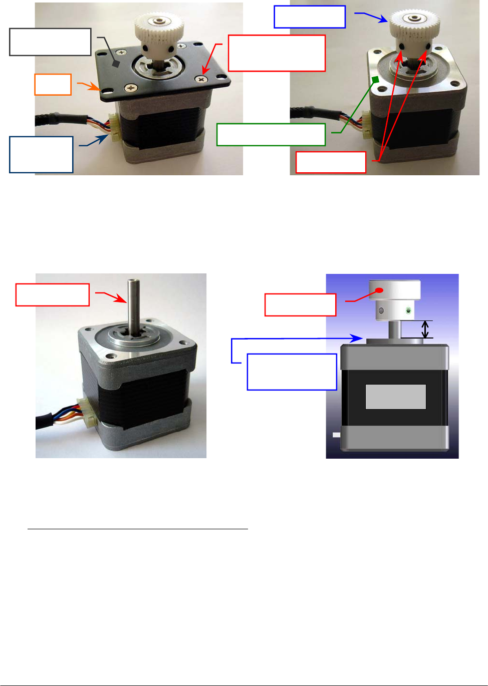
Chapter 05 – SETTINGS AND ADJUSTMENTS
SAT450 Service Manual Rev.00 03 July 2008 Page 11
4. Unscrew the four fastening screws of the Vertical Mov. Arm Motor anchor plate (Fig. 18) and
take out the anchor plate from the motor.
5. Loosen the two set screws of the motor gear (Fig. 19) and extract the gear from the motor shaft.
To replace the new Vertical Mov. Arm Motor (Fig. 20) perform the following steps:
6. Insert the gear on the motor shaft, position the gear to 7.00 mm with respect to circular upper
motor plane (Fig. 21), then tighten the two set screws of the gear (Fig. 19).
7. Position the anchor plate on the upper plane of the new Vertical Mov. Arm Motor (Fig. 19)
with either anchor plate slots sides on the side of the motor connector (as showed in the
Fig. 18) and screw its four fastening screws.
8. Replace the Vertical Mov. Arm Motor on its housing of the Sampling Arm Assy (Fig. 17).
9. Lean the gear of the Vertical Mov. Arm Motor on the rack of the Sampling Arm in order that
the tooths of the gear has a right grip on the rack (Fig. 22).
Fig. 18 – Vertical Mov. Arm Motor
anchor plate
Fig. 19 – Gear of the Vertical Mov.
Arm Motor
Anchor plate Anchor plate
fastening screw
Motor
g
ea
r
U
pp
er motor
p
lane
Slot
Motor
connecto
r
Fig. 20 – Vertical Mov. Arm Motor
[P/N: 10-00399-00]
Fig. 21 – Plate Motor (scheme)
Set screws
7 m
m
Motor
Circular upper
motor plane
Motor
g
ea
r
Motor shaft
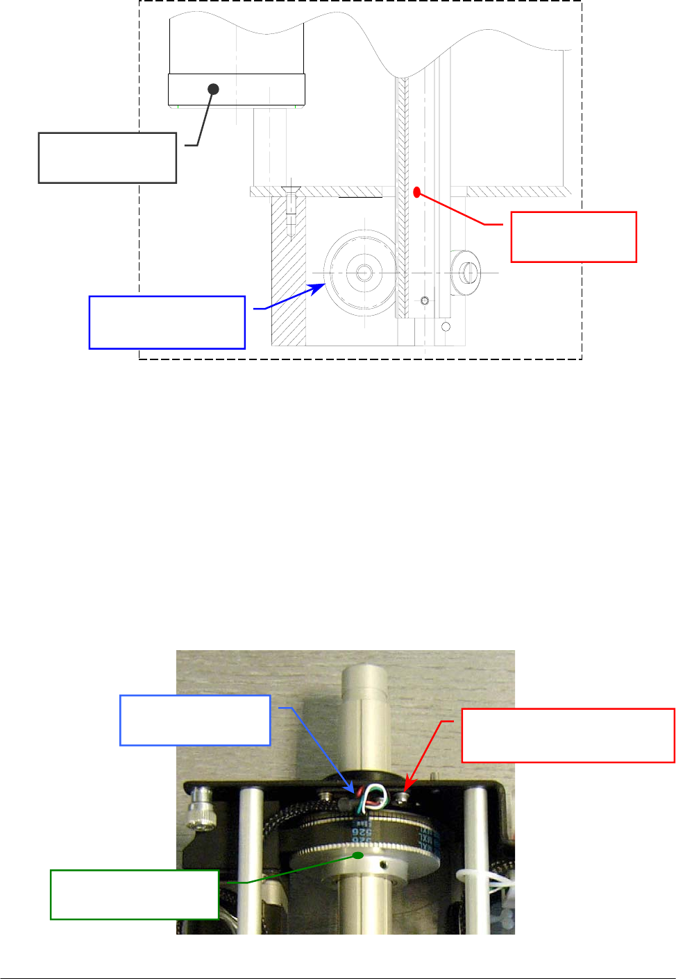
Chapter 05 – SETTINGS AND ADJUSTMENTS
SAT450 Service Manual Rev.00 03 July 2008 Page 12
Fig. 22 – Vertical Mov. Arm Motor gear lean on the rack (detail drawing)
10. Screw the four fastening screws of the Vertical Mov. Arm Motor (Fig. 17).
11. Plug the J4 connector in the Arm Interface Board (compare the scheme SC-30-02193-00).
12. Replace the Sampling Arm Assy in its housing performing the relative procedure described into
the previous Section 6.1.2, from step 7 to step 10.
5.1.6 Replacement of the Horizontal Mov. Arm Home Sensor
1. Remove the Sampling Arm Assy from its housing performing the relative procedure described
into the previous Section 6.1.2, from step 1 to step 6.
2. Unplug the J8 connector from the Arm Interface Board (compare the scheme SC-30-02193-00).
3. Unscrew the two fastening screws of the Horizontal Mov. Arm Home Sensor (Fig. 23) and take
out it from its housing.
Gear of the Vertical
Mov. Arm Moto
r
Rack of the
Sampling Arm
Horizontal Mov.
Arm Moto
r
Horizontal Mov. Arm Home
Sensor fastening screw
Horizontal Mov.
Arm Home Sensor
Pulley for the
Horizontal Mov. Arm
Fig. 23 – Horizontal Mov. Arm Home Sensor fastening screws

Chapter 05 – SETTINGS AND ADJUSTMENTS
SAT450 Service Manual Rev.00 03 July 2008 Page 13
4. Unscrew the two keep plate fastening screws of the Horizontal Mov. Arm Home Sensor
(Fig. 24) and take out the sensor from the keep plate.
To replace the new Horizontal Mov. Arm Home Sensor (Fig. 25) perform the following steps:
5. Position the keep plate below the Horizontal Mov. Arm Home Sensor with the keep plate side
proximal to the two central holes from the part of the threads of the sensor (as showed in the
Fig. 24), center the sensor with respect the keep plate and screw its two fastening screws.
6. Repeat the above steps in inverse order: from 3 to 2.
7. Replace the Sampling Arm Assy in its housing performing the relative procedure described into
the previous Section 6.1.2, from step 7 to step 10.
5.1.7 Replacement of the Vertical Mov. Arm Home Sensor
1. Make sure that the SAT450 instrument is turned off.
2. Unscrew the two captive screws on the front underside of the instrument (Fig. 6) and lift up the
Raising Top (Fig. 7).
3. Unplug the J1, J2, J3, J6 connectors and the ground wire from the Arm Interface Board
(compare the scheme SC-30-02193-00).
4. Unscrew the four fastening screws of the Arm Interface Board (Fig. 9) and push upward it.
5. Introduce the setscrew wrench in the eyelet of the Arm Interface Board mechanical support
(Fig. 26), unscrew the two fastening screws of the Vertical Mov. Arm Home Sensor
(Fig. 27) and take out it from its housing.
6. Unscrew the two keep plate fastening screws of the Vertical Mov. Arm Home Sensor
(Fig. 28) and take out the sensor from the keep plate.
Fig. 24 – Keep plate fastening screws
of the Horizontal Mov. Arm
Home Sensor
Fig. 25 – Horizontal Mov. Arm Home Sensor
[P/N: 9-10-0023-20]
Keep plate
Keep plate
fastenin
g
screw
Horizontal Mov.
Arm Home Senso
r
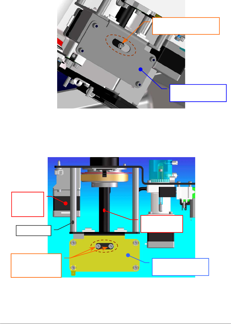
Chapter 05 – SETTINGS AND ADJUSTMENTS
SAT450 Service Manual Rev.00 03 July 2008 Page 14
Fig. 26 – Arm Interface Board mechanical support
Arm Interface Board
mechanical support
S
p
acin
g
ba
r
Rack of the
Sampling Arm
Horizontal
Mov. Arm
Moto
r
Fig. 27 – Vertical Mov. Arm Home Sensor fastening screws
Arm Interface Board
mechanical support
Vertical Mov. Arm Home
Sensor fastenin
g
screw
Vertical Mov.
Arm Home Sensor
fastening screws
E
y
elet
E
y
elet
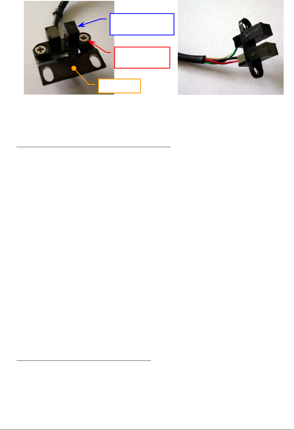
Chapter 05 – SETTINGS AND ADJUSTMENTS
SAT450 Service Manual Rev.00 03 July 2008 Page 15
To replace the new Vertical Mov. Arm Home Sensor (Fig. 29) perform the following steps:
7. Position the keep plate below the Vertical Mov. Arm Home Sensor as showed in the Fig. 28,
center the sensor with respect to the keep plate and screw its two fastening screws.
8. Repeat the above steps in inverse order: from 5 to 2.
9. Perform the procedure “Alignments and adjustments of the Sampling Probe” described into the
previous Section 6.1.1.
5.1.8 Replacement of the Horizontal Mov. Arm Belt
1. Remove the Sampling Arm Assy from its housing performing the relative procedure described
into the previous Section 6.1.2, from step 1 to step 6.
2. Unscrew the four fastening screws of the Vertical Mov. Arm Motor (Fig. 30) and take out it
from its housing.
3. Loosen the four fastening screws of the Horizontal Mov. Arm Motor (Fig. 30).
4. Let flow the Horizontal Mov. Arm Motor in the direction of the Horizontal Mov. Arm Pulley
(Fig. 30) and remove the belt from the Horizontal Mov. Arm Motor Pulley.
5. Pull out the home sensor small flag from the Vertical Mov. Arm Home Sensor (Fig. 30), rotate
the rack of the Sampling Arm and push it through the aperture of the Arm Interface Board
mechanical support (Fig. 30).
6. Take out the Horizontal Mov. Arm Belt from the rack of the Sampling Arm.
To replace the new Horizontal Mov. Arm Belt (Fig. 31) perform the following steps:
7. Wrap the new belt around the Horizontal Mov. Arm Pulley and around the Horizontal Mov.
Arm Motor Pulley, let flow the motor in the opposite direction of the Horizontal Mov. Arm
Pulley, then tighten the four fastening screws of the motor.
8. Insert the rack of the Sampling Arm in the aperture of the Arm Interface Board mechanical
support (Fig. 30), rotate the rack and pull the home sensor small flag in the Vertical Mov. Arm
Home Sensor (Fig. 30).
Fig. 28 – Keep plate fastening screws
of the Vertical Mov. Arm
Home Sensor
Fig. 29 – Vertical Mov. Arm Home Sensor
[P/N: 9-10-0024-00]
Keep plate
Vertical Mov.
Arm Home Sensor
Keep plate
fastenin
g
screw
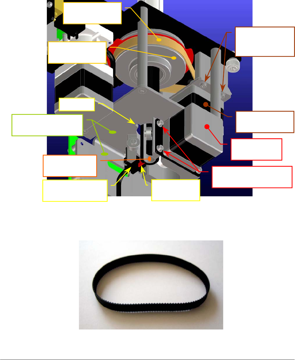
Chapter 05 – SETTINGS AND ADJUSTMENTS
SAT450 Service Manual Rev.00 03 July 2008 Page 16
9. Replace the Vertical Mov. Arm Motor in its housing performing the relative procedure
described into the previous Section 6.1.5, from step 8 to step 10.
10. Turn the Horizontal Mov. Arm Pulley and make sure that the new belt thoots are correctly
inserted on the Horizontal Mov. Arm Pulley and on the Horizontal Mov. Arm Motor Pulley.
11. Replace the Sampling Arm Assy in its housing performing the relative procedure described
into the previous Section 6.1.2, from step 7 to step 10.
Fig. 31 – Horizontal Mov. Arm Belt [P/N: 86-01514-36]
Fig. 30 – Horizontal Mov. Arm Belt and rack of the Sampling Arm
Vertical Mov.
Arm Motor
Horizontal Mov.
Arm Motor
Horizontal Mov.
Arm Belt
Vertical Mov.
Arm Home Senso
r
Rack of the
Sam
p
lin
g
Ar
m
Vertical Mov. Arm
Motor fastenin
g
screws
Horizontal Mov.
Arm Motor
fastenin
g
screws
A
p
erture
Arm Interface Board
mechanical su
pp
ort
Horizontal Mov.
Arm Pulle
y
Home sensor
small fla
g
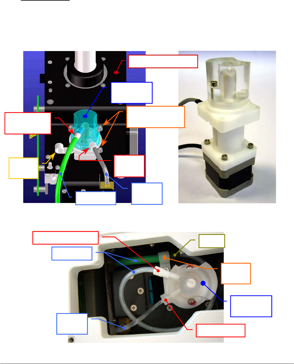
Chapter 05 – SETTINGS AND ADJUSTMENTS
SAT450 Service Manual Rev.00 03 July 2008 Page 17
5.2 DILUTER
5.2.1 Replacement of the Diluter Assy
1. Remove the Sampling Arm Assy from its housing performing the relative procedure
described into the previous Section 6.1.2, from step 1 to step 6.
2. Unscrew the screw of the tube holder (Fig. 32) and remove the Pre-heater tube from it.
3. Unscrew the “Pre-heater” fitting and the “EV1” fitting from the head of the Diluter (Fig. 32),
making attention to the spillage of liquid from the tubes.
4. Unplug the J9 and J10 connectors from the Arm Interface Board (compare the scheme
SC-30-02193-00).
5. Unscrew the other three fastening screws of the Diluter (Fig. 32) and take out it from its
housing on the Sampling Arm Assy.
Fig. 32 – Diluter fastening screws Fig. 33 – Diluter Assy [P/N: 10-00496-02]
Diluter
fastenin
g
screws
Head of
the Diluter
“Pre-heater”
fittin
g
Tube
holde
r
Ref. 11
tube
Pre-heater
“EV1”
fitting
Sam
p
lin
g
Arm Ass
y
Fig. 34 – Head of the Diluter
Pre-heater
Ref. 11
tube
“Pre-heater” fittin
g
“EV1” fittin
g
Head of
the Diluter
Tube
holde
r
Sheat
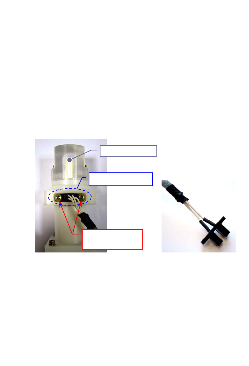
Chapter 05 – SETTINGS AND ADJUSTMENTS
SAT450 Service Manual Rev.00 03 July 2008 Page 18
To replace the new Diluter Assy (Fig. 33) perform the following steps:
6. Repeat the above steps in inverse order: from 5 to 4.
7. Replace the Pre-heater tube around the head of the Diluter as showed in the Fig. 34, push its
piece of the sheat in the tube holder and screw the tube holder screw.
8. Screw the “Pre-heater” fitting and the “EV1” fitting on the head of the Diluter (Fig. 34).
9. Replace the Sampling Arm Assy in its housing performing the relative procedure described
into the previous Section 6.1.2, from step 7 to step 10.
10. Perform the “Backlash Procedure” described into the previous Section 5.9.2.
5.2.2 Replacement of the Diluter Home Sensor
1. Remove the Diluter Assy performing the relative procedure described into the previous
Section 6.2.1, from step 1 to step 5.
2. Unscrew the two fastening screws of the Diluter Home Sensor (Fig. 35) and take out it from
its housing in the Diluter.
To replace the new Diluter Home Sensor (Fig. 36) perform the following steps:
3. Replace the home sensor in its housing in the Diluter as showed in the Fig. 35 and screw its
two fastening screws (Fig. 35).
4. Replace the Diluter Assy performing the relative procedure described into the previous
Section 6.2.1, from step 6 to step 9.
Fig. 35 – Diluter Home Sensor
fastening screws
Fig. 36 – Diluter Home Sensor
[P/N: 9-10-0024-00]
Diluter Home Sensor
fastening screws
Diluter Home Sensor
Head of the Dilute
r
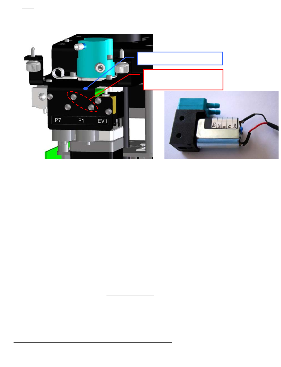
Chapter 05 – SETTINGS AND ADJUSTMENTS
SAT450 Service Manual Rev.00 03 July 2008 Page 19
5.2.3 Replacement of the Diluter Micropump (P1)
1. Remove the Sampling Arm Assy from its housing performing the relative procedure
described into the previous Section 6.1.2, from step 1 to step 6.
2. Unplug the J13 connector from the Arm Interface Board (compare the sch. SC-30-02193-00).
3. Remove the tubes with Ref. 5 and 31 from the “P1” Diluter Micropump (compare the scheme
SI-16-01873-00), making attention to the spillage of the Probe Rinse solution from the tubes
(note: the Probe Rinse solution is NOT a dangerous liquid).
4. Unscrew the two fastening screws of the “P1” Diluter Micropump (Fig. 37) and take out it
from the Diluter mechanical support.
To replace the new “P1” Diluter Micropump (Fig. 38) perform the following steps:
5. Compare the scheme MA-15-02339-00 and repeat the above steps in inverse order: from 4 to 2.
6. Replace the Sampling Arm Assy in its housing performing the relative procedure described
into the previous Section 6.1.2, from step 7 to step 10.
5.2.4 Replacement of the Arm Washing Well Micropump (P7)
1. Remove the Sampling Arm Assy from its housing performing the relative procedure
described into the previous Section 6.1.2, from step 1 to step 6.
2. Unplug the J11 connector from the Arm Interface Board (compare the sch. SC-30-02193-00).
3. Remove the tubes with Ref. 5 and 31 from the “P7” Arm Washing Well Micropump (compare
the scheme SI-16-01873-00), making attention to the spillage of the Probe Rinse solution
from the tubes (note: the Probe Rinse solution is NOT a dangerous liquid).
4. Unscrew the two fastening screws of the “P7” Arm Washing Well Micropump (Fig. 39) and
take out it from the Diluter mechanical support.
To replace the new “P7” Arm Washing Well Micropump (Fig. 40) perform the following steps:
5. Compare the scheme MA-15-02339-00 and repeat the above steps in inverse order: from 4 to 2.
Fig. 37 – « P1 » Diluter Micropump
fastenin
g
screws
Fig. 38 – « P1 » Diluter Micropump
[P/N: 05-01710-40]
«P1» Diluter Micropump
fastenin
g
screws
Diluter mechanical support
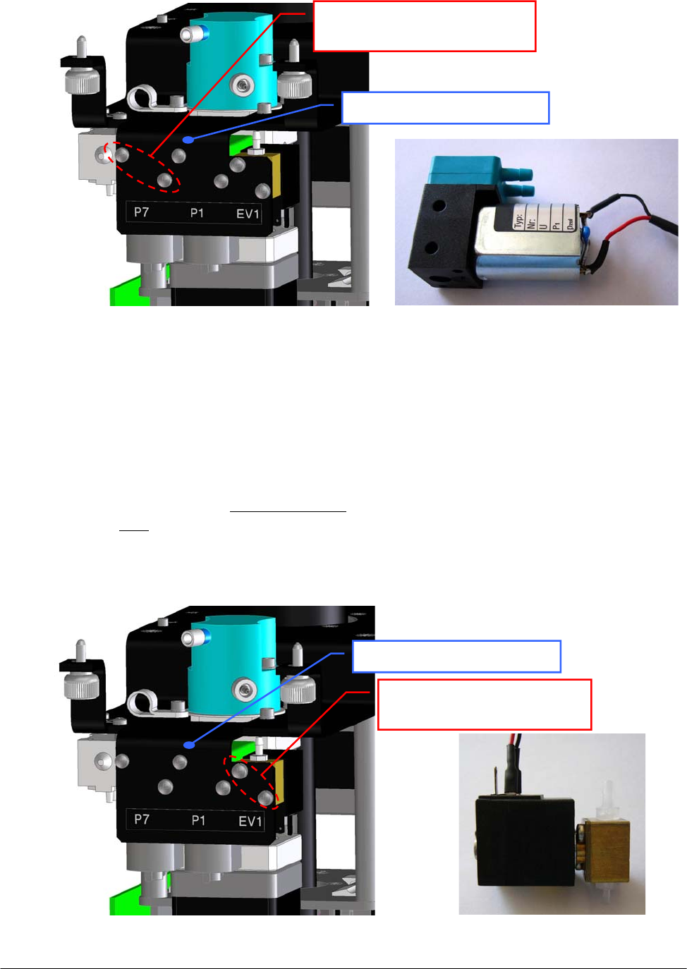
Chapter 05 – SETTINGS AND ADJUSTMENTS
SAT450 Service Manual Rev.00 03 July 2008 Page 20
6. Replace the Sampling Arm Assy in its housing performing the relative procedure described
into the previous Section 6.1.2, from step 7 to step 10.
5.2.5 Replacement of the Diluter Electrovalve (EV1)
1. Remove the Sampling Arm Assy from its housing performing the relative procedure
described into the previous Section 6.1.2, from step 1 to step 6.
2. Unplug the J12 connector from the Arm Interface Board (compare the sch. SC-30-02193-00).
3. Remove the tubes with Ref. 11 and 13 from the “EV1” Diluter Electrovalve (compare the
scheme SI-16-01873-00), making attention to the spillage of the Probe Rinse solution from
the tubes (note: the Probe Rinse solution is NOT a dangerous liquid).
4. Unscrew the two fastening screws of the “EV1” Diluter Electrovalve (Fig. 41) and take out it
from the Diluter mechanical support.
Fig. 41 – “EV1” Diluter Electrovalve
fastenin
g
screws
Fig. 42 – “EV1” Diluter Electrovalve
[P/N: 05-00700-48]
Fig. 39 – « P7 » Arm Washing Well
Micro
p
um
p
fastenin
g
screws
Fig. 40 – « P7 » Arm W. Well Micropump
[P/N: 05-02685-35]
«P7» Arm W.W. Micropump
fastenin
g
screws
Diluter mechanical support
“EV1” Diluter Electrovalve
fastenin
g
screws
Diluter mechanical support
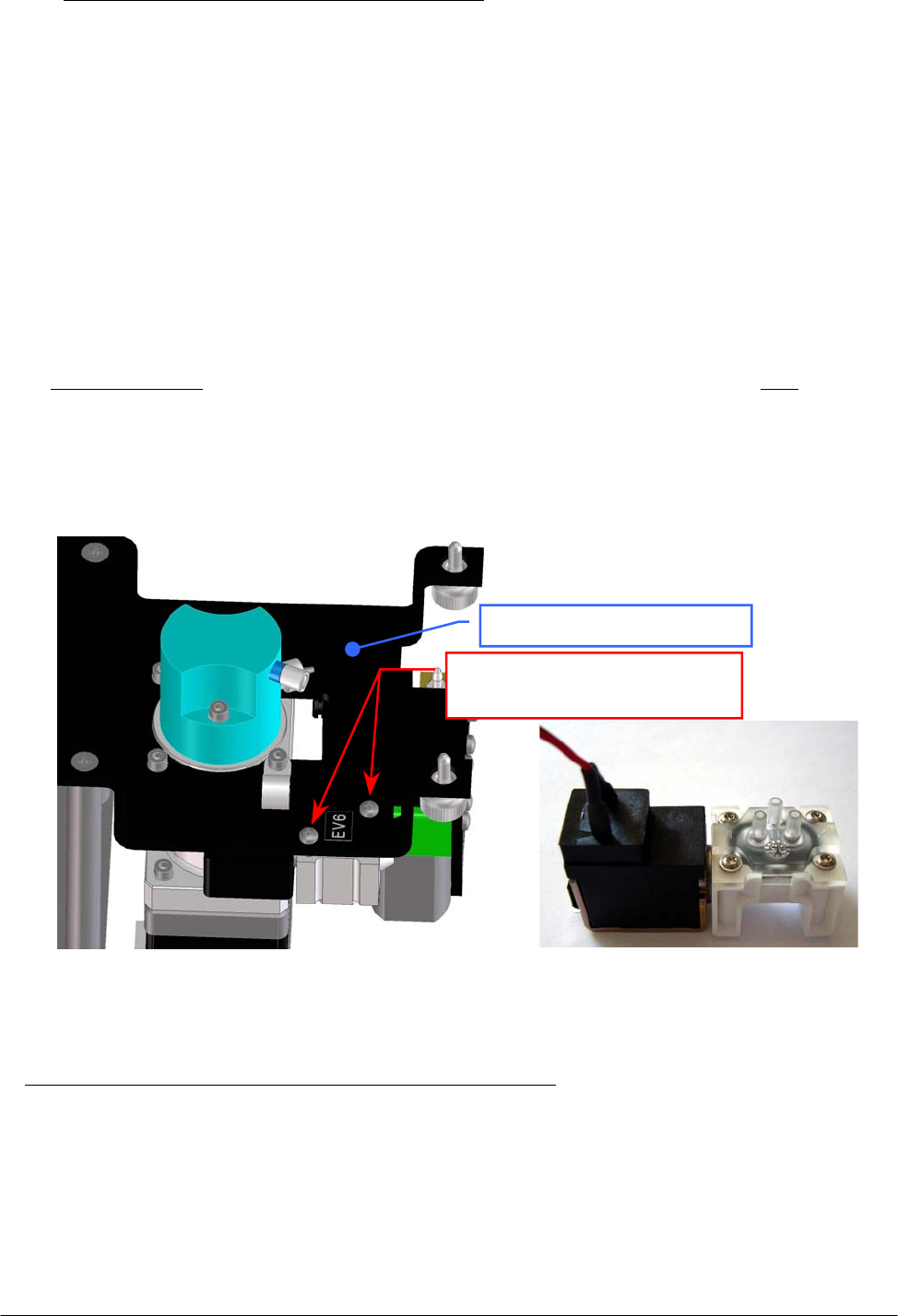
Chapter 05 – SETTINGS AND ADJUSTMENTS
SAT450 Service Manual Rev.00 03 July 2008 Page 21
To replace the new “EV1” Diluter Electrovalve (Fig. 42) perform the following steps:
5. Compare the scheme MA-15-02339-00 and repeat the above steps in inverse order: from 4 to 2.
6. Replace the Sampling Arm Assy in its housing performing the relative procedure described
into the previous Section 6.1.2, from step 7 to step 10.
5.2.6 Replacement of the Arm Washing Well Electrovalve (EV6)
1. Remove the Sampling Arm Assy from its housing performing the relative procedure described
into the previous Section 6.1.2, from step 1 to step 6.
2. Unplug the J14 connector from the Arm Interface Board (compare the sch. SC-30-02193-00).
3. Remove the tube with Ref. 32, the tube with “16” label text and the tube with “17” label text
from the “EV6” Arm Washing Well Electrovalve (compare the scheme SI-16-01873-00),
making attention to the spillage of the Probe Rinse solution from the tubes (note: the Probe
Rinse solution is NOT a dangerous liquid).
4. Unscrew the two fastening screws of the “EV6” Arm Washing Well Electrovalve (Fig. 43) and
take out it from the Diluter mechanical support.
To replace the new “EV6” Arm Washing Well Electrovalve (Fig. 44) perform the following steps:
5. Compare the scheme MA-15-02339-00 and repeat the above steps in inverse order: from 4 to 2.
6. Replace the Sampling Arm Assy in its housing performing the relative procedure described into
the previous Section 6.1.2, from step 7 to step 10.
Fig. 43 – “EV6” Arm Washing Well
Electrovalve fastening screws
Fig. 44 – “EV6” Arm W. Well Electrovalve
[P/N: 05-02630-25]
“EV6” Arm Washing Well
Electrovalve fastenin
g
screws
Diluter mechanical support
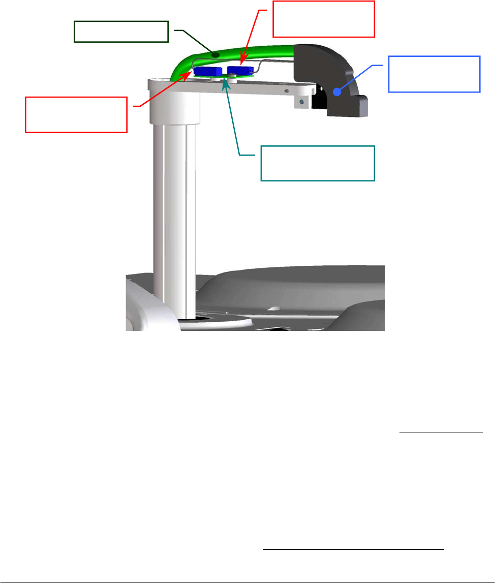
Chapter 05 – SETTINGS AND ADJUSTMENTS
SAT450 Service Manual Rev.00 03 July 2008 Page 22
5.3 PRE-HEATER
5.3.1 Replacement of the Pre-Heater Assy
1. Remove the Sampling Probe from its housing performing the relative procedure described into
the previous Section 6.1.3.
2. Remove the Sampling Arm cover (Fig. 7).
3. Unscrew the Probe adjustment screw places on the Sampling Arm head (Fig. 3).
4. Unplug the J1 and J2 connectors of the Pre-Heater from the Level Sensor Board (compare the
scheme SC-30-02193-00 and the Fig. 45).
5. Unscrew the two fastening screws of the Diluter cover (Fig. 7) and remove it from its housing.
6. Unscrew the tube holder screw (Fig. 32) and remove the Pre-Heater tube from it.
7. Unscrew the “Pre-Heater” fitting from the head of the Diluter (Fig. 32) – making attention to
the spillage of liquid from the tube – and move inside the instrument the relative part of the
Pre-Heater tube.
8. Unscrew the two captive screws on the front underside of the instrument (Fig. 6) and lift up the
Raising Top (Fig. 7).
9. Unplug the J3 connector of the Pre-Heater from the J15 connector of the Arm Interface Board
(compare the scheme SC-30-02193-00 and the Fig. 46).
10. Take out the seven wires of the Pre-Heater (read the relative note of the Fig. 51) from the
J3 connector (Fig. 47) and remove it.
Fig. 45 – Head of the Samplin
g
Arm
Sampling Arm
hea
d
Level Sensor Board
[P/N: 30-02365-00]
Pre-Heater tube
J1 connector
of the Pre-Heate
r
J2 connector
of the Pre-Heate
r
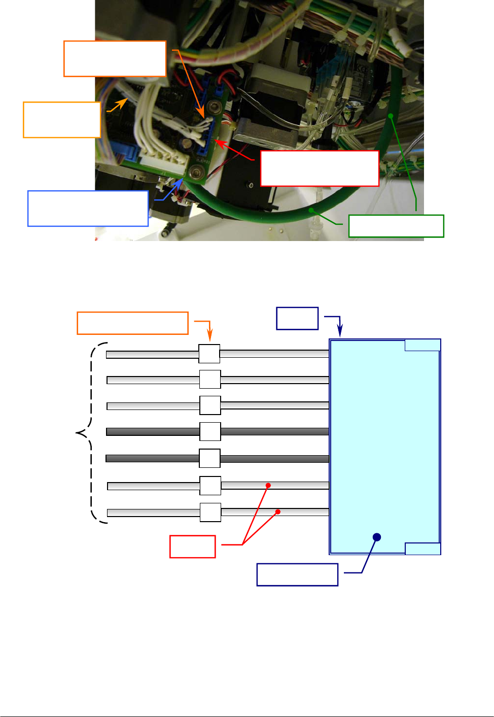
Chapter 05 – SETTINGS AND ADJUSTMENTS
SAT450 Service Manual Rev.00 03 July 2008 Page 23
11. Pull the Pre-Heater (tube and wires) up along the interior side of the Sampling Arm vertical
axis ( Fig. 48 (a) and Fig. 48 (b) ) until it is completely outside of the Sampling Arm.
Fig. 46 – J15 connector of the Arm Interface Board
Pre-Heater tube
Arm Interface Board
[P/N: 30-02193-00]
J15 connector of the
Arm Interface Boar
d
J3 connector
of the Pre-Heate
r
Wires of the
Pre-Heate
r
Fig. 47 – Connection scheme of the J3 connector of the Pre-Heater
1
2
3
4
5
6
7
1
2
3
4
5
6
7
8
# Pin
Labels of the wires
J3 connecto
r
n. 7 wires
Wires
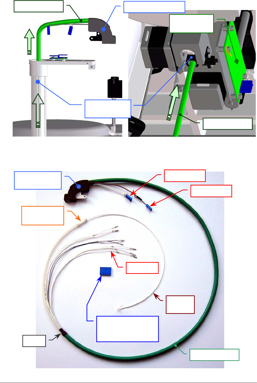
Chapter 05 – SETTINGS AND ADJUSTMENTS
SAT450 Service Manual Rev.00 03 July 2008 Page 24
Fig. 48 [(a), (b)] – Extraction of the Pre-Heater from the Sampling Arm
(a) – Outside of the instrument (b) – Inside of the instrument
Pre-Heater tube
Arm Interface
Boar
d
Fig. 49 – Pre-Heater Assy [P/N: 10-02335-00]
Sampling Arm
vertical axis
Pre-Heater tube Sam
p
lin
g
Arm hea
d
Pre-Heater tube
Sampling Arm
hea
d
J1 connector
J2 connector
Eight positions
single row connector
(
J3 connector
)
“Pre-Heater”
fittin
g
Sheat
n.7 wires
Driving
wire
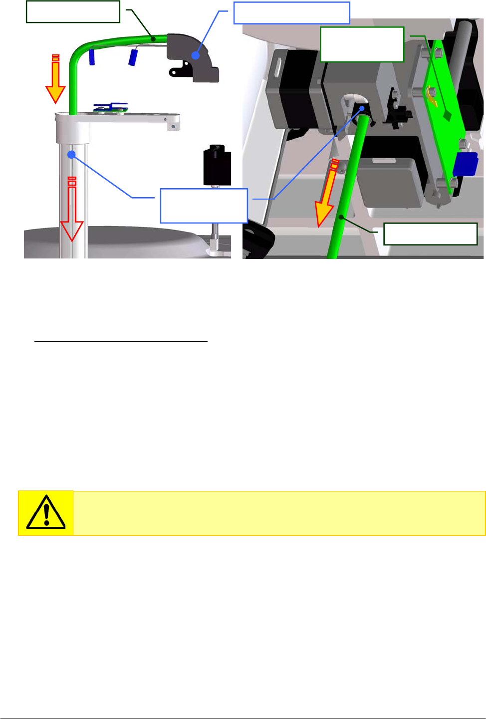
Chapter 05 – SETTINGS AND ADJUSTMENTS
SAT450 Service Manual Rev.00 03 July 2008 Page 25
To replace the new Pre-Heater Assy (Fig. 49) perform the following steps:
12. Pull the Pre-Heater (tube and wires) in the interior side of the Sampling Arm vertical axis
(as showed in Fig. 50(a) and in Fig. 50(b) ) until you reach the placement showed in Fig. 45.
13. Screw the Probe adjustment screw places on the Sampling Arm head (Fig. 3).
14. Plug the J1 and J2 connectors of the Pre-Heater (Fig. 49) in the J1 and J2 connectors –
respectively – of the Level Sensor Board (compare the sch. SC-30-02193-00 and the Fig. 45).
15. Replace the Sampling Arm cover (Fig. 2).
16. Plug the seven wires of the Pre-Heater (Fig. 49) in the eight positions single row connector
following the connection scheme showed in Fig. 47.
17. Plug the J3 connector of the Pre-Heater in the J15 connector of the Arm Interface Board
(compare the scheme SC-30-02193-00 and the Fig. 46).
18. Take the part of the Pre-Heater tube with the fitting near the head of the Diluter.
19. Bring down the Raising Top (Fig. 7) and screw the two captive screws on the front underside
of the instrument (Fig. 6).
20. Extract the driving wire (Fig. 49) from the Pre-Heater.
21. Replace the Pre-Heater tube around the head of the Diluter as showed in Fig. 34, push its
piece of the sheat in the tube holder and screw the tube holder screw.
Fig. 50 [(a), (b)] – Replacement of the Pre-Heater in the Sampling Arm
(a) – Outside o
f
the instrument (b) – Inside of the instrument
Pre-Heater tube
Arm Interface
Boar
d
Sampling Arm
vertical axis
Pre-Heater tube Sam
p
lin
g
Arm hea
d
Each of the seven contacts of the wires must be inserted into the relative position
of the single row connector as showed in Fig. 51 until to fix it inside the
connector.
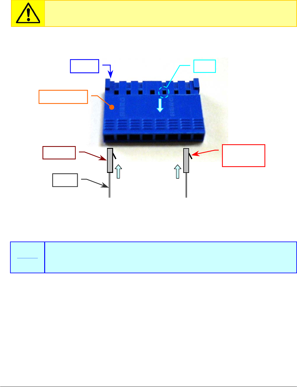
Chapter 05 – SETTINGS AND ADJUSTMENTS
SAT450 Service Manual Rev.00 03 July 2008 Page 26
22. Screw the “Pre-Heater” fitting on the head of the Diluter (Fig. 34).
23. Replace the Diluter cover in its housing (Fig. 7) and screw its two fastening screws.
24. Replace the Sampling Probe performing the relative procedure described into the previous
Section 6.1.3, from step 5 to step 10.
Make sure that the movement of the Pre-Heater tube inside the instrument during
the operative phase of the Sampling Arm is not thwarted.
. . . . . . . . .
Fig. 51 – Replacement of the seven wires in the J3 connector of the Pre-Heater
J3 connecto
r
PIN 1
Tongue of
the contact
Contact
Wire
In order to exctract a wire from the J3 connector, insert a needlepoint in the
correspondent slot of the connector, press the tongue toward the contact and
take out the wire (Fig. 51).
Fig. 51
Note
Slot
To re
p
lace To re
p
lace
To exctrac
t
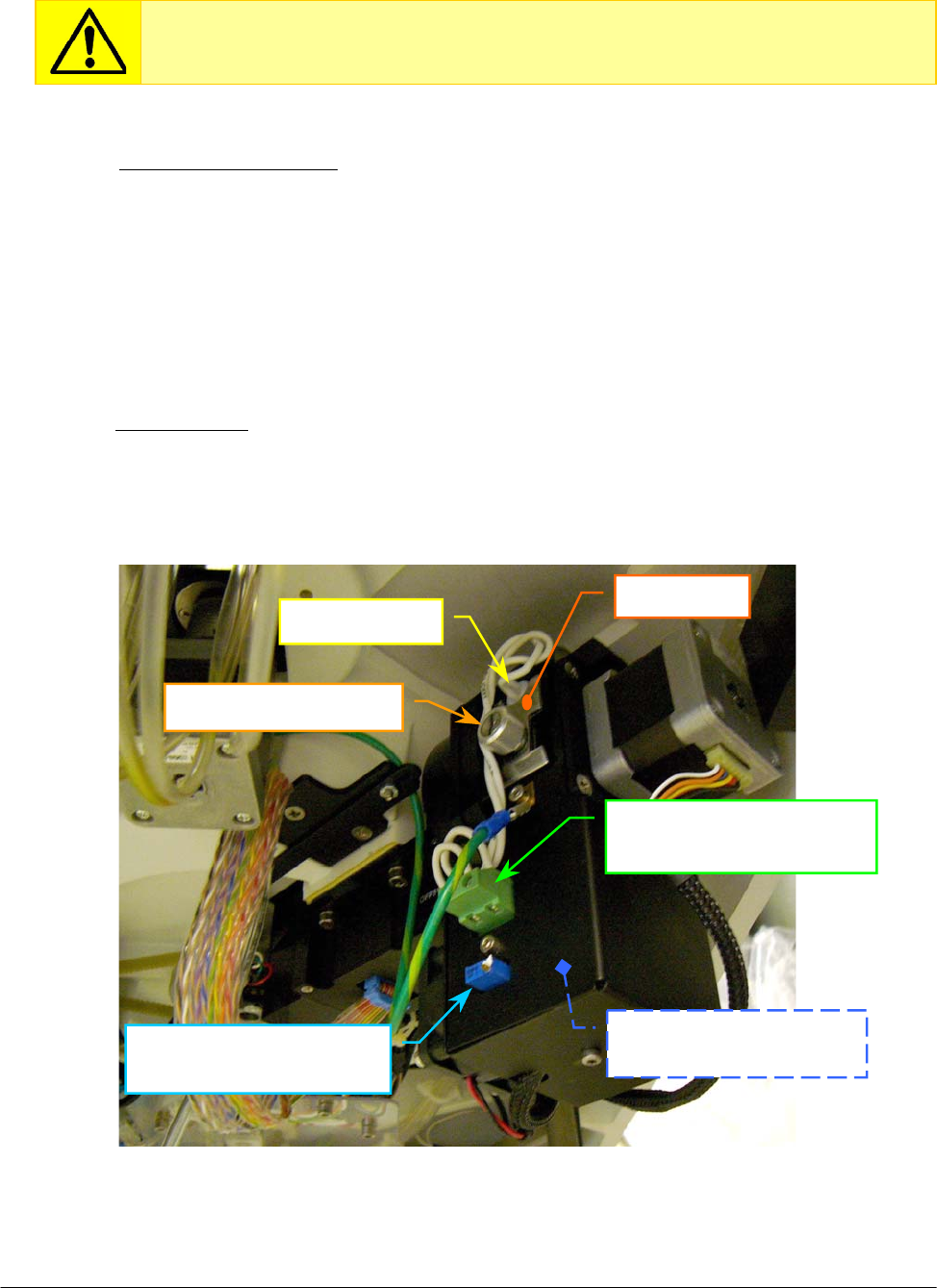
Chapter 05 – SETTINGS AND ADJUSTMENTS
SAT450 Service Manual Rev.00 03 July 2008 Page 27
5.4 PHOTOMETER
5.4.1 Electronic adjustments of the Photometer
1. Turn on the SAT450 system (instrument and computer) and launch the Diagnostic program.
2. Select "Miscellaneous” folder and request an Instrument General reset. Wait until the reset
instrument procedure has been completed.
3. Make sure that all the Home Sensors of the Sampling Arm, Reactions Plate, Reagents Plate,
Samples Plate and the Filters Wheel light up in green.
4. Remove the Reactions Plate cover (Fig. 7) and place 500 µL of distilled water in the
cuvette # 1 of the Reactions Plate.
5. Replace the Reactions Plate cover (Fig. 7) on its plate (in order to avoid external interferences
of light in the reading).
6. Select “Optic” folder and verify that the Photometer Halogen Lamp is in “ON” state.
7. Make sure that the voltage on the J2 connector of the “Photometer Lamp Board” (Fig. 52) is
equal to 5.8 Volts ± 0.1 . If it not be so, turn the R6 trimmer (Fig. 52) for adjusting the voltage.
Make sure that the Photometer Halogen Lamp and the Reactions Plate cuvettes
are brand-new before applying the following electronic adjustments procedure.
Lamp fastening screw
Halogen lamp
J2 connector of the
Photometer Lamp Board
R6 trimmer of the
Photometer Lam
p
Board
Photometer Lamp Board
[P/N: 30-01576-00]
Fi
g
. 52 – Photometer [P/N: 15-02448-00]
Kee
p
p
late
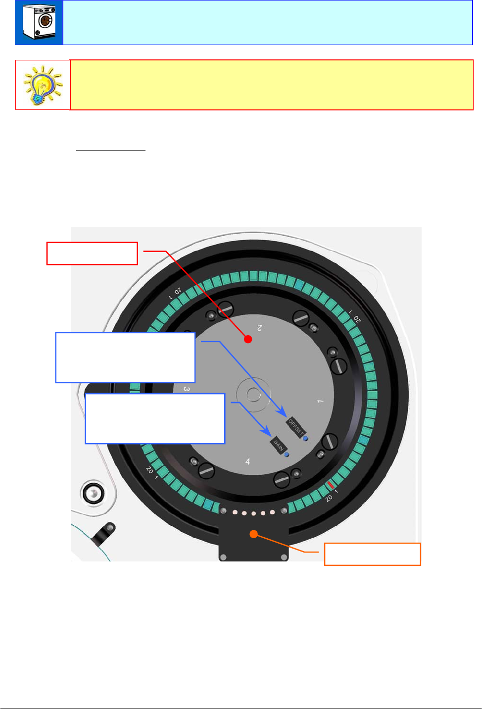
Chapter 05 – SETTINGS AND ADJUSTMENTS
SAT450 Service Manual Rev.00 03 July 2008 Page 28
8. Click the “Dark” button, click the "START Sample Channel Conversion" button and make
sure that the adjacent text box shows a counts value equal to 100 ± 50. If it not be so, turn the
OFFSET trimmer of the “Pre-Ampl./ADC Board (Sample Channel)” in order to set the
correct counts value (Fig. 53).
Fig. 53 – GAIN and OFFSET trimmers of the “Pre-Ampl./ADC Board” (Sample Channel)
9. After have to carry out the Sample Channel OFFSET adjusting, click the "STOP Sample
Channel Conversion" button.
10. Click the "START Reference Channel Conversion" button (in the “Dark” position) and
make sure that the adjacent text box shows a counts value equal to 100 ± 50. If it not be so,
turn the OFFSET trimmer of the “Pre-Ampl./ADC Board (Reference Channel)” in order to
set the correct counts value (Fig. 61).
Make sure that the Reactions Plate cuvettes are perfectly clean. If it not be so,
perform the “Washing cuvettes” operation (form “Start Work”).
OFFSET trimmer of the
“Pre-Ampl./ADC Board”
(Sample Channel)
GAIN trimmer of the
“Pre-Ampl./ADC Board”
(Sample Channel)
Reactions Plate
Washing Station
The electric light and the daylight can influence the readings of the Photometer.
Therefore, bring down the Raising Top and close the Reactions Plate with its
cover (Fig. 7) before to perform the reading operations.

Chapter 05 – SETTINGS AND ADJUSTMENTS
SAT450 Service Manual Rev.00 03 July 2008 Page 29
11. After have to carry out the Reference Channel OFFSET adjusting, click the "STOP Reference
Channel Conversion" button.
12. Determine the filter which transmits the highest signal (for the Sample Channel), selecting all
buttons of the filters (from 340 nm to 690 nm) and, for each one of them, performing
the following steps:
a. click the ”START Sample Channel Conversion" button;
b. read the counts value showed in the adjacent text box;
c. click the ”STOP Sample Channel Conversion" button.
13. Make sure that the counts value of the filter which transmits the highest signal (for the
Sample Channel) is between 58.000 and 62.000. If it not be so, turn the GAIN trimmer of
the “Pre-Ampl./ADC Board (Sample Channel)” in order to set the correct counts value
(Fig. 53).
14. Select all buttons of the filters (from 340 nm to 690 nm) and, for each one of them, performing
the following steps:
a. click the ”START Sample Channel Conversion" button;
b. make sure that the counts value showed in the adjacent text box is between 29.000 and 62.000 ;
c. click the ”STOP Sample Channel Conversion" button.
15. Determine the filter which transmits the highest signal (for the Reference Channel), selecting
all buttons of the filters (from 340 nm to 690 nm) and, for each one of them, performing
the following steps:
a. click the ”START Reference Channel Conversion" button;
b. read the counts value showed in the adjacent text box;
c. click the ”STOP Reference Channel Conversion" button.
16. Make sure that the counts value of the filter which transmits the highest signal (for the
Reference Channel) is between 53.000 and 57.000. If it not be so, turn the GAIN trimmer of
the “Pre-Ampl./ADC Board (Reference Channel)” in order to set the correct counts value
(Fig. 62).
17. Select all buttons of the filters (from 340 nm to 690 nm) and, for each one of them, performing
the following steps:
a. click the ”START Reference Channel Conversion" button;
b. make sure that the counts value showed in the adjacent text box is between 35.000 and 57.000 ;
c. click the ”STOP Reference Channel Conversion" button.
18. Remove the Reactions Plate cover (Fig. 7), empty the cuvette # 1 of the Reactions Plate and
replace the Reactions Plate cover on its plate.
19. Click the “Exit” button to exit from the Diagnostic program.
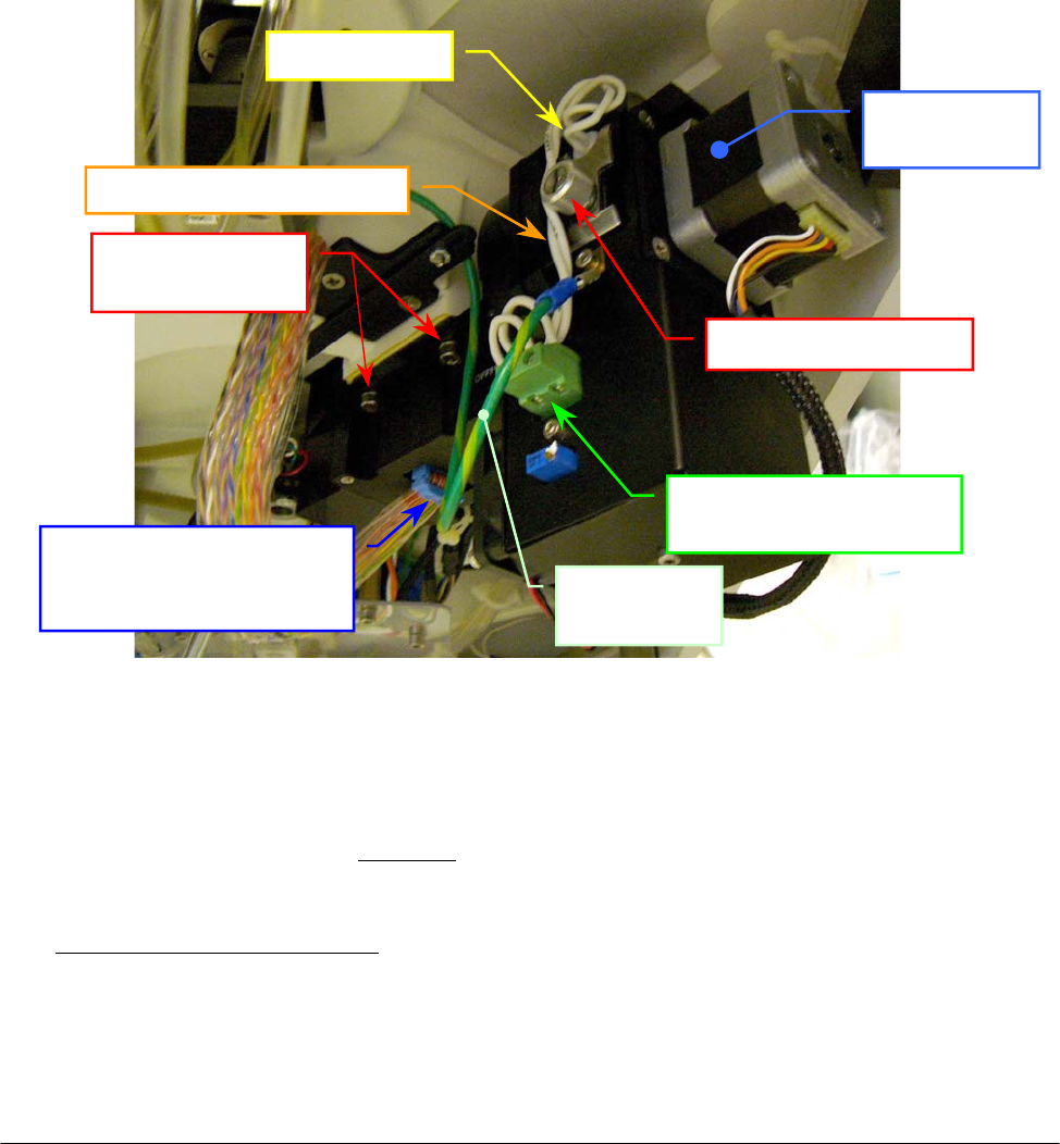
Chapter 05 – SETTINGS AND ADJUSTMENTS
SAT450 Service Manual Rev.00 03 July 2008 Page 30
5.4.2 Replacement of the Optic Assy
1. Make sure that the SAT450 instrument is turned off.
2. Unscrew the two captive screws on the front underside of the instrument (Fig. 6) and lift up the
Raising Top (Fig. 7).
3. Unplug the J4, J5, J18 and J19 connectors from the Reactions Plate Interface Board (compare
the scheme SC-30-02192-00).
4. Unplug the flat cable connector from the “Pre-Ampl./ADC Board (Sample Channel)”, the flat
cable connector from the “Pre-Ampl./ADC Board (Reference Channel)” and the ground wire
from the Photometer (Fig. 54).
5. Unscrew the four Photometer fastening screws (Fig. 54), pull down – moving carefully – the
Photometer from its housing and take out it from the instrument.
Fig. 54 – Photometer [P/N: 15-02448-00]
6. Unscrew the two screws of the J2 connector (Fig. 54) and take out the two halogen lamp
wires from the connector.
7. Unscrew the two fastening screws of the “Photometer Lamp Board” cover (Fig. 62) and take
out it from the Photometer (note well: in this mode – contemporaneously – take out from the
Photometer the “Photometer Lamp Board” and the Photometer Fan obtaining the Optic Assy).
To replace the new Optic Assy [P/N: 10-02449-00] perform the following steps:
8. Repeat the above steps in inverse order: from 7 to 2.
9. Perform the procedure “Electronic adjustment of the Photometer” described into the previous
Section 6.4.1.
Filters Wheel
Moto
r
Lamp fastening screw
Halo
g
en lam
p
J2 connector of the
P
hotometer Lam
p
Boar
d
Photometer
fastening screws
Photometer
ground wire
Flat cable connector of the
“Pre-Ampl./ADC Board
(
Reference Channel
)
”
Wires of the Halo
g
en lam
p
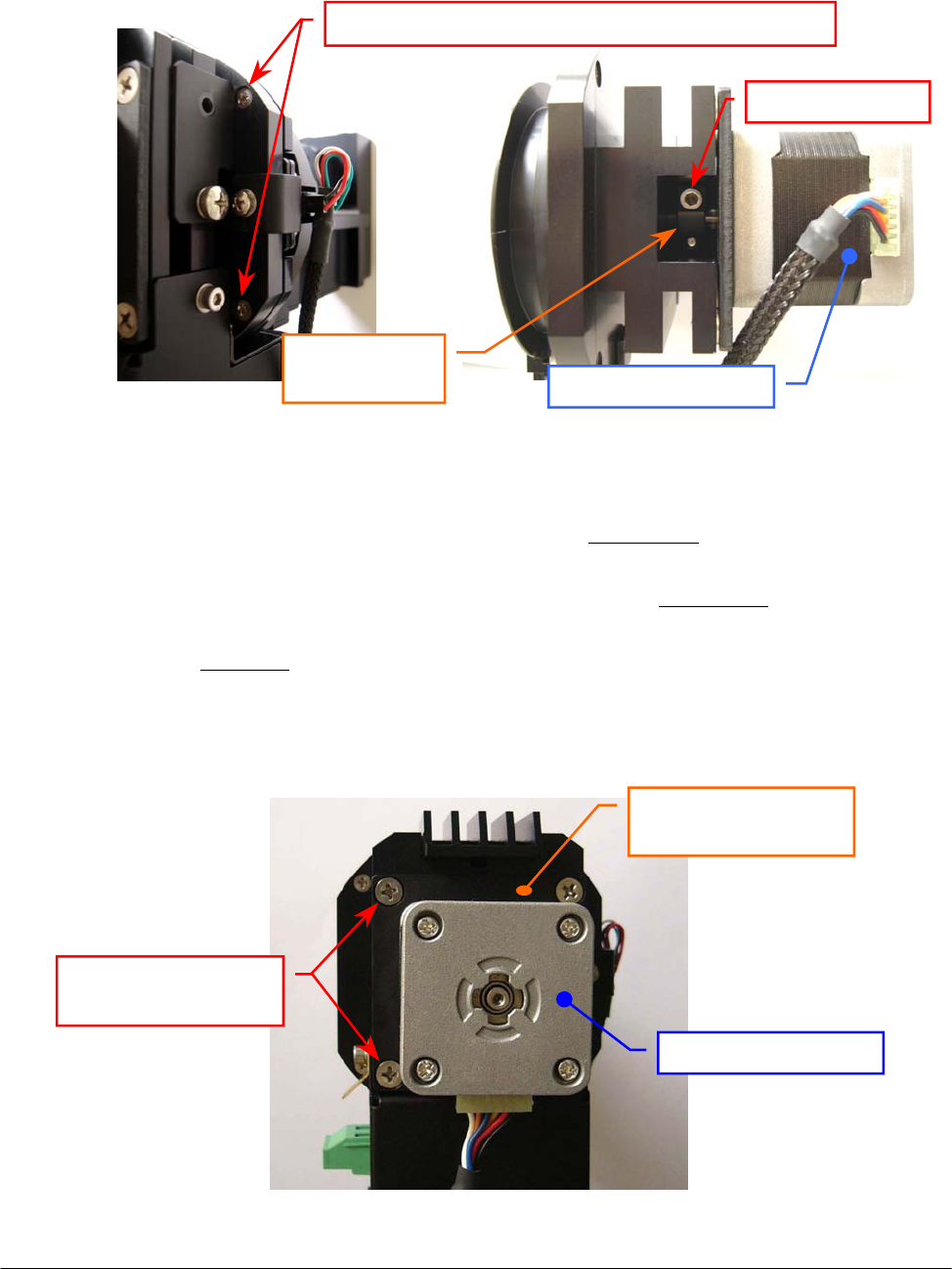
Chapter 05 – SETTINGS AND ADJUSTMENTS
SAT450 Service Manual Rev.00 03 July 2008 Page 31
5.4.3 Replacement of the Filters Wheel Motor
1. Remove the Optic Assy from its housing performing the relative procedure described into the
previous Section 6.4.2, from step 1 to step 7.
2. Unscrew the four fastening screws of the Filters Wheel mechanical support (Fig. 55) and take
out the Filters Wheel – together with the Filters Wheel Motor – from the Optic Assy.
3. Turn the Filters Wheel around the Filters Wheel motor shaft until to see in the relative slot one
of two screws of the Filters Wheel pulley (Fig. 56), then loosen little the screw.
4. Turn again the Filters Wheel around the Filters Wheel motor shaft until to see in the relative
slot the second screw of the Filters Wheel pulley (Fig. 56), then loosen little the screw.
5. Unscrew the four fastening screws of the Filters Wheel Motor (Fig. 57) and take out it from the
Filters Wheel (note well: don’t lose the four washers placed between the anchor plate motor
and the four holes of the Filters Wheel mechanical support!).
6. Unscrew the four fastening screws of the Filters Wheel Motor anchor plate (Fig. 58) and take
out the anchor plate from the motor.
Fig. 55 – Filters Wheel mechanical
support fastening screws
Fig. 56 – Fastening screws of the Filters
Wheel Motor pulley
Fig. 57 – Filters Wheel Motor fastening screws
Filters Wheel Moto
r
Filters Wheel
Motor
p
ulle
y
Fastenin
g
screw
Filters Wheel mechanical support fastening screws
Filters Wheel Motor
fastenin
g
screws
Filters Wheel Moto
r
Filters Wheel Motor
anchor
p
late
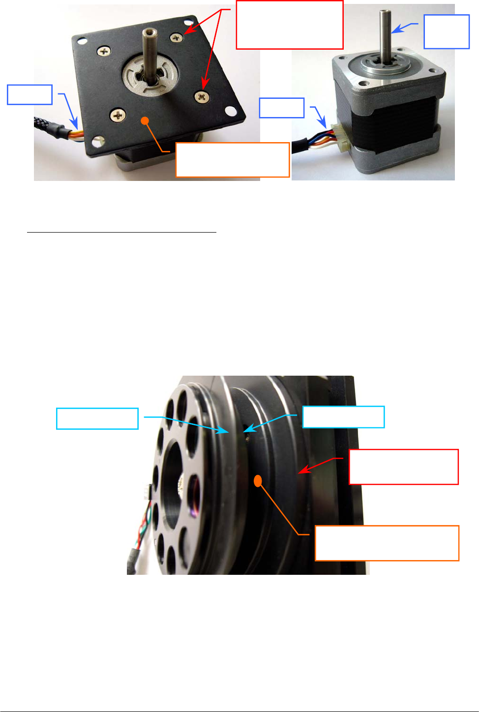
Chapter 05 – SETTINGS AND ADJUSTMENTS
SAT450 Service Manual Rev.00 03 July 2008 Page 32
To replace the new Filters Wheel Motor (Fig. 59) perform the following steps:
7. Position the anchor plate on the upper plane of the new motor as showed in Fig. 58 and screw
its four fastening screws.
8. Place the four washer between the motor and the four holes of the Filters Wheel mechanical
support, insert the shaft of the motor in the Filters Wheel pulley (with the motor connector
place on the opposite side in respect to the side of the Filters Wheel pulley slot), then screw the
four fastening screws of the Filters Wheel Motor (Fig. 57).
9. Position the Filters Wheel to 0.5 mm with respect to the upper side of the Filters Wheel
mechanical support (Fig. 60) and tighten one of two screws of the Filters Wheel pulley (Fig. 56).
Fig. 60 – Upper side of the Filters Wheel mechanical support
10. Turn the Filters Wheel around the Filters Wheel Motor shaft until to see in the relative slot the
second screw of the Filters Wheel pulley (Fig. 56) and tighten the screw.
11. Insert the Filters Wheel – together with the Filters Wheel Motor – in the outward part of the
Optic Assy and screw the four fastening screws of the Filters Wheel mechanical support
(Fig. 55).
12. Replace the Optic Assy in its housing performing the relative procedure described into the
previous Section 6.4.2, from step 8 to step 9.
Fig. 59 – Filters Wheel Motor
[P/N: 10-00399-40]
Fig. 58 – Filters Wheel Motor anchor plate
Filters Wheel
Upper side of the Filters
Wheel mechanical su
pp
ort
Filters Wheel
mechanical su
pp
ort
Filters Wheel Motor
anchor
p
late
Filters Wheel
Motor anchor plate
fastenin
g
screws
Moto
r
shaft
Wires
Wires
Filters Wheel
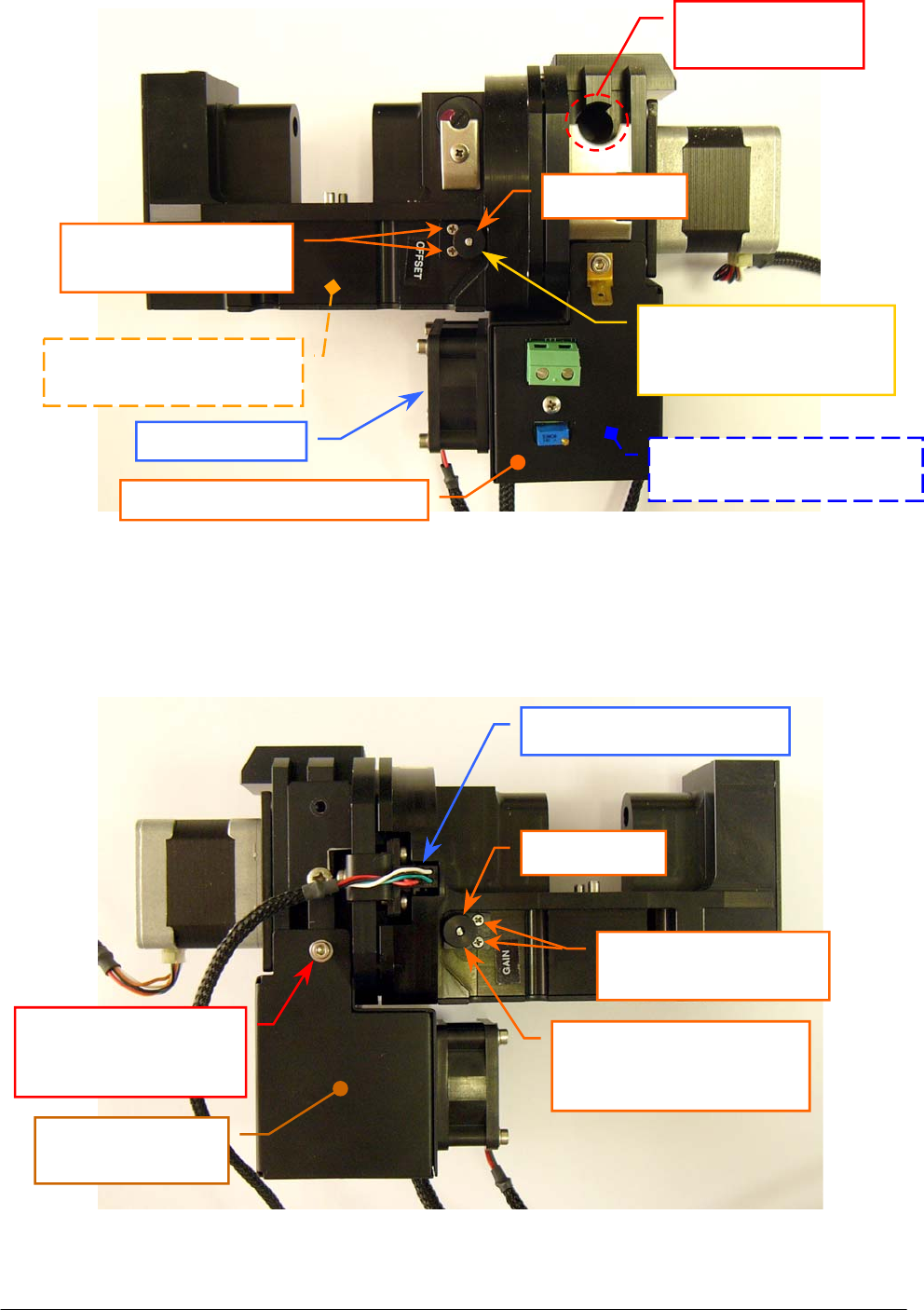
Chapter 05 – SETTINGS AND ADJUSTMENTS
SAT450 Service Manual Rev.00 03 July 2008 Page 33
Fig. 61 – OFFSET trimmer of the “Pre-Ampl./ADC Board” (Reference Channel)
Fig. 62 – GAIN trimmer of the “Pre-Ampl./ADC Board” (Reference Channel)
Photometer fan
Emplacement for
the halogen lamp
“Pre-Ampl./ADC Board”
(Reference Channel)
Photometer Lamp Board
[P/N: 30-01576-01]
Filter Wheel Home Sensor
GAIN trimmer of the
“Pre-Ampl./ADC Board”
(
Reference Channel
)
OFFSET trimmer of the
“Pre-Ampl./ADC Board”
(
Reference Channel
)
P
hotometer Lam
p
Board cove
r
Fastening screw of the
Photometer Lamp
Board cove
r
Photometer Lamp
Board cove
r
Fastening screws of
the trimmer keep plate
Fastening screws of
the trimmer keep plate
Small wheel
Small wheel
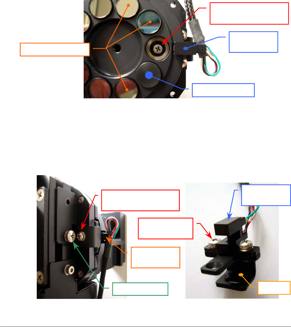
Chapter 05 – SETTINGS AND ADJUSTMENTS
SAT450 Service Manual Rev.00 03 July 2008 Page 34
5.4.4 Replacement of the Filters Wheel Home Sensor
1. Remove the Optic Assy from its housing performing the relative procedure described into the
previous Section 6.4.2, from step 1 to step 7.
2. Unscrew the four fastening screws of the Filters Wheel mechanical support (Fig. 55) and take
out the Filters Wheel – together with the Filters Wheel Motor – from the Optic Assy.
3. Turn the Filters Wheel around the Filters Wheel motor shaft until one filter is aligned with
respect to the Filters Wheel Home Sensor, unscrew the fastening screw of the Filters Holder
Wheel (Fig. 72), then remove it from the Filters Wheel (Fig. 72).
4. Remove the filter - using the tweezers - from its seating on the Filters Wheel (as showed in
Fig. 63) and unscrew the first Home Sensor support fastening screw placed under the Filters
Wheel (Fig. 63).
Fig. 63 – First Home Sensor support fastening screw
5. Unscrew the filler cap screw and the second Home Sensor support fastening screw placed on
the Filters Wheel mechanical support (Fig. 64) and take out the Home Sensor support from its
housing.
6. Unscrew the two fastening screws of the Filters Wheel Home Sensor (Fig. 65) and take out the
sensor from the support.
Fig. 64 – Second Home Sensor
support fastening screw
Fig. 65 – Filters Wheel Home
Sensor fastening screws
Filters Wheel
Home Senso
r
Interferential Filters
Second Home Sensor
su
pp
ort fastenin
g
screw
Filters Wheel
Home Senso
r
Filler ca
p
screw
Home Sensor
fastenin
g
screw
Filters Wheel
Home Senso
r
Su
pp
ort
First Home Sensor
support fastening screw
Stopper with hole
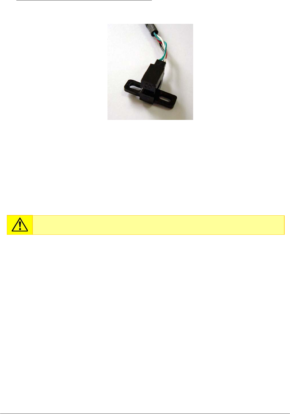
Chapter 05 – SETTINGS AND ADJUSTMENTS
SAT450 Service Manual Rev.00 03 July 2008 Page 35
To replace the new Filters Wheel Home Sensor (Fig. 66) perform the following steps:
Fig. 66 – Filters Wheel Home Sensor [P/N: 9-10-0023-40]
7. Position the support below the Filters Wheel Home Sensor as showed in Fig. 65, center the
sensor with respect to the support and screw its two fastening screws (Fig. 65).
8. Repeat the above steps in inverse order: from 5 to 3.
9. Replace the Filters Wheel – together with the Filters Wheel Motor – in the Optic Assy and
screw the four fastening screws of the Filters Wheel mechanical support (Fig. 55).
10. Replace the Optic Assy in its housing performing the relative procedure described into the
previous Section 6.4.2, from step 8 to step 9.
5.4.5 Replacement of the Photometer Halogen Lamp
1. Make sure that the SAT450 instrument is turned off.
2. Unscrew the two captive screws on the front underside of the instrument (Fig. 6) and lift up the
Raising Top (Fig. 7).
3. Unscrew the two screws of the J2 connector of the “Photometer Halogen Lamp” (Fig. 52) and
take out the two lamp wires from the connector.
Do not touch the filter with your hands. Make use of tweezers to replace it.
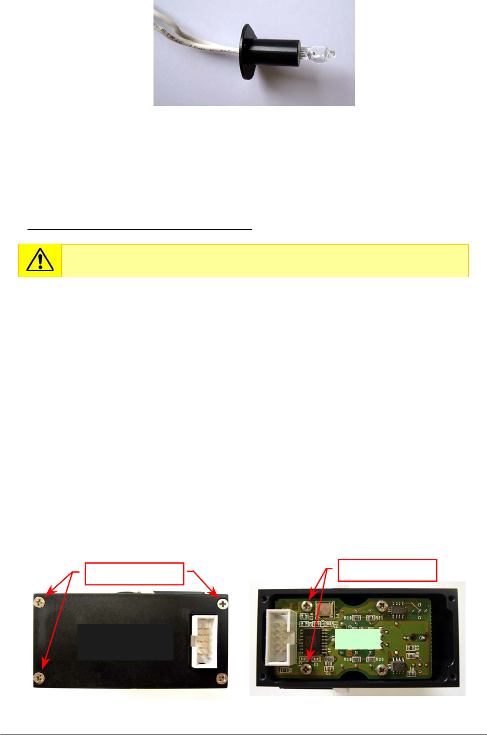
Chapter 05 – SETTINGS AND ADJUSTMENTS
SAT450 Service Manual Rev.00 03 July 2008 Page 36
4. Unscrew the lamp fastening screw (Fig. 52) and remove the lamp keep plate (Fig. 52) from the
Photometer.
5. Take out the Photometer Halogen Lamp from its emplacement on the Photometer (Fig. 61).
To replace the new Photometer Halogen Lamp (Fig. 67) perform the following steps:
6. Repeat the above steps in inverse order: from 5 to 3.
7. Bring down the Raising Top (Fig. 7) and screw the two captive screws on the front underside
of the instrument (Fig. 6).
8. Perform the procedure “Electronic adjustment of the Photometer” described into the previous
Section 6.4.1.
5.4.6 Replacement of the “Pre-Ampl./ADC Board” of the Sample Channel
1. Remove the Optic Assy from its housing performing the relative procedure described into the
previous Section 6.4.2, from step 1 to step 5.
2. Unscrew the four fastening screws of the Sample Channel board cover (Fig. 68) and remove it
from the Photometer.
3. Unscrew the four fastening screws of the “Pre-Ampl./ADC Board” of the Sample Channel
(Fig. 69) and take off - handling with care - the board from its housing on the Photometer.
Fig. 67 – Photometer Halogen Lamp [P/N: 09-35-0016-00]
Do not touch glass portion of Photometer Halogen Lamp with your hands.
Fig. 68 – Fastening screws of the
Sample Channel board cover
Fig. 69 – Fastening screws of the
Sam
p
le Channel board
Fastenin
g
screws
Sample Channel
board cover
Fastenin
g
screws
Boar
d
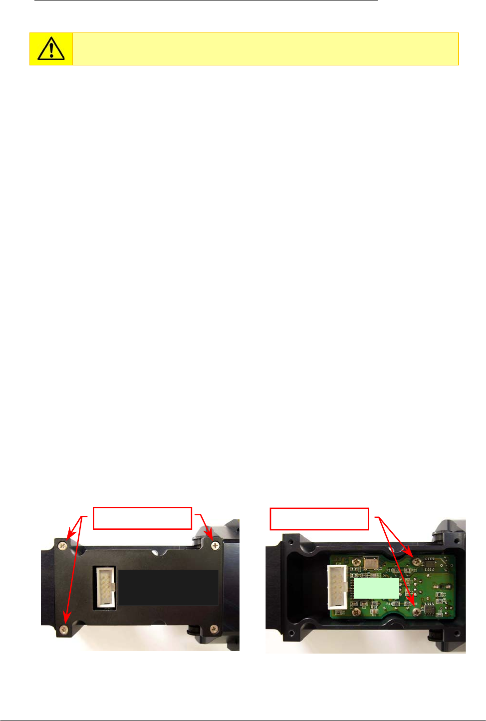
Chapter 05 – SETTINGS AND ADJUSTMENTS
SAT450 Service Manual Rev.00 03 July 2008 Page 37
To replace the new “Pre-Ampl./ADC Board” of the Sample Channel (compare the scheme
MA-15-02448-00) perform the following steps:
4. Replace the board - handling with care - in its housing in order to obtain the placement of the
photodiode in its seating and the alignment of the trimmer screw, for each of two trimmers,
with respect to the relative hole on the chassis board (compare the scheme MA-15-02448-00).
5. Repeat the above steps in inverse order: from 3 to 2.
6. Replace the Optic Assy in its housing performing the relative procedure described into the
previous Section 6.4.2, from step 8 to step 9.
5.4.7 Replacement of the “Pre-Ampl./ADC Board” of the Reference Channel
1. Remove the Optic Assy from its housing performing the relative procedure described into the
previous Section 6.4.2, from step 1 to step 5.
2. Unscrew the two keep plate screws of the external small wheel of the GAIN Trimmer of the
Reference Channel board (Fig. 62), then remove the small wheel (together with its keep plate)
from its hole.
3. Unscrew the two keep plate screws of the external small wheel of the OFFSET Trimmer of the
Reference Channel board (Fig. 61), then remove the small wheel (together with its keep plate)
from its hole.
4. Unscrew the four fastening screws of the Reference Channel board cover (Fig. 70) and remove
it from the Photometer.
5. Unscrew the four fastening screws of the “Pre-Ampl./ADC Board” of the Reference Channel
(Fig. 71) and take off - handling with care - the board from its housing on the Photometer.
Do not touch light-sensitive portion of photodiode with your hands.
Fig. 70 – Fastening screws of the
Reference Channel board cover
Fig. 71 – Fastening screws of the
Reference Channel board
Reference Channel
board cover Boar
d
Fastenin
g
screws Fastenin
g
screws
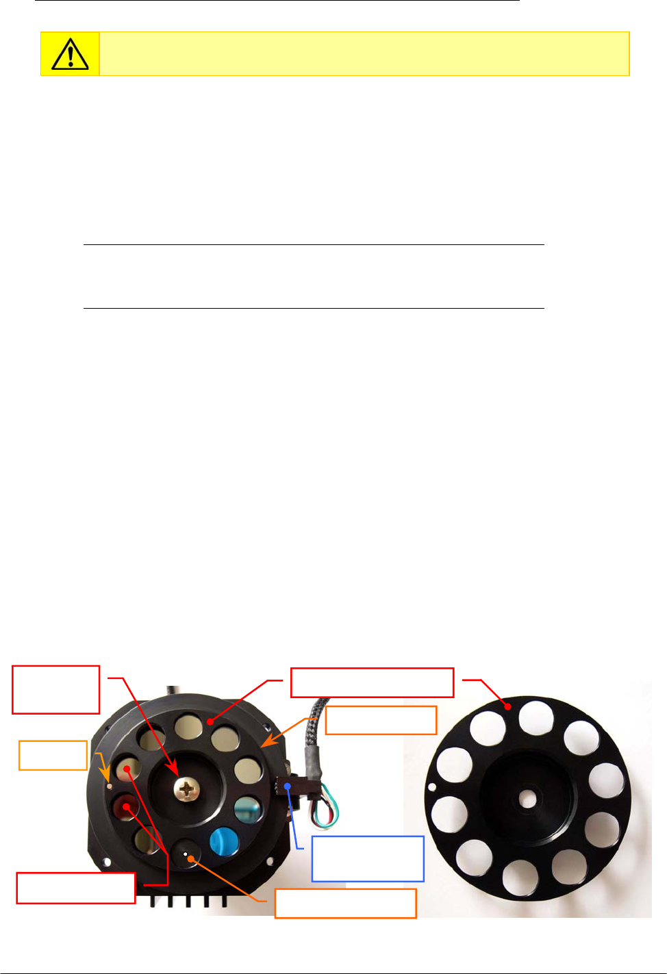
Chapter 05 – SETTINGS AND ADJUSTMENTS
SAT450 Service Manual Rev.00 03 July 2008 Page 38
To replace the new “Pre-Ampl./ADC Board” of the Reference Channel (compare the scheme
MA-15-02448-00) perform the following steps:
6. Replace the board - handling with care - in its housing in order to obtain the placement of the
photodiode in its seating and the alignment of the trimmer screw, for each of two trimmers,
with respect to the relative hole on the chassis board (compare the scheme MA-15-02448-00).
7. Screw the four fastening screws of the “Pre-Ampl./ADC Board” of the Reference Channel
in its housing (Fig. 71).
8. Replace the external small wheel in the hole of the GAIN Trimmer of the Reference Channel
board, make sure that the small wheel has a grip on the board trimmer screw and screw the two
small wheel keep plate screws (Fig. 62).
9. Replace the external small wheel in the hole of the OFFSET Trimmer of the Reference Channel
board, make sure that the small wheel has a grip on the board trimmer screw and screw the two
small wheel keep plate screws (Fig. 61).
10. Replace the Reference Channel board cover on its place and screw its four fastening screws
(Fig. 70).
11. Replace the Optic Assy in its housing performing the relative procedure described into the
previous Section 6.4.2, from step 8 to step 9.
5.4.8 Replacement of the Interferential Filters
1. Remove the Optic Assy from its housing performing the relative procedure described into the
previous Section 6.4.2, from step 1 to step 7.
2. Unscrew the four fastening screws of the Filters Wheel mechanical support (Fig. 55) and take
out the Filters Wheel – together with the Filters Wheel Motor – from the Optic Assy.
3. Turn the Filters Wheel around the Filters Wheel motor shaft until the dark position of the
Filters Wheel (compare the scheme MA-15-02448-00) is centered with respect to the Filters
Wheel Home Sensor (Fig. 74), unscrew the Filters Holder Wheel fastening screw (Fig. 72) and
remove the Filters Holder Wheel from its housing making drift it along the dowel (Fig. 72).
Do not touch light-sensitive portion of photodiode with your hands.
Fig. 72 – Filters Wheel Fig. 73 – Filters Holder Wheel
Filters Holder Wheel
Filters Wheel
Home Sensor
Dowel
Filters Wheel
Interfer. filters
Fastening
screw
Sto
pp
er with hole
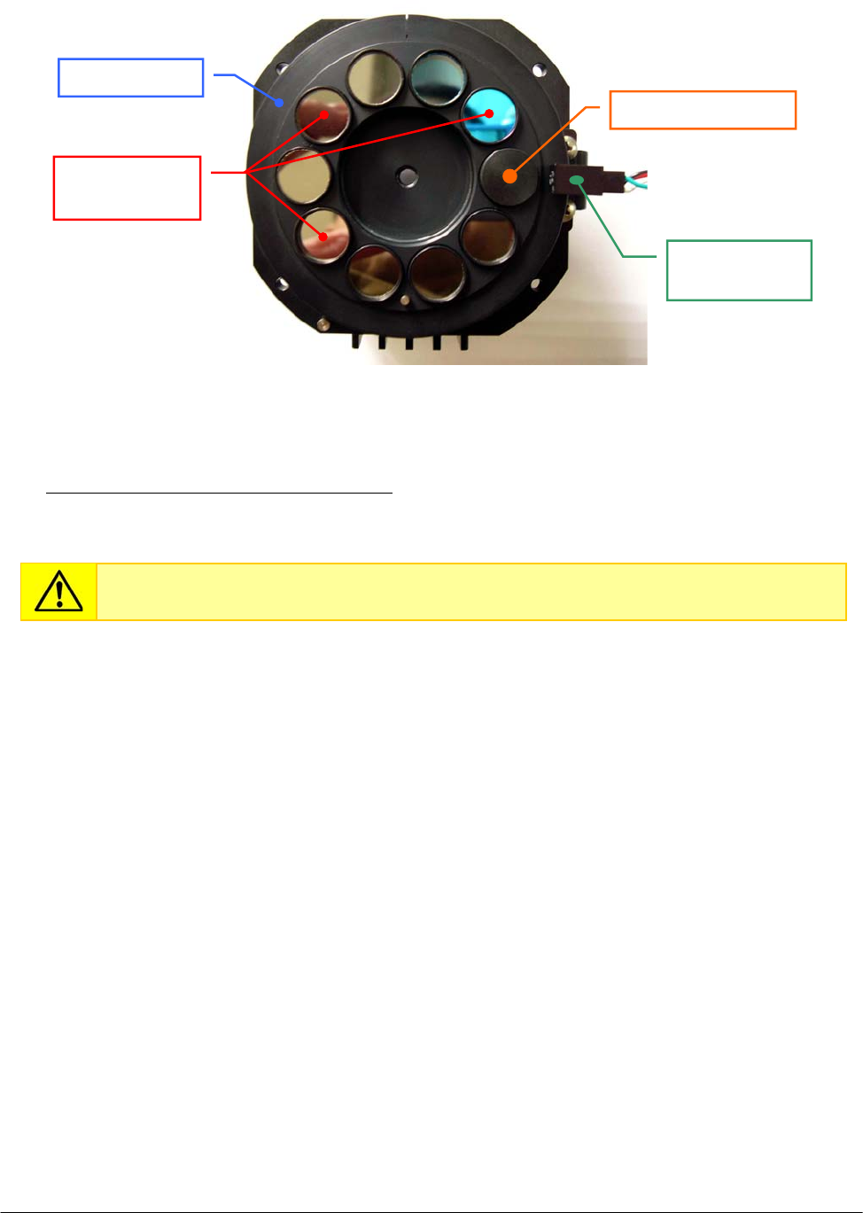
Chapter 05 – SETTINGS AND ADJUSTMENTS
SAT450 Service Manual Rev.00 03 July 2008 Page 39
4. Remove the specific interferential filter from its seating on the Filters Wheel (Fig. 74).
To replace the new Interferential Filter (compare the scheme MA-15-02448-00) perform the
following steps:
5. Make sure that the new interferential filter is right, then replace it on the Filters Wheel
positioning the smooth side of the small filter box on the bottom side of its specific seating
(compare the scheme MA-15-02448-00) above its wave spring washer.
6. Repeat the above steps in inverse order: from 3 to 2.
7. Replace the Optic Assy in its housing performing the relative procedure described into the
previous Section 6.4.2, from step 8 to step 9.
Do not touch the filter with your hands. Make use of tweezers to replace it.
Fig. 74 – Interferential Filters on the Filters Wheel
Interferential
filters
Filters Wheel
Home Senso
r
Sto
pp
er with hole
Filters Wheel

Chapter 05 – SETTINGS AND ADJUSTMENTS
SAT450 Service Manual Rev.00 03 July 2008 Page 40
5.5 REAGENTS PLATE
5.5.1 Mechanical adjustments of the Reagents Plate
1. Lift up the instrument cover and remove the Reagents Plate cover from the Reagents Plate
(Fig. 7).
2. Turn on the SAT450 system (instrument and computer) and launch the “Diagnostic” program.
3. Select "Plates” folder and request an Reagents Plate reset. Wait until the reset Reagents Plate
procedure has been completed.
4. Make sure that the two Home Sensors of the Reagents Plate light up in green.
5. Select “Arm” folder and request an Arm reset. Wait until the reset Sampling Arm procedure has
been completed.
6. Make sure that the Vertical and Horizontal Home Sensors of the Sampling Arm light up in
green.
7. Select “Plates” folder, choose the N° Cup #40 of the Reagents Plate, then click the correspondent
“To Asp.” button. Wait until the requested operation has been completed.
8. Select “Arm” folder, click the “Go Reagent” button, then click the correspondent “Down”
button. The Sampling Arm will move to aspiration position of the Reagents Plate, then it will go
down until to reach the right height.
9. Make sure that the Sampling Probe is centered with respect to the position #40 (rD-2 position)
of the Reagents Plate. If it not be so, center the four Peripheral Racks of the Reagents Plate in
the following way:
a. unscrew the two captive screws on the front underside of the instrument (Fig. 6) and
lift up the Raising Top (Fig. 7);
b. loosen the two set screws of the primary pulley of the Reagents Plate (Fig. 75);
c. center the position #40 (rD-2 position) with respect to the Sampling Probe, rotating
slowly the Reagents Plate;
d. tighten the two set screws of the primary pulley of the Reagents Plate (Fig. 75);
e. bring down the Raising Top (Fig. 7) and screw the two captive screws on the front
underside of the instrument (Fig. 6).
10. Select the N° Cup #1 of the Reagents Plate, then click the correspondent “To Asp.” button. Wait
until the requested operation has been completed.
11. Make sure that the Sampling Probe is centered with respect to the position #1 of the Reagents
Plate (note: the position#1 of the Reagents Plate is the position#1 of the Satellite Rack “A”).
If it not be so, center the four Satellite Racks of the Reagents Plate in the following way:
f. unscrew the two captive screws on the front underside of the instrument (Fig. 6) and
lift up the Raising Top (Fig. 7);
g. loosen the two set screws of the secondary pulley of the Reagents Plate (Fig. 76);
h. center the position #1 of the Satellite Rack “A” with respect to the Sampling Probe,
rotating slowly the Satellite Rack “A”;
Make sure that the position #1 of the Satellite Rack “A” is contemporaneously aligned
with respect to the position #1 of the Satellite Racks “B”, “C” and “D” of the Reagents
Plate (Fig. 78). If it not be so, perform the procedure “Mechanical alignments of the
Satellite Racks of the Reagents Plate” described into the following Section 6.5.3 .
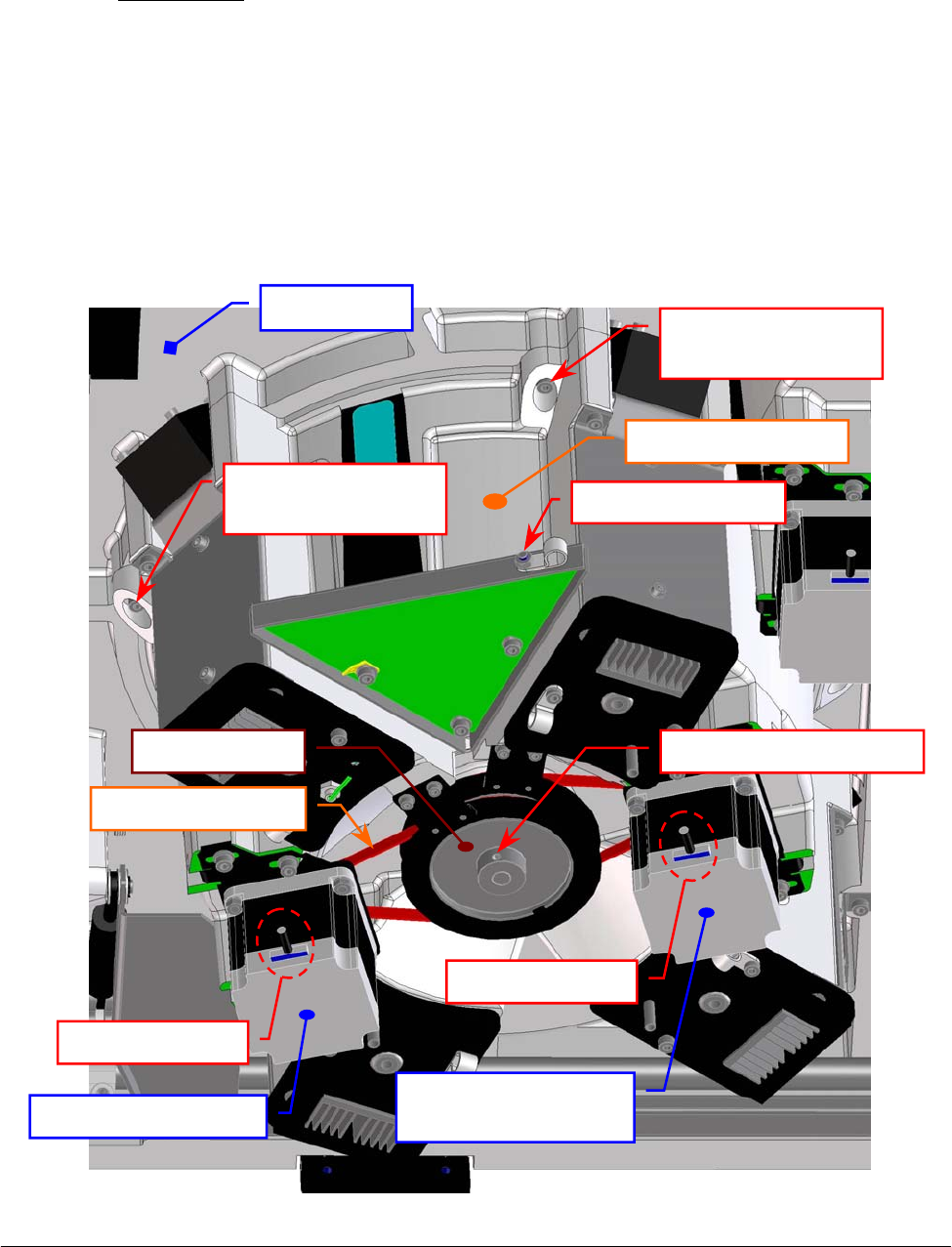
Chapter 05 – SETTINGS AND ADJUSTMENTS
SAT450 Service Manual Rev.00 03 July 2008 Page 41
i. lever on the primary pulley with a flat head screwdriver in order to obtain that the
secondary pulley is locked on the end of the run, and then tighten the two set screws
of the secondary pulley of the Reagents Plate (Fig. 76);
j. bring down the Raising Top (Fig. 7) and screw the two captive screws on the front
underside of the instrument (Fig. 6).
12. Select “Arm” folder and request an Arm reset. Wait until the reset Sampling Arm procedure has
been completed.
13. Make sure that the Vertical and Horizontal Home Sensors of the Sampling Arm light up in
green.
14. Request an Reagents Plate reset in the "Plates” folder. Wait until the reset Reagents Plate
procedure has been completed.
15. Make sure that the two Home Sensors of the Reagents Plate light up in green.
16. Replace the Reagents Plate cover on the Reagents Plate and bring down the instrument cover
(Fig. 7).
Fig. 75 – Primary pulley of the Reagents Plate Assy
Reagents Plate
Interface Board
Raising Top
Reagents Plate Assy
fastening screw
Reagents Plate Assy
fastening screw
Rea
g
ents Plate Ass
y
Cable holder screw
Satellites Mov.
Rea
g
ents Plate Moto
r
Rea
g
ents Plate Moto
r
Motor connecto
r
Motor connecto
r
Rea
g
ents Plate Belt
Primar
y
p
ulle
y
Primar
y
p
ulle
y
set screw
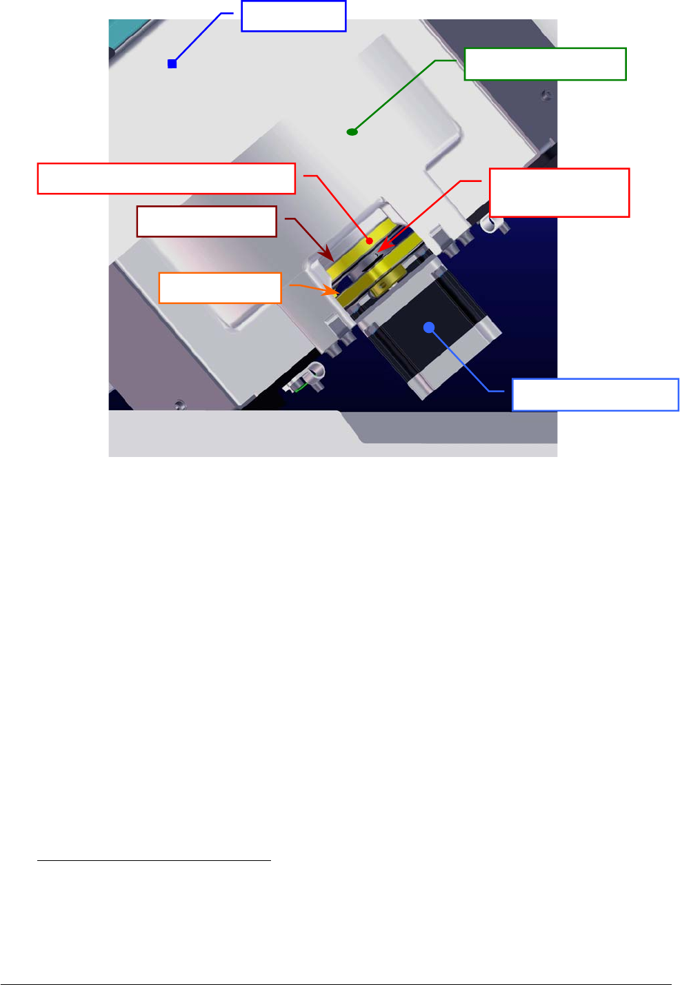
Chapter 05 – SETTINGS AND ADJUSTMENTS
SAT450 Service Manual Rev.00 03 July 2008 Page 42
Fig. 76 – Secondary pulley of the Reagents Plate Assy
5.5.2 Remotion of the Reagents Plate Assy from the Raising Top
1. Make sure that the SAT450 instrument is turned off.
2. Lift up the instrument cover and remove the Reagents Plate cover from the Reagents Plate
(Fig. 1).
3. Unscrew the two captive screws on the front underside of the instrument (Fig. 6) and lift up the
Raising Top (Fig. 7).
4. Unplug the J1, J10 and J11 connectors and the ground wire from the Reagents Plate Interface
Board (compare the scheme SC-30-02190-00).
5. Unscrew the cable holder screw (Fig. 75), remove the cable holder and put away the relative
cables from the Reagents Plate Assy.
6. Unscrew the four Reagents Plate Assy fastening screws (Fig. 75) and take out – moving
carefully – the Reagents Plate Assy from its housing.
To replace the Reagents Plate Assy (Fig. 77) perform the following steps:
7. Repeat the above steps in inverse order: from 6 to 3.
8. Perform the procedure “Mechanical adjustments of the Reagents Plate” described into the
previous Section 6.5.1, from step 2 to step 16.
Raisin
g
To
p
Reagents Plate Assy
Secondary pulley
set screw
Secondar
y
p
ulle
y
Primar
y
p
ulle
y
Satellites Mov. Rea
g
ents Plate Belt
Reagents Plate Motor
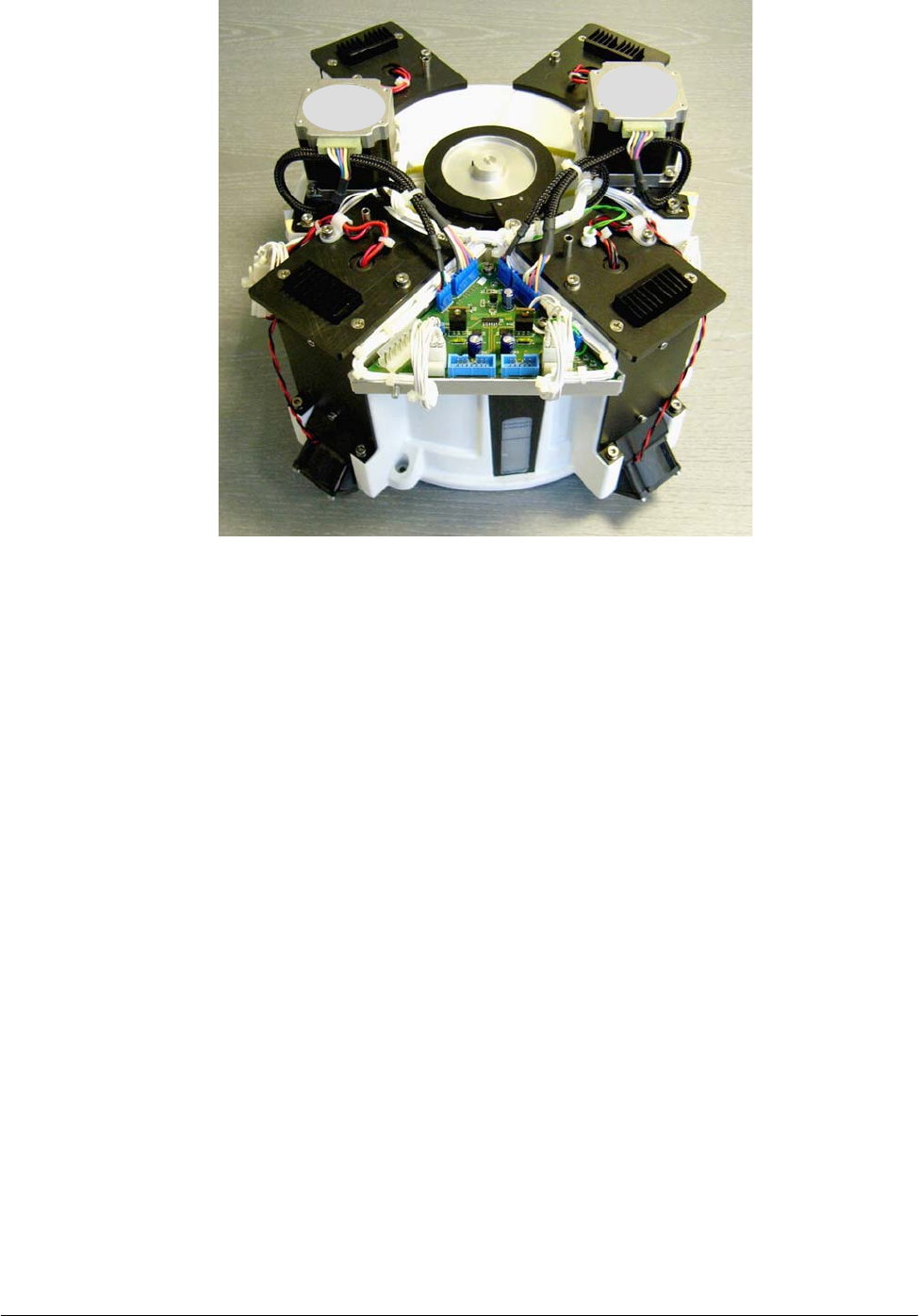
Chapter 05 – SETTINGS AND ADJUSTMENTS
SAT450 Service Manual Rev.00 03 July 2008 Page 43
Fig. 77 – Reagents Plate Assy
5.5.3 Mechanical alignments of the Satellite Racks of the Reagents Plate
1. Remove the Reagents Plate Assy from its housing performing the relative procedure described
into the previous Section 6.5.2, from step 1 to step 6.
2. Unscrew the four fastening screws of the Reagents Plate Motor (Fig. 82), push the motor toward
the primary pulley in order to obtain the loosening of the belt, then screw one motor fastening
screw.
3. Unscrew the four fastening screws of the Satellites Mov. Reagents Plate Motor (Fig. 82), push
the motor toward the secondary pulley in order to obtain the loosening of the belt, then screw
one motor fastening screw.
4. Unscrew the two fastening screws of the Reagents Plate Home Sensor (Fig. 82) and take out the
sensor from its housing on the Reagents Plate Assy.
5. Unscrew the two fastening screws of the Satellites Mov. Reagents Plate Home Sensor (Fig. 82)
and take out the sensor from its housing on the Reagents Plate Assy.
6. Loosen much the two set screws of the primary pulley of the Reagents Plate (Fig. 75).
7. Loosen much the two set screws of the secondary pulley of the Reagents Plate (Fig. 76).
8. Take out the plate base from the container of the Reagents Plate Assy (Fig. 80).
9. Identify with the names “anchor bolt I” and “anchor bolt IV” the two anchor bolt connected to
the internal secondary belt of the plate base (Fig. 79).
Motor
Motor
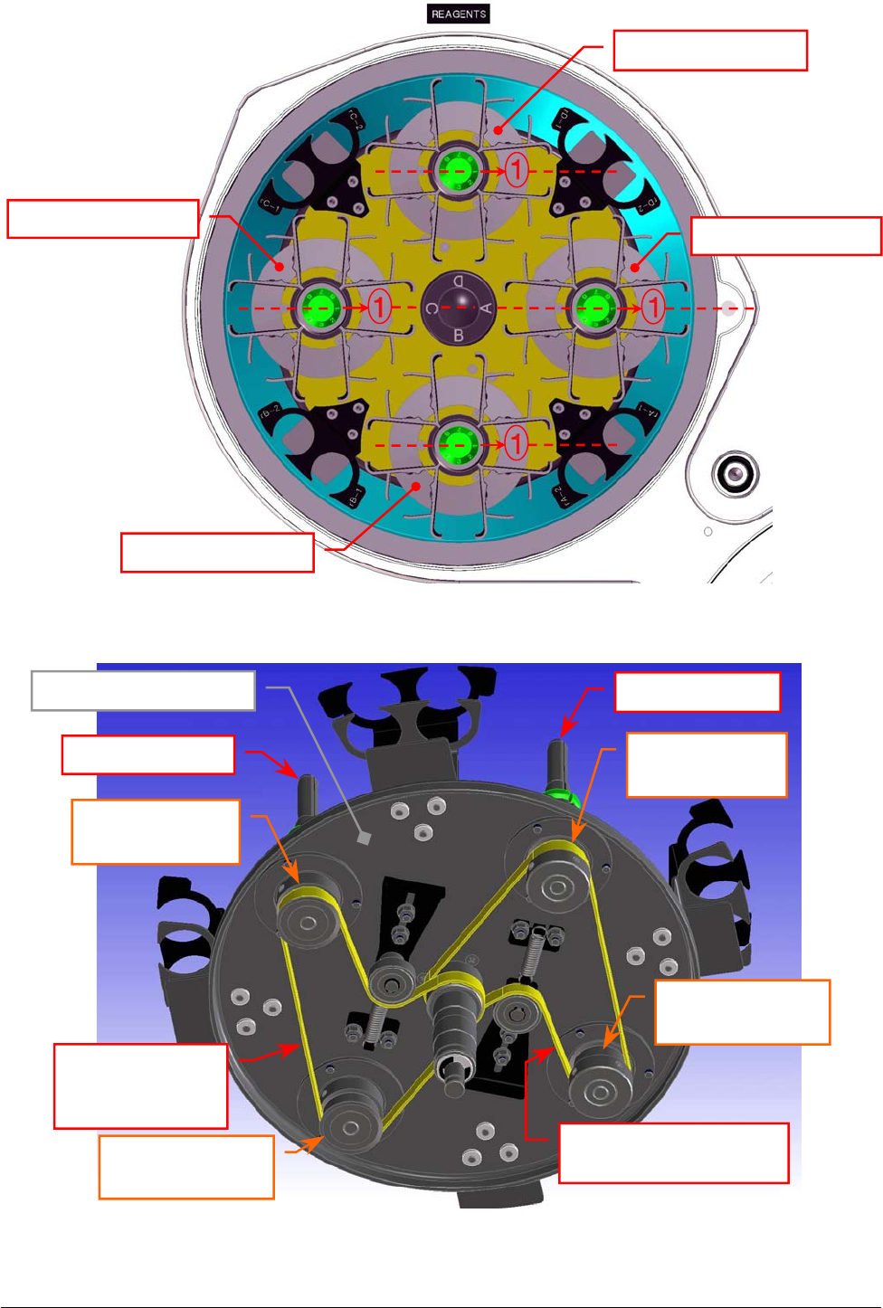
Chapter 05 – SETTINGS AND ADJUSTMENTS
SAT450 Service Manual Rev.00 03 July 2008 Page 44
Fig. 79 – Internal primary and secondary belts of the Reagents Plate
Internal secondary belt
[
P/N: 86-02334-12
]
Pulley of the
anchor bolt “I”
Plate base (bottom view)
Pulley of the
anchor bolt “IV”
Pulley of the
anchor bolt “II”
Pulley of the
anchor bolt “III”
Anchor bolt “II”
Anchor bolt “I”
Fig. 78 – Satellite Racks “A”, “B”, “C”, “D” of the Reagents Plate (top view)
A
B
Internal
primary belt
[
P/N: 86-02334-12
]
C
D
Satellite Rack “D”
Satellite Rack “A”
Satellite Rack “B”
Satellite Rack “C”
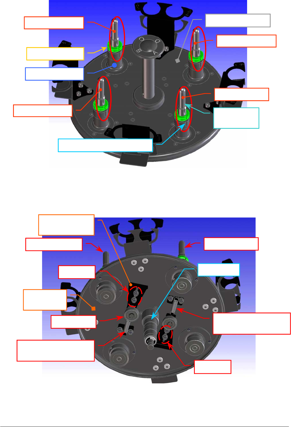
Chapter 05 – SETTINGS AND ADJUSTMENTS
SAT450 Service Manual Rev.00 03 July 2008 Page 45
Fi
g
. 80 – The
p
late base of the Rea
g
ents Plate
Fig. 81 – The two extension springs of the internal belts
Anchor bolt “IV”
Anchor bolt “III”
Anchor bolt “II”
Anchor bolt dis
k
Anchor bolt base
Notch of the anchor bolt base
Anchor bolt “I”
Notch of the
anchor bolt
Plate base (top view)
Plate base
(bottom view)
Anchor bolt “II” Anchor bolt “I”
Ball bearin
g
Extension spring of the
internal
p
rimar
y
belt
Extension spring of the
internal secondar
y
belt
Anchor plate of
the ball bearin
g
Sto
p
nuts
Stop nuts
Central
p
in

Chapter 05 – SETTINGS AND ADJUSTMENTS
SAT450 Service Manual Rev.00 03 July 2008 Page 4
6
10. Identify with the names “anchor bolt II” and “anchor bolt III” the two anchor bolt connected to
the internal primary belt of the plate base (Fig. 79).
11. Loosen the two stop nuts of the anchor plate of the ball bearing relative to the internal primary
belt, push the ball bearing until to obtain a sizable reduction in tension of the belt, then tighten
one of two stop nuts (Fig. 81).
12. Loosen the two stop nuts of the anchor plate of the ball bearing relative to the internal secondary
belt, push the ball bearing until to obtain a sizable reduction in tension of the belt, then tighten
one of two stop nuts (Fig. 81).
13. Make sure that the internal primary and secondary belts (Fig. 79) are serviceability.
If the internal secondary belt is not be so, replace it with the new internal secondary belt
in the following way:
a. remove the internal primary belt from the pulley of the anchor bolt “II”, from the
pulley of the anchor bolt “III” and from the pulley of the central pin;
b. remove the internal secondary belt from the pulley of the anchor bolt “I”, from the
pulley of the anchor bolt “IV” and from the pulley of the central pin;
c. wrap the new internal secondary belt around the pulley of the anchor bolt “I”, around
the pulley of the anchor bolt “IV”, around the pulley of the central pin, then tighten it
slightly resting it on the relative ball bearing (Fig. 79);
d. wrap the internal primary belt around the pulley of the anchor bolt “II”, around the
pulley of the anchor bolt “III”, around the pulley of the central pin, then tighten it
slightly resting it on the relative ball bearing (Fig. 79).
If the internal primary belt is not be so, replace it with the new internal primary belt
in the following way:
a. remove the belt from the pulley of the anchor bolt “II”, from the pulley of the anchor
bolt “III” and from the pulley of the central pin;
b. wrap the new internal primary belt around the pulley of the anchor bolt “II”, around the
pulley of the anchor bolt “III”, around the pulley of the central pin, then tighten it
slightly resting it on the relative ball bearing (Fig. 79).
Mechanical alignment between the two anchor bolts “I” and “IV”:
14. Bring into alignment the notch of the anchor bolt “I” with respect to the notch of its base
(Fig. 80) and – on the other side of the plate base – place in tension the part of the belt placed
between the pulley of the anchor bolt “I” and the respective pulley on the central pin (part “A”
of the belt in the Fig. 79) wrapping correctly the belt on them.
15. Bring into alignment the notch of the anchor bolt “IV” with respect to the notch of its base
(Fig. 80) and – on the other side of the plate base – place in tension also the part of the belt
placed between the pulley of the anchor bolt “I” and the pulley of the anchor bolt “IV” (part “B”
of the belt in the Fig. 79) wrapping correctly the belt on the latter.
16. Loosen the stop nut of the anchor plate of the ball bearing relative to the internal secondary belt,
leave free the ball bearing in order to obtain the right tension of the belt by means of the
extension spring, then tighten the two stop nuts (Fig. 81).
17. Turn the central pin and make sure that the internal secondary belt thoots are correctly inserted
on its pulley, on the pulley of the anchor bolt “I” and on the pulley of the anchor bolt “IV”.
18. Make sure that the notch of the anchor bolt “I” is aligned with respect to the notch of the anchor
bolt “IV”.

Chapter 05 – SETTINGS AND ADJUSTMENTS
SAT450 Service Manual Rev.00 03 July 2008 Page 4
7
Mechanical alignment between the two anchor bolts “II” and “III” and them with
respect to the two anchor bolts “I” and “IV”:
19. Turn the anchor bolt “I” until to obtain the alignment of the notchs of the anchor bolts “I” and
“IV” with respect to the respectives notchs of theirs bases.
20. Bring into alignment the notch of the anchor bolt “III” with respect to the notch of its base
(Fig. 80) and – on the other side of the plate base – place in tension the part of the belt placed
between the pulley of the anchor bolt “III” and the respective pulley on the central pin (part “C”
of the belt in the Fig. 79) wrapping correctly the belt on them.
21. Bring into alignment the notch of the anchor bolt “II” with respect to the notch of its base
(Fig. 80) and – on the other side of the plate base – place in tension also the part of the belt
placed between the pulley of the anchor bolt “III” and the pulley of the anchor bolt “II” (part
“D” of the belt in the Fig. 79) wrapping correctly the belt on the latter.
22. Loosen the stop nut of the anchor plate of the ball bearing relative to the internal primary belt,
leave free the ball bearing in order to obtain the right tension of the belt by means of the
extension spring, then tighten the two stop nuts (Fig. 81).
23. Turn the central pin and make sure that the internal primary belt thoots are correctly inserted on
its pulley, on the pulley of the anchor bolt “II” and on the pulley of the anchor bolt “III”.
24. Make sure that the notchs of the four anchor bolts “I”, “II”,“III” and “IV” are aligned between
them.
To replace the plate base (Reagents Plate support having P/N: 05-02271-01) in the Reagents
Plate Assy (Fig. 77) and the Reagents Plate Assy in the instrument (Fig. 75) perform the
following steps:
25. Put the plate base into the container of the Reagents Plate Assy inserting the central pin into the
apposite hole until the end of the run.
26. Lock on well the primary and secondary pulley over the container and between them, then
tighten the two set screws of the primary pulley and the two set screws of the secondary pulley
of the Reagents Plate (Fig. 75).
27. Perform the procedure “Replacement of the Satellites Mov. Reagents Plate Belt” described into
the next Section 6.5.9, from step 5 to step 14.
The Fig. 78 shows the position #1 of the Satellite Rack “A” contemporaneously aligned
with respect to the position #1 of the Satellite Racks “B”, “C” and “D” in the home
p
osition of the Reagents Plate.
Note
well
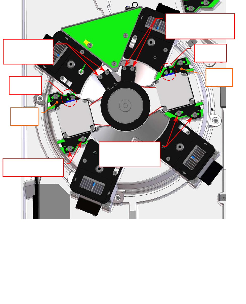
Chapter 05 – SETTINGS AND ADJUSTMENTS
SAT450 Service Manual Rev.00 03 July 2008 Page 48
5.5.4 Replacement of the Reagents Plate Motor
1. Make sure that the SAT450 instrument is turned off, then unscrew the two captive screws on the
front underside of the instrument (Fig. 6) and lift up the Raising Top (Fig. 7).
2. Unplug the J5 connector from the Reagents Plate Interface Board (compare the sch. SC-30-02190-00).
3. Unscrew the four fastening screws of the Reagents Plate Motor (Fig. 82).
4. Remove the belt from the pulley of the Reagents Plate Motor and take out it from its housing
and the two anchor plate springs from the anchor plate.
5. Unscrew the four fastening screws of the Reagents Plate Motor anchor plate (Fig. 83) and take
out the anchor plate from the motor.
Fig. 82 – Reagents Plate Motor and Satellites Mov. Reagents Plate Motor
Reagents Plate
Interface Board
Reagents
Plate
Motor
Satellites Mov.
Reagents Plate
Motor
Motor
connecto
r
Motor
connecto
r
Anchor
p
late
Anchor
p
late
Reagents Plate Motor
fastenin
g
screws
Satellites Mov.
Reagents Plate Motor
fastenin
g
screws
Satellites Mov. Reagents
Plate Home Sensor
fastenin
g
screws
Reagents Plate
Home Sensor
fastenin
g
screws
1
2
3
4
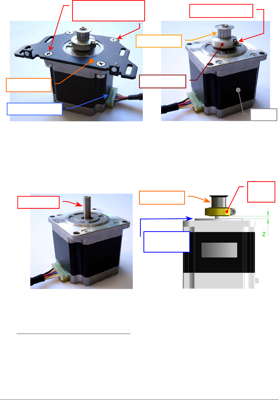
Chapter 05 – SETTINGS AND ADJUSTMENTS
SAT450 Service Manual Rev.00 03 July 2008 Page 49
6. Loosen the pulley clamp screw and extract the pulley clamp and the pulley from the motor shaft
(Fig. 84).
To replace the new Reagents Plate Motor (Fig. 85) perform the following steps:
7. Insert the pulley clamp completely on the motor pulley (Fig. 86) and then insert all two on the
motor shaft.
8. Position the motor pulley to 2.00 mm with respect to upper motor plane (Fig. 86), then tighten
the pulley clamp screw (Fig. 84).
9. Position the anchor plate on the upper plane of the new motor as showed in Fig. 83 and screw its
four fastening screws.
Fig. 83 – Reagents Plate Motor anchor plate Fig. 84 – Motor pulley
Fig. 85 – Reagents Plate Motor / Satellites
Mov. Reagents Plate Motor
[P/N: 9-10-0016-00]
Fig. 86 – Plate Motor (scheme)
Anchor plate
Fastening screws of
the motor anchor plate
Motor connecto
r
Motor
p
ulle
y
Pulley clamp
Pulley clamp screw
Moto
r
Motor shaft Motor
p
ulle
y
Pulley
clamp
Motor
Upper motor
p
lane
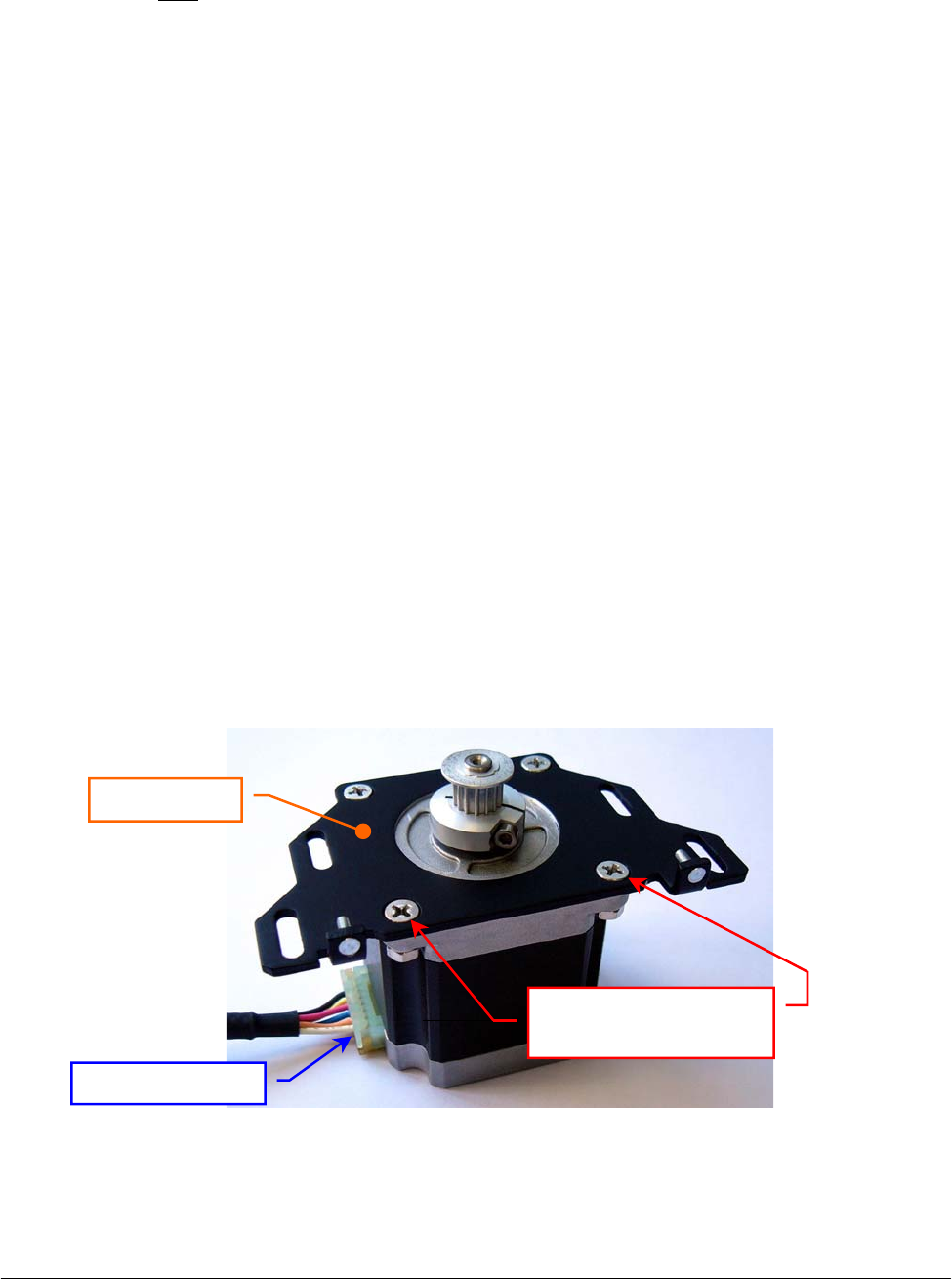
Chapter 05 – SETTINGS AND ADJUSTMENTS
SAT450 Service Manual Rev.00 03 July 2008 Page 50
10. Position the Reagents Plate Motor on its housing with the side of the motor connector oriented
towards the Reagents Plate Interface Board (Fig. 82) and with the anchor plate springs placed in
the relative slits, then tighten slightly its four fastening screws.
11. Push the motor toward the primary pulley, wrap the belt around the motor pulley, then leave free
the motor (note: the anchor plate springs give the right tension to the belt).
12. Turn the primary pulley and make sure that the belt thoots are correctly inserted on the Reagents
Plate Motor pulley and on the primary pulley.
13. Tighten the four fastening screws of the Reagents Plate Motor (Fig. 82).
14. Plug the Reagents Plate Motor connector in the J5 connector of the Reagents Plate Interface
Board (compare the scheme SC-30-02190-00).
15. Bring down the Raising Top (Fig. 7) and screw the two captive screws on the front underside of
the instrument (Fig. 6).
16. Perform the procedure “Mechanical adjustments of the Reagents Plate” described into the
previous Section 6.5.1 .
5.5.5 Replacement of the Satellites Mov. Reagents Plate Motor
1. Make sure that the SAT450 instrument is turned off, then unscrew the two captive screws on the
front underside of the instrument (Fig. 6) and lift up the Raising Top (Fig. 7).
2. Unplug the J3 connector from the Reagents Plate Interface Board (compare the sch. SC-30-02190-00).
3. Unscrew the four fastening screws of the Satellites Mov. Reagents Plate Motor (Fig. 82).
4. Remove the belt from the pulley of the Satellites Mov. Reagents Plate Motor and take out it
from its housing and the two anchor plate springs from the anchor plate.
5. Unscrew the four fastening screws of the Satellites Mov. Reagents Plate Motor anchor plate
(Fig. 87) and take out the anchor plate from the motor.
6. Loosen the pulley clamp screw and extract the pulley clamp and the pulley from the motor shaft
(Fig. 84).
Fig. 87 – Satellites Mov. Reagents Plate Motor anchor plate
Motor connecto
r
Anchor plate
Fastening screws of
the motor anchor plate

Chapter 05 – SETTINGS AND ADJUSTMENTS
SAT450 Service Manual Rev.00 03 July 2008 Page 51
To replace the new Satellites Mov. Reagents Plate Motor (Fig. 85) perform the following steps:
7. Insert the pulley clamp completely on the motor pulley (Fig. 86) and then insert all two on the
motor shaft.
8. Position the motor pulley to 2.00 mm with respect to upper motor plane (Fig. 86), then tighten
the pulley clamp screw.
9. Position the anchor plate on the upper plane of the new motor as showed in Fig. 87 and screw its
four fastening screws.
10. Position the Satellites Mov. Reagents Plate Motor on its housing with the side of the motor
connector oriented towards the Reagents Plate Interface Board (Fig. 82) and with the anchor
plate springs placed in the relative slits, then tighten slightly its four fastening screws.
11. Push the motor toward the secondary pulley, wrap the belt around the motor pulley, then leave
free the motor (note: the anchor plate springs give the right tension to the belt).
12. Turn the secondary pulley and make sure that the belt thoots are correctly inserted on the
Satellites Mov. Reagents Plate Motor pulley and on the secondary pulley.
13. Tighten the four fastening screws of the Satellites Mov. Reagents Plate Motor (Fig. 82).
14. Plug the Satellites Mov. Reagents Plate Motor connector in the J3 connector of the Reagents
Plate Interface Board (compare the scheme SC-30-02190-00).
15. Bring down the Raising Top (Fig. 7) and screw the two captive screws on the front underside of
the instrument (Fig. 6).
16. Perform the procedure “Mechanical adjustments of the Reagents Plate” described into the
previous Section 6.5.1 .
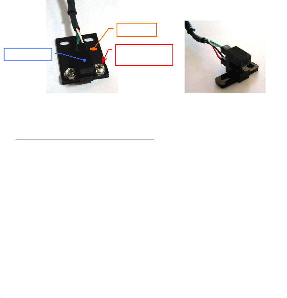
Chapter 05 – SETTINGS AND ADJUSTMENTS
SAT450 Service Manual Rev.00 03 July 2008 Page 52
5.5.6 Replacement of the Reagents Plate Home Sensor
1. Make sure that the SAT450 instrument is turned off.
2. Unscrew the two captive screws on the front underside of the instrument (Fig. 6) and lift up the
Raising Top (Fig. 7).
3. Unplug the J4 connector from the Reagents Plate Interface Board (compare the sch. SC-30-02190-00).
4. Unscrew the two fastening screws of the Reagents Plate Home Sensor (Fig. 82) and take out the
sensor from its housing on the Reagents Plate Assy.
5. Unscrew the two keep plate fastening screws of the Reagents Plate Home Sensor (Fig. 88) and
take out the sensor from the keep plate.
To replace the new Reagents Plate Home Sensor (Fig. 89) perform the following steps:
6. Position the keep plate below the new home sensor as showed in Fig. 88, center the sensor with
respect to the keep plate and screw its two fastening screws.
7. Position the new home sensor on its housing of the Reagents Plate Assy - as showed in
Fig. 82 - in order to obtain that the primary pulley disk is centered with respect to the internal
sides of the home sensor.
8. Screw the two fastening screws of the Reagents Plate Home Sensor (Fig. 82).
9. Turn the primary pulley and make sure that the primary pulley disk does not touch the Reagents
Plate Home Sensor.
10. Plug the Reagents Plate Home Sensor connector in the J4 connector of the Reagents Plate
Interface Board (compare the scheme SC-30-02190-00).
11. Bring down the Raising Top (Fig. 7) and screw the two captive screws on the front underside of
the instrument (Fig. 6).
12. Perform the procedure “Mechanical adjustments of the Reagents Plate” described into the
previous Section 6.5.1 .
Fig. 88 – Keep plate fastening screws
of the Home Sensor
Fig. 89 – Home Sensor Ass
y
[P/N: 9-10-0023-20]
Home Senso
r
Keep plate
Fastening screw
of the keep plate

Chapter 05 – SETTINGS AND ADJUSTMENTS
SAT450 Service Manual Rev.00 03 July 2008 Page 53
5.5.7 Replacement of the Satellites Mov. Reagents Plate Home Sensor
1. Make sure that the SAT450 instrument is turned off.
2. Unscrew the two captive screws on the front underside of the instrument (Fig. 6) and lift up the
Raising Top (Fig. 7).
3. Unplug the J2 connector from the Reagents Plate Interface Board (compare the sch. SC-30-02190-00).
4. Unscrew the two fastening screws of the Satellites Mov. Reagents Plate Home Sensor (Fig. 82)
and take out the sensor from its housing on the Reagents Plate Assy.
5. Unscrew the two keep plate fastening screws of the Satellites Mov. Reagents Plate Home Sensor
(Fig. 88) and take out the sensor from the keep plate.
To replace the new Sat. Mov. Reagents Plate Home Sensor (Fig. 89) perform the following steps:
6. Position the keep plate below the new home sensor as showed in Fig. 88, center the sensor with
respect to the keep plate and screw its two fastening screws.
7. Position the new home sensor on its housing of the Reagents Plate Assy - as showed in
Fig. 82 - in order to obtain that the secondary pulley disk is centered with respect to the internal
sides of the home sensor.
8. Screw the two fastening screws of the Satellites Mov. Reagents Plate Home Sensor (Fig. 82).
9. Turn the secondary pulley and make sure that the secondary pulley disk does not touch the
Reagents Plate Home Sensor.
10. Plug the Satellites Mov. Reagents Plate Home Sensor connector in the J2 connector of the
Reagents Plate Interface Board (compare the scheme SC-30-02190-00).
11. Bring down the Raising Top (Fig. 7) and screw the two captive screws on the front underside of
the instrument (Fig. 6).
12. Perform the procedure “Mechanical adjustments of the Reagents Plate” described into the
previous Section 6.5.1 .
5.5.8 Replacement of the Reagents Plate Belt
1. Make sure that the SAT450 instrument is turned off, then unscrew the two captive screws on the
front underside of the instrument (Fig. 6) and lift up the Raising Top (Fig. 7).
2. Loosen the four fastening screws of the Reagents Plate Motor and remove the Reagents Plate
Belt from the pulley of the Reagents Plate Motor (Fig. 82).
3. Unscrew the two fastening screws of the Reagents Plate Home Sensor (Fig. 82) and take out the
sensor from its housing on the Reagents Plate Assy.
4. Remove the Reagents Plate Belt from the primary pulley (Fig. 82).
To replace the new Reagents Plate Belt (Fig. 90) perform the following steps:
5. Wrap the new belt around the primary pulley.
6. Push the Reagents Plate Motor toward the primary pulley, wrap the new belt around the motor
pulley, then leave free the motor (note: the anchor plate springs give the right tension to the
belt).

Chapter 05 – SETTINGS AND ADJUSTMENTS
SAT450 Service Manual Rev.00 03 July 2008 Page 54
7. Turn the primary pulley and make sure that the new belt thoots are correctly inserted on the
Reagents Plate Motor pulley and on the primary pulley.
8. Tighten the four fastening screws of the Reagents Plate Motor (Fig. 82).
9. Position the Reagents Plate Home Sensor on its housing of the Reagents Plate Assy - as showed
in Fig. 82 - in order to obtain that the primary pulley disk is centered with respect to the internal
sides of the home sensor.
10. Screw the two fastening screws of the Reagents Plate Home Sensor (Fig. 82).
11. Turn the primary pulley and make sure that the primary pulley disk does not touch the Reagents
Plate Home Sensor.
12. Bring down the Raising Top (Fig. 7) and screw the two captive screws on the front underside of
the instrument (Fig. 6).
13. Perform the procedure “Mechanical adjustments of the Reagents Plate” described into the
previous Section 6.5.1 .
Fig. 90 – Plate Belt [P/N: 86-02334-11]
5.5.9 Replacement of the Satellites Mov. Reagents Plate Belt
1. Remove the Reagents Plate Belt from the Reagents Plate Assy performing the relative procedure
described into the previous Section 6.5.8, from step 1 to step 4.
2. Loosen the four fastening screws of the Satellites Mov. Reagents Plate Motor and remove the
Satellites Mov. Reagents Plate Belt from the pulley of the Satellites Mov. Reagents Plate Motor
(Fig. 82).
3. Unscrew the two fastening screws of the Satellites Mov. Reagents Plate Home Sensor (Fig. 82)
and take out the sensor from its housing on the Reagents Plate Assy.
4. Remove the Satellites Mov. Reagents Plate Belt from the secondary pulley (Fig. 82).
To replace the new Satellites Mov. Reagents Plate Belt (Fig. 90) perform the following steps:
5. Wrap the new belt around the secondary pulley.
6. Push the Satellites Mov. Reagents Plate Motor toward the secondary pulley, wrap the new belt
around the motor pulley, then leave free the motor (note: the anchor plate springs give the right
tension to the belt).
7. Turn the secondary pulley and make sure that the new belt thoots are correctly inserted on the
Satellites Mov. Reagents Plate Motor pulley and on the secondary pulley.
8. Tighten the four fastening screws of the Satellites Mov. Reagents Plate Motor (Fig. 82).
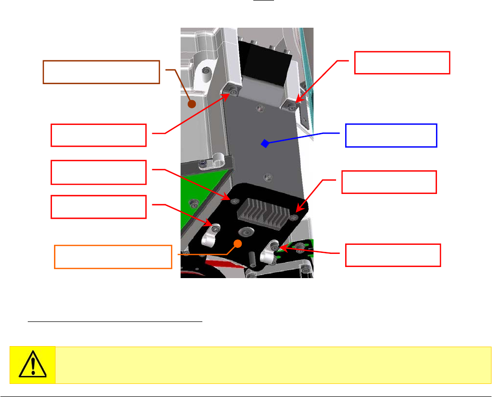
Chapter 05 – SETTINGS AND ADJUSTMENTS
SAT450 Service Manual Rev.00 03 July 2008 Page 55
9. Position the Satellites Mov. Reagents Plate Home Sensor on its housing of the Reagents Plate
Assy - as showed in Fig. 82 - in order to obtain that the secondary pulley disk is centered with
respect to the internal sides of the home sensor.
10. Screw the two fastening screws of the Satellites Mov. Reagents Plate Home Sensor (Fig. 82).
11. Turn the secondary pulley and make sure that the secondary pulley disk does not touch the
Satellites Mov. Reagents Plate Home Sensor.
12. Replace the Reagents Plate Belt in the Reagents Plate Assy performing the relative procedure
described into the previous Section 6.5.8, from step 5 to step 11.
13. Bring down the Raising Top (Fig. 7) and screw the two captive screws on the front underside of
the instrument (Fig. 6).
14. Perform the procedure “Mechanical adjustments of the Reagents Plate” described into the
previous Section 6.5.1 .
5.5.10 Replacement of the Cooler Module
1. Make sure that the SAT450 instrument is turned off.
2. Unscrew the two captive screws on the front underside of the instrument (Fig. 6) and lift up the
Raising Top (Fig. 7).
3. Unplug the connector of the Cooler Module’s cables from the relative connector of the Reagents
Plate wiring (P/N: 50-02602-00) as showed in the scheme SC-30-02190-00.
4. Unscrew the six fastening screws of the Cooler Module (Fig. 91) and take out the Cooler Module
from its housing on the Reagents Plate Assy (note: unscrewing the four fastening screw placed on
the Cooler Module plate, it and the remain part of the module do not keep together).
To replace the new Cooler Module (compare the scheme MA-10-02536-01) perform the above
steps in inverse order: from 4 to 2.
Fig. 91 – Cooler Module [P/N:10-02536-01] on the Reagents Plate Assy
Replace the Cooler Module in the Reagents Plate Assy inserting the module from
the bottom towards the top in its housing.
Fastenin
g
screw
Fastenin
g
screw
Fastening screw
Fastenin
g
screw
Fastening screw
Fastening screw
Cooler Module
Cooler Module plate
Reagents Plate Assy
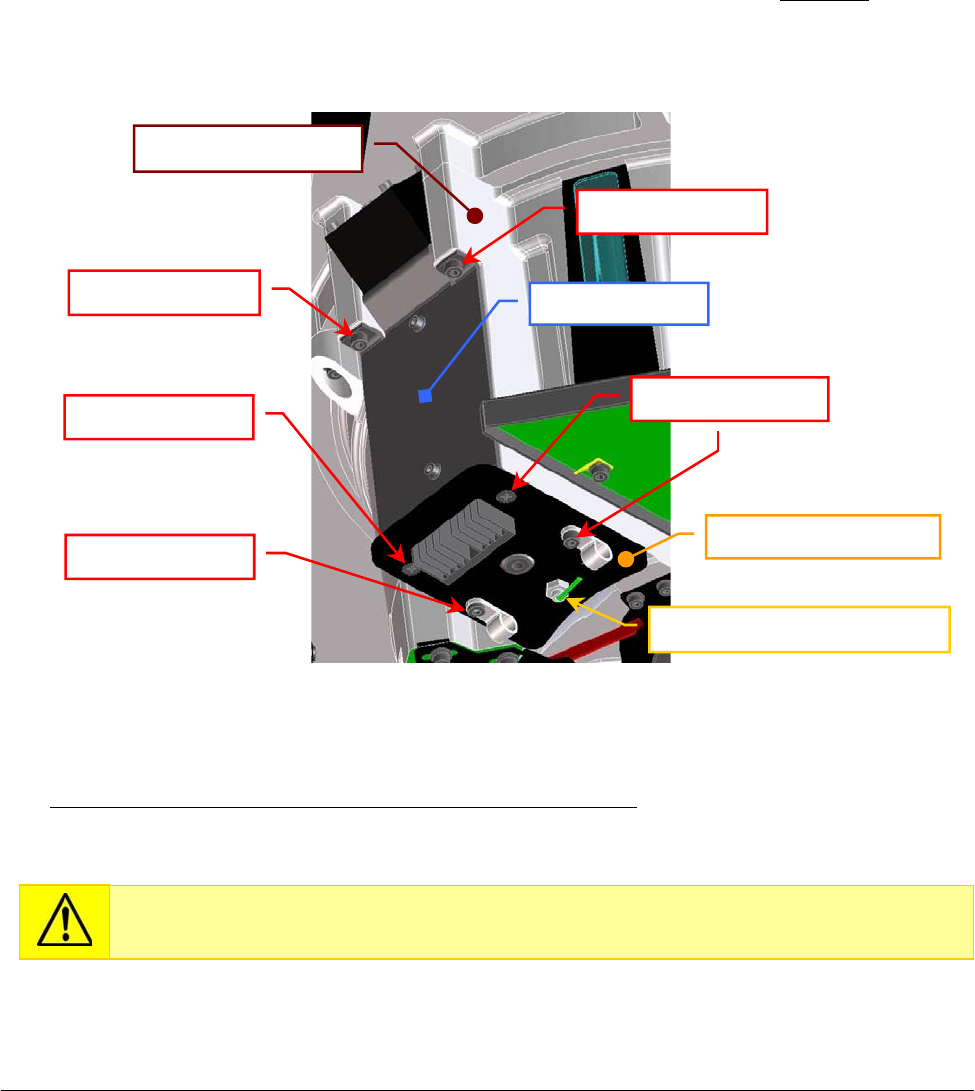
Chapter 05 – SETTINGS AND ADJUSTMENTS
SAT450 Service Manual Rev.00 03 July 2008 Page 5
6
5.5.11 Replacement of the Cooler Module with Temperature Sensor
1. Make sure that the SAT450 instrument is turned off.
2. Unscrew the two captive screws on the front underside of the instrument (Fig. 6) and lift up the
Raising Top (Fig. 7).
3. Unplug the connector of the Cooler Module’s cables from the relative connector of the Reagents
Plate wiring (P/N: 50-02602-00) as showed in the scheme SC-30-02190-00.
4. Unplug the J7 connector of the Cooler Temperature Sensor (P/N: 05-02351-28) from the
Reagents Plate Interface Board (compare the scheme SC-30-02190-00).
5. Unscrew the six fastening screws of the Cooler Module with Temperature Sensor (Fig. 92) and
take out the Cooler Module from its housing on the Reagents Plate Assy (note well: unscrewing
the four fastening screw placed on the Cooler Module plate, it and the remain part of the module
do not keep together).
To replace the new Cooler Module with Temperature Sensor (compare the sch. MA-10-02536-00),
perform the above steps in inverse order: from 5 to 2.
Fig. 92 – Cooler Module with Temperature Sensor [P/N: 10-02536-00]
on the Reagents Plate Assy
Replace the Cooler Module with Temperature Sensor in the Reagents Plate Assy
inserting the module from the bottom towards the top in its housing.
Fastenin
g
screw
Fastenin
g
screw Fastenin
g
screws
Fastenin
g
screw
Cooler Temperature Sensor
Fastenin
g
screw Cooler Module
Reagents Plate Assy
Cooler Module
p
late
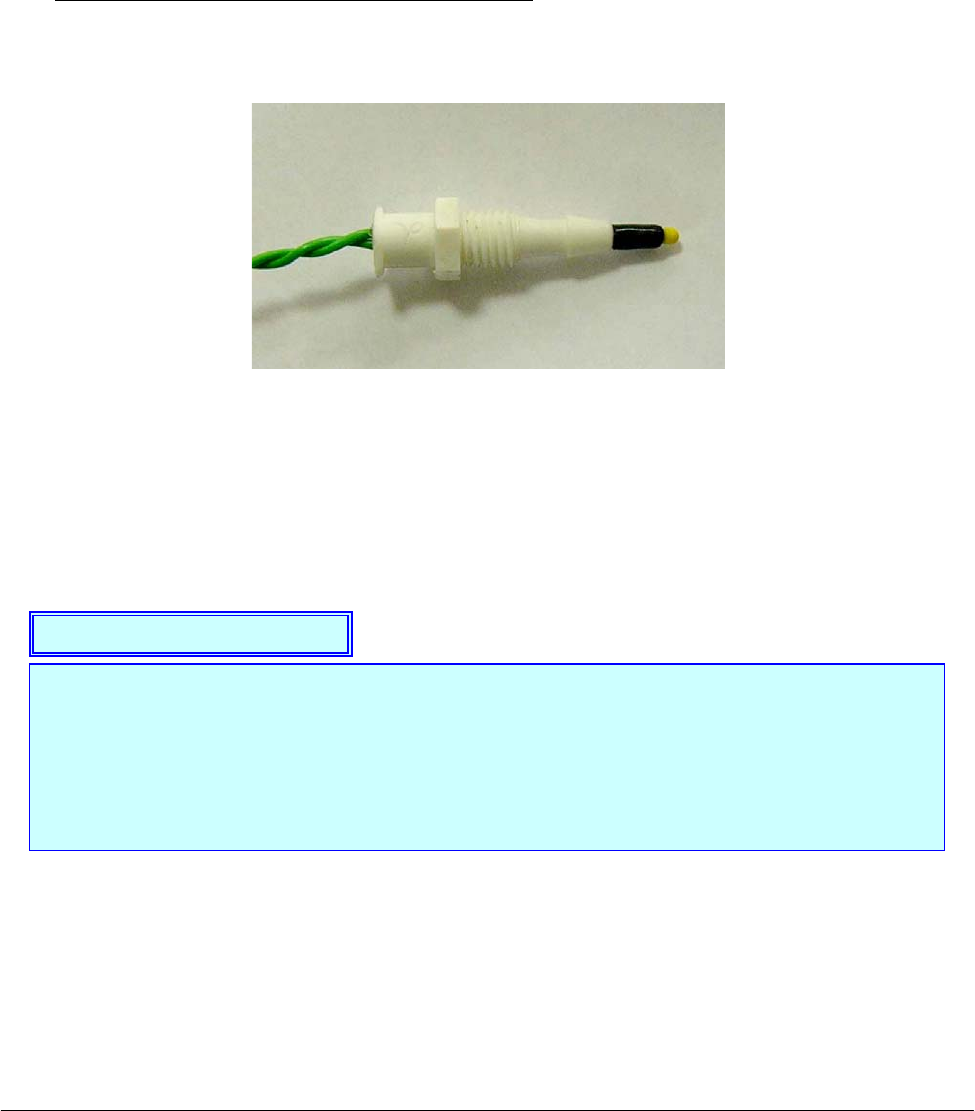
Chapter 05 – SETTINGS AND ADJUSTMENTS
SAT450 Service Manual Rev.00 03 July 2008 Page 5
7
5.5.12 Replacement of the Cooler Temperature Sensor
1. Make sure that the SAT450 instrument is turned off.
2. Unscrew the two captive screws on the front underside of the instrument (Fig. 6) and lift up the
Raising Top (Fig. 7).
3. Unplug the J7 connector of the Cooler Temperature Sensor (P/N: 05-02351-28) from the
Reagents Plate Interface Board (compare the scheme SC-30-02190-00).
4. Unscrew the Cooler Temperature Sensor from the plate of the relative Cooler Module with
P/N: 10-02536-00 (compare the scheme MA-10-02536-00 and the Fig. 92).
To replace the new Cooler Temperature Sensor (Fig. 93) perform the above steps in inverse
order: from 4 to 2.
Fig. 93 – Cooler Temperature Sensor [P/N: 05-02351-30]
The Peltier cells of the Cooler Modules “1” and “3” (compare the Fig. 82) constitute the
Peltier cells Assy 2, whereas the Peltier cells of the Cooler Modules “2” and “4” constitute
the Peltier cells Assy 1.
The lighting of the two yellow leds LD1 and LD2 of the Reagents Plate Interface Board
show the power up to the Peltier cells Assy 1 and to the Peltier cells Assy 2, respectively
(compare the scheme SE-30-02190-00).
Note on the Cooler Modules

Chapter 05 – SETTINGS AND ADJUSTMENTS
SAT450 Service Manual Rev.00 03 July 2008 Page 58
5.6 SAMPLES PLATE
5.6.1 Mechanical adjustments of the Samples Plate
1. Lift up the instrument cover, remove the Samples Plate cover and the Sample Plate safety
protection (Fig. 7) from the Samples Plate.
2. Turn on the SAT450 system (instrument and computer) and launch the “Diagnostic” program.
3. Select "Plates” folder and request an Samples Plate reset. Wait until the reset Samples Plate
procedure has been completed.
4. Make sure that the two Home Sensors of the Samples Plate light up in green.
5. Select “Arm” folder and request an Arm reset. Wait until the reset Sampling Arm procedure has
been completed.
6. Make sure that the Vertical and Horizontal Home Sensors of the Sampling Arm light up in
green.
7. Select "Plates” folder, choose the N° Cup #68 of the Samples Plate, then click the correspondent
“To Asp.” button. Wait until the requested operation has been completed.
8. Select “Arm” folder, choose the “(sA..sD)” option of the “Go Sample” button, click the
“Go Sample” button, then click the correspondent “Down” button. The Sampling Arm will
move to selected aspiration position of the Samples Plate, then it will go down until to reach the
right height.
9. Make sure that the Sampling Probe is centered with respect to the position #68 (sD-2 position)
of the Samples Plate. If it not be so, center the four Peripheral Racks of the Samples Plate in the
following way:
a. unscrew the two captive screws on the front underside of the instrument (Fig. 6) and
lift up the Raising Top (Fig. 7);
b. loosen the two set screws of the primary pulley of the Samples Plate (Fig. 94);
c. center the position #68 (sD-2 position) with respect to the Sampling Probe, rotating
slowly the Samples Plate;
d. tighten the two set screws of the primary pulley of the Samples Plate (Fig. 94);
e. bring down the Raising Top (Fig. 7) and screw the two captive screws on the front
underside of the instrument (Fig. 6).
10. Select "Arm” folder and request an Arm reset. Wait until the reset Sampling Arm procedure has
been completed.
11. Select "Plates” folder and request an Samples Plate reset. Wait until the reset Samples Plate
procedure has been completed.
12. Select the N° Cup #1 of the Samples Plate, then click the correspondent “To Asp.” button. Wait
until the requested operation has been completed.
13. Select "Arm” folder, choose the “Sat (A..D) Pos. 1” option of the “Go Sample” button, click the
“Go Sample” button, then click the correspondent “Down” button. The Sampling Arm will
move to selected aspiration position of the Samples Plate, then it will go down until to reach the
right height.
Make sure that the position #1 of the Satellite Rack “A” is contemporaneously aligned
with respect to the position #1 of the Satellite Racks “B”, “C” and “D” of the Samples
Plate (Fig. 97). If it not be so, perform the procedure “Mechanical alignments of the
Satellite Racks of the Samples Plate” described into the following Section 6.6.3 .
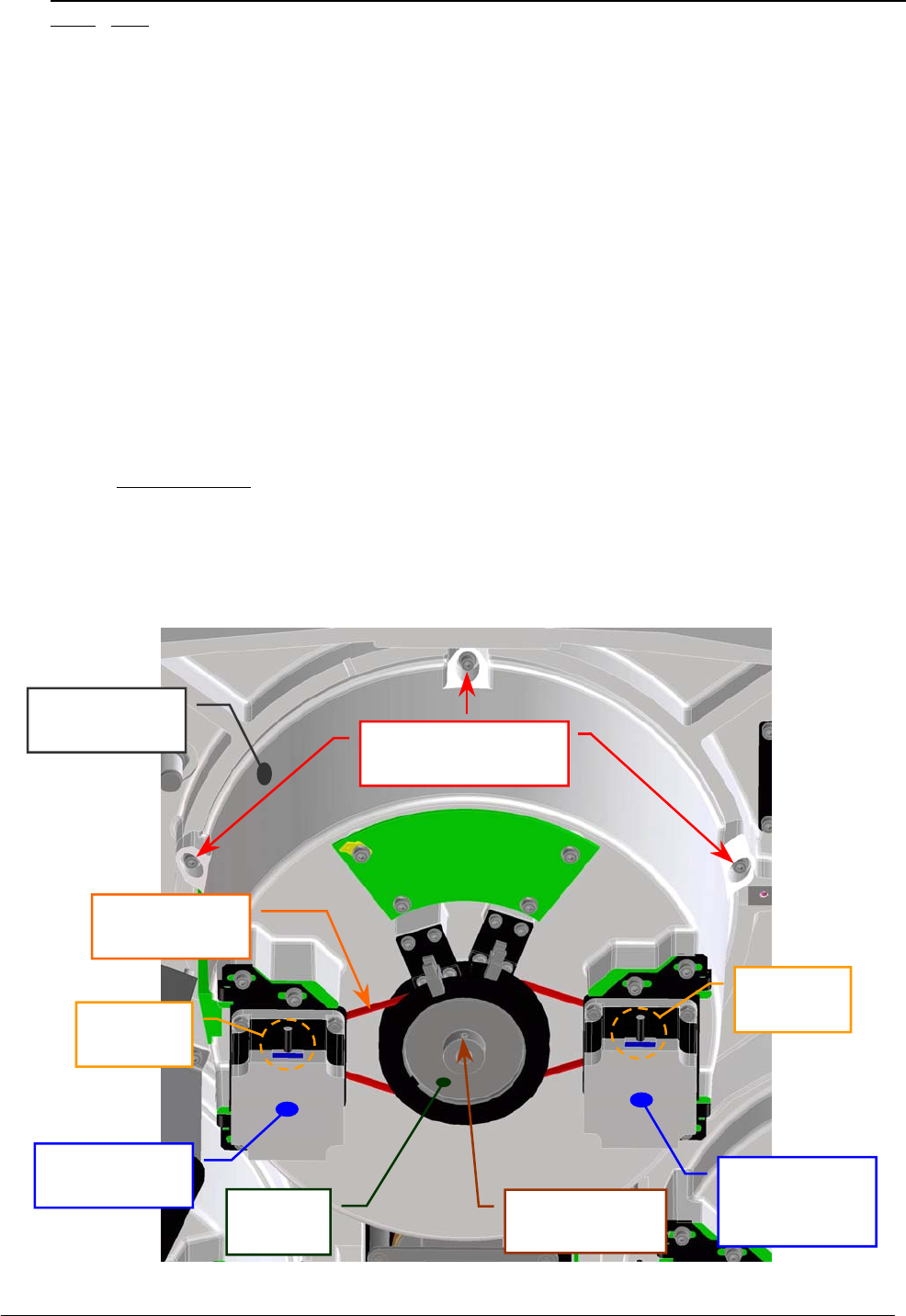
Chapter 05 – SETTINGS AND ADJUSTMENTS
SAT450 Service Manual Rev.00 03 July 2008 Page 59
14. Make sure that the Sampling Probe is centered with respect to the position #1 of the Samples
Plate (note: the position#1 of the Samples Plate is the position#1 of the Satellite Rack “A”).
If it not be so, center the four Satellite Racks of the Samples Plate in the following way:
f. unscrew the two captive screws on the front underside of the instrument (Fig. 6) and
lift up the Raising Top (Fig. 7);
g. loosen the two set screws of the secondary pulley of the Samples Plate (Fig. 95);
h. center the position #1 of the Satellite Rack “A” with respect to the Sampling Probe,
rotating slowly the Satellite Rack “A”;
i. lever on the primary pulley with a flat head screwdriver in order to obtain that the
secondary pulley is locked on the end of the run, and then tighten the two set screws of
the secondary pulley of the Samples Plate (Fig. 95);
j. bring down the Raising Top (Fig. 7) and screw the two captive screws on the front
underside of the instrument (Fig. 6).
15. Request an Arm reset in the “Arm” folder. Wait until the reset Sampling Arm procedure has
been completed.
16. Make sure that the Vertical and Horizontal Home Sensors of the Sampling Arm light up in
green.
17. Select "Plates” folder and request a Samples Plate reset. Wait until the reset Samples Plate
procedure has been completed.
18. Make sure that the two Home Sensors of the Samples Plate light up in green.
19. Replace the Samples Plate cover and the Samples Plate safety protection on the Samples Plate
(Fig. 7) and bring down the instrument cover (Fig. 7).
Fig. 94 – Primary pulley of the Samples Plate Assy
Samples Plate
Interface Boar
d
Samples Plate Assy
fastenin
g
screws
Samples Plate
Belt
Motor
connecto
r
Samples Plate
Moto
r
Primary
p
ulle
y
Primary pulley
set screw
Motor
connecto
r
Satellites
Mov. Samples
Plate Moto
r
Samples Plate
Ass
y
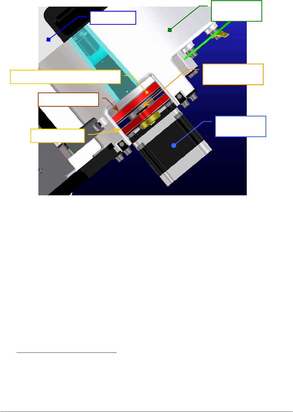
Chapter 05 – SETTINGS AND ADJUSTMENTS
SAT450 Service Manual Rev.00 03 July 2008 Page 60
Fig. 95 – Secondary pulley of the Samples Plate Assy
5.6.2 Remotion of the Samples Plate Assy from the Raising Top
1. Make sure that the SAT450 instrument is turned off.
2. Lift up the instrument cover, then remove the Samples Plate cover and the Samples Plate safety
protection (Fig. 7) from the Samples Plate.
3. Unscrew the two captive screws on the front underside of the instrument (Fig. 6) and lift up the
Raising Top (Fig. 7).
4. Unplug the J1, J4, J5, J8, J13 and J14 connectors and the ground wire from the Samples Plate
Interface Board (compare the scheme SC-30-02191-00).
5. Unscrew the five Samples Plate Assy fastening screws (Fig. 94) and take out – moving carefully
– the Samples Plate Assy from its housing.
To replace the Samples Plate Assy (Fig. 96) perform the following steps:
6. Repeat the above steps in inverse order: from 5 to 3.
7. Perform the procedure “Mechanical adjustments of the Samples Plate” described into the
previous Section 6.6.1, from step 2 to step 19.
Samples Plate
Moto
r
Secondary pulley
set screw
Samples Plate
Ass
y
Raisin
g
To
p
Secondary pulley
Primary pulley
Satellites Mov. Samples Plate Belt
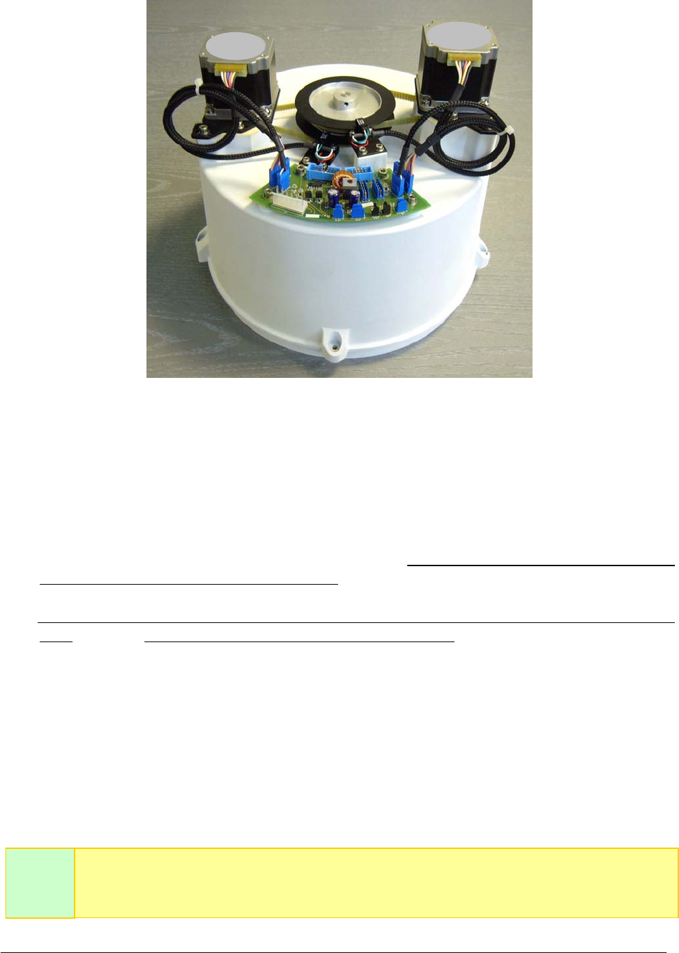
Chapter 05 – SETTINGS AND ADJUSTMENTS
SAT450 Service Manual Rev.00 03 July 2008 Page 61
Fig. 96 – Samples Plate Assy
5.6.3 Mechanical alignments of the Satellite Racks of the Samples Plate
1. Remove the Samples Plate Assy from its housing performing the relative procedure described
into the previous Section 6.6.2, from step 1 to step 5.
2. Considering that the plate base of the Samples Plate is just alike to the plate base of the Reagents
Plate (with the exception of the four Peripheral Racks), perform the procedure described into the
previous Section 6.5.3, from step 2 to step 24, on the Samples Plate Assy.
To replace the plate base (Samples Plate support having P/N: 05-02271-00) in the Samples Plate
Assy (Fig. 96) and the Samples Plate Assy in the instrument (Fig. 94) perform the following
steps:
3. Put the plate base into the container of the Samples Plate Assy inserting the central pin into the
apposite hole until the end of the run.
4. Lock on well the primary and secondary pulley over the container and between them, then
tighten the two set screws of the primary pulley and the two set screws of the secondary pulley
of the Samples Plate (Fig. 94).
5. Perform the procedure “Replacement of the Satellites Mov. Samples Plate Belt” described into
the next Section 6.6.9, from step 5 to step 14.
The Fig. 97 shows the position #1 of the Satellite Rack “A” contemporaneously aligned
with respect to the position #1 of the Satellite Racks “B”, “C” and “D” in the home
p
osition of the Samples Plate.
Note
well
Motor Motor
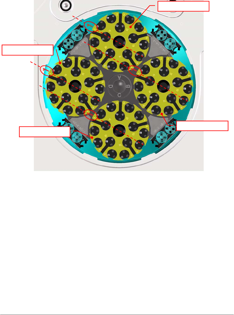
Chapter 05 – SETTINGS AND ADJUSTMENTS
SAT450 Service Manual Rev.00 03 July 2008 Page 62
Fig. 97 – Satellite Racks “A”, “B”, “C”, “D” of the Samples Plate (top view)
Satellite Rack “A”
Satellite Rack “B”
Satellite Rack “D”
Satellite Rack “C”
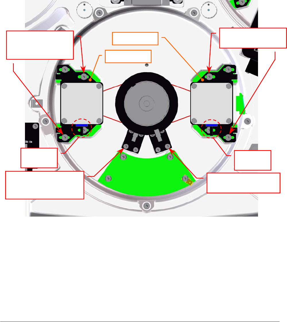
Chapter 05 – SETTINGS AND ADJUSTMENTS
SAT450 Service Manual Rev.00 03 July 2008 Page 63
5.6.4 Replacement of the Samples Plate Motor
1. Make sure that the SAT450 instrument is turned off, then unscrew the two captive screws on the
front underside of the instrument (Fig. 6) and lift up the Raising Top (Fig. 7).
2. Unplug the J6 connector from the Samples Plate Interface Board (compare the sch. SC-30-02191-00).
3. Unscrew the four fastening screws of the Samples Plate Motor (Fig. 98).
4. Remove the belt from the pulley of the Samples Plate Motor and take out it from its housing and
the two anchor plate springs from the anchor plate.
5. Unscrew the four fastening screws of the Samples Plate Motor anchor plate (Fig. 763) and take
out the anchor plate from the motor.
Samples Plate
Interface Board
Satellites
Mov. Samples
Plate Motor
Samples
Plate
Moto
r
Motor
connecto
r
Motor
connecto
r
Satellites Mov.
Samples Plate Motor
fastenin
g
screws
Samples Plate Motor
fastenin
g
screws
Anchor
p
late
Anchor
p
late
Satellites Mov. Samples
Plate Home Sensor
fastenin
g
screw
Samples Plate Home
Sensor fastenin
g
screw
Fig. 98 – Samples Plate Motor and Satellites Mov. Samples Plate Motor
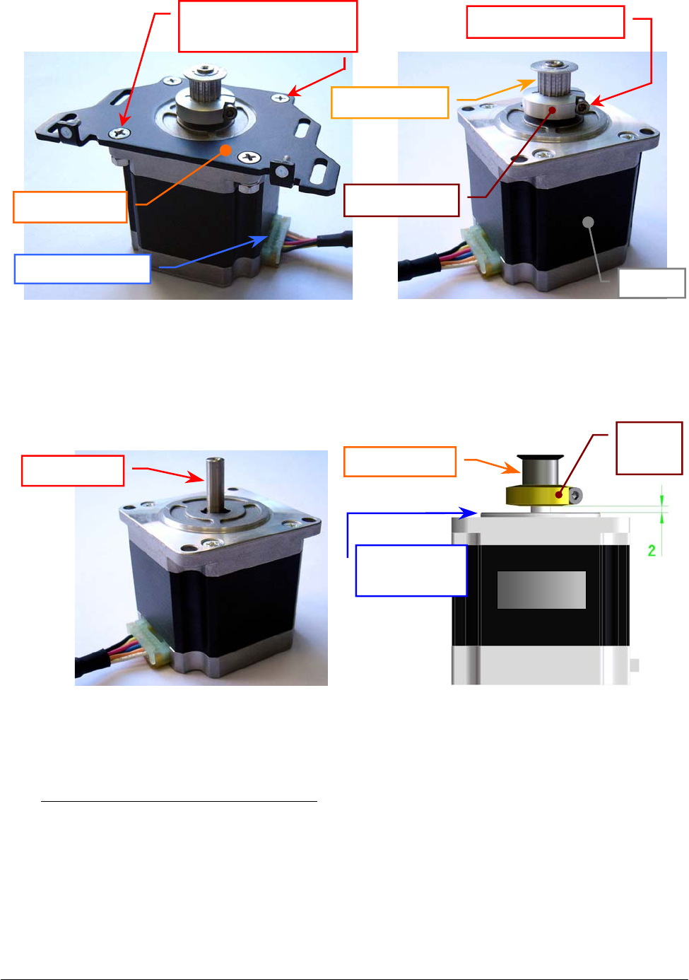
Chapter 05 – SETTINGS AND ADJUSTMENTS
SAT450 Service Manual Rev.00 03 July 2008 Page 64
6. Loosen the pulley clamp screw and extract the pulley clamp and the pulley from the motor shaft
(Fig. 100).
To replace the new Samples Plate Motor (Fig. 101) perform the following steps:
7. Insert the pulley clamp completely on the motor pulley (Fig. 102) and then insert all two on the
motor shaft.
8. Position the motor pulley to 2.00 mm with respect to upper motor plane (Fig. 102), then tighten
the pulley clamp screw.
9. Position the anchor plate on the upper plane of the new motor as showed in Fig. 99 and screw its
four fastening screws.
Fig. 99 – Samples Plate Motor anchor plate Fig. 100 – Motor pulley
Anchor
p
late
Fastening screws of
the motor anchor plate
Motor connecto
r
Motor
p
ulle
y
Pulley clamp
Pulley clamp screw
Moto
r
Fig. 101 – Samples Plate Motor / Satellites
Mov. Samples Plate Motor
[P/N: 9-10-0016-00]
Fig. 102 – Plate Motor (scheme)
Motor shaf
t
Motor
p
ulle
y
Motor
Upper motor
p
lane
Pulley
clamp
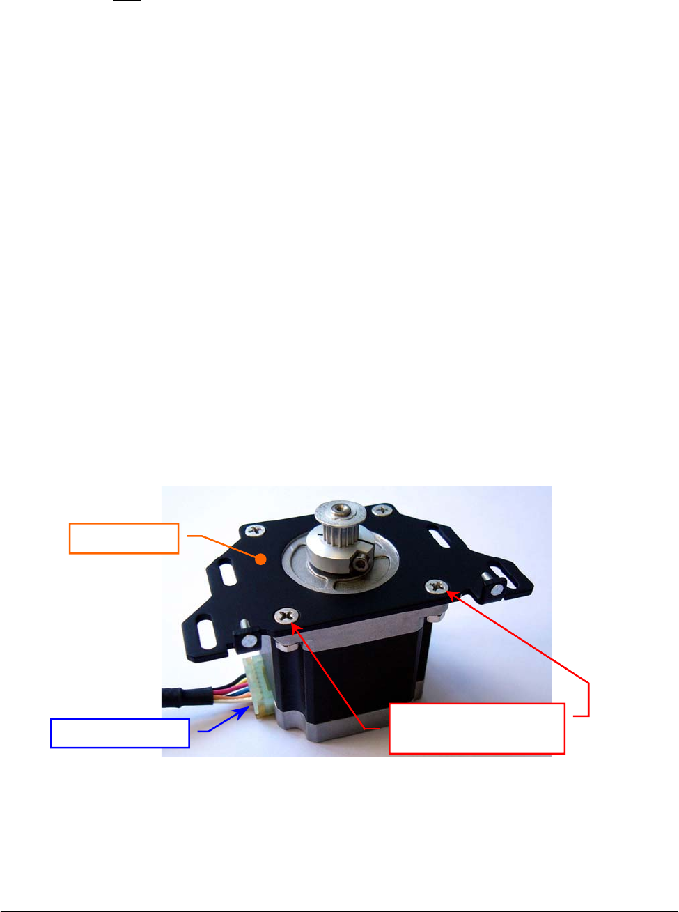
Chapter 05 – SETTINGS AND ADJUSTMENTS
SAT450 Service Manual Rev.00 03 July 2008 Page 65
10. Position the Samples Plate Motor on its housing with the side of the motor connector oriented
towards the Samples Plate Interface Board (Fig. 98) and with the anchor plate springs placed in
the relative slits, then tighten slightly its four fastening screws.
11. Push the motor toward the primary pulley, wrap the belt around the motor pulley, then leave free
the motor (note: the anchor plate springs give the right tension to the belt).
12. Turn the primary pulley and make sure that the belt thoots are correctly inserted on the Samples
Plate Motor pulley and on the primary pulley.
13. Tighten the four fastening screws of the Samples Plate Motor (Fig. 98).
14. Plug the Samples Plate Motor connector in the J6 connector of the Samples Plate Interface
Board (compare the scheme SC-30-02191-00).
15. Bring down the Raising Top (Fig. 7) and screw the two captive screws on the front underside of
the instrument (Fig. 6).
16. Perform the procedure “Mechanical adjustments of the Samples Plate” described into the
previous Section 6.6.1.
5.6.5 Replacement of the Satellites Mov. Samples Plate Motor
1. Make sure that the SAT450 instrument is turned off, then unscrew the two captive screws on the
front underside of the instrument (Fig. 6) and lift up the Raising Top (Fig. 7).
2. Unplug the J2 connector from the Samples Plate Interface Board (compare the sch. SC-30-02191-00).
3. Unscrew the four fastening screws of the Satellites Mov. Samples Plate Motor (Fig. 98).
4. Remove the belt from the pulley of the Satellites Mov. Samples Plate Motor and take out it from
its housing and the two anchor plate springs from the anchor plate.
5. Unscrew the four fastening screws of the Satellites Mov. Samples Plate Motor anchor plate
(Fig. 103) and take out the anchor plate from the motor.
6. Loosen the pulley clamp screw and extract the pulley clamp and the pulley from the motor shaft
(Fig. 100).
Fig. 103 – Satellites Mov. Samples Plate Motor anchor plate
Motor connecto
r
Anchor
p
late
Fastening screws of
the motor anchor plate
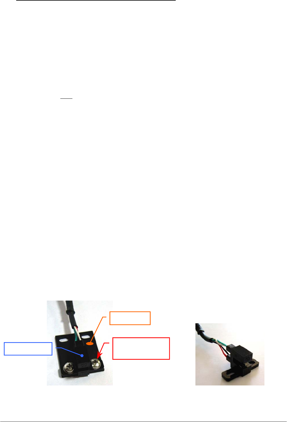
Chapter 05 – SETTINGS AND ADJUSTMENTS
SAT450 Service Manual Rev.00 03 July 2008 Page 6
6
To replace the new Satellites Mov. Samples Plate Motor (Fig. 101) perform the following steps:
7. Insert the pulley clamp completely on the motor pulley (Fig. 102) and then insert all two on the
motor shaft.
8. Position the motor pulley to 2.00 mm with respect to upper motor plane (Fig. 102), then tighten
the pulley clamp screw.
9. Position the anchor plate on the upper plane of the new motor as showed in Fig. 103 and screw
its four fastening screws.
10. Position the Satellites Mov. Samples Plate Motor on its housing with the side of the motor
connector oriented towards the Samples Plate Interface Board (Fig. 98) and with the anchor
plate springs placed in the relative slits, then tighten slightly its four fastening screws.
11. Push the motor toward the secondary pulley, wrap the belt around the motor pulley, then leave
free the motor (note: the anchor plate springs give the right tension to the belt).
12. Turn the secondary pulley and make sure that the belt thoots are correctly inserted on the
Satellites Mov. Samples Plate Motor pulley and on the secondary pulley.
13. Tighten the four fastening screws of the Satellites Mov. Samples Plate Motor (Fig. 98).
14. Plug the Satellites Mov. Samples Plate Motor connector in the J2 connector of the Samples Plate
Interface Board (compare the scheme SC-30-02191-00).
15. Bring down the Raising Top (Fig. 7) and screw the two captive screws on the front underside of
the instrument (Fig. 6).
16. Perform the procedure “Mechanical adjustments of the Samples Plate” described into the
previous Section 6.6.1.
5.6.6 Replacement of the Samples Plate Home Sensor
1. Make sure that the SAT450 instrument is turned off.
2. Unscrew the two captive screws on the front underside of the instrument (Fig. 6) and lift up the
Raising Top (Fig. 7).
3. Unplug the J7 connector from the Samples Plate Interface Board (compare the sch. SC-30-02191-00).
4. Unscrew the two fastening screws of the Samples Plate Home Sensor (Fig. 98) and take out the
sensor from its housing on the Samples Plate Assy.
5. Unscrew the two keep plate fastening screws of the Samples Plate Home Sensor (Fig. 104) and
take out the sensor from the keep plate.
Fig. 104 – Keep plate fastening screws
of the Home Sensor
Fig. 105 – Home Sensor Assy
[P/N: 9-10-0023-00]
Kee
p
p
late
Fastening screw
of the keep plate
Home Senso
r

Chapter 05 – SETTINGS AND ADJUSTMENTS
SAT450 Service Manual Rev.00 03 July 2008 Page 6
7
To replace the new Samples Plate Home Sensor (Fig. 105) perform the following steps:
6. Position the keep plate below the new home sensor as showed in Fig. 104, center the sensor with
respect to the keep plate and screw its two fastening screws.
7. Position the new home sensor on its housing of the Samples Plate Assy - as showed in
Fig. 98 - in order to obtain that the primary pulley disk is centered with respect to the internal
sides of the home sensor.
8. Screw the two fastening screws of the Samples Plate Home Sensor (Fig. 98).
9. Turn the primary pulley and make sure that the primary pulley disk does not touch the Samples
Plate Home Sensor.
10. Plug the Samples Plate Home Sensor connector in the J7 connector of the Samples Plate
Interface Board (compare the scheme SC-30-02191-00).
11. Bring down the Raising Top (Fig. 7) and screw the two captive screws on the front underside of
the instrument (Fig. 6).
12. Perform the procedure “Mechanical adjustments of the Samples Plate” described into the
previous Section 6.6.1 .
5.6.7 Replacement of the Satellites Mov. Samples Plate Home Sensor
1. Make sure that the SAT450 instrument is turned off.
2. Unscrew the two captive screws on the front underside of the instrument (Fig. 6) and lift up the
Raising Top (Fig. 7).
3. Unplug the J3 connector from the Samples Plate Interface Board (compare the sch. SC-30-02191-00).
4. Unscrew the two fastening screws of the Satellites Mov. Samples Plate Home Sensor (Fig. 98)
and take out the sensor from its housing on the Samples Plate Assy.
5. Unscrew the two keep plate fastening screws of the Satellites Mov. Samples Plate Home Sensor
(Fig. 104) and take out the sensor from the keep plate.
To replace the new Sat. Mov. Samples Plate Home Sensor (Fig. 105) perform the following steps:
6. Position the keep plate below the new home sensor as showed in Fig. 104, center the sensor with
respect to the keep plate and screw its two fastening screws.
7. Position the new home sensor on its housing of the Samples Plate Assy - as showed in
Fig. 98 - in order to obtain that the secondary pulley disk is centered with respect to the internal
sides of the home sensor.
8. Screw the two fastening screws of the Satellites Mov. Samples Plate Home Sensor (Fig. 98).
9. Turn the secondary pulley and make sure that the secondary pulley disk does not touch the
Samples Plate Home Sensor.
10. Plug the Satellites Mov. Samples Plate Home Sensor connector in the J3 connector of the
Samples Plate Interface Board (compare the scheme SC-30-02191-00).
11. Bring down the Raising Top (Fig. 7) and screw the two captive screws on the front underside of
the instrument (Fig. 6).
12. Perform the procedure “Mechanical adjustments of the Samples Plate” described into the
previous Section 6.6.1 .
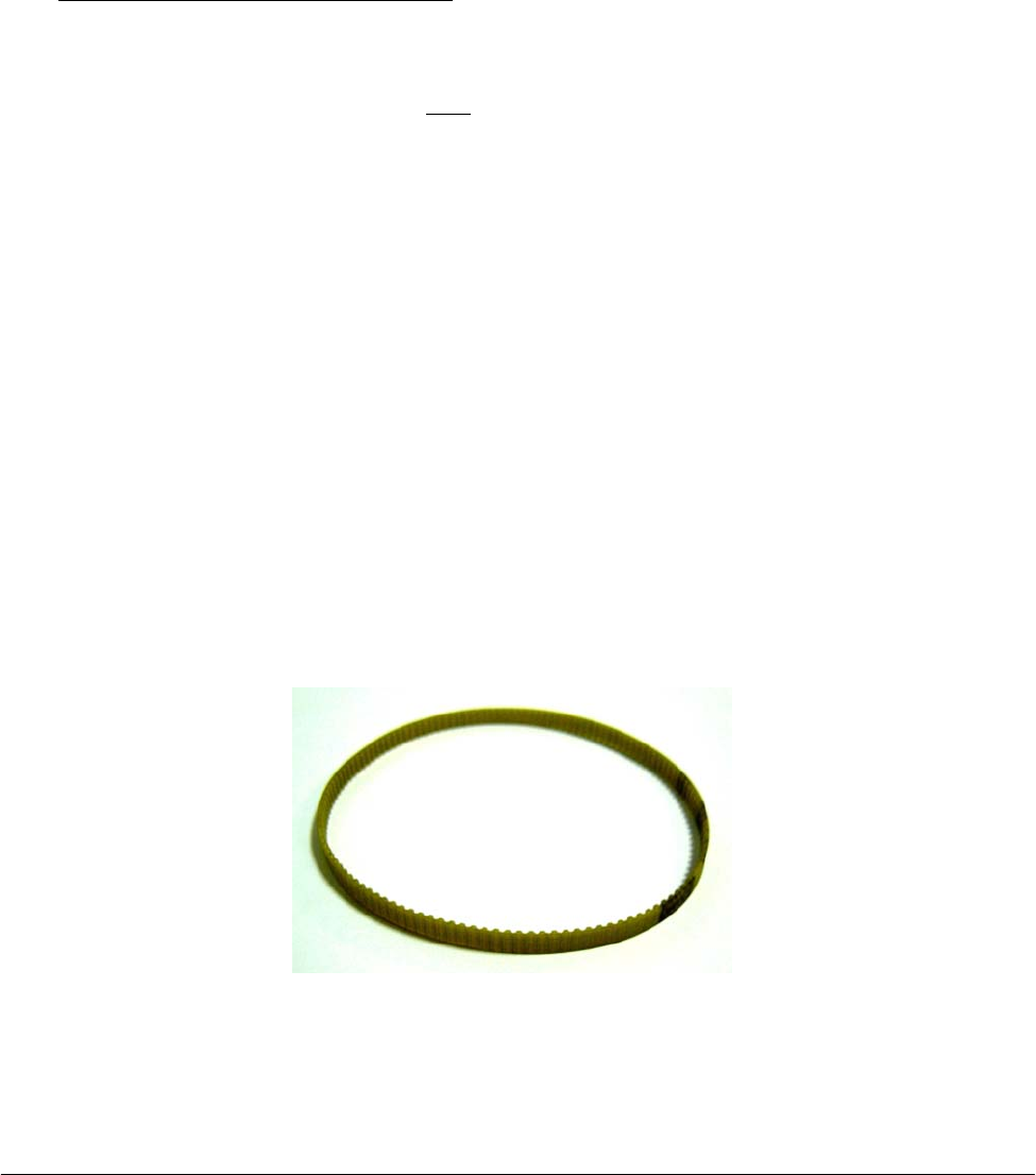
Chapter 05 – SETTINGS AND ADJUSTMENTS
SAT450 Service Manual Rev.00 03 July 2008 Page 68
5.6.8 Replacement of the Samples Plate Belt
1. Make sure that the SAT450 instrument is turned off, then unscrew the two captive screws on the
front underside of the instrument (Fig. 6) and lift up the Raising Top (Fig. 7).
2. Loosen the four fastening screws of the Samples Plate Motor and remove the Samples Plate Belt
from the pulley of the Samples Plate Motor (Fig. 98).
3. Unscrew the two fastening screws of the Samples Plate Home Sensor (Fig. 98) and take out the
sensor from its housing on the Samples Plate Assy.
4. Remove the Samples Plate Belt from the primary pulley (Fig. 98).
To replace the new Samples Plate Belt (Fig. 106) perform the following steps:
5. Wrap the new belt around the primary pulley.
6. Push the Samples Plate Motor toward the primary pulley, wrap the new belt around the motor
pulley, then leave free the motor (note: the anchor plate springs give the right tension to the
belt).
7. Turn the primary pulley and make sure that the new belt thoots are correctly inserted on the
Samples Plate Motor pulley and on the primary pulley.
8. Tighten the four fastening screws of the Samples Plate Motor (Fig. 98).
9. Position the Samples Plate Home Sensor on its housing of the Samples Plate Assy - as showed
in Fig. 98 - in order to obtain that the primary pulley disk is centered with respect to the internal
sides of the home sensor.
10. Screw the two fastening screws of the Samples Plate Home Sensor (Fig. 98).
11. Turn the primary pulley and make sure that the primary pulley disk does not touch the Samples
Plate Home Sensor.
12. Bring down the Raising Top (Fig. 7) and screw the two captive screws on the front underside of
the instrument (Fig. 6).
13. Perform the procedure “Mechanical adjustments of the Samples Plate” described into the
previous Section 6.6.1 .
Fig. 106 – Plate Belt [P/N: 86-02334-11]

Chapter 05 – SETTINGS AND ADJUSTMENTS
SAT450 Service Manual Rev.00 03 July 2008 Page 69
5.6.9 Replacement of the Satellites Mov. Samples Plate Belt
1. Remove the Samples Plate Belt from the Samples Plate Assy performing the relative procedure
described into the previous Section 6.6.8, from step 1 to step 4.
2. Loosen the four fastening screws of the Satellites Mov. Samples Plate Motor and remove the
Satellites Mov. Samples Plate Belt from the pulley of the Satellites Mov. Samples Plate Motor
(Fig. 98).
3. Unscrew the two fastening screws of the Satellites Mov. Samples Plate Home Sensor
(Fig. 98) and take out the sensor from its housing on the Samples Plate Assy.
4. Remove the Satellites Mov. Samples Plate Belt from the secondary pulley (Fig. 98).
To replace the new Satellites Mov. Samples Plate Belt (Fig. 106) perform the following steps:
5. Wrap the new belt around the secondary pulley.
6. Push the Satellites Mov. Samples Plate Motor toward the secondary pulley, wrap the new belt
around the motor pulley, then leave free the motor (note: the anchor plate springs give the right
tension to the belt).
7. Turn the secondary pulley and make sure that the new belt thoots are correctly inserted on the
Satellites Mov. Samples Plate Motor pulley and on the secondary pulley.
8. Tighten the four fastening screws of the Satellites Mov. Samples Plate Motor (Fig. 98).
9. Position the Satellites Mov. Samples Plate Home Sensor on its housing of the Samples Plate
Assy - as showed in Fig. 98 - in order to obtain that the secondary pulley disk is centered with
respect to the internal sides of the home sensor.
10. Screw the two fastening screws of the Satellites Mov. Samples Plate Home Sensor (Fig. 98).
11. Turn the secondary pulley and make sure that the secondary pulley disk does not touch the
Satellites Mov. Samples Plate Home Sensor.
12. Replace the Samples Plate Belt in the Samples Plate Assy performing the relative procedure
described into the previous Section 6.6.8, from step 5 to step 11.
13. Bring down the Raising Top (Fig. 7) and screw the two captive screws on the front underside of
the instrument (Fig. 6).
14. Perform the procedure “Mechanical adjustments of the Samples Plate” described into the
previous Section 6.6.1 .
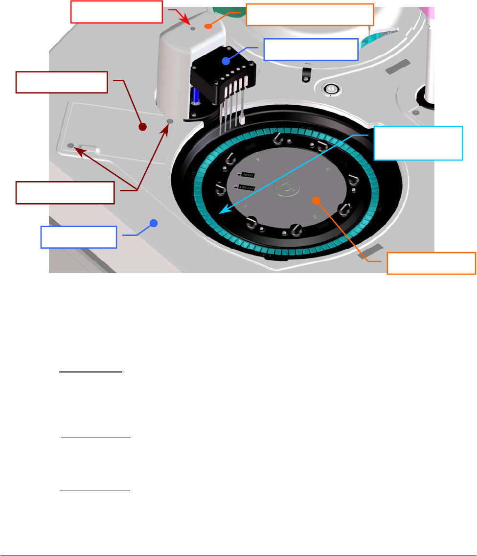
Chapter 05 – SETTINGS AND ADJUSTMENTS
SAT450 Service Manual Rev.00 03 July 2008 Page 70
5.7 REACTIONS PLATE
5.7.1 Mechanical adjustment of the Reactions Plate
1. Lift up the instrument cover and remove the Reactions Plate cover from the Reactions Plate
(Fig. 7).
2. Take a Reactions Plate Rack with a opaque cuvette #1, then substitute the Reactions Plate
Rack #1 (Fig. 107) with this new Rack.
3. Turn on the SAT450 system (instrument and computer) and launch the “Diagnostic” program.
4. Select “Arm” folder and request an Arm reset. Wait until the reset Sampling Arm procedure has
been completed.
5. Make sure that all the Home Sensors of the Sampling Arm (Vertical and Horizontal) light up in
green.
6. Select “Optic” folder and request an Filters Wheel reset. Wait until the reset Filters Wheel
procedure has been completed.
7. Make sure that the Home Sensor of the Filters Wheel light up in green.
8. Select "Plates” folder and request an Reactions Plate reset. Wait until the reset Reactions Plate
procedure has been completed.
9. Make sure that the Home Sensor of the Reactions Plate light up in green.
Fig. 107 – Reactions Plate
Raisin
g
To
p
Reactions Plate
Washin
g
Station
Reactions
p
anel
Fastening screws
Reactions Plate
Rack #1
Washin
g
Station cove
r
Fastening screw
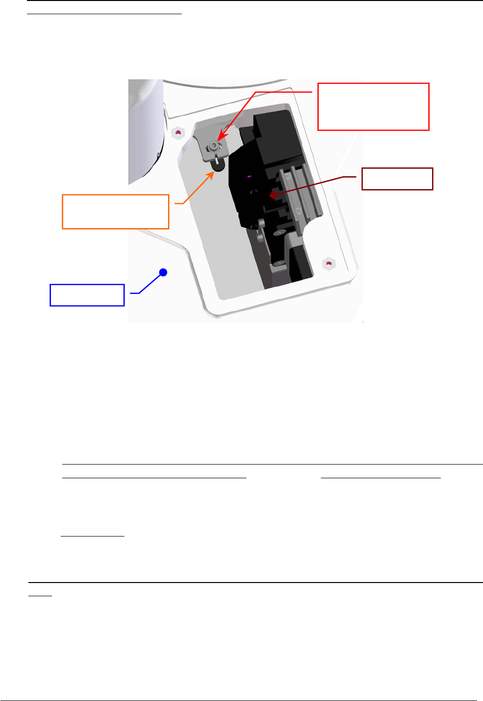
Chapter 05 – SETTINGS AND ADJUSTMENTS
SAT450 Service Manual Rev.00 03 July 2008 Page 71
10. Make sure that the light beam of the Photometer reading channel is centered with respect to the
cuvette #1 of the Reactions Plate. If it not be so, center the Reactions Plate in the following way:
a. unscrew the two fastening screws of the Reactions panel placed on the Raising Top near
the Washing Station (Fig. 107) and take out the panel from the Raising Top;
b. loosen the fastening screw of the Reactions Plate Home Sensor lever (Fig. 108);
c. turn slightly the Reactions Plate Home Sensor lever to the right toward in order to obtain
the centering;
d. tighten the fastening screw of the Reactions Plate Home Sensor lever (Fig. 108);
e. request an Reactions Plate reset in the "Plates” folder and wait until the reset procedure
has been completed;
f. make sure that the Home Sensor of the Reactions Plate light up in green;
g. make sure that the light beam of the Photometer reading channel is centered with respect
to the cuvette #1 of the Reactions Plate. If it not be so, repeat from the step 10-b.
11. Position the Reactions panel in its housing on the Raising Top (Fig. 107) and screw its two
fastening screws.
12. Select “Arm” folder, click the “Go Disp.” button, then click the correspondent “Down” button.
The Sampling Arm will move to cuvette #52 of the Reactions Plate, then it will go down until to
reach the right height.
13. Make sure that the Sampling Probe is centered with respect to the cuvette #52 of the Reactions
Plate. If it not be so, center the Sampling Probe in the following way:
a. click the “+”/“–“ buttons in the “Arm Setting” area of the “Arm” folder until to obtain
- by means of the correspondent movement of the Sampling Arm - the centering of the
Sampling Probe;
b. click the “Save” button in the “Arm Setting” area of the “Arm” folder in order to obtain
the memorization of the new Arm Setting value.
Fig. 108 – Fastening screw of the Reactions Plate Home Sensor lever
Raisin
g
To
p
Fastening screw of
the Reactions Plate
Home Sensor leve
r
Reactions Plate
Home Sensor leve
r
Photomete
r

Chapter 05 – SETTINGS AND ADJUSTMENTS
SAT450 Service Manual Rev.00 03 July 2008 Page 72
14. Request an Arm reset in the “Arm” folder. Wait until the reset Sampling Arm procedure has
been completed.
15. Make sure that all the Home Sensors of the Sampling Arm (Vertical and Horizontal) light up in
green.
16. Substitute the Reactions Plate Rack with the opaque cuvette #1 with the original Reactions Plate
Rack #1 (Fig. 107).
17. Select "Wash” folder and request an Washing Station reset. Wait until the reset Washing Station
procedure has been completed.
18. Make sure that the Home Sensor of the Washing Station light up in green.
19. Click the “Down to Adjust” button. The Washing Well will go down until to reach the right
height.
20. Make sure that the five probes of the Washing Station are centered with respect to the five
correspondent cuvettes of the Reactions Plate. If it not be so, perform the procedure
“Mechanical adjustments of the Washing Station” described into the following Section 6.8.1,
from step 2 to step 13.
21. Click the “Home” button in the “Wash” folder. Wait until the reset Washing Station procedure
has been completed.
22. Replace the Reactions Plate cover on the Reactions Plate and bring down the instrument cover
(Fig. 7).
5.7.2 Replacement of the Reactions Plate Motor
1. Unscrew the two captive screws on the front underside of the instrument (Fig. 6) and lift up the
Raising Top (Fig. 7).
2. Unscrew the four fastening screws of the protection panel (Fig. 109) and take out it from its
place.
3. Unplug the J12 connector from the Reactions Plate Interface Board (compare the sch. SC-30-02192-00).
4. Unscrew the four fastening screws of the Reactions Plate Motor (Fig. 109).
5. Remove the belt from the pulley of the Reactions Plate Motor and take out it from its housing
and the two anchor plate springs from the anchor plate.
6. Unscrew the four fastening screws of the Reactions Plate Motor anchor plate (Fig. 110) and take
out the anchor plate from the motor.
7. Loosen the pulley clamp screw and extract the pulley clamp and the pulley from the motor shaft
(Fig. 111).
To replace the new Reactions Plate Motor (Fig. 112) perform the following steps:
8. Insert the pulley clamp completely on the motor pulley (Fig. 113) and then insert all two on the
motor shaft.
9. Position the motor pulley to 2.00 mm with respect to upper motor plane (Fig. 113), then tighten
the pulley clamp screw.
10. Position the anchor plate on the upper plane of the new motor as showed in Fig. 110 and screw
its four fastening screws.
11. Position the Reactions Plate Motor on its housing with the side of the motor connector oriented
towards the Reactions Plate Interface Board (Fig. 109) and with the anchor plate springs placed
in the relative slits, then tighten slightly its four fastening screws.
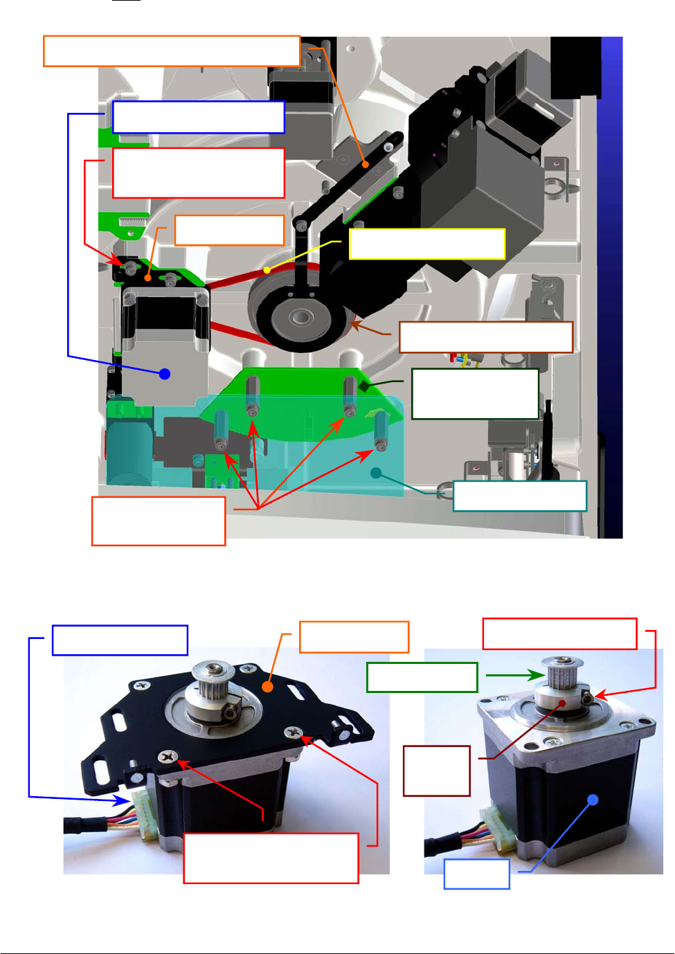
Chapter 05 – SETTINGS AND ADJUSTMENTS
SAT450 Service Manual Rev.00 03 July 2008 Page 73
12. Push the motor toward the plate pulley, wrap the belt around the motor pulley, then leave free
the motor (note: the anchor plate springs give the right tension to the belt).
Fig. 109 – Reactions Plate Assy (bottom view)
Fig. 110 – Reactions Plate Motor anchor plate Fig. 111 – Motor pulley
Reactions Plate
Interface Board
Protection
p
anel
Protection panel
fastenin
g
screws
Reactions Plate Moto
r
Reactions Plate pulley
Reactions Plate Home Sensor leve
r
Reactions Plate Motor
fastening screw
Anchor
p
late Reactions Plate belt
Anchor plate
Motor
p
ulle
y
Motor connecto
r
Fastening screws of
the motor anchor plate
Pulley
clamp
Pulley clamp screw
Moto
r
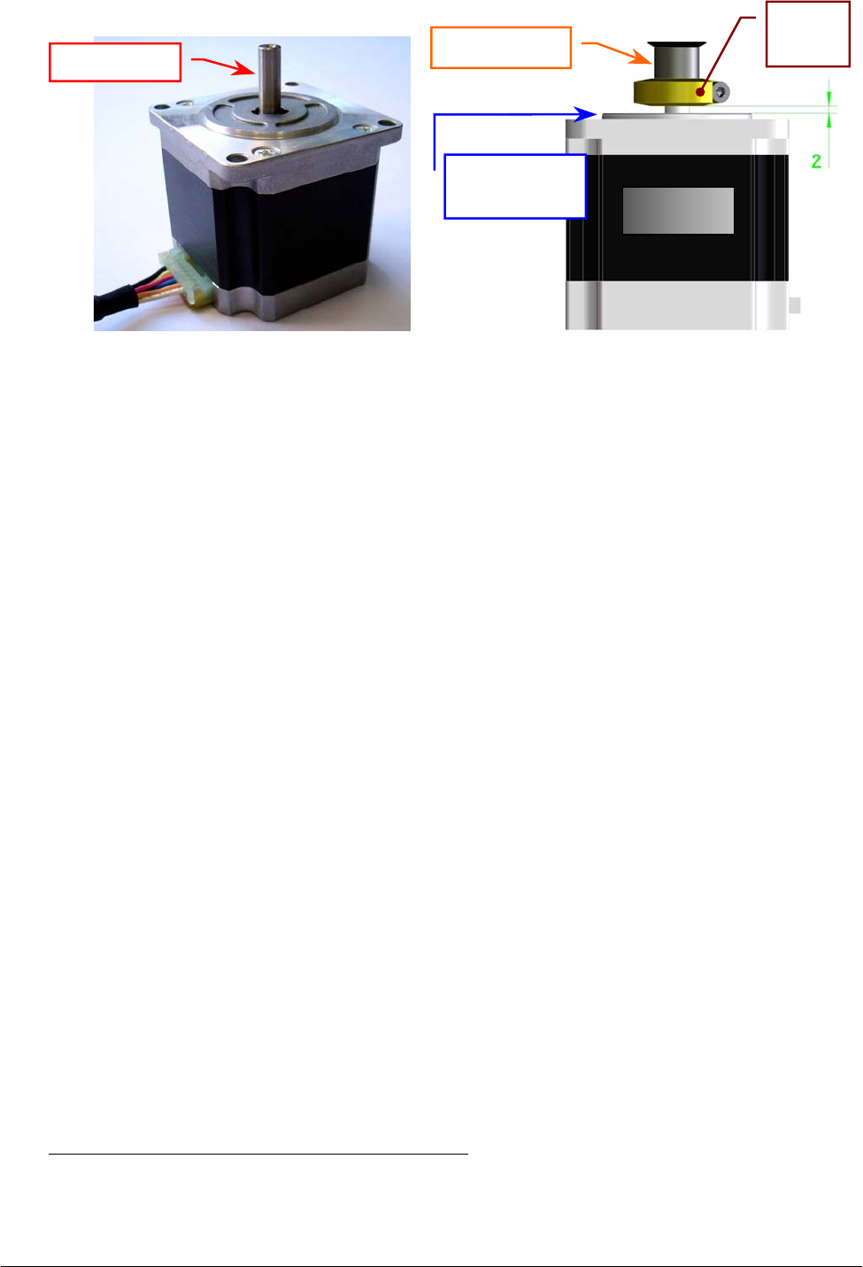
Chapter 05 – SETTINGS AND ADJUSTMENTS
SAT450 Service Manual Rev.00 03 July 2008 Page 74
13. Turn the plate pulley and make sure that the belt thoots are correctly inserted on the Reactions
Plate Motor pulley and on the plate pulley.
14. Tighten the four fastening screws of the Reactions Plate Motor (Fig. 109).
15. Plug the Reactions Plate Motor connector in the J12 connector of the Reactions Plate Interface
Board (compare the scheme SC-30-02192-00).
16. Replace the protection panel on its place - as showed in Fig. 109 - unscrewing its four fastening
screws in the correspondent spacing bars.
17. Bring down the Raising Top (Fig. 7) and screw the two captive screws on the front underside of
the instrument (Fig. 6).
18. Perform the procedure “Mechanical adjustment of the Reactions Plate” described into the
previous Section 6.7.1.
5.7.3 Replacement of the Reactions Plate Home Sensor
1. Unscrew the two captive screws on the front underside of the instrument (Fig. 6) and lift up the
Raising Top (Fig. 7).
2. Unscrew the four fastening screws of the protection panel (Fig. 109) and take out it from its
place.
3. Unplug the J13 connector from the Reactions Plate Interface Board (compare the sch. SC-30-02192-00).
4. Unscrew the three fastening screws of the Reactions Plate Home Sensor lever (Fig. 114) and take
out the lever from its place.
5. Unscrew the two lever fastening screws of the Reactions Plate Home Sensor lever (Fig. 115) and
take out the sensor from the lever.
To replace the new Reactions Plate Home Sensor (Fig. 116) perform the following steps:
6. Position the lever below the new home sensor as showed in Fig. 115, center the sensor with
respect to the lever and screw its two fastening screws.
Fig. 112 – Reactions Plate Motor
[P/N: 9-10-0016-00]
Fig. 113 – Plate Motor (scheme)
Motor shaft Motor
p
ulle
y
Motor
Upper motor
p
lane
Pulley
clamp
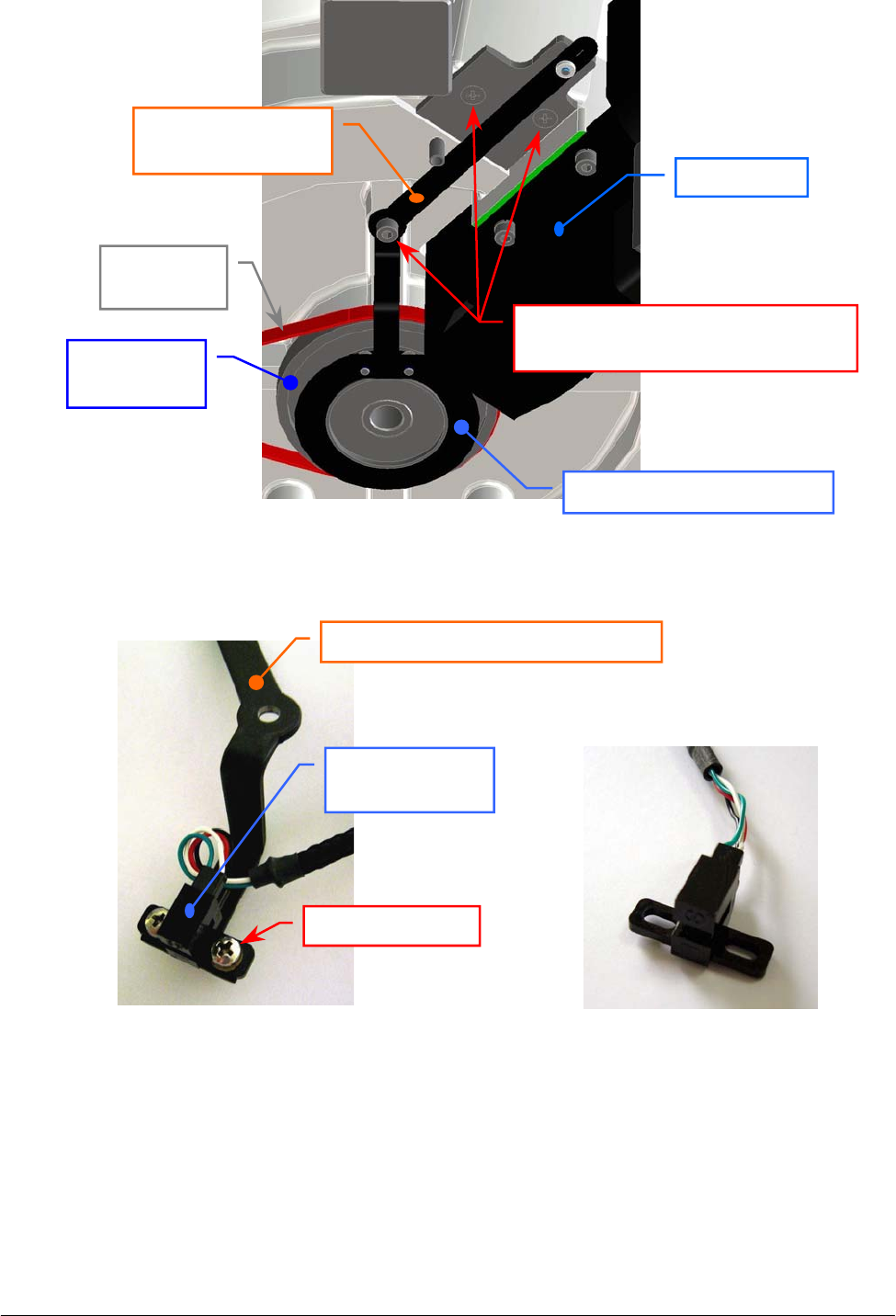
Chapter 05 – SETTINGS AND ADJUSTMENTS
SAT450 Service Manual Rev.00 03 July 2008 Page 75
Fig. 114 – Reactions Plate Home Sensor lever
7. Position the lever on its housing - as showed in Fig. 114 - in order to obtain that the plate pulley
disk is centered with respect to the internal sides of the home sensor.
8. Screw the three fastening screws of the Reactions Plate Home Sensor lever (Fig. 114).
9. Turn the plate pulley and make sure that the plate pulley disk does not touch the Reactions Plate
Home Sensor.
Fig. 115 – Two fastening screws of the
Reactions Plate Home Sensor lever
Fig. 116 – Reactions Plate Home Sensor
[P/N: 9-10-0023-40]
Reactions Plate
Home Sensor lever
Three fastening screws of the
Reactions Plate Home Sensor lever
Reactions Plate
p
ulle
y
dis
k
Reactions
Plate pulley
Reactions
Plate belt
Photomete
r
Reactions Plate Home Sensor leve
r
Reactions Plate
Home Sensor
Fastenin
g
screw

Chapter 05 – SETTINGS AND ADJUSTMENTS
SAT450 Service Manual Rev.00 03 July 2008 Page 7
6
10. Plug the Reactions Plate Home Sensor connector in the J13 connector of the Reactions Plate
Interface Board (compare the scheme SC-30-02192-00).
11. Replace the protection panel on its place - as showed in Fig. 109 - unscrewing its four fastening
screws in the correspondent spacing bars.
12. Bring down the Raising Top (Fig. 7) and screw the two captive screws on the front underside of
the instrument (Fig. 6).
13. Perform the procedure “Mechanical adjustment of the Reactions Plate” described into the
previous Section 6.7.1.
5.7.4 Replacement of the Reactions Plate Belt
1. Unscrew the two captive screws on the front underside of the instrument (Fig. 6) and lift up the
Raising Top (Fig. 7).
2. Loosen the four fastening screws of the Reactions Plate Motor (Fig. 109), push the motor
toward the plate pulley, then tighten only one fastening screw of the motor.
3. Unscrew the three fastening screws of the Reactions Plate Home Sensor lever (Fig. 114) and take
out the lever from its place.
4. Remove the belt from the Reactions Plate Motor pulley and from the plate pulley.
To replace the new Reactions Plate Belt (Fig. 106) perform the following steps:
5. Wrap the belt around the plate pulley.
6. Wrap the belt around the Reactions Plate Motor pulley, loosen the screwed fastening screw of
the motor, then leave free the motor (note: the anchor plate springs give the right tension to the
belt).
7. Turn the plate pulley and make sure that the belt thoots are correctly inserted on the Reactions
Plate Motor pulley and on the plate pulley.
8. Tighten the four fastening screws of the Reactions Plate Motor (Fig. 109).
9. Position the lever on its housing - as showed in Fig. 114 - in order to obtain that the plate pulley
disk is centered with respect to the internal sides of the home sensor.
10. Screw the three fastening screws of the Reactions Plate Home Sensor lever (Fig. 114).
11. Turn the plate pulley and make sure that the plate pulley disk does not touch the Reactions Plate
Home Sensor.
12. Bring down the Raising Top (Fig. 7) and screw the two captive screws on the front underside of
the instrument (Fig. 6).
13. Perform the procedure “Mechanical adjustment of the Reactions Plate” described into the
previous Section 6.7.1.
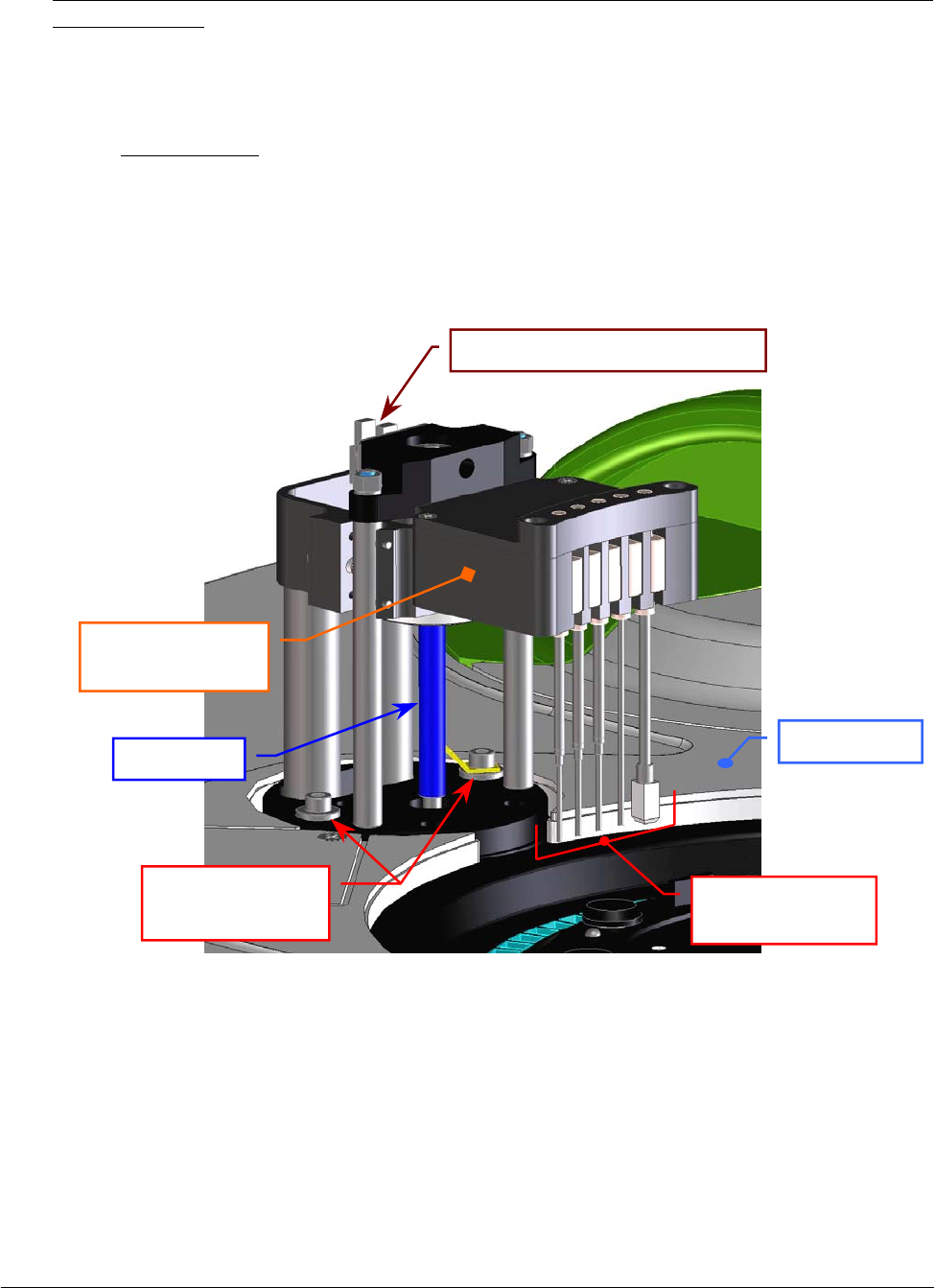
Chapter 05 – SETTINGS AND ADJUSTMENTS
SAT450 Service Manual Rev.00 03 July 2008 Page 7
7
5.8 WASHING STATION
5.8.1 Mechanical adjustments of the Washing Station
1. Center the cuvette #1 of the Reactions Plate with respect to the light beam of the Photometer
reading channel performing the procedure “Mechanical adjustment of the Reactions Plate”
described into the previous Section 6.7.1, from step 1 to step 12.
2. Unscrew the fastening screw of the Washing Station cover (Fig. 107) and remove the cover
from its place on the Raising Top.
3. Select “Wash” folder and click the “Home” button. Wait until the reset Washing Station
procedure has been completed.
4. Make sure that the Home Sensor of the Washing Station light up in green.
Fig. 117 – Fastening screws of the Washing Station
5. Click the “Down to Adjust” button in the “Wash” folder. The Washing Station will go down
until to reach the right height for the adjusting.
Leadscrew
Washing Station
p
robes
Washing Station
pr
obes holde
r
Washing Station
fastening screws
Washin
g
Station Home Senso
r
Raisin
g
To
p
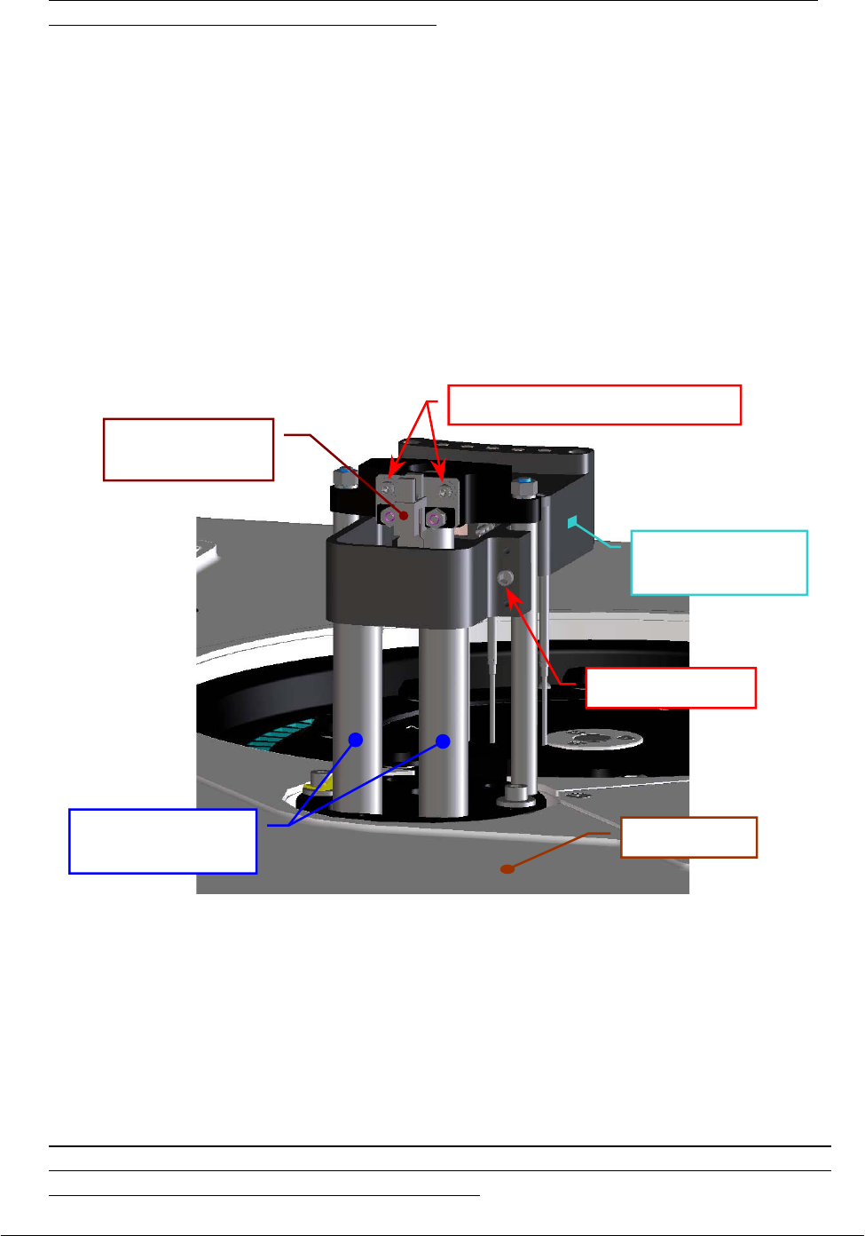
Chapter 05 – SETTINGS AND ADJUSTMENTS
SAT450 Service Manual Rev.00 03 July 2008 Page 78
6. Make sure that the five probes of the Washing Station are centered with respect to the five
correspondent cuvettes of the Reactions Plate. If it not be so, adjust in the following way:
a. loosen the two Washing Station fastening screws (Fig. 117);
b. shift horizontally – carefully – the Washing Station in order to obtain the
centering of the five probes with respect to the five correspondent cuvettes;
c. tighten the two Washing Station fastening screws (Fig. 117);
d. click the “Home” button in the “Wash” folder and wait until the reset
Washing Station procedure has been completed;
e. make sure that the Home Sensor of the Washing Station light up in green;
f. click the “Down to Adjust” button in the “Wash” folder and wait until the
request movement has been completed;
g. repeat the step 6.
Fig. 118 – Home Sensor of the Washing Station
7. Click the “Home” button in the “Wash” folder. Wait until the reset Washing Station
procedure has been completed.
8. Click the “Down (Full)” button in the “Wash” folder. The Washing Station will go down
until to reach the cuvettes of the Reactions Plate.
9. Make sure that the five probes of the Washing Station are centered with respect to the five
correspondent cuvettes of the Reactions Plate and, in particular, that the Drying Pad run
freely along the walls of the correspondent cuvette.
Adjusting screw
Washing Station
probes holde
r
Cylindrical guides
for the tubes
Washing Station
Home Senso
r
Home Sensor fastenin
g
screws
Raising Top
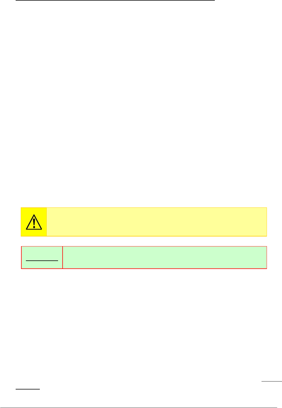
Chapter 05 – SETTINGS AND ADJUSTMENTS
SAT450 Service Manual Rev.00 03 July 2008 Page 79
10. Make sure that the five probes of the Washing Station are slightly raised. If it not be so, adjust in
the following way:
a. click the “Home” button in the “Wash” folder and wait until the reset Washing
Station procedure has been completed;
b. make sure that the Home Sensor of the Washing Station light up in green;
c. loosen the two fastening screws of the Washing Station Home Sensor (Fig. 118);
d. move slightly the Washing Station Home Sensor to the right vertically toward in
order to obtain the positioning of the Washing Station probes to the correct height;
e. tighten the two fastening screws of the Washing Station Home Sensor (Fig. 118);
f. click the “Home” button in the “Wash” folder and wait until the reset Washing
Station procedure has been completed;
g. make sure that the Home Sensor of the Washing Station light up in green;
h. click the “Down (Full)” button in the “Wash” folder and wait until the Washing
Station has been reach the cuvettes of the Reactions Plate;
i. repeat the step 10.
11. Click the “Home” button in the “Wash” folder. Wait until the reset Washing Station procedure
has been completed.
12. Make sure that the Home Sensor of the Washing Station light up in green.
13. Replace the Washing Station cover on the Washing Station and screw its fastening screw
(Fig. 107).
14. Replace the Reactions Plate cover on the Reactions Plate and bring down the instrument cover
(Fig. 7).
5.8.2 Replacement of the Washing Station Assy
1. Make sure that the SAT450 instrument is turned off.
2. Lift up the instrument cover (Fig. 7), unscrew the fastening screw of the Washing Station cover
(Fig. 107) and remove the cover from its place on the Raising Top.
3. Unscrew the four fastening screws of the Washing Station tubes cover (Fig. 119) and remove the
cover from the Washing Station.
4. Remove the five springs from the correspondent manifolds of the probes (Fig. 120).
5. Remove the eight tubes with “2”, “3”, “5”, “6”, “7”, “8”, “9” and “10” label texts from the
correspondent manifolds of the probes (compare the hydraulic diagram SI-16-01873-00), making
attention to the spillage of liquid from the tubes.
Make sure that the Sampling Probe is centered with respect to the
Reactions Plate cuvette. If it not be so, perform the procedure described into
the previous Section 6.7.1, from step 13 to step 16.
If the horizontal backlash of the Washing Station probes holder is
excessive, then adjust it acting on the adjusting screw (Fig. 118).
Remembe
r
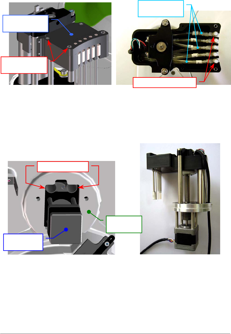
Chapter 05 – SETTINGS AND ADJUSTMENTS
SAT450 Service Manual Rev.00 03 July 2008 Page 80
6. Unscrew the two captive screws on the front underside of the instrument (Fig. 6) and lift up the
Raising Top (Fig. 7).
7. Take out the eight tubes from the two Washing Station cylindrical guides (Fig. 121).
8. Unplug the J10 and J11 connectors from the Electrovalves Control Board (compare the scheme
SC-30-02194-00).
9. Bring down the Raising Top (Fig. 7) and screw the two captive screws on the front underside of
the instrument (Fig. 6).
10. Unplug the ground wire from the Washing Station Assy, unscrew the two Washing Station
fastening screws (Fig. 117) and take out the Washing Station Assy from its housing.
Fig. 119 – Washing Station tubes cover Fig. 120 – Washing Station tubes
Fig. 121 – Cylindrical guides of
the Washing Station
Fig. 122 – Washing Station Assy
[P/N: 10-02181-00]
Washing Station
tubes cove
r
Tubes cover
fastenin
g
screws
C
y
lindrical
g
uides
Washing
Station Moto
r
Raising Top
(bottom view)
Washing Station
tubes
Washin
g
Station
p
robes
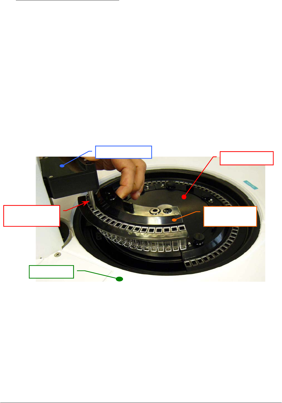
Chapter 05 – SETTINGS AND ADJUSTMENTS
SAT450 Service Manual Rev.00 03 July 2008 Page 81
To replace the Washing Station Assy (Fig. 122) perform the following steps:
11. Repeat the above steps in inverse order: from 10 to 3.
12. Perform the procedure “Mechanical adjustments of the Washing Station” described into the
previous Section 6.8.1, from step 3 to step 12.
13. Perform the “Functional check of the Washing Station” described into the next Section 6.8.2.1.
14. Replace the Washing Station cover on the Washing Station and screw its fastening screw
(Fig. 107).
15. Replace the Reactions Plate cover on the Reactions Plate and bring down the instrument cover
(Fig. 7).
5.8.2.1 Functional check of the Washing Station
1. Unscrew the two fastening pommels of the Reactions Plate Rack #4, carry up the Rack in
order to put on the five probes of the Washing Station until the bottom of the correspondent
cuvettes - as showed in the Fig. 123 (a) - .
2. Select the Cycles #5 in the “Wash” folder of the “Diagnostic” program, click the “Washing
Cycles” button and then, in the message box that appear, click the “OK” button to start the
Cycles requested.
3. At the fourth and fifth cycle of the Washing Station (with the hydraulic circuit filled), check
that each of five probes carries out correctly the specific operations described in the
Fig. 123 (b). If it not be so, check the hydraulic circuit – taking reference to the hydraulic
diagram SI-16-01873-00 –, find the abnormalities and resolve them.
4. Replace the Rack #4 in its housing on the Reactions Plate and screw its two fastening
pommels.
Fig. 123 (a) – Five probes of the Washin
g
Station in the Reactions Plate Rack
Reactions Plate
Reactions Plate
Rack #4
Washing Station
probes
Washin
g
Station
Raisin
g
To
p
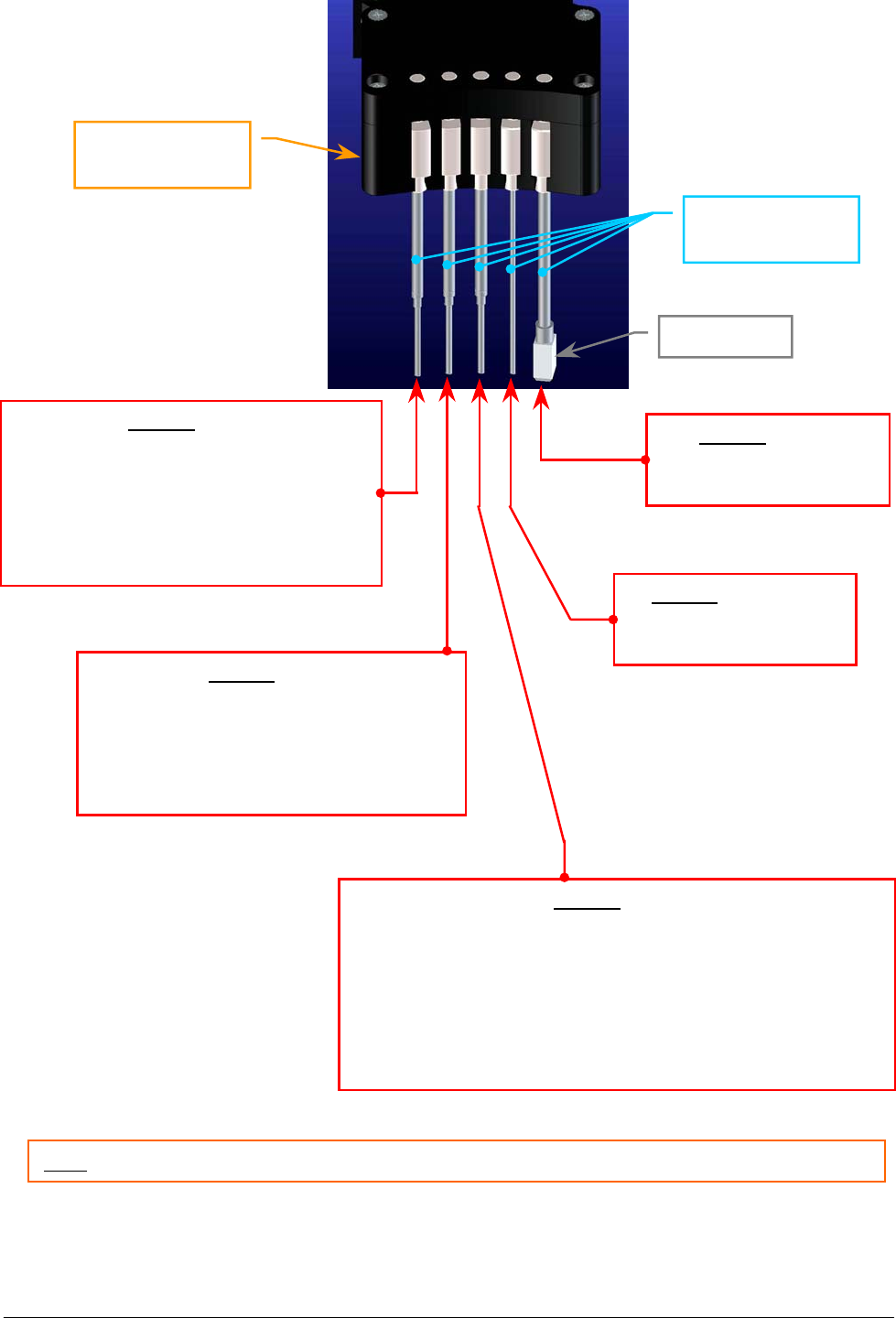
Chapter 05 – SETTINGS AND ADJUSTMENTS
SAT450 Service Manual Rev.00 03 July 2008 Page 82
Probe 1 (wash)
1. Aspiration of the reaction in the cuvette;
2. Dispensation and aspiration of the Acid
Solution - contemporaneously -;
3. Dispensation of the Acid Solution;
4. Aspiration of all the Acid Solution
contains in the cuvette.
Probe 2 (wash)
1. Dispensation and aspiration of the
Cleaning Solution - contemporaneously -;
2. Dispensation of the Cleaning Solution;
3. Aspiration of all the Cleaning Solution
contains in the cuvette.
Probe 3 (wash)
1. Dispensation and aspiration of the Distilled Water
- contemporaneously -;
2. Dispensation of the Distilled Water;
3. Aspiration of all the Distilled Water contains in the cuvette;
4. Dispensation of the Distilled Water in the cuvette (to perform
the “White on fly” reading with the analyzer in running);
5. Aspiration of all the Distilled Water contains in the cuvette.
Probe 4 (aspiration)
1. Aspiration of all the
contents of the cuvette.
Probe 5 (drying)
1. Drying (and aspiration)
of the cuvette.
Fig. 123 (b) – Description of one Washing Station Cycle
Washing Station
probes
Note: each cycle of the Washing Station start with one “beep” and finish with another “beep”.
Washing Station
probes holder
Drying Pad
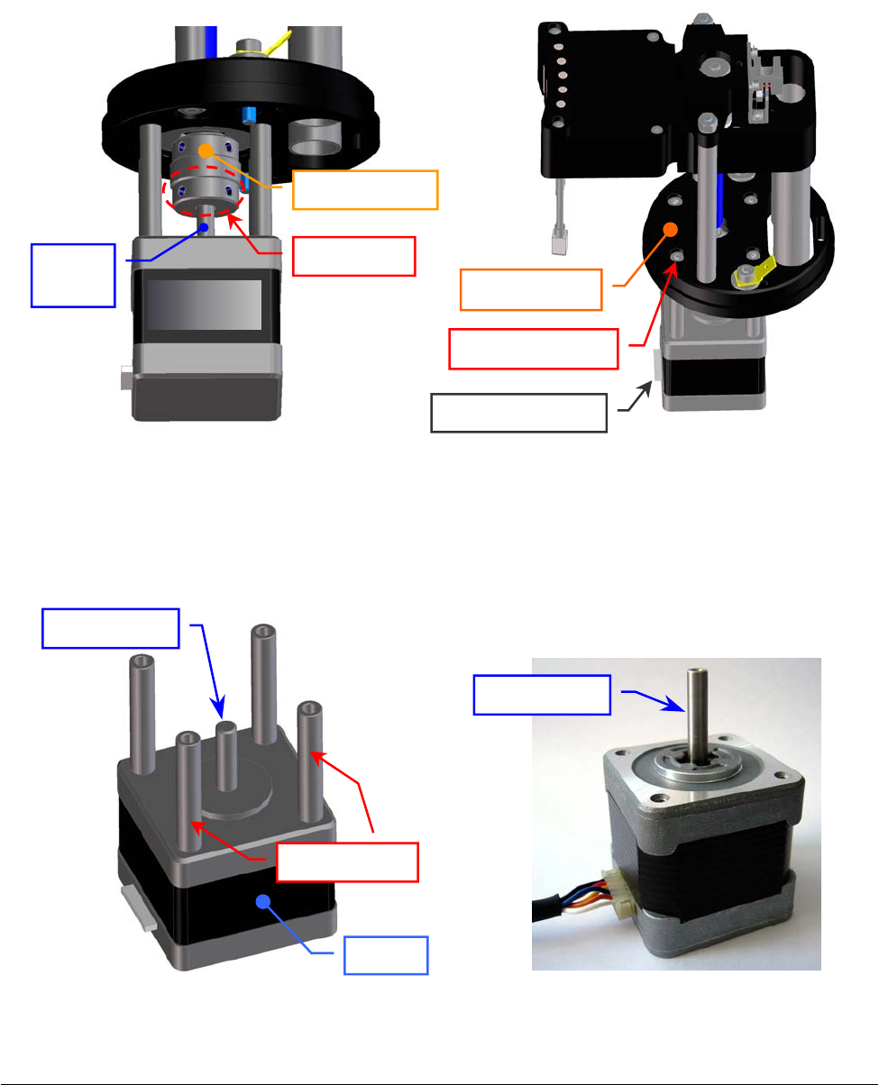
Chapter 05 – SETTINGS AND ADJUSTMENTS
SAT450 Service Manual Rev.00 03 July 2008 Page 83
5.8.3 Replacement of the Washing Station Motor
1. Remove the Washing Station Assy from its housing performing the relative procedure described
into the previous Section 6.8.2, from step 1 to step 10.
2. Unscrew (only) the two set screws of the flexible joint placed near the bottom side of it (Fig. 124).
3. Unscrew the four fastening screws of the Washing Station Motor (Fig. 125) and take out it from
the anchor plate of the Washing Station (Fig. 125).
4. Unscrew the four spacing bars of the Washing Station Motor (Fig. 126) and take out them from
the motor.
Fig. 124 – Set screws of the flexible joint Fig. 125 – The four fastening screws of
the Washing Station Motor
Fig. 126 – The four spacing bars of the
Washing Station Motor
Fig. 127 – Washing Station Motor
[P/N: 10-00399-01]
S
p
acin
g
bars
Set screws
Flexible
j
oin
t
Fastenin
g
screw
Anchor plate
Motor connecto
r
Motor
Motor
shaft
Motor shaft
Moto
r
Motor shaft
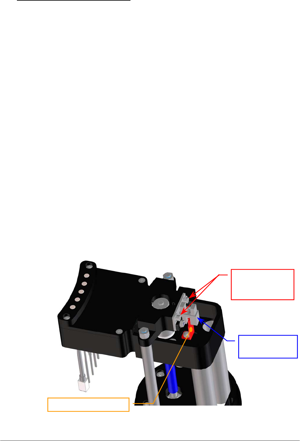
Chapter 05 – SETTINGS AND ADJUSTMENTS
SAT450 Service Manual Rev.00 03 July 2008 Page 84
To replace the Washing Station Motor (Fig. 127) perform the following steps:
5. Screw the four spacing bars on the new Washing Station Motor (Fig. 126).
6. Position the new Washing Station Motor on the anchor plate with the side of the motor
connector oriented towards the side of the Washing Station probes – as showed in Fig. 125 –
pushing the motor shaft in the flexible joint (Fig. 124), then screw the four fastening screws of
the motor (Fig. 125).
7. Screw the two set screws of the flexible joint placed near the bottom side of it (Fig. 124).
8. Perform the procedure “Replacement of the Washing Station Assy” described into the previous
Section 6.8.2, from step 11 to step 15.
5.8.4 Replacement of the Washing Station Home Sensor
1. Make sure that the SAT450 instrument is turned off.
2. Lift up the instrument cover (Fig. 7), unscrew the fastening screw of the Washing Station cover
(Fig. 107) and remove the cover from its place on the Raising Top.
3. Unscrew the two captive screws on the front underside of the instrument (Fig. 6) and lift up the
Raising Top (Fig. 7).
4. Unplug the J11 connector from the Electrovalves Control Board (compare the sch. SC-30-02194-00).
5. Bring down the Raising Top (Fig. 7) and screw the two captive screws on the front underside of
the instrument (Fig. 6).
6. Unscrew the two fastening screws of the Washing Station Home Sensor (Fig. 128) and take out
the sensor from its housing on the Washing Station Assy, pushing the cable and the connector of
the sensor through the anchor plate aperture (Fig. 129).
7. Unscrew the two keep plate screw nuts of the Washing Station Home Sensor (Fig. 130) and take
out the sensor from the keep plate.
Fig. 128 – The two fastening screws of the Washing Station Home Sensor
Washing Station
Home Senso
r
Washing Station
Home Sensor
fastenin
g
screws
Home Sensor small fla
g
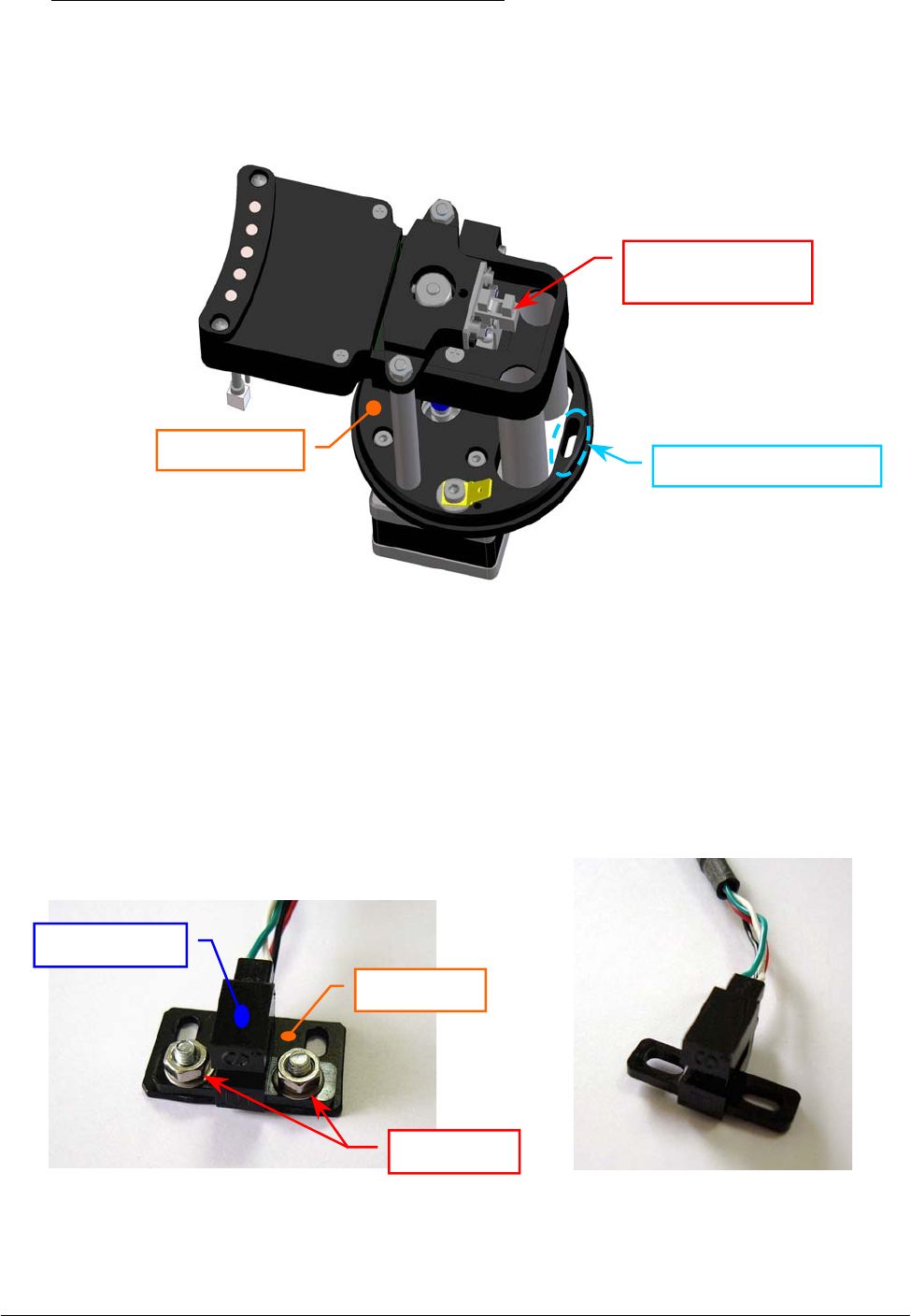
Chapter 05 – SETTINGS AND ADJUSTMENTS
SAT450 Service Manual Rev.00 03 July 2008 Page 85
To replace the new Washing Station Home Sensor (Fig. 131) perform the following steps:
8. Position the keep plate under the new home sensor as showed in the Fig. 130, center the sensor
with respect to the keep plate and screw its two screw nuts.
9. Position the Washing Station Home Sensor on its place in order to obtain that the home sensor
small flag is centered with respect to the internal sides of the home sensor - as showed in the
Fig. 128 - .
Fig. 129 – Anchor plate aperture of the Washing Station Assy
Fig. 130 – The two keep plate screw
nuts of the Home Sensor
Fig. 131 – Washing Station Home Sensor
[P/N: 9-10-0023-40]
Anchor
p
late a
p
erture
Washing Station
H
o
m
e
Se
n
sor
Anchor
p
late
Screw nuts
Keep plate
Home Sensor

Chapter 05 – SETTINGS AND ADJUSTMENTS
SAT450 Service Manual Rev.00 03 July 2008 Page 8
6
10. Screw the two fastening screws of the Washing Station Home Sensor (Fig. 128).
11. Push the Washing Station Home Sensor connector through the anchor plate aperture (Fig. 129).
12. Unscrew the two captive screws on the front underside of the instrument (Fig. 6) and lift up the
Raising Top (Fig. 7).
13. Pull down the cable of the Washing Station Home Sensor.
14. Plug the Washing Station Home Sensor connector in the J11 connector of the Electrovalves
Control Board (compare the scheme SC-30-02194-00).
15. Bring down the Raising Top (Fig. 7) and screw the two captive screws on the front underside of
the instrument (Fig. 6).
16. Remove the Reactions Plate cover from the Reactions Plate (Fig. 7).
17. Turn on the SAT450 system (instrument and computer) and launch the “Diagnostic” program.
18. Perform the procedure “Mechanical adjustments of the Washing Station” described into the
previous Section 6.8.1, from step 3 to step 14.
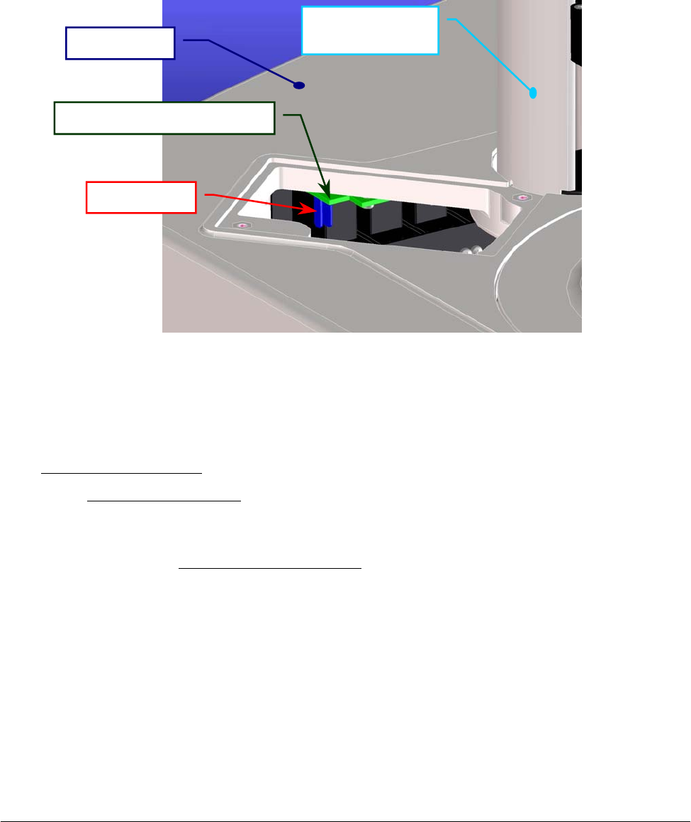
Chapter 05 – SETTINGS AND ADJUSTMENTS
SAT450 Service Manual Rev.00 03 July 2008 Page 8
7
5.9 TEMPERATURES ADJUSTMENTS
5.9.1 Procedure for the adjustment of the Reaction Cuvettes Temperature
1. Lift up the instrument cover (Fig. 7), unscrew the two fastening screws of the Reactions panel
placed on the Raising Top near the Washing Station (Fig. 107) and take out the panel from the
Raising Top.
2. Take the Service Probe of the Kit having P/N: 55-01204-00 and push it through the rectangular
opening of the Raising Top (Fig. 132).
3. Plug the connector of the Service Probe in the J8 connector of the Electrovalves Control Board
(compare the Fig. 132 and the scheme SC-30-02194-00).
4. Turn on the SAT450 system (instrument and computer), launch the “Diagnostic” program and
wait at least 30 minutes for warm-up the instrument.
5. Select “Temperatures” folder, click the “Service Pb.” button and read the temperature value (°C)
showed in the adjacent text box.
6. Make sure that the said temperature value (°C) is about equal to the Ambient Temperature value
(°C). If it not be so, calibrate the Service Probe in the following way:
a. click the “Calib. Sensor” button in the “Temperatures” folder and wait until the
“Calibration Temperature Sensor” form appears;
b. unplug the connector of the Service Probe from the J8 connector of the
Electrovalves Control Board;
c. plug the 10 KΩ resistor [Kit having P/N: 55-01204-00] in the J8 connector of the
Electrovalves Control Board (Fig. 132);
d. click the “Read 10K” button in the “Calibration Temperature Sensor” form;
e. unplug the 10 KΩ resistor from the J8 connector of the Electrovalves Control
Board;
Fig. 132 – Rectangular opening of the Raising Top
Raising Top
Electrovalves Control Board
J8 connecto
r
Washing Station
cove
r
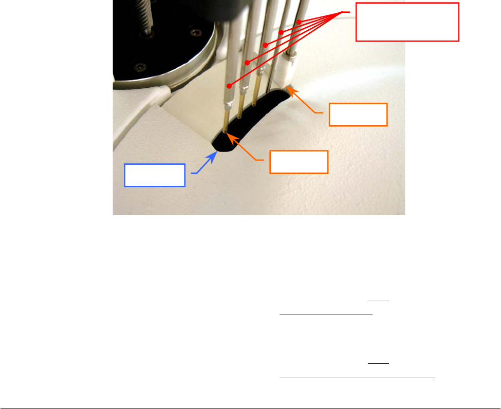
Chapter 05 – SETTINGS AND ADJUSTMENTS
SAT450 Service Manual Rev.00 03 July 2008 Page 88
f. plug the 5.76 KΩ resistor [Kit having P/N: 55-01204-00] in the J8 connector of the
Electrovalves Control Board (Fig. 132);
g. click the “Read 5K76” button in the “Calibration Temperature Sensor” form;
h. unplug the 5.76 KΩ resistor from the J8 connector of the Electrovalves Control
Board;
i. click the “Save” button in the “Calibration Temperature Sensor” form to save the
two calibration values;
j. click the “Exit” button in the “Calibration Temperature Sensor” form to exit from it;
k. plug the connector of the Service Probe in the J8 connector of the Electrovalves
Control Board (Fig. 132).
7. Click the “Temp. Test Run” button in the “Temperatures” folder and wait until the
“Temperature Test” form appears.
8. Insert a reagent bottle with distilled water in the position #1 of the Satellite Rack “A” of the
Reagents Plate.
9. Make sure that the four racks are correctly inserted in the Reactions Plate.
10. Click the “START” button in the “Temperature Test” form. Wait until that the five cuvettes
of the Reactions Plate - after the dispensation of the Sampling Arm - has been positioned under
the five probes of the Washing Station.
11. Push the Service Probe through the aperture of the Reactions Plate cover (Fig. 133).
12. Insert the Service Probe inside the cuvette placed under the Probe 5 of the Washing Station
(Fig. 133) until the NTC touches the bottom of the cuvette, shake slightly it and read the
temperature value (°C) showed in the “Service Probe” text box (note: the temperature of the
liquid of this cuvette is that more affected by the Pre-Heater heating).
13. Insert the Service Probe inside the cuvette placed under the Probe 1 of the Washing Station
(Fig. 133) until the NTC touches the bottom of the cuvette, shake slightly it and read the
temperature value (°C) showed in the “Service Probe” text box (note: the temperature of the
liquid of this cuvette is that more affected by the Reactions Plate resistor heating).
Fig. 133 - Aperture of the Reactions Plate cover
Reactions Plate cover
A
p
erture
Washing Station
probes
Probe 5
Probe 1

Chapter 05 – SETTINGS AND ADJUSTMENTS
SAT450 Service Manual Rev.00 03 July 2008 Page 89
14. Make sure that the two said temperature values are included in the following range:
[37 °C – 0.3, 37 °C + 0.3]. If it not be so, adjust the reactions cuvettes temperature in the
following way:
a. pull out the Service Probe from the aperture;
b. click the “WASH” button in the “Temperature Test” form and wait until the five
cuvettes are emptyed;
c. click the “EXIT” button in the “Temperature Test” form to exit from it;
d. select “Configuration” folder, enter the password (“1234”) in the “Password” form
and push the “OK” button;
e. taking into account the two said temperature values and that seven counts
correspond to about one degree centigrade (7 counts ≅ 1 °C):
⇒ set a new parameter for the Pre-Heater heating shifting the cursor in the
Heater–Arm area, then click the “OK” button to save it
and/or
⇒ set a new parameter for the Reactions Plate resistor heating shifting the cursor
in the Heater–Plate area, then click the “OK” button to save it;
f. select “Temperatures” folder;
g. wait 30 minutes to bring the instrument to the new(s) heating value(s);
h. click the “Temp. Test Run” button and wait until the “Temperature Test” form
appears;
i. click the “START” button in the “Temperature Test” form. Wait until that the five
cuvettes of the Reactions Plate - after the dispensation of the Sampling Arm - has
been positioned under the five probes of the Washing Station;
j. repeat the above steps 11, 12, 13 and 14.
15. Insert the Service Probe inside the cuvette placed under the Probe 2 of the Washing Station
until the NTC touches the bottom of the cuvette, shake slightly it, read the temperature value
(°C) showed in the “Service Probe” text box and make sure that it is included in the following
range: [37 °C – 0.3, 37 °C + 0.3].
16. Insert the Service Probe inside the cuvette placed under the Probe 3 of the Washing Station
until the NTC touches the bottom of the cuvette, shake slightly it, read the temperature value
(°C) showed in the “Service Probe” text box and make sure that it is included in the following
range: [37 °C – 0.3, 37 °C + 0.3].
17. Insert the Service Probe inside the cuvette placed under the Probe 4 of the Washing Station
until the NTC touches the bottom of the cuvette, shake slightly it, read the temperature value
(°C) showed in the “Service Probe” text box and make sure that it is included in the following
range: [37 °C – 0.3, 37 °C + 0.3].
18. Pull out the Service Probe from the aperture, unplug its connector of the Service Probe from the
J8 connector of the Electrovalves Control Board and take out it.
19. Click the “WASH” button in the “Temperature Test” form and wait until the five cuvettes are
emptyed.
20. Click the “EXIT” button in the “Temperature Test” form to exit from it.
21. Click the “Exit” button to exit from the “Diagnostic” program.
22. Position the Reactions panel in its housing on the Raising Top (Fig. 107) and screw its two
fastening screws.
23. Bring down the instrument cover (Fig. 7).
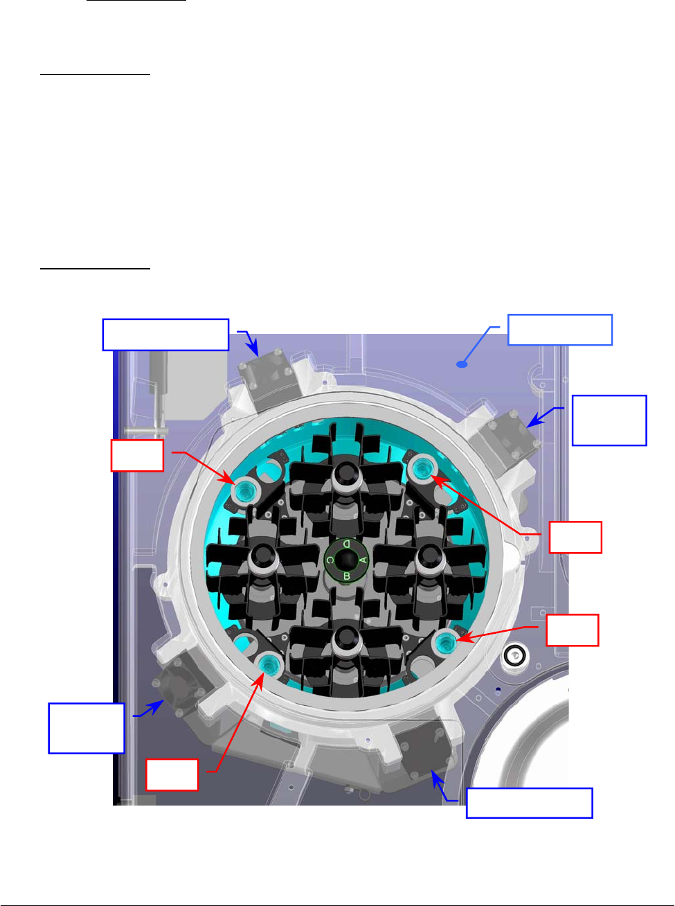
Chapter 05 – SETTINGS AND ADJUSTMENTS
SAT450 Service Manual Rev.00 03 July 2008 Page 90
5.9.2 Procedure for the check of the Reagents Cooling Temperature
1. Turn on the SAT450 system (instrument and computer) and launch the “Diagnostic” program.
2. Select "Plates” folder and request an Reagents Plate reset. Wait until the reset Reagents Plate
procedure has been completed.
3. Make sure that the two Home Sensors of the Reagents Plate light up in green.
4. Wait 30 minutes to bring the Reagents Plate to the correct cooling temperature.
5. Lift up the instrument cover and remove the Reagents Plate cover from the Reagents Plate
(Fig. 7).
6. Take four IL cups and fill them with distilled water to the ambient temperature.
7. Position the four filled cups in the positions #1 – by the adaptors – of the four Peripheral Racks
(rA-1, rB-1, rC-1 and rD-1 positions) as showed in the Fig. 134.
8. Replace the Reagents Plate cover on the Reagents Plate and bring down the instrument cover
(Fig. 7).
9. Wait 60 minutes to bring the distilled water of the four cups to the right cooling temperature.
Fig. 134 – Reagents Plate and Cooler Modules
Cooler Module
Cooler
Module
Cooler
Module
Cooler Module
Raisin
g
To
p
Cup
Cup
Cup
Cup

Chapter 05 – SETTINGS AND ADJUSTMENTS
SAT450 Service Manual Rev.00 03 July 2008 Page 91
10. Turn on a calibrated thermometer with probe.
11. Lift up the instrument cover and remove the Reagents Plate cover from the Reagents Plate
(Fig. 7).
12. Insert the probe of the thermometer inside the cup of the rA-1 position until the probe tip touches
the bottom of the cup, shake slightly it and read the temperature value (in °C).
13. Check that said temperature value is included in the following range: [8 °C , 12 °C].
14. Insert the probe of the thermometer inside the cup of the rB-1 position until the probe tip touches
the bottom of the cup, shake slightly it and read the temperature value (in °C).
15. Check that said temperature value is included in the following range: [8 °C , 12 °C].
16. Insert the probe of the thermometer inside the cup of the rC-1 position until the probe tip touches
the bottom of the cup, shake slightly it and read the temperature value (in °C).
17. Check that said temperature value is included in the following range: [8 °C , 12 °C].
18. Insert the probe of the thermometer inside the cup of the rD-1 position until the probe tip touches
the bottom of the cup, shake slightly it and read the temperature value (in °C).
19. Check that said temperature value is included in the following range: [8 °C , 12 °C].
20. Remove the four cups (and the adaptors) from the Peripheral Racks, replace the Reagents Plate
cover on the Reagents Plate and bring down the instrument cover (Fig. 7).

Chapter 06 - MAINTENANCE
SAT450 Service Manual Rev. 00 03 July 2008 Page 1
CHAPTER 06
- MAINTENANCE -
INDEX
6 MAINTENANCE…………………………………………………………………….….2
6.1 PREVENTIVE MAINTENANCE……………………………………………………….2
6.2 SAMPLING PROBE – Cleaning procedure……………….…………………………….3
6.3 WASHING STATION PROBES – Cleaning procedure……………..…………..……...3
6.4 FOUR LIQUID RESERVOIR BOTTLES – Cleaning procedure….……..………..……3
6.5 DRYING PAD – Cleaning procedure ………...…………………………………………4
6.6 PROCEDURE FOR REPLACING THE DRYING PAD………………………………..5
6.7 HYDRAULIC CIRCUIT – Washing procedure..………………………………………...6
6.8 REPLACEMENT OF THE PHOTOMETER HALOGEN LAMP………………..……..6
6.9 REPLACEMENT OF THE REACTION CUVETTES……………………….……….…7
6.10 REPLACEMENT OF THE TUBES…………….………………………….…………….7
6.11 MAINTENANCE PROCEDURES...…………………………………………………….8
6.12 DECONTAMINATION PROCEDURE………………………………………………...10
Chapter 06 - MAINTENANCE
SAT450 Service Manual Rev. 00 03 July 2008 Page 2
6 MAINTENANCE
This chapter contains all those routine operations, which concern SAT450 instrument
maintenance. Said procedures, listed and described below, should be carefully and scrupulously
followed in order to guarantee the specifications and the perfect working order of the instrument over
time.
6.1 PREVENTIVE MAINTENANCE
The Table A, illustrated below, lists all those procedures to be carried out by the user/operator and
the relative frequency schedule. Strict adherence to said schedule will guarantee the optimal
operative efficiency of the SAT450 instrument.
FREQUENCY PROCEDURE NOTES
DAILY – Before launching
“Start Work”
Check the levels of the four liquid reservoir
bottles I, II, III and IV and, if necessary, fill
their bottles
DAILY – Before launching
“Start Work”
Check the levels of the Reagents, Standards
and Controls
DAILY – Before launching
“Start Work”
Check the levels of the two waste tanks and,
if necessary, empty them
DAILY – Before to start
with daily routines Carry out a WBL cycle
DAILY – After Shutdown Clean the Sampling Probe using either paper
towel or gauze See Section 7.2
FREQUENCY PROCEDURE NOTES
EVERY TWO WEEKS Clean the (four) Washing Station probes See Section 7.3
EVERY TWO WEEKS Clean the four liquid reservoir bottles See Section 7.4
ONCE A MONTH Clean the Pad See Section 7.5
ONCE A MONTH Clean the Hydraulic Circuit See Section 7.7
EVERY THREE MONTHS Change the Reaction Cuvettes See Section 7.9
EVERY SIX MONTHS Change the Pad See Section 7.6
ONCE A YEAR Change all the tubes (Tubes Kit) See Section 7.10
EVERY 2000 HOURS Change the Photometer Halogen Lamp See Section 7.8
Table A – Maintenance Schedule (Daily)
Table B – Maintenance Schedule

Chapter 06 - MAINTENANCE
SAT450 Service Manual Rev. 00 03 July 2008 Page 3
6.2 SAMPLING PROBE – Cleaning procedure
1. Make sure that the SAT450 instrument is turned off.
2. Dampen the gauze or the paper towel with distilled water and clean the outside of the
Sampling Probe. Note: wipe the Probe from the top downwards only! This is to avoid that
any bits of cloth, paper or lint fibres accidentally enter inside the Probe.
6.3 WASHING STATION PROBES – Cleaning procedure
1. Make sure that the SAT450 instrument is turned off.
2. Place a sheet of paper under the Washing Station probes in order to keep any extraneous
material from accidentally downfall into the reaction cuvettes.
3. Dampen the gauze or the paper towel with distilled water and clean the outside of the probes
(with the exception of the last probe). Note: wipe the probes from the top downwards only!
This is to avoid that any bits of cloth, paper or lint fibres accidentally enter inside the probes.
4. Remove the sheet of paper from under the Washing Station probes.
6.4 FOUR LIQUID RESERVOIR BOTTLES – Cleaning procedure
During a normal use and over time, mold and dust can build up inside the four liquid
reservoir bottles. For this reason, it is extremely important that they be periodically washed.
The said cleaning must be thorough and meticulous in order to insure that every trace of mold
or residue be removed.
How often the bottles must be cleaned depends on their use and on the quality of the
distilled water used in that particular laboratory. However, it is recommended to make thorough
washing at least once every two weeks.
It is extremely important that the user not underestimate the risks associated with mold and
dust particles. They are to be regarded as a serious hazard as they can be the cause of
instrument malfunction.
The four liquid reservoir bottles are located on the side of the instrument inside their
container.
Use only lint free paper towel or gauze.
It is suggested that once weekly the above described cleaning procedure must be performe
d
using a 5% sodium hypochlorite solution instead of distilled water to dampen the gauze o
r
the paper towel. Then, repeat the procedure using distilled water.
Use only lint free paper towel or gauze.
It is suggested that once monthly the above described cleaning procedure must be performe
d
using a 5% sodium hypochlorite solution instead of distilled water to dampen the gauze or the
p
aper towel. Then, repeat the procedure using distilled water.

Chapter 06 - MAINTENANCE
SAT450 Service Manual Rev. 00 03 July 2008 Page 4
Cleaning procedure for the four liquid reservoir bottles:
1. Make sure that the SAT450 instrument is turned off.
2. Take the caps off the bottles and empty them.
3. Fill each bottle with a 5% sodium hypochlorite solution.
4. Clean the inside of each bottle using a bottle-brush in order to remove all traces of mold
and/or residue.
5. Leave the sodium hypochlorite solution stand in the bottles for at least ten minutes.
6. Empty the bottles, rinse them repeatedly and well with tap water, then twice more using
distilled water.
7. Dry the bottles.
8. Fill the bottles with their proper solutions.
9. Replace the bottles in their respective positions inside the container.
10. Close the bottles with their caps and turn on the instrument.
11. Carry out two ‘Washing Cuvettes’ cycles and two ‘WBL’ cycles. Check the system
efficiency by comparing the WBL values and the test results obtained against the
laboratory’s quality control values.
6.5 DRYING PAD – Cleaning procedure
The Pad is used to dry the cuvettes after they have been washed. This drying process is carried
out via aspiration and therefore, over time, the Pad will necessarily absorb various contaminating
particles.
It is suggested that the Pad be replaced every six months. Said frequency may vary depending
on the workload of the individual laboratory and the operating conditions/environment of the
single instrument.
The Pad must be washed regularly in order to guarantee proper functioning and must be
replaced - if necessary - with a new Pad.
Cleaning procedure for the Pad:
1. Make sure that the SAT450 instrument is turned off.
2. Unscrew the fastening screw of the Washing Station cover and remove the cover from its
place on the Raising Top.
3. Unscrew the four fastening screws of the Washing Station tubes cover and remove the
cover from the Washing Station.
4. Remove the probe that contains the Pad (the Probe 5) and its spring.
5. Disconnect the aspiration tube.
6. Once the probe has been removed, immerge it in a 5% solution of sodium hypochlorite
for at least 15 minutes.
7. Attach a 10 ml syringe to the probe, then aspirate and dispense the hypochlorite solution
through the probe (and the Pad) until the latter is completely clean. This aspirating and
dispensing forces the liquid through the Pad fibers in both directions.

Chapter 06 - MAINTENANCE
SAT450 Service Manual Rev. 00 03 July 2008 Page 5
8. Once the Pad is clean, repeat the aspirating and dispensing cycle 10 more times using
distilled water, then disconnect the syringe.
9. Reconnect the aspiration tube to the probe.
10. Re-position the probe in its housing being careful to not kink the aspiration tube.
11. Re-position the spring on the probe.
12. Re-position the tubes cover of the Washing Station – making sure that the cylindrical
tops of the probes fit into the corresponding holes on it – and screw its four fastening
screw.
13. Manually move the Washing Station downwards and centre the pad with the reaction
cuvette turning it.
14. Re-position the Washing Station cover and screw its fastening screw.
6.6 PROCEDURE FOR REPLACING THE DRYING PAD
1. Make sure that the SAT450 instrument is turned off.
2. Unscrew the fastening screw of the Washing Station cover and remove the cover from its
place on the Raising Top.
3. Unscrew the four fastening screws of the Washing Station tubes cover and remove the
cover from the Washing Station.
4. Remove the probe that contains the Pad (the Probe 5) and its spring.
5. Disconnect the aspiration tube.
6. Remove the used Pad and replace it with a new one.
Note: press lightly to push the new Pad into place – be careful to not press too hard as this
could deform the Pad.
7. Insert the probe containing the new Pad into a reaction cuvette, pushing it down inside
until it takes on the shape of the inside of the cuvette.
8. Remove the cuvette, connect the aspiration tube to the probe and reposition the probe back
into its proper housing in the Washing Station. Note: be careful to not kink the aspiration
tube while doing so.
9. Re-position the spring on the probe.
10. Re-position the tubes cover of the Washing Station – making sure that the cylindrical tops
of the probes fit into the corresponding holes on it – and screw its four fastening screw.
11. Manually move the Washing Station downwards and centre the pad with the reaction
cuvette turning it.
12. Re-position the Washing Station cover and screw its fastening screw.

Chapter 06 - MAINTENANCE
SAT450 Service Manual Rev. 00 03 July 2008 Page 6
6.7 HYDRAULIC CIRCUIT – Washing procedure
During normal use and over time, mold and dust can build up inside the bottles and can have a
negative effect on the hydraulic circuit, compromising the correct functioning of the micropumps
and electrovalves. This, in turn, can lead to inefficiency in the Sampling Probe and cuvette
washing system.
For this reason, it is extremely important that the hydraulic circuit be periodically washed. Said
cleaning must be thorough and meticulous in order to assure that every trace of mold or residue be
removed.
How often the hydraulic circuit must be washed depends on the operating conditions/
environment of the single instrument and the quality of the distilled water used in that particular
laboratory. It is recommended to make thorough washing at least once a month.
It is extremely important that the user not underestimate the risks associated with mold and dust
particles. They are to be regarded as a serious hazard as they can be the cause of instrument
malfunction.
The hydraulic circuit input straws are located inside the liquid reservoir bottles on the side of
the instrument.
Washing procedure for the Hydraulic Circuit:
1. Make sure that the SAT450 instrument is turned on.
2. Prepare a bottle containing 500 ml of a 5% sodium hypochlorite solution.
3. Insert the four aspiration straws, located inside the liquid reservoir bottles, into the
bottle containing the sodium hypochlorite solution.
4. Carry out a ‘WBL’ cycle and then a ‘Washing cuvettes’ cycle.
5. Wait for fifteen minutes. Clean and dry the four straws and then insert them into a bottle
containing distilled water.
6. Carry out a ‘WBL’ cycle and then a ‘Washing cuvettes’ cycle.
7. Insert the four aspiration straws back into their respective bottles. In the meantime, said
bottles should have been cleaned and filled with a fresh supply of the required solution.
8. Carry out a ‘Washing cuvettes’ cycle and then a ‘WBL’ cycle. Check the system
efficiency by comparing the WBL values and the test results obtained against the
laboratory’s quality control values.
6.8 REPLACEMENT OF THE PHOTOMETER HALOGEN LAMP
It is suggested that the halogen lamp be replaced after approximately 2000 hours of use.
The halogen lamp is mounted on the Photometer, which is located on the side of the Reactions
Plate.
Replace the Photometer Halogen Lamp performing the relative procedure described into
the Section 6.4.5 (Chapter 06).

Chapter 06 - MAINTENANCE
SAT450 Service Manual Rev. 00 03 July 2008 Page 7
6.9 REPLACEMENT OF THE REACTION CUVETTES
Over time and through normal use the perfect transparency of the cuvettes diminishes. This has
a negative impact on the quality of the optical readings. It is suggested that the cuvettes be
replaced after three months of use. The four Reactions Plate Racks are located inside the
Reactions Plate.
Replacement procedure of one Reactions Plate Rack:
1. Turn on the SAT450 instrument and wait until the instrument has reached its proper
operating temperature.
2. Remove the Reactions Plate cover from its housing.
3. Unscrew the two fastening pommels of the Rack.
4. Remove the Rack from its housing and replace it with a new one.
Note: make sure to reinsert the new Rack in the Reactions Plate vertically.
5. Screw the two fastening pommels in order to fix the Rack.
6. Replace the Reactions Plate cover on the Reactions Plate.
7. Carry out a ‘WBL’ cycle. Check the system efficiency by comparing the WBL values and
the test results obtained against the laboratory’s quality control values.
6.10 REPLACEMENT OF THE TUBES
Over time and through normal use, the tubes become worn.
It is suggested that the tubes be replaced at least once a year.
Replacement procedure of the tubes:
1. Make sure that the SAT450 instrument is turned off.
2. Unscrew the two captive screws on the front underside of the instrument and lift up the
Raising Top.
3. Remove the tubes following the indications provided in the hydraulic diagram (compare
the diagram SI-16-01873-00), making attention to the spillage of liquid from the tubes.
4. Replace the new tubes following the indications provided in the hydraulic diagram
(compare the diagram SI-16-01873-00).
5. Bring down the Raising Top.
6. Turn on the instrument and wait until it has reached its proper operating temperature.
7. Carry out a ‘Washing cuvettes’ cycle and then a ‘WBL’ cycle.
8. Lift up the Raising Top and make sure that there is no leakage.
9. Bring down the Raising Top and screw the two captive screws on the front underside of
the instrument.
10. Check the system efficiency by comparing the WBL values and the test results obtained
against the laboratory’s quality control values.
Be especially careful to not touch the external surface of the reaction cuvettes dedicated
to photometric reading.

Chapter 06 - MAINTENANCE
SAT450 Service Manual Rev. 00 03 July 2008 Page 8
6.11 MAINTENANCE PROCEDURES
The following table is a list of the maintenance procedures that can be performed by the
operator or by the maintenance technician.
Note: the frequency indicated in the table may vary according to the individual instrument’s
daily workload.
PROCEDURE
FREQUENCY
EFFECTUATED BY
CLEANING THE SAMPLING PROBE
DAILY
OPERATOR
CLEANING THE FOUR
WASHING STATION PROBES
EVERY TWO
WEEKS
OPERATOR
CLEANING THE FOUR
LIQUID RESERVOIR BOTTLES
EVERY TWO
WEEKS
OPERATOR
REPLACING THE REACTION CUVETTES
EVERY THREE
MONTHS
OPERATOR
CLEANING THE PAD
ONCE A MONTH
OPERATOR
REPLACING THE PAD
EVERY SIX
MONTHS
OPERATOR
REPLACING THE PHOTOMETER
HALOGEN LAMP
AFTER 2000
HOURS OF USE
OPERATOR
REPLACING THE SAMPLING PROBE
AS NEEDED
OPERATOR
CLEANING THE HYDRAULIC CIRCUIT ONCE A MONTH OPERATOR
REPLACING THE TUBES (Tubes Kit)
ONCE A YEAR
MAINTENANCE
TECHNICIAN
REPLACING THE PRE-HEATER
AS NEEDED
MAINTENANCE
TECHNICIAN
MECHANICAL ALIGNMENT OF THE
SAMPLING ARM
AS NEEDED
MAINTENANCE
TECHNICIAN

Chapter 06 - MAINTENANCE
SAT450 Service Manual Rev. 00 03 July 2008 Page 9
PROCEDURE
FREQUENCY
EFFECTUATED BY
REPLACING OR ADJUSTING THE
HOME SENSORS
AS NEEDED
MAINTENANCE
TECHNICIAN
REPLACING THE BELT
AS NEEDED
MAINTENANCE
TECHNICIAN
REPLACING THE MOTOR
AS NEEDED
MAINTENANCE
TECHNICIAN
MECHANICAL ALIGNMENT OF
THE WASHING STATION
AS NEEDED
MAINTENANCE
TECHNICIAN
MECHANICAL ALIGNMENT OF THE
REACTIONS PLATE OR
REAGENTS PLATE OR SAMPLES PLATE
AS NEEDED
MAINTENANCE
TECHNICIAN
REPLACING THE PHOTOMETER
AS NEEDED
MAINTENANCE
TECHNICIAN
ADJUSTING THE PHOTOMETER
AS NEEDED
MAINTENANCE
TECHNICIAN
REPLACING THE ELECTRONIC BOARDS
AND THE MECHANICAL MODULES
AS NEEDED
MAINTENANCE
TECHNICIAN

Chapter 06 - MAINTENANCE
SAT450 Service Manual Rev. 00 03 July 2008 Page 10
6.12 DECONTAMINATION PROCEDURE
Before replacing any instrument parts, repairing any defective items or performing any
instrument maintenance procedure(s), the operator or maintenance technician must carry out the
below described decontamination procedure of the instrument part(s) involved in the operation(s).
This procedure can be performed on:
the entire instrument;
those part(s) of the instrument subject to possible contamination.
⇒ Material necessary:
- an ESOFENOL solution diluted to 6% (60 cc in one litre of distilled water) or a
equivalent solution. Note: the ESOFENOL is an antibacterial and antiviral substance.
- Rubber gloves
- Face mask
- Lab coat
Decontamination procedure:
External surfaces and individual parts:
• Spray the solution all over the instrument, making particular attention to wetting:
- the Sampling Arm;
- the Reactions Plate (including the cuvettes);
- the Reagents Plate (including the racks);
- the Samples Plate (including the racks);
- the instrument chassis.
• allow at the solution to stand for approximately 30 minutes;
• wipe the solution off the instrument and the various components using a sponge dampened
with distilled water.
Hydraulic circuit:
• Fill a container with a 5% sodium hypochlorite solution;
• disconnect the aspiration tubes from the nipples of their respective bottles;
• immerge the four tubes into the container filled with the 5% sodium hypochlorite solution;
• carry out two ‘Washing cuvettes’ cycles and then two ‘WBL’ cycles;
• remove the four tubes from the 5% sodium hypochlorite solution and immerge them in
another container containing the instrument Rinse solution;
• carry out one ‘Washing cuvettes’ cycle and then one ‘WBL’ cycle;
• reconnect the aspiration tubes to the nipples on their respective bottles.

Chapter 07 – Host Communication
SAT450 Service Manual Rev. 00 03 July 2008 Page 1
CHAPTER 07
– HOST COMMUNICATION –
INDEX
7 HOST COMMUNICATION…………………………………………………………….2
7.1 COMMUNICATION WITH THE HOST COMPUTER..............................................................2
7.1.1 COMMUNICATION PARAMETERS......................................................................................2
7.2 PROTOCOL SPECIFICATIONS .................................................................................................2
7.3 HEADER RECORD (H)..................................................................................................4
7.4 PATIENT RECORD (P) ..................................................................................................5
7.5 TEST ORDER RECORD (O) ..........................................................................................8
7.6 RESULTS RECORD (R) ...............................................................................................11
7.7 MESSAGE TERMINATOR RECORD (L)...................................................................13
7.8 REQUEST INFORMATION RECORD (Q) .................................................................14

Chapter 07 – Host Communication
SAT450 Service Manual Rev. 00 03 July 2008 Page 2
7 HOST COMMUNICATION
7.1 COMMUNICATION WITH THE HOST COMPUTER
The SAT450 can be connected to a host computer for the purpose of facilitating results print-out
and patients management.
In order to enable communication between the SAT450 and the Host computer, select the “Host
Link” field under “Options” in the “Parameters” menu.
7.1.1 COMMUNICATION PARAMETERS
The ILabAries is linked to the managing computer using an RS-232C serial connector having the
following specifications:
Baud Rate : 9600 Bit/sec.
Data bits : 8
Parity : None
Stop bit : 1
7.2 PROTOCOL SPECIFICATIONS
This part of Help (Protocol Specifications) contains information for the laboratory computer
and analyzer. This exchange of data follows specific ASTM protocols:
E 1381-95 Standard Specification for Low-Level Protocol to Transfer Messages
between Clinical Laboratory Instruments and Computer Systems;
E 1394-97 Standard Specification for Transferring Information between Clinical
Instruments and Computer Systems.
ASTM uses a number of different terms to indicate the way it groups data.
• Field: an individual piece of data often referred to as a data field or a data element.
• Record: a number of logically related data fields grouped together to form one part of a
complete message.
• Repeat field: a data field of the same type as the one immediately preceding it. A delimiter
separates one instance of a repeat field from the next.
• Component field: part of data field that might contain more than one piece of data.
The default communication configuration for the program is the following: "9600, N, 8, 1".
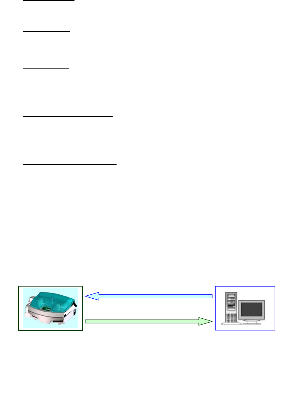
Chapter 07 – Host Communication
SAT450 Service Manual Rev. 00 03 July 2008 Page 3
ASTM uses record types that are common and familiar to all laboratory personnel. It uses the
following record types:
• Header Record (H): contains identifying information about the sending station,
conventions that the device uses for field recognition, and the date
and time of send station transmission.
• Patient Record (P): contains patient information and identification number.
• Test Order Record (O): contains information about the assay or requests themselves and
includes other data.
• Result Record (R): contains information about the outcome of individual tests for an
individual patient and follows a sample program record. The results
contain the actual measurements derived from the test and a
comparison of the individual result to certain ranges specified as
norms for the laboratory.
• Message Terminator Record (L): although the ASTM protocol supports three additional
record types - a Request for Information Record, a
Scientific Record and a Manufacturer's Information
Record - the program is not implementing these in the
first release and will ignore them.
• Request Information Record (Q): is used by either clinical instruments or computer
systems for a remote request for information from its
reciprocal system.
The instrument does not send or accept comment records.
The following scheme shows the “Download” and “Upload” operations between the SAT450
system and the Host computer:
SAT450 system Host computer
Download
Upload

Chapter 07 – Host Communication
SAT450 Service Manual Rev. 00 03 July 2008 Page 4
7.3 HEADER RECORD (H)
Field Field Title Down
Load
Up
Load
Max
Len Description and Valid Values
1 Record Type
ID R A
1 This is a required field that contains an
“H” identifying it as a header record.
2 Delimiters I A
4
The Analyzer System uses only the four
default values shown here. Delimiters
may not be duplicated. The field
delimiter follows the escape character to
separate the delimiter specification from
a subsequent field in the header record.
Using default values, the first six
characters of the header record will
appear using the following characters:
H I\^&I
Field Delimiter I
Repeat Delimiter \
Component Delimiter ^
Escape Delimiter &
3 Message
Control ID I N
4 Access
Password I N
5 Sender Name
or ID I A
10 ‘SHAnalyzer’: this is the name of the
device that is sending the data.
6 Sender Street
Address I N
7 Reserved Field I N
8 Sender Tel.
Number I N
9 Characteristics
of Sender I N
10 Receiver ID I N
11
Comments or
Special
Instructions
I N
12 Processing I N
13 ASTM Version
No. I N

Chapter 07 – Host Communication
SAT450 Service Manual Rev. 00 03 July 2008 Page 5
14 Date and Time I A
14
Date and Time of transmission:
formatted as YYYYMMDDHHMMSS.
For example: 3:35 PM on March 1, 1995
would be represented using the
following characters:
19950301153500.
Legend:
R Required D Down Load
O Optional U Up Load
I Ignored N Never
A Always S Sometimes
Example Header Record Layouts (H)
Record sent by Host computer H | \ ^ | | | HOST | | | | | | | | |19950301153500<CR>
Record sent by SAT450 system H | \ ^ & | | | SHAnalyzer | | | | | | | | | 19950301154000<CR>
7.4 PATIENT RECORD (P)
Field Field Title Down
Load
Up
Load
Max
Len Description and Valid Values
1 Record Type ID R A
1 This is a required field that contains a
“P” identifying it as a patient record.
2 Sequence
Number R A
3
This field starts with a “1” for the
patient and is incremented by 1 for each
additional patient within the
transmission.
3
Practice
Assigned
Patient ID
R A
15
This field can be assigned by the
instrument with no corresponding
download.
4
Laboratory
Assigned
Patient ID
I N
5 Patient ID No. 3 I N
6 Patient Name O S
36
This field has two components:
• Last Name (up to 20 characters)
• First Name (up to 15 characters).
7 Mother's
Maiden Name I N
8 Birth Date O S
8
Formatted as YYYYMMDD: For
example, a birth date of December 1,
1980 would be represented as:
19801201

Chapter 07 – Host Communication
SAT450 Service Manual Rev. 00 03 July 2008 Page 6
9 Patient Sex R O
1
This field indicates the sex of the
patient. The possible values are:
• M: male
• F: female
• U: unspecified
Download
If present and equal to “U”, the
patient will be considered Male or
Child depending to his birthdate
received and to the Child/Adult Age
Limit setted in the SAT450 system.
Upload
If patient has been received from the
Host computer this field will be
setted NULL. If the patient has not
been received from Host computer
this field will be:
o M: male
o F: female
o U: if the patient is Child
10
Patient
Race/Ethnic
Origin
I N
The Analyzer System will ignore this
field at launch.
11 Patient Address O S
60
For Analyzer, this is a four- component
field:
• Address (25 characters)
• City (25 characters)
• State (2 characters e.g.: NY, IT)
• Zip (5 characters)
12 Reserved Field I N
13 Patient Tel
Number I N
14 Attending
Physician ID I N
15 Special Field 1 I N
16 Special Field 2 I N
17 Patient Height I N
18 Patient Weight I N
19
Patient Known
or Suspected
Diagnosis
I N
20 Patient Active
Medications I N
21 Patient's Diet I N

Chapter 07 – Host Communication
SAT450 Service Manual Rev. 00 03 July 2008 Page 7
22 Practice Field
No. 1 I N
23 Practice Field
No. 2 I N
24
Admission Date
and Discharge
Date (if desired)
O S
8 Admission date only.
Formatted as YYYYMMDD.
25 Admission
Status I N
26 Location O S
20
27
Nature of
Alternative
Diagnostic
Code and
classifiers
I N
28
Alternative
Diagnostic
Code and
classification
I N
29 Patient Religion I N
30 Marital Status I N
31 Isolation Status I N
32 Language I N
33 Hospital
Service I N
34 Hospital
Institution I N
35 Dosage
Category I N
Legend:
R Required D Down Load
O Optional U Up Load
I Ignored N Never
A Always S Sometimes
Example Patient Record (P)
Record sent by
Host computer
P | 1 | B108K | | | MW5910^Smith | | 19861002 | M | | Park Avenue^New
York^NY^10002 | | | | | | | | | | | | | 20020923 | | Hematology | | | | | | | | | |
Record sent by
SAT450 system
P | 1 | B108K | | | MW5910^Smith | | 19861002 | M | | Park Avenue^New
York^NY^10002 | | | | | | | | | | | | | 20020923 | | Hematology | | | | | | | | |

Chapter 07 – Host Communication
SAT450 Service Manual Rev. 00 03 July 2008 Page 8
7.5 TEST ORDER RECORD (O)
Field Field Title Down
Load
Up
Load
Max
Length Description and Valid Values
1 Record Type
ID R A 1 This is required field that contains
an “O” identifying it as an order
2 Sequence
Number R A 3
This field starts with “1” for the first
Test Order Record and is
incremented by 1 for each additional
Test Order Record within the
record.
This will be reset to “1” whenever
another patient record is transmitted.
3 Specimen ID R A 15
Although the operator can manually
edit this field at any time, the value
of this field is usually assigned by
the laboratory computer before
down loading. The Analyzer uses
and reports its results based on the
assigned specimen ID.
4 Instrument
Specimen ID I N
5 Universal Test
ID
I
I
I
R
N
N
N
A
9
This is a four-component field:
• Universal Test ID Code
(not used)
• Universal Test ID Name
(not used)
• Universal Test ID Type
(not used)
• Manufacturer's or local code
(6 characters):
this is the code defined in the
Analyzer.
6 Priority O A
This field indicates the test priority
codes.
Download
If present and equal to “S” the
test will be considered as STAT.
If absent or present but different
from “S”, the test will be
considered with no priority.
Upload
It will be setted to “S” if the test
is a STAT, otherwise it will be a
NULL field.

Chapter 07 – Host Communication
SAT450 Service Manual Rev. 00 03 July 2008 Page 9
7
Request
Ordered
Date/Time
I N
8
Specimen
Collected
Date/Time
I N
9 Collection End
Time I N
10 Collection
Volume/Units I N
11 Collector ID I N
12 Action Code O N
This field indicates the action to be
taken with respect to the specimens
that accompany or precede the
request.
Download
If present and equal to “C”, the
test will be cancelled. If absent or
present and not equal to “C”, the
test will be added.
Upload
It will always be setted to NULL.
13 Danger Code I N
14 Relevant
Clinical Info. I N
15
Date/Time
Specimen
Received
I N
16 Specimen
Type R A 1
This is a numeric field indicating the
type of specimen:
The Imm. System uses the following
ASCII characters:
0= Serum
1= Urine
17 Ordering
Physician I N
18 Physician Tel.
Number I N
19 User Field
No. 1 I N
20 User Field
No. 2 I N

Chapter 07 – Host Communication
SAT450 Service Manual Rev. 00 03 July 2008 Page 10
21 Lab Field
No. 1 I N
22 Lab Field
No. 2 I N
23
Date /Time
Result
Reported Last
or Modified
I N
24 Instrument
Charge I N
25 Instrument
Section ID I N
26 Record Type I A 1
The field indicates the direction of
the transmission:
O - Down Loading
F - Up Loading
27 Reserved Field I N
28
Location or
Ward of
Specimen
Collection
I N
29 Nosocomial
Infection Flag I N
30 Specimen
Service I N
31 Specimen
Institution I N
Legend:
R Required D Down Load
O Optional U Up Load
I Ignored N Never
A Always S Sometimes
Example Test Order Record Layouts (O)
Record sent by Host computer O | 1 | AR102 | | ^^^GLU | | | | | | | | | | | 0 | | | | | | | | | | O | | | | |
Record sent by SAT450 system O | 1 | AR102 | | ^^^GLU | | | | | | | | | | | 0 | | | | | | | | | | F | | | | |

Chapter 07 – Host Communication
SAT450 Service Manual Rev. 00 03 July 2008 Page 11
7.6 RESULTS RECORD (R)
Field Field Title Down
Load
Up
Load
Max
Len Description and Valid Values
1 Record Type ID A 1 This is a required field that contains an
“R” identifying it as a Results Record.
2 Sequence
Number A 3
This field starts with “1” for the first
result and is incremented by 1 for each
additional result within the record.
This will be reset to “1” when the
results from another test order record
are transmitted to the laboratory
computer.
3 Universal Test ID
I
I
I
R
N
N
N
A
9
This is a four-component field:
• Universal Test ID Code
(not used)
• Universal Test ID Name
(not used)
• Universal Test ID Type
(not used)
• Local Manufacturer's or local
code (6 characters): this is the
code defined in the Analyzer.
4
Data or
Measurement
value
A 10
‘Data’ is a 10-character, floating point
field that includes the decimal point.
The number of precision point digits
will vary according to the test and is
configurable on the Analyzer.
5 Units of Measure A 6
This is a field for up to 6 characters
that the operator defines for analytic
measurement.
6 Reference Ranges A 21
This field has two components; one
giving the lower limit and the other the
upper limit of the range. The format
for this field is N^N.
7 Result Abnormal
Flags A 2
This field indicates the normal status
of the result. The following codes are
valid values:
L - Below Low normal
H - Above High normal
LL - Below Panic normal
HH - Above Panic normal
< - Below absolute low (under linearity)
> - Above absolute high (over linearity)
N - Normal
A - Abnormal
E - Edited

Chapter 07 – Host Communication
SAT450 Service Manual Rev. 00 03 July 2008 Page 12
8
Nature of
Abnormality
Testing
N
9 Result Status A 1
The Imm. System currently
implements only three valid values:
I - pending results in the instrument;
F - final results;
V - operator verified/approved result.
10
Date of Change in
Instrument
Normative Values
or Units
N
11 Operator ID N
12 Date/Time Test
Started N
13 Date/Time Test
Completed A 14
Date and Time of test completion:
formatted as
YYYYMMDDHHMMSS.
14 Instrument ID N
Legend:
R Required D Down Load
O Optional U Up Load
I Ignored N Never
A Always S Sometimes
Example Result Record Layouts (R)
Record sent by
SAT450 system R | 1 | ^^^GLU | 70.97 | UL | 70^105 | N | | F | | | | 20020923114302 |
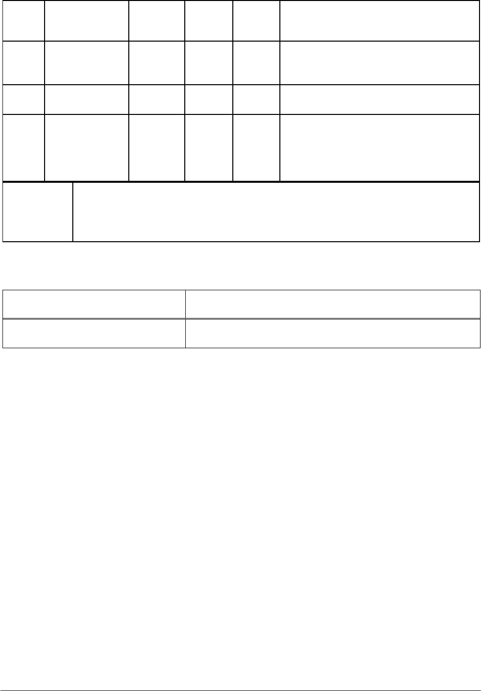
Chapter 07 – Host Communication
SAT450 Service Manual Rev. 00 03 July 2008 Page 13
7.7 MESSAGE TERMINATOR RECORD (L)
Field Field Title Down
Load
Up
Load
Max
Len Description and Valid Values
1 Record Type
ID R A
1
This is a required field that contains
an “L” identifying it as an Message
Terminator Record.
2 Sequence
Number R A
1 For a message terminator, this
message should always be “1”.
3 Termination
Code R A
1
This indicates the cause of
termination. The following codes are
valid values for the Analyzer :
Null or N-normal termination
Legend:
R Required D Down Load
O Optional U Up Load
I Ignored N Never
A Always S Sometimes
Example Message Terminator Record Layout (L)
Record sent by Host computer L | 1 | N
Record sent by SAT450 system L | 1 | N

Chapter 07 – Host Communication
SAT450 Service Manual Rev. 00 03 July 2008 Page 14
7.8 REQUEST INFORMATION RECORD (Q)
Field Field Title Down
Load
Up
Load
Max
Len Description and Valid Values
1 Record Type ID A 1
This is a required field that
contains a “Q” identifying it as a
request.
2 Sequence Number A 1 It is always “1”.
3 Starting Range ID
Number A 31
This field can either be:
"ALL" - to mean all
demographics and tests being
ordered should be sent to the
instrument at this time,
or can have two components:
• Computer system patient ID
No. (up to 15 characters);
• Computer system specimen
ID No. (up to 15 characters).
4 Ending Range ID
Number N
5 Universal Test ID N
6 Nature of Request
Time Limits N
7
Beginning Request
Results Date and
Time
N
8
Ending Request
Results Date and
Time
N
9 Requesting
Physician Name N
10
Requesting
Physician
Telephone Number
N
11 User Field No. 1 N
12 User Field No. 2 N
13 Request Information
Status Codes A 1 It is always "O" (requesting test
orders and demographics only).
Example Request Information Record Layouts (Q)
Record sent by SAT450 system
H | \^& | | | SHAnalyzer | | | | | | | | | 20020927100402
Q | 1 | ALL | | | | | | | | | | O
L | 1 | N

Chapter 08 - ERROR SIGNALING AND TROUBLESHOOTING
SAT450 Service Manual Rev. 00 03 July 2008 Page 1
CHAPTER 08
- ERROR SIGNALING AND TROUBLESHOOTING -
INDEX
8 ERROR SIGNALING AND TROUBLESHOOTING…………………………………...2
8.1 ERROR SEGNALING......................................................................................................................2
8.1.1 SYSTEM ERRORS........................................................................................................................2
8.1.2 RESULT FLAGS ...........................................................................................................................3
8.1.2.1 DESCRIPTION OF THE RESULT FLAGS ..............................................................................3
8.2 TROUBLESHOOTING GUIDE.......................................................................................................7

Chapter 08 - ERROR SIGNALING AND TROUBLESHOOTING
SAT450 Service Manual Rev. 00 03 July 2008 Page 2
8 ERROR SIGNALING AND TROUBLESHOOTING
8.1 ERROR SIGNALING
This chapter is dedicated to a description of the error signalling which may occur during the
programming or carrying out of the various operations. Error signals can be divided into the
following two groups:
System Errors;
Result Flags.
8.1.1 SYSTEM ERRORS
Whenever a system error is detected, it is signalled via the activation of the below listed
warning lights/buttons:
o Warning Light: a triangle-shape located in the System Monitor screen. It lights up yellow
when activated.
If this yellow triangle lights up, the operator needs simply to click on it to access the relative
visual text warning message indicating the cause of the signalled anomaly (said window will
open in that area dedicated to viewing data).
Following is a list of possible visual text “Warning!” messages:
• Liquid Alarm I
• Liquid Alarm II
• Liquid Alarm III
• Liquid Alarm IV
• Temperature Out-of-Range
• Host Serial Port cannot be opened
o Fatal Error: an “X”-shape located in the System Monitor mask. It lights up red when
activated.
If this red “X” lights up, the operator needs simply to click on it to access the relative visual
text message explaining the cause of the Fatal Error (said window will open in that area
dedicated to viewing data).
Following is a list of possible Fatal Error visual text messages:
• Arm Error
• Filters Error
• ADC Error – Sample Channel
• ADC Error – Reference Channel
• Plates Error (home sensor not found)
• Washing System Error
• Diluter Error
• Interlock Open while Instrument is running
Chapter 08 - ERROR SIGNALING AND TROUBLESHOOTING
SAT450 Service Manual Rev. 00 03 July 2008 Page 3
8.1.2 RESULT FLAGS
Result Flags are categorized under the following group headings. Each group is identified by
a symbol, as listed here below:
X PHYSICAL ERRORS
R CONCENTRATION ERRORS
C CALIBRATION ERRORS
A OPTIC DENSITY ERRORS
E RESULTS EDITED MANUALLY
? PROGRAMMING ERRORS
Every Result Flag, signalling an error, is accompanied by a symbol representing the pertinent
group. The operator needs simply to click on the small red square next to the Result Flag symbol
to access the visual text message explaining the cause(s) of the signalled error.
In the central column of the following tables, the user will find those symbols which signal
the type of error encountered, as used in the print-out of the final report. These symbols can be
modified by the operator in the “Print Options” form of the “Parameters” section.
8.1.2.1 DESCRIPTION OF THE RESULT FLAGS
X Physical Errors
Temperature Error: T Reaction temperature (of the Reactions Plate)
is out-of-range.
No Sample: S Either no sample or sample serum quantity
below minimum or above maximum level for
the declared container.
No Reagent: R Either no reagent or reagent level below
minimum or above maximum level for the
declared container.
The use of the Error Symbols in the print-out of the results (inclusion and/o
r
exclusion) IS UNDER THE DIRECT AND SOLE RESPONSIBILITY OF
THE USER.
Note

Chapter 08 - ERROR SIGNALING AND TROUBLESHOOTING
SAT450 Service Manual Rev. 00 03 July 2008 Page 4
R Concentration Errors
Very Low and Very High: L-H Flags determined by test results out-of-range
as setup in the Methods.
Low Alert and High Alert: A Flags determined by test results out-of-range
as setup in the Methods.
Low and High Linearity Limit: G Flags determined by test results out-of-range
as setup in the Methods.
Calculation Error: C Concentration calculation error due to
foreseeable causes (asymptote).
C Calibration Errors
RBL missing: * No Reagent Blank Level.
Calibration missing: * No Standard or no Calibration curve.
STD Replicate insufficient: * Insufficient number of valid Standard Replicates.
STD Replicate outside CV%: * Percentage Coefficient of Variation in the Standard
Replicates over the set value.
Invalid Calibration: * Calibration curve not valid – either because it is not
monotonic or because the Fit is above the set value.

Chapter 08 - ERROR SIGNALING AND TROUBLESHOOTING
SAT450 Service Manual Rev. 00 03 July 2008 Page 5
A Optic Density Errors
Inversion: I Reaction direction not in line with that set-up.
End Point Limit: P Values over the limits setup in the Methods
Parameters.
Depletion Limit: D Values over the limits setup in the Methods
Parameters.
First Limit: * Values over the limits setup in the Methods
Parameters.
FIT: F Values over the limits setup in the Methods
Parameters.
RBL out-of-range: * Reagent Blank Levels outside the range defined.
Sample outside Standard: # Sample absorbance outside the calibration curve.
Expired ! The Reagent Lot has expired.
Stability § The Reagent On Board stability has expired.
E Results Edited Manually
Results Edited: E This symbol automatically appears whenever the
operator has manually modified the obtained results.
This operation annuls all the symbols indicating
errors which, in this case, will not be viewed.
? Programming Errors
All those software errors - which are deemed unforeseeable - are indicated using this symbol.

Chapter 08 - ERROR SIGNALING AND TROUBLESHOOTING
SAT450 Service Manual Rev. 00 03 July 2008 Page 6
Moreover:
Result Asterisks
In the event that the following situations and/or error conditions occur, the system will notify
the user via a visualization of two asterisks (**) in the Results field:
PHYSICAL ERRORS
1. very little or no sample;
2. very little or no reagent;
3. no rack.
CONCENTRATION ERRORS
4. calculation error;
5. signalling depletion limit.
PROGRAMMING ERROR
6. all cases.
In the following situations and/or error conditions, the Results field will contain a “0”:
1. if the result is less than zero;
2. if the result is equal to zero.
OPTIC DENSITY ERRORS
3. flag signaling inversion.
Chapter 08 - ERROR SIGNALING AND TROUBLESHOOTING
SAT450 Service Manual Rev. 00 03 July 2008 Page 7
8.2 TROUBLESHOOTING GUIDE
PROBLEM
➢ POSSIBLE CAUSE
SOLUTION
Insufficient
repeatability of results
➢ Sampling Probe dirty.
Clean the Sampling Probe.
➢ Hydraulic leak and/or air bubbles in the hydraulic circuit.
Check the Sampling Probe fit.
Check the fit of the hydraulic tubes and their connection: if
necessary, substitute the tubes and/or adjust their
connections/fittings.
➢ Wash solution is contaminated. If the wash solution contains
contaminating particles (e.g.: mold, dust, lint), these micro-
particles can cause errors during the WBL running.
Change the wash solution.
Clean the liquid reservoir bottle(s) and carry out the Hydraulic
Circuit washing procedure.
➢ Deterioration of the Reagent(s).
Substitute the bad Reagent(s).
➢ Reaction cuvettes not dried correctly after being washed.
Check the Pad used to dry the cuvettes after washing to make
sure it is in good working condition. If necessary, clean the
Pad or change it, following the relative procedure.
➢ Halogen lamp not stable.
Halogen lamp nearing the end of its life cycle (2000 hours), or
premature deterioration. In both cases, change the Halogen
Lamp following the replacement procedure.
Insufficient
volume/quantity
of the various solutions
➢ This type of problem can present either when there is a lack of
liquid in one/more bottle(s) or - during the test running - when
the involved liquid has been finished.
Refill the involved bottle(s). If the instrument is running tests,
it will go automatically in “Pause”. Wait until sampling is
suspended, then refill the involved bottle(s) with the required
liquid(s). Press Start to run the rest of the programmed tests.
