SB02 008 MC500 Stalling
User Manual: MC500
Open the PDF directly: View PDF ![]() .
.
Page Count: 8

SB02-008
Cannondale Motorsports
Service Bulletin
Questions, call : 1-800-MOTO-USA
http://www.cannondale.com/motorsports
© 2001 Cannondale Corporation - All Rights Reserved
Printed : 4/6/02
SB02-008.fm
Information is subject to change without notice.
Page 1 of 8
BULLETIN : SB02-008
MODELS : Consult the following table for affected units.
ISSUED : 4/6/02
SUBJECT : Engine stalling
CONDITION : This is a two part bulletin covering random or intermittent engine stalling.
SOLUTION : Part 1: Operating code installation
A new revision of the MC1000 ECU operating code has been developed to support better ECU
management of sensor data interruption, a cause of engine stalling. The ECU operating code
should not be mistaken for the ECU calibration file or “map.” The operating code revisions defined
in this service bulletin MUST be installed as directed into all affected units. Units previously ser-
viced under service bulletins SBA01-10 (ATV) and SBM01-05 (Motorcycle) are also subject to this
bulletin. The new operating code files are:
All ATVs. - H302V03M.HEX
All Motorcycles - H002V03M.HEX
This bulletin includes installation instructions. See “Operating code installation” on page 2.
Part 2: Inspection points
After the new operating code revision is installed, conduct an inspection of the points listed in this
bulletin. See “Inspection points” on page 4. These points are common causes of engine stalling
related to the conditions of important vehicle systems (battery, connectors, wiring, relays, etc.).
All 2002 Up to VIN
X440s shipped prior to 3/15/02
C440 5B6BC212C32B000101
E440 5B6BC41C62B000167
Cannibal (MC1000 only) 5B6BB31352B001078
Speed 5B6CB31312B000286
Blaze 440 5B6DB313X2B000081
Moto 440 5B6EB31352B000090
All converted MC500 vehicles Kits shipped prior to 3/15/02
© 2001 Cannondale Corporation - All Rights Reserved
SB02-008.fm Page 2 of 8
CAUTION
Installing the operating code “erases” any
calibration file stored in the ECU and the vehicle
variables (Throttle position sensor min./max,
Injector offset and Injector flow rate). When
servicing the vehicle, under this bulletin, be sure
to write down the vehicle variables before
attempting to install the operating code. And use
the appropriate engine calibration files on the
diskette - P/N 5002371.
PARTS : The following parts are required to
perform the instructions of this ser-
vice bulletin:
1. CD - P/N 5002371, includes the
operating code files for ATVs and
Motorcycles and the latest engine
calibration files for each Cannondale
vehicle model.
2. MC1000 CD, Optimum,
P/N 971-5001983
Users with Windows XP, 2000, or NT
systems must call 1-800-DLR-
MOTO to obtain a special diskette to
install the operating code.
3. MC1000 Interface Cable,
P/N 971-5001984.
If you have any questions about
this service bulletin, call toll free
1-800-MOTO-USA.
OPERATING CODE INSTALLATION
NOTE :
Before you start:
So that you are familiar with the process and avoid
frustration or mistakes, read the procedure through
first before performing any of the work described.
Make sure the Cannondale Diagnostic and
Maintenance Tool has been installed onto the shop’s
PC.
Also, we strongly recommend that you read the
Cannondale Diagnostic Tool Manual (P/N 912-
5001985) thoroughly before continuing. This manual
is available on our website. The manual contains
important background information and explanations
that will be helpful to know before you attempt this
simple, but very technical procedure. We also
recommend that the service technician performing
the work have moderate PC skills.
1. Insert the CD labeled P/N 5002371 into the
CD drive of your computer.
2. Copy all but the “Readme.txt” file to the
C:\Program Files\Cal directory on your
computer.
The CD contains the two operating code
versions (ATV and Motorcycle) and all current
engine calibration files for all Cannondale
vehicles as of 4/6/02. Please note that the
exhaust silencer type installed on the vehicle
can determine the engine calibration file to
install. Consult the following table:
3. Click on the Windows START button in the
lower left corner of the PC screen and select
DealerCal.exe from the Cannondale
Diagnostic and Maintenance program group.
The Cannondale Diagnostic Tool main menu
will open. See the tool manual (P/N 912-
5001985) for a description of the main
window.
4. Click the OPEN Calibration file (saved) button
in the Cannondale Diagnostic Tool main menu
and select the correct engine calibration file
from the C:\Program Files\Cal directory.
Consult Be sure to use one of the files listed
below. Older files may be stored in the
directory, be sure you do not use them.
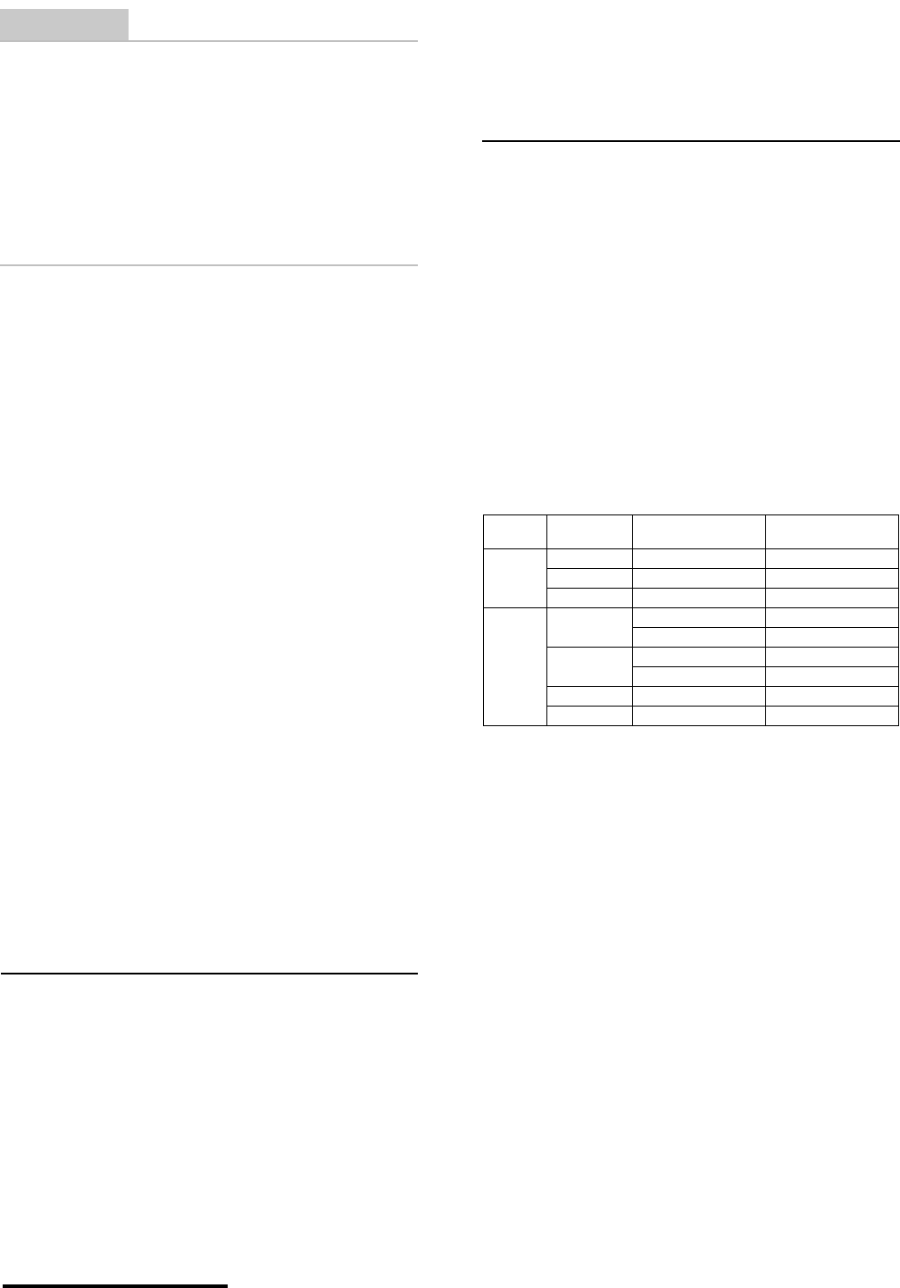
5. Make sure the correct engine calibration file
ID is displayed at Numeric Cal ID field in the
program window. If it is not, repeat the
previous step.
Vehicle
Type Model Engine Calibration
File ID Exhaust Silencer
P/N
Motorcy-
cle E440 03203 5002082
C440 02203 5002082
X440s 00202 5001760
ATV Cannibal 30203 6000215
30204 6000768
Speed 31203 6000215
31204 6000768
Blaze 440 32203 6001055
Moto 440 33203 6001055
Page 3 of 8
Printed : 4/6/02
CAUTION
Make sure the correct engine calibration file
ID number is displayed in the Numeric Cal ID
field of the Cannondale Diagnostic Tool main
menu. Installing the wrong file can result in
severe damage to the vehicle engine.
6. On motorcycles, disconnect the starter
solenoid from the wiring harness.
7. Connect the data cable to the vehicle and
make sure it is attached securely to the PC.
See the Cannondale Diagnostic Tool Manual
for details. Make sure the vehicle battery is
fully charged.
8. On ATVs, turn the ignition key to the ON
position.
For both vehicles types, press the vehicle
engine start button briefly. This will activate
the engine management circuits. The green
LED on the data cable block should be lit.
Look at the block to confirm that it is on. It
must remain on; if the light goes out anytime
during this procedure, just press the engine
start button again to turn it on.
9. Click the RECIEVE Calibration file (from
ECU) button.
When the Choose Receive Option window
opens select “Select to Receive only Throttle
and Injector Calibrations” and click OK. This
option reads only the TPS sensor closed
(volts), TPS open (volts), Throttle Body
Leakage, Injector flow rate, and Injector offset
variables from the current calibration file in
the ECU. These will be needed for the new
calibration file installation later because the
operating code installation “erases” them
from the ECU memory. The current
calibration file in the ECU will not be read.
Because the program is reading this relatively
small set of vehicle variables and not the
complete calibration file, the transfer of data
occurs quickly.
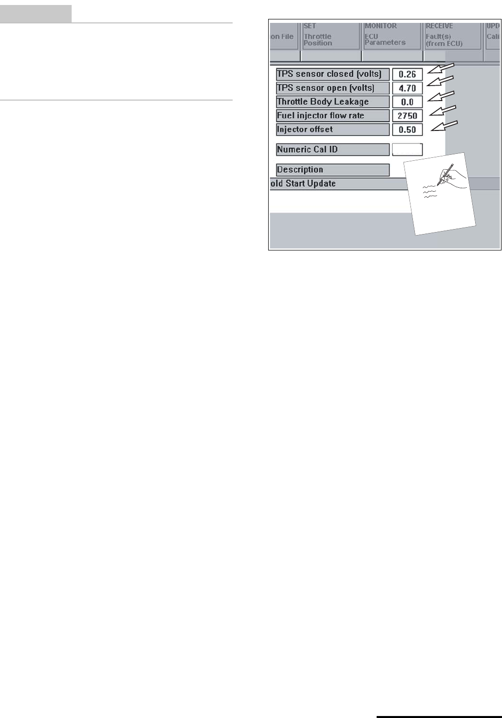
10. Write down the values displayed in the main
menu (see arrows below) for the vehicle. If
handling multiple vehicles make sure you
identify the values with the vehicle.
Written backup is helpful just in case you
encounter PC problems. As long as the
Cannondale Diagnostic and Maintenance
Tool program is open, the values will be held,
if the program is closed or the PC is shut off,
the values would be lost. If that happens, you
can manually input the values using the
software tool. See the manual.
11. From Windows START button (lower left
corner of the computer screen) select the
Cannondale Diagnostic and Maintenance
program group and select “Code Download.”
An MS-DOS program window will open.
12. If you are installing to an ATV type:
D H302V03M
If you are installing to an Motorcycle type:
D 002V03M
.............. but do not press the ENTER key!
13. Have an assistant PRESS AND CONTINUE
TO HOLD the engine start button on the
vehicle.
The arrows in the illustration above shows what values
you need to write down after they have been “read”
from the vehicle. Notice that engine calibration file
“03203” is open in the main menu. This is the engine
calibration file for an E440 motorcycle. Be sure the cor-
rect engine calibration file ID number is displayed at
this field before sending to the ECU after the operating
code installation is done.
03
2
03
© 2001 Cannondale Corporation - All Rights Reserved
SB02-008.fm Page 4 of 8
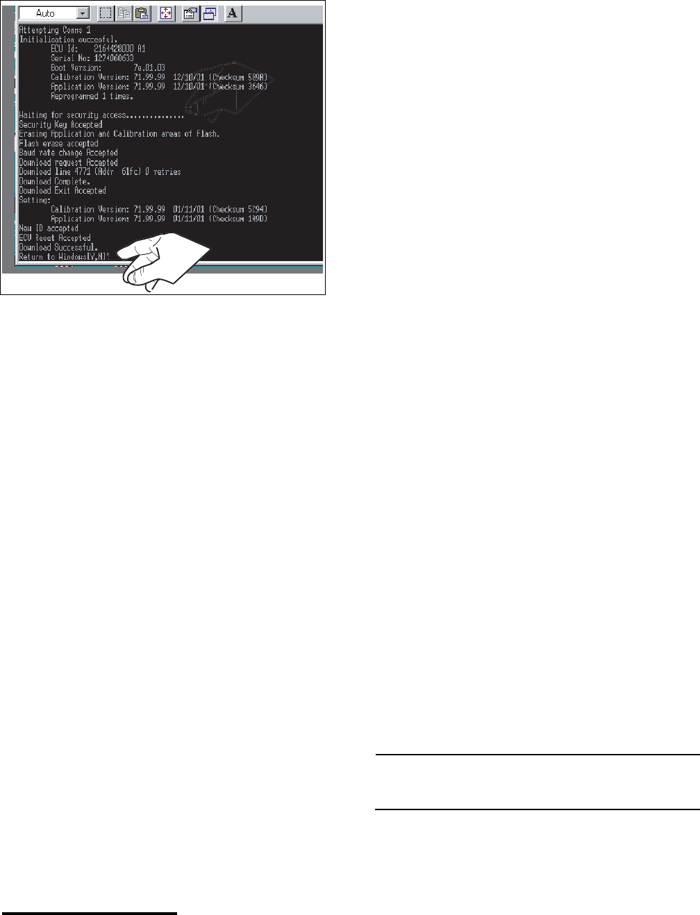
14. As your assistant holds the engine start
button, press the ENTER key on your
computer - you will see data transfer
information in the MS-DOS window.
15. When the transfer complete message
displays in the lower area of the program
window, tell your assistant to release the
engine start button and type Y and the MS-
DOS window will disappear and the
Cannondale Diagnostic Tool main menu
should be visible again.
16. Check the Numeric Cal ID field in the main
menu. Make sure the correct engine
calibration file ID number is displayed for the
vehicle. If it is not, open the necessary file
from the C:\Program Files\Cal directory.
17. Click the SEND Calibration file (to ECU)
button. The new calibration file together with
the vehicle specific variables read from the
ECU before the operating code installation
will be installed into the ECU. When the send
complete window displays, click OK.
18. On motorcycles, reconnect the starter
solenoid. Make sure the connector is latched
together properly.
19. Disconnect the data cable from the vehicle.
20. Reinstall any removed components.
21. Test engine operation. Be sure to inspect
engine idle and adjust as required.
SERVICE: Engine idle speed
2100 - 2200 r/min
INSPECTION POINTS
Common to ATV & Motorcycle
1. Low Battery Voltage
If the battery is weak the engine can turn over
normally, but a resulting low voltage while
cranking can cause the ECU power relay to
drop voltage supply to the ECU preventing the
engine from starting. Always keep the battery
fully charged and replace a weak battery with a
new one.
2. Loose Battery Terminals
Loose battery terminals can result in
intermittent or broken contact with the battery
and this can cause intermittent engine stalling.
Check the condition of both battery terminals.
Make sure they are free of corrosion and
tighten the terminal bolts to the specified
torque.
On ATVs, tighten the battery terminal bolts to
15.0 lbf•in (inch pounds) or 1.7 N•m.
On motorcycles, use Loctite #262 on the
terminal bolt threads and be sure to use the
star washers between the battery terminals and
harness ends. When using loctite allow a few
hours for the compound to cure. If the
compound is allowed to cure before use, it
results in a better hold. Tighten the motorcycle
battery terminal bolts to 15.0 lbf•in (inch
pounds) or 1.7 N•m.
3. Charging voltage
If the charging system is damaged, the battery
can be depleted and this will result in
intermittent engine stalling. Check the charging
voltage. The charging voltage must be
inspected with the engine running at 3000 rpm
- the voltage must be 13.5 to 14.5 volts.
NOTE :
Allowing the vehicle to idle for extended periods can
deplete the battery voltage.
4. Harness Abrasion or Damage
Check the vehicle wiring harness for signs of
abrasion or damage. Damage to the harness
Page 5 of 8
Printed : 4/6/02
can result in damage to the wires inside -
shorting to the frame or wiring - this will cause
intermittent engine shut down.
5. Loose or Damaged Connectors
Check all harness connectors terminating at a
device (fuel injector, ignition coil, coolant
sensor, air temperature sensor, etc.) for loose,
damaged, or corroded ends.
6. Engine Idle Speed
Check the engine idle speed and adjust to
specified. An incorrectly set engine idle speed
can result in engine stalling when the throttle is
quickly closed and re-opened. The set idle
speed can change as the mechanical stops on
the throttle body wear. Adjust the idle speed to
specification as required. Check the idle speed
more frequently on new vehicles.
SERVICE: Engine idle speed
2100 - 2200 r/min
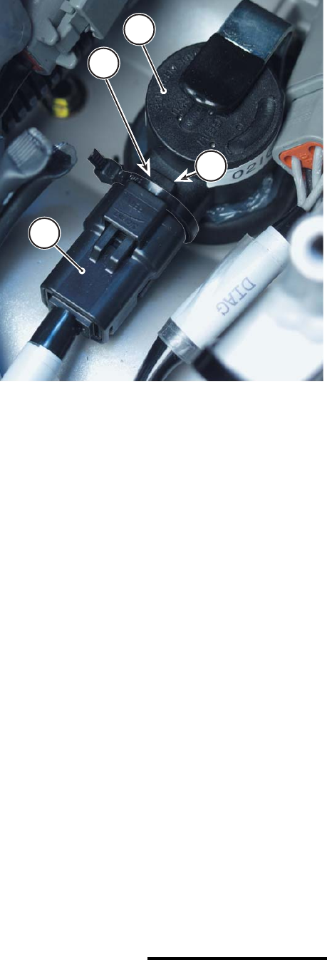
7. Ignition Coil Connector Zip Tie
Check the ignition coil to make sure it is
connected to the vehicle wiring harness
correctly. A loose connector can result in
intermittent engine shut off.
Apply a zip tie over the harness connector
locking tab. A small tie can prevent the
connector from failing and separating from the
coil.
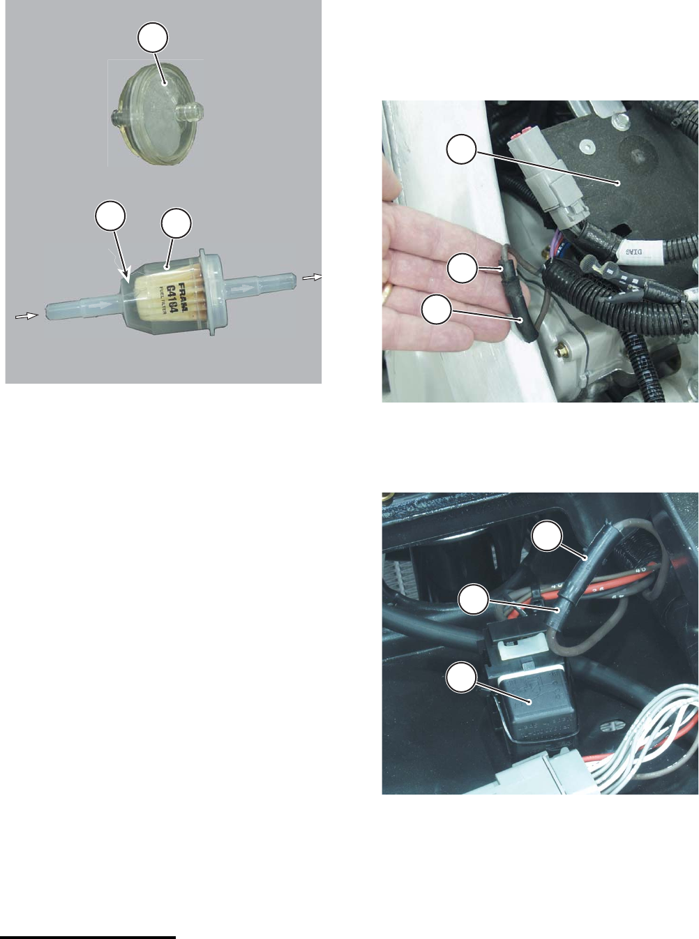
8. Fuel Filters
We recommend that owner’s replace the fuel
filters on their vehicles every five hours. The
fuel system constantly recirculates fuel and
contaminants inside the tank can clog the filter
quickly. Restricted or stopped fuel flow can
cause engine stalling.
If repeated clogging or restricted fuel flow is
detected, check the inside of the fuel tank for
any contamination.
For both ATVs and Motorcycle’s replace the old
style fuel filter P/N 353-5001674 with the newer
style filter P/N 5000544 (FRAM G4164 or 35
micron equivalent). When installing the filter be
This photo shows the application of the zip tie. This
photo was taken using a motorcycle. The technique is
the same for ATVs.
1. Ignition coil
2. Harness connector
3. Locking tab
4. Zip tie
2
1
3
4
© 2001 Cannondale Corporation - All Rights Reserved
SB02-008.fm Page 6 of 8
sure to observe the flow indicator. On all
vehicles, fuel flows out of the tank, through this
filter to the fuel pump. See below.
9. EMS Power Relay
Check the terminal ends of the main power
relay inside the EMS relay mounting socket
located under the air filter on ATVs and under
the seat on motorcycles. If the terminals that
receive the blades of the relay are spread or
deformed, or corroded - this will result in
broken or intermittent contact that can cause
an engine shut down.
When reinserting the relay into the harness
socket, apply some dielectric grease to the
relay blades and the socket to help prevent
corrosion. Also position a 5 mm zip tie between
the wires coming out of the back of the harness
socket and over the top of the relay. Secure the
zip tie. Consult Cannondale Technical Bulletin -
TB02-001.
10. Power Latch Accessory Bullet Connector
Check the bullet connector connection.
This connector is only present on X440s
motorcycles; it is located near the relay plate or
outside the harness near the subframe rails
depending on the wiring harness.
This connector is only present on early ATV
MC1000 wiring harnesses. In all cases of all
early ATV wiring harnesses, the connector is
located near the EMS power relay.
If this bullet connector connection is loose or
broken, engine stalling can result.
If electrical tape has been applied over the two
connector ends, removed it and re-apply the
tape. Tape can conceal a broken connection.
1. Old style fuel filter
2. New style fuel filter
a. Flow direction indicator
a
2
1
This photo shows a bullet connector located near the
relay plate mounted on the small frame spar.
1. Relay plate
2. Bullet connector male end
3. Bullet connector female end
This photo shows an ATV bullet connector located near
the EMS power under the air filter.
1. EMS power relay
2. Bullet connector male end
3. Bullet connector female end
3
2
1
2
3
1
Page 7 of 8
Printed : 4/6/02
ATV Specific
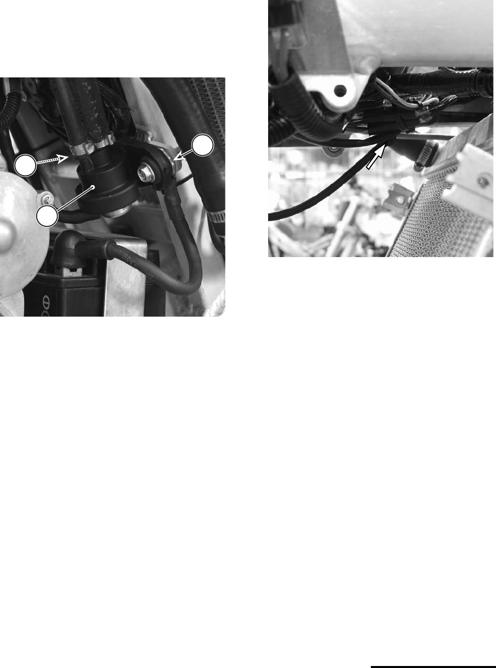
1. Frame Grounding
Check the connection of the negative battery
cable to frame and the wiring harness to the
frame terminals ends. Both are attached to the
frame at the fuel regulator mounting tab on the
main frame. If either connection is loose
intermittent contact can result in engine stalling.
2. Engine RUN/OFF Switch
Check the bullet connectors that tie the engine
“kill” switch leads into the wiring harness. A few
cases of random shut down, have been
attributed to loose bullet connectors. These
bullet connectors are located in the top front
area of the radiator. The bundle is probably zip
tied together. If the bullet connectors are
separated completely, the engine would not
start at all, or the connection between two wires
could be enough to start and run the engine
only breaking intermittently when the wires are
moved such as in shock and vibration
encountered while riding. Examine the bullet
connections making sure they are pushed
together completely.
3. Fuel Vapor Lock
Check to make sure the unit fuel line routing
has been re-routed as directed under
Cannondale Service Bulletin SB02-005.
1. Fuel pressure regulator
2. Negative battery cable end
3. Harness to Frame negative ground terminal
3
2
1
This photo take from the left side of the vehicle near the
fuse holder shows the location of the wire bundle of the
Engine RUN/OFF switch leads. The bundle is held in
place by cable ties. Check to make sure the bullet con-
nector ends of the switch leads and the wiring harness
are pushed together completely. Components have
been remove in this photo for clarity.
© 2001 Cannondale Corporation - All Rights Reserved
SB02-008.fm Page 8 of 8
Motorcycle Specific
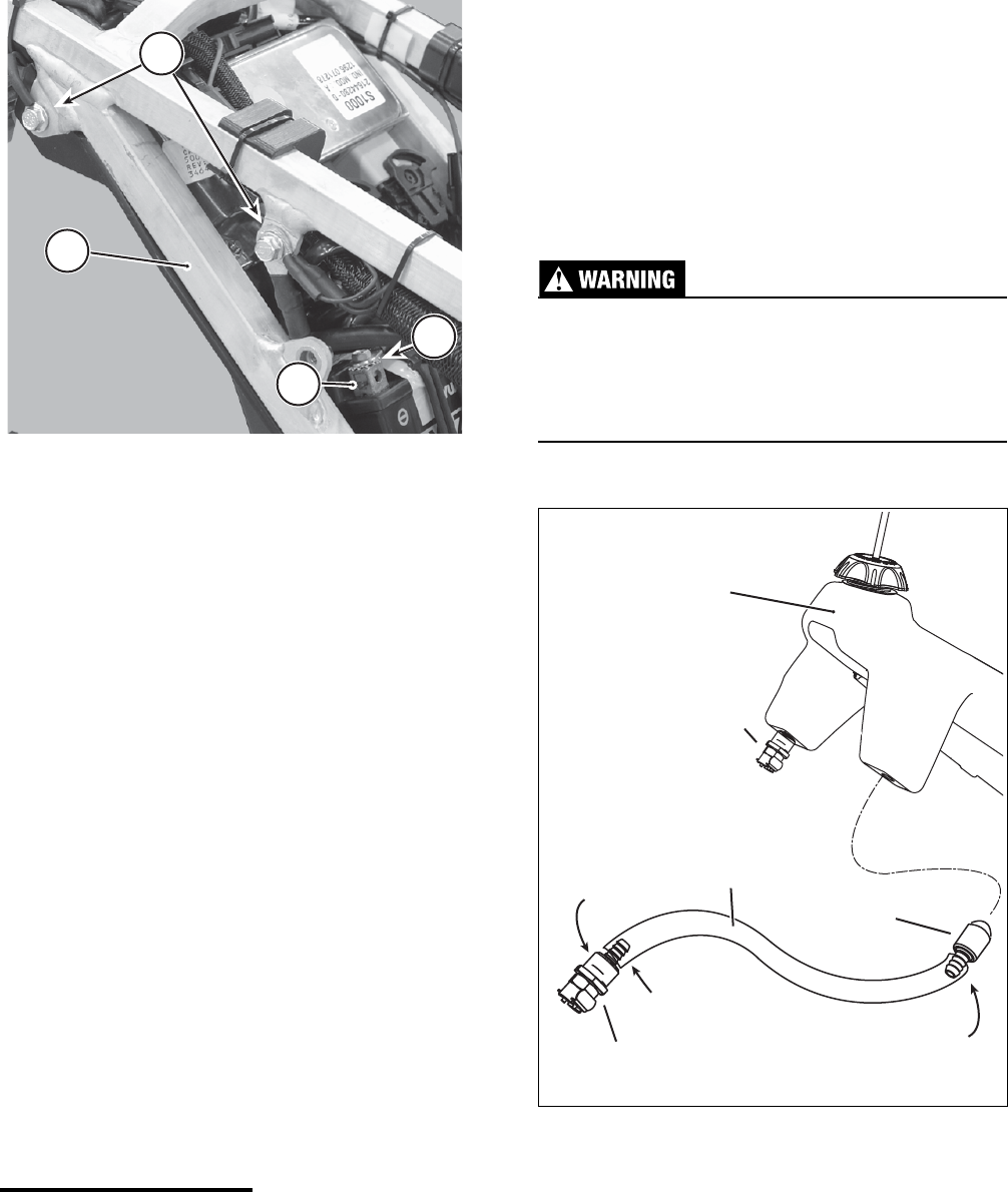
1. Frame Grounding
Check the check the subframe grounding point
located on the right side of the subframe for
tightness. There are several ground terminals
attached to the bolt on the subframe; vibration
and shock can result in intermittent loss of
contact with the frame.
2. Fuel Tank Pickup Hose
Check the condition of the fuel tank pickup
hose. Make sure the hose has not detached
from the fuel outlet fitting inside the tank. The
bike may run with a full tank of gas but shut off
as fuel level drops.
Check to make sure that the weighted pickup
screen at the end of the hose is not clogged
and attached to the end of the hose. Check to
make sure that the fuel pickup hose inside the
tank is not bent or pinched resulting restricted
fuel flow. The pick up hose is attached to the
tank outlet fitting on the left side of the tank.
If it is necessary to remove the outlet fitting
from the tank and reattach the pickup hose or
pickup screen please keep the following points
in mind:
The total length of the hose 660mm can be
trimmed about 25mm (1 inch) with good result
without sacrificing any fuel in the tank.
Trim the hose ends before re-sliding them onto
the fittings. Be sure to apply a small drop of 3M
CA40H instant CA (cyanoacrylate) adhesive on
both the outlet and pickup screen fitting barbs
before sliding the hose ends to improve the
attachment. Avoid eye and skin contact, avoid
breathing fumes and use adequate ventilation
when working with CA adhesives (super glues).
When reinstalling the pickup assembly back
into the tank, make sure the threads of the
outlet fitting and the tank threads are clean.
Apply a small amount of Loctite# 565 to the
outlet fitting threads and install the fitting into
the tank carefully. Tighten the fitting until it
contacts the tank. Overtightening can damage
the plastic fuel tank threads resulting in fuel
leaks.
Inspect the entire fuel system for leaks or
damage after servicing. Leaking fuel or a
damaged fuel system can cause a fire or
explosion. You can be severely injured or killed.
This photo shows the right side of the subframe.
The right side number panel and fuel tank have
been removed for clarity.
1. Subframe
2. Negative (-) ground points
3. Negative battery terminal
4. Star washer
1
2
3
4
Loctite #565
(thread sealant)
OUTLET
FITTING
PICKUP SCREEN
"clunk"
PICKUP
HOSE
RETURN
FITTING
FUEL TANK
3M CA40H
3M CA40H
