SC26 3759 0_Assembler_H_Programmers_Guide_Jun70 0 Assembler H Programmers Guide Jun70
SC26-3759-0_Assembler_H_Programmers_Guide_Jun70 SC26-3759-0_Assembler_H_Programmers_Guide_Jun70
User Manual: SC26-3759-0_Assembler_H_Programmers_Guide_Jun70
Open the PDF directly: View PDF ![]() .
.
Page Count: 84
C)
Program Product
o
IBM
System/360
Operating System
AssemblerH
Programmer's Guide
Program
Number
5734-AS1
TIlis
book tells how to
use
Assembler
H.
It
descnoes
assembler
options, cataloged Job Control
Language
pro-
cedures, assembler listing and output,
sample
programs,
and programming techniques and considerations.
Assembler
H is an assembler
language
processor for the
IBM
Systern/360 Operating System.
It
performs high-
speed
assemblies
on
an
IBM
Systern/360
Model
40 or
higher and on
an
IBM
Systern/370
Model
145, 155, or
165
with at least 256K bytes
of
main
storage.
This
book
is
intended for
all
Assembler
H programmmers.
It
should
be
used in conjunction with the Operating
System
Assembler
Language
manual, Order
No.
GC28-
6514; the
Assembler
H
Language
Specifications,
Order
No.
GC26-3771; and
the
Assembler H
Messages,
Order
No.
SC26-3770.
Page
of
SC26-3759-0
Revised
February
15
,
i971
By
TNL
SN33-8095
First
Edition
(June,
1970}
This
edition
with
Technical
Newsletter
SN33-8095
applies
to
version
2
of
the
IBM
System/360
Operating
System
Assembler
H
Program
Product
5734-ASI
and
to
all
subsequent
versions
until
otherwise
indicated
in
new
editions
or
Technical
Newsletter.
Changes
to
the
text,
and.small
changes
to
illustrations,
are
indicated
by
a
vertical
linte
to
the
left
of
the
change;
changed
or
added
illustrations
are
denoted
by
the
symbol
•
to
the
left
of
the
caption.
Changes
are
continually
made
to
the
information
herein;
before
using
this
publication
in
connection
with
the
operation
of
IBM
systems,
consult
the
latest
IBM
System/360
SRL
Newsletter,
Order
No.
GN20-0360
for
the
editions
that
are
applicable
and
current.
Requests
for
copies
of
IBM
publications
should
be
made
to
your
IBM
representative
or
to
the
IBM
branch
office
serving
your
locality.
A
form
for
readers
comments
is
provided
at
the
back
of
this
publication.
If
the
form
has
been
removed,
comments
may
be
addressed
to
IBM
Nordic
Laboratory,
Publications
Development,
Box
962,
5-18109
Lidingo
9,
Sweden.
1 ©
Copyri9htInternationa1
Business
Machines
Corporation
1970
o
o
o
Technical Newsletter R 0 d N
SC26-3759-0
e:
r er
o.
This Newsletter No.
SN33-8095
Date
February
15,
1971
Previous Newsletter Nos.
None
IBM
SYSTEM/360 OPERATING
SYSTEM
ASSEMBLER H
PROGRAMMER'S
GUIDE
cmM
corp.
1970
This
Technical
Newsletter,
a
part
of
version
2
of
IBM
System/360
Operating
System,
Assembler
H
Program
Product
provides
replace-
ment
pages
for
IBM
System/360
Operating
System
Assembler
H,
Pro-
grammer's
Guide,
Order
Number
SC26-3759-0.
These
replacement
pages
remain
in
effect
for
subsequent
versions
and
modifications
unless
specifically
altered.
Pages
to
be
inserted
and/or
removed
are
listed
below:
Cover,
ii
iii,
iv
3_
/4
7,8
31,32
37,38
A
change
to
the
text
or
a
small
change
to
an
illustration
is
indicated
by
a
vertical
line
to
the
left
of
the
change;
a
changed
or
added
illustration
is
denoted
by
the
symbol
•
to
the
left
of
the
caption.
Summary
of
Amendments
Minor
errors
are
corrected
throughout
the
manual,
information
changed
on
MHELP
Control
on
&SYSNDX,
and
IBM
System/370
information
added.
Note:
File
this
cover
letter
at
the
back
of
the
manual
to
provide
a
record
of
changes.
IBM
Nordic
Laboratory,
Technical
Communications,
Box
962,
5-18109
Lidingo
.9,
Sweden
©lBM
Corp.
1971
PRINTED
IN
U.S.A.

c
c
o
o
o
Page
of
SC26-3759-0
Revised
February
15,
1971
By
TNL
SN33-8095
Preface
~his
publication
tells
how
to
use
Assembler
H.
It
describes
asserrbler
options,
cataloged
job
control
language
{:rocedures,
a'ssembler
listing
and
cutput,
assembler
data
sets,
error
diagnostic
facilities,
sample
~rcgrarrs,
and
~rogramming
techniques
and
considerations.
Asserrbler
E
is
an
asserrbler-language
processor
for
the
IBM
System/360
Operating
System.
It
performs
high-speed
asserr.tlies
on
an
IBM
System/360
Model
40
or
higher
and
on
an
IBM
System/370
Model
145,
155,
or
165
with
at
least
256K
bytes
of
main
storage.
This
manual
has
the
following
main
sections:
•
Using
the
Asserrbler
•
Assembler
Listing
Description
•
Assembler
Diagnostic
Facilities
•
Programming
Considerations
"Using
the
Assembler"
describes
the
EXEC
statement
PARM
field
o{:tion,
the
data
sets
used
by
tbe
asserrbler,
and
the
jot
control
language
cataloged
procedures
sup~lied
by
IBM.
~he
cataloged
procedures
can
be
used
to
assemble,
link-edit
or
load,
and
execute
an
asserrbler
program.
"Assemtler
Listing
Descri~ticn"
describes
each
field
of
the
assembly
listing.
"Assembler
r::iagnostic
Facilities"
descri1:es
the
~urI::ose
and
format
of
error
messages,
MNO'IEs,
and
the
MHELF
macro
trace
facility.
"Programming
Considerations"
discusses
various
topics,
such
as
standard
entry
ahd
exit
procedures
fer
problem
programs.
Appendix
A
is
a
sample
program
which
des
crites
rrany
of
the
asserrbler-
lanquaqe
features,
especially
those
unique
to
Assembler
H.
Appendix
B
is
a
sarople
MHELP
macro
trace
and
dump.
Appendix
C
describes
the
ob;ect
module
output
formats.
Appendix
D
tells
how
to
call
the
assembler
dynarrically
frem
~rcblem
programs.
'Ihis
publication
is
intended
for
all
Assemt:ler
E
programmers.
To
use
this
~ublication,
you
should
be
familiar
with
the
assembler
language
and
with
the
basic
concepts
and
facilities
of
the
Operating
System,
especially
job
control
language,
data
management
services,
su~ervisor
services,
and
the
linkage
editor
and
loader.
Assem
bIer
Pu
blications
'Ihe
following
publication
contains
a
brief
description
of
Asserrbler
H
ana
how
it
differs
frcrr
lewer
level
Operating
System/360
assemblers:
IBM
System/360
Operating
System
General
Information
Manual,
Order
Number
GC26-3758
iii
The
followinq
~utlicaticns
describe
the
assembler
language
and
the
information
required
to
rur.
Assembler
H
programs:
IBM
System/360
Operating
System
Assembler
Language,
Order
Number
GC28-65l4
The
Assembler
lanquage
manual
contains
the
basic
assembler
and
rracro
assemtler
specificaticr.s,
except
those
unique
to
Assembler
H.
IBM
System/360
Operating
System
Assembler
H
Language
Specifications,
Order
Number
GC26-377l
The
Assembler
H
lanquage
specifications
describes
the
language
features
that
are
availatle
with
Asserrbler
H.
It
is
su~plemental
to
the
Assembler
language
manual
listed
above.
IBM
System/360
Operating
System
Assembler
H
Messages,
Order
Number
SC26-3770
The
Messaqes
manual
provides
an
explanation
of
each
of
the
diagnostic
and
abnormal
termination
messages
issued
by
Assembler
H
and
how
you
should
respond
in
each
case.
The
following
publications
contain
information
used
to
install
and
maintain
Assembler
H:
IBM
System/360
Operating
System
Assembler
H
System
Information,
Order
Number
GC26-3768
The
System
Inforrr.ation
n:anual
consists
of
three
self-contained
chapters
cn
performance
estimates,
storage
estimates,
and
system
generation
of
Assembler
H.
IBM
System/360
Operating
System
Assembler
H
Program
Logic
Manual,
Order
Number
LY26-3760
The
Program
logic
Manual
describes
the
design
logic
and
functional
characteristics
cf
Assembler
H.
Operating System Publications
The
following
putlications
contain
information
about
the
Operating
System:
IBM
System/360
Operating
System
Concepts
and
Facilities,
Order
Number
GC28-6535
Concepts
and
Facilities
introduces
and
interrelates
all
Operating
System/360
control
program
facilities.
It
shows
how
these
facilities
work
with
the
languaqe
translators
and
service
programs,
so
you
can
tetter
learn
bow
to
use
the
system.
IBM
System/360
Operating
System
Job
Control
Language,
Order
Number
GC28-6539
The
Job
Control
Language
book
tells
how
to
code
the
job
control
language
necessary
to
initiate
and
control
the
processing
of
any
program,
and
contains
all
cataloged
procedures.
iv
c
o
o
IBM
System/360
Operating
System
Linkage
Editor
and
Loader,
Order
Number
GC28-6538
ThE
Linkage
Editor
and
Loader
manual
provides
information
on
the
o~eration
and
use
of
the
linkage
editor
and
loader,
which
are
two
prograrrs
that
prepare
the
output
of
language
translators
for
execution.
IBM
System/360
Operating
System
Supervisor
and
Data
Management
Macro
Instructions,
Order
Number
GC28-6647,
and
and
Data
Mana
ement
Services,
'Ihe
Supervisor
and
Cata
Management
publications
describe
the
program
Execution-tirre
services
available
from
the
Operating
system
and
the
macro
instructions
required
to
use
these
services.
IBM
System/360
Operating
System
utilities,
Order
Number
GC28-6586
'Ihe
Utilities
publication
describes
the
utility
programs
of
the
OpErating
System.
'Ihe
asseItlbler-language
programmer
can
use
utilities
to
do
such
things
as
add
macro
definitions
to
a
library.
IBM
System/360
Operating
System
Messages
and
Codes,
Order
Number
GC28-
GC28-663l
'Ihis
publication
contains
the
messages
and
corrpletion
codes
issued
ty
the
Operating
Systerr.
(It
does
not
contain
the
messages
issued
by
Assemtler
H.)
IBM
System/360
Operating
System
Programmer's
Guide
to
Debugging,
Order
Number
GC28-6670
This
publication
describes
dumps
and
other
inforrraticn
issued
by
the
operating
Systerr
wten
an
asserrbler-language
program
executes
unsuccessfully.
v
This
page
intentionally
left
blank.
c
vi
~\-.:
~i
0·
...
"
'I
.
..
'''
.....
Using the Assembler
Assembler Options .
Default Options .
Assembler Data Sets
DD
Name SYSUT 1
DD
Name SYSIN
DD
Name SYSLIB
DD
Name SYSPRINT
DD
Name SYSPUNCH
DD
Name SYSLIN
Return Codes . . . .
Cataloged Procedures .
Cataloged Procedure for Assembly (ASMHC)
Cataloged Procedure for Assembly and Link-Editing (ASMHCL)
Cataloged Procedure for Assembly, Link-Editing, and Execution (ASMHCLG)
Cataloged Procedure for Assembly and Loader-Execution (ASMHCG)
Overriding Statements in Cataloged Procedures .
Assembler Listing . . . . . . .
External
Symbol
Dictionary (ESD) .
Source and Object Program.
Relocation
Dictionary.
. . . . .
Cross Reference . . . . . . . .
Diagnostic Cross Reference and Assembler
Summary
Assembler Diagnostic Facilities . .
Assembly Error Diagnostic Messages . . .
MNOTEs
............
.
Suppression
of
Error Messages and MNOTEs
Abnormal
Assembly
Termination
Macro Trace Facility (MHELP) . . . . .
Programming Considerations . . . . . .
Saving and Restoring General Register
Contents.
Program Termination . . . . . .
PARM Field
Access.
. . . . . . . . . . .
Macro Definition Library Additions . . . . .
Load Module Modification -
Entry
Point Restatement
Object Module Linkage . . . . . . . .
Special
CPU
Programming Considerations .
Controlling Instruction Execution Sequence .
Extended-Precision Machine Instructions .
Unaligned (Byte-Oriented) Operands
Appendix A. Sample Program
Appendix
B.
Sample Macro Trace and Dump (MHELP) .
Macro Call Trace (MHELP
1).
.
Macro
Entry
Dump (MHELP 16)
Macro AIF Dump (MHELP 4)
Macro Exit Dump (MHELP 8)
Appendix
C.
Object Deck
Output
ESD
Card
Format
TEXT
(TXT)
Card
Format
RLD
Card
Format . . .
END
Card
Format
...
TESTRAN
(SYM) Card Format
Appendix
D.
Dynamic Invocation
of
the Assembler
vii
Contents
1
1
4
4
6
6
6
6
6
7
8
9
9
10
12
13
15
19
21
22
24
25
25
27
27
30
30
30
30
33
33
34
34
34
35
35
38
38
38
39
41
53
53
53
54
54
61
61
61
62
63
63
67
Illustrations
Figures
Figure
1.
Figure
2.
Figure
3.
Figure
4.
Figure
5.
Figure
6.
Figure
7.
Figure
8 •
Figure
9.
Tables
Table
1.
Table
2.
Table
3.
Assembler
H
Data
Sets.......................................
5
Cataloged
Procedure
for
Assembly
(ASMHC)
•..•....•...........
10
Cataloged
Procedure
for
Assembling
and
Link-Editing
(ASMHCL)
.................•.•....•....•.........
11
Cataloged
Procedure
for
Assembly,
Link-Editing
and
Execution
(ASMHCLG)
...•.........•.........••................
13
Cataloged
Procedure
for
Assembly
and
Loader-Execution
(ASMHCG)
•............•............•........
14
Assembler
H
Listing
............................•............
20
Sample
Error
Diagnostic
Messages
......•...•.................
29
Sample
Assembler
Linkage
Statements
for
FORTRAN
or
COBOL
Subprograms
.....•..•....•..................
37
TESTRAN
SYM
Card
Format
.................•..........•...•....
65
Assembler
Data
Set
Characteristics
....................••....
7
Number
of
Channel
Program
(NCP)
Selection
...................
8
Types
of
ESD
Entries
........................................
20
viii
,f-'~'",
, !
",\~

o
o
o
Using the Assembler
This
section
describes
the
assembly-time
options
available
to
the
assembler-lanquage
programmer,
the
data
sets
used
by
the
assembler,
and
the
cataloged
procedures
of
job
control
language
supplied
by
IBM
to
simplify
assembling,
linkage
editing
or
leading,
and
execution
of
assembly
language
l=rograrr,s. The
job
control
language
is
described
in
detail
in
the
Job
Contrel
Language
publication,
order
~Umber
GC28-
6539.
Assembler Options
Assembler
H
offers
a
number
of
optional
facilities.
For
example,
you
can
suppress
printing
of
the
asserobly
listing
or
parts
of
the
listing,
and
you
can
specify
whether
you
want
an
object
deck
or
an
ob
ject
module.
You
select
the
options
by
including
appropriate
keywords
in
the
PARM
field
of
the
EXEC
statement
that
invokes
the
assembler.
There
are
two
types
of
options:
•
Simple
pairs
ef
keyword
s:
a
posi
ti
ve
form
(such
as
LOAD)
that
requests
a
facility,
and'
an
alternative
negative
form
(such
as
NCICAD)
that
rejects
that
facility.
• Keywords
that
permit
you
to
assign
a
value
to
a
function
(such
as
LINECN'I=50)
•
Each
of
these
options
has
a
standard
or
default
value
which
is
used
for
the
assembly
if
you
do
not
specify
an
alternative
value.
The
default
values
are
explained
in
the
following
section,
"Default
Options.
"
If
you
are
using
a
cataloged
procedure,
you
~ust
include
the
PARM
field
in
the
EXEC
statement
that
inVOkes
the
procedure.
You
must
also
qualify
the
keyword
(PJ\RMl
with
the
name
of
the
step
within
the
procedure
tha
t
inVOkes
the
compiler.
For
example:
//
EXEC
ASMHC, FARM.
C='
L·CAC,
NODECK'
The
sectien
"Overriding
Statements
in
ca
taloged
Procedures"
contains
mere
examples
on
how
to
specify
options
in
a
cataloged
procedu.~e.
PARM
is
a
keyword
parameter:
code
PARM=
followed
by
the
list
of
options,
separating
the
options
by
commas
and
enclosing
the
entire
list
within
sinqle
quotes
or
parentheses.
If
there
is
only
one
option
that
does
not
include
any
special
characters,
the
enclosing
quotes
or
parentheses
can
be
omitted.
The
option
list
m~st
not
be
longer
than
100
characters,
including
the
separating
commas. You
may
specify
the
options
in
any
order.
If
contradictcry
cptions
are
used
(for
example,
LIST
and
NOLIST),
the
rightmost
option
(in
this
case,
NOIIST)
is
used.
The
assembler
options
are:
(DECK, LOAD, LIST, TEST, XREF,
ALGN,
RENT, ESD,
RLD,
MULT,
PARM~
or or or
or
or
'LlNECNT=nn',
or
or
or
or
or
SYSPARM=xxx';MSGLEVEL~nnn')
(NODECK.NOLOAD,NOLIST
.NOTEST ,NOX
RE
F , ,NOALGN.NORE
NT
,NOESD.NOR
LD,NOMU
L T,
Using
The
Assembler
1
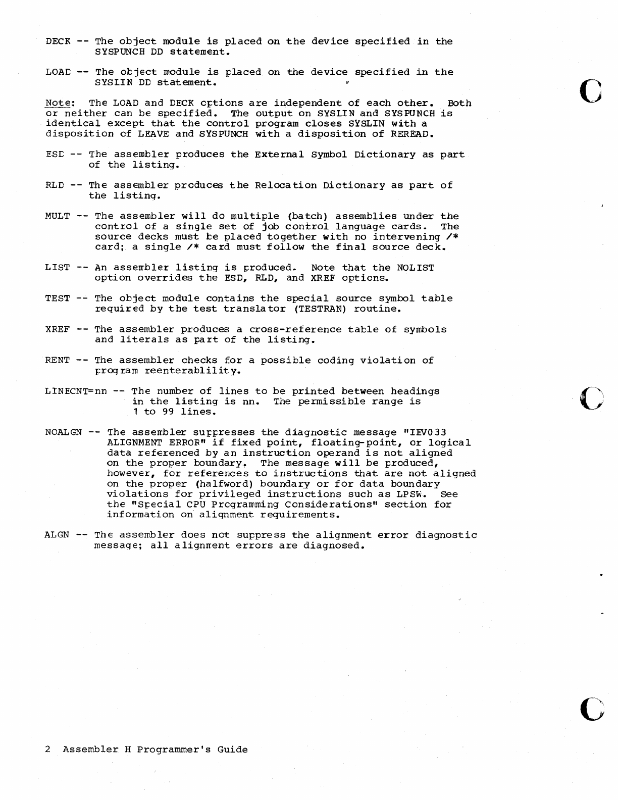
DECK
--
The
object
module
is
placed
on
the
device
specified
in
the
SYSPUNCH
DD
statement.
LOAC
--
The
object
module
is
placed
on
the
device
specified
in
the
SYSLIN
DC
statement.
Note:
The
LOAD
and
DECK
options
are
independent
of
each
other.
Both
or
neither
can
be
specified.
The
output
on
SYSLIN
and
SYSPUNCH
is
identical
except
that
the
control
program
closes
SYSLIN
with
a
disposition
of
LEAVE
and
SYSPUNCH
with
a
disposition
of
REREAD.
ESI:
--
The
assembler
produces
the
External
Symbol
Dictionary
as
part
of
the
listing.
RLD
--
The
assembler
produces
the
Relocation
Dictionary
as
part
of
the
listing.
MULT
The
assembler
will
do
multiple
(batch)
assemblies
under
the
control
of
a
single
set
of
jab
control
language
cards.
The
source
decks
must
be
placed
together
with
no
intervening
/*
card;
a
single
/*
card
must
follow
the
final
source
deck.
LIST
--
An
asserr.bler
listing
is
produced.
Note
that
the
NOLIST
option
overrides
the
ESD,
RLD,
and
XREF
options.
TEST
--
The
object
module
contains
the
special
source
symbol
table
required
by
the
test
transla
tor
(T'ESTRAN)
routine.
XREF
--
The
assembler
produces
a
cross-reference
table
of
syrrbols
and
literals
as
part
of
the
listing.
RENT
--
The
assembler
checks
for
a
possible
coding
violation
of
prOCJram
reenterablility.
LINECNT=nn
--
The
number
of
lines
to
be
printed
between
headings
in
the
listing
is
nne The
permissible
range
is
1
to
99
lines.
NOALGN
--
The
asserrbler
suppresses
the
diagnostic
message
"IEVO
33
ALIGNMENT
ERROR"
if
fixed
point,
floating-
point,
or
logical
data
referenced
by
an
instruction
operand
is
not
aligned
on
the
proper
boundary..
The
message
will
be
produced,
however,
for
references
to
instructions
that
are
not
aligned
on
the
proper
(halfword)
boundary
or
for
data
boundary
violations
for
privileged
instructions
such
as
LPSw.
See
the
"SJ:ecial
CPU
Prcgramming
Considerations"
section
for
information
on
alignment
requirements.
ALGN
--
The
assembler
does
not
suppress
the
alignment
error
diagnostic
message;
all
alignrrent
errors
are
diagnosed.
2
Assembler
H
Programmer's
Guide
c
o
c

o
o
Page
of
SC26-3759-O
Revised
February
15,
1971
By TNL
SN33-8095
MSGLEVEL=nnn
--
Error
diagnostic
messages
below
severity
code
nnn
will
not
appear
in
the
listing.
Diagnostic
messages
can
have
severity
codes
of
0,
4,
8,
12,
16,
or
20
(0
is
the
least
severe).
MNOTEs
can
have
a
severity
code
of
0
through
255.
Fer
example,
MSGLEVEL=8
will
suppress
messages
for
severity
codes
0
through
7.
SYSFARM=xxx
--
The
character
string
xxx
is
the
value
of
the
system
variable
synbol
&SYSPARM.
The
assembler
uses
&SYSPARM
as
a
read-only
SE'Ie
variable.
If
no
value
is
specified
for
the
SYSFARM
option,
&,SYSPARM
will
be
a
null
(empty)
character
string.
'Ihe
function
of
&SYSPARM
is
explained
in
the
Assenbler
H
Language
Specifications,
Order
Number
GC26-3771.
A
total
of
100
characters
is
allowed
in
the
PARM
field
of
the
EXEC
statement.
Thus,
the
maximum
length
of
the
SYSPARM
character
string
is
100
minus
the
total
number
of
other
characters
in
the
PARM
field.
(Commas
separating
c~tions
and
quotes
enclosing
individual
option
values
must
also
be
counted.)
For
exanJ;:le:
FARM='SYSFARM=xxx'
xxx
can
be
up
to
92
characters
FARM=(NCCECK,'SYSPARM=xxx')
xxx
can
be
up
to
83
characters
Commas
are
not
allowed
unless
parentheses
or
quotes
surrcund
the
entire
PARM
value.
Also,
two
quotes
are
needed
to
represent
a
single
quote
and
two
ampersands
are
needed
to
represent
a
single
ampersand,
For
example:
PARM=' LOAD, SYSPARM=(&&AB,&&XY),
PARM='NODECK,SYSPARM=('
'AB,"XY)'
The
SYSPARM
character
string
is
&AB,&XY
in
the
first
example
and
('AB,
'XY)
in
the
second
example.
If
you
are
calling
the
asseroble.r
from
a
prcblem
program
at
execution
time
(dynamic
invocation),
SYSPARM
can
be
up
to
256
characters
long,
Using
The
Assembler
3
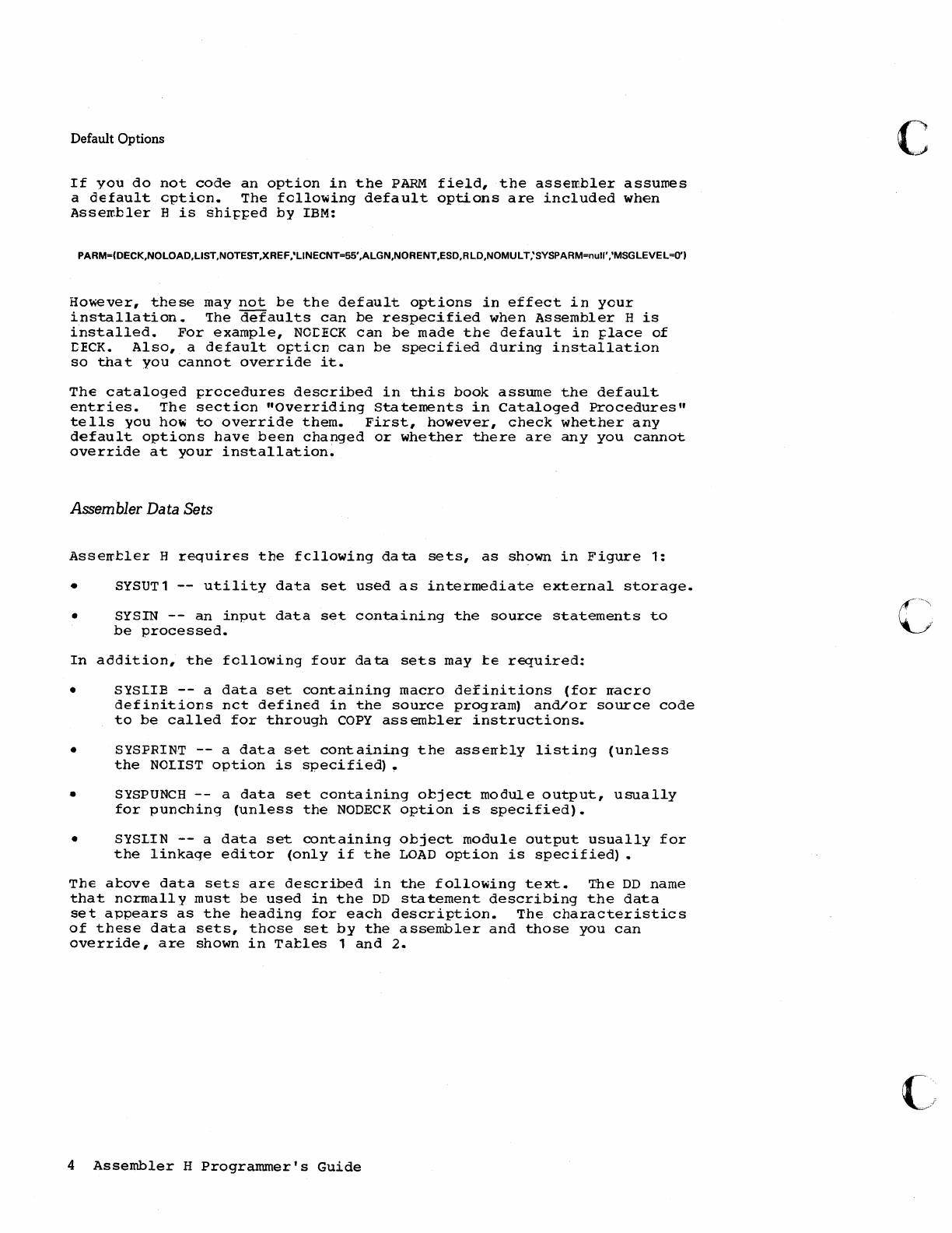
Default Options
If
you
do
not
code
an
option
in
the
PARM
field,
the
assembler
assumes
a
default
option.
The
following
default
options
are
included
when
Assembler
H
is
shi~~ed
by
IBM:
PARM=(DECK,NOLOAD,LlST,NOTEST,XREF,'LlNECNT=55',ALGN,NORENT,ESD,RLD,NOMULT,'SY$PARM=null','MSGLEVEL=O')
However,
these
may
not
be
the
default
options
in
effect
in
your
installation.
the
defaults
can
be
respecified
when
Assembler
H
is
installed.
For
example,
NcrECK
can
be
made
the
default
in
~lace
of
rECK.
Also,
a
default
opticn
can
be
specified
during
installation
so
that
you
cannot
override
it.
The
cataloged
procedures
described
in
this
book
assume
the
default
entries.
The
section
"overriding
Statements
in
Cataloged
Procedures"
tells
you
how
to
override
them.
First,
however,
check
whether
any
default
options
have
been
changed
or
whether
there
are
any
you
cannot
override
at
your
installation.
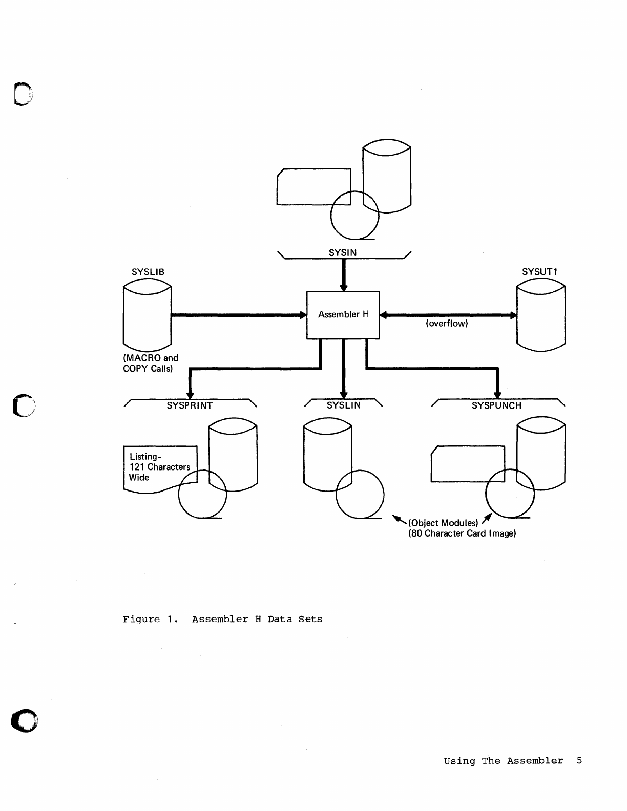
Assembler Data Sets
Asserrtler
H
requires
the
fcllowing
data
sets,
as
shown
in
Figure
1:
• SYSUT1
--
utility
data
set
used
as
intermediate
external
storage.
• SYSIN
--
an
input
data
set
containing
the
source
statements
to
be
processed.
In
addition,
the
following
four
data
sets
may
te
required:
• SYSLIB
--
a
data
set
containing
macro
definitions
(for
rracro
definitions
nct
defined
in
the
source
program)
and/or
source
code
to
be
called
for
through
COpy
assembler
instructions.
• SYSFRINT
--
a
data
s·et
containing
the
asserrtly
listing
(unless
the
NCLIST
option
is
specifie~
~
•
SYSPUNCH
--
a
data
set
containing
object
module
output,
usually
for
punching
(unless
the
NODECK
option
is
specified).
• SYSLIN
--
a
data
set
containing
object
module
output
usually
for
the
linkage
editor
(only
if
the
LOAD
option
is
specified)
•
The
atove
data
sets
are
described
in
the
follOwing
text.
The
DD
name
that
normally
must
be
used
in
the
DD
statement
describing
the
data
set
appears
as
the
heading
for
each
description.
The
characteristics
of
these
data
sets,
these
set
by
the
assembler
and
those
you
can
override,
are
shown
in
Tables
1
and
2.
4
Assembler
H
Programmer's
Guide
c
0;
..
,,)
o
SYSLIB
(MACRO
and
COpy
Calls)
SYSPRINT
SYSIN
Assembler H
Fiqure
1.
Assembler
H
Data
Sets
SYSUTl
(overflow)
SYSPUNCH
'(Object
Modules)
JI
(80
Character Card I
mage)
Using
The
Assembler
5
DD
Name SYSUT 1
The
assembler
uses
this
utility
data
set
as
an
intermediate
external
storage
device
when
~rocessing
the
source
program.
The
input/output
device
assiqned
to
this
data
set
must
be
a
direct
access
device.
The
assembler
does
not
support
a
multi-volume
utility
data
set.
DD
Name SYSIN
This
data
set
contains
the
input
to
the
assembler
--
the
source
staterr.ents
to
te
~rocessed.
The
input/output
device
assigned
to
this
data
set
may
be
either
the
device
transmitting
the
input
stream,
or
another
sequential
input
device
that
you
have
designated.
The
DD
statement
describing
this
data
set
appears
in
the
input
stream.
The
IEM-su~plied
~rocedures
de
net
contain
this
statement.
DD Name SYSLIB
From
this
data
set,
the
assembler
obtains
macro
definitions
and
assErrtler-languagE
stateITents
to
be
called
by
the
COpy
assembler
instruction.
It
is
a
partitioned
data
set;
each
macro
definition
or
sequence
of
asserrtler-language
statements
is
a
separate
member,
with
the
member
name
being
the
macro
instruction
mnerronic
or
COpy
code
name.
ThE
data
set
rray
be
defined
as
SYS1.MACLIB
or
your
private
macro
definition
or
COpy
library.
SYS1.MACLIB
contains
macro
definitions
for
the
system
macro
instructions
provided
by
IBM.
Your
private
library
may
te
concatenated
with
SYS1.MACLIB.
The
two
libraries
must
have
the
same
logical
record
length
(80
bytes),
but
the
blocking
factors
may
be
different.
'The
OD
statement
for
the
library
with
the
largest
blocksize
must
appear
first
in
the
job
control
language
for
the
assembly
(that
is,
bEfore
any
other
library
DD
statements).
The
Job
Control
Lanquage
publication,
Crder
Number
GC28-6539,
explains
the
concatenation
of
data
sets.
DD
Name SYSPRINT
'This
data
set
is
used
by
the
assembler
to
produce
a
listing.
Output
may
be
directed
to
a
printer,
magnetic
tape,
or
direct-access
storage
device.
The
assembler
uses
the
machine
code
carriage-control
characters
for
this
data
set.
DD
Name SYSPUNCH
The
assembler
uses
this
data
set
to
produce
the
object
module.
The
input/output
unit
assigned
to
this
data
set
may
be
either
a
card
punch
or
an
intermediate
storage
device
capable
of
sequential
access.
6
Assembler
H
Programmer's
Guide
c
(
'"
;
.;\
",.
o
o
o
DD
Name SYSLIN
Page
of
SC26-3759-0
Revised
February
15,
1971
By TNL
SN33-8095
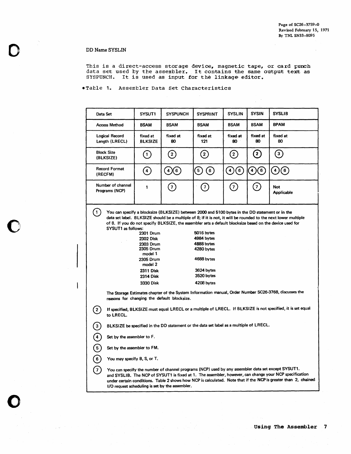
This
is
a
direct-access
storage
device,
magnetic
tape,
or
card
punch
data
set
used
ty
the
assembler.
It
contains
the
same
output
text
as
SYSPUNCH.
It
is
used
as
input
for
the
linkage
editor.
eTatle
1.
Assemcler
Data
Set
Characteristics
Data Set SYSUT1 SYSPUNCH SYSPRINT SYSLIN SYSIN SYSLIB
Access Method
BSAM BSAM BSAM
BSAM
BSAM BPAM
Logical Record fixed
at
fixed
at
fixed
at
fixed
at
fixed
at
fixed
at
Length (LRECL) BLKSIZE 80
121
80 80 80
Block Size
(0
CD
CD
CD
CD
CD
(BLKSIZE)
Record Format 0
00
00
00
00
00
(RECFM)
Number
of
channel 1 0 0 0 0 Not
Programs (NCP) Applicable
CD
o
o
o
o
You can specify a blocksize (BLKSIZE) between 2000 and
5100
bytes
in
the
DO
statement
or
in
the
data
set
label. BLKSIZE should be a multiple
of
8; if it
is
not,
it
will be rounded
to
the
next
lower multiple
of
8.
If
you
do
not
specify BLKSIZE,
the
assembler sets a default blocksize based
on
the
device used for
SYSUT1 as follows:
2301 Drum
2302 Disk
2303 Drum
2305 Drum
model
1-
2305 Drum
model 2
2311 Disk
2314
Disk
3330
Disk
5016 bytes
4984
bytes
4888
bytes
4280
bytes
4688
bytes
3624
bytes
3520
bytes
4208 bytes
The Storage Estimates chapter
of
the
System Information manual, Order Number SC26-3768, discusses
the
reasons for changing
the
default blocksize.
If
specified, BLKSIZE must equal LRECL
or
a multiple
of
LRECL. If BLKSIZE
is
not
specified, it
is
set equal
to
LRECL.
BLKSIZE be specified
in
the
DO
statement
or
the
data set label as a multiple
of
LRECL.
Set by
the
assembler
to
F.
Set by
the
assembler
to
FM.
You may specify
B,
S,
or
T.
You can specify
the
number
of
channel programs
(NCP)
used by any assembler data set except SYSUT1.
and SYSLIB. The
NCP
of
SYSUT1
is
fixed
at
1. The assembler, however, can change your
NCP
specification
under certain conditions. Table 2 shows how
NCP
is
calculated. Note
that
if
the
NCP
is
greater
than
2, chained
I/O request scheduling
is
set
by
the
assembler.
Using
The
Assembler
7
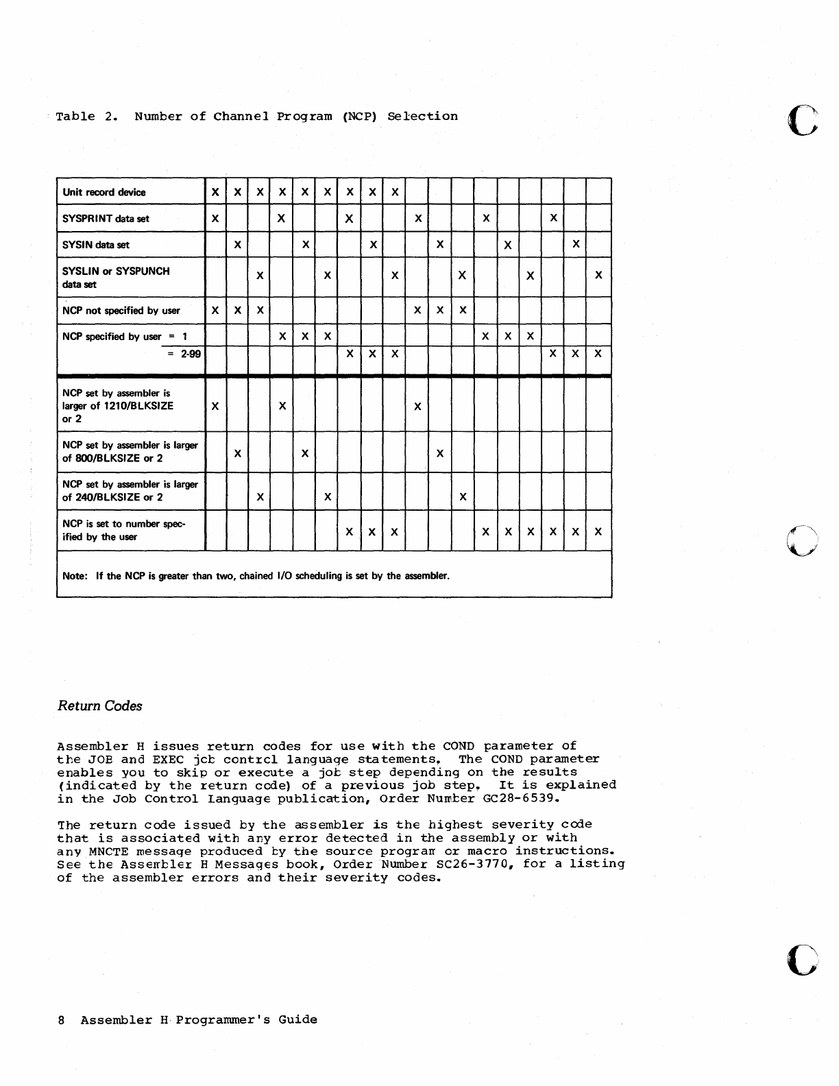
Table
2.
Number
of
Channel
Program
(NCP)
Selection
Unit record device X X X X X X X X X
SYSPR I
NT
data set X X X X X X
SYSI N data set X X X X X X
SYSLIN
or
SYSPUNCH X X X X X X
data set
NCP
not
specified by user X X X X X X
NCP
specified by user = 1 X X X X X X
= 2-99 X X X X X X
NCP
set by assembler
is
larger
of
1210/BLKSIZE X X X
or
2
NCP
set by assembler
is
larger X X X
of
8OO/BLKSIZE
or
2
NCP
set by assembler
is
larger
of
240/BLKSIZE
or
2 X X X
NCP
is
set
to
number spec- X X X X X X X X X
ified by
the
user
Note:
If
the
NCP
is
greater than two. chained I/O scheduling
is
set by
the
assembler.
Return Codes
Assembler
H
issues
return
codes
for
use
with
the
COND
parameter
of
the
JOB
and
EXEC
jct
cont~cl
language
statements.
The
COND
parameter
enables
you
to
skip
or
execute
a
jot
step
depending
on
the
results
(indicated
by
the
return
code)
of
a
previous
job
step.
It
is
explained
in
the
Job
Control
Language
publication,
Order
Numter
GC28-6539.
~he
return
code
issued
by
the
assembler
is
the
highest
severity
code
that
is
associated
with
any
error
detected
in
the
assembly
or
with
any
MNCTE
message
produced
ty
the
source
prograrr
or
macro
instructions.
See
the
Asserrble~
H
Messages
book,
Order
Number
SC26-3770,
for
a
listing
of
the
assembler
errors
and
their
severity
codes.
8
Assembler
HProgrammer's
Guide
c
c'
o
o
Cataloged
Procedures
Often
the
same
set
of
job
centrol
statements
is
used
over
and
over
again
(for
example,
to
specify
the
compilation,
link-editing,
and
execution
cf
many
different
programs).
'10
save
programming
time
and
to
reduce
the
possiblity
of
error,
sets
of
standard
series
of
EXEC
and
DD
stateff;ents
can
be
prepared
once
and
'cataloged'
in
a
system
library.
Such
a
set
of
statements
is
termed
a
cataloged
procedure
and
can
be
invcked
by
one
of
the
following
statements:
//stepname
EXEC
procname
//stepname
EXEC
PRO
c=
proc
name
The
specified
~recedure
is
read
from
the
procedure
library
(SYS1.PROCLIE)
and
merged
with
the
job
control
statements
that
follow
this
EXEC
statement.
The
System
Prcgrarr·ner's
Guide,
Order
Number
GC28-6550,
tells
how
to
place
cataloged
procedures
in
the
procedure
library.
This
section
describes
four
IBM-provided
cataloged
procedures:
a
procedure
for
assembling
(ASMHC),
a
procedure
for
assembling
and
link-
editing
(ASMHCL), a
procedure
for
assembling,
link-editing,
and
executing
(ASMHCLG),
and
a
procedure
for
asserrJ:ling
and
loader-executing
(ASMHCG)
•
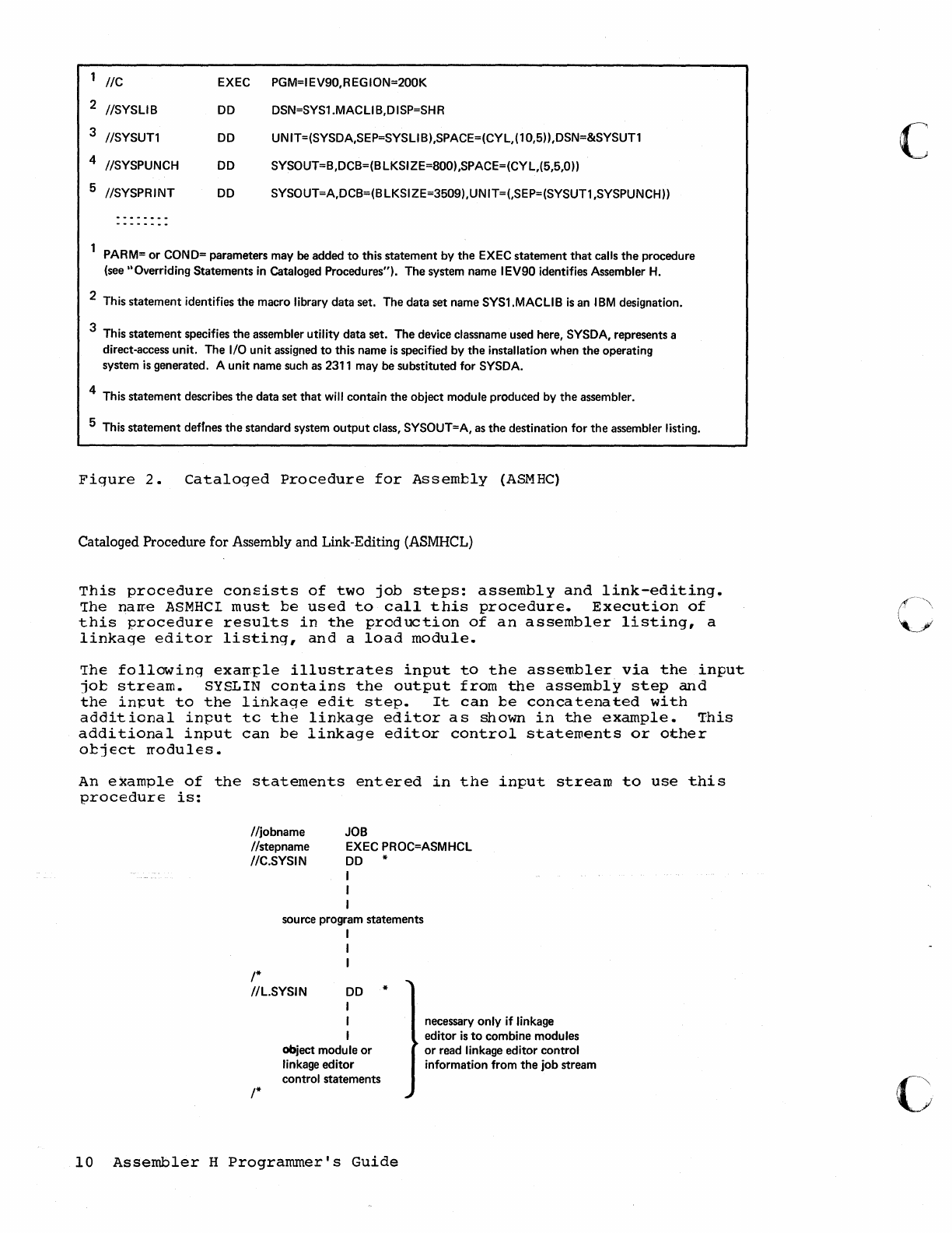
Cataloged Procedure for Assembly (ASMHC)
This
procedure
consists
of
one
jot
step:
asserrbly.
The
name
ASMHC
must
be
used
to
call
this
procedure.
The
result
of
execution
is
an
otject
module,
in
~unched
card
form,
and
an
assembler
listing.
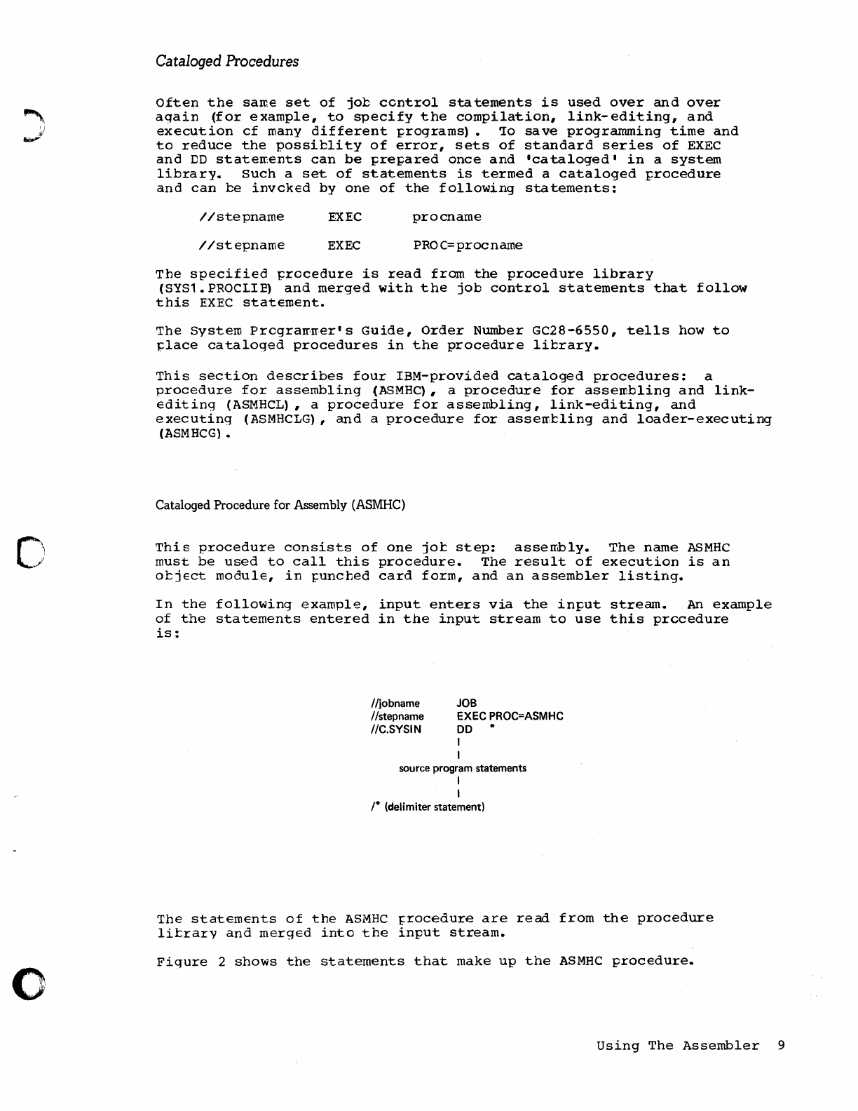
In
the
following
example,
input
enters
via
the
input
stream.
An
example
of
the
statements
entered
in
the
input
stream
to
use
this
prccedure
is:
/Ijobname
Ilstepname
IIC.SYSIN
JOB
EXEC
PROC=ASMHC
DO
I
I
source program statements
I
I
/* (delimiter statement)
The
statements
of
the
ASMHC
rrocedure
are
read
from
the
procedure
litrarv
and
merged
into
the
input
stream.
Figure
2
shows
the
statements
that
make
up
the
ASMHC
procedure.
Using
The
Assembler
9
2
3
4
5
//C
EXEC
PGM=I
EV90,R
EG
ION=200K
//SYSLIB
DO
DSN=SYS1.MACLI B,DISP=SHR
//SYSUT1
DO
UNIT=(SYSDA,SEP=SYSLlB),SPACE=(CYL,(10,5)),DSN=&SYSUT1
//SYSPUNCH
DO
SYSOUT=B,DCB=(BLKSIZE=800),SPACE=(CYL,(5,5,O))
//SYSPRINT
DO
SYSOUT=A,DCB=(B
LKSI
ZE=3509) ,UN IT=(,SEP=(SYSUT1 ,SYSPUNCH))
................
..
..
..
..
..
.. .. ..
PARM=
or
COND= parameters may be added
to
this
statement
by
the
EXEC
statement
that
calls
the
procedure
(see "Overriding Statements
in
cataloged Procedures"). The system name IEV90 identifies Assembler
H.
2 This
statement
identifies
the
macro library data set. The data set name SYS1.MACLI B
is
an I
BM
designation.
3 This
statement
specifies
the
assembler utility data set. The device classname used here, SYSDA, represents a
direct-access unit. The I/O unit assigned
to
this name
is
specified by
the
installation when
the
operating
system
is
generated. A
unit
name such as 2311 may be substituted for SYSDA.
4 This
statement
describes
the
data
set
that
will
contain
the
object module produced by
the
assembler.
5 This
statement
defInes
the
standard system
output
class, SYSOUT=A, as
the
destination for
the
assembler listing.
Figure
2.
Cataloged
Procedure
for
Assembly
(ASMHC)
Cataloged Procedure for Assembly and Link-Editing (ASMHCL)
This
procedure
consists
of
two
job
steps:
assembly
and
link-editing.
The
narre
ASMHCI
must
be
used
to
call
this
procedure.
Execution
of
this
procedure
results
in
the
production
of
an
assembler
listing,
a
linkage
editor
listing,
and
a
load
module.
The
following
exaIq:::le
illustrates
input
to
the
assembler
via
the
input
job
stream.
SYSLIN
contains
the
output
from
the
assembly
step
and
the
in~ut
to
the
linkage
edit
step.
It
can
be
concatenated
with
addit
icnal
input
tc
the
linkage
editor
a s
shown
in
the
e.xample.
This
additional
input
can
be
linkage
editor
control
statements
or
other
object
rrodules.
An
example
of
the
statements
entered
in
the
input
stream
to
use
this
procedure
is:
JOB
//jobname
//stepname
//C.SYSIN EXEC PROC=ASMHCL
DO
*
I
I
I
sou rce program statements
I
I
I
/*
//L.SYSIN
DO
I
/*
I
I
object modu
Ie
or
linkage
editor
control statements
*
10
Assembler
H
Programmer's
Guide
necessary only if linkage
editor
is
to
combine modules
or
read linkage editor control
information from
the
job stream
(
c
~\
\
11......./.
o
o
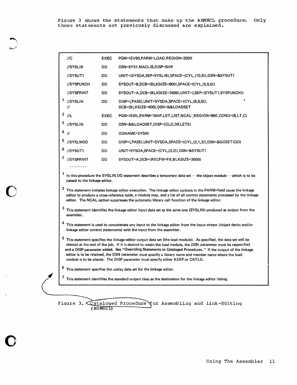
Figure
3
shows
the
statements
that
make
up
the
ASMHCL
procedure.
those
stateroents
not
previcusly
discussed
are
explained.
IIC
IISYSLIB
IISYSUTl
IISYSPUNCH
IISYSPRINT
IISYSLIN
II
2
IlL
3 IISYSLIN
4
II
5 IISYSLMOD
6 IISYSUTl
7 IISYSPRINT
--------
EXEC
DO
DO
DO
DO
DO
EXEC
DO
DO
DO
DO
DO
PGM=IEV90,PARM=LOAD,REGION=200K
DSN=SYS1.MACLI
B,D
ISP=SH R
UNIT=(SYSDA,SEP=SYSLlB),SPACE=(CYL,(10,5»,DSN=&SYSUTl
SYSOUT=B,DCB=(BLKSIZE=800),SPACE=(CYL,(5,5,O»
SYSOUT=A,DCB=(BLKSIZE=3509),UNIT=(,SEP=(SYSUT1,SYSPUNCH»
DISP=(,PASS),UNIT=SYSDA,SPACE=(CYL,(5,5,O»,
DCB=(B
LKSI
ZE=400), DSN=&&LOADSET
*
PGM=IEWL,PARM=,'MAP,LET,LlST,NCAL',REGION=96K,COND=(8,LT,C)
DSN=&&LOADSET,DISP=(OLD,DELETE)
DDNAME=SYSIN
DISP=(,?ASS),UNIT=SYSDA,SPACE=(CYL,(2,1,2»,DSN=&GOSET(GO)
UNIT=SYSDA,SPACE=(CYL,(3,2»,DSN=&SYSUTl
SYSOUT=A,DCB=(R ECF
M=F
B,B
LKSI ZE=3509)
Only
In
this procedure
the
SYSLIN
DO
statement
describes a
temporary
data
set
- -
the
object
module - - which
is
to
be
passed
to
the
linkage editor.
2 This
statement
initiates linkage
editor
execution.
The
linkage editor
options
in
the
PARM=field cause
the
linkage
editor
to
produce a cross-reference table, a module map, and a list
of
all
control
statements processed by
the
linkage
editor.
The
NCAL
option
suppresses
the
automatic library call function
of
the
linkage
editor.
3 This
statement
identifies
the
linkage
editor
input
data
set as
the
same
one
(SYSLlN) produced as
output
from
the
assembler.
4 This
statement
is
used
to
concatenate
any
input
to
the
linkage
editor
from
the
input
stream (object decks and/or
linkage
editor
control
statements) with
the
input
from
the
assembler.
5 This
statement
specifies
the
linkage-editor
output
data
set
(the
load module). As specified,
the
data
set
will be
deleted
at
the
end
of
the
job. If it
is
desired
to
retain
the
load module,
the
DSN
parameter
must
be respecified
and
a DISP parameter
added.
See "Overriding
Statements
in Cataloged Procedures. " If
the
output
of
the
linkage
editor
is
to
be retained,
the
DSN parameter must specify a library name and member name where
the
load
module
is
to
be placed.
The
DISP parameter must specify either KEEP
or
CATLG.
6 This
statement
specifies
the
utility data set for
the
linkage editor.
7 This
statement
identifies
the
standard
output
class as
the
destination
for
the
linkage
editor
listing.
~~~~------------~
or
Assembling
and
link-Editing
Using
The
Assembler
11

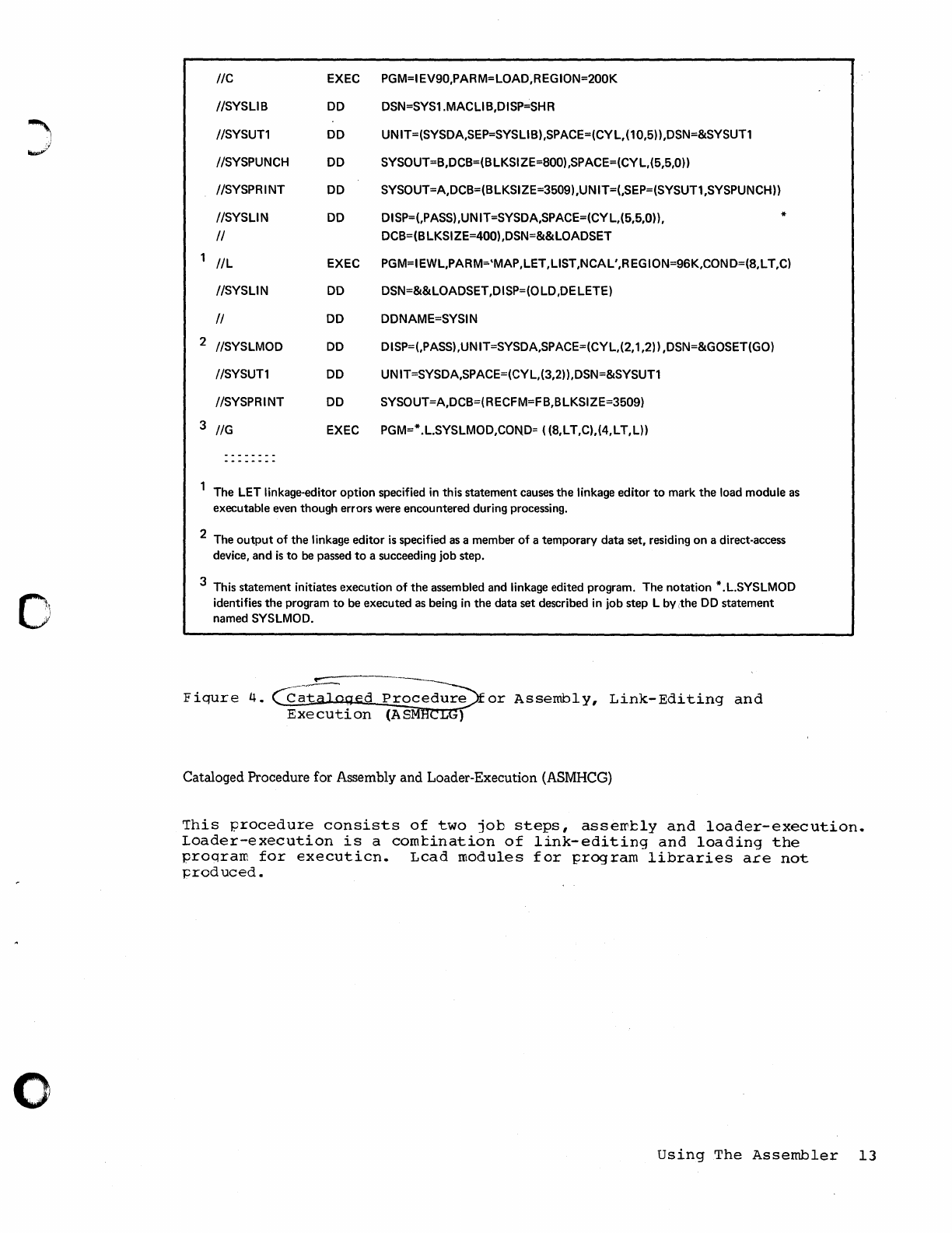
Cataloged Procedure for Assembly, Link-Editing, and Execution (ASMHCLG)
This
~rocedure
consists
of
three
job
steps:
asserrtly,
link-editing,
and
execution.
Fiqure
4
shows
the
staterrents
tha
t
make
up
the
ASMHCIG
procedure.
Cnlv
those
statements
not
previously
discussed
are
explained
in
the
f
iqure.
The
naroe
ASMHCLG
must
te
used
to
call
this
procedure.
An
assembler
listing,
an
object
deck,
and
a
linkage
editor
listing
are
prcduced.
'Ihe
staterr.ents
entered
in
the
irl1:ut
stream
to
use
this
procedure
are:
JOB //jobname
IIstepname
IIC.SYSIN EXEC PROC=ASMHCLG
DO
*
I
I
I
source program statements
I
I
I
/*
IIL.SYSI N
DO
I
I
I
object module
or
linkage editor
control statements
/*
IIG.ddname
IIG.ddname
IIG.ddname
I
I
DO
DO
DD
I
I
I
*
(parameters)
(parameters)
*
problem program input
I
I
12
Assembler
H
Programmer's
Guide
necessary only
if
linkage
editor
is
to
combine modules
or
read linkage editor control
information from the job stream
only
if
necessary
c
c
~
j
1iWY.
o
o
2
3
IIC
EXEC PGM=IEV90,PARM=LOAD,REGION=200K
IISYSLIB
DO DSN=SYS1.MACLlB,DISP=SHR
IISYSUTl
DO UNIT=(SYSDA,SEP=SYSLlB),SPACE=(CYL,(10,5)),DSN=&SYSUTl
IISYSPUNCH DO SYSOUT=B,DCB=(B LKSI ZE=800) ,SPACE=(CY L,(5,5,O))
IISYSPRINT DO SYSOUT=A,DCB=(B LKSI ZE=3509) ,UN IT=(,SEP=(SYSUTl ,SYSPUNCH))
IISYSLIN
DO
DISP=(,PASS),UNIT=SYSDA,SPACE=(CYL,(5,5,O)), *
II
DCB=(B LKSI ZE=400) ,DSN=&&LOADSET
IlL
EXEC PGM=IEWL,PARM='MAP,LET,LlST,NCAL',REGION=96K,COND=(8,LT,C)
IISYSLIN
DO
DSN=&&LOADSET
,DISP=(O LD ,DE LETE)
II DO DDNAME=SYSIN
IISYSLMOD
DO
DISP=(,PASS),UNIT=SYSDA,SPACE=(CYL,(2,1 ,2)) ,DSN=&GOSET(GO)
IISYSUTl
DO UN IT=SYSDA,SPACE=(CYL,(3,2)) ,DSN=&SYSUT1
IISYSPRINT DO SYSOUT=A,DCB=(RECFM=FB,BLKSIZE=3509)
IIG
EXEC PGM=*.L.SYSLMOD,COND=
((8,LT,C),(4,LT,L))
........................
...
...
-
...............
The
LET
linkage-editor
option
specified in this statement
causes
the linkage editor
to
mark the load module
as
executable
even
though errors were encountered during processing.
2 The
output
of
the linkage editor
is
specified
as
a member
of
a temporary data set, residing on a direct-access
device, and
is
to
be
passed
to
a succeeding
job
step.
3 This statement initiates execution
of
the assembled and linkage edited program. The notation * .L.SYSLMOD
identifies the program
to
be
executed
as
being in the data set described in
job
step L by ,the DO statement
named SYSLMOD.
Fiqure
4.
d
or
Assembly,
Link-Editing
and
Execution
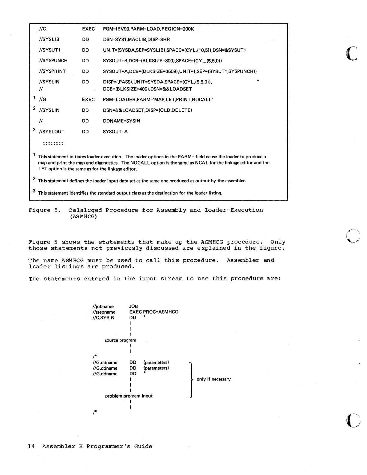
Cataloged Procedure for Assembly and Loader-Execution (ASMHCG)
This
procedure
consists
of
two
job
steps,
asserrtly
and
loader-execution.
Loader-execution
is
a
comtination
of
link-editing
and
loading
the
proqram
for
executien.
Lead
modules
for
program
libraries
are
not
produced.
Using
The
Assembler
13
2
3
IIC
EXEC PGM=IEV90,PARM=LOAD,REGION=200K
IISYSLIB DD DSN=SYS1.MACLlB,DISP=SHR
IISYSUTl DD UNIT=(SYSDA,SEP=SYSLlB),SPACE=(CYL,(10,5)),DSN=&SYSUTl
IISYSPUNCH DD SYSOUT=B,DCB=(B
lKSI
ZE=800) ,SPACE=(CY L,(5,5,O))
IISYSPRINT DD SYSOUT=A,DCB=(B LKSI ZE=3509) ,UN IT=(,SEP=(SYSUTl ,SYSPUNCH))
IISYSLIN
DD DISP=(,PASS),UNIT=SYSDA,SPACE=(CYL,(5,5,O)),
II
DCB=(B LKSI ZE=400) ,DSN=&& LOADSET
IIG
EXEC PGM=LOADER,PARM='MAP,LET,PRINT,NOCALL'
IISYSLIN DD DSN=&&LOADSET,DISP=(OLD,DELETE)
II
DD DDNAME=SYSIN
IISYSLOUT
DD SYSOUT=A
...
-------
.......................
This statement initiates loader-execution. The loader options in the PARM= field
cause
the loader
to
produce a
map and
print
the map and diagnostics. The
NOCALL
option
is
the
same
as
NCAL
for
the linkage editor and the
LET
option
is
the
same
as
for
the
linkage editor.
2 This statement defines the loader
input
data
set
as
the
same
one produced
as
output
by the assembler.
3 This statement identifies the standard
output
class
as
the destination
for
the loader listing.
Fiqure
5.
Calalcged
Procedure
for
Assembly
and
Loader-Execution
(ASMHCG)
Fiqure
5
shows
the
statements
that
make
up
the
ASMHCG
procedure.
Only
those
stateIr.ents
net
~revieusly
discussed
are
explained
in
the
figure
..
The
name
A&~HCG
must
be
used
to
call
this
procedure.
Assembler
and
leader
listings
are
produced.
'The
statements
entered
in
the
input
stream
to
use
this
prccedure
are:
Iljobname
Iistepname
IIC.SYSIN
JOB
EXEC PROC=ASMHCG
DD *
I
I
I
source program
I
/*
IIG.ddname
IIG.ddname
IIG.ddname
I
DD
DD
DD
I
I
I
(parameters)
(parameters)
*
problem program
input
I
I
/*
14
Assembler
H
Programmer's
Guide
} only if
necessary
C
c
c
O
'.··!I
,
••
1
Overriding Statements in Cataloged Procedures
Any
parameter
in
a
catalcged
procedure
can
be
overridden
except
the
PGM=
parameter
in
the
EXEC
statement.
Such
overriding
of
statements
or
fields
is
effective
only
for
the
dura
tion
of
the
job
step
in
which
the
statements
appear.
The
statements,
as
stored
in
the
procedure
litxary
of
tte
systerr,
remain
unchanged.
overriding
for
the
purposes
of
respecification,
addition,
or
nullification
is
accomplished
by
including
in
the
input
strearr
statements
containing
the
desired
changes
and
identifying
the
statements
to
be
overridden.
EXEC Statements
Any
EXEC
parameter
(except
PGM)
can
be
overridden.
For
example,
the
PARM=
and
COND=
parameters
can
be
added
or,
if
present,
respecified
by
including
in
the
EXEC
statement
calling
the
procedure
the
notation
PARM.
stepname=,
or
COND.
stepname=,
followed
by
the
desired
pararreters.
"ste}:name"
identifies
the
EXEC
statement
within
the
procedure
to
which
the
modification
applies.
If
the
procedure
ccnsists
cf
more
than
one
jot
step,
a
PARM.~rocste~name=
cr
COND.prccstepname=
parameter
may
be
entered
for
each
step.
The
entries
must
be
in
order,
(PARM
.•
procstep1
=,
PARM.procstep2=,
etc.).
DD
Statements
All
r::arameters
in
the
operand
field
of
DD
staterrents
may
be
cverridden
ty
including
in
the
in~ut
Etream
(following
the
EXEC
card
calling
the
procedure)
a
DD
statement
with
the
notation
//procstepname.ddname
in
the
name
field.
"Procstepname"
refers
to
the
job
step
in
which
the
statement
identified
by
"ddname"
appears.
Note:
If
rrcre
than
one
DD
statement
in
a
procedure
is
to
be
overridden,
the
overriding
statements
must
be
in
the
same
order
as
the
statements
in
the
procedu·re.
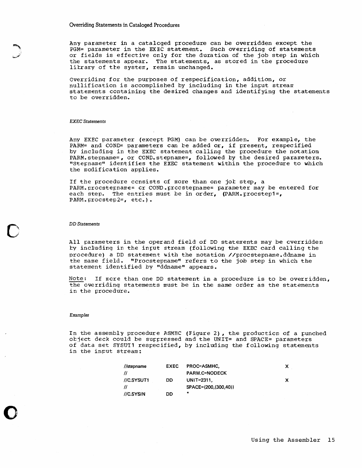
Examples
In
the
assembly
procedure
ASMEC
(Figure
2)
,
the
producticn
of
a
punched
oeject
deck
could
be
suppreEsed
and
the
UNIT=
and
SPACE=
parameters
of
data
set
SYSU71
respecified,
by
including
the
following
statements
in
the
input
stream:
//stepname EXEC PROC=ASMHC, X
II
PARM.C=NODECK
IIC.SYSUT1
DO
UNIT=2311, X
II
SPACE= (200,(300,40))
IIC.SYSIN
DO
Using
the
Assembler
15
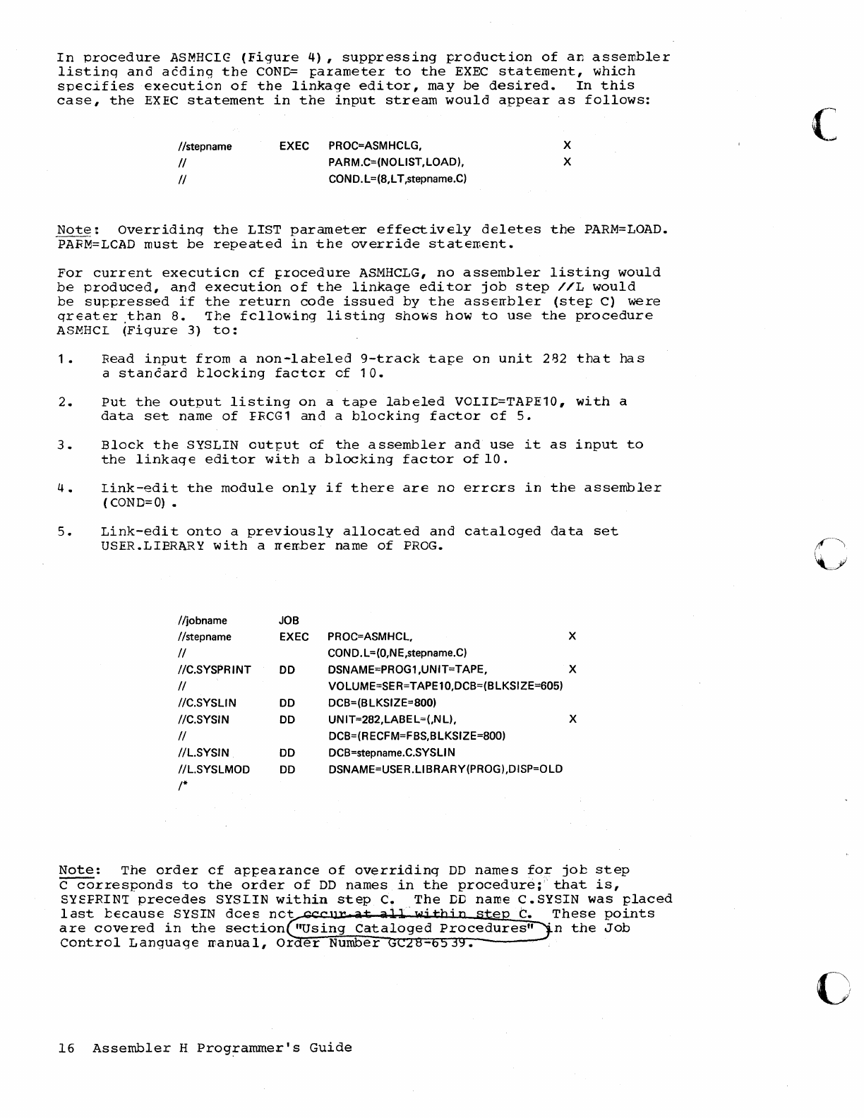
In
procedure
ASMHCIG
(Figure
4),
suppressing
production
of
an
assembler
listinq
and
acding
the
COND=
~arameter
to
the
EXEC
statement,
which
specifies
execution
of
the
linkage
editor,
may
be
desired.
In
this
case,
the
EXEC
statement
in
the
input
stream
would
appear
as
follows:
Ilstepname
II
II
EXEC PROC=ASMHCLG,
PARM.C=(NOLlST,LOAD),
COND.L=(8,LT,stepname.C)
X
X
Note:
Overriding
the
LIST
parameter
effectively
deletes
the
PARM=LOAD.
PARM=LCAD
must
be
repeated
in
the
override
statement.
For
current
executicn
cf
~rocedure
ASMHCLG,
no
assembler
listing
would
be
produced,
and
execution
of
the
linkage
editor
job
step
//L
would
be
su~pressed
if
the
return
code
issued
by
the
asserrbler
(step
C)
were
greater
than
8.
'The
fcllowing
listing
shows
how
to
use
the
procedure
ASMHCL
(Figure
3)
to:
.
1.
Read
input
from
a
non-lateled
9-track
tape
on
unit
2B2
that
has
a
stancard
blocking
factcr
cf
10.
2.
Put
the
output
listing
on
a
tape
labeled
VOIIL=TAPE10,
with
a
data
set
name
of
FRCG1
and
a
blocking
factor
of
5.
3.
Block
the
SYSLIN
out~ut
of
the
assembler
and
use
it
as
input
to
the
linkage
editor
with
a
blocking
factor
of
10.
4.
Link-edit
the
module
only
if
there
are
no
errcrs
in
the
assembler
(COND=O)
•
5.
Link-edit
onto
a
previously
allocated
and
cataloged
data
set
USER.LIBRARY
with
a
rrember
name
of
FROG.
Iljobname JOB
Ilstepname EXEC PROC=ASMHCL, X
II
COND.L=(O,NE,stepname.C)
IIC.SYSPR I
NT
DD DSNAME=PROG1,UNIT=TAPE, X
II
VOLUME=SER=TAPE10,DCB=(BLKSIZE=605)
IIC.SYSLIN DD DCB=(B LKSIZE=-800)
IIC.SYSIN DD UN IT=282,LABE L=(,N
L),
X
II
DCB=(RECFM=FBS,BLKSIZE=800)
IIL.SYSIN DD DCB=stepname.C.SYSLI N
IIL.SYSLMOD
DD DSNAME=USER.LlBRARY(PROG),DISP=OLD
1*
Note:
The
order
cf
appearance
of
overriding
DD
names
for
job
step
C
corresponds
to
the
order
of
DD
names
in
the
procedure;"
that
is,
SYEFRIN'I
precedes
SYSIIN
within
step
C.
The
DD
name
C.SYSIN
was
placed
last
because
SYSIN
dces
net
.
..
C.
These
points
are
covered
in
the
section
"Using
Cataloged
. n
the
Job
Control
Language
rranual,
Or
er
Number
16
Assembler
H
Prog~ammer's
Guide
c
o
o
o
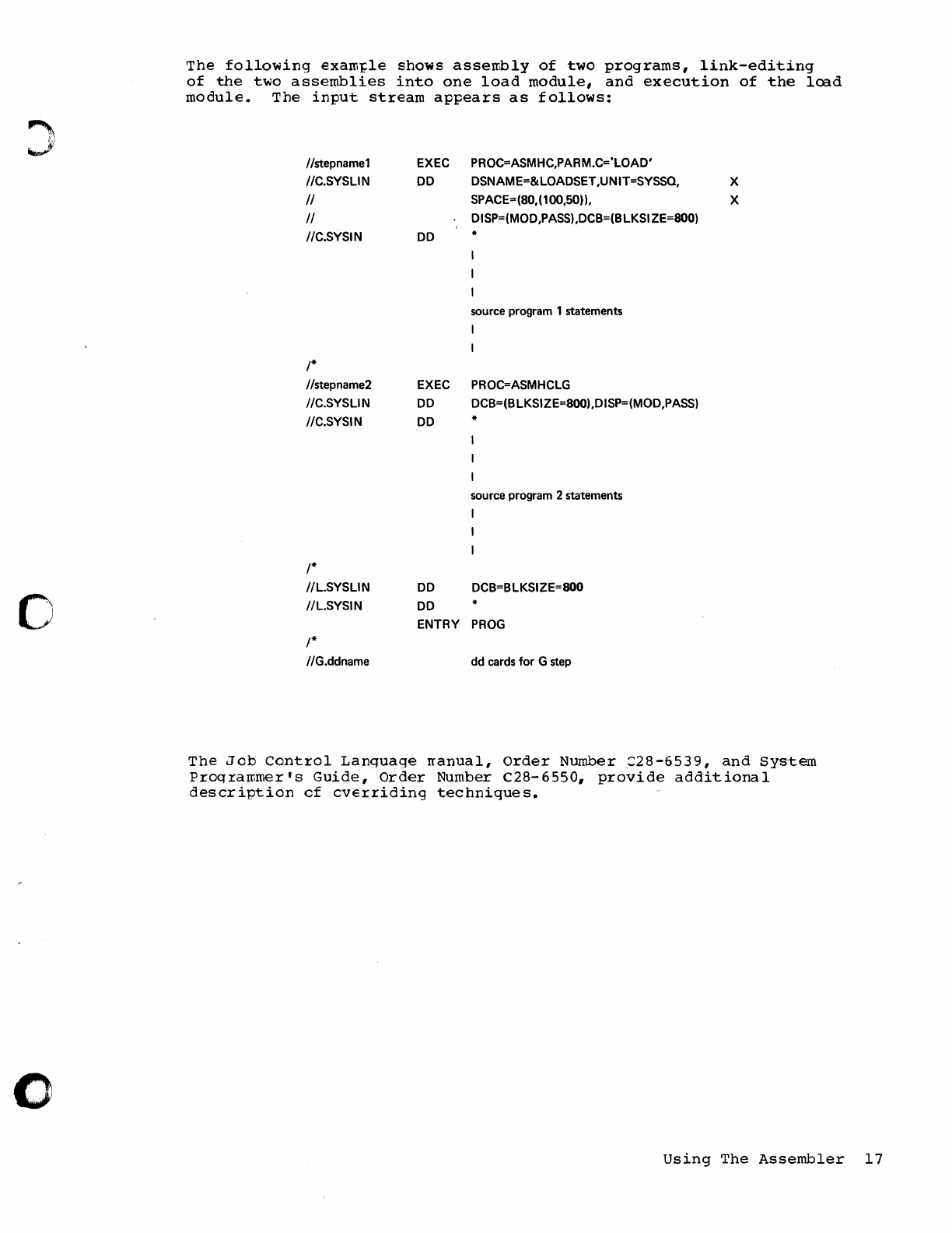
The
following
exarn~le
shows
assembly
of
two
programs,
link-editing
of
the
two
assemblies
into
one
load
module,
and
execution
of
the
load
module.
The
input
stream
appears
as
follows:
Ilstepnamel
/IC.SYSLIN
II
II
IIC.SYSIN
/*
Ilstepname2
IIC.SYSLIN
//C.SYSIN
/*
IIL.SYSLIN
IIL.SYSIN
/*
IIG.ddname
EXEC
DO
DO
EXEC
DO
DO
DO
PROC=ASMHC,PARM.C='LOAD'
DSNAME=&LOADSET ,UNIT=SYSSQ,
SPACE=(BO,(100,50)),
DISP=(MOD ,PASS) ,DCB=(B LKSI ZE=800)
*
source program 1 statements
I
PROC=ASMHCLG
DCB=(BLKSIZE=·BOO),DISP=(MOD,PASS)
*
source program 2 statements
I
I
DCB=BLKSIZE=800
DO *
ENTRY
PROG
dd cards for G step
X
X
The
Job
Control
Language
rranual,
Order
Number::::28-6539,
and
System
Programmer's
Guide,
Order
Number
C28-6550,
provide
additional
description
cf
cverriding
techniques.
Using
The
Assembler
17
This
page
intentionally
left
blank.
c
18
Assembler
H
Programmer's
Guide
o
o
Assem
bIer
Listing
!he
assembler
H
listing
consists
of
up
to
five
sections,
ordered
as
follows:
•
E~ternal
symbol
dictionary
•
Source
and
object
program
•
Relocation
dictionary
•
Symbol
and
literal
cross
reference
•
Diagnostic
cress
reference
and
assembler
summary
Figure
6
shows
each
section
of
the
listing.
Each
item
marked
with
a
circled
number
is
explained
in
the
following
section.
Assembler
Listing
19
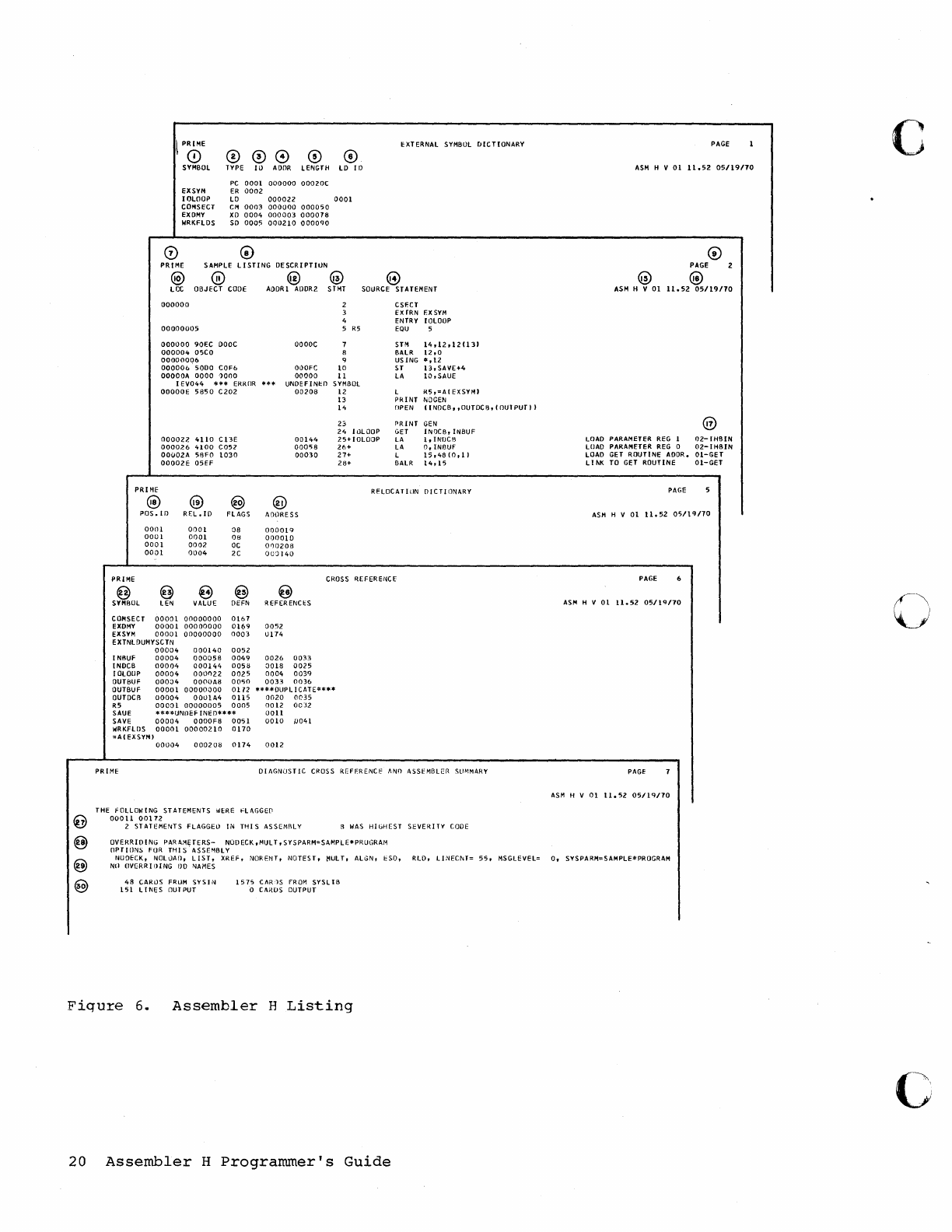
\
PRIME
CD
o
SYMBOL
EXSYM
IOlOOP
COMSECT
EXDMY
WRKFlDS
000
o
TYPE
IiJ
AOOR
lENGTH
PC
0001
000000
00020C
ER
0002
o
lO
If)
lD
000022
0001
eM
0003
000000
000050
XD
0004
000003
000018
SO
0005
000210
000090
PRIME
SAMPLE
LISTING
DESCRIPTIUN
@
(0
@ @
EXTERNAL SYMBOL
DICTIONARY
@
lOC
OBJECT
CODE
MORI
AODR?
SHU
SOURCE STATEMENT
PRIME
@
(JOOOOO
00(J00005
(J(J(JOOO
90fC
DOOC
000004
05CO
00000006
000006
5000
COFb
OOOOOA
0000
')000
I
EV044
**
.. ERR[)R
OOOOOE
5850
C202
000022
4110
CBE
000026
4100
C052
00002A
58FO
1030
00002E
05H
@ @
POS.ID
REL.
ID
FLAGS
OOlll
0001
08
0001
0001
08
0001
0002
OC
0001
0004
2C
..
OOOOC
OI}OFC
00000
UNDEFINI:O
00208
@
00144
00058
00030
AOtlRESS
000019
000010
000208
DUG
140
2
3
4
5
R5
7
H
9
10
11
SYMBOL
12
13
14
23
24
IOlOOP
25+
IOlOOP
26+
27+
28+
CS~CT
EXrRN
EXSYM
ENTRY
IOlOOP
EQU
5
STM
14,120121131
BAlR
12,(J
USING
",12
ST
13,
SAVE+4
lA
10,
SAUE
L
R5,=AI
EXSYMI
PRINT
NOGEN
(JPEN
IINDCB"OUTOCij,IOU1PUTII
PRINT
GEN
GET
INIJCB,INBUF
LA
l,INIJCB
LA
0,
INOUf
l
15,48
10
,II
BAlR
14,15
RFLOCATllIN
DICTIONARY
PRIME
CROSS
REFERENCE
@ @ @ @
SYMIIOl
LEN VALUE DEFN
COMSECT
00001
00000000
0161
EXDMY
00001
00000000
01(>9
EXSYM
00001
oaoooooo
0003
EXTNlDUMYSCTN
00004
000140
0052
~
REFERENCES
0052
0174
I NIIUF
00004
000058
0049 0026
0033
INDca
00004
000144
0058
0018
0025
IOLOOP
00004
0001)22
0025
0004 0039
OUTSUF
00004
0000A8
OOSO
0033
0036
OUTBUF
00001
00000000
0172
****DlJPLICATE**".
OUTDCII
00004
00U1A4
0115
0020
0035
R5
00001
00000005
0005 0012
0032
SAUE
"***UNIlEF
INED*
....
*
0011
SAVE
00004
0000F8
0051
0010
0041
WRKFlDS
00001
00000210
0170
=AIEXSYM)
00004
000208
0174 0012
PRIME
OIAGN(JST
IC
CROSS REFERENC!'
ANfl
ASSEMBLER
SlI~MARY
THE FOLLOWING STATEMENTS
WERE
HAGGE~
00011
00172
2 STATEMENTS
FlAGGEO
IN
THIS
ASSEMALY R
WAS
HIGHEST
SEVE~ITY
CODE
OVERR
III
I
NG
PAR
A.~ETERS-
NOD
ECK,
MUL
T,
S
YSPARM=SAMPLE.PRUGRAt~
OPTIONS
FOR
THIS'ASSE'IBLY
PAGE 1
ASM
H V
01
11.52
05/19110
PAGE 2
@ @
ASM
H
VOl
11.52
05119110
LOAD PARAMETER
REG
1
02-IHBIN
LOAD PARAMETER
REG
0
02-IHBIN
lOAD
GET
ROUTINE
ADDR.
01-GET
LI
t.K TO GET
ROUTINE
01-GET
PAGE
ASM
H V
01
1l.52
05/19/10
PAGE
ASM
H V
01
U.52
05119110
PAGE
ASM
H V
01
11.52
05/19170
NUDECK,
NOLtJAfl,
LIST,
XREF,
NORE~JT,
NOTEST,
/1UlT,
ALGN,
ESO,
RlD,
LINECNT=
55,
MSGLEVEl=
0,
SYSPARM=SAMPlE*PROGRAM
NO
OVERR
Illl
NG
110
NAMES
48
CARtJS
FRUM
SYS 1 N
151
LINES
DUTPUT
1575
CAR')S
FROM
SYSLIB
o
CAlWS
OUTPUT
Fiqure
6.
Assembler
H
Listing
20
Assembler
H
Programmer's
Guide
c
c
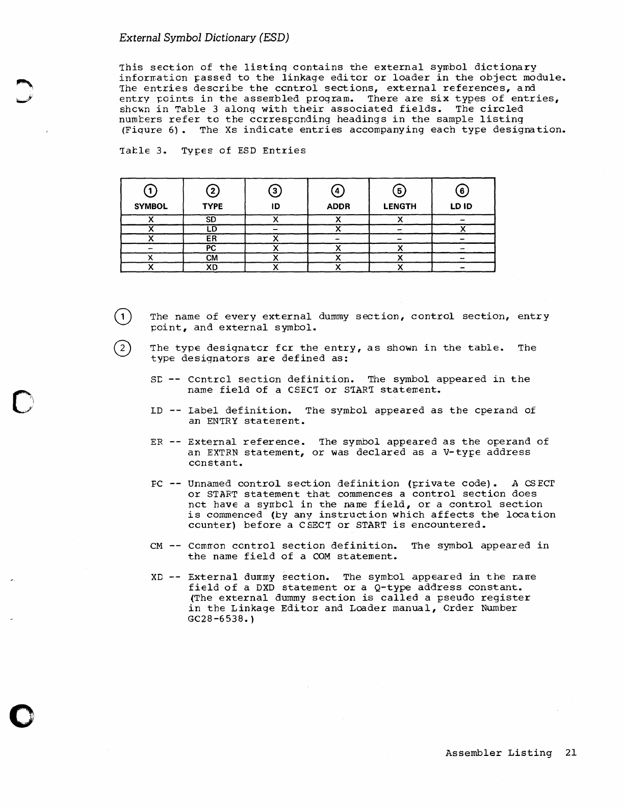
o
External
Symbol
Dictionary (ESD)
This
section
of
the
listing
contains
the
external
symbol
dictionary
inforrr.ation
~ass€d
to
the
linkage
editor
or
loader
in
the
object
module.
The
entries
describe
the
centrol
sections,
external
references,
and
entry
~oints
in
the
asserrbled
program.
There
are
six
types
of
entries,
shc~n
in
Table
3
along
with
their
associated
fields.
The
circled
numters
refer
to
the
ccrres~ending
headings
in
the
sample
listing
(Fiqure
6).
The
Xs
indicate
entries
accompanying
each
tYfe
designation.
1atle
3.
TYf€S
of
ESD
Entries
Q)
® ®
CD
@ ®
SYMBOL
TYPE
ID
ADDR
LENGTH
LDID
X
SO
X X X -
X
LO
-X -X
X
ER
X ---
-
PC
X X X -
X
eM
X X X -
X
XO
X X X -
The
name
of
every
external
dummy
section,
control
section,
entry
point,
and
external
symbol.
The
type
designatcr
fcr
the
entry,
as
shown
in
the
table.
The
type
designators
are
defined
as:
se
--
Ccntrel
section
definition.
The
symbol
appeared
in
the
name
field
of
a CSECT
or
START
statement.
LD
--
Label
definition.
The
symbol
appeared
as
the
cperand
of
an
ENTRY
staterrent.
ER
--
External
reference.
The
symbol
appeared
as
the
oferand
of
an
EXTRN
statement,
or
was
declared
as
a
V-tyfe
address
constant.
FC
--
Unnamed
control
section
definition
(frivate
code).
A
CSECT
or
START
statement
that
commences
a
control
section
does
nct
have
a
syrrbcl
in
the
name
field,
or
a
.control
section
is
commenced
(by
any
instruction
which
affects
the
location
counter)
before
a CSECT
or
START
is
encountered.
CM
--
Cerorron
centrol
section
definition.
The
symbol
appeared
in
the
name
field
of
a
COM
statement.
XD
--
External
dUff,my
section.
The
symt:ol
appeared
in
the
r.arre
field
of
a
DXD
statement
or
a
Q-type
address
constant.
(The
external
dummy
section
is
called
a
pseudo
register
in
the
Linkage
Editor
and
Loader
manual,
Order
Number
GC28
-6
538.
)
Assembler
Listing
21
o
The
external
symbol
dictionary
identification
number
(ESDID).
The
numter
is
a
unique
four-digit
hexadecimal
number
identifying
the
entry.
It
is
used
in
combination
with
the
LD
entry
of
the
ESD
and
in
the
relocation
dictionary
for
referencing
the
ESD.
The
address
of
the
symbol
(in
hexadecimal
notation)
for
SD-and
LD-type
entries,
and
blanks
forER-type
entries.
For
PC-
and
CM-type
entries,
it
indicates
the
beginning
address
of
the
control
section.
For
xL-type
entries,
it
indicates
the
alignment
by
printir.g
a
number
one
less
than
the
number
of
bytes
in
the
unit
of
alignment.
For
example,
7
indicates
doutleword
alignment.
The
asserrtled
length,
in
bytes,
of
the
control
section
(in
hexadecimal
nctaticn)
•
For
an
I.D
...
type
entry,
the
ESLID
of
the
control
secticn
in
which
the
syrntol
was
defined.
Source and Object Program
This
section
of
the
listir.g
documents
the
source
statements
and
the
resulting
object
program.
CD
CD
@
The
one
to
eight-character
deck
identification,
if
any.
It
is
obtained
from
the
name
field
of
the
first
named
TITLE
statement.
The
assembler
prints
the
deck
identification
and
date
(item
16)
On
every
page
of
the
listing.
The
information
taken
from
the
operand
field
of
a
TITLE
statement.
The
listing
page
number.
The
assembled
address
(in
hexadecimal
notation)
of
the
object
code.
•
For
ORG
statements,
the
location-counter
value
before
the
CRG
is
placed
in
the
location
column
and
the
location
counter
value
after
the
ORG
is
placed
in
the
otject
code
field.
•
If
the
END
staterr.ent
contains
an
operand,
the
operand
value
(transfer
addres
s)
aJ;pears
in
the
location
field
(LOC).
•
In
the
case
of
LCCTR,
COM,
CSECT,
and
DSECT
staterr.ents,
the
lccaticn
field
ccntains
the
current
address
of
these
control
sections.
•
In
the
case
of
EXTRN, ENTRY,
and
DXD
instructions,
the
location
field
ar.d
object
code
field
are
blank.
•
For
a USING
statement,
the
location
field
ccntains
the
value
of
the
first
oFerand.
It
is
four
bytes
long.
•
For
LTORG
staterrents,
the
location
field
contains
the
location
assigned
to
the
literal
pool.
•
For
an
EQU
staterrent,
the
location
field
contains
the
value
assigned.
It
is
four
bytes
long.
22
Assembler
H
Programmer's
Guide
c
c
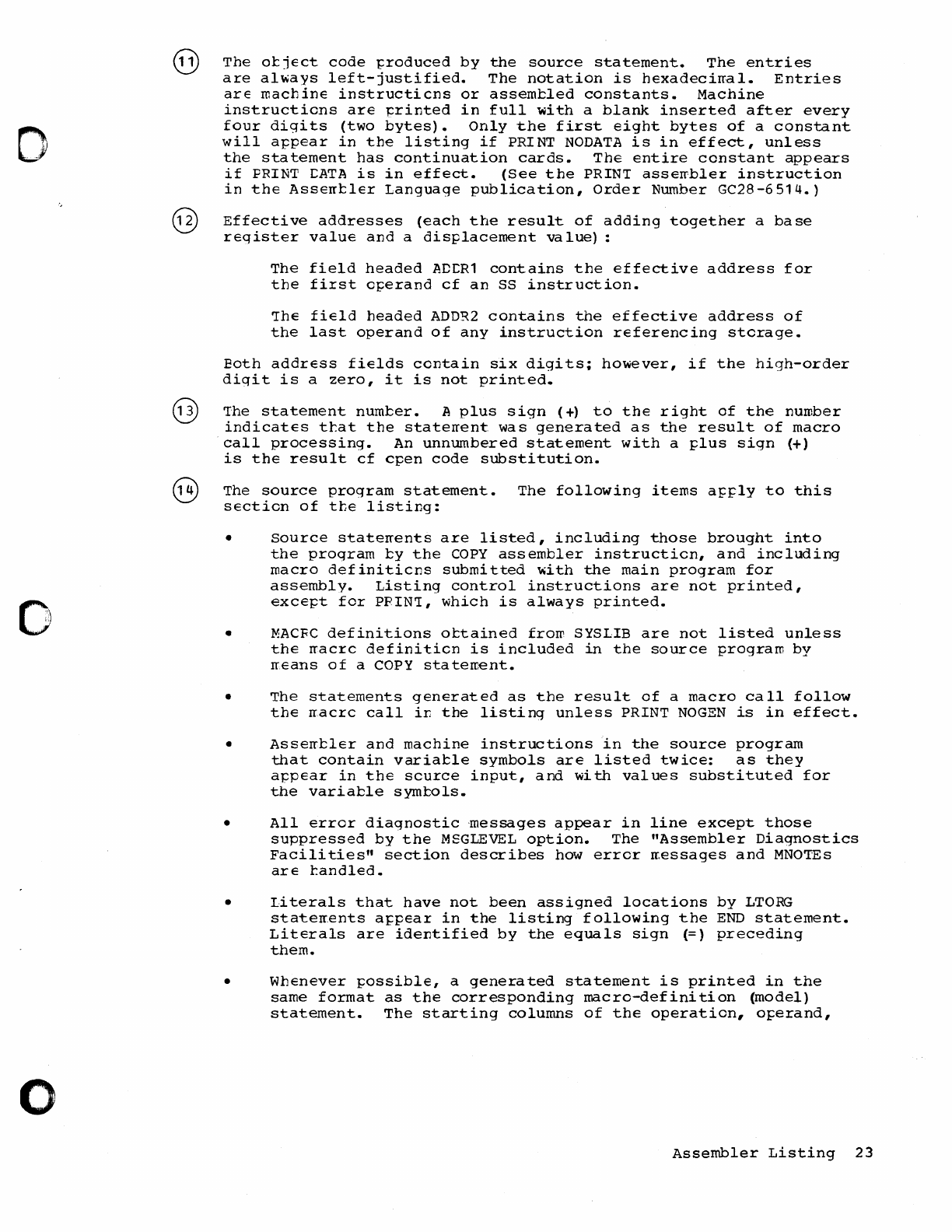
D
,
'
..
,"
o
o
The
otjEct
code
~roduced
by
the
source
statement.
The
entries
are
al~ays
left-justified.
The
notation
is
hExadecirral.
Entries
arE
machinE
instructicns
or
assemtled
constants.
Machine
instructions
arE
l=rinted
in
full
with
a
blank
inserted
after
every
four
digits
(two
bytes).
Only
the
first
eight
bytes
of
a
constant
will
appear
in
the
listing
if
PRINT
NODATA
is
in
effect,
unless
the
statement
has
continuation
cards.
The
entire
constant
appears
if
PRINT
r:ATA
is
in
effect.
(See
the
PRIN'I
asserrbler
instruction
in
the
AssErrtlEr
Language
publication,
Order
Number
GC28-6514.)
Effective
addresses
(each
the
result
of
adding
together
a
base
register
value
and
a
displacement
value)
:
The
field
headed
ADr:R1
contains
the
effective
address
for
the
first
operand
cf
an
SS
instruction.
!he
field
headed
ADDR2
contains
the
effective
address
of
the
last
operand
of
any
instruction
referencing
storage.
Eoth
addrEss
fields
contain
six
digits;
however,
if
the
high-order
digit
is
a
zero,
it
is
not
printed.
The
statement
numter.
A
plus
sign
(+)
to
the
right
of
the
number
indicates
ttat
the
staterrent.
was
generated
as
the
result
of
macro
call
processing.
An
unnumbered
statement
with
a
plus
sign
(+)
is
the
result
cf
cpen
code
substitution.
The
source
program
statement.
The
following
items
a~ply
to
this
section
of
the
listing:
•
•
Source
staterrents
are
listed,
including
those
brought
into
the
program
ty
the
copy
assembler
instruction,
and
including
macro
definiticns
submitted
~ith
the
main
program
for
assembly.
Listing
control
instructions
are
not
printed,
except
for
PPIN!,
which
is
always
printed.
MACFC
definitions
ottained
frOID
SYSLIB
are
not
listed
unless
the
rracrc
definition
is
included
in
the
source
program
by
rr.Eans
of
a COPY
staten:-ent.
•
The
statements
generated
as
the
result
of
a
macro
call
follow
the
rracrc
call
iT.
the
listing
unless
PRINT
NOGEN
is
in
effect.
•
Asserrtler
and
machine
instructions
in
the
source
program
that
contain
variatle
symbols
are
listed
twice:
as
they
appEar
in
the
scurce
input,
and
with
values
substituted
for
the
variatle
symtols.
•
All
error
diagnostic
·messages
appear
in
line
except
those
suppressed
by
the
MSGLEVEL
option.
The
"Assembler
Diagnostics
Facili
ties"
section
describes
how
error
rressages
and
MNOTEs
arE
tandled.
•
Literals
that
have
not
been
assigned
locations
by
LTORG
staterr.ents
appear
in
the
listing
following
the
END
statement.
Literals
are
identified
by
the
equals
sign
(=)
preceding
them.
•
Whenever
possible,
a
generated
statement
is
printed
in
the
same
format
as
the
corresponding
macro-definition
(model)
statement.
The
starting
columns
of
the
operation,
o~erand,
Assembler
Listing
23
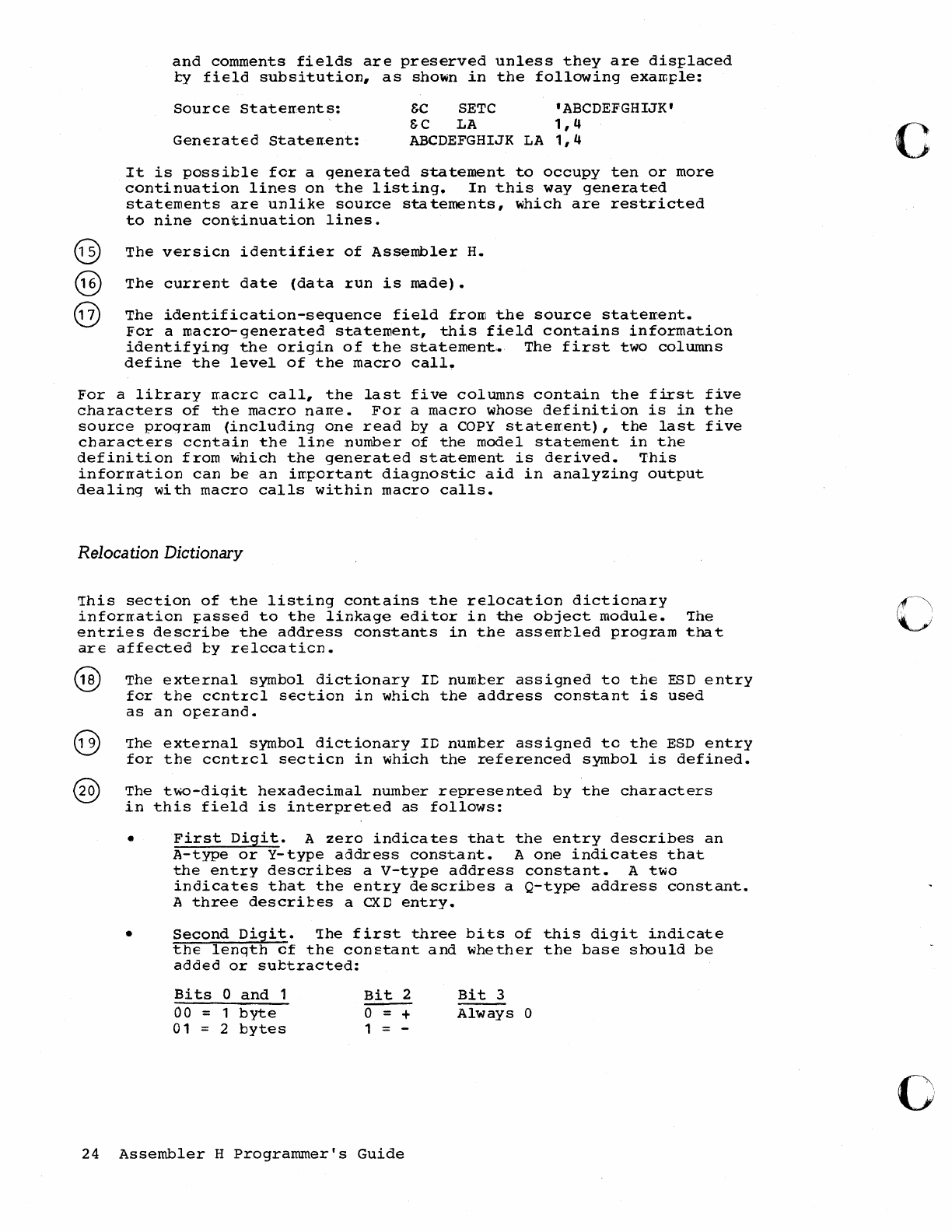
@
@
@
and
comments
fields
are
preserved
unless
they
are
dis~laced
ty
field
subsitution,
as
shown
in
the
following
exarr.~le:
Source
Staterrents:
&C
SETC
'ABCDEFGHIJK'
&C
LA
1,4
Generated
Staten.ent:
ABCDEFGHIJK
LA
1,4
It
is
possible
fer
a
generated
statement
to
occupy
ten
or
more
continuation
lines
on
the
listing.
In
this
way
generated
statements
are
unlike
source
statements,
which
are
restricted
to
nine
continuation
lines.
The
versicn
identifier
of
Assembler
H.
The
current
date
(data
run
is
made).
The
identification-sequence
field
from
the
source
staterrent.
For
a
macro-generated
statement,
this
field
contains
information
identifying
the
origin
of
the
statement,.
The
first
two
colwnns
define
the
level
of
the
macro
call.
For
a
lil:rary
IT,acre
call,
the
last
five
columns
contain
the
first
five
characters
of
the
macro
nane.
For
a
macro
whose
definition
is
in
the
source
program
(including
one
read
by a COpy
stateITent),
the
last
five
characters
centain
the
line
number
of
the
model
statement
in
the
definition
from
which
the
generated
statement
is
derived.
This
inforrration
can
be
an
irr:~ortant
diagnostic
aid
in
analyzing
output
dealing
with
macro
calls
within
macro
calls.
Relocation Dictionary
This
section
of
the
listing
contains
the
re.location
dictionary
inforrr,ation
J;assed
to
the
linkage
edi
tor
in
the
object
module.
The
entries
describe
the
address
constants
in
the
asseIT.bled
program
that
are
affected
by
relccatien.
The
external
symbol
dictionary
Ie
number
assigned
to
the
ESD
entry
for
the
centrel
section
in
which
the
address
constant
is
used
as
an
o~erand.
The
external
symbol
dictionary
ID
number
assigned
tc
the
ESD
entry
for
the
ccntrel
sectien
in
which
the
referenced
symbol
is
defined.
The
two-digit
hexadecimal
number
represented
by
the
characters
in
this
field
is
interpreted
as
follows:
•
First
Digit.
A
zero
indicates
that
the
entry
describes
an
A-type
or
Y-type
address
constant.
A
one
indicates
that
the
entry
describes
a
v-type
address
constant.
A
two
indicates
that
the
entry
describes
a
Q-type
address
constant.
A
three
descrires
a
CXD
entry.
•
Second
Digit.
The
first
three
bits
of
this
digit
indicate
the
length
of
the
constant
and
whether
the
base
should
be
added
or
subtracted:
Bits
0
and
1
00 = 1
byte
01
= 2
bytes
Bit
2
0=+
1 = -
24
Assembler
H
Programmer's
Guide
Bit
3
Always
0
c
o
o
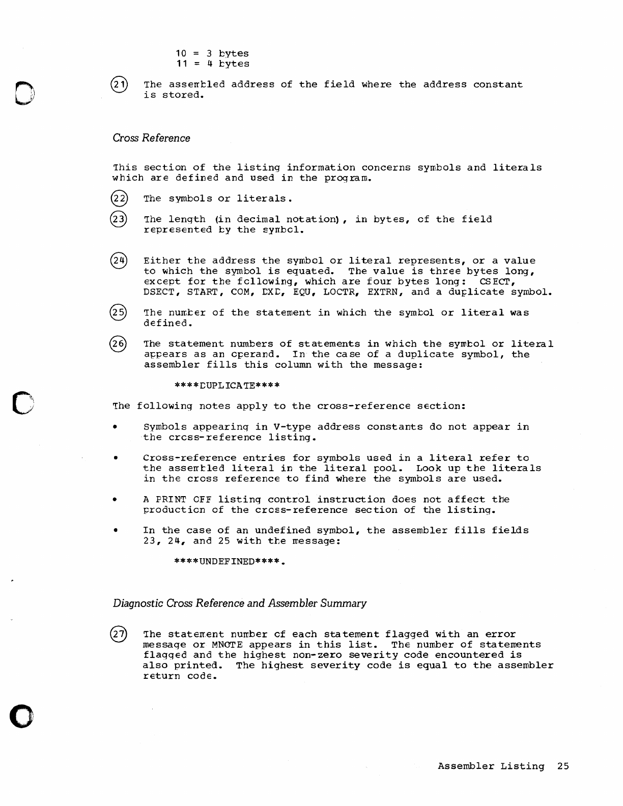
o
o
o
10
3
bytes
11 4
l:ytes
The
assenl:led
address
of
the
field
where
the
address
constant
is
stored.
Cross Reference
This
section
of
the
listing
information
concerns
symbols
and
literals
which
are
defined
and
used
in
the
progzam.
@
@
The
symbols
or
literals.
The
length
(in
decimal
notation),
in
bytes,
of
the
field
represented
l:y
the
syrrbcl.
Either
the
address
the
symbol
or
literal
represents,
or
a
value
to
which
the
symbol
is
equated.
The
value
is
three
bytes
long,
except
for
the
following,
which
are
four
bytes
long:
CSECT,
DSECT, START,
COM,
:CXC,
EQU,
LOCTR,
EXTRN,
and
a
dUI;licate
symbol.
The
nurr.l:er
of
the
statement
in
which
the
syml:ol
or
literal
was
defined.
The
statement
numbers
of
statements
in
which
the
syrol:ol
or
litezal
a~pears
as
an
c~erand.
In
the
case
of
a
duplicate
symbol,
the
assembler
fills
this
column
with
the
message:
****CUPLICATE****
The
following
notes
apply
to
the
cross-reference
sEction:
•
Symbols
appearing
in
V-type
address
constants
do
not
appear
in
the
cress-reference
listing.
•
Cross-reference
entries
for
symbols
used
in
a
literal
refer
to
the
asserrtled
literal
in
the
literal
~ool.
Look
up
the
literals
in
the
cross
reference
to
find
where
the
symbols
are
used.
• A PRINT
OFF
listing
control
instruction
does
not
affect
the
production
of
the
cross-reference
section
of
the
listing.
•
In
the
case
of
an
undefined
symbol,
the
assembler
fills
fields
23,
24,
and
25
with
tte
message:
****UNDEFINED****.
Diagnostic Cross Reference and Assembler
Summary
The
staten,ent
number
of
each
sta
tement
flagged
with
an
error
message
or
MNOTE
appears
in
this
list.
ThE
number
of
statenents
flagged
and
the
highest
non-zero
severity
code
encountered
is
also
printed.
The
highest
severity
code
is
equal
to
the
assembler
return
code.
Assembler
Listing
25
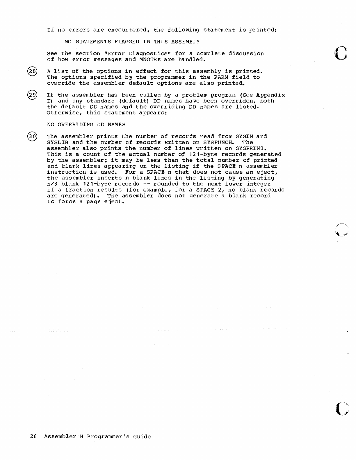
If
no
errors
are
enccuntered,
the
following
statement
is
printed:
NO
S'IA'IEMENTS
FLAGGED
IN
'IHIS
ASSEMBLY
See
the
section
"E,rror
:Ciagnostics"
for
a
ccmplete
discussion
of
how
error
nessages
and
MNOTEs
are
handled.
A
list
of
the
options
in
effect
for
this
assembly
is
printed.
The
options
specified
b:y
the
programmer
in
the
PARM
field
to
override
the
assembler
default
options
are
also
printed.
If
the
assembler
has
teen
called
by a
protlero
program
(See
Appendix
:C)
and
any
standard
(default)
DD
names
have
been
overriden,
both
the
default
:C:C
names
and
the
overriding
DD
names
are
listed.
Otherwise,
this
statement
appears:
NO
OVERRIDING
DD
NAMES
'Ihe
assembler
prints
the
number
of
records
read
froIT SYSIN
and
SYSL
IB
and
the
nurrber
of
records
~ri
tten
on
SYSPUNCH.
The
assembler
also
prints
the
number
of
lines
written
on
SYSPRIN'I.
This
is
a
count
of
the
actual
number
of
121-byte
records
generated
by
the
assembler;
it
may
be
less
than
the
total
number
of
printed
and
tlank
lines
a~~earir.g
on
the
listing
if
the
SPACE
n
assembler
instruction
is
used.
For
a
SPACE
n
that
does
not
cause
an
eject,
the
assemtler
inserts
n
blank
lines
in
the
listing
by
generating
n/3
blank
121-byte
records
--
rounded
to
the
next
lower
integer
if
a
fraction
results
(for
example,
for
a
SPACE
2,
no
blank
records
are
generated).
The
assembler
does
not
generate
a
blank
record
tc
force
a
page
eject.
26
Assembler
H
Programmer's
Guide
c
c
o
o
o
Assembler Diagnostic Facilities
1he
diaqnostic
facilities
for
Assembler
E
include
diagnostic
rres~ges
for
asserrtly
errors,
diagncstic
or
explanatory
messages
issued
by
the
source
program
or
by
macro
definitions
(MNOTEs), a
macro
trace
and
dump
facility
(MHELP),
and
messages
and
dumps
issued
by
the
assembler
in
case
it
terminates
abnormally.
This
section
briefly
describes
these
facilities.
The
assembly
error
diagnostic
rressages
and
atncrrral
assembly
termination
messages
are
described
in
detail
in
the
Assembler
H
Messages
book,
Order
Number
SC26-3770.
Assembly
Error Diagnostic Messages
Assembler
H
prints
most
error
messages
in
the
listing
immediately
followinq
the
stateroent
in
errcr.
It
also
prints
the
total
number
of
flagqed
statements
and
their
line
numbers
in
the
Diagncstic
Cross
Reference
section
at
the
end
of
the
listing.
'The
rressaqes
do
not
follow
the
statement
in
error
when:
•
•
Errors
are
dEtected
during
editing
of
macro
definitions
read
from
a
library.
A
message
for
such
an
error
appears
after
the
first
call
in
the
source
program
to
that
macro
definition.
You
can,
however,
l:::ring
the
rr.aore
defini
tien
into
the
source
program
with
a
COPY
statement.
The
editing
error
messages
will
then
be
attached
to
the
staterrents
in
error.
Errors
are
detected
by
the
lookahead
function
of
the
asse~bler
•
(Lookahead
scans,
fcr
attribute
references,
statements
after
the
one
being
asserrbled.)
Mes~ges
for
these
errors
appear
after
the
statements
in
which
they
occur.
The
messages
rray
also
appear
at
the
~oint
where
lcokahead
~as
called.
•
Errors
are
detected
on
conditional
assembly
statements
during
macro
generaticn
or
MHELP
testing.
Such
a
message
follows
the
most
recently
generated
statement
or
MHEIP
output
statement.
A
typical
error
diagnostic
message
is:
IEV057
***ERROR*** UNDEFINED OPERATION
CODE
--
xxxxx
The
term
***ERROR***
is
part
of
the
message
if
the
severity
code
is
8
or
qreater.
The
term
**WARNING**
is
part
of
the
message
if
the
severity
code
is
0
or
4.
A
copy
of
a
segment
of
the
statement
in
error,
represented
above
by
xxxxx,
is
appended
to
the
end
of
many
messages.
Normally
this
segment,
which
can
be
u~
to
16
bytes
lcng,
begins
at
the
bad
character
or
term.
For
some
errors,
however,
the
segment
may
begin
after
the
bad
character
or
term.
'The
segrr,ent
nay
include
part
of
the
remarks
field.
If
a
diaqnostic
message
follows
a
statement
generated
by
a
rracro
definition,
the
following
iterr,s
may
be
appended
to
the
error
message:
Assembler
Diagnostic
Facilities
27
• The
number
of
the
model
statement
in
which
the
error
occurred,
or
the
first
five
characters
of
the
macro
name.
• The
SET
symbol,
parameter
number,
or
value
string
associated
with
the
error.
Note:
references
to
macro
parameters
are
ty
number
(such
as
PARAMO
08)
instead
of
narrE. Tbe
first
seven
numbers
are
always
assigned
for
the
standard
system
parameters
as
follows:
PARAMO
0 0
&SYSNDX
PARAMO
0 1 =
&SYSECT
PARAMOO2
=
&SYSLCC
PARAMOO3
&SYS'IIME
PARAMOO4
=
&SYSI:ATE
PARAMOO5
=
&SYSPARM
PARAM006
Name
Field
Parameter
Then
the
keyword
parameters
are
numbered
in
the
order
defined
in
the
macro
defini
tion,
followed
by
positional
parameters.
When
there
are
no
keyword
parameters
in
the
macro
definition,
PARAM007
refers
to
the
first
~ositional
parameter.
If
a
diagnostic
message
follows
a
conditional
assembly
staterrent
in
the
source
prcgrarr,
the
following
items
will
be
appended
to
the
error
message:
• The
word
"OPENC"
• Tbe
SET
syrrtcl
or
value
string
a
ssocia
ted
wi
th
the
error
Several
messages
may
be
issued
for
a
single
staterrent
or
even
for
a
single
error
within
a
statement.
This
happens
because
each
statement
is
usually
evaluated
on
more
than
one
level
(for
exarrple,
tern
level,expressicn
level,
and
operand
level)
or
by
more
than
one
phase
of
the
assembler.
Each
level
or
phase
can
diagnose
errors;
therefore,
most
or
all
of
the
errors
in
the
statement
are
flagged.
Occasionally,
duplicate
error
messages
may
occur.
This
is
a
normal
result
of
the
error
detection
process.
Figure
7
is
an
exarrple
of
Assembler
H
handling'
of
error
messages.
28
Assembler
H
Programmer's
Guide
c
o
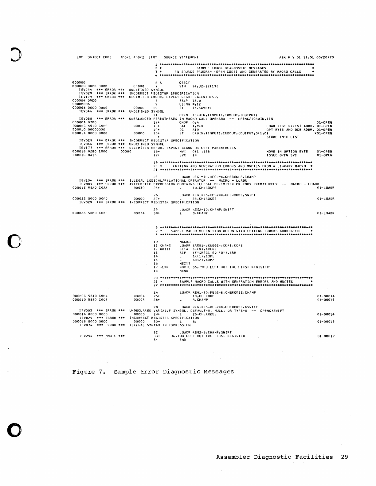
o
LOC
OBJECT
CODE
AOI)R 1 ADDR2
SHIT
SUUKCf
STATE;~FNT
ASM
H V
01
11.51
05/20110
000000
000000
0000
0000
00000
IEV044
"'**
ERROR
*"'*
UNDl:fINE(I
I
EV029
***
ERROR
***
INCORRECT
IEV119
**'"
ERROR
***
DEL
IMITER
000004
05CO
00000006
000006
0000
0000
00000
IEV044
**'"
EHROR
***
UtIIOEF
INEO
I E VOSS
*"'*
ERROR
**. UNBALANCED
OOOOOA
0100
nooooc
4510
COOF
00014
~00010
00000000
000014
0000
0000
00000
******************.******************.**** •••• ******************** •••••
* SAMPL E ERROR
01
AGNOST
IC
MESSAGES *
*
l;-.j
SOURCE PRUGRAr- (OPEN
CODEI
AND
GENERATED
BY
MACRO
CALLS
•
4 * * **. ***** **.****
****
*
***
**
*.**** * * •• ****** ***** ••
***
*
'"
*.******** •• **.*
6 A
7
~YMBllL
CSEC T
S
T>1
14,U2,
121
1
~I
REGISTER
SPECifiCATION
ERROR, EXPECT
RIGHT
PARI:NTHES
IS
8 BALR
12,0
9
USING
*,12
10
ST
13,SAV[+4
SYMBOL
11
PARI:NTHESES
12+
13+
14+
15+
OPEN
I CRIJI
N,
I
INPUT
I
,CRDOUT,
I OUTPUT)
IN
MACRO
CALL
Oi>ERANIJ
--
OPENClICRDIN,IIN
CNOP
0,4
01-0PEN
BAL
1,*+B
LOAD
REGl
W/LIST
AODR.
aI-OPEN
DC
Alai
OPT BYTE
AND
OCB
ADOR.
01-0PEN
ST
CRDIN,(INPUT),CRODUT,IOUTPUT,Oll,OI
XOI-0PEN
STORE
INTO
LIST
IEV029
***
ERROR
***
INCORRECT
REGISTt:R
SPECIFICATION
IEV044
***
ERROR
***
UNDEFINED
SYMBOL
IEV177
***
ERROR
***
DeLIMITER
F.RRUR, EXPECT BLANK
OR
LEFT
PARENTHESIS
000018
92BO
1000
00000
16+
MV(
O(
11
,128
00001C
OA13
17+
SVC
19
MOVE
IN
OPTION
BYTE
ISSUE
OPfN
SVC
19
*******
***
***
*********************************
**
**********************
20
*
ED
I
TI
NG
AND
GENE
RAT
ION
ERRORS AND MNOTES
fROM
A
Ll
BRARY MACRO
21
**
**
*****
** **
*
***
***** *
***
******** ******
***
***************************
23
LOAIJR
REGl=10,REG2=8,CHEROKEE,CHAMP
ILLEGAL
LOGICAL/RELATIONAL
OPERATOR
MACRU
-LUADR
aI-OPEN
01-0PEN
IEV136
***
ERROR
***
IEVOS~
*** !:RROR
***
00001
E
58AO
C02A
ARITHMETIC
rXPRESSlllN
CUNTAINS
ILLEGAL
DELIMITER
OR
ENDS PREMATURELY
00030
24+
L
10,CHI::ROKEE
MACRO
-LOADR
01-LOAOR
000022
0000
0000
IEV029
*** ERROK ***
000026
5800
can
QOOOOC
5BAO
C004
0000
1 0
5880
COOB
I
EV003
***
ERROR
***
000014
0000
0000
I
EV029
***
ERROR
***
000018
0000
0000
I
EV074
***
ERROR
***
IEV254
***
MNOTE
***
26
L')ADR
RI:Gl=25,RFG2=B,CHEROKFE,SWIFT
00000
21+
L
25,CHI::RUKEE
INCORRECT
REGISTER
SPECIFIC'ATION
000~4
00004
00008
29
30+
LllAIJR
KEG2=10,CHAMP,
SWIFT
L O,CHAMP
6 * * ******* * *****
**
****
**
****** ******** * ********
****
******* * ************
7 *
SAMPLt
MAC"O
I)EFINITION
RERUN
wITH
EDITING
ERRORS CORRECTEO *
f1
**
****
***
**** *
**
******
***
**
**
* ****** ****
***
******* ******* ***********
**
10
11
12
13
14
15
16
11
IB
20
21
22
24
25+
26<-
f.NAMF
&R
(1)
.ERR
MACKe)
LOADR
SETA
AIF
L
L
MEXI T
MNUTE
MEND
&'1.E('l=
,®2=,&'OPl
,&OP2
®
1,
®2
IT'&'RfGl
EQ
'O'I.ERR
&.R
I
11,
&OPI
&'R(21,&QP2
36,
'YOU
LEFT
OUT THE
FIRST
REGISTER'
**********************************************************************
* SAMPLf:
MACRO
CALLS
WITH
GENERATION
ERRORS
AND
MNOTES *
**
********
****
******* * *********** *
****
***
***** **** **************** ****
LOADR
REGl=
1
0,
REG2=8,
CHEROKEE, CHAMP
L
10,CHFROKEE
L
q,CHAt-'P
28
LOAUR
REGl=25,ReG2=B,CHEROKEE,&SWIFT
UNDECLARED
VARIABll'
SYMBOL.
DEFAULT=O,
NULL,
UR
TYPE=U
--
OPENC/SWIFT
00000
29+
L
25,CHEROKEE
INCORRECT
REGISTER
SPECIFICATION
00000
30+
L
B,
IllfGAL
SYNTAX
IN
EXPRESSION
32
~3+
34
LUAD'1.
REG2=B,CHAMP,SWIFT
36,YOU
LEFT
OUT
THE
FIRST
REGISTER
END
Ol-LOADR
Ol-LOADR
01-00014
01-00015
01-00014
01-00015
01-00017
Figure
7.
Sample
Error
Diagnostic
Messages
Assembler
Diagnostic
Facilities
29
MNOTEs
An
MNCTE
statement
is
included
in
a
macro
definition
er
in
the
source
proqram.
It
causes
the
assenbler
to
generate
an
inline
error
or
informational
message.
An
MNOTE
appears
in
the
listing
as
follows:
IEV254 ***MNCTE***
severity
code,
message
Unless
it
has
a
severity
code
of
*
or
the
severity
code
is
omitted,
the
statement
number
or
the
MNO'I'E
is
listed
in
the
diagnostic
cross
reference.
Suppression
of
Error Messages and MNOTEs
Error
messages
and
MNCTEs
telow
a
specified
severity
level
can
be
optionally
su~~ressed
by
declaring
in
the
EXEC
statement:
PARM=
'MSGLEVEL=n'
(where
"n"
is
the
selected
severity
level).
If
you
are
not
concerned
with
warning
and
error
messages
in
a
specific
assembly,
using
this
option
provides
a
cleaner
listing.
Abnormal
Assembly
Termination
Whenever
the
assently
cannct
be
completed,
Assembler
H
provides
a
rressage
and,
in
some
cases,
a
specially
formatted
dump
for
diagnostic
information.
This
nay
indicate
an
assembler
malfunction
or
it
may
indica
te
a
programmer
error.
The
s·tatement
causing
the
error
is
identified
and,
if
~ossibl€,
the
assembly
listing
up
to
the
point
of
the
error
is
printed.
The
Assemcler
H
Messages
took,
Order
Number
SC26-3770,
descrites
the
abnormal
termination
messages.
The
messages
give
enough
information
to
(1)
correct
the
error
and
reassemble
your
progran.,
or
(2)
determine
that
the
error
is
an
assembler
malfunction.
The
Assembler
H
Program
Lcgic
Manual,
Order
Number
LY26-3760,
gives
a
conplete
explanation
of
the
format
and
contents
cf
the
abncrnal
ternination
durr~.
Macro Trace Facility (MHELP)
The
~HELF
instruction
controls
a
set
of
trace
and
dump
facilities.
Options
are
selected
l:::y
an
absolute
ex~ression
in
the
MHELP
operand
field.
MHELF
statements
can
occur
anywhere
in
open
code
or
in
macro
definitions.
MHELP
options
remain
in
effect
continuously
until
superseded
by
another
MHELF
statement.
Appendix
B
is
a
sample
MHELP
trace
and
dun};:.
30
Assembler
H
Programmer's
Guide
c
o
o
o
o
Macro Call Trace
(MEELP
B'
l'
or
MHELP,
1}"1
'Ihis
oJ;:tion
provides
a
one-line
trace
for
each
macro
call,
gi
virig
the
name
of
the
called
ll'acro,
its
ne
sted
de
pth,
and
its
&SYSNDX
(total
nurrber
of
macro
calls)
value.
Note:
This
trace
is
provided
upon
entry
into
the
macro.
No
trace
is
provided
if
error
conditions
prevent
entry
into
the
macro.
Macro Branch
Trace
(MEELP
B'10',
or
MHELP
2).
This
option
provides
a
one-line
trace
for
each
AGO
and
true
AIF
conditional-assembly
statement
within
a
macro.
It
qives
the
model-statement
numbers
of
the
"branched
froll'''
and
"branched
to"
statell'ents,
and
the
name
of
the
macro
in
which
the
branch
occurs.
This
trace
option
is
suppressed
for
library
macros.
Macro
Entry
Dump
(MHELF
B'
10000',
or
MHELF
.16),
This
option
dumps
parameter
values
from
the
macro
dicticnary
when
'the
macro
is
called.
Macro
Exit
Dump
(MHELP
B'1000',
or
MHELP
8).
This
option
dumps
SET
symbol
values
from
the
macro
dictionary
upon
encountering
a
MEND
or
ME2<I'I
staterrent.
Macro
AIF
Dump
(MHEI.F
B'
100',
or
~HELF'4).
'Ihis
option
durops
SET
symbol
values
from
the
rracro
dictionaI:Y
ill'mediately
befoI:e
each
AIF
statement
that
is
encountered.
Global Suppression
(liliEI.F
B'1
00000',
or
MHEI.F
32).
This
option
sUJ;:presses
global
SE'I
symbols
in
the
twc
J;:receding
oJ;:tions,
MHELF
4
and
f.!HEI.F
8.
MHELP
Suppression
(~HEI.F
B'10000000',
or
MEELP
128t.
This
option
sUfpresses
all
currently
active
MEELP
cJ;:ticns.
Assembler
Diagnostic
Facilities
31
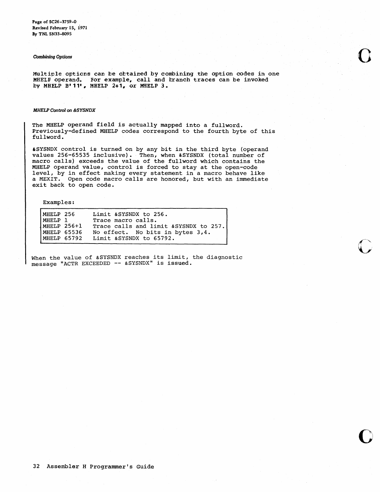
Page
of
SC26-3759-0
Revised February
15,
i971
By TNL SN33-8095
Combining Options
Multiple.opticns
can
be
ottained
by
combining
.the
option
codes
in
one
MHELF
operand.
For
example,
call
and
!:ranch
traces
can
be
invoked
by
MHELP
B'
11',
MEELP
2+1,
or
MHELP
3.
MHELP Control on &SYSNDX
The
MHELP
operand
field
is
actually
mapped
into
a
fullword.
Previously-defined
MHELP
codes
correspond
to
the
fourth
byte
of
this
fullword.
&SYSNDX
control
is
turned
on
by
any
bit
in
the
third
byte
(operand
values
256-65535
inclusive).
Then,
when
&SYSNDX
(total
number
of
macro
calls)
exceeds
the
value
of
the
fullword
which
contains
the
MHELP
operand
value,
control
is
forced
to
stay
at
the
open~code
level,
by
in
effect
making
every
statement
in
a
macro
behave
like
a MEXIT.
Open
code
macro
calls
are
honored,
but
with
an
immediate
exit
back
to
open
code.
Examples:
MHELP
256
MHELP
1
.MHELP
256+1
MHELP
65536
MHELP
65792
Limit
&SYSNDX
to
256.
Trace
macro
calls.
Trace
calls
and
limit
&SYSNDX
to
257.
No
effect.
No
bits
in
bytes
3,4.
Limit
&SYSNDX
to
65792.
When
the
value
of
&SYSNDX
reaches
its
limit,
the
diagnostic
message
"ACTR
EXCEEDED
--
&SYSNDX"
is
issued.
32
Assembler
H
Programmer's
Guide
o
c
o
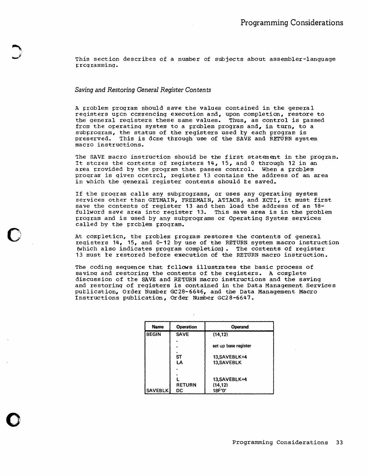
o
o
Programming Considerations
This
section
describes
of
a
number
of
subjects
about
assembler-language
}:rcq:ramming.
Saving and Restoring General Register Con ten ts
A }::roblem
program
should
save
the
values
contained
in
the
general
registers
u};:cn
cerrrrencing
execution
and,
upon
completion,
restore
to
the
general
reqistersthese
same
values.
Thus,
as
control
is
passed
from
the
operating
system
to
a
problem
program
and,
in
turn,
to
a
sub~:rog:ram,
the
status
of
the
registers
used
ty
each
program
is
preserved.
This
is
dcne
through
use
of
the
SAVE
and
REI'URN
system
mac:ro
instructions.
'Ihe
SAVE
mac:ro
instruction
should
be
the
first
statement
in
the
program.
It
steres
the
contents
of
:registers
14, 15,
and
0
through
12
in
an
area
~rovided
by
the
program
that
passes
control.
When a };:roblem
proqrarr
is
given
ccnt:rel,
:registe:r
13
contains
the
address
of
an
area
in
which
the
general
register
contents
should
te
saved.
If
the
progran
calls
any
sub};:rograms,
or
uses
any
operating
system
se:rvices
other
than
GE'IMAIN,
FREEMAIN,A'I'IACH,
and
XCTI,
it
must
first
save
the
contents
of
register
13
and
then
load
the
address
of
an
18-
fullword
save
area
into
register
13.
This
save
area
is
in
the
problem
T;:rogram
and
is
used
by
any
subprograms
or
Operating
Systerr:
services
called
by
the
prcblem
};:rogram.
At
corr.pletion,
the
};:roblerr. };:regram
restores
the
contents
of
general
:registers
14,
15,
and
0-12
by
use
of
the
RETURN
system
macro
instruction
~hich
also
indicates
program
completion).
The
contents
of
register
13
must
te
restored
before
execution
of
the
RETURN
macro
instruction.
The
ceding
sequence
that
fellows
illustrates
the
basic
process
of
savinq
and
restoring
the
contents
of
the
registers.
A
complete
discussion
of
the
SAVE
and
RE'IURN
macro
instructions
and
the
saving
and
restoring
of
registers
is
contained
in
the
Data
Management
Services
putlication,
Order
Nurr~er
GC28-6646,
and
the
Data
Management
Macro
Instructions
publication,
Order
Number
GC28-6647.
Name Operation Operand
BEGIN SAVE (14,12)
set
up base register
ST
13,SAVEBLK+4
LA
13,SAVEBLK
L 13,SAVEBLK+4
RETURN (14,12)
SAVEBLK
DC
18F'O'
Programming
Considerations
33
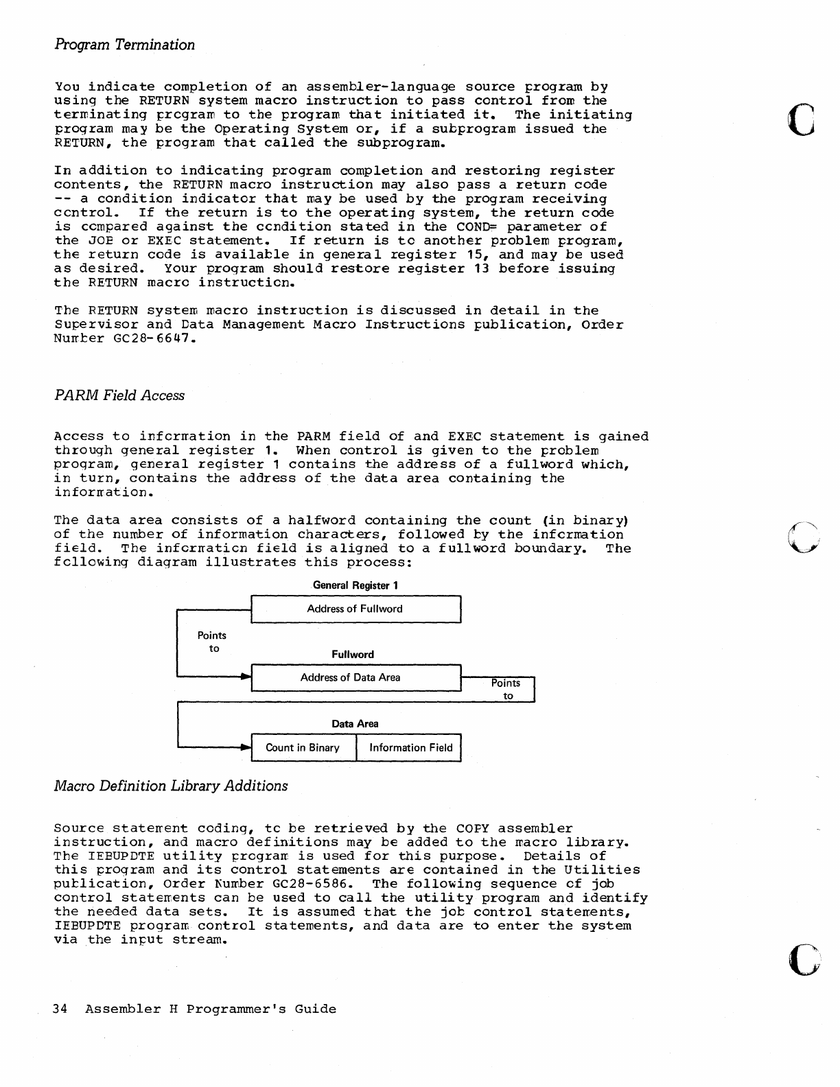
Program Termination
You
indicate
completion
of
an
assembler-language
source
program
by
using
the
RETURN
system
macro
instruction
to
pass
control
from
the
terminating
pregram
to
the
program
that
initiated
it.
The
initiating
program
may
be
the
Operating
System
or,
if
a
subprogram
issued
the
RETURN,
the
program
that
called
the
subprogram.
In
addition
to
indicating
program
completion
and
restoring
register
contents,
the
RETURN
macro
instruction
may
also
pass
a
return
code
--
a
condition
indicator
that
may
be
used
by
the
program
receiving
centrol.
If
the
return
is
to
the
operating
system,
the
return
code
is
ccmpared
against
the
ccndition
stated
in
the
COND=
parameter
of
the
JOE
or
EXEC
statement.
If
return
is
to
another
problem
program,
the
return
cede
is
available
in
general
register
15,
and
may
be
used
as
desired.
Your
program
should
restore
register
13
before
issuing
the
RETURN
macro
instruction.
The
RETURN
system
macro
instruction
is
discussed
in
detail
in
the
Supervisor
and
Data
Management
Macro
Instructions
publication,
Order
Numter
GC28-6647.
PARM Field Access
Access
to
information
in
the
PARM
field
of
and
EXEC
statement
is
gained
through
general
register
1.
When
control
is
given
to
the
problem
program,
general
register
1
contains
the
address
of
a
fullword
which,
in
turn,
contains
the
address
of
the
data
area
containing
the
information.
The
data
area
consists
of
a
halfword
containing
the
count
(in
binary)
of
the
number
of
information
characters,
followed
by
the
information
field.
The
information
field
is
aligned
to
a
fullword
boundary.
The
following
diagram
illustrates
this
process:
General Register 1
I Address
of
Fullword
I I
Points
to
Fu"word
..
J Address
of
Data Area
I I
I
Data Area
'--
___
+I:
Count
in
Binary I Information Field I
Macro Definition Library Additions
Points I
to
Source
statement
coding,
tc
be
retrieved
by
the
COpy
assembler
instruction,
and
macro
definitions
may
be
added
to
the
macro
library.
The
IEEUPDTE
utility
prograrr
is
used
for
this
purpose.
Details
of
this
program
and
its
control
statements
are
contained
in
the
Utilities
putlication,
Order
f'umber GC28-6586.
The
following
sequence
of
job
control
statements
can
be
used
to
call
the
utility
program
and
identify
the
needed
data
sets.
It
is
assumed
that
the
jot
control
statements,
IEEUPDTE
program
control
statements,
and
data
are
to
enter
the
system
via
the
in-put
stream.
34
Assembler
H
Programmer's
Guide
c
CI
c
o
o
//jobname
//stepname
//SYSUT1
//SYSUT2
//SYSPRINT
//SYSIN
JOB
EXEC
DO
DO
DO
DO
PGM=I EBUPDTE,PARM=MOD
DSNAME=SYS1.MACLIB,DISP=OLD
DSNAME=SYS1.MACLlB,DISP=OLD
SYSOUT=A
*
IEBUPDTE control statements and source statements
or
macro-definitions
to
be
added
to
the macro library
(SYS1.MACLlB)
/* (delimiter statement)
Load Module Modification -
Entry
Point Restatement
If
the
editing
functions
of
the
linkage
editor
are
to
be
used
to
modify
a
load
module,
the
entry
J;cint
to
the
load
module
must
be
restated
when
the
load
module
is
reprocessed
by
the
linkage
editor.
otherwise,
the
first
tyte
af
the
first
ccntrol
section
processed
by
the
linkage
editor
will
become
the
entry
point.
To
enable
restatement
of
the
oriqinal
entry
p'cint,
cr
designation
of
a
new
entry
point,
the
entry
~oint
must
have
been
identified
originally
as
an
external
syrrbcl;
that
is,
it
rrust
have
ap'p'eared
as
an
entry
in
the
external
symbol
dictionary.
External
symbol
identification
is
done
automatically
by
the
assewbler
if
the
entry
pOint
is
the
r.arc;e
of
a
control
section
or
STAR'!
statement;
other~ise,
an
assembler
EN'IRY
statement
must
J:e
used
to
identify
the
entry
point
name
as
an
external
symbol.
When a
new
object
rrodule
is
added
to
or
replaces
part
of
the
load
module,
the
entry
point
is
restated
in
one
of
three
ways:
• By
placing
the
entry
p'oint
symbol
in
the
operand
field
of
an
EXTRN
staterrent
and
an
END
statement
in
the
new
object
module.
•
By
using
an
END
statement
in
the
new
otject
module
tc
designate
a
new
entry
p'oint
in
the
new
object
module.
• By
using
a
lir.kage
editor
ENTRY
statement
to
designate
either
the
original
entry
point
or
a
new
entry
point
for
the
load
module.
Further
discussion
of
load
module
entry
points
is
contained
in
the
Linkage
Editor
and
Loader
J;ublication,
Order
Number
GC28-6538.
Object Module Linkage
Object
modules,
whether
generated
by
the
asseml:ler
or
another
language
processor,
may
be
combined
by
the
linkage
editor
to
produce
a
composite
load
mcdule,
provided
each
object
module
conforms
to
the
data
formats
and
linkage
conventions
required.
~his
topic
discusses
the
use
of
the
CALI.
system
macro
instruction
to
link
an
asseIl1bler
language
rrain
program
to
subprograms
produced
by
another
processor.
'!he
Supervisor
and
Data
Management
Macro
Instructions
publication,
Order
Number
GC28-
6647,
contains
additional
details
concerning
linkage
conventions
and
the
CALL
system
macro
instruction.
Programming
Considerations
35
Figure
8
is
an
example
of
statements
used
to
establish
the
assembler-
language
prograrr
linkage
to
FOR'TRAN
and
COBOL
subprograms.
If
any
input/output
o~erations
are
performed
by
called
subprcgra~s#
a~~ropriate
DD
statements
for
the
data
sets
used
by
the
subprograms
must
be
supplied.
See
the
appropriate
language
programmer's
guide
fer
an
explanation
of
the
CD
statements
and
special
data
set
record
formats
used
for
the
~rocessor.
36
Assembler
H
Programmer's
Guide
,(
c
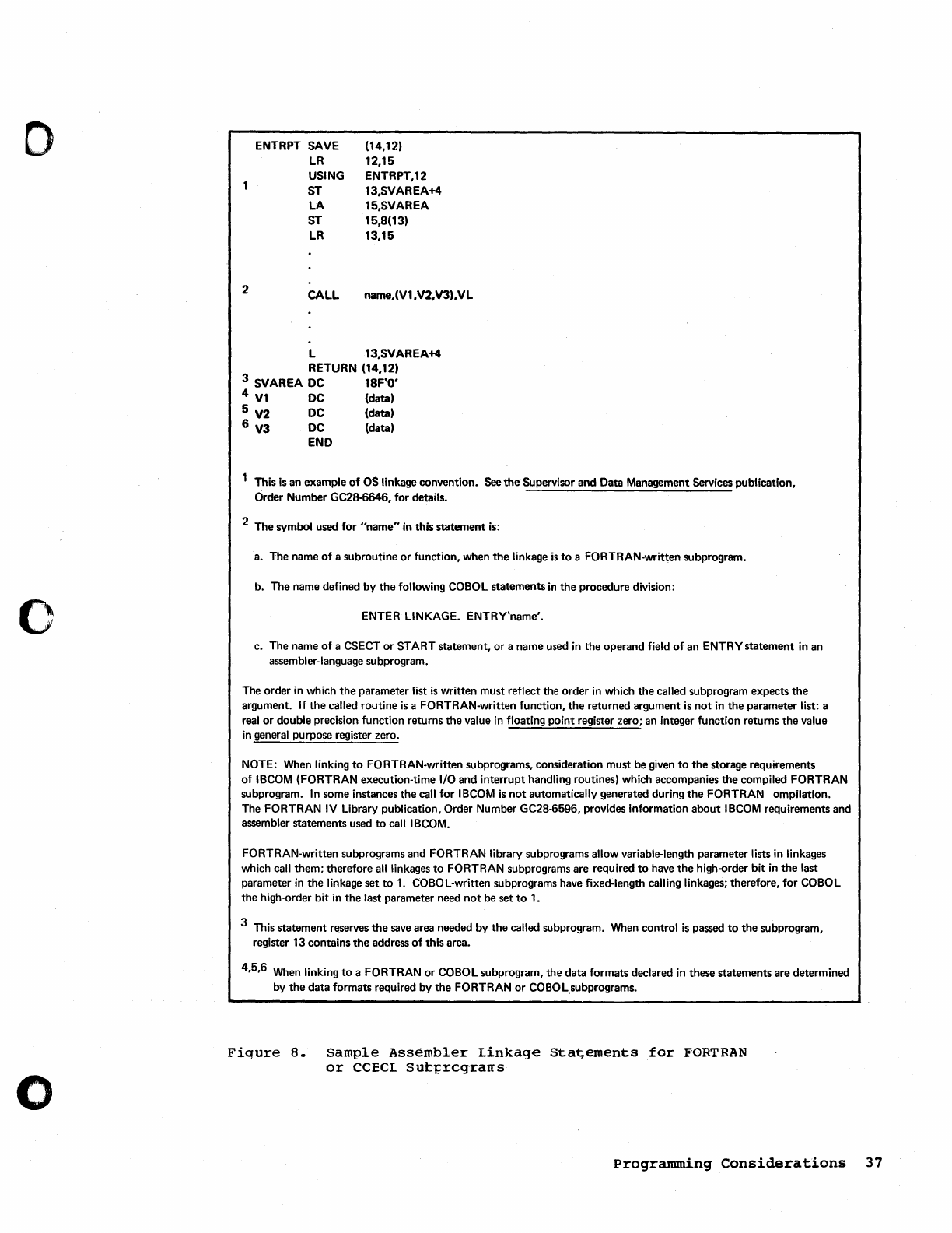
o
o
o
2
ENTRPT SAVE
LR
USING
ST
LA
ST
LR
CALL
(14,12)
12,15
ENTRPT,12
13,SVAREA+4
15,SVAREA
15,8(13)
13,15
name,(V1,V2,V3),VL
L 13,SVAREA+4
RETURN (14,12)
3 SVAREA
DC
18F'O'
4
V1
DC
(data)
5 V2
DC
(data)
6 V3
DC
(data)
END
This
is
an example
of
OS linkage convention.
See
the Supervisor and Data Management Services publication,
Order Number GC28-6646, for details.
2 The symbol used for
"name"
in
this statement
is:
a. The name of a subroutine
or
function, when
the
linkage
is
to
a FORTRAN-written subprogram.
b. The name defined by
the
following COBOL statements
in
the procedure division:
ENTER LINKAGE. ENTRY'name'.
c. The name of a CSECT
or
START statement,
or
a name used
in
the operand field
of
an ENTRY statement
in
an
assembler-language subprogram.
The order
in
which
the
parameter list
is
written must reflect the order
in
which
the
called subprogram expects
the
argument.
If
the
called routine
is
a FORTRAN-written function,
the
returned argument
is
not
in
the
parameter list: a
real
or
double precision function returns the value
in
floating point register zero;
an
integer function returns the value
in
general purpose register zero.
NOTE:
When
linking
to
FORTRAN-written subprograms, consideration must be given
to
the
storage requirements
of
IBCOM
(FORTRAN execution-time I/O and interrupt handling routines) which accompanies the compiled FORTRAN
subprogram.
In
some instances the call for
IBCOM
is
not
automatically generated during
the
FORTRAN ompilation.
The FORTRAN
IV
Library publication, Order Number GC28-6596, provides information about
IBCOM
requirements and
assembler statements used
to
call
IBCOM.
FORTRAN-written subprograms and FORTRAN library subprograms allow variable-length parameter lists
in
linkages
which call them; therefore
all
linkages
to
FORTRAN subprograms are required
to
have
the
high-order bit
in
the
last
parameter
in
the linkage set
to
1.
COBOL-written subprograms have fixed-length calling linkages; therefore, for COBOL
the high-order bit
in
the last parameter need
not
be set
to
1.
3 This statement reserves
the
save
area needed by
the
called subprogram.
When
control
is
passed
to
the subprogram,
register 13 contains
the
address
of
this area.
4,5,6
When
linking
to
a FORTRAN or COBOL subprogram, the data formats declared
in
these statements are determined
by
the
data formats required by the FORTRAN
or
COBOLsubprograms.
Fiqure
8.
Sample
Assembler
Linkage
Sta~ements
for
FORTRAN
or
CCECL
sut~rcgrarrs
Programming
Considerations
37
Page
of
SC26-3759-0
Revised
February
15,
i971
By
TNL
SN33-8095
Special CPU Programming Considerations
You
should
be
aware
of
operational
differences
~etween
the
Model
85,
Model
91,
and
Model
195
and
ether
system/360
models.
The
primary
diff
erences
are:
•
Non-sequential
instruction
execution
--
91
and
195
•
Extended
precision
Ir.achine
instructions
85
and
195
•
Unaligned
operands
--
85
and
195
Controlling Instruction Execution Sequence
'The
Model
Q
and
Model
8maintain
a
logical
consistency
with
respect
to
their
~
o~erations,
1Dcluding
the
beginning
and
ending
of
I/O
o~erations,
but
they
do
net
assume
responsibility
for
such
consistency
in
the
operations
performed
by
asynchronous
units.
Consequently,
for
any
asynchroncus
unit
that
de~nds
upon
a
strict
adherence
to
sequential
(or
serial)
execution,
a
problem
program
must
set
up
its
cwn
~rocedures
to
ensure
the
~ro~er
instruction
sequence.
For
a
program
secticn
that
requires
the
serial
or
sequential
execution
cf
instructions,
the
following
'no-operation'
instruction:
BCR
N,O N =
1,15
causes
instruction
deccding
to
halt
until
the
instructions
that
have
already
been
decoded
are
executed.
(This
action
is
calle~
a
pl,p~~line
drain.)
On
the
Model
91
and
Model
195,
this
instruction
ensures
that"
all
the
instructions
preceding
it
are
executed
l:efore
the
instruction
succeeding
it
is
decoded.
Use
of
this
instruction
should
be
rriniroized,
because
it
rray
affect
the
~erforrrance
of
the
CPU.
Isolating
an
instruction
by
preceding
it
and
following
it
with
a
ECR
N,O
instruction
eliminates
multiple
imprecise
interruptions
frcIT:
more
than
one
instruction
by
virtue
of
the
pipe-line
drain
effect.
However,
because
multiple
exceptions
may
occur
in
one
instruction,
this
technique
does
not
eliminate
a
multiple
imprecise
interruption,
nor
does
it
change
an
imprecise
interruption
into
a
precise
interruption.
The
use
of
the
BCR
instruction
does
not
assure
you
that
you
can
fix
up
an
error
situaticn.
In
general,
the
only
information
available
will
be
the
address
of
the
BeE<
instruction.
The
length
of
the
instruction
preceding
the
BCR
instruction
is
not
recorded,
and
generally
there
is
nc
~ay
to
determine
what
that
instruction
is.
I
Note:
BCR
0,0
does
not
cause
a
pipe-lin~
drain.
,
""""
Extended-Precision Machine Instructions
The
extended-precisio~
arithrretic
instructions
and
the
rounding
instructions
of
the
Model
85
and
the
Model
195
are
shown
below.
A
complete
descri~ticn
cf
these
instructions
is
in
the
System/360
Principles
of
Operation,
Crder
Number
GA22-6821.
38
Assembler
H
programmer's
Guide
o
o
c
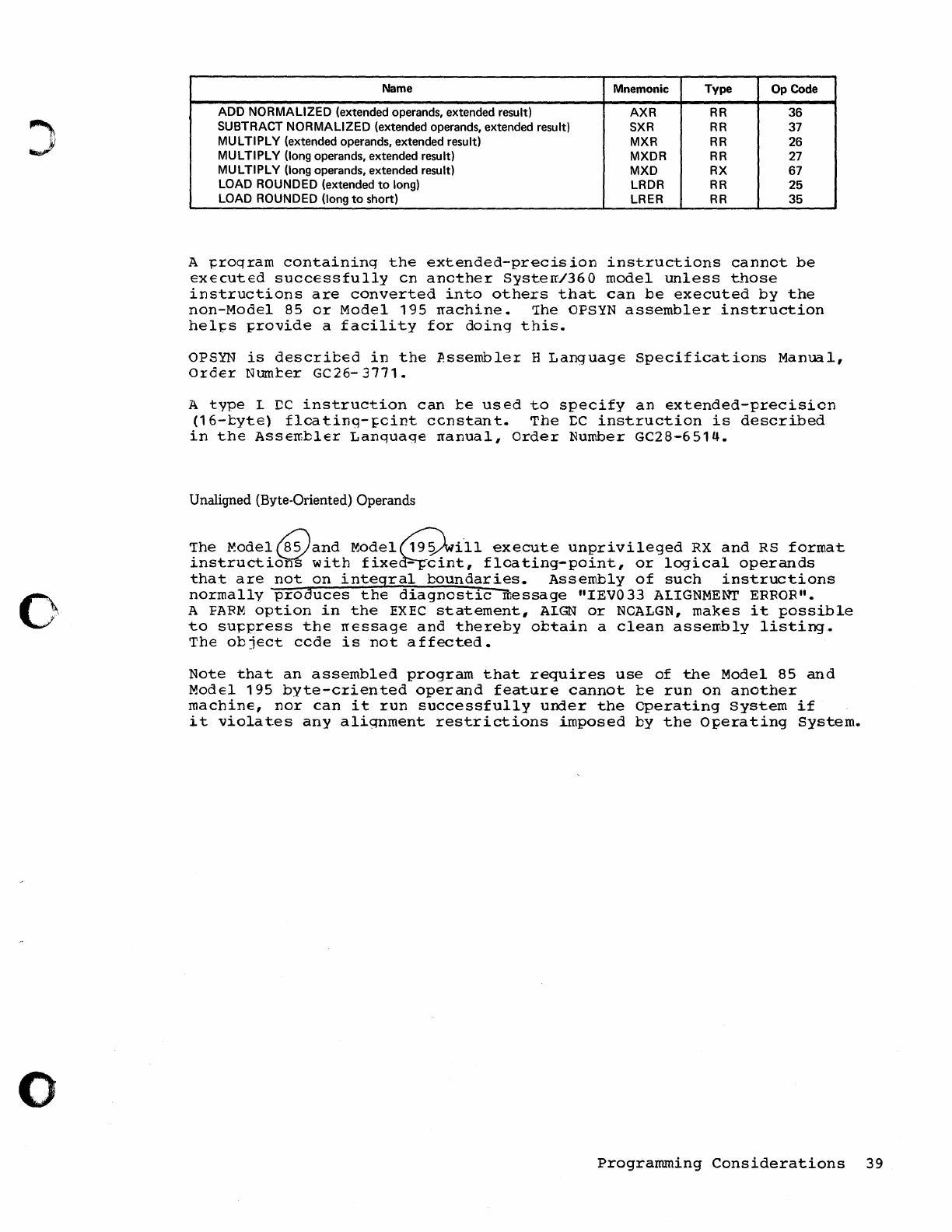
0'
o
Name Mnemonic Type Op Code
ADD
NORMALIZED
(extended operands, extended result)
AXR
RR
36
SUBTRACT
NORMALIZED
(extended operands, extended result) SXR
RR
37
MULTIPLY
(extended operands, extended result) MXR
RR
26
MULTIPLY
(long operands, extended result) MXDR
RR
27
MULTIPLY
(long operands, extended result)
MXD
RX
67
LOAD ROUNDED (extended
to
long) LRDR
RR
25
LOAD ROUNDED (long
to
short) LRER
RR
35
A
~roqram
containinq
the
extended-precision
instructions
cannot
be
executed
successfully
Cn
another
Systerr/360
model
unless
those
instructions
are
converted
into
others
that
can
be
executed
by
the
non-Model
85
or
Model
195
rrachine.
1he
OPSYN
assembler
instruction
hel~s
~rovide
a
facility
for
doing
this.
OPSYN
is
described
in
the
Assembler
H
Language
Specifications
Manual,
Order
Numter
GC26-
3771.
A
type
L
DC
instruction
can
be
used
to
specify
an
extended-precision
(16-tyte)
flcatinq-~cint
ccnstant.
The
~C
instruction
is
described
in
the
Assen;bler
Lanquage
rranual,
Order
Number
GC28-6514.
Unaligned (Byte-Oriented) Operands
'Ihe
~odel~and
MOdel~d{ll
execute
unprivileged
RX
and
RS
format
instructi~
with
fixe~~i~t,
floating-point,
or
logical
operands
that
are
not
on
integral
boundaries.
Assembly
of
such
instructions
normally
produces
the
diagnostic
message
"lEV033
ALIGNMENT
ERROR".
A
FAFM
option
in
the
EXEC
statement,
ALGN
or
NOALGN,
makes
it
possible
to
suppress
the
rressage
and
thereby
obtain
a
clean
assembly
listing
.•
The
object
ccde
is
not
affected.
Note
that
an
assembled
program
that
requires
use
of
the
Model
85
and
Model
195
byte-criented
operand
feature
cannot
te
run
on
another
machine,
nor
can
it
run
successfully
under
the
Operating
system
if
it
violates
any
aliqnment
restrictions
imposed
by
the
Operating
System.
Programming
Considerations
39
This
page
intentionally
left
blank.
40
Assembler
H
Programmer's
Guide
c
!~\
',_yl
()

o
o
o
Appendix A. Sample Program
The
sarr:ple
};:rcgrarr
included
with
Assembler
H when
it
is
received
from
IBM
is
described
in
this
appendix.
This
program
is
a
collection
of
casic
asserrbler-Ianguage,
nacre,
and
conditional
assembly
features,
most
of
which
are
illlique
to
Assembler
H.
The
circled
letters
in
the
description
below
refer
to
corresponding
letters
in
the
listing
that
fellows
the
description.
®
The
job
control
language
for
the
assembly
consists
of
the
IBM-
supplied
cataloqed
procedure
ASMHC
and
the
statements
needed
to
use
the
procedure
and
supply
input
to
the
assembler.
(In
this
sample,
tte
procedure
statements
begin
with
XX?)
Note
that
three
of
the
default
PARM
options
are
overridden
in
the
EXEC
statement
that
calls
the
procedure.
By
using
the
MUL'I
(rr.ultiple
assembly)
option,
this
sample
program,
the
sample
program
in
Appendix
B,
and
the
listings
in
Figure
6
and
Figure
7
were
asserrbled
with
one
set
of
JCL
cards.
Object
modules
were
not
punched
for
any
of
the
asserrblies
because
the
NODECK
eI=tion
is
specified.
'Ihe
character
string
specified
in
the
SYSPARM
option
is
avail
al:le
to
each
asselrl:ly.
The
character
string
is
displayed
in
this
program
by
using
the
system
variable
symbol
&SYSFAFM
(statement
144).
'Ihe
External
Symbol
Dictionary
shows
a named common
statement
.•
The
narred comrren
section
is
defined
in
statement
158.
Appendix
A.
Sample
Program
41
®
®
®
statement
10:
Save
the
current
status
of
the
PRINT
staterrent
(ON,
NODATA
,GEl\).
statement
11:
Leave
ON
in
effect,
modify
the
other
two
options
to
DATA,TSCGEN.
Statement
12:
Macro
call;
note
that
the
expansion
(statement
10)
is
not
printed.
statement
14:
All
28
bytes
of
data
are
dis~layed
to
the
twc-
operand
DC.
Statement
15:
Restore
prior
status
of
PRINT.
Statements
17
and
18:
The
generated
output
of
the
macro
W!O
is
shown
and
enly
the
first
8
bytes
of
data
are
displayed.
statements
14
and
18:
Multiple
constants
are
allowed
in
hexadecimal
and
binary
rc
operands,
and
neither
syrrbel
in
the
duplicaticn
factcr
has
been
defined
yet.
Definition
occurs
in
statements
108
and
109.
Statements
26,
28,
136,
and
155
illustrate
use
of
the
LOC!R
assembler
instruction.
~his
feature
allo~s
one
to
break
control
sections
down
into
sub-control
sections.
It
may
be
used
in
CSECT,
DSECT,
and
COM.
LOC!R
has
rrany
of
the
features
of
a
control
section
for
example,
all
of
the
first
LOCTR
in
a
section
is
assiqned
space,
then
the
second,
and
so
on.
The
name
of
the
control
section
automatically
names
the
first
LOCTR
section.
Thus
LOCTR A
is
begun,
or
resumed,
at
statements
2,
28,
and
155.
Note
that
the
location
counter
value
shown
each
time
is
the
resumed
value
of
the
LCCTR.
On
the
other
hand,
various
LOC'IR
sections
within
a
central
section
have
common
addressing
as
far
as
USING
statements
are
concerned,
subject
to
the
corn~uted
displacement
falling
within
0
through
4095.
In
the
sample,
CONSTANT
is
in
LCC'IF DEECEES
but
the
instruction
referencing
it
(staterrent
25)
has
no
addressing
~rcblerrs.
Three-operand
EQU.
Here,
we
are
assigning:
(a)
the
value
of
E5
(not
yet
defined)
to
A8,
(b)
the
length
attribute
of
AS
to
A8,
and
(e)
tre
ty~e
attribute
of
A7
to
A8.
If
no
operand
is
present
in
an
EOC
statement,
the
type
attribute
is
U
and
the
length
attribute
is
that
of
the
first
term
in
the
o~erand
expression.
Symtols
present
in
the
label
and/or
operand
field
must
be
previously
defined.
Note
that
it
is
not
possible
to
express
the
type
attribute
of
A7
directly
in
the
EOC
statement.
The
EQU
statement
at
32
could
have
been
written
A8
EeU
BS,2,C'L'
A8
EQU
B5,X'
2'
,X'C4'
Set
symbols
&LA8
and
&TA8
have
not
been
declared
in
a LCL
or
GEL
statement
prior
to
their
use
here~
Therefore,
they
are
defaulted
to
local
variable
syrrbols,
as
follows:
&lA8
is
a
LCLA
SET
symbol
because
it
appears
in
the
name
field
of
a SETA;
&TA8
is
a
LCLC
SET
symbol
tecause
it
is
first
used
in
a
SETC.
MNOTE
may
appear
in
open
code.
As
such,
they
have
all
properties
of
MNOTEs
inside
macros,
including
substitution.
42
Assembler
H
Programmer's
Guide
c
c

CD
o
®
®
o
®
o
A
SETC
expression
may
have
a
duplication
factor.
The
SETA
expression
must
be
enclosed
in
parentheses
and
immediately
precede
the
character
string,
the
substring
notation,
or
the
type
attribute
reference.
Statements
57-60
illustrate
4-byte
self-defining
values
and
unary
+
and
-.
Tte
value
cf
X
will
appear
later
in
a
literal
address
constant
(see
statement
162).
Location
counter
values
for
EQU
and
USING
(statement
3)
display
4
bytes.
The
prograrrrr,er
macro
DEMO
is
defined
well
after
the
start
of
the
assembly.
Macros
can
~e
defined
at
any
~oint
and,
having
been
defined
and/er
ex~anded,
can
be
redefined.
Note
that
the
parameters
on
the
prototype
are
a
mixture
of
k,eywords
and
positional
operands.
&SYSLIS~
may
be
used.
The
positional
parameters
are
identified
and
numbered
1,
2,
3
from
left
to
right;
keywords
are
skipped
ever.
Statement
70
illustrates
the
extended
SET
feature
(as
well
as
implicit
declaration
of
&LOC
(1)
as
a LCLC).
Both
&LOC
(1)
and
&LOC(2)
are
assigned
values.
One SETA, SETB,
or
SETC
statement
can
then
do
the
work
of
many.
Statement
72
is
a
model
statement
with
a
symtolic
paraIreter
in
its
operation
field.
This
statement
will
~e
edited
as
if
it
is
a
macro
call;
at
this
time,
each
operand
will
be
denoted
as
pcsitional
or
keyword.
At
macro
call
time,
it
will
not
be
possible
to
reverse
this
decision.
Even
though
treated
as
a
rracre,
it
is
still
expanded
as
a
machine
or
assembler
operation.
Statement
74
illustrates
the
computed
AGO
statement.
Control
will
~ass
to
.MNOTE1
if
&KEY2
is
1,
to
.MNOTE2
if
&KEY2
is
2,
to
.MNO~E3
if
&KEY3
er
will
fall
through
to
the
model
statement
at
75
otherwise.
Staterrent
77
illustrates
the
extended
AIF
facility.
This
statement
is
written
in
the
alternate
format.
The
logical
expressions
are
exarrined
frorr
left
te
right.
Control
passes
to
the
sequence
sym~ol
corresponding
to
the
first
true
expression
encountered,
else
falls
throug,h
to
the
next
model
staterrent.
statement
87
contains
a
subscripted
created
SET
symbol
in
the
name
field.
Exclusive
of
the
subscript
notation,
these
SET
symbols
have
the
form
See)
where
e
is
an
expression
wade
up
of
character
strings
and/or
variable
symbols.
When
such
a
symbol
is
encountered
at
expansion
time,
the
assembler
evaluates
e
and
attempts
to
use
&
(value)
in
place
of
&(e).
Looking
ahead,
we
see
that
DEMO
is
used
as
a
macro
instruction
in
statement
97
and
&KEY1=C.
Thus,
the
'e'
in
this
case
is
X&KEY1
Which
has
the
value
XC.
Finally,
the
rracro-generator
will
use
&XC(2)
as
the
name
field
of
this
model
statement.
In
statement
108,
note
that
&XC(2)equals
TRANSYLVANIA
(statement
96).
Finally,
in
the
sequence
field
of
statement
108,
we
see
that
this
statement
is
a
level
01
ex~ansion
of
a
programmer
macro
and
the
corresponding
wedel
statement
is
staterrent
nurrter
87.
Created
SET
symbols
may
be
used
wherever
regular
SET
symbols
are
used
in
declarations,
name
fields
or
operands
of
SET
statements,
in
model
staterrents,
etc.
Likewise,
they
are
subject
to
all
the
restrictions
of
regular
SET
symbols.
In
the
programrrer
macro
DEMO,
it
would
not
have
been
valid
to
have
the
statement
GBLC
&
(X&KEY1)
(1)
because,
in
statement
71,
we
have
ABLC
&XA
(5) ,
Appendix
A.
Sample
Program
43
®
®
@
(SXB920),
SXC{l)
and
S(XSKEY1){2)
becomes
SXC(2)
unless,
of
course,
SKEYl
was
assigned
scrrething
other
than
the
value
A,
B,
or
C
in
the
macro
instruction
DEMO,
statement
91.
In
that
case,
we
would
need
a
global
declaration
statement
if
we
wanted
&(X&KEY1)
to
te
a
glctal
SET
syrrbol.
Because
global
declarations
are
processed
at
generation
time
and
then
only
if
the
statement
is
encountered,
we
would
insert
the
following
statements
between,
say,
statements
11
and
72.
AIF('&KEY1'
EQ'A'
or
'EKEY1'
EQ
'B'
or
'EKEY1'
EQ
'C').
SKIP
GEIC & (XSKEY1)
(1)
•
SKIP
ANCP
As
the
macro
is
defined,
&
(X&I<EY
1)
will
be
a
global
SETC
if
SKEY1
is
A,
B,
or
C;
otherwise
it
will
be
a
LCLC
or,
possibly,
a LCLA.
In
the
macro,
if
S(X&KEY1)
becomes
a
local,
it
will
have
a
null
or
zero
value.
Created
SET
symbols
are
a
pOwerful
tool.
However,
their
use
requires
a
careful
planning.
In
statements
93
and
94,
note
that
&XA
is
declared
as
a
subscripted
qlocal
SE'IC
variacle
"ith
a
rraximum
subscript
of
1
and,
in
the
next
statement
(an
extended
SET
statement),
we
store
sorrething
into
&XA(2).
There
is
no
contradiction
here.
The
statement
GBLC
SXA(l)
marks
SXA
as
a
sucscripted
glotal
SETC
symtol
any
decimal
self-defined
nurrber
(1
through
2147483647)
can
be
used.
Furthermore,
only
a
ncminal
amount
of
space
is
set
aside
in
the
global
dictionary
--
this
space
is
open-ended
and
will
be
increased
on
derrand
and
enly
en
derrand.
Statement
97
is
the
macro
instruction
DEMO.
Note
that
SPl
has
the
value
WRITE.
Therefore,
the
model
statement
at
statement
72
tecomes
an
inner
rracro,
WRITE,
producing
the
code
at
statements
98-103.
The
sequence
field
of
these
statements
contains
03-1HBRD,
indicating
that
they
are
genera
ted
by
a
·level
03
macro
(DEMO
is
01,
WRITE
is
02)
named
lHERDWRS.
It
is
an
inner
macro
called
by
WRITE.
Statements
108
and
109
contain
some
ordinary
symbols
longer
than
eight
characters.
The
limit
for
ordinary
symbols,
operation
codes
(for
programmer
and
li1:rary
macros
and
op
codes
defined
through
OPSYN),
variable
syrr.bcls,
and
sequence
symbols
is
sixty-three
characters
(including
the
Sand
e
in
the
latter
two
instances,
respectively).
Most
long
symbols
will
probably
be
nearer
to
eight
than
sixty-three
characters
in
length.
Extremely
long
syrrbols
are
simply
teo
difficult
to
write,
especially
if
the
symbol
is
used
frequently.
The
requirement
that
the
operation
field
be
present
in
the
first
statement
of
in
state
ent
till
in
effect.
Furthermore,
name
s
of
SECT
'XTRN
etc.
symbols
are
:s~t=i=l~l~r~e=s=t==r~i~ct~.
~e~d~~~~~~~==~~~~
I.·ibrary
macros
may
be
inserted
into
the
source
stream
as
programmer
macros
by
use
of
a
COPY
statement.
The
result
(statements
118-126)
is
essentially
a
programmer
macro
definition.
When a
library
macro
is
brought
in
and
expanded
by
use
cf
a
macro
instructicn,
the
asserrbler
(1)
looks
the
macro
up
by
its
memher-
name
and
(2)
verifies
that
this
same
name
is'
used
in
the
operation
field
of
the
~rotetype
statement.
Therefore,
for
example,
DCB
has
to
catalogued
as
DCB.
However,
as
COpy
code,
the
member
name
bears
no
relationship
to
any
of
the
statements
in
the
mewb€r.
44
Assembler
H
Programmer's
Guide
c
c
c
@
o
Thus,
several
variations
of
a
given
macro
could
be
stored
as
a
li1::rary
under
separate
names,
then
copied
in
at
various
places
in
a
single
assembly
as
needed.
(Assembler
H
allows
you
to.
def'ine
and
redefine
a
rracre
any
number
of
times)
•
In
statement
129,
MARK
is
made a synonym
of
NOTE.
To
identify
NCTE
as
a
macro,
it
has
to
1::e
used
as
a
macro
instruction
or
programrrer
macro
definition
prior
to
its
use
in
the
operand
field
of
an
OPSYN
statement.
The
COpy
code
at
118-
126
is
a
programmer
macro
definition.
~he
macro
instruction
at
statement
130
is
MARK.
We
can
use
MARK
and
NO~E
interchangeably.
If
desired,
we
could
put
these
two
words
on
separate
lines
(that
is,
make
NOTE
synomomous
with
the
null
string).
This
~ould
remove
NOTE
as
a
macro
definition.
Then,
we
could
call
the
macro
only
as
MARK.
Statement
144
demonstrates
&5YSTIME,
&SYSDATE
and
&SYSPARM.
The
values
for
the
first
two
are
the
same
as
~e
use
on
the
heading
line.
The
value
for
&SYSPARM
is
the
value
passed
in
the
PARM
field
of
the
EXEC
statement
on
the
default
value
assigned
to
&SYSPARM
when
Asserr.bler
H
is
installed.
System
variable
symbols
&SYSLOC
and
&SYSECT
are
displayed.
The
sequence
field
indicates
that
the
model
staterrents
are
statements
148
and
149.
Illustration
of
named
COMMON.
Note
that
estatlishing
addressa1::ility
to
such
a
section
can
be
obtained
with
a USING
PD2
register
statement.
With
blank
COMMON,
one
has
to
make
use
of
some la1::el
cn
a
statement
after
the
CCMMON
statement.
If
there
are
literals
outstanding
when
the
END
statement
is
encountered,
they
are
assigned
to
the
LOCTR
currently
in
eff~ct
for
the
first
contrel
section
in
the
assembly.
This
mayor
may
not
put
the
literals
at
the
end
of
the
first
control
section.
In
this
sarrple
asserrbly,
the
first
~ontrol
section,
A,
has
two
I.CCTRs, A
and
CEECEES.
Eecause
A
is
active
(at
statexrent
155),
the
literals
are
assembled
there.
You
always
have
the
ability
to
centrol
placement
of
literal
pools
by
means
of
the
LTORG
sta
tement.
Note
that
X'
FF'FFFFE8'
is
used
for
the
contents
of
A(X),
statement
162.
~he
symbol
X
was
assigned
the
value
(4*-
6)
by
an
lieU
in
statement
43.
Appendix
A.
Sample
Program
45
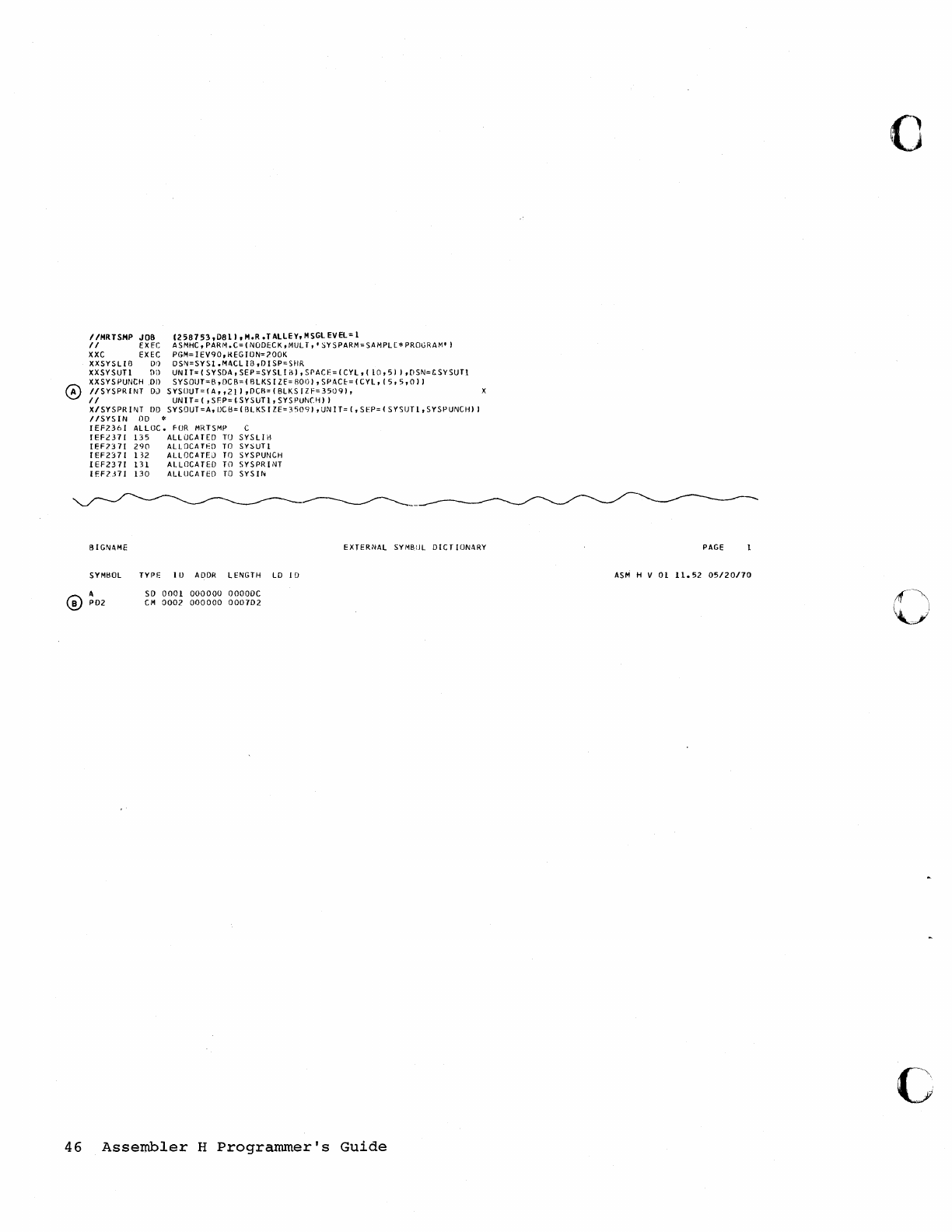
IIHR
TSHP
JOB
1258153,0811
,M.R.
TAllEY,
H
SGl
EVEl:
1
II
EX
EC
ASMHC, PARM.
C:
(NOOECK,
MUL
T,'
SY
SPARM=SAMPLE*
PROGRAM' I
XXC EXEC
PGM=IEV90,KEGION=700K
XXSYSLlB
DO
oSI\j=SYS1.M<\CLI£J,DISP=SHR
XXSYSUTl
Dil
UN
IT:
(SYSDA,
SEP:SYSL
I
nl,
SPACE:
(CYL,
(
10,51
I,DSI\j=£SYSUTl
XXSYSPUNCH
00
SYSOUT=B,DCB=(
fllKSIZf=8001
,SP4CI:-=(CYl,
(5,5,011
IISYSPRfNT
OJ
SYSOUT=(A,,211
,DCf\=(BLKSIZF=35091,
II
UNIT=(
,SFP=(.SYSUT1,SYSPUN(I~11
X/SYSPR
II\jT
DO
SYSOUT=A,
IlCB=
(flL
KS
I ZE=
35091,
UN
IT=
(,
SfP=
( S
YSUTl,
SYSPUNCHI I
/lSYSIN
00
*
IEF236I
ALlOC.
fOR
MRTSMP
IEF£371
135
ALLOCATED TO
IEF7371
290
ALLOCATI'O
TO
IEF2371
132
ALLOCATEJ
TO
IEF2371
131
ALLOCATED
TO
IEFl.H1
130
ALLUCATCO
TO
BIGN<\ME
C
SYSLlH
SYSUT!
SYSPUNCH
SYSPRINT
SYS
If'<
SYMtlOL
TYPI:
I D
ADDR
LENGTH LO f [)
<\
P02
SO
0001
000000
OOOODC
CM
OOOl
000000
000702
EXTERNAL SYMBOL
DICT
ION<\RY
46
Assembler
H
Programmer's
Guide
o
PAGE
ASM
H V
01
11.52
05/20170
c
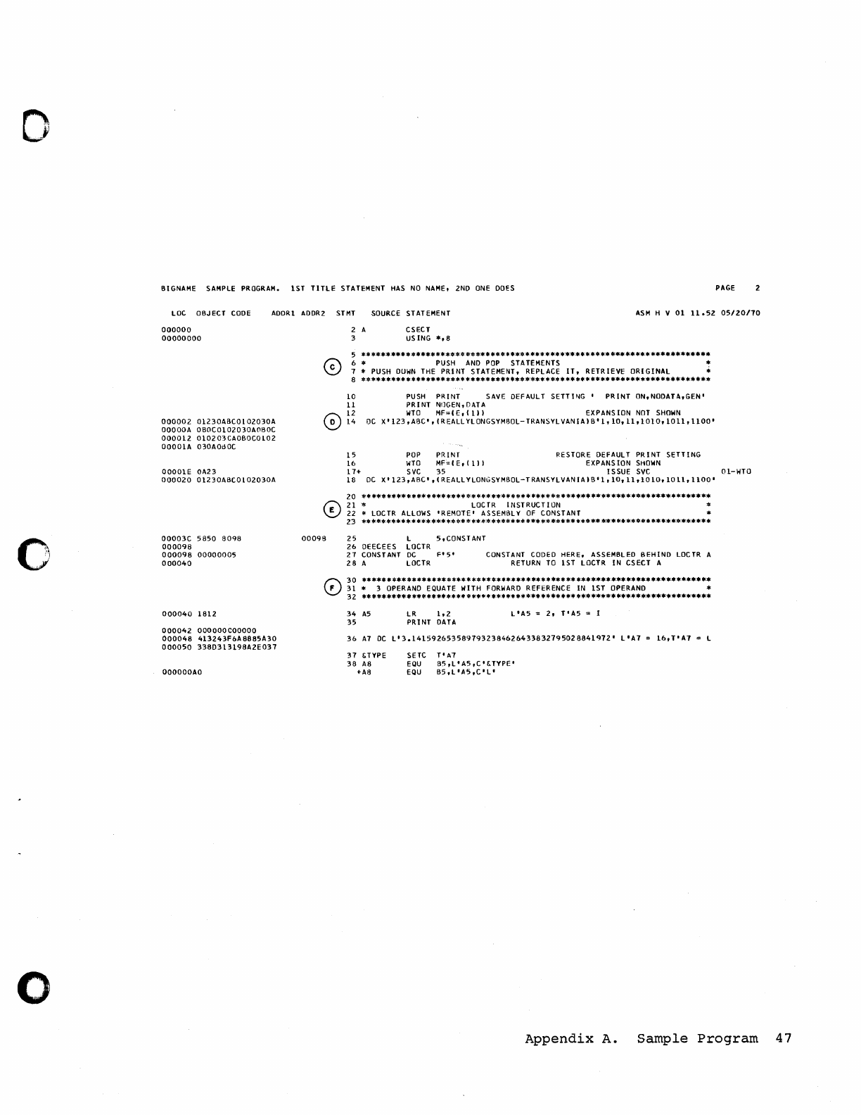
o
o
o
BIGNAME
SAMPLE
PROGRAM.
1ST
TITLE
STATEMENT
HAS
NO
NAME,
2ND
ONE
DOES
PAGE
LOC
OBJECT
CODE
AGORI
AOOR2
STMT
SOURCE
STATEMENT
ASM
H V
0111.5205/20170
000000
00000000
000002
01230ABCO 1
02030A
OOOOOA
OBOCOI02030AC1BOC
000012
010203CAOBOCOI02
00001A
030AOdOC
OOOOIE OA23
000020
01230ABCOI02030A
00003C
5850
8098
000098
000098
00000005
000040
000040
1812
000042
OOOOOOCOOOOO
000048
413243F6A8885A30
000050
338D313198A2E037
OOOOOOAO
2 A
3 CSECT
USING
*,8
5
**********************************************************************
6 *
PUSH
AND
POP
STATEMENTS *
7 * PUSH
DUWN
THE
PRINT STATEMENT, REPLACE
IT,
RETRIEVE ORIGINAL ..
8
**********************************************************************
10
11
PUSH
PRINT
SAVE
DEFAULT
SETTING'
PRINT
ON,NODATA,GEN'
PRINT
NIlGEN,DATA
o
~!
WTO
MF=CE, (
III
EXPANS
ION
NOT
SHOWN
OC
X'123,AI3C',
(REALLYLONGSYM60L-TRANSYLVANIAIB'l,
10,11,1010,
1011,1100'
15
POP PRINT RESTORE
DEFAULT
PRINT
SETTING
16
WTO
MF=(E,(I11
EXPANSION
SHOWN
17+
S
VC
35
ISSUE
SVC
Ol-WTO
18
DC
X'
123
,ABC'
, (REALL YLONGSYMBOL-T
RANSYLVAN
I A I B
'1,10,11
,10
10,1011,1100'
20
**********************************************************************
21
*
LOCTR
INSTRUCTION *
22
*
LOCTR
ALLOWS
'REMOTE'
ASSEMBLY
OF
CONSTANT *
23
**
*********
**********************
***
*******
*****
**************
********
00098
25
L 5,CONSTANT
26
DEECEES
LOCTR
27
CONSTANT
DC
Fl5'
CONSTANT
CODEO
HERE. ASSEMBLED BEHIND
LOCTR
A
28
A
LOCTR
RETURN
TO
1ST
LOCTR
IN CSECT A
f":\
30
**********************************************************************
\!..J
31
* 3
OPERAND
EQUATE
WITH
FORWARD
REFERENCE
IN
1ST
OPERAND
*
32
*********************
*****
*****************
***************************
34
AS
35
LR
1.2
PRINT
DATA
L'A5
=
2,
T'A5
= I
36
A7
DC
L'3.1415926535891932384626433832795028841912'
L'A1
Ib,T'A7
31
&TYPE
38
A8
+A8
SETC
EQU
EQU
T'A7
B5,L'A5,C'&TYPE'
85,L'A5,C'L'
Appendix
A.
Sample
Program
47
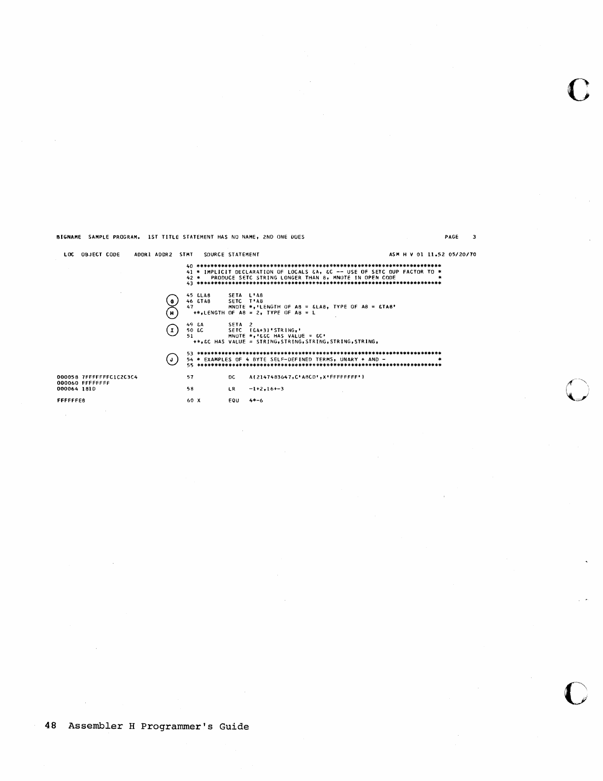
81GNAME SAMPLE PROGRAM. 1ST
TITlE
STATEMENT
HAS
NO
NAME, 2ND
ONE
DOES
PAGE
LOC
OB.JECT
CODE
ADDRI ADDR2
STMT
SOURCE
STATEMENT
ASM
H V
01
11.52
05/20110
000058
7FfFFFFFC1C2C3C4
000060
FFFFFFFF
000064
1810
FFFffFES
G)
0
0
o
40
******
****
******
*****
****
********
*
****
********
****
***
*
**********
******
41 *
IMPLICIT
DECLARATION
OF
LOCALS
I:.
A ,
I:.C
--
USE
OF
SETC
DUP
FACTOR
TO
*
42
*
PRODUCE
SHC
STRING
LONGER THAN
8,
MNUTE
IN
OPEN
CODE
*
43
**
*******************
****
******
*******
**
******************************
45
foLAS
SETA
L'
A8
46
&TAS
SETC
T'
A8
47
MNOTE
*,
'LENGTH
OF
AS
&LAS,
TYPE
OF
AS
&TA8'
+*,LENGTH
Of
A8 =
2,
TYPE'
OF
AB
L
49
I:.A
SETA 2
0;0
foC
SETC
(&A+31'
STR
lNG,'
51
MNUTE
*, 'I:.&C
HAS
VALUE =
&C'
+*,&C
HAS
VALUE =
STR!
NG, S
TR
lNG,
STR
lNG,
STR
lNG,
STR
lNG,
53
**********************************************************************
54
* EXAMPLES
OF
4 BYTE
SElF-DEfiNED
TERMS, UNARY +
AND
- *
55
**********************************************************************
57
DC
A(2147483647,C'ABCD',X'FFFFFFFF'1
58
LR
-1+2,16+-3
60
X
EQU
4*-6
48
Assembler
H
Programmer's
Guide
c
()
c
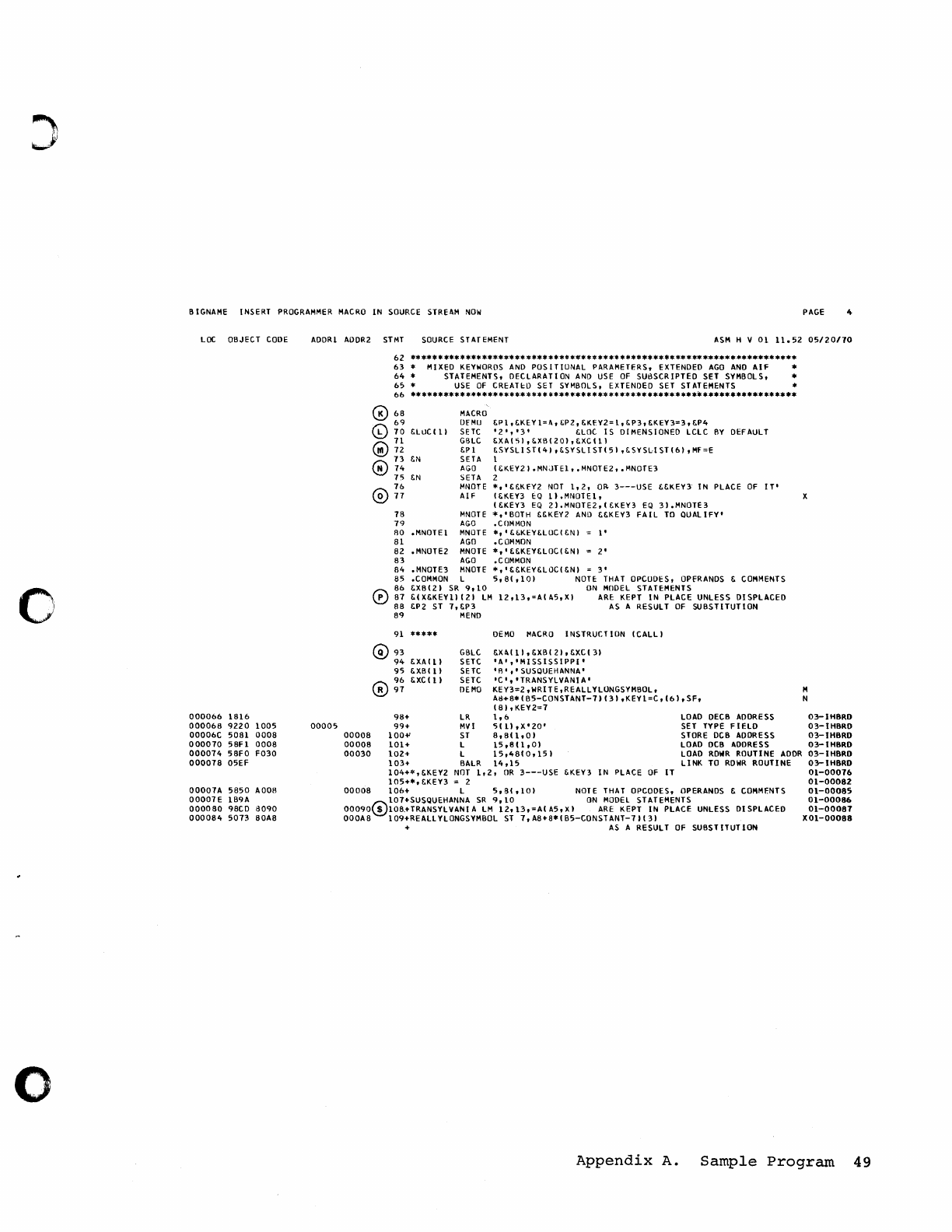
o
o
BIGNAME INSERT
PROGRAMMER
MACRO
IN
SOURCE
STREAM
NOW
PAGE
LOC
OBJECT
CODE
000066
1816
000068
9220
1005
00006C
5081
0008
000070
58Fl
0008
000074
58FO
F030
000078
05EF
00007.11
5850
.11006
00007E
IB9A
000080
98CD
6090
000084
5073
80.118
ADDRl ADDR2
STMT
SOURCE
STATEMENT
ASM
H V
01
11.52
05/20170
00005
62
****
**
***
****
********
****
****
***
**
**** ****
******
**
*
*******
************
63
* MIXED
KEYWORDS
AND
POSITIONAL
PARAMETERS, EXTENDED
AGO
AND
AIF
*
64
* STATEMENTS, DECLARATION
AND
USE
OF
SUBSCRIPTED SET SYMBOLS, *
65
*
USE
OF
CREATtD
SET SYMBOLS, EXTENDED
SET
STATEMENTS *
66
**********
******
*****
***
*
***************
***
*********.
**.*****.********
0
68
69
@
70
&LUCIlI
71
G)72
MACRO
OfMLJ
SErC
GBLC
&P
1
SETA
AGO
SETA
MNOTE
AIF
&P
1,
&KEY 1=.1\,
~P2,
&KfY2=
1,
&PJ,
&KEY3=3,
&P4
'2','3'
&LOC
IS
DIMENSIONED LCLC
BY
DI::FAULT
& X A I
'i
I ,
f.
X 6 I 201 ,
f.
XC
11 I
73
&N
0
74
&SYSLI
ST\41
,&SYSLI
ST\51
,&SYSLI
STl6I,MF=E
1
75
&N
I&KEY21.MNJTE1,
.MNOTE2,
.MNOTE3
2
76
0
77
78
79
80
81
82
83
84
85
86
0
87
88
89
91
G)
93
94
95
96
0
97
MNOTE
AGO
.MNOTE1
MNOTE
AGO
• MNOTE2
MNOTE
AGO
•
MNOT
E J
MNOTE
.COMMON
L
&XB121
SR
9,10
&IX&KEYlII21
LM
&P2 ST
7,&P3
MEND
*****
*,'&&KFY2
NOT
1,2,
OR-
3---USE
&&KEY3"
IN
PLACE
OF
IT'
I&KEY3
EQ
1I.MNOTE1,
I&KEY3
EQ
21.MNDTE2'\&KEY3
EQ
31.MNOTE3
*,'BOTH
&&KEV2
AND
&&KEY3
FAIL
TO
QUALIFY'
.COMMON
*,'&&KEY&LOCI&NI
l'
.COMMON
*,'&&KEY&LOCI&NI
2'
.COMMON
*,
'&&KEY&LOCI&NI
3'
5,81,101
NOTE
THAT OPCOOES, OPERANDS &
COMMENTS
ON
MODEL
STATEMENTS
12,13,=AIA5,XI
ARE:
KEPT
IN
PLACE UNLESS
DISPLACED
AS
A RESULT
OF
SUBSTITUTION
OEMO
MACRO
INSTRUCTION
ICALLI
GBLC
&XAI
11
,&XBI
21
,&XCI31
&XAlll
&XBlll
&XCllI
SETC
'A',
'MISSISSIPPI'
SETC
'IP,'
SUSQUEHANNA'
SETC
'C','TRANSYLVANIA'
OE
1010
KEYJ=Z
,WRIT
E
,REALL
YLONGSYMBOL,
AIl+8*IB5-CONSTANT-71131
,KEY1=C,
(61
,SF,
181,KEYZ=7
98+
LR
1,6
LOAD
DECB
AODRESS
SET TYPE
FIelD
STORE DCB ADDRESS
LOAD DC8 ADDRESS
99+
MVI
5111
,X'ZO'
00008
100"
ST
B,8(
1,01
00008
101+
L
15,8(
1
,01
00030
102+
L
15,4810,151
103+
BALR
14,15
104+*,&KEY2
NOT
1,Z,
OR
3---USE
&KEY3
IN
PLACE
OF
IT
105+*,
&KEY3 = 2
LOAD
RDWR
ROUTINE
ADDR
L1
NK
TO
RDWR
ROUTI
HE
00008
106+
L
5,81,10)
NOTE THAT OPCOOES, OPERANDS &
COMMENTS
10HSUSQUEHANNA
SR
9,10
ON
MODEl STATEMENTS
00090(!)108.+TRANSYLVANIA
LM
12,13,=AIA5,X)
ARE:
KEPT
IN
PLACE UNLESS
DISPLACED
000.118
1
09+REAll
YlONGSYMBOL
ST
7,
.118+8* I
B5-CONS
TANT-7
II
31
+
AS
A RESULT
OF
SUBSTITUTION
M
N
03-IH8RD
03-tH8RO
03-tH8RO
03-tH8RO
03-IH8RD
03-tH8RD
01-00076
01-00082
01-00085
01-00086
01-00081
X01-00088
Appendix
A.
Sample
Program
49
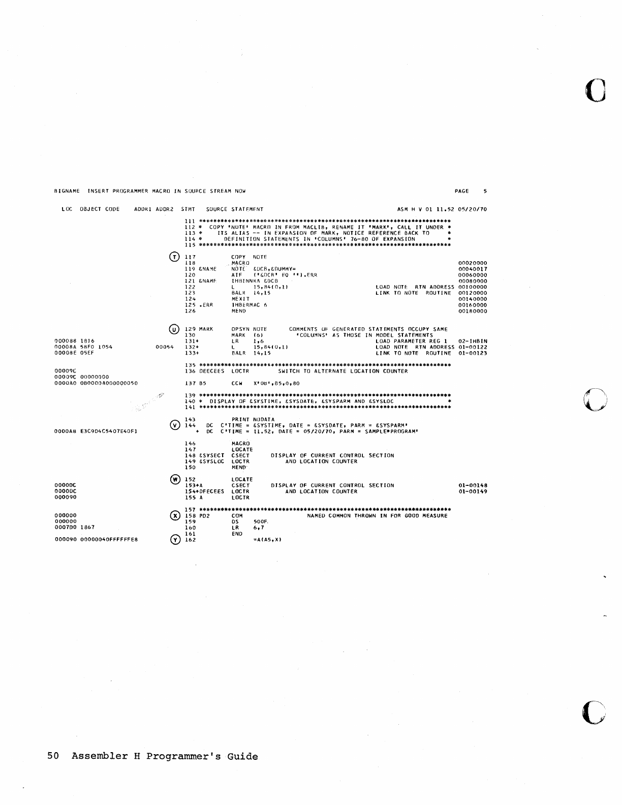
BIGNAME
INSERT
PROGRAMMER
MACRO
IN
SOURCE SrREAM
NOW
PAGE
LOC
OBJECT
CODE
ADORI
AODR2
STMT
SOURCE STATfMfNT
ASM
H V
01
11.52
05/20/70
000088
1816
OOOOBA
5BFO
1054
00008
E
05EF
00009C
00009C
00000000
OOOOAO
060000A000000050
0000A8
E3C9D4C5407E40Fl
OOOOOC
ooooac
000090
000000
000000
000700
1867
000090
00000040FFFFFFE8
0
@
00054
®
III
**************
***************
*********
********************************
112
*
COpy'
NUTE'
MACRO
IN
FROM
MACLl
B,
RENAME
IT
'MARK',
CALL
IT
UNDER
*
113
*
ITS
ALIAS
--
IN EXPAIISION
OF
MARK,
NOTICE REFERENCE
BACK
TO
*
114
*
DEFINITION
STAHMt:NTS
IN
'COLUMNS'
76-80
OF EXPANSION *
115
*********************
*************
****
*****
*.**************************
117
COpy NOn:
118
.
MACRO
119
&NA:>IE
NOTE
£OCB,
&OUMMY=
120
AIF
I't:DCR'
EO
'
'I.FRR
121
&NAMF
IHBINNI'.!I
&DCB
122
L
15,
R4
(
0,11
LOAD
NOH:
RTN
ADDRESS
123
BALR
14,15
LINK
TO
NOTE
ROUTINE
124
MEXIT
125
.ERR
IHBERMAC
6
126
MEND
129
MARK
OPSYN
NOTE
COMMENTS
lJf' GENERATED STATEMENTS OCCUpy
SAME
130
MARK
(61
'COLUMNS'
AS
THOSE
IN
MODEL
STATEMENTS
131+
LR
1,6
LOAD
PARAMETER
REG
1
132+
L
15,8410,11
LOAD
NOTE
RTN
ADDRESS
133+
BALR
14,15
LI
NK
TO
NOTE
ROUTINE
135
**
**
*****
***
*******
* *
** **
****
*****
***
*
***************
*****************
1360EECEES
LOCTR
SWITCH
TO
ALTERNATE LOCATION
COUNTER
137
B5
CCW
X'Otl',B5,0,80
139
*********
*
*****
***
*****
******
*****
**
*
********
***
****************
******
140
* DISPLAY
OF
&SYSTIME, &SYSDATE:, I;SYSPARM
AND
I;SYSLDC *
141
*****
****
*
*******
****
** **
*********
**
*
*************
********************
PRINT
NODATA
143
144
DC
DC
C'TIME
=
I;SYSTIME,
DATE
= 6.SYSDATE,
PARM
= &SYSPARM'
C'TIME
=
11.52,
DATE
=
05/20/70,
PARM
= SAMPLE*PROGRAM'
146
MACRO
147
LOCATE
148
&SYSECT CSECT
01
SPLAY
OF
CURRENT
CONTROL
SECT ION
149
&SYSLOC
LOCTR
AND
LOCAT
ION
COUNTER
150
MEND
152
LOCATE
153+1\ CSECT DISPLAY
OF
CURRENT
CONTROL
SECTION
1$4+DFECEES
LOCTR
AND
LOCATION COUNTER
155
A LOCTR
157
*****************
*************
***
********
**
**********************.*****
156
P02
COM
NAMED
COMMON
THROWN
IN
FOR
GOOD
MEASURE
159
OS
500~
160
LR
6,7
161
END
162
=A(A5,XI
50
Assembler
H
Programmer's
Guide
00020000
00040017
00060000
00080000
00)
00000
00120000
00140000
00160000
001BOOOO
02-IHBIN
01-00122
01-00123
01-00148
01-00149
c
c
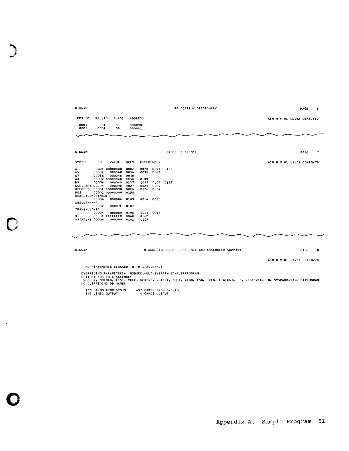
)
I"
0
o
8IGNAME
POS.ID
REL.lD
FLAGS ADDRESS
0001
0001
8IGNAME
SYMBOL
A
AS
A7
A8
85
CONSTANT
DEECEES
0001
0001
LEN
00001
00002
00016
00002
00008
00004
00001
OC
08
VALUE
00000000
000040
000048
OOOOOOAO
DOODAD
000098
00000098
PD2
00001
00000000
REALL
YLONGSYM80L
00004
000084
SUSQUEHANNA
00002
00007E
TRANSYLVANIA
00004
000080
X
00001
FFFFFFE8
=AIA5,X)
00004
000090
000090
OOOOAl
OEFN REFERENCES
0002
0028
0153
0034
0038
0162
0036
0038
0109
0137
0038
0109
0027
0025
0109
0026
0136 0154
0158
0109
0014
OOlS
0107
0108
0014
0018
0060
0162
0162
0108
RELOCATIUN
DICTIONARY
CROSS
REFERENCE
0155
0137
BIGNAME
DIAGNUSTIC
CROSS
REfERENCE
AND
ASSEMBLER
SUMMARY
NO
STATEMENTS FLAGGED
IN
THIS
ASSEMRLY
OVERRIDING
PARAMETERS- NODECK,MULT,SYSPARM=SAMPLE*PROGRAM
OPTIONS
FOR
THIS
ASSEMBLY
PAGE 6
ASM
H V
01
11.52
05/20110
PAGE 1
ASH
H V
01
11.52
05/2011'0
PAGE
ASM
H V
01
11.52
05/20110
NOOECK, NOLOAD,
LI
ST,
XREF,
NORENT, NOTES
T,
MUL
T,
ALGN,
ESD,
RLO,
LlNECNT=
55,
MSGLEVEL=
0,
SYSPARM=SAMPLE*PROGRAM
NO
OVERRIOING
DO
NAMES
136
CARDS
FROM
SYSIN
197
LINES
OUTPUT
432
CARDS
FROM
SYSLIB
o CARDS UUTPUT
Appendix
A.
Sample
Program
51
This
page
intentionally
left
blank.
(
c
o
52
Assembler
H
Programmer's
Guide
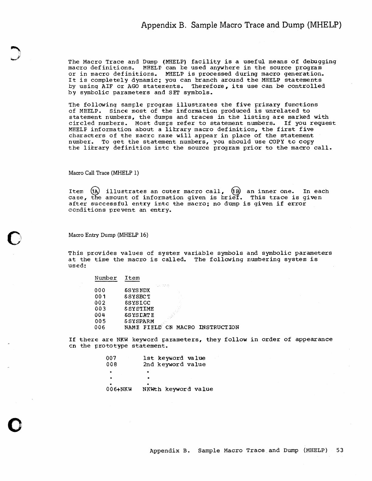
~i
~I
o
o
Appendix
B.
Sample Macro Trace and Dump (MHELP)
The
Macro
Trace
and
Dump
(MHELP)
facility
is
a
useful
means
of
debugging
macro
definitions.
MBELF
can
be
used
anywhere
in
the
source
program
or
in
macro
definitions,.
MHELP
is
processed
during
macro
generation.
It
is
completely
dynamic;
you
can
branch
around
the
MHELP
statements
by
using
AIF
or
AGO
staterr.ents.
'Therefore,
its
use
can
be
controlled
by
symbolic
parameters
and
SET
symbols.
'Ihe
following
sam~le
J:rogram
illustrates
the
five
frimary
functions
of
MEELP.
Since
most
of
the
information
produced
is
unrelated
to
statement
numbers,
the
dumps
and
traces
in
the
listing
are
marked
with
circled
numbers.
Most
duroI;s
refer
to
sta
tement
numbers.
If
you
request
MHELP
information
about
a
litrary
macro
definition,
the
first
five
characters
of
the
rracrc
narr.e
will
appear
in
place
of
the
statement
number.
To
get
the
statement
numbers,
you
should
use
COPY
to
copy
the
library
definition
intc
the
source
program
prior
to
the
macro
call.
Macro Call Trace (MHELP 1)
Item
l1iV
illustrates
an
outer
macro
call,
@
an
inner
one.
In
each
case,
t6e
amount
of
information
given
is
brief.
This
trace
is
given
after
successful
entry
intc
the
macro;
no
dump
is
given
if
error
conditions
prevent
an
entry.
Macro Entry Dump (MHELP 16)
This
provides
values
of
systerr
variable
symbols
and
symbolic
parameters
at
the
time
the
macro
is
called.
The
following
numbering
system
is
used:
Number
000
00
1
002
003
004
005
006
Item
&SYSNDX
&SYSEC'I
&SYSI.CC
&SYS'IIME
&SYSCATE
&SYSPARM
NAME
FIEL6
CN
MACRO
INSTRUCTION
If
there
are
NKW
keyword
parameters,
they
follow
in
order
of
appearance
en
the
prototype
statement.
007
008
006+NKW
1st
keyword
value
2nd
keyword
value
NKWth
keyword
value
Appendix
B.
Sample
Macro
Trace.and
Dump
(MHELP)
53
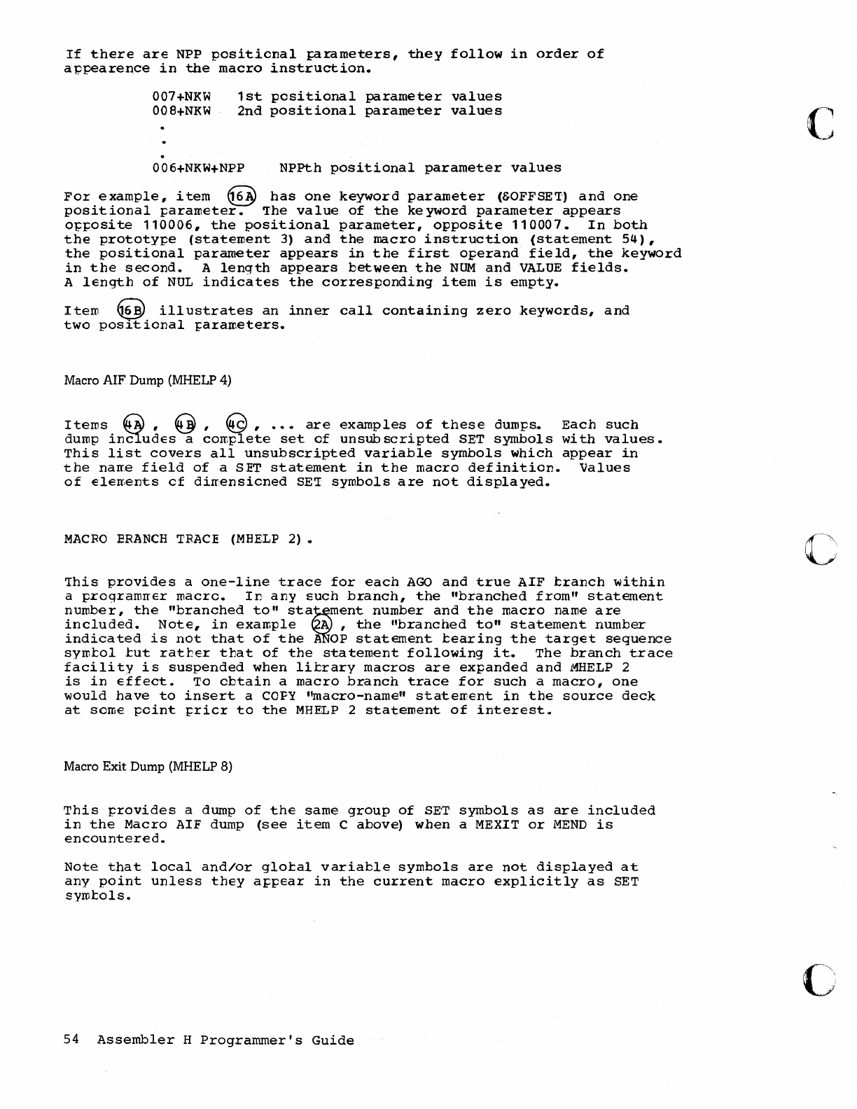
If
there
are
NPP
positicnal
pirameters,
they
follow
in
order
of
a
ppearence
in
the
macro
instruction.
007+NKW
008+NKW
1st
positional
parameter
values
2nd
positional
parameter
values
006+NKW+NPP
NPPth
positional
parameter
values
For
example,
item
@
has
one
keyword
parameter
(SOFFSE'I)
and
one
positional
parameter.
'Ihe
value
of
the
ke yword
parameter
appears
o~posite
110006,
the
positional
parameter,
opposite
110007.
In
both
the
prototype
(statement
3)
and
the
macro
instruction
(statement
54),
the
positional
parameter
appears
in
the
first
operand
field,
the
keyword
in
the
second.
A
length
appears
between
the
NOM
and
VALUE
fields.
A
length
of
NUL
indicates
the
corresponding
item
is
empty.
Item
~
ill
ustrates
an
inner
call
containing
zero
.keywcrds,
and
two
pos~t
ional
parameters.
Macro AIF Dump (MHELP 4)
Items
G,
@,
€9,
...
are
examples
of
these
dumps.
Each
such
dump
in21udes
a
complete
set
of
unsubscripted
SET
symbols
with
values.
This
list
covers
all
unsubscripted
variable
symbols
which
appear
in
the
narre
field
of
a
SET
statement
in
the
macro
definition.
Values
of
elelrents
cf
dirrensicned
SE'r
symbols
are
not
displayed.
MACRO
ERANCH
TRACE
(MHELP
2)
•
This
provides
a
one-line
trace
for
each
AGO
and
true
AIF
tranch
within
a
programrrer
macro.
In
any
such
branch,
the
"branched
from"
statement
number,
the
"branched
to"
sta~ment
number
and
the
macro
name
are
included.
Note,
in
example
A,
the
"branched
to"
statement
number
indicated
is
not
that
of
the
A
OP
statement
tearing
the
target
sequence
symtol
tut
rather
that
of
the
statement
following
it.
The
branch
trace
facility
is
suspended
when
library
macros
are
expanded
and
MHELP
2
is
in
effect.
To
obtain
a
macro
branch
trace
for
such
a
macro,
one
would
have
to
insert
a
COFY
''macro-name''
statement
in
the
source
deck
at
scme
point
prier
to
the
MHELP
2
statement
of
interest.
Macro Exit Dump (MHELP 8)
This
provides
a dump
of
the
same
group
of
SE'l'
symbols
as
are
included
in
the
Macro
AIF dump
(see
item
C
above)
when a
MEXIT
or
MEND
is
encountered.
Note.
that
local
and/or
global
variable
symbols
are
not
displayed
at
any
point
unless
they
appear
in
the
current
macro
explicitly
as
SET
symtols.
54
Assembler
H
Programmer's
Guide
c
()
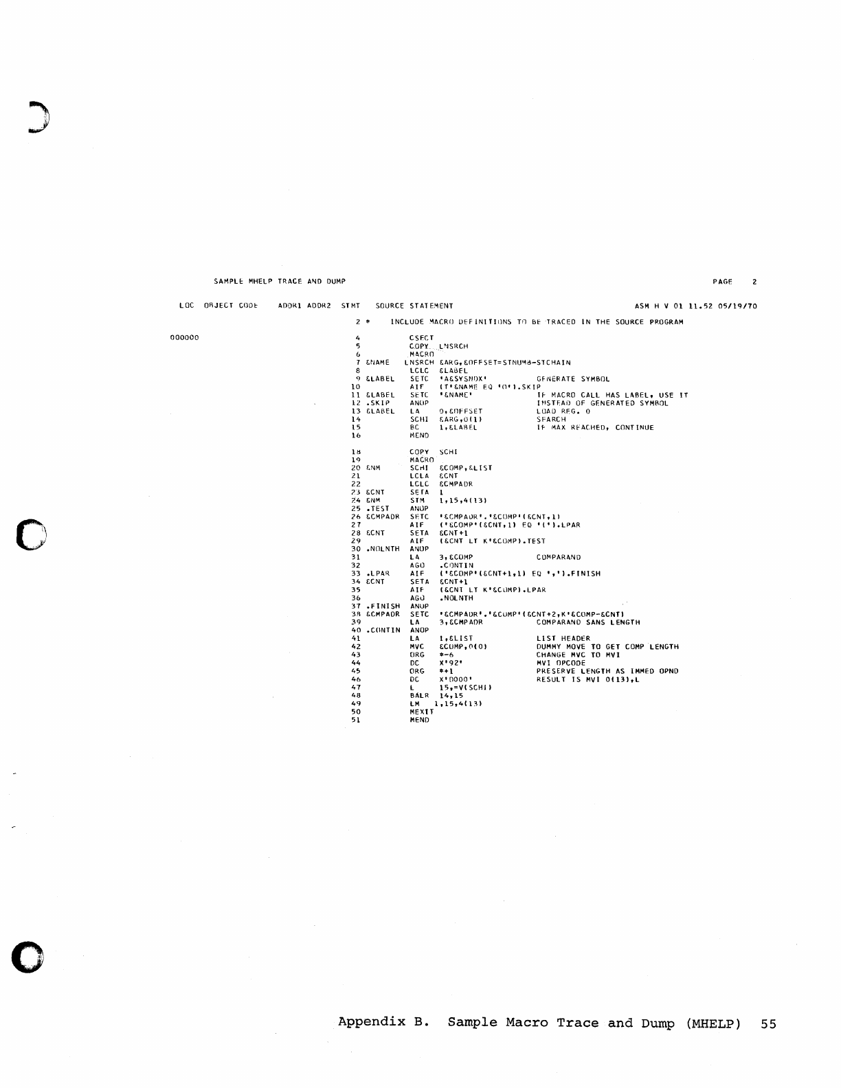
)
SAMPLt
MHELP TRACE
A~D
DUMP
PAGE
LaC
OBJECT
COOt
A[)[)K1 ADDR2 STMT SOURCE STATE:-lENT
ASM
H V
01
11.52
05/19/70
2 *
INCLUDE
:-lACRO
UfF
INI
TII1NS
Til
BbTRACED
IN
THE
SOURCE
PROGRAM
000000
4 CSECT
'5
COpy
L'ISRCH
Mtt.CRO
,,~JAME
LNSRCH &ARG,
"OFF
SE
T=
S
TNUMd-ST
CHAl
III
LCLC
&LABfL
q <.LABEL
sue
'
A"SYSNf)X'
GFNERATE SYMBOL
10
AI
f
IT'"NAME
EQ
'(1'
I.
SK
I P
11
"LABEL
51::
Te
I &NAME'
IF-
MACRO
CALL
HAS
LABEL,
USE
IT
12
•
SKIP
ANOP
I
~IS
Tf,Ail
OF
GENERATED SYMBOL
13
&LABEL
L4
0,
WfF::>ET
LOAU
RFG.
0
1'+ SCHI
f.ARG,OI11
SFARCH
15
BC
1,"LARF.L
IF-
MAX
RfACHED,
CONT
INUE
16
MEND
Ul
COpy
SCHI
19
M4CRO
20
f.NM
SCril
"CaMP,
f.L 1ST
21
LCLA
"CNT
22
LCLC
&CMPAOR
73
"CNT
SErA
1
24
!:NM
STM
1.15,41131
25
.TEST
ANOP
26
!:CMPADR SI'TC I !:CMPAOR' •
'!:COMP'
1
KCNT,
11
c)
27
AIF
I'
&COMP'
(&CNT.
11
EQ
'('1.LPAR
28
f.CNT SETA &CNT
+1
29
AIF
( !:CNT
LT
K'
!:COMP
I.
TEST
30
.NOLNTH
Ai\lUP
31
Lil
3,
&CUMP
COMPARAND
32
AGO
.CI)NTIN
33
.LPAR
AIF
('!:COMP'
(&CNT+1,
11
EQ
"
'I.FINISH
34
tCNT
SETA &CNT +1
35
A
IF
( !:CNT
LT
K'&CLlMPI.LPAR
36
AGO
.NOLNTH
37
.FINISH
ANUP
3R
"CMPAOR SETC I !:CMPADR
I.'
&CllMP'
(!:CNT
+2,
K'
!:COMP-!:CNTI
39
LA
3,
!:CMPAOR COMPAR4NO SANS LENGTH
40
.CONlIN
ANOP
41
LA
1,!:L1ST
Ll
ST
HEAOfR
42
MVC
!:CllMP,
('1(0 1
DUMMY
MOVE
TO
GET CaMP LENGTH
43
ORG
*-6
CHANGE
MVC
TO
MVI
44
DC
X'
'l2'
MVI
OPCOOE
45
ORG
*+1
PRESERVE LENGTH
AS
IMMED
OPNO
46
DC
X'OOOO'
RESULT
IS
MVI
01131,
L
47
L
15,=V(
SCHII
48
BALR
14,15
49
LM
1,15,4(131
50
MEXlT
51
MEND
o
Appendix
B.
Sample
Macro
Trace
and
Dump (MHELP)
55
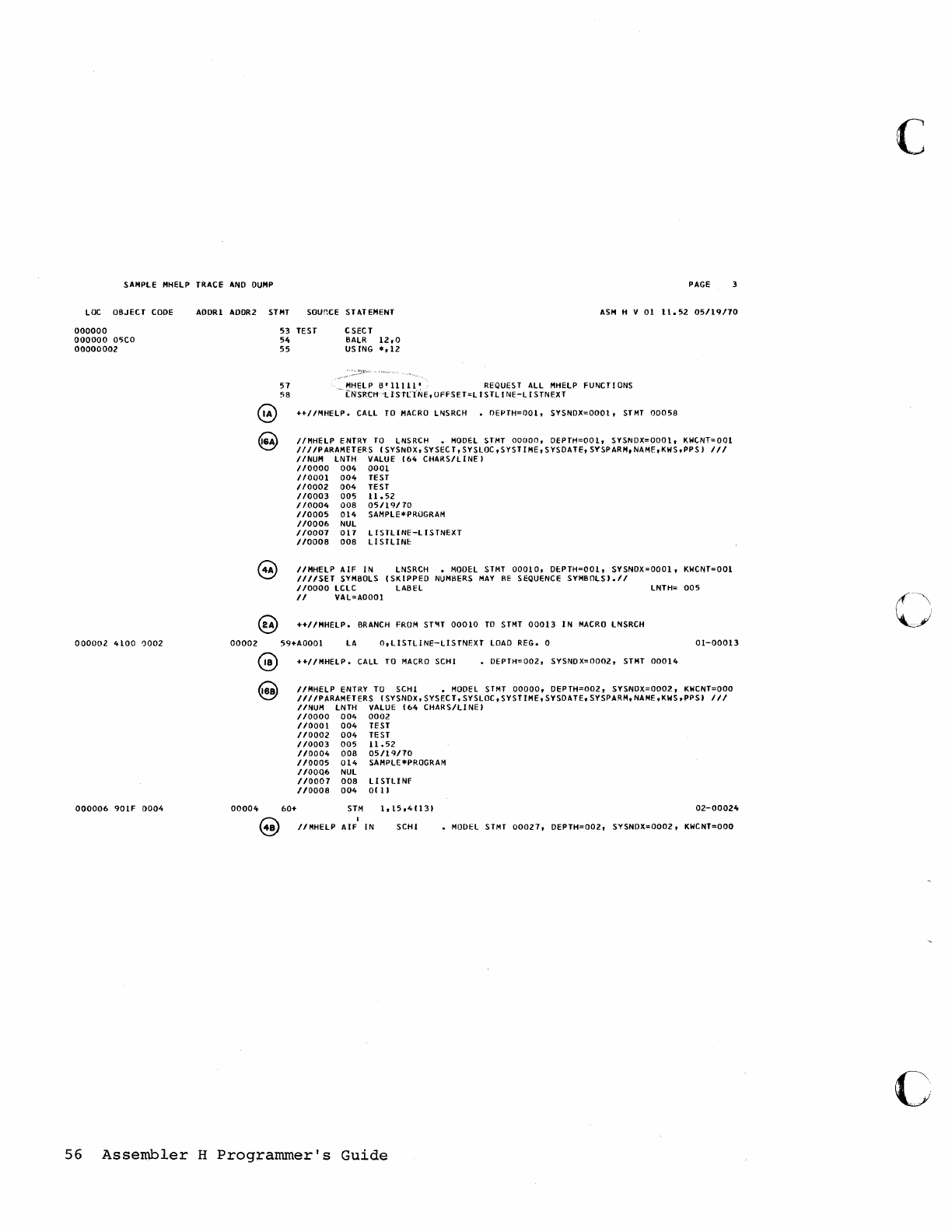
SAMPLE
MHElP
TRACE
AND
DUMP
PAGE
laC
OBJECT
CODE
000000
000000
O'>CO
00000002
000002
4100
a002
000006
901F
0004
AOORI AODR2
STMT
SOUr.CE
STATEMENT
ASM
H V
01
11.52
05/19110
53
TEST
54
55
57
5B
CSECT
BAlR
12,0
USING
*,12
MHElP
B'11111'
REQUEST
All
MHElP
FUNCTIONS
i::NS'RCH
'lISn::tNE,
UFFSET=L
I STL I
NE-ll
S TNEXT
@
++IIMHElP.
CAll
TO
MACRO
lNSRCH
•
DEPTH=OOl,
SYSNOX=OOOl,
STMT
00058
00002
00004
IIMHElP
ENTRY
TO
lNSRCH
•
MODEL
STMT
00000,
DEPTH=OOI,
SYSNDX=OOOl,
KWCNT=OOl
III/PARAMETERS
(SYSNDX,
SYSEC
T,
SYSlOC,
S
YSTI
ME, S YSOATE, SYSPARM,
NAME
,KHS
,PPS)
11/
IINUM LNTH VALUE
(64
CHARS/LINE)
110000
004
0001
110001
004
TEST
110002
004
TEST
110003
00'>
11.52
110004
008
05/19/70
1/0005
014
SAMPlE*PROGRAM
110006
NUL
1/0007
017
lISTlINE-lISTNEXT
1/0008
008
lISTLINE
I/MHElP
AIF
IN
lNSRCH.
MODEL
STMT
00010,
DE:PTH=OOI,
SYSNDX=OOOI,
KHCNT=OOI
III/SET
SYMBOLS
(SKIPPED
NUMBERS
MAY
fiE SEQUENCE
SYMBOlS).1/
110000
lClC
LABEL
lNTH=
005
II
VAL=AOOOI
++IIMHElP.
BRANCH
FROM
ST~T
00010
TO
STMT
00013
IN
MACRO
lNSRCH
59+AOOOI
lA
O,L1STLINE-LISTNEXT
lOAD
REG. 0
01-00013
60+
++IIMHElP.
CALL
TO
MACRO
SCHI •
DEPTH=002,
SYSNDX=0002,
STMT
00014
IIMHELP
ENTRY
TO
SCHI
•
MODEL
STMT
00000,
DEPTH=D02,
SYSNDX=0002,
KWCNT=OOO
IIIIPARAMETERS
(SYSNDX,
SYSEC
T,
SYSlOC,
SYSTIHE,
SYSDA
TE.
SYSPARH,
NAME
,KWS
,PPS'
III
/lNUM
lNTH
VALUE
(64
CHAR
SIll
NE'
110000
004
0002
/10001
004
TEST
/10002
004
TE
ST
1/0003
005
11.52
110004
008
05/19170
/10005
014
SAMPlE*PROGRAM
110006
NUL
110007
008
llSTllNF
1/0008
004
O(
11
STH
1,15,4113)
02-00024
I
/lHHElP
AIF
IN
SCHI
•
MODEL
STMT
00027,
DEPTH=002,
SYSNOX=0002,
KHCNT=OOO
56
Assembler
H
Programmer's
Guide
c
c
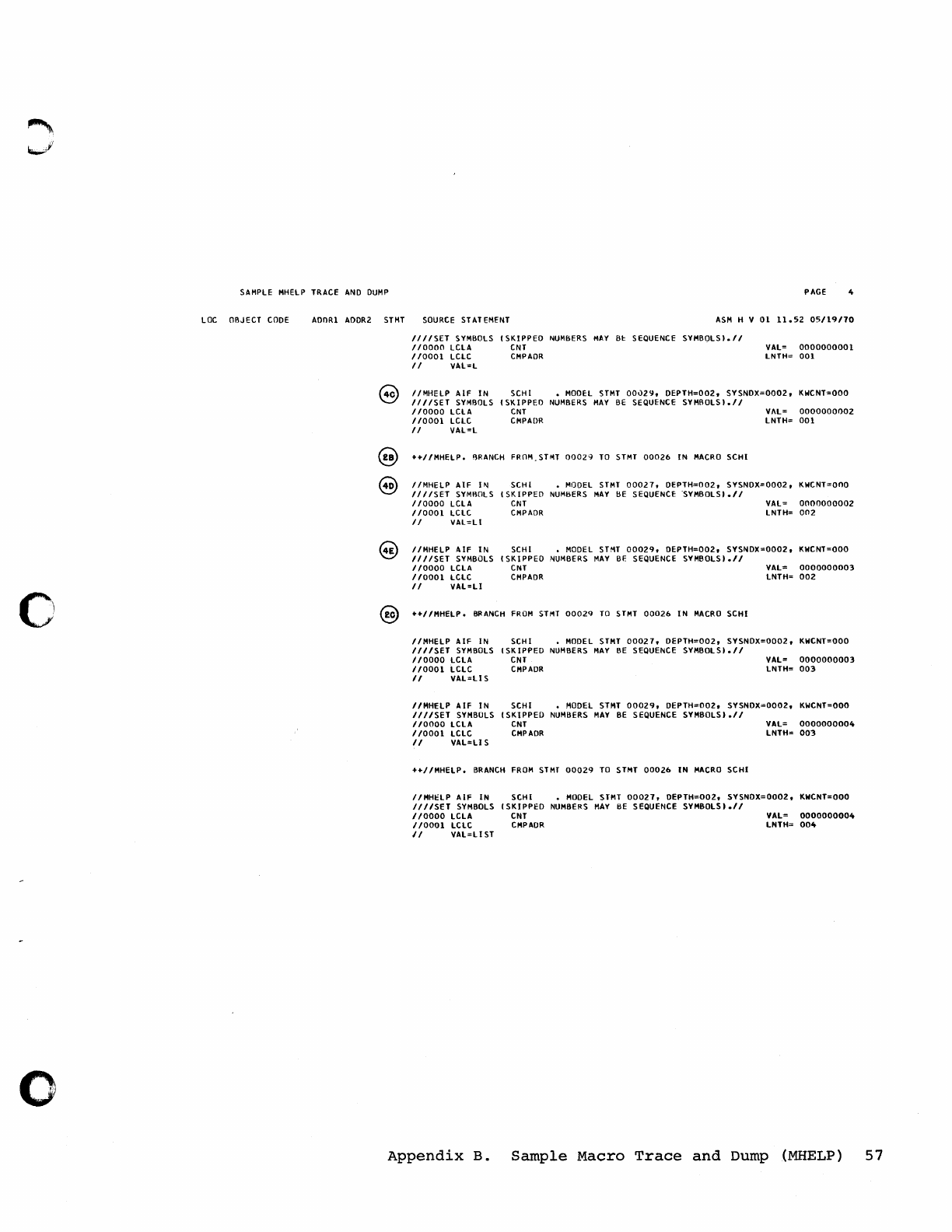
SAMPLE
MHElP
TRACE
AND
DUMP
PAGE 4
lOC
OBJECT
CODE
AOORl
AODR2
STMT
SOURCE
ST
AT
EMENT
ASM
H V
01
11.52
05/19/70
IIIISET
SYMBOLS
(SKIPPED
NUMBERS
MAY
Bt: SEQUENCE
SYMBOlS).1I
110000
lClA
CNT
VAl=
0000000001
110001
lClC
CMPAOR
lNTH=
001
II
VAl:l
IIMHElP
AIF
IN
SCHI •
MODEL
STMT
00029,
DEPTH=002,
SYSNDX=0002,
KWCNT=OOO
IIIISET
SYMBOLS
(SKIPPED
NUMBERS
MAY
BE
SEQUENCE
SYMBOlS).1I
110000
lClA
CNT
VAl=
0000000002
110001
lClC
CMPAOR
lNTH=
001
II
VAl=l
++IIMHElP.
BRANCH
FROM.STroIT
00029
TO
STMT
00026
IN
MACRO
SCHI
IIMHELP
AIF
1111
SCHI
•
MODEL
STMT
00027,
DEPTH=002,
SYSNDX=0002,
KWCNT=OOO
IIIISET
SYMI\OlS
(SKIPPED
NUMBERS
MAY
BE
SEQUENCE
·SYMBOlS).1I
110000
lClA
CNT
VAL:
0000000002
1/0001
lClC
CMPAOR
lNTH=
002
II
VAl=lI
IIMHElP
AIF
IN
SCHI •
MODEL
STMT
00029,
DEPTH=002,
SYSNDX=0002,
KWCNT=OOO
IIIISET
SYMBOLS
(SK
I PPED
NUMBERS
MAY
BF.
SEQUENCE SYMBOLS
1.11
110000
lClA
CNT
VAl=
0000000003
110001
lClC
CMPADR
lNTH=
002
II
VAl=Ll
o @
+"IIMHElP.
BRANCH
FROM
SHn
00029
TO
STMT
00026
IN
MACRO
SCHI
IIMHELP
AlF
IN
SCHI
MODEL
STMT
00027,
DEPTH=002,
SYSNDX=0002,
KWCNT=OOO
IIIISET
SYMBOLS
(SK
IPPED
NUMBERS
MAY
BE
SEQUENCE
SYMBOL
SI.II
110000
lClA
CNT
VAl=
0000000003
110001
lClC
CMPADR
lNTH=
003
II
VAl=Ll
S
IIMHELP
AIF
IN
SCHI •
MODEL
STMT
00029,
DEPTH=OOZ, SYSNOX=OOOZ,
KWCNT=OOO
III/SET
SYMBOLS
(SKIPPED
NUMBERS
MAY
BE
SEQUENCE
SYMBOlSI.1I
110000
LClA
CNT
VAl=
0000000004
110001
lClC
CMPADR
lNTH=
003
II
VAl=LI
S
HIIMHELP.
BRANCH
FROM
STMT
00029
TO
STMT
00026
IN
MACRO
SCHI
IIMHHP
AIF
IN
SCHI
•
MODEL
STMT
00027,
DEPTH=002,
SYSNOX=0002,
KWCNT=OOO
IIIISET
SYMBOLS
(SKIPPED
NUMBERS
MAY
BE
SEQUENCE
SYMBOlSI.1I
110000
lClA
CNT
VAl=
0000000004
1/0001
lClC
CMPADR
lNTH=
004
II
VAl=LIST
o
Appendix
B.
Sample
Macro
Trace
and
Dump (MHELP)
57
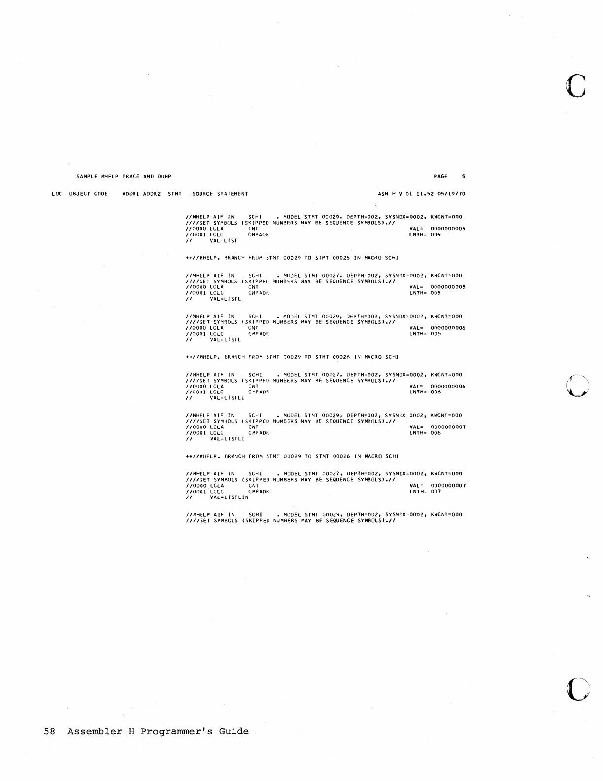
c
SAMPLE MHELP TRACE
AND
DUMP
PAGE
lOC
OBJECT
COOE
AOORl ADDR2 STMT
SOURCE
STATEMfNT
ASM
H V
01
1l.52
05119110
I/MHELP
AIF
IN
SCHl
• MODEL STMT
00029,
DEPTH=002,
SYSNDX=0002,
KWCNT=OOO
IIIISET
SYMBOLS
(SKIPPED
NUMBFRS
MAY
BE
SEQuENCE
SYMBOlS'.1I
110000
LCLA
(NT
VAL=
0000000005
1/0001
lCLC
CMPAOR
lNTH=
004
1/
VAL=LIST
++11
MHElP.
BRANCH
FROM
STMT
00029
TO
S
TMT
00026
I N
MACRO
SCHI
IIMHELP
AIF
IN
SCHl
MOOf:L
SHIT
0002f,
OEPTH=002,
SYSNnX=0002,
KWCNT=OOO
I
III
SET
SYM~OLS
(SKI
PPED
"IUMBf-ORS
;~AY
BE
SEQUENCE
SYMBOLS'./
I
1/0000
LCL A CNT
VAL=
0000000005
110001
LCLC
CMPAUR
LNTH=
005
II
VAL
=L1
S TL
IIMHELP
AIF
IN
SCHI
• MOOf.L
STMT
00029,
OFPTH=002,
SVSNDX=0002,
KWCNT=OOO
/I/ISET
SYMBOLS
(SKlPPfO
NUMBERS
MAY
BE
SEQUENCE
SYMBOLS'.II
110000
LCLA
CNT
VAL=
0000000006
/10001
LCLC
CMPAUR
LNTH=
005
/I
VAL=L1STL
++/lMHELP.
BRANCH
fROM STMT
00029
TO
STMT
00026
IN
MACRO
SCHI
I/MHELP
AIF
IN
SCHI
•
MODEL
STMT
00027,
DI:PTH=002,
SYSNDX=0002,
KWCNT=OOO
II/ISET
SYMBOLS
(SKIPPED
NUMBERS
MAY
fiE SEQUENCE
SYMHOLS'.II
110000
LCLA
CNT
VAL=
0000000006
110001
LCLC
CMPAOR
LNTH=
006
II
VAL=Ll
STU
IIMHELP
AIF
IN
SCHI •
MODEL
STMT
00029,
DI:PTH=002,
SYSNDX=0002,
KWCNT=OOO
IIIISET
SYMBOLS
(SKIPPEO
NUMBERS
MAY
HE'
SEQUENCE SYMBOLS'
.11
110000
LClA
CNT
VAl=
0000000007
110001
LClC
CMPADR LNTH=
006
II
VAl=LISTLI
++I/MHELP.
BR·ANCH
FROM
STMT
00029
TO
STMT
00026
IN
MACRO
SCHI
IIMHELP
AIF
IN
SCHI
•
MODEL
STMT
00027,
OEPTH=002,
SYSNDX=0002,
KWCNT=OOO
III/SET
SYMROLS
(SKIPPED
NUMBERS
MAY
BE SEQUENCE
SYMBOLS'.II
110000
LCLA
CNT
VAl=
0000000007
110001
LClC
CMPADR LNTH=
007
II
VAL=LISTLlN
IIMHELP
AIF
IN
SCHI
• MODEL STMT
00029,
DEPTH=002,
SYSNDX=0002,
KWCNT=OOO
I/I/SET
SYMBOLS
(SKIPPED
NUMBERS
MAY
BE
SEQUENCE
SYMBOLS'./!
c
58
Assembler
H
Programmer's
Guide
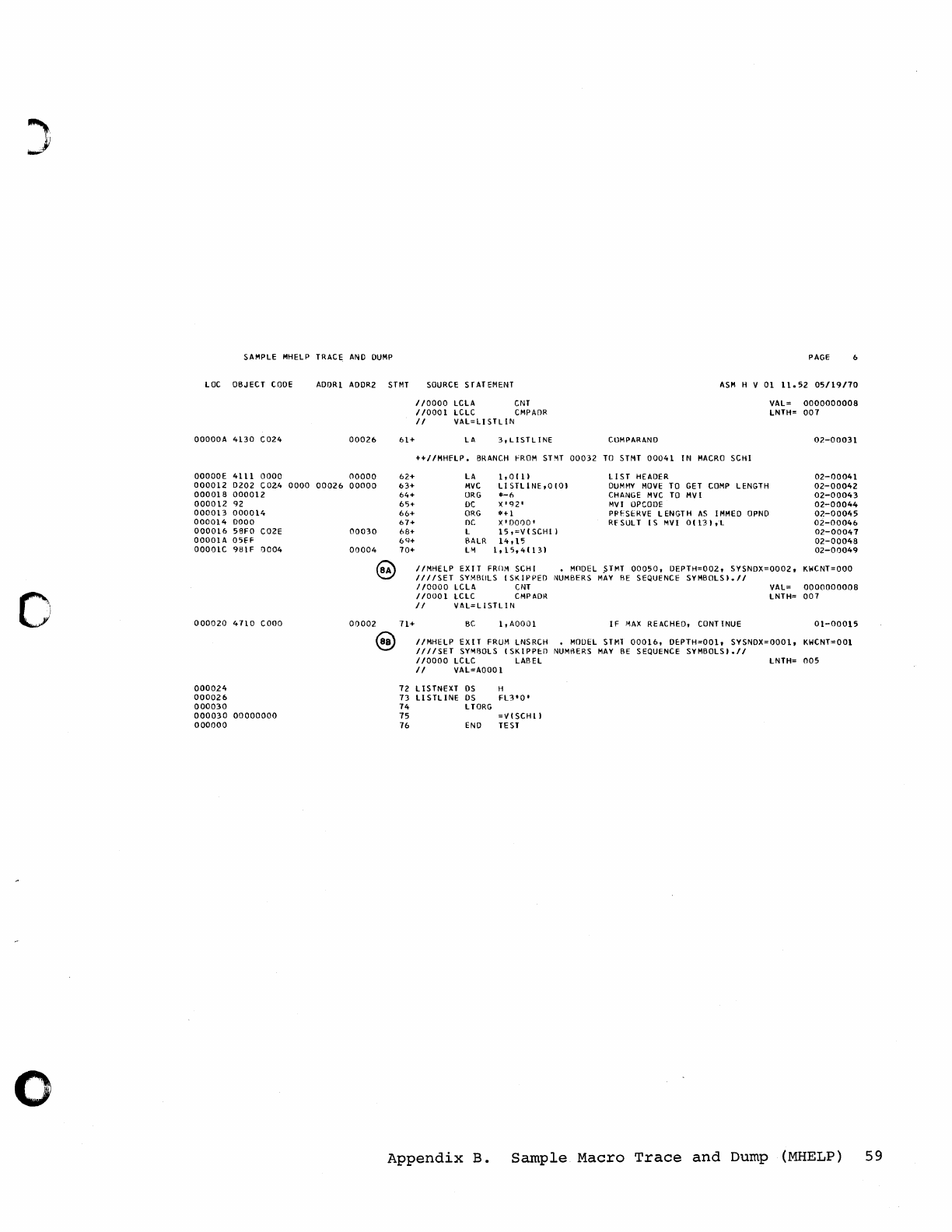
~.
J
Of
o
SAMPLE MHELP TRACE
AND
DUMP
PAGE
LOC
OBJECT
CODE
AODRI
AOOR2
STMT
SOURCE
STATEMENT
ASM
H V
01
1l.52
05/19170
OOOOOA
4130
C024
OOOOOE
4111
0000
0000
12
0202
C02.4
000018
000012
000012
92
000013
000014
000014
0000
000016
58FO
C02E
OOOOlA
05H
OOOOlC
9BIF
0004
000020
4710
COOO
000024
000026
000030
000030
00000000
000000
0000
00026
00026
00000
00000
00030
00004
@
00002
@
61+
62+
63+
64+
65+
66+
67+
68+
6<1+
70+
//0000
LCLA
CNT
110001
LCLC CMPAf)R
II
VAL=LISTLIN
LA
3,LlSTLlNE
CllMPARANO
++IIMHfLP.
BRANCH fROM
STMT
00032
TO
STMT
00041
IN
MACRO
SCHI
LA
MVC
ORG
DC
ORG
DC
L
BALR
LM
1,0111
LI
STLINE,O
(01
*-f>
X'
92'
*+1
X'OOOO'
15,=V(SCHII
14,15
1,15,41131
LIST
HEADER
DUMMY
MOVE
TO
GET
COMP
LENGTH
CHANGE
MVC
TO
MVI
MVI
OPCODE
PPI'SERVE L
ENGT
H
AS
I
MMEO
OPNO
RFSULT
[S
MVI
0113liL
VAL=
0000000008
LNTH=
007
02-00031
02-00041
02-00042
02-00043
02-00044
02-00045
02-00046
02-00047
02-00048
02-00049
II
MHE
lP
EX
IT
FROM
SCH
I • MnDEL S
TMT
00050,
OEPTH=002,
SYSNDX=0002,
KWCNT=OOO
III1SET
SYMBOLS
ISKIPPED
iIIUMBERS
MAY
BE
SEQUENCE
SYMBOLSI.II
110000
LCLt.
CNT
VAl=
0000000008
110001
lCLC
CMPADR
lNTH=
007
/1
VAL=LISTLIN
71+
BC
I,AOOOl
IF
MAX
REACHED, CONTINUE
01-00015
IIMHtLP
EXIT
FRUM LNSRCH • MODEL
STMl
00016,
O~PTH=OOl,
SYSNOX=OOOl,
KWCNT=OOI
IIIISET
SYMBOLS I
SKIPP~O
NUMBERS
MAY
BE
SEQUENCE
SYMBOLS)./1
110000
lCLC
LABEL
lNTH=
005
/I
VAL=AOOO 1
72
LISTNEXT
OS
H
73
LlSTLlNE
OS
FL3'O'
74
LTORG
75
=V(SCHll
76
END
TE
ST
Appendix
B.
Sample
Macro
Trace
and
Dump
(MHELP)
59
This
page
intentionally
left
blank.
c
c
60
Assembler
H
Progranuner's
Guide
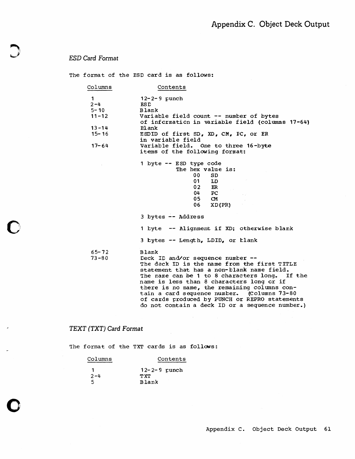
o
o
Appendix
C.
Object Deck
Output
ESD
Card
Format
The
format
of
the
ESD
card
is
as
follows:
Columns
1
2-4
5-10
11-12
13
-14
15-16
17-64
65-72
73-80
Contents
12-
2-
9
punch
ESD
Blank
Variable
field
count
--
number
of
bytes
of
infcrnaticn
in
variable
field
(columns
17-64)
Blank
ESDIO
of
first
SO,
XD,
CM,
FC,
or
ER
in
variable
field
Variable
field.
One
to
three
16-byte
items
of
the
following
format:
1
byte
--
ESD
type
code
'Ihe
hex
value
is:
00
SD
01
LD
02
ER
04 PC
05
Q.1
06
XD(PR)
3
bytes
Address
1
l:yte
Alignment
if
XO;
otherwise
blank
3
bytes
Length,
LOID,
or
tlank
Blank
Deck
ID
and/or
sequence
number
--
The
dack
10
is
the
name
from
the
first
TITLE
statement
that
has
a
non-clank
name
field.
'Ihe
nan,e
can
be
1
to
8
characters
long,.
If
the
name
is
less
than
8
characters
long
cr
if
there
is
no
name,
the
remaining
columns
con-
tain
a
card
sequence
number.. (Columns
73-80
of
cards
produced
by
PUNCH
or
REPRO
statements
do
not
contain
a
deck
ID
or
a
sequence
number.)
TEXT (TXT)
Card
Format
~he
format
of
the
TXT
cards
is
as
follows:
Columns
1
2-4
5
Contents
12-
2-
9
punch
TXT
Blank
Appendix
C.
Object
Deck
Output
61
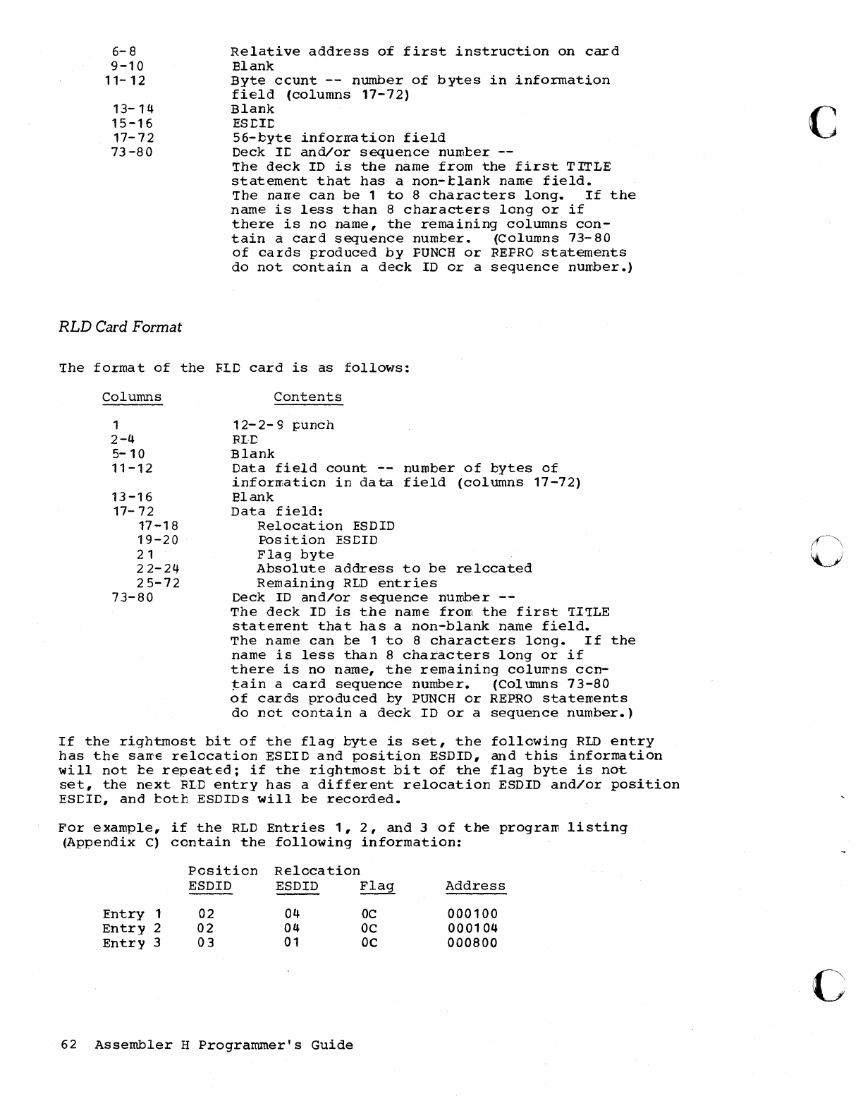
6-8
9-10
11-
12
13-14
15-16
17-72
73-80
RLD
Card Format
Relative
address
of
first
instruction
on
card
Blank
Byte
ccunt
--
number
of
bytes
in
information
field
(columns
17-72)
Blank
ES1:Ir::
56-byte
inforrration
field
Deck
11:
and/or
sequence
nurocer
'Ihe
deck
10
is
the
name
from
the
first
TITLE
statement
that
has
a
non-clank
name
field.
'Ihe
narre
can
be
1
to
8
characters
long.
If
the
name
is
less
than
8
characters
long
or
if
there
is
no
name,
the
remaining
columns
con-
tain
a
card
sequence
number.
~olumns
73-80
of
cards
produced
by
PUNCH
or
REPRO
statements
do
not
contain
a
deck
10
or
a
sequence
nurrber.)
The
forma
t
of
the
FLD
card
is
as
follows:
Columns
1
2-4
5-10
11-12
13
-16
17-72
17-18
19-20
21
22-24
25-72
73-80
Contents
12-2-9
punch
FL·C
Blank
Data
field
count
--
number
of
bytes
of
inforrraticn
in
data
field
(columns
17-72)
Blank
Data
field:
Relocation
ESDID
Position
ESDID
Flag
byte
Absolute
address
to
be
relocated
Remaining
RLD
entries
Deck
ID
and/or
sequence
nurrber
--
The
deok
ID
is
the
name
from
the
first
'II'ILE
staterrent
that
has
a
non-blank
name
field.
The
name
can
ce
1
to
8
characters
long.
If
the
name
is
less
than
8
characters
long
or
if
there
is
no
name,
the
remaining
colu~ns
con-
tain
a
card
sequence
number.
(Columns
73-80
of
cards
produced
by
PUNCH
or
REPRO
statements
do
not
contain
a
deck
ID
or
a
sequence
number.)
If
the
rightmost
bit
of
the
flag
byte
is
set,
the
following
RID
entry
has
the
sarre
relocation
ES1:ID
and
position
ESDID,
and
this
information
will
not
be
repeated;
if
the
rightmost
bit
of
the
flag
byte
is
not
set,
the
next
FLD
entry
has
a
different
relocation
ESDID
and/or
position
ESCID,
and
botb
ESOIDs
will
be
recorded.
For
example,
if
the
RLD
Entries
1,2,
and
3
of
the
program
listing
(Appendix
C)
contain
the
following
information:
Position
Relocation
ESDID
ESDID
---
Flag
Address
Entry
1
02
04
OC
000100
Entry
2
02
04
OC
000104
Entry
3
03
01
OC
000800
62
Assembler
H
Programmer's
Guide
c
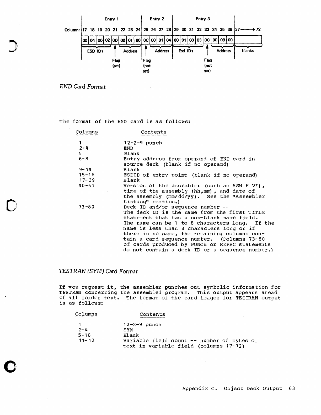
)
o
o
Entry 1 Entry 2 Entry 3
Column:
17
18 19 20
21
22
23
24
25
26
27
28
29
30
31
32 33 34 35
36
37~
72
END
Card Format
Flag
(set)
Flag
(not
set)
Flag
(not
set)
•
blanks
The
format
of
the
END
card
is
as
follows:
Columns
1
2-4
5
6-8
9-14
15-16
17-
39
40-64
73-80
contents
12-2-9
punch
END
Blank
Entry
address
from
operand
of
END
card
in
source
deck
(blank
if
no
operand)
Blank
ESCIC
of
entrY
point
(tlank
if
no
operand)
Blank
Version
of
the
assembler
(such
as
ASM
H
VI)
,
time
of
the
assembly
(hh,mrn) ,
and
date
of
the
assembly
(mm/dd/yy).
See
the
"AsseI'Pbler
Listing"
section.)
Deck
ID
and/or
sequence
nuroter
--
The
deck
ID
is
the
name
from
the
first
TITLE
statement
that
has
a
non-blank
name
field.
'The
name
can
be
1
to
8
characters
long.
If
the
name
is
less
than
8
characters
long
or
if
there
is
no
name,
the
remaining
columns
con-
tain
a
card
sequence
number.
(Columns
73-80
of
cards
produced
by
PUNCH
or
REFRC
statements
do
not
contain
a
deck
ID
or
a
sequence
nurrber.)
TESTRAN
(SYM)
Card Format
If
you
request
it,
the
assembler
punches
out
syrrtclic
infcrmation
for
TESTRAN
concerning
the
assembled
program.
This
output
appears
ahead
cf
all
loader
text.
The
format
of
the
card
images
for
CIESTRAN
output
is
as
follows:
Columns
1
2-4
5-10
11-12
Contents
12-2-9
punch
SYM
Blank
Variable
field
count
--
number
of
bytes
of
text
in
variable
field
(columns
17-72)
Appendix
C.
Object
Deck
Output
63
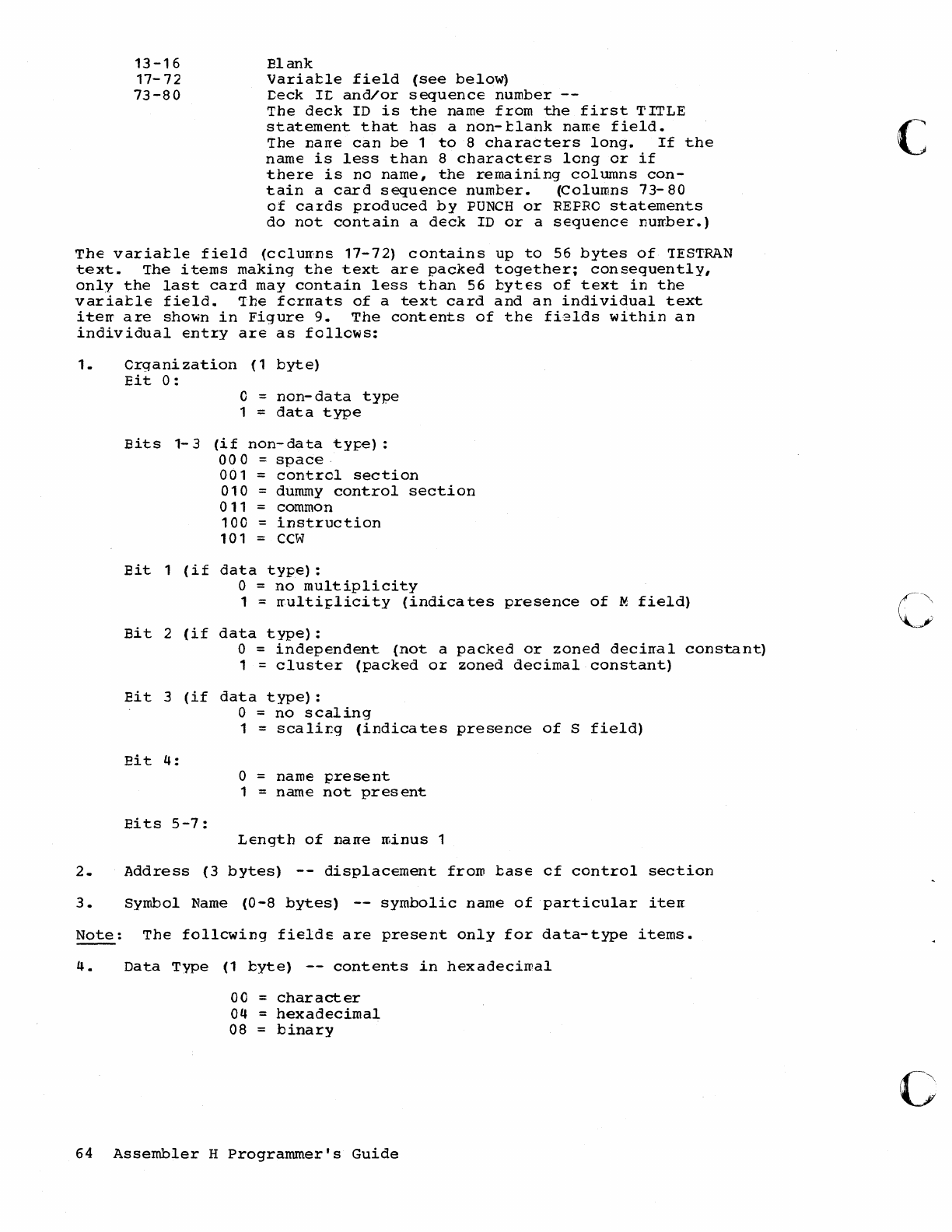
13-16
17-72
73-80
Elank
Variable
field
(see
below)
Ceck
IC
and/or
sequence
number
The
deck
ID
is
the
name
from
the
first
TITLE
statement
that
has
a
non-blank
name
field.
'The
narre
can
be
1
to
8
characters
long.
If
the
name
is
less
than
8
characters
long
or
if
there
is
no
name,
the
remaining
columns
con-
tain
a
card
sequence
number.
(Columns
73-
80
of
cards
produced
by
PUNCH
or
REPRO
statements
do
not
contain
a
deck
ID
or
a
sequence
nurrber.)
The
variatle
field
(cclurr:ns
17-72)
contains
up
to
56
bytes
of
'IES'IRAN
text.
'The
items
making
the
text
are
packed
together;
consequently,
only
the
last
card
may
contain
less
than
56
bytes
of
text
in
the
variatle
field.
'Ihe
fcrrrats
of
a
text
card
and
an
individual
text
iterr
are
shown
in
Figure
9.
The
contents
of
the
fi2lds
within
an
individual
entry
are
as
followS:
1.
erg
ani
zation
(1
byte)
Eit
0:
o =
non-data
type
1 =
data
type
Bits
1-3
(if
non-data
type):
000
space·
001
=
contrel
section
010
= dummy
control
section
011
= common
100
=
instruction
101
CCW
Eit
1
(if
data
type):
o =
no
multiplicity
1 =
rrulti~licity
(indicates
presence
of
M
field)
Bit
2
(if
data
type):
o
independent
(not
a
packed
or
zoned
decirral
constant)
1 =
cluster
(packed
or
zoned
decimal
constant)
Bit
3
(if
data
type):
o =
no
scaling
1 =
scalir.g
(indicates
presence
of
S
field)
Eit
4:
o =
name
pre
se
nt
1
name
not
present
Ei
ts
5-7:
Length
of
narre
minus
1
2.
Address
(3
bytes)
--
displacement
frOID
base
of
control
section
3.
Symbol
Name
(0-8
bytes)
--
symbolic
name
of
particular
iterr
Note:
The
follcwing
fields
are
present
only
for
data-type
items.
4.
Data
Type
(1
byte)
--
contents
in
hexadecimal
00
=
character
04
=
hexadecimal
08
=
binary
64
Assembler
H
Programmer's
Guide
c
c
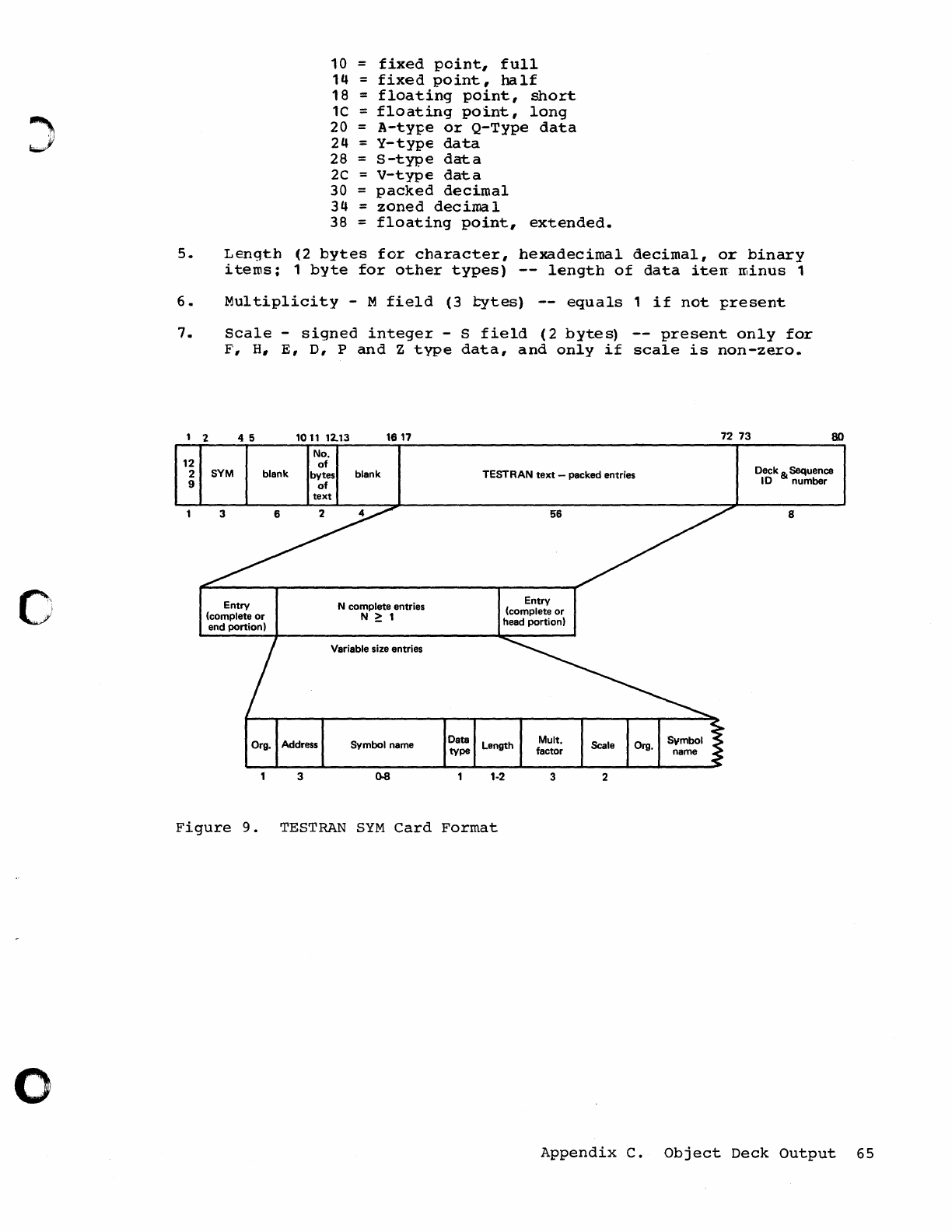
o
10
=
fixed
point,
full
14
=
fixed
point,
half
18
=
floating
point,
short
1C
=
floating
point,
long
20
=
A-ty~e
or
Q-Type
data
24
=
y-type
data
28
=
S-type
data
2C
=
V-type
data
30
=
packed
decimal
34
=
zoned
deciroa
1
38
=
floating
point,
extended.
5.
Length
(2
bytes
for
character,
hexadecimal
decimal,
or
binary
i
terns;
1
byte
for
other
types)
--
length
of
data
iterr
minus
1
6.
Multiplicity
- M
field
(3
tytes)
equals
1
if
not
~resent
7.
Scale
-
signed
integer
- S
field
(2
bytes)
--
present
only
for
F,
H,
E,
D,
P
and
Z
type
data,
and
only
if
scale
is
non-zero.
, 2 4 5
101112.13
1617
72 73
No.
so
12
of
Deck & Sequence
2 SYM blank bytes blank TESTRAN
text
-packed entries 10 number
9
3
of
text
6 2
Org. Address
3
N complete entries
N
~
1
Variable size entries
Symbol name Data
type
56
Entry
(complete or
head
portion)
1-2
3
8
2
Figure
9.
TESTRAN
SYM
Card
Format
Appendix
C.
Object
Deck
Output
65
This
page
intentionally
left
blank.
c
c
66
Assembler
H
Programmer's
Guide
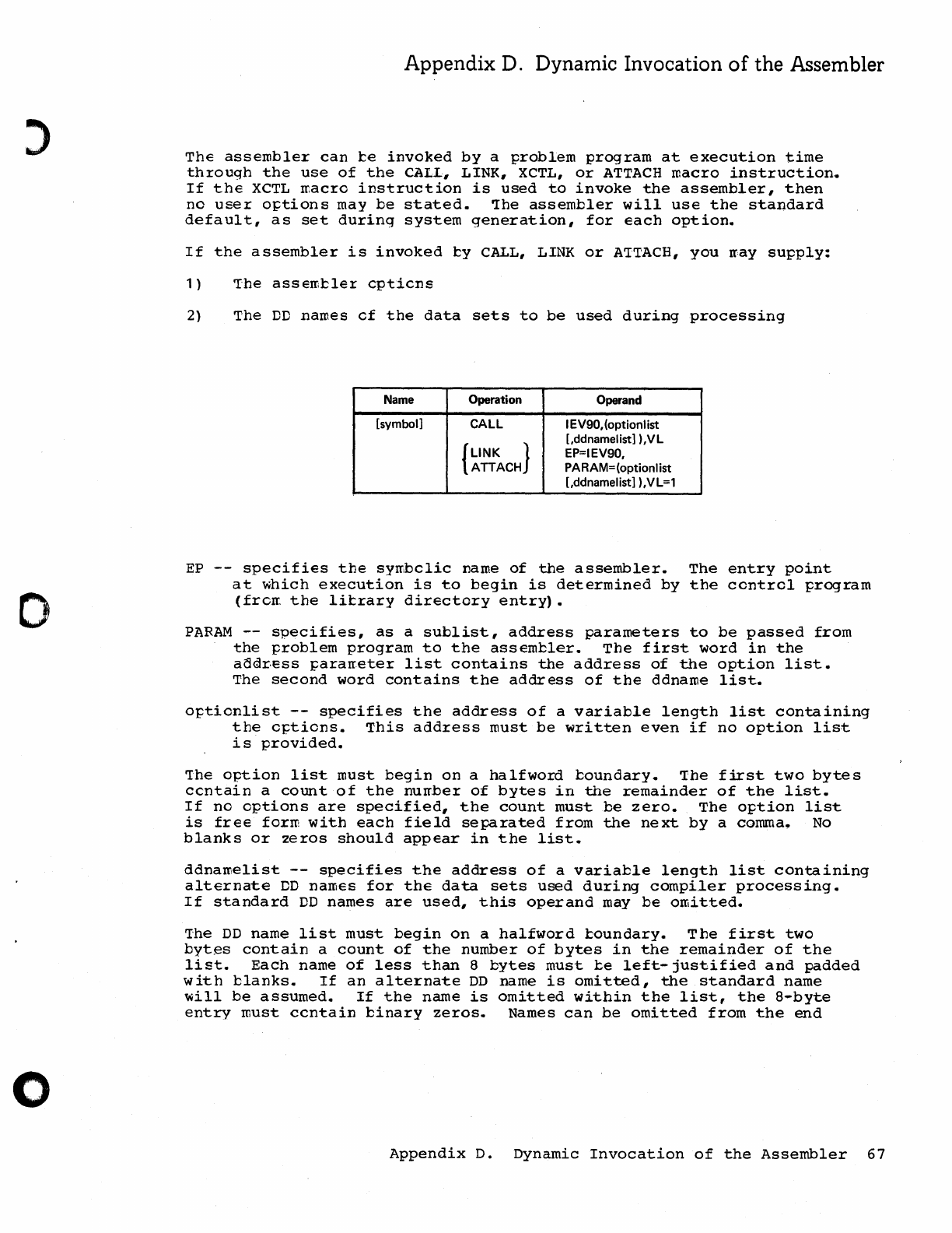
o
o
Appendix D. Dynamic Invocation
of
the Assembler
The
assembler
can
te
invoked
by
a
problem
program
at
execution
time
through
the
use
of
the
CALL,
LINK,
XCTL,
or
ATTACH
macro
instruction.
If
the
XCTL
macro
instruction
is
used
to
invoke
the
assembler,
then
no
user
o~tions
may
be
stated.
~he
assembler
will
use
the
standard
default,
as
set
during
system
generation,
for
each
option.
If
the
assembler
is
invoked
ty
CALL, LINK
or
A'ITACH,
you
rr,ay
supply:
1)
The
assemtler
cpticns
2)
The
DD
names
of
the
data
sets
to
be
used
during
processing
Name Operation Operand
[symbol] CALL I EV90,(optionlist
[,ddnamelistl ),VL
{LINK
} EP=IEV90,
ATTACH PARAM=(optionlist
[,ddnamelistl ),VL=1
EP
--
specifies
the
symbclic
name
of
the
assembler.
The
entry
point
at
which
execution
is
to
begin
is
determined
by
the
control
program
(from
the
litrary
directory
entry).
PARAM
--
specifies,
as
a
sublist,
address
parameters
to
be
passed
from
the
problem
program
to
the
assembler.
The
first
word
in
the
adGir.ess
~ararreter
list
contains
the
address
of
the
option
list.
The
second
word
contains
the
address
of
the
ddname
list.
o~tionlist
--
specifies
the
address
of
a
variable
length
list
containing
the
options.
This
address
must
be
written
even
if
no
option
list
is
provided.
'The
option
list
must
begin
on
a
ha1fword
boundary.
The
first
two
bytes
ccntain
a
count
of
the
nurr,ber
of
bytes
in
the
remainder
of
the
list.
If
no
options
are
specified,
the
count
must
be
zero.
The
option
list
is
free
form
with
each
field
separated
from
the
next
by
a comma.
No
blanks
or
2eros
should
appear
in
the
list.
ddnamelist
--
specifies
the
address
of
a
variable
length
list
containing
alternate
DD
names
for
the
data
sets
used
during
compiler
processing.
If
standard
DD
names
are
used,
this
operand
may
be
omitted.
The
DD
name
list
must
begin
on
a
halfword
toundary.
The
first
two
byt~s
contain
a
count
of
the
number
of
bytes
in
the
remainder
of
the
list.
Each
name
of
less
than
8
bytes
must
be
left-justified
and
padded
with
blanks.
If
an
alternate
DD
name
is
omitted,
the
standard
name
will
be
assumed.
If
the
name
is
omitted
within
the
list,
the
8-byte
entry
must
ccntain
binary
zeros.
Names
can
b.e
omitted
from
the
end
Appendix
D.
Dynamic
Invocation
of
the
Assembler
67
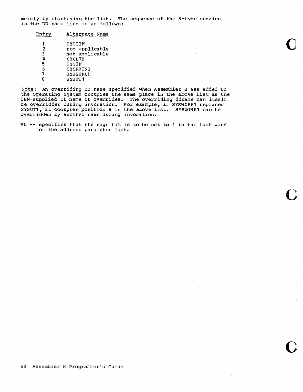
merely
ty
shortening
the
list.
The
sequence
of
the
a-byte
entries
in
the
DD
name
list
is
as
follows:
Entry
1
2
3
4
5
6
7
a
Alternate
Name
SYSI.IN
not
applicable
not
applicatle
SYSLIB
SYSIN
SYSPRIN'I
SYSFUNCH
SYSUT1
Note:
An
overriding
DD
nane
specified
when
Assembler
H
was
added
to
the
Operating
System
occupies
the
same
place
in
the
above
list
as
the
IBM-supplied
DC
name
it
overrides.
The
overriding
ddname
can
itself
te
overridden
during
invccatidn.
For
exam~le,
if
SYSWORK1
replaced
SYSUT1,
it
occupies
position
a
in
the
above
list.
SYSWORK1
can
be
overridden
ty
ancther
narre
during
invocation.
VL
--
specifies
that
the
sign
bit
is
to
be
set
to
1
in
the
last
word
of
the
address
parameter
list.
68
Assembler
H
Programmer's
Guide
c
o
o
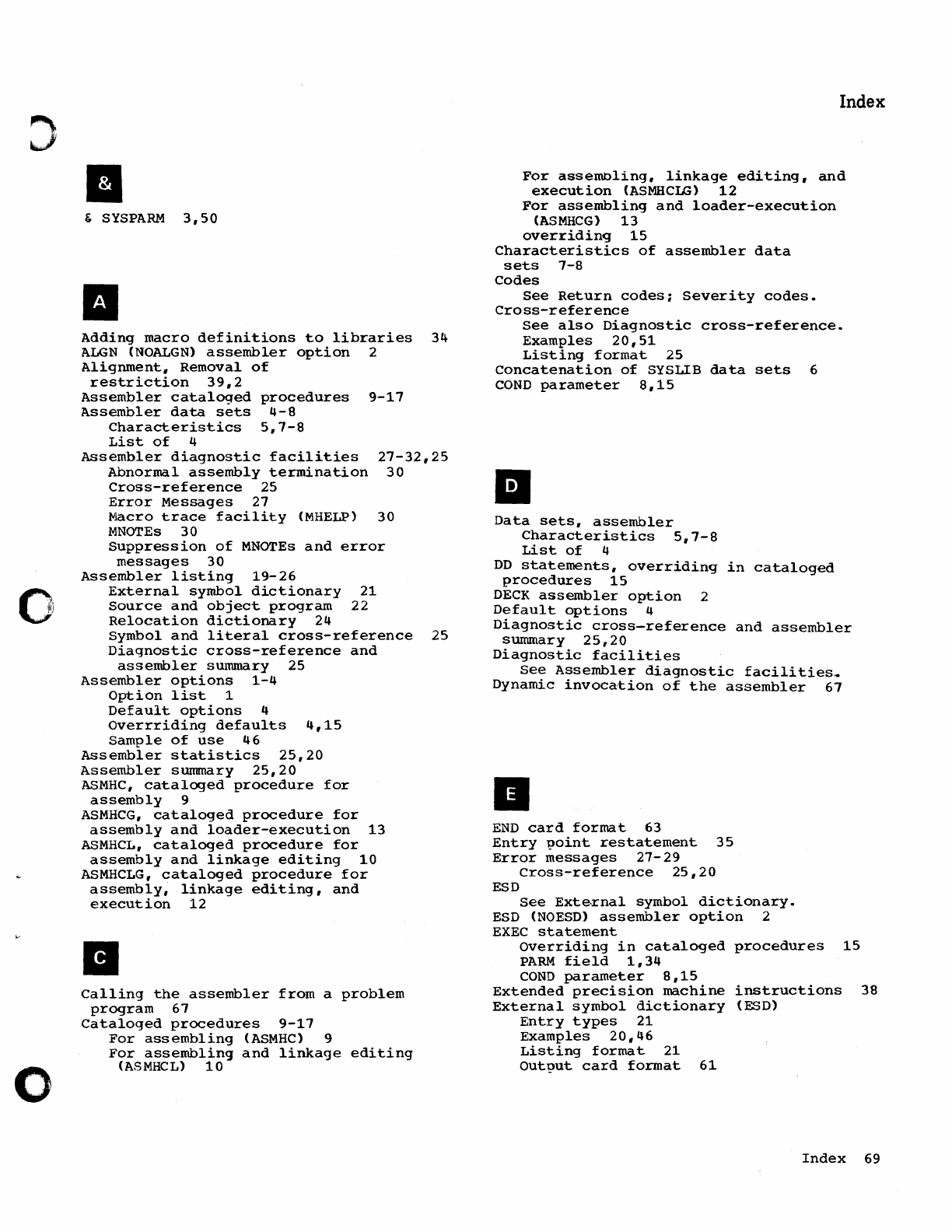
o
II
&
SYSPARM
3,50
II
Adding
macro
definitions
to
libraries
34
ALGN
(NOALGN)
assembler
option
2
Alignment,
Removal
of
restriction
39,2
Assembler
cataloqed
procedures
9-17
Assembler
data
sets
4-8
Characteristics
5,7-8
List
of
4
Assembler
diagnostic
facilities
27-32,25
Abnormal
assembly
termination
30
Cross-reference
25
Error
Messages
27
Macro
trace
facility
(MHELP)
30
MNOTEs
30
suppression
of
MNOTEs
and
error
messages
30
Assembler
listing
19-26
External
symbol
dictionary
21
Source
and
object
program
22
Relocation
dictionary
24
Symbol
and
literal
cross-reference
25
Diagnostic
cross-reference
and
assembler
summary
25
Assembler
options
1-4
Option
list
1
Default
options
4
Overrriding
defaults
4,15
Sample
of
use
46
Assembler
statistics
25,20
Assembler
summary
25,20
ASMHC,
cataloged
procedure
for
assembly
9
ASMHCG,
cataloged
procedure
for
assembly
and
loader-execution
13
ASMHCL,
cataloged
procedure
for
assembly
and
linkage
editing
10
ASMHCLG,
cataloged
procedure
for
assembly,
linkage
editing,
and
execution
12
II
Calling
the
assembler
from
a
problem
program
67
Cataloged
procedures
9-17
For
assembling
(ASMHC)
9
For
assembling
and
linkage
editing
(ASMHCL)
10
Index
For
assemnling,
linkage
editing,
and
execution
(ASMHCLG)
12
For
assembling
and
loader-execution
(ASMHCG)
13
overridinq
15
Characteristics
of
assembler
data
sets
7-8
Codes
See
Return
codes;
Severity
codes.
Cross-reference
See
also
Diagnostic
cross-reference.
Examples
20,51
Listing
format
25
Concatenation
of
SYSLIB
data
sets
6
COND
parameter
8,15
iii
Data
sets,
assembler
Characteristics
5,7-8
List
of
4
DD
statements,
overriding
in
cataloged
procedures
15
DECK
assembler
option
2
Default
options
4
Diagnostic
cross-reference
and
assembler
summary
25,20
Diagnostic
facilities
See
Assembler
diagnostic
facilities
.•
Dynamic
invocation
of
the
assembler
67
II
END
card
format
63
Entry
point
restatement
35
Error
messages
27-29
Cross-reference
25,20
ESD
See
External
symbol
dictionary.
ESD
(NOESD)
assembler
option
2
EXEC
statement
Overriding
in
cataloged
procedures
15
PARM
field
1,34
COND
parameter
8,15
Extended
precision
machine
instructions
38
External
symbol
dictionary
(ESD)
Entry
types
21
Examples
20,46
Listing
format
21
output
card
format
61
Index
69
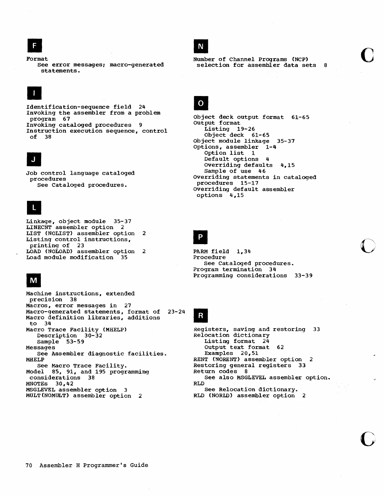
II
Format
See
error
messages;
macro-generated
statements.
a
Identification-sequence
field
24
Invoking
the
assembler
from
a
problem
program
67
Invoking
cataloged
procedures
9
Instruction
execution
sequence,
control
of
38
II
Job
control
language
cataloged
procedures
See
Cataloged
procedures.
..
Linkage,
object
module
35-37
LINECNT
assembler
option
2
LIST
(NOLIST)
assembler
option
2
Listing
control
instructions,
printing
of
23
LOAD
(NOLOAD)
assembler
option
2
Load
module
modification
35
II
Machine
instructions,
extended
precision
38
Macros,
error
messages
in
27
Macro-generated
statements,
format
of
23-24
Macro
definition
libraries,
additions
to
34
Macro
Trace
Facility
(MHELP)
Description
30-32
Sample
53-59
Messages
See
Assembler
diagnostic
facilities.
MHELP
See
Macro
Trace
Facility.
Model
85,
91,
and
195
programming
considerations
38
MNOTEs
30,42
MSGLEVEL
assembler
option
3
MULT(NOMULT)
assembler
option
2
70
Assembler
H
Programmer's
Guide
II
Number
of
Channel
Programs
(NCP)
selection
for
assembler
data
sets
8
II
Object
deck
output
format
61-65
Output
format
Listing
19-26
Object
deck
61-65
Object
module
linkage
35-37
Options,
assembler
1-4
Option
list
1
Default
options
4
Overriding
defaults
4,15
Sample
of
use
46
Overriding
statements
in
cataloged
procedures
15-17
Overriding
default
assembler
options
4,15
•
PARM
field
1,34
Procedure
See
Cataloged
procedures.
Program
termination
34
Programming
considerations
33-39
II
~egisters,
saving
and
restoring
33
Relocation
dictionary
Listing
format
24
Output
text
format
62
Examples
20,51
RENT
(NORENT)
assembler
option
2
Restoring
general
registers
33
Return
codes
8
See
also
MSGLEVEL
assembler
option.
RLD
See
Relocation
dictionary.
RLD
(NORLD)
assembler
option
2
c
o
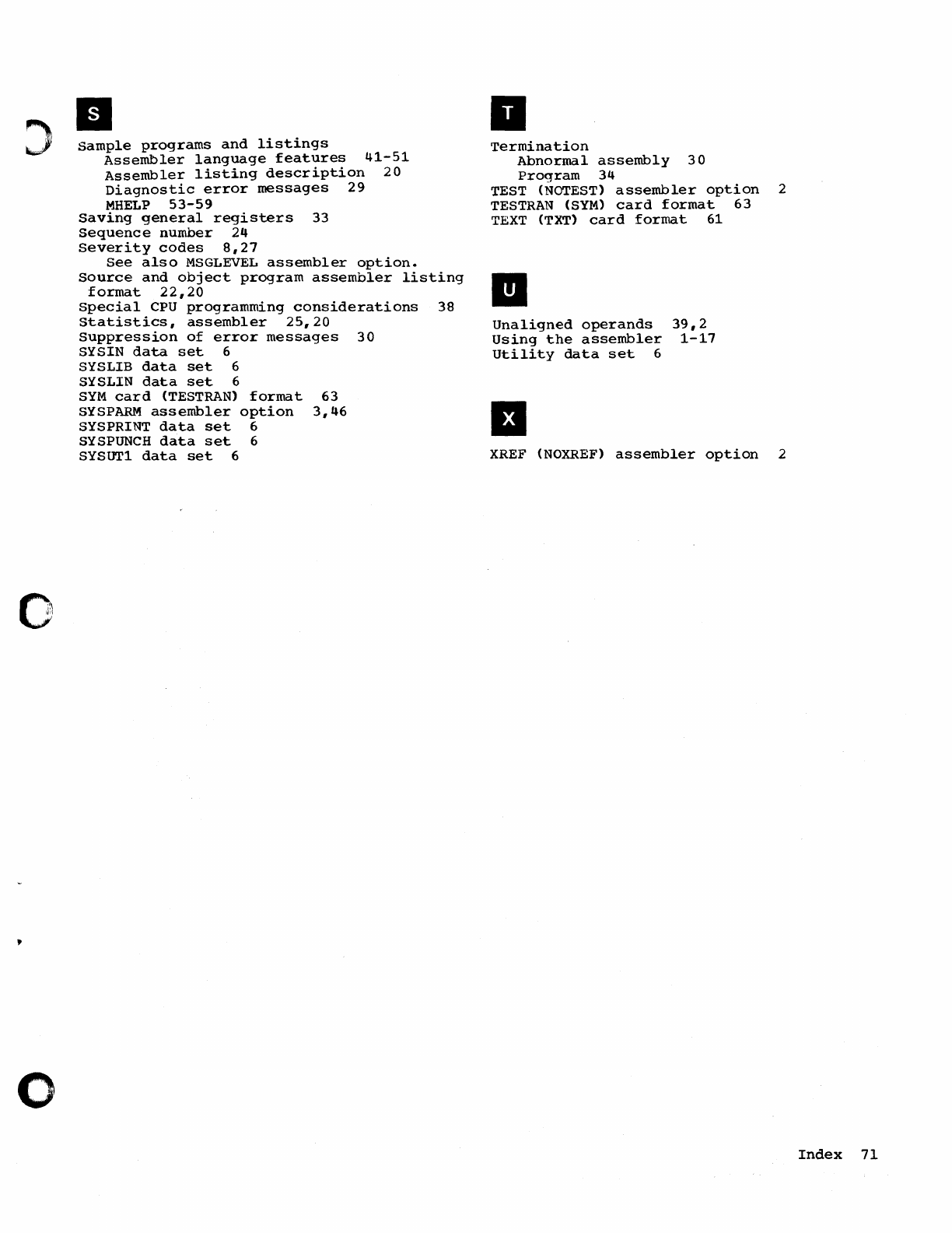
D
::>
sample
programs
and
listings
Assembler
language
features
41-51
Assembler
listing
description
20
Diagnostic
error
messages
29
MHELP
53-59
0,
I~
I'.
o
saving
general
registers
33
Sequence
number
24
Severity
codes
8,27
See
also
MSGLEVEL
assembler
option.
Source
and
object
program
assembler
listing
format
22,20
special
CPU
programming
considerations
38
Statistics,
assembler
25,20
Suppression
of
error
messages
30
SYSIN
data
set
6
SYSLIB
data
set
6
SYSLIN
data
set
6
SYM
card
(TESTRAN)
format
63
SYSPARM
assembler
option
3,46
SYSPRINT
data
set
6
SYSPUNCH
data
set
6
SYSUT1
data
set
6
a
Termination
Abnormal
assembly
30
Program
34
TEST (NOTEST)
assembler
option
TESTRAN
(SYM)
card
format
63
TEXT
(TXT)
card
format
61
Unaligned
operands
Using
the
assembler
Utility
data
set
6
•
39,2
1-17
XREF
(NOXREF)
assembler
option
2
2
Index
71
SC26-3759-0
YOUR COMMENTS, PLEASE
...
This publication
is
one
of
a series which serves
as
a reference source for systems analysts,
programmers, and operators
of
IBM
systems. Your answers to the questions on the back
of
this form, together with your comments, will help
us
produce better publications for your
use. Each reply will be carefully reviewed by the persons responsible for writing and
publishing this material.
All
comments and suggestions become the property
of
IBM.
Please note: Requests for copies
of
publications and for assistance in utilizing your
IBM
system should be directed to your
IBM
representative or
to
the
IBM
sales office serving
your locality.
fold
fold
BUSINESS REPLY MAIL
NO POSTAGE STAMP NECESSARY
IF
MAILED IN
U.
S.
A.
POSTAGE WILL BE PAID
BY
.
IBM
Corporation
Department 813
112 East Post Road
White Plains, New York
10601
International
Business
Machines
Corporation
Data
Processing
Division
112
East
Post
Road,
White
Plains,
N.Y.
10601
[USA Only]
IBM World
Trade
Corporation
821 United
Nations
Plaza,
New
York,
New
York
10017
[International]
fold
FIRST CLASS
PERMIT NO. 1359
WHITE PLAINS, N.Y.
fold
c
c
~
~.
(1)
c.
5'
~
c
en
):.
C/) •
()
I\.)
q>
w
"
(J1
co
6
o
)
o
READER'S
COMMENT
FORM
IBM
SYSTEM/360 OPERATING SYSTEM
ASSEMBLER H PROGRAMMER'S GUIDE
SC26-37S9-0
Please comment on the usefulness and readability
of
this book, suggest additions and deletions,
and list specific errors and omissions (give page numbers).
All
comments and suggestions become
the property
of
IBM.
If
you
want a reply, be sure
to
give
your name and address.
Name
_____________
Occupation
_________________
_
Address
___________________________________________
_
Thank
you
for
your
cooperation. No postage necessary
if
mailed in the U.S.A.
SC26-3759-0
YOUR
COMMENTS, PLEASE
...
This publication
is
one
of
a series which serves
as-
a reference source for systems analysts,
programmers, and operators
of
IBM
systems. Your answers
to
the questions on the back
of
this form, together with your comments, will help
us
produce better publications for your
use. Each reply
will
be carefully reviewed by the persons responsible for writing and
publishing this material.
All
comments and suggestions become the property
of
IBM.
Please note: Requests for copies
of
publications and for assistance in utilizing
your
IBM
system should be directed to your
IBM
representative or to the
IBM
sales office serving
your
locality.
fold
fold
BUSINESS REPLY MAIL
NO POSTAGE STAMP NECESSARY
IF
MAILED IN U.
S.
A.
POSTAGE WILL BE PAID BY .
IBM
Corporation
Department 813
112 East Post Road
White Plains, New York
10601
International
Business
Machines
Corporation
Data
Processing
Division
112
East
Post
Road,
White
Plains,
N.Y.
10601
[USA Only)
IBM World
Trade
Corporation
821 United
Nations
Plaza,
New York, New York
10017
[
International]
fold
FIRST CLASS
PERMIT NO. 1359
WHITE PLAINS, N.Y.
fold
(
c
~
:;'
....
CI)
0.
:;'
...
c
en
?>
en
•
(")
I\,)
0')
w
.....
CJ1
co
6
