SCA830 D07 Inclinometer Datasheet 82 823 00 D
SCA830-D07_Inclinometer_Datasheet_82-823-00-D
User Manual:
Open the PDF directly: View PDF ![]() .
.
Page Count: 5
1 (5)
Murata Electronics Oy
SCA830-D07
Doc. No. 82 823 00 D
www.murata.com
Features
3.3V supply voltage
1 g measurement range
Single axis measurement in Y direction
30mg offset accuracy over temp range
SPI digital interface
Extensive self diagnostics features
Size 7.6 x 3.3 x 8.6 mm (w x h x l)
Qualified according to AEC-Q100 standard
Package, pin-out and SPI protocol compatible
with VTI digital accelerometer product family
RoHS compliant Dual Flat Lead (DFL) plastic
package suitable for lead free soldering
process and SMD mounting
Proven capacitive 3D-MEMS technology
High resolution 16-bit A/D converter
Applications
The SCA830-D07 is targeted to applications with
high stability requirements. Typical applications
include
Hill Start Aid (HSA)
Electronic Parking Brake (EPB)
Roll Over detection
Suspension control
Inclinometers
Motion and position measurements
General Description
The SCA830-D07 is a single axis inclinometer component based on VTI's capacitive 3D-MEMS
technology. The component integrates high accuracy micromechanical acceleration sensing together
with a flexible SPI digital interface. Dual Flat Lead (DFL) housing guarantees reliable operation over
product lifetime.
The SCA830-D07 is designed, manufactured and tested for high stability, reliability and quality
requirements of automotive applications. The inclinometer has an extremely stable output over wide
ranges of temperature, humidity and mechanical noise. The component is qualified to the AEC-Q100
standard and has several advanced self diagnostics features. The DFL housing is suitable for SMD
mounting and the component is compatible with the RoHS and ELV directives.
The SCA830-D07 is a part of VTI's digital accelerometer family and fully compatible with its single
axis accelerometers (SCA800 Series) and other multi axis accelerometers (SCA2100 Series and
SCA3100 Series).
DATA SHEET
SCA830-D07 1-AXIS INCLINOMETER WITH DIGITAL SPI INTERFACE
2 (5)
Murata Electronics Oy
SCA830-D07
Doc. No. 82 823 00 D
www.murata.com
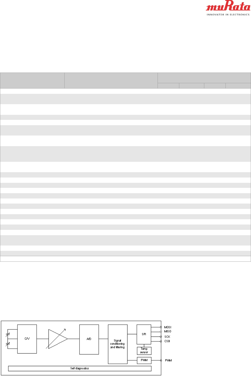
MOSI
MISO
SCK
CSB
C/V A/D Signal
conditioning
and filtering
SPI
Self diagnostics
PWM PWM
Temp
sensor
Performance Characteristics
Vdd=3.3 V and ambient temperature unless otherwise specified.
Parameter
Condition
Min
Typ A)
Max
Units
Analog and digital Vdd
3.0
3.6
V
Current consumption
Active mode
Power down mode
5
6.3
0.1
mA
mA
Measurement range
Measurement axis (Y)
-1
-90
1
+90
g
°
Operating temperature
-40
125
°C
Total offset error B)
Temperature range -40 ... +125 °C
-70
+70
mg
Offset stability C)
Temperature range -40 ... +125 °C
-25
-1.5
25
1.5
mg
°
Offset calibration error D)
@25°C
±20
±1.1
mg
°
Offset temperature drift
Temperature range -40 ... +125 °C
Temperature range -20 ... +85 °C
±13 F)
±0.85
30 E)
mg
mg
°
Sensitivity
16 bit output
between ±3°
32 000
0.00179
Count/g
°/Count
Total sensitivity error
Temperature range -40 ... +125 °C
-4
4
% FS
Sensitivity calibration error
@25 °C ±5°C
±1.4
% FS
Sensitivity temperature drift
Temperature range -40 ... +125 °C
±0.9
% FS
Linearity error
+1g ... -1g range
-20
20
mg
Cross-Axis sensitivity
±2
±3.5
%
Zero acceleration output
2-complement
0
Counts
Amplitude response
-3dB frequency
6.25
Hz
Noise
0.15
5
mg RMS
Power on setup time
0.3
s
Output data rate
125
Hz
Output load
50
pF
SPI clock rate
8
MHz
ESD protection
Human Body Model
Charge Device Model
2
1
kV
kV
Moisture sensitivity level
IPC/JEDEC J-STD-020C, Level 3
Mechanical shock
20 000
g
ID register value
Customer readable ID register (27hex)
0A
A) Typical ± values are ±3 sigma variation limits from validation test population.
B) Includes offset deviation from 0g value including calibration error and drift over lifetime, temperature and
supply voltage.
C) After mounting of ECU the application and after offset zero-setting at room temperature. Relevant
offset failure due to temperature dependency of offset as well as aging over lifetime
D) Includes offset deviation from 0g value including calibration error and drift over lifetime.
E) Offset drift due to temperature. Value is a relative value and has been centered to zero. Error defined as
maximum change of offset in temperature range. Offset (max)-Offset Min). 100% tested in production.
F) Biggest change of output from RT value due temperature.
Figure 1. SCA830-D07 Block diagram

3 (5)
Murata Electronics Oy
SCA830-D07
Doc. No. 82 823 00 D
www.murata.com
Typical Performance characteristics
Offset calibration error
0
5
10
15
20
25
30
35
40
-25 -20 -15 -10 -5 0 5 10 15 20 25 30 35
Offset [m g]
Percent of parts[%]
Temperature dependency of offset
-20
-15
-10
-5
0
5
10
15
20
25
30
-45 -20 5 30 55 80 105 130
Temp [oC]
Offset[mg]
+3 Sigma
Mean
-3 Sigma
Offset drift at temperature range
-40oC…+125oC
0
5
10
15
20
25
30
-25 -20 -15 -10 -5 0 5 10 15 20 25 30 35
Offset drift [mg]
Percent of parts[%]
Sensitivity at 25oC
0
5
10
15
20
25
30
35
40
45
50
31300 31450 31600 31750 31900 32050 32200 32350 32500 32650 32800
Sensitivity [LSB/g]
Percent of parts[%]
Sensitivity drift at temperature range
-40oC…+125oC
0
5
10
15
20
25
30
35
40
45
50
-0.9 -0.8 -0.7 -0.6 -0.5 -0.4 -0.3 -0.2 -0.1 0 0.1
Sensitivity error [% FS]
Percent of parts[%]
4 (5)
Murata Electronics Oy
SCA830-D07
Doc. No. 82 823 00 D
www.murata.com
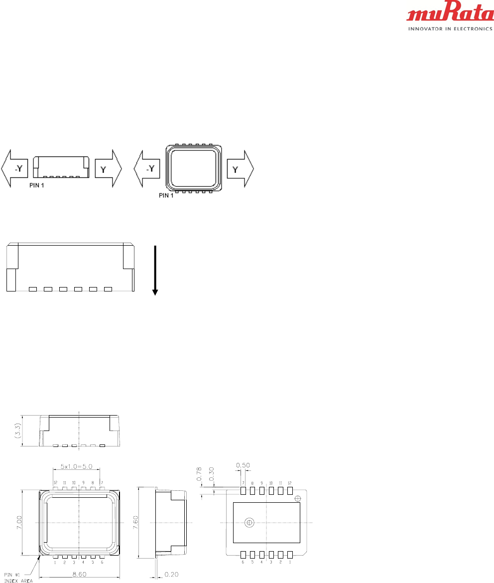
Measurement directions
Figure 2. Accelerometer measuring directions
PIN 1
Figure 3. Zero acceleration output position
Housing dimensions
Figure 4. Housing dimensions
Earth gravitation
5 (5)
Murata Electronics Oy
SCA830-D07
Doc. No. 82 823 00 D
www.murata.com
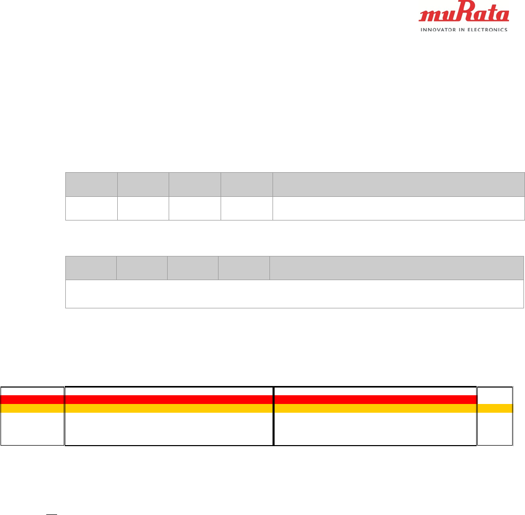
Application Note for Acceleration Output Reading (16 bit output sensitivity)
This is addition to SCA8X0_21X0_3100 Product Family Specification chapter 3.1.
DOUT_LSB Address: 4h
Bits
Mode
Initial
Value
Name
Description
7:0
R
00h
DATA
Acceleration data LSB frame
Read always DOUT_MSB prior to DOUT_LSB.
DOUT_MSB Address: 5h
Bits
Mode
Initial
Value
Name
Description
7:0
R
00h
DATA
Acceleration data MSB frame
Reading of this register latches DOUT_LSB.
The bit level description of acceleration data from DOUT_LSB ... DOUT_MSB registers is presented
below. The acceleration data is presented in 2's complement format. At 0 g acceleration the output is
ideally 0000h.
+/-1g product DOUT MSB bits(7:0) DOUT LSB bits(7:0) 16b
Bit number
15 14 13 12 11 10 9 8 7 6 5 4 3 2 1 0 [-] Bits (15:0)
SCA8xx s 512,0 256,0 128,0 64,0 32,0 16,0 8,0 4,00 2,00 1,00 0,50 0,25 0,13 0,06 0,03 [mg] [Dec]
+1g position 0 1 1 1 1 1 0 1 0 0 0 0 0 0 0 0 1000 32000
-1g position 1 0 0 0 0 0 1 1 0 0 0 0 0 0 0 0 -1000 -32000
+Full-scale 0 1 1 1 1 1 1 1 1 1 1 1 1 1 1 1 1023 32767
-Full-scale 1 0 0 0 0 0 0 0 0 0 0 0 0 0 0 0 -1024 -32768
s = sign bit
Acceleration bits can be converted to mg acceleration (Acc) using following equation
02122
232425262728292102112122132142
32
1
13
4456789101112131415
bbb
bbbbbbbbbbbbs
mgAcc
