SDUser Guide
User Manual: SDUserGuide
Open the PDF directly: View PDF ![]() .
.
Page Count: 76

SD Range
Installation and
Operation Guide

Dedicated Micros ©2007
2
SD Range
Whilst every attempt is made to ensure these manuals are accurate and current, Dedicated Micros reserve the right to alter or
Contents
Introduction3
Features4
Important Safeguards5
Installing the Unit7
Installation10
Remote Control12
21
Status22
General23
Cameras24
Schedule26
Recording27
32
Alarms35
Activity38
Serial43
Audio44
Text45
Admin47
Maintain49
Demos50
Help51
Unit Operation52
Event List58
Copy Menu60
62
Appendix A66
Appendix B67
Appendix C69

Dedicated Micros ©2007 3
SD Range
Introduction
What is …
SD Range ?
A comprehensive, digital recording solution, the SD Range allows customers to improve the
functionality of their CCTV solution without increasing their budget.Offering either JPEG or
MPEG-4 recording at scalable quality settings in PAL or NTSC format, the SD Range provides the
user with both high quality video images and minimum storage consumption.
Available with either 8, 12, 16 or 32* camera inputs and offering telemetry control, the SD range has
built in Alarm functionality and onboard Activity detection software. The MultiMode recording feature recording feature
enables different recording rates, resolutions and compression formats to be set across scheduled,
normal, and alarm modes for each individual camera.
Its size and design enables it to be an ideal desktop solution, a perfect replacement for an existing
VCR/Mux installation, or an outstanding rst-time CCTV solution.
The user interface has a colour coded ‘Softkey’ interface and the conguration menus are common
to both the local monitor and web interface, making for easy set-up and operation.
The SD Range includes both an integrated CD-R Writer and USB ports for video archiving. The unit
also offers integrated text support, allowing users to connect with cash registers in retail applications
to monitor Point Of Sale (POS) locations. Capturing and associating video with the relevant text
information allows the user to search video footage by time, event, and text data to provide evidence
of fraud or to aid identication of regular offenders.
Among the many other features included as standard on the SD Range are; multiway display, picture
in picture viewing, remote monitoring using NetVu ObserVer, which uses DM’s unique TransCoding
capabillities to provide uent live and replay images, plus Dedicated Micros’ trademark plug and play
set-up with a user-friendly interface to keep installation and operator training to a minimum.
With telemetry control of up to 32 cameras, including coax telemetry, control of dome cameras,
audio recording and activity detection. The SD Range is the ideal product for single site and small to
medium sized businesses wishing to deploy a fully functional digital recording solution.
* 4 camera input model available after future development.
For further information, please visit the website:
www.dedicatedmicros.com
or contact customer services in your region.

Dedicated Micros ©2007
4
SD Range
Features
• 8, 12, 16 or 32 camera input options ( 8, 12, 16 or 32 camera input options (4 camera input model available after future
development)
• Telemetry support (Coax & Serial) Telemetry support (Coax & Serial)
• MultiMode
• Built in activity detection Built in activity detection
memory
• Alarm Inputs & Outputs Alarm Inputs & Outputs
• BS8418 compliant BS8418 compliant
• Text support and text search features ideal for retail installations Text support and text search features ideal for retail installations
Design of the manual
The manual has three parts:
Dedicated Micros ©2007 5
SD Range
Important Safeguards
Read Instructions
Power Sources
Servicing
Do not attempt to service this unit yourself as opening or removing covers may expose you to
Ventilation
Lightning Strike
Regulatory Notes and FCC and DOC Information
(USA and Canadian Models Only)
Dedicated Micros ©2007
6
SD Range
CE Mark
Laser
• To prevent exposure to laser emanations (harmful to the eyes), do not attempt to

Dedicated Micros ©2007 7
SD Range
Installing the Unit
Before you start
Check the contents of the box
The following items are included in the box:
• SD DVR (either 8, 12, 16 or 32 input)
• IR Remote Control (x 2)
• IR Remote Control Extender
Note: Before installing the SD DVR, carefully read all Safety Instructions and the following
information on where the unit should be located.
Choosing a location for installation
• Ensure the IR receiver on the front of the unit faces the operator position, and is not
more than 10 feet (3
Electrical Connections
Please ensure the following are available and have been tested prior to the installation:
• Mains point

Dedicated Micros ©2007
8
SD Range
Quick Overview Of Default SD Record Settings
SD units provide out of the box:
High performance recording on ALL cameras with minimal conguration.
Consistent recording duration and smooth motion video per camera regardless of the number of
cameras.
The product range has Normal, Medium and Low record rate models.
Normal
Medium
Low
Complete Flexibility
Note: It is the Installer/Owner’s responsibilty to ensure that the record duration is set to the
necessary requirements of the application.
MultiMode Recording
The unit supports MultiMode recording, which is a storage technology developed by Dedicated
Micros. This offers the ability to set different recording rates, resolutions and compression formats
across scheduled, normal and alarm modes for each individual camera.
By varying the quality, bit rate and le size of the recorded images, the MultiMode function can
increase recording capabilities of the unit.
MultiMode offers:
Differences between MPEG-4 and MJPEG(JPEG)

Dedicated Micros ©2007 9
SD Range
MPEG-4 is used primarily to compress audio and visual (AV) digital data (moving images and
Note: Dedicated Micros recommends using MPEG4 as a background recording setting; switching
to MJPEG on event or alarm.
Dedicated Micros ©2007
10
SD Range
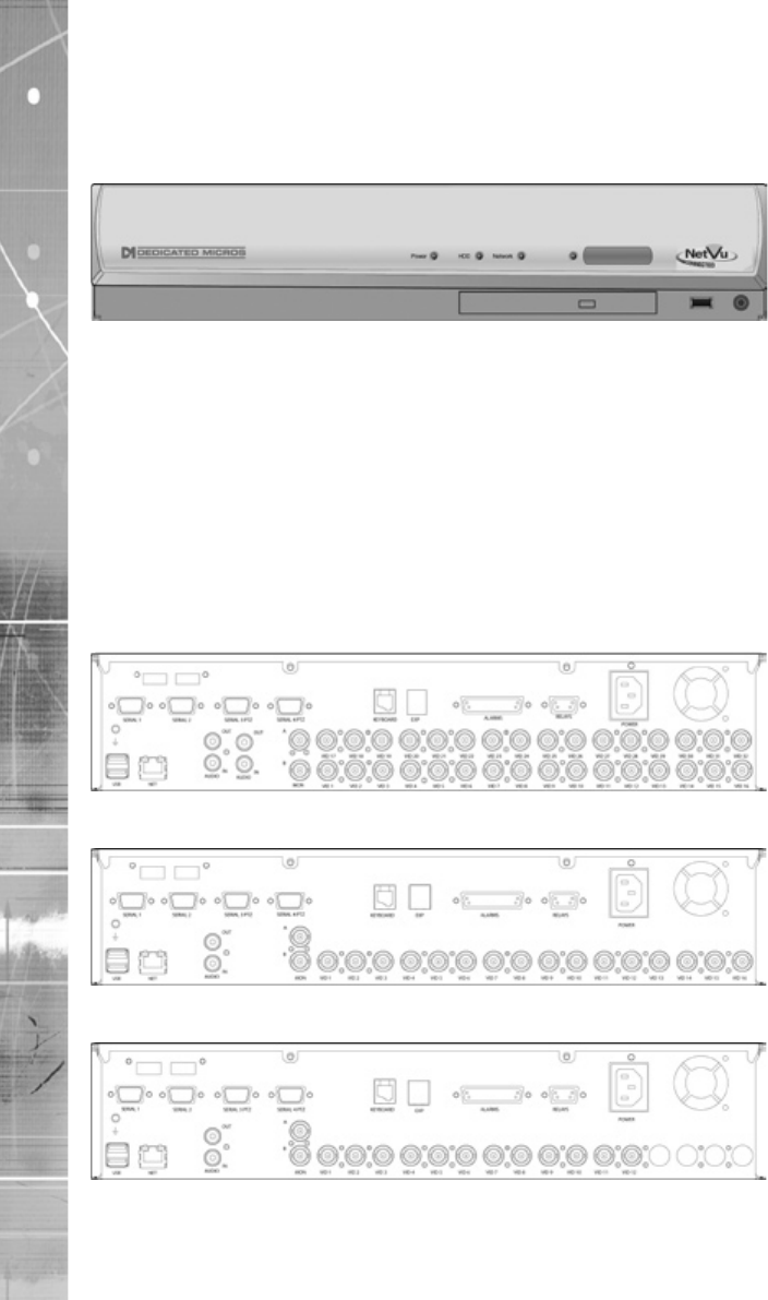
Installation
Front Panel connections
Data
internal unit
Rear Panel connections
32 Input model
16 Input model
12 Input model
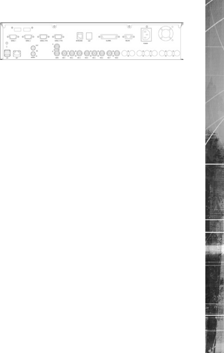
Dedicated Micros ©2007 11
SD Range
8 Input model
Video
MON B Spot Monitor outputMONIOONITOO
Audio
input
Note: The 32 input model has two Audio IN / Audio OUT connections.
Data
Power
Alarms and relays
Range of Alarm states are
Dedicated Micros ©2007
12
SD Range
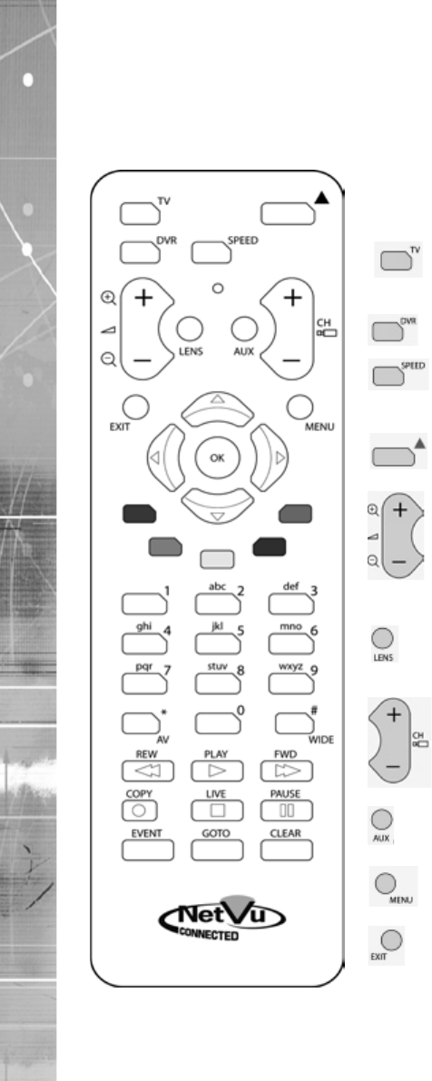
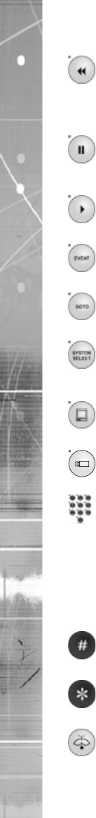
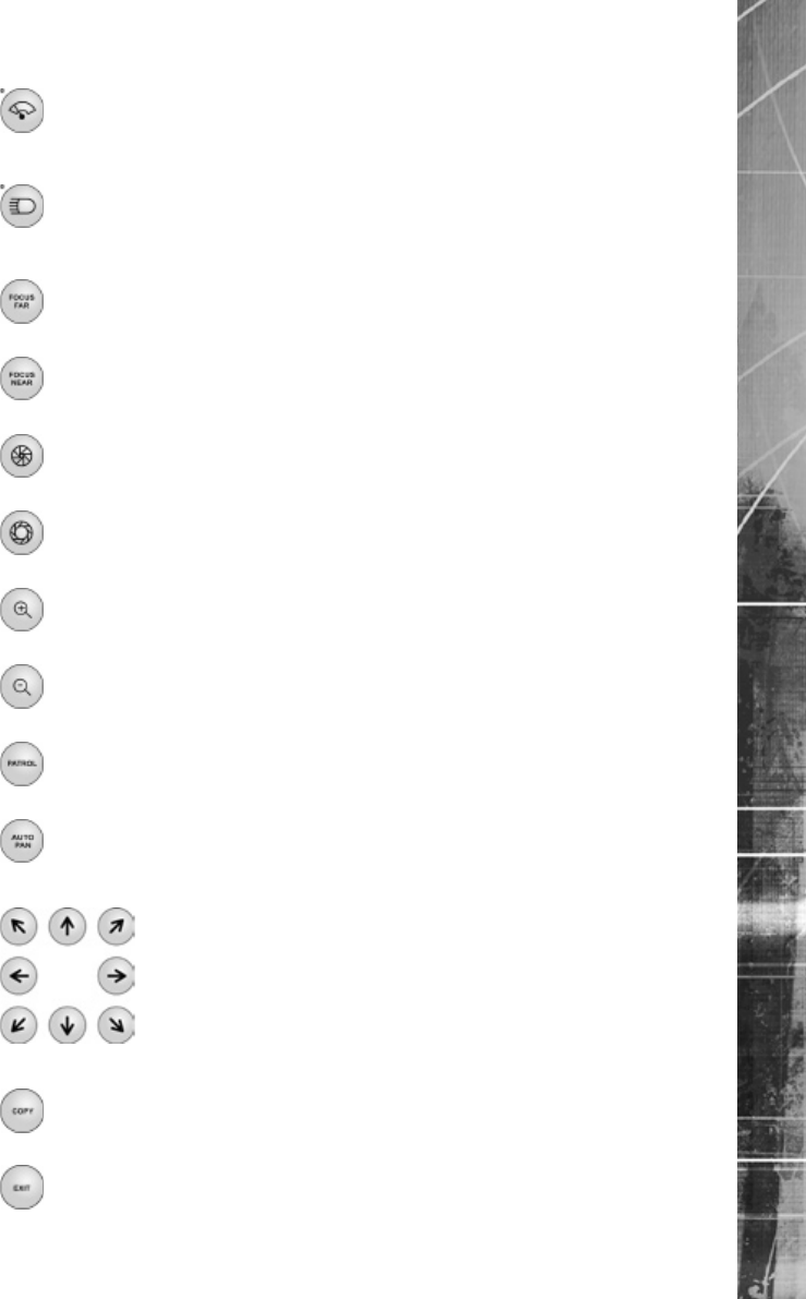
Remote Control
The IR Remote Control offers all the control functionality traditionally available via front panel
navigation.
Button Guide
Key Function
Toggle the speed of PTZ camera
This
operation to focus or iris functions
carry out auxiliary actions on a PTZ
Dedicated Micros ©2007 13
SD Range
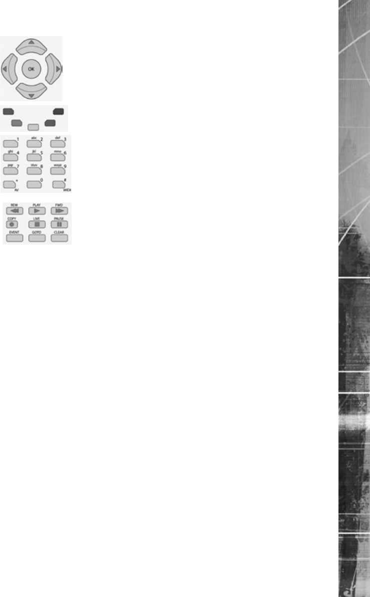
How to navigate the pages
Using the IR Remote Control
Using a USB Mouse or the webpages

Dedicated Micros ©2007
14
SD Range
Note: A selected item in the drop down list will appear highlighted.
Dedicated Micros ©2007 15
SD Range
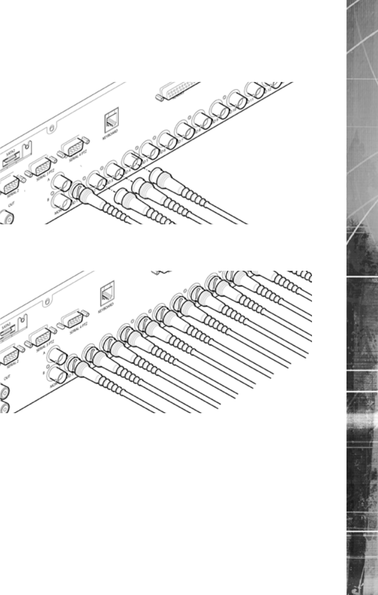
Installing the SD Unit
This procedure shows the sixteen camera input version.
Step 1 Connecting Video
Step 2 Monitor
Dedicated Micros ©2007
16
SD Range
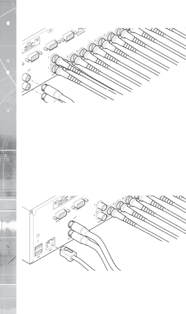
Step 3 Connecting Audio
* 32 input model supports two channels of bi-directional audio, 8, 12 and 16 input models
support one.
Note:Note: The Audio ouptut can be congured as a challenge output or as a replay output.
Step 4 Connecting to the Network
Dedicated Micros ©2007 17
SD Range
3Step 5 Relays
KEYBOARD
USB
NETAUDIO
IN
VID 1
MON
B
VID 2VID 3
SERIAL 1
SATA1
SERIAL 2 PTZ
OUT
SATA2
A
VID 13
VID 8
VID 6
VID 4VID 5VID 7 VID 9 VID 10VID 12
VID 11 VID 14 VID 16
ALARMSRELAYS
POWER
B
B
B
B
B
B
B
B
B
B
B
B
B
B
B
B
B
Pin 4 Relay 4 Signal
Pin 3 Relay 3 Signal
Pin 2 Relay 2 Signal
Pin 1 Relay 1 Signal
Pin 6 Relay 1 Signal
Pin 7 Relay 2 Signal
Pin 8 Relay 3 Signal
Pin 9 Relay 4 Signal
RELAYS
Relay Connector
Pins Connection
1 & 6 Relay 1 signal
2 & 7 Relay 2 signal
3 & 8 Relay 3 signal
4 & 9 Relay 4 signal
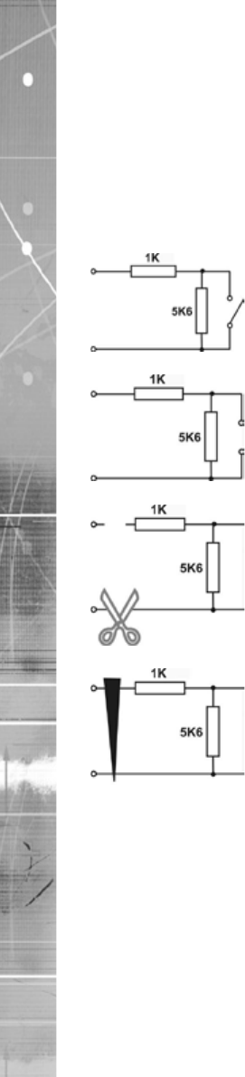
Step 6 Alarms
KEYBOARD
USB
NET AUDIO
IN
VID 1
MON
B
VID 2 VID 3
SERIAL 2
SERIAL 3 PTZ
OUT A
VID 13
VID 8
VID 6
VID 4 VID 5 VID 7 VID 9 VID 10 VID 12
VID 11 VID 14 VID 15 VID 16
ALARMS RELAYS
POWER
B
B
B
B
B
B
B
B
B
B
B
B
B
B
B
B
B
B
B
B
B
B
B
B
B
B
SERIAL 4 PTZ
SERIAL 1
Pin 2 DTX
Pin 4 DTX
Pin 6 DTX
Pin 8 DTX
Pin 10 DTX
Pin 12
Pin 1 DTX
Pin 3 DTX
Pin 5 DTX
Pin 7 DTX
Pin 9 DTX
Pin 11 DTX
Pin 13 DTX
Pin 25 Earth
Pin 23 Earth
Pin 21 Earth
Pin 19 Earth
Pin 17 DTX
Pin 15 DTX
Pin 24 Earth
Pin 22 Earth
Pin 20 Earth
Pin 18 Earth
Pin 16 Earth
Pin 14 DTX
ALARMS
Dedicated Micros ©2007
18
SD Range
Relay Connector
Pin Alarm Input Connection
1 - 17 1-17
18-25 Earth Common
End Of Line Circuitry
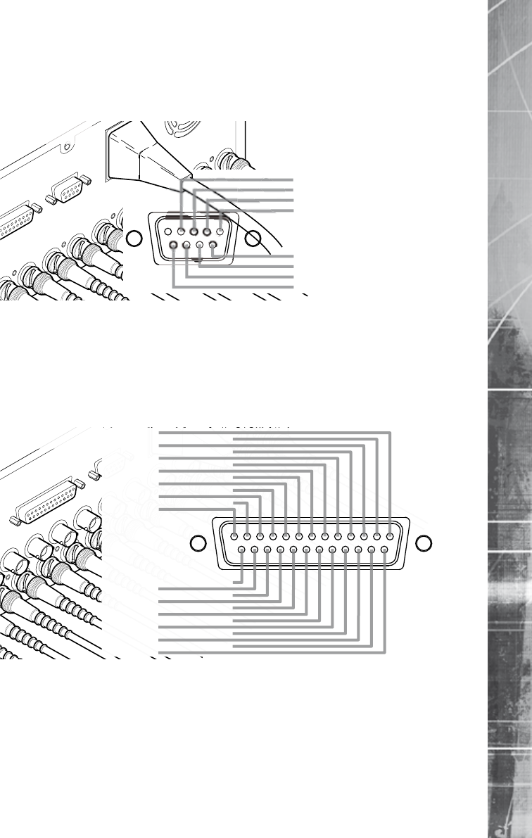
Step 7 Connecting Serial Ports
Note: Telemetry cameras should be connected to Serial 3 and 4. Text data can be retrieved from
any serial port.
Dedicated Micros ©2007 19
SD Range
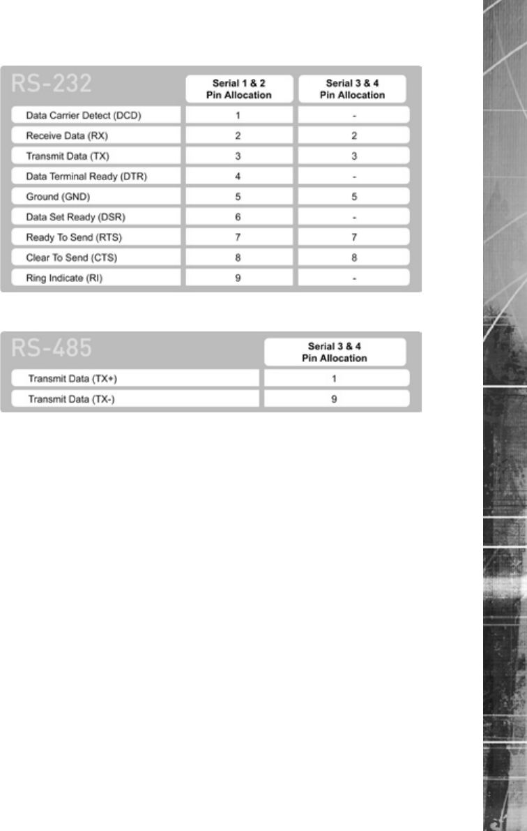
RS232
RS485
Step 8 Connecting a Keyboard
Note: Refer to the Unit Operation section of this manual for further guidance regarding the
supported keyboards.
Step 9 Connecting Dennard 2060 & 2040 Domes
Dome Cable SD Serial Connector
Green 9 TX-
Dedicated Micros ©2007
20
SD Range
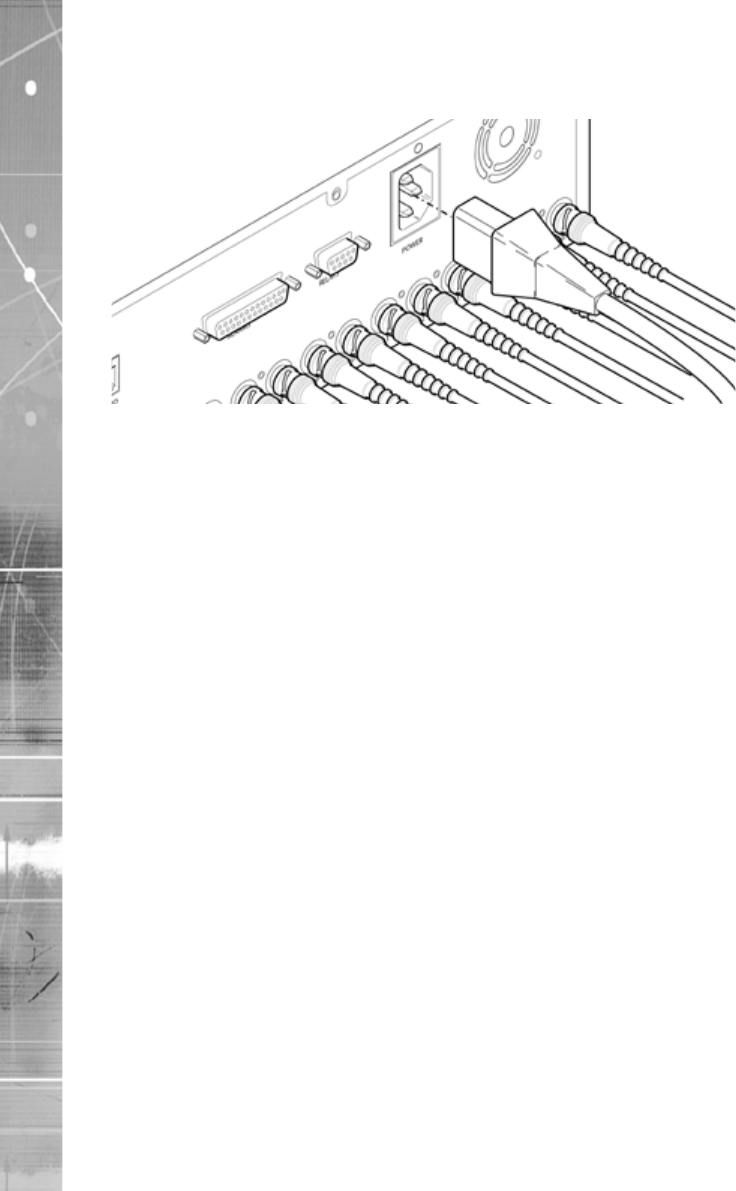
Step 10 Connecting Power
RF
Dedicated Micros ©2007 21
SD Range
Conguring the Unit
The unit can be congured either on the local monitor or over the network using a PC with Internet
Explorer or similar browser. Both methods have identical interfaces.
Accessing the menus on a local monitor
Note: If the IR Remote Control does not open the menu, press the DVR button on the Remote to
make sure it is in DVR mode, then press the MENU button again.
Accessing the menus on a PC web browser
Locating the Unit IP address
The IP address of the unit is required to access these pages. The SD unit’s IP address can be
identied from the local menu pages. Using the local monitor, press the MENU button and then
navigate to the Network menu to nd the DHCP assigned IP address.
If DNS is not to be used, it is important to set a xed IP address so that the same URL can be
entered to contact the unit every time.
If a permanent IP address is not assigned to the unit, it will attempt to contact the DHCP server
every time it starts up. If for any reason, a DHCP server cannot allocate an IP address to the unit,
the encoder will use a default IP address. It is recommended that DNS (Domain Name Server) be
used as assigning a name makes it easier for a remote user to locate the unit.
Accessing the Conguration Web Pages
The unit can be congured using on the on-board web pages. To access these:
Dedicated Micros ©2007
22
SD Range
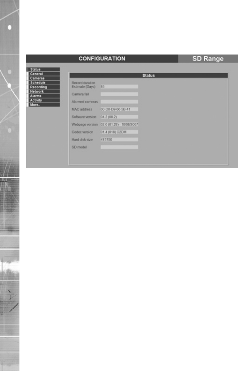
Status
This page shows the general information about the unit, including the version of software installed
and the adopted video standard.
Note: Any changes made on the web pages are automatically saved when the page is closed.
To ‘manually’ save changes, select the Save button. Use the ‘Cancel’ button to exit a page
without saving any changes made.
Note: The Save button is only displayed when accessing the menus via the web interface.
Note: Some pages may be displayed differently on the web browser than the local monitor.
Dedicated Micros ©2007 23
SD Range
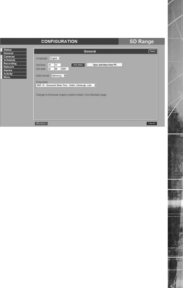
General
This page enables conguration of the time, date, local region and language used to display text.
unit currently supports languages (English, French, Italian,
Note: Any changes made on the web pages are automatically saved when the page is closed.
To ‘manually’ save changes, select the Save button. Use the ‘Cancel’ button to exit a page
without saving any changes made.
Note: The Save button is only displayed when accessing the menus via the web interface.
Dedicated Micros ©2007
24
SD Range
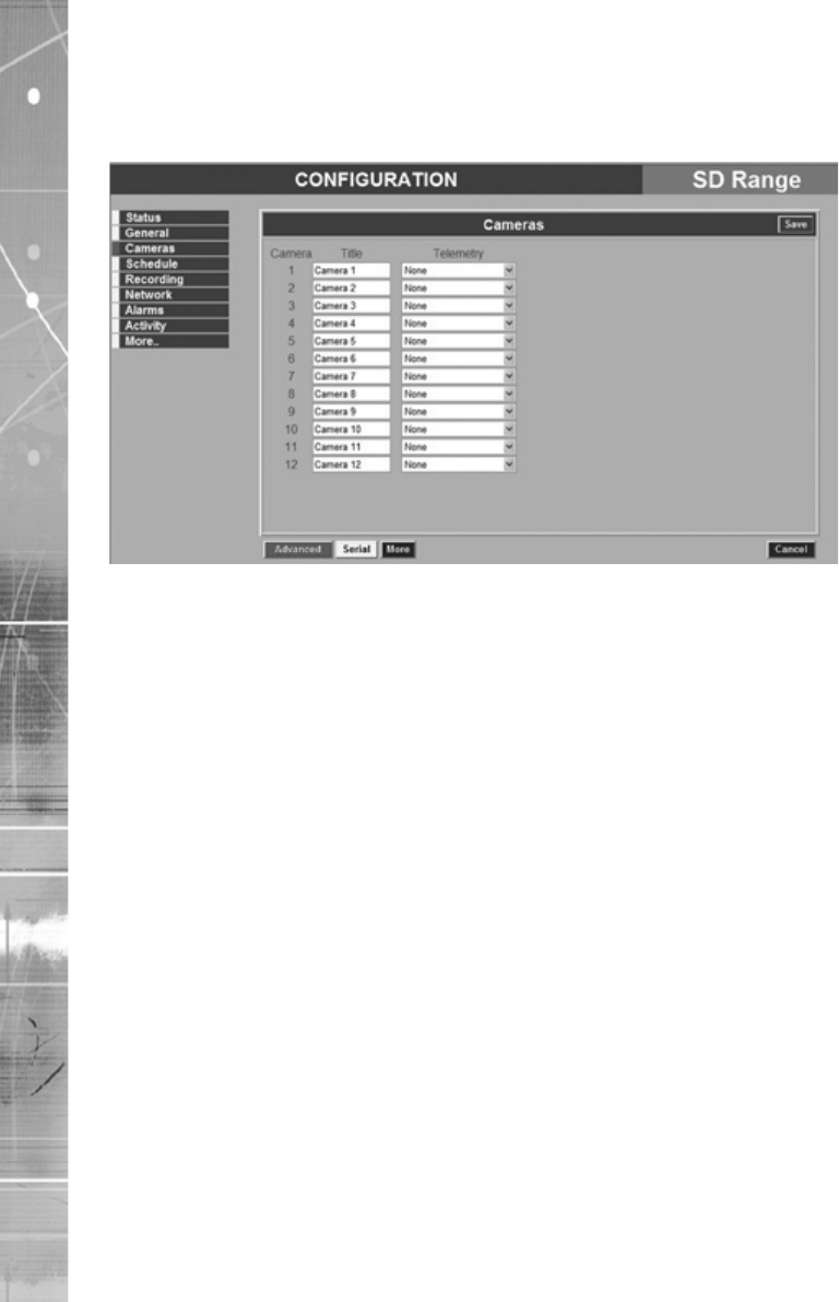
Cameras
This page allows the connected cameras to be congured.
Note: If a camera title is entered via the local monitor, an on-screen virtual keyboard will be
displayed to aid text entry.
Telemetry If a Dome or PTZ camera is used; the appropriate control protocol
Note: Any changes made on the web pages are automatically saved when the page is closed.
To ‘manually’ save changes, select the Save button. Use the ‘Cancel’ button to exit a page
without saving any changes made.
Note: The Save button is only displayed when accessing the menus via the web interface.
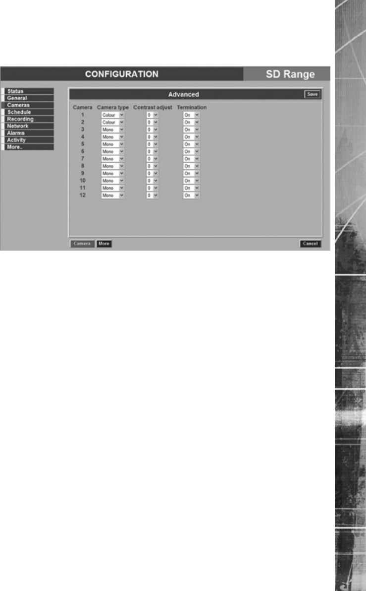
Dedicated Micros ©2007 25
SD Range
Advanced
The Advanced button on the cameras page will access the Advanced settings page, allowing more
of the camera settings to be edited.
Dedicated Micros ©2007
26
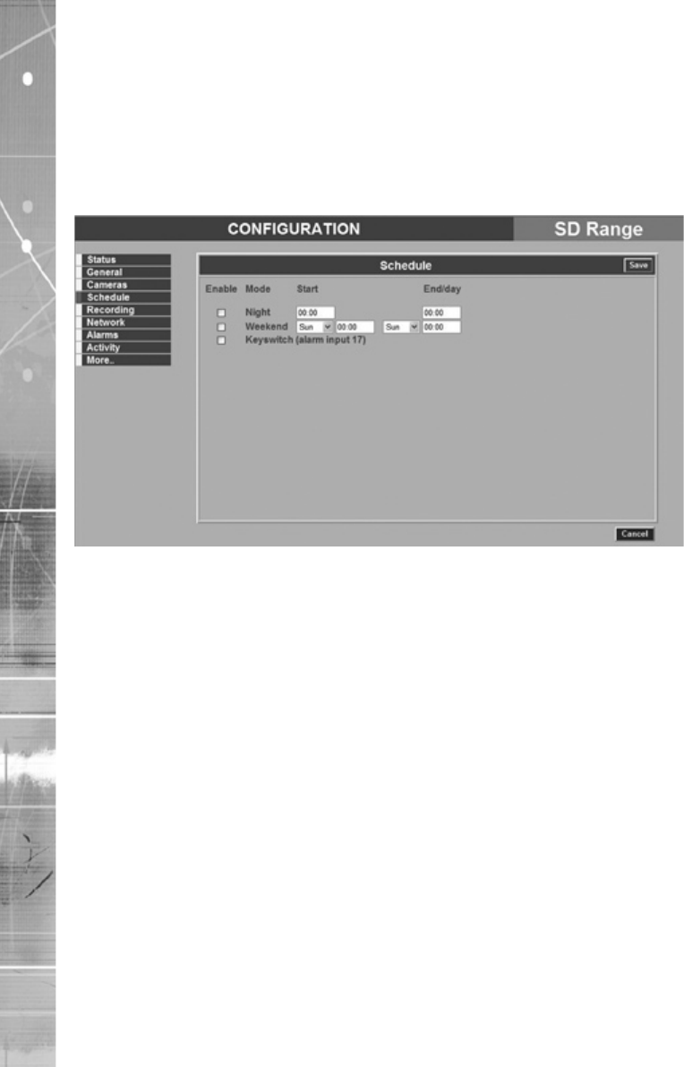
SD Range
Schedule
The SD DVR recording quality is controlled by three factors; the time of day, the quality of image that
has been set to record during that time, and whether the unit is in alarm. These factors combine to
produce a recording prole. Each of these parameters can be adjusted individually. The schedule
conguration can also be used to determine when the alarm contacts are active on the unit.
This page allows the schedule settings on the unit to be edited.
(refer to Recording - Advanced)
using
Note: Use of a Keyswitch precludes the use of schedules.

Dedicated Micros ©2007 27
SD Range
Recording
The SD has a range of pre-dened congurations available As standard the unit can record at 5pps
MPEG4 and at a duration of 7, 14, 30 or 60 days (the default is 14 days). Alternatively the unit
can be congured for 1pps JPEG recording on each camera or can be congured for MultiMode
operation so that it switches from 5pps MPEG to 5pps JPEG on Event (Note that this will result in
the record duration being determined by the amount of time the unit is in alarm). The Apply button
updates the system record duration calculator which calculates the actual duration capable of being
held on the drive. If specic requirements are needed on a camera, the Advanced conguration can
be used to congure the exact requirement.
MultiMode
(see later)
(see later)
Dedicated Micros ©2007
28
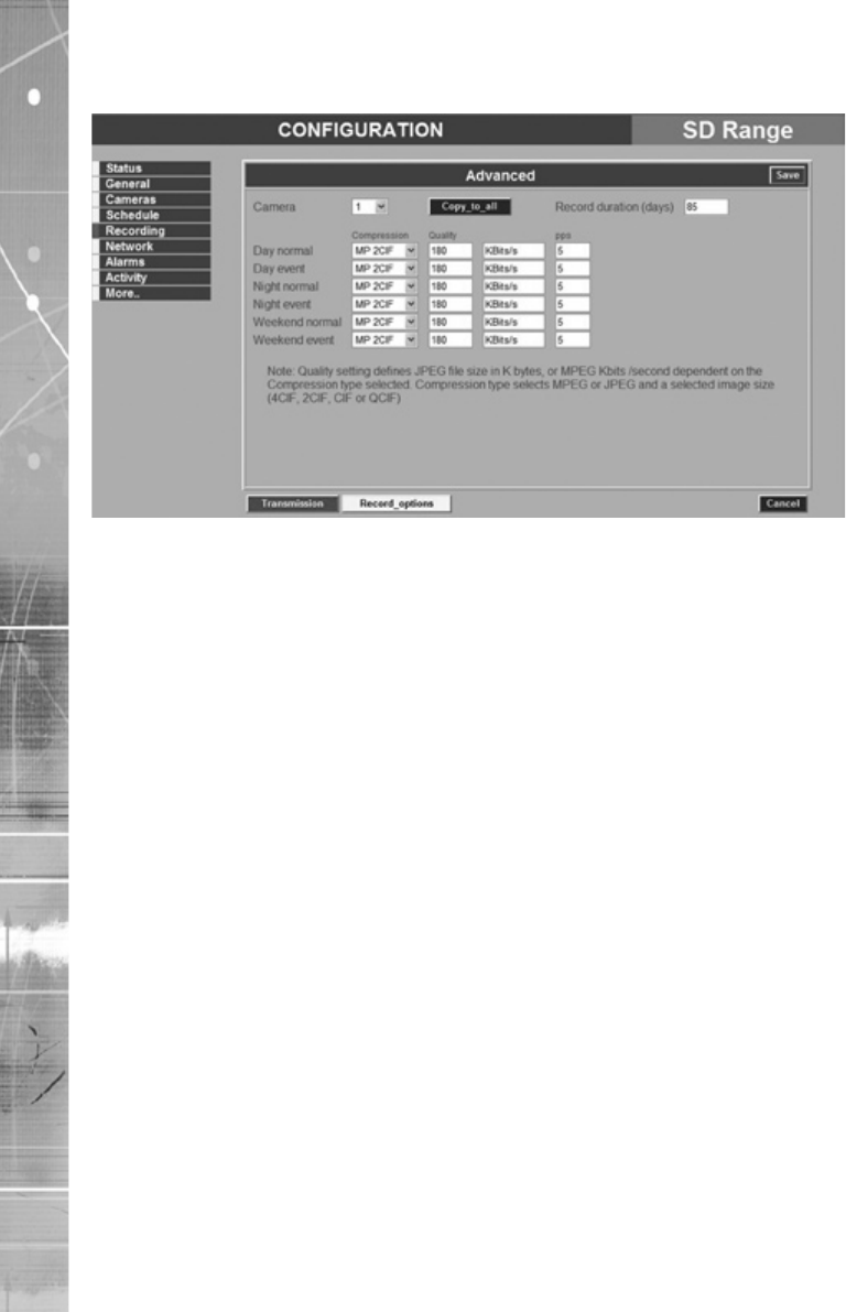
SD Range
Advanced Settings
C
schedules are applied and the camera is operating under Normal
(see later).
(see later)
Dedicated Micros ©2007 29
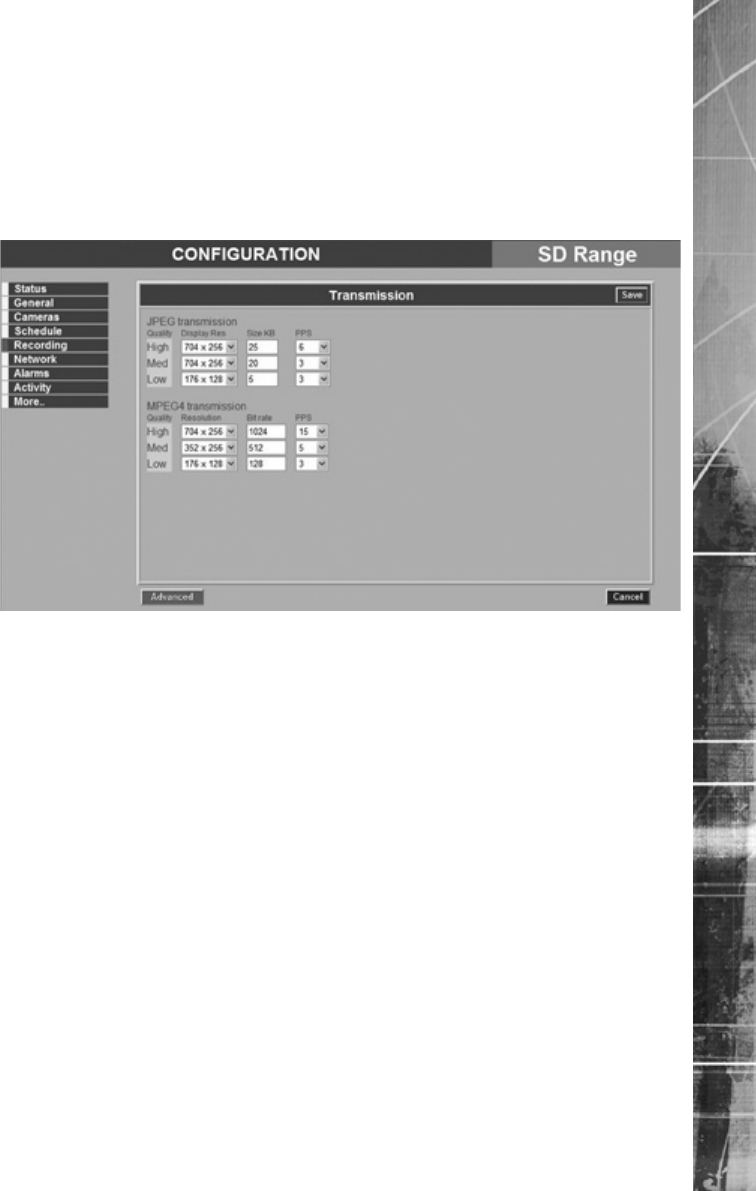
SD Range
Transmission
The NetVu Connected remote viewing software (NetVu ObserVer) will use the settings congured
on this page as the defaults for JPEG & MPEG; High, Medium and Low settings. The SD transmits
live images using JPEG or MPEG image formats utilising the soft codec architecture (VISP). The
SD features TransCoding which enables recorded JPEG images to be Transcoded to low bit rateTranscoded to low bit rate to low bit rate
MPEG4 for transmission over limited bandwith links. This is essential for efcient, ‘fast update’
remote viewing of recorded video in central monitoring applications. The SD can also TranscodeTranscode
from recorded high bit rate MPEG4 to low bit rate MPEG4.
MPEG4
352x256 & 176x128
(see
below)
Dedicated Micros ©2007
30
SD Range
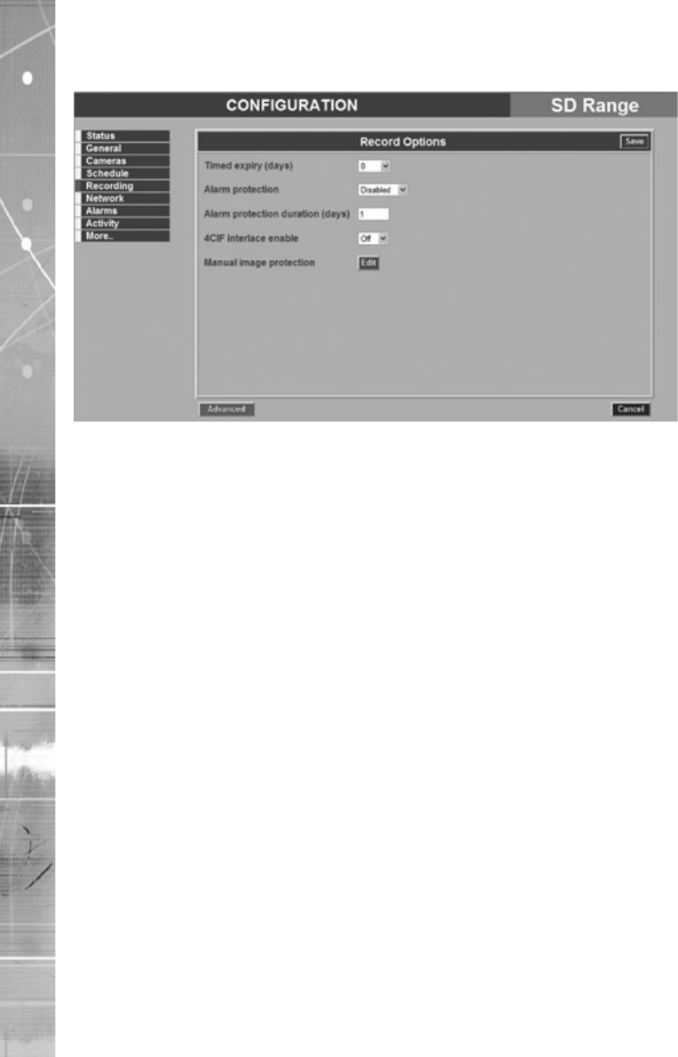
Record Options
recorded images must adhere to legislation on retaining images
Warning: All images older than the selected timed expiry will no longer be available.
Dedicated Micros ©2007 31
SD Range
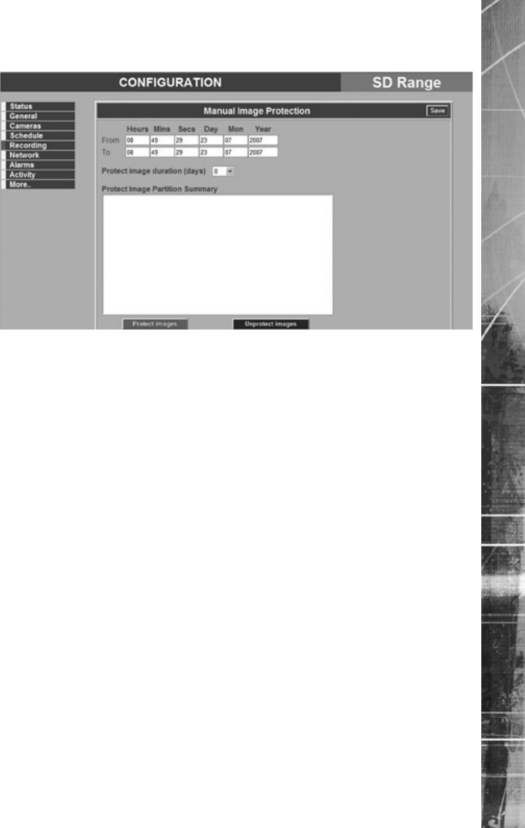
Manual Image Protection
From Enter the date and start time for the period containing the
Note: It may take some time to add protected images to the list.
Note: It may take some time to remove protected images from the list.
Dedicated Micros ©2007
32
SD Range
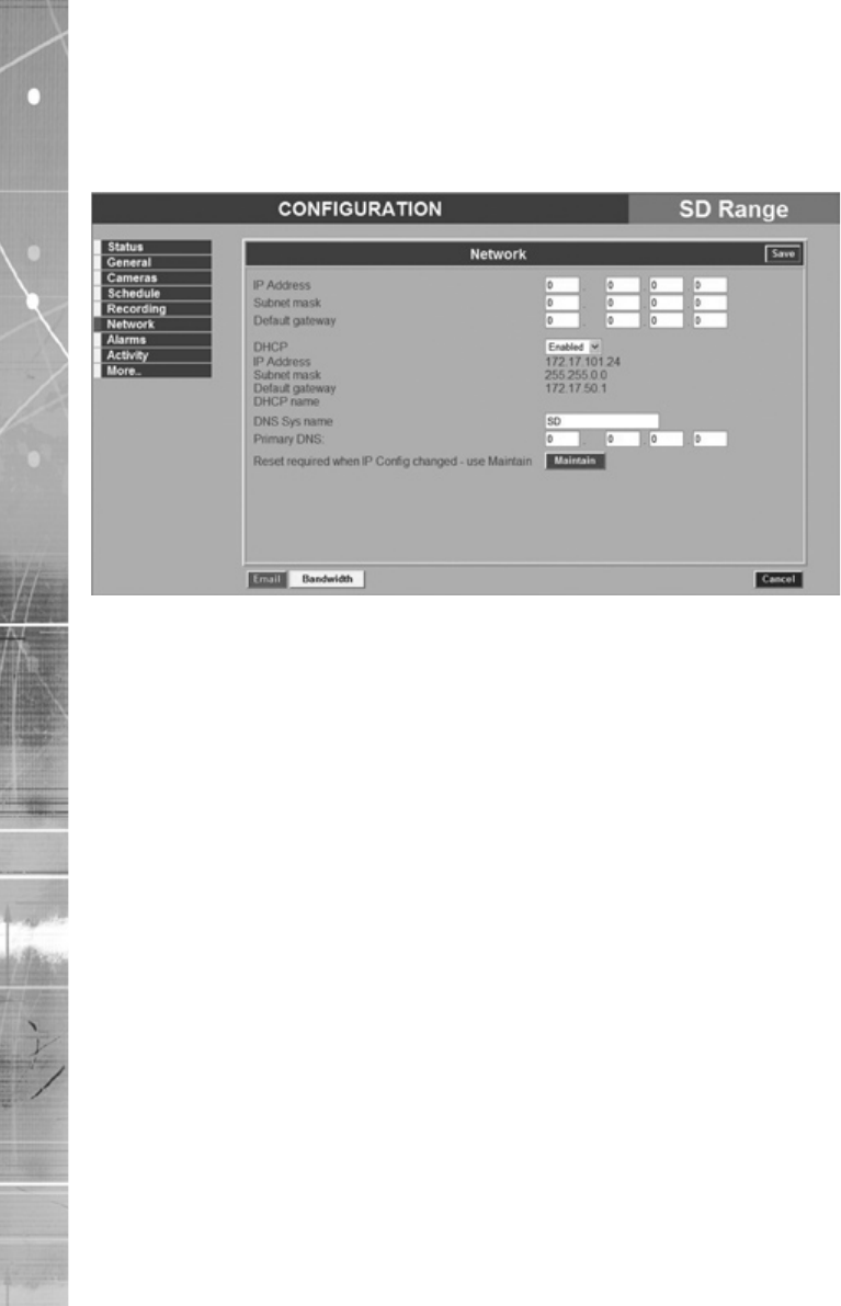
Network
This page allows conguration of the network settings for the unit. Note that the unit is initially
congured for DHCP.
Primary DNS This is the primary DNS server IP address for applications that are
(see later)
Dedicated Micros ©2007 33
SD Range
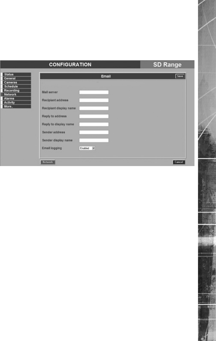
Email Settings
Mail Server This is the IP address or URL of the SMTP Server that the e-mail
Recipient address This is the e-mail address and display name of the intended
Dedicated Micros ©2007
34
SD Range
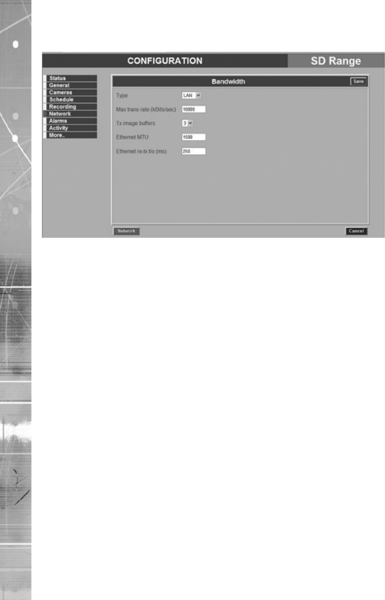
Bandwidth Selection
Type This option ensures the speed of the data from the unit matches
(see Network)
Dedicated Micros ©2007 35
SD Range
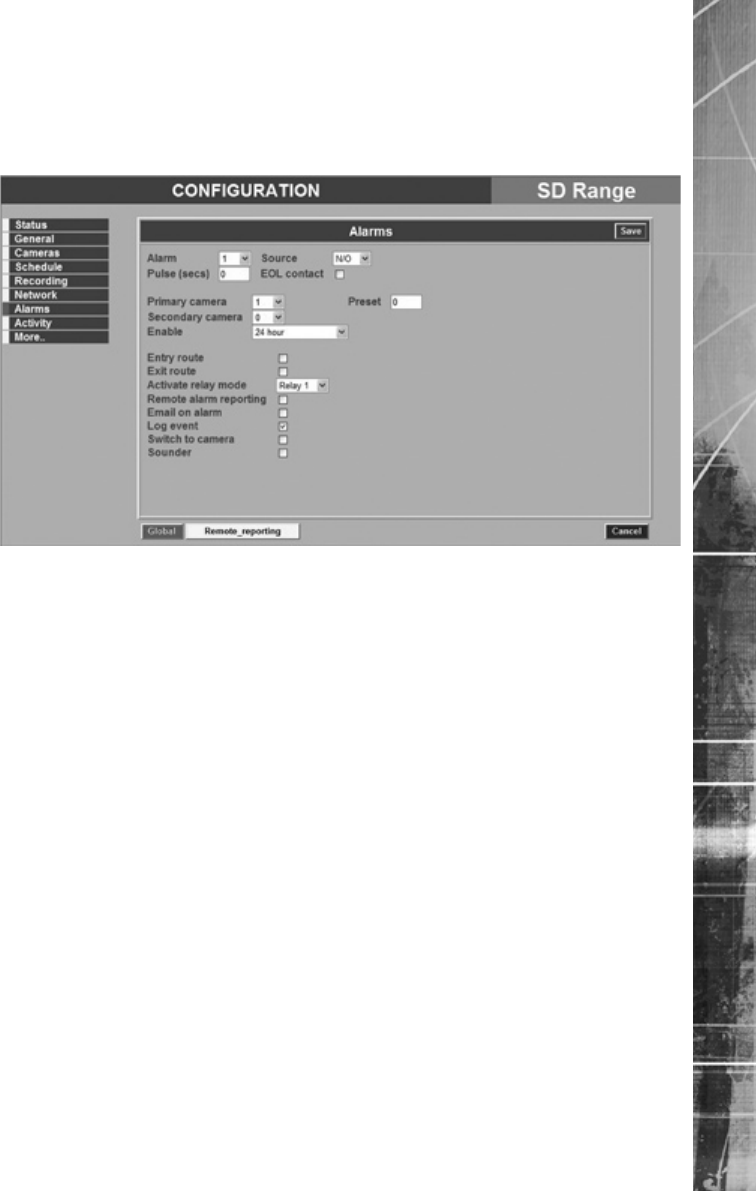
Alarms
This page allows conguration of the alarm settings. For hardware installation information, refer to
‘Installing the SD DVR’.
The alarms are associated with cameras by default. There is a panic alarm available using the panic
button on the remote, or on a connected SD keyboard. This will put all cameras into alarm recording.
There is also a contact alarm that is congured as a keyswitch via Alarm input 17.
Alarms support tamper proof detection to detect short circuit, open circuit and contact closure.
EOL contact The End Of Line (EOL) is part of the advanced alarm feature andThe End Of Line (EOL) is part of the advanced alarm feature and
mode (refer to ‘End Of Line Circuitry’ in the ‘Installing The SD’
section)
The primary

Dedicated Micros ©2007
36
SD Range
Dedicated Micros ©2007 37
SD Range
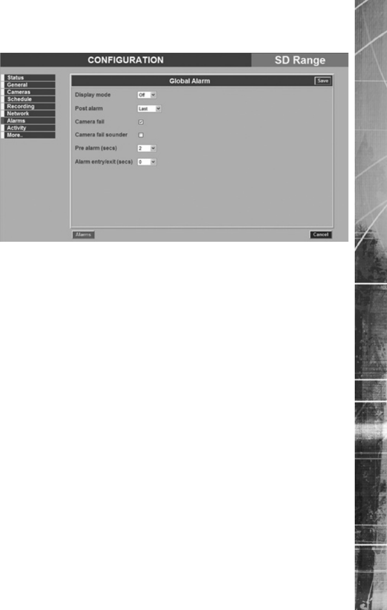
Global Alarms

Dedicated Micros ©2007
38
SD Range
Activity
This page allows conguration of the activity detection settings.
The unit can detect changes in the image received from a camera. This detection can be rened to
specify certain areas of the image using an overlay grid. This grid can be edited.
Note: When setting the sensitivity it is recommended that an Activity test is run to ensure the
correct sensitivity is selected.
Select the sensitivity level to suit the camera location:
The sensitivity levels are:

Dedicated Micros ©2007 39
SD Range
Display activity area Use this option to test and tune the sensitivity and activity grid
Use
Dedicated Micros ©2007
40
SD Range
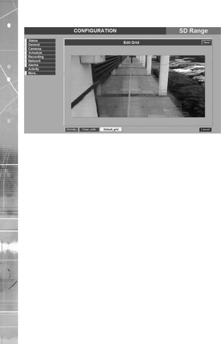
Activity Grid
The alarm detection area can be edited via the Activity Grid. The Activity Grid can be used to
exclude areas where there may be continuous movement (i.e. trees or bushes) which lead to
false triggers. The camera view can be overlaid by a grid of up to 16x16 cells. Each cell can be
individually enabled or disabled.
Select a camera via the Activity Detection screen, then select the Edit Grid option (Red Softkey).
Use the up/down/left/right Directional buttons to navigate between cells. To add cells, press the OK
button on an area of the image that does not presently contain any cells. A cell will be added. Use
the Directional buttons to add more cells. When the required number of cells have been added,
press the OK button again. If cells need to be removed, highlight a cell and press the OK button.
Use the Directional buttons to move around the image deleting other cells. Press the OK button
when all required cells have been deleted. If only a small area of the camera view may be subject
to false triggers. Use the Default_grid feature (Yellow Softkey) to ll the screen with a full 16x16 cell
grid, then highlight the required cell(s) to be removed via the OK button.
Dedicated Micros ©2007 41
SD Range
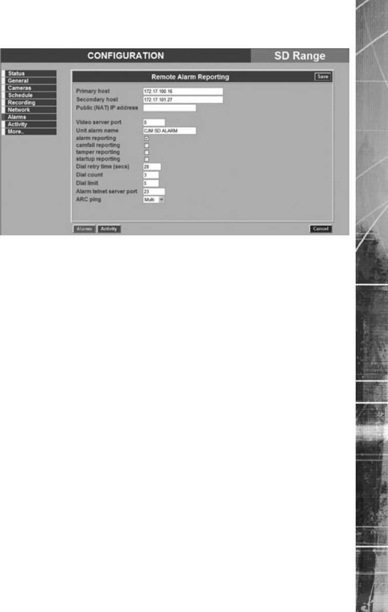
Remote Alarm Reporting
Tamper reporting The unit supports Tamper alarm inputs, if a tamper is detected,

Dedicated Micros ©2007
42
SD Range
Dedicated Micros ©2007 43
SD Range
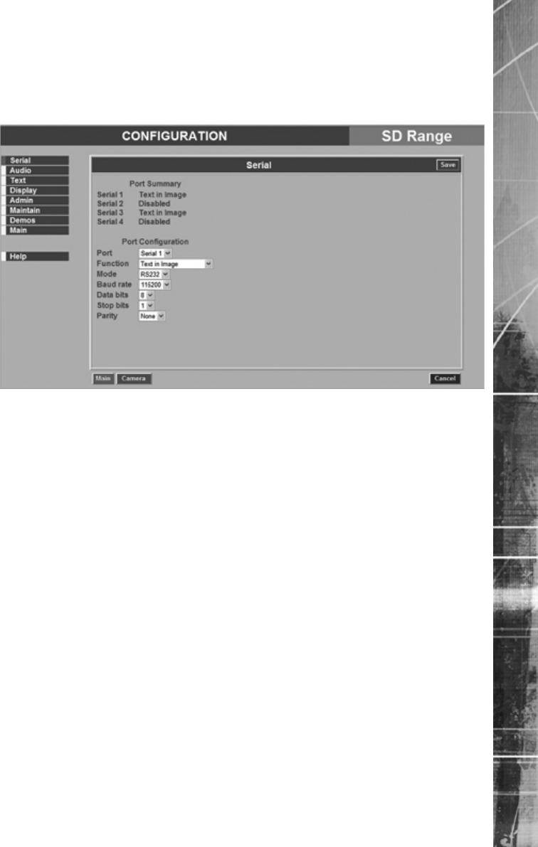
Serial
This page allows conguration of the two Serial ports on the rear of the unit. For installationFor installation
information, refer to ‘Installing the SD DVR’.
Mode, Baud Rate, Parity, Data Bits, Stop BitsStop Bits
Note: When a telemetry protocol is selected these settings will be set to the default to pre-
determined values for the protocol, and should not normally be altered manually.
Dedicated Micros ©2007
44
SD Range
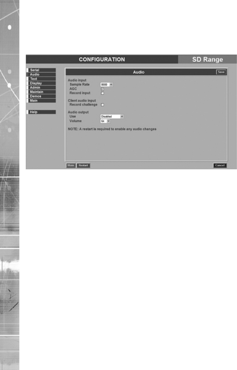
Audio
The settings for any available audio stream can be edited on this page. For hardware installationFor hardware installation
information, refer to ‘Installing the SD DVR’.
Audio Input
Client audio input
Record challenge
Dedicated Micros ©2007 45
SD Range
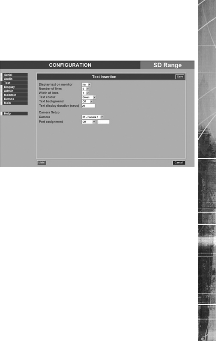
Text
The SD DVR can handle POS text data within the unit. This menu enables control of the data, how
it is displayed on the monitor and recorded on the DVR. Dedicated Micro’s can provide a range of
text solutions for Retail, ATM or other applications, for details on how to use Text to enhance your
security and video management system, talk to your DM Sales or Technical support contact.
Width of lines
Cancel (Purple)
Dedicated Micros ©2007
46
SD Range
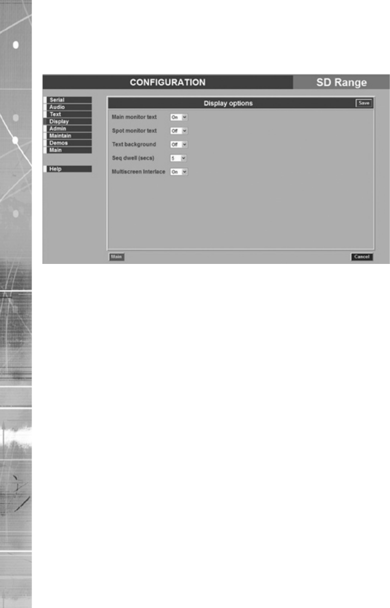
Display
This page allows conguration of the Monitor settings.
Dedicated Micros ©2007 47
SD Range
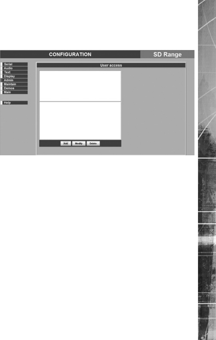
Admin
The unit can protect access to the conguration options by setting passwords. These can be set
individually for access to the menus and access to the recorded data.
Dedicated Micros ©2007
48
SD Range
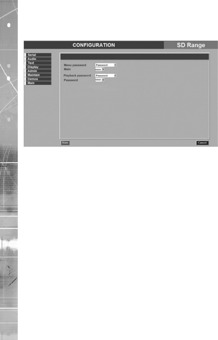
Local Admin Passwords
Please note that if the Conguration pages are accessed via the local monitor GUI, the menu screenlocal monitor GUI, the menu screen
shown below will be displayed.
Dedicated Micros ©2007 49
SD Range
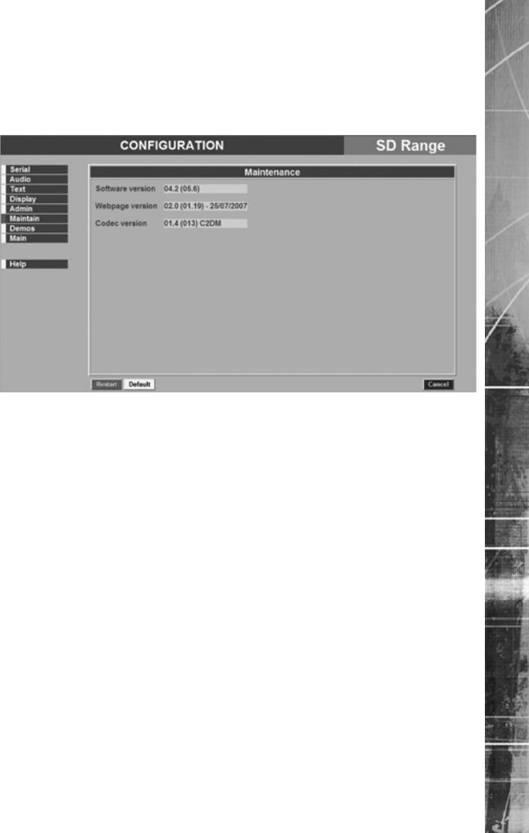
Maintain
This page can be used to view the software details the unit is utilising. The unit can be shut down
and reset from this point, while all settings can be returned to their original factory release state via
the Default button.
Note: The Upgrade button is only available via the Local monitor menu.
Dedicated Micros ©2007
50
SD Range
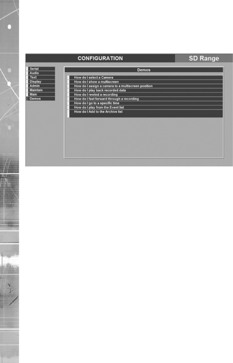
Demos
The Demo section details several short tutorials on how to carry out common procedures via the IR
Remote Control.
Dedicated Micros ©2007 51
SD Range
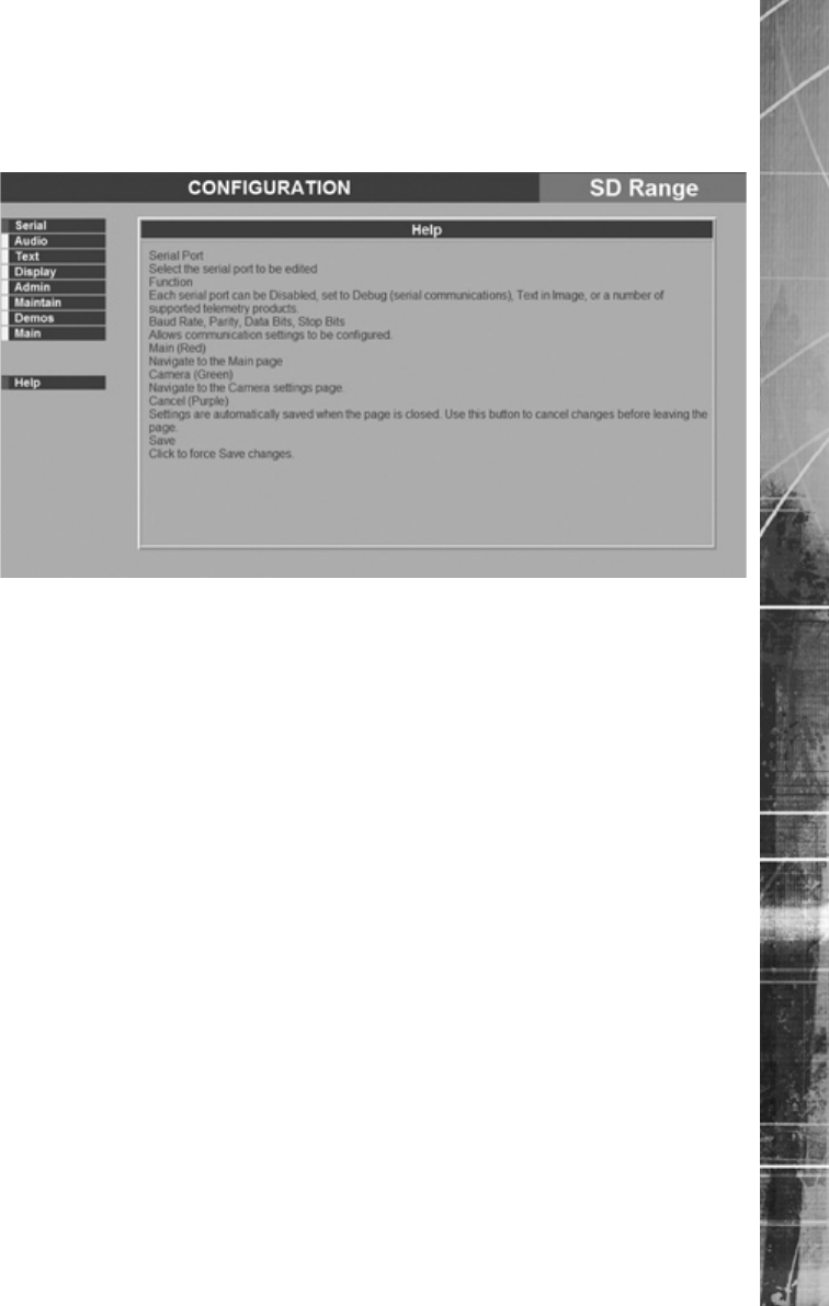
Help
The Help section provides quick and easy guidance to currently displayed menu screens.
Dedicated Micros ©2007
52
SD Range
Unit Operation
The SD unit can be operated using the enclosed IR Remote Control, via the optional keyboard or
using a USB mouse.
Using the IR Remote Control
By default, the Keyboard/ Remote Control will be in “DVR” mode. If the unit does not respond to
commands from the Remote Control, pressing the “DVR” button will always return the Keyboard/
Remote Control to “DVR” mode. Pressing the “TV” button will switch to “TV” mode and send codes
understood by common television sets (when pre-programmed to do so; see Appendix B).
Pressing any of the coloured Softkeys at any time will display the ‘coloured’ keys rst and then
access the equivalent ‘coloured’ option displayed in the menus.
Using the Optional touch keyboard
The unit can also be controlled using either the optional; DM/KBC1 or DM/KBC2 keyboard. This is
connected via the KBD connector on the rear of the SD and provides the same control functions as
the Keyboard/Remote Control.
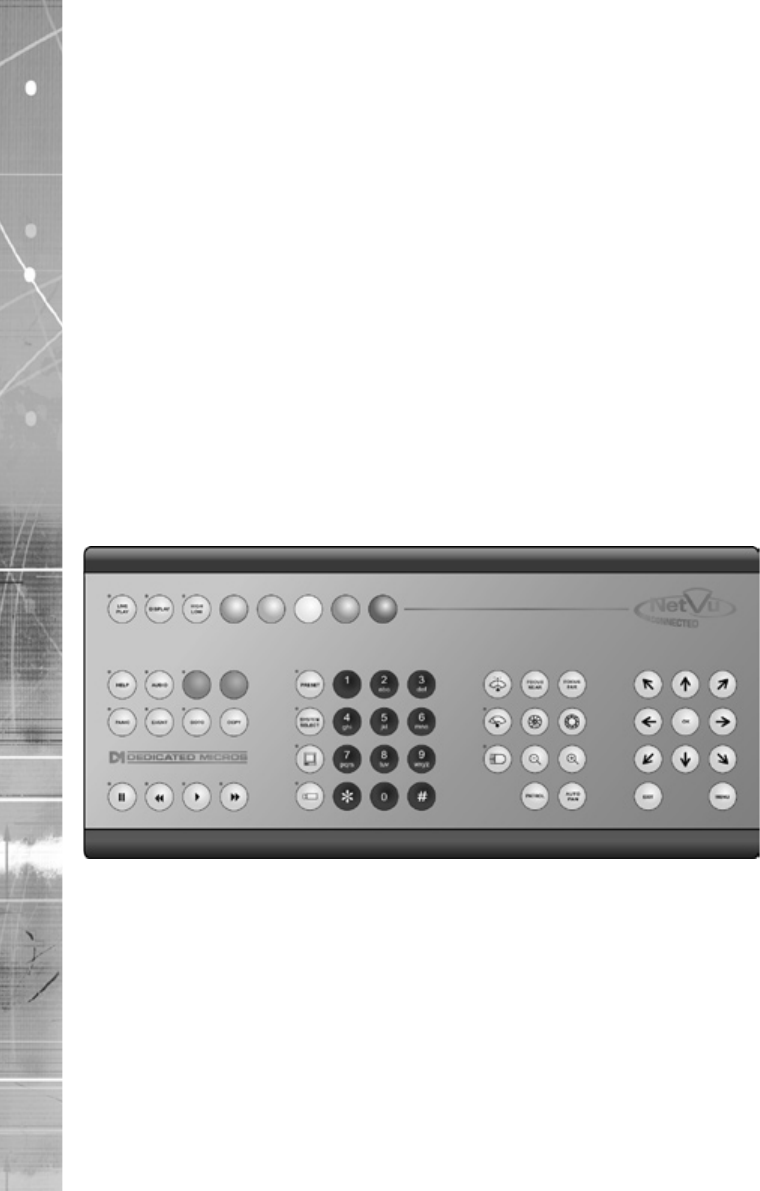
DM/KBC1 Keyboard
Dedicated Micros ©2007 53
SD Range
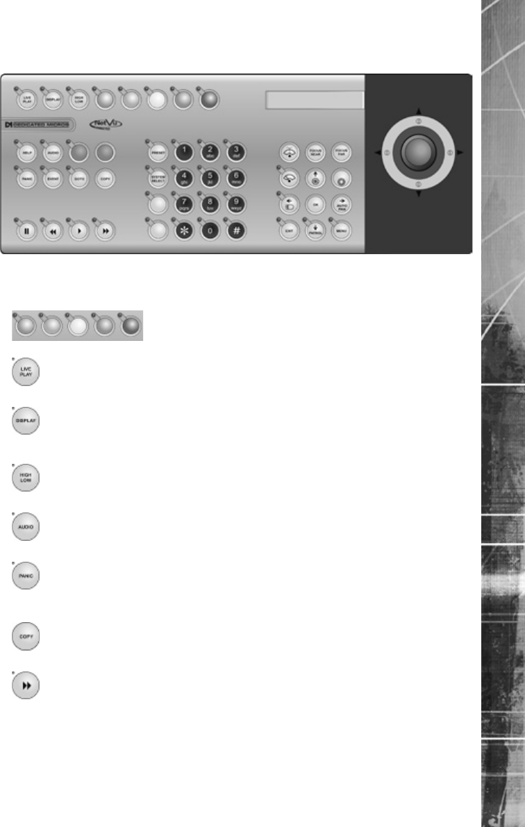
DM/KBC2 Keyboard
Note: Not all buttons detailed below are relevant for both models of keyboard.
For future use
Forces all the cameras to record in alarm mode for three minutes, or until
Displays the archiving options
Live mode - No functionality
Dedicated Micros ©2007
54
SD Range
Opens the GOTO menu
Dedicated Micros ©2007 55
SD Range
Instructs the selected telemetry camera to automatically pan (on cameras
Pan and tilt control for telemetry cameras
Dedicated Micros ©2007
56
SD Range
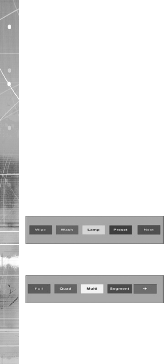
Softkey Guidance
The IR Remote Control, KBC1 and KBC2 have a common user interface to control the SD. In
addition to the direct action keys (rewind, fast forward etc.), there are coloured Softkeys that are
context sensitive and enable rapid access to required functions.
To bring up context sensitive Softkey functions at any time, press any of the coloured keys on the
keyboard or IR Remote Control.
To select cameras
Electronic Zoom
Note: Electronic zoom is possible on Dome cameras, however the unit must be in Live or Replay
mode ( not Telemetry mode - TELEM (displayed in the status bar).)
To control PTZ dome cameras
Note: To zoom in with the camera, use the Zoom IN button.
To select Multiscreen
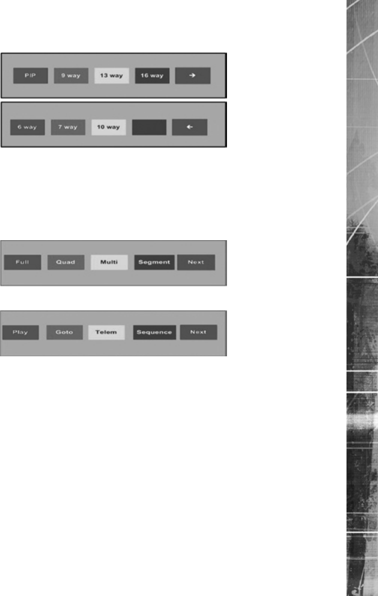
Dedicated Micros ©2007 57
SD Range
To change the camera in a specic segment of a multiscreen:
To select a Sequence
To control a spot monitor
To Copy cameras to an archive
To Investigate events
Dedicated Micros ©2007
58
SD Range
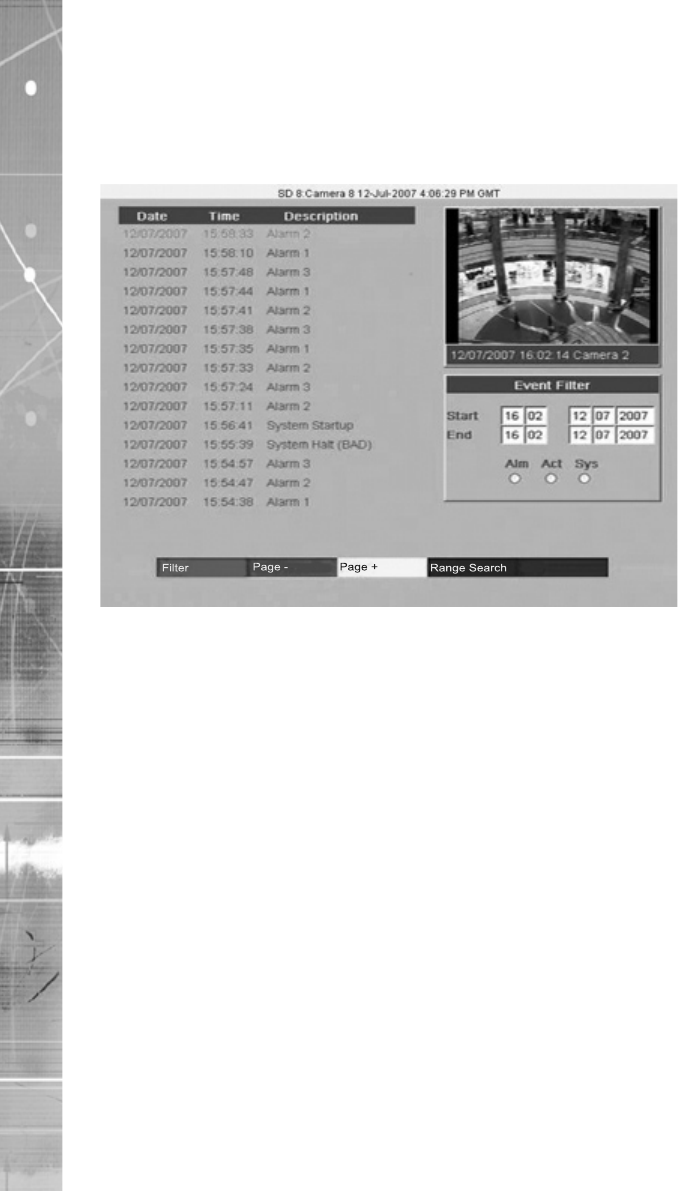
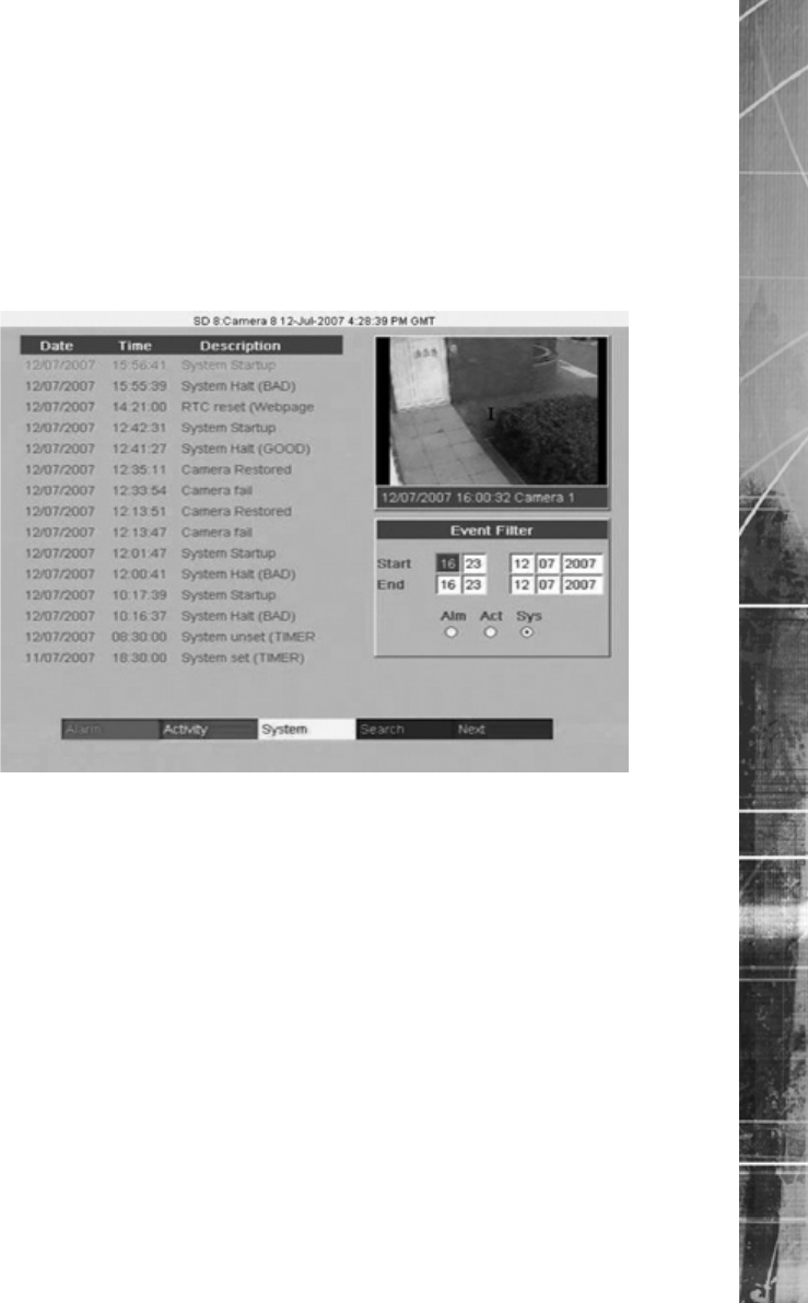
Event List
Alarms and activity detection are tagged and stored in the Event list for easy retrieval along with
System events such as system start data and camera fails. Each event is labelled with an event type
(alarm, activity or system) and its time and date. To view an event from the Event list:
Dedicated Micros ©2007 59
SD Range
Event Search Filter
Alarm - Red
Activity - Green
Play an event back full screen
Copy Events To The Archive List
Start a new search
in the Event Search Filter menu
Dedicated Micros ©2007
60
SD Range
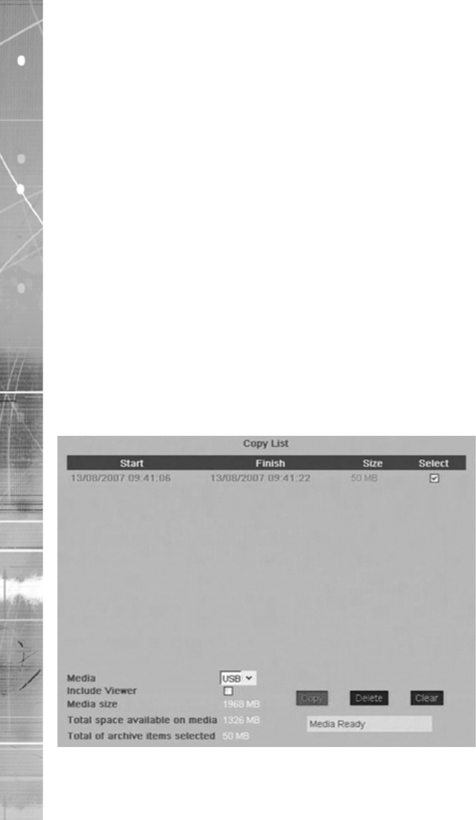
Copy Menu
Copy Images to CD or USB device
Using the Copy Menu
Images and events can be copied to CD or USB Media for reviewing remote from the unit for
evidential or monitoring purposes.
Using the Copy option during Playback

Dedicated Micros ©2007 61
SD Range
Using the Copy option within Event list
To Copy Events/Images to CD
Please Wait
LeadIn
Writing
Verifying
To Copy Events/Images to a USB Device
Note: The SD range will support most USB Flash and USB HDD media for export, a summary of
known supported items is displayed in Appendix C.
Selecting/Deselecting Copy items

Dedicated Micros ©2007
62
SD Range
Problem Solving
This is a list of common problems encountered using Digital Video recording technology in a CCTV
environment; and suggested solutions for each scenario.
I keep getting two alarms for one event. How can I prevent this ?
A pulse extension extends the trigger period to avoid double alarm triggers from occurring, i.e. If a second trigger
occurs on the same alarm input within the pulse extension time period, the unit will not create a new event.
Answer
My images are feint/dark ?
Ensure the camera has been set up correctly. Signals from the cameras can be adjusted within the DVR to
compensate for a variety of conditions. The contrast can be altered.
Answer
Also
How do I identify which unit I am viewing over a network ?
Each unit can be allocated a relevant 20 character name to identify the unit to the Operator or System
Administrator.
Answer
How do I make sure I delete images after a certain time period ?
Images recorded onto disk can be made unavailable after a user-dened number of days and hours. This is
designed to help operators comply with legislation on the retention of images for a set period of time. Once the
timed expiry has been set, all images older than the selected time will be no longer available.
Answer
How do I protect images from being overwritten ?
It is possible to protect images stored on the unit hard drives. These images will not be overwritten.
Answer
How do I see all system alarms, failed cameras, the amount of available storage and
earliest protected recording on my unit ?
All of these parameters are available via the Status Page. This should be checked every day to ensure the system
is operating well and there are no obvious imminent problems.
Answer
There is no response from the unit when I try to navigate the menus
Most likely solution is that the unit is in spot mode (the word SPOT will be displayed on the bottom of the screen
and the SPOT LED is lit).
Answer
The cable could have been connected incorrectly.
Answer
I cannot select a specic camera
Answer
Answer

Dedicated Micros ©2007 63
SD Range
Cannot display any other cameras apart from the one currently displayed
Answer
I have a white screen with a selected camera and an image displayed of a ‘crossed out’
camera
The camera has failed.
Answer
All of my cameras are being displayed in monochrome
Answer
Answer
Answer
I have a single camera being displayed in monochrome
Answer
My camera image is either too bright or too dark.
The solution can either be a hardware or software issue.
Answer
Answer
My unit is not recording.
Answer
Answer
Answer
I have a specic camera that will not record
The most likely solution is a conguration error in the system setup.
Answer
I have no serial or co-axial telemetry control
The most likely solution is a conguration error.
Answer
Answer
I have no serial telemetry
The most likely solution is a communications error
Answer
Erratic camera movement/camera moves on its own
Over time, the calibration between the joystick and unit could deteriorate
Answer

Dedicated Micros ©2007
64
SD Range
Telemetry works when using the keyboard but not over the LAN/Internet
Signals from the unit are being interrupted or blocked’
Answer
I cannot playback the recorded CD on my DVR
Recorded CDs and DVDs can only be played back on a Windows based PC.
Answer
I get a message ‘No CD in requested device’ message, yet there is a disk in the drive
Disk may be dirty, scratched or not blank.
Answer
I get a message ‘Nothing to Archive’
No images have been recorded during the times you have selected to be archived to disk.
Answer
My audio works live, but is not being recorded
Live feed means the physical connections are correct, therefore it is probably a conguration error.
Answer
Audio can be heard on a PC connected over a LAN, but not over a WAN or the Internet
There is a rewall conguration problem.
Answer
Audio recorded is too quiet
The audio feed signal is too low.
Answer
I cannot nd my unit on the network, it cannot be connected to or even ‘pinged’
Network connection problems can be difcult to diagnose due to the nature of network connections. There are a
few common solutions presented below.
Answer
Answer
Answer
I cannot connect to the unit with Internet Explorer, but the unit can be pinged. I can
even connect with NetVu Observer
Answer
Why does my unit keep timing out.
Answer
What is the username and password when trying to enter conguration options?
Answer dmweb

Dedicated Micros ©2007 65
SD Range
Alarms inputs and/or Activity are not being registered or logged.
Answer
I was performing a walktest and the unit stopped sending alarms.
There is a feature that will disable a repeatedly tripping contact. If this has been activated, it can effect walktests.
Answer
Dedicated Micros ©2007
66
SD Range
Appendix A
Alarm & Relay Pin Outs
Using Serial Ports
It is possible to connect a variety of telemetry cameras to the unit, using the following table as a
guide to the serial port connections.
15
6 9
RS485 Connectivity (2 wire) (Serial 3, 4)
Pin Description
9 RS485 - (B)
RS232 Connectivity (Serial 1, 2)
Pin Description Desc
1 Data Carrier Detect DCD
2 Receive Data RX
3 Transmit Data TX
4 Data Terminal Ready DTR
5 Ground GND
6 Data Set Ready DSR
7 Ready to Send RTS
8 Clear to Send CTS
9 Ring Indicate RI
RS232 Connectivity (Serial 3, 4)
Pin Description Desc
2 Receive Data RX
3 Transmit Data TX
5 Ground GND
7 Ready to Send RTS
8 Clear to Send CTS

Dedicated Micros ©2007 67
SD Range
Appendix B
Using the Keyboard/RC Interface Control To Control A Common
Television Set
To use the Keyboard/RC Interface Control as a common television remote handset, it is necessary
to input a code specic to the relevant television. Below are detailed the procedures to follow and a
listing of the codes associated with common television brands.
How to Program The SD IR Remote Control
Codes Relevant To Common Televisions.
TV Brand Code(s)
Bang & Olufsen 2000
Bauer 2617
Binatone 2003
Brother 2610
Goldline 2498

Dedicated Micros ©2007
68
SD Range
648
Technics 2043
CO

Dedicated Micros ©2007 69
SD Range
Appendix C
Unit Specication
LANGUAGES
SUPPORTED USB DEVICES
CAMERAS
MONITOR VIEWING
Main monitor:
Spot monitor:
ACTIVITY DETECTION
ALARMS & RELAYS
AUDIO
Connections:
SEARCH AND PLAYBACK
MultiMode RECORDING
MultiMode
RECORDING

Dedicated Micros ©2007
70
SD Range
EVENT COPYING
TEXT SUPPORT
NETWORKING CAPABILITIES
KEYBOARD/RC INTERFACE CONTROL
OPTIONAL KEYBOARDS
TELEMETRY
• Dedicated Micros Serial
• Baxall C
• Ernitec
• Pelco C
• Samsung
• Sanyo
• Sensormatic
• Vantage
• Vicon
• Vista
COLOUR RESOLUTION
COMPRESSION

Dedicated Micros ©2007 71
SD Range
SD RANGE DATA
TEMPERATURE RANGE
5 - 40°C
RELATIVE HUMIDITY
UNIT DIMENSIONS

Dedicated Micros ©2007
72
SD Range

Dedicated Micros ©2007 73
SD Range
Dedicated Micros ©2007
74
SD Range
Notes

Dedicated Micros ©2007 75
SD Range
Index
21
Accessing the menus on a local monitor 21
21
Activity 38
Activity Grid 40
Admin 47
Advanced 25
Advanced Settings 28
Alarm & Relay Pin Outs 66
Alarms 35
Alarms and relays 11
Appendix A 66
Appendix B 67
Appendix C 69
Audio 44
64
34
Cameras 24
7
Choosing a location for installation 7
67
8
21
Copy Events To The Archive List 59
Copy Images to CD or USB device 60
Copy Menu 60
Data 10
Demos 50
Design of the manual 4
8
52
Electrical Connections 7
Electronic Zoom 56
Email Settings 33
63
Event List 58
Event Search Filter 59
Features 4
Front Panel connections 10
General 23
37
13
64
62
64
63
I have no serial or co-axial telemetry control 63
I have no serial telemetry 63
Important Safeguards 5
Installation 10
Installing the SD Unit 15
Installing the Unit 7
Introduction 3
65
Laser 6
5
48
Locating the Unit IP address 21
Maintain 49
Manual Image Protection 31
MultiMode Recording 8
64
63
62
63
32
59
11
5
62
8
Rear Panel connections 10
Recording 27
Record Options 30
Remote Control 12
RS232 19
RS485 19
Schedule 26
61
Serial 43
Servicing 5
56
59
Status 22
To control a spot monitor 57
To control PTZ dome cameras 56
To Copy cameras to an archive 57
61
To Investigate events 57
57
To select cameras 56
To select Multiscreen 56
Transmission 29
Unit Operation 52
69
13
Using Serial Ports 66
Using the Copy Menu 60
60
61
Using the IR Remote Control 52
Common Television Set 67
52
Ventilation 5
Video 11
64
64

Dedicated Micros France
9-13 rue du Moulinet
75013 Paris, France
Dedicated Micros Slovenia
4208 Sencure, Slovenia
Dedicated Micros Benelux
Chantilly, Virginia 20151 USA
Suite 100, Torrance,
CA 90505, USA
NSW 2154, Australia
#03-03 Hudson Techno Centre,
Singapore 536204
Dedicated Micros Middle East
Installed by
