SDV594
User Manual: SDV594
Open the PDF directly: View PDF ![]() .
.
Page Count: 134 [warning: Documents this large are best viewed by clicking the View PDF Link!]
SERVICE MANUAL
DVD VIDEO PLAYER & VIDEO
CASSETTE RECORDER
DOCUMENT CREATED IN JAPAN, April, 2006 GREEN
SD-V594SC
FILE NO. 810-200612GRI
The above model is classified as a green product (*1), as indicated by the underlined serial number.
This Service Manual describes replacement parts for the green product. When repairing this green
product, use the part(s) described in this manual and lead-free solder (*2).
For (*1) and (*2), see the next page.
INTERNAL PUBLICATION

(*1) GREEN PRODUCT PROCUREMENT
The EC is actively promoting the WEEE & RoHS Directives that define standards for recycling
and reuse of Waste Electrical and Electronic Equipment and for the Restriction of the use of
certain Hazardous Substances. From July 1, 2006, the RoHS Directive will prohibit any
marketing of new products containing the restricted substances.
Increasing attention is given to issues related to the global environmental. Toshiba Corporation
recognizes environmental protection as a key management tasks, and is doing its utmost to
enhance and improve the quality and scope of its environmental activities. In line with this,
Toshiba proactively promotes Green Procurement, and seeks to purchase and use products,
parts and materials that have low environmental impacts.
Green procurement of parts is not only confined to manufacture. The same green parts used in
manufacture must also be used as replacement parts.
(*2) LEAD-FREE SOLDER
This product is manufactured using lead-free solder as a part of a movement within the consumer
products industry at large to be environmentally responsible. Lead-free solder must be used in
the servicing and repair of this product.
WARNING
This product is manufactured using lead free solder.
DO NOT USE LEAD BASED SOLDER TO REPAIR THIS PRODUCT !
The melting temperature of lead-free solder is higher than that of leaded solder by 86°F to 104°F
(30°C to 40°C). Use of a soldering iron designed for lead-based solders to repair product made
with lead-free solder may result in damage to the component and or PCB being soldered. Great
care should be made to ensure high-quality soldering when servicing this product especially
when soldering large components, through-hole pins, and on PCBs as the level of heat
required to melt lead-free solder is high.
Printed in Thailand
ColorStream and ColorStream Pro are registered trademarks of Toshiba America Consumer Products, L.L.C.
2
16
27
34
39
44
Introduction
47
50
63
71
DVD VIDEO PLAYER & VIDEO
CASSETTE RECORDER
SD-V594SC
OWNER’S MANUAL
©2006 Toshiba Corporation
This device does not tape-record copy protected DVD Video Discs.
Connections
Basic setup
(VCR)
Playback
(VCR)
Recording
(VCR)
Other functions
(VCR)
Basic playback
(DVD)
Advanced
playback
(DVD)
Function setup
(DVD)
Others
2
Introduction
SAFETY PRECAUTIONS
WARNING: TO REDUCE THE RISK OF FIRE OR ELECTRIC SHOCK, do not expose this appliance to rain
or moisture.
CAUTION: TO PREVENT ELECTRIC SHOCK DO NOT USE THIS POLARIZED PLUG WITH AN
EXTENSION CORD, RECEPTACLE OR OTHER OUTLET UNLESS THE BLADES CAN
BE FULLY INSERTED TO PREVENT BLADE EXPOSURE.
ATTENTION: POUR EVITER LES CHOCS ELECTRIQUES, INTRODUIRE LA LAME LA PLUS LARGE DE LA
FICHE DANS LA BORNE CORRESPONDANTE DE LA PRISE ET POUSSER JUSQU’AU FOND.
FCC NOTICE
:
This equipment has been tested and found to comply with the limits for a Class B digital device,
pursuant to Part 15 of the FCC Rules. These limits are designed to provide reasonable protection
against harmful interference in a residential installation. This equipment generates, uses and can
radiate radio frequency energy and, if not installed and used in accordance with the instructions,
may cause harmful interference to radio communications.
However, there is no guarantee that interference will not occur in a particular installation. If this
equipment does cause harmful interference to radio or television reception, which can be deter-
mined by turning the equipment off and on, the user is encouraged to try to correct the interference
by one or more of the following measures:
- Reorient or relocate the receiving antenna.
- Increase the separation between the equipment and receiver.
-
Connect the equipment into an outlet on a circuit different from that to which the receiver is
connected.
- Consult the dealer or an experienced radio/TV technician for help.
CAUTION:
Changes or modifications not expressly approved by the partly responsible for compliance with the
FCC Rules could void the user's authority to operate this equipment.
CAUTION: THIS DIGITAL VIDEO PLAYER EMPLOYS A LASER SYSTEM.
TO ENSURE PROPER USE OF THIS PRODUCT, PLEASE READ THIS USER'S GUIDE CARE-
FULLY AND RETAIN FOR FUTURE REFERENCE. SHOULD THE UNIT REQUIRE MAINTE-
NANCE, CONTACT AN AUTHORIZED SERVICE LOCATION.
USE OF CONTROLS, ADJUSTMENTS OR THE PERFORMANCE OF PROCEDURES OTHER
THAN THOSE SPECIFIED HEREIN MAY RESULT IN HAZARDOUS RADIATION EXPOSURE.
TO PREVENT DIRECT EXPOSURE TO LASER BEAM, DO NOT TRY TO OPEN THE ENCLO-
SURE. VISIBLE LASER RADIATION MAY BE PRESENT WHEN THE ENCLOSURE IS OPENED.
DO NOT STARE INTO BEAM.
The lightning flash with arrowhead symbol, within an
equilateral triangle is intended to alert the user to the presence
of uninsulated dangerous voltage within the product's
enclosure that may be of sufficient magnitude to constitute a
risk of electric shock to persons.
The exclamation point within an equilateral triangle is intended
to alert the user to the presence of important operating and
maintenance (servicing) instructions in the literature
accompanying the appliance.
Location of the required Marking
The rating sheet and the safety caution are on the rear of the unit.
CERTIFICATION: COMPLIES WITH FDA RADIATION PERFORMANCE
STANDARDS, 21 CFR SUBCHAPTER J.
RISK OF ELECTRIC SHOCK
DO NOT OPEN
CAUTION
3
Introduction
1. READ INSTRUCTIONS
All the safety and operating instructions should be read before the unit is operated.
2. RETAIN INSTRUCTIONS
The safety and operating instructions should be retained for future reference.
3. HEED WARNINGS
All warnings on the unit and in the operating instructions should be adhered to.
4. FOLLOW INSTRUCTIONS
All operating and use instructions should be followed.
5. CLEANING
Unplug this unit from the wall outlet before cleaning. Do not use liquid cleaners or aerosol cleaners.
Use a soft dry cloth for cleaning the exterior cabinet only.
6. ATTACHMENTS
The manufacturer of this unit does not make any recommendations for attachments, as they may cause
hazards.
7. WATER AND MOISTURE
Do not use this unit near water. For example, near a bathtub, washbowl, kitchen sink, laundry tub, in a wet
basement, or near a swimming pool.
8. ACCESSORIES
Do not place this unit on an unstable cart, stand, tripod, bracket, or table.
The unit may fall, causing serious injury, and serious damage to the unit.
8A. An appliance and cart combination should be moved with care. Quick stops,
excessive force, and uneven surfaces may cause the appliance and cart
combination to overturn.
9. VENTILATION
Slots and openings in the cabinet back or bottom are provided for ventilation,
to ensure reliable operation of the unit, and to protect it from overheating.
These openings must not be blocked or covered. The openings should never be blocked by placing the unit
on a bed, sofa, rug, or other similar surface. This unit should never be placed near or over a radiator or heat
source. This unit should not be placed in a built-in installation such as a bookcase or rack unless proper
ventilation is provided and/or the manufacturer’s instructions have been adhered to.
10. POWER SOURCE
This unit should be operated only from the type of power source indicated on the rating plate. If you are not
sure of the type of power supply to your home, consult your appliance dealer or local power company.
11. GROUNDING OR POLARIZATION
This unit is equipped with a polarized alternating-current line plug (a plug having one blade wider than the
other). This plug will fit into the power outlet only one way. This is a safety feature. If you are unable to
insert the plug fully into the outlet, try reversing the plug. If the plug should still fail to fit, contact your
electrician to replace your obsolete outlet. Do not defeat the safety purpose of the grounding-type plug.
12. POWER-CORD PROTECTION
Power-supply cords should be routed so that they are not likely to be walked on or pinched by items placed
upon or against them, paying particular attention to cords at plugs, convenience receptacles, and the point
where they exit from the appliance.
S3125A
PORTABLE CART WARNING
(symbol provided by RETAC)
IMPORTANT SAFEGUARDS

4
Introduction
IMPORTANT SAFEGUARDS
13. LIGHTNING
To protect your unit from a lightning storm, or when it is left unattended and unused for long periods of time,
unplug it from the wall outlet and disconnect the antenna or cable system. This will prevent damage to the
unit due to lightning and power line surges.
14. POWER LINES
An outside antenna system should not be located in the vicinity of overhead power lines or other electric
light or power circuits, or where it can fall onto or against such power lines or circuits. When installing an
outside antenna system, extreme care should be taken to keep from touching such power lines or circuits,
as contact with them might be fatal.
15. OVERLOADING
Do not overload wall outlets and extension cords, as this can result in a risk of fire or electric shock.
16. OBJECT AND LIQUID ENTRY
Do not push objects through any openings in this unit, as they may touch dangerous voltage points or short
out parts that could result in fire or electric shock. Never spill or spray any type of liquid into the unit.
17. OUTDOOR ANTENNA GROUNDING
If an outside antenna or cable system is connected to the unit, be sure the antenna or cable system is
grounded to provide some protection against voltage surges and built-up static charges, Section 810 of the
National Electrical Code, ANSI/NFPA 70, provides information with respect to proper grounding of the mast
and supporting structure, grounding of the lead-in wire to an antenna discharge unit, size of grounding
conductors, location of antenna discharge unit, connection to grounding electrodes, and requirements for
the grounding electrode.
EXAMPLE OF ANTENNA GROUNDING AS PER THE
NATIONAL ELECTRICAL CODE
ANTENNA
DISCHARGE UNIT
(NEC SECTION 810-20)
ANTENNA LEAD IN WIRE
GROUNDING CONDUCTORS
(NEC SECTION 810-21)
GROUND CLAMPS
POWER SERVICE GROUNDING
ELECTRODE SYSTEM
(NEC ART 250, PART H)
GROUND CLAMP
ELECTRIC SERVICE
EQUIPMENT
NEC-NATIONAL ELECTRICAL CODE
S2898A
18. SERVICING
Do not attempt to service this unit yourself as opening or removing covers may expose you to dangerous
voltage or other hazards. Refer all servicing to qualified service personnel.
For example:
a. When the power-supply cord or plug is damaged.
b. If liquid has been spilled, or objects have fallen into the unit.
c. If the unit has been exposed to rain or water.
d.
If the unit does not operate normally by following the operating instructions. Adjust only those controls that
are covered by the operating instructions, as an improper adjustment of other controls may result in damage
and will often require extensive work by a qualified technician to restore the unit to its normal operation.
e. If the unit has been dropped or the cabinet has been damaged.
f . When the unit exhibits a distinct change in performance, this indicates a need for service.
5
Introduction
19. REPLACEMENT PARTS
When replacement parts are required, be sure the service technician uses replacement parts specified by
the manufacturer or those that have the same characteristics as the original part.
Unauthorized substitutions may result in fire, electric shock or other hazards.
20. SAFETY CHECK
Upon completion of any service or repairs to this unit, ask the service technician to perform safety checks to
determine that the unit is in proper operating condition.
21. HEAT
The product should be situated away from heat sources such as radiators, heat registers, stoves, or other
products (including amplifiers) that produce heat.
22. DISC TRAY
Keep your fingers well clear of the disc tray as it is closing. It may cause serious personal injury.
23. CONNECTING
When you connect the product to other equipment, turn off the power and unplug all of the equipment from
the wall outlet. Failure to do so may cause a product damage. Read the owner's manual of the other
equipment carefully and follow the instructions when making any connections.
24. LASER BEAM
Do not look into the opening of the disc tray or ventilation opening of the product to see the source of the
laser beam. It may cause sight damage.
25. DISC
Do not use a cracked, deformed, or repaired disc. These discs are easily broken and may cause serious
personal injury and product malfunction.
26. NOTE TO CABLE TV SYSTEM INSTALLER
This reminder is provided to call the Cable TV system installer’s attention to Article 820-40 of the NEC that
provides guidelines for proper grounding and, in particular, specifies that the cable ground shall be con-
nected to the grounding system of the building, as close to the point of cable entry as practical.
IMPORTANT SAFEGUARDS / Power source
TO USE AC POWER SOURCE
Use the AC polarized line cord provided for operation on AC. Insert
the AC cord plug into a standard 120V 60Hz polarized AC outlet.
Notes:
•Never connect the AC line cord plug to other than the specified
voltage (120V 60Hz). Use the attached power cord only.
•If the polarized AC cord does not fit into a non-polarized AC
outlet, do not attempt to file or cut the blade. It is the user’s
responsibility to have an electrician replace the obsolete outlet.
•If you cause a static discharge when touching the unit and the
unit fails to function, simply unplug the unit from the AC outlet
and plug it back in. The unit should return to normal operation.
Polarized AC Cord Plug
(One blade is wider than the other.)
AC Outlet
Wider Hole
and Blade
Power source
6
Introduction
Notes on handling
When shipping the DVD/VCR, the original shipping
carton and packing materials come in handy. For
maximum protection, repack the unit as it was
originally packed at the factory.
Do not use volatile liquids, such as insect spray, near
the DVD/VCR. Do not leave rubber or plastic
products to contact the DVD/VCR for a prolonged
period. They will leave marks on the finish.
The top and rear panels of the DVD/VCR may
become warm after a long period of use. This is not a
malfunction.
When the DVD/VCR is not in use, be sure to remove
the disc and the video cassette turn off the power.
If you do not use the DVD/VCR for a long period, the
unit may not function properly in the future. Turn on
and use the DVD/VCR occasionally.
Notes on locating
Place the DVD/VCR on a level surface. Do not use it
on a shaky or unstable surface such as a wobbling
table or inclined stand. The loaded disc or the video
tape may become dis-aligned and damage the DVD/
VCR.
When you place this DVD/VCR near a TV, radio, or
VCR, the playback picture may become poor and the
sound may be distorted. In this case, place the DVD/
VCR away from the TV, radio or VCR.
Notes on cleaning
Use a soft, dry cloth for cleaning.
Use a dry cloth to wipe.
Do not use any type of solvent, such as thinner and
benzine, as they may damage the surface of the
DVD/VCR.
If you use a chemical saturated cloth to clean the unit,
follow that product’s instructions.
Note on moisture condensation
Moisture condensation damages the DVD/VCR.
Please read the following carefully.
Moisture condensation occurs, for example, when you
pour a cold drink into a glass on a warm day. Drops of
water form on the outside of the glass. In the same way,
moisture may condense on the head drum or the optical
pick-up lens inside this unit, one of the most crucial
internal parts of the DVD/VCR.
Moisture condensation occurs during the
following cases.
When you bring the DVD/VCR directly from a cold
place to a warm place.
When you use the DVD/VCR in a room where you
just turned on the heater, or a place where the cold
wind from the air conditioner directly hits the unit.
In summer, when you use the DVD/VCR in a hot and
humid place just after you move the unit from an air
conditioned room.
When you use the DVD/VCR in a humid place.
Do not use the DVD/VCR when moisture
condensation may occur.
If you use the DVD/VCR in such a situation, it may
damage discs and internal parts. Remove the disc or
the video tape, connect the power cord of the DVD/
VCR to the wall outlet, turn on the DVD/VCR, and
leave it for two or three hours. After two or three
hours, the DVD/VCR will have warmed up and
evaporated any moisture. Keep the DVD/VCR
connected to the wall outlet and moisture
condensation will seldom occur.
Precautions
E
x
a
m
p
l
e
o
f
m
o
i
s
t
u
r
e
c
o
n
d
e
n
s
a
t
i
o
n
!
Tape
Head drum
It’s too
warm!
Wait!
7
Introduction
Notes and Informations
On handling discs
Do not touch the playback side of the disc.
Do not attach paper or tape to discs.
On cleaning discs
Fingerprints and dust on the disc cause picture and
sound deterioration. Wipe the disc from the center
outwards with a soft cloth. Always keep the disc
clean.
Do not use any type of solvent such as thinner,
benzine, commercially available cleaners or antistatic
spray for vinyl LPs. It may damage the disc.
On storing discs
Do not store discs in a place subject to direct sunlight
or near heat sources.
Do not store discs in places subject to moisture and
dust such as a bathroom or near a humidifier.
Store discs vertically in a case. Stacking or placing
objects on discs outside of their case may cause
warping.
Playback side
Structure of disc contents
Normally, DVD video discs are divided into titles, and the
titles are sub-divided into chapters. VIDEO CDs and
audio CDs are divided into tracks.
DVD video disc
Video CD/Audio CD
Each title, chapter or track is assigned a number, which
is called “title number”, “chapter number” or “track
number” respectively.
There may be discs that do not have these numbers.
DVD video disc
Title 1 Title 2
Chapter 1 Chapter 2 Chapter 1 Chapter 2 Chapter 3
Track 1 Track 2 Track 3 Track 4 Track 5
Video CD/Audio CD
Playable discs
This DVD/VCR can play the following discs.
• You cannot play discs other than those listed above.
• You cannot play discs of DVD-RAM, DVD-ROM, Photo
CD, etc., or non standardized discs even if they may be
labeled as above.
• Some CD-R/RWs cannot be played back depending on
the recording conditions.
• This DVD/VCR uses the NTSC color system, and
cannot play DVD video discs recorded in any other
color system (PAL, SECAM, etc.).
Because of problems and errors that can occur during
the creation of DVD and CD Software and/or the
manufacture of DVD and CD discs, Toshiba cannot
assure that the DVD player will successfully play every
disc bearing DVD and CD logos. If you happen to
experience any difficulty playing a DVD and/or CD disc
on this DVD player, please contact Toshiba Customer
Service.
Disc Mark
Contents
8 cm
12 cm
8 cm
12 cm
8 cm
12 cm
The following discs are also available.
DVD-R/RW discs of DVD video format
CD-R/CD-RW discs of CD-DA, Video CD, SVCD,
MP3, WMA, JPEG or DivX format
Kodak picture CD, FUJICOLOR CD format
Some of these discs may be incompatible.
DVD
video
discs
Video
CDs
Audio
CDs
DIGITAL VIDEO
Maximum
playback time
Disc
Size
Approx. 4 hours
(single sided disc)
Approx. 8 hours
(double sided disc)
Approx. 80 minutes
(single sided disc)
Approx. 160 minutes
(double sided disc)
Approx. 74 minutes
(single sided disc)
Approx. 20 minutes
(single sided disc)
Approx. 74 minutes
(single sided disc)
Approx. 20 minutes
(single sided disc)
Audio
+
Video
(moving
pictures)
Audio
+
Video
(moving
pictures)
Audio
is a trademark of DVD Format/Logo Licensing Corporation.
8
Introduction
Notes and Informations (Continued)
Notes on copyright
The unauthorized recording, use, distribution, or revision
of copyrighted materials including, without limitation,
television programs, videotapes, and DVDs is prohibited
under the Copyright Laws of the United States and other
countries, and may subject you to civil and criminal
liability.
This product incorporates copyright protection
technology that is protected by U.S. patents and other
intellectual property rights. Use of this copyright
protection technology must be authorized by
Macrovision, and is intended for home and other limited
viewing uses only unless otherwise authorized by
Macrovision. Reverse engineering or disassembly is
prohibited.
Consumers should note that not all high definition
television sets are fully compatible with this product and
may cause artifacts to be displayed in the picture. In
case of 525 progressive scan picture problems, it is
recommended that the user switch the connection to the
“STANDARD DEFINITION” output. If there are questions
regarding our TV set compatibility with this model 525p
DVD player, please contact our customer service center.
Notes on region numbers
The region number of this DVD/VCR is 1. If region numbers, which
stand for their playable area, are printed on your DVD video
disc
and you do not find
1
or
ALL
, disc playback will not be
allowed
by the player. (In this case, the DVD/VCR will display a
message on-screen.)
On Video CDs
This DVD/VCR supports Video CDs equipped with the PBC
(Version 2.0) function. (PBC is the abbreviation of Playback
Control.) You can enjoy two playback variations depending on
types of discs.
• Video CD not equipped with PBC function
(Version 1.1)
Sound and movie can be played on this DVD/VCR in the
same way as an audio CD.
• Video CD equipped with PBC function
(Version 2.0)
In addition to operation of a Video CD not equipped with the
PBC function, you can enjoy playback of interactive software
with search function by using the menu displayed on the TV
screen (Menu Playback). Some of the functions described in
this owner’s manual may not work with some discs.
Playable USB Mass Storages
This unit is compatible with USB memory devices that accept Mass
Storage Class (referred to as USB Mass Storage in this owner’s
manual). Please note that this does not guarantee that the unit is
compatible with any kind of USB Mass Storage.
This unit can be used to read JPEG, WMA, MP3 and DivX® data
for the equipment shown in the table below. However, please note
that it is not possible to guarantee that all functions are available
and some functions may not work properly for some equipment.
This unit cannot playback the DivX® VOD content protected by
DRM (Digital Rights Management) system on the USB Mass
Storage.
This unit is compatible with Nikon COOLPIX P2 and FUJIFILM
FinePix A345 digital cameras. However, successful connection
depends on the version of the software installed in the camera
and the memory capacity and connection status.
This unit cannot be used to read data from equipment not listed
below.
Please refer to “Connecting to a USB Mass Storage” for details
of how to connect a USB Mass Storage and the necessary
precautions when using the unit.
About this owner’s manual
This owner’s manual explains the basic instructions of
this DVD/VCR. Some DVD video discs are produced in
a manner that allows specific or limited operation during
playback. As such, the DVD/VCR may not respond to all
operating commands. This is not a defect in the DVD/
VCR. Refer to instruction notes of discs.
The following symbol may appear on the TV screen
during operation.
It means that the operation is not permitted by the DVD/
VCR or the disc.
For example, sometimes it is unable to stop the
playback of copyright message of the disc when the
STOP ( ) button is pressed. Alternatively, this symbol
may also indicate that the feature is not available for the
disc.
San Disk
ZIO
GE
Nikon
FUJIFILM
Lexar
San Disk
PNY
SAMSUNG
Sony
RCA
SDDR-89
CM-28100
HO97949
COOLPIX P2
FinePix A345
JDA1GB-275
SDCZ2-512-A10
PFD01GU20RF
YP-T7Z
NW-E507
RD2780
Equipment
Memory Card
Reader
Digital Camera
USB Memory
MP3 Player
ModelsBrand
9
Introduction
SAFETY PRECAUTIONS ................................2
IMPORTANT SAFEGUARDS ..........................3
Power source ...................................................5
Precautions ......................................................6
Notes and Informations .................................... 7
Contents. .......................................................... 9
Identification of controls ................................. 10
Multi brand remote control ............................. 14
Antenna connections...................................... 16
Cable TV connections .................................... 18
Connecting to a TV ........................................ 20
Connecting to an audio equipment ................ 24
Connecting to a USB Mass Storage .............. 26
Introduction
Recording a TV program ................................ 39
One-touch Timer Recording (OTR) ................ 41
Timer recording .............................................. 42
Recording (VCR)
Stereo recording and playback ...................... 44
Second Audio Program (SAP)........................ 44
Duplicating a video tape ................................. 45
Recording a DVD/CD disc.............................. 46
Other functions (VCR)
Loading and unloading a cassette tape ......... 34
Cassette tape playback .................................. 35
Special playback ............................................ 36
Convenience function..................................... 37
Playback (VCR)
Setting the video channel ............................... 27
Setting the language ...................................... 28
Clock setting................................................... 29
Tuner setting .................................................. 32
Basic setup (VCR)
Playing a disc ................................................. 47
Basic playback (DVD)
Advanced playback (DVD)
Zooming ......................................................... 50
Locating desired scene .................................. 50
Marking desired scenes ................................. 51
Repeat playback ............................................ 52
A-B Repeat playback ..................................... 52
Program playback .......................................... 53
Random playback .......................................... 53
Changing angles ............................................ 54
Title selection ................................................. 54
DVD menu...................................................... 54
Changing soundtrack language ..................... 55
Setting surround sound .................................. 55
Subtitles ......................................................... 56
To turn off the PBC ......................................... 56
MP3/WMA/JPEG/DivX® and Audio CD
operation ........................................................ 57
Language code list ......................................... 71
Troubleshooting ............................................. 72
Specifications ................................................. 73
Canadian warranty information ...................... 74
Others
Contents
Connections
Function setup (DVD)
Customizing the function settings .................. 63
Temporary disabling of rating level by
DVD disc ........................................................ 70
10
Introduction
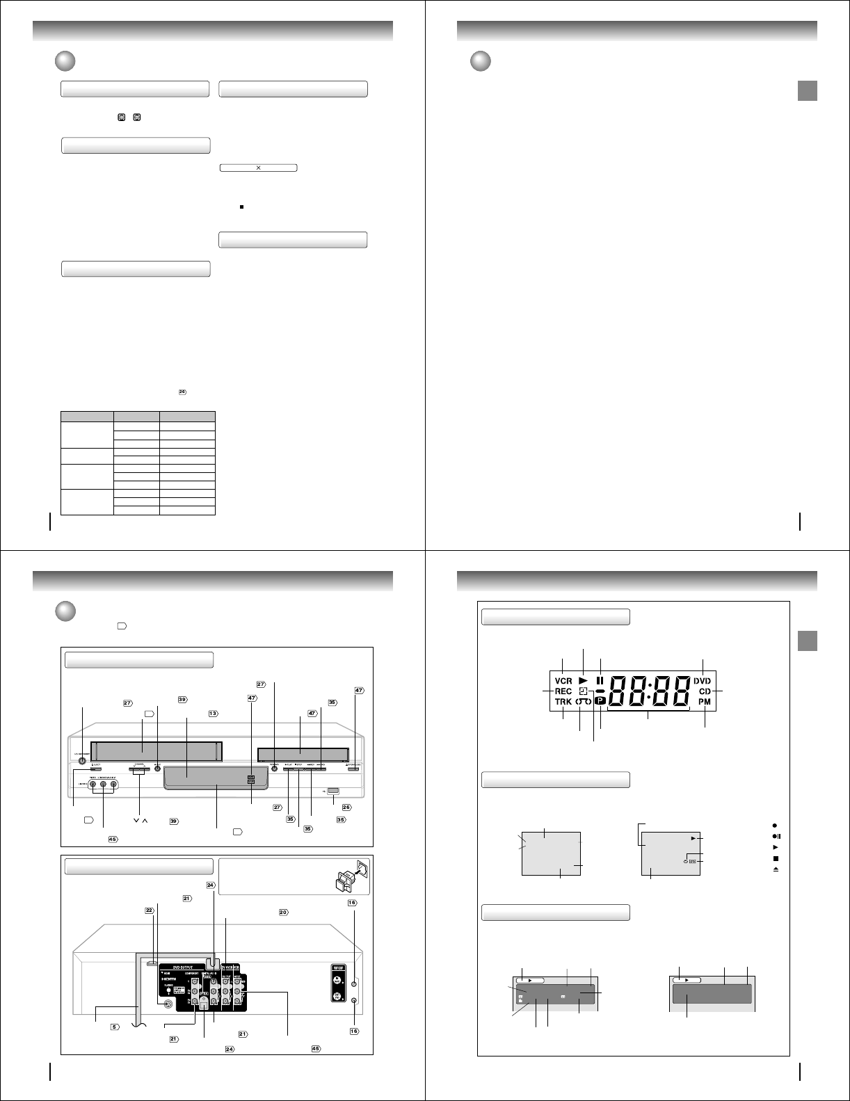
Identification of controls
See the page in for details.
Front panel
ON/STANDBY button
AUDIO (L/R)/VIDEO IN
(LINE IN 2) jacks
EJECT
button
Disc tray
Display window
11
REC button
CHANNEL / buttons
OPEN/CLOSE button
Remote sensor
VCR mode indicator
DVD mode indicator
Cassette loading slot
34
VCR/DVD mode selector
button
STOP button
PLAY button REV button
FWD button
USB Port
Rear panel
DVD S-VIDEO OUT jack
DVD AUDIO (L/R)
OUT jacks
DVD COAXIAL DIGITAL AUDIO OUT jack
DVD COMPONENT
OUT jacks
ANT OUT jack
ANT IN jack
AUDIO (L/R)/VIDEO
IN (LINE IN1) jacks
DVD/VCR common AUDIO
(L/R)/VIDEO OUT jacks
AC power cord
HDMI OUT jack
DVD OPTICAL DIGITAL
AUDIO OUT jack
When connecting the optical digital cable, remove
the cap and fit the connector into the jack firmly.
When not using the jack, keep the cap inserted
to protect it from dust intrusion.
34
11
Introduction
VCR operation status
CH 125
8 : 47
AM
MON
00 : 00 : 00 SP
STEREO SAP
While watching TV
DAY OF THE WEEK
CHANNEL
TAPE SPEED
REAL TIME COUNTER
CLOCK
STEREO AND
SECOND
AUDIO
PROGRAM
(SAP)
8 : 30
AM
MON
00 : 15 : 12 SP
HI-FI
STEREO
While operating a tape
OPERATING
MODE
TAPE IN
AUTO REPEAT
HI-FI STEREO
Disc operation status
Press CALL to display VCR operation status on the screen.
To cancel the display, press CALL again.
Recording :
Rec/Pause
:
Play :
Stop :
Eject :
VCR Icons
Press DISPLAY, the status display of the disc will appear on the screen as follows.
To cancel the display, press DISPLAY again.
VCD
CHAPTER
NO.
OUTPUT SELECTION
Timer Recording indicator (VCR)
Multifunctional indicator
Recording
indicator
(VCR)
Track indicator (CD)
Tape loaded indicator (VCR)
Play indicator
VCR indicator (VCR) Still indicator DVD disc inserted indicator
CD inserted
indicator
AM/PM indicator
(AM is not displayed)
Progressive indicator
Display window
DVD 00:15:25 01:41:39
Title 1/3 Chapter 2/24
1/1 Eng Dolby Digital 1/2 Eng
1/1
ELAPSED
TIME
ANGLE NO.
DISC OPERATION
TITLE NO.
TOTAL
TIME
AUDIO LANGUAGE
DVD
A KIND OF AUDIO
SUBTITLE LANGUAGE
VCD 00:08:32 00:51:03
Track 3/15
DISC OPERATION
TRACK NO.
ELAPSED
TIME
TOTAL
TIME
12
Introduction
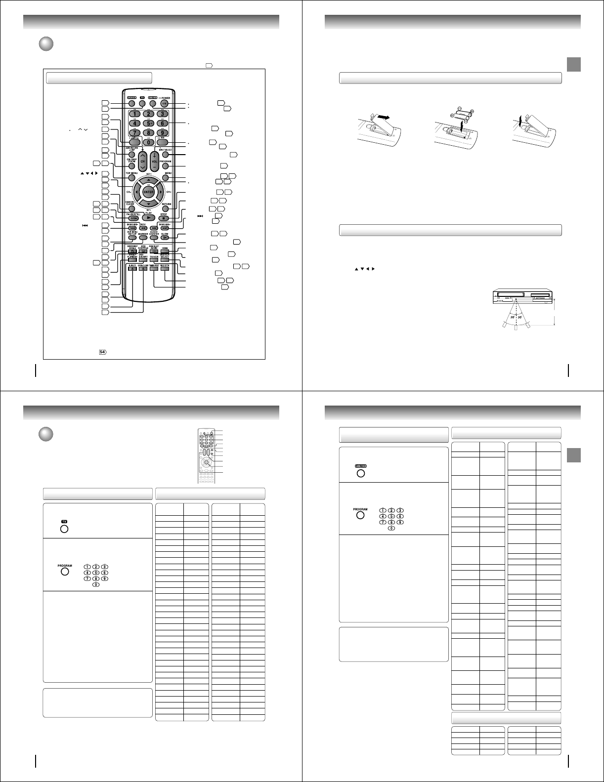
Identification of controls (Continued)
Remote control
DVD MENU button
Use the MENU button to display the menu included on
many DVD video discs. To operate a menu, follow the
instructions in “DVD Menu.”
The instructions in this manual describe the functions on the remote control. See the page in for details.
*TV control buttons
The various brands of TV listed on page 14 can be operated
with this remote control. There may be some TV models that
cannot be operated with this remote control. If this is the case,
use the original remote control supplied with the TV.
•CABLE BOX control buttons
The various brands of CABLE BOX listed on page 15 can
be operated with this remote control. There may be some
CABLE BOX models that cannot be operated with this
remote control. If this is the case, use the original remote
control supplied with the CABLE BOX.
FWD
USB
DVD
DVD/VCR button
13
* TV button
14
14
CALL button
* DISPLAY button
11
11
ZERO RETURN button
JUMP button
37
50
CM SKIP button
ZOOM button
36
50
CANCEL button
CLEAR button
31
50
VCR MENU button
SETUP button
28
63
COUNTER RESET button
37
5954
ATR button
SUBTITLE button
36
56
SP/SLP button
PLAYMODE button
39
52
DVD/USB button
A-B RPT button
58
52
49
38
TOP MENU button
5954
PLAY button
4735
PAUSE/STILL button
4836
REV button
4935
13
28
13
Direction buttons
SET+/
-
buttons
CH+/
-
buttons
///
()
* POWER button
13
* 100 button
14
* VOL +/
-
buttons
14
* INPUT SELECT button
14
PROGRAM button
14
RETURN button
63 70
STOP button
4735
HDMI button
22
DVD/VCR SELECT button
27 47
TV/VCR button
27
REC/OTR button
39
TIMER REC button
42
41
SLOW button
4936
CLOCK/COUNTER button
38
FWD button
49
SKIP button
VISS + button
49
38
AUDIO SELECT button
AUDIO button
44
55
35
DVD MENU button
54 59
* ENTER button
28 63
SKIP button
CABLE BOX button
15
* Direct channel selection
buttons (0-9)
Number buttons (0-9)
13
14
* CH / button
VISS
-
button
51
MARKER button
34
EJECT button (VCR)
47
OPEN/CLOSE (DVD)
ANGLE button
13
Introduction
Operation
• Aim the remote control at the remote sensor and press control buttons to
operate.
• Operate the remote control within 30° angle on either side of the remote
sensor, up to a distance of approx. 7 meters.
Replace the compartment
cover.
Install two “AAA” batteries
(supplied),
paying attention to the
polarity diagram in the battery
compartment.
Open the battery compart-
ment cover in the direction of
the arrow.
Approx. 7 meters
Caution:
Never throw batteries into a fire.
Notes:
• Be sure to use AAA size batteries.
• Dispose of batteries in a designated disposal area.
•
Batteries should always be disposed of with the environment in mind. Always dispose of batteries in accordance with
applicable laws and regulations.
• If the remote control does not operate correctly, or if the operating range becomes reduced, replace batteries with
new ones.
• When necessary to replace batteries in the remote control, always replace both batteries with new ones. Never mix
battery types or use new and used batteries in combination.
• Always remove batteries from remote control if they are dead or if the remote control is not to be used for an
extended period of time. This will prevent battery acid from leaking into the battery compartment.
• Press DVD/VCR to operate the DVD/VCR.
• Press POWER to turn the DVD/VCR on or off.
• Select your desired operating mode (DVD or VCR) using DVD/VCR SELECT.
(DVD or VCR indicator on the front panel will show you which mode is selected.)
• Press CH + or CH – to move through the channels one channel at a time.
• The / / / are also used to navigate on-screen menu system.
• You can directly access specific channels using Direct channel selection buttons (0–9).
• Each press of DVD/VCR SELECT on the remote control, switches the screen between the VCR screen (VCR mode)
and the DVD screen (DVD mode).
12 3
Remote control basics
Inserting batteries
14
Introduction
Multi brand remote control
This remote control can be compatible with various brands of TV/
Cable box/DSS® satellite receiver by setting their control codes. The
TOSHIBA code has initially been set to control TOSHIBA TVs.
Setting TV control codes Table of TV brand codes
Brand name Brand Code
of your TV
Toshiba 01
Bell & Howell 09
Carver 10
Celebrity 03
Citizen 12
Curtis Mathes 09, 12
Dumont 14
Electro band 03
Emerson 09,11
Fisher 09
GE 02, 07, 11
Gibralter 14
Goldstar 11
Hallmark 11
Hitachi 06
Infinity 10
JBL 10
JCB 03
JVC 05
LXI
01, 02, 09, 10, 11
Magnavox 10
Marantz 10
Megatron 06, 11
Memorex 04, 09, 11
MGA 04, 11
Midland 02,07, 14
Mitsubishi 04, 11
Motorola 08
MTC 12
NAD 01, 11
Nikko 11
Optimus 09
Optonica 08
Panasonic 07, 10, 15
Press TV to set the remote control operating
your TV.
1
2
Important
Some TV’s may not respond to all the operations above,
or may not be operated at all with this remote control. In
this case, operate your TV with its own remote control.
Notes:
• For some brands, several control codes (brand codes) are al-
located. Try each of them until the buttons work on your TV.
• If you replace the remote control’s batteries, set the brand code
again.
While holding down PROGRAM, enter the two
digits of your TV's brand code (listed on the
right) using Number buttons (0–9), then release
PROGRAM.
Point the remote control at your TV and use each button
listed below to make sure that your TV is operated
correctly.
POWER To turn the TV on or off.
CH MM
MM
M/??
??
?To select TV channels in the upper
or lower direction.
VOL +/– To adjust the sound level.
INPUT SELECT To select an external source such
as a VCR.
To select TV channels. When select-
ing channels 1 to 9, first enter 0 and
then desired number.
100 To substitute for 100 channel key.
DISPLAY To turn TV’s screen display on or
off.
ENTER To use for the TV’s ENTER key.
Direct channel
selection buttons
(0-9)
Brand name Brand Code
of your TV
Penney
01, 02, 07, 11, 12
Philco 10
Philips 10
Pioneer 16
Princeclub 12
Prism 07
Proscan 02
Proton 11
Pulser 14
Quasar 07, 15
Radio Shack 13
RCA 02
Realistic 09, 11, 13
Runco(NEC) 14
Samsung 11, 12
Sanyo 09
Scotch 11
Scott 11
Sears
01, 02, 09, 10, 11
Sharp 08, 13
Sony 03
Soundesign 11
Supreme 03
Sylvania 10
Tandy 08
Technics 07, 15
Techwood 07
Teknika 04,10,12
TMK 11
Victor 05
Vidikron 10
Vidtech 11
Wards 10, 11,13
Zenith 14
ENTER
PROGRAM
POWER
CH MM
MM
M/??
??
?
0–9
TV
100
INPUT SELECT
VOL +/–
DISPLAY
15
Introduction
Table of Cable box brand codes
Setting Cable box/DSS® satellite
receiver control codes
Press CABLE BOX to set the remote control
operating your Cable box/DSS
®
satellite receiver.
1
2
Important
Some
Cable box/DSS
®
satellite receiver
may not respond
to all the operations above, or may not be operated at all
with this remote control. In this case, operate them with
its own remote control.
Notes:
• For some brands, several control codes (brand codes) are al-
located. Try each of them until the buttons work on your
Cable
box/DSS
®
satellite receiver
.
• If you replace the remote control’s batteries, set the brand code
again.
While holding down PROGRAM, enter the two
digits of your Cable box/DSS® satellite receiver
brand code (listed on the right) using Number
buttons (0–9), then release PROGRAM.
Point the remote control at your Cable box/DSS®
satellite receiver and use each button listed below to
make sure that your
Cable box/DSS
®
satellite receiver
is operated correctly.
POWER To turn the Cable box/DSS® satel-
lite receiver on or off.
CH MM
MM
M/??
??
?To select cable/satellite channels in
the upper or lower direction. (Not
applicable to some brands of cable
box/satellite receiver.)
Number buttons (0–9)
To select desired channels to record.
ENTER
To use for the Cable box’s ENTER key.
(Some cable boxes require you to use 100 button as the
enter button.)
Brand name of Brand Code
your cable box
Toshiba 36
Anvision 13, 20, 21,
22, 23, 24,
25, 26, 58,
62, 84
Archer 1, 20, 21,
29, 42, 44,
63, 88, 91
Cablestar 13, 20, 21,
22, 23, 24,
25, 26, 58,
62, 84
Cableview 30, 42, 44,
52, 63, 88
Citizen 30, 42, 44,
52, 63, 88
Curtis 8, 9, 56, 61
Diamond 1, 20, 21,
29, 42, 44,
63, 88, 91
Eagle 13, 20, 21,
22, 23, 24,
25, 26, 58,
62, 84
Eastern 26, 28
GC Brand 30, 42, 44,
52, 63, 88
Gemini 4, 30, 85
General 1, 2, 3,
4, 31, 34,
55, 83, 85,
91
Hamlin 14, 15, 28,
41
Hitachi 31, 79, 80
Jerrold 1, 2, 3,
4, 31, 34,
55, 85, 91
Macom 31, 79, 80
Magnavox 13, 20, 21,
22, 23, 24,
25, 26, 58,
62, 84
Movietime 29, 32, 38,
39, 42, 44,
88
NSC 29, 32, 38,
39, 42, 44,
88
OAK 10, 11, 12,
13, 46
OAK Sigma 10, 11, 12,
13, 46
Panasonic 6, 8, 16, 17
Brand name of Brand Code
your cable box
Philips 4, 13, 20,
21, 22, 23,
24, 25, 26,
58, 62, 84
Pioneer 5, 6, 78
Pulsar 30, 42, 44,
52, 63, 88
Randtek 13, 20, 21,
22, 23, 24,
25, 26, 58,
62, 84
RCA 6, 8, 16, 17
Realistic 44, 88
Regal 14, 23, 41,
84
Regency 26, 28
Rembrandt 29, 32, 38,
39, 42, 44,
88
Samsung 4, 6, 32,
42, 78
Scientific Atlanta
8, 9, 56, 61
Sheritech 27
SL Mark 4, 6, 32,
42, 78
Sprucher 6, 8, 16, 17
Stargate 4, 6, 30, 32,
42, 44, 52,
63, 78, 88
Sylvania 19
Teknika 74
Telecaption 77
Teleview 4, 6, 32,
42, 78
Texscan 18, 19
Tocom 1, 33, 34,
42, 48, 49,
73, 91
Unica 1, 20, 21,
29, 42, 44,
63, 88, 91
Universal 29, 42, 43,
44, 52, 63,
82, 88
Videoway 7, 23, 45,
50, 84
Viewstar 13, 20, 21,
22, 23, 24,
25, 26, 58,
62, 84
Warner Amex
6
Zenith 7, 23, 45,
50, 84
Instrument
Brand name Brand code
Toshiba 99
RCA 98
Sony 97
Magnavox 95, 96
Brand name Brand code
Draker 94
Primestar 93
Hitachi 92, 89
Panasonic 90
Table of DSS
®
satellite receiver brand codes

16
Connections
Notes: •A clear picture will not be obtained by the DVD/VCR unless the antenna signal is good. Connect the antenna to the
DVD/VCR properly.
•For better quality recording, an indoor antenna or a telescopic antenna is not recommended. The use of an outdoor
type antenna is required.
•If you are not sure about the connection, please refer to qualified service personnel.
The DVD/VCR must be connected “between” the antenna and the TV. First, disconnect the antenna from the TV and
connect it to the DVD/VCR. Then connect the DVD/VCR to the TV. Below are 3 common methods of connecting an
antenna system to a DVD/VCR. Find the type of antenna system you are using and follow the connection diagram.
If both VHF and UHF antennas have 300 ohm twin lead (flat) wires, use a combiner having two 300 ohm inputs and
one 75 ohm output.
Note:
Combination VHF/UHF Antenna with 75 ohm Coaxial Cable
Combination VHF/UHF Antenna with 300 ohm Twin Lead (Flat) Wire
Separate VHF and UHF Antennas
DVD/VCR
VHF UHF
300 ohm Twin Lead (Flat) Wire
(not supplied)
Matching Transformer 300 ohm Input 75
ohm output (not supplied)
300 ohm Twin Lead (Flat) Wire
(not supplied)
75 ohm Coaxial Cable
75 ohm Coaxial Cable
Combiner 75/300 ohm Inputs 75 ohm output
(not supplied)
DVD/VCR
DVD/VCR
Antenna connections
If you are using an antenna system, follow these instructions. If you are a Cable TV subscriber, skip ahead to page
for the proper connections.
Antenna to DVD/VCR connection
1
2
3
17
Connections
UHF
VHF
UHF
VHF
VHF/UHF IN
Note: If a VHF or UHF antenna is used,
set the TV/CABLE menu option to
the “TV” mode.
Note: If a VHF or UHF antenna is used,
set the TV/CABLE menu option
to the “TV” mode.
Note: If a VHF or UHF antenna is used,
set the TV/CABLE menu option to
the “TV” mode.
75 ohm Coaxial Cable (supplied)
Splitter 75 ohm Input
75/300 ohm outputs
(not supplied)
Splitter 75 ohm Input
300 ohm outputs
(not supplied)
TV with single 75 ohm VHF/UHF antenna
input
TV with 300 ohm UHF and 75 ohm VHF
antenna inputs
TV with 300 ohm UHF and 300 ohm VHF
antenna inputs
After you have connected the antenna to the DVD/VCR, you must connect the DVD/VCR to the TV.
Below are 3 common methods of connecting your DVD/VCR to a TV. Find the type of TV you are using and follow the
connection diagram.
This DVD/VCR has a single 75 ohm output for connection to a TV. If your TV has separate VHF and UHF antenna
inputs (numbers 2 and 3 below), use a splitter to connect the DVD/VCR to the TV for VHF and UHF reception.
TV
TV
TV
75 ohm Coaxial Cable
(supplied)
75 ohm Coaxial Cable
(supplied)
DVD/VCR to TV connection
18
Connections
Cable TV connections
VHF/UHF
IN (ANT)
VHF/UHF
IN (ANT)
VHF/UHF
IN (ANT)
Many cable companies offer services permitting reception of extra channels including pay or subscription channels. This
DVD/VCR has an extended tuning range and can be tuned to most cable channels without using a cable company
supplied converter box, except for those premium channels which are intentionally scrambled. If you subscribe to a
premium channel which is scrambled, you must have a descrambler box for proper reception.
Allows: *Recording of nonscrambled channels.
*Use of the programmable timer.
*Recording of one channel while watching another.
Allows: *Recording of channels through the converter box
(scrambled and unscrambled).
*Using the programmable timer to record only the
channel selected at the converter box.
Prevents: *Recording one channel while watching another.
*Using the DVD/VCR tuner to select channels.
DVD/VCR
Incoming Cable
TV
Converter/
Descrambler
Incoming
Cable
TV
TV
Note:
To record from converter/descrambler, DVD/
VCR tuner must be tuned to the converter
output channel, usually channel 3 or 4.
DVD/VCR
DVD/VCR
Note: Whenever a Converter/Descrambler box is placed before the DVD/VCR, you must tune the DVD/VCR to the output of
the Converter/Descrambler box, usually channel 3 or 4.
Incoming Cable
Converter/Descrambler
Allows: *Recording of nonscrambled channels.
*Use of the programmable timer.
*Recording an unscrambled channel while watching
any channel selected at the converter box.
Prevents: Recording scrambled channels.
Note:
If you are playing a tape or using the tuner
built into the DVD/VCR, the converter must
be set to the video channel output of the DVD/
VCR (either 3 or 4).
1
2
3
19
Connections
VHF/UHF
IN (ANT)
A
B
VHF/UHF
IN (ANT)
A
B
This DVD/VCR cannot receive scrambled programs since it does not contain a descrambler. In order to receive scram-
bled programs, your existing descrambler must be used. Descrambler boxes are available from cable companies. Con-
sult your local cable company for more information concerning connection to their descrambler equipment. There are
many ways to connect your DVD/VCR to a cable system. Below are six common methods of connection.
IMPORTANT: Make sure the TV/CABLE menu option is set to the “CABLE” mode.
Incoming Cable
Allows: *Recording of one channel while watching another.
*Using the programmable timer to record only the channel selected at the converter box.
*Recording of all channels through the converter box.
Prevents: *Watching scrambled channels while recording another channel.
*Using the DVD/VCR tuner to select channels.
DVD/VCR
Splitter
Converter/Descrambler
TV
DVD/VCR
Converter/Descrambler A/B Switch
TV
Incoming Cable
Splitter
Allows: *Recording of nonscrambled channels.
*Recording of one channel while watching another.
*
Watching premium channels through the converter while recording nonscrambled channels.
*Using the programmable timer.
Prevents: Recording scrambled channels.
DVD/VCR
Splitter
TV
Converter/Descrambler
A/B Switch
VHF/UHF
IN (ANT)
A
B
Allows: *Recording of all channels through the converter box.
*Recording a scrambled or unscrambled channel while watching another (scrambled or
unscrambled) channel.
*Using the programmable timer to record only the channel selected at the converter box.
Prevents: Using the DVD/VCR tuner to select channels.
A/B Switch
Incoming Cable Converter/Descrambler
4
5
6

20
Connections
Connecting to a TV
Connect the DVD/VCR to your TV.
To VIDEO
OUT To ANALOG AUDIO OUT
(red) (white)
(yellow)
Signal flow
To wall outlet
To video input
(yellow) (red)
Audio/video cable (supplied)
To audio inputs
(white)
Notes:
• Refer to the owner’s manual of the connected TV as well.
• When you connect the DVD/VCR to your TV, be sure to turn off the power and unplug both units from the wall outlet before
making any connections.
• If your television set has one audio input, connect the left and right audio outputs of the DVD/VCR to a Y cable adapter
(not supplied) and then connect to your TV.
• Connect the DVD/VCR directly to your TV. If you connect the DVD/VCR to a VCR, TV/VCR combination or video selector,
the playback picture may be distorted as DVD video discs are copy protected.
• While HDMI is being output in the DVD mode, it is impossible to output from the Video out jack, S-video out jack or
Component video out jacks.
TV or monitor with
audio/video inputs
Basic connection
Note: This method transports VHS and DVD-video signals. For enhanced DVD-video performance, we recommend you to
connect the S-video or ColorStream® component video outputs to your TV/monitor also.
• Make sure following setting.
On-screen display Select: Page
“Digital Out” “PCM” or “Bitstream”
21
Connections
Notes:
• Refer to the owner’s manual of the connected equipment as well.
• When you connect the DVD/VCR to other equipment, be sure to turn off the power and unplug all of the equipment from
the wall outlet before making any connections.
• If you place the DVD/VCR near a tuner or radio, the radio broadcast sound might be distorted. In this case, place the DVD/
VCR away from the tuner and radio.
• The output sound of the DVD/VCR has a wide dynamic range. Be sure to adjust the receiver’s volume to a moderate
listening level. Otherwise, the speakers may be damaged by a sudden high volume sound.
• Turn off the amplifier before you connect or disconnect the DVD/VCR’s power cord. If you leave the amplifier power on, the
speakers may be damaged.
• While HDMI is being output in the DVD mode, it is impossible to output from the Video out jack, S-video out jack or
Component video out jacks.
•When connecting to a TV using the S-video jack, make sure that the Progressive indicator “” on the display
window is not lit. If it is lit, the S-video outputs do not feed the correct signals and you cannot see any picture. To
turn off the Progressive indicator, select Interlaced output
69
.
Connecting to an audio system and TV equipped with S-video input/component video inputs
• Actual
labels for
component
video inputs
may vary
depending
on the TV
manufac-
turer (ex. Y,
R-Y, B-Y or
Y, C B, CR).
TV or monitor with
component video inputs
To
P
R/
C
R
video input
To P
R
/C
R
VIDEO
OUT
Signal flow
To wall outlet
To audio inputs of
the amplifier
(red)
(white)
(red) (white)
To Y
VIDEO
OUT
To P
B
/C
B
VIDEO
OUT
To Y video input
To
P
B/
C
B
video input
Audio system
To ANALOG
AUDIO OUT
To S-VIDEO
OUT
Component
video cable
(not supplied)
To S-video input
S-video cable
(not supplied) Audio cable (not supplied)
If you connect the DVD/VCR to
your TV with the DVD OUT jacks,
select the corresponding video
input on your television to watch
DVD video discs.
The S-video output and component video output transports the DVD-video signal exclusively and will deliver enhanced DVD
video picture performance.
S-video output
An S-Video connection is superior to Video (Yellow) output. Use this method for DVD playback when the connected television has S-
Video input, and does not have component video inputs.
Component video outputs
PROGRESSIVE outputs
Some TVs or monitors are equipped with component video inputs that are capable of reproducing a progressively scanned video
signal. Connecting to these inputs allows you to view the highest quality pictures with less flicker.
INTERLACED outputs
Some TVs or monitors are equipped with component video inputs. Connecting to these inputs allows you to enjoy the highest quality
DVD picture playback.
Notes:
• To switch the scan mode between the interlace and progressive modes, see page
69
.
• In some TVs or monitors, the color levels of the playback picture may be reduced slightly or the tint may change. In such a case,
adjust the TV or monitor for optimum performance.
• Make sure following setting.
On-screen display Select: Page
“Digital Out” “PCM” or “Bitstream”
22
Connections
About HDMI
HDMI (High Definition Multimedia Interface) supports both video
and audio on a single digital connection for use with DVD players,
DTV, set-top boxes, and other AV devices. HDMI was developed
to provide the technologies of High Bandwidth Digital Content
Protection (HDCP) as well as Digital Visual Interface (DVI) in one
specification. HDCP is used to protect digital content transmitted
and received by DVI-compliant or HDMI-compliant displays.
HDMI has the capability to support standard, enhanced, or high-
definition video plus standard to multi-channel surround-sound
audio. HDMI features include uncompressed digital video, a
bandwidth of up to 2.2 gigabytes per second (with HDTV signals),
one connector (instead of several cables and connectors), and
communication between the AV source and AV devices such as
DTVs.
HDMI, the HDMI logo and High-Definition Multimedia Interface are
trademarks or registered trademarks of HDMI licensing LLC.
Connecting to a display (Using the HDMI cable)
Signal flow
HDMI Cable (not supplied)
HDMI-compatible display
To HDMI input
To HDMI OUT
To wall outlet
Connecting to a TV (Continued)
Switching the video quality (HDMI mode) using HDMI
button on the remote control
Press HDMI on the remote control to receive a suitable
video quality. The video quality is required to match
your TV having HDMI feature and suitable quality.
Please also check your TV owner's manual.
Press HDMI to change the video quality as follows:
On-screen display Select: Page
“Digital Out” “PCM”
• Make sure following setting.
Notes:
It is only possible to switch the HDMI output in the following below cases unless only an Audio/Video Cable/S-video cable/
Component Video Cables is connected.
* When in DVD Mode (in DISC/USB Mode)
* When the disc is in Stop or Resume mode
* When the Setup Menu is not being displayed
* When the HDMI Cable is connected
HDMI: Off
NTSC: 480p (Progressive)
NTSC: 720p (Progressive)
NTSC: 1080i (Interlace)
HDMI: cannot output
Component/Composite/S-Video: outputting
(Output setup is set to Progressive : cannot output S-Video)
HDMI: outputting
Component/Composite/S-Video: cannot output
For proper operation, it is recommended
that you use as short an HDMI cable as
possible.
23
Connections
USER setting/operation Content of output for each output jack
Mode
VCR/DVD
HDMI
Output
*1 HDMI
Output
Setting Video S-Video Component RF
Modulator
VCR VCR VCR
DVD
DVD
DVD 480p (DVD)
480i (DVD)
480p (DVD)
480i (DVD)
DVD
DVD
DVD
Off Interlace
Progressive
Interlace
Progressive
Interlace
Progressive
Interlace
Progressive
480p
720p
1080i
480p
720p
Off
1080i
480p (DVD)
720p (DVD)
1080i (DVD)
480p (DVD)
720p (DVD)
1080i (DVD)
480p (DVD)
720p (DVD)
1080i (DVD)
480p (DVD)
720p (DVD)
1080i (DVD)
480p
720p
1080i
480p
720p
1080i
-
-
-
-
-
-
-
-
-
-
-
-
-
-
-
Notes:
• When in DVD Mode/outputting HDMI signal, it is impossible to output any video images from either the Video out jack/S-Video
out jack/Component out jacks.
If the viewer would like to view videos using the Video out jack/S-Video out jack/Component out jacks, then the HDMI output must
set to “Off” by pressing the HDMI button on the remote control.
• When the HDMI Cable is connected, if the HDMI is pressed or the VCR Mode is switched to DVD Mode, there is a possibility that
the monitor will not show any output images. In this case, turn off the HDMI mode.
Deactivate HDMI output with HDMI (For details, please refer to “Switching the video quality (HDMI mode) using HDMI
button on the remote control” ).
• Refer to the Owner’s manual of the connected TV as well.
• When connecting the DVD/VCR to your TV, be sure to turn off the power and unplug both units from the wall outlet before making any
connections.
• If you have an HDMI (with HDCP) equipped monitor or display, you can connect it to the DVD/VCR using the HDMI cable.
• The HDMI connector outputs uncompressed digital video as well as almost every kind of digital audio that the DVD/VCR is compatible
with, including DVD-Video, Video CD, Audio CD and MP3/WMA/JPEG/DivX® files.
• No sound will be output from the HDMI cable if the “Digital Out” is not set to “PCM” .
3Picture Output
• DVD Mode
The following refers to instructions for Picture Output in DVD Mode.
There is no Analog Output (*2) for HDMI output.
When HDMI output setting is “Off”, there is no HDMI output.
*2: Output from Video out jack/S-Video out jack/Component out jacks
• VCR Mode
The following refers to instructions for Picture Output in VCR mode.
This set outputs the picture from the Video out jack in VCR mode. However, please see the following instructions for HDMI out
jack/S-Video out jack/Component out jacks.
<During HDMI Output>
DVD picture is always output from HDMI out jack during HDMI Output, but it cannot output from S-Video out jack/Component out
jacks during HDMI Output.
<When HDMI Output setting is “Off”>
When the HDMI output setting is “Off”, this set outputs picture signals as follows according to the HDMI Setting in the Setup
Menu. When HDMI Output setting is “Off”, HDMI output does not function.
When the Output setting is “Interlace”: Picture from VCR is output from the Video out jack
Picture from the DVD is output from the S-Video out jack/Component out jacks
When Output setting is “Progressive”: Picture from VCR is output from the Video out jack
NO OUTPUT from the S-Video out jack
Picture from the DVD is output from the Component out jacks
The content of the output for each output jack are as shown in the following table and differ depending on User settings/operation.
*1: Settings for HDMI output format are performed using the “HDMI” key on the remote control.
24
Connections
Connecting to an audio equipment
You can enjoy high quality dynamic sounds of DVD video discs or
audio CDs by connecting the DVD/VCR to optional audio
equipment.
For connection to your TV, see “Connecting to a TV”
.
: Front speaker
: Rear speaker
: Sub woofer
: Center speaker
: Signal flow
Connecting to an amplifier equipped with a Dolby® Digital decoder
Connecting to an amplifier equipped with Dolby Surround Pro Logic
Dolby Surround Pro Logic
You can enjoy the dynamic realistic sound of Dolby Surround Pro Logic by connecting an amplifier and speaker system (right and left
front speakers, a center speaker, and one or two rear speakers).
Connecting to an amplifier equipped with a DTS decoder
Digital Theater Systems (DTS)
DTS is a high quality surround technology used in theaters and now available for home use,
on DVD video discs or audio CDs.
If you have a DTS decoder or processor, you can obtain the full
benefit of 5.1 channel DTS encoded sound tracks on DVD
video discs or audio CDs.
Manufactured under license from
Dolby Laboratories. “Dolby”, “Pro
Logic” and the double-D symbol are
trademarks of Dolby Laboratories.
• Use DVD video discs
encoded via the Dolby Digital
recording system.
• Make sure following setting.
• Use DVD video discs or
audio CDs encoded via the
DTS recording system.
• Make sure following setting.
* Connect one or two rear speakers.
The output sound from the rear
speakers will be monaural even if you
connect two rear speakers.
“DTS” and “DTS Digital Out” are
trademarks of Digital Theater Systems,
Inc.
Amplifier equipped with a
Dolby Digital decoder
75 1 coaxial cable (not supplied)
To COAXIAL
type digital
audio input
*
Amplifier equipped with a
DTS decoder
To COAXIAL
type digital
audio input
• This selection uses the following reference mark.
To ANALOG
AUDIO OUT
To audio input
Audio cable (not supplied)
75 1 coaxial cable (not supplied)
Dolby Digital
Dolby Digital is the surround sound technology used in theaters showing the latest movies, and is
now available to reproduce this realistic effect in the home. You can enjoy motion picture and live
concert DVD video discs encoded via the Dolby Digital recording system with this dynamic realistic
sound by connecting the DVD/VCR to a 6 channel amplifier equipped with a Dolby Digital decoder
or Dolby Digital processor. If you have a Dolby Pro Logic Surround decoder, you will obtain the full
benefit of Pro Logic from the same DVD movies that provide full 5.1-channel Dolby Digital soundtracks,
as well as from titles with the Dolby Surround mark.
Amplifier equipped with
Dolby Surround Pro Logic
With an amplifier equipped with Dolby Digital
Connect the equipment the same way as described in “Connecting to an amplifier
equipped with a Dolby Digital decoder.” Refer to that amplifier’s owner’s manual and set
the amplifier so that you can enjoy Dolby Surround Pro Logic sound.
With an amplifier not equipped with Dolby Digital
Connect the equipment as follows.
• This connection is only suitable for Video CDs and
Audio CDs.
Connect either
Connect either
On-screen display Select: Page
“Digital Out” “PCM” or
“Bitstream”
Optical cable (not supplied)
To OPTICAL
type digital
audio input
On-screen display Select: Page
“Digital Out” “PCM” or
“Bitstream”
• Make sure following setting.
Optical cable (not supplied)
To OPTICAL
type digital
audio input
On-screen display Select: Page
“Digital Out” “Bitstream”
25
Connections
75 1 coaxial cable (not supplied)
75 1 coaxial cable (not supplied)
Warning
When playing DTS-encoded discs (DVD video discs and audio CDs), excessive noise may be output from the analog stereo
jacks. To avoid possible damage to the audio system, you should take proper precautions when the ANALOG AUDIO OUT (L/
R) jacks of the DVD/VCR are connected to an amplification system. (Do not leave the ANALOG AUDIO OUT (L/R) wires
dangling.) To enjoy DTS Digital Surround™ playback, an external 5.1 channel DTS Digital Surround™ decoder system must
be connected to the OPTICAL or COAXIAL DIGITAL AUDIO OUT jack of the DVD/VCR.
Connecting to an amplifier equipped with an MPEG2 audio decoder
MPEG2 sound
You can enjoy motion picture and live concert DVD video discs encoded via the MPEG2 recording system with dynamic realistic sound
by connecting an amplifier equipped with an MPEG2 audio decoder or MPEG2 audio processor.
Connecting to an amplifier equipped with a digital audio input
2 channel digital stereo
You can enjoy the dynamic sound of 2 channel digital stereo by connecting an amplifier equipped with a digital audio input and speaker
system (right and left front speakers).
Notes:
• DO NOT connect the OPTICAL or COAXIAL DIGITAL AUDIO OUT jack of the DVD/VCR to the AC-3 RF input of a Dolby
Digital Receiver. This input on your A/V Receiver is reserved for Laserdisc use only and is incompatible with the OPTICAL or
COAXIAL DIGITAL AUDIO OUT jack of the DVD/VCR.
• Connect the OPTICAL DIGITAL AUDIO OUT jack of the DVD/VCR to the “OPTICAL” input of a Receiver or Processor.
• Connect the COAXIAL DIGITAL AUDIO OUT jack of the DVD/VCR to the “COAXIAL” input of a Receiver or Processor.
• Refer to the owner’s manual of the connected equipment as well.
• When you connect the DVD/VCR to other equipment, be sure to turn off the power and unplug all of the equipment from the
wall outlet before making any connections.
• The output sound of the DVD/VCR has a wide dynamic range. Be sure to adjust the receiver’s volume to a moderate
listening level. Otherwise, the speakers and your hearing may be damaged by a sudden high volume sound.
• Turn off the amplifier before you connect or disconnect the DVD/VCR’s power cord. If you leave the amplifier’s power on, the
speakers may be damaged.
• Use DVD video discs
encoded via the MPEG2
recording system.
• Make sure following setting.
Amplifier equipped with an
MPEG2 audio decoder
To COAXIAL
type digital
audio input
Amplifier equipped with a
digital audio input
To COAXIAL
type digital
audio input
Connect either
Connect either
Optical cable (not supplied)
To OPTICAL
type digital
audio input
On-screen display Select: Page
“Digital Out” “PCM” or
“Bitstream”
Optical cable (not supplied)
To OPTICAL
type digital
audio input
• Make sure following setting.
On-screen display Select: Page
“Digital Out” “PCM” or
“Bitstream”
26
Connections
Connecting to a USB Mass Storage
Signal flow
To USB port
USB Cable (not supplied)
USB Mass Storage
Connecting to a USB Mass Storage
Notes:
In order to avoid damage to the unit, the USB Mass Storage, the Memory Card, etc, the following instructions should
be observed.
• Insert the USB cable properly taking care to observe the correct port direction.
• Make sure the unit is off or is set to DISC mode when disconnecting the USB Mass Storage from the unit.
• In order to avoid damage to recorded data, do not plug in or unplug the unit, no matter whether the USB Mass
Storage is On or Off, including Resume Stop mode.
• In order to avoid damage to recorded data, do not disconnect the USB Mass Storage from the port, no matter
whether the USB Mass Storage is On or Off, including Resume Stop mode.
• Before removing the Memory Card while a Memory Card Reader or Digital Camera is connected to the unit, ensure
that the power is off or that the unit is in DISC mode .
• Do not remove the Memory Card from the Memory Card Reader or Digital Camera no matter whether the Memory
Card is On or Off, including Resume Stop mode.
• In order to avoid damage to recorded data, do not plug in or unplug the unit, no matter whether the Memory Card
is inserted or not inserted into the Memory Card Reader or Digital Camera, including Resume Stop mode.
• In order to understand the correct operation and handling of the USB Mass Storage, read the USB Mass Storage
instructions carefully.
• As it cannot be guaranteed that recorded data will not be damaged while using this unit, it is recommended to
make back-up data.
• Avoid connecting any other USB connectable device that uses electricity from the USB connector such as a Printer
or Keyboard when the USB Mass Storage is connected.
• It is impossible to connect several devices by using a USB HUB.
This unit can be used to read JPEG, WMA, MP3 and DivX® data for any memory card reader/writer or digital camera that
accepts USB Mass Storage Class.
For devices that are compatible with the unit’s USB port, please refer to page
8
.
27
Basic setup (VCR)
Setting the video channel
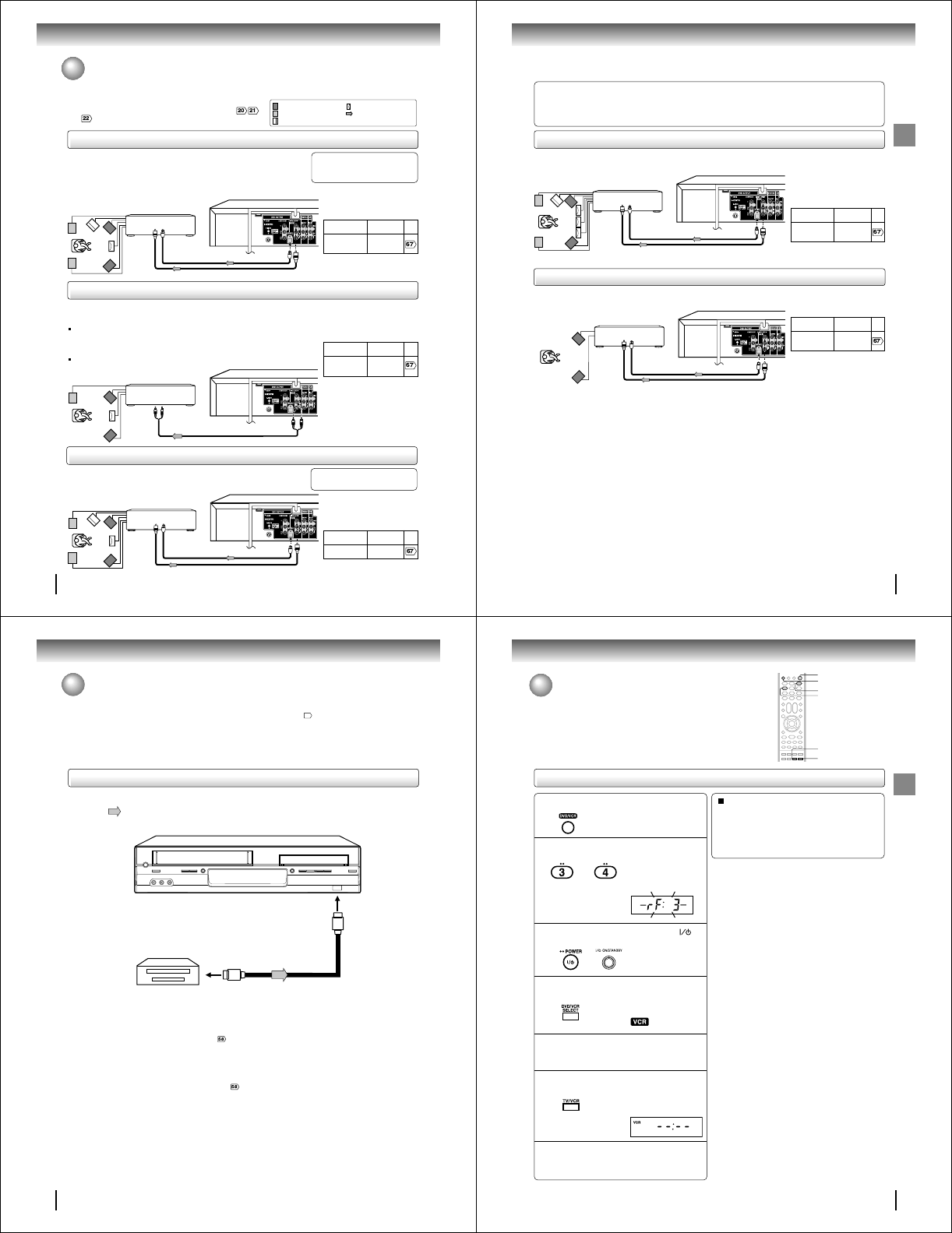
When a TV is connected with the 75 ohm coaxial cable only.
To view playback of a recorded tape or DVD disc, or to watch a
program selected by the VCR's channel selector, the TV must be set to
channel 3 or 4 (video channel).
Setting the video channel
Press POWER on the remote control or ON/
STANDBY on the unit to turn on the DVD/VCR.
Press DVD/VCR SELECT to select the VCR mode.
Turn ON the TV and set to CH 3 or 4 to corre-
spond with the channel selected in step 2.
Press TV/VCR to select the VCR position.
Select any channel to receive a TV station in
your area.
The channel number will appear on the screen
for about 4 seconds.
2
The VCR indicator on the
front panel will light.
3
4
5
6
7
The VCR indicator will
appear in the display
window.
For a push-button TV tuner
If CH 3 or 4 corresponding to the video channel cannot
be tuned on your TV, proceed as follows: set the VCR
3/4 channel selector and the TV to CH 3 or 4, playback
a prerecorded tape and tune the TV to receive a sharp
color picture from the video cassette recorder. Refer to
your TV owner's manual for details.
Note:
If the unit does not operate properly, or No key operation
(by the unit and/or the remote control): Static electricity, etc.,
may affect the player's operation. Disconnect the AC power cord
once, then connect it again.
POWER
DVD/VCR SELECT
DVD/VCR
Press and hold 3 or 4 on the remote for 3
seconds in standby mode.
The video channel will
start to flash for 3
seconds in the display
window.
3
4
OR
1Press DVD/VCR to operate the DVD/VCR.
TV/VCR
Basic setup (VCR)
28
Basic setup (VCR)
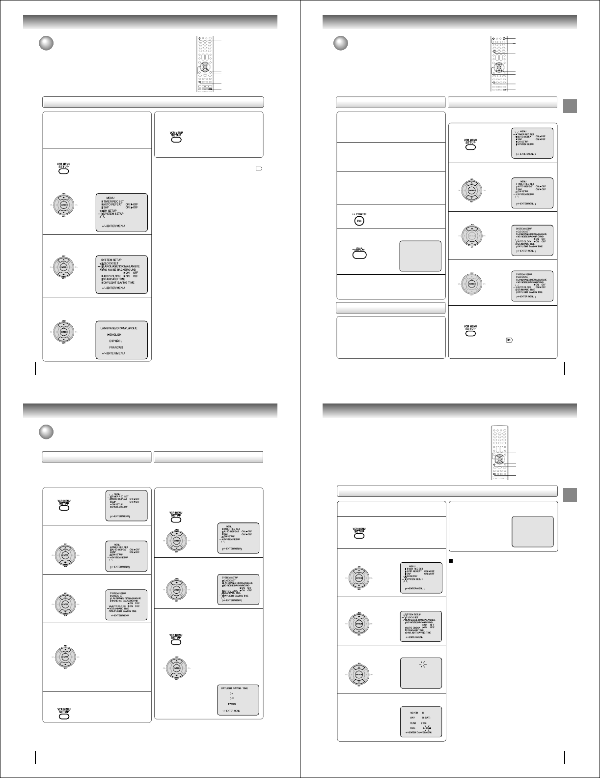
Press SET + or – to select “LANGUAGE”, then
press ENTER.
Press VCR MENU.
The VCR menu screen will appear.
Press SET + or – to select “SYSTEM
SETUP”, then press ENTER.
If you use the unit for the first time,
press VCR MENU, instead of the
“SYSTEM SETUP” menu screen of
the main screen in step 2 may appear.
Setting the language
Setting the language
You can choose from three different languages (English,
French and Spanish) for the on-screen display.
1
2
Press SET + or – to select the desired language:
English (ENGLISH), Spanish (ESPAÑOL) or
French (FRANCAIS), then press ENTER.
3
Press VCR MENU until the menu screen is
cleared.
4
〈 〉
〈〉
〈 〉
Notes:
• Both the VCR and the DVD have their own player menus
63
.
• If no buttons are pressed for more than 60 seconds, the VCR
MENU screen will return to normal TV-operation automatically.
Preparation:
• Turn ON the TV and select to the corresponding
video input.
• Press DVD/VCR to operate the DVD/VCR.
• Press DVD/VCR SELECT to select the VCR mode.
(The VCR indicator will light.)
SET +/–
VCR MENU
DVD/VCR
ENTER
DVD/VCR SELECT
29
Basic setup (VCR)
Connect the Antenna or Cable system.
• If you use a cable box, turn it on.
Clock setting
The AUTO CLOCK function will automatically set the built-in clock
(Month, Day, Year and Time) when the DVD/VCR is connected to an
Antenna or Cable system and it is turned off. The DVD/VCR searches for
a station in your area containing the necessary AUTO CLOCK setting
signals. Once received, it will take approximately 4 minutes for the clock
to set itself automatically.
Preparation:
• Turn ON the TV and select the corresponding video input.
• Press DVD/VCR to operate the DVD/VCR.
• Press DVD/VCR SELECT to select the VCR mode.
(The VCR indicator will light.)
1
Plug the AC power cord to the AC outlet.
2
Make sure the DVD/VCR is turned off.
• Depending on the reception
condition it may take approx. thirty
minutes.
• If you press POWER, the Auto
Clock set is not programmed.
3
Wait at least three minutes and press POWER.
4
Press CALL to check the clock setting on
the on screen display.
5
If the clock is not set, check the antenna
condition. The AUTO CLOCK may not
function properly if the reception condition
is not good.
6
To set AUTO CLOCK to off
The auto clock adjustment will be updated at 6:00
AM, 12:00 PM and 6:00 PM everyday when the DVD/
VCR turned off.
• If you use a cable box and you want AUTO CLOCK
adjustment to be performed, the cable box must be
left on.
• The AUTO CLOCK adjustment is not effective when
there is a difference of more than 5 minutes exists
between the built-in clock time and the actual time.
When shipped from factory the AUTO CLOCK is set to “ON”.
But if you do not want AUTO CLOCK setting:
Press VCR MENU.
1
Press SET + or – to select “SYSTEM SETUP”,
then press ENTER.
2
Press SET + or – to select “AUTO CLOCK”.
3
Press ENTER to select “OFF”.
4
Press VCR MENU repeatedly to return to the
normal screen.
• When the AUTO CLOCK is set to
“OFF”, the AUTO CLOCK adjustment
does not function. Set the clock
manually .
5
POWER
VCR MENU
ENTER
CALL
DVD/VCR
SET +/–
DVD/VCR SELECT
AUTO CLOCK setting
AUTO CLOCK adjustment
CH 125
8 : 47
AM
MON
00 : 00 : 00 SP
STEREO SAP
30
Basic setup (VCR)
Press VCR MENU.
1
Press SET + or – to select “SYSTEM SETUP”,
then press ENTER.
2
Press
SET + or –
to select “STANDARD TIME”
,
then press ENTER.
3
Press SET + or – to select your time zone,
then press ENTER.
4
Press VCR MENU until the menu screen is
cleared.
5
In the rare event that you live within broadcast range of two
stations in two different time zones, the DVD/VCR may recognize
the wrong station for the AUTO CLOCK setting.
To correct the situation:
Notes:
• To be able to select the standard time, the clock must first be
set by AUTO CLOCK once.
• If you live in Newfoundland and the AUTO CLOCK does not
function properly, set the AUTO CLOCK menu option to “OFF”
and set the clock manually.
Press VCR MENU.
Press SET + or – to select “SYSTEM SETUP”,
then press ENTER.
1
Press SET + or – to select “DAYLIGHT
SAVING TIME”, then press ENTER.
2
Press SET + or – to select one of the
options, then press ENTER. Press VCR
MENU until the MENU screen is cleared.
3
Notes:
• When shipped from factory, the DAYLIGHT SAVING TIME is
set to “AUTO” position.
• When the clock is not set, DAYLIGHT SAVING TIME setting
is not available.
• When there is no DAYLIGHT SAVING TIME in your area, al-
ways select “OFF” position in step 3.
When you want to set the
DAYLIGHT
SAVING TIME
manually, on the first
Sunday in April you set to “ON”, and
on the last Sunday in October you set
to “OFF”.
ON:
OFF:
AUTO:
for manual setting
(forward one hour)
for manual setting
(back one hour)
for automatic setting
(read XDS in the signal)
〈〉
ATLANTIC : GMT–4hours
EASTERN : GMT–5hours
CENTRAL : GMT–6hours
MOUNTAIN : GMT–7hours
PACIFIC : GMT–8hours
ALASKA : GMT–9hours
HAWAII : GMT–10hours
AUTO : AUTO SET
(GMT: Greenwich Mean Time)
〈〉
To set DAYLIGHT SAVING TIME
You can set the DAYLIGHT SAVING TIME automatically or
manually.
To set STANDARD TIME
Clock setting (Continued)
31
Basic setup (VCR)
CANCEL
Press VCR MENU.
EXAMPLE: Setting the clock to “8:30 AM” October, 28
(SAT), 2006.
1
8 : 30
AM
SAT
Manual clock setting
After setting the clock, date and time starts
functioning automatically.
6
Note:
After a power failure or disconnection of the power, the timer
settings will be lost. In this case, reset the present time.
To make corrections any time during the process
Press CANCEL repeatedly until the item you want to
change blinks, then press SET + or –.
Press SET + or – to select “SYSTEM SETUP”,
then press ENTER.
2
Press SET + or – to select “CLOCK SET”,
then press ENTER.
3
Press SET + or – to set the month, then press
ENTER.
4
Set the day, year and time as in step 4.
5
〈 〉
If the AUTO CLOCK process did not set the date and time correctly, you
must set them manually for timer recording and DAYLIGHT SAVING TIME. VCR MENU
〈+/
–
/ENTER/CANCEL/MENU
〉
MONTH
DAY
YEAR
TIME
10
1 (SUN)
2006
12 : 00
AM
〈 〉
ENTER
SET +/–
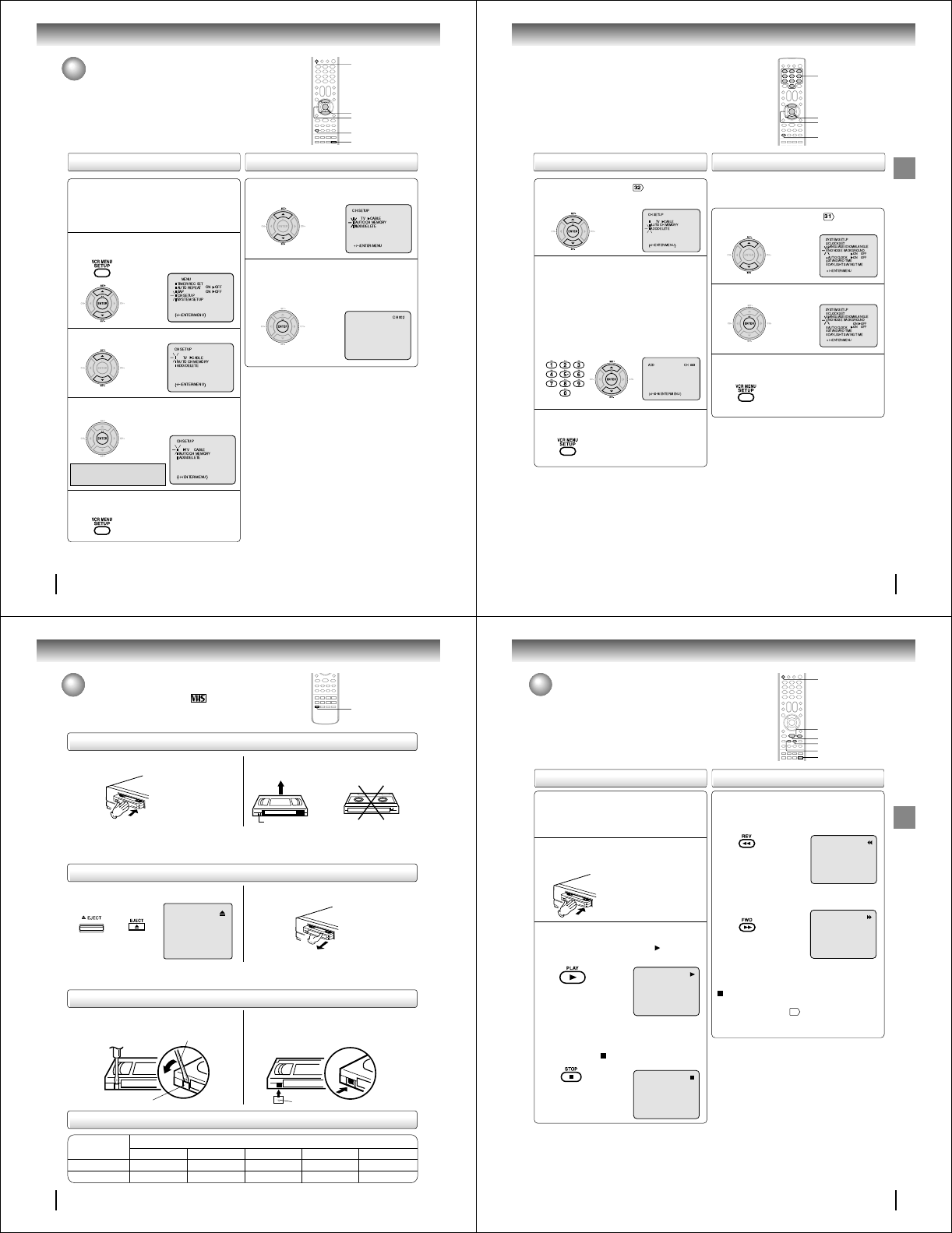
32
Basic setup (VCR)
Tuner setting
This DVD/VCR is equipped with a channel memory feature which allows
channels to skip up or down to the next channel set into memory,
skipping over unwanted channels. Before selecting channels, they must
be programmed into the DVD/VCR’s memory. In addition to normal
VHF and UHF channels, this DVD/VCR can receive up to 113 Cable
TV channels. To use this DVD/VCR with an antenna, set the TV/CABLE
menu option to the TV mode. When shipped from the factory, this menu
option is in the CABLE mode.
Press VCR MENU. Press
SET + or –
to select
“CH SETUP”, then press ENTER.
1
Press SET + or – to select “TV/CABLE”.
2
TV/CABLE selection Setting channels automatically
Repeat left step 1 and press SET + or – to
select “AUTO CH MEMORY”.
1
Press ENTER.
Auto tuning will begin. The channel dis-
play will count up and when finished,
the screen returns to normal.
2
Note:
You can’t select “CH SETUP” if you set the channel to “L1” or
“L2”.
Press ENTER to select the TV or CABLE
mode.
The arrow indicates the selected mode.
3
Press VCR MENU until the menu screen is
cleared.
4
TV - VHF/UHF channels
CABLE - Cable TV channels
VCR MENU
ENTER
〈 〉
DVD/VCR
Preparation:
• Turn ON the TV and select to the corresponding
video input.
• Press DVD/VCR to operate the DVD/VCR.
• Press DVD/VCR SELECT to select the VCR mode.
(The VCR indicator will light.)
SET +/–
DVD/VCR SELECT
33
Basic setup (VCR)
Repeat the step 1 on page . Then press SET +
or – to select the “ADD/DELETE” and press
ENTER.
1
To ADD/DELETE channels
Press VCR MENU until the menu screen is
cleared.
3
To Add or Delete channels
2
1) Press Direct channel selection buttons (0–9)
or SET +/– to select a channel number you want
to add or delete.
2) To add channels
Press ENTER until “ADD” appears on the screen.
To delete channels
Press ENTER until “DELETE” appears on the
screen. The channel number will blink.
3) Repeat step 1 and 2 to add or delete other
channel.
Noise elimination
When you don't want to receive a weak signal broadcast, a Blue
back screen can be obtained by selecting the NO NOISE BACK-
GROUND to “ON”. When the unit is shipped from the factory,
the NO NOISE BACKGROUND is set to “ON”.
Repeat the steps 1~2 on page and press
SET + or – to select “NO NOISE BACKGROUND”.
1
Press ENTER to select “ON” or “OFF” position.
2
〈〉
Press VCR MENU until the menu screen is
cleared.
3
0–9
ENTER
VCR MENU
〈〉
SET +/–
34
Playback (VCR)
Loading and unloading a cassette tape
Use only video cassette tapes marked .
Loading
Remove the erase prevention tab with a screwdriver. Cover the hole with a piece of adhesive tape.
To record again
Screwdriver
Automatic tape eject
This DVD/VCR will automatically rewind the tape when the tape has ended. Once the tape is rewound to its beginning,
the cassette tape will be ejected automatically.
Push the center of the tape until it is automatically
inserted.
Insert the cassette tape with its labeled side facing up
and the erase prevention tab positioned at your left. An
inverted cassette tape cannot be inserted.
Automatic playback
When loading a cassette tape without an erase prevention tab, playback will start automatically.
Automatic power ON
When you insert a cassette tape, the DVD/VCR power will turn ON automatically.
2
Erase prevention tab
Adhesive tape
Remove the cassette tape.
Erase prevention tab
Unloading
To prevent accidental erasure
To prevent accidental erasure
Tape speed and maximum recording time
Video cassette tape
Tape Speed
SLP (Super Long Play)
T-160 T-120 T-90 T-60 T-30
2-2/3 hours 2 hours 1-1/2 hours 1 hour 30 minutes
8 hours 6 hours 4-1/2 hours 3 hours 1-1/2 hours
SP (Standard Play)
EJECT
or
Press EJECT on the front panel or on the remote.
1
35
Playback (VCR)
Cassette tape playback
To play a prerecorded tape.
Load a prerecorded tape
(When loading a cassette tape without the erase
prevention tab, playback will start automatically).
Preparation:
• Turn ON the TV and select the corresponding video input.
• Press DVD/VCR to operate the DVD/VCR.
• Press DVD/VCR SELECT to select the VCR mode.
(The VCR indicator will light).
1
Press PLAY.
Playback will start. “ ” will appear
on the screen for about 4 seconds.
Press STOP once.
The tape will stop but remain fully
loaded and ready to play.
“ ” will appear on the screen for
about 4 seconds.
To stop playback
Stop the playback or recording via STOP on remote
control.
To discontinue the tape-winding, press STOP. To switch to
playback directly (without STOP), press PLAY.
Notes:
• This VCR selects the playback tape speed SP, LP or SLP au-
tomatically.
• The Cassette tape and DVD disc can be played back simulta-
neously. If you press DVD/VCR SELECT, the tape playback
and DVD playback alternate with each other on the screen
(via CH3, 4 or video connection).
2
To start playback
Playback Rewind or forward the tape
To rewind the tape:
Press REV.
To forward the tape:
Press FWD.
Forward/Reverse picture search mode
When the tape is being winded, you can switch to picture
search mode (see page
36
). To do this, press REV or
FWD and hold it down. The unit will resume the tape
advance or rewinding as soon as the button is released.
PLAY
STOP
FWD
REV
DVD/VCR
DVD/VCR SELECT

36
Playback (VCR)
Special playback
Picture search
Reverse picture search function
Press REV once or twice during playback.
Forward picture search function
Press FWD once or twice during playback.
To return to playback, press PLAY.
Press PAUSE/STILL during playback.
To resume normal playback, press PLAY or PAUSE/STILL.
During playback press SLOW.
To return to playback, press PLAY.
Whenever you insert a tape and start playback, the
automatic tracking feature continuously analyzes the signal
to enable optimum picture quality during playback.
Press PAUSE/STILL during playback.
Press SLOW repeatedly. The picture advances frame by
frame.
To return to playback, press PLAY or PAUSE/STILL.
Slow tracking and vertical lock adjustment
If noise bars appear in the picture during slow motion,
press the SET + /– to reduce the noise bars.
If the still picture jitters excessively, press SET +/– to
stabilize the still picture.
Automatic tracking adjustment
If automatic tracking cannot eliminate noises well during
playback, press SET +/– to eliminate the noise. “MANUAL
TR.” will appear on the screen. Press it once for a fine
adjustment, or press and hold for a coarse adjustment.
Manual tracking adjustment
SPEED SEARCH TIMES
Adjusting tracking condition
Still picture
Slow motion
Frame by frame picture
Notes:
•
The audio output is muted during PICTURE SEARCH, STILL,
FRAME ADVANCE and SLOW MOTION.
• During picture search mode there will be noise bars. This is
not a defect.
• Playback will commence after approx. 5 minutes to protect
the video tape against excessive wear during pause mode.
Press ATR to reactivate automatic tracking again.
“AUTO TR.” will appear on the screen.
PICTURE SEARCH SPEED
PRESS TWICE
TAPE SPEED PRESS ONCE
SP (Standard Play)
LP (Long Play)
SLP (Super Long Play)
5 X
9 X
15 X
3 X
7 X
9 X
REV
PLAY
FWD
SLOW
ATR
PAUSE/STILL
Video head cleaning
Video head clogging
The video heads are the means by
which the DVD/VCR reads the picture
from the tape during playback. In the
unlikely event that the heads become
dirty enough to be clogged, no picture
will be displayed. This can easily be
determined if, during playback of a
known good tape, there is good sound,
but no picture (picture is extremely
snowy). If this is the case, the DVD/
VCR need to check and clean by the
qualified service personnel.
Notes:
•
DO NOT ATTEMPT TO CLEAN THE VIDEO HEADS OR
SERVICE THE UNIT BY REMOVING THE REAR COVER.
• Video heads may eventually wear out and should be re-
placed when they fail to produce clear pictures.
• To help prevent video head clogging, use only good qual-
ity VHS tapes. Discard worn out tapes.
Good Picture
Snowy Picture
CM skip
Press CM SKIP during playback. The DVD/VCR will search
forward through approximately 30 seconds of the tape (e.g.
unwanted commercial time) for each press of CM SKIP (maxi-
mum six presses) and then resume normal playback.
For example : 1 press: 30 seconds of tape
2 press: 60 seconds of tape
3 press: 90 seconds of tape
CM SKIP
SET +/–
37
Playback (VCR)
COUNTER RESET
Convenience function
To cancel repeat mode:
Follow the above step 1, then press ENTER to select “OFF”
position. Press VCR MENU to return to the TV.
Press VCR MENU.
Press SET + or – to select “AUTO
REPEAT”.
1
Press ENTER to select “ON” or “OFF”.
If “ON” is selected, the playback will
be repeated endlessly.
2
Press VCR MENU until the menu screen is
cleared.
If you press CALL, “ ” will appear
on the screen
11
.
3
To commence playback, press PLAY.
The playback will be repeated
endlessly.
4
This function rewinds the tape to the
“00:00”
counter position
automatically.
Press CLOCK/COUNTER.
The counter display shows the tape run-
ning time during playback or recording.
1
Press COUNTER RESET at the desired tape
position.
The counter display will be reset to
“00:00” position (e.g. the beginning of
recording).
2
Press STOP when playback or recording is
completed.
Press ZERO RETURN.
The tape will automatically rewind or fast
forward to the “00:00” counter position.
3
Repeat playback
The entire video tape will play until its end. The tape will
automatically rewind to the beginning and the playback will be
repeated.
Zero return function
PLAY
VCR MENU
SET +/–
ENTER
STOP
ZERO RETURN
CLOCK/COUNTER
CALL
COUNTER RESET
38
Playback (VCR)
This function enables you to locate the beginning of any recording
made on the VCR.
Recording an INDEX mark
The Index Search function auto-
matically records an INDEX mark
on the tape whenever a recording
is initiated.
Index search
Press VISS + or
–
during stop or play mode.
For Succeeding programs: Press VISS +.
For Preceding programs: Press VISS –.
(As many as 9 index points can be accessed via this
method.)
SQPB (S-VHS Quasi Playback)
You can playback video cassette tapes recorded in the
S-VHS system.
However, the picture will not have the high resolution of
S-VHS system.
Note: You cannot record S-VHS video format with this VCR.
Notes:
• When you record an INDEX mark at the very beginning of the
tape, the mark may not be found.
• During INDEX search, the tape may stop and begin to play at a
slightly different location.
• INDEX may not function properly with old or worn out video
tapes.
• INDEX marks may not be found if it is extremely close to the point
where the search began.
• During recording, if you stop recording temporarily, the INDEX
mark is not recorded on the tape.
Video index search system
Press CLOCK/COUNTER. The clock and tape counter
alternate with each other in the display window.
Notes:
• If you rewind the tape beyond “00:00”, a minus sign (“–”) will
be displayed in front of the time.
• When you load a tape, the counter will reset to “00:00”.
• The counter does not function on non-recorded (blank)
sections of the tape. When you rewind, fast forward or play
tapes through blank sections, the counter stops.
Clock/counter display
COUNTER
CLOCK
Press DVD/VCR SELECT. The DVD mode and the
VCR mode alternate with each other in the display.
DVD mode
VCR mode INDEX NO. (up to 9)
or is displayed
STOP
DVD/VCR SELECT
VISS
+
/
–
CLOCK/COUNTER
When the VISS + or – is pressed,
the unit starts searching the se-
lected INDEX NO. and finds the
portion. Then playback starts au-
tomatically. To stop the Index
Search, press STOP.
Convenience function (Continued)
39
Recording (VCR)
Recording a TV program
Recording and viewing the same TV program.
Recording a TV program
Load a cassette tape with the erase prevention
tab intact.
The DVD/VCR will automatically turn on.
1
Press SP/SLP to select the desired tape speed
SP or SLP.
The tape counter and “SP” or “SLP”
will appear on the screen for about 4
seconds.
2
Select “TV” or “CABLE” to the appropriate
position .
3
TV - VHF/UHF channels
CABLE - Cable TV channels
Press Number buttons or CH +/– to select the
channel to be recorded.
4
Press REC/OTR.
“ ” will appear on the screen for
about 4 seconds and “REC” will
appear on the display window.
5
VHF/UHF/CABLE TV CHANNELS
TV CABLE TV
VHF
2-13
UHF
14-69
VHF
2-13
STD/HRC/IRC
14-36 (A) (W)
37-59 (AA) (WW)
60-85 (AAA) (ZZZ)
86-94 (86) (94)
95-99 (A-5) (A-1)
100-125 (100) (125)
01 (5A)
TV mode direct channel selection:
All channels can be instantly selected by using two
buttons. (for example, to select channel 2, press “0”, then
“2”. If you press only “2”, channel selection will be delayed
for two seconds.) For channels 10 and above, press the 2
digits in order.
CABLE mode direct channel selection:
1-9 Press 0 twice and then 1-9 as required.
Example: To select “2”, Press 002.
10-12 Press 0 first and then the remaining 2 digits in
order from left to right.
Example: Press 012 for “12”.
13-99 Press 2 digits in order.
Example: Press 22 for “22”.
100-125 Press the 3 digits in order.
Example: Press 110 for “110”.
0–9
REC/OTR
CH +/–
DVD/VCR
Preparation:
• Turn ON the TV and select to the corresponding
video input.
• Press DVD/VCR to operate the DVD/VCR.
• Press DVD/VCR SELECT to select the VCR mode.
(The VCR indicator will light.)
SP/SLP
DVD/VCR SELECT
Recording (VCR)
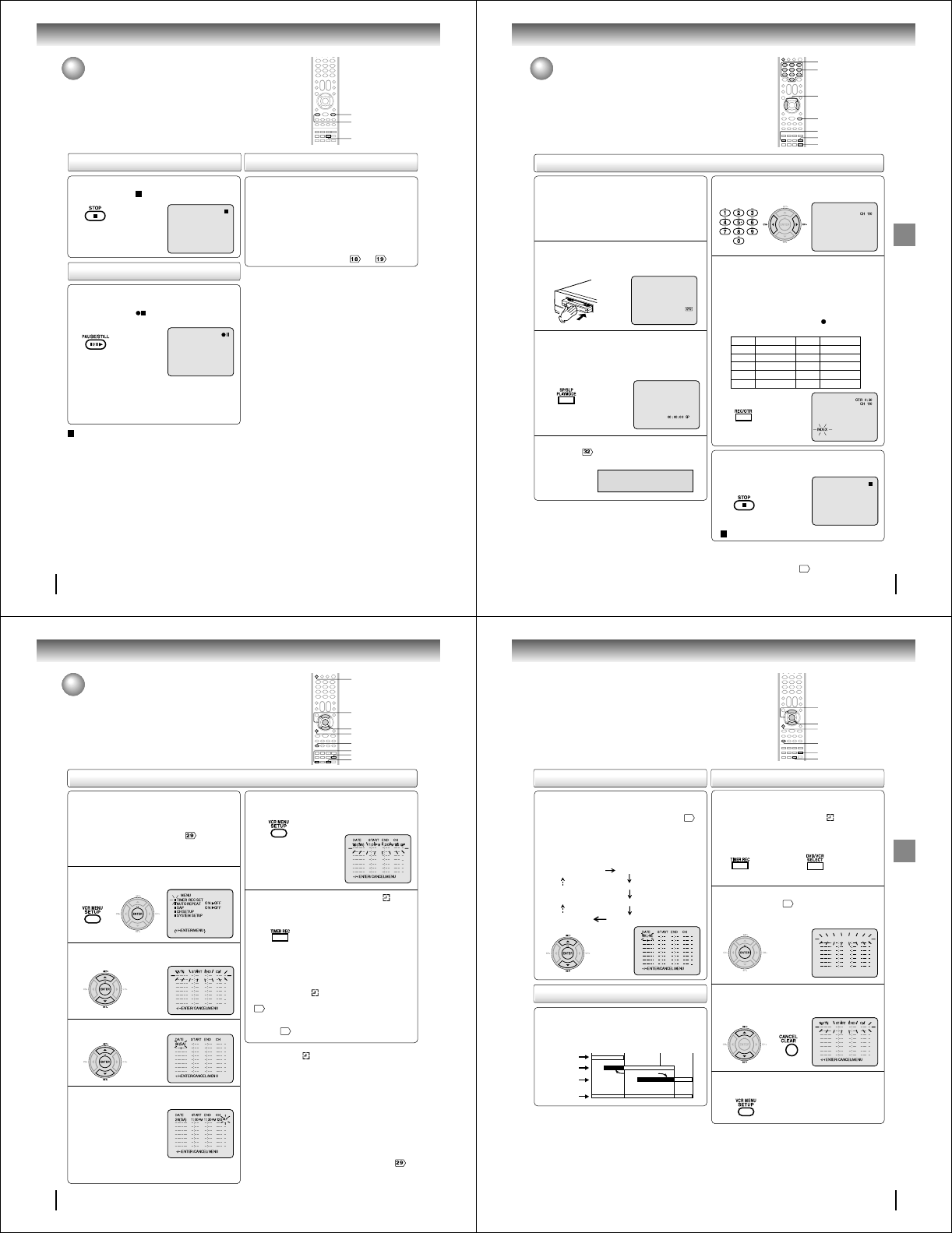
40
Recording (VCR)
Press STOP to stop recording.
“ ” will appear on screen for about
4 seconds.
Press PAUSE/STILL to avoid recording unwanted
material. Press again to continue the recording.
“ ” will appear on screen for
about 4 seconds.
Notes:
•
The pause function will be released after 5 minutes to prevent
damage to the tape or the VCR. The VCR will change to the
STOP mode.
• You can select a recording channel in the recording pause
mode.
To stop recording temporarily
While the VCR is recording, select your desired channel
on the TV.
When a TV is connected with an antenna cable only,
press TV/VCR to select the TV position.
The “VCR” display will go off and recording will continue.
Select the TV channel you want to watch by using the
TV channel selector.
Note:
Some Cable TV hookups do not permit viewing one channel
while recording another. See pages and .
This VCR will automatically rewind the tape when the tape
has ended (except during OTR and timer recording). It will
also eject the tape.
Auto Rewind feature
To stop recording
TV/VCR
STOP
PAUSE/STILL
Recording a TV program (Continued)
Recording one program while watching another
41
Recording (VCR)
One-touch Timer Recording (OTR)
The One-touch Timer Recording feature provides a simple and
convenient way to make a timed recording.
One-touch Timer Recording (OTR)
Press
once
twice
3 times
4 times
5 times
NORMAL REC
0:30
1:00
1:30
2:00
3:00
4:00
5:00
6:00
NORMAL REC
Recording time Press
6 times
7 times
8 times
9 times
10 times
Recording time
Load a cassette tape with the erase
prevention tab intact.
The VCR will automatically turn on.
1
Press SP/SLP to select the desired tape speed
SP or SLP.
The tape counter and “SP” or “SLP”
will appear on the screen for about 4
seconds.
2
Set “TV” or “CABLE” option to the appropriate
position .
3
TV - VHF/UHF channels
CABLE- Cable TV channels
Press Direct channel selection buttons (0–9) or
CH +/– to select the channel to be recorded.
4
Press
REC/OTR
. Recording begins. Press the
button again to stop recording after 30 minutes.
Each additional press of
REC/OTR
will increase
recording time as shown in the chart below, up
to a maximum of 6 hours.
The OTR and recording time will
appear on the screen for about 4
seconds. And, “ ” will appear on
the display.
5
To cancel OTR
Press STOP or turn off the power.
“ ” will appear on screen for about 4 seconds.
Note:
If you wish to watch the DVD playback during OTR or standard
recording, press DVD/VCR SELECT to change to DVD mode
and perform the DVD playback
47
.
0–9
CH +/–
REC/OTR
SP/SLP
DVD/VCR
STOP
Preparation:
• Turn ON the TV and select to the corresponding
video input.
• Press DVD/VCR to operate the DVD/VCR.
• Press DVD/VCR SELECT to select the VCR mode.
(The VCR indicator will light.)
Example: One-touch Timer Recording for 30 minutes.
DVD/VCR SELECT
42
Recording (VCR)
Timer recording
Timer recording can be programmed on-screen with the remote control.
The built-in timer allows automatic unattended recording of up to 8
programs within 1 month.
Timer recording
Notes:
• Press CANCEL to move cursor backward for correction.
• To record from external source set the channel to “L1” or
“L2”.
Notes:
• If the timer symbol ( ) blinks when the timer recording ended,
the TV program has not been completely recorded because of
an insufficient tape length. Press TIMER REC to cancel the
timer program or press EJECT to remove the cassette tape.
• During timer recording standby mode, the VCR mode cannot be
operated. To use the VCR, first press TIMER REC then press
DVD/VCR SELECT to change to VCR mode. After VCR mode
is selected, press TIMER REC again to put the VCR into timer
recording standby mode.
• If you press TIMER REC during timer recording, the recording
operation will be interrupted. If you press TIMER REC again
within the programmed time, the recording operation will start
again.
• After a power failure or disconnection of the power plug, all
programmed recording settings and time display will be lost
upon resumption of power. In this case, reset the clock and
reprogram any timer recording.
Press VCR MENU. Select “TIMER REC SET”,
then press ENTER.
Preparation:
• Press DVD/VCR to operate the DVD/VCR.
• Press DVD/VCR SELECT to select the VCR mode.
• Load a cassette tape with the erase prevention tab
intact.
• Check the time and date are correct .
Example: Program a timer recording for the 26th day,
channel 125 (Cable TV), 11:00 - 11:30 PM on timer
program number 1 (Tape speed: SLP).
1
Press SET + or – to select one of the program
line, then press ENTER.
2
Press SET + or – to select the date, then press
ENTER.
3
Set the start time, end time, channel and tape
speed as in step 3.
4
To enter other programs, repeat steps 2
through 4.
• To return to the normal screen,
press VCR MENU twice.
5
Press TIMER REC. The timer symbol ( ) will
appear on the display and the VCR standbys
for recording.
At the same time, VCR mode will
change to DVD mode automatically.
You can use DVD even if the VCR is
in the timer recording mode.
If you do not use the DVD, turn the
power off.
6
Notes:
• The timer recording will start at 5 seconds before the
preset starting time.
• If the timer symbol ( ) does not appear on the display
when TIMER REC is pressed, the cassette is not inserted
34
.
• If the cassette is ejected when TIMER REC is pressed, the
erase prevention tab of the cassette may have been
removed
34
.
• During Timer recording, the power cannot be turned off.
SET +/–
DVD/VCR
ENTER
CANCEL
VCR MENU
EJECT
TIMER REC
DVD/VCR SELECT
〈 〉
〈 〉
〈 〉
〈 〉
43
Recording (VCR)
Setting procedure
To set daily/weekly timer
To confirm Timer program:
At step 1 on page
42
, select “TIMER REC SET”
and press ENTER.
The timer program list will appear on the screen.
2
The current day (Friday) SU-SA (Sunday to Saturday)
MO-SA (Monday to Saturday)
MO-FR (Monday to Friday)
WKL-WE WKL-TH (Weekly Thursday)
(Weekly Wednesday)
One month later
minus one day
Weekly (e.g. WKL-TU: each Tuesday) or daily (e.g. MO-
SA: Monday to Saturday) Timer recording
Follow the procedure of timer recording on page
42
. At
step 3, press SET + or – repeatedly until the desired setting
appears. Then press ENTER.
When you press SET – repeatedly, the
DATE indicator will change as follows, in
this case the day is Friday.
If the programs overlap another
Do not overlap timer programs as portions of the
conflicting programs will be lost. The first recording
time has priority over the next recording time as shown
in the diagram below.
Notes:
• The daily/weekly recording can be made continuously until the
recording is canceled or the tape reaches the end.
• During timer recording the automatic rewinding mechanism
does not function.
8 : 00 11 : 00
9 : 00 10 : 00
Program 1
Prog.1
Deleted Parts
Non Recorded Portion Parts
Prog.2 Prog.3
Program 2
Program 3
Recording
Control Settings
〈 〉
〈+/
—
/ENTER/CANCEL/MENU〉
DATE START END CH
26(SA)
11
:00
PM
11
:30
PM
125
SLP
Notes:
• If there are other timer record programs remaining, TIMER
REC must be pressed to reactivate the timer, otherwise the
remaining timer record programs will be ignored.
• You cannot confirm the Timer program during timer recording
operation.
• You can correct or cancel a programmed setting in program
confirm mode.
If the Timer has been activated, press TIMER
REC to deactivate the Timer.
The timer symbol ( ) will
disappear. Then press DVD/VCR
SELECT to change to VCR mode.
1
To cancel Timer program:
Press SET + or – to select the unwanted program,
then press CANCEL to cancel the program.
3
Press VCR MENU repeatedly until the menu
screen is cleared.
4
To confirm or cancel a program
SET +/–
ENTER
VCR MENU
CANCEL
DVD/VCR SELECT
TIMER REC
〈 〉

44
Other functions (VCR)
Stereo recording and playback/
Second Audio Program (SAP)
When a MTS STEREO broad-
cast is received, “STEREO” will
appear on the screen for about
4 seconds and the program can
be viewed or recorded in stereo.
The Hi-Fi stereo recording pro-
cedure is the same as for normal
recordings.
Notes:
• When playing back a tape that is not recorded in Hi-Fi stereo
mode, the audio will automatically be monaural.
• When listening to a VHS Hi-Fi video tape or MTS broadcast
through the VHF/UHF jack (Audio/Video cable not connected),
the sound will be monaural.
When viewing an MTS stereo TV program, or playing a
prerecorded VHS Hi-Fi stereo videotape, press AUDIO
SELECT to select how the audio will be heard through
the speakers. Normally set to the Hi-Fi stereo position,
this button can be set to the MONO position if the
stereo broadcast or videotape audio is of poor quality.
The “R” and “L” positions allow the audio from the Right
or Left Hi-Fi channel to be heard over both TV speak-
ers. This button has no effect when viewing a MONO
videotape or TV program. Each time when you press
the button, OUTPUT SELECTION display appears on
the screen for several seconds. Refer to the chart
below.
Output selection
Your DVD/VCR is fitted with a SAP broadcast system which
enables you to switch to a second audio program when view-
ing a selected channel.
This function applies only when the program is broadcast in
multi-languages through the SAP broadcast system.
When the VCR is turned on or a channel selection is
made, make certain the letters “SAP” appears on the
screen for about 4 seconds. This means that the “Second
Audio Program” broadcasting is available.
Listening to SAP
Stereo recording and playback
The VHS Hi-Fi audio system permits high fidelity record-
ing of MTS STEREO TV broadcasts.
Second Audio Program (SAP)
OUTPUT
SELECTION
STEREO
L ch
R ch
MONO
SOUND HEARD ON BOTH
SPEAKERS
STEREO
LEFT CHANNEL AUDIO
RIGHT CHANNEL AUDIO
MONO
Press VCR MENU. Then press SET + or – to
select “SAP”.
1
Press ENTER to select “ON”.
Then press VCR MENU until the
menu screen is cleared.
2
STEREO
OR
SET +/–
ENTER
VCR MENU
Note:
When using a Cable TV system, stereo TV programs may
be transmitted over a mono cable channel. In this case
“STEREO” will not appear and the sound will be in mono.
AUDIO SELECT
Other functions (VCR)
45
Other functions (VCR)
To AUDIO (L) OUT
AUDIO/VIDEO cable (supplied)
Playback VCR
To VIDEO OUT To AUDIO (R) OUT
Recording VCR
To AUDIO (L) IN
To VIDEO IN To AUDIO (R) IN
Duplicating a video tape
If you connect the DVD/VCR to another VCR or Camcorder, you can duplicate
a previously recorded tape. Make all connections before turning on the power.
Duplicating a video tape
For duplicating a previously recorded tape from a
camcorder, follow the camcorder manufacturer’s
instructions. A typical camcorder dubbing hookup is
shown above.
AUDIO/VIDEO cable (not supplied)
To AUDIO (R) IN
To AUDIO (L) IN
To VIDEO IN
Recording VCR
To AV Jack
Playback Camcorder
Connection with second VCR
Connection with Camcorder
Press SP/SLP to select the desired tape speed
SP or SLP.
It is recommended to set the tape
speed to the SP mode on the
recording VCR for best results.
1
Press INPUT SELECT once or twice to select
AUDIO/VIDEO input position.
“L1” or “L2” will appear in the display.
2
Press REC/OTR on the recording VCR.
The duplicating process begins.
3
Press PLAY on the playback VCR or Camcorder.
4
Press STOP when you finish duplicating.
5
L1: on the rear panel
L2: on the front panel
Preparation:
• Turn ON the TV and select the corresponding video
input.
• Press DVD/VCR to operate the DVD/VCR.
• Press DVD/VCR SELECT to select the VCR mode.
(The VCR indicator will light.)
• Load a cassette tape with the erase prevention tab
intact.
• Load a previously recorded tape into the playback
VCR or Camcorder.
REC/OTR
STOP
SP/SLP
INPUT SELECT
DVD/VCR SELECT
DVD/VCR
46
Other functions (VCR)
Press REC/OTR to start recording.
The DVD/VCR will change to the
VCR mode automatically and the
playback picture or sound will be
duplicated on the video cassette
tape.
Recording a DVD/CD disc
You can record disc material in DVD, Video CD, Audio CD, etc.
onto a Video tape with this DVD/VCR.
Duplicating a DVD or CD disc
Press SP/SLP to select the desired tape speed
SP or SLP.
Preparation:
• Turn ON the TV and select the corresponding video
input.
• Press DVD/VCR to operate the DVD/VCR.
• Press DVD/VCR SELECT to select the VCR mode.
(The VCR indicator will light.)
•
Load a cassette tape with the erase prevention tab intact.
• Load a DVD/CD disc.
1
Press DVD/VCR SELECT selector to select the
DVD mode.
The DVD indicator will light.
2
Press PLAY to start playback.
3
4
Press STOP when you finish recording.
If you wish to stop a DVD/CD disc,
press
DVD/VCR SELECT
selector to
change the DVD mode, then press
STOP.
5
Notes:
• You may not be able to record the beginning of the disc.
Begin VCR recording once program playback commences
on the DVD.
• When the scanning mode is set to the progressive mode,
you cannot duplicate a disc material onto a video tape.
When REC/OTR is pressed, the PROGRESSIVE indicator
“” on the display window will flash.
• When the HDMI mode is ON (480p, 720p, 1080i), you
cannot duplicate a disc material onto a video tape.
• You cannot record discs encoded with copy guard
function. The following icon and text will show up on the
TV screen.
DISC IS COPY PROTECTED
SP/SLP
STOP
DVD/VCR
PLAY
REC/OTR
DVD/VCR SELECT
47
Basic playback (DVD)
Basic playback (DVD)
CAUTION
Keep your fingers well clear of the
disc tray as it is closing. Neglecting
to do so may cause serious
personal injury.
Basic playback
Playing a disc
This section shows you the basics on how to play a disc.
Basic playback (DVD)
Preparations:
• When you want to view a disc, turn on the TV and select the corresponding video input connected to the DVD/VCR.
This may include S-video or component video inputs which are exclusive to DVD playback.
• When you want to enjoy the sound of discs from the audio system, turn on the audio system and select the input
connected to the DVD/VCR.
DVD
VCD
CD
Press OPEN/CLOSE or PLAY on the unit.
The disc tray closes automatically.
On the TV-screen, “ ” changes to
“Reading” and then playback
commences.
• A menu screen will appear on the TV screen, if
the disc has a menu feature.
Press / or / to select title.
Press ENTER.
• Title is selected and play
commences.
Press STOP to end playback.
• The unit records the stopped point,
depending on the disc. “ ”
appears on the screen. Press
PLAY
to resume playback (from
the scene point).
• If you press STOP again or unload
the disc (“ ” appears on the
screen.), the unit will clear the
stopped point.
Press ON/STANDBY.
The DVD/VCR turns on.
Press VCR/DVD on the unit to select the DVD mode.
The DVD indicator will light.
Press OPEN/CLOSE.
The disc tray opens.
Place the disc on the disc tray.
With the playback
side down
• There are two different disc sizes. Place the disc
in the correct guide on the disc tray. If the disc is
out of the guide, it may damage the disc and
cause the DVD/VCR to malfunction.
• Do not place a disc which is unplayable in this
DVD/VCR.
2
4
5
6
37
8
9
To start playback in the stop mode
Press PLAY.
OR
1Press DVD/VCR on the remote control to
operate the DVD/VCR.
C/D/B/A
ENTER
DVD/VCR
Display window OPEN/CLOSE
STOP Disc trayVCR/DVD
PLAY
ON/STANDBY
Reading
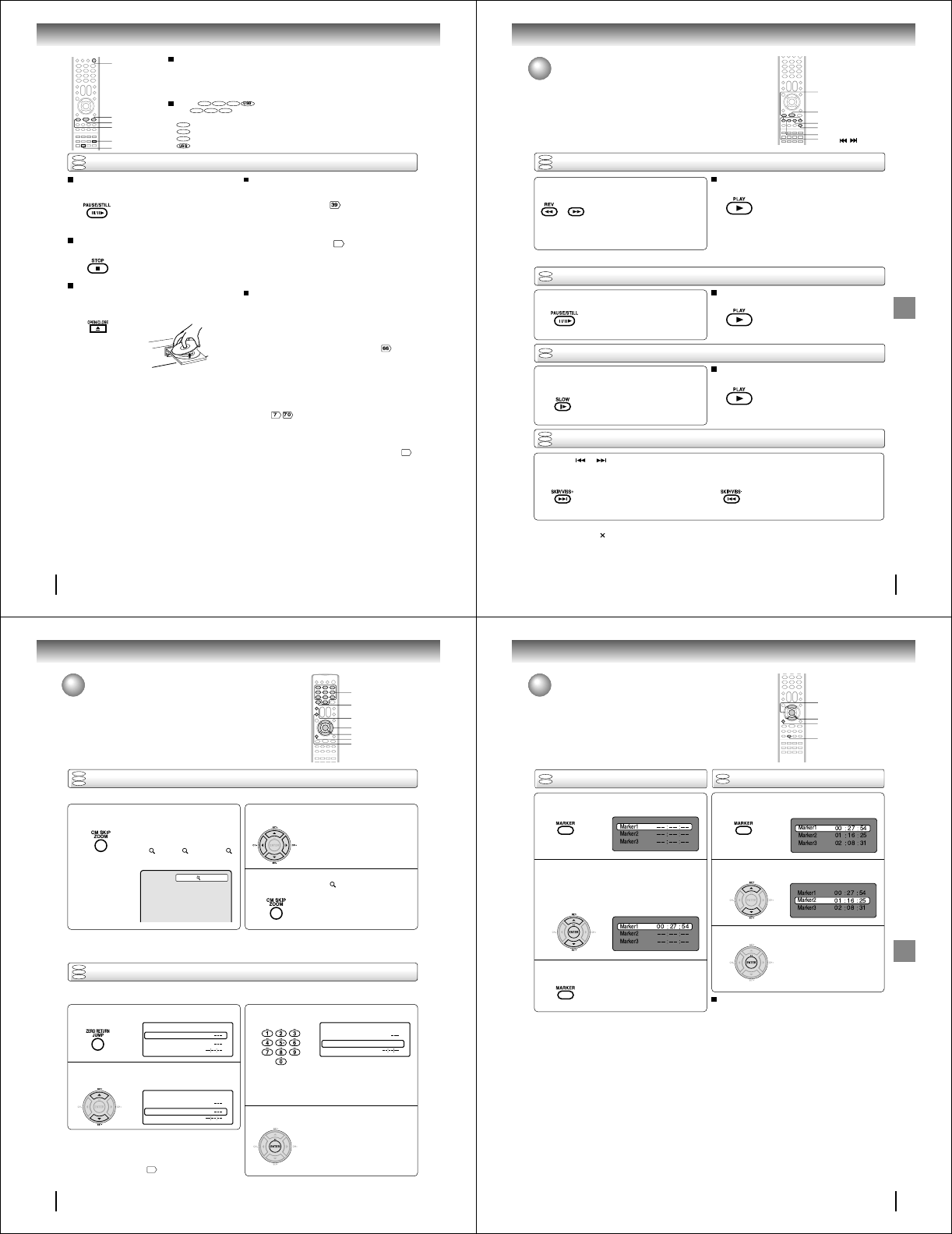
48
Basic playback (DVD)
To pause playback (still mode)
Press PAUSE/STILL during playback.
To resume normal playback, press
PLAY.
• The sound is muted during still
mode.
To stop playback
Press STOP.
Notes:
• If a non-compatible disc is loaded, “Incorrect Disc”, “Region Code Error” or “Parental Error” will appear on the TV screen
according to the type of loaded disc. In this case, check your disc again .
• Some discs may take a minute or so to start playback.
• When you set a single-faced disc label downwards (i.e. the wrong way up) and press OPEN/CLOSE or PLAY on the unit,
“Reading” will appear on the display for a few minutes and then “Incorrect Disc” will continue to be displayed.
•Some discs may not work the resuming facility.
• Resuming cannot function when you play a PBC-featured Video CD while the PBC is on. To turn off the PBC, see page
56
.
• Some playback operations of DVDs may be intentionally fixed by software producers. Since this unit plays DVDs according to
the disc contents the software producers designed, some playback features may not be available. Also refer to the
instructions supplied with the DVDs.
• Do not move the unit during playback. Doing so may damage the disc.
• Use the OPEN/CLOSE to open and close the disc tray. Do not push the disc tray while it is moving. Doing so may cause the
unit to malfunction.
• Do not push up on the disc tray or put any objects other than discs on the disc tray. Doing so may cause the unit to
malfunction.
• In many instances, a menu screen will appear after playback of a movie is completed. Prolonged display of an on-screen
menu may damage your television set, permanently etching that image onto its screen. To avoid this, be sure to press
POWER on your remote control once the movie is completed.
• There may be a slight delay between the button is pressed and the function activates.
• The screen saver does not operate when connecting this DVD/VCR to the TV using the HDMI cable.
Screen saver function
The screen saver operates when you leave the unit in
DVD stop mode for approx. five minutes.
The screen will repeatedly get dark gradually and back
to normal.
Please press any button when you want to return to an
usual screen.
To turn on or off the screen saver, see page .
OPEN/CLOSE
STOP
PAUSE/STILL
PLAY
To remove the disc
Press OPEN/CLOSE.
Remove the disc after the disc tray
opens completely.
Be sure to press OPEN/CLOSE to close the disc tray
after you remove the disc.
POWER
Playing a Disc while the VCR section is recording
or standing by for timer recording
1) Start to record.
Follow steps 1~5 on page .
•If the DVD/VCR is standing by for recording, turn on
the DVD/VCR.
2) Press DVD/VCR SELECT selector to select DVD mode.
3) Play a disc.
Follow steps 4 ~ 6 on page
47
.
•Press PLAY if the DVD/VCR does not start to play a
disc automatically.
4) Stop to play.
Press STOP to stop play back a disc.
DVD/VCR SELECT
Basic playback
DVD
VCD
CD
To obtain a higher quality picture
Occasionally, some picture noise not usually visible on the TV screen during a normal
broadcast may appear while playing a DVD video disc.
It is because due to high resolution pictures on these discs which include a lot of
information. The amount of noise depends on the disc you use with this unit. You should
generally reduce the sharpness adjustment on your TV when viewing DVD video discs.
About
DVD VCD CD
The
DVD VCD CD
icons on the heading bar show the playable discs for the
function described under that heading.
DVD
: You can use this function with DVD video discs.
VCD
: You can use this function with Video CDs.
CD
: You can use this function with Audio CDs and CD-R/RW CDs.
: You can use this function with USB Mass Storage.
49
Basic playback (DVD)
Playing a disc (Continued)
You can play discs at various speeds.
Playing frame by frame
DVD
VCD
DVD
VCD
Playing in fast reverse or fast forward directions
Press REV or FWD during playback.
REV: Fast reverse playback
FWD: Fast forward playback
Each time you press REV or FWD,
the playback speed changes.
To resume normal playback
Press PLAY.
Notes:
• The DVD/VCR mutes sound and subtitles during reverse
and forward scan of DVD/VCD video discs. However, this
unit plays sound during fast forward or fast reverse play of
audio CDs.
• The playback speed may differ depending on the disc.
Press PAUSE/STILL during still playback.
Each time you press PAUSE/STILL,
the picture advances one frame.
To resume normal playback
Press PLAY.
Note:
The sound is muted during frame by frame playback.
Press SLOW during playback.
Each time you press the button, the
slow-motion speed changes.
To resume normal playback
Press PLAY.
Note:
The sound is muted during slow-motion playback.
Press SKIP or repeatedly to display the chapter or track number you want.
Playback starts from the selected chapter or track.
To locate succeeding chapters or
tracks. Playback starts from the beginning of the
current chapter or track.
When you press twice in quick successions,
playback starts from the beginning of the
preceding chapter or track.
• A prohibition symbol “ ” may appear at the upper right of the screen. This symbol means either the feature you tried is not
available on the disc, or the DVD/VCR cannot access the feature at this time. This does not indicate a problem with the DVD/
VCR.
• The unit is capable of holding a still video image or On screen display image on your television screen indefinitely. If you leave
the still video image or On screen display image displayed on your TV for an extended period of time, you risk permanent
damage to your television screen. Projection televisions are very susceptible.
Notes:
Locating a chapter or track
Playing in slow-motion
DVD
VCD
CD
DVD
VCD
CD
FWD
REV
PLAY
PAUSE/STILL
SKIP /
SLOW
FWD
50
Advanced playback (DVD)
Zooming
12
Press ZOOM during playback.
The center part of the image will be
zoomed in.
Each press of ZOOM will change the
ZOOM 1 (x 1.3), 2 (x 1.5) and 3
(x 2.0).
Zooming/Locating desired scene
This unit will allow you to zoom in on the frame image. You can then make selections by switching the position of the frame.
Press CC
CC
C/DD
DD
D/BB
BB
B/A A
A A
A to view a different part of the
frame.
You may move the frame from the
center position to UP, DOWN, LEFT or
RIGHT direction.
3
Notes:
• You can select the Pause, Slow or Search playback in the zoom mode.
• Some discs may not respond to zoom feature.
Locating desired scene
Use the title, chapter and time recorded on the DVD disc to locate the desired point to play back. In the case of VCD/CD
discs, time and track are used to locate the desired point to play back. To check the title, chapter and time, press DISPLAY.
1
4
2
3
C/D/B/A
ZOOM
0–9
ENTER
DISPLAY
CLEAR
JUMP
In the zoom mode, press ZOOM repeatedly to
return to a 1:1 view ( Off).
Press JUMP during playback or resume stop
mode.
Press C C
C C
C or DD
DD
D to select the “Title/Track”, “Chapter”
or “Time”.
Press Number buttons (0–9) to change the
number.
• If you input a wrong number, press
CLEAR.
• Refer to the package supplied with
the disc to check the numbers.
Press ENTER. Playback starts.
• When you change the title,
playback starts from Chapter 1 of
the selected title.
• Some discs may not work in the
above operation.
DVD
VCD
CD
DVD
VCD
CD
1
Time
Title
Chapter
Jump
Time
Title
Chapter
Jump
Notes:
• In case of the Audio CD and Video-CD, only Track and Time
can be selected.
• In case of the Video-CD playback with PBC, the JUMP does
not work. Turn off the PBC
56
.
Time
Title
Chapter 12
Jump
Advanced playback (DVD)
51
Advanced playback (DVD)
Marking the scenes Returning to the scenes
1
Press MARKER during playback or stop mode.
2
1
3
Marking desired scenes
The unit stores the points that you want to watch again up to 3 points.
You can resume playback from each scene.
2
3
Notes:
Some discs may not work with the marking operation.
The marking is canceled when you open the disc tray or
turn the power off.
Some subtitles recorded around the marker may fail to
appear.
In case of Video CD with PBC, Marker function is prohibited.
•
•
•
•
To cancel the Marker
Follow the above steps 1~2, then press CLEAR.
ENTER
CLEAR
MARKER
C/D
Press MARKER during playback.
Select the blank Marker using C or D.
Then press ENTER at the desired scene.
• Repeat this procedure to set the
other 2 scenes.
Press MARKER to clear this display.
Press ENTER.
Playback starts from the marked
scene.
Press C or D to select the Marker 1-3.
DVD
VCD
DVD
VCD
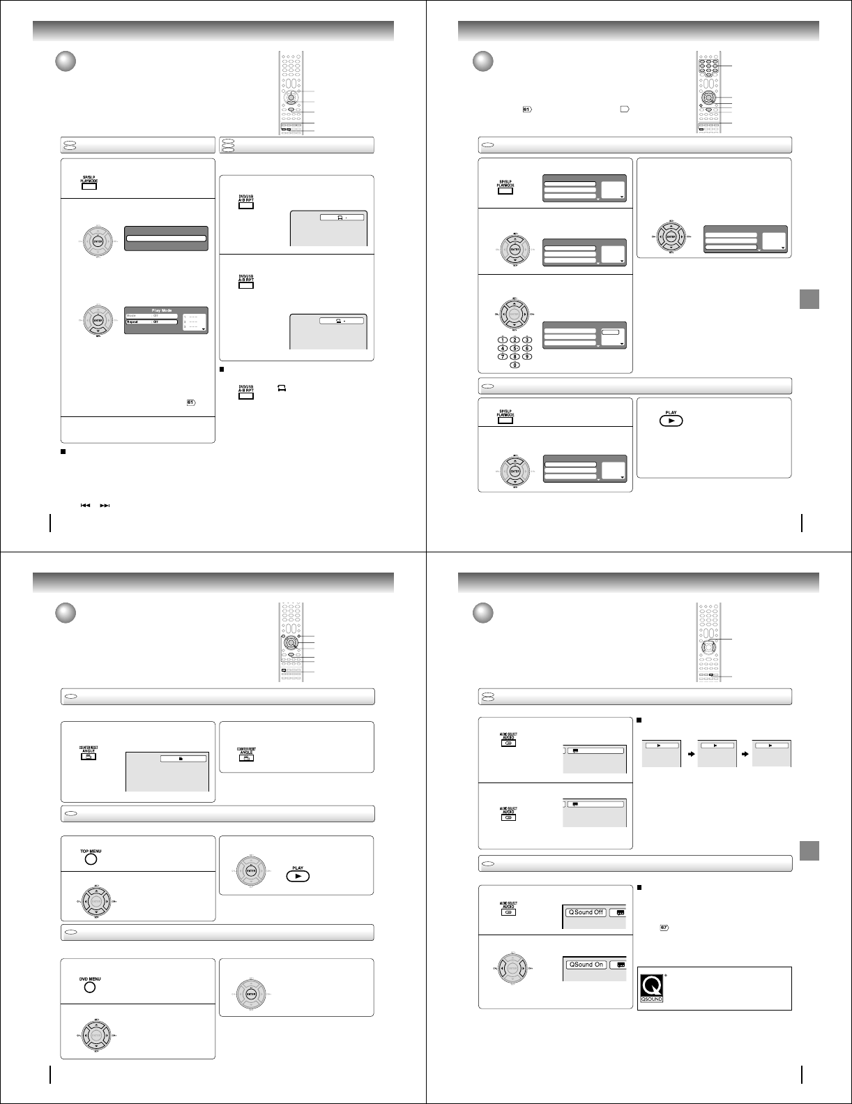
52
Advanced playback (DVD)
Repeat playback
1
Press PLAYMODE during playback or stop mode.
Repeat playback/A-B Repeat playback
Press PLAYMODE again to clear the screen.
3
A-B Repeat playback
1
Press A-B RPT during playback.
The start point is selected.
A-B repeat playback allows you to repeat material between
two selected points.
2
2
A
Notes:
• In A-B Repeat mode, subtitles near the A or B locations may
not be displayed.
• You cannot set the A-B Repeat for the scenes that include
multiple angles.
• A-B Repeat playback does not work when Repeat playback is
activated.
• You may not be able to set A-B Repeat, during certain scenes
of the DVD.
• A-B Repeat does not work with an interactive DVD, MP3/WMA/
JPEG/DivX® CD.
• A-B Repeat is prohibited when PBC is on.
To resume normal playback
Press A-B RPT again.
“
Off
” appears on the screen.
Notes:
• Some discs may not work with the repeat operation.
• In case of Video CD with PBC, repeat functions are prohib-
ited during playback.
• Chapter/Track repeat function is canceled whenever
SKIP or is pressed.
[DVD]
Press ENTER to select “Chapter” or “Title”.
The unit automatically starts repeat
playback after finishing the current ti-
tle or chapter.
[Video CD]
Press DD
DD
D to select “Repeat”.
Press ENTER to select “Track” or “All”.
The unit automatically starts repeat
playback after finishing the current
track.
• If you set the repeat mode during stop mode,
press PLAY to start Repeat playback.
[Audio CD and MP3/WMA CD]
Please see “Repeat playback (CD/USB)” .
Press A-B RPT again.
The end point is selected. Playback
starts at the point that you selected.
Playback stops at the end point, re-
turns to Point A automatically, then
starts again.
To resume normal playback
Select Repeat : “Off” in step 2.
ENTER
DVD
VCD
CD
Play Mode
Repeat : Off
AB
DVD
VCD
D
PLAYMODE
A-B RPT
PLAY
53
Advanced playback (DVD)
Program playback
Press PLAYMODE during stop mode.
1
Press BB
BB
B/AA
AA
A to return to the left column, then
press CC
CC
C/D D
D D
D to select the “Program Playback”
and press ENTER.
The programs you selected will start to playback in
the order.
•To resume normal playback, select Mode
“Off” in step 2.
4
Program playback/Random playback
You can arrange the playback order of tracks or files on the disc.
And the unit can also select tracks or files at random and playback
them. These feature works for Video CD.
For Audio CD and MP3/WMA CD, please see “Random playback
(CD/USB)” and “Program playback (CD/USB)”
62
.
2
3
Random playback
Press CC
CC
C/DD
DD
D to select “Mode”, then press
ENTER to select “Random”.
1
Press PLAY.
The Random Playback will start.
3
2
Note:
In playing back the Video CD with PBC, you cannot set
Random playback.
■To change the program
1. Select Mode to “Program” (as step 2), press B /A/C/
D to select the track number you want to change, then
press CLEAR.
2. Press Number buttons (0–9) to overwrite the new
track number.
■To clear the program one by one
Select Mode to “Program”, press B/A/C/D to select the
track number. Then press CLEAR.
■To clear all the programs
In the left column, press C/D to select “Clear Program”.
Then press ENTER.
Notes:
• In playing back the Video CD with PBC, you cannot set
Program playback.
• The program is canceled when you open the disc tray or
turn the power off.
Press CC
CC
C/DD
DD
D to select “Mode”, then press
ENTER to select “Program”.
Press BB
BB
B/AA
AA
A to select the right column, then use
Number buttons (0–9) to input the track numbers.
• If you input a wrong number, press
CLEAR.
Press PLAYMODE during playback or stop mode.
• If you set “Random” during playback mode,
Random playback will begin after the track that is
currently being played has ended.
• To resume normal playback, select Mode
“Off” in step 2.
1— — —
2— — —
3— — —
Play Mode
Repeat : Off
Program Playback
Mode : Off
1– – –
2– – –
3– – –
Play Mode
Repeat : Off
Program Playback
Mode : Program
1 9
2– – –
3– – –
Play Mode
Repeat : Off
Program Playback
Mode : Program
1 9
2 3
3 11
Play Mode
Repeat : Off
Program Playback
Mode : Program
VCD
VCD
ENTER
C/D/B/A
PLAYMODE
PLAY
0–9
CLEAR
1– – –
2– – –
3– – –
Play Mode
Repeat : Off
Program Playback
Mode : Random
54
Advanced playback (DVD)
Press CC
CC
C/DD
DD
D/BB
BB
B/AA
AA
A to select the desired title.
Changing angles/Title selection/DVD menu
Press ANGLE during playback.
The current angle will appear.
When playing back a disc recorded with multi-angle facility, you can change the angle that you are viewing the scene from.
1
Press ANGLE repeatedly until the desired angle
is selected.
2
Note:
Depending on the DVD, you may not be able to change the
angles even if multi-angles are recorded on the DVD.
Two or more titles are recorded on some discs. If the title menu is recorded on the disc, you can select the desired title.
1
Press ENTER or PLAY.
The playback of the selected title will
start.
3
Note:
Depending on the DVD, you may not be able to select the title.
Depending on the DVD, a “title menu” may simply be called a
“menu” or “title” in the instructions supplied with the disc.
2
Press CC
CC
C/DD
DD
D/BB
BB
B/AA
AA
A to select the desired item.
Some DVDs allow you to select the disc contents using the menu.
When you play back these DVDs, you can select the subtitle language and sound-track language, etc. using the menu.
1
Press ENTER.
The menu continues to another
screen. Repeat steps 2 and 3 to set
the item completely.
3
2
Press TOP MENU during playback.
Title menu appears on the screen.
Press DVD MENU during playback.
The DVD menu appears on the screen.
• Press DVD MENU again to resume
playback at the scene when you
press DVD MENU.
Note:
Depending on the DVD, you may not be able to resume playback
from the scene point when you press DVD MENU.
DVD
1/2
DVD
DVD
Changing angles
Title selection
DVD menu
ANGLE
ENTER
C/D/B/A
TOP MENU
PLAY
DVD MENU
55
Advanced playback (DVD)
Changing soundtrack language/
Setting surround sound
Changing soundtrack language
1
Press AUDIO during playback.
The current soundtrack language will
appear.
You can select the language when you play a multilingual disc.
In case of Video CD playback
Audio type changes as follows each time you press AUDIO.
DVD
VCD
1/2 Eng Dolby Digital
LR
L R
2
Notes:
• If the desired language is not heard after pressing the
button several times, the language is not recorded on
the disc.
• Changing soundtrack language is canceled when you
open the disc tray. The initial default language or available
language will be heard if the disc is played back again.
Press AUDIO repeatedly until the desired lan-
guage is selected.
•The on screen display will disappear after a few
seconds.
2/2 Fre Dolby Digital
Press B or A to select “On”.
• The on screen display will disappear after a few
seconds.
1
Setting surround sound
This DVD video player equipped with a “QSound”. It can produce the effect of being in a cinema or a concert hall.
2
To cancel Surround mode:
Follow the left steps 1~2, then press B or A to select the
“Off” position.
Notes:
• The QSound setting can also be changed in the function
setting .
• The “QSound” works only when the DVD disc recorded
with Dolby Digital is played back.
• When this function works, the volume might changed.
• When the voice is distorted, turn off QSound.
During disc playback press AUDIO.
Manufactured under license from QSound Labs,
Inc. U.S. patent Nos. 5,105,462, 5,208,860 and
5,440,638 and various foreign counterpart.
Copyright QSound Labs, Inc. 1998-2002.
QXpander™ is a trademark of QSound Labs, Inc.
All rights reserved.
DVD
AUDIO
B/A
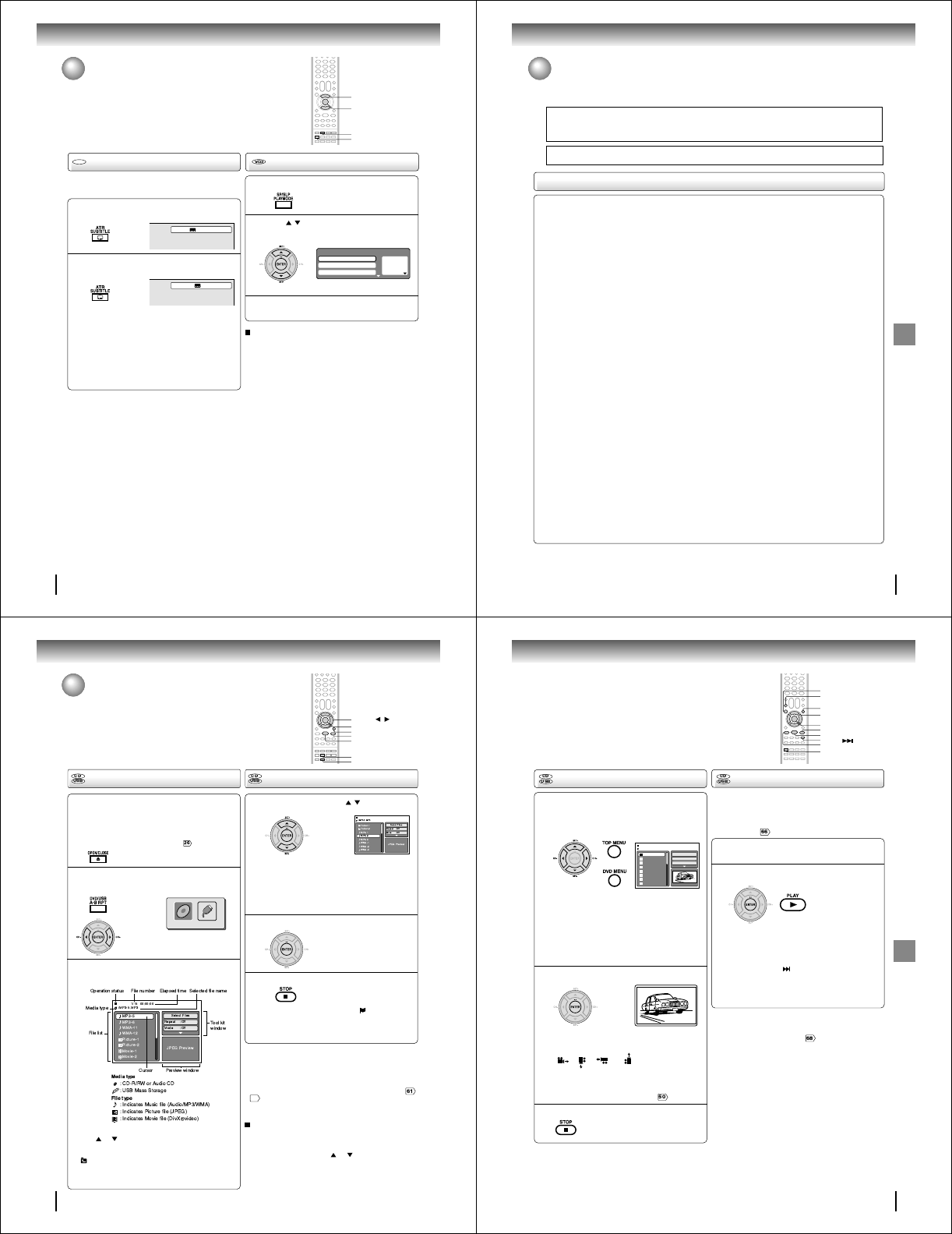
56
Advanced playback (DVD)
Subtitles/To turn off the PBC
When playing back a disc recorded with subtitles, you can
select the subtitle language or turn the subtitle off.
To turn off the subtitle, press SUBTITLE until
“Off” appears.
• The on screen display will disappear after a few
seconds.
1
Notes:
• Depending on the DVD, you may not be able to change
subtitles, or to turn subtitles on or off.
• While playing a DVD, the subtitle may change when you
open or close the disc tray.
• In some cases, a selected subtitle language may not be
changed immediately.
Subtitles
Press SUBTITLE repeatedly during playback
until your desired language appears.
2
DVD
To turn off the PBC (see page 8)
Press / to select “Mode”, then press
ENTER repeatedly until “Off” appear.
1
Press PLAYMODE in the stop mode.
2
Press PLAYMODE again to clear the screen.
3
Follow the above steps 1~2, then press ENTER repeatedly
until “PBC” appear.
To turn on the PBC
1/5 Eng
Off
1— — —
2— — —
3— — —
Play Mode
Repeat : Off
Program Playback
Mode : Off
SUBTITLE
ENTER
PLAYMODE
C/D
57
Advanced playback (DVD)
MP3/WMA/JPEG/DivX
®
and Audio CD operation
This player can playback the MP3/WMA/JPEG/DivX®-data which has been recorded on CD-R/RW or USB Mass Storage. To
produce the MP3/WMA JPEG/DivX®-data, you need a Windows-PC with CD-RW drive or USB memory device and a MP3/
WMA/JPEG/DivX®-encoding Software (not supplied). The Apple-HFS-System cannot be played.
This player requires discs/recordings to meet certain technical standards in order to achieve optimal playback quality.
There are many different types of recordable disc formats (including CD-R containing MP3/WMA files). Not all
recordable discs will produce optimal playback quality. The technical criteria set forth in this owner's manual are meant
only as a guide. Use of CD-RW for MP3 files is not recommended.
You must obtain any required permission from copyright owners to download or use copyrighted content.
Toshiba cannot and does not grant such permission.
MP3/WMA/JPEG/DivX® - data information
Limitations on MP3/WMA/JPEG/DivX® playback
• MP3/WMA/JPEG/DivX® CD/USB Mass Storage are standardized by ISO9660, its file name must include following
extensions; “.mp3”, “.wma”, “.jpg”, “.div”, “.divx”, “.avi”.
• MP3/WMA/JPEG/DivX® CD/USB Mass Storage must be correspond to the ISO standardized files.
• This unit can read 600 files per disc. If one directory has more than 600 files, it reads up to 600 files, the remaining files
will be omitted. (In case of USB Mass Storage, this limitation becomes 2,000 files).
• The unit is able to recognize up to a maximum of 50 directories per disc or USB Mass Storage.
• MP3/WMA/JPEG/DivX® CDs/USB Mass Storage cannot be used for the purpose of recording.
• If the CD/USB Mass Storage has both audio tracks and MP3/WMA/JPEG/DivX® files, only audio tracks are played.
• It may take more than one minute for this unit to read MP3/WMA/JPEG/DivX® files depending on its structure.
• Music recorded by “Joliet Recording Specification” can be played back, the file name is displayed (within 15 letters) on
the screen. Long file names will be condensed.
• The music files recorded by “Hierarchical File System” (HFS) cannot be played.
Limitations on display.
• The maximum number for display is 15 letters.
Available characters for display are the following:
capital or small alphabets of A through Z, numbers of 0 through 9, and _ (under score).
• Other characters than those above are replaced in hyphen.
Notes on MP3/WMA/JPEG/DivX® files
To playback MP3/WMA/JPEG/DivX® CD/USB Mass Storage in the recorded order,
1. Use MP3/WMA/JPEG/DivX® software that records data alphabetically or numerically.
2. Insert two or three digit number in the head of file name. (ex. “01” “02” or “001” “002”).
3. Refrain from making too many sub-folders.
CAUTION:
• Some MP3/WMA/JPEG/DivX® CDs/USB Mass Storage cannot be played back depending on the recording conditions.
• The CD-R/RW or USB Mass Storage that has no music data or non MP3/WMA/JPEG/DivX® files cannot be played back.
Standard sampling frequency, and the bit rate:
MP3
MPEG-1 Audio
32kHz, 44.1kHz, 48kHz
32kbps ~ 320kbps (constant bit rate or variable bit rate)
The recommend recording setting for a high-quality sound is 44.1kHz of sampling frequency and 128kbps of constant bit
rate.
WMA
WMA version 7 and 8
32kHz/48kbps, 44.1kHz/48kbps~192kbps, 48kHz/128kbps~192kbps
The file recorded by mono, 48kHz, 48 kbps is not available to this unit.
DivX® video
DivX® version: DivX® 3, 4, 5, and 6 (specifically 3.1.1, 4.1.2, 5.0.2, 5.0.5, 5.1.1, 5.2.1, 6.0 at Home Theater profile).
Audio format: MPEG1 Layer2 (MP2), MPEG1 Layer3 (MP3)
Sampling frequencies: 32kHz, 44.1kHz, 48kHz
Bit rate: 32kbps ~ 320kbps
Resolution: Max 720 x 576 (at 25fps), Max 720 x 480 (at 30fps)
Microsoft, Windows Media, and Windows Logo are either registered trademarks or trademarks of Microsoft Corporation in the
United States and/or other countries.
DivX, DivX Certified, and associated logos are trade marks of DivX, Inc. and are used under license.
58
Advanced playback (DVD)
MP3/WMA/JPEG/DivX
®
and Audio
CD operation (Continued)
A file browser screen will be appear on the
screen.
• In case the current directory includes 9 files or more,
press or to scroll in the file list.
• To see contents in folder, select the folder and then
press ENTER. To return to the upstairs directory, select
“ Go Up ...” then press ENTER.
• In case of a CD/USB Mass Storage containing a mixture
of MP3, WMA, JPEG and DivX® files, the files are played
back by selecting them from the file browser.
Loading media
ENTER
▲/▼//
STOP
Notes:
• MP3 or WMA file on the Kodak Picture CD is not recognized
on this unit.
• During MP3/WMA/JPEG-Playback, you cannot use Jump and
A-B Repeat functions.
• You can use Repeat (Track or All), Random functions and
Program playback for MP3/WMA/JPEG/DivX®-Playback ,
62
.
• At USB mode with no disc on the tray, you can move to DISC
mode when you press OPEN/CLOSE on the remote control.
[MP3/WMA/JPEG/DivX® CD, Audio CD]
Place a MP3/WMA/JPEG/DivX® CD or an Audio
CD onto the disc tray, then press OPEN/CLOSE.
[USB Mass Storage]
Connect USB Mass Storage to the USB port on
the front of the unit (see page ).
1
2
3
PLAY
Select Files
The file type to make it display in the file browser can be chosen.
1. Press B or A to highlight “Select Files” at right column
in the file browser.
2. Press ENTER, then press or to select file type
from the list (Music, Picture or Movie).
3. Press ENTER to add/remove check mark. Checked file
type will be displayed in the file browser.
4. Press RETURN to save the setting.
OPEN/CLOSE
Press DVD/USB to display the media selection
window. Press B or A to select the DISC
mode or the USB mode, then press ENTER.
You cannot select the mode if
DISC/USB media is not inserted.
MP3/WMA and Audio CD playback
In the file browser, press / to select the
desired file.
When PLAY is pressed after the file browser displayed,
playback begins automatically starting from the first file. In
this case, if the first file is an MP3/WMA file, only MP3/
WMA files are played back in order. If the first file is a
JPEG file, the first JPEG file is played back. If the first file is
a DivX® file, the first DivX® file is played back. If there is no
file at a root directory, playback does not begin
automatically
.
1
Press ENTER. The selected file starts playing
back.
2
Press STOP to end playback.
• The unit records the stopped point. “ ” appears on the
screen. Press PLAY to resume playback (from the scene
point).
• If you press STOP again or unload the disc, the unit will
clear the stopped point.
3
DVD/USB
RETURN
DISC USB
59
Advanced playback (DVD)
The slide show enables you to view pictures (files) one after
another automatically.
Preparation:
Set “JPEG Interval” setting to “5 Seconds”, “10 Seconds”
or “15 Seconds” .
In the file browser, press C/D to select the
desired JPEG file.
To display a thumbnail list, press DVD MENU.
Press B/A or C/D to select the desired file.
(To return to a file browser, press TOP MENU.)
1
Press ENTER. The selected picture appears on
the screen.
Rotating an image
You can rotate an image by 90 degrees by
pressing ANGLE during playback of the image.
“”, “ ”, “ ” or “ ” appears on the
screen.
Zooming an image
Zoom function also can be used in viewing JPEG
files. Press ZOOM (See “Zooming” ).
Press STOP to end playback.
The file browser appears on the
screen. If you want to watch the
other file, repeat steps 1 ~ 2.
3
JPEG playback
Select your desired starting file for the slide
show in step 1 on the left.
2
Press ENTER or PLAY to start slide show from
the selected file.
•If you press PAUSE/STILL during the slide show, the
slide show stops temporary. “ 4 ” appears briefly on
the screen.
If the picture appears upside down or sideways, press
ANGLE repeatedly until it’s right side up.
Press PLAY or SKIP again to resume the slide show.
•When the slide show playback finished, the file list ap-
pears.
•To stop the slide show, press STOP. The file list ap-
pears.
Slide show playback
1
When PLAY is pressed after displaying the file
browser, playback begins
automatically starting
from the first file. In this case,
if the first file is a
JPEG file, the first JPEG file is played back. If the
first file is a DivX® file, the first DivX® file is
played back. If the first file is an MP3/WMA file,
only MP3/WMA files are played back in order. If
there is no file at a root directory, playback does
not begin automatically.
2
Notes:
• If the DVD/VCR is connected to a HDTV using HDMI, you
can display the HD resolution JPEG images (720p or
1080i). See “HD Jpeg” on page .
• During JPEG playback, you cannot use Jump and A-B
Repeat functions.
TOP MENU
DVD MENU
ENTER
ANGLE
PLAY
STOP
PAUSE/STILL
Picture-01
Picture-02
Picture-03
Picture-04
Picture-05
Picture-06
Picture-07
Picture-08
JPEG Preview
Select Files
Repeat :Off
Mode :Off
W: 2048 H: 1536
/Picture-01.JPG
ZOOM
SKIP
C/D/B/A
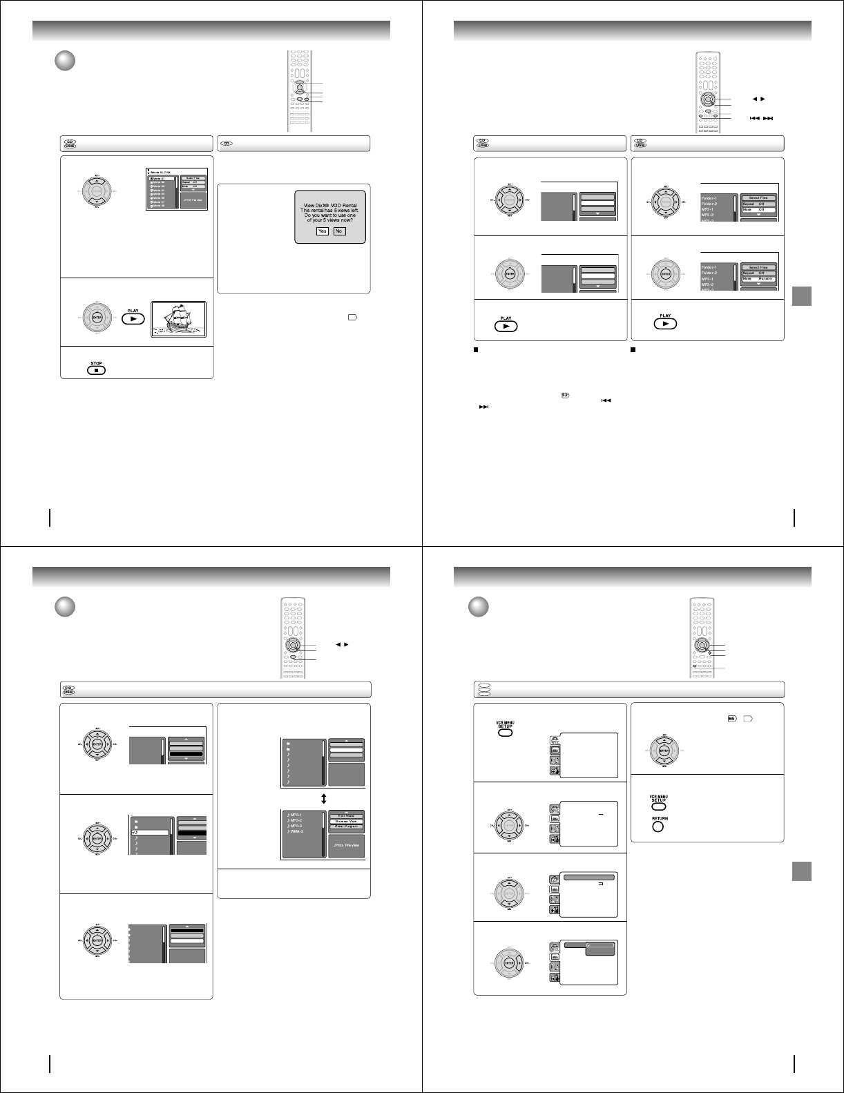
60
Advanced playback (DVD)
1
3
2
▲/▼
ENTER
PLAY
STOP
MP3/WMA/JPEG/DivX
®
and Audio
CD operation (Continued)
Press C/D to select desired DivX® file.
Press ENTER or PLAY. The selected DivX®
movie will be played back on the screen.
Press STOP to end playback.
The file browser appears on the
screen. If you want to watch the
other file, repeat steps 1 ~ 2.
When PLAY has been pressed after displaying
the file browser, playback begins automatically
starting from the first file. In this case, if the first
file is a JPEG file, the first JPEG file is played
back. If the first file is a DivX® file, the first DivX®
file is played back. If the first file is an MP3/WMA
file, only MP3/WMA file are played back in order.
If there is no file at a root directory, playback does
not begin automatically.
DivX® playback Playing DivX® VOD content
DivX® VOD content is protected by DRM (Digital Rights
Management) system. This restricts playback of content to
specific registered devices.
If the incorrect DRM file is
loaded, “Authorization
Error This player is not
authorized to play this
video.” will appear on the
screen.
When you attempt to play
DivX® VOD, the number of
plays is limited and the right message will appear on
the screen. If you wish to play it, select “YES”.
• If the number of plays goes over the limit, then
“Rental Expired” will be displayed, in this case the
file will not be played.
Notes:
• In order to play DivX® VOD content on this unit, you first need
to register the unit with registration code. See page
69
.
• This unit cannot playback the DivX® VOD content on the USB
Mass Storage.
61
Advanced playback (DVD)
Folder-1
Folder-2
MP3-1
MP3-2
MP3-3
Select Files
Repeat :Off
Mode :Off
Folder-1
Folder-2
MP3-1
MP3-2
MP3 3
Select Files
Repeat :Track
Mode :Off
Repeat playback (CD/USB)
In the file browser, press B/A or C/D to select
“Repeat” during stop mode.
Press ENTER to select “Track” or “All”.
Press PLAY.
The unit automatically starts repeat
playback after finishing the current
track.
Random playback (CD/USB)
To resume normal playback
Select Repeat : “Off” in step 2.
In the file browser, press B/A or C/D to select
“Mode” during stop mode.
Press ENTER to select “Random”.
Press PLAY.
The Random playback will start.
To resume normal playback
Select Mode : “Off” in step 2.
Notes:
• The program is canceled when you open the disc tray or
turn the power off.
• In case of Audio CD, the function of A-B Repeat can be
used. See “A-B Repeat playback” .
• Track repeat function is canceled whenever SKIP or
is pressed.
1
2
3
1
2
3
ENTER
▲/▼//
PLAY
SKIP /
62
Advanced playback (DVD)
Folder-1
Folder-2
MP3-1
MP3-2
MP3 3
Repeat :Off
Mode :Off
Edit Mode
Folder-1
Folder-2
MP3-1
MP3-2
MP3-3
WMA-1
WMA 2
JPEG Previe
w
Repeat :Off
Mode :Off
Edit Mode
Folder-1
Folder-2
MP3-1
MP3-2
MP3-3
WMA-1
WMA-2
JPEG Preview
Edit Mode
Program View
Add To Program
In the file browser, press B/A or C/D to select
“Edit Mode”, then press ENTER.
When “Edit Mode” is black color,
you can mark the files which you
want to add into Program list.
Press B/A or C/D to select the file you want to
add into the program list.
Press ENTER. Selected file was
marked.
Repeat this procedure to select the
other files.
Press B/A or C/D to select “Add To Program”.
Then press ENTER. All marked files are added
into the program list.
•When you finish storing all the files
you want into the Program list,
select “Edit Mode” again and press
ENTER to release edit mode.
Program playback (CD/USB)
Press C/D to select “Program View”, then
press ENTER. Program View shows only the
programed files that you have added in Step 2.
Program View
In the Program View, press PLAY. The files
start to playback in programmed order that
were added by you.
To remove file from program list
In the Edit Mode, switch to Program View. Select the files
you want to remove, then press ENTER. Select “Clear
Program” and press ENTER. Marked file is removed
from program list.
1
2
3
4
5
ENTER
▲/▼//
PLAY
MP3/WMA/JPEG/DivX
®
and Audio
CD operation (Continued)
Folder-1
Folder-2
MP3-1
MP3-2
MP3-3
WMA-1
WMA-2
WMA-3
JPEG Preview
Edit Mode
Program View
Add To Program
Browser View
63
Function setup (DVD)
ENTER
C/D/B/A
SETUP
RETURN
Setting procedure
DVD
VCD
CD
Customizing the function settings
You can change the default settings to customize performance
to your preference.
Press SETUP during stop mode.
The following on-screen display
appears.
1
2
3
To clear SETUP screen, press SETUP or
RETURN.
6
Press C or D to select the desired section, then
press B or A.
First option will be highlighted. Press C or D
to select the desired option.
4
Then press A or ENTER. The selectable
settings will appear.
Parental : Off
Set Password
Output : Interlace
DivX(R) VOD
DRC : Off
QSound : On
E.B.L. : Off
TV Screen : 4:3
Display : On
Picture Mode : Auto
JPEG Interval : 5 Seconds
Screen Saver : On
Menu : English
Subtitle : English
Audio : English
Parental : Off
Set Password
Output : Interlace
DivX(R) VOD
DRC : Off
QSound : On
Menu : English
Subtitle : English
Audio : English
E.B.L. : Off
TV Screen : On
Display : On
Picture Mode : Auto
JPEG Interval : Off
Screen Saver : On
•Repeat steps 3 ~ 5 to change
other option.
•To select another section, go
back to step 2 by pressing B
repeatedly.
5
Change the selection using C or D, by referring
to the corresponding pages ~
69
.
Press ENTER to save the setting.
Parental : Off
Set Password
Output : Interlace
DivX(R) VOD
DRC : Off
QSound : On
Menu : English
Subtitle : English
Audio : English
E.B.L. : Off
TV Screen : 4:3
Display : On
Picture Mode : Auto
JPEG Interval : Off
Screen Saver : On
Parental : Off
Set Password
Output : Interlace
DivX(R) VOD
DRC : Off
QSound : On
Menu : English
Subtitle : English
Audio : English
E.B.L. : Off
TV Screen : 4:3
Display : On
Picture Mode : Auto
JPEG Interval : Off
Screen Saver : On
Function setup (DVD)
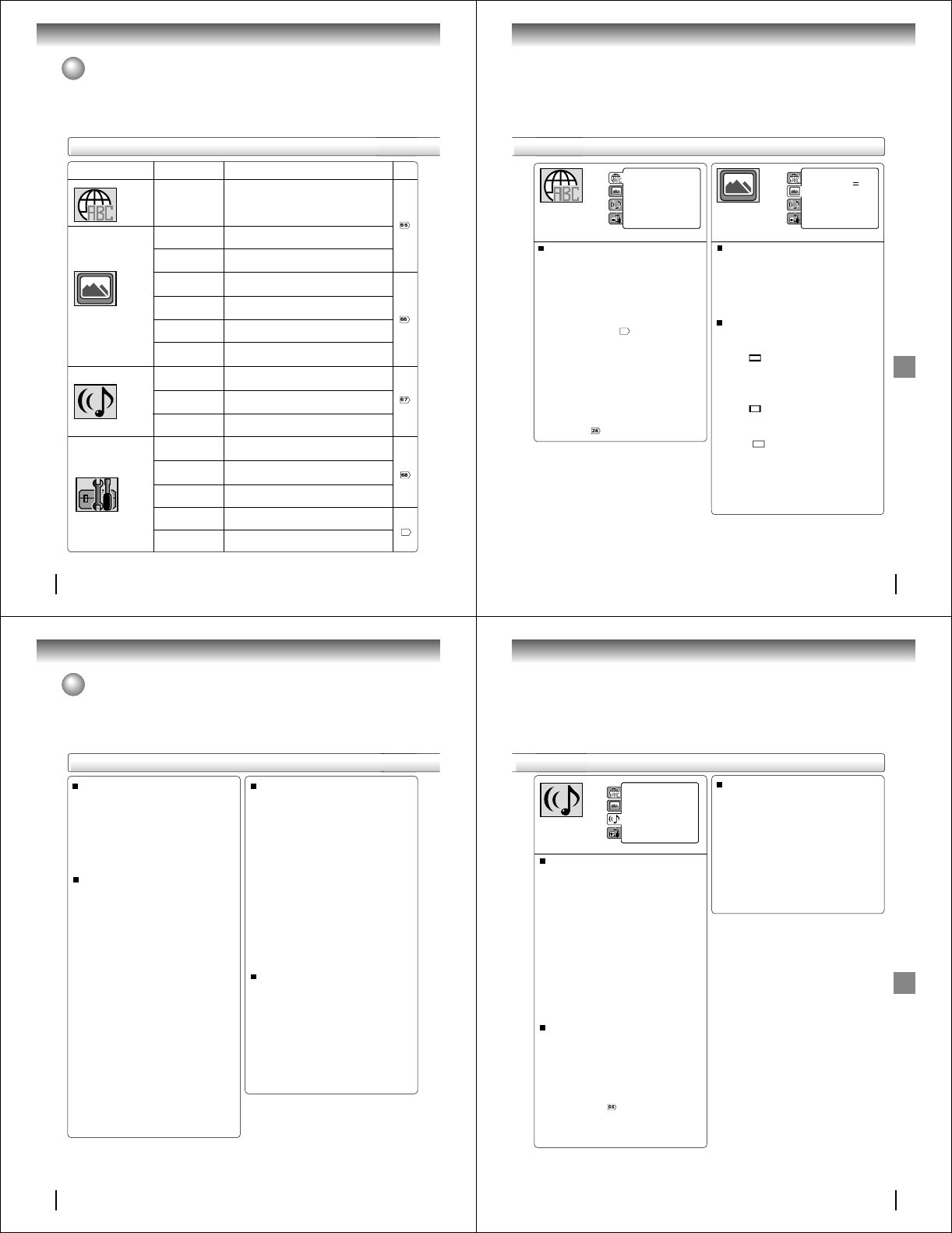
64
Function setup (DVD)
Customizing the function settings (Continued)
Section Option
Menu
Subtitle
Audio
E.B.L.
TV Screen
Display
Picture Mode
JPEG Interval
Screen Saver
DRC
QSound
Digital Out
Parental
Password
HD Jpeg
Output
DivX(R) VOD
Details
To select the language of “Menu”, “Subtitle” and
“Audio” if more than one language are available on
the disc.
To select On or Off for E.B.L. (Enhanced Black
Level).
To select a picture size according to the aspect
ratio of your TV.
To turn on or de-activate the operational status dis-
play on the screen.
To select a preferred picture mode from “Video”,
“Film” or “Auto”.
To select a preferred setting for the slide show play-
back.
To select On or Off for Screen Saver function.
To select On or Off for DRC (Dynamic Range Con-
trol).
To select On or Off for QSound.
To select an output sound format corresponding to
your system connection.
To select a preferred parental level for the parental
setting.
Input 4-digit password to set the parental level.
To select On or Off for HD Jpeg mode.
To select a preferred video output signal from “Inter-
lace” or “Progressive”.
To display your 8-character registration code.
Page
Setting details
69
65
Function setup (DVD)
Menu, Subtitle, Audio
You can select the language of “Menu”, “Subtitle” and
“Audio” if more than one languages are recorded onto
the disc.
English, Francais, Espanol:
The selected language will be heard or seen.
Other:
Other language can be selected (see the
“Language code list”
71
).
Original: (Audio)
The unit will select the first priority language of
each disc.
Off: (Subtitle)
Subtitles do not appear.
Notes:
• If the selected language is not recorded on the disc, the
first-priority language is selected.
• If you want to change the OSD language, you can perform
it by VCR MENU .
E.B.L.
To select the black level of playback pictures, set your
preference and monitor’s ability.
Off: Standard grey scale (7.5 IRE cut off)
On: Enhanced grey scale (0 IRE cut off)
TV Screen
You have the following screen sizes to choose from:
4:3 (Letter box):
Select this mode when connecting to a conven-
tional TV. When playing back a wide screen-DVD
disc, it displays the wide picture with black bands
at the top and bottom of screen.
4:3 (Pan scan):
It displays the wide picture on the whole screen
with left and right edges automatically cut off.
16:9 (Wide):
Select this mode when connecting to a wide-
screen TV. A wide screen picture is displayed full
size.
Note:
If the DVD disc is not formatted in the pan & scan style, it
displays 4:3 style.
Parental : Off
Set Password
Output : Interlace
DivX(R) VOD
DRC : Off
QSound : On
E.B.L. : Off
TV Screen : 4:3
Display : On
Picture Mode : Auto
JPEG Interval : 5 Seconds
Screen Saver : On
Menu : English
Subtitle : English
Audio : English
Parental : Off
Set Password
Output : Interlace
DivX(R) VOD
DRC : Off
QSound : On
Menu : English
Subtitle : English
Audio : English
E.B.L. : Off
TV Screen : 4:3
Display : On
Picture Mode : Auto
JPEG Interval : Off
Screen Saver : On
66
Function setup (DVD)
Customizing the function settings (Continued)
JPEG Interval
You can continuously playback all JPEG files
automatically.
After the selection below, the disc will start playback on
which JPEG files have been recorded.
Off:
Plays back one file at a time.
5 Seconds:
Plays back images in the form of a slide show at
5 second intervals.
10 Seconds:
Plays back images in the form of a slide show at
10 second intervals.
15 Seconds:
Plays back images in the form of a slide show at
15 second intervals.
Picture Mode
There are two types of source content in pictures
recorded in DVD video discs: film content (pictures
recorded from films at 24 frames per second) and
video content (video signals recorded at 30 frames per
second). Make this selection according to the type of
content being viewed.
Auto: Select this position normally.
The DVD player automatically detects
source content, film or video, of
playback source, and converts that
signal in the progressive output format
in an appropriate method.
Film: The DVD player converts film content
pictures in the progressive output
format appropriately. Suitable for
playback of film content pictures. The
progressive output feature will be most
effective under this selection.
Video: The DVD player filters video signal,
and converts it in the progressive
output formatappropriately.
Suitable for playback of video content
pictures.
Note:
Depending on the disc, pictures may be cut off or
doubled. In this case, select “Video”.
Display
On screen display can be switched on or off when you
press the buttons.
Off: On screen displays do not appear when you
press any buttons.
On: On screen displays appear when you press
the buttons (factory setting).
Screen Saver
The screen saver operates when you leave the unit
in DVD stop mode for approx. five minutes.
The screen will repeatedly get dark gradually and
back to normal.
Off:
Screen Saver function is invalidated.
On:
Screen Saver function is made effective.
Setting details
67
Function setup (DVD)
Parental : Off
Set Password
Output : Interlace
DivX(R) VOD
Menu : English
Subtitle : English
Audio : English
E.B.L. : Off
TV Screen : 4:3
Display : On
Picture Mode : Auto
JPEG Interval : 5 Seconds
Screen Saver : On
DRC : Off
QSound : Off
Digital out : PCM
QSound
This DVD video player equipped with a “QSound”. It can
produce the effect of being in a cinema or a concert hall.
Off: The QSound is disengaged.
On: The QSound operates.
Off:
It plays back at the recording level on the disc.
On:
Loud sound such as explosion or similar is toned
down slightly when played back. This makes it
suitable for when it is connected to a stereo.
Notes:
• This function works only during playback of Dolby Digital
recorded discs.
• The level of Dynamic Range Reduction may differ
depending on DVD video disc.
DRC
DRC (Dynamic Range Control) enables you to control
the dynamic range so as to achieve a suitable sound for
your equipment.
Notes:
• The QSound setting can also be changed with AUDIO
on the remote control .
• This function works only when the disc recorded with
Dolby Digital is played back.
• When this function works, the volume might changed.
• When the voice is distorted, turn off QSound.
Digital Out
Selected the output sound format corresponding to your
system connection.
PCM:
Select when connected to a 2 channel digital
stereo amplifier.
Bitstream:
Disc audio bitstream data will be output.
Notes:
•When you make a connection to a TV, or Dolby
Surround Pro Logic or stereo system via the analog
audio jacks, select “PCM” or “Bitstream”.
•If apply HDMI connection to TV, make sure to select
“PCM”, audio signal passing to TV via HDMI cable.
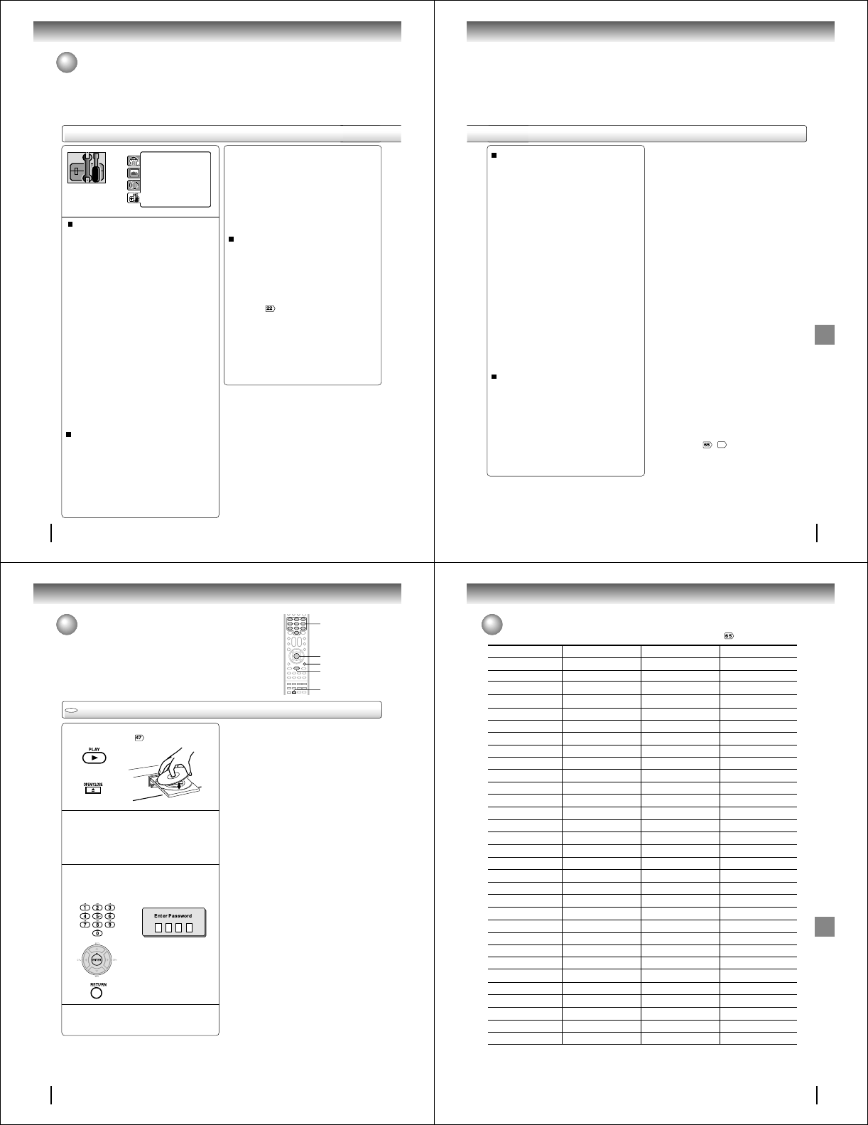
68
Function setup (DVD)
Customizing the function settings (Continued)
DRC : Off
QSound : On
Menu : English
Subtitle : English
Audio : English
E.B.L. : Off
TV Screen : 4:3
Display : On
Picture Mode : Auto
JPEG Interval : 5 Seconds
Screen Saver : On
Parental : Off
Password : Change
HD Jpeg : Off
Output : Interlace
DivX(R) VOD : Display
Parental control setting
Some discs are specified not suitable for children.
Such discs can be limited not to play back with the
unit.
1) Press C or D to select “Parental”, then press
ENTER. “Enter Password” screen will appear.
2) Press “0000” using Number buttons (0–9).
(Please note, this is pre-setting password of this
unit). Then press ENTER. The parental level list will
appear.
• Level Off: The parental control setting does not
function.
• Level 8: Virtually all DVD software can be
played back.
• Level 1: DVD software for adults cannot be
played back.
3) Press C or D to select from the level 1 to level 8.
The limitation will be more severe as the level
number is lower. Then press ENTER.
4) Press OPEN/CLOSE to activate Parental control
setting.
Notes:
• Depending on the discs, the unit cannot limit
playback.
• Some discs may not be encoded with specific rating
level information though its disc jacket says “adult.” For
those discs, the age restriction will not work.
• The password is required every time when you change
the parental level.
• If you input a wrong number, press CLEAR.
Set the new password
1) Press C or D to select “Password”, then press
ENTER. “Enter Current Password” screen will
appear.
2) Press Number buttons (0–9) to input the current
password (If the password has not been set yet
after you purchase this unit, it is “0000”).
3) Then press ENTER. “Enter New Password” screen
will appear. Press Number buttons (0–9) to input
the new password.
4) Press ENTER. Now your new password has been
set. Be sure to remember this number!
If you forget the password...
1) Press OPEN/CLOSE to open the disc tray.
2) Remove the disc.
3) Press OPEN/CLOSE again to close the disc tray.
“No Disc” appears on the screen.
4) While holding 7 down on the remote control and
at the same time press STOP on the front panel.
“Password Clear” appears on the screen. Now the
password has been returned to the initial value
(“0000”).
HD Jpeg
This DVD/VCR equipped with a “HD Jpeg”. It can display
the HD resolution JPEG images when the DVD/VCR is
connected to a HDTV using HDMI.
On:
Select when you connect the DVD video player to
a HDTV via HDMI OUT jack. JPEG images is dis-
played in suitable picture quality (480p, 720p or
1080i) .
Off:
The picture processing quality is fixed to 480p.
Notes:
• When the DVD/VCR is not connected to a TV using
HDMI, you cannot select “On”.
• When HD Jpeg is set to “On”, zoom function is prohibited
and component video outputs disabled when 480p, 720p
or 1080i is selected.
Setting details
69
Function setup (DVD)
Output
You can select the video output signal of the DVD
video player to the TV from “Interlace” or “Progres-
sive”.
Interlace:
Select when connecting to a composite TV or
a TV equipped with component video inputs
but progressive scan is not compatible.
Progressive:
Select when connecting to a TV equipped
with component video inputs and progressive
scan compatible.
Warning:
Once “Progressive” is selected when connecting to a
TV progressive scan incompatible, no image will be
seen on the video display.
In this case, you must reset the unit by pressing STOP
on the front panel for five seconds. The video output
will be restored to “Interlace” setting, and a picture will
once again be seen on a conventional analog display.
Notes:
• Some discs may not be played back with the progressive
scanning mode correctly because of the disc characteris-
tics or recording condition.
• Once Progressive scan on, S-video output is disabled.
Note:
If each setup (pages ~
69
) has been completed, the unit
can always be worked under the same conditions (espe-
cially with DVD discs).
Each setup will be retained in the memory even if you turn
the power off.
DivX® VOD
In order to play DivX® VOD (Video On Demand)
content on this unit, you first need to register the unit
with your DivX® VOD content provider. You do this by
generating a DivX® VOD registration code, which you
submit to your provider.
Press C or D to select “DivX(R) VOD”. Then press
ENTER. Your 8-character registration code is
displayed. Make a note of the code as you will need
it when you register with a DivX® VOD provider.
Then press ENTER to select Done.
70
Function setup (DVD)
Temporary disabling of rating level by DVD disc
Depending on the DVD disc, the disc may try to temporarily cancel the rating
level that you have set.
It is up to you to decide whether to cancel the rating level or not.
Load a DVD disc and press PLAY or OPEN/
CLOSE on the unit .
Note:
This temporary cancellation of rating level will be kept until the
disc is ejected.
When the disc is ejected, the original rating level will be set again
automatically.
1
2
ENTER
PLAY
0–9
OPEN/CLOSE
If the DVD disc has been designed to tempo-
rarily cancel the Rating level, the screen which
follows the “Reading” screen will change,
depending on which disc is played. If you
select “YES” with the ENTER key, password
input screen will then appear.
Enter the password with Number buttons (0–9).
Then press ENTER.
Function setup (DVD)
3
To exit from the entry, press
RETURN.
RETURN
Temporary disabling of rating level by DVD disc
Playback will commence if the entered
password was correct.
4
DVD
71
Others
Language code list
Enter the appropriate code number for the initial settings “Menu”, “Subtitle” and/or “Audio” .
Abkhazian 1112 Fiji 1620 Lingala 2224 Singhalese 2919
Afar 1111 Finnish 1619 Lithuanian 2230 Slovak 2921
Afrikaans 1116 French 1628 Macedonian 2321 Slovenian 2922
Albanian 2927 Frisian 1635 Malagasy 2317 Somali 2925
Amharic 1123 Galician 1722 Malay 2329 Spanish 1529
Arabic 1128 Georgian 2111 Malayalam 2322 Sundanese 2931
Armenian 1835 German 1415 Maltese 2330 Swahili 2933
Assamese 1129 Greek 1522 Maori 2319 Swedish 2932
Aymara 1135 Greenlandic 2122 Marathi 2328 Tagalog 3022
Azerbaijani 1136 Guarani 1724 Moldavian 2325 Tajik 3017
Bashkir 1211 Gujarati 1731 Mongolian 2324 Tamil 3011
Basque 1531 Hausa 1811 Nauru 2411 Tatar 3030
Bengali; Bangla 1224 Hebrew 1933 Nepali 2415 Telugu 3015
Bhutani 1436 Hindi 1819 Norwegian 2425 Thai 3018
Bihari 1218 Hungarian 1831 Oriya 2528 Tibetan 1225
Breton 1228 Icelandic 1929 Panjabi 2611 Tigrinya 3019
Bulgarian 1217 Indonesian 1924 Pashto, Pushto 2629 Tonga 3025
Burmese 2335 Interlingua 1911 Persian 1611 Turkish 3028
Byelorussian 1215 Irish 1711 Polish 2622 Turkmen 3021
Cambodian 2123 Italian 1930 Portuguese 2630 Twi 3033
Catalan 1311 Japanese 2011 Quechua 2731 Ukrainian 3121
Chinese 3618 Javanese 2033
Rhaeto-Romance
2823 Urdu 3128
Corsican 1325 Kannada 2124 Romanian 2825 Uzbek 3136
Croatian 1828 Kashmiri 2129 Russian 2831 Vietnamese 3219
Czech 1329 Kazakh 2121 Samoan 2923 Volapük 3225
Danish 1411 Kirghiz 2135 Sanskrit 2911 Welsh 1335
Dutch 2422 Korean 2125 Scots Gaelic 1714 Wolof 3325
English 1524 Kurdish 2131 Serbian 2928 Xhosa 3418
Esperanto 1525 Laothian 2225 Serbo-Croatian 2918 Yiddish 2019
Estonian 1530 Latin 2211 Shona 2924 Yoruba 3525
Faroese 1625 Latvian, Lettish 2232 Sindhi 2914 Zulu 3631
Language Name Code Language Name Code Language Name Code Language Name Code
Others
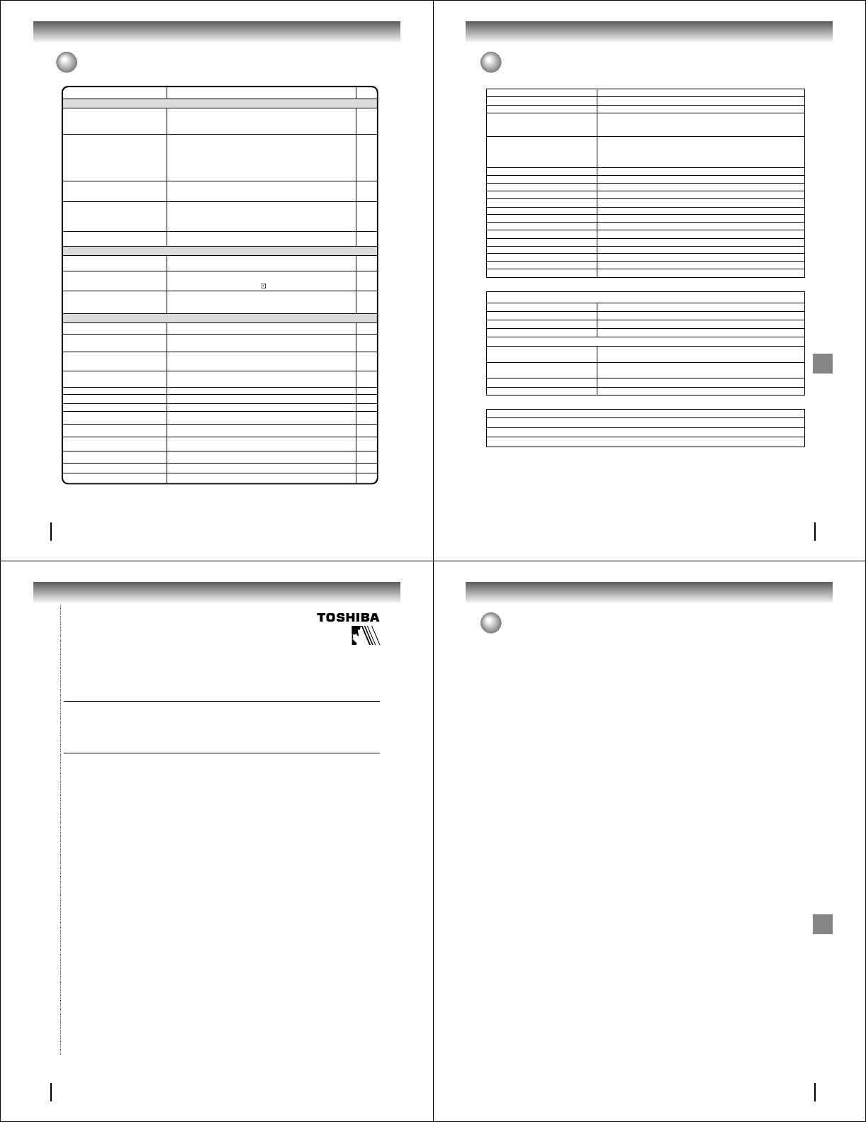
72
Others
Troubleshooting
Before calling a service technician, please check the following table for a possible cause of the symptoms and some solutions.
Symptoms Solutions
• Make sure the power cord is plugged in.
• Try another AC outlet.
• Unplug unit, then plug it back in.
• Select the DVD or VCR mode before operating.
DVD/VCR does not operate.
DVD/VCR
Page
5
–
5
35,47
The remote control does not function.
• Aim the remote control at the remote sensor.
• Operate within Approx. 7 Meters or reduce the light in the room.
• Clear the path of the beam.
• The batteries are weak. Replace the batteries.
• Check the batteries are inserted correctly.
13
DVD
No picture.
• Antenna connection is not correct or antenna cable is disconnected.
• The video channel is not in the correct position or the TV is not set to the video
channel 3 or 4.
• Check the unit is connected correctly.
• The video input selector of the TV is not set to VIDEO. Set to VIDEO (or
equivalent).
• Channel is set to the external mode.
• Press HDMI to turn off the HDMI mode.
No sound. • Check the unit is connected correctly.
• Check the input selector of the amplifier is set properly.
• The unit is in the Special playback mode.
16~19
27
16~26
–
–
22
16~26
–
36,49
• Select proper language in the menu options.Display is not shown in your language. 65
Playback doesn’t start. • No disc is inserted.
• The disc may be dirty. Clean up the disc.
• The unit cannot play DVD-ROMs, etc.
Stopping playback, slow-motion play, repeat
play, or memory play, etc. cannot be
performed. • Some discs may not do some of the functions.
47
7
7
–
No Cable TV reception. • Check all Cable TV connections.
• Station or Cable TV system problems, try another station. 18,19
Noise bars on screen.
• Tracking adjustment beyond range of automatic tracking circuit. Try Manual
tracking adjustment.
• Video heads are dirty.
• The tape is worn or damaged.
VCR
• The erase prevention tab of the video cassette is broken off.
• The unit is in the external input mode.
TV recording does not work. 34,39
Timer recording does not work. • The time is not set correctly.
• The recording start/end time is not set correctly.
• The TIMER REC has not been pressed ( is not lit).
29~31
42
42
36
36
–
No picture, or the screen is blurred or divided
into two parts.
• The PROGRESSIVE scan is “On” although the unit is connected to a TV
via the VIDEO OUT or the S-VIDEO OUT jack. 69
No subtitle. • Some discs have no subtitles.
• Subtitles are cleared. Press SUBTITLE.
Angle cannot be changed. • Multi-angles are not recorded on the DVD disc.
• The function is prohibited with the unit or the disc.
“X” appears on the screen.
56
54
49
No 4:3 (16:9) picture. • The setup does not match your TV.
No on-screen display. • Set Display to “On”.
65
66
No surround sound. • The setup does not match your stereo system.
The unit or remote operation key is not
functioning. • Turn off the unit and unplug the AC power cord for several minutes, then replug it.
67
Playback does not start when the title is
selected. • Check the Parental setup.
Audio soundtrack and/or subtitle language
is not changed when you playback a DVD. • Multilingual language is not recorded on the DVD disc.
–
68,70
55,56
73
Others
Specifications
AC 120 V 60 Hz
Operation: 20 W, Stand by: 2 W
7.7 lbs (3.5 kg)
Width: 16-15/16 inches (430.6 mm)
Height: 3-9/16 inches (89.7 mm)
Depth: 9 inches (228.7 mm)
181 channel freq. synthesized
VHF 2-13
UHF 14-69
Cable TV 113 Channels
UHF/VHF In/Out: 75 1 coaxial
Channel 3 or 4, Switchable
NTSC
4 Rotary heads
Hi-Fi sound - 2 Tracks / MONO sound - 1 Track
20 Hz to 20 kHz
More than 90dB
Approx. 1 minute and 48 seconds (with T-120 Cassette Tape)
DVD (12 cm, 8 cm), CD (12 cm, 8 cm)
DVD: 4 Hz-22 kHz, CD: 4 Hz-20 kHz
85dB (DVD)
0.06% (DVD)
Less than 0.01% Wrms
Temperature: 5˚C-40˚C (41˚F-104˚F), Operating status: Horizontal
Power supply
Power consumption
Weight
Dimensions
Tuner
Antenna input/output
RF channel output
Color system
Video head
Audio track
Hi-Fi frequency response
Hi-Fi dynamic range
FWD/REV time at 25˚C (77˚F)
Applicable disc
Frequency range
S/N ratio
Harmonic distortion
Wow and flutter
Operating conditions
General
Input/Output
DVD/VCR
Video input 1.0 V (p-p), 75 1, negative sync., pin jack x 2
Video output 1.0 V (p-p), 75 1, negative sync., pin jack x 1
Audio input –8 dBm, 50 k1, negative sync., pin jack (L/R) x 2
Audio output –8 dBm, 1 k1, negative sync., pin jack (L/R) x 1
DVD
S-video output (Y) 1.0 V (p-p), 75 1, negative sync., Mini DIN 4-pin x 1
(C) 0.286 V (p-p), 75 1
Component video output (Y) 1.0 V (p-p), 75 1, negative sync., pin jack x 1
(PB)/(PR) 0.7 V (p-p), 75 1, pin jack x 2
Audio output (COAXIAL DIGITAL) 0.5 V (p-p), 75 1, pin jack x 1
Audio output (ANALOG) –12 dBm, 1 k1, pin jacks (L/R) x 1
Supplied accessories
Audio/video cable ................................................. 1
Remote control (SE-R0221) ................................. 1
Batteries (R03/AAA) ............................................. 2
75 1 coaxial cable ................................................ 1
• This model complies with the above specifications.
• Designs and specifications are subject to change without notice.
• This model may not be compatible with features and/or specifications that may be added in the future.
74
Others
- IMPORTANT -
CANADIAN WARRANTY INFORMATION
GARANTIE CANADIENNE
STANDARD WARRANTY
TYPE OF SET DVD Player
DVD/VCR Combination
Home Theatre in a Box
DVD Recorder
Portable DVD
WARRANTY PERIOD 12 MONTHS
CANADIAN WARRANTY
Toshiba of Canada Limited (TCL) makes the following
limited warranties to original consumers in Canada.
Please retain your “Bill of Sale” as proof of purchase.
To obtain a “Canadian Warranty” please register
online at www.toshiba.ca.
Canadian Warranty Information
Should service be required on this unit during the one year
warranty period, TCL's option will be to repair or exchange the
defective unit. It will be necessary to follow this procedure:
Contact: Toshiba of Canada Limited at the Consumer
Electronics Group, customer support line.
Phone: 1-800-268-3404
Email: ceg_customer_support@toshiba.ca
All in-warranty repairs must be made by an authorized TCL
service centre.
For service exchange TCL will arrange to have the unit picked
up by courier and a replacement unit will be returned via same
courier. (Note: A major credit card number will be required as a
charge of $25.00 will apply if no fault is found with the unit.)
During the first 3 months of ownership, a new unit will be sup-
plied as a replacement. During the remainder of the warranty
period a service-renewed unit will be supplied.
The original “Bill of Sale” must be provided as proof of pur-
chase (it will be returned with the replacement unit.)
This 12-month warranty will be strictly adhered to.
Out of warranty units should be repaired by a TCL authorized
service centre.
Note: It is the responsibility of the owner to ensure proper
packaging. Should damage in shipping occur, due to poor
packaging, a charge back for the repair will result.
This warranty applies to the original purchaser only and is not
transferable.
This warranty does not apply to sets that have been subjected
to misuse, neglect, accident, physical damage or acts of
nature.
Sets with the serial number removed, altered, replaced or
defaced will not be covered by this warranty.
The warranties from TCL are effective only if the product is
purchased in Canada from an authorized TCL dealer and
operated in Canada.
Products utilized for rental or commercial purposes are not
covered by this warranty.
This warranty is in lieu of all other warranties, guaranties or
agreements, whether expressed or implied, and no person,
agent distributor, dealer, service centre or company is author-
ized to change, modify or extend its terms in any manner
whatsoever.
GARANTIE NORMALE
TYPE D’APPAREIL Lecteur DVD
DVD/magnétoscope combo
Cinéma maison dans une boîte
Enregistreur DVD
DVD Portatif
DURÉE DE LA GARANTIE: 12 MOIS
GARANTIE CANADIENNE
1) Toshiba du Canada Limitée (TCL) offre au Canada les
garanties limitées suivantes aux consommateurs origin-
aux. Veuillez conserver votre « facture » comme preuve
d’achat. Pour obtenir une garantie canadienne,
veuillez vous inscrire en ligne à www.toshiba.ca
Information sur la garantie Canadienne
Si vous avez besoin de service sur cet appareil au cours le
l'année de garantie, Toshiba du Canada Limitée aura l'option
de réparer ou échanger l'appareil défectueux. Vous devrez
suivre la procédure suivante:
Contact: Toshiba du Canada Limitée au Groupe Électronique
aux consommateurs, service à la clientèle.
Tél: 1-800-268-3404
Courriel: ceg_customer_support@toshiba.ca
Toutes les réparations au cours de la garantie doivent être faites
par un centre de service autorisé Toshiba.
Pour un échange TCL s'assurera qu'un service de courrier
ramassera l'unité et qu'un appareil de remplacement soit
expédié par le même service de courrier.
(Note: Un numéro de carte de crédit sera requis car une
charge de 25,00$ sera appliquée si toutefois l’appareil n’avait
aucun problème de fonctionnement.)
Une nouvelle unité sera fournie comme remplacement durant
les premiers 3 mois de propriété. Par contre durant la balance
de la garantie une unité remise à neuf sera fournie.
La «facture originale doit être fournie comme preuve d’achat
(elle vous sera retournée avec l’unité de remplacement.)
Cette garantie de 12 mois sera strictement adhérée.
Les unités hors de garantie devraient être réparées par un
centre de service autorisé Toshiba.
Note: C’est la responsabilité du propriétaire de s’assurer que
l’emballage est adéquat. Vous serez facturé pour toutes répa-
rations causées par des dommages encourus à cause d’un
emballage non adéquat.
Cette garantie est octroyée à l’acheteur initial et n’est pas
transférable. Cette garantie ne s’aplique pas aux appareils qui
ont été sujets aux abus, négligences, accidents, dommages
physiques ou actes naturels.
Les appareils dont le numéro de série a été enlevé, altéré,
remplacé ou barbouillé ne sont pas couverts par cette
garantie.
Les garanties de TCL sont valides seulement sur les unités
sont achetées et utilisées au Canada d'un marchand autorisé
TCL.
Cette garantie ne couvre pas les produits de location ou à
usage commercial. Cette garantie remplace toutes autres
garanties ou ententes exprimées ou sous-entendues. Aucune
personne, agent, distributeur, concessionaire ou compagnie
n’est autorisé à changer, modifier ou prolonger les termes de
cette garantie de quelque façon que ce soit.
Toshiba of Canada Limited 191 McNabb Street Markham, Ontario L3R 8H2
75
Others
Memo
...................................................................................................................................
...................................................................................................................................
...................................................................................................................................
...................................................................................................................................
...................................................................................................................................
...................................................................................................................................
...................................................................................................................................
...................................................................................................................................
...................................................................................................................................
...................................................................................................................................
...................................................................................................................................
...................................................................................................................................
...................................................................................................................................
...................................................................................................................................
...................................................................................................................................
...................................................................................................................................
...................................................................................................................................
...................................................................................................................................
...................................................................................................................................
...................................................................................................................................
...................................................................................................................................
...................................................................................................................................
...................................................................................................................................
...................................................................................................................................
...................................................................................................................................
...................................................................................................................................
...................................................................................................................................
...................................................................................................................................
...................................................................................................................................
...................................................................................................................................
...................................................................................................................................
...................................................................................................................................
...................................................................................................................................
...................................................................................................................................
...................................................................................................................................
...................................................................................................................................
...................................................................................................................................
...................................................................................................................................
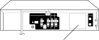
A1-1
CAUTION
THIS DIGITAL VIDEO PLAYER EMPLOYS A LASER SYSTEM.
TO ENSURE PROPER USE OF THIS PRODUCT, PLEASE READ THIS SERVICE MANUAL CARE-
FULLY AND RETAIN FOR FUTURE REFERENCE. SHOULD THE UNIT REQUIRE MAINTENANCE,
CONTACT AN AUTHORIZED SERVICE LOCATION-SEE SERVICE PROCEDURE.
USE OF CONTROLS, ADJUSTMENTS OR THE PERFORMANCE OF PROCEDURES OTHER THAN
THOSE SPECIFIED HEREIN MAY RESULT IN HAZARDOUS RADIATION EXPOSURE.
TO PREVENT DIRECT EXPOSURE TO LASER BEAM, DO NOT TRY TO OPEN THE ENCLOSURE.
VISIBLE LASER RADIATION MAY BE PRESENT WHEN THE ENCLOSURE IS OPENED. DO NOT
STARE INTO BEAM.
Location of the required Marking
The rating sheet and the safety caution are on the rear of the unit.
CERTIFICATION: COMPLIES WITH FDA RADIATION PERFORMANCE
STANDARDS, 21 CFR SUBCHAPTER J.
PREPARATION OF SERVICING
The laser diode used for a pickup head may be destroyed with external static electricity.
Moreover, even if it is operating normally after repair, when static electricity discharge is received at the
time of repair, the life of the product may be shortened.
Please perform the following measure against static electricity, be careful of destruction of a laser diode
at the time of repair.
• Place the unit on a workstation equipped to protect against static electricity, such as conductive mat.
• Soldering iron with ground wire or ceramic type is used.
• A worker needs to use a ground conductive wrist strap for body.
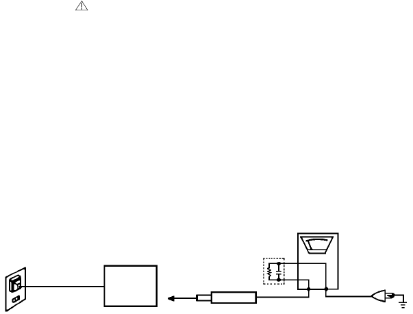
A1-2
IMPORTANT SERVICE SAFETY INFORMATION
Safety precautions to be followed during servicing:
1.
2.
Parts marked with an are critical parts for safety. Replace only with the one described in the parts
list.
Before returning the DVD product to the customer, make the appropriate leakage current check or
resistance measurements to ensure that exposed parts are properly insulated from the supply circuit.
A leakage current check is recommended for this unit. Plug the AC line cord directly into a 120V 60Hz AC
outlet (do not use an isolation transformer for this check). Use a leakage current tester (Fig. 1) or a
metering system which complies with Underwriters Laboratories (UL 1492). Measure for current from all
exposed metal parts of the cabinet to a known earth ground: particularly, any exposed metal part having a
return path to the chassis. Any current measured must not exceed 0.5mA. Any measurement not within
the limits outlined above are indicative of a potential shock hazard and corrective action must be taken
before returning the unit to the customer.
KNOWN EARTH
GROUND
1.5K ohm
0.15 µF
(Reading should not be above 0.5mA)
Leakage Current Tester
TEST PROBE
Test all exposed
metal surfaces
PRODUCT UNDER TEST
2-Blade polarized
type cord set
Fig. 1 AC Leakage Test

A1-3
IMPORTANT SAFEGUARDS
1.
2.
3.
4.
5.
6.
7.
8.
8A.
9.
10.
11.
12.
13.
14.
15.
16.
READ INSTRUCTIONS
All the safety and operating instructions should be read before the unit is operated.
RETAIN INSTRUCTIONS
The safety and operating instructions should be retained for future reference.
HEED WARNINGS
All warnings on the unit and in the operating instructions should be adhered to.
FOLLOW INSTRUCTIONS
All operating and use instructions should be followed.
CLEANING
Unplug this unit from the wall outlet before cleaning. Do not use liquid cleaners or aerosol cleaners. Use a damp
cloth for cleaning.
ATTACHMENTS
Do not use attachments not recommended by the unit’s manufacturer as they may cause hazards.
WATER AND MOISTURE
Do not use this unit near water. For example, near a bathtub, washbowl, kitchen sink, or laundry tub, in a wet
basement, or near a swimming pool.
ACCESSORIES
Do not place this unit on an unstable cart, stand, tripod, bracket, or table. The
unit may fall, causing serious injury, and serious damage to the unit. Use only
with a cart, stand, tripod, bracket, or table recommended by the manufacturer.
An appliance and cart combination should be moved with care. Quick stops,
excessive force, and uneven surfaces may cause the appliance and cart
combination to overturn.
VENTILATION
Slots and openings in the cabinet and in the back or bottom are provided for ventilation, to ensure reliable
operation of the unit, and to protect it from overheating. These openings must not be blocked or covered. The
openings should never be blocked by placing the unit on a bed, sofa, rug, or other similar surface. This unit
should never be placed near or over a radiator or heat source. This unit should not be placed in a built-in
installation such as a bookcase or rack unless proper ventilation is provided or the manufacturer’s instructions
have been adhered to.
POWER SOURCES
This unit should be operated only from the type of power source indicated on the rating plate. If you are not sure
of the type of power supply to your home, consult your appliance dealer or local power company. For units
intended to operate from battery power, or other sources, refer to the operating instructions.
GROUNDING OR POLARIZATION
This unit is equipped with a polarized alternating-current line plug (a plug having one blade wider than the other).
This plug will fit into the power outlet only one way. This is a safety feature. If you are unable to insert the plug
fully into the outlet, try reversing the plug. If the plug should still fail to fit, contact your electrician to replace your
obsolete outlet. Do not defeat the safety purpose of the polarized plug. If your unit is equipped with a 3-wire
grounding-type plug, a plug having a third (grounding) pin, this plug will only fit into a grounding-type power
outlet. This too, is a safety feature. If you are unable to insert the plug into the outlet, contact your electrician to
replace your obsolete outlet. Do not defeat the safety purpose of the grounding-type plug.
POWER-CORD PROTECTION
Power-supply cords should be routed so that they are not likely to be walked on or pinched by items placed upon
or against them, paying particular attention to cords at plugs, convenience receptacles, and the point where they
exit from the appliance.
LIGHTNING
To protect your unit from a lightning storm, or when it is left unattended and unused for long periods of time,
unplug it from the wall outlet and disconnect the antenna or cable system. This will prevent damage to the unit
due to lightning and power line surges.
POWER LINES
An outside antenna system should not be located in the vicinity of overhead power lines or other electric light or
power circuits, or where it can fall into such power lines or circuits. When installing an outside antenna system,
extreme care should be taken to keep from touching such power lines or circuits, as contact with them might be
fatal.
OVERLOADING
Do not overload wall outlets and extension cords, as this can result in a risk of fire or electric shock.
OBJECT AND LIQUID ENTRY
Do not push objects through any openings in this unit, as they may touch dangerous voltage points or short out
parts that could result in fire or electric shock. Never spill or spray any type of liquid into the unit.
PORTABLE CART WARNING
(symbol provided by RETAC)
S3125A

A1-4
IMPORTANT SAFEGUARDS (CONTINUED)
OUTDOOR ANTENNA GROUNDING
If an outside antenna or cable system is connected to the unit, be sure the antenna or cable system is grounded
so as to provide some protection against voltage surges and built-up static charges. Section 810 of the National
Electrical Code, ANSI/NFPA 70, provides information with respect to proper grounding of the mast and supporting
structure, grounding of the lead-in wire to an antenna discharge unit, size of grounding conductors, location of
antenna discharge unit, connection to grounding electrodes, and requirements for the grounding electrode.
SERVICING
Do not attempt to service this unit yourself as opening or removing covers may expose you to dangerous voltage
or other hazards. Refer all servicing to qualified service personnel.
DAMAGE REQUIRING SERVICE
Unplug this unit from the wall outlet and refer servicing to qualified service personnel under the following
conditions:
REPLACEMENT PARTS
When replacement parts are required, be sure the service technician uses replacement parts specified by the
manufacturer or those that have the same characteristics as the original parts.
Unauthorized substitutions may result in fire, electric shock or other hazards.
SAFETY CHECK
Upon completion of any service or repairs to this unit, ask the service technician to perform safety checks to
determine that the unit is in proper operating condition.
WALL OR CEILING MOUNTING
The product should be mounted to a wall or ceiling only as recommended by the manufacturer.
HEAT
The product should be situated away from heat sources such as radiators, heat registers, stoves, or other
products (including amplifiers) that produce heat.
DISC TRAY
Keep your fingers well clear of the disc tray as it is closing. It may cause serious personal injury.
CONNECTING
When you connect the product to other equipment, turn off the power and unplug all of the equipment from the
wall outlet. Failure to do so may cause an electric shock and serious personal injury. Read the owner's manual of
the other equipment carefully and follow the instructions when making any connections.
SOUND VOLUME
Reduce the volume to the minimum level before you turn on the product. Otherwise, sudden high volume sound
may cause hearing or speaker damage.
SOUND DISTORTION
Do not allow the product output distorted sound for a longtime. It may cause speaker overheating and fire.
HEADPHONES
When you use the headphones, keep the volume at a moderate level. If you use the headphones continuously
with high volume sound, it may cause hearing damage.
LASER BEAM
Do not look into the opening of the disc tray or ventilation opening of the product to see the source of the laser
beam. It may cause sight damage.
DISC
Do not use a cracked, deformed, or repaired disc. These discs are easily broken and may cause serious
personal injury and product malfunction.
NOTE TO CATV SYSTEM INSTALLER
This reminder is provided to call the CATV system installer’s attention to Article 820-40 of the NEC that provides
guidelines for proper grounding and, in particular, specifies that the cable ground shall be connected to the
grounding system of the building, as close to the point of cable entry as practical.
17.
18.
19.
20.
21.
22.
23.
24.
25.
26.
27.
28.
29.
30.
31.
a.
b.
c.
d.
e.
f.
When the power-supply cord or plug is damaged.
If liquid has been spilled, or objects have fallen into the unit.
If the unit has been exposed to rain or water.
If the unit does not operate normally by following the operating instructions. Adjust only those controls that
are covered by the operating instructions, as an improper adjustment of other controls may result in
damage and will often require extensive work by a qualified technician to restore the unit to its normal
operation.
If the unit has been dropped or the cabinet has been damaged.
When the unit exhibits a distinct change in performance, this indicates a need for service.
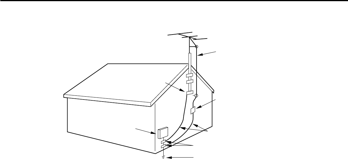
A1-5
EXAMPLE OF ANTENNA GROUNDING AS PER THE NATIONAL ELECTRICAL CODE
ANTENNA
DISCHARGE UNIT
(NEC SECTION 810-20)
ANTENNA LEAD
IN WIRE
GROUNDING CONDUCTORS
(NEC SECTION 810-21)
GROUND CLAMPS
POWER SERVICE GROUNDING
ELECTRODE SYSTEM
(NEC ART 250, PART H)
GROUND
CLAMP
ELECTRIC SERVICE
EQUIPMENT
NEC-NATIONAL ELECTRICAL CODE
S2898A
IMPORTANT SAFEGUARDS (CONTINUED)
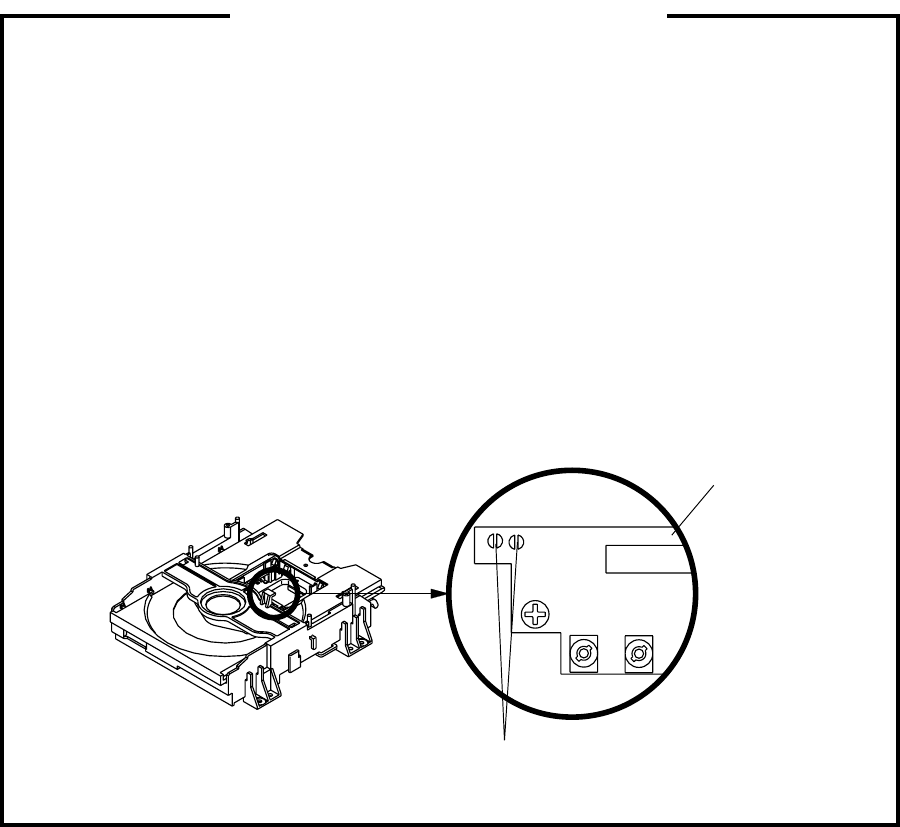
A1-6
Before removing Pick Up PCB and DVD PCB connector, the short circuit the position shown in Fig. 1
using a soldering iron. If you remove the DVD Deck with no soldering, the Laser may be damaged.
WHEN REPLACING DVD DECK
[ When removing the DVD Deck ]
[ When installing the DVD Deck ]
Remove all the soldering on the short circuit position after the connection of Pick Up PCB and DVD
PCB connector.
NOTE
Fig. 1
Before your operation, please read “PREPARATION OF SERVICING”.
Use the Lead Free solder.
Manual soldering conditions
• Soldering temperature: 350 ± 5˚C
• Soldering time: Within 2 seconds
• Soldering combination: Sn-3.0Ag-0.5Cu
When Soldering/Removing of solder, use the draw in equipment over the Pick Up Unit to keep the
Flux smoke away from it.
•
•
•
•
Short circuit using a
soldering iron.
Pick Up PCB
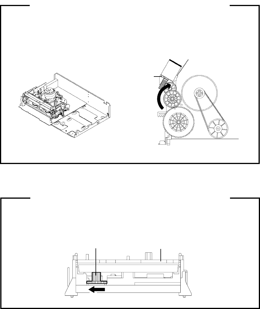
A1-7
TAPE REMOVAL METHOD AT NO POWER SUPPLY
Fig. 1
Fig. 2
Remove the Top Cabinet, Front Cabinet and DVD Block. (Refer to item 1 of the
DISASSEMBLY INSTRUCTIONS.)
Remove the screw 1 of the Deck Chassis and remove the Loading Motor. (Refer to Fig. 2)
Rotate the Pinch Roller Cam in the direction of the arrow by hand to slacken the Video Tape.
Rotate the Clutch Ass'y either derection to wind the Video Tape in the Cassette Case.
Repeat steps 3~4. Then take out the Video Cassette from the Deck Chassis. Be careful not to scratch the
tape.
1.
2.
3.
4.
5.
Main Cam Clutch Ass'y
Main Chassis (Front Side)
Loading Motor
Capstan DD Unit
Pinch Roller Cam
Screw 1
1.
2.
3.
Remove the Top and Front Cabinet. (Refer to item 1 of the DISASSEMBLY INSTRUCTIONS.)
Rotate the Main Gear in the direction of the arrow by hand.
(Refer to Fig. 1)
Manually open the Tray.
DISC REMOVAL METHOD AT NO POWER SUPPLY
Fig. 1
DVD DeckMain Gear

A1-8
TRAY LOCK
PARENTAL CONTROL - RATING LEVEL
4 DIGIT PASSWORD CANCELLATION
If the stored 4 digit password in the Rating Level menu needs to be cancelled, please follow the steps below.
Turn Unit ON.
Set the DVD Mode.
Confirm that the 'No Disc' will be appeared on the screen.
Press and hold the '7' key on the remote control unit.
Simultaneously press and hold the 'STOP' key on the front panel.
Hold both keys for more than 3 seconds.
The On Screen Display message 'PASSWORD CLEAR' will appear.
The 4 digit password has now been cleared
1.
2.
3.
4.
5.
6.
7.
8.
Turn Unit ON.
Set the DVD to the Stop Mode.
Press it in order of 'SETUP', 'SUBTITLE', '3', 'AUDIO' and '0' key of a remote control unit.
The On Screen Display message ' ' will appear.
The Tray Lock has now been set up.
Tray cannot be opened by setting the Tray Lock, please follow the steps below.
1.
2.
3.
4.
5.
To unlock the Tray Lock, please follow the steps below.
Turn Unit ON.
Set the DVD to the Stop Mode.
Press it in order of 'SETUP', 'SUBTITLE', '3', 'AUDIO' and '0' key of a remote control unit.
The On Screen Display message ' ' will appear.
The Tray Lock has now been cleared.
1.
2.
3.
4.
5.
TABLE OF CONTENTS
• GREEN PRODUCT PROCUREMENT
• LEAD-FREE SOLDER
• OWNER'S MANUAL
CAUTION ....................................................................................................................................
PREPARATION OF SERVICING ...............................................................................................
IMPORTANT SERVICE SAFETY INFORMATION ...................................................................
IMPORTANT SAFEGUARDS .....................................................................................................
WHEN REPLACING DVD DECK ...............................................................................................
TAPE REMOVAL METHOD AT NO POWER SUPPLY ............................................................
DISC REMOVAL METHOD AT NO POWER SUPPLY .............................................................
PARENTAL CONTROL-RATING LEVEL ..................................................................................
TRAY LOCK ................................................................................................................................
TABLE OF CONTENTS ..............................................................................................................
GENERAL SPECIFICATIONS ...................................................................................................
DISASSEMBLY INSTRUCTIONS
1.REMOVAL OF MECHANICAL PARTS AND P. C. BOARDS..............................................
2.REMOVAL OF VCR DECK PARTS .....................................................................................
3.REMOVAL OF DVD DECK PARTS .....................................................................................
4.REMOVAL AND INSTALLATION OF FLAT PACKAGE IC .................................................
KEY TO ABBREVIATIONS ........................................................................................................
SERVICE MODE LIST ................................................................................................................
PREVENTIVE CHECKS AND SERVICE INTERVALS ..............................................................
RE-WRITE FOR DVD FIRMWARE ............................................................................................
WHEN REPLACING EEPROM (MEMORY) IC ..........................................................................
RF SIGNAL CHECK OF DVD MT PCB .....................................................................................
SERVICING FIXTURES AND TOOLS .......................................................................................
PREPARATION FOR SERVICING.............................................................................................
MECHANICAL ADJUSTMENTS ................................................................................................
ELECTRICAL ADJUSTMENTS..................................................................................................
TROUBLESHOOTING GUIDE ...................................................................................................
BLOCK DIAGRAMS
DVD..........................................................................................................................................
VCR..........................................................................................................................................
PRINTED CIRCUIT BOARDS
DVD MT/USB ...........................................................................................................................
VCR MT/OPERATION/OPERATION 2 ...................................................................................
LOADING MOTOR/SW ...........................................................................................................
SCHEMATIC DIAGRAMS
MPEG/MICON/DSP/RF_AMP .................................................................................................
MEMORY .................................................................................................................................
MOTOR DRIVE .......................................................................................................................
AUDIO/VIDEO .........................................................................................................................
HDMI/USB ...............................................................................................................................
Y/C/AUDIO/CCD/HEAD AMP .................................................................................................
SYSCON ..................................................................................................................................
TUNER/JACK ..........................................................................................................................
OPERATION/DISPLAY ...........................................................................................................
Hi-Fi/DEMODULATOR ............................................................................................................
POWER ...................................................................................................................................
OPERATION/LED....................................................................................................................
LOADING MOTOR/SW ...........................................................................................................
INTERCONNECTION DIAGRAM ...............................................................................................
WAVEFORMS .............................................................................................................................
MECHANICAL EXPLODED VIEW .............................................................................................
CHASSIS EXPLODED VIEW .....................................................................................................
DVD DECK EXPLODED VIEW...................................................................................................
MECHANICAL REPLACEMENT PARTS LIST .........................................................................
CHASSIS REPLACEMENT PARTS LIST..................................................................................
DVD DECK REPLACEMENT PARTS LIST ...............................................................................
ELECTRICAL REPLACEMENT PARTS LIST ...........................................................................
A1-1
A1-1
A1-2
A1-3~A1-5
A1-6
A1-7
A1-7
A1-8
A1-8
A2-1
A3-1~A3-5
B1-1, B1-2
B2-1~B2-6
B3-1~B3-4
B4-1, B4-2
C1-1, C1-2
C2-1
C3-1, C3-2
C4-1
C4-2
C4-3
D1-1
D1-1
D2-1~D2-4
D3-1, D3-2
E-1~E-34
F-1, F-2
F-3, F-4
G-1,G-2
G-3~G-6
G-7, G-8
H-1, H-2
H-3, H-4
H-5, H-6
H-7, H-8
H-9, H-10
H-11, H-12
H-13, H-14
H-15, H-16
H-17, H-18
H-19, H-20
H-21, H-22
H-23, H-24
H-25, H-26
H-27, H-28
I-1, I-2
J1-1, J1-2
J2-1, J2-2
J3-1
K1-1
K2-1
K3-1
K4-1~K4-5
A2-1

GENERAL SPECIFICATIONS
G-1 Outline of the product DVD VIDEO PLAYER & VHS Player / Recorder
G-2 DVD System Color System NTSC
Disc
Disc Diameter 120 mm , 80 mm
Drive DM3SA
Search speed Fwd 4 steps
Actual 2-120 times (DVD, VIDEO CD, SVCD)
4-40 times (CD)
Rev 4 steps
Actual 2-120 times (DVD, VIDEO CD, SVCD)
4-40 times (CD)
Slow speed Fwd 1/7-1/2 times
Actual --
Rev --
Actual --
G-3 VCR System VHS Player / Recorder
System Video System NTSC
Hi-Fi STEREO Yes
NTSC PB(PAL60Hz) No
Deck OVD-7S
Heads Video Head 4Head
FM Audio Head 2Head
Audio / Control Mono/Yes
Erase (Full Track Erase) Yes
Erase (Normal Audio Track Erase) No
Tape Rec PAL -
Speed NTSC SP/SLP(EP)
Play PAL -
NTSC SP/SLP(EP)
Fast Forward / Rewind Time (Approx.) at 25oC FF:1'48"/REW:1'48"
with Cassette T-120
Forward/Reverse NTSC or PAL-M SP/LP/SLP(EP) = 3x,5x / 7x,9x / 9x,15x
Picture Search PAL or SECAM -
Frame Advance Yes
Slow Speed 1/10
G-4 Tuning Broadcasting System US System M
System Tuner and System 1Tuner
Receive CH Destination US (w/CABLE)
CH Coverage 2-69,4A,A-5~ A-1,A~I,
J~ W, W+1-W+84
Intermediate Picture (FP) 45.75 MHz
Frequency Sound (FS) 41.25 MHz
FP-FS 4.50 MHz
Preset CH -
RF Converter Output Yes
Channel 3 or 4 ch
Level / Impedance 66 dBu / 75 Ohm
Sound Selector No
Stereo / Dual TV Sound US-ST
Tuner Sound Muting Yes
G-5 Power Power Source AC 120V 60Hz
DC -
Power Consumption 20 W at 120V 60Hz
Stand by 2 W at 120V 60Hz
Per Year -- W
Energy Star No
Protector Power Fuse Yes
Safety Circuit Yes
IC Protector(Micro Fuse) No
G-6 Regulation Safety UL / CSA
Radiation FCC / IC
Laser DHHS
G-7 Temperature Operation 5oC - 40oC
Storage -20oC - 60oC
G-8 Operating Humidity Less than 80% RH
DVD, CD-DA, CD-R/RW, VIDEO CD,
SVCD, DVD-R/RW (VIDEO FORMAT ONLY)
A3-1

GENERAL SPECIFICATIONS
G-9 Signal Video Signal Output Level 1 V p-p/75 ohm (DVD,VCR)
S/N Ratio (Weighted) 65 dB(DVD) 50 dB(VCR)
Horizontal Resolution 500 Lines (DVD) 230 Lines(VCR Mode)
RGB Signal Output Level -
Audio Signal Input Level Microphone -
Input Level Line -8 dBm/ 50k ohm (VCR, 0dBm=0.775Vrms)
Output Level Line
Digital Output Level 0.5 V p-p / 75 ohm(DVD)
S/N Ratio at (Weighted) 85dB(DVD), 42dB(VCR at SP)
Harmonic Distortion (1KHz) Typical 0.06% (1KHz) (DVD) , 1.5% (1KHz) (VCR)
Frequency Response : DVD Mode at DVD 4 Hz - 22 KHz
DVD Mode at VIDEO CD/SVCD 4 Hz - 20 KHz
DVD Mode at CD 4 Hz - 20 KHz
VCR Mode at SP 100Hz - 10 KHz
VCR Mode at LP -
VCR Mode at SLP 100Hz - 4 KHz
Hi-Fi Audio Signal Dynamic Range : More than 90dB
Frequency Response 20Hz ~20kHz
Wow And Flutter : Less than 0.01 %Wrms
Channel Separation : More than 60 dB
Harmonic Distortion : Less than 0.01
G-10 OSD Language English / French / Spanish
G-11 Clock,Timer Calendar 1990/1/1 ~ 2081/12/31
and Timer Timer Events 8 Program/ 1 Month
Back-up One Touch Recording Max Time 6 Hours
Timer Back-up (at Power Off Mode) 5sec
G-12 Display DISPLAY Yes
DISPLAY type LED Module (Green, "Rec" &Timer symbol = Red)
Clock/Counter,CH,Timer Rec,
OTR,Play,Rec,FF(Cue),Rew(Rev),
Stop,ATR,Eject
No
VCR Yes
DVD Yes
CD Yes
Clock Yes (12h)
AM No
PM Yes
Counter VCR Yes (hour:min)
DVD Yes (hour:min)
CD Yes (min:sec)
Eject Yes
Counter Remain No
Play Yes
Stop No
Rec Yes
FF / Cue No
REW / Review No
Pause / Still Yes
OTR (ITR) No
T-Rec Yes
Chapter No
TITLE No
TRACK Yes
Repeat No
Hi-Fi No
SP No
LP No
SLP No
CH Yes
RF Output CH Yes
Tape In Yes
Remocon Custom Code No
Progressive Scan Out Yes
-8 dBm/ 1k ohm (VCR, 0dBm=0.775Vrms)
-12dBm/ 1k ohm (DVD, -20dBFs 0dBFs=2.0Vrms)
A3-2

GENERAL SPECIFICATIONS
G-13 Remote Unit RC-LM
Control Glow in Dark Remocon Yes
Remocon Format TOSHIBA
Format TOSHIBA
Custom Code 45-BA
Power Source Voltage(D.C) 3V
UM size x pcs UM-4 x 2 pcs
Total Keys 56 Key
Keys DVD/VCR Yes
TV Yes
CABLE BOX Yes
Power Yes
1 Yes
2 Yes
3 Yes
4 Yes
5 Yes
6 Yes
7 Yes
8 Yes
9 Yes
0 Yes
DISPLAY/CALL Yes
100 Yes
JUMP/ZERO RETURN Yes
ZOOM/CM SKIP Yes
CH+ Yes
CH- Yes
Vol.+ Yes
Vol.- Yes
Input Select Yes
Input Select / PROGRESSIVE No
PROGRAM Yes
TITLE (TOP MENU) Yes
DVD MENU(MENU) Yes
UP/ SET+ / TRACKING+ Yes
DOWN/ SET- / TRACKING- Yes
LEFT/CH- Yes
RIGHT/CH+ Yes
SELECT/ENTER Yes
CLEAR/CANCEL Yes
RETURN Yes
PAUSE/STILL/STEP Yes
PLAY Yes
STOP Yes
SKIP- / INDEX- Yes
REW(Review)/SEARCH- Yes
FF(Cue)/SEARCH+ Yes
SKIP+ / INDEX+ Yes
SETUP MENU/VCR MENU Yes
MARKER Yes
CLOCK / COUNTER Yes
SLOW (Forward) Yes
ANGLE/COUNTER RESET Yes
SUBTITLE/ATR Yes
AUDIO / AUDIO SELECT Yes
HDMI Yes
PLAY MODE/SPEED Yes
REPEAT A-B/ DVD/USB Yes
TV/VCR Yes
DVD/VCR SELECT Yes
EJECT Yes
OPEN/CLOSE Yes
T-REC Yes
REC/OTR Yes
A3-3

GENERAL SPECIFICATIONS
G-14 Features Auto Power Off No
(DVD) Video CD Playback Yes
SVCD Playback Yes
MP3 Playback Yes
WMA Playback Yes
JPEG Playback Yes
DivX Play back Yes
1 DMF Support No
Progressive Scan Out Yes
HD JPEG Yes
HDMI Out Yes
USB Yes (Some USB devices may not be usable.)
Card slot No
Digital Out Dolby Digital Yes
MPEG Yes
PCM Yes
DTS Yes
Down Mix Out (Dolby Digital) Yes
(DTS) No
Surround Q Sound
E.B.L.
(
Enhanced Black Level
)
Yes
Screen Saver Yes
Tray Lock Yes
Auto Stop No
Audio DAC 192kHz / 24bit
Closed Caption signal in VBI (DVD Playback) Yes
Features Auto Head Cleaning No
(VCR) Auto Power Off No
Forward/Reverse Picture Search Yes
VIDEO PLUS+ (SHOWVIEW, G-CODE) No
CH Set-Up Add/Delete Yes
One Touch Playback No
Clock Set Yes (Calendar 12H)
Auto CH Memory Yes
AREA CODE No
Auto Clock Set Yes
Index Search Yes
SQPB Yes
CATV Yes
MTS (SAP) Yes
CM Skip (30sec x 6 Times) Yes
Copy (Disc to Tape) Yes (by Conditioning)
G-15 Accessories Owner's Manual Language English / French
w/Guarantee Card Yes
Remote Control Unit Yes
Guarantee Card No
Registration Card No
Warning Sheet No
Service Station List No
Important Tag No
AC Plug Adapter No
Quick Set-up Sheet No
Battery Yes
UM size x pcs UM-4 x 2 pcs
AC Cord No
AV Cord (1.2m) Yes
75 Ohm Coaxial Cable (Single Shield) Yes (0.9m)
HDMI Cable No
S-Video Cable No
21pin cable No
800 No Sticker No
Toll Free Insert Sheet No
Safety Tip No
Information Sheet (Return) Yes
Netflix Card No
PVC Warning Sheet No
A3-4

GENERAL SPECIFICATIONS
G-16 Interface Switch Front Power Yes
Play Yes
Eject (VCR) Yes
Stop Yes
Rec/OTR Yes
Open/Close (DVD) Yes
CH + Yes
CH - Yes
FF/ Search(>>) Yes
Rew/Search(<<) Yes
Still/Pause No
Shuttle (Search/REV/FWD) No
DVD/VCR Yes
Main Power SW No
Rear Attenuator No
S-Video/Component Video Selector No
RF Out (Slide SW) No
Main Power SW No
Terminals Front Video In RCA x 1 (Black/Silver)
Audio In RCA x 2 (L/MONO,R Black/Silver)
USB Yes
Rear Video Output RCA x1 (Yellow)
S-Video x 1 (DVD Signal Only)
Component x1 (RCA 3pin, DVD Signal Only)
Audio Output RCA x 4(L,R White,Red)
Coaxial x 1 (Digital Audio, DVD Signal Only)
Optical Out (Option) Yes
Video Input (Option) RCA x 1 (Yellow)
Audio Input (Option) RCA x 2 (L/MONO,R White,Red)
RF Input / Output Yes
Euro Scart No
HDMI Output Yes
AC Inlet No
Indicator LED Power No
Rec No
T-Rec No
TV/VCR No
DVD Yes (GREEN)
VCR Yes (GREEN)
Surround No
Level Meter No
G-17 Set Size Approx. W x D x H (mm) 430.6 x 228.7 x 89.7
G-18 Weight Net (Approx.) 3.5 kg( 7.7lbs)
Gross (Approx.) 4.5 kg( 9.9lbs)
G-19 Carton Master Carton No
Content --- Sets
Material --- / ---
Dimensions W x D x H(mm) ---
Description of Origin ---
Gift Box Material Double / White
W/Color Photo Label No
Dimensions W x D x H(mm) 497 x 340 x 174
Description of Origin Yes
Drop Test
Height (cm) 80 cm
Container Stuffing 2,015 Sets/40' container
G-20 Material Cabinet Front PS 94V2 or More / DECABROM
PCB Non-Halogen Demand No
Eyelet Demand No
G-21 Environment Environmental standard requirement (by buyer) Green procurement of TOSHIBA
Pb-free Phase3(Phase3A)
Measures for Whisker Yes
Natural Dropping At 1 Corner / 3 Edges / 6
Surfaces
A3-5
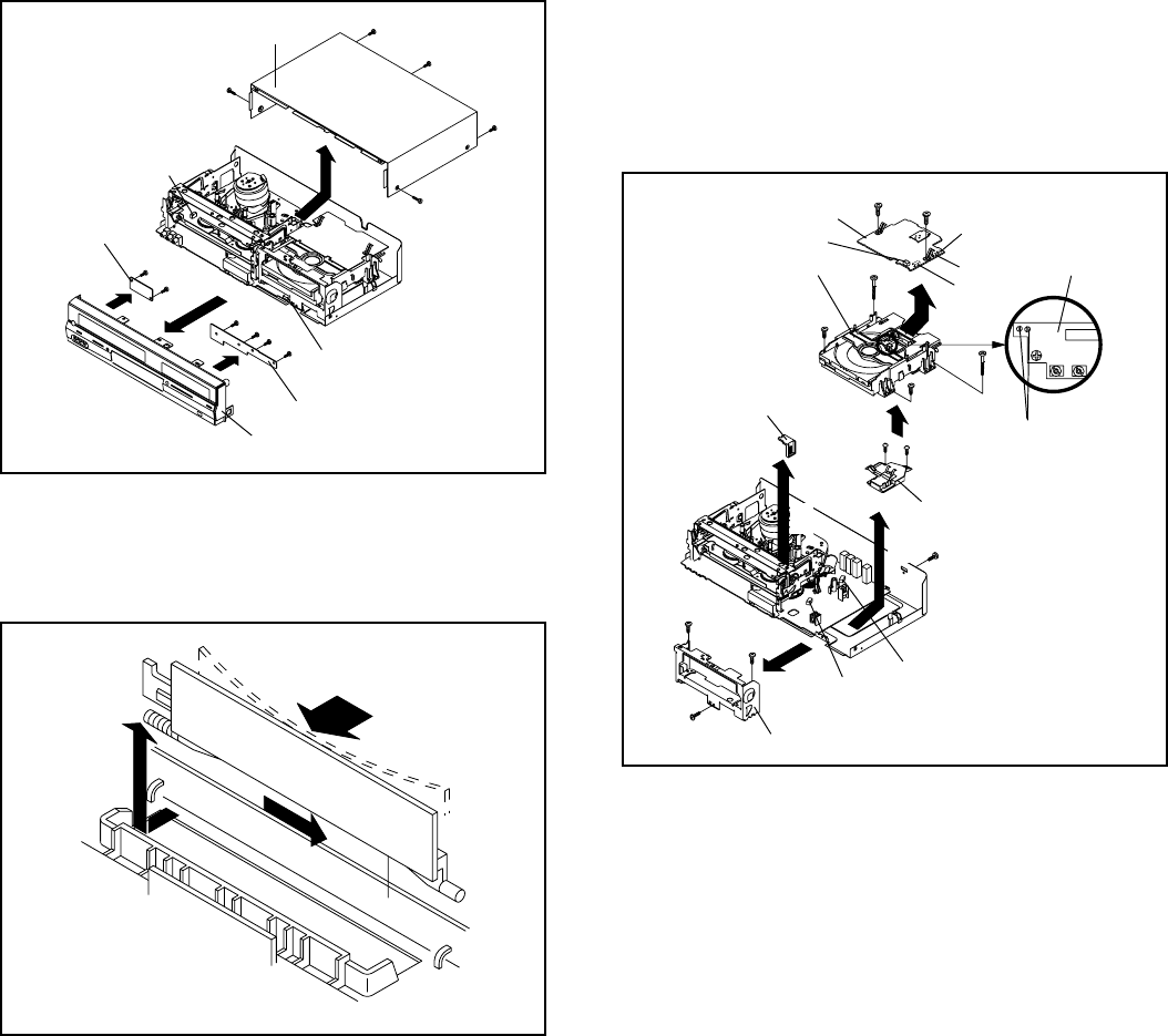
DISASSEMBLY INSTRUCTIONS
B1-1
1. REMOVAL OF MECHANICAL PARTS
AND P.C. BOARDS
1.
2.
Open Flap to 90˚ and flex in direction of arrow (A), at the
same time slide in direction of arrow (B).
Then lift in direction of arrow (C).
1-2: FLAP (Refer to Fig. 1-2)
Fig. 1-2
(A)
Flap
(B)
(C)
1-1: TOP CABINET/FRONT CABINET/OPERATION PCB/
OPERATION 2 PCB (Refer to Fig. 1-1)
1.
2.
3.
4.
5.
6.
7.
Remove the 5 screws 1.
Remove the Top Cabinet in the direction of arrow (A).
Disconnect the following connectors:
(CP651, CP653).
Unlock the 8 supports 2.
Remove the Front Cabinet in the direction of arrow (B).
Remove the 6 screws 3.
Remove the Operation PCB and Operation 2 PCB in the
direction of arrow (C).
1
1
2
Top Cabinet
1
1
1
(A)
2
2
2
22
(B)
2
(C)
3
Operation 2 PCB
3
3333
Front Cabinet
Operation PCB
1-3:
(C)
CP651
CP653
Fig. 1-1
2
DVD DECK/DVD MT PCB/USB BLOCK
(Refer to Fig. 1-3)
1.
2.
3.
4.
5.
6.
7.
8.
9.
10.
11.
12.
13.
14.
Short circuit the position shown in Fig. 1-3 using a
soldering iron. If you remove the DVD Deck with no
soldering, the Laser may be damaged.
Unlock the support 1 and remove the Deck Top Holder
in the direction of arrow (A).
Remove the 2 screws 2.
Remove the 2 screws 3.
Remove the screw 4.
Disconnect the following connectors:
(CP501, CP8001, CP6601).
Remove the DVD Deck in the direction of arrow (B).
Disconnect the following connectors:
(CP2301, CP2302, CP2303).
Remove the 2 screws 5.
Remove the DVD MT PCB in the direction of arrow (C).
Remove the 3 screws 6.
Remove the Front Angle in the direction of arrow (D).
Remove the 2 screws 7.
Remove the USB Block in the direction of arrow (E).
Fig. 1-3
1
Deck Top Holder
(A)
6
6
CP501
CP8001
NOTE
Before your operation, please read “PREPARATION OF
SERVICING”.
Use the Lead Free solder.
Manual soldering conditions
• Soldering temperature: 350 ± 5˚C
• Soldering time: Within 2 seconds
• Soldering combination: Sn-3.0Ag-0.5Cu
When Soldering/Removing of solder, use the drawing
equipment over the Pick Up Unit to keep the Flux smoke
away from it.
When installing the DVD Deck, remove all the soldering on
the short circuit position after the connection of Pick Up
PCB and DVD MT PCB connector.
1.
2.
3.
4.
5.
2
2
3
3
5
DVD Deck
5
(E)
DVD MT PCB
CP2301
CP2302
CP2303
CP6601
(C)
6
Front Angle
4
77
Short circuit using a
soldering iron.
Pick Up PCB
(D)
(B)
USB Block
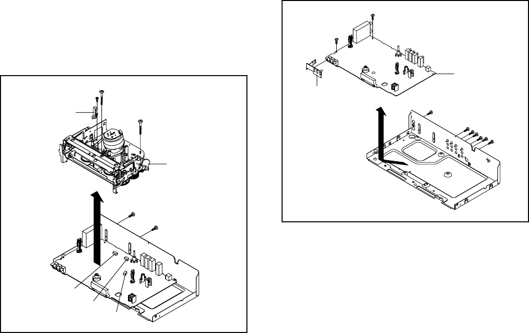
DISASSEMBLY INSTRUCTIONS
B1-2
1
FE Head
2
VCR Deck
2
3
3
1-4: VCR DECK (Refer to Fig. 1-4)
Do not remove the cable at the FE Head section. The FE
Head may be damaged if you remove the cable by force.
NOTE
1.
2.
3.
4.
5.
6.
7.
Remove the screw 1.
Remove the FE Head.
Move the Cassette Holder Ass’y to the back side.
Remove the 2 screws 2.
Remove the 2 screws 3.
Disconnect the following connectors:
(CP101, CP102, CP3001).
Remove the VCR Deck in the direction of arrow.
Fig. 1-4
1-5: VCR MT PCB (Refer to Fig. 1-5)
1.
2.
3.
4.
5.
Remove the screw 1.
Remove the 6 screws 2.
Remove the 2 screws 3.
Remove the Shiel Jack.
Remove the VCR MT PCB in the direction of arrow.
1
2
3
2
2
22
VCR MT PCB
3
Fig. 1-5
Shield Jack
CP101
CP102
CP3001
2

DISASSEMBLY INSTRUCTIONS
B2-1
2. REMOVAL OF VCR DECK PARTS
2-1: TOP BRACKET (Refer to Fig. 2-1)
Extend the 2 supports 1.
Slide the 2 supports 2 and remove the Top Bracket.
1.
2.
2-2: CASSETTE HOLDER ASS'Y (Refer to Fig. 2-2)
Move the Cassette Holder Ass'y to the front side.
Push the Locker R to remove the Cassette Side R.
Remove the Cassette Side L.
1.
2.
3.
Fig. 2-1
2
2
Main Chassis
Main Chassis
Top Bracket
Top Bracket
Main Chassis
Main Chassis
Cassette Side L
Cassette Side R
Locker R
Fig. 2-2
Link Unit
2-3: LINK UNIT (Refer to Fig. 2-3)
Set the Link Unit to the Eject position.
Unlock the support 1.
Remove the (A) side of the Link Unit first, then remove
the (B) side.
1.
2.
3.
Fig. 2-3
(A)
Link Unit
Main Chassis
1
Link Unit
(B)
Main Chassis
11
NOTE
1. After installation of the Top Bracket, bend the support 1
so that the Top Bracket is fixed.
2-4: LINK LEVER/FLAP LEVER (Refer to Fig. 2-4)
Extend the support 1.
Remove the Link Lever.
Remove the Flap Lever.
1.
2.
3.
Fig. 2-4
Link Lever
Flap Lever
1
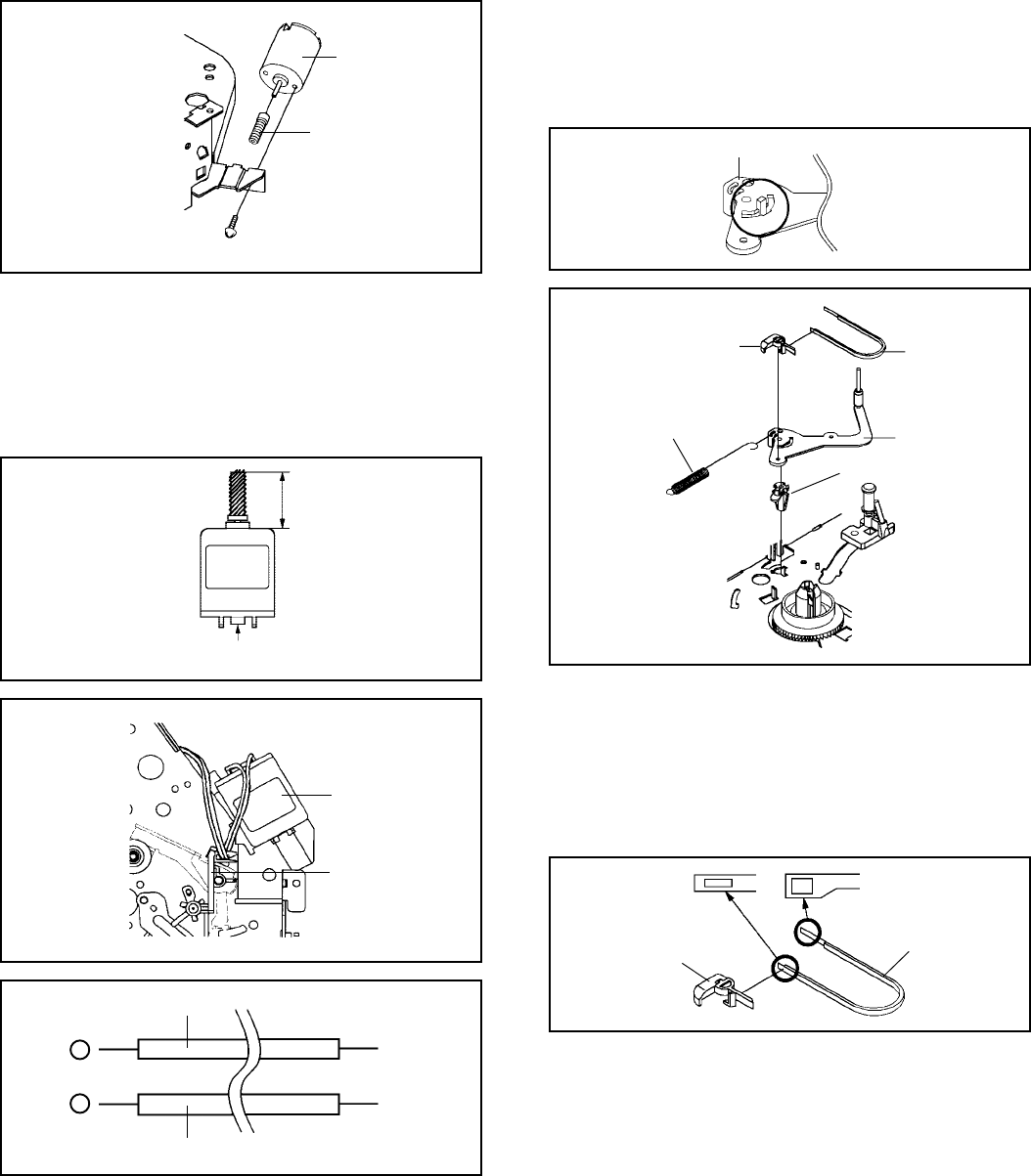
DISASSEMBLY INSTRUCTIONS
B2-2
2-5: LOADING MOTOR/WORM (Refer to Fig. 2-5-A)
1.
2.
3.
Remove the screw 1.
Remove the Loading Motor.
Remove the Worm.
Fig. 2-5-A
Loading Motor
Worm
• Screw Torque: 3 ± 0.5kgf•cm
Main Chassis
1
NOTE
1.
2.
3.
In case of the Worm installation, check if the value of the
Fig. 2-5-B is correct.
In case of the Loading Motor installation, hook the wire on
the Cassette Opener as shown Fig. 2-5-C.
When installing the wires between Capstan DD Unit and
Loading Motor, connect them correctly as shown Fig. 2-5-D.
Fig. 2-5-B
19.2 ± 0.1mm
Safety surface for pressing
of the insert.
2-6: TENSION ASS’Y (Refer to Fig. 2-6-B)
1.
2.
3.
4.
5.
6.
Turn the Pinch Roller Cam clockwise so that the Tension
Holder hook is set to the position of Fig. 2-6-A to move
the Tension Arm Ass’y.
Remove the Tension Spring.
Unlock the 2 supports 1 and remove the Tension Band.
Unlock the support 2 and remove the Tension Arm Ass’y.
Unlock the support 3 and remove the Tension Connect.
Float the hook 4 and turn it clockwise then remove the
Tension Holder.
Fig. 2-5-C
Loading Motor
Cassette Opener
Fig. 2-6-B
Tension Band
Tension Connect
Tension Spring Tension Arm Ass’y
Tension Holder
1
1
3
2
4
NOTE
1.
2.
3.
In case of the Tension Band installation, note the direc-
tion of the installation. (Refer to Fig. 2-6-C)
In case of the Tension Band installation, install correctly
as Fig. 2-6-D.
In case of the Tension Connect installation, install as the
circled section of Fig. 2-6-E.
Fig. 2-6-C
Tension Band
Tension Connect
Tension Arm Ass’y
Fig. 2-6-A
Fig. 2-5-D
Pink
Loading Motor
White
Capstan DD Unit
L2
L1
-
+

DISASSEMBLY INSTRUCTIONS
B2-3
Fig. 2-6-D
[OK]
[NG]
Tension Connect
Tension Band
Tension Connect Tension Band
Fig. 2-6-E
Tension Connect
Main Chassis
2-7: T BRAKE ARM/T BRAKE BAND (Refer to Fig. 2-7-A)
Remove the T Brake Spring.
Turn the T Brake Arm clockwise and bend the hook
section to remove it.
Unlock the 2 supports 1 and remove the T Brake Band.
1.
2.
3.
Fig. 2-7-A
T Brake Band
Hook section
T Brake Arm
T Brake Spring
1
1
NOTE
1. In case of the T Brake Band installation, install correctly
as Fig. 2-7-B.
Fig. 2-7-B
[OK]
[NG]
T Brake Arm
T Brake Band
T Brake Arm
T Brake Band
2-8: S REEL/T REEL/IDLER ARM ASS’Y/IDLER GEAR
(Refer to Fig. 2-8-A)
1.
2.
3.
Remove the S Reel and T Reel.
Remove the 2 Polyslider Washers 1.
Remove the Idler Arm Ass’y and Idler Gear.
NOTE
1.
2.
3.
4.
5.
6.
Take care not to damage the gears of the S Reel and T
Reel.
The Polyslider Washer may on the back of the reel.
Take care not to damage the shaft.
Do not touch section “A” of S Reel and T Reel. (Use
gloves.) (Refer to Fig. 2-8-A) Touching may leave stains
on section "A".
When you install the reel, clean the shaft and grease it. (If
you do not grease, noise may be heard in FF/REW
mode.)
After installing the reel, adjust the height of the reel.
(Refer to MECHANICAL ADJUSTMENT)
Fig. 2-8-A
Idler Gear
Idler Arm Ass’y
S Reel
T Reel
(A)
1
1
(A)
NOTE
1.
2.
In case of the S Reel and T Reel installation, check if the
correct parts are installed. (Refer to Fig. 2-8-B)
In case of the Idler Arm Ass’y installation, install correctly
as Fig. 2-8-C. And also set it so that the section “B” of
Fig. 2-8-A is placed under the Main Chassis tab.
Fig. 2-8-B
Big Hole
(S Reel) Small Hole
(T Reel)
Fig. 2-8-C
[OK]
[NG]
Clutch Gear Idler Arm Ass’y
Idler Arm Ass’y
Clutch Gear
(B)
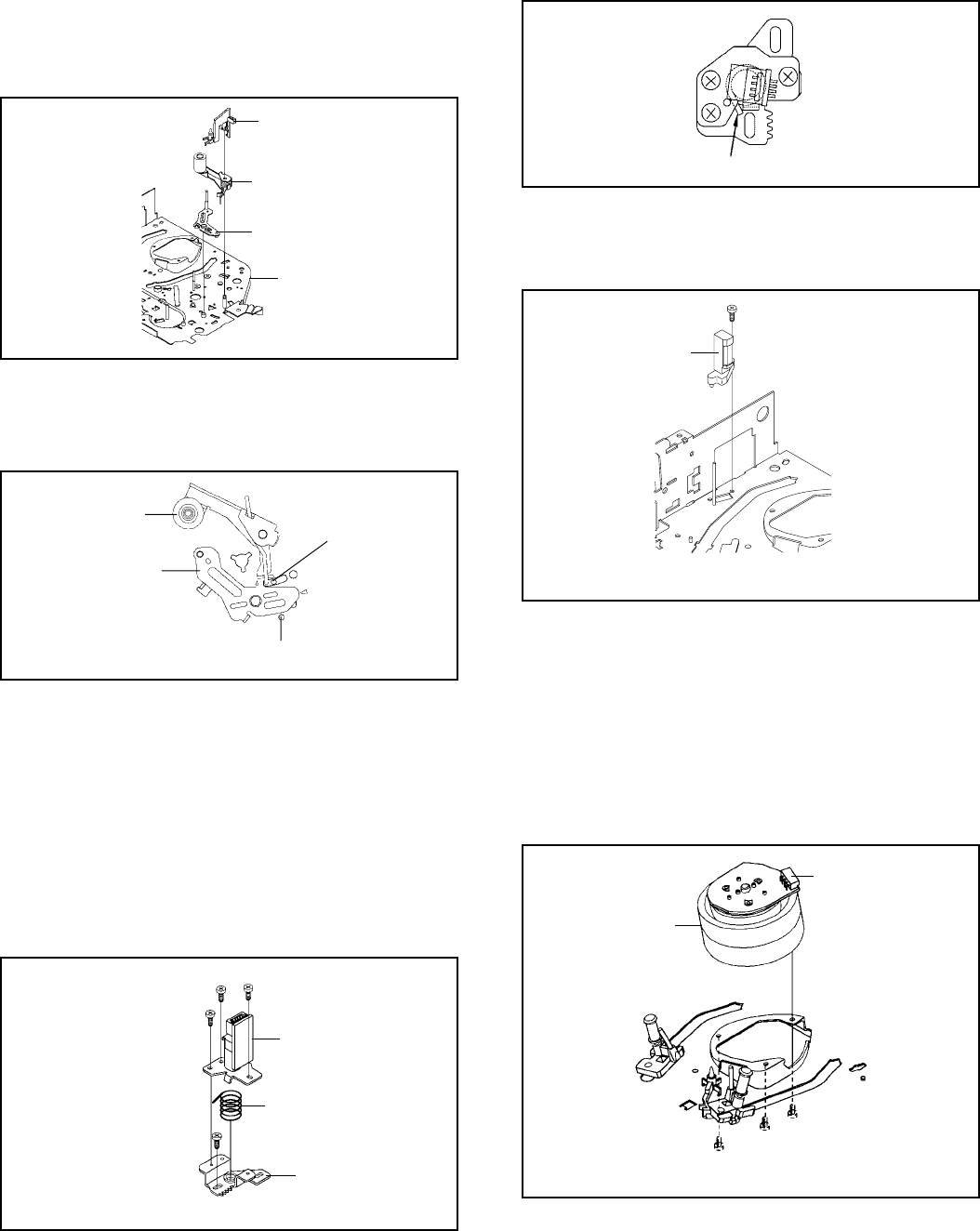
DISASSEMBLY INSTRUCTIONS
B2-4
2-9: CASSETTE OPENER/PINCH ROLLER BLOCK/P5
ARM ASS’Y (Refer to Fig. 2-9-A)
1.
2. Unlock the support 1 and remove the Cassette Opener.
Remove the Pinch Roller Block and P5 Arm Ass’y.
Fig. 2-9-A
Cassette Opener
1
Pinch Roller Block
P5 Arm Ass’y
Main Chassis
NOTE
1.
2. Do not touch the Pinch Roller. (Use gloves.)
In case of the Pinch Roller Block and the Pinch Roller
Cam installation, install correctly as Fig. 2-9-B.
Fig. 2-9-B
Pinch Roller Block Can be seen the hole of
the Pinch Roller Cam.
P5 Arm Ass’y
Can be seen the hole of the
Main Cam.
2-10: A/C HEAD (Refer to Fig. 2-10-A)
1.
2.
3.
4.
Remove the screw 1.
Remove the A/C Head Base.
Remove the 3 screws 2.
Remove the A/C Head and A/C Head Spring.
NOTE
1.
2.
3.
Do not touch the A/C Head. (Use gloves.)
When you install the A/C Head Spring, install as shown in
Fig. 2-10-B.
When you install the A/C Head, tighten the screw (1) first,
then tighten the screw (2), finally tighten the screw (3).
Fig. 2-10-A
(1)
2
A/C Head
A/C Head Spring
A/C Head Base
• Screw Torque: 5 ± 0.5kgf•cm (Screw 1)
2
2
(3)
(2)
1
Fig. 2-10-B
Spring Position
2-11: FE HEAD (RECORDER ONLY) (Refer to Fig. 2-11)
Remove the screw 1.
Remove the FE Head.
1.
2.
FE Head
• Screw Torque: 5 ± 0.5kgf•cm
• The FE Head is not installed on the Video Cassette Player. Fig. 2-11
1
2-12: CYLINDER UNIT ASS'Y (Refer to Fig. 2-12)
Disconnect the following connector:
(CD2001).
Remove the 3 screws 1.
Remove the Cylinder Unit Ass'y.
1.
2.
3.
When you install the Cylinder Unit Ass'y, tighten the
screws from (1) to (3) in order while pulling the Ass'y
toward the left front direction.
NOTE
Fig. 2-12
1.
• Screw Torque: 3 ± 0.5kgf•cm
Cylinder Unit Ass'y
1
1
1
(1)
(3)
(2)
CD2001
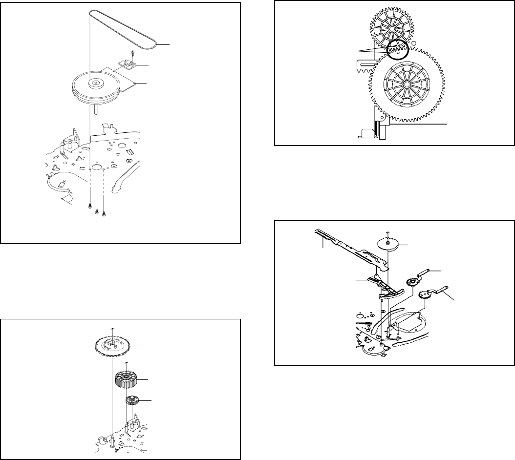
DISASSEMBLY INSTRUCTIONS
B2-5
2-14: MAIN CAM/PINCH ROLLER CAM/JOINT GEAR
(Refer to Fig. 2-14-A)
1.
2. Remove the E-Ring 1, then remove the Main Cam.
Remove the E-Ring 2, then remove the Pinch Roller
Cam and Joint Gear.
Fig. 2-14-A
1
Main Cam
Pinch Roller Cam
Joint Gear
2
NOTE
1. In case of the Pinch Roller Cam and Main Cam installa-
tion, install them as shown in the circled section of Fig. 2-
14-B so that the markers meet. (Refer to Fig. 2-14-B)
And also can be seen the Main Chassis hole through the
Main Cam maker hole.
Fig. 2-14-B
Pinch Roller Cam
Marker
Main Cam
2-15: LOADING GEAR S/T UNIT (Refer to Fig. 2-15-A)
1.
2.
Remove the E-Ring 1 and remove the Main Loading
Gear.
Remove the Main Rod, Tension Lever, Loading Arm S
Unit and Loading Arm T Unit.
1
Main Loading Gear
Main Rod
Tension Lever
Loading Arm T Unit
Loading Arm S Unit
Fig. 2-15-A
2-13: CAPSTAN DD UNIT (Refer to Fig. 2-13)
Remove the Capstan Belt.
Remove the screw 1.
Remove the Capstan Holder.
Remove the 3 screws 2.
Remove the Capstan DD Unit.
1.
2.
3.
4.
5.
• Screw Torque: 4 ± 0.5kgf•cm
Capstan DD Unit
Capstan Belt
Fig. 2-13
1
2
Capstan Holder
2
2

DISASSEMBLY INSTRUCTIONS
B2-6
1
Clutch Ass’y
Ring Spring
Clutch Lever
Coupling Gear
Coupling Spring
Clutch Gear
NOTE
1. When you install the Loading Arm S Unit, Loading Arm T
Unit and Main Loading Gear, align each marker. (Refer
to Fig. 2-15-B)
Fig. 2-15-B
Marker
Main Loading Gear
Loading Arm T Unit Loading Arm S Unit
Marker
2-16: CLUTCH ASS’Y/RING SPRING/CLUTCH LEVER/
CLUTCH GEAR (Refer to Fig. 2-16-A)
1.
2.
3.
4.
Remove the Polyslider Washer 1.
Remove the Clutch Ass’y and Ring Spring.
Remove the Clutch Lever.
Remove the Coupling Gear, Coupling Spring and Clutch
Gear.
Fig. 2-16-A
NOTE
1. In case of the Clutch Ass’y installation, install it with
inserting the spring of the Clutch Ass’y into the dent of the
Coupling Gear. (Refer to Fig. 2-16-B)
Fig. 2-16-B
Clutch Ass’y
Coupling Gear
2-17:
Remove the P4 Cap.
Unlock the support 1 and remove the Cassette Guide
Post.
Remove the Inclined Base S/T Unit.
Remove the screw 2.
Remove the LED Reflector.
1.
2.
3.
4.
5.
Fig. 2-17-A
CASSETTE GUIDE POST/INCLINED BASE S/T
UNIT/P4 CAP/LED REFLECTOR
(Refer to Fig. 2-17-A)
P4 Cap
Cassette Guide Post
1
Inclined Base T Unit
Inclined Base S Unit
2
LED Reflector
NOTE
1.
2.
3.
Do not touch the roller of Guide Roller.
In case of the P4 Cap installation, install it with parallel
for “A” and “B” of Fig. 2-17-B.
In case of the Cassette Guide Post installation, install
correctly as the circled section of Fig. 2-17-C.
Fig. 2-17-B
“A” “B”
P4 Cap Cassette Opener
[OK]
Cassette Guide Post
[NG]
Cassette Guide Post
Fig. 2-17-C
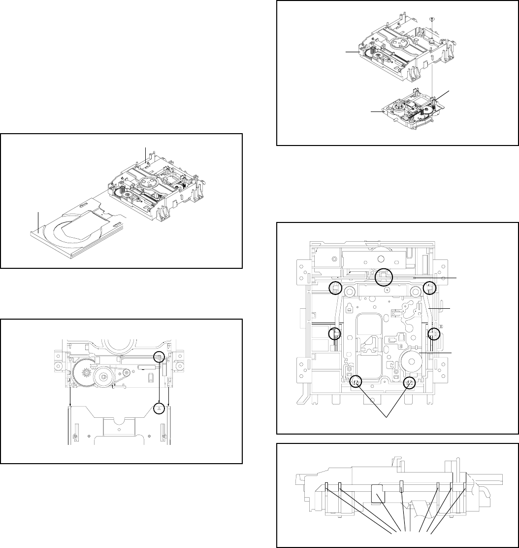
DISASSEMBLY INSTRUCTIONS
B3-1
Main Frame Ass'y
Check Hook
3. REMOVAL OF DVD DECK PARTS
3-1: TRAY (Refer to Fig. 3-1-A)
Set the Tray opened. (Refer to the DISC REMOVAL
METHOD AT NO POWER SUPPLY)
Unlock the 2 supports 1 and remove the Tray.
1.
2.
Fig. 3-1-A
Tray
Main Frame Ass'y
1
NOTE
1. In case of the Tray installation, install them as the circled
section of Fig. 3-1-B so that the each markers are met.
3-2: MAIN CHASSIS ASS'Y (Refer to Fig. 3-2-A)
Remove the screw 1.
Unlock the 2 supports 2.
Remove the Insulator (R) from the Main Frame Ass'y.
Remove the Main Chassis Ass'y.
1.
2.
3.
4.
Fig. 3-2-A
Tray
Main Frame Ass'y
Fig. 3-1-B
Insulator (R)
NOTE
1. Do not disassemble the DVD DECK PARTS except listed
parts here. Minute adjustments are needed if the
disassemble is done. If the repair is needed except listed
parts, replace the DVD MECHA ASS'Y.
1
1
2
Main Frame Ass'y
Main Chassis Ass'y
2
• Screw Torque: 2.0 ± 0.5kgf•cm
NOTE
1.
2.
In case of the Main Chassis Ass'y, install it from (1) to (4)
in order. (Refer to Fig. 3-2-B)
In case of the Main Chassis Ass'y installation, hook the
wire on the Main Frame Ass'y as shown Fig. 3-2-C.
Fig. 3-2-B
Fig. 3-2-C
(1)
(2)
(3)
(3)
(4)
(3)
Check Lock
(4)
Main Chassis Ass'y
Rack Loading
Main Frame Ass'y (Bottom Side)
Traverse Holder
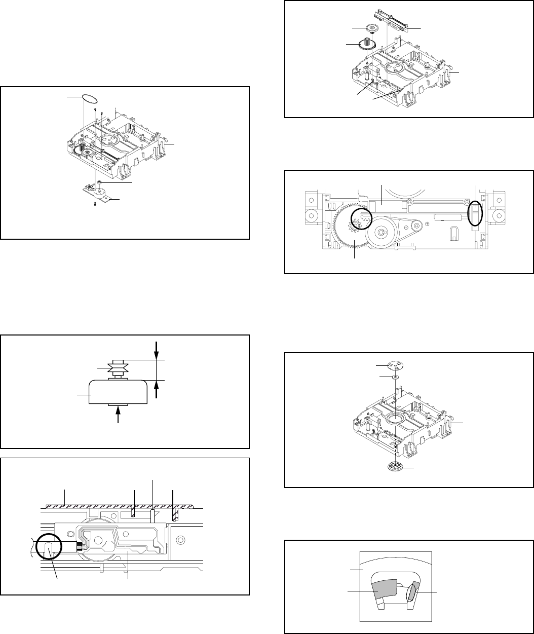
DISASSEMBLY INSTRUCTIONS
B3-2
NOTE
1.
2.
3.
In case of the Pulley Motor installation, check if the value
of the Fig. 3-3-B is correct.
When installing the Loading Motor PCB Ass'y, install it
correctly as Fig. 3-3-C.
In case of the Loading Motor PCB Ass'y installation, hook
the wire on the Main Frame Ass'y as shown Fig. 3-3-C.
Fig. 3-3-B
7.0 ± 0.1mm
Safety surface for pressing
of the insert.
Loading Motor
Pulley Motor
Fig. 3-3-C
Rack Loading AB
The Lever should be position
between A and B.
Check Hook
3-4: RACK LOADING/MAIN GEAR/PULLEY GEAR
(Refer to Fig. 3-4-A)
1.
2.
3.
Press down the catcher 1 and slide the Rack Loading.
Unlock the support 2 and remove the Pulley Gear.
Remove the Main Gear.
Loading Motor PCB Ass’y
Loading Belt
Pulley Gear
1
Main Frame Ass’y
3-3: LOADING MOTOR PCB ASS'Y/ LOADING BELT
(Refer to Fig. 3-3-A)
1.
2.
3.
4.
5.
Remove the Loading Belt.
Remove the screw 1.
Remove the 2 screws 2.
Remove the Loading Motor PCB Ass'y.
Remove the Pulley Gear.
Fig. 3-3-A
22
Loading Motor PCB Ass’y
• Screw Torque: 2.5 ± 0.3kgf•cm (Screw 1)
• Screw Torque: 1.0 ± 0.3kgf•cm (Screw 2)
Rack Loading
1
Main Frame Ass’y
Main Gear
Pulley Gear
2
Fig. 3-4-A
Fig. 3-4-B
NOTE
1. In case of the Rack Loading installation, do not mesh it
to the Main Gear as shown the Fig. 3-4-B.
Check Hook
Main Gear
Rack Loading
3-5: CLAMPER ASS'Y (Refer to Fig. 3-5-A)
Press the Clamper and rotate the Clamper Plate
clockwise, then unlock the 3 supports 1.
Remove the Clamper Plate, Clamper Magnet and
Clamper.
1.
2.
Clamper Plate
Clamper Magnet
Fig. 3-5-A
Main Frame
Clamper
1
1
1
NOTE
1. In case of the Clamper Ass'y installation, install correctly
as Fig. 3-5-B.
Fig. 3-5-B
No gap
Clamper Plate
Clamper
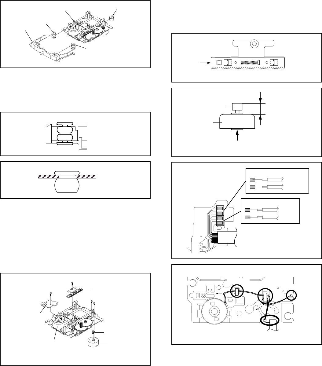
DISASSEMBLY INSTRUCTIONS
B3-3
Fig. 3-6-C
Insulator (R) Main Chassis Ass'y (Top Side)
3-7:
Remove the screw 1.
Remove the Rack Feed Ass'y.
Remove the screw 2.
Remove the Switch PCB Ass'y.
Remove the 2 screw 3.
Remove the Feed Motor.
Remove the Motor Gear.
1.
2.
3.
4.
5.
6.
7.
RACK FEED ASS'Y/SWITCH PCB ASS'Y/FEED
MOTOR (Refer to Fig. 3-7-A)
Traverse Holder
Insulator (F)
Main Chassis Ass'y
Insulator (F)
Insulator (R)
3-6:
Remove the Traverse Holder.
Remove the 2 Insulator (F).
Remove the Insulator (R).
1.
2.
3.
Fig. 3-6-A
TRAVERSE HOLDER/INSULATOR (F)/INSULATOR
(R) (Refer to Fig. 3-6-A)
NOTE
1.
2.
In case of the Insulator (F) installation, install correctly as
Fig. 3-6-B.
In case of the Insulator (R) installation, install correctly as
Fig. 3-6-C.
Fig. 3-6-B
Traverse Holder
Insulator (F)
Fig. 3-7-C
6.0 ± 0.2mm
Safety surface for pressing
of the insert.
Feed Motor
Motor Gear
NOTE
1.
2.
3.
4.
When pushing the Rack Feed in the direction of the
arrow, it should be restored to the original position by the
spring force. (Refer to Fig. 3-7-B)
In case of the Motor Gear installation, check if the value
of the Fig. 3-7-C is correct.
When installing the wire of the Switch PCB Ass'y, install it
correctly as Fig. 3-7-D.
After the assembly of the Main Chassis Ass'y, hook the
wire on the Main Chassis Ass'y as shown Fig. 3-7-E.
Fig. 3-7-B
Push
Rack Feed Ass'y
~ FEED MOTOR ~
BLUE (4)
ORANGE (3)
~ SPINDLE MOTOR ~
BLACK (2)
RED (1)
Fig. 3-7-D
Switch PCB Ass'y
• Install wire from (1) to (4) in order.
Main Chassis Ass'y (Bottom Side)
Check Hook
Check Hook
Fig. 3-7-E
Check Hook
Check Hook
• Loosen the wire in the direction of the arrow.
Fig. 3-7-A
• Screw Torque: 5.0 ± 0.3kgf•cm (Screw 1)
• Screw Torque: 3.0 ± 0.3kgf•cm (Screw 2)
• Screw Torque: 1.0 ± 0.3kgf•cm (Screw 3)
Main Chassis Ass'y
1
Rack Feed Ass'y
2
Switch PCB Ass'y
3
3
Motor Gear
Feed Motor
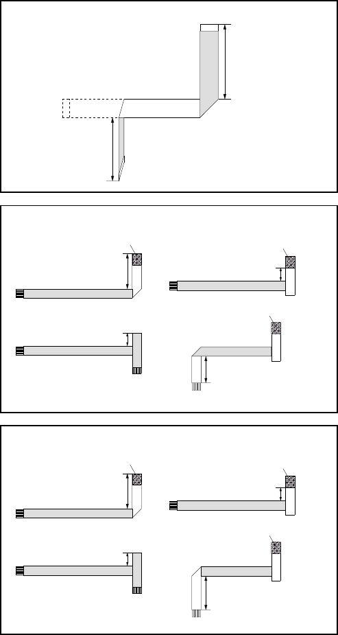
DISASSEMBLY INSTRUCTIONS
B3-4
Printing Surface
Reinforcement Plate
59 ± 1mm
Fold
(1)
Printing Surface
10 ± 1mm
Fold
(3)
Printing Surface
44 ± 1mm
Fold
(4)
Printing Surface
Printing Surface
10 ± 1mm
Fold
(2)
Reinforcement Plate
Reinforcement Plate
Printing Surface
Fold
43 ± 1mm
54 ± 1mm
Printing Surface
Pick Up Side
Fold it by 90˚
[ 24 pin FFC ]
When installing the FFC, fold it correctly and install it as
shown from Fig. 3-8-A to Fig. 3-8-C.
3-8: FFC WIRE HANDLING
1.
Do not make the folding lines except the specified
positions for the FFC.
1.
NOTE
Fig. 3-8-A
• Proceed the steps (1) through (4).
[ 6 pin FFC ]
Fig. 3-8-B
Printing Surface
Reinforcement Plate
55 ± 1mm
Fold
(1)
Printing Surface
10 ± 1mm
Fold
(3)
Printing Surface
60 ± 1mm
Fold
(4)
Printing Surface
Printing Surface
10 ± 1mm
Fold
(2)
Reinforcement Plate
Reinforcement Plate
• Proceed the steps (1) through (4).
[ 5 pin FFC ]
Fig. 3-8-C
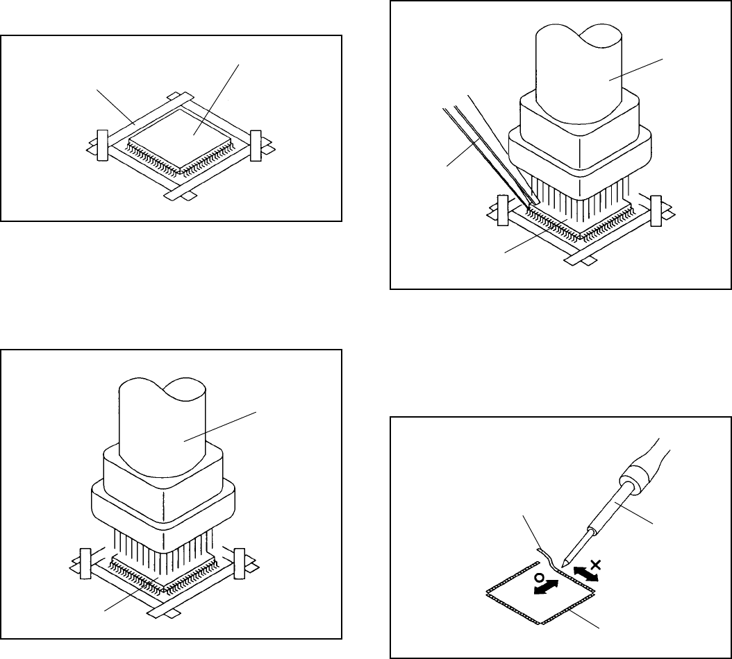
DISASSEMBLY INSTRUCTIONS
B4-1
4. REMOVAL AND INSTALLATION OF FLAT
PACKAGE IC
REMOVAL
1. Put Masking Tape (cotton tape) around the Flat Package
IC to protect other parts from any damage.
(Refer to Fig. 4-1.)
NOTE
Masking is carried out on all the parts located within
10 mm distance from IC leads.
Fig. 4-1
Masking Tape
(Cotton Tape)
IC
2. Heat the IC leads using a blower type IC desoldering
machine. (Refer to Fig. 4-2.)
NOTE
Do not rotate or move the IC back and forth , until IC
can move back and forth easily after desoldering the
leads completely.
Fig. 4-2
Blower type IC
desoldering machine
IC
3. When IC starts moving back and forth easily after
desoldering completely, pickup the corner of the IC using
a tweezers and remove the IC by moving with the IC
desoldering machine. (Refer to Fig. 4-3.)
NOTE
Some ICs on the PCB are affixed with glue, so be
careful not to break or damage the foil of each IC
leads or solder lands under the IC when removing it.
Fig. 4-3
Blower type IC
desoldering machine
Tweezers
IC
4.
5. Peel off the Masking Tape.
Absorb the solder left on the pattern using the Braided
Shield Wire. (Refer to Fig. 4-4.)
NOTE
Do not move the Braided Shield Wire in the vertical
direction towards the IC pattern.
Fig. 4-4
Braided Shield Wire
Soldering Iron
IC pattern

DISASSEMBLY INSTRUCTIONS
B4-2
Fig. 4-5
INSTALLATION
1. Take care of the polarity of new IC and then install the
new IC fitting on the printed circuit pattern. Then solder
each lead on the diagonal positions of IC temporarily.
(Refer to Fig. 4-5.)
Soldering Iron
Solder temporarily Solder temporarily
2. Supply the solder from the upper position of IC leads
sliding to the lower position of the IC leads.
(Refer to Fig. 4-6.)
Fig. 4-6
Solder
IC
Soldering Iron
Supply soldering
from upper position
to lower position
3. Absorb the solder left on the lead using the Braided
Shield Wire. (Refer to Fig. 4-7.)
NOTE
Do not absorb the solder to excess.
Fig. 4-7
Soldering Iron
IC
Braided Shield Wire
4. When bridge-soldering between terminals and/or the
soldering amount are not enough, resolder using a Thin-
tip Soldering Iron. (Refer to Fig. 4-8.)
Fig. 4-8
Thin-tip Soldering Iron
IC
5. Finally, confirm the soldering status on four sides of the
IC using a magnifying glass.
Confirm that no abnormality is found on the soldering
position and installation position of the parts around the
IC. If some abnormality is found, correct by resoldering.
NOTE
When the IC leads are bent during soldering and/or
repairing, do not repair the bending of leads. If the
bending of leads are repaired, the pattern may be
damaged. So, always be sure to replace the IC in this
case.
KEY TO ABBREVIATIONS
A
B
C
D
E
F
G
A/C
ACC
AE
AFC
AFT
AFT DET
AGC
AMP
ANT
A.PB
APC
ASS'Y
AT
AUTO
A/V
BGP
BOT
BPF
BRAKE SOL
BUFF
B/W
C
CASE
CAP
CARR
CH
CLK
CLOCK (SY-SE)
COMB
CONV
CPM
CTL
CYL
CYL-M
CYL SENS
DATA (SY-CE)
dB
DC
DD Unit
DEMOD
DET
DEV
E
EF
EMPH
ENC
ENV
EOT
EQ
EXT
F
FBC
FE
FF
FG
FL SW
FM
FSC
FWD
GEN
GND
:
:
:
:
:
:
:
:
:
:
:
:
:
:
:
:
:
:
:
:
:
:
:
:
:
:
:
:
:
:
:
:
:
:
:
:
:
:
:
:
:
:
:
:
:
:
:
:
:
:
:
:
:
:
:
:
:
:
:
:
:
Audio/Control
Automatic Color Control
Audio Erase
Automatic Frequency Control
Automatic Fine Tuning
Automatic Fine Tuning Detect
Automatic Gain Control
Amplifier
Antenna
Audio Playback
Automatic Phase Control
Assembly
All Time
Automatic
Audio/Video
Burst Gate Pulse
Beginning of Tape
Bandpass Filter
Brake Solenoid
Buffer
Black and White
Capacitance, Collector
Cassette
Capstan
Carrier
Channel
Clock
Clock (Syscon to Servo)
Combination, Comb Filter
Converter
Capstan Motor
Control
Cylinder
Cylinder-Motor
Cylinder-Sensor
Data (Syscon to Servo)
Decibel
Direct Current
Direct Drive Motor Unit
Demodulator
Detector
Deviation
Emitter
Emitter Follower
Emphasis
Encoder
Envelope
End of Tape
Equalizer
External
Fuse
Feed Back Clamp
Full Erase
Fast Forward, Flip-flop
Frequency Generator
Front Loading Switch
Frequency Modulation
Frequency Sub Carrier
Forward
Generator
Ground
H
I
K
L
M
N
O
P
R
S
H.P.F
H.SW
Hz
IC
IF
IND
INV
KIL
L
LED
LIMIT AMP
LM, LDM
LP
L.P.F
LUMI.
M
MAX
MINI
MIX
MM
MOD
MPX
MS SW
NC
NR
OSC
OPE
PB
PB CTL
PB-C
PB-Y
PCB
P. CON
PD
PG
P-P
R
REC
REC-C
REC-Y
REEL BRK
REEL S
REF
REG
REW
REV, RVS
RF
RMC
RY
S. CLK
S. COM
S. DATA
SEG
SEL
SENS
SER
SI
SIF
SO
SOL
SP
:
:
:
:
:
:
:
:
:
:
:
:
:
:
:
:
:
:
:
:
:
:
:
:
:
:
:
:
:
:
:
:
:
:
:
:
:
:
:
:
:
:
:
:
:
:
:
:
:
:
:
:
:
:
:
:
:
:
:
:
:
High Pass Filter
Head Switch
Hertz
Integrated Circuit
Intermediate Frequency
Indicator
Inverter
Killer
Left
Light Emitting Diode
Limiter Amplifier
Loading Motor
Long Play
Low Pass Filter
Luminance
Motor
Maximum
Minimum
Mixer, mixing
Monostable Multivibrator
Modulator, Modulation
Multiplexer, Multiplex
Mecha State Switch
Non Connection
Noise Reduction
Oscillator
Operation
Playback
Playback Control
Playback-Chrominance
Playback-Luminance
Printed Circuit Board
Power Control
Phase Detector
Pulse Generator
Peak-to Peak
Right
Recording
Recording-Chrominance
Recording-Luminance
Reel Brake
Reel Sensor
Reference
Regulated, Regulator
Rewind
Reverse
Radio Frequency
Remote Control
Relay
Serial Clock
Sensor Common
Serial Data
Segment
Select, Selector
Sensor
Search Mode
Serial Input
Sound Intermediate Frequency
Serial Output
Solenoid
Standard Play
C1-1
KEY TO ABBREVIATIONS
S
T
U
V
X
Y
STB
SW
SYNC
SYNC SEP
TR
TRAC
TRICK PB
TP
UNREG
V
VCO
VIF
VP
V.PB
VR
V.REC
VSF
VSR
VSS
V-SYNC
VT
X'TAL
Y/C
:
:
:
:
:
:
:
:
:
:
:
:
:
:
:
:
:
:
:
:
:
:
:
Serial Strobe
Switch
Synchronization
Sync Separator, Separation
Transistor
Tracking
Trick Playback
Test Point
Unregulated
Volt
Voltage Controlled Oscillator
Video Intermediate Frequency
Vertical Pulse, Voltage Display
Video Playback
Variable Resistor
Video Recording
Visual Search Fast Forward
Visual Search Rewind
Voltage Super Source
Vertical-Synchronization
Voltage Tuning
Crystal
Luminance/Chrominance
C1-2

C2-1
SERVICE MODE LIST
This unit is provided with the following SERVICE MODES so you can repair, examine and adjust easily.
To enter to the SERVICE MODE function, press and hold both buttons simultaneously on the main unit or on the main unit and on
the remote control for more than a standard time in the appropriate condition. (See below chart.)
In case of the main unit and remote control, press the remote control buttons first, then press the main unit buttons.
Set Key Operations
Remocon
Key Standard
Time
Initialization of factory DVD data.
NOTE: Do not use this for normal servicing.
REC 4 2 sec.
Set
Condition
DVD mode
(No disc)
DVD Write mode.
Refer to the “RE-WRITE FOR DVD FIRMWARE”.
NOTE: Do not use this for the normal servicing.
REC 6 2 sec.
DVD mode
(Stop)
Method Operations
Set Key Operations
CH UP
PLAY/REC total hours are displayed on the TV Monitor.
Refer to the “PREVENTIVE CHECKS AND SERVICE INTERVALS”
(CONFIRMATION OF HOURS USED).
Can be checked of the INITIAL DATA of MEMORY IC.
Refer to the “WHEN REPLACING EEPROM (MEMORY) IC”.
Set Key
FWD 2 sec.
CH UP PLAY 2 sec.
Initialization of factory VCR data.
NOTE: Do not use this for normal servicing.
If you set factory initialization, the memories are reset such as
the clock setting, the channel setting, and PLAY/REC total
hours.
Standard
Time
CH DOWN ON/
STANDBY 2 sec.
VCR operation mode at no connection of DVD.
Refer to the “PREPARATION FOR SERVICING”
NOTE: Although the DVD is connected, the DVD mode cannot be
selected.
Adjust the PG SHIFTER automatically.
Refer to the “ELECTRICAL ADJUSTMENT”.
CH UP STOP 2 sec.
Set
Condition
VCR mode
Power Off
VCR mode
(Playback)
VCR mode
Releasing of PARENTAL LOCK.
Refer to the “PARENTAL CONTROL - RATING LEVEL”.
STOP 7 3 sec.
DVD mode
(No disc)
Check for the firmware version.
Refer to the “RE-WRITE FOR DVD FIRMWARE”.
NOTE: Do not use this for the normal servicing.
STOP 1 3 sec.
DVD mode
(Stop)
Press the following remocon
keys continuously.
SETUP SUBTITLE 3
AUDIO 0
Press the ATR button on the
remote control for more than
2 seconds during PLAY.
Adjusting of the Tracking to the center position.
Refer to the “MECHANICAL ADJUSTMENT” (GUIDE ROLLER) and “ELECTRICAL
ADJUSTMENT” (PG SHIFTER).
Make the short circuit
between the test point of
SERVICE and the GND.
The BOT, EOT, and the Reel Sensor do not work and the VCR deck can be operated
without a cassette tape.
Refer to the “PREPARATION FOR SERVICING”
Tray cannot be opened.
Refer to the “TRAY LOCK”.
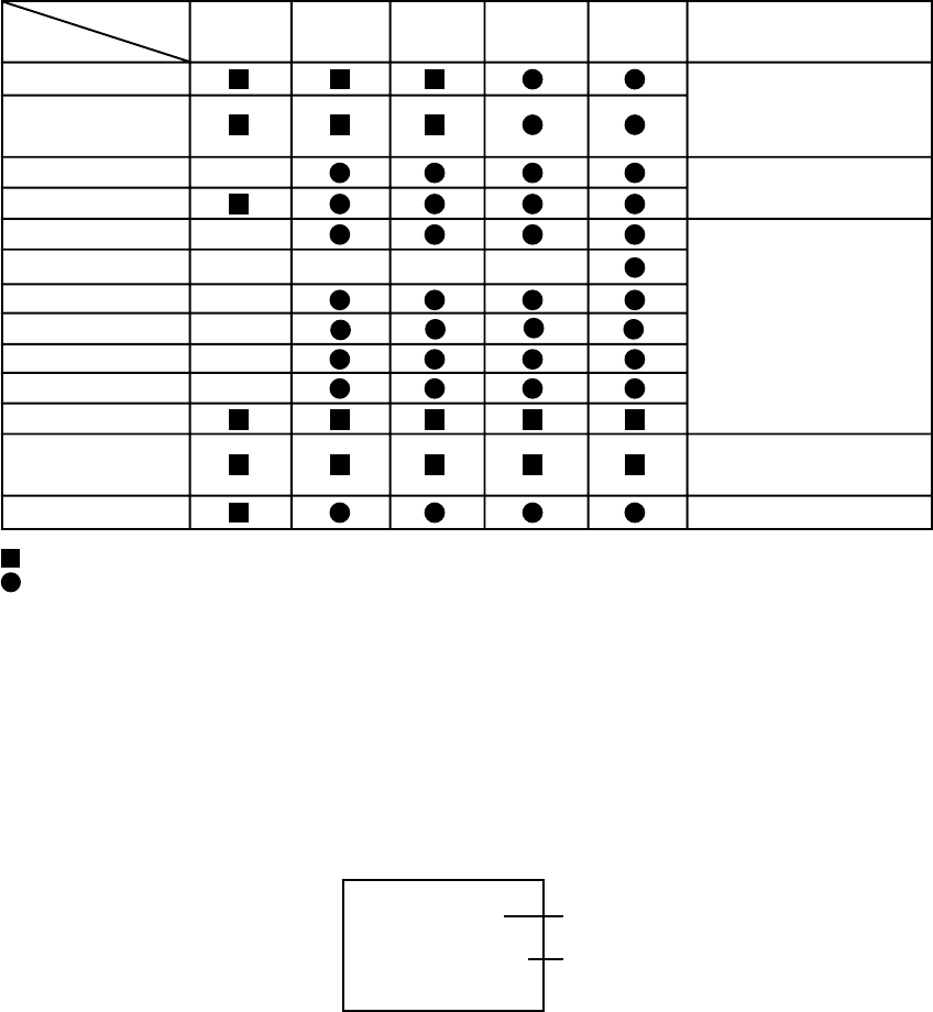
C3-1
PREVENTIVE CHECKS AND SERVICE INTERVALS
The following standard table depends on environmental conditions and usage.
Parts replacing time does not mean the life span for individual parts.
Also, long term storage or misuse may cause transformation and aging of rubber parts.
The following list means standard hours, so the checking hours depends on the conditions.
: Clean
: Check it and if necessary, replace it.
Time
Parts Name
500
hours 1,000
hours Notes
1,500
hours 2,000
hours 2,500
hours
Audio Control Head
Full Erase Head
(Recorder only)
Capstan Belt
Pinch Roller
Capstan DD Unit
Loading Motor
Tension Band
Capstan Shaft
Tape Running
Guide Post
Cylinder Unit
Clean those parts in
contact with the tape.
Clean the rubber, and parts
which the rubber touches.
Replace when rolling
becomes abnormal.
Clean the Head
T Brake Band
Clutch Ass’y
Idler Arm Ass’y
CONFIRMATION OF HOURS USED
PLAY/REC total hours can be checked on the screen.
Total hours are displayed in 16 system of notation.
NOTE: If you set factory initialization, the total hours is reset to “0”.
1.
2.
3.
4.
Connect the set to TV Monitor.
Turn on the POWER, and set to the VCR mode.
Press both CH UP button on the set and the FF button on the set for more than 2 seconds.
The Fig. 1 screen will appear on TV Monitor.
After the confirmation of using hours, turn off the power.
Initial setting content of MEMORY IC.
PLAY/REC total hours.
= (16 x 16 x 16 x thousands digit value)
+ (16 x 16 x hundreds digit value)
+ (16 x tens digit value)
+ (ones digit value)
INIT 00 0E
PLAY/REC 0010
Fig. 1

PREVENTIVE CHECKS AND SERVICE INTERVALS
CLEANING
NOTE
After cleaning the heads with isopropyl alcohol, do not
run a tape until the heads dry completely. If the heads
are not completely dry and alcohol gets on the tape,
damage may occur.
1. AUDIO CONTROL HEAD
Clean the Audio Control Head with a cotton stick
soaked by alcohol. Clean the full erase head in the
same manner. (Refer to the figure below.)
2. TAPE RUNNING SYSTEM
When cleaning the tape transport system, use
gauze moistened with isopropyl alcohol.
3. CYLINDER
Wrap a piece of chamois around your finger. Dip it in
isopropyl alcohol. Hold it to the cylinder head softly.
Turn the cylinder head counterclockwise to clean it (in
the direction of the arrow). (Refer to the figure below.)
NOTE
Do not exert force against the cylinder head. Do not move
the chamois upward or downward on the head.
Use the chamois one by one.
Cylinder Head
Audio Control Head
C3-2

C4-1
Turn on the power, and set the DVD mode.
Confirm that the "No Disc" will be appeared on the screen.
Open the DVD tray.
Press both Channel button (6) on the remote control and the REC button on the set for more than 2 seconds.
Press OPEN/CLOSE button on the unit to check if all the keys on the unit do not function.
NOTE: To check if DVD Write mode is set.
When inserting Up-Date Disc at Non DVD Write mode, the read error will happen.
Place the Up-Date Disc and close the tray by hand. (Refer to SERVICING FIXTURE AND TOOLS)
Automatic read will start and "CD-R UPDATE PROCESS" will be displayed on the screen.
At this time, the horizontal noise lines may appear. But no problem.
Approxi. 20 seconds later, the tray will open automatically. Remove the Up-Date Disc.
Then, Approxi. 40 seconds later, the above indication will disappear and the tray will close automatically.
When the "No Disc" appears on the screen, the write will end.
NOTE: Do not turn off the unit or push the tray by hand to close it.
Up-Date error will happen and can not be done with the Up-Date of Up-Date Disc.
Unplug the AC cord, then plug it in.
After the write, set to the initializing of shipping.
Set to the DVD mode, press both Channel button (4) on the remote control and the REC button on the set for more than 2
seconds.
The "INITIALIZE 5 ---> COMPLETE" will appear on the screen.
Then unplug the AC cord, and plug it in.
CHECK FOR THE FIRMWARE VERSION
Set to the DVD mode, press both Channel button (1) on the remote control and the STOP button on the set for more than
3 seconds.
Firmware version will be displayed on the top left of the screen.
Turn off the power
RE-WRITE FOR DVD FIRMWARE
1.
2.
3.
4.
5.
6.
7.
8.
9.
10.
11.
12.
13.
14.
No Disc
ACALA6213C A C A L A 6 2 1 3 C
Fixed
Release date (Example: 2006.2.13)
Released times on the same date
A = October
B = November
C = December
When the changed version displays, the Re-write will be completed.
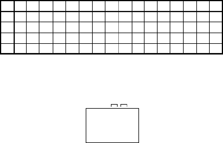
C4-2
WHEN REPLACING EEPROM (MEMORY) IC
If a service repair is undertaken where it has been required to change the MEMORY IC, the following steps should be taken to
ensure correct data settings while making reference to TABLE 1.
INIT +0 +1 +2 +4 +5 +6 +7 +8 +9 +A +B +C +D +E +F
00 0E 32 BE FF 64 64 4A 86 0B 26 86 32 8A C8 0A 01
10 AF 97 95 8A B0 6A 31 04 88 A5 9F 3A 00 10 BF 00
20 2A 11 22 70 61 2A 3A 00 0B 00 60 E5 9A B0 00 37
30 03 17 00 84 00 00 --- --- --- --- --- --- --- --- --- ---
4.
5.
6.
7.
8.
9.
10.
11.
12.
The unit will now have the correct DATA for the new MEMORY IC.
Table 1
ADDRESS is now selected and should "blink". Using the SET + or - button on the remote, step through the ADDRESS
until required ADDRESS to be changed is reached.
Press ENTER to select DATA. When DATA is selected, it will "blink".
Again, step through the DATA using SET + or - button until required DATA value has been selected.
Pressing ENTER will take you back to ADDRESS for further selection if necessary.
Repeat steps 4 to 7 until all data has been checked.
When satisfied correct DATA has been entered, turn POWER off (return to STANDBY MODE) to finish DATA input.
After the data input, set to the initializing of shipping.
Turn on the POWER, and set to the VCR mode.
Press both CH UP button on the set and the PLAY button on the set for more than 2 seconds.
After the finishing of the initializing of shipping, the unit will turn off automatically.
Fig. 1
1.
2.
3.
Connect the set to TV Monitor.
Turn on the POWER, and set to the VCR mode.
Press both CH UP button on the set and the FF button on the set for more than 2 seconds.
ADDRESS and DATA will appear on TV Monitor as Fig 1.
INIT 00 0E
PLAY/REC 0010
ADDRESS DATA
+3
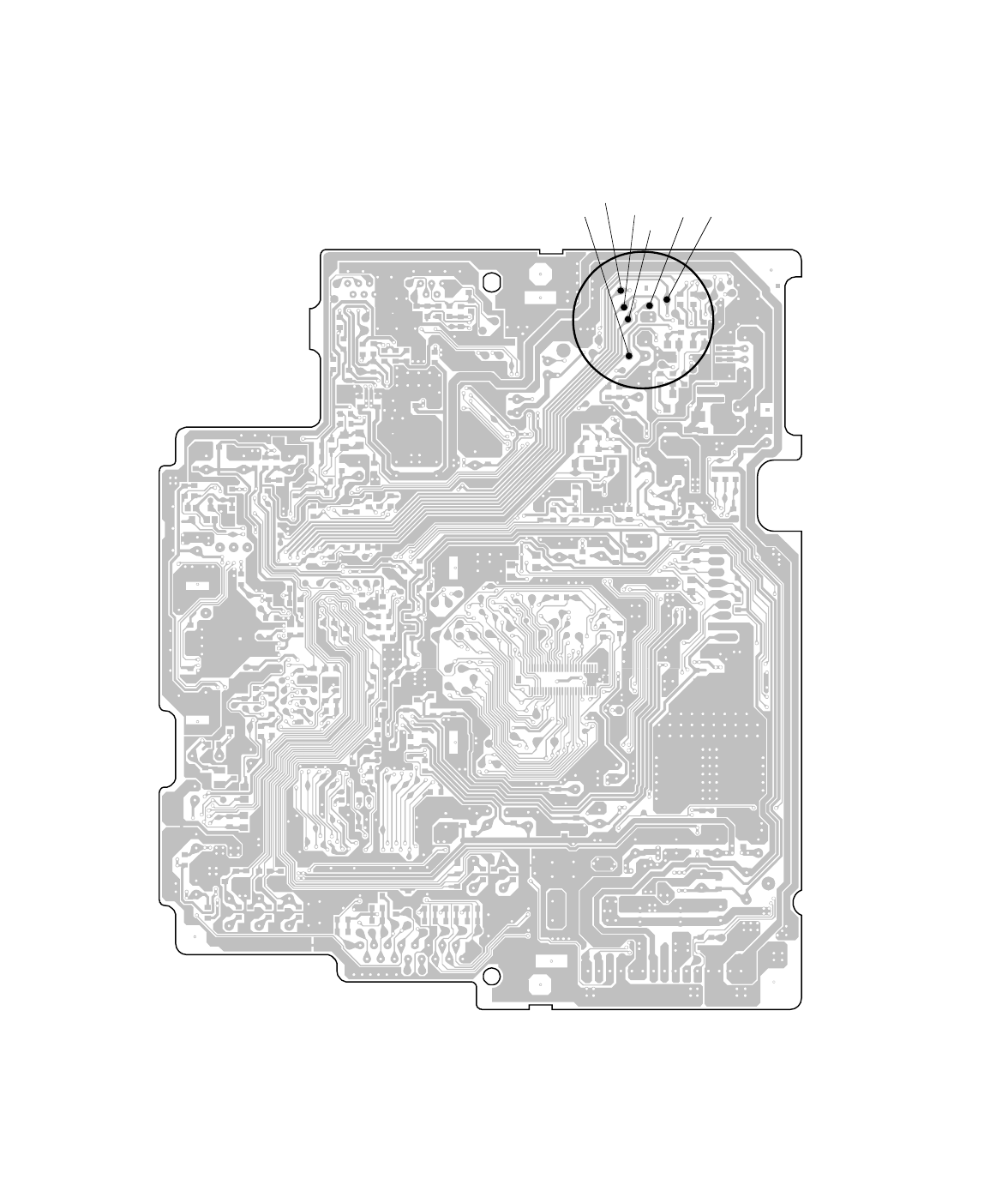
RF SIGNAL CHECK OF DVD MT PCB
RF signal check can be done at the following A~F resistance points on the DVD MT PCB.
DVD MT PCB (BOTTOM SIDE)
CA
B
DMF071A
D
C4-3
F E

SERVICING FIXTURES AND TOOLS
Taper nut driver
70909228
Back tension cassette gauge
70909103
Torque cassette gauge
(KT-300NR)
70909199
Adapter
Dial Torque Gauge
(10~90gf•cm)
(60~600gf•cm)
JG154 Cable
VTR cleaning kit VTR lubrication kit Grease JG002B
JG002E
JG002F
JG153 X Value Adjustment
Screwdriver
JG022 Master Plane JG024A Reel Disk Height
Adjustment Jig
Alignment Tape
ST-N5
ST-NF
JG185 TentelometerJG176 Up-Date Disc
Remarks
Part No.Ref. No. Parts Name
JG002B
JG002E
JG002F
APJG002B00
APJG002E00
APJG002F00
Adapter
Dial Torque Gauge (10~90gf•cm)
Dial Torque Gauge (60~600gf•cm)
VSR Torque, Brake Torque (S Reel/T Reel Ass'y)
Brake Torque (T Reel Ass'y)
VSR Torque, Brake Torque (S Reel)
JG154 APJG154000 Cable Used to connect the test point of SERVICE and GROUND
APJG022000JG022 Master Plane Reel Disk Height Adjustment
JG024A APJG024A00 Reel Disk Height Adjustment Jig Reel Disk Height Adjustment
JG153 APJG153000 X Value Adjustment Screwdriver X Value Adjustment
JG176 APJG176092 Up-Date Disc Up-Date of the Firmware
D1-1
JG185 APJG185000 Tentelometer Confirmation of Tape Tension on Playback
PREPARATION FOR SERVICING
1.
2.
3.
How to use the Servicing Fixture
While pressing the CH DOWN button on the set for more than 2 seconds, press the ON/STANDBY button on the set
simultaneously at the Power OFF. Although the DVD is connected, the DVD mode cannot be selected.
Short circuit between TP3001 and Ground with the cable JG154.
(The BOT, EOT, and the Reel Sensor do not work and the VCR deck can be operated without a cassette tape.)
In case of using a cassette tape, press the EJECT button to insert or eject a cassette tape.
Turn on the power and re-check the cable before checking the trouble points.
When you servicing with connection of DVD, perform the operations above step 2 to step 3.
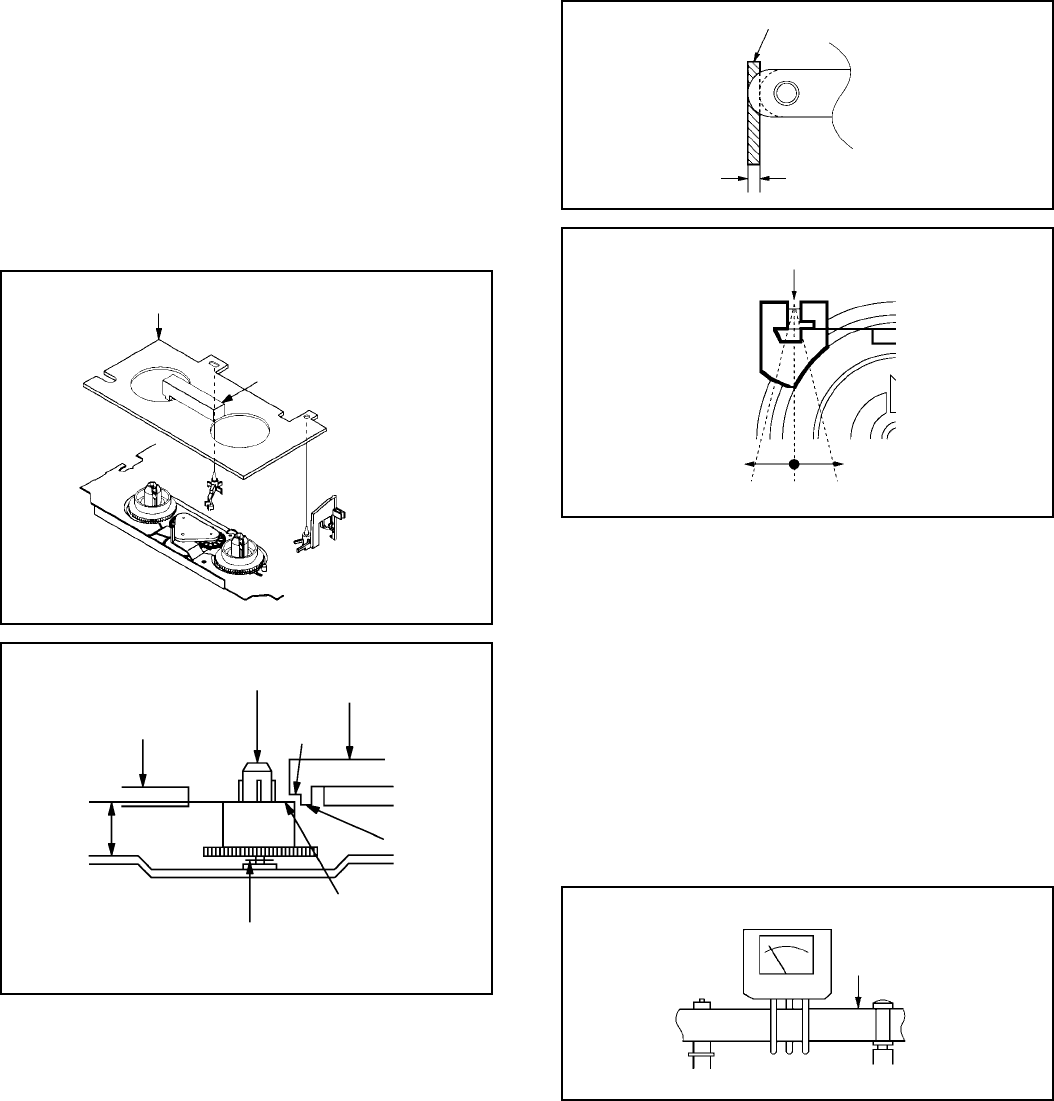
D2-1
MECHANICAL ADJUSTMENTS
1. CONFIRMATION AND ADJUSTMENT
Read the following NOTES before starting work.
• Place an object which weighs between 450g~500g on the
Cassette Tape to keep it steady when you want to make
the tape run without the Cassette Holder. (Do not place an
object which weighs over 500g.)
CONFIRMATION AND ADJUSTMENT OF REEL DISK
HEIGHT
1-1:
1.
2.
3.
4.
Turn on the power and set to the STOP mode.
Set the master plane (JG022) and reel disk height
adjustment jig (JG024A) on the mechanism framework,
taking care not to scratch the drum, as shown in Fig. 1-1-
A.
While turning the reel and confirm the following points.
Check if the surface "A" of reel disk is lower than the
surface "B" of reel disk height adjustment jig (JG024A)
and is higher than the surface "C". If it is not passed,
place the height adjustment washers and adjust to 10(+2,
-0)mm.
Adjust the other reel in the same way.
Fig. 1-2-B
1-3: CONFIRMATION OF PLAYBACK TORQUE AND
BACK TENSION TORQUE DURING PLAYBACK
Load a video tape (T-120) recorded in standard speed mode.
Set the unit to the PLAY mode.
Install the tentelometer (JG185) as shown in Fig. 1-3. Confirm
that the meter indicates 20 ± 2gf in the beginning of playback.
1.
2.
• USING A CASSETTE TYPE TORQUE TAPE (KT-300NR)
1.
2.
3.
After confirmation and adjustment of Tension Post
position (Refer to item 1-2), load the cassette type
torque tape (KT-300NR) and set to the PLAY mode.
Confirm that the right meter of the torque tape indicates
50~90gf•cm during playback in SP mode.
Confirm that the left meter of the torque tape indicates
25~40gf•cm during playback in SP mode.
Tentelometer
(JG185)
Video Tape
Guide Roller
P1 Post Fig. 1-3
1-2: CONFIRMATION AND ADJUSTMENT OF TENSION
POST POSITION
1.
2.
3.
Set to the PLAY mode.
Adjust the adjusting section for the Tension Arm position
so that the Tension Arm top is within the standard line of
Main Chassis.
While turning the S Reel clockwise, confirm that the edge
of the Tension Arm is located in the position described
above.
Fig. 1-2-A
Standard line of Main Chassis
Tension Arm
0.5mm (Adjusting range)
Reel Disk Height Adjustment Jig
(JG024A)
Fig. 1-1-A
Reel Disk
Height Adjustment
Washer
2.6x4.7xT0.13
2.6X4.7xT0.25
(B)
(C)
Master Plane (JG022)
Fig. 1-1-B
(A)
10(+0.2, -0)mm
Master Plane (JG022)
Reel Disk Height
Adjustment Jig
(JG024A)
Adjusting section for the
Tension Arm position
Bend
Tension Band
The Tension Arm top will
move to the outside direction
of the Main Chassis.
The Tension Arm top will
move to the inside direction
of the Main Chassis.
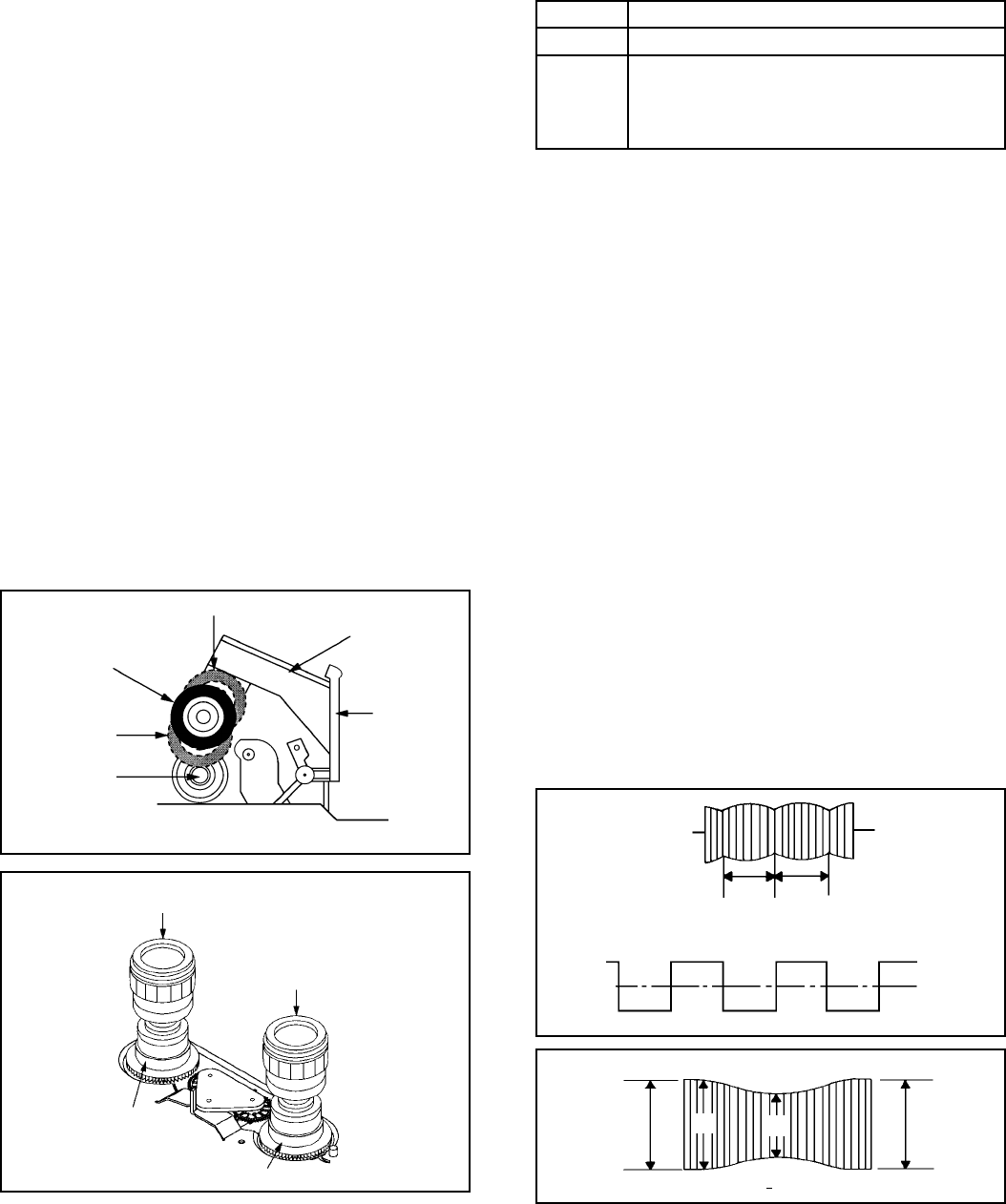
D2-2
Entrance Exit
Max
A : B ≥ 3 : 2
AMax
B
S Reel/Tension Band/Tension
Connect/Tension Arm Ass'y
T Reel/T Brake Band//T Brake
Spring/T Brake Arm
MECHANICAL ADJUSTMENTS
1-4: CONFIRMATION OF VSR TORQUE
Install the Torque Gauge (JG002F) and Adapter (JG002B)
on the S Reel. Set to the Picture Search (Rewind) mode.
(Refer to Fig.1-4-B)
Then, confirm that it indicates 120~180gf•cm.
1.
2.
NOTE
If the torque is out of the range, replace the following parts.
Check item
1-4
1-5
Replacement Part
Idler Ass'y/Clutch Ass'y
S Reel side:
T Reel side:
2. CONFIRMATION AND ADJUSTMENT OF
TAPE RUNNING MECHANISM
Tape Running Mechanism is adjusted precisely at the
factory. Adjustment is not necessary as usual. When you
replace the parts of the tape running mechanism because of
long term usage or failure, the confirmation and adjustment
are necessary.
2-1: GUIDE ROLLER
Playback the VHS Alignment Tape (Monoscope of ST-N5
MODE2).
Connect CH-1 of the oscilloscope to TP101 (Envelope)
and CH-2 to TP3002 (SW Pulse).
Trigger with SW Pulse and observe the envelope. (Refer
to Fig. 2-1-A)
When observing the envelope, adjust the Taper Nut Driver
slightly until the envelope will be flat.
Even if you press the Tracking Button, adjust so that
flatness is not moved so much.
Adjust so that the A : B ratio is better than 3 : 2 as shown
in Fig. 2-1-B, even if you press the Tracking Button to
move the envelope (The envelope waveform will begin to
decrease when you press the Tracking Button).
Adjust the PG shifter during playback.
(Refer to the ELECTRICAL ADJUSTMENTS)
1.
2.
3.
4.
5.
6.
NOTE
After adjustment, confirm and adjust A/C head.
(Refer to item 2-2)
Fig. 2-1-A
Fig. 2-1-B
NOTE
Install the Torque Gauge on the reel disk firmly. Press the
REW button to turn the reel disk.
1-5: CONFIRMATION OF REEL BRAKE TORQUE
(S Reel Brake) (Refer to Fig. 1-4-B)
Once set to the Fast Forward mode then set to the Stop
mode. While, unplug the AC cord when the Pinch Roller
Block is on the position of Fig. 1-4-A.
Move the Idler Ass'y from the S Reel.
Install the Torque Gauge (JG002F) and Adapter
(JG002B) on the S Reel. Turn the Torque Gauge
(JG002F) clockwise.
Then, confirm that it indicates 60~100gf•cm.
1.
2.
3.
4.
(T Reel Brake) (Refer to Fig. 1-4-B)
Once set to the Fast Forward mode then set to the Stop
mode. While, unplug the AC cord when the Pinch Roller
Block is on the position of Fig. 1-4-A.
Move the Idler Ass'y from the T Reel.
Install the Torque Gauge (JG002E) and Adapter
(JG002B) on the T reel. Turn the Torque Gauge
(JG002E) counterclockwise.
Then, confirm that it indicates 30~50gf•cm.
1.
2.
3.
4.
Fig. 1-4-A
The position at FF mode.
The position at
STOP mode.
Cassette
Opener
Pinch Roller Block
Capstan DD Unit
Cassette Holder Ass'y
Stop at this position.
Fig. 1-4-B
Torque Gauge/Adapter
(JG002F/JG002B)
T Reel
S Reel
Torque Gauge/Adapter
(JG002E/JG002B)
CH-2
SW Pulse (TP3002)
CH-1
Track
CH-2
Track
CH-1
Envelope
(TP101)
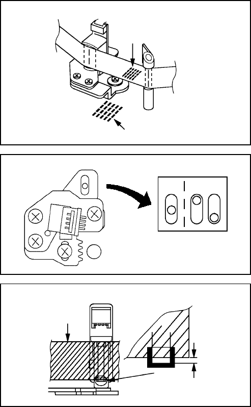
D2-3
Audio/Control Head
1
3
2
4
5[NG][OK]
MECHANICAL ADJUSTMENTS
2-3:2-2:
When the Tape Running Mechanism does not work well,
adjust the following items.
CONFIRMATION AND ADJUSTMENT OF AUDIO/
CONTROL HEAD
1.
2.
3.
4.
When the height is not correct, turn the screw 3 to
adjust the height. Then, adjust the 1~3 again.
Playback the VHS Alignment Tape (Monoscope of ST-N5
MODE2).
Confirm that the reflected picture of stamp mark is
appeared on the tape prior to P4 Cap as shown in Fig. 2-
2-A.
a)
b)
Turn the screw 2 to set the audio level to maximum.
Confirm that the bottom of the Audio/ Control Head and
the bottom of the tape is shown in Fig. 2-2-C.
c)
When the reflected picture is distorted, turn the screw
1 clockwise until the distortion is disappeared.
When the reflected picture is not distorted, turn the
screw 1 counterclockwise until little distortion is
appeared, then adjust the a).
P4 Cap
Fig. 2-2-A
Fig. 2-2-B
Audio/Control Head
Fig. 2-2-C
TAPE RUNNING ADJUSTMENT
(X VALUE ADJUSTMENT)
Confirm and adjust the height of the Reel Disk.
(Refer to item 1-1)
Confirm and adjust the position of the Tension Post.
(Refer to item 1-2)
Adjust the Guide Roller. (Refer to item 2-1)
Confirm and adjust the Audio/Control Head.
(Refer to item 2-2)
Connect CH-1 of the oscilloscope to TP3002 and CH-2 to
TP101.
Playback the VHS Alignment Tape (Monoscope of ST-N5
MODE2).
Press and hold the ATR button on the remote control
more than 2 seconds to set tracking to center.
Set the X Value adjustment driver (JG153) to the 4 of
Fig. 2-2-B. Adjust X value so that the envelope waveform
output becomes maximum. Then, check if the 5 section
of Fig. 2-2-B is on the center position (or rather to the
cylinder side). In case of the envelope maximum at the
difference position from the center, adjust the matching of
picture and sound again.
1.
2.
3.
4.
5.
6.
7.
8.
Audio/Control Head
Reflected picture of
Stamp Mark
Stamp Mark
Tape
0.25±0.05mm
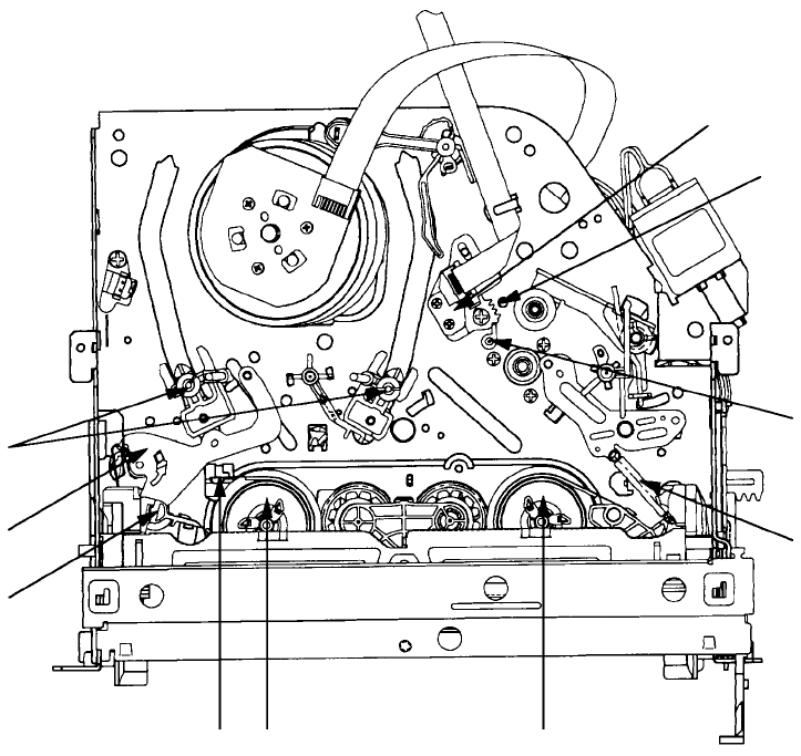
D2-4
MECHANICAL ADJUSTMENTS
3. MECHANISM ADJUSTMENT PARTS LOCATION GUIDE
5
6
7
8910
1
2
3
4
1. Tension Connect
2. Tension Arm
3. Guide Roller
4. Audio/Control Head
5. X value adjustment driver hole
6.
7.
8.
9.
10.
P4 Post
T Brake Spring
T Reel
S Reel
Adjusting section for the Tension Arm position
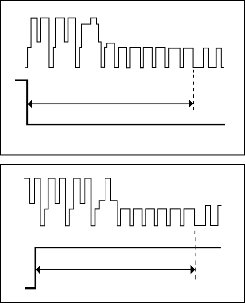
ELECTRICAL ADJUSTMENTS
D3-1
Read and perform this adjustment when repairing the
circuits or replacing electrical parts or PCB assemblies.
1. BASIC ADJUSTMENT
CAUTION
1-1: PG SHIFTER
CONDITIONS
MODE-PLAYBACK
Input Signal-Alignment Tape
INSTRUCTIONS
Connect CH-1 on the oscilloscope to TP3002 and CH-2
to Video Out Jack.
Playback the alignment tape.
Press and hold the ATR button on the remote control
more than 2 seconds to set tracking to center.
Press both CH UP button on the set and the STOP button
on the set for more than 2 seconds.
1.
2.
3.
4.
When you exchange IC and Transistor with a heat sink,
apply silicon grease on the contact section of the heat
sink. Before applying new silicon grease, remove all the
old silicon grease. (Old grease may cause damages to the
IC and Transistor.)
6.5H
CH-1
CH-2
Fig. 1-1-A
CH-1
CH-2
6.5H
Fig. 1-1-B
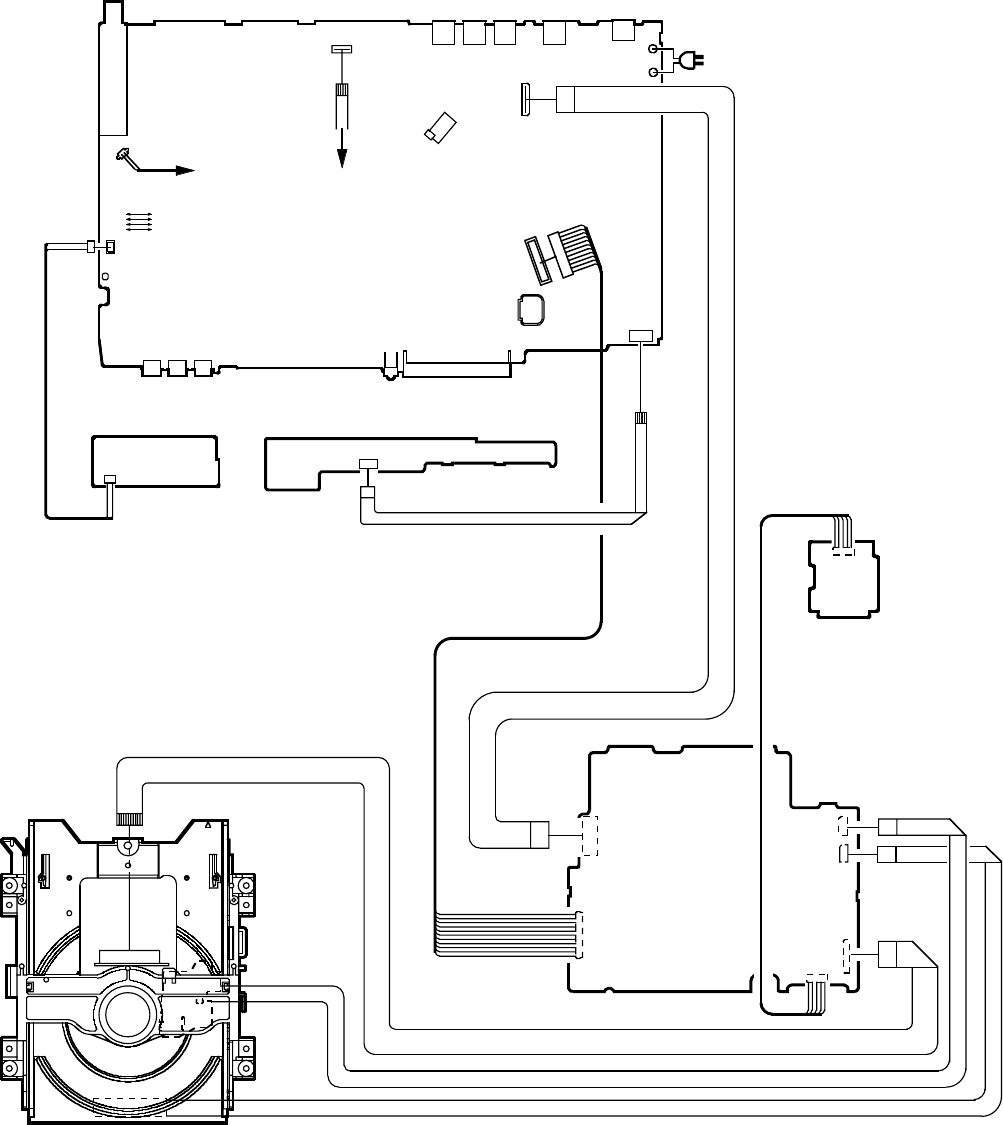
ELECTRICAL ADJUSTMENTS
2. ELECTRICAL ADJUSTMENT PARTS LOCATION GUIDE (WIRING CONNECTION)
DVD MT PCB
DVD DECK
CD2301
CD2001
CP8101
CD4002
CD2302
OPERATION 2PCB
VCR MT PCB
TU301
S501
S502
CP501
FE HEAD AC HEAD
CD102
AC IN
CD8001
D3-2
CP2301
CP2303
CP2302
V651
OS651
J8008
TP101
TP3001
TP3002
J653
J652
J651
J8007
J8006
J8001
J8002
CP102
CD501
CP653
CP103
CP3001
CP8001
TP701
CD683
OPERATION PCB
CP651
CP6601
CP6602
USB PCB
CP683 CP682
CD682
CD6601
CD103
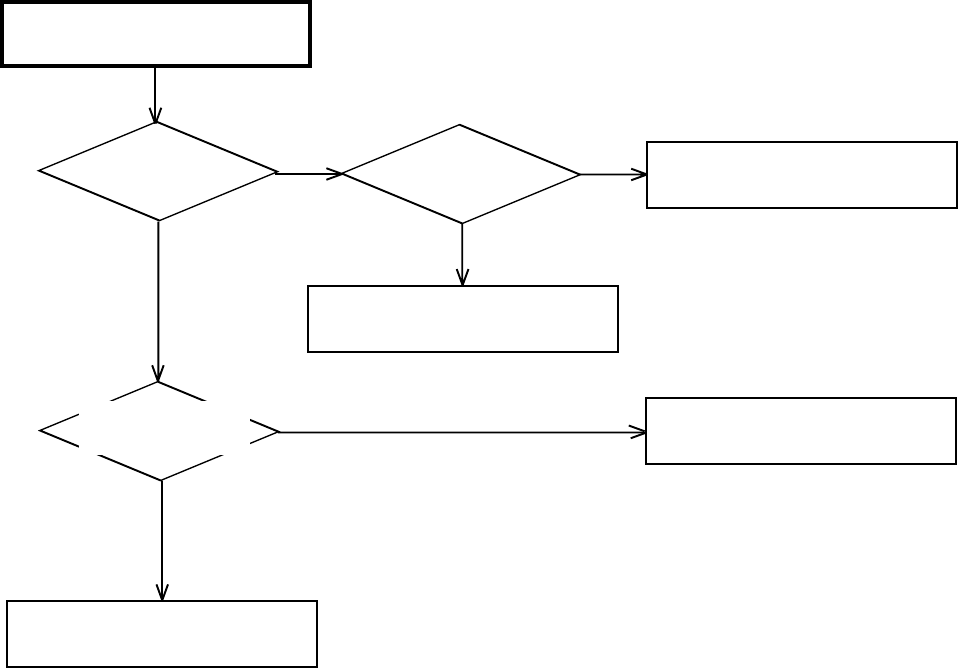
TROUBLESHOOTING GUIDE
E-1
POWER DOES NOT TURN ON
NO
(VCR SECTION)
YES
NO
YES
NO
YES
Check of T501
and peripheral circuit.
Check of V651
and peripheral circuit.
Check IC3001.
Check of T501
and peripheral circuit.
Is the voltage at
pin 41 of IC3001
0V?
Does display light? Is the voltage
linked to L506?
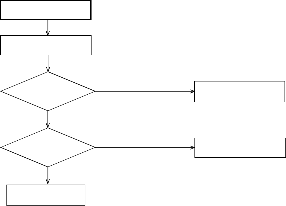
TROUBLESHOOTING GUIDE
E-2
THE POWER SUPPLY CUT
Inserting a cassette
and push play button.
YES
YES
NO
NO
Does the power cut
after 3 seconds?
Check CAPSTAN DD UNIT
and CYLINDER UNIT.
Does the power cut
after about 6 seconds?
Check Q3006, Q3008
and CAPSTAN BELT.
Check the POWER BLOCK.
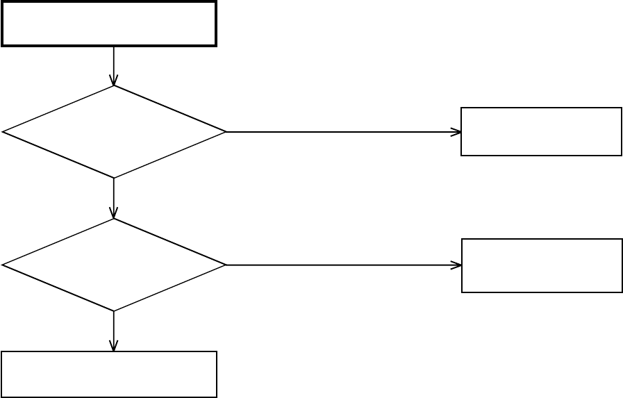
TROUBLESHOOTING GUIDE
E-3
Check IC3001.
Check the DECK BLOCK.
YES
YES
NO
NO
AT PLAYBACK AND RECORDING,
CYLINDER MOTOR UNLOAD
Is the voltage at pin 8 of
CP3001 about DC12.6V? Check IC502.
In playback, is at pin 12 of
CP3001 about DC2.6V?
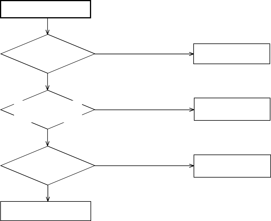
TROUBLESHOOTING GUIDE
E-4
YES
YES
YES
NO
NO
NO
AUDIO SHAKES
Is AUDIO HEAD
scratched? Change AUDIO HEAD.
At playback, is input about
4.5Vp-p of a rectangular
wave at pin 9 of IC3001?
Change CAPSTAN DD UNIT.
Check IC3001.
At playback, is pin 5 of
CP3001 3.5V?
Check AUDIO BLOCK.
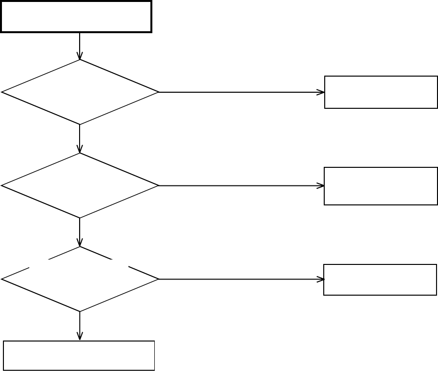
TROUBLESHOOTING GUIDE
E-5
Check LED of DECK,
PHOTO SENSOR.
Change
LOADING MOTOR.
The CASSETTE TAPE
CAN NOT BE INSERTED
Check WORM GEAR
of cassette loading block.
YES
YES
YES
NO
NO
NO
Does WORM GEAR of
cassette loading block
move?
When a CASSETTE can
not inserted, is pin 25 of
IC3001 5V ?
When a CASSETTE is
inserted, is pin 8 of
CP3001 12.6V ?
Check circuit of POWER BLOCK.
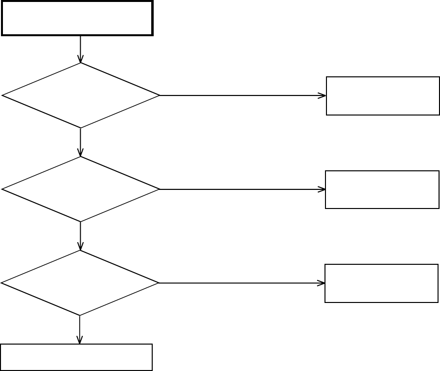
TROUBLESHOOTING GUIDE
E-6
Check IC3001.
Does another CASSETTE
insert?
Check SW3001.
Defective CASSETTE
or cassette loading block.
NO
YES
YES
NO
NO
YES
Does SW3001 and
REC LEVER
correctly set ?
After inserting
CASSETTE, is pin 35
of IC3001 0V ?
Correctly SW3001
and REC LEVER set.
WHEN INSERTING A CASSETTE,
IT EJECTS IMMEDIATELY
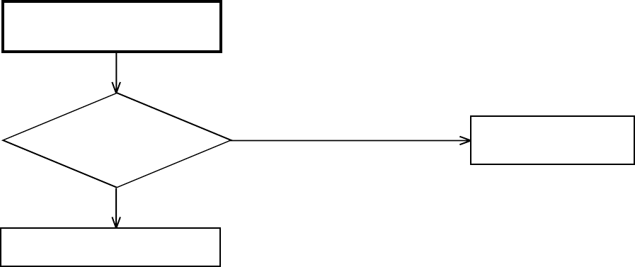
TROUBLESHOOTING GUIDE
E-7
Check DECK MECHANISM.
CAN NOT FF/REW
YES
NO
At FF/REW, does voltage
at pin 98 of IC3001
change?
Check of IC3001.
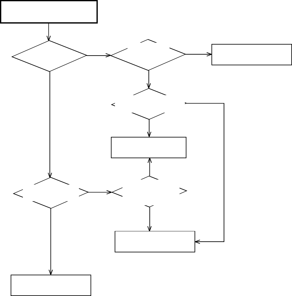
TROUBLESHOOTING GUIDE
E-8
Change CYLINDER unit.
TAPE LOADING IS OK, BUT
UNLOADS IMMEDIATELY
Check POWER BLOCK.
Change IC3001.
Check Q3006 and Q3008.
YES YES
YES
YES
YES
NO
NO
NO
NO
NO
Does CYLINDER
rotate?
Is there HEAD SW
PULSE at TP3002 ?
Is the voltage
at pin 2 of CP3001
12V ?
At play, is the voltage
at pin 12 of CP3001 2.6V ?
Is PG PULSE signal
inputted to pin 104
of IC3001 ?
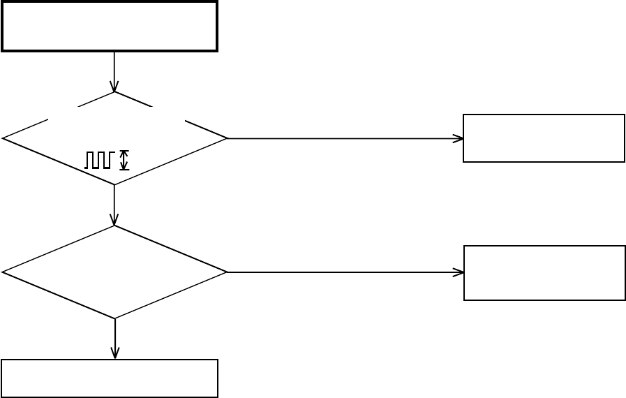
TROUBLESHOOTING GUIDE
E-9
5V
Change
CYLINDER MOTOR.
Change IC3001.
Change CYLINDER MOTOR.
YES
YES
NO
NO
AT PLAY, THE PICTURE
JITTERS VERTICAL MINUTELY
Is FG wave of CP3001
at pin 11 5V ?
Is pin 12 of CP3001 2.6V ?

TROUBLESHOOTING GUIDE
E-10
AUTO TRACKING
DOES NOT OPERATE
YES
NO
NO
In auto tracking, is the
voltage at pin 24 of IC3001
more than DC 0.2V?
Check CONTROL HEAD.
Change IC3001.
more than 0.6Vp-p
YES
Does the CTL pulse
signal (more than 0.6Vp-p)
appear at pin 7 of IC3001?
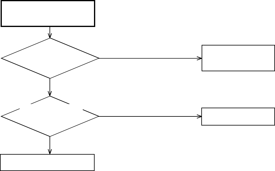
TROUBLESHOOTING GUIDE
E-11
YES
YES
NO
NO
WHEN PLAYBACK, FF OR REW
MODE IS ACTIVE, UNIT STOPS
IMMEDIATELY
Does CAPSTAN DD
MOTOR rotate?
Refer to section "CAPSTAN
DD MOTOR NOT
ROTAING".
Is there REEL SENSOR
PULSE signal at pins 38 and
39 of IC3001?
Check Q3001 and Q3002.
Change IC3001.

TROUBLESHOOTING GUIDE
E-12
YES
YES
YES
YES
YES
NO
NO
NO
NO
NO
AT PLAY, PICTURE JITTERS
HORIZONTALLY
Does a noise on the picture
appear?
By adjusting the MANUAL
TRACKING UP/DOWN
BUTTONS, will the line
disappear?
Check P/B ENVELOPE.
Is a height of GUIDE POST
maximum?
The height of GUIDE POST
readjust.
Is PG SHIFTER
adjustment 6.5H? Adjust PG SHIFTER.
Is a wave of PB-Y unusual? Change IC101
and peripheral circuit.
Change IC101.
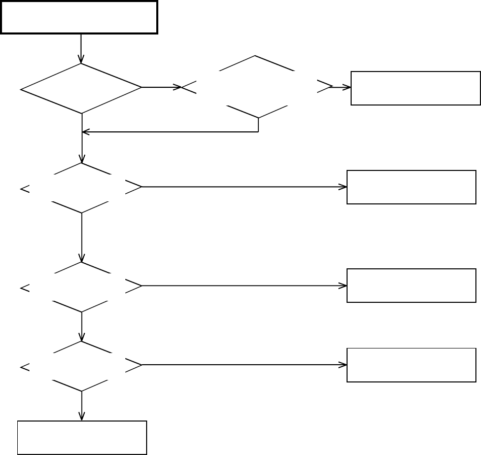
TROUBLESHOOTING GUIDE
E-13
YES
YES
YES
YES YES
NO NO
NO
NO
NO
AT PLAYBACK, THE PICTUER
DOES NOT APPEAR
Does E-E picture
appear?
Is the voltage at pins 23,
44, 45, 68, 52 and 77 of
IC101 5V?
Check POWER BLOCK.
Is there video signal
at pin 26 of IC101? Change IC101.
Change IC8005.
Is there video signal
at pin 2 of IC8005?
Is there video signal
at pin 19 of IC3001?
Check J8001.
Change IC3001.
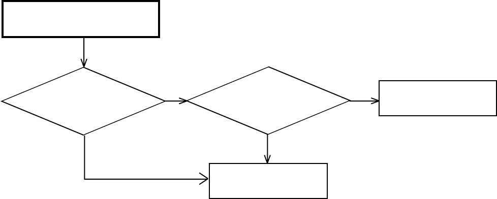
TROUBLESHOOTING GUIDE
E-14
YES
YES
NO
NO
AT PLAYBACK, THE COLER DOES
NOT APPEAR
Is there color signal in
video signal at pin 26 of
IC101?
Is there video signal at pin
26 of IC101? Change X'tal.
Change IC101.
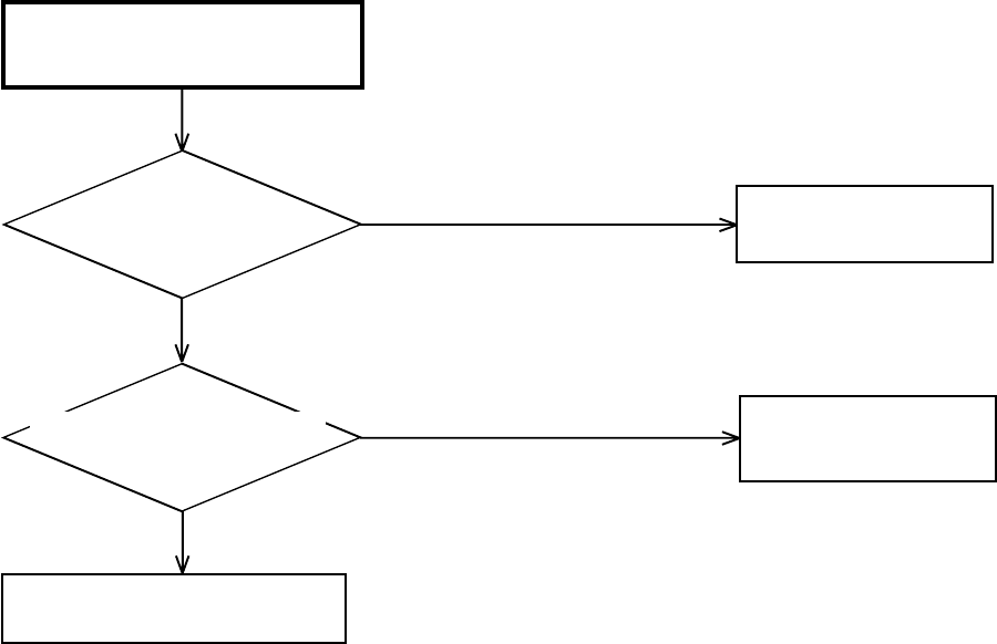
TROUBLESHOOTING GUIDE
E-15
YES
YES
NO
NO
PLAYBACK PICTURE IS NOISY
(EVEN AFTER CLEANING HEADS)
Is noisy a wave of video
signal at pin 26 of IC101?
Is noisy a wave of video signal
of EMITTER of Q8004?
Check J8001.
Check Q8004.
Check CYLINDER.
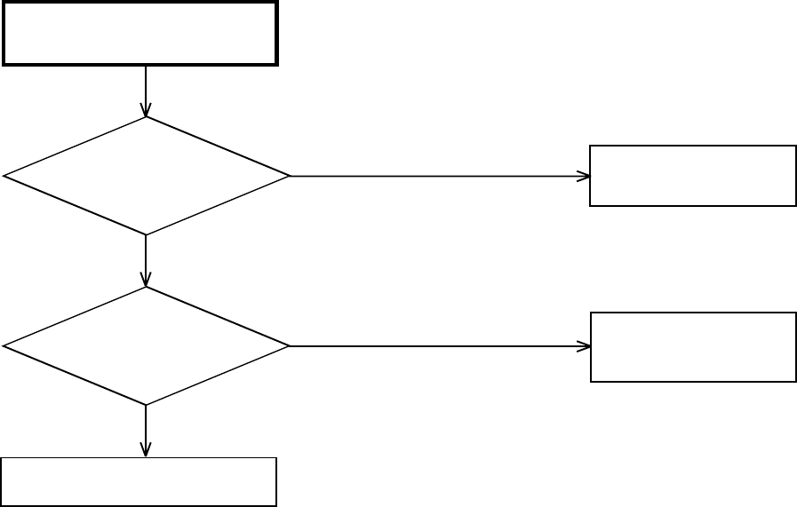
TROUBLESHOOTING GUIDE
E-16
YES
YES
NO
NO
NO COLOR DURING SELF
RECORDING AND PLAYBACK
Is there CHROMA signal
at pins 30 and 32 of
IC101?
Check TU301, IC8002, J653
and circuit around it.
Is there CHROMA signal at
pin 26 of IC101?
Check IC8005 and circuit around of
J8001.
Change IC101.

TROUBLESHOOTING GUIDE
E-17
YES
YES
YES
YES
NO
NO
NO
NO
AT PLAY, AUDIO DOES NOT
APPEAR
At E-E, does audio appear? Refer to section "E-E DOES
NOT APPEAR".
Is the voltage at pins 6, 8
and 9 of IC101 about
2.5V?
Check A/C HEAD.
Check circuit around at pin
10 of IC101.
Check circuit around at pins
78 and 80 of IC101.
Is there audio signal at pin
10 of IC101?
Is there audio signal at
pins 78 and 80 of IC101?
Check whether there are not a
damage, dirt in AUDIO HEAD.
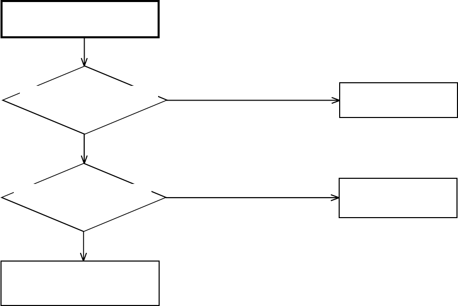
TROUBLESHOOTING GUIDE
E-18
YES
YES
NO
NO
CAPSTAN DD MOTOR NOT
ROTATING
Check POWER BLOCK.
Change IC3001.
In playback, is there voltage
at pin 102 of IC3001 2.5V?
DD MOTOR rotate now?
If not, replace it.
In playback, is there voltage
at pin 2 of CP3001 12V?
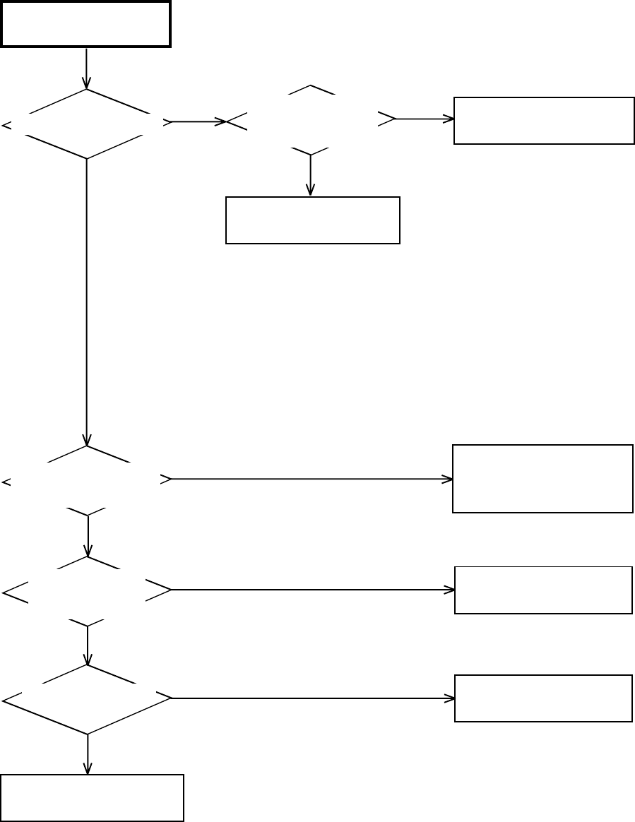
TROUBLESHOOTING GUIDE
E-19
YES
YES
YES
YES
YES
NO NO
NO
NO
NO
THE AUDIO CAN NOT
RECORD
Is bias level at L102 OK?
In starting recording,
is there sine wave at
pin 96 of IC3001?
Check IC3001.
Check disconnection
and short of L102.
Is there audio signal at
pin 80 of IC101?
Is there voltage
of base of Q103
about 5V?
Check IC701 and
the circuit from TUNER
or audio input jack to IC701 .
Change Q103.
Change L101.
Is there a sine wave
at pin 5 of L101?
Check lead wire of A/C HEAD
and CONNECTOR.
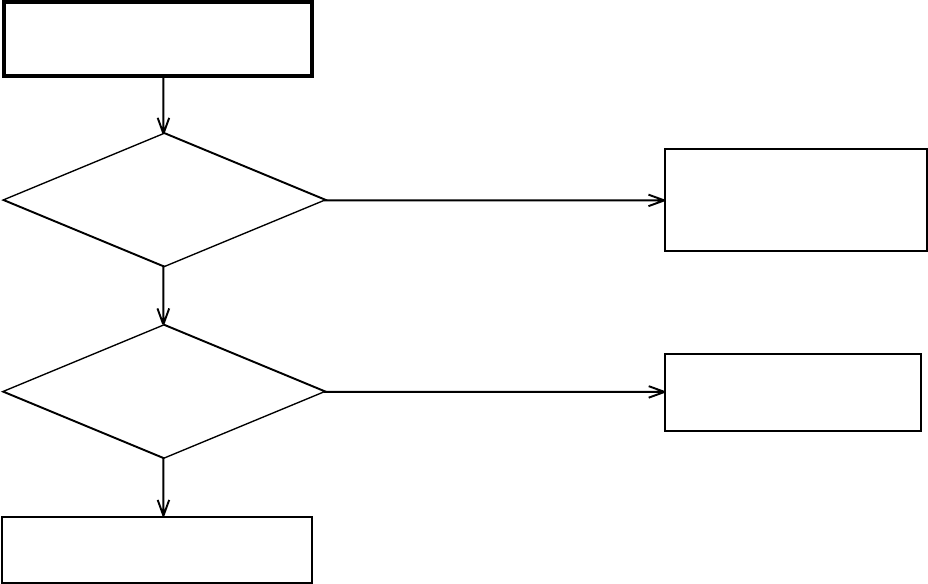
TROUBLESHOOTING GUIDE
E-20
YES
YES
NO
NO
THE CASSETTE INSERT, BUT
THE TAPE DOES NOT MOVE
Does the mode
appear at display?
Does operate with
remote control?
Check operation PCB.
Check LOADING MOTOR and
MODE SENSOR
RELATION DEPARTMENT.
Check IC3001.
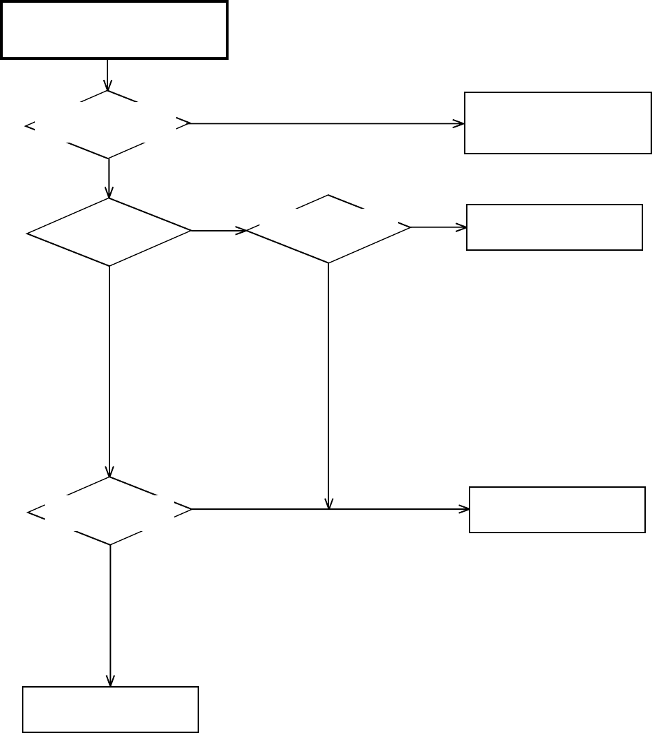
TROUBLESHOOTING GUIDE
E-21
YES
YES
YES
YES
NO
NO NO
NO
RECORDING MECHANISM WORKS,
BUT NO VIDEO RECORD FROM
INPUT JACK OR TUNER
Is there video signal at
pins 30 and 32 of IC
101?
Is the BASE of
Q103 5V?
Is the voltage at pin 96
of IC3001 5V?
Check circuit of video signal
from VIDEO IN or
TUNER to IC101.
Change IC3001.
Change IC101.
Is there video signal
at pin 26 of IC101?
Check CYLINDER UNIT and
circuit around of CP101.

TROUBLESHOOTING GUIDE
E-22
YES
YES
YES
YES
YES
NO
NO
NO
NO
NO
E-E DOES NOT APPEAR
(THE PICTURE DOES NOT
APPEAR FROM TUNER)
Does normality AUDIO JACK
CONNECT? Connection is done over again.
Check POWER BLOCK.
Are there the voltage
of +B(5V) and TU(32V)
of TU301?
Check the picture.
Is there video signal at
pin 17 of TU301? Change TU301.
Change IC101.
Change IC3001.
Is there video signal
at pin 26 of IC101?
Is there video signal at
pin 19 of IC3001?
Check J8001.
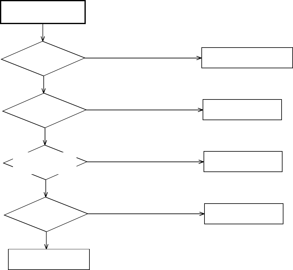
TROUBLESHOOTING GUIDE
E-23
YES
YES
YES
YES
NO
NO
NO
NO
E-E AUDIO (MONO)
DOES NOT APPEAR
Does E-E AUDIO
(STEREO) appear?
Refer to section "E-E AUDIO
(STEREO) DOES NOT APPEAR".
Is the voltage at pin 95
of IC3001 5V?
Change IC3001.
Check J651 and J652 or
J8002.
Change IC701.
Is there audio signal at
pins 9 and 71 or pins 7
and 69 of IC701?
Is there audio signal at
pin 6 of IC701?
Check circuit around of J8001.
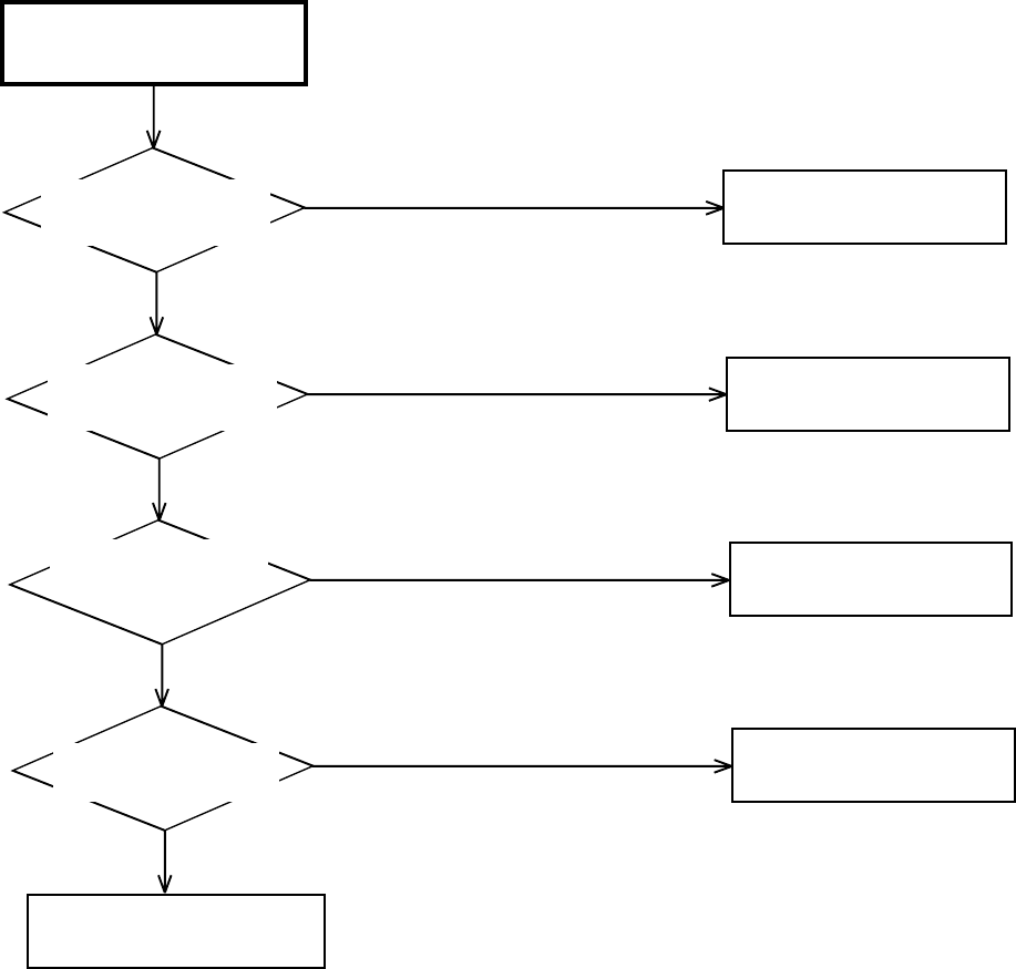
TROUBLESHOOTING GUIDE
E-24
YES
YES
YES
YES
NO
NO
NO
NO
E-E AUDIO (STEREO)
DOES NOT APPEAR
Is the voltage at pins 5,
15 and 32 of IC701 5V? Check POWER BLOCK.
Check POWER BLOCK.
Change IC701.
Is there Audio signal at
pins 7, 9, 61 and 71 of
IC701?
Is there Audio signal at
pins 78 and 80 of IC701.
Check circuit around of J8001.
Check J651, J652 and J8002.
Is the voltage at pins
3 and 54 of IC701 9V?
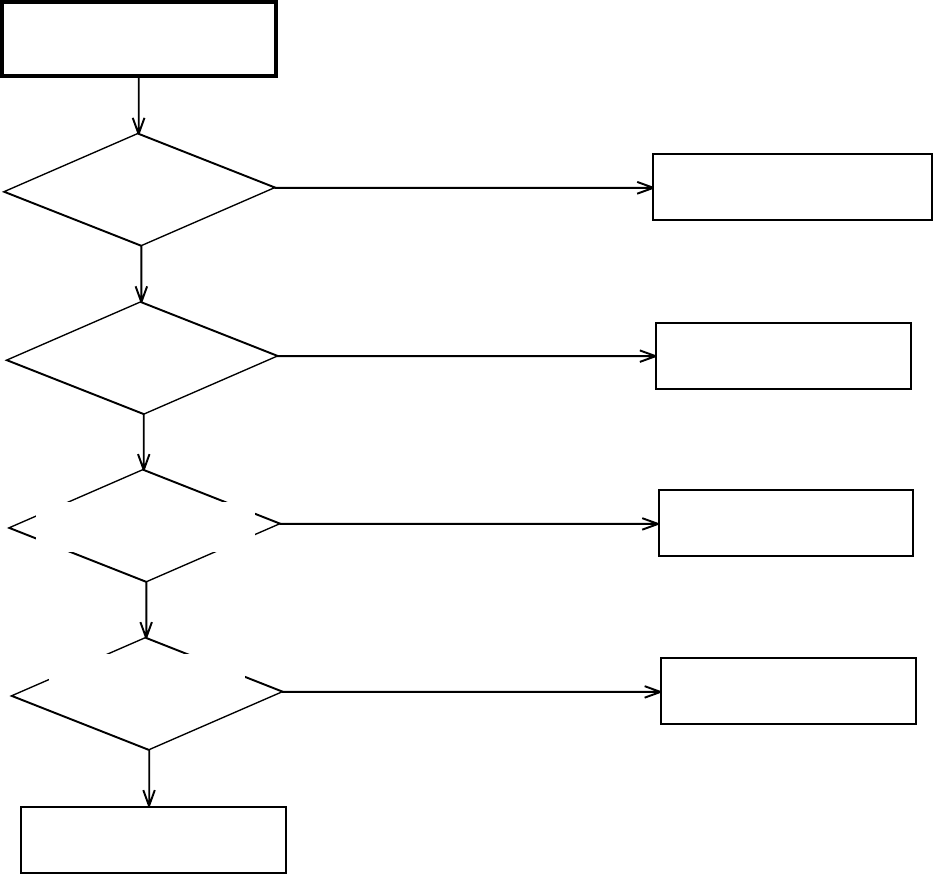
TROUBLESHOOTING GUIDE
E-25
YES
YES
YES
YES
NO
NO
NO
NO
TUNER AUDIO (MONO)
DOES NOT APPEAR
Does E-E AUDIO
(MONO) appear?
Refer to section "E-E AUDIO
(MONO) DOES NOT APPEAR".
Check circuit around of TU301
at pin 14.
Change IC701.
Check IC701.
Is there signal at pin
57 of IC701?
Is there audio signal at
pin 78 and 80 of IC701?
Is there audio signal
a collector of Q8005
and Q8006?
Check circuit around of J8001.
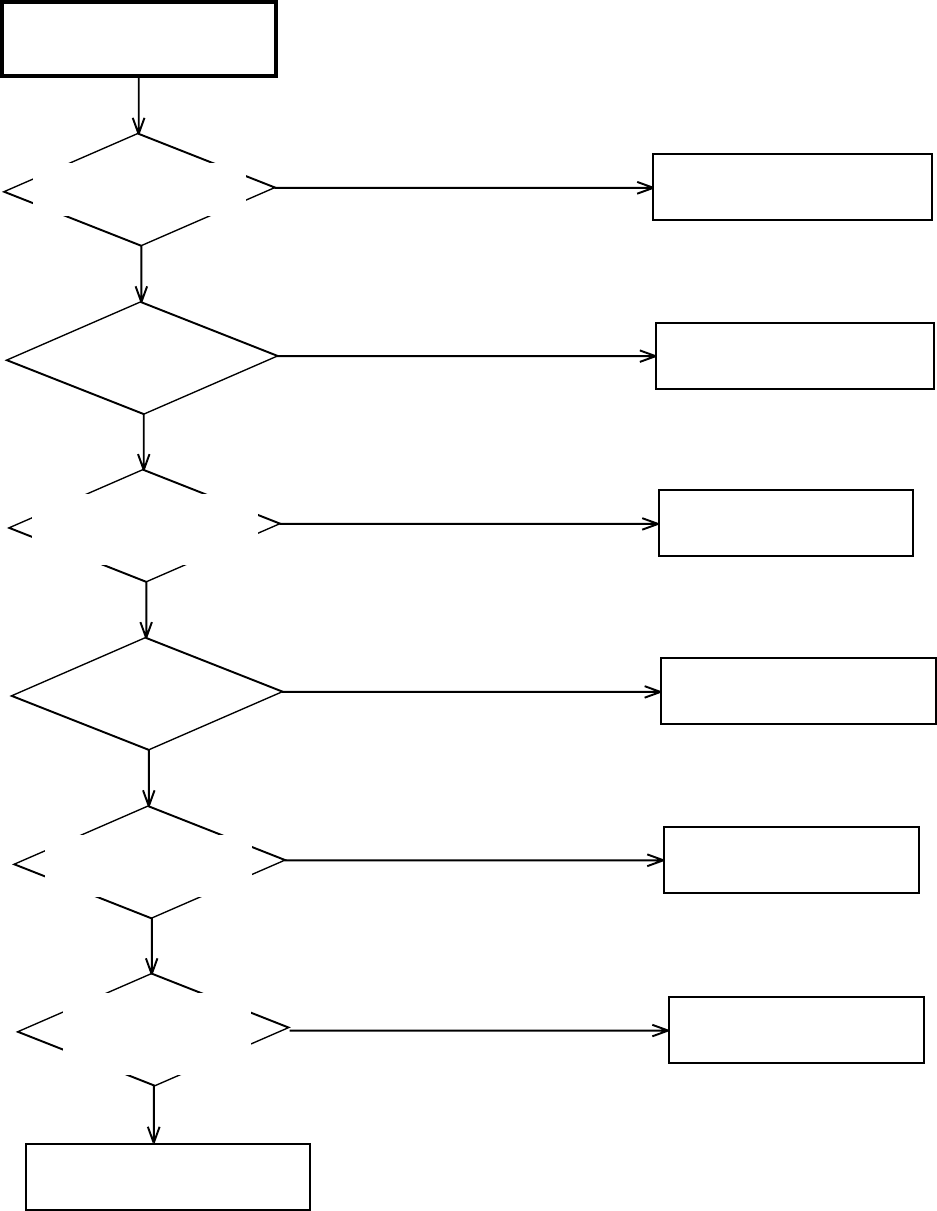
TROUBLESHOOTING GUIDE
E-26
YES
YES
YES
YES
YES
YES
NO
NO
NO
NO
NO
NO
TUNER AUDIO (STEREO)
DOES NOT APPEAR
Does TUNER AUDIO
(MONO) appear?
Refer to section "TUNER AUDIO
(MONO) DOES NOT APPEAR".
Refer to section "E-E AUDIO
(STEREO) DOES NOT APPEAR".
Does E-E AUDIO
(STEREO) appear?
At the time of channel change,
does the display of a stereo
come out to the screen?
Is there audio signal at
pin 57 of IC701?
Check circuit around
of TU301 at pin 14.
Change IC701.
Check IC701.
Is there audio signal
a emitter of
Q8005 and Q8006?
Check circuit around of J8001.
Change IC701.
Is there audio signal at
pin 78 and 80 of IC701?
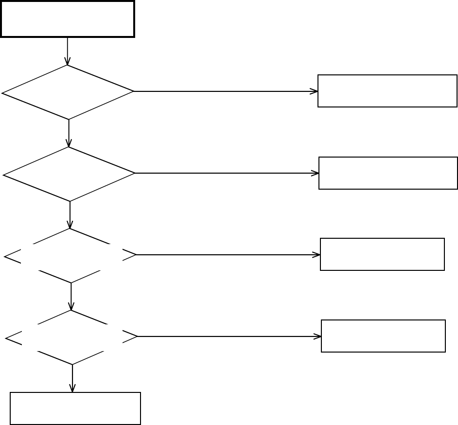
TROUBLESHOOTING GUIDE
E-27
YES
YES
YES
YES
NO
NO
NO
NO
PB AUDIO (Hi-Fi)
DOES NOT APPEAR
Does E-E AUDIO
(STEREO) appear?
Does NORMAL PB
AUDIO appear?
Is there audio signal at
pins 24 and 27 of IC701?
Is there audio signal at
pins 78 and 80 of IC701?
Check circuit around of J8001.
Refer to section "E-E AUDIO
(STEREO) DOES NOT APPEAR".
Refer to section "AT PLAY,
AUDIO DOES NOT APPEAR".
Check circuit of HEAD AMP
and CYLINDER UNIT.
Change IC701.
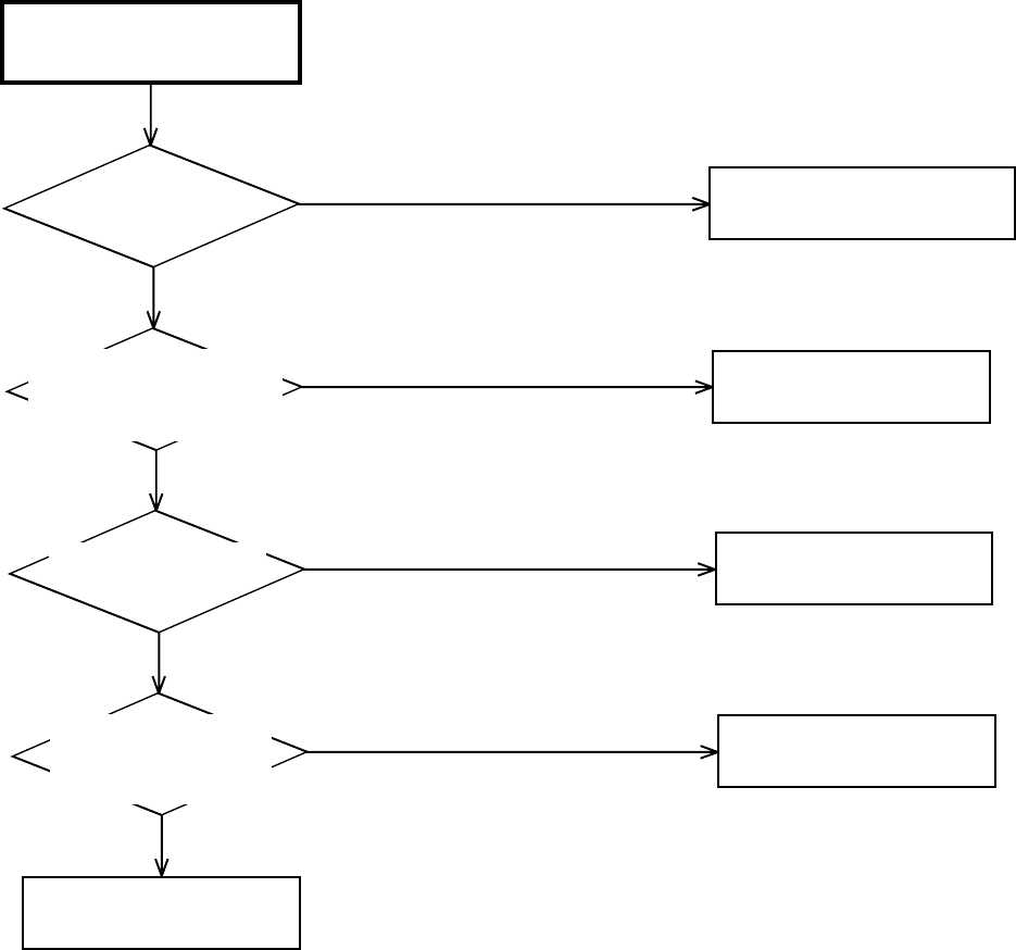
TROUBLESHOOTING GUIDE
E-28
YES
YES
YES
YES
NO
NO
NO
NO
Hi-Fi AUDIO
CAN NOT RECORD
Does E-E AUDIO appear?
AT state of video recording,
is there audio signal at
pins 7, 9, 69 and 71 of IC701?
Is there audio signal at
pins 78 and 80 of
IC701?
At recording and play, is
there signal at pins 7, 8
and 9 of CP101?
Check IC701.
Check CYLINDER UNIT.
Change IC701.
Check circuit around of J651,
J652, J8002 and TU301.
Refer to section "E-E AUDIO
(MONO) DOES NOT APPEAR".
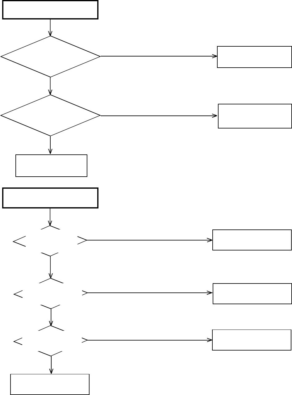
TROUBLESHOOTING GUIDE
E-29
NO
YES
NO
DECK DOES NOT ACCEPT
OPEN/CLOSE
Is the voltage at pin 3, 18 and
19 of IC2301 about DC6V ?
Check P.CON +6V line of
POWER BLOCK.
YESIs the lose connection
at CD2302 to DECK ?
Check CP2302 connection
to DECK.
Check loader block.
(DVD SECTION)
NO PLAYBACK PICTURE OF AV
JACK
Check LOADER BLOCK.
Is there voltage
(beam current) at
JG017 and JG019 ?
Yes
No
Is there VIDEO signal at
pins 183, 184, 186, 187
and 189 of IC4001 ?
Change IC4001.
No
Yes
No
Yes
Check J8007 and peripheral
circuit.
Is there signal at pins
196, 198, 201, 203, 206
and 208 of IC4001?
Check IC4001 and peripheral
circuit.
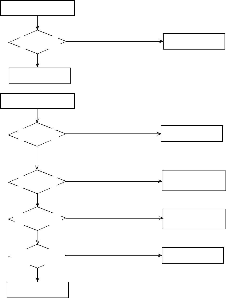
TROUBLESHOOTING GUIDE
E-30
NO PLAYBACK PICTURE OF
S-VIDEO JACK
Is there Y signal at
pin 184 of IC4001 ?
NO
YES Check J8008 and
peripheral circuit.
Change IC4001.
NO COLOR PLAYBACK PICTURE
OF S-VIDEO JACK
Is the voltage at pins 34,
80, 109, 147, 158 and 218
of IC4001 about 1.8V?
Check P.CON+3.3V line on
POWER BLOCK.
Change IC4001.
YES
NO
NO
YES
YES
NO
NO
YES Check J8008 and
peripheral circuit.
Is there Y signal at
pin 184 of IC4001?
REFER TO "NO PLAYBACK
PICTURE OF S-VIDEO JACK".
Is there VIDEO signal
at pin 186 of IC4001?
REFER TO "NO PLAYBACK
PICTURE OF AV JACK" .
Is there C signal at
pin 183 of IC4001 ?
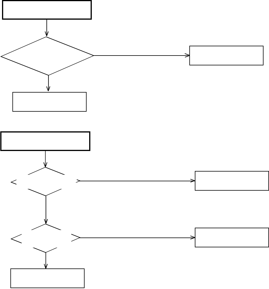
TROUBLESHOOTING GUIDE
E-31
NO AUDIO ON PLAYBACK
Is there AUDIO signal at
pins 7 and 8 of IC8102 ?
YES Check IC8102 and
peripheral circuit.
NO
Change IC4001.
NO DIGITAL AUDIO ON
PLAYBACK OF COAXIAL JACK
Is there waveform at pin 5
of J8006 about 1Vp-p?
Check connection at RCA
Cable.
Yes
Yes
No
No
Change IC4001.
Is there waveform at
pin 126 of IC4001
about 3Vp-p ?
Check Q8001 and peripheral
circuit.
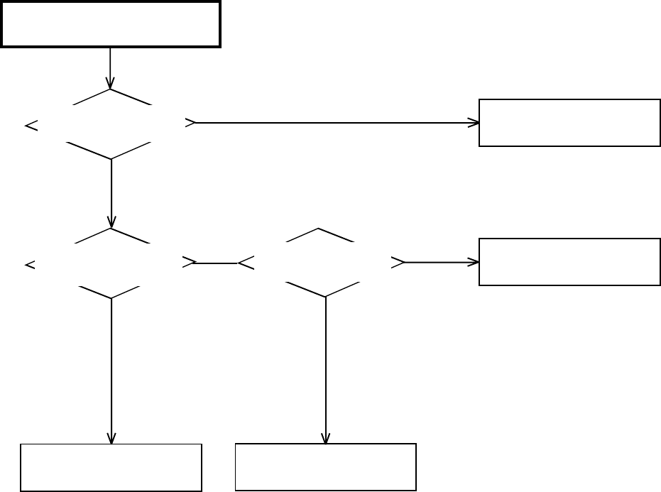
TROUBLESHOOTING GUIDE
E-32
NO ANALOG AUDIO ON
PLAYBACK
Is there AUDIO signal at
pins 1 and 7 of IC8001 ?
Yes
Is there waveform at pins
1, 2, 3 and 16 of IC8102 ?
Yes
Check J8006 and peripheral
circuit.
No
No
Check AT+5V.
Change IC4001.
No
Yes
Change IC8102.
Is there voltage at pin
6 of IC8102 about 5V ?
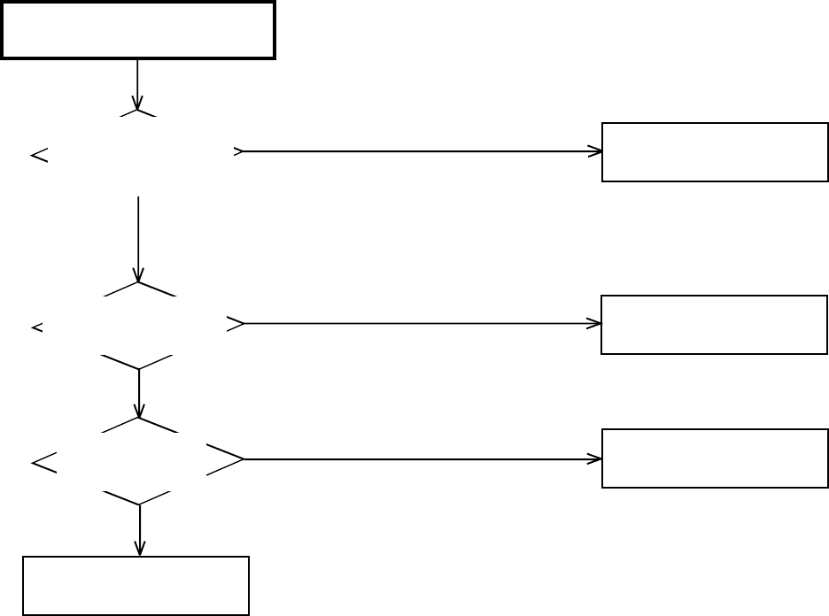
TROUBLESHOOTING GUIDE
E-33
NO HDMI ON PLAYBACK
Check 1.8V and 3.3V line of
IC4001 and peripheral circuit.
Yes
No
Is there waveform
Q5904 (SCL) and
Q5905 (SDA) ?
Change IC4001.
No
Yes
No
Yes
Check IC4001 and peripheral
circuit.
Is there voltage at pins
18 and 19 of CP5901?
(Connects with monitor)
Check P.CON 5V line and
peripheral circuit.
Is there voltage at pins 161,
178 of IC4001 about 1.8V
and at pins 166 and 172
about 3.3V ?
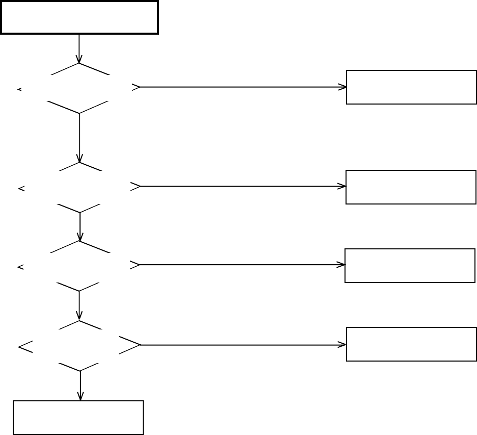
TROUBLESHOOTING GUIDE
E-34
NO USB ON PLAYBACK
Check P.CON 3.3V line of
IC4001 and peripheral circuit.
Is there voltage at pin 65
of IC4001 about 3.3V ?
Yes
No
Is there waveform
at pins 2 and 3 of
CP6602 ?
Change IC4001.
No
Yes
No
Yes
Check IC4001 and peripheral
circuit.
Is there voltage at pins 4
and 5 of IC6601 5V. Change IC6601.
No
Yes
Is there voltage at pins 4
and 5 of CP6602 ? Change CD6601.
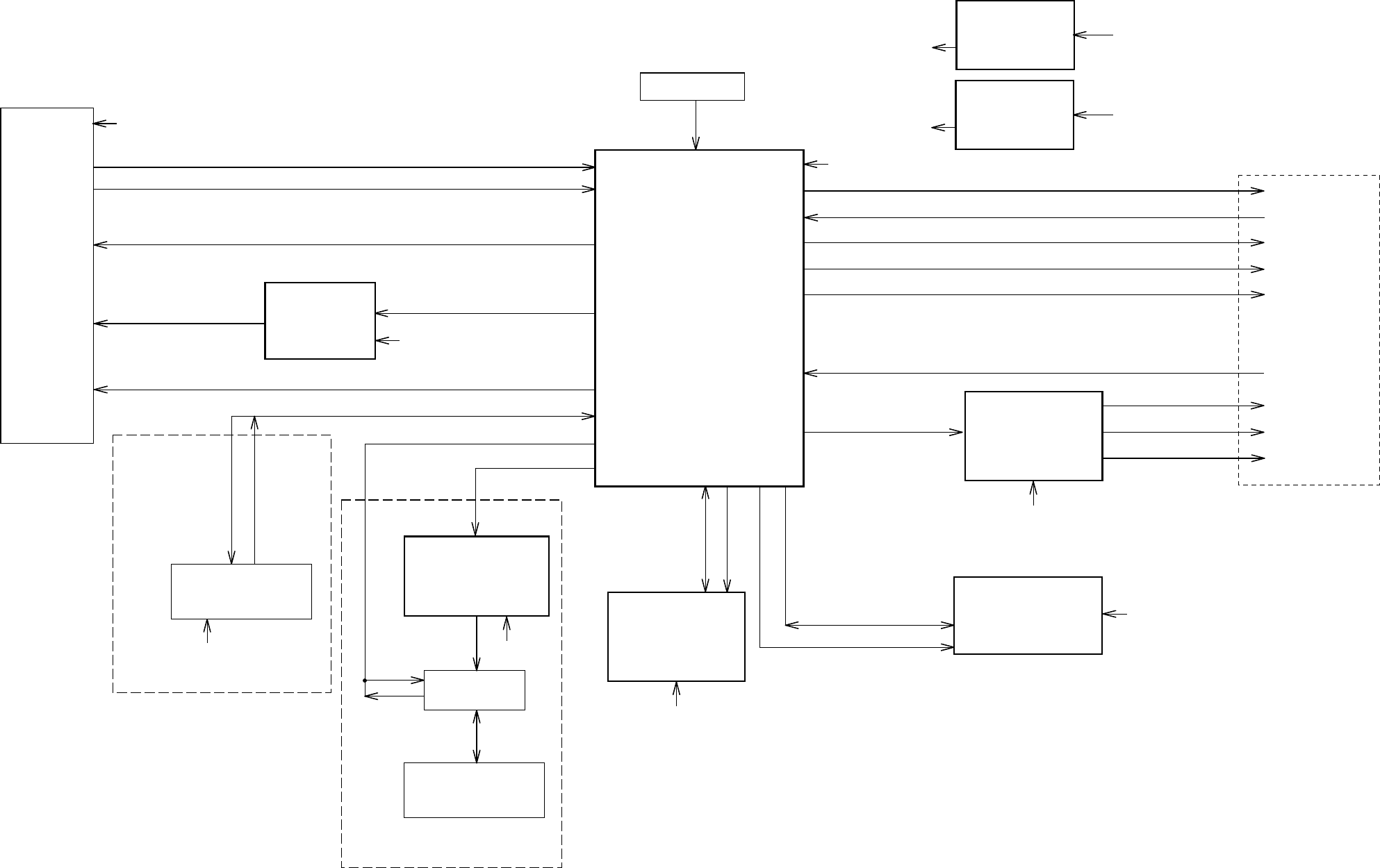
MPEG/MICON/DSP/RF_AMP/HDMI
IC4001
ZR36888HLCG
(Vaddis8)
OPU
SPINDLE/
STEPING/
SLED
MOTOR
HDMI CONNECTOR
CP5901
RF, A, B, C, D, E, F
HOME, TIN_SW, TOUT_SW
DVD LOADER
DM-S/3O
DVD/CD, DVD_LD, CD_LD, VREF(VC), VR/DVD, VR/CD
Motor Drive
IC2301
LA6565VR-TLM-E
TR+/-, FO+/-,
MOT_LD+/-,
MOT_SLED+/-,
MOT_SPDL+/-
SPINDLE/SLED/
FOCUS/TRACK_PWM,
TRAY_CLOSE/OPEN, DRVSB
B, C
DVD BLOCK DIAGRAM
I/TMDS_D2+/-,
I/TMDS_D1+/-,
I/TMDS_D0+/-,
I/TMDS_CLK+/-,
I2CCLK, I2CDAT
SD_D0~D15
64Mbit SDRAM
IC4005
M12L64164A-7TG B
+3.3VREG
IC4003
BA00BC0WFP-E2
VCR BLOCK
DVD-H, P-H/I-L
DAC_A~E_VIDEO
SPDIF
DVD RESET
AUDIO L
AUDIO R
ZERO
2ch Audio DAC
IC8102
PCM1753DBQR
A
B
ML, MC, MD,
AMCLK, ABCLK,
ASDATA0
D
F-1
A--- AT+3.8V
B--- +3.3V
C--- +1.8V
D--- +5V
E--- +A5V
F--- +6V
G--- AT+5.2V
E
F-2
DVD/CDPD
SD_A0~A11,
RAMCS0/RAMCS1/RAMRAS/RAMCAS/
RAMWE/SD_BA0, RAMCLK, RAMDQM
RX
TX
X4001 +1.8VREG
IC4004
BA00BC0WFP-E2
A
C
16Mbit Flash
IC4007
SST39VF1601-70-4C-
EKE
HA0~A20,
HD0~D15,
MEMCS0, MEMCS1,
RD, WR
B
UBS Current Limitation
IC6601
RT9702-PB
HDMI_DET
D
CP6601
USB CONNECTOR
CP6603
DVD-H
5V
USB_DN
USB_DP USB_DN,
USB_DP,
5V
G
F
HDMI BLOCK
USB BLOCK
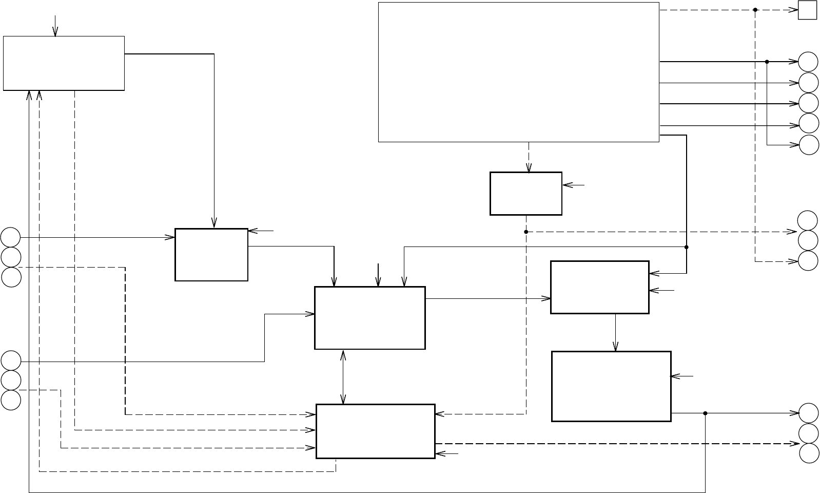
A, H
TUNER
TU301
TU_V_OUT
REAR IN JACK
J8002 V
L
R
FRONT AV JACK
J653
J652
J651
V
L
R
REAR_V_IN
REAR_A_IN
SIF_OUT
FRONT_A_IN
RF_CONV_A_OUT
IC8002
MM1501XNRE
C
A
Y/C/AUDIO/CCD/
HEAD AMP
IC101
LA71206M-MPB-E
NORMAL A_ON/OUT
HIFI/DEMODULATOR
IC701
LA72670BM-L-MPB-E HiFi_AUDIO_OUT
A, C, E
SYSCON/TIMER/SERVO
IC3001
OEC0157B
SW V_OUT
C
B, F
VIDEO_OUT
Y/C_VIDEO OUT
DVD_A_OUT
DVD_A
D
DVD_V_OUT
VCR/DVD VIDEO SW
IC8005
MM1501XNRE
OPE AMP
IC8001
RC4580IDR
DVD BLOCK
SPDIF
Y(G)_OUT
U(PB)_OUT
V(PR)_OUT
C_OUT
V
L
R
Y
U
C
O
L
R
VREAR OUT JACK
J8001
DVD AUDIO OUT JACK
J8006
COAXIAL
OS8001
OPTICAL
YUV OUT
J8007
S-VIDEO OUT
J8008
A ...P.CON+5V
B ...P.CON+5V (MICON)
C ...P.CON+9V
D ...P.CON+12V
E ...AT+5.2V
F ...AT+5V (MICON)
G ...AT+12.6V
H ...+32V
VCR BLOCK DIAGRAM
F-3 F-4
C
Y
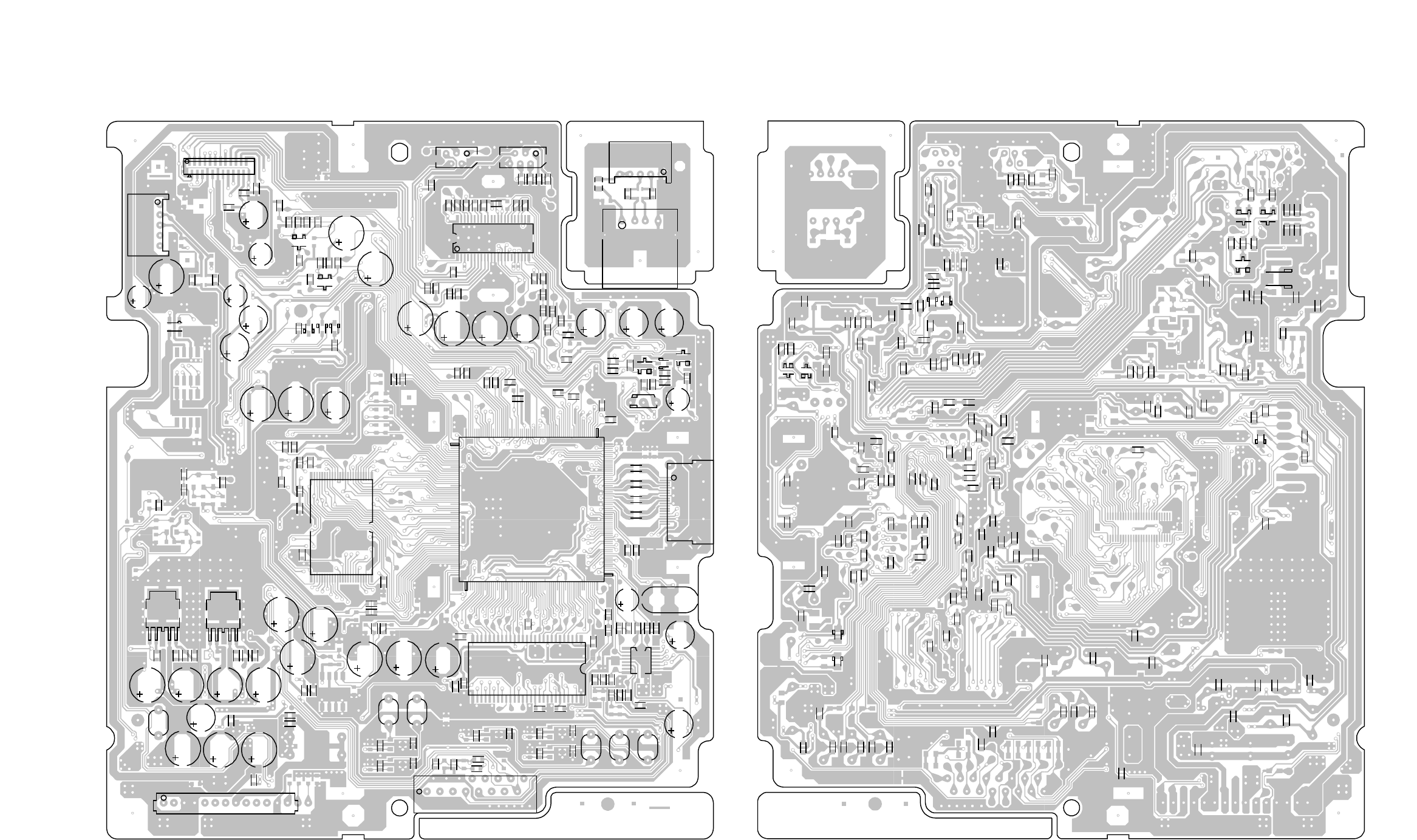
DMF071A
DMF071A
DEF091A DEF091A
1
65 129
193
CP5901
IC4001
X4001
CP8101_1
W836
R4042
R4027
IC8102
R4058
R4026
R4025
W826
W824
L8103
W820
W815
C8127
C8112
L8101
L8105
L8104
C8103
W831
C8120
R8101
R8113
R8112
L8102
W818
C8106C8109
W819
W833
CP6602
CP6601
C5901
Q5901
R5904
R5902
R5903
R5905
R5906
D5901
Q5903
R5908
R5901
C4063
B4007 C4062
C4064
IC4007
C4039 R4040 R4044
C4095
R4010
R4018
C4078
R4054
R4053
C4032
C4096
C4050
C4040C4041
R4048
C4021
C4047
R4008
IC4005
C4102
C4086
IC4003 IC4004
R4066
R4080
R4009
R4081
C4053_1
C4009_1
C4110_1
C4011_1
L4001
C4084_1
R4032
R4047
R4067
C4097
W804
W807 C4091
C6606
C4090
C4089
C4100
C4066
R4078 D4004
D4003
R4406
D4002
C2329_1
R2333
R2332
C2341_1
C2340_1
Q2301
B2301
R2306
R2318
B2302
Q2302
R2341
R2340
C2315
C2331
C2328_1
R2355
R2360
C2309
IC2301
CP2302 CP2303
C2313
R2304
C2303
R2303
C2302
C2357
C2359
C2360
C2358
C2310_1
C2314_1
R2305
C2316_1
R2330
R2328
R2310
R2307
R2301
R2308
R2320
R2321
R2326
R2325R2337
R2319
R2324
R2334
R2342
W850
IC6601
C6603
C6605
R5907
C4071_1
R2335
R2339
C4068_1
C4067_1
C4108
C4026
C2346_1
C2343_1
B4010R4071
C8114
C8125
C8126
C8113
R4052
C4098
R2336
CP2301
R4060
CD4002
R4063
R4016
R4045
B6602
C4083
C4051
C4069
Q5902
C4085
W830
R4062
B4013
C4057
W854
CP6603
C4070_1
C4101
C8121
C8119
W817
W809
W810
W838
B4008
R2354
R6614
R6615
L5901
L5902
L5903
L5904
C5902
Q5904
Q5905
R4408
C4027
C4030
C4103
C4081
R4407
C4031
R4012
C4034
C4035
C8108
C8102
C8115
C8111
B8103
C4007
R4001
C8101
C8124
C8110
C8107
C8105
C8104
C8122
B5901
R5910
R5909
C4014
C4013 C4010 C4008
C4016
C4017
C4077
R4051
C4046
C4045
R4059 C4022 B4017
C4109
B4004
C4099
C4038
R4039
R4037
R4038
R4036
R4019
R4020
R4021
C4004
R4022 R4043
C4088
C4052
C4015
C4111
C4012
C4036
C4065
R6606R6605
R4404
R4072
R4402
R2356
Q2303
R2359
Q2305
R2348
Q2304
R2347
R2346
C2348
R2349
C2317
C2306
C2307
C2301
R2313
R2357
R2358
R2329
R2323
R2338
R2327
C2304
D2304
D2303
R2309
C2337
C2365
R2302
C2305
R2352
R2353
D8112
D8111
R6603
C6604
C4076
B4002
B4021
C4087
B4003
C4075
B4016
C4072
B4005
B4020
C4082
R4024
B4015
C4074
B4006
C4107
C4044
B4019
C2347
B2304
C2332
B2303
C2342
C4002
C4080
R4086
R4005
R4004
R4002
R4003 R4061
B4011
C4003
B4012
C4056
C4001
B4009
C4024
C4019
C4029
C4033
R2351
R2350
C4025
C4028
C4023
C4020
C4018
B6601
B4001
W834
D4005
C6602
D6601
C4114
C4117
C4116
R6613
C4120
C4119
R4070
D5902D5903
W837
B4022
W865
C6609 C6610
C4122
PRINTED CIRCUIT BOARDS
DVD MT/USB (TOP SIDE) DVD MT (BOTTOM SIDE)
G-1 G-2
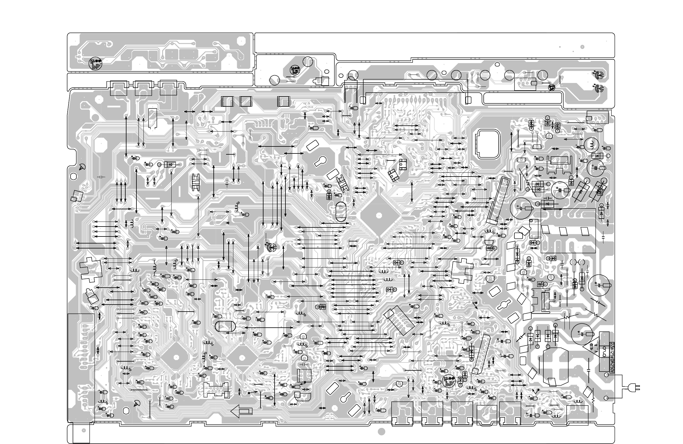
Q3006
V651
C3052
Q3005
Q3004
SW655 SW654 SW653
C656
X3001
C3016
C3032
C3013
W024
W056
R3050
L3003
D3007
W079
C3021_1
D3009
W116
CP101
X101
R123
C105
Q104
Q105
L104_1
L102
L107
R137
W136
CP3001
Q3002
SW3001
Q3001
W836
R3002
W071
C3029
L705
Q3008
W099
W101
W075
W184
W072
C3033
W185
W186
C3045
W112
W108
C309
R109
W144
C8031
C136
C138
C135
C110
W102
W041
W034
C652
L8004
W028
C318_1
W174
C174
R3019
D3001
CP103
R3011
W173
W190
W189
C112
W201
W155
W045
W047
W070
W111
R3028
C104
W200
W193
C101
W807
W025
W110
W118
W105
W100
W124
W123
W161
W127
C119_1
L101
OS651
W049
W048
W906
L301
L103
W867
W043
R3012
D3002
C102
W064
C8010_1
C315_1
W042
R706
C313_1
C765
W231
W026
W103
W037
W036
W057
W055
W054
W053
R651
W033 W031
W027
W109
R105
W067
W113
W141
W140
W052
W122
W133
W131
W125
C123
W207
W137
W130
W128
W126
W162
W160
W158
W156
W083
W082
W080
R140
W167
W150
R144
W152
W153
W134
W159
W147
W148
W202
W139
W132
W199
W195
C763
C767
C758
C755_1
C751
R723
C740_1W237
C731
R704 C722
W229
C721_1
W230
C720_1
C713
R703
C719
R702
R712
C759
R719
C152
C753
C750_1
C728 C716
C712
C725
C756
C726
C727
C742
W236
W191
OS8001
C8062_1
C8063_1
W019
L8001
L8002
R513
R553
D526
Q504
R514
Q503 C521
W827
R533
D514
C505
L505
D516
R554
C504
D527
W816
C501
D507
IC501
D522
C522
R517
D523
C514
IC502
C506
T501
Q501
HS501
FH502
F501
FH501
S501
C653
D656
R501
D502
D505
D506
D503
R503
R512
D509
B501
C513
R516
C515
R502
W017
C525 R506
R508
D510
Q502
R505
IC503
C509
R504
W013
D504
D524
D512
D501
C512Q507
R529
R549
D518
D511
C518
W092
W091
W166
C8032
D8004
W021
D8005
C8034
D8006
C8004_1
W098
C8013
Q8004
W164
W001
R509
W008
W011
W004
W076
W044
W003
R530
W032
W058
W050
W077
C8003_1
D8001
R8011
W095
W094
W151
W801
W121
C8042
W143
W142
CP102_1
W203
W196
R724
W197
W198
W227
W228
W187
TP101
TP701
TP3001
TP3002
W224
W226
W194
W232
W235
W221
R729
R728
W220
W214
W222 L701
L704
W119
W179
W120
R3015
C516
C526
W175
W178
L703
C735
C3023
W081
W114
W117
W208
W225
W188
W211
W212
W210
W217
W218
W219
L501
R3016
W168
W170
W062
W093
W163
W819
W104
L702
D519
W051
W046
W238
W845
C502_1
W223
R527
W002
W138
W206
C8005
R710
R718
S502
W018
W014
TU301
J651
J8007
J8006
J8001
J8002
C8035
C8038
W061
W065
W165
W172
L8009
W007
W005
W022
W073
W085
W084
R8009
W089
W074
R534
W060
L8007
W068
W063
W169
W171
W149
R8004
W023
R8036
W012
W192
W205
D508
R8059
W215
C115
C131
C142
C163
C531
C8022
C8024
C8075_1
C8043
L8008
W204
L506
W213
C511_1
C540_1
W016
W097
R8053
C8051
C8037
W182
W820
W157
W821
C8036
Q505
Q510
D529
D686
D685
SW691
SW686
SW689
SW685
SW687
SW690
R692
R695
R693
R689
R691
R697
R686
R699
CP683
SW697
R698
C3000
SW699
R700
W886
HS502
R8033
C8015_1
C8048
W020
C600
C8047_1
CP8001_1
W881
W241
W242
W243
W145
C535
W246
W245
CP653
R535
W239
W066
W146
W216
R8029
R8028
W078
W833
W832
W804
W834
W135
W090
W069
J653 J652
J8008
CP651_1
CP682
CP501_1
C519
D515_1
W885
W817
W815
W835
W852
W839
W840
W837
W838
R8047
W879
W806
W829
W850
W842
W841
D533
W822
W877
W826
C8040_1
CD501
W880
W846
W856
W847
S801X
S801Y
S802X
S802Y
W183
PRINTED CIRCUIT BOARDS
VCR MT/OPERATION/OPERATION2 (INSERTED PARTS)
SOLDER SIDE
DME063A
DEE079A
DEE080A
DEE081A
RISK OF FIRE - REPLACE AS MARKED .
G-3 G-4
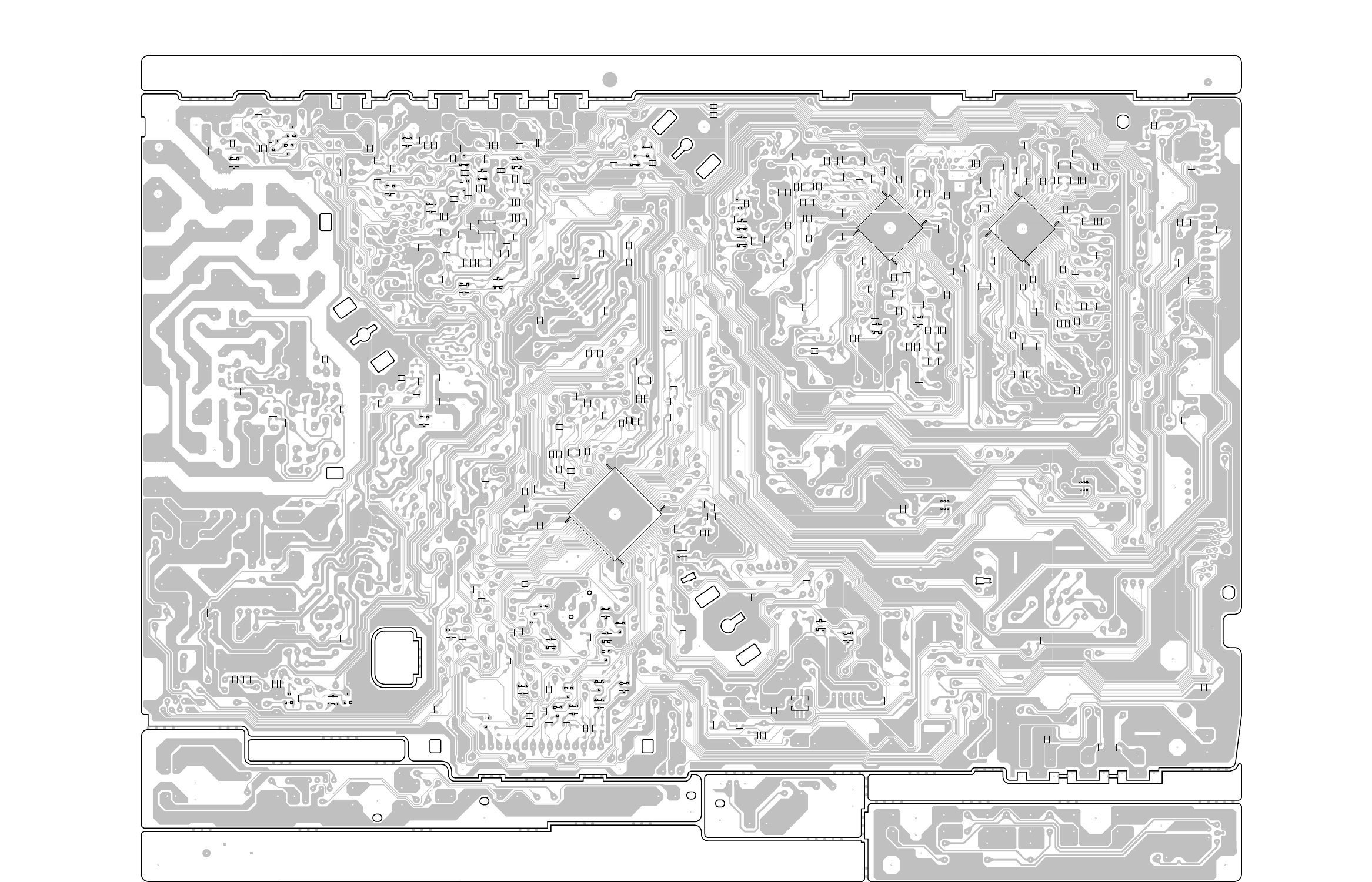
1
29
57
85
1
21
41
61 1
21
41
61
C3005
IC3001
C3006
Q664
Q655 Q652
Q663
R662
R663
R665
R667
R672
R673
R675
R3087
R3037
R3034
C3024
C3025 C3009
R3004
R3063
R3053
C3034C3049
C3038
R3043
C3001
Q662
Q660
Q654
R669
Q659
R670
Q651
R3025
C3044
R3022
R3027
C3018
C3031
C3019
C3015
R3030
C3022
R3020
R3017 R3007
C3010
R3014
C3007
R3031
R3008
R3001
R3032
R3049
R3051
C3030
C3036
R108
R103
R102
R101
IC101
C169
C166
C162
C165
R142
C154
C156
R127
C141
Q109
C144
R132
C145
R133 C147
R131
Q107
C139
C127
C126
C125
R117
R116
C109
C106
C107
R107
C116
R110
R115
C121
C122
R114
R111
R112
C118
R122
C143
Q103
C158
C108
R106
C114
R139
R138
R664
C3027
C3065
R3047
R3046
R3062
C3050 R3033
C3053
C3020 C3008
R3003
R3057
C3017
R3006
R3056
C655
C654
C3061
R3044
R3045
R301
C302
C317
C307
R302
C303
R3010
R3083
Q656
R668
Q657
Q658
R674
Q661
Q665
C8057
Q666
Q101
Q102
R304
R129
R3026
C3040
R666
Q653
R661
R113
C117
R124
C133
R3009
Q3007
Q3003
C129
R141
R683
C3041
R136
R3035
R3055
R671
R126
R119
C160
C3002
R3021
C124
C137
C134
C120
C132
C146
C148
C151
R3038
IC701
C762
R727
C768
C771
R726
C704
R725
C766
R731
C764
C760
C752
C748
C702
R722
R721
C749
R720
C744
R714
C741
C730
C724
C733
C708
R708
R717
R716
C701
R713
C706
R707
C703
R715
C711
R711
C710
C717 C723
C718
C757
C754
C739
C747
C709
C743
C732
C715
R701
C714
C705
C707
C746
C8058
R8001
R8010
C8055
C8054
C8060
Q514
Q513
R552
Q506
R523
C534
R511
Q509
R515
R536
C520
R519
R518
R521
R520
R522
C524
R532
C508
R507
C527
R531
R547
C510
C8028
R8012
R8008
R8007
C8025
R8006
R8005
Q8001
B8001
R8054
R8002
R8003
C8023
Q8008
Q8009
R8022
Q8010
R8023
Q8011 Q8012
R8027
R8026
C8033
R8024
R8025
C8056
R8046
R8042
R8039
R8049 R8034
C8014
Q8003
R8014
R8015
Q8006
Q8005
R8016
R8017
Q8007
C8008
C8009
C544
Q8002
C308
R3036
C8059
C3004
C3014
C3066
C140
IC8002
IC8005
IC3003
R676
R306
R8040
R8037
Q8020
Q8021
Q8022
Q8019
C8046
C161
C8050
C8044
R8035
C8049
R8057
R8051
R8045
R8030
R8031
R8013
R8055
R8052
C8065
R8041
R8050
R8038
C8064
C8045
R8048
R8021
IC3099_1
IC8001
C3035
R678
R677
R524
C8021
W800
W808
PRINTED CIRCUIT BOARDS
VCR MT (CHIP MOUNTED PARTS)
SOLDER SIDE
G-5 G-6
DME063A
DEE079A
DEE080A DEE081A
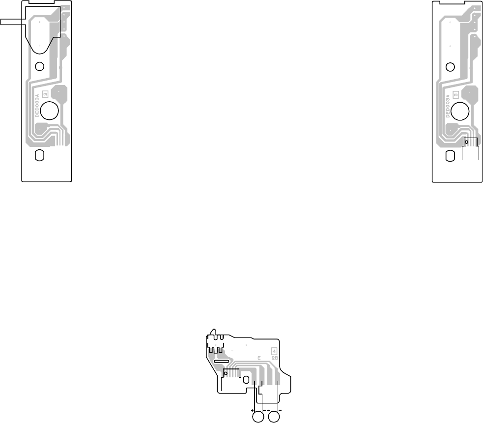
SW1
CD2302
PRINTED CIRCUIT BOARDS
LOADING MOTOR (INSERTED PARTS)
SOLDER SIDE LOADING MOTOR (CHIP MOUNTED PARTS)
SOLDER SIDE
SW
SOLDER SIDE
DD00
RE
BLUE
OR
BL
SW2
CD2301
M2602M2601
G-7 G-8
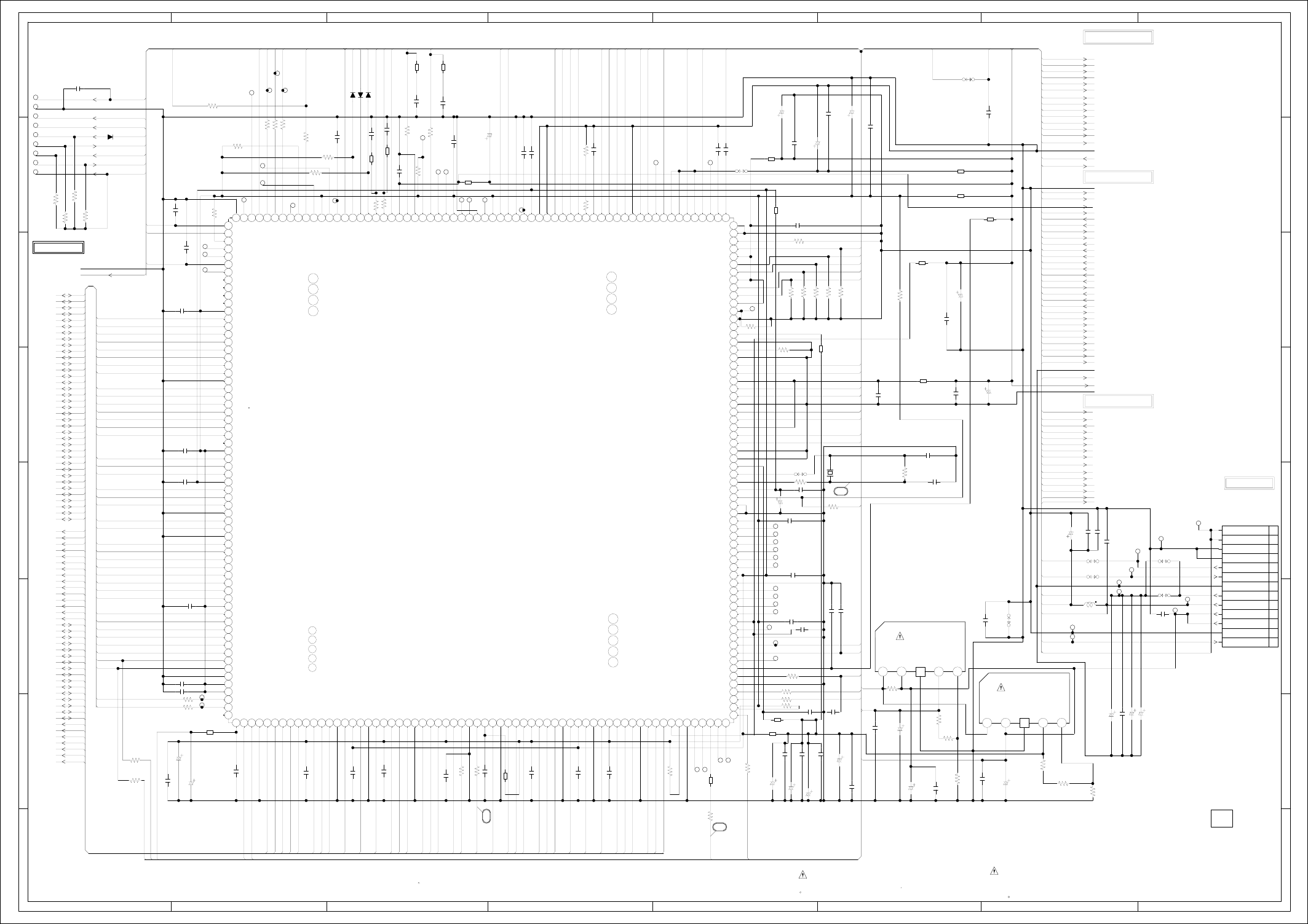
ABC D E F GH
ABC D E F GH
2
1
3
4
5
6
7
8
2
1
3
4
5
6
7
8
IC4001
ZR36888HLCG
MPEG/MICON/DSP/RF_AMP/HDMI IC
101102 103 104105 106 107108 109 110111 112 113 114 115 116 117118 119 120121 122 123124 125 126127 128
129130 131 132133 134 135136 137 138139 140 141 142 143 144 145146 147 148149 150 151152 153 154155 156 157158 159 160161 162 163164 165 166167 168 169170 171 172173 174 175176 177 178179 180 181182 183 184185 186 187 188189 190 191192
193194195196197198199200201202203204205206207208209210211212213214215216217218219220221222223224225226227228229230231232233234235236237238239240
241242243244245246247248249
250251
252
253254
255256
110
100
111213141516171819 22021222324
2526272829 3
30313233343536373839 4
40414243444546474849 5
50
51525354
55
56575859 6
6061626364
65 66 67 68 69
7
70 71 72 73 74 75 76 77 78 79
8
80 81 82 83 84 85 86 87 88 89
9
90 91 92 93 94 95 96 97 98 99
TP4015
TP4012
TP4013
TP4010
JG4006
JG4009
JG4007
JG4008
JG4012
JG029
TP4005
TP4004
TP4006
JG4005
JG4015
JG4029
JG4032
JG4014
JG4001
JG4002
JG4003
JG001
JG002
JG003
JG004
JG005
JG006
JG007
JG008
JG009
JG4016
JG4017
JG4028
JG4027
JG4026
JG4025
JG4023
JG4022
JG4021
JG4020
JG4019
JG4024
JG4030
JG4031
TP4022
TP4014
TP4020
TP4021
TP4027
TP4028
JG4011
JG4010
JG4004
TP4009
TP4008
TP4003
TP4007
JG4013
TP4011
JG4018
IC4004
BA00BC0WFP
REG+1.8V IC
12 456
IC4003
BA00BC0WFP
REG+3.3V IC
12 456
CD4002
CH2D1101
1
10
11
12
13
2
3
4
5
6
7
8
9
B4021
MMZ1608R102CT
B4012 MMZ1608R102CT
B4009
MMZ1608
R102CT
B4016
MMZ1608R102CT
B4011
MMZ1608R102CT
B4013
MMZ1608R102CT
B4002
MMZ1608R102CT
B4020
MMZ1608
R102CT
B4015
MMZ1608R102CT
B4022 MMZ1608R102CT
B4006
MMZ1608R102CT
B4010
MMZ1608R102CT
B4004
MMZ1608R102CT
B4005
MMZ1608R102CT
B4001
MMZ1608R102CT
B4017
MMZ1608R102CT
B4003
MMZ1608R102CT
B4019
MMZ1608R102CT
DANS LA NOMENCLATURE DES PIECES
N’UTILISER QUE CELLS DECRITES
DANGEREUSES AN POINT DE VUE SECURITE
:LES PIECES REPAREES PAR UN ETANT
ATTENTION
:SINCE THESE PARTS MARKED BY
CAUTION
DESCRIBED IN PARTS LIST ONLY
CRITICAL FOR SAFETY,USE ONES
ARE
D4002 1SS355
D4004 1SS355
D4003 1SS355
D4005
1SS355
DURING PLAYBACK.
MEASURED WITH THE DIGITAL TESTER
NOTE:THE DC VOLTAGE EACH PART WAS
OF PRINTING AND SUBJECT TO CHANGE WITHOUT NOTICE
NOTE:THIS SCHEMATIC DIAGRAM IS THE LATEST AT THE TIME
C4110_1
4716V KA
C4089 10010V KA
C4090 10010V KA
C4100 10010V KA
C4011_1
1006.3V KA
C4051
1006.3V KA
C4026
1006.3V KA
C4083
1006.3V KA
C4078
1006.3V KA
C4102
1006.3V KA
C4053_1
1006.3V KA
C4009_1
47
16V KA
C4122
0.1 B
C4111
0.1 F
C4034 8P CH
C4114
0.001 B
C4072
0.1 F
C4091
100P CH
C4036 0.1 B
C4097 0.01 B
C4065 0.01 B
C4035 15P CH
C4107
0.1 F
C4080 0.01 B
C4056
0.027 B
C4033 0.1 F
C4002
0.1 F
C4001
0.0012 B
C4117
100P CH
C4003
0.027 B
C4116 100P CH
C4088 1 B
C4004 0.1 F
C4085 0.001 B
C4086 0.001 B
C4087
0.1 F
C4027 0.1 F
C4028 0.1 F
C4081 0.1 F
C4031 0.01 B
C4103
0.1 F
C4098
10P CH
C4119
2.2 B
C4012
0.1 F
C4082
0.1 F
C4044
0.1 F
C4074
0.1 F
C4120
0.001 B
C4109
0.1 F
C4077
0.1 F
C4032
0.001 B
C4096
0.001 B
C4038
0.01 B
C4008
0.1 F
C4010
0.1 F
C4013
1B
C4014
0.1 F
C4016 0.1 F
C4024 1 B
C4025 0.1 F
C4020 0.1 F
C4019 1B
C4023 0.1 F
C4017 0.1 F
C4030 1 B
C4007 0.1 F
C4057
180P CH
C4029 0.1 F
C4066
1B
C4018 0.1 F
C4076
0.1 F
C4075
0.1 F
C4052
0.1 F
C4015
0.1 F
C4022 0.1 F
R4047
330 +-1%
R4067
3.9K +-1%
R4012
1M
R4045 4.7K
R4001 390 +-1%
R4080
5.6K
+-1%
R4061 11K
R4062 39K
R4060
11K
R4063
15K
R4406
4.7K
R4078
4.7K
R4019 33
R4020 33
R4021 33
R4402 4.7K
R4404
4.7K
R4043
10K +-1%
R4022
10K
+-1%
R4070
75 +-1%
R4408
430 +-1%
R4016
100
R4042 100
R4026 220
R4027 220
R4407 4.7K
R4071
150
R4024 4.7K
R4054
1K
R4053
1K
R4051
4.7K
R4036
4.7K
R4037
4.7K
R4039
4.7K
R4038
4.7K
R4059 100
R4008 100
R4025 220
R4005 75 +-1%
R4004 75 +-1%
R4003 75 +-1%
R4058
220
R4052
4.7K
R4072
10
R4010 33
R4018 33
R4066
10K
R4009
1K+-1%
R4032
1.5K +-1%
R4081
3.9K +-1%
R4086 75 +-1%
R4002 75 +-1%
C4084_1
476.3V KA
C4101
10010V
YK
C4108
1006.3V KA
C4068_1
100
6.3V KA
C4069
47
6.3V
KA
C4067_1
476.3V KA
C4071_1
476.3V KA
C4070_1
2206.3V YK
W830
W850
W834
W817
W804
W865
W836
W807
X4001
100BT02701
27MHz
L4001
2.2uH 0305
VC
RX
MD
MC
ML
DUPTD1
DUPRD1
DUPTD0
DUPRD0
OPU_F
OPU_E
OPU_D
OPU_C
OPU_B
SYS_MUTE
P.CON+5V
SLED_PWM
DRVSB
DVD_LD
CD_LD
RF
DUPTD1
P-H/I-L
FOCUS_PWM
DVD/CD
HDMI_DET
SPDL_SENS+
SPDL_SENS-
OPU_A
TRAY_OPEN
DVD/CDPD
DVD/CDPD
SPINDLE_PWM
AMCLK
P.CON+3.3V
TRACK_PWM
ABCLK
ALRCLK
DAC_VIDEO_C
DAC_VIDEO_B
DAC_VIDEO_D
UNREG+3.8V
DAC_VIDEO_A
DAC_VIDEO_E
MD
BOOT2
MC
BOOT1 ML
P.CON+5V
DUPTD1
P-H/I-L
DUPRD1
IRRCV
GND
DUPTD0
RESET
DUPRD0 ASDATA0
D1_1 VDDAFERF
P.CON+5V
GND
+1.8V
TRAY_OPEN
+3.3V
TRAY_CLOSE
D1_2
RFINN
RFINP
VDDPWM3.3V
VDDDAC
HOME
TOUT_SW
TIN_SW TIN_SW
DVD/CD
TRAY_CLOSE
DRVSB
RF
DAC_VIDEO_C OPU_A
DAC_VIDEO_B OPU_B
OPU_C
TOUT_SW DAC_VIDEO_D
GND OPU_D
DAC_VIDEO_A
P.CON+3.3V OPU_E
DAC_VIDEO_E OPU_F
VC
SPDL_SENS-
HA0 SPDL_SENS+
HA1 DVD/CDPD
HA2 DVD_LD
HA3 HA15 CD_LD
HA4 SPINDLE_PWM
HA5 HA16
SLED_PWM
HA6 HA14 HDVCC+1.8V
TRACK_PWM
HA7 HA13 FOCUS_PWM
HA8 HA12 P.CON+A5V
HA9 P.CON+3.3V
HA10 HD15
VCC+6V
HA11 HA11 I/TMDS_D2+
HA12 M_GND
HD7 I/TMDS_D2-
HA13 P.CON+5V
HDVCC+3.3V
HA14 P.CON+3.3V
HA15 HA10 I/TMDS_D1+
GND
HA16 HD14 I/TMDS_D1-
HA17 HA9
HA18 HD6 I/TMDS_D0+ I2CDAT
HA19
HA20 HA8 I/TMDS_D0- I2CCLK
HD0 HDMI_DET
HD13
HD1 I/TMDS_D2+
HD5 I/TMDS_CLK+
HD2 I/TMDS_D2-
I/TMDS_CLK-
HD3 I/TMDS_D1+
HD4 I/TMDS_D1-
HD5 I/TMDS_D0+
HD12
HD6 I/TMDS_D0-
WR
HD7 I/TMDS_CLK+
HD4
HD8 I/TMDS_CLK-
HD9 USB_DP
HD10 HD11 USB_DN
HD11 HD3 AT+5.2V
HD12 VCC+6V
HA19
HD13 RESET
HD14
HD15 HD10
HA18
MEMCS0
RD
WR HD2
SD_A0 HA17
SD_A1 HD9 DUPRD1
SD_A2 HA7
SD_A3
SD_A4 HD1 RX
SD_A5 HA6
SD_A6 HD8
SD_A7 VCC+6V
HA5
SD_A8 P.CON+A5V
SD_A9
SD_A10 HD0 P.CON+5V
SD_A11 HA4
SD_D0 RD
SD_D1
SD_D2 HA3 SPDIF
SD_D3 HA2 SYS_MUTE
SD_D4 MEMCS0 HOME AT+5.2V
SD_D5 HA1
SD_D6
SD_D7 HA0 UNREG+3.8V
SD_D8 AMCLK
SD_D9
SD_D10 DVD-H
ABCLK
SD_D11
SD_D12 I2CDAT ALRCLK
SD_D13 I2CCLK P.CON+3.3V
SD_D14
SD_D15
RAMCS0#
RAMRAS#
RAMCAS#
SD_BA0
RAMDQM
RAMWE# UNREG+3.8V
RAMCLK
P.CON+3.3V
RAMCAS#
BOOT1
BOOT2
RAMCS0#
RAMCS1#
RAMRAS#
SD_BA0
RAMWE#
RAMDQM
SD_D11
SD_A11
RAMCLK
SD_D10
SD_D5
SD_D12
SD_D13
SD_D14
SD_D15
SD_D0
USB_DP
USB_DN
SD_A4
SD_A3
SD_A5
SD_A2
SD_A6
SD_A1
SD_A7
SD_A0
SD_A10
SD_D8
SD_D7
SD_D9
SD_D6
SD_D4
SD_D3
SD_D2
SD_D1
SD_A8
SD_A9
ASDATA0
SPDIF
2
3
1
EN GND VOVCC ADJ
FROM/TO HDMI/USB
FROM/TO MOTOR DRIVE
FROM/TO AUDIO/VIDEO
H-2
H-1
FROM/TO POWER
DVD/VR 130mm
DVD COMBO 250mm
(CP501_1)
NC
NC
NC
NC
NC
NC
GPCI/O[52]
GPCI/O[54]
GPCI/O[53]
GPCI/O[57]
SSCCLK / GPCI/O[59]
SSCTXD / GPCIO[60]
SSCRXD / GPCIO[17]
MEMCS[1]
VDDP
MEMAD[15]
MEMAD[16]
MEMAD[14]
MEMAD[13]
MEMAD[12]
MEMDA[15]
MEMDA[7]
MEMAD[11]
GNDP
MEMAD[10]
MEMDA[6]
MEMAD[8]
MEMDA[13]
MEMDA[5]
MEMAD[20]
MEMDA[14]
VDDP
MEMDA[12]
MEMWR/
MEMDA[4]
VDDC
MEMDA[11]
MEMDA[3]
MEMAD[19]
GNDC
MEMDA[10]
MEMAD[18]
MEMDA[2]
MEMAD[17]
MEMDA[9]
MEMAD[7]
MEMDA[1]
MEMAD[6]
MEMDA[8]
MEMAD[5]
VDDP
MEMDA[0]
MEMAD[4]
MEMAD[3]
MEMAD[2]
MEMAD[1]
MEMAD[0]
GNDP
GNDP
VDD-IP
VDDP
RAMCKE
GPCI/O[61]
GPCI/O[62]
RAMADD[3]
RAMADD[5]
RAMADD[2]
RAMADD[6]
VDDP
RAMADD[1]
RAMADD[7]
RAMADD[0]
GNDP
RAMADD[8]
VDDC
RAMADD[10]
GNDC
RAMADD[9]
VDDP
RAMADD[11]
RAMBA[0]
GNDP
RAMCS[0]/
RAMCS[1]/
RAMRAS/
RAMCAS/
VDDP
RAMWE/
RAMDQM
GNDPCLK
PCLK
VDDPCLK
RAMDAT[8]
GNDP
RAMDAT[7]
RAMDAT[9]
RAMDAT[6]
VDDP
RAMDAT[10]
RAMDAT[5]
RAMDAT[11]
GNDP
RAMDAT[4]
VDDC
RAMDAT[12]
GNDC
RAMDAT[3]
VDDP
RAMDAT[13]
RAMDAT[2]
RAMDAT[14]
GNDP
RAMDAT[1]
RAMDAT[15]
RAMDAT[0]
VDDP
ALRCLK
ABCLK
GNDP-A2
AMCLK
VDDP-A2
ADPWMP[2]
GPCI/O[20]
GPCI/O[25]
GNDP
ADPWMN[2]
VDDP
ADPWMP[3]
ADPWMN[3]
ADPWMP[4]
ADPWMN[4]
GNDC
VDDC
ADPWMP[5]
ADPWMN[5]
ADPWMP[6]
ADPWMN[6]
ADPWMP[7]
ADPWMN[7]
VDDP
GNDP
GNDA
RESET/
VDDA
XO
GCLKP
AHVDD
AHGND
AGNDP
HDTXCN
HDTXCP
AVDDP
HDTXDN0
HDTXDP0
AGNDP
HDTXDN1
HDTXDP1
AVDDP
HDTXDN2
HDTXDP2
AGNDP
HDCSET
AGNDC
GNDDACD
GNDDACD
DAC6
VDDDACD
DAC5
DAC4
VDDDAC
DAC3
DAC2
VDDDAC
DAC1
RSET
GNDDACP
GNDDABS2
VDDAFE
ADCIN[B]
VDDSAFE
VDDAFE
ADCIN[C]
ADCIN[H]
ADCIN[D]
ADCIN[J]
GNDADC
ADCIN[E]
ADCIN[K]
ADCIN[F]
OPUREF
BGCAP
RESLOAD
CDMD
DVDMD
CDLD
DVDLD
GNDAFER
GNDADC
VDDC
GNDC
ICGPCI/O[4]
ICGPCI/O[5]
VDDP
GNDP
VDD-IP
PWMCO[2]
GPCI/O[44]
GNDPWMS
PWMCO[4]
VDDPWMS
GPCI/O[46]
DUPRD0
DUPTD0
DUPRD1
DUPTD1
VDDP
GPCI/O[40]
GPCI/O[42]
GPCI/O[33]
GPCI/O[34]
GPCI/O[48]
GPCI/O[49]
GPCI/O[50]
IDGPCI/O[5]
VDDUSB
USBDP
USBDN67
GNDUSB
RAMADD[4]
65
66
68
69
GPCI/O[51]253
254
255
256 GNDP
193
194
195
196
RFINP
RFINN
ADCIN[A]
MEMAD[9]
MEMRD/
MEMCS[0]/
PWMCI[6]
PWMCI[0]
GPCI/O[47]
GPCI/O[16]
CPUNMI
GNDP
ADPWMP[0]
IDGPCIO[0]
AOUT[2] / ADPWMN[0]
AOUT[1] / ADPWMP[1]
126
127
128
S/PDIFOUT
129
130
AOUT[0]/ADPWMN[1]
GPCI/O[65]
AVDDT18
(MUTE-L)
(VR_CD)
(VR_DVD)
(DVD-L/CD-H)
(DVD MT PCB)
MPEG/MICON/DSP/RF_AMP SCHEMATIC DIAGRAM
EN GND VOVCC ADJ
PCB130
DMF071
FROM/TO MEMORY
(D_GND)
GND(M)
P.CON+A5V
GND(A)
GND(D)
GND(D)
SPDIF
SSCCLK/TX
RDY(I/O(0))/RX
P.CON+6V
AT+5.2V
AT+5.2V
UNREG+3.8V
UNREG+3.8V
(W803)
(A_GND)
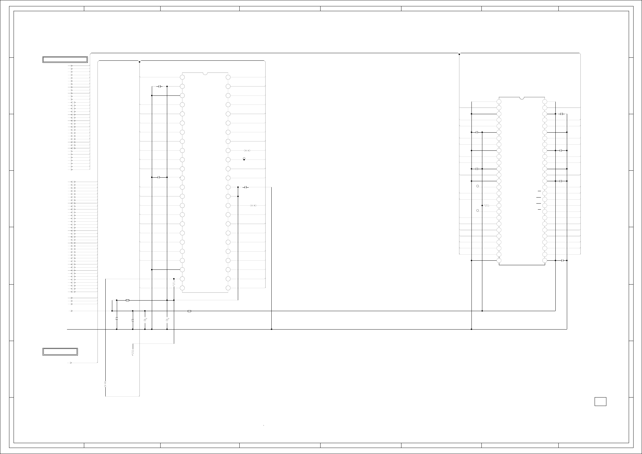
ABC D E F GH
ABC D E F GH
2
1
3
4
5
6
7
8
2
1
3
4
5
6
7
8
IC4005 M12L64164A-7TG
64M SDRAM IC
110111213141516171819 22021222324252627
28 29
3
30 31 32 33 34 35 36 37 38 39
4
40 41 42 43 44 45 46 47 48 49
5
50 51 52 53 54
6789
IC4007 SST39VF1601-70-4C-EKE
FLASH IC 16M IC
110111213141516171819 22021222324
25 26 27 28 29
3
30 31 32 33 34 35 36 37 38 39
4
40 41 42 43 44 45 46 47 48
56789
JG4033
JG4034
JG4035
B4007
MMZ1608R102CT
B4008
MMZ1608R102CT
DURING PLAYBACK.
MEASURED WITH THE DIGITAL TESTER
NOTE:THE DC VOLTAGE EACH PART WAS
OF PRINTING AND SUBJECT TO CHANGE WITHOUT NOTICE
NOTE:THIS SCHEMATIC DIAGRAM IS THE LATEST AT THE TIME
C4045
0.1 F
C4050
0.1 F
C4046
0.1 F
C4047
0.1 F
C4041
0.1 F
C4040
0.1 F
C4095
0.01 B
C4099
0.01 B
C4039
0.1 F
C4064
0.1 F
C4062
0.1 F
R4048
47K
R4044
4.7K
R4040
4.7K
C4021
1006.3V KA
C4063
2206.3V KA
W837
W838
W854
SD_A0
SD_A1
SD_A2
SD_A3 HA16 HA15
SD_A4
SD_A5
SD_A6 HA14
SD_A7
SD_A8
SD_A9 HA13
SD_A10
SD_A11
SD_D0 HD15 HA12
SD_D1 SD_D15 SD_D0
SD_D2
SD_D3 HD7 HA11
SD_D4
SD_D5 SD_D14 SD_D1
SD_D6 HD14 HA10
SD_D7 SD_D13 SD_D2
SD_D8
SD_D9 HD6 HA9
SD_D10
SD_D11 SD_D12 SD_D3
SD_D12 HD13 HA8
SD_D13 SD_D11 SD_D4
SD_D14
SD_D15 HD5 HA19
RAMCS0#
RAMRAS# SD_D10 SD_D5
RAMCAS# HD12 HA20
SD_BA0 SD_D9 SD_D6
RAMDQM
RAMWE# HD4 WR
RAMCLK
SD_D8 SD_D7
RESET
HA0
HA1 HD11 RAMDQM
HA2
HA3 RAMDQM RAMWE#
HA4 HD3
HA5 RAMCLK RAMCAS#
HA6
HA7 HD10 HA19 RAMRAS#
HA8
HA9 RAMCS1#
HA10 HD2 HA18
HA11 SD_A11 SD_BA0
HA12
HA13 HD9 HA17 SD_A9 RAMCS0#
HA14
HA15 SD_A8 SD_A10
HA16 HD1 HA7
HA17 SD_A7 SD_A0
HA18
HA19 HD8 HA6 SD_A6 SD_A1
HA20
HD0 SD_A5 SD_A2
HD1 HD0 HA5
HD2 SD_A4 SD_A3
HD3
HD4 RD HA4
HD5
HD6
HD7 HA3
HD8
HD9
HD10 FLASHCS HA2
HD11
HD12
HD13 HA0 HA1
HD14
HD15
MEMCS0
RD
WR
P.CON+3.3V
GND
RESET
MEMCS0
PCB130
DMF071
H-4H-3
FROM AUDIO/VIDEO
FROM/TO MPEG/MICON/DSP/RF_AMP
NC
NC
NC
DQ15
DQ7
DQ14
DQ6
DQ13
DQ5
DQ12
DQ11
DQ3
DQ10
DQ2
DQ9
DQ1
DQ8
DQ0
CE#
A0
DQ4
A7
A6
A5
A4
A3
A2
A1
VCCQ A14
A13
A12
A11
A9
A8
A18
A17
A10
A19
A20
RP#
VPP
WP#
A19
WE#
A15A16
VCC
OE#
GND
GND
VDD
DQ0
VDDQ
DQ1
DQ2
VSSQ
DQ3
DQ4
VDDQ
DQ5
VSSQ
DQ6
DQ7
VDD
LDQM
WE
CAS
RAS
CS
BA0
BA1
A10/AP
A0
A1
A2
A3
VDD
VSS
DQ15
VSSQ
DQ14
DQ13
VDDQ
DQ12
DQ11
VSSQ
DQ10
DQ9
VDDQ
DQ8
VSS
NC
UDQM
CLK
CKE
NC
A11
A9
A8
A7
A6
A5
A4
VSS
DEBUG MODE
MEMORY SCHEMATIC DIAGRAM
(DVD MT PCB)
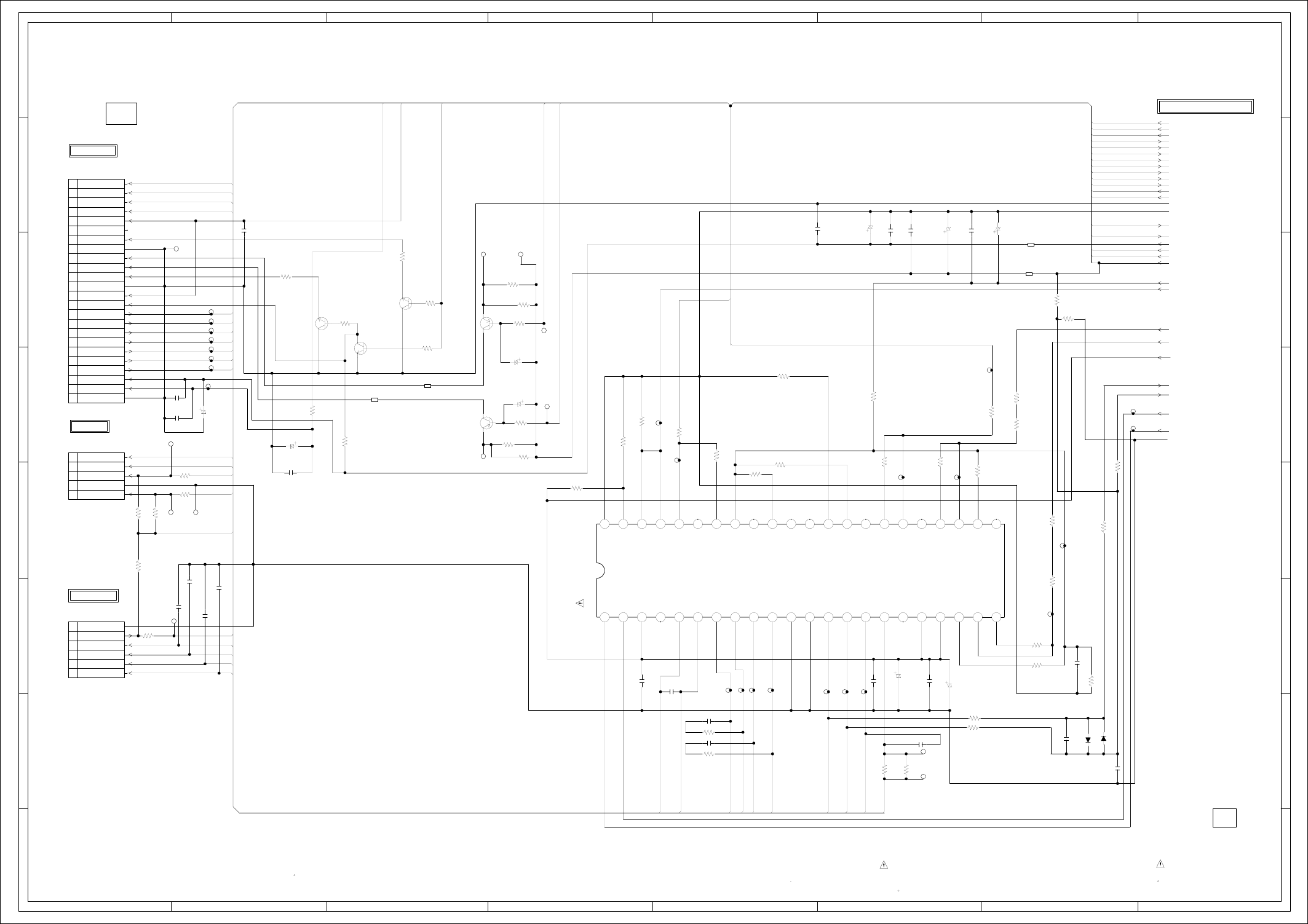
ABC D E F GH
ABC D E F GH
2
1
3
4
5
6
7
8
2
1
3
4
5
6
7
8
CP2302
00_6232_005_006_800+
1
2
3
4
5
CP2303
00_6232_006_006_800+
1
2
3
4
5
6
CP2301
LD07T2-24ND-03
1
10
11
12
13
14
15
16
17
18
19
2
20
21
22
23
24
3
4
5
6
7
8
9
IC2301 LA6565VR-TLM-E
MOTOR DRIVE IC
1 1011121314151617 18 192 20 21 22
23242526272829
3
30313233343536373839
4
4041424344
56789
TP2316
TP2317
JG057
TP2320
JG012
TP2318
TP2319
TP2324
TP2323
TP2304
TP2305
TP2303
TP2307
JG017
TP2308
JG019
JG018
TP2306
TP2322
TP2321
TP2310
TP2309
TP2311
TP2312
JG058
TP2313
TP2315
TP2314
JG056
JG016
JG010
JG011
JG040
JG013
JG014
JG015
B2301
MMZ1608R102CT
B2302
MMZ1608R102CT
B2303
MMZ1608R102CT
B2304
MMZ1608R102CT
DANS LA NOMENCLATURE DES PIECES
N’UTILISER QUE CELLS DECRITES
DANGEREUSES AN POINT DE VUE SECURITE
:LES PIECES REPAREES PAR UN ETANT
ATTENTION :SINCE THESE PARTS MARKED BY
CAUTION
DESCRIBED IN PARTS LIST ONLY
CRITICAL FOR SAFETY,USE ONES
ARE
D2304 1SS355
D23031SS355
DURING PLAYBACK.
MEASURED WITH THE DIGITAL TESTER
NOTE:THE DC VOLTAGE EACH PART WAS
OF PRINTING AND SUBJECT TO CHANGE WITHOUT NOTICE
NOTE:THIS SCHEMATIC DIAGRAM IS THE LATEST AT THE TIME
C2304
0.022 BC2365
0.1 B
C2305
0.1 B
C2307 0.1 B
C2348
1B
C2359
100P CH C2360
100P CH
C2309
0.1 B
C2337
0.1 F
C2357
100P CH C2358
100P CH
C2313
0.1 B
C2301
0.1 F
C2303 0.1 B
C2302 0.1 B
C2347
0.1 F
C2331
0.1 F
C2315
0.1 F
C2342
0.1 F
C2332
0.1 F
C2306 0.1 F
C2317
0.1 F
R2354
3.3K
R2357 1K
R2358 120
R2302
100 +-1%
R2330
1K
R2313
4.7K
R2359
82
R2341
6.8
R2340
6.8
R2338
4.7K
R2310
4.7K
R2326
5.6K
R2321
27K
R2339
1.2K
R2324
1K
R2342
4.7K
R2350
4.7K
R2353
100
R2351
4.7K
R2352
100
R2334
10K
R2318
6.8
R2333
220
R2332
220
R2306
6.8
R2347
3.3K
R2346
3.3K
R2356
82
R2349
100
R2337
10K
R2308
10K
R2301
1K
R2307
75K
R2305
10K
R2319
33K
R2327
4.7K
R2304 2.2
R2303 2.2
R2323
1.2
R2329
1.2
R2328
4.7K
R2325
6.8K
R2355
1K
R2348
3.3K
R2360
33
R2309
100 +-1%
R2320
4.7K
R2336
390
R2335 5.6K
C2328_1
476.3V KA
C2310_1
10010V KA
C2314_1
10010V KA
C2340_1
1006.3V KA
C2341_1
100
6.3V KA
C2346_1
47
6.3V KA
C2343_1
476.3V KA
C2329_1
476.3V KA
C2316_1
476.3V KA
Q2303
KTC3875S_Y_RTK
VR DVD
Q2304
KTC3875S_Y_RTK
DVD/CD
Q2305
KTC3875S_Y_RTK
VR DVD
Q2301
KTA1505S
-Y-RTK/P
DVD LDCTL
Q2302
KTA1544T-RTK/P
CD LD CTL
VC
DVD/CD
DVD_LD
CD_LD
DVD/CDPD
DVD/CD
DVD_LD
CD_LD
DVD/CDPD
RF
OPU_A
OPU_B
OPU_C
OPU_D
OPU_E
TR- OPU_F
VC
TR+
HOME
FO- GND
FO+ GND
DVD/CDPD
TOUT_SW
TIN_SW
VR/DVD RF_A5V P.CON+A5V
TRACK_PWM
FOCUS_PWM
DVDLD
P.CON+3.3V
CDLD
VR/CD
VDDPWM3.3V
DRVSB
DVD/CDPD TRACK_PWM
DVD_CD
RF
OPU_C
SPINDLE_PWM
OPU_B
OPU_A SLED_PWM
FOCUS_PWM
OPU_D
VCC+6V
OPU_F
OPU_E
SPDL_SENS+
SPDL_SENS-
TRAY_CLOSE
OPU_VREF TRAY_OPEN
M_GND
MOT_LD-
MOT_LD+
TOUT_SW
TIN_SW
P.CON+3.3V
HOME
MOT_SLED-
MOT_SLED+
MOT_SPDL-
MOT_SPDL+
MOT_SPDL+
MOT_SLED-
MOT_SPDL-
MOT_SLED+
MOT_LD+
MOT_LD-
TR+
TR-
FO+
FO-
FROM/TO LOADER
NC
GND(PDIC)
MON(DVD)
NC(SW)
VOL(DVD)
GND(DVD)
LD(DVD)
LD(CD)
VOL(CD)
GND(CD)
MON(COM)
RF
C
B
A
D
F
E
VCC
Vref
F-
F+
T-
T+
DVD/CD
GND(D)
LD-
LD+
OPEN
CLOSE
TO LOADER
PCB130
DMF071
H-6H-5
FROM/TO MPEG/MICON/DSP/RF_AMP
NC
NC NC NC NC NC
NC
DM3S/3O
3.9
4.5
1.0
4.5
3.9
1.0
(RF_GND)
0.7
0
0
SP1-
SP1+
SLD+
SLD-
LIMIT SW
SW(GND)
FROM/TO LOADER
FWD
REV
VCC2
VLD-
VLD+
VD4+
VD4-
VD3+
VD3-
VD2+
VD2-
VD1-
VD1+
VCC1
VCCS
VIN1+A
VIN1-A
VIN 1
VO_OP
VIN3
VIN3-
VIN2
VIN2-
VIN2+
VIN-OP
VIN+OP
REG-IN
REG-OUT
VREF-OUT
VREF-IN
VIN4
VIN4-
MUTE234
MUTE1
VCONT
S-GND
NC
NC
NC
NC
NC
NC
PGND1
PGND2
NCNC
VC2
(VR_CD/VR_DVD)
0.7
0
0.1
0.1
0.1
0
MOTOR DRIVE SCHEMATIC DIAGRAM
(DVD MT PCB)
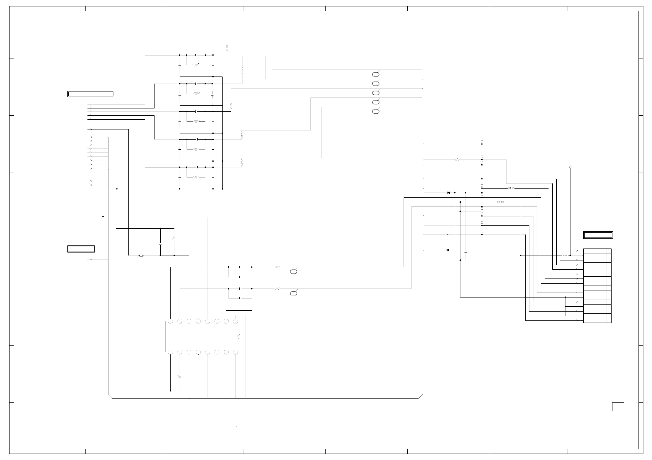
ABC D E F GH
ABC D E F GH
2
1
3
4
5
6
7
8
2
1
3
4
5
6
7
8
IC8102 PCM1753DBQR
STEREO DAC IC
1
10 11 12 13 14 15 16
234
5678
9
TP8101
TP8114
TP8113
TP8112
TP8110
TP8109
TP8108
TP8107
TP8105
TP8106
TP8102
TP8115
TP8103
B8103
MMZ1608R102CT
CP8101_1
IMSA-9604S-16F
1
10
11
12
13
14
15
16
2
3
4
5
6
7
8
9
D8112
1SS355
D8111 1SS355
DURING PLAYBACK.
MEASURED WITH THE DIGITAL TESTER
NOTE:THE DC VOLTAGE EACH PART WAS
OF PRINTING AND SUBJECT TO CHANGE WITHOUT NOTICE
NOTE:THIS SCHEMATIC DIAGRAM IS THE LATEST AT THE TIME
C8122
0.001 B
C8114
1B
C8125
1B
C8113
1B
C8126
1B
C8105
12P CH
C8104
150P CH
C8106
150P CH
C8107
150P CH
C8109
150P CH
C8108
12P CH
C8124
150P CH
C8127
150P CH
C8115
12P CH
C8110
150P CH
C8112
150P CH
C8111
12P CH
C8101
100P CH
C8103
33P CH
C8102
12P CH
C8120
0.1 F
R8113
470
R8112
470
R8101
1K
C8119
10010V YK
C8121
10010V YK
W815
W818
W819
W820W831
W833
W826
W824
L8103
1uH 0305
L8102
1uH 0305
L8105
1uH 0305
L8104
1uH 0305
L8101
1uH 0305
DAC_VIDEO_A
DAC_A_VIDEO
DAC_C_VIDEO
DAC_VIDEO_C
DAC_B_VIDEO
DAC_D_DVD_VIDEO
DAC_VIDEO_A DAC_E_VIDEO
DAC_VIDEO_C
DAC_VIDEO_B DAC_VIDEO_B
DAC_VIDEO_D
DAC_VIDEO_E
P.CON+5V
RESET DAC_VIDEO_D
MC DAC_E_VIDEO
MD
ML
AMCLK
ABCLK DVD-H
ALRCLK
ASDATA0 P-H/I-L
DAC_VIDEO_E
P-H/I-L
DAC_A_VIDEO
DVD-H
SYS_MUTE RESET
ZERO
R_AUDIO
L_AUDIO
DAC_B_VIDEO
GND
DAC_C_VIDEO
DAC_D_DVD_VIDEO
SYS_MUTE
RESET
ASDATA0
AMCLK
ABCLK
ALRCLK
ZERO
MD
MC
ML
FROM/TOTUNER/JACK
5
4
10
9
8
7
6
H-8H-7
TO MEMORY
FROM/TO MPEG/MICON/DSP/RF_AMP
PCB130
DMF071
NC
0NC
0
SCK
ML
MC
MD
ZEROL/NA
ZEROR/ZEROA
VCOM
AGND VOUTR
VOUTL
VCC
VDD
DGND
LRCK
DATA
BCK
1.61.11.63.34.92.5
2.4
2.4
3.3 0 0 0 3.3 1.7
CVBS/G/Y
CVBS/C
C/B/U
Y/R/V
CVBS
Y(G)
U(B)
GND
V(R)
GND
AUDIO-L
GND
AUDIO-R
ZERO
GND
DVD-H
DVD CVBS
DVD RESET
GND
AUDIO/VIDEO SCHEMATIC DIAGRAM
(DVD MT PCB)
P-H/I-L
(CP8001_1)
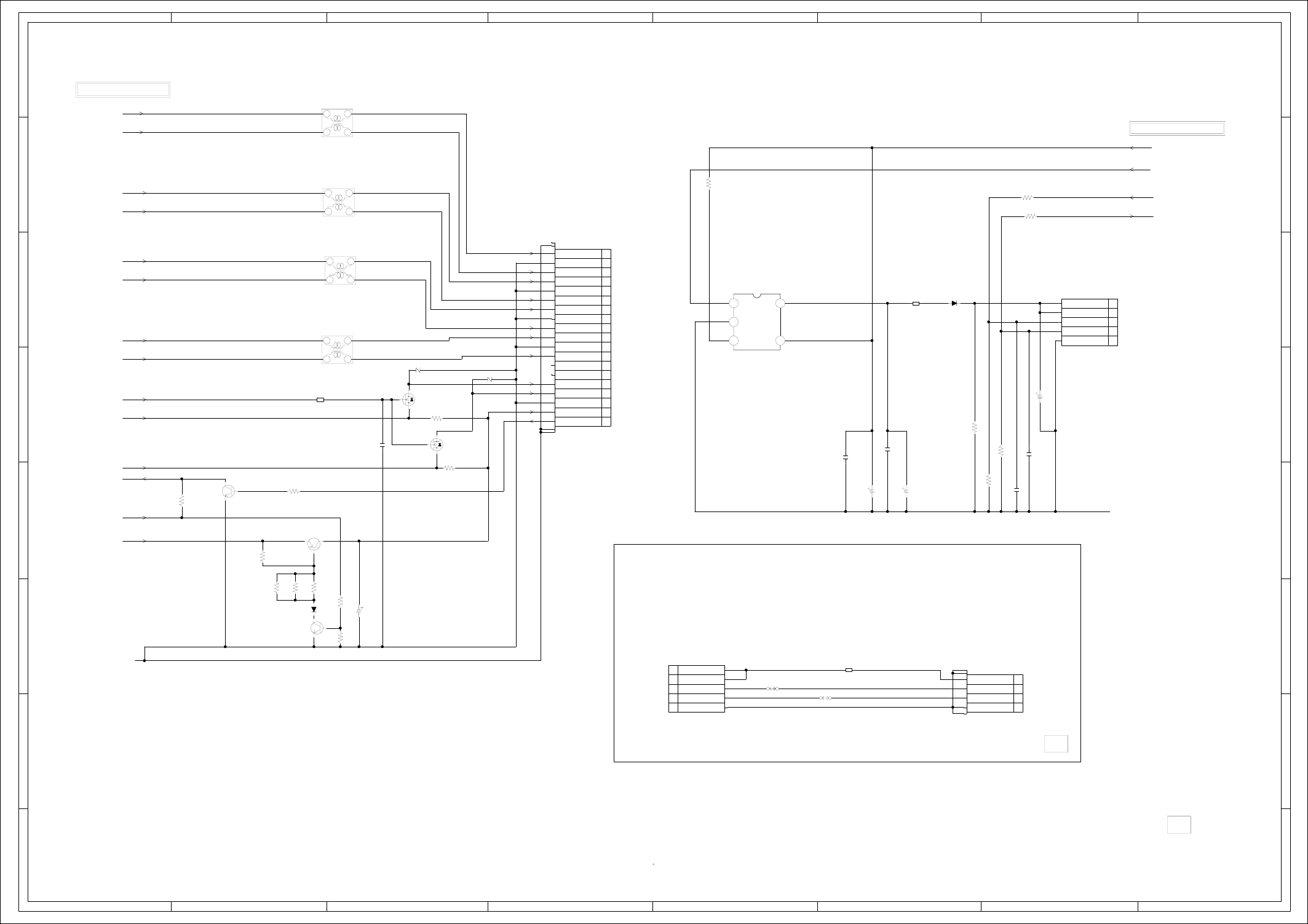
ABC D E F GH
ABC D E F GH
2
1
3
4
5
6
7
8
2
1
3
4
5
6
7
8
CP5901
1903015-3
HDMI CONNECTOR
1
10
11
12
13
14
15
16
17
18
19
2
3
4
5
6
7
8
9
L5904
ACM2012H-900-2P
1
23
4
L5901
ACM2012H-900-2P
1
23
4
L5902
ACM2012H-900-2P
1
23
4
L5903
ACM2012H-900-2P
1
23
4
D5903
AVRL161A1R1NT
D5902
AVRL161A1R1NT
CP6603
C33F-004-5079A
1
2
3
4
CP6601
A2001WR2-5P
1
2
3
4
5
CP6602
A2001WR2-5P
1
2
3
4
5
S
D
GQ5904
2SK3018T106
LEVEL_CONV
S
D
G
Q5905
2SK3018T106
LEVEL_CONV
B6602
HCB2012K-600T25
B6601
HCB2012K-600T25
B5901
MMZ1608R102CT
IC6601 RT9702-PB
USB CUTIENT LIMITATION
123
45
D6601
RB051L-40
D5901
1SS355
DURING PLAYBACK.
MEASURED WITH THE DIGITAL TESTER
NOTE:THE DC VOLTAGE EACH PART WAS
OF PRINTING AND SUBJECT TO CHANGE WITHOUT NOTICE
NOTE:THIS SCHEMATIC DIAGRAM IS THE LATEST AT THE TIME
C5901
1025V KA
C6602
0.1 F
C6610
68P CH
C6609
68P CH
C5902 0.1 F
C6604
0.1 F
R6613
10K
R6606
15K
R6605
15K
R6603
100K
R5909
1.8K
R6615
27
R6614
27
R5910
1.8K
R5907
4.7K
R5908
4.7K
R5906
1K
R5905
1K
R5903
1K
R5904
10K
R5902
1K
R5901
10K
C6605
1025V KA
C6606
476.3V KA
C6603
1025V KA
Q5903
KTC3875S_Y_RTK
HDMI 5V REG
Q5901
KTC3875S_Y_RTK
HDMI DET
W809
W810
Q5902
KTA1281_Y
HDMI 5V REG
I/TMDS_D2+
I/TMDS_D2-
AT+5.2V
DVD-H
I/TMDS_D1+ USB_DN
I/TMDS_D1- USB_DP
I/TMDS_D0+
I/TMDS_D0-
I/TMDS_CLK+
I/TMDS_CLK-
VCC+6V VCC+6V
I2CCLK
I2CDAT
HDMI_DET
GND
P.CON+3.3V
P.CON+5V
GND
NC
NC
D2+
D0-
CLK+
SDA
GND
POWER
D2-S
D2-
D1+
D1-S
D1-
D0+
D0-S
CLK-S
CLK-
CEC
SCL
NC
HOTPLUG
NC
+5V
GND
USB_DN
USB_DP
(CP6602)
GND
USB_DN
USB_DP
+5V
+5V
H-10H-9
FROM/TO MPEG/MICON/DSP/RF_AMP
(HDVCC+3.3V)
FROM/TO MPEG/MICON/DSP/RF_AMP
0
(USB PCB)
PCB130
DMF071
5.0
9.0 5.0
5.09.0
5.0
5.0 5.0
4.2
0
0.7
GND
USB_DN
USB_DP
+5V
+5V
DEF091
PCBDD0
EN
GND
/FLG VIN
VOUT
HDMI/USB SCHEMATIC DIAGRAM
(DVD MT PCB)
(HDMI_GND)
(CP6001)
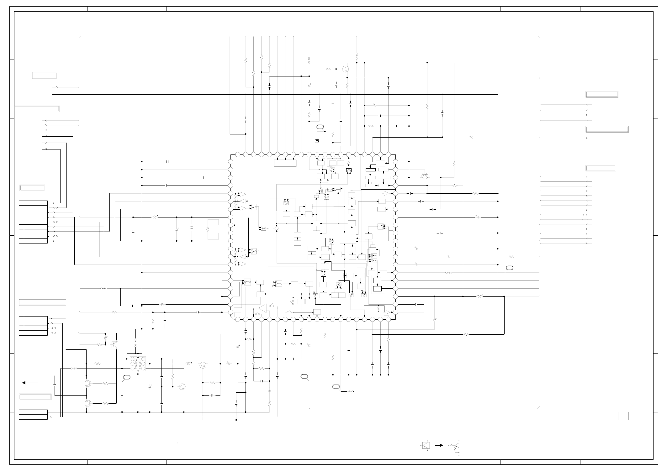
ABC D E F GH
ABC D E F GH
2
1
3
4
5
6
7
8
2
1
3
4
5
6
7
8
CP102_1
IMSA-9604S-04C
1
2
3
4
CP103
B2013H02-2P
1
2
CD102
2F041508
FFC
CAUTION: DIGITAL TRANSISTOR
Q103
KRA103SRTK
SW
CP101
TOC-C09X-A1
1
2
3
4
5
6
7
8
9
DURING PLAYBACK.
MEASURED WITH THE DIGITAL TESTER
NOTE:THE DC VOLTAGE EACH PART WAS
OF PRINTING AND SUBJECT TO CHANGE WITHOUT NOTICE
NOTE:THIS SCHEMATIC DIAGRAM IS THE LATEST AT THE TIME
C131
1006.3V KA
C163
47
6.3V KA
C105
2216V KA
C112
2206.3V KA
C115
3310V KA
C123
4.7
50V KA
C104
2206.3V KA
L101
1626010
COIL,BIAS OSC
1
2
34
5
6
C125
390P CH C126
0.1 F
C122
0.0012 B
C120
1B
C107
0.015 B
C132
1B
C162
0.1 F
C140
15P CH
C169
0.047 F
C160
22P CH
C114
0.1 F
C118
0.01 B
C127
180P CH
C148
1B
C146
1B
C151
1B
C137
1B
C124
1B
C133
1B
C117
0.01 B
C116
0.1 F
C139
0.1 F
C165
0.047 F
C166
0.068 B
C154
0.1 B
C108
0.01 B
C143
1F
C141
0.01 B
C156
0.1 F
C144
0.01 B
C121
0.0027 B
C147
0.022 B
C145
0.022 B
C101
0.033100V MMTS
C158
1F
C106
0.01 B
C161
22P CH
C134
1B
C129
1F C109
0.1 B
R119
1.8K
R122
100K
R144
220K 1/4W
R136
22K
R137
12K 1/4W
R142
820
R133
8.2K
R138
22K
R126
1.8K
R113
220
R102
10K
R103
10K
R140
2.2K 1/4W
R101
560
R110
8.2K
R111
8.2K
R112
330K
R109
1K
1/4W
R114
20K
R116
15K
R127
680K
R106
680
R108
22K
R124
82K
R117
6.8K
R131
1.5K
R105
1K 1/4W
R129
1.8K
R115
820
R141
100
R107
3.9K
R132
3.3K
R123
2.2K 1/4W
R139
12K
C138
150V YK
C110
4716V YK
C119_1
1025V KA
C174
47
6.3V KA
C136
2250V YK
C135
0.22
50V YK
C152
476.3V KA
C142
476.3V KA
C102
1025V KA
Q101
KTC3875S_Y_RTK
AUDIO PB SW
Q102
KTC3875S_Y_RTK
AUDIO PB SW
Q104
KTC3203_Y
BIAS OSC
Q109
KTC3875S_Y_RTK
BUFFER
W819
W817
W852
W815
TP101
V.ENV
W801
Q105
KTA1266
BIAS CTL
Q107
KTA1504S_Y_RTK
BUFFER
X101
100DT3R528
3.579545MHZ
L107
22uH 0305
L104_1
22uH 0305
L102
100uH 0305
IC101
LA71206M-MPB-E
Y/C/AUDIO/CCD/HEAD AMP IC 1 1011121314151617 18 192 20
21 22 23 24 25 26 27 28 29
3
30 31 32 33 34 35 36 37 38 39
4
40
414243444546474849
5
50515253545556575859
6
60
616263646566676869
7
70717273747576777879
8
80
9
L103
5.6uH
S802X S802Y
COMP
H.SW
Y/C_CS
ENV.DET
P.CON+5V
P.CON+5V
H.AMP_SW
C.ROTARY
Y/C_DATA
Y/C_CLK
AUDIO_MUTE-H
FSC
P.CON+5V
GND
DVD_V_OUT
TU/REAR_V_IN
Y/C_VIDEO_OUT
FSC FSC
TO_NORMAL_A
FROM_NORMAL_A
HF2 4FSC FRONT_V_IN
HF_COM
HF1
4FSC
Y/C_CLK
Y/C_DATA
Y/C_CS
DUMMY_V.SYNC
V.REC_ST-H
C.ROTARY
AUDIO_MUTE-H
CTL-
P.CON+5V
CTL+
H.AMP_SW
TU/REAR_V_IN
COMP
ENV.DET
H.SW
FRONT_V_IN
C.SYNC
DVD_V_OUT
Y/C_VIDEO_OUT
C.SYNC
P.CON+5V DUMMY_V.SYNC
P.CON+5V
TO_NORMAL_A
CTL+
CTL- P.CON+5V
V.REC_ST-H
FROM_NORMAL_A
GND
HOT
19
H-12H-11
FROM POWER
FROM/TO CYL
PCB010
DME063
(VCR MT PCB)
Y/C/AUDIO/CCD/HEAD AMP SCHEMATIC DIAGRAM
CTL-
CTL+
AUDIO PB
AUDIO REC
2.3 2.3 2.3 2.32.3 2.3 0 2.3 2.3 4.80.8 1.1 1.1 1.4 02.0 0.22.62.6
5.3
0
5.2
5.2
5.2
0
FE HEAD(HOT)
18
16
17
4.8
FE HEAD(GND)
0
0
0.7
0.7
0
0
EP/LP-CH2 (L)
EP/LP-CH1 (R)
SP-CH2 (L)
SP-CH1 (R)
EP/LP COM
HF1 (R)
HF2 (L)
NC
+
Vref
2.3V
SP,LP
EQ
AMP
ALC
ALC
A-VCC
1
2
3
A-GND
HA
PRE GND
R
P
P
R
P
P
H
L
H
L
REC:LP<EP
PB:EP
DET
PB,EE
PB,EE
VREF
REC
AMP MUTE
AUTO
BIAS
LINE
AMP REC
FM-EQ
FM
AGC
VHS SOPB
PR
PB
FM EQ PR
S-EQ
MAIN
DE-EM
LIM
DOUBBLE FM
DEM SUB
LPF
B
S
DET
EMPHA
FIL
MAIN
4.7K
Y-VCC
V.SYNC
SEP
SEP
6DB
QV/QH
AGC
TC2
BAL
TC1
REG
4V
1
2
3
VDD 4Fsc CLOCK
PLL
TIMMING OUT
DRIVER AUTO-BIAS
CLAMP
CCD
VSS
OUT
IN
VCA VCA
CLAMP
VCP
ALWAYS
5V
B
VX01 320FH
VCO SLD
PHASE
EQ
fo-ADJ
PHASE
EQ
Q-ADJ
FM
AGC
FIL Y-GND
R
P
FBC
1/2
VIDEO
AGC
Y/C
MIX
NC1
N.L.
DEEM
Y-LPF
CLAMP
DETAIL
ENH
NL
EMPHA
NL
EMPHA
FM
MOD
NORMAL
R-EQ
TEST
YNR/COMB
3.58M
BPF1
B.D
P
PB
AMP
CNC
BGA
BGA
BGA
R
P
AFTER
BEFORE
3.58M
BPF2
B-UP
AMP
Main
CONV
ACC
AMP
DET
ACC
C-LPF
4.21M
BPF
Sub
CONV R
R
P
PP
LPF
RP
REC
AFC
PB
APC
REC
APC
PR
R
P
RP
C-VCC
SERAIL
DECODER
C-GND
C-ROT
RF-SW
IN
AUDIO
MUTE
HA SW
ENV
DET
ACC
DET
HA VCC
COMP
OUT
KILL
DET
DET
CHROMA
GND
HA
R
R
P
P
R
PB-C
PB-C
R
R
P
P
VSS
SYNC
0
2.1
2.9
1.6
1.8
1.9
1.8
5.0
1.8
1.6
0
1.8
1.8
1.8
0
2.3
4.9
2.3
0
2.3 2.1
3.2
4.4
5.0
4.1
3.6
1.6
2.1
2.3
2.3
4.1
2.6
3.3
2.6
3.2
3.2
2.5
0
1.6
0
0.82.21.24.94.93.24.95.25.25.205.204.84.8 2.1 4.1 3.3 3.2
2.8
SP_COM
HF_COM
NC
NC
TO FULL ERASE HEAD
0
0
0
4.9
3.3
3.9
FROM/TO SYSCON
FROM/TO TUNER/JACK
FROM OPERATION/DISPLAY
20
2.2
0
1.6
FROM/TO Hi-Fi/DEMODULATOR
FROM/TO HEAD AUDIO CONTROL
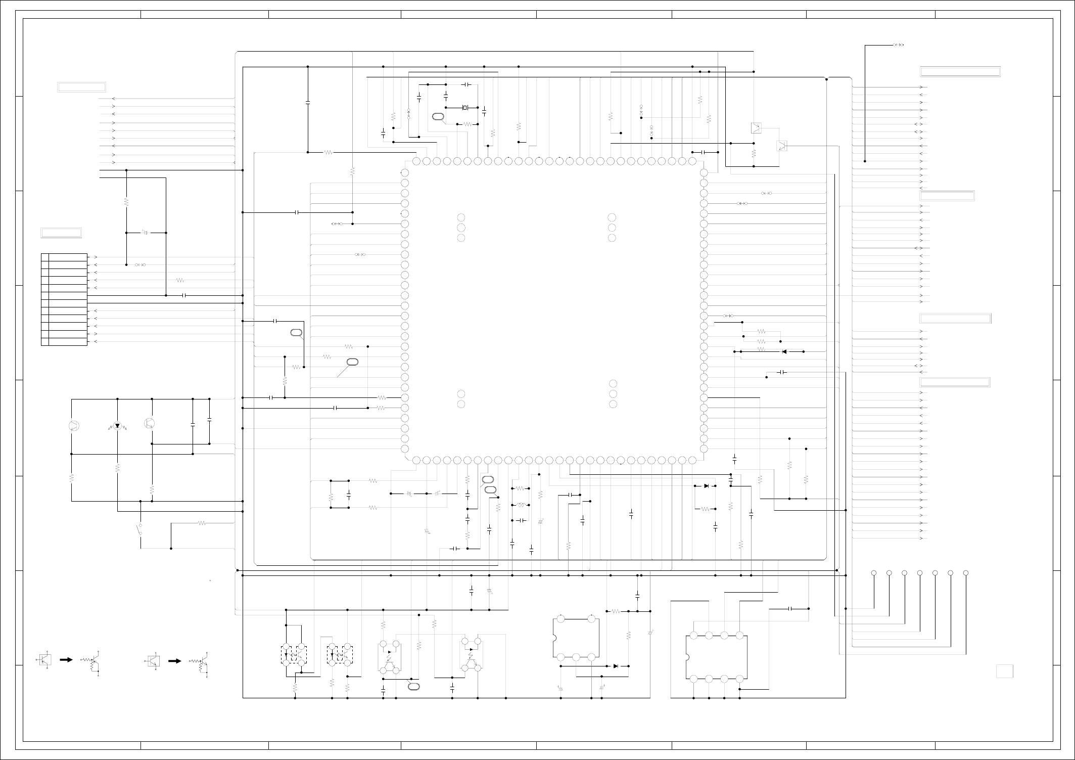
ABC D E F GH
ABC D E F GH
2
1
3
4
5
6
7
8
2
1
3
4
5
6
7
8
JG3002 JG3003 JG3004 JG3005 JG3007 JG3008JG3006
IC3003 PST3231NR
SYSTEM RESET IC
123
45
SW3001
LSA-1144EAU
TAB SW
CP3001
TMC-J12P-B2
1
10
11
12
2
3
4
5
6
7
8
9
Q3007
KRC103SRTK
RX DRIVE
D3002
1SS133
D3007
1SS133
D3009
1SS133
Q3006
ST-304L
EOT SENSOR
Q3008
ST-304L
BOT SENSOR
IC3001
OEC0157B
SYSCON/TIMER/SERVO IC
110 101102103104105106107108109112 111
110
100
11 12 13 14 15 16 17 18 192 20 21 22 23 24 25 26 27 28
29
3
30 31 32 33 34 35 36 37 38 39
4
40 41 42 43 44 45 46 47 48 49
5
50 51 52 53 54 55 56
575859
6
60616263646566676869
7
70717273747576777879
8
8081828384
8586878889
9
90919293949596979899
IC3099_1 BR24L02F-WE2
EEP ROM IC
1234
5678
Q3005
RPI-352C40N
MS_SEN A
1
23
4
Q3004
RPI-352C40N
MS_SEN B
1
23
4
D3001
LTE-3271T-012A-O
Q3002 RPI-303
REEL SENS
1
2
34
Q3001
RPI-303
REEL SENS
1
2
34
CAUTION: DIGITAL TRANSISTOR
CAUTION: DIGITAL TRANSISTOR
Q3003
KRA103SRTK
RX DRIVE
DURING PLAYBACK.
MEASURED WITH THE DIGITAL TESTER
NOTE:THE DC VOLTAGE EACH PART WAS
OF PRINTING AND SUBJECT TO CHANGE WITHOUT NOTICE
NOTE:THIS SCHEMATIC DIAGRAM IS THE LATEST AT THE TIME
C3013
2216V KA
C3023
2206.3V YK
C3032
2.2
50V KA
C3052
2216V KA
C3029
476.3V KA
C3038
1F
C3010
0.001 B
C3030
0.1 F
C3024
12P CH
C3066
0.01 B
C3002
1F
C3020
0.022 B
C3014
180P CH
C3036 0.1 F
C3049
100P CH
C3004 0.022 B
C3001
1B
C3022
470P B
C3053
0.1 F
C3061
0.1 F
C3040
1F
C3034
1F
C3017
0.001 B
C3008
0.0047 B
C3007
0.1 B
C3065
0.1 F
C3006
0.001 B
C3005
0.001 B
C3050 0.01 B
C3025
15P CH
C3009
0.1 F
C3027
0.1 F
C3031
0.0015 B
C3044
12P CH
C3018
150P CH
C3019
0.1 B
C3041
0.0015 B
C3035
0.001
B
C3000
0.001 B
C3015
820P B
R3046
10K
R3043
470K
R3030
5.6K
R3033
10K
R3037 47K
R3055 22K
R3063
1K
R3010
10K
R3051
18K
R3017
560
R3002
120 1/4W
R3036
10K
R3057
22K
R3015
47K 1/4W
R3021 1K
R3009
2.2K
R3019
47K 1/4W
R3006
47K
R3083
33K
R3050
100 1/4W
R3087
33K
R3038 4.7K
R3026
270K
R3028
47K 1/4W
R3003
3.3K
R3035
10K
R3049
47K
R3053
470K
R3016
270 1/4W
R3004
330K
R3001
5.6K
R3011
47K 1/4W
R3045
3.3K
R3044 3.3K
R3047
10K
R3062 1K
R3034
1M
R3032
10K
R3031
1M
R3008
1K
R3012
56K 1/4W
R3014 56K
R3007
6.8K
R3020
560
R3022
150K
R3027
15K
R3056
1K
R3025
470
C3016
476.3V
KA
C3033
22016V YK
C3045
0.4750V KA
C3021_1
1025V KA
W867
W906
TP3001
SERVICE
W835
W838
W839
W840
W837
W836
TP3002 H.SW
X3001
100GT01006
10MHz
L3003
12uH
AT+5.2V
H.SW
MD0
RESET
SEG_8
SEG_7
SEG_6
TX
SEG_5
SCL
AT+5.2V
FWE
SEG_10
SEG_9
SDA
SEG_2
DUMMY_V.SYNC
SEG_3
REC_MUTE_H
SEG_4
AT+5V[M-CON]
AT+5V[M-CON]
C.SYNC
TX V.REC_ST-H
RX C.ROTARY
DVD_POWER_CTL AUDIO_MUTE-H
AT+12.6_V CTL-
P.CON+5V CTL+
AT+5V[M-CON] H.AMP_SW
VCR_POWER_ON-L RX COMP
CAP_LIMIT ENV.DET
POWER_FAIL
H.SW
AT+5.2V
Y/C_CS
GND
Y/C_DATA
MOTOR_GND Y/C_CLK
TV/VCR SEG_1
4FSC
POWER_MUTE-L Y/C_DATA
SYS_MUTE Y/C_CLK
DVD_POWER_CTL
RF_CH_SW
5G/CS/BS_LED
SW_V_OUT
4G/VSC_LED
AV_SW1
AV_SW2 3G/TV/VCR_LED AV_SW2
SCL
AV_SW1 2G/DUB/REC_LED
SDA
Y/C_CS 1G/VCR/T-REC_LED AFT-S.CURVE
CAP_FG
TV/VCR
AT+12.6_V RF_CH_SW VCR_LED
VIDEO_OUT
P.CON+5V AUDIO_MUTE-H DVD_LED
POWER_MUTE-L
CAP_F/R
V.REC_ST-H DVD_POWER_CTL VIDEO_MUTE-H
CAP_LIMIT
LDM_CTL DVD_RESET
SYS_MUTE
CAP_F/R REM_IN
AT+12.6_V
C.ROTARY REC_L/REEL-T
CONTROL_IN VCR_POWER_ON-L
LDM_CTL H.AMP_SW
REC_MUTE_H
CYL_FG/PG COMP VIDEO_MUTE-H
HIFI_ENV.DET
CYL_DRIVE AT+5.2V
CONTROL_IN HIFI_H.SW
C.SYNC AUDIO_MUTE-H
CYL_DRIVE VSC_L/REEL-S SCL
SDA
CYL_FG/PG POWER_FAIL
ST_SELECT
H.SW AT+5V[M-CON]
HIFI_H.SW TAB_SW
DVD_LED
AT+5.2V VCR_LED
AFT-S.CURVE KEY-A
KEY-B
DUMMY_V.SYNC HIFI_ENV.DET
REM_IN
ST_SELECT
1G/VCR/T-REC_LED
C.SYNC KEY-A 2G/DUB/REC_LED
EOT
3G/TV/VCR_LED
AT+5V[M-CON] KEY-B
BOT 4G/VSC_LED
5G/CS/BS_LED
SEG_1
SEG_2
CTL+
SEG_3
SEG_4
AT+5.2V SEG_5
CTL- SEG_6
SEG_7
AT+5.2V SEG_8
SEG_9
SEG_10
AT+5V[M-CON]
VIDEO_OUT
MS_SEN-B
MS_SEN-A
SW_V_OUT
TAB_SW
SW_V_OUT
CAP_FG
ENV.DET
4FSC
BOT
EOT
SDA
SCL
AT+5.2V
MS_SEN-B
MS_SEN-A
RESET
REC_L/REEL-T
VSC_L/REEL-S
AT+5V[M-CON]
P.CON+5V
AT+5.2V
TX
MD0
RESET
FWE
AT+5V[M-CON]
2.4 1.2
H-14
H-13
FROM/TO Y/C/AUDIO/CCD/HEAD.AMP
23
PCB010
DME063
CV IN2
CV IN1
REC_L/
REC_L/
REEL T
REEL T
JUST_CLK
ST SELECT
REC MUTE-H
NCNC
000
NC
NC
PG
NC SERVICE
0
3.4
0
0
5.3
5.2
SYNC DET/
VSC_L/ REEL S
(VCR MT PCB)
1.2
5.10.9
1.3
1.3
5.1
0.4
0.9
5.1
00
5.0
5.0
0
4.8
5.2 0 5.0 4.9
0
(LED_GND)
FROM/TO DECK
MOTOR GND
CYL CTL
CYL FG/PG
LDM CTL
CAP CTL
LD/CY VCO
I LIMIT
CAP.M/F/R
CAP VCO
CAP FG
GND
VCC
3.3
SYSCON SCHEMATIC DIAGRAM
POWER ON-L
VIDEO_MUTE-H
5.0
0.1
RF CH SW
SYS MUTE
/RESET
24
DVD_POWER_CTL
DVD RESET
DVD LED
22
25
21
5.0
5.0
5.0
4.8
0
0
4.7
3.3
5.1
0.3
5.0
5.0
5.0
4.84.804.800
5.0
5.0
00
4.84.82.53.45.1
0.1
5.1
0
0
2.4
0
2.5
1G/VCR/T-REC_LED
NC
NCNC
OUT IN GND
NC
VCR LED
2G/DUB/REC LED
4G/TIME SHIFT LED
5G/CS/BS LED
3G/TV/VCR LED
SEG1
SEG2
SEG3
SEG4
VSS
00
A2
A1
A0
SDA
SCL
TEST
VCC
00
IIC CLK
IIC SDA
SEG9
SEG10
LDM_CTL
V.REC ST-H
AUDIO MUTE-H
Y/C CS
AV SW1
AV SW2
TAB SW
Y/C DATA
Y/C CLK
CAP FWD-L
SEG6
SEG7
SEG8
SEG5
POWER MUTE-L
VCR_H
CYL SPEED UP
CAP LIMIT
VCC (BACK UP)
D FG/PG
SI1/RX
SO1/TX
REM IN
C SYNC/H SYNC
87
POWER FAIL
VSS (GND)
KEY-A
31
4FSCOUT/2FSCOUT
4FSCIN/2FSCIN
KEY-B
BOT-H
V ENV
AVCC (BACK UP)
VSS (GND)
FWE
X2
X1
OSC1
OSC2
VCL
MD0
VSS (GND)
H.AMP SW
COMP
VIDEO H.SW
HIFI H.SW
DRUM PWM
CAP PWM
DUMMY_V.SYNC
C SYNC
VCC (BACK UP)
V CYNC
AFC LPF
AFC OSC
AFC PC
CTL REF
CTL(+)
CTL(-)
CTL BIAS
CTL FB
CTL AMP(O)
CTL SMT(I)
CAP FG
SVCC (P.CON5V)
SVSS (GND)
29
56
30
112
111
86
85
AVSS (GND)
MS SEN-A
MS SEN-B
EOT-H
ST SELECT
HiFi ENV
AFT S.CURVE
C.ROTARY
CAP FULL
55
54
OVCC
CV OUT
OVSS(GND)
NC
0 0 2.5 0 2.5 0.1 2.6 2.5 2.3 5.1 2.0 2.0 1.5 0.4 0 3.1 2.6 5.1 2.6 0 0 2.5 0 2.6 0 0 1.3 1.3
5.2
5.2
0
3.7
2.5
0
0
5.1
5.0
5.1
05.04.901.51.45.100
0
0
2.7
0
3.0
2.5
2.5
2.7
2.7
0
0
0.4
5.1
5.0
5.0
5.1
2.4
NC
FROM/TO TUNER/JACK
FROM/TO POWER
FROM/TO Hi-Fi/DEMODULATOR
FROM/TO OPERATION1/DISPLAY
00
0
0
0
0
0
27
5.2 0 5.2 0
0
5.05.0
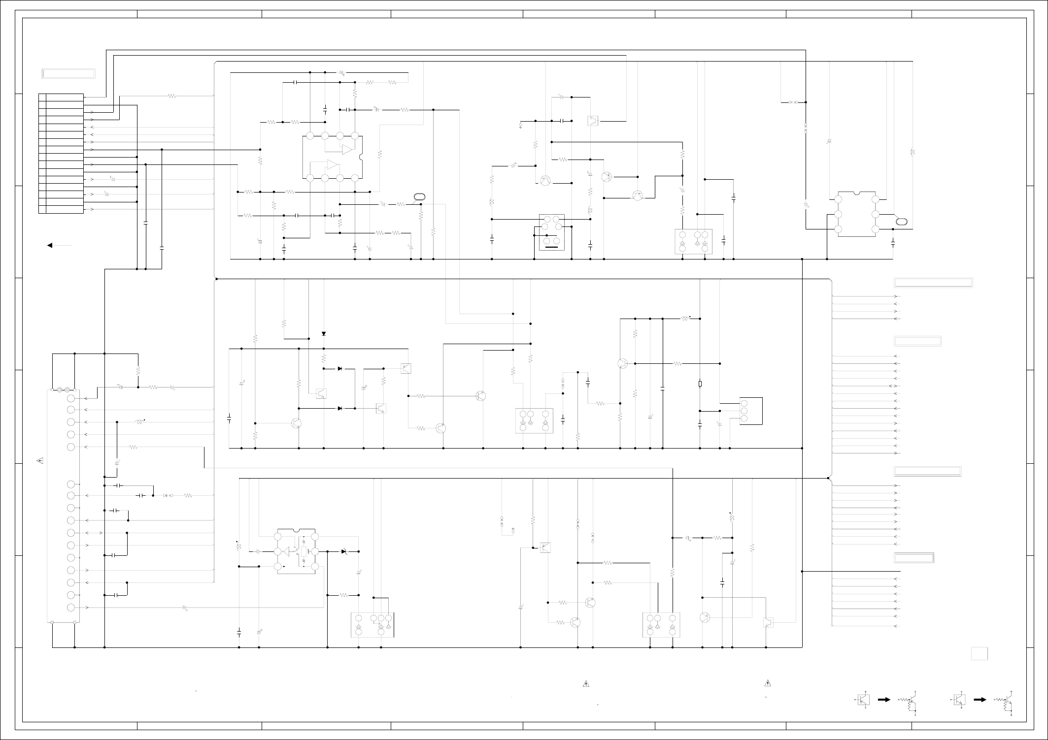
ABC D E F GH
ABC D E F GH
2
1
3
4
5
6
7
8
2
1
3
4
5
6
7
8
WAS RECEIVED IN GOOD CONDITION AND PICTURE IS NORMAL.
WITH THE DIGITAL TESTER WHEN THE COLOR BROADCAST
NOTE:THE DC VOLTAGE AT EACH PART WAS MEASURED
OS8001
RFT5CB1
OPTICAL
1
2
3
J8008
DIN-409A
Y/C SEPA
12
34
56
H1 H1H2
EE
J8007
MSP-213V1-652_NI_LF
YUV OUT
1
23
4
5
H1H1 H2
EE
J8001
MSP-213V1-432_NI_LF
REAR OUT JACK 1
23
4
5
H1H1 H2
EE
J8006
MSP-213V1-732_NI_LF
DVD AUDIO OUT
COAXIAL
1
23
4
5
TU301 115-V-HA35ARE_G
1
10
11
12
13
14
15
16
17
18
19
2
20
21
3
4
5
7
8
9
IC8005 MM1501XNRE
AV SW IC
123
456
IC8002 MM1501XNRE
AV SW IC
123
456
EE
H1 NC H1 H2
J8002
MSP-213V2-432_NI_LF
REAR IN JACK
1
234
5
6
B8001
BLM18BD102SN1
DANS LA NOMENCLATURE DES PIECES
N’UTILISER QUE CELLS DECRITES
DANGEREUSES AN POINT DE VUE SECURITE
:LES PIECES REPAREES PAR UN ETANT
ATTENTION :SINCE THESE PARTS MARKED BY
CAUTION
DESCRIBED IN PARTS LIST ONLY
CRITICAL FOR SAFETY,USE ONES
ARE
D8001
MTZJ10B-EIC
C8040_1
4.716V KANP
CP8001_1
IMSA-9604S-16C
1
10
11
12
13
14
15
16
2
3
4
5
6
7
8
9
Q8022
KRC103SRTK
SW
Q8011
KRC103SRTK
MUTE SW
Q8002
KRC104SRTK
MUTE SW
Q8003
KRC103SRTK
VIDEO MUTE SW
D8005
1SS133
D8004
1SS133
D8006
1SS133
IC8001 RC4580IDR
AUDIO_AMP IC
1234
5678
CAUTION: DIGITAL TRANSISTOR
CD8001
2F0G1002
FFC
CAUTION: DIGITAL TRANSISTOR
Q8010
KRA101SRTK
MUTE SW
Q8007
KRA103SRTK
MUTE SW
OF PRINTING AND SUBJECT TO CHANGE WITHOUT NOTICE
NOTE:THIS SCHEMATIC DIAGRAM IS THE LATEST AT THE TIME
C8034
2206.3V YK
C309
2206.3V YK
C8003_1
1025V KA
C8005
4706.3V YK
C8013
1050V KA
C307
33P CH C308
0.01 B
C8054
33P CH
C8060
10P CH
C8046
0.1 F
C8025
0.1 B
C8023
0.022 B
C8033
220P CH
C8065
330P CH
C8050
150P CH
C8009
0.0015 B
C8008
0.0015 B
C303
0.1 F
C317
100P CH
C302
100P CH
C8055
33P CH
C8028
100P CH
C8059
0.1 F
C8014
0.1 F
C8021
0.1 F
C8057
0.1 F
C8058
10P CH
C8044
330P
CH
C8049
330P CH
C8056
0.1 F
C8064
330P
CH
C8045
150P CH
R8047
33 1/4W
R8033
560 1/4W
R8040
75
R8012
470
R8008
470
R306
22
R8037
75
R8029
560 1/4W
R8036
75 1/4W
R8028
560 1/4W
R8054
2.2K
R8021
1K
R8004
22K 1/4W
R8026
470K
R8025
1K
R8053
56 1/4W
R8049
10K
R8046
100K
R8045
100K
R8051
47K
R8050
10K
R8042
10K
R302
1K
R304
1K
R301
33K
R8010
68
R8059
4.7K 1/4W
R8035
15K
R8034
1.5K
R8039
12K
R8023
3.3K
R8027
4.7K
R8024
4.7K
R8022
1K
R8015
270
R8014
270
R8017
2.2K
R8016
2.2K
R8011
100 1/4W
R8009
330 1/2W
R8003
1.5K
R8002
3.3K
R8005
220
R8006
68
R8007
100K
R8013
10K
R8048
10K
R8031
470
R8057
47K
R8041
10K
R8038
12K
R8055
1.5K
R8052
15K
R8001
75
R8030
470
C8047_1
470
6.3V YK
C8015_1
470
6.3V YK
C8031
4.750V KA
C8048
1000
6.3V
YK
C8043
4716V
YK
C8024
476.3V KA
C8051
3350V YK
C8062_1
470
16V YK
C318_1
10
25V KA
C315_1
1025V KA
C8010_1
10
25V KA
C8075_1
4716V YK
C8004_1
10016V
YK
C313_1
10
25V KA
C8063_1
470
16V YK
C8032
4.750V KA
C8022
476.3V KA
C8036
2.250V KA
C8035
2.250V KA
C8038
2216V KA
C8042
2216V KA
C8037
2216V KA
Q8008
KTC3875S_Y_RTK
AUDIO MUTE
Q8012
KTC3875S_Y_RTK
MUTE DET Q8009
KTC3875S_Y_RTK
AUDIO MUTE
Q8005
KTC3875S_Y_RTK
MUTE SW
Q8001
KTC3875S_Y_RTK
D AUDIO DRIVER
Q8006
KTC3875S_Y_RTK
MUTE SW
W879
W880
W881
W820
W808
W800
W847
Q8021
KTA1504S_Y_RTK
BUFFER
Q8004
KTA1266
BUFFER
Q8019
KTA1504S_Y_RTK
BUFFER
Q8020
KTA1504S_Y_RTK
BUFFER
L8007
100uH 0305
L301
22uH 0305
L8009
100uH 0305
L8008
100uH 0305
L8002
0.33uH
L8004
47uH
L8001
0.33uH
S801Y
S801X
DVD_C
AV_SW1
P.CON+9V
DVD_U
DVD_V
SW_V_OUT
DVD_V_OUT
P.CON+10V
DVD_Y
Y/C_VIDEO_OUT
DVD_Y
DVD_POWER_CTL
DVD_RESET
ZERO
DVD_V
DVD_U
DVD_C
SPDIF
SYS_MUTE
ZERO
AT+5.2V
P.CON+5V
P.CON+5V
DVD_V_OUT
DVD_A_OUT_R
DVD_A_OUT_L
FSC
TU/REAR_V_IN
Y/C_VIDEO_OUT
DVD_POWER_CTL
DVD_RESET
SYS_MUTE
SCL
SDA
RF_CONV_A_OUT
AV_SW1
AV_SW2
TV/VCR
RF_CH_SW
RF_CH_SW
P.CON+5V AFT-S.CURVE
POWER_MUTE-L
TV/VCR
VIDEO_MUTE-H
VIDEO_OUT
SW_V_OUT
P.CON+9V
DVD_A_OUT_R
AV_SW2
AT+5.2V
P.CON+10V
VIDEO_OUT
DVD_A_OUT_L
P.CON+10V
FSC
AUDIO_OUT_L
REAR_A_IN_L
REAR_A_IN_R
POWER_MUTE-L
AUDIO_OUT_R
VIDEO_MUTE-H
TU/REAR_V_IN
SIF_OUT
P.CON+9V
REAR_A_IN_L
SCL REAR_A_IN_R
AUDIO_OUT_L
SDA
AUDIO_OUT_R
RF_CONV_A_OUT
AFT-S.CURVE
SIF_OUT GND
+32V
+32V
AT+5.2V
P.CON+5V
P.CON+10V
SPDIF
P.CON+6V
P.CON+9V
FROM/TO AUDIO/VIDEO
0
0
0
5.1
0
0
0
H-16H-15
FROM POWER
CVBS
GND
U(B)
GND
V(R)
GND
AUDIO-L
GND
AUDIO-R
ZERO
DVD RESET
DVD-H
Y(G)
DVD CVBS
GND
(CP8101_1)
P-H/I-L
YUV
PCB010
DME063
0
0
5.1
0
0.3
0
CO
RL
0
0
L
R
VRLV3.3
2.6
0
0
0
5.1
2.3
2.2
INPUT
VCC
GND
NC
NC
TU 32V
SIF OUT
A.OUT
FSC
NCNC
V.IN
CONTROL
+B
CH
A.IN
NC
DATA
CLOCK
AFT
NC
V.OUT
NC
32
7.0
8.4
0
SW1
V OUT
VccVin2
GND
Vin1
11.7
07.8
YC
(VCR MT PCB)
TUNER/JACK SCHEMATIC DIAGRAM
42
A_GND
+
-
5.85.85.80
5.8 5.8 5.8 11.6
VCC
-
+
0
00
0
0
5.2
0
0
00
FROM/TO Y/C/AUDIO/CCD/HEAD AMP
FROM/TO SYSCON
Vcc
BAIAS
BUFFER
H
FROM/TO Hi-Fi/DEMODULATOR
0.2
0
5.0
0
0
3.8
0
0
5.0
5.0
2.0
2.0
0.2
31.0
2.0
0
5.2
4.2
9.0
3.5
0
3.5
0
5.1
6.8
0
0
0
0
3.2
0
0.6
0.3
0.6
0.3
5.3
0
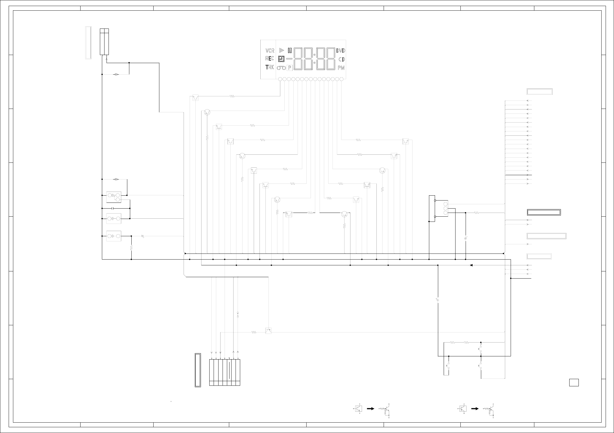
ABC D E F GH
ABC D E F GH
2
1
3
4
5
6
7
8
2
1
3
4
5
6
7
8
CP651_1
IMSA-9604S-07F
1
2
3
4
5
6
7
H
E
J653
RCA-109-01
FRONT AV JACK
VIDEO
1
2H
E
J652
RCA-109-01
FRONT AV JACK
AUDIO L
1
2HNC
E
J651
MSP-281V30-A
FRONT AV JACK
AUDIO R
1
23
Vout
B+
GND
OS651
ROM-V338LO
1
2
3
SW655
EVQ21505R
CH DOWN
SW654
EVQ21505R
CH UP
SW653
EVQ21505R
VCR/DVD(REC)
V651 TOF-440EBHG-B16/B4
1101112131415 23456789
Q652
KRC103SRTK
SEG10 SW
Q653
KRC103SRTK
SEG9 SW
Q655
KRC103SRTK
SEG8 SW
Q656
KRC103SRTK
SEG7 SW
Q664
KRC103SRTK
SEG1 SW
Q663
KRC103SRTK
SEG2 SW
Q662
KRC103SRTK
SEG3 SW
Q660
KRC103SRTK
SEG4 SW
Q658
KRC103SRTK
SEG5 SW
Q657
KRC103SRTK
SEG6 SW
D656
1N4005-EIC
CAUTION: DIGITAL TRANSISTOR
CP653
52147-0210
1
2
CAUTION: DIGITAL TRANSISTOR
Q666
KRA103SRTK
DVD LED SW
DURING PLAYBACK.
MEASURED WITH THE DIGITAL TESTER
NOTE:THE DC VOLTAGE EACH PART WAS
OF PRINTING AND SUBJECT TO CHANGE WITHOUT NOTICE
NOTE:THIS SCHEMATIC DIAGRAM IS THE LATEST AT THE TIME
C652
100
10V YK
C656
1025V KA
C600
0.1 F
C654
470P B
C655
470P B
R662
180
R672
180
R673
180
R663
180
R666
180
R670
180
R667
180
R651
100 1/4W
R661
820
R665
180
R664
820
R674
180
R675
820
R671
820
R668
180
R669
820
R676
75
R683
220
R677
2.7K
R678
3.3K
C653
47010V YK
W807
Q651
KTA1504S_Y_RTK
5G SW
Q654
KTA1504S_Y_RTK
4G SW
Q665
KTA1504S_Y_RTK
1G SW
Q661
KTA1504S_Y_RTK
2G SW
Q659
KTA1504S_Y_RTK
3G SW
DVD_LED
VCR_LED
1G/VCR/T-REC_LED
KEY-B
2G/DUB/REC_LED
3G/TV/VCR_LED
4G/VSC_LED
5G/CS/BS_LED
SEG_1
SEG_2
SEG_3
SEG_4
SEG_5
SEG_6
SEG_7
SEG_8
SEG_9
SEG_10
REM_IN
KEY-B
KEY-A
FRONT_A_IN_R
REM_IN
AT+5.2V
FRONT_A_IN_L
FRONT_A_IN_L
FRONT_A_IN_R
FRONT_V_IN
1G/VCR/T-REC_LED
2G/DUB/REC_LED
3G/TV/VCR_LED
5G/CS/BS_LED
FRONT_V_IN
4G/VSC_LED
SEG_5
SEG_7
SEG_9
SEG_10
SEG_3
SEG_4
SEG_8
SEG_1
SEG_2
SEG_6
LEM_VCC
P.CON+5V
AT+5.2V
GND
KEY-A
KEY-B
AT+5.2V
DVD_LED
VCR_LED
AT+5.2V
KEY-A
KEY-B
H-18H-17
TO Hi-Fi/DEMODULATOR
TO OPERATION/LED
(VCR MT PCB)
OPERATION/DISPLAY SCHEMATIC DIAGRAM
KEY-B
KEY-A
AT+5.2V
VCR LED
DVD LED
GND
NC
(CP682)
FROM/TO OPERATION/LED
PCB010
DME063
0
5.25.2
5.1
0.4 0
4.0
0.9 0
4.0
1.3 5.2
4.9
0
03.5
5.2
3.1 0
0
4.9
1.7
1.1
1.75.2
4.9
0
2.0
1.9
4.0
0.40
0.40
4.0
0
4.0
1.75.2
4.9
3.0
1.00
4.9
5.2 1.7
0 0.4
4.0
4.9
0
FROM/TO SYSCON
KEY-B
GND
TO Y/C/AUDIO/CCD/HEAD AMP
FROM POWER
(CP683)
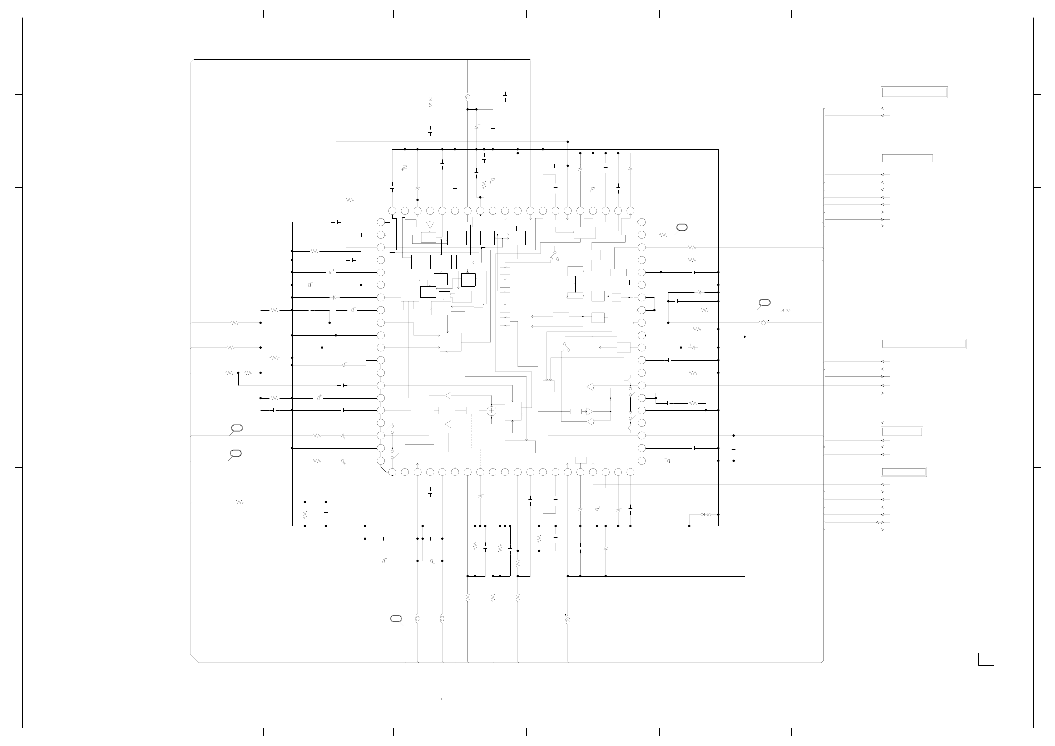
ABC D E F GH
ABC D E F GH
2
1
3
4
5
6
7
8
2
1
3
4
5
6
7
8
DURING PLAYBACK.
MEASURED WITH THE DIGITAL TESTER
NOTE:THE DC VOLTAGE EACH PART WAS
OF PRINTING AND SUBJECT TO CHANGE WITHOUT NOTICE
NOTE:THIS SCHEMATIC DIAGRAM IS THE LATEST AT THE TIME
C731
47
6.3V
KA
C735
10016V KA
C758 4.750V KA
C751
2216V KA
C709
1B
C724
0.1 F
C732
0.01 B
C705
1B
C715
1B
C714
0.033 B
C718
0.1 B
C717
1B
C711
560P CH
C723
1B
C707
1B
C747
1B
C746
0.1 F
C757
0.0047 B
C754
0.01 B
C764
0.1 F
C766
0.1 F
C704
0.01 B
C771
0.01 B
C752
0.1 F
C703
1B
C702
1B
C741 560P CH
C708
0.022 B
C733
1F
C730
0.1 F
C701
1B
C710
560P CH
C706 680P CH
C739
0.1 F
C768
0.0047 B
C762
0.01 B
C749
680P CH
C743
0.01 B
C748
1B
C760 0.01 B
C744 560P CH
R712
47K 1/4W
R702
47K 1/4W
R718
2.2M 1/4W
R710
390K 1/4W
R7014.7K
R715
5.6K
R722
1.8K
R723
12K 1/4W
R714 5.6K
R706
47K 1/4W
R708
330
R704
1K 1/4W
R713
1.5K
R711
5.6K
R707
1.8K
R726
2.2K
R727
470
R717
330
R716
330
R703
12K 1/4W
R731
1K
R721
1.5K
R719
47K 1/4W
R724
1K 1/4W
R729 100 1/4W
R728 100 1/4W
R725 39K
R720 5.6K
C742
2.250V KA
C722
10016V YK
C750_1
1025V KA
C740_1
10
25V KA
C721_1
10
25V KA
C720_1
10
25V KA
C725
2216V KA
C712
4.750V KA
C728
22
16V KA
C716
4.750V KA
C719
4.750V KA
C713
4.750V KA
C726
4.750V KA
C727
2.250V KA
C753
4.750V KA
C759
2216V KA
C765
476.3V KA
C756
476.3V KA
C767
4.7
50V KA
C763
2216V KA
C755_1
1025V KA
TP701
HIFI ENV
W850
W821
L704
22uH 0305
L705
22uH 0305
IC701
LA72670BM-L-MPB-E
HI-FI/DEMODULATOR IC 1 101112131415161718192 20
21 22 23 24 25 26 27 28 29
3
30 31 32 33 34 35 36 37 38 39
4
40
414243444546474849
5
50515253545556575859
6
60
616263646566676869
7
70717273747576777879
8
80
9
L701
22uH
L702
22uH
L703
22uH
FSC
SIF_OUT
AUDIO_MUTE-H
P.CON+9V
FRONT_A_IN_L
FRONT_A_IN_R
REAR_A_IN_L
REAR_A_IN_R
SIF_OUT
DVD_A_OUT_L
DVD_A_OUT_R
RF_CONV_A_OUT
AUDIO_OUT_L
ST_SELECT
AUDIO_OUT_R
HIFI_H.SW
SCL
SDA
REAR_A_IN_R P.CON+5V
FRONT_A_IN_R
FSC
FROM_NORMAL_A
DVD_A_OUT_R
TO_NORMAL_A
HF2
HF_COM
HF1
AUDIO_OUT_R HIFI_ENV.DET
AT+5.2V
P.CON+5V
P.CON+9V
AUDIO_OUT_L GND
REC_MUTE_H
HIFI_ENV.DET
HIFI_H.SW
FROM_NORMAL_A
AUDIO_MUTE-H
SCL
SDA
ST_SELECT
RF_CONV_A_OUT
P.CON+5V
FRONT_A_IN_L
TO_NORMAL_A
REAR_A_IN_L
DVD_A_OUT_L
AT+5.2V
P.CON+9V
NC
36
H-20
H-19
FROM OPERATION/DISPLAY
PCB010
DME063
2.72.72.72.70.34.82.52.7000.40.10.48.93.83.81.50.300.3
PILOT
DET
CONT SAP
DET
SW
ST/SAP
DEMOD
SAP
DEMOD
L-R
PLL
STEREO
CANCEL
PILOT
FILUTER
SAPFILUTER
Adj.
FILUTER
STEREO
D.C
VREF
MATRIX
DEC
dbx
LIM
AMP
SIF
DEMOD
RIPPLE
FILTER
MUTE ALC OUT
SEL
A GND
A GND
L-CH
IN SEL
R-CH
R-CH
PNR
LIM
DEV
HOLD
PULSE
LOGIC
SW
NOISE
DO DET
COMP R-CH
BPF
R-CH
BPF
LIM
NOISE
DET
VCO
LPF
MIX
ENV
DET
VREF
COMP
PB AMP
PB AMP
REC AMP
REC-H
REC-H
40
38
39
NC
0
0.3
0.4
0.7
0
0
0
0.1
0
2.5
0.1
4.1
0
4.1
0.1
0.1
0.1 2.5 8.9 2.5 5.1 0.1 0 0.7 0 0 0 2.5 2.7 2.5 4.8 2.5 5.0 0.2 2.7 2.7
2.7
2.6
0.1
2.3
0
2.3
2.3
0
0.1
3.0
3.5
4.9
2.5
2.5
0
4.6
4.7
2.5
0.2
FROM/TO Y/C/AUDIO/CCD/HEAD AMP
(VCR MT PCB)
4.8
0.2
0.2
0.2
0.2
37
Hi-Fi/DEMODULATOR SCHEMATIC DIAGRAM
FROM/TO TUNER/JACK
FROM/TO SYSCON
FROM POWER
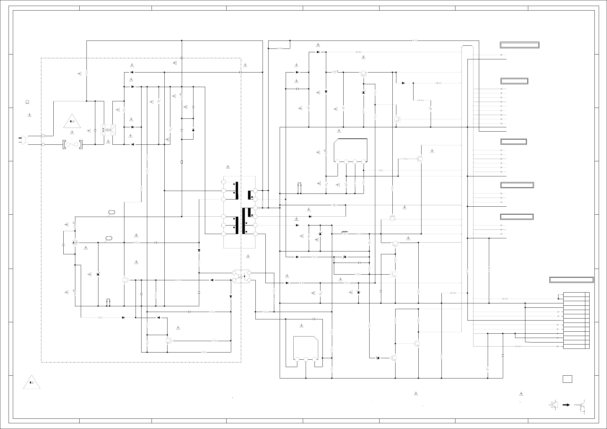
ABC D E F GH
ABC D E F GH
2
1
3
4
5
6
7
8
2
1
3
4
5
6
7
8
L506
10uH TSL0808
IC501 KIA431A-AT
VOLTAGE CTL IC
123
REPLACE ONLY WITH THE SAME TYPE FUSE
:FOR CONTINUED PROTECTION AGAINST FIRE HAZARD,
CAUTION
N’UTILISER QUE DES FUSIBLE DE MEME TYPE
:POUR UNE PROTECTION CONTINUE LES RISQUES D’INCEIE
ATTENTION
HS501
763WAAA070
HS6S
HS502
763WAAA120
HS6S
2.5A 125V
2.5A 125V
T501
81291244
10
11
12
13
14
15
2
3
4
6
7
8
IC502 KIA78R06API
6V REG. IC
1234
S
D
G
Q501
2SK3563(ORION_Q)
SWITCHING
L502
W5T_20X10X10A
BLACK
WHITE
BLADE
WIDE
CD501
09415911
AC120V_60HZ
IC503
PS2561AL1-1-V(W)
PHOTO COUPLER
1
2
34
FH501
EYF-52BCY
FH502
EYF-52BCY
L501
SS11VL-05230
COIL,LINE FILTER
12
34
F501
2.5A125V
51MS025L
R516
0.22 1W
R502
0.68 1W
R512
68K 1W
R535
3.9 3W
D524
1SS133
D514
MTZJ11B-EIC
D516
MTZJ5.1B-EIC
D523
MTZJ33B-EIC
CP501_1
A2001WV2-13P
1
10
11
12
13
2
3
4
5
6
7
8
9
B501
W4BRH3.5X6X1.0X2
DANS LA NOMENCLATURE DES PIECES
N’UTILISER QUE CELLS DECRITES
DANGEREUSES AN POINT DE VUE SECURITE
:LES PIECES REPAREES PAR UN ETANT
ATTENTION :SINCE THESE PARTS MARKED BY
CAUTION
DESCRIBED IN PARTS LIST ONLY
CRITICAL FOR SAFETY,USE ONES
ARE
D510
MTZJ22B-EIC
D519
MTZJ6.8B-EIC
D526
MTZJ3.3B-EIC
S502
S501
Q506
KRC103SRTK
M-CON POWER SW
Q509
KRC103SRTK
P.ON SW
D512
1SS133
D527
1N4005-EIC
D515_1
SR340-004
D533
1N4005-EIC
D529
1N4005-EIC
D501
1SS133
D505
1N4005-EIC
D503
1N4005-EIC
D506
1N4005-EIC
D502
1N4005-EIC
D504
1SS133
D518
1SS133
D509
SARS01-V1
D511
SR340-004
D507
FR155-F
D508
1SS133
D522
1H3-E
CAUTION: DIGITAL TRANSISTOR
DURING PLAYBACK.
MEASURED WITH THE DIGITAL TESTER
NOTE:THE DC VOLTAGE EACH PART WAS
OF PRINTING AND SUBJECT TO CHANGE WITHOUT NOTICE
NOTE:THIS SCHEMATIC DIAGRAM IS THE LATEST AT THE TIME
C511_1
47200V PK
C540_1
47200V PK
C501
220016V YK
C514
10016V YK
C518
22006.3V FM
C521
10016V YK
C522
22
50V YK C519
10016V YK
C504
2200
10V YK
C524
0.47 B
C510
0.022 B
C508
0.022 B
C531
560P
500V B
C544
1B
C527
0.001 B
C526
0.0022
250V KY
C515
0.01500V B
C516
0.0022250V KY
C502_1
0.22
275V ECQUL
C525
680P2KV R
C509
0.018 M
C513
100P2KV R
C520
1F
C534
1F
R552
100
R519
1K
R507
10K
R547
100K
R530
470K 1/4W
R532
10K
R534
10K 1/2W
R501
3.3M 1/2W +-10%
R503
1.5M 1/2W
R531
10K
R504
560 1/2W
R529
680K 1/4W
R505
680K 1/4W
R506
1M1/2W
R508
100 1/4W
R549
100K 1/4W
R524
100
R522
3.3K +-1%
R520
3.3K +-1%
R521
470
R533
220 1/4W
R527
220 1/4W
R518
150
R517
1K 1/2W
R515
27K
R536
5.6K
R509
100 1/4W
R514
220 1/2W
R513
390 1/2W
R553
47K 1/4W
R554
10K 1/4W
R523
6.8K
R511
560K
C535
1025V KA
C512
1025V KA
C505
10016V YK
C506
100
10V YK
Q502
KTC3203_Y
PROTECT CONTROL
Q507
KTC3203_Y
PROTECT CONTROL
Q503
KTC3209_Y
P.CON+5V SW
Q505
2SD1835S/T-AA
P.CON5V SW
Q513
KTC3875S_Y_RTK
POWER FAIL SW
Q514
KTC3875S_Y_RTK
POWER FAIL SW
Q510
2SD1835S/T-AA
P.CON+12V SW
W829
W826
W856
W885
W834
W877
W827
W846
W841
W842
W822
W806
W845
W816
W833
W832
W886
W804
Q504
KTA1271_Y
M-CON +5V SW
L505
22uH 0305
AT+12.6_V
P.CON+5V
GND
P.CON+10V
P.CON+9V
TX
RX
AT+5.2V
DVD_POWER_CTL
VCR_POWER_ON-L
POWER_FAIL
AT+5V[M-CON]
VCR_POWER_ON-L AT+12.6_V
P.CON+5V
GND
MOTOR_GND
P.CON+5V_DH
P.CON+9V
SPDIF
+32V
AT+5.2V
P.CON+5V
DVD_POWER_CTL
P.CON+10V
P.CON+6V GND
LEM_VCC
P.CON+5V
AT+5.2V
AT+3.8V
GND
P.CON+5V
LEM_VCC P.CON+9V
P.CON+5V
AT+5.2V AT+5.2V
GND
AT+5V[M-CON]
+32V
AT+5.2V
AT+5.2V
TX
RX
P.CON+6V
P.CON+5V_DH
POWER_FAIL AT+3.8V
SPDIF
10.4
(VCR MT PCB)
POWER SCHEMATIC DIAGRAM
0
0.5
H-22
H-21
TO Hi-Fi/DEMODULATOR
TO OPERATION/DISPLAY
TO TUNER/JACK
TO Y/C/AUDIO/CCD/HEAD AMP
FROM/TO MPEG/MICON/DSP/RF_AMP
(CD4002)
3.2
PCB010
DME063
16.0
0
NC
0
142.0 96
16.6
12.9
0
0
2.5A 125V(F501).
2.5A 125V(F501).
BLACK
WHITE
0
0
NC
12.5
0.3 4.1
5.1
139.3
43
0.1
0.5
44
0.3
0
0
0.6
4.1
INOUT GND
2.50
4.4
5.2 5.1
12.4
0
0.1
3.3
0
0
0
5.3
0
IN SWOUT GND
FROM/TO SYSCON
0
0
0
0
0
05.3
GND(D)
GND(D)
TX
RX
GND(M)
P.CON+A5V
UNREG+3.8V
UNREG+3.8V
GND(A)
SPDIF
19.1
0
0
P.CON+6V
0 5.09.011.6
AT+5.2V
AT+5.2V
11.1
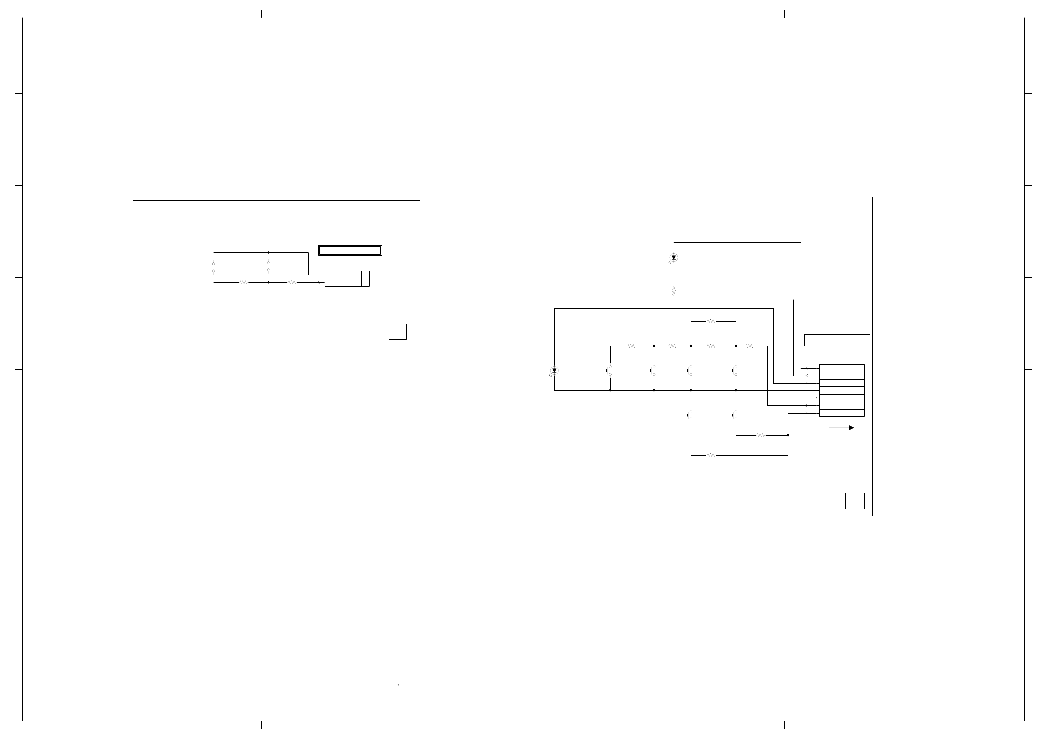
ABC D E F GH
ABC D E F GH
2
1
3
4
5
6
7
8
2
1
3
4
5
6
7
8
D685
LTL-1CHGE-002A
VCR LED
D686
LTL-1CHGE-002A
DVD LED
CP682
IMSA-9604S-07F
1
2
3
4
5
6
7
SW699
EVQ11L05R
POWER
SW697
EVQ11L05R
VCR EJECT
SW689
EVQ11L05R
STOP
SW691
EVQ11L05R
VCR/DVD
SW687
EVQ11L05R
FF/CUE
SW690
EVQ11L05R
OPEN/CLOSE
SW686
EVQ11L05R
PLAY
SW685
EVQ11L05R
REW/REV
CP683
B2013H02-2P
1
2
CD682
2H070904
DURING PLAYBACK.
MEASURED WITH THE DIGITAL TESTER
NOTE:THE DC VOLTAGE EACH PART WAS
OF PRINTING AND SUBJECT TO CHANGE WITHOUT NOTICE
NOTE:THIS SCHEMATIC DIAGRAM IS THE LATEST AT THE TIME
R693
220 1/4W
R700
3.3K 1/4W
R691
15K 1/4W
R695
33K 1/4W
R692
1.5K 1/4W
R686
6.8K 1/4W
R699
13K 1/4W
R689
3.3K 1/4W
R697
12K 1/4W
R698
2.7K 1/4W
H-24H-23
PCB270
DEE080
FROM OPERATION/DISPLAY
(CP653)
OPERATION/LED SCHEMATIC DIAGRAM
KEY-B
KEY-A
DVD LED
VCR LED
AT+5.2V
FROM/TO OPERATION/DISPLAY
GND
(OPERATION PCB)
NC
(CP651_1)
GND
KEY-B
(OPERATION2 PCB)
PCB280
DEE081
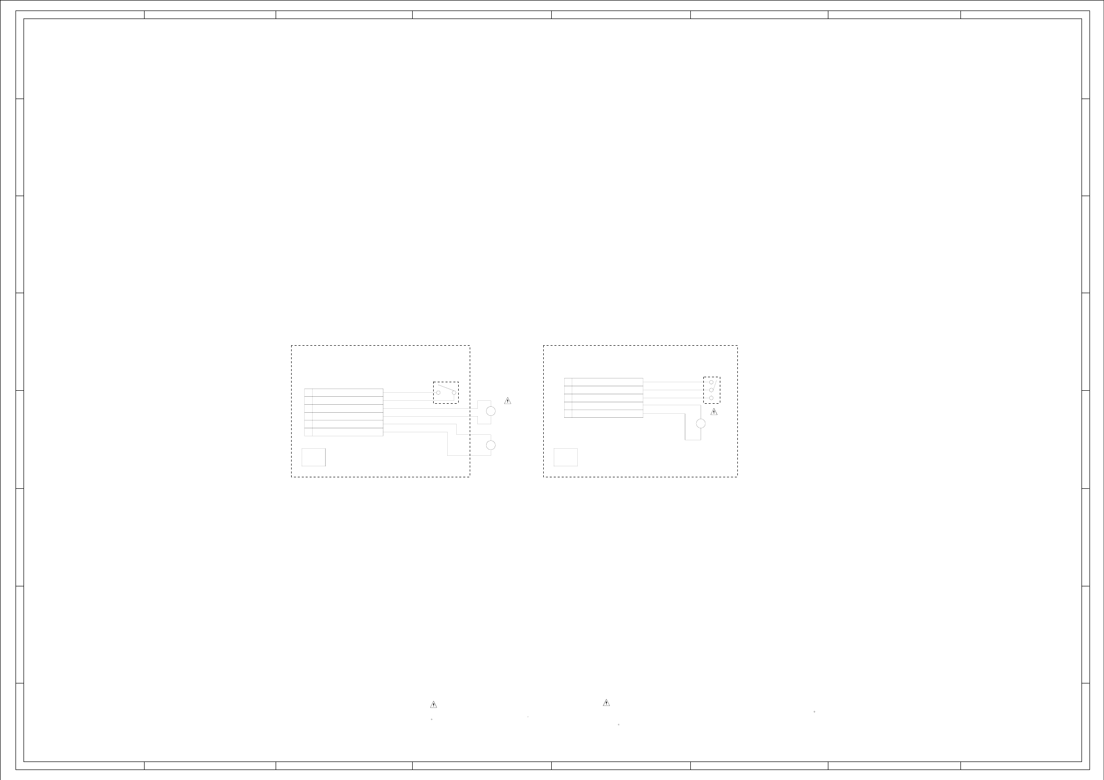
ABC D E F GH
ABC D E F GH
2
1
3
4
5
6
7
8
2
1
3
4
5
6
7
8
OF PRINTING AND SUBJECT TO CHANGE WITHOUT NOTICE
NOTE:THIS SCHEMATIC DIAGRAM IS THE LATEST AT THE TIME
(LOADING MOTOR PCB)
LOADING MOTOR/SW SCHEMATIC DIAGRAM
H-26
H-25
(SW PCB)
SSS-13-2
SW1
GND(SW)
SW-2(CLOSE)
SW-1(OPEN)
LOADING MOTOR(-)
LOADING MOTOR(+)
DED003
PCB610
DED002
PCB640
BCZ3B52
M2603
CD2302
2H052601
M
M
5
4
3
2
1
6
5
4
3
2
1 GND(SW)
FEED MOTOR (+)
SPINDLE MOTOR (+)
SPINDLE MOTOR (-)
FEED MOTOR (-)
PICK UP INNER LIMIT SWITCH
SW2
JCV9B06
M2601
BCZ3B03
M2602
ESE22MH24
CD2301
2H062102
M
:SINCE THESE PARTS MARKED BY
CAUTIONDESCRIBED IN PARTS LIST ONLY
CRITICAL FOR SAFETY,USE ONES ARE
DANS LA NOMENCLATURE DES PIECES
N’UTILISER QUE CELLS DECRITES
DANGEREUSES AN POINT DE VUE SECURITE
:LES PIECES REPAREES PAR UN ETANT
ATTENTION
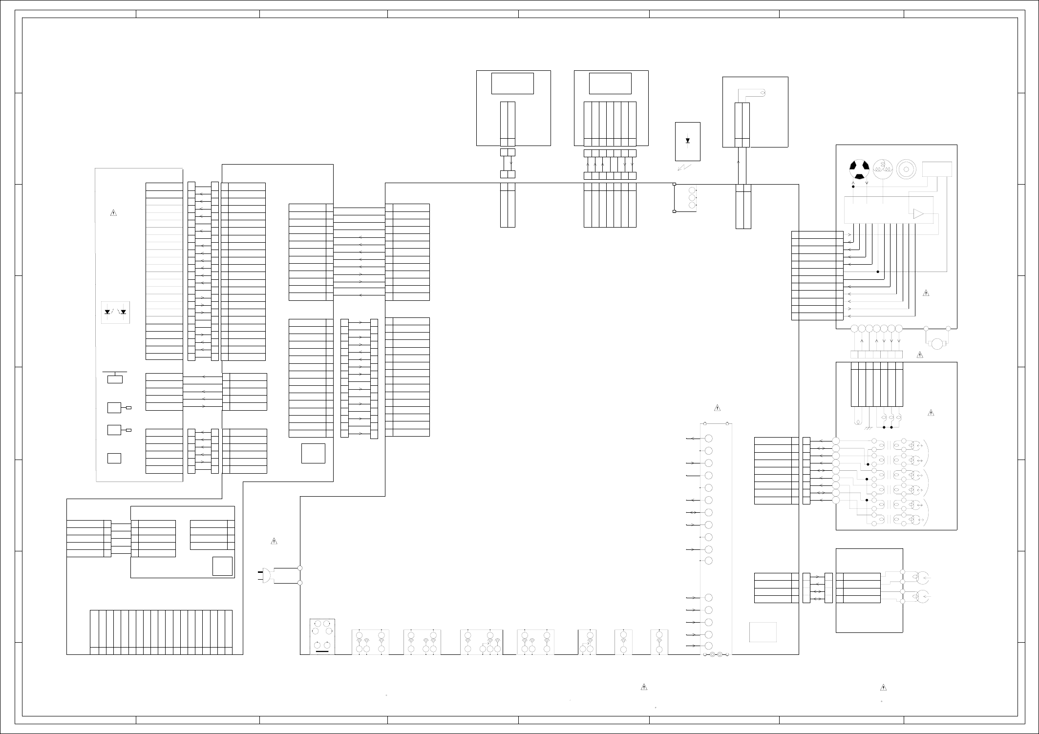
ABC D E F GH
ABC D E F GH
2
1
3
4
5
6
7
8
2
1
3
4
5
6
7
8
19
18
17
16
15
14
13
12
11
10
9
8
7
6
4
5
3
2
1
CP5901_3
HDMI CONNECTOR
13
12
11
10
9
8
7
6
4
5
3
2
1
CD4002_1
13
12
11
10
9
8
7
6
4
5
3
2
1
CP501_1
2
1
16
15
14
13
12
11
10
9
8
7
6
5
4
3
2
1
16
15
14
13
12
11
10
9
8
7
6
5
4
3
4
3
2
1
4
3
2
1
4
3
2
1
2
1
CP103
2
1
CP653
2
1
CP683
24
23
22
21
20
19
2
1
18
17
16
15
14
13
12
11
10
9
8
7
6
5
4
3
CP2301
5
4
3
2
1
5
4
3
2
1
5
4
3
2
1
CP2302
7
6
5
4
3
2
1
7
6
5
4
3
2
1
7
6
5
4
3
2
1
12
11
10
9
8
7
6
5
4
3
2
1
12
11
10
9
8
7
6
5
4
3
2
1
9
8
7
6
4
5
3
2
1
CP101
6
5
4
3
2
1
CP2303
OF PRINTING AND SUBJECT TO CHANGE WITHOUT NOTICE
THE TIMETHIS INTERCONNECTION DIAGRAM IS THE LATEST ATNOTE:
BLACK
WHITE
BLADE
WIDE
CD501
AC120V_60Hz
H
E
J652
FRONT AV JACK
AUDIO IN L
1
2H
E
J653
FRONT AV JACK
VIDEO
1
2
HNC
E
J651
FRONT AV JACK
AUDIO IN R
1
23
Vout
B+
GND
OS651
1
2
3
J8008
Y/C SEPA
12
34
56
H1H1 H2
EE
J8001
REAR OUT JACK
1
2 3
4
5
H1H1 H2
EE
J8007
YUV OUT
1
2 3
4
5H1 H1H2
EE
J8006
DVD AUDIO OUT
1
23
4
5
TU301
1
10
11
12
13
14
15
16
17
18
19
2
20
21
3
4
5
7
8
9
EE
H1 NC H1 H2
J8002
REAR IN JACK
1
23 4
5
6
DANS LA NOMENCLATURE DES PIECES
N’UTILISER QUE CELLS DECRITES
DANGEREUSES AN POINT DE VUE SECURITE
:LES PIECES REPAREES PAR UN ETANT
ATTENTION :SINCE THESE PARTS MARKED BY
CAUTION
DESCRIBED IN PARTS LIST ONLY
CRITICAL FOR SAFETY,USE ONES
ARE
H-28H-27
POWER
HOTPLUG
D2+
D0-
CLK+
SDA
GND
D2-S
D2-
D1+
D1-S
D1-
D0+
D0-S
CLK-S
CLK-
CEC
SCL
NC
CP6603
CP6601CP6602
CVBS
Y(G)
U(B)
GND
V(R)
GND
AUDIO-L
GND
AUDIO-R
ZERO
GND
DVD-H
DVD CVBS
DVD RESET
GND
P-H/I-L
GND(M)
P.CON+A5V
GND(A)
GND(D)
GND(D)
SPDIF
SSCCLK/TX
RDY(I/O(0))/RX
P.CON+6V
AT+5.2V
AT+5.2V
UNREG+3.8V
UNREG+3.8V
GND(D)
GND(D)
TX
RX
GND(M)
P.CON+A5V
UNREG+3.8V
UNREG+3.8V
GND(A)
SPDIF
P.CON+6V
AT+5.2V
AT+5.2V
CVBS
GND
U(B)
GND
V(R)
GND
AUDIO-L
GND
AUDIO-R
ZERO
DVD RESET
DVD-H
Y(G)
DVD CVBS
GND
P-H/I-L
DMF071
DEF091
USB PCB
USB CONNECTOR
+5V
GND
USB_DN
USB_DP
PCBDD0
GND
USB_DN
USB_DP
+5V
+5V
GND
USB_DN
USB_DP
+5V
+5V
CP8101_1
MON(DVD)
NC(SW)
VOL(DVD)
GND(DVD)
LD(DVD)
LD(CD)
VOL(CD)
GND(CD)
MON(COM)
RF
C
B
A
D
F
E
VCC
Vref
GND(PDIC)
F-
F+
T-
T+
DVD/CD
MON(DVD)
NC(SW)
VOL(DVD)
GND(DVD)
LD(DVD)
LD(CD)
VOL(CD)
GND(CD)
MON(COM)
RF
C
B
A
D
F
E
VCC
Vref
GND(PDIC)
F-
F+
T-
T+
DVD/CD
LD-
LD+
LD-
LD+
GND(D)
CLOSE
OPEN
GND(D)
CLOSE
OPEN
LIMIT SW LIMIT SW
SW(GND)SW(GND)
SLD-
SLD+
SP1-
SP1+
SLD-
SLD+
SP1-
SP1+
FFC
6
5
4
3
2
1
6
5
4
3
2
1
24
23
22
21
20
19
18
17
16
15
14
13
12
11
10
9
8
7
6
5
4
3
2
1
24
23
22
21
20
19
18
17
16
15
14
13
12
11
10
9
8
7
6
5
4
3
2
1
PCB130
DVD MT PCB
SLED MOTOR
LOADING MOTOR
FG SENSER
DM-3S
SPINDLE MOTOR
DRIVE
DVD
OPTICAL PICK-UP
AUDIO PB
CTL-
AUDIO REC
3
2
1
4
2
1
3
4
CD102
FFC
CTL+
H5001
HEAD AUDIO CONTROL ASS’Y
AUDIO
CONTROL
FPC
3
2
1
5
4
6
9
8
7
LD/CY VCO
3
2
1
5
4
6
9
8
7
7
6
5
4
3
2
1
FFC
7
6
5
4
3
2
1
CYLINDER UNIT
WHITERED
M101
LOADING MOTOR
LM
D-U OUT
D-V OUT
D-W OUT
D-COM
M-GND
D-PG OUT
D-PG GND
EP/LP HEAD
SP HEAD
HI-FI HEAD
CAPSTAN DD UNIT
M2001
CYL CTL
CAP FG
CAP VCO
VCC
CAP CTL
CYL FG/PG
LDM CTL
GND
MOTOR GND
I LIMIT
CAP.M/F/R
O
G
VCC
FG SENSORMAGNETCOIL
LOGIC
SWITCH
OUT
SENSOR
IN
HALL
VCC
HALL
MRROTORMAINHALL
FULL ERASE HEAD ASS’Y
AUDIO PB
AUDIO REC
CP102_1
CTL-
CTL+
CP3001
HF1 (R)
EP/LP COM
SP COM
HF2 (L)
HF COM
SP-CH2 (L)
SP-CH1 (R)
EP/LP-CH2 (L)
EP/LP-CH1 (R)
DME063
A.OUT
SIF OUT
TU 32V
PCB010
VCR MT PCB
FSC
V.OUT
V.IN
CONTROL
+B
CH
A.IN
NC
AFT
DATA
NC
NC
FE HEAD (GND)
FE HEAD (HOT)
FE HEAD (GND)
FE HEAD (HOT)
2
1
H5002
OPERATION PCBOPERATION2 PCB
KEY-B
GND
CD683
FFC
2
1
2
1
GND
KEY-B
CD682
PCB280
DEE081
6
7
5
4
3
2
1
6
7
5
4
3
2
1
FFC
CP682
KEY-B
KEY-A
DVD LED
VCR LED
AT+5.2V
NC
GND
KEY-B
KEY-A
AT+5.2V
VCR LED
DVD LED
GND
NC
CP651_1
PCB270
DEE080
CP8001_1
16
15
14
16
15
14
13
12
11
10
9
7
8
6
5
4
3
2
1
CD8001
TM601
COMMAND TRANSMITTER
S501
S502
BLACK
WHITE
13
12
11
10
9
6
5
4
3
2
1
8
7
FFC
NC
NC
NC
NC
CLOCK
INTERCONNECTION DIAGRAM
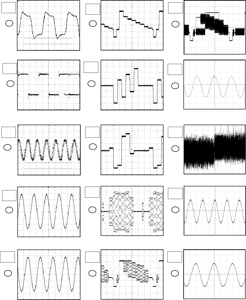
WAVEFORMS
I-1
The following waveforms were measured at the point of the corresponding
balloon number in the schematic diagram.
NOTE:
Y/C/AUDIO/CCD/HEAD AMP
50µs
1.0V
5
1
MPEG/MICON/DSP/FR_AMP
10ns
1.0V
8
10µs
200mV
10µs
200mV
9
10µs
500mV
10
4
500µs
1.0V
3
5ns
200mV
2
200ns
20mV
AUDIO/VIDEO
10µs
200mV
7
6
10µs
500mV
16
PB
10µs
500mV
17
PB
100ns
100mV
PB
1ms
100mV
18
REC
5µs
20V
20
PB
200ms
500mV
19
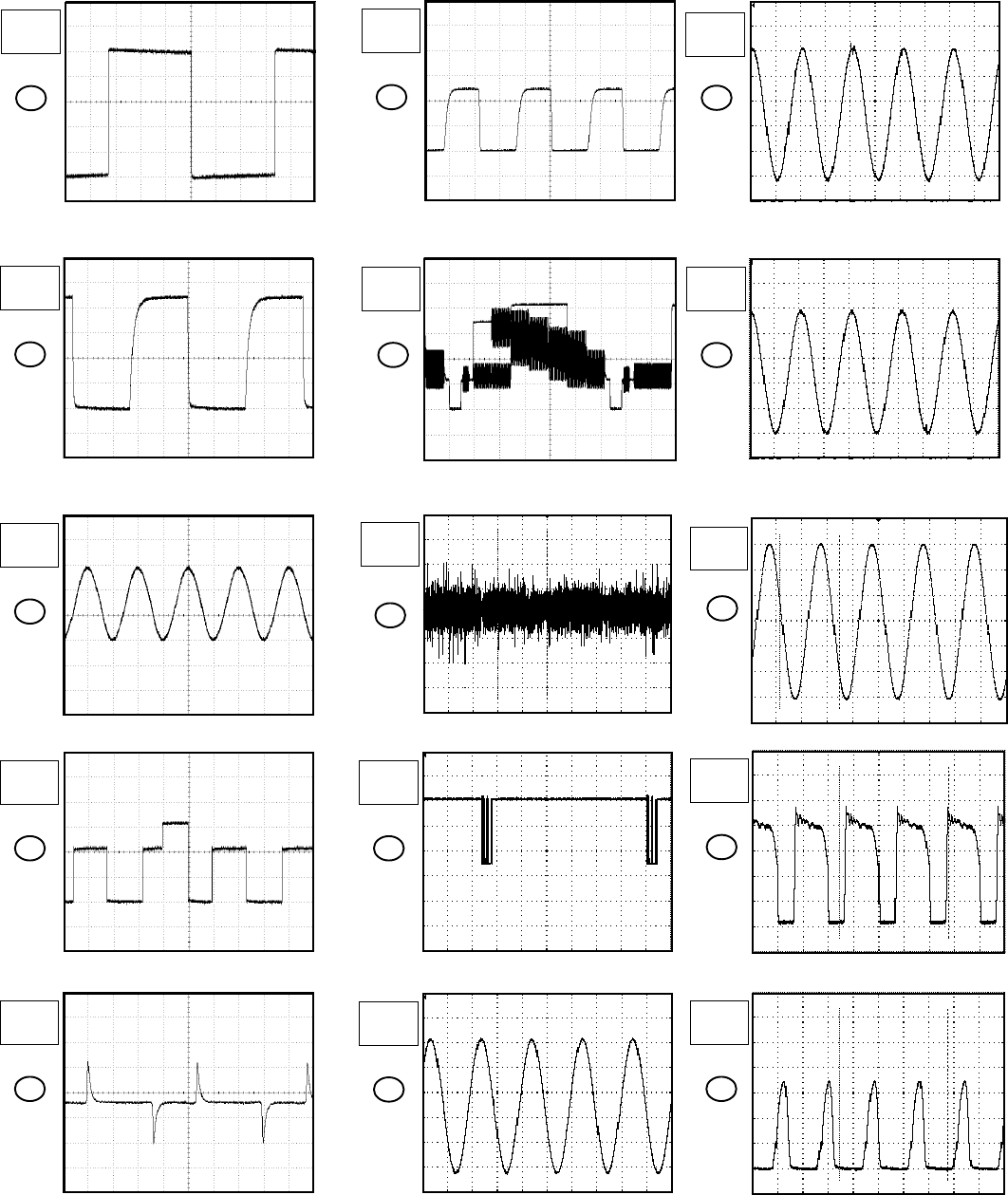
WAVEFORMS
I-2
The following waveforms were measured at the point of the corresponding
balloon number in the schematic diagram.
NOTE:
PB
5µs
500mV
43
POWER
PB
5µs
5.0V
44
PB
200µs
1.0V
22
POWER ON
50ns
1.0V
23
PB
500µs
1.0V
24
PB
5ms
2.0V
27
PB
10µs
200mV
32
TUNER/JACK
TUNER/JACK
42
PB
500µs
100mV
PB
1ms
2.0V
37
36
PB
10ms
1.0V
Hi-Fi/DEMODULATOR
PB
500µs
200mV
39
PB
500µs
200mV
40
PB
5ms
500mV
25
PB
500µs
200mV
38
SYSCON
PB
5ms
1.0V
21
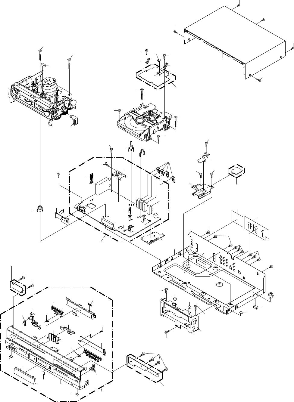
MECHANICAL EXPLODED VIEW
J1-1
211
211
117
120
204
113
118
202
212
202
107
202
115
119
206
119
210
108
204
122
122
127
121
214
214
124
125
213
PCBDD0
(USB PCB ASS'Y)
114
205
205
205
205
205
209
208
209
208
PCB130
(DVD MT PCB ASS'Y)
110
207
110
207
123
126
111
104
102
103 109
105 104
202
203
106
116
203
112
202
PCB010
(VCR MT PCB ASS'Y)
PCB270
(OPERATION PCB ASS'Y)
101P 101
101J
101J
101M
101B
101N
101H
101I
101L
101G
101K
101A
101D 101O
101F
101C
101P
101E
PCB280
(OPERATION 2 PCB ASS'Y)
207
207
207
101Q 201
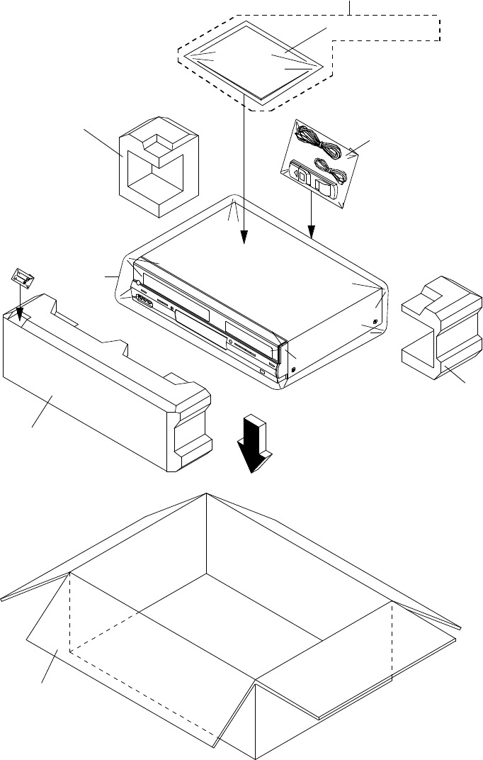
MECHANICAL EXPLODED VIEW
(PACKING DIAGRAM)
J1-2
CD6002, CD6003,
TM601
130
131
128
128
129
133, 134, 135, 136
132
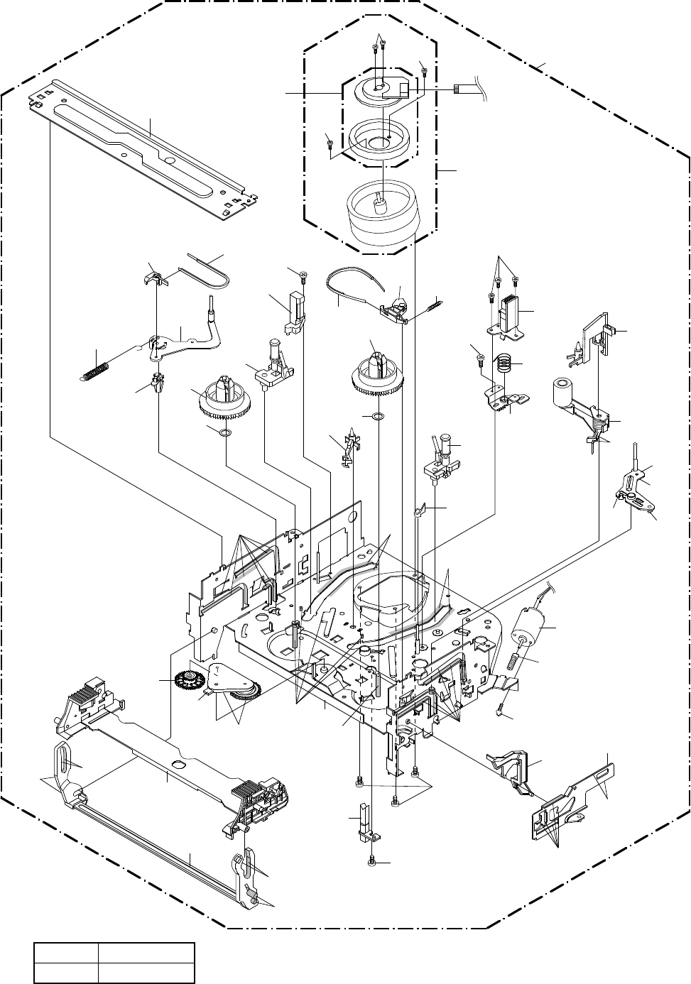
CHASSIS EXPLODED VIEW (TOP VIEW)
J2-1
505
503
503
UN4001
M2003 CD1501
321
AA
AA
AA
AA
309
325
AA
312
315
504
H5001
503
306
305
332
507
335 342
322508
324
319
506
501
H5002
323
508
341
331
334 333
314
301
313
307
300
316
336
302 345
317
AA
AA
AA
AA
AA
AA
AA
AA
AA
AA
AA
AA
M101
304
CD1502
510
318
Applying positions AA for the grease are displayed for this section.
Check if the correct grease is applied for each position.
NOTE:
CLASS
GREASE
MARK
AA
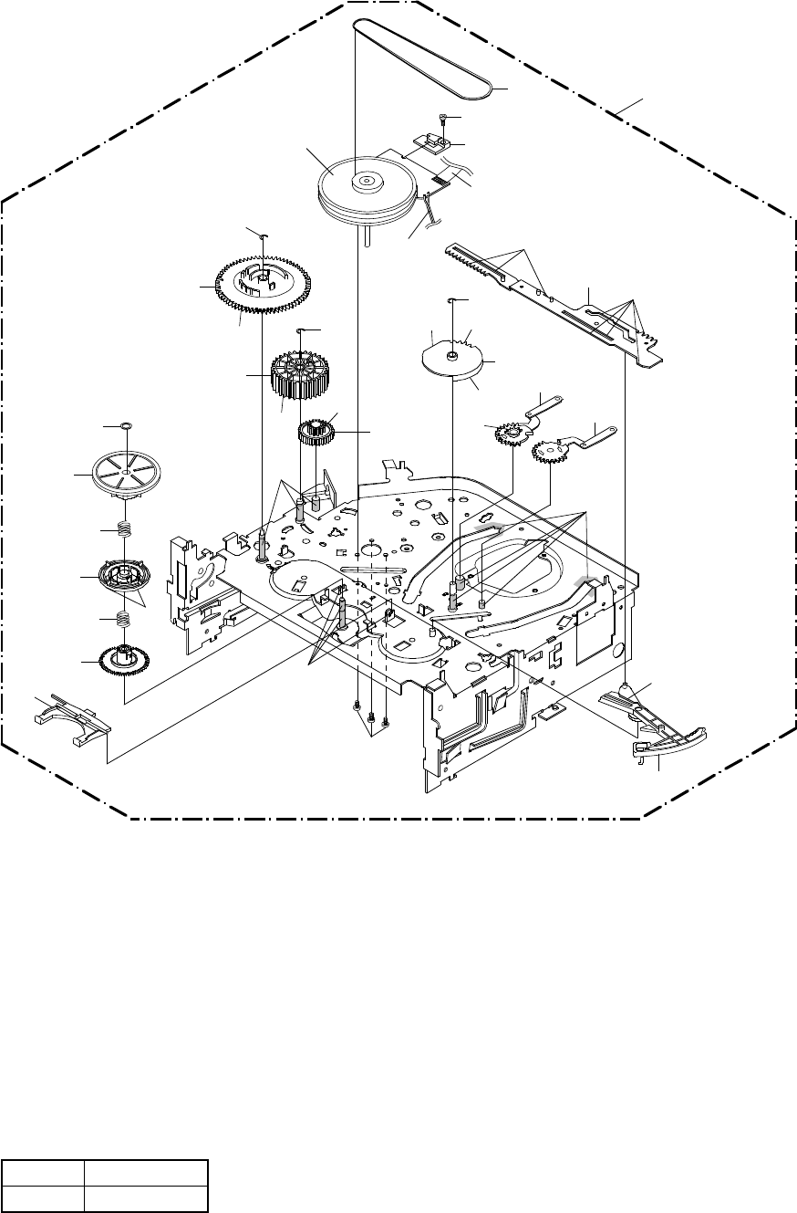
M2001
300
303
502
329
311
310
330
505
502
338
502
337
340
509
308
344
327
343
326
328
AA
AA
AA
AA
AA
AA
AA AA
AA AA
AA
CD1501
CD1502
AA
339
AA
AA
320
501
Applying positions AA for the grease are displayed for this section.
Check if the correct grease is applied for each position.
NOTE:
CLASS
GREASE
MARK
AA
CHASSIS EXPLODED VIEW (BOTTOM VIEW)
J2-2
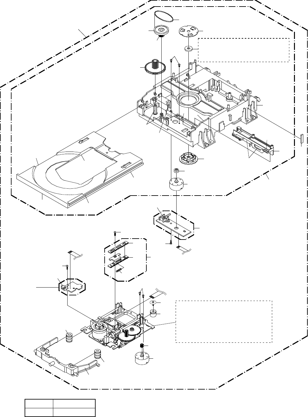
DVD DECK EXPLODED VIEW
J3-1
Applying positions AA for the grease are displayed for this section.
Check if the correct grease is applied for each position.
NOTE:
CLASS
GREASE
MARK
AA
600
610
608
M2603
704
612
614
615
613
602
609
611
AA
AA
AA
AA
AA AA
AA
AA
AA AA
AA
Do not replace the parts. Because,
minute adjustments are needed if
this condition is disassembled
further more.
If the repair is needed, replace the
DVD MECHA ASS'Y.
SW2
PCB640
(SW PCB ASS'Y) CD2001
CD2301
M2602
603
601
605
605
606
702
705
703
SW1
PCB610
(LOADING MOTOR PCB ASS'Y)
CD2302
701
607
604
705
617
616
618
619
Cannot supply separately.
If the repair is needed, replace the
LOADER SUB ASS'Y.
MECHANICAL REPLACEMENT PARTS LIST
Location No. TSB P/N Reference No. Description
101 AE008288 7A7010188A FRONT CABI ASS'Y
101A AE008289 701WPJ1409 CABINET FRONT
101B AE008166 711WPDA693 PLATE DISPLAY
101C AE008167 712WPJC212 FLAP DVD
101D AE008168 712WPJC213 FLAP VCR
101E AE008171 723000D250 SHEET LED
101F AE001847 7235490018 BADGE BRAND
101G AE008290 736WPB0020 BUTTON FRAME 1
101H AE008291 736WPB0021 BUTTON FRAME 2
101I AE008172 736WPAA010 BUTTON FRAME 3
101J AE008292 736WPB0023 BUTTON FRAME 4
101K AE008176 736WPBA013 BUTTON RING 1
101L AE008177 736WPBA014 BUTTON RING 2
101M AE008178 736WPBA015 BUTTON RING 3
101N AE008179 738WPAA072 STOPPER BUTTON
101O AE001848 743WKA0042 SPRING FLAP
101P AE004701 800WFAA015 CUSHION LEG
101Q AE001324 742WKA0001 SPRING DVD-FLAP
102 BZ710466 752WSA0230 SHIELD CASE H/AMP
103 BZ710331 753WUAA006 SPRING EARTH H/AMP
104 BZ710498 85OP700038 HOLDER END SENSOR
105 AE006652 701WPA1363 HOLDER DECK
106 AE006653 701WPA1364 HOLDER DECK
107 AE008293 702WSA0273 PLATE BOTTOM
108 AE008294 7230008089 SHEET JACK
109 BZ710659 752WSA0290 SHIELD COMPO
110 AE003509 753WUA0065 SPRING EARTH
111 AE004703 761WPA0321 HOLDER DVD BL
112 AE007201 761WPA0406 COVER PCB
113 AE008181 761WSAA040 ANGLE FRONT
114 AE006725 702WSA0241 CABINET TOP
115 AE008728 722549A617 SHEET RATING
116 AE008180 752WUAA005 SHIELD JACK
117 AE008243 761WPAA137 HOLDER DECK TOP
118 79091466 761WPA0261 HOLDER DVD BR
119 AE001852 8965TS1010 CUSHION 65TS10-10(10*10*25)
120 AE001853 8965TS1017 CUSHION 65TS10-10(17.5*20*14)
121 AE005122 726000A073 SHEET CAUTION
122 AE007416 800WFA0074 CUSHION LEG
123 AE008297 752WSA0581 SHIELD HDMI
124 AE008298 753WUA0081 SHIELD USB
125 AE008299 761WPA0425 HOLDER USB
126 AE005385 8965TS1015 CUSHION 65TS10-5(10*5*15)
127 AE008300 7230007876 SHEET 20*20*T0.1
128 AE006733 792WHA0603 PACKAGE BACK
129 AE008729 793WCDD226 GIFT BOX
130 AD301577 791WHA0100 GIFT SHEET
131 AE008182 792WHAA187 PACKAGE FRONT
132 AE008730 A2I403H975 INSTRUCTION BOOK KIT
133 AE007590 JB5ND300 POLYBAG INSTRUCTION(RED CAUTION)
134 AE008731 J2I40301A INSTRUCTION BOOK(E)
135 AE008732 J2I40310A INSTRUCTION BOOK(F)
136 AE007852 J5N00629A INFORMATION SHEET(CND)
201 AE008246 8110E2606U SCREW TAP TITE(P)WH10 M2.6*6 CH
202 AE007202 810923053U SCREW TAP TITE(B) R BIND 3*5.3 CH
203 AE003524 8109I30A0U SCREW TAP TITE(B) WH7 3*10 CH
204 AE003526 810923080U SCREW TAP TITE(B) BIND 3*8 CH
205 AE004724 8109K3060U SCREW TAP TITE(B) BIND(3D) 3*6 CH
206 AE005539 810713040U SCREW TAP TITE(S) PAN 3*4 CH
207 AE003530 811022680U SCREW TAP TITE(P) BIND 2.6*8 CH
208 AE005541 810F13080U SEMS(F) 3*8 CH
209 AE005537 8154D3033U SCREW TAP TITE(B) WH8 3*33R CH
210 AE005540 810722660U SCREW TAP TITE(S) BIND 2.6*6 CH
211 AE006673 8109130B7U SCREW TAP TITE(B)R PAN 3*27 CH
212 AE007212 810213060U SCREW PAN M3*6 CH
213 AE003529 811063080U SCREW TAP TITE(P) BRAZIER 3*8 CH
214 AE008305 8146230F5U SCREW,TAP TITE(B) R-BIND 3*4.2+4*2.3 CH
K1-1

CHASSIS REPLACEMENT PARTS LIST
Location No. TSB P/N Reference No. Description
300 AE008141 A2F403H420K DECK ASSY A2F403H420K
301 AE005514 85OA400245 PINCH ROLLER BLOCK VA2
302 AE006679 85OP900759 LEVER,FLAP(S)
303 BZ710193 85OP200290 BELT,CAPSTAN (S)
304 BZ710515 85OP600581 WORM
305 AE005919 85OP500091 BASE,AC HEAD
306 BZ710112 85OP800324 SPRING,AC HEAD
307 AE006676 85OA000529 MAIN CHASSIS ASS'Y(S)
308 BZ710517 85OA200089 CLUTCH ASS'Y
309 AE005920 85OA200092 ARM IDLER ASS'Y
310 AE005836 85OA300068 LOADING ARM S UNIT
311 AE005837 85OA300070 LOADING ARM T UNIT
312 BZ710521 85OA400223 INCLINED BASE T UINT 3S
313 AE005838 85OA400249 P5 ARM ASS'Y 2
314 AE005839 85OA400248 TENSION ARM ASS'Y 2
315 BZ710524 85OA400231 INCLINED BASE S UNIT
316 AE006677 85OA900236 CASS HOLDER ASS'Y(S)
317 BZ710552 85OP900745 CASS,OPENER
318 BZ710106 85OP700035 REFLECTOR,LED
319 AE006678 85OP900756 BRACKET,TOP(S)
320 AE007221 85OP400554 HOLDER,CAPSTAN
321 AE005842 85OA900233 LINK UNIT
322 BZ710531 85OP000496 POST,CASS GUIDE
323 BZ710532 85OP200316 REEL,S (S)
324 BZ710533 85OP200317 REEL,T (S)
325 BZ710534 85OP200308 GEAR,IDLER
326 BZ710535 85OP200311 GEAR,CLUTCH
327 BZ710536 85OP200312 GEAR,COUPLING
328 BZ710537 85OP200313 LEVER,CLUTCH
329 BZ710538 85OP300194 GEAR,MAIN LOADING
330 BZ710092 85OP400490 LEVER,TENSION
331 BZ710093 85OP400492 HOLDER,TENSION
332 BZ710366 85OP400520 CAP.P4
333 BZ710762 85OP400542 BAND,TENSION
334 BZ710540 85OP400533 CONNECT,TENSION
335 BZ710541 85OP600573 ARM,BRAKE T
336 BZ710763 85OP600584 BAND,BRAKE T
337 BZ710543 85OP600577 CAM,PINCH ROLLER
338 BZ710544 85OP600578 CAM,MAIN
339 AE005843 85OP600585 ROD,MAIN
340 BZ710546 85OP600582 GEAR,JOINT
341 BZ710110 85OP800322 SPRING,TENSION
342 BZ710547 85OP800360 SPRING,BRAKE T
343 BZ710548 85OP800355 SPRING,COUPLING
344 BZ710549 85OP800356 SPRING,RING
345 AE005844 85OP900754 LEVER,LINK
501 AE005845 810722680U SCREW,TAP TITE(S) BIND M2.6*8 CH
502 AE005846 83ETW3000U E-RING 3.0
503 AE005847 810722640U SCREW,TAP TITE(S) BIND M2.6*4 CH
504 AE005848 810212060U SCREW,PAN M2*6 CH
505 AE005849 810912660U SCREW,TAP TITE(B) PAN M2.6*6 CH
506 AE005850 810A13040U SCREW/WASHER(A) M3*4 CH
507 AE005851 810A12650U SCREW/WASHER(A) M2.6*5 CH
508 BZ710056 82Q264713N POLYSLIDER WASHER 2.6*4.7*T0.13
509 BZ710054 82P184505N POLYSLIDER WASHER(CUT) 1.8*4.5*T0.5
510 AE005540 810722660U SCREW TAP TITE(S) BIND 2.6*6 CH
CD1501 BZ614292 122H071704 CORD JUMPER 2H071704
CD1502 BZ614339 122Y021902 CORD JUMPER 2Y021902
H5001 AE004714 1523Q91004 HEAD,AUDIO CONTROL VTR-1X2RPE22-772
H5002 AD301676 1543Q02014 HEAD (FULL ERASE) VTR-1X2ERS11-154
! M101 AE005552 1596S98002 MOTOR,LOADING MDB2B66B
! M2001 AE005853 1510S98044 CAPSTAN DD UNIT F2QVB73B
! M2003 AE006792 1589S11025 MICRO MOTOR I20AL34K
! UN4001 AE008130 A2F3PDH500 CYLINDER UNIT ASS'Y A2F3PDH500
K2-1

DVD DECK REPLACEMENT PARTS LIST
Location No. TSB P/N Reference No. Description
! 600 AE008191 A2I301H650 DVD MECHA ASS'Y A2I301H650
601 AE005003 92P100109A HOLDER,TRAVERSE
602 AE003550 92P100094A CLAMPER
603 AE003551 92P100088A GEAR,MOTOR
604 AE003537 92AAA0013A FEED RACK ASS'Y
605 AE003538 92P200013A INSULATOR(F)
606 AE003539 92P200014A INSULATOR(R)
607 AE006115 92SBB0029A LOADER SUB ASS'Y
608 AE003541 92P100095A GEAR,PULLEY
609 AE003542 92P100097A PULLEY,MOTOR
610 AE003549 92P100096A GEAR,MAIN
611 AE005810 92P200015A BELT,LOADING
612 AE003545 92P000014A PLATE,CLAMPER
613 AE003546 92P100093A RACK,LOADING
614 AE003547 92P100091A FRAME,MAIN
615 AE003548 92P100092A TRAY
616 AE003535 92P100089A RACK,FEED 1
617 AE003536 92P100090A RACK,FEED 2
618 AE003543 92P300020A SPRING,RACK FEED
619 BZ710149 800WFAA008 CUSHION C
701 AE003530 811022680U SCREW TAP TITE(P) BIND 2.6*8 CH
702 AE003554 814011723U SCREW,PAN M1.7*2.3 P3 CH
703 AE003555 816112080U SEMS.TAP TITE(P) PAN W10 2*8 CH
704 AE003556 814011730U SCREW,PAN M1.7*3 P3 CH
705 AE003557 811022080U SCREW,TAP TITE(P) BIND 2*8 CH
CD2001 AE008247 122J4O1903 CORD JUMPER 127000-2928
CD2301 AE003558 122H062102 CORD JUMPER 2H062102
CD2302 AE003559 122H052601 CORD JUMPER 2H052601
! M2602 AE005930 1515S98003 FEED MOTOR BCZ3B03B
! M2603 AE005931 1596S18003 MOTOR,LOADING BCZ3B52B
PCB610 AE003562 A5M4016610 LOADING MOTOR PCB ASS'Y DED003A
PCB640 AE008143 A5N813W640 SW PCB ASS'Y DED002B
SW1 AE003564 0515S32002 SWITCH SSS-13-2
SW2 AE003565 0500101037 PUSH SWITCH ESE22MH24
K3-1

ELECTRICAL REPLACEMENT PARTS LIST
Location No. TSB P/N Reference No. Description
RESISTORS
! R501 BZ210219 R0G3K2335K RC 3.3M OHM 1/2W
! R502 BZ210058 R3X181R68J R,METAL OXIDE 0.68 OHM 1W
! R503 BZ210206 R002T2155J RC 1.5M OHM 1/2W
! R504 AE000145 R002T2561J RC 560 OHM 1/2W
! R512 AE008325 R3K581683J R,METAL OXIDE 68K OHM 1W
! R516 AE005735 R63881R22J R,FUSE 0.22 OHM 1W
! R517 BZ210180 R002T2102J RC 1K OHM 1/2W
! R535 AE000037 R3X28B3R9J R,METAL 3.9 OHM 3W
CAPACITORS
! C501 BZ110119 E02LF2222M CE 2200 UF 16V
! C502 BZ110025 P2122B224M CMP 0.22 UF 275V ECQUL
C504 BZ110076 E02LF1222M CE 2200 UF 10V
! C505 AD301535 E02LU2101M CE 100 UF 16V
! C511 BZ110186 E62QFC470M CE 47 UF 200V
C513 AE000599 C0PLRR712K CC 100 PF 2KV R
! C514 AD301535 E02LU2101M CE 100 UF 16V
! C515 AE001722 C0J0B0514K CC 0.01 UF 500V B
! C516 BZ110256 CC3LE0MH3M CC 0.0022UF 250V
! C518 AE004691 E61FF0222D CE 2200 UF 6.3V
! C519 AD301535 E02LU2101M CE 100 UF 16V
! C522 BZ110205 E02LU5220M CE 22 UF 50V
C525 BZ110172 C03L0R7U2K CC 680 PF 2KV R
! C526 BZ110256 CC3LE0MH3M CC 0.0022UF 250V
! C531 AE001723 C0JTB05S2K CC 560 PF 500V B
! C540 BZ110186 E62QFC470M CE 47 UF 200V
DIODES
D501 BZ410006 D1VT001330 DIODE,SILICON 1SS133T-77
! D502 BZ410085 D2WXN40050 DIODE,SILICON 1N4005-EIC
! D503 BZ410085 D2WXN40050 DIODE,SILICON 1N4005-EIC
D504 BZ410006 D1VT001330 DIODE,SILICON 1SS133T-77
! D505 BZ410085 D2WXN40050 DIODE,SILICON 1N4005-EIC
! D506 BZ410085 D2WXN40050 DIODE,SILICON 1N4005-EIC
! D507 AE008220 D2LXFR1550 DIODE,SILICON FR155-F
D508 BZ410006 D1VT001330 DIODE,SILICON 1SS133T-77
D509 AE002133 D2BXARS010 DIODE,SILICON SARS01-V1
! D510 AE006706 D9WU02202B DIODE,ZENER MTZJ22B-EIC
! D511 AE008248 D2LKSR3400 DIODE,SCHOTTKY SR340-004
D512 BZ410006 D1VT001330 DIODE,SILICON 1SS133T-77
D514 AE008320 D9WU01102B DIODE,ZENER MTZJ11B-EIC
! D515 AE008248 D2LKSR3400 DIODE,SCHOTTKY SR340-004
D516 AE006709 D9WU05R12B DIODE,ZENER MTZJ5.1B-EIC
D518 BZ410006 D1VT001330 DIODE,SILICON 1SS133T-77
! D519 AE006710 D9WU06R82B DIODE,ZENER MTZJ6.8B-EIC
! D522 AE008319 D4AT01H3E0 DIODE,RECTIFIER 1H3-E
! D523 AE006707 D9WU03302B DIODE,ZENER MTZJ33B-EIC
D524 BZ410006 D1VT001330 DIODE,SILICON 1SS133T-77
D526 AE006708 D9WU03R32B DIODE,ZENER MTZJ3.3B-EIC
! D527 BZ410085 D2WXN40050 DIODE,SILICON 1N4005-EIC
! D529 BZ410085 D2WXN40050 DIODE,SILICON 1N4005-EIC
D533 BZ410085 D2WXN40050 DIODE,SILICON 1N4005-EIC
D656 BZ410085 D2WXN40050 DIODE,SILICON 1N4005-EIC
D685 AD301537 0021E5Q210 LED LTL-1CHGE-002A
D686 AD301537 0021E5Q210 LED LTL-1CHGE-002A
D2303 BZ410086 DD7R0S3550 DIODE,SILICON 1SS355 TE-17
D2304 BZ410086 DD7R0S3550 DIODE,SILICON 1SS355 TE-17
D3001 AD301638 0010E00330 INFRARED LED LTE-3271T-012A-O
D3002 BZ410006 D1VT001330 DIODE,SILICON 1SS133T-77
D3007 BZ410006 D1VT001330 DIODE,SILICON 1SS133T-77
D3009 BZ410006 D1VT001330 DIODE,SILICON 1SS133T-77
D4002 BZ410086 DD7R0S3550 DIODE,SILICON 1SS355 TE-17
D4003 BZ410086 DD7R0S3550 DIODE,SILICON 1SS355 TE-17
D4004 BZ410086 DD7R0S3550 DIODE,SILICON 1SS355 TE-17
D4005 BZ410086 DD7R0S3550 DIODE,SILICON 1SS355 TE-17
D5901 BZ410086 DD7R0S3550 DIODE,SILICON 1SS355 TE-17
D5902 AE004937 D77R1A1R10 DIODE,VARISTA AVRL161A1R1NT
D5903 AE004937 D77R1A1R10 DIODE,VARISTA AVRL161A1R1NT
D6601 AE008321 DD7RB051L0 DIODE,SCHOTTKY RB051L-40_TE25
D8001 AE008193 D9WU01002B DIODE,ZENER MTZJ10B-EIC
D8004 BZ410006 D1VT001330 DIODE,SILICON 1SS133T-77
D8005 BZ410006 D1VT001330 DIODE,SILICON 1SS133T-77
D8006 BZ410006 D1VT001330 DIODE,SILICON 1SS133T-77
D8111 BZ410086 DD7R0S3550 DIODE,SILICON 1SS355 TE-17
D8112 BZ410086 DD7R0S3550 DIODE,SILICON 1SS355 TE-17
ICS
IC101 AE005890 I03F3206ME IC LA71206M-MPB-E
K4-1

ELECTRICAL REPLACEMENT PARTS LIST
Location No. TSB P/N Reference No. Description
ICS
! IC501 AD302211 I1KJ9A431A IC KIA431A-AT
! IC502 AE001070 I1KA98R06A IC KIA78R06API
! IC503 AE002809 000220002W PHOTO COUPLER PS2561AL1-1-V(W)
IC701 AE004692 I03F670BM0 IC LA72670BM-L-MPB-E
! IC2301 AE008194 I03FV65650 IC LA6565VR-TLM-E
IC3001 AE008195 I54F50157B IC OEC0157B
IC3003 AD301641 I9UF032310 IC PST3231NR
IC3099 AE008724 A2I401H015 INIT DATA BR24L02F-WE2
IC4001 AE008323 ICQK068880 IC ZR36888HLCG
! IC4003 AE007825 I07F0C0WF0 IC BA00BC0WFP-E2
! IC4004 AE007825 I07F0C0WF0 IC BA00BC0WFP-E2
IC4005 AE008324 IF9J0164AG IC M12L64164A-7TG
IC4007 AE008725 S2I401HF02 MEMORY DATA SST39VF1601-70-4C-EKE
IC6601 AE008322 I4UF097020 IC RT9702-PB
IC8001 AE006711 I04J045800 IC RC4580IDR
IC8002 AD301988 I0UF015010 IC MM1501XNRE
IC8005 AD301988 I0UF015010 IC MM1501XNRE
IC8102 AE003584 I17F017530 IC PCM1753DBQR
TRANSISTORS
Q101 BZ510109 TCAA3875SY TRANSISTOR,SILICON KTC3875S_Y_RTK
Q102 BZ510109 TCAA3875SY TRANSISTOR,SILICON KTC3875S_Y_RTK
Q103 BZ510072 TPAAC05002 COMPOUND TRANSISTOR KRA103SRTK
Q104 BZ510070 TCAT032034 TRANSISTOR,SILICON KTC3203_Y-AT
Q105 BZ510073 TAATA12660 TRANSISTOR,SILICON KTA1266-AT(Y,GR)
Q107 BZ510108 TAAA1504SY TRANSISTOR,SILICON KTA1504S_Y_RTK
Q109 BZ510109 TCAA3875SY TRANSISTOR,SILICON KTC3875S_Y_RTK
! Q501 AE002251 T25F035630 FET 2SK3563(ORION_Q)
! Q502 BZ510070 TCAT032034 TRANSISTOR,SILICON KTC3203_Y-AT
! Q503 BZ510105 TCAT03209Y TRANSISTOR,SILICON KTC3209_Y-AT
! Q504 BZ510077 TAAT012714 TRANSISTOR,SILICON KTA1271_Y-AT
! Q505 AE006717 TD3T018350 TRANSISTOR,SILICON 2SD1835S/T-AA
Q506 BZ510067 TNAAC05002 COMPOUND TRANSISTOR KRC103SRTK
! Q507 BZ510070 TCAT032034 TRANSISTOR,SILICON KTC3203_Y-AT
Q509 BZ510067 TNAAC05002 COMPOUND TRANSISTOR KRC103SRTK
! Q510 AE006717 TD3T018350 TRANSISTOR,SILICON 2SD1835S/T-AA
Q513 BZ510109 TCAA3875SY TRANSISTOR,SILICON KTC3875S_Y_RTK
Q514 BZ510109 TCAA3875SY TRANSISTOR,SILICON KTC3875S_Y_RTK
Q651 BZ510108 TAAA1504SY TRANSISTOR,SILICON KTA1504S_Y_RTK
Q652 BZ510067 TNAAC05002 COMPOUND TRANSISTOR KRC103SRTK
Q653 BZ510067 TNAAC05002 COMPOUND TRANSISTOR KRC103SRTK
Q654 BZ510108 TAAA1504SY TRANSISTOR,SILICON KTA1504S_Y_RTK
Q655 BZ510067 TNAAC05002 COMPOUND TRANSISTOR KRC103SRTK
Q656 BZ510067 TNAAC05002 COMPOUND TRANSISTOR KRC103SRTK
Q657 BZ510067 TNAAC05002 COMPOUND TRANSISTOR KRC103SRTK
Q658 BZ510067 TNAAC05002 COMPOUND TRANSISTOR KRC103SRTK
Q659 BZ510108 TAAA1504SY TRANSISTOR,SILICON KTA1504S_Y_RTK
Q660 BZ510067 TNAAC05002 COMPOUND TRANSISTOR KRC103SRTK
Q661 BZ510108 TAAA1504SY TRANSISTOR,SILICON KTA1504S_Y_RTK
Q662 BZ510067 TNAAC05002 COMPOUND TRANSISTOR KRC103SRTK
Q663 BZ510067 TNAAC05002 COMPOUND TRANSISTOR KRC103SRTK
Q664 BZ510067 TNAAC05002 COMPOUND TRANSISTOR KRC103SRTK
Q665 BZ510108 TAAA1504SY TRANSISTOR,SILICON KTA1504S_Y_RTK
Q666 BZ510072 TPAAC05002 COMPOUND TRANSISTOR KRA103SRTK
Q2301 AE008330 TAAA1505SY TRANSISTOR,SILICON KTA1505S-Y-RTK/P
Q2302 AE008331 TAAA1544T0 TRANSISTOR,SILICON KTA1544T-RTK/P
Q2303 BZ510109 TCAA3875SY TRANSISTOR,SILICON KTC3875S_Y_RTK
Q2304 BZ510109 TCAA3875SY TRANSISTOR,SILICON KTC3875S_Y_RTK
Q2305 BZ510109 TCAA3875SY TRANSISTOR,SILICON KTC3875S_Y_RTK
Q3001 BZ410107 0002700690 PHOTO COUPLER RPI-303
Q3002 BZ410107 0002700690 PHOTO COUPLER RPI-303
Q3003 BZ510072 TPAAC05002 COMPOUND TRANSISTOR KRA103SRTK
Q3004 BZ410106 0002700680 PHOTO COUPLER RPI-352C40N
Q3005 BZ410106 0002700680 PHOTO COUPLER RPI-352C40N
Q3006 BZ410097 0000M00390 PHOTO TRANSISTOR ST-304L
Q3007 BZ510067 TNAAC05002 COMPOUND TRANSISTOR KRC103SRTK
Q3008 BZ410097 0000M00390 PHOTO TRANSISTOR ST-304L
Q5901 BZ510109 TCAA3875SY TRANSISTOR,SILICON KTC3875S_Y_RTK
Q5902 BZ510057 TAAT01281Y TRANSISTOR,SILICON KTA1281_Y
Q5903 BZ510109 TCAA3875SY TRANSISTOR,SILICON KTC3875S_Y_RTK
Q5904 BZ510113 T27T030180 FET 2SK3018T106
Q5905 BZ510113 T27T030180 FET 2SK3018T106
Q8001 BZ510109 TCAA3875SY TRANSISTOR,SILICON KTC3875S_Y_RTK
Q8002 BZ510088 TNAAD05001 COMPOUND TRANSISTOR KRC104SRTK
Q8003 BZ510067 TNAAC05002 COMPOUND TRANSISTOR KRC103SRTK
Q8004 BZ510073 TAATA12660 TRANSISTOR,SILICON KTA1266-AT(Y,GR)
K4-2

ELECTRICAL REPLACEMENT PARTS LIST
Location No. TSB P/N Reference No. Description
TRANSISTORS
Q8005 BZ510109 TCAA3875SY TRANSISTOR,SILICON KTC3875S_Y_RTK
Q8006 BZ510109 TCAA3875SY TRANSISTOR,SILICON KTC3875S_Y_RTK
Q8007 BZ510072 TPAAC05002 COMPOUND TRANSISTOR KRA103SRTK
Q8008 BZ510109 TCAA3875SY TRANSISTOR,SILICON KTC3875S_Y_RTK
Q8009 BZ510109 TCAA3875SY TRANSISTOR,SILICON KTC3875S_Y_RTK
Q8010 BZ510107 TPAAA05001 COMPOUND TRANSISTOR KRA101SRTK
Q8011 BZ510067 TNAAC05002 COMPOUND TRANSISTOR KRC103SRTK
Q8012 BZ510109 TCAA3875SY TRANSISTOR,SILICON KTC3875S_Y_RTK
Q8019 BZ510108 TAAA1504SY TRANSISTOR,SILICON KTA1504S_Y_RTK
Q8020 BZ510108 TAAA1504SY TRANSISTOR,SILICON KTA1504S_Y_RTK
Q8021 BZ510108 TAAA1504SY TRANSISTOR,SILICON KTA1504S_Y_RTK
Q8022 BZ510067 TNAAC05002 COMPOUND TRANSISTOR KRC103SRTK
COILS &TRANSFORMERS
L101 AE004672 031626010R COIL,BIAS OSC 1626010
L102 BZ310041 02167F101J COIL 100 UH
L103 AE002102 021LA65R6K COIL 5.6 UH
L104 BZ310039 02167F220J COIL 22 UH
L107 BZ310039 02167F220J COIL 22 UH
L301 BZ310039 02167F220J COIL 22 UH
! L501 AE004671 029X000117 COIL,LINE FILTER SS11VL-05230
L502 AD301539 02AHB0A0A4 CORE,FERRITE W5T_20X10X10A
L505 BZ310039 02167F220J COIL 22 UH
L506 AD301785 02167E100K COIL 10 UH
L701 BZ310183 021LA6220J COIL 22 UH
L702 BZ310183 021LA6220J COIL 22 UH
L703 BZ310039 02167F220J COIL 22 UH
L704 BZ310039 02167F220J COIL 22 UH
L705 BZ310039 02167F220J COIL 22 UH
L3003 AE000773 021LA6120J COIL 12 UH
L4001 BZ310191 02167F2R2J COIL 2.2 UH
L5901 AE008306 02D6000073 COIL,CHOKE ACM2012H-900-2P-T
L5902 AE008306 02D6000073 COIL,CHOKE ACM2012H-900-2P-T
L5903 AE008306 02D6000073 COIL,CHOKE ACM2012H-900-2P-T
L5904 AE008306 02D6000073 COIL,CHOKE ACM2012H-900-2P-T
L8001 BZ310147 021LA6R33M COIL 0.33 UH
L8002 BZ310147 021LA6R33M COIL 0.33 UH
L8004 AE002183 021LA6470J COIL 47 UH
L8007 BZ310041 02167F101J COIL 100 UH
L8008 BZ310041 02167F101J COIL 100 UH
L8009 BZ310041 02167F101J COIL 100 UH
L8101 AE000828 02167F1R0K COIL 1 UH
L8102 AE000828 02167F1R0K COIL 1 UH
L8103 AE000828 02167F1R0K COIL 1 UH
L8104 AE000828 02167F1R0K COIL 1 UH
L8105 AE000828 02167F1R0K COIL 1 UH
! T501 AE004673 0481291244 TRANSFORMER,SWITCHING 81291244
JACKS
J651 AE006693 060J421038 RCA JACK MSP-281V30-A
J652 AE008151 060R401119 RCA JACK RCA-109-01
J653 AE008151 060R401119 RCA JACK RCA-109-01
J8001 AE002758 060J411031 RCA JACK MSP-213V1-432_NI_LF
J8002 AE002759 060J431020 RCA JACK MSP-213V2-432_NI_LF
J8006 AE002760 060J411033 RCA JACK MSP-213V1-732_NI_LF
J8007 AE002761 060J411032 RCA JACK MSP-213V1-652_NI_LF
J8008 AE008152 063R700013 JACK DIN-409A
SWITCHES
SW653 BZ612010 0504101T34 SWITCH,TACT EVQ21505R
SW654 BZ612010 0504101T34 SWITCH,TACT EVQ21505R
SW655 BZ612010 0504101T34 SWITCH,TACT EVQ21505R
SW685 AE001707 0504R01T38 SWITCH,TACT EVQ11L05R
SW686 AE001707 0504R01T38 SWITCH,TACT EVQ11L05R
SW687 AE001707 0504R01T38 SWITCH,TACT EVQ11L05R
SW689 AE001707 0504R01T38 SWITCH,TACT EVQ11L05R
SW690 AE001707 0504R01T38 SWITCH,TACT EVQ11L05R
SW691 AE001707 0504R01T38 SWITCH,TACT EVQ11L05R
SW697 AE001707 0504R01T38 SWITCH,TACT EVQ11L05R
SW699 AE001707 0504R01T38 SWITCH,TACT EVQ11L05R
SW3001 BZ612016 0508S11001 SWITCH (LEAF) LSA-1144EAU
P.C.BOARD ASSEMBLIES
PCB010 AE008726 A2I403H010 VCR MT PCB ASS'Y DME063A
PCB130 AE008727 A2I403H130 DVD MT PCB ASS'Y DMF071A
PCB270 AE008316 A2I401H270 OPERATION PCB ASS'Y DEE080A
PCB280 AE008317 A2I401H280 OPERATION 2 PCB ASS'Y DEE081A
PCBDD0 AE008318 A2I401HDD0 USB PCB ASS'Y DEF091A
K4-3

ELECTRICAL REPLACEMENT PARTS LIST
Location No. TSB P/N Reference No. Description
MISCELLANEOUS
B501 BZ310122 024HT03563 CORE,BEADS W4BRH3.5X6X1.0X2
B2301 AE005476 0246C51024 CORE,BEADS MMZ1608R102CT
B2302 AE005476 0246C51024 CORE,BEADS MMZ1608R102CT
B2303 AE005476 0246C51024 CORE,BEADS MMZ1608R102CT
B2304 AE005476 0246C51024 CORE,BEADS MMZ1608R102CT
B4001 AE005476 0246C51024 CORE,BEADS MMZ1608R102CT
B4002 AE005476 0246C51024 CORE,BEADS MMZ1608R102CT
B4003 AE005476 0246C51024 CORE,BEADS MMZ1608R102CT
B4004 AE005476 0246C51024 CORE,BEADS MMZ1608R102CT
B4005 AE005476 0246C51024 CORE,BEADS MMZ1608R102CT
B4006 AE005476 0246C51024 CORE,BEADS MMZ1608R102CT
B4007 AE005476 0246C51024 CORE,BEADS MMZ1608R102CT
B4008 AE005476 0246C51024 CORE,BEADS MMZ1608R102CT
B4009 AE005476 0246C51024 CORE,BEADS MMZ1608R102CT
B4010 AE005476 0246C51024 CORE,BEADS MMZ1608R102CT
B4011 AE005476 0246C51024 CORE,BEADS MMZ1608R102CT
B4012 AE005476 0246C51024 CORE,BEADS MMZ1608R102CT
B4013 AE005476 0246C51024 CORE,BEADS MMZ1608R102CT
B4015 AE005476 0246C51024 CORE,BEADS MMZ1608R102CT
B4016 AE005476 0246C51024 CORE,BEADS MMZ1608R102CT
B4017 AE005476 0246C51024 CORE,BEADS MMZ1608R102CT
B4019 AE005476 0246C51024 CORE,BEADS MMZ1608R102CT
B4020 AE005476 0246C51024 CORE,BEADS MMZ1608R102CT
B4021 AE005476 0246C51024 CORE,BEADS MMZ1608R102CT
B4022 AE005476 0246C51024 CORE,BEADS MMZ1608R102CT
B5901 AE005476 0246C51024 CORE,BEADS MMZ1608R102CT
B6601 AE004602 024HC36001 CORE,BEADS HCB2012K-600T25
B6602 AE004602 024HC36001 CORE,BEADS HCB2012K-600T25
B8001 AE007391 024AC5102F CORE,BEADS BLM18BD102SN1D
B8103 AE005476 0246C51024 CORE,BEADS MMZ1608R102CT
BT601 AE008217 141U004016 BATTERY,MANGAN MNAAA(R03)
CD102 AE004682 122F041508 CORD,JUMPER 2F041508
CD103 AE007029 W9L6012042 FLAT CABLE AWM2468 AWG26 2C BLACK 120MM
! CD501 AE007346 1209415911 CORD,AC BUSH 9415911
CD682 AE008163 122H070904 CORD,JUMPER 2H070904
CD683 AE007029 W9L6012042 FLAT CABLE AWM2468 AWG26 2C BLACK 120MM
CP101 BZ614011 0697290620 CONNECTOR PCB SIDE TOC-C09X-A1
CP102 AE004674 069J740599 CONNECTOR PCB SIDE IMSA-9604S-04C
CP103 AD301649 067U002019 WIRE HOLDER B2013H02-2P
CP501 BZ614420 069S2D0629 CONNECTOR PCB SIDE A2001WV2-13P
CP651 AE008153 069J770589 CONNECTOR PCB SIDE IMSA-9604S-07F
CP653 AE008157 069R220589 CONNECTOR PCB SIDE 52147-0210
CP682 AE008153 069J770589 CONNECTOR PCB SIDE IMSA-9604S-07F
CP683 AD301649 067U002019 WIRE HOLDER B2013H02-2P
CD4002 AE008310 06CH2D1101 CORD,CONNECTOR CH2D1101
CD6002 AE001243 06CPL02006 CABLE CPL02006
CD6003 AE006433 06CPBA2006 CORD,RCA PIN TD-OR0201R
CD6601 AE008309 06CH251805 CORD,CONNECTOR CH251805
CD8001 AE008313 122F0G1002 CORD,JUMPER 2F0G1002
CP2301 AE008156 069KYOT159 CONNECTOR PCB SIDE LD07T2-24ND-03
CP2302 AE005934 069EV53030 CONNECTOR PCB SIDE 00_6232_005_006_800+
CP2303 AE005935 069EV63030 CONNECTOR PCB SIDE 00_6232_006_006_800+
CP3001 BZ614289 06972C0010 CONNECTOR PCB SIDE TMC-J12P-B2
CP5901 AE008307 0694YJ3018 CONNECTOR PCB SIDE 1903015-3
CP6601 BZ614440 069S250639 CONNECTOR PCB SIDE A2001WR2-5P
CP6602 BZ614440 069S250639 CONNECTOR PCB SIDE A2001WR2-5P
CP6603 AE008308 069LAA1005 CONNECTOR PCB SIDE C33F-004-5079A
CP8001 AE008155 069J7G0599 CONNECTOR PCB SIDE IMSA-9604S-16C
CP8101 AE008154 069J7G0589 CONNECTOR PCB SIDE IMSA-9604S-16F
! F501 AE001715 081PC2R505 FUSE 51MS025L
FH501 AE002634 06710T0009 HOLDER,FUSE EYF-52BCY
FH502 AE002634 06710T0009 HOLDER,FUSE EYF-52BCY
OS651 AE008160 077A037013 REMOTE RECEIVER ROM-V338LO
OS8001 AE008312 07AA000011 OPTICAL DEVICE RFT5CB1
TM601 AE008311 076D0LM030 TRANSMITTER ORD204UC505913-J
! TU301 AE008150 0162300047 RF UNIT 115-V-HA35ARE G
V651 AE008149 0040N54011 LED DISPLAY TOF-440EBHG-B16/B4
X101 AE001717 100DT3R528 CRYSTAL HC-49/U
X3001 AE004679 100GT01006 CRYSTAL B10000C001
X4001 AE008161 100GT02720 CRYSTAL B27000C005
K4-4
ELECTRICAL REPLACEMENT PARTS LIST
RESISTOR
RC..................
.
CARBON RESISTOR
CAPACITORS
CC..................
.
CERAMIC CAPACITOR
CE................... ALUMI ELECTROLYTIC CAPACITOR
CP................... POLYESTER CAPACITOR
CPP................
.
POLYPROPYLENE CAPACITOR
CPL................. PLASTIC CAPACITOR
CMP................ METAL POLYESTER CAPACITOR
CMPL.............. METAL PLASTIC CAPACITOR
CMPP.............
.
METAL POLYPROPYLENE CAPACITOR
K4-5

TOSHIBA CORPORATION
1-1, SHIBAURA 1-CHOME, MINATO-KU, TOKYO 105-8001, JAPAN
