Instant Recovery 24 BB Gas SE 1216 Safe Link Catelogue 3V
User Manual: Instant Recovery 24 BB Gas
Open the PDF directly: View PDF ![]() .
.
Page Count: 38
Medium Voltage Products
SafeLink CB
SF6 insulated secondary distribution
compact Ring Main Unit

2 SafeLink CB | Product brochure
Table of contents
Applications 3
Design philosophy 5
Features overview 6
Configurations 7
Technical data 8
C – Cable switch module 9
V – Vacuum circuit breaker module 10
Vacuum interrupter and current interruption 11
Quenching principle ABB interrupter 12
Functions overview 14
Bushings 15
Cable test bushings 16
Completely sealed enclosure 17
Mechanisms and Interlocks 18
External busbar and bushings 19
Motor operation 21
Shunt releases 22
Auxiliary / Signal contacts 23
VPIS and indicators 24
Transformer protection and relay 25
Cable terminations 26
Unit dimensions 27
Footprint / Foundation details 31
Standards 32
Operating Conditions 33
General Data, Enclosure and Dimensions 34
Operations, Degree of Protection and Color 35
Environment 36
Recycling 37
Product brochure | SafeLink CB 3
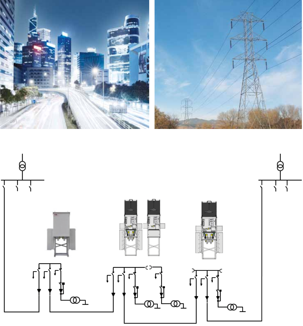
Applications
SafeLink CB for Secondary Distribution Network
4 SafeLink CB | Product brochure
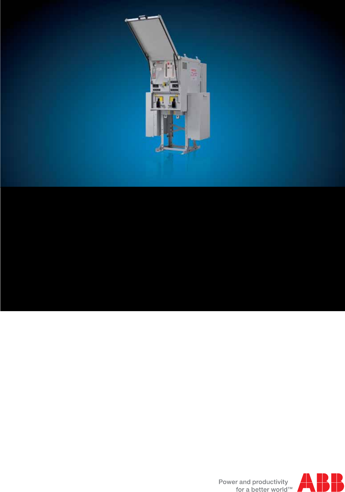
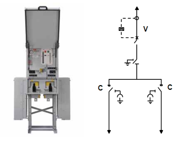
SafeLink CB is a SF6 insulated outdoor ring main unit for
applications in 12 kV medium voltage distribution networks.
SafeLink CB can be supplied with Ring Switch and/or Vacuum
Circuit Breaker configurations of CVC, +CVC+, +C+ and
+V+ with extensibility options. SafeLink CB offers a sealed
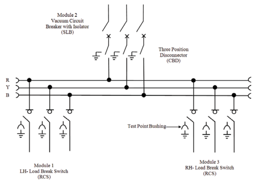
‘CVC’, ‘+CVC+’, ‘+C+’ & ‘+V+’ modules can be provided
where,
C – Cable / Ring Switch
V – Vacuum Circuit Breaker (with Disconnector on the busbar
side)
‘+’ symbol represents extensibility option
The SafeLink CB unit offers a circuit-breaker with relay
combination for protection of the transformer.
Applications
stainless steel tank which contains all the live components
and switching functions. The stainless steel tank is robotically
welded and is sealed for life ensuring high level of personnel
safety as well as maintenance free system.
SafeLink CB is designed for use in the following applications:
– Small industries
– Wind power plants
– Hotels, shopping centers, office buildings, business centers
etc.
– Light mining applications, airports
– Hospitals, tunnels and underground railways
Product brochure | SafeLink CB 5
Evolution - more functionality, compact dimensions
Secondary distribution switchgears have been subject to a
significant development in recent 20 years. The traditional
switching cells are substituted with complete switchgear
systems. Specific functions such as grounding, disconnecting,
cable connections, busbar extension, protection and
switching have become integrated features in compact
functional units. Compact switchgear systems fulfill customers
MV application requirements. ABB has always taken an active
part in this development. The most unique specialization
is the development of the compact secondary switchgear.
The numerous distribution substations requested a unified
switching functionality that evolved into the Ring Main Unit
concept. ABB’s SafeLink CB is adapted to the needs in the
utility distribution networks.
Customer’s involvement
The applied functionality in SafeLink CB is a result of input
from customers all over the world.
Key customers are continuously involved with ABB design
staff to ensure optimised switchgear operation.
Personnel – safety operation
All products are designed and manufactured in compliance
with ISO 9001, ISO 14001 and ISO 18001.The latest edition
of relevant IEC standards will always apply to our continuous
test programme. Safety is not only a specification and rating
issue, but also a real life experience.
All units are factory routine tested according to international
standards. ABB takes this further to be an objective related
to durability and repetitive manufacturing quality. Features for
further enhancing personnel safety are available. “Integrated
functionality” is a key objective to reduce the number
of moving components, further reducing the risk of any
mechanical defect.
Design philosophy
We are responsible for the environment
The location for manufacturing SafeLink CB is Nashik,
India. Green policy assures focus on environmental factors
in manufacturing as well as over the switchgear’s life span.
All products are manufactured in accordance with our ISO
14001 certification. Materials are carefully selected, to
ensure reuse at end of life. Recycling capability is 95% (for
details see chapter 10). To facilitate the recycling process we
continuously work along with our partners to improve end of
life handling.
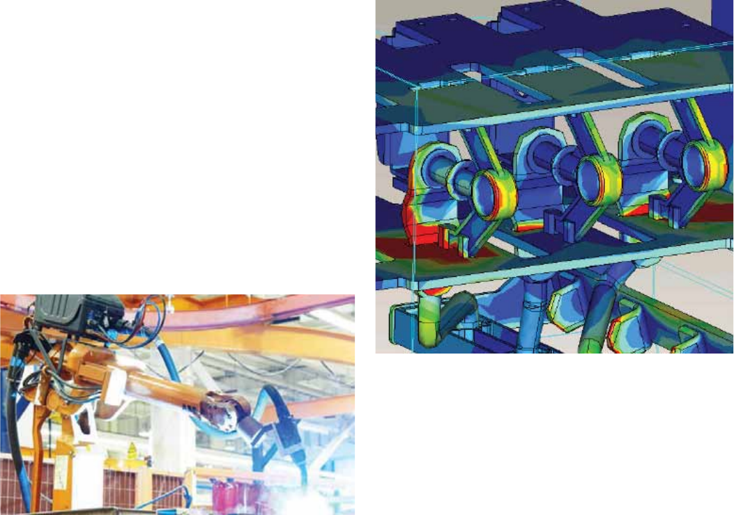
Modern - development and manufacturing
Numerical simulations together with long experience ensure
reliable and safe, compact and robust design. Dielectric
simulations ensure that compactness does not influence the
dielectric capability. The combination of design techniques;
experience and the most modern production technology
guarantee state of the art products and durability.
6 SafeLink CB | Product brochure
– C Cable / Ring Switch module with test point facility (3
positions ON-OFF-EARTH)
– V Vacuum Circuit Breaker module for relay transformer
protection (with manually operated
Disconnector).
SafeLink CB, can be also delivered as an extensible Ring Main
Unit.
SafeLink CB is supplied with the following standard
equipments
– Vacuum circuit breaker with disconnector
– Circuit breaker spring charged indication and indication for
ON and OFF
– Two-position mechanism with auto-reclosing duty for
vacuum circuit breaker
– Relay trip coil
– Manually operated 3 position disconnector
– 2 nos of three position switch disconnector cum earthing
switch
– Switch position indication for load break switch, earthing
switch and disconnector
– Single spring independent operated mechanism on 3
position switch disconnector cum earthing switch
– Cable bushings 400 series bolted with integrated
capacitive voltage indication provision
– Capacitive voltage indication
– Busbars, 630A
– Earthing bar
– Operating handle
– Lifting lugs for easy handling
Standard configuration CVC (non extensible)
Features overview
– Manometer for SF6 pressure
– All cable compartments fully interlocked with respective
Earthing Switches
– External structure – painted
– Test Point facility for Ring Cable Switches
– Fully interlocked Test Point Box for both ring switches
– Facilities for padlocks on switching disconnector, Earthing
Switches and Disconnector
– Arc proof cable compartments
Optional features, factory assembled or retrofit
– Signal (1NO) from internal pressure indicator wired to
terminals (one each SF6-enclosure)
– Motorised operation
– Shunt opening and closing release / coil (for vacuum circuit
breaker)
– Additional shunt opening release / coil (for vacuum circuit
breaker)
– Aux. switch (2NO+3NC or 3NO+2NC) for vacuum circuit
breaker positions
– Aux. switch (2NO+2NC) for switch disconnector / earthing
switch positions
– Aux. switch (2NO+2NC) for disconnector / earthing switch
positions
– Short circuit indicator and / or earth fault indicator for
switch disconnectors
– Extensible bushings (630 A) on the sides for connection of
external busbars
– Protective end box for extensible bushings
– External busbars for coupling 2 RMUs along with its
covering box (for extensible version)
Product brochure | SafeLink CB 7
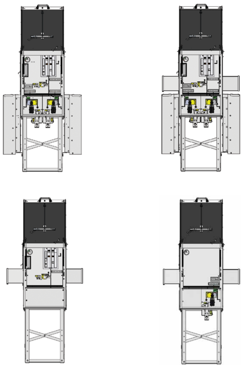
SafeLink CB is available in following configurations.
CVC non extensible
+V+ both side extensible
+CVC+ both side extensible
+C+ both side extensible
Configurations

8 SafeLink CB | Product brochure
Technical data
SafeLink CB is tested according to IEC standards IEC 62271-
200, IEC 62271-1, IEC 62271-100, IEC 62271-102, IEC
60265-1 and IEC 60529
Rated filling level for insulation 0.02 MPa
Short time current (on earthing circuit) 21 kA 1 sec
Internal arc classification (IAC) 20 kA 1 sec for inside tank
Rated normal current for external busbar 630 A (for extensible version)
C Module V Module
Switch
disconnector Earthing switch Vacuum circuit
breaker
Earthing switch /
disconnector
Rated voltage kV 12 12 12 12
Power frequency withstand voltage kV 38 38 38 38
- across disconnector kV 45 45 45 45
Lightning impulse withstand voltage kVp 95 95 95 95
- across isolating distance kV 110 110 110 110
Rated normal current* A630 630 630 630
Breaking capacities
- active load breaking current A630
- closed loop breaking current A630
- cable charging breaking current A25 25 (Class C2)
- line charging breaking current A 1 10 (Class C2)
- earth fault breaking current A75
- earth fault cable and line charging A43.5
- short circuit breaking current kA 21
Making capacity kA 52.5 (Class E2) 52.5 (Class E2) 52.5 (Class E2) see1)
Short time current (3-sec) kA 21 21 21 21
Mechanical operations Nos M1 (1000 CO) M0(1000 CO) M1+3000 M0 (1000 CO)
Rated operating sequence –0-0.3sec-CO-
3min-CO
1) Disconnector is manually operated; earthing operation is through vacuum BKR. Hence no making capacity assigned
*suitable derating shall be applied for ambient temperatures greater than 40˚C
Product brochure | SafeLink CB 9
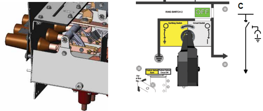
C – Cable switch
The Ring Cable Switch (C-Module) is a three position switch
disconnector and earthing switch using SF6 gas as an arc
quenching and insulating medium. The switch positions are
Close – Open – Earthed. In the open position the switch
satisfies the disconnector requirements. C module is provided
with test point bushings protruding on bottom side of the tank
as standard.
Standard features
– Three position load break switch with disconnector and
earthing switch
– Single spring latched mechanism with common operating
shaft for load break and earthing function
– Switch position indication for load break switch and
earthing switch
– Cable bushings horizontal on the sides, Interface C
(400 series bolted) with integrated capacitor for voltage
indication
– Busbars, 630A
– Bushings for cable testing (incl. earthing device test
points)
– Arc proof cable covers
– Interlocking
- Cable compartment on the sides interlocked with
respective earthing switch
- Interlocking of test point bushing box with respective
earthing switch
– VPIS (Voltage Presence Indicating System) with integrated
indicator lamps
– Padlock for all three positions of ON-OFF-EARTH
– End box for extensible bushings (if present)
Optional features (also available as retrofit)
– Extensible bushing for connection of external busbars on
side (630 A)
– Signal (1NO) from internal pressure indicator wired to
terminals (only one for each SF6 tank)
– Motorised operation for Load Break Switch
– Aux. switch (2NO+2NC) for switch disconnector / Earthing
Switch positions
– Short circuit and / or earth fault indicator
10 SafeLink CB | Product brochure
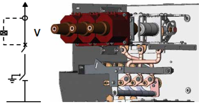
The vacuum circuit breaker (V-module) has vacuum bottles
for short-circuit current interruption. A three position
disconnector is connected in series with the circuit-breaker
on the busbar side. The operation between vacuum circuit
V – Vacuum circuit breaker
Standard features
– 630 A vacuum circuit breaker
– Two position EL2 trip free mechanism with auto-reclosing
facility for vacuum circuit breaker
– Mechanical signaling device for closing springs charged /
discharged
– Mechanical signaling device for circuit-breaker open /
closed
– Lever for manually charging the closing spring of
mechanism
– Closing pushbutton, opening pushbutton
– O-C-O operation possibility with closing spring in charged
condition
– Manually operated three position disconnector with
earthing switch in series
– Interlocking between vacuum circuit breaker and
disconnector
– Position indication for disconnector and earthing switch
– Self powered electronic protection relay with ring core CTs
on T-off side cable bushing
– Solenoid / trip coil (for relay tripping)
– Cable bushings with interface C (400 series bolted) with
integrated capacitor for voltage indication
– Main busbar, 630A
– Arc proof cable compartment cover on the back side
– Cable compartment cover interlocked with earthing switch
and vacuum circuit breaker
– Manometer
– VPIS (Voltage Presence Indicating System) with integrated
indicator lamps
– End box for extensible bushings (if present)
Optional features available as retrofit
– Extensible bushing for connection of external busbars on
side (630 A)
– Signal (1NO) from internal pressure indicator wired to
terminals (only one for each SF6 tank)
– Spring charging geared motor with electrical signaling of
spring charged
– Auxiliary switches
- Vacuum Circuit Breaker position 3NO+2NC or
2NO+3NC
- Disconnector / earthing position 2NO+2NC
– Shunt opening and closing release / coil
– Additional shunt opening release
– Operation counter for breaker ON-OFF operations
– Contact signaling closing spring charged / discharge
– Covering box for externally coupled busbars
breaker and disconnector as well as between disconnector
and earthing switch are mechanically interlocked. The
earthing of the T-off side cable is done through the vacuum
interrupters.
Product brochure | SafeLink CB 11
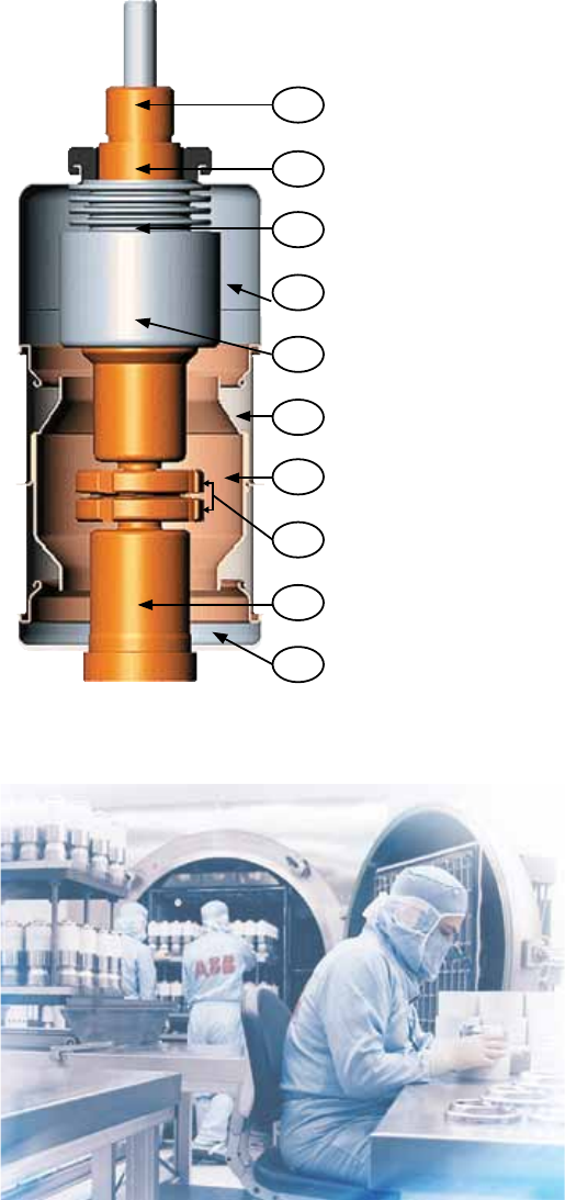
The vacuum interrupter bottles are manufactured in world
class ABB facility with main contacts in copper chromium
material. Vacuum interrupting technology offers advantage
of high dielelectric strength at short gap distances making it
ideal for use in medium voltage products.
The vacuum circuit breaker does not require an interrupting
and insulating medium. In fact, the interrupters do not
contain ionisable material. In any case, on separation of the
contacts an electric arc is generated made up exclusively
of melted and vaporized contact material. The electric arc
remains supported by the external energy until the current
is cancelled in the vicinity of natural zero. At that instant,
the rapid reduction in the load density carried and the rapid
condensation of the metallic vapour, leads to extremely
rapid recovery of the dielectric characteristics. The vacuum
interrupter therefore recovers the insulating capacity and
the capacity to withstand the transient recovery voltage,
definitively extinguishing the arc. Since high dielectric strength
can be reached in the vacuum, even with minimum distances,
interruption of the circuit is also guaranteed when separation
of the contacts takes place a few milliseconds before passage
of the current through natural zero. The special geometry
of the contacts and the material used, as well as the limited
duration and low voltage of the arc, guarantee minimum
contact wear and long life. Furthermore, the vacuum prevents
their oxidation and contamination.
Vacuum interrupter and current interruption
1 Stem / terminal
2 Twist protection
3 Bellows
4 Interrupter housing
5 Shield
6 Ceramic insulator
7 Shield
8 Contacts
9 Terminal
10 Interrupter housing
1
2
3
4
5
6
7
8
9
10
Vacuum Interrupter
Clean Room for VI Production
12 SafeLink CB | Product brochure
In a vacuum interrupter, the electric arc starts at the moment
of contact separation and is maintained until zero current and
can be influenced by magnetic fields.
Vacuum arc – diffuse or contracted
Following contact separation, single melting points form
over the entire surface of the cathode, producing metal
vapours which support the arc. The diffuse vacuum arc is
characterised by expansion over the contact surface and by
an even distribution of thermal stress on the contact surfaces.
At the rated current of the vacuum interrupter, the electric arc
is always of the diffuse type. Contact erosion is very limited
and the number of current interruptions very high.
As the interrupted current value increases (above the rated
value), the electric arc tends to be transformed from the
diffuse into the contracted type, due to the Hall effect.
Starting at the anode, the arc contracts and as the current
rises further it tends to become sharply defined. Near the area
involved there is an increase in temperature with consequent
thermal stress on the contact. To prevent overheating and
erosion of the contacts, the arc is kept rotating. With arc
rotation it becomes similar to a moving conductor which the
current passes through.
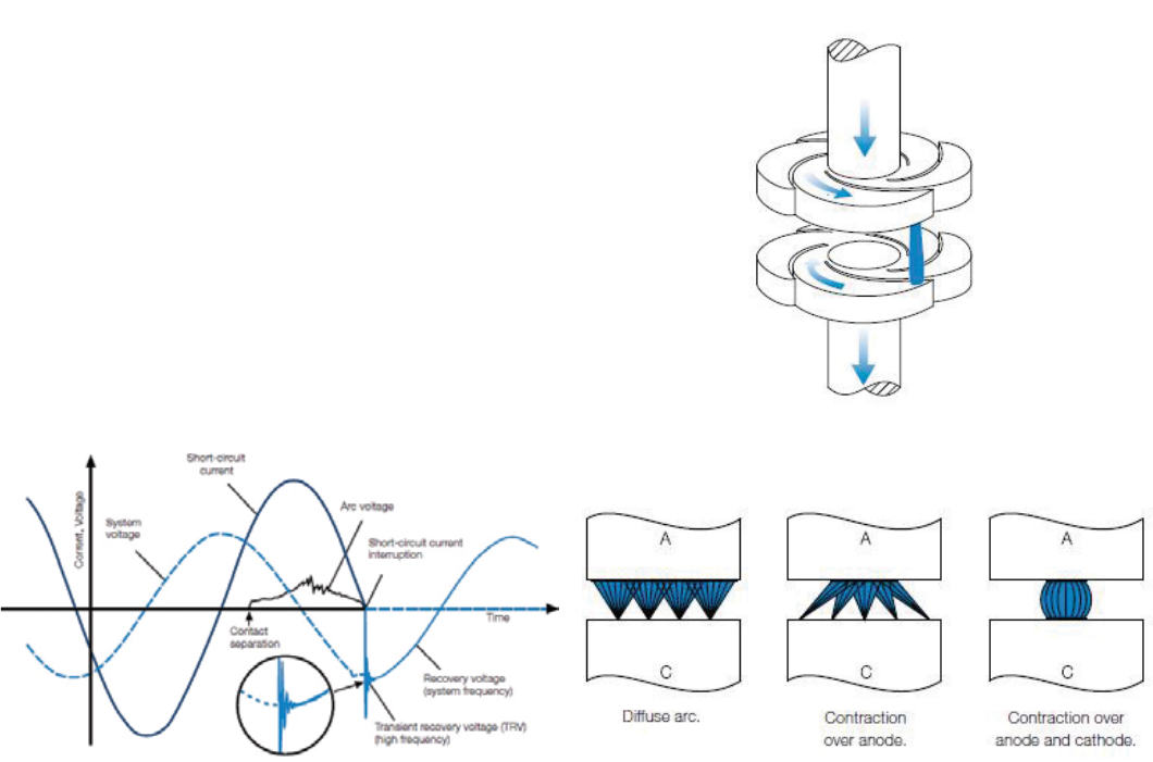
Quenching principle of ABB interrupter
The spiral geometry of ABB vacuum interrupter contacts
The special geometry of the spiral contacts generates a radial
magnetic field in all areas of the arc column, concentrated
over the contact circumferences. An electromagnetic force
is self-generated and this acts tangentially, causing rapid arc
rotation around the contact axis. This means the arc is forced
to rotate and to involve a wider surface than that of a fixed
contracted arc. Apart from minimising thermal stress on the
contacts, all this makes contact erosion negligible and, above
all, allows the interruption process to be controlled even with
very high short-circuits. ABB vacuum interrupters are zero-
current interrupters and are free of any re-striking. Rapid
reduction in the current charge and rapid condensation of the
metal vapours simultaneously with the zero current, allows
maximum dielectric strength to be restored between the
interrupter contacts within microseconds.
Radial magnetic field contact arrangement with rotating vacuum arc
Schematic diagram of the transition from a diffuse arc to a contracted arc
in a vacuum interrupter.
Development of current and voltage trends during a single phase vacuum
interruption process
Product brochure | SafeLink CB 13
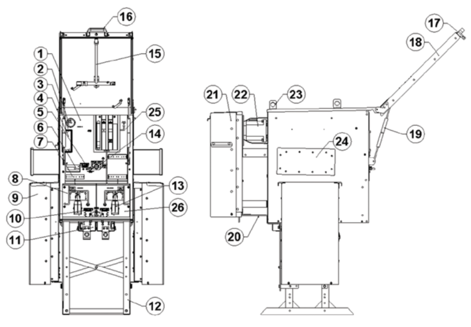
+CVC+ Configuration (Extensible)
1. Rating plate
2. Manometer
3. Front upper mimic
4. Relay
5. VCB disconnector padlock
6. Fault indicator
7. VPIS for ring switch RHS
8. Ring Switch RHS
9. Cable box for ring switch RHS
10. Padlock for ring switch RHS
11. Test point box for ring switch RHS
12. Switchgear stand
13. Earth & circuit slider for ring switch
14. VCB disconnector
15. Operating handle
16. Door handle
17. Padlocking for switchgear front door
18. Switchgear front door
19. Gas Spring for switchgear front door
20. Switchgear earthing
21. T-Off cable box (For VCB)
22. Current transformer (Directly mounted on VCB bushings)
23. Lifting hook for switchgear
24. End box (for extensible version only)
25. ‘V’ module section
26. ‘C’ module section
14 SafeLink CB | Product brochure
Functions overview
Covers
Upper and lower front mimic covers inside the front door have
a thickness of 2 mm mild steel for displaying functions on the
front side. The front mimic diagram shows the main circuit
with the mechanical / position indicators for the switching
devices and also spring charged condition for circuit breaker.
Background color for these foils is light grey (RAL 7035). The
upper and lower front mimics cover are removable.
The external structure is powder painted with color RAL
7035 as standard. The side sheets are of 2 mm mild steel.
All cable compartment covers are removable. The Ring Cable
Switches have separate cable compartments on the side
whereas the T-off side circuit breaker module has the cable
compartment on the back. In case of an arc fault inside the
SF6 tank, followed by an opening of the pressure relief in the
rear-bottom of the tank, the gases are routed to the bottom
but towards the back in between the space of T-off cable box
and rear sheet of the unit.
Product brochure | SafeLink CB 15
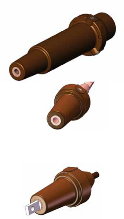
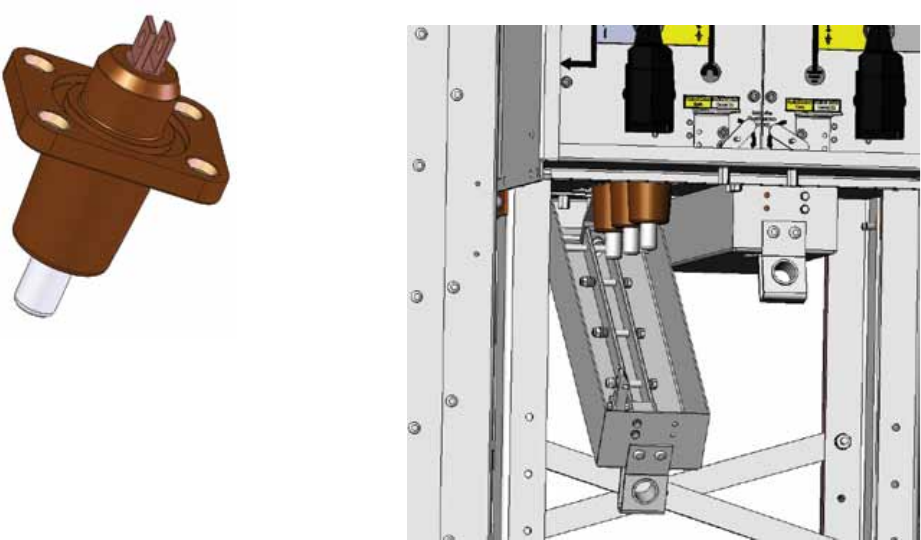
The connection of the HV-cables is made by cable bushings.
The bushings are made of cast resin with molded-in
conductors. In addition, an earthed screen is moulded in
to control the electrical field and is also used as the main
capacitor supplying the voltage indicating systems.
ABB also has experience with bushings for SF6 switchgears
since 1985 with high performance and quality. A very large
number has been installed worldwide in distribution networks,
power stations and industrial complexes. Used together with
fully screened connectors it is an ideal solution for areas with
humidity or condensation problems.
SafeLink CB has 2 types of cable bushings as shown below
1) For ring cable switch
2) For T-off side vacuum circuit breaker
The bushings are designed according to EN 50181 and are
of type Interface C (400 series with M16 bolted contact,
In=630A).
In addition to the above, in case of external busbar
connection required between two extensible Ring Main
Units, following type of bushings fitted on the side(s) is used.
Connection is bolted type with sleeved busbars.
Bushings
T-off cable bushing
Extensible Connection Bushing
Switch Cable Bushing
16 SafeLink CB | Product brochure
‘C’ modules of SafeLink CB are equipped with cable test
bushings on the bottom side of the tank. Each set of
test cable bushings have separate covering box which is
interlocked with respective earthing switches to avoid access
to the cable test compartment before earthing switch is in
closed position.
When these bushings are mounted, cable insulation test can
easily be done according to the following procedure:
1. Close the earthing switch after having checked the voltage
indicators
2. Remove the handle and bring the mimic selector switch to
‘Blocked Position’
Cable test bushings
3. Open the test point box which removes the common
earthing bar
4. Install the injection device onto the access terminals and
perform cable testing
5. After cable testing close the test point box.
6. Move the selector switch to ‘Earth open position’, insert
the handle
7. Open the earthing switch
Please follow cable manufacturer instructions for cable testing
purpose.
TP Bushing
TP box area in a CVC Unit
Product brochure | SafeLink CB 17
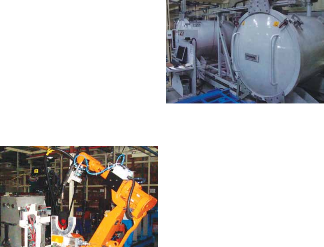
SafeLink CB is gas insulated switchgear using SF6 as an
insulating and quenching medium. The complete switchgear is
assembled and supported inside stainless steel welded tank.
High precision and programmed ABB robots are used for
the welding ensure high quality welded joints. Electrical and
mechanical bushings penetrating the tank are clamped and
sealed to the tank by high quality ‘O’ rings. The mechanical
bushings have in addition a rotating shaft which connects
the shaft of the switch to the corresponding shaft of the
mechanism. The rotating shaft is sealed by double set of gas
seals.
All assembled Ring Main Units tanks have to pass through a
stringent and pre-programmed leakage test before filling the
equipment with SF6. Leakage test and gas filling are done
inside a common chamber. The first step in the leakage test is
to evacuate all air inside both SF6 tank and vacuum chamber
simultaneously. Helium gas is used for testing and monitoring
the leaks if any in all the sealing and welding areas. Helium
being inert and light gas can easily penetrate in extremely
small pores of the weldments. Due to the characteristic of
Helium this test will detect absolutely all possible leakages.
Switchgear tank on a successful and leak free test is then
filled with SF6 gas after removal of Helium. The stainless steel
tank on account of the construction, production process has
a degree of protection of IP67.
Automatic gas filling and leakage testing station
Completely sealed enclosure
Stainless steel tanks of SafeLink CB Ring Main Units are
classified as sealed pressure system as defined in IEC and
are sealed for life with an operating life time of 30 years.
The leakage rate is less than 0.1% per year. This ensures
adequate pressure of SF6 gas for maintaining insulation and
quenching levels for the required switching and breaking
conditions throughout the specified operating life.
18 SafeLink CB | Product brochure
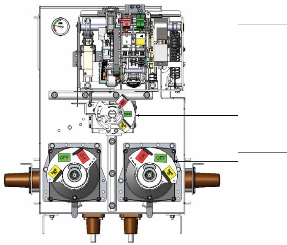
All operating mechanisms are situated outside the SF6-tank
behind the front mimic covers with degree of protection of
IP2X. This gives the opportunity of access to all operating
mechanisms if retrofit or service should be required.
The speed of operation of these mechanisms is independent
of the operator (except the manually operated three position
disconnector of the circuit breaker).
To prevent access to cable compartment before earthing
switch is in closed position, all mechanisms are provided with
mechanical interlocks which make it impossible to remove the
cable compartment covers. It will then also be not possible
to operate load break / disconnector switch to open position
before cable compartment cover is mounted properly.
Mechanism compartment view
Mechanisms and interlocks
Ring switch and dsconnector mechanisms are equipped
with padlocking facility with suitable holes which when
used will restrict the access to operate the mechanism. All
operating mechanisms are equipped with mechanical position
indicators for ON-OFF-EARTH conditions. In addition the
circuit breaker mechanism also has indication to show spring
charged / discharged condition. Operating handle is required
only for the ring switch disconnector and manually operated
disconnector. For ring switch mechanism there is anti-reflex
system which prevents an immediate re-operation of the
switch. All steel parts are electroplated with zinc and then
chromotised.
EL2 mechanism
for vacuum circuit
breaker
Manually operated
disconnector
Mechanism for
switch disconnector
Product brochure | SafeLink CB 19
Cable Switch (C)
The ring switch mechanism has one single operating shaft for
the load break switch and for the earthing switch function.
Shaft is operated by single spring. When both load break
switch and earthing switch are in open position the switch
satisfies the specifications of disconnector. Due to selector
switch interlock inside the mechanism, it is impossible to
operate the load break switch when earthing switch is in
earthed position or operate the earthing switch when the load
break switch is in closed position.
The lower mechanism is manually operated and is without
any spring / latched action. It has 3 positions of OPEN,
CLOSE and EARTH which can be padlocked after the pull for
disconnector knob is in the respective slot / position.
mechanical commands. Should both the closing command
and any one of the opening commands (local or remote)
be active at the same time, there would be a continuous
succession of opening and closing commands. The anti-
pumping device avoids this situation, ensuring that each
closing operation is only followed by an opening operation
and that there is no other closing operation after this. To
obtain a further closing operation, the closing command
must be released and then re-launched. Furthermore, the
anti-pumping device only allows circuit breaker closure if the
following conditions are present at the same time:
– Operating mechanism spring fully charged
– Opening pushbutton and / or shunt opening release
(-MO1 / -MO2) not activated
– Circuit-breaker open.
Ring switch mechanism
There is a mechanical interlock between these two
mechanisms which prevents operating of the disconnector
and / or earthing switch when the circuit-breaker is in closed
position.
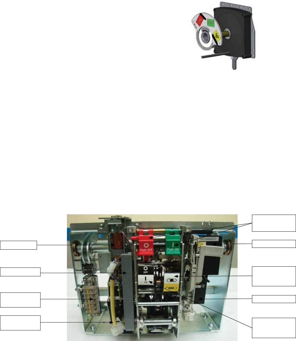
Vacuum circuit breaker (V)
This module has two mechanisms; the upper one (EL2) is for
vacuum circuit breaker and the lower one is manually operated
with single operating shaft for the three position disconnector.
The EL mechanism is provided with a lever for manually
charging the closing spring. The Vacuum Circuit Breaker has
the possibility of rapid auto-reclosing duty. By means for
mechanical push buttons it is possible to close and open the
circuit-breaker. The opening spring is always charged when
the circuit-breaker is in closed position and will be ready to
open immediately if the protection relay gives a trip signal.
If the mechanism is recharged after closing, it is possible to
perform Open - Close - Open sequence.
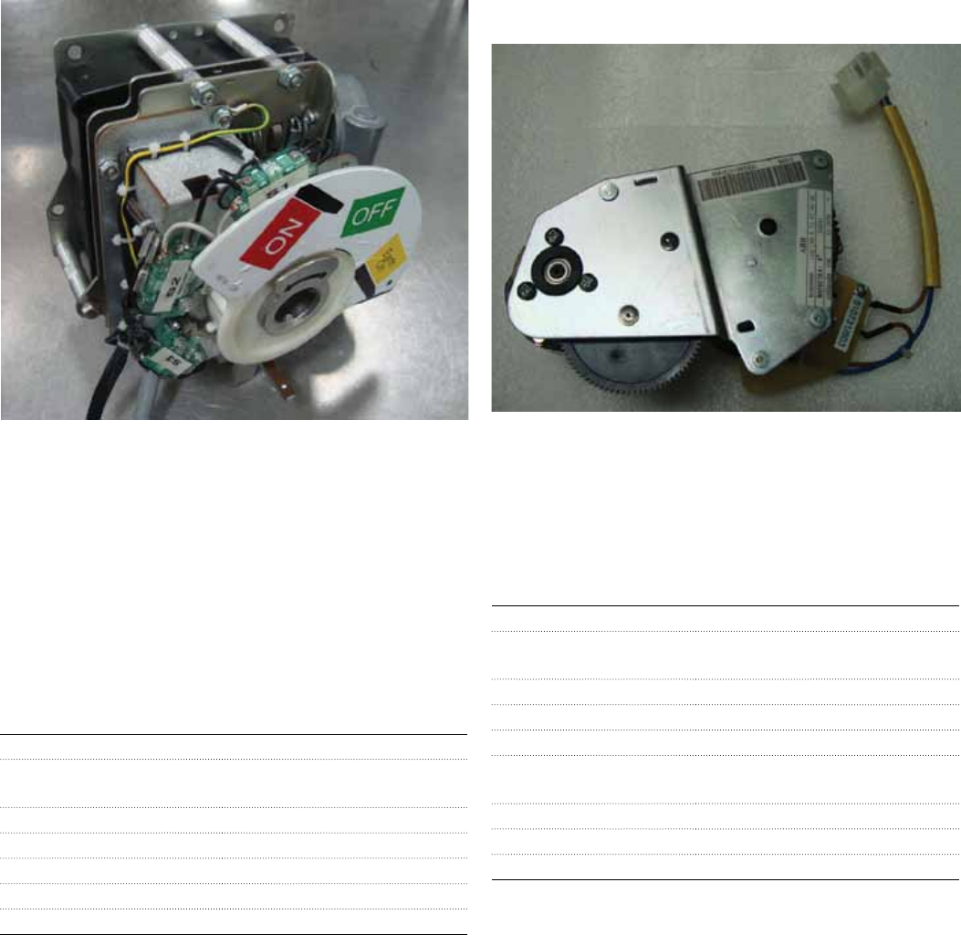
The EL mechanism is fitted with a mechanical anti-pumping
device which prevents re-closing due to either electrical or
Relay trip coil
Push buttons for
ON-OFF
Shunt close coil
Spring charged/
discharged
indication
Shunt trip coil
Circuit breaker
ON-OFF position
indicator
EL2 mechanism
Auxiliary switch,
Type BB1 / BB2
Motor for EL2
mechanism
Mechanisms and interlocks
20 SafeLink CB | Product brochure
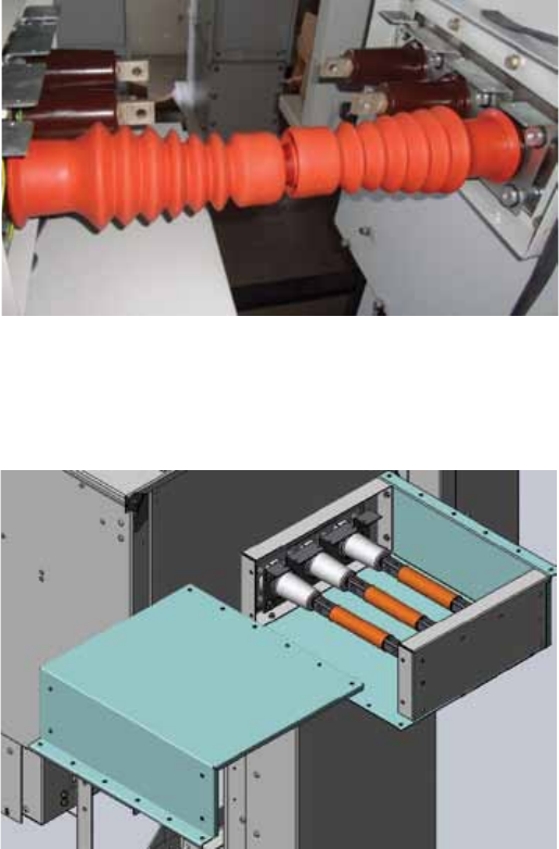
SafeLink CB can be provided with extensible bushings on
side(s), for connection of external busbars on LHS and / or
RHS side. The extensible bushing rated for 630 A has molded
screen and is earthed to the switchgear body. A factory
fitted end box is provided for covering extensible bushings.
All extensible configurations of SafeLink CB will be always
extensible on both sides.
The length of the coupling busbar is of standard size
irrespective of the configuration of extensible RMU’s. For
detailed coupling instruction between two extensible SafeLink
CB RMU’s separate instruction document 1VYN403090-067
is to be followed.
Covering box as shown below is used to protect the busbars
in coupled condition during installation at site
Sleeved busbars in coupled condition with insulating boot
Covering boxes to protect busbars in coupled condition
External busbar and bushings
Sleeved busbar in coupled condition and with insulating boot/
covering (RCAB) version is shown below.
Product brochure | SafeLink CB 21
1) Motorised version for ring cable switch
Closing and opening operations of mechanism for Ring Cable
Switches can be performed with a motor operation.
2) Spring charging motor for vacuum circuit breaker
Charging of the closing spring of the EL2 mechanism for
the vacuum circuit breaker can be performed with a motor
operation. Manually operated disconnector and earthing
switch of the V-module does not have this possibility.
Operating cycle for motor operation is CO - 3 min (i.e. it may
be operated with a frequency of up to one close and one
open operation every third minute).
Motors and coils can easily be mounted to the mechanisms
after delivery (retrofit). Test voltage for tables below is + 10 /
-15 % for motor operations and closing coils and +10 / -30%
for trip coils and opening coils. The motor and coils can be
retrofitted after delivery.
Auxiliaries like motor drives and auxiliary switches are located
behind the lower mimic.
This carries out automatic charging of the circuit-breaker
operating mechanism closing spring. After circuit-breaker
closing, the geared motor immediately recharges the closing
springs. In the case of a power cut or during maintenance
work, the closing spring can be charged manually in any case
(by means of the crank handle incorporated in the operating
mechanism).
Characteristics Specifications
Rated voltages for motor (Un) 24 VDC, 48 VDC, 60 VDC, 110
VDC, 220 VDC, 110 VAC, 230 VAC
Voltage variation 85-110% Un
Rated power consumption (max) 90 W, 90 VAC
Charging time < 8 sec
Insulation voltage 2 kV 1 min (50 Hz)
Characteristics Specifications
Rated voltages for motor (Un) 24 VDC, 48 VDC, 60 VDC, 110 VDC,
220 VDC, 110 VAC, 230 VAC
Voltage variation 85-110% Un
Inrush power (Ps) 600 W,
600 VAC
Rated power (Pn) 200 W,
200 VA
Charging time < 10 sec
Inrush time 0.2 sec
Insulation voltage 2 kV 50 Hz for 1 min
Motor operation
22 SafeLink CB | Product brochure
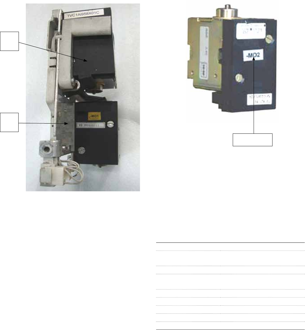
1 Shunt opening release (-MO1)
This allows remote opening control of the circuit breaker. The
release can operate both in direct and alternating current.
This release is suitable for both instantaneous and permanent
service. In the case of instantaneous service, the minimum
current impulse time must be 100 ms.
2 Additional shunt opening release (-MO2)
Like the shunt opening release described above, this allows
remote opening control of the circuit breaker and can be
supplied by a circuit completely separate from the release
(-MO1).
3 Shunt closing release (-MC)
This allows remote closing control of the circuit breaker. The
release can operate both in direct and alternating current.
This release is suitable both for instantaneous and permanent
service. In the case of instantaneous service, the minimum
Characteristics Specifications
Rated voltages for motor (Un) 24 VDC, 48 VDC, 60 VDC, 110 VDC,
220 VDC, 110 VAC, 230 VAC
Operating limits 70-110% Un
Inrush power (Ps) max 300 W,
300 VAC
Continuous power (Pc) 5 W, 5 VA
#Closing time* (ms) 40-70
#Opening time (ms) 40-80
Inrush duration (ms) approx 100
Insulation voltage 2 kV 50 Hz for 1 min
Shunt releases
current impulse time must be 100 ms. Use of the permanently
supplied release is recommended to carry out the electrical
anti-pumping function.
Characteristics for MO1, MO2 and MC coil / releases
Shunt
close
coil
Shunt
trip
coil
Additional shunt
trip coil
Product brochure | SafeLink CB 23
Auxiliary / Signal contacts
1) Vacuum circuit-breaker auxiliary contacts (-BB1, -BB2)
Electrical signaling of circuit-breaker open / closed position
can be provided with a group of 5 auxiliary contacts as
standard. These are with combination of break contacts
(signaling circuit-breaker open) and make contacts (signaling
circuit-breaker closed) i.e. with options of BB1 (3NO+2NC) or
BB2 (2NO+3NC).
2) Switch disconnector / circuit breaker disconnector auxiliary
contacts
Switch disconnector / earthing switch and circuit breaker
disconnector can be provided with 2NO+2NC for each of the
positions
3) Contact for signaling circuit breaker closing spring charged
/ discharged (-BS2)
This consists of a micro switch which allows remote signaling
of the state of the circuit-breaker operating mechanism
closing spring. The following signals are possible:
– Contact open: signaling spring charged
– Contact closed: signaling spring discharged.
The two signals must be used for circuits which have the
same power supply voltage
24 SafeLink CB | Product brochure
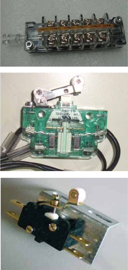
VPIS and indicators
VPIS
All modules are equipped with capacitive voltage indication
type VPIS (Voltage Present Indicating System). This system
has integrated LEDs. The LED starts to flicker when there is a
system voltage between 10%-45% of line to ground voltage.
By means of the sockets in VPIS it is possible to carry out
phase balance check using suitable phase comparators.
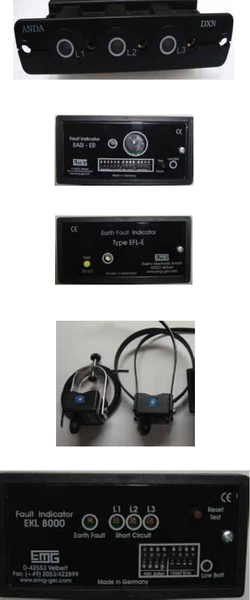
Combined short circuit and earth fault can be also provided.
The indicator set consists of one reading instrument, four
sensors (one sensor on the 3 core cable and three for the
individual 1 core cables) and four fiber optic cables. Earth
fault and short circuit can be indicated via one LED each or
short circuit via one LED for each core, one LED for earth
fault. Besides this a remote indication for earth fault and short
circuit via one relay contact can be also provided.
Short circuit and / or earth fault indicators
Earth fault and / or short circuit indicators according to the
DIN standards can be provided for both the Ring Cable
Switches.
Shown above are panel mounted reading instruments. The
reading instrument is equipped with a LED. The LED starts to
blink, if the pre-adjusted operating current has been reached
or exceeded. It can be reset manually or automatically after
a certain defined delay. Test push button is provided and
contact(s) for remote indication can be also provided. For
different operating points / current settings, kindly check
individual catalogues.
Earth Fault and Short Circuit Indicator
Sensors
Earth Fault Indicator
Earth Fault Indicator
Product brochure | SafeLink CB 25
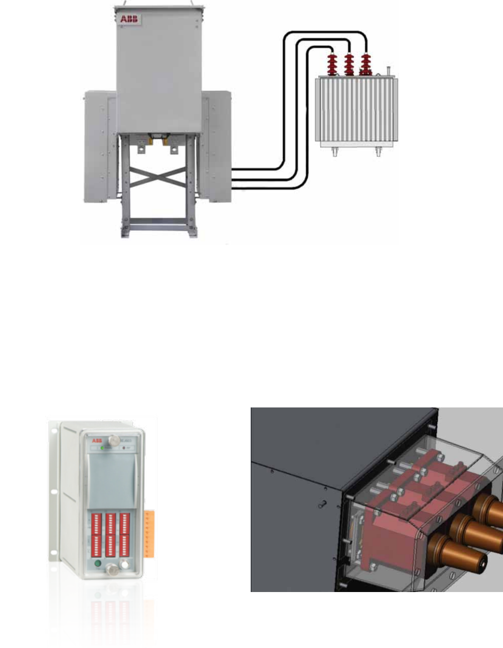
ABB REJ 603 relay
CT’s mounted on T-off side bushings
Transformer protection and relay
SafeLink CB offers a circuit-breaker in combination with
relay for transformer protection which has better protection
against low over-currents. Circuit-breaker with relay is always
recommended for higher rated transformers. SafeLink CB is
delivered with 630 A rated V-module. SafeLink CB has relay
which is a self powered relay that utilizes the energy from
the CTs under a fault situation, for energizing the trip coil.
The CT’s for the vacuum circuit breaker are mounted on the
T-off side cable bushings. The self powered relay can also be
used for cable protection and more details on the different
relays can be found in relay manufacturer’s catalogue. Relay is
mounted behind front door.
Typical for vacuum circuit breaker protection:
– Good protection against short-circuits
– Very good for protection of over currents
– Small fault currents are detected in an early stage
Relay characteristics
– Economical
– Easy adjustment
– Perfect for large distribution transformers
– REJ603: ABB relay option with HMI
– Other relays with advanced over current and earth fault
functions available
26 SafeLink CB | Product brochure
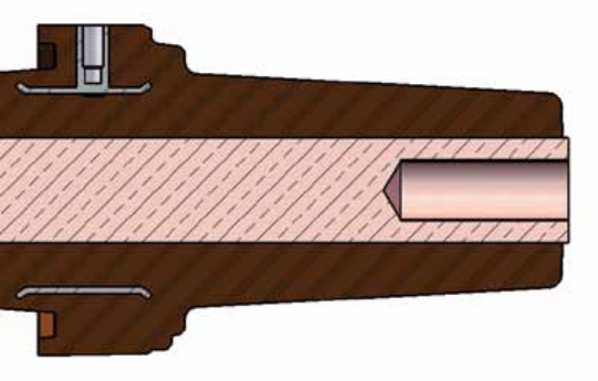
SafeLink CB is equipped with cable bushings which comply
with EN 50181 and IEC 60137 for termination of cables. The
cable bushing has following external interface:
Interface C with M16 x 2 metric threads
400 series, In = 630 A
Standard on C, V (In=630A)
All cable bushings are protected by cable compartment cover.
The installation instructions from the manufacturer of cable
terminations must be followed. Be sure to lubricate the
bushings thoroughly with the silicone grease supplied. Where
cables are not connected, the earthing switch must be locked
in closed position or the bushings must be fitted with dead
end receptacles before the unit is energized.
Cable bushing cross section
Cable terminations
The following manufacturers of cable terminations are
recommended:
– ABB Kabeldon
– Euromold / Elastimold
– Tyco / Raychem
– 3M
The cable bushings are situated on a height from the
foundation level as per the details in next section.
Product brochure | SafeLink CB 27
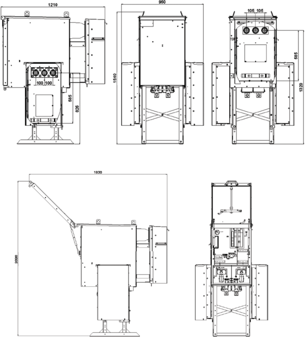
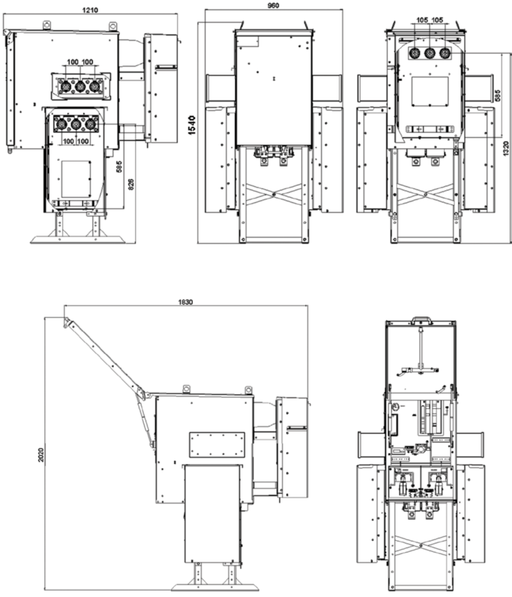
Unit dimensions* (CVC)
Side view with open door Front View with open door
RHS view Front view Back view
* All dimensions are in mm
28 SafeLink CB | Product brochure
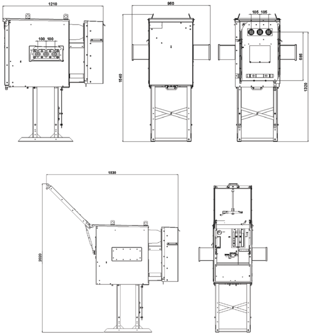
Unit dimensions* (+CVC+)
RHS view
Side view with open door Front view with open door
Front view Back view
* All dimensions are in mm
Product brochure | SafeLink CB 29
Unit dimensions* (+V+)
Side view with open door Front view with open door
* All dimensions are in mm
RHS view Front view Back view
30 SafeLink CB | Product brochure
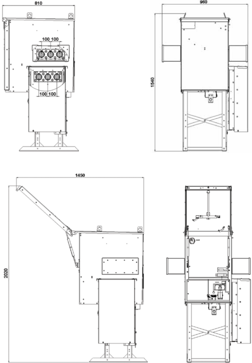
Unit dimensions* (+C+)
* All dimensions are in mm
RHS view
Side view with open door Front view with open door
Front view
Product brochure | SafeLink CB 31
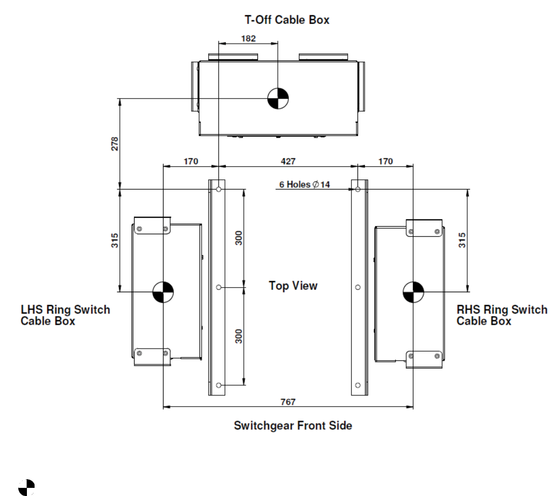
Footprint / Foundation detail*
Following picture shows the footprint of SafeLink CB for
foundation purpose considering a typical CVC configuration
and its related cable entry positions1
1 Dimensions for T-off cable box to be considered for +V+ configuration and RHS Ring Switch Cable Box to be considered for +C+ configuration.
* All dimensions are in mm. 6 holes of Dia. 14. are provided for foundation fixing purpose.
Dowel Pin symbol indicates Cable Entry positions.

32 SafeLink CB | Product brochure
SafeLink CB is validated as per the following IEC standards
Standards
IEC 62271-1 High-voltage switchgear and controlgear
Part 1: Common specification
IEC 62271-100 High-voltage switchgear and controlgear
Part 100: High-voltage alternating-current circuit breakers
IEC 62271-102 High-voltage switchgear and controlgear
Part 102: Alternating current disconnectors and Earthing Switches
IEC 62271-105 High-voltage switchgear and controlgear
Part 105: Alternating current switch-fuse combination
IEC 62271-200 High-voltage switchgear and controlgear
Part 200: A.C. metal enclosed switchgear and controlgear for rated voltages above 1kV and upto and including 52 kV
IEC 60265-1 High voltage switches- Part 1: Switches for rated voltage above 1 kV and less than 52 kV
IEC 60529 Degree of protection provided by enclosures (IP codes)
Product brochure | SafeLink CB 33
Normal ambient conditions
SafeLink CB is generally equipped for operation / service in
normal indoor and outdoor conditions in accordance with IEC
62271-1. The following limitations apply:
Ambient temperature
Max. temperature +40°C
Max. temperature (24-hour average) +35°C
Min. temperature - 25°C
Humidity
Max. average relative humidity measured over 24 hours 95%
Max. average relative humidity measured over 1 month 90%
Max height above sea level for installation without reducing
gas pressure 1000 meters
Special conditions
In accordance with IEC 62271-1, the manufacturer and
end-user must agree about special operating conditions
which deviate from operation under normal conditions. The
manufacturer / supplier must be consulted in advance if
especially difficult operating conditions are involved. When
electrical equipment is installed at more than 1000 meters
above sea level, for example, the atmospheric pressure will
be lower and the overpressure in the tank will have to be
reduced.
Operating conditions

34 SafeLink CB | Product brochure
General data, enclosure and dimensions
1Type of Ring Main Unit & Compact Switchgear Metal enclosed switchgear and control gear according to IEC 62271-200
2Number of poles 3
3Pressure test on gas filled tank 1.728 bar abs (1 min withstand test)
4Facility provided with pressure relief Yes
5Insulation gas SF6
6Nominal operating gas pressure 1.2 bar abs at 20°C
7Minimum functional gas pressure 1.1 bar abs at 20°C
8Gas leakage rate / annum Less than 0.1%
9Expected operating lifetime 30 years
10 Facilities provided for gas monitoring Yes, temperature compensated manometer can be delivered
11 Material used in tank construction Stainless steel sheet
12 Main busbar 320 mm2 Cu
13 Earth bar external 120 mm2 Cu
14 Overall dimension of fully assembled RMU
(width x height x depth)
CVC,+CVC+ & +V+
+C+
960 x 1540 x 1210 (mm)
960 x 1540 x 810 (mm)
15 Approximate weight of standalone standard units excluding
additional equipments and transport pallets
CVC,
+CVC+
+V+
+C+
325 kg
355 kg
275 kg
215 kg
16 Distance between adjacent side sheets for extensible RMU’s in
coupled condition
512 mm

Product brochure | SafeLink CB 35
Operations, degree of protection and color
1Means of switch and disconnector operation separate handle
2Means of circuit breaker operation Inbuilt handle and push button
3Rated operating sequence of circuit breaker O - 0.3 sec - CO - 3 min - CO
4Total opening time of circuit breaker 40-80 ms approx
5Closing time of circuit breaker 40-70 ms approx
6Mechanical operations of switch 1000 CO
7Mechanical operations of all earthing switches 1000 CO
8Mechanical operations of disconnector 1000 CO
9Mechanical operations of circuit breaker 5000 CO
Load break switch
10 Rated operation on short circuit current (Class E2) 3
11 Rated operations mainly active load 100
Degree of protection
12 High voltage live parts, SF6 tank IP 67
13 Front mimic and mechanism cover IP 2X
14 Protection class for external structure and cable box IP 54
Colors
15 Front mimic RAL 7035
16 External structure and cable covers RAL 7035 (standard)
Cable compartment data
17 Phase to phase center distance (Ring Switch Side) 100 mm
18 Phase to phase center distance (T-off side) 105 mm
19 Phase to phase clearance (min) 75 mm
20 Phase to earth clearance 65 mm
21 Phase to earth over insulator surface (creepage) 110 mm
22 Type of cable termination adapters Elbow or T-connector
36 SafeLink CB | Product brochure
Life expectancy of Product / environment declaration:
The product is in compliance with the requirements denoted
by IEC 62271-200. The design incorporates a life span under
normal service conditions (IEC 62271-1 subclause 2.1). The
switchgear is gas-tight and classified as sealed pressure
system*) with an expected operating life exceeding 30 years
and a diffusion rate of less than 0.1 % per year (IEC 62271-1
subclause 5.15 and annex E). Referring to the filling pressure
of 1.2 bar, the switchgear will maintain gas-tightness and a
gas-pressure better than 1.1 bar*) throughout its operating
life.
*) No topping up required during operating life at 20°C
Environment
End-of-life
ABB is committed to the protection of the environment and
adhere to ISO 14001 standards. It is our obligation to facilitate
end-of-life recycling for our products. There exist no explicit
requirements for how to handle discarded switchgear at
end-of-life. ABB’s recycling service is according to IEC 61634
edition 1995 section 6: «End of life of SF6 filled equipment»
and in particular 6.5.2.a: «Low decomposition»: «No special
action is required; nonrecoverable parts can be disposed of
normally according to local regulations.»
We also recommend ABB’s website : http://www.abb.com/
sf6 .

Product brochure | SafeLink CB 37
Recycling
The production processes are carried out in compliance
with the standards for environmental protection in terms of
reduction in energy consumption as well as in raw materials
and production of waste materials. This is to allow maximum
recycling at the end of the useful life cycle of the switchgear.
Raw material Weight % of total
weight -325 kg Recycle Environmental effects and recycle reuse processes
Iron 200.10 61.57 Ye s Separate, utilise in favour of new source (ore)
Stainless steel 50.26 15.46 Yes Separate, utilise in favour of new source (ore)
Copper 31.83 9.79 Yes Separate, utilise in favour of new source (ore)
Brass 2.28 0.70 Yes Separate, utilise in favour of new source (ore)
Aluminium 2.27 0.70 Yes Separate, utilise in favour of new source (ore)
Zinc 3.90 1.20 Separate, utilise in favour of new source (ore)
Silver 0.08 0.02 Electrolysis, utilise in favour of new source
Thermoplastic 3.50 1.08 Yes Make granulate, re-use or apply as energy superior additive in refuse incineration
Epoxy incl. 60% quartz 13.15 4.05 Yes Grind to powder and use as high grade energy additive in cement mill
Backelite 3.06 0.94 Yes Make granulate, re-use or apply as energy superior additive in refuse incineration
Rubber 0.51 0.16 Yes High grade energy additive in refuse incineration
SF6 gas 0.80 0.25 Yes ABB reclaims used SF6 gas.
Total for recycling 311.73 95.92
Not specified* 13.27 4.08 Stickers, Film-foils, powder coating, screws, nuts, tiny components, grease…..
Total weight 325.00 100.00
Packing foil 0.20 Yes High grade energy additive in refuse incineration
Wooden pallet 20.00 Yes Re-use or use as energy additive in refuse incineration
*All the above figures are for CVC configuration (non-ext. version)
Not specified weight can vary based on the additional mountings and auxiliaries

Contact us
ABB Ltd.
Medium Voltage Technologies
Plot No. 79, Street No 17
MIDC Estate, Satpur, Nashik 422007
Maharashtra, India
Phone: +91 253 2201200
Fax: +91 253 2351260
www.abb.co.in
1VYN403090-0XX Rev.- en 2011.07.XX © Copyright2012 ABB All rights reserved.
The data and illustrations in this catalogue
are not binding. We reserve the right to make
changes of the content, in the course of
technical development of the product.
