SFD API RP 2A WSD 22nd
User Manual: SFD-API-RP-2A-WSD-22nd
Open the PDF directly: View PDF ![]() .
.
Page Count: 19
Steel Frame Design Manual
API RP 2A-WSD 22nd

API RP 2A-WSD 22nd
Steel Frame Design Manual
for
ISO SAP022217M38 Rev. 0 February 2017
Proudly developed in the United States of America
COPYRIGHT
Copyright © Computers and Structures, Inc., 1978 – 2017
All rights reserved.
The CSI Logo® and SAP2000® are registered trademarks of Computers and Structures, Inc.
The computer program SAP2000® and all associated documentation are proprietary and copyrighted
products. Worldwide rights of ownership rest with Computers and Structures, Inc. Unlicensed use of this
program or reproduction of documentation in any form, without prior written authorization from
Computers and Structures, Inc., is explicitly prohibited.
No part of this publication may be reproduced or distributed in any form or by any means, or stored in a
database or retrieval system, without the prior written permission of the publisher.
Further information and copies of this documentation may be obtained from:
Computers and Structures, Inc.
www.csiamerica.com
info@csiamerica.com (for general information)
support@csiamerica.com (for technical questions)
DISCLAIMER
CONSIDERABLE TIME, EFFORT, AND EXPENSE HAVE GONE INTO THE DEVELOPMENT
AND TESTING OF THIS SOFTWARE. HOWEVER, THE USER ACCEPTS AND UNDERSTANDS
THAT NO WARRANTY IS EXPRESSED OR IMPLIED BY THE DEVELOPERS OR THE
DISTRIBUTORS ON THE ACCURACY OR THE RELIABILITY OF THIS PRODUCT.
THIS PRODUCT IS A PRACTICAL AND POWERFUL TOOL FOR STRUCTURAL DESIGN.
HOWEVER, THE USER MUST EXPLICITLY UNDERSTAND THE BASIC ASSUMPTIONS OF
THE SOFTWARE MODELING, ANALYSIS, AND DESIGN ALGORITHMS AND COMPENSATE
FOR THE ASPECTS THAT ARE NOT ADDRESSED.
THE INFORMATION PRODUCED BY THE SOFTWARE MUST BE CHECKED BY A QUALIFIED
AND EXPERIENCED ENGINEER. THE ENGINEER MUST INDEPENDENTLY VERIFY THE
RESULTS AND TAKE PROFESSIONAL RESPONSIBILITY FOR THE INFORMATION THAT IS
USED.

Contents
1 Introduction 1
1.1 Units 1
1.2 Axes Notation 1
1.3 Symbols 1
2 Member Design 4
2.1 Safety Factors 4
2.2 Tension Check 4
2.3 Compression Check 5
2.4 Flexure Check 5
2.5 Shear Check 6
2.6 Hoop Buckling Check 6
2.7 Axial Tension and Bending Check 7
2.8 Axial Compression and Bending Check 8
3 Joint Design 10
3.1 Joint Geometry 10
3.2 Allowable Capacities 11
3.3 Axial and Bending Check 13
4 References 14
i

1 Introduction
This manual describes the steel frame design algorithms in the software for API Recommended
Practice 2A-WSD 22nd Edition (American Petroleum Institute, 2014). The design algorithms in
the software for API RP 2A-WSD 22nd cover allowable stress checks for typical structural
elements used in offshore steel structures, as detailed in this manual. Such elements are tubular
members and tubular joints. For other types of structural elements, the software uses AISC ASD
9th Edition. Requirements of the code not documented in this manual should be considered
using other methods.
This manual documents the design details for cylindrical sections having thickness t ≥ 6mm, D/t
< 300. Members of other section shapes are designed in accordance with AISC ASD 9th Edition
(American Institute of Steel Construction, 1989).
It is important to read this entire manual before using the design algorithms to become familiar
with any limitations of the algorithms or assumptions that have been made.
1.1 Units
The API RP 2A-WSD design code is based on metric and imperial units. This manual is written
using imperial units, unless noted otherwise. Any units, imperial, metric, or MKS may be used
in the software in conjunction with API RP 2A-WSD design.
1.2 Axes Notation
The software analysis results refer to the member local axes system, which consists of the 2-2
axis and the 3-3 axis. The API RP 2A-WSD design code refers to x-x and y-y axes, which are
equivalent to the software 3-3 and 2-2 axes, respectively. These notations may be used
interchangeably in the design algorithms, although every effort has been made to use the design
code convention where possible.
1.3 Symbols
The following table provides a list of the symbols used in this manual, along with a short
Units 1

Steel Frame Design API RP 2A-WSD 22nd Introduction
description. Where possible, the same symbol from the design code is used in this manual.
A
Cross sectional area, in2
C
Critical elastic buckling coefficient
C
h
Critical hoop buckling coefficient
C
m
Reduction factor
D
Outside diameter, in
E
Young’s modulus of elasticity, ksi
f
a
Design tensile stress, ksi
F
a
Allowable compressive stress, ksi
f
b
Design bending stress, ksi
F
b
Allowable bending stress, ksi
F
e
’
Euler stress, ksi
f
h
Hoop stress due to hydrostatic pressure, ksi
F
hc
Critical hoop buckling stress, ksi
F
he
Elastic hoop buckling stress, ksi
F
t
Allowable tensile stress, ksi
f
v
Design beam shear stress, ksi
F
v
Allowable beam shear stress, ksi
f
vt
Design torsional shear stress, ksi
F
vt
Allowable torsional shear stress, ksi
f
x
Design compressive stress, ksi
F
xc
Inelastic local buckling stress, ksi
F
xe
Elastic local buckling stress, ksi
F
y
Yield strength, ksi
g
Gap distance, in
I
p
Polar moment of inertia, in4
K
Effective length factor
l
Unbraced length, in
L
Length between stiffening rings, diaphragms, or end connections, in
M
Bending moment, kip-in
M
Geometric parameter
M
a
Allowable brace bending moment, kip-in
M
t
Torsional moment, kip-in
p
Hydrostatic pressure, ksi
Symbols 2

Steel Frame Design API RP 2A-WSD 22nd Introduction
P
Axial force, kip
P
a
Allowable brace axial load, kip
Q
f
Chord load factor
Q
g
Gap factor
Q
u
Ultimate strength factor
Q
β
Geometric factor
r
Radius of gyration, in
SF
b
Safety factor for bending
SF
h
Safety factor against hydrostatic collapse
SF
x
Safety factor for axial force
t
Wall thickness, in
V
Transverse shear force, kip
ν
Poisson’s ratio
θ
Angle between the chord and the brace
Symbols 3
2 Member Design
This chapter provides the details of the structural steel design and stress check algorithms that
are used for cylindrical member design and checking at each output station in accordance with
API RP 2A-WSD.
Cylindrical members subjected solely to axial tension, axial compression, bending, shear, or
hydrostatic pressure are designed in accordance with API RP 2A-WSD Sections 6.2.1 to 6.2.5,
respectively. Cylindrical members subjected to combined loads without hydrostatic pressure are
designed in accordance with API RP 2A-WSD Sections 6.3.2 and 6.3.3. Cylindrical members
subjected to combined loads with hydrostatic pressure are designed in accordance with API RP
2A-WSD Sections 6.3.4 and 6.3.5.
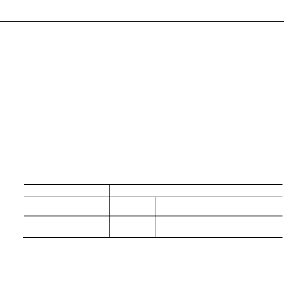
2.1 Safety Factors
The safety factors used in calculating allowable stresses in the following sections are defined as:
Table 1 - Safety factors
Loading
Design Condition Axial
Tension Axial
Compression Bending Hoop
Compression
Basic allowable stresses
1.67
2.0
2.0
One-third increase in allowable
stresses is permitted
1.25
1.5
(1.33)
1.5
2.2 Tension Check
Members subjected to axial tension are checked for the following condition:
1.0
[API 6.2.1]
The allowable tensile stress, Ft, is defined as:
Safety Factors 4
Steel Frame Design API RP 2A-WSD 22nd Member Design
= 0.6
[API Eq. 6.1]
2.3 Compression Check
Members subjected to axial compression are checked for the following condition:
1.0
[API 6.2.2]
The allowable compressive stress, Fa, is defined as:
=
1(
)
2
5 3
+3(
)
8(
)
8
for
<
12
23(
)for
[API Eq. 6.2 &
Eq. 6.3]
where,
=2
.
=for
60
min(,)for
>60
For members with D/t > 60, the yield strength, Fy, in the above equations is replaced by the
critical local buckling stress, defined as the minimum of Fxe or Fxc.
The elastic local buckling stress, Fxe, is defined as:
= 2
[API Eq. 6.4]
where the critical elastic buckling coefficient, C = 0.3.
The inelastic local buckling stress, Fxc, is defined as:
=1.64 0.23(
)
[API Eq. 6.5]
2.4 Flexure Check
Members subjected to bending are checked for the following condition:
1.0
[API 6.2.3]
Compression Check 5
Steel Frame Design API RP 2A-WSD 22nd Member Design
The allowable bending stress, Fb, is defined as:
=
0.75for 1500
0.84 1.74
for 1500
<3000
0.72 0.58
for
3000
<
300
[API Eq. 6.6,
6.7, and 6.8]
2.5 Shear Check
Members subjected to beam shear are checked for the following condition:
1.0
[API 6.2.4.1]
The maximum beam shear stress, fv, and the allowable beam shear stress Fv are defined as:
=
0.5
[API Eq. 6.9]
= 0.4
[API Eq. 6.10]
Members subjected to torsional shear are checked for the following condition:
1.0
[API 6.2.4.2]
The maximum torsional shear stress, fvt, and the allowable torsional shear stress Fvt are defined
as:
=(2
)
[API Eq. 6.11]
= 0.4
[API Eq. 6.12]
2.6 Hoop Buckling Check
Members subjected to external pressure are checked for the following condition:
[API Eq. 6.13]
The hoop stress due to hydrostatic pressure, fh, is defined as:
=2
[API Eq. 6.14]
Shear Check 6
Steel Frame Design API RP 2A-WSD 22nd Member Design
The critical hoop buckling stress, Fhc, is defined as:
=
for 0.55
0.45
+ 0.18
for 0.55
<
1.6
1.31
1.15 +
for 1.6<6.2
for > 6.2
[API Eq. 6.18]
The elastic hoop buckling stress, Fhe, is defined as:
= 2
[API Eq. 6.16]
The critical hoop buckling coefficient, Ch, is defined as:
=
0.44
for 1.6
0.44(
)+0.21(
)
for 0.825
< 1.6
0.736 (0.636)for 3.5 M < 0.825
0.755 (0.559)for 1.5 < 3.5
0.8 for < 1.5
The geometric parameter, M, is defined as:
=(2
).
[API Eq. 6.17]
2.7 Axial Tension and Bending Check
Members subjected to combined axial tension and bending loads, without hydrostatic pressure,
are checked for the following condition:
0.6+
+
1.0
[API Eq. 6.21]
Members subjected to combined axial tension, bending, and hydrostatic pressure are checked
for the following condition:
++ 2||1.0
[API Eq. 6.26]
where,
=+(0.5)
()
=
()
Axial Tension and Bending Check 7
Steel Frame Design API RP 2A-WSD 22nd Member Design
2.8 Axial Compression and Bending Check
Members subjected to combined axial compression and bending, without hydrostatic pressure,
are checked for the following conditions:
+
1
+
1
1.0
[API Eq. 6.23]
0.6+
+
1.0
[API Eq. 6.21]
where,
=12
23(
)
[AISC H1]
The reduction factors, Cmx and Cmy are calculated according to AISC H1.
If
0.15, the previous two conditions are substituted by the following condition:
+
+
1.0
[API Eq. 6.22]
Members subjected to combined axial compression, bending, and hydrostatic pressure are
checked for the following conditions:
+(0.5)
()+
()1.0
[API Eq. 6.27]
1.0
[API Eq. 6.28]
If > 0.5, the following condition is also satisfied:
0.5
0.5+
1.0
[API Eq. 6.29]
where,
F=
Axial Compression and Bending Check 8

Steel Frame Design API RP 2A-WSD 22nd Member Design
=
=++(0.5)
Axial Compression and Bending Check 9

3 Joint Design
This chapter provides the details of the joint punching load check algorithm that is used for
tubular joints in accordance with API RP 2A-WSD Section 7.3.
API RP 2A-WSD allows the joints to be designed on the basis of nominal loads in the braces.
3.1 Joint Geometry
Figure 1 illustrates some of the geometric parameters used in the punching load check.
d
Brace diameter, in
D
Chord diameter, in
g
Gap distance, in
t
Brace thickness, in
T
Chord thickness, in
θ
Angle measured from the chord to the brace
10
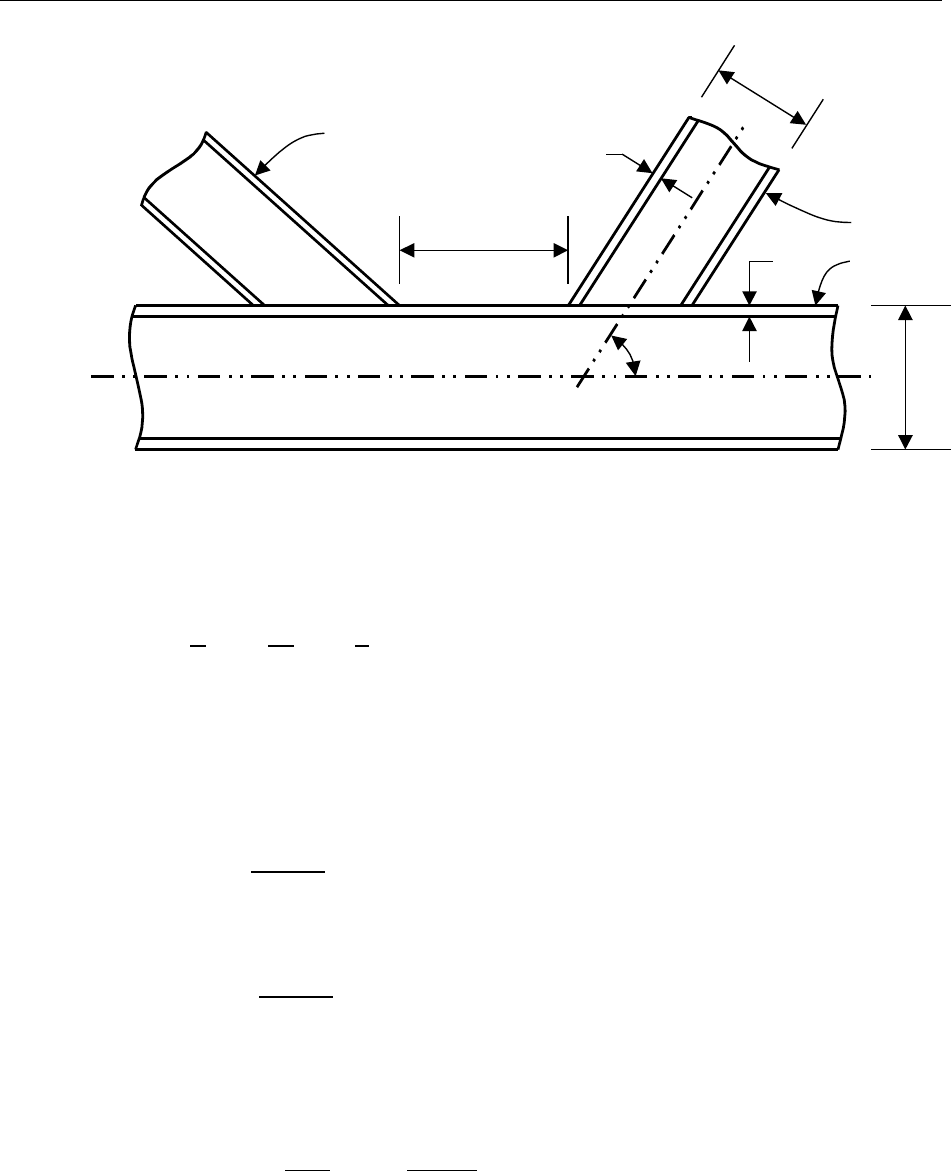
Steel Frame Design API RP 2A-WSD 22nd Joint Design
Figure 1 - Joint geometry
The following geometric parameters are derived from those in Figure 1.
==
2=
3.2 Allowable Capacities
The allowable brace axial load, Pa, is defined as:
=
sin
[API Eq. 7.1]
The allowable brace bending moment, Ma, is defined as:
=
sin
[API Eq. 7.2]
where the safety factor, FS = 1.60.
The chord load factor, Qf, is defined as:
=1 +
[API Eq. 7.3]
The parameter, A, is defined as:
T
D
g
d
t
θ
Chord
Brace
Brace
Allowable Capacities 11
Steel Frame Design API RP 2A-WSD 22nd Joint Design
=
+
.
[API Eq. 7.4]
where the safety factor, FS = 1.20 where the 1/3 increase is applicable. Pc is the nominal axial
load and Mc is the nominal bending resultant in the chord.
=
+
[API 4.3.4]
The coefficients, C1, C2, and C3, are determined based on API Table 7.3.
Table 2 – Coefficients, C1, C2, and C3
Joint Type C1 C2 C3
K axial
0.2
0.2
0.3
T&Y axial
0.3
0
0.8
X axial 0.9
0.2
0
0.5
X axial = 1.0
-0.2
0
0.2
All joints moment
0.2
0
0.4
The ultimate strength factor, Qu, is determined based on API Table 7.2.
Table 3 – Factor, Qu
Brace Action
Joint
Class Axial
Tension Axial
Compression In-plane
Bending Out-of-plane
Bending
K
(16 + 1.2).40.
(5 + 0.7). 2.5+(4.5 + 0.2).
T&Y
30
2.8
+(20 + 0.8).
2.8 + 36.
X
23for 0.9
20.7 + (0.9)
(17220)for > 0.9
[2.8
+(12 + 0.1)]
The geometric factor, Q
β
, is defined as:
=0.3
(10.833)for > 0.6
1.0 for 0.6
[API Table 7.2]
The gap factor, Qg, is defined as:
=1 + 0.2[12.8
]1.0 for
0.05
0.13 + 0.65.for
<0.05
[API Table 7.2]
Allowable Capacities 12

Steel Frame Design API RP 2A-WSD 22nd Joint Design
=
3.3 Axial and Bending Check
Joints are checked for the following condition:
+
+
1.0
[API Eq. 7.6]
The subscripts IPB and OPB correspond to in-plane bending and out-of-plane bending,
respectively.
Axial and Bending Check 13

4 References
American Institute of Steel Construction. (1989). Manual of Steel Construction - Allowable Stress Design
(9th ed.). Chicago, Illinois, USA: American Institute of Steel Construction.
American Petroleum Institute. (2014). Recommended Practice for Planning, Designing and Constructing
Fixed Offshore Platforms - Working Stress Design (22nd ed.). Washington, District of Columbia,
USA: API Publishing Services.
14
