SS GME8 S
User Manual: SS-GME8
Open the PDF directly: View PDF ![]() .
.
Page Count: 8
PRODUCT SPECIFICATIONS
SS-GME8 www.goodmanmfg.com 6/08
Supersedes 2/08
GME8 SERIES
Standard Features
• Patented Tu Tube™ dual-diameter tubular heat exchanger
with lifetime limited warranty plus 10-year limited furnace
replacement warranty*
• Two-stage gas valve with revolutionary new convertible tech-
nology that allows installer to turn on two-stage
operation with the ip of a dipswitch
• Super-e cient EEM circulator motor saves
energy during heating and cooling months
• Silicon Nitride igniter with patented adaptive learning control
for maximum igniter life
• Furnace control board with self-diagnostics, color-coded low-
voltage terminals, and provisions for electronic air cleaner and
24-volt humidi ers
• Control board stores the last ve diagnostic codes in memory;
simple push-button activation outputs the fault history to a
ashing red LED
• Low constant fan allows homeowner to activate the low heat
speed to e ciently circulate air throughout the home.
• Self-adjusting feature automatically adjusts furnace to high or
low stage based on outside temperature without an outdoor
temperature sensor
• All models comply with California NOx emissions standards
Cabinet Features
• Fully insulated, heavy-gauge steel cabinet with durable
baked-enamel nish
• Foil-faced insulation lines the heat exchanger
• Designed for multi-position installation: up ow, horizontal
left or right
• Removable bottom for side- or bottom-return applications
• Convenient left or right connection for gas & electric service
• Coil and furnace t ush for most installations
MULTI-POSITION, TWO-STAGE (CONVERTIBLE),
MULTI-SPEED GAS FURNACE
HEATING INPUT:
70,000–115,000 BTU/H
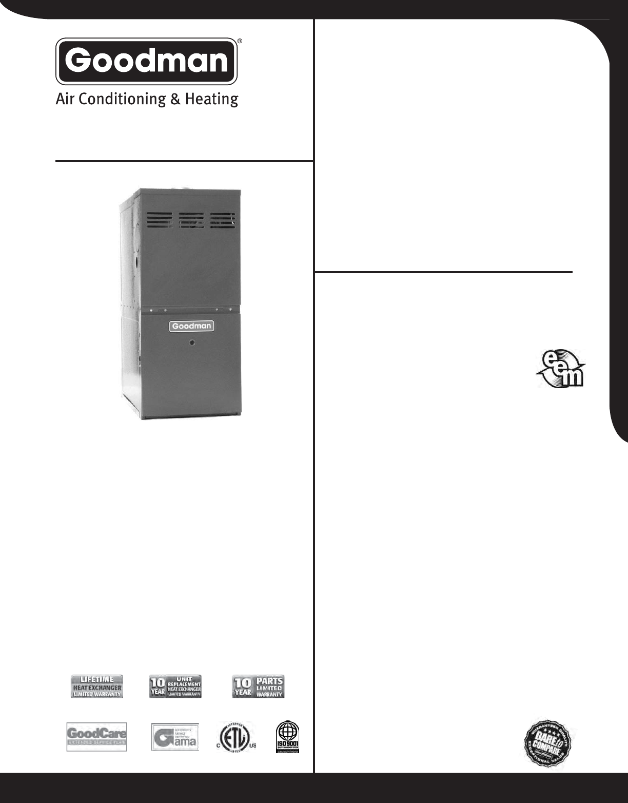
The Goodman® GME8 80% AFUE Two-Stage (Convertible),
Multi-Speed Multi-Position Gas Furnace features a patented
aluminized-steel tubular heat exchanger and durable Silicon
Nitride Hot Surface Ignition system, plus a super-e cient
EEM circulator motor that saves energy during the heating
and cooling months. With a heavy-gauge, reinforced,
insulated steel cabinet and durable baked enamel nish, the
GME8 can be installed in a variety of locations.
80% AFUE
Online registration is required within 60 days of installation.

2 www.goodmanmfg.com SS-GME8
PRODUCT SPECIFICATIONS
NOMENCLATURE
Brand Revisions
GGoodman
®
Brand A Initial Release
or Distinctions™ B 1st Revision
C 2nd Revision
Airflow Direction
C Downflow/Horizontal
D Dedicated Downflo
w
NOx
H High Airflow N Natural Gas
K Dedicated Upflow X Low NOx
M Upflow/Horizontal
Cabinet Width
Description A14”
V Two-Stage/Variable-speed B 17½”
H Two-Stage/Multi-speed C 21”
S Single-Stage/Multi-speed D 24½”
E Two-Stage/X-13 Motor
AFUE Maximum CFM @ 0.5” ESP
95 95% 3 1,200
9 90%+ 4 1,600
880% 5 2,000
MBTU/h
045: 45,000 115: 115,000
070: 70,000 140: 140,000
090: 90,000
E
3
4
5,6,74
970M
21
G
8
B
10
X
911
A
SS-GME8 www.goodmanmfg.com 3
PRODUCT SPECIFICATIONS
SPECIFICATIONS
GME80704BXA GME80905CXA GME81155CXA
Performance Data
Input¹ 70,000 90,000 115,000
Natual Gas Output¹ 56,000 72,000 92,000
LP Output¹ 46,000 64,000 80,000
AFUE² 80% 80% 80%
Tons AC @ 0.5” ESP 4 5 5
Temperature Rise Range (°F) 20-50 35-65 35-65
Circulator Blower
Size (D x W) 10 X 8 10 X 10 10 X 10
HP 3/4 1 1
Speed 5 5 5
Vent Diameter³ 4 4 4
No. of Burners 3 4 5
Filter Size (in²)4
Disposable 385 480 480
Permanent 770 960 960
Electrical Data
Min. Circuit Ampacity511.9 13.9 13.9
Max. Overcurrent Protection615 amps 15 amps 15 amps
Ship Weight (lbs) 143 163 163
¹ Natural Gas BTU/h: for altitudes above 2,000’, reduce input rating 4% for each 1,000’ above sea level. Low-fi re
rate is 75% of high-fi re rate.
² DOE AFUE based upon Isolated Combustion System (ICS).
³ Vent diameter may vary depending upon vent length. Refer to the latest editions of the National Fuel Gas Code
NFPA 54/ANSI Z223.1 (in the USA) and the Canada National Standard of Canada, CAN/CSA B149.1 and CAN/
CSA B142.2 (in Canada).
4 Permanent fi lter size based on 600 FPM. Check with fi lter manufacturer for specifi c details.
5 Minimum Circuit Ampacity = (1.25 x Circulator Blower Amps) + ID Blower amps. Wire size should be determined
in accordance with National Electrical Codes. Extensive wire runs will require larger wire sizes.
6 Refers to maximum recommended fuse or circuit breaker size; may use fuses or HACR-type circuit breakers of
the same size as noted.
Notes:
All furnaces are manufactured for use on 115 VAC, 60 Hz, single phase electrical supply.
Gas Service Connection ½” FPT
Important: It is required to size overcurrent protection device and wires properly and make electrical connections
in accordance with the National Electrical Code and/or all existing local codes.
•
•
•
4 www.goodmanmfg.com SS-GME8
PRODUCT SPECIFICATIONS
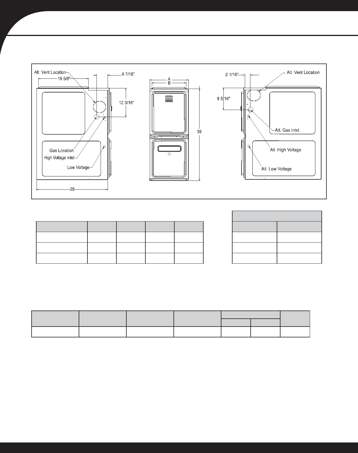
DIMENSIONS
Return Air (Bottom) Opening
Model A B C D Opening Width Opening Length
GME80704BXA 17½” 16” 39” 28” 16 23¾
GME80905CXA 21” 19½” 39” 28” 19½ 23¾
GME81155CXA 21” 19½” 39” 28” 19½ 23¾
MINIMUM CLEARANCES TO COMBUSTIBLE MATERIALS
Sides Rear Front Bottom Vent Top
SW B
103C611
C = If placed on combustible fl oor, the fl oor MUST be wood ONLY.
Notes:
For servicing or cleaning, a 24” front clearance is recommended.
Unit connections (electrical, fl ue, and drain) may necessitate greater clearances than the minimum clearances listed above.
In all cases, accessibility clearance must take precedence over clearances from the enclosure where accessibility clearances are
greater.
Refer to the appropriate USA and Canadian codes:
In the USA: the National Fuel Gas Code NFPA 54 / ANSI Z223.1
In Canada: the Canada National Standard of Canada, CAN/CSA B149.1 and CAN/CSA B142.2
•
•
•
•
◊
◊
SS-GME8 www.goodmanmfg.com 5
PRODUCT SPECIFICATIONS
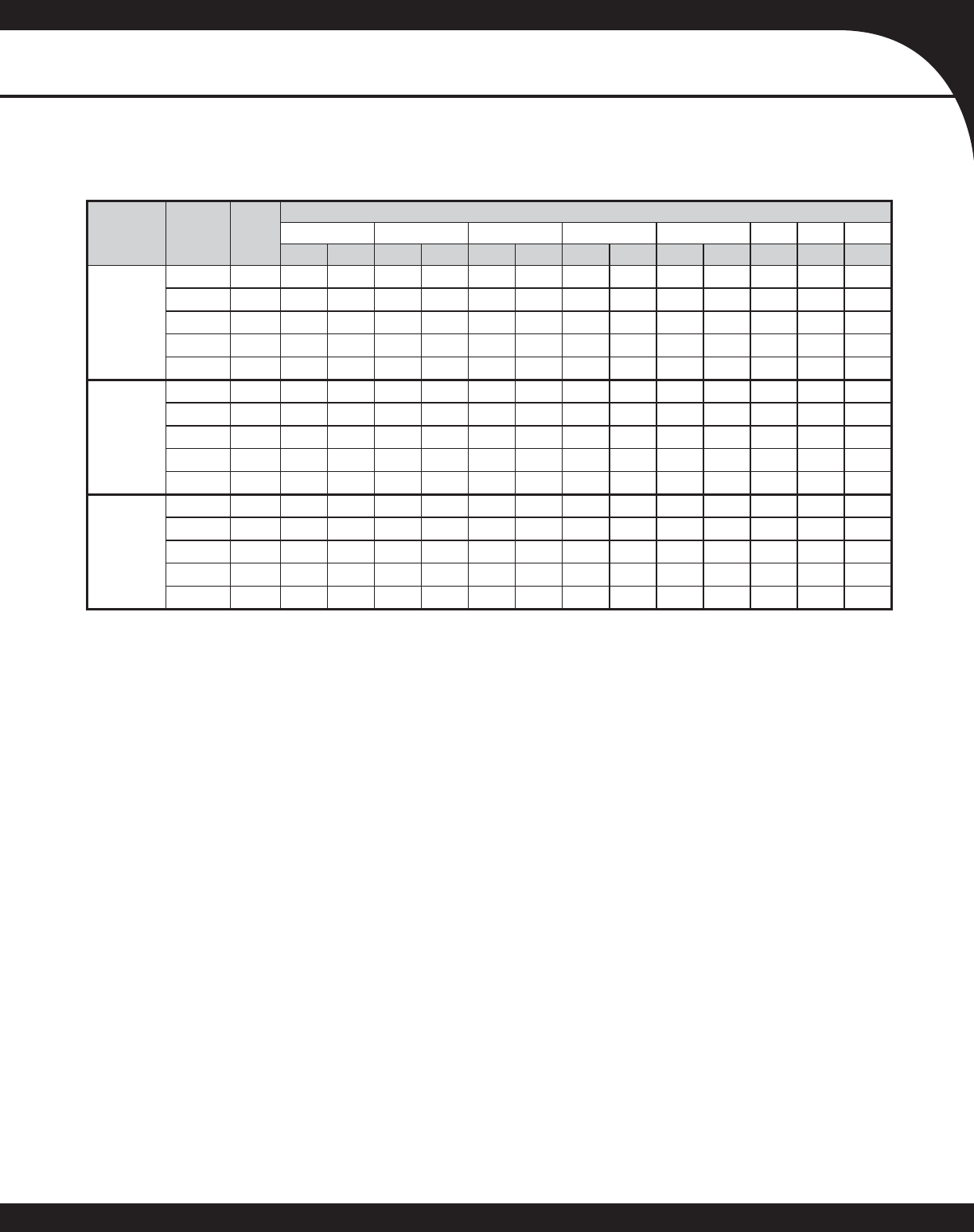
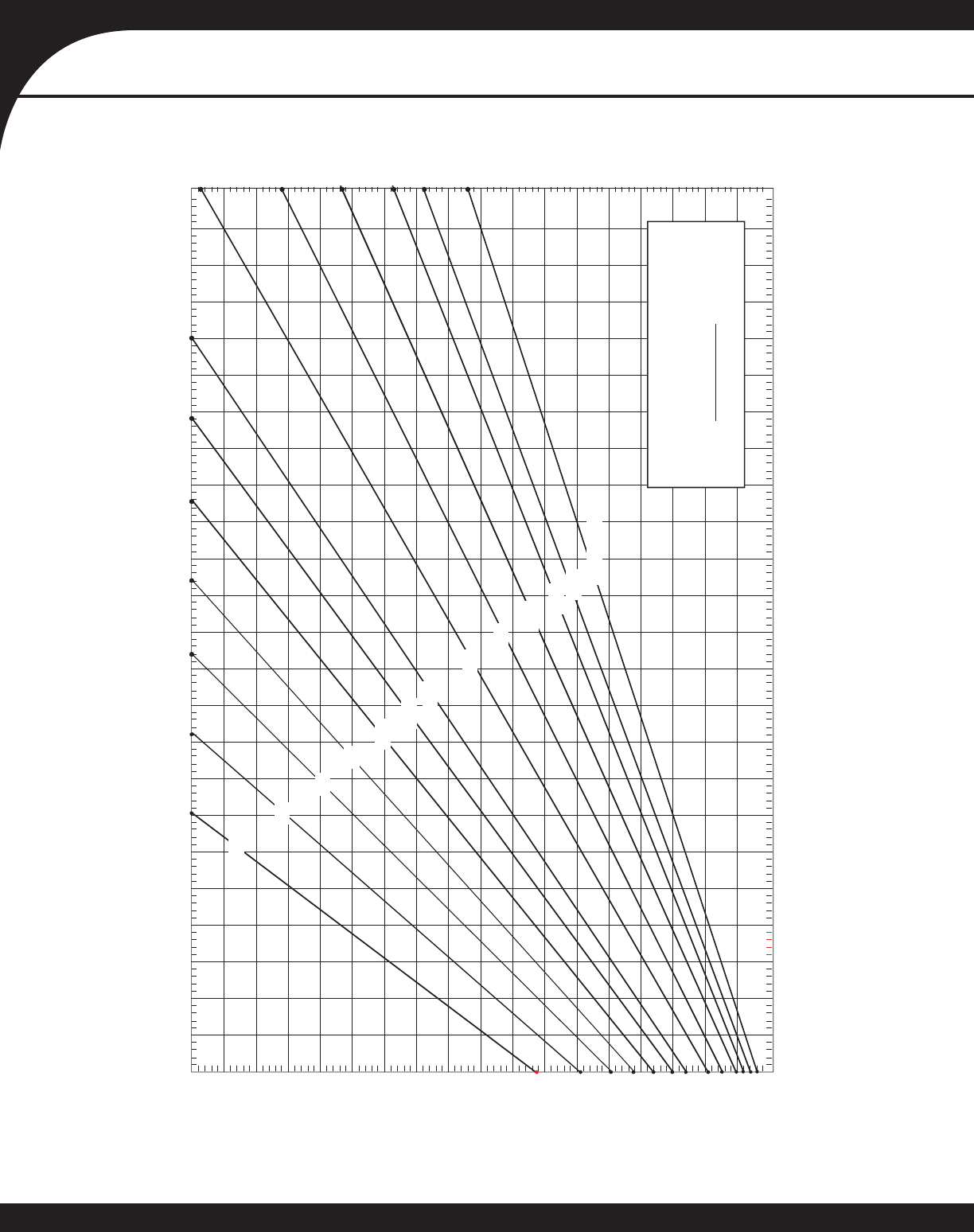
BLOWER PERFORMANCE DATA
CFM & Temperature Rise vs. External Static Pressure
Model Motor
Speed Tons
AC *
External Static Pressure, (Inches Water Column)
0.1 0.2 0.3 0.4 0.5 0.6 0.7 0.8
CFM Rise CFM Rise CFM Rise CFM Rise CFM Rise CFM CFM CFM
GME8
0704BXA
T1 3.0 1,224 42 1,178 44 1,162 45 1,139 46 1,106 47 1,060 1,029 987
T2 3.5 1,515 34 1,411 37 1,424 36 1,385 37 1,361 38 1,328 1,300 1,266
T3 1.5 781 66 642 81 561 92 501 103 425 122 365 326 288
T4 2.0 863 60 842 62 783 66 741 70 690 75 645 572 532
T5 2.5 1,083 48 1,044 50 1,012 51 989 52 946 55 904 877 825
GME8
0905CXA
T1 2.5 1,184 56 1,109 60 1,068 62 995 67 898 74 860 808 765
T2 3.5 1,537 43 1,488 45 1,448 46 1,404 47 1,371 49 1,314 1,247 1,181
T3 3.0 1,359 49 1,288 52 1,243 54 1,212 55 1,146 58 1,079 1,039 976
T4 4.0 1,658 40 1,610 41 1,604 42 1,548 43 1,511 44 1,470 1,416 1,365
T5 5.0 2,185 31 2,081 32 2,004 33 1,948 34 1,924 35 1,806 1,668 1,480
GME8
1155CXA
T1 3.0 1,351 63 1,315 65 1,261 68 1,197 71 1,133 75 1,037 966 909
T2 4.5 1,777 48 1,692 50 1,640 52 1,627 52 1,578 54 1,517 1,472 1,214
T3 3.5 1,548 55 1,470 58 1,449 59 1,395 61 1,337 64 1,244 1,166 1,096
T4 4.0 1,720 50 1,633 52 1,601 53 1,570 54 1,521 56 1,462 1,402 1,201
T5 5.0 2,312 37 2,213 38 2,155 40 2,099 41 1,988 43 1,864 1,691 1,501
* at 0.5” ESP
Notes:
CFM in chart is without fi lter(s). Filters do not ship with this furnace, but must be provided by the installer. If the furnace requires two return
fi lters, this chart assumes both fi lters are installed.
For most jobs, about 375 - 400 CFM per ton when cooling is desirable.
INSTALLATION IS TO BE ADJUSTED TO OBTAIN TEMPERATURE RISE WITHIN THE RANGE SPECIFIED ON THE RATING PLATE.
This chart is for information only. For satisfactory operation, external static pressure should not exceed value shown on the rating plate. The
shaded area indicates ranges in excess of recommended maximum heating static pressure.
The above chart is for U.S. furnaces installed at 0-2,000 feet. At higher altitudes, a properly derated unit will have approximately the same
temperature rise at a particular CFM, while ESP at the CFM will be lower.
Factory Motor Speed Setting: T1 = 1st Stage Heating; T2 = 2nd Stage Heating; T5 = Cooling
Temperature rise data is based on 2nd-stage heat. First-stage heat is 75% of rise indicated above.
•
•
•
•
•
•
•
6 www.goodmanmfg.com SS-GME8
PRODUCT SPECIFICATIONS
30 40 50 60 70 80 90 110 120
100 130 140 150
100
90
80
70
60
50
40
30
20
10
OUTPUT BTU/HR x 1000
BTU OUTPUT vs TEMPERATURE RISE CHART
TEMPERATURE RISE
600 CFM
700
900
1000
1100
1200
1400
1600
1800
2000
2200
2400 CFM
FORMULAS
BTU OUTPUT = CFM x 1.08 x RISE
RISE = BTU OUTPUT
1.08 ÷ CFM
800
BLOWER PERFORMANCE DATA (CONT.)
SS-GME8 www.goodmanmfg.com 7
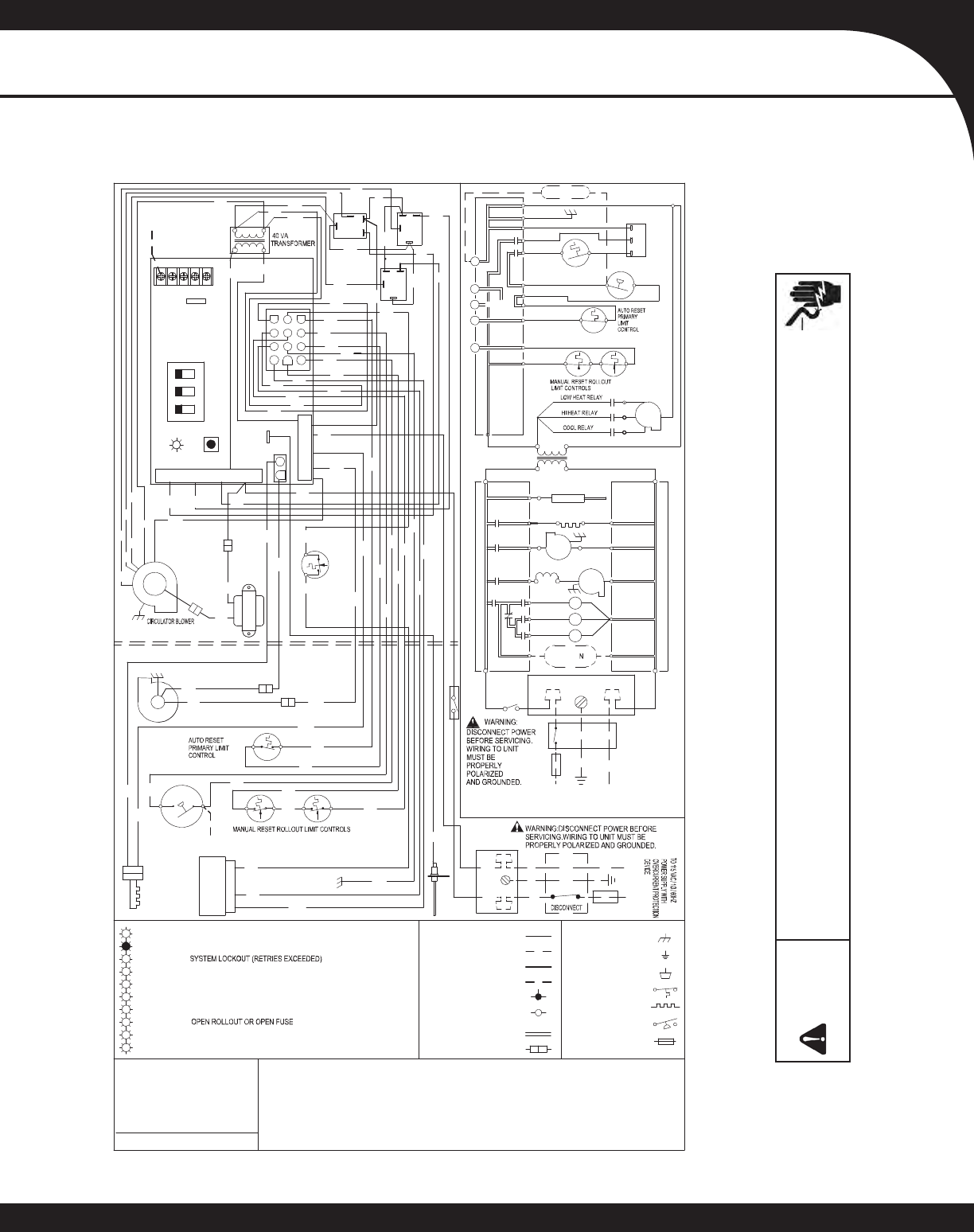
PRODUCT SPECIFICATIONS
R
Y
L
YEL
L
OW
O
R
ORANG
E
P
U
PUR
P
LE
G
N
GR
E
E
N
B
KB
LA
CK
B
R
B
RO
W
N
WH
W
H
IT
E
B
LB
LU
E
G
Y
GR
AY
R
D
RED
CO
L
O
R
CODES:
LOW
V
OLTA
G
E
(
2
4V
)
LOWVOLTAGEFIEL
D
HIV
O
LT
A
GE
(
115V)
H
IV
OLTA
G
EF
I
ELD
N
O
T
E
S
:
1.SETHE
A
T
A
N
T
I
CI
PATOR
O
NROOMTHERMO
S
TATA
T0
.7
AMP
S
.
2
.
MA
N
U
FA
C
T
U
RER'S S
P
E
CI
F
I
E
DR
EPLA
C
E
M
E
N
TPARTSM
U
S
TB
EUS
E
D
W
HENS
E
R
V
ICI
N
G
.
0
1
40F
004
72
REV.
A
GASVALVE
C
PM
C
G
W
I
N
TER
N
ALT
O
I
N
T
E
GRATEDCONTR
O
L
JUNC
T
I
ON
EQUIPMENTGND
FIEL
D
GN
D
D
IAGNOSTI
C
L
E
D
H
O
T
S
U
R
F
ACE
IG
N
I
T
E
R
O
V
ERCURRENT
PRO
T
.D
EVI
C
E
I
GNIT
E
R
I
NTE
G
RATED
C
O
NTROL
MO
DULE
INTEGRATED CONTROL MODULE
INTEGRATED CONTRO L MO DULE
OV
E
RC
URR
EN
TP
R
O
TEC
T
I
ON
DEV
I
CE
B
L
B
R
B
K
O
R
BK
4.
I
FH
E
A
T
ING
A
ND
C
OOL
I
NGBLOWE
R
S
P
E
E
DS
A
R
EN
O
T
THES
A
M
E
,DIS
CA
RD
J
U
MP
E
R
BEFOR
EC
O
N
NECTINGBLOWE
R
LE
A
DS
.
U
N
U
SE
D
B
LOW
E
RLEADSM
U
S
TB
EP
L
ACEDON"PARK"TE
RMI
NALSO
F
INT
E
G
RA
T
E
D
C
ON
T
R
O
LORTAPE
D
.
3.
I
FA
N
YOFTH
E
ORI
G
I
N
A
L
WIREA
SS
UPPL
I
ED
W
I
T
HT
H
EFURNAC
E
MUSTB
E
R
E
PLACED,
I
T
M
U
S
TB
E
RE
P
L
A
CED
W
I
T
H
WI
RI
NG M
A
T
E
R
IA
L
H
A
V
INGATEM
P
E
R
ATURER
A
TING
O
FA
T
LEAS
T1
05
TERMINAL
S
W
I
TCH(P
R
ESS.
)
5
.
U
NI
T
MU
STBEPE
RM
A
NE
N
T
L
Y
GRO
UN
D
E
DA
N
DCON
F
O
R
MTO
N.
E.
C
.
A
NDL
O
CALCO
D
E
S
.
PKP
I
NK
1
1
5
V
ACH
O
TAND
PA
RKTER
M
INA
L
S
L
IN
E-H
F
LA
ME
S
EN
S
OR
B
K
PLU
GC
ON
N
E
C
T
I
ON
F
I
E
LD
S
P
LI
CE
SWITCH(
T
E
M
P.)
2
4
V
THERM
O
STAT
C
ON
N
EC
T
I
O
NS
GR
GN
D
115VAC
24
V
AC
BK
GND
L
N
WH
JUN
CTION
BO
X
1
Y
L
ID
BL
O
WER
P
RES
S
UR
E
S
W
IT
C
H
CO
O
L-H
G
N
D
W
H
BK
W
H
G
N
D
BU
R
N
E
R
C
OMPARTM
EN
T
B
L
OW
E
R
C
OMPARTM
E
NT
N
O
LO
W
H
E
AT-H
BK
BK
YL
WH
B
R
R
D
R
D
PU
PU
PU
BK
W
HWH
BL
O
W
ER
INDUCE
D
DRA
F
T
C
G
ND
RO1(5)
R
O
2(
11)
H
L
O(
1
)
HL
I
(
7
)
MV
C(
9)
G
N
D
(
8)
T
R(
6
)
YL
WH
WH
RD
YL PU
PU
GR BL
BR
RD
WH
115 VAC NEUTRAL
BL
24V THERMOSTAT CONNECTIONS
MICR
O
TO
C
G
Y
W
R
2
W
H
YL
RD
Y
L
PU
RDBL
R
D
PU
R
D
BL
WH
XFMR-H
TERMINALS
BR
B
R
G
R
BL
1
2
3
1
21110
987
65
4
°C
.
USECO
P
P
E
RC
O
N
DU
CT
O
RS
O
NL
Y.
2
4V
AC
H
UMIDIF
IE
R
2
4
VAC
H
U
MI
D
IFIE
R
H
UMID
I
FI
E
R
P
S
O
(4
)
M
V
L(2
)
P
S(
10)
C
N
O
CN
O
A
U
X
I
L
I
ARY
L
I
MIT
I
D
BLOWE
R
P
RE
S
S
U
R
E
S
WITCH
0
C
7
6
5
4
3
2
1
O
FF
=CO
NTROL
F
A
I
L
U
RE
S
T
EA
D
YO
N
=NORMALO
P
E
R
AT
I
ON
1F
LA
S
H=
2FL
A
S
H
ES
=PRE
S
S
UR
E
S
WI
T
C
H
S
TUC
K
CLOSED
3F
LA
S
H
ES
=
P
R
ESS
U
RES
W
ITCHST
U
CKOP
E
N
4FLA
S
HES=OP
E
N
HI
G
H
LIM
IT
5FLA
S
H
ES
=FLA
M
E
S
E
N
S
E
W
I
THOUTGAS
V
A
LV
E
7F
L
ASH
E
S=
LO
W
F
LAMES
I
GNAL
6F
LA
SHES
=
CON
T
I
N
UOU
S
/R
AP
IDFL
A
S
H
E
S
=REVER
SE
D
1
15VA
CPO
L
A
RI
TY
CO
N
TRO
L
MO
D
U
L
E
I
NTEGRATED
FUSE
ON OFF
2ND
STAGE
DELAY
MODE
HEAT
OFF
DELAY
FS
1
2
3
H
I
B
R
BR
PM
G
A
S
VALV
E
C
H
I
M
VH
(
1
2)
F
A
C
T
O
R
YS
E
TTI
NG
S
SHO
WN
*
*
*
*
SEE
NOTE 6
T
O115
V
AC
/
1
Ø
/
60
H
ZP
OWE
R
S
U
PPLYW
I
TH
Y
6
.TO
R
E
CA
LLTHELAST
5F
A
U
L
TS
,
M
O
S
TRECENTT
OL
E
A
S
T
RECENT,DEPRESSSWITC
HF
ORMO
R
ETHAN2S
E
C
O
NDS
WHI
LEI
N
S
T
AN
D
B
Y
(N
O
THER
MO
S
T
A
T
IN
P
U
T
S
)
BK
LINE NEUTRALS
I
NDUCTO
R
CO
I
L
1
2
4
3
1
2
4
3
LOW
HEAT
RELAY
COOL
RELAY
HI HEAT-H
SWITCH
DOOR
L
DISCONNECT
GND
JUNCTION BOX
EAC-H
ELECTRONIC
A
IR CLEANER
LINE-H
COOL-H
LO HEAT-H
R
BLWR
CIR
R
R
T5
T2
T1
BL
B
R
WH
Y
L
RD RD
RD
RD
YL
BL
OR
WH WH
HI
HEAT-H
WH
BR
OR BL
BK
AUXILIARY
LIMIT
DOOR SWIT CH
BK
BL
TRANSFORMER
40 VA
24 VAC
11 5 VAC
T5
T2
T1
CIR
BLWR
TH (3)
XFMR- H
INDUCTER COIL
HIGH
HEAT
RELAY
3
4
2
1
BLWR
ID
IND
FS
IGNITER
HOT SURFACE
IGN
FLAME SENSOR
WH
WIRING DIAGRAM
Wiring is subject to change. Always refer to the wiring diagram on the unit for the most up-to-date wiring schematic.
WARNING
High Voltage:
Disconnect all power before servicing or installing this unit. Multiple power sources may
be present. Failure to do so may cause property damage, personal injury, or death.
8 www.goodmanmfg.com SS-GME8
PRODUCT SPECIFICATIONS
Goodman Manufacturing Company, L.P., reserves the right to discontinue, or change at any time, specifi cations or designs without notice
or without incurring obligations. © 2008 • Goodman Manufacturing Company, L.P. • Houston, Texas • Printed in the USA.
ACCESSORIES
Model Description GME8
0704BX GME8
0905CX GME8
155CX
LPM-03B LP Conversion Kit
(Gas Valve) √√√
LPM-05 LP Conversion Kit
(Springs & Orifi ce) √√√
HA02 High-Altitude
Natural Gas Kit √√√
AFE18-60A Fossil Fuel Kit √√√
THERMOSTATS
Model Description
CHT18-60 Cooling/Heating, Mechanical
CH70TG Cooling/Heating, Digital,
Non-programmable
CHSATG Cooling/Heating, Mechanical
H20TWR Heating Only, Mechanical
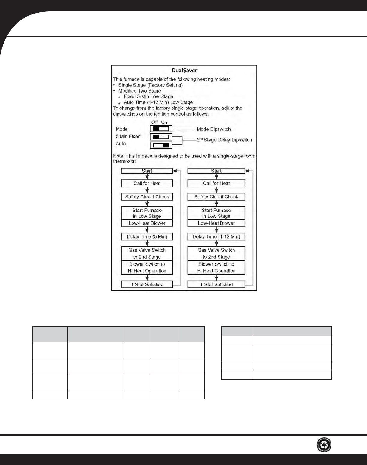
DUAL$AVER CONFIGURATION & OPERATION
