SGS134
User Manual: SGS134
Open the PDF directly: View PDF ![]() .
.
Page Count: 18

Form F-116
1-70
Rev.
4-72
TABLE OF CONTENTS
SECTION ONE -
FLIGHT
PROCEDURES
General Description
Flight
Controls
Retractable Gear Control
Pre-Flight
Inspection
Weight and Balance
Aero Towing
Auto or Winch Towing
Take-off
-
Spins
-
Aerobatics
-
Dive
Brakes
-
Slipping
Landing Procedures
-
Normal and Emergency
Cold Weather Operation
Flight Envelope
Flight Envelope Graph (Fig. III)
Performance
Curves
(Fig. IV)
SECTION ‘IWO -
ERECTION
&
MAINTENANCE
Final Assembly Hardware
List
Unloading from Trailer
Sailplane
Assembly
General
Maintenance
Instructions
Fabric
Covering.
Finish
Lubrication
Chart
-
Fig. I
Lubrication Chart
-
Fig. II
Lubrication Chart
-
Fig. III
Rigging
Wheel and Brake
Annual or 100 Hour
Inspection
Annual or 100 Hour Inspection Record
Sailplane Tie Down
l-l
l-2
l-4
l-4
1-5
1-6
1-6
1-7
l-8
1-9
l-11
l-12
1-13
2-l
2-2
2-3
2-7
2-7
2-8
2-9
2-10
2-11
2-12
2-13
2-15
2-16
GENERAL DESCRIPTION
MODEL SGS l-34
The SGS l-34 is a
single
place, high performance, all-metal sailplane of
monocoque construction, built by
Schweizer
Aircraft
Corp., Elmira, N. Y.
It was designed and built to meet the need and demand for a US Standard
Class Sailplane.Its many safety features plus the excellent flying and
handling
characteristics
serve
to make it an ideal sailplane for the average
soaring
pilot;
as well as for one with competition in mind.
Pilot fatigue, after long duration flights,
has
been virtually
eliminated
be-
cause of the
semi-reclining
adjustable seat, adjustable rudder pedals and
adjustable headrest.
The rate of roll and controllability, while thermalling, is very good. The
visibility
out of the cockpit
in
all directions is excellent.The cockpit is roomy,
with all the controls and instruments within easy reach.
These
features add up
to more pilot comfort and better proficiency.
MODEL SGS l-34R
The SGS l-34R flight and handling
characteristics,
from
lift-off
to touch-
down, are identical with those of the l-34.
The l-34R incorporates a manually-operated retractable main gear with
doors. The retractable gear offers three advantages over the conventional gear.
One, obviously that of resulting in a more aerodynamically clean aircraft.
Second, the weight of the retraction mechanism
is
beneficial from a penetration
standpoint. Furthermore, additional ground clearance is provided by the ex-
tended gear for those operating from uneven fields. The overall dimensions re-
main the same except for the ground height, which is slightly increased on
the
l-34R.In this connection, the gear for the l-34
has
a one inch up and down
ground adjustment through the use of alternate axle
holes
In the gear plates and
brake torque arm.
Overall Dimensions
Length
25 ft. 5 in.
Span (15 meters) 49 ft. 2
in.
Height
7 ft. 6 in.
Wing
Area 151 sq.ft.
Other Characterletlcs
1-34
Aspect
Ratio
16
l-34R
16
Empty Welght 570 Ibs. 595
lbs,
Useful Load 270
lbs.
245 lbs.
Max.
Gross
Welght
840
Ibs. 840
lbs.
l-1

Calculated
L/D
Mtn.
Sink
Placard (red line) Speed:
dive
brakes
closed
dive brakes open
Stall Speed
Opening the Canopy:
PERFORMANCE DATA
SGS 1-34
SGS 1-34R
33 at 55 mph 34 at 55.5 mph
2.4 fps
@
49 mph 2.2
fps
@
46 mph
800# GW
840#
GW
800#
GW
840#
GW
----
135 mph
132 mph 135 mph 132 mph
142 mph 132 mph 142 mph
132
mph
36
-
38 mph 36
-
38 mph
Access to the cockpit is gained normally from the left hand side of the ship.
The small window panel in the lower section of the canopy is pushed slightly
inward, then aft. Reach across the cockpit to the ring on the latch handle, rotate
the latch by pulling the handle ring inboard and aft.The canopy is unlatched when
the handle is at right angles to the longeron. To latch the canopy after tie-down,
reverse the above procedure.
FLIGHT CONTROLS:
1.
Control Stick:
The single bent control stick
is
conventional for aileron and elevator
control.
2a. Rudder Pedals:
Rudder pedals are conventional with a five position adjustment. Ease
of adjustment
is
provided for by a levered
lock-pin
arrangement and
a spring assisted pedal retraction.
b.
Rudder Pedal Adjustment Lever:
Located between the bottom of the rudder pedals.To adjust, depress
lever with either heel and relax pressure on rudder pedals.
The
spring will retract the pedals to the full aft position. Push pedals for-
ward to
desired
position and allow lever to lock in place by removing heel.
3. Trim Control
(longitudinal):
The cockpit control is a lever with a knurled lock-knob located on the
right hand side of the cockpit. The lock-knob must be turned counter-
clockwise to unlock and clockwise to lock.
On
the first few aircraft, the cockpit control is a T-handle located
under the lower left side of the instrument panel.To unlock, turn
T-handle counterclock-wise.Pull to the desired trim position and
lock by turning the handle firmly clockwise.
The trim
system
is of the bungee type which applies tension
to
the
elevator cable to reduce the control
stick
back-pressure required
while flying at slower
airspeeds.
Forward position for nose-down
trim and aft positions for increasing amounts of nose-up trim, for
either type of control.
4. Tow
Release
Control:
The release control is a knob located below center of
the
instrument
panel. Pull the knob fully aft to actuate the tow hook release.
5.
Dive Brake Control:
The dive brakes are actuated by a
lever
located at the forward left
hand side of the cockpit. Lever is pulled slightly inboard to unlock
and aft
to
the desired degree of dive brake application.
To
close
and
lock dive brakes, push the lever forward until it snaps into the locked
position.Forces required to open and close the dive brakes are
light at low speeds, but will require
more
force
to
close as speed is
increased.
6.
Main Wheel Brake:
The main wheel brake is a hydraulically actuated disc type and
is
applied by unlocking the dive brake lever and pulling to the full aft
position.
The
wheel brake
is
actuated during
the
final
few
inches of
the dive brake control lever travel.Extra
pull
force is needed to
achieve wheel-braking action.
7. Instrumentation:
An airspeed indicator,
sensitive
altimeter and magnetic compass
are required. Additional instruments, up
to
a
full
panel, are op-
tional at the owner’s
discretion.
8. Static Line Drain:
Provision for draining of any accumulation of water from
the
airspeed
static line
is
made by a spring-loaded valve located at the 1ower left
hand side of center console.
To
open
the
drain valve, push
forward
on
the
handle pins and turn counter-clockwise approximately l/4 turn.To
close
valve, turn
handle pins l/4 turn clockwise and release.
Factory flight tests have shown that with this valve
open
in flight, air-
speed readings are reduced slightly.Flight with this valve inadver-
tently in the open position is therefore not particularly
hazardous,
and,
in an emergency, may be used as an
alternate
source
of static pressure
l-3
l-2

9.
10.
11.
12.
13.
14.
Canopy Latch:
Located on
right
side
center bottom canopy frame. Push down and
for-
ward to
secure
canopy.Reverse to unlatch
-
the handle is at right angle
to the longeron in the unlatched position.
Cockpit Ventilation:
Located at top left side or right side of console. Adjust valve as desired.
Clear-vision
Window Panel:
Located at 1eft or right bottom side of canopy aft of center. To open,
pull small knob inward and slide panel
aft
to ventilate and remove con-
densation from internal canopy surfaces.
Headrest Adjustment Lever:
Located at center of aft hatch forward bulkhead.To adjust, pull
spring-loaded
lever outboard and set headrest to desired position.
Release lever to lock
in
place.Six positions are provided to comple-
ment the
various
seat-back positions.
Seat-back Adjustment Levers:
Located at top outboard sides of seat back. Depress both spring-loaded
levers inboard and set seat-back to desired position in the adjustment
racks.Release levers to lock into position.
Retractable Gear Control, I-34R:
The gear retraction/extension control has a slide-tube and cable arrange-
ment with a knob handle, together with a squeeze-type finger lever latch,
on the
right
side of the cockpit. For
“Gear
Down”,
the control knob is in
the full forward position; for “Gear Up”, the control
is
pulled to its full
aft posltion.At both “Gear
Up”
and
“Gear
Down
”
positions. the control
is
locked by a pin (on the underslde of the latch lever) engaging a
hole
in
the inner slide tube. A “Gear Down” safety pin is provided (attached to
a bead chain) for insertion through the slide tubes for additional pro-
tection against inadvertent gear retraction during ground-handling or
tie down periods.
PREFLIGHT INSPECTION
CHECK ALL POINTS AS LISTED
Fusela ge
and Cockpit:
a. Flight controls for free and normal movement.
b. Rudder pedal adjustment.
C.
Seat and headrest adjustments.
d. Release hook and linkage.
I-4
e.
f.
g.
h.
j.
k.
1.
m.
n.
Instruments, lines, pltot-static openings, static line drain.
Canopy
-
hinges
and latch, head
clearance.
Safety belt and shoulder harness.
Wing pins
-
main spar. and aft
carry-thru.
i. Aileron control attachment, fuselage to wing.
Tire condition and inflation (31 psi).
Wheel brake operation.
Nose skid attachment and condition.
General condition exterior surfaces.
Retractable gear safety pin removed
-
l-34R only.
a. Aileron hinge and
pushrod
connection.
b. Dive brake and
mechanism.
C.
General surface condition.
Empennage:
a. Stabilizer attach, forward and aft.
b. Elevator
-
hinges,
pu shrod
attach.
C.
Rudder
-
hinges and fabric.
d. Remove inspection plate
-
rudder and elevator control connections.
f.
e. Tail wheel.
General condition surfaces and aft fuselage.
WEIGHT AND BALANCE.
SGS
1-34
The weight and balance, furnished with each sailplane, should be the con-
cern of each pilot, to familiarize himself with the various weights, and
weight
distribution limits shown.The “placard limits” plate attached to the instrument
panel shows only the basic weight limitations as to maximum pilot weight
to
reach either (1) maximum gross weight, or forward CG limit, whichever is less;
and
(2).
the minimum pilot weight to maintain the aft CG limit. .However, be-
cause of
variables
in loading conditions, pilot-weight limits will also vary.
For
instance, the maximum pilot weight (for forward
CG
limit) with the seat back in
the fully forward position, will sometimes calculate to be less than the weight
necessary to obtain the maximum gross weight.See Weight and Balance Report
for the aircraft.It should be understood that the
heavier pilot
will, in most
cases, be tall enough to require that the seat-back be adjusted to a
position
other than the
fu lly
forward position. In such
case,
it
is quite probable
that
the maximum gross weight figure is applicable, as each
succeeding
position
(aft) of the seat back adjustment will allow a somewhat greater pilot welgbt and
still remain within the forward
limit.
In any
ca se,
flight at, or near, the
forward
1-5

CG limit condition is not as
critcal
to controllability as is flight at the aft
CG
limit condition.
CAUTION: Upon entering the cockpit, the nose section should be pushed down-
ward so that the
nose
skid rests on the ground.
Should the pilot’s own weight
fail to keep the nose skid in contact with the ground, the C.G. condition must
be rechecked, to assure that the aft C.G. limit is not exceeded, before flight
is attempted. This indication of the C.G. applies to the fixed gear model only.
WEIGHT AND BALANCE. l-34R
The Datum, MAC and C.G. limits are identical with those for the SGS l-34.
The l-34R maximum Gross Weight is 840
l
gross weight was also
approved for the model SGS l-34 and was made retroactive to include ships
Serial No. 1 and up.
The main wheel on the
1-34R,
as stated previously, extends farther below
the
fuselage
than on the l-34.The axle position is also moved forward ap-
proximately eleven inches.This has no effect on the weight and balance out-
come -only the figures used in some computations.
AERO TOWING
Use normal aero tow procedures.The actual take-off should not be at-
tempted until an
IAS
of 40 mph is reached.Due to the low
angle
of attack, a
slower attempt of take-off will result in a series of tail bumps which will be
severe if the terrain or runway is not smooth.The recommended
aero
tow
speed is 55 - 60 mph. Towing slower than an
IAS
of 50 mph is not recom-
mended.
AUTO OR WINCH TOWING
Both the SGS l-34 and SGS l-34R have been flight-tested and approved for
auto-winch towing at maximum gross weight. However, with the release nook
so far forward of the CG, this manner of launch is something less than ideal.
Therefore, not recommended for any pilot without proper instruction or
equivalent experience.
Normal auto or winch tow procedures are used, however, as the tow hook
is so far forward, the sailplane has a porpoising tendency when too much up-
elevator is used for the climb.Should this occur, reduce back pressure on
the stick until the porpoising stops. The maximum tow speed of 66 mph
mu
s
t
be observed.
TAKE-OFF
The take-off
characteristics
for the l-34R are different from the l-34 be-
cause of the more forward location of the main landing gear.For this reason,
a forward pressure on the stick is required to raise the tail off the ground to
attain a level flying attitude for take-off.
SPINS
Spin entries, rotation and recoveries are all normal throughout the C.G.
range.The following characteristics occur as the C.G. is moved rearward.
1.
Entries will be more difficult.
2.
Rotation will be slower
and
flatter.
3.
Control movements for recoveries more pronounced.
4.
Slower recovery, but will not exceed
3/8
-
l/2
turn at aft
CG
limit.
5.
Slower indicated airspeed upon recovery.
6.
Less loss of altitude per rotation.
AEROBATICS
The 1-34 is
fully
aerobatic, but due to the danger of easily exceeding the
maximum placard speed from a poorly executed maneuver, it is highly recom-
mended that pilots without aerobatic experience either not attempt aerobatics,
or get instruction prior to engaging in such flight.
DIVE BRAKES
Dive brakes can be used for rapid loss of altitude at any time, including the
normal landing procedure as described below.
Ths
1-34’s
dive brakes are extremely effective and will
limit
the aircraft’s
speed to approximately 142 mph in a
vertical-attitude
dive at full gross weight.
They can be opened at any
IAS
up to 142 mph.To maintain a given
IAS
the nose
must be lowered as the dive brakes are pulled open.The reverse is true when
closing them.
SLIPPING THE AIRCRAFT
Slips can be executed normally, but with the effectiveness of the
dive
brakes
it
is
unlikely that slipping should become necessary.
l-7
l-6

LANDING PROCEDURES
A. Normal
Landing
Pattern
Aporoach
Touch Down
Ground run
after
landing
Wheel brake
It is standard
practice
to fly a normal
traffic
pattern.Allow
extra airspeed as necessary depending on gust and wind conditions
The approach should be made high with use of dive brakes as
needed. They increase both sink and drag which. in
turn,
creates a steeper and more controllable glide path.
Can be made wlth dive brakes fully open, partially open, or
fully closed. However, the latter is not recommended except
for practice or to stretch cut a landing approach.The actual
landing should be made at an
IAS
of 40
-
45 mph. Landing at
a slower speed will resultin a tailfirst landing.
On the l-34R the main wheel
mmai
is located
in
a more forward
position.For that reason forward pressure is used during the
landing roll and
stick
movement increased as airspeed de-
creases, until elevator control becomes lost and the tail wheel
contacts the ground.
After touch-down, the aircraft should be literally flown to a
stop. Care should be taken to keep the wings level and the
track
straight.
When
taxiing
in a cross wind, keep the upwind
wing low for best possible control.
May be used at any
time.
and to any extent, for as quick a stop
as desired after touch down. The
aircraft
can be landed with the
wheel brake fully on.This will not cause the sailplane to nose
over, although an abrupt rotation will occur until the nose
skid
makes contact wlth the ground.
B. Landing,
Dive-Brakes
Inoperative
-
Emergency Procedure:
In the event that the dive brakes should become inoperative,
in
which case
the wheel brake would probably be also inoperative, the correct landing pro-
cedure is:
1.
Enter pattern at lower than normal altitude.
2. Fly pattern at a slow but safe speed (45
-
50 mph).
3.
Slip
as necessary at an indicated 45-50 mph until
sailplane
is l/2
wing span from the ground.
4. Raise low wing as altitude decreases, but hold in full opposite
rudder.
5. At 2 to 3 feet above ground, wings should be level and
opposite
rudder eased off to neutral position (straight and level
flight).
6. From 2 to 3 feet force the sailplane gently but
firmly
to a flying
touch-down.
7. Upon touch-down, immediately but slowly, push the
stick
full
forward so that the skid wlll contact
the
ground and assist in
braking to a stop.
It’s rather
difficult
to land a high performance
sailplane
using the above pro-
cedure. Therefore, some
practice
landings
of this type would be very
beneficial
for a future emergency. However.
since
an
inoperative
dive brake is
considered
to be a remote possibility
,
a pilot should not attempt to
practice
this emergency
procedure
until
he has become thoroughly
familiar
with the normal
flight
and
handling characteristics of the sailplane.
COLD WEATHER OPERATION OF THE l-34
Since
the 1-34 may be used in wave and
winter
flying,
it
is recommended
that
a low-temperature lubricant be used on all pivot
points,
bearing
surfaces, and
other moving parts.To do
this,
the pins and bolts should be removed and cleaned
of any old grease or oil with a solvent. Apply low-temperature grease, such as
Esso “Beacon
#325”,
or equlvalent. which meets low-temperature
requirements
of Spec. MIL-G-3276 (See QPL-3278).
DIVE
BRAKE FREEZING:
Two types of
freezing are possible with the dive brake
system. The first is
the actual freezing down of the
dive
brake doors and the second is the high
friction
of the dive brake control system due to the low temperature effect on lubricants.
Snow or
ice
on the top surface of the wing
will
usually
be melted by the sun
which results
in
a water
film
in
the dive brake door recesses. In flight as the
air
cools
with altitude,
this
water freezes the doors into the recesses
so
that
they may not be opened.It is recommended that the
doors
and recesses be
checked and dried off if flying in
freezing
weather is expected or intended.
The dive brake system should be cleaned and
re-lubricated
with low-temp-
erature grease as previoualy stated.
ICE, FROST OR SNOW ON SAILPLANE:
Ice, frost or snow on a sailplane can be dangerous in that
it
greatly increases
stalling
speed. All ice,
frost
and snow should
be
removed from the
sailplane
prior to fllght.This can most
easily
be done by
cleaning
off the excess and then
letting the sun melt the rest.If heated hangars or blowers are
available,
they
1-8
l-9

1-34 and 1-34R
FLIGHT
ENVELOPE
can be used.
Be
sure
surfaces
are dry before
attempting
flight.
Do not scrape
ice,
snow
or frost from surfacee
as
this
is likely
to
scratch the
finish,
or
possibly
gouge the skin.
CANOPY
PROVISIONS:
Be
sure
that the
bolts
and
nuts
holding the
plexiglass
to the canopy frame are
only
snug
so
that plastic can move
as
it
expands or contracts. It
is
recommended
that
clear-view
panels
be
installed
inside the canopy to provide a dead air space.
Use of the
ventilating
window may not be practical at extremely
low
temperatures.
BATTERIES:
Dry and wet cell batteries lose voltage
with
low temperature.
Insulation
helps
to reduce
loss
of
voltage.Some of the newer
types
batteries have
improved
cold weather performance and
should
be
considered.
WHEEL
FREEZING:
When
operating through slush or mud, lt
is
possible that the wheel well may
become filled
during
one or several take-offs and landings. Then
during
flight,
if
temperature
drops
sufficiently, slush may freeze and lock the wheel.There
is
no
remedy for
this
except to avold the
slush
and mud. The
consequence
for
landin
g
with a wheel locked
is
not severe
-
at most, a blown tire could
result.
On
the
SGS l-34R, the above
conditions
hold
true,
but with the additional
possibility
of the retraction
mechanisms
and
doors
becoming frozen
in
the
“gear
up”
position.While
this
is
undesireable
a nearly normal
landing
can be made on
the
nose
skid
without necessarily damaging
the
sailplane.Allowances
should be
made to compensate for the absence of the wheel-brake in
such
an
instance.
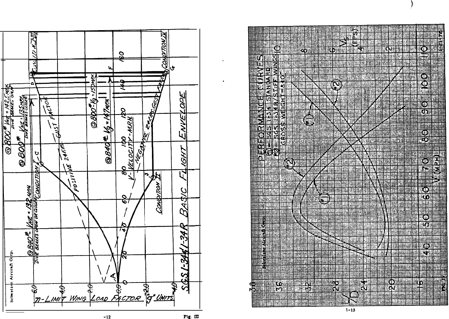
The graph an the
following
page
(Fig.
III)
shows
the
basic
Flight
Envelope.
The
aircraft
should
be operated
within
the envelope limits at all times.Note
the
different maximum
speeds
allowable
with
or
without
use
of the
dive
brakes.
From
points
A to C and A to
J
abrupt maneuvers will not exceed the load
factor
indicated
by
this
line.
Above
C (83 mph) the maneuver must be
limited
to
avoid
excessive
load
factors.The gust
lines are based
on
the standard 24
ft/sec.
gust,
In
case of extreme
turbulence,
such
as
found in
wave conditions
and
clouds,
gusts
can be much
higher
and the aircraft ehould be operated
as
slowly as
practible,
considering
the fact that under turbulent
conditions
a
safe
margin
above
stalling
speed
should
be maintained.
Keep
in
mind that while the load factors
in
the
Flight Envelope carry
a
50%
margin of
safety,
these
margins
should
not be used
intentionally
-
they are for
inadvertent
conditions
only.
This
is
also
generally true for over-speeding A
20% increasre
in
speed above the placard limit
will
use up the margin
of
safety.
A
wise
pilot
will never use greater
speed,
or pull more G’s than the condition
requires.
A word of caution on
aerobatics. Sailplane
aerobatics
is
a
specialized
field
and requires instruction and experience
to
accomplish
safely.
As
previously
stated
in
this
manual, it
is
all
too
easy to exceed
flight
limits
in
an
improperly
executed maneuver, and for that reason
aerobatic
flight
is
not
recommended.
PERFORMANCE CURVES
To aid the
serious
pilot in
becoming
familiar with the various L/D vs. air-
speed relationships, a graph
of the
calculated
performance
curves,
at maximum
gross
weight,
is provided for
his
information.
See Figure IV.
l-11
1-10
E
-
I
I
I
I
I
I
I

_
SCHWEIZER AIRCRAFT CORP.
Elmira,
New
York
14902
Form F-116
l-70
Rev. l-72
SECTION
TWO
MODELS SGS l-34
& 1-34R

_
SGS
l-34.-
FINAL ASSEMBLY HARDWARE LIST
The
following
lists
of
assembly hardware are for a convenient reference.
Wings
to Fuselage Attach: Stabilizer to Elevator Attach (Ref.
):
(2)
34430B-1
Pin
-
Main,
Wing (2)
AN3-11
Bolt (L/R)
(2)
34901B-1
Main Safety
Pin
(2)
AN393-25
Clevis
Pin
(6) No. LSP-l,
Comm’l.
Safety Pin
(2)
34237D-1
Pin-Rear Carry-Thru
(2)
AN310-3
Nut
(2)
AN960-10
Washer
(2)
AN380-2-2
Cotter
Pin
(Captlve
in
Fuse.
)
(2)
34239D-3
Pin
-
Main
Spar (Captive In Fuse.)
Stabilizer to Fuselage Attach: Fln to Fuselage Attach (Ref.
):
(2)
34902A
Bolt, Stab. Attach
(2)
AN310-5
Nut
(2)
AN380-2-2
Cotter Pln
(2)
AN960-516
Washer
(1)
AN4-7A
Bolt
(Fwd.
)
(5)
AN960-416
Washer
(4) AN
4-5A
Bolt (Rear)
(4)
AN365-428
Nut
Alleron to
Push
Rod Attach (Ref.
):
Rudder to
Fin
Attach (Ref.):
(1)
AN3-11
Bolt
(L/R)
(1)
AN960-10
Washer
(1)
AN310-3
Nut
(1)
AN380-2-2
Cotter
Pin
(3)
AN3-11
Bolt
(3)
AN960-10
Washer
(3)
AN310-3
Nut
(3)
AN380-2-2
Cotter
Pin
Aileron
to
Wing
Attach (Ref.
):
Rudder to Horn Attach (Ref.
:)
(2)
34505B-5
Hinge
Pin (L/R)
(2)
34505B-7
Hinge Pin
(L/R)
(1)
AN4-20
Bolt
(1) AN960-416
Washer
(1)
AN310-4
Nut
(1)
AN380-2-2
Cotter Pin
NOTE:
Items
marked
“(Ref.
)"
are not
normally dleaesembled for routine
handllng and trallerlng.
Tall Cone to Fuselage
(Ref.
):
(12)
AN509-8R-8
Screw
ERECTION PROCEDURES
To
facilitate
disassembly
for trailering and reassembly at
the
launch site,
the
l-34
is
so
designed
that
this
may be
accomplished
easily and
quickly.
Unloading
from
Trailer:
A. Unloading Preparations:
1.
Release trailer from
towing
vehicle.
2.
Place tow-bar end on ground and block up the aft end
with
a
saw
horse, jack or other convenient
means.
B.
Wing
Removal:
1.
Unfasten wing tip tie down.
2. Loosen
and remove bolt that
fastens
the spar butt to
the
trailer.
3.
Place one
person
at the
wing
tip,
holding
the
wing
by
its
leading
and trailing edges.
4.
Place one
person
at the
root
end,
lifting
by the
wing
leading
edge.
5.
Both men lift the
wing
simultaneously,
high
enough to
clear
the
trailer.
6.
When the wing is clear of the trailer,
carry
to
its
relative
position
near the point
of
assembly and place flat on
the
ground.
7.
Remove the
opposite
wing
with the same procedure
outlined
above.
C.
Horizontal
Stabilizer:
1.
Remove
wing-nuts
from frame and
swing
the
holding
straps
down
out
of the way.
2.
Remove stabilizers
from
traller and carry to position.
D. Fuselage
Removal:
1.
Remove canopy and set aside in a safe place.
2.
Remove the
blocking
means
from under the rear of the trallsr,
reverse
the
tilt
of the
trailer
so
that the aft end
rests
on the
ground
and place the
blocking
under the forward end.
2-l
2-2

3.
Remove the bolt attaching the tall wheel bracket to the
trailer.
4. Remove supports from
fuselage
attach
points
at rear
carry-thru;
at
the
same
time
make sure that the
fuselage
is
supported manually.
5.
With
one person guiding the tail wheel, and one on each side of the
fuselage
at the
cockpit,
lift
fuselage out of the wheel chocks and
carefully back the fuselage off the aft end of the trailer.
SAILPLANE ASSEMBLY
A. Wing to
Fuselage
Assembly:
Before
attaching
the
wing
to the fuselage, check to
insure
that no
dirt
is
clinging
to the spar butt or between the fuaelage carry-thru plates.A soft cloth
may be used to
wipe
the surfaces clean. The main wing pin holes, the
holes
in
the
yoke
fitting
on each
side
of the fuselage and the rear carry-thru flttlng
should
also
be checked for
cleanliness
It
is
recommended that a
step-by-step
pro-
cedure be followed to avoid trouble.
A
light
film
of grease applied to the
inside
surfaces of the
right
hand yoke flttlng, also on the
wing
spar
in
the
area of con-
tact, may be beneficial
in
sliding
the wing
into
position.
1.
Support the fuselage
in
a normal
upright
position
with
the canopy and
wing
fairing
removed.
2.
Wings
should be
conveniently
located on the ground, or on racks, on
their
respective
sides
of the fuselage.
Assembly hardware should
also be placed near
its
point of use.The dive brake control lever
In the cockpit
must
be in
its
forward position and locked
in
order for
the dive brake
slip-fittings
to engage
automatically.
3.
Check to make sure that the four
captive
(3/8"
dia.
)
L-shaped
pins
(2 for the rear carry-thru and one each upper
side
of the fuselage
at the
U-shaped
yoke fitting), are completely
disengaged
by
pulling
the pins
forward
against the pin
stops.
4.
The
right
hand
wing is
to be installed
first,
as
it
has a wing align-
ment
pin
installed
on the
underside
of the spar butt. Have one
person
level the fuselage
standing
on the right hand
side
of
fuselage.
Two
men pick up the
wing.
one at the tip and one at the root.
The
leading
edge of the
wing
is
handed to the man
supporting
the fuselage and the
man carrying the wing root
moves
to
support the traillng edge.
5.
The spar
butt
is
raised
to clear the fuselage wing attach yoke
fitting
and wing alignment
pin
on the lower
side
of the
spar
butt.
Lower
wing
into
the yoke fitting and have tip man
push
wing inboard to
8.
9.
10.
engage wing
alignment
pin
in
its
receiver
block together with
the
rear
carry-thru flitting.Extreme care must be
exercised
at this
point
so
that the
man
guiding
the rear carry-thru
fitting
into
position
does
not
have
his
fingers caught between the
sharp
wing
skin
and
the
fuselage.
After engagement
of
rear fitting and
wing
alignment
pin,
rock
wing
slightly and
insert
3/8”
rear carry-thru
pin
and
safety
each
by
turn-
ing
the
L-shaped handle portion to the vertical
position,
lower
the
hinged-plate
over
the
end
of
the handle and
install
a
type
AN416-1
safety
pin
through the hole
provided
in
the
handle
end.
Next,
insert
the forward L-shaped
wing
attach
pin
at the
yoke
fitting
under the
spar. Push
the pin aft, through the
main
spar
and the aft
leg of
the
yoke
fitting, until stopped
by
the roll
pin
bumping
against
the forward leg
of the yoke
fitting.
Safety the
wing
pin
by
installing
a
type
AN416-1
safety
pin
through
the
wing
pin
just
aft
of
the forward
guide
bracket.
The
right
hand wing tip
should
now be held, or
supported,
in
a nearly
level
position,
while the three
persons
install
the
opposite
wing
in
a similar
manner
to that
outlined
above.
Install
the two main
wing
pins
P/N
34430B-1.
A slight rocking at
the
wing tip will
aid
in
inserting
each
pin
as
will the
convenient
handle,
Safety both main
pins
using
the P/N
34901B-1
large
safety
pins;
the
two aileron
pushrods
are attached to the aileron idler horn by en-
gaging
the quick-disconnect pins (captive
in
the idler horn), and are
then safetied with (2)
AN416-1
safety
pins.
Check operation
of
dive
brake doors and
aileron
control
system
to
insure
freedom of movement.
B.
Horizontal
Tail
Surfaces
to
Fuselage:
Before
placing
stabilizer on the fuselage torque tube, check to make
sure
tbat
the torque tube
is
free
of
dirt or grit..A
soft
cloth should be used to
wipe
the
surfaces
clean.
NOTE: The stabilizers and elevators are
essentially
symmetrical and are capable
of
being
installed
on opposite sides of the fuselage.
However,
the lower
surface
of each stabilizer can be
identified
by a rectangular notch
in
the
aft
inboard
corner
of the
skin.
2-4
2-3

1.
Place
stabilizer
on torque tube, align the
stabilizer
with forward
line-up hole and the elevator wlth the elevator-drive-aesembly pins.
Push further inboard until the (vertical) attach hole
in
the stabilizer
aligns with that
in
torque tube.
Insert
P/N 34902A-1 collared attach
bolt, add AN960-516 washer, AN310-6 nut and (1) AN380-2-3 cotter
pin.
2. Repeat the above procedure for opposite hand.
3.
Check operation of the elevator control
system
for freedom of
movement.
C. Control Surfaces, Travel:
1.
In the event that the rigging of the control surfaces has been disturbed,
the travel of the
moveable
surfaces must be rechecked to assure that
they are within their respective specified tolerances. Specified travel
of the
various
surfaces
are shown below.In
case
protractor-type
measuring devices are unavailable for making this check, the chordal
dimensions, min. and
max.
from neutral, are listed immediately
following
the callout in degrees.
30-1/2º to 33-1/2º UP --- 4.96" to 5.43" at indoard endd Aileron: 10º to 13º DOWN ----------- 1.64" to 2.14” at inboard end
Dive Brake: Upper 87º to
97º
--- 9.64” to 10.48” at inboard end
Lower 68º to
78º
---
7.27”
to
8.18"
to inboard end
Elevator:
26º
to
31º
UP --- 5.34” to 5.90” at intersection of trailing
edge and root rib
2
4º
to 27º DOWN
--- 4.58” to
5.16”
at intersection of
trailing edge and root rib.
R
Rudder:
30º to 33º L R
--- 8.18” to 8.98" at bottom of trailing edge
2. Aileron control stops are located on the under-floor bulkhead and
contact the horn on the control stick torque tube just above the cable
attach points.
Elevator control stops are located beneath the control
stick
torque
tube, immedlately forward and aft of the control stick.
Rudder control
stops
are
bolts,
placed vertically through brackets
In the aft fuselage, which
restrict
rotation of the rudder
horn.
D.
Wing
Fairing and Canopy:
1. To install the fiberglass top wing fairing carefully align the
slots
formed by the joggled strips on the aft end of the canopy over the
metal lip protruding forward from the aft fuselage. Push the fairing
aft
until
the studs on the fuselage
line
up with the
respective
hole
in
the attach angle inside each forward corner of the fairing. Push the
canopy down over the studs, When properly seated, insert the two
type
AN415-2
pins
thru the hole provided
in
each stud.Secure
the
‘ball-type latches, one each side, connecting the upper and lower
sections
of the bulkhead at the forward end of the fairing.
2. Canopy installation
is
accomplished
by placing the canopy
in
position
over the double studs on the hinges located on the top of
the
left hand
cockpit longeron. Lower the canopy,
guiding
the studs through the
holes
in
the canopy frame. Insert the looped-end pins, P/N 34227R-
15, along the top side of the canopy frame member, through the holes
provided
in
the double-studs at each hinge. The canopy
restraint
cord
is
tied to the pin (AN395-32) located in the aft canopy bow, about six
inches to the right of canopy center line. The S-hook on the opposite
end of the
restrainer
cord
is
then hooked into the
eyebolt,
attached to
the bulkhead
in
the aft, right rear corner of the cockpit. Position the
latch handle directly
inboard
and close canopy.
To lock the canopy from outside the sailplane,
push
inboard and aft
on the small
sliding
vent wlndow located
in
the lower left
hand
side
of the canopy
glass..
Reach
across
cockpit
and rotate latch handle
forward until seating of
the
latch
pin
into
detent is felt. Reverse the
above procedure to open canopy from outside the
aircraft.
2-5 2-6
GENERAL MAINTENANCE
The all-metal construction, rudder covering excepted, to
maintenance required for
LEVELING:
1. Lateral
-
using
adjustable supports under the
wing
tips, level
the
aircraft and check with a spirit level along the upper edge of the
bulkhead
aft of
the
reat.
2.
Longitudinal
-
raise
the tail of the sailplane, place support under
the tail wheel and check with a
spirit
level at
the
rivet
line
along
the
side
longeron,
aft of the wing
trailing
edge.
LUBRICATION:
The pulleys
in
the various control
systems
are
equipped
wlth sealed anti-
friction
bearings
and, under normal operating
conditions,
are considered to be
permanently lubricated.
This
also
applies
to
the
square
slide-tube
for rudder
pedal adjustment, the main wheel bearings, and the aileron push-tube
guide
rollers
inside the
wing.
A
good
grade of
engine
lubricating oil
(SAE
#30)
may be used on
pivot
points
throughout
the control
systems.
However, under dry and dusty
conditions,
it
is
desireable to use a dry-type lubrication such as a silicone, or solid-film
spray
or stick lubricant to prevent retention of grit or dirt around
the
bearing.
The
Lubrication
Charts
(Figs.
I,
II
and
Ill),
indicate the
points
requiring
lubrication and the type of lubricant to be used.The maximum
interval
for
complete
lubrication
is
at annual inspections.
FABRIC
COVERING:
1.
The rudder is
the
only surface on the
aircraft
which
iS fabric covered.
The
covering
is
a
synthetic
fabric,
"Ceconite
No.
103”.
manufactured
and sold by
Ceconite,
Inc.,4677 Worth Street. Los
Angeles,
Calif.
90063. A Ceconlte Process Procedure Manual No. 101 may be pro-
cured from them for
guidance
in
maintenance
and
repair
of this
fabric..See front of aircraft logbook for finishes applied.
2.
FAA Manual No.
AC43.13-1,
Chapter 3, also
contains
guidance
information
for fabric testing and
repairs.
LUBRICATION CHART
FIG. 1
KEY TO LUBRICATION:
0
Lubricating
Oil
(SAE
#30)
0
Silicone
or
Solid-Film
Spray (alt.)
@
Hydraulic
Fluid
(MIL-H-5606
or
equiv.)
SGS l-34 Aileron 4
Dive
Brake
Controls:
Wing
2-7
2-8
LUBRICATION
CHART
--FUSELAGE
FIG.
II
2-9

FINISH:
1.
The production
aircraft
are finished with
acrylic
lacquer. (Ex-
ceptions are ship serial numbers 7 and
8,
which have enamel finish).
Colors, manufacturer and manufacturer’s numbers of the
material
applied is noted
in
the
aircraft
description
section
in
the front of the
individual
aircraft
logbook.
RIGGING:
1.
2.
3.
4.
5.
The angle of incidence and dihedral angle are built into the wing and
fuselage and are not adjustable
in
the
field.
The aileron and elevator control system cables are rigged to a tension
of 10 to 12
lbs.
The tension should not be exceeded to prevent
friction
build-up in the system.
The rudder control
cables
are rigged to a tension of 10 to 14 lbs. This
rigging tension is to be developed
prior
to attaching the rudder bungee
link
cables,
from the captive pretensioned springs in the aft fuselage,
to the bolt connection on the rudder cable turnbuckles.
Control cables
should
be rigged with the turnbuckle threads flush with
the end of the barrel, although a maximum of three threads showing
is
permissible..
Safety wiring of tumbuckles is done by the double-
wrap method shown
in
Chapter 4
of
FAA
Manual
AC43.13-1,
or
in
Military Standard No.
MS33591.
The dive-brake/wheel-brake linkage should be rigged
so
that there
is no
lost
motion when the control handle
is
moved.
Loosely
rigged
linkage may
result
in
partial opening of the
dive
brakes
even though
the control lever is locked in the closed position. The wheel brake
should be rigged to phase-in at the last segment of the brake lever
travel. The wheel brake should be fully on at the point when the
dive brake doors have reached maximum travel.
The spring attached to the aft end of the tow hook release arm should
be tensioned to a point which
requires
a pull (aft) of 9 to 20
lbs.,
at
the tow hook slot in the arm, to actuate the release arm and releaee
the
hook.
On the 1-34R, the main gear up-cable and down-cable should be
rigged to equal tension
so
that the cables do not drag
in
fairleads.
However, avoid
exsess
tension which would cause friction build-up
and consequent difficulty
in
operation of the control.
2-11
WHEEL
AND BRAKE:
The
main
wheel
is
a
split
rim type, wlth roller bearing
in
each
half.
The
tire
is
a 5.00 x 5
(aircraft)
Type
III,
4 ply rating
and
takes a 8.00 x
5
tube.
Inflation should be maintained at 31 psi.
The main wheel brake
is
a Cleveland
Aircraft
Products Co. No. 30-S.
It
is
a
disc
type, hydraulically operated by a
cylinder.
Scott Aviation. Part
No.
44083, mounted in the aft fuselage
section
on the right hnd side.
The brake system
is
serviced with hydraulic fluid (specification
MIL-H-
5808, or equivalent) by removing the fillisster head
screw
from the top plate
on the master cylinder
and
filling through this Bcrew hole.
To
bleed the brake
system,
remove the bleeder-valve cap on the brake
assembly,
opposite the line-attach point. Actuate the brake
cylinder
and,
while
pressure
is
maintained,
crack the bleeder-valve screw to allow air to
escape.
Repeat this cycle,
adding
hydraulic fluid
as
necessary,
until
the
air
is
exhausted. Check brakes for normal operation then tighten bleeder valve
screw, replace bleeder-valve cap,
also
replace the
screw
in master
cylinder
filler-hole.
An
"O"
ring (type
AN6290-4)
is
required
in
the master cylinder outlet and
is
inserted ahead
of the (type
AN815-4D) tube union
fitting.
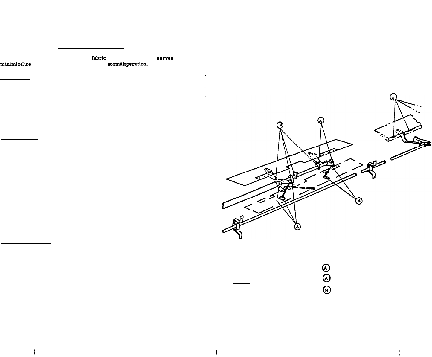
MAIN
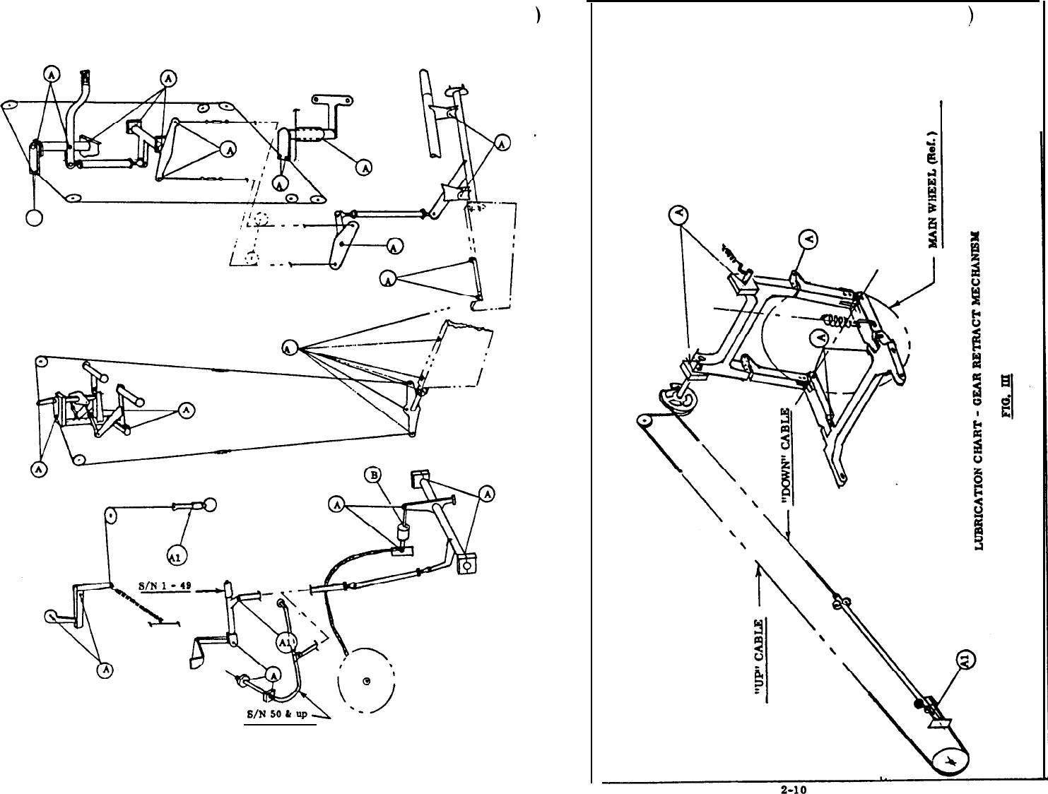
GEAR RETRACTION MECHANISM.
1-34R:
Retraction of the main gear
is
effected by the knee-action between the
rear fork (upper) and the lower wheel support struts. The rear fork (upper)
is bolted to
trunnion
shafts
,
the
right
hand shaft
being
also bolted to a
sector
assembly
which,
through a cable arrangement, rotates the upper rear fork
forward and up together
with
the struts and
forward
fork.
A large spring,
mounted in a near-vertical
in
the forward left hand comer of the wheel well,
compensates
for most of the weight
of
the wheel and forks thereby
reducing
control actuation effort to a
reasonable
level.Adjustable stop-bolts,
with
jamb
nuts,
are
incorporated
in both
lower
struts to
facilitate
adjustment.
as
need be,
between the rear
fork and
struts
when the gear
is
in
the down position.
The gear doors are linked, wlth a turnbuckle,
directly
to the lower end
of
the
wheel support
struts.
Adjustment for proper closed
position is
the
only
adjustment
necessary.
The brake line
is
routed through
grommets
in the wheel well cover and
care must be
exercised in
provldlng the correct lay of the
line
to prevent
kinking of the line when the gear
is
in
the up
position.
Fig. III
shows a schematic of the gear arrangement and
lubrication
re-
quirements
.
2-12

AFT FUSELAGE:
PREFLIGHT INSPECTION
Refer to the Flight Procedures portion (section 1) of this manual for
ln-
structions relative to Preflight Inspection.
ANNUAL OR 100 HOUR INSPECTION
Federal Aviation Regulations require that 100 hour inspection be performed
on
aircraft
which are used in commercial service. All aircraft, regardless of
useage, are required to undergo an Annual Inspection
in
order to maintaln the
validity of the Certificate of Airworthiness.The form reproduced on Page 15
may be used as a guide for performing and recording these inspections.Useful
and official information
is
listed in FAA Glider Data Sheet No.
G3EA.
FORWARD FUSELAGE:
a.
b.
C.
d.
8.
f.
::
;:
k.
1.
m.
n.
0.
P.
9.
r.
8.
t.
U.
Skins. damage, cracks, buckling.
Canopy, plexiglass cracks or crazing. frame, hinges, latches, vent
window.
Upper wing falrlng aft of canopy, for cracks or damage.
Nose cap, pitot tube,
static
vents, ventilating-air tube.
Seat, back and bottom adjustments.
Control stlck, torque tube, elevator push rod.
Elevator bellcrank,
fwd.
operation, attach polnts.
Elevator control cable system, tension, turnbuckles.
Instrument panel and instruments,
pitot/static
lines.
Radio and accessory console.
Cabln ventilator, ducts, outlets.
Rudder pedals, adjustlng
mechanism,
return spring.
Rudder control cable system, falrleads, tension, bungee, turnbuckles.
Tow release control, cable, pulley, spring tension.
Release arm, attachment, condltlon, spring tension.
Release hook, attachment, condition, operation.
Safety belt and shoulder harness, condition, attachment.
Dive brake
mechanism
(fuse.
).
attachment, handle lock.
Placards, instrument markings, legibility, currency.
Lubrication of controls (See Lubrication Chart).
Gear retraction control, locking lever, down lock pin, cable
condition and attachment, operation. (I-34R ONLY)
a.
b.
C.
d.
e.
f.
g.
h.
i.
WINGS.
A
a.
b.
C.
d.
e.
f.
g.
h.
j.
k.
1.
m.
Elevator cable runs, fairleads, gulde pulleys, Sta. 161.
Rudder cable runs, falrleads.
Skins, damage, cracks, buckling.
Stabilizer,
condltlon, attachment.
Elevator, condition. hinge bolts, safety.
Elevator bellcrank, wear, security, puehrod and horn attach, safety.
Fin, general condition, attachment forward
and
aft.
Rudder, fabric, hinges wear and safety,
air
seal, balance welght
attach.
Rudder
bellcrank,
unlversal attach to rudder, wear, attachment,
safety.
Spar butt, main wing
pin
attach holes
(.
499/.
501).
Main wing
pin,
wear, damage, handle attach, safety.
Maln spar, captive pin, attachment, safety.
Aft carry-thru, captive pin, attachment, safety.
Aileron push rods, condition, attachment.
Aileron bellcrank, condition, pivot bolt, safety.
Ailerons, condltlon, balance weight attach, hlnges, safety.
Dive brake torque tube, condition,
inboard
engagement. outboard
attach bolts.
i. Dive brake mechanism, rod end attach, return spring attach.
Dive brake doors, condition, rod end attach, hinges, safety.
Wing
sskins,
bbuckling, damage.
Wing tip wheel (optional), condition, attachment.
Lubrication of dive brake
mechanism.
(See Lubrication Chart)
LANDING GEAR:
a. Nose skid and shoe, condition, attachment.
b. Wheel, condition, bolts, bearing noise, axle attachment.
c. Tire and tube, condition, inflation
(31
psi).
d. Brake, operation,
cylinder,
fluld level, line, grommet, puck
and
disc,
torque arm attachment.
e. Tail wheel and bracket, condition, attachment and safety.
l-34R ONLY:
f.
Gear retraction mechanism, wear, attachment, down-stops, safety.
g. Gear door, condition, linkage adjust, attach. safety.
2-13 2-14

SCHWEIZER
AIRCRAFT CORP.
INSPECTION RECORD
Elmira.
New York
14903
ANNUAL &/or 100 HOUR
SGS l-34 & l-34R
Sailplane
Model
S/N
Reg. No.
N-
Work Order No.
Check the
following
for proper
installation.
tension,
safety, wear, excessive free play,
evidence
of corrosion or other damage.
Indicate
airworth
by
checking
( ) block.
When
unairworthy
items are noted, leave
appropriate
block blank,
until
corrected.
This form may be reproduced for used
in
the field..
NOTE:
FWD.
FUSELAGE
&
COCKPIT:
A/W
a.
b.
C.
d.
Bungee control and cable
e. Release control and cable
f. Dive-brake control
h
.
1:
m.
n.
Control
stick
&
torque tube
-
Forward elevator bellcrank
Elevator cables and
guides
- g. g.
g. Rudder
pedals
and
springs
Rudder cables and guides
i. Instrument installations
j. Cabin
ventilator
k. Canopy (glass and latches)
Safety Belt
Shoulder
harness
Gear retraction control (l-34R)
AFT FUSELAGE:.
A/W
Main
wing attach holes
Forward
carry-thru attach
Aft
wing
attach holes
=
a.
b.
C.
d.
g.
h.
j.
k.
1.
WING:
Main attach
pin
holes
Drag
fittings
and attach holes
-
a.
b.
C.
d.
e.
f.
h.
j.
k.
1.
Long all. push rod and
guides
_
Dive
brake
torque
tube
Dive-brake well
&
contr.
inst.
=
Aileron
idler
inst.
g. Aileron
pushrod
and horn
Aileron
hinges
i. Wing
tip
Exterior
surface
Visible
interior
surfaces
Leading
edge
=
EMPENNAGE GROUP:
a.
b.
C.
d.
g.
h.
j.
k.
Stab. attach
holes
&
pins
Elevator
hinges
Elev.
horn att.
holes
&
pins
Elevator idler horn
inst.
e. Elev.
cables and guides
f. Fin attach points
Rudder hinges
Rudder cables
&
guides
i. Tail wheel
&
bracket
Tail fairing
Rudder covering
-
fabric
Aft
carry-thru attach
Aileron,
transfer
inst.
Dive-brake
idler
inst.
Brake
inst.
and cable
Elevator cables and guldes
i. Rudder cables end
guides
-
=
Inside
skins
Wing
falrlng, aft of canopy
--
Gear retraction mech. (1-34R)
mech
1
m. Gear doors
(l-34R)
a.
b.
C.
d.
e.
f.
h.
j.
k.
1.
Main
attach
pin holes
LEFT WING:
Drag
fittings
and attach boles
-
Long ail. push rod
&
guides
Dive
brake
torque tube
z
Dive-brake
well
&
constr.
inst.
-
Aileron idler
inst.
g. Aileron
pushrod
and horn
=
Aileron hinges
i. Wing
tip
Exterior
surface
Visible
interior
surfaces
1
Leading
Edge
GENERAL EXTERIOR:
a. Tow hook
inst.
b. Nose
skid
and
shoe
c. Tire and inflation
d.
Identification
markings
e.
Covering,
fabric/metal
skins
=
f. Pitot-static
tubes/vents
Aircraft Total Tlme
Prev.
Ann.
Insp.
on
@
hrs.
date,
hre.
Mechanic’s signature
Insp.
Auth.
signature
Cert. No.
Cert. No.
Date
Date
SAILPLANE TIE DOWNS
By
its
very
nature,
a
sailplane
is
suscepitble
to the
effects
of winds,
More
sailplanes
are damaged on the ground by
the
wind
than
in
accidents
during
flight.
This
is
usually
because of
either
leaving
the
ship
unsecured,
or from
the
me of
inadequate
tie-downs.
Therefore,
it
is important
that
adequate
tie
downs be
provided.
The
following
recommendations,
based on
experience.
may be
used
as
a
guide.
1.
Sheltered
Area: Tall down, ropes
(*)
at
wings
and
tail
(**).
2. Unsheltered
Area:
Facing
into
prevailing
wind.
Rope
at
wings
and tail and chain tie down
to
release
hook.
3.
Unsheltered
-
High
Wind Hazard: Tail supported on padded stand.
Rope to
wings
and
two ropes to tail.
Short
chain
(5/16"
welded
link), tie down to
tow
hook.
4.
Flightline
Tie
Down: :Short chain
tie down to tow
hook
(tail
in
air).
Water
filled
tire
tubs on end of
one
wing.
NOTE:
*
Minimum
size recommended
ropes
-
5/16"
nylon, or 1/2"
manila
-
renewed each
season.
(Knots can reduce rope
strength
by 50%.)
**
Ground
anchor
size
and style
will
depend
on soil
composition
and
type of sailplane. In
light
sandy
soils,
anchor arm or
chain
longer
and set deeper.
A
ground anchor
should
be able to withstand
a
vertical pull of at least 2,000
#..
Sbould not be located
directly
under
tle downs.
Rudderlock
-
recommended
if
control locks are not used.
Ailerons
and elevator can be secured wlth seat belt around control stick.
Securing
the
spoilers or
dive
brakes
"open"
will
decrease
lifting
forces.
2-16
