SH M7000 RD MANUAL
User Manual: SH-M7000-RD-MANUAL
Open the PDF directly: View PDF ![]() .
.
Page Count: 31

(English)
DM-MBRD001-00
SLX
RD-M7000
Dealer's Manual
ROAD MTB Trekking
City Touring/
Comfort Bike URBAN SPORT E-BIKE
Rear Derailleur
2
CONTENTS
IMPORTANT NOTICE ............................................................................................. 3
TO ENSURE SAFETY ............................................................................................... 4
LIST OF TOOLS TO BE USED .................................................................................. 6
INSTALLATION ....................................................................................................... 8
Installation of the rear derailleur ................................................................................................................8
ADJUSTMENT ...................................................................................................... 11
Stroke adjustment ...................................................................................................................................... 11
Installing the chain .....................................................................................................................................12
Securing the cable ...................................................................................................................................... 13
Using the end adjust bolt ..........................................................................................................................17
SIS adjustment ............................................................................................................................................18
Adjusting friction .......................................................................................................................................20
MAINTENANCE .................................................................................................... 24
Replacing the plate and the plate tension spring ....................................................................................24
Applying grease to the chain stabilizer ....................................................................................................29
Replacing the pulley ..................................................................................................................................30
3
IMPORTANT NOTICE
IMPORTANT NOTICE
•
This dealer’s manual is intended primarily for use by professional bicycle mechanics.
Users who are not professionally trained for bicycle assembly should not attempt to install the components themselves using the dealer’s manuals.
If any part of the information on the manual is unclear to you, do not proceed with the installation. Instead, contact your place of purchase or a local
bicycle dealer for their assistance.
•
Make sure to read all instruction manuals included with the product.
•
Do not disassemble or modify the product other than as stated in the information contained in this dealer’s manual.
•
All dealer’s manuals and instruction manuals can be viewed on-line on our website (http://si.shimano.com).
•
Please observe the appropriate rules and regulations of the country, state or region in which you conduct your business as a dealer.
For safety, be sure to read this dealer’s manual thoroughly before use, and follow it for correct use.
The following instructions must be observed at all times in order to prevent personal injury and physical damage to equipment and surroundings.
The instructions are classified according to the degree of danger or damage which may occur if the product is used incorrectly.
DANGER
Failure to follow the instructions will result in death or serious injury.
WARNING
Failure to follow the instructions could result in death or serious injury.
CAUTION
Failure to follow the instructions could cause personal injury or physical damage to equipment and surroundings.
4
TO ENSURE SAFETY
TO ENSURE SAFETY
WARNING
•
Be sure to follow the instructions provided in the manuals when installing the product.
It is recommended to use genuine Shimano parts only. If parts such as bolts and nuts become loose or damaged, the bicycle may suddenly fall over,
which may cause serious injury.
In addition, if adjustments are not carried out correctly, problems may occur, and the bicycle may suddenly fall over, which may cause serious injury.
•
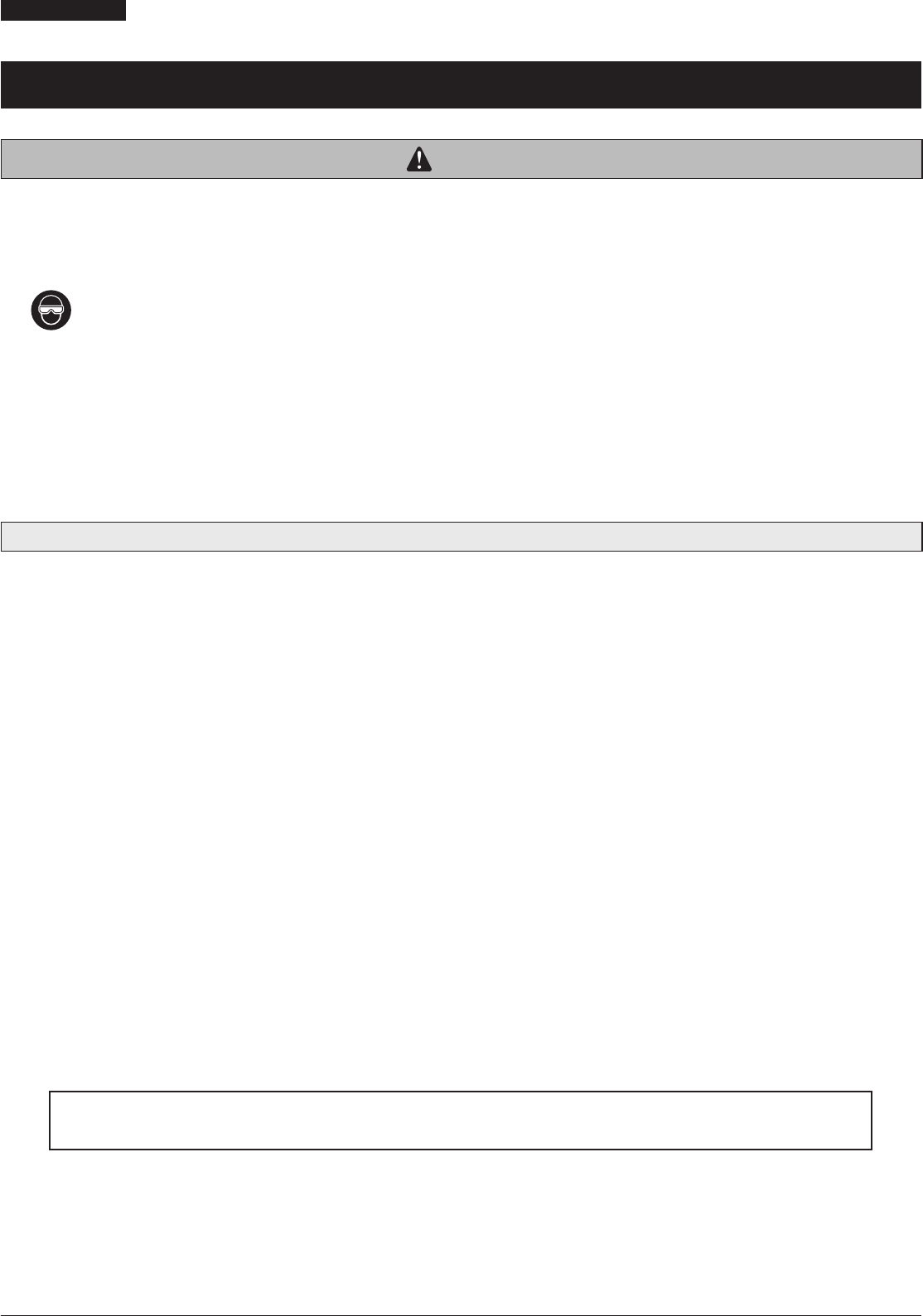
Be sure to wear safety glasses or goggles to protect your eyes while performing maintenance tasks such as replacing parts.
•
After reading the dealer's manual thoroughly, keep it in a safe place for later reference.
Be sure to also inform users of the following:
•
Intervals between maintenance depend on the use and riding circumstances. Clean the chain with an appropriate chain cleaner regularly. Never use
alkali based or acid based solvents, such as rust cleaners. If those solvents are used the chain might break and cause serious injury.
•
Check the chain for any damage (deformation or crack), skipping, or other abnormalities such as unintended gear shifting. If any problems are found,
consult a dealer or an agency. The chain may break, and you may fall.
NOTE
Be sure to also inform users of the following:
•
For SHADOW RD+, be sure to check that the plate unit cover is installed before riding the bicycle.
•
If gear shifting operations do not feel smooth, wash the derailleur and lubricate all moving parts.
•
If looseness in the links is so great that gear shifting adjustments cannot be made, replace the derailleur.
•
Products are not guaranteed against natural wear and deterioration from normal use and aging.
•
For maximum performance we highly recommend Shimano lubricants and maintenance products.
For Installation to the Bicycle, and Maintenance:
•
Depending on the shape of the frame, the rear derailleur may interfere with the chainstay.
•
Grease the inner cable and the inside of the outer casing before use to ensure that they slide properly. Do not let dust adhere to the inner cable. If the
grease on the inner cable is wiped off, the application of SIS SP41 grease (Y04180000) is recommended.
•
Use an outer casing [OT-SP41] and a cable guide (SM-SP17/SP18) for smooth operation.
•
Use an outer casing which still has some length to spare even when the handlebars are turned all the way to both sides. Furthermore, check that the
shifting lever does not touch the bicycle frame when the handlebars are turned all the way.
•
If gear shifting adjustments cannot be carried out, check that the rear fork ends are aligned. Check whether the cable is lubricated and clean, and if
the outer casing is too long or short.
•
Periodically clean the derailleur and lubricate all moving parts (mechanism and pulleys).
•
Depending on the model, the guide pulley has arrows on it to indicate the direction of rotation. Install the guide pulley so that the arrows are
pointing counterclockwise when looking at the outer side of the derailleur.
•
If you hear abnormal noise as a result of looseness in a pulley, you should replace the pulley.
The actual product may differ from the illustration because this manual is intended mainly to explain the procedures for using
the product.

LIST OF TOOLS TO BE USED

6
LIST OF TOOLS TO BE USED
LIST OF TOOLS TO BE USED
The following tools are needed for installation, adjustment, and maintenance purposes.
Tool Tool Tool
2mm Allen key 5mm Allen key Hexalobular[#30]
3mm Allen key 5.5mm spanner
4mm Allen key Screwdriver[#2]

INSTALLATION
8
INSTALLATION
Installation of the rear derailleur
INSTALLATION
Installation of the rear derailleur
Standard type
Lever switch setting
1
(A)
(z)
(y)
Make sure that the lever switch is in the
OFF position.
If the lever switch is in the ON position,
be sure to move it to the OFF position.
(y)
ON
(z)
OFF
(A)
Lever switch
The shape differs depending on the model.
2
(A)
(B)
Install the rear derailleur.
(A)
Fork end
(B)
Bracket
Tightening torque
8 - 10 N·m
NOTE
Periodically check that there is no gap
between the fork end and the bracket as
shown in the illustration. If there is a gap
between these two parts, problems with gear
shifting performance may occur.
9
INSTALLATION
Installation of the rear derailleur
Direct mount type
Lever switch setting
(A)
(z)
Make sure that the lever switch is in the
OFF position.
If the lever switch is in the ON position,
be sure to move it to the OFF position.
(z)
OFF position
(A)
Lever switch
The shape differs depending on the model.
Replacing with direct mount type
Remove the bracket axle.

ADJUSTMENT
11
ADJUSTMENT
Stroke adjustment
ADJUSTMENT
Stroke adjustment
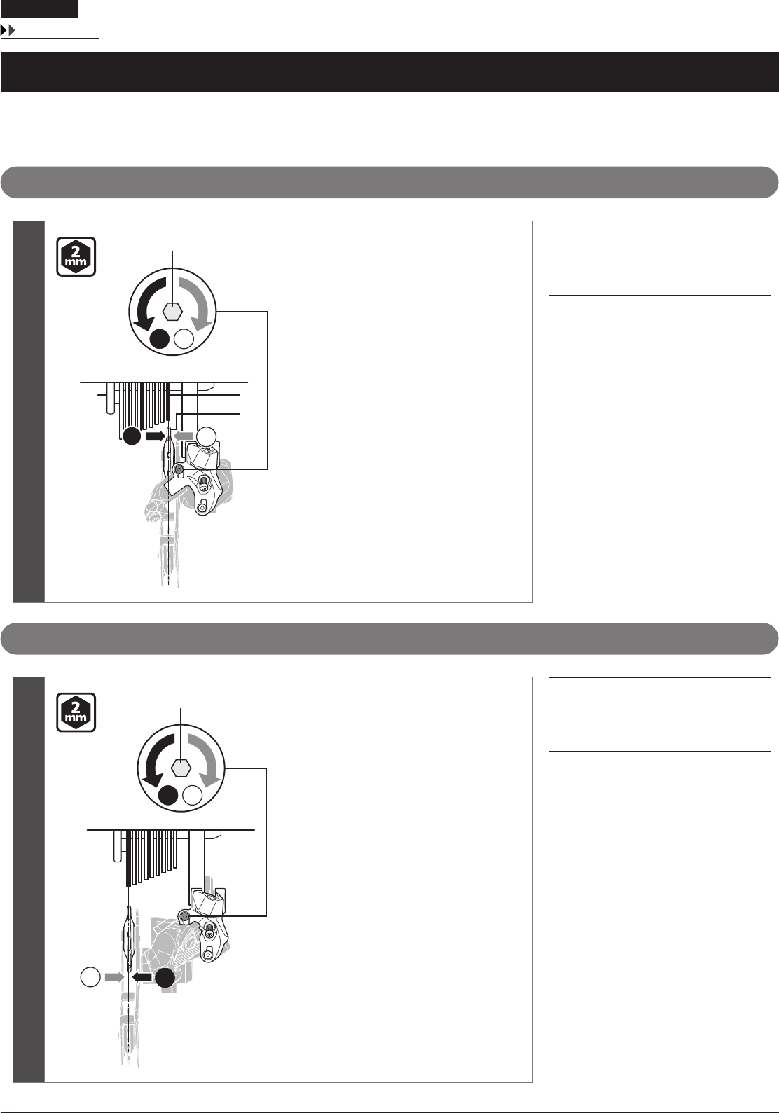
Top adjustment
BA
BA
(A)
(B)
(C)
Turn the top adjustment screw to
position the guide pulley over the outer
line of the smallest sprocket when seen
from the rear side.
(A)
Top adjustment screw
(B)
Smallest sprocket
(C)
Guide pulley
Low adjustment
BA
AB
(A)
(B)
(C)
Turn the low adjustment screw to
position the guide pulley directly
underneath the largest sprocket.
(A)
Low adjustment screw
(B)
Largest sprocket
(C)
Guide pulley
12
ADJUSTMENT
Installing the chain
Installing the chain
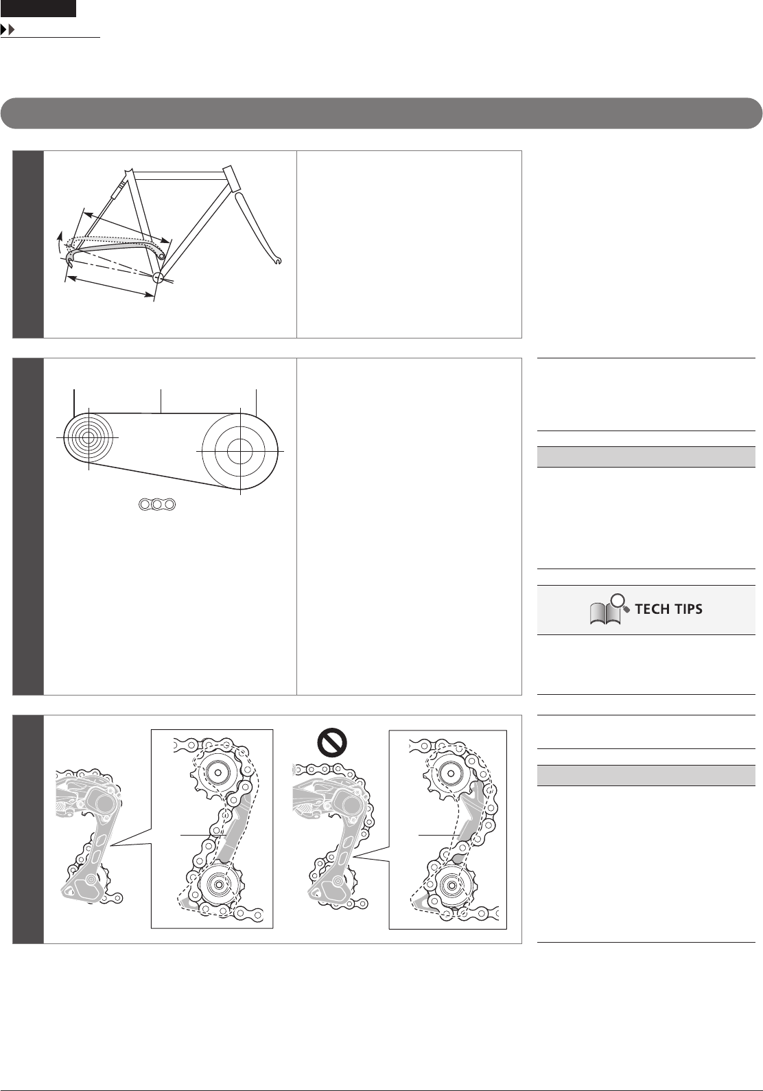
Chain length
1
[X]
[X]
The length of dimension [X] will vary
depending on the movement of the rear
suspension.
Consequently, an excessive load may be
placed on the drive system if the chain
length is too short.
The rear suspension operates and stops
when dimension [X] reaches its greatest
extension.
2
+
(A) (B) (C)
Mount the chain on to the largest
sprocket and the largest chainring.
Next, add 2 links to set the length of the
chain.
(A)
Largest sprocket
(B)
Chain
(C)
Largest chainring
NOTE
If there is a lot of movement in the rear
suspension, the slack in the chain may not be
taken up properly when the chain is on the
smallest chainring and smallest sprocket.
Add 2 links (with the chain on the largest
sprocket and the largest chainring).
The same chain length checking method
applies to the triple front gear, the double
front gear, and the single front gear.
(A) (A)
(A)
Chain derailment prevention plate
NOTE
The rear derailleur plate assembly is equipped
with a pin or plate that prevents the chain
from derailing.
When passing the chain through the rear
derailleur, pass it through the rear derailleur
body from the side of the chain derailment
prevention plate as shown in the illustration.
If the chain is not passed through the correct
position, damage may be caused to the chain
or rear derailleur.
13
ADJUSTMENT
Securing the cable
Securing the cable
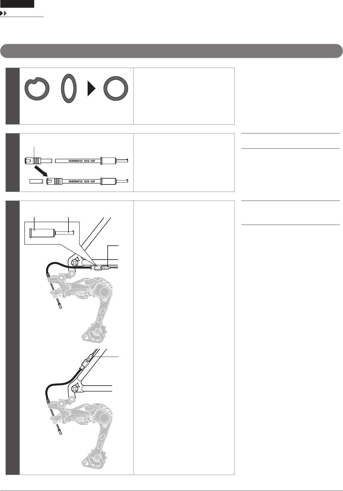
Cutting the outer casing
1
When cutting the outer casing, cut
the end opposite to the end with the
marking.
After cutting the outer casing, make the
end round so that the inside of the hole
has a uniform diameter.
2
(A)
After cutting, attach the same sealed
outer cap to the end.
(A)
Sealed outer cap
3
(A)
(B)
(B)
(z)
Install the sealed outer cap with tongue
and the rubber shield onto the outer
casing stopper of the frame.
(z)
Be careful not to bend this
section.
(A)
Sealed outer cap with tongue
(B)
Rubber shield
14
ADJUSTMENT
Securing the cable
Outer casing length
1
(A)
Loosen the end adjust bolt until it is in
the position shown in the illustration.
(A)
End adjust bolt
2
(A)
(C)
(B)
Check that there is enough slack in the
outer casing.
Next, align the outer casing, on which
the sealed outer cap is installed, with the
bottom edge of the outer casing holder
on the rear derailleur, then cut off any
excess length of outer casing.
(A)
Outer casing holder
(B)
Outer casing
(C)
Sealed outer cap
NOTE
The distance between the outer stopper to
the outer casing holder of the rear derailleur
may change when the rear suspension moves,
so determine the length of the outer casing at
the point where this length is at its greatest.
If the motion of the rear derailleur is extreme,
such as in a rear suspension bicycle, replacing
it with the aluminum type sealed outer cap
provided is recommended.
Sealed outer cap Sealed outer cap
(aluminum type)
15
To be continued on next page
ADJUSTMENT
Securing the cable
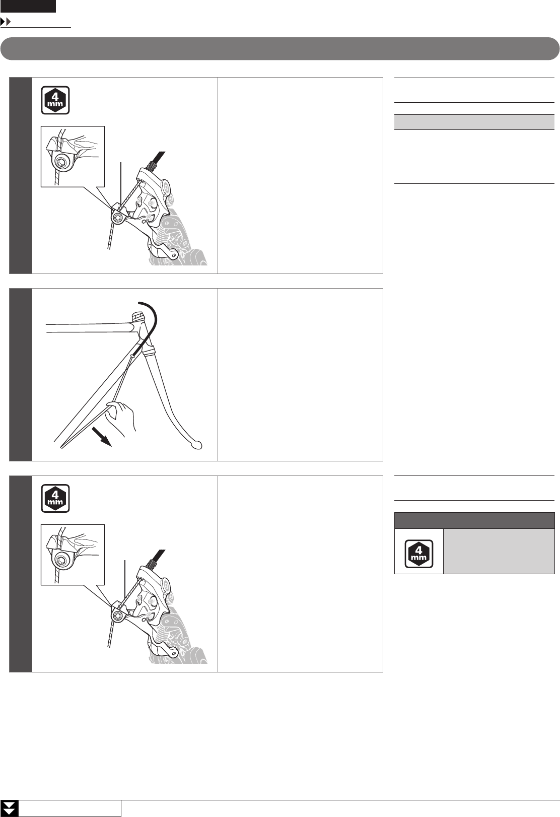
Connecting and securing the cable
1
(A)
Connect the inner cable to the rear
derailleur.
(A)
Inner cable
NOTE
•
Fuzz may be generated when the inner
cable is installed or when the coating is
damaged during use, but this will not
affect its functions.
2
Remove the initial slack from the cable
as shown in the illustration.
3
(A)
Reconnect the inner cable to the rear
derailleur.
Be sure that the cable is securely in the
groove.
(A)
Inner cable
Tightening torque
6 - 7 N·m

16
ADJUSTMENT
Securing the cable
4
(A)
(z)
Set the inner cable so that the margin is
approximately 30mm or less.
Install the inner end cap.
(z)
30mm or less
(A)
Inner end cap
NOTE
Check that the inner cable does not interfere
with the wheel spokes.
Stop the wheel from turning while carrying
out this step.
17
ADJUSTMENT
Using the end adjust bolt
Using the end adjust bolt
Adjusting the end adjust bolt
A
B
B
BA
A
(A) (C)(B)
Mount the chain on the smallest
chainring and the largest sprocket, and
turn the crank arm to shift gears.
Adjust the end adjust bolt so that the
guide pulley does not interfere with the
sprocket, but do not let the guide pulley
come so close to the chain that they
come into contact with each other.
Next, set the chain on the smallest
sprocket and repeat the above
procedure to make sure that the pulley
does not come into contact with the
sprockets.
(A)
Largest sprocket
(B)
Smallest sprocket
(C)
End adjust bolt
Checking the distance between the largest sprocket and the guide pulley
(z)
(A)
(B)
Set the rear derailleur on the largest
sprocket, and with the wheel stopped,
make sure that the clearance between
the tip of the guide pulley and the tip of
the largest sprocket is within the range
of 5 to 6mm.
(z)
5 – 6mm
(A)
Largest sprocket
(B)
Guide pulley
NOTE
Check the distance between the largest
sprocket and the guide pulley with the rear
suspension at its greatest extension.
18
To be continued on next page
ADJUSTMENT
SIS adjustment
SIS adjustment
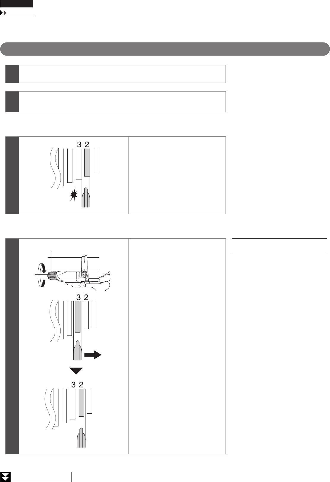
SIS adjustment
1Move the lever switch to the OFF position.
2Operate the shifting lever once to move the chain from the smallest sprocket to the 2nd
sprocket.
Best setting
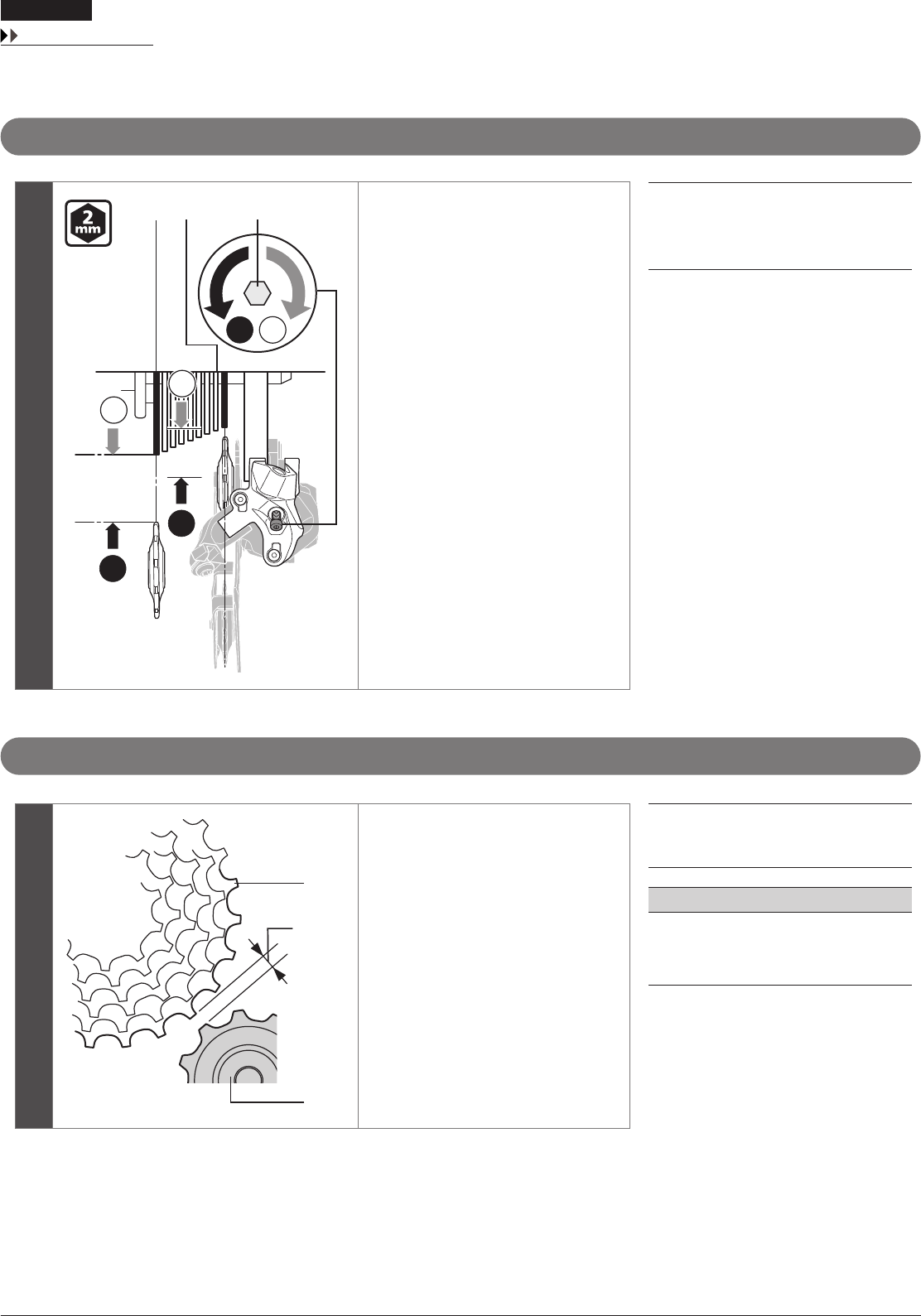
3
The best setting is when the shifting
lever is operated just enough to close
the lever gap and the chain touches the
3rd sprocket counting from the smallest
sprocket and makes noise.
When shifting to the 3rd sprocket counting from the smallest sprocket
3
(A)
Tighten the cable adjustment barrel
(clockwise) until the chain returns to the
2nd sprocket counting from the smallest
sprocket.
(A)
Cable adjustment barrel
19
ADJUSTMENT
SIS adjustment
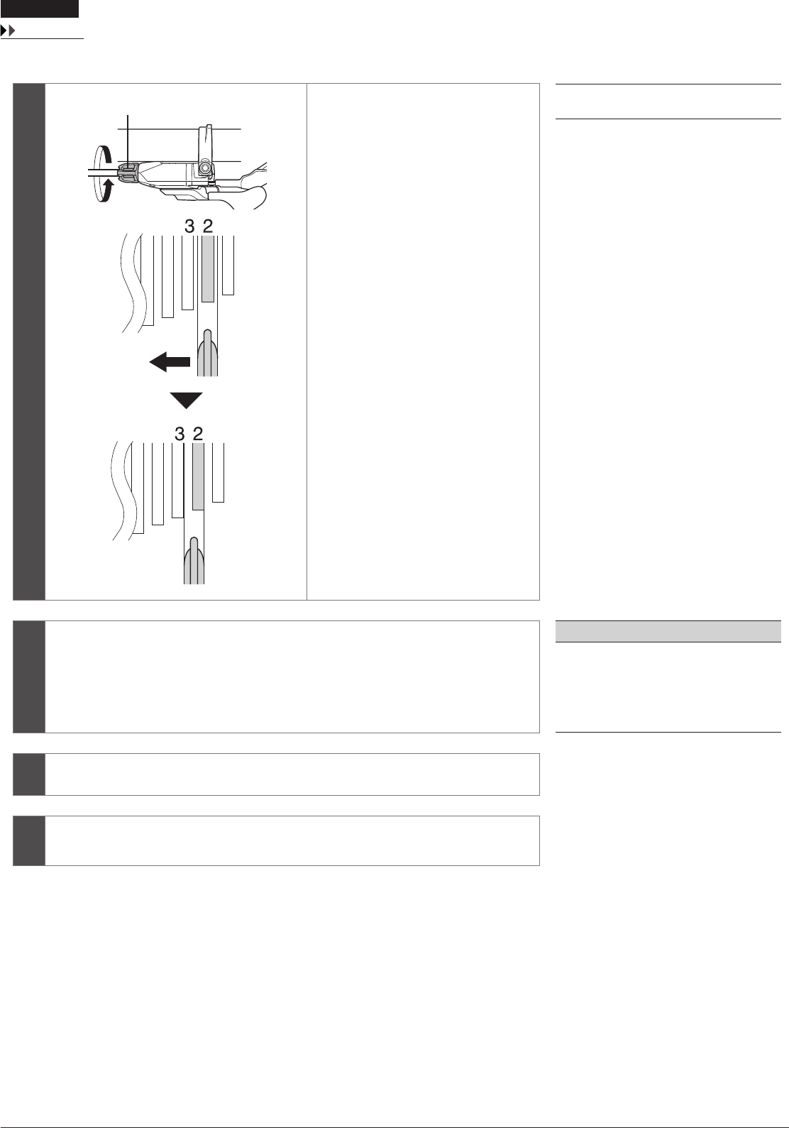
When no sound at all is generated
3
(A)
Loosen the cable adjustment barrel
(counter-clockwise) until the chain
touches the 3rd sprocket counting from
the smallest sprocket and makes noise.
(A)
Cable adjustment barrel
4
Return the lever to its original position (the position where the lever is at the 2nd sprocket
setting counting from the smallest sprocket and it has been released) and then turn the
crank arm clockwise.
NOTE
If the chain is touching the 3rd sprocket
counting from the smallest sprocket and
making noise, turn the cable adjustment
barrel clockwise slightly to tighten it until the
noise stops and the chain runs smoothly.
5Operate lever to change gears, and check that no noise occurs in any of the gear positions.
6Set the lever switch to ON, and then ride the bicycle normally and check that there are no
problems with gear shifting.
20
To be continued on next page
ADJUSTMENT
Adjusting friction
Adjusting friction
The friction capacity can be adjusted as desired. Furthermore, you can also adjust after a change of the friction occurs during use.
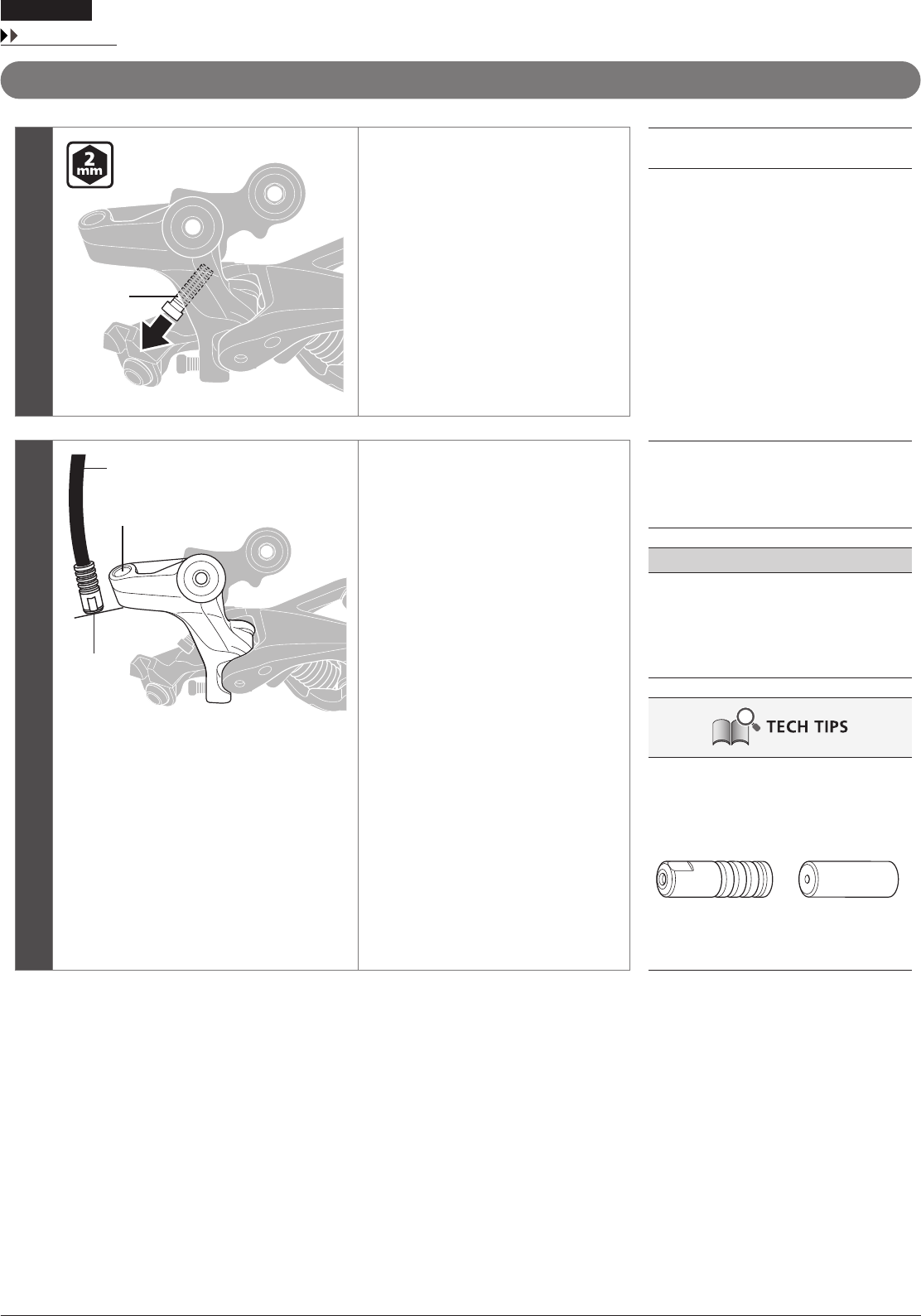
Friction adjustment
1Move the lever switch to the OFF position.
2
(A)
(C) (B)
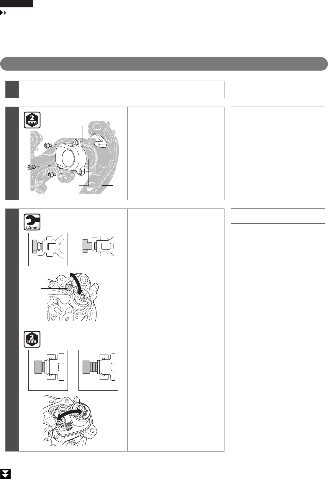
Using a 2mm Allen key, remove the plate
unit cover.
(A)
Plate unit cover
(B)
Lever switch
(C)
Plate unit
3
(A)
(z)(y)
RD-M7000-10-SGS
Using a 5.5mm spanner, turn the friction
adjustment bolt to adjust the friction.
(y)
Friction increases
(z)
Friction decreases
(A)
Friction adjustment bolt
(A)
(y) (z)
RD-M7000-11-GS
Using a 2mm Allen key, turn the friction
adjustment bolt to adjust the friction.
(y)
Friction increases
(z)
Friction decreases
21
To be continued on next page
ADJUSTMENT
Adjusting friction
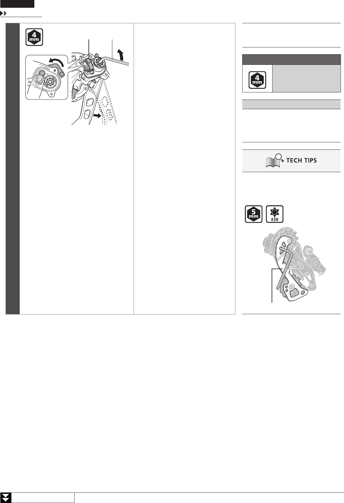
4
(B)(A)
(z)
Check the friction torque.
While pressing the friction unit with your
fi nger as shown in the illustration, set
the lever switch to the ON position and
check the friction torque.
(z)
ON
(A)
Friction unit
(B)
4mm Allen key
Friction torque
3.5 - 5.4 N·m
NOTE
If adjusting the friction once more, be sure to
set the lever switch to the OFF position while
pressing the friction unit with your fi nger
before making the adjustment.
RD-M7000-11-GS
Friction torque may also be checked by
inserting an Allen key or hexalobular wrench
into the left plate.
Left plate
22
ADJUSTMENT
Adjusting friction
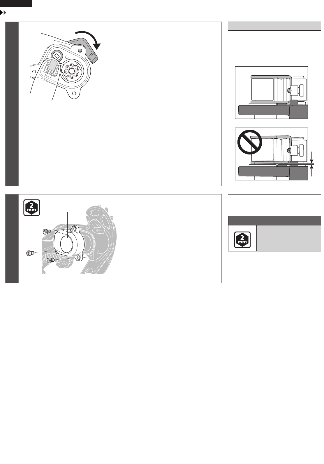
5
(z)
While pressing the friction unit with your
fi nger, set the lever switch to the OFF
position.
At that time, make sure that the friction
unit is in contact with the bottom of the
plate unit.
(z)
OFF
NOTE
Do not install the plate unit cover with a gap
between the bottom of the plate unit. It may
not seal suffi ciently, which will cause the
inner mechanism to rust, potentially resulting
in the adhesion of the plate.
6
(A)
Install the plate unit cover.
(A)
Plate unit cover
Tightening torque
1 - 1.5 N·m

MAINTENANCE
24
To be continued on next page
MAINTENANCE
Replacing the plate and the plate tension spring
MAINTENANCE
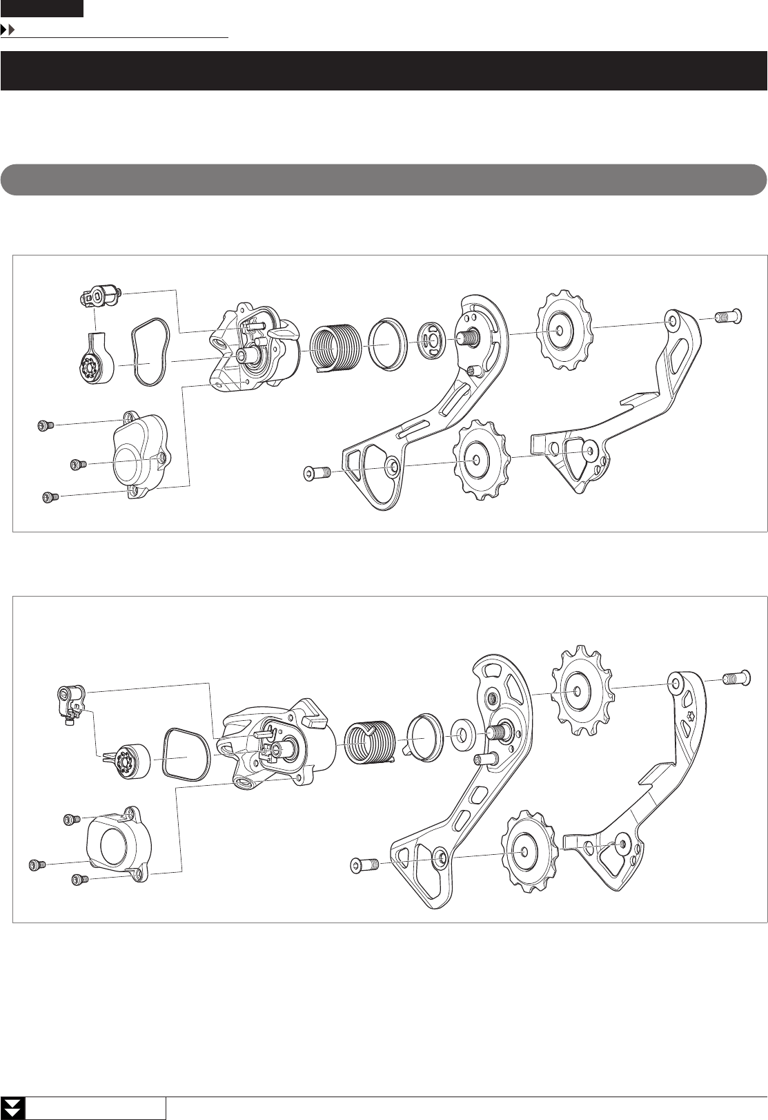
Replacing the plate and the plate tension spring
Removal
RD-M7000-10-SGS
Exploded view
RD-M7000-11-GS
Exploded view
25
To be continued on next page
MAINTENANCE
Replacing the plate and the plate tension spring
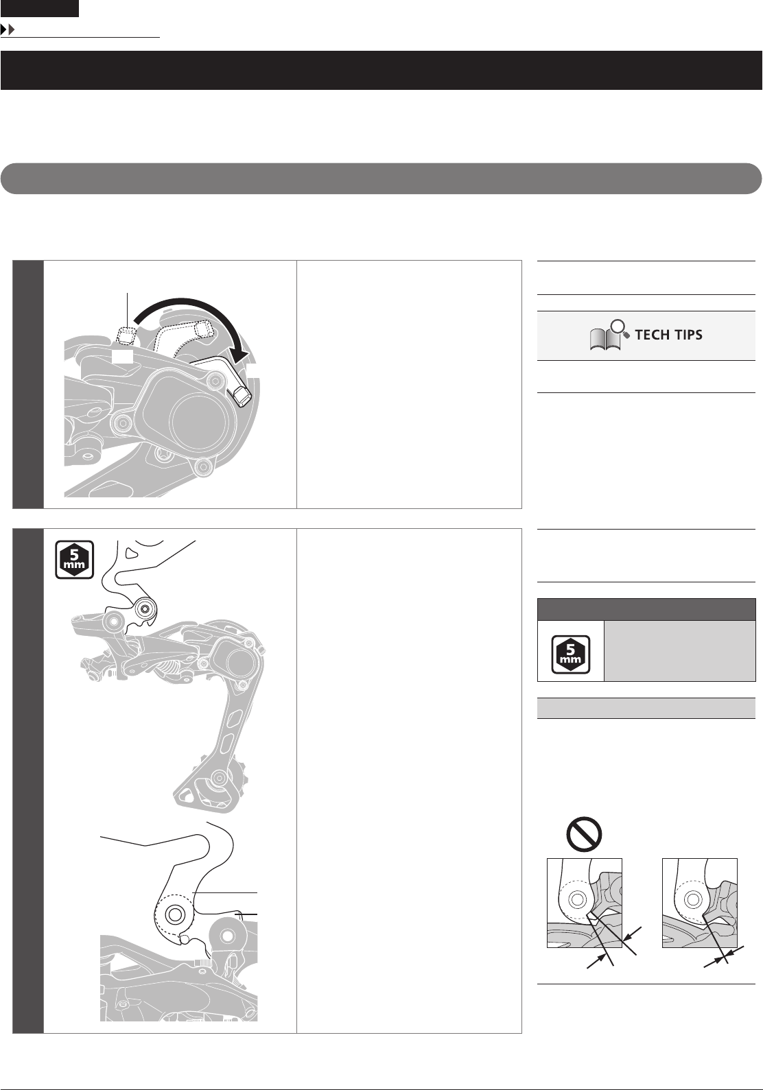
1
(A)
(z)
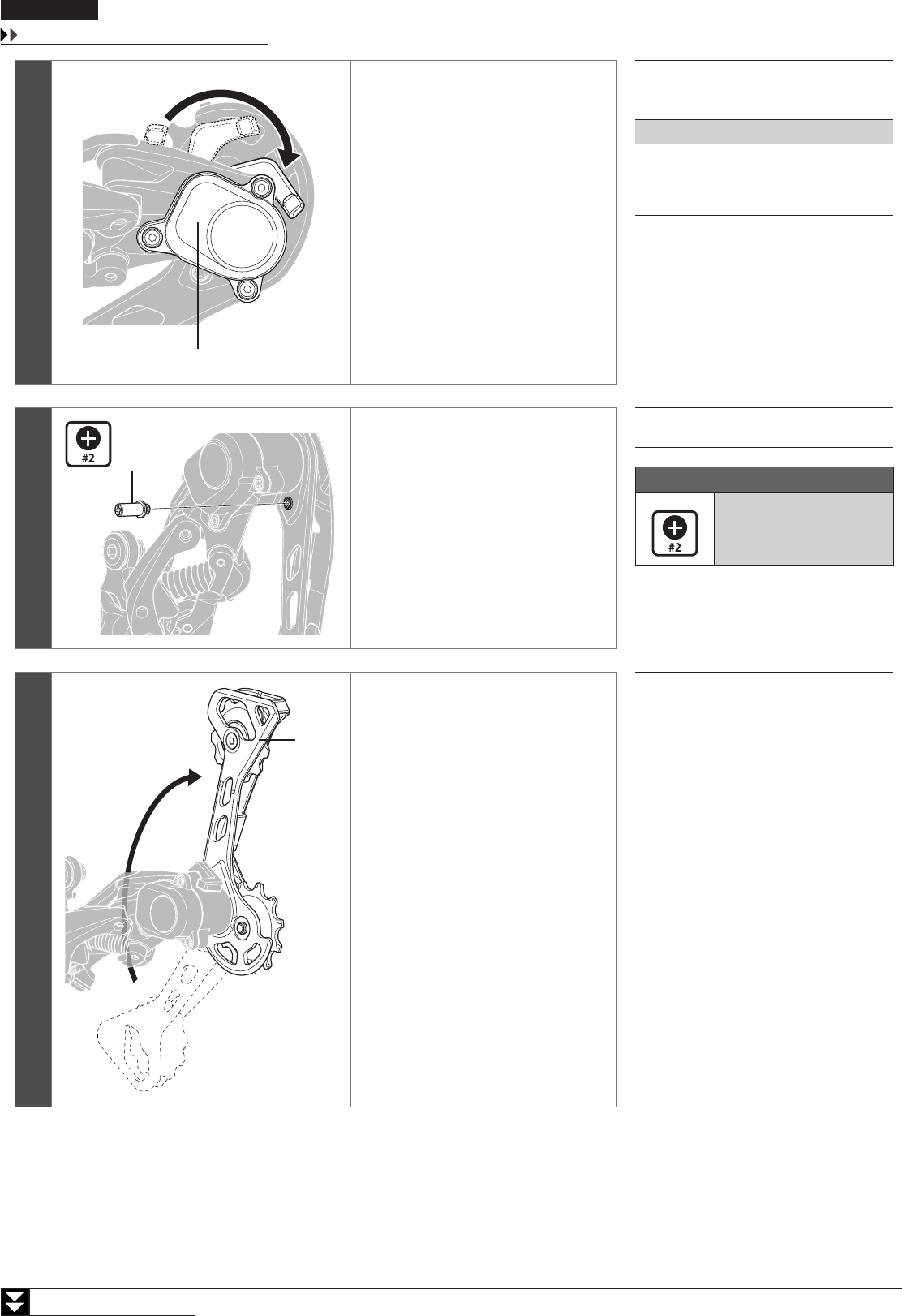
Make sure that the lever switch is in the
OFF position.
If the lever switch is in the ON position,
be sure to move it to the OFF position.
(z)
OFF position
(A)
Friction unit
NOTE
If operating the lever switch while the plate
unit cover is removed, press the friction unit
with your finger so that it does not fly out.
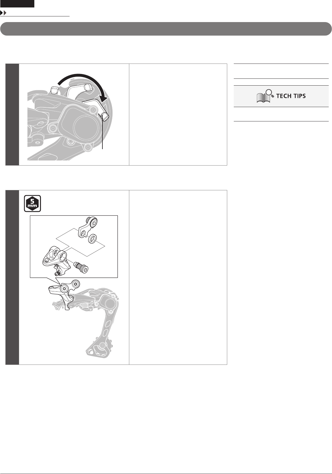
2
(A)
Remove the plate stopper pin with a
screwdriver.
(A)
Plate stopper pin
Tightening torque
1 N·m
3
(A)
Turn the plate to loosen the plate
tension spring as shown in the
illustration.
(A)
Plate
26
MAINTENANCE
Replacing the plate and the plate tension spring
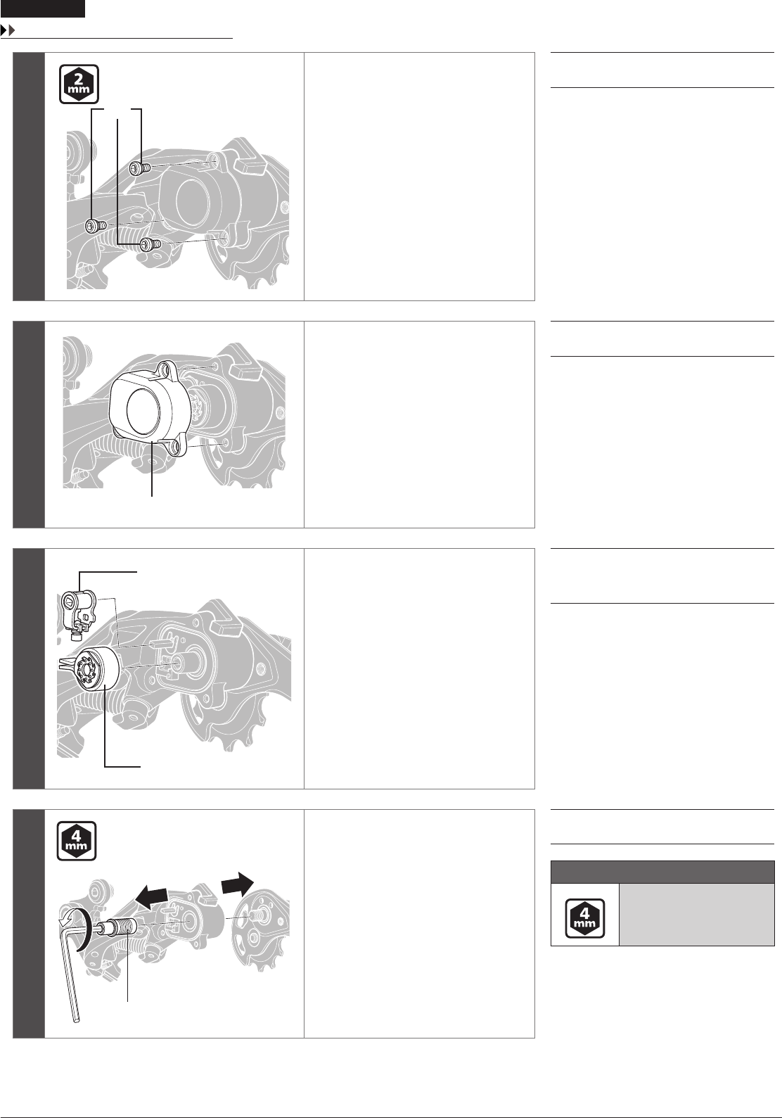
4
(A)
Remove the plate unit cover bolts.
(A)
Plate unit cover bolts
5
(A)
Remove the plate unit cover.
(A)
Plate unit cover
6
(A)
(B)
Remove the cam unit and the chain
stabilizer.
(A)
Cam unit
(B)
Chain stabilizer
7
(A)
Remove the plate axle.
(A)
Plate axle
Tightening torque
8 - 10 N·m
27
To be continued on next page
MAINTENANCE
Replacing the plate and the plate tension spring
Reassembly
Carry out the removal procedure in reverse.
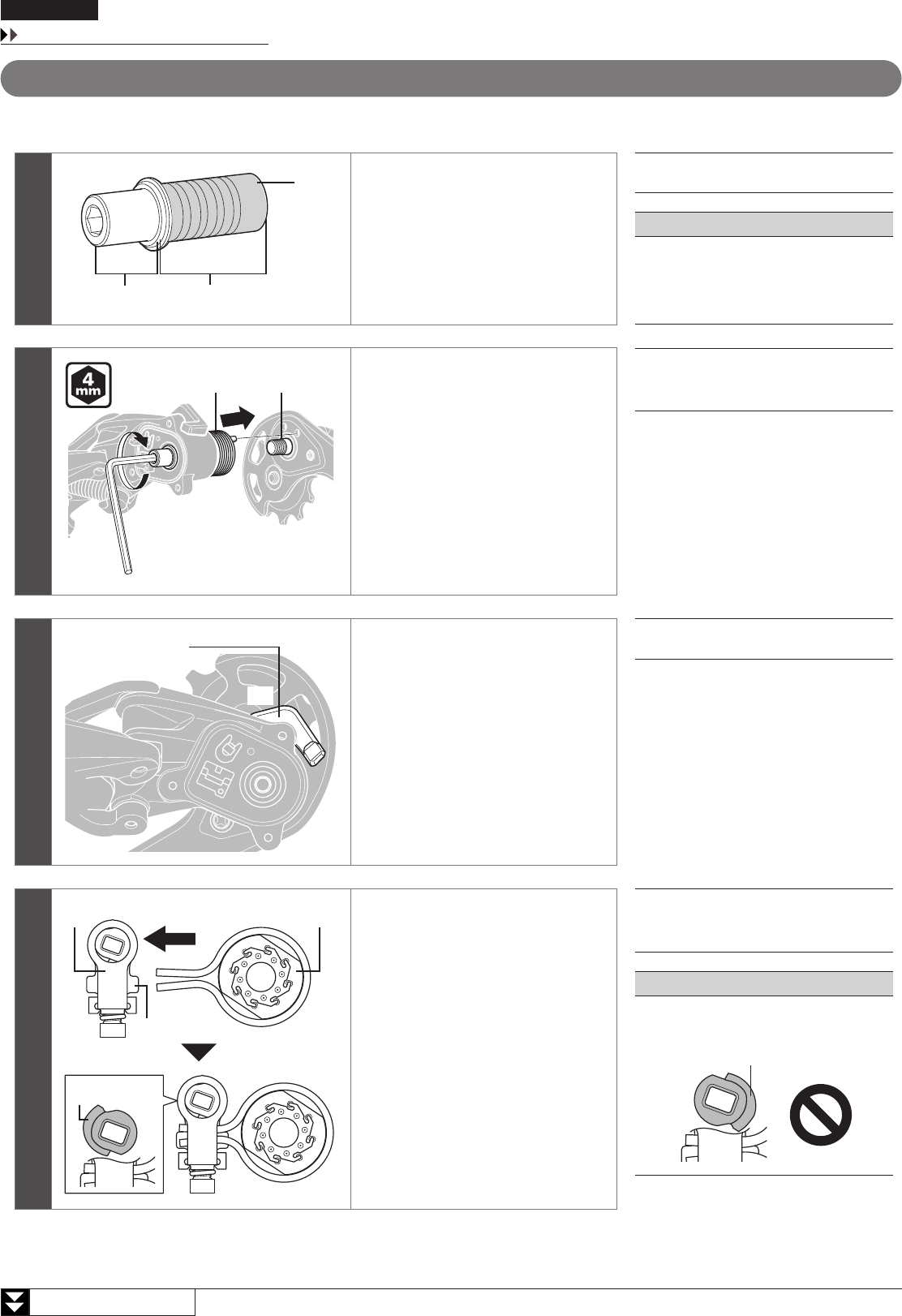
1
(A)
(y)(z)
Apply grease to the plate axle.
(y)
Grease application area
Grease number:
Premium grease (Y04110000)
(z)
A (Do not apply grease)
(A)
Plate axle
NOTE
Do not apply grease to A.
If grease is applied, grease will get on the
inner surface of the roller clutch and friction
will be lost.
2
(A) (B)
Insert the plate axle and insert the tip of
the plate tension spring into the groove
of the plate.
(A)
Plate tension spring
(B)
Plate
3
(A)
(z)
Make sure that the lever switch is in the
OFF position.
If the lever switch is in the ON position,
be sure to move it to the OFF position.
(z)
OFF position
(A)
Lever switch
4
(A) (B)
(y)
(z) [X]
Set the chain stabilizer into the cam unit
as shown in the illustration.
Make sure that the raised section of the
cam unit is positioned as in [X] at this
time.
(y)
The end with the protrusions is
the bottom
(z)
Raised section
(A)
Cam unit
(B)
Chain stabilizer
NOTE
Make sure the cam unit is not set as shown in
the following illustration.
Raised section
28
MAINTENANCE
Replacing the plate and the plate tension spring
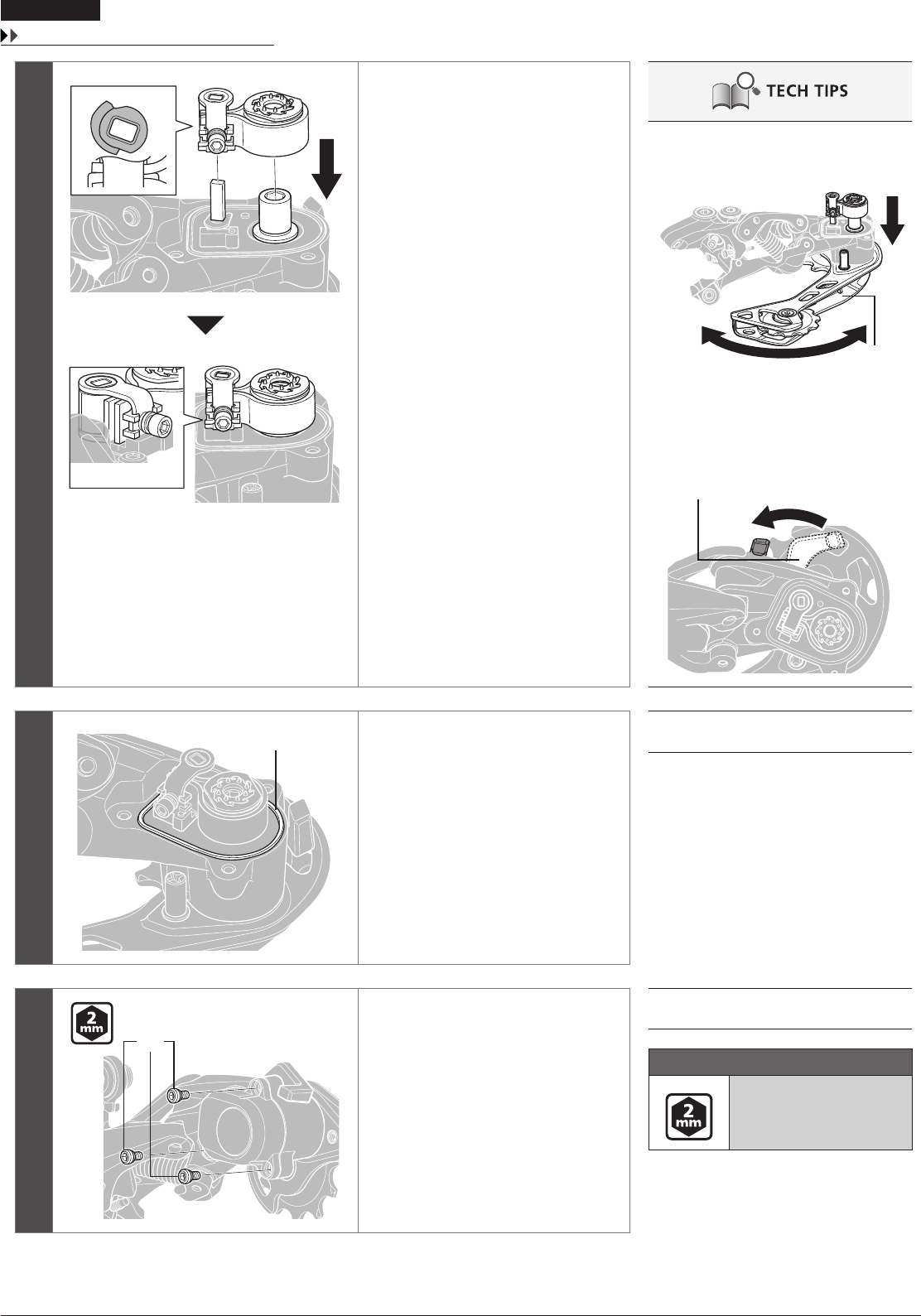
5
(z)
Align the holes in the cam unit and
chain stabilizer with the projections
on the plate unit and attach as in the
illustration.
Pay attention to the positioning of the
raised section of the cam unit when
attaching.
(z)
Components when attached
correctly
•
It helps to move the plate while holding
down the cam unit and chain stabilizer
when attaching.
Plate
•
If there is resistance when moving the lever
switch to the ON position, the components
are attached correctly.
If there is no resistance, check the position
of the raised section of the cam unit and
then reattach the components.
Lever switch
6
(A)
Make sure that the plate unit cover
gasket is attached along the grooves in
the plate unit.
(A)
Plate unit cover gasket
7
(A)
Install the plate unit cover bolts.
(A)
Plate unit cover bolts
Tightening torque
1 - 1.5 N·m
29
MAINTENANCE
Applying grease to the chain stabilizer
Applying grease to the chain stabilizer
If the friction changes or noise is generated, the grease may have become discolored or may have disappeared. Apply more grease.
*
Reassemble by carrying out the disassembly procedure in reverse.
1Move the lever switch to the OFF position.
2
(A)
(B)
(C)
Remove the plate unit cover.
(A)
Plate unit cover
(B)
Lever switch
(C)
Plate unit
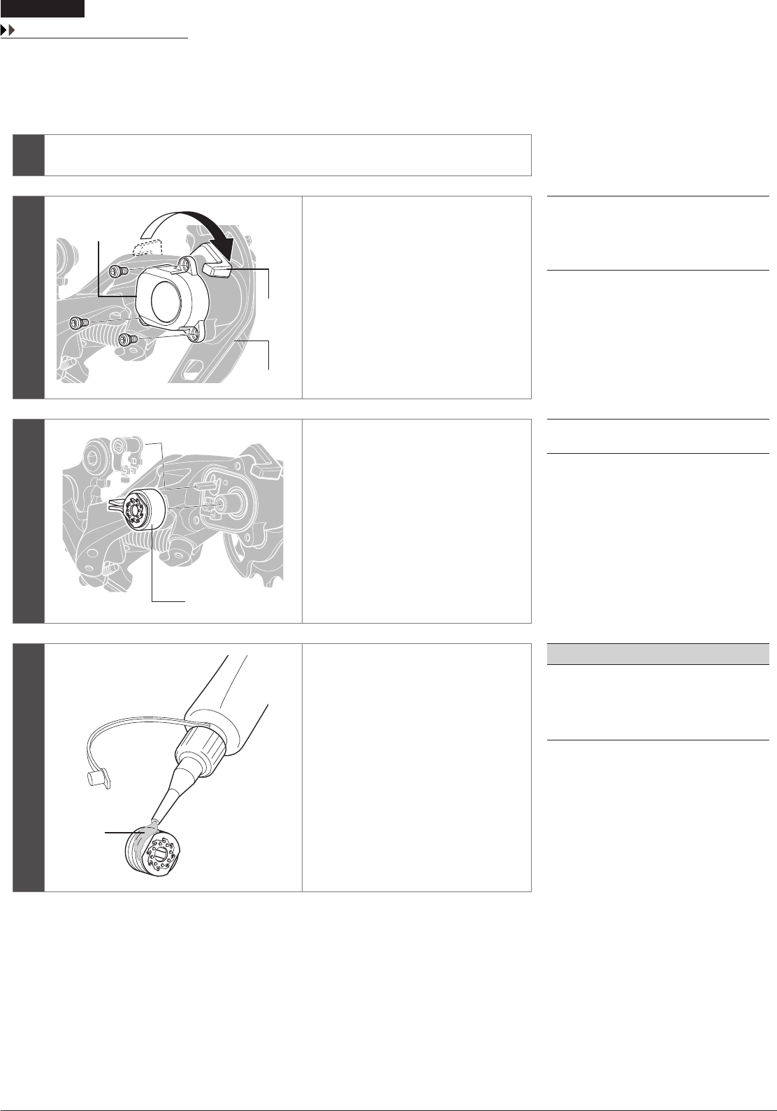
3
(A)
Remove the chain stabilizer.
(A)
Chain stabilizer
4
(z)
Apply grease to the clutch.
(z)
Grease number: Y04120800
NOTE
Be careful not to get grease on the inner
surface of the roller clutch. If grease gets
inside the clutch, it will cause the clutch to
malfunction.
30
MAINTENANCE
Replacing the pulley
Replacing the pulley
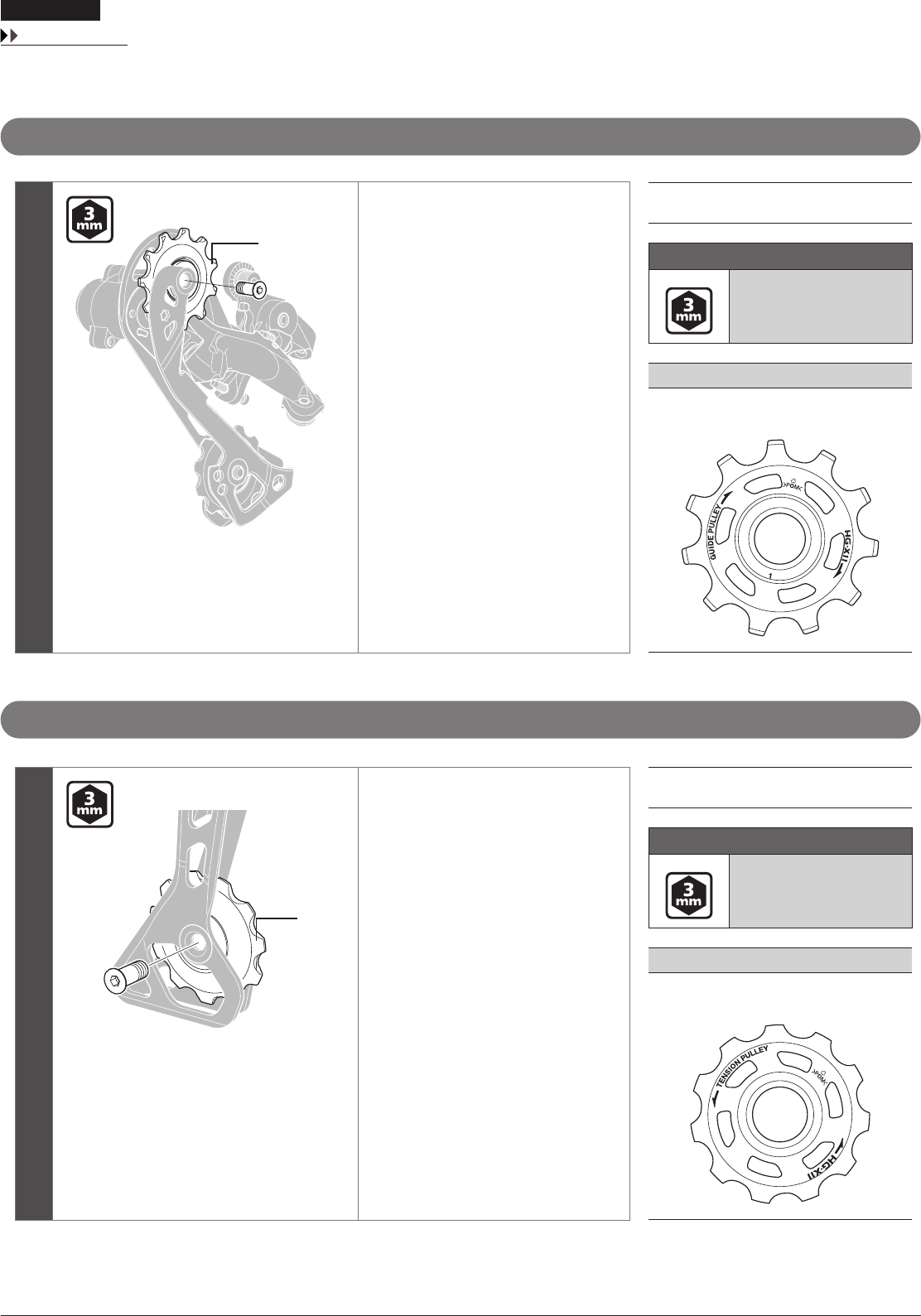
Guide pulley
(A)
Replace the guide pulley.
(A)
Guide pulley
Tightening torque
2.5 - 5 N·m
NOTE
Check the arrow direction on the pulley when
installing it.
Tension pulley
(A)
Replace the tension pulley.
(A)
Tension pulley
Tightening torque
2.5 - 5 N·m
NOTE
Check the arrow direction on the pulley when
installing it.

Please note: specifications are subject to change for improvement without notice. (English)
©
Jan. 2016 by Shimano Inc. HTR
