SM 030 0009 10_Configuration_Guide_Chap_5 10 Configuration Guide Chap 5
SM-030-0009-10_Configuration_Guide_Chap_5 SM-030-0009-10_Configuration_Guide_Chap_5
User Manual: SM-030-0009-10_Configuration_Guide_Chap_5
Open the PDF directly: View PDF ![]() .
.
Page Count: 20
2.3
DISC SERVICE PROCESSOR (DSP)
OSP
is
an
on-line
interactive
utility
package
for
the
debugging
and
servicing
of
processors
and
other
files
under
IRIS.
Any
location
in
memory
or
any
file
on
disc
can
be
accessed
by
the
use
of
OSP.
The
system
manager
may
allow
limited
access
to
OSP
for
authorized
accounts
(see
Section
5.l1.2.3l.
OSP
is
a
powerful
tool
I Use
with
carel
2.3.1
nsp ACCESS/EXIT
To
use
OSP,
first
log
on
to
the
manager's
account.
accessed
as
follows:
DSP
<CTRL-E>key<CTRL-E>
OSP
is
where
key
is
the
password
assigned
by
the
system
manager
(the
default
password
is
Xl.
OSP
may
be
exited
either
with
<CTRL-C>
or
the
X command •
.•
If
you
exit
OSP
using
<CTRL-C>,
it
may
be
reentered
from
the
same
terminal
without
a
password.
It
will
have
retained
the
previously
selected
context
(i
.e.,
file,
disc
block,
or
memory) •
• To
prevent
unauthorized
use
of
OSP,
be
sure
to
exit
with
an
X
command when
leaving
the
terminal.
2.3.2
USING
nsp
Unless
otherwise
noted,
a
<RETURN>
is
required
to
activate
the
command
string.
The
<RETURN>
is
not
shown
unless
it
is
the
only
command
required.
Any
command
which
follows
an
F,
G,
or
H command,
examines
and/or
modifies
data
and
operates
either
on
real
memory,
on
a
file,
or
on
a
disc
block.
Any
address
may
be
specified
as
a
byte
address
by
adding
a
hyphen
to
the
address.
For
example,
03025-
will
dump
bytes
starting
with
the
right-hand
byte
of
word
address
1412,
and
E17000-
will
allow
entry
of
bytes
sthrting
at
the
left-hand
byte
of
word
address
7400.
The
contents
of
any
byte
address
may
not
exceed
377
octal.
If
a
byte
address
is
given
when
an
enabled
driver
file
(i.e.,
$file)
is
selected,
then
that
byte
address
in
real
memory
is
referenced;
this
eliminates
the
need
to
select
real
memory
to
examine
the
driver's
buffers.
SM-OJO-0009-11
POINT
4
Data
Corporation
2-26
I&C
SERVICE
ROUTINES
IRIS
Installation/Config
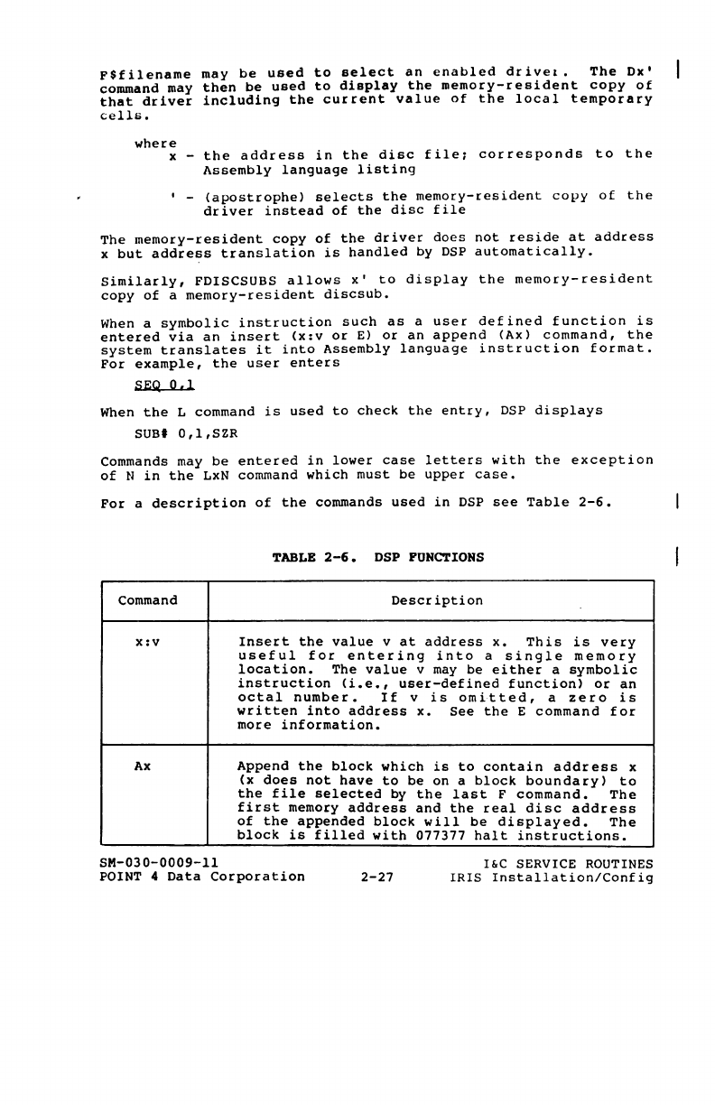
F$filename
may
be
used
to
select
an
enabled
drivel.
The
Dx'
command may
then
be
used
to
display
the
memory-resident
copy
of
that
driver
including
the
current
value
of
the
local
temporary
cells.
where
x -
the
address
in
the
disc
file;
corresponds
to
the
Assembly
language
listing
I _
(apostrophe)
selects
the
memory-resident
copy
of
the
driver
instead
of
the
disc
file
The
memory-resident
copy
of
the
driver
does
not
reside
at
address
x
but
address
translation
is
handled
by
DSP
automatically.
Similarly,
FDISCSUBS
allows
x,
to
display
the
memory-resident
copy
of
a
memory-resident
discsub.
When a
symbolic
instruction
such
as
a
user
defined
function
is
entered
via
an
insert
(x:v
or
E)
or
an
append
(Ax)
command,
the
system
translates
it
into
Assembly
language
instruction
format.
For
example,
the
user
enters
SEQ
0,1
When
the
L
command
is
used
to
check
the
entry.
DSP
displays
SUBt
O,l,SZR
Commands may
be
entered
in
lower
case
letters
with
the
exception
of
N
in
the
LxN
command
which
must
be
upper
case.
For
a
description
of
the
commands
used
in
DSP
see
Table
2-6.
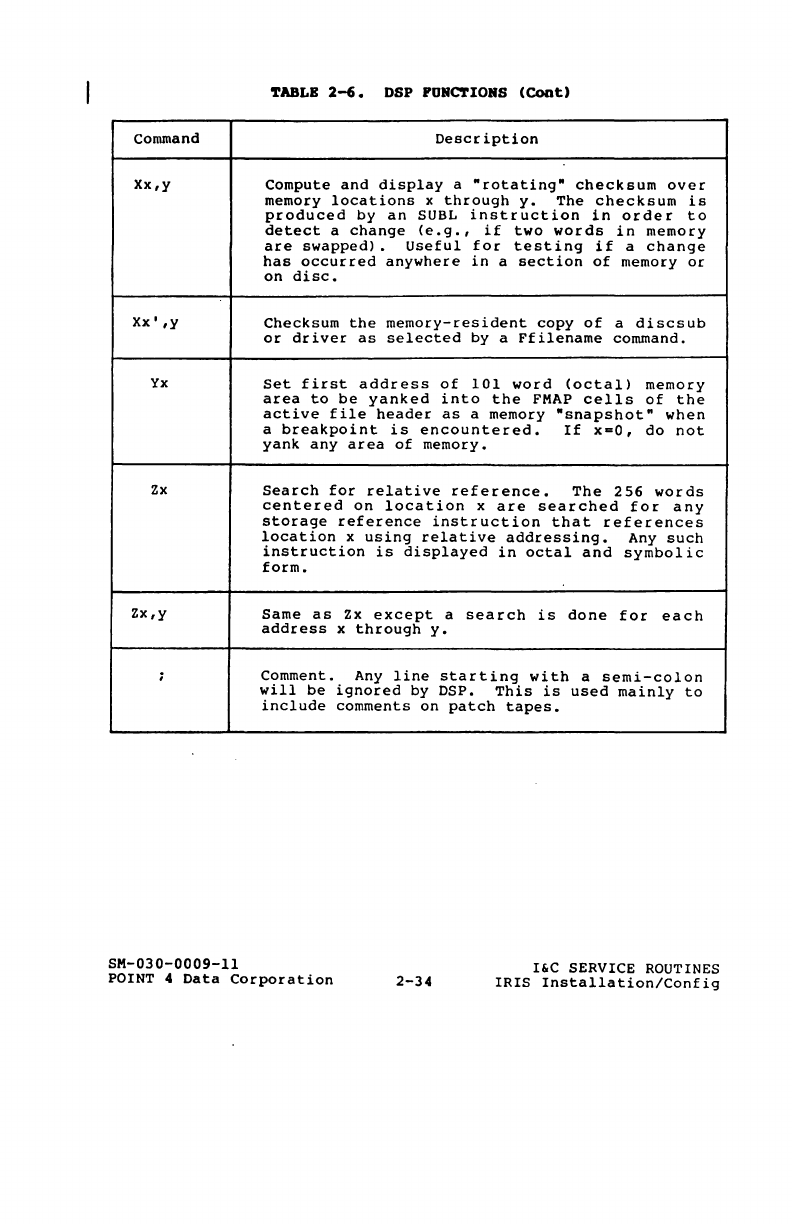
TABLB
2-6.
DSP FUNCTIONS
Command
Description
XlV
Insert
the
value
v
at
address
x.
This
is
very
useful
for
entering
into
a
single
memory
location.
The
value
v may
be
either
a
symbolic
instruction
(i.e.
,
user-defined
function)
or
an
octal
number.
If
v
is
omitted,
a
zero
is
written
into
address
x.
See
the
E
command
for
more
information.
Ax
Append
the
block
which
is
to
contain
address
x
(x
does
not
have
to
be
on
a
block
boundary)
to
the
file
selected
by
the
last
F
command.
The
first
memory
address
and
the
real
disc
address
of
the
appended
block
will
be
displayed.
The
block
is
filled
with
077377
halt
instructions.
SM-030-0009-ll
POINT 4
Data
Corporation
2-27
I&C
SERVICE ROUTINES
IRIS
Installation/Config
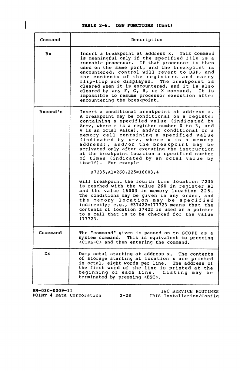
~ABLB
2-6.
DSP
FUNCTIONS
(Cont)
Command
Description
Bx
Bxcond'n
Ccommand
Dx
SM-030-0009-11
Insert
a
breakpoint
at
address
x.
This
command
is
meaningful
only
if
the
specified
file
is
a
runnable
processor.
If
that
processor
is
then
used
on
the
same
port,
and
the
breakpoint
is
encountered,
control
will
revert
to
DSP,
and
the
contents
of
the
registers
and
carry
flip-flop
are
displayed.
The
breakpoint
is
cleared
when
it
is
encountered,
and
it
is
also
cleared
by
any
F,
G,
H,
or
X
command.
It
is
impossible
to
resume
processor
execution
after
encountering
the
breakpoint.
Insert
a
conditional
breakpoint
at
address
x.
A
breakpoint
may
be
conditional
on
a
register
containing
a
specified
value
<indicated
by
Ar=v,
where
r
is
a
register
number
0
to
3,
and
v
is
an
octal
value),
and/or
conditional
on
a
memory
cell
containing
a
specified
value
<indicated
by
x=v,
where
x
is
a
memory
address),
and/or
the
breakpoint
may
be
activated
only
after
executing
the
instruction
at
the
breakpoint
location
a
specified
number
of
times
<indicated
by
an
octal
value
by
itself).
For
example
B7235,Al=260,225=16003,4
will
breakpoint
the
fourth
time
location
7235
is
reached
with
the
value
260
in
register
Al
and
the
value
16003
in
memory
location
225.
The
conditions
may
be
given
in
any
order,
and
the
memory
location
may
be
specified
indirectly;
e.g.,
@37422=177723
means
that
the
contents
of
location
37422
is
used
as
a
pointer
to
a
cell
that
is
to
be
checked
for
the
value
177723.
The
"command"
given
is
passed
on
to
SCOPE
as
a
system
command.
This
is
equivalent
to
pressing
<CTRL-C>
and
then
entering
the
command.
Dump
octal
starting
at
address
x.
The
contents
of
storage
starting
at
location
x
are
printed
in
octal,
eight
words
per
line.
The
address
of
the
first
word
of
the
line
is
printed
at
the
beginning
of
each
line.
Listing
may
be
terminated
by
pressing
<ESC>.
POINT
4
Data
Corporation
2-28
I&C
SERVICE ROUTINES
IRIS
Installation/Config
TABLE
2-6.
DSP
POHCTIORS
(COnt)
Command
Description
Dx,y
Dump
table
starting
at
address
x.
Prints
storage
starting
at
location
x
in
octal,
y
words
per
line;
y
ranges
from
1
through
10
(octal)
•
The
address
of
the
first
word
in
each
line
prints
at
the
beginning
of
the
line.
<ESC)
terminates
dump.
Ex
Enter
octal
or
symbolic
instruction
(i.
e.
,
user-defined
instruction)
sequentially
in
memory
starting
at
address
x.
Each
entry
must
be
followed
by
a
<RETURN).
If
(RETURN)
is
pressed
without
a
preceding
entry,
a
zero
is
stored
at
address
x.
Machine
instructions
may
be
entered
in
symbolic
form,
but
the
device
address
must
be
given
in
octal
(rather
than
using
device
name)
in
I/O
instructions
(e.g.
,
10
rather
than
TTl).
Labels
may
not
be
used,
but
absolute
addresses
will
be
converted
to
relative
if
possible.
Press
(ESC)
to
terminate
entry
mode.
F
Select
real
memory
to
be
examined
and/or
modified.
Ffilename
Select
the
file
identified
by
filename
to
be
examined
and/or
modified.
Logical
unit
zero
is
assumed
unless
given
in
the
form
LU/filename,
where
LU
is
the
logical
unit
number
in
decimal.
NOTE
If
an
extended
random
file
is
selected,
any
address
x
given
will
refer
to
a
location
in
the
header
extenders
rather
than
to
the
data
blocks.
F@
Select
this
port's
active
file
to
be
examined
and/or
modified.
The
form
F@n
will
select
the
active
file
of
port
number
n
to
be
examined
and/or
modified.
The
main
memory
address
in
the
active
file
header
is
ignored,
and
all
addressing
is
relative
to
the
beginning
of
user
storage
in
the
partition.
SM-030-0009-11
POINT 4
Data
Corporation
2-29
I&C
SERVICE ROUTINES
IRIS
Installation/Config
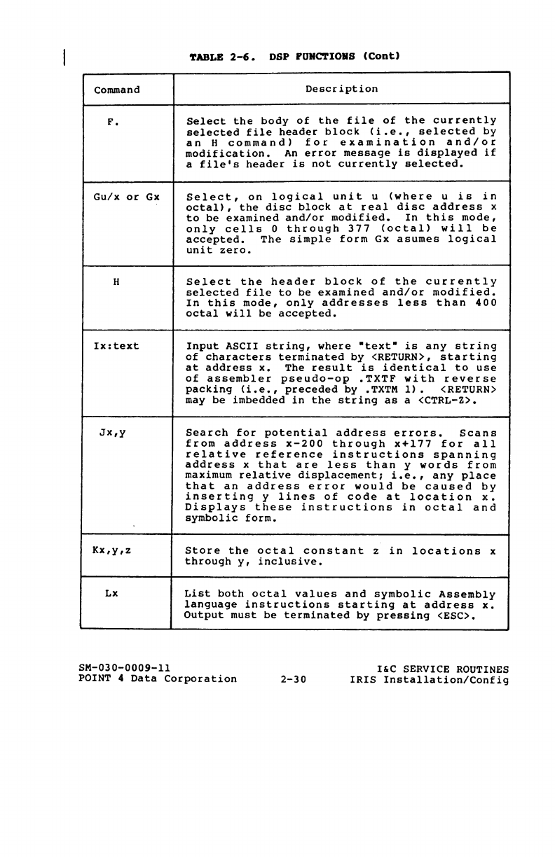
~ABLB
2-6.
DSP
PUNCTIORS
(Cont)
Command
Description
F.
Gu/x
or
Gx
H
Ix:text
JX,y
Kx,y,z
Lx
SM-030-0009-11
Select
the
body
of
the
file
of
the
currently
selected
file
header
block
(i.e.,
selected
by
an
H
command)
for
examination
and/or
modification.
An
error
message
is
displayed
if
a
file's
header
is
not
currently
selected.
Select,
on
logical
unit
u
(where
u
is
in
octal),
the
disc
block
at
real
disc
address
x
to
be
examined
and/or
modified.
In
this
mode,
only
cells
0
through
377
(octal)
will
be
accepted.
The
simple
form
Gx
asumes
logical
unit
zero.
Select
the
header
block
of
the
currently
selected
file
to
be
examined
and/or
modified.
In
this
mode,
only
addresses
less
than
400
octal
will
be
accepted.
Input
ASCII
string,
where
"text"
is
any
string
of
characters
terminated
by
<RETURN>,
starting
at
address
x.
The
result
is
identical
to
use
of
assembler
pseudo-op
.TXTF
with
reverse
packing
(i.e.,
preceded
by
.TXTM
1).
<RETURN>
may
be
imbedded
in
the
string
as
a <CTRL-Z>.
Search
for
potential
address
errors.
Scans
from
address
x-200
through
x+177
for
all
relative
reference
instructions
spanning
address
x
that
are
less
than
y
words
from
maximum
relative
displacement;
i.e.,
any
place
that
an
address
error
would
be
caused
by
inserting
y
lines
of
code
at
location
x.
Displays
these
instructions
in
octal
and
symbolic
form.
Store
the
octal
constant
z
in
locations
x
through
y,
inclusive.
List
both
octal
values
and
symbolic
Assembly
language
instructions
starting
at
address
x.
Output
must
be
terminated
by
pressing
<ESC>.
POINT 4
Data
Corporation
2-30
I'C
SERVICE
ROUTINES
IRIS
Installation/Config
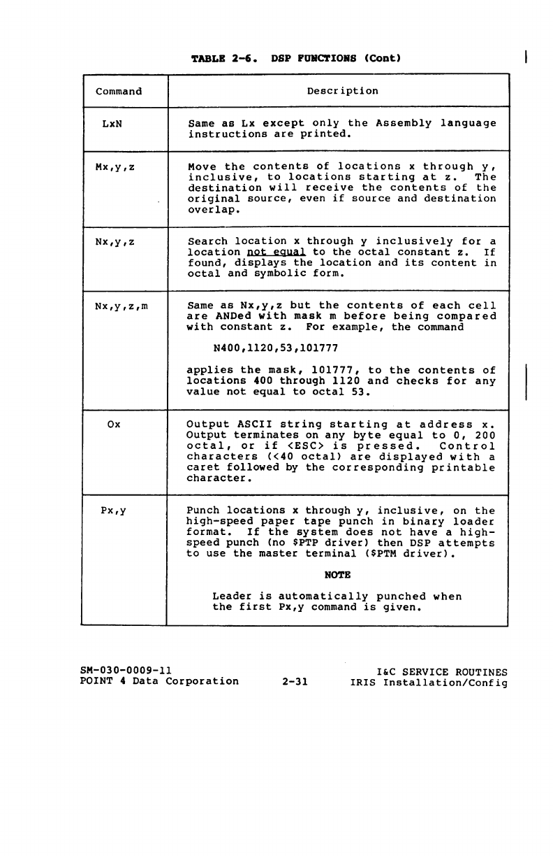
TABLB
2-6.
DSP POIIC'l'IORS
(COot)
Command
Descr
iption
LxN
Same
as
Lx
except
only
the
Assembly
language
instructions
are
printed.
Mx,y,z
Move
the
contents
of
locations
x
through
y,
inclusive,
to
locations
starting
at
z.
The
destination
will
receive
the
contents
of
the
original
source,
even
if
source
and
destination
overlap.
Nx,y,z
Search
location
x
through
y
inclusively
for
a
location
not
equal
to
the
octal
constant
z.
If
found,
displays
the
location
and
its
content
in
octal
and
symbolic
form.
Nx,y,z,m
Same
as
Nx,y,z
but
the
contents
of
each
cell
are
ANDed
with
mask
m
before
being
compared
with
constant
z.
For
example,
the
command
N400,1120,53,101777
applies
the
mask,
101777,
to
the
contents
of
locations
400
through
1120
and
checks
for
any
value
not
equal
to
octal
53.
Ox
Output
ASCII
string
starting
at
address
x.
Output
terminates
on
any
byte
equal
to
0,
200
octal,
or
if
<ESC>
is
pressed.
Control
characters
«40
octal>
are
displayed
with
a
caret
followed
by
the
corresponding
printable
character.
Px,y
Punch
locations
x
through
y,
inclusive,
on
the
high-speed
paper
tape
punch
in
binary
loader
format.
If
the
system
does
not
have
a
high-
speed
punch
(no
$PTP
driver)
then
DSP
attempts
to
use
the
master
terminal
($PTM
driver).
NOTE
Leader
is
automatically
punched
when
the
first
Px,y
command
is
given.
SM-030-0009-11
POINT
4
Data
Corporation
2-31
I&C
SERVICE
ROUTINES
IRIS
Installation/Config
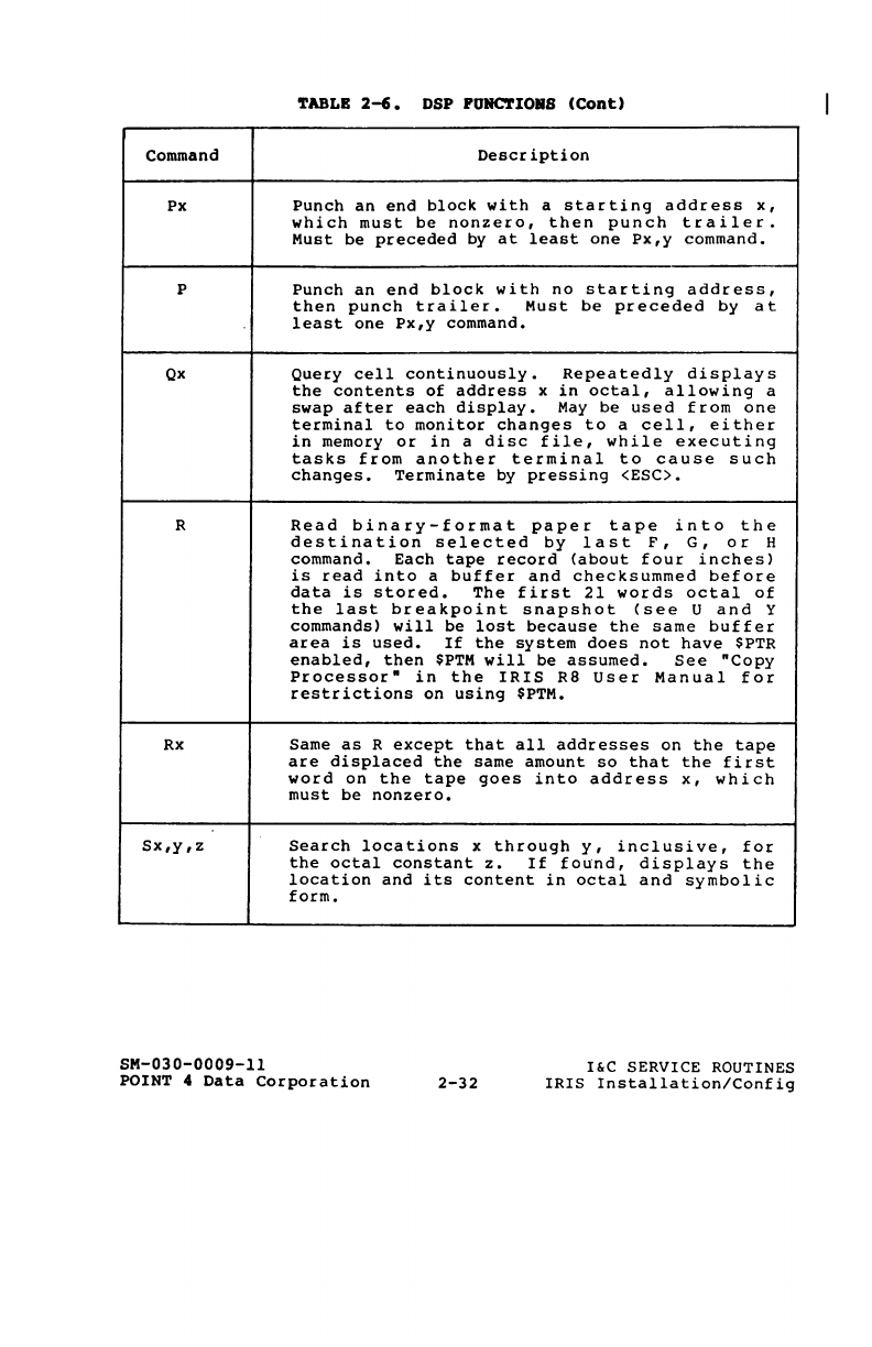
'fABLB
2-6.
DSP
PORC'rIORS
(COnt)
Command
Descr
iption
Px
Punch
an
end
block
with
a
starting
address
x,
which
must
be
nonzero,
then
punch
trailer.
Must
be
preceded
by
at
least
one
Px,y
command.
P
Punch
an
end
block
with
no
starting
address,
then
punch
trailer.
Must
be
preceded
by
at
least
one
Px,y
command.
Qx
Query
cell
continuously.
Repeatedly
displays
the
contents
of
address
x
in
octal,
allowing
a
swap
after
each
display.
May
be
used
from
one
terminal
to
monitor
changes
to
a
cell,
either
in
memory
or
in
a
disc
file,
while
executing
tasks
from
another
terminal
to
cause
such
changes.
Terminate
by
pressing
(ESC>.
R
Read
binary-format
paper
tape
into
the
destination
selected
by
last
F,
G,
or
H
command.
Each
tape
record
(about
four
inches)
is
read
into
a
buffer
and
checksummed
before
data
is
stored.
The
first
21
words
octal
of
the
last
breakpoint
snapshot
(see
U
and
y
commands)
will
be
lost
because
the
same
buffer
area
is
used.
If
the
system
does
not
have
$PTR
enabled,
then
$PTM
will
be
assumed.
See
·Copy
Processor"
in
the
IRIS
R8
User
Manual
for
restrictions
on
using
$PTM.
Rx
Same
as
R
except
that
all
addresses
on
the
tape
are
displaced
the
same
amount
so
that
the
first
word
on
the
tape
goes
into
address
x,
which
must
be
nonzero.
Sx,y,z
Search
locations
x
through
y,
inclusive,
for
the
octal
constant
z.
If
found,
displays
the
location
and
its
content
in
octal
and
symbolic
form.
SM-030-0009-11
POINT 4
Data
Corporation
2-32
I&C
SERVICE ROUTINES
IRIS
Installation/Config
TABLE
2-6.
DSP PUIIC'rIORS
(COnt)
Command
Description
sx,y,z,m
Same
as
Sx,y,z
except
that
the
contents
of
each
cell
are
ANDed
with
mask
m
before
being
compared
with
constant
z.
For
example,
the
command
S400,1120,53,101777
searches
locations
400
through
1120,
inclusive,
for
any
instruction
referencing
location
53.
T
Not
used.
Ux
Display
snapshot
yanked
into
FMAP
cells
of
active
file
at
last
breakpoint.
Start
display
(in
octal
dump
format)
at
virtual
address
x
where
y
<=
x
<=
y+lOO
and
y
is
the
snapshot
address
set
by
the
last
Y
command.
CAlIl:IQH
The
addresses
will
be
wrong
if
a
different
Y
command
has
been
given
since
the
breakpoint
was
encountered.
V
Verify
paper
tape.
This
and
the
Vx
command
are
the
same
as
the
respective
R
commands
except
that
information
from
the
tape
is
compared
with
the
contents
of
the
selected
file
(or
memory)
instead
of
being
stored.
If
a
difference
is
detected,
the
address
and
the
word
from
storage
are
displayed.
Wu/x
or
Wx
Write
the
disc
block
selected
by
the
last
G
or
H
command
on
disc
at
real
disc
address
x
of
logical
unit
u.
This
command
is
rejected
if
u/x
is
not
a
legal
real
disc
address
or
if
a
single
disc
block
has
not
been
selected.
The
simple
form
Wx
assumes
logical
unit
zero.
X
Exit
from
DSP,
clear
any
existing
file
selection
or
breakpoint,
and
prevent
re-entry
to
DSP
without
the
password.
X~)
771n
CA
Lc:",
11\.
e
c..he(\:-
Su.
M --=
---
SM
030
0009
11
POINT 4
Data
Corporation
2-33
I&C
SERVICE ROUTINES
IRIS
Installation/Config
'.rABLB
2-6.
DSP
FURC'l'IORS
(Coot)
Command
Description
Xx,y
Compute
and
display
a
"rotating"
checksum
over
memory
locations
x
through
y.
The
checksum
is
produced
by
an
SUBL
instruction
in
order
to
detect
a
change
(e.
g.
,
if
two
words
in
memory
are
swapped)
.
Useful
for
testing
if
a
change
has
occurred
anywhere
in
a
section
of
memory
or
on
disc.
Xx'
,y
Checksum
the
memory-resident
copy
of
a
discsub
or
driver
as
selected
by
a
Ff
ilename
command.
Yx
Set
first
address
of
101
word
(octal)
memory
area
to
be
yanked
into
the
FMAP
cells
of
the
active
file
header
as
a memory
"snapshot"
when
a
breakpoint
is
encountered.
If
x=O,
do
not
yank
any
area
of
memory.
Zx
Search
for
relative
reference.
The
256
words
centered
on
location
x
are
searched
for
any
storage
reference
instruction
that
references
location
x
using
relative
addressing.
Any
such
instruction
is
displayed
in
octal
and
symbolic
form.
Zx,y
Same
as
Zx
except
a
search
is
done
for
each
address
x
through
y.
;
Comment.
Any
line
starting
with
a
semi-colon
will
be
ignored
by
DSP.
This
is
used
mainly
to
include
comments
on
patch
tapes.
SM-030-0009-ll
POINT 4
Data
Corporation
2-34
I&C
SERVICE ROUTINES
IRIS
Installation!Config
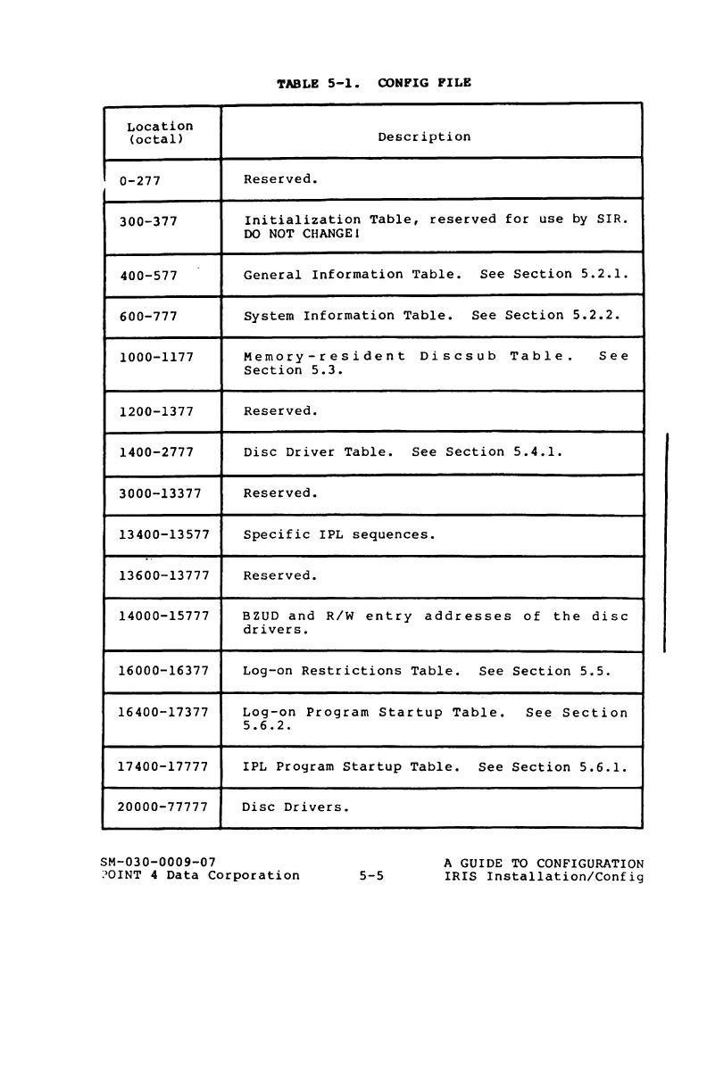
TABLE
5-1.
COMFIG
FILE
Location
(octal)
Description
0-277
Reserved.
300-377
Ini
tialization
Table,
reserved
for
use
by
SIR.
DO
NOT
CHANGEI
400-577
General
Information
Table.
See
Section
5.2.l.
600-777
System
Information
Table.
See
Section
5.2.2.
1000-1177
Memory-resident
Discsub
Table.
See
Section
5.3.
1200-1377
Reserved.
1400-2777
Disc
Driver
Table.
See
Section
5.4.l.
3000-13377
Reserved.
13400-13577
Specific
IPL
sequences
•
..
13600-13777
Reserved.
14000-15777
BZUD
and
RiW
entry
addresses
of
the
disc
drivers.
16000-16377
Log-on
Restrictions
Table.
See
Section
5.5.
16400-17377
Log-on
Program
Startup
Table.
See
Section
5.6.2.
17400-17777
IPL
Program
Startup
Table.
See
Section
5.6.l.
20000-77777
Disc
Drivers.
SM-030-0009-07
!OINT 4
Data
Corporation
5-5
A GUIDE TO CONFIGURATION
IRIS
Insta11ationiConfig
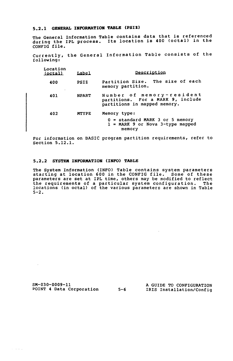
5.2.1
GENERAL
INFORMATION
TABLE
(PSII)
The
General
Information
Table
contains
data
that
is
referenced
during
the
IPL
process.
Its
location
is
400
(octal)
in
the
CONFIG
file.
Currently,
the
General
Information
Table
consists
of
the
following:
Location
(octal)
400
401
402
PSIZ
NPART
MTYPE
Description
Partition
Size.
The
size
of
each
memory
partition.
Number
of
memory-resident
partitions.
For
a
MARK
9,
include
partitions
in
mapped
memory.
Memory
type:
o =
standard
MARK
3
or
5 memory
1 =
MARK
9
or
Nova
3-type
mapped
memory
For
information
on
BASIC
program
partition
requirements,
refer
to
Section
5.12.1.
5.2.2
SYSTEM
INFORMATION (INFO)
TABLE
The
System
Information
(INFO)
Table
contains
system
parameters
starting
at
location
600
in
the
CONFIG
file.
Some
of
these
parameters
are
set
at
IPL
time,
others
may
be
modified
to
reflect
the
requirements
of
a
particular
system
configuration.
The
locations
(in
octal)
of
the
various
parameters
are
shown
in
Table
5-2.
SM-030-0009-ll
POINT 4
Data
Corporation
5-6
A GUIDE TO
CONFIGURATION
IRIS
Installation/Config
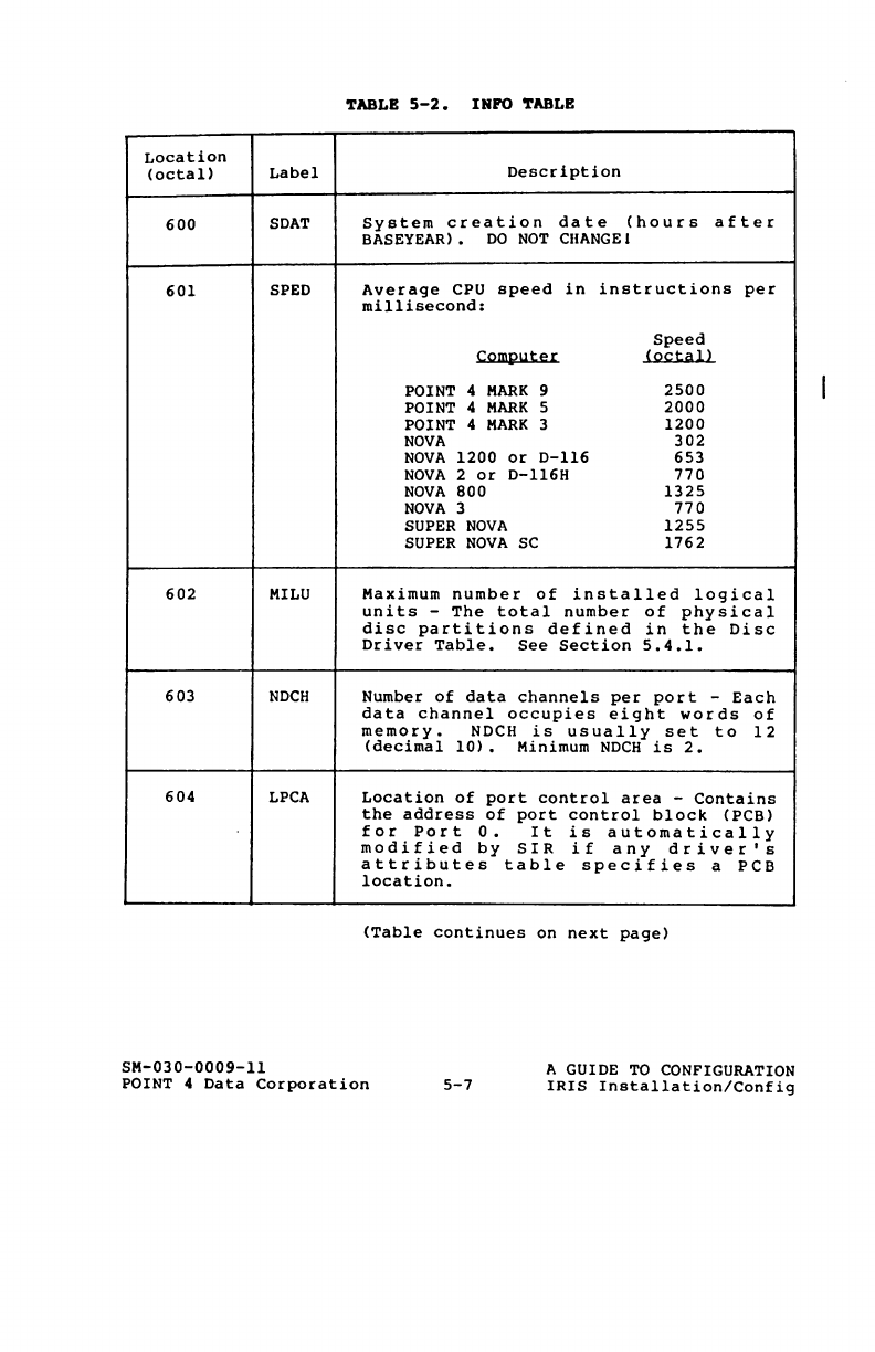
'l'ABLB
5-2.
INFO
'l'ABLB
Location
(octal)
Label
Description
600
SDAT
System
creation
date
(hours
after
BASEYEAR)
•
DO
NOT
CIIANGEI
601
SPED
Average
CPU
speed
in
instructions
per
millisecond:
Speed
Computer
(octal!
POINT 4
MARK
9
2500
POINT 4
MARK
5
2000
POINT 4
MARK
3
1200
NOVA
302
NOVA
1200
or
0-116
653
NOVA
2
or
D-116H
770
NOVA
800
1325
NOVA
3
770
SUPER
NOVA
1255
SUPER
NOVA
SC
1762
602
MILU
Maximum
number
of
installed
logical
units
-
The
total
number
of
physical
disc
partitions
defined
in
the
Disc
Driver
Table.
See
Section
5.4.1.
603
NDCH
Number
of
data
channels
per
port
-
Each
data
channel
occupies
eight
words
of
memory.
NDCH
is
usually
set
to
12
(decimal
10)
• Minimum
NDCH
is
2.
604
LPCA
Location
of
port
control
area
-
Contains
the
address
of
port
control
block
(PCB)
for
Port
O.
It
is
automatically
modified
by
SIR
if
any
driver's
attributes
table
specifies
a
PCB
location.
(Table
continues
on
next
page)
SM-030-0009-11
POINT 4
Data
Corporation
5-7
A GUIDE
TO
CONFIGURATION
IRIS
Installation/Config
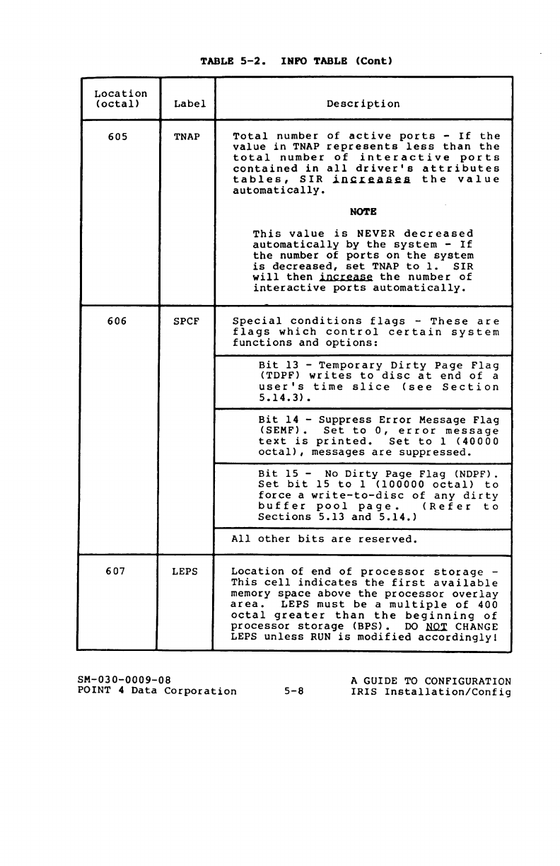
TABLE
5-2.
INFO
TABLE
(Cant)
Location
(octal)
Label
Description
605
TNAP
Total
number
of
active
ports
-
If
the
value
in
TNAP
represents
less
than
the
total
number
of
interactive
ports
contained
in
all
driver's
attributes
tables,
SIR
.ini:LJUUi~.II.
the
value
automatically.
ROTE
This
value
is
NEVER
decreased
automatically
by
the
system
-
If
the
number
of
ports
on
the
system
is
decreased,
set
TNAP
to
1.
SIR
will
then
iD~t:Si:iiIU:
the
number
of
interactive
ports
automatically.
606
SPCF
Special
conditions
flags
-
These
are
flags
which
control
certain
system
functions
and
options:
Bit
13
-
Temporary
Dirty
Page
Flag
(TDPF)
writes
to
disc
at
end
of
a
user's
time
slice
(
see
Section
5.14.3)
•
Bit
14
-
Suppress
Error
Message
Flag
(SEMF) •
Set
to
0,
error
message
text
is
printed.
Set
to
1
(40000
octal),
messages
are
suppressed.
Bit
15
-
No
Dirty
Page
Flag
(NDPF) .
Set
bit
15
to
1
(100000
octal!
to
force
a
write-to-disc
of
any
dirty
buffer
pool
pa
ge.
(Refer
to
Sections
5.13
and
5.14.
)
All
other
bits
are
reserved.
607
LEPS
Location
of
end
of
processor
storage
-
This
cell
indicates
the
first
available
memory
space
above
the
processor
overlay
area.
LEPS
must
be
a
multiple
of
400
octal
greater
than
the
beginning
of
processor
storage
(BPS).
DO NQ:r
CHANGE
LEPS
unless
RUN
is
modified
accordingly
I
SM-030-0009-08
POINT 4
Data
Corporation
5-8
A GUIDE
TO
CONFIGURATION
IRIS
Installation/Config
TABLB
5-2.
INFO
TABLB
(Cant)
Location
(octal)
Label
Description
610
TOPW
Highest
addressable
word
in
memory
-
IRIS
ignores
any
memory
above
this
address.
The
memory
available
above
77777
octal
is
used
for
user
partitions
and
buffer
pooling.
Do
not
set
TOPW
above
77777
unless
the
CPU
and
all
disc
controllers
on
the
system
use
a
16-bit
memory
address.
All
other
devices
use
lower
(<32K)
memory.
611
ABUF
Size
of
auxiliary
buffer
area
(number
of
words)
-
Must
be
at
least
1004
words
octal
if
indexed
data
files
are
to
be
used.
612
UDSB
Number
of
user
discsubs
-
The
minimum
value
is
one
greater
than
the
largest
subroutine
number
in
the
DISCSUBS.USER
file.
613
NCQN
Number
of
extra
character
queue
nodes
-
SIR
allocates
two
nodes
per
interactive
port
plus
this
number
of
extra
nodes.
Extra
nodes
are
required
to
handle
peak
input
rates
if
extra
heavy
character
processing
is
required.
Each
node
occupies
two
words
of
memory.
Minimum
value
is
two.
614
NNOD
Minimum
number
of
free
nodes
-
Each
node
occupies
32
words
(decimal)
•
615
NSIG Number
of
signal
buffer
nodes
-
This
is
the
maximum
number
of
signals
which
can
be
waiting
to
be
received.
Each
node
occupies
4
words
of
memory.
Minimum
value
is
1.
616
SDSB
Number
of
System
discsubs
-
The
minimum
value
is
one
greater
than
the
largest
subroutine
number
in
the
DISCSUBS
file.
SM-030-0009-07
POINT 4
Data
Corporation
5-9
A GUIDE
TO
CONFIGURATION
IRIS
Installation/Config
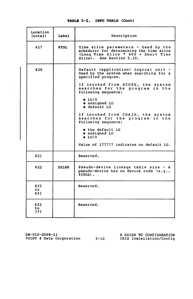
TABLB
5-2.
INFO
TABLB
(Cont)
Location
(octal!
Label
Description
617
KTSL
Time
slice
parameters
-
Used
by
the
scheduler
for
determining
the
time
slice
(Long
Time
Slice
*
400
+
Short
Time
Slice)
•
See
Section
5.10.
620
Default
(application)
logical
unit
-
Used
by
the
system
when
searching
for
a
specified
program.
If
invoked
from
SCOPE,
the
system
searches
for
the
program
in
the
following
sequence:
•
Lu/O
•
assigned
LU
•
default
LU
If
invoked
from
CHAIN,
the
system
searches
for
the
program
in
the
following
sequence:
•
the
default
LU
•
assigned
LU
• LU/O
Value
of
177777
indicates
no
default
LU.
621
Reserv£\d.
622
SZLNK
Pseudo-device
linkage
table
size
-A
pseudo-device
has
no
device
code
(e.g.
,
$CTUS).
623
Reserved.
to
631
632
Reserved.
to
777
SM-030-0009-ll
POINT 4
Data
Corporation
5-10
A GUIDE
TO
CONFIGURATION
IRIS
Installation/Config
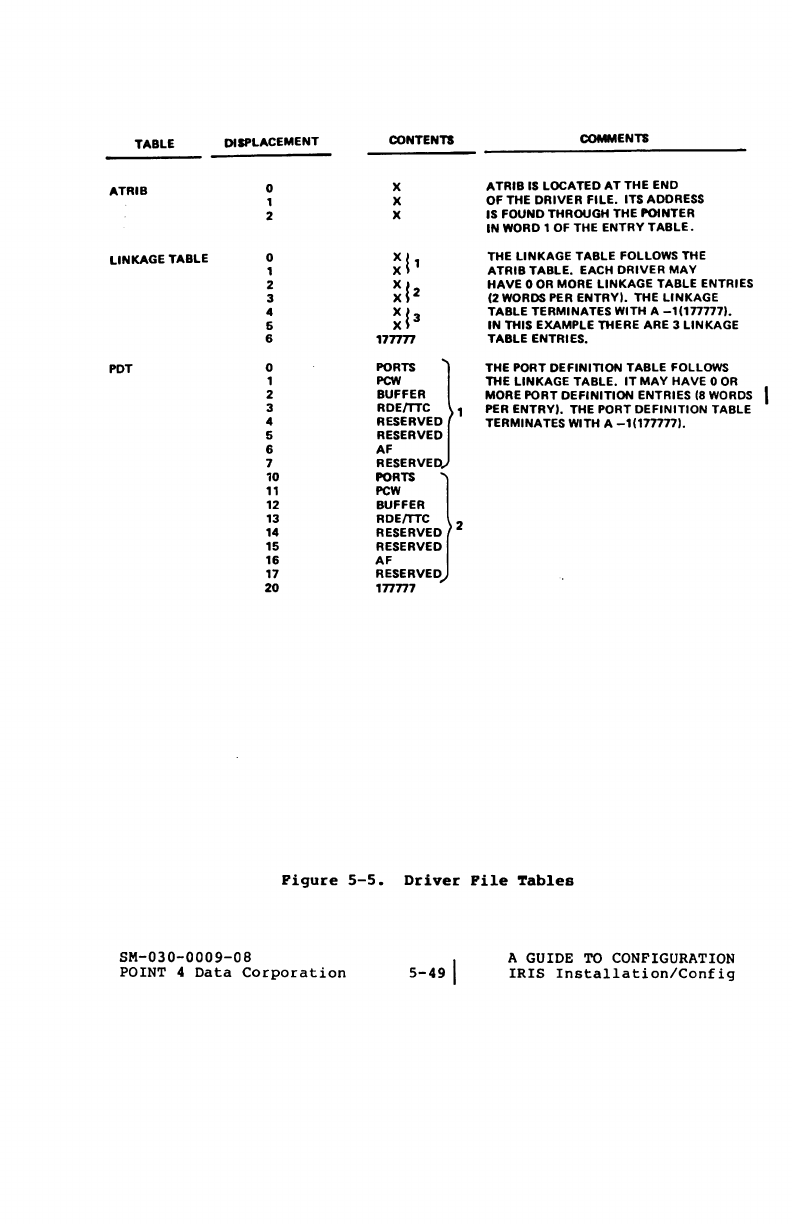
TABLE DISPLACEMENT CONTENTS COMMENTS
ATRIB
0 X
ATRIB
IS LOCATED
AT
THE END
1 X OF THE DRIVER
FILE.
ITS ADDRESS
2 X IS FOUND THROUGH THE POINTER
IN
WORD 1
OF
THE ENTRY
TABLE.
LINKAGE TABLE 0
~
l'
THE
LINKAGE
TABLE FOLLOWS THE
1
ATRIB
TABLE. EACH DRIVER
MAY
2
~12
HAVE
0
OR
MORE
LINKAGE
TABLE ENTRIES
3 (2
WORDS
PER
ENTRYI.
THE
LINKAGE
4
~13
TABLE TERMINATES WITH A -1(1777771.
6
IN
THIS EXAMPLE THERE ARE 3 LINKAGE
6 177777 TABLE ENTRIES.
PDT 0
~~
} THE PORT DEFINITION TABLE FOLLOWS
1
PCW
THE LINKAGE TABLE.
IT
MAY
HAVE 0
OR
2 BUFFER MORE PORT DEFINITION ENTRIES
(8
WORDS
3
RDEmC
1
PER
ENTRYI. THE PORT DEFINITION TABLE
4 RESERVED TERMINATES WITH A -1(1777771.
6 RESERVED
6 AF
7 RESERVED
10
_n
}
11
PeW
12 BUFFER
13
RDEmC
14 RESERVED 2
15 RESERVED
16
AF
17 RESERVED
20
177777
Pigure
5-5.
Driver
Pile
Tables
SM-030-0009-0B
POINT 4
Data
Corporation
5-49\
A GUIDE
TO
CONFIGURATION
IRIS
Installation/Config
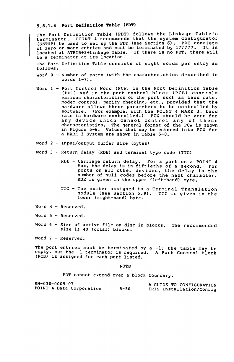
5.8.1.4
Po~t
Definition
Table
(PDT)
The
Port
Definition
Table
(PDT)
follows
the
Linkage
Table's
terminator.
POINT 4
recommends
that
the
system
configurator
(SETUP)
be
used
to
set
up
the
PDT
(see
Section
6).
PDT
consists
of
zero
or
more
entries
and
must
be
terminated
by
177777.
It
is
located
at
ATRIB+3+Linkage
Table.
If
there
is
no
PDT,
there
will
be
a
terminator
at
its
location.
The
Port
Definition
Table
consists
of
eight
words
per
entry
as
follows:
Word 0 - Number
of
ports
(with
the
characteristics
described
in
words
1-7).
Word 1 -
Port
Control
word
(PCW)
in
the
Port
Definition
Table
(PDT)
and
in
the
port
control
block
(PCB)
controls
various
characteristics
of
the
port
such
as
baud
rate,
modem
control,
parity
checking,
etc.,
provided
that
the
hardware
allows
these
parameters
to
be
controlled
by
software.
(For
example,
with
the
POINT
4
MARK
3,
baud
rate
is
hardware
controlled.)
PCW
should
be
zero
for
any
device
which
cannot
control
any
of
these
characteristics.
The
general
format
of
the
PCW
is
shown
in
Figure
5-6.
Values
that
may
be
entered
into
PCW
for
a
MARK
3
System
are
shown
in
Table
5-8.
Word 2 -
Input/output
buffer
size
(bytes)
Word 3 -
Return
delay
(ROE)
and
terminal
type
code
(TTC)
RDE
-
Carriage
return
delay.
For
a
port
on
a
POINT
4
Mux,
the
delay
is
in
fiftieths
of
a
second.
For
ports
on
all
other
devices,
the
delay
is
the
number
of
null
codes
before
the
next
character.
RDE
is
given
in
the
upper
(left-hand)
byte.
TTC
-
The
number
assigned
to
a
Terminal
Translation
Module
(see
Section
5.9).
TTC
is
given
in
the
lower
(right-hand)
byte.
Word 4 -
Reserved.
Word 5 -
Reserved.
Word 6
Size
of
active
file
on
disc
in
blocks.
The
recommended
size
is
40
(octal)
blocks.
Word 7 -
Reserved.
The
port
entries
must
be
terminated
by
a
-1;
the
table
may
be
empty,
but
the
-1
terminator
is
required.
A
Port
Control
Block
(PCB)
is
assigned
for
each
port
listed.
NO'l'B
PDT
cannot
extend
over
a
block
boundary.
SM-030-0009-07
POINT 4
Data
Corporation
5-50
A GUIDE
TO
CONFIGURATION
IRIS
Installation/Config
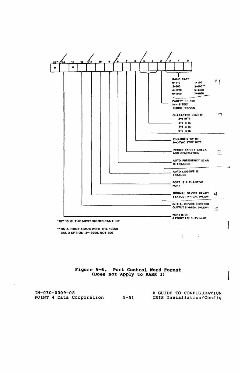
,
••
/.
'3
.i
10
.1.
rOT
101 I T I 1
-BIT
15
IS
THE
MOST
SIGNIFICANT
BIT
-,·ON
A
POINT
4
MUX
WITH
THE
19200
BAUD
OPTION.
3-19200.
NOT
600
1
.1.
•
I T T I
-=,.--J
31
1 0
I I I I
BAU~
RATE'
0-110
2-_
'-1200
S-2400
...
""'"
1-iN11O
---..----
----
L-
~::II~EI~~:
N
OT
0-000
'~EV
EN
CHARACTER
LENGTH:
Jo-8 BITS
l-7B1TS
'-8
BITS
o-s
Bns
~OHEST
OP BIT,
P BITS
1->TWO
$TO
INHIBIT
PARI
TV
CHECK
liON
AND
GEN~RA
AUTO FREOU
ENey
SCAN
1$
ENABLEO
AUTO
LOG-O
Ff
IS
ENABLED
PORT
IS A
PH
ANTOM
PORT
NORMAL
DE
VICE
READY
GH,
G-lOW!
STATUS I1-HI
'----
INITIAL
DE
VI
CE
CONTROL
GH.O-LOW)
OUTPUT I1-HI
PORT
IS
O~~
A
POINT
..
MIGHTY
MUX
2
Figure
5-6.
Port
Control
Word
Format
(Does
Not
Apply
to
MARK
3)
3M-030-0009-08
POINT 4
Data
Corporation
5-51
A GUIDE
TO
CONFIGURATION
IRIS
Insta11ation/Config
No.
Data
7
7
7
7
8
8
8
8
TABLB
5-8.
PCW
VALUBS
FOR
A
MARI
3 SYSTBM
of
No.
of
Bits
Parity
Stop
Bits
PCW
Value
Even
2
140201
Odd 2
140205
Even
1
140211
Odd
1
140215
Inhibited
2
140221
Inhibited
1
140225
Even
1
14023l
Odd 1
140235
NOTB
The
PCW
value
for
a
phantom
port
on
a
MARK
3
is
2000.
SM-030-0009-10
A GUIDE
TO
CONFIGURATION
IRIS
Insta11ation/Config
POINT 4
Data
Corporation
5-52
I-t.
,.v.4h'e
~
1~/7t73
1'{(,t.S{'
II/liSt.
1f'33/1
/'/~!!(J!;"
0 0
,
(SCH.t:'.,e/~e)
,
/r
:
t:I-;g,t!s
/1
z~/'t'$
.v/~#daJ
;/
I'ldrf
-:10-;11 _
CHa$
,.",',
','
&l-.;l$
UAr
,
'
ilcc~/JIltkt~d
".t.:n-6
c-1Pd
-60
).406
//dt!~S:
~iI'.r
ast!'.r&,
ZJa.6e '
'",
.,
',
. •
e:
/'¢IJ.;I./
V
.,
36"
,o;,,;er
;. . ,
If.'{j/'>tnt
'.
1".;0/".;0,,'6
y,
,
~~/,~
..
6,
'.:
£<:1""qe
~-
377
f
.'
C4.C4/' .
",e
~
~
-,&$0",.<,,0',
7
,It::.ur-
A~amJ
h'~
$t6~
/5"-1'1
/J
,R/i/
L"",el
/3-6
/I
t!C
,
a'-<>
C(
I/.;t!t
6"-0
tIlc""
p$t!,.
.t:!.
.56
S,vdij
S(!O;t}
1."
tI-C
/!,A;"h~.:L
40-.07 l>l1s;r
1)~IU""'4-/
aa<!It-,»u./a~,.
&ve
,.4,.e~
(/$,.,/
&y.
"yf,escrqI"N
&0
Save
t
~
Ao:.
fS/J(
l>/I-
o"'-o//s
tt-6-
.sw~;c
-ceu!
eo
-c-h¢6-
-cA
~
y
..
<U"
6<:
,
~
;,
,
~s&,,·~~
'.&y
"liMb
/(<:$'£"
a..-6
'!
'h II! .
4eJfC-
t5WQ,fJ ,tt'4,
so;:£?
1J3~
-It
~:s
",OL.
",...,./y.6y
/.>;:S~
~rV'"",<!
hOd<'5CO/'
,.
oCher
~$P
a/.:"
usee:
1./17"/1
(-t/3)
N,o;"S(-'
IS')
FHI{"o
(ta4
7tJ-/7t;)
U!.c.b
(MIl'!')
,
N.e~b
(..d
/(,)
