SUNNY MINI CENTRAL 4600A/5000A/6000A Installation Manual SMC 5000A SMA PV Inverter 4600A 6000A
User Manual: Sunny Mini Central SMC 5000A
Open the PDF directly: View PDF ![]() .
.
Page Count: 88
- 1 Information on this Manual
- 2 Safety
- 3 Unpacking
- 4 Mounting
- 5 Electrical Connection
- 6 Commissioning
- 7 Opening and Closing
- 8 Maintenance and Cleaning
- 9 Troubleshooting
- 10 Decommissioning
- 11 Technical Data
- 12 Accessories
- 13 Contact
SMC46-60A-IA-IEN120471 | IME-SMC50A_60A | Version 7.1
EN
PV Inverter
SUNNY MINI CENTRAL 4600A / 5000A / 6000A
Installation Manual
SMA Solar Technology AG Table of Contents
Installation Manual SMC46-60A-IA-IEN120471 3
Table of Contents
1 Information on this Manual. . . . . . . . . . . . . . . . . . . . . . . . . 7
1.1 Validity . . . . . . . . . . . . . . . . . . . . . . . . . . . . . . . . . . . . . . . . . . . . 7
1.2 Target Group . . . . . . . . . . . . . . . . . . . . . . . . . . . . . . . . . . . . . . . 7
1.3 Additional Information . . . . . . . . . . . . . . . . . . . . . . . . . . . . . . . . 7
1.4 Symbols Used . . . . . . . . . . . . . . . . . . . . . . . . . . . . . . . . . . . . . . . 8
2 Safety . . . . . . . . . . . . . . . . . . . . . . . . . . . . . . . . . . . . . . . . . . 9
2.1 Intended Use. . . . . . . . . . . . . . . . . . . . . . . . . . . . . . . . . . . . . . . . 9
2.2 Safety Precautions. . . . . . . . . . . . . . . . . . . . . . . . . . . . . . . . . . . 10
2.3 Explanation of Symbols . . . . . . . . . . . . . . . . . . . . . . . . . . . . . . 11
2.3.1 Symbols on the Inverter. . . . . . . . . . . . . . . . . . . . . . . . . . . . . . . . . . . . . . . . . 11
2.3.2 Symbols on the Type Label . . . . . . . . . . . . . . . . . . . . . . . . . . . . . . . . . . . . . . 12
3 Unpacking. . . . . . . . . . . . . . . . . . . . . . . . . . . . . . . . . . . . . . 13
3.1 Scope of Delivery . . . . . . . . . . . . . . . . . . . . . . . . . . . . . . . . . . . 13
3.2 Identifying the Inverter . . . . . . . . . . . . . . . . . . . . . . . . . . . . . . . 14
4 Mounting. . . . . . . . . . . . . . . . . . . . . . . . . . . . . . . . . . . . . . . 15
4.1 Safety . . . . . . . . . . . . . . . . . . . . . . . . . . . . . . . . . . . . . . . . . . . . 15
4.2 Selecting the Mounting Location. . . . . . . . . . . . . . . . . . . . . . . . 15
4.3 Mounting the Inverter with the Wall Mounting Bracket . . . . . . 17
5 Electrical Connection . . . . . . . . . . . . . . . . . . . . . . . . . . . . . 20
5.1 Overview of the Connection Area . . . . . . . . . . . . . . . . . . . . . . 20
5.1.1 Exterior View . . . . . . . . . . . . . . . . . . . . . . . . . . . . . . . . . . . . . . . . . . . . . . . . . 20
5.1.2 Interior View . . . . . . . . . . . . . . . . . . . . . . . . . . . . . . . . . . . . . . . . . . . . . . . . . 21
5.2 Connection to the Power Distribution Grid (AC). . . . . . . . . . . . 23
5.2.1 Conditions for the AC Connection . . . . . . . . . . . . . . . . . . . . . . . . . . . . . . . . 23
5.2.2 Connecting the Inverter to the Power Distribution Grid (AC) . . . . . . . . . . . . 25
5.2.3 Additional Grounding of the Enclosure. . . . . . . . . . . . . . . . . . . . . . . . . . . . . 27
Table of Contents SMA Solar Technology AG
4 SMC46-60A-IA-IEN120471 Installation Manual
5.3 Setting the Display Language . . . . . . . . . . . . . . . . . . . . . . . . . . 28
5.4 Connecting the PV Array (DC) . . . . . . . . . . . . . . . . . . . . . . . . . 29
5.4.1 Conditions for the DC Connection . . . . . . . . . . . . . . . . . . . . . . . . . . . . . . . . 29
5.4.2 Assembling the DC Connectors. . . . . . . . . . . . . . . . . . . . . . . . . . . . . . . . . . . 30
5.4.3 Opening the DC Connector . . . . . . . . . . . . . . . . . . . . . . . . . . . . . . . . . . . . . 32
5.4.4 Connecting the PV Array (DC) . . . . . . . . . . . . . . . . . . . . . . . . . . . . . . . . . . . 33
5.5 Connection of the SMA Power Balancer . . . . . . . . . . . . . . . . . 37
5.5.1 Configuration . . . . . . . . . . . . . . . . . . . . . . . . . . . . . . . . . . . . . . . . . . . . . . . . 37
5.5.2 Cabling . . . . . . . . . . . . . . . . . . . . . . . . . . . . . . . . . . . . . . . . . . . . . . . . . . . . . 41
5.5.3 Testing the Functioning . . . . . . . . . . . . . . . . . . . . . . . . . . . . . . . . . . . . . . . . . 45
5.6 Communication. . . . . . . . . . . . . . . . . . . . . . . . . . . . . . . . . . . . . 46
5.7 Setting the Grid and Country Parameters . . . . . . . . . . . . . . . . . 46
5.7.1 Setting the Installation Country . . . . . . . . . . . . . . . . . . . . . . . . . . . . . . . . . . . 46
5.7.2 Setting Stand‑alone Grid Operation . . . . . . . . . . . . . . . . . . . . . . . . . . . . . . . 47
5.7.3 Additional Country Parameters . . . . . . . . . . . . . . . . . . . . . . . . . . . . . . . . . . . 47
6 Commissioning . . . . . . . . . . . . . . . . . . . . . . . . . . . . . . . . . . 48
6.1 Commissioning the Inverter. . . . . . . . . . . . . . . . . . . . . . . . . . . . 48
6.2 Display Messages During the Startup Phase . . . . . . . . . . . . . . 49
6.3 Self‑test in Accordance with DK 5940, Ed. 2.2
(Applies to Italy Only). . . . . . . . . . . . . . . . . . . . . . . . . . . . . . . . 50
6.3.1 Starting the Self‑Test by Tapping. . . . . . . . . . . . . . . . . . . . . . . . . . . . . . . . . . 50
6.3.2 Completion of the Self‑test. . . . . . . . . . . . . . . . . . . . . . . . . . . . . . . . . . . . . . . 51
7 Opening and Closing. . . . . . . . . . . . . . . . . . . . . . . . . . . . . 55
7.1 Safety . . . . . . . . . . . . . . . . . . . . . . . . . . . . . . . . . . . . . . . . . . . . 55
7.2 Opening the Inverter. . . . . . . . . . . . . . . . . . . . . . . . . . . . . . . . . 55
7.3 Closing the Inverter. . . . . . . . . . . . . . . . . . . . . . . . . . . . . . . . . . 58
8 Maintenance and Cleaning. . . . . . . . . . . . . . . . . . . . . . . . 60
8.1 Cleaning the Inverter. . . . . . . . . . . . . . . . . . . . . . . . . . . . . . . . . 60
8.2 Checking Heat Dissipation . . . . . . . . . . . . . . . . . . . . . . . . . . . . 60
SMA Solar Technology AG Table of Contents
Installation Manual SMC46-60A-IA-IEN120471 5
8.2.1 Cleaning the Fans . . . . . . . . . . . . . . . . . . . . . . . . . . . . . . . . . . . . . . . . . . . . . 60
8.2.2 Checking the Fans. . . . . . . . . . . . . . . . . . . . . . . . . . . . . . . . . . . . . . . . . . . . . 62
8.2.3 Cleaning the Fan Guards . . . . . . . . . . . . . . . . . . . . . . . . . . . . . . . . . . . . . . . 63
8.3 Checking the Electronic Solar Switch (ESS) for Wear . . . . . . . 64
9 Troubleshooting . . . . . . . . . . . . . . . . . . . . . . . . . . . . . . . . . 65
9.1 Blink Codes. . . . . . . . . . . . . . . . . . . . . . . . . . . . . . . . . . . . . . . . 65
9.2 Error Messages. . . . . . . . . . . . . . . . . . . . . . . . . . . . . . . . . . . . . 66
9.3 Red LED is Permanently Lit . . . . . . . . . . . . . . . . . . . . . . . . . . . . 70
9.3.1 Checking the PV Array for Ground Faults . . . . . . . . . . . . . . . . . . . . . . . . . . . 71
9.3.2 Checking the Function of the Varistors . . . . . . . . . . . . . . . . . . . . . . . . . . . . . 73
10 Decommissioning . . . . . . . . . . . . . . . . . . . . . . . . . . . . . . . . 75
10.1 Disassembling the Inverter . . . . . . . . . . . . . . . . . . . . . . . . . . . . 75
10.2 Packing the Inverter. . . . . . . . . . . . . . . . . . . . . . . . . . . . . . . . . . 76
10.3 Storing the Inverter . . . . . . . . . . . . . . . . . . . . . . . . . . . . . . . . . . 76
10.4 Disposing of the Inverter . . . . . . . . . . . . . . . . . . . . . . . . . . . . . . 76
11 Technical Data . . . . . . . . . . . . . . . . . . . . . . . . . . . . . . . . . . 77
11.1 DC/AC . . . . . . . . . . . . . . . . . . . . . . . . . . . . . . . . . . . . . . . . . . . 77
11.1.1 Sunny Mini Central 4600A. . . . . . . . . . . . . . . . . . . . . . . . . . . . . . . . . . . . . . 77
11.1.2 Sunny Mini Central 5000A. . . . . . . . . . . . . . . . . . . . . . . . . . . . . . . . . . . . . . 79
11.1.3 Sunny Mini Central 6000A. . . . . . . . . . . . . . . . . . . . . . . . . . . . . . . . . . . . . . 81
11.2 General Data . . . . . . . . . . . . . . . . . . . . . . . . . . . . . . . . . . . . . . 82
11.3 Protective Devices . . . . . . . . . . . . . . . . . . . . . . . . . . . . . . . . . . . 82
11.4 National Standards . . . . . . . . . . . . . . . . . . . . . . . . . . . . . . . . . 83
11.5 Climatic Conditions. . . . . . . . . . . . . . . . . . . . . . . . . . . . . . . . . . 83
11.6 Features . . . . . . . . . . . . . . . . . . . . . . . . . . . . . . . . . . . . . . . . . . 84
11.7 Electronic Solar Switch (ESS) . . . . . . . . . . . . . . . . . . . . . . . . . . 84
11.8 Torque. . . . . . . . . . . . . . . . . . . . . . . . . . . . . . . . . . . . . . . . . . . . 84
11.9 Distribution Systems . . . . . . . . . . . . . . . . . . . . . . . . . . . . . . . . . 84
SMA Solar Technology AG Information on this Manual
Installation Manual SMC46-60A-IA-IEN120471 7
1 Information on this Manual
1.1 Validity
This installation manual describes the assembly, installation, commissioning, maintenance and
troubleshooting of the following SMA inverters:
• Sunny Mini Central 4600A (SMC 4600A, SMC 4600A-11)
• Sunny Mini Central 5000A (SMC 5000A, SMC 5000A-11, SMC 5000A-IT)
• Sunny Mini Central 6000A (SMC 6000A, SMC 6000A-11, SMC 6000A-IT)
Keep this manual in a convenient place for future reference.
1.2 Target Group
This manual is for electrically qualified persons. The tasks described in this manual may be performed
by electrically qualified persons only.
1.3 Additional Information
You will find further information on special topics such as designing a miniature circuit‑breaker or the
description of the operating parameters in the download area at www.SMA.de/en.
Refer to the user manual provided for detailed information on operating the inverter.
Information on this Manual SMA Solar Technology AG
8 SMC46-60A-IA-IEN120471 Installation Manual
1.4 Symbols Used
The following types of safety precautions and general information are used in this manual:
DANGER!
DANGER indicates a hazardous situation which, if not avoided, will result in death or
serious injury.
WARNING!
WARNING indicates a hazardous situation which, if not avoided, could result in death or
serious injury.
CAUTION!
CAUTION indicates a hazardous situation which, if not avoided, could result in minor or
moderate injury.
NOTICE!
NOTICE indicates a situation that can result in property damage if not avoided.
Information
Information provides tips that are valuable for the optimal installation and operation of
your product.
☑ This symbol indicates the result of an action.
SMA Solar Technology AG Safety
Installation Manual SMC46-60A-IA-IEN120471 9
2 Safety
2.1 Intended Use
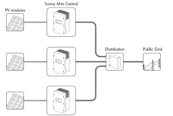
The Sunny Mini Central is a PV inverter which converts the direct current of the PV array to alternating
current and feeds it into the power distribution grid.
Operating Principle of a PV Plant with Sunny Mini Central
The Sunny Mini Central may only be operated with PV arrays (PV modules and cabling) of protection
class II. Do not connect any energy sources other than PV modules to the Sunny Mini Central.
When designing the PV plant, ensure that the values comply with the permitted operating range of all
components at all times. The free design program "Sunny Design" (www.SMA.de/en/SunnyDesign)
will assist you. The manufacturer of the PV modules must have approved the modules for use with this
Sunny Mini Central. You must also ensure that all measures recommended by the module
manufacturer for long-term maintenance of the module properties are taken (see also Technical
Information "Module Technology" in the download area of www.SMA.de/en).
For safety reasons, it is forbidden to modify the product or install component parts that are not
explicitly recommended or distributed by SMA Solar Technology AG.
Safety SMA Solar Technology AG
10 SMC46-60A-IA-IEN120471 Installation Manual
2.2 Safety Precautions
DANGER!
Danger to life due to high voltages in the inverter.
• All work on the inverter may only be carried out by an electrically qualified person.
CAUTION!
Risk of burns due to hot enclosure parts.
• Do not touch the enclosure during operation.
• Only touch the enclosure lid during operation.
NOTICE!
Dust and water intrusion can damage the inverter.
Once the Electronic Solar Switch has been pulled out, the inverter only provides degree of
protection IP21. The inverter is then no longer protected against water and dust intrusion.
In order to also maintain degree of protection IP65 during temporary decommissioning,
proceed as follows:
• Unlock and disconnect all DC connectors.
• Open all DC connectors and remove the cables.
• Close all DC inputs with the corresponding DC connectors and the supplied sealing
plugs.
• Firmly connect the Electronic Solar Switch again.
PV array grounding
Comply with the local regulations for grounding the PV modules and the PV array. In order
to maintain the best possible protection for both the PV plant and human life,
SMA Solar Technology AG recommends connecting together the PV array frame and other
electrically conductive surfaces and grounding them.
SMA Solar Technology AG Safety
Installation Manual SMC46-60A-IA-IEN120471 11
2.3 Explanation of Symbols
This section gives an explanation of all the symbols found on the inverter and on the type label.
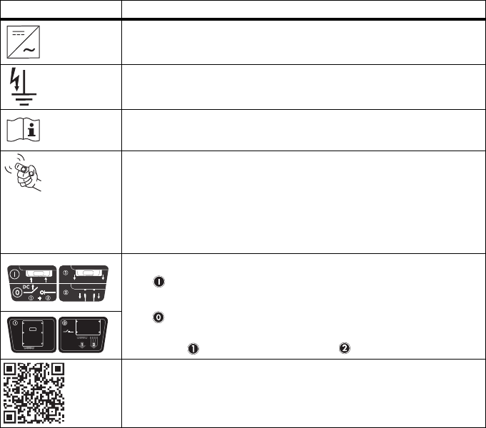
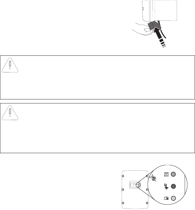
2.3.1 Symbols on the Inverter
* This function is valid from firmware version 2.15
** QR-Code is a registered trademark of DENSO WAVE INCORPORATED.
Symbol Explanation
Operation display. Indicates the operating state of the inverter.
Ground fault or varistor defective. Read section 9.3"Red LED is
Permanently Lit" (page70).
Error or fault. Read section 9"Troubleshooting" (page65).
You can operate the display by tapping the enclosure lid:
• Tapping once: the backlight switches on or the display scrolls to the
next display message.
• Tapping twice in quick succession*: The inverter shows the display
messages from the startup phase again (see section 6.2"Display
Messages During the Startup Phase" (page49)).
DC load disconnection unit Electronic Solar Switch (ESS)
• When the Electronic Solar Switch is plugged in, the DC electric
circuit is closed.
• To interrupt the DC electric circuit and safely disconnect the
inverter when under load, you must first remove the Electronic Solar
Switch and then all DC connectors .
QR‑Code®** for SMA bonus program
You will find information on the SMA bonus program at
www.SMA‑Bonus.com.
Safety SMA Solar Technology AG
12 SMC46-60A-IA-IEN120471 Installation Manual
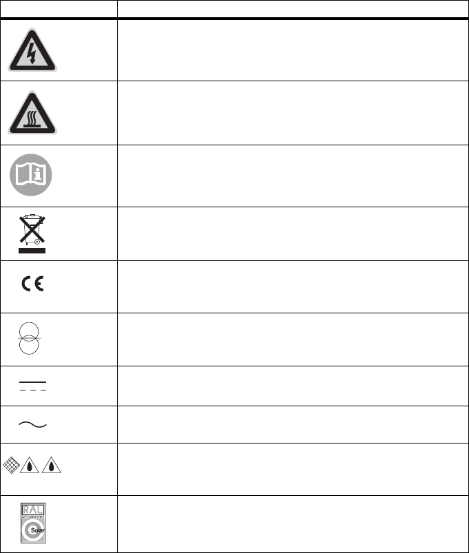
2.3.2 Symbols on the Type Label
Symbol Explanation
Beware of hazardous voltage.
The inverter operates at high voltages. All work on the inverter may only be
carried out by an electrically qualified person.
Beware of hot surface.
The inverter can become hot during operation. Avoid contact during
operation.
Observe all documentation that accompanies the inverter.
The inverter must not be disposed of together with the household waste. For
more information on disposal, see section 10.4"Disposing of the Inverter"
(page76).
CE mark.
The inverter complies with the requirements of the applicable
EC guidelines.
The inverter has a transformer.
Direct current (DC)
Alternating current (AC)
Degree of protection IP65.
The inverter is protected against dust intrusion and water jets from any
angle.
RAL quality mark for solar products.
The inverter complies with the requirements of the German Institute for
Quality Assurance and Labeling.
SMA Solar Technology AG Unpacking
Installation Manual SMC46-60A-IA-IEN120471 13
3 Unpacking
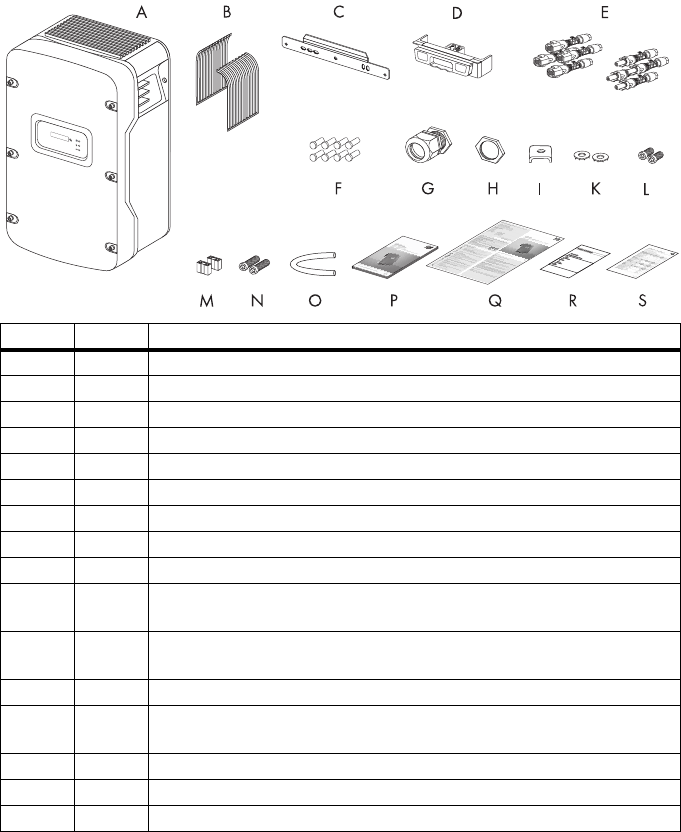
3.1 Scope of Delivery
Check the delivery for completeness and any visible external damage. Contact your specialty retailer
if anything is damaged or missing.
Object
Quantity
Description
A1 Sunny Mini Central
B1Fan guards (right/left)
C1 Wall mounting bracket
D1 DC load disconnection unit Electronic Solar Switch (ESS)
E8DC connectors (4 x positive, 4 x negative)
F8 Sealing plugs for the DC connectors
G1 Cable gland for AC connection
H1 Counter nut for cable gland at AC connection
I1 Clamping bracket for additional grounding
K2Conical spring washers:
1 x for enclosure lid screws (replacement), 1 x for ground terminal
L2 Cheese‑head screws (M6x16):
1 x for enclosure lid (replacement), 1 x for ground terminal
M2 Jumpers (1 x for fan test, 1 x for the SMA Power Balancer wiring)
N2 Cheese‑head screws (M6x8) for securing the inverter to the wall mounting
bracket
O1 Silicone tube for insulating the SMA Power Balancer connection cable
P1 Installation Manual
Q1User Manual
Unpacking SMA Solar Technology AG
14 SMC46-60A-IA-IEN120471 Installation Manual
3.2 Identifying the Inverter
You can identify the inverter using the type label. The type label is on the right‑hand side of the
enclosure.
The serial number (Serial No.) and the type (Type/Model) of the inverter, as well as device‑specific
characteristics are specified on the type label.
R1 Set of documents with explanations and certificates
S1 Supplementary sheet with inverter default settings
Object
Quantity
Description
SMA Solar Technology AG Mounting
Installation Manual SMC46-60A-IA-IEN120471 15
4 Mounting
4.1 Safety
4.2 Selecting the Mounting Location
Consider the following requirements when selecting the mounting location:
• The mounting method and location must be suitable for the inverter's weight and dimensions
(see section 11"Technical Data" (page77)).
• Mount on a solid surface.
• The mounting location must at all times be clear and safely accessible without the use of
additional aids such as scaffolding or lifting platforms. Non‑fulfillment of these criteria may
restrict servicing.
DANGER!
Danger to life due to fire or explosion.
Despite careful construction, electrical devices can cause fires.
• Do not mount the inverter on flammable construction materials.
• Do not mount the inverter in areas where highly flammable materials are stored.
• Do not mount the inverter in a potentially explosive atmosphere.
CAUTION!
Risk of burns due to hot enclosure parts.
• Mount the inverter in such a way that it cannot be touched inadvertently.
CAUTION!
Risk of injury due to the heavy weight of the inverter.
• Take the inverter's weight of approx. 63 kg into account for mounting.
Mounting SMA Solar Technology AG
16 SMC46-60A-IA-IEN120471 Installation Manual
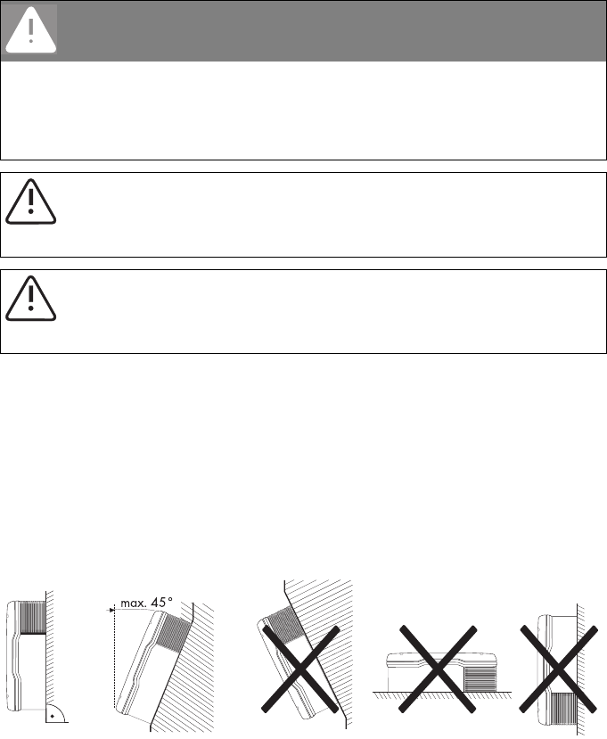
• Mount vertically or tilted backwards by max. 45°.
• The connection area must point downward.
• Never mount the device with a forward tilt.
• Never install the device with a sideways tilt.
• Do not mount horizontally.
• Mount at eye level to allow operating states to be read at all times.
• The ambient temperature should be below 40°C to ensure optimum operation.
• Do not expose the inverter to direct solar irradiation as this can cause excessive heating and
thus power reduction.
• In living areas, do not mount the unit on plasterboard walls or similar to avoid audible vibrations.
When in use, the inverter emits noises which may be perceived as a nuisance in a living area.
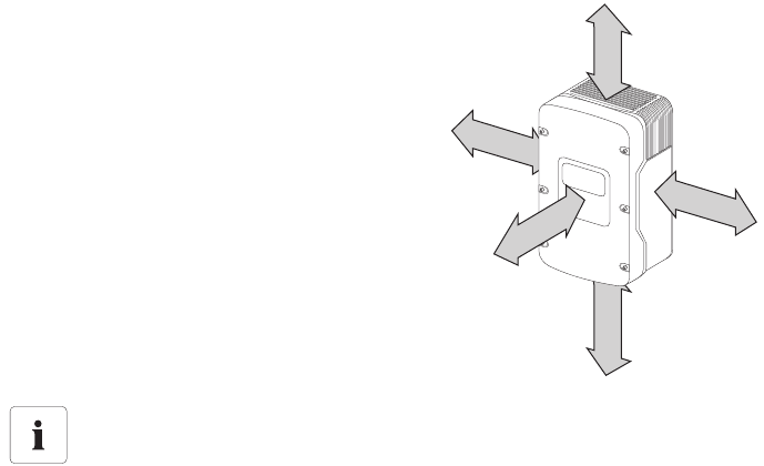
• Observe the minimum clearances to walls, other
inverters, or objects as shown in the diagram in
order to ensure sufficient heat dissipation and
sufficient space for removing the
Electronic Solar Switch.
Multiple inverters installed in areas with high ambient temperatures
There must be sufficient clearance between the individual inverters to ensure that the
cooling air of the adjacent inverter is not taken in.
If necessary, increase the clearance spaces and make sure there is enough fresh‑air supply
to ensure sufficient cooling of the inverters.
500 mm
300 mm 300 mm
50 mm
300 mm
SMA Solar Technology AG Mounting
Installation Manual SMC46-60A-IA-IEN120471 17
4.3 Mounting the Inverter with the Wall Mounting Bracket
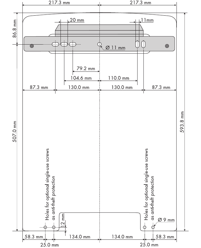
1. Mark the position of the drill holes using the wall mounting bracket and drill the holes.
Use at least 2 of the 6 holes, with 1 hole on the right and 1 on the left.
Mounting SMA Solar Technology AG
18 SMC46-60A-IA-IEN120471 Installation Manual
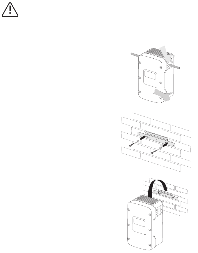
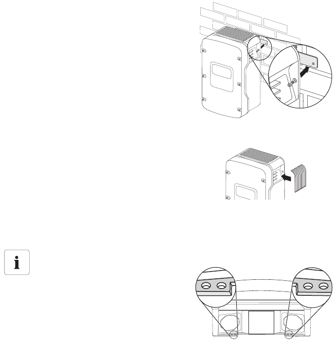
2. Secure the wall mounting bracket to the wall using
appropriate screws and washers.
3. Hang the inverter onto the wall mounting bracket
using the opening for this purpose in the rear of the
enclosure.
CAUTION!
Risk of injury due to the heavy weight of the inverter.
The inverter weighs approx. 63 kg.
• Attach the wall mounting bracket with the corresponding mounting material
(depending on the surface).
• Use the side handles (above and below)
or a steel rod (maximum diameter of
30 mm) for transport and mounting.
The rod must be pushed through the
enclosure openings.
SMA Solar Technology AG Mounting
Installation Manual SMC46-60A-IA-IEN120471 19
4. Screw the inverter onto the wall mounting bracket
on both sides using the screws (M6x8) provided.
Only tighten the screws hand‑tight.
5. Check to ensure that the inverter is securely in
place.
6. Close the recessed grips with the fan guards
provided. To help you identify the sides, the fan
guards are marked "rechts/right" and "links/left" on
the inside.
The fan guards prevent dirt and insects from
entering the device and, if necessary, can be
reordered from SMA Solar Technology AG
(see section 13"Contact" (page86)).
Optional anti‑theft protection
To protect the inverter against theft, the back
panel can be secured to the wall at the bottom
using 2 safety screws.
The other 2 holes are spares.
Electrical Connection SMA Solar Technology AG
20 SMC46-60A-IA-IEN120471 Installation Manual
5 Electrical Connection
5.1 Overview of the Connection Area
5.1.1 Exterior View
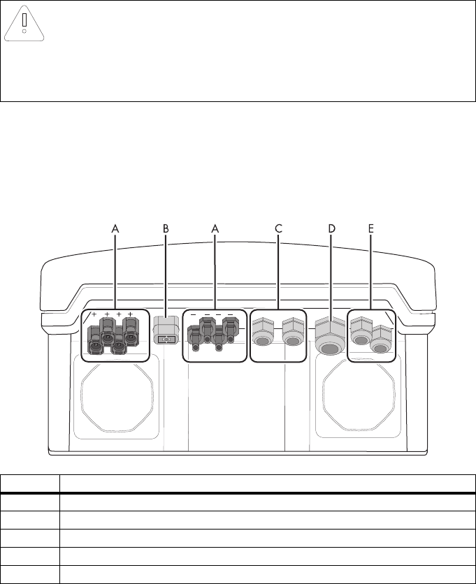
The following figure shows the assignment of the individual connection areas on the bottom of the
inverter.
NOTICE!
Electrostatic discharges can damage the inverter.
Internal component parts of the inverter can be irreparably damaged by static electric
discharge.
• Ground yourself before touching a component part.
Object Description
ADC connectors for connecting the PV strings
BJack for connecting the Electronic Solar Switch (ESS) DC load disconnection unit
CCable glands for optional communication via RS485 (PG16)
DCable gland for connection to the power distribution grid (AC) (12 mm ... 25 mm)
ECable glands for SMA Power Balancer
SMA Solar Technology AG Electrical Connection
Installation Manual SMC46-60A-IA-IEN120471 21
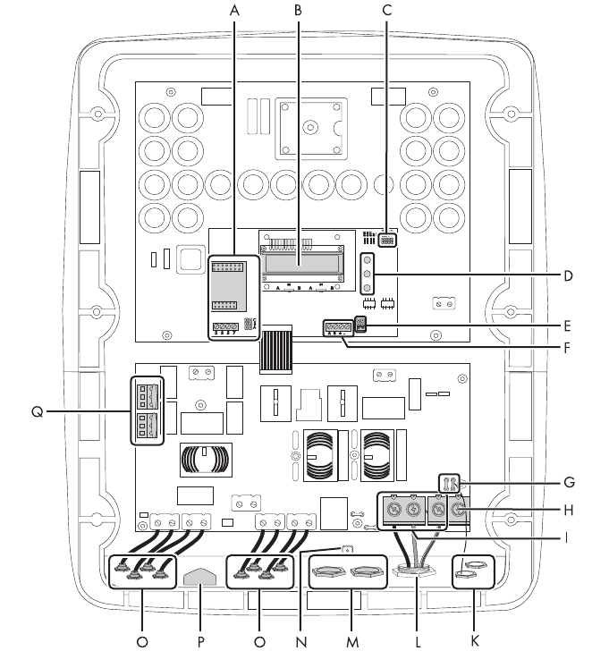
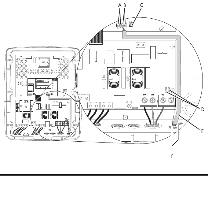
5.1.2 Interior View
The following figure shows the various components and connection areas of the open inverter.

Electrical Connection SMA Solar Technology AG
22 SMC46-60A-IA-IEN120471 Installation Manual
Object Description
AConnection area and slots for communication
BDisplay
CJumper slot for the fan test
DLEDs for displaying the operating states
EJumper slot for SMA Power Balancer
FTerminals for SMA Power Balancer
GFlat male tab for grounding the cable shield when connecting the SMA Power Balancer
HAdditional terminal for grounding
ITerminals for AC cables
KCable glands for the SMA Power Balancer
LCable gland for AC-cable
MCable glands for communication
NScrewing device for shield connection terminal for communication cable
ODC connector
PConnection jack for Electronic Solar Switch (ESS)
QVaristors
SMA Solar Technology AG Electrical Connection
Installation Manual SMC46-60A-IA-IEN120471 23
5.2 Connection to the Power Distribution Grid (AC)
5.2.1 Conditions for the AC Connection
Cable Design
Use "Sunny Design" version 2.0 or higher for the dimensioning of the conductor cross‑sectional areas
(see "Sunny Design" program at www.SMA.de/en).
Cable Requirements
Connection requirements of the grid operator
Always observe the connection requirements of your grid operator.
Halving the cable losses
If 3 inverters with symmetrical feed‑in are combined to form a three‑phase system, the
neutral conductor is not subjected to any load, and the cable losses are halved.
Thus, the maximum possible cable length is doubled.
Position Designation Value
AExternal diameter 12 mm … 25 mm
BConductor cross‑section 6 mm² … 16 mm²
CLength of insulation to be stripped off approx. 16 mm
Electrical Connection SMA Solar Technology AG
24 SMC46-60A-IA-IEN120471 Installation Manual
Load Disconnection Unit
You must install a separate miniature circuit‑breaker for each inverter in order to ensure that the
inverter can be securely disconnected under load. The maximum permissible fuse protection can be
found in section 11"Technical Data" (page77).
Detailed information and examples for the rating of a miniature circuit‑breaker can be found in the
Technical Information "Miniature Circuit Breaker" in the SMA Solar Technology AG download area
at www.SMA.de/en.
DANGER!
Danger to life due to fire.
When more than 1 inverter is connected in parallel to the same miniature circuit‑breaker,
the protective function of the miniature circuit‑breaker is no longer guaranteed.
It can result in a cable fire or destruction of the inverter.
• Never connect several inverters to the same miniature circuit‑breaker.
• Observe the maximum permissible fuse protection of the inverter when selecting the
miniature circuit‑breaker.
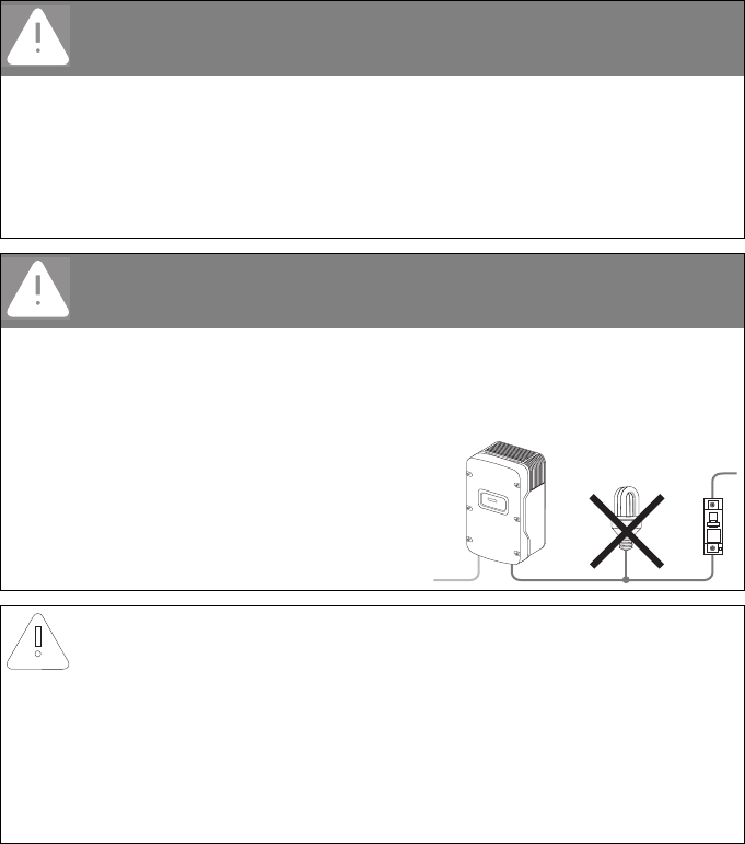
DANGER!
Danger to life due to fire.
When a generator (inverter) and a load are connected to the same miniature
circuit‑breaker, the protective function of the miniature circuit‑breaker is no longer
guaranteed. The current from the inverter and the power distribution grid can accumulate
to overcurrent which is not detected by the miniature circuit‑breaker.
• Never connect loads between the
inverter and the miniature circuit‑breaker
without fuse protection.
• Always protect loads separately.
NOTICE!
Damage to the inverter by using screw type fuses as a load disconnection unit.
A screw type fuse, e.g. DIAZED fuse or NEOZED fuse, is not a switch-disconnector and thus
may not be used as a load disconnection unit. A screw type fuse only acts as cable
protection.
When disconnecting under load using a screw type fuse, the inverter can be damaged.
• Use only a switch‑disconnector or a miniature circuit‑breaker as a load disconnection
unit.
SMA Solar Technology AG Electrical Connection
Installation Manual SMC46-60A-IA-IEN120471 25
5.2.2 Connecting the Inverter to the Power Distribution Grid (AC)
1. Check the line voltage and compare with "VAC nom" on the type label.
The exact operating range of the inverter is specified in the operating parameters.
The corresponding document is available in the download area at www.SMA.de/en.
2. Disconnect the miniature circuit‑breaker and secure against reconnection.
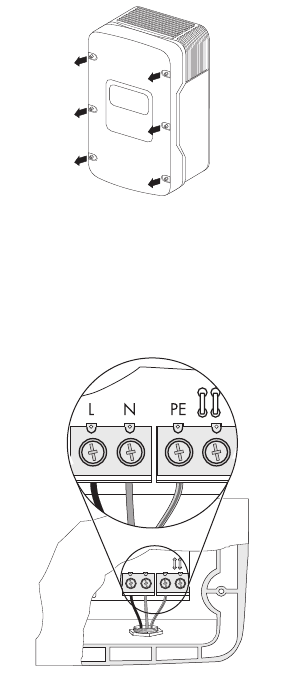
3. Loosen all screws of the enclosure lid and remove
the lid.
4. Remove the adhesive tape from the AC enclosure opening (see "D" on Page 20).
5. Insert the AC cable gland from the outside into the enclosure opening and tighten it from the
inside with the counter nut.
6. Unscrew the cable gland's lock nut and pass it over the cable.
7. Route the cable through the cable gland to the AC terminal.
8. Connect L, N and the protective conductor (PE) to
the terminal blocks using a screwdriver in
accordance with the label.
To do this, the PE insulated conductor must be 5 mm
longer than the L and N insulated conductors.
L and N must not be swapped.
Electrical Connection SMA Solar Technology AG
26 SMC46-60A-IA-IEN120471 Installation Manual
9. Tighten the lock nut firmly to the cable gland.
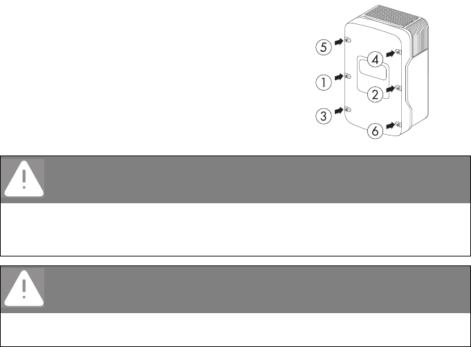
10. Secure the enclosure lid with all screws and the
corresponding conical spring washers.
Tighten the screws with 6 Nm torque in the order
shown in the figure on the right. The toothing of the
conical spring washers must point toward the
enclosure lid.
The scope of delivery of the inverter includes
another spare screw and conical spring washer.
☑ The inverter is now connected to the power distribution grid (AC).
DANGER!
Danger to life due to enclosure lid carrying voltage.
The grounding of the enclosure lid is ensured by the conical spring washers.
• Attach the conical spring washers for all 6 screws with the toothing facing toward the
enclosure lid.
DANGER!
Danger to life due to high voltages in the inverter.
• Do not switch on the miniature circuit‑breaker until the PV array has also been
connected and the inverter is securely closed.
SMA Solar Technology AG Electrical Connection
Installation Manual SMC46-60A-IA-IEN120471 27
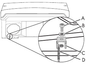
5.2.3 Additional Grounding of the Enclosure
If the installation requires, you can use the ground terminal to connect a second protective conductor
or as equipotential bonding.
Procedure
1. Insert the stripped grounding cable (D) under the
clamping bracket (C) (max. cross‑section 16 mm²
or with bootlace ferrule max. 10 mm²).
2. Screw the clamping bracket tight with screw
(A) and conical spring washer (B).
The toothing of the conical spring washer must face
toward the clamping bracket.
☑ The inverter's enclosure is additionally grounded.
Electrical Connection SMA Solar Technology AG
28 SMC46-60A-IA-IEN120471 Installation Manual
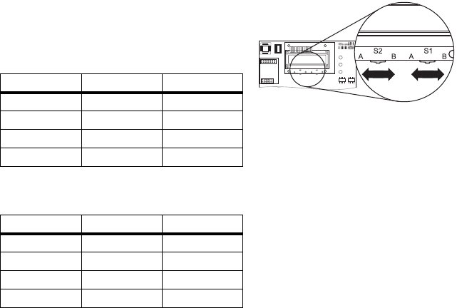
5.3 Setting the Display Language
You can set the language of the display using the switches at the bottom of the display assembly inside
the inverter.
When selecting the display language, different switching settings apply to inverters that are set to the
Italian national standard DK 5940. You can see the standard to which the inverter was set upon
delivery on the type label and the supplementary sheet provided with the default settings. For more
information, see the Technical Description "Operating Parameters" at www.SMA.de/en.
Procedure
1. Open the inverter as described in section 7.2"Opening the Inverter" (page55).
2. Set the switches to the required language, as
shown below.
The following switch settings, except for DK 5940,
apply to all national standards:
The following switch settings apply to inverters that
are set to the Italian national standard DK 5940:
3. Close the inverter as described in section 7.3"Closing the Inverter" (page58).
☑ The display language is set.
Language Switch S2 Switch S1
German B B
English B A
French A B
Spanish A A
Language Switch S2 Switch S1
Italian B A
English A A
German B B
French A B
SMA Solar Technology AG Electrical Connection
Installation Manual SMC46-60A-IA-IEN120471 29
5.4 Connecting the PV Array (DC)
5.4.1 Conditions for the DC Connection
• Requirements for the PV modules of the connected strings:
– Same type
– Same quantity
– Identical alignment
– Identical tilt
• The connection cables of the PV modules must be equipped with connectors.
The DC connectors for the DC connection are included in the delivery.
• The following limiting values at the DC input of the inverter must not be exceeded:
Using Y adapters for parallel connection of strings
Y adapters may not be visible within close proximity of the inverter or freely accessible.
• The DC electric circuit may not be interrupted by Y adapters.
• Observe the procedure for disconnecting the inverter as described in section
7.2"Opening the Inverter" (page55).
Maximum input voltage Maximum input current
600 V (DC) 26.0 A (DC)
WARNING!
Risk of lethal electric shock or fire.
The maximum possible input current per string is limited by the connectors used. If the
connectors are overloaded, an electric arc may occur and there is a risk of fire.
• Ensure that the input current for each string does not exceed the maximum
through‑fault current of the connectors used.

Electrical Connection SMA Solar Technology AG
30 SMC46-60A-IA-IEN120471 Installation Manual
5.4.2 Assembling the DC Connectors
All PV module connection cables must be equipped with the included DC connectors before
connecting them to the inverter.
To assemble the DC connectors, proceed as follows. Ensure the connectors have the correct polarity.
The DC connectors have the symbols "+" and "‒".
Cable requirements:
• Use a PV1‑F cable.
Procedure
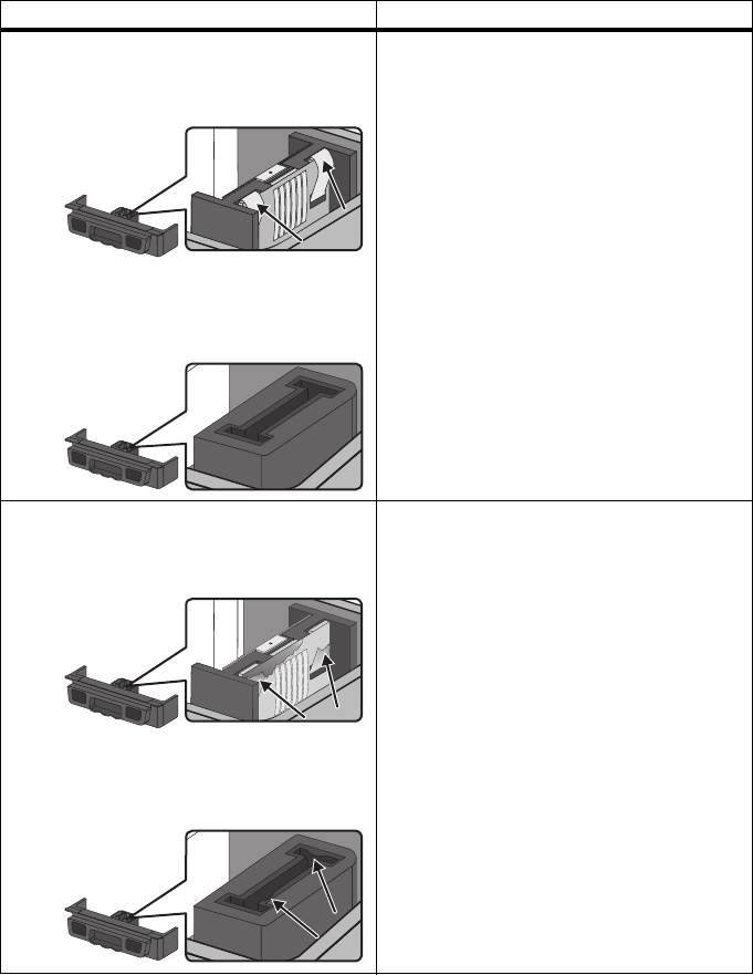
1. Lead the stripped cable all the way into the plug.
2. Press the clamping bracket down until it audibly
snaps into place.
3. Ensure that the cable is correctly positioned:
Result Measure
☑ If the stranded wire is visible in the chamber
of the clamping bracket, the cable is
correctly positioned.
• Proceed to step 4.
... ...
SMA Solar Technology AG Electrical Connection
Installation Manual SMC46-60A-IA-IEN120471 31
4. Push the threaded joint up to the thread and screw into place with a torque of 2 Nm.
☑ The DC connectors are assembled and can now be connected to the inverter as described in
section 5.4.4"Connecting the PV Array (DC)" (page33).
☑ If the stranded wire is not visible in the
chamber, the cable is not correctly
positioned.
• Loosen the clamping bracket. To do so,
insert a 3.5 mm screwdriver into the
clamping bracket and lever it out.
• Remove the cable and go back to step 1.
Result Measure
Electrical Connection SMA Solar Technology AG
32 SMC46-60A-IA-IEN120471 Installation Manual
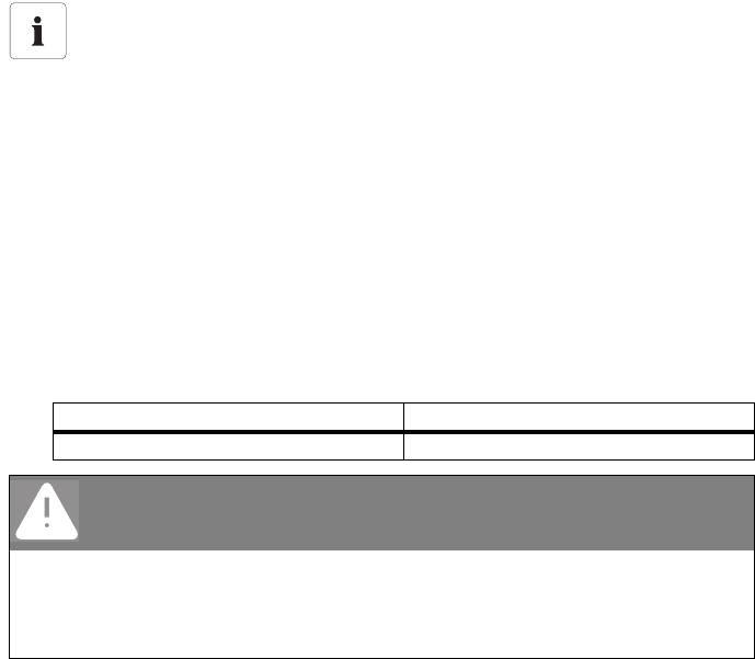
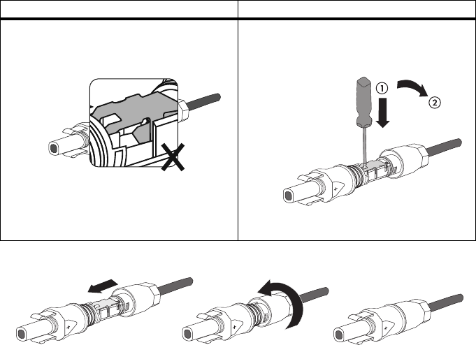
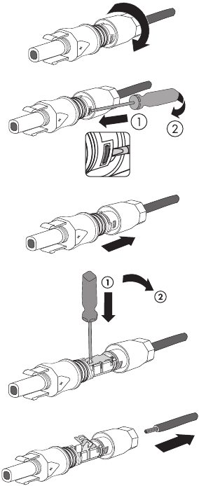
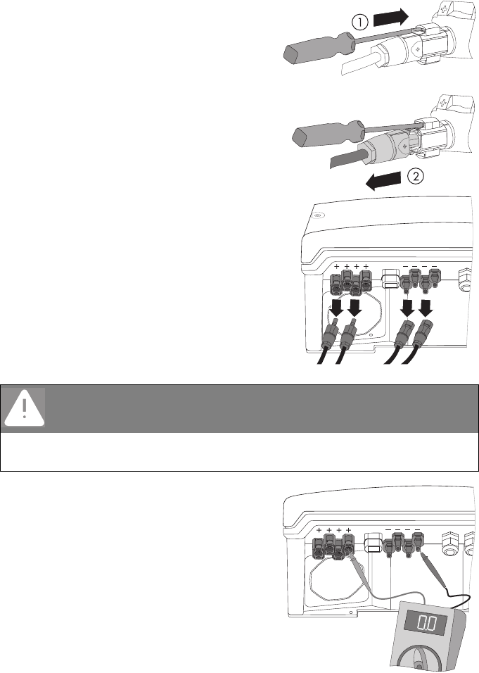
5.4.3 Opening the DC Connector
1. Unscrew the screw connection.
2. Unlocking the DC connector: Insert a 3.5 mm
screwdriver into the snap slot on the side and lever
it out.
3. Carefully pull the DC connector apart.
4. Loosen the clamping bracket. To do so, insert a
3.5 mm screwdriver into the clamping bracket and
lever it out.
5. Remove the cable.
☑ The cable is now removed from the DC connector.
SMA Solar Technology AG Electrical Connection
Installation Manual SMC46-60A-IA-IEN120471 33
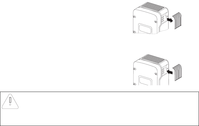
5.4.4 Connecting the PV Array (DC)
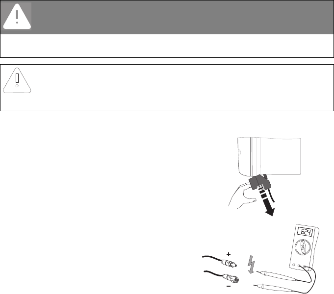
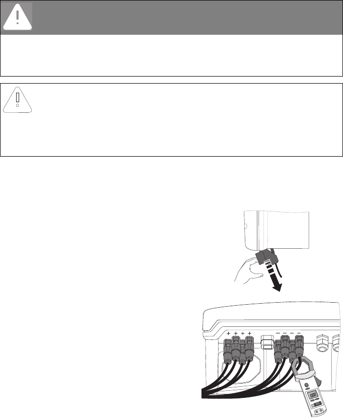
1. Disconnect the miniature circuit‑breaker and secure against reconnection.
2. Pull the Electronic Solar Switch downward, slightly
towards the wall.
3. Check the connection cable of the PV modules for
correct polarity and make sure that the maximum
input voltage of the inverter is not exceeded.
At an ambient temperature above 10°C, the
open‑circuit voltage of the PV modules must not be
more than 90% of the maximum inverter input
voltage.
Otherwise, check the plant design and the
PV module connection. If this is not done, the
maximum inverter input voltage can be exceeded
at low ambient temperatures.
DANGER!
Danger to life due to high voltages in the inverter.
• Before connecting the PV array, ensure that the miniature circuit‑breaker is switched
off.
NOTICE!
Excessive voltages can destroy the measuring device.
• Only use measuring devices with a DC input voltage range up to at least 1 000 V.
Electrical Connection SMA Solar Technology AG
34 SMC46-60A-IA-IEN120471 Installation Manual
4. Check the strings for ground faults as described in section 9.3.1"Checking the PV Array for
Ground Faults" (page71).
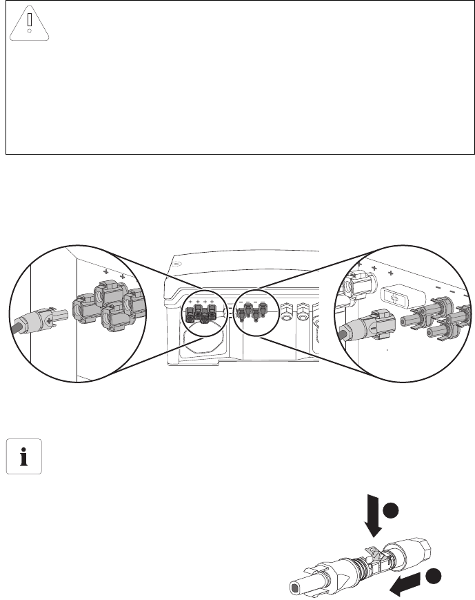
5. Connect the assembled DC connectors to the inverter.
☑ The DC connectors click audibly into position.
6. In order to seal the inverter, all the DC inputs that are not required have to be closed with
DC connectors and sealing plugs:
– For unused DC connectors, push down the
clamping bracket and push it onto the cable
gland.
NOTICE!
Overvoltage can destroy the inverter.
If the voltage of the PV modules exceeds the maximum input voltage of the inverter,
it can be destroyed by overvoltage.
This will void all warranty claims.
• Do not connect strings with an open‑circuit voltage greater than the maximum input
voltage of the inverter.
• Check the plant design.
Sealing plugs
•Do not plug the sealing plugs directly into the DC inputs on the inverter.
+
1
2
SMA Solar Technology AG Electrical Connection
Installation Manual SMC46-60A-IA-IEN120471 35
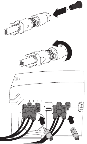
– Plug the sealing plug into the DC connector.
– Tighten the DC connector (torque: 2 Nm).
– Insert the DC connectors with sealing plugs into
the corresponding DC inputs on the inverter.
☑ The DC connectors click audibly into position.
7. Ensure that all DC connectors are securely in place.
+
+
Electrical Connection SMA Solar Technology AG
36 SMC46-60A-IA-IEN120471 Installation Manual
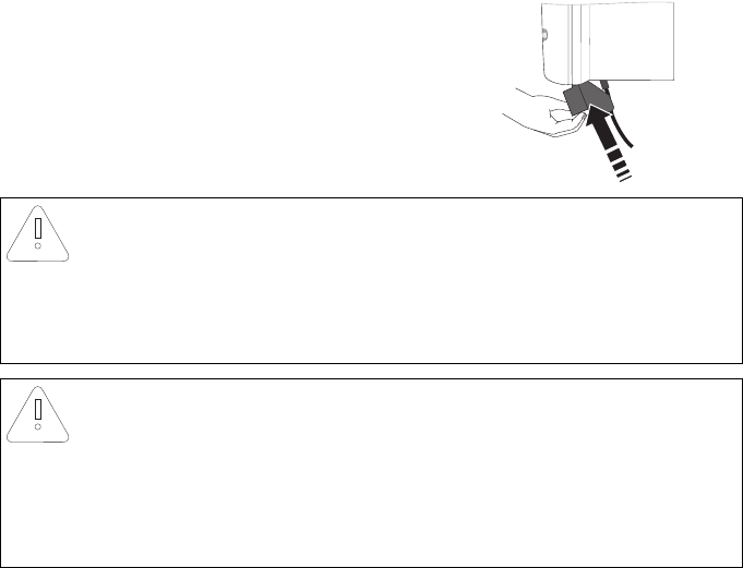
8. Check the Electronic Solar Switch for wear, as
described in section 8.3"Checking the Electronic
Solar Switch (ESS) for Wear" (page64) and attach
it firmly.
☑ The PV array is connected.
You can now commission the inverter as described in section 6"Commissioning" (page48).
The following connections are optional.
NOTICE!
Manipulating the connector in the handle can damage the Electronic Solar
Switch.
The connector inside the handle must remain movable in order to ensure proper contact.
Tightening the screw voids all warranty claims and creates a fire risk.
•Do not tighten the connector screw in the Electronic Solar Switch handle.
NOTICE!
Electronic Solar Switch can be damaged.
If it is not correctly connected, the Electronic Solar Switch can be damaged by high
voltages.
• Plug the handle firmly onto the jack of the Electronic Solar Switch.
• Make sure that the device is securely in place.
SMA Solar Technology AG Electrical Connection
Installation Manual SMC46-60A-IA-IEN120471 37
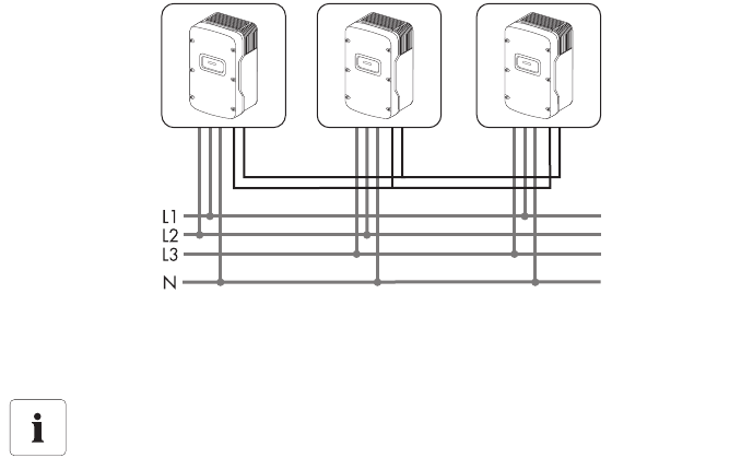
5.5 Connection of the SMA Power Balancer
The Sunny Mini Central is equipped with the SMA Power Balancer as standard. This enables a circuit
connection of 3 Sunny Mini Central inverters to a three‑phase feed‑in system.
Each of the 3 Sunny Mini Central devices in a group must be connected to a different line conductor
of the low‑voltage grid (L1, L2 and L3).
By activating this electronic circuit, you can stipulate how the other 2 Sunny Mini Central inverters are
to react if there is a device fault with the 3rd Sunny Mini Central or there is a line voltage fault in its
line conductor.
The connections for the SMA Power Balancer are galvanically isolated from the rest of the
Sunny Mini Central electronic circuit.
5.5.1 Configuration
If the national standard VDE-AR-N4105-MP or VDE-AR-N4105-HP is set, the SMA Power Balancer is
activated by default and set to operating mode "PowerGuard" in SMC 4600A‑11, SMC 5000A-11
and SMC 6000A-11. All other national standards deactivate the SMA Power Balancer by default in
SMC 4600A-11, SMC 5000A-11 and SMC 6000A-11.
The SMA Power Balancer is always deactivated by default in SMC 4600A, SMC 5000A,
SMC 5000A-IT, SMC 6000A and SMC 6000A-IT, regardless of which national standard is set.
The SMA Power Balancer can only be activated or configured using a communication product.
To change the "PowerBalancer" parameter, you need a personal access code – the so‑called
SMA Grid Guard Code. The application form for the personal access code is available in the
download area at www.SMA.de/en, in the "Certificate" category of the respective inverter.
The configuration options are described below.
Three‑phase grid connection
For further information on this subject, see the Technical Information "Three phase
connection with Sunny Mini Central" in the download area at www.SMA.de/en.
Electrical Connection SMA Solar Technology AG
38 SMC46-60A-IA-IEN120471 Installation Manual
Configuration Options
There are 4 different configuration options for the "PowerBalancer" parameter.
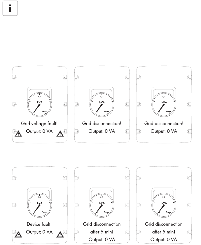
•FaultGuard
This operating mode allows for the implementation of a three‑phase line voltage monitoring,
which also reacts to device faults.
– If 1 of the 3 inverters indicates a line voltage fault and stops feeding in,
the other 2 inverters also disconnect from the power distribution grid immediately.
– If 1 of the 3 inverters indicates a device fault and stops feeding in,
the other 2 inverters also disconnect from the power distribution grid 5 minutes later.
Local connection requirements
Select the respective setting and always observe the local connection requirements and
provisions of your grid operator.
SMA Solar Technology AG Electrical Connection
Installation Manual SMC46-60A-IA-IEN120471 39
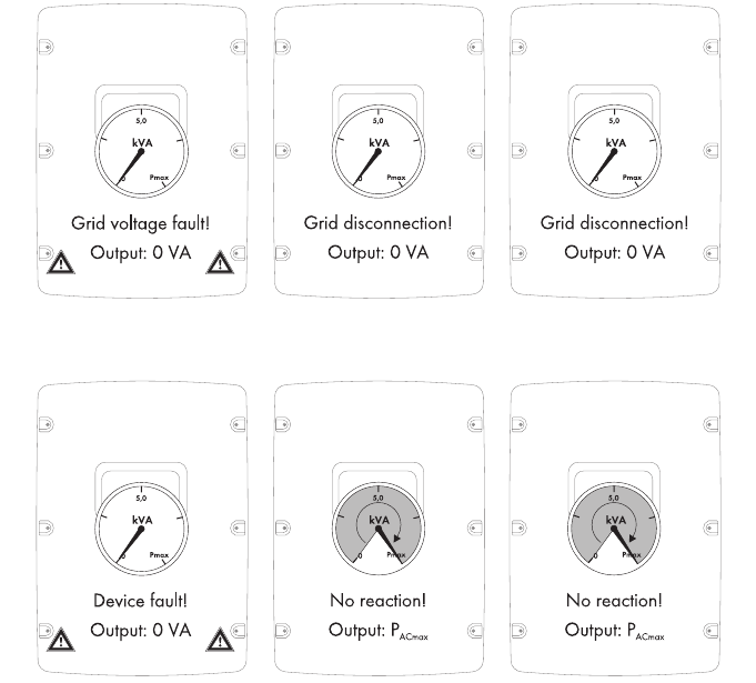
•PhaseGuard
This operating mode allows for the implementation of a three-phase grid voltage monitoring.
– If 1 of the 3 inverters indicates a line voltage fault and stops feeding in,
the other 2 inverters also disconnect from the power distribution grid automatically.
– If 1 of the 3 inverters indicates a device fault and stops feeding in,
the other 2 inverters are not affected and continue to feed in at full power.
Electrical Connection SMA Solar Technology AG
40 SMC46-60A-IA-IEN120471 Installation Manual
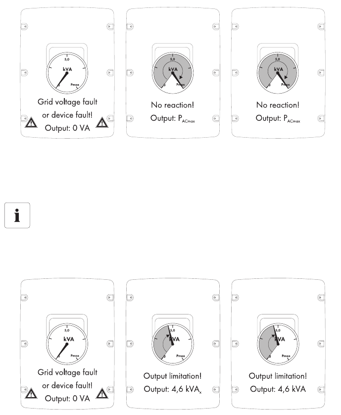
•Off
The SMA Power Balancer is deactivated (default setting).
– In the event of a device fault or line voltage fault at an inverter, only this inverter is
disconnected from the power distribution grid and the other two inverters continue to run at
an undiminished power level.
•PowerGuard
This setting can be selected if the entire PV plant only consists of three 3 Sunny Mini Central
inverters and in the event of a malfunction, the unbalanced load should be limited to 4.6 kVA
over a 10‑minute average.
– If 1 of the 3 inverters indicates a line voltage fault or device fault and stops feeding in,
the other 2 inverters automatically limit their power to 4.6 kVA over a 10-minute average.
Deviating unbalanced load limit for Italy
The unbalanced load for inverters set to the Italian national standard DK 5940 is limited
to 6 kVA over a 10‑minute average.
SMA Solar Technology AG Electrical Connection
Installation Manual SMC46-60A-IA-IEN120471 41
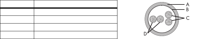
5.5.2 Cabling
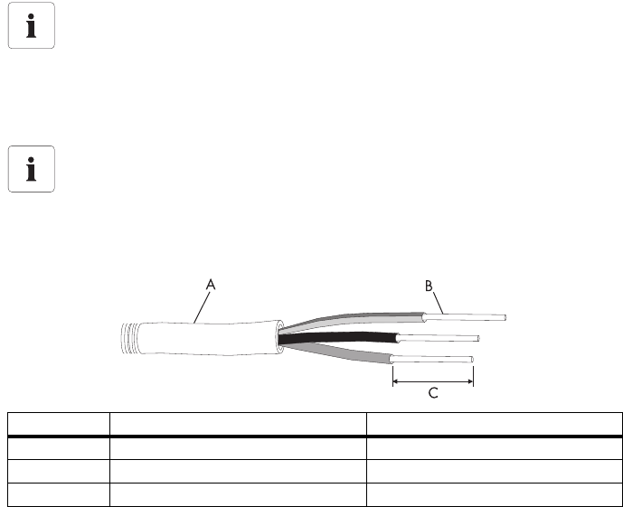
Cable Requirements
For cabling the SMA Power Balancer, use a "LiYCY" cable, structured as shown here:
• Indoor: LiYCY 2 x 2 x 0.25
• Outdoor: Li‑2YCYv 2 x 2 x 0.25
Position Designation
AFlexible insulation
BShielding
CTwisted pair 2 (2 x 0.25 mm²)
DTwisted pair 1 (2 x 0.25 mm²)
Electrical Connection SMA Solar Technology AG
42 SMC46-60A-IA-IEN120471 Installation Manual
Overview of the Connection Area
Object Description
AScrew terminals for the wire bridge
BScrew terminals for connecting the cables
CJumper slot
DFlat male tab for grounding the cable shield
ESilicone tube/cable route
FCable glands
SMA Solar Technology AG Electrical Connection
Installation Manual SMC46-60A-IA-IEN120471 43
Procedure
1. Open the inverter as described in section 7.2"Opening the Inverter" (page55).
2. Insert the cable into each inverter.
Use 1 of the 2 enclosure openings (F) on the right‑hand side.
3. Draw the cable along the cable route (E) as far as the terminal block (B).
4. Ground the cable shield in each inverter at the PE terminal (D).
5. Sheath the positive and negative cable conductors in each inverter with bootlace ferrules.
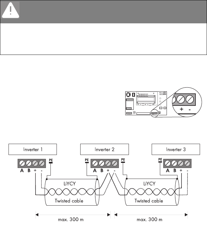
6. Connect the positive and negative pole to the
corresponding screw terminals.
7. In order to connect the 3 inverters together, connect the positive and negative conductors from
the 2 other inverters to the terminal block of the middle inverter.
The cable length between 2 inverters may not exceed 300 m.
DANGER!
Danger to life through high voltage if there is a fault with the
SMA Power Balancer cable.
• Sheath the positive and negative cable conductors in each inverter using the
enclosed silicone tube.
• Cut the silicone tube to the required length.
• The silicone tube must completely cover the cable inside the inverter enclosure.
Electrical Connection SMA Solar Technology AG
44 SMC46-60A-IA-IEN120471 Installation Manual
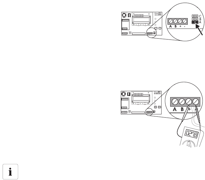
8. Only in the middle inverter (the one with 2 wires
for each terminal), insert one of the provided
jumpers into the lowest of the slots as depicted on
the right.
Do not plug the jumpers in the bottom slot of the
2 other inverters.
or
Bridge the "A" and "B" screw terminals on the
middle inverter with a wire bridge.
Do not bridge the "A" and "B" screw terminals in
the 2 other inverters.
9. Measure the resistance between the terminal
block's positive and negative poles in the middle
inverter.
☑ If the resistance is approximately 27.8 k Ω
(±370 Ω ), the SMA Power Balancer has been
connected correctly. Otherwise, check the
cabling.
10. Close all inverters as described in section 7.3"Closing the Inverter" (page58).
Connection with a Sunny Mini Central 9000TL, 10000TL or 11000TL
In order to be able to connect the SMA Power Balancer with a Sunny Mini Central 9000TL,
10000TL or 11000TL, the Sunny Mini Central 4600A, 5000A or 6000A must be
equipped with a special plug. 3 inverters are then connected together with a special
connection cable.
You can order the plug and the connection cable from SMA Solar Technology AG or your
specialty retailer. Section 12"Accessories" (page85) contains a list of the order numbers.
SMA Solar Technology AG Electrical Connection
Installation Manual SMC46-60A-IA-IEN120471 45
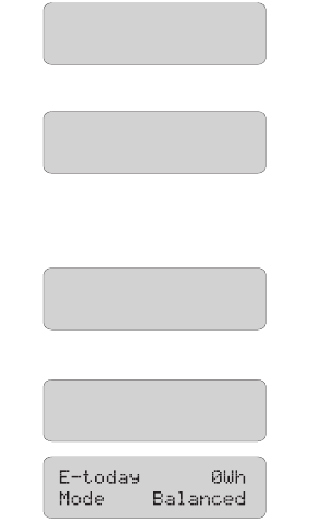
5.5.3 Testing the Functioning
To test whether the SMA Power Balancer operates correctly, proceed as follows.
1. Select the "PhaseGuard" setting of the "PowerBalancer" parameter for all 3 inverters.
2. Check whether all inverters in the group are feeding the power distribution grid normally.
☑ If the green LED lights up steadily or if the
display message pictured on the right appears,
proceed to step 3.
or
☑ If all inverters in this group show the display
message pictured on the right: Check the
installation of the SMA Power Balancer and
contact the SMA Service Line, if necessary.
3. Switch off the miniature circuit‑breaker for
1 of the 3 inverters.
• The inverter with a deactivated miniature
circuit‑breaker then indicates a line voltage fault
with the display message pictured on the right
("Bfr" and "Srr" are irrelevant).
• The other 2 inverters then also disconnect
themselves from the power distribution grid with the
display message pictured on the right.
• Both inverters subsequently switch to "Balanced"
mode.
☑ If the inverters react as described above, the
functionality test has been completed
successfully. Otherwise, check the
configuration.
4. If applicable, reset the "PowerBalancer" parameter to the desired setting in all inverters.
5. Switch on the miniature circuit‑breaker again.
☑The functionality test has been completed.
E-today 0Wh
Mode MPP
Disturbance
PowerBalance
Disturbance
Vac-Bfr
Disturbance
PowerBalance

Electrical Connection SMA Solar Technology AG
46 SMC46-60A-IA-IEN120471 Installation Manual
5.6 Communication
The inverter is equipped with a slot for communication interfaces in order to communicate with special
data loggers (e.g., Sunny WebBox) or a PC with corresponding software (e.g., Sunny Data Control
or Sunny Explorer).
Refer to the respective communication interface manual for a detailed wiring diagram and an
installation description for the interface.
The inverter's active power can be limited or its displacement power factor can be set externally using
the Power Reducer Box from SMA Solar Technology AG. Detailed information on the
Power Reducer Box is available in its Technical Description at www.SMA.de/en.
5.7 Setting the Grid and Country Parameters
A detailed description of the operating parameters for the inverter is available in the download area
at www.SMA.de/en in the category "Technical Description" of the respective inverter.
5.7.1 Setting the Installation Country
Using the "Default" parameter, you can set the installation country and/or the grid connection
standard valid for the country via a communication product (e.g., Sunny WebBox) or a PC with
corresponding software (e.g., Sunny Data Control or Sunny Explorer). This, however, is only required
if the inverter was originally ordered for another country. You can see the standard to which the
inverter was set upon delivery on the type label and on the included supplementary sheet with the
default settings.
Changing grid‑relevant and country parameters
To change grid‑relevant parameters, you need a personal access code – the so‑called
SMA Grid Guard Code. The application form for the personal access code is available in
the download area at www.SMA.de/en, in the "Certificate" category of the respective
inverter.
Ensure that you discuss the changes to these parameters with your grid operator.
SMA Solar Technology AG Electrical Connection
Installation Manual SMC46-60A-IA-IEN120471 47
5.7.2 Setting Stand‑alone Grid Operation
To operate the inverter in a stand‑alone grid system with Sunny Island, you must set the "Default"
parameter to stand‑alone grid ("OFF-Grid") operation.
You have several possibilities to set the inverter to stand‑alone grid operation:
• Setting via Sunny WebBox
or
• Setting via Sunny Data Control or Sunny Explorer
5.7.3 Additional Country Parameters
The deactivation criteria (voltage, frequency, impedance) are specified via country parameters as
with all Sunny Mini Central inverters.
The additional default country parameter "MVtgDirective" expands the deactivation limits of the
inverter for voltage and frequency to a maximum/minimum. This country setting may only be selected
if the PV plant or the inverter is operated with external three‑phase decoupling protection, which will
automatically disconnect the inverter from the power distribution grid if non‑permissible voltage and
frequency values occur. Device protection is still guaranteed.
DANGER!
Danger to life due to high voltages in the event of outage of the power
distribution grid.
If you set the inverter to stand‑alone grid operation, it does not fulfill any country-specific
standards and guidelines. If there is a power distribution grid outage, there is consequently
a danger of feedback.
•Never operate the inverter directly on the power distribution grid when set to
stand‑alone grid operation.
Requirement for the setting
Set the installation country as described in section 5.7.1"Setting the Installation Country"
(page46) before setting the country parameter described here.
DANGER!
Risk of lethal electric shock if external decoupling protection is missing.
At country setting "MVtgDirective", the inverter may only be operated with an external
three‑phase decoupling protection device which complies with the country‑specific
requirements.
Without such external decoupling protection, the inverter will not disconnect from the
power distribution grid when the standard requirement is exceeded.
• Install external three‑phase decoupling protection.
Commissioning SMA Solar Technology AG
48 SMC46-60A-IA-IEN120471 Installation Manual
6 Commissioning
6.1 Commissioning the Inverter
1. Check the following requirements before commissioning:
– The inverter is securely in place.
– AC cables are correctly connected (power distribution grid).
– DC cables (PV strings) are completely connected.
– Unused DC inputs are closed using the corresponding DC connectors and sealing plugs.
– The enclosure lid is securely screwed in place.
– The Electronic Solar Switch is securely plugged.
– The miniature circuit‑breaker is correctly laid out.
2. Switch on the miniature circuit‑breaker.
☑ All 3 LEDs are lit or flashing: the startup phase is starting.
☑ Green LED is lit: commissioning was successful.
or
☑ Green LED flashes in case of insufficient irradiation: grid connection conditions have not yet
been reached. Wait for sufficient irradiation.
or
☑ The red or yellow LED is lit or flashing: there is a fault. Proceed to step 3.
3. Read section 9"Troubleshooting" (page65) and if necessary, eliminate the error or fault.
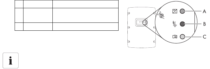
AGreen LED operation
BRed LED ground fault or varistor
defective
CYellow LED Fault
Self‑test in accordance with DK 5940, Ed. 2.2 during initial start-up
(applies to Italy only)
The Italian DK 5940 standard requires that an inverter must only be connected to the
power distribution grid if the disconnection times for overvoltage, undervoltage,
minimum frequency and maximum frequency have been checked.
Start the self‑test as described in section 6.3"Self‑test in Accordance with DK 5940, Ed.
2.2 (Applies to Italy Only)" (page50). The test takes approx. 8 minutes.
SMA Solar Technology AG Commissioning
Installation Manual SMC46-60A-IA-IEN120471 49
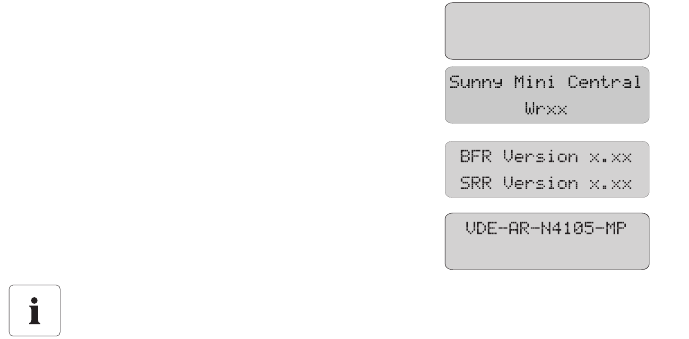
6.2 Display Messages During the Startup Phase
• After commissioning, the inverter displays the
device type in the startup phase.
• After 5 seconds or when you tap again on the
enclosure lid, the firmware version of the internal
processors is displayed by the inverter.
• After a further 5 seconds or when you tap again,
the configured country standard is displayed by the
inverter (example: "VDE-AR-N4105-MP").
Showing the display messages again (valid as of firmware version 2.15)
If you want to view the display messages of the startup phase again while in normal
operation, tap the enclosure lid twice in quick succession.
SMC xxx
Wrxxx

Commissioning SMA Solar Technology AG
50 SMC46-60A-IA-IEN120471 Installation Manual
6.3 Self‑test in Accordance with DK 5940, Ed. 2.2
(Applies to Italy Only)
6.3.1 Starting the Self‑Test by Tapping
You can start testing the disconnection times by tapping on the enclosure lid. A prerequisite here is
that the country configuration of the inverter has been set to Italy (IT/DK5940) or "trimmed".
Proceed as follows for checking the disconnection times:
1. Connect the PV array to the inverter. The inverter can only initialize if the PV array produces
enough power. It is therefore not possible to test the disconnection times at night.
2. Connect the inverter on the AC side. For this, you have to establish the AC connection
(AC plug or direct connection) and/or switch on the miniature circuit‑breaker.
3. The inverter is now in the initialization phase, i.e. all 3 LEDs are lit at the same time.
Start the self‑test immediately after all 3 LEDs have gone out by tapping on the display of the
inverter.
4. The question of whether you would like to start the
test sequence appears in the display. Tap on the
display again within 30 seconds to confirm the
question.
Once you have started the test sequence, the inverter checks the disconnection times for overvoltage,
undervoltage, maximum frequency and minimum frequency one after the other. During the tests, the
inverter shows the values in the display which are described in section 6.3.2"Completion of the
Self‑test" (page51).
SMA Solar Technology AG Commissioning
Installation Manual SMC46-60A-IA-IEN120471 51
6.3.2 Completion of the Self‑test
Note the values which are displayed during the self‑test. These values must be entered into a test
report. The test results of the individual tests are displayed 3 times, one after the other.
The respective display message is displayed for 10 seconds.
The self‑test changes the upper and lower disconnection thresholds for each protective function on a
linear basis with a modification of 0.05 Hz/s and 0.05 Vn/s for the frequency and voltage
monitoring. As soon as the actual measured value is outside the permitted range
(altered disconnection threshold), the inverter disconnects itself from the power distribution grid. In this
way, the inverter determines the reaction time and checks itself.
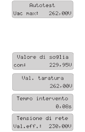
Overvoltage Test
The inverter begins with the overvoltage test. During the
test sequence, the voltage limit applied is shown in the
display of the inverter.
The voltage limit is reduced successively until the
disconnection threshold is reached and the inverter disconnects from the power distribution grid.
Once the inverter has disconnected from the power distribution grid, the display successively shows
the following values one after the other:
•Disconnection value,
•Calibration value,
•Reaction time,
• Current line voltage.
Commissioning SMA Solar Technology AG
52 SMC46-60A-IA-IEN120471 Installation Manual
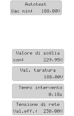
Undervoltage Test
After the overvoltage test, the inverter performs the
undervoltage test. During the test sequence, the current
calibration value of the voltage limit applied is shown in
the display of the inverter.
The voltage limit is increased successively until the disconnection threshold is reached and the inverter
disconnects from the power distribution grid.
Once the inverter has disconnected from the power distribution grid, the display successively shows
the following values one after the other:
•Disconnection value,
•Calibration value,
•Reaction time,
• Current line voltage.
SMA Solar Technology AG Commissioning
Installation Manual SMC46-60A-IA-IEN120471 53
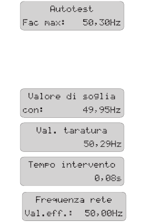
Maximum Frequency
In a third step, the inverter tests the maximum frequency.
During the test sequence, the frequency limit applied is
shown in the display of the inverter.
The frequency limit is reduced successively until the
disconnection threshold is reached and the inverter disconnects from the power distribution grid.
Once the inverter has disconnected from the power distribution grid, the display successively shows
the following values one after the other:
•Disconnection value,
•Calibration value,
•Reaction time,
• Current power frequency.
Commissioning SMA Solar Technology AG
54 SMC46-60A-IA-IEN120471 Installation Manual
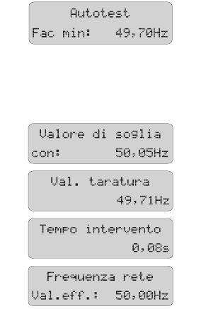
Minimum Frequency
In the last step, the inverter tests the minimum frequency.
During the test sequence, the frequency limit applied is
shown in the display of the inverter.
The frequency limit is increased successively until the
disconnection threshold is reached and the inverter disconnects from the power distribution grid.
Once the inverter has disconnected from the power distribution grid, the display successively shows
the following values one after the other:
•Disconnection value,
•Calibration value,
•Reaction time,
• Current power frequency.
Once the inverter has carried out the 4 tests, it switches to "MPP‑Operation (MPP)" mode. The original
calibration values are then reset and the inverter automatically connects to the power distribution grid.
If you would like to carry out the test again, you must disconnect the inverter, i.e. disconnect it on the
AC and DC sides and then later recommission it. You can then restart the self‑test as described in
section 6.3.1"Starting the Self‑Test by Tapping" (page50). The inverter starts again the test sequence
as described in section 6.3.2"Completion of the Self‑test" (page51).
SMA Solar Technology AG Opening and Closing
Installation Manual SMC46-60A-IA-IEN120471 55
7 Opening and Closing
7.1 Safety
7.2 Opening the Inverter
1. Disconnect the miniature circuit‑breaker and secure against reconnection.
2. Pull the Electronic Solar Switch downward, slightly
towards the wall.
3. Use a current probe to ensure that no current is
present in any of the DC cables.
☑ If current is present, check the installation.
DANGER!
Risk of lethal electric shock.
Before opening the inverter, observe the following:
• Ensure that no voltage is present on the AC side.
• Ensure that neither voltage nor current is present on the DC side.
NOTICE!
Electrostatic discharges can damage the inverter.
The internal component parts of the inverter can be irreparably damaged by electrostatic
discharge.
• Ground yourself before touching a component part.
Opening and Closing SMA Solar Technology AG
56 SMC46-60A-IA-IEN120471 Installation Manual
4. Unlock and disconnect all DC connectors. To do
this, insert the screwdriver into one of the side slots
(blade width: 3.5 mm) and pull the DC connectors
straight down. Do not pull on the cable while doing
this.
☑ All DC connectors are disconnected from the
inverter. The inverter is entirely disconnected
from the PV array.
5. Ensure that no voltage is present at the DC plugs on
the inverter.
☑If voltage is present, check the installation.
DANGER!
Danger to life due to high voltages in the inverter.
The capacitors in the inverter require 5 minutes to discharge.
• Wait 5 minutes before opening the inverter.
SMA Solar Technology AG Opening and Closing
Installation Manual SMC46-60A-IA-IEN120471 57
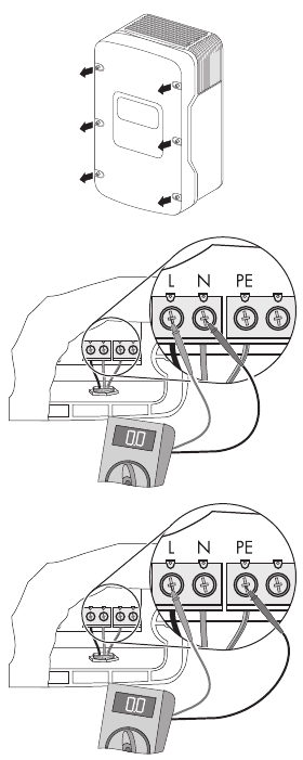
6. Loosen all 6 screws of the enclosure lid and remove
the enclosure lid from the front.
7. Verify the absence of voltage L with respect to
N at the AC terminal with an appropriate
measuring device.
☑If voltage is present, check the installation.
8. Verify the absence of voltage L with respect to PE at
the AC terminal with an appropriate measuring
device.
☑If voltage is present, check the installation.
☑ The inverter is open and no voltage is present.
Opening and Closing SMA Solar Technology AG
58 SMC46-60A-IA-IEN120471 Installation Manual
7.3 Closing the Inverter
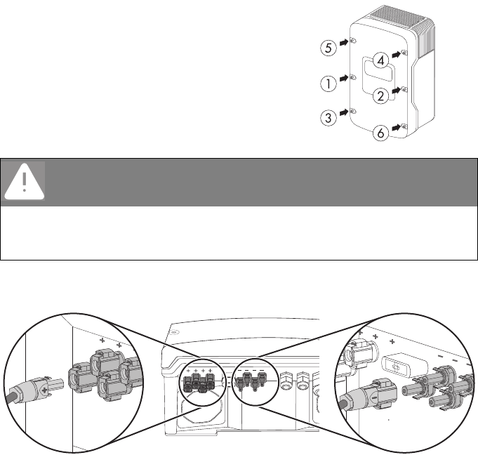
1. Secure the enclosure lid with the 6 screws and the
corresponding conical spring washers.
Tighten the screws with 6 Nm torque in the order
shown in the figure on the right. The toothing of the
conical spring washers must point toward the
enclosure lid.
The scope of delivery of the inverter includes
another spare screw and conical spring washer.
2. Check the DC connectors for correct polarity and connect them.
To unlock the DC connectors, see section 7.2"Opening the Inverter" (page55).
3. Close all the DC inputs that are not needed as described in section 5.4.4"Connecting the PV
Array (DC)" (page33) to seal the inverter.
DANGER!
Danger to life due to enclosure lid carrying voltage.
The grounding of the enclosure lid is ensured by the conical spring washers.
• Attach the conical spring washers for all 6 screws with the toothing facing toward the
enclosure lid.
SMA Solar Technology AG Opening and Closing
Installation Manual SMC46-60A-IA-IEN120471 59
4. Check the Electronic Solar Switch for wear, as
described in section 8.3 and attach it firmly.
5. Switch on the miniature circuit‑breaker.
6. Check whether the display and the LEDs indicate a
normal operating state (see section
6"Commissioning" (page48)).
☑ The inverter is now closed and in operation.
NOTICE!
Manipulating the connector in the handle can damage the
Electronic Solar Switch.
The connector inside the handle must remain movable in order to ensure proper contact.
Tightening the screw voids all warranty claims and creates a fire risk.
• Do not tighten the connector screw in the Electronic Solar Switch handle.
NOTICE!
Electronic Solar Switch can be damaged.
If it is not correctly connected, the Electronic Solar Switch can be damaged by high
voltages.
• Plug the handle firmly onto the jack of the Electronic Solar Switch.
• Make sure that the device is securely in place.
Maintenance and Cleaning SMA Solar Technology AG
60 SMC46-60A-IA-IEN120471 Installation Manual
8 Maintenance and Cleaning
8.1 Cleaning the Inverter
If the inverter is dirty and the visibility of the operating data and operating states of the inverter is only
limited, clean the enclosure lid, the display and the LEDs with a damp cloth. Do not use any corrosive
substances (e.g., solvents or abrasives) for cleaning.
8.2 Checking Heat Dissipation
8.2.1 Cleaning the Fans
If the fan guards are soiled with loose dust, they can be cleaned using a vacuum cleaner.
If you do not achieve satisfactory results with a vacuum cleaner, dismantle the fans for cleaning.
Procedure
1. Disconnect the inverter from both the DC and AC sides as described in section 7.2"Opening
the Inverter" (page55).
2. Wait for the fans to stop rotating.
Cleaning the Fan Guards
3. Removing the fan guards:
– Press both latches on the right edge of the fan
guard to the right using a screwdriver and
loosen from the retainer.
– Carefully remove the fan guard.
4. Clean the fan guards with a soft brush, a paint brush, a cloth or compressed air.
SMA Solar Technology AG Maintenance and Cleaning
Installation Manual SMC46-60A-IA-IEN120471 61
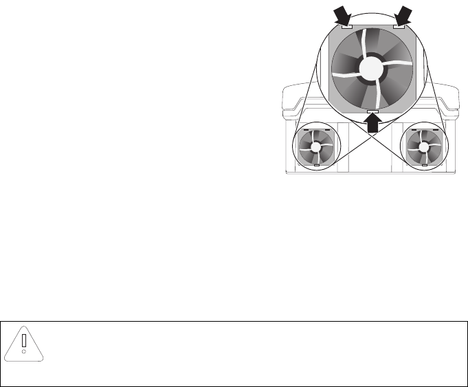
Cleaning the Fans
5. Press the front latches backward and the rear latch
forward.
6. Remove the fan by pulling it slowly and carefully downward.
7. Unlock and remove the plug.
The fan cables are long enough that you can lift the fans far enough out to disconnect the
internal plug in the inverter.
8. Remove the fan.
9. Clean the fan with a soft brush, a paint brush, or a damp cloth.
10. After cleaning, reassemble everything in reverse order.
☑ The fans are cleaned.
11. Check the functioning of the fans as described in the following section.
NOTICE!
Damage to the fan through use of compressed air.
• Do not use compressed air to clean the fan. This can damage the fan.
Maintenance and Cleaning SMA Solar Technology AG
62 SMC46-60A-IA-IEN120471 Installation Manual
8.2.2 Checking the Fans
You can check that the fans are working in 2 ways:
• Set the "Fan‑Test" parameter to "1" in the installer mode using Sunny Data Control,
Sunny Explorer or Sunny WebBox.
or
• Plug the provided jumper into the system control board.
Setting Parameters
1. Request the installer password from the SMA Service Line (contact: see Page 86).
2. Set the "Fan‑Test" parameter to "1" in the installer mode.
3. Check the fans' air flow.
The inverter takes cooling air in from underneath and then blows it back out on the upper sides.
Listen for any unusual noise, which could indicate incorrect installation or that the fans are faulty.
4. After checking the fans, set the "Fan‑Test" parameter back to "0".
☑ The test of the fans has been completed.
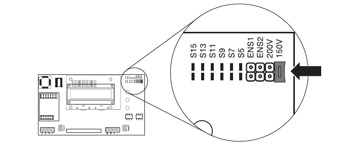
Plugging the Jumper
The inverter recognizes the jumper only after the system has been restarted
(i.e. all LEDs must have gone out before a restart).
1. Open the inverter as described in section 7.2"Opening the Inverter" (page55).
2. Plug the provided jumper in the slot on the system control board as shown below.
3. Close the inverter as described in section 7.3"Closing the Inverter" (page58).
SMA Solar Technology AG Maintenance and Cleaning
Installation Manual SMC46-60A-IA-IEN120471 63
4. Check the fans' air flow.
The inverter takes cooling air in from underneath and then blows it back out on the upper sides.
Listen for any unusual noise, which could indicate incorrect installation or that the fans are faulty.
5. After checking the fans, remove the jumper. Open and close the inverter as described in section
7"Opening and Closing" (page55).
☑ The test of the fans has been completed.
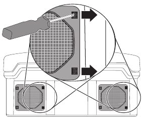
8.2.3 Cleaning the Fan Guards
The inverter takes cooling air in from underneath via the fans and blows it out again through the fan
guards on the upper sides. Clean the fan guards if they are dirty.
Procedure
1. Remove the fan guards.
Insert your finger above in the space between the
fan guard and the enclosure and remove the fan
guard to the side.
2. Clean the fan guards with a soft brush, a paint
brush, or compressed air.
3. Re‑attach the fan guards to the inverter.
The fan guards must be attached according to the
inside inscription ("links/left" and "rechts/right").
NOTICE!
Risk of damage to the inverter through intrusion of insects.
• The fan guards must not be removed permanently, because otherwise the device is
not protected against insects entering.
Maintenance and Cleaning SMA Solar Technology AG
64 SMC46-60A-IA-IEN120471 Installation Manual
8.3 Checking the Electronic Solar Switch (ESS) for Wear
Check the Electronic Solar Switch for wear before plugging it in. Depending on the shape of the
Electronic Solar Switch, you can estimate the wear on either the metal tongues (shape A) or on the
plastic (shape B).
Result Measure
☑ The metal tongues in the Electronic Solar
Switch are undamaged and not discolored
(A).
or
☑ The plastic in the Electronic Solar Switch is
undamaged (B).
1. Securely attach the Electronic Solar Switch
handle.
2. Commission the inverter as described in
section 6"Commissioning" (page48).
☑ The metal tongues in the Electronic Solar
Switch have a brown discoloration or are
burned through (A).
or
☑The plastic in the Electronic Solar Switch
shows thermal deformation (B).
The Electronic Solar Switch can no longer reliably
disconnect the DC side.
1. Replace the Electronic Solar Switch handle
before attaching it again (for the order
number, see section 12"Accessories"
(page85)).
2. Recommission the inverter as described in
section 6"Commissioning" (page48).
A
B
A
B
SMA Solar Technology AG Troubleshooting
Installation Manual SMC46-60A-IA-IEN120471 65
9 Troubleshooting
If the inverter displays other blink codes or error messages than those described below,
contact the SMA Service Line.
You will also find a description of display messages during operation, status messages and
measurement channels in the user manual provided.
Do not perform any repairs that are not described here and take advantage of the 24‑hour
replacement service (inverter ready for shipping and handed over to a freight‑forwarding company
within 24 hours) and the SMA Solar Technology AG repair service instead.
9.1 Blink Codes
Green Red Yellow Status
flashing flashing flashing OK (startup phase)
is permanently lit is not lit is not lit OK (feed‑in operation)
is permanently lit is not lit ground fault or varistor
defective
is permanently lit OK (initialization)
is flashing quickly
(3 x per second)
is not lit is not lit OK (stop)
is permanently lit is not lit ground fault or varistor
defective
is flashing slowly
(1 x per second)
is not lit is not lit OK (waiting, grid
monitoring)
goes out briefly
(approx. 1 x per
second)
is permanently lit is not lit ground fault or varistor
defective
is not lit is not lit OK (derating)
is not lit is not lit is not lit OK (nighttime
deactivation or
Electronic Solar Switch
not connected)
is lit/flashing fault
is permanently lit is not lit ground fault or varistor
defective
is lit/flashing ground fault or varistor
defective and fault
Troubleshooting SMA Solar Technology AG
66 SMC46-60A-IA-IEN120471 Installation Manual
9.2 Error Messages
When a fault occurs, the inverter generates a message which depends on the operating mode and
the type of the fault detected.
Message Description and corrective measure
!PV‑Overvoltage!
!DISCONNECT DC!
Overvoltage at DC input.
Overvoltage can destroy the inverter.
Corrective measures
Disconnect the inverter from the power distribution grid immediately.
1. Disconnect the miniature circuit‑breaker.
2. Remove the Electronic Solar Switch.
3. Remove all DC connectors.
4. Check the DC voltage:
– If the DC voltage is above the maximum input voltage, check the
PV plant design or contact the PV array installer.
– If the DC voltage is below the maximum input voltage,
reconnect the inverter to the PV array as described in section
5.4.4"Connecting the PV Array (DC)" (page33).
If the message occurs again, disconnect the inverter again and contact
the SMA Service Line (see section 13"Contact" (page86)).
ACVtgRPro The 10‑minute average line voltage is no longer within the permissible
range. This can be caused by either of the following:
• The line voltage at the terminal is too high.
• The grid impedance at the terminal is too high.
The inverter disconnects to assure compliance with the power quality of
the power distribution grid.
Corrective measures
Check the line voltage at the terminal of the inverter:
• If, due to the local grid conditions, the line voltage is 253 V or
more, ask the grid operator whether the voltage at the feed‑in point
can be adjusted, or whether they would agree to an alteration of
the limiting value of parameter "ACVtgRPro" for power quality
monitoring.
• If the line voltage is continually within the tolerance range and this
error message is still displayed, contact the SMA Service Line.
Bfr‑Srr Internal measurement comparison fault or hardware defect.
Corrective measures
• If this fault occurs frequently, contact the SMA Service Line.
SMA Solar Technology AG Troubleshooting
Installation Manual SMC46-60A-IA-IEN120471 67
Derating The "Derating" operating state is a normal operating state which may
occur occasionally and can have several causes.
Once the inverter enters the "Derating" operating state, it will display the
"Derating" warning until the next total disconnection of the device
(at the end of the day).
Corrective measures
• Check the heat dissipation as described in section 8.2"Checking
Heat Dissipation" (page60).
EEPROM Transition fault while data is being written or read from EEPROM.
The data is not relevant for safe operation.
• This fault has no effect on the performance of the inverter.
EEPROM dBh EEPROM data is defective. The inverter has switched itself off because the
loss of data has disabled important functions of the inverter.
Corrective measures
• Contact the SMA Service Line.
EeRestore One of the duplicate records in the EEPROM is defective and has been
reconstructed without loss of data.
• This error message only serves to inform you and has no effect on
the performance of the inverter.
Fac‑Bfr
Fac‑Srr
FacFast
The power frequency is no longer within the permissible range
("Bfr"/"Srr"/"Fast" is an internal message that has no meaning for the
user). The inverter disconnects itself from the power distribution grid for
safety reasons.
Corrective measures
• Check the grid connection and contact the grid operator if
necessary.
• If the power frequency is within the tolerable range, but "Fac‑Bfr",
"Fac‑Srr" or "FacFast" faults are still displayed, contact the
SMA Service Line.
K1‑Close
K1‑Open
Error during relay test.
Corrective measures
• If this fault frequently occurs or occurs several times consecutively,
contact the SMA Service Line.
Imax Overcurrent on the AC side. This message is displayed if the current in the
AC grid is higher than specified.
Corrective measures
• Check the plant design and grid conditions.
Message Description and corrective measure
Troubleshooting SMA Solar Technology AG
68 SMC46-60A-IA-IEN120471 Installation Manual
MSD-Fac Internal measurement comparison fault or hardware defect.
Corrective measures
• If this fault occurs frequently, contact the SMA Service Line.
MSD‑Vac Internal measurement comparison fault or hardware defect.
Corrective measures
• If this fault occurs frequently, contact the SMA Service Line.
MSD‑Timeout Internal measurement comparison fault or hardware defect.
Corrective measures
• If this fault occurs frequently, contact the SMA Service Line.
OFFSET The "OFFSET" operating state is a normal operating state that occurs prior
to grid monitoring. If "OFFSET" is displayed as an error, there is a fault in
the data logging.
Corrective measures
• If this fault occurs frequently, contact the SMA Service Line.
PowerBalance The Sunny Mini Central is part of a three‑phase system with 2 further
Sunny Mini Central inverters equipped with the SMA Power Balancer for
preventing unbalanced loads. The operating parameter "PowerBalancer"
is set to "PhaseGuard" or "FaultGuard".
Corrective measures
• For detailed descriptions of the operation modes "PhaseGuard"
and "FaultGuard", refer to section 5.5"Connection of the SMA
Power Balancer" (page37).
Riso The electrical insulation between the PV plant and ground is defective.
The resistance between the DC plus and/or DC minus connection and
ground is outside the defined limit range.
Corrective measures
• Check the insulation of the PV plant.
• Check the PV plant for ground faults as described in section
9.3.1"Checking the PV Array for Ground Faults" (page71).
ROM The inverter's firmware is faulty.
Corrective measures
• If this fault occurs frequently, contact the SMA Service Line.
Trafo‑Temp‑F Temperatures in the transformer have exceeded the acceptable limit. The
inverter stops feeding the grid until the temperature lies within the
acceptable range.
Corrective measures
• If this fault occurs frequently, check the heat dissipation.
Message Description and corrective measure
SMA Solar Technology AG Troubleshooting
Installation Manual SMC46-60A-IA-IEN120471 69
Trafo‑Temp‑W If the transformer reaches an inadmissibly high temperature, the inverter
stops feeding the grid until the transformer has reached an admissible
temperature and the plant can begin feeding the grid again.
The "Trafo‑Temp‑W" warning is displayed until the device is completely
disconnected.
Corrective measures
• Check the heat dissipation of the inverter.
Shutdown Temporary inverter fault.
Corrective measures
• Contact the SMA Service Line.
Vac‑Bfr
Vac‑Srr
The line voltage is no longer within the permissible range ("Bfr" or "Srr" is
an internal message of no relevance for the user). This fault can be
caused by any of the following conditions:
• Power distribution grid disconnected
(miniature circuit‑breaker, fuse)
•AC cable is broken
• AC cable is highly resistive
The inverter disconnects itself from the power distribution grid for safety
reasons.
Corrective measures
• Check the line voltage and connection on the inverter.
• If the line voltage lies outside the acceptable range because of
local grid conditions, ask the grid operator if the voltages can be
adjusted at the feed‑in point or if they agree to changes in the
values of the monitored operating limits
(operating parameters: Vac‑Min and Vac‑Max).
• If the line voltage lies within the tolerance range, yet "Vac‑Bfr" or
"Vac‑Srr" faults are still displayed, contact the SMA Service Line.
Message Description and corrective measure
Troubleshooting SMA Solar Technology AG
70 SMC46-60A-IA-IEN120471 Installation Manual
9.3 Red LED is Permanently Lit
If the red status display LED is permanently lit during operation, there is a ground fault in the PV array
or at least one of the varistors for overvoltage protection is defective.
Procedure
1. Check for ground faults in the PV array as described in section 9.3.1"Checking the PV Array
for Ground Faults" (page71).
2. If the red LED continues to be lit, check the varistors as described in section 9.3.2"Checking the
Function of the Varistors" (page73).
UpvMax Overvoltage at DC input. The inverter may be damaged.
Corrective measures
Disconnect the inverter from the power distribution grid immediately.
1. Disconnect the miniature circuit‑breaker.
2. Remove the Electronic Solar Switch.
3. Remove all DC connectors.
4. Check the DC voltage:
– If the DC voltage is above the maximum input voltage, check the
PV plant design or contact the PV array installer.
– If the DC voltage is below the maximum input voltage,
reconnect the inverter to the PV array as described in section
5.4.4"Connecting the PV Array (DC)" (page33).
If the message occurs again, disconnect the inverter again and contact
the SMA Service Line (see section 13"Contact" (page86)).
Watchdog
Watchdog Srr
Internal program run fault.
Corrective measures
• If this fault occurs frequently, contact the SMA Service Line.
Message Description and corrective measure
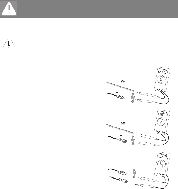
SMA Solar Technology AG Troubleshooting
Installation Manual SMC46-60A-IA-IEN120471 71
9.3.1 Checking the PV Array for Ground Faults
1. Disconnect the inverter from both the DC and AC sides as described in section 7.2"Opening
the Inverter" (page55).
2. Measure the voltages between the positive pole of
each string and the ground potential (PE).
3. Measure the voltages between the negative pole of
each string and the ground potential (PE).
4. Measure the voltages between the positive and
negative poles of each string.
☑ A ground fault exists if the measured voltages are stable and the sum of the voltages from
the positive pole to the ground potential and from the negative pole to the ground potential
of a string is approximately equal to the voltage between the positive and negative poles.
DANGER!
Risk of lethal electric shock.
• Only touch the cables of the PV array on their insulation.
• Do not connect strings with ground faults to the inverter.
NOTICE!
Excessive voltages can destroy the measuring device.
• Only use measuring devices with a DC input voltage range up to at least 1 000 V.
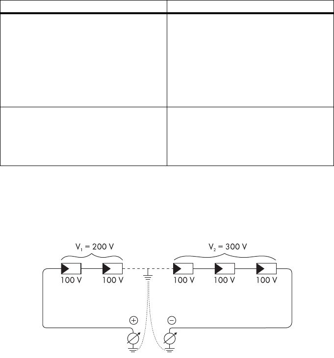
Troubleshooting SMA Solar Technology AG
72 SMC46-60A-IA-IEN120471 Installation Manual
Location of the Ground Fault
The approximate position of the ground fault can be determined from the ratio of the measured
voltages between the positive pole against ground potential (PE) and the negative pole against
ground potential (PE).
Example:
In this case, the ground fault is between the 2nd and 3rd PV modules.
☑ The ground fault check is now complete.
Result Measure
☑You have found a ground fault. • The installer of the PV array must remedy
the ground fault in the affected string. You
can determine the location of the ground
fault as described below.
•Do not reconnect the faulty string.
• Close the inverter and commission it as
described in section 7.3"Closing the
Inverter" (page58).
☑You have found no ground fault. It is likely that one of the thermally monitored
varistors is defective.
• Check the varistors as described in section
9.3.2"Checking the Function of the
Varistors" (page73).
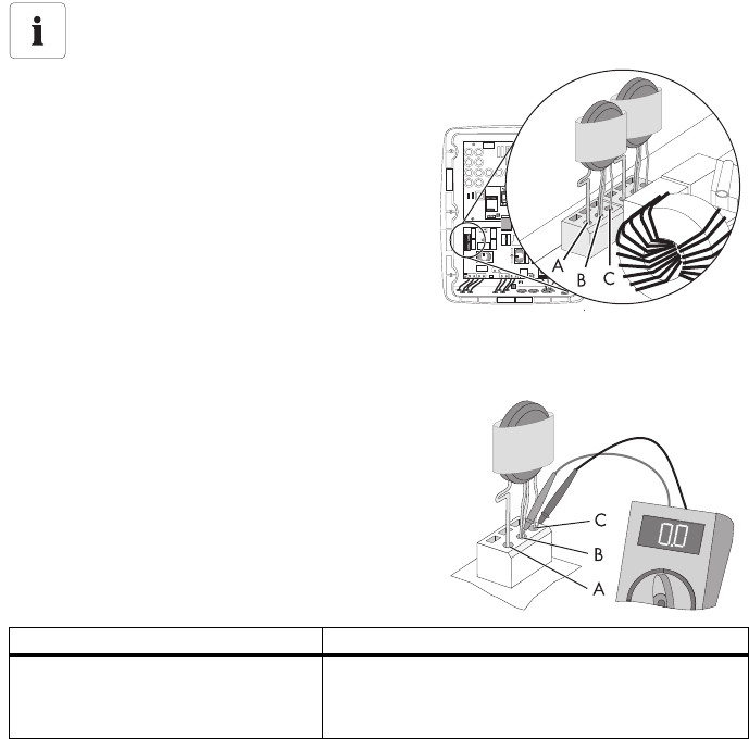
SMA Solar Technology AG Troubleshooting
Installation Manual SMC46-60A-IA-IEN120471 73
9.3.2 Checking the Function of the Varistors
Varistors are wearing parts. Their functional efficiency diminishes with age or following repeated
responses as a result of overvoltages. It is therefore possible that one of the thermally monitored
varistors has lost its protective function, and thus the red LED is lit.
Check the function of the varistors as described below:
1. Open the inverter as described in section 7.2"Opening the Inverter" (page55).
2. With the aid of a multimeter, determine for both
varistors in the installed state whether a conductive
connection exists between connectors B and C.
Position of varistors
You can determine the position of the varistors using the illustration below.
Observe the following assignment of the
terminals:
• Terminal A: outer terminal (varistor
connection with loop [crimp])
• Terminal B: middle terminal
• Terminal C: outer terminal (varistor
connection without loop [crimp])
Result Measure
☑There is a conductive connection. There is probably a different error in the inverter.
• Contact the SMA Service Line
(see section 13"Contact" (page86)).
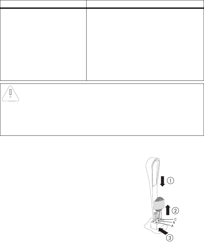
Troubleshooting SMA Solar Technology AG
74 SMC46-60A-IA-IEN120471 Installation Manual
3. Insert an insertion tool into the openings of the
terminal contacts (1).
☑ This releases the terminals.
If you do not receive an insertion tool for operating
the terminals with your replacement varistors,
contact SMA Solar Technology AG. As an
alternative, the individual terminal contacts can be
operated using a 3.5 mm wide screwdriver.
4. Remove the varistor (2).
5. Insert the new varistor (3).
The pole with the small loop (crimp) must be fitted
to terminal A when replacing the varistor.
6. Close the inverter as described in section
7.3"Closing the Inverter" (page58).
☑ The check and replacement of the varistors is
completed.
☑There is no conductive
connection.
The respective varistor is defective and must be replaced.
Varistor failure is generally due to influences that affect
all varistors similarly (temperature, age, induced
overvoltage). SMA Solar Technology AG recommends
that you replace both varistors.
The varistors are specially manufactured for use in the
inverter and are not commercially available. They must
be ordered directly from SMA Solar Technology AG
(see section 12"Accessories" (page85)).
• To replace the varistors, proceed to step 3.
NOTICE!
Destruction of the inverter due to overvoltage.
If varistors are missing, the inverter is no longer protected against overvoltages.
• Replacement varistors should be obtained as soon as possible.
•Do not operate the inverter without varistors in PV plants with a high risk of
overvoltages.
Result Measure
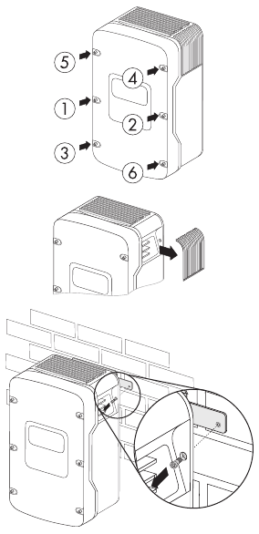
SMA Solar Technology AG Decommissioning
Installation Manual SMC46-60A-IA-IEN120471 75
10 Decommissioning
10.1 Disassembling the Inverter
1. Open the inverter as described in section 7.2"Opening the Inverter" (page55).
2. Remove all cables from the inverter.
3. Close the inverter with the 6 screws and the
corresponding conical spring washers.
4. Remove the fan guards from both sides.
5. Remove the 2 screws on the left and right side of the
inverter that attach it to the wall bracket.
6. Disconnect the anti‑theft protection, if applicable.
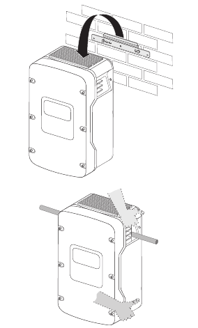
Decommissioning SMA Solar Technology AG
76 SMC46-60A-IA-IEN120471 Installation Manual
7. Remove the inverter upwards from the wall
mounting bracket.
8. Use the side handles (above and below) or a steel
rod (maximum diameter 30 mm) to transport the
inverter. The rod must be pushed through the
enclosure openings.
☑ The inverter is disassembled.
10.2 Packing the Inverter
If possible, always pack the inverter in its original packaging. If it is no longer available, you can also
use an equivalent carton. The carton must be completely closeable, have a handle system and be
made to support both the weight and size of the inverter.
10.3 Storing the Inverter
Store the inverter in a dry place where ambient temperatures are always between
‒25°C and +60°C.
10.4 Disposing of the Inverter
Dispose of the inverter at the end of its service life in accordance with the current locally applicable
disposal regulations for electronic waste. Alternatively, send it back to SMA Solar Technology AG
with shipping paid by sender, and labeled "ZUR ENTSORGUNG" ("for disposal")
(contact see Page 86).

SMA Solar Technology AG Technical Data
Installation Manual SMC46-60A-IA-IEN120471 77
11 Technical Data
11.1 DC/AC
11.1.1 Sunny Mini Central 4600A
DC Input
* The maximum open-circuit voltage that can occur with ‒10°C cell temperature may not exceed the maximum input voltage.
Maximum DC power at cos φ = 1 5 250 W
Maximum input voltage* 600 V
MPP voltage range 246 V … 480 V
Rated input voltage 246 V
Minimum input voltage 211 V
Start input voltage 300 V
Maximum input current 26 A
Maximum input current per string 26 A
Number of independent MPP inputs 1
Strings per MPP input 4
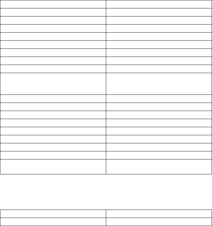
Technical Data SMA Solar Technology AG
78 SMC46-60A-IA-IEN120471 Installation Manual
AC Output
* 4 600 VA with VDE-AR-N 4105
** Applies to SMC 4600A-11
*** Applies to SMC 4600A
Efficiency
Rated power at 230 V, 50 Hz 4 600 W
Maximum apparent AC power* 5 000 VA
Rated grid voltage 230 V
Nominal AC voltage 220 V/230 V/240 V
AC voltage range 160 V … 265 V
Nominal AC current at 220 V 20.9 A
Nominal AC current at 230 V 20.0 A
Nominal AC current at 240 V 19.16 A
Maximum output current 26 A
Total harmonic factor of the output current with
AC voltage < 2% and
AC power > 50% of rated power
≤3%
Rated power frequency 50 Hz
AC power frequency 50 Hz/60 Hz
Operating range at AC power frequency 50 Hz 44 Hz … 55 Hz
Operating range at AC power frequency 60 Hz 54 Hz … 65 Hz
Displacement power factor, adjustable** 0.8overexcited …0.8
underexcited
Power factor at nominal AC power*** 1
Feed‑in phases 1
Connection phases 1
Overvoltage category according to
IEC 60664‑1
III
Maximum efficiency, ηmax 96.1%
European weighted efficiency, ηEU 95.3%

SMA Solar Technology AG Technical Data
Installation Manual SMC46-60A-IA-IEN120471 79
11.1.2 Sunny Mini Central 5000A
DC Input
* The maximum open‑circuit voltage that can occur with ‒10°C cell temperature may not exceed the maximum input voltage.
Maximum DC power at cos φ = 1 5 750 W
Maximum input voltage* 600 V
MPP voltage range 246 V … 480 V
Rated input voltage 246 V
Minimum input voltage 211 V
Start input voltage 300 V
Maximum input current 26 A
Maximum input current per string 26 A
Number of independent MPP inputs 1
Strings per MPP input 4

Technical Data SMA Solar Technology AG
80 SMC46-60A-IA-IEN120471 Installation Manual
AC Output
* Applies to SMC 5000A-11
** Applies to SMC 5000A/SMC 5000A-IT
Efficiency
Rated power at 230 V, 50 Hz 5 000 W
Maximum apparent AC power 5 500 VA
Rated grid voltage 230 V
Nominal AC voltage 220 V/230 V/240 V
AC voltage range 160 V … 265 V
Nominal AC current at 220 V 22.7 A
Nominal AC current at 230 V 21.7 A
Nominal AC current at 240 V 20.8 A
Maximum output current 26 A
Total harmonic factor of the output current with
AC voltage < 2% and
AC power > 50% of rated power
≤3%
Rated power frequency 50 Hz
AC power frequency 50 Hz/60 Hz
Operating range at AC power frequency 50 Hz 44 Hz … 55 Hz
Operating range at AC power frequency 60 Hz 54 Hz … 65 Hz
Displacement power factor, adjustable* 0.8overexcited …0.8
underexcited
Power factor at nominal AC power** 1
Feed‑in phases 1
Connection phases 1
Overvoltage category according to
IEC 60664‑1
III
Maximum efficiency, ηmax 96.1%
European weighted efficiency, ηEU 95.3%
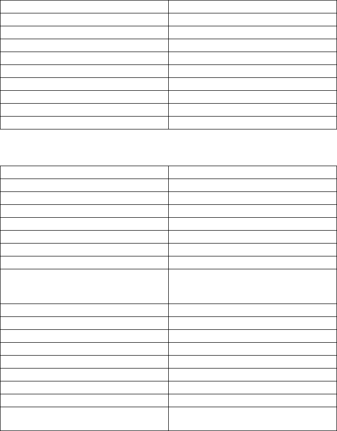
SMA Solar Technology AG Technical Data
Installation Manual SMC46-60A-IA-IEN120471 81
11.1.3 Sunny Mini Central 6000A
DC Input
* The maximum open‑circuit voltage that can occur with ‒10°C cell temperature may not exceed the maximum input voltage.
AC Output
* Applies to SMC 6000A-11
** Applies to SMC 6000A/SMC 6000A-IT
Maximum DC power at cos φ = 1 6 300 W
Maximum input voltage* 600 V
MPP voltage range 246 V … 480 V
Rated input voltage 246 V
Minimum input voltage 211 V
Start input voltage 300 V
Maximum input current 26 A
Maximum input current per string 26 A
Number of independent MPP inputs 1
Strings per MPP input 4
Rated power at 230 V, 50 Hz 6 000 W
Maximum apparent AC power 6 000 VA
Rated grid voltage 230 V
Nominal AC voltage 220 V/230 V/240 V
AC voltage range 160 V … 265 V
Nominal AC current at 230 V 26 A
Nominal AC current at 240 V 25 A
Maximum output current 26 A
Total harmonic factor of the output current with
AC voltage < 2% and
AC power > 50% of rated power
≤3%
Rated power frequency 50 Hz
AC power frequency 50 Hz/60 Hz
Operating range at AC power frequency 50 Hz 44 Hz … 55 Hz
Operating range at AC power frequency 60 Hz 54 Hz … 65 Hz
Displacement power factor, adjustable* 0.8overexcited …0.8
underexcited
Power factor at nominal AC power** 1
Feed‑in phases 1
Connection phases 1
Overvoltage category according to
IEC 60664‑1
III
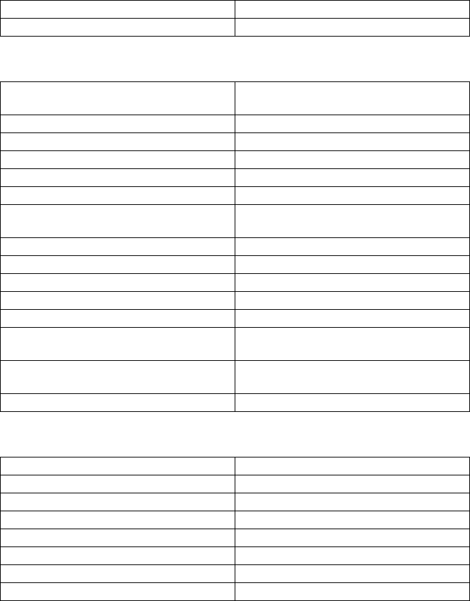
Technical Data SMA Solar Technology AG
82 SMC46-60A-IA-IEN120471 Installation Manual
Efficiency
11.2 General Data
11.3 Protective Devices
Maximum efficiency, ηmax 96.1%
European weighted efficiency, ηEU 95.3%
Width x height x depth with
Electronic Solar Switch
468mmx613mmx242mm
Weight 63 kg
Length x width x height of packaging 396 mm x 803 mm x 596 mm
Transport weight 68 kg
Climatic category according to IEC 60721‑2‑1 4K4H
Operating temperature range ‒25°C … +60°C
Maximum permissible value for relative humidity,
non‑condensing
100%
Maximum operating altitude above MSL 2 000 m
Noise emission (typical) ≤ 42 dB(A)
Power loss in night operation 0.25 W
Topology LF transformer
Cooling concept OptiCool
Fan connection designed for safe disconnection in accordance
with DIN EN 50178:1998‑04
Electronics degree of protection according to
IEC 60529
IP65
Protection class according to IEC 62103 I
DC reverse polarity protection short‑circuit diode
Input‑side disconnection device Electronic Solar Switch
DC overvoltage protection thermally monitored varistors
AC short‑circuit current capability current control
Grid monitoring SMA Grid Guard 2.1
Maximum permissible fuse protection 40 A
Ground fault monitoring Insulation monitoring: Riso >1MΩ
Galvanic isolation available
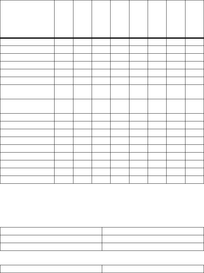
SMA Solar Technology AG Technical Data
Installation Manual SMC46-60A-IA-IEN120471 83
11.4 National Standards
* EN 50438: Does not apply to all national standard deviations.
○ In planning
11.5 Climatic Conditions
According to IEC 60721‑3‑4, Installation Type C, Class 4K4H
According to IEC 60721‑3‑4, Transport Type E, Class 2K3
National standard as
at 01/2012
SMC 4600A-11
SMC 5000A-11
SMC 6000A-11
SMC 4600A
SMC 5000A
SMC 6000A
SMC 5000A-IT
SMC 6000A-IT
VDE0126-1-1 ✓ ✓ ✓ ✓ ✓ ✓ ‒ ‒
VDE-AR-N-4105 ✓ ✓ ✓ ‒ ‒ ‒ ‒ ‒
AS 4777 ○ ○ ○ ‒ ✓ ✓ ‒ ‒
C10/11 ○ ○ ○ ✓ ✓ ✓ ‒ ‒
PPDS ○ ○ ○ ✓ ✓ ✓ ‒ ‒
GBT19939-2005 ○ ○ ○ ✓ ✓ ✓ ‒ ‒
VDE0126-1-1/
UTE C15-712-1
○○○✓✓✓‒‒
UTE C15-712-1/
EDF SEI req.
○○○✓✓✓‒‒
PPC ○ ○ ○ ✓ ✓ ✓ ‒ ‒
SI 4777 ○ ○ ○ ✓ ✓ ✓ ‒ ‒
DK5940 ‒‒‒‒‒‒✓✓
EN 50438* ✓ ✓ ✓ ✓ ✓ ✓ ‒ ‒
RD 1663/2000 ○ ○ ○ ✓ ✓ ✓ ‒ ‒
RD 661/2007 ○ ○ ○ ✓ ✓ ✓ ‒ ‒
IEC 61727 PEA ‒ ✓ ✓ ‒ ✓ ✓ ‒ ‒
G83/1-1 ○ ○ ○ ✓ ✓ ✓ ‒ ‒
G59/2 ‒‒‒‒‒✓‒‒
Extended temperature range ‒25°C … +60°C
Extended air humidity range 0% … 100%
Extended air pressure range 79.5 kPa … 106 kPa
Temperature range ‒25°C … +70°C
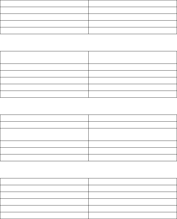
Technical Data SMA Solar Technology AG
84 SMC46-60A-IA-IEN120471 Installation Manual
11.6 Features
11.7 Electronic Solar Switch (ESS)
11.8 Torque
11.9 Distribution Systems
DC connection SUNCLIX DC connector
AC connection screw terminal
Display LC text display
Bluetooth® Wireless Technology optional
RS485, galvanically isolated optional
Electrical endurance in the event of a short circuit,
with a nominal current of 35 A
min. 50 switching processes
Maximum switching current 35 A
Maximum switching voltage 800 V
Maximum PV power 12 kW
Degree of protection when plugged IP65
Degree of protection when unplugged IP21
Enclosure lid screws 6.0 Nm
Additional ground terminal 6.0 Nm
Cheese‑head screw for attaching the enclosure to
the wall mounting bracket
6.0 Nm
SUNCLIX lock nut 2.0 Nm
Screw terminal AC connection 2.5 Nm
RS485 communication connection 1.5 Nm
IT system suitable
TN‑C system suitable
TN‑S system suitable
TN‑C‑S system suitable
TT system suitable
Split Phase suitable

SMA Solar Technology AG Accessories
Installation Manual SMC46-60A-IA-IEN120471 85
12 Accessories
You will find the corresponding accessories and spare parts for your product in the following
overview. If required, you can order these from SMA Solar Technology AG or your specialty retailer.
Designation Brief description SMA order number
Bluetooth retrofit kit Bluetooth communication interface BTPBINV‑NR
Insertion tool for the
replacement of varistors
insertion tool for varistors SB‑TVWZ
Electronic Solar Switch ESS handle spare part ESS-HANDLE:04
Also enter the inverter's
serial number.
Negative grounding set retrofit kit for the negative connection to ground
of the DC input
ESHV‑N‑NR
Positive grounding set retrofit kit for the positive connection to ground of
the DC input
ESHV‑P‑NR
Replacement varistors set of thermally monitored varistors (2) incl.
insertion tool
SB‑TV4
Radio retrofit kit radio Piggy‑Back for retrofitting an inverter for
communication with Sunny Beam, including
antenna, coaxial cable, and PG cable gland
(metal)
BEAMPB‑NR
Fan guard fan guard set "right and left" as spare part 45‑7202
Power Balancer plug retrofit kit for retrofitting a Sunny Mini Central
equipped with an SMA Power Balancer to the
SMA Power Balancer plug‑in system
PBL‑SMC‑10‑NR
RS485 retrofit kit RS485 interface 485PB‑SMC‑NR
SMA Power Balancer
Ycable
connecting cable (2 x 2 m) for
SMA Power Balancer plug‑in system
PBL‑YCABLE‑10
SUNCLIX DC connector field plug for conductor cross‑sectional areas
2.5 mm² … 6 mm²
SUNCLIX‑FC6‑SET
Contact SMA Solar Technology AG
86 SMC46-60A-IA-IEN120471 Installation Manual
13 Contact
If you have technical problems concerning our products, contact the SMA Service Line.
We need the following data in order to provide you with the necessary assistance:
• Inverter type
• Inverter serial number
• Type and number of the PV modules connected
• Optional equipment, e.g. communication products
• Blink code or display message of the inverter
SMA Solar Technology AG
Sonnenallee 1
34266 Niestetal, Germany
www.SMA.de
SMA Service Line
Inverters +49 561 9522 1499
Communication: +49 561 9522 2499
Fax: +49 561 9522 4699
E‑Mail: ServiceLine@SMA.de
SMA Solar Technology AG Legal Restrictions
Installation Manual SMC46-60A-IA-IEN120471 87
The information contained in this document is the property of SMA Solar Technology AG. Publishing its content, either partially or
in full, requires the written permission of SMA Solar Technology AG. Any internal company copying of the document for the
purposes of evaluating the product or its correct implementation is allowed and does not require permission.
SMA Factory Warranty
The current guarantee conditions come enclosed with your device. These are also available online at www.SMA.de and can be
downloaded or are available on paper from the usual sales channels if required.
Trademarks
All trademarks are recognized even if these are not marked separately. Missing designations do not mean that a product or brand
is not a registered trademark.
The Bluetooth® word mark and logos are registered trademarks owned by Bluetooth SIG, Inc. and any use of such marks by
SMA Solar Technology AG is under license.
SMA Solar Technology AG
Sonnenallee 1
34266 Niestetal
Germany
Tel. +49 561 9522-0
Fax +49 561 9522-100
www.SMA.de
E-Mail: info@SMA.de
© 2004 to 2012 SMA Solar Technology AG. All rights reserved

XXX4."4PMBSDPN
4."4PMBS5FDIOPMPHZ
4."4PMBS5FDIOPMPHZ"(
XXX4."EF
4.""NFSJDB--$
XXX4.""NFSJDBDPN
4."5FDIOPMPHZ"VTUSBMJB1UZ-UE
XXX4.""VTUSBMJBDPNBV
4."#FOFMVY413-
XXX4."#FOFMVYDPN
4."#FJKJOH$PNNFSDJBM$P-UE
XXX4."$IJOBDPN
4."$[FDI3FQVCMJDTSP
XXX4."$[FDIDPN
4."'SBODF4"4
XXX4."'SBODFDPN
4.")FMMBT"&
XXX4.")FMMBTDPN
4."*C©SJDB5FDOPMPHB4PMBS4-
XXX4."*CFSJDBDPN
4."*UBMJB4SM
XXX4."*UBMJBDPN
4."5FDIOPMPHZ,PSFB$P-UE
XXX4.",PSFBDPN
