Sherwood Scuba Diving Equipment REGULATORS SR1 Repair Manual 2nd Stage 09
User Manual: Sherwood Scuba Diving Equipment REGULATORS
Open the PDF directly: View PDF ![]() .
.
Page Count: 20

SRB1000
SECOND STAGE
SERVICE GUIDE
200_08
2
www.sherwoodscuba.com
INTRODUCTION
The instructions set forth in this document are intended to guide the experienced scuba equipment repair technician
through the standard service procedure for the SR1 regulator.
It is assumed that the technician possesses basic scuba equipment repair training, proper tools and the skill
necessary to perform the service. If you have not received regulator service training provided by Sherwood Scuba
specifically for this equipment, do not attempt to perform the service described in this document.
Service parts for Sherwood equipment are sold only to Authorized Sherwood Dealers.
Before attempting to perform service read this manual in its entirety. There are warnings and cautions contained in
the manual that may affect your safety or the safety of the regulator user.
If you are uncertain as to whether you are qualified to perform this service contact your regional Sherwood Scuba
Distributor for technical assistance.
USE OF WARNINGS, CAUTIONS AND NOTES
WHEN TO SERVICE
The SR1 should be inspected for service at least annually. In most cases a simple inspection, and if needed,
minimal adjustment not requiring the replacement of parts will be sufficient for continued use. Guidelines for the
Annual Inspection are included in this manual.
The SR1 is designed and tested to perform acceptably under typical recreational diving conditions up to 300 hours
of use.
If the regulator has been subjected to more than 300 hours of use or it has not received the benefit of careful
post-dive cleaning and storage in a clean environment, a standard service overhaul is required.
In any case the SR1 should receive a standard service overhaul at least every two years to maintain optimal
performance. The standard service overhaul includes disassembly, cleaning, inspection, replacement of seals,
lubrication, reassembly and adjustments.
Sherwood Scuba offers a standard service kit that contains the parts recommended to be replaced in connection
with the standard service overhaul.
WARNING: Indicates a potentially hazardous condition or situation which, if not avoided, may
result in serious injury or death.
CAUTION: Indicates a potentially hazardous condition or situation which, if not avoided, may
result in minor injury. It may also be used to alert against unsafe practices.
NOTE: Indicates an important point or reminder.
!
!

3
www.sherwoodscuba.com
ANNUAL INSPECTION GUIDELINES
1. Visually inspect the first and second stage for signs of damage or deterioration. Mouthpieces with tears or other
damage should be replaced.
2. Retract hose protectors and inspect the hose over its entire length for signs of damage including blisters, deep
cuts or separation at the crimped fittings. If these signs are present the hose must replaced and standard service
overhaul is recommended.
3. Insert a soft probe through the exit port and lift the Exhaust Valve to inspect it for cuts, tears or contaminated
surfaces. Perform this examination from both sides of the Exhaust Cover to observe the entire perimeter of the
Exhaust Valve. If damage to the Exhaust Valve is found a complete overhaul is recommended. If the Exhaust
Valve or the sealing surfaces on the Housing are contaminated with debris, the Exhaust Cover must be removed
and the surfaces must be cleaned. Instructions for removing and replacing the Exhaust Cover appear in
the Disassembly Instructions in this manual. As a final check of the Exhaust Valve apply a moderate suction
(approximately minus 5 inches of water, moderate inhalation effort) to the second stage mouthpiece with the air
supply closed and the second stage purged. If leakage is detected a complete overhaul is recommended.
4. Inspect the first stage filter for evidence of contamination. Discolored filters indicate previous contact with
contaminated air. If evidence of contamination is present it is recommended that a standard service overhaul be
performed. In addition you should advise the customer that the regulator has been exposed to contamination
and that previously used air cylinders used should be inspected.
5. Install an intermediate pressure gauge into one of the available LP ports.
6. Pressurize the regulator to approximately 500 psi and inspect for leakage. If air leakage through the second
stage is detected, it is possible that the second stage Orifice is not in position to create a seal. Close the valve
to stop the air flow and reopen quickly. This will generate enough sudden pressure to move the Orifice to its
proper position. Note intermediate pressure. It should not be greater than 145 psi. If no leakage is detected
increase pressure to 3000 psi. Again check intermediate pressure. It should not exceed 145 psi. The specified
intermediate pressure for the SR1 is 135+/- 10 psi. If intermediate pressure is out of range or leakage is present
a standard service overhaul is recommended.
7. With the second stage Control Knob set at the least sensitive position (rotated fully clockwise) test the purge
function. If there is not a strong surge of air, a standard overhaul is recommended.
8. Gently submerge the entire regulator and look for bubbles that indicate leakage. If leakage is present a standard
service overhaul is recommended.
9. If a test bench is available perform an inhalation test. With the Control Knob in the most sensitive position
(rotated fully counterclockwise) inhalation effort should not be greater than 2.0 inches of water at opening and
less than 5.0 inches of water at 15 SCFM. If there is a slight leakage of air present refer to Adjustments Section
of this manual and adjust as needed. If adjustment fails to stop the leak a standard overhaul is recommended.
If a test bench is not available perform a subjective breathing test. When properly adjusted the regulator
should provide smooth and easy inhalation. If difficulty with inhalation is suspected a standard overhaul is
recommended.

4
www.sherwoodscuba.com
GENERAL COMMENTS
1. Read the entire set of procedures that follows before starting to service. Steps taken out of sequence or without
the knowledge of the proper procedure could damage the regulator or otherwise complicate the service process.
2. Refer to the Illustrated Parts List while performing service. Each part is identified with an item number the first
time it appears in the text. Parts that are to be replaced with new parts in conjunction with an overhaul have
encircled reference numbers.
3. Do not attempt to reuse parts that are designated for replacement. Retain discarded parts to show to the
customer to illustrate that a full overhaul service has been completed.
4. Work in a clean properly equipped area. Cleanliness is essential for all regulator servicing and is critical for
regulators that will be exposed to enriched air mixtures (nitrox). Do not attempt to service if all required tools
and a clean work area are not available.
5. Work on one regulator at a time taking care not to mix parts from other regulators. Use only genuine Sherwood
parts. Parts that appear similar may have different features that are not easy to detect and may cause poor
performance.
6. Be careful to protect the finish on all surfaces of the regulator during the service procedure. When holding parts
in a vise use soft or padded jaws to prevent defacing surfaces.
7. O-rings are classified by the service they perform and are identified as either static or dynamic. Dynamic
O-rings are those that are subjected to movement and the effects of friction which tend to shorten the useful life
of the O-ring. Static O-rings are used to create a seal between non-moving parts and are not subject to the
same wearing effects. Static O-rings have a longer useful life and are not replaced unless they show signs of
deterioration or brittleness. Careful inspection of these O-rings is required before they are returned to service.
Lubrication of O-rings:
a. General - O-rings in most instances should receive only enough lubricant to ensure they are supple. A light
coating of lubricant should present a surface that glistens but without a defined layer of lubricant visible.
b. Ample – When an ample application of lubricant is specified it generally applies to a dynamic O-ring
subject to considerable motion or environmental conditions where a more generous application of lubricant
might be beneficial. In this situation there should be a light film or layer of lubricant visible.
8. When removing O-rings use a wooden, plastic or a soft brass tool to lift the O-ring out of its groove. Do not use
steel or other hard tools that might scratch sealing surfaces.
9. When instructed to use tools such as a hex key or a wrench, follow the standard convention to rotate clockwise
to tighten and counterclockwise to loosen unless otherwise directed.
10. When instructed to tighten a part until snug, it means to apply torque just until the part stops moving freely and
the torque requirement to advance it further rises markedly. When specific torque specifications are given there
is a necessity to ensure that the part is tightened enough to retain position or to create a seal. Unless you are
skilled at accurately estimating torque, a torque wrench should be used. Excessive torque may damage parts and
require replacement.
NOTE - Read this section before attempting to perform service.
5
www.sherwoodscuba.com
ENRICHED AIR NITROX SERVICE
The SR1 has been designed and manufactured to allow the use of Enriched Air Nitrox (EAN) gas with an oxygen
component not to exceed 40%.
In order to maintain this option the user must ensure that the regulator is protected from the introduction of
hydrocarbons. The introduction of hydrocarbons into the regulator may increase the risk of fire when used with EAN.
When servicing the regulator, the technician must be aware of this requirement and exercise caution not to
contaminate the regulator with hydrocarbons. This requires a clean workplace, free of oil, grease, debris and other
contaminants. Additionally in order to return the regulator to EAN service, the overhaul procedure must have a
cleaning provision to remove all hydrocarbons before the regulator is reassembled. Do not substitute parts or use
lubricants other Christo-Lube 111. Silicone lubricants are not acceptable and increase the risk of a fire hazard.
FACILITY REQUIREMENTS
The service facility is perhaps the mot important asset of any professional dive store. It should be clean and will
lighted, and stocked with a complete inventory of parts and manufacturer’s specialty tools for the products your store
sells. As a minimum requirement, your service facility should be equipped with the following items:
• Ultrasonic Cleaner - Select the right size model that can keep up with the volume of regulators that your
store services. A built in timer and heater will help control the cleaning time and temperature of the solution,
since most solutions work best when heated.
• Bench Mounted Vise - A vise is sometimes needed to hold the regulator secure – especially when removing
the first stage yoke retainer. Special care must be taken, however, to avoid damage that can result from improper
use of this tool. Be sure to follow the instructions provided in this manual.
• Magnification Lamp - Strong lighting and magnification are essential requirements for performing a
thorough parts inspection - especially when locating the cause of a small leak.
• Quality Wrenches & Sockets - When working with chrome plated brass parts, it is especially critical to use
the correct size wrench and to ensure that it fits properly over the part. The use of an adjustable wrench is very
likely to cause damage to your customer’s regulator, and should be strictly avoided at all times.
• Calibrated Inch-Pound Torque Wrench - it is important to follow the manufacturer’s torque values
whenever they are specified, in order to avoid overtightening or under tightening a part. This is especially
important for smaller parts and fittings, when overtightening can easily damage the part.
• Calibrated Foot-Pound Torque Wrench - Torque wrenches that can be set for both inch-pound and
foot-pound measurements generally tend to be less accurate than wrenches that are designed to measure torque
within a specific range.
• Manufacturer’s Specialty Tools -Specialty tools are critically important to performing each step of
disassembly and reassembly according to each manufacturer’s procedures. Sherwood specialty tools are
required to perform service for the SR1 first stage are listed on the following page.
WARNING – The introduction of hydrocarbons, lint, dirt and other contaminants into the areas of
the regulator subjected to high pressures (greater than 500 psi) and EAN mixtures containing more
than 40% oxygen may constitute a fire hazard and may subject the user to serious injury.
!

6
www.sherwoodscuba.com
RECOMMENDED TOOLS AND SUPPLIERS
The specialty tools identified below may be purchased from your Sherwood Scuba Distributor. Common tools are
available from several sources.
Including:
Sears Roebuck www.sears.com/craftsman
Home Depot www.homedepot.com
Harborfreight Tools www.harborfreight.com
Common Tools
Open End Wrenches - 9/16", 5/8",1/2"
Box End Wrench – 3/4"
Hex Keys 1/4", 5/32",1/8"
Small Flat Blade Screw Driver
Padded Pry Bar
Torque Wrenches 25 ft-lb and 60 in-lb
Flashlight
Compressed Air Gun
1/4" x 6" wooden dowel
O-ring picks, plastic or soft metal
Magnifier
Specialty Tools
SR1 Tool Kit 20-700-100
Includes the following:
Seat Retainer Tool 20-701-100
Cover Retainer Tool 20-703-100
Stem O-ring Tool 20-705-100
Poppet/Flange O-ring 20-706-100
Installation Tool
Available specialty tools not included in kit.
First Stage Handle 20-115-100
Yoke Retainer Socket 20-155-200
Breaker Bar 20-157-500
Snap Ring Pliers 10-101-500
3/8" Drive Extension 20-156-500
First Stage Spanner 20-600-200

7
www.sherwoodscuba.com
1. If the Second and First stages are still connected together, record the First Stage and Second Stage serial
numbers and an inventory of all attached accessories before beginning disassembly.
2. Perform an inspection of the regulator in accordance with the Annual Inspection Guidelines. This process will
provide an assessment of the regulator condition before the service is performed This information may be
valuable to understand any conditions that are not corrected by the standard service.
3. Retract the Hose Protector at the First Stage and disconnect the LP Hose from the First Stage using a 9/16" open
end wrench. Set aside the First Stage for service.
4. Retract the Second Stage Hose Protector (27) and use a 5/8" open end wrench to loosen the connection and
remove the LP Hose (1) from the Valve Body (9). Remove and discard O-ring (4) and set aside hose assembly
for cleaning and reassembly.
5. Remove the Front Cover Assembly by grasping the Cover Ring (23) and rotating it counterclockwise. Inspect
the flexible Cover (24) for signs of tears, holes or other damage. Replace if damage is evident. If no damage is
found go to step 7.
1
SECTION
DISASSEMBLY PROCEDURE
NOTE – Generally it is unnecessary to disassemble the Front Cover Assembly when performing
standard service. Cleaning can be adequately accomplished by rinsing and scrubbing if necessary with
a soft brush. However if damage to the Cover is observed, and it must be disassembled to replace parts,
proceed as described below.

8
www.sherwoodscuba.com
6. If further disassembly of the Cover Assembly is determined to be necessary, use Cover Retainer Tool (P/N 20-
703-100) to engage the slots in the Cover Retainer (25) and rotate counterclockwise to separate the Cover
Retainer from the Accent Ring (22). This will release the Cover (24) and the Cover Ring (23). Set aside for
cleaning and reassembly.
7. Remove the Diaphragm (26) and set aside for cleaning and reassembly.
8. Carefully snip the Tie Strap (31) from the Mouthpiece (32) using wire cutters or another suitable tool that will
cut the nylon strap without piercing the mouthpiece. Remove the Mouthpiece and set aside for cleaning
and reassembly.
9. Remove the Exhaust Cover (34) by inserting a padded bar shaped tool. Place at the location shown below.
Gently pry with the tool to lift the edge of the Exhaust Cover off the tab near the bottom of the Second Stage
Housing. Repeat this operation at the opposite side of the Housing and the Exhaust Cover should release from
the Housing. Set aside for cleaning and reassembly.
CAUTION – Be certain to use a padded or protected tool to lift the Exhaust Cover from the tabs on the
Housing. Use of an unprotected tool will damage the Exhaust Cover and may require replacement of the part.
!
9
www.sherwoodscuba.com
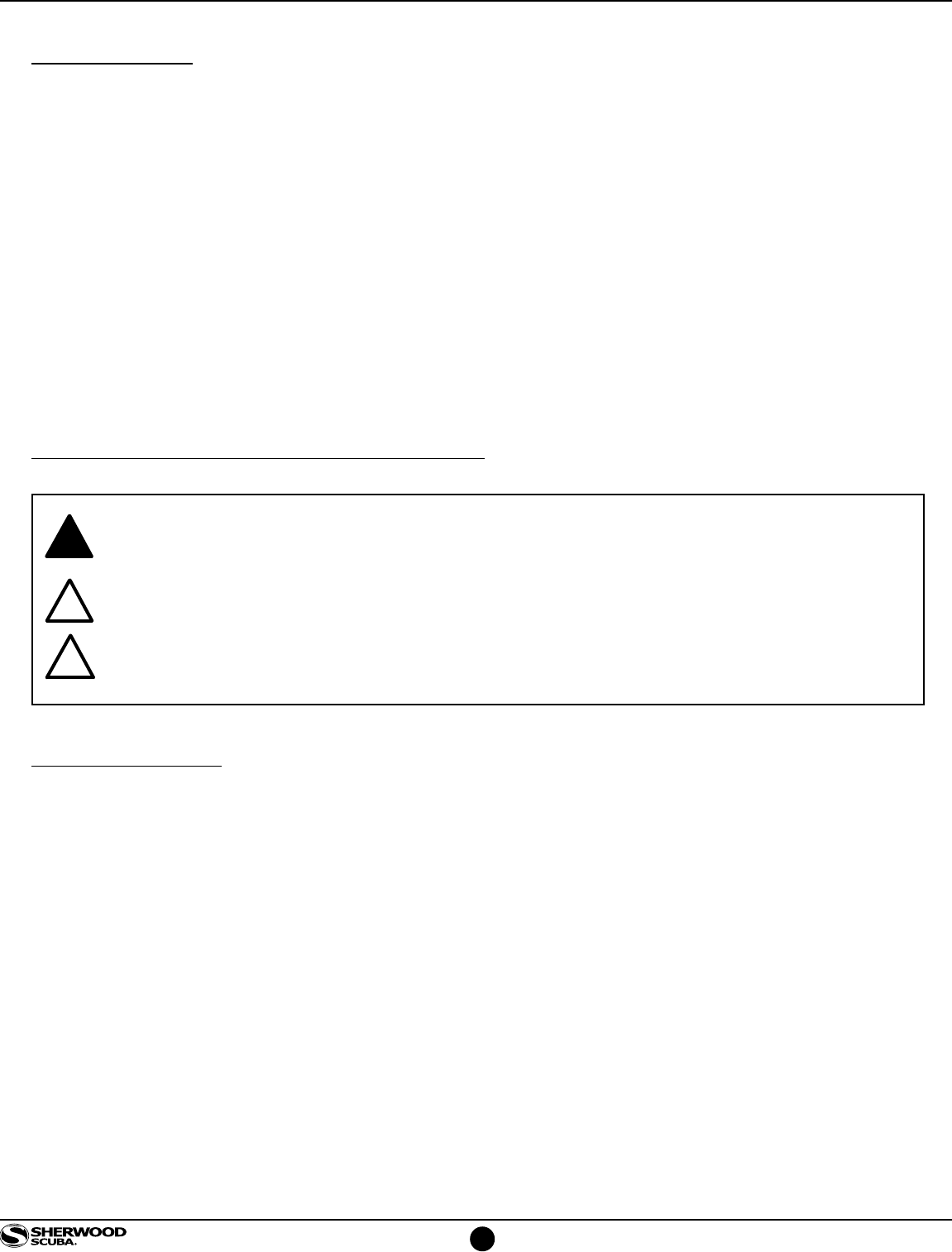
10. Remove the Retainer Nut (28) with a 3/4" box end wrench or 3/4" deep socket. Remove the Clip (35) using a
small flat blade screw driver. Set parts aside for cleaning and reassembly.
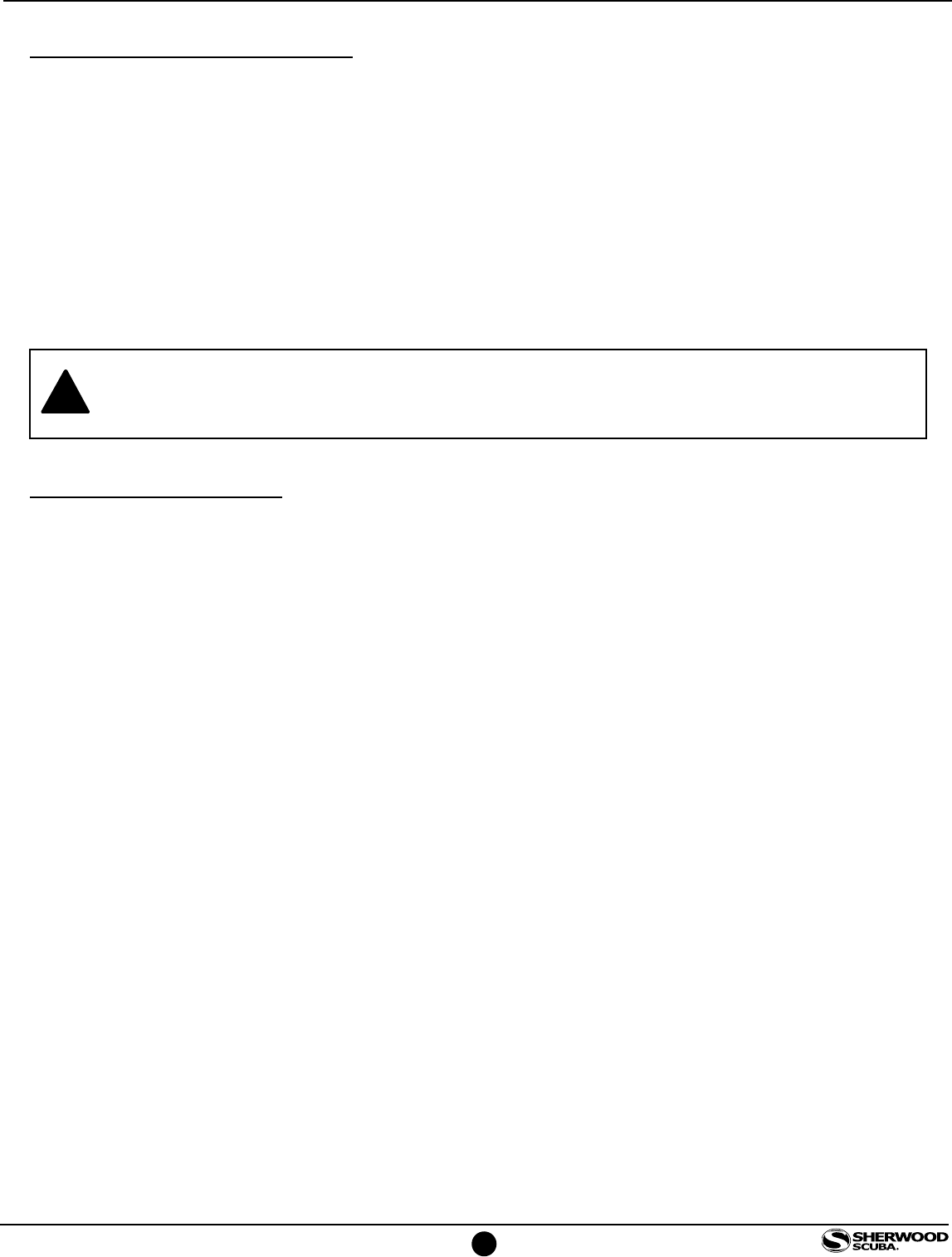
11. While depressing the Lever (8) fully with one hand, push on the threaded end of the Valve Body (9) to remove
the entire subassembly from the Housing (30). O-ring (29) will release from the Body. Set it aside for cleaning
and reassembly.
12. It is not generally necessary to remove the Exhaust Valve (33) from the Body for cleaning and inspection.
However if it is removed, be certain to use the technique that is least stressful to the Exhaust Valve by folding
it over and pinching it between the fingers while grasping the tab and gently pulling in opposite directions to
elongate the tab as it passes through the rectangular hole in the Housing. Set aside both parts for cleaning,
inspection and reassembly.
10
www.sherwoodscuba.com
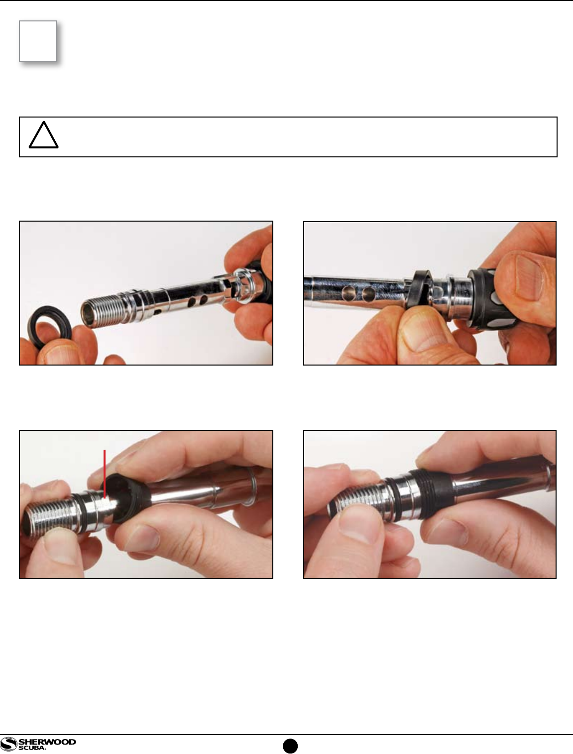
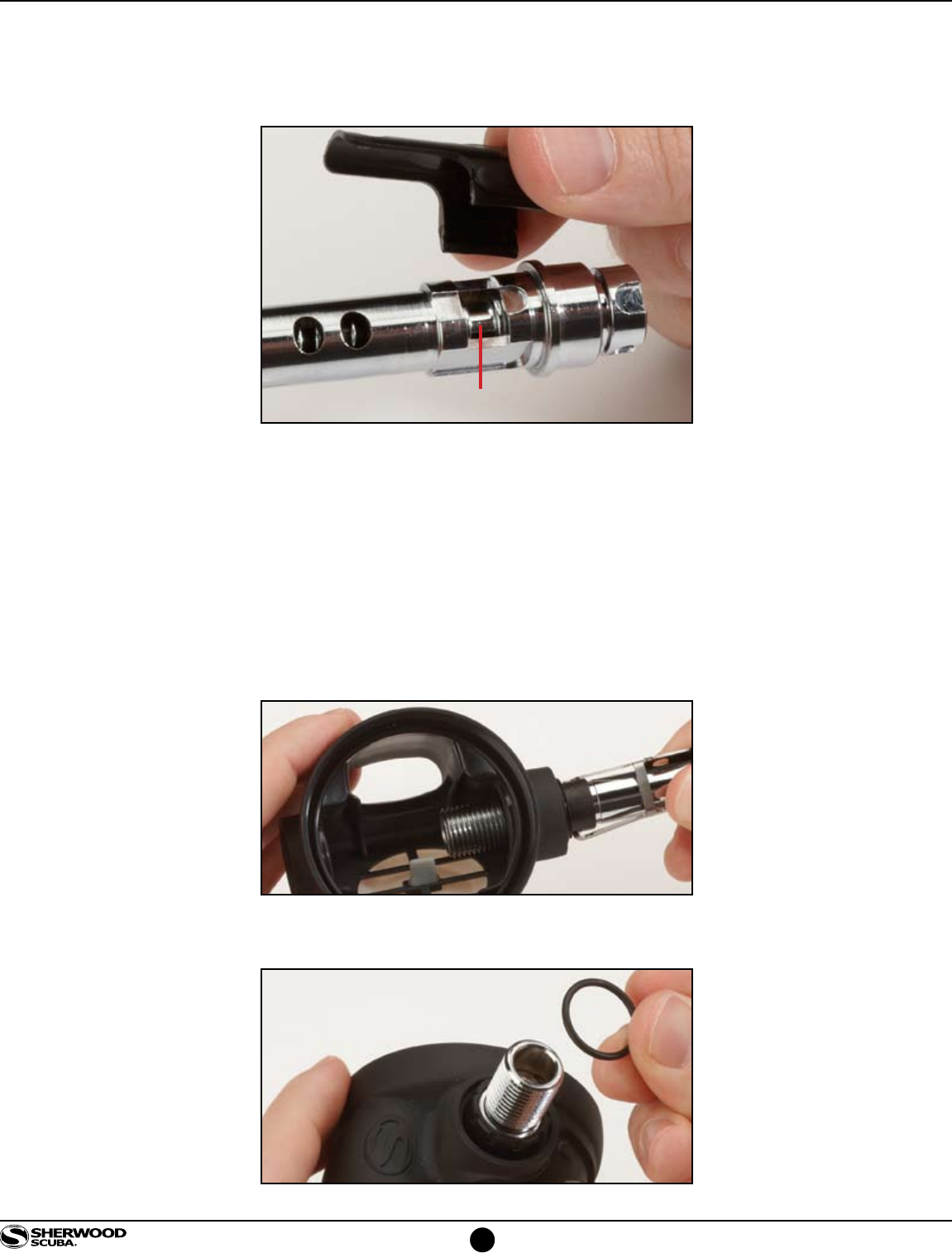
13. Remove the Adjustment Sleeve (2) from the Valve Body by rotating it counterclockwise. Remove O-ring (3). Set
both parts aside for cleaning, inspection and reassembly.
14. Remove the Lever (8) by gently prying one leg at a time outward until it clears the Valve Body.
15. Remove the Lever Saddle (7) using your finger tips to open the diameter sufficiently to lift the Lever Saddle off the
Valve Body.
16. Remove the Diverter (15) by gently lifting it by the tip. Set aside for cleaning and reassembly.
17. Remove the Ring Seal (6) by moving it toward the threaded end of the Valve Body.
Lever Saddle
11
www.sherwoodscuba.com
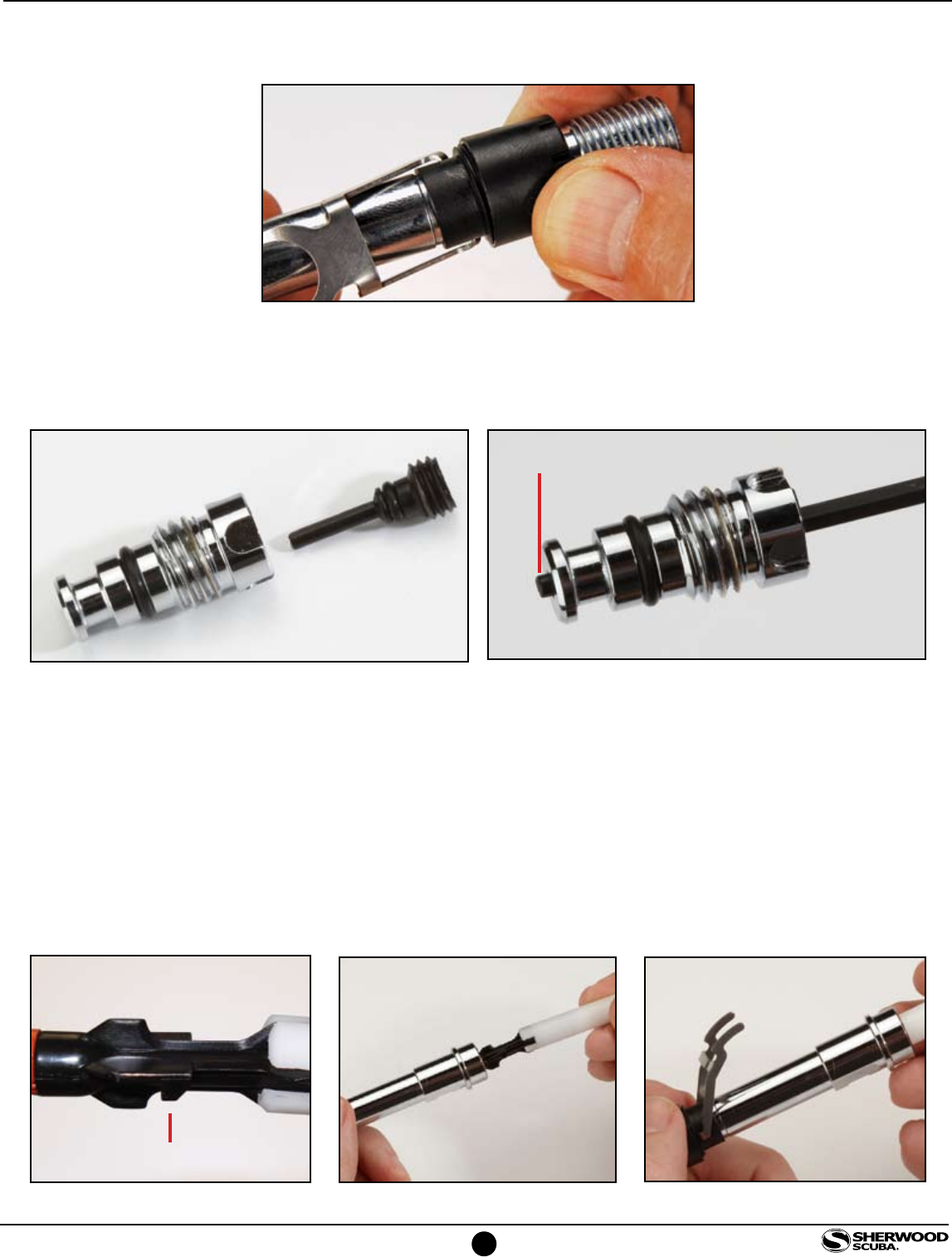
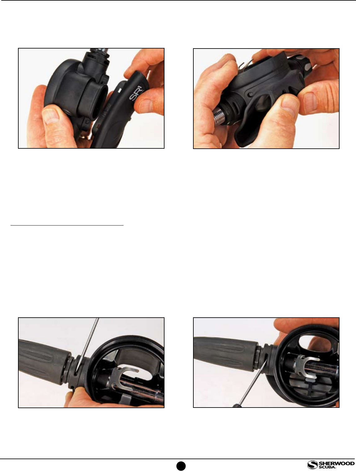
18. Rotate the control Knob (20) counterclockwise until the adjuster body subassembly (17) separates from the
Valve Body (9). Set the assembly aside for later disassembly. The Poppet (11), Spring (13) and Balance
Chamber (14) will release from the Valve Body. Remove and discard O-ring (12). Remove the Seat (10) by
grasping and pulling lightly. Discard the seat. Set aside the Balance Chamber (14), Poppet (11) and Spring
(13) for cleaning and reassembly.
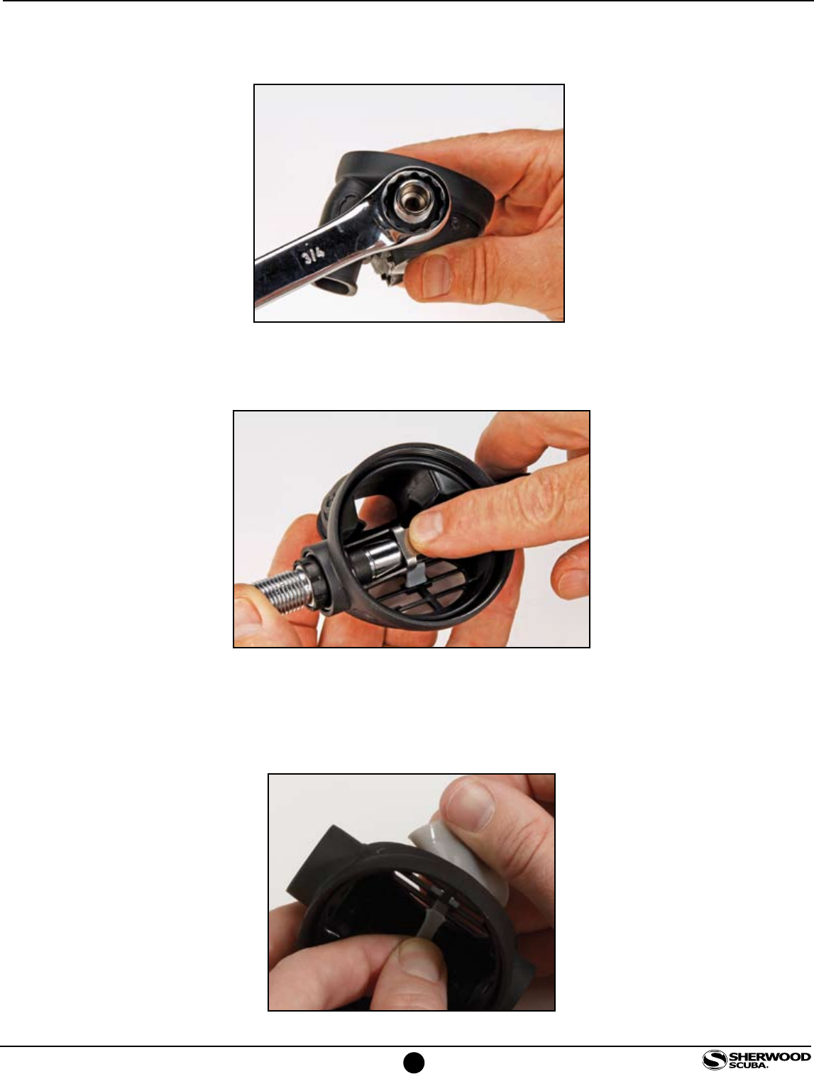
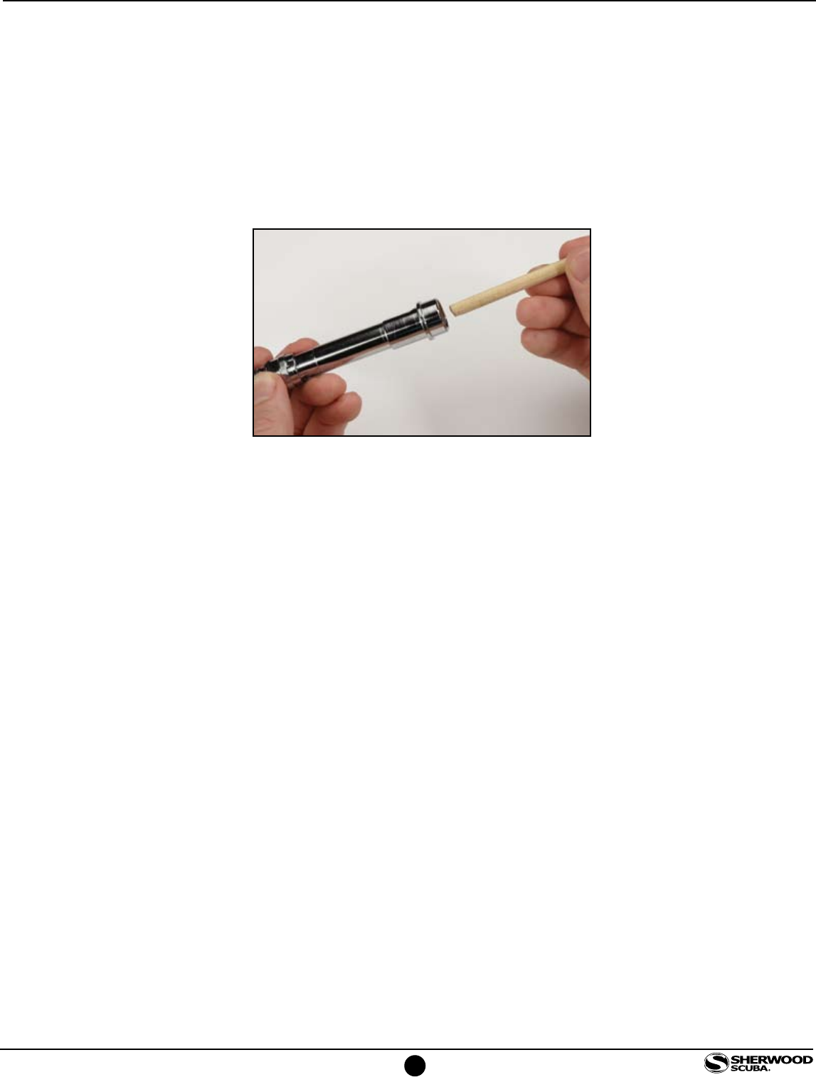
19. Insert a blunt 1/4" diameter wooden dowel into the Valve Body at the end that does not have external threads
and press against the Orifice (5) until it releases from the Valve Body. Remove and discard O-ring (4). Set aside
the Orifice for cleaning, inspection and reassembly.
20. Remove and discard O-ring (16) from the Adjuster Body (17).
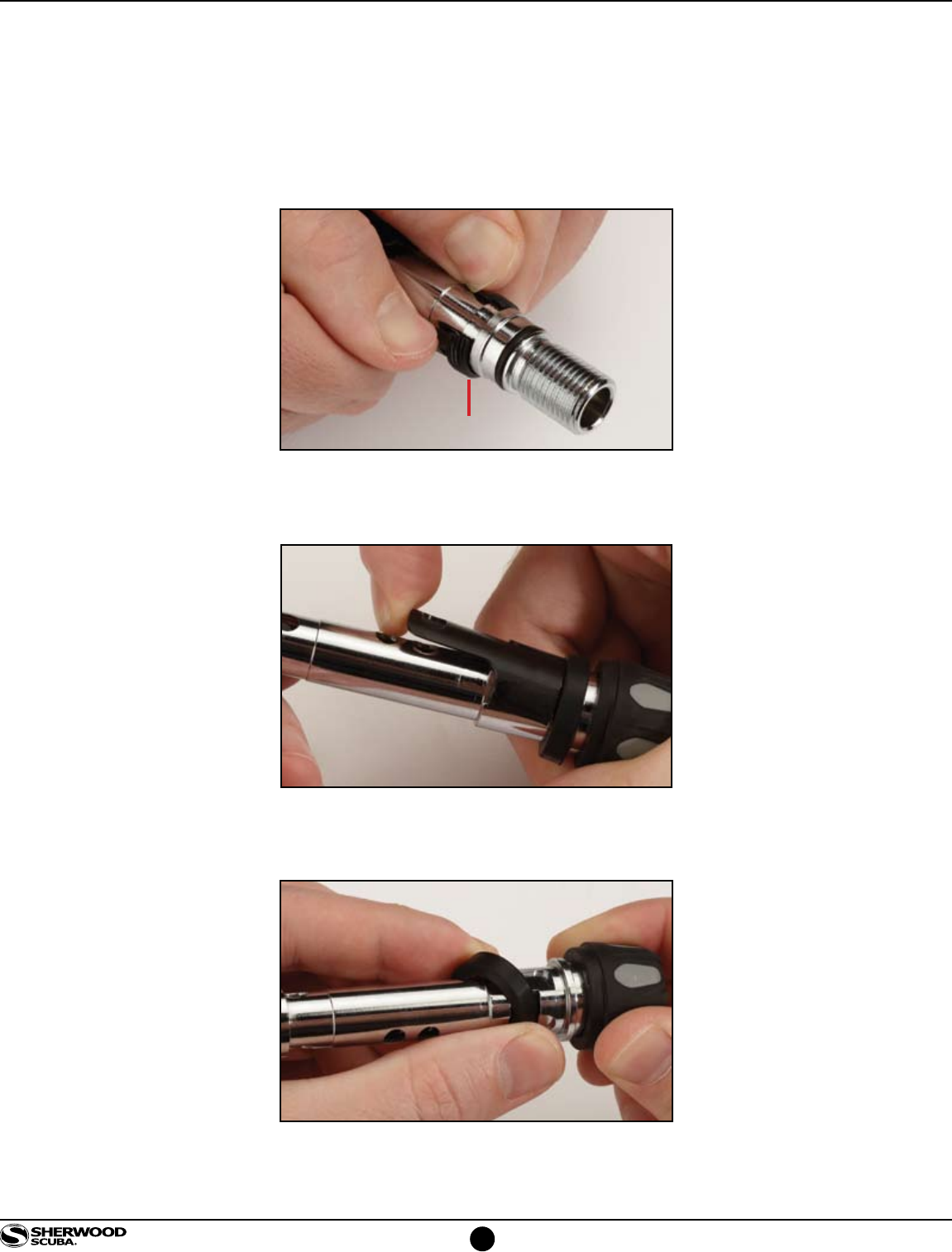
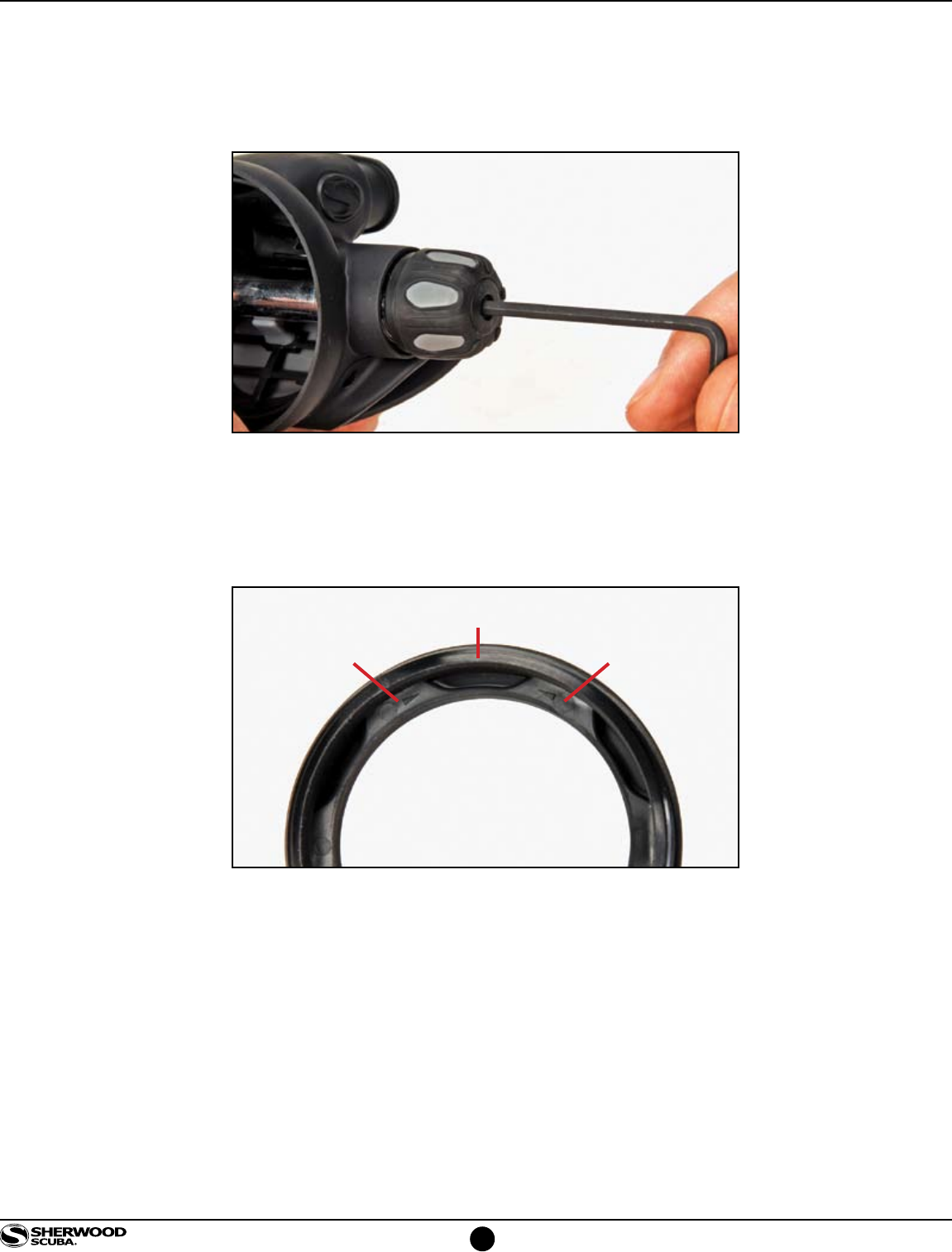
21. Use a 5/32" hex key to remove the Knob Retainer (21) and Control Knob (20) and set aside for cleaning
and reassembly.
22. Use a 1/8" hex key to remove the Adjustment Stem (19) Set aside the Adjuster Body for cleaning
and reassembly.
23. Remove and discard O-ring (18).

12
www.sherwoodscuba.com
2
SECTION
GENERAL CLEANING PROCEDURES
1. Thermoplastic, silicone rubber and anodized aluminum parts, such as diaphragms, adjustment knobs, static
O-rings, and thermoplastic housings.
a. Soak in a solution of warm water and ordinary liquid dish detergent. Scrub with a soft nylon bristle brush
to remove deposits.
b. Rinse with fresh water and blow dry with clean low pressure compressed air.
2. Chrome-plated Brass and Stainless Steel parts -
a. Soak in a solution of warm water and ordinary liquid dish detergent. Scrub with a soft nylon bristle brush
to remove deposits.
b. Thoroughly rinse with fresh water.
c. If deposits cannot be removed with above process, soak parts in dilute solution of white vinegar
(50% water) for approximately 30 minutes and scrub with a nylon brush. Use of an ultrasonic cleaner will
accelerate this process. Do not subject thermoplastic or rubber parts to vinegar solution or
ultrasonic cleaning.
d. Rinse first with freshwater and follow up with a final rinse in deionized (distilled) water. Tap water
typically contains minerals that will leave undesirable residue on the cleaned parts if final rinse is omitted.
3. Hoses -
a. Corrosion or mineral deposits on the metallic fittings on hoses may be cleaned using the procedure
presented above provided that care is taken to just dip only the metal fittings at each the end of the hose
into the cleaning solution. Take care to prevent entrance of the solution into the hose interior.
b. Rinsing should include flushing the interior of the hose with fresh water followed by drying with
compressed air.
13
www.sherwoodscuba.com
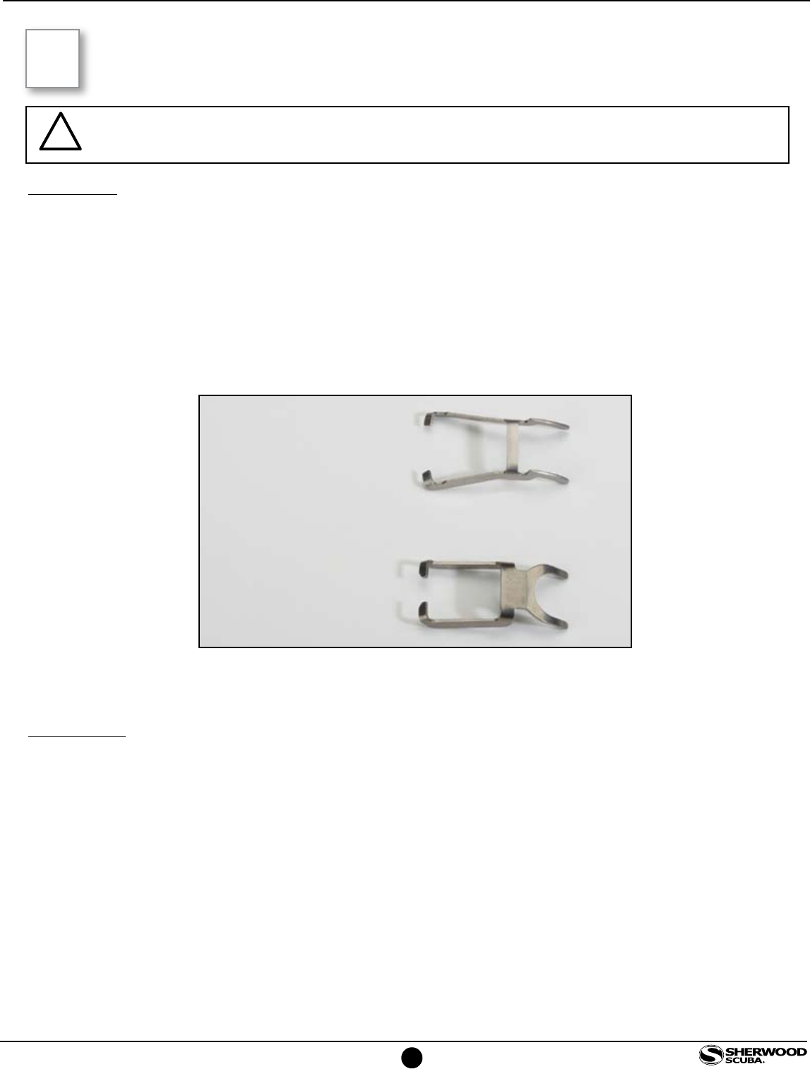
Inspection
a. Inspect the Lever (8) for distortion. The legs of the Lever should be parallel and the end tabs should be
perpendicular to the legs as shown below.
b. Inspect the Orifice sealing areas at the tip of the Orifice (5) and the O-ring groove for scratches, nick or
distortion. Imperfect surfaces can cause leaks. Discard and replace Orifice if sealing surfaces
are damaged.
c. Inspect the second stage Diaphragm (26) for pin holes, tears, or other damage. Hold the Diaphragm up
to a light source and stretch lightly to expose potential damage. Replace it if damaged.
d. Inspect all rubber and plastic parts for signs of cracking, distortion or other damage. Replace
if damaged.
Lubrication
Christo-Lube 111 is the only approved lubricant for Sherwood regulators. Silicone lubricant is not approved and
may present a hazard for use with Enriched Air Nitrox (EAN).
O-ring lubrication -
a. General - O-rings in most instances should receive only enough lubricant to ensure they are supple. A
light coating of lubricant should present a surface that glistens but without a defined layer of lubricant
visible.
b. Ample – When an ample application of lubricant is specified it generally applies to a dynamic O-ring
subject to considerable motion or environmental conditions where a more generous application of
lubricant might be beneficial. In this situation there should be a light film or layer of lubricant visible.
3
SECTION
INSPECTION AND LUBRICATION PROCEDURES
ACCEPTABLE
UNACCEPTABLE
NOTE – Inspection and lubrication must be preceded by thorough cleaning to enable adequate
exposure of damaged parts and proper application of lubricant.
14
www.sherwoodscuba.com
4
SECTION
REASSEMBLY PROCEDURES
1. Place an amply lubricated new O-ring (4) on the Orifice (5) and insert the Orifice into the threaded end of the
Valve Body (9). Press with the 1/4” wooden dowel unit the Orifice is fully seated.
2. Slide the Ring Seal (6) over the threaded end of the Valve Body until it reaches the shoulder near the opposite
end. Observe the orientation of the taper of the Ring Seal so that the smallest diameter is toward the threaded
end of the Valve Body.
3. Install the Lever Saddle (7) over the Valve Body taking care to align the tab under the threaded area of the Lever
Saddle with the slot in the outer surface of the Valve Body.
4. Attach Lever (8) by inserting one leg into the side hole of the Lever Saddle and then by gently pulling the other
leg outwardly just enough to pass over the Valve Body to engage the opposite side hole.
5. Apply ample lubricant to O-ring (3) and install it onto the Valve Body taking care to avoid damage to the O-ring
as it passes over the Valve Body threads. Additional lubricant is needed in this application to minimize friction to
allow the Adjustment Sleeve (2) to move easily during the adjustment procedure.
NOTE – Be certain that the O-ring is amply lubricated so that it will move freely when the second stage
is pressurized and depressurized.
Slot
15
www.sherwoodscuba.com
6. Thread the Adjustment Sleeve onto the Lever Saddle (7) until there is only about one thread exposed. Set valve
body assembly (9) aside.
7. Place a lubricated new O-ring (18) on the Stem (19) and insert the Stem into the Adjuster Body (17). Use a
1/8” hex key to fully seat the Stem inside the Adjuster Body. Do not over torque. Just tighten until you feel it stop.
When fully seated the Stem should project from the Adjuster Body by about 1/16 “. Place a lubricated new O-
ring (16) on the Adjuster Body. Set subassembly aside for later insertion onto the Valve Body.
8. Insert a new Seat (10) into the Poppet (11). Insert an amply lubricated new O-ring (12) at the small end of the
Poppet.
9. Hold the Valve Body (9) with the Lever (8) positioned at an upward 90° angle with the axis of the valve Body.
Use the Poppet/Flange O-ring Installation Tool (P/N 20-706-100) to hold the Poppet (11) with the lever contact
tabs facing downward and insert the Poppet into the Valve Body. Test the correct positioning by applying
force against the installed Poppet. The Lever should rise. If it fails to rise, the lever contact tabs are not aligned
properly with the Lever. In this case the Poppet must be removed and reinserted to obtain the correct positioning.
After the Poppet is positioned correctly, insert the Spring (13) and Balance Chamber (14) into the Valve Body.
Apply force to the end of the Balance Chamber to lightly compress the Spring and actuate the Lever to verify that
it responds to spring force.
End of Stem
Lever Contact Tab
16
www.sherwoodscuba.com
10. Insert the Adjuster Body (17) into the Valve Body (9) threading clockwise just until thread engagement starts.
Place the control Knob (20) onto the Adjuster Body and continue threading the adjuster Body into the Valve
Body until the groove in the Adjuster Body is centered in the rectangular hole in the Valve Body.
11. Attach the Diverter (15) onto the Valve Body covering the rectangular hole.
12. Secure the Knob (20) in place by threading the Knob Retainer (21) into the end of the Knob. Tighten the Knob
Retainer with a 5/32” hex key until snug.
13. If the Exhaust Valve (33) was removed reinstall it by passing the small tab through the rectangular hole in the
Body Housing (30). Pull the tab until the Exhaust Valve fully seats.
14. Hold the Housing (30) oriented to view the front of the second stage. Depress the Lever and pass the Valve Body
(9) through the housing moving from right to left.
15. Insert lubricated O-ring (29) and install the Clip (35) over the Valve Body between the Adjustment Sleeve and
the threads of the Valve Body. Install the Retaining Nut (28) and tighten until snug.
Adjuster Body Groove Aligned with Valve Body Hole
Adjuster Body Centered
17
www.sherwoodscuba.com
16. While holding the Housing (30) with the two tabs located on the shoulder of the housing below the mouthpiece
boss facing up, locate the two slots on the top of the Exhaust Cover (34). Align the two slots with the two tabs
and assemble the exhaust Cover to the Housing, complete the installation of Exhaust Cover by compressing the
bottom edge of the cover engaging the two lower slots and tabs.
17. Install a lubricated new O-ring (4) in the LP Hose (1) and attach the Hose to the Valve Body. Move the Hose
Protector (27) to the fully seated position.
18. Attach the partially assembled second stage to properly functioning first stage with an intermediate pressure set
at 135 ± 10 psi.
19. Rotate the Knob (20) to the full counterclockwise position.
SECOND STAGE ADJUSTMENT
20. Apply intermediate pressure to the second stage. If air leaks by the Poppet the Orifice may not be in the correct
position. It should automatically move to the proper position when the regulator is pressurized. Turn off the
supply pressure and then quickly reopen the supply valve to apply a surge of pressure to the second stage. This
should properly position the Orifice.
21. Insert a small probe through one of the slots in the Retainer Nut (28) to engage one of the linear slots in the
Adjustment Sleeve (2). Rotate the Adjustment Sleeve counterclockwise until a slight leak is detected and then
rotate it clockwise until the leak just stops. From this position rotate the Adjustment Sleeve clockwise through an
arc equal in length to one of the slots in the Retaining Nut.
18
www.sherwoodscuba.com
22. With the control Knob still rotated fully counterclockwise complete the fine adjustment as follows:
Insert a 1/8” hex key into the Adjuster Stem (19) and rotate it counterclockwise until leakage starts and then
rotate it clockwise until leakage stops. This establishes the optimal adjustment of the second stage opening
effort. If initial rotation in the counter clockwise direction does not result in air leakage, the spring already
provides sufficient force and the clockwise rotation of the hex key is not necessary.
23. Install the Diaphragm (26).
24. If the Cover Assembly was not disassembled proceed to step 25. If it was disassembled proceed as follows.
a. Orient the Cover Ring (23) to view the inside detail. Observe the two opposing arrow tips and adjust the
Cover Ring so that the slotted hole in the Cover Ring located between the arrow tips is at 12 O’clock.
b. Match the metal Accent Ring (22) to the front of the Cover Ring (23). There are six possible positions for
the Accent Ring to engage the Cover Ring. Any of the six are acceptable.
c. Determine which of the six feature lines on the inside of the Cover (24) align with the “SHERWOOD”
logo on the outside of the cover. Match the selected feature lines so that they align at the 9 O’clock and 3
O’clock positions on the inside of the Cover Ring. Install Cover Retainer (25) and tighten with the Cover
Retainer Tool (P/N 20-703-100) until the Cover cannot be rotated relative to the Cover Ring.
25. Install the Cover Assembly into the Housing and tighten by hand until the space between the Housing and Cover
Assembly is closed. When the Cover is fully installed the “SHERWOOD” logo will be displayed in horizontal
alignment with front of the second stage. If installation of the Cover Assembly causes the second stage to leak the
Lever height may be slightly out of adjustment. Repeat steps 19-21 with the Cover in place. There should be no
need to repeat steps 20-22.
12 O’clock
Arrow TipArrow Tip

19
www.sherwoodscuba.com
25. Rotate the control Knob fully clockwise. Press the Cover to check the purge function. There should be a strong
flow of air. If there is not a strong flow, it is likely that the Lever was not positioned correctly repeat steps 19-21.
26. Install the Mouthpiece (32) onto the Housing. Secure the connection with a Tie Strap (31). Trim excess material
from the Tie Strap.
This concludes the service procedure for the SR1 Second Stage
20
www.sherwoodscuba.com
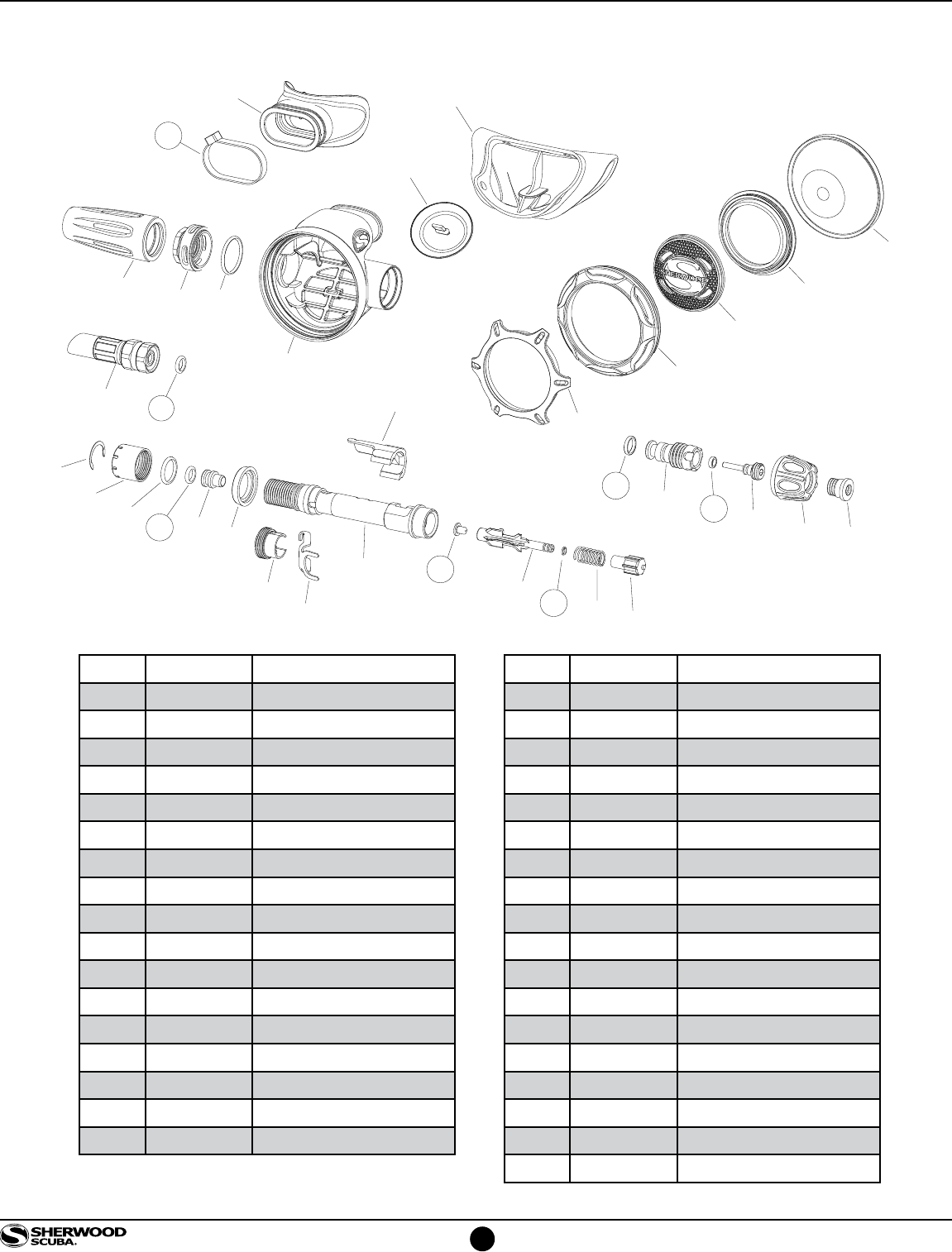
ITEM PART # DESCRIPTION
1 1000-50-31 LP-Hose
2 1200-2 Adjustment Sleeve
3 972013 O-ring
4 970010 O-ring
5 1200-5 Orifice
6 1200-6 Ring Seal
7 1200-7 Lever Saddle
8 1200-8 Lever
9 1200-9 Valve Body
10 7206-98N Seat
11 1200-11 Poppet
12 970410 O-ring
13 1200-13 Spring
14 1200-14 Balance Chamber
15 1200-15 Diverter
16 972010 O-ring
17 1200-17 Adjuster Body
35
2
3
45
6
7
8
910
11
12
14
13
15
16
17 18
19
20 21
22
23
24
25
26
27
28 29
31
32
30
33
34
4
1
SR1 SECOND STAGE
ITEM PART # DESCRIPTION
18 972006 O-ring
19 1200-19 Stem
20 1200-20 Knob
21 1200-21 Knob Retainer
22 1200-22 Accent Ring
23 1200-23 Cover Ring
24 1200-24 Cover
25 1200-25 Cover Retainer
26 1200-26 Diaphragm
27 1200-27 Hose Protector
28 1200-28 Retaining Nut
29 972016 O-ring
30 1200-30 Housing
31 7206-1 Tie Strap
32 7206-3 Mouthpiece
33 1200-33 Exhaust Valve
34 1200-34 Exhaust Cover
35 1200-35 Clip
001
