SSM2033
User Manual: SSM2033
Open the PDF directly: View PDF ![]() .
.
Page Count: 4
SoUdSlcile SSM
2033
VOLTAGE
CONTROLLED
OSCILLATOR-
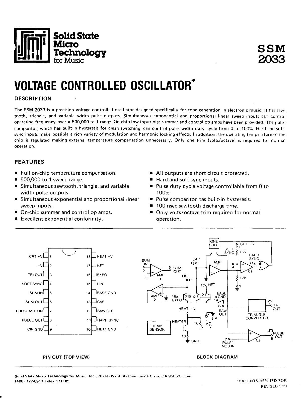
DESCRIPTION
The SSM 2033 is a precision
voltage controlled oscillator designed
specifically
for tone generation
in electronic music.
lt has
saw-
tooth, triangle,
and variable
width pulse
outputs. Simultaneous
exponential
and proportional linear
sweep inputs can control
operating
frequency over a 500,000-to-1 range.
On-chip
low input bias summer
and control
op amps
have
been
provided.
The
pulse
comparitor,
which has built-in
hysteresis for clean
switching,
can control pulse
width duty cycle from 0 to 100%.
Hard
and
soft
sync
inputs make possible
a rich variety of modulation
and
harmonic
locking effects. ln addition, the
operating temperature
of the
chip is regulated making external
temperature
compensation unnecessary.
Only one trim (volts/octave)
is required
for normal
operation.
FEATURES
Mlcro
Technologry
lor Music
Full
on-chip temperature compensation.
500,000-to-1 sweep
range.
Simultaneous sawtooth, triangle,
and
variable
width
pulse
outputs.
Simultaneous exponential and
proportional
linear
sweep
inputs.
On-chip summer
and control
op amps.
Excellent
exponential conformity.
All outputs
are
short
circuit
protected.
Hard and
soft
sync inputs.
Pulse
duty
cycle voltage
controllable from 0 to
100%
Pulse
comparitor
has
built-in
hysteresis.
100 nsec sawtooth
discharge
t''ne.
Only
volts/octave
trim required for normal
operation.
I
I
I
t
I
I
!
I
tI
I
t-1
2 17
3 16
4 15
5 14
6 13
7 12
8 11
I 10
CRT
+V
-V
TRI
OUT
SOFT
SYNC
SUM IN
SUM OUT
PULSE
MOD IN
PUL6E
OUT
CIR
GND
HEAT +V
HFT
EXPO
LIN
BASE GND
SAW
OUT
HARD SYNC
HEAT GND
PIN OUT
(TOP
VIEW)
CFT 'V
I
BASE
GND
,OA
BLOCK DIAGRAM
Solid
Srare Micro Technology
for Music, Inc.,20768 Walsh
Avenue,
Santa Clara,
CA 95050,
USA
l408l 727-0917 Telex 171189 .PATENTS
APPLIED
FOR
REVISED
5
81
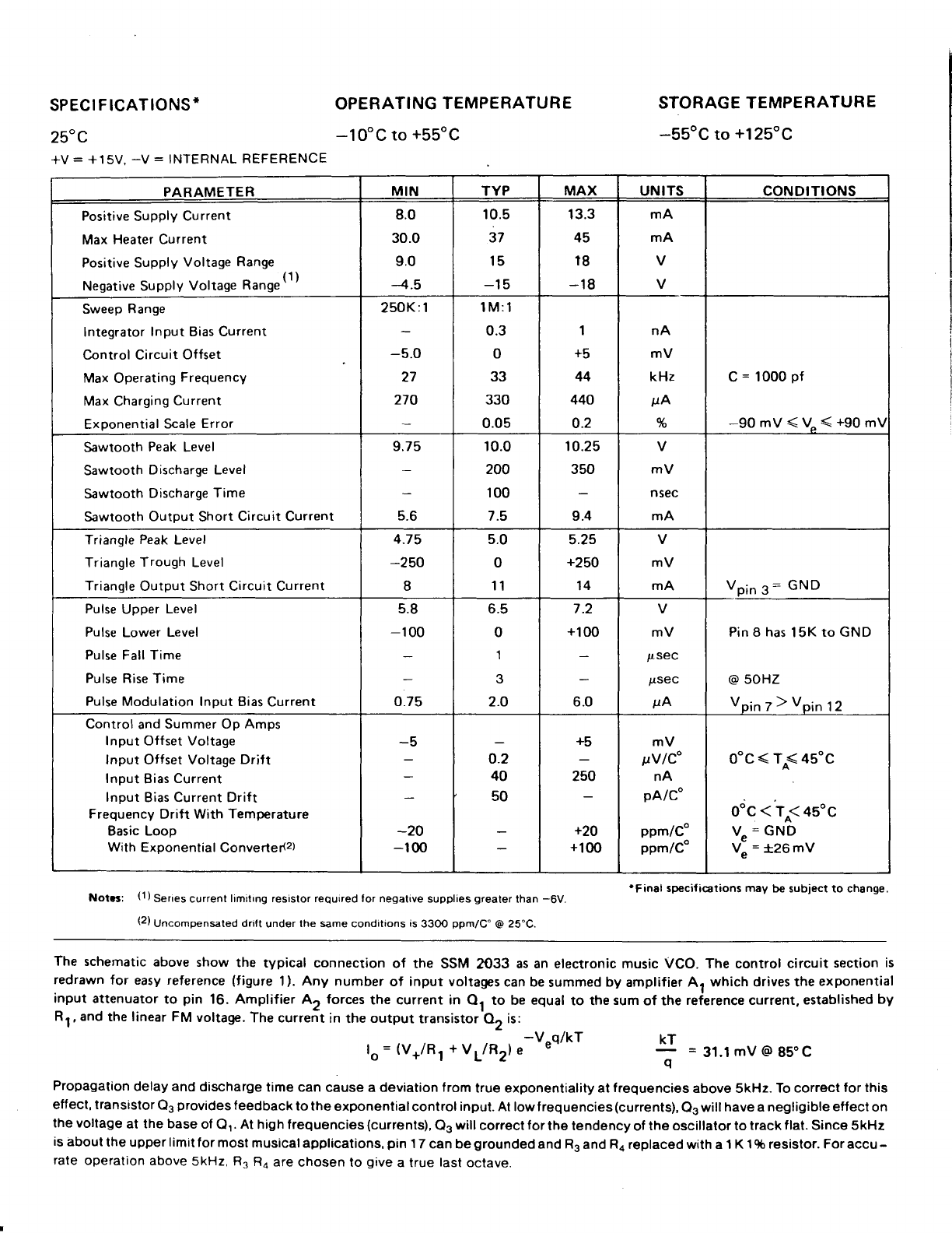
SPECIFICATIONS*
25"C
*V
= *15V.
-V = INTERNAL
REFERENCE
OPERATING
TEMPERATURE
-10"C
to
+55oC
STORAGE TEMPERATURE
-55oC
to
+125"C
PARAMETER MIN TYP MAX UNITS CONDITIONS
Positive
Supply
Current
Max Heater
Current
Positive Supply
Voltage
Range
Negative Supply
Voltage
R.ng"(1)
8.0
30.0
9.0
4.5
r0.5
37
15
-15
13.3
45
18
-18
mA
mA
V
V
Sweep
Range
Integrator
Input Bias Current
Control Circuit Offset
Max
Operating
Frequency
Max
Charging
Current
Exponential
Scale
Error
250K:1
-5.0
27
270
1M:1
0.3
0
33
330
0.05
1
+5
44
440
o.2
nA
mV
kHz
sA
%
C
= 1000
pf
-90 mV
< V^
< +90
m!
Sawtooth Peak
Level
Sawtooth Discharge Level
Sawtooth Discharge
Time
Sawtooth Output Short Circuit Current
9.75
5.6
10.0
200
100
7.5
10.25
350
9.4
V
mV
nsec
mA
Triangle
Peak
Level
Triangle
Trough Level
Triangle
Output Short Circuit Current
4.75
-250
I
5.0
0
11
5.25
+250
14
V
mV
mA Vpin
3: GND
Pulse
Upper
Level
Pulse
Lower Level
Pulse Fall Time
Pulse Rise Time
Pulse
Modulation Input Bias
Current
5.8
-100
0.75
6.5
0
1
3
2.O
7.2
+100
6.0
V
mV
pseC
psec
pA
Pin 8 has
15K
to GND
@
50HZ
VpinT)Vpin12
Control
and
Summer Op Amps
Input Offset Voltage
lnput Offset Voltage
Drift
Input
Bias
Current
lnput Bias Current Drift
Frequency
Drift With Temperature
Basic Loop
With Exoonential
Converter(z)
-5
-20
-r00
o.2
40
50
+5
250
+20
+100
mV
pVlC"
nA
pA/Co
ppm/Co
ppm/C"
o"c
< TA< 45oc
odc < To< 4s"c
V"
=
GND
V" =
i26 mV
Not6: (1)Series
current
limi|ng resistor required tor negative
supplies
greater
than
-6V
(2)
Unco*pensated drift under
the same
conditions
is
33OO
ppm/C' @
25'C.
'Final specifications may be subiect to change.
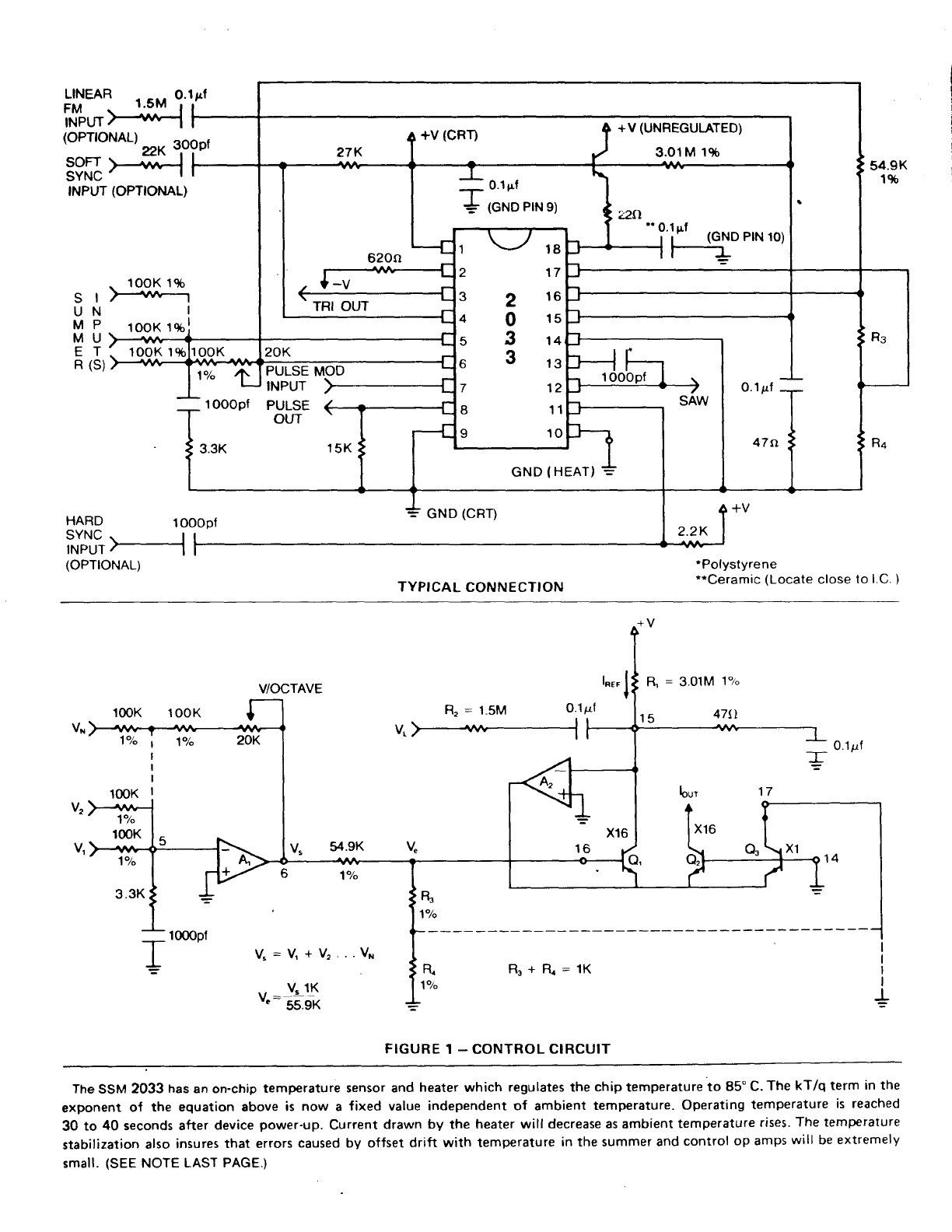
The schematic
above
show
the typical connection
of the SSM
2033 as an electronic music VCO. The control
circuit
section
is
redrawn
for easy reference
(figure
1).
Any number
of input voltages
can be
summed
by amplifier A1 which drives the
exponential
input attenuator
to pin 16. Amplifier
A, forces
the current in Q1 to be equal
to the
sum
of the
reference current,
established
by
Rr, and
the linear FM
voltage.
The current
in the
output
transistor
02 is:
KT
E =31.1
mV@85"C
q
Propagataon
delay and
discharge
time
can
cause
a deviation f rom
true exponentiality al
lrequencies
above 5kHz.
To correct
for this
effect, transistor
Q3
provides
feedback
to the
exponentialcontrol input.
At low f requencies
(currents),
Q3 will
have a negligible
effect
on
the voltage
at the base
of
Q.'.
At
high f requencies
(currents),
Q3
will
correct
for
the tendency
of
the oscillator to
track flat. Since 5kHz
is
about
the
upper
limit
for
most
musical applications,
pin
1
7 can be
grounded
and R3
and
R4
replaced with a 1
K
1%
resistor.
For
accu
-
rate
operation
above
5kHz, R3
Ro
are
chosen to give
a true
last
octave.
-V^qi kT
lo=(V+/Rl+VL/R2)e E'
+V
(UNREGULATED)
3.01M
1%
T o.tpt
+ (GND
PIN
s)
" ? l,"t (GND
PlN 10)
-l t-:-
1
2
3
4
5
6
7
I
o
18
17
16
15
14
13
't2
11
10
GND
(HEAT)
54.9K
1%
INPUT
(OPTIONAL)
SI
UN
MP
MU
ET
R
(S)
. lOOK 1%
I
roox rc6l
looK'l
1o/o PULSE
MOD
1
OOOpf
INPUT
PULSE
OUT
15K
3.3K
HARD lOOOpt
i-"J,?>--
(OPTIONAL)
GND
(CRT)
TYPICAL
CONNECTION
2.2K
'Polystyrene
**Ceramic
(Locate
close
to l.C.
)
V/OCTAVE l".r
l
O.1pf
R' = 3.01M
19"
47tl
100K 1
00K
1o/"
1.5M
1o/o
100K
'lo/"
100K
R.+fu=16
0.1sf
1o/o
3.3K
54.9K
1o/"
100Opf I
I
I
I
+
R.
1o/"
rV"=V+%
., --V" (
" - 55.9K
FIGURE
T
_ CONTROL
CIRCUIT
The
SSM 2033 has an on-chip
temperature sensor and heater which regulates the chip temperature
to 85'C. The kT/q term in the
exponent of the equation above is now a fixed value independent of ambient temperature. Operating temperature is reached
30 to 40 seconds after device power-up. Current drawn by the heater will decrease as ambient temperature rises.
The temperature
stabilization also insures
that errors
caused by offset drift with temperature in the summer and control op amps
will be
extremely
small. (SEE
NOTE LAST PAGE.)
The outtlut current
oi the
control
circuit
is
fed
to an
integrating
amplif
rer
whrch
creates the sawtooth
waveform.
The instantaneous
sawtooth output is compared to a reference
voltage that is two-thirds of the positive supply. Sawtooth discharge
is accomplished
by a capacitorless
one-shot
which delivers
a pulse
to the discharge transistor
when triggered by comparator C1.
The triangle converter and pulse width comparator shape the sawtooth to provide the other two waveform outputs. The 27K
resistor between the positive supply and the soft sync pin centers the sawtooth for proper triangle conversion. Comparator C2
compares
the pulse width modulation input voltage to the instantaneous
sawtooth output to create a pulse that can have a duty
cycle between 0 and 100%.
The control range
on the PWM input is between
0 and 10 V. C2 has
about 180 mV of built'in hysteresis
to give
fast clean transistions
on both the rising
and falling edges of the output.
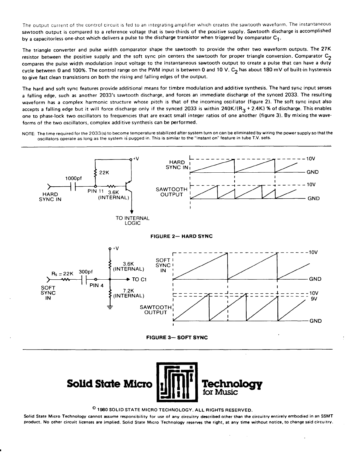
The hard and soft sync features
provide additional means for timbre modulation and additive synthesis.
The hard sync input senses
a falling edge. such as another 2033's sawtooth discharge, and forces an immediate discharge of the synced 2033. The resulting
waveform has a complex harmonic structure whose pitch is that of the incoming oscillator (figure 2). The soft sync input also
accepts a falling edge but it will force discharge only if the synced 2033 is
within 240Kl(R3 +2.4K1 %of discharge. Thisenables
one to phase-lock
two oscillators
to freguencies that are exact small integer ratios of one another (figure
3). By mixing the wave-
forms of the two oscillators,
complex additive synthesis can be performed.
NOTE: The
time required
f
or
the 2033
(s)
lo
become
temperature stabilized
afler system lurn on can be eliminated by
wiring
the
powef
supply so
lhat the
oscillators
operale
as
long as the system
ii pugged
in.
This
is
similar to
the
"instant
on"
feature in tube T.V. sets.
1 000pf
>--l
HARD
SYNC
IN
R5 = 22K 3,o9ef
>-*--l h
SOFT T
SYNC
IN
PIN 11 3.6K
(TNTERNAL)
HARD I
SYNC lN
r
t-
SAWTOOTH'
OUTPUT :
FIGURE
2_ HARD
SYNC
SOFT
SYNC
IN
--10v
GND
GND
TO INTERNAL
LOGIC
3.6K
(TNTERNAL)
TO C1
7.2K
(TNTERNAL) -----l
SAWTOOTH
OUTPUT
9V
GND
FIGURE
3_ SOFT SYNC
SoUd
Stcrte
Mlcro ffir
Teghnologry
lor Music !'
@
tso soLrD srATE
MrcRo
rEcHNoLocy. ALL
RTGHTS
RESERvED.
Solid State Micro Technology cannot assume
responsibility for use ol any circuitry dercribed oth€r than the circuitry entirely embodied in an SSMT
product. No other circuit licenses are implied. Solid Stare
Micro Technology reserves thc right. at any tima without notice, to change
said
circuitry.
