Standby Power Supply Using Alternative Energy Through Cogeneration Technologies Telecommunications Special, The Third I
User Manual: Home
Open the PDF directly: View PDF ![]() .
.
Page Count: 5
STANDBY POWER SUPPLY USING ALTERNATIVE ENERGY
THROUGH COGENERATION TECHNOLOGIES
Dr. Jardan,
R.
K.
*,Dranga,
0.
(Ph.D.
Student)*,
Bereknyei, D.
(Ph.D. Student)*
*
BUDAPEST UNIVERSITY
OF
TECHNOLOGY
AND
ECONOMICS
H-1
1 1
1
Budapest, Budafoki,8.
Hungary.
Tel:
+361-463-2338,
Fax:
+361 4633163
e-mail: jrk@elektro.get.bme.hu
ABSTRACT
A
special co-generation system, developed for producing electric and heat energy from low pressure saturated steam or
some other working medium has been developed. The system consists of a high speed turbine, coupled to
a
three-
phase permanent magnet synchronous generator, a three-phase
ACIAC
converter and
a
microprocessor supervisory
control unit. The main purpose of the system is to produce electric energy, that can be utilised directly to supply loads
in stand-alone mode or it can be fed back to existing utility mains. In the latter case the converter, connected in parallel
to the mains, can serve
also
as a source of reactive power and higher harmonic current components, i.e. the converter,
by changing its control method, can be turned into a system providing not only active power, but functioning
as
a
complete active filter or a.c. line conditioner at the same time. In the paper a further feature of the system, its ability to
serve also as a stand-by (SPS) or uninterruptible power supply (UPS) is presented in some detail.
1 INTRODUCTION
The paper describes a special system ‘designed
to be used
as
an alternative power source for
telecommunication equipment or as an UPS-system.
The system
is
based on the application of co-
generation principle, that makes it possible to generate
electric and heat energy by utilising alternative
renewable and waste energy sources. The basis
of
the
solution is a system that consists of a high-speed turbine
coupled to
a
three-phase synchronous generator, a three-
phase
ACIAC
converter and a microprocessor
supervisory control unit. The function of the system is
to utilise the energy content of some working medium,
such as steam, gas or pressurised fluid, by a special
turbine.
A
more detailed description of the system can
be found in
[l].
The turbine is developed for various
working media
of
low energy content. Genetally, the
system, beside heat energy produces electric energy,
that can be utilised directly to supply loads in stand-
alone mode in isolated rural areas as general-purpose
power supply for telecommunication and other loads or
feeding it back to existing utility mains. The additional
feature of the system that makes it possible to use it
as
an a.c. line conditioner is presented in
[2].
As
the energy source
of
the system is different
from the mains, it offers the possibility to use
it
as an
SPS
or UPS. In the parallel mode of operation, when
the system feeds energy back to the mains, during mains
failures, it
can
serve as
a
standby power supply or UPS
for a selected group of loads including
telecommunication equipment.
A
possible advantage of the system is that
it
can use alternative energy sources that are suitable for
producing saturated or superheated steam with
IOW
or
medium pressure, thus it is applicable in
.
telecommunication systems even in places where
electric energy is not directly available. In most cases
the electric energy can be produced within co-
generation or less frequently in direct generation
process. The alternative renewable energy sources
include solar energy (direct solar steam system
or
solar
energy with heat exchanger), geothermal energy (with
or without heat exchanger) and biomass energy. Various
waste energy sources can
also
be utilised by applying
the system. These include the energy extracted from the
procgs of pressure reduction in steam, gas and fluid
networks and the energy that can be recovered
in
the
process of seawater desalination.
2.
Description
of
the
system
Various configurations
of
uninterruptible power supply
systems are available to increase the reliability of the
energy supply and improve the overall performance.
Development of an up-to-date high performance system
requires careful attention to every detail of
it.
In
a
previous paper
[4]
solution to problems of the inverter
21
5
stage was presented, here the questions of application of
renewable energy sources is discussed in some detail.
At the beginning of static
UPS
applications the
system was built of a controlled rectifier an inverter
(including the filter) and a battery connected to the DC
link. It soon became evident that this simple
arrangement had two basic shortcomings. First, if any
problem occurred in the inverter operation, the supply
of the load was lost, even if the mains was present. The
second problem is connected with the internal
impedance of the inverter and filter stage. In case of a
transient load increase, the output voltage had relatively
large drops, that frequently resulted malfunction of
sensitive loads.
Great improvement in system performance was
achieved by the introduction of fast-acting static
switches.
In the scheme shown in Figure
1
static switch
SW
is closed in normal operation while static transfer
switch STS is open. In case of failure
or
excessive
voltage drop detection,
SW
is open and at the same time
STS
is closed. This way a large current transient can be
supported by the mains. If the load current returns to
normal and output voltage of the inverter is within
tolerance, the load can be transferred back to the
inverter.
&
WTT.
STS
I
Figure
1.
Block diagram of a
UPS
configuration
A brief description of the system is given
for the application
in
steam networks, however, it
should be emphasised that the key elements and the
basic principles of the operation are the same in the
case of other energy sources and working media.
Applying the turbine-generator system, the
functional block diagram shown in Figure
1.
has to
be modified, as the rectifier is supplied by the
generator instead of the mains. The generator, driven
directly by the turbine,
is
a machine of special
construction. Due to the high speed and the
requirement of high reliability, a permanent magnet
solution has been selected. The output voltage of the
generator is fed to the rectifier
R
that is followed by
the inverter
INV.
The resulting AC/AC converter
connects the generator of variable frequency and
output voltage to the utility mains of fixed voltage
and frequency.
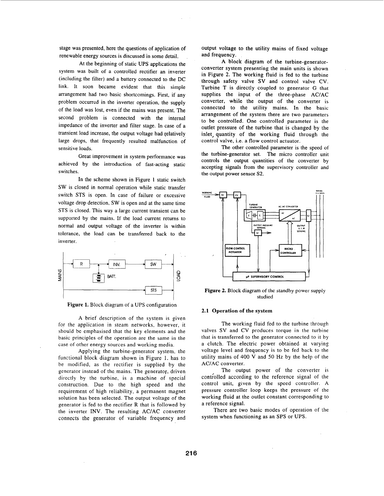
A
block diagram of the turbine-generator-
converter system presenting the main units is shown
in Figure
2.
The working fluid
is
fed
to
the turbine
through safety valve
SV
and control valve CV.
Turbine
T
is directly coupled to generator
G
that
supplies the input of the three-phase AC/AC
converter, while the output of the converter is
connected to the utility mains. In the basic
arrangement
of
the system there are two parameters
to be controlled. One controlled parameter is the
outlet pressure of the turbine that is changed by the
inlet, quantity of the working fluid through the
control valve, i.e.
a
flow control actuator.
The other controlled parameter is the speed
of
the turbine-generator set. The micro controller unit
controls the output quantities of the converter by
accepting signals from the supervisory controller and
the output power sensor
S2.
4C.AC CONVERTER
I
I
TURBINE
CINERATOR
m
pP
SUPERVISORY
CONIROL
Figure
2.
Block diagram
of
the standby power supply
studied
2.1
Operation
of the
system
The working fluid fed to the turbine through
valves SV and CV produces torque
in
the turbine
that is transferred to the generator connected to
it
by
a clutch. The electric power obtained at varying
voltage level and frequency is to be fed back to the
utility mains
of
400
V
and
50
Hz
by the help
of
the
ACfAC converter.
The output power of the converter is
cont;olled according to the reference signal of the
control unit, given by the speed controller.
A
pressure controller
loop
keeps the pressure
of
the
working fluid at the outlet constant corresponding to
a reference signal.
There are two basic modes of operation
of
the
system when functioning as an
SPS
or
UPS.
21
6
2.1.1.
Stand-alone or Island Mode
of
Operation
In this mode the loads are directly supplied by the
converter of the turbine-generator system.
Theoretically, in this mode the turbine-generator
system, without any additional measures, is
functioning like a UPS. Naturally, the group of the
loads have to be selected to match the output power
of the UPS. The control strategy of the system is
based on controlling the input power on the
mechanical side to ensure power equilibrium
between the mechanical and electrical side.
2.1.2. Parallel mode.
In this mode both the turbine-generator system (UPS)
and
a
selected group of loads are connected to the
mains. In normal mode the turbine-generator system
feeds all the power back to the utility mains, available
on the mechanical side, that is automatically ensured by
the speed regulation of the machine set. In case of mains
failure the group of loads is disconnected from the
mains by opening the static transfer switch STS and
further on the power will be supplied by the turbine
-
generator system. Apart from some switching transients
the power supply of the loads can be regarded
continuous. When the static transfer switch is opened,
the control strategy of the turbine-generator system has
to be changed to correspond to the stand-alone mode.
After the mains returns to normal, the system can be
restored to the original state.
3
Power Factor Correction
In an industrial environment a considerable portion
of
the loads have a poor power factor resulting from low
cos
cp
and high harmonic content of the load current.
The principles of compensating the reactive power and
the higher harmonic content will be discussed next.
3.1 Compensating Reactive Power
Assuming that the mains current contains only
fundamental component but the power factor needs
correction, reactive power has to be supplied to the
mains. If the power source is suitable to change the
reactive power supplied, a closed-loop power factor
compensation can be built by sensing the power factor
at
a
point of the network where compensation and
controlling the source of reactive power is needed to
supply the required amount of reactive power. When the
power capability of the reactive power source is limited,
it
makes
it
only possible to improve the power factor
or
to
compensate the power factor of
a
selected group of
loads. This is the case with the converter of the turbine-
generator system
as
the rated power of the unit is
generally considerably lower than the power level
required e.g. by
a
factory.
If the reactive power of the loads
is
QL,
to
obtain
unity
power factor,
a
reactive power
QL
has to be fed to
the mains. By sensing the reactive power needed, the
converter can be controlled in such
a
way that it will
prodfice the requested power components The. contro!
unit has two input accepting reference signals
P
and
Q
that determines the active
P
and reactive
Q
power
independently.
For
this purpose the amplitude and the
phase of the internal voltage
of
the controller has to be
controlled.
A
converter dimensioned for rated current can supply
reactive power only if the active component
is
less than
rated. To produce reactive power by the converter at
rated active power evidently needs over-dimensioning
some parts of the converter. A
50
o/o
over-dimensioning
in current ensures that reactive power can be supplied,
in the range of
110
to
150
%,
depending on the active
power needed.
4
Simulation and test results
The idea described here has been checked by
computer simulations and laboratory tests.
A turbine generator converter system with an
output power of
20
kW
and
25
kVAr has been built and
tested. The system is installed in an industrial
environment where the Total Harmonic Distortion
(THD) of the mains voltage is unusually high due to
rectifier type loads. The average THD of the mains was
over
9
%
and
it
offered good opportunity to demonstrate
the effect of the converter on the power quality.
1
3-phase voltages
400
I-----'
,
300
i
200
I
100
jlull
so
-qp
-200
-300
I
-400
J
I
I
ttmsl
I
i
3-phase
currents
40
20
90
-20
-40
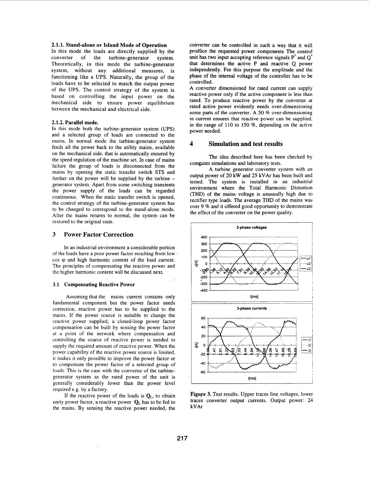
Figure
3.
Test results. Upper traces line voltages, lower
traces converter output currents. Output power:
24
kVAr
21
7
Signal
I”
phase
Ursm 223.43
1
thd(U)
-~
17.84- 17.95
-1
7i
~
1-
Irsm
36.23 34.18 33.60
thd(1) 12.53 11.62 11.89
2’Id phase 3rd phase
Total
226.04 225.73
I
i
I
I
S(kVA)
I
8.10
I
7.73
I
8.26
I
24.08
I
-0. I2 -0.46
-0.03
-0.61
-7.7
I
-8.26 -24.07
-0.01 -0.06 -0.03
Table
1.
Laboratory test results
U1
(Magnitude)
100
-1
0
12
3
4
5
6
7
8 9
101112131415
Harmonics
I
,
I1
(Magnitude)
I
I
I
100
15
10
i
s
mil
1
5
0
I
0
1
2
3
4 5
6
7
8
9
101112131415
Harmonics
I
Figure
4.
Harmonic voltages and currents test
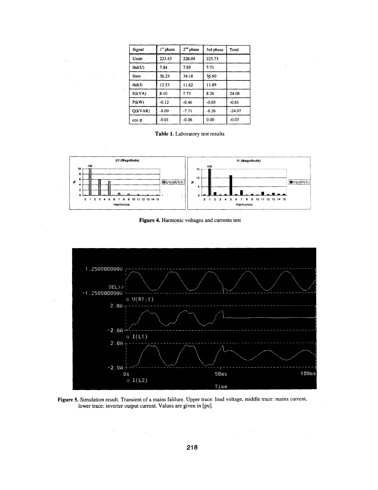
Figure
5.
Simulation result. Transient of a mains falilure. Upper trace: load voltage, middle trace: mains current,
lower trace: inverter output current. Values are given
in
[pu].
21
8
The results were recorded by using network analyser
equipment inserted between the output of the converter
and the mains. The equivalent circuit of the mains, from
measured values, was calculated as
R,=0.3
R
(ohmic
resistance) and
L,=
508
pH (inductance). The converter
filter parameters are
R,=0.05
R
and
L,=2.5
mH.
Figure 3. shows that the shape of the output
voltage and the current is different from the ideal
sinusoidal one due to its compensation affect on the
network. These results are displayed in Table
1.
During the above test the converter supplied
24 kVAr reactive power to the mains and the THD was
reduced from
9.4
%
to
7.8
%
corresponding well to the
calculated attenuation coefficient kp0.83.
Using &he measured harmonic compqnents
of
the line voltage and an above parameters the system was
simulated taking accurately into account the operation
of
the
converter with
a
switching frequency of
10
kHz
and applying a unipolar
PWM.
In Figure
5.
the results of a simulation run are
shown. In a system operating in parallel mode, a mains
failure is assumed at the instant of
50
ms. The static
transfer switch is opened and further on the load current
is supported by the inverter. The output current of the
inverter is reduced as the load is assumed to be lower
than rated.
It
can be seen that due to the distorted
waveform of the mains, the output current
of
the
inverter contains high harmonic content in normal
operation, while
it
becomes sinusoidal in the stand-
alone mode.
(A
linear load is assumed).
5.
Conclusion
consists of
a
high-speed turbine coupled to a three-phase
synchronous generator,
a
three-phase
AC/AC
converter
and a microprocessor supervisory control unit, was
presented. The system
is
designed to operate using
alternative energy source that is suitable also to serve
as
a standby or uninterruptible power supply.
A
control
strategy, easy to implement, ensures closed loop control
of the power factor and at the same time the power
quality is favourably affected.
References
Jgrdan,
R.K.
Generation
of
Eleciric Energy
by
High-speed Turbine -Generator Sets.
Proceedings
of
Intelec'95 Conference October 29-November
1.
The
Hague, The Netherlands, pp.664-670
Casadei, D.-Grandi, G.-Jardan, R.K.-Profumo,
F.
Control Strategy
of
a Power Line Conditioner
for
Cogeneration Plants.
PESC'99, Power Electronics
Specialists Conference, Charleston, South Carolina,
US.
June 27-July
1,
1999.
Jardan,
R.
K
-Nagy,
I.-
Korondi, P. Masada,
E
-
Nitta,T.-
Ohsaki,
H.
Power Generation Systeiii
for
Utilising
Alternative Renewable and Waste Energy
IPEC-Tokyo-2000, April 3-7.2000 Tokyo
Jardan,
R.
K.
.
Prohlerns
of
Static Switches
in
Three-
Phase UPS Systems,
Proceedings
of
the 22'ld International
Power Conversion Conference, June 25-27,
1991,
Nuremberg, Germany
In the paper
a
special power systkm, th,at'
21
9
