Reference Manual STARCOS 3.0
User Manual:
Open the PDF directly: View PDF ![]() .
.
Page Count: 442 [warning: Documents this large are best viewed by clicking the View PDF Link!]
- Content
- Files – Definitions and Structures
- Security-related Data Objects
- Access Rules
- Security States and Authentication
- Cryptographic Keys
- Overview and Definitions
- Additional Key Information in the Records of EF_KEYD
- Tag ’X3’ or ’X4’ Key Reference Data Object
- Tag ’83’ or ’84’ Key Name Data Object
- Tag ’CX’ and ’DX’ Structure Data Object
- Tag ’8A’ Life Cycle Status Data Object
- Tag ’90’ KFPC
- Tag ’91’ Operation Counter Data Object
- Tag ’92’ Generation Counter Data Object
- Tag ’9F 22’ Data Object with Initial Value for the Signature Counter
- Tag ’A1’ ARR Data Object
- Tag ’7B’ Supported Security Mechanisms
- Control-Reference Template
- ’BA’ Template for Key Management
- Certificate Information in the Records of the EF_CERT
- Storage of Cryptographic Keys
- Export of Public Keys
- Handling of Master Keys and Negotiation Keys
- Master Keys and Derived Keys
- Negotiation Keys and Session Keys
- Certificate Keys and Public Keys in Certificates
- Key Search Algorithm
- Key Management – Overview
- Key Derivation
- Key Negotiation
- Certificate Verification
- Generation of RSA Keys
- Passwords
- PIN and Password
- Resetting Codes
- Additional Information and Password Links in the Records of the EF_PWDD and EF_RCD
- Storage of Reference Data Regarding PINs and Passwords
- Storage of Key Fault Presentation Counters and Optional Operation Counters
- Transmission Formats for PINs
- Algorithm for Password Search
- Resetting Passwords
- Security Environments
- Secure Messaging
- Logical Channels
- Commands
- Structures
- Command Overview
- Sequence for Processing of Commands
- Command Sequence
- Status Bytes
- ACTIVATE FILE
- APPEND RECORD
- CHANGE REFERENCE DATA
- COMPUTE DIGITAL SIGNATURE
- CREATE FILE
- DEACTIVATE FILE
- DECIPHER
- DELETE FILE
- ENCIPHER
- EXTERNAL AUTHENTICATE
- GENERATE ASYMMETRIC KEY PAIR
- GET CHALLENGE
- GET DATA
- GET KEYINFO
- GET RESPONSE
- HASH
- INTERNAL AUTHENICATE
- MANAGE CHANNEL
- MANAGE SECURITY ENVIRONMENT
- MUTUAL AUTHENTICATE
- PERFORM SECURITY OPERATION
- PUT DATA
- READ BINARY
- READ RECORD
- RESET RETRY COUNTER
- SEARCH RECORD
- SELECT FILE
- TERMINATE
- UPDATE BINARY
- UPDATE RECORD
- VERIFY
- VERIFY CERTIFICATE
- VERIFY DIGITAL SIGNATURE
- Appendix

© Copyright 2005 by
Giesecke & Devrient GmbH
Prinzregentenstr. 159
Postfach 80 07 29
D-81607 München
This document as well as the information or material contained is copyrighted. Any use not explicitly permit-
ted by copyright law requires prior consent of Giesecke & Devrient GmbH. This applies to any reproduction,
revision, translation, storage on microfilm as well as its import and processing in electronical systems, in par-
ticular.
The information or material contained in this document is property of Giesecke & Devrient GmbH and any
recipient of this document shall not disclose or divulge, directly or indirectly, this document or the information
or material contained herein without the prior written consent of Giesecke & Devrient GmbH.
All copyrights, trademarks, patents and other rights in connection herewith are expressly reserved to the
Giesecke & Devrient group of companies and no license is created hereby.
Subject to technical changes.
All brand or product names mentioned are marks or registered marks of their respective holders.

Content
Reference Manual STARCOS® 3.0/Edition 06/2005
ID No. 30016255
Content
About the Product .................................................................................................................... 1
About the Manual .................................................................................................................... 2
Related Manuals ................................................................................................................. 2
Basic Knowledge................................................................................................................ 3
Notation .............................................................................................................................. 3
Files – Definitions and Structures............................................................................... 5
Data Objects............................................................................................................................. 6
Structure ............................................................................................................................. 6
Blocks with Fixed Tag Order ............................................................................................. 7
Blocks with Tags in any Order........................................................................................... 8
Restrictions of Tag Amounts Possible ............................................................................... 9
File and Data Structures......................................................................................................... 10
Referencing............................................................................................................................ 11
Referencing of Files ......................................................................................................... 11
EF Structures ......................................................................................................................... 14
Transparent EF ................................................................................................................. 14
Formatted EFs .................................................................................................................. 15
File Life Cycle ....................................................................................................................... 17
Rule Analysis Implications............................................................................................... 19
Special Data Fields ................................................................................................................ 20
Overview .......................................................................................................................... 20
EF_ARR ........................................................................................................................... 20
EF_DO.............................................................................................................................. 21
EF_FCI ............................................................................................................................. 21
EF_SE............................................................................................................................... 21
EF_ALIAS........................................................................................................................ 21
EF_GDO........................................................................................................................... 22
EF_KEY and EF_PrK ...................................................................................................... 22
Access to Data Objects .......................................................................................................... 23
Regular Access of GET DATA and PUT DATA to Data Objects................................... 23
Access with Tag ’DF 20’.................................................................................................. 24
File Control Information Templates ...................................................................................... 25
File Control Parameters (FCP) ......................................................................................... 25
File Control Information (FCI)......................................................................................... 26
Data Objects in the File Control Information Templates ...................................................... 28
Tag ’80’
Memory Space.................................................................................................................. 28
Tag ’82’
File Descriptor .................................................................................................................. 28
Tag ’83’
File ID............................................................................................................................... 29
Tag ’84’
DF Name .......................................................................................................................... 29
Tag ’85’
Memory Space.................................................................................................................. 29
Tag ’88’
Short File Identifier .......................................................................................................... 29

Content
Reference Manual STARCOS® 3.0/Edition 06/2005
ID No. 30016255
Tag ’8A’
LCS ................................................................................................................................... 29
Tag ’A1’
Access Rule Reference(s) ................................................................................................. 30
Access Rule Reference........................................................................................................... 32
Security-related Data Objects .....................................................................................33
Control Reference Data Objects............................................................................................. 34
Application of CRDO ....................................................................................................... 34
Usage Qualifier ...................................................................................................................... 38
Key Reference........................................................................................................................ 39
Interpretation of the Coding into 1 Byte and 2 Bytes ....................................................... 39
Password Reference ............................................................................................................... 42
Key Name............................................................................................................................... 43
Access Rules ..........................................................................................................................45
EF_ARR................................................................................................................................. 46
Access Mode Data Object...................................................................................................... 49
Tag ’80’ Bitmap ................................................................................................................ 49
Tag ’81’ to ’8F’ Variable Command Description............................................................. 52
Security Condition Data Object ............................................................................................. 53
ALW Security Conditions................................................................................................. 54
NEV Security Conditions.................................................................................................. 54
AUT Security Conditions.................................................................................................. 54
PWD Security Conditions................................................................................................. 55
SM Security Conditions .................................................................................................... 56
MAC-SM-SC and ENC-SM-SC ............................................................................................ 57
SM-SC Data Objects......................................................................................................... 57
AND-Linkage of MAC-SM-ACs and ENC-SM-ACs ........................................................... 61
AND-Linkage Variants ..................................................................................................... 61
AND-Template for Security Conditions ........................................................................... 63
OR-Template for Security Conditions .............................................................................. 63
Linkage to Access Rules ........................................................................................................ 64
OR-Linkage of Access Rules............................................................................................ 64
Security States and Authentication ..........................................................................67
Security States........................................................................................................................ 68
Storage of Security States ................................................................................................. 69
Deletion of Security States................................................................................................ 69
Component Authentication Procedures.................................................................................. 71
Triple-DES Authentication ............................................................................................... 71
RSA Authentication .......................................................................................................... 73
ECC Authentication .......................................................................................................... 74
Cryptographic Keys..........................................................................................................75
Overview and Definitions ...................................................................................................... 76
Type of Key ...................................................................................................................... 76
Allocating the Keys........................................................................................................... 77
Additional Information ..................................................................................................... 78

Content
Reference Manual STARCOS® 3.0/Edition 06/2005
ID No. 30016255
Additional Key Information in the Records of EF_KEYD ................................................... 79
Tag ’X3’ or ’X4’ Key Reference Data Object ................................................................. 80
Tag ’83’ or ’84’ Key Name Data Object.......................................................................... 81
Tag ’CX’ and ’DX’ Structure Data Object....................................................................... 82
Tag ’8A’ Life Cycle Status Data Object .......................................................................... 87
Tag ’90’ KFPC ................................................................................................................. 87
Tag ’91’ Operation Counter Data Object ......................................................................... 88
Tag ’92’ Generation Counter Data Object ....................................................................... 88
Tag ’9F 22’ Data Object with Initial Value for the Signature Counter............................ 88
Tag ’A1’ ARR Data Object.............................................................................................. 90
Tag ’7B’ Supported Security Mechanisms....................................................................... 92
Control-Reference Template ................................................................................................. 97
’A4’ CRT for Authentication ........................................................................................... 97
Formats of the EF_KEYD .............................................................................................. 100
’B4’ CRT for MAC ........................................................................................................ 102
’B6’ CRT for Digital Signature...................................................................................... 108
’B8’ CRT for Confidentiality ......................................................................................... 110
’BA’ Template for Key Management.................................................................................. 114
’89’ - Algorithm ID ........................................................................................................ 116
’9F 21’ - Initial Value for Operation Counter ................................................................ 117
’A4’ - CRT for Authentication (AT) .............................................................................. 117
’B4’ - CRT for MAC (CCT) .......................................................................................... 117
’B8’ - CRT for Enciphering (CT)................................................................................... 118
’BA’ - Template for Key Management (KMT).............................................................. 119
Certificate Information in the Records of the EF_CERT .................................................... 120
’5F29’ CPI ...................................................................................................................... 121
’4D’ Header List............................................................................................................. 121
’7B’ SE-specific Data Information................................................................................. 122
Storage of Cryptographic Keys ........................................................................................... 125
Symmetric Keys ............................................................................................................. 125
RSA Keys ....................................................................................................................... 125
Export of Public Keys.......................................................................................................... 130
Data Objects for Key Export .......................................................................................... 130
Handling of Master Keys and Negotiation Keys................................................................. 133
Master Keys and Derived Keys ........................................................................................... 134
Negotiation Keys and Session Keys .................................................................................... 136
Key Negotiation with a Secret Negotiation Key ............................................................ 136
Key Negotiation with Negotiation Keys ........................................................................ 137
Handling of Session Keys .............................................................................................. 138
Certificate Keys and Public Keys in Certificates ................................................................ 140
Key Search Algorithm ......................................................................................................... 141
Search for the Key Group Relevant DF ......................................................................... 141
Search for the Additional Key Information.................................................................... 143
Analysis of the Additional Key Information .................................................................. 145
Access to the Key ........................................................................................................... 151
Key Management – Overview............................................................................................. 155
Key Derivation..................................................................................................................... 155
Key Negotiation................................................................................................................... 157
Symmetric Procedures.................................................................................................... 157
Asymmetric Procedures.................................................................................................. 160

Content
Reference Manual STARCOS® 3.0/Edition 06/2005
ID No. 30016255
Certificate Verification......................................................................................................... 167
Generation of RSA Keys...................................................................................................... 169
Passwords .............................................................................................................................171
PIN and Password ................................................................................................................ 172
Resetting Codes.................................................................................................................... 174
Additional Information and Password Links in the Records of the EF_PWDD and EF_RCD 175
’83’,’93’ or ’84’, ’94’ Password Reference .................................................................... 175
’89’ Storage Format ........................................................................................................ 176
’A1’ ARR Data Object.................................................................................................... 178
’7B’ SE Data Object ....................................................................................................... 178
Storage of Reference Data Regarding PINs and Passwords ................................................ 182
Storage of Key Fault Presentation Counters and Optional Operation Counters.................. 183
Transmission Formats for PINs ........................................................................................... 185
Transmission in Format 2 PIN Block ............................................................................. 185
Transmission in Format 1 PIN Block ............................................................................. 185
BC-coded Transmission.................................................................................................. 186
ASCII Coded Transmission ............................................................................................ 186
Transmission in Enciphered Format 2 PIN Block
(EMV-PIN Enciphering)................................................................................................. 186
Algorithm for Password Search ........................................................................................... 187
Search for the Password Number Relevant DF .............................................................. 187
Verification of the Additional Information..................................................................... 190
Resetting Passwords............................................................................................................. 193
Resetting the KFPC......................................................................................................... 193
Resetting the KFPC + Resetting Code............................................................................ 193
Resetting the KFPC + Resetting Code +
New Password................................................................................................................. 194
Transmission of the Resetting Code in a
PIN Block........................................................................................................................ 195
Security Environments..................................................................................................201
Structure of SE ..................................................................................................................... 202
Activation of SEs ................................................................................................................. 203
Predefined CRDOs of SEs ................................................................................................... 204
’A4’
CRT for Authentication (AT) ......................................................................................... 205
’AA’
CRT for Hash Calculation (HT)...................................................................................... 207
’B4’
CRT for MAC (CCT)...................................................................................................... 207
’B6’
CRT for Digital Signature (DST).................................................................................... 208
’B8’
RT for Enciphering (CT)................................................................................................. 209
SET Variant of the MSE Command..................................................................................... 212
Selection of Keys and Algorithms ....................................................................................... 214
Selection of Keys ............................................................................................................ 216
Selection of Algorithms .................................................................................................. 219

Content
Reference Manual STARCOS® 3.0/Edition 06/2005
ID No. 30016255
Transfer of Challenge .......................................................................................................... 222
General SE Key Derivation Data......................................................................................... 223
Secure Messaging............................................................................................................. 225
Secure Messaging – Data Structures ................................................................................... 226
MAC Calculation............................................................................................................ 227
Secure Messaging – Data Objects ....................................................................................... 228
CCT and CT (see page 231)DO for Data Fields ............................................................ 228
DO-Le............................................................................................................................. 229
DO Status Information ................................................................................................... 229
DO-MAC....................................................................................................................... 230
Response Descriptor....................................................................................................... 230
CCT and CT ................................................................................................................... 231
Secure Messaging – Securing Commands........................................................................... 234
Case 1 ............................................................................................................................. 234
Case 2 ............................................................................................................................. 235
Case 3 ............................................................................................................................. 238
Case 4 ............................................................................................................................. 241
ICV Handling....................................................................................................................... 246
ICV Handling with Secure Messaging ........................................................................... 246
ICV Handling for Command-specific Protection........................................................... 250
Logical Channels.............................................................................................................. 251
Working with Logical Channels.......................................................................................... 252
Filescriptor Byte in FCP................................................................................................. 252
Checking using Logical Channels .................................................................................. 252
Level 7 Chaining ............................................................................................................ 252
Channel States ..................................................................................................................... 252
Channel Management .......................................................................................................... 254
Command MANAGE CHANNEL................................................................................. 254
Commands........................................................................................................................... 255
Structures ............................................................................................................................. 256
Command ....................................................................................................................... 256
Response......................................................................................................................... 259
Command Overview............................................................................................................ 260
Sequence for Processing of Commands .............................................................................. 262
Command Sequence ............................................................................................................ 263
Recovery for Incomplete
Write Operations ............................................................................................................ 263
Reaction to
Memory Errors ............................................................................................................... 263
Formal Checks................................................................................................................ 263
Evaluation of
Access Rules................................................................................................................... 264
Referencing of
EFs, Records and
Data Units....................................................................................................................... 266
Command Chaining........................................................................................................ 267

Content
Reference Manual STARCOS® 3.0/Edition 06/2005
ID No. 30016255
Secure Messaging for the Response................................................................................ 268
Status Bytes.......................................................................................................................... 269
Warnings ......................................................................................................................... 269
Error Messages................................................................................................................ 271
ACTIVATE FILE .................................................................................................................. 279
APPEND RECORD.............................................................................................................. 280
CHANGE REFERENCE DATA ........................................................................................... 282
Format 2 PIN Block ........................................................................................................ 284
Format 1 PIN Block ........................................................................................................ 284
PIN – BCD-Coded .......................................................................................................... 285
PIN – ASCII-Coded ........................................................................................................ 286
Enciphered Format 2 PIN Block..................................................................................... 287
Password – ASCII-Coded ............................................................................................... 288
COMPUTE DIGITAL SIGNATURE .................................................................................... 290
CREATE FILE...................................................................................................................... 292
Command Sequence for CREATE FILE EF ................................................................... 292
Command Sequence for CREATE FILE DF................................................................... 292
DATA for
CREATE FILE EF........................................................................................................... 293
DATA for
CREATE FILE DF .......................................................................................................... 294
DEACTIVATE FILE............................................................................................................. 295
DECIPHER .......................................................................................................................... 296
DELETE FILE...................................................................................................................... 299
ENCIPHER .......................................................................................................................... 301
EXTERNAL AUTHENTICATE............................................................................................. 303
Authentication Using Secret Key.................................................................................... 303
Authentication Using Public Key ................................................................................... 304
GENERATE ASYMMETRIC KEY PAIR .............................................................................. 306
Data for Public Key......................................................................................................... 310
GET CHALLENGE .............................................................................................................. 311
GET DATA ........................................................................................................................... 312
GET KEYINFO..................................................................................................................... 313
GET RESPONSE.................................................................................................................. 315
HASH.................................................................................................................................... 316
INTERNAL AUTHENICATE................................................................................................ 319
Authentication Using Secret Key.................................................................................... 321
Authentication Using Private Key .................................................................................. 321
Client-Server Authentication .......................................................................................... 325
MANAGE CHANNEL........................................................................................................... 327
MANAGE SECURITY ENVIRONMENT.............................................................................. 329
MUTUAL AUTHENTICATE................................................................................................ 333
Authentication without Key Negotiation ........................................................................ 333
Authentication with Key Negotiation ............................................................................. 335
Authentication according to E-SignK ............................................................................. 338
PERFORM SECURITY OPERATION ................................................................................. 341
PUT DATA ........................................................................................................................... 342
READ BINARY ..................................................................................................................... 343
READ RECORD................................................................................................................... 345
RESET RETRY COUNTER .................................................................................................. 346

Content
Reference Manual STARCOS® 3.0/Edition 06/2005
ID No. 30016255
SEARCH RECORD.............................................................................................................. 349
Standard Search .............................................................................................................. 349
Extended Search ............................................................................................................. 350
Specific Search ............................................................................................................... 351
SELECT FILE...................................................................................................................... 356
TERMINATE........................................................................................................................ 358
TERMINATE DF ............................................................................................................ 358
TERMINATE EF............................................................................................................. 358
TERMINATE CARD USAGE ......................................................................................... 359
UPDATE BINARY ............................................................................................................... 360
UPDATE RECORD ............................................................................................................. 362
VERIFY................................................................................................................................ 364
VERIFY CERTIFICATE ...................................................................................................... 368
VERIFY DIGITAL SIGNATURE ......................................................................................... 373
Appendix .............................................................................................................................. 377
Cryptographic Algorithms................................................................................................... 378
Survey............................................................................................................................. 378
DES and Triple-DES Algorithms ........................................................................................ 379
RSA Algorithms .................................................................................................................. 383
Key Components ............................................................................................................ 383
En-/ and Decryption ....................................................................................................... 384
Standard Signature.......................................................................................................... 386
Signature Algorithm according to ISO 9796-2 .............................................................. 388
Hash Algorithms.................................................................................................................. 391
SHA-1............................................................................................................................. 391
RIPEMD-160.................................................................................................................. 391
MAC Creation ..................................................................................................................... 392
Simple CBC MAC.......................................................................................................... 392
Simple CFB MAC .......................................................................................................... 393
Retail CBC MAC ........................................................................................................... 393
Retail CFB MAC............................................................................................................ 394
Retail CBC MAC with Dynamized Key ........................................................................ 394
Signature Procedure............................................................................................................. 395
Signature Procedure according to ISO 9796-2............................................................... 396
Signature Procedure according to DINSIG .................................................................... 401
Signature Procedure according to PKCS#1.................................................................... 403
Padding ................................................................................................................................ 406
Padding for Symmetric Algorithms................................................................................ 406
Padding for Asymmetric Algorithms ............................................................................. 406
Padding Indicators .......................................................................................................... 408
Algorithm IDs...................................................................................................................... 411
Padding Indicators ............................................................................................................... 415
Random Numbers ................................................................................................................ 417
Glossary ............................................................................................................................... 418
Index .................................................................................................................................... 427

Content
Reference Manual STARCOS® 3.0/Edition 06/2005
ID No. 30016255

About the Product
Reference Manual STARCOS® 3.0/Edition 06/2005 1
ID No. 30016255
About the Product
characteristics STARCOS®1 3.0 developed by G&D constitutes a full-featured operating
system for smart cards.
Smart card operating systems manage the exchange of data and individual
memory areas, and process information; as manager of resources, smart card
operating systems provide the necessary functions for operating and manag-
ing arbitrary applications.
Main features of STARCOS® 3.0 include:
– Support of multiple applications (DFs) on one card, including indepen-
dent installation of these applications
– Fragmented File System, deletion of files and applications possible, with
reuse of space
– Secure Write mechanism for reliable operation
– Configuration of file and key access based on authentication status (ac-
cess control) according to ISO 7816-4/8/9
– Cryptographic algorithms:
– DES/3-DES, RSA-CRT up to 2048 bit key length
– Realization of multiple authentication mechanisms (PIN, Challenge-Re-
sponse)
– Support of mutual authentication according to E-SignK
– Protection of data transmission through secure messaging
– Data de-/encryption
– Signature computation and verification
– RSA on card key generation up to 2048 bit
– ISO 7816-3 T=0 and T=1 transmission protocol, with baudrates up to 115
kBaud (CRCF = 31)
– ISO 7816-4 compatible file system and commands, up to 8 DF levels
– ISO 7816-8 compatible cryptographic commands (PSO)
– ISO 7816-9 life cycle
– Support of logical channels
1STARCOS® is a registered mark of Giesecke & Devrient GmbH, München

About the Manual
2Reference Manual STARCOS® 3.0/Edition 06/2005
ID No. 30016255
About the Manual
This STARCOS® 3.0 Reference Manual serves as an introduction and refe-
rence guide for the STARCOS® 3.0 operating system, and is intended for
G&D customers.
Related Manuals Further information can be found in the following documents:
– Europay, MasterCard and Visa
EMV ‘96 Integrated Circuit Card Specification for Payment Systems
– FIPS PUB 180-1, 1995
Secure Hash Standard
– ISO/IEC 7816
Information technology - Identification cards - Integrated circuit(s) cards
with contacts
– Part 3: Electrical interface and transmission protocols
– Part 4: Inter-industry commands for interchange
– Part 6: Inter-industry data elements
– Part 7: Enhanced inter-industry commands
– Part 8: Security architecture and related inter-industry commands
– Part 9: Integrated circuits cards with contact
– ISO/IEC 9796-2
Information technology - Security techniques - Digital signature schemes
giving message recovery
Part 2: Mechanisms using a hash-function
– ISO/IEC 9797-1
Information technology - Security techniques - Message authentication
codes, Part 1: Mechanisms using a block cipher, 27 May 1998
– DIN EN ISO 11568-2.1996
Banking - Key management - (Retail)
Part 2: Techniques for key management for symmetric encryption (ISO
11568-2:1994)
German EN ISO 11569-2

About the Manual
Reference Manual STARCOS® 3.0/Edition 06/2005 3
ID No. 30016255
– Preliminary Norm DIN V 66291
Chipcards with digital signature application/function according to SigG
and SigV
– Part 1: Application interface (German digital signature legislation)
– Part 4: Basic security services
– Ronald Rivest, Adi Shamir, Leonard Adleman
"A method for obtaining digital signatures and public key cryptosys-
tems", Communications of the ACM, vol. 21, 1978, pp. 120-126
The explanations in this manual refer to the standards and/or committee
drafts ISO/IEC 7816-1 through 7816-8.
– E-SignK-1
Application Interface for sMart Cards Used as Secure Signature Creation
Devices; Part 1 - Basic Requirements Version 1 Release 9 Rev.2
– E-SignK-2
Application Interface for sMart Cards Used as Secure Signature Creation
Devices; Part 2 - Additional Service Version 1.03
– International Civil Aviation Organization (ICAO)
PKI for Machine Readable Travel Documents offering ICC Read-Only
Access, Version1.1, October 2004
Target Group This Reference Manual addresses developers and specialists for smart card
applications. The user should be familiar both with smart card hardware/soft-
ware and the appropriate technical terms.
Basic Knowledge This Reference Manual assumes that you have a basic understanding of ISO/
IEC 7816.
Notation In order to facilitate access to required information and to provide quick ori-
entation, the following notation has been used:
Catchword short information in the margin
Program element menus, commands or windows
Program element commands or functions
Program element menus or functions
KEY keys or key entries
’00 01’ hexadecimal values
int bin[sample] source code or syntax

About the Manual
4Reference Manual STARCOS® 3.0/Edition 06/2005
ID No. 30016255
Notes comprise of hints and recommendations useful when working with
STARCOS®.
Caution
Please read warnings carefully - they are given to prevent severe mal-
functions and loss of data!
The header page of each chapter features an overview of the topics covered in
the chapter. All technical terms and abbreviations used are explained in a
glossary at the end of the manual.

Reference Manual STARCOS® 3.0/Edition 06/2005 5
ID No. 30016255
Files – Definitions and
Structures
The operating system STARCOS® 3.0 organizes data into files, which can be
arranged up to a depth of eight levels. The structure of STARCOS® 3.0 is ap-
plication-oriented. The information required is connected by file referencing.

Files – Definitions and Structures
Data Objects
6Reference Manual STARCOS® 3.0/Edition 06/2005
ID No. 30016255
Data Objects
Structure In STARCOS®, the term ’data object’ (DO) is used for BER-TLV-coded data
objects. They consist of a data object or a concatenation of data objects. A
data object consists of two or three fields.
Tag The first field is the tag coded in one or two bytes.
According to ISO 8825-1, the second byte of a two-byte tag has a value
of at least ’1F’. In order to enable the processing of tags defined in appen-
dix B of ICC Specification for Payment Systems, Book 3, tags with a
length of two bytes are also permissible, whose second byte has a value
between ’00’ and ’1E’.
Length Field The second field is the length field coded in one byte or several bytes.
Only data objects with a length field of 3 bytes at most are stored by
STARCOS®.
Value If the value of the length field deviates from 0, it will be followed by the value
field serving as third field containing data of the byte length indicated in the
length byte:
– Empty data object
If the value of the length field corresponds to 0, the value field will be
missing.
– Primitive data object
The value field of a data object contains data which are not further struc-
tured by tags. The bit b6 of the highest-value byte of the tag must have a
value of 0.
– Compound data object
The value field of a data object also consists of data objects and is de-
scribed as template as well.For compound data objects, the bit b6 of the
highest-value byte of the tag must have a value of 1.
Depending on the respective application case, different requirements may be
necessary concerning the structure of TLV structures:
– Explicit demands are made on the position of a specific data object in the
data (e.g., when searching for the correct additional key information).
– No requirements concerning the order of tags and unexpected tags may
just be ignored (e.g., for the evaluation of SE data objects in additional
key information).
T L V

Files – Definitions and Structures
Data Objects
Reference Manual STARCOS® 3.0/Edition 06/2005 7
ID No. 30016255
Rules The following rules are defined in order to meet the different requirements
during the evaluation of TLV structures of one level and to obtain, neverthe-
less, a procedure which is generally applicable as far as possible:
– Each TLV structure consists of one or several blocks.
– One block consists of none, one or several data objects.
– Each data object of a TLV structure is clearly allocated to one block.
– A fixed amount of tags is allocated to each block.
Block Types Two types of blocks are differentiated:
– Blocks with fixed tag order
– Blocks with tags in any order
The card recognize each violation of this rule as error. Tags which are not
indicated were rejected in blocks with a fixed tag order. Tags which are
not indicated were tolerated in blocks with tags in any order.
Blocks with Fixed Tag
Order
Only the tags indicated may occur in a block with fixed tag order. For this
purpose, the data objects must observe the tag order indicated.
Furthermore, specified tags are differentiated into mandatory and optional
tags:
– Mandatory tag
must exactly occur in the quantity indicated.
– Optional tag
may only occur in the quantity indicated.
Tags may be used in blocks both as mandatory and optional tags. In this case,
each occurrence of a tag up to the required quantity is valued as occurrence of
the mandatory tag, and any further occurrence refers to an optional tag.
End of Block End of Block Action
One mandatory tag Block is terminated by a data object
with this tag.
One or several optional tags Block is terminated before the first
data object whose tag does not be-
long to the (still remaining) amount
of optional tags.
Block with fixed tag order The last data object of the block is
also the end of the TLV structure.

Files – Definitions and Structures
Data Objects
8Reference Manual STARCOS® 3.0/Edition 06/2005
ID No. 30016255
If data objects with unknown tags are to be followed after this block up to the
end of the TLV structure, the TLV structure must be terminated by a block
with tags in any order and with empty tag amount.
A block with empty tag amount must always be a block with tags in any order
and may only occur as last block of a TLV structure.
Blocks with Tags in
any Order
Blocks with tags in any order may contain any tags in any order.
Searching for a tag or for a subset of the tags indicated is possible within the
block. The search for the first occurrence of a tag is initiated at the start posi-
tion of the block, the search for the second occurrence begins at the data ob-
ject behind the first occurrence, and so on. A block with tags in any order ends
before the first data object, which serves as end-of-block marker.
End of Block End-of-block markers are
– the end of the TLV structure
or
– all data objects with tags from the tag amount of the next block if the next
block is a block with tags of any order,
or
– the tags t1 to tn of the next block if the next block is a block with fixed tag
order and t1 to tn-1 represents the amount of the optional tags at the begin-
ning and tn is the first mandatory tag of this block.
If the application context does not require the access to all the tags, indicated
tags which are probably missing will not be detected. Moreover, the detection
of errors occurring in the TLV coding of block parts that have not been
searched is not necessary.

Files – Definitions and Structures
Data Objects
Reference Manual STARCOS® 3.0/Edition 06/2005 9
ID No. 30016255
Restrictions of Tag
Amounts Possible
If necessary, the tag amount of the subsequent block must be restricted for a
correct detection of the end of a block. Depending on the block structure, the
restrictions are described in the following table. The card cannot detect a vio-
lation of the rules.
Tag Order
of the Pre-
cursor
Tag Order
of the Suc-
cessor
Demands on the Successor
fix fix t1, ... , tm are the optional tags at the end of the
precursor, t’1, ... , t’ n-1 are the optional tags at
the beginning, and t’ n is the first mandatory
tag of the successor. The intersection of {t1, ...
, t m} and {t’ 1, ... , t’ n-1} must be empty.
any any The successor must begin with a tag, which
serves as end-of-block marker of the precur-
sor. The tag amounts of the precursor and suc-
cessor are disjoint.
any fix t’1, ... , t’ n-1 are the optional tags at the begin-
ning, and t’ n is the first mandatory tag of the
successor. The amount {t’1, ... , t’n-1} and the
tag amount of the precursor must be disjoint.
fix any t1, ... , tm are the optional tags at the end of the
precursor. The successor must not begin with
a tag, which is contained in the amount {t1, ...
, tm}. The tag amount of the successor and the
amount {t1, ... , tm} are disjoint.
Files – Definitions and Structures
File and Data Structures
10 Reference Manual STARCOS® 3.0/Edition 06/2005
ID No. 30016255
File and Data Structures
The file system of STARCOS®3.0 consists of directories (Dedicated File -
DF) and data fields (Elementary File - EF). STARCOS®3.0 stores data in files
with a logical structure.
The file hierarchy consists of the following levels:
– Master file (MF)
constitutes the file system root (comparable to the root directory)
– Dedicated file (DF)
a structure (comparable to a directory), which may feature EFs and DFs
– Elementary files (EF)
store the actual data of the applications and administrative information;
these EFs are available at levels (comparable to files)
The dedicated and elementary files can be created in up to eight different lev-
els.
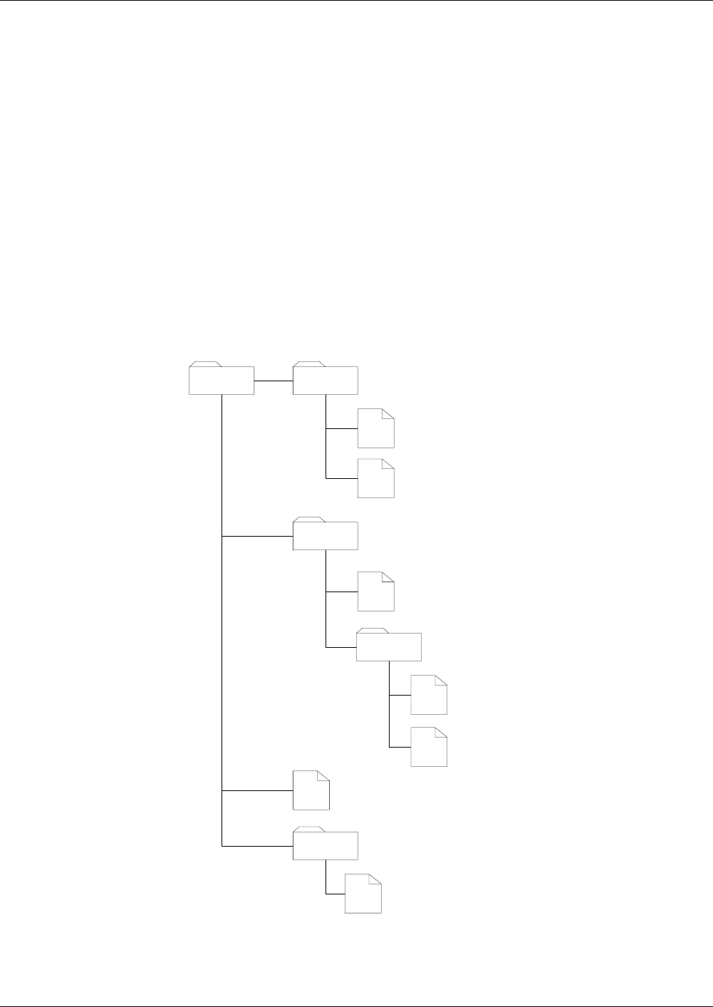
Fig. 1 File hierarchy depicted as a directory tree
MF
EF
EF
DF
EF
DF
EF
EF
DF
EF
DF
EF

Files – Definitions and Structures
Referencing
Reference Manual STARCOS® 3.0/Edition 06/2005 11
ID No. 30016255
Referencing
Referencing of Files Implicit or explicit referencing converts a file into a current or selected file.
– Implicit referencing
by calling a command
– Explicit referencing by means of
– referencing with the help of the file ID and path
– referencing by DF names
– referencing by SFI
After an Answer to Reset ( ATR),
– there is exactly one current DF, and
– exactly one current EF may exist within the current DF.
Rule For this purpose, the following rules apply:
– The MF is selected automatically after an ATR. A current EF does not
exists.
– The corresponding DF not the EF is selected directly after selecting a DF
(inclusive MF).
– The explicit selection of a DF can only be performed by the command
SELECT FILE. An implicit selection of a DF will only be possible if a
subordinate directory is selected and deleted.
– An explicit selection of the EF can only be performed by the command
SELECT FILE. If an EF is selected and deleted, no EF will be selected af-
terwards.
Referencing by file ID
and Path
Each file features a binary-coded file ID with a length of 2 bytes. The follow-
ing rules apply to the allocation of the file ID:
Rule – The MF has the file ID ’3F 00’, which must not be allocated to any fur-
ther file in the smart card.
– All files directly contained in the DF must have different file IDs.
– Reservations exist for the file IDs ’3F FF’ and ’FF FF’.
This allocation of file IDs clearly identifies each file in the STARCOS® 3.0
smart card.

Files – Definitions and Structures
Referencing
12 Reference Manual STARCOS® 3.0/Edition 06/2005
ID No. 30016255
In the STARCOS® 3.0, the following file IDs are reserved for specific EFs of
the smart card:
Referencing by DF
Name
Referencing by the command SELECT FILE and by the DF name enables the
card environment to have access to applications without knowing the file
structure of the smart card.
Each DF of the smart card has at least one DF name. A DF may have several
DF names. Within the smart card, each DF name must be unambiguous, its
length varies between 1 and 16 bytes and is binary coded.
AID Structure A DF name may be an Application ID (AID).
RID – Registered Application Provider ID
PIX – Proprietary Application Identifier
Different AIDs with the same RID must have different PIXs.
File ID Reserved for
’00 10’ EF_KEY
’00 12’ EF_PWD
’00 13’ EF_KEYD
’00 15’ EF_PWDD
’00 16’ EF_KFPC
’00 18’ EF_ALIAS
’00 19’ EF_CERT
’00 30’ EF_ARR
’00 31’ EF_DO
’00 32’ EF_FCI
’00 33’ EF_SE
’00 34’ EF_RC
’00 35’ EF_RCD
’00 36’ EF_RCZ
’0E XX’ Key EFs with public keys
’0F XX’ Key EFs with private keys
’2F 02’ EF_GDO
RID PIX (optional)
5 bytes max. 11 bytes

Files – Definitions and Structures
Referencing
Reference Manual STARCOS® 3.0/Edition 06/2005 13
ID No. 30016255
Referencing by SFI Within an DF, the referencing of EFs by means of SFI provides the execution
of commands for the EFs of the application without selecting them explicitly,
i.e., it is not necessary to know their file ID.
Within an DF, each EF may have a unique Short EF-ID (SFI). The values of
the SFIs of an application may range between 1 and 30. An SFI is binary
coded in 5 bits.

Files – Definitions and Structures
EF Structures
14 Reference Manual STARCOS® 3.0/Edition 06/2005
ID No. 30016255
EF Structures
For referencing data in EFs, STARCOS® 3.0 supports the following file
structures:
– Transparent EF
– Formatted EF:
– Linear Fixed
– Linear Variable
– Cyclic Fixed
– Cyclic Variable
The file structures differ in their access and storage modes. The decision
which structure should be used for a given type of data depends on its
variability.
The file structure for EFs may be chosen at random during generation.
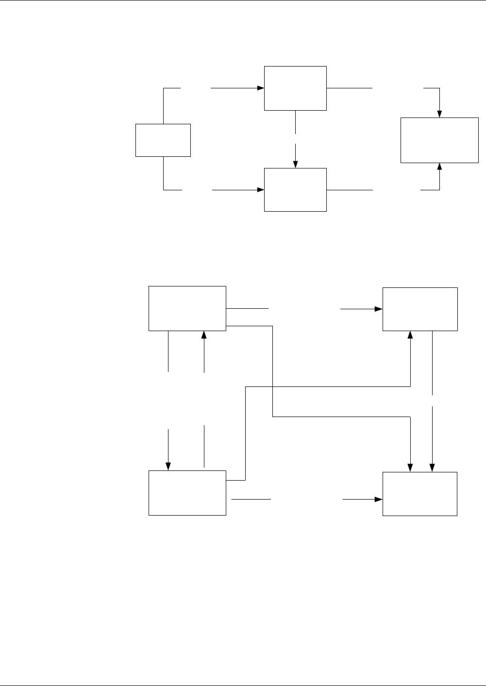
Fig. 2 File structures
Transparent EF The file structure transparent has an amorphous or binary structure for the op-
erating system. The terminal is responsible for addressing and managing data;
STARCOS® 3.0 only provides an allocated memory space.
Addressing uses an absolute offset with 2 bytes within the file, with the first
data byte of the file having the offset ’00 00’.
Transparent Amorphous or transparent structure
Linear Fixed Records with fixed length
Linear Variable Records with variable length
Cyclic Fixed Cyclic structure with fixed length

Files – Definitions and Structures
EF Structures
Reference Manual STARCOS® 3.0/Edition 06/2005 15
ID No. 30016255
Formatted EFs Data in a formatted EF are stored as a series of records. The record number
clearly identifies the records of a formatted EF, it is binary coded in 8 bits and
may have values between ’01’ and ’FE’. The values ’00’ and ’FF’ are re-
served. Therefore, a maximum of 254 records may be contained in the for-
matted EF of the STARCOS®3.0 card.
The record numbers are allocated in formatted EFs in sequential order.
Linear Fixed The file structure linear fixed handles records of identical (fixed) length; it al-
lows random access reading and writing, since every record is stored in a po-
sition specified by a unique record number. The operating system requires
this number for any read or write operation.
Reading/writing:
– Random write sequence
– Writing requires parameter information that the record will be overwrit-
ten
– Data may be read partially (prefixes)
Within a linear EF, the order of record numbers corresponds to the order in
which the records are created during the initialization or personalization and/
or by the command APPEND RECORD. The record created first (FIRST) is
the record with the number ’01’. The record created last (LAST) has the high-
est available record number.
Linear Variable The file structure linear variable handles records of variable length. This en-
ables an improved use of memory space on the card. The features are similar
to those of the linear fixed structure.
Cyclic The file structure cyclic handles elements of identical length; it does not al-
low random access writing. The elements are stored in sequential order. How-
ever, only a limited number X of elements may be stored; when this number
X is exceeded, the most obsolete element will be overwritten by a new one.
Addressing for read operations uses a relative offset, called element offset.
This means that the element written last has the number 1, the preceding ele-
ment the number 2 and so on. A number which is too large is rejected as in-
valid addressing.
Referencing The record numbers are allocated in reverse order in a cyclic EF. The record
which has been created last has the number ’01’ and is the FIRST record. For
defining the LAST record with the highest available record number, two
cases must be distinguished. If the cyclic EF provides memory space for n
records, the LAST record will be
– the record created first, as long as only n records were created,
– the cyclic successor of the FIRST record if more than n records were cre-
ated.

Files – Definitions and Structures
EF Structures
16 Reference Manual STARCOS® 3.0/Edition 06/2005
ID No. 30016255
Example Examples for cyclic EF with n = 10 records:
Six records have been created so far. The LAST record is the record created
first having the record number 6.
Ten records have been created so far. The LAST record is the record created
first having the record number 10.
Twelve records have been created so far. The LAST record is the cyclic suc-
cessor of the FIRST record having the record number 10.
654321
10987654321
21109876543

Files – Definitions and Structures
File Life Cycle
Reference Manual STARCOS® 3.0/Edition 06/2005 17
ID No. 30016255
File Life Cycle
The life cycle status defines the following states of the life cycle:
– Creation state
– Initialization state
– Operational state
– Termination state
The life cycle status byte (LCS) shall be interpreted according ’Tag ’8A’
LCS’ on page 29.
For card and file management the following commands may be used:
–CREATE FILE
–DELETE FILE
–ACTIVATE FILE
–DEACTIVATE FILE
–TERMINATE DF
–TERMINATE EF
–TERMINATE CARD USAGE
Depending on the file LCS, execution of commands can be forbidden. The
file which is evaluated is the file which will be accessed by the command, e.g.
an EF for file access commands or the DF for authentications.
The following table shows the file states, in which a command is not allowed.
Commands
Not allowed in the Current State
Cre-
ational
Initialization Operational
(deacti-
vated)
Termination
ACTIVATE
FILE
x
DEACTIVATE
FILE
xx x x
TERMINATE
DF
xx x
TERMINATE
EF
xx x
TERMINAL
CARD USAGE
Files – Definitions and Structures
File Life Cycle
18 Reference Manual STARCOS® 3.0/Edition 06/2005
ID No. 30016255
Figures 1 and 2 shows the file life cycle states and the commands that invoke
a transition upon successful completion. It does not show the conditions of
execution of those commands.
* depending on individual file LCS
Fig. 3 Life cycle state - part 1
Fig. 4 Life cycle state - part 2
Operational State
Creational
State
Nonexistent
File
Initialisation
State
CREATE
CREATE ACTIVATE MF*
ACTIVATE DF
ACTIVATE MF*
MF
Operational State
(active)
Deactivating file
security check
Activating file
Security check
MF
Terminational
State
TERMINATE DF/EF
Delited
File
DELETE DF/EF
TERMINATE DF/EF
MF
Operational State
(deactive)
TERMINATE DF/EF
ACTIVATE DF/EF

Files – Definitions and Structures
File Life Cycle
Reference Manual STARCOS® 3.0/Edition 06/2005 19
ID No. 30016255
Rule Analysis
Implications
If the MF is in the creation state, no security attributes are active, and the rule
file is deactivated. All files are implicitly in the creation state, regardless of
the own LCSI. New DFs can be created with operational LCS. Once the MF
is activated, the associated DFs are implicitly activated as well.
If the MF is operational (i.e. it has been activated) and the current DF is in the
initialization state, all commands must fulfill the rule for CREATED DF from
the next upper DF in the operational state.
Once the MF has been activated, new DFs should be created in the ini-
tialization state. The next step is to create the rule file EF_ARR.
Caution
If no rule exists and the DF is switched operational, no operation in the
DF would be possible.

Files – Definitions and Structures
Special Data Fields
20 Reference Manual STARCOS® 3.0/Edition 06/2005
ID No. 30016255
Special Data Fields
Special data fields of the smart card refer to those EFs which are evaluated
and possibly changed by STARCOS® 3.0. Special EFs are identified by the
file ID within the DF in which they are directly contained. Since STARCOS®
3.0 uses these file IDs for the access to specific EFs, they are reserved and
must not be used in any DF for another file.
Overview
* – An EF_XX must always be a linear EF. If all records of an EF_XX have
the same length, the EF_XX may be an EF with records of constant length.
Otherwise, it must be an EF with records of variable length.
EF_ARR An EF_ARR must always be a linear EF. If all records of an EF_ARR have
the same length, the EF_ARR may be an EF with records of constant length.
Otherwise, it must be an EF with records of variable length.
The records of an EF_ARR contain one or several access rules linked by OR.
This determines the access of commands to the resources of the DF, which
contains the EF_ARR. The access rules defined for the resources of DFs may
also be stored in other linear EFs within the DF. The access rule and/or OR
linkage of access rules, which are stored in the record of the EF_ARR or in
another file, are either referenced
– by the corresponding record number within the EF_ARR
or
– by the file ID of the file with access rules and the record number in this
file (see ’Tag ’8B’’ on page 30) and (see ’Tag ’A0’’ on page 31).
Data Field DF must
Contain EF
DF may
Contain EF
MF may
Contain EF
File ID
EF_ARR* x x ’00 30’
default
EF_DO* x x ’00 31’
EF_FCI x x ’00 32’
EF_SE* x x ’00 33’
EF_ALIAS* x x ’00 18’
EF_GDO x ’2F 02’
EF_KEY* x x ’00 10’
EF_PrK x x ’0F XX’

Files – Definitions and Structures
Special Data Fields
Reference Manual STARCOS® 3.0/Edition 06/2005 21
ID No. 30016255
EF_DO The data objects for which regular access is provided by GET DATA and
PUT DATA are stored in the EF_DO of the DF (see chapter ’GET DATA’ on
page 312 and ’PUT DATA’ on page 342).
An EF_DO must always be a linear EF. If all records of an EF_DO have the
same length, the EF_DO may be an EF with records of constant length. Oth-
erwise, it must be an EF with records of variable length.
EF_FCI Proprietary information about applications loaded on the smart card is stored
in the EF_FCI of the DF.
An EF_FCI must always be a linear EF. The EF_FCI may be an EF with
records of constant or variable length. Usually, it contains only one record,
however, it may contain several ones.
If available, the record(s) of the EF_FCI contain(s) a data object with tag ’A5’
including tag and length. This data object will be issued in the FCI of the DF
if it is selected by the corresponding option (see ’File Control Information
(FCI)’ on page 26).
EF_SE Key references and/or algorithms for security mechanisms are predefined per
security environment in the EF_SE of a DF (see ’Predefined CRDOs of SEs’
on page 204). If the current DF contains an EF_SE, this EF_SE may be eval-
uated
– by the commands INTERNAL AUTHENTICATE, EXTERNAL AUTHEN-
TICATE, MUTUAL AUTHENTICATE, COMPUTE DIGITAL SIGNA-
TURE, VERIFY DIGITAL SIGNATURE, ENCIPHER, DECIPHER, and
VERIFY CERTIFICATE in order to identify the key to be used,
– within the scope of secure messaging in order to identify the key to be
used,
– by the commands INTERNAL AUTHENTICATE, EXTERNAL AUTHEN-
TICATE, MUTUAL AUTHENTICATE, COMPUTE DIGITAL SIGNA-
TURE, VERIFY DIGITAL SIGNATURE, HASH, ENCIPHER,
DECIPHER, and VERIFY CERTIFICATE in order to identify the algo-
rithm to be used.
EF_ALIAS The EF_ALIAS in a DF is used like a dictionary. Two or more data objects are
stored in each record of an EF_ALIAS. Independent from each other, the data
objects may be primitive or compound. The record length corresponds to the
sum of the total length of the data objects contained, each inclusive tag and
length.
The EF_ALIAS of STARCOS® 3.0 are used by the SET variant of the MSE
command (see ’Predefined CRDOs of SEs’ on page 204).

Files – Definitions and Structures
Special Data Fields
22 Reference Manual STARCOS® 3.0/Edition 06/2005
ID No. 30016255
EF_GDO The smart card can contain a serial number as an option. When a serial num-
ber is present, it must be stored in EF_GDO.
The EF_GDO is a transparent file with the FID of ’2F 02’ which is stored in
MF. The serial number is stored in EF_GDO in a TLV object with the
tag ’5A’. The minimum length of the TLV object is 8 bytes of which the least
significant 8 bytes is the serial number.
If EF_GDO is not present or does not contain a tag ’5A’ or at least 8 bytes, the
command MUTUAL AUTHENTICATE uses ’00 00 00 00 00 00 00 00’ for the
authentication.
EF_KEY and EF_PrK These files contain secret keys. They can not be read by OS commands.
Therefore their file ID ranges must not be used for normal files.

Files – Definitions and Structures
Access to Data Objects
Reference Manual STARCOS® 3.0/Edition 06/2005 23
ID No. 30016255
Access to Data Objects
Each DF may contain a linear EF, in whose records data objects are stored.
This EF is clearly identified within a DF by its file ID ’00 31’. In the follow-
ing, it is referred to as EF_DO.
The EF_DO may be an EF with records of constant or variable length. A
primitive or compound TLV-coded data object may be stored in each record
of the EF_DO. The tags of the stored data objects may have a length of 1 byte
or 2 bytes. The record length must comply with the total length of the data ob-
ject stored.
Reading of data objects is effected by GET DATA, writing by PUT DATA.
The access of commands to data objects may be classified according to:
– Regular access of GET DATA and PUT DATA to data objects
– Special determinations
for the reading of data objects with the tag ’DF 20’ by means of GET
DATA.
For information about the commands GET DATA (see ’GET DATA’ on
page 312) and PUT DATA (see ’PUT DATA’ on page 342).
Regular Access of GET
DATA and PUT DATA
to Data Objects
Verification of file control information template when executing the com-
mand if access to the data object indicated in P1-P2 of the command headers
is permissible in the current DF at all.
Verification if an access rule and/or OR linkage of access rules for the access
of GET DATA or PUT DATA to the data object is defined for the active SE,
and whether the corresponding access rule and/or OR linkage of access rules
is available in the current DF.
Evaluation of access rule and/or OR linkage of access rules (see ’Access
Rules’ from page 45 onwards).
Reading and writing of the data object in the EF_DO of the DF currently valid
when executing the command.
Reading and Writing of
Data Objects
After evaluation of an access rule, control is transferred to the command GET
DATA or PUT DATA.
Verification if the data object including the tag indicated has already been
stored in a record of the EF_DO of the current DF.
– Data object is stored including the tag indicated.
The data object is register in the corresponding record, indicating the new
value and correct length. The tag remains unchanged, the length is ob-
tained from Lc of the unprotected command, and the value field is de-
rived from the data field of the command.

Files – Definitions and Structures
Access to Data Objects
24 Reference Manual STARCOS® 3.0/Edition 06/2005
ID No. 30016255
Access with Tag ’DF
20’
– The data object with the private tag ’DF 20’ contains the record data of
the smart card manufacturer, the module manufacturer, and of the per-
sons who initialize and personalize the chip (record data).
– The command GET DATA with P1-P2 = ’DF 20’ is independent from the
currently selected DF. Its file control information template can always be
executed. The record data are issued in the response data.
– GET DATA with P1-P2 = ’DF 20’ cannot be performed by means of se-
cure messaging.
– Independent of the currently selected DF and its file control information
template, the command PUT DATA with P1-P2 = ’DF 20’ will always be
rejected.

Files – Definitions and Structures
File Control Information Templates
Reference Manual STARCOS® 3.0/Edition 06/2005 25
ID No. 30016255
File Control Information Templates
In response to the command SELECT FILE, the STARCOS® 3.0 card issues
a file control information template, which consists of data that identify the file
as well as determine the structure and security attributes. The response of the
SELECT FILE to the DFs indicates, how much memory space is still avail-
able in the STARCOS® 3.0 card for the creation of additional files. Further
data that may be issued as part of the file control information template of a DF
are obtained from a specific file (EF_FCI) provided that it is available.
File control information template is always issued in the form of a compound
BER-TLV data object. STARCOS® 3.0 differentiates between the following
data objects:
– File Control Parameters (FCP)
– File Control Information (FCI)
For detailed information about the data objects refer ’Data Objects in the File
Control Information Templates’ on page 28.
File Control
Parameters (FCP)
The FCP template contains file characteristics.
Depending on the kind of file, the FCP consists of a selection of BER-TLV
data objects of the following list. The length of the FCP refers to the total
length of these BER-TLV data objects.
Tag Length Va l u e
’62’ var. FCP
Tag Length Val u e Value Applicable to
’80’ ’02’ Memory space indicated in
byte reserved for the infor-
mative data
Transparent EFs
’82’ ’01’ to
’05’
File descriptor byte Any EFs of record struc-
ture
’83’ ’02’ File ID All files
’84’ ’01’ to
’10’
DF name (AID) DFs
’85’ ’02’ Free memory space in the
STARCOS® 3.0 smart card,
memory space is indicated
in byte reserved for infor-
mative data
DFs, EFs with records of
variable length

Files – Definitions and Structures
File Control Information Templates
26 Reference Manual STARCOS® 3.0/Edition 06/2005
ID No. 30016255
* optional
Rule for Tag ’84’ If a DF is selected by the DF name, only the DF name used for this purpose
will be issued in the FCP. If the selection of the DF takes place in another way,
all DF names of the DF will be issued in the FCP. The remaining data objects
must be contained in the FCPs of the respective file type and may occur only
once.
The FCPs, except for the information about free memory space (tag ’85’ for
DFs), are transferred to the card when the file is created by the command
CREATE FILE or transferred into the card during the production.
If several DF names are allocated to one DF, this will always be performed
when the DF is created by the command CREATE FILE or during the produc-
tion of the smart card.
File Control
Information (FCI)
The FCI template contains proprietary information.
If the file is an EF, the FCI will consist of the two bytes ’6F 00’.
If the file is a DF, the FCI will contain the following BER-TLV data objects:
The data object with the tag ’84’ may occur several times in the FCI of a DF.
– If a DF is selected by means of the DF name, only the DF name used dur-
ing this procedure will be issued in the FCI.
– If a DF is selected in another way, all the DF names of the DF will be is-
sued in the FCI.
’88’ ’00’ or
’01’
SFI EFs
’8A’ ’01’ LCS* All files
’A1’ var. Data objects with access
rule reference(s)
All files
Tag Length Va l ue Value Applicable to
Tag Length Val u e
’6F’ var. FCI
Tag Length Va l ue Value applicable to
’84’ ’01’ to
’10 ’
DF name (AID) DFs
’A5’ var. Proprietary information DFs

Files – Definitions and Structures
File Control Information Templates
Reference Manual STARCOS® 3.0/Edition 06/2005 27
ID No. 30016255
The smart card obtains the data object with tag ’A5’ inclusive tag and length
from a specific EF within the DF to be selected. This EF is a linear EF, which
is clearly identified by its file ID ’00 32’ within the DF. In the following, it is
referred to as EF_FCI. The empty data object ’A5 00’ will be issued in the
FCI if
– the DF to be selected does not contain an EF_FCI,
– the EF_FCI does not contain any records
or
– the EF_FCI is not linear.

Files – Definitions and Structures
Data Objects in the File Control Information Templates
28 Reference Manual STARCOS® 3.0/Edition 06/2005
ID No. 30016255
Data Objects in the File Control Information
Templates
The BER-TLV data objects used in the file control information templates are
described more detailed. The meaning of tag ’85’ depends on the template
that contains the corresponding data object.
Tag ’80’
Memory Space
Tag ’80’ indicates the memory space of transparent EFs. Its value is binary
coded.
Tag ’82’
File Descriptor
Tag ’82’ indicates the file descriptor. It has a length of one byte for DF's and
transparent EF's, and five bytes for formatted EF's
The first byte (file descriptor byte) has the following values for EFs:
Val u e Byte Value applicable to
’82’ 1 File descriptor byte
2 ’41’ Data coding byte
3 and 4 Maximum record size on two bytes
5 Number of records on one byte
b8 b7 b6 b5 b4 b3 b2 b1 Description
0
0
0
1
File accessibility
Not shareable file
Shareable file
00111000DF (always shareable)
0
0
0
0
0
0
1
1
0
1
0
1
1
0
0
0
EF structure
Transparent EF
Linear EF, records of constant length
Linear EF, records of variable length
Cyclic EF, records of constant length
1XXXXXXXRFU

Files – Definitions and Structures
Data Objects in the File Control Information Templates
Reference Manual STARCOS® 3.0/Edition 06/2005 29
ID No. 30016255
Tag ’83’
File ID
Tag ’83’ indicates the file ID.
Caution
None of the file IDs '3F 00', '3FFF' and 'FF FF' may be allocated dur-
ing the creation of a file by means of CREATE FILE.
It must be allocated according to the rules defined in ’Referencing by file ID
and Path’ on page 11. It is binary coded in 2 bytes.
Tag ’84’
DF Name
Tag ’84’ indicates the DF name.
Each DF of STARCOS® 3.0 must contain at least one DF name, which is to
be allocated in accordance with the rules defined in ’Referencing by file ID
and Path’ on page 11.
The DF name is binary coded and its length varies between ’01’ and ’10’
bytes.
Tag ’85’
Memory Space
Tag ’85’ describes the free memory space and the memory space for EFs with
records of variable length. Referring to the DFs, the amount of memory space
available in the entire STARCOS® 3.0 card for the creation of files is indi-
cated in bytes.
Concerning EFs with records of variable length, the memory space to be used
at most for the informative data of the EF is indicated in bytes. This value is
determined during the creation of the EF.
The value of the data object is always binary coded.
Tag ’88’
Short File Identifier
Tag ’88’ describes the Short File Identifier (SFI).
An SFI having a value between 1 and 30 can be allocated to an EF of the-
STARCOS® 3.0 smart card. The SFI is coded in one byte as follows:
SFI – Short File Identifier, value ’0’, ’31’ no evaluation
The SFIs in the FCPs of all the EFs contained in a DF must be unambiguous
within this DF.
If the FCPs of an EF contain no data object with tag ’88’ or an empty data ob-
ject with tag ’88’ (’88 00’), no SFI will be allocated to the EF in the directly
superior DF by its FCP.
Tag ’8A’
LCS
Tag ’8A’ describes the life cycle state data object.
b8 b7 b6 b5 b4 b3 b2 b1 Description
XXXXX0 0 0
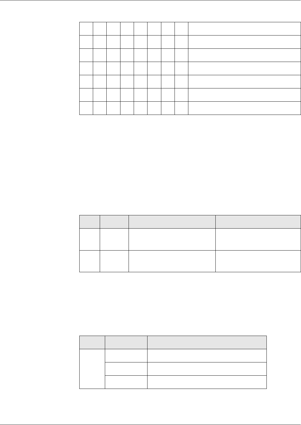
Files – Definitions and Structures
Data Objects in the File Control Information Templates
30 Reference Manual STARCOS® 3.0/Edition 06/2005
ID No. 30016255
LCS for file life cycle:
For more information refer to ’File Life Cycle’ on page 17.
Tag ’A1’
Access Rule
Reference(s)
Tag ’A1’ defines the access rule reference(s) (ARR). The data object with tag
’A1’ is referred to as ARR data object, (ARR-DO).
If the file control information template does not contain any data object with
tag ’A1’, commands, which try to access to the data object, respond in a way
as if an access rule would have to be observed in which the command is not
available as access type (see ’Evaluation of Access Rules’ on page 264). The
value field of the data object with tag ’A1’ contains the BER-TLV data ob-
jects:
First, the individual data objects are described in the following. Then, the re-
quired composition of the value field ARR-DO using these data objects is ex-
plained.
Tag ’8B’ Tag ’8B’ indicates the access rule reference.
The data object may have the following lengths:
b8 b7 b6 b5 b4 b3 b2 b1 Description
00000000RFU
00000001Creation state
00000011Initialization state
00000101Operational state - activated
00000100Operational state - deactivated
0000110-Termination state
Tag Length Va l ue Value Applicable to
’8B’ ’01’,
’03’
Access rule reference(s) All files
’A0’ var. Access rule reference(s) for
data objects
DFs
Tag Length Val u e
’8B’ ’01’ RN
’03’ FID || RN
2+n*2 bytes FID || SE#1, RN1 || ... || SE#n, RNn

Files – Definitions and Structures
Data Objects in the File Control Information Templates
Reference Manual STARCOS® 3.0/Edition 06/2005 31
ID No. 30016255
FID - file ID (usually ’00 30’), 2 byte
SE# - Number for the identification of a security environment, binary coded
in one byte, for which only the values between ’00’ and ’FE’ are permis-
sible besides the value ’EF’. Each SE# contained in the list must be dif-
ferent.
RN - Record Number, binary coded in one byte, may have values between
’01’ and ’FE’. The list may contain the same RN several times.
For further information, see ’Access Rule Reference’ on page 32.
Tag ’A0’ Tag ’A0’ indicates the access rule reference for data objects.
Access to data objects will be possible by the commands GET DATA and
PUT DATA only if the file control information template of the DF currently
valid during the execution of the command contains a compound data object
with tag ’A0’, whose value references an access rule for the access of both
commands to the data object.
Exceptions GET DATA with P1- P2 = ’DF 20’ may always be executed for each
transmission type even if the DF does not contain the tag ’A0’ or if tag
’DF 20’ is not contained in the tag list of the data object available with
tag ’A0’.
The value field of the data object with tag ’A0’ consists of a pair of data ob-
jects:
Tag Length Va l u e
’A0’ ’01’, ’03’,
2+n*2
ARR or ’XX XX’ || SE#1, RN1 || ... ||
SE#n, RNn
’5C’ var. Concatenation of tags

Files – Definitions and Structures
Access Rule Reference
32 Reference Manual STARCOS® 3.0/Edition 06/2005
ID No. 30016255
Access Rule Reference
The access of commands to the resources of the smart card is determined by
one or several access rules, which are linked by OR. Usually, the defined ac-
cess rules are stored in the records of the EF_ARR (see ’EF_ARR’ on
page 20).
Definition The reference to an access rule is described as access rule reference (ARR).
The access rules, which are stored within a record of the EF_ARR or in an-
other file, are either referenced
– by the corresponding record number within the EF_ARR
or
– by the file ID of the file with access rules and record numbers in this file.
The access rules to be observed are referenced in the file control information
template of the file itself or of a key descriptor by the value field of a data ob-
ject with tag ’8B’ (ARR data object). The command description specifies in
which file control information template the corresponding ARR data object
must be searched for.
For the access of a command, either one ARR can be determined for all SEs,
or different ARRs can be indicated for different SEs.
The command must always use the ARR that is defined for the SE that is ac-
tive during its execution for the DF that contains the ARR.
The value of a ARR data object has either a length of 1 byte, 3 bytes or 2+n*2
(with n>=1) bytes.
1-Byte Value Field The data object contains a record number as ARR, which references an access
rule in the EF_ARR. The record number is binary coded and its values may
vary between ’01’ and ’FE’.
3-Byte Value Field A file ID in the first two bytes and a record number in the third byte are con-
tained in the data object as ARR. This record number references an access
rule in the file whose file ID is indicated in the first two bytes. This file ID
must identify a file within the DF whose FCP is concerned and/or which di-
rectly contains the file whose FCP is concerned.
2+n*2-Byte Value Field The value field consists of the linkage of a file ID (usually ’00 30’), and n
pairs of SE# and record numbers (RN):
’XX XX’ || SE#1, RN1 || ... || SE#n, RNn
SE# - ’00’
the associated ARR is applied to all SEs except for the SEs listed in the other
pairs of SE# and RN. If only the SE# with the value ’00’ is available, the al-
located ARR will be applied to all SEs. This would be an equivalent represen-
tation for a ARR with a length of 1 byte or 3 bytes.

Reference Manual STARCOS® 3.0/Edition 06/2005 33
ID No. 30016255
Security-related Data
Objects
In order to guarantee a secure exchange of data, STARCOS® 3.0 accesses a
series of security mechanisms and uses a security environment.
Special data objects define, for example, which cryptographic keys and algo-
rithms have to be used for the security mechanism.

Security-related Data Objects
Control Reference Data Objects
34 Reference Manual STARCOS® 3.0/Edition 06/2005
ID No. 30016255
Control Reference Data Objects
Control Reference Data Objects (CRDOs) are used for the description and se-
lection of security mechanisms within the scope of secure messaging and in
security environments. CRDOs determine
– which cryptographic key,
– which cryptographic algorithm and mode of operation,
– which additional data to be used, e.g. Initial Chaining Values (ICV)
and/or
– which data to be included in the calculation, e.g. data to be enciphered
and signed for the described security mechanism have to be used.
CRDOs can be integrated into so-called Control Reference Templates
(CRTs), which create a reference between CRDOs and security mechanisms.
There is no clear allocation between CRTs and security mechanisms. For in-
stance, the AT must be used to describe the card proprietor authentication as
well as the component authentication. In order to describe the authentication
of data, both the CCT and the DST can be used. A specific CRDO, which is
referred to as Usage Qualifier, serves as reference for the security mechanism
(see ’Usage Qualifier’ on page 38).
A CRT is the value field of an especially composed data object. There are five
types of CRTs:
– CRT for authentication (AT),
Since a component authentication or an encryption can be based on a
symmetric or an asymmetric cryptographic method, a security mecha-
nism based on both methods can be described.
– CRT for hash calculation (HT),
– CRT for cryptographic checksum and/or MAC (CCT),
Only security mechanisms can be described that are based on symmetric
cryptographic methods since a cryptographic checksum or a MAC is al-
ways calculated by a symmetric cryptographic method.
– CRT for the digital signature (DST),
Only security mechanisms can be described that are based on asymmetric
cryptographic methods since a digital signature is always calculated by
an asymmetric cryptographic method.
– CRT for confidentiality (CT).
The same conditions apply as used for CRT and AT.
Application of CRDO – CRDOs are used in the data field of the command MSE to select keys
and/or algorithms for security mechanisms and/or to transmit a challenge
or key derivation data to the smart card.
See ’Predefined CRDOs of SEs’ on page 204, ’Transfer of Challenge’ on
page 222, ’General SE Key Derivation Data’ on page 223.

Security-related Data Objects
Control Reference Data Objects
Reference Manual STARCOS® 3.0/Edition 06/2005 35
ID No. 30016255
– CRDOs with key and /or algorithm selections are stored in the EF_SE
(see ’Predefined CRDOs of SEs’ on page 204).
– It is determined in the additional key information by means of CRDOs
for which procedure of the key management or for which cryptographic
algorithm or which authentication method a key may be used (see ’Addi-
tional Key Information in the Records of EF_KEYD’ on page 79).
– CRDOs are used in access rules
to state security mechanisms to be applied in access conditions (see ’Se-
curity Condition Data Object’ on page 53).
– CRDOs are used within the scope of SM
to select keys or ICVs for MAC protection or enciphering.
The following tables show the tags and values of the CRDOs used in
STARCOS® and indicate within which CRTs a CRDO can be used.
Fig. 5 CRDOs in the data field of the MSE command, tags of the CRTs in P2
.
Fig. 6 CRDOs of the CRTs of an EF_SE
Tag Value AT
sym
AT
asym
CCT CT
sym
CT
asym
DST HT
’80’ Algorithm reference X X X X X
’83’ Key reference or key name
of a secret key
of a public key X
X
XX
XX
’84’ Key reference or key name
of a private key
XXX
’87’ Initial Chaining Value (ICV) X
’89’ Algorithm ID X X X X X
’94’ Key Derivation Data (CID) XXXX
Tag Value AT
sym
AT
asym
CCT CT
sym
CT
asym
DST HT
’83’ Key reference
of a secret key
of a public key
X
X
XX
XX
’84’ Key reference
of a private key X X X
’89’ Algorithm ID X X X X X

Security-related Data Objects
Control Reference Data Objects
36 Reference Manual STARCOS® 3.0/Edition 06/2005
ID No. 30016255
.
Fig. 7 CRDOs in additional key information
.
Fig. 8 CRDOs in access conditions
.
Fig. 9 CRDOs in messages in SM format
Data objects with algorithm ID and padding indicator are defined in ’Algo-
rithm IDs’ on page 411 and ’Padding Indicators’ on page 415.
Data objects with Initial Chaining Value (ICV) and key derivation data (CID)
are described in ’Transfer of Challenge’ on page 222, ’General SE Key Deri-
vation Data’ on page 223.
Tag Value AT
sym
AT
asym
CCT CT
sym
CT
asym
DST HT
’95’ Usage Qualifier X X X X X X
’83’
’84’
KID and KV of one or two ses-
sion keys
KID and KV of a private key
XX
X
’87’ ICV Indicator X X
’89’ Algorithm ID X X X X X X
’8A’ Padding Indicator X X X
’8B SM-specific determinations for
MAC protection
X
’8E’ MAC length X
Tag Value AT
sym
AT
asym
CCT CT
sym
CT
asym
DST HT
’95’ Usage Qualifier X X X X
’83’ Key or password reference
XXXX
’8B’ SM-specific determinations for
MAC protection X
’8E’ MAC length X
Tag Value AT
sym
AT
asym
CCT CT
sym
CT
asym
DST HT
’83’ Key reference X X
’87’ Initial Chaining Value (ICV) X X

Security-related Data Objects
Control Reference Data Objects
Reference Manual STARCOS® 3.0/Edition 06/2005 37
ID No. 30016255
Data objects with ICV indicator, SM-specific determinations for SM and
MAC length are described in ’Additional Key Information in the Records of
EF_KEYD’ on page 79.
Data objects with Usage Qualifier, key or password reference and key name
are described in the following.

Security-related Data Objects
Usage Qualifier
38 Reference Manual STARCOS® 3.0/Edition 06/2005
ID No. 30016255
Usage Qualifier
The Usage Qualifier (UQ) defines the reference of the following CRDOs
more detailed within a CRT. Since the value field of the Usage Qualifier Data
Object (UQ-DO) has a length of one byte, the length field has the value ’01’.
The following table shows how the UQ is coded in one byte.
Fig. 10 Coding of the Usage Qualifier
b8 b7 b6 b5 b4 b3 b2 b1 Description
1
1
0
0
0
0
0
0
0
0
0
0
0
0
UQ for component authentication, en-
ciphering and digital signature
External authentication (AT)
verification of a digital signature
(DST), enciphering (CT)
Internal authentication (AT)
calculation of digital signature (DST)
deciphering (CT)
0
0
0
0
1
1
0
0
0
0
0
0
0
0
UQ for MAC and enciphering for SM
SM for response (CT, CCT)
SM for command (CT, CCT)
00001000
UQ for card proprietor authentication
Card proprietor authentication (AT)
0
0
0
0
0
0
0
0
0
0
0
0
1
1
UQ for command-specific protection
Command-specific protection for re-
sponse (CT, CCT, AT, DST)
Command-specific protection for
command (CT, CCT, AT, DST)

Security-related Data Objects
Key Reference
Reference Manual STARCOS® 3.0/Edition 06/2005 39
ID No. 30016255
Key Reference
A cryptographic key is clearly determined by means of a key search algo-
rithm with the following parameters:
– Search code "global" or "DF-specific",
– Key number KID,
– Optional key version KV
– Key type
–DF
In order to find a key for a given DF of the smart card, a key reference is re-
quired, which contains the search code, key number and, if necessary, the key
version.
3-byte Key Reference A key reference can be coded in 1, 2 or 3 bytes for the STARCOS® smart
card. The interpretation into 1 byte or 2 bytes depends on the respective ap-
plication context. The interpretation of the coding into 3 bytes is independent
from the application of the key reference. The following table represents the
coding of a key reference in 3 bytes:
Interpretation of the
Coding into 1 Byte and
2 Bytes
The interpretation of the coding in 1 byte or 2 bytes depends on the applica-
tion of the key references. The key references are predefined for the following
applications:
– SET command
– Access conditions
– SE data objects
– Commands with secure messaging
– Authentication commands
Position Length Value Description
11
’00’
or
’80’
Search code
"global"
or
"DF-specific"
2 1 ’XX’ Binary-coded key number between 1
and 254
3 1 ’XX’ oroptional binary-coded key version
between 0 and 254
or
place holder ’FF’

Security-related Data Objects
Key Reference
40 Reference Manual STARCOS® 3.0/Edition 06/2005
ID No. 30016255
Key Reference in the
SET Command
Key reference data objects are used for the selection of keys in the SET vari-
ant of the command MSE. These data objects may contain key references,
which are coded in 1, 2 or 3 bytes. The respective coding can be recognized
by the length field of the key reference data object.
For 3 byte key reference (see ’3-byte Key Reference’ on page 39).
1-byte Key Reference The following tables show how a key reference is coded in 1 or 2 bytes in the
SET command.
2-byte Key Reference Only search codes and key numbers between 1 and 127 are indicated; this
corresponds to the assignment ’FF’ of the key version in a 1 or 2 byte coding:
A key reference in a SET command, which is coded in 2 bytes, can also be
coded in 3 bytes. For this purpose, the search code represented by bit b8 of the
first byte is coded in one byte. The key number represented by bit b7...b1 is
coded in a second byte. The key version is set unchanged in a third byte.
Key References in
Security Conditions
Key reference data objects with tag ’83’ are used for referencing crypto-
graphic keys in access conditions of the type AUT, SM and, if required,
SPEC.
In this case, a 3 byte key reference can be used. Furthermore, a 2 byte key ref-
erence can be used, which is coded without key version.
Key References in SE
Data Objects
SE data objects in additional key or password information may contain key
reference data objects, which consist of a 2 byte key reference that is coded
without search code. This way keys are referenced which are in the same di-
rectory as the corresponding additional information.
b8 b7 b6 b5 b4 b3 b2 b1 Description
0 Search code "global"
1 Search code "DF-specific"
XXXXXXXKey number 1to 127
Position Length Value Description
1 1 ’XX’ Search code "global" or "DF-specific"
and key number 1 to 127
2 1 ’XX’ Binary-coded key version between 0
and 254 or place holder ’FF’

Security-related Data Objects
Key Reference
Reference Manual STARCOS® 3.0/Edition 06/2005 41
ID No. 30016255
Key References in
Commands with Secure
Messaging
Key reference data objects with tag ’83’ are used for the selection of a key in
the command within the scope of secure messaging.
If a command is executed by SM, the command may contain a 3 byte coded
key reference or a 2 byte coded key reference.
Moreover, the command may contain a 1 byte key reference as value field of
a key reference data object with tag ’83’:
Position Length Value Description
1 1 ’XX’ Binary-coded key version between 0
and 254 or place holder ’FF’

Security-related Data Objects
Password Reference
42 Reference Manual STARCOS® 3.0/Edition 06/2005
ID No. 30016255
Password Reference
With the following parameters and a password search algorithm, a password
is clearly determined in the STARCOS® smart card:
– Search code "global" or "DF-specific",
– Password number
–DF
In order to find a password referring to the given DF of the smart card, a pass-
word reference is required that contains the search code and the password
number.
The password reference can be coded in 1 byte or 2 bytes for the STARCOS®
smart card. The interpretation of both codings is independent from the appli-
cation of the password reference.
1-byte Password
Reference
Parameter P2 in the header of the commands VERIFY and CHANGE REFER-
ENCE DATA contains a password reference coded in 1 byte:
A password reference coded in 1 byte can also be coded in 2 bytes. For this
purpose, the search code, which is represented by bit b8, is coded in 1 byte.
The password number represented by bit b3...b1 is coded in a second byte.
2-byte Password
Reference
The following table shows the coding of a password reference in 2 bytes:
A password reference coded in 2 bytes is used as value field of a password
reference data object with tag ’83’ in access conditions of type PWD.
b8 b7 b6 b5 b4 b3 b2 b1 Description
00000000Key reference in the SE
0 Search code "global"
1 Search code "DF-specific"
0
0
1
1
0
1
0
1
RFU
RFU
RFU
XXXXXKey number 1 to 7
Position Length Value Description
1 1 ’XX’ Binary-coded key version between 0
and 254 or place holder ’FF’

Security-related Data Objects
Key Name
Reference Manual STARCOS® 3.0/Edition 06/2005 43
ID No. 30016255
Key Name
A key name is clearly determined in the STARCOS® smart card by means of
a key search algorithm and the following parameters:
– Search code
– Key number KID
– Optional key version KV
– Key type.
In the SET variant of the command MSE for the selection of a key, keys can
also be referenced by means of a key name. A key name is a binary-coded se-
ries with a length of at least four bytes, which is interpreted into a key refer-
ence by the SET variant of the MSE command. This way keys with the SET
variant of the MSE command can be selected independently from the internal
key referencing of the STARCOS® smart card.
A key name is used as value field of a key name data object with tag ’83’ or
’84’ in the data field of the SET. The key type is determined by the prefixed
tag:
’83’ secret or public
’84’ private.


Reference Manual STARCOS® 3.0/Edition 06/2005 45
ID No. 30016255
Access Rules
The access rules defined for a DF are stored in a linear EF, the EF_ARR,
within the DF. The EF is uniquely identified within the DF by the file ID ’00
30’.
An access rule determines which access conditions (SC) have to be met in or-
der to enable the access to resources of the smart card with the help of an ac-
cess mode. Access modes are defined by one or several commands. Access
conditions need not be observed for the execution of any command.
An access rule combines access modes and access conditions. The access
mode specifies one or several commands. The access conditions determine
which prerequisites have to be fulfilled so that an access with the defined ac-
cess mode, i.e., with the commands indicated, may be performed.

Access Rules
EF_ARR
46 Reference Manual STARCOS® 3.0/Edition 06/2005
ID No. 30016255
EF_ARR
An access rule EF can be an EF with records of constant or variable length.
Storage An access rule and/or OR-linkage of access rules is stored in each record be-
longing to an access rule EF. However, it is also permissible to store access
rules in other linear EFs within a DF. These EFs are referred to as access rule
EF.
Reference Within an access rule EF, the access rule is referenced by the corresponding
record number.
Within a DF, the access rule is referenced by
– a record number which then refers to the EF_ARR,
or
– a file ID and a record number, which then identifies an access rule in a
record of another access rule EF as the EF_ARR.
The reference to an access rule within a DF is described as access rule refer-
ence (ARR).
When integrating access rules into an access rule EF by the command
APPEND RECORD, it must be noted that the record numbers are deter-
mined by the order of the APPEND RECORD used.
Classification Regarding the evaluation of access rules, the commands can be divided into
three groups:
– Commands which must evaluate access conditions
(evaluation mandatory)
– Commands which may evaluate access conditions
(evaluation optional)
– Commands which must not evaluate access conditions
(no evaluation)
Access The specification of the command defines where the command can find the
access rule reference (ARR) for the active SE. This either can be in a file
header (EF or DF) or in the additional information of a key.
The chapters Data Objects in the File Control Information Templates, ’Tag
’8B’’ on page 30 and ’Tag ’A0’’ on page 31 explain how the user can find the
correct access rule.
The SE# of the DF, which contains the ARR-DO, is used for the evaluation of
the ARR data object (ARR-DO). The access rule EF and the access rule are
searched in the DF which includes the ARR-DO.

Access Rules
EF_ARR
Reference Manual STARCOS® 3.0/Edition 06/2005 47
ID No. 30016255
Where to find the ARR? The following table shows where to find the ARRs used for standard and ad-
ministration commands:
Command Evaluation of
Access Rules
ARR Location
READ RECORD
READ BINARY
SEARCH RECORD
Mandatory ARR-DO in the file control information
template of the EF from which data
should be read.
UPDATE RECORD
UPDATE BINARY
APPEND RECORD
Mandatory ARR-DO in the file control information
template of the EF in which data should
be written.
PUT DATA
GET DATA
Mandatory ARR-DO in the data object with tag
’A0’ in the file control information
template of the current DF.
SELECT FILE
(DF selection)
(EF selection)
No evaluation
Optional ARR-DO in the file control information
template of the EF which should be se-
lected.
INTERNAL AUTHENTICATE
EXTERNAL AUTHENTICATE
MUTUAL AUTHENTICATE
Optional ARR-DO in the additional information
of the key to which access should be
performed.
VERIFY
CHANGE REFERENCE DATA
RESET RETRY COUNTER
Mandatory ARR-DO in the additional information
of the password which should be ac-
cessed.

Access Rules
EF_ARR
48 Reference Manual STARCOS® 3.0/Edition 06/2005
ID No. 30016255
Referring to additional commands, it is determined in their specification
whether and which access rules are to be observed and where these rules are
referenced.
In the following, the coding of the access mode and access conditions is ex-
plained at first. The structure of access rules and OR-linkages of access rules
consisting of these components is illustrated afterwards.
variant of
MANAGE SECURITY ENVI-
RONMENT
(RESTORE)
(SET)
No evaluation
Optional
ARR-DO in the data object with tag
’A0’ in the file control information
template of the current DF.
COMPUTE DIGITAL SIGNA-
TURE
VERIFY DIGITAL SIGNATURE
VERIFY CERTIFICATE
ENCIPHER
DECIPHER
GENERATE
PUBLIC KEY PAIR
Mandatory ARR-DO in the additional information
of the key which should be accessed
HASH
CREATE FILE
Optional
Mandatory
ARR-DO in the file control information
template of the current DF
DELETE FILE Mandatory ARR-DO in the file control information
template of the EF (DF) which should
be deleted
GET KEYINFO Optional ARR-DO in the file control information
template of the EF_KEYD from which
key versions should be read
Command Evaluation of
Access Rules
ARR Location

Access Rules
Access Mode Data Object
Reference Manual STARCOS® 3.0/Edition 06/2005 49
ID No. 30016255
Access Mode Data Object
Definition Within an access rule, the access mode is determined by a list of access mode
data objects (AM-DOs). The AM-DO list can consist of one or several AM-
DOs. It must always be located at the beginning of an access rule. An access
rule applies to all commands, which are described within one or several AM-
DOs in the AM-DO list at the beginning of the access rule.
Structure All AM-DOs included in the list must be in successive order.
Tag ’80’ Bitmap The bitmap is to be interpreted depending on the fact to which resources the
corresponding access rule applies.
If the access mode should be specified more detailed by a standard or ad-
ministration command, the access mode of the corresponding standard or
administration command must be defined by a command description (see
’Tag ’81’ to ’8F’ Variable Command Description’ on page 52). This ap-
plies if different access rules are to be defined for different values of P1
or P2.
DF Bitmap for the referencing of standard and administration commands regard-
ing the access to DFs:
Tag Length Value
’80’ ’01’ Bitmap for standard and administration com-
mands
’81’ to
’8F’
var. Command description by CLA, INS, P1, P2
b8 b7 b6 b5 b4 b3 b2 b1 Description
0 b7..b4 proprietary, b3..b1 according
to ISO 7816- 9
0 1 DELETE FILE (self)
0 1 TERMINATE CARD USAGE, TER-
MINATE DF
0 1 ACTIVATE FILE
0 1 DEACTIVATE FILE

Access Rules
Access Mode Data Object
50 Reference Manual STARCOS® 3.0/Edition 06/2005
ID No. 30016255
Formatted EF Bitmap for the referencing of standard and administration commands regard-
ing the access to formatted EFs:
Transparent EF Bitmap for the referencing of standard and administration commands regard-
ing the access to transparent EFs:
0 1 CREATE FILE (DF)
0 1 CREATE FILE (EF)
0 1 DELETE FILE (child DF)
b8 b7 b6 b5 b4 b3 b2 b1 Description
b8 b7 b6 b5 b4 b3 b2 b1 Description
0 b7..b4 proprietary, b3..b1 according
to ISO 7816- 9
0 1 DELETE FILE (self)
0 1 TERMINATE EF
0 1 ACTIVATE FILE
0 1 DEACTIVATE FILE
0 1 APPEND RECORD
0 1 UPDATE RECORD (EF)
0 1 READ RECORD
SEARCH RECORD
b8 b7 b6 b5 b4 b3 b2 b1 Description
0 b7..b4 proprietary, b3..b1 according
to ISO 7816- 9
1 DELETE FILE (self)
1 TERMINATE EF
1ACTIVATE FILE
1 DEACTIVATE FILE
1RFU
1UPDATE BINARY
1 READ BINARY

Access Rules
Access Mode Data Object
Reference Manual STARCOS® 3.0/Edition 06/2005 51
ID No. 30016255
Data objects Bitmap for the referencing of standard and administration commands regard-
ing the access to data objects
Passwords Bitmap for the referencing of standard and administration commands regard-
ing the access to passwords
b8 b7 b6 b5 b4 b3 b2 b1 Description
b7..b4 proprietary, b3..b1 according
to ISO 7816- 9
1RFU
1RFU
1RFU
1RFU
1
SET variant of MANAGE
SECURITY ENVIRONMENT
1PUT DATA
1 GET DATA
b8 b7 b6 b5 b4 b3 b2 b1 Description
1 b7..b4 proprietary, b3..b1 according
to ISO 7816- 9
1RFU
1 TERMINATE PIN
1ACTIVATE PIN
1 DEACTIVATE PIN
1 RESET RETRY COUNTER
1 CHANGE REFERENCE DATA
1VERIFY

Access Rules
Access Mode Data Object
52 Reference Manual STARCOS® 3.0/Edition 06/2005
ID No. 30016255
Tag ’81’ to ’8F’
Variable Command
Description
An AM-DO with a tag between ’81’ and ’8F’ contains the description of one
or several commands by indicating CLA and/or INS and/or P1 and/or P2.
The following table shows the coding of the right half-byte of the tags ’81’ to
’8F’:
Examples For instance, the value field of an AM-DO with tag ’84’ and length ’05’ con-
tains the INS bytes of five commands. An AM-DO with tag ’87’ must have a
length representing a multiple of 3. The value field of an AM-DO with tag
’87’ and length ’0F’ contains INS, P1, P2 for five commands.
The access rule, which contains the AM-DO with command description, ap-
plies to all commands, whose highest-value bit b8 to b3 of CLA, whose INS
byte, P1 and P2 comply with the description. In case the CLA byte is used in
a command description, the two lowest-value bit, b2 and b1, must be set to 0.
If CLA, INS, P1 and/or P2 are not available in a description, the rule will be
applied independent from their values.
In case a command can be performed by command chaining, which is dis-
played by the value of bit b5 of the CLA byte, the following rules will be ap-
plied:
– If the CLA byte is not included in the command description, the corre-
sponding access rule will be applied to all steps of the command chain-
ing.
– If the CLA byte is included in the command description, the rule will be
applied to the command step described by the value of the CLA byte. In
case the same security condition is to be applied to all steps of the com-
mand chaining, one command description must be available each for the
first steps and for the last step in an access mode data object.
b4 b3 b2 b1 Description
1 CLA contained
1 INS contained
1 P1 contained
1 P2 contained

Access Rules
Security Condition Data Object
Reference Manual STARCOS® 3.0/Edition 06/2005 53
ID No. 30016255
Security Condition Data Object
Definition Within an access rule, the access conditions are determined by a security con-
dition data object (SC-DO). The following types of access conditions are de-
fined:
–ALW
–NEV
– AUT
–PWD
–SM
Structure An access rule contains exactly one of the data objects mentioned.
If an access rule contains the SC-DO with tag ’A0’, its OR-template must
contain at least two SC-DOs. SC-DOs with all tags except for ’97’ and ’A0’
are permissible in an OR-template. It must not contain an OR-linkage of OR-
linkages.
If an access rule or OR-template in an access rule contains an SC-DO with tag
’AF’, its AND-template must contain at least two SC-DOs. Only SC-DOs
with the tags ’A4’, ’B4’, ’B8’ and ’BA’ are permissible in an AND-template.
It must not contain AND-linkages of OR and AND-linkages.
Tag Length Value Description
’90’ ’00’ ALW
’97’ ’00’ NEV
’A4’ var. UQ and CRDOs Access condition(s) of the type
AUT or PWD
’B4’ var. UQ and CRDOs Access condition(s) of the type
SM for MAC protection
’B8’ var. UQ and CRDOs Access condition(s) of the type
SM for enciphering
’A0’ var. SC-DOs OR-linkage
’AF’ var. SC-DOs AND-linkage

Access Rules
Security Condition Data Object
54 Reference Manual STARCOS® 3.0/Edition 06/2005
ID No. 30016255
ALW Security
Conditions
The ALW security condition determines that a command can be executed
without any conditions.
Executing a command with secure messaging is impossible without con-
dition. In order to be able to execute a command with SM, a security con-
dition of the type SM must be defined for this command, which at least
specifies which keys are to be used for the SM.
In case a command is executed with secure messaging, the ALW security
condition for this command is thus not fulfilled due to formal reasons.
ALW must not be linked by AND with any other security condition; however,
an OR-linkage of ALW with other access conditions is permissible.
NEV Security
Conditions
The security condition of the type NEV prohibits the execution of a com-
mand. NEV must neither be linked by AND nor OR with other access condi-
tions.
AUT Security
Conditions
The security condition of the type AUT determines that the commands listed
in the access mode may only be executed if a successful component authenti-
cation with a cryptographic key has been implemented in advance.
Description of AUT The SC determines which key must be used for the authentication. For this
purpose, a list of keys can be indicated. Then, the authentication must be per-
formed with at least one of the keys mentioned.
An security condition of the type AUT is coded by an AT with tag ’A4’,
whose value field contains the following BER-TLV data objects in the order
indicated:
Tag Length Value
’95’ ’01’ ’80’: Usage Qualifier (UQ) for external authenti-
cation
’83’ ’02’ or
’03’
Key reference

Access Rules
Security Condition Data Object
Reference Manual STARCOS® 3.0/Edition 06/2005 55
ID No. 30016255
’83’ - Key reference
In case the key reference does not contain a key version, only the key
group referenced by the search code and key number will be relevant for
the security condition.
PWD Security
Conditions
An SC of the type PWD determines that the commands mentioned in the ac-
cess mode may only be executed if the cardholder authentication has success-
fully been conducted in advance with the help of a password.
Description of PWD An SC determines which password must be used for the authentication. For
this purpose, a list of passwords can be indicated. In this case, the authentica-
tion must only be performed with at least one of the passwords listed.
A security condition of the type PWD is coded by an AT with tag ’A4’, whose
value field contains the following BER-TLV data objects in the order indi-
cated:.
Position Length Value Description
11
’00’
or
’80’
Search code
"global"
or
"DF-specific"
2 1 ’XX’ Binary-coded key number KID
between 1 and 254
3 1 ’XX’ Optional, binary-coded key version KV
between 0 and 254
Tag Length Value
’95’ ’01’ ’08’: Usage Qualifier (UQ) for cardholder au-
thentication
’83’ ’02’ Password reference

Access Rules
Security Condition Data Object
56 Reference Manual STARCOS® 3.0/Edition 06/2005
ID No. 30016255
’83’ - Password reference
SM Security
Conditions
A security condition of the type SM determines how the commands and/or re-
sponses of the commands mentioned in the access mode are to be secured by
means of secure messaging (SM). For further information, see ’MAC-SM-SC
and ENC-SM-SC’ from page 57 onwards.
Description of SM A security condition of the type SM is also referred to as SM-SC in the fol-
lowing. Regarding securing messaging by SM-SC, the following determina-
tions can be made.
The following security mechanisms are required for the command and/or re-
sponse:
– Cryptographic checksum (MAC protection) and/or
– Confidentiality (enciphering)
Different keys can be used for the MAC protection and enciphering. The
command and response can also be secured independent from the stan-
dard commands.
Within the scope of secure messaging, it is no evaluation to secure a com-
mand and/or response with two or more MACs and with two or more enci-
pherings, respectively.
Since the following options are available for the command and response
– neither MAC protection nor enciphering,
– MAC protection only,
– enciphering only,
– MAC protection and enciphering,
Altogether, a range of 15 different types of secure messaging ACs (see
’AND-Linkage of MAC-SM-ACs and ENC-SM-ACs’ from page 61 on-
wards) exists. MAC-SM-ACs and ENC-SM-ACs are used, which are linked
by AND for the representation of these access conditions of the type SM.
Position Length Value Description
11
’00’
or
’80’
Search code
"global"
or
"DF-specific"
2 1 ’XX’ Binary-coded password number PW-
DID between 0 and 7

Access Rules
MAC-SM-SC and ENC-SM-SC
Reference Manual STARCOS® 3.0/Edition 06/2005 57
ID No. 30016255
MAC-SM-SC and ENC-SM-SC
MAC-SM-SC A MAC-SM-SC is coded by a CCT with tag ’B4’, whose value field consists
of BER-TLV data objects belonging to the following list:
* - optional
The order of the data objects must be observed. The CCT length for the cod-
ing of a MAC-SM-SC results from the number and length of the data objects
available.
ENC-SM-SC An ENC-SM-SC is coded by a CT with tag ’B8’, whose value field consists
of BER-TLV data objects belonging to the following list:
* - optional
The CT length for the coding of an ENC-SM-SC results from the number and
length of data objects available.
SM-SC Data Objects The data objects of MAC-SM-SC and ENC-SM-SC are defined as follows.
’95’ Usage Qualifier
(UQ)
The UQ contained in a CCT and/or CT determines how the secure messaging
should be performed for the commands mentioned in the access mode.
Tag Length Valu e
’95’ ’01’ Usage Qualifier (UQ)*
’83’ ’02’ or ’03’ Key reference
’8B’ ’01’ SM-specific determinations for MAC protec-
tion*
’8E’ ’01’ MAC (minimum) length*
Tag Length Valu e
’95’ ’01’ Usage Qualifier (UQ)*
’83’ ’02’ or ’03’ Key reference
UQ Secure Messaging
’10’ MAC protection of the command and enciphering of command
data, respectively
’20’ MAC protection of the response and enciphering of response
data, respectively
’30’ MAC protection of both messages and enciphering of command
and response data, respectively

Access Rules
MAC-SM-SC and ENC-SM-SC
58 Reference Manual STARCOS® 3.0/Edition 06/2005
ID No. 30016255
In case a CCT or CT without UQ is used for the coding of a MAC-SM-SC or
ENC-SM-SC, the default UQ with value ’30’ applies.
’83’ Key Reference The key reference in a CCT indicates which key is to be used for the MAC
protection of the command and response. Within a CT, the key reference in-
dicates which key is to be used for the enciphering of the command and re-
sponse data.
The key reference in a CCT or CT of a security condition of the type SM is
coded as follows:
2 Byte key reference SM-SC determines the key to be used only exactly up to the key group. The
card environment must then indicate at least one key version in order to deter-
mine the key to be used. This procedure will also be applied if the key group
referenced by the search code and key number contains only one key. The key
reference indicated by the card environment must be consistent with the key
reference of the SM-SC. The card environment is allowed to use the key ver-
sion ’FF’.
3 Byte key reference
If the key reference has a length of 3 bytes, an additional selection of the key
by the card environment will not be required. If it is performed, nevertheless,
it must be consistent with the predefined key reference. This means that the
selected KID must be identical with the KID in the SM-SC. The KV indicated
must either be identical with the KV in the SM-SC, or it must have the value
’FF’. Then, ’FF’ means that the KV from the SM-SC is applied.
Position Length Value Description
11
’00’
or
’80’
Search code
"global"
or
"DF-specific"
2 1 ’XX’ Binary-coded key number KID be-
tween 1 and 254
3 1 ’XX’ Optional, binary-coded key version KV
between 0 and 255
Length Value Description
3 ’00’ to ’FE’ SM-SC uniquely determines the key to be used
3 ’FF’ SM-SC uniquely determines the key to be used.
The first and usually the only key is to be used
with the key number indicated.

Access Rules
MAC-SM-SC and ENC-SM-SC
Reference Manual STARCOS® 3.0/Edition 06/2005 59
ID No. 30016255
’8B’ SM-specific
Determinations
If the data object with tag ’8B’ exists in a CCT of an SM-SC. The value field
consists of one byte, which is coded as follows:
The value field is evaluated bit by bit. Currently, the bits b2 to b8 are ignored.
If the bit b1 in this byte is not set, the header of the command need not be in-
cluded in the MAC protection. In case this is performed, nevertheless, it will
be accepted by the smart card.
If the data object is available in a CCT with UQ ’20’, it will be ignored. In
case the data object exists in a CCT with UQ ’30’, it will only be evaluated for
the command within the scope of secure messaging.
The SM-specific determinations in a MAC-SM-SC must be consistent with
the SM-specific determinations in the additional information of the key refer-
enced by the MAC-SM-SC. In this case, the SM-specific determinations ap-
ply to the key, which are defined in the SE that is active for the DF in which
the key is stored.
’8E’ MAC Length The data object ’8E’ indicates the minimum length for a MAC via the com-
mand and determines the required length of the MAC for the response.
Currently, the value field has a length of 1 byte and is coded as described in
’’8E’ - MAC Lengths’ on page 107.
The MAC length L can have values between 4 and 8. In case less than 8 bytes
of a calculated MAC are to be issued or received, it refers to the highest-value
L bytes of the MAC calculated from the message.
The data object can be missing in the CCT.
In case the data object is available in a CCT with UQ ’10’, the left half-byte
of the value field will be ignored.
In case the data object is available in a CCT with UQ ’20’, the right half-byte
of the value field will determine the (minimum) length of the MAC via the re-
sponse if the left half-byte of the value field has the value ’0’ or if the left
half-byte of the value field has the value ’F’ and the MAC via the command
is shorter than indicated by the value of the right half-byte.
b8 b7 b6 b5 b4 b3 b2 b1 Description
00000001Header must be MAC protected
00000000Header must not be MAC pro-
tected, however, it may be MAC
protected

Access Rules
MAC-SM-SC and ENC-SM-SC
60 Reference Manual STARCOS® 3.0/Edition 06/2005
ID No. 30016255
In case the data object is available in a CCT with UQ ’30’,
– the left half-byte of the value field will be ignored during the verification
of the command,
– the right half-byte of the value field will determine the (minimum) length
of the MAC via the response if the left half-byte of the value field has the
value ’0’ or if the left half-byte of the value field has the value ’F’ and the
MAC via the command is shorter than indicated by the value of the right
half-byte.
The MAC lengths determined in a MAC-SM-SC must be consistent with the
additional information of the MAC lengths of the key referenced by the
MAC-SM-SC. For this purpose, the SM-specific determinations apply to the
key, which are determined in the SE that is active for the DF in which the key
is stored.

Access Rules
AND-Linkage of MAC-SM-ACs and ENC-SM-ACs
Reference Manual STARCOS® 3.0/Edition 06/2005 61
ID No. 30016255
AND-Linkage of MAC-SM-ACs and ENC-SM-
ACs
In order to illustrate 15 different types of SM-ACs, the MAC-SM-ACs and
ENC-SM-ACs defined in the ’MAC-SM-SC and ENC-SM-SC’ on page 57
can be linked by means of AND-templates (Tag ’AF’).
An AND-template may contain up to two CCTs and/or up to two CTs. If an
AND-template contains two CCTs and/or two CTs, each of them must con-
tain the different UQ values ’10’ and ’20’.
The CCT determines whether and with which key the command and/or re-
sponse is to be MAC protected within the scope of secure messaging. The CT
determines whether and with which key the command and/or response data
are to be enciphered within the scope of secure messaging.
In case the MAC protection and/or enciphering of the command and response
is to be performed with the same key, only one CCT and/or CT will be re-
quired for the description of the MAC-SM-SC and/or ENC-SM-SC (then
with the UQ value ’30’). However, it is permissible to use the same key in dif-
ferent CCTs and/or CTs (then with the UQ values ’10’ and ’20’) within an
AND-template. This will be handled as if two different keys are concerned.
There is no special representation for the fact that the MAC protection and en-
ciphering is to be performed with the same key.
AND-Linkage
Varian ts
The following table summarizes how these 15 types of SM-ACs can be rep-
resented by the MAC-SM-ACs and ENC-SM-ACs and their AND-linkage.
UQ for
Significance
CCT CCT CT CT
’10’ - - - MAC-SM-SC for the command
’20’ - - - MAC-SM-SC for the response
- - ’10’ - ENC-SM-SC for command data
- - ’20’ - ENC-SM-SC for response data
’30’ - - - MAC-SM-SC for the command and re-
sponse with the same key
’10’ ’20’ - - MAC-SM-SC for the command and re-
sponse
- - ’30’ - ENC-SM-SC for command and response
data with the same key
- - ’10’ ’20’ ENC-SM-SC for command and response
data

Access Rules
AND-Linkage of MAC-SM-ACs and ENC-SM-ACs
62 Reference Manual STARCOS® 3.0/Edition 06/2005
ID No. 30016255
’10’ - ’10’ - MAC-SM-SC for the command and ENC-
SM-SC for command data
’10’ - ’20’ - MAC-SM-SC for the command and ENC-
SM-SC for response data
’20’ - ’10’ - MAC-SM-SC for the response and ENC-
SM-SC for command data
’20’ - ’20’ - MAC-SM-SC for the response and ENC-
SM-SC for response data
’30’ - ’10’ - MAC-SM-SC for the command and re-
sponse with the same key and ENC-SM-SC
for command data
’30’ - ’20’ - MAC-SM-SC for the command and re-
sponse with the same key and ENC-SM-SC
for response data
’10’ - ’30’ - MAC-SM-SC for the command and ENC-
SM-SC for command and response data
with the same key
’20’ - ’30’ - MAC-SM-SC for the response and ENC-
SM-SC for command and response data
with the same key
’10’ ’20’ ’10’ - MAC-SM-SC for the command and re-
sponse and ENC-SM-SC for response data
’10’ ’20’ ’10’ - MAC-SM-SC for the command and re-
sponse and ENC-SM-SC for response data
’10’ - ’10’ ’20’ MAC-SM-SC for the command and ENC-
SM-SC for command and response data
’20’ - ’10’ ’20’ MAC-SM-SC for the response and ENC-
SM-SC for command and response data
’30’ - ’30’ - MAC-SM-SC for the command and re-
sponse and ENC-SM-SC for command and
response data each with the same key
UQ for
Significance
CCT CCT CT CT

Access Rules
AND-Linkage of MAC-SM-ACs and ENC-SM-ACs
Reference Manual STARCOS® 3.0/Edition 06/2005 63
ID No. 30016255
AND-Template for
Security Conditions
SC-DOs can be summarized by the AND-template. An AND-template must
contain at least two SC-DOs. It may contain an arbitrary amount of SC-DOs
with tag ’A4’ (of the type AUT and PWD). It can have a maximum of four
SC-DOs for the coding of an SM-SC. The chapter (see ’AND-Linkage of
MAC-SM-ACs and ENC-SM-ACs’ from page 61 onwards) represents which
CCTs and/or CTs in an AND-template can be summarized for the coding of
an SM-SC.
In case SC-DOs used for the coding of access conditions of the type AUT,
PWD and/or SM are summarized in an AND-template, all the access condi-
tions contained must fulfilled so that the complete SC is fulfilled.
OR-Template for
Security Conditions
An OR-template enables the summarization of SC-DOs for the coding of
ALW, of access conditions regarding the type AUT or PWD, of MAC-SM-
ACs or ENC-SM-ACs as well as of access conditions that are linked by AND.
An OR-template must contain at least two SC-DOs.
At least one of the ACs linked by OR must be fulfilled so that the SC repre-
sented by the OR-template is fulfilled.
’10’ ’20’ ’30’ - MAC-SM-SC for the command and re-
sponse and ENC-SM-SC for command and
response data with the same key
’30’ - ’10’ ’20’ MAC-SM-SC for the command and re-
sponse with the same key and ENC-SM-SC
for command and response data
’10’ ’20’ ’10’ ’20’ MAC-SM-SC for the command and re-
sponse and ENC-SM-SC for command and
response data
UQ for
Significance
CCT CCT CT CT

Access Rules
Linkage to Access Rules
64 Reference Manual STARCOS® 3.0/Edition 06/2005
ID No. 30016255
Linkage to Access Rules
The access rule consists of a list of one or several access mode data objects
(AM-DOs) and of a security condition data object (SC-DO) by means of con-
catenation ( || ) as follows:
AM-DO1 [|| AM-DO2 || .. || AM-DOn] || SC-DO
If the security condition is to be determined for a command, the list of access
mode data objects will be scanned in the corresponding access rule from left
to right, searching for a reference to the command.
In case the command is identified in the list, it will be checked whether the as-
sociated security condition that is defined by the security condition data ob-
ject (SC-DO) is or can be fulfilled.
It must be noted that already one access mode data object usually represents
a list of commands and/or representations of commands.
In the list of AM-DOs, a command may be referenced both within the same
AM-DOs and in different AM-DOs several times. For instance, the command
can be described in an AM-DO by INS and in another AM-DO by CLA and
INS. Or a command can be referenced in the same AM-DO by INS and by
two different values of P1. If a reference to the command is detected, further
references will not be searched for after the evaluation of the associated secu-
rity condition.
The SC-DO can consist of SC-DOs with the tag ’90’, ’97’, ’A4’, ’B4’, ’B8’
and ’BA’ by means of AND and/or OR as follows:
SC-DO11 [ AND .. AND SC-DO1k1 ] [OR .. OR SC-DOm1 [ AND .. AND SC-
DOmkm ] ].
For this purpose, only SC-DOs with the tag ’A4’, ’B4’, ’B8’ and ’BA’ may be
linked by AND according to the rules mentioned in chapter ’AND-Linkage
Variants’ on page 61. ALW may be available alone or in an OR-linkage. NEV
may only be present alone.
OR-Linkage of Access
Rules
The record of an access rule EF can contain several access rules linked by
OR.
Such an OR-linkage is formed by concatenation:
Access rule 1 || .. || Access rule r.
Access rules linked by OR are evaluated from left to right. First, a search for
the reference to the command takes place in the first access rule in the list of
access mode data objects.
If the command is identified in the first access rule, it will be checked whether
the associated security condition, which is defined by the security condition
data object (SC-DO), is or can be fulfilled.

Access Rules
Linkage to Access Rules
Reference Manual STARCOS® 3.0/Edition 06/2005 65
ID No. 30016255
In case the command in the first access rule is not referenced, or if the security
condition of the first access rule is or cannot be fulfilled, the next access rule
will be evaluated.
Access rules linked by OR are evaluated until a security condition is or can be
fulfilled, a severe error is detected or if the list that is linked by OR does not
contain any further access rules.
A severe error will exist if inconsistencies are detected in the smart card. If
the verification of an SM-SC fails due to a wrong MAC via the command or
because a cryptogram cannot be deciphered properly, this will also be re-
garded as severe error.


Reference Manual STARCOS® 3.0/Edition 06/2005 67
ID No. 30016255
Security States and
Authentication
Some commands can only be executed if the smart card is in a particular se-
curity state. These security states can only be changed after an authentication.

Security States and Authentication
Security States
68 Reference Manual STARCOS® 3.0/Edition 06/2005
ID No. 30016255
Security States
For a command of the STARCOS® 3.0 smart card, an access rule can deter-
mine that
– the command may only be executed under a certain condition
– the command may have access to a file if the STARCOS® 3.0 smart card
is in a certain security state.
In order to change one of the security states, the card environment must au-
thenticate itself towards the STARCOS® 3.0 smart card.
The authentication can be effected
– user authentication, as card proprietor by proof of knowledge of specific
data (passwords) with the command VERIFY or CHANGE REFERENCE
DATA
or
– as component authentication by proof of possession of a cryptographic
key with the command EXTERNAL AUTHENTICATE or MUTUAL AU-
THENTICATE.
Every successful authentication is stored in the smart card by the correspond-
ing security state.
For every key or password which is stored in volatile/non-volatile memory in
the smart card, it is determined how and in which way the key or password
can be used for the authentication of the card environment by the correspond-
ing additional information for different SEs. A component authentication
with different keys stored in volatile/non-volatile memory with the same KID
and KV is impossible.
Whereas for one key per SE only one procedure for external authentication is
possible, for one password per SE different security conditions and transmis-
sion types are admissible for the authentication of the card proprietor. How-
ever, in this case the password is referenced with different PWDIDs in the
corresponding additional information.
For this purpose, the STARCOS® 3.0 smart card administrates
– global security states
– DF-specific security states
DF-specific security states Security states, which are allocated to a DF that is not the MF, are described
as DF-specific security states.
global security states Security states, which are allocated to the MF, are referred to as global secu-
rity states.
A security state within an active SE is always achieved with a procedure that
is allocated to the active SE. Therefore, security states are only valid for the
active SE in which they were achieved.

Security States and Authentication
Security States
Reference Manual STARCOS® 3.0/Edition 06/2005 69
ID No. 30016255
The STARCOS® 3.0 smart card stores 5 security states per DF:
– 2 security states (PWDID), which were achieved by card proprietor au-
thentication with a password from this DF.
– 3 security states (KID and KV), which were achieved by component au-
thentication with a key from this DF.
It must be noted that in a security state for the card proprietor authentication
always a PWDID from the EF_PWDD is stored that contains additional infor-
mation for the password used. A PWDID from a password reference is only
used for the password search and does not result in a security state in the DF
with the password reference.
Storage of Security
States
The following rules are to be observed for the storage of security states:
– If after a successful authentication another authentication is performed
with the same PWDID or the same key and
– if this authentication fails, the PWDID and/or the pair KID and KV
will be deleted from the corresponding list of security states.
– if this authentication is successful, the PWDID and/or the pair KID
and KV is renewed in the corresponding list of security states.
– If more than two card proprietor authentications with different PWDID
are successful, the PWDID which was stored first is overwritten by the
new PWDID. In this case, it must be noted that the renewal has to be con-
sidered as new storage. This applies analogously to the security states for
component authentications.
Deletion of Security
States
The security states of the STARCOS® 3.0 smart are deleted as follows:
– During the RESET of the smart card, all security states of the
STARCOS® 3.0 smart card are deleted.
– When selecting a DF, the security states of a selected DF and the DFs,
which are superior to this DF up to the MF, remain unchanged. All other
security states are deleted.
– If an SE is activated in a DF, all security states allocated to this DF are
deleted. This applies also if the SE, which was activated before, is acti-
vated. The security states of the other DFs remain unaffected.
– If a key stored in volatile memory is deleted, the security state belonging
to this key or the negotiation key or the master are deleted.
If a card proprietor authentication is effected by the command CHANGE
REFERENCE DATA, the corresponding security state will remain after
successful execution of the command even if it refers to a new password.

Security States and Authentication
Security States
70 Reference Manual STARCOS® 3.0/Edition 06/2005
ID No. 30016255
Therefore, only the security states of the current DF and all superior DFs up to
the MF are stored, which have last been achieved in the active SEs of the in-
dividual DFs. The smart card stores 5 security states for eight DFs. If more se-
curity states must be stored in case of a successful authentication, the smart
card will reject the authentication.

Security States and Authentication
Component Authentication Procedures
Reference Manual STARCOS® 3.0/Edition 06/2005 71
ID No. 30016255
Component Authentication Procedures
The authentication procedures protect the access supervision, i.e. the access
to certain functions and to data access rights. The complexity of the authenti-
cation depends on the security level required.
The following procedures are supported by the STARCOS® smart card:
– Authentication with triple-DES
– Authentication with RSA
– Asymmetric and symmetric authentication with Key Negotiation (see
’Key Negotiation’ from page 157 onwards)
– Authentication with ECC
For descriptions of the authentication commands, see:
’EXTERNAL AUTHENTICATE’ on page 303
’INTERNAL AUTHENICATE’ on page 319
’MUTUAL AUTHENTICATE’ on page 333.
Triple-DES
Authentication
The following triple-DES authentication procedures are supported by the
STARCOS® smart card:
– Internal Authentication
The smart card authenticates itself towards the terminal.
– External Authentication
The terminal authenticates itself towards the smart card.
– Mutual Authentication
Mutual authentication during which the terminal first authenticates itself
towards the smart card.
Internal Authentication The authentication of the smart card towards the terminal is implemented by
the command INTERNAL AUTHENTICATE.
prerequisite – Random number RND.IFD created by the terminal
– Card-specific key (CSK), 16 bytes or 8 bytes
execution
– The random number RND.IFD transferred from the terminal is enci-
phered by the smart card without padding.
Smart card Terminal
e*CSK(RND.IFD)
Å
Æ
INTERNAL AUTHENTICATE
RND.IFD

Security States and Authentication
Component Authentication Procedures
72 Reference Manual STARCOS® 3.0/Edition 06/2005
ID No. 30016255
– The smart card returns the code text block.
External Authentication The authentication of the terminal towards the smart card is implemented by
the command EXTERNAL AUTHENTICATE.
prerequisite – Random number RND.ICC created by the smart card
– Card-specific key CSK, 16 bytes or 8 bytes
execution
– Right before the command EXTERNAL AUTHENTICATE, the smart
card transfers a random number RND.ICC to the terminal by the com-
mand GET CHALLENGE.
– The terminal enciphers the random number RND.ICC without padding.
– The terminal returns the code text block.
– The smart card decipher and verifies the enciphered RND.ICC.
– The smart card returns OK.
Mutual Authentication The mutual authentication between smart card and terminal is implemented
by the command MUTUAL AUTHENTICATE. For this purpose, the terminal
first authenticates itself towards the smart card.
prerequisite – Random number RND.ICC created by the smart card
Random number RND.IFD created by the terminal
– Card-specific key CSK, 16 bytes or 8 bytes
execution
– Right before the command MUTUAL AUTHENTICATE, the smart card
transfers a random number RND.ICC to the terminal by the command
GET CHALLENGE.
Smart Card Terminal
RND.ICC
Å
Æ
GET CHALLENGE
OK
Å
Æ
EXTERNAL AUTHENTICATE
e*CSK(RND.ICC)
Smart Card Terminal
RND.ICC
Å
Æ
GET CHALLENGE
e*CSK(RND.IFD)
Å
Æ
MUTUAL AUTHENTICATE
e*CSK(RND.ICC) || RND.IFD

Security States and Authentication
Component Authentication Procedures
Reference Manual STARCOS® 3.0/Edition 06/2005 73
ID No. 30016255
– The terminal enciphers the random number RND.ICC and the self-cre-
ated random number RND.IFD without padding.
– The terminal returns the code text block.
– The smart card deciphers the code text block and verifies the RND.ICC.
– The smart card enciphers the random number RND.IFD without pad-
ding.
– The smart card returns the code text block.
– The terminal deciphers and verifies the enciphered RND.IFD.
RSA Authentication The following RSA authentication procedures are supported by the-
STARCOS® smart card:
– Client-Server Authentication
Client-Server
Authentication
The client-server authentication is implemented by the command INTERNAL
AUTHENTICATE. For this purpose, the smart card, as a part of a client, sup-
ports the authentication towards a server.
prerequisite – Private RSA key of the smart card SK
– Modulus n of SK
Byte length N of the series of bytes of the modulus n.
Bit length k of the bit string of the modulus n
execution
– The encryption of the Authentication Input is effected by padding.
– AI is a series of bytes with length L and can thus be written as series
of the byte Bi:
AI = BL BL-1 ... B1, leading ’00’-bytes are possible
– Padding will be implemented if
L ≤ 0,4*N
L ≤ N - 11
N ≥ 96 bytes
Smart Card Client
sign(SK)[’01’ || PS || ’00’ || AI]
Å
Æ
INTERNAL AUTHENTICATE
Authentication Input AI

Security States and Authentication
Component Authentication Procedures
74 Reference Manual STARCOS® 3.0/Edition 06/2005
ID No. 30016255
– The authentication input is formatted to a series of N-1 bytes as follows:
As the series of bytes has a length of N-1, the integer value of the series
of bytes resulting from the binary representation is smaller than the value
of the modulus n.
ECC Authentication The following ECC authentication procedures are supported by the
STARCOS® smart card:
– Client-Server Authentication
Client-Server
Authentication
The client-server authentication is implemented by the command INTERNAL
AUTHENTICATE. For this purpose, the smart card, as a part of a client, sup-
ports the authentication towards a server.
prerequisite – Key pair ≠ device authentication keys and signature generation keys re-
spectively
– Key pair stored with the distinguished name and certified by a X.509 cer-
tificate
The certificate is stored on the ICC; other certificates necessary to verify
this certificate are stored at the client except the self-signed root certifi-
cate which will be available at the server.
– User verification before the client-server authentication
execution
– The client reads the certificate with the command READ BINARY.
–MSE SET sets the key for client-server authentication.
– The client calculates a SHA-1 hash over all relevant hand-shake mes-
sages transmitted between client and server.
– The client sends the resulting hash value to the ICC with the com-
mand INTERNAL AUTHENTICATE.
Designation Byte
Length
Value
Block type 1 ’01’
Padding String (PS) N-3-L ’FF...FF’
Separator 1 ’00’
Data field L Authentication Input (AI)
Smart Card Client
sign(SK)[’00’ ... ’00’ || AI]
Å
Æ
INTERNAL AUTHENTICATE
Authentication Input AI

Reference Manual STARCOS® 3.0/Edition 06/2005 75
ID No. 30016255
Cryptographic Keys
STARCOS® 3.1 supports security algorithms that are based on DES and
RSA algorithms:

Cryptographic Keys
Overview and Definitions
76 Reference Manual STARCOS® 3.0/Edition 06/2005
ID No. 30016255
Overview and Definitions
The way in which a cryptographic key stored in the STARCOS® 3.0 card may
be used is defined for each of these keys. In particular, it is possible to define
for which security algorithms and security mechanisms a key may be used.
allocating cryptographic keys
stored in volatile memory
A distinction is made between keys stored in volatile memory and keys stored
in non-volatile memory.
Keys stored in volatile memory are the result of a procedure regarding key
management and will not be issued by the smart card. They are available for
internal use by the security algorithms. The following security algorithms or
linked up security algorithms can be allocated to the cryptographic keys
stored in volatile memory in the STARCOS® 3.0 smart card:
– Cryptographic algorithm and/or authentication procedure (symmetric
and asymmetric keys)
– Certificate verification (public asymmetric keys)
– At first, negotiation on the key, then cryptographic algorithm (symmetric
and asymmetric keys)
Security algorithms are allocated to a key stored in volatile/non-volatile
memory in the STARCOS® 3.0 smart card per SE#. Thus, in principle the us-
ability of a key depends on which SE is active in the DF in which the key is
stored.
allocating cryptographic keys
stored in non-volatile
memory
The following security algorithms or linked up security algorithms can be al-
located to the cryptographic keys stored in non-volatile memory in the
STARCOS® 3.0 smart card:
– Cryptographic algorithm and/or authentication procedure (symmetric
and asymmetric keys)
– Certificate verification (public asymmetric keys)
– At first, derivation of the key, then cryptographic algorithm and/or au-
thentication procedure (symmetric and asymmetric keys)
– At first, negotiation on the key, then cryptographic algorithm (symmetric
and asymmetric keys)
– At first, derivation of the key, then key negotiation, then cryptographic
algorithm (symmetric keys)
In addition, a procedure for key generation can be allocated to private asym-
metric keys stored in non-volatile memory.
Type of Key STARCOS® 3.0 supports the following key types:
– Directly usable keys
– Single-level key management keys
– Dual-level key management keys
– Certificate keys

Cryptographic Keys
Overview and Definitions
Reference Manual STARCOS® 3.0/Edition 06/2005 77
ID No. 30016255
Directly usable keys The property of being directly usable is allocated to a symmetric or asymmet-
ric key across all SEs. Only cryptographic algorithms or authentication pro-
cedures may be allocated to a directly usable key in each SE.
Single-level Key
Management Keys
Master keys serving for the derivation of directly usable keys and negotiation
keys are referred to as single-level key management keys.
The property of being a single-level key management key is allocated to a
symmetric or asymmetric key across all SEs. Only such procedures on key
management leading to derived (only valid for symmetric keys) or negotiated
keys being directly usable may be allocated to a single-level symmetric or
asymmetric key management key in each SE.
Dual-level Key
Management Keys
Master keys serving for the derivation of negotiation keys are referred to as
dual-level key management keys. A dual-level key management key can only
be a symmetric key, to which the procedure on the key derivation of symmet-
ric negotiation keys is allocated in each SE.
Certificate Keys Certificate keys can only be public asymmetric keys. Procedures on certifi-
cate verification must be allocated to a certificate key in each SE.
Certificate keys are key management keys which are not allocated to a level.
Allocating the Keys Each key stored in non-volatile memory in the STARCOS® 3.0 smart card is
uniquely allocated to a DF of the smart card due to the fact that it is stored in
an EF that is included in the corresponding DF.
A key stored in volatile memory in the STARCOS® 3.0 smart card is allo-
cated to the DF to which the key management key is allocated that was used
for the derivation, the negotiation or the introduction in the course of a certif-
icate verification of the key.
A key stored in volatile memory in the STARCOS® 3.0 smart card is always
allocated to the security environment that is active when the key is stored in
the DF, to which the key used for generating the volatile key is allocated. A
key stored in volatile memory can only be used in this SE with the security al-
gorithm allocated to it in this environment and when the access regulations al-
located to it are adhered to.
Different security algorithms and possibly access regulations can be allocated
to a key stored in non-volatile memory in the smart card for different security
environments.
Within the same security environment, different security algorithms can be
allocated to a key that is not a symmetric key management key and that is
stored in volatile/non-volatile memory in the smart card.
Restrictions must be observed in connection with the allocation of the secu-
rity algorithms to a key (see ’Tag ’7B’ Supported Security Mechanisms’ on
page 92)

Cryptographic Keys
Overview and Definitions
78 Reference Manual STARCOS® 3.0/Edition 06/2005
ID No. 30016255
Additional
Information
Additional information defining the type of key and its usability must be allo-
cated to each key stored in volatile/non-volatile memory in the STARCOS®
3.0 card. The STARCOS® 3.0 card contains the following additional informa-
tion:
– EF_KEYD - additional key information (see ’Additional Key Informa-
tion in the Records of EF_KEYD’ from page 79 onwards)
– EF_CERT - certificate information (see ’Certificate Information in the
Records of the EF_CERT’ from page 120 onwards).

Cryptographic Keys
Additional Key Information in the Records of EF_KEYD
Reference Manual STARCOS® 3.0/Edition 06/2005 79
ID No. 30016255
Additional Key Information in the Records of
EF_KEYD
The volatile additional information regarding the keys is stored in a linear EF.
This EF is identified uniquely by the file ID ’00 13’ in the DF. It is referred to
as EF_KEYD. Typically, the non-volatile additional information regarding
volatile keys is supplemented by information that is generated together with
the newly generated key and stored in volatile memory.
* optional
Tag Length Value
’83’ or
’84’
’02’, ’04’
or ’06’
Key number and version or key number and ver-
sion and file ID or key number and version and
two file IDs for a mutually usable key
’93’ or
’94’
’02’, ’04’
or ’06’
Key number and version or key number and ver-
sion and file ID or key number and version and
two file IDs for a key that can only be used lo-
cally
’83’ or
’84’
var. Key name
’CX’ or
’DX’
’02’ or var. Type and structure of a symmetric or asymmet-
ric key
’8A’ ’01’ Life Cycle Status (LCS)*
’90’ var. KFPC, binary*
’91’ var. Operation counter, binary*
’92’ var. Generation counter, binary*
’9F 22’ ’01’ or
’02’
Initial value for signature counter, binary*
’A1’ var. Data objects with access rule reference (ARR-
DO)*
’7B’ var. Definition of the usability of the key for security
mechanisms (if applicable, per security environ-
ment)

Cryptographic Keys
Additional Key Information in the Records of EF_KEYD
80 Reference Manual STARCOS® 3.0/Edition 06/2005
ID No. 30016255
If existing, the data objects listed must appear in the specified order in a
record with additional key information. If a key name is allocated to the
key, the key reference data object in the record with the additional infor-
mation will be followed by a data object with the key name (key name
DO). Otherwise, the key name data object will be missing.
Tag ’X3’ or ’X4’ Key
Reference Data Object
The first data object in a record of EF_KEYD is always the primitive data ob-
ject with the key reference that clearly identifies the additional key informa-
tion and the corresponding key within the DF. The tag used indicates
– whether the key can be used locally or mutually
– whether the key is a secret symmetric, a public asymmetric or a private
asymmetric key. The tag of the key reference data object does not differ-
entiate between secret and public. This distinction is only made accord-
ing to the structure data object of the key (see ’Tag ’CX’ and ’DX’
Structure Data Object’ on page 82).
The 1-byte-long tag of the key reference data object is coded as follows:
The first byte of the value field of the key reference data object specifies the
key number (KID) of the key whose description data is contained in the
record. The key number is coded as binary number and may be assigned val-
ues between ’01’ and ’FE’.
The second byte of the value field specified the key version (KV) of the key
whose description data is contained in the record. The key version is coded as
binary number and may be assigned values between ’00’ and ’FE’.
Cryptographic keys are identified uniquely by the pair KID || KV in an
EF_KEYD as follows:
– In the EF_KEYD, a pair KID || KV is allocated to each secret symmetric
key.
– In the EF_KEYD, a pair KID || KV is allocated mutually to each pair of
asymmetric keys consisting of a private and a public key. The additional
information regarding both keys are differentiated between according to
the tag ’X3’ (public key) and the tag ’X4’ (private key).
Left Half-
Byte
Right
Half-Byte
Description
’8’ Globally usable key
’9’ Only locally usable key
’3’ Secret symmetric key or public asymmetric key
’4’ Private asymmetric key

Cryptographic Keys
Additional Key Information in the Records of EF_KEYD
Reference Manual STARCOS® 3.0/Edition 06/2005 81
ID No. 30016255
– All secret keys and pairs of asymmetric keys stored in the EF_KEYD
must have different pairs of KID || KV:
– In the EF_KEYD, the same KID can be allocated to various secret
symmetric keys or pairs of asymmetric keys. In this case, however,
these must all have different KVs.
– Symmetric keys and asymmetric keys must not have the same KID
in the EF_KEYD.
The pairs of key number and version, KID || KV, can appear in the records of
the EF_KEYD in any order.
The value of the data object can have a length of 2, 4 or 6 bytes depending on
the type of key:
Tag ’83’ or ’84’ Key
Name Data Object
The key name data object is binary coded and can have any length.
In additional information relating to a key stored in volatile memory. the key
name data object can be available but empty. Since only secret or public keys
can be stored in volatile memory in the STARCOS® 3.0 smart card, an empty
key name data object can only occur with tag ’83’.
Type of
Key
Meaning of Byte 3-4 Meaning of Byte 5-6
Secret
symmetric
key
– Can be missing, implicit
value file ID ’00 10’ of the
EF_KEYD
– If present:
’00 00’or file ID ’00 10’ or
’0F XX’ of a file within the
directly superior DF,
which holds the secret key.
No evaluation
Public
RSA key
Must be present:
’00 00’ or file ID of a file
within the directly superior
DF, which holds the public
key
No evaluation
Private
RSA key
Must be present:
file ID ’0F XX’ of a file
within the directly superior
DF, which holds the private
key
Can be missing,
if present: file ID of a file
within the direct higher-level
DF in which the public key is
stored

Cryptographic Keys
Additional Key Information in the Records of EF_KEYD
82 Reference Manual STARCOS® 3.0/Edition 06/2005
ID No. 30016255
In this case, the key name must be defined when the associated key is stored
in volatile memory and stored in volatile memory together with the key.
Tag ’CX’ and ’DX’
Structure Data Object
The tag of the data object indicates the type of key. The 1-byte-long tag is
coded as follows:
In this version only the "Directly usable key" variant for ECC keys is im-
plemented.
The tag clearly identifies the type of key together with the tag of the key ref-
erence data object as follows:
Tag of the Key Reference DO Tag of the Key Name DO
’83’ ’83’
’84’ ’84’
’93’ ’83’
’94’ ’84’
Left Half-
Byte
Right
Half-Byte
Description
’C’ Symmetric key
’D’ Asymmetric key
’0’ Directly usable key
’1’ Single-level key management key
’2’ Dual-level key management key
(for symmetric keys only)
’8’ Certificate key
(for public asymmetric keys only)
’3’ - ’7’,
’9’ - ’F’ RFU
Tag of the Key Reference
DO
Tag of the Structure
DO
Type of Key
’83’ ’CX’ Secret
’83’ ’DX’ RSA public
’84’ ’CX’ No evaluation
’84’ ’DX’ RSA private
Cryptographic Keys
Additional Key Information in the Records of EF_KEYD
Reference Manual STARCOS® 3.0/Edition 06/2005 83
ID No. 30016255
The value of the structure data object indicates how the key data is structured.
For this purpose, the value field consists of pairs of tags identifying the indi-
vidual key components stored in the key EF and of lengths indicating the
length of the individual key components.
The types of components that can form the key data and the way in which
these components should be used depend on the types of cryptographic algo-
rithms the key is to be used for. These algorithms are defined by the algorithm
IDs defined per SE in the additional key information following in the record.
The following tags used in the cryptographic algorithms DES and RSA for
identifying keys and key components are supported:
Structure Data Object
for Symmetric Key
If the structure data object has a tag ’CX’ (symmetric key), then, the value
field can only contain a list consisting of a tag (’81’ for secret symmetric key)
and the associated length:
If the file ID in the key reference data object is not ’00 00’, the actual length
of the symmetric key will result from the length of the record with the key in
the corresponding key EF (see ’Symmetric Keys’ on page 125).
– If the file ID in the key reference data object is ’00 00’, the length of the
symmetric key must be stored in volatile memory together with the key.
The following lengths must be identical:
– The length of the key defined by the record length in the key EF or stored
in volatile memory.
– The indication of the length in the structure data object and the key length
resulting from the algorithm IDs allocated to the key in different SEs.
Tag DES RSA
’81’ DES-key Modulus n
’82’
’83’
’84’
- Public exponent
’92’ - CRT parameter
Tag and Length Description
’81 08’ 8-byte-long symmetric key
’81 10’ 16-byte-long symmetric key

Cryptographic Keys
Additional Key Information in the Records of EF_KEYD
84 Reference Manual STARCOS® 3.0/Edition 06/2005
ID No. 30016255
Structure Data Object
for Public RSA Key
In case the structure data object has a tag ’DX’, (asymmetric key), the value
field for a public key must contain the tag ’81’ (modulus) and one of the tags
’82’, ’83’ or ’84’ (public exponent) including the associated lengths:
Tag ’81’
The byte length of the modulus stored in non-volatile/volatile memory
must meet the following requirements:
– The modulus stored as byte order has the exact byte length as indi-
cated.
– The highest-value bit in the highest-value byte of the modulus has
the value 1.
Tag ’82’
The following rules apply to the byte length of the public exponent stored
in non-volatile/volatile memory:
– The public exponent stored as byte order has the exact byte length as
indicated.
– The byte order representing the public exponent may contain leading
’00’ bytes. The highest-value byte of the exponent different from
’00’ may contain leading 0 bits.
A public exponent 3 or F4 can be indicated - but does not have to - by a tag in
the structure data object. If the structure data object contains the tag ’82’, a
public exponent 3 or F4 can be stored in volatile memory or in the key EF.
Tag and
Length
File ID Description
’81 XX’,
’81 81 XX’,
’81 82 XX XX’
≠ ’00 00’ Modulus of the length ’XX’ and/or ’XX XX’
bytes in the key EF
’81 00’ ’00 00’ modulus stored in volatile memory, the
length is stored in volatile memory together
with the modulus
’82 XX’,
’82 81 XX’,
’82 82 XX XX’
≠ ’00 00’ Public exponent of the length ’XX’ and/or
’XX XX’ bytes in the key EF
’82 00’ ’00 00’ Public exponent stored in volatile memory,
the length is stored in volatile memory to-
gether with the exponent
’83 00’ - Public exponent 3
’84 00’ - Public exponent F4

Cryptographic Keys
Additional Key Information in the Records of EF_KEYD
Reference Manual STARCOS® 3.0/Edition 06/2005 85
ID No. 30016255
In case one of the tags ’83’ or ’84’ is used in the structure data object, a public
exponent that might be stored in volatile memory or in the key EF will be ig-
nored.
Structure Data Object
for Private RSA Key
If the structure data object has a tag ’DX’ (asymmetric key), the value field of
a private key will be composed of the following tags with the associated
lengths:
The following tags must appear in the tag list in the value field of the structure
data object of a private key:
– Tag ’81’
– Tag ’82’ or tag ’83’ or tag ’84’
– Tag ’92’
The order of the tags must be kept by any means. The length ’00’ must
not be allocated to the tags ’81’ and ’82’ in the structure data object of a
private key.
Tag ’81’
the length allocated to this tag indicates the length of the modulus per-
taining to the private key. If the key reference data object contains a sec-
ond file ID, then this length will also indicate the length of the modulus
stored in the referenced key EF.
The byte length of the modulus must meet the following requirements:
– The byte order of the modulus has the exact byte length as indicated.
– The highest-value bit in the highest-value byte of the modulus has the
value 1.
Tag and Length Description
’81 XX’, ’81 81 XX’,
’81 82 XX XX’
Modulus of the length ’XX’ and/or ’XX XX’
bytes in the key EF
’82 XX’, ’82 81 XX’,
’82 82 XX XX’
Public exponent of the length ’XX’ and/or ’XX
XX’ bytes in the key EF
’83 00’ Public exponent 3
’84 00’ Public exponent F4
’91 00’ not supported by STARCOS®
’92 00’ Private key represented by CRT parameters

Cryptographic Keys
Additional Key Information in the Records of EF_KEYD
86 Reference Manual STARCOS® 3.0/Edition 06/2005
ID No. 30016255
Tag ’82’
the length allocated to this tag indicates the length of the public exponent
pertaining to the private key. If the key reference data object contains a
second file ID, then this length will also indicate the length of the expo-
nent stored in the referenced key EF.
The following rules apply to the byte length of the public exponent:
– The public exponent can be represented as byte order with the indi-
cated byte length. Provided that the public exponent is stored in a
key EF whose file ID appears second in the key reference data ob-
ject, it is stored as byte order of the indicated length.
– The byte order representing the public exponent can contain leading
’00’ bytes. The highest-value byte of the exponent different from
’00’ can contain leading 0 bits.
Tag ’83’ or Tag ’84’
the length ’00’ must be allocated to these tags. In this case, the public ex-
ponent pertaining to the private key is defined by the structure data ob-
ject.
A public exponent 3 or F4 can be indicated - but does not have to - by a
tag in the structure data object. Even if the structure data object contains
the tag ’82’, one of the public exponents 3 or F4 can pertain to the private
key. In case one of the tags ’83’ or ’84’ is used in the structure data ob-
ject, a public exponent that might be stored in the key EF will be ignored.

Cryptographic Keys
Additional Key Information in the Records of EF_KEYD
Reference Manual STARCOS® 3.0/Edition 06/2005 87
ID No. 30016255
Tag ’8A’ Life Cycle
Status Data Object
The following table represents the values the data object can assume:
In case the LCS data object is missing in the additional information of an
asymmetric key, the key will be treated as if an LCS data object with the
value ’05’ were allocated to it, i.e. as if the key had the status activated.
In case the LCS data object is present in the additional information of a
symmetric key, it will be ignored.
Tag ’90’ KFPC The KFPC will be reduced, if
– an error occurs when a key negotiated with this key is used and no dedi-
cated additional information is allocated to the negotiated key.
– a command accessing the corresponding key or a key derived from this
key or a key negotiated with this key having the same additional informa-
tion allocated to it is aborted prematurely.
The key will be disabled for any further use if this counter has reached the
value 0.
The length and the initial value of the KFPC can be used to define how many
key faults are permissible by a non-volatile key or by a key successfully
stored in volatile memory.
Tag Description Explanation
’03’ initialized If a key has this status, access is only permitted via
the command GENERATE ASYMMETRIC KEY
PA I R within the scope of the access rules and al-
gorithm ID allocated to the key. Once the key gen-
eration has been completed successfully, the
command GENERATE ASYMMETRIC KEY PAIR
will set the status to activated.
’04’ deactivated If a key has this status, access is only permitted via
the command GENERATE ASYMMETRIC KEY
PA I R within the scope of the access rules and al-
gorithm ID allocated to the key. The command
GENERATE ASYMMETRIC KEY PAIR allocates
this status to a key before initiating the key gener-
ation. Once the key generation has been completed
successfully, the command GENERATE ASYM-
METRIC KEY PAIR will set the status to activated.
’05’ activated If a key has this status, access is permitted within
the scope of the appropriate security mechanisms
and access rules, if applicable.

Cryptographic Keys
Additional Key Information in the Records of EF_KEYD
88 Reference Manual STARCOS® 3.0/Edition 06/2005
ID No. 30016255
In case the additional information refers to a volatile key (file ID ’00 00’ in
the key reference data object), all keys successfully stored in volatile memory
will use the stored KFPC with regard to the additional information.
If the KFPC data object is missing, the counter will not be used for this key.
Tag ’91’ Operation
Counter Data Object
The value of the operation counter will be reduced by 1, if
– a function is using this key.
– a command accessing the corresponding key is prematurely aborted.
The key will be disabled for any further use if this counter has reached the
value 0. The length and the initial value of the operation counter can be used
to define how many operations are permissible by a non-volatile key or
through a key successfully stored in volatile memory.
In case the additional information refers to a volatile key (file ID ’00 00’ in
the key reference data object), all keys successfully stored in volatile memory
regarding the additional information will use the stored operation counter.
If the OC data object is missing, the operation counter will not be used for this
key.
Tag ’92’ Generation
Counter Data Object
The value of the generation counter (GC) will be reduced by 1, if the corre-
sponding key is (re-)generated.
The key cannot be regenerated, if this counter has reached the value 0. The
length and the initial value of the generation counter can be used to define
how many times the corresponding key can be (re-)generated.
If the GC data object is missing, the generation counter will not be used for
this key.
Only asymmetric private keys can be generated. In case a generation
counter data object is included in the additional information of other
keys, it will be ignored.
Tag ’9F 22’ Data
Object with Initial
Value for the Signature
Counter
The value of the signature counter changes when the command COMPUTE
DIGITAL SIGNATURE for calculating a signature accesses a key. This in-
cludes the following possibilities:
– If a signature counter stored in volatile memory is available in the key, it
will be reduced by 1.
In case the signature counter stored in volatile memory has the value 0,
the command for calculating the signature will be rejected.

Cryptographic Keys
Additional Key Information in the Records of EF_KEYD
Reference Manual STARCOS® 3.0/Edition 06/2005 89
ID No. 30016255
– If no signature counter stored in volatile memory is available yet and the
maximum number of signatures storable in volatile memory regarding
the smart card has not been reached, a signature counter stored in volatile
memory is initialized with the indicated value and decremented immedi-
ately by 1.
In case the value field of the signature counter has the value 0, the com-
mand for calculating the signature will be rejected.
– If no signature counter stored in volatile memory is available for the key
yet and the maximum number of signatures storable in volatile memory
regarding the smart card has been reached, the command for calculating
the signature will be rejected.
The length and the value of the initial value of a signature counter can be used
to define how many times the corresponding key can be used, before a RESET
or RESTORE is required to enable the re-initialization of the signature
counter.
After the occurrences mentioned, all security states in the DF which holds the
key are also deleted. Thus, it is necessary
– to reset the security states.
– to re-perform the cardholder authentication with a password, if this au-
thentication is a security condition for access to the key by the command
for calculating the key.
In case the additional information of a key does not include a data object with
the tag ’9F 22’, no signature counter stored in volatile memory will be used
for this key.
Only asymmetric private keys can be generated. In case a generation
counter data object is included in the additional information of other
keys, it will be ignored.
Deletion of the
Signature Counter
Signature counters stored in volatile memory with regard to keys can only be
deleted, if
– the smart card is RESET.
– a DF is selected (also in case of implicit selection by deleting the subor-
dinate DF), the signature counters stored in volatile memory of the DFs
that neither are the selected DF nor are superior to the selected DF up to
the MF are deleted. The signature counters stored in volatile memory of
the selected DF and of the DFs that are superior to the selected DF up to
the MF must remain unchanged.

Cryptographic Keys
Additional Key Information in the Records of EF_KEYD
90 Reference Manual STARCOS® 3.0/Edition 06/2005
ID No. 30016255
– an SE is activated in a DF, all signature counters stored in volatile mem-
ory allocated to this DF are deleted.
This will also apply if the SE is activated that was active before. The sig-
nature counters stored in volatile memory of the other DFs are not af-
fected.
In case the additional information of a key does not include a data object with
the tag ’9F 22’, no signature counter stored in volatile memory will be used
for this key.
The length and the value of the initial value of a signature counter can be used
to define how many times the corresponding key can be used before a re-ini-
tialization is required. Since the occurrences mentioned also delete any secu-
rity states in the DF that holds the key, the expiry of the signature counter
stored in volatile memory also requires the security states to be reset.
Tag ’A1’ ARR Data
Object
The ARR data object includes BER-TLV data objects from the following list:.
Tag ’8B’
Access Rule Reference
The structure of the interface byte is specified in chapter ’Tag ’8B’’ on page
30. However, the additional key information of a ARR-DO cannot contain a
data object with the tag ’A0’.
The access rule reference (ARR) in an ARR-DO with the tag ’8B’ is evalu-
ated by the commands in order to find the access rule and the OR-linkage of
access rules to be adhered to, respectively:
–INTERNAL AUTHENTICATE,
–EXTERNAL AUTHENTICATE,
–MUTUAL AUTHENTICATE,
–COMPUTE DIGITAL SIGNATURE,
–VERIFY DIGITAL SIGNATURE,
–VERIFY CERTIFICATE,
–ENCIPHER and DECIPHER
–GENERATE ASYMMETRIC KEY PAIR.
The evaluation of access rules is specified in ’Evaluation of Access Rules’ on
page 264.
The EF_ARR or the file identified by a file ID in an ARR data object must be
included directly in the DF that also directly contains the EF_KEYD. The SE
to be considered in the evaluation is the SE active in the DF which holds the
EF_KEYD with the ARR-DO.
Tag Length Description
’8B’ ’01’, ’03’
or
2+n*2
Access rule reference (ARR)

Cryptographic Keys
Additional Key Information in the Records of EF_KEYD
Reference Manual STARCOS® 3.0/Edition 06/2005 91
ID No. 30016255
In case the ARR-DO is missing at this place or if it does not include an ARR
data object for the SE to be considered or for the transmission type to be con-
sidered or if it references an access rule that does not include the correspond-
ing command as access mode,
– the commands INTERNAL AUTHENTICATE, EXTERNAL AUTHENTI-
CATE and MUTUAL AUTHENTICATE may access the key within the
scope of the security mechanisms defined for the key without adhering to
any other security conditions (implicit ALW),
– the variants of PERFORM SECURITY OPERATION and GENERATE
ASYMMETRIC KEY PAIR may not access the corresponding key (im-
plicit NEV).
If the security condition ALW is allocated implicitly to a command, it cannot
be performed with secure messaging (see ’ALW Security Conditions’ on
page 54).
If additional key information include a ARR-DO, it will be ignored in case of
access that does not require an evaluation of security conditions either option-
ally or obligatorily. An example for this case is the access to a key within the
scope of secure messaging.
What should be observed
regarding the definition and
the evaluation of security
conditions?
The following issues should be observed with regard to the definition and the
evaluation of security conditions regarding the access to keys by the com-
mands mentioned above:
– An access rule referenced in additional key information can only include
one of the commands mentioned above as access mode.
No different access rules can be defined for a transmission type and an
SE regarding the access of a command to a key within the scope of dif-
ferent security mechanisms.
– The additional information of symmetric keys can include information
on different types of keys. This can be the case if this additional informa-
tion concerns a single- or dual-level key management key.
In case such additional information make reference to access rules, these
access rules will principally control the access of the commands men-
tioned above to all keys to which the additional information is allocated.
– If the key referenced by the additional information is a master key and
the security conditions referenced in the additional information are ful-
filled for a command, a key may be derived when the command is exe-
cuted as is defined by the corresponding algorithm ID for the master key.
This also applies when the command cannot access the derived key, for
instance, because no adequate algorithm is allocated to this key.

Cryptographic Keys
Additional Key Information in the Records of EF_KEYD
92 Reference Manual STARCOS® 3.0/Edition 06/2005
ID No. 30016255
– In case security conditions are set for negotiation keys that require secure
messaging with session keys for the key negotiation, see ’Handling of
Session Keys’ on page 138.
– In case an SM-SC that references a session key is set for the access
of EXTERNAL AUTHENTICATE to a public negotiation key or of
MUTUAL AUTHENTICATE to a secret negotiation key, the key ne-
gotiation with the corresponding negotiation key will fail.
– In case an SM-SC that references a session key is set for the access
of EXTERNAL AUTHENTICATE to a private negotiation key, the
key can be negotiated successfully provided that the smart card must
authenticate itself first and that no SM-SC referencing a session key
is set for the access of EXTERNAL AUTHENTICATE to the corre-
sponding public negotiation key
Thus, a key negotiation can never be completely protected with the help
of session keys.
Tag ’7B’ Supported
Security Mechanisms
This tag defines for each key which security mechanisms are supported
through the use of this key. If it is a symmetric key management key, it can
also be defined for keys that were derived from the key or that were negoti-
ated with the key which security mechanisms can be supported by using this
key.
If different security mechanisms are to be defined for different SEs, the record
of the EF_KEYD will contain several data objects with tag ’7B’. Such a data
object is referred to as SE data object below.
’80’
SE Reference Data
Object
The value field of an SE data object is TLV coded. It comprises a block with
a fixed tag order followed by a block with tags in any order. The fixed tag or-
der block includes the following BER-TLV data object:
The SE reference data object is empty or has a length of one byte and its value
field then includes a binary-coded SE# with a value between ’00’ and ’FE’
except for ’EF’.
If the SE reference data object is empty or has the value ’00’,
– the further definitions of the corresponding SE data object will apply to
all SEs. The definitions do not apply to other SE data objects regarding
the same CPI in the same record or SEs listed in other records of the
EF_KEYD.
Tag Length Value
’80’ ’00’ or
’01’
SE reference data object
Cryptographic Keys
Additional Key Information in the Records of EF_KEYD
Reference Manual STARCOS® 3.0/Edition 06/2005 93
ID No. 30016255
– or if it is the only SE data object in a record of the EF_KEYD with an SE
reference data object with the SE# ’00’, its definitions will apply to all
SEs.
The SE data object always includes a primitive data object with the tag ’80’.
It indicates for which SE(s) the following definitions of the SE data object ap-
ply. This data object is referred to as SE reference data object.
The block with the arbitrary tag order includes BER-TLV data objects from
the following list. It can contain any number of additional TLV coded data ob-
jects. Only the indicated data objects will be evaluated in the block with tags
in any order.
Rules In this context the following rules apply:
Tag Length Value
’A4’ var. CRT for authentication (AT) (see page 97)
’B4’ var. CRT for MAC (CCT) (see page 102)
’B6’ var. CRT for digital signature (DST) (see page 108)
’B8’ var. CRT for confidentiality (CT) (see page 110)
’BA’ var. Template for key management (KMT) (see
page 114)
Key Type Rule
Directly usable key – Cryptographic algorithms and/or authentica-
tion procedures are allocated in each SE data
object.
– The SE reference data object is followed by
one or more CRTs for describing the sup-
ported security mechanisms.
Private asymmetric key The SE reference data object may also be fol-
lowed by DST(s) indicating an algorithm for
key generation.
Single- or dual-level
symmetric master key
The SE reference data object must be followed
by a KMT whose content can be used for defin-
ing
– the procedure to be used for the key deriva-
tion
– the usability of the derived key.

Cryptographic Keys
Additional Key Information in the Records of EF_KEYD
94 Reference Manual STARCOS® 3.0/Edition 06/2005
ID No. 30016255
If these rules are not observed, the keys cannot be used as correspondingly in-
tended.
In case the SE reference data object in the value field of the SE data object is
followed by the data objects mentioned above or by other data objects, then
the keys can be used as correspondingly intended. ’Analysis of the Additional
Key Information’ on page 145 specifies how the data objects following the
SE reference data object in the value field of an SE data object are evaluated.
Symmetric
negotiation key
The SE reference data object must be followed
by a KMT or AT. The content of a KMT de-
fines the usability of the negotiated key(s). The
content of an AT defines the procedure to be
used for the key negotiation. The AT references
KID and KV of the negotiated session key(s).
Asymmetric
negotiation key
The SE reference data object must be followed
by ATs if
– an SE reference data object
or
– a ARR data object is available.
In case of a private asymmetric key, the SE ref-
erence data object may be followed by DST(s)
as well.
Certificate key The SE reference data object must be followed
by DSTs if
– an SE reference data object
or
– a ARR data object is available.
The content of a DST defines the supported se-
curity mechanisms for the certificate analysis.
Key Type Rule

Cryptographic Keys
Additional Key Information in the Records of EF_KEYD
Reference Manual STARCOS® 3.0/Edition 06/2005 95
ID No. 30016255
Allocation of Security
Mechanisms to Keys
Regarding the allocation of security mechanisms to the keys, the following
requirements must be observed:
– A symmetric key used in an SE for a procedure regarding key manage-
ment may neither be used directly in the same SE nor in another SE for a
cryptographic algorithm or for an authentication procedure. In addition a
symmetric key may not be used for more than one procedure regarding
key management.
If an algorithm ID for a cryptographic algorithm or for an authentication
procedure is allocated to a symmetric key management key in one or
more SE(s), neither the cryptographic algorithm nor the authentication
procedure can be used when the key is accessed, even if the correspond-
ing SE is active. The smart card does not verify whether different algo-
rithm IDs for key management are allocated to one key management key
in different SEs. Thus, this requirement must be fulfilled when the addi-
tional information is entered into the EF_KEYD.
– An asymmetric key used as a certificate key in an SE may neither be used
as a negotiation key in the same SE nor in another SE or used directly for
a cryptographic algorithm or for an authentication procedure. Neverthe-
less, it is not excluded that the key be used in an SE or in other SEs for
different procedures regarding certificate verification.
If an algorithm ID for a cryptographic algorithm or for an authentication
procedure or for the key negotiation is allocated to an asymmetric certif-
icate key in one or more SE(s), none of these algorithms can be used
when the key is accessed, even if the corresponding SE is active.
If the value field of the SE data object includes CRTs and/or KMT(s), the
individual CRT types and KMT(s) can appear multiple times and in any
order. Depending on key type, key norm and access mode, not all types
of CRTs and KMT(s) are evaluated, respectively.

Cryptographic Keys
Additional Key Information in the Records of EF_KEYD
96 Reference Manual STARCOS® 3.0/Edition 06/2005
ID No. 30016255
The following table shows when the CRT-UQ combination and/or the UQ can
be accessed listed for the different key types, key norms, types of CRTs and
UQs as well as for the KMT:.
Key Norm and Type CRT UQ Access and/or Execution by
Secret,
directly usable
AT ’ 8 0 ’ EXTERNAL AUTHENTICATE
’40’ INTERNAL AUTHENTICATE
’C0’ EXTERNAL AUTHENTICATE, MUTUAL AUTHENTICATE,
INTERNAL AUTHENTICATE
CCT ’20’ SM-MAC protection of the response
’10’ SM-MAC protection of the command
’30’ SM-MAC protection of the command and response
’02’ Specific MAC protection of the response
’01’ Specific MAC protection of the command
’03’ Specific MAC protection of the command and response
CT ’20’ SM enciphering of the response data
’10’ SM enciphering of the command data
’30’ SM enciphering of the command and response data
’02’ Specific enciphering of the response data
’01’ Specific enciphering of the command data
’03’ Specific enciphering of the command and response data
Secret, single-level key
management key
KMT - Key derivation or MUTUAL AUTHENTICATE
AT ’ C 0 ’ MUTUAL AUTHENTICATE
Secret, dual-level key
management key
KMT - Key derivation
Public, directly usable DST ’80’ VERIFY DIGITAL SIGNATURE
CT ’80’ ENCIPHER
Public, single-level key
management key
AT ’ C 0 ’ EXTERNAL AUTHENTICATE and INTERNAL AUTHENTI-
CATE
Public,
certificate key
AT ’ 8 0 ’ VERIFY CERTIFICATE

Cryptographic Keys
Additional Key Information in the Records of EF_KEYD
Reference Manual STARCOS® 3.0/Edition 06/2005 97
ID No. 30016255
Control-Reference Template
The Control-Reference Template is part of the SE reference data object (see
’Tag ’7B’ Supported Security Mechanisms’ on page 92).
’A4’ CRT for
Authentication
The value field of an AT includes BER-TLV data objects from the following
list.
The UQ data object may be missing. If the AT includes a UQ data object,
it must be the first data object in the value field of the AT. The other data
objects can appear in any order. The data object indicating the algorithm
ID must be available. No more than one of the two data objects with tag
’83’ and ’84’ may be present.
Private, directly usable AT ’40’ INTERNAL AUTHENTICATE
DST ’40’ COMPUTE DIGITAL SIGNATURE, GENERATE ASYMMET-
RIC KEY PAIR
CT ’40’ DECIPHER
Private, single-level
key management key
AT ’ C 0 ’ EXTERNAL AUTHENTICATE, INTERNAL AUTHENTICATE
DST ’40’ GENERATE ASYMMETRIC KEY PAIR
Key Norm and Type CRT UQ Access and/or Execution by
Tag Length Value
’95’ ’01’ Usage Qualifier (UQ)
’89’ var. Algorithm ID
’83’ ’01’ or
’02’.
KID, KV of the SK2 or
KID, KV of the SK2 and KID, KV of the SK1
’84’ ’02’ KID, KV of an associated private negotiation
key

Cryptographic Keys
Additional Key Information in the Records of EF_KEYD
98 Reference Manual STARCOS® 3.0/Edition 06/2005
ID No. 30016255
’95’ -
Usage Qualifier (UQ)
Within a CRT it defines in more detail the way in which a key may be used.
The UQ may have one of the following values within the AT:
If the UQ is missing within an AT, the default value ’C0’ will be used.
’89’ - Algorithm-ID An algorithm ID for an authentication procedure, for a signature procedure or
for the key negotiation can be allocated to a key within the AT. The UQ and
the algorithm ID must be consistent. This means that the UQ must at least al-
low the execution of the commands that are defined by the algorithm ID. Oth-
erwise, the command may not be executed due to inconsistent data on the
smart card. If the UQ allowed the execution of commands that are not cov-
ered by the algorithm ID, they will not be executed.
consistency of the algorithm
ID
The algorithm ID must be consistent with regard to the type and structure of
the key:
– In case of an 8-byte-long secret key, an algorithm ID for simple DES
must be used.
– In case of a 16-byte-long secret key, an algorithm ID for triple-DES
with a key that is twice as long must be used.
– In case of a directly usable secret key, only an algorithm ID for a
DES based authentication procedure can be used in an AT.
Tag Permissible Commands Non-permissible Com-
mands
’40’ INTERNAL AUTHENTICATE per-
missible within the scope of the algo-
rithm ID (tag ’89’) as well as type and
structure of the key and, if applicable,
referenced access rules
EXTERNAL
AUTHENTICATE
or
MUTUAL
AUTHENTICATE
’80’ EXTERNAL AUTHENTICATE per-
missible within the scope of the algo-
rithm ID (tag ’89’) as well as type and
structure of the key and, if applicable,
referenced access rules
INTERNAL
AUTHENTICATE
or
MUTUAL
AUTHENTICATE
’C0’ EXTERNAL AUTHENTICATE
INTERNAL AUTHENTICATE,
MUTUAL AUTHENTICATE
permissible within the scope of the al-
gorithm ID (tag ’89’) as well as type
and structure of the key and, if appli-
cable, referenced access rules

Cryptographic Keys
Additional Key Information in the Records of EF_KEYD
Reference Manual STARCOS® 3.0/Edition 06/2005 99
ID No. 30016255
– In case of a secret single-level key management key, only an algo-
rithm ID for a DES based procedure for key negotiation can be used
in an AT.
– In case of a secret dual-level key management key, no AT may be al-
located to it.
– In case of a directly usable public key, no AT may be allocated to it.
– In case of a public negotiation key, only an algorithm ID for an RSA
based procedure for key negotiation can be used in an AT.
– In case of a public certificate key, no AT may be allocated to it.
– In case of a directly usable private key, only the algorithm ID for the
RSA based authentication procedure can be used in an AT.
– In case of a private negotiation key, only an algorithm ID for an RSA
based procedure for key negotiation can be used in an AT.
If type and structure of the key and the algorithm ID are not consistent,
the key cannot be used for the authentication procedure due to inconsis-
tent data on the smart card.
’83’ - Key Number and
Key Version
If the algorithm ID defines that the key is a secret or private negotiation
key to which a procedure for key negotiation in accordance with ’Key
Management – Overview’ on page 99 is allocated, a data object with tag
’83’ must be included in the AT. Otherwise, an existing data object with
tag ’83’ is ignored.
Whether the EF_KEYD includes one of the records specified below will be
verified as follows:
– The EF_KEYD is searched with the help of the indicated tag and the in-
dicated pair KID and KV and the records are searched sorted by increas-
ing record number.
– If tag, KID and KV are not included, the corresponding record will not
exist.
– If tag, KID and KV are found for the first time, the system will check
whether the corresponding record meets the requirements.
If it does, the record that was searched has been found. Otherwise, the
corresponding record does not exist.
’84’ - Key Number and
Key Version
A data object with tag ’84’ may be included in the AT, if the algorithm ID de-
fines that the key is a public negotiation key to which a procedure for key ne-
gotiation is allocated. Otherwise, an existing data object with tag ’84’ will be
ignored.
If the data object is available, the value field contains a pair of KID and KV.
KID and KV can reference a private negotiation key. This ensures that the
public negotiation key is only used together with the indicated private nego-
tiation key.

Cryptographic Keys
Additional Key Information in the Records of EF_KEYD
100 Reference Manual STARCOS® 3.0/Edition 06/2005
ID No. 30016255
Formats of the
EF_KEYD
Private Negotiation Key,
SK1 Cannot be Used
The EF_KEYD must contain a record
– whose key reference data object
– has a tag ’83’ or ’93’,
– has the length ’04’,
– includes KID2 and KV2,
– includes the file ID ’00 00’,
– whose structure data object has the tag ’C0’ and the value ’81 10’,
– whose SE data object for the SE that is active in the DF containing the
EF_KEYD includes exactly one CCT that
– includes the UQ ’30’ or no UQ and
– includes an ICV indicator ’01’ for an algorithm ID with ICV<>0 or
includes no ICV indicator
– that may include further correctly coded data objects.
Private Negotiation Key,
SK1 Can be Used
The EF_KEYD must contain a record as specified in ’Private Negotiation
Key, SK1 Cannot be Used’ on page 100.
The EF_KEYD must further contain a record
– whose key reference data object
– has a tag ’83’ or ’93’,
– has the length ’04’,
– includes KID1 and KV1,
– includes the file ID ’00 00’,
– whose structure data object has the tag ’C0’ and the value ’81 10’,
Tag Length Session
Keys
DO Negotiation Key
’83’ ’02’ - KID2, KV2Private negotiation key, SK1
cannot be used
’04’ - KID2, KV2,
KID1, KV1
Private negotiation key, SK1
can be used
’02’ 1 KID1, KV1Secret negotiation key, one
negotiated key
’04’ 2 KID2, KV2,
KID1, KV1
Secret negotiation key, two
negotiated keys

Cryptographic Keys
Additional Key Information in the Records of EF_KEYD
Reference Manual STARCOS® 3.0/Edition 06/2005 101
ID No. 30016255
– whose SE data object for the SE that is active in the DF containing the
EF_KEYD includes exactly one CT that
– includes one UQ for secure messaging or no UQ (default = ’10’) and
– only includes an algorithm with ICV<>0 if this also applies for the
additional information regarding KID2 and KV2,
– that may include further correctly coded data objects.
The record of the EF_KEYD with KID2 and KV2 in the key reference data
object contains the additional information regarding a session key SK2 nego-
tiated according to ’Asymmetric Procedures’ on page 160, which is to be used
for MAC protection within the scope of secure messaging. The algorithm ID
in this additional information defines in particular whether the negotiated
SSC is used.
The record of the EF_KEYD with KID1 and KV1 in the key reference data
object contains the additional information regarding a session key SK1 nego-
tiated according to ’Asymmetric Procedures’ on page 160, which can be used
for MAC protection within the scope of secure messaging.
Secret Negotiation Key,
One Negotiated Key
The EF_KEYD must contain a record,
– whose key reference data object
– has a tag ’83’ or ’93’,
– has the length ’04’,
– includes KID1 and KV1,
– includes the file ID ’00 00’,
– whose structure data object has the tag ’C0’ and the value ’81 10’,
– whose SE data object for the SE that is active in the DF containing the
EF_KEYD includes exactly one CCT that
– includes the UQ ’30’ or no UQ and
– includes the algorithm ID ’12 21’, if no SSC was negotiated,
– includes an algorithm ID with ICV<>0, if an SSC was negotiated,
– includes an ICV indicator ’01’ for an algorithm ID with ICV<>0 or
includes no ICV indicator
– whose SE data object for the SE that is active in the DF containing the
EF_KEYD includes no more than one CT that
– includes one UQ for the SM or no UQ (default = ’10’!) and
– includes the algorithm ID ’11 21’, in case no SSC was negotiated,
– that may include further correctly coded data objects.

Cryptographic Keys
Additional Key Information in the Records of EF_KEYD
102 Reference Manual STARCOS® 3.0/Edition 06/2005
ID No. 30016255
Secret Negotiation Key,
Two Negotiated Keys
The EF_KEYD must include a record,
– whose key reference object
– has a tag ’83’ or ’93’,
– has the length ’04’,
– includes KID2 and KV2,
– includes the file ID ’00 00’,
– whose structure data object has the tag ’C0’ and the value ’81 10’,
– whose SE data object for the SE that is active in the DF containing the
EF_KEYD includes exactly one CCT that
– includes the UQ ’30’ or no UQ and
– includes the algorithm ID ’12 21’, if no SSC was negotiated,
– includes an algorithm ID with ICV<>0, if an SSC was negotiated,
– includes an ICV indicator ’01’ for an algorithm ID with ICV<>0 or
includes no ICV indicator
– that may include further correctly coded data objects.
The EF_KEYD must further include a record,
– whose key reference object
– has a tag ’83’ or ’93’,
– has the length ’04’,
– includes KID1 and KV1,
– includes the file ID ’00 00’,
– whose structure data object has the tag ’C0’ and the value ’81 10’,
– whose SE data object that is active in the DF containing the EF_KEYD
includes exactly one CT that
– includes a UQ for secure messaging or no UQ (Default = ’10’) and
– includes the algorithm ID ’11 21’, if no SSC was negotiated,
that may include further correctly coded data objects.
’B4’ CRT for MAC If the SE data object does not include a CCT, the corresponding key may
not be used for data authentication within the SE(s). The key may neither
be used for the command-specific MAC protection nor for the MAC pro-
tection within the scope of secure messaging of commands or responses.
If the SE data object includes different CCTs, then the UQs of these CCTs
must be disjunctive in pairs. Therefore, an SE data object may include no
more than four CCTs (with the UQ ’01’,’02’, ’10’ and ’20’).

Cryptographic Keys
Additional Key Information in the Records of EF_KEYD
Reference Manual STARCOS® 3.0/Edition 06/2005 103
ID No. 30016255
The value field of a CCT includes BER-TLV data objects from the following
list.
* optional
If the UQ-DO is available, it must be introduced as a first object in the value
field of the CCT. All other data objects may appear in any order.
In case the UQ is a command-specific MAC protection, additional data ob-
jects may be available in the value field of the CCT, whose tags and values are
specified command-specifically and are to be evaluated.
’95’ - Usage Qualifier
(UQ)
Theoretically, the UQ can assume one of 15 values within the CCT. However,
only such values that do not provide mutual definitions for SM and command
specific security are used.
Thus, the following 6 UQs may appear:
Tag Length Value
’95’ ’01’ Usage Qualifier (UQ)
’89’ var. Algorithm ID
’87’ ’01’ Parameter for choosing ICV handling (ICV-In-
dicator)*
’8A’ ’01’ Parameter for choosing the padding (Padding In-
dicator)*
’8B’ ’01’ SM specific definitions regarding the MAC pro-
tection*
’8E’ ’01’* MAC-(minimum) length
Tag Description
’10’ The key may only be used for MAC protecting the command
within the scope of SM.
’20’ The key may only be used for MAC protecting the response
within the scope of SM.
’30’ The key may be used for MAC protecting both the commands
and the responses within the scope of SM.
’01’ The key may only be used for the command-specific data au-
thentication of the command.
’02’ The key may only be used for the command-specific data au-
thentication of the response.
’03’ The key may be used for the command-specific data authentica-
tion of the commands and responses.

Cryptographic Keys
Additional Key Information in the Records of EF_KEYD
104 Reference Manual STARCOS® 3.0/Edition 06/2005
ID No. 30016255
In case the UQ is missing within a CCT, the default value ’30’ is assumed. If
the associated key is a negotiated session key (see ’Symmetric Procedures’
from page 101 onwards) the UQ must be missing or have the default value
’30’.
’89’ Algorithm ID One of the algorithm IDs for the cryptographic algorithms used for MAC pro-
tection can be allocated to a key within the CCT (see ’MAC Creation’ from
page 392 onwards).
The algorithm ID must be consistent with the type and structure of the key:
– In case of an 8-byte-long secret key, an algorithm ID for simple DES
must be used.
– In case of a 16-byte-long secret key, an algorithm ID for triple-DES
with a key that is twice as long must be used.
– In case of a directly usable secret key, only an algorithm ID for a
cryptographic algorithm for MAC creation must be used.
– In case of an 8-byte-long secret key, an algorithm ID for simple DES
must be used.
– In case of a 16-byte-long secret key, an algorithm ID for triple-DES with
a key that is twice as long must be used.
– In case of a directly usable secret key, only an algorithm ID for a crypto-
graphic algorithm for MAC creation must be used.
– No CCT may be allocated to keys of different types and structures.
If type and structure of the key and the algorithm ID are not consistent, the
key cannot be used for the corresponding MAC protection due to inconsistent
data on the smart card.
’87’ - ICV Indicator If the algorithm ID requires the use of an ICV<>0, it must be defined which of
the currently available procedures regarding the handling of the ICV is to be
used.
The value field of the ICV indicator defines which procedure regarding the
handling of the ICV is to be used for MAC protection. Currently, the value
field has al length of 1 byte and can assume the values ’01’ and ’02’.

Cryptographic Keys
Additional Key Information in the Records of EF_KEYD
Reference Manual STARCOS® 3.0/Edition 06/2005 105
ID No. 30016255
The meaning of the value depends on the context, the context being defined
by the UQ. The following table shows the values currently defined and their
meaning depending on the UQ:
Additional values can be defined within the scope of the command-specific
MAC protection, which are to be evaluated command-specifically after-
wards.
In case the algorithm ID does not require an ICV<>0, the ICV indicator may
be missing. An existing ICV will be ignored.
In case the algorithm ID requires an ICV<>0, the ICV indicator may be miss-
ing. In this case, a default value of ’01’ will be assumed independently from
the UQ.
Value UQ Description
’01’ ’10’ Standard handling of the ICV for SM of the com-
mand:
previous output with GET CHALLENGE or SSC
’01’ ’20’ Standard handling of the ICV for SM of the response:
Transfer via SET or in the command or SSC
’01’ ’30’ Standard handling of the ICV for SM of the response
and commands:
previous output with GET CHALLENGE of the ICV
for SM of the command and transfer of the ICV for
SM of the response via SET or in the command or
SSC
’02’ ’10’ Script ICV for SM of the command
’02’ ’20’ Script-ICV for SM of the response
’02’ ’30’ Script-ICV for SM of the commands and responses
’01’ ’01’ Standard handling of the ICV for command-specific
MAC protection of the command: previous output
with GET CHALLENGE
’01’ ’02’ Standard handling of the ICV for command-specific
MAC protection of the response: transfer in the com-
mand
’01’ ’03’ Standard handling of the ICV for command-specific
MAC protection of the response and commands:
previous output with GET CHALLENGE of the ICV
for command-specific MAC protection of the com-
mand and transfer of the ICV for command-specific
MAC protection of the response in the command
Cryptographic Keys
Additional Key Information in the Records of EF_KEYD
106 Reference Manual STARCOS® 3.0/Edition 06/2005
ID No. 30016255
In case the associated key is a negotiated session key and the algorithm ID re-
quires an ICV<>0, the ICV indicator must be missing or have the value ’01’,
which requires the SSC to be used as ICV.
’8A’ - Padding Indicator The section ’Padding’ from page 406 onwards specifies the currently avail-
able padding procedures.
The value field of the padding indicator defines which procedure is to be used
for MAC calculation. The value field has a length of 1 byte and can assume
the values ’01’ and ’80’.
In case the UQ defines that the padding is performed within the scope of SM
and if a padding indicator is available, the padding indicator must have a
value of ’01’. This defines that ISO block padding is to be performed.
If the padding indicator is missing, the default value is assumed depending on
the value of the UQ as follows:
’8B’ - SM-specific
Definitions
Only the data object for CCT will be specified whose UQ has one of the val-
ues for SM. This does not define the meaning of such a data object in a CCT
with a UQ for command-specific security.
Currently, the value field consists of one byte that is coded as follows:
If bit b1 is not set in this byte, the header of the command does not have to be
included in the MAC protection. If this occurs nevertheless, it will be ac-
cepted by the smart card.
The data object may be missing in the CCT. If the data object appears in a
CCT with UQ ’20’, it will currently be ignored. If the data object appears in
a CCT with UQ ’30’, it will only be evaluated for the command within the
scope of secure messaging.
UQ Default Value for the Padding
Definition
’10’, ’20’, ’30’ (Padding within the
scope of SM)
’01’ (ISO padding)
’01’, ’02’, ’03’ (Padding within the
scope of command-specific MAC
protection)
’80’ (0 padding)
b8 b7 b6 b5 b4 b3 b2 b1 Description
00000001Header must be MAC protected
00000000Header does not have to be MAC
protected but can be

Cryptographic Keys
Additional Key Information in the Records of EF_KEYD
Reference Manual STARCOS® 3.0/Edition 06/2005 107
ID No. 30016255
The SM specific definitions in additional key information must be consistent
with the SM specific definitions in the MAC-SM-SC, which make reference
to the corresponding key.
’8E’ - MAC Lengths Only the data object for CCT will be specified whose UQ has one of the val-
ues for SM. This does not define the meaning of such a data object in a CCT
with a UQ for command-specific security.
In case the data object with the tag ’8E’ is available in a CCT for SM, it indi-
cates the minimum length for a MAC via the command and via the response.
Currently, the value field consists of one byte that is coded as follows:
The MAC length L can have a value between 4 and 8. If less than 8 bytes of
a calculated MAC are to be issued or received, these bytes are the highest-
value L byte of the MAC calculated from the message.
b8 b7 b6 b5 b4 b3 b2 b1 Description
----XXXXValue between ’4’ and ’8’: Minimum
length of the MAC via the command
other values no evaluation
0
1
X
0
1
X
0
1
X
0
1
X
-
-
X
-
-
X
-
-
X
-
-
X
(Minimum) length of the MAC via
the response as defined by the value
of b4 to b1
(Minimum) length of the MAC via
the response as actual length of the
MAC via the command, at least as de-
fined by the value of b4 to b1
all other values no evaluation
Cryptographic Keys
Additional Key Information in the Records of EF_KEYD
108 Reference Manual STARCOS® 3.0/Edition 06/2005
ID No. 30016255
The data object can be missing in the CCT:
The MAC lengths defined in the additional key information must be consis-
tent with the MAC lengths defined in the MAC-SM-SC, which make refer-
ence to the corresponding key.
’B6’ CRT for Digital
Signature
The value field of a DST includes BER-TLV data objects from the following
list.
The UQ-DO may be missing. If the DST includes a UQ-DO, it must be the
first data object in the value field of the DST. The data object indicating the
algorithm ID must be present.
UQ Default Value for the Definition of Padding
’10’ The left half-byte of the value field is ignored.
’20’ The right half-byte of the value field will define the (minimum)
length of the MAC via the response if the left half-byte of the value
field has the value ’0’ or if the left half-byte of the value field has the
value ’F’ and the MAC via the command is shorter than indicated by
the value of the right half-byte.
’30’ – The left half-byte of the value field is ignored.
– The right half-byte of the value field will define the (minimum)
length of the MAC via the response if the left half-byte of the
value field has the value ’0’ or if the left half-byte of the value
field has the value ’F’ and the MAC via the command is shorter
than indicated by the value of the right half-byte.
Tag Length Value
’95’ ’01’ Usage Qualifier (UQ)
’89’ var. Algorithm ID

Cryptographic Keys
Additional Key Information in the Records of EF_KEYD
Reference Manual STARCOS® 3.0/Edition 06/2005 109
ID No. 30016255
’95’ - Usage Qualifier
(UQ)
The Usage Qualifier (UQ) defines in more detail within a CRT how a key
may be used. The following table shows the values currently defined and their
meaning depending on the UQ:
If the UQ is missing within a DST, the UQ resulting from the type of key will
be assumed.
’89’ - Algorithm ID Within the DST, an algorithm ID for a signature procedure or for certificate
verification or for key generation can be allocated to a key depending on its
type and structure.
The algorithm ID must be consistent with the type and structure of the key:
– In case of a secret key, no DST may be allocated to it.
– In case of a directly usable public key, only an algorithm ID for a signa-
ture procedure can be used in a DST.
– In case of a public negotiation key, no DST may be allocated to it.
– In case of a public certificate key, only an algorithm ID for a procedure
for certificate verification can be used in a DST.
– In case of a directly usable private key, an algorithm ID for a signature
procedure or for key generation can be used in a DST.
– In case of a private negotiation key, an algorithm ID for key generation
can be used in a DST.
If type and structure of the key and the algorithm ID are not consistent, the
key cannot be used due to inconsistent data on the smart card.
Tag Description
’40’ The key may be used for calculating a digital signature: The com-
mand COMPUTE DIGITAL SIGNATURE is permissible within the
scope of the algorithm ID as well as type and structure of the key and
referenced access rules.
The key may be generated in the card:
GENERATE ASYMMETRIC KEY PAIR is permissible within the
scope of the algorithm ID as well as type of key (private) and refer-
enced access rules.
Must be allocated to a private key.
’80’ The key may only be used for verifying a digital signature, in partic-
ular, certificates: VERIFY DIGITAL SIGNATURE or VERIFY CER-
TIFICATE are permissible within the scope of the algorithm ID as
well as type and structure of the key and referenced access rules.
Must be allocated to a public key.

Cryptographic Keys
Additional Key Information in the Records of EF_KEYD
110 Reference Manual STARCOS® 3.0/Edition 06/2005
ID No. 30016255
’B8’ CRT for
Confidentiality
The value field of a CT includes BER-TLV data objects from the following
list.
* optional
If the UQ-DO is available, it must be introduced as a first object in the value
field of the CT. All other data objects may appear in any order.
In case the UQ defines a command-specific enciphering, additional data ob-
jects may be available in the value field of the CT, whose tags and values are
specified command-specifically and are to be evaluated.
’95’ - Usage Qualifier
(UQ)
In theory, the UQ can have one of 63 values. However, only such values are
used that do not have mutual definitions for SM, command-specific security
as well as enciphering and deciphering. As enciphering and deciphering out-
side of secure messaging are only supported for asymmetric keys, a key can-
not be used simultaneously for enciphering and deciphering.
Thus, the following 8 UQs may appear:
Tag Length Value
’95’ ’01’* Usage Qualifier (UQ)
’89’ var. Algorithm ID
’87’ ’01’* ICV Indicator
’8A’ ’01’ Padding Indicator
Tag Description
’10’ The key may only be used for enciphering the command data within
the scope of SM.
’20’ The key may only be used for enciphering the response data within
the scope of SM.
’30’ The key may be used for enciphering both command and response
data within the scope of SM.
’01’ The key may only be used for the command-specific enciphering of
the command.
’02’ The key may only be used for the command-specific enciphering of
the response.

Cryptographic Keys
Additional Key Information in the Records of EF_KEYD
Reference Manual STARCOS® 3.0/Edition 06/2005 111
ID No. 30016255
If available, the UQ must be consistent with the type of key. One of the first
6 UQs must be allocated to a secret key.
If the associated key is a negotiated session key, the UQ must have one of the
three values indicating secure messaging.
If the UQ for a secret key is missing within a CT, the default value of ’10’ will
be assumed.
If the UQ for an asymmetric key is missing within a CT, the UQ resulting
from the type of key will be assumed.
’89’ - Algorithm ID Within a CT, an algorithm ID for a cryptographic algorithm can be allocated
to a key for enciphering purposes depending on its type and structure. The
UQ and the algorithm ID must be consistent. This means that the UQ must at
least allow the execution of commands defined by the algorithm ID. Other-
wise, the command may not be executed due to inconsistent data on the smart
card. If the UQ allowed the execution of commands that are not covered by
the algorithm ID, these could not be executed.
The algorithm ID must be consistent with regard to the type and structure of
the key (see ’Algorithm IDs’ from page 411 onwards):
– In case of an 8-byte-long secret key, an algorithm ID for simple DES
must be used.
– In case of a 16-byte-long secret key, an algorithm ID for triple-DES
with a key that is twice as long must be used.
– In case of a directly usable secret key, only an algorithm ID for a
DES based enciphering can be used in an AT.
– In case of a secret key management key, no CT may be allocated to
it.
’03’ The key may be used for the command-specific enciphering of both
the commands and responses.
’80’ The key may only be used for enciphering:
ENCIPHER is permissible within the scope of the algorithm ID (tag
’89’) and the padding indicator (tag ’8A’) as well as type and struc-
ture of the key and referenced access rules.
Is used for public keys.
’40’ The key may be used for deciphering:
DECIPHER or EMV-PIN deciphering via VERIFY or CHANGE
REFERENCE DATA is permissible within the scope of the algo-
rithm ID (tag ’89’) and the padding indicator (tag ’8A’) as well as
type and structure of the key and referenced access rules.
Is used for private keys.

Cryptographic Keys
Additional Key Information in the Records of EF_KEYD
112 Reference Manual STARCOS® 3.0/Edition 06/2005
ID No. 30016255
– In case of a directly usable public key, only the algorithm ID for the
RSA based enciphering and deciphering can be used in a CT.
– In case of a public negotiation key or a certificate key, no CT may be
allocated to it.
– In case of a private negotiation key, no CT may be allocated to it.
If type and structure of the key and the algorithm ID are not consistent, the
key cannot be used for the corresponding enciphering and deciphering due to
inconsistent data on the smart card.
’87’ - ICV Indicator The ICV indicator can only be available in a CT, if it is a secret key. If the al-
gorithm ID requires the use of an ICV<>0, it must be defined which of the
currently available procedures for handling the ICV is to be used.
The data object with tag ’87’ (ICV indicator) can be used for that purpose. Its
value field defines which procedure is to be used for handling ICVs for enci-
phering purposes. Currently, the value field has a length of 1 byte and can
have the values ’01’ and ’02’. The meaning of the value depends on the con-
text, the context being defined by the UQ.
The following table shows the values currently defined and their meanings
depending on the UQ:
Value UQ Description
’01’ ’10’ Standard handling of the ICV for SM of the command:
The ICV is transmitted together with the command or the
SSC is used as ICV.
’01’ ’20’ Standard handling of the ICV for SM of the response:
The ICV is transmitted together with the response or the
SSC is used as ICV.
’01’ ’30’ Standard handling of the ICV for SM of the response and
commands:
The ICV is transmitted together with the corresponding
notice or the SSC is used as ICV.
’02’ ’10’ Use of the same ICV as for SM-MAC protection of the
command
’02’ ’20’ Use of the same ICV as for SM-MAC protection of the re-
sponse
’02’ ’30’ Use of the corresponding ICV for the SM-MAC protec-
tion of the command and response, respectively

Cryptographic Keys
Additional Key Information in the Records of EF_KEYD
Reference Manual STARCOS® 3.0/Edition 06/2005 113
ID No. 30016255
Additional values can be defined within the scope of the command-specific
MAC protection, which are to be evaluated command-specifically after-
wards.
If the algorithm ID does not require an ICV<>0, the ICV indicator may be
missing. An existing ICV will be ignored.
If the associated key is a negotiated session key and the algorithm ID requires
an ICV<>0, the values ’01’ and ’02’ of the ICV indicator have the same
meaning, as the SSC to be used for MAC calculation taking place within the
scope of secure messaging is required to be the ICV in both cases.
If the ICV indicator defines that the same ICV has to be used as for SM-MAC
protection, but no SM-MAC protection is performed for the corresponding
message or an SM-MAC protection is performed with ICV=0, the key cannot
be used for enciphering due to inconsistent data on the smart card.
If the algorithm ID requires an ICV<>0, the ICV indicator may be missing. In
this case the default value ’01’ will be assumed independent from the UQ.
’8A’ Padding Indicator ’Padding’ from page 406 onwards specifies the padding procedures available.
The value field of the data object with tag ’8A’ (padding indicator) defines
which procedure is to be used for enciphering or deciphering. Currently, the
value field has a length of 1 byte and can assume the values defined in ’’8A’
- Padding Indicator’ on page 106. If the UQ defines that the padding is per-
formed within the scope of SM and a padding indicator is available, the pad-
ding indicator must have the value ’01’. This defines that ISO block padding
is to be performed.
In case of a secret key where the UQ defines command-specific security, an
existing padding indicator must have either of the values ’01’ or ’80’.
In case of an asymmetric key, an existing padding indicator must have one of
the values ’81, ’82, or’8E’.
’01’ ’01’ Standard handling of the ICV for command-specific enci-
phering of the command data:
The ICV is transmitted together with the command.
’01’ ’02’ Standard handling of the ICV for command-specific enci-
phering of the command data:
The ICV is transmitted together with the response.
’01’ ’03’ Standard handling of the ICV for command-specific enci-
phering of the response and command data:
The ICV is transmitted together with the corresponding
message.

Cryptographic Keys
Additional Key Information in the Records of EF_KEYD
114 Reference Manual STARCOS® 3.0/Edition 06/2005
ID No. 30016255
In case the padding indicator is missing, the default value will be assumed as
follows depending on the value of the UQ:
’BA’ Template for Key Management
A KMT must be used in an SE data object if the key is a secret master key.
A KMT can be used in an SE data object if it is a secret negotiation key. In this
case, the usability of the negotiated session key or the negotiated session keys
is also defined within the KMT.
Currently, the value field of a KMT includes BER-TLV data objects from the
following list.
From the data objects listed above, the data object with the algorithm ID al-
ways must appear first. The algorithm ID must identify a DES based proce-
dure for the key management. It must be consistent with the type, the
structure and the norm of the key.
In case of a secret single-level key management key, the algorithm ID can ei-
ther indicate that it is a:
– key for the key derivation of a master key
or
UQ Default Value for the Padding
Definition
’10’, ’20’, ’30’
(Padding within the scope of SM)
’01’ (ISO padding)
’01’, ’02’, ’03’
(Padding within the scope of the
command-specific MAC protection)
’80’ (0-padding)
’80’, ’40’
(Padding in case of the enciphering
or deciphering with an asymmetric
key
No padding
Tag Length Value
’89’ var. Algorithm ID
’9F 21’ ’01’ Initial value for operation counter, binary
’A4’ var. CRT for authentication (AT)
’B4’ var. CRT for MAC (CCT)
’B8’ var. CRT for confidentiality (CT)
’BA’ var. Template for key management (KMT)

Cryptographic Keys
Additional Key Information in the Records of EF_KEYD
Reference Manual STARCOS® 3.0/Edition 06/2005 115
ID No. 30016255
– key for the key derivation of a session key.
In case of a secret dual-level key management key, the algorithm ID must in-
dicate that it is a key for the key derivation of a master key. In this case, the al-
gorithm ID must indicate that it is a master key for the derivation of keys with
a length of 16 bytes.
Key Derivation of a
Master Key
In case of a single-level key management key, the value field of the KMT
contains the following BER-TLV data objects:
*optional
In case of a dual-level key management key, the value field of the KMT con-
tains the following BER-TLV data objects:
*optional
In addition, other data objects that must be coded can be included, which will
be ignored by the smart card otherwise.
Tag Length Value Order
’89’ var. Algorithm ID Compulsory
’9F 21’ ’01’* Initial value for operations counter
’A4’ var. CRT for authentication (AT) Any, multiple
appearance pos-
sible
’B4’ var. CRT for MAC (CCT)
’B8’ var. CRT for confidentiality (CT)
Tag Length Value Order
’89’ var. Algorithm ID Compulsory
’9F 21’ ’01’* Initial value for operations counter
’A4’ var. CRT for authentication (AT)
or
’BA’ var. Template for key management
(KMT)

Cryptographic Keys
Additional Key Information in the Records of EF_KEYD
116 Reference Manual STARCOS® 3.0/Edition 06/2005
ID No. 30016255
Procedure on the Key
Negotiation of a Session
key
In case of a single-level key management key, the value field of a KMT con-
tains the following BER-TLV data objects:
In addition, other data objects that must be coded correctly can be included,
which will be ignored by the smart card otherwise.
’89’ - Algorithm ID Currently, one of the algorithm IDs for the DES based key management can
be allocated to a key within a KMT. The algorithm ID must be consistent with
the type, norm and structure of the key. The key must be a 16-byte-long secret
key.
In case of a secret single-stage key management key, any algorithm IDs for
key management that are defined for secret keys may appear.
In case of a dual-level key management key, the key must be a secret key.
Only the algorithm IDs for deriving a master key may appear.
If type, norm and structure of the key and of the algorithm ID are not consis-
tent, the key cannot be used for the key management procedure due to incon-
sistent data on the smart card.
If the algorithm ID indicates that the key is a secret key for negotiating a ses-
sion key, the algorithm ID implicitly defines how the negotiated session key
SK1 or SK2 may be used for MAC protection within the scope of secure mes-
saging.
MAC key without SSC If only one session key SK1 is negotiated without SSC, this key must be used
for MAC protecting the commands and responses within the scope of SM of
the following commands. Thus, the following CCT is always allocated to this
key:
If session keys SK1 and SK2 are negotiated without SSC, SK2 must be used
for MAC protecting the commands and responses within the scope of SM of
the following commands.
MAC key with SSC If only one session key SK1 is negotiated with SSC, this key must be used for
MAC protecting the commands and responses within the scope of SM of the
following commands, whereby the incremented SSC is to be used as ICV.
Tag Length Value
’89’ var. Algorithm ID
’B8’ var. CRT for confidentiality (CT)
Tag Length Value Description
’B4’ ’07’ CCT tag and length
’95’ ’01’ ’30’ MAC protection of commands and responses
within the scope of secure messaging
’89’ ’01’ ’12 21’ Algorithm ID for Retail-CBC-MAC (ICV=0)

Cryptographic Keys
Additional Key Information in the Records of EF_KEYD
Reference Manual STARCOS® 3.0/Edition 06/2005 117
ID No. 30016255
Thus, the following CCT is always allocated implicitly to this key:
If session keys SK1 and SK2 are negotiated with SSC, SK2 must be used for
MAC protecting the commands and responses within the scope of SM of the
following commands, whereby the incremented SSC is to be used as ICV.
’9F 21’ - Initial Value
for Operation Counter
If the algorithm ID in the value field of the KMT defines that the key stored
in non-volatile memory in the STARCOS® 3.0 smart card is a master key,
there is the option of defining an initial value for an operation counter for a
key derived from this master key. This initial value is binary coded in one
byte and can have a maximum value of 255.
Whenever a key is derived from the master key, an operation counter is ini-
tialized for this derived key with the value indicated, which is decremented
each time the derived key is used for one of the procedures allocated to it by
the following KMT or the following CRTs.
This operation counter is stored together with the derived key. It is deleted
when the key stored in volatile memory is deleted. If the operation counter
stored in volatile memory has reached the value 0, the derived key and the op-
eration counter must be deleted. In this case the KFPC of the master key is
decremented, if applicable.
’A4’ - CRT for
Authentication (AT)
Currently, a KMT may only include an AT if the algorithm ID defines that the
key stored in non-volatile memory in the STARCOS® 3.0 smart card is a sin-
gle- or dual-level master key.
The definitions from ’’A4’ CRT for Authentication’ on page 97 apply analo-
gous to the derived keys.
’B4’ - CRT for MAC
(CCT)
Currently, a KMT may only include a CCT if the algorithm ID defines that the
key stored in the non-volatile memory in the STARCOS® 3.0 smart card is a
single-level master key.
The definitions from ’’B4’ CRT for MAC’ on page 102 apply analogous to
the derived key.
Tag Length Value Description
’B4’ ’07’ CCT tag and length
’95’ ’01’ ’30’ MAC protection of commands and responses
within the scope of secure messaging
’89’ ’01’ ’12 22’ Algorithm ID for Retail-CFB-MAC (ICV =
SSC-increment)
Cryptographic Keys
Additional Key Information in the Records of EF_KEYD
118 Reference Manual STARCOS® 3.0/Edition 06/2005
ID No. 30016255
’B8’ - CRT for
Enciphering (CT)
If the algorithm ID in the value field of the KMT defines that the key stored
in non-volatile memory in the STARCOS® 3.0 smart card is a single-level
master key, the definitions from ’’B8’ CRT for Confidentiality’ on page 110
will apply to both a CT that is included and to the derived key.
If the algorithm ID in the value field of the KMT indicates that the key is a se-
cret key for negotiating a session key, it must be defined for the negotiated
session key SK1 if and how it may be used for enciphering. For this purpose,
a CT is used as follows:
– If only one SK1 with or without SSC was negotiated and if SK1 may not
be used for enciphering, the KMT will not include a CT.
– If only one SK1 with or without SSC was negotiated and if this SK1 may
be used for enciphering or if SK1 and SK2 were negotiated with or with-
out SSC, the KMT must include a CT.
The value field of a CT in a KMT includes BER-TLV data objects from the
following list:
* optional
If the UQ-DO is available, it must be introduced in the value field of the CT
as a first object. All other data objects may appear in any order.
The UQ must define that the enciphering is performed within the scope of se-
cure messaging.
’95’ - Usage Qualifier The UQ is coded in one byte as specified in table 7. Only such values are used
within the CT that provide definitions for SM. Thus, the following 3 UQs
may appear:
If the UQ within a CT is missing in a KMT, the default value ’30’ is assumed.
Tag Length Value
’95’ ’01’* Usage Qualifier (UQ)
’89’ var. Algorithm ID
Tag Description
’10’ The key may only be used for enciphering the command data within
the scope of SM.
’20’ The key may only be used for enciphering the response data within
the scope of SM.
’30’ The key may be used for enciphering the command and the response
data within the scope of SM.

Cryptographic Keys
Additional Key Information in the Records of EF_KEYD
Reference Manual STARCOS® 3.0/Edition 06/2005 119
ID No. 30016255
’89’ - Algorithm ID Currently, one of the algorithm IDs for the cryptographic algorithms can be
allocated to a key for enciphering purposes within a CT.
The algorithm ID must be consistent with the type and structure of the key. As
SK1 is always a 16-byte-long key, an algorithm ID for triple-DES with a key
that is twice as long must be used. If type and structure of the key and of the
algorithm ID are not consistent, the key cannot be used for the corresponding
enciphering due to inconsistent data on the smart card.
The algorithm ID may only indicate an ICV <>0, if an SSC was negotiated. In
this case the same SSC is used as ICV as is used for MAC protection.
’BA’ - Template for
Key Management
(KMT)
If the algorithm ID in the value field of the KMT defines that the key stored
in non-volatile memory in the STARCOS® 3.0 smart card is a secret dual-
level master key, the definitions from ’’BA’ Template for Key Management’
on page 114 apply with limitations to a KMT that is included, as they are re-
lated to a derived key. This key must be a secret negotiation key.
The value field of a KMT within a KMT includes BER-TLV data objects
from the following list:
The data object with the algorithm ID must always be available and located at
the first position. The algorithm ID must identify an algorithm for negotiating
a session key.
Whether a CT is included in the value field of the KMT depends on the algo-
rithm ID. In addition, other data objects that must be correctly coded, but are
otherwise ignored by the smart card may be included.
’89’ - Algorithm ID Currently, only an algorithm ID for negotiating session keys may be allocated
to a key that is included in a KMT within a KMT.
The algorithm ID must be consistent with the type and structure of the previ-
ously derived key. The key must be a 16-byte-long key. If type and structure
of the key and of the algorithm ID are not consistent, then the key cannot be
used for the key negotiation.
The way in which the negotiated session key or the negotiated session keys
may be used must be defined for the key that is used for negotiating a session
key.
’B8’ - CRT for
Enciphering (CT)
A CT within a KMT included in a KMT may be missing, if the associated al-
gorithm ID defines that only one session key is negotiated. Otherwise, the CT
defines the way in which the session key SK1 is to be used for enciphering.
Tag Length Value
’89’ var. Algorithm ID
’B8’ var. CRT for confidentiality (CT)

Cryptographic Keys
Certificate Information in the Records of the EF_CERT
120 Reference Manual STARCOS® 3.0/Edition 06/2005
ID No. 30016255
Certificate Information in the Records of the
EF_CERT
When introducing and storing a public key in volatile memory in the
STARCOS® 3.0 smart card by means of verifying and evaluating a certifi-
cate, the smart card requires information on
– the structure of the content of the certificate,
– the requirements regarding certain elements of the content of the certifi-
cate,
– the requirements regarding the certificate key used for the verification of
the certificate,
– choice and content of additional key information for the public key to be
introduced depending on the structure and content of the certificate.
This information on the certificate is identified by means of the value of the
first byte(s) in the content of a verified certificate. This byte is/these bytes are
referred to as Certificate Profile Identifier (CPI). Different additional infor-
mation can be allocated to a CPI in different SEs.
The CPI with the corresponding certificate information is stored in the so-
called EF_CERT. The EF_CERT is identified in a DF by its file ID ’00 19’.
The CPI and associated certificate information are contained in the so-called
EF_CERT. If EF_CERT exists, it is uniquely identified in a DF by means of
its file ID ’00 19’.
The records of the EF_CERT are TLV-coded and include the following BER-
TLV data objects.
Each record must include a CPI data object, a header list data object, and at
least a data object with tag ’7B’ (SE data object).
The first data object in a record with certificate information must be a CPI
data object. The second data object in a record with certificate information
must be a header list data object.
If different certificate information is to be allocated to the CPI in different se-
curity environments, the record includes several SE data object with tag ’7B’
as third and further data objects.
Tag Length Value
’5F 29’ var. CPI
’4D’ var. Header list for describing the structure of the
content of the certificate
’7B’ var. Certificate information allocated to the CPI per
security environment

Cryptographic Keys
Certificate Information in the Records of the EF_CERT
Reference Manual STARCOS® 3.0/Edition 06/2005 121
ID No. 30016255
The EF_CERT can be an EF with records of constant or variable length. In
case all records have the same length, the EF_CERT can be an EF with con-
stant length. Otherwise, the records must be of variable length.
The data objects in the record of the EF_CERT are specified in more detail
below.
’5F29’ CPI The first data object in a record of the EF_CERT is always the primitive data
object with the CPI clearly identifying the certificate information within the
DF. CPIs are variable in length and binary coded.
It is permissible for different records of the EF_CERT to contain the same
CPI or to contain CPIs in which one CPI constitutes the first part of the other
CPI. In this case, the SE data objects must contain different SE# in the corre-
sponding records.
’4D’ Header List The data object defines the structure of a certificate content whose first byte
or first bytes contain the CPI.
The following tags may appear in the header list and must be evaluated by the
smart card, if they are present:
The header list may include any number of additional tags.
The header list defines a structure of a content of a certificate by interpreting
the content of the certificate as a concatenation of the data elements resulting
from the header list. If the length of the content of the certificate does not cor-
respond to the length resulting from the lengths in the header list, the corre-
sponding certificate cannot be accepted by the smart card.
Tag Length Value
’42’ var. Certification Authority Reference (CAR)’
identifies the instance whose secret key was
used for signing the certificate
’5F 20’ var. Certificate Holder Reference (CHR)
identifies the instance to which the public key in-
cluded in the certificate is allocated.
Cryptographic Keys
Certificate Information in the Records of the EF_CERT
122 Reference Manual STARCOS® 3.0/Edition 06/2005
ID No. 30016255
The value field of the header list data object is designed according to ISO
7816-4. It may not include any length fields with the value ’00’ for primitive
data objects, as it cannot be assumed that the length of the data elements in-
cluded in a content of a certificate is implicitly known. Length fields with the
value ’00’ are permissible for compound data objects. The corresponding tags
are ignored. The value field can include any type of tag, whereby the follow-
ing tags must appear because they must be evaluated by the smart card when
analyzing the content of a certificate:
’7F 49’ Data Objects
with the Key
Components of a Public
Key
Tag ’7F 49’ consists of:
* optional
’7B’ SE-specific Data
Information
An SE data object in a record of the EF_CERT is a compound data object with
tag ’7B’, which, depending on an SE#, defines for the CPI,
– the requirements to be met by the elements of the content of the certifi-
cate and,
– depending on the requirements regarding the elements of the content of
the certificate, which additional information is allocated to the public key
to be taken from the content of the certificate.
In case different certificate information regarding a CPI is to be defined for
different SEs, the record of the EF_CERT can include various data objects
with tag ’7B’. As an alternative, the CPI can occur in various records of the
EF_CERT with different allocated header list and SE data objects.
The value field of an SE data object contains the following BER-TLV data
objects:
Tag Length Value
’5F 29’ var. CPI
’7F 49’ var. Data object with the key components of a public
key (currently, tags ’81’ and ’82’)
Tag Length Value
’81’ var. Modulus of an RSA key
’82’ var. Public exponent of an RSA key*
Tag Length Value
’80’ ’00’ or ’01’ SE reference data object
’E0’ var. IF-THEN-Template

Cryptographic Keys
Certificate Information in the Records of the EF_CERT
Reference Manual STARCOS® 3.0/Edition 06/2005 123
ID No. 30016255
’80’ - SE Reference Data
Object
The SE reference data object is empty or has a length of one byte and its value
field then contains a binary-coded SE# with a value between ’00’ and ’FE’
except for ’EF’.
If the SE reference data object is empty or has the value ’00’,
– the additional definitions of the corresponding SE data object apply
to all SEs. The definitions do not apply to other SE data objects re-
lated to the same CPI in the same record or to SEs listed in other
records of the EF_CERT.
– and if it is the only SE data object in the records of the EF_CERT re-
lated to a CPI, its definitions for this CPI will apply to all SEs.
’E0’ - IF-THEN
Template
then this defines
– which key is to be used for verifying the certificate (optional),
– which values must have certain data elements in the additional infor-
mation (IF data object) (optional)
– which additional information is allocated to the public key from the
content of the certificate depending on these values (THEN data ob-
ject).
Thus, the value field of an IF-THEN data object contains the following
BER_TLV data objects:
’E1’ IF Template The IF data object defines which key is to be used for verifying the certificate
and/or which values the data elements of the content of the certificate must
have in order for the content of the certificate to be accepted and in order for
the included public key to be allocatable to the additional information defined
in the THEN data object.
The IF data object can be empty (’E1 00’). In this case, there are no require-
ments regarding the certificate key used or the values of the data elements.
If the IF data object is not empty, it must contain one or both of the data ob-
jects from the following list:
Tag Length Valu e
’E1’ var. IF-Template
’E2’ var. THEN-Template
Tag Length Valu e
’83’ ’01’ or ’02’ KID or KID and KV of a certificate key
’7F 21’ var. Certificate data object
Data object with tags from the header list

Cryptographic Keys
Certificate Information in the Records of the EF_CERT
124 Reference Manual STARCOS® 3.0/Edition 06/2005
ID No. 30016255
Each of the two data objects may occur no more than once in an IF data ob-
ject. If both data objects occur, the indicated order must be kept. The indica-
tion of both data objects corresponds to a logical AND operation of the two
conditions specified.
In case the certificate key used and the content of the certificate do not meet
the requirements of any ID data object in the IF-THEN data objects allocated
to a header list in an SE, the content of the certificate cannot be accepted.
’83’ - Key reference data object
It defines that the certificate key used for performing the verification of
the certificate must include the KID and/or the KID and KV, so that the
additional information with KID and KV can be allocated in the THEN
data object to the public key included in the certificate
Within the scope of certificate verification, the EF_CERT that is in the
same DF as the certificate key used is always analyzed. Therefore, KID
and/or KID and KV from the IF data object must identify a certificate key
in the DF holding the EF_CERT.
’7F 21’ - Certificate data object
It serves the purpose of defining values for data objects from the header
list. It must include data objects, whose tags directly appear in the asso-
ciated header list. The order must correspond to the order defined in the
header list. The length of the data object must indicate the correct total
length of the primitive and/or compound data objects included therein.
In case the certificate data object includes a primitive data object from
the header list, its length must correspond to the length in the header list.
In case the certificate data object includes a compound data object from
the header list, it must be filled recursively and have the correct length, as
specified for the certificate data object.
’E2’ THEN- Template
Structure
If the certificate key used and the content of the certificate meet the require-
ments of an IF data object, additional information will be allocated to the in-
cluded public key by the THEN data object. For this purpose the value field of
the THEN data object includes the following BER-TLV data object:
KID and KV in the key reference data object with tag ’83’ must also appear in
the EF_KEYD of the DF in a key reference data object with tag ’83’ or ’93’.
The additional information stored in the corresponding record of the
EF_KEYD is allocated to the public key that is included in the content of the
certificate.
Tag Length Value
’83’ ’02’ KID and KV

Cryptographic Keys
Certificate Information in the Records of the EF_CERT
Reference Manual STARCOS® 3.0/Edition 06/2005 125
ID No. 30016255
Storage of Cryptographic Keys
All files containing secret keys are protected and can not be read by OS com-
mands. Therefore their file ID ranges must not be used for normal files.
Symmetric Keys Symmetric cryptographic keys are stored in non-volatile memory in the
records of the EF_KEY (file ID ’00 10’) of a DF.
A record of a key EF with symmetric keys has the following structure:
If only keys of the same length are stored in the records of a key EF, the key
EF can be a linear EF with records of a constant length. Otherwise, the key EF
must be a linear EF with records of variable lengths.
The pair KID and KV must be unique within a DF, in particular in the key-
EFs of a DF.
The length of the key must be consistent with the corresponding definition in
the EF_KEYD of the DF.
The key EFs of a DF should have the same type of EF as the EF_KEYD of the
DF.
RSA Keys The file ID of the key EF, in which the modulus and the public exponent of an
public RSA key are stored in non-volatile memory, is indicated in the key ref-
erence data object in the additional information on the asymmetric public key
and/or in the key reference data object in the additional information on the as-
sociated RSA private key.
Public RSA Keys Public RSA keys can be stored in non-volatile memory in the smart card,
even if no additional information of their own is allocated to them. In this
case, the file ID of the key EF of the public key is only indicated in the addi-
tional information of the associated private key.
Each public key is stored in a separate EF. Moduli and public exponents are
stored in transparent EFs.
Position Length Value Description
1 1 ’01’ to
’FE’
KID, binary coded
2 1 ’00’ to
’FE’
KV, binary coded
3 8, 16 or
32
’XX XX’ Key, binary coded

Cryptographic Keys
Certificate Information in the Records of the EF_CERT
126 Reference Manual STARCOS® 3.0/Edition 06/2005
ID No. 30016255
The modulus and the public exponent are stored in the transparent key EF as
byte orders with prefixed tag and prefixed length as follows:
The length fields are always coded in 3 bytes, even if the modulus or the pub-
lic exponent is shorter than 256 bytes.
The lengths of the modulus and the public exponent are defined by the struc-
ture data object in the additional information (see ’Tag ’CX’ and ’DX’ Struc-
ture Data Object’ from page 82 onwards). In this context:
– The modulus stored as byte order has the exact byte length as indicated.
– The highest-value byte of the modulus has a value that is different
from’00’.
– The public exponent stored as byte order has the exact byte length as in-
dicated.
– The byte order representing the public exponent can contain leading ’00’
bytes. The highest-value byte different from ’00’ of the exponent can
contain leading 0-bits.
The card uses the following approach in case of an internal access to the mod-
ulus and/or the public exponent:
– The tag and the length of the modulus are checked for consistency with
the tag and the length indicated in the additional information.
– If the public exponent is identified by the tag ’82’ in the additional infor-
mation, the tag and the length of the public exponent will be checked for
consistency with the tag and the length in the additional information.
Position Length Value Description
1 1 ’81’ Tag for modulus
2 3 ’82 XX XX’ Length L1 of the modulus, binary coded
in two bytes ’XX XX’
3 L1 ’XX XX’ binary-coded modulus
4 1 ’82’ Tag for public exponent
5 3 ’82 XX XX’ Length L2 of the public exponent, bi-
nary coded in two bytes ’XX XX’
6 L2 ’XX XX’ binary-coded public exponent
71
’9E’
’8E’
signature for secure public key export
created with
SKICC.AUT
or
KICC.AUT

Cryptographic Keys
Certificate Information in the Records of the EF_CERT
Reference Manual STARCOS® 3.0/Edition 06/2005 127
ID No. 30016255
– In case one of the public exponents 3 or F4 is indicated by an empty data
object ’83 00’ or ’84 00’, the card does not access the public exponent
stored in the key EF nor does it check the tag and the length in the key-
EF.
Private RSA Keys The file ID of the key EF, in which the key components to be kept secret are
stored, is indicated first in the key reference data object of the additional in-
formation regarding an private RSA key. This file ID must have a value of ’0F
XX’. The components of each private RSA key that are to be kept secret are
stored in a separate EF.
Representation of the
Private Key by the CRT
Parameters
For a key is represented by the CRT parameters, the key reference data object
of a private CRT key in the associated additional key information may only
contain one file ID. The first file ID identifies the key EF, in which the CRT
parameters are stored. Optionally, a second file ID can be indicated. The sec-
ond file ID identifies the transparent key EF, in which the modulus and the
public exponent are stored.
’RSA Keys’ on page 125 specifies the storage of modulus and public expo-
nent, if applicable. The required structure information can be found in the ad-
ditional information of the private key.
Regarding the access to the public key represented by modulus and exponent,
separate additional information can be stored in the EF_KEYD.
A linear EF for storing CRT parameters contains 6 records. The 5 CRT pa-
rameters and the public exponent are each stored in a record with prefixed tag
and prefixed length as follows:
The byte order representing the public exponent may not contain any leading
’00’ bytes.
Position Length Value Description
1 1 ’XX’ Tags of the key components
2 2 ’81 XX’ Length L of the key component, binary
coded in one byte ’XX’
3 L ’XX XX’ Binary-coded key component

Cryptographic Keys
Certificate Information in the Records of the EF_CERT
128 Reference Manual STARCOS® 3.0/Edition 06/2005
ID No. 30016255
The key components are stored in the records of the EF with the following
tags and in the following order:
* - optional
When storage is allocated to a key EF for storing CRT parameters, the actual
values of the parameters are usually not yet known.
Regarding an EF with records of variable length:
and/or bytes
N – the length of the associated modulus
K – the maximum length of the public exponent defined by the structure data
object
Regarding an EF with records of constant length
and/or bytes
if
Bytes not occupied by the key components must be occupied with ’00’, when:
– the CRT parameters of a key are written to the card within the scope of
personalization
and/or
– when the EF has records of constant length.
If the CRT parameters are generated by the card within the scope of a key
generation process, they are written to the records of an EF with records of
variable length.
Record
number
Tag Description
1 ’92’ Prime factor p, p < q
2 ’93’ Prime factor q, p < q
3 ’94’ q -1 mod p
4 ’95’ d mod p-1
5 ’96’ d mod q-1
6 ’97’ Public exponent e
7 ’83’* Registration number for public key export
5N2)⁄ 5)+((⋅ 5N2)⁄ 5)K3+++((⋅
5N2)⁄ 5)+((⋅ 6N2)⁄ 5)+((⋅
KN2)⁄ 2)+((≤

Cryptographic Keys
Certificate Information in the Records of the EF_CERT
Reference Manual STARCOS® 3.0/Edition 06/2005 129
ID No. 30016255
In case of an internal access to the CRT parameters, the card uses the follow-
ing approach:
– The tag is obtained from the first byte of a record and its value is checked
for consistency with the record number.
– Then the length of the data contained is obtained from the third byte and
the data are taken from the rest of the record. If the record is shorter than
required from the length indication, the corresponding command will be
aborted due to inconsistent data.
– If the additional information of the key defines one of the public expo-
nents 3 or F4, it must be verified whether the corresponding value is en-
tered in record 6. If that is not the case, the corresponding command will
be aborted due to inconsistent data.
Cryptographic Keys
Export of Public Keys
130 Reference Manual STARCOS® 3.0/Edition 06/2005
ID No. 30016255
Export of Public Keys
A public key can be generated with the command GENERATE ASYMMET-
RIC KEY PAIR with P1 = ’02’ and stored for certification by a certification
authority (CA) for the generation of a X.509 certificate for secure export.
For this purpose, the command GENERATE ASYMMETRIC KEY PAIR calcu-
lates during the key generation a signature or checksum via the PUK with a
card-internal authorization key (asymmetrical or symmetrical). This signa-
ture or the checksum contains the required data for the unambiguous assign-
ment of the key generated to the generating smart card. The associated data
are stored, TLV coded, in a transparent public key file.
Before the command GENERATE ASYMMETRIC KEY PAIR, the private key
to be generated is to be selected for this by means of a volatile or non-volatile
stored key reference in the SE that is active for the actual DF for the execution
of the command GENERATE ASYMMETRIC KEY PAIR. For this purpose, the
SE must contain a DST with UQ '40' and a key reference with the tag '84'. The
associated public key is thereby implicitly selected and has the same KID/KV
(see ’GENERATE ASYMMETRIC KEY PAIR’ on page 306).
After the GENERATE ASYMMETRIC KEY PAIR, the pubic key can be se-
curely exported with the command READ BINARY.
Data Objects for Key
Export
Depending on the application of the authentication key, the following data ob-
jects are generated by the smart card:
– For the application of an asymmetrical authentication key, the data object
contains a digital signature:
T L V
’A8’ ’82 XX
XX’
DO input: Template for verification of digital signa-
ture
T L V
’B6’ ’XX’ Digital signature template
T L V
’83’ ’XX’ Key reference of
PKCH.DS
’7F 49’ ’82 XX
XX’
Public key data object
’C0’ ’XX’ Key generation data object
’9E’ ’82 XX
XX’
Digital signature with SKIC-
CAUT
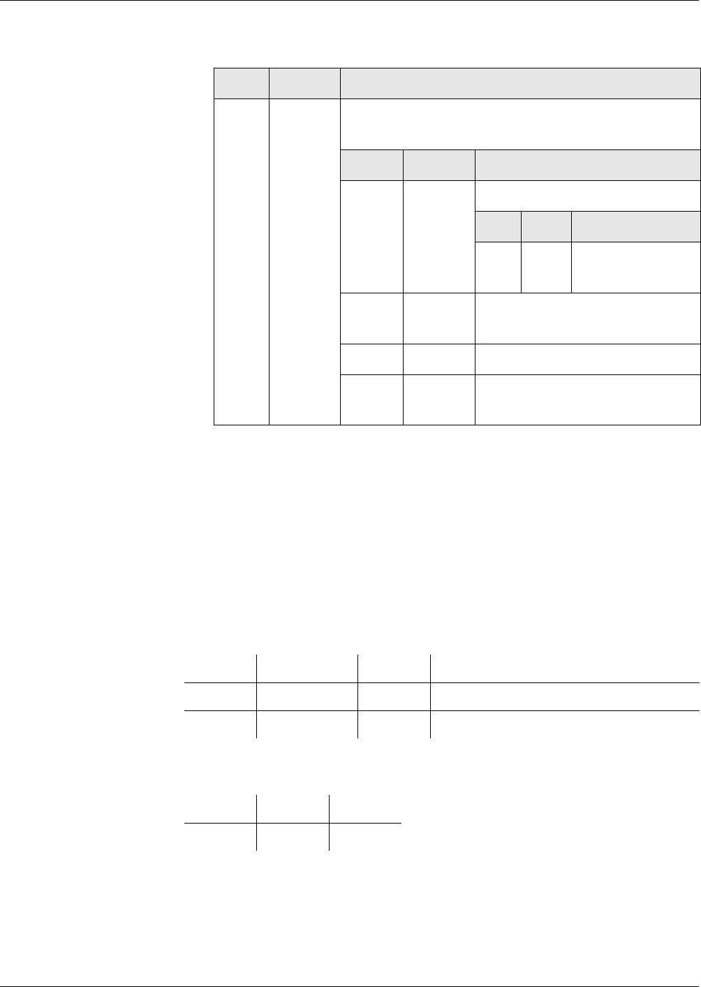
Cryptographic Keys
Export of Public Keys
Reference Manual STARCOS® 3.0/Edition 06/2005 131
ID No. 30016255
– For the application of a symmetrical authentication key, the data object
contains a checksum consisting of a MAC:
The signature as well as the checksum are calculated via the data objects
’B6’, ’7F 49’ and ’C0’ (complete TLV structure).
The content of these data objects is in accordance with the key type used.
RSA Keys
key reference The data object with the tag ’83’ and the key reference of PKCH.DS must be
contained in the 7th record of the private key file.
If this record does not exist, the serial number of the smart card will be en-
tered as the key reference.
public key data object The public key data object for the RSA key has the following structure:
key generation data object The key generation data object contains the information whether the key was
generated in the smart card or only entered.
T L V
’A2’ ’82 XX
XX’
DO input: Template for verification of a crypto-
graphic checksum
T L V
’B6’ ’XX’ Digital signature template
T L V
’83’ ’XX’ Key reference of
PKCH.DS
’7F 49’ ’82 XX
XX’
Public key data object
’C0’ Var. Key generation data object
’8E’ ’82 XX
XX’
Cryptographic checksum gener-
ated by means of KICCAUT
TAG Length Value Description
’81’ ’82 XX XX’ N Modulus
’82’ ’82 XX XX’ e Public exponent
TAG Length Value
’C0’ ’XX’ ’XX’

Cryptographic Keys
Export of Public Keys
132 Reference Manual STARCOS® 3.0/Edition 06/2005
ID No. 30016255
Val u e ’X X ’
Authentication Key –
signature or
cryptographic checksum
If the authentication key is a RSA key, the RSA procedure is converted to
PKCS#1 with SHA1 Hash.
If the authentication key is a symmetrical key, the retail MAC procedure is
converted as CBC-MAC with ICV = 0.
b8 b7 b6 b5 b4 b3 b2 b1 Description
0
1
Key generated:
on card
not on card
XXXXXXXRFU

Cryptographic Keys
Handling of Master Keys and Negotiation Keys
Reference Manual STARCOS® 3.0/Edition 06/2005 133
ID No. 30016255
Handling of Master Keys and Negotiation Keys
A secret cryptographic key can be accessed when the following commands
are executed:
– EXTERNAL AUTHENTICATE
– INTERNAL AUTHENTICATE
– MUTUAL AUTHENTICATE
as well as when performing secure messaging.
In this context, the key to be used is detected by means of a key reference, the
type of key and the key search algorithm (see ’Key Search Algorithm’ from
page 141 onwards).
For each access, check is made with the help of the additional key informa-
tion whether the access is permissible in the SE.
In this context, the following rules apply:
Rules – A master key may itself only be used for deriving a key, if
– this occurs when a command for a cryptographic operation is exe-
cuted, if
– the derived key may be accessed in the active SE.
In this case, access is not made directly to the master key itself, but to the
key stored in volatile memory that was derived from the master key.
– A secret negotiation key may only be accessed via the command MU-
TUAL AUTHENTICATE in order to negotiate one or two session keys.
– In case the negotiation key is a key to be derived from a master key,
a key derivation process may be performed during the execution of
MUTUAL AUTHENTICATE as a first step before the negotiation
key is accessed.
– The negotiated session key is stored in volatile memory in the
STARCOS® 3.0 smart card. Once the command MUTUAL AU-
THENTICATE has been executed successfully, it is available in the
active SE for use within the scope of the secure messaging of the fol-
lowing commands.

Cryptographic Keys
Master Keys and Derived Keys
134 Reference Manual STARCOS® 3.0/Edition 06/2005
ID No. 30016255
Master Keys and Derived Keys
A cryptographic key that is stored in non-volatile memory in the STARCOS®
3.0 smart card will be referred to as master key in an SE if a procedure for key
derivation is allocated to it in the SE. Formally, this means that the corre-
sponding SE data object contains a KMT with an algorithm ID for the key
derivation in the additional information of this key
The coding of additional key information does not permit a key in an SE to be
declared as a master key while using it directly for a cryptographic algorithm
in a different SE.
CID
key derivation data
’General SE Key Derivation Data’ from page 223 onwards specifies how
CIDs can be transferred to the STARCOS® 3.0 smart card and be stored via
the SET variant of the MSE command. These CID are independent from the
active SE while they are stored and can be used for key derivation by the cur-
rent DF. The CID remain stored until new CID are transferred to the smart
card. This also applies if a RESET is performed in the meantime or if the
smart card is deactivated.
access to master keys In case a key that is declared as a master key in the active SE and that was not
yet used for deriving a key in the active SE is to be accessed while a command
for performing a cryptographic operation is executed, it will be checked
whether CID are stored in the STARCOS® 3.0 smart card. If that applies, a
key will now be derived from the master key and the CID. For this purpose,
the procedure defined for the active SE by the algorithm ID in the KMT of the
master key is used. Whenever a key derivation process is performed, the op-
eration counter of the master key must be decremented, if applicable. In addi-
tion, an operation counter for the derived key must be initialized if an initial
value is available.
If no CID are present, the command whose execution requires access to the
master key cannot be executed. This can only be the case until a SET was ex-
ecuted successfully with CID for the first time.
A key derived from a master key with the current CID will be stored in vola-
tile memory in the STARCOS® 3.0 smart card together with the operation
counter that may exist.
The derived key then can be identified uniquely by means of KID and KV of
the associated master key in the DF that holds the master key. In particular, a
derived key is re-allocated to the DF containing the associated master keys.
A derived key "inherits" the property of being usable locally or mutually from
the associated master key. If the EF_KEYD of the DF to which the derived
key is allocated, is a local EF, the derived key, as any other key in this DF, will
be a locally usable key.
type and structure of the
derived key
The type and structure of the derived key result from the type and structure of
the master key and from the key management procedure used for deriving
that key.

Cryptographic Keys
Master Keys and Derived Keys
Reference Manual STARCOS® 3.0/Edition 06/2005 135
ID No. 30016255
The following table shows which structure data object is allocated to a de-
rived key:
The KFPC of the associated master key, if available, and the operation
counter stored in volatile memory associated with the derived key, if avail-
able, are used for a derived key.
The way in which the derived key may be used is defined by the active SE
data object. Altogether, all the information required for the derived key that is
also defined for a key stored in non-volatile memory of the smart card is at
hand. However, a derived key cannot become a master key.
The additional information regarding the derived key is used to check
whether the derived key may be used as required within the scope of the com-
mand to be executed.
– In case access to the derived key is no evaluation, the accessing com-
mand is aborted. Operation and KFPC remain unaffected. A key that was
derived successfully before will not be deleted.
– If access to the derived key is permissible, the accessing command will
be executed as specified. In this context, the operation counter of the de-
rived key is decremented correspondingly, if applicable.
If an error occurs when the command is executed, the derived key will not be
deleted. Provided that the error occurs when the derived key is used, the
KFPC will be decremented, if applicable.
deletion of derived keys Whenever the smart card is RESET, the derived keys are deleted. Further-
more, a derived key is deleted if the associated operation counter has reached
the value 0. In addition, selecting a DF (even if the selection is made implic-
itly by deleting the subordinate DF) will result in the deletion of derived keys
as follows:
If a DF is selected, the derived keys of the DFs outside the path from the se-
lected DF must be deleted up to the MF. Any derived key of the selected DF
and any superior DFs up to the MF remain unchanged. In particular, selecting
a DF does not have any effect on the derived key of the selected DF.
Furthermore, any derived keys associated to a particular DF will be deleted
when an SE in this DF is activated.
storing derived keys STARCOS® 3.0 stores a maximum of 4 derived keys. If more keys need to be
stored, the oldest one is overwritten.
Structure DO Mas-
ter Key
Algo-ID
Key Derivation
Structure DO Derived Key
’C1 02 81 10’ ’31 11’ ’C0 02 81 10’
’31 12’ ’C0 02 81 08’
’C2 02 81 10’ ’31 11’ ’C1 02 81 10’

Cryptographic Keys
Negotiation Keys and Session Keys
136 Reference Manual STARCOS® 3.0/Edition 06/2005
ID No. 30016255
Negotiation Keys and Session Keys
Key Negotiation with a
Secret Negotiation Key
A secret negotiation key may only be used for a cryptographic operation
when the command MUTUAL AUTHENTICATE is executed.
When the command MUTUAL AUTHENTICATE is executed, the operation
counter of the secret negotiation key is decremented, if applicable. In case the
command MUTUAL AUTHENTICATE determines an error when the secret
negotiation key is used, the KFPC of the negotiation key and/or of the associ-
ated master key will be decremented, if applicable.
Upon successful execution of MUTUAL AUTHENTICATE, the security state
allocated to the negotiation key will be set.
If the command MUTUAL AUTHENTICATE has been executed successfully,
the smart card will store the negotiated session key in volatile memory and
possibly the initial value for the SSC. The algorithm ID for the key negotia-
tion in the relevant KMT or AT defines which variant of MUTUAL AUTHEN-
TICATE is to be used.
KMT Once the command MUTUAL AUTHENTICATE has been executed success-
fully, the session key and possibly the SSC are available. In this context they
are referenced within the DF they are allocated to by the KID and KV of their
negotiation key (see ’’BA’ - Template for Key Management (KMT)’ from
page 119 onwards).
The negotiation key used for negotiating the session key must be determined
for this purpose. The session key can clearly be identified in the correspond-
ing DF through the KID and KV of the associated negotiation key.
A session key "inherits" the property of being usable locally or mutually from
the associated negotiation key.
Session keys are always secret keys with a length of 16 bytes that are directly
usable.
No operation counter is allocated to session keys. The KFPC of the associated
negotiation key is used.
The negotiated session keys are keys exclusively usable for secure messag-
ing. The way in which a negotiated session key is to be used for secure mes-
saging in the active SE is defined implicitly by the procedure for key
negotiation and possibly explicitly by a CT.
Where is the additional session key infor-
mation located?
Procedure
Included in the additional information of the
negotiation key
Key negotiation in a KMT
Stored in a separate record or in separate
records of the EF_KEYD
Key negotiation in an AT

Cryptographic Keys
Negotiation Keys and Session Keys
Reference Manual STARCOS® 3.0/Edition 06/2005 137
ID No. 30016255
If two session keys were negotiated, STARCOS® 3.0 will use the MAC pro-
tecting process within the scope of secure messaging is performed with SK2
and that the enciphering is performed with SK1, although both session keys
are referenced by the same KID and KV.
AT In this case, the session key(s) are clearly identified in the corresponding DF
by separate KID and KV. Session keys are allocated to the DF to which the as-
sociated negotiation key is allocated.
Chapter ’’A4’ - CRT for Authentication (AT)’ on page 117 explains which
checks regarding the additional information for session keys are performed
within the scope of the key negotiation. This additional information is then al-
located to a session key as is the case in keys stored in non-volatile memory.
In case this additional information includes a KFPC, this counter will be used
for all keys successfully stored in volatile memory.
No operation counter is allocated to session keys. If the corresponding addi-
tional information includes an operation counter, it will be ignored. Session
keys can be used in a limited way only (see ’Handling of Session Keys’ on
page 138).
Key Negotiation with
Negotiation Keys
Two session keys are always negotiated. Each have a length of 16 bytes.
A private and a public asymmetric key are involved in the procedures. The
private key is stored non-volatile memory. The public key can be stored in ei-
ther volatile memory or non-volatile memory. Asymmetric keys can only be
used for key negotiation if they are single-level key management keys and if
an algorithm ID for key negotiation is allocated to them. The algorithm ID
must be allocated in an AT in the SE that is active in the particular DF in
which they are stored.
access to the negotiation keys A public or private negotiation key may only be accessed with the commands
INTERNAL AUTHENTICATE and EXTERNAL AUTHENTICATE within the
scope of a procedure on key negotiation.
If available, operation counter and/or KFPC of the asymmetric keys involved
will be handled as described in the command description when the key nego-
tiation is performed.
When the key negotiation has been performed successfully, the security state
allocated to the public negotiation key is set. The smart card saves the nego-
tiated session key(s) in volatile memory and possibly the initial value for the
SSC.
Chapter ’’A4’ - CRT for Authentication (AT)’ on page 117 explains which
checks regarding the additional information for session keys have to be per-
formed within the scope of the key negotiation. This additional information is
then allocated to a session key as is the case in keys stored in non-volatile
memory. In case this additional information includes a KFPC, this counter
will be used for all keys successfully stored in volatile memory.

Cryptographic Keys
Negotiation Keys and Session Keys
138 Reference Manual STARCOS® 3.0/Edition 06/2005
ID No. 30016255
The data object with tag ’83’ in the AT of the private negotiation key defines
whether both negotiated session keys are stored or just SK2. Furthermore, the
algorithm ID allocated to the session key SK2 defines whether the negotiated
SSC is to be used. The session keys are clearly identified in the corresponding
DF by their own KID and KV. The session keys are allocated to the DF to
which the associated negotiation key is allocated.
No operation counter is allocated to session keys. The usability of session
keys is limited.
Handling of Session
Keys
The following rules have to be observed when session keys are used:
– When the session key or keys are deleted, the security state allocated to
the negotiation key is also be deleted.
– The session key, the SSC as well as the security state allocated to the ne-
gotiation key will be deleted if
– a command is executed whose command and/or response are not
protected within the scope of secure messaging with the session key
SK1 or SK2 in the way assigned to the session key, in particular, as
soon as a command without secure messaging is executed.
– a command is executed whose command and/or response data are to
be enciphered with a different key than SK1 within the scope of se-
cure messaging.
– an error occurs when a command is executed, whose commands and
responses are protected with the session key within the scope of se-
cure messaging.
The response will not be MAC protected.
The command can be executed, however, if
– the security conditions regarding the command are fulfilled even af-
ter the session keys and the security state allocated to the negotiation
key have been deleted.
– the security conditions are fulfilled even after the session keys and
the security state allocated to the negotiation key have been deleted.
This will not be the case if the session key is to be used for MAC
protecting the command.
– If the DF, to which session keys are allocated, is deleted, the session keys
as well as the security state allocated to the negotiation key must be de-
leted as well.
Thus, a command can only be executed successfully with secure messaging
while using one or both session keys if the security condition of the command
SM-MAC protection of the commands and responses defines the session keys
with the KID (see ’SM Security Conditions’ from page 56 onwards). If the
security condition also calls for SM enciphering, the KID of the session keys
must be referenced as well.

Cryptographic Keys
Negotiation Keys and Session Keys
Reference Manual STARCOS® 3.0/Edition 06/2005 139
ID No. 30016255
deletion of session keys The commands SELECT FILE and RESTORE cause session keys to be de-
leted, since they cannot be executed with secure messaging.
The commands SELECT FILE for selecting a directory and RESTORE cause
session keys to be deleted, since they cannot be executed with Secure Mes-
saging.

Cryptographic Keys
Certificate Keys and Public Keys in Certificates
140 Reference Manual STARCOS® 3.0/Edition 06/2005
ID No. 30016255
Certificate Keys and Public Keys in Certificates
Definition A public key stored in the STARCOS® 3.0 smart card will be referred to as
certificate key if a structure data object with tag ’D8’ is allocated to it in the
associated additional information. A procedure for introducing public keys by
means of certificate verification must be allocated to it in all permissible SEs
(see ’Certificate Verification’ from page 109 onwards).
Use of VERIFY
CERTIFICATE
The description of the command VERIFY CERTIFICATE explains how a cer-
tificate key is used for a CPI controlled procedure for introducing a public
key. The command VERIFY CERTIFICATE is used for this certificate verifi-
cation.
If the command VERIFY CERTIFICATE is executed successfully, the public
key included in the certificate will be stored in volatile memory in the smart
card afterwards. In case the certificate key was key stored in volatile memory
itself, it will be deleted afterwards together with any information stored in
volatile memory which is allocated to it.
The non-volatile additional information allocated to the public key is stored
in the EF_KEYD of the DF, to which the certificate key was or is allocated.
Non-volatile additional information is allocated to the public key. This addi-
tional information is allocated in the EF_KEYD of the DF to which the cer-
tificate key is assigned.
The public key is allocated to the DF, to which the certificate key is allocated.
and can be referenced there together with the key reference allocated to it. If
the public key has a key name, an allocation between key name and key ref-
erence for access of the SET command is stored in volatile memory.
access to the key Access to the certificate key is permissible within the scope of the additional
information allocated to it for the SE that is active in the DF in which it is
stored.
If access to the key does not permit evaluation
then the accessing command is aborted. Operation and KFPC of the key are
not affected by this. The key will not be deleted.
If access to the key is permissible
the accessing command will be executed as specified. In this context the op-
eration counter of the key is decremented, if applicable.
Should an error occur while the command is executed, the key will not be de-
leted. Provided that the error occurs when the key is used, the KFPC of the
key will be decremented, if applicable.

Cryptographic Keys
Key Search Algorithm
Reference Manual STARCOS® 3.0/Edition 06/2005 141
ID No. 30016255
Key Search Algorithm
The algorithm regarding the selection of a key works according to the follow-
ing parameters:
– Search identifier "global" or "DF specific"
– Key number KID
– Optional key version KV
– Optional key type
– Current DF of the STARCOS® 3.0 smart card as starting point for the
search process.
Regarding the type of key, the key search algorithm only makes a distinction
between private on the one hand, and secret or public on the other hand.
These types can be distinguished according to the right half-byte of the tag of
the key reference data object in the additional key information. Furthermore,
this distinction is sufficient for clearly identifying the additional information
searched for, as no secret and public key should have the same KID and KV.
The key search algorithm is arranged as follows:
– Search for the key group relevant DF,
– Search for the additional key information of the key,
– Evaluation of the additional key information, and
– Access to the key.
Search for the Key
Group Relevant DF
The key group relevant DF is searched for according to the following param-
eters:
– Current DF
– Search identifier
– Key number KID
Starting with the current DF, the first DF is searched for with the help of the
search identifier, in which at least one key out of the key group identified by
the KID may be used from the current DF.
search identifier "global" The search is started directly in the MF independent from the DF that is the
starting point of the search.
The key group relevant DF related to a current DF, the search identifier "glo-
bal", and a key number KID will be the MF if the EF_KEYD of the MF in-
cludes additional information regarding at least one key with the key number
KID, which is usable from the assigned DF.
If the current DF is not the MF, there will be no key group relevant DF related
to the current DF, the search identifier "global", and the key number KID.

Cryptographic Keys
Key Search Algorithm
142 Reference Manual STARCOS® 3.0/Edition 06/2005
ID No. 30016255
search identifier "DF-
specific"
The search is started in the DF, which is the starting point for the search, un-
less the MF is the starting point. The MF cannot be the starting point for a
search with the search identifier "DF-specific".
The key group relevant DF related to a current DF, the search identifier "DF-
specific" and a key number KID is the current DF itself, if the DF is not the
MF and the EF_KEYD of the DF contains additional information regarding at
least one key with the key number KID.
Otherwise, the first superior DF in the file structure of the STARCOS® 3.0
smart card that is not the MF and that contains a mutually usable EF_KEYD
containing additional information on at least one mutually usable key with the
key number KID is the key group relevant DF related to the current DF, the
search identifier "DF-specific" and the key number KID.
If such a DF does not exist, the search algorithm for the current DF, the search
identifier "DF-specific" and the key number KID will be without success.
search in the key reference
data objects
Within additional key information of the MF or of another DF, the left half-
byte of the tag in a key reference data object reveals whether the correspond-
ing key can be used mutually (value ’8’) or only locally (value ’9’). The first
byte in the value field of a key reference data object contains the KID.
On principle, the search in the key reference data objects must be performed
per DF as follows:
– First, the key reference data objects of session keys possibly stored in
volatile memory are searched sorted by the order of their storage,
– then the key reference data objects of derived keys which are possibly
stored in volatile memory are searched sorted by the order of their stor-
age,
– then the key reference data object of a public key possibly stored in vol-
atile memory is analyzed,
– then the key reference data objects in the records of the EF_KEYD are
searched sorted by increasing record number.
So the corresponding key reference data object of the session key stored first
in the DF is searched first. The order of storage must be recorded for derived
keys (see ’Master Keys and Derived Keys’ on page 134). The order of the
storage of session keys is specified in ’Negotiation Keys and Session Keys’
on page 136.
As the key reference data objects regarding keys stored in volatile memory
are also stored in records of the EF_KEYD, it may occur that the key refer-
ence data objects of keys stored in volatile memory are searched twice. Fur-
thermore, it is possible that a session key was negotiated with a derived key.
In this case, the corresponding key reference data object could be searched up
to three times. Implementing the search in key reference data objects should
avoid such multiple searches.

Cryptographic Keys
Key Search Algorithm
Reference Manual STARCOS® 3.0/Edition 06/2005 143
ID No. 30016255
analysis of the key reference
data objects
The searched key reference data objects are analyzed as follows:
– If the searched DF is identical to the DF, the system will check whether
the left half-byte of the tag has one of the values ’8’ or ’9’. Otherwise, it
will be checked whether the left half-byte has the value ’8’.
This ensures that the corresponding key can be used from the current DF.
– The right half-byte of the tag is checked if it has one of the values ’3’ or
’4’.
– Check is made whether the first byte of the value field has the value cur-
rent as KID.
The following points are not checked:
– coding errors of key reference data objects not concerning the tag.
– Whether triple KID || KV || type of key appear multiple times in the DF
(see ’Tag ’X3’ or ’X4’ Key Reference Data Object’ on page 80).
– Other additional information stored in the records of the EF_KEYD is
not analyzed. In particular, whether the use of the keys in the SE that is
active for the searched DFs is permissible.
In case the search was successful, the key reference data object detected (see
’Tag ’X3’ or ’X4’ Key Reference Data Object’ on page 80) is checked to see
whether its coding is correct when the key additional information is analyzed
later on.
Search for the
Additional Key
Information
When the key group relevant DF has been detected for the current DF, the
search identifier and the current KID, the system checks whether additional
information regarding a key that may be used from the current DF, with the
current KID and, if indicated, the current KV and, if indicated, the current
type of key is stored in the DF. Thus, if both KV and type of key are indicated
for the search, additional information is searched, in which both are present
with the value searched for.
The search is performed based exclusively on the tag and the first one or two
bytes in the value field of the key reference data object contained in the addi-
tional key information of the key group relevant DF.
The type of key can be recognized with the help of the right half-byte of the
tag (’3’ means secret or public, ’4’ means private). The first byte in the value
field of a key reference data object contains the KID. The second byte in the
value field of a key reference data object contains the KV.
search in the key reference
data objects
The search in the key reference data objects of the key group relevant DF
must be performed as follows:
– First, the key reference data objects of session keys possibly stored in
volatile memory are searched sorted by the order of their storage,
– then the key reference data objects of derived keys possibly stored in vol-
atile memory are searched sorted by the order of their storage,

Cryptographic Keys
Key Search Algorithm
144 Reference Manual STARCOS® 3.0/Edition 06/2005
ID No. 30016255
– then the key reference data object of a public key possibly stored in vol-
atile memory is analyzed,
– then the key reference data objects in the records of the EF_KEYD are
searched sorted by increasing record number.
So the corresponding key reference data object of the session key stored first
in the DF is searched first. The order of storage must be recorded for derived
keys (see ’Master Keys and Derived Keys’ on page 134). The order of the
storage of session keys is specified in ’Negotiation Keys and Session Keys’
on page 136.
As the key reference data objects regarding keys stored in volatile memory
are also stored in records of the EF_KEYD, it may occur that the key refer-
ence data objects of keys stored in volatile memory are searched twice. Fur-
thermore, it is possible that a session key was negotiated with a derived key.
In this case, the corresponding key reference data object could be searched up
to three times. Implementing the search in key reference data objects should
avoid such multiple searches.
analysis of the key reference
data objects
The searched key reference data objects are analyzed as follows:
– If the key group relevant DF is identical to the DF that was assigned as
being the starting point for the search, the system will check whether the
left half-byte of the tag has one of the values ’8’ or ’9’. Otherwise, it will
be checked whether the left half-byte has the value ’8’.
This ensures that the corresponding key can be used from the current DF.
– If a search is performed without type of key, the system will check
whether the right half-byte of the tag has one of the values ’3’ or ’4’. Oth-
erwise, it will be checked whether the right half-byte of the tag has the
value assigned as type of key.
– Check is made whether the first byte of the value field has the value pre-
defined as KID.
– If a search is performed without KV, the second byte of the value field of
the key reference data object is not checked. Otherwise, the system will
check whether the second byte of the value field has the value predefined
as KV.
Either the search is completed successfully, as soon as a key reference data
object with the searched characteristics has been detected, or it is ended with-
out success, if the key group relevant DF does not contain any additional key
information whose key reference data object fulfills the corresponding search
criterion.
If the search was successful, the key reference data object detected will be
checked to see whether its coding is correct when the key additional informa-
tion is analyzed later on.

Cryptographic Keys
Key Search Algorithm
Reference Manual STARCOS® 3.0/Edition 06/2005 145
ID No. 30016255
Analysis of the
Additional Key
Information
The structure and the content of the additional key information are examined
to see whether they conform to the specification in so far as the information is
needed for the use of the associated key when a command is executed.
When the additional key information of an asymmetric key is accessed, the
following commands and cryptographic operations must check whether an
LCS data object is included in the additional information and what its value
is:
–INTERNAL AUTHENTICATE
–EXTERNAL AUTHENTICATE
–GENERATE ASYMMETRIC KEY PAIR,
–COMPUTE DIGITAL SIGNATURE
–VERIFY DIGITAL SIGNATURE,
–VERIFY CERTIFICATE,
–ENCIPHER and DECIPHER
The commands and cryptographic operations mentioned (except for GENER-
ATE ASYMMETRIC KEY PAIR) are only permissible, either if no LCS data
object is available or if it is available and has the value ’05’.
The command GENERATE ASYMMETRIC KEY PAIR may only generate an
asymmetric key if an LCS data object is available in its additional informa-
tion. The way in which the value of the LCS data object is handled by the
command GENERATE ASYMMETRIC KEY PAIR is illustrated in ’GENER-
ATE ASYMMETRIC KEY PAIR’ on page 306.
The following chapters illustrate the way in which the coded data must be
verified for unambiguity when a search for an SE data object is performed for
the active SE and when a CRT with UQ and/or KMT is searched for in an SE
data object or KMT.
Search for an SE Data
Key Information
The SE data objects with tag ’7B’ are checked to see whether there is an SE
data object in the additional information that is defined for the active SE. For
this purpose, the SE# of the SE, which is active for the DF which holds addi-
tional information, is determined. This SE# can be different from the SE# of
the active SE for the currently selected DF if the additional information is not
available in the currently selected DF.
The SE# is searched for in the SE data objects in the additional information
from the left to the right. For this purpose, only the SE reference data object
of the SE data objects is evaluated. If an SE data object does not contain an SE
reference data object as a first data object or if this data object does not have
the length ’01’ or ’00’, the additional information will contain inconsistent
data.
It is only analyzed whether the value field of an SE reference data object with
the length ’01’ contains the SE# searched for. The search will be terminated
as soon as the SE# is detected.

Cryptographic Keys
Key Search Algorithm
146 Reference Manual STARCOS® 3.0/Edition 06/2005
ID No. 30016255
In case the SE# cannot be found in any SE data object, the length or the value
’00’ is searched for in the SE data objects in the additional information from
the left to the right.
For this purpose, only the SE reference data object of the SE data object is
evaluated. If an SE data object does not contain an SE reference data object as
a first data object or if this data object does not have the length ’01’ or ’00’,
the additional information will contain inconsistent data.
It is only analyzed whether the length field or the value field of an SE refer-
ence data object contains the value ’00’. The search will be terminated as
soon as ’00’ is detected.
The search for the first appearance of the length or the value ’00’ can also take
place in parallel to the search for the first appearance of the SE#. This way
SE# appearing multiple times or non-permissible SE# are ignored.
Search for CRT with UQ
or KMT in an SE Data
Object or KMT
When the CRTs and/or KMT are analyzed in an SE data object and/or in a
KMT, the smart card must behave uniquely, even if the UQs in the CRTs are
occupied ambiguous.
If a command is executed with secure messaging or if one of the commands
INTERNAL AUTHENTICATE, EXTERNAL AUTHENTICATE, MUTUAL
AUTHENTICATE, COMPUTE DIGITAL SIGNATURE, VERIFY DIGITAL
SIGNATURE, ENCIPHER, DECIPHER, VERIFY CERTIFICATE or GEN-
ERATE ASYMMETRIC KEY PAIR is executed, first the type and norm of the
key will be determined with the help of the key reference data object and the
structure data object when the additional information of a key is accessed.
This will show whether an SE data object or KMT has to be searched for a
CRT only, for a KMT only or for a CRT and a KMT in order to determine if
and how a key may be used when the command is executed (see ’Commands’
from page 255 onwards).
Search for CRT If the key is a directly usable key, an asymmetric negotiation key or a certifi-
cate key, a certain tag of a CRT with possible values of the UQ will be
searched for.
Key Search in SE Data Object/KMT
Directly usable key,
asymmetric negotiation key
the certificate key negotiates
For CRT
Several CRTs even with identical
UQ can be allocated to such a
key.
Symmetric single-level key manage-
ment key
For KMT or AT
Exactly one KMT or one AT may
be allocated to such a key.
Symmetric dual-level key management
key
For KMT

Cryptographic Keys
Key Search Algorithm
Reference Manual STARCOS® 3.0/Edition 06/2005 147
ID No. 30016255
possible UQs The following table shows which values can appear:
If the usability of the key is not searched for within the scope of secure mes-
saging, and in which an algorithm ID is selected for an AT, DST or CT with
one of the UQs ’80’ or ’40’ for the DF that is current when the corresponding
command is executed, then not only a tag-UQ combination will be searched
for but also a tag with a UQ and the predefined algorithm ID.
Search For this purpose, the following approach is used:
– The tag and the UQ is searched for in the data objects in an SE data object
or KMT from the left to the right under evaluation of the TLV coding.
For this purpose, the following is evaluated:
– The tags of all data objects
– The UQ-DO of the data objects with the tag searched for
Origin of the Search Searched Tag and UQ
INTERNAL AUTHENTICATE ’A4’ and ’40’ or
’A4’ and ’C0’
EXTERNAL AUTHENTICATE ’A4’ and ’80’ or
’A4’ and ’C0’
MUTUAL AUTHENTICATE ’A4’ and ’C0’
VERIFY DIGITAL SIGNATURE ’B6’ and ’80’
COMPUTE DIGITAL SIGNATURE ’B6’ and ’40’
VERIFY CERTIFICATE ’B8’ and ’80’
ENCIPHER ’B8’ and ’80’
DECIPHER ’B8’ and ’40’
GENERATE ASYMMETRIC KEY
PAIR
’B6’ and ’40’
MAC-SM-SC for command ’B4’ and ’10’ or
’B4’ and ’30’
MAC-SM-SC for response ’B4’ and ’20’ or
’B4’ and ’30’
MAC-SM-SC for commands and re-
sponses
’B4’ and ’20’ or
’B4’ and ’10’ and ’B4’ and ’20’
ENC-SM-SC for command ’B8’ and ’10’ or
’B8’ and ’30’
ENC-SM-SC for response ’B8’ and ’20’ or
’B8’ and ’30’
ENC-SM-SC for command and re-
sponses
’B8’ and ’30’ or
’B8’ and ’10’ and ’B8’ and ’20’

Cryptographic Keys
Key Search Algorithm
148 Reference Manual STARCOS® 3.0/Edition 06/2005
ID No. 30016255
– The algorithm ID in the data objects with the tag and UQ searched
for
If a data object with the tag searched for is found and does not contain a
UQ-DO as a first data object, the default value defined for the corre-
sponding CRT and for the type of key will be assumed.
– The SE data object and/or KMT is searched through until the first tag-
UQ-algorithm ID combination that is identical to the combination(s)
searched for is detected or until the end of the value field of the SE data
object or of the KMT has been reached.
If tag-UQ combinations are searched for within the scope of the evalua-
tion of a MAC-SM-SC or an ENC-SM-SC for commands and responses,
and the UQ detected first has one of the values ’10’ or ’20’, the tag-UQ
combination with the corresponding other UQ ’20’ or ’10’ is searched for
in the SE data object or KMT further to the right until this combination
searched for has been detected or the end of the value field of the SE data
object or the KMT has been reached.
It should be noted that in case various UQs are permissible for one tag
and the tag is detected, it will be checked for any UQ (yet) searched for
whether it is contained in the corresponding CRT. So not all data objects
are analyzed with one UQ at first and then with another UQ. This way it
is ensured that the search will always produce the same result. In princi-
ple, this will also apply if the SE data object or KMT contains data ob-
jects that are not defined. These will be ignored provided that the TLV-
coding is correct altogether.
In particular, a KMT available in the SE data object or KMT does not
have to be recognized as an error. This KMT will never be accessed, as it
is allocated to a key that is directly usable for searching for KMT and AT,
to an asymmetric negotiation key or to a certificate key.
In case the SE data object or KMT contains CRTs with unequal UQs, the first
CRT from the left with the UQ will always be detected if the search is per-
formed without algorithm ID. Therefore, the included algorithm ID must be
selected via SET in order to find a CRT with the UQ located behind the first
CRT with the UQ.
In case a CRT that was detected is not coded correctly, e.g. because the UQ in
a CRT that was detected is not consistent with the algorithm ID or if a CRT
that was detected is unusable, e.g. because it contains an algorithm ID that is
not usable for the command to be executed, the search for additional CRTs
and UQs will be continued.
Search for KMT and AT If the key is a symmetric single-level key management key, the tag of the
KMT (’BA’) and possibly the tag of the AT (’A4’) with UQ ’C0’ or without
UQ will be searched for.

Cryptographic Keys
Key Search Algorithm
Reference Manual STARCOS® 3.0/Edition 06/2005 149
ID No. 30016255
possible tags The following table illustrates which values can be searched for:
Other commands do not have access to a symmetric single-level key manage-
ment key.
It must be guaranteed that a single-level symmetric key management key in
an SE is used for exactly one procedure for key management, even if the cor-
responding SE data object or DMT is coded incorrectly and, for instance, a
KMT contains an AT.
Therefore, the tags of the data objects are analyzed from the left to the right in
the corresponding SE data object or KMT to see whether they have one of the
values ’BA’ or A4’. As soon as such a data object has been detected or when
the end of the value field of the SE data object has been reached, the search
will be terminated. If the data object detected is an AT although a KMT must
be detected, the search will not be continued.
If the data object detected is usable for the corresponding access, it will be an-
alyzed whether the data object detected contains an algorithm ID and/or a UQ
and an algorithm ID usable for the corresponding access. If that is not the
case, the search will be continued.
Origin of the Search Searched Tag (and UQ)
INTERNAL AUTHENTICATE ’BA’
EXTERNAL AUTHENTICATE ’BA’
MUTUAL AUTHENTICATE ’BA’ or ’A4’ or
’A4’ and ’C0’
MAC-SM-SC for command ’BA’
MAC-SM-SC for response ’BA’
MAC-SM-SC for commands and re-
sponses
’BA’
ENC-SM-SC for command ’BA’
ENC-SM-SC for response ’BA’
ENC-SM-SC for commands and re-
sponses
’BA’
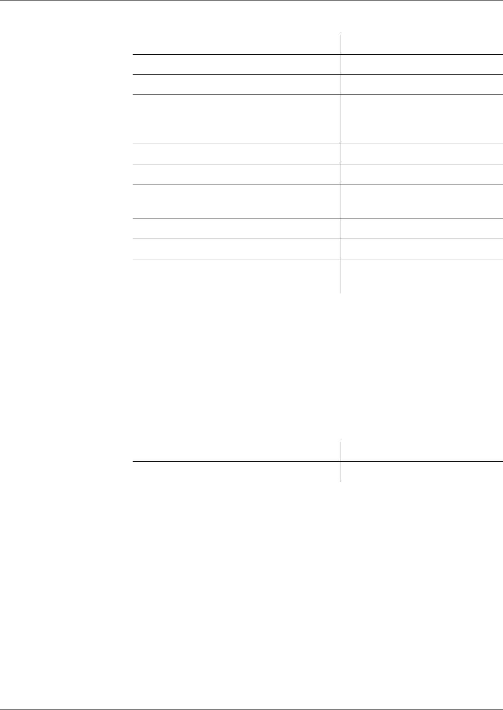
Cryptographic Keys
Key Search Algorithm
150 Reference Manual STARCOS® 3.0/Edition 06/2005
ID No. 30016255
Data objects and algorithm ID can be used for access as follows::
If the usability of the key is searched for within the frame of executing MU-
TUAL AUTHENTICATE and an algorithm ID was selected for AT with UQ
’80’ via SET (see ’Selection of Algorithms’ on page 219), it must also be ver-
ified whether the algorithm ID in the KMT or AT detected is identical to the
algorithm ID searched for. If that is not the case, the search will not be contin-
ued.
search for KMT If the key is a symmetric two-level key management key, the tag of the KMT
(’BA’) will be searched for. The following table shows which values can be
searched for:
Other commands do not have access to a symmetric dual-level key manage-
ment key.
The tags of the data objects in the corresponding SE data object are analyzed
from the left to the right to see whether they have the value ’BA’. As soon as
such a data object has been detected or when the end of the value field of the
SE data object has been reached, the search will be terminated.
If a KMT is detected, it will be analyzed whether the data object detected con-
tains an algorithm ID for the key derivation. If that is not the case, the search
will not be continued.
Origin of the Search DO and Algorithm
INTERNAL AUTHENTICATE ’BA’ and key derivation
EXTERNAL AUTHENTICATE ’BA’ and key derivation
MUTUAL AUTHENTICATE ’BA’ and key negotiation or
’A4’ (and ’C0’) and key negoti-
ation
MAC-SM-SC for command ’BA’ and key derivation
MAC-SM-SC for response ’BA’ and key derivation
MAC-SM-SC for commands and re-
sponses
’BA’ and key derivation
ENC-SM-SC for command ’BA’ and key derivation
ENC-SM-SC for response ’BA’ and key derivation
ENC-SM-SC for commands and re-
sponses
’BA’ and key derivation
Origin of Search Searched Tag (and UQ)
MUTUAL AUTHENTICATE ’BA’ and key derivation

Cryptographic Keys
Key Search Algorithm
Reference Manual STARCOS® 3.0/Edition 06/2005 151
ID No. 30016255
Access to the Key If the search algorithm is successful and if structure and content of the addi-
tional information are correct, a decision must be made on which of the keys
referenced by KID and KV are to be used:
– A cryptographic key stored in volatile/non-volatile memory is always al-
located uniquely to a DF.
Each of these keys has a KID and a KV identifying it within the DF to
which it is allocated.
– Derived keys have the same KID and KV as the key stored in non-vola-
tile memory from which they were derived in the active SE.
– Session keys that were negotiated with a symmetric key can have the
same KID and KV as the key stored in non-volatile memory that was
used for their negotiation in the active SE.
– Session keys that were negotiated with an asymmetric key in the active
SE have their own KID and KV. Session keys that were negotiated with
a symmetric key in the active SE can have their own KID and KV.
– Public keys that were stored in the active SE within the scope of a certif-
icate verification have their own KID and KV.
A pair of KID and KV in the active SE can have the following types of sym-
metric keys in a DF:
– A master key stored in non-volatile memory and
– a negotiation key stored in volatile memory that was derived from the
master key in the active SE
or
– a master key stored in non-volatile memory and
– a directly usable key stored in volatile memory that was derived from the
master key in the active SE
or
– a negotiation key stored in non-volatile memory and
– one or two session keys stored in volatile memory that were negotiated
with the negotiation key in the active SE
The additional key information regarding KID and KV clearly defines for
each key stored in non-volatile/volatile memory how it may be used in the ac-
tive SE. Furthermore, the additional key information regarding KID and KV
define for each key whether it is a local key or a mutually usable key. In ad-
dition, all keys with the same KID and KV use the KFPC (if available) for the
key stored in non-volatile memory.
If available, the operation counter stored in non-volatile memory is only used
for the key stored in non-volatile memory. During the derivation an operation
counter to be stored in volatile memory can be allocated to a key that is de-
rived from a master key. Session keys do not have an operation counter.

Cryptographic Keys
Key Search Algorithm
152 Reference Manual STARCOS® 3.0/Edition 06/2005
ID No. 30016255
The rule for handling keys with the same KID and KV is:
Rule If a cryptographic operation is to be performed while a command is exe-
cuted, and if for that purpose a key within a DF is referenced with the
help of KID and KV, then the key that was generated last will be refer-
enced with this KID and KV.
Application of the Rule A key stored in non-volatile memory is referenced by KID and KV.
In order to use a key stored in non-volatile memory, the corresponding key is
searched in the EF_KEY by means of KID and KV. In this context, the
records of the EF are scanned by increasing record number.
The command will be aborted if
– no key is found.
– the length of the key is not consistent with the definitions in the addi-
tional information.
– the KFPC and/or operation counter associated to a key has the value ’00’
in the additional information.
– the parity of the key stored in non-volatile memory is not correct
KID and KV make reference to:
– a key stored in non-volatile memory.
The key stored in non-vol-
atile memory in the active
SE is a
Procedure
Master key Proceed as specified in ’Master Keys and De-
rived Keys’ on page 134, where a key is de-
rived, stored and used if applicable
Negotiation key Proceed as specified in ’Negotiation Keys
and Session Keys’ on page 136, where one or
two session keys are stored in case of success
Directly usable key The corresponding CRTs in the additional in-
formation are used for checking whether the
key may be used for the requested operation
and is used correspondingly (’Additional Key
Information in the Records of EF_KEYD’ on
page 79 and ’Master Keys and Derived Keys’
on page 134).

Cryptographic Keys
Key Search Algorithm
Reference Manual STARCOS® 3.0/Edition 06/2005 153
ID No. 30016255
– a key stored in volatile memory and two session keys, respectively.
KID and KV make reference to:
– A key stored in non-volatile memory (master key)
– A negotiation key stored in volatile memory
– One or two session keys stored in volatile memory.
procedures The negotiation procedure (implicitly) and the definitions made by a CT (ex-
plicitly) are used to analyze whether the session key(s) may be used as re-
quested.
If that is not the case, the session key(s) must be deleted and the requesting
command must be rejected, whereby the operation counter of the negotiation
key and the KFPC of the master key remain unchanged.
The access of a MUTUAL AUTHENTICATE that makes reference to the KID
and KV of the session key(s) must be rejected.
If errors occur when the session key(s) is/are used, the KFPC of the associ-
The key stored in non-vol-
atile memory in the active
SE is a
Procedure
negotiation key that was
derived from a master key
Proceed as specified in ’Negotiation Keys and Session Keys’ on page
136, where one or two session keys are stored in case of success
If errors occur when the derived key is used, the KFPC of the associated
master key stored in non-volatile memory will be decremented, but the
derived key remains stored.
directly usable key that was
derived from a master key
The corresponding CRTs in the additional information are used for check-
ing whether the key may be used for the requested operation (’Additional
Key Information in the Records of EF_KEYD’ on page 79 and ’Master
Keys and Derived Keys’ on page 134) and is used correspondingly.
If that is not the case, the requesting command will be rejected.
If errors occur when the derived key is used, the KFPC of the associated
master key stored in non-volatile memory will be decremented, but the
derived key remains stored.
a session key that was ne-
gotiated with a negotiation
key stored in non-volatile
memory
The negotiation procedure (implicitly) and the definitions made by a CT
(explicitly) are used to analyze whether the session key(s) may be used as
requested.
If that is not the case, the session key must be deleted and the requesting
command must be rejected. The operation counters and the KFPC of the
negotiation key remain unchanged.
The access of a MUTUAL AUTHENTICATE that makes reference to the
KID and KV of the session key(s) must be rejected.
If errors occur when the session key(s) is/are used, the KFPC of the asso-
ciated negotiation key stored in non-volatile memory will be decre-
mented, and the session key must be deleted.

Cryptographic Keys
Key Search Algorithm
154 Reference Manual STARCOS® 3.0/Edition 06/2005
ID No. 30016255
ated master key stored in non-volatile memory will be decremented, if appli-
cable, and the session key(s) must be deleted.
The negotiation key stored in volatile memory remains stored in any case. If
the session key(s) is/are deleted, the key that was last stored with KID and KV
will become the negotiation key and can be referenced in the next command.
The command will be aborted if
– the length of a key stored in volatile memory is not consistent with the
definition in the associated additional information, the accessing com-
mand will be aborted.
– the operation counter and/or KFPC associated with a key stored in vola-
tile memory to be used has the value ’00’ in the additional information.
Keys stored in volatile memory with their own KID and KV are accessed like
keys stored in non-volatile memory. The operation counter and KFPC of the
associated certificate or negotiation key will not be accessed.

Cryptographic Keys
Key Management – Overview
Reference Manual STARCOS® 3.0/Edition 06/2005 155
ID No. 30016255
Key Management – Overview
STARCOS® uses three procedures for the key management:
– Key derivation
A key individual for each card is derived from the master key.
– Key negotiation (see page 157)
A temporary key is derived from a random number.
– Verification of certificate (see page 167)
A public key including a certificate is transferred to the smart card.
Key Derivation
With the key derivation, a card-specific key (CSK) is derived from the master
key (Key Generating Key, KGK) and from the card identification data (CID).
Prerequisite The following applies to the calculation of a CSK with 16 bytes:
– KGK, 16 bytes
– CID padded with ’00’ to the next multiple of 8 bytes, however, at least to
16 bytes (0-Padding)
– publicly known initial value
I = ’52 52 52 52 52 52 52 52 25 25 25 25 25 25 25 25’, 16 bytes
Calculation CSK = P(d*KGK(H(I,CID)))
P – Parity Adjustment Function
If b1,..,b8 is the representation of one byte as series of 8 bits, then the
lower-order bit b8 of each byte will be set to odd parity by P; i.e. b8 is set
in each byte so that it contains an odd number of 1.
d*KGK – triple-DES decryption by the key KGK
For this purpose, the two blocks H1 and H2 with a length of 8 bytes are
individually deciphered by H(I,CID) = H1 || H2 (ECB mode):
d*KGK(H(I,CID)) = d*KGK(H1) || d*KGK(H2)
H – Hash function
The values X with a length = multiple of 8 bytes are mapped to a value of
16 bytes by the initial value I.
The transformations u (Ad10) and u’ (Ad 01) extended by P are used (for
transformations, see also ISO HF2). H is recursively defined.
prerequisite for
hash function
–X = x
1 || ... || xn is the decomposition of the value X into blocks with
a length of 8 bytes, and L0 || R0 means the decomposition of the
specified initial value I into two blocks of 8 bytes.
– eK(X) refers to the DES encryption of an 8-byte value with the help
of an 8-byte key.
–⊕ is the addition of modulo 2 (XOR) bit by bit.

Cryptographic Keys
Key Management – Overview
156 Reference Manual STARCOS® 3.0/Edition 06/2005
ID No. 30016255
– The transformations Ad10 and Ad01 transform the 8-byte values K
as follows:
If K = k1,...,k64 is the representation of K as series of 64 bits.
Then
Ad10(K) = [P](k1,1,0,k4,...,k64)
Ad01(K) = [P](k1,0,1,k4,...,k64)
[P]: P in Ad10 and Ad01 is optional.
P may be dropped if the parity of the key K is not verified prior to the
DES encryption eK(X).
–L
i || Ri from Li-1 || Ri-1 and xi are calculated as follows:
Li-1 consists of the bits l1,...,l64 and
Ri-1 consists of the bits r1,...,r64,
Step 1: L’i || i := Ad10(Li-1) = [P](l1,1,0,l4,...,l64)
R’i := Ad01(Ri-1) = [P](r1,0,1,r4,...,r64)
Step 2: Ai = Ai[left] || Ai[right] = eL’i || i(xi) ⊕ xi.
Bi = Bi[left] || Bi[right] = eR’i ¦| i(xi) ⊕ xi.
Step 3: Li = Ai[left] || Bi[right]
Ri = Bi[left] || Ai[right]
–L
n || Rn is then the hash value of X under H:
H(I,X) = Ln || Rn
For the calculation of the 8-byte key K from KGK, CID and I, which is
card-specific, first the 16-byte key CSK is determined and the left half of
CSK is used as K.

Cryptographic Keys
Key Negotiation
Reference Manual STARCOS® 3.0/Edition 06/2005 157
ID No. 30016255
Key Negotiation
During the key negotiation, a session key is derived from a random number as
temporary key. STARCOS® supports the negotiation of session keys by sym
metric and asymmetric procedures and mutual authentication according E-
signK (For asymmetric procedures, see page 160).
Symmetric Procedures STARCOS® supports the following symmetric procedures:
– Mutual Authentication
– Mutual Authentication according to E-SignK (see page 158)
Mutual Authentication The key negotiation by symmetric procedures is implemented by the com-
mand MUTUAL AUTHENTICATE. For this purpose, the smart card and the
terminal first authenticate themselves mutually and then transfer one or two
session keys. Optionally, a Send Sequence Counter (SSC) with a length of 8
bytes may be initialized simultaneously. The smart card uses a triple-DES key
(CSK), which is card specific, for the negotiation.
– Random numbers RND.ICC and K1 created by the smart card
Random numbers RND.IFD and K0 created by the terminal
– RND.ICC, RND.IFD with 8 bytes each
K0, K1 with 16 or 32 bytes each
– Right before the command MUTUAL AUTHENTICATE, the smart card
transfers a random number RND.ICC to the terminal by the command
GET CHALLENGE.
– When the smart card receives the command MUTUAL AUTHENTI-
CATE, the smart card verifies whether the random number RND.ICC
created and issued by the card is correctly contained in the bytes 9 to 16
of the deciphered command data.
– Padding is not used for the decryption.
– The smart card creates the value K0, and with the help of K1: K0 ⊕ K1
it is used for an XOR operation.
As K0 and K1 must have the same length, K0 ⊕ K1 has a length of 16
bytes or 32 bytes.
Smart Card Terminal
RND.ICC
Å
Æ
GET CHALLENGE
e*CSK(0, RND.ICC ||
RND.IFD || K1)
Å
Æ
MUTUAL AUTHENTICATE
e*CSK(0, RND.IFD ||
RND.ICC || K0)

Cryptographic Keys
Key Negotiation
158 Reference Manual STARCOS® 3.0/Edition 06/2005
ID No. 30016255
– Two session keys each containing 16 bytes are created for K0 ⊕ K1:
SK1 || SK2 = K0 ⊕ K1
– One session key of 16 bytes is created for K0 ⊕ K1:
SK1 = K0 ⊕ K1
– If an SSC is initialized simultaneously, the 4 lower-order bytes of
RND.ICC and RND.IFD are linked:
SSC = 4 lower-order bytes of RND.ICC ||
4 lower-order bytes of RND.IFD
– The smart card sets a security status, which indicates the successful ex-
ternal authentication by the key CSK.
Mutual Authentication
according to E-SignK
Another method of mutual authentication supported by STARCOS® 3.0 is
mutual authentication according to E-SignK. This method allows for the se-
cure production of one or two session keys for later use in secure messaging.
Single Key Version If only one key (KEsignK) is stored in the EF_KEY the following key deriva-
tion is used to generate the keys:
KENC = (Byte 1-16) P*(SHA1 (KEsignK || ’00000001’))
KMAC = (Byte 1-16) P*(SHA1 (KEsignK || ’00000002’))
For detail information see page 338.
In addition to the keys the following data are used for the key negotiation:
– Random number RND.ICC created by the smart card
Random number RND.IFD created by the terminal
– Serial number SN.ICC created by the smart card
Serial number SN.IFD created by the terminal
Smart Card Terminal
SN.ICC
Å
Æ
READ BINARY
from EF.GDO
RND.ICC
Å
Æ
GET CHALLENGE
R* || MAC (KMAC, R*)
R = RND.ICC || SN.ICC ||
RND.IFD || SN.IFD || KICC
R* = ENC(KENC, R)
Å
Æ
MUTUAL AUTHENTICATE
S* || MAC (KMAC, S*)
S = RND.IFD || SN.IFD ||
RND.ICC || SN.ICC ||
KIFD (8 || 8 || 8 || 8 || 32 bytes)
S* = ENC(KENC, S)

Cryptographic Keys
Key Negotiation
Reference Manual STARCOS® 3.0/Edition 06/2005 159
ID No. 30016255
– The serial number of the smart card is sent using the command READ BI-
NARY.
– Right before the command MUTUAL AUTHENTICATE, the smart card
transfers a random number RND.ICC to the terminal by the command
GET CHALLENGE.
– The terminal enciphers the RND.IFD and the SN.IFD as well as the
RND.ICC and the SN.ICC along with the 32 bytes key part KIFD.
– The terminal calculates and appends a MAC.
– The terminal returns the code text block.
– The smart card calculates and verifies the MAC.
– The smart card deciphers the code text block and verifies the RND.ICC
and the SN.ICC.
– The smart card calculates the two session keys (see ’MUTUAL AU-
THENTICATE’ on page 333).
– The smart card enciphers the RND.ICC and the SN.ICC as well as The
RND.IFD and the SN.IFD along with the 32 bytes key part KICC.
– The smart card calculates and appends a MAC.
– The smart card returns the code text block.
– The terminal calculates and verifies the MAC.
– The terminal deciphers the code text block and verifies the RND.IFD and
the SN.IFD.
– The terminal calculates the two session keys.
Use of Session Keys After the key negotiation, the command and response messages of all follow-
ing commands must be implemented by secure messaging.
The kind of security depends on the number of session keys and whether an
SSC has been initialized.
– One session key SK1 but no SSC
Both the command message and the response message must contain an
SK1-Retail CBC-MAC.
In addition, the command and/or response data can be enciphered by SK1
triple-DES CBC, for which ICV = 0 is used.
– One session key SK1 and SSC
Both the command message and the response message must contain an
SK1-Retail CFB-MAC.
Prior to each MAC creation, the SSC is increased by 1 and then used as
ICV. Thus, the ICV for the command message = SSC + 1, the ICV for the
response message = SSC + 2.

Cryptographic Keys
Key Negotiation
160 Reference Manual STARCOS® 3.0/Edition 06/2005
ID No. 30016255
In addition, the command and/or response data can be enciphered by SK1
triple-DES CBC, for which ICV = 0 or the SSC currently valid for the
corresponding message is used.
– Two session keys SK1 and SK2 but no SCC
Both the command message and the response message must contain an
SK2-Retail CBC-MAC.
In addition, the command and/or response data can be enciphered by SK1
triple-DES triple-DES CBC, for which the ICV = 0 is used.
– Two session keys SK1 and SK2 as well as SCC
Both the command message and the response message must contain an
SK2-Retail CFB-MAC.
Prior to each MAC creation, the SSC is increased by 1 and then used as
ICV. Thus, the ICV for the command message = SSC + 1, the ICV for the
response message = SSC + 2.
In addition, the command and/or response data can be enciphered by SK1
triple-DES CBC, for which ICV = 0 or the SSC currently valid for the
corresponding message is used.
If a command is implemented without the corresponding MAC protection or
if the protection shows an error, the smart card will delete the respective ses-
sion keys, the SSC, if available, and the security status which indicates the ex-
ternal authentication by CSK.
Asymmetric
Procedures
The key negotiation with asymmetric procedures is implemented by the com-
mands INTERNAL AUTHENTICATE and EXTERNAL AUTHENTICATE.
Smart card and terminal mutually authenticate themselves. In addition, a
Send Sequence Counter (SSC) with a length of 8 bytes is initialized.
During this negotiation, the STARCOS® smart card supports two procedures:
– First, the smart card authenticates itself towards the terminal, then the
terminal authenticates itself towards the smart card.
– First, the terminal authenticates itself towards the smart card, then the
smart card authenticates itself towards the terminal.
Further information about ’Negotiation Keys and Session Keys’ on page 136,
about ’INTERNAL AUTHENICATE’ on page 319 and about ’EXTERNAL
AUTHENTICATE’ on page 303.
Prerequisite – Smart card (ICC) with identification data ICC-ID
Terminal (IFD) with identification data IFD-ID
The corresponding identification data are series of bytes and must mutu-
ally be known.
signature procedures – Signature procedures according to ISO 9796-2, using an RSA algorithm
as signature algorithm and a hash algorithm
– Two key pairs for smart card and terminal:

Cryptographic Keys
Key Negotiation
Reference Manual STARCOS® 3.0/Edition 06/2005 161
ID No. 30016255
– RSA key pair PK.ICC and SK.ICC of the smart card
– RSA key pair PK.IFD and SK.IFD of the terminal
The SK.ICC and the PK.IFD must be stored in the smart card. They must
contain the information whether they are allowed to be used for the key
negotiation and which part authenticates itself first.
modulus – Modulus of the smart card n.ICC with bit length = multiple of 8
Modulus of the terminal n.IFD with bit length = multiple of 8
The modules are series of bytes having the same length, whose higher-or-
der bit has the value 1.
– Byte length of the modules N
Bit length of the modules k = N*8
hash algorithm – Hash values as series of bytes with bit length = multiple of 8
– Byte length of the hash values H
Bit length of the hash values h = H*8
Procedure if Smart Card
Authenticates Itself First
For definition to M0, see page 164, to M1, see page 165.
INTERNAL
AUTHENTICATE
When the smart card receives the command INTERNAL AUTHENTICATE,
the following steps will be implemented:
– Check is made whether the lower-order 8 bytes of IFD-ID in the com-
mand message comply with the lower-order 8 bytes of IFD-ID’, which
are stored together with the PK.IFD.
– The 4 lower-order bytes of RND.ICC are stored.
– A key-half K0 with a length of 32 bytes is randomly created and stored.
– The message M0 is prepared and signed with the private key SK.ICC
(sign*9796(SK.ICC)[M0]).
– sign*9796(SK.ICC)[M0] is enciphered with the public key of the termi-
nal PK.IFD.
Smart Card Terminal
enc(PK.IFD)[sign*9796(SK.ICC)
[M0]]
Å
Æ
INTERNAL AUTHENTICATE
RND.ICC, 8 bytes
IFD-ID, 8 bytes
RND.IFD, 8 Bytes
Å
Æ
GET CHALLENGE
OK
Å
Æ
EXTERNAL AUTHENTICATE
enc(PK.ICC)[sign*9796(SK.IFD)
[M1]]

Cryptographic Keys
Key Negotiation
162 Reference Manual STARCOS® 3.0/Edition 06/2005
ID No. 30016255
– The encrypted data are issued as series of bytes with the length N.
random numbers The key half K0 and the 4 bytes of RND.ICC stored will be deleted by the
smart card if
– another command than GET CHALLENGE or EXTERNAL AUTHENTI-
CATE is implemented.
– the command EXTERNAL AUTHENTICATE is implemented, however,
the second key half K1 is not transferred with the same keys used by the
command INTERNAL AUTHENTICATE.
EXTERNAL
AUTHENTICATE
When the smart card receives the command EXTERNAL AUTHENTICATE,
the following steps will be implemented:
– Check is made whether a random number RND.IFD was issued right be-
fore by the command GET CHALLENGE.
– Check is made whether a session key negotiation was performed and if
the key half K0 and the 4 lower-order bytes of the random number
RND.ICC are stored.
– The encrypted data transferred are deciphered by the SK.ICC.
– The plain text sign*9796(SK.IFD)[M1] obtained is verified with the help
of PK.IFD. The following part is used as non-recoverable part of the
signed message:
RND.IFD || lower-order 8 bytes of the key name of SK.ICC.
– The key half K1 is gathered from M1.
For the creation of the session key, the self-created value K0 and the
value K1 transferred with the command EXTERNAL AUTHENTICATE
are used for an XOR operation of the smart card:
K0 ⊕ K1.
For K0 ⊕ K1 with 32 bytes, two session keys are provided each
containing16 bytes:
SK1 || SK2 = K0 ⊕ K1.
The 4 lower-order bytes of RND.ICC and RND.IFD are linked to obtain
the SSC:
SSC = 4 lower-order bytes of RND.IFD || 4 lower-order bytes of
RND.ICC.
– A security status is set, which indicates a successful external authentica-
tion with the key PK.IFD.

Cryptographic Keys
Key Negotiation
Reference Manual STARCOS® 3.0/Edition 06/2005 163
ID No. 30016255
Procedure if the
Terminal Authenticates
Itself First
For definition to M0, see page 164, to M1, see page 165.
EXTERNAL
AUTHENTICATE
When the smart card receives the command EXTERNAL AUTHENTICATE,
the following steps will be implemented:
– Check is made whether a random number RND.IFD was issued right be-
fore by the command GET CHALLENGE.
– The encrypted data transferred are deciphered by SK.ICC.
– The plain text sign*9796(SK.IFD)[M1] obtained is verified with the help
of PK.IFD. The following part is used as non-recoverable part of the
signed message:
RND.IFD || lower-order 8 bytes of the key name of SK.ICC.
– The key half K1 with a length of 32 bytes is gathered from M1 and
stored.
– The 4 lower-order bytes of RND.IFD are stored.
random numbers The key half K1 and the 4 bytes of RND.IFD stored will be deleted by the
smart card if
– another command than INTERNAL AUTHENTICATE is implemented.
– the command INTERNAL AUTHENTICATE is implemented, however,
the second key half K0 is not transferred with the same keys used by the
command EXTERNAL AUTHENTICATE.
INTERNAL
AUTHENTICATE
When the smart card receives the command INTERNAL AUTHENTICATE,
the following steps will be implemented:
– Check is made whether a session key negotiation was performed and if
the key half K1 and the 4 lower-order bytes of the random number
RND.IFD are stored.
– Check is made whether the 8 bytes of IFD-ID in the command message
comply with the lower-order 8 bytes of IFD-ID’, which are stored to-
gether with the PK.IFD.
Smart Card Terminal
RND.IFD, 8 bytes
Å
Æ
GET CHALLENGE
OK
Å
Æ
EXTERNAL AUTHENTICATE
enc(PK.ICC)[sign*9796(SK.IFD)
[M1]]
enc(PK.IFD)[sign*9796(SK.ICC)
[M0]]
Å
Æ
INTERNAL AUTHENTICATE
RND.ICC, 8 bytes
IFD-ID, 8 bytes

Cryptographic Keys
Key Negotiation
164 Reference Manual STARCOS® 3.0/Edition 06/2005
ID No. 30016255
– A key half K0 with a length of 32 bytes is randomly created.
– The message M0 is prepared and signed with the private key SK.ICC
(sign*9796(SK.ICC)[M0]).
– sign*9796(SK.ICC)[M0] is enciphered with the public key of the terminal
PK.IFD.
– For the creation of the session key, the self-created value K0 and the
value K1 transferred with the command EXTERNAL AUTHENTICATE
are used for an XOR operation of the smart card:
K0 ⊕ K1.
For K0 ⊕ K1 with 32 bytes, two session keys are obtained each contain-
ing 16 bytes:
SK1 || SK2 = K0 ⊕ K1.
The 4 lower-order bytes of RND.ICC and RND.IFD are linked to ob-
tained the SSC:
SSC = 4 lower-order bytes of RND.IFD || 4 lower-order bytes of
RND.ICC.
– A security status is set, which indicates a successful external authentica-
tion by the key PK.IFD.
– The encrypted data are issued as series of bytes of the length N.
Messages M0 and M1
for Authentication
The message to be signed and the message to be verified are structured as fol-
lows for the authentication between the smart card and the terminal.
M0 – message to be signed
Length in
Bytes
Designation Description
N-H-32-2 PRND.ICC Binary-coded padding random number
created by the smart card
32 K0 32 binary-coded key half randomly cre-
ated by the smart card
8 RND.ICC Binary-coded random number
8 IFD-ID Binary-coded lower-order 8 bytes of the
IFD-ID obtained from the command mes-
sage

Cryptographic Keys
Key Negotiation
Reference Manual STARCOS® 3.0/Edition 06/2005 165
ID No. 30016255
M1 – message to be verified
– As H amounts to 20 bytes for the hash algorithms used, the following ap-
plies to the padding random number:
Modulus length = 96 bytes PRND = 42 bytes
Modulus length = 128 bytes PRND = 74 bytes
– Each of the messages M0 and M1 consists of a recoverable and a non-re-
coverable part:
M0r = PRND.ICC || K0
M0n = RND.ICC || IFD-ID (8 bytes)
M1r = PRND.IFD || K1
M1n = RND.IFD || ICC-ID (8 bytes)
Use of Session Keys The negotiated session keys may only be used as follows:
– Command- and response message of all following commands must be
implemented by secure messaging.
– Both the command message and the response message must contain
an SK2-MAC.
The algorithm used for the MAC protection is determined by the ad-
ditional information allocated to the SK2.
In case of an algorithm with ICV ≠ 0, the SSC must be used as ICV.
For this purpose, the SSC is increased by 1 prior to each MAC cre-
ation, and it is then used as ICV. Thus, the ICV for the command
message = SSC + 1, the ICV for the response message = SSC + 2.
– In addition, command and/or response data can be enciphered by SK1 tri-
ple-DES CBC, for which ICV = 0 or the SSC currently valid for the cor-
responding message is used.
Length in
Bytes
Designation Description
N-H-32-2 PRND.IFD Binary-coded padding random number
created by the terminal
32 K1 32 binary-coded key half randomly cre-
ated by the terminal
8 RND.IFD Binary-coded random number
previously displayed by GET CHAL-
LENGE
8 ICC-ID ICC-ID binary-coded lower-order 8 bytes
of the ICC-ID identical with the lower-or-
der 8 bytes of the key name of SK.ICC

Cryptographic Keys
Key Negotiation
166 Reference Manual STARCOS® 3.0/Edition 06/2005
ID No. 30016255
If a command is implemented without the corresponding MAC protection or
if the protection shows an error, the smart card will delete the respective ses-
sion keys, the SSC, and the security status set by the authentication key
PK.IFD.

Cryptographic Keys
Certificate Verification
Reference Manual STARCOS® 3.0/Edition 06/2005 167
ID No. 30016255
Certificate Verification
A public key can be transferred into the smart card by presenting a card veri-
fiable (CV) certificate.
Prerequisite – Signature procedure determined for the verification of the certificate sig-
nature
– Determination how the public key must be withdrawn from the certifi-
cate content.
procedures supported Currently, the smart card supports:
– Signature procedures according to ISO 9796-2 for the verification of cer-
tificates
– Use of certificates which consist of the linkage of data elements and
which fulfil the following requirements:
– The structure of the certificate content is determined by a header list
implicitly or explicitly stored in the smart card.
– The header list to be used for the analysis of the certificate content
must clearly be identified by means of the first byte(s) of the certifi-
cate content (Certificate Profile Identifier).
Certificate Creation The following procedure is used for the creation of a certificate card verifi-
able (CV):
Data Elements Used for the
Certificate Content
– The certificate content CC is created by linking the following data ele-
ments that are intended to be used for the verification of the certificate:
– With the help of the header list, the data required for the public key and
the public key itself can be found in the certificate content.
Tag Length
in
Bytes
Data Element
’5F 29’ ’01’ CPI (Certificate Profile Identifier)
’42’ ’08’ CAR (Certification Authority Reference)
’5F 20’ ’0C’ CHR (Certificate Holder Reference)
’5F 4B’ ’07’ CHA (Certificate Holder Authorization)
’06’ variable OID (Object Identifier) for the indication of the
public key)
’81’ variable Modulus
’82’ variable Public exponent

Cryptographic Keys
Certificate Verification
168 Reference Manual STARCOS® 3.0/Edition 06/2005
ID No. 30016255
– By means of the signature procedure according to ISO 9796-2, a signa-
ture is calculated for the certificate content using the private key of the
certification authority:
sign9796(SK.CA)[CC]
– The certificate content is divided into a recoverable and a non-recover-
able part:
CC = CCr || CCn.
The non-recoverable part of the certificate content is also described as
public key remainder as it usually consists of parts belonging to the pub-
lic key.
– If the length of the modulus of the certification authority exceeds the
length of the modulus of the public key to be certified, the certificate con-
tent can completely be recovered from the signature. In this case, CC =
CCr.
–sign
9796(SK.CA)[CC] and CCn are transferred to the smart card in order
to verify the signature.
The smart card uses the Certification Authority Reference (CAR) as key
name for the verification of the public key of the certification authority.
– The smart card verifies the signature and recovers the certificate content
CC.
– With the help of the command VERIFY CERTIFICATE, the smart card
withdraws the public key, determines its use, and stores the key non-per-
manently with the respective additional information.
Example Example for a header list, which describes the certificate content:
If
NDE = 4 bytes (NDE refers to a data element to which
the tag ’C0’ was allocated by the header list)
CHR = 8 bytes
OID = 7 bytes
Modulus = 96 bytes
Exponent = 1 byte
then the structure of the header list =
’4D 16 - 5F29 01 - 42 08 - C0 04 - 5F20 08 - 5F4B 07 - 06 07 -
7F49 04 81 60 82 01’
For this purpose, it must be observed that the meaning of the context-specific
tags of the modulus and the exponent will only be qualified by the tag ’7F 49’
as parts of a public key.
In the example below, the certificate content (132 bytes) is a series of bytes,
which consists of the following linkage of data elements:
CC = CPI || CAR || NDE || CHR || CHA || OID || Modulus || Exponent

Cryptographic Keys
Certificate Verification
Reference Manual STARCOS® 3.0/Edition 06/2005 169
ID No. 30016255
If the modulus of the certification authority has a length of 128 bytes, CCr and
CCn will consist of the following data:
CCr = CPI || CAR || NDE || CHR || CHA || OID || 69 bytes of the modulus
CCn = 27 bytes of the modulus || Exponent
Generation of RSA Keys
During the execution of the command GENERATE ASYMMETRIC KEY
PA I R , the STARCOS® smart card creates an RSA key pair (see also ’GEN-
ERATE ASYMMETRIC KEY PAIR’ on page 306).
prerequisite The following requirements must be fulfilled for the creation of a key:
– byte length N of the modulus to be created
96 ≤ N ≤ 256
– specification of the public exponent
– modulus with bit length k, for which k = 8*N.
For this purpose, the higher-order bit in the higher-order byte of the series
of bytes, which represents the modulus, must have the value 1.
creation of prime number Two prime numbers (p,q) are created during the key creation, whose product
forms the modulus.
The prime numbers meet the following requirements:
– p and q have virtually the same size:
0.5 < || log2(p) - log2(q) || < 30.
Each reduction of the indicated interval within the limits mentioned
above is admissible.
– p and q are generated randomly and independently from each other.
– The error probability that a candidate for p or q identified as prime num-
ber by a probabilistic prime number test is actually composed, does not
exceed 2-60.
– The specified public exponent e is relatively prime to p - 1 and q - 1.
The following applies to the private exponent d:
e*d ≡ 1 mod kgV (p - 1, q - 1)
For its bit length l the following applies: l > k/2


Reference Manual STARCOS® 3.0/Edition 06/2005 171
ID No. 30016255
Passwords
The cardholder authentication with regard to the STARCOS® 3.0 smart card
is performed by means of a Personal Identification Number (PIN) or a pass-
word. Whereas a PIN can only be made up of digits, a password may contain
any character, including a combination of digits and characters.

Passwords
PIN and Password
172 Reference Manual STARCOS® 3.0/Edition 06/2005
ID No. 30016255
PIN and Password
Unless an explicit distinction is made between PINs and passwords below,
both PINs and passwords are referred to as passwords.
Length PINs are made up of at least 4 and a maximum of 12 digits. A password must
contain at least 6 and no more than 8 ASCII characters. Only the so-called
transport passwords may fall below the minimum length of 6 ASCII charac-
ters.
Passwords are not stored in plain text in the STARCOS® 3.0 smart card. Only
a reference value that is calculated from the corresponding password by
means of a one-way function is stored in the smart card. The associated refer-
ence value is stored in an EF directly included in the corresponding DF.
EF_PWD The reference values of passwords for setting a security state are stored within
a DF in the EF that is uniquely identified by the file ID ’00 12’, the so-called
EF_PWD. The EF_PWD is a linear EF. A reference value is stored in each
record of the EF.
Within a DF, passwords are referenced by a password number (PWDID).
Currently, the password numbers can assume a value between 0 and 7. Pass-
words stored in an EF_PWD for setting the security states and resetting codes
optionally stored in an EF_RC are referenced by number ranges that are inde-
pendent from each other. It is permissible to reference the same reference
value stored in an EF_PWD or EF_RC by different password numbers.
EF_PWDD The additional information regarding the passwords for setting a security
state of a DF is stored in a linear EF. This EF is uniquely identified in the DF
by the file ID ’00 15’. It is referred to as EF_PWDD.
Additional password information is allocated to the stored passwords, as a re-
sult of which a definition is made for each password regarding which PW-
DID(s) it is referenced with in the associated DF. In order to perform the
cardholder authentication, a definition must be made per PWDID regarding
– by which PWDID the password is referenced in the DF
– the minimum length of the password,
– the format the password must have at the interface.
– which access rules apply when performing a cardholder authentication,
resetting the KFPC or changing a password
Each record of an EF_PWDD must include a PWDID, whereby the PWDIDs
in the records of an EF_PWDD must each be different. KFPCs are connected
to the PWD by using the same record number as in EF_KFPC and EF_PWD.
A record of the EF_PWDD can contain:
– additional information regarding a password stored in the associated
EF_PWD
or
– a password link to the PWDID in the MF.

Passwords
PIN and Password
Reference Manual STARCOS® 3.0/Edition 06/2005 173
ID No. 30016255
It is permissible for the same password in an EF_PWD of a DF to be refer-
enced or described by different PWDIDs and additional information in the
EF_PWDD of the DF.
The EF_PWDD can be an EF with records of constant or variable length.
local passwords The data in the records of an EF_PWDD can be reserved for use within the
DF in which they are stored. In this case, the data are referred to a local pass-
word link. A password is reserved for exclusive use in its DF, if all additional
information referring to this password in the associated EF_PWDD is local
additional information.
mutually usable passwords Data that are not reserved for local use are referred to a mutually usable pass-
word link.
The EF_PWDD can be declared to be a mutually usable or only locally usable
EF by the EF type. If the EF_PWDD is only usable locally, all passwords of
the DF will be local passwords.
EF_KFPC A key fault presentation counter and an initial value of the key fault presenta-
tion counter are allocated to each password for setting a security state of a DF.
These data are stored in a linear EF that is identified uniquely within a DF by
the file ID ’00 16’. It is referred to as EF_KFPC.

Passwords
Resetting Codes
174 Reference Manual STARCOS® 3.0/Edition 06/2005
ID No. 30016255
Resetting Codes
The smart card supports special passwords, so-called resetting codes. A card-
holder authentication performed with a resetting code only enables the key
fault presentation counter of a password to be increased and possibly the
password to be newly entered. The cardholder authentication with a resetting
code can only be performed within the scope of two variants of the command
RESET RETRY COUNTER (see ’RESET RETRY COUNTER’ on page 346).
Such a cardholder authentication is only valid for as long as the command is
executed and - in contrast to the commands VERIFY or CHANGE REFER-
ENCE DATA - does not set a security state.
The connection between RCs and the passwords to reset is made by the rules
associated with the password, i.e. the rules must explicitly allow the use of
RESET RETRY COUNTER with the specified RC.
EF_RC Resetting codes are stored within a DF in the so-called EF_RC that is
uniquely identified by the file ID ’00 34’. The EF_RC is a linear EF. A refer-
ence value is stored in each record of the EF.
EF_RCD Additional information regarding the resetting codes of a DF is stored in a lin-
ear EF. This EF is uniquely identified in the DF by the file ID ’00 35’. It is re-
ferred to as EF_RCD.
EF_RCZ A key fault presentation counter and an initial value of the key fault presenta-
tion counter are allocated to each resetting code. Optionally, an operation
counter can be allocated to each resetting code. These data are stored in a lin-
ear EF that is uniquely identified within a DF by the file ID ’00 36’. It is re-
ferred to as EF_RCZ.
Each record of an EF_RCD must include a PWDID whereby the PWDIDs in
the records of an EF_RCD must each be different. In addition, a record of the
EF_RCD contains additional information regarding a password that is stored
in the associated EF_RC.
The EF_RCD can be an EF with records of constant or variable length. In
case the data in all records of an EF_RCD have the same length, the EF_RCD
can be an EF with records of constant length. Otherwise, the records must
have a variable length.
The data in the records of an EF_RCD are always reserved for use within the
DF in which they are stored (see ’Search in the EF_RCD’ on page 190), re-
gardless of whether the EF_RCD is declared as a mutually usable or only lo-
cally usable EF by the EF type.

Passwords
Additional Information and Password Links in the Records of the EF_PWDD and EF_RCD
Reference Manual STARCOS® 3.0/Edition 06/2005 175
ID No. 30016255
Additional Information and Password Links in
the Records of the EF_PWDD and EF_RCD
The records in the EF_PWDD and the EF_RCD are TLV coded. They are
made up of a block with fixed tag order that is followed by a block with an
empty tag volume.
The block with fixed tag order contains BER-TLV data objects from the fol-
lowing list.
* optional
If an ARR data object is included in a record of an EF_RCD, it will be ig-
nored.
In case an ARR data object is available in a record of an EF_PWDD, ARR
data objects included in the following SE data objects will be ignored.
’83’,’93’ or ’84’, ’94’
Password Reference
The first data object in a record of the EF_PWDD or the EF_RCD must al-
ways be a primitive data object with one of the tags ’83’, ’84’, ’93’ or ’94’.
Only the tags ’83’ and ’93’ are supposed to be used in the records of the
EF_PWDD of the MF and in the records of all EF_RCDs.
Tag Length Value
’83’ or
’93’
’02’ Password reference
Password number and record number of the as-
sociated EF_PWD or EF_RC for mutually us-
able additional information or for additional
information that is only usable locally
’84’ or
’94’
’01’ Password reference
Password number as password link to the
EF_PWDD of the MF for a mutually usable
password link or for a password link that is only
usable locally
’89’ var. Storage format of the password
’A1’* var. Data object with access rule reference (ARR-
DO)
’7B’ var. Definition of the access rule references (option-
ally) and of the transmission format per SE for
the password
Passwords
Additional Information and Password Links in the Records of the EF_PWDD and EF_RCD
176 Reference Manual STARCOS® 3.0/Edition 06/2005
ID No. 30016255
The following table defines the half-bytes of the tag of the password reference
in a record of the EF_PWDD:
’89’ Storage Format If a password reference has one of the tags ’83’ or ’93’ and thus contains a
record number linking the PWDID to a PWD in the associated DF, then the
record must contain a data object with tag ’89’. This data object must be the
second data object in the record. The value of the data object with tag ’89’ de-
fines
– the format of the PIN or password,
– the procedure for generating the reference value stored in the record of
the EF_PWD or the EF_RC,
– the minimum length of the PIN or of the password.
Format of the PIN or
Password
A PIN or a password, which is used for generating a reference value as fol-
lows, can consist of 4 to 12 decimal digits. Each field represents a half-byte.
C - Control field, binary coded, has the value ’2’
L - PIN length, binary coded, possible values from ’4’ to ’C’
P - PIN digit, BCD coded
F - Filler, binary coded, has the value ’F’
P/F: PIN digit/filler allocation depending on the PIN length
Left Half-
Byte
Right
Half-Byte
Description
’8’ The additional information or password link is
usable mutually
’9’ The additional information or password link is
only usable locally
’3’ The record contains additional information re-
garding a password in the associated EF_PWD
or EF_RC
’4’ The record contains a password link to the
EF_PWDD of the MF (no evaluation in the
EF_PWDD of the MF)
C L P P P P P/F P/F P/F P/F P/F P/F P/F P/F F F

Passwords
Additional Information and Password Links in the Records of the EF_PWDD and EF_RCD
Reference Manual STARCOS® 3.0/Edition 06/2005 177
ID No. 30016255
The available storage formats are represented as a sequence of natural num-
bers without using the value 0, analogous to the algorithm IDs (see ’Algo-
rithm IDs’ on page 411). The following table shows which values are used.
e.g. Coding of the storage format for PINs
’11 40’ - ’11 70’ 4 - 7 digits PIN lengtj
’11 90’ - ’11 94’ 8 - 12 digits PIN length
Coding of the storage format for passwords
’21 60’ - ’21 70’ 6 - 7 characters password length
’21 90’ 8 character password length
Coding of the biometric storage format
’30 00’ biometrics
Generation of a
Reference Value for
PINs
The PIN block generated is referred to as PB. The reference value to be stored
is generated from this PIN block via DES enciphering with itself:
PIN reference value: ePB(PB)
If required, a parity adjustment (see ’Calculation’ on page 99) is performed
prior to using PB as DES key. PB is used unchanged as plain text.
1:
Format for PINs
2:
DES enciphering of the
Format 2PIN Block with
itself
4:
Minimum length 4 digits
...
12:
Minimum length 12 digits
2:
Format for Pass-
words
1:
DES enciphering of the
password padded to 8
bytes with ’00’ with it-
self
6:
Minimum length
6 characters
7:
Minimum length
7 characters
8:
Minimum length
8 characters
3:
Format for Bio-
metrics
00

Passwords
Additional Information and Password Links in the Records of the EF_PWDD and EF_RCD
178 Reference Manual STARCOS® 3.0/Edition 06/2005
ID No. 30016255
Generation of a
Reference Value for
Passwords
A password that is used for generating a reference value as follows can con-
sist of up to 8 ASCII characters. In case the password consists of less than 8
ASCII characters, is will be padded to 8 bytes with a ’00’ byte. The reference
value is also generated via DES enciphering with itself from the block gener-
ated in this way, possibly after a parity adjustment was performed with regard
to the use as a key.
Minimum length of the
PIN or of the Password
No PIN or password may be used which consists of less than 4 digits or
characters.
’A1’ ARR Data Object If the password reference in a record of the EF_PWDD or the EF_RCD has
one of the tags ’83’ or ’93’, the record can contain an ARR data object with
tag ’A1’.
If a record in the EF_RCD contains a data object with tag ’A1’, this data ob-
ject will be ignored even if it is empty. The coding of the value field of a non-
empty ARR data object in a record of the EF_RCD will not be verified.
If an ARR data object exists in a record of the EF_PWDD, the password num-
ber PWDID will be analyzed in order to find the access rules to be observed
or the OR-linkage of access rules for the SE that is active in the directory
where the EF_PWDD is located.
The definitions in (see ’Tag ’A1’ Access Rule Reference(s)’ on page 30) ap-
ply to the structure, the analysis and the verification of the ARR data object in
a record of the EF_PWDD. In this context, it must be noted that the EF_ARR
or the file identified by a file ID must be included in the DF, which also con-
tains the EF_PWDD.
If the ARR-DO is missing at this location in a record of the EF_PWDD, the
commands VERIFY, CHANGE REFERENCE DATA and RESET RETRY
COUNTER must analyze the following SE data objects in order to find SE-
specific ARR-DO there.
’7B’ SE Data Object If the password reference in a record of the EF_PWDD or the EF_RCD has
one of the tags ’83’ or ’93’, the record must contain at least one compound
data object with tag ’7B’ (SE data object).
An SE data object in a record of the EF_PWDD defines the following for the
password in the EF_PWD and the key fault presentation counter in the
EF_KFPC per SE(s):
– Which access rules are to be observed by the commands VERIFY,
CHANGE REFERENCE DATA and RESET RETRY COUNTER for
which transmission type (with or without contact) (optionally).
– In which transmission format the passwords in the commands VERIFY,
CHANGE REFERENCE DATA and RESET RETRY COUNTER must be
transferred.

Passwords
Additional Information and Password Links in the Records of the EF_PWDD and EF_RCD
Reference Manual STARCOS® 3.0/Edition 06/2005 179
ID No. 30016255
An SE data object in a record of the EF_RCD defines for the password in the
referenced record of the EF_RC per SE(s) in which transmission format the
password in the command RESET RETRY COUNTER must be transferred as
a resetting code.
If different access rule references and/or transmission formats are to be de-
fined for one password and one PWDID, the record of the EF_PWDD or the
EF_RCD will contain various data objects with tag ’7B’.
The value field of an SE data object is TLV coded. It is made up of a block
with fixed tag order that is followed by a block with an empty tag volume.
The block with fixed tag order contains BER-TLV data objects from the fol-
lowing list:
* optional
The existing data objects must be included in the value field of the SE data
object in the indicated sequence.
’80’ SE Reference Data
Object
The SE reference data object must appear as the first data object in the block,
thus also in the value field of the SE data object. The SE reference data object
is either empty or has a length of one byte. In this case, its value field contains
a binary-coded SE# with a value between ’00’ and ’FE’ except for ’EF’.
The other definitions of the corresponding SE data object (see ’Security En-
vironments’ from page 201 onwards) apply. If the SE data object with an
empty SE reference data object or with an SE reference data object that has
the SE# ’00’ is the only SE data object in a record of the EF_PWDD, its def-
initions will apply to all SEs.
’A1’ ARR Data Object The definitions in (see ’Tag ’A1’ Access Rule Reference(s)’ on page 30) ap-
ply to the structure, the evaluation and the verification of an ARR data object
in an SE data object in a record of the EF_PWDD, whereby the following
points have to be observed:
– The value field of an ARR data object is either 1 or 3 bytes long.
– Length 1 byte
The data object contains an ARR, which makes reference to an ac-
cess rule or OR-linkage of access rules in the EF_ARR by indicating
Tag Length Value
’80’ ’00’ or
’01’
SE reference data object
’A1’* var. Data object with access rule reference(s) (ARR-
DO)
’89’ var. Transmission format of the authentication data
’84’ * ’02’ Key number KID and key version KV

Passwords
Additional Information and Password Links in the Records of the EF_PWDD and EF_RCD
180 Reference Manual STARCOS® 3.0/Edition 06/2005
ID No. 30016255
the corresponding record number. The EF_ARR must be contained
directly in the DF that also contains the EF_PWDD.
– Length 3 bytes
The data object contains a file ID in the first two bytes and a record
number in the third byte, which makes reference to an access rule in
the file. The file ID of this file is indicated in the first two bytes. This
file ID must identify a file within the DF containing the EF_PWDD.
– The access rules referenced by the ARR must be evaluated by each of the
commands VERIFY, CHANGE REFERENCE DATA and RESET RETRY
COUNTER if the SE (or an SE whose SE# is referenced by the SE refer-
ence in the SE data object) is active.
In case the additional password information in a record of the EF_PWDD
does not contain an ARR data object in front of the first SE data object, the
commands VERIFY, CHANGE REFERENCE DATA and RESET RETRY
COUNTER may not be performed when the password number indicated in
the record is used for access if
– an SE is active whose SE# is not referenced by any SE reference.
– an SE is active whose SE# is contained in an SE data object not contain-
ing an ARR-DO.
’89’ Transmission
Format
A password can only be transmitted in an ASCII coded format in the data
field of the commands VERIFY, CHANGE REFERENCE DATA or RESET
RETRY COUNTER. For this purpose, k password characters are stored ASCII
coded in k bytes.

Passwords
Additional Information and Password Links in the Records of the EF_PWDD and EF_RCD
Reference Manual STARCOS® 3.0/Edition 06/2005 181
ID No. 30016255
The available transmission formats are represented as a sequence of natural
numbers without using the value 0, analogous to the algorithm IDs ’Algo-
rithm for Password Search’ on page 187. The following table shows which
values are currently used.
’84’ Key Number and
Ve r s i o n
The value field contains a pair of KID and KV. In the DF containing the
EF_PWDD, the KID and KV must make reference to a private key, which
may be used for EMV-PIN deciphering in the SE that is active when the ad-
ditional information regarding the password is accessed.
Otherwise, an existing data object with tag ’84’ will be ignored. If the data
object with tag ’84’ is ignored, a length different from ’02’ will not be an er-
ror.
1:
Format for PINs
1:
Format 1 PIN Block
2:
Format 2 PIN Block
2:
Format 2 PIN Block
1:
EMV-PIN-Padding
3:
with RSA
(Standard)
3:
BCD coded
4:
ASCII coded
2:
Format for Pass-
words
1:
ASCII coded

Passwords
Storage of Reference Data Regarding PINs and Passwords
182 Reference Manual STARCOS® 3.0/Edition 06/2005
ID No. 30016255
Storage of Reference Data Regarding PINs and
Passwords
The reference data regarding PINs and passwords are stored in the records of
the EF_PWD (file ID ’00 12’) and the EF_RC (file ID ’00 34’) of a DF, re-
spectively. The reference data is referenced by the record number. A record
has the following structure:
If the reference value regarding a password is stored in the record of the
EF_RC, the value of the length must range between ’06’ and ’08’.
Thus, each record has a length of 9 bytes. The EF_PWD and the EF_RC can
be linear EFs with records of constant length.
The EF_PWD and/or the EF_RC of a DF should have the same EF type
as the EF_PWDD and the EF_RCD of the DF, respectively.
Position Length Value Description
11
’04’ to ’0C’
’04’ to ’08’
Binary-coded length
of the PIN or
the password
2 8 ’XX ... XX’ Binary-coded reference value

Passwords
Storage of Key Fault Presentation Counters and Optional Operation Counters
Reference Manual STARCOS® 3.0/Edition 06/2005 183
ID No. 30016255
Storage of Key Fault Presentation Counters and
Optional Operation Counters
The following values are stored in a record of the EF_KFPC regarding the
PINs and passwords in the EF_PWD of a directory:
– The initial value of the key fault presentation counter
– The current value of the key fault presentation counter
The following values are stored in a record of the EF_RCZ regarding the
PINs and passwords in the EF_RC of a directory:
– The initial value of the key fault presentation counter
– The current value of the key fault presentation counter
– The length and the current value of an operation counter optionally
The following record numbers must match:
– The record number of the record in the EF_PWD and /or EF_RC of a DF,
in which the reference data regarding a PIN or a password is stored
– The record number of the record in the EF_KFPC and/or EF_RCZ of the
DF, in which the associated initial value and the current value of the key
fault presentation counter as well as the length and the value of an oper-
ation counter, if applicable, are stored.
structure of the EF_KFPC Currently, a record of an EF_KFPC has the following structure:
Thus, each record has a length of 2 bytes. Therefore, the EF_KFPC can be a
linear EF with records of constant length.
Position 2 contains the binary coded key fault presentation counter (KFPC) of
the password, whose reference data is stored in the corresponding record of
the EF_PWD. The key fault presentation counter is handled as follows:
key fault presentation counter The KFPC is decremented by 1 when the associated password is verified by
means of VERIFY or CHANGE REFERENCE DATA within the scope of the
cardholder authentication and the verification procedure is erroneous or
aborted prematurely. When the KFPC has reached the value ’00’, the associ-
ated password is disabled for any further cardholder authentication processes.
The KFPC can be reset to the initial value in position 1 via the command RE-
SET RETRY COUNTER if the corresponding access rules are observed and,
if applicable, after a successful verification of the password as resetting code.
Position Length Value Description
1 1 ’XX’ Binary-coded initial value of the key
fault presentation counter
2 1 ’XX’ Binary-coded key fault presentation
counter

Passwords
Storage of Key Fault Presentation Counters and Optional Operation Counters
184 Reference Manual STARCOS® 3.0/Edition 06/2005
ID No. 30016255
After a successful cardholder authentication with the associated password,
the key fault presentation counter is always reset to the initial value.
The EF_KFPC of a DF should have the same EF type as the EF_PWDD of the
DF.
structure of the EF_RCZ The EF_RCZ can be a linear EF with records of constant or variable length.
Currently, a record of an EF_RCZ has the following structure:
* optional
If position 4 is missing and position 3 exists, then position 3 must have
the value ’00’.
key fault presentation counter The KFPC is decremented by 1 when the associated resetting code is verified
during the command RESET RETRY COUNTER and the verification proce-
dure is erroneous or aborted prematurely. When the KFPC has reached the
value ’00’, the associated resetting code is disabled.
The KFPC cannot be reset to a KFPC of a resetting code with RESET RETRY
COUNTER.
OC - operation counter The operation counter is decremented by 1 when
– the associated resetting code is verified by means of RESET RETRY
COUNTER.
Position Length Value Description
1 1 ’XX’ Binary-coded initial value of the key
fault presentation counter
2 1 ’XX’ Binary-coded key fault presentation
counter (KFPC)
3 1 ’XX’ Binary-coded length L of the operation
counter*
4 L ’XX’ ... XX’ Current value of the binary-coded oper-
ation counter (OC)*

Passwords
Transmission Formats for PINs
Reference Manual STARCOS® 3.0/Edition 06/2005 185
ID No. 30016255
Transmission Formats for PINs
A PIN can be transmitted in the commands VERIFY and CHANGE REFER-
ENCE DATA as follows:
– In plain text
– in a format 2 PIN block,
– in a format 1 PIN block,
– as a sequence of BCD digits, possibly supplemented to full byte-
length by a half-byte ’F’
– as a sequence of ASCII digits,
– Asymmetrically enciphered
– in a format 2 PIN block.
A PIN can only be transmitted as resetting code and as PIN to be newly en-
tered in plain text when using the command RESET RETRY COUNTER.
Transmission in plain text means that the PIN is transmitted in plain text
within an unprotected command VERIFY, CHANGE REFERENCE DATA or
RESET RETRY COUNTER. These commands can be enciphered within the
scope of secure messaging, so that the transmission actually takes place enci-
phered. It is possible to additionally encipher a VERIFY or CHANGE REFER-
ENCE DATA used to transport one PIN or two PINs enciphered
asymmetrically within the scope of secure messaging.
Transmission in
Format 2 PIN Block
The format 2 PIN block is illustrated in ’Format of the PIN or Password’ on
page 176.
Transmission in
Format 1 PIN Block
The 8-byte-long format 1 PIN block is generated from a PIN with 4 to 12 dec-
imal digits according to [ISO PIN1] as follows. Each field represents a half-
byte.
C - Control field, binary coded, has the value ’1’
L - PIN length, binary coded, possible values from ’4’ to ’C’
P - PIN digit, BCD coded
F - Random value, binary coded, has a random value between ’0’ and ’F’
P/F: PIN digit/random value allocation depending on the PIN length
C L P P P P P/T P/T P/T P/T P/T P/T P/T P/T T T

Passwords
Transmission Formats for PINs
186 Reference Manual STARCOS® 3.0/Edition 06/2005
ID No. 30016255
BC-coded
Transmission
If the PIN consists of an even number 2*k of digits, the PIN will be BCD
coded in k bytes.
If the PIN consists of an odd number 2*k-1 of digits, the PIN will be coded in
k bytes by storing the PIN left-aligned and BCD coded in k bytes and filling
the last half-byte with ’F’.
ASCII Coded
Transmission
If the PIN consists of k PIN digits, the PIN will be stored ASCII coded in k
bytes (values ’30’ to ’39’).
Transmission in
Enciphered Format 2
PIN Block
(EMV-PIN
Enciphering)
Transmission within the command VERIFY
This PIN is stored in an 8-byte-long format 2 PIN block.
Transmission within the command CHANGE REFERENCE DATA
For that purpose, two PINs are to be transmitted which are stored each in a
format 2 PIN block. Subsequently, these two PIN blocks are concatenated to
16 bytes.
One PIN block or two concatenated PIN blocks are formatted into an N-byte-
long byte order as an 8 or 16-byte-long message M via EMV-PIN padding.
The N-byte-long byte order representing the cryptogram is transmitted in the
data field of the commands VERIFY or CHANGE REFERENCE DATA.

Passwords
Algorithm for Password Search
Reference Manual STARCOS® 3.0/Edition 06/2005 187
ID No. 30016255
Algorithm for Password Search
The complete password search algorithm consists of:
– The search for the password number relevant DF
– The verification of the additional information detected this way
Search for the
Password Number
Relevant DF
The password number relevant DF can be located in the following files:
– EF_PWDD, the password serves the purpose of setting a security state
– EF_RC, the password is used as a resetting code.
Search in EF_PWDD STARCOS® 3.0 uses the following parameters for the search algorithm for
selecting a password in an EF_PWD:
– Current DF of the STARCOS® 3.0 smart card as starting point of the
search
– Search code "global" or "DF specific"
– Password number PWDID
Search for DF Starting from the current DF, the first DF whose EF_PWDD holds additional
information identified by the PWDID or password links, is searched for at
first with the help of the search code.
"Usable from the current DF" is to be interpreted as follows:
Mutually usable additional information and password links are always usable
from a current DF. Additional local information and password links will only
be usable from a current DF if they are included in the EF_PWDD of the cur-
rent DF.
– If additional information regarding a password in the EF_PWD of the DF
found is detected in this step, the search will be terminated. In this case,
the DF detected is the so-called password number relevant DF regarding
the current DF, the search code, and the password number PWDID.
– If a password link to the EF_PWDD of the MF is detected in this step, it
must be verified in a second step whether the EF_PWDD of the MF in-
cludes additional information that contains the PWDID and that may be
used. If this applies, the MF will be the password number relevant DF re-
garding the current DF, the search code, and the password number PW-
DID. The search is performed independently from the SEs that are active
in the scanned DFs.
This procedure is explained in more detail below.
The search for the password relevant DF regarding the current DF, the search
code and the password number PWDID is performed as follows:
search for search code
"global"
It is verified whether a password reference with tag ’83’ or ’93’ and with the
current PWDID exist in the first byte of the value field in a record of the
EF_PWDD of the MF.

Passwords
Algorithm for Password Search
188 Reference Manual STARCOS® 3.0/Edition 06/2005
ID No. 30016255
The search will be terminated successfully if
– the PWDID is detected
– the MF is the current DF.
The MF is the password number relevant DF regarding itself, the
search code "global", and the password number PWDID.
or
– the PWDID is detected
– the MF is not the current DF,
– the tag of the password reference has the value ’83’ (mutually us-
able)
– the EF_PWDD of the MF is mutually usable
The MF is the password number relevant DF regarding the current
subordinate DF, the search code "global", and the password number
PWDID.
In all other cases, there is no password number relevant DF regarding a cur-
rent DF, the search code "global", and the password number PWDID.
search for search code "DF
specific"
In this case, the current DF may not be the MF. There is no password number
relevant DF regarding the MF as a current DF, with the search code "DF spe-
cific’ and a PWDID.
It is verified for a current DF below the MF, the search code "DF specific" and
a password number PWDID whether the EF_PWDD of the current DF has a
password reference with tag ’83’, ’93’, ’84’ or ’94’ and the current PWDID in
the first byte of the value field.
The search will be terminated successfully if
– the PWDID is detected and
– the corresponding password reference has one of the tags ’83’ or ’93’.
The DF is the password number relevant DF regarding itself, the search code
"DF specific", and the password number PWDID.
Reference will be made to additional information in the EF_PWDD of the
MF if
– the PWDID is detected
– the corresponding password reference has one of the tags ’84’ or ’94’.
The search will also be terminated successfully if:
– the EF_PWDD of the MF is mutually usable and
– a password reference with tag ’83’ is available in a record of the
EF_PWDD and
– the current PWDID is available in the first byte of the value field.
The MF is the password number relevant DF regarding the current sub-
ordinate DF, the search code "DF specific", and the password number
PWDID.

Passwords
Algorithm for Password Search
Reference Manual STARCOS® 3.0/Edition 06/2005 189
ID No. 30016255
Otherwise, there is no password number relevant DF regarding the cur-
rent DF, the search code "DF specific", and the password number PW-
DID.
In case the PWDID is not detected in the EF_PWDD of the current DF, the
search will be continued in the next superior DF unless that DF is the MF. In
this context, it is verified whether the EF_PWDD is available and mutually
usable and if a password reference with tag ’83’ or ’84’ is available with the
predefined PWDID in the first byte of the value field in a record of the
EF_PWDD of the DF.
The search will be terminated successfully if
– the PWDID is detected and
– the corresponding password reference has the tag ’83’ (associated refer-
ence value in the DF).
The DF scanned last is the password number relevant DF regarding the
current DF, the search code "DF specific", and the password number PW-
DID.
Reference will be made to additional information in the EF_PWDD of the
MF if
– the PWDID is detected and
– the corresponding password reference has the tag ’84’.
The search will also be terminated successfully if
– a password reference with tag ’83’ is available in a record of the
EF_PWDD of the MF and
– the predefined PWDID is available in the first byte of the value field.
The MF is the password number relevant DF regarding the current
DF, the search code "DF specific", and the password number PW-
DID.
Otherwise, there is no password number relevant DF regarding the cur-
rent DF, the search code "DF specific", and the password number PW-
DID.
In case the PWDID is not detected in the EF_PWDD of the first superior DF,
the search will be continued analogously in the next superior DFs that are not
yet the MF.
In case the PWDID is neither detected in the current DF nor in one of the su-
perior DFs below the MF, there will be no password number relevant DF re-
garding the current DF, the search code "DF specific", and the password
number PWDID.
The records of an EF_PWDD are scanned for a password reference with a
password number PWDID in the first byte of the value field sorted by ascend-
ing record number.

Passwords
Algorithm for Password Search
190 Reference Manual STARCOS® 3.0/Edition 06/2005
ID No. 30016255
Search in the EF_RCD STARCOS® 3.0 uses the following parameters for the search algorithm for
selecting a password in an EF_PWD:
– Current DF of the STARCOS® 3.0 smart card as starting point of the
search
– Password number PWDID
It is verified for the current DF whether additional information identified by
the PWDID exists in its EF_RCD. In this context, the records of the EF_RCD
are scanned for a password reference with tag ’83’ or ’93’ and the password
number PWDID in the first byte of the value field sorted by ascending record
number.
If this applies, the search will be terminated. The current DF is the password
relevant DF regarding the current DF and the password number PWDID.
If this is not the case, there will be no password number relevant DF regarding
the current DF and the PWDID.
Verification of the
Additional
Information
The following approach is to be used to verify whether the additional infor-
mation detected is consistent with the specification of the structure and con-
tent in (see ’Additional Information and Password Links in the Records of the
EF_PWDD and EF_RCD’ on page 175):
– The correct structure and coding of the data object with the password ref-
erence must be verified when the search for the password number rele-
vant DF is performed.
If a password reference with a password link is followed by further data
objects in the corresponding records, then these data objects will be ig-
nored.
A record with additional information must contain a data object with tag
’89’ and at least one data object with tag ’7B’ in this sequence apart from
the data object with the password reference. In case there are various data
objects with tag ’7B’, they must be in succession to each other. If an ARR
data object with tag ’A1’ is available directly in the record, it must be lo-
cated directly behind the data object with tag ’89’ and it must precede the
first data object with tag ’7B’. Data (objects) after the last data object
with tag ’7B’ will be ignored.
– The TLV coding and the value of the data object with tag ’89’ are verified
implicitly for correct length and correct coding within the scope of veri-
fying the record in the EF_PWD and/or EF_RC and for a correct alloca-
tion during the conversion process into the storage format.
The TLV coding and the value field of the ARR-DO are verified as spec-
ified in ’Tag ’A1’ Access Rule Reference(s)’ on page 30 when the ARR
of the current transmission type is searched.

Passwords
Algorithm for Password Search
Reference Manual STARCOS® 3.0/Edition 06/2005 191
ID No. 30016255
– The verification of whether the existing and scanned SE data objects con-
tain a correctly coded SE reference in their first position is performed im-
plicitly when the search for a reference for the active SE is performed.
Besides the SE reference data object, the SE data object for the active SE
must contain a data object with tag ’89’. It can contain an ARR data ob-
ject and/or a data object with tag ’84’ with KID and KV. The order of the
existing data objects is indicated in ’’7B’ SE Data Object’ on page 178.
An ARR data object in an SE data object will be ignored if the record
with the additional password information directly contains an ARR data
object. If this is not the case, the TLV coding and the value field of the
ARR-DO as well as the data objects with tag ’8B’.
– The TLV coding and the value of the data object with tag ’89’ are verified
implicitly for correct length and correct coding within the scope of the
conversion process from the transmission format.
The correct coding of a data object with tag ’84’ in an SE data object will
be verified implicitly during the conversion process from the transmis-
sion format if the transmission format defined by the data object with tag
’89’ defines a deciphered transmission.
Besides this verification process, the following is also required:
– Verification whether an SE data object is defined for the active SE in the
additional information (see ’Key Search Algorithm’ on page 141).
– Verification whether the password number relevant DF contains an
EF_PWD and/or EF_RC, and an EF_KFPC and/or EF_RCZ, and
whether a record with the record number from the additional information
detected is available.
– Verification of whether the data in the corresponding record of the
EF_PWD and EF_KFPC and/or EF_RC and EF_RCZ is consistent with
the specification and content (see ’Storage of Reference Data Regarding
PINs and Passwords’ on page 182) and (see ’Storage of Key Fault Pre-
sentation Counters and Optional Operation Counters’ on page 183).
In this context, the following approach is to be used:
– The length of the record must be correct.
– The length in the first byte of the record in the EF_PWD and/or
EF_RC must be consistent with the storage format, especially with
the minimum length. This requirement will not apply if the com-
mand CHANGE REFERENCE DATA is executed.
– The KFPC in the second byte may not exceed the initial value in the
first byte of the record in the EF_KFPC and the EF_RCZ, respec-
tively.
In case one of the steps of the password search algorithm is not successful, the
command during whose execution the password search algorithm is used,
must be aborted with an error message.

Passwords
Algorithm for Password Search
192 Reference Manual STARCOS® 3.0/Edition 06/2005
ID No. 30016255
In this context, recognized inconsistencies in and between the data of the ad-
ditional information, the password file and the key fault presentation counter
file as well as a missing password or key fault presentation counter referenced
by the additional information lead to an abort due to inconsistent data on the
smart card.

Passwords
Resetting Passwords
Reference Manual STARCOS® 3.0/Edition 06/2005 193
ID No. 30016255
Resetting Passwords
Using the
– Resetting the KFPC
– Resetting the KFPC + resetting code
– Resetting the KFPC + new password + resetting code
Resetting the KFPC The following steps are performed when only the KFPC is reset:
– The parameters
– global or DF-specific password (bit b8 from P2),
– password number x (bits b1 - b3 from P2),
– current DF,
and the password search algorithm are used to find the password-number
relevant DF which is referenced by the command RESET RETRY
COUNTER.
– The KFPC of the password referenced in P2 is set to the initial value
stored in EF_RC.
Resetting the KFPC +
Resetting Code
The following steps are performed when a password passed as the resetting
code is verified prior to resetting the KFPC:
– The parameters
– global or DF-specific password (bit b8 from P2),
– password number x (bits b1 - b3 from P2),
– current DF,
and the password search algorithm are used to find the password-number
relevant DF which is referenced by the command RESET RETRY
COUNTER (see page 187).
– The parameters
– password number x (bits b5 - b7 from P1),
– password-number relevant DF found,
and the password search algorithm are used to find the additional infor-
mation which is referenced by the command RESET RETRY COUNTER
for the password specified as the resetting code.
– Which transmission format has been specified for the password given as
the resetting code is determined from the SE data object. The SE data ob-
ject is defined for the active SE of the DF in which the password is found.
– The defined transmission format and the defined storage format must be
consistent. Both formats must be either a PIN format or a password for-
mat.

Passwords
Resetting Passwords
194 Reference Manual STARCOS® 3.0/Edition 06/2005
ID No. 30016255
– The length of the PIN or password must match the length prescribed by
the storage format. The length is stored in the first byte of the record of
EF_RC.
– The initial value of the KFPC must be equal or greater than the associated
KFPC. The initial value and the associated KFPC are stored in a record
of EF_RCZ.
– The format of DATA is checked according to the transmission format and
converted into the storage format.
2 PIN block format (see page 284)
1 PIN block format (see page 284)
BCD-coded PIN (see page 285)
ASCII-coded PIN (see page 286)
ASCII-coded password (see page 288)
– The key fault presentation counter assigned to the password given as the
resetting code and the usage counter, if provided, are each decremented
by 1 before the password is verified.
– The previously determined length L of the PIN or password must match
the actual length in the first byte of the record in EF_RC.
– If a reference value was created previously, it must match the reference
value stored in EF_RC.
– On successful verification, the key fault presentation counter assigned to
the password in the associated EF_RCZ is set to the initial value con-
tained in EF_RCZ.
– The KFPC of the password referenced in P2 is reset.
Resetting the KFPC +
Resetting Code +
New Password
The following steps are performed when, prior to resetting the KFPC, a pass-
word passed as the resetting code is verified and a new password is entered:
– The parameters
– global or DF-specific password (bit b8 from P2),
– password number x (bits b1 - b3 from P2),
– current DF,
and the password search algorithm are used to find the password-number
relevant DF which is referenced by the command RESET RETRY
COUNTER (see page 187).
– The parameters
– password number x (bits b5 - b7 from P1),
– password-number relevant DF found,
and the password search algorithm are used to find the additional infor-
mation which is referenced by the command RESET RETRY COUNTER
for the password specified as the resetting code.

Passwords
Resetting Passwords
Reference Manual STARCOS® 3.0/Edition 06/2005 195
ID No. 30016255
– Which transmission format has been specified for the password given as
the resetting code is determined from the SE data object in EF_RCZ.
Which transmission format has been specified for the password that is to
be newly entered is determined from the SE data object in EF_PWDD.
– The defined transmission formats and the defined storage formats must
be consistent. Both formats must be either a PIN format or a password
format.
– The following must apply to the password specified as the resetting code:
– The length of the PIN or password must match the length prescribed
by the storage format. The length is stored in the first byte of the
record of EF_RC.
– The initial value of the KFPC must be equal or greater than the asso-
ciated KFPC. The initial value and the associated KFPC are stored in
a record of EF_RCZ.
– The format of DATA is checked according to the transmission format and
converted into the storage format.
DATA must contain the resetting code password and the new password.
The passwords may be assigned different transmission formats. No de-
limiter field is inserted between the passwords. If the transmission is not
performed in a PIN block, the secret length of the resetting code pass-
word is accessed to determine the lengths of the transmitted passwords.
If an error occurs during this process, the KFPC of the resetting code is
decremented by 1.
If the command RESET RETRY COUNTER is aborted already during the
processing of the public transmission and storage formats, the KFPC or
usage counter of the resetting code password is not decremented.
Transmission of the
Resetting Code in a
PIN Block
The following prerequisites and steps are required for transmitting the reset-
ting code in a PIN block:
–L
c = ’00’ New password is transmitted in a PIN block
Lc = ’0A’ New password is a PIN to be transmitted in BCD code
Lc = ’0C’ New password is a PIN to be transmitted in ASCII code
Lc = ’0E’ New password is a password to be transmitted in ASCII
code
– The first 8 DATA bytes must be coded in a PIN block (see page 176 and
see page 185).
– The length L1 of the PIN (PIN1) specified as the resetting code is ob-
tained from the second half-byte of the first PIN block.
– A format 2 PIN block is DES enciphered with itself to form a reference
value of 8 bytes length.

Passwords
Resetting Passwords
196 Reference Manual STARCOS® 3.0/Edition 06/2005
ID No. 30016255
– In a format 1 PIN block, the control field and the random numbers are re-
placed in such a way that the format 2 PIN block is created.
The result is DES enciphered with itself to form reference values of 8
bytes length.
new password in a PIN block – The following applies when the new password is also transmitted in a
PIN block:
– The last 8 DATA bytes must be coded in a PIN block.
– The length L2 of the new PIN (PIN2) is obtained from the second
half-byte of the second PIN block.
– A format 2 PIN block is DES enciphered with itself to form a refer-
ence value of 8 bytes length.
– In a format 1 PIN block, the control field and the random digits are
replaced in such a way that the format 2 PIN block is created.
The result is DES enciphered with itself to form reference values of
8 bytes length.
new password BCD-coded – The following applies when the new password is transmitted as a BCD-
coded PIN:
– DATA, minus the first 8 bytes, must be BCD-coded except for the
last half-byte. The last half-byte either must have the value ’F’ or
must also be BCD-coded.
– The length L2 of the new PIN is calculated as follows:
Last half-byte of DATA ≠ ’F’: L2 = 2 * (Lc - 8)
Last half-byte of DATA = ’F’: L2 = 2 * (Lc - 8) - 1.
– The BCD-coded PIN is converted into a format 2 PIN block and
DES enciphered with itself to form a reference value of 8 bytes
length.
new password
ASCII-coded PIN
– The following applies when the new password is transmitted as an
ASCII-coded PIN:
– The DATA bytes, minus the first 8 bytes, must contain values be-
tween ’30’ and ’39’.
– The length L2 of the new PIN is calculated:
L2 = Lc - 8
– The ASCII-coded PIN is converted into a format 2 PIN block and
DES enciphered with itself to form a reference value of 8 bytes
length.

Passwords
Resetting Passwords
Reference Manual STARCOS® 3.0/Edition 06/2005 197
ID No. 30016255
new password
ASCII-coded password
– The following applies when the new password is transmitted as an
ASCII-coded password:
– The length L2 of the new password (PWD2) is calculated:
L2 = Lc - 8
– The ASCII-coded password is padded with ’00’ to 8 bytes, if re-
quired.
The result is DES enciphered with itself to form a reference value of
8 bytes length.
Transmission of the New
Password in a PIN Block
The following prerequisites and steps are required for transmitting the new
password in a PIN block:
–L
c = ’0A’ Resetting code is a PIN to be transmitted in BCD code
Lc = ’0C’ Resetting code is a PIN to be transmitted in ASCII code
Lc = ’0E’ Resetting code is a password to be transmitted in ASCII
code
– The last 8 DATA bytes must be coded in a PIN block (see page 176 and
see page 185).
– The length L2 of the new PIN (PIN2) is obtained from the second half-
byte of the PIN block.
– A format 2 PIN block is DES enciphered with itself to form a reference
value of 8 bytes length.
– In a format 1 PIN block, the control field and the random digits are re-
placed in such a way that the format 2 PIN block is created.
The result is DES enciphered with itself to form reference values of 8
bytes length.
resetting code BCD-coded – The following applies when the resetting code is transmitted as a BCD-
coded PIN:
– DATA, minus the last 8 bytes, must be BCD-coded except for the
last half-byte. The last half-byte either must have the value ’F’ or
must also be BCD-coded.
– The length L1 of the PIN1 specified as the resetting code is calcu-
lated as follows:
Last half-byte of DATA ≠ ’F’: L1 = 2 * (Lc - 8)
Last half-byte of DATA = ’F’: L2 = 2 * (Lc - 8) - 1.
– The BCD-coded PIN is converted into a format 2 PIN block and
DES enciphered with itself to form a reference value of 8 bytes
length.

Passwords
Resetting Passwords
198 Reference Manual STARCOS® 3.0/Edition 06/2005
ID No. 30016255
resetting code
ASCII-coded PIN
– The following applies when the resetting code is transmitted as an
ASCII-coded PIN:
– The DATA bytes, minus the last 8 bytes, must contain values be-
tween ’30’ and ’39’.
– The length L1 of the PIN1 specified as the resetting code is calcu-
lated:
L1 = Lc - 8
– The ASCII-coded PIN is converted into a format 2 PIN block and
DES enciphered with itself to form a reference value of 8 bytes
length.
resetting code
ASCII-coded password
– The following applies when the resetting code is transmitted as an
ASCII-coded password:
– The length L1 of the password (PWD1) specified as the resetting
code is calculated:
L1 = Lc - 8
– The ASCII-coded password is padded with ’00’ to 8 bytes, if re-
quired.
The result is DES enciphered with itself to form a reference value of
8 bytes length.
general sequence When the resetting code and/or the new password have been transmitted, the
following steps are performed:
– The key fault presentation counter assigned to the resetting code and the
usage counter, if provided, are each decremented by 1 before the pass-
word is verified.
– The previously determined length L1 of the PIN or password must match
the actual length in the first byte of the record in EF_RC.
– If a reference value was created previously for the resetting code, it must
match the reference value stored in EF_RC.
– On successful verification, the key fault presentation counter assigned to
the resetting code in the associated EF_RCZ is set to the initial value con-
tained in EF_RCZ.
– The reference value of PIN2 and/or PWD2 replaces the reference value
that has been stored in a record of EF_PWD. The length L2 of PIN2 and/
or PWD2 is stored in binary code in the first byte of this record.
The reference value for the new PIN and/or the new password is stored in
bytes 2 to 9.
– The KFPC of PIN2 and/or PWD2 is set to the initial value stored in
EF_RC.

Passwords
Resetting Passwords
Reference Manual STARCOS® 3.0/Edition 06/2005 199
ID No. 30016255
Transmission of
Resetting Code and New
Password Not in a PIN
Block
The following prerequisites and steps are required when the resetting code
and the new password are not transmitted in a PIN block:
– The key fault presentation counter assigned to the resetting code and the
usage counter, if provided, are each decremented by 1 before the pass-
word is verified.
– The length L of the stored resetting code is obtained from the first byte of
the associated record of EF_RC.
– The number of DATA bytes occupied by the resetting code in the trans-
mission format is designated as k.
Depending on the transmission format specified for the resetting code,
the command data are verified, k is determined, and the resetting code is
obtained and converted into the storage format.
resetting code BCD-coded – The following applies when the resetting code is transmitted as a BCD-
coded PIN:
– L = even and
First L/2 bytes of command data = BCD-coded and
Command data ≥ L/2 bytes
or
– L = odd and
First (L+1)/2 bytes of command data except for last half-byte =
BCD-coded and
Last half-byte of (L+1)/2th byte = ’F’
– The following applies if the first L/2 or (L+1)/2 bytes of the com-
mand data are correctly coded:
L = L1, where L1 = length of resetting code
k = L/2 or (L+1)/2
– The BCD-coded resetting code is converted into a format 2 PIN
block and DES enciphered with itself to form a reference value of 8
bytes length.
resetting code
ASCII-coded PIN
– The following applies when the resetting code is transmitted as an
ASCII-coded PIN:
– The first L bytes of the command data must contain values between
’30’ and ’39’ and
Command data ≥ L bytes.
– The following applies if the first L bytes of the command data are
correctly coded:
L = L1, where L1 = length of resetting code
k = L
– The ASCII-coded resetting code is converted into a format 2 PIN
block and DES enciphered with itself to form a reference value of 8
bytes length.

Passwords
Resetting Passwords
200 Reference Manual STARCOS® 3.0/Edition 06/2005
ID No. 30016255
resetting code
ASCII-coded password
– The following applies when the resetting code is transmitted as an
ASCII-coded password:
– L = L1, where L1 = length of resetting code
k = L
– The ASCII-coded resetting code is padded with ’00’ to 8 bytes, if re-
quired.
The result is DES enciphered with itself to form a reference value of
8 bytes length.
new password BCD-coded – The following applies when the new password is transmitted as a BCD-
coded PIN:
– The command data, minus Lc - k, must be BCD-coded except for the
last half-byte. The last half-byte either must have the value ’F’ or
must also be BCD-coded.
– The length L2 of the new PIN2 is calculated as follows:
Last half-byte of DATA ≠ ’F’: L2 = 2 * (Lc - k)
Last half-byte of DATA = ’F’: L2 = 2 * (Lc - k) - 1.
– The BCD-coded PIN is converted into a format 2 PIN block and
DES enciphered with itself to form a reference value of 8 bytes
length.
new password
ASCII-coded PIN
– The following applies when the new password is transmitted as an
ASCII-coded PIN:
– The command data, minus Lc - k, must contain values between ’30’
and ’39’.
– The length L2 of the new PIN is calculated: L2 = Lc - k
– The ASCII-coded PIN is converted into a format 2 PIN block and
DES enciphered with itself to form a reference value of 8 bytes
length.
new password
ASCII-coded password
– The following applies when the new password is transmitted as an
ASCII-coded password:
– The length L2 of the new password (PWD2) is calculated:
L2 = Lc - k
– The ASCII-coded password is padded with ’00’ to 8 bytes, if re-
quired.
The result is DES enciphered with itself to form a reference value of
8 bytes length.

Reference Manual STARCOS® 3.0/Edition 06/2005 201
ID No. 30016255
Security Environments
The Security Environment (SE) defines for a directory of STARCOS® 3.0
– for which security mechanisms and with which algorithms and parame-
ters the cryptographic keys of the directory can be used,
– in which format the passwords of the directory are to be transferred to the
smart card,
– which access rules are to be observed for the files, data objects, keys and
passwords of the directory,
– which cryptographic keys are currently selected (optional) for the secu-
rity mechanisms,
– which security algorithm is currently selected (optional) for the crypto-
graphic operations to be executed by means of PERFORM SECURITY
OPERATION as well as by INTERNAL AUTHENTICATE, EXTERNAL
AUTHENTICATE, MUTUAL AUTHENTICATE and GENERATE
ASYMMETRIC KEY PAIR.
Several SEs may be defined for a directory. They are identified with the help
of numbers (SE#) ranging between ’01’ and ’FE’ (without ’EF’).

Security Environments
Structure of SE
202 Reference Manual STARCOS® 3.0/Edition 06/2005
ID No. 30016255
Structure of SE
Each SE consists of components stored in volatile/non-volatile memory.
When activating an SE for a directory, the following keys, passwords or
codes are available:
– Keys of the directory for which, referring to this SE, security mecha-
nisms are defined, adhering to the access rules with the defined algo-
rithms.
– Passwords of the directory for which, referring to this SE, access rules
and transfer formats are defined, adhering to the access rules and transfer
formats.
– Optionally available resetting codes of the directory for which, referring
to this SE, transfer formats are defined, adhering to the transfer formats.
– Other resources of the directory for which, referring to this SE, access
rules are determined, adhering to these rules.
Selection of Security
Mechanisms
If it has been determined during the implementation of the security mecha-
nism for the current directory which key and/or algorithm for a security
mechanism must be used in the SE activated there, this security mechanism
can be implemented without indicating the key and/or algorithm.
For the current directory in the SE active there,
– a hash algorithm is predefined or was selected by means of the SET vari-
ant of MANAGE SECURITY ENVIRONMENT,
then this algorithm will be used.
– no hash algorithm is predefined and the hash algorithm has not been se-
lected,
then the hash algorithm SHA-1 will be used as default by the crypto-
graphic operation HASH.
If a cryptographic operation is performed by PERFORM SECURITY OPER-
ATION, or if INTERNAL AUTHENTICATE, EXTERNAL AUTHENTICATE,
MUTUAL AUTHENTICATE or GENERATE ASYMMETRIC KEY PAIR are
executed, the security algorithm to be used will be selected as follows.
If, for the directory currently valid during the execution of the command,
– a security algorithm is predefined or selected by SET in the SE which is
active there,
then this algorithm will be used by the command. In doing so, the algo-
rithm must be allocated to the additional key information used for this
purpose.
– no security algorithm is predefined and no explicit selection has been ex-
ecuted by SET,
then the first security algorithm allocated to the additional key informa-
tion used will be applied.

Security Environments
Structure of SE
Reference Manual STARCOS® 3.0/Edition 06/2005 203
ID No. 30016255
Activation of SEs
After an ATR, an SE is active at any time and for any DF.
Directly after an ATR, the SE having the number ’01’ is implicitly active for
each DF.
Directly after creating a DF by CREATE FILE (DF), the SE having the num-
ber ’01’ is active in this DF.
By using the variant RESTORE of the command MSE, an SE# can be selected
and the corresponding SE can thus be activated for the DF selected when the
command was executed.
The explicit activation of an SE by RESTORE activates the corresponding SE
only for the current directory. Regarding all the other directories, the SEs ac-
tivated there remain active.
If a DF is selected, the SE having the number ’01’ will be activated implicitly
for all DFs beyond the path from the selected DF to the MF. This will also ap-
ply if a DF is selected implicitly by deleting the subordinate DF. The SE,
which is active for the selected DF and all superior DFs up to the MF, remains
unchanged.
STARCOS® 3.0 stores a number codable in one byte for the current directory
and for all superior directories up to the MF. STARCOS® 3.0 can store eight
different SE#. If more than eight SE# different from ’01’ must be stored, the
command RESTORE will be rejected.

Security Environments
Predefined CRDOs of SEs
204 Reference Manual STARCOS® 3.0/Edition 06/2005
ID No. 30016255
Predefined CRDOs of SEs
Each DF may optionally contain one EF (CRDO), in which key references
and/or security algorithms can be predefined for security mechanisms per SE.
This EF is a linear EF, which is clearly identified by its file ID ’00 33’ within
a DF. In the following, it is referred to as EF_SE.
The EF_SE may be an EF with records of constant or variable length. If the
definitions for all SEs have the same length, the EF_SE may be an EF with
records of constant length. Otherwise, the records must have a variable
length.
If a DF does not contain an EF_SE,
– key references will not be predefined for any SE within this DF, the cryp-
tographic operations VERIFY CERTIFICATE, COMPUTE DIGITAL
SIGNATURE, VERIFY DIGITAL SIGNATURE, ENCIPHER and DECI-
PHER as well as the commands INTERNAL AUTHENTICATE, EXTER-
NAL AUTHENTICATE, MUTUAL AUTHENTICATE, and GENERATE
ASYMMETRIC KEY PAIR must use the first security algorithm in each
SE, which is allocated to the key to be used unless an algorithm has been
selected by SET,
– the hash algorithm SHA-1 will implicitly be predefined for all SEs within
this DF.
The first byte of each record of the EF_SE contains a binary-coded number.
Usually, this number does not comply with the record number.
It must not have the values ’EF’ and ’FF’ since an SE with the SE# ’EF’ or
’FF’ cannot be activated. If the first byte of a record has a value between ’01’
and ’FE’ apart from ’EF’, it will refer to an SE#. In this case, the definitions
coded in the record apply to the indicated SE and to the directory which con-
tains the EF_SE.
If the first byte has the value ’00’, in the record will apply to all SEs whose
numbers are not set in the first byte of one of the other records of the EF_SE.

Security Environments
Predefined CRDOs of SEs
Reference Manual STARCOS® 3.0/Edition 06/2005 205
ID No. 30016255
As of byte 2 of a record, BER-TLV data objects must be set in the record from
the following list. If a record contains other correctly coded data objects those
objects will be ignored during the evaluation of the record. The record length
is the total length of the contained TLV-coded data objects incremented by 1.
A record should not contain several CRT-UQ pairs because only the first
CRT-UQ pair is evaluated. The CRT may be stored in a record of the EF_SE
in any order. In the following, it is explained in detail which CRDO in the
CRT can be used in an EF_SE.
’A4’
CRT for
Authentication (AT)
If the EF_SE for an SE# does not contain a record, or if the record allocated
to an SE# does not contain an AT, no key and no algorithm will be predefined
for the component authentication within the SE.
A maximum of two ATs should be contained in a record, distinguished by the
UQ ’80’ and ’40’. If a record contains several ATs with the same UQ, only
the first AT will be evaluated with this UQ.
The value field of an AT in a record of the EF_SE consists of the following
BER-TLV data objects:
* - optional
Any further correctly coded data objects in an AT are ignored during its
evaluation.
Tag Length Va l u e
’A4’ var. CRT for authentication (AT)
’AA’ var. CRT for hash calculation (HT)
’B4’ var. CRT for MAC (CCT)
’B6’ var. CRT for digital signature (DST)
’B8’ var. CRT for confidentiality (CT)
Tag Length Va l u e
’95’ ’01’. Usage Qualifier (UQ)*
’83’ or
’84’
’03’ Key reference
’89’ var. Algorithm ID

Security Environments
Predefined CRDOs of SEs
206 Reference Manual STARCOS® 3.0/Edition 06/2005
ID No. 30016255
ATs should not be empty or consist solely of a UQ. Moreover, an AT should
only contain one key reference data object and/or one algorithm ID data ob-
ject since only the first data object of each type is evaluated. If available, the
UQ must be the first data object. If several data object are available besides
one UQ, they may be in any order.
’95’ Usage Qualifier (UQ)
is coded in one byte (see ’Usage Qualifier’ from page 38 onwards).
Within the AT for key referencing, the UQ may either have the value
’80’or ’40’.
’80’
applies to the commands EXTERNAL AUTHENTICATE and MUTUAL
AUTHENTICATE.
’40’
applies to the command INTERNAL AUTHENTICATE.
If the UQ is missing within an AT, the default value will be set to ’80’.
’83’ or ’84’ key reference
is coded in 3 bytes within the EF_SE (see ’3-byte Key Reference’ on
page 39).
During the evaluation of an AT, the consistency of the tag pertaining to a
key reference data object is not verified by AT and UQ.
’89’ Algorithm ID
must be defined (see ’Algorithm IDs’ on page 411).
UQ Key Reference Data Object
missing ’83’
The command EXTERNAL AUTHENTICATE can only
access to a secret or public key, and the command MU-
TUAL AUTHENTICATE may only access to a secret
key.
’40’ ’83’ (key type secret) or ’84’ (key type private)
The command INTERNAL AUTHENTICATE can access
to a secret or private key.

Security Environments
Predefined CRDOs of SEs
Reference Manual STARCOS® 3.0/Edition 06/2005 207
ID No. 30016255
’AA’
CRT for Hash
Calculation (HT)
If the EF_SE does not contain a record, for an SE# or if the record allocated
to an SE# does not contain an HT, the hash algorithm SHA-1 will be pre-
defined as standard within the corresponding SE.
A maximum of one HT should be contained in a record. If a record contains
several HTs, only the first HT will be evaluated.
The value field of an HT in a record of the EF_SE may contain the following
BER-TLV data object. Any further correctly coded data objects in an HT are
ignored during its evaluation.
The HT should not be empty. Only one algorithm ID data object should be
contained in an HT since only the first algorithm ID data object is evaluated.
’89’ Algorithm ID
must be defined (see ’Algorithm IDs’ on page 411).
’B4’
CRT for MAC (CCT)
If the EF_SE does not contain a record for an SE#, or if the record allocated
to an SE# does not contain a CCT, no key will be predefined for the data au-
thentication within the SE in the scope of secure messaging.
A maximum of two CCTs should be contained in a record. If a record contains
several CCTs with the same UQ, only the first CCT will be evaluated with
this UQ.
The value field of a CCT in a record of the EF_SE consists of the following
BER-TLV data objects.
Any further correctly coded data objects in a CCT are ignored during its
evaluation.
The UQ may be missing and must be, if available, the first data object in the
CCT.
Only one key reference should be contained in the CCT since only the first
key reference data object is evaluated.
Tag Length Va l u e
’89’ ’02’ Algorithm ID
Tag Length Va l u e
’95’ ’01’ Usage Qualifier (UQ)
’83’ ’03’ Key reference

Security Environments
Predefined CRDOs of SEs
208 Reference Manual STARCOS® 3.0/Edition 06/2005
ID No. 30016255
’95’ Usage Qualifier (UQ)
is coded in one byte (see ’Usage Qualifier’ from page 38 onwards).
Within the CCT for key referencing, the UQ may have the value ’10’ or
’20’.
’10’
applies to the MAC protection of the response within the scope of secure
messaging.
’20’
applies to the MAC protection of the command within the scope of se-
cure messaging.
If the UQ is missing within an AT, the default value will be set to ’20’.
’83’ Key reference
A key reference within an EF_SE is coded in 3 bytes (see ’3-byte Key
Reference’ on page 39).
Since only secret keys can be used for the calculation and verification of
cryptographic checksums (MACs), a key reference data object within a
CCT should always have the tag ’83’ (key type secret).
During the evaluation of a CCT, the consistency of a tag pertaining to a key
reference data object is not verified by CCT and UQ.
’B6’
CRT for Digital
Signature (DST)
If the EF_SE does not contain a record, for an SE# or if the record allocated
to an SE# does not contain a DST, no key and no algorithm will be predefined
for the digital signature within the SE.
A maximum of two DSTs should be contained in a record, distinguished by
the UQ ’80’ and ’40’. If a record contains several DSTs with the same UQ,
only the first DST with this UQ will be evaluated.
The value field of a DST in a record of the EF_SE consists of the following
BER-TLV data objects:
* - optional
Any further correctly coded data objects in a DST are ignored during its eval-
uation.
Tag Length Val u e
’95’ ’01’. Usage Qualifier (UQ)*
’83’ or
’84’
’03’ Key reference
’89’ var. Algorithm ID

Security Environments
Predefined CRDOs of SEs
Reference Manual STARCOS® 3.0/Edition 06/2005 209
ID No. 30016255
Only one key reference data object and/or one algorithm data object should
be contained in a DST since only the first data object of each type is evalu-
ated. The UQ must be, if available, the first data object. If several data objects
are available besides a UQ, they may be in any order.
’95’ Usage Qualifier (UQ)
is coded in one byte (see ’Usage Qualifier’ from page 38 onwards).
Within the DST for key referencing, the UQ may have the value ’80’ or
’40’.
’80’
applies to the verification of a digital signature by means of the command
VERIFY DIGITAL SIGNATURE or to the verification of a certificate by
means of the command VERIFY CERTIFICATE.
’40’
applies to the calculation of a digital signature by means of the command
COMPUTE DIGITAL SIGNATURE.
If the UQ is missing within the DST, the default value will be set to ’80’.
’83’ or ’84’ Key reference
is coded in 3 bytes within an EF_SE (see ’3-byte Key Reference’ on
page 39).
During the evaluation of an AT, the consistency of the tag pertaining to a
key reference data object is not verified by AT and UQ.
’89’ Algorithm ID
must be defined (see ’Algorithm IDs’ on page 411).
’B8’
RT for Enciphering
(CT)
If the EF_SE does not contain a record for an SE#, or if the record allocated
to an SE# does not contain a CT, no key will be predefined for the encipher-
ing within the SE.
A maximum of four CTs should be contained in a record. If a record contains
several CTs with the same UQ, only the first CT will be evaluated by this UQ.
UQ CRDO
’80’. ’83’
The commands VERIFY DIGITAL SIGNATURE and
VERIFY CERTIFICATE may only access to a public
key.
’40’ ’84
The command COMPUTE DIGITAL SIGNATURE must
access to a private key.

Security Environments
Predefined CRDOs of SEs
210 Reference Manual STARCOS® 3.0/Edition 06/2005
ID No. 30016255
UQ ’10’ or ’20’ The value field of a CT containing UQ ’10’ or ’20’ in a record of the EF_SE
consists of the following BER-TLV data objects:
Any further correctly coded data objects in a CT with UQ ’10’ or ’20’ are ig-
nored during its evaluation.
UQ ’80’ or ’40’ The value field of a CT containing UQ ’80’ or ’40’ in a record of the EF_SE
consists of the following BER-TLV data objects:
* - optional
Any further correctly coded data objects in a CT are ignored during its evalu-
ation.
Only one key reference data object and/or one algorithm ID data object
should be contained in a CT since only the first data object of each type is
evaluated. The UQ must be, if available, the first data object. If several data
objects are available besides the UQ, they may be in any order.
’95’ Usage Qualifier (UQ)
is coded in one byte (see ’Usage Qualifier’ from page 38 onwards).
Within the DST for key referencing, the UQ may have one of the follow-
ing values.
’80’
applies to the enciphering by the command ENCIPHER.
’40’
applies to the deciphering by the command DECIPHER.
’20’
applies to the enciphering of response data within the scope of secure
messaging.
’10’
applies to the deciphering of command data within the scope of secure
messaging.
If the UQ is missing within a CT, the default value will be set to ’2’.
Tag Length Val u e
’95’ ’01’ Usage Qualifier (UQ)
’83’ ’03’ Key reference
Tag Length Val u e
’95’ ’01’. Usage Qualifier (UQ)*
’83’ or
’84’
’03’ Key reference
’89’ var. Algorithm ID

Security Environments
Predefined CRDOs of SEs
Reference Manual STARCOS® 3.0/Edition 06/2005 211
ID No. 30016255
’83’ or ’84’ Key reference
is coded in 3 bytes within the EF_SE (see ’3-byte Key Reference’ on
page 39).
During the evaluation of a CT, the consistency of a tag pertaining to a key
reference data object is not verified by CT and UQ.
’89’ Algorithm ID
must be defined (see ’Algorithm IDs’ on page 411).
A CT with UQ ’10’ or ’20’ should not contain an algorithm ID data ob-
ject. If this is the case, however, it will be ignored during the evaluation
of the CT.
UQ CRDO
’10’ or ’20’ ’83’
Only secret keys can be used for the enciphering within
the scope of SM.
’80’. ’83’
The command ENCIPHER may only access to public
keys.
’40’ ’84’
The command DECIPHER must access to private keys.

Security Environments
SET Variant of the MSE Command
212 Reference Manual STARCOS® 3.0/Edition 06/2005
ID No. 30016255
SET Variant of the MSE Command
With the help of the variant SET of the command MSE, CRDOs with key ref-
erences or key names, algorithm IDs or algorithm references can be trans-
ferred to the smart card for the SE that is active in the current DF during the
execution of SET. The SET variant of the MSE command can be used as well
to transfer a challenge with a length of 8 bytes (see ’Transfer of Challenge’
from page 222 onwards) or alternative key derivation data to the smart card
(see ’General SE Key Derivation Data’ from page 223 onwards).
With the help of the variant SET of the command MSE, CRDOs can be de-
leted in volatile memory, overwritten and set anew in the CRT of the SE
which is active for the current DF. In logical terms, this procedure corre-
sponds to the physical deletion and writing of the CRDOs in the CRT of a
record of the EF_SE.
However, the values of a possibly available record of the EF_SE are not phys-
ically changed by SET.
This way, the SET variant of the MSE command currently enables that
– key references or key names are indicated for the following commands
(see ’Selection of Keys’ from page 216 onwards):
–INTERNAL AUTHENTICATE,
–EXTERNAL AUTHENTICATE,
–MUTUAL AUTHENTICATE,
–COMPUTE DIGITAL SIGNATURE,
–VERIFY DIGITAL SIGNATURE,
–ENCIPHER and DECIPHER,
–VERIFY CERTIFICATE,
–GENERATE ASYMMETRIC KEY PAIR,
– MAC protection and/or enciphering of command and/or response
within the scope of secure messaging,
– algorithm IDs or algorithm references are indicated for the following
commands (see ’Selection of Keys’ from page 216 onwards):
–INTERNAL AUTHENTICATE,
–EXTERNAL AUTHENTICATE,
–MUTUAL AUTHENTICATE,
–COMPUTE DIGITAL SIGNATURE,
–VERIFY DIGITAL SIGNATURE,
–VERIFY CERTIFICATE,
–HASH,
–ENCIPHER and DECIPHER,
–GENERATE ASYMMETRIC KEY PAIR.

Security Environments
SET Variant of the MSE Command
Reference Manual STARCOS® 3.0/Edition 06/2005 213
ID No. 30016255
For the evaluation of key names and algorithm references contained in
the data field, the SET variant of the MSE command uses the EF_ALIAS
and, if available, allocations stored in volatile memory for DFs of key
names referring to key references. Hereby, key names are logically re-
placed by key references as well as algorithm references by algorithm
IDs.
– challenges are transferred (see ’Transfer of Challenge’ from page 222
onwards)
– key derivation data (CID) are transferred in addition or alternatively to
the smart card (see ’General SE Key Derivation Data’ from page 223 on-
wards)

Security Environments
Selection of Keys and Algorithms
214 Reference Manual STARCOS® 3.0/Edition 06/2005
ID No. 30016255
Selection of Keys and Algorithms
The following table represents which of the parameters P1 and P2 can be used
for the execution of the command MSE to select keys and/or algorithms.
P1 P2 Description
1.DO Explanation 2.DO Explanation
’81’ ’A4’ SET for EXTERNAL and MUTUAL AUTHENTICATE
’83’ Secret or public key for
EXTERNAL AU-
THENTICATE or se-
cret key for MUTUAL
AUTHENTICATE
- No evaluation
’41’ ’A4’ SET for INTERNAL AUTHENTICATE
’83’ Secret key for INTER-
NAL AUTHENTI-
CATE
- No evaluation
’84’ Private key for INTER-
NAL AUTHENTI-
CATE
- No evaluation
’C1’ ’A4’ SET for EXTERNAL, INTERNAL AUTHENTICATE and
MUTUAL AUTHENTICATE
’83’ Secret key for EXTER-
NAL AUTHENTI-
CATE, MUTUAL
AUTHENTICATE and
INTERNAL AUTHEN-
TICATE
- Not available
’83’ Public key for EXTER-
NAL AUTHENTI-
CATE
’84’ Private key for IN-
TERNAL AU-
THENTICATE
’81’ ’B6’ SET for VERIFY DIGITAL SIGNATURE and VERIFY
CERTIFICATE
’83’ Public key for VERIFY
DIGITAL SIGNA-
TURE or VERIFY
CERTIFICATE
- No evaluation

Security Environments
Selection of Keys and Algorithms
Reference Manual STARCOS® 3.0/Edition 06/2005 215
ID No. 30016255
’41’ ’B6’ SET for COMPUTE DIGITAL SIGNATURE and GENER-
ATE ASYMMETRIC KEY PAIR
’84’ Private key for COM-
PUTE DIGITAL SIG-
NATURE or private
key for GENERATE
ASYMMETRIC KEY
PAIRGENERATE
ASYMMETRIC KEY
PAIR
- No evaluation
’C1’ ’B6’ SET for VERIFY DIGITAL SIGNATURE, VERIFY CER-
TIFICATE and COMPUTE DIGITAL SIGNATURE
’83’ Public key for VERIFY
DIGITAL SIGNA-
TURE or VERIFY
CERTIFICATE
’84’ Private key for
COMPUTE DIGI-
TAL SIGNA-
TURE or private
key for GENER-
ATE ASYMMET-
RIC KEY PAIR
’81’ ’B8’ SET for ENCIPHER
’83’ Public key for ENCI-
PHER
- No evaluation
’41’ ’B8’ SET for DECIPHER
’84’ Private key for DECI-
PHER
- No evaluation
’C1’ ’B8’ SET for ENCIPHER and DECIPHER
’83’ Public key for ENCI-
PHER
’84’ Private key for
DECIPHER
’41’ ’AA
’
SET for HASH, only selection of algorithm
’21’ ’B4’ SET for MAC protection of the response within the scope of
SM
’83’ Secret key for MAC
Protection of response
- No evaluation
P1 P2 Description
1.DO Explanation 2.DO Explanation

Security Environments
Selection of Keys and Algorithms
216 Reference Manual STARCOS® 3.0/Edition 06/2005
ID No. 30016255
The order of D1 and D2 is not compulsory.
Selection of Keys If the command of a MANAGE SECURITY ENVIRONMENT of the parameter
P2 contains the tag of an AT, DST, CT or CCT, the data field of the SET com-
mand may contain one or two data objects with key references or key names.
The key reference(s) and/or key name(s) in the data field of the command is/
are allocated to the corresponding security mechanism by the tag in P2.
’11’ ’B4’ SET for the MAC protection of the command within the
scope of SM
’83’ Secret key for MAC
Protection of command
- No evaluation
’31’ ’B4’ SET for the MAC protection of the command and response
within the scope of SM
’83’ Secret key for MAC
protection of response
and command
- No evaluation
’21’ ’B8’ SET for enciphering the response data within the scope of SM
’83’ Secret key for encipher-
ing of response data
- No evaluation
’11’ ’B8’ SET for enciphering the command data within the scope of
SM
’83’ Secret key for encipher-
ing of command data
- No evaluation
’31’ ’B8’ SET for enciphering the command and response data within
the scope of SM
’83’ Secret key for encipher-
ing of response and
command data
- No evaluation
P1 P2 Description
1.DO Explanation 2.DO Explanation

Security Environments
Selection of Keys and Algorithms
Reference Manual STARCOS® 3.0/Edition 06/2005 217
ID No. 30016255
Analogous to a UQ, P1 determines in more detail the way in which the key(s)
is/are to be used for this mechanism. It depends on the value of P1 whether
the data field may contain one or two data objects with key reference and/or
key name. For this purpose, both the key reference data objects and the key
name data objects have one of the tags ’83’ or ’84’ (see table in ’Selection of
Keys’ from page 216 onwards).
Search for Data Objects
with Tag ’83’ or ’84’
The search for a data object with tag ’83’ or ’84’, whose value field contains
a key name that has to be translated into a key reference, is started with two
parameters:
– DF of the smart card used as starting point of the search (Start-DF).
– Data object to be explained inclusive tag and length
smart card DF For this purpose, the DF currently valid during the execution of the MSE
command is set as Start-DF for searching the definition of the key name.
The search is effected as follows:
– If an allocation between a key name data object and a key reference data
object is stored in volatile memory in the DF just searched, it will be ver-
ified whether the data object to be explained is identical with the key
name data object stored in volatile memory.
The present specification does not determine the format used for the vol-
atile storage of an allocation between a key name data object and a key
reference data object.
– If the DF just searched does not contain a allocation stored in volatile
memory between a key name data object and a key reference data object,
or if the data object stored in volatile memory to be explained does not
comply with the key name data object, it will be verified whether the DF
just searched contains an EF_ALIAS.
– If the DF just searched contains an EF_ALIAS,
the records of the EF_ALIAS contained in the DF just searched will
be sorted by ascending record numbers, searching for the data object
to be explained. For this purpose, the first data object of the left side
of each record inclusive tag and length is compared with the data ob-
ject to be explained.
– If the DF just searched does not contain an EF_ALIAS,
the search will be continued in the DF which is directly superior to
the DF just searched unless the DF jest searched is the MF. This pro-
cedure will also be applied if the DF just searched is directly con-
tained in the MF.
Data Object to be
Explained
The data object to be explained must correctly be coded. Only the left L byte
of the records pertaining to the EF_ALIAS must be compared with the data
object to be explained of length L (inclusive tag and length) during the search
in an EF_ALIAS.

Security Environments
Selection of Keys and Algorithms
218 Reference Manual STARCOS® 3.0/Edition 06/2005
ID No. 30016255
The search will be terminated as soon as the data object to be explained is de-
tected in volatile memory or in an EF_ALIAS.
If the data object to be explained is detected, the detected record of an
EF_ALIAS must contain a key reference data object as second data object,
which has the same tag as the data object to be explained and whose value
field contains a key reference correctly coded in 3 bytes.
– If a data object included in the data field of the SET command with tag
’83’ or ’84’ contains a value field with a length of 1 up to 3 bytes, it will
be checked whether the value field refers to a correctly coded key refer-
ence.
– If all the data objects contained in the data field of the SET command
with tag ’83’ and/or tag ’84’
– are empty, the corresponding key references will be deleted in vola-
tile memory in the smart card
or
– contain value fields, which are correctly allocated to a correctly
coded key reference by successfully searching for the key name, the
corresponding key references will be stored in the smart card.
Key References for
Authentication
If, by means of SET, a key reference is set simultaneously for EXTERNAL,
MUTUAL AUTHENTICATE and INTERNAL AUTHENTICATE (P1= ’C1’,
P2 = ’A4’), two key references (one for EXTERNAL and MUTUAL AU-
THENTICATE as well as one for INTERNAL AUTHENTICATE) will inter-
nally be stored.
For this purpose, the system distinguishes whether the data field of SET con-
tains one or two key reference(s) and key name data objects, respectively.
– If SET contains one key reference and/or key name data object,
it must have the tag ’83’. In this case, a key reference for EXTERNAL and
MUTUAL AUTHENTICATE as well as a key reference for INTERNAL
AUTHENTICATE is internally stored on the same key.
– If SET contains two key references and/or key name data objects, one
data object must have the tag ’83’ and one data object the tag ’84’. In this
case, a key reference for EXTERNAL and MUTUAL AUTHENTICATE is
internally stored on the key, which is identified by the data object with
tag ’83’, and a key reference for INTERNAL AUTHENTICATE is inter-
nally stored on the key, which is identified by the data object with tag
’84’.

Security Environments
Selection of Keys and Algorithms
Reference Manual STARCOS® 3.0/Edition 06/2005 219
ID No. 30016255
Key Reference for
Secure Messaging
If, by means of SET, a key reference is set simultaneously for the security of
command and responses within the scope of secure messaging (P1=’31’, P2 =
’B4’ or P2 = ’B8’), two key references (one for the command and response
each) will internally be stored on the same key. In particular, a key reference
for the command and response replaces for the period of its validity the cor-
responding key references for the command and response stored in non-vola-
tile memory in the EF_SE.
Key Reference for PSO
and GENERATE
ASYMMETRIC KEY
PAIR
If, by means of SET, a key reference is set simultaneously for VERIFY DIG-
ITAL SIGNATURE and VERIFY CERTIFICATE as well as for COMPUTE
DIGITAL SIGNATURE and GENERATE ASYMMETRIC KEY PAIR
(P1=’C1’, P2 = ’B6’), the SET data field must contain two key reference and/
or key name data objects. One data object must have the tag ’83’, the other
one the tag ’84’. In this case, a key reference is internally stored for VERIFY
DIGITAL SIGNATURE and VERIFY CERTIFICATE on the key, which is
identified by the data object with tag ’83’, and a key reference is internally
stored for COMPUTE DIGITAL SIGNATURE and GENERATE ASYM-
METRIC KEY PAIR on the key, which is identified by the data object with
tag ’84’.
Key Reference for
Enciphering
If, by means of SET, a key reference is set simultaneously for ENCIPHER
and DECIPHER (P1= ’C1’, P2 = ’B8’), the SET data field must contain two
key reference and/or key name data objects. One data object must have the
tag ’83’, the other one the tag ’84’. In this case, a key reference for ENCI-
PHER is internally stored on the key, which is identified by the data object
with tag ’83’, and a key reference for DECIPHER is internally stored on the
key, which is identified by the data object with tag ’84’.
Selection of
Algorithms
The parameters P1 and P2 in the command of a MANAGE SECURITY EN-
VIRONMENT may contain the following data:
P2 - data objects are allocated to a cryptographic operation in the data field of
the command.
P1 P2 Data Field of the SET Command
’41’ ’AA’ Algorithm ID (tag ’89’)
or
Algorithm reference (tag ’80’)
’41’
81’
or
’C1’
’A4’
’B6’
or
’B8’
Algorithm ID (tag ’89’)
or
Algorithm reference (tag ’80’)

Security Environments
Selection of Keys and Algorithms
220 Reference Manual STARCOS® 3.0/Edition 06/2005
ID No. 30016255
P1 - determines in which way the referenced and/or described algorithm is to
be used.
If a data object with tag ’80’ contained in the data field of the MSE command
is not empty, it will contain an algorithm reference. The algorithm reference
must logically be replaced by an algorithm ID.
The DF, which is currently valid during the execution of the MSE command,
is set as Start-DF for searching the definition of the algorithm reference by an
algorithm ID in an EF_ALIAS.
The search is performed as follows:
DF contains an EF_ALIAS The records of the EF_ALIAS contained in the DF just searched are sorted by
ascending record number, searching for the data object to be explained. For
this purpose, the first data object of the left side of each record inclusive tag
and length is compared with the data object to be explained.
DF contains no EF_ALIAS The search is continued in the DF, which is directly superior to the DF just
searched unless the DF just searched is the MF. This procedure shall also be
applied if the DF just searched is directly contained in the MF.
Data Object to be
Explained
The data object to be explained must correctly be coded. When searching in
an EF_ALIAS, only the left L byte of the record pertaining to the EF_ALIAS
must be compared with the data object to be explained of length L (inclusive
tag and length).
The search will be terminated unsuccessfully if the data object to be ex-
plained is not detected up to the MF inclusive. The search will be terminated
as soon as the data object to be explained will be stored in volatile memory or
detected in an EF_ALIAS.
If the data object is detected, the data object following to the data object de-
tected will be obtained from the corresponding record of the EF_ALIAS pro-
vided that it refers to a non-empty data object with tag ’89’. If the record does
not contain any further data objects, or if any further data object does not have
the tag ’89’ or is empty, then inconsistencies of the card data have been de-
tected. The MSE command is correspondingly rejected without storing data
in the smart card.
If the search is successful, the non-empty algorithm reference data object will
logically be replaced by the algorithm ID detected.
If an empty data object with tag ’80’ is contained in the data field of the SET
command, it will logically be replaced by an empty data object with tag ’89’.

Security Environments
Selection of Keys and Algorithms
Reference Manual STARCOS® 3.0/Edition 06/2005 221
ID No. 30016255
Deletion/Volatile
Storage of Algorithm ID
After transferring an algorithm ID explicitly or implicitly by the SET com-
mand with the help of P1 = ’81’, ’41’, ’C1’ and P2 = ’A4’, ’B6’, ’B8’ or by
P1-P2 = ’41 AA’, the algorithm ID is stored in volatile memory or deleted as
follows in the SE which is active for the current DF:
Deleting an algorithm ID data object means that no algorithm ID is selected
for the corresponding CRT and for the UQ. A maximum of 7 algorithm IDs
can be deleted in volatile memory and/or stored at the same time.
Algorithm ID
Data Object
Action
Value
The content of the value
field is not verified,
however, the data object
is stored in volatile
memory in one or two
CRT.
For the SE that is active in the current DF, a vol-
atile entry is performed in the CRT. The tag of
the respective CRT is contained in P2 and its UQ
is contained in P1.
A volatile entry will be made in exactly one
CRT, if P1 has either the value ’81’ or’41’. For
this purpose, the UQ of the CRT will have the
value ’40’ (’80’) if P1 has the value ’41’ (’81’).
One volatile entry each of the same content will
be made in two CRTs if P1 has the value ’C1’.
For this purpose, the UQ of the one CRT has the
value ’40’ and the UQ of the other CRT has the
value ’80’.
Empty
The corresponding en-
try is deleted in volatile
memory in one or two
CRT(s).
For the SE that is active in the current DF, an en-
try with the algorithm ID data object is deleted in
volatile memory in the CRT(s) whose tag is con-
tained in P2 and whose UQ is contained in P1.
The entry will be deleted in volatile memory in
exactly one CRT if P1 has either the value ’81’
or ’41’. For this purpose, the UQ of the CRT will
have the value ’40’ (’80’) if P1 has the value ’41’
(’81’).
One entry each will be deleted in two CRT(s) if
P1 has the value ’C1’. For this purpose, the UQ
of the one CRT has the value ’40’ and the UQ of
the other CRT has the value ’80’.

Security Environments
Transfer of Challenge
222 Reference Manual STARCOS® 3.0/Edition 06/2005
ID No. 30016255
Transfer of Challenge
The SET variant of the MSE command may be used as well for the transfer of
a challenge with a length of 8 bytes to the smart card.
Since this challenge is normally used as ICV for the MAC protection of the
response within the scope of secure messaging, the following parameters are
used in the header of the command:
P1
’21’ - SET for SM of the response
P2
’B4’ - determination for MAC calculation.
A data object with tag ’87’ is set into the data field of the command. The data
object may be empty (’87 00’). Otherwise, it contains a binary-coded value
with a length of 8 bytes (’87 08 XX XX’).
The smart card internally stores challenges transferred by SET. It remains
valid until
– a RESET of the smart card is performed
or
– an SE is activated by means of RESTORE
or
– a DF is selected (as for an implicit selection by deleting the subordinate
DF)
or
– the challenge is deleted by a new SET with empty data object ’87 00’ or
by overwriting with a new challenge.
Then, the challenge becomes invalid and may no longer be used.
Currently, a challenge is used as ICV for the MAC protection of the response
and possibly for the enciphering of the response within the scope of secure
messaging.
If a challenge must be used by a command, however, there is only an invalid
challenge available at the point of execution, then the command will be
aborted.

Security Environments
General SE Key Derivation Data
Reference Manual STARCOS® 3.0/Edition 06/2005 223
ID No. 30016255
General SE Key Derivation Data
Key derivation data (CID) used for the derivation of a symmetric and card-in-
dividual key from a symmetric master key can be transferred additionally or
alternatively to the smart card by the SET variants of the command MSE
listed in the following table:
For this purpose, a data object with tag ’94’ (CID-DO), whose value field
contains the derivation data, is set into the data field of the SET command.
The value field of the CID-DO must have a length of at least 16 bytes.
Currently, CID with a maximum length of 40 bytes are transferred to the
smart card by means of SET. If a SET command, which contains a CID-DO,
can be implemented successfully, the smart card will store the CID.
Storing the CID deletes CIDs that may possibly be transferred before as well
as all the keys derived from the previously stored CID. If keys derived from
the previous CID are used to derive or negotiate another key(s), they must be
deleted, too.
If the SET command cannot be performed successfully, the CID stored up to
now as well as derived keys will remain unchanged.
P1 P2 Description
’81’ ’A4’ SET for EXTERNAL and MUTUAL AUTHENTI-
CATE
’41’ ’A4’ SET for INTERNAL AUTHENTICATE
’C1’ ’A4’ SET for EXTERNAL and MUTUAL AUTHENTI-
CATE as well as
INTERNAL AUTHENTICATE
’21’ ’B4’ SET for the MAC protection of the response within
the scope of SM
’11’ ’B4’ SET for the MAC protection of the command
within the scope of SM
’31’ ’B4’ SET for the MAC protection of the command and
response within the scope of SM
’21’ ’B8’ SET for the enciphering of response data within the
scope of SM
’11’ ’B8’ SET for the enciphering of command data within
the scope of SM
’31’ ’B8’ SET for the enciphering of the command and re-
sponse data within the scope of SM

Security Environments
General SE Key Derivation Data
224 Reference Manual STARCOS® 3.0/Edition 06/2005
ID No. 30016255
CID will remain stored as long as new CID are transferred successfully to the
smart card by means of SET. Any RESET or deactivation and activation of
the smart card, any selection of a DF or the activation of an SE does not
change or delete the CID stored. Thus, CID represent a general SE compo-
nent of the SEs.
Later, the stored CID may be used during the execution of commands, which
require derived keys, for the derivation of card-individual keys (see ’Han-
dling of Master Keys and Negotiation Keys’ from page 133 onwards).

Reference Manual STARCOS® 3.0/Edition 06/2005 225
ID No. 30016255
Secure Messaging
Secure messaging comprises preprocessor functions for protecting a data
block against eavesdropping or modification; secure messaging enciphers the
data and supplements them with an authentication code. Since not all infor-
mation requires this high level of security, secure messaging may be specified
for every single command and its response.

Secure Messaging
Secure Messaging – Data Structures
226 Reference Manual STARCOS® 3.0/Edition 06/2005
ID No. 30016255
Secure Messaging – Data Structures
If a command is executed by secure messaging, the command and/or response
data will be protected from eavesdropping or modifications by authentication.
For this purpose, the message will be TLV-coded and the entire data field will
be protected. The data objects contained in the command or response in se-
cure messaging format are described as Secure Messaging Data Objects or in
short SM-DOs.
Command and Response
Structure
The unprotected command
is converted into the secured command. For this purpose, Lc, the data field,
and Le are TLV-coded.
The unprotected response
is converted into the secured response. For this purpose, the data field is TLV-
coded.
For a detailed description of command structures and cases see ’Structures’
from page 256 onwards.
Security Modes – MAC protection
Only the authenticity of the message is verified. The application data are
transmitted without encryption. The checksum consists of a MAC cre-
ated by the header and the data part of a command; this checksum is at-
tached to the data.
– MAC protection + enciphering
First, the application data are enciphered in a cryptogram, then, similar to
the MAC protection described above, a MAC is created by the header
and the enciphered data part and attached to the data.
– Padding
ISO Padding is used for the enciphering within the scope of secure mes-
saging. Enciphered padding bytes are part of the cryptogram to be trans-
mitted.
’X0’ INS P1 P2 [Lc] [data field] [Le]
CLA INS P1 P2 [Lc’] [data field’] [Le’ = ’00’]
[data field] SW1 SW2
[data field’] SW1 SW2

Secure Messaging
Secure Messaging – Data Structures
Reference Manual STARCOS® 3.0/Edition 06/2005 227
ID No. 30016255
CLA Byte Secure Messaging can be used for command and responses as well as individ-
ually for command and responses. The procedure is controlled by the CLA
byte.
MAC Calculation The data fields of the command and response of the secured commands are
TLV-coded, if available.
All data objects with an uneven tag in the data field of the command or re-
sponse are taken into consideration in the respective MAC calculation.
The data to be included in the MAC calculation for a command are structured
as follows:
– Command for CLA byte = ’XC’:
CLA || INS || P1 || P2 || ’80 00 00 00’ || data block1|| ’80’ || ’00..00’ ||
... || data blockn|| ’80’ || ’00..00’
– Command for CLA byte = ’X8’ and response:
data block1|| ’80’ || ’00..00’ || ... || data blockn|| ’80’ || ’00..00’
Data objects with an uneven tag and adjacent command or response data
fields are described as data blocks. Command or response data will contain
only more than one data block if they comprise data objects with an uneven
tag, which are separated by at least one data object with an even tag.
For the MAC calculation each data block is calculated by ISO padding to
have a length of a multiple of 8 bytes. The ISO padding bytes are only used
for the MAC calculation and not transmitted with the command or response.
CLA Description
’XC’ The command header is included in the MAC protection of the
command.
’X8’ – The command header is not included in the MAC protection
of the command.
– The command is not MAC-protected, however, the com-
mand is enciphered and/or the response has MAC protec-
tion and/or enciphering
’X0’ The command is executed without secure messaging.

Secure Messaging
Secure Messaging – Data Objects
228 Reference Manual STARCOS® 3.0/Edition 06/2005
ID No. 30016255
Secure Messaging – Data Objects
The structure of a command remains unchanged during the transmission with
secure messaging. The data part contains the coding relevant for secure mes-
saging. Within the data part the elements are stored as TLV Data Objects
(DO).
STARCOS® uses the following data objects:
– DO for data fields (see page 228)
–DO L
e (see page 229)
– DO status information (see page 229)
– DO MAC (see page 230)
– Response descriptor (see page 230)
CCT and CT (see
page 231)DO for Data
Fields
If a command is to be executed by secure messaging and the command and/or
response of the unprotected command contains a data field, this data field:
– will be set unchanged in a plain text DO as value field.
L = Lcdata field from the command
L = Ledata field from the response
or
– will be enciphered and the cryptogram will be set in a cryptogram DO as
value field.
L = 1 + multiple of the block length of the encryption algorithm
The plain text or cryptogram DO is set in the data field of the command or re-
sponse of the protected command.
INS T L V
even ’80 or ’81’ Data field
odd ’B2 or ’B3’ Data field
INS T L V
even ’86 or ’87’ ’01’ || enc(data field|| ’80’ [ || ’00’..’00’ ])
odd ’B2 or ’B3’ enc(data field|| ’80’ [ || ’00’..’00’ ])

Secure Messaging
Secure Messaging – Data Objects
Reference Manual STARCOS® 3.0/Edition 06/2005 229
ID No. 30016255
The following table shows which combinations of data objects are supported
for the data fields of the command and responses of STARCOS®.
The first entry of each line contains the tag for the command, the second entry
contains the tag for the response.
The DOs for data fields contain the whole data field of the unprotected com-
mand or response as value field.
DO-LeIf a command is to be executed by secure messaging and the command of the
unprotected command contains an Le byte, this Le-byte will be set in a DO-Le
as value field.
DO Status Information If a command is to be executed by secure messaging and the response of the
unprotected command is to be MAC-protected, a warning or a positive return
code will be set in the DO status information as value field.
SW1/SW2
Command
Response
No Pro-
tection
MAC
Protection
Encoding MAC Protection+
Encoding
No Protection
even INS
odd INS
- - ’81’ ’80’
’B3’ ’B2’
’86’ ’80’
’84’ ’B2’
’87’ ’80’
’85’ ’B2’
MAC
Protection
even INS
odd INS
’80’ ’81’
’B2’ ’B3’
’81’ ’81’
’B3’ ’B3’
’86’ ’81’
’B3’ ’B3’
’87’ ’81’
’85’ ’B3’
Encoding
even INS
odd INS
’80’ ’86’
’B2’ ’84’
’81’ ’86’
’B3’ ’84’
’86’ ’86’
’84’ ’84’
’87’ ’86’
’85’ ’84’
MAC Protec-
tion+Encoding
even INS
odd INS
’80’ ’87’
’B2’ ’85’
’81’ ’87’
’B3’ ’85’
’86’ ’87’
’84’ ’85’
’87’ ’87’
’85’ ’85’
T L V
’96 or ’97’ ’01’ Le
T L V
’99’ ’02’ SW1/SW2
Secure Messaging
Secure Messaging – Data Objects
230 Reference Manual STARCOS® 3.0/Edition 06/2005
ID No. 30016255
– Positive return codes
’90 00’ for all commands
’63 CX’ for authentication commands
– Warnings
’62 82’ for the command SEARCH RECORD
’63 CX’ for all commands except authentication commands
The DO status information is set in the data field of the response and included
in the MAC protection of the response.
Prerequisites Commands that require a response without response data do generally not
contain an Le-byte. If, however, the response is to be MAC-protected, the pro-
tected command must contain an Le’-Byte = ’00’. This way a data field is re-
quested in the protected response with the status information data object.
DO-MAC If a command is to be executed by secure messaging and the command and/or
response is to be MAC-protected, the message will be first created without
MAC by the TLV-coded data field of the protected command. Then, the MAC
is calculated by the message.
The calculated MAC or the 4 to 7 highest-value bytes of the MAC are set in
the DO-MAC as value field.
The DO-MAC is set in the data field.
If the command does neither contain a CLA byte with the value ’XC’ nor an
SM data object with an uneven tag or if the response does not contain an SM
data object with an uneven tag, the DO-MAC will not be present in the corre-
sponding message.
Response Descriptor If a command is to be executed by secure messaging, a composed data object,
which is described as response descriptor, can be set in the data field of the
protected command to determine the protection of the response.
T L V
’8E’ ’08’
’07’
’04’
MAC
7 highest-value MAC bytes
4 highest-value MAC bytes
T L V
’BA’ variable CCT and/or CT
T L V
’B4’ variable CRT for MAC (CCT)
’B8’ variable CRT for confidentiality (CT)
Secure Messaging
Secure Messaging – Data Objects
Reference Manual STARCOS® 3.0/Edition 06/2005 231
ID No. 30016255
If the protected command contains a response descriptor, the response will be
MAC-protected and/or enciphered. This depends on whether the response de-
scriptor contains a CCT and/or CT.
The response descriptor with the even tag ’BA’ is not included in the MAC
protection of the protected command.
CCT and CT If a command is to be executed by secure messaging, a CCT and/or CT can be
set in the data field of the protected command and/or response. These data ob-
jects determine the protection of the command and response.
CCT and CT with the even tags ’B4’ and ’B8’ are not included in the MAC
protection of the protected command.
CCT and CT in the
Command
Within a protected command, CCT or CT can be found directly in the data
field or within a possibly existing response descriptor (see page 230).
CT in the Response The data field of a protected response can contain one CT at most. If the re-
sponse contains a CT, it must be enciphered.
CCT/CT Value Field The value field of a CCT or CT used for secure messaging is composed of the
following data objects:
T L V
’B4’ variable CRT for MAC (CCT)
’B8’ variable CRT for confidentiality (CT)
T L V
’83’ ’01’ or ’03’ Key reference
’87’ ’08’ ICV

Secure Messaging
Secure Messaging – Data Objects
232 Reference Manual STARCOS® 3.0/Edition 06/2005
ID No. 30016255
Key reference
1 or 3 bytes within a CCT or CT
ICV – Initial Chaining Value
binary-coded value with 8 bytes, which is selected at random by the re-
spective transmitter.
combinations between CCT/
CT value field and setting
location
The following combinations of CCT/CT, setting possibilities and content of
the value fields are possible:
Key Ref-
erence
Posi-
tion
Length
in Bytes
Value Description
with
3 bytes
11
’00’
’80’
Search code
Global
DF-specific
2 1 ’XX’ Binary-coded key number
between 1 and 254
3 1 ’XX’ Binary-coded key version
between 0 and 255
with
1 byte
1 1 ’XX’ Binary-coded key version
between 0 and 255
Protec-
tion
Location Content
CCT directly in
the com-
mand
– Key reference for the selection of the key
for MAC protection of the command
Note: An ICV possibly required for the MAC
protection is created and issued by the smart
card by the command GET CHALLENGE.
CCT response de-
scriptor
– Key reference for the selection of the key
for MAC protection in the response
– ICV for the MAC protection in the re-
sponse
CT directly in
the com-
mand
– Key reference for the selection of the key
for encryption of command data
–ICV
Note: the ICV was selected by the terminal for
the encryption of command data.

Secure Messaging
Secure Messaging – Data Objects
Reference Manual STARCOS® 3.0/Edition 06/2005 233
ID No. 30016255
CT response de-
scriptor
– Key reference for the selection of the key
for the encryption of response data
Note: an ICV possibly required for the encryp-
tion is either issued by the smart card in the re-
sponse or it is identical with the ICV for the
MAC protection of the response.
CT response ICV
Note: the ICV was selected by the smart card as
ICV for the encryption of response data.
Protec-
tion
Location Content
Secure Messaging
Secure Messaging – Securing Commands
234 Reference Manual STARCOS® 3.0/Edition 06/2005
ID No. 30016255
Secure Messaging – Securing Commands
The following starting positions apply for the MAC protection of unprotected
command and responses by Secure Messaging:
– Case 1: command and response without data field
– Case 2: command without data field, response with data field
(see page 235)
– Case 3: command with data field, response without data field
(see page 238)
– Case 4: command and response with data field (see page 241)
Command and response structure of the unprotected commands see page 226.
The following examples are valid only for even INS bytes.
Case 1 In this case, either the command or the response, or both message can be
MAC-protected. Encryption is impossible since neither the command nor the
response contains a data field.
MAC Protection of the
Command
Structure of the protected command:
Data field’
Structure of the protected response:
MAC Protection of the
Response
Structure of the protected command:
Data field’ is empty or contains the following data object:
’XC’ INS P1 P2 Lc’ data field’
T L V
’B4’ variable’ CCT with key reference
’8E’ ’04’ to ’08’ MAC from the command header
SW1 SW2
’X8’ INS P1 P2 [Lc’] [data field’] Le’ = ’00’
T L V
’BA’ variable’ Response descriptor with CCT
Secure Messaging
Secure Messaging – Securing Commands
Reference Manual STARCOS® 3.0/Edition 06/2005 235
ID No. 30016255
Structure of the protected response:
If a negative return code is issued, the data field will be empty or it will
contain the following data objects:
MAC Protection of
Command and Response
Structure of the protected command:
Data field:
Structure of the protected response:
corresponds to the structure if only the response is MAC-protected (see
page 237).
Case 2 In this case, either the command or the response, or both messages can be
MAC-protected.
Only the response data can be enciphered as the command has no data field.
If the response data are enciphered, both messages can be without MAC pro-
tection. A completely unprotected transmission is inadmissible within the
scope of Secure Messaging.
Encryption without
MAC Protection
Structure of the protected command:
Data field’
[data field’] SW1 SW2
T L V
’99’ ’02’ DO status information
’8E’ ’04’ to ’08’ MAC from the DO status information
’XC’ INS P1 P2 Lc’ data field’ Le’ = ’00’
T L V
’B4’ variable CCT with key reference, optional
’BA’ variable Response Descriptor with CCT, optional
’8E’ ’04’ to ’08’ MAC from the command header
’X8’ INS P1 P2 Lc’ data field’ Le’ = ’00’
T L V
’BA’ variable’ Response Descriptor with CT, optional
’96’ ’01’ Le from the unprotected command

Secure Messaging
Secure Messaging – Securing Commands
236 Reference Manual STARCOS® 3.0/Edition 06/2005
ID No. 30016255
Structure of the protected response:
If a negative return code is issued, the data field will be empty or it will
contain the following data objects:
MAC Protection of the
Command
If the command is MAC-protected, the command header and/or the DO-Le
will be included in the MAC protection.
Structure of the protected command:
Data field’
Structure of the protected response message:
[data field’] SW1 SW2
T L V
’B8’ variable CT with ICV, optional
’86’ variable Cryptogram DO with the data field of the un-
protected response
’X8’ or
’XC’
INS P1 P2 Lc’ data field’ Le’ = ’00’
T L V
’B4’ variable CCT with key reference, optional
’BA’ variable Response Descriptor with CT, optional
must not exist if the response data are not en-
ciphered
’96’ or
’97’
’01’ Le from the unprotected command
’8E’ ’04’ to ’08’ If CLA = ’XC’:
MAC from the command header,
If tag ’97’:
MAC and/or from the Le data object
[data field’] SW1 SW2

Secure Messaging
Secure Messaging – Securing Commands
Reference Manual STARCOS® 3.0/Edition 06/2005 237
ID No. 30016255
If a negative return code is issued, the data field will be empty or it will
contain the following data objects:
MAC Protection of the
Response
If the response is MAC-protected, only the plain text or cryptogram DO is in-
cluded in the MAC protection.
Structure of the protected command:
Data field’
Structure of the protected response:
If a negative return code is issued, the data field will be empty or it will
contain the following data objects:
T L V
’B8’ variable CT with ICV, optional
must not exist if the response data are not en-
ciphered
’80’ or
’86’
variable Plain text or cryptogram DO with the data
field of the unprotected response
’X8’ INS P1 P2 Lc’ data field’ Le’ = ’00’
T L V
’BA’ variable’ Response Descriptor CCT and/or CT, op-
tional
CT must not exist if the response data are not
enciphered
’96’ ’01’ Le from the unprotected command
[data field’] SW1 SW2
T L V
’B8’ variable CT with ICV, optional
must not exist if the response data are not en-
ciphered
’81’ or
’87’
variable Plain text or cryptogram DO with the data
field of the unprotected response
’8E’ ’04’ to ’08’ MAC from the plain text or cryptogram DO

Secure Messaging
Secure Messaging – Securing Commands
238 Reference Manual STARCOS® 3.0/Edition 06/2005
ID No. 30016255
MAC Protection of
Command and Response
Structure of the protected command:
Data field’
Structure of the protected response:
If a negative return code is issued, the data field will be empty or it will
contain the following data objects:
Case 3 In this case, either the command or the response, or both messages can be
MAC-protected.
Only the command data can be enciphered as the response does not contain a
data field.
If the command data are enciphered, both messages may be without MAC-
protection. A completely unprotected transmission is inadmissible within the
scope of Secure Messaging.
’X8’ or
’XC’
INS P1 P2 Lc’ data field’ Le’ = ’00’
T L V
’B4’ variable CCT with key reference, optional
’BA’ variable Response Descriptor with CCT and/or CT,
optional
CT must not exist if the response data are not
enciphered
’96’ or
’97’
’01’ Le from the unprotected command
’8E’ ’04’ to ’08’ If CLA = ’XC’:
MAC from the command header,
If tag ’97’:
and/or MAC from the DO-Le
[data field’] SW1 SW2
T L V
’B8’ variable CT, optional
must not exist if the response data are not en-
ciphered
’81’ or
’87’
variable Plain text or cryptogram DO with the data
field of the unprotected response
’8E’ ’04’ to ’08’ MAC from the plain text or cryptogram DO

Secure Messaging
Secure Messaging – Securing Commands
Reference Manual STARCOS® 3.0/Edition 06/2005 239
ID No. 30016255
Encryption without
MAC Protection
Structure of the protected command:
Data field’
Structure of the protected response:
MAC Protection of the
Command
If the command is MAC-protected, the plain text or cryptogram DO will be
included in the MAC protection.
If CLA-Byte = ’XC’ the command header will be additionally included in the
MAC protection.
Structure of the protected command:
Data field’
Structure of the protected response:
’X8’ INS P1 P2 Lc’ data field’
T L V
’B8’ variable CT with key reference and/or ICV,
optional
’86’ variable Cryptogram DO with the enciphered content
of the data field of the unprotected command
SW1 SW2
’X8’ or ’XC’ INS P1 P2 Lc’ data field’
T L V
’B4’ variable CCT with key reference, optional
’B8’ variable CT with key reference and/or ICV,
optional, must not exist if the command data
are not enciphered
’81’ or
’87’
variable Plain text or cryptogram DO with the data
field of the unprotected command
’8E’ ’04’ to ’08’ MAC from the command header,
If CLA = ’XC’:
additionally MAC from the plain text or
cryptogram DO
SW1 SW2
Secure Messaging
Secure Messaging – Securing Commands
240 Reference Manual STARCOS® 3.0/Edition 06/2005
ID No. 30016255
MAC Protection of the
Response
If the response is MAC-protected, only a DO status information with a posi-
tive return code or a warning will be included as value in the MAC protection.
Structure of the protected command:
Data field’:
Structure of the protected response:
If a negative return code is issued, the data field will be empty or it will
contain the following data objects:
’X8’ INS P1 P2 Lc’ data field’ Le’ = ’00’
T L V
’B8’ variable CT with key reference and/or ICV,
optional, must not exist if the response data
are not enciphered
’BA’ variable Response descriptor with CCT, optional
’80’ or
’86’
variable Plain text or cryptogram DO with the data
field of the unprotected command
[data field’] SW1 SW2
T L V
’99’ ’02’ DO status information
’8E’ ’04’ to ’08’ MAC from DO status information

Secure Messaging
Secure Messaging – Securing Commands
Reference Manual STARCOS® 3.0/Edition 06/2005 241
ID No. 30016255
MAC Protection of
Command and Response
Structure of the protected command:
Data field’
Structure of the protected response:
corresponds to the structure if only the response is MAC-protected (see
page 234).
Case 4 In this case, the command, the response or both messages can be MAC-pro-
tected.
Encryption is possible for both command and response data.
If command and/or response data are enciphered, both messages may be with-
out MAC protection. A completely unprotected transmission is inadmissible
within the scope of Secure Messaging.
’X8’ or ’XC’ INS P1 P2 Lc’ data field’
T L V
’B4’ variable CCT with key reference, optional
’B8’ variable CT with key reference and/or ICV,
optional, must not exist if the command data
are not enciphered
’BA’ variable Response descriptor with CCT, optional
’81’ or
’87’
variable Plain text or cryptogram DO with the data
field of the unprotected command
’8E’ ’04’ to ’08’ MAC from the command header,
If CLA = ’XC’:
additionally MAC from the plain text or
cryptogram DO

Secure Messaging
Secure Messaging – Securing Commands
242 Reference Manual STARCOS® 3.0/Edition 06/2005
ID No. 30016255
Encryption without
MAC Protection
Structure of the protected command:
Data field’
Structure of the protected response:
If a negative return code is issued, the data field will be empty or it will
contain the following data objects:
’X8’ INS P1 P2 Lc’ data field’ Le’ = ’00’
T L V
’B8’ variable CT with key reference and/or ICV,
optional, must not exist if the command data
are not enciphered
’BA’ variable Response Descriptor with CT, optional,
CT must not exist if the response data are not
enciphered
’80’ or
’86’
variable Plain text or cryptogram DO with the enci-
phered content of the data field of the unpro-
tected command
’96’ ’01’ Le from the unprotected command
[data field’] SW1 SW2
T L V
’B8’ variable CT with ICV, optional, must not exist if the
response data are not enciphered
’80’ or
’86’
variable Plain text or cryptogram DO with the data
field of the unprotected response

Secure Messaging
Secure Messaging – Securing Commands
Reference Manual STARCOS® 3.0/Edition 06/2005 243
ID No. 30016255
MAC Protection of the
Command
If the command is MAC-protected, the plain text or cryptogram DO will be
included in the MAC-protection. In addition, the MAC protection comprises:
– command header if CLA-Byte = ’XC’
– DO-Le with tag ’97’
Structure of the protected command:
Data field’
Structure of the protected response:
’X8’ or
’XC’
INS P1 P2 Lc’ data field’ Le’ = ’00’
T L V
’B4’ variable CCT with key reference, optional
’B8’ variable CT with key reference and/or ICV,
optional,
CT must not exist if the command data are
not enciphered
’BA’ variable Response descriptor with CT, optional,
CT must not exist if the response data are not
enciphered
’81’ or
’87’
variable Plain text or cryptogram DO with the data
field of the unprotected command
’96’ or
’97’
’01’ Le from the unprotected command
’8E’ ’04’ to ’08’ If CLA = ’XC’:
MAC from the command header,
If tag ’97’:
additionally MAC from plain text or crypto-
gram DO and DO-Le
[data field’] SW1 SW2

Secure Messaging
Secure Messaging – Securing Commands
244 Reference Manual STARCOS® 3.0/Edition 06/2005
ID No. 30016255
If a negative return code is issued, the data field will be empty or it will
contain the following data objects:
MAC Protection of the
Response
If the response is MAC-protected, only the plain text or cryptogram DO is in-
cluded in the MAC protection.
Structure of the protected command:
Data field’
Structure of the protected response:
T L V
’B8’ variable CT, optional, must not exist if the response
data are not enciphered
’80’ or
’86’
variable Plain text or cryptogram DO with the data
field of the unprotected response
’X8’ INS P1 P2 Lc’ data field’ Le’ = ’00’
T L V
’B8’ variable CT with key reference and/or ICV,
optional, must not exist if the command data
are not enciphered
’BA’ variable Response descriptor with CCT and/or CT,
optional, must not exist if the response data
are not enciphered
’80’ or
’86’
variable Plain text or cryptogram DO with the data
field of the unprotected command
’96’ ’01’ Le from the unprotected command
[data field’] SW1 SW2

Secure Messaging
Secure Messaging – Securing Commands
Reference Manual STARCOS® 3.0/Edition 06/2005 245
ID No. 30016255
If a negative return code is issued, the data field will be empty or it will
contain the following data objects:
MAC Protection of
Command and Response
Structure of the protected command:
Data field’
Structure of the protected response:
corresponds to the structure if only the response is MAC-protected (see
page 244).
T L V
’B8’ variable CT with ICV, optional
must not exist if the response data are not en-
ciphered
’81’ or
’87’
variable Plain text or cryptogram DO with the data
field of the unprotected response
’8E’ ’04’ to ’08’ MAC from the plain text or cryptogram DO
’X8’ or
’XC’
INS P1 P2 Lc’ data field’ Le’ = ’00’
T L V
’B4’ variable CCT with key reference, optional
’B8’ variable CT with key reference and/or ICV,
optional,
CT must not exist if the command data are
not enciphered
’BA’ variable Response descriptor with CCT and/or CT,
optional,
CT must not exist if the response data are not
enciphered
’81’ or
’87’
variable Plain text or cryptogram DO with the data
field of the unprotected command
’96’ or
’97’
’01’ Le from the unprotected command
’8E’ ’04’ to ’08’ If CLA = ’XC’:
MAC from the command header,
If tag ’97’:
additionally MAC from the plain text or
cryptogram DO and DO-Le

Secure Messaging
Secure Messaging – Securing Commands
246 Reference Manual STARCOS® 3.0/Edition 06/2005
ID No. 30016255
ICV Handling
The Initial Chaining Value (ICV) is determined for en-/decryption or MAC
creation during the execution of the command.
The following options exist for the en-/decryption or MAC creation with ICV
≠ 0:
– The ICV used for the MAC protection of the command message must
have been transferred from the smart card to the terminal prior to the ex-
ecution of the command.
– The ICV used for the MAC protection of the response message must be
transferred from the terminal to the smart card prior to the execution of
the command or by the command message.
– The ICV used for the encryption of command data is determined by the
terminal and transferred to the smart card by the command message.
– The ICV used for the encryption of response data is determined by the
smart card and issued in the response message.
For possible deviations from the regular ICV handling applying to a key
and its usage, see page 92.
The ICV handling can be implemented with secure messaging or specific to
each command.
ICV Handling with
Secure Messaging
With secure messaging, the ICV handling can be implemented by the follow-
ing variants:
– Regular
– For encryption
–Script
Regular ICV Handling The MAC protection with an ICV ≠ 0 can be executed using secure messag-
ing with or without session key negotiation.
ICV with session key In order to perform the MAC protection with a negotiated session key, the
smart card must previously initialize an SSC for the session key. The follow-
ing applies to the MAC protection with ICV:
– The SSC is increased by 1 prior to each MAC creation.
– The increased value is used as ICV for the MAC calculation.
This means, the ICV for the MAC calculation of the first command mes-
sage is SSC+1 and for the first response message SSC+2.
Secure Messaging
Secure Messaging – Securing Commands
Reference Manual STARCOS® 3.0/Edition 06/2005 247
ID No. 30016255
ICV without session key The ICV can be determined as follows for a MAC protection without session
key:
– The ICV used for the MAC protection of the command message is issued
with the command GET CHALLENGE.
– The ICV used for the MAC protection of the response message is entered
as value field of the data object with tag ’87’ within a CCT.
– Prior to the execution of the command message, the ICV is trans-
ferred with the command MSE SET.
The transferred ICV will be valid until it is overwritten by a new
ICV with an additional command MSE SET, deleted, deleted by the
selection of a DF or by the activation of an SE.
– For the transfer of an ICV with the command message, this message
must contain a response descriptor with CCT and ICV.
The response message is transferred as follows:
’BA 0C B4 08 87 08 XX .. XX’.
If both an ICV transferred by the command MSE SET and an ICV con-
tained in the command message are available for the command, the ICV
obtained from the command message will be used by the command.
– Transfer of ICV for the encryption of command data as value field of the
data object with tag ’87’ within a CT in the command message.
Response Descriptor
T L V
’BA’ var. CCT
T L V
’B4’ ’08’ ICV data object
T L V
’87’ ICV
CT
T L V
’B8’ variable ICV data object
T L V
’87’ ’08’ ICV

Secure Messaging
Secure Messaging – Securing Commands
248 Reference Manual STARCOS® 3.0/Edition 06/2005
ID No. 30016255
The command message is transferred as follows:
’B8 0A 87 08 XX .. XX’.
– Issue of the ICV for the encryption of response data as value field of the
data object with tag ’87’ within a CT in the response message.
The structure of the CT and the issue of the ICV correspond to the struc-
ture defined in the command message (see page 250).
ICV for Encryption In case of secure messaging, the encryption with an ICV ≠ 0 can be imple-
mented with or without negotiation of a session key.
ICV with session key In order to perform the encryption with a negotiated session key, the smart
card must previously initialize an SSC for the session key. In addition, this
SSC must be used for the MAC protection.
The encryption with a session key is implemented with the same ICV ≠ 0 that
has already been used for the MAC protection (see page 248).
ICV without session key For the encryption of command data without a session key the same ICV ≠ 0
is used as for the MAC protection of the command message. The encryption
of response date is implemented with the same ICV ≠ 0 that has been used for
the MAC protection of the response message (see page 248).
Script ICV The MAC, with which the command or response message of the command
executed right before was saved within the scope of secure messaging, can be
used as ICV ≠ 0 for a MAC protection without session key. Commands per-
mitting these executions are referred to as commands with script ICV.
The following applies to the execution of a command with script ICV:
– A command with script ICV can also be executed if the required ICV has
been provided by the regular procedure.
– A command with script ICV will only use the MAC of the command
used just before as ICV if the latter was a command with script ICV.
– The ICV for a command with script ICV will be provided by a supple-
mentary command that was executed directly before if this command is
not executed by secure messaging with script ICV.
– If MACs with less than 8 bytes are issued to the smart card or the termi-
nal, nevertheless, values with a length of 8 bytes will be provided inter-
nally as script ICV that have been calculated during the MAC
verification and creation, respectively.
ICV script for command
message
The protection of the command message depends on the action, which has
been implemented immediately before the command with script ICV:
– A random number with the command GET CHALLENGE was issued:
This random number is used as ICV ≠ 0.

Secure Messaging
Secure Messaging – Securing Commands
Reference Manual STARCOS® 3.0/Edition 06/2005 249
ID No. 30016255
– A command with script ICV for the command message was implemented
successfully:
The MAC for the command message of the previous command is used as
ICV ≠ 0.
For the command message, a successfully executed command with script
ICV must always provide the MAC for a command with script ICV that
is possibly following via command message.
– A supplementary command without MAC protection with script ICV
was successfully executed and provided an ICV as script ICV for com-
mand messages:
The ICV provided is used as ICV ≠ 0.
A command with script ICV for the command message cannot be imple-
mented after a RESET of the smart card.
ICV script for response
message
The protection of the response message depends on the action, which has
been implemented immediately before a command with script ICV used for
the response message:
– An ICV was attached to the command message:
The ICV attached is used as ICV ≠ 0.
– A command with script ICV for the response message was implemented
successfully, and the command itself does not contain an ICV:
The MAC for the response message of the previous command is used as
ICV ≠ 0.
For the response message, a successfully implemented command with
script ICV must always provide the MAC for a command with script ICV
that possibly follows via response message.
– A supplementary command without MAC protection with script ICV
was successfully executed and provided an ICV as script ICV for re-
sponse messages:
The ICV provided is used as ICV ≠ 0.
– Neither an ICV was attached to the command message nor a command
was executed right before, which provided an ICV for the response mes-
sage:
A valid ICV transferred by the command MSE is used as ICV ≠ 0.
A command with script ICV for the response message cannot be imple-
mented after a RESET of the smart card.

Secure Messaging
Secure Messaging – Securing Commands
250 Reference Manual STARCOS® 3.0/Edition 06/2005
ID No. 30016255
ICV Handling for
Command-specific
Protection
The following applies to command and/or response data which have a com-
mand-specific MAC protection or which are enciphered:
– The ICV for the MAC protection of command data is issued by the com-
mand GET CHALLENGE.
– The ICV for the MAC protection of response data is entered in the com-
mand message.
– The ICV for the enciphering of command data is transferred to the com-
mand message.
– The ICV for the enciphering of response data is issued in the response
message.
All data referring to the ICV as well as possible deviations must be specified
in the respective command.

Reference Manual STARCOS® 3.0/Edition 06/2005 251
ID No. 30016255
Logical Channels
To support simultaneous access and to increase security, the STARCOS® card
supports up to four channels that retain their secure environment.

Logical Channels
Working with Logical Channels
252 Reference Manual STARCOS® 3.0/Edition 06/2005
ID No. 30016255
Working with Logical Channels
Logical channels act like independent smart cards. The STARCOS® 3.0 card
supports up to four channels that retain their secure environment.
According to ISO definition, you are able to select specific files which
can be accessed by one logical channel at one time.
Filescriptor Byte in
FCP
The first byte of tag ’82’ shows the shareable property of a EF (see ’Tag ’82’
File Descriptor’ on page 28). If bit 7 is set, more than one channel could have
access to the file at the same time. DFs are always used shareable.
Checking using
Logical Channels
If a file is selected (either explicitly with SELECT or implicitly via SFI)
STARCOS® 3.0 checks all other open channel for sharing violations, this
would cause a negative return code ’6881’.
Security State will not be
Handover By contrast to ISO 7816-4, the sharing of the security state in a shared DF
is not supported. In this case, the main aspect is the possibility of data
loss.
The security state of a DF opened in a new channel is the same like MF after
ATR .
Return Requested Data The GET RESPONSE command only returns data in the logic channel where
it was requested.
The available data are deleted if the command GET RESPONSE does not
come directly after the command which requested the data.
Level 7 Chaining Active Level 7 Chaining may not be interluded by commands which address
a different logical channel. In this situation, Level 7 Chaining is not sup-
ported.
Channel States
Channel states are valid for one logical channel only and are called security
states. These states denote the following security-related data:
– All the security-relevant data that is temporarily valid during a session
– Individual selection of a DF and EF for all 4 logical channels
The security-related scope includes:

Logical Channels
Working with Logical Channels
Reference Manual STARCOS® 3.0/Edition 06/2005 253
ID No. 30016255
– Current state of the MF and the DF
– Secure messaging related data
– Current selections of DF and EF
These structs are cleared on reset (basic channel) or with the command MAN-
AGE CHANNEL (Open).

Logical Channels
Channel Management
254 Reference Manual STARCOS® 3.0/Edition 06/2005
ID No. 30016255
Channel Management
The card manages the following:
– Currently active logical channel
– Opened logical channels (1-3)
– Channel environments (0-3) for the opened channels
All commands refer to a logical channel via the CLA (CLASS) byte (see
’CLA – Class Byte’ on page 256).
The following conditions apply:
– If the CLASS byte assigns a logical channel other than the active one and
if the referred channel is opened, the channel environment of the current
channel is stored.
– The channel environment of the referred logical channel is restored, and
the referred channel becomes the active channel.
– Data available to the GET RESPONSE command becomes invalid.
Response .The following response comes directly after the command in the same chan-
nel.
By contrast to ISO 7816-4, opening a logical channel using Select DF is
not supported.
Command MANAGE
CHANNEL
Logical channels can be opened and closed with the command MANAGE
CHANNEL. The command could be send from any opened channel.
The cards opens the unused channel with the lowest number. The channel
number is given back in the response. The newly opened channel environ-
ment behaves in the same way as after a reset of the card.
For command description ’MANAGE CHANNEL’ from page 327 onwards.
Code Description
’68 81’ Referenced channel not open

Reference Manual STARCOS® 3.0/Edition 06/2005 255
ID No. 30016255
Commands
The prerequisite for any activity of the STARCOS® card is the communica-
tion with a terminal via a command response pair (CRP). The terminal always
generates the command; thus, the card with its response is the reacting party.
This chapter describes the command and response structures and illustrates
the command sequences for recovery, formal checks, access rules and com-
mand chaining, for example.
All commands are covered both with an overview table and with detailed ex-
planations in alphabetical order.
Commands
Structures
256 Reference Manual STARCOS® 3.0/Edition 06/2005
ID No. 30016255
Structures
Command A command which the terminal (IFD) sends to the card (ICC) is called Com-
mand APDU. This APDU can have the following components:
Fig. 11 Command structure
CLA – Class Byte The class byte coding differentiates between commands according to ISO/
IEC (CLA = ’0X’).
In addition, the class byte coding specifies whether the command trans-
mission will be protected with secure messaging (see page 227).
INS – Instruction Byte The instruction byte contains the coding of the command. As a standard,
STARCOS® uses ISO/IEC coding; if a command is not defined in ISO/IEC,
STARCOS® will either use an instruction code from ETSI/CEN or its own
code.
P1/P2 – Parameter The parameters P1 and P2 are used for subdividing a command; their inter-
pretation depends on the respective command.
Header Body
CLA INS P1 P2 P3 DATA Le
b8 b7 b6 b5 b4 b3 b2 b1 Description
0
0
0
0
0
0
0
1
Command chaining control
The command is the last or the
only command of a chain.
The command is not the last com-
mand of a chain.
0
0
1
1
0
1
0
1
Secure Messaging indication
No SM or no indication
Proprietary SM format
SM, command header not au-
thenticated
SM, command header authenti-
cated
XX Logical channel number from
zero to three
00RFU
Commands
Structures
Reference Manual STARCOS® 3.0/Edition 06/2005 257
ID No. 30016255
P3/DATA/LeThe existence and interpretation of the parameter P3 depends on the respec-
tive command. According to ISO/IEC 7816-4 4 cases are differentiated:
–Case 1
commands which do not transmit or receive data. In this case there is no
P3, no DATA part and no Le.
Example: command DELETE FILE DF
For the protocol T = 0, the APDU must consist of at least 5 bytes; this
means a P3 = ’00’ must also be transmitted.
–Case 2
commands which do not transmit data to the card but receive data from
the card. In this case the parameter P3 is interpreted by the card as Le
(number of expected response bytes).
Example: command READ RECORD
Response
If the amount of expected response data is unknown, the Le byte can be
set to ’00’. The card then transmits all response data.
CLA INS P1 P2
’0X’ ’E4’ ’01’ ’00’
CLA INS P1 P2 Le
’0X’ ’B2’ ’00’ ’04’ ’05’
DATA SW1 SW2
’0A’ ’0B’ ’0C’ ’0D’ ’0E’ ’90’ ’00’
Le
Commands
Structures
258 Reference Manual STARCOS® 3.0/Edition 06/2005
ID No. 30016255
– Case 3
commands which transmit data to the card but do not receive data from
the card. In this case the parameter P3 is interpreted by the card as Lc
(number of sent data bytes).
Example: command UPDATE RECORD
– Case 4
commands which transmit data to the card and receive data from the
card. In this case the parameter P3 is interpreted by the card as Lc and ad-
ditionally Le must be transmitted at the end of the APDU.
Example: command INTERNAL AUTHENTICATE
Response
If the number of expected response data is unknown, the Le byte can be
set to ’00’. The card then sends all response data.
For the protocol T = 0, the APDU in Case 4 may not contain an Le byte;
this means it is not transmitted and the card interprets it as ’00’.
command transmission with
secure messaging
If a command transmission is protected by secure messaging, the command
structure will not be modified; the coding for secure messaging is part of the
data part.
CLA INS P1 P2 P3 DATA
’0X’ ’B0’ RN RC ’05’ ’0A’ ’0B’ ’0C’ ’0D’ ’0E’
Lc
CLA INS P1 P2 P3 DATA Le
’0X’ ’88’ ’00’ ’00’ ’10’ RND.ICC ||
IFD-ID
’00’
Lc
DATA SW1 SW2
Response - Token ’90’ ’00’
Le

Commands
Structures
Reference Manual STARCOS® 3.0/Edition 06/2005 259
ID No. 30016255
Response The card has to react with a response to a terminal command. The response
consists of a minimum of 2 status bytes (trailer) constituting the status mes-
sage. The additional data component (body) may contain the required data
and depends on the command.
Fig. 12 Response structure
The typical status message for correct command execution is SW1 = ’90’ and
SW2 = ’00’.
All status bytes described in the following are in hexadecimal format.
Body Trailer
DATA SW1 SW2

Commands
Command Overview
260 Reference Manual STARCOS® 3.0/Edition 06/2005
ID No. 30016255
Command Overview
Command Code
(INS
Byte)
Usage, Description
ACTIVATE ’44’ File management (see page 279)
APPEND RECORD ’E2’ File management (see page 280)
CHANGE
REFERENCE DATA
’24’ Cryptography (see page 282)
COMPUTE DIGITAL
SIGNATURE
’2A’ Cryptography (see page 290)
CREATE FILE ’E0’ File management (see page 292)
DEACTIVATE ’04’ File management (see page 295)
DECIPHER ’2A’ Cryptography (see page 296)
DELETE FILE ’E4’ File management (see page 299)
ENCIPHER ’2A’ Cryptography (see page 301)
EXTERNAL
AUTHENTICATE
’82’ Authentication (see page 303)
GENERATE ASYM-
METRIC KEY PAIR
’46’ Cryptography (see page 306)
GET CHALLENGE ’84’ Authentication (see page 311)
GET DATA ’CA’ Data transmission (see page 312)
GET KEYINFO ’EE’ Data transmission (see page 313)
GET RESPONSE Data transmission (see page 315)
HASH ’2A’ Cryptography (see page 316)
INTERNAL
AUTHENTICATE
’88’ Authentication (see page 319)
MANAGE CHANNEL ’70’ Logical channels (see page 251)
MANAGE SECURITY
ENVIRONMENT
’22’ Reference management (see page 329)
MUTUAL
AUTHENTICATE
’82’ Authentication (see page 333)
PERFORM SECURITY
OPERATION
’2A’ Cryptography (see page 341)
PUT DATA ’DA’ Data transmission (see page 342)
READ BINARY ’B0’ File management (see page 343)

Commands
Command Overview
Reference Manual STARCOS® 3.0/Edition 06/2005 261
ID No. 30016255
READ RECORD ’B2’ File management (see page 345)
RESET RETRY
COUNTER
’2C’ Data transmission (see page 346)
SEARCH RECORD ’A2’ File management (see page 349)
SELECT FILE ’A4’ File management (see page 356)
TERMINATE CARD
USAGE
’FE’ File management (see page 358)
TERMINATE DF ’E6’ File management (see page 358)
TERMINATE EF ’E8’ File management (see page 358)
UPDATE BINARY ’D6’ File management (see page 360)
UPDATE RECORD ’DC’ File management (see page 362)
VERIFY ’20’ Authentication (see page 364)
VERIFY
CERTIFICATE
’2A’ Cryptography (see page 368)
VERIFY DIGITAL SIG-
NATURE
’2A’ Cryptography (see page 373)
Command Code
(INS
Byte)
Usage, Description
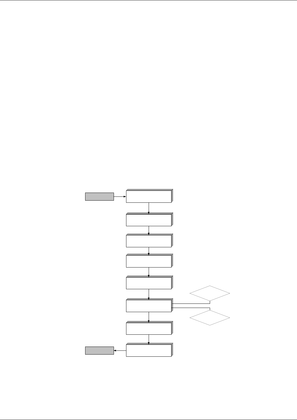
Commands
Sequence for Processing of Commands
262 Reference Manual STARCOS® 3.0/Edition 06/2005
ID No. 30016255
Sequence for Processing of Commands
The basic principle of any STARCOS® 3.0 activity is the reception of a com-
mand from the terminal and the transmission of a respective response from
the card. Thus every STARCOS® function is a command processing activity
which happens in the following functional units:
– Transmission manager
supervises correct data transmission.
– Secure messaging (optional)
secures the data transmission using cryptographic security mechanisms.
– Command interpreter
identifies the command with the class and instruction bytes; checks the
parameters P1, P2 and P3 for their upper and lower limits.
– File manager
checks the required access rights before data operations are permitted.
Every command processing must be correct and complete, i.e. all
commands must pass through the functional units or managers
without any errors. If an error occurs, the respective error message
will be set.
Fig. 13 Command processing scheme
Transmission Manager
Logical ChannelLogical Channel
Secure Messaging
Command Processor
File Manager
Secure Messaging
Transmission Manager
Command
Response
Key
Management
Authentication
Access Rule Check

Commands
Command Sequence
Reference Manual STARCOS® 3.0/Edition 06/2005 263
ID No. 30016255
Command Sequence
Recovery for
Incomplete
Write Operations
If data are to be modified in the non-volatile memory of the smart card and the
command for this action is interrupted while being executed, causing only
part of the data to be written, this case is handled by internal recovery mech-
anisms. They ensure that the data to be modified are set either to the state
prior to command execution (roll back) or to the state after command execu-
tion (roll forward).
Reaction to
Memory Errors
STARCOS® detects memory errors during internal access to programs, appli-
cation data or structure data of the smart card.
If no recovery mechanisms are available for these memory errors, the com-
mand is aborted with ’65 81’.
Formal Checks The smart card first checks each incoming command for its formal structure.
If a condition is not met, the command is aborted and the corresponding error
code is generated.
Not Fulfilled
(Error Code)
Condition
’68 82’ The commands SELECT FILE (DF), DEFRAG, GET
CHALLENGE, GET DATA (with P1/P2 = ’DF 20’) and
MANAGE SECURITY ENVIRONMENT RESTORE must
not be executed with secure messaging
(the 2 most significant bits of the right CLA half-byte must
be unequal 10 or 11).
’69 88’ If a command is executed with secure messaging, the TLV
coding and the SM data objects must be specified correctly
(see page 226).
’69 88’ The data of the commands SELECT FILE EF and DELETE
FILE must not be enciphered when using secure messag-
ing.
The data field of the MUTUAL AUTHENTICATE com-
mand may only be enciphered if either the command
header or the active SE of the current DF contains a key
reference.
’67 00’ Lc must be specified and have a value which is permitted
for the command.
’67 00’ The length of the command data must match Lc.
’67 00’ La must be ≤ Le.
Le = ’00’ for 256 bytes

Commands
Command Sequence
264 Reference Manual STARCOS® 3.0/Edition 06/2005
ID No. 30016255
Evaluation of
Access Rules
STARCOS® features three different command groups:
– Commands which must evaluate access conditions
(evaluation mandatory)
– Commands which may evaluate access conditions
(evaluation optional)
– Commands which do not evaluate access conditions
’67 00’ For secure messaging, Lc and Le must be appropriately
specified and indicate the correct length (see page 226).
’69 87’ If a command is executed with secure messaging, all SM
data objects need to exist.
’6A 86’ P1/P2 must have a value specified for CLA/INS.
’6D 00’ INS must be defined for smart cards.
’6E 00’ The smart card must support the left CLA half-byte for
INS.
Requirement for the right CLA half-byte:
2 most significant bits = 00, 11 or 10.
Not Fulfilled
(Error Code)
Condition
Command CLA INS Evaluation of
Access Rules
ACTIVATE FILE
Creation Status
Other States
’0X’ ’44’
No evaluation
Mandatory
APPEND RECORD ’0X’ ’E2’ Mandatory
CHANGE REFERENCE DATA ’0X’ ’24’ Mandatory
COMPUTE DIGITAL SIGNTURE,
VERIFY DIGITAL SIGNATURE,
VERIPHY CERTIFICATE,
ENCIPHER,
DECIPHER
’0X’
or
’1X’
’2A’ Mandatory
CREATE FILE ’0X’
or
’1X’
’E0’ Mandatory
DEACTIVATE FILE ’0X’ ’04’ Mandatory
DELETE FILE ’0X’ ’E4’ Mandatory
EXTERNAL AUTHENTICATE ’0X’ ’82’ Optional

Commands
Command Sequence
Reference Manual STARCOS® 3.0/Edition 06/2005 265
ID No. 30016255
GENERATE ASYMMETRIC KEY PAIR ’0X’ ’46’ Mandatory
GET CHALLENGE ’00’ ’84’ No evaluation
GET DATA
P1/P2 = ’DF 20’
P1/P2 ≠ ’DF 20’
’0X’ ’CA’
Optional
Mandatory
GET KEYINFO ’BX’ ’EE’ Optional
GET RESPONSE ’0X’ ’C0’ None
HASH ’0X’
or
’1X’
’2A’ Optional
INTERNAL AUTHENTICATE ’0X’ ’88’ Optional
MANAGE CHANNEL ’00’ ’70’ Optional
MANAGE SECURITY MANAGEMENT
P1 = ’F3’ (RESTORE)
other
’00’
’0X’
’22’
No evaluation
Optional
MUTUAL AUTHENTICATE ’0X’ ’82’ Optional
PUT DATA ’0X’ ’DA’ Mandatory
READ BINARY ’0X’ ’B0’ Mandatory
READ RECORD ’0X’ ’B2’ Mandatory
RESET RETRY COUNTER ’0X’ ’2C’ Mandatory
SEARCH RECORD ’0X’ ’A2’ Mandatory
SELECT FILE
P1 ≠ ’02’ (DF selection)
P1 = ’02’ (EF selection)
’00’
’0X’
’A4’
No evaluation
Optional
TERMINATE
CARD USAGE
DF
EF
’0X’
’FE’
’E6’
’E8’
Mandatory
Mandatory
UPDATE BINARY ’0X’ ’D6’ Mandatory
UPDATE RECORD ’0X’ ’DC’ Mandatory
VERIFY ’0X’ ’20’ Mandatory
Command CLA INS Evaluation of
Access Rules

Commands
Command Sequence
266 Reference Manual STARCOS® 3.0/Edition 06/2005
ID No. 30016255
Actions with
Access Rules
The following table shows how the smart card will react to specific actions in
connection with access rules.
Referencing of
EFs, Records and
Data Units
The commands READ BINARY, READ RECORD, UPDATE BINARY, AP-
PEND RECORD, UPDATE RECORD and SEARCH RECORD may access
the currently selected EF or, by using an SFI, reference the EF to be accessed.
If one of the commands accesses an EF with an SFI, the EF is thereby se-
lected.
The EF will only be referenced correctly if specific conditions are fulfilled.
Action Evaluation
Optional Mandatory
For a command, no access rule is found
which defines this command as an access
mode.
Execute with
SC ALW
Do not execute
No ARR is found for the current trans-
mission type.
Execute with
SC ALW
Abort with
’69 82’
ARRs exist, but are not assigned to the
active SE that is to be considered.
Execute with
SC ALW
Abort with
’69 82’
Not Fulfilled
(Error Code)
Condition
’69 81’ A locally usable EF may only be accessed with an SFI if it
is contained directly in the currently selected DF.
’69 81’ A formatted EF cannot be accessed with the commands
READ BINARY and UPDATE BINARY.
A transparent EF cannot be accessed with the commands
APPEND RECORD, READ RECORD, UPDATE
RECORD and SEARCH RECORD.
’69 86’ No current EF.
’6A 82’ File not found.
’6A 83’ The commands READ RECORD, UPDATE RECORD and
SEARCH RECORD refer to a record with a record number.
The record number must be less than the number of the
EF’s LAST record to be accessed.
’6B 00’ The commands READ BINARY and UPDATE BINARY re-
fer to data in a transparent EF with the offset and the length
of the data.
The offset must be less than the size of the application data
contained in the transparent EF.

Commands
Command Sequence
Reference Manual STARCOS® 3.0/Edition 06/2005 267
ID No. 30016255
Command Chaining The following rules need to be observed when executing command chaining:
general rules – The last command must be coded as CLA = ’0X’, whereas all preceding
commands must be coded as CLA = ’1X’.
– The INS byte is identical in all commands.
If P1 and/or P2 must be identical as well, this is determined in the speci-
fication of the command executable by command chaining.
– If a command is aborted, the execution of command chaining is aborted
altogether.
– The smart card must respond with ’90 00’ to all commands except the
last; otherwise, the execution of command chaining is aborted.
– If a command chaining command with CLA = ’1X’ is followed by a reset
or a command that does not belong to the chain, command chaining is
aborted.
access rules If a command executed by command chaining can or must evaluate access
rules, the following rules need to be observed:
– Every command evaluates access rules separately and, if required, is se-
cured separately with secure messaging.
Therefore, the right half-byte of the CLA byte must be the same for each
command.
random number/ICV The following rules apply to the handling of random numbers and ICVs:
– The first command renders a random number generated with the com-
mand GET CHALLENGE invalid.
– Every command handles a script ICV independently, if the use of a script
ICV has been specified for secure messaging. The command uses one or
both of the provided script ICVs and writes the corresponding script
ICVs.
– If command chaining is to be secured using a session key, all commands
are secured separately with the session key.
If the session key was negotiated with SSC, the SSC is incremented prior
to the MAC check of each command and prior to forming the response
MAC.

Commands
Command Sequence
268 Reference Manual STARCOS® 3.0/Edition 06/2005
ID No. 30016255
Secure Messaging for
the Response
When the access rules are evaluated, the existing security condition SM is
checked to see whether it can be fulfilled.
If key usage counters exist according to the access rules, they are decre-
mented prior to the execution of the command.
When secure messaging is used for the response, the KFPC of a key being
used cannot be decremented, since no checks which could fail are performed
with this key.
If an error occurs when secure messaging is used for the response, a corre-
sponding error code is issued. In this case, no roll back will be performed for
the memory areas that have been changed by the command.

Commands
Status Bytes
Reference Manual STARCOS® 3.0/Edition 06/2005 269
ID No. 30016255
Status Bytes
When a command has been executed correctly, the status bytes SW1/SW2 ’90
00’ are returned.
Warnings are returned if the command was executed, but the requested data
are not correct. Error messages show that a command was aborted, and indi-
cate why.
Warnings
Code Command Description
’61 XX’ Generally Normal processing, SW2 encodes the number of data bytes still
available (T=0)
’62 81’ Generally Part of returned data may be corrupted
READ BINARY,
READ RECORD
– EF data memory error
’62 82’ Generally End of file/record reached before reading Le bytes or before finding
matching string
READ BINARY – For Le ≠ ’00’, offset is greater than application data
SEARCH RECORD – Search pattern does not exist in specified data area
’62 83’ SELECT FILE – DF or EF is deactivated
VERIFY – Command with no DATA refers to a password in the deactivation
state
’62 85’ SELECT FILE – DF or EF is terminated
VERIFY – Command with no DATA refers to a password in the termination
state

Commands
Status Bytes
270 Reference Manual STARCOS® 3.0/Edition 06/2005
ID No. 30016255
’63 CX’ Generally Use of internal retry routine
(counter ’X’, valued from 0 to 15)
CHANGE REFE-
RENCE DATA,
EXTERNAL
AUTHENTICATE,
MUTUAL
AUTHENTICATE
VERIFY,
VERIFY
CERTIFICATE,
VERIFY DIGITAL
SIGNATURE
– Erroneous reference value for card holder authentication or com-
ponent authentication,
X = count of the KFPC after decrementation;
’F’ is returned for X ≥ 16
VERIFY – Command with no DATA refers to a password in the activation
state or without LCD data object (’X’ = number of retries).
Code Command Description

Commands
Status Bytes
Reference Manual STARCOS® 3.0/Edition 06/2005 271
ID No. 30016255
Error Messages
Code Command Description
’64 00’ Generally Execution error, state of non-volatile memory unchanged
CHANGE REFER-
ENCE DATA,
VERIFY
– Files or data are missing for KFPC, password or additional pass-
word information
– Files or data are missing for key or additional key information
COMPUTE DIGI-
TAL SIGNATURE,
ENCIHER,
EXTERNAL
AUTHENTICATE,
INTERNAL
AUTHENTICATE,
MUTUAL
AUTHENTICATE,
VERIFY
CERTIFICATE,
VERIFY DIGITAL
SIGNATURE
– Files or data are missing for key or additional key information
GENERATE ASYM-
METRIC KEY PAIR
– Files or data are missing for key or additional key information
– Referenced EF not found or incorrectly coded
– Public exponent found is even
– Key EF not correctly structured
– Key EF does not contain enough memory space
GET KEYINFO – KV exists more than once in a DF
PUT DATA – Record length in EF_DO in which the data object to be entered
has been stored ≠ total length of data object
RESET RETRY
COUNTER
– Files or data are missing for KFPC, password or additional pass-
word information
– Defined transmission formats not existing in the SE data object
– Defined transmission or storage format not consistent
– Length of entered password incorrect
DELETE FILE,
SELECT FILE
–SC ENC-SM set for command message
VERIFY – Defined transmission formats not existing in the SE data object
– Defined transmission or storage format not consistent
– Length of entered password incorrect
’65 00’ Generally Error: state of non-volatile memory changed
(further qualification in SW2)

Commands
Status Bytes
272 Reference Manual STARCOS® 3.0/Edition 06/2005
ID No. 30016255
’65 81’ Generally Memory failure
GENERATE ASYM-
METRIC KEY PAIR
– Error writing the key EF
UPDATE BINARY
UPDATE RECORD
APPEND RECORD
CREATE
– Error during EEPROM programming
’67 00’ Generally Wrong length
MSE – Command data exist for P1 = ’F3’
– No command data exist for P1 = ’X1’
RESET RETRY
COUNTER,
VERIFY
–DATA missing
’68 81’ Generally Additional logical channel opened
’68 82’ Generally Secure messaging not supported
’68 83’ Generally Final command expected
’69 81’ Generally Command incompatible with file structure
CREATE FILE EF – File ID or SFI already exists
CREATE FILE DF – File ID or DF name already exists
DELETE FILE – Selected DF to be deleted is an MF
SEARCH RECORD – Offset > length of record to be found
’69 82’ Generally Security status not satisfied
’69 83’ Generally Authentication method blocked
CHANGE REFER-
ENCE DATA,
VERIFY
– KFPC of password = 0
EXTERNAL
AUTHENTICATE,
INTERNAL
AUTHENTICATE,
MUTUAL
AUTHENTICATE,
– UC or KFPC of key or master key = 0
RESET RETRY
COUNTER
– KFPC or usage counter in EF_RCZ of the resetting code password
= 0
Code Command Description

Commands
Status Bytes
Reference Manual STARCOS® 3.0/Edition 06/2005 273
ID No. 30016255
’69 84’ Generally Referenced data invalidated
COMPUTE DIGI-
TAL SIGNATURE,
VERIFY
CERTIFICATE,
– UC or KFPC of key = 0
– Initial value for signature counter = 0
– Volatile signature counter = 0
CHANGE REFER-
ENCE DATA,
VERIFY
– During transmission using encrypted format 2 PIN block, UC or
KFPC with value 0 was found for private key
VERIFY – Command with no DATA refers to a password in the initialization
state
DECIPHER,
ENCIPHER,
EXTERNAL
AUTHENTICATE,
VERIFY DIGITAL
SIGNATURE
– UC or KFPC of key = 0
INTERNAL
AUTHENTICATE
– UC or KFPC of key or master key = 0
GENERATE ASYM-
METRIC KEY PAIR
– Generation counter of private key = 0
’69 85’ Generally Conditions of use not satisfied
ACTIVATE FILE – A superior DF or the MF is not in the operation state
ACTIVATE PIN – Applies to a password which is in the activated operational state
CHANGE REFER-
ENCE DATA
(P1 = ’00’)
– During transmission using encrypted format 2 PIN block, no ran-
dom number was issued previously with GET CHALLENGE
– Key-management key for PIN decipherment found
– Incorrect algorithm ID or padding indicator assigned to key
– Most significant bits not set in most significant byte of modulus
CHANGE REFER-
ENCE DATA
(P1 = ’01’)
– Command is sent with EMV-PIN RSA encryption
COMPUTE DIGI-
TAL SIGNATURE,
– Additional information of key contains LCS data object ≠ ’05’
– Key is an asymmetric or key-management key
– Incorrect security algorithm for key
– Length of the key for the signature calculation is ≤ the maximum
bit length of the hash
Code Command Description

Commands
Status Bytes
274 Reference Manual STARCOS® 3.0/Edition 06/2005
ID No. 30016255
’69 85’ DEACTIVATE FILE – File is in the creation or initialization state
DEACTIVATE PIN – Applies to a password which is in the initialization state
DECIPHER,
ENCIPHER
– Additional information of key contains LCS data object ≠ ’05’
– Key is a key-management or certificate key
– Selected key ID not contained in any CT
– Incorrect security algorithm for key
– CT data object with tag ’8A’ does not contain values ’81’ or ’82’
EXTERNAL
AUTHENTICATE
– Additional information of public or private key contains LCS data
object ≠ ’05’
– Key is a symmetric second-level key-management key or certifi-
cate key
– Key is a symmetric first-level key-management key without key
derivation procedure
– Error during key derivation of the master key
– Search for AT for asymmetric negotiation key or directly usable
key failed
– Incorrect security algorithm assigned to negotiation key or di-
rectly usable key
– Bit length of public key’s modulus not correct
– No RND.IFD passed using GET CHALLENGE
– Only for authentication with public key:
– Key-group relevant DFs of public and private keys not identical
– KID and KV for public keys (from AT with tag ’84’) and private
key not identical
EXTERNAL
AUTHENTICATE
– Directly usable key found for private key
– No AT found for asymmetric negotiation key
– KID and KV not identical to records in EF_KEYD
– No SE data objects contained in additional information
– Bit lengths of SK.ICC and PK.IFD not identical
– No key name assigned to SK.ICC
GENERATE ASYM-
METRIC KEY PAIR
– Additional information of key contains LCS data object ≠ ’03’,
’04’ or ’05’
– File ID of private key to be generated not identical to file ID of
public key
– Incorrect security algorithm for key
– Length of the key for the signature calculation is ≤ the maximum
bit length of the hash
– 0 > r, S > n, n = order of the generator point
Code Command Description

Commands
Status Bytes
Reference Manual STARCOS® 3.0/Edition 06/2005 275
ID No. 30016255
’69 85’ INTERNAL
AUTHENTICATE
– Public key specified in additional information
– Additional information of private of public key contains LCS data
object ≠ ’05’
– Key is a symmetric second-level key-management key
– Error during key derivation of the master key
– No AT found for asymmetric negotiation key
– No KID or KV found during key negotiation
– No SE data objects contained in additional information
– Incorrect security algorithm assigned to negotiation key
INTERNAL
AUTHENTICATE
– Incorrect bit or byte length of private key
– No key reference found for private or public key
– During authentication with private key, directly usable key or cer-
tificate key found for public key
– During authentication with private key, KID and KV of private
and public keys not identical
– During authentication with private key, no key name assigned to
public key
– During client-server authentication, byte length of key > 256
– Length of the key for the signature calculation is ≤ the maximum
bit length of the hash
MUTUAL
AUTHENTICATE
– Public key found in additional information
– No key derivation procedure assigned to symmetric first-level
key-management key
– No AT or KMT found for symmetric first-level key-management
key
– Error during key derivation of the master key
– Incorrect security algorithm for key
– No RND passed using GET CHALLENGE
SEARCH RECORD – TLV coding of a record erroneous
VERIFY – During transmission using encrypted format 2 PIN block, no ran-
dom number was issued previously with GET CHALLENGE
– Key-management key for PIN decipherment found
– Incorrect algorithm ID or padding indicator assigned to key
– Most significant bits not set in most significant byte of modulus
– Referenced password is not in the activation state
– Command with no DATA is sent with EMV-PIN RSA encryption
Code Command Description

Commands
Status Bytes
276 Reference Manual STARCOS® 3.0/Edition 06/2005
ID No. 30016255
’69 85’ VERIFY
CERTIFICATE,
– Additional information of key contains LCS data object ≠ ’05’
– Key is an asymmetric or key-management key
– Incorrect security algorithm for key
VERIFY DIGITAL
SIGNATURE
– Additional information of key contains LCS data object ≠ ’05’
– Key is an asymmetric or key-management key
– Incorrect security algorithm for key
– Length of the key for the signature calculation is ≤ the maximum
bit length of the hash
– 0 > r, S > n, n = order of the generator point
– Key data for the storing of the key components not present
’69 86’ Generally Command not allowed (no current EF)
ACTIVATE FILE – File is already activated
TERMINATE PIN – Applies to a password which is in the initialization state
’69 87’ Generally Expected SM data objects missing
’69 88’ Generally SM data objects incorrect
DELETE FILE,
SELECT FILE
– SM requested and command data enciphered
’6A 80’ Generally Incorrect parameters in the data field
COMPUTE DIGI-
TAL SIGNATURE,
ENCIPHER
– For new hash value and signature use, length of data field ≠ length
of hash values
– For new hash value and PKCS #1, length of data field ≠ length of
DigestInfo
– DigestInfo not correctly TLV-coded
– OID not correct
CHANGE REFER-
ENCE DATA
– In BCD-coded transmission, PIN length < 4 or PIN length > 12
CREATE FILE DF – Command contains data objects with tags ≠ ’62’ or ’73’
– DATA contains no FCP for a DF in the first subcommand
– DATA contains data objects with tag ’62’ without FCPs for EFs in
the subsequent commands
INTERNAL
AUTHENTICATE
– During authentication with private key, key name of public key
too short or incorrect
MSE – Details see page 329
PUT DATA – Data field for composite data object incorrect
RESET RETRY
COUNTER
– Length of new PIN not as specified in storage format
Code Command Description

Commands
Status Bytes
Reference Manual STARCOS® 3.0/Edition 06/2005 277
ID No. 30016255
’6A 80’ SEARCH RECORD – 1st byte in DATA ≠ ’04’ or ≠’0C’
– Offset = ’FF’
– Byte string of search interval cannot be divided by 2
– Search interval lower limit > upper limit
SELECT FILE – P1 = ’00’ and DATA = ’3F 00’ or empty
VERIFY – L < 4 or L > 12 in BCD- or ASCII-coded transmission
– Byte length N of plain text < 25 in transmission using encrypted
format 2 PIN block
– 1st byte of plain text ≠ ’7F’
– Bytes 2-9 do not contain a correctly coded format 2 PIN block
– Bytes 10-17 do not contain the previously generated random num-
ber RND
VERIFY
CERTIFICATE
– Length of header list ≠ length of certificate content
– No key name assigned to certificate key
– CAR of certificate content ≠ key name
’6A 81’ Generally Function not supported
ACTIVATE FILE,
ACTIVATE PIN
DEACTIVATE FILE,
DEACTIVATE PIN
– File or PIN is terminated or already deactivated
TERMINATE EF,DF,
TERMINATE PIN
– File or PIN is terminated
TERMINATE CARD
USAGE
– Command not possible, access to smart card was terminated
’6A 82’ Generally File not found
DELETE FILE,
SELECT FILE
– No DF or EF with specified file ID found
– MF is currently selected, selection of a higher-level DF not possi-
ble
VERIFY
CERTIFICATE
– No EF_CERT found for certificate
’6A 83’ Generally Record not found
’6A 84’ Generally Not enough memory space
PUT DATA – EF_DO does not exist or is not linear
– Data object length > record length
– Data object length < record length for EF_DO with records of
fixed length
– Maximum number of records already reached
’6A 86’ Generally Incorrect parameters P1/P2
Code Command Description

Commands
Status Bytes
278 Reference Manual STARCOS® 3.0/Edition 06/2005
ID No. 30016255
’6A 87’ Generally Lc inconsistent with P1/P2
’6A 88’ Generally Referenced data not found
CHANGE REFER-
ENZCE DATA,
VERIFY
– No DF relevant to password numbers found
– No additional information found for referenced key in transmis-
sion using encrypted format 2 PIN block
COMPUTE DIGI-
TAL SIGNATURE
– No additional information found for referenced key
– Algorithm ID for hash value calculation is missing during execu-
tion using buffered hash value
– Hash value buffered with incorrect length
– Hash algorithm found during execution using new hash value
DECIPER,
ENCIPHER
– No additional information found for referenced key
– File ID ’00 00’ found in key reference data object of public key,
but no key found for associated additional information
DECIPHER DH – Key reference not defined
EXTERNAL
AUTHENTICATE
– File ID ’00 00’ found in key reference data object of public key,
but no key found for associated additional information
GENERATE ASYM-
METRIC KEY PAIR
– No key reference selected or found
GET DATA – EF_DO does not exist or is not linear
GET KEYINFO – No key-group relevant DF found
INTERNAL
AUTHENTICATE
– In client-server authentication, active SE contains no header list in
volatile memory
RESET TETRY
COUNTER
– No DF relevant to password number found
– No additional information found for resetting code
VERIFY
CERTIFCATE,
VERIFY DIGITAL
SIGNATURE
– No additional information found for referenced key
– File ID ’00 00’ found in key reference data object of public key,
but no key found for associated additional information
– Hash value buffered with incorrect length
– No certificate information found
’6B 00’ generally Wrong parameter(s) P1/P2; incorrect offset
’6C 00’ generally Wrong Le field; SW2 encodes the exact number of available data
bytes (T=0)
’6D 00’ generally Wrong instruction code (INS)
’6E 00’ generally Class (CLA) not supported
’90 00’ generally Normal processing
Code Command Description
Commands
ACTIVATE FILE
Reference Manual STARCOS® 3.0/Edition 06/2005 279
ID No. 30016255
ACTIVATE FILE
The command ACTIVATE FILE has two applications:
– During creation of the file system, the command ACTIVATE FILE
switches DFs from the creational/intializational state to the operational
state. This can be done without any access checks (see ’File Life Cycle’
on page 17).
– In the operational phase, the command ACTIVATE FILE is used to toggle
files (EF and DF) between the activated and deactivated state.
Notes The command ACTIVATE FILE functions only on the currently selected
file.
A transition from the creation/initialization state (exist only for DFs) to
the activated operational state is always done without a security check.
The command ACTIVATE FILE must check ACs.
Rule
Command
Response
Status Bytes For warnings and error messages see ’Status Bytes’ from page 269 onwards.
Execution No evaluation in creation state
Mandatory in all other states
Access from ARR in the ARR data object of the file control information
template of the EF or DF to be accessed
Evaluation SE# of the security environment from the current DF
CLA INS P1 P2
’0X’ ’44’ ’00’ ’00’
SW1 SW2
’90’ ’00’
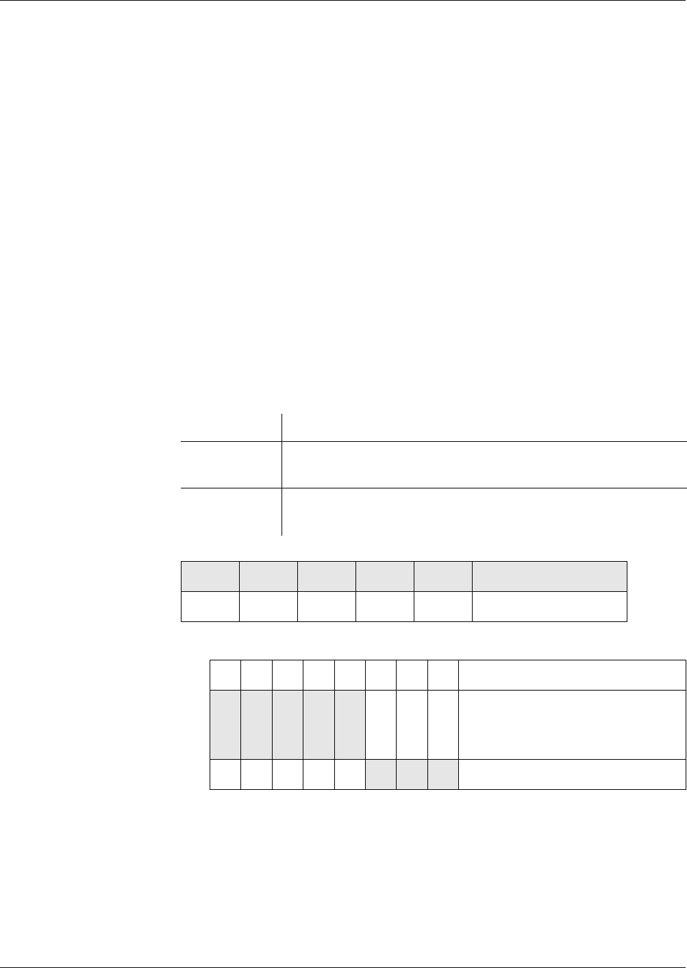
Commands
APPEND RECORD
280 Reference Manual STARCOS® 3.0/Edition 06/2005
ID No. 30016255
APPEND RECORD
The command APPEND RECORD is used to append a record to the end of an
EF with linear structure or to append an element with the number ’01’ to the
end of an EF with cyclic structure. The length of the record or element is
specified in Lc.
Notes If the command UPDATE RECORD is to be used to write a record to an
EF created with the command CREATE FILE, the record must be created
previously by using the command APPEND RECORD.
If the memory space allocated to the EF is not sufficient for the new
record, the command APPEND RECORD will be aborted.
If an EF with a linear fixed structure already contains the maximum num-
ber of records, the command APPEND RECORD will be aborted.
If an EF with cyclic structure already contains the maximum number of
elements, the first element created using the command APPEND
RECORD will be overwritten with the new command APPEND
RECORD.
Rule
Command
P2 – Reference control byte
Lc – Record/Element Length
EF with linear fixed structure Lc = maximum defined length
EF with linear variable structure Lc ≤ maximum defined length
EF with cyclic structure Lc = maximum defined length
Execution Mandatory
Access from ARR in the ARR data object of the file control information
template of the EF to be accessed
Evaluation SE# of the security environment from the DF of the current
EF
CLA INS P1 P2 LcDATA
’0X’ ’E2’ ’00’
b8 b7 b6 b5 b4 b3 b2 b1 Description
0
X
0
X
0
X
0
X
0
X
File selection:
Currently selected EF
SFI (’01’ - ’1E’)
000 Fixed value


Commands
CHANGE REFERENCE DATA
282 Reference Manual STARCOS® 3.0/Edition 06/2005
ID No. 30016255
CHANGE REFERENCE DATA
The command CHANGE REFERENCE DATA is used to change a current
password. During this procedure, the current password is checked first and, if
it is correct, the new password is entered.
If the existing password has the required minimum length and the password
has been entered correctly, a security state is set which indicates that the card
holder has been successfully authenticated with this password. If the existing
password is less than required by the minimum length and the password has
been entered correctly, the new password will be entered, but no security state
will be set.
In order to store a new PIN in the smart card without using a transport PIN,
the command CHANGE REFERENCE DATA can be adapted to support new
reference data only in the command data. This is allowed when P1 = ’01’.
Command Sequence The following steps and checks are performed in the execution of the com-
mand CHANGE REFERENCE DATA:
– The parameters
– global or DF-specific password (bit b8 from P2),
– password number x (bits b1 - b3 from P2),
– current DF
and the password search algorithm are used to find the password-number
relevant DF which is referenced by the command CHANGE REFER-
ENCE DATA (see page 187).
– The card checks the transmission format and password lengths.
Notes for P1 = ’00’ DATA must contain two PINs or two passwords, with no delimiter field
being set between the old and new PINs/passwords.
Notes for P1 = ’01’ The command CHANGE REFERENCE DATA with P1 = ’01’ does not
support EMV-PIN RSA encryption of command data.
Bit 4 of P2 must be 0.
Both command variations (P1= ’00’ or ’01’) are permitted in the initial-
ization state. In this case the command is successful, the state is set to the
activated state.
Notes If the command CHANGE REFERENCE DATA is aborted already during
the processing of the public transmission and storage formats, the PIN
KFPC will not be decremented.
Rule Execution Mandatory
Commands
CHANGE REFERENCE DATA
Reference Manual STARCOS® 3.0/Edition 06/2005 283
ID No. 30016255
Command
P1
’00’ with old + new password in DATA
’01’ only with new password in DATA
P2 – Reference control byte for password
Lc
Length of the command data
Access from ARR in the ARR data object which is contained in an ARR
data object in the previously found additional password in-
formation.
Evaluation The evaluation depends on the position of the ARR data ob-
ject from the additional information:
– If it precedes the first SE data object, this SE data object
needs to be evaluated using the SE# of the security en-
vironment which is active in the DF relevant to the
password number.
– If no preceding ARR data object exists, an SE data ob-
ject having the SE# of the security environment which
is active in the DF relevant to the password number
needs to be selected first. The evaluation is performed
as described in the ARR Data Object section (see
page 178).
CLA INS P1 P2 LcDATA
’0X’ ’24’
b8 b7 b6 b5 b4 b3 b2 b1 Description
0
1
Password type:
Global
DF-specific password
000or RFU
0
1
Transmission format:
Plain text
Cryptogram encipherment
XXX RSA: binary-coded password
number (0 - 7);
ECC: PWD_ID of password

Commands
CHANGE REFERENCE DATA
284 Reference Manual STARCOS® 3.0/Edition 06/2005
ID No. 30016255
DATA
for P1 = ’00’ OLD_PIN || NEW_PIN
for P1 = ’01’ NEW_PIN
in one of the following transmission formats
Format 2 PIN Block Prerequisites:
Lc = ’10’
DATA must be coded in two chained blocks of format 2 PIN block (see
page 185).
Sequence:
– The length L2 of the new PIN (PIN2) is obtained from the second half-
byte of the second PIN block. L2 ≥ minimum length of storage format.
– The length L1 of the old PIN (PIN1) is obtained from the second half-
byte of the first PIN block.
DES encipherment – Both format 2 PIN blocks are DES enciphered with one another to form
reference values of 8 bytes length.
– The KFPC assigned to the PIN is decremented by 1 before the PIN check
is run.
– If L1 and the reference value created for PIN1 match the values pre-
defined in EF_PWD, the KFPC of the PIN is set to the initial value con-
tained in EF_RC.
–If L1 ≥ minimum length of storage format, the password number is en-
tered into the card holder authentication list which is assigned to the DF
relevant to the password number (see page 68).
– The reference value of PIN2 replaces the reference value that has been
stored in a record of EF_PWD. L2 is stored in binary code in the first
byte of this record.
The reference value for the new PIN is stored in bytes 2 to 9.
– If a security state has been set, it will remain unchanged.
Format 1 PIN Block Prerequisites:
–L
c = ’10’
– DATA must be coded in two chained blocks of format 1 PIN block (see
page 185).
Sequence:
– The length L2 of the new PIN (PIN2) is obtained from the second half-
byte of the second PIN block. L2 ≥ minimum length of storage format.
– The length L1 of the old PIN (PIN1) is obtained from the second half-
byte of the first PIN block.

Commands
CHANGE REFERENCE DATA
Reference Manual STARCOS® 3.0/Edition 06/2005 285
ID No. 30016255
– In the format 1 PIN blocks, the control field and the random digits are re-
placed in such a way that format 2 PIN blocks are created.
– Both format 2 PIN blocks are DES enciphered with one another to form
reference values of 8 bytes length.
– The subsequent command steps are the same as with transmission using
format 2 PIN block (see page 284).
PIN – BCD-Coded Prerequisite:
– DATA must be BCD-coded except for two half-bytes.
Both non-coded half-bytes must be = ’F’ and one of these half-bytes
must be the last half-byte.
If another half-byte = ’F’ exists, it must be a right-hand half-byte. The as-
sociated byte is referred to as the k-th byte.
k-th byte = ’F’ and
L1 = odd
Sequence if the k-th byte = ’F’ and L1 = odd:
– In this case, k < Lc. L1 is calculated from L1 = 2*k-1.
– The length L2 of the new PIN is calculated as follows:
Last half-byte of DATA ≠ ’F’: L2 = 2*(Lc - k)
Last half-byte of DATA = ’F’: L2 = 2*(Lc - k) - 1.
– The BCD-coded PINs of the correct PIN lengths L1 and L2 are each con-
verted into a format 2 PIN block and DES enciphered with one another to
form reference values of 8 bytes length.
– The subsequent command steps are the same as with transmission using
format 2 PIN block (see page 284).
last half-byte = ’F’ and
L1 = even
Sequence if the last half-byte = ’F’ and L1 = even:
– The value of L1 can only be determined by accessing the length L of the
stored PIN.
– The key fault presentation counter assigned to the PIN is decremented by
1 before the PIN check is run.
– If L is even and L = L1, L1 is calculated from L1 = 2*k,
where k = number of bytes contained in the data field of PIN1.
– The length L2 of the new PIN is calculated as follows:
Last half-byte of DATA ≠ ’F’: L2 = 2*(Lc - k)
Last half-byte of DATA = ’F’: L2 = 2*(Lc - k) - 1.
– If L is not even and 4 > L2 > 12, the password number is deleted from the
card holder authentication list, if applicable(see page 68). The key fault
presentation counter is not incremented.
– If L2 is correct, the BCD-coded PINs of the correct PIN lengths L1 and
L2 are each converted into a format 2 PIN block and DES enciphered
with one another to form reference values of 8 bytes length.

Commands
CHANGE REFERENCE DATA
286 Reference Manual STARCOS® 3.0/Edition 06/2005
ID No. 30016255
– If the reference value created for PIN1 matches the value predefined in
EF_PWD, the KFPC of the PIN is set to the initial value contained in
EF_RC.
–If L1 ≥ minimum length of storage format, the password number is en-
tered into the card holder authentication list which is assigned to the DF
relevant to the password number.
– The reference value of PIN2 replaces the reference value that has been
stored in a record of EF_PWD. L2 is stored in binary code in the first
byte of this record.
The reference value for the new PIN is stored in bytes 2 to 9.
– If a security state has been set, it will remain unchanged.
PIN – ASCII-Coded Prerequisite:
– The DATA bytes must contain values between ’30’ and ’39’.
Sequence:
– The value of L1 can only determined by accessing the length L of the
stored PIN.
– The key fault presentation counter assigned to the PIN is decremented by
1 before the PIN check is run.
– If L = L1, L2 is calculated from L2 = Lc-L1.
– If L2 is correct, the ASCII-coded PINs of the correct PIN lengths L1 and
L2 are each converted into a format 2 PIN block and DES enciphered
with one another to form reference values of 8 bytes length.
– If L < minimum length of storage format and the reference value created
for PIN1 does not match the stored reference value, the password number
is deleted from the card holder authentication list, if applicable (see
page 68). The key fault presentation counter is not incremented.
– If the reference value for PIN1 is correct, the key fault presentation
counter assigned to the PIN is set to the initial value contained in EF_RC.
–If L1 ≥ minimum length of storage format, the password number is en-
tered into the card holder authentication list which is assigned to the DF
relevant to the password number.
– The reference value of PIN2 replaces the reference value that has been
stored in a record of EF_PWD. L2 is stored in binary code in the first
byte of this record.
The reference value for the new PIN is stored in bytes 2 to 9.
– If a security state has been set, it will remain unchanged.

Commands
CHANGE REFERENCE DATA
Reference Manual STARCOS® 3.0/Edition 06/2005 287
ID No. 30016255
Enciphered Format 2
PIN Block
Prerequisites:
– Prior to the command CHANGE REFERENCE DATA, a random number
RND must be issued using the command GET CHALLENGE.
– The key that is to be used for decipherment must be specified by indicat-
ing the KID and KV in a data object with the tag ’84’. This data object
must follow the data object with the transmission format in the SE data
object for the active SE.
Encipherment sequence:
– The private key identified by KID and KV is searched for. The key-group
relevant DF for this key is the DF which also contains the additional
password information.
– The parameters
– key number KID,
– key version KV,
– key type (private),
are used to find the additional information for the referenced key (see
page 143).
– The command CHANGE REFERENCE DATA does not evaluate any ac-
cess rules for access to the found key.
– The key is checked to determine whether and how it may be used in the
SE of the current key-group relevant DF. This is done by performing an
analysis of the SE data object (see page 145).
– For a directly usable key, a CT is searched for.
– The algorithm ID in the found CT indicates whether the command
CHANGE REFERENCE DATA is allowed to access the key in accor-
dance with the security algorithm assigned to the key.
Sequence of deciphering the format 2 PIN block
Where: SK = private keys
n = the modulus of byte length N which is associated with SK:
– The byte length of the command data must be N.
– The command data are interpreted as a cryptogram.
– The integer from the binary notation of the cryptogram must be less than
the integer of the modulus n.

Commands
CHANGE REFERENCE DATA
288 Reference Manual STARCOS® 3.0/Edition 06/2005
ID No. 30016255
– The RSA decipherment is performed (see page 383). The plain text that
is generated during this process is a byte string of N bytes length. The fol-
lowing must be complied with:
–N ≥ 33
– 1st byte = ’7F’
– Bytes 2 to 9 and bytes 10 to 17 must each contain a correctly coded
block of format 2 PIN.
– Bytes 18 to 25 must contain the issued random number RND.
– The usage counter of the SK, if provided, is decremented by 1 even if the
command CHANGE REFERENCE DATA:
– Is aborted during or after decipherment.
– Is aborted during or after checking the padding and the format of the
PIN block.
– The format 2 PIN blocks are obtained from the correctly coded plain text.
The length L2 of the new PIN is obtained from the second half-byte of
the second PIN block.
– The length L1 of the old PIN is obtained from the second half-byte of the
first PIN block.
– Both format 2 PIN blocks are DES enciphered with themselves to form
reference values of 8 bytes length.
– The subsequent command steps are the same as with transmission using
format 2 PIN block (see page 284).
Password – ASCII-
Coded
Sequence:
– The value of L1 can only be determined by accessing the length L of the
stored password (PWD1).
– The key fault presentation counter assigned to the password is decre-
mented by 1 before the password is verified.
– If L = L1, the length L2 of the new password (PWD2) is calculated from
L2 = Lc - L1.
– If L2 is correct, the ASCII-coded passwords are padded with ’00’ to 8
bytes, if required.
– The results are DES enciphered with one another to form reference val-
ues of 8 bytes length.
– If L < minimum length of storage format and the reference value created
for PWD1 does not match the stored reference value, the password num-
ber is deleted from the card holder authentication list, if applicable (see
page 68). The key fault presentation counter is not incremented.

Commands
CHANGE REFERENCE DATA
Reference Manual STARCOS® 3.0/Edition 06/2005 289
ID No. 30016255
– If the reference value created for PWD1 matches the reference value
stored in EF_PWD, the key fault presentation counter assigned to the
password is set to the initial value contained in EF_RC.
–If L1 ≥ minimum length of storage format, the password number is en-
tered into the card holder authentication list which is assigned to the DF
relevant to the password number.
– The reference value of PWD2 replaces the reference value that has been
stored in a record of EF_PWD. The length L2 is stored in binary code in
the first byte of this record.
The reference value for the new PWD is stored in bytes 2 to 9.
– The security state that has been set remains unchanged.
Response
Status Bytes For warnings and error messages see ’Status Bytes’ from page 269 onwards.
SW1 SW2
’90’ ’00’

Commands
COMPUTE DIGITAL SIGNATURE
290 Reference Manual STARCOS® 3.0/Edition 06/2005
ID No. 30016255
COMPUTE DIGITAL SIGNATURE
The command COMPUTE DIGITAL SIGNATURE is a subcommand of
the command PERFORM SECURITY OPERATION.
The command COMPUTE DIGITAL SIGNATURE is used to compute a sig-
nature on a hash value calculated by the smart card or transmitted to the smart
card.
The digital signature is computed using a private key which is stored in the
smart card.
Command Sequence The following steps are performed when executing the command:
– The key to be used is selected through a key reference which is stored in
volatile or non-volatile memory in the active SE of the current DF.
DATA does not contain any data:
– The smart card checks whether a hash value of correct length has been
buffered. The hash value must be calculated using the hash algorithm
specified by the algorithm ID.
– With the hash value and the private key found previously, a signature is
computed by using one of the two signature methods.
– The usage counter and/or the volatile signature counter of the key used, if
provided, are decremented by 1.
– The computed signature is returned in the response.
Rule
Command
DATA
Hash value
DigestInfo
Empty, the digital signature is computed on the buffered hash value
Le – Length of expected response data
Execution Mandatory
Access from ARR in the ARR data object of the key’s additional informa-
tion
Evaluation SE# of the security environment from the DF to which the
found key is assigned
CLA INS P1 P2 DATA Le
’0X’ ’2A’ ’9E’ ’9A’


Commands
CREATE FILE
292 Reference Manual STARCOS® 3.0/Edition 06/2005
ID No. 30016255
CREATE FILE
The command CREATE FILE is used to create DFs or EFs within the current
DF.
Command Sequence
for CREATE FILE EF
The following steps are performed during the creation of an EF:
– The command CREATE FILE EF checks the contents and the TLV cod-
ing of the passed data for plausibility (see page 28).
– When the EF is created, the memory space is allocated.
For a transparent EF, the memory space is allocated with ’00’.
Command Sequence
for CREATE FILE DF
To allow creating EFs and entering data into them after having created and se-
lected a DF, an access rule EF containing at least one access rule is the first
that needs to be created in this DF right after the DF itself has been created.
The following steps are performed during the creation of a DF with EFs:
– The command CREATE FILE DF checks the contents and TLV coding of
the passed data for plausibility (see page 28).
– The command CREATE FILE EF does not add any access rules to the
smart card. Missing access rules must be added to the applicable access
rule EF by using the command APPEND RECORD.
– If the first data object which contains the FCP for the DF is compatible
with the file organization of the smart card and enough memory space is
available, the DF is created.
– If the command CREATE DF is aborted, the status of the smart card prior
to execution remains unchanged.
– The DF created is selected automatically.
Rule
Command
P1
Specifies whether an EF or DF is created
’00’ EF
’38’ DF
Lc – Length of the command data
Execution Mandatory
Access from ARR in the ARR data object of the file control information
template of the current DF
Evaluation SE# of the security environment from the current DF
CLA INS P1 P2 LcDATA
’0X’ ’E0’ ’00’

Commands
CREATE FILE
Reference Manual STARCOS® 3.0/Edition 06/2005 293
ID No. 30016255
DATA for
CREATE FILE EF
Data object with FCP for EFs
For more information see ’Data Objects in the File Control Information
Templates’ on page 28.
T L V
’62’ Variable FCP for EF
T L V
’80’ ’02’ Only for transparent EFs:
Memory space allocated to
application data
’82’
’05’
’05’
’01’
File descriptor for
EF linear
EF cyclic
EF transparent
’83’ ’02’ File ID
’85’ ’02’ Only for linear variable EFs:
Size of the application data
’88’ ’01’
or
’00’
Short File ID (optional)
’8A’ ’01’ LCS (see ’Tag ’8A’ LCS’ on
page 29)
’A1’ Vari-
able
Data objects with ARR,
optionally ARR
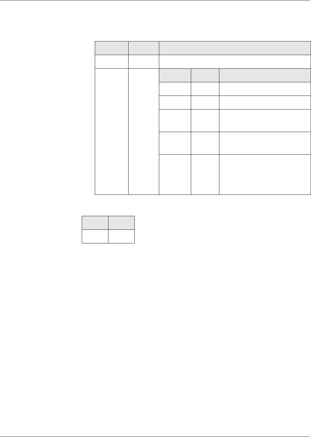
Commands
CREATE FILE
294 Reference Manual STARCOS® 3.0/Edition 06/2005
ID No. 30016255
DATA for
CREATE FILE DF
Data objects with FCPs
Tag ’62’ Data object in the first subcommand with FCP for DF
Data object with FCP for DF
Response
Status Bytes For warnings and error messages see ’Status Bytes’ from page 269 onwards.
T L V
’62’ Variable FCP for DF
T L V
’82’ ’01’ File descriptor ’38’
’83’ ’02’ File ID
’84’ ’01’ -
’10’
DF name (AID),
multiple entries possible
’8A’ ’01’ LCS (see ’Tag ’8A’ LCS’ on
page 29)
’A1’ Vari-
able
ARR data objects,
optionally data objects with
ARR,
optionally ARR
SW1 SW2
’90’ ’00’
Commands
DEACTIVATE FILE
Reference Manual STARCOS® 3.0/Edition 06/2005 295
ID No. 30016255
DEACTIVATE FILE
The command DEACTIVATE FILE switches a DF or EF from the activated
state to the deactivated state. A deactivated file can no longer be accessed. In
case of a DF, no childs can be selected. Deactivation is reversible (see ’File
Life Cycle’ on page 17).
The command DEACTIVATE FILE can be used for the currently selected
file (EF or DF).
For a DF, the command DEACTIVATE FILE is not executed if more than
one logical channel is open.
This does not apply for EFs.
DEACTIVATE FILE should be executed with secure messaging. How-
ever, this must be defined in the access rules of the application.
Rule
Command
Response
Status Bytes For warnings and error messages see ’Status Bytes’ from page 269 onwards.
Execution Mandatory
Access from ARR in the ARR data object of the file control information
template of the EF or DF to be accessed
Evaluation SE# of the security environment from the current DF
CLA INS P1 P2
’0X’ ’04’ ’00’ ’00’
SW1 SW2
’90’ ’00’

Commands
DECIPHER
296 Reference Manual STARCOS® 3.0/Edition 06/2005
ID No. 30016255
DECIPHER
The command DECIPHER is a subcommand of the command PER-
FORM SECURITY OPERATION.
The command DECIPHER is used to decipher a cryptogram with a private
key stored in the smart card.
Command Sequence The following steps are performed in the execution of the command DECI-
PHER:
– The key to be used is selected through a key reference which is stored in
volatile or non-volatile memory in the active SE of the current DF.
– The SE is checked to determine whether it contains a CT with UQ = ’40’
and a key reference with the tag = ’84’ as well as an algorithm ID, also
CT with UQ = ’40’.
– The parameters
– search identifier,
– key number KID,
– key version KV = key reference,
KV = ’FF’: no search for a specific KV in the additional information,
– key type (private),
– current DF,
and the key search algorithm are used to find the additional information
for the referenced key see ’Search for the Key Group Relevant DF’ on
page 141 and ’Search for the Additional Key Information’ on page 143.
– Check is made if the key can be used for decipherment with the indicated
padding.
– After decipherment, the message is checked for the indicated padding is
checked.
Notes The command DECIPHER permits only RSA decipherment.
SK is the private key.
n is the modulus of byte length N which is associated with SK and
k is the bit length of the modulus n.
The usage counter of the SK, if provided, is decremented by 1.
Command chaining can be used to transfer more than 255 bytes of cipher
text to the smartcard.
Rule Execution Mandatory
Commands
DECIPHER
Reference Manual STARCOS® 3.0/Edition 06/2005 297
ID No. 30016255
Command
CLA
’1X’ – first or intermediate command
’0X’ – last or only command
Lc
Lc = N + 1
DATA for ’1X’
If desired, the data can be split between the chained commands, whereby
the second record must have a minimum length of 1 byte.
DATA for ’0X’
Padding indicator || Cryptogram
1st byte = padding indicator = ’00’, ’81’ or ’82’
+ N bytes cryptogram
Le
’1X’ – Le= absent
’0X’ – Le= present
Response
No Padding DATA
Plain text as byte string, N bytes
PKCS#1 Padding DATA
Data field L from the following plain text:
Access from ARR in the ARR data object of the key’s additional informa-
tion
Evaluation SE# of the security environment from the DF to which the
found key is assigned
CLA INS P1 P2 LcDATA Le
’2A’ ’80’ ’86’
DATA SW1 SW2
’90’ ’00’
Designation Byte
Length
Value
Block Type 1 ’02’
Padding Field N - 3 - L All bytes ≠ ’00’
Separator 1 ’00’
Data Field L Message M of L bytes length

Commands
DECIPHER
298 Reference Manual STARCOS® 3.0/Edition 06/2005
ID No. 30016255
DINSIG Padding DATA
Data field from the following plain text:
m = 8 * L
Status Bytes For warnings and error messages see ’Status Bytes’ from page 269 onwards.
Designation Bit
Length
Value
Header 2 0 1
More-DATA Bit 1 Fixed value 1
Padding Field k - m - 75 k - m - 76 bit 0
followed by a bit 1 (boundary bit)
Data Field 64 + m Random number and message M
of m bits length
Trailer 8 ’BC’

Commands
DELETE FILE
Reference Manual STARCOS® 3.0/Edition 06/2005 299
ID No. 30016255
DELETE FILE
The command DELETE FILE is used to delete a DF or EF. The freed memory
space is available for the creation of new files.
Deleting a DF A DF can be deleted in two ways:
– A DF defined by a file ID is deleted from the selected parent DF. The se-
lection remains unchanged by the deletion.
– The currently selected DF is deleted. After the deletion, the parent DF is
selected.
In both cases, the DF is deleted along with all the files it contains, regardless
of the access rules specified for them.
If the MF is deleted, the card LCS is changed to the ’creation’ state.
Deleting an EF The EF defined by a file ID is deleted from the selected parent DF. The EF
does not need to be selected. If a different EF is selected, it will remain se-
lected after the deletion.
Notes If the command DELETE FILE is executed with secure messaging, the
command data must not be enciphered and the SC ENC-SM must not be
set.
The command DELETE FILE is only allowed if no additional logical
channels are open.
Rule Deleting EF:
Deleting DF:
Execution Mandatory
Access from ARR in the ARR data object of the file control information
template of the EF to be deleted
Evaluation SE# of the security environment of the current DF
Execution Mandatory
Access from ARR in the ARR data object of the file control information
template of the currently selected DF
Evaluation SE# of the security environment of the current DF
Commands
DELETE FILE
300 Reference Manual STARCOS® 3.0/Edition 06/2005
ID No. 30016255
Command
P1
’00’ Deletes the currently selected DF
’01’ Deletes the DF defined by the file ID from the current DF
’02’ Deletes the EF defined by the file ID from the current DF
Lc and DATA
For P1 = ’00’ Empty
For P1 = ’01’ or ’02’ Length of the command data and file ID
Response
Status Bytes For warnings and error messages see ’Status Bytes’ from page 269 onwards.
CLA INS P1 P2 LcDATA
’0X’ ’E4’ ’00’
SW1 SW2
’90’ ’00’

Commands
ENCIPHER
Reference Manual STARCOS® 3.0/Edition 06/2005 301
ID No. 30016255
ENCIPHER
The command ENCIPHER is a subcommand of the command PER-
FORM SECURITY OPERATION.
The command ENCIPHER is used to encipher data with a public key which is
stored in volatile or non-volatile memory in the smart card.
Command Sequence The following steps are performed in the execution of the command ENCI-
PHER:
– The key to be used is selected through a key reference which is stored in
volatile or non-volatile memory in the active SE of the current DF.
– The SE is checked to determine whether it contains a CT with UQ = ’80’
and a key reference with the tag = ’83’ as well as an algorithm ID, also
CT with UQ = ’80’.
– The parameters
– search identifier,
– key number KID,
– key version KV = key reference,
KV = ’FF’: no search for a specific KV in the additional information,
– key type (public),
– current DF,
and the key search algorithm are used to find the additional information
for the referenced key see ’Search for the Key Group Relevant DF’ on
page 141 and ’Search for the Additional Key Information’ on page 143.
– The key is checked whether it can be used for ENCIPHER with the indi-
cated padding.
– Padding is performed on the command message (if indicated).
– Message is enciphered.
Notes The command ENCIPHER permits only RSA encipherment.
PK is the public key.
n is the modulus of byte length N which is associated with PK.
N must be < 256 bytes; otherwise, the response data cannot be returned
completely.
The usage counter of the PK, if provided, is decremented by 1.
Rule Execution Mandatory
Access from ARR in the ARR data object of the key’s additional informa-
tion
Commands
ENCIPHER
302 Reference Manual STARCOS® 3.0/Edition 06/2005
ID No. 30016255
Command
No Padding Lc
Lc ≤ byte length N
DATA
Plain text data
Integer of byte string from binary notation < value of modulus n
PKCS#1 Padding Lc
Lc ≤ N - 11
DATA
Plain text data, different length
DINSIG Padding Lc
L * 8 ≤ k - 76, k = bit length of modulus n
DATA
plain text data, different length
Response
DATA
Padding Indicator || Cryptogram
No Padding ’00’ || Byte string of length N
PKCS#1 Padding ’81’ || Byte string of length N
DINSIG Padding ’82’ || Byte string of length N
Status Bytes For warnings and error messages see ’Status Bytes’ from page 269 onwards.
Evaluation SE# of the security environment from the DF to which the
found key is assigned
CLA INS P1 P2 LcDATA Le
’0X’ ’2A’ ’86’ ’80’ ’00’
DATA SW1 SW2
’90’ ’00’

Commands
EXTERNAL AUTHENTICATE
Reference Manual STARCOS® 3.0/Edition 06/2005 303
ID No. 30016255
EXTERNAL AUTHENTICATE
With the command EXTERNAL AUTHENTICATE, the terminal authenticates
itself to the smart card by using a secret or private key. Before the command
EXTERNAL AUTHENTICATE is executed, the terminal must request a chal-
lenge from the smart card by using the command GET CHALLENGE.
The authentication is determined by the access conditions and algorithms of
the referenced key, which are specified in the additional information of
EF_KEYD (see page 79).
Command Sequence The following steps are performed in the execution of the command EXTER-
NAL AUTHENTICATE:
– The key referenced by P2 or the current SE is searched (see ’Key Search
Algorithm’ on page 141).
– Check is made whether the key can be used for EXTERNAL AUTHENTI-
CATE.
– Depending on the key type, the authentication continues.
Notes For P2 = ’00’, the active SE of the current DF must be checked to deter-
mine whether it contains a volatile or non-volatile stored key reference
for the command EXTERNAL AUTHENTICATE.
Rule
Authentication Using
Secret Key
The following steps are performed in authentication using a secret key (see
’Component Authentication Procedures’ on page 71):
– The random number RND.IFD stored is enciphered using the referenced
secret key. The 8 bytes long ciphered value is compared with the ci-
phered value passed in the command data. The algorithm specified for
the key in the corresponding EF_KEYD by the algorithm ID is used as
the encipherment algorithm.
– The usage counter, if provided, is decremented by 1.
– If authentication is successful, the key number and version are entered
into the component authentication list.
Execution Optional
Access from ARR in the ARR data object of the key’s additional informa-
tion
Evaluation SE# of the security environment from the DF to which the
found key is assigned

Commands
EXTERNAL AUTHENTICATE
304 Reference Manual STARCOS® 3.0/Edition 06/2005
ID No. 30016255
Authentication Using
Public Key
The following steps are performed in the key negotiation for a public key (see
’Key Negotiation’ on page 157):
– The corresponding private key for the key negotiation process is
searched for; however, no access rules are checked for the private key.
– Depending on the required order of the mutual authentication, check is
made if all prerequisites have been fulfilled
– Usage counters of private and public key are decremented
– The given token is checked. If authentication fails, the KFPC of the pub-
lic key is decremented.
– Upon successful authentication, the public key is entered in the compo-
nent authentication list.
–If INTERNAL AUTHENTICATE has already been performed, the negoti-
ated session key and ICV are valid; otherwise, the key parts negotiated
up to now are stored.
Notes If a key half and an SSC were negotiated previously using the command
INTERNAL AUTHENTICATE and the command EXTERNAL AUTHEN-
TICATE was aborted due to an error, the stored key half and the SSC are
deleted.
PK.IFD is the public key.
Command data = length of the modulus of PK.IFD ≤ 256 bytes.
Bit length of the modulus = multiple of 8
SK.ICC is the private key found
Bit length of the modulus of SK.ICC = bit length of the modulus of
PK.IFD
Commands
EXTERNAL AUTHENTICATE
Reference Manual STARCOS® 3.0/Edition 06/2005 305
ID No. 30016255
Command
P2
’00’ Key reference from SE of current DF, if
key reference in SE and AT with UQ = ’80’ and
or
Key reference
Lc – Length of the command data
DATA depending on the authentication method:
DATA for secret key
Ciphered value eK(RND.IFD) or e*CSK(RND.IFD), 8 bytes
Passed with RND.IFD, 8 bytes, using command GET CHALLENGE
DATA for session key
Ciphered value enc(PK.ICC)[sign*9796(SK.IFD)[M1]], ≥ 96 bytes
Response
Status Bytes For warnings and error messages see ’Status Bytes’ from page 269 onwards.
CLA INS P1 P2 LcDATA
’0X’ ’82’ ’00’
b8 b7 b6 b5 b4 b3 b2 b1 Description
0
1
Key type:
Global
DF-specific key
00or RFU
XXXXX Key number (1 - 31)
SW1 SW2
’90’ ’00’

Commands
GENERATE ASYMMETRIC KEY PAIR
306 Reference Manual STARCOS® 3.0/Edition 06/2005
ID No. 30016255
GENERATE ASYMMETRIC KEY PAIR
The command GENERATE ASYMMETRIC KEY PAIR is used to generate an
RSA key pair in the smart card. The key components that are to be kept secret
are stored in a key EF in the smart card and not issued.
The public key components are also stored in a key EF if an EF_KEYD entry
is found for a relevant public key and a corresponding key EF exists for the
public key.
Commando Sequence The following steps are performed in the execution of the command GENER-
ATE ASYMMETRIC KEY PAIR:
– Search is made in the active SE of the current DF for a key reference with
the tag ’84’ (DST with UQ ’40’). If a corresponding key reference does
not exist, the command is rejected.
– Search is made in the active SE of the current DF for an algorithm ID in
the DST with UQ ’40’. If a corresponding algorithm ID is not selected,
only this is registered.
– Check whether the algorithm ID can be used by the command occurs dur-
ing the analysis of any additional key information found.
– The key search algorithm is used to search for additional information on
the private key to be generated. For this purpose, the following parame-
ters are used:
– Search ID ("global" or "DF specifc")
– Key number KID
– Key version KV
– Key type (private)
– Knowledge about the current DF
If the search is unsuccessful, the command is aborted. The additional in-
formation is checked for consistency, and the SE data object is analyzed.
Check is made whether an LCS data object exists and whether the key can
be generated with the command GENERATE ASYMMETRIC KEY PAIR.
– If generation counter exists for the private key found and if this counter
has a value of 0, the command is aborted.
– The key search algorithm is used to search for additional information on
the public key to be generated. For this purpose, the following parame-
ters are used:
– Search ID ("global" or "DF specific")
– Key number KID
– Key version KV
– Key type (public)
– Knowledge about the current DF

Commands
GENERATE ASYMMETRIC KEY PAIR
Reference Manual STARCOS® 3.0/Edition 06/2005 307
ID No. 30016255
If the search is unsuccessful, this is only noted. The additional informa-
tion is checked for consistency, and the SE data object is analyzed. Check
is made whether an LCS data object exists and whether the values are
reasonable. If the key reference data object of the private key contains a
second file ID, this is checked for consistency with the file ID of the pub-
lic key now found.
– If P1 = ’02’ the key data of the public key are stored in an transparent key
EF (see ’Export of Public Keys’ on page 130).
key generation The following steps are performed when generating a key:
– The length of the modulus to be created is obtained from the structure
data object of the key to be generated.
– The key components are generated (see page 169).
– Before the generated key components are stored, the value of the LCS
data object in the additional information of the private key to be gener-
ated is set to ’04’.
If additional information also exists for the public key, the value of the
LCS data object it contains is also set to ’04’.
– The key components are generated (see ’Generation of RSA Keys’ on
page 169 and ANSI X9.62 and ANSI X.9.63 for ECC keys).
– The generated key components are stored in the associated key EFs (see
’Storage of Cryptographic Keys’ on page 125). Existing data are over-
written without checking their contents.
– The signature of the key is generated.
– The generation counter, if provided, is decremented by 1.
– The LCS data object(s) is/are set to the value ’05’.
Notes General The additional information for the private key to be generated need to be
stored in EF_KEYD already prior to the generation.
This information specifies whether the command GENERATE ASYM-
METRIC KEY PAIR may be executed, which access conditions need to be
fulfilled by the key and which algorithm is used.
The key EFs need to be created prior to the command GENERATE
ASYMMETRIC KEY PAIR.
The key to be generated is selected through a key reference stored in vol-
atile or non-volatile memory in the SE which is active for the current DF
at the time of execution of the command COMPUTE DIGITAL SIGNA-
TURE. The SE must contain a DST with UQ ’40’ and a key reference
with the tag ’84’ for this purpose.
The byte string of a stored public exponent may contain leading ’00’
bytes.

Commands
GENERATE ASYMMETRIC KEY PAIR
308 Reference Manual STARCOS® 3.0/Edition 06/2005
ID No. 30016255
An algorithm ID for the key generation can be stored in the active SE of
the current DF. This can also be used in the key search (DST with UQ
’40’).
For the command variant P1 = ’02’, the SE of the currently active DF
contain an AT with a UQ ’40’ and a key reference (’83’ – symmetric key,
’84’ – asymmetric key). Optionally, the algorithm ID can be set for the
corresponding authentication in the SE, which is also used in the key
search.
Notes for RSA The EF for the storing of the public key can be referenced via the second
FID of the data object key reference. In this manner, a public key does
not requires its own entry in its additional information.
The EF for the storing of the public key is optional. If no EF is refer-
enced, the public key is not stored.
The first file ID of ’0F XX’ in the DO key reference of the private key
must reference a linear EF in the DF which contains the additional infor-
mation.
Conditions for this linear EF:
–≥ 6 records
– The sixth record must be a data object with the tag ’97’ and contain
the correct length to tag ’82’ from the structure data object. The pub-
lic exponent must be entered in the value field of this data object.
– The seventh record is optional. If it is present, it must contain a data
object with the tag ’83’.
An optional second file ID in the DO key reference of the private key ref-
erences a transparent EF that is also in the DF of the additional informa-
tion.
Conditions for this transparent EF:
– Contains the prescribed public exponent in the value field of the data
object with the tag ’82’.
– The byte sequence that represents a stored public exponent can con-
tain leading ’00’-bytes.
– The data object with the tag ’82’ is the second DO in the EF. Its
length must agree with the length to the tag ’82’ from the structure
data object.
– The data object with the tag ’81’ is the first DO in the EF. Its length
must agree with the length of the tag ’81’ from the structure data ob-
ject.
Commands
GENERATE ASYMMETRIC KEY PAIR
Reference Manual STARCOS® 3.0/Edition 06/2005 309
ID No. 30016255
For the structure data object of the private key, the following applies:
– Contains the modulus to be generated in the data object with the tag
’81’.
– If it contains the empty data object ’83 00’ or ’84 00’, the value of
’03’ or F4 (= 216+1) is to be used as the public exponent.
– If it contains the tag ’82’, the public exponent is predefined. The
length of the public exponent is then to be taken from the structure
data object.
– Must contain the empty data object ’92 00’ with the CRT parameters
Rule
Command
P1
‘00‘ – Key generation without public key export (proprietary)
‘01‘– Key generation with public key export data generation
Response
SW1 – Status Byte1
SW2 – Status Byte 2
Execution Mandatory
Access from ARR in the ARR data object of the key’s additional informa-
tion
Evaluation SE# of the security environment from the DF to which the
found key is assigned.
CLA INS P1 P2
’0X’ ’46’ ’00’
SW1 SW2

Commands
GENERATE ASYMMETRIC KEY PAIR
310 Reference Manual STARCOS® 3.0/Edition 06/2005
ID No. 30016255
Data for Public Key For the command GENERATE ASYMMETRIC KEY PAIR with P1 = ’02’
see ’Export of Public Keys’ on page 130.
After a successful command GENERATE ASYMMETRIC KEY PAIR with
P1 = ’00’, the following TLV objects are stored in the associated EF:
RSA key Data objects for a RSA public key:
After a successful command GENERATE ASYMMETRIC KEY PAIR with
P1=1 the data objects for a key export are written in the public key files (see
’Export of Public Keys’ from page 130 onwards).
Status Bytes For warnings and error messages see ’Status Bytes’ from page 269 onwards.
TAG Length Value Description
’81’ Len81 N Modulus
’82’ Len82 e Public exponent
Commands
GET CHALLENGE
Reference Manual STARCOS® 3.0/Edition 06/2005 311
ID No. 30016255
GET CHALLENGE
With the command GET CHALLENGE, the terminal requests a random num-
ber (RND) from the smart card (see ’Random Numbers’ on page 417).
Notes The length of the random number is 8 bytes.
The command GET CHALLENGE cannot be used with secure messag-
ing.
Rule
Command
Response
Status Bytes For warnings and error messages see ’Status Bytes’ from page 269 onwards.
Execution No evaluation
CLA INS P1 P2 Le
’0X’ ’84’ ’00’ ’00’ ’08’
DATA SW1 SW2
RND ’90’ ’00’
Commands
GET DATA
312 Reference Manual STARCOS® 3.0/Edition 06/2005
ID No. 30016255
GET DATA
The command GET DATA is used to read the value field of a data object. The
associated tag is specified in P1/P2 (see ’Regular Access of GET DATA and
PUT DATA to Data Objects’ from page 23 onwards).
Notes With P1/P2 = ’DF 20’, the command GET DATA is executed without ac-
cess rules. This option returns protocol data regarding card production
and issuance.
Rule
Command
P1/P2
’00 40’ - ’00 FE’ BER-TLV tag with 1 byte in P2
’5F 01’ - ’FF 7F’ BER-TLV tag with 2 bytes in P1/P2
Response
Status Bytes For warnings and error messages see ’Status Bytes’ from page 269 onwards.
Execution No execution for P1/P2 = ’DF 20’
Mandatory for P1/P2 ≠ ’DF 20’
Access from ARR in the ARR data object for the data objects of the file
control information template of the current DF
Evaluation P1/P2 and SE# of the security environment from the current
DF
CLA INS P1/P2 Le
’0X’ ’CA’ ’00’
DATA SW1 SW2
Value field of
data object
’90’ ’00’
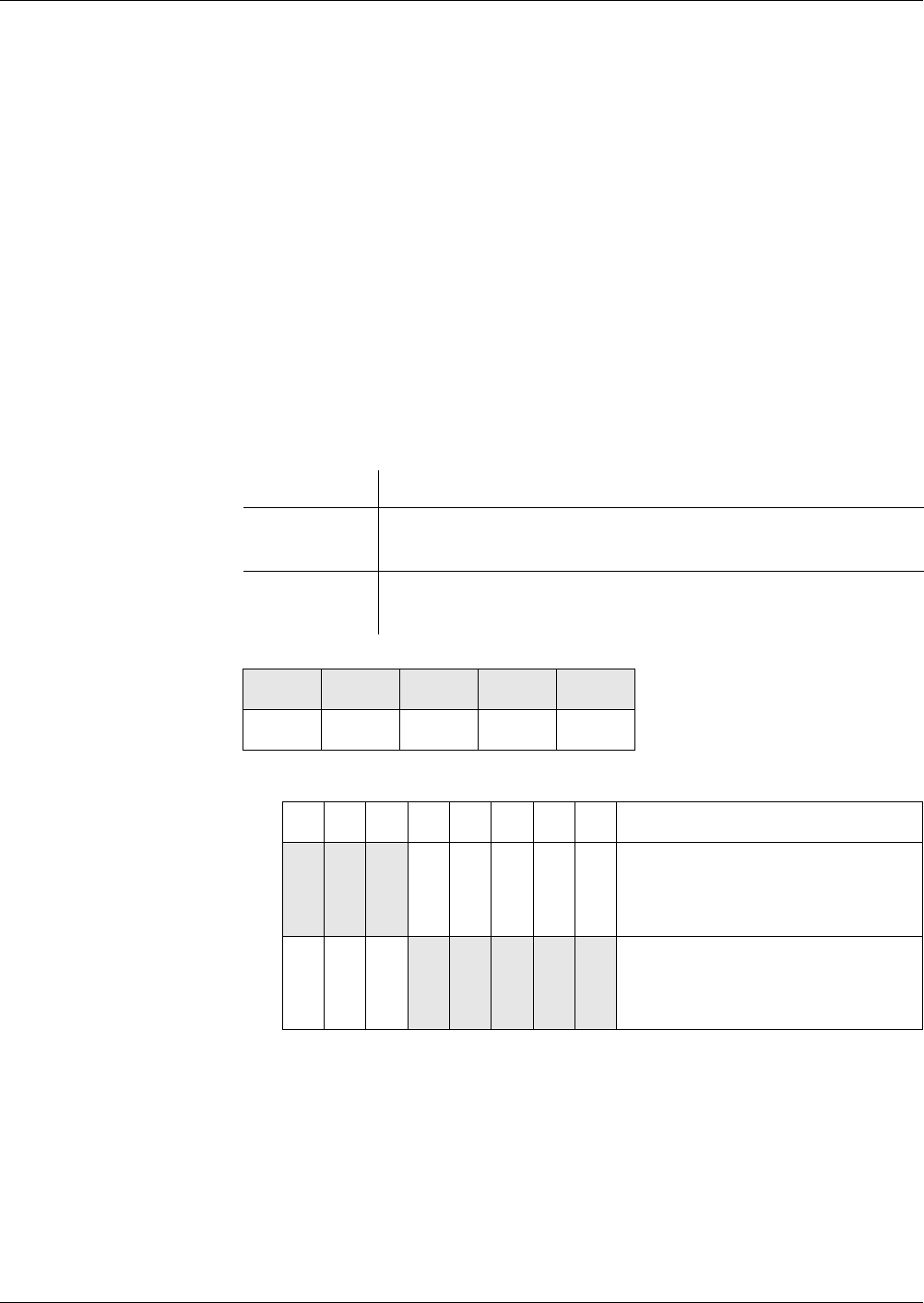
Commands
GET KEYINFO
Reference Manual STARCOS® 3.0/Edition 06/2005 313
ID No. 30016255
GET KEYINFO
The command GET KEYINFO is used to return the key versions which are as-
sociated with a key number and can be used by the terminal.
Command Sequence The following steps are performed in the execution of the command GET
KEYINFO:
– The key search algorithm is used to find the key-group relevant DF for
the DF from which the search starts.
– The key versions KV are obtained from the additional information found,
returned in the response data and sorted in ascending order.
Notes The key search algorithm will only consider a locally usable EF_KEYD
and a contained key identified as local, if the key search starts from the
DF which contains the EF_KEYD.
Rule
Command
P1 – Key search parameters
P2 – Key number (KID)
Execution Optional
Access from ARR in the ARR data object of the file control information
template of the EF_KEYD in the key-group relevant DF
Evaluation SE# of the security environment of the key-group relevant
DF
CLA INS P1 P2 Le
’BX’ ’EE’ ’00’
b8 b7 b6 b5 b4 b3 b2 b1 Description
0
1
0
0
0
0
Search identifier:
Global
DF-specific
0
1
0
1
0
1
0
1
0
1
Searching:
The start DF is depending on b8
Starts in the current DF

Commands
GET RESPONSE
Reference Manual STARCOS® 3.0/Edition 06/2005 315
ID No. 30016255
GET RESPONSE
The GET RESPONSE command is only used with byte transmission pro-
tocol T=0.
The terminal requests response data from the STARCOS® card with the GET
RESPONSE command.
A so-called Case 4 command cannot transmit and receive data simulta-
neously; therefore, the actual application command must be followed accord-
ing to ISO/IEC 7816-4 by a GET RESPONSE command.
If Case 1 or Case 3 commands are transmitted using secure messaging, the
application command must be followed by a GET RESPONSE command.
Note The smart card confirms the correct execution of the application com-
mand with the code ’61 XX’, XX indicating the length of available re-
sponse data. The response data may be retrieved by one (Le = XX) or
more (∑Le ≤ XX) GET RESPONSE commands.
Rule
Command
Le – Length of expected response data
Response
Status Bytes For warnings and error messages see ’Status Bytes’ from page 269 onwards.
Execution None
CLA INS P1 P2 Le
’00’ ’C0’ ’00’ ’00’
DATA SW1 SW2
response data ’90’ ’00’

Commands
HASH
316 Reference Manual STARCOS® 3.0/Edition 06/2005
ID No. 30016255
HASH
The command HASH is a subcommand of the command PERFORM SE-
CURITY OPERATION.
Using a hash algorithm, the command HASH computes a hash value for mes-
sages of any length.
In the computation process, the messages are regarded as unstructured byte
strings which are processed from left to right. They are divided into blocks
which are successively included in the computation of the hash value. The
processing of a message block is also referred to as a round of the hash algo-
rithm. The hash value to be computed is the result of the last round. The pre-
vious rounds each provide an intermediate value. This intermediate value and
the corresponding message block are included in computing the next round.
With the command HASH, the hash value can be computed in the smart card
either completely or only for the last few rounds. The command HASH may
also be used simply to pass a precomputed has value to the smart card.
The computed hash value and the hash algorithm used are stored in the vola-
tile memory of the smart card.
command chaining The command HASH can be executed using command chaining. The follow-
ing must be noted in this regard:
– The last subcommand performs the padding specified by the hash alg-
orighm.
– INS, P1, P2 and the right half-byte of CLA must be identical in all sub-
commands.
– If a subcommand fails or is aborted, a previously computed intermediate
value is deleted. No new intermediate value or hash value must be stored.
Notes The hash algorithm is specified in the active SE of the current DF.
If the SE does not contain an HT, the hash algorithm SHA-1 is used by
default.
If the SE contains an HT, the hash algorithm (SHA-1 or RIPEMD-160)
defined by the contained algorithm ID is used.
When the command HASH or a first subcommand is executed, a previ-
ously computed hash value that may still be stored in volatile memory is
deleted. The new value will remain stored until the next HASH command
or until a reset of the smart card.
Rule Execution Optional
Access from ARR in the ARR data object of the file control information
template of the current DF

Commands
HASH
Reference Manual STARCOS® 3.0/Edition 06/2005 317
ID No. 30016255
Command
CLA
’0X’ CLA for last subcommand
’1X’ CLA for preceding subcommand
Lc – Length of the command data
DATA
Data objects for the computing the hash value
H and H’ each have 20 bytes.
Length of data object with tag ’80’ = multiple of block length B,
only applies to subcommands, but not to single commands or the last
subcommand,
B for SHA-1 and RIPEMD-160 = 64 bytes.
Evaluation SE# of the security environment of the current DF
CLA INS P1 P2 LcDATA
’2A’ ’90’ ’A0’
T L V
’90’ H’ +
8 bytes
Previously computed intermediate value of
length H’ + number of previously processed mes-
sage bits binary coded in 8 bytes
H Complete hash value of length H
’00’ Empty, hash calculation is initialized
’80’ Message blocks

Commands
HASH
318 Reference Manual STARCOS® 3.0/Edition 06/2005
ID No. 30016255
The following table illustrates which combinations are permitted for the
data objects in the subcommands and how they are interpreted by the
smart card.
The following applies: Without CC = HASH, the command will be exe-
cuted without command chaining.
Response
Status Bytes For warnings and error messages see ’Status Bytes’ from page 269 onwards.
Tags (T) Lengths (L) Subcom-
mand
Interpretation
T = ’90’ L = H Without
CC
A hash value is passed
T = ’90’
T = ’80’
L = H’ + 8,
L = var.
Without
CC
An intermediate value is passed
together with that part of the
message that still needs to be
hashed
T = ’90’
T = ’80’
L = ’00’,
L = var.
Without
CC
The hash calculation is initial-
ized and the complete message
to be hashed is passed
T = ’90’ L = H’ + 8 First An intermediate value is passed
with the counter for message
bits
T = ’90’ L = ’00’ First A hash calculation is initialized
T = ’80’ L = k*B Subse-
quent
Message blocks are passed
T = ’80’ L = var. Last The last part to be hashed of the
message is passed
SW1 SW2
’90’ ’00’

Commands
INTERNAL AUTHENICATE
Reference Manual STARCOS® 3.0/Edition 06/2005 319
ID No. 30016255
INTERNAL AUTHENICATE
With the command INTERNAL AUTHENTICATE, the smart card authenti-
cates itself to the terminal by using a secret or private key.
The authentication is determined by the access conditions and algorithms of
the referenced key, which are specified in the additional information of
EF_KEYD.
Command Sequence The following steps are performed in the execution of the command INTER-
NAL AUTHENTICATE:
– The active SE of the current DF is checked to determine whether an al-
gorithm ID is stored in this SE (AT with UQ = ’40’).
– The parameters
– search identifier,
– key number KID,
– key version KV, if specified in the key reference and
≠ ’FF’,
– key type (secret or private)
unambiguously defined if the search is conducted with a key refer-
ence from the SE of the current DF
not unambiguously defined if the search is conducted with a key ref-
erence from P2,
– current DF,
and the key search algorithm are used to find the additional information
for the referenced key (see ’Search for the Key Group Relevant DF’ from
page 141 onwards). For this purpose, the right half-byte of the tags of the
searched key reference data objects is checked to determine:
– Whether half-byte = ’3’, if unambiguously defined that the search is
conducted for a secret or private key.
– Whether half-byte = ’3’ or = ’4’, if no key has been unambiguously
defined.
– The key that was last generated for the key reference is identified through
the key search algorithm. The key may also be a non-volatile stored key.
– If the key type has not been ambiguously defined by a key reference from
the SE, it is obtained from the additional information found.
– If, prior to the command INTERNAL AUTHENTICATE, one key half was
negotiated with the command EXTERNAL AUTHENTICATE and the
found key is not identical to the private key used previously, the stored
key half is deleted.
– The key is checked to determine whether and how it may be used in the
active SE of the key-group relevant DF. If an algorithm ID has been se-
lected, it will be used in the search.

Commands
INTERNAL AUTHENICATE
320 Reference Manual STARCOS® 3.0/Edition 06/2005
ID No. 30016255
The following must apply to an asymmetric negotiation key:
– The algorithm ID in the AT of the additional information is used to deter-
mine whether the command INTERNAL AUTHENTICATE may access
the key in accordance with the security algorithm coded by it.
– The AT must meet the following prerequisites for negotiating a private
key:
– The AT must contain the UQ = ’C0’ and a data object with the tag
’83’ and the length ’02’ or ’04’.
– The value field of the data object is checked to determine whether
the EF_KEYD contains one or two records with additional informa-
tion on the KID, KV pair or on the KID, KV pairs in the data object
with the tag ’83’.
The additional information found for the SE which is active for the
DF of the EF_KEYD must contain an SE data object each.
Whether the SSC is to be used and whether SK1 is to be stored for
encipherment is obtained from the additional information found.
The following must apply to a directly usable key:
– An AT is searched for (see page 148).
– The algorithm ID in a found AT is used to determine whether the com-
mand INTERNAL AUTHENTICATE may access the key in accordance
with the security algorithm assigned to the key.
Notes For P2 = ’00’, the active SE of the current DF is checked to determine
whether it contains a volatile or non-volatile stored key reference for the
command INTERNAL AUTHENTICATE (AT with UQ = ’40’).
When a symmetric first-level key-management key is used, the key is as-
signed a key derivation method. Symmetric second-level key-manage-
ment keys are not permitted.
When the key is a master key, the key is derived according to its algo-
rithm ID. If an error occurs during this process, a new check is run for the
derived key to determine how it may be used in the active SE of the key-
group relevant DF.
Rule Execution Optional
Access from ARR in the ARR data object of the key’s additional informa-
tion
Evaluation SE# of the security environment from the DF to which the
found key is assigned
Commands
INTERNAL AUTHENICATE
Reference Manual STARCOS® 3.0/Edition 06/2005 321
ID No. 30016255
Authentication Using
Secret Key
The following steps are performed in authentication using a secret key:
– The algorithm specified for the key in the corresponding EF_KEYD by
the algorithm ID is used for encipherment.
– The usage counter (if provided) of the key used is decremented by 1 even
if the command INTERNAL AUTHENTICATE was aborted during or af-
ter encipherment.
Command
P2
’00’ Key reference from SE of current DF
or
Key reference
Response
DATA
Ciphered value ek(RND.IFD) or e*CSK(RND.IFD), 8 bytes
Status Bytes For warnings and error messages see ’Status Bytes’ from page 269 onwards.
Authentication Using
Private Key
The following steps are always performed in authentication using a private
key:
– The active SE of the current DF is checked to determine whether it con-
tains a volatile or non-volatile stored key reference of a public key for the
command EXTERNAL AUTHENTICATE
(AT with UQ ’80’, key reference with tag ’83’).
– The active SE of the current DF is checked for an algorithm ID for the
command EXTERNAL AUTHENTICATE (AT with UQ ’80’).
CLA INS P1 P2 LcDATA Le
’0X’ ’88’ ’00’ ’08’ RND.IFD ’00’
b8 b7 b6 b5 b4 b3 b2 b1 Description
0
1
Key type:
Global
DF-specific key
00RFU
XXXXX Key number (1 - 31)
DATA SW1 SW2
’90’ ’00’

Commands
INTERNAL AUTHENICATE
322 Reference Manual STARCOS® 3.0/Edition 06/2005
ID No. 30016255
– The parameters
– search identifier,
– key number KID,
– key version KV, if provided in the key reference and
≠ ’FF’,
– key type (public),
– current DF,
and the key search algorithm are used to find the additional information
for the referenced public key (see page 141).
– The command INTERNAL AUTHENTICATE does not evaluate any ac-
cess rules for access to the public key found.
– The public key is checked to determine whether and how it may be used
in the active SE of the key-group relevant DF.
– If the key is an asymmetric negotiation key, an AT is searched for
(see page 148).
– If the AT of the public key found contains KID and KV in a TLV ob-
ject with the tag ’84’, a verification checks whether they are identical
to the KID and the KV of the private key.
The following steps will only be performed if the found keys first require an
authentication of the terminal:
– The smart card verifies whether the external authentication has been per-
formed correctly. This is the case if:
– A 32 bytes long key half K1 and 4 bytes RND.IFD are stored in vol-
atile memory.
– The key half and RND.IFD are assigned to the key-group relevant
DF for SK.ICC and PK.IFD.
– The key half and RND.IFD are specified to have been negotiated
with the same SK.ICC and PK.IFD which are to be used for executing
the command INTERNAL AUTHENTICATE.
The following steps are always performed:
– The smart card verifies whether the IFD ID contained in the bytes 9 to 16
of the command data matches the 8 least significant bytes of the key
name of the PK.IFD.
– The smart card obtains the 8 bytes long value RND.ICC from the first 8
bytes of the command data.
– The smart card generates a 32 bytes long key half K0.

Commands
INTERNAL AUTHENICATE
Reference Manual STARCOS® 3.0/Edition 06/2005 323
ID No. 30016255
The following steps will only be performed if the found keys first require an
authentication of the terminal:
– To generate the session keys, the smart card performs an XOR operation
on the value K0 it generated itself and the value K1 passed and stored
previously with the command EXTERNAL AUTHENTICATE:
K0 ⊕ K1 (32 bytes).
This results in two session keys of 16 bytes each:
SK1 || SK2 = K0 ⊕ K1.
The 4 least significant bytes of RND.ICC and the 4 least significant bytes
stored of RND.IFD are combined:
SSC = 4 least significant bytes of RND.ICC ||
4 least significant bytes of RND.IFD.
SK1, SK2 and SSC are stored in volatile memory and assigned implicitly
to the DF in whose EF_KEYD the additional information of the SK2 and,
if applicable, the SK1 have been stored.
For the duration of their existence, the SK2 is—or the session keys are—
referenced by the key reference(s) KID2 || KV2 and, if applicable, KID1 ||
KV1 which are specified in the AT of the SK.ICC (see page 103 and see
page 136).
– The key number and version of the PK.IFD are re-entered into the com-
ponent authentication list. The list is assigned to the MF or DF whose
EF_KEY contains the PK.IFD.
The following steps will only be performed if the found keys first require an
authentication of the smart card:
– The key half K0 is buffered together with the information that the nego-
tiation was performed using SK.ICC and PK.IFD.
– The smart card stores the 4 least significant bytes of RND.ICC.
– If session keys are still stored at this point in time, they need to be deleted
now. This also applies if they have been assigned to a different DF or to
other key references within the same DF.
The following steps are always performed:
– The message M0 is composed. The bytes 9 to 16 of the command data are
used as the IFD ID. M0 is signed with the SK.ICC. The signature method
is defined by the algorithm ID. The result is
sign*9796(SK.ICC)[M0].
The usage counter of the SK.ICC, if provided, is decremented by 1 even
if the command INTERNAL AUTHENTICATE was aborted during or af-
ter signature calculation.
– sign*9796(SK.ICC)[M0] is enciphered using the public key PK.IFD.
Commands
INTERNAL AUTHENICATE
324 Reference Manual STARCOS® 3.0/Edition 06/2005
ID No. 30016255
– The ciphered value enc(PK.IFD)[sign*9796(SK.ICC)[M0]] is returned in
the response. The ciphered value is issued as a byte string whose byte
length is identical to that of the modulus of PK.IFD.
If the command INTERNAL AUTHENTICATE was successfully performed as
the first step of a key negotiation, the stored key half K0 is handled as fol-
lows:
– If a reset of the smart card or a command other than GET CHALLENGE
or EXTERNAL AUTHENTICATE is executed, the key half is deleted.
– The command EXTERNAL AUTHENTICATE contains information spec-
ifying how a stored key half is handled during the execution of the com-
mand.
Notes If a SSC was negotiated previously using the command EXTERNAL AU-
THENTICATE and the command INTERNAL AUTHENTICATE was
aborted due to an error, the stored key half is deleted.
Byte length of key modulus = max. 256 bytes.
The bit length of the modulus must be a multiple of 8.
The bit length of the private key SK.ICC must be identical to the public
key (PK.IFD).
Command
P2
’00’ Key reference from SE of current DF
or
Key reference
DATA
RND.ICC || IFD ID
RND.ICC (8 bytes), prescribed by the terminal
IFD ID (8 least significant bytes) for identifying the public key to be used
CLA INS P1 P2 LcDATA Le
’0X’ ’88’ ’00’ ’10’ ’00’
b8 b7 b6 b5 b4 b3 b2 b1 Description
0
1
Key type:
Global
DF-specific key
00or RFU
XXXXX Key number (1 - 31)
Commands
INTERNAL AUTHENICATE
Reference Manual STARCOS® 3.0/Edition 06/2005 325
ID No. 30016255
Response
DATA
Ciphered value enc(PK.IFD)[sign*9796(SK.ICC)[M0]], ≥ 96 bytes
Status Bytes For warnings and error messages see ’Status Bytes’ from page 269 onwards.
Client-Server
Authentication
PKCS #1 padding is used for the AI command data. The default signature
generation method using the private authentication key (SK) is applied to the
resulting byte string.
The signature is a byte string of the byte length of the modulus of SK.
Notes for RSA The modulus of the key has the byte length N (N ≤ 256).
The usage counter of the SK, if provided, is decremented by 1 even if the
command INTERNAL AUTHENTICATE was aborted during or after sig-
nature calculation.
Command
P2
’00’ Key reference from SE of current DF
or
Key reference
Lc – Length of the command data
for RSA Lc ≤ 0.4*N and Lc ≤ N - 11
DATA
for RSA AI
DATA SW1 SW2
’90’ ’00’
CLA INS P1 P2 LcDATA Le
’0X’ ’88’ ’00’
b8 b7 b6 b5 b4 b3 b2 b1 Description
0
1
Key type:
Global
DF-specific key
00or RFU
XXXXX Key number (1 - 31)

Commands
INTERNAL AUTHENICATE
326 Reference Manual STARCOS® 3.0/Edition 06/2005
ID No. 30016255
Le – Expected response data
’00’ Data expected
’XX’ Length of digital signature
Response
DATA
for RSA Signature sign(SK)[’01’ | PS | ’00’ | AI], at least 96 bytes
Status Bytes For warnings and error messages see ’Status Bytes’ from page 269 onwards.
DATA SW1 SW2
’90’ ’00’
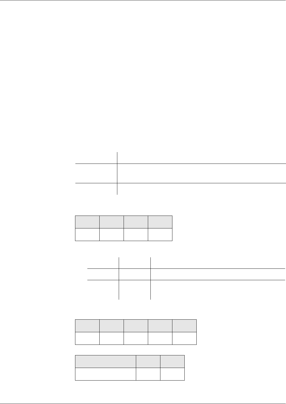
Commands
MANAGE CHANNEL
Reference Manual STARCOS® 3.0/Edition 06/2005 327
ID No. 30016255
MANAGE CHANNEL
Using the command MANAGE CHANNEL, logical channels can be opened
and closed. The Security Environment of the opened channel is in the same
state as after RESET, the MF is selected and all security states are deleted. If
command MANAGE CHANNEL is executed from the basic channel 0, the MF
is selected in the new channel. Otherwise the current file selection is also cop-
ied to the new channel.
Notes After a reset of the card, the logical channels 1 to 3 are closed. The logi-
cal channel 0 is always open and cannot be closed.
Using the command MANAGE CHANNEL, either the next free channel or a
channel specified in P2 can be opened. In the first scenario, the command is a
Case 2 command because the card returns the number of the open channel. In
the second scenario, it is a Case 1 command because data are sent neither to
nor by the card.
Rule
Command Case 1
P1 and P2
Case 2
Response
Execution Optional
Access from ARR in the ARR data object of the file control information
template of the current DF to be accessed
Evaluation SE# of the security environment from the current DF
CLA INS P1 P2
’0x’ ’70’
P1 P2 Description
’00’ ’01’-’03’ Opens the specified logical channel
’80’ ’0x’ Closes the active channel specified in the Class
Byte
CLA INS P1 P2 Le
’0x’ ’70’ ’00’ ’00’ ’01’
DATA SW1 SW2
’01’-’03’ ’90’ ’00’


Commands
MANAGE SECURITY ENVIRONMENT
Reference Manual STARCOS® 3.0/Edition 06/2005 329
ID No. 30016255
MANAGE SECURITY ENVIRONMENT
The functions which may be executed with the command MANAGMENT SE-
CURITY ENVIRONMENT (MSE) are described in detail in the chapter ’Secu-
rity Environments’ from page 201 onwards.
The service for changing the SE is specified in P1. The associated SE# or the
tag of the CRT is defined in P2.
Notes Permissible combinations for P1, P2 and CRDOs:
*or:
Each of the data object of this list may exist only once. Apart from that,
multiple data objects may be combined as desired, provided that each
data object occurs only once.
P1 P2 Tags of Permitted CRDOs
’81’ ’A4’ ’80’ or* ’89’, ’83’, ’94’
’41’ ’A4’ ’80’ or ’89’, ’83’ or ’84’, ’94’
’C1’ ’A4’ ’80’ or ’89’, ’83’, ’84’, ’94’
’81’ ’B6’ ’80’ or ’89’, ’83’
’41’ ’B6’ ’80’ or ’89’, ’84’
’C1’ ’B6’ ’80’ or ’89’, ’83’, ’84’
’81’ ’B8’ ’80’ or ’89’, ’83’
’41’ ’B8’ ’80’ or ’89’, ’84’
’C1’ ’B8’ ’80’ or ’89’, ’83’, ’84’
’41’ ’AA’ ’80’ or ’89’
’21’ ’B4’ ’83’, ’87’, ’94’
’11’ ’B4’ ’83’, ’94’
’31’ ’B4’ ’83’, ’94’
’21’ ’B8’ ’83’, ’94’
’11’ ’B8’ ’83’, ’94’
’31’ ’B8’ ’83’, ’94’

Commands
MANAGE SECURITY ENVIRONMENT
330 Reference Manual STARCOS® 3.0/Edition 06/2005
ID No. 30016255
The command MSE is aborted with ’6A 80’ if P1 = ’X1’ and
– Command data are not correctly TLV-coded
or
Tag for CRDO from command data ≠ ’80’, ’81’, ’83’, ’84’, ’87’, ’89’
or ’94’
or
CRDOs are not correctly coded
– Key names or algorithm references are not found in a search in
EF_ALIAS.
The command MSE does not check the contents of the data objects that
are passed.
The command MSE RESTORE cannot be executed using secure messag-
ing.
Rule Execution For P1 = ’F3’: No evaluation
For P1 = ’X1’: Optional
Access from ARR in the ARR data object for data objects of the file con-
trol information template of the current DF
The tag list in a data object with the tag ’A0’, which has
been defined for the transmission type used, is searched for
the tag of the CRT in P2.
Evaluation SE# of the security environment of the current DF
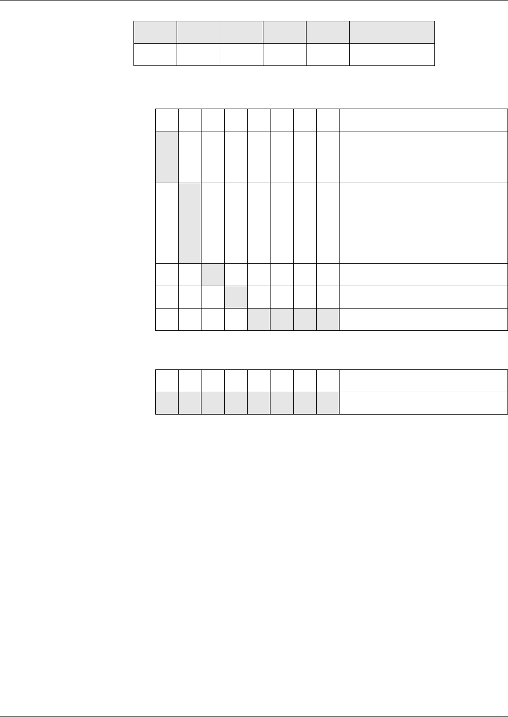
Commands
MANAGE SECURITY ENVIRONMENT
Reference Manual STARCOS® 3.0/Edition 06/2005 331
ID No. 30016255
Command
P1
For MSE SET
For MSE RESTORE SE
P2 for MSE SET
’A4’ AT, specifications for component authentication in the
data field
’AA’ HT, specification for hash calculation in the data field
’B4’ CCT, specifications for data authentication in the data field
’B6’ DST, specifications for digital signature in the data field
’B8’ CT, specifications for confidentiality in the data field
.P2 for MSE RESTORE SE
’XY’ SE# (SE# ≠ ’00’, ’EF’ and ’FF’)
Lc – Length of the command data
For P1 = ’F3’ Lc = 0
DATA
For P1 = ’F3’ (MSE RESTORE SE)DATA = 0
CLA INS P1 P2 LcDATA
’0X’ ’22’
b8 b7 b6 b5 b4 b3 b2 b1 Description
1 External authentication,
Verification of a digital signature,
Encipherment
1 Internal authentication,
Calculation of a digital signature,
Decipherment,
Generation of a key pair,
Calculation of a hash value
1 SM response
1 SM command
0001SET
b8 b7 b6 b5 b4 b3 b2 b1 Description
11110011RESTORE SE
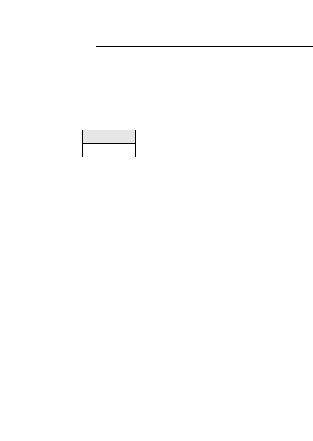
Commands
MANAGE SECURITY ENVIRONMENT
332 Reference Manual STARCOS® 3.0/Edition 06/2005
ID No. 30016255
For P1 = ’X1’ (MSE SET) the following data objects
Response
Status Bytes For warnings and error messages see ’Status Bytes’ from page 269 onwards.
Tag Value
’80’ Empty or algorithm reference
’83’ Empty or key name or key reference
’84’ Empty or key name or key reference
’87’ Empty or random number, 8 bytes binary
’89’ Empty or algorithm ID
’94’ Card identification data for deriving individual keys for the
card from master keys, at least 16 bytes
SW1 SW2
’90’ ’00’

Commands
MUTUAL AUTHENTICATE
Reference Manual STARCOS® 3.0/Edition 06/2005 333
ID No. 30016255
MUTUAL AUTHENTICATE
With the command MUTUAL AUTHENTICATE, the terminal and the smart
card authenticate each other by using a secret key. The terminal is always au-
thenticated first.
In addition, one or two session keys may be negotiated and a send sequence
counter (SSC) initialized.
The following variants of the command MUTUAL AUTHENTICATE are thus
available:
– Authentication without negotiating a session key,
– Authentication with negotiation of a session key with or without SSC,
– Authentication with negotiation of two session keys with or without
SSC.
– Authentication with negotiation of two session keys according to E-
SignK.
The authentication is determined by the access conditions and algorithms of
the referenced key, which are specified in the additional information of the
EF_KEYD.
Command Sequence – The referened key and the additional key information are searched.
– The key is checked to determine whether and how it may be used in the
active SE of the key-group relevant DF.
– The mutual authentication is performed.
Notes When using secure messaging, DATA must not be enciphered if it con-
tains a key reference.
Before every command MUTUAL AUTHENTICATE, the smart card
must have passed a random number to the terminal by using a GET
CHALLENGE command.
Rule
Authentication without
Key Negotiation
The following steps are performed in the authentication:
– The first 8 bytes from the cryptogram of DATA are deciphered. The algo-
rithm to be used is specified by the algorithm ID in the associated
EF_KEYD.
Execution Optional
Access from ARR in the ARR data object in the additional information
Evaluation SE# of the security environment from the DF to which the
found key is assigned
Commands
MUTUAL AUTHENTICATE
334 Reference Manual STARCOS® 3.0/Edition 06/2005
ID No. 30016255
– The usage counter, if provided, is decremented by 1 even if the command
MUTUAL AUTHENTICATE is aborted during or after decipherment.
– The plain text contained is checked for compliance with the random
number RND.IFD.
– If the authentication is successful, the key number and version are en-
tered into the component authentication list. The list is assigned to the
MF or DF whose EF_KEY contains the key found.
– If the authentication fails, the following applies:
– The key fault presentation counter, if provided, is decremented by 1
even if the command MUTUAL AUTHENTICATE was aborted dur-
ing or after authentication.
– The key number and version are removed from the component au-
thentication list.
Command
P2
’00’ Key reference from active SE of current DF, if:
Key reference in SE and AT with UQ = ’80’ and
DATA with key reference
or
Key reference
LC – Length of the command data
’10’ without key reference
’13’ with key reference
DATA
Cryptogram eK(RND.ICC) || RND.IFD, 16 bytes
Optionally key reference, 3 bytes
Le – Expected response data
Le = 0, all bytes available
CLA INS P1 P2 LcDATA Le
’0X’ ’82’ ’00’ ’00’
b8 b7 b6 b5 b4 b3 b2 b1 Description
0
1
Key type:
Global
DF-specific key
00or RFU
XXXXX Key number (1 - 31)

Commands
MUTUAL AUTHENTICATE
Reference Manual STARCOS® 3.0/Edition 06/2005 335
ID No. 30016255
Response
DATA
Ciphered value eK(RND.IFD), 8 bytes
Status Bytes For warnings and error messages see ’Status Bytes’ from page 269 onwards.
Authentication with
Key Negotiation
The following steps are performed in the authentication with key negotiation
(when figures are given, such as 23/33, the first figure applies to one session
key and the second figure to two session keys):
– The first 32/48 bytes from the cryptogram of DATA are deciphered. The
algorithm to be used is specified by the algorithm ID in the associated
EF_KEYD.
The deciphered block contains:
RND.IFD Random number generated by the terminal
RND.ICC Random number generated by the smart card
K0 Key half generated by the terminal for the
session key(s)
– The usage counter, if provided, is decremented by 1 even if the command
MUTUAL AUTHENTICATE is aborted during or after decipherment.
– The deciphered RND.ICC is checked for compliance with the random
number passed by the command GET CHALLENGE.
– If the authentication is successful, the key number and version are en-
tered into the component authentication list. The list is assigned to the
MF or DF whose EF_KEY contains the key found.
– If the authentication fails, the following applies:
– The key fault presentation counter, if provided, is decremented by 1
even if the command MUTUAL AUTHENTICATE was aborted dur-
ing or after authentication.
– The key number and version are removed from the component au-
thentication list.
– A 16 bytes long subkey K1 is generated for negotiating a session key.
The session key SK1 is computed by combining K1 and the received K0
by an XOR operation.
or
– A 32 bytes long subkey K1 is generated for negotiating two session keys.
The combination of the session keys SK1 and SK2 is computed by com-
bining K1 and the received K0 by an XOR operation.
– The command MUTUAL AUTHENTICATE initializes the SSC depend-
ing on the algorithm ID of the referenced key.
DATA SW1 SW2
’90’ ’00’

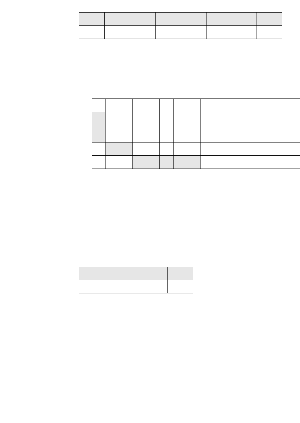
Commands
MUTUAL AUTHENTICATE
Reference Manual STARCOS® 3.0/Edition 06/2005 337
ID No. 30016255
Command
P2
’00’ Key reference from active SE of current DF, if:
Key reference in SE and AT with UQ = ’80’ and
DATA with key reference
or
Key reference
Lc – Length of the command data with 1/2 session keys
’20’/’30’ without key reference
’23’/’33’ with key reference
DATA
Cryptogram eK(RND.IFD || RND.ICC || K0),
K0 key half generated by terminal
K0 = 16 bytes for 1 session key
K0 = 32 bytes for 2 session keys
Optionally key reference, 3 bytes
Response
DATA with 1 session key
Ciphered value eK(RND.ICC || RND.IFD|| K1)
K1 key half generated by smart card
K1 = 16 bytes for 1 session key
K1 = 32 bytes for 2 session keys
Status Bytes For warnings and error messages see ’Status Bytes’ from page 269 onwards.
CLA INS P1 P2 LcDATA Le
’0X’ ’82’ ’00’
b8 b7 b6 b5 b4 b3 b2 b1 Description
0
1
Key type:
Global
DF-specific key
00or RFU
XXXXX Key number (1 - 31)
DATA SW1 SW2
’90’ ’00’

Commands
MUTUAL AUTHENTICATE
338 Reference Manual STARCOS® 3.0/Edition 06/2005
ID No. 30016255
Authentication
according to E-SignK
The following steps are performed in the authentication:
– A MAC over the 64 bytes cryptogram of DATA is calculated and com-
pared to the 8 byte MAC appended to the DATA.
– The 64 bytes from the cryptogram of DATA are deciphered. The algo-
rithm to be used is specified by the algorithm ID in the associated
EF_KEYD.
The deciphered block contains:
RND.IFD Random number generated by the terminal
SN.IFD Serial number generated by the terminal
RND.ICC Random number generated by the smart card
SN.ICC Serial number generated by the smart card
KIFD Key half generated by the terminal for the
session key(s)
– The usage counter, if provided, is decremented by 1 even if the command
MUTUAL AUTHENTICATE is aborted during or after decipherment.
– The deciphered RNDN.ICC is checked for compliance with the random
number passed by the command GET CHALLENGE.
– The deciphered SN.ICC is checked for compliance with the serial num-
ber stored in EF.GDO.
– If the authentication is successful, the key number and version are en-
tered into the component authentication list. The list is assigned to the
MF or DF whose EF_KEY contains the key found.
– If the authentication fails, the following applies:
– The key fault presentation counter, if provided, is decremented by 1
even if the command MUTUAL AUTHENTICATE was aborted dur-
ing or after authentication.
– The key number and version are removed from the component au-
thentication list.
– A 32 bytes long subkey KICC is generated.
– The 32 bytes KIFD/ICC is computed by combining KICC and the received
KIFD by an XOR operation:
KIFD/ICC = KIFD ⊕ KICC
– The four bytes ’00 00 00 01’ are appended to KIFD/ICC and the result is
hashed to produce HASH1:
HASH1 = SHA1(KIFD/ICC || ’00000001’).
– The four bytes ’00 00 00 02’ are appended to KIFD/ICC and the result is
hashed to produce HASH2:
HASH1 = SHA1(KIFD/ICC || ’00000002’).
– The parity of HASH1 and HASH2 is adjusted to ’odd’.
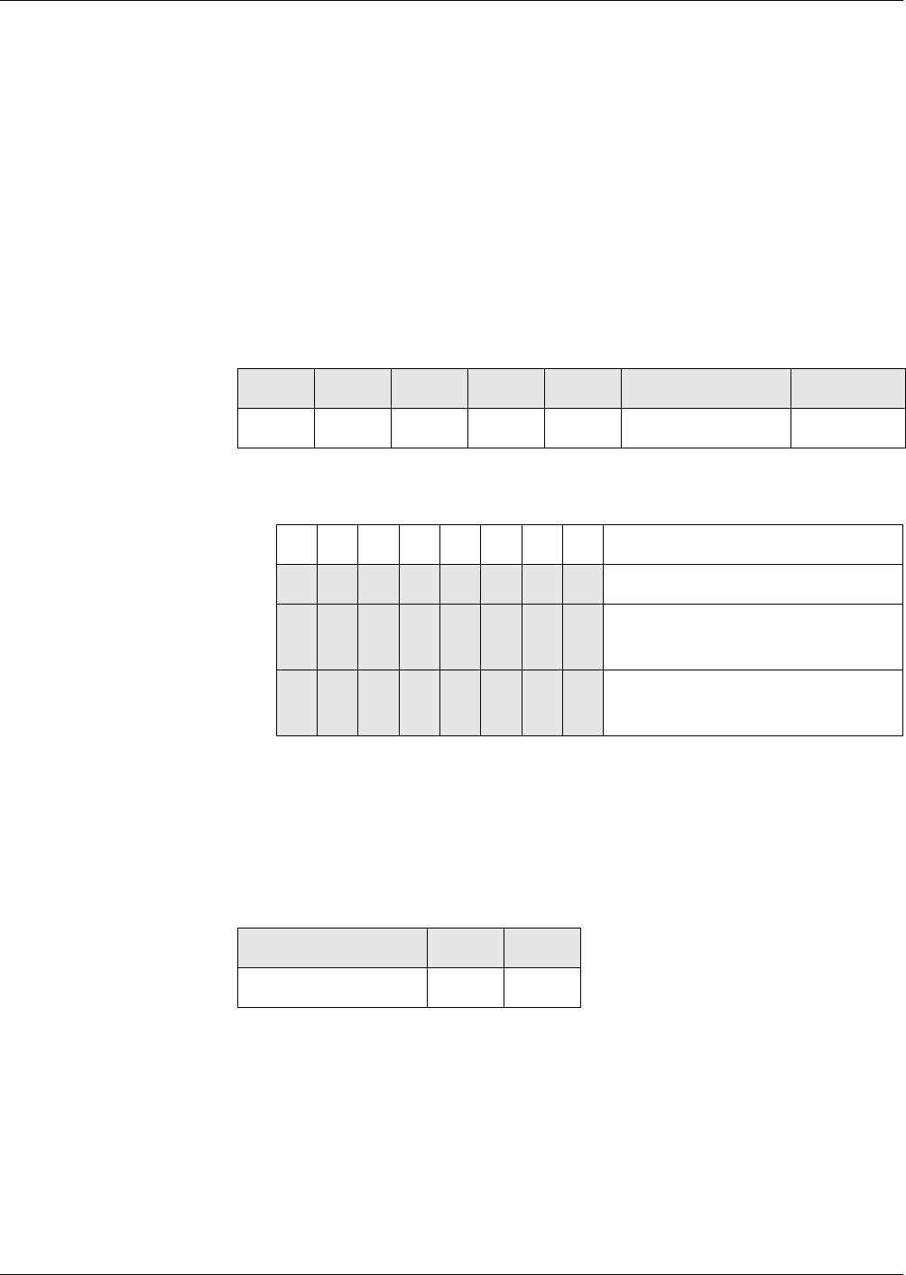
Commands
MUTUAL AUTHENTICATE
Reference Manual STARCOS® 3.0/Edition 06/2005 339
ID No. 30016255
– The 16 bytes encryption session key is taken from the first 16 bytes of
HASH1:
KSK.ENC = (Byte 1-16) of HASH1
– The 16 bytes MAC session key is taken from the first 16 bytes of
HASH2:
KSK.MAC = (Byte 1-16) of HASH2
– The command MUTUAL AUTHENTICATE generates the
SSC.ICC = 4 lower-order bytes of RND.ICC || 4 lower-order bytes of
RND.IFD.
– The response data are enciphered using the key specified by the key ref-
erence and a MAC is calculated over the response and appended to it.
Command
P2
Key reference
DATA
S* || MAC3DES.CBC(KMAC, S*)
S* = E3DES.CBC(KENC, S)
S = RNDIFD || SNIFD || RNDICC || SNICC || KIFD
(see ’Mutual Authentication according to E-SignK’ on page 158)
Response
DATA
R* || MAC3DES.CBC(KMAC, R*)
R* = E3DES.CBC(KENC, R)
R = RNDICC || SNICC || RNDIFD || SNIFD || KICC
Status Bytes For warnings and error messages see ’Status Bytes’ from page 269 onwards.
CLA INS P1 P2 LcDATA Le
’0X’ ’82’ ’00’ ’48’ ’00’
b8 b7 b6 b5 b4 b3 b2 b1 Description
00000000 KeyID Implicitly referenced
0 0 0 X X X X X
Global Key
KeyID of KENC and KMAC
1 0 0 X X X X X
DF-specific Key
KeyID of KENC and KMAC
DATA SW1 SW2
’90’ ’00’


Commands
PERFORM SECURITY OPERATION
Reference Manual STARCOS® 3.0/Edition 06/2005 341
ID No. 30016255
PERFORM SECURITY OPERATION
The command PERFORM SECURITY OPERATION covers the following
subcommands featuring the same instruction byte ’2A’:
– ’COMPUTE DIGITAL SIGNATURE’ from page 290 onwards
– ’DECIPHER’ from page 296 onwards
– ’ENCIPHER’ from page 301 onwards
– ’HASH’ from page 316 onwards
– ’VERIFY CERTIFICATE’ from page 368 onwards
– ’VERIFY DIGITAL SIGNATURE’ from page 373 onwards
Functions and syntax of the subcommands are described in the respective
commands’ sections.
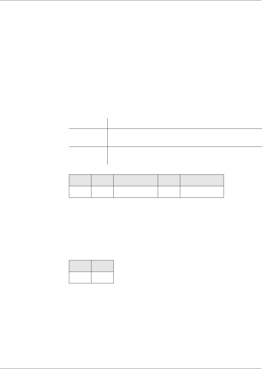
Commands
PUT DATA
342 Reference Manual STARCOS® 3.0/Edition 06/2005
ID No. 30016255
PUT DATA
The command PUT DATA is used to write a data object. The relevant tag is
specified in P1/P2 (for command sequence see page 28).
The command PUT DATA distinguishes two different cases of write opera-
tions:
– The data object to be written already exists in a record of the EF_DO and
is overwritten with a new value of identical length (update).
– The data object to be written is newly entered into a record of the EF_DO
(append).
Notes If the tag indicates a composite data object, correct TLV coding is veri-
fied for the data field.
Rule
Command
P1/P2 – Tag
’00 40’ - ’00 FE’ BER-TLV tag with 1 byte in P2
’5F 01’ - ’FF 7F’ BER-TLV tag with 2 bytes in P1/P2
Lc – Length of the data to be passed
DATA
Value field of the data object to be written
Response
Status Bytes For warnings and error messages see ’Status Bytes’ from page 269 onwards.
Execution Mandatory
Access from ARR in the ARR data object for data objects of the file con-
trol information template of the current DF, see page 31
Evaluation P1/P2 and SE# of the security environment from the current
DF
CLA INS P1/P2 LcDATA
’0X’ ’DA’
SW1 SW2
’90’ ’00’
Commands
READ BINARY
Reference Manual STARCOS® 3.0/Edition 06/2005 343
ID No. 30016255
READ BINARY
The command READ BINARY reads data only from EFs with transparent
structure.
Notes After a READ BINARY command with uncommon instruction, the file se-
lection remains valid, even if errors were detected while reading the file.
Rule
Command
READ BINARY
P1 – Reference control byte
P1 with b8 = 0
Data are read from the currently selected EF and
P2 = Offset low byte
P1 with b8 = 1
Data are read from an EF referenced by an SFI and
P2 = Offset
Le – Number of bytes to be read
’00’ All bytes up to end of file, maximum 256 bytes
Response
Execution Mandatory
Access from ARR in the ARR data object of the file control information
template of the EF to be accessed
Evaluation SE# of the security environment from the DF of the current
EF
CLA INS P1 P2 Le
’0X’ ’B0’
b8 b7 b6 b5 b4 b3 b2 b1 Description
0
####### Offset high byte
b8 b7 b6 b5 b4 b3 b2 b1 Description
100
##### SFI (’01’ - ’1E’)
DATA SW1 SW2
Requested data ’90’ ’00’

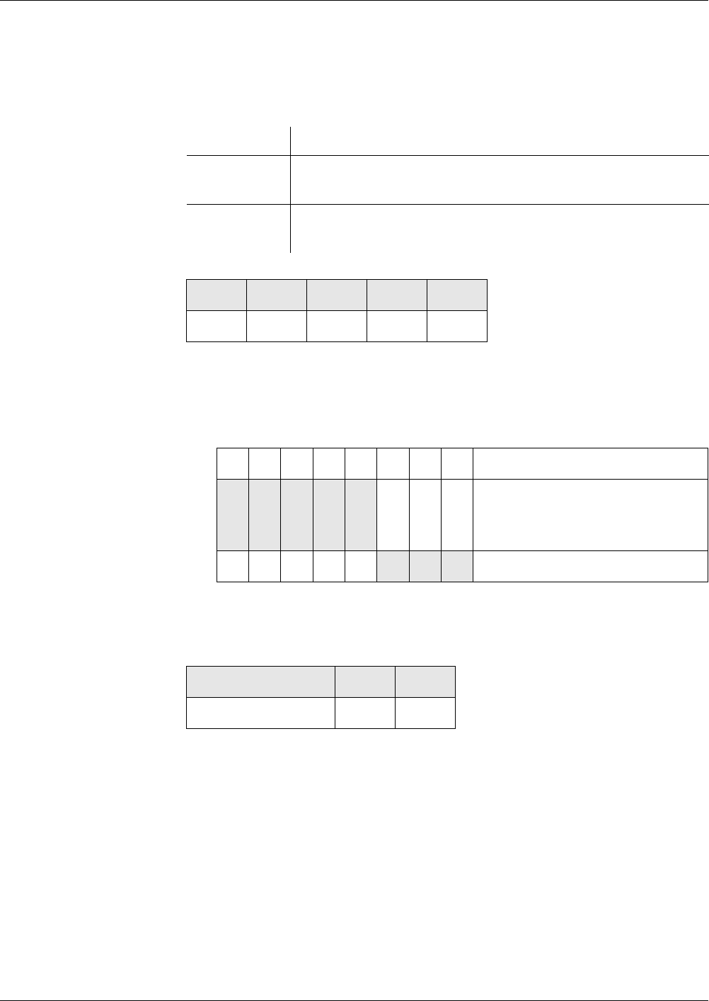
Commands
READ RECORD
Reference Manual STARCOS® 3.0/Edition 06/2005 345
ID No. 30016255
READ RECORD
The command READ RECORD reads records/elements from EFs with linear
fixed, linear variable and cyclic record structures.
Rule
Command
P1 – Record number
P1 ≠ ’00’ and
P1 ≠ ’FF’
P2 – Reference control byte
Le – Expected response data
Le = 0, all bytes available
Response
Status Bytes For warnings and error messages see ’Status Bytes’ from page 269 onwards.
Execution Mandatory
Access from ARR in the ARR data object of the file control information
template of the EF to be accessed
Evaluation SE# of the security environment from the DF of the current
EF
CLA INS P1 P2 Le
’0X’ ’B2’
b8 b7 b6 b5 b4 b3 b2 b1 Description
0
X
0
X
0
X
0
X
0
X
File selection:
Currently selected EF
SFI (’01’ - ’1E’)
100 Fixed value
DATA SW1 SW2
requested data ’90’ ’00’

Commands
RESET RETRY COUNTER
346 Reference Manual STARCOS® 3.0/Edition 06/2005
ID No. 30016255
RESET RETRY COUNTER
The command RESET RETRY COUNTER is used to reset the elapsed key
fault presentation counter of a password. Controlled by P1, the command RE-
SET RETRY COUNTER can be executed in the following three variants:
– Resetting the KFPC
– Resetting the KFPC + resetting code
– Resetting the KFPC + new password + resetting code
Notes To execute the command RESET RETRY COUNTER, the KFPC of the
password must have the value 0.
The lengths of PINs and passwords are prescribed:
4 ≤ PIN length ≤ 12
4 ≤ Password length ≤ 8
Rule
general sequence When the resetting code and/or the new password have been transmitted, the
following steps are performed:
– The previously determined length L1 of the PIN1 or PWD1 must match
the actual length in the first byte of the record in EF_RC.
– If a reference value was created previously for the resetting code, it must
match the reference value stored in EF_RC.
– On successful verification, the key fault presentation counter assigned to
the resetting code in the associated EF_RCZ is set to the initial value con-
tained in EF_RCZ.
Execution Mandatory
Access from ARR in the ARR data object which is contained in an ARR
data object in the previously found additional password in-
formation.
Evaluation The evaluation depends on the position of the ARR data ob-
ject from the additional information:
– If it precedes the first SE data object, this SE data object
needs to be evaluated using the SE# of the security en-
vironment which is active in the DF relevant to the
password number.
– If no preceding ARR data object exists, an SE data ob-
ject having the SE# of the security environment which
is active in the DF relevant to the password number
needs to be selected first. The evaluation is performed
as described in the ARR Data Object section (see
page 178)
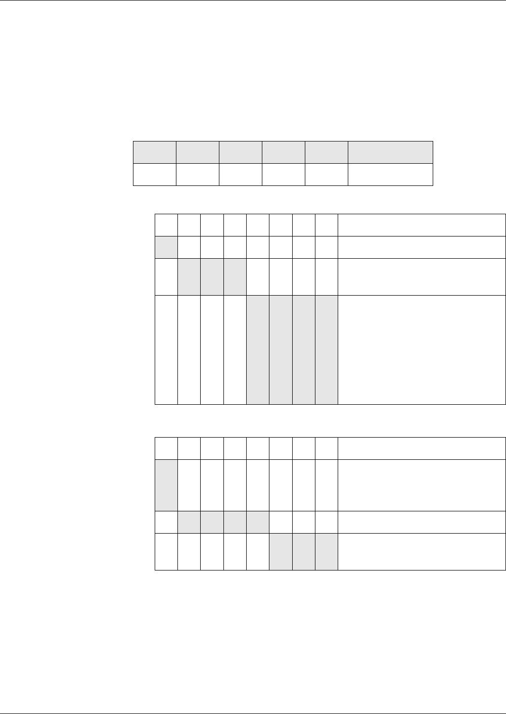
Commands
RESET RETRY COUNTER
Reference Manual STARCOS® 3.0/Edition 06/2005 347
ID No. 30016255
– The reference value of PIN2 and/or PWD2 replaces the reference value
that has been stored in a record of EF_PWD. The length L2 of PIN2 and/
or PWD2 is stored in binary code in the first byte of this record.
The reference value for the new PIN and/or the new password is stored in
bytes 2 to 9.
– The KFPC of PIN2 and/or PWD2 is set to the initial value stored in
EF_RC.
Command
P1
P2 – Reference control byte for password
DATA
P1 = ’3x’ No data
P1 = ’1x’ Resetting code in defined transmission format
P1 = ’0x’ Resetting code || New password
each in the defined transmission format
CLA INS P1 P2 LcDATA
’0X’ ’2C’
b8 b7 b6 b5 b4 b3 b2 b1 Description
0RFU
X X X Binary-coded resetting code
number (0 - 7)
0
0
0
0
0
0
0
0
1
0
1
1
Command type:
Resetting of KFPC + resetting
code + new password
Resetting of KFPC + resetting
code + password remains un-
changed
Resetting of KFPC
b8 b7 b6 b5 b4 b3 b2 b1 Description
0
1
Password type:
Global
DF-specific password
0000RFU
XXX Binary-coded password number
(0 - 7)

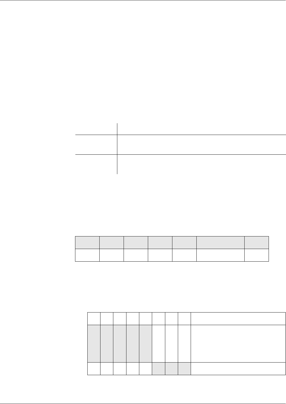
Commands
SEARCH RECORD
Reference Manual STARCOS® 3.0/Edition 06/2005 349
ID No. 30016255
SEARCH RECORD
The command SEARCH RECORD is used to find one or more records/ele-
ments in EFs with linear or cyclic structures.
The search always runs through the records of the EF, starting from the record
defined in P1. The search results must match the search pattern defined in
DATA.
P2 specifies which EF is accessed and which type of search is to be run.
STARCOS® supports three search variants:
– Standard search
– Extended search
– Specific search
Rule
Standard Search A standard search searches through all the records of an EF, starting from the
record defined in P1.
The record is checked for the occurrence of the search pattern.
The search in lInear fixed records can only be performed with patterns having
the same length as the records itself.
Command
P1 – Record number
Defines the record from which the search is to start
P1 ≠ ’00’ and
P1 ≠ ’FF’
P2 – Reference control byte
Execution Mandatory
Access from ARR in the ARR data object of the file control information
template of the EF to be accessed
Evaluation SE# of the security environment from the DF of the current
EF
CLA INS P1 P2 LcDATA Le
’0X’ ’A2’ Search pattern ’00’
b8 b7 b6 b5 b4 b3 b2 b1 Description
0
X
1
0
X
1
0
X
1
0
X
1
0
X
1
File selection:
Currently selected EF
SFI (’01’ - ’1E’)
RFU
100 Referencing by RN
Commands
SEARCH RECORD
350 Reference Manual STARCOS® 3.0/Edition 06/2005
ID No. 30016255
Lc – Length of search pattern
Response
Status Bytes For warnings and error messages see ’Status Bytes’ from page 269 onwards.
Extended Search An extended search searches through all the records of an EF, starting from
the record defined in P1. DATA specifies where the search is to start and in
which direction it is to be performed.
The search checks whether the record, without the offset byte or after the sep-
arator, contains at least the n bytes of the search pattern. With records of con-
stant length, the length of the record must match the search pattern. With
records of variable length, the search is continued in the next record if the
record is shorter than the search pattern.
Notes For CRTLB = ’04’ and EF with linear fixed structure:
Offset for start of search < length of record to be found.
With EFs of a linear variable structure, the search is continued after the
next record if the offset is greater than the length of the record.
Command
P1 – Record number
Defines the record from which the search is to start
P1 ≠ ’00’ and
P1 ≠ ’FF’
P2 – Reference control byte
Lc
2 bytes: CTRLB/OIB + length of search pattern
DATA SW1 SW2
RN(s) to find ’90’ ’00’
CLA INS P1 P2 LcDATA Le
’0X’ ’A2’ ’00’
b8 b7 b6 b5 b4 b3 b2 b1 Description
0
X
1
0
X
1
0
X
1
0
X
1
0
X
1
File selection:
Currently selected EF
SFI (’01’ - ’1E’)
RFU
110 Referencing by RN

Commands
SEARCH RECORD
Reference Manual STARCOS® 3.0/Edition 06/2005 351
ID No. 30016255
DATA
CRTLB || OIB || Search pattern
CTRLB – Control byte, OIB – Offset indicator byte
CTRLB = ’04’ Search performed according to ascending RN with
OIB = ’00’ - ’FE’ Offset for start of search
CTRLB = ’0C’ Search starts with record as defined in RN
OIB Any, will be interpreted as the separator after
the first occurrence of which the search is to start.
Response
Status Bytes For warnings and error messages see ’Status Bytes’ from page 269 onwards.
Specific Search A specific search searches through all the records of an EF, starting from the
record defined in P1. Unlike the standard and extended search variants, the
specific search can be terminated as soon as the search pattern has been found
in a record. In addition, the data of this record can also be returned.
To determine the search variants, DATA contains not only the CTRLB and
OIB, as in the extended search, but also a configuration byte.
The following search variants can be specified:
– Search for record data as unstructured byte string
– Search for record data as TLV object
– Search for search patterns or search intervals
– Search at fixed position for the entire byte string
– Search of all records or up to 1st hit
Search for Record Data
as Unstructured Byte
String
As in the extended search, the record data are interpreted as unstructured byte
strings. The configuration byte is followed directly by the search pattern or
search interval.
Search for Record Data
as TLV Object
If the configuration byte specifies that the record data to be found are to be in-
terpreted as one or more TLV objects, the configuration byte is followed by a
tag, an IGN byte and an additional OIB’ first, and then come the search pat-
tern and search interval.
The TLV objects to be found are identified by the specified tag.
In the search, the value fields of composite data objects are searched recur-
sively for data objects. If the end of the record is not yet reached on reaching
the end of a data object, the search assumes that the subsequent record data
start again with a tag.
DATA SW1 SW2
RN(s) to find ’90’ ’00’

Commands
SEARCH RECORD
352 Reference Manual STARCOS® 3.0/Edition 06/2005
ID No. 30016255
Since a record may contain different data object with the same tag, this search
variant allows defining which one of the data objects with the specified tag is
to be found. The number of data objects (k-1) with this tag which are to be
skipped are binary coded in the IGN byte.
The search for the k-th occurrence of a tag in a record is concluded unsuccess-
fully if the end of the record is reached before the tag was found for the k-th
time or if inconsistencies are detected in the TLV structure of the data.
When the search for the k-th occurrence of a data object in a record is success-
ful, the value field of this data object is regarded as an unstructured byte string
in which a search pattern or a value from a search interval is search for. The
value field is also regarded as unstructured in the case of a composite data ob-
ject.
An offset is specified in the OIB’ for the search in the value field. If the value
of OIB’ is not less than the length of the value field to be searched through,
the search is continued with the subsequent record, unless the last record of
the data field has already been searched through.
Search for Search
Patterns or Search
Intervals
In the search for a search pattern, a fixed value is searched for. As in the ex-
tended search, the search pattern is specified by a byte string which is com-
pared with the byte string in the found record during the search.
A specific search can also be used to find a search interval. The upper and
lower limits of the search interval are specified by concatenating two binary
values of the same byte lengths. The left value indicates the lower limit, the
right value the upper limit:
’UU ... UU’ || ’OO ... OO’.
The search is performed in the following way:
If ’UU ... UU’ and ’OO ... OO’ are each n bytes long, n bytes ’XX ... XX’ is
checked for ’UU ... UU’ ≤ ‘XX ... XX’ ≤ ‘OO ... OO’.
The comparison is performed as a comparison of binary values. For example,
the interval specified by the lower limit ’12 34’ and the upper limit ’23 45’ in-
cludes the value ’1A 3B’.
Search at Fixed Position
for Entire Byte String
The first steps of the search in a record always lead to specifying an unstruc-
tured byte string within the record data. This byte string is then searched
through for a search pattern or search interval in the subsequent steps.
Depending on the configuration byte, this byte string is either that part of the
record that is specified by CTRLB and OIB or that part, specified by OIB’, of
the value field of the data object found in the record according to CTRLB and
OIB, the tag and the IGN byte.
The configuration byte specifies whether the subsequent search only consists
in comparing the first bytes of the byte string once with the search pattern or
search interval, or whether the beginning of the byte string is to constitute the
start position for the search.
Commands
SEARCH RECORD
Reference Manual STARCOS® 3.0/Edition 06/2005 353
ID No. 30016255
If the byte string is shorter than the search pattern or than the upper and lower
limits of the search interval, the search is continued for the next record, unless
the last record has already been searched through.
If only a one-time comparison is to be performed with the search pattern or
search interval and this comparison is negative, the search is continued for the
next record, unless the last record has already been searched through.
If the beginning of the byte string is the start position for the search, the com-
parison position successively moves one byte towards the end of the byte
string with each negative comparison with the search pattern or search inter-
val. In this case, a check is performed prior to a comparison with an n byte
long search pattern or with n bytes long upper and lower limits to verify
whether n bytes are still available in the byte string.
If the byte string no longer provides n bytes for comparison, the search for
this record is concluded. The search continues with the next record.
Search of All Records or
up to First Hit
If the search only runs up to the first hit, only the record number or the record
number and the contents of the record are returned with the first hit.
If the search covers all records, the record number of a record with a hit is
stored and the search is continued with the next record, unless the last record
has already been searched through.
The record numbers of the records which contain the search pattern or a value
in the search interval are returned, sorted in ascending order.
Command
P1 – Record number
Defines the record from which the search is to start
P1 ≠ ’00’ and
P1 ≠ ’FF’
P2 – Reference control byte
Lc – Length of the command data
CLA INS P1 P2 LcDATA Le
’0X’ ’A2’ ’00’
b8 b7 b6 b5 b4 b3 b2 b1 Description
0
X
1
0
X
1
0
X
1
0
X
1
0
X
1
File selection:
Currently selected EF
SFI (’01’ - ’1E’)
RFU
111 Referencing by RN

Commands
SEARCH RECORD
354 Reference Manual STARCOS® 3.0/Edition 06/2005
ID No. 30016255
DATA
Search for record data as unstructured byte string:
CTRLB || OIB || Configuration byte || Search pattern/Search interval
Search for record data as TLV object:
CTRLB || OIB || Configuration byte || [ Tag || IGN byte || OIB’] || Search
pattern/Search interval
CTRLB – Control byte, OIB – Offset indicator byte
CTRLB = ’04’ Search performed according to ascending RN with
OIB = ’00’ - ’FE’ Offset for start of search
CTRLB = ’0C’ Search starts with record as defined in RN
OIB Any, is interpreted as the separator after
the first occurrence of which the search is to start.
Configuration byte
OIB’ – 2. Offset indicator byte
’00’ - ’FE’
b8 b7 b6 b5 b4 b3 b2 b1 Description
1
0
Search for:
Record data as unstructured byte
string
Record data as TLV object
1
0
Search for:
Search interval
Search pattern
0 0 0RFU
1
1
0
0
0
1
0
1
Search:
Up to 1st hit
Up to 1st hit and return of the
record
Through all records
RFU
1
0
Search:
At first position of the byte string
throughout the byte string


Commands
SELECT FILE
356 Reference Manual STARCOS® 3.0/Edition 06/2005
ID No. 30016255
SELECT FILE
The command SELECT FILE is used to select a DF or EF and, optionally, to
issue the associated file control information template (FCP, FCI).
The command SELECT FILE DF allows modifying the global or DF-specific
security status of the smart card.
By selecting an ADF, the corresponding application context is opened.
When the command SELECT FILE DF is executed, the security states and de-
rived keys of the newly selected directory and of its parent DFs all the way up
to the MF are retained; all other security states and derived keys as well as all
negotiated keys are deleted.
Correspondingly, the active SE of a selected directory and the active SEs of
its parent DFs up to the MF remain unchanged. For all other DFs, the relevant
SE with the number ’01’ implicitly becomes active.
Selecting a directory deletes all volatile SE components except the CID.
If the command SELECT FILE fails:
– If a selection fails, the old selection of DF and EF will remain selected.
– An EF that may have been selected when the command was called re-
mains selected.
– The security states of the active SEs, the volatile SE components and the
derived or negotiated keys of the smart card remain unchanged.
Notes The command SELECT FILE can be sent with secure messaging and en-
crypted data. The command SELECT FILE searches for an ARR in the
DF header. The rule is optional.
The command SELECT FILE DF cannot be executed using secure mes-
saging.
The implicit opening of a logical channel is not supported.
Rule Execution No evaluation for P1 ≠ ’02’
Optional for P1 = ’02’
Access from ARR in the ARR data object of the file control information
template of the EF to be accessed
Evaluation SE# of the security environment from the DF of the current
EF
Commands
SELECT FILE
Reference Manual STARCOS® 3.0/Edition 06/2005 357
ID No. 30016255
Command
P1 – Selection control
P2 – Selection option
Lc – Length of the command data
DATA
For P1 = ’00’ No data or ’3F 00’
For P1 = ’01’ File ID of a DF, 2 bytes
For P1 = ’02’ File ID of an EF, 2 bytes
For P1 = ’03’ No data
For P1 = ’04’ DF name, 1 - 16 bytes
Le – Length of expected response data
Response
Status Bytes For warnings and error messages see ’Status Bytes’ from page 269 onwards.
CLA INS P1 P2 LcDATA Le
’0X’ ’A4’
b8 b7 b6 b5 b4 b3 b2 b1 Description
00000 Fixed value
0
0
0
0
0
0
1
1
0
1
0
1
Selection for:
MF
Lower-level DF
EF in current DF
Higher-level DF
00000100 Selection by DF name
b8 b7 b6 b5 b4 b3 b2 b1 Description
0000 00 Fixed value
0
0
1
1
0
1
0
1
file control information template
to be returned:
FCI
FCP
FMD
No data returned
DATA SW1 SW2
File control
information
’90’ ’00’

Commands
TERMINATE
358 Reference Manual STARCOS® 3.0/Edition 06/2005
ID No. 30016255
TERMINATE
The command TERMINATE switches the Life Cycle State (LCS) from oper-
ational state to termination state.
The process is irreversible.
Notes The command TERMINATE can be performed only if the security status
satisfies the security attributes defined for this command.
The command TERMINATE should be executed with secure messaging.
However, this must be defined in the access rules.
TERMINATE DF After a successful command TERMINATE DF, the DF is in termination state
and the functionality available from the DF and its subdirectory is reduced:
All the child DFs and EFs of the terminated DF will no longer be accessible
and every command that references a child DF/EF of the terminated DF will
be aborted with an error.
After the current DF is terminated it will remain selected, the EF pointer is
lost.
Notes The command TERMINATE DF shall not be executed when there is more
than one logical channel open.
If an terminated command is appeared and a EF is selected, the parent DF
will be terminated.
The MF cannot be terminated with the command TERMINATE DF.
The terminated DF can be deleted with the DELETE FILE command in-
clusive its complete subtree, if the security status satisfies the security at-
tributes defined for this command.
The FID and DF name of the terminated DF is valid and not usable for
new creations until they have been deleted.
The terminated DF is furthermore selectable as long as its parent or a su-
perior DF has not yet been terminated or deactivated. But a command
SELECT FILE DF on a terminated file will cause a warning.
TERMINATE EF After a successful command TERMINATE EF, the EF is no longer accessible
by any command except the SELECT FILE and DELETE FILE commands.
All other commands that reference the EF will be aborted with an error.
The terminated EF remains selected.
Notes The command can be executed when there is more than one logical chan-
nel open.
Commands
TERMINATE
Reference Manual STARCOS® 3.0/Edition 06/2005 359
ID No. 30016255
The terminated EF can be deleted with the command DELETE FILE, if
the security status satisfies the security attributes defined for this com-
mand.
The FID and the SFI name of a terminated EF cannot be used for creating
a new file until it has been deleted.
The terminated EF is furthermore selectable as long as its parent or a su-
perior DF has not yet been terminated or deactivated. But a command
SELECT FILE EF on a terminated file will cause a warning.
TERMINATE CARD
USAGE
The command TERMINATE CARD USAGE can be performed from any DF
level. A successful command implicitly selects the MF. No file on the smart
card can be accessed and the card does not support the command SELECT
FILE.
The termination state of the smart card is indicated in the ATR.
Rule
Command
INS
’E6’ TERMINATE DF
’E8’ TERMINATE EF
’FE’ TERMINATE CARD USAGE
Response
Status Bytes For warnings and error messages see ’Status Bytes’ from page 269 onwards.
Execution Mandatory
Access from ARR in the ARR data object of the file control information
template of the EF to be accessed
Evaluation SE# of the security environment from the DF of the current
EF
CLA INS P1 P2
’0X’ ’00’ ’00’
SW1 SW2
’90’ ’00’
Commands
UPDATE BINARY
360 Reference Manual STARCOS® 3.0/Edition 06/2005
ID No. 30016255
UPDATE BINARY
The command UPDATE BINARY writes data only to EFs with transparent
structure.
Notes After an UPDATE BINARY command with uncommon instruction, the
file selection remains valid, even if errors were detected while reading
the file.
Rule
Command
INS
’D6’ – UPDATE
BINARY
UPDATE BINARY
P1 – Reference control byte
P1 with b8 = 0
Data are written to the currently selected EF and
P2 = Offset low byte
P1 with b8 = 1
Data are written to an EF referenced by an SFI and
P2 = Offset
Lc – Data length
Length of data to be written
Execution Mandatory
Access from ARR in the ARR data object of the file control information
template of the EF to be accessed
Evaluation SE# of the security environment from the DF of the current
EF
CLA INS P1 P2 LcDATA
’0X’
CLA INS P1 P2 LcDATA
’0X’ ’D6’
b8 b7 b6 b5 b4 b3 b2 b1 Description
0
####### Offset high byte
b8 b7 b6 b5 b4 b3 b2 b1 Description
100
##### SFI (’01’ - ’1E’)

Commands
UPDATE BINARY
Reference Manual STARCOS® 3.0/Edition 06/2005 361
ID No. 30016255
DATA
Data to be written
’53’ – writes the data without checking the TLV structure
’73’ – checks the TLV structure of the data before writing
Response
Status Bytes For warnings and error messages see ’Status Bytes’ from page 269 onwards.
SW1 SW2
’90’ ’00’
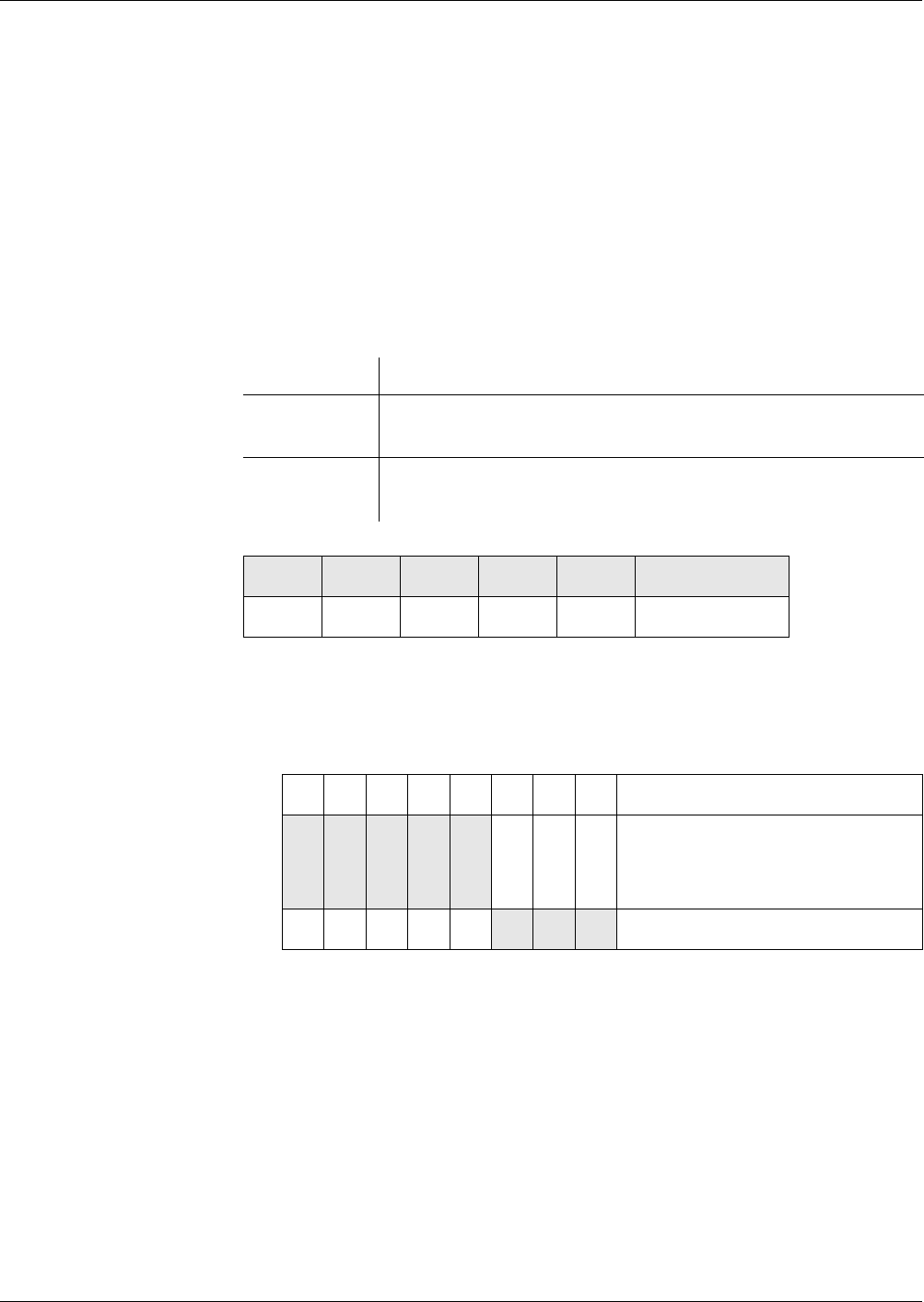
Commands
UPDATE RECORD
362 Reference Manual STARCOS® 3.0/Edition 06/2005
ID No. 30016255
UPDATE RECORD
The command UPDATE RECORD is used to overwrite one record of an EF
with linear or cyclic record structure. P1 specifies the record to be overwritten
and P2 the corresponding EF. The length of the record/element is specified in
Lc.
Notes The record must be created previously with the command APPEND
RECORD.
If the memory area allocated to the EF is not sufficient for the record to
be written, the command UPDATE RECORD is aborted.
Rule
Command
P1 – Record number
P1 ≠ ’00’ and
P1 ≠ ’FF’
P2 – Reference control byte
Lc – Record/element length
EF with linear fixed structure Lc = maximum defined length
EF with linear variable structure Lc ≤ maximum defined length
EF with cyclic structure Lc = maximum defined length
DATA
Record data to be written
Execution Mandatory
Access from ARR in the ARR data object of the file control information
template of the EF to be accessed
Evaluation SE# of the security environment from the DF of the current
EF
CLA INS P1 P2 LcDATA
’0X’ ’DC’
b8 b7 b6 b5 b4 b3 b2 b1 Description
0
X
0
X
0
X
0
X
0
X
File selection:
Currently selected EF
SFI (’01’ - ’1E’)
100 Referencing by RN


Commands
VERIFY
364 Reference Manual STARCOS® 3.0/Edition 06/2005
ID No. 30016255
VERIFY
With the command VERIFY, a user authenticates himself to the smart card by
entering a password. Upon correct entry of the password, a security state is set
which indicates the successful authentication.
In addition, with the command VERIFY, the KFPC of a password can be read
out. The command VERIFY returns only the status byte with the number of at-
tempts as the answer.
Command Sequence The following steps are performed in the execution of the command VERIFY:
– The parameters
– global or DF-specific password (bit b8 from P2),
– password number x (bits b1 - b3 from P2),
– current DF,
and the password search algorithm are used to find the password-number
relevant DF which is referenced by the command VERIFY (see
page 187).
– Which transmission format has been specified for the password is deter-
mined from the SE data object. The SE data object is defined for the ac-
tive SE of the DF in which the password is found.
– The defined transmission format and defined storage format must be con-
sistent. Both formats must be either a PIN format or a password format.
– The length of the PIN or password must match the length prescribed by
the storage format. The length is stored in the first byte of the record of
EF_PWD which also contains the associated PIN or the password.
– The initial value of the KFPC must be equal or greater than the associated
KFPC. The initial value and the associated KFPC are stored in a record
of EF_RC.
– The defined transmission format must be consistent with the values spec-
ified in P2.
– The format of DATA is checked according to the transmission format and
converted into the storage format (for format descriptions see page 366
onwards).
– The KFPC assigned to the password is decremented by 1 before the pass-
word is verified.
– The previously determined length L of the PIN or password must match
the actual length in the first byte of the record in EF_PWD.
– If a reference value was created previously, it must match the reference
value stored in EF_PWD.

Commands
VERIFY
Reference Manual STARCOS® 3.0/Edition 06/2005 365
ID No. 30016255
– The password number is entered into the card holder authentication list
which is assigned to the DF relevant to the password number (see ’Secu-
rity States’ on page 68).
The KFPC assigned to the password in the associated EF_RC is set to the
initial value contained in EF_RC.
– If the length of the stored value is not correct, the password number is de-
leted from the card holder authentication list. The KFPC is not incre-
mented.
Notes The status bytes SW1/SW2 return the number of retries are allowed for a
password without attempting a verification (’63 CX’, X = number of re-
tries allowed).
When only the KFPC is read out, the security states are not set or deleted.
The command VERIFY does not support EMV-PIN RSA encryption of
command data. Bit 4 of P2 must be 0.
Rule Execution Mandatory
Access from ARR in the ARR data object which is contained in an ARR
data object in the previously found additional password in-
formation.
Evaluation The evaluation depends on the position of the ARR data ob-
ject from the additional information:
– If it precedes the first SE data object, this SE data object
needs to be evaluated using the SE# of the security en-
vironment which is active in the DF relevant to the
password number.
– If no preceding ARR data object exists, an SE data ob-
ject having the SE# of the security environment which
is active in the DF relevant to the password number
needs to be selected first. The evaluation is performed
as described in the ARR Data Object section (see
page 178).
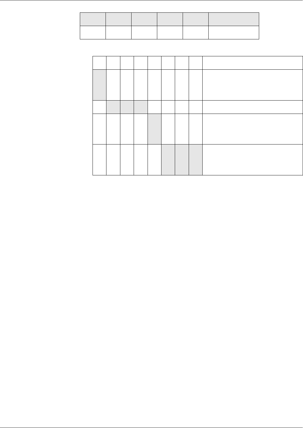
Commands
VERIFY
366 Reference Manual STARCOS® 3.0/Edition 06/2005
ID No. 30016255
Command
P2 – Reference control byte for password
DATA
Password in one of the following transmission formats
Format 2 PIN Block Prerequisites:
–L
c = ’08’
– DATA must be coded in format 2 PIN block (see page 176).
Sequence:
– The length L of the PIN is obtained from the second half-byte of the PIN
block.
Format 1 PIN Block Prerequisites:
–L
c = ’08’
– DATA must be coded in format 1 PIN block (see page 185).
Sequence:
– The length L of the PIN is obtained from the second half-byte of the PIN
block
– In the format 1 PIN block, the control field and the random digits are re-
placed in such a way that the format 2 PIN block is created.
CLA INS P1 P2 LcDATA
’0X’ ’20’ ’00’
b8 b7 b6 b5 b4 b3 b2 b1 Description
0
1
Password type:
Global
DF-specific password
000or RFU
0
1
Transmission format:
Plain text
Cryptogram encipherment
X X X
Password access:
Binary-coded password number
(0 - 7) (PWD_ID)

Commands
VERIFY
Reference Manual STARCOS® 3.0/Edition 06/2005 367
ID No. 30016255
PIN – BCD-Coded Prerequisite:
– DATA, except the last half-byte, must be BCD-coded. The last half-byte
either must have the value ’F’ or must also be BCD-coded.
Sequence:
– The length L of the PIN is calculated as follows:
Last half-byte of DATA = BCD-coded L = 2*Lc
Last half-byte of DATA = ’F’ L = 2*Lc-1.
– The BCD-coded PIN is converted into a format 2 PIN block, DES enci-
phered with itself to form a reference value of 8 bytes length and buffered
together with the length L.
PIN – ASCII-Coded Prerequisite:
– The DATA bytes must contain values between ’30’ and ’39’.
Sequence:
– The length L of the PIN is calculated:
L = Lc.
Password – ASCII-
Coded
Prerequisite:
–L
c ≤ ’08’
Sequence:
– The length L of the password is calculated: L = Lc.
– The ASCII-coded password is padded with ’00’ to 8 bytes, if required.
– The result is DES enciphered with itself to form a reference value of 8
bytes length and buffered together with the length L.
Response
Status Bytes For warnings and error messages see ’Status Bytes’ from page 269 onwards.
SW1 SW2
’90’ ’00’

Commands
VERIFY CERTIFICATE
368 Reference Manual STARCOS® 3.0/Edition 06/2005
ID No. 30016255
VERIFY CERTIFICATE
The command VERIFY CERTIFICATE is a subcommand of the com-
mand PERFORM SECURITY OPERATION.
The command VERIFY CERTIFICATE only applies to RSA keys and
RSA-based certificates.
Using the command VERIFY CERTIFICATE a certificate is verified with a
public key and stored in the smart card.
Command Sequence The following steps are performed in the execution of the command VERIFY
CERTIFICATE:
– The key to be used is selected through a key reference which is stored in
volatile or non-volatile memory in the active SE of the current DF.
– The SE is checked to determine whether it contains a DST with UQ =
’80’ and a key reference with the tag = ’83’ as well as an algorithm ID,
also DST with UQ = ’80’.
– The parameters
– search identifier,
– key number KID,
– key version KV, KV ≠ ’FF’,
– key type (public),
– current DF,
and the key search algorithm are used to find the additional information
for the referenced key (see page 141 and see page 143).
– The key that was last generated for the key reference is identified through
the key search algorithm.
– The public key found is checked to determine whether and how it may be
used in the active SE of the key-group relevant DF.
This is done by performing an analysis of the SE data object. If an algo-
rithm ID has been selected, it will be used in the search.
– For a certificate key, a DST is searched for.
– The algorithm ID in the found DST specifies how the command VERIFY
CERTIFICATE may access the key by using the assigned security algo-
rithm.

Commands
VERIFY CERTIFICATE
Reference Manual STARCOS® 3.0/Edition 06/2005 369
ID No. 30016255
The following steps are performed in the execution of the signature pro-
cesses:
– The smart card evaluates EF_CERT for the recovered certificate.
EF_CERT with the file ID ’00 19’ must be located in the key-group rel-
evant DF of the certificate key found.
– After the signature of the certificate and, if available, the public key re-
mainder have been passed to the smart card, the smart card verifies the
signature.
For this purpose, the smart card computes the hash value on the recov-
ered certificate contents by using the hash algorithm that is assigned to
the certificate key.
– The key fault presentation counter, if provided, of the certificate key is
decremented if the signature verification fails, even if the command
VERIFY CERTIFICATE was aborted during or after the verification.
– The usage counter of the certificate key, if provided, is decremented in
the signature verification, even if the command VERIFY CERTIFICATE
was aborted during or after the verification.
– When analyzing the certificate contents, the smart card searches the
records of EF_CERT for the certificate information that is to be evalu-
ated.
– The smart card analyzes the record of EF_CERT, which contains the SE
data object found. The record must contain a header list data object with
the tag ’4D’ and the header list must be coded correctly (see page 121).
– The length of the certificate contents must correspond to the header list.
When the length of the certificate contents is correct, the data elements
which make up the certificate contents are declared and implicitly pro-
vided with a tag and a length.
– If the header list specifies that the certificate contents contain a CAR, the
CAR must match the key name of the certificate key.
Evaluation of the IF
Data Object
– The smart card analyzes the found SE data object with the certificate in-
formation. The SE reference data object contained must be followed by
at least one IF-THEN data object with the tag ’E0’.
– The IF-THEN data objects from the certificate information are analyzed
successively from left to right.
The analysis process checks whether an IF-THEN data object contains an
IF data object with the tag ’E1’.
– If the IF data object contains a data object with the tag ’83’, the KID and,
if applicable, the KV of the certificate key are checked for compliance
with the specified KID and, if applicable, KV.
If they do not comply, the next IF-THEN data object in the certificate in-
formation is evaluated.

Commands
VERIFY CERTIFICATE
370 Reference Manual STARCOS® 3.0/Edition 06/2005
ID No. 30016255
– If the IF data object contains a certificate data object, a check determines
whether it is correctly coded and whether the data elements in the con-
tained data objects match the corresponding data elements in the certifi-
cate contents.
If this is not the case, the next IF-THEN data object in the certificate in-
formation is evaluated.
Evaluation of the THEN
Data Object
– If the specified certificate key is used and/or all data elements comprised
in the certificate data object are correctly provided in the certificate con-
tents, the THEN data object is evaluated.
The THEN data object must contain a data object with tag = ’83’ and
length = ’02’ as the first data object.
– The two bytes KID and KV are obtained from the key reference data ob-
ject with the tag ’83’, which is contained in the THEN data object.
– The EF_KEYD of the DF to which the certificate key is assigned is
checked for a key reference data object with the tag ’83’ or ’93’, the KID
and the KV.
Evaluation of the
EF_KEYD Entry for the
Volatile Key
– The EF_KEYD of the DF is checked for a file ID of ’00 00’.
– If additional information which is referenced by KID and KV is found in
EF_KEYD, this information is analyzed as described below. If the infor-
mation contains an empty key name data object and empty data objects
for key components, they are volatile padded:
– If the additional information contain an empty key name data object,
the AI must contain a CHR.
An existing CHR is stored in volatile memory as a key name of cor-
rect length.
An assignment between the key name and the key reference is stored
in the DF to which the key to be stored in volatile memory is as-
signed.
To make this assignment, ’00’ is entered as the search identifier into
the key reference if the key to be volatile stored is assigned to the
MF; otherwise, ’80’ is entered.
– If the additional information do not contain a key name data object
or if it contains key name data object that is not empty, a CHR con-
tained in the AI is ignored.
– The structure data object must have a tag ’DX’.

Commands
VERIFY CERTIFICATE
Reference Manual STARCOS® 3.0/Edition 06/2005 371
ID No. 30016255
– The value field of the structure data object contains exactly those
tags of the length ’00’ which are contained in the tag ’7F 49’ of the
header list.
The tag ’81’ always needs to be contained in the tag ’7F 49’, whereas
the tag ’82’ may be missing.
If the tag ’82’ does not occur in the tag ’7F 49’ of the header list, the
structure data object must contain the tag ’83’ or ’84’ of the length
’00’. The reason is that a public exponent cannot be specified in any
other way.
– The lengths of the corresponding key components from the header
list are volatile entered.
– After the additional key components have been volatile padded, the key
components of the public key from the certificate are stored in volatile
memory together with the volatile additional information.
– If the certificate key used is a volatile stored key, it will be deleted to-
gether with its volatile stored additional information.
Notes The command VERIFY CERTIFICATE can only be used for certificates
with message recovery. The contents of these certificates consist of con-
catenated data elements and their structure is identified by a CPI in the
first byte(s) of the certificate contents (see page 109).
If part of a certificate cannot be recovered from the certificate signature,
this non-recoverable part must be passed to the smart card in an addi-
tional data object. This non-recoverable part is referred to as the public
key remainder.
The command VERIFY CERTIFICATE can be used with command
chaining. Passing the data objects requires maximum 2 subcommands.
INS, P1, P2 and the right half-byte of CLA must be identical in the two
subcommands. For details on the command chaining rules see page 267.
Only the signature method for including a public key with certificate ver-
ification (see page 415) is permitted for the command VERIFY CERTIF-
ICATE.
Rule Execution Mandatory
Access from ARR in the ARR data object of the additional information of
the certificate key
Evaluation SE# of the security environment from the DF to which the
found key is assigned
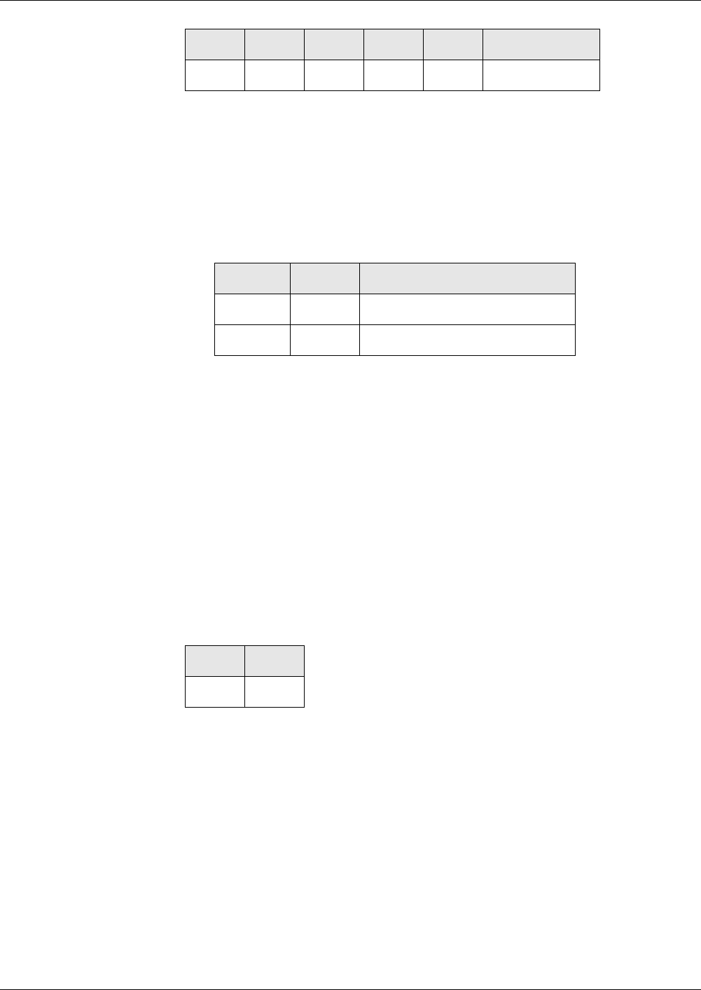
Commands
VERIFY CERTIFICATE
372 Reference Manual STARCOS® 3.0/Edition 06/2005
ID No. 30016255
Command
CLA
’0X’ CLA for last subcommand
’1X’ CLA for first subcommand
Lc – Total length L of the data objects in DATA,
Lc ≤ 255
DATA
Data objects for certificate verification
Data object with tag ’5F 37’:
N = Byte length of the modulus of the certificate key and
N ≤ 251 bytes
Integer of the signature from the binary representation < integer of the
modulus of the public key to be used
DATA without
Command Chaining
Data object may contain the certificate signature along (tag = ’5F 37’) or
together with the public key remainder (Tag = ’5F 38’).
The public key remainder alone is not permitted.
DATA with Command
Chaining
1st subcommand (tag = ’5F 37’) contains certificate signature
2nd subcommand (tag = ’5F 38’) contains public key remainder
Response
Status Bytes For warnings and error messages see ’Status Bytes’ from page 269 onwards.
CLA INS P1 P2 LcDATA
’2A’ ’00’ ’AE’
T L V
’5F 37’ N Certificate signature
’5F 38’ Variable Public key remainder
SW1 SW2
’90’ ’00’

Commands
VERIFY DIGITAL SIGNATURE
Reference Manual STARCOS® 3.0/Edition 06/2005 373
ID No. 30016255
VERIFY DIGITAL SIGNATURE
The command VERIFY DIGITAL SIGNATURE is a subcommand of the
command PERFORM SECURITY OPERATION.
The command VERIFY DIGITAL SIGNATURE is used by the smart card to
verify a digital signature. The smart card requires the following data for this
purpose:
– A hash value which was passed with the command HASH.
– The signature to be verified.
– A public key.
Command Sequence The following steps are performed in the execution of the command VERIFY
DIGITAL SIGNATURE:
– The key to be used is selected through a key reference which is stored in
volatile or non-volatile memory in the active SE of the current DF.
– The SE is checked to determine whether it contains a DST with UQ =
’80’ and a key reference with the tag = ’83’ as well as an algorithm ID.
– The parameters
– search identifier,
– key number KID,
– key version KV = key reference,
KV = ’FF’: no search for a specific KV in the additional information,
– key type (public),
– current DF,
and the key search algorithm are used to find the additional information
for the referenced key (see page 141 and see page 143).
– The key that was last generated for the key reference is identified through
the key search algorithm.
– The public key found is checked to determine whether and how it may be
used in the active SE of the key-group relevant DF.
This is done by performing an analysis of the SE data object. If an algo-
rithm ID has been selected, it will be used in the search.
– For a directly usable key, a DST is searched for.
– The algorithm ID in the found CT indicates that the command VER-
IFY DIGITAL SIGNATURE uses an RSA algorithm for the key.

Commands
VERIFY DIGITAL SIGNATURE
374 Reference Manual STARCOS® 3.0/Edition 06/2005
ID No. 30016255
The following steps are performed in the execution of the signature pro-
cesses:
– The smart card verifies whether a hash value of the correct length has
been buffered. This hash value must have been computed using the hash
algorithm specified by the algorithm ID.
– The signature is verified with the public key.
This is done by comparing the buffered hash value with the hash value
obtained from the signature.
When verifying a signature with PKCS #1, the OID of the hash function
with which the stored hash value was computed must be used for the ver-
ification.
– The key fault presentation counter, if provided, of the public key is dec-
remented if the signature verification fails, even if the command VERIFY
DIGITAL SIGNATURE was aborted during or after the verification.
– The usage counter, if provided, of the public key is decremented in the
signature verification, even if the command VERIFY DIGITAL SIGNA-
TURE was aborted during or after the verification
Note for RSA Only signature methods complying with the specification (see page 401)
as well as PKCS #1 (see page 403) are permitted for the command VER-
IFY DIGITAL SIGNATURE.
Notes for ECC The following applies for the ECDSA procedure:
Bit length of the order of the generator point of the curve > bit length of
the hash algorithm to be used
Length of the key for the signature calculation ≥ maximum bit length of
the hash
The following must apply for the signature (r, s)
0 < r, s < n, n = order of the generator point
The components of the signature (r, s) are each filled with 0-bits to the
byte length of the generator point. For this, the following applies:
r’ = padded r component
s’ = padded s component
r’ || s’ = output signature
The command VERIFY DIGITAL SIGNATURE is assigned the algorithm
ID 1335 with the variations 133510 and 133520.
Rule Execution Mandatory
Access from ARR in the ARR data object of the key’s additional informa-
tion
Evaluation SE# of the security environment from the DF to which the
found key is assigned

Commands
VERIFY DIGITAL SIGNATURE
Reference Manual STARCOS® 3.0/Edition 06/2005 375
ID No. 30016255
Command
Lc – Total length L of the data object in DATA,
Lc ≤ 255
DATA for RSA
Data object for signature verification
N = Byte length of the modulus of the certificate key and
N ≤ 252 bytes
Integer of the signature from the binary representation < integer of the
modulus of the public key to be used
DATA for ECC
’XX ... XX’ Data objects for signature verification
’9E’ || Length of signature || Signature (r || s)
Response
Status Bytes For warnings and error messages see ’Status Bytes’ from page 269 onwards.
CLA INS P1 P2 LcDATA
’0X’ ’2A’ ’00’ ’A8’
T L V
’9E’ N Signature
SW1 SW2
’90’ ’00’


Reference Manual STARCOS® 3.0/Edition 06/2005 377
ID No. 30016255
Appendix
The appendix describes different cryptographic algorithms, MAC creation,
different signature procedures, padding and algorithm IDs.
Furthermore the appendix contains a glossary of terms and abbreviations used
as well as the index which facilitate using the manual.

Appendix
Cryptographic Algorithms
378 Reference Manual STARCOS® 3.0/Edition 06/2005
ID No. 30016255
Cryptographic Algorithms
Survey STARCOS® 3.0 supports the following cryptographic algorithms:
– DES and Triple-DES (see page 379)
– RSA (see page 383)
– Hash algorithms (see page 391):
–SHA-1
– RIPEMD-160
– MAC creation (see page 392):
– Simple MAC
–Retail MAC
– Signature procedures (see page 395):
– Signature procedure according to ISO 9796-2
– Signature procedure according to DINSIG
– Signature procedure according to PKCS#11

Appendix
DES and Triple-DES Algorithms
Reference Manual STARCOS® 3.0/Edition 06/2005 379
ID No. 30016255
DES and Triple-DES Algorithms
STARCOS® uses DES and Triple-DES keys for the symmetric encryption.
They are referred to as secret or symmetric keys. The same key is used both
for the encryption and the decryption.
DES Prerequisite:
– Plain text blocks x, 8 bytes
– Code text blocks y, 8 bytes
– DES keys K, 8 bytes
Notation DES encryption: eK(x)
DES decryption: dK(y)
For each block of 8 bytes the following applies:
eK(dK(x)) = dK(EK(x)) = x
Triple-DES Prerequisite:
– Plain text blocks x, 8 bytes
– Code text blocks y, 8 bytes
– Triple-DES key K, 16 bytes
Notation Triple-DES encryption: e*CSK(x)
Triple-DES decryption: d*CSK(y)
The triple-DES consists of a threefold application of the basic DES routine. If
CSKl refers to the left and CSKr to the right half of the key CSK with is twice
the length, the following applies to the procedure:
e*CSK(x) = eCSKl(dCSKr(eCSKl(x)))
d*CSK(y) = dCSKl(eCSKr(dCSKl(y)))
For each block of 8 bytes x the following applies:
e*CSK(d*CSK(x)) = d*CSK(e*CSK(x)) = x
Triple-DES Dynamic
Key
In case of this algorithm, the triple-DES key dynamizes with a random num-
ber.
Prerequisite:
– Triple-DES key CSK, 16 bytes
– Random number RND = RND0 || ... || RND7, 8 bytes
calculation The dynamized triple-DES key is calculated without padding.
DCSK = DCSKL || DCSKR, 16 bytes
The following applies to the left and right half of the key:
–DCSK
L =
e*CSK(RND0 || RND1 || ’F0’ || RND3 || RND4 || RND5 || RND6 || RND7)

Appendix
DES and Triple-DES Algorithms
380 Reference Manual STARCOS® 3.0/Edition 06/2005
ID No. 30016255
–DCSK
R =
e*CSK(RND0 || RND1 || ’0F’ || RND3 || RND4 || RND5 || RND6 || RND7)
notation Dynamic key with random number for triple-DES:
DCSK(RND)
DES and Triple-DES
Encryption
In order to ensure the confidence of data, STARCOS® supports the following
en-/decryption:
– DES CBC mode
– Triple-DES CBC mode
– Triple-DES CBC mode with dynamized key
– DES/Triple-DES CBC mode with ICV encryption
An ICV encryption will be possible only if the key is not dynamic.
DES CBC Mode Prerequisite:
– K key, 8 bytes
– ICV (Initial Chaining Value), 8 bytes
– Message x
x1 || ... || xn the message x is divided into blocks of 8 bytes xi.
A message length, which is a multiple of 8 bytes, is obtained by padding.
encryption The encryption with DES in the CBC mode is recursively defined as follows:
y0 = ICV
yi = eK(yi-1 XOR xi) for i = 1,...,n
decryption y1 || ... || yn refers to the code text blocks, which belong to the message.
The reverse order shall be used for decryption:
y0 = ICV
xi = dK(yi) XOR yi-1 for i = 1,...,n
notation – DES CBC mode encryption:
eK(ICV,x)
– DES CBC mode decryption:
dK(ICV,y)
The following applies:
eK(ICV,dK(ICV,x)) = dK(ICV,eK(ICV,x)) = x
Triple-DES CBC Mode Prerequisite:
– CSK key, 16 bytes
– ICV, 8 bytes
– Message x.

Appendix
DES and Triple-DES Algorithms
Reference Manual STARCOS® 3.0/Edition 06/2005 381
ID No. 30016255
en-/decryption The triple-DES CBC mode en-/decryption is implemented analogous to the
one used for the DES in the CBC mode. The CSK key having twice the length
is used instead of the K key with simple length.
notation – Triple-DES CBC mode encryption:
e*CSK(ICV,x)
– Triple-DES CBC mode decryption:
d*CSK(ICV,y)
The above mentioned relations used for the simple DES in the CBC mode
shall be applied analogously.
Triple-DES CBC mode with
Dynamized Key
Prerequisite:
– CSK key, 16 bytes
– ICV, 8 bytes
– Message x.
en-/decryption First, the CSK key is dynamically transferred from ICV to DKK (for dynam-
ized key, see page 379).
Afterwards, the en-/decryption is implemented analogously to the simple tri-
ple-DES CBC mode en-/decryption.
The triple-DES CBC mode en-/decryption is implemented analogously to the
one used for the DES in the CBC mode. The dynamized key, DKK, is used in-
stead of the CSK key which has twice the length. For this purpose, ICV = 0
applies.
notation – Triple-DES CBC mode encryption with dynamized key:
e*DKK(ICV)(0,x)
– Triple-DES CBC mode decryption with dynamized key:
d*DKK(ICV)(0,y)
DES/triple-DES CBC Mode
with ICV Encryption
The encryption of the ICV prevents the ICV from any manipulation during
the transfer between the sender and recipient. Thus, the result of the en-/de-
cryption of the first message block cannot be influenced.
Prerequisite:
– Sender and recipient of an enciphered message must know the ICV used.
en-decryption During the encryption, the ICV to be transferred will be enciphered in the first
place, following an XOR operation with the first message block. The further
procedure is analogous to the triple-DES CBC mode en-/decryption.
notation for DES CBC mode – DES CBC mode encryption with ICV encryption:
eK(ICV,x)

Appendix
DES and Triple-DES Algorithms
382 Reference Manual STARCOS® 3.0/Edition 06/2005
ID No. 30016255
– DES CBC mode decryption with ICV encryption:
dK(ICV*,y)
notation for triple-DES CBC
mode
– Triple-DES CBC mode encryption with ICV encryption:
e*CSK(ICV*,x)
– Triple-DES CBC mode decryption with ICV encryption:
d*CSK(ICV*,y)

Appendix
RSA Algorithms
Reference Manual STARCOS® 3.0/Edition 06/2005 383
ID No. 30016255
RSA Algorithms
STARCOS® uses an odd public exponent for the encryption of the RSA key
pair.
The smart card uses an RSA key pair both for the en-/decryption and for the
creation of the signature as well as for the recovery of the plain text.
Key Components The key pair consists of the following components:
– Public and private exponent
– Modulus
– Public and private key: PK and SK
Public and Private
Exponent
Two different prime numbers, p and q (prime factors) are used for the creation
of the RSA key pair with an odd public exponent, e, for which e is relatively
prime to (p-1) and (q-1).
The following applies to the corresponding private exponent d:
e*d ≡ 1 mod kgV(p-1, q-1).
The prima numbers, p and q, as well as the private exponent, d, must be
kept secret.
Modulus The product of the prime numbers, n = p*q, is described as modulus.
Public Key The public key PK of the RSA key pair consists of the components:
– Modulus n
– Public exponent e
Private Key The private key SK can be described by one of the following representations:
– Representation of SK by the components:
– Modulus n
– Private exponent d
Only the component d must be kept secret for the 1st representation.
– Representation by CRT parameters:
– Prime factor p
– Prime factor q
–d
p = d mod (p-1)
–d
q = d mod (q-1)
– qInv = q-1 mod p

Appendix
RSA Algorithms
384 Reference Manual STARCOS® 3.0/Edition 06/2005
ID No. 30016255
The components are summarized as Chinese Remainder Theorem-Pa-
rameter (CRT-Parameter).
All CRT parameters must be kept secret.
Notation The following notations shall be applied to the length of bits and bytes of the
modulus.
bit length k k refers to the bit length of the modulus n of an RSA key pair.
k is clearly defined by the equation:
2k-1 ≤ n < 2k.
n is the series of bits n = bk bk-1 ... b1, for which bk ≠ 0 applies.
The following applies to the value n as whole number:
first left bit bk = highest-order bit and
last right bit b1 = lowest-order bit in the binary representation of n
bit series n Unambiguous numbers, N ≥ 1 and 8 ≥ r ≥ 1 with k = 8*(N-1) + r exist for k.
Therefore, n can be expressed as series of bits:
n = br br-1 ... b1 b8*(N-1) ... b8*(N-2)+1 ... b8 ... b1.
If r = 8, n can directly be represented as series of N bytes:
n = BN BN-1 ... B1, for which BN ≠ ’00’ applies.
If r < 8, 8-r binary 0
of the bit series br br-1 ... b1 b8*(N-1) ... b8*(N-2)+1 ... b8 ... b1 serve as prefix:
n = 0 ... 0 br br-1 ... b1 b8*(N-1) ... b8*(N-2)+1 ... b8 ... b1.
and a series of bytes will be obtained again
n = BN BN-1 ... B1, for which BN ≠ ’00’ applies.
The integer value of n is not changed by leading zeros in the binary represen-
tation, so that the presentation of n as a result of N bytes leaves the number
value, which is represented as series of k bits, unchanged.
byte length N N refers to the byte length of n.
N is clearly defined by the equation 28*(N-1) ≤ n < 28*N.
En-/ and Decryption For the encryption a binary-coded series of bytes is encoded by means of a
public RSA key. During the decryption, this series of bytes is decoded with
the help of the corresponding private key.
Encryption Prerequisite:
– Public RSA key PK
– Modulus n
– Odd public exponents e

Appendix
RSA Algorithms
Reference Manual STARCOS® 3.0/Edition 06/2005 385
ID No. 30016255
execution Binary -coded series of bytes x are enciphered by PK.
The integer value of the byte series resulting from the binary representation of
x ranges between 0 and n-1.
Thus, x can be represented as a
– series of bytes with N bytes
– series of bits with k bits
for which
– k bit = 1, not compulsory
–bits b
8*N ... bk+1 = 0, if available
notation enc(PK)[x] = xe mod n
For this purpose, the exponentiation xe mod n is effected with the whole num-
ber, whose value results from the binary representation of x.
result The result of the encryption is a cryptogram with the byte series c, which re-
sults from the binary representation of the integer value of the exponent xe
mod n.
The integer value of x e mod n ranges between 0 and n-1.
Therefore, the cryptogram can be represented as a
– series of bytes with N bytes
– series of bits with k bits,
for which
– k bit = 1, not compulsory
–bits b
8*N ... bk+1 = 0, if available
Decryption Prerequisite:
– Bytes series c with a value ranging between 0 and n-1 that results from
the binary representation
– Private key SK belonging to PK and consisting of the modulus n and the
private exponent d
notation – For private key consisting of the modulus n and the private exponent d:
dec(SK)[c] = cd mod n
– For private key consisting of CRT parameters:
dec(SK)[c] = x2 + h*q
for which x2 and h are calculated as follows:
x1 =cdp mod p
x2 =cdq mod q
h = qInv*(x1 - x2) mod p.

Appendix
RSA Algorithms
386 Reference Manual STARCOS® 3.0/Edition 06/2005
ID No. 30016255
For this purpose, the whole number, whose value results from the binary
representation of c, is used for the exponentiations cd mod n, cdp mod p
and cdq mod q.
– For an RSA key pair PK and SK:
dec(SK)[enc(PK)[x]] = xed mod n = x
result The result of the decryption is a plain text with a series of bytes, which results
from the binary representation of the integer value of the exponent cd mod n
and/or. from x2 + h*q.
The integer value ranges between 0 and n-1.
Thus, the plain text can be represented as a
– series of bytes with N bytes
– series of bits with k bits.
for which
– k bit = 1, not compulsory
–bits b
8*N ... bk+1 = 0, if available
Standard Signature The signature algorithm consists of an algorithm for the creation of the signa-
ture and an algorithm inversive to that signature used for the recovery of the
plain text. STARCOS® supports the signature algorithms of the standard vari-
ant and the RSA variant (for signature algorithm according to ISO 9796, see
page 388).
The signature procedures used for the series of bytes that are applied in the
creation of the signature are described in the chapter ’Signature Procedure’
from page 395 onwards.
Creation of Standard
Signatures
Prerequisite:
– Private RSA key SK consisting of
– modulus n and private exponent d
or
CRT parameters
– Public RSA key PK consisting of
– modulus n and public exponent e
execution Binary-coded series of bytes, x are signed with the help of SK.
The integer value of the series of bytes resulting from the binary representa-
tion of x ranges between 0 and n-1.
Thus, x can be represented as a
– series of bytes with N bytes
– series of bits with k bits
for which

Appendix
RSA Algorithms
Reference Manual STARCOS® 3.0/Edition 06/2005 387
ID No. 30016255
– k bit = 1, not compulsory
–bits b
8*N ... bk+1 = 0, if available
notation – For the signature with private key consisting of the modulus n and the
private exponent d:
sign(SK)[x] = xd mod n
– For the signature with private key consisting of CRT parameters:
sign(SK)[x] = s2 + h*q
for which s2 and h are calculated as follows:
s1 =xdp mod p
s2 =xdq mod q
h = qInv*(s1 - s2) mod p.
For this purpose, the whole number, whose value results from the binary
representation of x, is used for the exponentiations xd mod n, xdp mod p,
xdq mod q.
result The result of the signature creation is a series of bytes s, which results from
the binary representation of the integer value of the exponent xd mod n and/or
from s2 + h*q.
The integer value ranges between 0 and n-1.
Therefore, s can be represented as a
– series of bytes with N bytes
– series of bits with k bits.
for which
– k bit = 1, not compulsory
–bits b
8*N ... bk+1 = 0, if available
Standard Plain Text
Recovery
Prerequisite:
– Public RSA key PK consisting of
– modulus n and public exponents e
execution With the help of PK, the plain text will be recovered from a binary-coded se-
ries of bytes s if the integer value resulting from the binary representation
ranges between 0 and n-1.
Thus, s can be represented as a
– series of bytes with N bytes
– series of bits with k bits
for which
– k bit = 1, not compulsory

Appendix
RSA Algorithms
388 Reference Manual STARCOS® 3.0/Edition 06/2005
ID No. 30016255
–bits b
8*N ... bk+1 = 0, if available
notation – recover(PK)[s] = se mod n
The whole number, whose value results from the binary representation of
s, is used for the exponentiation se mod n.
– For an RSA key pair PK and SK:
recover(PK)[sign(SK)[x]] = x
result The result of the plain text recovery is a whole number.
The integer value ranges between 0 and n-1.
Thus, the plain text can be represented as a
– series of bytes with N bytes
– series of bits with k bits.
for which
– k bit = 1, not compulsory
–bits b
8*N ... bk+1 = 0, if available
Signature Algorithm
according to ISO 9796-
2
The signature algorithms based on the RSA algorithm (signature algorithm
according to ISO 9796) are only used by the smart card within the scope of
the signature procedure (see ’Signature Procedure’ on page 395).
The signature procedures, which are used for the series of bytes applied in the
creation of the signature, are described in the chapter ’Signature Procedure’
from page 395 onwards.
Creation of Signature
According to ISO 9796-
2
Prerequisite:
– Private RSA key SK with modulus n
execution At the beginning, the procedure is the same as with the standard creation of
signature. In addition, a further step guarantees that the result of the creation
of signature is < n/2.
With the help of SK, binary-coded series of bytes x will be signed if:
– the integer value of the series of bytes, which results from the binary rep-
resentation of x, ranges between 2(k-2) and 2(k-1) -1.
Thus, x can be represented as a
– series of bytes with N bytes
– series of bits with (k -1) bits
for which
– (k - 1)-th bit = 1
k bit = 0
–bits b
8*N ... bk+1 = 0, if available

Appendix
RSA Algorithms
Reference Manual STARCOS® 3.0/Edition 06/2005 389
ID No. 30016255
– the lowest-order half-byte of x = ’C’
An integer value y is calculated for the creation of signature just as with the
standard creation of signature:
y = sign(SK)[x]
The resulting integer y ranges between 0 and n-1.
notation – For y < n/2: sign*(SK)[x] = y
– For y > n/2: sign*(SK)[x] = n - y
The following connection exists between sign and sign*:
– For (SK)[x] < n/2: sign*(SK)[x] = sign(SK)[x]
– For (SK)[x] > n/2: sign*(SK)[x] = n - sign(SK)[x]
result The result of the creation of signature is a series of bytes s, which derives
from the binary representation of the integer value of y and of n-y respec-
tively.
The integer value ranges between 0 and n/2.
Thus, s can be represented as a
– series of bytes with N bytes
– series of bits with k bits
for which
– k bit = 0
(k - 1)-th bit = 1, not compulsory
–bits b
8*N ... bk+1 = 0, if available
Recovery of Plain Text
According to ISO 9796-
2
Prerequisite:
– Public RSA key PK with modulus n
execution With the help of PK, a plain text will be recovered from a series of bytes s if
the integer value resulting from the binary representation of s ranges between
0 and the biggest whole number below n/2.
Thus, s can be displayed as a
– series of bytes with N bytes
– series of bits with k bits
for which
– k bit = 0
(k - 1)-th bit = 1, not compulsory
–bits b
8*N ... bk+1 = 0, if available

Appendix
RSA Algorithms
390 Reference Manual STARCOS® 3.0/Edition 06/2005
ID No. 30016255
The plain text recovery according to ISO 9796-2 will refuse a series of
bytes s if its integer value, which results from the binary representation,
is > n/2.
The whole number z is calculated in the same way as with the standard plain
text recovery:
z = recover(PK)[s]
notation – if the lowest-order half-byte of z = ’C’:
recover*(PK)[s] = z
– if the lowest-order half-byte of n - z = ’C’:
recover*(PK)[s] = n - z
The following applies to a private RSA key SK and a series of bytes x:
–If x
d < n/2: (sign*(SK)[x])e = xde = x mod n
–If x
d > n/2: (sign*(SK)[x])e = (n-xd )e = n - xde = n - x mod n
Provided that for the integer values a and the odd values e the following
applies:
(n-a)e = n - ae mod n
Additionally, if n = odd the following applies:
lowest-order half-byte of n - x ≠ ’C’ and
lowest-order half-byte of x = ’C’
The following applies to an RSA key pair PK and SK:
recover*(PK)[sign*(SK)[x]] = x.
For recover* the following applies:
– sign(SK)[x] > n/2:
recover* refuses sign(SK)[x] > n/2 as input.
– sign(SK)[x] < n/2:
recover*(PK)[sign(SK)[x]] = x
result The result of the plain text recovery is a series of bytes, which results from the
binary representation of the integer value of z or n-z.
The integer value ranges between 0 and n - 1.
Thus, the plain text can be represented as a
– series of bytes with N bytes
– series of bits with k bits
for which
– k bit = = 1, not compulsory
–bits b
8*N ... bk+1 = 0, if available

Appendix
Hash Algorithms
Reference Manual STARCOS® 3.0/Edition 06/2005 391
ID No. 30016255
Hash Algorithms
A Hash algorithm creates bit strings of any length (input bit string) on byte se-
ries with a fix length that has been determined by the hash algorithm. The re-
sult of the application of a hash algorithm on a series of bytes is referred to as
hash value.
The cryptographic HASH operation and the signature procedures of the smart
card can be executed by the following hash algorithms:
–SHA-1
– RIPEMD-160
SHA-1 The hash algorithm SHA-1 creates input bit strings of any length on byte se-
ries with a length of 20 bytes. The padding of input bit strings to a multiple of
64 bytes is part of the hash algorithm. The padding will also be implemented
if the input bit strings has already a length of a multiple of 64 bytes.
SHA-1 processes input bit strings in blocks with a length of 64 bytes.
Hash value = SHA(x).
RIPEMD-160 The hash algorithm RIPEMD-160 creates input bit strings of any length on a
hash value with a length of 20 bytes, which is represented as byte series. The
padding of input bit strings to a multiple of 64 bytes is part of the hash algo-
rithm. The padding will also be implemented if the input bit string has already
a length of a multiple of 64 bytes.
RIPEMD-160 processes input bit strings in blocks with a length of 64 bytes.
Hash value = RIPEMD(x).

Appendix
MAC Creation
392 Reference Manual STARCOS® 3.0/Edition 06/2005
ID No. 30016255
MAC Creation
A Message Authentication Code (MAC) is calculated over a message using a
cryptographic key. The MAC is appended to the original data, and mailed
with the message. Thus, the recipient can check the integrity of the message.
Depending on the length of the key used, different algorithms based on the
DES are implemented for the MAC creation in the smart card, all of them cre-
ating a MAC with a length of 8 bytes:
– Simple MAC
generated by an 8-byte key
CBC and CFB mode possible
– Retail MAC
generated by a 16-byte key
CBC and CFB mode possible
CBC mode with dynamized key possible
Usually for secure messaging, the complete MAC with a length of 8
bytes must be transferred to the smart card and issued by the smart card,
respectively.
If there are exceptions from this rule, this must be determined in the ac-
cess rule used for the MAC security (see ’MAC-SM-SC and ENC-SM-
SC’ on page 57).
Simple CBC MAC Prerequisite:
– K key, 8 bytes
– ICV = ’00..00’, 8 bytes
– Message x
If x1 || ... || xn, the message x will be divided into blocks of 8 bytes xi.
A message length, which is a multiple of 8 bytes, is obtained by padding.
MAC creation Except for the last block, the individual code text blocks only represent in-
terim results. The last output block presents the simple CBC MAC.
The simple CBC MAC is recursively defined as follows:
y0 = ICV = ’00..00’
yi = eK(yi-1 XOR xi) for i = 1,...,n
yn is the simple CBC MAC belonging to the message.
notation CBC MAC generation: mK(x)

Appendix
MAC Creation
Reference Manual STARCOS® 3.0/Edition 06/2005 393
ID No. 30016255
Simple CFB MAC Prerequisite:
– K key, 8 bytes
– ICV, 8 bytes
– Message x
x1|| ... || xn is the message x divided into blocks of 8 bytes xi.
A message length with a multiple of 8 bytes is obtained by padding.
MAC creation By using the ICV as prefix a message with 8 additional bytes is created from
the message x:
x’ = ICV || x
With the help of the K key, the simple CBC MAC is calculated for this mes-
sage x’:
y = mK(x’)
y is the simple CFB MAC belonging to the message x and to the ICV.
The simple CFB MAC is recursively defined as follows:
y0 = eK(ICV)
yi = eK(yi-1 XOR xi) for i = 1,...,n
yn is the simple CFB MAC belonging to the message.
notation CFB MAC generation: mK(ICV,x)
Retail CBC MAC Prerequisite:
– CSK key, 16 bytes
CSKl = left half of CSK, 8 bytes
– ICV = ’00..00’, 8 bytes
– Message x
x1|| ... || xn is the message x divided into blocks of 8 bytes xi.
A message length with a multiple of 8 bytes is obtained by padding.
MAC creation With the help of a message x that is divided into n blocks with a length of 8
bytes and the key half CSKl a simple CBC MAC for the first n-1 blocks is cal-
culated, which serves first as interim result.
Afterwards, the CSK key enables a triple-DES encryption by means of the
XOR total of the interim result with the last message block.
The 8-byte output block obtained is the retail CBC MAC.
The retail CBC MAC is defined as follows:
y = mCSKl(x1 || ... || xn-1)
y’ = e*CSK(y XOR xn)
y’ is the retail CBC MAC, which belongs to the message.
notation Retail CBC MAC generation: m*CSK(x)

Appendix
MAC Creation
394 Reference Manual STARCOS® 3.0/Edition 06/2005
ID No. 30016255
Retail CFB MAC Prerequisite:
– CSK key, 16 bytes
– ICV, 8 bytes
– Message x
x1|| ... || xn is the message x divided into blocks with a length of 8 bytes xi.
A message length with a multiple of 8 bytes is obtained by padding.
MAC creation By using the ICV as prefix a message with 8 additional bytes is created from
the message x:
x’ = ICV || x
With the help of the CSK key, the retail CBC MAC is calculated for this mes-
sage x’:
y = m*CSK(x’)
y is the retail CFB MAC, which belongs to the message x and to the ICV.
notation Retail CFB MAC generation: m*CSK(ICV,x)
Retail CBC MAC with
Dynamized Key
Prerequisite:
– CSK key, 16 bytes
– ICV, 8 bytes
– Message x
MAC creation For the calculation of a retail CBC MAC with dynamized key, first of all the
CSK key is dynamically transferred from ICV to DKK (see page 379).
Then, the dynamized key DKK is used for the calculation of the retail CBC
MAC (see page 393).
notation Retail CBC MAC generation with dynamized key:
m*DKK(ICV)(x)

Appendix
Signature Procedure
Reference Manual STARCOS® 3.0/Edition 06/2005 395
ID No. 30016255
Signature Procedure
The signature procedure determines how a message M must be converted into
a byte series, which is then used for the creation of a signature in a signature
algorithm. STARCOS® supports the signature algorithms:
– Standard signature (see page 386)
– Signature algorithm according to ISO 9796-2 (see page 388).
The byte series included in the creation of the signature is described as Digital
Signature Input (DSI). Depending on the share of the message M which is
contained in the DSI as series of bytes, the following signature procedures
(SP) are distinguished:
– SP with message recovery
The message M is completely or in parts contained in the DSI and can be
recovered as plain text
– Complete message recovery
M = Mr (Mr = part of the message which can be recovered)
– Partial message recovery
M = Mr + Mn (Mn = part of the message which cannot be recovered)
– SP without message recovery
DSI does not contain any part of the message
M = Mn
For the verification of a digital signature created by a signature procedure the
part of the signed message which cannot be recovered is also required besides
the signature itself.
DSI creation The signature procedures supported by STARCOS® use the following for the
creation of the DSI:
– Hash algorithm (possible hash algorithms (see page 391)
– Signature format
Prerequisite The signature procedures described below use the following notations for the
message M and the signature format:
signature format – h refers to the bit length of the hash values of the hash algorithm HASH,
which is used for a signature procedure.
Each hash value can be written as series of h bits
HASH(x) = bh bh-1 ... b1.
If h refers to a multiple of 8 (h = 8*H), each hash value can be written as
series of H bytes
HASH(x) = BH BH-1 ... B1.
Then, H is the byte length of the hash values of the hash algorithm
HASH.

Appendix
Signature Procedure
396 Reference Manual STARCOS® 3.0/Edition 06/2005
ID No. 30016255
– k refers to the bit length of the representation as bit string of the modulus
n.
N describes the byte length of the representation as byte series of the
modulus n.
message M The messages M processed in a signature procedure are understood as bit
strings of the bit length m. Thus, M can be written as series of bits bi:
M = bm bm-1 ... b1
If M is understood as binary number, the following applies:
– First left bit bm = highest-order bit
– Last right bit b1 = lowest-order bit
The lowest- or highest-order bit of a message can have a value of 0.
Signature Procedure
according to ISO 9796-
2
The signature procedure according to ISO 9796-2 is a signature procedure
with message recovery for which STARCOS® uses an RSA algorithm as sig-
nature algorithm.
Prerequisite The following must be known for the calculation and verification of a digital
signature:
– Hash algorithm HASH used
– Bit length h of the hash values created
– Signature algorithm used
– Bit length k of the DSI created for the signature algorithm =
bit length of the modulus n of the RSA key used.
Signature calculation The signature calculation for the message M comprises the following steps:
1st step calculation of the hash value HASH(M) of the bit length h.

Appendix
Signature Procedure
Reference Manual STARCOS® 3.0/Edition 06/2005 397
ID No. 30016255
2nd step Creation of the so-called interim value. The interim value represents a series
of k bits, which are structured as follows:
* currently, only the signature format with the trailer ’BC’ is supported
by STARCOS®
The message M is divided into the recoverable part Mr and the non-recover-
able part Mn:
M = Mr || Mn, for which applies: Mr ≤ bit length (k - h - 12)
– If bit length m ≤ bit length (k - h - 12), the following applies:
The complete message M must be included in the interim value, and is
thus fully recoverable.
M = Mr and r = m.
The padding field contains (k - h - 12 - m) bits with the value 0 followed
by one bit 1.
– If bit length m > (k - h - 12), the following applies:
M can be recovered only in parts.
The bit length of the non-recoverable part of M must be a multiple of 8,
so that Mn can be represented as series of bytes.
If the whole number x is determined by
8*x ≥ m - (k - h - 12) > 8*(x - 1)
the following applies:
Mn = 8*x right bits of M
Mr = r = m - 8*x left bits of M
The padding field contains (k - h - 12 -r) bits with the value 0 followed by
one bit 1.
The value of (k - h - 12 - r) ranges between 0 and 7.
As k ≥ 768 and h = 160, r > 0.
Designation Bit
Length
Value
Header 2 0 1
More-data bit 1 0, if Mr = M
1, if Mn exists
Padding field ≥ 1 none, one or several bits 0, followed by
exactly one bit 1 (boundary bit)
Data field r Mr
Hash value h HASH(M)
Trailer* 8 ’BC’

Appendix
Signature Procedure
398 Reference Manual STARCOS® 3.0/Edition 06/2005
ID No. 30016255
The first 4 bits of the interim value can have the following values:
3rd step The DSI is created from the interim value.
The bits of the interim value are processed from the left to the right in groups
of 4 bits (half-byte).
If the interim value can be represented as bit string bk bk-1 ... b1, first the bits
bk ... bk-3, then the bits bk-4 ... bk-7 etc. will be processed.
For this purpose, k is not necessarily a multiple of 4.
The first half-byte remains unchanged, and it has the values mentioned at the
2nd step in the DSI.
– If the first half-byte is odd, the following applies:
DSI ≡ interim value
– If the first half-byte is even, the DSI will be created from the interim
value as follows:
– All half-bytes following the first half-byte successively with the
value ’0’ are replaced by the half-byte with the value ’B’.
– The first following half-byte with a different value than "0", value
’X’, is replaced by the half-byte with the value ’X’ XOR ’B’.
– All following half-bytes are adopted unchanged.
4th step A signature is calculated from the DSI by means of the algorithm used for the
creation of the signature.
For this purpose, the following applies
– DSI is a series of k bits including a first high-order bit = 0.
Thus, the integer value of the DSI resulting from the binary representa-
tion is smaller than 2k-1 and smaller than the value of the modulus n.
– DSI is a series of bytes.
For this purpose, a maximum of 7 bits with the value 0 are prefixed to the
first bit of the bit string.
The series of bytes has the same integer value as the bit string.
Value Descri ption
’4’ The complete message can be recovered.
Padding field > 1 bit
’5’ The complete message can be recovered.
Padding field = 1 bit = boundary bit
’6’ A part of the message cannot be recovered.
Padding field > 1 bit
’7’ A part of the message cannot be recovered.
Padding field = 1 bit = boundary bit

Appendix
Signature Procedure
Reference Manual STARCOS® 3.0/Edition 06/2005 399
ID No. 30016255
The signature is a series of bytes with byte length N.
For the representation of modulus n as series of bytes, the bit bk has the value
1, and the bits b8*N b8*N-1 ... bk+1 have the value 0, if available.
For the representation of the signature as series of bytes, the bits b8*N b8*N-1
... bk+1 have the value 0, too.
Signature Verification Prerequisite:
– Signature to be verified
– Un case of a partial message recovery, the partial message Mn’
Mn’ is a series of bytes as Mn’ has a bit length, which is a multiple of 8.
– Signature as series of bytes with byte length N
For the representation of the signature as series of bytes, the bits b8*N
b8*N-1 ... bk+1, if available, must have the value 0.
The verification of the signature comprises the following steps:
1st step The algorithm of the plain text recovery is used for the signature. It provides
a series of bytes for which the following applies:
– Lowest-order byte = ’BC’.
–Bit b
k-1 = 1
all bits of higher-order = 0
The partial series of the recovered plain text consisting of the bits bk ... b1 is
further processed. This bit string is described as DSI’.
2nd step An interim value’ is created from DSI’.
The bits of the DSI’ are processed from the left to the right in groups of 4 bits
(half-byte). If the DSI’ can be represented as bit string bk bk-1 ... b1, first the
bits bk ... bk-3, then the bits bk-4 ... bk-7 etc. will be processed.
For this purpose, k is not necessarily a multiple of 4.
– If the first half-byte is odd, the following applies:
DSI’ ≡ interim value’
– If the first half-byte is even, the interim value’ will be created from the
DSI’ as follows:
– All half-bytes following the first half-byte successively with the
value ’B’ are replaced by the half-byte with the value ’0’.
If the first half-byte has the value ’6’ and more than one half-byte
with the value ’B’ are following directly after the first half-byte, the
signature will be refused.
– The first following half-byte with a value different from ’B’, value
’X’, is replaced by the half-byte with the value ’X’ XOR ’B’. The
first bit of the left side contained in this half-byte with the value 1 is
the boundary bit’.
– All following half-bytes are adopted unchanged.

Appendix
Signature Procedure
400 Reference Manual STARCOS® 3.0/Edition 06/2005
ID No. 30016255
3rd step A hash value’ and a partial message Mr’ are taken from the interim value.
– The hash value’ consists of h bits, which precede the trailer ’BC’.
–M
r’ consists of the bits placed between the boundary bit’ and the hash
value’.
4th step The message M’ is recovered
– if the first half-byte of the DSI’ = ’4’ or ’5’, the following applies
M’ = Mr’.
– if the first half-byte of the DSI’ = ’6’ or ’7’, the following applies
M’ = Mr’ || Mn’.
5th step Verification of the hash value.
For this purpose, the hash value HASH(M’) is calculated and compared with
the hash value’.
The values must correspond with each other for a successful verification.
Notation The following notations are valid for the signature procedure according to
ISO 9796-2:
– For the calculation:
sign9796(SK)[M]
– For the calculation in variant A:
sign*9796(SK)[M]
– For the verification of a signature s:
verify9796(PK)[s,M]
– For the verification of a signature s in variant A:
verify*9796(PK)[s,M]
In variant A the signature length is halved by an additional step (see ISO
DS2, appendix A).

Appendix
Signature Procedure
Reference Manual STARCOS® 3.0/Edition 06/2005 401
ID No. 30016255
Signature Procedure
according to DINSIG
The signature procedure according to DINSIG is based on the signature pro-
cedure pursuant to ISO 9796-2; however, it is a signature procedure without
message recovery.
Prerequisite The following must be known for the calculation and verification of a digital
signature:
– Hash algorithm HASH used
– Bit length h of the hash values created
– Signature algorithm used
– Bit length k of the DSI created for the signature algorithm =
bit length of the modulus n of the RSA key used.
Signature Calculation The signature calculation used for the message M comprises the following
steps:
1st step calculation of the hash value HASH(M) of the bit length h.
2nd step Creation of the DSI. The DSI is a series of k bits, which are structured as fol-
lows:
The message M consists completely of the non-recoverable part Mn.
The first 4 bits of the DSI have the value ’6’, as (k - h - 76) > 0.
The random number is dynamically created during each calculation of the
signature and it is integrated into the DSI.
3rd step A signature is calculated from the DSI by the algorithm used for the creation
of the signature.
For this purpose, the following applies:
– The DSI is a series of k bits including the first higher-order bit = 0.
Thus, the integer value of the DSI resulting from the binary representa-
tion is smaller than 2k-1 and smaller than the value of the modulus n.
Designation Bit
Length
Value
Header 2 0 1
More-data bit 1 0, as M = Mn is
Padding field k-h-75 k-h-76 bits 0 followed by exactly one bit
1 (boundary bit)
Data field 64 random number
Hash value h HASH(M)
Trailer 8 ’BC’

Appendix
Signature Procedure
402 Reference Manual STARCOS® 3.0/Edition 06/2005
ID No. 30016255
– The DSI is a series of bytes.
In this series, a maximum of 7 bits with the value 0 precede the first bit of
the bit string.
– The series of bytes has the same integer value as the bit string.
– The signature is a series of bytes with byte length N.
For the representation of the modulus n as series of bytes, the bit bk has
the value 1 and the bits b8*N b8*N-1 ... bk+1 have, if available, the value 0.
For the representation of the signature as series of bytes, the bits b8*N
b8*N-1 ... bk+1 have the value 0, too.
Signature Verification Prerequisite:
– Signature to be verified
– Message M’ of bit length m’
– Signature as series of bytes with byte length N
For the representation of the signature as series of bytes, the bits b8*N
b8*N-1 ... bk+1, if available, must have the value 0.
The verification of the signature comprises the following steps:
1st step The algorithm of the plain text recovery is used for the signature. The result is
a series of bytes, for which the following applies:
– Lowest-order byte = ’BC’.
–Bit b
k-1 = 1
all bits of higher-order = 0
The partial series of the recovered plain text consisting of the bits bk ... b1 is
further processed. This bit string is described as DSI’.
2nd step A hash value ’ is gathered from the DSI’.
The hash-value’ consists of h bits, which precede the trailer ’BC’.
3rd step Verification of the hash value.
For this purpose, the hash value HASH(M’) is calculated and compared with
the hash value’.
The values must correspond with each for a successful test.
Notation The following notations are valid for the signature procedure according to
DINIG of the signature application:
– For the calculation:
signDINSIG(SK)[M]
– For the verification of a signature s:
verifyDINSIG(PK)[s,M]
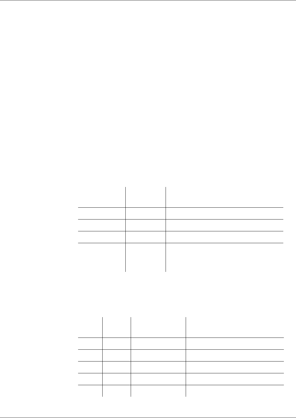
Appendix
Signature Procedure
Reference Manual STARCOS® 3.0/Edition 06/2005 403
ID No. 30016255
Signature Procedure
according to PKCS#1
The signature procedure according to PKCS#1 is a signature procedure with-
out message recovery.
Prerequisite The following facts must be known for the calculation and verification of a
digital signature:
– Hash algorithm HASH used
– Byte length H of the hash values created
– Signature algorithm used
– Byte length N of the DSI created for the signature algorithm =
byte length of the modulus n of the RSA key used.
In the signature procedure according to PKCS#1, both the hash algorithm
SHA-1 and the hash algorithm RIPEMD-160 are supported by the smart card.
Signature Calculation The calculation of the signature used for the message M comprises the fol-
lowing steps:
1st step Calculation of the hash value HASH(M) of the byte length H.
2nd step Creation of the DSI. The DSI is a series of N - 1 bytes, which is structured as
follows:
The byte length D of the digest-info has the value 35, so that the padding field
has a length of N-38 bytes.
As N ≥ 96, padding is effected with a minimum of 58 bytes ’FF’.
Structure of the digest-info used for the hash algorithm SHA-1:
Designation Byte
Length
Value
Block type 1 ’01’
Padding field N-3-D ’FF..FF’
Separator 1 ’00’
Digest-info D BER-TLV-coded data object with OID
and parameters of the hash algorithm as
well as the hash value
Tag Length
in Byte
Value Description
’30’ ’21’ Tag and length of SEQUENCE
’30’ ’09’ Tag and length of SEQUENCE
’06’ ’05’ ’2B 0E 03 02 1A’ OID of SHA-1 (1 3 14 3 2 26)
’05’ ’00’ TLV code of ZERO
’04’ ’14’ ’XX...XX’ Hash value

Appendix
Signature Procedure
404 Reference Manual STARCOS® 3.0/Edition 06/2005
ID No. 30016255
Structure of the digest-info for the hash algorithm RIPEMD-160:
The message M consists completely of the non-recoverable part Mn.
3rd step A signature is calculated from the DSI by the algorithm used for the creation
of the signature.
For this purpose, it is valid that DSI is a series of N-1 bytes.
Thus, the integer value of the DSI resulting from the binary representation is
smaller than the value of the modulus n.
The signature is a series of bytes with byte length N.
For the representation of the modulus n as series of bytes, the bit bk has the
value 1 and the bits b8*N b8*N-1 ... bk+1 have, if available, the value 0.
For the representation of the signature as series of bytes, the bits b8*N b8*N-1
... bk+1 have the value 0, too.
Signature Verification Prerequisite:
– Signature to be verified
– Message M’ as series of bytes
– Signature as series of bytes with byte length N
For the representation of the signature as series of bytes, the bits b8*N
b8*N-1 ... bk+1, if available, must have the value 0.
The integer value resulting from the binary representation of the signa-
ture must be smaller than n.
The verification of the signature comprises the following steps:
1st step The algorithm of the plain text recovery is used for the signature. It provides
a series of bytes with a byte length of N-1.
2nd step A DSI’ with a byte length of N-1 is created from the message M’. This step
corresponds to the second step of the calculation of the signature according to
PKCS#1 (see page 403).
Tag Length
in Byte
Value Description
’30’ ’21’ Tag and length of SEQUENCE
’30’ ’09’ Tag and length of SEQUENCE
’06’ ’05’ ’2B 24 03 02 01’ OID of RIPEMD-160
(1 3 36 3 2 1)
’05’ ’00’ TLV code of ZERO
’04’ ’14’ ’XX...XX’ Hash value

Appendix
Signature Procedure
Reference Manual STARCOS® 3.0/Edition 06/2005 405
ID No. 30016255
3rd step The DSI’ is compared with the plain text recovered by the 2nd step.
The values must correspond with each other for a successful verification.
Notation The following notations are valid for the signature procedure according to
PKCS#1:
– For the calculation:
signPKCS1(SK)[M]
– For the verification:
verifyPKCS1(PK)[s,M]

Appendix
Padding
406 Reference Manual STARCOS® 3.0/Edition 06/2005
ID No. 30016255
Padding
STARCOS® supports padding for symmetric and asymmetric algorithms.
The respective padding procedures are allocated with the help of padding in-
dicators (see page 415).
Padding for
Symmetric Algorithms
Depending on the security procedures used, the following padding proce-
dures are supported by STARCOS®:
– ISO Padding
Application in secure messaging for encryption and MAC creation as
well as for encryptions which are specifically used for certain commands
– 0-Padding
Application in MAC creation specific to a command
ISO Padding In case of ISO padding, one byte ’80’ is always attached to the message.
If the extended message then has a length which does not represent a multiple
of 8 bytes, as many bytes ’00’ will be attached to the extended message as
necessary to achieve a multiple of 8.
Padding may be required for several blocks of a message during the MAC
creation for secure messaging.
0-Padding In case of 0-padding, as many ’00’ bytes are attached to the message as re-
quired to obtain a length, which represents a multiple of 8.
Messages which do already have a multiple value of 8 bytes remain un-
changed.
Padding for
Asymmetric
Algorithms
STARCOS® supports the following padding procedures for RSA algorithms:
– PKCS #1 Padding
– DINSIG Padding
Each padding procedure determines how a message M must be processed to
obtain a byte series that can be enciphered by RSA.
Prerequisite The following applies to all three padding procedures:
– Message M is
– a bit string with length m:
M = bm bm-1 ... b1, for which bm ≠ 0
– binary number and
first left bit bm = higher-order bit
last right bit b1 = lower-order bit.

Appendix
Padding
Reference Manual STARCOS® 3.0/Edition 06/2005 407
ID No. 30016255
– If unique numbers L ≥ 1 and 8 ≥ r ≥ 1 with m = 8*(L-1) + r exist, M will
be the series of bits, too:
M = br br-1 ... b1 b8*(L-1) ... b8*(L-2)+1 ... b8 ... b1.
– If r = 8, M will directly be the series of L bytes:
M = BL BL-1 ... B1, for which BL ≠ ’00’.
– If r < 8, 8-r binary 0 will precede the series of bits
br br-1 ... b1 b8*(L-1) ... b8*(L-2)+1 ... b8 ... b1:
M = 0 ... 0 br br-1 ... b1 b8*(L-1) ... b8*(L-2)+1 ... b8 ... b1,
and it will result in a series of bytes:
M = BL BL-1 ... B1, for which BL ≠ ’00’.
– Byte length L of M.
The integer value of M is not changed by a leading 0 in the binary repre-
sentation, so that the number value represented by a series of m bits re-
mains unchanged by the representation of M as series of L bytes.
– Modulus n of the RSA key pair for the en-/decryption.
N refers to the byte length of the series of bytes of the modulus n.
k refers to the bit length of the bit string of the modulus n
PKCS #1-Padding – For the implementation of the padding, L must be ≤ N - 11.
– The message M is formatted to a series of N-1 bytes as follows:
As the series of bytes has a length of N-1, the integer value of the series
of bytes resulting from the binary representation is smaller than the value
of the modulus n.
Designation Byte
Length
Value
Block type 1 ’02’
Padding field N - 3 - L random number consisting of bytes ≠
’00’
Separator 1 ’00’
Data field L message M of the length L bytes

Appendix
Padding
408 Reference Manual STARCOS® 3.0/Edition 06/2005
ID No. 30016255
DINSIG-Padding – For the implementation of the padding, m must be ≤ k - 76.
– The message M is formatted to a series of k bits as follows:
If k - m - 76 > 0, the first four bits of this series will have the value ’6’.
As the higher-order bit in the series of bits has the value 0, the integer
value of the bit string resulting from the binary representation is smaller
than the value of the modulus n.
Padding Indicators Padding indicators are used for the clear allocation of padding procedures.
The padding indicator is defined in the value field of a data object with tag
’8A’.
The STARCOS® smart card supports the following padding indicators:
Designation Bit
Length
Value
Header 2 0 1
More-data Bit 1 fixed value1
Padding field k-m-75 k - m - 76 bits 0
succeeded by exactly one bit 1 (boundary
bit)
Data field 64
m
random number
message M
Trailer 8 ’BC’
Padding Indicator
(1 Byte)
Description
’01’ ISO padding
’80’ 0-padding
’81’ PKCS #1 padding
’82’ DINSIG padding
Padding Indicator
(1 Byte)
Description
’01’ ISO padding
’80’ 0-padding
’81’ PKCS #1 padding
’82’ DINSIG padding
’8E’ EMV-PIN padding

Appendix
Padding
Reference Manual STARCOS® 3.0/Edition 06/2005 409
ID No. 30016255
Padding for Algorithms The padding procedure used for an algorithm will be determined if the CRT
within key supplementary information contains both an algorithm ID data ob-
ject and a padding indicator data object.
The STARCOS® smart card supports padding procedures only for the algo-
rithm IDs ’11 XX’ used for enciphering algorithms and ’12 XX’ used for
MAC algorithms. The following table shows the allocation of padding indi-
cators and also which padding procedure will be used if a padding indicator is
not available.:
TODO EMV condition
Algorithm ID Padding Indicator Description
’11 1X’
’11 2X’
’11 30’
ISO padding
’01’ ISO padding
’80’ 0-padding
’81’, ’82’, ’8E’ inadmissible
no padding
’01’, ’80’ inadmissible
’81’ PKCS #1 padding
’82’ DINSIG padding
’12 XX’ ISO padding for SM, 0-pad-
ding for command-specific
MAC protection
’01’ ISO padding
’80’ 0-padding
’81’, ’82’, ’8E’ inadmissible
Algorithm ID Padding Indicator Description
’11 1x’
’11 2x’
ISO padding
’01’ ISO padding
’80’ 0-padding
’81’, ’82’, ’8E’ inadmissible

Appendix
Padding
410 Reference Manual STARCOS® 3.0/Edition 06/2005
ID No. 30016255
’11 30’ no padding
’01’, ’80’ inadmissible
’81’ PKCS #1 padding
’82’ DINSIG padding
’8E’ EMV-PIN padding
’12 xx’ SO padding for SM, 0-padding
for command-specific MAC
protection
’01’ ISO padding
’80’ 0-padding
’81’, ’82’, ’8E’ inadmissible
Algorithm ID Padding Indicator Description

Appendix
Algorithm IDs
Reference Manual STARCOS® 3.0/Edition 06/2005 411
ID No. 30016255
Algorithm IDs
Algorithm IDs are used for the clear identification and classification of cryp-
tographic algorithms as well as for the procedures used for authentication,
key management, and for the creation of keys.
Algorithm IDs consist of partial IDs. Each partial ID can be regarded as node
or leaf within the hierarchic structure. The significance of a partial ID de-
pends on the significance of the superior partial ID.
Partial Ids are represented by natural numbers requiring a value ≠ 0.
The algorithm ID is defined in the value field of a data object with tag ’89’.
Notation and Coding In order to be incorporated in the smart card, the algorithm IDs are coded as
follows:
– Each partial ID is represented by a series of one or more half-bytes.
– The higher-order bit b4 of a half-byte indicates whether it is the last one
to be represented as partial ID within a series.
The higher-order bit of the last half-byte = 0.
The higher-order bit of all preceding half-bytes of a series = 1.
– The bits b3 - b1 of the series are linked to a binary number. The higher-
order bit of the series is the bit b3 of the first half-byte, and the lower-or-
der bit is the bit b1 of the last half-byte.
– The algorithm ID is the linkage of partial IDs. If the linkage consists of
an odd number of half-bytes, a half-byte ’0’ will be appended.
All the algorithm IDs currently defined can be represented by values with a
maximum length of 4 bytes.
example
Value as Natural Num-
ber
Value Coded
3 1 1 1 1 ’31 11 10’
Appendix
Algorithm IDs
412 Reference Manual STARCOS® 3.0/Edition 06/2005
ID No. 30016255
Defined Algorithm IDs The STARCOS® smart card evaluates the following algorithm IDs:
Note to algorithm ID 1 3 1 3
The algorithm IDs for signature procedures without hash algorithm will
be used if a signature is calculated by the command COMPUTE DIGI-
TAL SIGNATURE without prior calculation of the hash value with the
command HASH by the smart card.
1 Cryptoalgorithms
1 Enciphering
1Simple DES
1 CBC mode, ICV = 0
2 CBC mode, ICV ≠ 0
3 CBC mode, ICV enciphering
2 Triple-DES with key of twice the length
1 CBC mode, ICV = 0
2 CBC mode, ICV ≠ 0
3 CBC mode, ICV enciphering
4 CBC mode, dynamization
3RSA (standard)
2 MAC creation
1Simple MAC
1 CBC mode, ICV = 0
2CFB mode
2 Retail MAC
1 CBC mode, ICV = 0
2CFB mode
3 CBC mode, dynamization
3 Signature procedure
1 ISO 9796-2 DINSIG
3 With RSA (standard) (see note on the next page)
1 With SHA-1
2 With RIPEMD-160
2PKCS#1
3 With RSA (standard)
1 With SHA-1
2 With RIPEMD-160
4 Hash algorithms
1 SHA-1
2RIPEMD-160
Appendix
Algorithm IDs
Reference Manual STARCOS® 3.0/Edition 06/2005 413
ID No. 30016255
2 Authentication
1 One-sided, symmetric authentication
1 Internal authentication
1Simple DES
2 Triple-DES with key of twice the length
2 External authentication
1Simple DES
2 Triple-DES with key of twice the length
2 Double-sided, symmetric authentication
1 Mutual authentication
1Simple DES
2 Triple-DES with key of twice the length
3 Asymmetric authentication
1 Client-Server authentication
3 With RSA (standard)
5 Internal Authenticate (ICAO)
3 With RSA (standard)
1 With SHA-1
Appendix
Algorithm IDs
414 Reference Manual STARCOS® 3.0/Edition 06/2005
ID No. 30016255
3 Key management
1 Key derivation
1 Key negotiation
1 16 bytes KGK, 16 bytes CSK
2 16 bytes KGK, 8 bytes K
2 Key transport
1 Key negotiation by symmetric procedures
1 16 bytes CSK, SK
1 1 Session key, no SCC
2 2 Session key, no SCC
3 1 Session key, SCC
4 2 Session key, SCC
2 Key negotiation by asymmetric procedures
1 Authentication of smart card first
1 Signature procedures according to ISO 9796-2
4 With RSA (ISO-2 variant)
1 With SHA-1
2 With RIPEMD-160
2 Authentication of terminal first
1 Signature procedures according to ISO 9796-2
4 With RSA (ISO-2 variant)
1 With SHA-1
2 With RIPEMD-160
4 Authentication method identical to E-SignK chapter 8.7 with session key negotiation
or
ICAO TR PKI 1.2 E.2
1 16 bytes KK and SK triple-DES
4 2 Session keys SSC
0 Filler
3 Implementation with certificate
1 CPI identified certificate
1 Signature procedures according to ISO 9796-2
3 With RSA (standard)
1 With SHA-1
2 With RIPEMD-160
4 Key creation
1 RSA key generation
3 ECC key generation
1GF(p)

Appendix
Padding Indicators
Reference Manual STARCOS® 3.0/Edition 06/2005 415
ID No. 30016255
Padding Indicators
Padding indicators are used for the clear allocation of padding procedures.
The padding indicator is defined in the value field of a data object with tag
’8A’.
The STARCOS® smart card supports the following padding indicators:
Padding for Algorithms The padding procedure used for an algorithm will be determined if the CRT
within key supplementary information contains both an algorithm ID data ob-
ject and a padding indicator data object.
The STARCOS® smart card supports padding procedures only for the algo-
rithm IDs ’11 XX’ used for enciphering algorithms and ’12 XX’ used for
MAC algorithms. The following table shows the allocation of padding indi-
cators and also which padding procedure will be used if a padding indicator is
not available:
Padding Indicator
(1 Byte)
Description
’01’ ISO padding
’80’ 0-padding
’81’ PKCS #1 padding
’82’ DINSIG padding
Padding Indicator
(1 Byte)
Description
’01’ ISO padding
’80’ 0-padding
’81’ PKCS #1 padding
’82’ DINSIG padding
’8E’ EMV-PIN padding
Algorithm ID Padding Indicator Description
’11 1x’
’11 2x’
ISO padding
’01’ ISO padding
’80’ 0-padding
’81’, ’82’, ’8E’ inadmissible

Appendix
Padding Indicators
416 Reference Manual STARCOS® 3.0/Edition 06/2005
ID No. 30016255
’11 30’ no padding
’01’, ’80’ inadmissible
’81’ PKCS #1 padding
’82’ DINSIG padding
’8E’ EMV-PIN padding
’12 xx’ SO padding for SM, 0-padding
for command-specific MAC
protection
’01’ ISO padding
’80’ 0-padding
’81’, ’82’, ’8E’ inadmissible
Algorithm ID Padding Indicator Description

Appendix
Random Numbers
Reference Manual STARCOS® 3.0/Edition 06/2005 417
ID No. 30016255
Random Numbers
With a Random Number Generator, the STARCOS® smart card creates ran-
dom numbers for cryptographic functions.
The random numbers (zi) have the following characteristics:
– Valid from creation to use, until the execution of the next command at the
latest
– RESET of the smart card always invalidates random numbers;
– Their length depends on their use,
e.g. zi = binary coded, 8 bytes or
> 8 bytes for RSA key and padding procedures
Due to these properties, random numbers can only be used for the execution
of commands during which they were created or directly with the next com-
mand.
If a command requires a random number for its execution, but there is no
valid number available, the command will be aborted.

Appendix
Glossary
418 Reference Manual STARCOS® 3.0/Edition 06/2005
ID No. 30016255
Glossary
ACP Access Control Parameter
authentication parameter
ACV Access Control Value
consists of 2 bytes: the first byte determines when a key may be used (AC);
the second bytes specifies the consecutive state (CST)
ADF Application Directory
AEF Application Data Field
AI Authentication Input for Client-Server Authentication
AID Application Identifier
AKD Additional Key Description
Alg-ID Algorithm Reference
ALW ALWAYS
security condition
AM Access Method
AM Access mode
AM-DO Access mode data object
APDU Application Protocol Data Unit
basic module of communication on layer 7
ARR Access rule reference
ARR-DO Access Rule Reference Data Object
AT CRT for Authentication (tag 'A4')
area of a security environment for authentications
ATR Answer To Reset
response after power-on sequence of card; contains card ID
ATS Answer To Select
response after select-command in the anticollission procedure (in contact-
less mode). Equals ATR in contact mode.
BCD Binary Coded Decimal
Binary-coded decimal number

Appendix
Glossary
Reference Manual STARCOS® 3.0/Edition 06/2005 419
ID No. 30016255
BER Basic Encoding Rules
in accordance with ISO/IEC 8825
BGT Block Guard Time
point of time when the smart card may begin transmission (default 22 etu)
BIT Biometric Information Template
BWI Block Waiting Integer
BWT Block Waiting Time
maximum interval for the terminal to wait for a response from the smart
card
CA Certification Authority
trusted third party, authorized to certify keys
CAR Certification Authority Reference
ID of a CA
CBC Cipher Block Chaining
chained decipherment of several blocks with 8 bytes each
CC Cryptographic Checksum
CCT Cryptographic Checksum Template
CD Card Data
CDS Compute Digital Signature
Certificate key A public asymmetric key to which a procedure for certificate verification is
allocated in an SE. This can be a key stored in volatile memory but also a
volatile key which is the result of a certificate verification.
CFB Cipher Feedback
mode of encryption
CG Cryptogram
CHA Certificate Holder Authorization
CHR Certificate Holder Reference
identification of certificate holder, also used as key identifier
CID Card IDentifier
used in contactless mode to distinguish between one or more cards simulta-
neously in the reading range of a terminal

Appendix
Glossary
420 Reference Manual STARCOS® 3.0/Edition 06/2005
ID No. 30016255
CLA Class Byte
contains encoded command structure and transmission protection
commonly usable key keys, which are not reserved for local use
CP Certificate Profile
structure of a certificate consisting of data elements
CPI Certificate Profile Identifier
CRC Cyclical Redundancy Check
checksum method with which it can be determined whether a file has been
modified or not.
CRDO Control Reference Data Object
data object with control reference
CRP Command Response Pair
CRT Control Reference Template
or
Chinese Remainder Theorem
Chinese mathematics theorem, allowing quick calculation of digital signa-
tures
CSK Card Specific Key
CST Consecutive State
state accessed after successful execution of a command
CT Cipher Template
area of a security environment for encryption and decryption
CWI Character Waiting Integer
CWT Character Waiting Time
maximum interval between the characters transmitted by the smart card
DC Data Coding
DES Data Encryption Standard
symmetric encipherment algorithm
DF Dedicated File
structure underlying the MF (comparable to directories); may contain single
applications
DFA Differential Fault Analysis
detailed fault analysis

Appendix
Glossary
Reference Manual STARCOS® 3.0/Edition 06/2005 421
ID No. 30016255
DF-specific key keys contained in the DF
DF-specific password password whose reference value is contained in the DF, which is not the MF
DH Diffie-Hellman
DI Dual Interface
interface for contact-based and contactless communication
directly usable key Stored key to which a cryptographic algorithm or an authentication proce-
dure is allocated in an SE
Directly usable key A key to which a cryptographic algorithm or an authentication procedure is
allocated in an SE. This can be a key stored in non-volatile memory but also
a key stored in volatile memory.
DK Derived Key
DO Data Object
DOL Data Object List
DSI Digital Signature Input
DST Digital Signature Template
area of a security environment for digital signatures
EA External Authenticate
EBCDIC Extended Binary Coded Decimal Interchange Code
EDC Error Detection Code
EF Elementary File
stores the actual application data
EMV Europay, MasterCard, Visa
specification of card payment systems
ENC-SM-AC an SM-AC that defines explicitly the encryption for one message or both
messages.
EOF End Of File
etu Elementary Time Unit
FCB File Control Block
block with management information for each file type
FCI File Control Information

Appendix
Glossary
422 Reference Manual STARCOS® 3.0/Edition 06/2005
ID No. 30016255
FCP File Control Parameter
FID File Identifier
FIPS Federal Information Processing Standard
US standardization authority for information processing
FM File Manager
controls data access
GDO Ground Data Object
GF Galois Field
global key key contained in the MF
global password password whose reference value is contained in the MF
HT Hash Template
IA Internal Authenticate
ICC Integrated Circuit Card
smart card
ICC-ID Byte order for the identification of an ICC during the negotiation of session
keys
ICV Initial Chaining Value
ID Identifier
IFD Interface Device
general term for smart card terminal
IFD-ID Byte order for the identification of an IFD during the negotiation of session
keys
IFSC Information Field Size for the Card
IFSD Information Field Size for the Interface Device
IK Individual Key
individual symmetric key
INS Instruction Byte
contains instruction code of layer 7
IS Initial State
Key EF EF in which keys are stored

Appendix
Glossary
Reference Manual STARCOS® 3.0/Edition 06/2005 423
ID No. 30016255
Key Group Keys of the DF that have the same key number
Key Management Key Master keys, negotiation keys and certificate keys belong to the keys for
key management and are also referred to as key management keys.
Key-CCT CCT in additional key information
KFL Key Format List
specifies the key structure
KFPC Key Fault Presentation Counter
error counter for authentication key
KGK Key Generation Key
KID Key Identifier
KMT Key Management Template
KV Key Version
LCS Life Cycle Status
LEN Length Byte
contains block length specification (T=1)
locally usable key key that is used within the DF in which it is stored
MAC Message Authentication Code
value for secure messaging, calculated cryptographically
MAC-SM-AC an SM-AC, which defines MAC protection exclusively for one message or
both messages
Master key A symmetric key stored in volatile memory to which a procedure for key
derivation is allocated in an SE.
MF Master File
root directory of STARCOS® file system
MK Master Key
symmetric master key
MSE MANAGE SECURITY ENVIRONMENT
ISO command
NAD Node Address Byte
contains coded transmitter and receiver of a block (T=1, T = CL)

Appendix
Glossary
424 Reference Manual STARCOS® 3.0/Edition 06/2005
ID No. 30016255
Negotiation Key A key to which a procedure for key negotiation is allocated in an SE. This
can be a symmetric or asymmetric key stored in non-volatile memory but
also a symmetric or asymmetric key stored in volatile memory.
NEV NEVER
security condition
OC Operation counter
OID Object Identifier
international code for an object, in this case algorithms
OIP Offset Indicator Byte
OP Operation Mode
PParity adjust
P1, P2 Parameter bytes in commands
PB Padding Byte
PCB Protocol Control Byte
contains control information for communication
PI Padding Indicator
PIN Personal Identification Number
PIX Proprietary Application Identifier Extension
PK Public Key
PKCS Public Key Cryptographic Standard
key component in public key cryptosystems; used to verify digital signa-
tures
PPS Protocol and Parameter Selection
protected command command protected by secure messaging
PS Padding field (padding string) for client-server authentication
PSO PERFORM SECURITY OPERATION
PT Plain Text
PTS Protocol Type Select
switch between transmission protocols

Appendix
Glossary
Reference Manual STARCOS® 3.0/Edition 06/2005 425
ID No. 30016255
PU Private Use
commands developed by G&D
PUK Personal Unblocking Key
special PIN for unblocking a PIN with expired KFPC
PV Plain Value
PWDID Password number
RF Radio Frequency
RFU Reserved for Future Use
RID Registered Application Provider ID
RN Record Number
RND Random Number
RO Read Only
RSA Rivest, Shamir, Adleman
cryptographic method; named after its inventors’ last names
RW Read/Write
SC Security Condition
SC-CCT CCT in a SM-SC
SC-DO Security Condition Data Object
SE Security Environment
security environment for referring to data objects
SE# Number for identification of the security environment
SFI Short File Identifier
SHA-1 Secure Hash Algorithm
standardized hash algorithm
SID Short Identifier
SK Session Key
SM Secure Messaging
data transmission protection
SN Serial Number

Appendix
Glossary
426 Reference Manual STARCOS® 3.0/Edition 06/2005
ID No. 30016255
SSC Send Sequence Counter
communication counter
SSD Security Status Description
authentication parameter
STARCOS S smart card chip operating system/standard version
SW Status Word
application status byte
TLV Tag Length Value
TM Transmission Manager
controls data transmission
unprotected command Command not protected by secure messaging
UQ Usage Qualifier
one byte long bit-map for precise determination of the use of CRDOs within
a CRT
UQ-DO Usage Qualifier Data Object
Data object whose value field contains a UQ
VC VERIFY CERTIFICATE
VDS VERIFY DIGITAL SIGNATURE
WR Write
WTX Waiting Time Extension
extends the maximum interval for the terminal to wait for a response from
the smart card for time-consuming operations

Index
Reference Manual STARCOS® 3.0/Edition 06/2005 427
ID No. 30016255
Index
Numerics
0-padding 406
A
access conditions
actions 266
access rule reference 30
definition 32
value field 32
access rules
actions 266
Access with Tag ’DF 20’ 24
ACTIVATE FILE
description 279
algorithm
DES, Triple-DES 379
Hash 391
hash 316
RSA 383
survey 378
algorithm ID 411
defined algorithm IDs 412
deletion 221
notation and coding 411
volatile storage 221
allocation of security mechanisms 95
APPEND RECORD
description 280
ARR 32
ARRT 30, 90
asymmetric
algorithms for padding 406
ECC authentication 74
RSA authentication 73
AT 93, 97, 117, 205
authentication 73, 74
according to E-SignK 158
client server 73, 74, 325
ECC 74
external 303
external authentication 72
internal 71
itself 364
key references 218
mutual 333
mutual authentication 72, 158
private key 321
procedures 71
public key 304
RSA 73
secret key 303, 321
smart card authenticates itself to the
terminal 319
Triple-DES 71
with key negotiation 335
without key negotiation 333
authentication input
client server 74
B
basic knowledge 3
blocks
fixed tag order 7
zags in any order 8
C
CAR 167, 168
case 1 257
case 2 257
case 3 258
case 4 258
CBC-MAC
retail with dynamized key 394
simple 392
CCT 93, 102, 117, 207
secure message 231
certificate
content 167
creation 167
message recovery 371
verification 167
verify 368
certificate information
EF_CERT 120
certificate keys
handling 140
CFB-MAC
retail 394
simple 393
CHA 167
CHANGE REFERNECE DATA
description 282
change security state 356
channel
open and close 327
channel management 254
checks
command 263
chip card
authentication of Server 73, 74
CHR 167
CID 134
client server
authentication 73, 74, 325
command
abort CREATE FILE 292
coding 256
formal checks 263
MAC protection 234
processing scheme 262
secure message 231
structure 256
CLA-byte 256
INS-byte 256
length byte 257
parameter P1, P2 256
parameter P3 257
command chaining
HASH 316
rules 267
VERIFY CERTIFICATE 371
COMPUTE DIGITAL SIGNATURE
description 290
control reference 329
control-reference template 97
CPI 121, 167
create
access rule-EF 292
CREATE FILE
abort command 292
description 292
creation of prime number 169
creation status 279

Index
428 Reference Manual STARCOS® 3.0/Edition 06/2005
ID No. 30016255
cryptographic keys
allocating 77
overview and definitions 76
storage 125
type 76
CT 93, 110, 118, 209
secure message 231
with ICV 247
cyclic
address 15
read 345
D
data control information 356
data field 226
data information
SE specific 122
data object
access 23
ARRT 90
asymmetric public key 84
control reference 329
for data fields 228
generation counter 88
hash-computing 317
key export 130
Le 229
life cycle status 87
MAC 230
maloperation counter 87
operation counter 88
plain text 228
read value field 312
regular access 23
status information 229
with initial value for the signature
Counter 88
write 342
data objects 6
data units
referencing 266
DEACTIVATE FILE
description 295
DECIPHER
description 296
padding 297
RSA-encipherment 296
dedicated file
see DF
DELETE FILE
description 299
derived key
type and structure 134
derived keys
deletion 135
storing 135
DES
algorithm 379
CBC-mode 380
encryption 380
DF
activate 279
create 292
deactivate 295
delete 299
level concept
select 356
terminate 358
digest-info
structure for RIPEMD-160 404
structure for SHA-1 403
digital signature input 395
DINSIG padding 408
DSI
creation 395
signature according to PKCS#1 403
signature procedure according to the
specification 401
DST 93, 108, 208
dynamic key
Triple-DES 379
E
ECC
authentication 74
mutual authentication 158
ECC key
storage 125
EF
activate 279
create 292
deactivate 295
delete 299
level concept
operation status 295
read 343, 345, 360
referencing 266
select 356
terminate 358
EF_ALIAS 217
in DF 220
EF_CERT
certificate information 120
EF_KEYD
formats 100
ELC key
structure data object 85
element
identical length 15
offset 15
overwrite 362
elementary file
see EF
EMV-PIN padding 411
en-/ and decryption
RSA decryption
RSA 384
ENCIPHER
description 301
padding 302
enciphering
key reference 219
encryption
DES CBC-mode 380
DES, triple-DES 380
ICV 248
triple DES CBC mode 380
triple-DES CBC-mode 380
evaluation
of CRTs
test 224
export
public keys 130
EXTERNAL AUTHENTICATE
description 303
key negotiation 160
asymmetric 162, 163
key reference 305
external authentication 72
F
FBZ
reset
FCI 26
FCP 25
DF 294
EF 294
for EF 293
file
hierarchy
directory tree 10
levels 10
referencing 11
structure
amorphous/binary 14
cyclic 15
linear fixed 15
object 20
transparent 14
file control information 25

Index
Reference Manual STARCOS® 3.0/Edition 06/2005 429
ID No. 30016255
file control parameter
see FCP
G
GENERATE ASYMMETRIC KEY PAIR
219
description 306
generation of keys 169
public key export 130
generate key pair 306
generating keys 169
generation counter data object 88
GET CHALLENGE
description 311
key negotiation
asymmetric 162
symmetric 157
MAC encryption with ICV 247
triple-DES authentication 72
GET DATA
description 312
GET KEYINFO
description 313
GET RESPONSE
description 315
H
HASH
command chaining 316
description 316
Hash
algorithm 391
hash 316
algorithm
key negotiation 161
data object 317
RIPEMD-160 391
SHA-1 391
value 316
hierarchy
directory tree 10
levels 10
HT 207
I
ICV 248
command-specific protection 250
encryption 248
regular 246
script for command message 248
script for response message 249
secure messaging 246
session key 246, 248
without session key 248
ICV Handling 246
IF-THEN template 123
IF 123
THEN 124
indicators
padding 408, 415
initial value for operation counter 117
INS-byte 256
INTERNAL AUTHENTICATE
Client-Server authentication 73, 74
description 319
key negotiation
asymmetric 161, 163
internal authentication 71
ISO padding 406
K
key agreement
calculation 155
key components
RSA 383
key derivation 158
master key 115
key management
EXTERNAL AUTHENTICATE 320
overview 155
template 114
key name data object 81
key negotiation
asymmetric 160
asymmetric negotiation keys 137
AT 137
KMT 136
secret negotiation key 136
symmetric 157
key number 313
key reference
enciphering 219
EXTERNAL AUTHENTICATE 305
INTERNAL AUTHENTICATE 321,
324, 325
MUTUAL AUTHENTICATE 334,
337, 339
PSO and GENERATE ASYMMETRIC
KEY PAIR 219
secure messaging 219
key reference data object 80
key references
authentication 218
key search
parameter 313
key version 314
return key number 313
KFPC
parameter 193, 347
reset
resetting code 193
KMT 93, 119
L
Le-byte
for secure messaging 229
Level 7 Chaining 252
life cycle status data object 87
linear
read 345
linear fixed
description 15
Logical Channels 251
logical channels
channel management 254
Level 7 Chaining 252
SM 252
M
MAC
creation 392
retail 393
retail CBC-MAC 393
retail CFB-MAC 394
secure messaging 227, 230
simple CBC-MAC 392
simple CFB-MAC 393
with dynamized key 394
MAC lengths 107
maloperation counter data object 87
MANAGE CHANNEL 327
MANAGE CHANNEL
case 1 327
case 2 327
MANAGE SECURITY ENVIROMENT
SET variant 212
MANAGE SECURITY ENVIRON-

Index
430 Reference Manual STARCOS® 3.0/Edition 06/2005
ID No. 30016255
MENT
description 329
MAC encryption with ICV 247
master file
see MF
master key
access 134
EXTERNAL AUTHENTICATE 320
memory error 263
message
key negotiation
signation 165
recovery 395
Messages 164
MF
level concept
modulus 167
MSE RESTORE
parameter 331
MSE SET
parameter 331
MUTUAL AUTHENTICATE
description 333
key negotiation 157, 160
mutual authentication 72, 158
according to E-SignK 158
N
notation 3
O
object
data 6
description 20
offset
absolute 14
relative 15
OID 167
operation counter data object 88
operation status 279
P
padding
0-padding 406
algorithms
asymmetric 406
symmetric 406
DECIPHER 297
DINSIG 408
EMV-PIN 411
ENCIPHER 302
indicators 408, 415
ISO padding 406
PKCS#1 407
padding for algorithms 409, 415
password
change 282
LCS value 30
RCB 283, 366
transmission format
ASCII coded 288
encrypted 287
format 1 PIN block 284
format 2 PIN blocks 284
PERFORM SECURITY OPERATION
description 341
subcommand
COMPUTE DIGITAL SIGNA-
TURE 290
DECIPHER 296
ENCIPHER 301
HASH 316
VERIFY CERTIFICATE 368
VERIFY DIGITAL SIGNATURE
373
PIN
change 282
transmission format
ASCII coded 286
PIN transmission format
BCD coded 285
PIX 12
PKCS #1 padding 407
plain text
data objects 228
private key
decipher 296
definition 383
signature compute 290
proprietary file control information
record entries 294
protocol T = 0
response date request 315
PSO 219
public exponent 167
public key
encipher 301
export 130
EXTERNAL AUTHENTICATE 304
public keys
handling 140
PUT DATA
description 342
R
random number 417
request 311
RCB
file selection 280, 345
KFPC 347
password 283, 366
record extended search 350
record specific search 353
record standard search 349
update EF 360
update record 362
READ BINARY
description 343, 358
READ RECORD
description 345
read the value field of a data object 312
record
extended search 350
fixed length 15
number 15
overwrite 362
read 345
record specific search
configuration byte 354
referencing 266
search 349
specific search 351
standard search 349
recovery 263
GENERATE PUBLIC KEY PAIR 307
referencing 266
ATR 11
by file and path 11
by name 12
by SFI 13
EF 15
explicit 11
files 11
implicit 11
related manuals 2
RESET RETRY COUNTER
parameter for KFPC 193, 347
reset retry counter
see FBZ

Index
Reference Manual STARCOS® 3.0/Edition 06/2005 431
ID No. 30016255
response
structure
body 259
SW1, SW2 259
trailer 259
response descriptor 230
secure response 230
with ICV 247
retail
CBC-MAC 393
CFB-MAC 394
CFB-MAC with dynamized key 394
RID 12
RIPEMD-160 391
roll-back 263
roll-forward 263
RSA
authentication 73
DECIPHER 296
en-/ and decryption 384
ENCIPHER 301
generate key pair 306
generating keys 169
key components 383
private key 383
signature according to ISO 9796-2
388
standard signature 386
RSA algorithms 383
S
Script-ICV 248
SE 201
activation 203
reference data object 92
specific data information 122
search
identifier "DF-specific" 142
search for search
patterns or search intervals 352
SEARCH RECORD
description 349
extended search 350
specific search 351
standard search 349
secret key
EXTERNAL AUTHENTICATE 303
secure messaging
command protection 234
command without data field 229
data objects 228
data structures 226
ICV 246
key reference 219
MAC calculation 227
response 268
security algorithms
see algorithm
SELECT FILE
description 356
selection
control 357
keys 216
option 357
serial number
EF_GDO 22
session key
ICV 246, 248
key negotiation 157, 159, 165
SET 223
SFI 13, 29
SHA-1 391
Short File Identifier see SFI
signature
according to ISO 9796-2 388
creation 388
recovery of plain text 389
compute 290
verify 373
signature procedure 395
according ISO 9796-2
key negotiation 160
according to ISO 9796-2 396
calculation 396
interim value 397
notation 400
signature verification 167
verification 399
according to PKCS#1 403
calculation 403
notation 405
verification 404
according to the specification 401
calculation 401
notation 402
signature verification 402
signature verification
signature procedure
according to the specification 402
simple CBC-MAC 392
simple CFB-MAC 393
single key 158
single key version 158
SM
in logical channels 252
specific search
configuration byte 354
entire byte string 352
TLV object 351
unstructured byte string 351
up to first hit 353
standard signature 386
creation 386
plain text recovery 387
status
creation 279
operation 279, 295
termination 358
status bytes
warnings 269
structure
EF 14
transparent 14
structure data object 82
asymmetric private key 85
asymmetric public key 84
ELC key 85
symmetric key 83
Structures
Data 10
structures
file 10
supported security mechanisms 92
SW1, SW2 259
symmetric
key negotiation 157
padding for algorithms 406
T
target group 3
template for key management 114
termination status 358
transparent
address 14
description 14
read 343, 360
Triple DES CBC mode with dynamized
key 381
Triple-DES
algorithms 379
dynamic key 379, 381
triple-DES
CBC-mode 380
encryption 380

