Ooo3062.tmp STEWART Compression Er TM 9 4910 582 14 And P
User Manual: STEWART-Compression-er-TM-9-4910-582-14-and-P Igor's of metalworking and electrical manuals
Open the PDF directly: View PDF ![]() .
.
Page Count: 22

TM 9-4910-582-14&P
TECHNICAL MANUAL
OPERATOR’S, ORGANIZATIONAL, DIRECT SUPPORT,
AND GENERAL SUPPORT MAINTENANCE
MANUAL INCLUDING REPAIR PARTS LIST
FOR
TESTER, CYLINDER
MODEL 2093A
(STEWART-THOMAS INDUSTRIES INC.)
(NSN 4910-00-250-2423)
HEADQUARTERS,DEPARTMENT OF THE ARMY
SEPTEMBER 1980
TM 9-4910-582-14&P
TECHNICAL MANUAL
No. 9-4910-582-14&P
HEADQUARTERS
DEPARTMENT OF THE ARMY
WASHINGTON, DC, 26 September 1980
OPERATOR’S, ORGANIZATIONAL, DIRECT SUPPORT,
AND GENERAL SUPPORT MAINTENANCE MANUAL
INCLUDING REPAIR PARTS LIST
FOR
TESTER, CYLINDER
MODEL 2093A
(NSN 4910-00-250-2423)
NOTE
This manual is published for the purpose of identifying an authorized commercial
manual for the use of the personnel to whom this cylinder tester is issued.
Manufactured by: Stewart-Thomas Industries, Inc.
100 Cabot Street
West Babylon, NY 11704
Procured under Contract No. DAAK09-78-C-4437
i
TM 9-4910-582-14&P
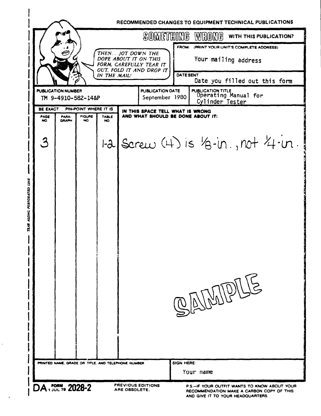
INSTRUCTIONS FOR REQUISITIONING PARTS
NOT IDENTIFIED BY NSN
When requisitioning parts not identified by National Stock Number, it is
mandatory that the following information be furnished the supply officer.
1-
2-
3-
4-
5-
6-
7-
Manufacturer’s Federal Supply Code Number-
31077
Manufacturer’s Part Number exactly as listed herein.
Nomenclature exactly as listed herein, including dimensions, if
necessary.
Manufacturer’s Model Number - Model 2093A
Manufacturer’s Serial Number (End Item)
Any other information such as Type, Frame Number, and Electrical
Characteristics, if applicable.
If DD Form 1348 is used, fill in all blocks except 4, 5, 6, and
Remarks field in accordance with AR 725-50.
Complete Form as Follows:
(a) In blocks 4, 5, 6, list manufacturer’s Federal Supply Code
Number - 31077
followed by a colon and manufacturer’s
Part Number for the repair part.
(b) Complete Remarks field as follows:
Noun:
(nomenclature of repair part)
For: NSN:
4910-00-250-2423
Manufacturer:
Stewart-Thomas Industries, Inc.
Model: 2093A
Serial: (of end item)
Any other pertinent information such as Frame Number,
Type, Dimensions, etc.
The Model
pressure. A valve,
release the air
TM 9-4910-582-14&P
OPERATING INSTRUCTIONS
MODEL 2093A
COMPRESSION TESTER
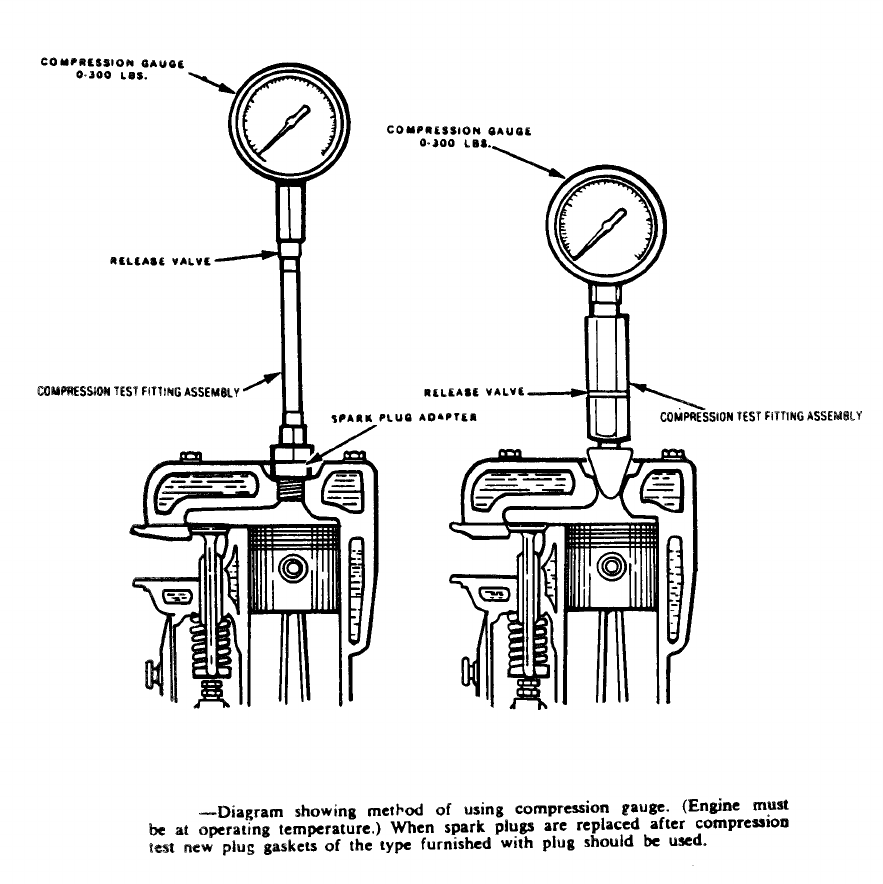
2093A tester is equipped with a dial calibrated from 0 to 300 lbs.
located in the bottom of the check valve fitting, is provided to
pressure in the gauge.
A set of adapters, Figure 1,with threads to match the spark plugs of
various engines is provided.A flexible extension is also furnished for use in
restricted places.The cone adapter fitting is used for quick succession
cylinder tests.
COMPRESSION TEST.The engine oil level, grade and cleanliness should be
noted before making this test.When removing spark plugs for a compression
test, first loosen the plugs slightly and then with an air hose blow out all the
accumulation of dirt and foreign substances, which usually become pocketed
around the spark plug. This will prevent a particle of foreign matter from
dropping into the combustion chamber and becoming lodged under a valve. A valve
thus held open will cause an erroneous compression reading of the cylinder. After
the plugs are removed, it is a good plan to apply the air hose for blowing out the
combustion chambers.
Observe the spark plugs as they are removed for evidence of
fouling, burning, heat range, etc.
The engine should be up to normal operating temperature before starting
this test to assure normal oil and metal expnsion conditions.
Crank the engine with the starting motor with the ignition OFF. In case
of ignition switch-operated starting motor, ground ignition coil high-tension wire
and use the ignition switch.
When making a compression test of an engine, the operator should take
care to see that the highest gauge reading is obtained for each cylinder with
the same number of turns of the starting motor. Usually about eight turns
(which easily can be counted) of the motor is sufficient for each cylinder.
(1)

During this process if the operator
sticking valve easily may be detected.
TM 9-4910-582-14&P
carefully watches the gauge hand, a
The hand progressively rises with
each revolution of the starting motor until no further rise is obtained.The
indicated pressure on the gauge represents the maximum compression
pressure under the prevailing conditions.
Should the hand remain fixed at any one of the “beats” or revolutions of
the starting motor and then again rise, the point where it lagged indicates a
valve sticking in the open position. Compression pressures will be found to
be higher in modern engines than for older models.
With the pistons, rings, valves and gaskets in good condition, maximum
readings on all cylinders should be uniform within plus or minus 5 lbs. of
specified pressures.
The maximum overall readings will vary slightly according to the altitude, but
are influenced considerably by overall engine
speed, valve settings, etc.
Low readings on adjacent cylinders will
between cylinders.
temperatures, oil viscosity, cranking
ordinarily indicate gasket leakage
Low cylinder indication -particularly in one cylinder - indicates either
improper valve seating or piston and ring blow-by.
In order to re-check, heavy sealing oil may be squirted onto the heads of
all of the pistons and a re-check similar to the first test carried out.
PREVENTIVE MAINTENANCE. All parts of the equipment should be wiped
clean and dried after use and retained in the carrying case to prevent damage.
TROUBLESHOOTING. Should a pressure drop occur when reading the pressure gage,
pressurize the unit with compressed air; Caution: Do not exceed 300 psi. Submerge
unit in water up to the stem of the Pressure Gage. DO not submerge Pressure Gage.
Bubbles will appear at the leak. Tighten as is necessary and repeat test with unit
pressurized.
(2)
TM 9-4910-582-14&P
-3-
TM 9-4910-582-14&P
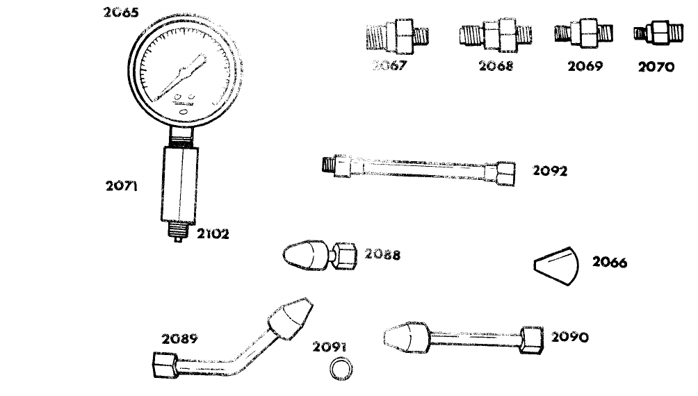
PARTS LIST FOR MODEL 2093A
COMPRESSION TESTER
FIGURE 1
PART
NUMBERDESCRIPTION
2065
2066
2067
2068
2069
2070
2071
2082
2088
2089
2090
2091
2092
2102
NUMBER
REQUIRED
Compression Gauge 0-300 lbs.
Cone Type Rubber Adapter
Spark Plug Adapter 10MM
Spark Plug Adapter 14MM
Spark Plug Adapter 18MM
Spark Plug Adapter 7/8 in.
Check Valve Fitting
Carrying Case (not shown)
3" Universal Adapter with Rubber COne
135° Universal Adapter with Rubber Cone
6-1/4" Universal Adapter with Rubber Cone
O Ring
Flexible Compression Hose Adapter
Relief Valve
1
2
1
1
1
1
1
1
1
1
1
2
1
1
-4-
By Order of the Secretary of the Army:
Official:
J. C. PENNINGTON
Major General,
United States
The Adjutant General
E. C. MEYER
General, United States Army
Chief of Staff
Army
✰ U. S. GOVERNMENT PRINTING OFFICE: 1982 O -388-969

TM 9-4910-582-14&P
