STM32F PMSM Single/dual FOC SDK V4.3 STM32 MC Library User Manual
STM32%20PMSM%20MC%20Library%20User%20manual
User Manual:
Open the PDF directly: View PDF ![]() .
.
Page Count: 178 [warning: Documents this large are best viewed by clicking the View PDF Link!]

September 2016
DocID18458 Rev 9
1/178
www.st.com
UM1052
User manual
STM32F PMSM single/dual FOC SDK v4.3
Introduction
This manual describes the Motor Control Software Development Kit (STSW-STM32100) designed for
and to be used with STM32F MCUs microcontrollers. The software library implements the Field
Oriented Control (FOC) drive of 3-phase Permanent Magnet Synchronous Motors (PMSM), both
Surface Mounted (SM-PMSM) and Internal (I-PMSM). The library exploit a new sensorless technique
that, in conjunction with an I-PMSM motor, is able to extend the range of allowed speed to zero. This
newest sensorless algorithm take benefit of the motor structure in order to detect the rotor angular
position even when the motor is at low speed or still. In this user manual we will refer to this technique
as "High Frequency Injection" also called HFI. This new algorithm take benefit of the floating point unit
of STM32F30x and STM32F4 series.
The STM32F family of 32-bit Flash microcontrollers is based on the breakthrough ARM® Cortex®-M
cores: the Cortex®-M0 for STM32F0, the Cortex®-M3 for STM32F1 and STM32F2, and the Cortex®-M4
for STM32F3 and STM32F4, specifically developed for embedded applications. These microcontrollers
combine high performance with first-class peripherals that make them suitable for performing three-
phase motors FOC.
The PMSM FOC library can be used to quickly evaluate ST microcontrollers and complete ST
application platforms, and to save time when developing Motor Control algorithms to be run on ST
microcontrollers. It is written in C language, and implements the core Motor Control algorithms as well
as sensor reading/decoding algorithms and a sensorless algorithm for rotor position reconstruction. The
library can be easily configured to make use of STM32F30x's embedded advanced analog peripheral
set (fast comparators and Programmable Gain Amplifiers, PGA) for current sensing and protection, thus
simplifying application board.
When deployed with STM32F103 (Flash memory from 256KBytes to 1MByte), STM32F2, STM32F303
or STM32F4 devices, the library allows simultaneous dual FOC of two different motors. The library can
be customized to suit user application parameters (motor, sensors, power stage, control stage, pin-out
assignment) and provides a ready-to-use Application Programming Interface (API). A user project has
been implemented to demonstrate how to interact with the Motor Control API.
This project provides LCD and UART User Interface, thus representing a convenient real-time fine-
tuning and remote control tool. A PC Graphical User Interface (GUI), the ST MC Workbench, allows a
complete and easy customization of the PMSM FOC library. In a very short time the user can run a
PMSM motor. A set of ready-to-use examples are provided to explain the usage of the motor control API
and its most common features.
Supported microcontrollers are listed in release note RN0085.

Contents
UM1052
2/178
DocID18458 Rev 9
Contents
1 Motor control library features ....................................................... 10
1.1 User project and interface features ................................................. 11
2 MC software development kit architecture .................................. 12
2.1 STM32Fxxx standard peripherals library and CMSIS library ........... 12
2.2 Motor control library ........................................................................ 12
2.3 Motor control application ................................................................. 13
2.4 Demonstration user project ............................................................. 13
3 Documentation architecture ......................................................... 15
3.1 Where to find the information you need .......................................... 15
3.2 Related documents ......................................................................... 15
4 Overview of the FOC and other implemented algorithms .......... 17
4.1 The new Motor Profiler procedure ................................................... 17
4.1.1 Restrictions and disclaimer .............................................................. 23
4.2 On-the-fly sensorless startup .......................................................... 23
4.3 Introduction to the PMSM FOC drive .............................................. 24
4.4 PM motor structures ........................................................................ 26
4.5 PMSM fundamental equations ........................................................ 28
4.5.1 SM-PMSM field-oriented control (FOC) ........................................... 29
4.6 PMSM maximum torque per ampere (MTPA) control ..................... 30
4.7 Feed-forward current regulation ...................................................... 32
4.8 Flux-weakening control ................................................................... 33
4.9 PID regulator theoretical background .............................................. 35
4.9.1 Regulator sampling time setting ....................................................... 35
4.10 A priori determination of flux and torque current PI gains ............... 36
4.11 Space vector PWM implementation ................................................ 38
4.12 Reference frame transformations .................................................... 40
4.12.1 Circle limitation ................................................................................. 42
4.13 Digital PFC ...................................................................................... 43
4.13.1 Implemented features ....................................................................... 46
4.13.2 PFC hardware settings ..................................................................... 47
4.13.3 PFC usage ........................................................................................ 48
4.13.4 PFC registers .................................................................................... 50
5 Current sampling ........................................................................... 52

UM1052
Contents
DocID18458 Rev 9
3/178
5.1 Current sampling in three-shunt topology using two A/D converters52
5.1.1 Tuning delay parameters and sampling stator currents in shunt
resistor 54
5.2 Current sampling in three-shunt topology using one A/D converter 58
5.2.1 Tuning delay parameters and sampling stator currents in shunt
resistor 60
5.3 Current sampling in single-shunt topology ...................................... 64
5.3.1 Definition of the noise parameter and boundary zone ..................... 66
5.4 Current sampling in isolated current sensor topology ..................... 71
6 Current sensing and protection on embedded PGA ................... 73
6.1 Introduction ..................................................................................... 73
6.2 Current sensing ............................................................................... 73
6.3 Overcurrent protection .................................................................... 76
6.4 Resources allocation - single drive .................................................. 77
6.4.1 Single shunt topology ....................................................................... 77
6.4.2 Three shunts topology ...................................................................... 78
6.5 Resources allocation - dual drive .................................................... 78
6.5.1 Single shunt topology ....................................................................... 78
6.5.2 Three shunts topology mixed with single shunt topology ................. 79
6.5.3 Dual three shunt topology, resources not shared ............................ 79
6.5.4 Dual three shunt topology, shared resources .................................. 79
7 Overvoltage protection with embedded analog (STM32F3x only)81
8 Rotor position/speed feedback .................................................... 83
8.1 Sensorless algorithm (BEMF reconstruction) .................................. 83
8.1.1 A priori determination of state observer gains .................................. 84
8.2 Sensorless algorithm: High frequency injection(HFI) ...................... 86
8.2.1 Overview ........................................................................................... 86
8.2.2 Incremental system build .................................................................. 86
8.3 Hall sensor feedback processing .................................................... 89
8.3.1 Speed measurement implementation ............................................... 89
8.3.2 Electrical angle extrapolation implementation .................................. 91
8.3.3 Setting up the system when using Hall-effect sensors ..................... 92
8.4 Encoder sensor feedback processing ............................................. 94
8.4.1 Setting up the system when using an encoder ................................ 95
9 Working environment .................................................................... 96
9.1 Motor control workspace ................................................................. 98

Contents
UM1052
4/178
DocID18458 Rev 9
9.2 MC SDK customization process .................................................... 100
9.3 Motor control library project (confidential distribution) ................... 102
9.4 User project ................................................................................... 104
9.5 Full LCD UI project ........................................................................ 107
9.6 Light LCD UI.................................................................................. 111
10 MC application programming interface (API) ............................ 112
10.1 MCInterfaceClass .......................................................................... 112
10.1.1 User commands ............................................................................. 113
10.1.2 Buffered commands ....................................................................... 114
10.2 MCTuningClass ............................................................................. 115
10.3 How to create a user project that interacts with the MC API ......... 115
10.4 Measurement units ........................................................................ 119
10.4.1 Rotor angle ..................................................................................... 119
10.4.2 Rotor speed .................................................................................... 120
10.4.3 Current measurement..................................................................... 120
10.4.4 Voltage measurement .................................................................... 120
11 Full LCD user interface ............................................................... 121
11.1 Running the motor control firmware using the full LCD interface .. 121
11.2 LCD User interface structure ......................................................... 122
11.2.1 Motor control application layer configuration (speed sensor)......... 123
11.2.2 Welcome message ......................................................................... 123
11.2.3 Configuration and debug page ....................................................... 124
11.2.4 Dual control panel page.................................................................. 129
11.2.5 Speed controller page .................................................................... 131
11.2.6 Current controller page ................................................................... 133
11.2.7 Sensorless tuning STO & PLL page ............................................... 136
11.2.8 Sensorless tuning STO and CORDIC page ................................... 139
12 Light LCD user interface ............................................................. 142
12.1 Torque control mode ..................................................................... 142
12.2 Speed control mode ...................................................................... 144
12.3 Currents and speed regulator tuning ............................................. 145
12.4 Flux-weakening PI controller tuning .............................................. 146
12.5 Observer and PLL gain tuning....................................................... 147
12.6 DAC functionality ........................................................................... 148
12.7 Power stage feedbacks ................................................................. 148

UM1052
Contents
DocID18458 Rev 9
5/178
12.8 Fault messages ............................................................................. 149
13 User Interface class overview .................................................... 150
13.1 User interface class (CUI) ............................................................. 151
13.2 User interface configuration .......................................................... 153
13.3 LCD manager class (CLCD_UI) .................................................... 154
13.4 Using the LCD manager ................................................................ 155
13.5 Motor control protocol class (CMCP_UI) ....................................... 155
13.6 Using the motor control protocol ................................................... 156
13.7 DAC manager class (CDACx_UI) ................................................. 157
13.8 Using the DAC manager ............................................................... 159
13.9 How to configure the user defined DAC variables ......................... 160
14 Serial communication class overview ....................................... 161
14.1 Set register frame .......................................................................... 163
14.2 Get register frame ......................................................................... 166
14.3 Execute command frame .............................................................. 167
14.4 Execute ramp frame ...................................................................... 168
14.5 Get revup data frame .................................................................... 169
14.6 Set revup data frame ..................................................................... 170
14.7 Set current references frame......................................................... 171
15 Fast serial communication ......................................................... 173
16 Document conventions ............................................................... 174
17 References ................................................................................... 175
18 Revision history .......................................................................... 176

List of tables
UM1052
6/178
DocID18458 Rev 9
List of tables
Table 2: References .................................................................................................................................. 26
Table 3: Sector identification .................................................................................................................... 40
Table 4: PFC register descriptions ........................................................................................................... 50
Table 5: PFC faults ................................................................................................................................... 51
Table 6: Three-shunt current reading, used resources (single drive, F103 LD/MD) ................................ 53
Table 7: Three-shunt current reading, used resources (Dual drive,F103 HD, F2x, F4x) ......................... 53
Table 8: Three-shunt current reading, used resources, single drive, STM32F302x6, STM32F302x8 .... 60
Table 9: Three-shunt current reading, used resources, single drive, STM32F030x8 .............................. 60
Table 10: Current through the shunt resistor ............................................................................................ 65
Table 11: Single-shunt current reading, used resources (single drive, F103/F100 LD/MD, F0x) ............ 69
Table 12: single-shunt current reading, used resources (single or dual drive, F103HD) ......................... 69
Table 13: Single-shunt current reading, used resources, single or dual drive, STM32F2xxx/F4xx ......... 70
Table 14: ICS current reading, used resources (single drive, F103 LD/MD)............................................ 71
Table 15: ICS current reading, used resources (single or dual drive, F103 HD, F2xx, F4xx) .................. 71
Table 16: File structure ............................................................................................................................. 96
Table 17: Project configurations ............................................................................................................. 106
Table 18: Integrating the MC Interface in a user project ........................................................................ 116
Table 19: MC application preemption priorities ...................................................................................... 118
Table 20: Priority configuration, overall (non FreeRTOS) ...................................................................... 119
Table 21: Priority configuration, overall (FreeRTOS) ............................................................................. 119
Table 22: Joystick actions and conventions ........................................................................................... 121
Table 23: List of controls used in the LCD demonstration program ....................................................... 123
Table 24: Definitions ............................................................................................................................... 125
Table 25: List of DAC variables .............................................................................................................. 126
Table 26: DAC variables related to each state observer sensor ............................................................ 127
Table 27: Fault conditions list ................................................................................................................. 129
Table 28: Control groups ........................................................................................................................ 131
Table 29: Speed controller page controls ............................................................................................... 132
Table 30: Control groups ........................................................................................................................ 133
Table 31: Current controller page controls ............................................................................................. 134
Table 32: Control groups ........................................................................................................................ 136
Table 33: Sensorless tuning STO and PLL page controls...................................................................... 137
Table 34: Control groups ........................................................................................................................ 139
Table 35: Sensorless tuning STO and PLL page controls...................................................................... 140
Table 36: User interface configuration - Sensor codes .......................................................................... 153
Table 37: User interface configuration - CFG bit descriptions ................................................................ 153
Table 38: Description of relevant DAC variables .................................................................................... 157
Table 39: Generic starting frame ............................................................................................................ 162
Table 40: FRAME_START byte .............................................................................................................. 162
Table 41: FRAME_START motor bits ..................................................................................................... 162
Table 42: Starting frame codes ............................................................................................................... 163
Table 43: List of error codes ................................................................................................................... 164
Table 44: List of relevant motor control registers ................................................................................... 164
Table 45: List of commands .................................................................................................................... 167
Table 46: List of abbreviations ................................................................................................................ 174
Table 47: Document revision history ...................................................................................................... 176

UM1052
List of figures
DocID18458 Rev 9
7/178
List of figures
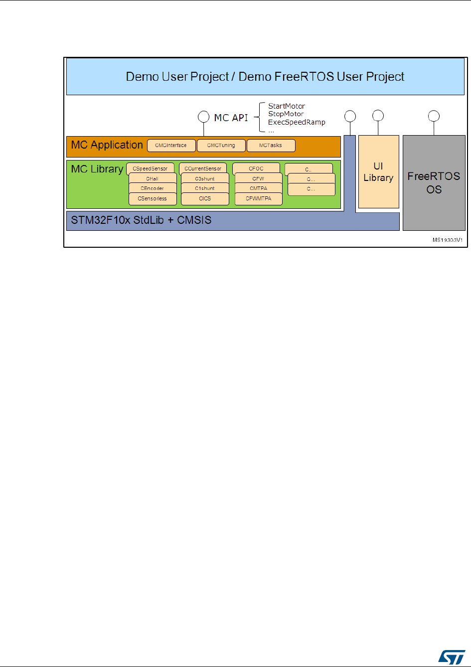
Figure 1: MC software library architecture ................................................................................................ 12
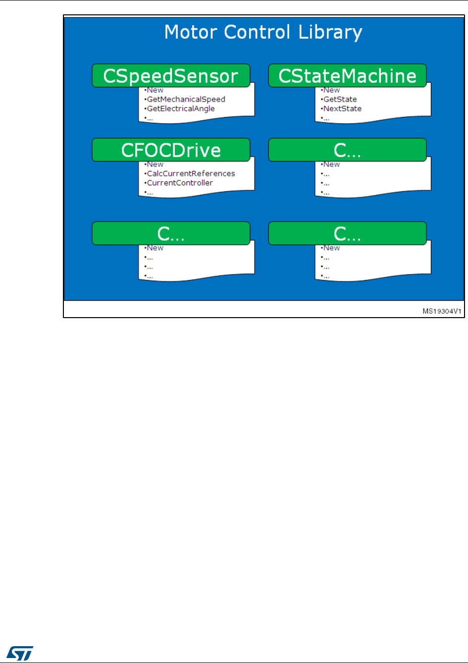
Figure 2: Motor control library ................................................................................................................... 13
Figure 3: Example scenario ...................................................................................................................... 14
Figure 4: Link to ST Motor Profiler ............................................................................................................ 17
Figure 5: Installation folder tree ................................................................................................................ 17
Figure 6: ST Motor Profiler ....................................................................................................................... 17
Figure 7: List of compatible systems ........................................................................................................ 18
Figure 8: Example of settings for surface permanent magnet motors ...................................................... 19
Figure 9: Example of settings for internal permanent magnet motors ...................................................... 19
Figure 10: Motor Profiler results ............................................................................................................... 20
Figure 11: Save motor .............................................................................................................................. 20
Figure 12: Play mode ................................................................................................................................ 21
Figure 13: Workbench new project creation ............................................................................................. 22
Figure 14: ST MC Workbench "Motor" list box ......................................................................................... 22
Figure 15: Enabling on-the-fly startup ....................................................................................................... 24
Figure 16: Basic FOC algorithm structure, torque control ........................................................................ 25
Figure 17: Speed control loop ................................................................................................................... 26
Figure 18: Different PM motor constructions ............................................................................................ 27
Figure 19: Assumed PMSM reference frame convention ......................................................................... 28
Figure 20: MTPA trajectory ....................................................................................................................... 31
Figure 21: MTPA control ........................................................................................................................... 32
Figure 22: Feed-forward current regulation .............................................................................................. 33
Figure 23: Flux-weakening operation scheme .......................................................................................... 34
Figure 24: PID general equation ............................................................................................................... 35
Figure 25: Time domain to discrete PID equations .................................................................................. 36
Figure 26: Block diagram of PI controller.................................................................................................. 36
Figure 27: Closed loop block diagram ...................................................................................................... 37
Figure 28: Pole-zero cancellation ............................................................................................................. 37
Figure 29: Block diagram of closed loop system after pole-zero cancellation .......................................... 38
Figure 30: Vα and Vβ stator voltage components .................................................................................... 39
Figure 31: SVPWM phase voltage waveforms ......................................................................................... 39
Figure 32: Transformation from an abc stationary frame to a rotating frame (q, d).................................. 41
Figure 33: Circle limitation working principle ............................................................................................ 42
Figure 34: PFC hardware support ............................................................................................................ 44
Figure 35: PFC settings ............................................................................................................................ 44
Figure 36: PFC parameters ...................................................................................................................... 45
Figure 37: PFC block diagram .................................................................................................................. 46
Figure 38: PFC hardware settings ............................................................................................................ 47
Figure 39: ST MC Workbench monitor ..................................................................................................... 49
Figure 40: PFC register table in Workbench ............................................................................................ 50
Figure 41: Three-shunt topology hardware architecture ........................................................................... 52
Figure 42: PWM and ADC synchronization .............................................................................................. 53
Figure 43: Inverter leg and shunt resistor position ................................................................................... 54
Figure 44: Low-side switch gate signals (low modulation indexes) .......................................................... 55
Figure 45: Case 1 ..................................................................................................................................... 56
Figure 46: Case 2 ..................................................................................................................................... 56
Figure 47: Case 3 ..................................................................................................................................... 57
Figure 48: Case 4 ..................................................................................................................................... 57
Figure 49: three-shunt hardware architecture .......................................................................................... 58
Figure 50: PWM and ADC synchronization ADC rising edge external trigger.......................................... 59
Figure 51: PWM and ADC synchronization ADC falling edge external trigger ......................................... 59
Figure 52: three inverter legs .................................................................................................................... 60
Figure 53: Low side of phase A, B, C duty cycle > DT + max(TN,TR) ..................................................... 62

List of figures
UM1052
8/178
DocID18458 Rev 9
Figure 54: Low side Phase A duty cycle > DT+ max(TN,TR) ................................................................... 62
Figure 55: Two current samplings performed into 2DDutyA time ............................................................. 63
Figure 56: Two current samplings performed into DDutyAB time ............................................................ 63
Figure 57: Two current samplings cannot performed ............................................................................... 64
Figure 58: Single-shunt hardware architecture ......................................................................................... 64
Figure 59: Single-shunt current reading ................................................................................................... 65
Figure 60: Boundary between two space-vector sectors.......................................................................... 66
Figure 61: Low modulation index .............................................................................................................. 66
Figure 62: Definition of noise parameters ................................................................................................. 67
Figure 63: Regular region ......................................................................................................................... 67
Figure 64: Boundary 1 .............................................................................................................................. 68
Figure 65: Boundary 2 .............................................................................................................................. 68
Figure 66: Boundary 3 .............................................................................................................................. 68
Figure 67: ICS hardware architecture ....................................................................................................... 71
Figure 68: Stator currents sampling in ICS configuration ......................................................................... 72
Figure 69: Current sensing network and overcurrent protection with STM32F302/303 ........................... 73
Figure 70: Current sensing network using external gains ........................................................................ 74
Figure 71: Current sensing network using internal gains plus filtering capacitor ..................................... 75
Figure 72: STMCWB window related to PGA/COMP settings for motor currents .................................... 76
Figure 73: Overvoltage protection network ............................................................................................... 81
Figure 74: STMCWB windows related to ADC/COMP settings for DC bus Voltage ................................ 82
Figure 75: STMCWB windows related to ADC/COMP settings for DC bus Voltage ................................ 82
Figure 76: General sensorless algorithm block diagram .......................................................................... 84
Figure 77: PMSM back-emfs detected by the sensorless state observer algorithm ................................ 85
Figure 78: IPMSM anisotropy fitting HFI algorithm ................................................................................... 88
Figure 79: Incremental system building oscilloscope captures ................................................................ 88
Figure 80: Hall sensors, output-state correspondence ............................................................................. 89
Figure 81: Hall sensor timer interface prescaler decrease ....................................................................... 90
Figure 82: Hall sensor timer interface prescaler increase ........................................................................ 90
Figure 83: TIMx_IRQHandler flowchart .................................................................................................... 91
Figure 84: Hall sensor output transitions .................................................................................................. 92
Figure 85: 60° and 120° displaced Hall sensor output waveforms ........................................................... 93
Figure 86: Determination of Hall electrical phase shift ............................................................................. 94
Figure 87: Encoder output signals: counter operation .............................................................................. 94
Figure 88: MC workspace structure .......................................................................................................... 98
Figure 89: IAR EWARM IDE workspace overview ................................................................................. 100
Figure 90: Keil uVision workspace overview .......................................................................................... 100
Figure 91: Workspace batch build for IAR EWARM IDE ........................................................................ 101
Figure 92: Workspace batch build for Keil uVision ................................................................................. 102
Figure 93: MC Library project in IAR EWARM IDE ................................................................................ 103
Figure 94: MC Library project in Keil uVision.......................................................................................... 104
Figure 95: User project for IAR EWARM IDE ......................................................................................... 105
Figure 96: User project for Keil uVision .................................................................................................. 107
Figure 97: Enabling the Full LCD UI in the ST MC Workbench.............................................................. 108
Figure 98: Flash loader wizard screen.................................................................................................... 109
Figure 99: LCD UI project ....................................................................................................................... 111
Figure 100: Enabling the Light LCD UI in the ST MC Workbench ......................................................... 111
Figure 101: State machine flow diagram ................................................................................................ 113
Figure 102: Radians vs s16 .................................................................................................................... 120
Figure 103: User interface reference ...................................................................................................... 121
Figure 104: Page structure and navigation ............................................................................................. 122
Figure 105: STM32 Motor Control demonstration project welcome message ....................................... 124
Figure 106: Configuration and debug page ............................................................................................ 124
Figure 107: Dual control panel page ....................................................................................................... 130
Figure 108: Speed controller page ......................................................................................................... 132
Figure 109: Current controller page ........................................................................................................ 134

UM1052
List of figures
DocID18458 Rev 9
9/178
Figure 110: Current controller page with polar coordinates .................................................................... 135
Figure 111: Iq, Id component versus Amp, Eps component................................................................... 136
Figure 112: Sensorless tuning STO and PLL page ................................................................................ 137
Figure 113: Example of rev-up sequence ............................................................................................... 139
Figure 114: Sensorless tuning STO and CORDIC page ........................................................................ 140
Figure 115: Light LCD User interface ..................................................................................................... 142
Figure 116: LCD screen for Torque control settings ............................................................................... 143
Figure 117: LCD screen for Target Iq settings ....................................................................................... 143
Figure 118: LCD screen for Target Id settings ....................................................................................... 144
Figure 119: Speed control main settings ................................................................................................ 144
Figure 120: LCD screen for setting Target speed .................................................................................. 145
Figure 121: LCD screen for setting the P term of torque PID ................................................................. 145
Figure 122: LCD screen for setting the P term of the speed PID ........................................................... 146
Figure 123: LCD screen for setting the P term of the speed PID ........................................................... 146
Figure 124: LCD screen for setting the P term of the flux-weakening PI ............................................... 147
Figure 125: LCD screen for setting the P term of the flux PID ............................................................... 147
Figure 126: LCD screen for setting the P term of the flux PID ............................................................... 148
Figure 127: Power stage status .............................................................................................................. 148
Figure 128: Error message shown in the event of an undervoltage fault ............................................... 149
Figure 129: Software layers .................................................................................................................... 150
Figure 130: User interface block diagram ............................................................................................... 151
Figure 131: User interface configuration bit field .................................................................................... 153
Figure 132: LCD manager block diagram ............................................................................................... 154
Figure 133: Serial communication software layers ................................................................................. 156
Figure 134: Serial communication in motor control application .............................................................. 161
Figure 135: Master-slave communication architecture ........................................................................... 162
Figure 136: Set register frame ................................................................................................................ 163
Figure 137: Get register frame ................................................................................................................ 166
Figure 138: Execute command frame ..................................................................................................... 167
Figure 139: Execute ramp frame ............................................................................................................ 168
Figure 140: Speed ramp ......................................................................................................................... 169
Figure 141: Get revup data frame ........................................................................................................... 169
Figure 142: Revup sequence .................................................................................................................. 170
Figure 143: Set revup data frame ........................................................................................................... 171
Figure 144: Set current reference frame................................................................................................. 172
Figure 145: Enabling fast unidirectional serial communication .............................................................. 173

Motor control library features
UM1052
10/178
DocID18458 Rev 9
1 Motor control library features
Motor profiler:
a new algorithm able to auto-measure electromechanical parameters of PMSM
motors (STM32F30x and STM32F4xx only).
One touch tuning:
a new algorithm that uses a single parameter to set up the speed controller
according to the type of load. Together with the Motor profiler, it can be enabled
to achieve the setup and run of an unknown motor from the scratch (only the
STM32F30x and STM32F4xx).
On-the-fly sensorless startup, a new algorithm able to detect if the motor is running
before the startup and skip the acceleration phase if not necessary. The motor is run
in FOC from the begin without need to stop it before the start. This feature is particular
useful for fan application (any STM32F supported).
Single or simultaneous Dual PMSM FOC
sensorless/sensored (Dual PMSM FOC only when running on STM32F103xx
High-Density, STM32F103xx XL-Density, STM32F2xx, STM32F303xB/C or
STM32F4xx)
Speed feedbacks:
Sensorless (High Frequency Injection HFI plus B-EMF State Observer, PLL rotor
speed/angle computation from B-EMF, only for STM32F30x or STM32F4xx);
Sensorless (B-EMF State Observer, PLL rotor speed/angle computation from
BEMF);
Sensorless (B-EMF State Observer, CORDIC rotor angle computation from
BEMF);
60° or 120° displaced Hall sensors decoding, rising/falling edge responsiveness;
Quadrature incremental encoder;
For each motor, dual simultaneous speed feedback processing;
On-the-fly speed sensor switching capability;
Current sampling methods:
Two ICS (only when running on STM32F103xx, STM32F2xx, or STM32F4xx);
Single, common DC-link shunt resistor (ST patented);
Three shunt resistors placed on the bottom of the three inverter legs (only when
running on STM32F103xx, STM32F2xx, STM32F302xB/C, STM32F303xB/C or
STM32F4xx);
Embedded analog (STM32F30x only):
PGA (Programmable Gain Amplifiers) for current sensing: support for three-shunt
and single shunt, internal and external gain;
Comparators for overcurrent protection: support for three-shunt and single shunt,
internal and external threshold;
Comparators for overvoltage protection: support for motor phases short-circuiting
mode and free-wheeling mode, internal and external threshold;
FOC hardware acceleration (STM32F30x only);
ADC queue of context (ST patented architecture) support;
CCM (core coupled memory) RAM support;
Advanced Timer structures for single shunt (ST patented) support;
Flux weakening algorithm to attain higher than rated motor speed (optional);
Feed-Forward, high performance current regulation algorithm (optional);
SVPWM generation:
Centered PWM pattern type;
Adjustable PWM frequency;
Torque control mode, speed control mode; on-the-fly switching capability;

UM1052
Motor control library features
DocID18458 Rev 9
11/178
Brake strategies (optional):
Dissipative DC link brake resistor handling;
Motor phases short-circuiting (with optional hardware over-current protection
disabling);
motor phases free-wheeling;
When running Dual FOC, any combination of the above-mentioned speed feedback,
current sampling, control mode, optional algorithm;
Optimized I-PMSM and SM-PMSM drive;
Programmable speed ramps (parameters duration and final target);
Programmable torque ramps (parameters duration and final target);
Real-time fine tuning of:
PID regulators;
Sensorless algorithm;
Flux weakening algorithm;
Startup procedure (in case of sensorless);
Fault management:
Overcurrent;
Overvoltage;
Overtemperature;
Speed feedback reliability error;
FOC algorithm execution overrun;
Easy customization of options, pin-out assignments, CPU clock frequency through ST
MC Workbench GUI;
C language code:
Compliant with MISRA-C 2004 rules;
Conforms strictly with ISO/ANSI;
Object-oriented programming architecture;
1.1 User project and interface features
There are two available options:
FreeRTOS-based user project (for STM32F103xx and STM32F2xx only);
SysTick-timer-easy-scheduler-based user project;
Available User Interface options (and combinations of them):
Full LCD plus joystick;
Light LCD plus joystick;
Serial communication protocol bidirectional (compatible with ST MC Workbench GUI);
Serial communication protocol fast unidirectional;
Drive system variables logging/displaying via:
SPI;
DAC (DAC peripheral is not present in the STM32F103xx low or medium density;
in this case, RC-filtered PWM signal option is available);
MC software development kit architecture
UM1052
12/178
DocID18458 Rev 9
2 MC software development kit architecture
Figure 1: MC software library architecture
2.1 STM32Fxxx standard peripherals library and CMSIS library
The STM32Fxxx standard peripherals library is an independent firmware package that
contains a collection of routines, data structures and macros that cover the features of the
STM32 peripherals. Version 3.5.0 of STM32F10x standard peripheral library is included in
the MC SDK, version 1.0.0 is available for STM32F0x, STM32F2xx and STM32F4xx,
version 1.0.1 is available for STM32F30x. The STM32Fxxx standard peripherals library is
CMSIS and MISRA-C compliant. Visit www.st.com/stm32 for complete documentation.
2.2 Motor control library
The motor control library is a wide collection of classes that describe the functionality of
elements involved in motor control (such as speed sensors, current sensors, algorithms).
Each class has an interface, which is a list of methods applicable to objects of that class.
Two distributions of the motor control library are available:
Web distribution, available free of charge at www.st.com, where the motor control
library is provided as a compiled .lib file.
Confidential distribution, available free of charge on demand by contacting your
nearest ST sales office or support team. Source class files are provided, except for ST
protected IPs, which are furnished as compiled object files. Source files of protected
IPs can also be provided free of charge to ST partners upon request. Contact your
nearest ST office or support team for further information.
UM1052
MC software development kit architecture
DocID18458 Rev 9
13/178
Figure 2: Motor control library
The motor control library uses the lower STM32Fxxx Standard Peripheral Library layer
extensively for initializations and settings on peripherals. Direct access to STM32
peripheral registers is preferred when optimizations (in terms of execution speed or code
size) are required. More information about the Motor Control Library, its classes and object
oriented programming, can be found in UM1053 Advanced developers guide for
STM32F0x/F100xx/F103xx/STM32F2xx/F30x/F4xx MCUs PMSM single/dual FOC library.
2.3 Motor control application
The Motor Control Application (MCA) is an application that uses the motor control library in
order to accomplish commands received from the user level. This set of commands is
specified in its Application Programming Interface (API).
During its boot stage, the MCA creates the required controls in accordance with actual
system parameters, defined in specific .h files that are generated by the ST MC Workbench
GUI (or manually edited). It coordinates them continuously for the purpose of
accomplishing received commands, by means of tasks of proper priority and periodicity.
More information about the MCA can be found in Section 12: "MC application programming
interface (API)", and details on tasks and implemented algorithms in UM1053 Advanced
developers guide for STM32F0x/F100xx/F103xx/STM32F2xx/F30x/F4xx MCUs PMSM
single/dual FOC library.
2.4 Demonstration user project
At the user level, a user project has been implemented to demonstrate how to interact with
the MC API to successfully achieve the execution of commands. Depending on definable
options, the user project can act as a Human Interface Device (using a joystick, buttons

MC software development kit architecture
UM1052
14/178
DocID18458 Rev 9
and LCD screens), as a command launcher through a serial communication protocol, as a
data logging/displaying utility, or as a tuning tool.
Two versions of this user project are available (STM32F103xx and STM32F2xx only). One
is based on FreeRTOS, the other is not. The demonstration user project can be dismantled
and replaced by the user application layer, or quite easily integrated, as shown in Figure 3:
"Example scenario". The user application layer uses the STM32Fxxx Standard Library for
its own purposes and sends commands directly to the MC API while the serial
communication interface, provided in the demonstration user project, dispatches
commands received from the outer world to the MC API.
More information about the modules integrated with the demonstration user project, such
as serial communication protocol, drive variables monitoring through DAC / SPI, HID
(generically called 'UI library') and a description of LCD screens can be found in Section
11: "Full LCD user interface" and Section 15: "User Interface class overview".
Figure 3: Example scenario

UM1052
Documentation architecture
DocID18458 Rev 9
15/178
3 Documentation architecture
3.1 Where to find the information you need
Technical information about the MC SDK is arranged thus:
User manual UM1052: STM32F PMSM single/dual FOC SDK v4.3 (available on
www.st.com):
features
architecture
workspace
customization processes
overview of algorithms implemented (FOC, current sensors, speed sensors,
embedded analog topologies supported)
MC API
sample user project
sample LCD user interface
sample serial communication protocol
User manual UM1053: Advanced developers guide for STM32F MCUs PMSM
single/dual FOC library (available on www.st.com):
object oriented programming style used for developing the MC library
description of classes that belong to the MC library
interactions between classes
description of tasks of the MCA
MC library source documentation (Doxygen compiled HTLM file).
describes the public interface of each class of the MC library (methods,
parameters required for object creation)
MC Application source documentation (Doxygen compiled HTML file).
describes the classes that make up the MC API
User Interface source documentation (Doxygen compiled HTML file).
describes the classes that make up the UI library
STM32F0xx, STM32F10xx, STM32F2xx, STM32F30x or STM32F4xx Standard
Peripherals Library source documentation (Doxygen compiled HTML file).
ST MC Workbench GUI documentation.
describes the steps and parameters required to customize the library, as shown
in the GUI
In-depth documentation of certain algorithms (sensorless position/speed detection,
flux weakening, MTPA, feed-forward current regulation).
Visit www.st.com or contact your nearest ST sales office for further information.
3.2 Related documents
Available from www.arm.com
Cortex®-M0 Technical Reference Manual, available from: http://infocenter.arm.com.
Cortex®-M3 Technical Reference Manual, available from: http://infocenter.arm.com.
Cortex®-M4 Technical Reference Manual, available from:http://infocenter.arm.com.
Available from www.st.com or your STMicroelectronics sales office
STM32F030x datasheets
STM32F051x datasheets

Documentation architecture
UM1052
16/178
DocID18458 Rev 9
STM32F100xx datasheets
STM32F103xx datasheets
STM32F20x and STM32F21x datasheets
STM32F302x6/8 datasheets
STM32F302xB/C datasheets
STM32F303xB/C datasheets
STM32F40x and STM32F41x datasheets
STM32F051x user manual (RM0091)
STM32F100xx user manual (RM0041)
STM32F103xx user manual (RM0008)
STM32F20x and STM32F21x user manual (RM0033)
STM32F30x user manual (RM0316)
STM32F40x and STM32F41x user manual (RM0090)
STM32F103xx AC induction motor IFOC software library V2.0 (UM0483)
STM32 and STM8 Flash Loader demonstrator (UM0462)

UM1052
Overview of the FOC and other implemented
algorithms
DocID18458 Rev 9
17/178
4 Overview of the FOC and other implemented
algorithms
4.1 The new Motor Profiler procedure
1
Execute the “STMotorProfiler.exe” application from the Motor Profiler (MP) button shown
in the ST Motor Control Workbench figured below.
Alternatively, you can run the file from the “STMotorProfiler” folder in the installation
folder.
Figure 4: Link to ST Motor Profiler
Figure 5: Installation folder tree
Figure 6: ST Motor Profiler
Overview of the FOC and other implemented
algorithms
UM1052
18/178
DocID18458 Rev 9
2
Click “Select Boards” button in the Motor Profiler opening screen to open a list of
supported boards.
The Motor Profiler feature can be used only in the systems listed there.
Figure 7: List of compatible systems
3
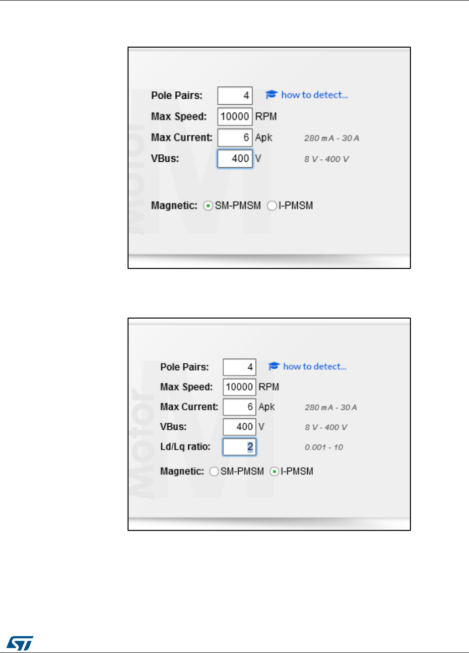
Select the system that you are using.
For example, if you are using the P-NUCLEO-IHM001, select the system with NUCLEO-
F302R8 plus X-NUCLEO-IHM07M1.
4
Insert the number of pole pairs on your motor.
This field is mandatory.
5
Insert the Max Speed field.
This is not mandatory; if not selected, the Motor Profiler attempts to reach the maximum
allowed speed according to the motor and to the system you are using.
6
Insert the Max Current field.
This is not mandatory; it is expressed in amperes and represents the maximum peak
current delivered to the motor.
7
Insert the expected bus voltage provided to the system.
This is not mandatory; it is the DC bus voltage supplied to the power stage for low
voltage applications or √2VACrms for applications supplied with a high voltage AC power
supply.
UM1052
Overview of the FOC and other implemented
algorithms
DocID18458 Rev 9
19/178
8
Select SM-PMSM in the magnetic field if the motor has a surface permanent magnet.
It is the default setting.
Figure 8: Example of settings for surface permanent magnet motors
9
If the motor has an internal permanent magnet, select I-PMSM.
You must also input the Ld/Lq ratio.
Figure 9: Example of settings for internal permanent magnet motors
10
Check the boards are correctly configured for motor control, supplied with the expected
input voltage and connected with the serial communication cable and JTAG/SWD
programming cable. Check the user manual of each evaluation board for the correct
configuration, voltage range, serial communication capabilities and
programming/debugging interface.
Overview of the FOC and other implemented
algorithms
UM1052
20/178
DocID18458 Rev 9
11
Click on the “Connect” button.
a. If the board is new or has been erased, the correct FW is automatically loaded
into the microcontroller.
b. If the programming procedure can’t be executed, check the JTAG/SWD
programming cable.
c. If the programming procedure is executed but Motor Profiler still can’t
communicate with the board, check the serial communication connections.
12
Once connection is established, press the profile button to start the procedure.
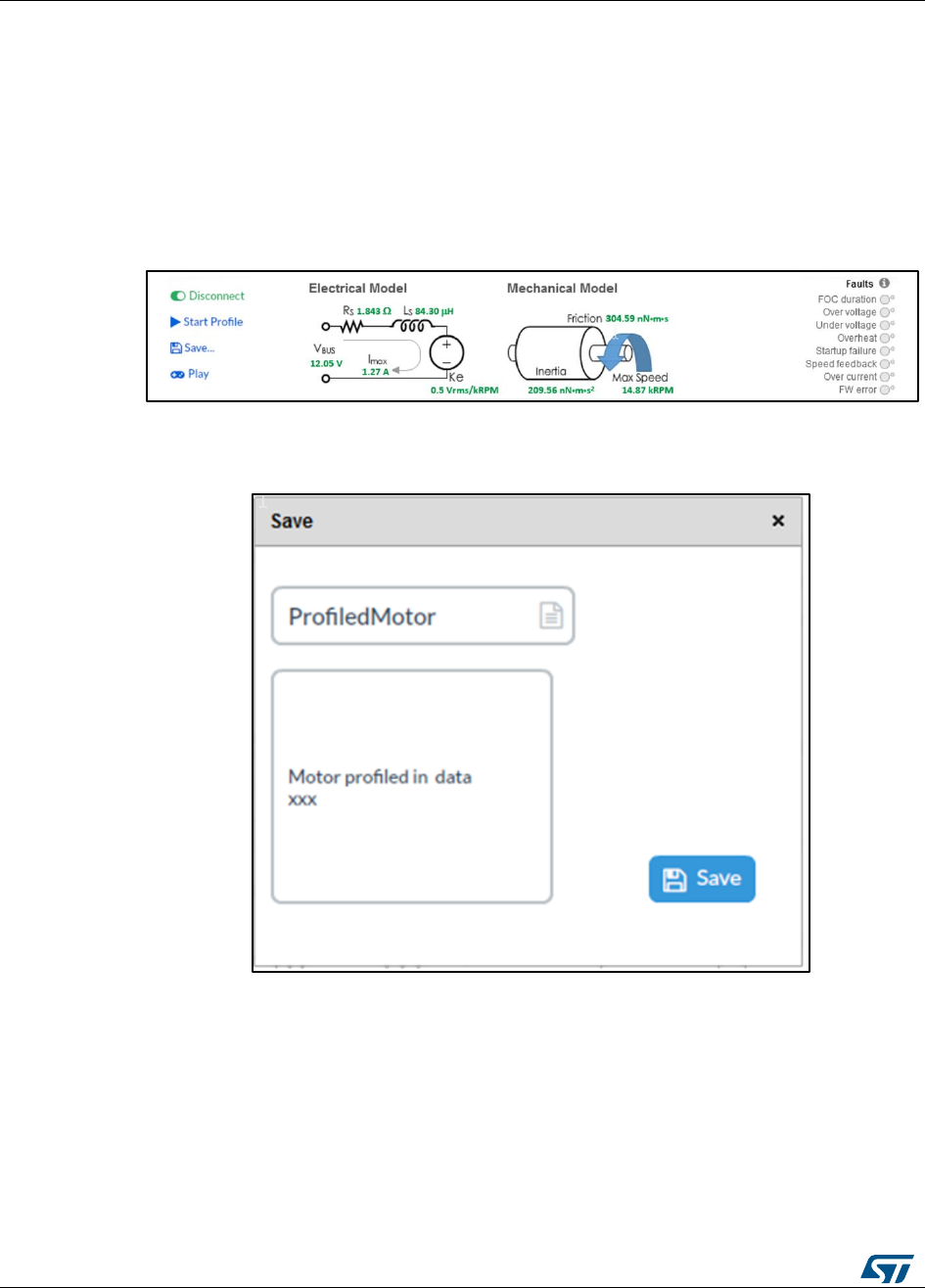
At the end of the procedure, all measured parameters are shown and the “Save” button is enabled.
Figure 10: Motor Profiler results
13
Click on the “Save” to store the motor profiled motor for later use with ST MC
Workbench.
Figure 11: Save motor
UM1052
Overview of the FOC and other implemented
algorithms
DocID18458 Rev 9
21/178
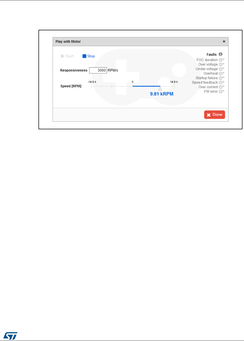
14
At the end of the procedure, the motor is recognized and can be controlled via the Play
button without having to repeat the Motor Profiler procedure. The user can start and stop
the motor, adjust the speed and accelerate in the clockwise or anti-clockwise directions.
Figure 12: Play mode
15
If the Motor Profiler procedure is required, click the Profile button to force a new
procedure.
Overview of the FOC and other implemented
algorithms
UM1052
22/178
DocID18458 Rev 9
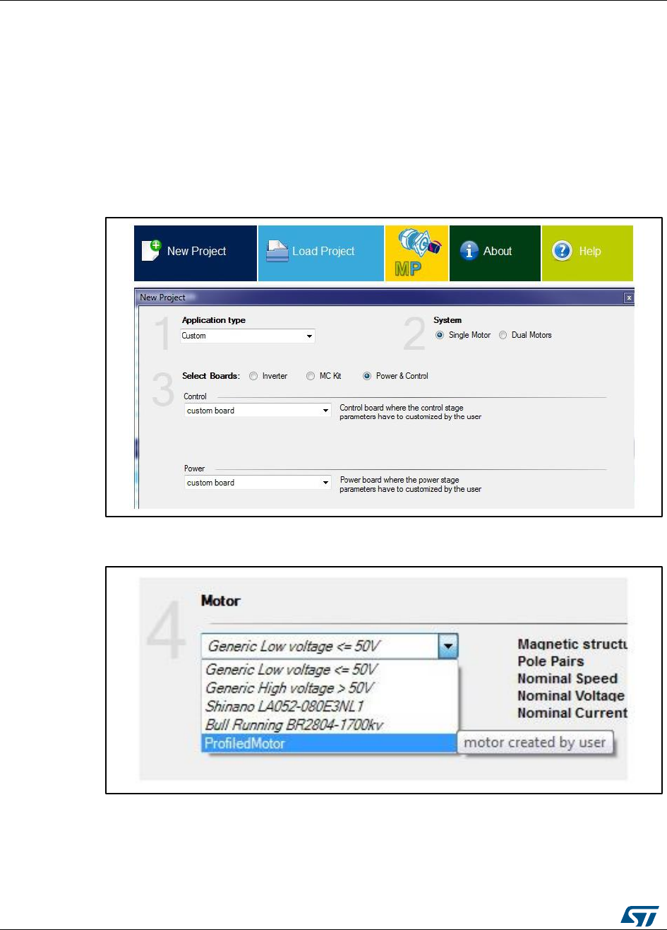
16
When the motor is successfully profiled, open ST MC Workbench and select “New
Project”.
d. Select the “Application Type”, Single Motor or Dual Motor, and the board to be
used.
e. If the board is a complete inverter (single board with power and control), select
“Inverter” combo box and then select the inverter in the list box.
f. If an MC Kit is used (like the P-NUCLEO-IHM001), select “MC Kit” combo box
and then select the kit in the list box.
g. If a system composed by a control evaluation board plus power evaluation
board is used, select “Power & Control” combo box and select both Control
board and Power board.
Figure 13: Workbench new project creation
17
Then select the motor from the “Motor” list box with all the saved motor profiles.
Figure 14: ST MC Workbench "Motor" list box
The created project imports the HW settings according to the selected boards and the motor
settings according the Motor profiler results; it also imports other settings like PWM frequency and
startup acceleration used during the Motor Profiler procedure.

UM1052
Overview of the FOC and other implemented
algorithms
DocID18458 Rev 9
23/178
18
Proceed with the usual generation of the .h file, compilation and flashing as described in
Chapter 9 or in the “Hands-on” (STM32 PMSM FOC SDK Hands-on workshop with
hardware tools).
4.1.1 Restrictions and disclaimer
The Motor Profiler algorithm is intended for rapid evaluation of the ST motor control
solution. You can use it to drive any three-phase motor with an internal permanent magnet
without any specific instruments or special skills.
The measurements performed, however, cannot be as precise as proper instrumentation.
The Motor Profiler measurement errors can be particularly significant for motors with
parameters those indicated in the following table.
Moreover, it is important to choose the appropriate HW according to the characteristics of
the motor. For instance, the maximum current of the motor should match the maximum
current of the board as closely as possible.
Motor Profiler can be used only using compatible ST evaluation boards. Please use the
STMotorProfiler tool to view the list of the supported systems.
4.2 On-the-fly sensorless startup
The on-the-fly sensorless startup algorithm can detect if the motor is running before startup
and skip the acceleration phase if it is not required. If the motor runs at a speed that is
above the allowed threshold, the firmware applies the FOC from the beginning, without
having to stop and restart it.
This feature is particularly useful for fan applications and can be enabled when Sensor-less
(Observer+PLL) or Sensor-less (Observer+Cordic) is selected in the Drive Management –
Speed Position Feedback Management dialog, by checking the On-the-Fly startup check
box.
Overview of the FOC and other implemented
algorithms
UM1052
24/178
DocID18458 Rev 9
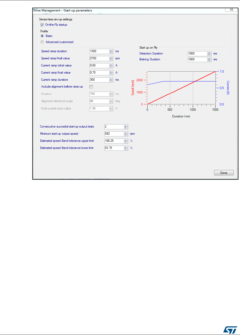
Figure 15: Enabling on-the-fly startup
Minimum startup-output speed represents the minimum speed for which the sensorless
observer provides reliable measurements and is used to determine if it is possible to skip
the acceleration phase. It can be set with reference to the nominal speed of the motor.
After enabling on-the-fly startup, the following parameters become available:
Detection Duration – the OTF startup detection phase duration (in ms) of in which the
reliability of the sensorless measurements are tested in order to validate the speed
and run directly in FOC.
Braking Duration – the braking phase duration (in ms) applied if the sensorless
measurements are not reliable during the detection phase; the motor is brought to a
stop before the new acceleration is applied.
Both basic and advanced startup profiles can be used if the OTF startup is enabled. The
startup profile can be set by the user to define the acceleration strategy if the speed of the
motor is below the reliability threshold during the detection phase.
4.3 Introduction to the PMSM FOC drive
This software library is designed to achieve the high dynamic performance in AC
permanent-magnet synchronous motor (PMSM) control offered by the well-established field
oriented control (FOC) strategy.
With this approach, it can be stated that, by controlling the two currents iqs and ids, which
are mathematical transformations of the stator currents, it is possible to offer
electromagnetic torque (Te) regulation and, to some extent, flux weakening capability.
UM1052
Overview of the FOC and other implemented
algorithms
DocID18458 Rev 9
25/178
This resembles the favorable condition of a DC motor, where those roles are held by the
armature and field currents.
Therefore, it is possible to say that FOC consists of controlling and orienting stator currents
in phase and quadrature with the rotor flux. This definition makes it clear that a means of
measuring stator currents and the rotor angle is needed.
Basic information on the algorithm structure (and then on the library functions) is
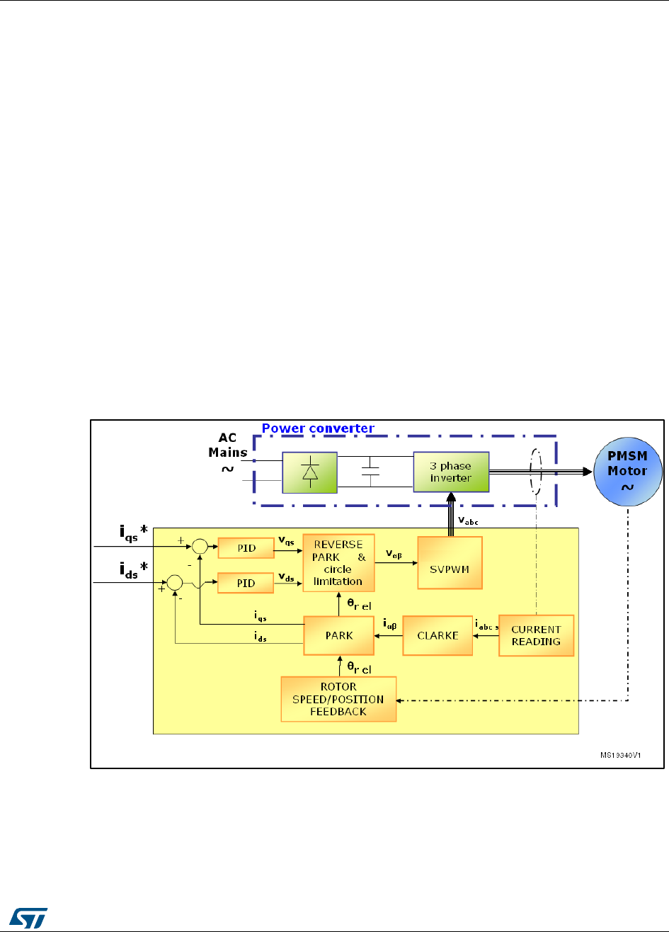
represented in Figure 15: "Basic FOC algorithm structure, torque control".
The iqs and ids current references can be selected to perform electromagnetic torque
and flux control.
The space vector PWM block (SVPWM) implements an advanced modulation method
that reduces current harmonics, thus optimizing DC bus exploitation.
The current reading block allows the system to measure stator currents correctly,
using either cheap shunt resistors or market-available isolated current Hall sensors
(ICS).
The rotor speed/position feedback block allows the system to handle Hall sensor or
incremental encoder signals in order to correctly acquire the rotor angular velocity or
position. Moreover, this firmware library provides sensorless detection of rotor
speed/position.
The PID-controller blocks implement proportional, integral and derivative feedback
controllers (current regulation).
The Clarke, Park, Reverse Park & Circle limitation blocks implement the mathematical
transformations required by FOC.
Figure 16: Basic FOC algorithm structure, torque control
Overview of the FOC and other implemented
algorithms
UM1052
26/178
DocID18458 Rev 9
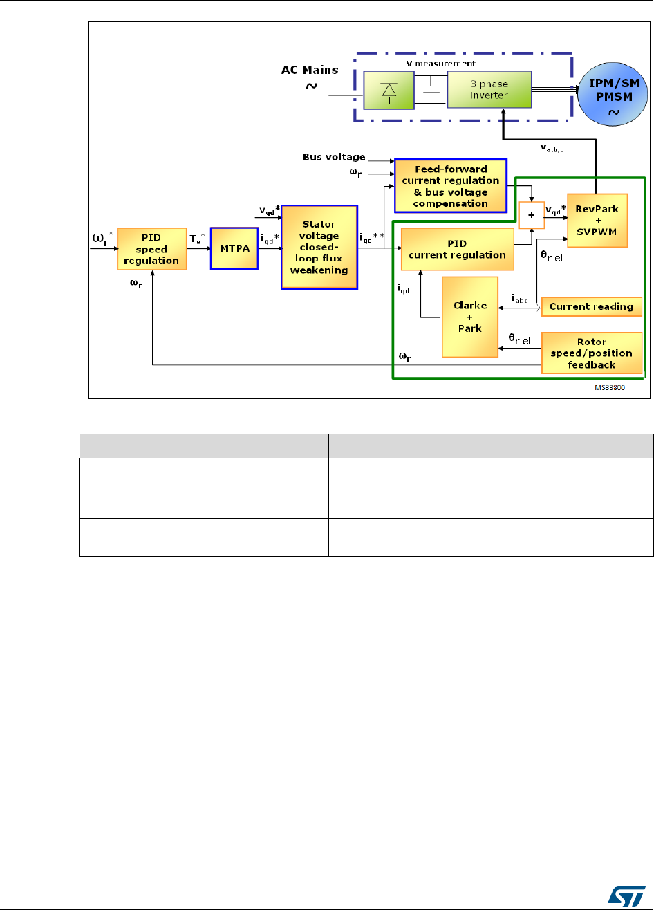
Figure 17: Speed control loop
Table 2: References
Reference
Detail
Section 6.6: "PMSM maximum torque per
ampere (MTPA) control"
Explains the MTPA (maximum-torque-per-
ampere) strategy optimized for IPMSM.
Section 6.8: "Flux-weakening control"
Explains the flux-weakening control.
Section 6.7: "Feed-forward current
regulation"
Shows how to take advantage of the feed-forward
current regulation.
Figure 16: "Speed control loop" shows the speed control loop built around the 'core' torque
control loop, plus additional specific features offered by this motor control library (see Table
2: "References"). Each of them can be set as an option, depending on the motor being
used and user needs, via the ST MC Workbench GUI, which generates the .h file used to
correctly initialize the MCA during its boot stage.
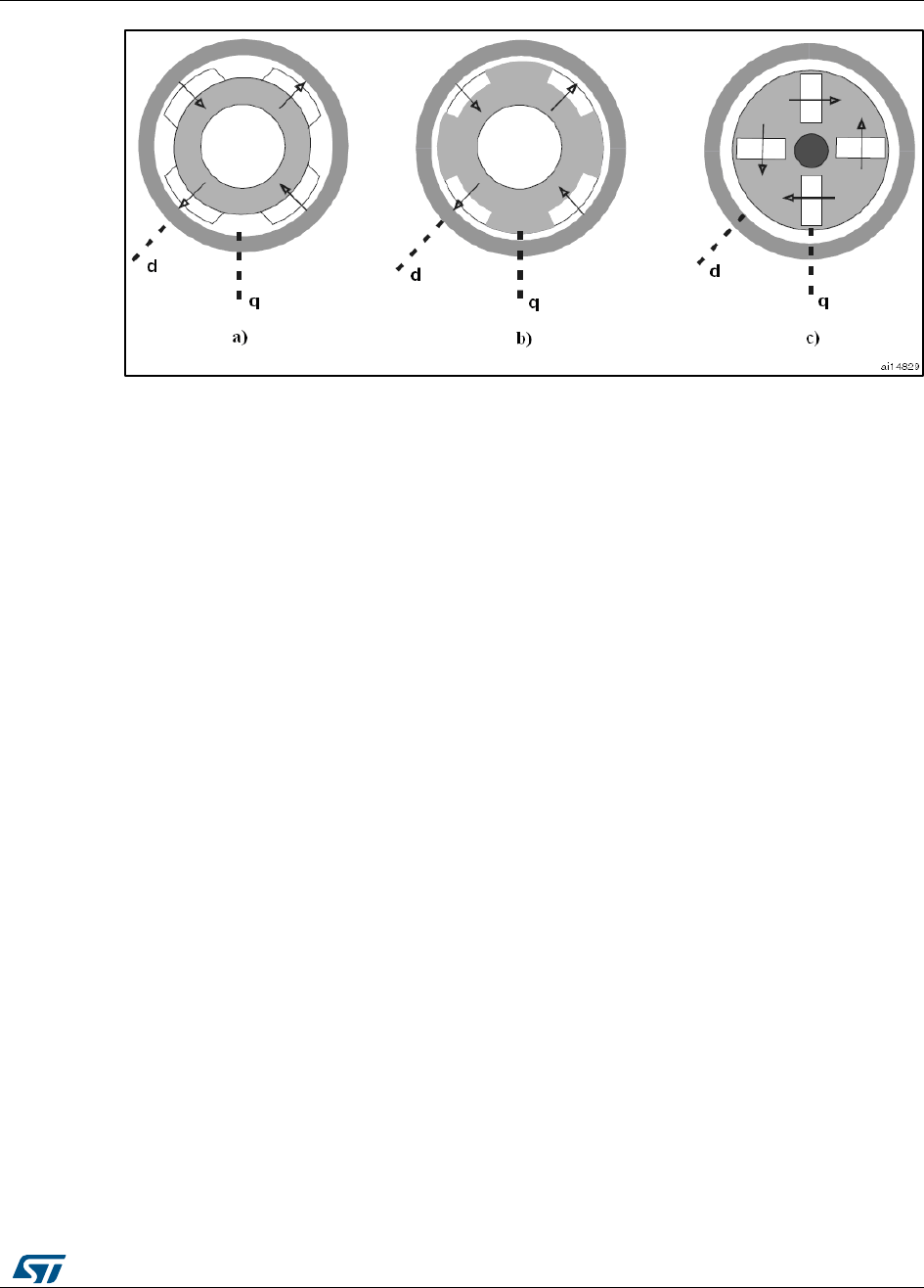
4.4 PM motor structures
Two different PM motor constructions are available:
In drawing a) in Figure 17: "Different PM motor constructions", the magnets are glued
to the surface of the rotor, and this is the reason why it is referred to as SM-PMSM
(surface mounted PMSM)
In drawings b) and c) in Figure 17: "Different PM motor constructions", the magnets
are embedded in the rotor structure. This construction is known as IPMSM (interior
PMSM)
UM1052
Overview of the FOC and other implemented
algorithms
DocID18458 Rev 9
27/178
Figure 18: Different PM motor constructions
SM-PMSMs inherently have an isotropic structure, which means that the direct and
quadrature inductances Ld and Lq are the same. Usually, their mechanical structure allows
a wider airgap which, in turn, means lower flux weakening capability.
On the other hand, IPMSMs show an anisotropic structure (with Ld < Lq, typically), slight in
the b) construction (called inset PM motor), strong in the c) configuration (called buried or
radial PM motor). This peculiar magnetic structure can be exploited (as explained in
Section 6.6: "PMSM maximum torque per ampere (MTPA) control") to produce a greater
amount of electromagnetic torque. their fine mechanical structure usually shows a narrow
airgap, thus giving good flux weakening capability.
This firmware library is optimized for use in conjunction with SM-PMSMs and IPMSMs.
machines.
Overview of the FOC and other implemented
algorithms
UM1052
28/178
DocID18458 Rev 9
4.5 PMSM fundamental equations
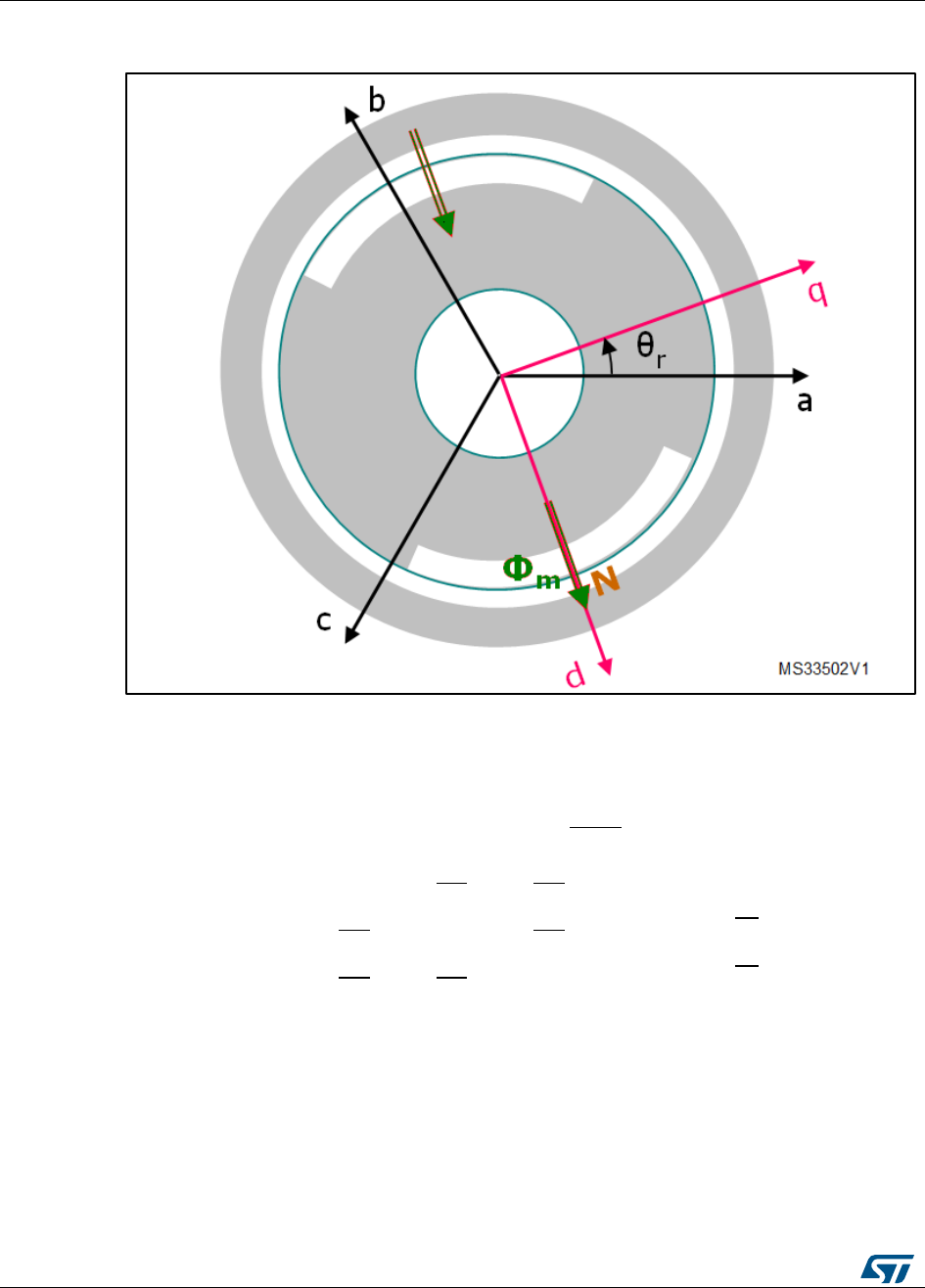
Figure 19: Assumed PMSM reference frame convention
With reference to Figure 18: "Assumed PMSM reference frame convention", the motor
voltage and flux linkage equations of a PMSM (SM-PMSM or IPMSM) are generally
expressed as:
where:
rs = stator phase winding resistance
Lls = stator phase winding leakage inductance
Lms = stator phase winding magnetizing inductance; in case of an IPMSM, self and
mutual inductances have a secon harmonic component L2s proportional to cos(2θr + k
× 2π/3), with k = 0±1, in addition to the constant component Lms(neglecting higher-
order harmonics)
θr = rotor electrical angle
Φm = flux linkage due to permanent magnets

UM1052
Overview of the FOC and other implemented
algorithms
DocID18458 Rev 9
29/178
The complexity of these equations is apparent, as the three stator flux linkages are
mutually coupled, and as they are dependent on the rotor position, which is time-varying
and a function of the electromagnetic and load torques.
The reference frame theory simplifies the PM motor equations by changing a set of
variables that refers the stator quantities abc (that can be visualized as directed along axes
each 120° apart) to qd components, directed along a 90° apart axes, rotating
synchronously with the rotor, and vice versa. The d “direct” axis is aligned with the rotor
flux, while the q “quadrature” axis leads at 90 degrees in the positive rolling direction.
The motor voltage and flux equations are simplified to:
For an SM-PMSM, the inductances of the d- and q- axis circuits are the same (refer to
Section 6.4: "PM motor structures"), that is:
On the other hand, IPMSMs show a salient magnetic structure; thus, their inductances can
be written as:
4.5.1 SM-PMSM field-oriented control (FOC)
The equations below describe the electromagnetic torque of an SM-PMSM:
The last equation makes it clear that the quadrature current component iqs has linear
control on the torque generation, whereas the current component ids has no effect on it (as
mentioned above, these equations are valid for SM-PMSMs).
Therefore, if Is is the motor rated current, then its maximum torque is produced for iqs = Is
and ids = 0 (in fact,
). In any case, it is clear that, when using an SM-PMSM,
the torque/current ratio is optimized by letting ids = 0. This choice corresponds to the MTPA
(maximum-torque-per-ampere) control for isotropic motors.
On the other hand, the magnetic flux can be weakened by acting on the direct axis current
ids; this extends the achievable speed range, but at the cost of a decrease in maximum
quadrature current iqs, and hence in the electromagnetic torque supplied to the load (see
Section 6.8: "Flux-weakening control" for details about the Flux weakening strategy).
In conclusion, by regulating the motor currents through their components iqs and ids, FOC
manages to regulate the PMSM torque and flux. Current regulation is achieved by means
of what is usually called a “synchronous frame CR-PWM”.

Overview of the FOC and other implemented
algorithms
UM1052
30/178
DocID18458 Rev 9
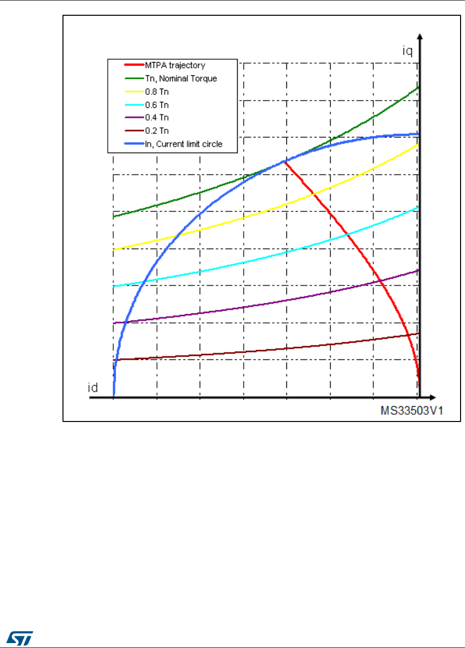
4.6 PMSM maximum torque per ampere (MTPA) control
The electromagnetic torque equation of an IPMSM is:
The first term in this expression is the PM excitation torque. The second term is the so-
called reluctance torque, which represents an additional component due to the intrinsic
salient magnetic structure. Besides, since Ld < Lq typically, reluctance and excitation
torques have the same direction only if ids < 0.
Considering the torque equation, it can be pointed out that the current components iqs and
ids both have a direct influence on the torque generation.
The aim of the MTPA (maximum-torque-per-ampere) control is to calculate the reference
currents (iqs, ids) which maximize the ratio between produced electromagnetic torque and
copper losses (under the following condition).
Therefore, given a set of motor parameters (pole pairs, direct and quadrature inductances
Ld and Lq, magnets flux linkage, nominal current), the MTPA trajectory is identified as the
locus of (iqs, ids) pairs that minimizes the current consumption for each required torque (see
Figure 19: "MTPA trajectory").
This feature can be activated through correct settings in .h parameter files (generated by
the ST MC Workbench GUI) used to initialize the MC Application during its boot stage.
In confidential distribution, the classes that implement the MTPA algorithm are provided as
compiled object files. The source code is available free of charge from ST on request.
Please contact your nearest ST sales office.
UM1052
Overview of the FOC and other implemented
algorithms
DocID18458 Rev 9
31/178
Figure 20: MTPA trajectory
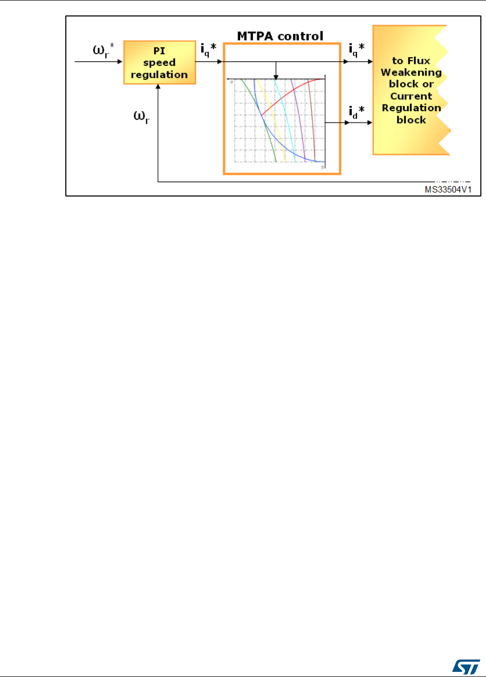
Figure 20: "MTPA control" shows the MTPA strategy implemented inside a speed-control
loop. In this case, iq* (output of the PI regulator) is fed to the MTPA function, id* is chosen by
entering the linear interpolated trajectory.
Overview of the FOC and other implemented
algorithms
UM1052
32/178
DocID18458 Rev 9
Figure 21: MTPA control
In all cases, by acting on the direct axis current ids, the magnetic flux can be weakened so
as to extend the achievable speed range. As a consequence of entering this operating
region, the MTPA path is left (see Section 6.8: "Flux-weakening control" for details about
the flux-weakening strategy).
In conclusion, by regulating the motor currents through their iqs and ids components, FOC
manages to regulate the PMSM torque and flux. Current regulation is then achieved by
means of what is usually called a “synchronous frame CR-PWM”.
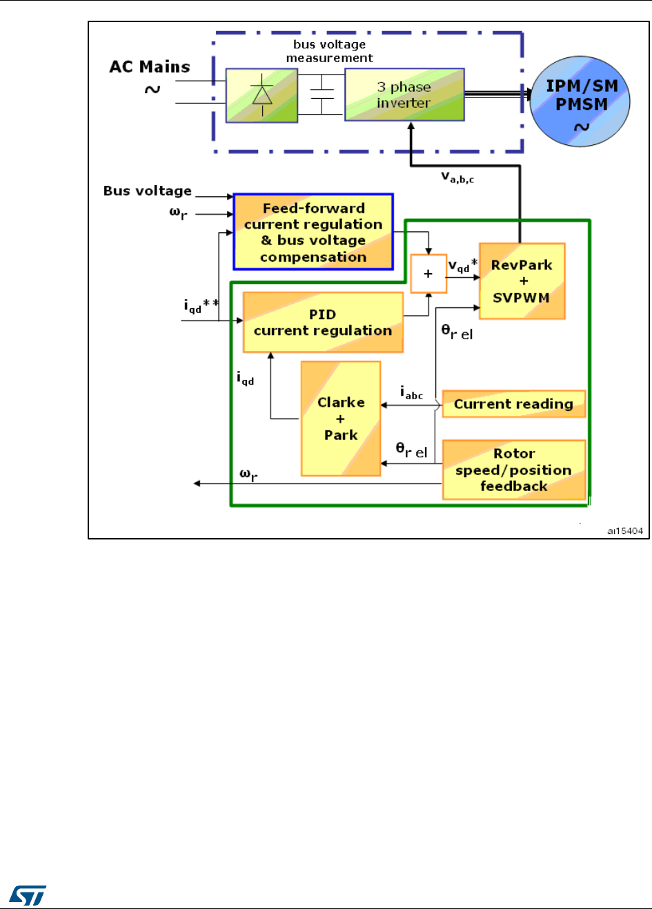
4.7 Feed-forward current regulation
The feed-forward feature provided by this firmware library aims at improving the
performance of the CR-PWM (current-regulated pulse width modulation) part of the motor
drive.
It calculates in advance the vq* and vd* stator voltage commands required to feed the motor
with the iq** and id** current references. By doing so, it backs up the standard PID current
regulation (see Figure 21: "Feed-forward current regulation").
The feed-forward feature works in the synchronous reference frame and requires good
knowledge of some machine parameters, such as the winding inductances Ld and Lq (or Ls
if an SM-PMSM is used) and the motor voltage constant Ke.
The feed-forward algorithm has been designed to compensate for the frequency-dependent
back emf’s and cross-coupled inductive voltage drops in permanent magnet motors. As a
result, the q-axis and d-axis PID current control loops become linear, and a high
performance current control is achieved.
As a further effect, since the calculated stator voltage commands vq* and vd* are
compensated according to the present DC voltage measurement, a bus voltage ripple
compensation is accomplished.
UM1052
Overview of the FOC and other implemented
algorithms
DocID18458 Rev 9
33/178
Figure 22: Feed-forward current regulation
Depending on certain overall system parameters, such as the DC bulk capacitor size,
electrical frequency required by the application, and motor parameters, the feed-forward
functionality can provide a major or a poor contribution to the motor drive. It is therefore
recommended that you assess the resulting system performance and enable the
functionality only if a valuable effect is measured.
This feature can be activated through proper settings in .h parameter files (generated by
the ST MC Workbench GUI) used to initialize the MCA during its boot stage.
In confidential distribution, the classes that implement the feed-forward algorithm are
provided as compiled object files. The source code is available free of charge from ST on
request. Please contact your nearest ST sales office.
4.8 Flux-weakening control
The purpose of the flux-weakening functionality is to expand the operating limits of a
permanent-magnet motor by reaching speeds higher than rated, as many applications
require under operating conditions where the load is lower than rated. Here, the rated
speed is considered to be the highest speed at which the motor can still deliver maximum
torque.

Overview of the FOC and other implemented
algorithms
UM1052
34/178
DocID18458 Rev 9
The magnetic flux can be weakened by acting on direct axis current id; given a motor rated
current In, such as
, if we choose to set id ≠ 0, then the maximum available
quadrature current iq is reduced. Consequently, in case of an SM-PMSM, as shown in
Section 6.5.1: "SM-PMSM field-oriented control (FOC)", the maximum deliverable
electromagnetic torque is also reduced. On the other hand, for an IPM motor, acting
separately on id causes a deviation from the MTPA path (as explained in Section 6.6:
"PMSM maximum torque per ampere (MTPA) control").
“Closed-loop” flux weakening has been implemented. Accurate knowledge of machine
parameters is not required, which strongly reduces sensitivity to parameter deviation (see
[3]-[4] in Appendix Section 19: "References"). This scheme is suitable for both IPMSMs and
SM-PMSMs.
The control loop is based on stator voltage monitoring (Figure 22: "Flux-weakening
operation scheme" shows the diagram).
The current regulator output Vs is checked against a settled threshold (“voltage level*”
parameter). If Vs is beyond that limit, the flux-weakening region is entered automatically by
regulating a control signal, ifw*, that is summed up to ids*, the output of the MTPA controller.
This is done by means of a PI regulator (whose gain can be tuned in real-time) in order to
prevent the saturation of the current regulators. It clearly appears, then, that the higher the
voltage level* parameter is settled (by keeping up current regulation), the higher the
achieved efficiency and maximum speed.
If Vs is smaller than the settled threshold, then ifw decreases to zero and the MTPA block
resumes control.
The current ids** output from the flux-weakening controller must be checked against ids max
to avoid the demagnetization of the motor.
Figure 23: Flux-weakening operation scheme
This feature can be activated through correct settings in .h parameter files (generated by
the ST MC Workbench GUI) used to initialize the MC Application during its 'boot' stage.
In confidential distribution, the classes that implement the flux weakening algorithm are
provided as compiled object files. The source code is available free of charge from ST on
request. Please contact your nearest ST sales office.
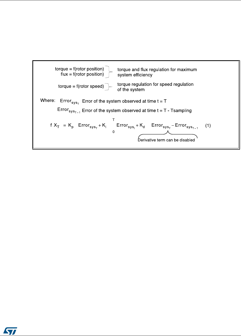
UM1052
Overview of the FOC and other implemented
algorithms
DocID18458 Rev 9
35/178
4.9 PID regulator theoretical background
The regulators implemented for Torque, Flux and Speed are actually Proportional Integral
Derivative (PID) regulators. PID regulator theory and tuning methods are subjects which
have been extensively discussed in technical literature. This section provides a basic
reminder of the theory.
PID regulators are useful to maintain a level of torque, flux or speed according to a desired
target.
Figure 24: PID general equation
Equation 1 corresponds to a classical PID implementation, where:
Kp is the proportional coefficient.
Ki is the integral coefficient.
Kd is the differential coefficient.
4.9.1 Regulator sampling time setting
The sampling time needs to be modified to adjust the regulation bandwidth. As an
accumulative term (the integral term) is used in the algorithm, increasing the loop time
decreases its effects (accumulation is slower and the integral action on the output is
delayed). Inversely, decreasing the loop time increases its effects (accumulation is faster
and the integral action on the output is increased). This is why this parameter has to be
adjusted prior to setting up any coefficient of the PID regulator.
In order to keep the CPU load as low as possible and as shown in Equation 1 in Figure 23:
"PID general equation", the sampling time is directly part of the integral coefficient, thus
avoiding an extra multiplication. Figure 24: "Time domain to discrete PID equations"
describes the link between the time domain and the discrete system.
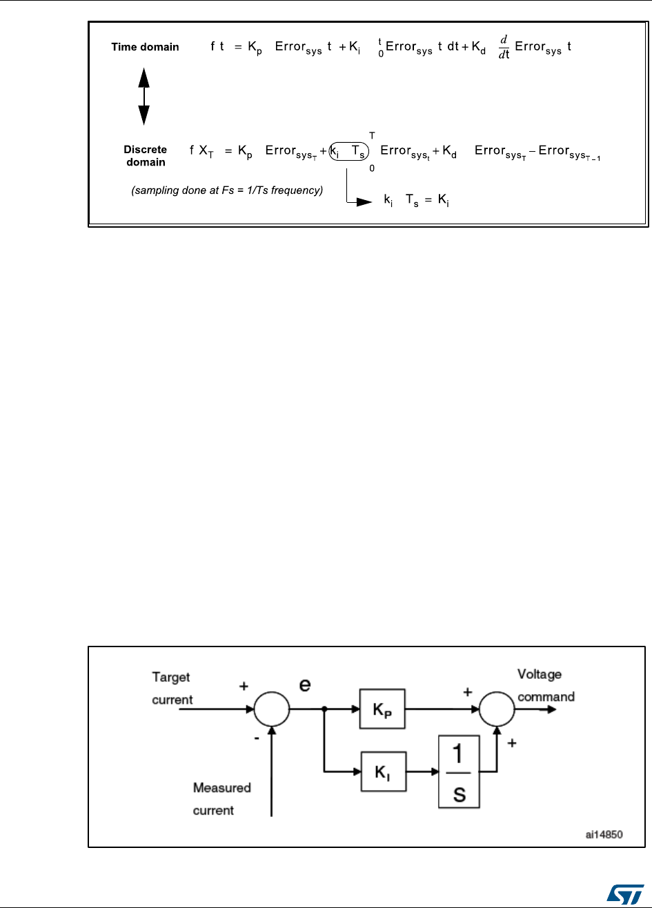
Overview of the FOC and other implemented
algorithms
UM1052
36/178
DocID18458 Rev 9
Figure 25: Time domain to discrete PID equations
In theory, the higher the sampling rate, the better the regulation. In practice, you must keep
in mind that:
The related CPU load will grow accordingly.
For speed regulation, there is absolutely no need to have a sampling time lower than
the refresh rate of the speed information fed back by the external sensors; this
becomes especially true when Hall sensors are used while driving the motor at low
speed.
4.10 A priori determination of flux and torque current PI gains
This section provides a criterion for the computation of the initial values of the torque/flux PI
parameters (KI and KP). This criterion is also used by the ST MC Workbench in its
computation.
To calculate these starting values, it is required to know the electrical characteristics of the
motor (stator resistance Rs and inductance Ls) and the electrical characteristics of the
hardware (shunt resistor RShunt, current sense amplification network AOp and the direct
current bus voltage VBusDC).
The derivative action of the controller is not considered using this method.
Figure 25: "Block diagram of PI controller" shows the PI controller block diagram used for
torque or flux regulation.
Figure 26: Block diagram of PI controller

UM1052
Overview of the FOC and other implemented
algorithms
DocID18458 Rev 9
37/178
For this analysis, the motor electrical characteristics are assumed to be isotropic with
respect to the q and d axes. It is assumed that the torque and flux regulators have the
same starting value of KP and the same KI value.
Figure 26: "Closed loop block diagram" shows the closed loop system in which the motor
phase is modelled using the resistor-inductance equivalent circuit in the “locked-rotor”
condition.
Block “A” is the proportionality constant between the software variable storing the voltage
command (expressed in digit) and the real voltage applied to the motor phase (expressed
in Volt). Likewise, block “B” is the is the proportionality constant between the real current
(expressed in Ampere) and the software variable storing the phase current (expressed in
digit).
Figure 27: Closed loop block diagram
The transfer functions of the two blocks “A” and “B” are expressed as:
and
and , respectively.
By inserting KP/KI = LS/RS, it is possible to perform pole-zero cancellation shown below.
Figure 28: Pole-zero cancellation
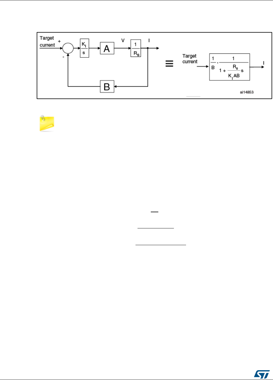
Overview of the FOC and other implemented
algorithms
UM1052
38/178
DocID18458 Rev 9
In this condition, the closed loop system is brought back to a first-order system and the
dynamics of the system can be assigned using a proper value of KI. See Figure 28: "Block
diagram of closed loop system after pole-zero cancellation".
Figure 29: Block diagram of closed loop system after pole-zero cancellation
The parameters used in the PI algorithms must be integers; so the calculated KI
and KP values must be expressed as fractions (dividend/divisor).
Moreover, the PI algorithm does not include the PI sampling time (T) in the computation of
the integral component. Referring to the following formula:
Since the integral part of the controller is computed as a sum of successive errors, it is
required to include T in the calculation of KI.
The final formula can be expressed as:
Usually, it is possible to set ωC (the bandwidth of the closed loop system) to 1500 rad/s, to
obtain a good trade-off between dynamic response and sensitivity to the measurement
noise.
4.11 Space vector PWM implementation
Figure 29: "Vα and Vβ stator voltage components" shows the stator voltage components Va
and Vb while Figure 30: "SVPWM phase voltage waveforms" illustrates the corresponding
PWM for each of the six space vector sectors.
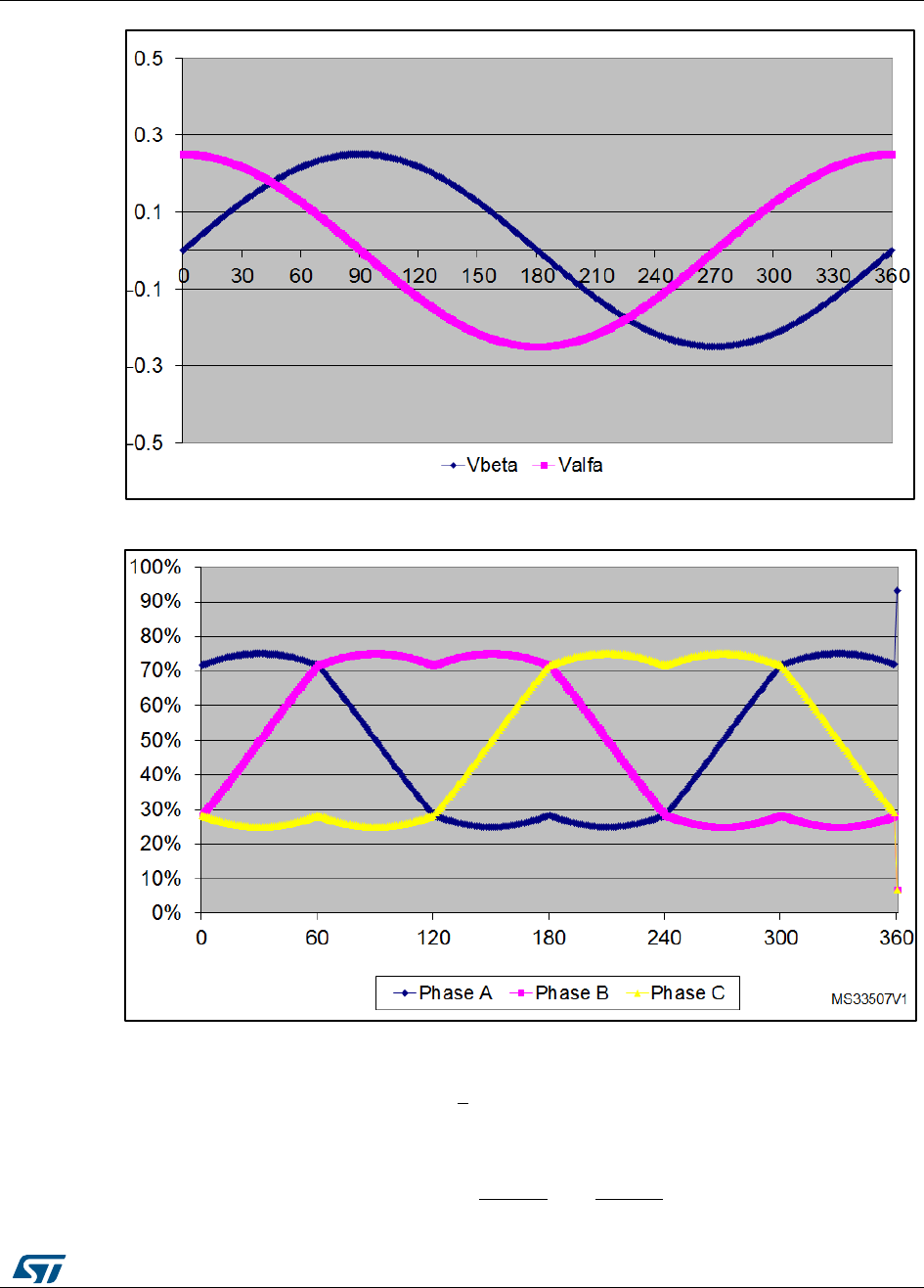
UM1052
Overview of the FOC and other implemented
algorithms
DocID18458 Rev 9
39/178
Figure 30: Vα and Vβ stator voltage components
Figure 31: SVPWM phase voltage waveforms
For:
and
Overview of the FOC and other implemented
algorithms
UM1052
40/178
DocID18458 Rev 9
The literature demonstrates that the space vector sector is identified by the conditions
shown in Table 3: "Sector identification".
Table 3: Sector identification
Y < 0
Y ≥ 0
Z < 0
Z ≥ 0
Z < 0
Z ≥ 0
X ≤ 0
X > 0
X ≤ 0
X > 0
Sector
V
IV
III
VI
I
II
The duration of the positive pulse widths for the PWM applied on Phase A, B and C are
respectively computed by the following relationships:
...where T is the PWM period.
Considering that the PWM pattern is center-aligned and that the phase voltages must be
centered at 50% of duty cycle, it follows that the values to be loaded into the PWM output
compare registers are given respectively by:
4.12 Reference frame transformations
PM synchronous motors show very complex and time-varying voltage equations.
By changing a set of variables that refers stator quantities to a frame of reference
synchronous with the rotor, it is possible to reduce the complexity of these equations.
This strategy is often referred to as the Reference-Frame theory [1].
Supposing fax, fbx, fcx are three-phase instantaneous quantities directed along axis, each
displaced by 120 degrees, where x can be replaced with s or r to treat stator or rotor
quantities (see Figure 31: "Transformation from an abc stationary frame to a rotating frame
(q, d)"); supposing fqx, fdx, f0x are their transformations, directed along paths orthogonal to
each other; the equations of transformation to a reference frame (rotating at an arbitrary
angular velocity ω) can be expressed as:
UM1052
Overview of the FOC and other implemented
algorithms
DocID18458 Rev 9
41/178
where θ is the angular displacement of the (q, d) reference frame at the time of
observation, and θ0 that displacement at t=0 (see Figure 31: "Transformation from an abc
stationary frame to a rotating frame (q, d)").
Figure 32: Transformation from an abc stationary frame to a rotating frame (q, d)
With Clark’s transformation, stator currents ias and ibs (which are directed along axes each
displaced by 120 degrees) are resolved into currents iα and iβ on a stationary reference
frame (α β).
An appropriate substitution into the general equations (given above) yields to:
In Park’s change of variables, stator currents ia and iβ, which belong to a stationary
reference frame (α β), are resolved to a reference frame synchronous with the rotor and
fax
fbx
fcx
q
d
w
q
0
a
b
c

Overview of the FOC and other implemented
algorithms
UM1052
42/178
DocID18458 Rev 9
oriented so that the d-axis is aligned with the permanent magnets flux, so as to obtain iqs
and ids.
Consequently, with this choice of reference, we have:
On the other hand, reverse Park transformation takes back stator voltage vq and vd,
belonging to a rotating frame synchronous and properly oriented with the rotor, to a
stationary reference frame, so as to obtain vα and vβ:
4.12.1 Circle limitation
As discussed above, FOC allows to separately control the torque and the flux of a 3-phase
permanent magnet motor. After the two new values(and ) of the stator voltage
producing flux and torque components of the stator current have been independently
computed by flux and torque PIDs, it is necessary to saturate the magnitude of the resulting
vector (
) before passing them to the Reverse Park transformation and, finally, to the
SVPWM block.
The saturation boundary is normally given by the value (S16_MAX=32767) which produces
the maximum output voltage magnitude (corresponding to a duty cycle going from 0% to
100%).
Nevertheless, when using a single-shunt or three-shunt resistor configuration and
depending on PWM frequency, it might be necessary to limit the maximum PWM duty cycle
to guarantee the proper functioning of the stator currents reading block.
For this reason, the saturation boundary could be a value slightly lower than S16_MAX
depending on PWM switching frequency when using a single-shunt or three-shunt resistor
configuration.
The circle limitation function performs the discussed stator voltage components saturation,
as illustrated below.
Figure 33: Circle limitation working principle
Vd and Vq represent the saturated stator voltage components to be passed to the Reverse
Park transformation function, while Vd* and Vq* are the outputs of the PID current
*
q
V
S16_MAXMMI
r2
S16_MAX
*
d
V
d
V
q
V
*
V
r
V
r*
2
r1
1
r
*
*
r
r
r

UM1052
Overview of the FOC and other implemented
algorithms
DocID18458 Rev 9
43/178
controllers. From geometrical considerations, it is possible to draw the following
relationship:
In order to speed up the computation of the above equations while keeping an adequate
resolution, the value
is computed and stored in a look-up table for different values of
and MMI (Maximum
Modulation Index).
4.13 Digital PFC
The power factor of an AC electrical power system is defined as the ratio of the real power
flowing to the load versus the apparent power in the circuit. For passive loads, it is a
dimensionless number in the closed interval of 0 to 1. A power factor of less than one
means that the voltage and current waveforms are not in phase, reducing the
instantaneous product of the two waveforms (V x I).
Due to a non-linear load that distorts the wave shape of the current drawn from the source,
the apparent power will be greater than the real power, reducing the power factor; this is
typical of motor control applications.
A load with a low power factor draws more current than a load with a high power factor for
the same amount of useful power transferred, which is usually discouraged by local
regulations.
Linear loads with low power factor can be corrected to a passive network of capacitors or
inductors. As non-linear loads distort the current drawn from the system, active power
factor correction may be used to counteract the distortion and raise the power factor.
If the active power-factor-correction (PFC) is performed using the same microcontroller
controlling the motor, the advantages are:
1. the cost saving due to the reduction of components used
2. the performance optimization because the microcontroller knows information on the
load (for instance the power requested by the motor) and can improve the
performance of the PFC
A digital power-factor-correction algorithm working together with the ST motor control FOC
firmware is included in the ST MC FOC SDK, and can be enabled using the ST MC
Workbench.
This feature is not only a software feature; the power stage needs to be
compatible with it.
To ascertain compatibility, create a new project in Workbench and select the required
Power Stage (or MC Kit or Inverter) in the new project dialog box. Enter power stage
Overview of the FOC and other implemented
algorithms
UM1052
44/178
DocID18458 Rev 9
section and verify whether the PFC checkbox is available, indicating that the hardware is
indeed compatible and that you can enable the FW feature.
Figure 34: PFC hardware support
To enable the digital PFC, go to Drive Management > Additional Features and PFC
settings and click on PFC Parameters.
Figure 35: PFC settings
The PFC parameters dialog box will appear; the same dialog can be opened clicking the
PFC block in the power stage section. Then check the “Enabling feature” check to enable
the PFC in the firmware.
UM1052
Overview of the FOC and other implemented
algorithms
DocID18458 Rev 9
45/178
Figure 36: PFC parameters
In the current version of the library, the digital PFC FW is only available for the STM32F103
family (STM32F103xC, STM32F103xD, STM32F103xE, STM32F103xF and
STM32F103xG) or for the STM32F303 family (STM32F303xB and STM32F303xC).
The implemented digital PFC firmware and the supported PFC hardware (single stage
boost topology) is shown below.

Overview of the FOC and other implemented
algorithms
UM1052
46/178
DocID18458 Rev 9
Figure 37: PFC block diagram
4.13.1 Implemented features
Digital PFC using variable PWM frequency and repetition rate.
Selection of the PFC PWM frequency via PFC setting > current regulation PWM
frequency.
Control can be performed each “n” PWM periods according to the value in the
current regulation execution rate box (see Figure 35: "PFC parameters").
Variable voltage output reference.
Define the VDC BUS voltage reference and change it on the fly.
Default settings can be set in the PFC setting > Output voltage reference box
(see Figure 35: "PFC parameters").
It is then possible to change it via serial communication or by API (see Section
6.13.3: "PFC usage" and STM32 FOC PMSM FW library developer Help
file.chm).
Soft start enabling.
When enabled, PFC regulation is performed with a voltage reference ramp.
The duration of the soft start can be programmed in the PFC setting > Soft Start
duration box (see Figure 35: "PFC parameters").
Power threshold activation or deactivation.
The PFC is automatically enabled or disabled according the power request
coming from the load. In this case, the load is the motor controlled by the FOC
algorithm and the power requested by the motor is measured in run time.
The activation power threshold can be set in the PFC setting > Switch on power
level box and the deactivation power threshold can be set in the PFC setting >
Switch off power level box (see Figure 35: "PFC parameters").
Software overcurrent protection.
On top of the hardware overcurrent protection, software overcurrent protection is
implemented in the FW and the threshold can be set in the PFC Setting > SW
overcurrent threshold box (see Figure 35: "PFC parameters").

UM1052
Overview of the FOC and other implemented
algorithms
DocID18458 Rev 9
47/178
Over voltage protection is always enabled in the FW and the threshold can be set in
PFC setting > “PFC over-voltage threshold” box (see Figure 35: "PFC parameters").
Current PI and Voltage PI parameters are not calculated by the Workbench; they
must be adjusted manually using empirical methods.
4.13.2 PFC hardware settings
The physical hardware parameters are grouped in the Hardware Settings tab shown below.
Figure 38: PFC hardware settings
The settings are normally preconfigured according to the power stage selected during New
Project procedure, but can be manually modified to support custom hardware.
Nominal power represents the maximum power (in watts) supported by the power stage.
When this value is changed, the expected nominal current for the PFC Power Transistor is
automatically calculated and shown in the Nominal current box.
Nominal current represents the peak current that can flow into the Power Transistor
during nominal operation. This of course means that the overcurrent protection threshold
must be greater than this value; the software overcurrent must be greater than the nominal
current and lower than the hardware overcurrent threshold.
Shunt resistor value reflects the shunt resistor value used to measure the current that is
sunk from the AC input.

Overview of the FOC and other implemented
algorithms
UM1052
48/178
DocID18458 Rev 9
OPAMP on power stage is checked if the operational amplifier (OPAMP) used by the
sensing network to measure the current sunk from the AC input is external; if the OPAMP
is embedded in the microcontroller, it will be unchecked.
Overall network gain represents the gain between the shunt resistor voltage and the input
of the ADC of the micro.
Use OPAMP for current protection is checked if the output of the OPAMP used for
sensing is input to the comparator used by the overcurrent protection network on the PFC
MOSFET; if the shunt resistor is directly connected to the comparator, it will be unchecked.
Comparator threshold indicates the comparator threshold vale for hardware overcurrent
protection.
Expected Over Current Threshold represents the hardware overcurrent threshold
calculated from the Comparator threshold setting.
Max. power transistor current is the maximum current supported by the PFC MOSFET. It
is usually greater than the HW overvoltage threshold.
AC voltage sensing divider 1/… indicates partitioning factor used to scale the rectified AC
input before it is fed to the microcontroller ADC input.
Ton propagation delay and Toff propagation delay indicate the delay before turning on
and turning off the PFC MOSFET.
Driving signal polarity indicates whether the PFC MOSFET is active (i.e., conducting)
when the control signal is High level (3.3 V) or Low level (0 V).
Over current signal polarity indicates whether the overcurrent signal output from the
comparator used for the protection is active (indicating the overcurrent condition) when the
control signal is High level (3.3 V) or Low level (0 V).
4.13.3 PFC usage
You can enable, disable and adjust the PFC variables real-time using the Workbench
monitor.
1
Enable the PFC in the FW
2
Generate the .h configuration file
3
Compile and upload the binary into the micro as described in Section 11: "Working
environment" or in “Hands-on” (STM32 PMSM FOC SDK Hands-on workshop with
hardware tools)
UM1052
Overview of the FOC and other implemented
algorithms
DocID18458 Rev 9
49/178
4
Click on Monitor button in the Workbench shown below
Figure 39: ST MC Workbench monitor
5
connect with the FW as described in the ST Motor Control Workbench Help File or in
the “Hands-on” (STM32 PMSM FOC SDK Hands-on workshop with hardware tools)
The PFC section in Figure 38: "ST MC Workbench monitor" will be enabled.
6
Click on PFC Enable button.
The real activation of the PFC is then demanded on the load of the motor according to
the Switch-on power level.
If the motor power measured is above the Switch-on power level and the PFC is
enabled, the FW starts performing the PFC algorithm.
7
Click PFC disable to disable the PFC algorithm.
8
Click on PFC Fault Ack to clear the PFC faults.
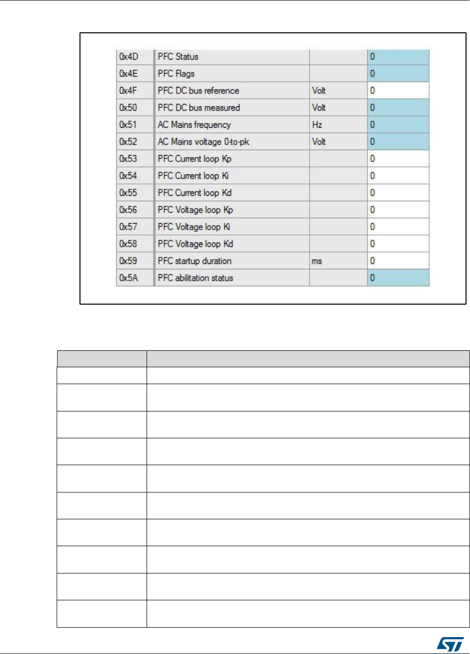
Overview of the FOC and other implemented
algorithms
UM1052
50/178
DocID18458 Rev 9
9
The PFC status and register can be viewed and modified in the Register tab.
Figure 40: PFC register table in Workbench
4.13.4 PFC registers
Table 4: PFC register descriptions
Name
Description
PFC Status
state of the PFC: IDLE, FAULT, RUN
PFC Flags
one of the fault states in Table 5: "PFC faults"; more than one fault state can
be combined in a bitwise OR operation - zero = no fault
PFC DC bus
reference
read or change the current DC bus reference (in volts); changes take
immediate effect in the FW
PFC DC bus
measured
the DC bus measurement (volts)
AC Mains
frequency
This register gives information about the AC input frequency (Hz/10); not
updated when in fault states
AC Mains voltage
0-to-pk
peak value of the AC input in volts
PFC Current loop
Kp, Ki, Kd
read and modify the PI parameters of the current controller; Kd is not used
PFC Voltage loop
Kp, Ki, Kd
read and modify the PI parameters of voltage controller; Kd is not used
PFC startup
duration
PFC activation time; can be changed on-the-fly to find the best compromise
directly inside the application
PFC activation
status
the activation state of the PFC: 0 = PFC disabled, 1 = PFC enabled

UM1052
Overview of the FOC and other implemented
algorithms
DocID18458 Rev 9
51/178
Table 5: PFC faults
Name
Value
Description
PFC_SWE
0x01
general software error; will not occur in normal operation
PFC_HW_PROT
0x02
hardware overcurrent or overvoltage
PFC_SW_OVER_VOLT
0x04
software overvoltage
PFC_SW_OVER_CURRENT
0x08
software overcurrent
PFC_SW_MAINS_FREQ
0x10
the AC input frequency is not in the correct range
PFC_SW_MAIN_VOLT
0x20
the AC input voltage in not in the correct range
If certain registers are not updated, check the Period and Enable values. Period
indicates the refresh period expressed in milliseconds; 0 means disabled. Enable
must be checked to update the registers.
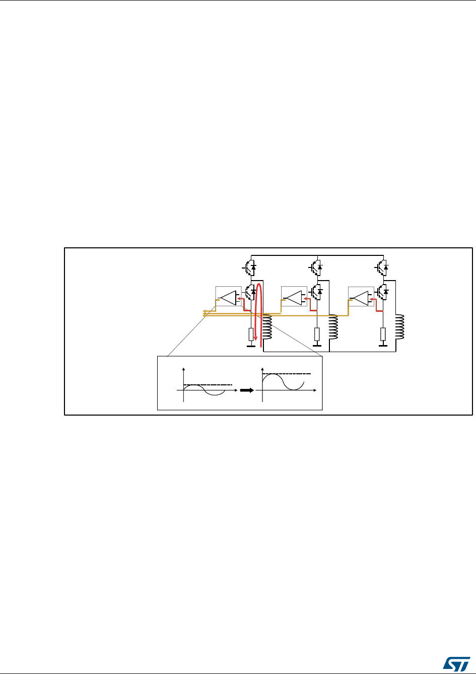
Current sampling
UM1052
52/178
DocID18458 Rev 9
5 Current sampling
Section 6.3: "Introduction to the PMSM FOC drive" shows that current sampling plays a
crucial role in PMSM field-oriented control. This motor control library provides complete
modules for supporting three-shunt, single-shunt, and ICS topologies. Refer to sections
Section 7.1: "Current sampling in three-shunt topology using two A/D converters", Section
7.3: "Current sampling in single-shunt topology", Section 7.4: "Current sampling in isolated
current sensor topology" respectively for further details.
The selection of decoding algorithm—to match the topology actually in use—can be
performed through correct settings in the .h parameter files (generated by the ST MC
Workbench GUI) used to initialize the MC Application during its boot stage.
5.1 Current sampling in three-shunt topology using two A/D
converters
Figure 40: "Three-shunt topology hardware architecture" shows the three-shunt topology
hardware architecture.
Figure 41: Three-shunt topology hardware architecture
The three currents I1, I2, and I3 flowing through a three-phase system follow the
mathematical relation:
I1 + I2 + I3 = 0
For this reason, to reconstruct the currents flowing through a generic three-phase load, it is
sufficient to sample only two out of the three currents while the third one can be computed
by using the above relation.
The flexibility of the STM32 A/D converter makes it possible to synchronously sample the
two A/D conversions needed for reconstructing the current flowing through the motor. The
ADC can also be used to synchronize the current sampling point with the PWM output
using the external triggering capability of the peripheral. Owing to this, current conversions
can be performed at any given time during the PWM period. To do this, the control
algorithm uses the fourth PWM channel of TIM1 to synchronize the start of the
conversions.
Figure 41: "PWM and ADC synchronization" shows the synchronization strategy between
the TIM1 PWM output and the ADC. The A/D converter peripheral is configured so that it is
triggered by the rising edge of TIM1_CH4.
ADC
GateDriver
+
-
OpAmp +Offset
+
-
OpAmp +Offset
+
-
OpAmp + Offset
500mV
3.3V
OpAmp + Offset
Voltage on R ShuntVoltage to be converted
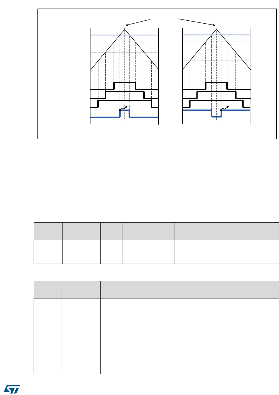
UM1052
Current sampling
DocID18458 Rev 9
53/178
Figure 42: PWM and ADC synchronization
In this way, supposing that the sampling point must be set before the counter overflow, that
is, when the TIM1 counter value matches the OCR4 register value during the upcounting,
the A/D conversions for current sampling are started. If the sampling point must be set after
the counter overflow, the PWM 4 output has to be inverted by modifying the CC4P bit in the
TIM1_CCER register. Thus, when the TIM1 counter matches the OCR4 register value
during the downcounting, the A/D samplings are started.
After execution of the FOC algorithm, the value to be loaded into the OCR4 register is
calculated to set the sampling point for the next PWM period, and the A/D converter is
configured to sample the correct channels.
Table 6: Three-shunt current reading, used resources (single drive, F103 LD/MD)
Adv.
timer
DMA
ISR
ADC
master
ADC
slave
Note
TIM1
DMA1_CH1
DMA1_CH5
None
ADC1
ADC2
DMA is used to enable ADC injected
conversion external trigger.
Disabling is performed by software.
Table 7: Three-shunt current reading, used resources (Dual drive,F103 HD, F2x, F4x)
Adv.
timer
DMA
ISR
ADC
Note
TIM1
DMA1_CH1
TIM1_UP
ADC1
ADC2
Used by first or second motor
configured in three-shunt, according
to user selection. ADC is used in
time sharing. Trigger selection is
performed in the TIM_UP ISR.
TIM8
None
TIM8_UP
ADC1
ADC2
Used by first or second motor
configured in three-shunt, according
to user selection. ADC is used in
time sharing. Trigger selection is
performed in the TIM_UP ISR.
TIM1_CH3
TIM1_CH4
ADC Start
TIM1_CH1
TIM1_CH2
Sampling point before counter overflow
TIM1_CH3
TIM1_CH4
ADC Start
TIM1_CH1
TIM1_CH2
Sampling point after counter overflow
Counter overflow
OCR 3
OCR 2
OCR 1
OCR 4
OCR 3
OCR 2
OCR 1
OCR 4
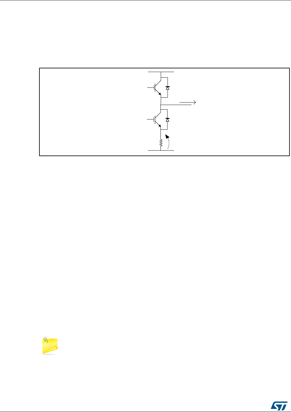
Current sampling
UM1052
54/178
DocID18458 Rev 9
Refer to Section 8: "Current sensing and protection on embedded PGA" for STM32F30x
microcontroller configuration.
5.1.1 Tuning delay parameters and sampling stator currents in shunt
resistor
Figure 42: "Inverter leg and shunt resistor position" shows one of the three inverter legs
with the related shunt resistor:
Figure 43: Inverter leg and shunt resistor position
To indirectly measure the phase current I, it is possible to read the voltage V provided that
the current flows through the shunt resistor R.
It is possible to demonstrate that, whatever the direction of current I, it always flows through
the resistor R if transistor T2 is switched on and T1 is switched off. This implies that, in
order to properly reconstruct the current flowing through one of the inverter legs, it is
necessary to properly synchronize the conversion start with the generated PWM signals.
This also means that current reading cannot be performed on a phase where the duty cycle
applied to the low side transistor is either null or very short.
As discussed in Section 7.1: "Current sampling in three-shunt topology using two A/D
converters", to reconstruct the currents flowing through a generic three-phase load, it is
sufficient to simultaneously sample only two out of three currents, the third one being
computed from the relation given in Section 7.1: "Current sampling in three-shunt topology
using two A/D converters". Thus, depending on the space vector sector, the A/D
conversion of voltage V will be performed only on the two phases where the duty cycles
applied to the low side switches are the highest. Looking at Figure 30: "SVPWM phase
voltage waveforms", you can deduct that, in sectors 1 and 6, the voltage on phase A shunt
resistor can be discarded; likewise in sectors 2 and 3 for phase B, and in sectors 4 and 5
for phase C.
Moreover, in order to properly synchronize the two stator current reading A/D conversions,
it is necessary to distinguish between the different situations that can occur depending on
PWM frequency and applied duty cycles.
The explanations below refer to space vector. They can be applied in the same
manner to the other sectors.
T1
T2
D1
D2
RV
I
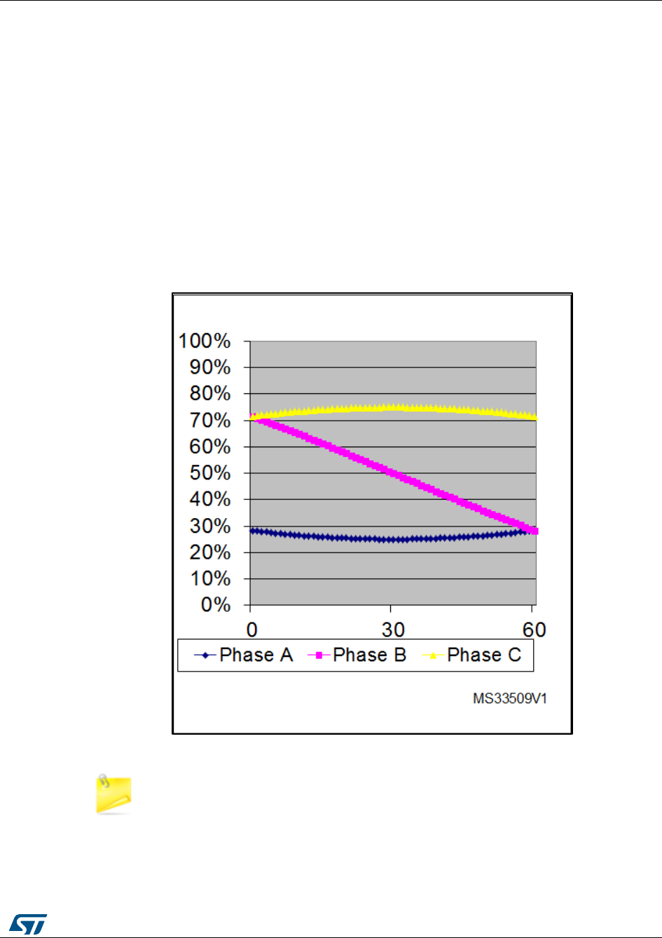
UM1052
Current sampling
DocID18458 Rev 9
55/178
Case 1: Duty cycle applied to Phase A low side switch > DT+TN
Where:
DT is dead time.
TN is the duration of the noise induced on the shunt resistor voltage of a phase by the
commutation of a switch belonging to another phase.
TS is the sampling time of the A/D converter (presuming TS < DT + TN). Refer to the
relevant microcontrollerreference manual for more information.
This case typically occurs when SVPWM with low (<60%) modulation index is generated
(see Figure 43: "Low-side switch gate signals (low modulation indexes)"). The modulation
index is the applied phase voltage magnitude expressed as a percentage of the maximum
applicable phase voltage (the duty cycle ranges from 0% to 100%).
Figure 44: "Case 1" offers a reconstruction of the PWM signals applied to low side switches
of phase A and B in these conditions, plus a view of the analog voltages measured on the
A/D converter pins for both phase B and C (the time base is lower than the PWM period).
Figure 44: Low-side switch gate signals (low modulation indexes)
These current feedbacks are constant in Figure 44: "Case 1" because it is
assumed that commutations on phase B and C have occurred out of the
visualized time window. In this case, the two stator current sampling conversions
can be performed synchronized with the counter overflow, as shown in Figure 44:
"Case 1".
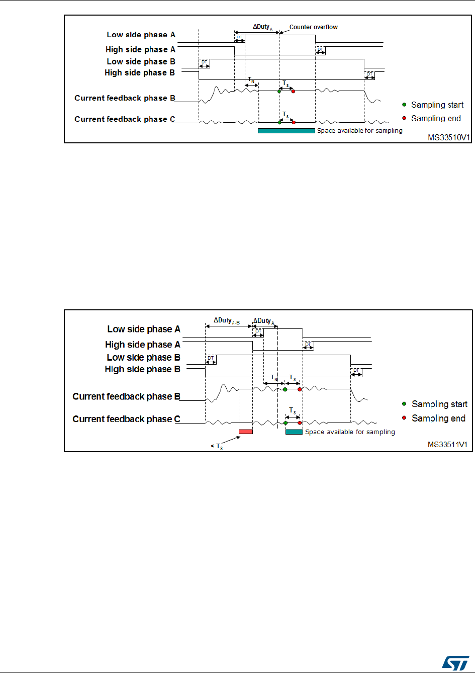
Current sampling
UM1052
56/178
DocID18458 Rev 9
Figure 45: Case 1
Case 2: (DT+TN+TS)/2 < ΔDutyA < DT+TN and ΔDutyAB < DT+TR+TS
With the increase in modulation index, ΔDutyA can have values smaller than DT+TN.
Sampling synchronized with the counter overflow could be impossible.
In this case, the two currents can still be sampled between the two phase A low side
commutations, but only after the counter overflow.
To avoid the acquisition of the noise induced on the phase B current feedback by phase A
switch commutations, it is required to wait for the noise to be over (TN). See Figure 45:
"Case 2".
Figure 46: Case 2
Case 3: ΔDutyA < (DT+TN+TS)/2 and ΔDutyA-B>DT+TR+TS
In this case, it is no longer possible to sample the currents during phase A low-side switch-
on. Anyway, the two currents can be sampled between phase B low-side switch-on and
phase A high-side switch-off. The choice was made to sample the currents TS µs before of
phase A high-side switch-off. See Figure 46: "Case 3".
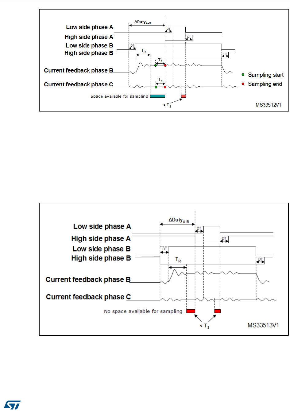
UM1052
Current sampling
DocID18458 Rev 9
57/178
Figure 47: Case 3
Case 4: ΔDutyA<(DT+TN+TS)/2 and ΔDutyA-B<DT+TR+TS
In this case, the duty cycle applied to phase A is so short that no current sampling can be
performed between the two low-side commutations.
If the difference in duty cycles between phase B and A is not long enough to allow the A/D
conversions to be performed between phase B low-side switch-on and phase A high-side
switch-off, it is impossible to sample the currents. See Figure 47: "Case 4".
To avoid this condition, it is necessary to reduce the maximum modulation index or to
decrease the PWM frequency.
Figure 48: Case 4

Current sampling
UM1052
58/178
DocID18458 Rev 9
5.2 Current sampling in three-shunt topology using one A/D
converter
Figure 48: "three-shunt hardware architecture" shows the three-shunt topology hardware
architecture.
Figure 49: three-shunt hardware architecture
The three currents I1, I2 and I3 flowing through a three-phase system follow the
mathematical relation:
I1 + I2 + I3 = 0
For this reason, in order to rebuild the currents flowing through a generic three-phase load,
it is sufficient to sample only two out of the three currents while the third one can be
computed by using the above relation.
Unlike the case of current sapling with two ADCs, in the case of single ADC it is not
possible to synchronously sample the two phase current A/D conversions, needed for
reconstructing the current flowing through the motor, but they can be performed only in
sequence mode.
The ADC can be used to synchronize the current sampling point with the PWM output
using the external triggering capability of the peripheral. Owing to this, current conversion
sequence can be performed at any given time during the PWM period.
To do this, the control algorithm uses the fourth PWM channel of TIM1 to synchronize the
start of the conversion sequence.
Figure 49: "PWM and ADC synchronization ADC rising edge external trigger" and Figure
50: "PWM and ADC synchronization ADC falling edge external trigger" show the
synchronization strategy between the TIM1 PWM output and the ADC.
ADC
GateDriver
+
-
OpAmp +Offset
+
-
OpAmp +Offset
+
-
OpAmp + Offset
500mV
3.3V
OpAmp + Offset
Voltage on R ShuntVoltage to be converted
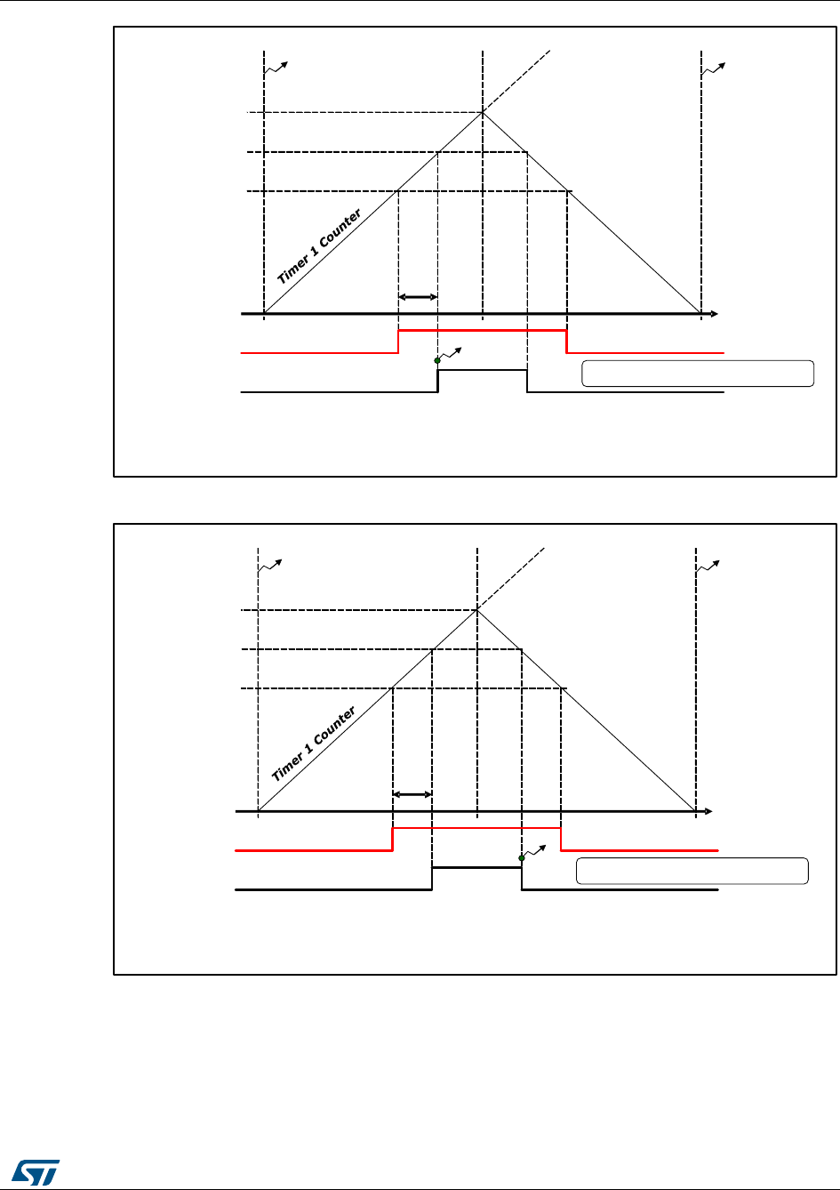
UM1052
Current sampling
DocID18458 Rev 9
59/178
Figure 50: PWM and ADC synchronization ADC rising edge external trigger
Figure 51: PWM and ADC synchronization ADC falling edge external trigger
In this way, supposing that the sampling point must be set before the counter overflow, that
is, when the TIM1 counter value matches the OCR4 register value during the up counting,
the A/D conversion sequence for current sampling are started. If the sampling point must
be set after the counter overflow, it’s necessary set a falling edge ADC external trigger.
Thus, when the TIM1 counter matches the OCR4 register value during the down counting,
the A/D sampling are started.
CCR A
CCR 4
PWM_VALUE
PWM A
PWM 4
ADC Start
If CCR A + Delay < PWM_VALUE it is possible to set the CCR 4 equal to CCR A
plus the delay and set ADC External trigger as Rising edge
Sampling is on rising edge of PWM4
PWM Update PWM Update
DT+TN
CCR A
CCR 4
PWM_VALUE
PWM A
PWM 4
ADC Start
If CCR A + Delay > PWM_VALUE it is possible to set the CCR 4 equal to CCR A
plus the delay and set a falling ADC External trigger
Sampling is on falling edge of PWM4
PWM Update PWM Update
DT+TN
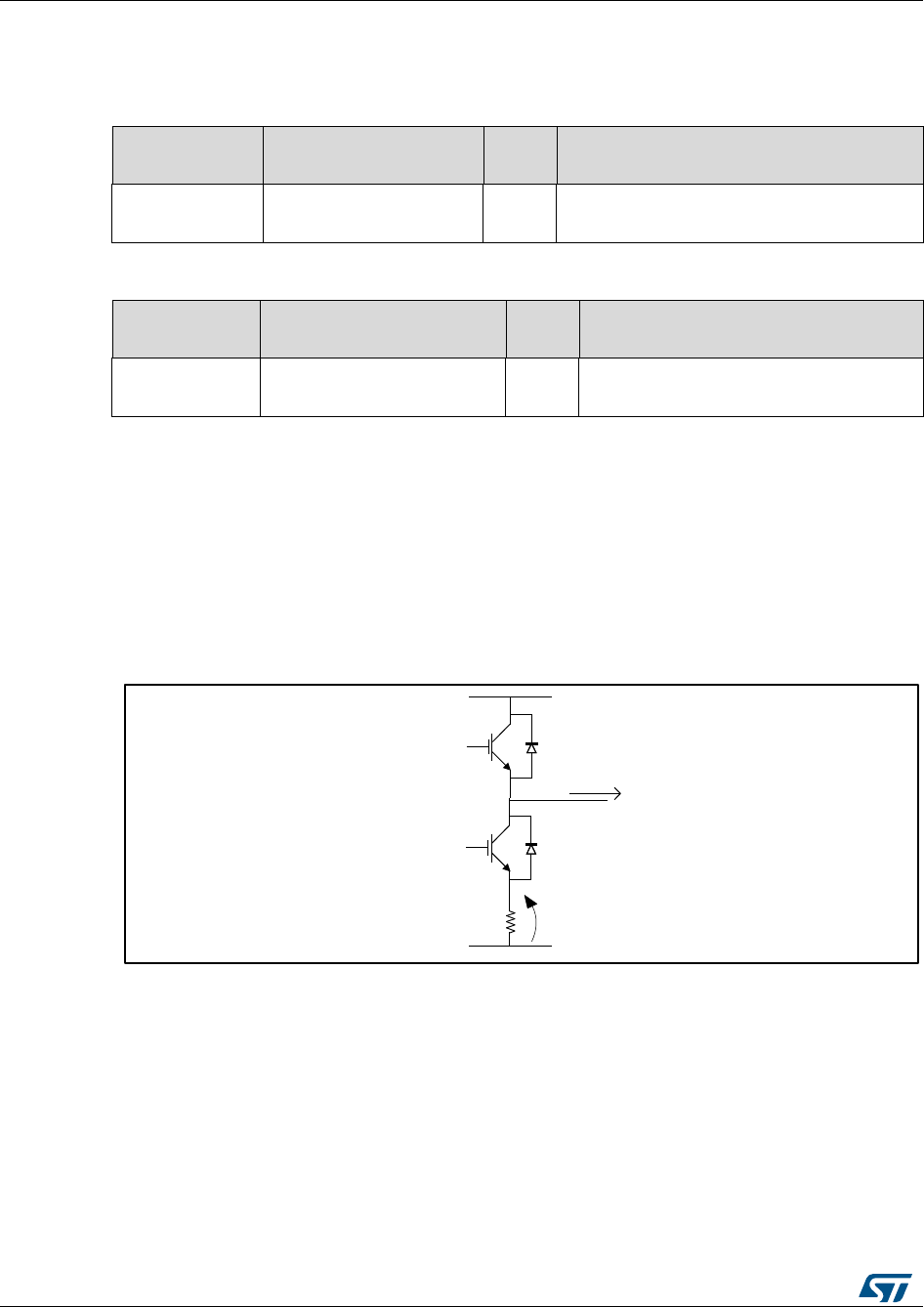
Current sampling
UM1052
60/178
DocID18458 Rev 9
After execution of the FOC algorithm, the value to be loaded into the OCR4 register is
calculated to set the sampling point for the next PWM period, and the A/D converter is
configured to sample the correct channels.
Table 8: Three-shunt current reading, used resources, single drive, STM32F302x6,
STM32F302x8
Advanced
Timer
ISR
ADC
Note
TIM1
ADC1_IRQn
TIM1_BRK_TIM15_IRQN
ADC1
The dual drive mode and the internal
PGA are not available
Table 9: Three-shunt current reading, used resources, single drive, STM32F030x8
Advanced
Timer
ISR
ADC
Note
TIM1
DMA1_Channel1_IRQn
TIM1_BRK_UP_COM_IRQN
ADC1
The dual drive mode and the internal
PGA are not available
The FOC starts after DMA1_Channel1 Transmission is complete (dual sampling). The
DMA is used to manage the A/D conversion sequence since the STM32F0x ADC doesn’t
support the injected conversion type but only the regular conversion type.
5.2.1 Tuning delay parameters and sampling stator currents in shunt
resistor
Figure 51: "three inverter legs" shows one of the three inverter legs with the related shunt
resistor.
Figure 52: three inverter legs
To indirectly measure the phase current I, it is possible to read the voltage V provided that
the current flows through the shunt resistor, R.
It is possible to demonstrate that, whatever the direction of current I, it always flows through
the resistor R if transistor T2 is switched on and T1 is switched off. This implies that, in
order to properly reconstruct the current flowing through one of the inverter legs, it is
necessary to properly synchronize the conversion start with the generated PWM signals.
This also means that current reading cannot be performed on a phase where the duty cycle
applied to the low side transistor is either null or very short.
As discussed in Section 7.2: "Current sampling in three-shunt topology using one A/D
converter", to rebuild the currents flowing through a generic three-phase load, it is sufficient
to sample only two out of three currents, the third one being computed from the relation
T1
T2
D1
D2
RV
I

UM1052
Current sampling
DocID18458 Rev 9
61/178
given in Section 7.2: "Current sampling in three-shunt topology using one A/D converter". It
is noted that two current samples are not simultaneous but the start of the second current
sampling is delayed from the first current measurement by its global conversion time (Ts +
Tc); this introduces a conceptual error in the third current computation using the relation
given in Section 7.2: "Current sampling in three-shunt topology using one A/D converter",
because the two current samples are referred to two different time instants and this
equation is true if the three current values are referred at the same time instant. Anyway,
this error is negligible for a width range of motors.
Thus, depending on the space vector sector, the A/D conversion of voltage, V, will be
performed only on the two phases where the duty cycles applied to the low side switches
are the highest. Looking at the Figure 24: "Time domain to discrete PID equations", it can
be noted that in the sectors 1 and 6, the voltage on phase A shunt resistor can be
discarded; likewise in the sectors 2 and 3 for phase B, and in the sectors 4 and 5 for phase
C.
Moreover, in order to have a correct A/D conversion of the two stator currents, it is
necessary to distinguish between the different situations that can occur depending on PWM
frequency and applied duty cycles.
Used symbols:
DT is dead time.
TN is the duration of the noise induced on the shunt resistor voltage of a phase by the
commutation of a switch belonging to another phase.
TR is the rising time of the input signal of the ADC.
TS is the sampling time of the A/D.
TC is the conversion time of ADC. Refer to the microcontroller reference manual for
more detailed information.
The following five cases are based on the hypothesis that 2TS + TC < DT + max(TN,TR).
It’s possible to individuate a common case for all sectors shown below.
Common Case: Duty cycles applied to Phases A, B, C low side switches are larger than
DT+ max(TN,TR)
In this case, to minimize measurement errors due to errors in calibration of the ADC, which
introduce inaccuracies in the calculation of the third component by means of the equation
I1 + I2 + I3 = 0, always the currents of phases A and B are converted, as shown in the
Figure 52: "Low side of phase A, B, C duty cycle > DT + max(TN,TR)".
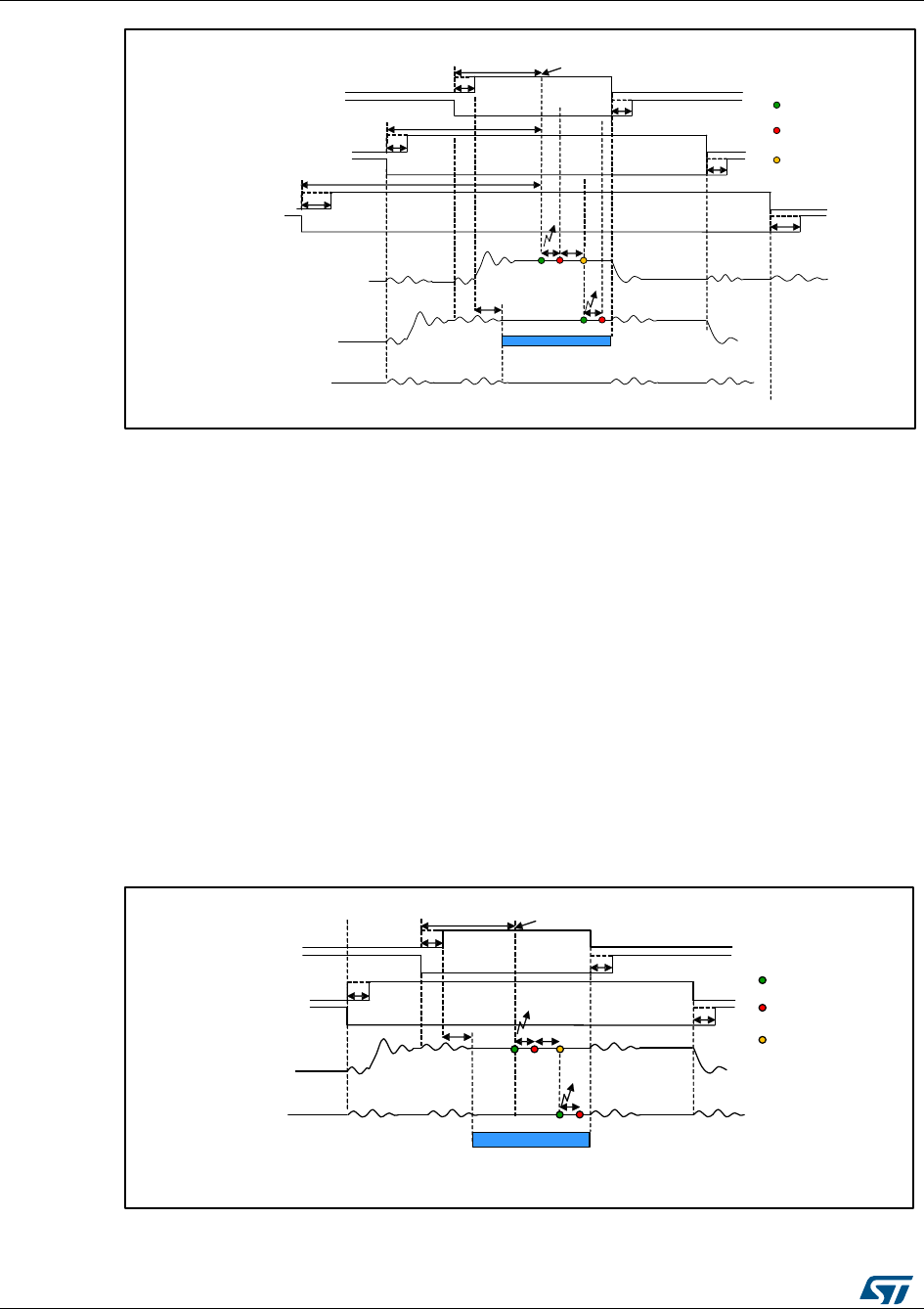
Current sampling
UM1052
62/178
DocID18458 Rev 9
Figure 53: Low side of phase A, B, C duty cycle > DT + max(TN,TR)
The following explanations refer to space vector sector 1 and can be applied in the same
manner to the other sectors.
With the increase of the modulation index, ∆DutyA ,∆DutyB ,∆DutyC can assume values
smaller than DT+ max(TN,TR) and sampling in correspondence of the counter overflow can
be impossible.
The following cases depend on the value of the minimum duty cycle of the low side signal
between A, B, C phases. In the case of sector 1 is the Phase A as shown in Figure 24:
"Time domain to discrete PID equations".
Case 1: Duty cycle applied to Phase A low side switch is larger than DT+ max(TN,TR)
This case typically occurs when SVPWM with low (<60%) modulation index is generated.
The modulation index is the applied phase voltage magnitude expressed as a percentage
of the maximum applicable phase voltage (the duty cycle ranges from 0% to 100%).
Figure 53: "Low side Phase A duty cycle > DT+ max(TN,TR)" offers a reconstruction of the
PWM signals applied to low side switches of phase A and B in these conditions, in addition
of a view of the analog voltages measured on the ADC pins for both phase B and C.
Figure 54: Low side Phase A duty cycle > DT+ max(TN,TR)
Case 2: DDutyA < DT+ max(TN,TR) and DDutyAB < 2 (DDutyA)
High side phase A DT
DT
Low side phase A
Low side phase B DT
DT
High side phase B
TN
Current feedback phase B
Current feedback phase C
Sampling end
ΔDuty
A
Sampling start
Counter overflow
TS
Low side phase C
High side phase C
DT
DT
TSTC
Current feedback phase A
ΔDuty
B
ΔDuty
C
Conversion end
Space Available for sequence Sampling
High side phase A DT
DT
Low side phase A
Low side phase B DT
DT
High side phase B
TS
TN
ΔDutyACounter overflow
TC
TS
Space Available for sequence Sampling
Sampling end
Sampling start
Conversion end

UM1052
Current sampling
DocID18458 Rev 9
63/178
With the increase in modulation index, ΔDutyA can assume values smaller than DT+
max(TN,TR). Start of conversion sequence synchronized with the counter overflow could be
impossible.
In this case, the sequence of two currents can still be sampled between the two phase A
low side commutations, but only after the counter overflow.
To avoid the acquisition of the noise induced on the phase B current feedback by phase A
switch commutations, it is required to wait for the noise to be over (TN). See Figure X7.
Figure 55: Two current samplings performed into 2DDutyA time
Case 3: DDutyA < DT+ max(TN,TR) and DDutyAB >2 (DDutyA)
In this case, it is no longer possible to sample the currents during phase A low-side on-
state. Anyway, the two currents can be sampled between phase B low-side switch-on and
phase A high-side switch-off. The choice was made to sample the currents (2TS + Tc) μs
before of phase A high-side switch-off (see Figure 55: "Two current samplings performed
into DDutyAB time")
Figure 56: Two current samplings performed into DDutyAB time
Case 4: DDutyA < DT+ max(TN,TR), DDutyAB >2 (DDutyA) and DDutyAB - (DT + TR) < 2TN
+ TR)
In this case, the duty cycle applied to phase A is so short that no current sampling can be
performed between the two low-side commutations considering that the two sampling are
not simultaneous than the time requested to sampling is greater, because between the
start of the two samplings there is the time of conversion of the first current.
If the difference in duty cycles between phase B and A is not long enough to allow the A/D
conversions to be performed between phase B low-side switch-on and phase A high-side
TN
DT
DT
High side phase A
DT
Low side phase A
Low side phase B DT
High side phase B
Current feedback phase B
TC
TS
TS
Current feedback phase C
Sampling end
Sampling start
Conversion end
TR
ΔDutyAB ΔDutyA
Space Available for
sequence Sampling
<2TS+TC
ΔDutyAB
Space Available for
sequence Sampling
DT
DT
High side phase A
DT
Low side phase A
Low side phase B DT
High side phase B
Current feedback phase B
Current feedback phase C
Sampling end
Sampling start
Conversion end
ΔDutyA
TR
TS
TS
2TS+TCTN
TC
<2TS+TC
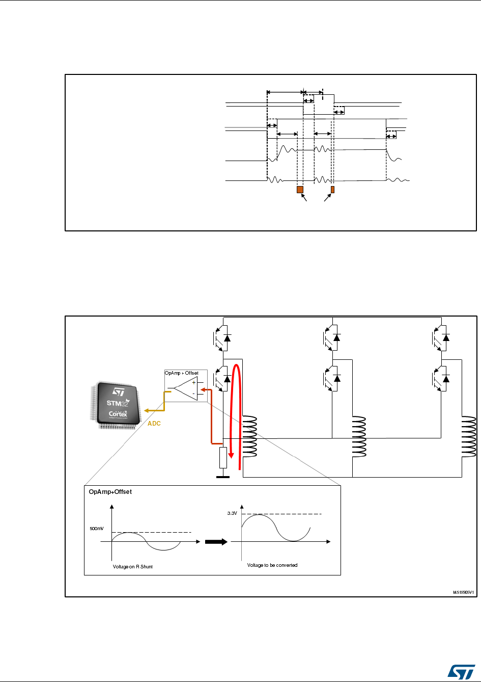
Current sampling
UM1052
64/178
DocID18458 Rev 9
switch-off, it is impossible to sample the currents (See Figure 56: "Two current samplings
cannot performed").
To avoid this condition, it is necessary to reduce the maximum modulation index or to
decrease the PWM frequency.
Figure 57: Two current samplings cannot performed
5.3 Current sampling in single-shunt topology
Figure 57: "Single-shunt hardware architecture" illustrates the single-shunt topology
hardware architecture.
Figure 58: Single-shunt hardware architecture
It is possible to demonstrate that, for each configuration of the low-side switches, the
current through the shunt resistor is given in Table 10: "Current through the shunt resistor".
T4, T5 and T6 assume the complementary values of T1, T2 and T3, respectively.
TR
ΔDutyAB ΔDutyA
No space Available
for sampling
<2TS+TC
DT
DT
High side phase A
DT
Low side phase A
Low side phase B DT
High side phase B
Current feedback phase B
Current feedback phase C
TN
<2TS+TC
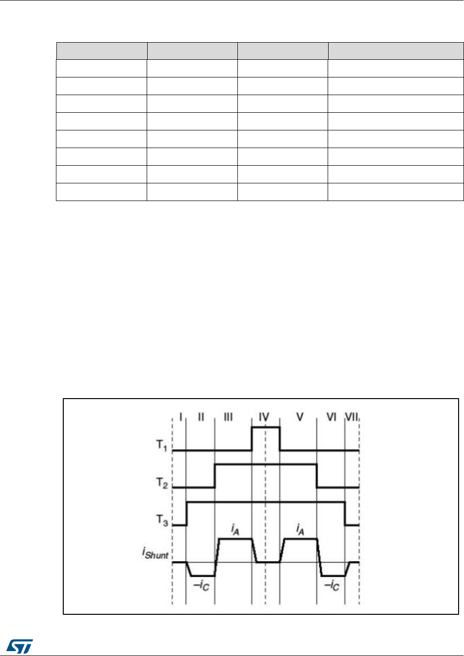
UM1052
Current sampling
DocID18458 Rev 9
65/178
In Table 10: "Current through the shunt resistor", value “0” means that the switch is open
whereas value “1” means that the switch is closed.
Table 10: Current through the shunt resistor
T1
T2
T3
IShunt
0
0
0
0
0
1
1
iA
0
0
1
-iC
1
0
1
iB
1
0
0
-iA
1
1
0
iC
0
1
0
-iB
1
1
1
0
Using the centered-aligned pattern, each PWM period is subdivided into 7 subperiods (see
Figure 58: "Single-shunt current reading"). During three subperiods (I, IV, VII), the current
through the shunt resistor is zero. During the other subperiods, the current through the
shunt resistor is symmetrical with respect to the center of the PWM.
For the conditions showed in Figure 58: "Single-shunt current reading", there are two pairs:
subperiods II and VI, during which iShunt is equal to –iC
subperiods III and V, during which iShunt is equal to iA
Under these conditions, it is possible to reconstruct the three-phase current through the
motor from the sampled values:
iA is iShunt measured during subperiod III or V
iC is -iShunt measured during subperiod II or VI
iB = –iA – iC
Figure 59: Single-shunt current reading

Current sampling
UM1052
66/178
DocID18458 Rev 9
If the stator-voltage demand vector lies in the boundary space between two space vector
sectors, two out of the three duty cycles will assume approximately the same value. In this
case, the seven subperiods are reduced to five subperiods.
Under these conditions, only one current can be sampled, the other two cannot be
reconstructed. This means that it is not possible to sense both currents during the same
PWM period, when the imposed voltage demand vector falls in the gray area of the space
vector diagram represented in Figure 59: "Boundary between two space-vector sectors".
Figure 60: Boundary between two space-vector sectors
Similarly, for a low modulation index, the three duty cycles assume approximately the same
value. In this case, the seven subperiods are reduced to three subperiods. During all three
subperiods, the current through the shunt resistor is zero. This means that it is not possible
to sense any current when the imposed voltage vector falls in the gray area of the space-
vector diagram represented in Figure 60: "Low modulation index".
Figure 61: Low modulation index
5.3.1 Definition of the noise parameter and boundary zone
TRise is the time required for the data to become stable in the ADC channel after the power
device has been switched on or off.
The duration of the ADC sampling is called the sampling time.
T3
T2
T1
iA
iShunt
iA
III III IV V
T3
T2
T1
–iC
iShunt –iC
III III IV VV3V2
V1
V6
V5
V4
β
a
T3
T2
T1
iShunt
III III V3V2
V1
V6
V5
V4
b
a
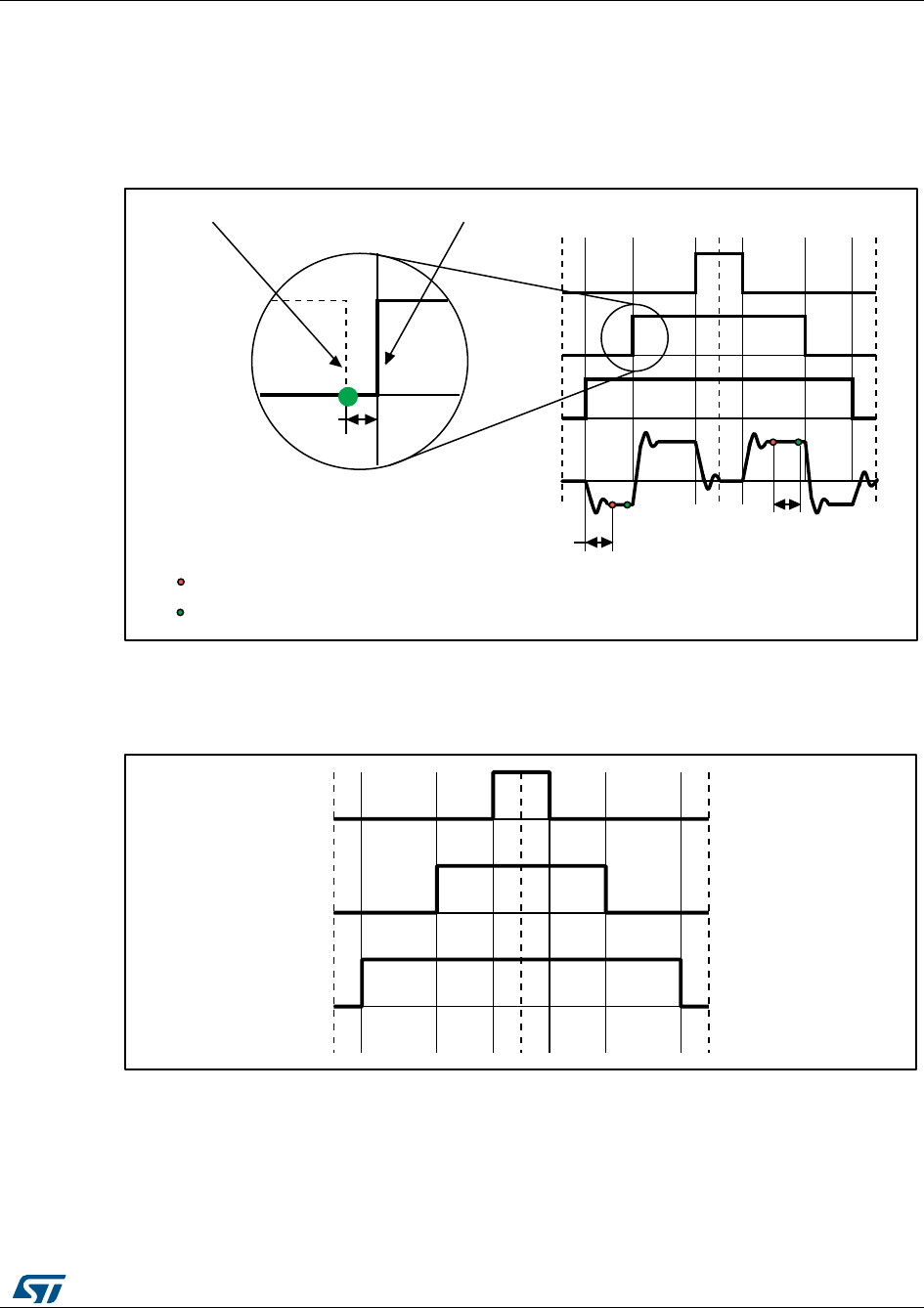
UM1052
Current sampling
DocID18458 Rev 9
67/178
TMIN is the minimum time required to perform the sampling, and
TMIN = TRise + sampling time + dead time
DMIN is the value of TMIN expressed in duty cycle percent. It is related to the PWM frequency
as follows:
DMIN = (TMIN × FPWM) × 100
Figure 62: Definition of noise parameters
The voltage-demand vector lies in a region called the Regular region when the three duty
cycles (calculated by space vector modulation) inside a PWM pattern differ from each other
by more than DMIN. This is represented in Figure 62: "Regular region".
Figure 63: Regular region
The voltage-demand vector lies in a region called Boundary 1 when two duty cycles differ
from each other by less than DMIN, and the third is greater than the other two and differs
from them by more than DMIN. This is represented in Figure 63: "Boundary 1".
T3
T2
T1
iA
–iC
iShunt
iA
–iC
III III IV VIV VII
End of noise, start of sampling
End of sampling, start of conversion
Dead
time
T5 switched off T2 switched on
TRise Sampling time
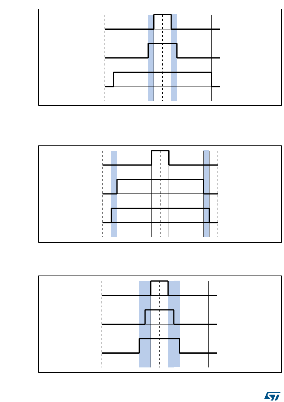
Current sampling
UM1052
68/178
DocID18458 Rev 9
Figure 64: Boundary 1
The voltage-demand vector lies in a region called Boundary 2 when two duty cycles differ
from each other by less than DMIN, and the third is smaller than the other two and differs
from them by more than DMIN. This is represented in Figure 64: "Boundary 2".
Figure 65: Boundary 2
The voltage-demand vector lies in a region called Boundary 3 when the three PWM signals
differ from each other by less than DMIN. This is represented in Figure 65: "Boundary 3".
Figure 66: Boundary 3

UM1052
Current sampling
DocID18458 Rev 9
69/178
If the voltage-demand vector lies in Boundary 1 or Boundary 2 region, a distortion must be
introduced in the related PWM signal phases to sample the motor phase current.
An ST patented technique for current sampling in the “Boundary” regions has been
implemented in the firmware. Please contact your nearest ST sales office or support team
for further information about this technique.
Table 11: Single-shunt current reading, used resources (single drive, F103/F100 LD/MD, F0x)
Adv.
timer
Aux.
timer
DMA
ISR
ADC
Note
TIM1
TIM3
(CH4)
DMA1_CH1
DMA1_CH3
DMA1_CH4
TIM1_UP
DMA1_CH4_TC
(Rep>1)
ADC1
F103/F100 LD device
configuration, RC DAC cannot
be used; ADC1 is used for
general purpose conversions
TIM1
TIM4
(CH3)
DMA1_CH1
DMA1_CH5
DMA1_CH4
TIM1_UP
DMA1_CH4_TC
(Rep>1)
ADC1
F103/F100 MD device
configuration; ADC1 is used for
general purpose conversions
TIM1
TIM15
(CH1)
DMA1_CH2
DMA1_CH5
DMA1_CH4
TIM1_UP
DMA1_CH4_TC
(Rep>1)
ADC1
F051x device configuration
TIM1
TIM3
(CH4)
DMA1_CH2
DMA1_CH3
DMA1_CH4
TIM1_UP
DMA1_CH4_TC
(Rep>1)
ADC1
F050x/F030x device
configuration
Table 12: single-shunt current reading, used resources (single or dual drive, F103HD)
Adv.
timer
Aux.
timer
DMA
ISR
ADC
Note
TIM1
TIM5
(CH4)
DMA1_CH1
DMA2_CH1
DMA1_CH4
TIM1_UP
DMA1_CH4_TC
(Rep>1)
ADC3
Option1: used by the first motor
configured in single-shunt, or the
second motor when the first is
not single-shunt; ADC1 is used
for general purpose conversions
TIM8
TIM4
(CH3)
DMA1_CH1
DMA1_CH5
DMA2_CH2
TIM8_UP
DMA2_CH2_TC
(Rep>1)
ADC1
Option1: used by the second
motor configured in single-shunt
when the first motor is also
configured in single-shunt.
TIM8
TIM5
(CH4)
DMA1_CH1
DMA2_CH1
DMA2_CH2
TIM8_UP
DMA2_CH2_TC
(Rep>1)
ADC3
Option2: used by the first motor
configured in single-shunt or by
the second motor when the first
is not single-shunt; ADC1 is
used for general purpose
conversions
TIM1
TIM4
(CH3)
DMA1_CH1
DMA1_CH5
DMA1_CH4
TIM1_UP
DMA1_CH4_TC
(Rep>1)
ADC1
Option2: used by the second
motor configured in single-shunt
when the first motor is also
configured in single-shunt.

Current sampling
UM1052
70/178
DocID18458 Rev 9
Table 13: Single-shunt current reading, used resources, single or dual drive,
STM32F2xxx/F4xx
Adv
Timer
Aux
Timer
DMA
ISR
ADC
Note
TIM1
TIM5
(ch4)
DMA1,
stream1,
ch6;
DMA2,
stream4, ch6
TIM1_UP;
DMA2_stream4_TC
(FOC rate>1)
ADC3
Option 1: used by first motor when it
is configured in single shunt, or by
second motor when the first one isn’t
in single shunt. ADVC1 used for
general purpose conversions
TIM8
TIM4(ch2)
DMA1,
stream3,ch2;
DMA2,
stream7, ch7
TIM8_UP;
DMA2_stream7_TC
(FOC rate>1)
ADC1
Option 1: used by second motor
when it is configured in single shunt
and when first motor isn’t in single
shunt. ADVC1 used for general
purpose conversions
TIM8
TIM5(ch4)
DMA1,
stream1,ch6;
DMA2,
stream7, ch7
TIM8_UP;
DMA2_stream7_TC
(FOC rate>1)
ADC3
Option 2: used by first motor when it
is configured in single shunt, or by
second motor when the first one isn’t
in single shunt. ADVC1 used for
general purpose conversions
TIM1
TIM4(ch2)
DMA1,
stream3,ch2;
DMA2,
stream4, ch6
TIM1_UP;
DMA2_stream4_TC
(FOC rate>1)
ADC1
Option 2: used by second motor
when it is configured in single shunt
and when first motor is also in single
shunt. ADVC1 used for general
purpose conversions
Using F103HD, F2xx, F4xx in single drive, it is possible to choose between option 1 and
option 2 (Table 12: "single-shunt current reading, used resources (single or dual drive,
F103HD)" and Table 13: "Single-shunt current reading, used resources, single or dual
drive, STM32F2xxx/F4xx"); resources are allocated or saved accordingly.
Please refer to Section 8: "Current sensing and protection on embedded PGA" for
STM32F30x microcontroller configuration.
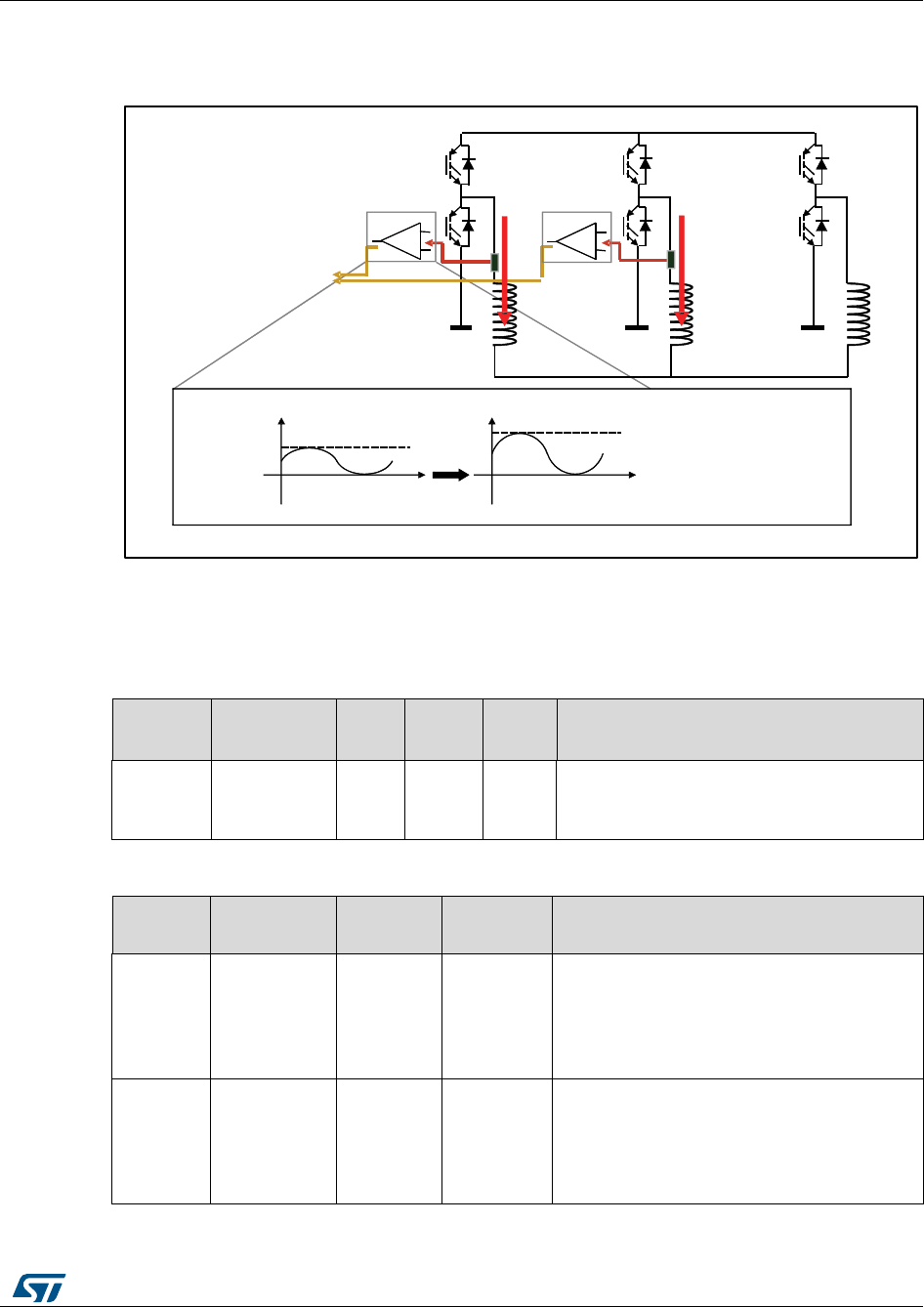
UM1052
Current sampling
DocID18458 Rev 9
71/178
5.4 Current sampling in isolated current sensor topology
Figure 66: "ICS hardware architecture" illustrates the ICS topology hardware architecture.
Figure 67: ICS hardware architecture
The three currents I1, I2, and I3 flowing through a three-phase system follow the
mathematical relationship:
I1 + I2 + I3 = 0
Table 14: ICS current reading, used resources (single drive, F103 LD/MD)
Adv.
timer
DMA
ISR
ADC
master
ADC
slave
Note
TIM1
DMA1_CH5
None
ADC1
ADC2
DMA is used to enable ADC injected
conversion external trigger.
Disabling is performed by software.
Table 15: ICS current reading, used resources (single or dual drive, F103 HD, F2xx, F4xx)
Adv.
timer
DMA
ISR
ADC
Note
TIM1
None
TIM1_UP
ADC1
ADC2
Used by the first or second motors
configured in three-shunt, depending on
the user selection. ADC is used in time
sharing. Trigger selection is performed
in the TIM_UP ISR.
TIM8
None
TIM8_UP
ADC1
ADC2
Used by the first or second motor
configured in three-shunt, depending on
the user selection. ADC is used in time
sharing. Trigger selection is performed
in the TIM_UP ISR.
ADC
+
-
Conditioning
+
-
Conditioning
XXXmV 3.3V
Conditioning N etw ork
Voltage from ICS Voltage to be converted
ICS must generate a positive
voltage when current goes
out of the inverter.
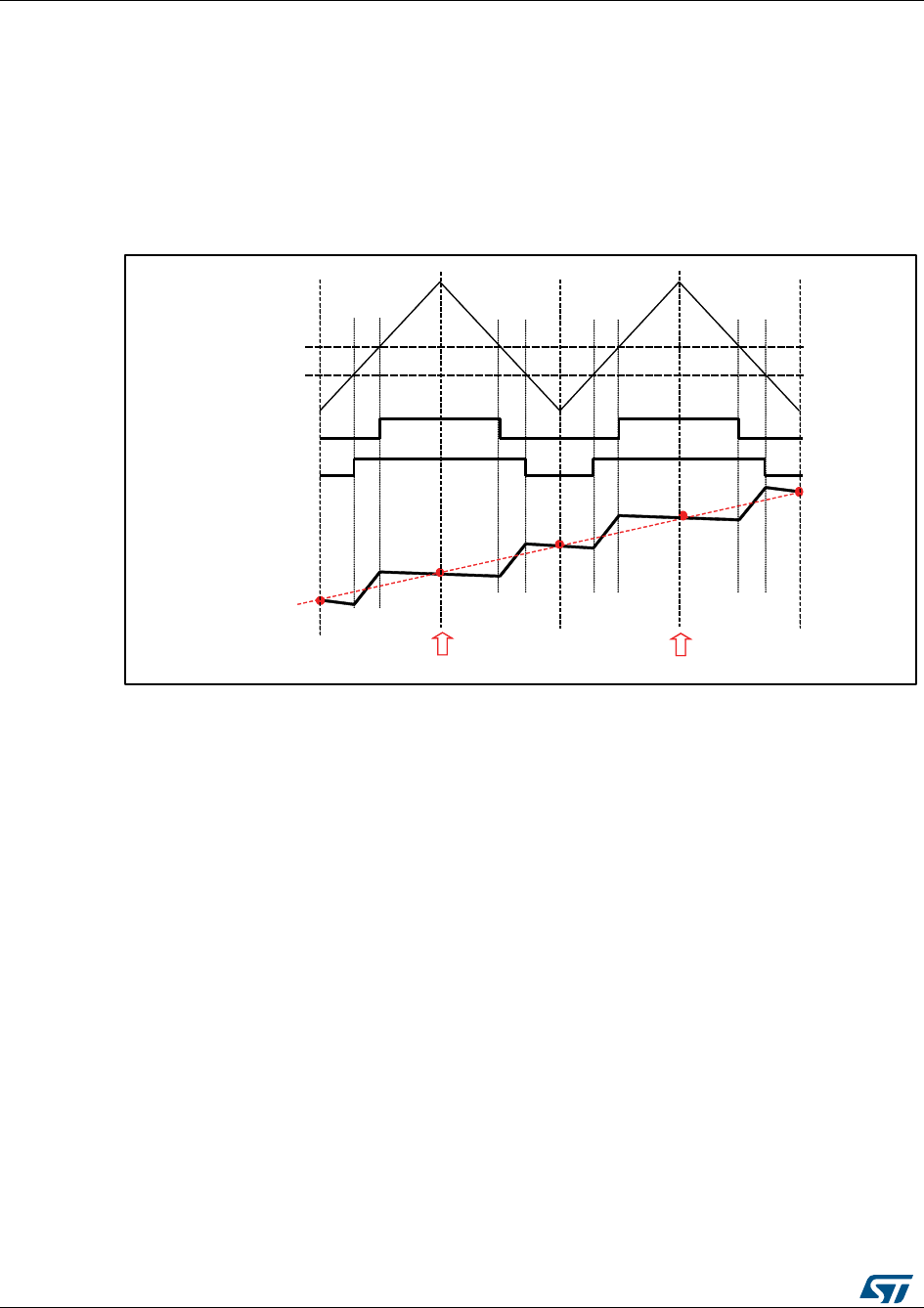
Current sampling
UM1052
72/178
DocID18458 Rev 9
To reconstruct the currents flowing through a generic three-phase load, it is therefore
sufficient to sample only two out of the three currents, while the third is calculated using the
above relationship.
The flexibility of the A/D converter trigger makes it possible to synchronize the two A/D
conversions necessary for reconstructing the stator currents flowing through the motor with
the PWM reload register updates. This is important because, as shown in Figure 67:
"Stator currents sampling in ICS configuration", it is precisely during the counter overflow
and underflow that the average level of current is equal to the sampled current. Refer to the
microcontroller reference manual to learn more about A/D conversion triggering.
Figure 68: Stator currents sampling in ICS configuration
CompareA
CompareB
LowsideA
LowsideB
Averagecurrent
Phasecurrent
PWMCounter
TIM1Update,
ADCtrigger
TIM1Update,
ADCtrigger
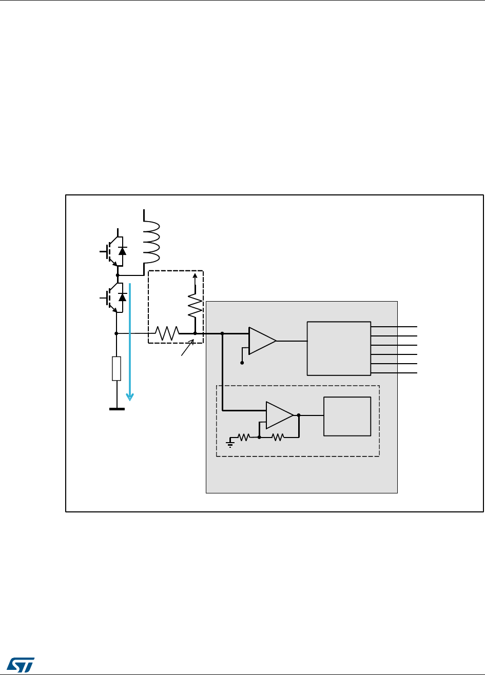
UM1052
Current sensing and protection on embedded
PGA
DocID18458 Rev 9
73/178
6 Current sensing and protection on embedded PGA
6.1 Introduction
The STM32F302xB/C or STM32F303xB/C microcontrollers feature an enhanced set of
peripherals including comparators, PGAs, DACs and high-speed ADCs.
Figure 68: "Current sensing network and overcurrent protection with STM32F302/303"
shows a current sensing and overcurrent protection scheme that can be implemented using
the internal resources of the STM32F302/303. The voltage drop on the shunt resistor, due
to the motor phase current, can be either positive or negative, an offset is set by R1 and
R2. The signal is linked to a microcontroller input pin that has both functionality of amplifier
and comparator non-inverting.
Figure 69: Current sensing network and overcurrent protection with STM32F302/303
This optimized configuration using STM32F3 reduces the number of external components
and microcontroller pins assigned to the MC application.
6.2 Current sensing
In order to maximize the resolution of the measurement, the PGA can be used to adapt the
level of voltage drop in the shunt resistor (Rshunt), caused by the motor current, up to the
maximum range allowed by the analog to digital converter (ADC).
RShunt
+Vdd
TIM1,8
STM32F3xx
+
-
V-
BRK2
COMP
IV+
6 PWM
+
-
OP AMP
ADC
Current measurement
R1
R2

Current sensing and protection on embedded
PGA
UM1052
74/178
DocID18458 Rev 9
The PGA has a set of fixed internal gains (x2, x4, x8, x16). An alternative option in PGA
mode allows you to route the central point of the resistive network on one of the I/Os
connected to the non-inverting input. This feature can be used for instance to add a low-
pass filter to PGA, as shown in Figure 69: "Current sensing network using external gains".
If a different value of amplification is required, it is possible to define the amplification
network (e.g., as shown in Figure 68: "Current sensing network and overcurrent protection
with STM32F302/303").
Figure 70: Current sensing network using external gains
The MC library can be arranged to match all the configurations shown. In the dialogue
window located in Control Stage > Analog Input > Phase current feedback (Figure 71:
"STMCWB window related to PGA/COMP settings for motor currents"), setting:
“Embedded PGA" as current sensing topology;
"PGA internal gain (like in Figure 68: "Current sensing network and overcurrent
protection with STM32F302/303"): Settling "Internal" in the "OPAMP Gain" drop down
list;
"PGA external gain (like in Figure 69: "Current sensing network using external gains"):
Settling "External" in the "OPAMP Gain" drop down list;
"PGA internal gain with external filtering capacitor (like in Figure 70: "Current sensing
network using internal gains plus filtering capacitor"): Settling "Internal" in the "OPAMP
Gain" drop down list and checking the "Feedback net filtering" check box in the same
group.
Just one of this setting is present in the workbench for each drives, since the configuration
applies to each shunt resistor conditioning network.
RShunt
+Vdd
TIM1,8
STM32F3xx
+
-
V-
BRK2
COMP
IV+
6 PWM
+
-
OP AMP
ADC
Current measurement
R1
R2
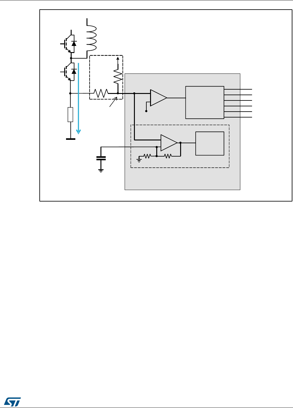
UM1052
Current sensing and protection on embedded
PGA
DocID18458 Rev 9
75/178
Figure 71: Current sensing network using internal gains plus filtering capacitor
It is also possible to set up the motor current measurement network to use external
operational amplifiers. In this case the amplified signals are directly fed to the ADC
channels. In the dialogue window located in Control Stage > Analog Input > Phase current
feedback, setting "External OPAMP" as current sensing topology.
RShunt
+Vdd
TIM1.8
STM32F3xx
+
-
V-
BRK2
COMP
IV+
6 PWM
+
-
OP AMP
ADC
Current measurement
R1
R2
CFilter
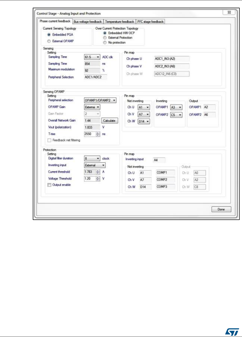
Current sensing and protection on embedded
PGA
UM1052
76/178
DocID18458 Rev 9
Figure 72: STMCWB window related to PGA/COMP settings for motor currents
6.3 Overcurrent protection
The basic principle of the hardware over-current protection mechanism can be summarized
as follows:
The phase current of the motor flows in the power transistor of the inverter bridge and
passes through the shunt resistor (RShunt) producing a voltage drop (V+).
This voltage drop is compared with a threshold (V-) defining the maximum admissible
current.
If the threshold is exceeded, a break signal stops the PWM generation putting the
system in a safe state.
All of these actions can be performed using the internal resources of the STM32F302/303
and, in particular, the embedded comparators and the advanced timer break function
(BRK2). As shown in Figure 68: "Current sensing network and overcurrent protection with
STM32F302/303", Figure 69: "Current sensing network using external gains" and Figure

UM1052
Current sensing and protection on embedded
PGA
DocID18458 Rev 9
77/178
70: "Current sensing network using internal gains plus filtering capacitor" the same signal is
fed to both not inverting input of embedded comparators and PGA.
The overcurrent threshold (V-) can be defined in three different ways:
using one of the available internal voltage reference (1.2V, 0.9V, 0.6V, 0.3V);
providing it externally using the inverting input pin of the comparator;
programming a DAC channel.
The MC library can be arranged to match all the configurations shown by using the ST MC
Workbench, creating a project based on STM32F302xB/C or STM32F303xB/C, from the
dialogue window located in Control Stage -> Analog Input -> Phase current feedback
(Figure 71: "STMCWB window related to PGA/COMP settings for motor currents"), setting:
“Embedded HW OCP" radio button as overcurrent protection topology;
HW OCP internal threshold: selecting "Internal" in the "Inverting input" drop down list
and choosing the internal voltage reference (among available values) in "Voltage
Threshold".
HW OCP external threshold: selecting "External" in the "Inverting input" drop down list
and editing the external voltage reference in "Voltage Threshold".
HW OCP internal threshold using DAC: selecting "DAC" in the "Inverting input" drop
down list and editing the DAC voltage reference to be generated in "Voltage
Threshold". A DAC channel must be assigned for this functionality (OCP) from the
related dialogue window located in Control stage -> DAC functionality (Figure 74:
"STMCWB windows related to ADC/COMP settings for DC bus Voltage").
On the other hand, it is possible to setup the motor overcurrent protection network to use
external components. In this case the overcurrent protection signal - coming from a
comparator for instance - is directly fed to the advanced-timer's BKIN2 pin. By using the ST
MC Workbench, creating a project based on STM32F302 or STM32F303, from the
dialogue window located in Control Stage -> Analog Input -> Phase current feedback,
setting "External protection" as OCP protection topology.
In any case, either using embedded comparators or external components, a digital filter,
upstream the BKIN2 function, can be enabled and configured to reject noises.
6.4 Resources allocation - single drive
For project based on STM32F302xB/C or STM32F303xB/C the current feedback network
configurations supported by STM32 FOC SDK are single shunt and three shunt.
6.4.1 Single shunt topology
According to the configuration (see Section 8.2: "Current sensing" and Section 8.3:
"Overcurrent protection"), one ADC, OPAMP, comparator, DAC channel must be assigned.
If "Embedded PGA" is enabled, the selection of ADC peripheral (and input pin) is
linked to this specific PGA peripheral.
If "Embedded HW OCP" and "Embedded PGA" are enabled, the selection of ADC and
comparator (and their input and '+" pins) is linked to to this specific PGA peripheral
(and its '+' input).
If "Embedded HW OCP" is enabled and "Embedded PGA" is disabled, the selection of
comparator is free.
If "Embedded HW OCP" and "Embedded PGA" are both disabled, the selection of
comparator and ADC is free.
If both PGA and comparator for OC protection are used they will share the same input
pins for the motor current measurement signal.

Current sensing and protection on embedded
PGA
UM1052
78/178
DocID18458 Rev 9
6.4.2 Three shunts topology
According to the configuration (see Section 8.2: "Current sensing" and Section 8.3:
"Overcurrent protection"), 2 ADCs, 2 OPAMPs, 3 comparators, 1 DAC channel must be
assigned.
If "Embedded PGA" is enabled, the selection of ADC peripherals (and input pins) is
linked to this specific PGA peripherals.
If "Embedded HW OCP" and "Embedded PGA" are enabled, the selection of ADCs
and comparators (and their inputs and '+" pins) is linked to this specific PGA
peripherals (and theirs '+' inputs).
If "Embedded HW OCP" is enabled and "Embedded PGA" is disabled, the selection of
comparators is free.
If "Embedded HW OCP" and "Embedded PGA" are both disabled, the selection of
comparators and ADCs is free.
The pair OPAMP1/OPAMP2 can be used in a project based on STM32F302 or
STM32F303; the pair OPAMP3/OPAMP4 can be used additionally in a project based
on STM32F303.
The pair ADC1/ADC2 can be used in a project based on STM32F302 or STM32F303;
the pair ADC3/ADC4 can be used additionally in a project based on STM32F303.
If both PGA and comparator for OC protection are used they will share the same input
pins for the motor current measurement signal.
6.5 Resources allocation - dual drive
Dual drive project can be designed by using a STM32F303 microcontroller. The current
feedback network configurations supported by STM32 FOC SDK are single shunt and
three shunt.
Dual single shunt drive, dual three shunts drive and mixed "single plus three" shunts drives
are allowed.
The sharing of peripherals between "single shunt drive" and "three shunt drive" is not
allowed.
The sharing of peripherals between two "single shunt drive" is not allowed.
The sharing of peripherals between two "three shunt drive" is allowed, in the forms
expressed below.
6.5.1 Single shunt topology
For each motor, according to configuration (as explained in Section 8.2: "Current sensing"
and Section 8.3: "Overcurrent protection"), one ADC, OPAMP and comparator must be
assigned.
If "Embedded PGA" is enabled, the selection of ADC peripheral (and input pin) is
linked to this specific PGA peripheral.
If "Embedded HW OCP" and "Embedded PGA" are enabled, the selection of ADC and
comparator (and their input and '+" pins) is linked to this specific PGA peripheral (and
its '+' input).
If "Embedded HW OCP" is enabled and "Embedded PGA" is disabled, the selection of
comparator is free.
If "Embedded HW OCP" and "Embedded PGA" are both disabled, the selection of
comparator and ADC is free.
If both PGA and comparator for OC protection are used they will share the same input
pins for the motor current measurement signal.

UM1052
Current sensing and protection on embedded
PGA
DocID18458 Rev 9
79/178
6.5.2 Three shunts topology mixed with single shunt topology
According to configuration (as explained in Section 8.2: "Current sensing" and Section 8.3:
"Overcurrent protection"), 2 ADCs, 2 OPAMPs, 3 comparators, 1 DAC channel must be
assigned.
If "Embedded PGA" is enabled, the selection of ADC peripherals (and input pins) is
linked to this specific PGA peripherals.
If "Embedded HW OCP" and "Embedded PGA" are enabled, the selection of ADCs
and comparators (and their inputs and '+" pins) is linked to this specific PGA
peripherals (and theirs '+' inputs).
If "Embedded HW OCP" is enabled and "Embedded PGA" is disabled, the selection of
comparators is free.
If "Embedded HW OCP" and "Embedded PGA" are both disabled, the selection of
comparators and ADCs is free.
The pair OPAMP1/OPAMP2 can be used in a project based on STM32F302 or
STM32F303; the pair OPAMP3/OPAMP4 can be used additionally in a project based
on STM32F303.
The pair ADC1/ADC2 can be used in a project based on STM32F302 or STM32F303;
the pair ADC3/ADC4 can be used additionally in a project based on STM32F303.
If both PGA and comparator for OC protection are used they will share the same input
pins for the motor current measurement signal.
6.5.3 Dual three shunt topology, resources not shared
According to configuration (as explained in Section 8.2: "Current sensing" and Section 8.3:
"Overcurrent protection"), 4 ADCs, 4 OPAMPs, 6 comparators, 2 DAC channels must be
assigned.
If "Embedded PGA" is enabled, the selection of ADC peripherals (and input pins) is
linked to this specific PGA peripherals.
If "Embedded HW OCP" and "Embedded PGA" are enabled, the selection of ADCs
and comparators (and their inputs and '+" pins) is linked to this specific PGA
peripherals (and theirs '+' inputs).
If "Embedded HW OCP" is enabled and "Embedded PGA" is disabled, the selection of
comparators is free.
If "Embedded HW OCP" and "Embedded PGA" are both disabled, the selection of
comparators and ADCs is free.
The pairs that can be used are OPAMP1/OPAMP2 can be used in a project based on
STM32F302 or STM32F303; the pair OPAMP3/OPAMP4 can be used additionally in a
project based on STM32F303.
The pair ADC1/ADC2 can be used in a project based on STM32F302 or STM32F303;
the pair ADC3/ADC4 can be used additionally in a project based on STM32F303.
If both PGA and comparator for OC protection are used they will share the same input
pins for the motor current measurement signal.
6.5.4 Dual three shunt topology, shared resources
If both drives are three shunts, it can be possible to share the ADC and/or the PGA to
perform the motor current measurement. To do this is mandatory to have both use external
operational amplifier or both use the embedded PGA for the motor current measurement
signals amplification. It can be settled by the user in the ST MC Workbench clicking the
"Shared resource" check box in the Control Stage -> Analog Input.

Current sensing and protection on embedded
PGA
UM1052
80/178
DocID18458 Rev 9
If shared resource is settled and external operational amplifier is used, it is possible to use
the pairs ADC1/ADC2 or the pairs ADC3/ADC4 for both drivers. ST MC Workbench will
propose the allowed inputs pins for motor currents measurement in this case.
If shared resource is settled and embedded PGA is used, the following configuration is
used:
The pair OPAMP1/OPAMP3 is used
OPAMP gains is only "Internal"
External capacitor filer is not allowed
Input pins are: PA5, PA7, and PB13 respectively U, V, W for motor 1 and PA1, PA3
and PB0 respectively U, V, W for motor 2.
In this case, if the hardware over current protection is managed by internal comparators, is
mandatory to connect externally the pins PA3 with one of the pins PB14 or PD14 and
connect externally the pins PA5 with one of the pins PB11 or PD11. The pins selected can
be settled in the workbench in Control Stage > Analog Input > Phase current feedback >
Protection.
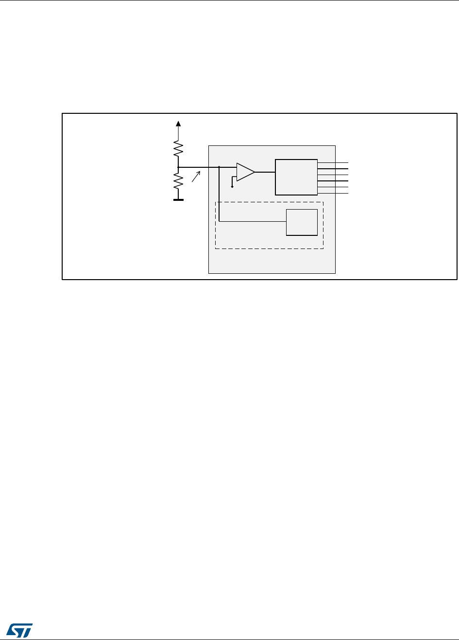
UM1052
Overvoltage protection with embedded analog
(STM32F3x only)
DocID18458 Rev 9
81/178
7 Overvoltage protection with embedded analog
(STM32F3x only)
Figure 72: "Overvoltage protection network" shows a basic implementation of over-voltage
protection network that can be implemented using the internal resources of the
STM32F30x.
Figure 73: Overvoltage protection network
The principle is similar to the one described in Section 8.3: "Overcurrent protection":
A resistive voltage divider provides a signal proportional to the bus voltage. It must be
sized depending on the bus voltage range requested by the target application, so that
it never exceeds the MCU's input maximum admissible voltage level.
This reading is compared to an overvoltage threshold to generate a fault signal.
If the threshold is exceeded, a break signal stops the PWM generation putting the
system in a safe state.
As mentioned before, these actions can be performed automatically using the internal
comparator of the STM32F30x. In this case, it is convenient to use the second break
functionality (BRK) of the advanced timer in order to differentiate the action to perform on
the PWM signals in case of an over-current: disable PMW generation or turn-on low side
switches.
The MC library can be arranged to match these configurations by using the ST MC
Workbench, creating a project based on STM32F302 or STM32F303, from the dialogue
window located in Control Stage -> Analog Input -> Bus voltage feedback (Figure 73:
"STMCWB windows related to ADC/COMP settings for DC bus Voltage"), setting:
"Embedded HW OVP" checkbox;
HW OVP internal threshold: selecting "Internal" in the "Inverting input" drop down list
and choosing the internal voltage reference (among available values) in "Comparator
Input".
HW OVP external threshold: selecting "External" in the "Inverting input" drop down list
and editing the external voltage reference in "Comparator Input".
HW OVP internal threshold using DAC: selecting "DAC" in the "Inverting input" drop
down list and editing the DAC voltage reference to be generated in "Comparator
Input". A DAC channel must be assigned for this functionality (OVP) from the related
TIM1,8
STM32F3xx
+
-
V-
BRK
COMP
V+
6 PWM
ADC
Bus voltage measurement
BUS voltage
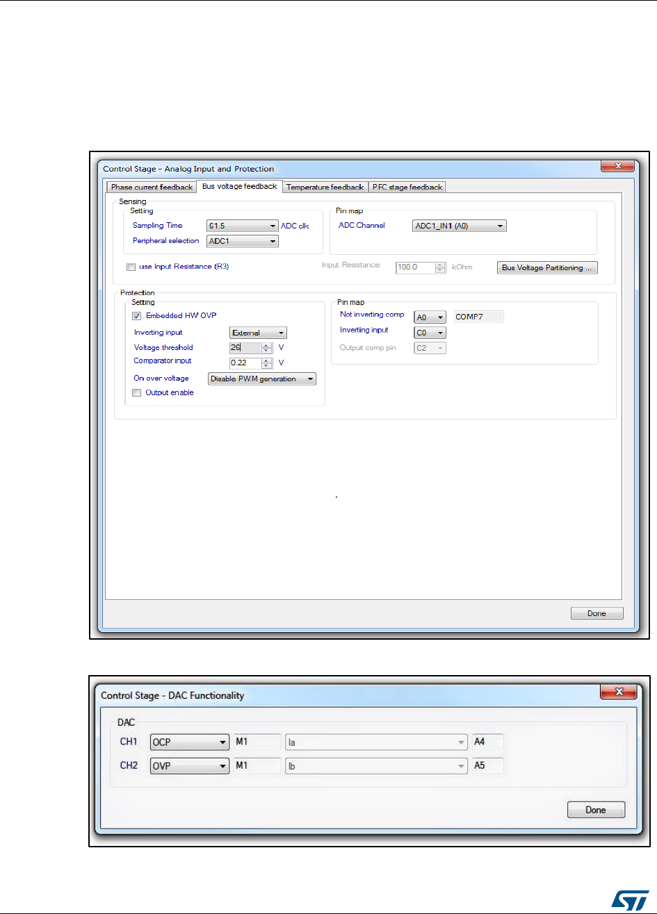
Overvoltage protection with embedded analog
(STM32F3x only)
UM1052
82/178
DocID18458 Rev 9
dialogue window located in Control stage -> DAC functionality (Figure 74: "STMCWB
windows related to ADC/COMP settings for DC bus Voltage")
The selection of 'not-inverting' input pin contextually picks the comparator to be used.
The drive behavior when an overvoltage state is found: disable PWM generation, or
turn-on low side switches;
Enabling or disabling the comparator output has no effect on the overvoltage protection
functionality itself
Figure 74: STMCWB windows related to ADC/COMP settings for DC bus Voltage
Figure 75: STMCWB windows related to ADC/COMP settings for DC bus Voltage

UM1052
Rotor position/speed feedback
DocID18458 Rev 9
83/178
8 Rotor position/speed feedback
Section 6.3: "Introduction to the PMSM FOC drive" shows that rotor position/speed
measurement has a crucial role in PMSM field-oriented control. Hall sensors or encoders
are broadly used in the control chain for that purpose. Sensorless algorithms for rotor
position/speed feedback are considered very useful for various reasons: to lower the
overall cost of the application, to enhance the reliability by redundancy, and so on. Refer to
Section 10.1: "Sensorless algorithm (BEMF reconstruction)", Section 10.3: "Hall sensor
feedback processing", and Section 10.4: "Encoder sensor feedback processing" for further
details.
The selection of speed/position feedback can be performed through correct settings in the
.h parameter files (generated by the ST MC Workbench GUI) used to initialize the MC
Application during its boot stage.
8.1 Sensorless algorithm (BEMF reconstruction)
This firmware library provides a complete solution for sensorless detection of rotor
position/speed feedback, which is based on the state observer theory. The implemented
algorithm is applicable to both SM-PM and IPM synchronous motors, as explained in ([5]).
A theoretical and experimental comparison between the implemented rotor flux observer
and a classical VI estimator (Appendix [6]) has pointed out the observer's advantage, which
turns out to be a clearly reduced dependence on the stator resistance variation and an
overall robustness in terms of parameter variations.
A state observer, in control theory, is a system that provides an estimation of the internal
state of a real system, given its input and output measurement.
In our case, the internal states of the motor are the back-emfs and the phase currents,
while the input and output quantities supplied are the phase voltages and measured
currents, respectively (see Figure 22: "Flux-weakening operation scheme").
DC bus voltage measurement is used to convert voltage commands into voltage applied to
motor phases.
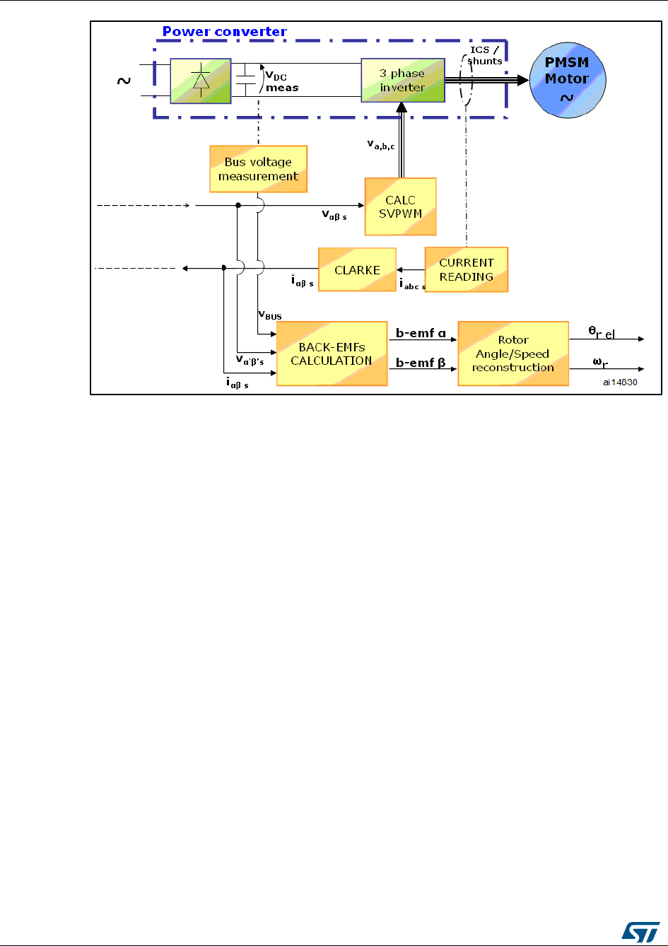
Rotor position/speed feedback
UM1052
84/178
DocID18458 Rev 9
Figure 76: General sensorless algorithm block diagram
The observed states are compared for consistency with the real system via the phase
currents, and the result is used to adjust the model through a gain vector (K1, K2).
The motor back-emfs are defined as:
As can be seen, they hold information about the rotor angle. Then, back-emfs are fed to a
block which is able to reconstruct the rotor electrical angle and speed. This latter block can
be a PLL (Phase-Locked Loop) or a CORDIC (COordinate Rotation DIgital Computer),
depending on the user's choice.
In addition, the module processes the output data and, by doing so, implements a safety
feature that detects locked-rotor condition or malfunctioning.
Figure 76: "PMSM back-emfs detected by the sensorless state observer algorithm" shows
a scope capture taken while the motor is running in field-oriented control (positive rolling
direction). The yellow and the red waveforms (C1,C2) are respectively the observed back-
emfs alpha and beta. The blue square wave (C3) is a signal coming from a Hall sensor cell
placed on the a-axis. The green sinewave is current ia (C4).
In confidential distribution, the classes that implement the sensorless algorithm are
provided as compiled object files. The source code is available free of charge from ST on
request. Please contact your nearest ST sales office.
8.1.1 A priori determination of state observer gains
The computation of the initial values of gains K1 and K2 is based on the placement of the
state observer eigenvalues. The required motor parameters are rs (motor winding
resistance), Ls (motor winding inductance), T (sampling time of the sensorless algorithm,
which coincides with FOC and stator currents sampling).
The motor model eigenvalues could be calculated as:
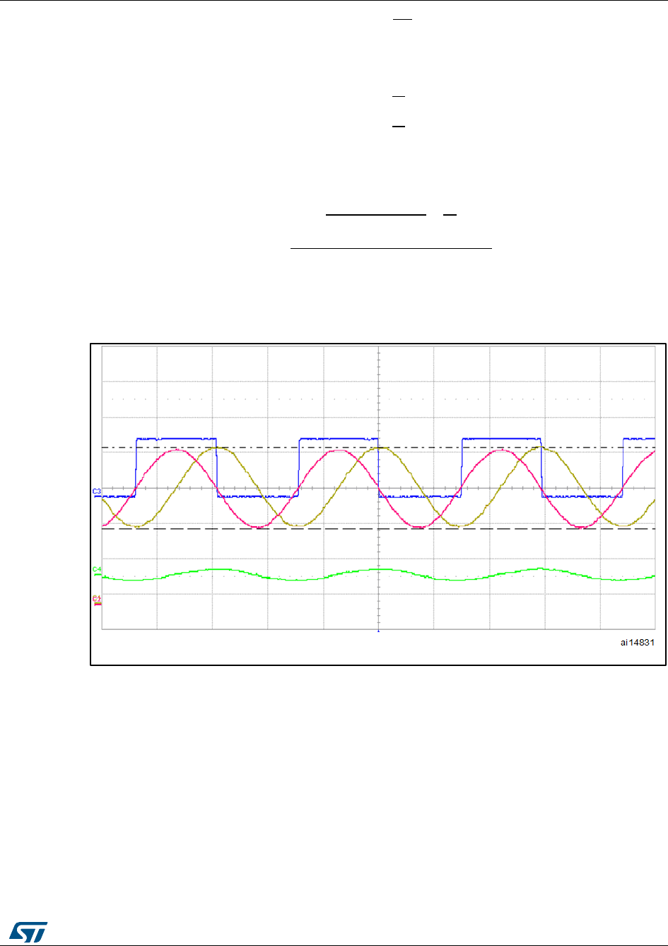
UM1052
Rotor position/speed feedback
DocID18458 Rev 9
85/178
The observer eigenvalues are placed with:
Typically, as a rule of the thumb, set f = 4;
The initial values of K1 and K2 could be calculated as:
This procedure is followed by the ST MC Workbench GUI to calculate proper state
observer gains. It is also possible to modify these values using other criteria or after fine-
tuning.
Figure 77: PMSM back-emfs detected by the sensorless state observer algorithm
1. C1= b-emf alpha
2. C2 = b-emf beta
3. C3 = Hall 1
4. C4 = phase A, measured current
More information on how to fine-tune parameters to make the firmware suit the motor can
be found in Section 11: "Full LCD user interface".

Rotor position/speed feedback
UM1052
86/178
DocID18458 Rev 9
8.2 Sensorless algorithm: High frequency injection(HFI)
8.2.1 Overview
A new sensorless algorithm (ST patent pending) is available for I-PMSM motors that, by
exploiting the peculiar anisotropy of their magnetic structure, are able to detect rotor
angular position at very low speeds and at standstill.
The algorithm is based on injection of a small high frequency voltage signal along a given
direction so that, thanks to the rotor saliency, a periodic current signal is generated whose
amplitude is function of the phase displacement between rotor position and injection angle.
Consequently, a robust rotor position tracking, unaffected by parameter variations (speed
and load), is obtained by minimizing the amplitude of the above mentioned signal
response.
This new high frequency injection algorithm can work in synergy with the back-emfs
observer (section 8.1) in order to cover, complementarily, a broad speed operating range:
zero and very low speed the first, low and up to deep flux weakening the second.
The HFI can be enabled on STM32F30x and STM32F4x, taking full advantage of their
floating point unit (VFP).
8.2.2 Incremental system build
The tuning of an HFI-based system can be accomplished by means of an “incremental
system build” path, whose steps involve the following strict steps: utilization of the
STMCWB as configurator, a toolchain for code building and flashing, trials on the system
(taking advantage of the DAC tracer and STMCWB serial communication), and then back
to STMCWB to set the parameters that have been found.
In particular, the defined path goes through:
1. Complete a hardware/firmware setup and related STMCWB configuration that is able
to run the motor in FOC sensorless, observer + PLL mode, in a speed range from
10% to nominal;
2. STMCWB configurator:
a. enable “Sensorless HFI + Observer” as speed sensor;
b. set an HFI “Amplitude” which, considering the (default) HFI frequency and motor
RL figure allows the flow of – roughly, as starting value – 5% of the motor
nominal current;
c. enable HFI Debug mode;
d. leave other HFI parameters as default;
e. enable DAC functionality, and set “HFI current” and “Ia” as CH1 and CH2
variables (related of course to the motor drive under testing, between M1 and
M2);
f. generate h files
3. toolchain: build and download; this step, actually, follows any new settings in the
STMCWB configuration, before it can be re-tested;
4. system testing, applicability of HFI to the motor:
a. arrange the necessary hardware, oscilloscope triggering and probes to capture
DAC tracers, power source;
b. run the motor giving a “start motor command” (from LCD UI or STMCWB serial)
the motor will not move at all because, at step 1.c, debug mode has been
activated
after the oscilloscope has captured the waveforms, it’s possible to move
back the state machine giving a “Stop Motor” command (by LCD or serial UI,
for instance);
c. analyze the oscilloscope capture:

UM1052
Rotor position/speed feedback
DocID18458 Rev 9
87/178
if “HFI current” (CH1) has a periodic waveform and its period is half that of
“Ia” (CH2), similarly to what shown in Figure 77: "IPMSM anisotropy fitting
HFI algorithm", then the IPMSM motor under testing is suitable for this ST
HFI sensorless algorithm, it’s possible to proceed with step 4)
if CH1 is clearly periodic but its period is wrong, then the motor it’s not
suitable for HFI algorithm;
if CH1 is flat or not well defined periodicity , restart from step 1) b, increase
(incrementally, up to a viable value) the HFI “Amplitude” . At that point, if
CH1 acquires the right shape then the motor is suitable for HFI, it’s possible
to proceed with step 4)
5. System testing, initial angle detection:
a. modify the DAC variable CH2 (for instance using LCD UI or STMCWB serial) by
setting “HFI initial angle PLL”, run the motor (as described in 3)b);
b. analyze the oscilloscope capture:
if CH2 converges asymptotically to a value, which depends from rotor angle,
before the allowed time is ended (which is evident from CH2 itself), as
shown in Figure 78: "Incremental system building oscilloscope captures",
then “Initial angle PLL” gains are ok, it’s possible to proceed with step 4)c
if CH2 oscillates around a value, which depends from rotor angle, then
decrease “Init angle PLL” KI or increase KP, build, flash and try again;
if the trend of CH2 is clearly interrupted before reaching its asymptotical
value, then increase KI or increase Scan Rotation number (the procedure
will take more time, in this case), build, flash and try again;
c. Read the variable “HFI saturation difference” from STMCWB serial registers
If the variable is around 5-10% of the nominal current, then it can be copied
in the STMCBW configurator as “Min saturation Difference”; it’s possible to
proceed with step 5)
If the variable is lower than 5% of the nominal current, then increase
(incrementally, up to a viable value) in the STMCWB configurator the
parameter “Amplitude boost”; build, flash, and try again;
6. System testing, angle tracking:
a. Run the motor, as described in 3)b, analyze the oscilloscope capture: in
particular, variable CH2 has to show the pattern of Figure 78: "Incremental
system building oscilloscope captures", stage 3:
if CH2 converges asymptotically to a value, which depends from rotor angle,
before the allowed time is ended then HFI PI gains are ok; it’s possible to
proceed with step 5)b
if CH2 oscillates around a value, which depends from rotor angle, then
decrease HFI KI or increase KP, build, flash and try again;
if the trend of CH2 is clearly interrupted before reaching its asymptotical
value, then increase KI, build, flash and try again;
b. If possible, turn the rotor by hand or other means, otherwise skip to step 6):
if CH2 should show the HFI’s measured rotor angle, it’s possible to proceed
with step 6);
7. System testing, run mode:
a. Disable “HFI debug mode” from STMCWB;
b. Set an “HFI-STO threshold” in the range of 20% of the nominal speed;
c. build the workspace, and download;
d. Set an initial target speed (from STMCWB serial, LCD UI or other UI) lower than
what configured in as “HFI-STO threshold”, say 5% of the nominal speed, so as
that HFI only is used for this testing;
e. Run the motor. If all is well, it should be possible to now configure the transition
between HFI and STO, and vice versa. This usually happens at about 10% of the
motor nominal speed; please refer to STMCWB documentation for related
parameters.

Rotor position/speed feedback
UM1052
88/178
DocID18458 Rev 9
Figure 78: IPMSM anisotropy fitting HFI algorithm
Figure 79: Incremental system building oscilloscope captures
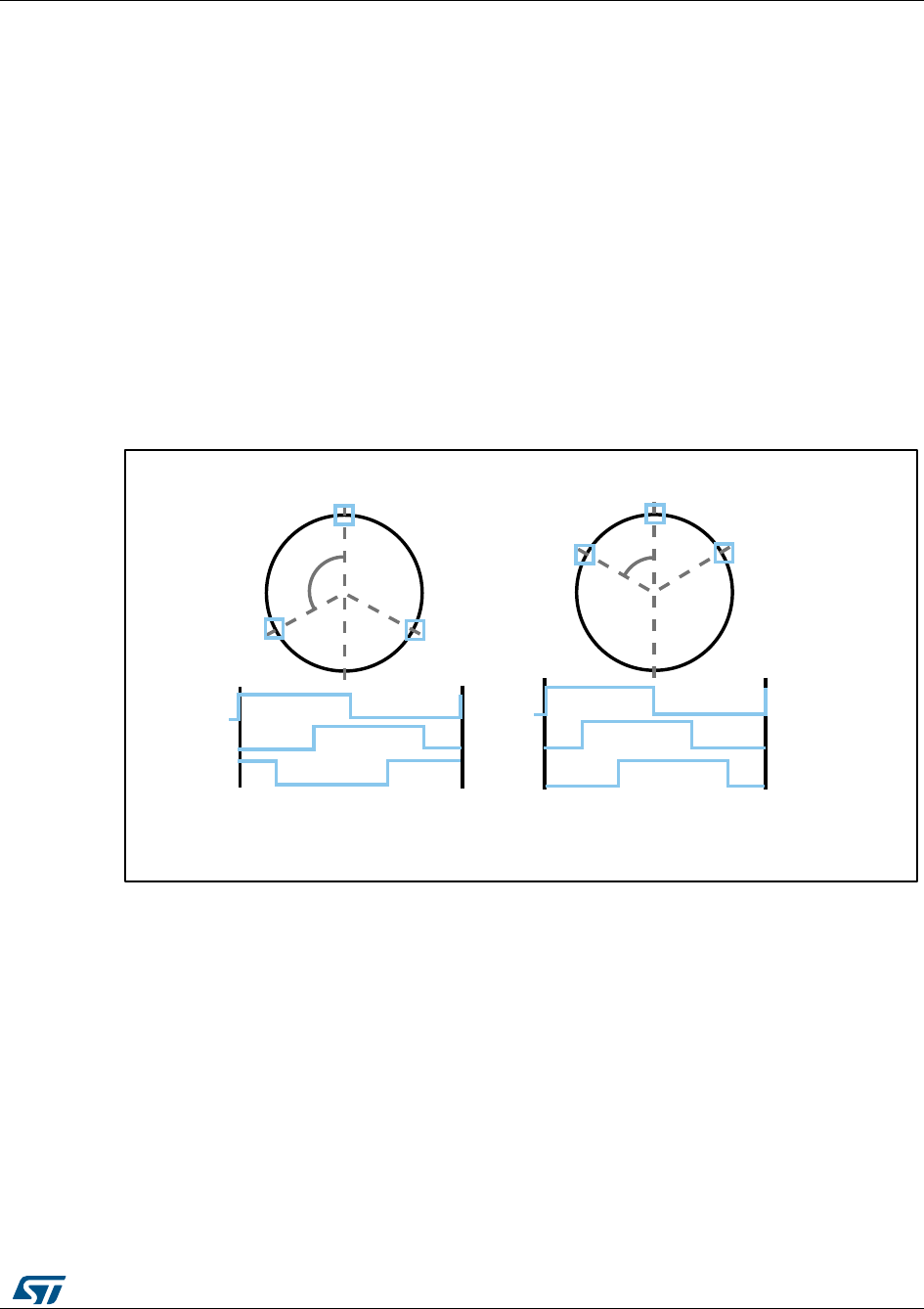
UM1052
Rotor position/speed feedback
DocID18458 Rev 9
89/178
8.3 Hall sensor feedback processing
8.3.1 Speed measurement implementation
Thanks to the STM32 general-purpose timer (TIMx) features, it is very simple to interface
the microcontroller with three Hall sensors. When the TI1S bit in the TIMx_CR2 register is
set, the three signals on the TIMx_CH1, TIMx_CH2 and TIMx_CH3 pins are XORed and
the resulting signal is connected to the TIMx input capture.
Thus, the speed measurement is converted into the period measurement of a square wave
with a frequency six times higher than the real electrical frequency. The only exception is
that the rolling direction, which is not extractable from the XORed signal, is performed by a
direct access to the three Hall sensor outputs.
Rolling direction identification
As shown in Figure 79: "Hall sensors, output-state correspondence", it is possible to
associate any of Hall sensor output combinations with a state whose number is obtainable
by considering H3-H2-H1 as a three-digit binary number (H3 is the most significant bit).
Figure 80: Hall sensors, output-state correspondence
Consequently, it is possible to reconstruct the rolling direction of the rotor by comparing the
present state with the previous one. In the presence of a positive speed, the sequence
must be as illustrated in Figure 79: "Hall sensors, output-state correspondence".
Period measurement
Although the principle for measuring a period with a timer is quite simple, it is important to
keep the best resolution, in particular for signals, such as the one under consideration, that
can vary with a ratio easily reaching 1:1000.
In order to always have the best resolution, the timer clock prescaler is constantly adjusted
in the current implementation.
The basic principle is to speed up the timer if the captured values are too low (for an
example of short periods, see Figure 80: "Hall sensor timer interface prescaler decrease"),
120° 60°
H1
H2 H3
H1
H2 H3
H1
H2
H3
H1
H2
H3
3 sensors 120° 3 sensors 60°
State5 –> State1 –> State 3 –> State1 –> State3 –> State 7 –>
State2 –> State6 –> State 4 –>... State6 –> State4 –> State 0 –>...
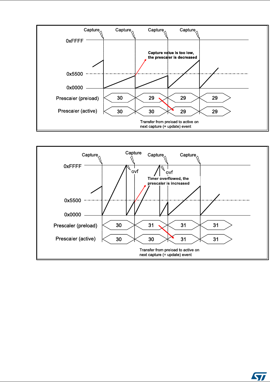
Rotor position/speed feedback
UM1052
90/178
DocID18458 Rev 9
and to slow it down when the timer overflows between two consecutive captures (see the
example of large periods in Figure 81: "Hall sensor timer interface prescaler increase").
Figure 81: Hall sensor timer interface prescaler decrease
Figure 82: Hall sensor timer interface prescaler increase
The prescaler modification is done in the capture interrupt, taking advantage of the buffered
registers: the new prescaler value is taken into account only on the next capture event, by
the hardware, without disturbing the measurement.
Further details are provided in the flowchart shown in Figure 82: "TIMx_IRQHandler
flowchart", which summarizes the actions taken into the TIMx_IRQHandler.
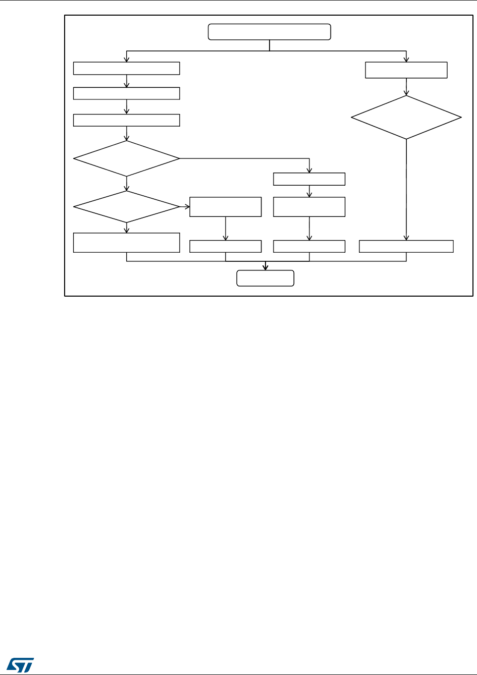
UM1052
Rotor position/speed feedback
DocID18458 Rev 9
91/178
Figure 83: TIMx_IRQHandler flowchart
8.3.2 Electrical angle extrapolation implementation
As shown in Figure 82: "TIMx_IRQHandler flowchart", the speed measurement is not the
only task performed in TIMx_IRQHandler. As well as the speed measurement, the high-to-
low or low-to-high transition of the XORed signal also gives the possibility of synchronizing
the software variable that contains the present electrical angle.
The synchronization is performed avoiding abrupt changes in the measured electrical
angles. In order to do this, the difference between the expected electrical angle, computed
from the last speed measurement, and the real electrical angle, coming from the Hall
sensor signals (see ) is computed. The new speed measurement is adjusted with this
information in order to compensate for the difference.
As can be seen in Figure 83: "Hall sensor output transitions", any Hall sensor transition
gives very precise information about the rotor position.
HALL_IRQHandler
Read present state
Extract spinning direction
There were
overflows?
Captured value
is too low?
OVF_Counter++
OVF_Counter >
HALL_MAX_OV
ERFLOWS?
Time out = TRUE
Re- compute capture
Store capture
prescaler direction
Prescaler ++Prescaler --
Store capture
prescaler direction
Store capture prescaler direction
End
Extract electrical angle
Capture event Update (OVF) event
Yes
Yes
Yes

Rotor position/speed feedback
UM1052
92/178
DocID18458 Rev 9
Figure 84: Hall sensor output transitions
Furthermore, the utilisation of the FOC algorithm implies the need for a good and constant
rotor position accuracy, including between two consecutive falling edges of the XORed
signal (which occurs each 60 electrical degrees). For this reason, it is clearly necessary to
interpolate rotor electrical angle information. For this purpose, the latest available speed
measurement (see Section 12.4: "Measurement units") in dpp format (adjusted as
described above) is added to the present electrical angle software variable value, any time
the FOC algorithm is executed. See Section 12.4: "Measurement units".
8.3.3 Setting up the system when using Hall-effect sensors
Hall-effect sensors are devices capable of sensing the polarity of the rotor’s magnetic field.
They provide a logic output, which is 0 or 1 depending on the magnetic pole they face and
thus, on the rotor position.
Typically, in a three-phase PM motor, three Hall-effect sensors are used to feed back the
rotor position information. They are usually mechanically displaced by either 120° or 60°
and the presented firmware library was designed to support both possibilities.
As shown in Figure 84: "60° and 120° displaced Hall sensor output waveforms", the typical
waveforms can be visualized at the sensor outputs in case of 60° and 120° displaced Hall
sensors. More particularly, Figure 84: "60° and 120° displaced Hall sensor output
waveforms" refers to an electrical period (that is, one mechanical revolution, in case of one
pole pair motor).
120°
H1
H2 H3
H1
H2
H3
3 sensors 120°
N S
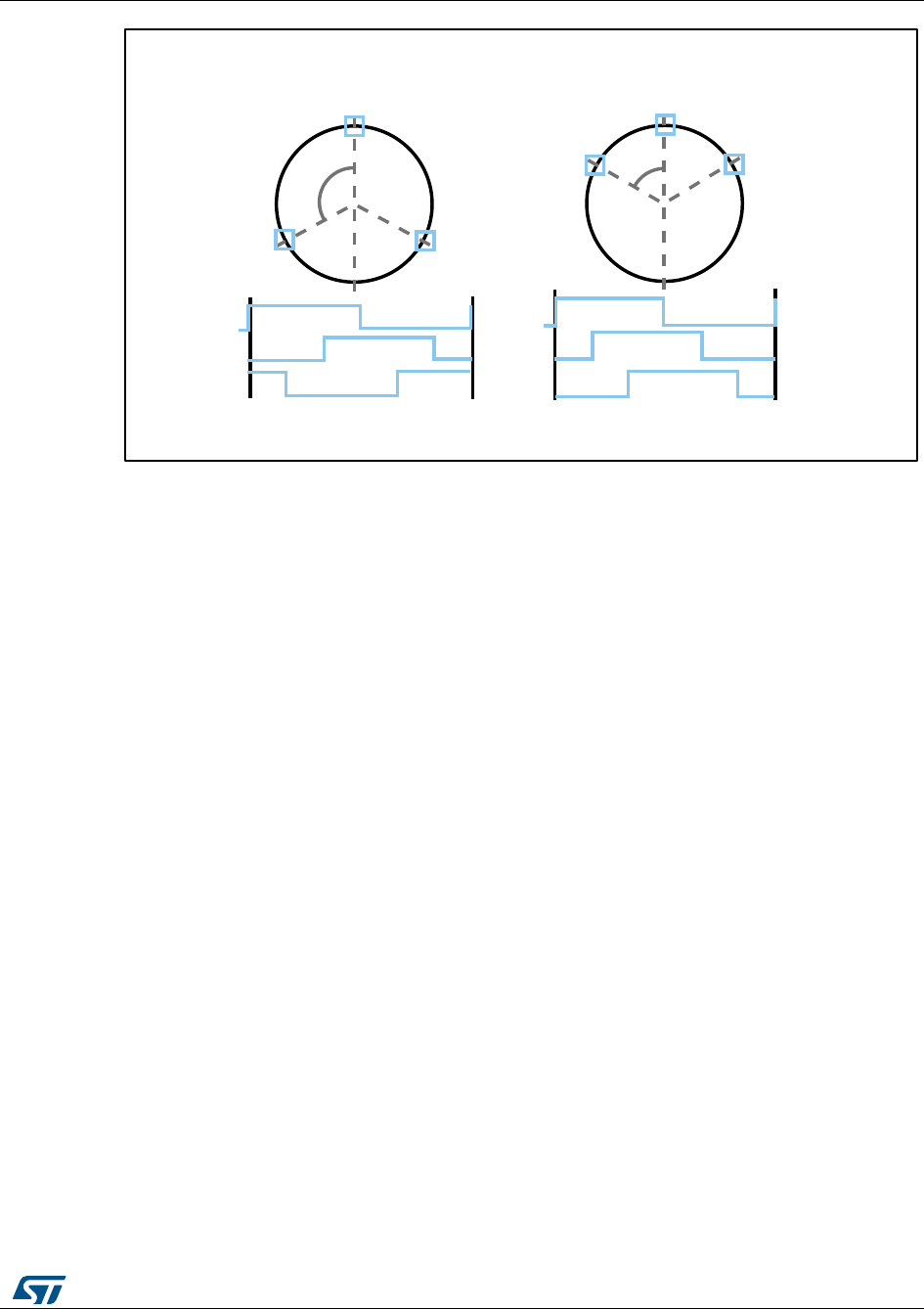
UM1052
Rotor position/speed feedback
DocID18458 Rev 9
93/178
Figure 85: 60° and 120° displaced Hall sensor output waveforms
Because the rotor position information they provide is absolute, there is no need for
any initial rotor prepositioning. Particular attention must be paid, however, when connecting
the sensors to the proper microcontroller inputs.
This software library assumes that the positive rolling direction is the rolling direction of a
machine that is fed with a three-phase system of positive sequence. In this case, to work
correctly, the software library expects the Hall sensor signal transitions to be in the
sequence shown in Figure 84: "60° and 120° displaced Hall sensor output waveforms" for
both 60° and 120° displaced Hall sensors.
For these reasons, it is suggested to follow the instructions given below when connecting a
Hall-sensor equipped PM motor to your board:
2. Turn the rotor by hand in the direction assumed to be positive and look at the B-emf
induced on the three motor phases. If the real neutral point is not available, it can be
reconstructed by means of three resistors, for instance.
3. Connect the motor phases to the hardware respecting the positive sequence. Let
“phase A”, “phase B” and “phase C” be the motor phases driven by TIM1_CH1,
TIM1_CH2 and TIM1_CH3, respectively (for example, when using the MB459 board, a
positive sequence of the motor phases could be connected to J5 2,1 and 3).
4. Turn the rotor by hand in the direction assumed to be positive, look at the three Hall
sensor outputs (H1, H2 and H3) and connect them to the selected timer on channels
1, 2 and 3, respectively, making sure that the sequence shown in Figure 84: "60° and
120° displaced Hall sensor output waveforms" is respected.
5. Measure the delay in electrical degrees between the maximum of the B-emf induced
on phase A and the first rising edge of signal H1.
6. Enter two parameters displacement and delay found in the ST MC Workbench GUI,
inside the window related to motor speed and position sensor. An example with delay
equal to 270° is illustrated in Figure 85: "Determination of Hall electrical phase shift"
120° 60°
H1
H2 H3
H1
H2 H3
H1
H2
H3
H1
H2
H3
3 sensors 120° 3 sensors 60°
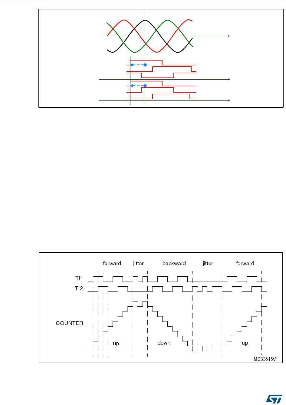
Rotor position/speed feedback
UM1052
94/178
DocID18458 Rev 9
Figure 86: Determination of Hall electrical phase shift
8.4 Encoder sensor feedback processing
Quadrature incremental encoders are widely used to read the rotor position of electric
machines.
As the name implies, incremental encoders actually read angular displacements with
respect to an initial position: if that position is known, then the rotor absolute angle is known
too. For this reason, it is always necessary, when processing the encoder feedback, to
perform a rotor prepositioning before the first startup after any fault event or microcontroller
reset.
Quadrature encoders have two output signals (represented in Figure 86: "Encoder output
signals: counter operation" as TI1 and TI2). Together with the standard timer in the
encoder interface mode, once the said alignment procedure has been executed, it is
possible to get information about the actual rotor angle - and therefore the rolling direction -
by simply reading the counter of the timer used to decode encoder signals.
For the purpose of MC Library and as information provided by the MC API, the rotor angle
is expressed in ‘s16degrees’ (see Section 12.4: "Measurement units").
Figure 87: Encoder output signals: counter operation
The rotor angular velocity can be easily calculated as a time derivative of the angular
position.
Bemf
CBemf
ABemf
B
H1
H2
H3
120°
H1
H2
H3
60°
delay
delay
t
t
t

UM1052
Rotor position/speed feedback
DocID18458 Rev 9
95/178
8.4.1 Setting up the system when using an encoder
Extra care should be taken over what is considered to be the positive rolling direction: this
software library assumes that the positive rolling direction is the rolling direction of a
machine that is fed with a three-phase system of positive sequence.
Because of this, and because of how the encoder output signals are wired to the
microcontroller input pins, it is possible to have a sign discrepancy between the real rolling
direction and the direction that is read. To avoid this kind of reading error, apply the
following procedure:
1. Turn the rotor by hand in the direction assumed to be positive and look at the B-emf
induced on the three motor phases. A neutral point may need to be reconstructed with
three resistors if the real one is not available.
2. Connect the motor phases to the hardware respecting the positive sequence (for
instance when using the MB459 board, a positive sequence of the motor phases may
be connected to J5 2,1 and 3).
3. Run the firmware in the encoder configuration and turn by hand the rotor in the
direction assumed to be positive. If the measured speed shown on the LCD is positive,
the connection is correct; otherwise, it can be corrected by simply swapping and
rewiring the encoder output signals.
If this is not practical, a software setting may be modified instead, using the ST MC
Workbench GUI (see the GUI help file).
Alignment settings
The quadrature encoder is a relative position sensor. Considering that absolute information
is required for performing field-oriented control, it is necessary to establish a 0° position.
This task is performed by means of an alignment phase (Section 13.2.3: "Configuration and
debug page", callout 9 in Figure 105: "Configuration and debug page"), and shall be carried
out at the first motor startup and optionally after any fault event. It consists of imposing a
stator flux with a linearly increasing magnitude and a constant orientation.
If properly configured, at the end of this phase, the rotor is locked in a well-known position
and the encoder timer counter is initialized accordingly.

Working environment
UM1052
96/178
DocID18458 Rev 9
9 Working environment
The working environment for the Motor Control SDK is composed of:
A PC
A third-party integrated development environment (IDE)
A third-party C-compiler
A JTAG/SWD interface for debugging and programming
An application board with an STM32F0x, STM32F100xx/STM32F103xx, STM32F2xx,
STM32F30x or STM32F4xx properly designed to drive its power stage (PWM outputs
to gate driver, ADC channels to read currents, DC bus voltage). Many evaluation
boards are available from ST, some of them have an ST-link programmer on board.
A three-phase PMSM motor
Table 16: "File structure" explains the MC SDK file structure for both Web and confidential
distributions.
Table 16: File structure
File
Subfile
Description
MClibrary
Source file of the MC library layer
interface
Public definitions (interfaces) of
classes
inc (available only in
confidential distribution)
Private definitions (data structure) of
classes
src (available only in
confidential distribution)
Source files
common
Public definitions (interfaces) of
classes and definitions exported up
to the highest level (PI, Digital
Output, reference frame
transformation)
obj
Compiled classes
MCApplication
Source file of the MC application
layer
interface
Public definitions (interfaces) of
classes
inc
Private definitions (data structure) of
classes
src
Source files
UILibrary
Source file of the User Interface
layer
interface
Public definitions (interfaces) of
classes
inc
Private definitions (data structure) of
classes
src
Source files

UM1052
Working environment
DocID18458 Rev 9
97/178
File
Subfile
Description
STMFC
LCD graphics library
Libraries
FreeRTOS source
FreeRTOS V1.6 distribution (GNU
GPL license,
http://freertos.org/a00114.html)
CMSIS
Cortex™ Microcontroller Software
Interface Standard v1.30
STMF0xx_StdPeriph_Driver
STMF0xx Standard Peripherals
Library Drivers V1.0.0
STMF10x_StdPeriph_Driver
STMF10x Standard Peripherals
Library Drivers V3.5.0
STMF2xx_StdPeriph_Driver
STMF2xx Standard Peripherals
Library Drivers V1.0.0
STMF30x_StdPeriph_Driver
STMF30x Standard Peripherals
Library Drivers V1.0.1
STMF4xx_StdPeriph_Driver
STMF4xx Standard Peripherals
Library Drivers V1.0.0
SystemDriveParams
Contains default parameter files
(unpacked at installation time,
referring to the STM32 MC Kit) or
those generated by the ST MC
workbench GUI according to user's
system
Utilities
STM32_EVAL
Contains code needed for specific
functions of ST evaluation boards
(LCD drivers, I/O pin assignment,
port expanders).
WB_Projects
Contains the ST MC Workbench
project ready to startup a new
design using one of the available
STM32 EVAL boards compatible
with STM32 FOC lib.
Project
Contains source files of the
demonstration user layer application and
configuration files for IDEs.
In addition, inside each IDE folder (in
\\MC library Compiled\\exe), compiled
MC library is provided (in case of web
distribution) or created/modified by the
IDE (in case of confidential distribution)
for single and dual motor drive.
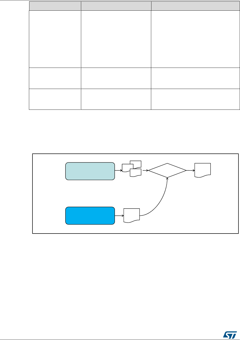
Working environment
UM1052
98/178
DocID18458 Rev 9
File
Subfile
Description
FreeRTOSProject
Contains source files of the
demonstration user layer application
based on FreeRTOS and configuration
files for IDEs.
In addition, inside each IDE folder (in
\\MC library Compiled\\exe), compiled
MC library is provided (in case of web
distribution) or created/modified by the
IDE (in case of confidential distribution)
for single and dual motor drive.
LCDProject
Contains source files of the optional
LCD user interface and configuration
files for IDEs
HEX
Contains the compiled version of
LCD firmware ready to be flashed
using ST Link utility
9.1 Motor control workspace
The Motor Control SDK is composed of two projects (as shown in Figure 87: "MC
workspace structure"), which constitute the MC workspace.
Figure 88: MC workspace structure
The Motor Control Library project: the collection of all the classes developed to
implement all the features. Each class has its own public interface. A public interface is the
list of the parameters needed to identify an 'object' of that kind and of the methods (or
functions) available. Note that, in the case of a derivative class, applicable methods are
those of the specific derived plus those of the base class. Further detail is provided in the
Advanced developers guide for STM32F0x/F100xx/F103xx/ STM32F2xx/F30x/F4xx MCUs
PMSM single/dual FOC library (UM1053).
All these interfaces constitute the Motor Control Library Interface. The Motor Control
Library project is independent from system parameters (the only exception is single/dual
drive configuration), and is built as a compiled library, not as an executable file (see
Section 11.3: "Motor control library project (confidential distribution)").
The user project: it contains both the MC Application layer and the demonstration program
that makes use of that layer through its MC API and provides the required clockings and
access to Interrupt Handlers. Parameters and configurations related to user's application
1010010
.
.LIB
1110010
.OBJ
1000010
.OBJ
Linker
.EXE
User Project
11001001010
10001010010
10010101001
MC Library
Project
11011101010
10010111100
01101010101

UM1052
Working environment
DocID18458 Rev 9
99/178
are used here to create right objects in what is called the run-time system 'boot'. The Motor
Control API is the set of commands granted to the upper layer. The program can run some
useful functions (depending on user options), such as serial communication, LCD/keys
interface, system variables displaying through DAC.
13 user project workspaces are available. They differ in the supported STM32 family, IDE
supported, how they generate the clocks: a simple time base itself or an Operating System
(FreeRTOS). The first 8 are for IAR EWARM IDE and are stored in the folder
Project\\EWARM:
STM32F0xx_Workspace for STM32F0xx devices and simple time base
STM32F10x_Workspace for both STM32F100xx and STM32F103xx devices and
simple time base
STM32F10x_Example for both STM32F100xx and STM32F103xx devices with simple
time base and ready-to-use examples.
STM32F2xx_Workspace for STM32F2xx devices and simple time base
STM32F4xx_Workspace for STM32F4xx devices and simple time base
STM32F10x_RTOS_Workspace for both STM32F100xx and STM32F103xx devices
and FreeRTOS
STM32F2xx_RTOS_Workspace for STM32F2xx devices and FreeRTOS
STM32F30x_Workspace for STM32F302/303 devices and simple time base.
The remaining 5 are for Keil uVision and are stored in the folder Project\\MDK-ARM:
STM32F0xx_Workspace for STM32F0xx devices and simple time base
STM32F10x_Workspace for both STM32F100xx and STM32F103xx devices and
simple time base
STM32F2xx_Workspace for STM32F2xx devices and simple time base
STM32F4xx_Workspace for STM32F4xx devices and simple time base
STM32F30x_Workspace for STM32F302/303 devices and simple time base.
See Section 12.3: "How to create a user project that interacts with the MC API" to
understand how to create a brand new user project.
In Section 11.4: "User project", built .lib files are linked with the user project in order to
generate the file that can be downloaded into the microcontroller memory for execution.
Figure 88: "IAR EWARM IDE workspace overview" provides an overview of the IAR
EWARM IDE workspace (located in the Installation folder
\\Project\\EWARM\\STM32F10x_Workspace.eww). The following sections provide
details on this. The equivalent workspace based on FreeRTOS is located in the Installation
folder \\FreeRTOSProject\\EWARM\\STM32F10x_RTOS_Workspace.eww.
Working environment
UM1052
100/178
DocID18458 Rev 9
Figure 89: IAR EWARM IDE workspace overview
Section 11.2: "MC SDK customization process" provides the procedure for customizing the
Motor Control SDK.
Figure 89: "Keil uVision workspace overview" provides an overview of the Keil uVision
workspace (located in the Installation folder \\Project\\MDK-
ARM\\STM32F10x_Workspace.uvmpw).
Figure 90: Keil uVision workspace overview
9.2 MC SDK customization process
This section explains how to customize the Motor Control SDK using IAR EWARM IDE, or
Keil uVision, so that it corresponds to the user's current system.
1. Using the ST MC Workbench GUI configure the firmware according to the HW, motor
and specific drive setting of the system. This part of the process ends by generating
the .h parameters in the correct directory (Installation
folder\\SystemDriveParams).
UM1052
Working environment
DocID18458 Rev 9
101/178
2. If the system is configured to enable the full LCD User Interface, download the specific
firmware. See Section 11.5: "Full LCD UI project".
3. Using Keil uVision follow the point 7, 8, 9, 10. Open one of the MC workspaces:
FreeRTOS based:
Installation
folder\\FreeRTOSProject\\EWARM\\STM32F10x_RTOS_Workspace.eww
Installation
folder\\FreeRTOSProject\\EWARM\\STM32F2xx_RTOS_Workspace.eww
Non-FreeRTOS:
Installation folder\\Project\\EWARM\\STM32F0xx_Workspace.eww
Installation folder\\Project\\EWARM\\STM32F10x_Workspace.eww
Installation folder\\Project\\EWARM\\STM32F2xx_Workspace.eww
Installation folder\\Project\\EWARM\\STM32F3xx_Workspace.eww
Installation folder\\Project\\EWARM\\STM32F4xx_Workspace.eww
4. Enable the user project (callout 1 in Figure 90: "Workspace batch build for IAR
EWARM IDE") and select the appropriate option from the combo-box (callout 2 in
Figure 90: "Workspace batch build for IAR EWARM IDE"). If none of the boards
displayed is in use, read Section 11.4: "User project" to perform a correct
configuration.
5. Press F8 to batch-build the entire workspace. The dialog box shown in Figure 90:
"Workspace batch build for IAR EWARM IDE" appears.
6. Select a batch command (callout 3, Figure 90: "Workspace batch build for IAR
EWARM IDE") as for step 4, then click the Make button to make the build (callout 4,
Figure 90: "Workspace batch build for IAR EWARM IDE"). If no error or relevant
warning appears, download the firmware (callout 5, Figure 90: "Workspace batch build
for IAR EWARM IDE") and do a test run.
Figure 91: Workspace batch build for IAR EWARM IDE
1. Open one of the MC workspaces:
2. Installation folder\\Project\\MDK-ARM\\STM32F0xx_Workspace.uvmpw
3. Installation folder\\Project\\MDK-ARM\\STM32F10x_Workspace.uvmpw
4. Installation folder\\Project\\MDK-ARM\\STM32F2xx_Workspace.uvmpw
5. Installation folder\\Project\\MDK-ARM\\STM32F3xx_Workspace.uvmpw
Working environment
UM1052
102/178
DocID18458 Rev 9
6. Installation folder\\Project\\MDK-ARM\\STM32F4xx_Workspace.uvmpw
7. Enable the UserProject (callout 1 in Figure 91: "Workspace batch build for Keil
uVision") right click on it and select "Set as Active Project" according the evaluation
board used. If none of the boards displayed is in use, read Section 9.5: User project to
perform a correct configuration.
8. Press batch build button (callout 2 in Figure 91: "Workspace batch build for Keil
uVision") The dialog box shown in Figure 91: "Workspace batch build for Keil uVision":
Batch Build appears.
9. Select the configuration to be build according the step 7 (callout 3 in Figure 91:
"Workspace batch build for Keil uVision") and selecting the proper conflagration of the
MC Library (Single or Dual drive) (callout 4 in Figure 91: "Workspace batch build for
Keil uVision"). Then click Build button to make the build (callout 5 in Figure 91:
"Workspace batch build for Keil uVision"). If no error or relevant warning appears,
download the firmware (callout 6, Figure 91: "Workspace batch build for Keil uVision")
and do a test run.
Figure 92: Workspace batch build for Keil uVision
When the system configuration or parameters are modified, just the User project
requires to be recompiled. The batch build procedure is requested just if the MC
Library is provided as source code and only for the first compilation for both single
and dual drive configuration.
9.3 Motor control library project (confidential distribution)
The MC Library project (available only in confidential distribution) is a collection of classes
related to motor control functions.
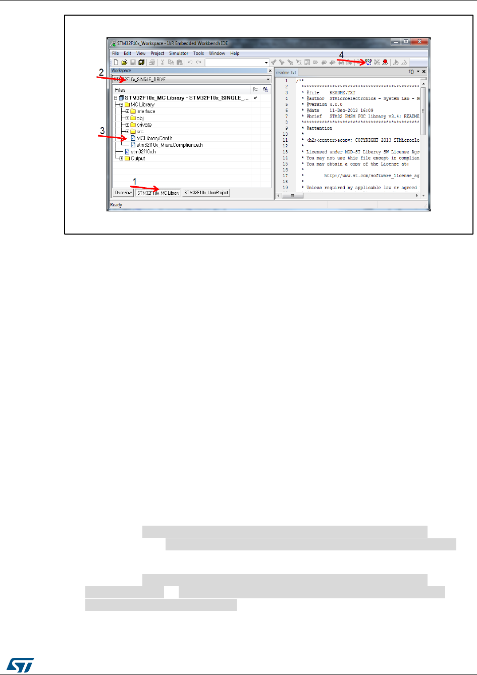
UM1052
Working environment
DocID18458 Rev 9
103/178
Figure 93: MC Library project in IAR EWARM IDE
1. To access the project using IAR IDE, open an MC workspace (FreeRTOS based or
not) and click the name in the workspace tabbed browser (callout1, Figure 92: "MC
Library project in IAR EWARM IDE"). Remember that IDE toolbars and commands
always refer to the active project (the one whose tab is engraved).
Figure 92: "MC Library project in IAR EWARM IDE" displays the logical arrangement
of files on the left-hand side (similar arrangement is in folders). For each class, the
subfolder src contains the source code, private contains its private definitions,
interface contains its public interface, obj contains compiled object files of certain
classes.
2. Depending on system characteristics, configure the project for single motor drive or
dual motor drive by selecting SINGLE_DRIVE or DUAL_DRIVE from the combo-box
(callout 2, Figure 92: "MC Library project in IAR EWARM IDE").
3. Classes of the MC Library can create new objects resorting to dynamic memory
allocation, or statically allotting them from predefined size-pools. This is a matter of
preference. Modify the header file MCLibraryConf.h to choose the allocation (callout 3,
Figure 92: "MC Library project in IAR EWARM IDE"). To activate the dynamic
allocation, uncomment line 52 (#define MC_CLASS_DYNAMIC). To activate the static
allocation, comment this line.
4. Once all these settings have been configured and checked, build the library (callout 4,
Figure 92: "MC Library project in IAR EWARM IDE").
If SINGLE_DRIVE was selected, the proper output file among the following:
is created in Installation folder \\Project\\EWARM\\MCLibrary
Compiled\\Exe or Installation folder \\FreeRTOSProject\\EWARM\\MC
Library Compiled\\Exe.
If DUAL_DRIVE was selected, the proper output file among the following:
is created in Installation folder \\Project\\EWARM\\MCLibrary
Compiled\\Exe or Installation folder \\FreeRTOSProject\\EWARM
\\MCLibrary Compiled\\Exe.
MC_Library_STM32F0xx_single_drive.a
MC_Library_STM32F10x_single_drive.a
MC_Library_STM32F2xx_single_drive.a
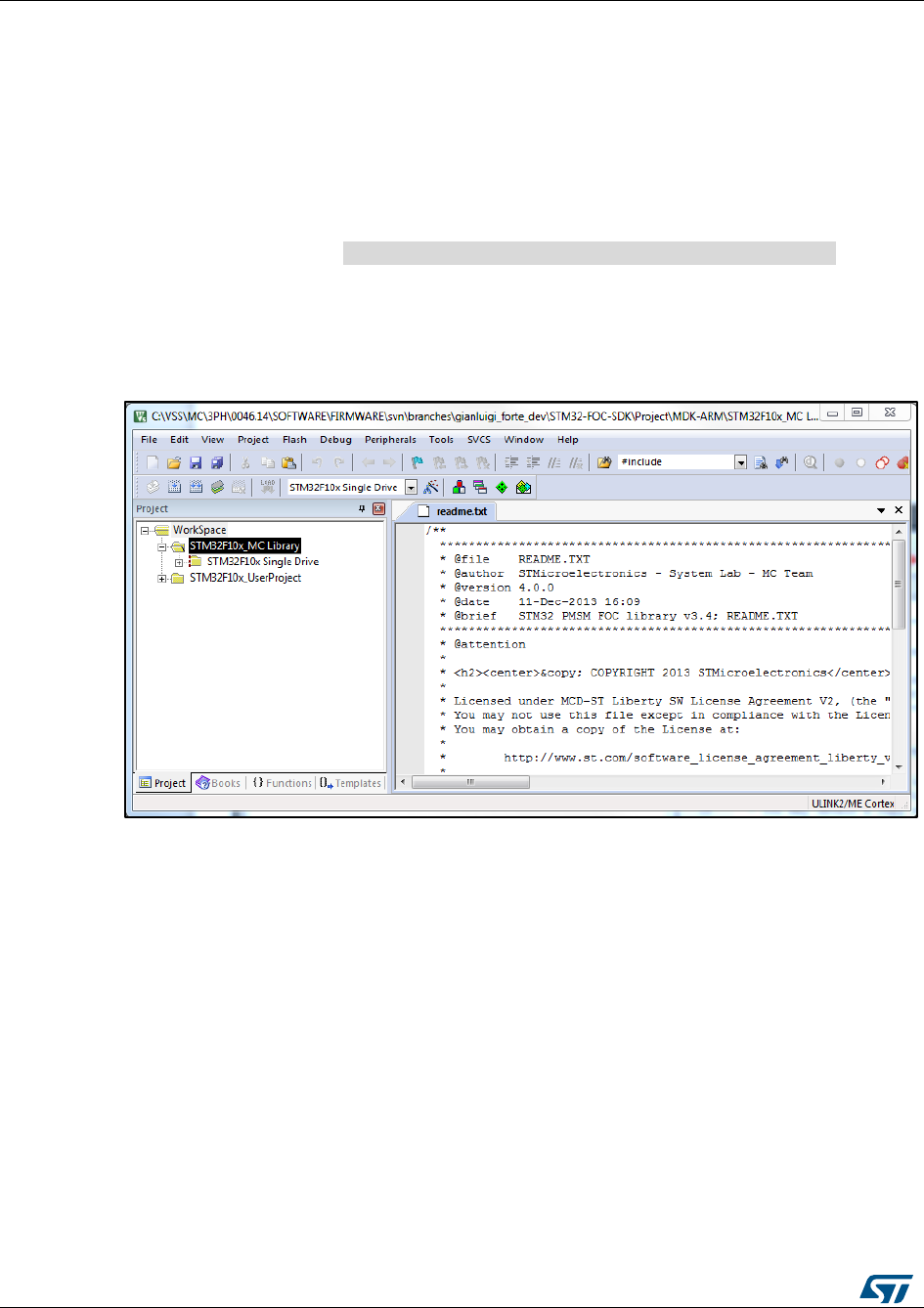
Working environment
UM1052
104/178
DocID18458 Rev 9
MC_Library_STM32F303_single_drive.a
MC_Library_STM32F4xx_single_drive.a
MC_Library_STM32F302_single_drive.a
MC_Library_STM32F302x8_single_drive.a
MC_Library_STM32F10x_dual_drive.a
MC_Library_STM32F2xx_dual_drive.a
MC_Library_STM32F303_dual_drive.a
MC_Library_STM32F4xx_dual_drive.a
5. Compliance with MISRA-C rules 2004 can be checked using IAR EWARM. The test is
performed by uncommenting line 47(#define MISRA_C_2004_BUILD) in the header
file Installation folder \\MCLibrary\\Interface\\Common\\MC_type.h. The
compiler should be configured in Strict ISO/ANSI standard C mode (MISRA C 2004
rule 1.1).
Figure 93: "MC Library project in Keil uVision" shows the MC Library project in the Keil
uVision IDE.
Figure 94: MC Library project in Keil uVision
9.4 User project
The User project is the application layer that exploits the MC API.
Access the project using IAR IDE by opening an MC workspace (FreeRTOS based or not),
and clicking its name in the workspace tabbed browser (callout 1, Figure 94: "User project
for IAR EWARM IDE"). Remember that IDE toolbars and commands always refer to the
active project (the one whose tab is engraved).
Figure 94: "User project for IAR EWARM IDE" displays the logical arrangement of files and
actions necessary to set up and download the User project.
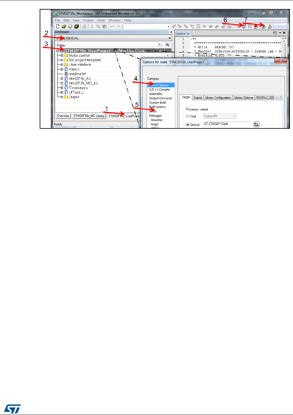
UM1052
Working environment
DocID18458 Rev 9
105/178
Figure 95: User project for IAR EWARM IDE
The Motor Control folder contains the MC API and interfaces of classes that may also be
useful in the user's application (such as PI, Digital Output, reference frame transformation).
The Std project template folder contains:
STM32Fxxx Standard Peripherals Library
CMSIS library, startup and vector table files for EWARMv5 toolchain
IC drivers (LCD, IOE, SD card) used in STM32 evaluation boards.
All these files belong to V3.5.0 distribution of the STM32 Standard Peripheral Library
package for the STM32F10x and to v1.0.0 distribution for STM32F0xx, STM32F2xx,
STM32F3xx and STM32F4xx (updates available from STMicroelectronics web site,
www.st.com).
This demonstration user project exploits the features offered by the User Interface Library
(see Section 15: "User Interface class overview" for further details).
In the STM32Fxxx_Workspace, the following project configurations (callout 2, Figure 94:
"User project for IAR EWARM IDE") are provided, one for each STM32 evaluation board
that has been tested with the MC SDK:
STM32F10B-EVAL
STM32F10E-EVAL
STM32F100B-EVAL
STEVAL-IHM022V1_SINGLEDRIVE
STEVAL-IHM022V1_DUALDRIVE
STM322xG-EVAL
STM32F2xx_dual
STM32303C-EVAL_SINGLEDRIVE
STM32303C-EVAL_DUALDRIVE
STM32F302_SINGLEDRIVE
STM324xG-EVAL
STEVAL-IHM039V1_SINGLEDRIVE

Working environment
UM1052
106/178
DocID18458 Rev 9
STEVAL-IHM039V1_DUALDRIVE
P-NUCLEO-IHM001_SINGLEDRIVE
If the target is one of these boards, just select its name from the combo-box. Otherwise, the
LCD UI should be disabled (using the ST MC Workbench GUI) and the choice is to be
done according to Table 17: "Project configurations":
Table 17: Project configurations
STM32 device part, single/dual drive
selection
Viable configuration among existing
STM32F0xx, Single motor drive
STM320518-EVAL
STM32F103 low density/medium density
STM3210B-EVAL
STM32F103 high density/XL density,
Single motor drive
STM3210E-EVAL or
STEVAL-IHM022V1_SINGLEDRIVE
STM32F103 high density/XL density,
Dual motor drive
STEVAL-IHM022V1_DUALDRIVE
STM32F100 low / medium / high density
STM32100B-EVAL
STM32F2xx, Single motor drive
STM322xG-EVAL
STM32F2xx, Dual motor drive
STM32F2xx_dual
STM32F303xB/C, Single motor drive
STM32303C-EVAL_SINGLEDRIVE
STM32F303xB/C, Dual motor drive
STM32303C-EVAL_DUALDRIVE
STM32F302xB/C, Single motor drive
STM32302C_SINGLEDRIVE
STM32F302x6/8, Single motor drive
P-NUCLEO-IHM001_SINGLEDRIVE
STM32F4xx, Single motor drive
STM324xG-EVAL
STEVAL-IHM039V1_SINGLEDRIVE
STM32F4xx, Dual motor drive
STEVAL-IHM039V1_DUALDRIVE
If the target is not one of the above-mentioned ST evaluation boards, or if you want to
modify the configurations provided, right-click on User Project (callout 3, Figure 94: "User
project for IAR EWARM IDE") > Option to open the Options dialog box. Select the correct
device part number (callout 4, Figure 94: "User project for IAR EWARM IDE") and edit the
linker file (callout 5, Figure 94: "User project for IAR EWARM IDE").
MC SDK default linker files reserve an amount of Flash and RAM (heap) for LCD
UI manager (see Section 11.4: "User project"). We recommend that you restore
their total size (please refer to the STM32 datasheet) if you do not need it.
Once all these settings have been performed, the MC Library and MC Application projects
are built and you can build the user project (callout 6, Figure 94: "User project for IAR
EWARM IDE"), and download it to the microcontroller memory (callout 7, Figure 94: "User
project for IAR EWARM IDE").
The same considerations can be done for Keil uVision user project shown in Figure 95:
"User project for Keil uVision".
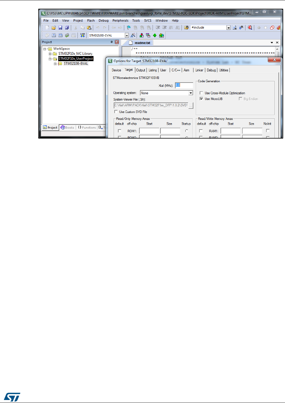
UM1052
Working environment
DocID18458 Rev 9
107/178
Figure 96: User project for Keil uVision
9.5 Full LCD UI project
When an STM32 evaluation board equipped with LCD (such as STM3210B-EVAL,
STM3210E-EVAL, STM32100B-EVAL, STEVAL-IHM022V1, STM322xG-EVAL,
STM324xG-EVAL, STEVAL-IHM039V1, STM32303C-EVAL) is in use, you can enable the
LCD plus Joystick User Interface—a useful feature of the demonstration user project that
can be used as a run-time command launcher, a fine-tuning or monitoring tool (screens
and functions are detailed in ). This option can be selected via a setting in the ST MC
Workbench GUI (see Figure 96: "Enabling the Full LCD UI in the ST MC Workbench").
In this case, the LCD UI software (single or dual drive configuration) is downloaded in the
microcontroller in a reserved area, located at the end of the addressable Flash memory.
Unless you erase it or change the configuration from single-drive to dual-drive or vice-
versa, there is no need to download it again. Even disabling the option with the GUI does
not mean you need to flash it again when you reenable the option.
The latest STM3210B-MCKIT Motor Control starter kits come with the Motor Control
Library and the LCD UI software (single-drive) pre-flashed. If your Motor Control kit has a
version of Motor Control Library lower than 3.4, or if you do not have the Motor Control kit
but you are using one of the evaluation boards mentioned, or if you are changing the
configuration (single-dual), you should follow one of the three procedures explained below
to download the LCD UI.
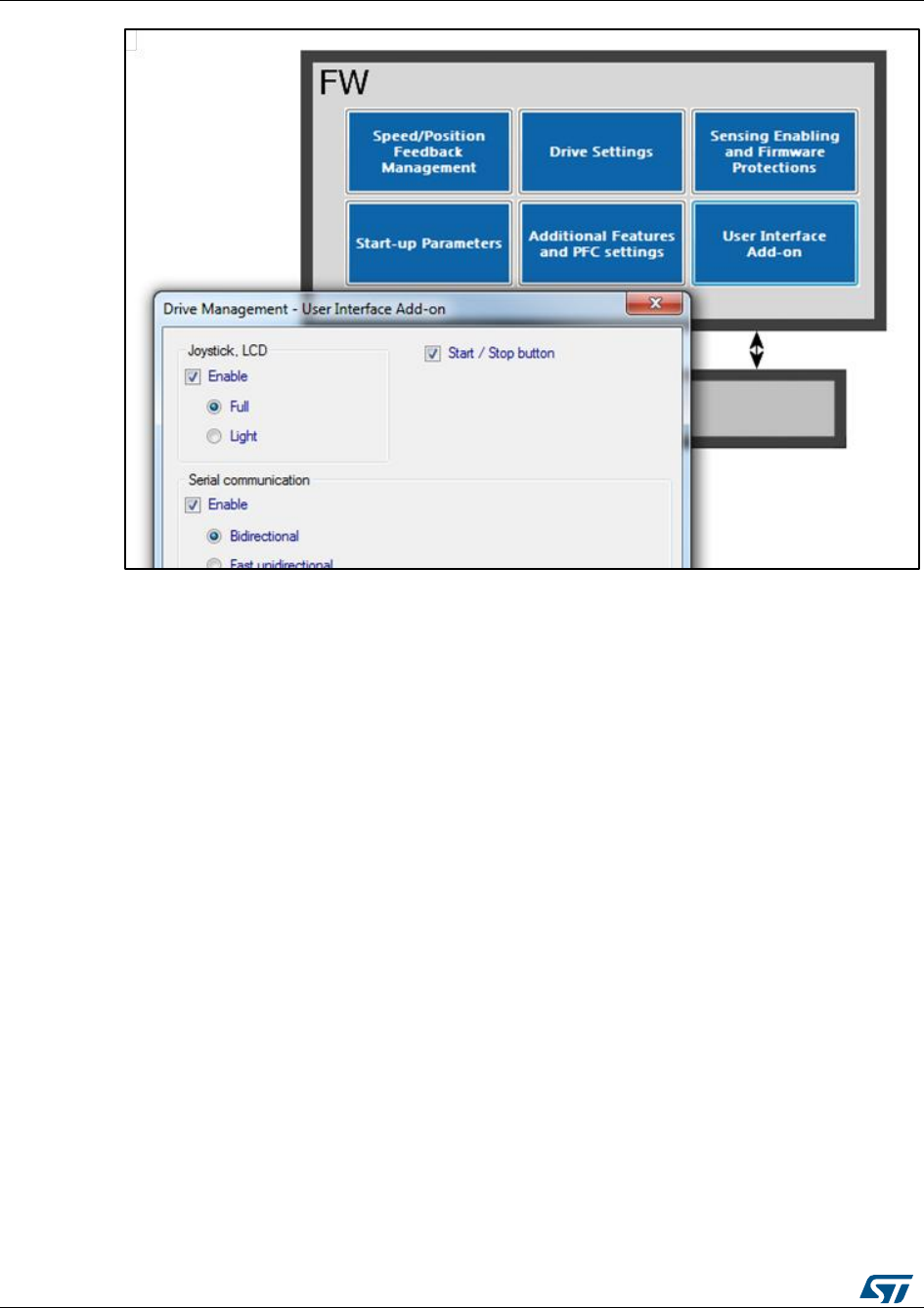
Working environment
UM1052
108/178
DocID18458 Rev 9
Figure 97: Enabling the Full LCD UI in the ST MC Workbench
Option 1
Option 1 is straightforward and the preferred one.
Use the STM32 ST-LINK Utility tool to download the LCD pre-compiled file.
Activate File ->Open file.
Select the appropriate pre-compiled file (STM3210B-EVAL.hex, STM32100B-
EVAL.hex, STM3210E-EVAL.hex, STEVAL-IHM022V1_SINGLEDRIVE.hex, STEVAL-
IHM022V1_DUALDRIVE.hex, STM322xG-EVAL.hex, STM324xG-EVAL.hex,
STEVAL-IHM039V1_SINGLEDRIVE.hex, STEVAL-IHM039V1_DUALDRIVE.hex,
STM32303C-EVAL_SINGLEDRIVE.hex, STM32303C-EVAL_DUALDRIVE.hex)
Option 2
1. Use the STM32 and STM8 Flash loader demonstrator PC software package. This is
available from the ST web site (www.st.com).
The User Manual, UM0462 (included in the package), fully explains how to operate it.
For communication purposes, you need to verify that you have an available COM port
(RS232) on your PC.
2. After the program is installed, run the Flash loader demonstrator application from the
Programs menu, making sure that the device is connected to your PC and that the
boot configuration pins are set correctly to boot from the system memory (check the
evaluation board user manual).
3. Reset the microcontroller to restart the system memory boot loader code.
4. When the connection is established, the wizard displays the available device
information such as the target ID, the firmware version, the supported device, the
memory map and the memory protection status. Select the target name in the target
combo-box.
5. Click the Download to device radio button (see Figure 97: "Flash loader wizard
screen") and browse to select the appropriate hexadecimal file
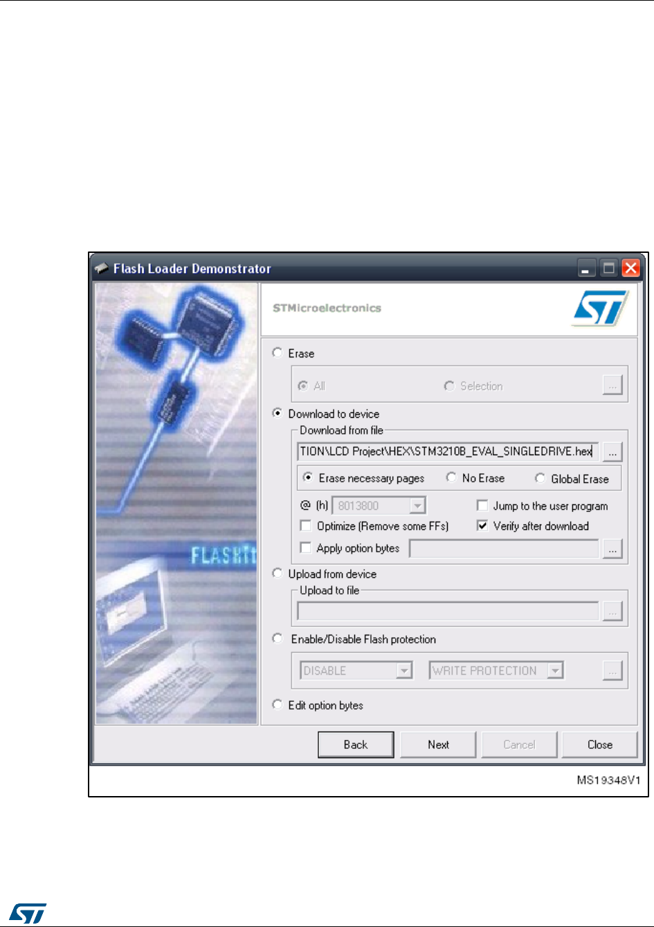
UM1052
Working environment
DocID18458 Rev 9
109/178
(STM3210B_EVAL.hex, STM32100B_EVAL.hex, STM3210E_EVAL.hex,
STEVAL_IHM022V1_SINGLEDRIVE.hex, STEVAL_IHM022V1_DUALDRIVE.hex,
STM322xG-EVAL.hex, STM324xG-EVAL.hex,
STEVAL_IHM039V1_SINGLEDRIVE.hex or STEVAL_IHM039V1_DUALDRIVE.hex)
from Installation folder\\LCD Project\\Hex\\.
6. Program the downloading to Flash memory. After the code has been successfully
flashed, set up the board to reboot from the user Flash memory and reset the
microcontroller.
7. To test that the LCD UI has been correctly flashed, for both option 1 and 2, open, build
and download the user project (see Section 11.2: "MC SDK customization process"
and Section 11.4: "User project").
8. From the debug session, run the firmware (F5) and then, after a while, stop debugging
(CTRL+Shift+D). The LCD UI has not been properly flashed if the program is stalled in
a trap inside UITask.c, line 195.
Figure 98: Flash loader wizard screen

Working environment
UM1052
110/178
DocID18458 Rev 9
Option 3
This option is intended for users who want to modify the LCD UI code.
1. Use an IDE to rebuild and download the LCD UI.
2. After parameter files have been generated by the GUI (to set the single/dual drive
configuration) using KEIL uVision4 IDE, open the workspace located in
Figure 98: "LCD UI project" displays the logical arrangement of files (left-hand side)
and actions that may be needed for set-up and download.
Following project configurations are provided for the STM32Fxxx_Workspace (callout
1, Figure 98: "LCD UI project"), one for each STM32 evaluation board that has been
tested with the MC SDK:
This configuration affects the LCD driver and linker file selection.
Installation folder\\LCDProject\\MDK-ARM\\STM32F0xx_LCD Project.uvopt
Installation folder\\LCDProject\\MDK-ARM\\STM32F10x_LCD Project.uvopt
Installation folder\\LCDProject\\MDK-ARM\\STM32F2xx_LCD Project.uvopt
Installation folder\\LCDProject\\MDK-ARM\\STM32F3xx_LCD Project.uvopt
Installation folder\\LCDProject\\MDK-ARM\\STM32F4xx_LCD Project.uvopt
STM32F100B-EVAL
STM32F10B-EVAL
STM32F10E-EVAL
STEVAL-IHM022V1_SINGLEDRIVE
STEVAL-IHM022V1_DUALDRIVE
STM322xG-EVAL
STM32303C-EVAL_SINGLEDRIVE
.......
STM324xG-EVAL
STEVAL-IHM039V1_SINGLEDRIVE
STEVAL-IHM039V1_DUALDRIVE
3. Build the project (callout 2, Figure 98: "LCD UI project"), and download it to the
microcontroller memory (callout 3, Figure 98: "LCD UI project").
4. To test that the LCD UI has been correctly flashed, for both option 1 and 2, open, build
and download the user project (see Section 11.2: "MC SDK customization process"
and Section 11.4: "User project").
5. From the debug session, run the firmware (F5) and then, after a while, stop debugging
(CTRL+Shift+D). The LCD UI has not been properly flashed if the program is stalled in
a trap in UITask.c, line 195.

UM1052
Working environment
DocID18458 Rev 9
111/178
Figure 99: LCD UI project
9.6 Light LCD UI
Together with the User project is provided a simplified version of LCD user interface that
can be used together with a STM32 evaluation board equipped with LCD (such as
STM3210B-EVAL, STM3210E-EVAL, STM32100B-EVAL, STEVAL-IHM022V1,
STM322xG-EVAL, STM324xG-EVAL, STEVAL-IHM039V1, STM32303C-EVAL) (screens
and functions are detailed in Section 14: "Light LCD user interface"). This option can be
selected via a setting in the ST MC Workbench GUI (Figure 99: "Enabling the Light LCD UI
in the ST MC Workbench").
Enabling this option is not necessary to flash the LCD FW code as explained in the
previous paragraph.
Figure 100: Enabling the Light LCD UI in the ST MC Workbench

MC application programming interface (API)
UM1052
112/178
DocID18458 Rev 9
10 MC application programming interface (API)
The Motor Control Application is built on top of the Motor Control Library, provided that:
parameter files are generated by the ST MC workbench GUI, or manually edited
starting from default, for the purpose of describing the system configuration;
a user project, such as the one included in the SDK, or any other one that complies
with the guidelines described in Section 12.3: "How to create a user project that
interacts with the MC API", is in place.
The MCA grants the user layer the execution of a set of commands, named the MC
Application Programming Interface (MC API).
The MC API is divided into two sections and is included in two files: MCInterfaceClass.h
and MCTuningClass.h. MCInterfaceClass (details in Section 12.1: "MCInterfaceClass")
holds the principal high-level commands, while MCTuningClass (details in Section 12.2:
"MCTuningClass") acts as a gateway to set and read data to and from objects (such as
sensors, PI controllers) belonging to the Motor Control Application.
A third section belongs to MC API, MCtask.h: it holds the MCboot function and tasks
(medium/high frequency and safety) to be clocked by the user project (see Section 12.3:
"How to create a user project that interacts with the MC API" for details)
When the user project calls function MCboot (oMCI, oMCT), the Motor Control Application
starts its operations: the booting process begins, objects are created from the Motor
Control Library according to the system configuration (specified in parameter files), and the
application is up and represented by two objects, oMCI and oMCT, whose type is
respectively CMCI and CMCT (type definition can be obtained by including
MCInterfaceClass.h and MCTuningClass.h). Methods of MCInterfaceClass must be
addressed to the oMCI object, oMCT addresses methods of MCTuningClass. oMCI and
oMCT are two arrays, each of two elements, so that oMCI[0] and oMCT[0] refer to Motor 1,
oMCI[1] and oMCT[1] refer to Motor2.
GetMCIList function, to be called if necessary after MCboot, returns a pointer to the CMCI
oMCI vector instantiated by MCboot. The vector has a length equal to the number of motor
drives.
GetMCTList function, to be called if necessary after MCboot, returns a pointer to the CMCT
oMCT vector instantiated by MCboot. The vector has a length equal to the number of motor
drives.
10.1 MCInterfaceClass
Commands of the MCInterfaceClass can be grouped in two different typologies:
User commands: commands that become active as soon as they are called. If the
state machine is not in the expected state, the command is discarded and the method
returns FALSE. The user must manage this by resending the command until it is
accepted, or by discarding the command.
Buffered commands: commands that do not execute instantaneously, but are stored in
a buffer and become active when the state machine is in a specified state. These
commands are not discarded until they become active, unless other delayed
commands are sent to the buffer, thus clearing the previous one.
Detailed information can be found in the Motor Control Application source documentation
(doxygen compiled .html Help file).

UM1052
MC application programming interface (API)
DocID18458 Rev 9
113/178
10.1.1 User commands
bool MCI_StartMotor(CMCI oMCI): starts the motor. It is mandatory to set the
target control mode (speed control/torque control) and initial reference before
executing this command, otherwise the behavior in run state is unpredictable. Use one
of these commands to do this: MCI_ExecSpeedRamp, MCI_ExecTorqueRamp or
MCI_SetCurrentReferences.
bool MCI_StopMotor(CMCI oMCI): stops the motor driving and disables the
PWM outputs.
bool MCI_FaultAcknowledged(CMCI oMCI): this function must be called after a
system fault to tell the Motor Control Interface that the user has acknowledged the
occurred fault. When a malfunction (overcurrent, overvoltage) is detected by the
application, the motor is stopped and the internal state machine goes to the Fault state
(see Figure 100: "State machine flow diagram"). The API is locked (it no longer
receives commands). The API is unlocked and the state machine returns to Idle when
the user sends this MCI_FaultAcknowledged.
bool MCI_EncoderAlign(CMCI oMCI): this function is only used when an
encoder speed sensor is used. It must be called after any system reset and before the
first motor start.
State_t MCI_GetSTMState(CMCI oMCI): returns the state machine status (see
Figure 100: "State machine flow diagram"). Further detail is provided in the Advanced
developers guide for STM32F0x/F100xx/F103xx/STM32F2xx/F30x/F4xx MCUs
PMSM single/dual FOC library (UM1053).
Figure 101: State machine flow diagram
int16_t MCI_GetMecSpeedRef01Hz(CMCI oMCI): returns the current
mechanical rotor speed reference expressed in tenths of Hertz.
int16_t MCI_GetAvrgMecSpeed01Hz(CMCI oMCI): returns the last computed
average mechanical speed expressed in tenth of Hertz.
int16_t MCI_GetTorqueRef(CMCI oMCI): returns the present motor torque
reference. This value represents the Iq current reference expressed in 's16A'. To
convert a current expressed in 's16A' to a current expressed in Ampere, use the
formula: Current[A] = [Current(s16A) * Vdd micro(V)] /
[65536 * Rshunt(Ohm) * AmplificationNetworkGain]

MC application programming interface (API)
UM1052
114/178
DocID18458 Rev 9
int16_t MCI_GetTorque(CMCI oMCI): returns the present motor measured
torque. This value represents the Iq current expressed in 's16A'. To convert a current
expressed in 's16A' to current expressed in Ampere, use the formula: Current[A] =
[Current(s16A) * Vdd micro(V)] /
[65536 * Rshunt(Ohm) * AmplificationNetworkGain]
Curr_Components MCI_GetCurrentsReference(CMCI oMCI): returns stator
current references Iq and Id in 's16A'. To convert a current expressed in 's16A' to a
current expressed in Ampere, use the formula: Current[A] = [Current(s16A) * Vdd
micro(V)] /
[65536 * Rshunt(Ohm) * AmplificationNetworkGain].
int16_t MCI_GetPhaseCurrentAmplitude(CMCI oMCI): returns the motor
phase current amplitude (0-to-peak) in 's16A'. To convert a current expressed in
's16A' to a current expressed in Ampere, use the formula: Current[A] = [Current(s16A)
* Vdd micro(V)] /
[65536 * Rshunt(Ohm) * AmplificationNetworkGain].
int16_t MCI_GetPhaseVoltageAmplitude(CMCI oMCI): returns the applied
motor phase voltage amplitude (0-to-peak) in 's16V'. To convert a voltage expressed
in 's16V' to a voltage expressed in Volt, use the formula: PhaseVoltage(V) =
[PhaseVoltage(s16V) * Vbus(V)] /[sqrt(3) *32767].
STC_Modality_t MCI_GetControlMode(CMCI oMCI): returns the present
control mode: speed mode or torque mode.
int16_t MCI_GetImposedMotorDirection(CMCI oMCI): returns the motor
direction imposed by the last command (MCI_ExecSpeedRamp,
MCI_ExecTorqueRamp or MCI_SetCurrentReferences).
int16_t MCI_GetLastRampFinalSpeed (CMCI this): returns information
about the last ramp final speed sent by the user, expressed in tenths of HZ.
10.1.2 Buffered commands
void MCI_ExecSpeedRamp(CMCI oMCI, int16_t hFinalSpeed, uint16_t
hDurationms): sets the control mode in speed control, generates a ramp of speed
references from real speed to hFinalSpeed parameter (to be expressed as mechanical
rotor speed, tenth of hertz). The ramp execution duration is the ‘hDurationms’
parameter (to be expressed in milliseconds). If hDurationms is set to 0, a step
variation is generated. This command is only executed when the state machine is in
the START_RUN or RUN state. The user can check the status of the command calling
the MCI_IsCommandAcknowledged method.
void MCI_ExecTorqueRamp(CMCI oMCI, int16_t hFinalTorque, uint16_t
hDurationms): sets the control mode in "torque control", generates a ramp of torque
references from real torque to the ‘hFinalTorque’ parameter (to be expressed as
s16A). The ramp execution duration is the hDurationms parameter (to be expressed in
milliseconds). If hDurationms is set to 0, a step variation is generated. This command
is only executed when the state machine is in the START_RUN or RUN state. The
user can check the status of the command calling the MCI_IsCommandAcknowledged
method.
void MCI_SetCurrentReferences(CMCI oMCI, Curr_Components Iqdref):
sets the control mode in "torque control external" (see Advanced developers guide for
STM32F0x/F100xx/F103xx/STM32F2xx/F30x/F4xx MCUs PMSM single/dual FOC
library (UM1053)) and directly sets the motor current references Iq and Id (to be
expressed as s16A). This command is only executed when the state machine status is
START_RUN or RUN.
CommandState_t MCI_IsCommandAcknowledged(CMCI oMCI): returns
information about the state of the last buffered command. CommandState_t can be
one of the following codes:

UM1052
MC application programming interface (API)
DocID18458 Rev 9
115/178
MCI_BUFFER_EMPTY if no buffered command has been called.
MCI_COMMAND_NOT_ALREADY_EXECUTED if the buffered command condition
has not already occurred.
MCI_COMMAND_EXECUTED_SUCCESFULLY if the buffered command has been
executed successfully. In this case, calling this function resets the command
state to MCI_BUFFER_EMPTY.
MCI_COMMAND_EXECUTED_UNSUCCESFULLY if the buffered command has been
executed unsuccessfully. In this case, calling this function resets the command
state to MCI_BUFFER_EMPTY.
10.2 MCTuningClass
The MCTuningClass allows the user to obtain objects of the Motor Control Application and
apply methods on them.
MCTuningClass.h is divided into the following sections:
1. Public definitions of all the MC classes exported
2. MCT_GetXXX functions, used to receive objects
3. For each of the classes exported, a list of applicable methods
For example, if you want to read or set parameters of the speed PI controller:
1. Make sure that the Motor Control Application is already booted, and oMCI and oMCT
objects are available (you can receive them through GetMCIList or GetMCTList
functions)
2. Declare a 'PIspeed' automatic variable of the type CPI (PI class, type definition at line
92)
3. Obtain the speed PI object (which is actually a pointer) by calling the
MCT_GetSpeedLoopPID function (prototype at line 210)
4. Set the KP gain by calling the PI_SetKP function (prototype at line 708).
The resulting C code could be something like:#include "MCTuningClass.h"
{
...
CPI PIspeedMotor2;
...
PIspeedMotor2 = MCT_GetSpeedLoopPID(oMCT[1]);
PI_SetKP(PIspeedMotor2, NewKpGain);
...
}
To reduce Flash and RAM occupation, you can disable the MCTuning section of
the MC application. This is done by commenting #define
MC_TUNING_INTERFACE in the MCTask.c source file, line 90. If you do this,
disable the LCD UI and Serial Communication UI too.
See the doxygen compiled .html Help file to know which are the other exported
functions of MCTasks and refer to section 7.3 to know how to use them.
10.3 How to create a user project that interacts with the MC API
This section explains how to integrate the Motor Control Application with a user project
(thus replacing the provided demonstrative one) in order to take advantage of its API.

MC application programming interface (API)
UM1052
116/178
DocID18458 Rev 9
1. A timebase is needed to clock the MC Application:
The demonstration timebase.c can be considered as an example or used as is. It uses the
Systick timer and its Systick_Handler and PendSV_Handler as resources.
Alternatively, an Operating System can be used for this purpose, as is done in the
FreeRTOS-based demonstration project.
The timebase should provide the clocks listed in Table 18: "Integrating the MC Interface in
a user project":
Table 18: Integrating the MC Interface in a user project
Number
Function to call
Periodicity
Priority
Preemptiveness
*1
TSK_MediumFrequencyTask
Equal to that
set in ST MC
Workbench,
speed
regulation rate
Systick
priority
Yes, over non MC
functions
*2
TSK_SafetyTask
0.5 ms
Higher
than *1
optional over *1
2. Include source files ($ = installation folder):
for STM32F0xx projects
$\\Libraries\\CMSIS\\CMSIS_2_x\\Device\\ST\\STM32F0xx\\Source\\Template\\system_stm3
2f0xx.c
$\\Libraries\\CMSIS\\CMSIS_2_x\\Device\\ST\\STM32F0xx\\Source\\Template\\XXX\\startu
p_stm32f0xx.s (XXX according to IDE)
$\\Project\\stm32f0xx_it.c (removing conditional compilation, can be modified)
$\\Project\\SystemDriveParams\\stm32f0xx_MC_it.c>
$\\Libraries\\STM32F0xx_StdPeriph_Driver\\src\\ (standard peripheral driver sources
as needed)
For STM32F1xx projects
$\\Libraries\\CMSIS\\CM3\\DeviceSupport\\ST\\STM32F10x\\system_stm32f10x.c
$\\Libraries\\CMSIS\\CM3\\DeviceSupport\\ST\\STM32F10x\\startup\\XXX\\startup_stm32f
10x_YYY.s (XXX according to IDE)(YYY according to device)
$\\Project\\stm32f10x_it.c (removing conditional compilation, can be modified)
$\\Project\\SystemDriveParams\\stm32f10x_MC_it.c (GUI generated according to system
parameters)
$\\Libraries\\STM32F10x_StdPeriph_Driver\\src\\ (standard peripheral driver sources
as needed)
for STM32F2xx projects
$\\Libraries\\CMSIS\\CM3\\DeviceSupport\\ST\\STM32F2xx\\system_stm32f2xx.c
$\\Libraries\\CMSIS\\CM3\\DeviceSupport\\ST\\STM32F2xx\\startup\\XXX\\startup_stm32f
2xx.s (XXX according to IDE)
$\\Project\\stm32f2xx_it.c (removing conditional compilation, can be modified)
$\\Project\\SystemDriveParams\\stm32f2xx_MC_it.c (GUI generated according to system
parameters)
$\\Libraries\\STM32F2xx_StdPeriph_Driver\\src\\ (standard peripheral driver sources
as needed)
for STM32F3xx projects
$\\Libraries\\CMSIS\\CMSIS_2_x\\Device\\ST\\STM32F30x\\Source\\Template\\system_stm3
2f30x.c
$\\Libraries\\CMSIS\\CMSIS_2_x\\Device\\ST\\STM32F30x\\Source\\Template\\XXX\\startu
p_stm32f302.s or startup_stm32f303.s (XXX according to IDE)
$\\Project\\stm32f30x_it.c (removing conditional compilation, can be modified)
$\\Project\\SystemDriveParams\\stm32f30x_MC_it.c (GUI generated according to system
parameters)

UM1052
MC application programming interface (API)
DocID18458 Rev 9
117/178
$\\Libraries\\STM32F30x_StdPeriph_Driver\\src\\ (standard peripheral driver sources
as needed)
for STM32F4xx projects
$\\Libraries\\CMSIS\\CMSIS_2_x\\Device\\ST\\STM32F4xx\\Source\\Templatesystem_stm32f
4xx.c
$\\Libraries\\CMSIS\\CMSIS_2_x\\Device\\ST\\STM32F4xx\\Source\\Templates\\XXX\\start
up_stm32f4xx.s (XXX according to IDE)
$\\Project\\stm32f4xx_it.c (removing conditional compilation, can be modified)
$\\Project\\SystemDriveParams\\stm32f4xx_MC_it.c (GUI generated according to system
parameters)
$\\Libraries\\STM32F4xx_StdPeriph_Driver\\src\\ (standard peripheral driver sources
as needed)
3. Include paths:
for STM32F0xx projects
$\\Libraries\\CMSIS\\CMSIS_2_x\\Device\\ST\\STM32F0xx\\Include
$\\Libraries\\STM32F0xx_StdPeriph_Driver\\inc
$\\MClibrary\\interface\\common\\
$\\MCApplication\\interface\\
$\\SystemDrive Params\\
$\\Project\\
for STM32F1xx projects
$\\Libraries\\CMSIS\\CM3\\DeviceSupport\\ST\\STM32F10x\\
$\\Libraries\\STM32F10x_StdPeriph_Driver\\inc\\
$\\MClibrary\\interface\\common\\
$\\MCApplication\\interface\\
$\\SystemDriveParams\\
$\\Project\\
for STM32F2xx projects
$\\Libraries\\CMSIS\\CM3\\DeviceSupport\\ST\\STM32F2xx
$\\Libraries\\STM32F2xx_StdPeriph_Driver\\inc
$\\MClibrary\\interface\\common\\
$\\MCApplication\\interface\\
$\\SystemDriveParams\\
$\\Project\\
for STM32F30x projects
$\\Libraries\\CMSIS\\CMSIS_2_x\\Device\\ST\\STM32F30x\\Include
$\\Libraries\\STM32F30x_StdPeriph_Driver\\inc
$\\MCLibrary\\interface\\common\\
$\\MCApplication\\interface\\
$\\SystemDriveParams\\
$\\Project\\
for STM32F4xx projects
$\\Libraries\\CMSIS\\CMSIS_2_x\\Device\\ST\\STM32F4xx\\Include
$\\Libraries\\STM32F4xx_StdPeriph_Driver\\inc
$\\MClibrary\\interface\\common\\
$\\MCApplication\\interface\\
$\\SystemDriveParams\\
$\\Project\\
4. Include libraries:
(if in single motor drive) Select the proper libraries according to the microcontroller family:
*\\MC Library Compiled\\Exe\\MC_Library_STM32F0xx_single_drive.a
*\\MC Library Compiled\\Exe\\MC_Library_STM32F10x_single_drive.a
>*\\MC Library Compiled\\Exe\\MC_Library_STM32F2xx_single_drive.
*\\MC Library Compiled\\Exe\\MC_Library_STM32F303_single_drive.a
*\\MC Library Compiled\\Exe\\MC_Library_STM32F302_single_drive.a
*\\MC Library Compiled\\Exe\\MC_Library_STM32F4xx_single_drive.a
(if in dual motor drive) Select the proper libraries according to the microcontroller family:

MC application programming interface (API)
UM1052
118/178
DocID18458 Rev 9
*\\MC Library Compiled\\Exe\\MC_Library_STM32F10x_dual_drive.a
*\\MC Library Compiled\\Exe\\MC_Library_STM32F2xx_dual_drive.a
*\\MC Library Compiled\\Exe\\MC_Library_STM32F303_dual_drive.a
*\\MC Library Compiled\\Exe\\MC_Library_STM32F4xx_dual_drive.a
Select the proper libraries according to the microcontroller family:
**\\MC Application Compiled\\Exe\\MC_Application_STM32F0xx.a
**\\MC Application Compiled\\Exe\\MC_Application_STM32F10x.a
**\\MC Application Compiled\\Exe\\MC_Application_STM32F2xx.a
**\\MC Application Compiled\\Exe\\MC_Application_STM32F30x.a
**\\MC Application Compiled\\Exe\\MC_Application_STM32F4xx.a
* is the path where the MCLibrary IDE project is located
** is the path where the MCApplication IDE project is located
5. Define symbols:
USE_STDPERIPH_DRIVER
STM32F0XX \\ STM32F10X_MD \\ STM32F10X_HD \\ STM32F10X_MD_VL \\ STM32F2XX,
STM32F30X, STM32F40X(according to STM32 part)
6. Set the STM32 NVIC (Nested Vectored Interrupt Controller) priority group configuration
(the default option is NVIC_PriorityGroup_3).
NVIC_PriorityGroupConfig(NVIC_PriorityGroup_3);
Table 19: "MC application preemption priorities" shows preemption priorities used by the
MC application; user priorities should be lower (higher number):
Table 19: MC application preemption priorities
IRQ
Preemption priority
TIM1 UPDATE
0
TIM8 UPDATE (F103HD/XL, F2xx, F30x, F4xx)
0
DMA
0
ADC1_2 (F103, F2xx, F30x, F4xx)
2
ADC1 (F0xx)
1
ADC3 (F103HD/XL, F2xx, F30x, F4xx)
2
ADC4 (F30x only)
2
ADC1 (F100 only)
2
USART (UI library)
3
USART (UI library for F0xx)
3
TIMx GLOBAL (speed sensor decoding)
3
TIMx GLOBAL (speed sensor decoding for F0xx)
2
Timebase
>3
Timebase (Systick for F0xx)
2
Timebase (PendSV for F0xx)
3
Hard Fault
-1 (fixed by core architecture)

UM1052
MC application programming interface (API)
DocID18458 Rev 9
119/178
Table 20: Priority configuration, overall (non FreeRTOS)
Component
Preemption priority
MC Library
0,1,2,3
Timebase (MCA clocks)
3,4
Timebase (MCA clocks for F0xx)
2,3
User
5,6,7
User (F0xx)
3
Table 21: Priority configuration, overall (FreeRTOS)
Component
Preemption priority
MC Library
0,1,2,3
User (only FreeRTOS API)
4,5
FreeRTOS
6,7
RTOS priority
MCA clock tasks
Highest
User tasks
Lower
7. Include the Motor Control Interface in the source files where the API is to be accessed:
#include "MCTuningClass.h"
#include "MCInterfaceClass.h"
#include "MCTasks.h"
8. Declare a static array of CMCI (MC Interface class) type:
CMCI oMCI[MC_NUM]; /* MC_NUM is the number of motors to drive*/
9. Declare a static array of CMCT (MC Tuning class) type:
CMCT oMCT[MC_NUM]; /* MC_NUM is the number of motors to drive*/
10. Start the MC Interface boot process:
MCboot(oMCI,oMCT);
Send the command to the MC API. For example:
MCI_ExecSpeedRamp(oMCI[1],100,1000);
MCI_StartMotor(oMCI[1]);
... /* after a laps of time*/
MCI_StopMotor(oMCI[1]);
10.4 Measurement units
10.4.1 Rotor angle
The rotor angle measurement unit used in the MC API is called s16degrees, where:
Figure 101: "Radians vs s16" shows how an angle expressed in radians can be mapped
into the s16degrees domain.
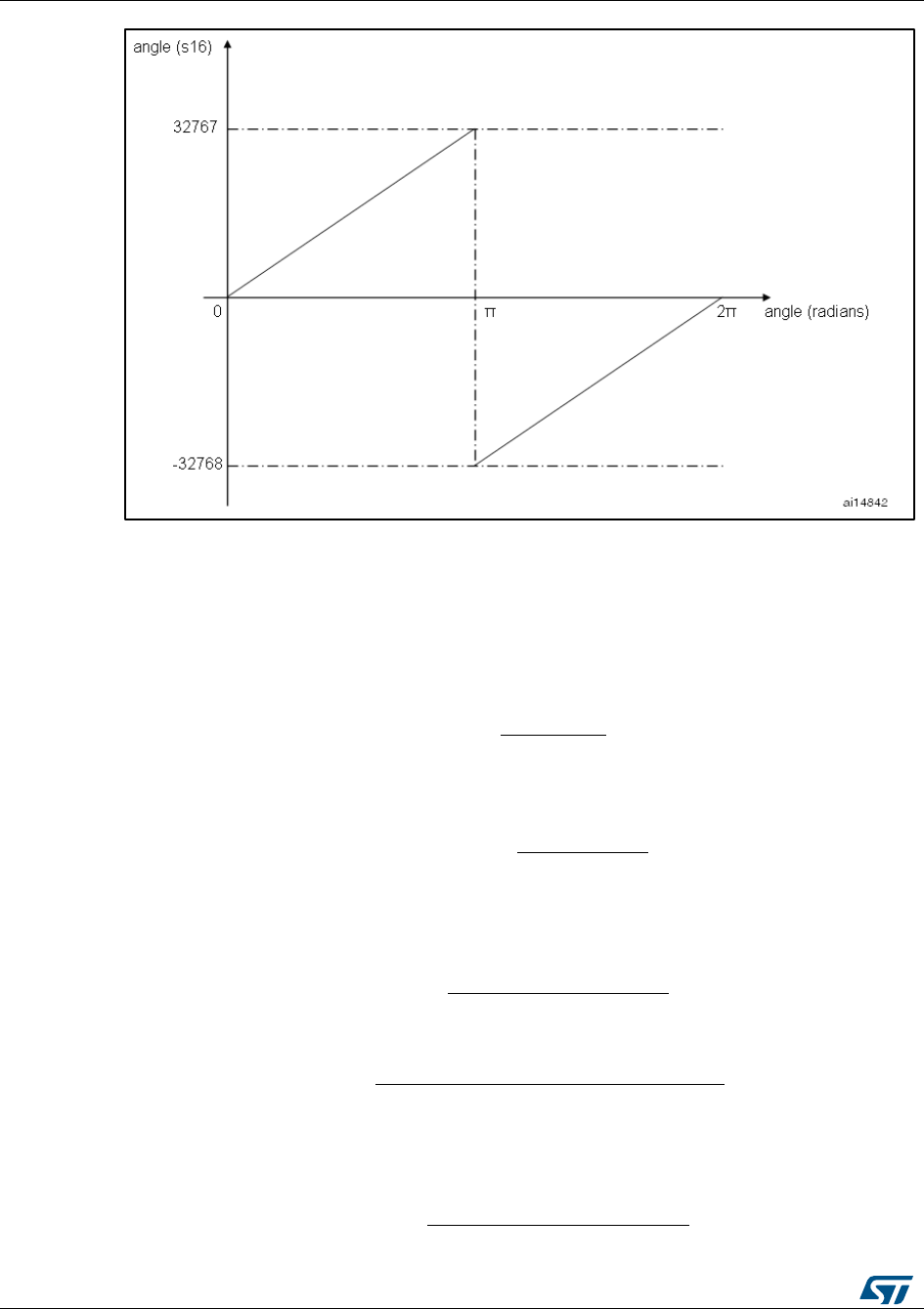
MC application programming interface (API)
UM1052
120/178
DocID18458 Rev 9
Figure 102: Radians vs s16
10.4.2 Rotor speed
The rotor speed units used in the MC API are:
Tenth of Hertz (01Hz): straightforwardly, it is 01Hz = 0.1 Hz
digit per control period (dpp): the dpp format expresses the angular speed as the
variation of the electrical angle (expressed in s16 format) within a FOC period.
An angular speed, expressed as the frequency in Tenth of Hertz (01Hz), can be easily
converted to dpp using the formula:
10.4.3 Current measurement
Phase currents measurement unit used in the MC API is called s16A, where:
A current, expressed in Ampere, can be easily converted to s16A, using the formula:
10.4.4 Voltage measurement
Applied phase voltage unit used in the MC API is called s16V, where:
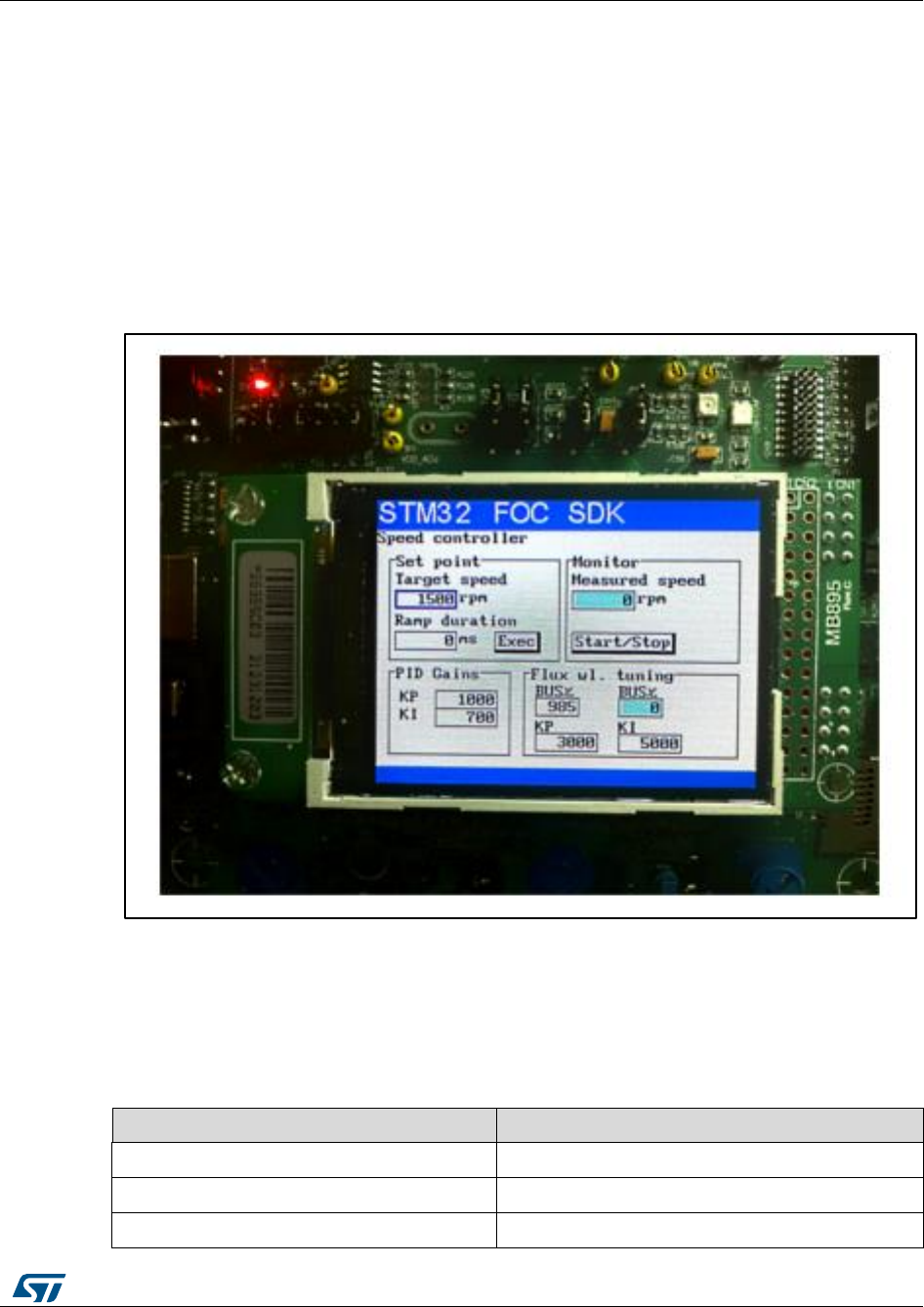
UM1052
Full LCD user interface
DocID18458 Rev 9
121/178
11 Full LCD user interface
11.1 Running the motor control firmware using the full LCD
interface
The STM32 motor control library includes a demonstration program that enables you to
display drive variables, customize the application by changing parameters, and enable and
disable options in real time.
The user interface reference is the one present in the STM32 evaluation boards and is
shown in Figure 102: "User interface reference".
Figure 103: User interface reference
The interface is composed of:
A 320x240 pixel color LCD screen
A joystick (see Table 22: "Joystick actions and conventions" for the list of joystick
actions and conventions)
A push button (KEY button)
Table 22: Joystick actions and conventions
Keyword
User action
UP
Joystick pressed up
DOWN
Joystick pressed down
LEFT
Joystick pressed to the left
Full LCD user interface
UM1052
122/178
DocID18458 Rev 9
Keyword
User action
RIGHT
Joystick pressed to the right
JOYSEL
Joystick pushed
KEY
Press the KEY push button
In the default firmware configuration, the LCD management is enabled. It can be disabled
using the STM32 MC Workbench or disabling the feature and manually changing the line:
define #define LCD_JOYSTICK_BUTTON_FUNCTIONALITY DISABLE (line 316) of
the Drive parameters.h file.
11.2 LCD User interface structure
The demonstration program is based on circular navigation pages.
The visibility of certain pages shown in Figure 103: "Page structure and navigation"
depends on the firmware configuration:
Dual control panel is only present if the firmware is configured for dual motor drive.
Speed controller page is only present when the firmware is configured in speed mode.
Sensorless tuning page (PLL) is only present if the firmware is configured with state
observer with PLL as primary or auxiliary speed sensor.
Sensorless tuning page (CORDIC) is only present if the firmware is configured with
state observer with CORDIC as primary or auxiliary speed sensor.
To navigate the help menus, use:
RIGHT: navigate to the next page on the right
LEFT: navigate to the next page on the left
Figure 104: Page structure and navigation
Each page is composed of a set of controls. Table 23: "List of controls used in the LCD
demonstration program" presents the list of controls used in the LCD demonstration
program. You can navigate between focusable controls in the page by pressing the joystick
UP and DOWN. The focused control is highlighted with a blue rectangle. When focused,
you can activate the control by pressing JOYSEL.
For some configurations such as STM32F100B-EVAL and STM320518-EVAL, a reduced
set of LCD pages and/or controls is available.
Complete documentation about this LCD User Interface can be found in User manual
STM32F PMSM single/dual FOC SDK (UM1052).
RIGHT
LEFT
RIGHT
LEFT
RIGHT
LEFT
RIGHT
LEFT
WELCOME
HELP PAGE
CONFIG
AND DEBUG
PAGE
SPEED
CONTROLLER
PAGE
CURRENT
CONTROLLERS
PAGE
SENSORLESS
TUNING PAGE
PLL
DUAL
CONTROL
PANEL
RIGHT
RIGHT
LEFT
LEFT
SENSORLESS
TUNING PAGE
CORDIC
RIGHT
LEFT
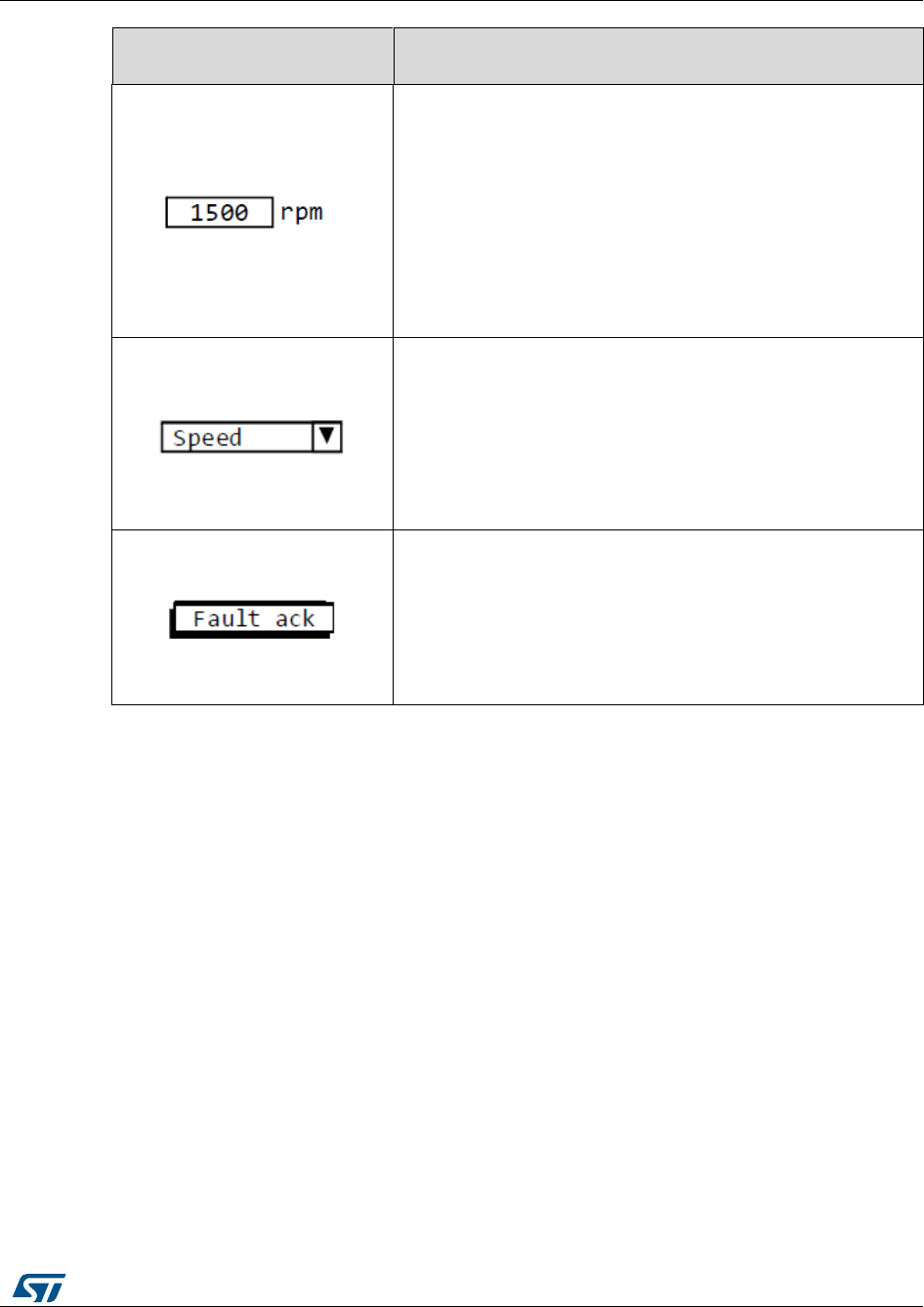
UM1052
Full LCD user interface
DocID18458 Rev 9
123/178
Table 23: List of controls used in the LCD demonstration program
Control name and
examples
Description
Edit box
Manages a numerical value. It can be “read only” or “read/write”.
A read only edit box has a gray background and cannot be
focused. A read/write edit box has a white background and can
be focused.
When a read/write edit box is focused, it can be activated for
modification by pressing JOYSEL. An activated read/write edit
box has a green background and its value can be modified
pressing and/or keeping joystick UP/DOWN pressed.
The new value is set to the motor control-related object
instantaneously when the value changes, unless otherwise
mentioned in this manual.
Combo-box
Manages a list of predefined values.
For example, Speed or Torque control mode. When focused, it
can be activated for modification by pressing JOYSEL.
An activated combo-box has a green background and its value
can be modified by pressing the joystick UP/DOWN.
When the value changes, the new value is instantaneously set to
the motor control-related object, unless otherwise mentioned in
this manual.
Button
Sends commands. For example, a start/stop button.
A disabled button is drawn in light gray and cannot be focused.
An enabled button is painted in black and can be focused.
When focused, pressing JOYSEL corresponds to “pushing” the
button and sending the related command.
11.2.1 Motor control application layer configuration (speed sensor)
The motor control application layer can be configured to use a position and speed sensor
as a primary or auxiliary speed sensor.
A primary speed and position sensor is used by the FOC algorithm to drive the motor. It is
mandatory to configure a primary speed sensor.
An auxiliary speed and position sensor may be used in parallel with the primary sensor for
debugging purposes. It is not used by the FOC algorithm. It is not mandatory to configure
an auxiliary speed sensor.
The following sensors are implemented in the MC library:
Hall sensor
Quadrature encoder
State observer plus PLL
State observer plus CORDIC
11.2.2 Welcome message
After the STM32 evaluation board is powered on or reset, a welcome message appears on
the LCD with loaded firmware code and version information.
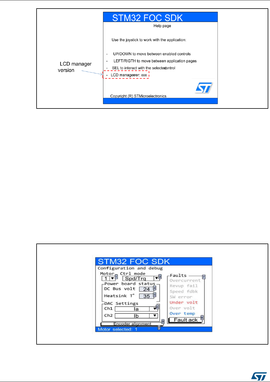
Full LCD user interface
UM1052
124/178
DocID18458 Rev 9
Figure 105: STM32 Motor Control demonstration project welcome message
11.2.3 Configuration and debug page
Press the RIGHT joystick from the welcome page to enter the configuration and debug
page.
To navigate between focusable controls on the page, press the UP/DOWN joystick.
Use the configuration and debug page shown in Figure 105: "Configuration and debug
page" to:
select the active motor drive (field 1 in Figure 105: "Configuration and debug page").
This control is present only for dual motor control applications. This combo-box
enables you to select the active motor drive. Once the active motor is selected, it is
shown in the status bar present at the bottom of the screen (field 2 in Figure 105:
"Configuration and debug page"). Commands performed on, or feedback from a
control, are only relative to the active motor.
select the control mode (field 3 in Figure 105: "Configuration and debug page"). Two
control modes are available: speed and torque. You can change the control mode
from speed to torque and vice versa on-the-fly even if the motor is already running.
Figure 106: Configuration and debug page

UM1052
Full LCD user interface
DocID18458 Rev 9
125/178
read the DC bus voltage value (field 4 in Figure 105: "Configuration and debug page").
This control is read-only.
read the heat sink temperature value (field 5 in Figure 105: "Configuration and debug
page"). This control is read-only.
select the variables to be put in output through DAC channels (field 6 in Figure 105:
"Configuration and debug page"). These controls are present only if the DAC option is
enabled in the firmware. The list of variables also depends on firmware settings. Table
25: "List of DAC variables" and Table 26: "DAC variables related to each state
observer sensor" introduce the list of variables that can be present in these combo-
boxes, depending on the configuration.
Table 24: "Definitions" shows the conventions used for DAC outputs of Currents, Voltages,
Electrical angles, Motor Speed and Observed BEMF.
The DAC voltage range is assumed to be 0 to 3.3 V in Table 24: "Definitions".
Table 24: Definitions
Definition
Description
Currents quantity
(Ia, Iq, …)
Current quantities are output to DAC as signed 16-bit numeric quantities
converted in the range of DAC voltage range.
Zero current is at 1.65 volt of DAC output.
Maximum positive current (that runs from inverter to the
motor) is at 3.3 volt of DAC output.
Maximum negative current (that runs from inverter to the
motor) is at 0 volt of DAC output.
Voltage quantity
(Valpha, Vq)
Voltage quantities are output to DAC as signed 16-bit numeric quantities
converted in the range of DAC voltage range.
0% of modulation index is at 1.65 volt of DAC output.
100% of modulation index is at 0 and 3.3 volt of DAC output.
Electrical angle
This is expressed in digits converted to the DAC voltage range.
180 electrical degrees are at 0 and 3.3 volt of DAC output.
0 electrical degrees are at 1.65 volt of DAC output.
Motor speed
This is proportional to the maximum application speed.
0 speed is at 1.65 volt of DAC output.
Maximum positive application speed is at 3.3 volt of DAC
output.
Maximum negative application speed is at 0 volt of DAC
output.
Observer BEMF
voltage
This is referenced to the maximum application speed and the voltage
constant configured in the firmware.
Values of BEMF present at the maximum application speed are at 0 and
3.3 volt of DAC output.

Full LCD user interface
UM1052
126/178
DocID18458 Rev 9
Table 25: List of DAC variables
Variable name
Description
Ia
Measured phase A motor current
Ib
Measured phase B motor current
Ialpha
Measured alpha component of motor phase's current expressed in
alpha/beta reference.
Ibeta
Measured beta component of motor phase's current expressed in
alpha/beta reference
Iq
Measured "q" component of motor phase's current expressed in q/d
reference.
Id
Measured "d" component of motor phase's current expressed in q/d
reference
Iq ref
Target "q" component of motor phase's current expressed in q/d
reference
Id ref
Target "d" component of motor phase's current expressed in q/d
reference
Vq
Forced "q" component of motor phase's voltage expressed in q/d
reference
Vd
Forced "d" component of motor phase's voltage expressed in q/d
reference
Valpha
Forced alpha component of motor phase's voltage expressed in
alpha/beta reference.
Vbeta
Forced beta component of motor phase's voltage expressed in
alpha/beta reference
Meas. El Angle
Measured motor electrical angle. This variable is present only if a
"real" sensor (encoder, Hall) is configured as a primary or auxiliary
speed sensor and it is relative to this sensor
Meas. Rotor Speed
Measured motor speed. This variable is present only if a "real"
sensor (encoder, Hall) is configured as a primary or auxiliary speed
sensor and it is relative to this sensor
Obs. El Angle
Observed motor electrical angle. This variable is present only if a
"state observer" sensor is configured as a primary or auxiliary
speed sensor and it is relative to this sensor
Obs. Rotor Speed
Observed motor speed. This variable is present only if a "state
observer" sensor is configured as a primary or auxiliary speed
sensor and it is relative to this sensor
Obs. Ialpha
Observed alpha component of motor phase's current expressed in
alpha/beta reference. This variable is present only if a "state
observer" sensor is configured as a primary or auxiliary speed
sensor and it is relative to this sensor.

UM1052
Full LCD user interface
DocID18458 Rev 9
127/178
Variable name
Description
Obs. Ibeta
Observed beta component of motor phase's current expressed in
alpha/beta reference. This variable is present only if a "state
observer" sensor is configured as a primary or auxiliary speed
sensor and it is relative to this sensor
Obs. B-emf alpha
Observed alpha component of motor BEMF expressed in
alpha/beta reference. This variable is present only if a "state
observer" sensor is configured as a primary or auxiliary speed
sensor and it is relative to this sensor.
Obs. B-emf beta
Observed beta component of motor BEMF expressed in alpha/beta
reference. This variable is present only if a "state observer" sensor
is configured as a primary or auxiliary speed sensor and it is
relative to this sensor.
Exp. B-emf level
The expected Bemf squared level.
Obs. B-emf level
The observed Bemf squared level.
User 1
User defined DAC variable. Section 15.9: "How to configure the user
defined DAC variables" describes how to configure user defined DAC
variables.
User 2
User defined DAC variable. Section 15.9: "How to configure the user
defined DAC variables" describes how to configure user defined DAC
variables.
Observed variables (Obs.) in Table 25: "List of DAC variables" refer to a configuration that
uses only one sensorless speed sensor configured as a primary or auxiliary sensor and
refers to that state observer sensor. When the firmware is configured to use two sensorless
speed sensors, state observer plus PLL and state observer plus CORDIC as a primary and
auxiliary speed sensor, the DAC variables related to each state observer sensor are
indicated in Table 26: "DAC variables related to each state observer sensor".
Table 26: DAC variables related to each state observer sensor
Variable name
Description
Obs. El Ang. (PLL)
Observed motor electrical angle. This variable is present only if a
"state observer plus PLL" sensor is configured as a primary or
auxiliary speed sensor and it is relative to this sensor.
Obs. Ialpha (PLL)
Observed alpha component of motor phase's current expressed in
alpha/beta reference. This variable is present only if a "state
observer plus PLL" sensor is configured as a primary or auxiliary
speed sensor and it is relative to this sensor.
Obs. Rot. Spd (PLL)
Observed motor speed. This variable is present only if a "state
observer plus PLL" sensor is configured as a primary or auxiliary
speed sensor and it is relative to this sensor.
Obs. Ibeta (PLL)
Observed beta component of motor phase's current expressed in
alpha/beta reference. This variable is present only if a "state
observer plus PLL" sensor is configured as a primary or auxiliary
speed sensor and it is relative to this sensor.

Full LCD user interface
UM1052
128/178
DocID18458 Rev 9
Variable name
Description
Obs. Bemf a. (PLL)
Observed alpha component of motor BEMF expressed in
alpha/beta reference. This variable is present only if a "state
observer plus PLL" sensor is configured as a primary or auxiliary
speed sensor and it is relative to this sensor.
Obs. Bemf b. (PLL)
Observed beta component of motor BEMF expressed in alpha/beta
reference. This variable is present only if a "state observer plus
PLL" sensor is configured as a primary or auxiliary speed sensor
and it is relative to this sensor.
Obs. El Ang. (CR)
Observed motor electrical angle. This variable is present only if a
"state observer plus CORDIC" sensor is configured as a primary or
auxiliary speed sensor and it is relative to this sensor.
Obs. Rot. Spd (CR)
Observed motor speed. This variable is present only if a "state
observer plus CORDIC" sensor is configured as a primary or
auxiliary speed sensor and it is relative to this sensor.
Obs. Ialpha (CR)
Observed alpha component of motor phase's current expressed in
alpha/beta reference. This variable is present only if a "state
observer plus CORDIC" sensor is configured as a primary or
auxiliary speed sensor and it is relative to this sensor.
Obs. Ibeta (CR)
Observed beta component of motor phase's current expressed in
alpha/beta reference. This variable is present only if a "state
observer plus CORDIC" sensor is configured as a primary or
auxiliary speed sensor and it is relative to this sensor.
Obs. Bemf a. (CR)
Observed alpha component of motor BEMF expressed in
alpha/beta reference. This variable is present only if a "state
observer plus CORDIC" sensor is configured as a primary or
auxiliary speed sensor and it is relative to this sensor.
Obs. Bemf b. (CR)
Observed beta component of motor BEMF expressed in alpha/beta
reference. This variable is present only if a "state observer plus
CORDIC" sensor is configured as a primary or auxiliary speed
sensor and it is relative to this sensor.
Table 26: "DAC variables related to each state observer sensor" lists the DAC variables
related to each state observer sensor when two state observer speed sensors are selected.
It is possible to read the list of fault causes (field 7 in Figure 105: "Configuration and
debug page") if fault conditions have occurred, or if they are still present. The list of
possible faults is summarized in Table 27: "Fault conditions list" and is represented by
the list of labels in the LCD screen (field 7 in Figure 105: "Configuration and debug
page"). If a fault condition occurred and is over, the relative label is displayed in blue.
If a fault condition is still present, the relative label is displayed in red. It is gray if there
is no error.
To acknowledge the fault condition, press the "Fault ack" button (field 8 in Figure 105:
"Configuration and debug page"). If a fault condition occurs, the motor is stopped and
it is no longer possible to navigate in the other pages. In this condition, it is not
possible to restart the motor until the fault condition is over and the occurred faults
have been acknowledged by the user pushing the "Fault ack" button. If a fault
condition is running, the "Fault ack" button is disabled.

UM1052
Full LCD user interface
DocID18458 Rev 9
129/178
Table 27: Fault conditions list
Fault
Description
Overcurrent
This fault occurs when the microcontroller break input signal is activated. It is
usually used to indicate hardware over current condition.
Revup fail
This fault occurs when the programmed rev-up sequence ends without
validating the speed sensor information. The rev-up sequence is performed
only when the state observer is configured as the primary speed sensor.
Speed fdbk
This fault occurs only in RUN state when the sensor no longer meets the
conditions of reliability.
SW error
This fault occurs when the software detects a general fault condition. In the
present implementation, the software error is raised when the FOC
frequency is too high to allow the FOC execution.
Under volt
This fault occurs when the DC bus voltage is below the configured threshold.
Over volt
This fault occurs when the DC bus voltage is above the configured threshold.
If the dissipative brake resistor management is enabled, this fault is not
raised.
Over temp
This fault occurs when the heat sink temperature is above the configured
threshold.
Execute the encoder initialization. If the firmware is configured to use the encoder as a
primary speed sensor or an auxiliary speed sensor, the "encoder alignment" button is
also present. In this case, the alignment of the encoder is required only once after
each reset of the microcontroller.
11.2.4 Dual control panel page
This page is present only if the firmware is configured for dual motor drive.
To enter the Dual control panel page, press the joystick RIGHT from the Configuration and
debug page.
It is possible to navigate between focusable controls present in the page by pressing the
joystick UP/DOWN.
The Dual control panel page shown in Figure 106: "Dual control panel page" is used to
send commands and get feedback from both motors. It is divided into three groups:
Groups A and B depend on speed/torque settings. The group content is updated on-
the-fly when the control mode (torque/speed) is changed in the Configuration and
debug page. The control present in group A is related to the first motor. The control
present in group B is related to the second motor.
Group C does not depend on speed/torque settings. The control present in this group
is related to both motors.
Figure 106: "Dual control panel page" shows an example in which the first motor is set in
torque mode and the second motor is set in speed mode.
The controls present in this page are used as follows:
To set the Iq reference (1). This is related to motor 1 and is only present if motor 1 is
set in torque mode. Iq reference is expressed in s16A. In this page, the current
references are always expressed as Cartesian coordinates (Iq,Id).
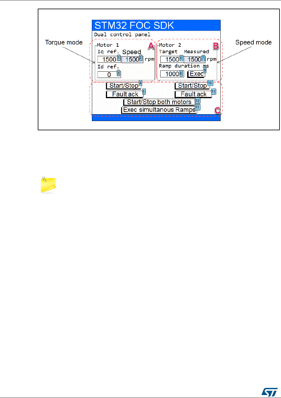
Full LCD user interface
UM1052
130/178
DocID18458 Rev 9
Figure 107: Dual control panel page
To set the Id reference (3). This is related to motor 1. This control is only present if
motor 1 is set in torque mode. Id reference is expressed in s16A. In this page, the
current references are always expressed as Cartesian coordinates (Iq,Id).
To convert current expressed in amps to current expressed in digits, use the
following formula:
Current(s16A) = [Current(Amp) * 65536 * Rshunt * Aop] / Vdd micro.
Set the final motor speed of a speed ramp (6). This is related to motor 2. This control
is only present if motor 2 is set in speed mode. Motor speed is expressed in RPM. The
value set in this control is not automatically sent to the motor control related object but
it is used to perform a speed ramp execution. See the Exec button description (9).
Set the duration of a speed ramp (8). This is related to motor 2. This control is only
present if motor 2 is set in speed mode. The duration is expressed in milliseconds.
The value set in this control is not automatically sent to the motor control related
object, but it is used to perform a speed ramp execution. See the Exec button
description (9). It is possible to set a duration value of 0 to program a ramp with an
instantaneous change in the speed reference from the current speed to the final motor
speed (6).
Execute a speed ramp by pushing the “Exec” button (9). This is related to motor 2.
This control is only present if motor 2 is set in speed mode. The Exec speed ramp
command is sent to the motor control related object together with the final motor
speed and duration currently selected (6). The Exec speed ramp command performs a
speed ramp from the current speed to the final motor speed in a time defined by the
duration. The command is buffered and takes effect only when the motor is in RUN
state.
To read the motor speed, respectively (2) and (7) for motor 1 and motor 2. The motor
speed is expressed in RPM. This control is read-only.
Send a start/stop command, (4) for motor 1, (10) for motor 2. This is performed by
pushing the start/stop button. A start/stop command means: start the motor if it is
stopped, or stop the motor if it is running. If the drive is configured in speed mode
when the motor starts, a speed ramp with the latest values of the final motor speed
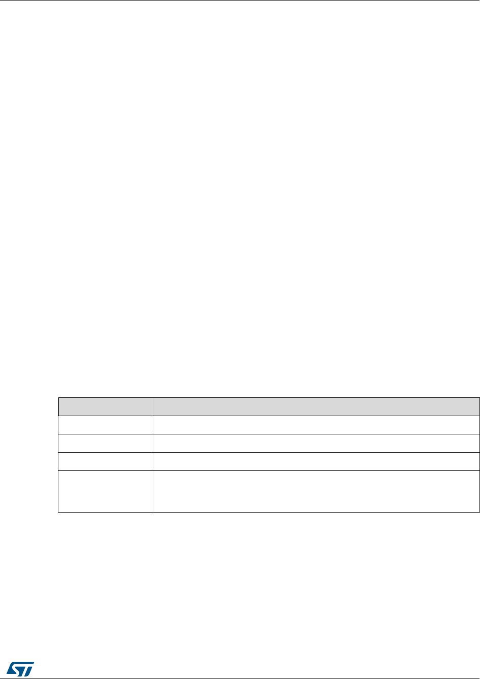
UM1052
Full LCD user interface
DocID18458 Rev 9
131/178
and duration is performed. If a fault condition occurs at any time, the motor is stopped
(if running) and the start/stop button is disabled.
When a fault condition is over, the Fault ack button, (5) for motor 1, (11) for motor 2,
is enabled. Pushing this button acknowledges the fault conditions that have occurred.
After the fault is acknowledged, the start/stop button becomes available again. When
a fault occurs and before it is acknowledged, it is only possible to navigate in the Dual
control panel page and the Configuration and debug page.
To start or stop both motors simultaneously, push the Start/Stop both motors button
(12). This button is enabled only when the motors are both in Idle state or both in RUN
state. If any of the motors is configured in speed mode when it starts, a speed ramp
with the last values of the final motor speed and duration is performed. It is possible to
stop both motors at any time by pushing the KEY button.
To execute simultaneous speed ramps on both motors, push the Exec simultaneous
Ramps button (13). This button is disabled when at least one of the two motors is
configured in torque mode. The Exec speed ramp command is sent to both motor
control objects together with the related final motor speed and the duration currently
selected. The Exec speed ramp command performs a speed ramp from the current
speed to the final motor speed in a time defined by the duration for each motor. The
commands are buffered and take effect only when the related motor is in RUN state.
11.2.5 Speed controller page
This page is only present if the control mode set in is the speed mode.
To enter the Speed controller page, press the joystick RIGHT from the Configuration and
deFigure 105: "Configuration and debug page"bug page (or from the Dual control panel
page, if the firmware is configured in dual motor drive).
It is possible to navigate between focusable controls present in the page by pressing the
joystick UP/DOWN.
The Speed controller page shown in Figure 107: "Speed controller page" is used to send
commands and get feedback related to the speed controller from the active motor. There
are four groups of controls in this page:
Table 28: Control groups
Control group
Description
Set point
Used to configure and execute a speed ramp
PID gains
Used to change the speed controller gains in real- time
Flux wk. tuning
Used to tune the flux weakening related variables
Measured speed
with start/stop
button
Composed of two controls that are also present in the Current
controllers page and in the sensorless tuning page; it provides a fast
access to the measured speed and to the motor start/stop function

Full LCD user interface
UM1052
132/178
DocID18458 Rev 9
Figure 108: Speed controller page
If the firmware is configured as dual motor drive, it is possible to know which motor is active
by reading the label at the bottom of the page. To change the active motor, go to the
Configuration and debug page and change (1) in Figure 107: "Speed controller page".
Table 29: "Speed controller page controls " lists the actions that can be performed using
this page.
Table 29: Speed controller page controls
Control
Description
Target speed (1 in Figure
107: "Speed controller
page")
Sets the final motor speed of a speed ramp for the active
motor. The motor speed is expressed in RPM. The value set in
this control is not automatically sent to the motor control
related object, but it is used to perform a speed ramp
execution. See the Exec button description (3)
Ramp duration (2)
Sets the duration of a speed ramp for the active motor. The
duration is expressed in milliseconds. The value set in this
control is not automatically sent to the motor control related
object, but it is used to perform a speed ramp execution. See
the Exec button description (3). It is possible to set a duration
value of 0 to program a ramp with an instantaneous change in
the speed reference from the current speed to the final motor
speed (1).
Exec button (3)
Executes a speed ramp for the active motor. The execute
speed ramp command is sent to the motor control related
object together with the final motor speed and duration
presently selected (1) and (2). The execute speed ramp
command performs a speed ramp from the current speed to
the final motor speed in a time defined by duration. The
command is buffered and takes effect only when the motor
becomes in RUN state.
Measured speed (4)
Reads the motor speed for the active motor. The motor speed
is expressed in RPM and is a read-only control.

UM1052
Full LCD user interface
DocID18458 Rev 9
133/178
Control
Description
Start/Stop button (5)
Sends a start/stop command for the active motor. A start/stop
command starts the motor if it is stopped, or stops a running
motor. Used with a motor start, a speed ramp with the last
values of the final motor speed and duration is performed. If a
fault condition occurs at any time, the motor is stopped (if
running) and the Configuration and debug page displays.
Speed PID gain KP (6)
Sets the proportional coefficient of the speed controller for the
active motor. The value set in this control is automatically sent
to the motor control related object, allowing the run-time tuning
of the speed controller.
Speed PID gain KI (7)
Sets the integral coefficient of the speed controller for the
active motor. The value set in this control is automatically sent
to the motor control related object, allowing the run-time tuning
of the speed controller.
Bus‰ (8)
The value set in this control is automatically sent to the motor
control related object, allowing the run-time tuning of flux
weakening controller. The value is expressed in per mil (‰) of
DC bus voltage.
Bus‰ (9)
DC bus voltage percentage presently used for the active
motor; it is a read-only control. This control is present only if
the flux weakening feature is enabled in the firmware. The
value is actually expressed in per mil (‰) of DC bus voltage.
Flux wk PI gain KP (10)
The value set in this control is automatically sent to the motor
control related object, allowing the run-time tuning of the flux
weakening controller.
Flux wk PI gain KI (11)
The value set in this control is automatically sent to the motor
control related object, allowing the run-time tuning of the flux
weakening controller.
11.2.6 Current controller page
To enter the current controller page, press the RIGHT joystick from the speed controller
page (or from one of the above described pages if the speed controller page is not visible).
It is possible to navigate between focusable controls present in the page, pressing the
UP/DOWN joystick.
The current controller page shown in Figure 108: "Current controller page" is used to send
commands and get a feedback related to current controllers, from the active motor. There
are five control groups in this page, listed in the table below.
Table 30: Control groups
Control group
Description
Set point
Used to set the current references and read measured currents
Iq PID gains
Used to change in real time the speed controller gains
Id PID gains
Full LCD user interface
UM1052
134/178
DocID18458 Rev 9
Control group
Description
Measured speed with
start/stop button
Composed of two controls that are also present in the current
controller page and in the sensorless tuning page; this provides
a fast access to the measured speed and to the motor start/stop
function
Option selection
Selects options
Figure 109: Current controller page
If the firmware is configured as a dual motor drive, it is possible to know which is the active
motor reading the label at the bottom of the page. To change the active motor, the motor
field in the configuration and debug page has to be changed (field 1 in Figure 108: "Current
controller page").
Table 31: "Current controller page controls " lists the actions that can be performed using
this page.
Table 31: Current controller page controls
Control
Description
Iq reference (field 1 in
Figure 108: "Current
controller page")
To set and read the Iq reference for the active motor. This control is
read-only if the active motor is set in speed mode, otherwise it can be
modified. The Iq reference is expressed in s16A. To convert current
expressed in Amps to current expressed in digits, use the formula:
Current(s16A) = [Current(Amp) * 65536 * Rshunt * Aop] / Vdd micro
Id reference (field 2 in
Figure 108: "Current
controller page")
To set and read the Id reference for the active motor. This control is
usually read-only if the active motor is set in speed mode, otherwise it
can be modified. The Id reference is expressed in digits. It is also
possible to configure the firmware to have an Id reference editable
even in speed mode. To convert current expressed in Amps to
current expressed in s16A, it is possible to use the formula:
Current(s16A) = [Current(Amp) * 65536 * Rshunt * Aop] / Vdd micro
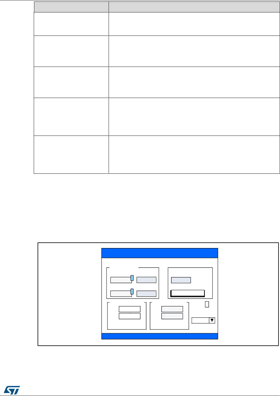
UM1052
Full LCD user interface
DocID18458 Rev 9
135/178
Control
Description
Measured Iq (field 3 in
Figure 108: "Current
controller page")
To read the measured Iq for the active motor. Measured Iq is
expressed in s16A and is a read-only control.
Iq PI(D) gain, KP (field 5
in Figure 108: "Current
controller page")
To set the proportional coefficient of the Iq current controller for
the active motor. The value set in this control is automatically
sent to the motor control related object, allowing the run-time
tuning of the current controller.
Iq PI(D) gain, KI (field 6 in
Figure 108: "Current
controller page")
To set the integral coefficient of the Iq current controller for the
active motor. The value set in this control is automatically sent
to the motor control related object, allowing the run-time tuning
of the current controller.
Id PI(D) gain, KP (field 7
in Figure 108: "Current
controller page")
To set the proportional coefficient of the Id current controller for
the active motor. The value set in this control is automatically
sent to the motor control related object, allowing the run-time
tuning of the current controller. This control is only read if the
link check-box is checked.
Id PI(D) gain, KI (field 8 in
Figure 108: "Current
controller page")
To set the integral coefficient of the Id current controller for the
active motor. The value set in this control is automatically sent
to the motor control related object, allowing the run-time tuning
of the current controller. This control is only read if the link
check-box is checked.
Enabling or disabling the link between Iq and Id controllers KP and KI gains is performed by
checking or unchecking the link check-box (field 9 in Figure 108: "Current controller page").
It is possible to change the current reference variables from Cartesian coordinates (Iq/Id) to
polar coordinates (Amp, Eps Figure 109: "Current controller page with polar coordinates")
using the input combo-box (field 10 in Figure 108: "Current controller page"). If polar
coordinates are selected, the current controller page is modified as in Figure 109: "Current
controller page with polar coordinates".
Figure 110: Current controller page with polar coordinates
The Amp field (field 1 in Figure 109: "Current controller page with polar coordinates")
is used to set and read the current reference amplitude for the active motor. This
STM32 FOC SDK
Motor selected: 1
Amp. Iq
Eps.Deg. Id
Iq PID Gains
KP
KI
Id PID Gains
KP
KI
Link X
Measured speed
rpm
Current controllers
Set points
Input
/
1
2
1500 1500
90 0
1000
500 1000
500
1500
Start/Stop
Am Ep
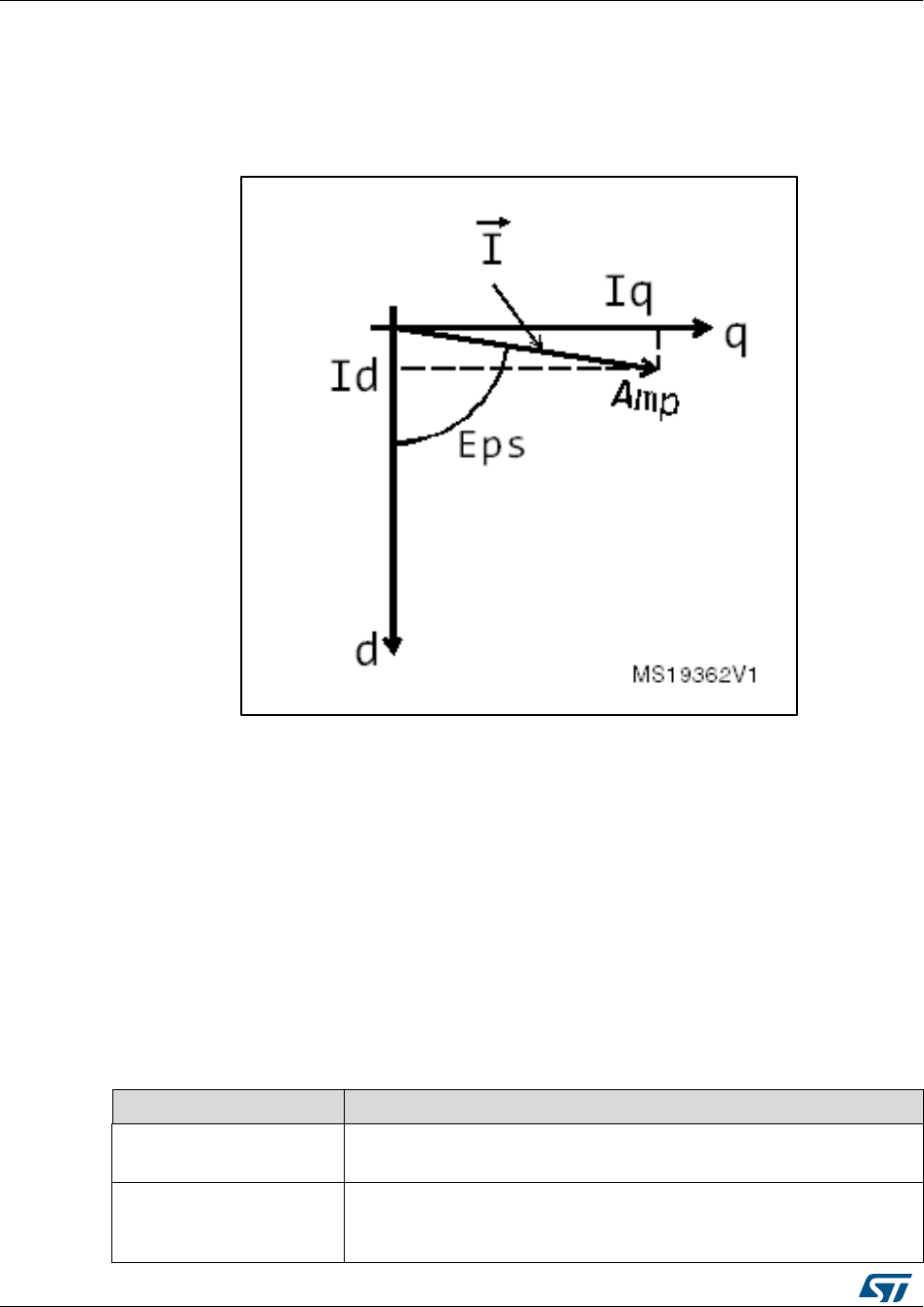
Full LCD user interface
UM1052
136/178
DocID18458 Rev 9
control is read-only if the active motor is set in speed mode, otherwise it is editable.
Amplitude reference is expressed in digits.
The Eps field (field 2 in Figure 109: "Current controller page with polar coordinates") is
used to set and read the current reference phase for the active motor. This control is
read-only if the active motor is set in speed mode, otherwise it is editable. The phase
is expressed in degrees.
Figure 111: Iq, Id component versus Amp, Eps component
11.2.7 Sensorless tuning STO & PLL page
This page is present only if the firmware is configured to use a state observer (STO) plus a
PLL sensor set as a primary or auxiliary speed and position sensor. If the state observer
sensor is set as an auxiliary speed and position sensor, the (AUX) label will be shown near
the page title (See field 9 in Figure 111: "Sensorless tuning STO and PLL page").
To enter the sensorless tuning page, press the RIGHT joystick from the current controller
page.
It is possible to navigate between focusable controls present in the page by pressing the
UP/DOWN joystick.
The sensorless tuning page shown in Figure 111: "Sensorless tuning STO and PLL page"
is used to send commands and get a feedback related to a state observer plus a PLL
object from the active motor. There are three groups of control in this page.
Table 32: Control groups
Control group
Description
State observer tuning
Used to configure the parameters of the state observer object in
real-time
Rev up tuning gains
Used to change the start up related parameters in real-time.
This group is only present if the state observer plus PLL sensor
is selected as the primary speed and position sensor.
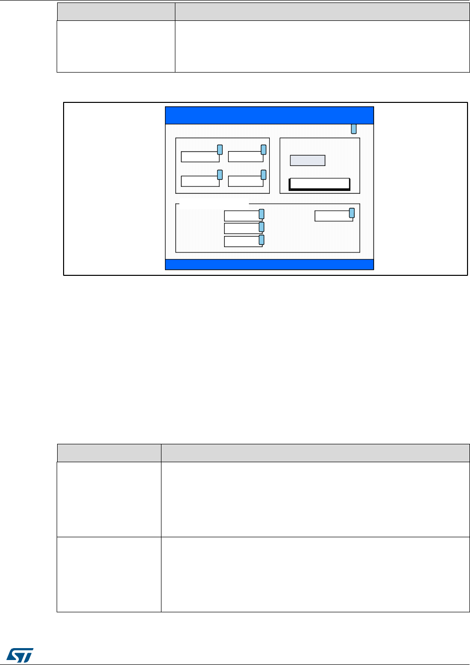
UM1052
Full LCD user interface
DocID18458 Rev 9
137/178
Control group
Description
Measured speed with
start/stop button
Composed of two controls that are also present in the current
controller page and in the sensorless tuning page; this provides
a fast access to the measured speed and to the motor start/stop
function
Figure 112: Sensorless tuning STO and PLL page
If the firmware is configured as a dual motor drive, it is possible to know which is the active
motor by reading the label at the bottom of the page. To change the active motor, change
the motor field in the configuration and debug page.
Table 33: "Sensorless tuning STO and PLL page controls " lists the actions that can be
performed using this page.
Table 33: Sensorless tuning STO and PLL page controls
Control
Description
G1
(field 1 in Figure 111:
"Sensorless tuning
STO and PLL page")
To modify the G1 gain parameter in real-time. The value set in this
control is automatically sent to the motor control related object,
allowing the run-time tuning of the state observer object. This value
is proportional to the K1 observer gain and is equal to C2 STO
object parameter (See STM32 FOC PMSM FW library developer
Help file.chm).
G2
(field 2 in Figure 111:
"Sensorless tuning
STO and PLL page")
To modify the G2 gain parameter in real-time. The value set in this
control is automatically sent to the motor control related object,
allowing the run-time tuning of the state observer object. This value
is proportional to the K2 observer gain and is equal to C4 STO
object parameter (See STM32 FOC PMSM FW library developer
Help file.chm).
STM32 FOC SDK
Motor selected: 1
G1
PLL KP
1500 1500
100
G2
PLL KI
20
Duration
F. Speed
Iq
700
0
20000
Measured speed
1500 rpm
Start/Stop
Sensorless tuning STO & PLL (AUX)
Stage 0
ms
rpm
12
3 4
5
6
7
8
9
Rev up tuning

Full LCD user interface
UM1052
138/178
DocID18458 Rev 9
Control
Description
PLL KP
(field 3 in Figure 111:
"Sensorless tuning
STO and PLL page")
To set the proportional coefficient of the PLL for the active motor.
The value set in this control is automatically sent to the motor
control related object, allowing the run-time tuning of the current
controller. This control is only present if the state observer + PLL
object is set as the primary or auxiliary speed and position sensor,
and if the PLL tuning option is enabled in the firmware.
PLL KI
(field 4 in Figure 111:
"Sensorless tuning
STO and PLL page")
To set the integral coefficient of the PLL for the active motor. The
value set in this control is automatically sent to the motor control
related object, allowing the run-time tuning of the current controller.
This control is only present if the state observer + PLL object is set
as the primary or auxiliary speed and position sensor, and if the
PLL tuning option is enabled in the firmware.
Duration
(field 5 in Figure 111:
"Sensorless tuning
STO and PLL page")
To set the duration of the active rev-up stage for the active motor.
The value set in this control is automatically sent to the motor
control related object and becomes active on next motor start-up,
allowing the tuning of the rev-up sequence. The duration is
expressed in milliseconds.
F. Speed
(field 6 in Figure 111:
"Sensorless tuning
STO and PLL page")
To set the final mechanical speed for the active motor and active
rev-up controller stage. The value set in this control is automatically
sent to the motor control related object and becomes active on next
motor start-up, allowing the run-time tuning of rev-up sequence.
The final mechanical speed is expressed in RPM.
Iq
(field 7 in Figure 111:
"Sensorless tuning
STO and PLL page")
To set the final torque reference for the active motor and active rev-up
controller stage. The value set in this control is automatically sent to the
motor control related object and becomes active on next motor start-up,
allowing the tuning of the rev-up sequence. The final torque reference is
expressed in Id current and becomes active on next motor start-up.
To convert current expressed in Amps to current expressed in digits, use
the formula:
Current(s16A) = [Current(Amp) * 65536 * Rshunt * Aop] / Vdd micro.
Stage
(Field 8 in Figure 111:
"Sensorless tuning
STO and PLL page")
To set the active rev-up stage that receives the Duration, F. Speed
and Final torque reference (Iq) new values set in Fields 5, 6 and 7.
The rev-up sequence consists of five stages. Figure 112: "Example of rev-up sequence"
shows an example of a rev-up sequence. It is possible to tune each stage in run-time using
rows 5-8 of Table 33: "Sensorless tuning STO and PLL page controls ".

UM1052
Full LCD user interface
DocID18458 Rev 9
139/178
Figure 113: Example of rev-up sequence
11.2.8 Sensorless tuning STO and CORDIC page
This page is only present if the firmware is configured to use a state observer plus CORDIC
sensor set as a primary or auxiliary speed and position sensor. If the state observer sensor
is set as an auxiliary speed and position sensor, the (AUX) label will be shown near the
page title (See field 7 in Figure 113: "Sensorless tuning STO and CORDIC page").
To enter the sensorless tuning page, press the RIGHT joystick from the current controller
page.
It is possible to navigate between focusable controls present in the page by pressing the
UP/DOWN joystick.
The sensorless tuning page shown in Figure 113: "Sensorless tuning STO and CORDIC
page" is used to send commands and get feedbacks, related to the state observer plus
CORDIC object, from the active motor. There are three groups of controls in this page.
Table 34: Control groups
Control group
Description
State observer
tuning
Used to configure the parameters of the state observer object in real-
time
Rev up tuning
gains
Used to change the start-up related parameters in real-time. This
group is only present if the state observer plus CORDIC sensor is
selected as the primary speed and position sensor.
Measured speed
with start/stop
button
Composed of two controls that are also present in the current
controller page and in the sensorless tuning page; this provides a fast
access to the measured speed and to the motor start/stop function
Full LCD user interface
UM1052
140/178
DocID18458 Rev 9
Figure 114: Sensorless tuning STO and CORDIC page
If the firmware is configured as a dual motor drive, it is possible to know which is the active
motor by reading the label at the bottom of the page. To change the active motor, change
the motor field in the configuration and debug page.
Table 35: "Sensorless tuning STO and PLL page controls " lists the actions that can be
performed using this page.
Table 35: Sensorless tuning STO and PLL page controls
Control
Description
G1 (field 1 in Figure
113: "Sensorless
tuning STO and
CORDIC page")
To modify the G1 gain parameter in real-time. The value set in this
control is automatically sent to the motor control related object,
allowing the run-time tuning of the state observer object. This value
is proportional to the K1 observer gain and is equal to C2 STO
object parameter (See doxygen.chm).
G2 (field 2 in Figure
113: "Sensorless
tuning STO and
CORDIC page")
To modify the G2 gain parameter in real-time. The value set in this
control is automatically sent to the motor control related object,
allowing the run-time tuning of the state observer object. This value
is proportional to the K2 observer gain and is equal to C4 STO
object parameter (See doxygen.chm).
Duration (field 3 in
Figure 113:
"Sensorless tuning
STO and CORDIC
page")
To set the duration of the active rev-up stage for the active motor.
The value set in this control is automatically sent to the motor
control related object and becomes active on next motor start-up,
allowing the tuning of the rev-up sequence. The duration is
expressed in milliseconds.

UM1052
Full LCD user interface
DocID18458 Rev 9
141/178
Control
Description
F. Speed (field 4 in
Figure 113:
"Sensorless tuning
STO and CORDIC
page")
To set the final mechanical speed for the active motor and active
rev-up controller stage. The value set in this control is automatically
sent to the motor control related object and becomes active on next
motor start-up, allowing the run-time tuning of the rev-up sequence.
The final mechanical speed is expressed in RPM.
Iq (field 5 in Figure
113: "Sensorless
tuning STO and
CORDIC page")
To set the final torque reference for the active motor and active rev-up
controller stage. The value set in this control is automatically sent to the
motor control related object and becomes active on next motor start-up,
allowing the tuning of the rev-up sequence. The final torque reference is
expressed in Id current and becomes active on next motor start-up.
To convert current expressed in Amps to current expressed in digits, use
the formula:
Current(s16A) = [Current(Amp) * 65536 * Rshunt * Aop] / Vdd micro.
Stage (Field 8 in
Figure 113:
"Sensorless tuning
STO and CORDIC
page")
To set the active rev-up stage that receives the Duration, F. Speed
and Final torque reference (Iq) new values set in Fields 5, 6 and 7.
It is possible to set the active rev-up stage (field 6 in Figure 113: "Sensorless tuning STO
and CORDIC page"). Figure 112: "Example of rev-up sequence" shows an example of a
rev-up sequence.
Light LCD user interface
UM1052
142/178
DocID18458 Rev 9
12 Light LCD user interface
The STM32 motor control library includes a simplified version of demonstration program
that enables you to display drive variables, customize the application by changing
parameters, and enable and disable options in real time. It is shown in Figure 114: "Light
LCD User interface".
Figure 115: Light LCD User interface
12.1 Torque control mode
Figure 115: "LCD screen for Torque control settings", Figure 116: "LCD screen for Target
Iq settings" and Figure 117: "LCD screen for Target Id settings" show a few LCD menus for
setting control parameters when in Torque Control mode. The parameter highlighted, in red
color, is the one that can be set and its value can be modified by acting on the joystick key.
Moving the joystick up/down, selects the active control mode (in the example shown in
Figure 115: "LCD screen for Torque control settings", it is Torque control).
UM1052
Light LCD user interface
DocID18458 Rev 9
143/178
Figure 116: LCD screen for Torque control settings
From the previous screen (Figure 115: "LCD screen for Torque control settings"), if the
joystick is moved to the right, the Target Iq current component becomes highlighted (in red).
This parameter can now be modified by moving the joystick up/down. Once the motor Start
command has been issued, Target Iq can be changed in runtime while the measured Iq
current component is shown in the Measured field.
Figure 117: LCD screen for Target Iq settings
From the previous screen (Figure 116: "LCD screen for Target Iq settings"), if the joystick is
moved to the right, the Target Id current component becomes highlighted (in red). This
parameter can now be modified by moving the joystick up/down. Once the motor Start
command has been issued, the Target Id can be changed in runtime while the measured Id
current component is shown in the Measured field.
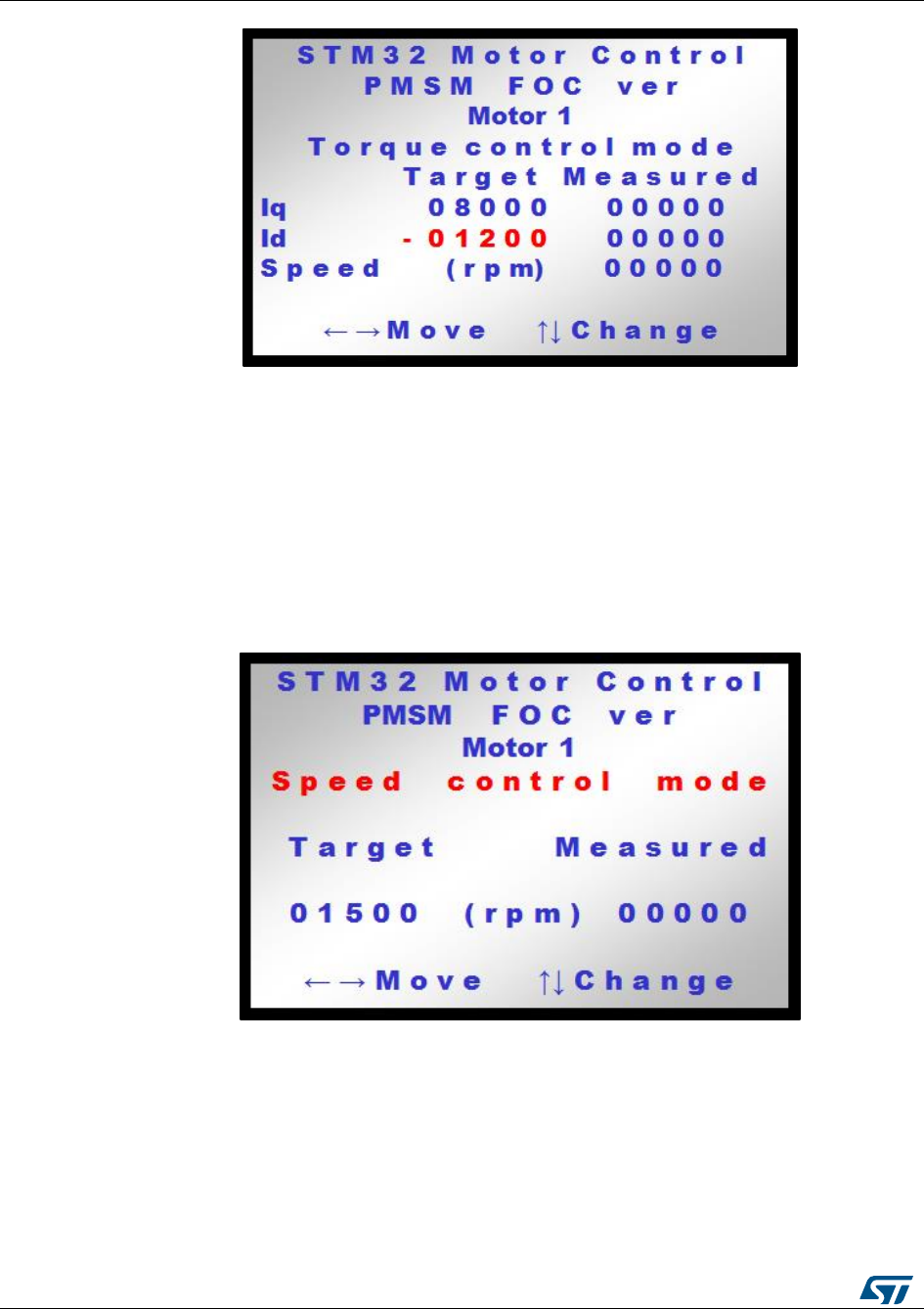
Light LCD user interface
UM1052
144/178
DocID18458 Rev 9
Figure 118: LCD screen for Target Id settings
12.2 Speed control mode
Figure 118: "Speed control main settings" and Figure 119: "LCD screen for setting Target
speed" show two LCD menus used to set control parameters when in Speed control mode.
The parameter highlighted in red color can be set and its value can be modified by acting
on the joystick key.
From the menu screen shown in Figure 118: "Speed control main settings", it is possible to
switch from Torque control to Speed control operations (and vice versa) by moving the
joystick up/down.
Figure 119: Speed control main settings
From the menu screen shown in Figure 118: "Speed control main settings", moving the
joystick to the right selects the Target speed (parameter highlighted in red). Once selected,
the parameter can be incremented/decremented by moving the joystick up/down. The
motor can then be started simply by pressing the joystick. When the motor is on, the target
speed can still be modified.
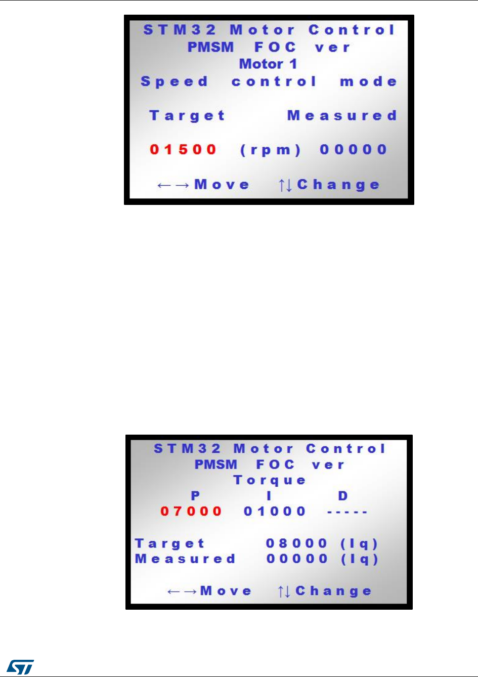
UM1052
Light LCD user interface
DocID18458 Rev 9
145/178
Figure 120: LCD screen for setting Target speed
Like in the torque control mode, the motor is started/stopped by pressing the joystick or the
KEY button.
Since in speed control mode, the torque and flux parameters (Target Iq and Target Id) are
the outputs of the Torque and flux controller, they cannot be set directly. The PID
regulators can however be real-time tuned as explained below.
12.3 Currents and speed regulator tuning
Next figures show the two LCD menus allowing the real-time tuning of the proportional,
integral gains:
Figure 120: "LCD screen for setting the P term of torque PID" shows the screen used to
select either of the torque PID coefficients whereas Figure 121: "LCD screen for setting the
P term of the speed PID" shows the screen used to select either of the flux PID
coefficients. From both screen, either of the P, I coefficient can be selected (highlighted in
red) by moving the joystick to the right/left. Then, each value can be changed (incremented
or decremented) by pressing the joystick up/down.
Figure 121: LCD screen for setting the P term of torque PID
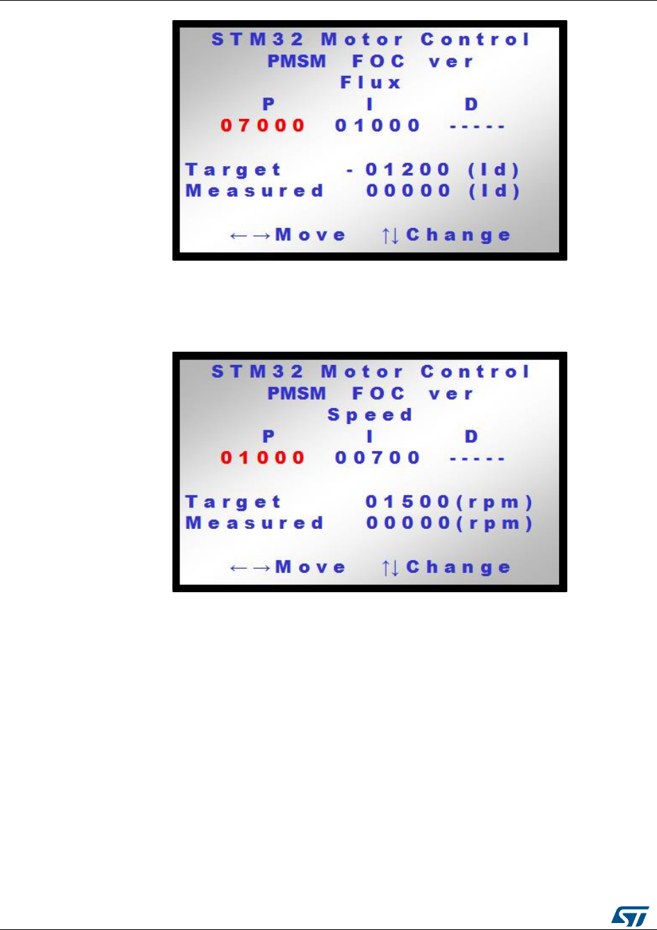
Light LCD user interface
UM1052
146/178
DocID18458 Rev 9
Figure 122: LCD screen for setting the P term of the speed PID
Moreover, to achieve speed regulation in speed control mode, a PI is also implemented.
The tuning of its related gains can be done in real time by means of the dedicated LCD
menu:
Figure 123: LCD screen for setting the P term of the speed PID
Like for the previous menus, either of the P or I coefficients can be selected (highlighted in
red) by moving the joystick to the right/left. The desired values can then be changed
(incremented or decremented) by pressing the joystick up/down.
12.4 Flux-weakening PI controller tuning
This menu is available if the flux-weakening functionality has been enabled in the ST MC
Workbench project.
It is used to real-time tune the proportional and integral gains of the PI regulator used
inside the flux-weakening block.
Either the P coefficient, I coefficient or the target stator voltage Vs can be selected
(highlighted in red) by moving the joystick to the right/left. The desired values can then be
changed (incremented or decremented) by pressing the joystick up/down. Figure 123:
"LCD screen for setting the P term of the flux-weakening PI" shows the screen used for the
tuning operation.
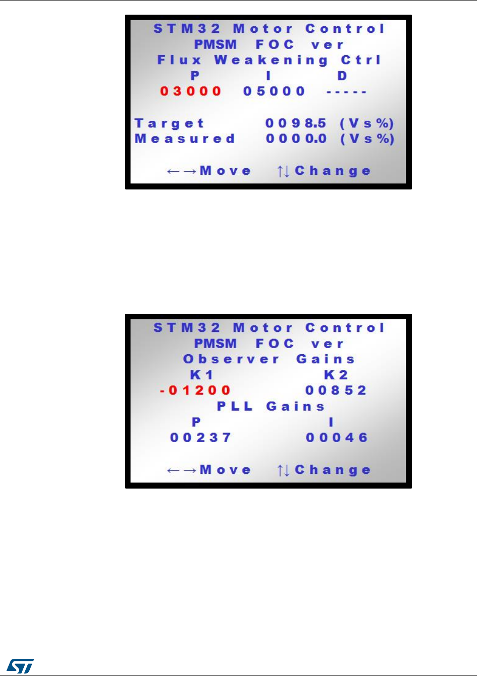
UM1052
Light LCD user interface
DocID18458 Rev 9
147/178
Figure 124: LCD screen for setting the P term of the flux-weakening PI
The target and measured stator voltages are shown in the lower part of the screen as a
percentage of the maximum available phase voltage.
12.5 Observer and PLL gain tuning
When state observer is set as main or auxiliary speed and position sensor in the ST MC
Workbench project, a dedicated menu is shown on the LCD to tune the observer and PLL
gains (Figure 124: "LCD screen for setting the P term of the flux PID").
Figure 125: LCD screen for setting the P term of the flux PID
When the menu in Figure 124: "LCD screen for setting the P term of the flux PID" is
displayed, the joystick can be moved to the right/left to navigate between the different
gains. Pressing the joystick up/down will increment/decrement the gain highlighted in red
color.
This menu is used to change both the observer and the PLL gains in real time. This feature
is particularly useful when used in conjunction with the DAC functionality and with a
firmware configuration handling either Hall effect sensors or an encoder. In this way, it is
possible to modify the observer and PLL gains by looking for example at both the observed
and measured rotor electrical angle and by adjusting the gains so as to cancel any error
between the two waveforms.
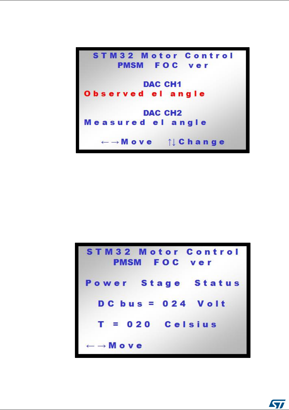
Light LCD user interface
UM1052
148/178
DocID18458 Rev 9
12.6 DAC functionality
When enabled in the ST MC Workbench project, the DAC functionality is a powerful debug
tool which allows the simultaneous tracing of up to two software variables selectable in real
time using a dedicated menu.
Figure 126: LCD screen for setting the P term of the flux PID
When the menu in Figure 125: "LCD screen for setting the P term of the flux PID" is
displayed, the joystick can be moved to the right/left to select the desired DAC channel. To
change the software variable in output, move the joystick up/down (the list of the available
variables depends on the selected firmware configuration). For all other menus, pressing
the joystick or the Key button will cause the motor to start/stop.
12.7 Power stage feedbacks
A dedicated menu was designed to show the value in volts of the DC bus voltage and the
temperature of the heat sink.
Figure 127: Power stage status
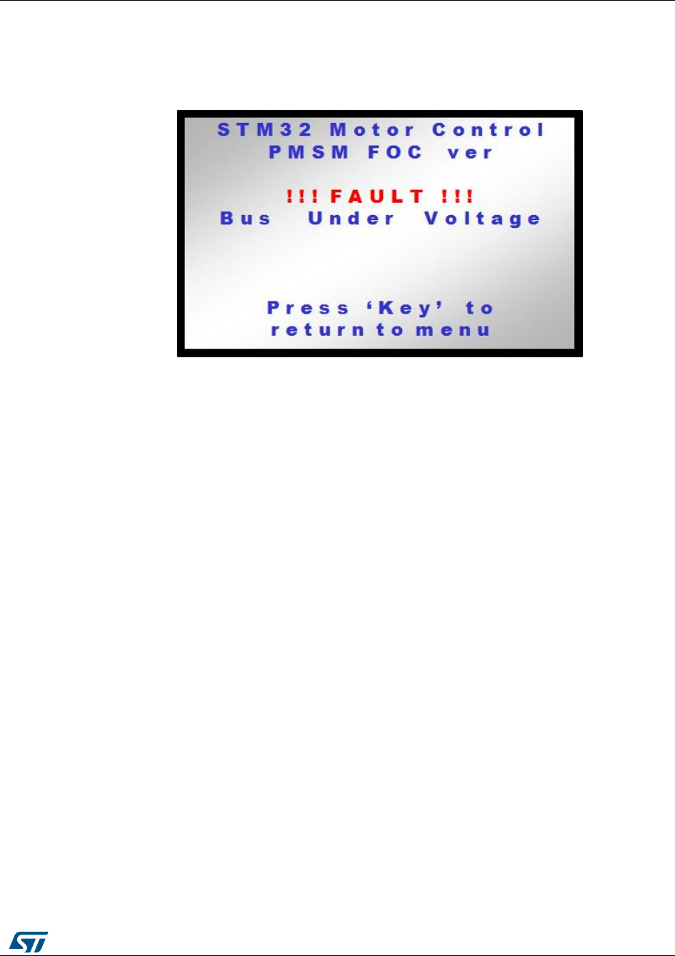
UM1052
Light LCD user interface
DocID18458 Rev 9
149/178
12.8 Fault messages
This section provides a description of all the possible fault messages that can be detected
when using the software library. Figure 127: "Error message shown in the event of an
undervoltage fault" shows a typical error message as displayed on the LCD.
Figure 128: Error message shown in the event of an undervoltage fault
The message “Press ‘Key’ to return to menu” is visible only if the source of the fault has
disappeared. In this case, pressing the ‘Key’ button causes the main state machine to
switch from the Fault occurred state to the Idle state.
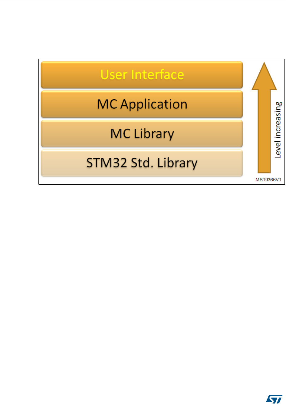
User Interface class overview
UM1052
150/178
DocID18458 Rev 9
13 User Interface class overview
The STM32 FOC motor control firmware is arranged in software layers (Figure 128:
"Software layers"). Each level can include the interface of the next level, with the exception
that the STM32 Std. Library can be included in every level.
Figure 129: Software layers
This section describes the details of the User interface layer. This is the highest software
level present in the released STM32 PMSM FOC Library.
The user interface class (CUI) manages the interaction between the user and the motor
control library (MC Library) via the motor control application layer (MC Application).
In the current implementation, the user interaction can be performed by any of the following
devices: digital to analog converter (DAC), LCD display plus joystick, serial communication.
For each of these devices, one or more derived class of UI object have been implemented
(see Figure 129: "User interface block diagram"):
LCD Manager Class (CLCD_UI) is used to interact with the LCD color display. It has
been implemented over the LCD graphical library STMFC written in C++ language.
Motor control protocol (CMCP_UI) is used to manage serial communications. The
serial communication is implemented over the Frame communication protocol class
CFCP (Transport layer). The CFCP is, in turn, implemented over a physical layer
communication class CCOM (Physical layer). Daughter classes of CCOM are
CUSART_COM, CI2C_COM and CSPI_COM. Presently only the CUSART_COM, that
implements the physical serial communication using the USART channel, has been
implemented and only with a PC master microcontroller slave configuration.
DAC manager (CDAC_UI) is used to manage the DAC outputs using a real DAC
peripheral. This is the default setting when DAC output is enabled using the
STM32F0xx, STM32F100 (Value line), STM32F103xE (High density), STM32F2xx,
STM32F30x or STM32F4xx devices.
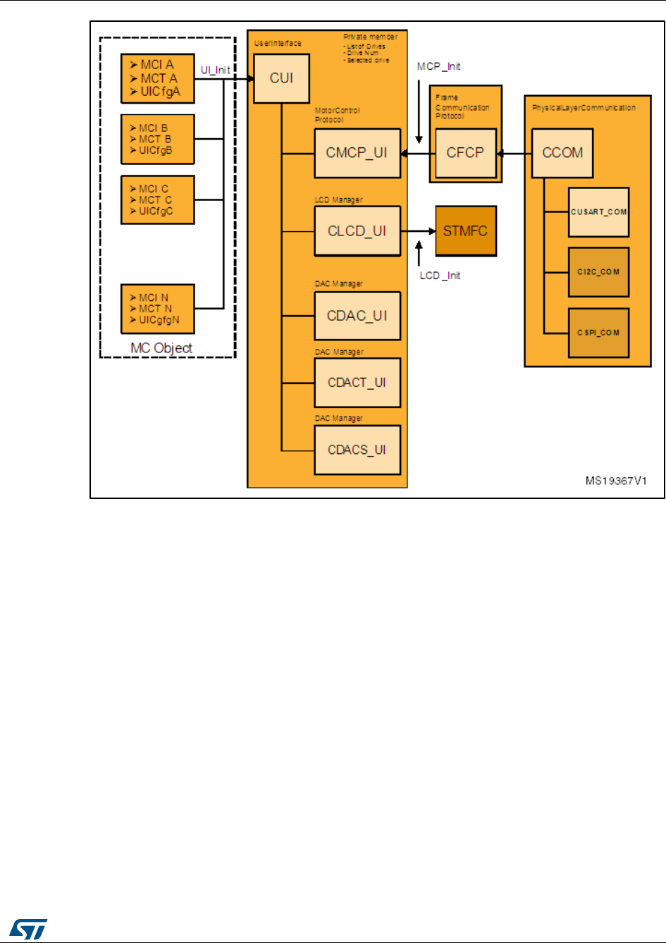
UM1052
User Interface class overview
DocID18458 Rev 9
151/178
Figure 130: User interface block diagram
The DAC manager (CDACT_UI) manages DAC outputs using a virtual DAC
implemented with a filtered PWM output generated by a timer peripheral. This is the
default setting when a DAC output is enabled using the STM32F103xB (Medium
density) device.
CDACS_UI does not perform a digital to analog conversion but sends the output
variables through an SPI communication.
13.1 User interface class (CUI)
This class implements the interaction between the user and the motor control library (MC
Library) using the motor control application layer (MC Application). In particular, the CUI
object is to be used to read or write relevant motor control quantities (for example,
Electrical torque, Motor speed) and to execute the motor control commands exported by
the MC Application (for example, Start motor, execute speed or torque ramps, customize
the startup). Any object of this class must be linked to a derived class object.
The user interface class requires the following steps (implemented inside the UI_Init.
method):
1. Defines the number of motor drives managed by user interface objects. The
implementation of the MC firmware manages at most two motor drives. The CUI can
manage N drivers.
2. Creates the link between MC tuning (MCT) MC interface (MCI) objects and user
interface objects.

User Interface class overview
UM1052
152/178
DocID18458 Rev 9
See Section 12.1: "MCInterfaceClass" and Section 12.2: "MCTuningClass" for more
information about MCI and MCT.
3. Configures the options of user interface objects. See Section 15.2: "User interface
configuration".
Once initialized, the UI object is able to:
1. Get and set the selected motor control drive that the UI operates on
(UI_GetSlectedMC/UI_SelectMC). For example, UI_SelectMC is required in the case
of a dual motor control, in order to select the active drive to which commands are
applied (for example, Set/Get register, start motor).
2. Get and set registers (UI_SetReg/UI_GetReg). A register is a relevant MC quantity
that can be exported from, or imposed to, MC objects through MCI / MCT. The list of
this quantity MC_PROTOCOL_REG_xxx is exported by UserInterfaceClass.h. See
STM32 FOC PMSM FW library v3_3 developer Help file.chm.
For example, to set up the proportional term of the speed controller of the second
motor:
A similar sequence can be used to get values from MC objects replacing the
UI_SetReg method with the UI_GetReg method.
a. Obtain the oMCT and oMCI object through GetMCIList, GetMCTList functions,
exported by MCTasks.h. The oMCI and oMCT are two arrays of objects. CMCI
oMCI[MC_NUM];
CMCT oMCT[MC_NUM];
...
GetMCIList(oMCI);
GeMCTList(oMCT);
...
b. Instantiate and initialize a CUI object. oUI = UI_NewObject(MC_NULL);
UI_Init(oUI, MC_NUM, oMCI, oMCT, MC_NULL);
c. Select the motor drives UI_SelectMC(oUI, 2);
d. Set the MC_PROTOCOL_REG_SPEED_KP register value.> UI_SetReg(oUI,
MC_PROTOCOL_REG_SPEED_KP, <Desired value>);
3. Execute an MC command (UI_ExecCmd). The list of available MC commands
MC_PROTOCOL_CMD_xxx is exported by UserInterfaceClass.h. See STM32 FOC
PMSM FW library developer Help file.chm.
For example, to execute a Start command to the first motor:
a. Obtain the oMCT and oMCI object through GetMCIList, GetMCTList functions,
exported by MCTasks.h. The oMCI and oMCT are two arrays of objects. CMCI
oMCI[MC_NUM];
CMCT oMCT[MC_NUM];
...
GetMCIList(oMCI);
GeMCTList(oMCT);
...
b. Instantiate and initialize a CUI object. oUI = UI_NewObject(MC_NULL);
UI_Init(oUI, MC_NUM, oMCI, oMCT, MC_NULL);
c. Select the motor drivesUI_SelectMC(oUI, 2);
d. Provide a command (for example, Start motor).UI_ExecCmd (oUI,
MC_PROTOCOL_CMD_START_MOTOR);
4. Execute torque and speed ramps, set the current reference, and set or get revup data.
See STM32 FOC PMSM FW library developer Help file.chm.
5. Execute specific functions dedicated to CDAC objects. See Section 15.7: "DAC
manager class (CDACx_UI)".
UM1052
User Interface class overview
DocID18458 Rev 9
153/178
All derived classes of CUI act on MCI and MCT objects through the CUI methods.
For instance, the LCD manager updates a motor control quantity calling
UI_SetReg method and so on.
13.2 User interface configuration
A user interface object and its derivatives are configured using a 32-bit configuration value
(see Figure 130: "User interface configuration bit field").
The first byte of this register contains the sensor configuration. Each sensor is defined
using 4 bits. The values UI_SCODE_xxx are exported by UserInterfaceClass.h. See Table
36: "User interface configuration - Sensor codes".
The first 4-bit defines the main speed and position sensor. The second 4-bit defines the
auxiliary speed and position sensor. 1
Figure 131: User interface configuration bit field
The remaining bit field values UI_CFGOPT_xxx are exported by UserInterfaceClass.h. See
Table 37: "User interface configuration - CFG bit descriptions".
To configure the user interface object, the configuration should be passed in the UI_Init
function as the 5th parameter. The 5th parameter of the UI_Init function is an array of
configuration values, one for each motor drive.
The 32-bit configuration value is automatically computed by a preprocessor in the
Parameters conversion.h file, based on the configuration present in the System &
Drive Params folder. It can be manually edited by the user.
Table 36: User interface configuration - Sensor codes
Code
Description
UI_SCODE_HALL
This code identifies the Hall sensor
UI_SCODE_ENC
This code identifies the Encoder sensor
UI_SCODE_STO_PLL
This code identifies the State observer + PLL sensor
UI_SCODE_STO_CR
This code identifies the State observer + CORDIC sensor
Table 37: User interface configuration - CFG bit descriptions
Code
Description
UI_CFGOPT_NONE
Enable this option when no other option is selected
Main sensor Auxiliary sensor Reserved Reserved CFG
4 bit 4 bit 8 bit 8 bit 8 bit
Reserved PLL tuning Set ld in Spd DAC ldKd lqKd SpeedKd Flux weaking
CFG 8 bit
User Interface class overview
UM1052
154/178
DocID18458 Rev 9
Code
Description
UI_CFGOPT_FW
Enable this option when the flux weakening is enabled in the
MC firmware
UI_CFGOPT_SPEED_K
D
Enable this option when the speed controller has a derivative
action
UI_CFGOPT_Iq_KD
Enable this option when the Iq controller has a derivative action
UI_CFGOPT_Id_KD
Enable this option when the Id controller has a derivative action
UI_CFGOPT_DAC
Enable this option if a DAC object is associated with the UI
UI_CFGOPT_SETIDIN
SPDMODE
Enable this option to allow setting the Id reference when MC is in
speed mode
UI_CFGOPT_PLLTUNI
NG
Enable this option to allow the PLL KP and KI setting
13.3 LCD manager class (CLCD_UI)
This is a derived class of UI that implements the management of the LCD screen. It is
based on the LCD graphical library STMFC written in C++ language.
A functional block diagram of LCD manager is shown in Figure 131: "LCD manager block
diagram".
The MC objects (MCI/MCT) are linked to the LCD manager by the UI_Init and are
accessed only by base class methods.
Figure 132: LCD manager block diagram
The LCD_Interface is a module written in C++ that performs the interface between UI
objects and the STMFC library.

UM1052
User Interface class overview
DocID18458 Rev 9
155/178
When LCD_Init or LCD_UpdateAll are called, the LCDI_UpdateAll method is also called
and updates all values of the LCD GUI. You can also call LCDI_UpdateMesured to update
only the measured quantity (the quantity that changes inside the MC object itself, such as
measured speed, measure Iq).
13.4 Using the LCD manager
To use the LCD manager, you must:
1. Obtain the oMCT and oMCI object through GetMCIList, GetMCTList functions,
exported by MCTasks.h. The oMCI and oMCT are two arrays of objects. CMCI
oMCI[MC_NUM];
CMCT oMCT[MC_NUM];
...
GetMCIList(oMCI);
GeMCTList(oMCT);
...
2. Instantiate and initialize an CLCD_UI object. CLCD_UI oLCD =
LCD_NewObject(MC_NULL);
UI_Init((CUI)oLCD, MC_NUM, oMCI, oMCT, pUICfg);
LCD_Init(oLCD, (CUI)oDAC, s_fwVer);
Note that you must call both UI_Init and LCD_Init. LCD_Init must be called after
UI_Init.
pUICfg is the user interface configurations array. See Section 15.2: "User
interface configuration".
oDAC is the related DAC object that should be driven by the LCD manager. This
DAC object should be correctly instantiated before the LCD_Init calls. See the
DAC manager class (CDAC).
s_fwVer is a string that will be displayed in the LCD (See Figure 104: "STM32
Motor Control demonstration project welcome message") containing both the
Firmware version and Release version; it must be separated by the 0x0
character.
3. Periodically call the LCD_UpdateMeasured method. This updates LCD GUI variables
and calls the LCD_Exec method that performs the LCD screen refresh.
LCD_Exec(oLCD);
LCD_UpdateMeasured(oLCD);
These functions are performed inside UITask.c. The LCD refresh also uses Timebase.c or
RTOS.
13.5 Motor control protocol class (CMCP_UI)
This is a derived class of UI that is based on the serial communication. This class is on the
top layer of the serial communication architecture (See Figure 132: "Serial communication
software layers") and manages the highest level of the motor control protocol.
User Interface class overview
UM1052
156/178
DocID18458 Rev 9
Figure 133: Serial communication software layers
The frame communication protocol (CFCP) implements the transport layer of the serial
communication. It is responsible for the correct transfer of the information, CRC checksum
and so on.
The CCOM class implements the physical layer, through its derivatives. For each physical
communication channel, there is a specific derivative of the CCOM object. Only the USART
channel has been implemented so far (by CUSART_COM class).
13.6 Using the motor control protocol
1. Obtain the oMCT and oMCI object through GetMCIList and GetMCTList functions,
exported by MCTasks.h. oMCI and oMCT are two arrays of objects. CMCI
oMCI[MC_NUM];
CMCT oMCT[MC_NUM];
GetMCIList(oMCI);
GeMCTList(oMCT);
...
2. MCP parameters, Frame parameters and USART parameters are defined in
USARTParams.h and can be modified if required.
3. Instantiate and initialize CMCP_UI, CFCP, and COM objects. CMCP_UI oMCP =
MCP_NewObject(MC_NULL,&MCPParams)
CFCP oFCP = FCP_NewObject(&FrameParams_str);
FCP_Init(oFCP, (CCOM)oUSART);
UI_Init((CUI)oMCP, bMCNum, oMCIList, oMCTList, pUICfg);
Note that you must call both MCP_Init and UI_Init.
pUICfg is the user interface configurations array. See Section 15.2: "User
interface configuration".
oDAC is the related DAC object that should be driven by the LCD manager. This
DAC object should be correctly instantiated before the LCD_Init calls. See the
DAC manager class (CDAC).
s_fwVer is a string containing the Firmware version and Release version. It is
separated by the 0x0 character that will be sent back to PC after a "get firmware
info" command.
4. Manage the serial communication timeout. After the first byte has been received by
the microcontroller, a timeout timer is started. If all the expected bytes of the frame
sequence have been received, the timeout counter is stopped. On the contrary, if the

UM1052
User Interface class overview
DocID18458 Rev 9
157/178
timeout occurs, the timeout event must be handled calling:
Exec_UI_IRQ_Handler(UI_IRQ_USART,3,0);
These functions are performed inside UITask.c. The time base for serial
communication timeout also uses Timebase.c or RTOS, by default.
13.7 DAC manager class (CDACx_UI)
There are three derivatives of CUI that implement DAC management:
DAC_UI (DAC_UI): DAC peripheral used as the output.
DACRCTIMER_UI (DACT_UI): General purpose timer used and output together with
an RC filter.
DACSPI_UI (DACS_UI): SPI peripheral used as the output. The data can be codified
by an oscilloscope, for instance.
For each DAC class, the number of channels (two) is defined. The DAC variables are
predefined motor control variables or user defined variables that can be output by DAC
objects. DAC variables can be any MC_PROTOCOL_REG_xxx value exported by
UserInterfaceClass.h. Table 38: "Description of relevant DAC variables " describes a set of
relevant motor control quantities.
Table 38: Description of relevant DAC variables
Variable name
Description
MC_PROTOCOL_REG_I_A
Measured phase A motor current.
MC_PROTOCOL_REG_I_B
Measured phase B motor current.
MC_PROTOCOL_REG_I_ALPHA
Measured alpha component of motor
phase's current expressed in alpha/beta
reference.
MC_PROTOCOL_REG_I_BETA
Measured beta component of motor phase's
current expressed in alpha/beta reference.
MC_PROTOCOL_REG_I_Q
Measured "q" component of motor phase's
current expressed in q/d reference.
MC_PROTOCOL_REG_I_D
Measured "d" component of motor phase's
current expressed in q/d reference.
MC_PROTOCOL_REG_I_Q_REF
Target "q" component of motor phase's
current expressed in q/d reference.
MC_PROTOCOL_REG_I_D_REF
Target "d" component of motor phase's
current expressed in q/d reference.
MC_PROTOCOL_REG_V_Q
Forced "q" component of motor phase's
voltage expressed in q/d reference.
MC_PROTOCOL_REG_V_D
Forced "d" component of motor phase's
voltage expressed in q/d reference.
MC_PROTOCOL_REG_V_ALPHA
Forced alpha component of motor phase's
voltage expressed in alpha/beta reference.
MC_PROTOCOL_REG_V_BETA
Forced beta component of motor phase's
voltage expressed in alpha/beta reference.

User Interface class overview
UM1052
158/178
DocID18458 Rev 9
Variable name
Description
MC_PROTOCOL_REG_MEAS_EL_ANGLE
Measured motor electrical angle. This
variable is related to a "real" sensor
(encoder, Hall) configured as a primary or
auxiliary speed sensor.
MC_PROTOCOL_REG_MEAS_ROT_SPEED
Measured motor speed. This variable is
related to a "real" sensor (encoder, Hall)
configured as a primary or auxiliary speed.
MC_PROTOCOL_REG_OBS_EL_ANGLE
Observed motor electrical angle. This
variable is related to a "state observer +
PLL" sensor configured as a primary or
auxiliary speed sensor.
MC_PROTOCOL_REG_OBS_ROT_SPEED
Observed motor speed. This variable is
related to a "state observer+ PLL" sensor
configured as a primary or auxiliary speed
sensor.
MC_PROTOCOL_REG_OBS_I_ALPHA
Observed alpha component of motor
phase's current expressed in alpha/beta
reference. This variable is related to a "state
observer + PLL" sensor configured as a
primary or auxiliary speed sensor.
MC_PROTOCOL_REG_OBS_I_BETA
Observed beta component of motor phase's
current expressed in alpha/beta reference.
This variable is related to a "state observer
+ PLL" sensor configured as a primary or
auxiliary speed sensor.
MC_PROTOCOL_REG_OBS_BEMF_ALPHA
Observed alpha component of motor BEMF
expressed in alpha/beta reference. This
variable is related to a "state observer +
PLL" sensor configured as a primary or
auxiliary speed sensor.
MC_PROTOCOL_REG_OBS_BEMF_BETA
Observed beta component of motor BEMF
expressed in alpha/beta reference. This
variable is related to a "state observer +
PLL" sensor configured as a primary or
auxiliary speed sensor.
MC_PROTOCOL_REG_OBS_CR_EL_ANGLE
Observed motor electrical angle. This
variable is related to a "state observer +
CORDIC" sensor configured as a primary or
auxiliary speed sensor.
MC_PROTOCOL_REG_OBS_CR_ROT_SPEED
Observed motor speed. This variable is
related to a "state observer+ CORDIC"
sensor configured as a primary or auxiliary
speed sensor.
MC_PROTOCOL_REG_OBS_CR_I_ALPHA
Observed alpha component of motor
phase's current expressed in alpha/beta
reference. This variable is related to a "state
observer + CORDIC" sensor configured as
a primary or auxiliary speed sensor.

UM1052
User Interface class overview
DocID18458 Rev 9
159/178
Variable name
Description
MC_PROTOCOL_REG_OBS_CR_I_BETA
Observed beta component of motor phase's
current expressed in alpha/beta reference.
This variable is related to a "state observer
+ CORDIC" sensor configured as a primary
or auxiliary speed sensor.
MC_PROTOCOL_REG_OBS_CR_BEMF_ALPHA
Observed alpha component of motor BEMF
expressed in alpha/beta reference. This
variable is related to a "state observer +
CORDIC" sensor configured as a primary or
auxiliary speed sensor.
MC_PROTOCOL_REG_OBS_CR_BEMF_BETA
Observed beta component of motor BEMF
expressed in alpha/beta reference. This
variable is related to a "state observer +
CORDIC" sensor configured as a primary or
auxiliary speed sensor.
MC_PROTOCOL_REG_DAC_USER1
User defined DAC variable. Section 15.9:
"How to configure the user defined DAC
variables" describes how to configure user
defined DAC variables.
MC_PROTOCOL_REG_DAC_USER2
User defined DAC variable. Section 15.9:
"How to configure the user defined DAC
variables" describes how to configure user
defined DAC variables.
Each DAC variable can be selected to be output to a DAC channel. The DAC channel is
physically put in the output by calling the UI_DACExec method.
13.8 Using the DAC manager
1. Obtain the oMCT and oMCI object through GetMCIList, and GetMCTList functions,
exported by MCTasks.h. oMCI and oMCT are two arrays of objects. CMCI
oMCI[MC_NUM];
CMCT oMCT[MC_NUM];
...
GetMCIList(oMCI);
GeMCTList(oMCT);
...
2. Instantiate and initialize CDACx_UI objects. Choose the correct CDACx_UI object
based on the hardware setting. CDACx_UI oDAC =
DACT_NewObject(MC_NULL,MC_NULL);
UI_Init((CUI)oDAC, bMCNum, oMCIList, oMCTList, pUICfg);
UI_DACInit((CUI)oDAC);
Note that you must call both UI_Init and UI_DACInit.
pUICfg is the user interface configuration array. See Section 15.2: "User interface
configuration".
3. Configure the DAC variables for each DAC channel.
UI_DACChannelConfig((CUI)oDAC, DAC_CH0, MC_PROTOCOL_REG_I_A);
UI_DACChannelConfig((CUI)oDAC, DAC_CH1, MC_PROTOCOL_REG_I_B);
In this case, the motor current Ia and Ib will be put in output.
4. Periodically update the DAC output by calling the UI_DACExec method that performs
the update of DAC channel into the physical output.

User Interface class overview
UM1052
160/178
DocID18458 Rev 9
These functions are performed inside UITask.c. For the update, the DAC outputs also use
stm32fxxx_MC_it.c.
The default variables that is selected after each reset of the microcontroller can be
selected in the ST MC Workbench->Control stage->DAC
13.9 How to configure the user defined DAC variables
Two user-defined DAC variables can be put as analog outputs. These variables enable
custom debugging on variables that change in real-time, and monitor the correlation with
relevant motor control values such as real/measured currents. You cannot put more than
two DAC variables (motor control predefined or user-defined) in the output.
To store the user value in a user-defined DAC variable, follow these steps:
1. Obtain the oDAC DAC objects through the GetDAC function exported by UITask.h.
2. Call the UI_DACSetUserChannelValue method of a CUI object to update the content
of a user defined DAC variable. UI_DACSetUserChannelValue(oDAC,0,hUser1);
In this case, the hUser1 value is set in the first (0) user-defined DAC variable.
3. Configure user-defined DAC variables to be put in output using the
UI_DACChannelConfig method, or put the user-defined variables in the output using
the LCD/Joystick interface (see Section 13.2.3: "Configuration and debug page").
UI_DACChannelConfig((CUI)oDAC, DAC_CH0,
MC_PROTOCOL_REG_DAC_USER1);
4. The user value is physically put in the output when UI_DACExec is executed.
UITask.c performs the following:UI_DACExec((CUI)oDAC);
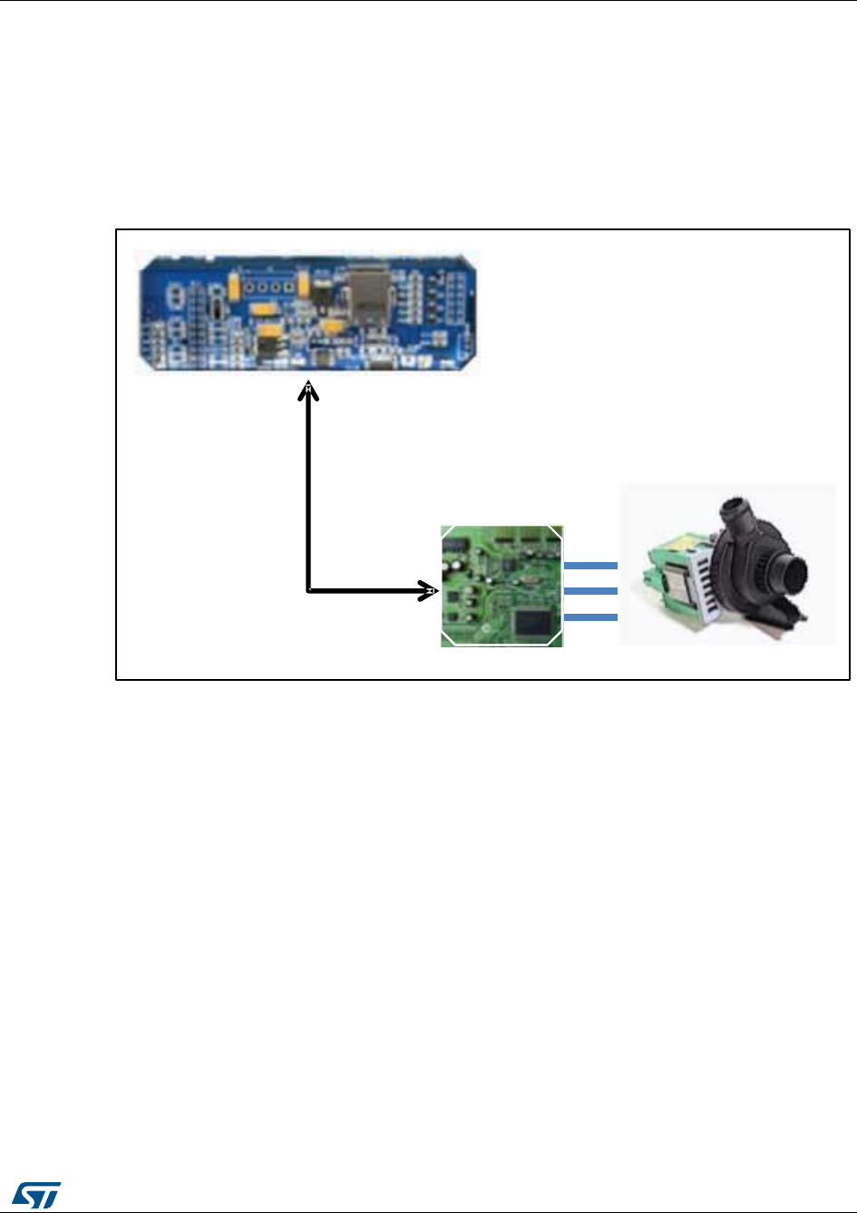
UM1052
Serial communication class overview
DocID18458 Rev 9
161/178
14 Serial communication class overview
Applications on the market, that require an electrical motor to be driven, usually have the
electronics split in two parts: application board and motor drive board.
To drive the system correctly, the application board requires a method to send a command
to the motor drive board and get a feedback. This is usually performed using a serial
communication. See Figure 133: "Serial communication in motor control application".
Figure 134: Serial communication in motor control application
To target this kind of application, a dedicated serial communication protocol has been
developed for real-time data exchange. The aim of this protocol is to implement the feature
requested by motor control related applications. The implemented protocol is called motor
control protocol (MCP).
MCP makes it possible to send commands such as start/stop motor and set the target
speed to the STM32 FOC motor control firmware, and also to tune in real-time relevant
control variables such as PI coefficients. It is also possible to monitor relevant quantities,
such as the speed of the motor or the bus voltage present in the board related to the
controlled system.
The implemented communication protocol is based on a master-slave architecture in which
the motor control firmware, running on an STM32 microcontroller, is the slave.
The master, usually a PC or another microcontroller present on a master board, can start
the communication at any time by sending the first communication frame to the slave. The
slave answers this frame with the acknowledge frame. See Figure 134: "Master-slave
communication architecture".
Application board
Motor
Drive
Board
Serial communication
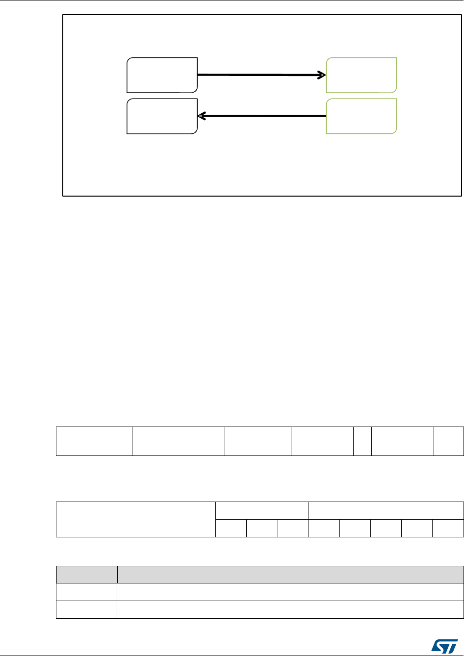
Serial communication class overview
UM1052
162/178
DocID18458 Rev 9
Figure 135: Master-slave communication architecture
The implemented MCP is based on the physical layer that uses the USART
communication.
A generic starting frame (Table 39: "Generic starting frame") is composed of:
Frame_start: this byte defines the type of starting frame. The least significant 5 bits
indicate the frame identifier. The most significant 3 bits indicate the motor selection.
See Table 40: "FRAME_START byte".
Payload_Length: the total number of bytes that compose the frame payload
Payload_ID: first byte of the payload that contains the identifier of payload. Not
necessary if not required by this type of frame.
Payload[x]: the remaining payload content. Not necessary if not required by this type
of frame.
CRC: byte used for cyclic redundancy check.
The CRC byte is computed as follows:
Table 39: Generic starting frame
FRAME_STA
RT
PAYLOAD_LENG
TH
PAYLOAD_I
D
PAYLOAD[
0]
..
.
PAYLOAD[
n]
CR
C
Table 42: "Starting frame codes " shows the list of possible starting frames.
Table 40: FRAME_START byte
FRAME_START
Motor
FRAME_ID
7
6
5
4
3
2
1
0
Table 41: FRAME_START motor bits
FRAME_ID
Motor bit
000
The command is applied to the last motor selected
001
The command is applied to motor 1; motor 1 is selected from now on
Master Slave
Starting frame
Master Slave
Acknowledgment frame
UM1052
Serial communication class overview
DocID18458 Rev 9
163/178
FRAME_ID
Motor bit
010
The command is applied to motor 2; motor 2 is selected from now on (this
can be accepted only in dual drive)
Table 42: Starting frame codes
Frame_ID
Description
0x01
Set register frame. It is used to write a value into a relevant motor control
variable. See Set register frame.
0x02
Get register frame. It is used to read a value from a relevant motor control
variable. See Get register frame.
0x03
Execute command frame. It is used to send a command to the motor control
object. See Execute command frame.
0x06
Get board info. It is used to retrieve information about the firmware currently
running on the microcontroller.
0x07
Exec ramp. It is used to execute a speed ramp. See Section 16.4: "Execute
ramp frame".
0x08
Get revup data. It is used to retrieve the revup parameters. See Section 16.5:
"Get revup data frame".
0x09
Set revup data. It is used to set the revup parameters. See Section 16.6: "Set
revup data frame".
0x0A
Set current references. It is used to set the current reference. See Section
16.7: "Set current references frame"
14.1 Set register frame
The set register frame (Figure 135: "Set register frame") is sent by the master to write a
value into a relevant motor control variable.
Figure 136: Set register frame
The payload length depends on REG_ID (See Table 43: "List of error codes").
0x01 PAYLOAD_LENGTH REG_ID REG_LB …REG_HB CRC
PC
0xFF ERROR_CODE CRC
BOARD 0x1
0xF0 CRC0x00
OR
Error Acknowledgment frame
Data Acknowledgment frame, No errors
Set register frame
0x01 PAYLOAD_LENGTH REG_ID REG_LB …REG_HB CRC
PC
Set register frame
BOARD

Serial communication class overview
UM1052
164/178
DocID18458 Rev 9
Reg Id indicates the register to be updated.
The remaining payload contains the value to be updated, starting from the least significant
byte to the most significant byte.
The Acknowledgment frame can be of two types:
Data Acknowledgment frame, if the operation has been successfully completed. The
payload of this Data Acknowledgment frame is zero.
Error Acknowledgment frame, if the operation has not been successfully completed by
the firmware. The payload of this Error Acknowledgment frame is always 1. The list of
error codes is shown in Table 43: "List of error codes".
Table 43: List of error codes
Error code
Description
0x01
BAD Frame ID. The Frame ID has not been recognized by the firmware.
0x02
Write on read-only. The master wants to write on a read-only register.
0x03
Read not allowed. The value cannot be read.
0x04
Bad target drive. The target motor is not supported by the firmware.
0x05
Out of range. The value used in the frame is outside the range expected by
the firmware.
0x07
Bad command ID. The command ID has not been recognized.
0x08
Overrun error. The frame has not been received correctly because the
transmission speed is too fast.
0x09
Timeout error. The frame has not been received correctly and a timeout
occurs. This kind of error usually occurs when the frame is not correct or is
not correctly recognized by the firmware.
0x0A
Bad CRC. The computed CRC is not equal to the received CRC byte.
0x0B
Bad target drive. The target motor is not supported by the firmware.
Table 44: "List of relevant motor control registers " indicates the following for each of the
relevant motor control registers:
Type (u8 8-bit unsigned, u16 16-bit unsigned, u32 32-bit unsigned, s16 16-bit signed,
s32 32-bit signed)
Payload length in Set register frame
allowed access (R read, W write)
Reg Id
Table 44: List of relevant motor control registers
Register name
Type
Payload
length
Access
Reg
Id
Target motor
u8
2
RW
0x00
Flags
u32
5
R
0x01
Status
u8
2
R
0x02
Control mode
u8
2
RW
0x03
Speed reference
s32
5
R
0x04

UM1052
Serial communication class overview
DocID18458 Rev 9
165/178
Register name
Type
Payload
length
Access
Reg
Id
Speed KP
u16
3
RW
0x05
Speed KI
u16
3
RW
0x06
Speed KD
u16
3
RW
0x07
Torque reference (Iq)
s16
3
RW
0x08
Torque KP
u16
3
RW
0x09
Torque KI
u16
3
RW
0x0A
Torque KD
u16
3
RW
0x0B
Flux reference (Id)
s16
3
RW
0x0C
Flux KP
u16
3
RW
0x1D
Flux KI
u16
3
RW
0x1E
Flux KD
u16
3
RW
0x1F
Observer C1
s16
3
RW
0x10
Observer C2
s16
3
RW
0x11
Cordic Observer C1
s16
3
RW
0x12
Cordic Observer C2
s16
3
RW
0x13
PLL KI
u16
3
RW
0x14
PLL KP
u16
3
RW
0x15
Flux weakening KP
u16
3
RW
0x16
Flux weakening KI
u16
3
RW
0x17
Flux weakening BUS Voltage allowed
percentage reference
u16
3
RW
0x18
Bus Voltage
u16
3
R
0x19
Heatsink temperature
u16
3
R
0x1A
Motor power
u16
3
R
0x1B
DAC Out 1
u8
2
RW
0x1C
DAC Out 2
u8
2
RW
0x1D
Speed measured
s32
5
R
0x1E
Torque measured (Iq)
s16
3
R
0x1F
Flux measured (Id)
s16
3
R
0x20
Flux weakening BUS Voltage allowed
percentage measured
u16
3
R
0x21
Revup stage numbers
u8
2
R
0x22
Maximum application speed
u32
5
R
0x3F
Minimum application speed
u32
5
R
0x40
Serial communication class overview
UM1052
166/178
DocID18458 Rev 9
Register name
Type
Payload
length
Access
Reg
Id
Iq reference in speed mode
s16
3
W
0x41
Expected BEMF level (PLL)
s16
3
R
0x42
Observed BEMF level (PLL)
s16
3
R
0x43
Expected BEMF level (CORDIC)
s16
3
R
0x44
Observed BEMF level (CORDIC)
s16
3
R
0x45
Feedforward (1Q)
s32
5
RW
0x46
Feedforward (1D)
s32
5
RW
0x47
Feedforward (2)
s32
5
RW
0x48
Feedforward (VQ)
s16
3
R
0x49
Feedforward (VD)
s16
3
R
0x4A
Feedforward (VQ PI out)
s16
3
R
0x4B
Feedforward (VD PI out)
s16
3
R
0x4C
Ramp final speed
s32
5
RW
0x5B
Ramp duration
u16
3
RW
0x5C
14.2 Get register frame
The get register frame (Figure 136: "Get register frame") is sent by the master to read a
value from a relevant motor control variable.
Figure 137: Get register frame
Payload length is always 1.
Reg Id indicates the register to be queried (See Table 44: "List of relevant motor control
registers ").
The Acknowledgment frame can be of two types:
0x02 REG_ID CRC
0xFF ERROR_CODE CRC0x1
0x1
0xF0 PAYLOAD_LENGTH REG_LB …REG_HB CRC
Error Acknowledgment frame
DataAcknowledgment frame, No errors
Get register frame
0x02 REG_ID CRC0x1
Get register frame
OR
PC
BOARD
PC
BOARD
UM1052
Serial communication class overview
DocID18458 Rev 9
167/178
Data Acknowledgment frame, if the operation has been successfully completed. In this
case, the returned value is embedded in the Data Acknowledgment frame. The size of
the payload depends on Reg Id and is equal to the Payload length present in Table
44: "List of relevant motor control registers " minus 1. The value is returned starting
from the least significant byte to the most significant byte.
Error Acknowledgment frame, if the operation has not been successfully completed by
the firmware. The payload of this Error Acknowledgment frame is always 1. The list of
error codes is shown in Table 43: "List of error codes".
14.3 Execute command frame
The execute command frame (Figure 137: "Execute command frame") is sent by the
master to the motor control firmware to request the execution of a specific command.
Figure 138: Execute command frame
Payload length is always 1.
Command Id indicates the requested command (See Table 45: "List of commands").
The Acknowledgment frame can be of two types:
Data Acknowledgment frame, if the operation has been successfully completed. In this
case, the returned value embedded in the Data Acknowledgment frame is an echo of
the same Command Id. The size of payload is always 1.
Error Acknowledgment frame, if the operation has not been successfully completed by
the firmware. The payload of this Error Acknowledgment frame is always 1. The list of
error codes is shown in Table 43: "List of error codes".
Table 45: "List of commands" indicates the list of commands:
Table 45: List of commands
Command
Command ID
Description
Start Motor
0x01
Indicates the user request to start the motor regardless
the state of the motor.
Stop Motor
0x02
Indicates the user request to stop the motor regardless
the state of the motor.
Stop Ramp
0x03
Indicates the user request to stop the execution of the
speed ramp that is currently executed
PC
BOARD
0x03 COMMAND_ID CRC0x1
0xFF ERROR_CODE CRC0x1
0xF0 CRC0x00
OR
Executecommandframe
DataAcknowledgment frame, No errors
Error Acknowledgment frame
PC 0x03 COMMAND_ID CRC0x1
Executecommandframe
BOARD
Serial communication class overview
UM1052
168/178
DocID18458 Rev 9
Command
Command ID
Description
Start/Stop
0x06
Indicates the user request to start the motor if the motor
is still, or to stop the motor if it runs.
Fault Ack
0x07
Communicates the user acknowledges of the occurred
fault conditions.
Encoder
Align
0x08
Indicates the user request to perform the encoder
alignment procedure.
14.4 Execute ramp frame
The execute ramp frame (Figure 138: "Execute ramp frame") is sent by the master to the
motor control firmware, to request the execution of a speed ramp.
A speed ramp always starts from the current motor speed, and is defined by a duration and
a final speed. See Figure 139: "Speed ramp".
Figure 139: Execute ramp frame
Payload length is always 6.
The four bytes FS[x] represent the final speed expressed in rpm least significant byte and
most significant byte.
DR_LB and DR_HB represent the duration expressed in milliseconds, respectively least
significant byte and most significant byte.
The Acknowledgment frame can be of two types:
Data Acknowledgment frame, if the operation has been successfully completed. The
payload of this Data Acknowledgment frame will be zero.
Error Acknowledgment frame, if the operation has not been successfully completed by
the firmware. The payload of this Error Acknowledgment frame is always 1. The list of
error codes is shown in Table 43: "List of error codes".
OR
BOARD 0xF0 CRC0x00
Data Acknowledgment frame, No errors
Executeramp frame
0x07 0x06 CRC
PC FS_[x] DR_LB DR_HB
Executeramp frame
PC
0xFF ERROR_CODE CRC0x1
Error Acknowledgment frame
BOARD
0x07 0x06 CRCFS_[x] DR_LB DR_HB
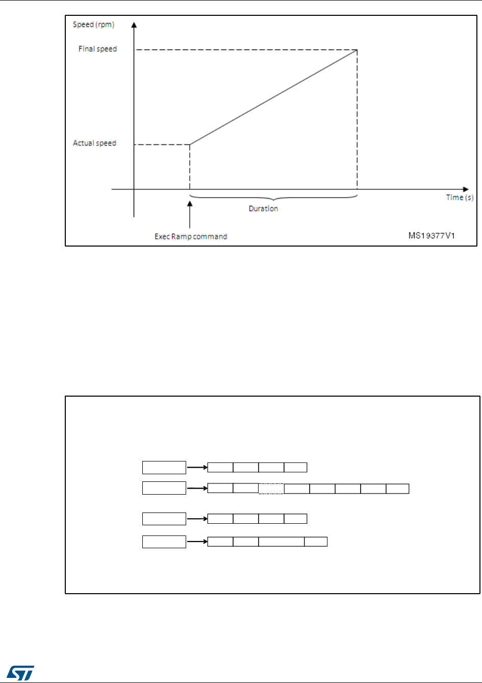
UM1052
Serial communication class overview
DocID18458 Rev 9
169/178
Figure 140: Speed ramp
14.5 Get revup data frame
The get revup data frame (Figure 140: "Get revup data frame") is sent by the master to
retrieve the current revup parameters.
Revup sequence is a set of commands performed by the motor control firmware to drive
the motor from zero speed up to run condition. It is mandatory for a sensorless
configuration. The sequence is split into several stages; a duration, final speed and final
torque (actually Iq reference) can be set up for each stage. See Figure 141: "Revup
sequence".
Figure 141: Get revup data frame
The master indicates the requested stage parameter sending the stage number in the
starting frame payload. Payload length is always 1.
The Acknowledgment frame can be of two types:
OR
BOARD
Data Acknowledgment frame, No errors
0xFF ERROR_CODE CRC0x1
Error Acknowledgment frame
BOARD
Get revup data frame
PC 0x08 0x01 CRCStage
Get revup data frame
PC 0x08 0x01 CRCStage
0xF0 CRC
0x06 DR_LB DR_HBFT_LB FT_HB
FS_[x]
Serial communication class overview
UM1052
170/178
DocID18458 Rev 9
Data Acknowledgment frame, if the operation has been successfully completed. In this
case, the returned values are embedded in the Data Acknowledgment frame. The
payload size of this Data Acknowledgment frame is always 8.
The four bytes FS[x] represent the final speed of the selected stage expressed in rpm, from
the least significant byte to the most significant byte.
FT_LB and FT_HB represent the final torque of the selected stage expressed in digit,
respectively the least significant byte and the most significant byte.
To convert current expressed in Amps to current expressed in digit, use the
formula:
Current(digit)=[Current(Amp)×65536×R_Shunt×A_OP ]/V_(DD Micro)
DR_LB and DR_HB represent the duration of the selected stage expressed in
milliseconds, respectively the least significant byte and the most significant byte.
Error Acknowledgment frame, if the operation has not been successfully completed by
the firmware. The payload of this Error Acknowledgment frame is always 1. The list of
error codes is shown in Table 43: "List of error codes".
Figure 142: Revup sequence
14.6 Set revup data frame
The set revup data frame (Figure 142: "Set revup data frame") is sent by the master to
modify the revup parameters.
Revup sequence is a set of commands performed by the motor control firmware to drive
the motor from zero speed up to run condition. It is mandatory for a sensorless
configuration. The sequence is split into several stages. For each stage, a duration, final
speed and final torque (actually Iq reference) can be set up. See Figure 141: "Revup
sequence".

UM1052
Serial communication class overview
DocID18458 Rev 9
171/178
Figure 143: Set revup data frame
The Master sends the requested stage parameter.
The payload length is always 9.
Stage is the revup stage that will be modified.
The four bytes FS[x] is the requested new final speed of the selected stage expressed in
rpm, from the least significant byte to the most significant byte.
FT_LB and FT_HB are the requested new final torque of the selected stage expressed in
digit, respectively the least significant byte and the most significant byte.
To convert current expressed in Amps to current expressed in digit, it is possible
to use the formula:
Current(digit) = [Current(Amp) * 65536 * Rshunt * Aop] / Vdd micro.
DR_LB and DR_HB is the requested new duration of the selected stage
expressed in milliseconds, respectively the least significant byte and the most
significant byte.
The Acknowledgment frame can be of two types:
Data Acknowledgment frame, if the operation has been successfully completed. The
payload of this Data Acknowledgment frame will be zero.
Error Acknowledgment frame, if the operation has not been successfully completed by
the firmware. The payload of this Error Acknowledgment frame is always 1. The list of
error codes is shown in Table 43: "List of error codes".
14.7 Set current references frame
The set current references frame (Figure 143: "Set current reference frame") is sent by the
Master to modify the current references Iq, Id.
OR
0xFF ERROR_CODE CRC0x1
Error Acknowledgment frame
BOARD
Set
Set revup data frame
PC 0x09 0x09 CRCStage DR_LB DR_HBFT_LB FT_HB
BOARD 0xF0 CRC
0x00
Data Acknowledgment frame, No errors
Setrevupdata frame
PC 0x09 0x09 CRCStage DR_LB DR_HBFT_LB FT_HB
FS_[x]
FS_[x]
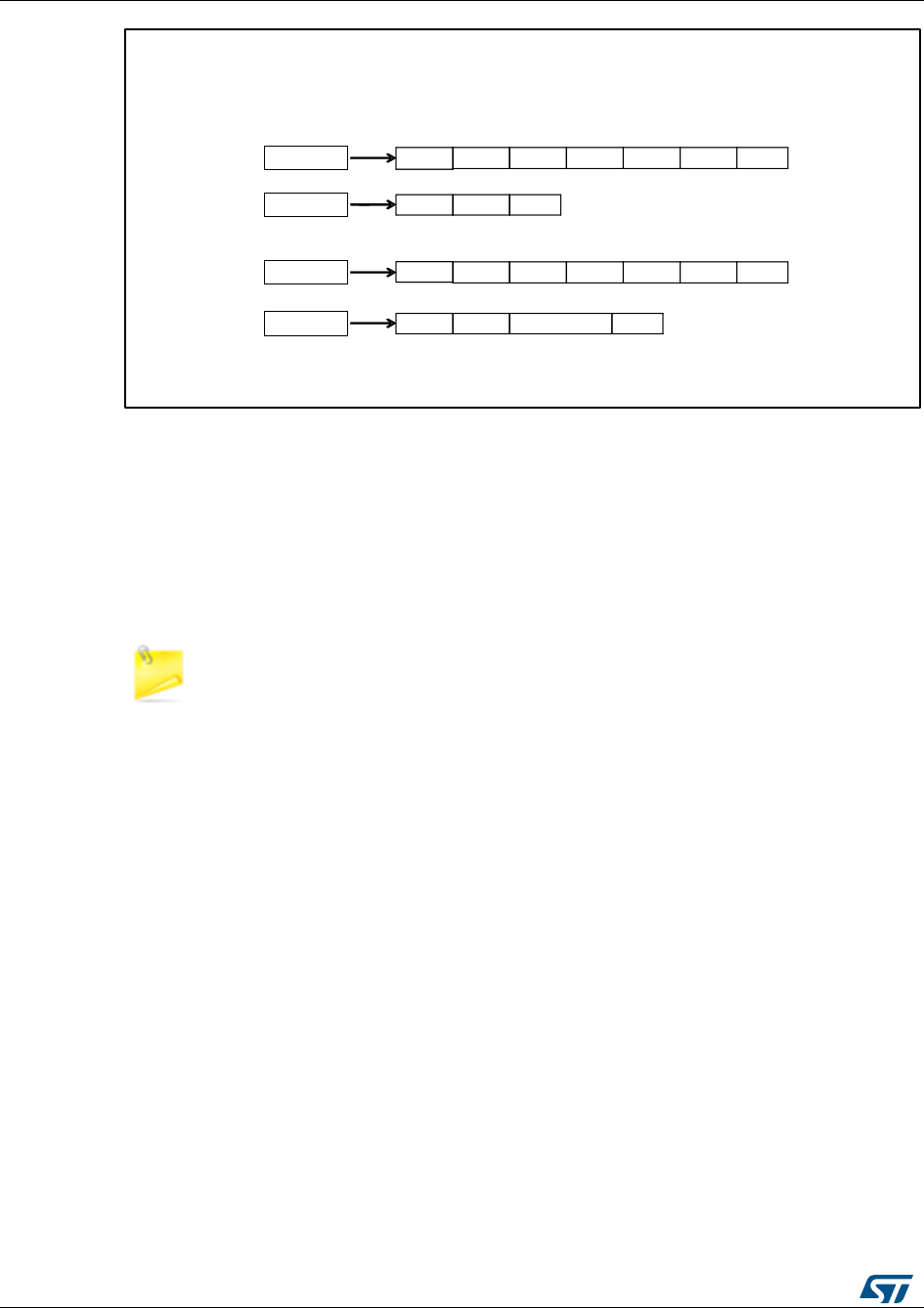
Serial communication class overview
UM1052
172/178
DocID18458 Rev 9
Figure 144: Set current reference frame
The Master sends the requested current references.
The payload length is always 4.
Iq_LB and Iq_HB are the requested new Iq references expressed in digit, respectively the
least significant byte and the most significant byte.
Id_LB and Id_HB are the requested new Id reference expressed in digit, respectively the
least significant byte and the most significant byte.
To convert current expressed in Amps to current expressed in digit, it is possible
to use the formula:
Current(digit)=[Current(Amp)×65536×R_Shunt×A_OP ]/Vdd micro)
The Acknowledgment frame can be of two types:
Data Acknowledgment frame, if the operation has been successfully completed. The
payload of this Data Acknowledgment frame will be zero.
Error Acknowledgment frame, if the operation has not been successfully completed by
the firmware. The payload of this Error Acknowledgment frame is always 1. The list of
error codes is shown in Table 43: "List of error codes".
OR
0xFF ERROR_CODE CRC0x1
Error Acknowledgment frame
BOARD
BOARD 0xF0 CRC0x00
Data Acknowledgment frame, No errors
Set current references frame
PC 0x0A 0x04 CRCIq_LB Iq_HB Id_LB Id_HB
Set current references frame
PC 0x0A 0x04 CRCIq_LB Iq_HB Id_LB Id_HB
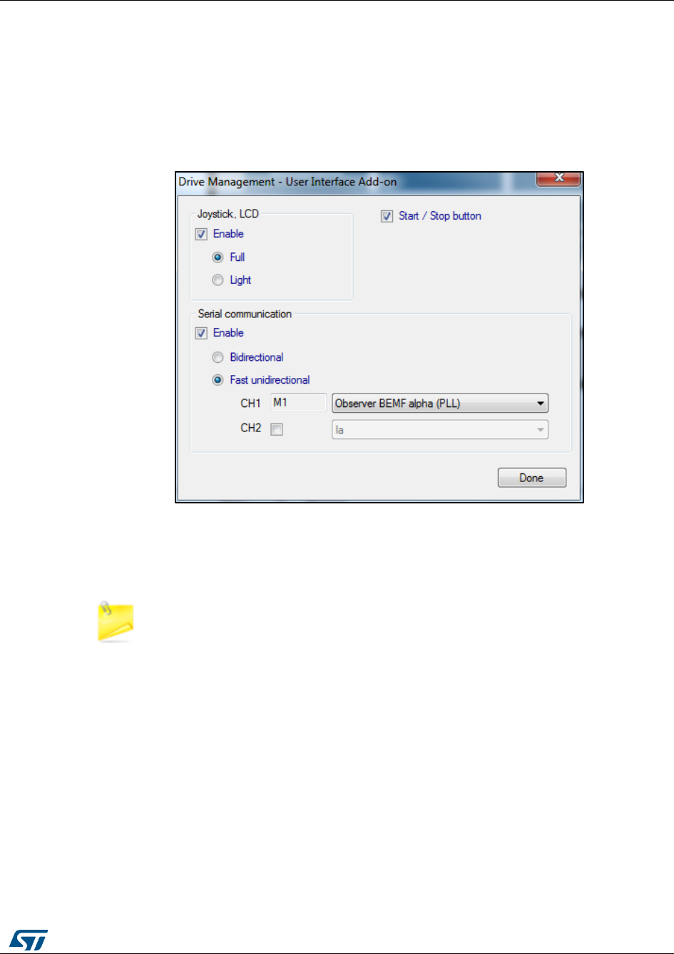
UM1052
Fast serial communication
DocID18458 Rev 9
173/178
15 Fast serial communication
Fast unidirectional serial communication option is implemented in the STM32 FOC
Firmware library and can be enabled in the ST MC Workbench checking "Enable" in the
Drive Management - User Interface Add-on - Serial communication and select "Fast
unidirectional" option like shown in Figure 144: "Enabling fast unidirectional serial
communication".
Figure 145: Enabling fast unidirectional serial communication
When enabled is possible also to select the variables that can be sent through serial
communication among the relevant motor control variables (in a way similar to the list of
DAC variables). Optionally two variables can be sent alternatively.
This kind of serial communication is not supported by the real time communication
of ST MC Workbench.

Document conventions
UM1052
174/178
DocID18458 Rev 9
16 Document conventions
Table 46: List of abbreviations
Abbreviation
Definition
AC
Alternate Current
API
Application Programming Interface
B-EMF
Back Electromotive Force
CC-RAM
Core Coupled Memory Random Access Memory
CORDIC
COordinate Rotation DIgital Computer
DAC
Digital to Analog Converter
DC
Direct Current
FOC
Field Oriented Control
GUI
Graphical User Interface
I-PMSM
Internal Permanent Magnet Synchronous Motor
IC
Integrated Circuit
ICS
Isolated Current Sensor
IDE
Integrated Development Environment
MC
Motor Control
MCI
Motor Control Interface
MCT
Motor Control Tuning
MTPA
Maximum Torque Per Ampere
PGA
Programmable Gain Amplifier
PID controller
Proportional-Integral-Derivative controller
PLL
Phase-Locked Loop
PMSM
Permanent Magnet Synchronous Motor
SDK
Software Development Kit
SM-PMSM
Surface Mounted Permanent Magnet Synchronous Motor
SV PWM
Space Vector Pulse-Width Modulation
UI
User Interface

UM1052
References
DocID18458 Rev 9
175/178
17 References
[1] P. C. Krause, O. Wasynczuk, S. D. Sudhoff, Analysis of Electric Machinery and Drive
Systems, Wiley-IEEE Press, 2002.
[2] T. A. Lipo and D. W. Novotny, Vector Control and Dynamics of AC Drives, Oxford
University Press, 1996.
[3] S. Morimoto, Y. Takeda, T. Hirasa, K. Taniguchi, “Expansion of Operating Limits for
Permanent Magnet Motor by Optimum Flux-Weakening”, Conference Record of the 1989
IEEE, pp. 51-56 (1989).
[4] J. Kim, S. Sul, “Speed control of Interior PM Synchronous Motor Drive for the Flux-
Weakening Operation”, IEEE Trans. on Industry Applications, 33, pp. 43-48 (1997).
[5] M. Tursini, A. Scafati, A. Guerriero, R. Petrella, “Extended torque-speed region sensor-
less control of interior permanent magnet synchronous motors”, ACEMP'07, pp. 647 - 652
(2007).
[6] M. Cacciato, G. Scarcella, G. Scelba, S.M. Billè, D. Costanzo, A. Cucuccio,
“Comparison of Low-Cost-Implementation Sensorless Schemes in Vector Controlled
Adjustable Speed Drives”, SPEEDAM '08, Applied Power Electronics Conference and
Exposition (2008).

Revision history
UM1052
176/178
DocID18458 Rev 9
18 Revision history
Table 47: Document revision history
Date
Version
Changes
18-Apr-2011
1
Initial release.
24-May-2011
2
Added references for web and confidential distributions of
STM32 FOC PMSM SDK v3.0
28-Mar-2012
3
The product range has been expanded from "STM32F103xx or
STM32F100xx" to
"STM32F103xx/STM32F100xx/STM32F2xx/STM32F4xx".
This has impacted several sections, among them the Introduction,
Section 10.3: How to create a user project that interacts with the MC
API, Section 14: Serial communication class overview and Section
14.1: Set register frame.
14-Nov-2012
4
Added “STM32F05xx" to the product range, which has
impacted the title and most of the sections.
Changed the software library version (from v3.2 to v3.3).
Added Table 1: Applicable products.
19-Dec-2013
5
Added STM32F30x to the product range, which has impacted
the title and most of the sections.
Changed the software library version (from v3.3 to v3.4).
Added Table 9: Single-shunt current reading, used resources, single
or dual drive, STM32F2xxx/F4xx.
Added Section 6: Current sensing and protection on embedded PGA
and Section 7: Overvoltage protection with embedded analog
(STM32F3x only).
Updated Table 12: File structure, Table 13: Project configurations and
Table 15: MC application preemption priorities.
Updated Figure 59, Figure 61, Figure 62, Figure 90, Figure 92, Figure
93, Figure 94, Figure 95, Figure 96, Figure 99 and Figure 101.
20-Jun-2014
6
Updated cover page specifying new features.
Added onSection 1 new sensorless specifications, updated list of user
interface option on “User project and interface features”.
Removed older chapter 9.4: Motor control application project.
Added: Section 8.2, Figure 77, Figure 79, point from 7 to 9 in Section
9.2 on page 96, Figure 81, Figure 83, Figure 84, Figure 85. Section
12: Light LCD user interface, Section 15: Fast serial communication
Updated:
– title on Section 8.1, Section 9.1, Section 9.2,
– Figure 75: MC workspace structure, Figure 76, Figure 78, Figure
80, Figure 82
– title on Section 9.5: Full LCD UI project
– title on Section 11: Full LCD user interface and Section 11.1:
Running the motor control firmware using the full LCD interface
– Figure 90, Figure 92, Figure 93

UM1052
Revision history
DocID18458 Rev 9
177/178
Date
Version
Changes
21-May-2015
7
Updated: – list of features on Section 1: Motor control library
features – Figure 59 and Figure 88 Added: – Section 4.1 and
Section 4.2 Removed in all document any reference to
STM320518-EVAL.
07-Sep-2015
8
Updated:
–Section 3.2, Section 5.1, Section 9.3, Section 9.4, Section 9.5
–equation on Section 4.6
–Figure 30
Added:
–Section 5.2: Current sampling in three-shunt topology using one
A/D converter
–Section 5.3: Current sampling in three-shunt topology using one
A/D converter
27-Sep-2016
9
Text and formatting changes throughout document
Updated FOC SDK version number to 4.3 (was 4.2)
New section Section 4.1: "The new Motor Profiler procedure"
(replaces Motor profiler and One Touch Tuning)
Added section Section 4.13: "Digital PFC"
Renamed Section 5.1: "Current sampling in three-shunt topology
using two A/D converters" (was Current sampling in three-shunt
topology)
Updated Section 5.2: "Current sampling in three-shunt topology using
one A/D converter" and added Table 9: "Three-shunt current reading,
used resources, single drive, STM32F030x8"
Renamed Section 5.2.1: "Tuning delay parameters and sampling
stator currents in shunt resistor" (was Current sampling in three-shunt
topology using one A/D converter)
Moved Table 11: "Single-shunt current reading, used resources
(single drive, F103/F100 LD/MD, F0x)", Table 12: "single-shunt
current reading, used resources (single or dual drive, F103HD)" and
Table 13: "Single-shunt current reading, used resources, single or
dual drive, STM32F2xxx/F4xx" to Section 5.3.1: "Definition of the
noise parameter and boundary zone" (were in Section 5.3: "Current
sampling in single-shunt topology")

UM1052
178/178
DocID18458 Rev 9
IMPORTANT NOTICE – PLEASE READ CAREFULLY
STMicroelectronics NV and its subsidiaries (“ST”) reserve the right to make changes, corrections, enhancements, modifications,
and improvements to ST products and/or to this document at any time without notice. Purchasers should obtain the latest relevant
information on ST products before placing orders. ST products are sold pursuant to ST’s terms and conditions of sale in place at
the time of order acknowledgement.
Purchasers are solely responsible for the choice, selection, and use of ST products and ST assumes no liability for application
assistance or the design of Purchasers’ products.
No license, express or implied, to any intellectual property right is granted by ST herein.
Resale of ST products with provisions different from the information set forth herein shall void any warranty granted by ST for such
product.
ST and the ST logo are trademarks of ST. All other product or service names are the property of their respective owners.
Information in this document supersedes and replaces information previously supplied in any prior versions of this document.
© 2016 STMicroelectronics – All rights reserved
