UM1718 STM32Cube MX Manual
STM32CubeMX-Manual
User Manual:
Open the PDF directly: View PDF ![]() .
.
Page Count: 345 [warning: Documents this large are best viewed by clicking the View PDF Link!]
- 1 General information
- 2 STM32Cube overview
- 3 Getting started with STM32CubeMX
- 4 Installing and running STM32CubeMX
- 5 STM32CubeMX user interface
- 5.1 Welcome page
- 5.2 New project window
- 5.3 Main window
- 5.4 Toolbar and menus
- 5.5 Output windows
- 5.6 Import Project window
- 5.7 Set unused / Reset used GPIOs windows
- 5.8 Project Settings window
- 5.9 Update Manager windows
- 5.10 Additional software component selection window
- 5.11 About window
- 5.12 Pinout view
- 5.13 Configuration view
- Table 12. Peripheral and middleware configuration buttons
- 5.13.1 Peripherals and Middleware Configuration window
- 5.13.2 User Constants configuration window
- 5.13.3 GPIO Configuration window
- 5.13.4 DMA Configuration window
- 5.13.5 NVIC Configuration window
- 5.13.6 FreeRTOS middleware configuration view
- 5.13.7 Graphics frameworks and simulator
- 5.14 Clock tree configuration view
- 5.15 Power Consumption Calculator view
- 6 STM32CubeMX C Code generation overview
- 7 Support of additional software components using CMSIS-Pack standard
- 8 Tutorial 1: From pinout to project C code generation using an STM32F4 MCU
- 8.1 Creating a new STM32CubeMX Project
- 8.2 Configuring the MCU pinout
- 8.3 Saving the project
- 8.4 Generating the report
- 8.5 Configuring the MCU clock tree
- 8.6 Configuring the MCU initialization parameters
- 8.7 Generating a complete C project
- 8.8 Building and updating the C code project
- 8.9 Switching to another MCU
- 9 Tutorial 2 - Example of FatFs on an SD card using STM32429I-EVAL evaluation board
- 10 Tutorial 3 - Using the Power Consumption Calculator to optimize the embedded application consumption and more
- 11 Tutorial 4 - Example of UART communications with a STM32L053xx Nucleo board
- 11.1 Tutorial overview
- 11.2 Creating a new STM32CubeMX project and selecting the Nucleo board
- 11.3 Selecting the features from the Pinout view
- 11.4 Configuring the MCU clock tree from the Clock Configuration view
- 11.5 Configuring the peripheral parameters from the Configuration view
- 11.6 Configuring the project settings and generating the project
- 11.7 Updating the project with the user application code
- 11.8 Compiling and running the project
- 11.9 Configuring Tera Term software as serial communication client on the PC
- 12 Tutorial 5: Exporting current project configuration to a compatible MCU
- 13 Tutorial 6 – Adding embedded software packs to user projects
- 14 Tutorial 7 – Using the BlueNRG-MS software pack
- 15 Tutorial 8 – Using STemWin Graphics framework
- 16 Tutorial 9: Using STM32CubeMX Graphics simulator
- 17 FAQ
- 17.1 On the Pinout configuration panel, why does STM32CubeMX move some functions when I add a new peripheral mode?
- 17.2 How can I manually force a function remapping?
- 17.3 Why are some pins highlighted in yellow or in light green in the Chip view? Why cannot I change the function of some pins (when I click some pins, nothing happens)?
- 17.4 Why do I get the error “Java 7 update 45” when installing “Java 7 update 45” or a more recent version of the JRE?
- 17.5 Why does the RTC multiplexer remain inactive on the Clock tree view?
- 17.6 How can I select LSE and HSE as clock source and change the frequency?
- 17.7 Why STM32CubeMX does not allow me to configure PC13, PC14, PC15 and PI8 as outputs when one of them is already configured as an output?
- 17.8 Ethernet Configuration: why cannot I specify DP83848 or LAN8742A in some cases?
- Appendix A STM32CubeMX pin assignment rules
- A.1 Block consistency
- A.2 Block inter-dependency
- A.3 One block = one peripheral mode
- A.4 Block remapping (STM32F10x only)
- A.5 Function remapping
- A.6 Block shifting (only for STM32F10x and when “Keep Current Signals placement” is unchecked)
- A.7 Setting and clearing a peripheral mode
- A.8 Mapping a function individually
- A.9 GPIO signals mapping
- Appendix B STM32CubeMX C code generation design choices and limitations
- Appendix C STM32 microcontrollers naming conventions
- Appendix D STM32 microcontrollers power consumption parameters
- Appendix E STM32Cube embedded software packages
- 18 Revision history

September 2018 UM1718 Rev 26 1/345
1
UM1718
User manual
STM32CubeMX for STM32 configuration
and initialization C code generation
Introduction
STM32CubeMX is a graphical tool for STM32 microcontrollers. It is part of the
STM32Cube™ initiative (see Section 2) and is available either as a standalone application
or as an Eclipse plug-in for integration in Integrated Development Environments (IDEs).
STM32CubeMX has the following key features:
Easy microcontroller selection covering the whole STM32 portfolio
Board selection from a list of STMicroelectronics boards
Easy microcontroller configuration (pins, clock tree, peripherals, middleware) and
generation of the corresponding initialization C code
Easy switching to another microcontroller by importing a previously-saved
configuration to a new MCU project
Easy exporting of current configuration to a compatible MCU
Generation of configuration reports
Generation of embedded C projects for a selection of integrated development
environment tool chains. STM32CubeMX projects include the generated initialization C
code, MISRA 2004 compliant STM32 HAL drivers, the middleware stacks required for the
user configuration, and all the relevant files for opening and building the project in the
selected IDE.
Power consumption calculation for a user-defined application sequence
Self-updates allowing the user to keep STM32CubeMX up-to-date
Download and update of STM32Cube embedded software required for user application
development (see Appendix E: STM32Cube embedded software packages for details on
the STM32Cube embedded software offer)
Although STM32CubeMX offers a user interface and generates C code compliant with
STM32 MCU design and firmware solutions, users need to refer to the product technical
documentation for details on actual implementations of microcontroller peripherals and
firmware.
The following documents are available from www.st.com:
STM32 microcontroller reference manuals and datasheets
STM32Cube HAL/LL driver user manuals for STM32F0 (UM1785), STM32F1
(UM1850), STM32F2 (UM1940), STM32F3 (UM1786), STM32F4 (UM1725), STM32F7
(UM1905), STM32L0 (UM1749), STM32L1 (UM1816), STM32L4/L4+ (UM1884) and
STM32H7 (UM2217).
www.st.com

Contents UM1718
2/345 UM1718 Rev 26
Contents
1 General information . . . . . . . . . . . . . . . . . . . . . . . . . . . . . . . . . . . . . . . . 17
2 STM32Cube overview . . . . . . . . . . . . . . . . . . . . . . . . . . . . . . . . . . . . . . . 17
3 Getting started with STM32CubeMX . . . . . . . . . . . . . . . . . . . . . . . . . . . 18
3.1 Principles . . . . . . . . . . . . . . . . . . . . . . . . . . . . . . . . . . . . . . . . . . . . . . . . . 18
3.2 Key features . . . . . . . . . . . . . . . . . . . . . . . . . . . . . . . . . . . . . . . . . . . . . . . 20
3.3 Rules and limitations . . . . . . . . . . . . . . . . . . . . . . . . . . . . . . . . . . . . . . . . 21
4 Installing and running STM32CubeMX . . . . . . . . . . . . . . . . . . . . . . . . . 23
4.1 System requirements . . . . . . . . . . . . . . . . . . . . . . . . . . . . . . . . . . . . . . . . 23
4.1.1 Supported operating systems and architectures . . . . . . . . . . . . . . . . . . 23
4.1.2 Memory prerequisites . . . . . . . . . . . . . . . . . . . . . . . . . . . . . . . . . . . . . . 23
4.1.3 Software requirements . . . . . . . . . . . . . . . . . . . . . . . . . . . . . . . . . . . . . . 23
4.2 Installing/uninstalling STM32CubeMX standalone version . . . . . . . . . . . 23
4.2.1 Installing STM32CubeMX standalone version . . . . . . . . . . . . . . . . . . . . 23
4.2.2 Installing STM32CubeMX from command line . . . . . . . . . . . . . . . . . . . 25
4.2.3 Uninstalling STM32CubeMX standalone version . . . . . . . . . . . . . . . . . . 27
4.3 Installing STM32CubeMX plug-in version . . . . . . . . . . . . . . . . . . . . . . . . 28
4.3.1 Downloading STM32CubeMX plug-in installation package . . . . . . . . . . 28
4.3.2 Installing STM32CubeMX as an Eclipse IDE plug-in . . . . . . . . . . . . . . . 28
4.3.3 Uninstalling STM32CubeMX as Eclipse IDE plug-in . . . . . . . . . . . . . . . 29
4.4 Launching STM32CubeMX . . . . . . . . . . . . . . . . . . . . . . . . . . . . . . . . . . . 31
4.4.1 Running STM32CubeMX as standalone application . . . . . . . . . . . . . . . 31
4.4.2 Running STM32CubeMX in command-line mode . . . . . . . . . . . . . . . . . 31
4.4.3 Running STM32CubeMX plug-in from Eclipse IDE . . . . . . . . . . . . . . . . 34
4.5 Getting updates using STM32CubeMX . . . . . . . . . . . . . . . . . . . . . . . . . . 35
4.5.1 Updater configuration . . . . . . . . . . . . . . . . . . . . . . . . . . . . . . . . . . . . . . 37
4.5.2 Installing STM32 MCU packages . . . . . . . . . . . . . . . . . . . . . . . . . . . . . . 39
4.5.3 Installing STM32 MCU package patches . . . . . . . . . . . . . . . . . . . . . . . . 40
4.5.4 Installing embedded software packs . . . . . . . . . . . . . . . . . . . . . . . . . . . 40
4.5.5 Removing already installed embedded software packages . . . . . . . . . . 46
4.5.6 Checking for updates . . . . . . . . . . . . . . . . . . . . . . . . . . . . . . . . . . . . . . . 47

UM1718 Rev 26 3/345
UM1718 Contents
8
5 STM32CubeMX user interface . . . . . . . . . . . . . . . . . . . . . . . . . . . . . . . . 49
5.1 Welcome page . . . . . . . . . . . . . . . . . . . . . . . . . . . . . . . . . . . . . . . . . . . . . 49
5.2 New project window . . . . . . . . . . . . . . . . . . . . . . . . . . . . . . . . . . . . . . . . . 51
5.3 Main window . . . . . . . . . . . . . . . . . . . . . . . . . . . . . . . . . . . . . . . . . . . . . . . 56
5.4 Toolbar and menus . . . . . . . . . . . . . . . . . . . . . . . . . . . . . . . . . . . . . . . . . . 59
5.4.1 File menu . . . . . . . . . . . . . . . . . . . . . . . . . . . . . . . . . . . . . . . . . . . . . . . . 59
5.4.2 Project menu . . . . . . . . . . . . . . . . . . . . . . . . . . . . . . . . . . . . . . . . . . . . . 60
5.4.3 Pinout menu . . . . . . . . . . . . . . . . . . . . . . . . . . . . . . . . . . . . . . . . . . . . . . 60
5.4.4 Window menu . . . . . . . . . . . . . . . . . . . . . . . . . . . . . . . . . . . . . . . . . . . . 63
5.4.5 Help menu . . . . . . . . . . . . . . . . . . . . . . . . . . . . . . . . . . . . . . . . . . . . . . . 63
5.4.6 Social links . . . . . . . . . . . . . . . . . . . . . . . . . . . . . . . . . . . . . . . . . . . . . . . 64
5.5 Output windows . . . . . . . . . . . . . . . . . . . . . . . . . . . . . . . . . . . . . . . . . . . . 64
5.5.1 MCUs selection panel . . . . . . . . . . . . . . . . . . . . . . . . . . . . . . . . . . . . . . 64
5.5.2 Output panel . . . . . . . . . . . . . . . . . . . . . . . . . . . . . . . . . . . . . . . . . . . . . 66
5.6 Import Project window . . . . . . . . . . . . . . . . . . . . . . . . . . . . . . . . . . . . . . . 66
5.7 Set unused / Reset used GPIOs windows . . . . . . . . . . . . . . . . . . . . . . . . 72
5.8 Project Settings window . . . . . . . . . . . . . . . . . . . . . . . . . . . . . . . . . . . . . . 74
5.8.1 Project tab . . . . . . . . . . . . . . . . . . . . . . . . . . . . . . . . . . . . . . . . . . . . . . . 76
5.8.2 Code Generator tab . . . . . . . . . . . . . . . . . . . . . . . . . . . . . . . . . . . . . . . . 81
5.8.3 Advanced Settings tab . . . . . . . . . . . . . . . . . . . . . . . . . . . . . . . . . . . . . . 85
5.9 Update Manager windows . . . . . . . . . . . . . . . . . . . . . . . . . . . . . . . . . . . . 87
5.10 Additional software component selection window . . . . . . . . . . . . . . . . . . 87
5.10.1 Introduction on software components . . . . . . . . . . . . . . . . . . . . . . . . . . 87
5.10.2 Filter panel . . . . . . . . . . . . . . . . . . . . . . . . . . . . . . . . . . . . . . . . . . . . . . . 89
5.10.3 Software component table . . . . . . . . . . . . . . . . . . . . . . . . . . . . . . . . . . . 89
5.10.4 Software component conditions . . . . . . . . . . . . . . . . . . . . . . . . . . . . . . . 90
5.10.5 Updating the tree view for additional software components . . . . . . . . . 93
5.11 About window . . . . . . . . . . . . . . . . . . . . . . . . . . . . . . . . . . . . . . . . . . . . . . 94
5.12 Pinout view . . . . . . . . . . . . . . . . . . . . . . . . . . . . . . . . . . . . . . . . . . . . . . . . 94
5.12.1 Peripheral and Middleware tree panel . . . . . . . . . . . . . . . . . . . . . . . . . . 96
5.12.2 Chip view . . . . . . . . . . . . . . . . . . . . . . . . . . . . . . . . . . . . . . . . . . . . . . . . 98
5.12.3 Chip view advanced actions . . . . . . . . . . . . . . . . . . . . . . . . . . . . . . . . 104
5.12.4 Keep Current Signals Placement . . . . . . . . . . . . . . . . . . . . . . . . . . . . . 105
5.12.5 Pinning and labeling signals on pins . . . . . . . . . . . . . . . . . . . . . . . . . . 106
5.12.6 Setting HAL timebase source . . . . . . . . . . . . . . . . . . . . . . . . . . . . . . . 107

Contents UM1718
4/345 UM1718 Rev 26
5.13 Configuration view . . . . . . . . . . . . . . . . . . . . . . . . . . . . . . . . . . . . . . . . . .113
5.13.1 Peripherals and Middleware Configuration window . . . . . . . . . . . . . . . 115
5.13.2 User Constants configuration window . . . . . . . . . . . . . . . . . . . . . . . . . 118
5.13.3 GPIO Configuration window . . . . . . . . . . . . . . . . . . . . . . . . . . . . . . . . 123
5.13.4 DMA Configuration window . . . . . . . . . . . . . . . . . . . . . . . . . . . . . . . . . 126
5.13.5 NVIC Configuration window . . . . . . . . . . . . . . . . . . . . . . . . . . . . . . . . . 129
5.13.6 FreeRTOS middleware configuration view . . . . . . . . . . . . . . . . . . . . . 137
5.13.7 Graphics frameworks and simulator . . . . . . . . . . . . . . . . . . . . . . . . . . 143
5.14 Clock tree configuration view . . . . . . . . . . . . . . . . . . . . . . . . . . . . . . . . . 147
5.14.1 Clock tree configuration functions . . . . . . . . . . . . . . . . . . . . . . . . . . . . 147
5.14.2 Recommendations . . . . . . . . . . . . . . . . . . . . . . . . . . . . . . . . . . . . . . . . 152
5.14.3 STM32F43x/42x power-over drive feature . . . . . . . . . . . . . . . . . . . . . 153
5.14.4 Clock tree glossary . . . . . . . . . . . . . . . . . . . . . . . . . . . . . . . . . . . . . . . 154
5.15 Power Consumption Calculator view . . . . . . . . . . . . . . . . . . . . . . . . . . . 155
5.15.1 Building a power consumption sequence . . . . . . . . . . . . . . . . . . . . . . 156
5.15.2 Configuring a step in the power sequence . . . . . . . . . . . . . . . . . . . . . 163
5.15.3 Managing user-defined power sequence and reviewing results . . . . . 167
5.15.4 Power sequence step parameters glossary . . . . . . . . . . . . . . . . . . . . . 170
5.15.5 Battery glossary . . . . . . . . . . . . . . . . . . . . . . . . . . . . . . . . . . . . . . . . . . 173
5.15.6 SMPS feature . . . . . . . . . . . . . . . . . . . . . . . . . . . . . . . . . . . . . . . . . . . 173
6 STM32CubeMX C Code generation overview . . . . . . . . . . . . . . . . . . . 178
6.1 STM32Cube code generation using only HAL drivers
(default mode) . . . . . . . . . . . . . . . . . . . . . . . . . . . . . . . . . . . . . . . . . . . . 178
6.2 STM32Cube code generation using Low Layer drivers . . . . . . . . . . . . . 180
6.3 Custom code generation . . . . . . . . . . . . . . . . . . . . . . . . . . . . . . . . . . . . 186
6.3.1 STM32CubeMX data model for FreeMarker user templates . . . . . . . . 186
6.3.2 Saving and selecting user templates . . . . . . . . . . . . . . . . . . . . . . . . . . 186
6.3.3 Custom code generation . . . . . . . . . . . . . . . . . . . . . . . . . . . . . . . . . . . 187
6.4 Additional settings for C project generation . . . . . . . . . . . . . . . . . . . . . . 190
7 Support of additional software components using
CMSIS-Pack standard . . . . . . . . . . . . . . . . . . . . . . . . . . . . . . . . . . . . . . 194
8 Tutorial 1: From pinout to project C code generation
using an STM32F4 MCU . . . . . . . . . . . . . . . . . . . . . . . . . . . . . . . . . . . . 198
8.1 Creating a new STM32CubeMX Project . . . . . . . . . . . . . . . . . . . . . . . . 198

UM1718 Rev 26 5/345
UM1718 Contents
8
8.2 Configuring the MCU pinout . . . . . . . . . . . . . . . . . . . . . . . . . . . . . . . . . . 201
8.3 Saving the project . . . . . . . . . . . . . . . . . . . . . . . . . . . . . . . . . . . . . . . . . . 202
8.4 Generating the report . . . . . . . . . . . . . . . . . . . . . . . . . . . . . . . . . . . . . . . 203
8.5 Configuring the MCU clock tree . . . . . . . . . . . . . . . . . . . . . . . . . . . . . . . 203
8.6 Configuring the MCU initialization parameters . . . . . . . . . . . . . . . . . . . . 206
8.6.1 Initial conditions . . . . . . . . . . . . . . . . . . . . . . . . . . . . . . . . . . . . . . . . . . 206
8.6.2 Configuring the peripherals . . . . . . . . . . . . . . . . . . . . . . . . . . . . . . . . . 207
8.6.3 Configuring the GPIOs . . . . . . . . . . . . . . . . . . . . . . . . . . . . . . . . . . . . . 210
8.6.4 Configuring the DMAs . . . . . . . . . . . . . . . . . . . . . . . . . . . . . . . . . . . . . 211
8.6.5 Configuring the middleware . . . . . . . . . . . . . . . . . . . . . . . . . . . . . . . . . 212
8.7 Generating a complete C project . . . . . . . . . . . . . . . . . . . . . . . . . . . . . . 215
8.7.1 Setting project options . . . . . . . . . . . . . . . . . . . . . . . . . . . . . . . . . . . . . 215
8.7.2 Downloading firmware package and generating the C code . . . . . . . . 217
8.8 Building and updating the C code project . . . . . . . . . . . . . . . . . . . . . . . . 222
8.9 Switching to another MCU . . . . . . . . . . . . . . . . . . . . . . . . . . . . . . . . . . . 227
9 Tutorial 2 - Example of FatFs on an SD card using
STM32429I-EVAL evaluation board . . . . . . . . . . . . . . . . . . . . . . . . . . . 229
10 Tutorial 3 - Using the Power Consumption Calculator
to optimize the embedded application consumption and more . . . . 237
10.1 Tutorial overview . . . . . . . . . . . . . . . . . . . . . . . . . . . . . . . . . . . . . . . . . . 237
10.2 Application example description . . . . . . . . . . . . . . . . . . . . . . . . . . . . . . . 238
10.3 Using the Power Consumption Calculator . . . . . . . . . . . . . . . . . . . . . . . 238
10.3.1 Creating a power sequence . . . . . . . . . . . . . . . . . . . . . . . . . . . . . . . . . 238
10.3.2 Optimizing application power consumption . . . . . . . . . . . . . . . . . . . . . 241
11 Tutorial 4 - Example of UART communications with
a STM32L053xx Nucleo board . . . . . . . . . . . . . . . . . . . . . . . . . . . . . . . 249
11.1 Tutorial overview . . . . . . . . . . . . . . . . . . . . . . . . . . . . . . . . . . . . . . . . . . 249
11.2 Creating a new STM32CubeMX project and
selecting the Nucleo board . . . . . . . . . . . . . . . . . . . . . . . . . . . . . . . . . . . 249
11.3 Selecting the features from the Pinout view . . . . . . . . . . . . . . . . . . . . . . 251
11.4 Configuring the MCU clock tree from the Clock Configuration view . . . . 254
11.5 Configuring the peripheral parameters from the Configuration view . . . 255
11.6 Configuring the project settings and generating the project . . . . . . . . . . 258

Contents UM1718
6/345 UM1718 Rev 26
11.7 Updating the project with the user application code . . . . . . . . . . . . . . . . 259
11.8 Compiling and running the project . . . . . . . . . . . . . . . . . . . . . . . . . . . . . 260
11.9 Configuring Tera Term software as serial communication
client on the PC . . . . . . . . . . . . . . . . . . . . . . . . . . . . . . . . . . . . . . . . . . . 260
12 Tutorial 5: Exporting current project configuration to
a compatible MCU . . . . . . . . . . . . . . . . . . . . . . . . . . . . . . . . . . . . . . . . . 262
13 Tutorial 6 – Adding embedded software packs to user projects . . . 266
14 Tutorial 7 – Using the BlueNRG-MS software pack . . . . . . . . . . . . . . 270
15 Tutorial 8 – Using STemWin Graphics framework . . . . . . . . . . . . . . . 283
15.1 Step 1: Selecting an MCU for Graphics . . . . . . . . . . . . . . . . . . . . . . . . . 283
15.2 Step 2: Enabling STemWin from the pinout view . . . . . . . . . . . . . . . . . . 283
15.3 Step 3: Configuring STemWin parameters from the
configuration window . . . . . . . . . . . . . . . . . . . . . . . . . . . . . . . . . . . . . . . 285
15.4 Step 4: Using STemWin GUIBuilder tool from the
configuration window . . . . . . . . . . . . . . . . . . . . . . . . . . . . . . . . . . . . . . . 285
15.5 Step 5: Generating the embedded C project and updates . . . . . . . . . . . 287
16 Tutorial 9: Using STM32CubeMX Graphics simulator . . . . . . . . . . . . 289
17 FAQ . . . . . . . . . . . . . . . . . . . . . . . . . . . . . . . . . . . . . . . . . . . . . . . . . . . . . 292
17.1 On the Pinout configuration panel, why does STM32CubeMX
move some functions when I add a new peripheral mode? . . . . . . . . . . 292
17.2 How can I manually force a function remapping? . . . . . . . . . . . . . . . . . 292
17.3 Why are some pins highlighted in yellow or in light green in
the Chip view? Why cannot I change the function of some
pins (when I click some pins, nothing happens)? . . . . . . . . . . . . . . . . . . 292
17.4 Why do I get the error “Java 7 update 45” when installing
“Java 7 update 45” or a more recent version of the JRE? . . . . . . . . . . . 292
17.5 Why does the RTC multiplexer remain inactive on the Clock tree view? 293
17.6 How can I select LSE and HSE as clock source and
change the frequency? . . . . . . . . . . . . . . . . . . . . . . . . . . . . . . . . . . . . . . 294
17.7 Why STM32CubeMX does not allow me to configure PC13,
PC14, PC15 and PI8 as outputs when one of them
is already configured as an output? . . . . . . . . . . . . . . . . . . . . . . . . . . . . 294

UM1718 Rev 26 7/345
UM1718 Contents
8
17.8 Ethernet Configuration: why cannot I specify DP83848
or LAN8742A in some cases? . . . . . . . . . . . . . . . . . . . . . . . . . . . . . . . . 295
Appendix A STM32CubeMX pin assignment rules . . . . . . . . . . . . . . . . . . . . . . 296
A.1 Block consistency . . . . . . . . . . . . . . . . . . . . . . . . . . . . . . . . . . . . . . . . . . 296
A.2 Block inter-dependency. . . . . . . . . . . . . . . . . . . . . . . . . . . . . . . . . . . . . . 300
A.3 One block = one peripheral mode . . . . . . . . . . . . . . . . . . . . . . . . . . . . . . 303
A.4 Block remapping (STM32F10x only). . . . . . . . . . . . . . . . . . . . . . . . . . . . 303
A.5 Function remapping. . . . . . . . . . . . . . . . . . . . . . . . . . . . . . . . . . . . . . . . . 304
A.6 Block shifting (only for STM32F10x and when
“Keep Current Signals placement” is unchecked). . . . . . . . . . . . . . . . . . 305
A.7 Setting and clearing a peripheral mode. . . . . . . . . . . . . . . . . . . . . . . . . . 306
A.8 Mapping a function individually . . . . . . . . . . . . . . . . . . . . . . . . . . . . . . . . 306
A.9 GPIO signals mapping . . . . . . . . . . . . . . . . . . . . . . . . . . . . . . . . . . . . . . 306
Appendix B STM32CubeMX C code generation design
choices and limitations . . . . . . . . . . . . . . . . . . . . . . . . . . . . . . . . . . 307
B.1 STM32CubeMX generated C code and user sections . . . . . . . . . . . . . . 307
B.2 STM32CubeMX design choices for peripheral initialization . . . . . . . . . . 307
B.3 STM32CubeMX design choices and limitations for
middleware initialization . . . . . . . . . . . . . . . . . . . . . . . . . . . . . . . . . . . . . 308
B.3.1 Overview. . . . . . . . . . . . . . . . . . . . . . . . . . . . . . . . . . . . . . . . . . . . . . . . 308
B.3.2 USB Host . . . . . . . . . . . . . . . . . . . . . . . . . . . . . . . . . . . . . . . . . . . . . . . 309
B.3.3 USB Device . . . . . . . . . . . . . . . . . . . . . . . . . . . . . . . . . . . . . . . . . . . . . 309
B.3.4 FatFs. . . . . . . . . . . . . . . . . . . . . . . . . . . . . . . . . . . . . . . . . . . . . . . . . . . 309
B.3.5 FreeRTOS. . . . . . . . . . . . . . . . . . . . . . . . . . . . . . . . . . . . . . . . . . . . . . . 310
B.3.6 LwIP . . . . . . . . . . . . . . . . . . . . . . . . . . . . . . . . . . . . . . . . . . . . . . . . . . . 311
B.3.7 Libjpeg . . . . . . . . . . . . . . . . . . . . . . . . . . . . . . . . . . . . . . . . . . . . . . . . . 313
B.3.8 Mbed TLS . . . . . . . . . . . . . . . . . . . . . . . . . . . . . . . . . . . . . . . . . . . . . . . 314
B.3.9 TouchSensing . . . . . . . . . . . . . . . . . . . . . . . . . . . . . . . . . . . . . . . . . . . . 317
B.3.10 PDM2PCM . . . . . . . . . . . . . . . . . . . . . . . . . . . . . . . . . . . . . . . . . . . . . . 320
B.3.11 Graphics . . . . . . . . . . . . . . . . . . . . . . . . . . . . . . . . . . . . . . . . . . . . . . . . 320
Appendix C STM32 microcontrollers naming conventions . . . . . . . . . . . . . . . 322
Appendix D STM32 microcontrollers power consumption parameters . . . . . 324
D.1 Power modes . . . . . . . . . . . . . . . . . . . . . . . . . . . . . . . . . . . . . . . . . . . . . 324

Contents UM1718
8/345 UM1718 Rev 26
D.1.1 STM32L1 Series . . . . . . . . . . . . . . . . . . . . . . . . . . . . . . . . . . . . . . . . . . 324
D.1.2 STM32F4 Series. . . . . . . . . . . . . . . . . . . . . . . . . . . . . . . . . . . . . . . . . . 325
D.1.3 STM32L0 Series . . . . . . . . . . . . . . . . . . . . . . . . . . . . . . . . . . . . . . . . . . 326
D.2 Power consumption ranges. . . . . . . . . . . . . . . . . . . . . . . . . . . . . . . . . . . 327
D.2.1 STM32L1 Series features three VCORE ranges . . . . . . . . . . . . . . . . . 327
D.2.2 STM32F4 Series features several VCORE scales . . . . . . . . . . . . . . . . 328
D.2.3 STM32L0 Series features three VCORE ranges . . . . . . . . . . . . . . . . . 328
Appendix E STM32Cube embedded software packages . . . . . . . . . . . . . . . . . 329
18 Revision history . . . . . . . . . . . . . . . . . . . . . . . . . . . . . . . . . . . . . . . . . . 330

UM1718 Rev 26 9/345
UM1718 List of tables
9
List of tables
Table 1. Command line summary. . . . . . . . . . . . . . . . . . . . . . . . . . . . . . . . . . . . . . . . . . . . . . . . . . . 32
Table 2. Welcome page shortcuts . . . . . . . . . . . . . . . . . . . . . . . . . . . . . . . . . . . . . . . . . . . . . . . . . . 50
Table 3. File menu functions. . . . . . . . . . . . . . . . . . . . . . . . . . . . . . . . . . . . . . . . . . . . . . . . . . . . . . . 59
Table 4. Project menu. . . . . . . . . . . . . . . . . . . . . . . . . . . . . . . . . . . . . . . . . . . . . . . . . . . . . . . . . . . . 60
Table 5. Pinout menu . . . . . . . . . . . . . . . . . . . . . . . . . . . . . . . . . . . . . . . . . . . . . . . . . . . . . . . . . . . . 61
Table 6. Window menu . . . . . . . . . . . . . . . . . . . . . . . . . . . . . . . . . . . . . . . . . . . . . . . . . . . . . . . . . . . 63
Table 7. Help menu . . . . . . . . . . . . . . . . . . . . . . . . . . . . . . . . . . . . . . . . . . . . . . . . . . . . . . . . . . . . . 63
Table 8. Software components . . . . . . . . . . . . . . . . . . . . . . . . . . . . . . . . . . . . . . . . . . . . . . . . . . . . . 89
Table 9. Software component conditions icons . . . . . . . . . . . . . . . . . . . . . . . . . . . . . . . . . . . . . . . . 90
Table 10. Peripheral and Middleware tree panel - icons and color scheme . . . . . . . . . . . . . . . . . . . . 97
Table 11. STM32CubeMX Chip view - Icons and color scheme. . . . . . . . . . . . . . . . . . . . . . . . . . . . 100
Table 12. Peripheral and middleware configuration buttons. . . . . . . . . . . . . . . . . . . . . . . . . . . . . . . 114
Table 13. Peripheral and Middleware Configuration window buttons and tooltips . . . . . . . . . . . . . . 116
Table 14. Clock tree view widget . . . . . . . . . . . . . . . . . . . . . . . . . . . . . . . . . . . . . . . . . . . . . . . . . . . 151
Table 15. Voltage scaling versus power over-drive and HCLK frequency . . . . . . . . . . . . . . . . . . . . 154
Table 16. Relations between power over-drive and HCLK frequency . . . . . . . . . . . . . . . . . . . . . . . 154
Table 17. Glossary . . . . . . . . . . . . . . . . . . . . . . . . . . . . . . . . . . . . . . . . . . . . . . . . . . . . . . . . . . . . . . 154
Table 18. LL versus HAL code generation: drivers included in STM32CubeMX projects . . . . . . . . 181
Table 19. LL versus HAL code generation: STM32CubeMX generated header files . . . . . . . . . . . . 181
Table 20. LL versus HAL: STM32CubeMX generated source files . . . . . . . . . . . . . . . . . . . . . . . . . 182
Table 21. LL versus HAL: STM32CubeMX generated functions and function calls . . . . . . . . . . . . . 182
Table 22. Connection with hardware resources . . . . . . . . . . . . . . . . . . . . . . . . . . . . . . . . . . . . . . . . 277
Table 23. Document revision history . . . . . . . . . . . . . . . . . . . . . . . . . . . . . . . . . . . . . . . . . . . . . . . . 330

List of figures UM1718
10/345 UM1718 Rev 26
List of figures
Figure 1. Overview of STM32CubeMX C code generation flow. . . . . . . . . . . . . . . . . . . . . . . . . . . . . 19
Figure 2. Example of STM32CubeMX installation in interactive mode . . . . . . . . . . . . . . . . . . . . . . . 25
Figure 3. STM32Cube Installation Wizard . . . . . . . . . . . . . . . . . . . . . . . . . . . . . . . . . . . . . . . . . . . . . 26
Figure 4. Auto-install command line. . . . . . . . . . . . . . . . . . . . . . . . . . . . . . . . . . . . . . . . . . . . . . . . . . 27
Figure 5. Adding STM32CubeMX plug-in archive . . . . . . . . . . . . . . . . . . . . . . . . . . . . . . . . . . . . . . . 28
Figure 6. Installing STM32CubeMX plug-in . . . . . . . . . . . . . . . . . . . . . . . . . . . . . . . . . . . . . . . . . . . . 29
Figure 7. Closing STM32CubeMX perspective . . . . . . . . . . . . . . . . . . . . . . . . . . . . . . . . . . . . . . . . . 29
Figure 8. Uninstalling STM32CubeMX plug-in . . . . . . . . . . . . . . . . . . . . . . . . . . . . . . . . . . . . . . . . . . 30
Figure 9. Opening Eclipse plug-in . . . . . . . . . . . . . . . . . . . . . . . . . . . . . . . . . . . . . . . . . . . . . . . . . . . 34
Figure 10. STM32CubeMX perspective . . . . . . . . . . . . . . . . . . . . . . . . . . . . . . . . . . . . . . . . . . . . . . . . 35
Figure 11. Displaying Windows default proxy settings. . . . . . . . . . . . . . . . . . . . . . . . . . . . . . . . . . . . . 36
Figure 12. Updater Settings window . . . . . . . . . . . . . . . . . . . . . . . . . . . . . . . . . . . . . . . . . . . . . . . . . . 37
Figure 13. Connection Parameters tab - Manual Configuration of Proxy Server . . . . . . . . . . . . . . . . . 38
Figure 14. Embedded Software Packages Manager window . . . . . . . . . . . . . . . . . . . . . . . . . . . . . . . 39
Figure 15. Managing embedded software packages - Help menu . . . . . . . . . . . . . . . . . . . . . . . . . . . 41
Figure 16. Managing embedded software packages - Adding new url . . . . . . . . . . . . . . . . . . . . . . . . 42
Figure 17. Checking the validity of vendor pack .pdsc file url . . . . . . . . . . . . . . . . . . . . . . . . . . . . . . . 42
Figure 18. User-defined list of software packs. . . . . . . . . . . . . . . . . . . . . . . . . . . . . . . . . . . . . . . . . . . 43
Figure 19. Selecting an embedded software pack release . . . . . . . . . . . . . . . . . . . . . . . . . . . . . . . . . 44
Figure 20. License agreement acceptance . . . . . . . . . . . . . . . . . . . . . . . . . . . . . . . . . . . . . . . . . . . . . 45
Figure 21. Embedded software pack release - Successful installation . . . . . . . . . . . . . . . . . . . . . . . . 45
Figure 22. Removing libraries . . . . . . . . . . . . . . . . . . . . . . . . . . . . . . . . . . . . . . . . . . . . . . . . . . . . . . . 46
Figure 23. Removing library confirmation message. . . . . . . . . . . . . . . . . . . . . . . . . . . . . . . . . . . . . . . 46
Figure 24. Library deletion progress window . . . . . . . . . . . . . . . . . . . . . . . . . . . . . . . . . . . . . . . . . . . . 47
Figure 25. Help menu: checking for updates . . . . . . . . . . . . . . . . . . . . . . . . . . . . . . . . . . . . . . . . . . . . 48
Figure 26. STM32CubeMX Welcome page . . . . . . . . . . . . . . . . . . . . . . . . . . . . . . . . . . . . . . . . . . . . . 50
Figure 27. New Project window - MCU selector. . . . . . . . . . . . . . . . . . . . . . . . . . . . . . . . . . . . . . . . . . 51
Figure 28. Enabling graphics choice in MCU selector . . . . . . . . . . . . . . . . . . . . . . . . . . . . . . . . . . . . . 52
Figure 29. Marking an MCU as a favorite . . . . . . . . . . . . . . . . . . . . . . . . . . . . . . . . . . . . . . . . . . . . . . 53
Figure 30. New Project window - MCU list with close MCUs function . . . . . . . . . . . . . . . . . . . . . . . . . 54
Figure 31. New Project window - MCU list showing close MCUs . . . . . . . . . . . . . . . . . . . . . . . . . . . . 54
Figure 32. New Project window - board selector . . . . . . . . . . . . . . . . . . . . . . . . . . . . . . . . . . . . . . . . . 55
Figure 33. STM32CubeMX Main window upon MCU selection . . . . . . . . . . . . . . . . . . . . . . . . . . . . . . 56
Figure 34. STM32CubeMX Main window upon board selection
(Peripheral default option unchecked) . . . . . . . . . . . . . . . . . . . . . . . . . . . . . . . . . . . . . . . . 57
Figure 35. STM32CubeMX Main window upon board selection
(Peripheral default option checked) . . . . . . . . . . . . . . . . . . . . . . . . . . . . . . . . . . . . . . . . . . 58
Figure 36. Pinout menus (Pinout tab selected) . . . . . . . . . . . . . . . . . . . . . . . . . . . . . . . . . . . . . . . . . . 60
Figure 37. Pinout menus (Pinout tab not selected) . . . . . . . . . . . . . . . . . . . . . . . . . . . . . . . . . . . . . . . 61
Figure 38. Link to social platforms . . . . . . . . . . . . . . . . . . . . . . . . . . . . . . . . . . . . . . . . . . . . . . . . . . . . 64
Figure 39. MCU selection menu . . . . . . . . . . . . . . . . . . . . . . . . . . . . . . . . . . . . . . . . . . . . . . . . . . . . . 65
Figure 40. Output panel . . . . . . . . . . . . . . . . . . . . . . . . . . . . . . . . . . . . . . . . . . . . . . . . . . . . . . . . . . . . 66
Figure 41. Automatic project import . . . . . . . . . . . . . . . . . . . . . . . . . . . . . . . . . . . . . . . . . . . . . . . . . . . 67
Figure 42. Manual project import . . . . . . . . . . . . . . . . . . . . . . . . . . . . . . . . . . . . . . . . . . . . . . . . . . . . . 68
Figure 43. Import Project menu - Try import with errors . . . . . . . . . . . . . . . . . . . . . . . . . . . . . . . . . . . 70
Figure 44. Import Project menu - Successful import after adjustments . . . . . . . . . . . . . . . . . . . . . . . . 71
Figure 45. Set unused pins window . . . . . . . . . . . . . . . . . . . . . . . . . . . . . . . . . . . . . . . . . . . . . . . . . . . 72
Figure 46. Reset used pins window . . . . . . . . . . . . . . . . . . . . . . . . . . . . . . . . . . . . . . . . . . . . . . . . . . . 72

UM1718 Rev 26 11/345
UM1718 List of figures
16
Figure 47. Set unused GPIO pins with Keep Current Signals Placement checked . . . . . . . . . . . . . . . 73
Figure 48. Set unused GPIO pins with Keep Current Signals Placement unchecked . . . . . . . . . . . . . 74
Figure 49. Project Settings window . . . . . . . . . . . . . . . . . . . . . . . . . . . . . . . . . . . . . . . . . . . . . . . . . . . 75
Figure 50. Project folder. . . . . . . . . . . . . . . . . . . . . . . . . . . . . . . . . . . . . . . . . . . . . . . . . . . . . . . . . . . . 76
Figure 51. Selecting basic application structure . . . . . . . . . . . . . . . . . . . . . . . . . . . . . . . . . . . . . . . . . 78
Figure 52. Selecting advanced application structure . . . . . . . . . . . . . . . . . . . . . . . . . . . . . . . . . . . . . . 79
Figure 53. Selecting a different firmware location . . . . . . . . . . . . . . . . . . . . . . . . . . . . . . . . . . . . . . . . 80
Figure 54. Firmware location selection error message . . . . . . . . . . . . . . . . . . . . . . . . . . . . . . . . . . . . 80
Figure 55. Recommended new firmware repository structure . . . . . . . . . . . . . . . . . . . . . . . . . . . . . . . 81
Figure 56. Project Settings Code Generator . . . . . . . . . . . . . . . . . . . . . . . . . . . . . . . . . . . . . . . . . . . . 83
Figure 57. Template Settings window . . . . . . . . . . . . . . . . . . . . . . . . . . . . . . . . . . . . . . . . . . . . . . . . . 84
Figure 58. Generated project template . . . . . . . . . . . . . . . . . . . . . . . . . . . . . . . . . . . . . . . . . . . . . . . . 85
Figure 59. Advanced Settings window . . . . . . . . . . . . . . . . . . . . . . . . . . . . . . . . . . . . . . . . . . . . . . . . . 86
Figure 60. Generated init functions without C language “static” keyword . . . . . . . . . . . . . . . . . . . . . . 86
Figure 61. Additional software components - collapsed view showing packs and bundles . . . . . . . . . 88
Figure 62. Additional software components - expanded view showing component details . . . . . . . . . 89
Figure 63. Dependency solving: solution found . . . . . . . . . . . . . . . . . . . . . . . . . . . . . . . . . . . . . . . . . . 91
Figure 64. Dependency solving: no solution found . . . . . . . . . . . . . . . . . . . . . . . . . . . . . . . . . . . . . . . 91
Figure 65. Software components conditions - Solution proposals and guidance . . . . . . . . . . . . . . . . 92
Figure 66. Software components conditions resolved . . . . . . . . . . . . . . . . . . . . . . . . . . . . . . . . . . . . . 92
Figure 67. Selection of additional software components . . . . . . . . . . . . . . . . . . . . . . . . . . . . . . . . . . . 93
Figure 68. Additional software components - Updated tree view. . . . . . . . . . . . . . . . . . . . . . . . . . . . . 93
Figure 69. About window . . . . . . . . . . . . . . . . . . . . . . . . . . . . . . . . . . . . . . . . . . . . . . . . . . . . . . . . . . . 94
Figure 70. STM32CubeMX Pinout view . . . . . . . . . . . . . . . . . . . . . . . . . . . . . . . . . . . . . . . . . . . . . . . . 95
Figure 71. Contextual Help Window (default) . . . . . . . . . . . . . . . . . . . . . . . . . . . . . . . . . . . . . . . . . . . 96
Figure 72. Contextual Help detailed information . . . . . . . . . . . . . . . . . . . . . . . . . . . . . . . . . . . . . . . . . 97
Figure 73. Chip view . . . . . . . . . . . . . . . . . . . . . . . . . . . . . . . . . . . . . . . . . . . . . . . . . . . . . . . . . . . . . . 99
Figure 74. Red highlights and tooltip example - no mode configuration available. . . . . . . . . . . . . . . 103
Figure 75. Orange highlight and tooltip example - some configurations unavailable. . . . . . . . . . . . . 103
Figure 76. Tooltip example - all configurations unavailable . . . . . . . . . . . . . . . . . . . . . . . . . . . . . . . . 103
Figure 77. Modifying pin assignments from the Chip view. . . . . . . . . . . . . . . . . . . . . . . . . . . . . . . . . 104
Figure 78. Example of remapping in case of block of pins consistency. . . . . . . . . . . . . . . . . . . . . . . 105
Figure 79. Pins/Signals Options window . . . . . . . . . . . . . . . . . . . . . . . . . . . . . . . . . . . . . . . . . . . . . . 107
Figure 80. Selecting a HAL timebase source (STM32F407 example) . . . . . . . . . . . . . . . . . . . . . . . . 108
Figure 81. TIM2 selected as HAL timebase source . . . . . . . . . . . . . . . . . . . . . . . . . . . . . . . . . . . . . . 108
Figure 82. NVIC settings when using SysTick as HAL timebase, no FreeRTOS . . . . . . . . . . . . . . . 109
Figure 83. NVIC settings when using FreeRTOS and SysTick as HAL timebase . . . . . . . . . . . . . . 110
Figure 84. NVIC settings when using FreeRTOS and TIM2 as HAL timebase . . . . . . . . . . . . . . . . . 112
Figure 85. STM32CubeMX Configuration view . . . . . . . . . . . . . . . . . . . . . . . . . . . . . . . . . . . . . . . . . 113
Figure 86. Configuration window tabs for GPIO, DMA and NVIC settings (STM32F4 Series) . . . . . 114
Figure 87. Peripheral Configuration window (STM32F4 Series) . . . . . . . . . . . . . . . . . . . . . . . . . . . . 115
Figure 88. User Constants window . . . . . . . . . . . . . . . . . . . . . . . . . . . . . . . . . . . . . . . . . . . . . . . . . . 118
Figure 89. Extract of the generated main.h file . . . . . . . . . . . . . . . . . . . . . . . . . . . . . . . . . . . . . . . . . 119
Figure 90. Using constants for peripheral parameter settings . . . . . . . . . . . . . . . . . . . . . . . . . . . . . . 119
Figure 91. Specifying user constant value and name . . . . . . . . . . . . . . . . . . . . . . . . . . . . . . . . . . . . 120
Figure 92. Deleting user constant not allowed when the
constant is already used for another constant definition. . . . . . . . . . . . . . . . . . . . . . . . . . 121
Figure 93. Deleting an user constant used for parameter configuration -
Confirmation request . . . . . . . . . . . . . . . . . . . . . . . . . . . . . . . . . . . . . . . . . . . . . . . . . . . . 121
Figure 94. Deleting a user constant used for peripheral configuration -
Consequence on peripheral configuration . . . . . . . . . . . . . . . . . . . . . . . . . . . . . . . . . . . . 122
Figure 95. Searching for a name in a user constant list. . . . . . . . . . . . . . . . . . . . . . . . . . . . . . . . . . . 122

List of figures UM1718
12/345 UM1718 Rev 26
Figure 96. Searching for a value in a user constant list . . . . . . . . . . . . . . . . . . . . . . . . . . . . . . . . . . . 123
Figure 97. GPIO Configuration window - GPIO selection . . . . . . . . . . . . . . . . . . . . . . . . . . . . . . . . . 124
Figure 98. GPIO Configuration window - Displaying GPIO settings . . . . . . . . . . . . . . . . . . . . . . . . . 125
Figure 99. GPIO configuration grouped by peripheral . . . . . . . . . . . . . . . . . . . . . . . . . . . . . . . . . . . . 125
Figure 100. Multiple Pins Configuration . . . . . . . . . . . . . . . . . . . . . . . . . . . . . . . . . . . . . . . . . . . . . . . . 126
Figure 101. Adding a new DMA request . . . . . . . . . . . . . . . . . . . . . . . . . . . . . . . . . . . . . . . . . . . . . . . 127
Figure 102. DMA configuration . . . . . . . . . . . . . . . . . . . . . . . . . . . . . . . . . . . . . . . . . . . . . . . . . . . . . . 128
Figure 103. DMA MemToMem configuration . . . . . . . . . . . . . . . . . . . . . . . . . . . . . . . . . . . . . . . . . . . . 129
Figure 104. NVIC Configuration tab - FreeRTOS disabled . . . . . . . . . . . . . . . . . . . . . . . . . . . . . . . . . 130
Figure 105. NVIC Configuration tab - FreeRTOS enabled . . . . . . . . . . . . . . . . . . . . . . . . . . . . . . . . . 131
Figure 106. I2C NVIC Configuration window . . . . . . . . . . . . . . . . . . . . . . . . . . . . . . . . . . . . . . . . . . . . 131
Figure 107. NVIC Code generation – All interrupts enabled . . . . . . . . . . . . . . . . . . . . . . . . . . . . . . . . 133
Figure 108. NVIC Code generation – Interrupt initialization sequence configuration. . . . . . . . . . . . . . 135
Figure 109. NVIC Code generation – IRQ Handler generation . . . . . . . . . . . . . . . . . . . . . . . . . . . . . . 136
Figure 110. FreeRTOS configuration view. . . . . . . . . . . . . . . . . . . . . . . . . . . . . . . . . . . . . . . . . . . . . . 137
Figure 111. FreeRTOS: configuring tasks and queues . . . . . . . . . . . . . . . . . . . . . . . . . . . . . . . . . . . . 138
Figure 112. FreeRTOS: creating a new task . . . . . . . . . . . . . . . . . . . . . . . . . . . . . . . . . . . . . . . . . . . . 139
Figure 113. FreeRTOS - Configuring timers, mutexes and semaphores. . . . . . . . . . . . . . . . . . . . . . . 141
Figure 114. FreeRTOS Heap usage . . . . . . . . . . . . . . . . . . . . . . . . . . . . . . . . . . . . . . . . . . . . . . . . . . 143
Figure 115. Enabling STemWin Frameworks . . . . . . . . . . . . . . . . . . . . . . . . . . . . . . . . . . . . . . . . . . . 144
Figure 116. Configuration view for Graphics . . . . . . . . . . . . . . . . . . . . . . . . . . . . . . . . . . . . . . . . . . . . 145
Figure 117. Graphics configuration window . . . . . . . . . . . . . . . . . . . . . . . . . . . . . . . . . . . . . . . . . . . . . 145
Figure 118. Saving changes . . . . . . . . . . . . . . . . . . . . . . . . . . . . . . . . . . . . . . . . . . . . . . . . . . . . . . . . 146
Figure 119. STM32F429xx Clock Tree configuration view . . . . . . . . . . . . . . . . . . . . . . . . . . . . . . . . . 150
Figure 120. Clock Tree configuration view with errors. . . . . . . . . . . . . . . . . . . . . . . . . . . . . . . . . . . . . 150
Figure 121. Clock tree configuration: enabling RTC, RCC Clock source
and outputs from Pinout view . . . . . . . . . . . . . . . . . . . . . . . . . . . . . . . . . . . . . . . . . . . . . . 152
Figure 122. Clock tree configuration: RCC Peripheral Advanced parameters. . . . . . . . . . . . . . . . . . . 153
Figure 123. Power Consumption Calculator default view . . . . . . . . . . . . . . . . . . . . . . . . . . . . . . . . . . 156
Figure 124. Battery selection . . . . . . . . . . . . . . . . . . . . . . . . . . . . . . . . . . . . . . . . . . . . . . . . . . . . . . . . 157
Figure 125. Building a power consumption sequence . . . . . . . . . . . . . . . . . . . . . . . . . . . . . . . . . . . . . 158
Figure 126. Step management functions . . . . . . . . . . . . . . . . . . . . . . . . . . . . . . . . . . . . . . . . . . . . . . . 158
Figure 127. Power consumption sequence: new step default view . . . . . . . . . . . . . . . . . . . . . . . . . . . 159
Figure 128. Edit Step window . . . . . . . . . . . . . . . . . . . . . . . . . . . . . . . . . . . . . . . . . . . . . . . . . . . . . . . 160
Figure 129. Enabling the transition checker option on an
already configured sequence - All transitions valid. . . . . . . . . . . . . . . . . . . . . . . . . . . . . . 161
Figure 130. Enabling the transition checker option on an already configured sequence -
At least one transition invalid . . . . . . . . . . . . . . . . . . . . . . . . . . . . . . . . . . . . . . . . . . . . . . 162
Figure 131. Transition checker option - Show log . . . . . . . . . . . . . . . . . . . . . . . . . . . . . . . . . . . . . . . . 162
Figure 132. Interpolated Power consumption . . . . . . . . . . . . . . . . . . . . . . . . . . . . . . . . . . . . . . . . . . . 164
Figure 133. ADC selected in Pinout view. . . . . . . . . . . . . . . . . . . . . . . . . . . . . . . . . . . . . . . . . . . . . . . 165
Figure 134. Power Consumption Calculator Step configuration window:
ADC enabled using import pinout . . . . . . . . . . . . . . . . . . . . . . . . . . . . . . . . . . . . . . . . . . . 166
Figure 135. Power Consumption Calculator view after sequence building . . . . . . . . . . . . . . . . . . . . . 167
Figure 136. Sequence table management functions . . . . . . . . . . . . . . . . . . . . . . . . . . . . . . . . . . . . . . 168
Figure 137. Power Consumption: Peripherals Consumption Chart . . . . . . . . . . . . . . . . . . . . . . . . . . . 169
Figure 138. Description of the Results area. . . . . . . . . . . . . . . . . . . . . . . . . . . . . . . . . . . . . . . . . . . . . 170
Figure 139. Peripheral power consumption tooltip. . . . . . . . . . . . . . . . . . . . . . . . . . . . . . . . . . . . . . . . 172
Figure 140. Selecting SMPS for the current project. . . . . . . . . . . . . . . . . . . . . . . . . . . . . . . . . . . . . . . 174
Figure 141. SMPS database - adding new SMPS models . . . . . . . . . . . . . . . . . . . . . . . . . . . . . . . . . 174
Figure 142. SMPS database - Selecting a different SMPS model. . . . . . . . . . . . . . . . . . . . . . . . . . . . 175
Figure 143. Current project configuration updated with new SMPS model . . . . . . . . . . . . . . . . . . . . . 175

UM1718 Rev 26 13/345
UM1718 List of figures
16
Figure 144. SMPS database management window with new model selected. . . . . . . . . . . . . . . . . . . 175
Figure 145. SMPS transition checker and state diagram helper window. . . . . . . . . . . . . . . . . . . . . . . 176
Figure 146. Configuring the SMPS mode for each step . . . . . . . . . . . . . . . . . . . . . . . . . . . . . . . . . . . 177
Figure 147. Labels for pins generating define statements . . . . . . . . . . . . . . . . . . . . . . . . . . . . . . . . . . 179
Figure 148. User constant generating define statements . . . . . . . . . . . . . . . . . . . . . . . . . . . . . . . . . . 179
Figure 149. Duplicate labels . . . . . . . . . . . . . . . . . . . . . . . . . . . . . . . . . . . . . . . . . . . . . . . . . . . . . . . . 179
Figure 150. HAL-based peripheral initialization: usart.c code snippet . . . . . . . . . . . . . . . . . . . . . . . . . 184
Figure 151. LL-based peripheral initialization: usart.c code snippet . . . . . . . . . . . . . . . . . . . . . . . . . . 185
Figure 152. HAL versus LL : main.c code snippet . . . . . . . . . . . . . . . . . . . . . . . . . . . . . . . . . . . . . . . . 185
Figure 153. extra_templates folder – default content. . . . . . . . . . . . . . . . . . . . . . . . . . . . . . . . . . . . . . 187
Figure 154. extra_templates folder with user templates . . . . . . . . . . . . . . . . . . . . . . . . . . . . . . . . . . . 188
Figure 155. Project root folder with corresponding custom generated files . . . . . . . . . . . . . . . . . . . . . 188
Figure 156. User custom folder for templates . . . . . . . . . . . . . . . . . . . . . . . . . . . . . . . . . . . . . . . . . . . 189
Figure 157. Custom folder with corresponding custom generated files . . . . . . . . . . . . . . . . . . . . . . . . 189
Figure 158. Update of the project .ewp file (EWARM IDE)
for preprocessor define statements . . . . . . . . . . . . . . . . . . . . . . . . . . . . . . . . . . . . . . . . . 191
Figure 159. Update of stm32f4xx_hal_conf.h file to enable selected modules . . . . . . . . . . . . . . . . . . 192
Figure 160. New groups and new files added to groups in EWARM IDE . . . . . . . . . . . . . . . . . . . . . . 192
Figure 161. Preprocessor define statements in EWARM IDE . . . . . . . . . . . . . . . . . . . . . . . . . . . . . . . 193
Figure 162. Selecting a CMSIS-Pack software component . . . . . . . . . . . . . . . . . . . . . . . . . . . . . . . . . 195
Figure 163. Enabling a CMSIS-Pack software components . . . . . . . . . . . . . . . . . . . . . . . . . . . . . . . . 196
Figure 164. Enabling and configuring a CMSIS-Pack software component . . . . . . . . . . . . . . . . . . . . 196
Figure 165. Project generated with CMSIS-Pack software component . . . . . . . . . . . . . . . . . . . . . . . . 197
Figure 166. MCU selection . . . . . . . . . . . . . . . . . . . . . . . . . . . . . . . . . . . . . . . . . . . . . . . . . . . . . . . . . 198
Figure 167. Pinout view with MCUs selection . . . . . . . . . . . . . . . . . . . . . . . . . . . . . . . . . . . . . . . . . . . 199
Figure 168. Pinout view without MCUs selection window . . . . . . . . . . . . . . . . . . . . . . . . . . . . . . . . . . 200
Figure 169. GPIO pin configuration . . . . . . . . . . . . . . . . . . . . . . . . . . . . . . . . . . . . . . . . . . . . . . . . . . . 201
Figure 170. Timer configuration . . . . . . . . . . . . . . . . . . . . . . . . . . . . . . . . . . . . . . . . . . . . . . . . . . . . . . 201
Figure 171. Simple pinout configuration . . . . . . . . . . . . . . . . . . . . . . . . . . . . . . . . . . . . . . . . . . . . . . . 202
Figure 172. Save Project As window . . . . . . . . . . . . . . . . . . . . . . . . . . . . . . . . . . . . . . . . . . . . . . . . . . 202
Figure 173. Generate Project Report - New project creation. . . . . . . . . . . . . . . . . . . . . . . . . . . . . . . . 203
Figure 174. Generate Project Report - Project successfully created . . . . . . . . . . . . . . . . . . . . . . . . . . 203
Figure 175. Clock tree view . . . . . . . . . . . . . . . . . . . . . . . . . . . . . . . . . . . . . . . . . . . . . . . . . . . . . . . . . 204
Figure 176. HSI clock enabled . . . . . . . . . . . . . . . . . . . . . . . . . . . . . . . . . . . . . . . . . . . . . . . . . . . . . . . 205
Figure 177. HSE clock source disabled . . . . . . . . . . . . . . . . . . . . . . . . . . . . . . . . . . . . . . . . . . . . . . . . 205
Figure 178. HSE clock source enabled . . . . . . . . . . . . . . . . . . . . . . . . . . . . . . . . . . . . . . . . . . . . . . . . 205
Figure 179. External PLL clock source enabled . . . . . . . . . . . . . . . . . . . . . . . . . . . . . . . . . . . . . . . . . 205
Figure 180. Configuration view . . . . . . . . . . . . . . . . . . . . . . . . . . . . . . . . . . . . . . . . . . . . . . . . . . . . . . 207
Figure 181. Case of Peripheral and Middleware without configuration parameters. . . . . . . . . . . . . . . 207
Figure 182. Timer 3 configuration window . . . . . . . . . . . . . . . . . . . . . . . . . . . . . . . . . . . . . . . . . . . . . . 208
Figure 183. Timer 3 configuration . . . . . . . . . . . . . . . . . . . . . . . . . . . . . . . . . . . . . . . . . . . . . . . . . . . . 209
Figure 184. Enabling Timer 3 interrupt . . . . . . . . . . . . . . . . . . . . . . . . . . . . . . . . . . . . . . . . . . . . . . . . 210
Figure 185. GPIO configuration color scheme and tooltip . . . . . . . . . . . . . . . . . . . . . . . . . . . . . . . . . . 210
Figure 186. GPIO mode configuration . . . . . . . . . . . . . . . . . . . . . . . . . . . . . . . . . . . . . . . . . . . . . . . . . 211
Figure 187. DMA Parameters configuration window . . . . . . . . . . . . . . . . . . . . . . . . . . . . . . . . . . . . . . 212
Figure 188. FatFs disabled . . . . . . . . . . . . . . . . . . . . . . . . . . . . . . . . . . . . . . . . . . . . . . . . . . . . . . . . . 212
Figure 189. USB Host configuration . . . . . . . . . . . . . . . . . . . . . . . . . . . . . . . . . . . . . . . . . . . . . . . . . . 213
Figure 190. FatFs over USB mode enabled . . . . . . . . . . . . . . . . . . . . . . . . . . . . . . . . . . . . . . . . . . . . 213
Figure 191. Configuration view with FatFs and USB enabled . . . . . . . . . . . . . . . . . . . . . . . . . . . . . . . 213
Figure 192. FatFs peripheral instances . . . . . . . . . . . . . . . . . . . . . . . . . . . . . . . . . . . . . . . . . . . . . . . . 214
Figure 193. FatFs define statements . . . . . . . . . . . . . . . . . . . . . . . . . . . . . . . . . . . . . . . . . . . . . . . . . . 214
Figure 194. Project Settings and toolchain selection . . . . . . . . . . . . . . . . . . . . . . . . . . . . . . . . . . . . . . 215

List of figures UM1718
14/345 UM1718 Rev 26
Figure 195. Project Settings menu - Code Generator tab . . . . . . . . . . . . . . . . . . . . . . . . . . . . . . . . . . 216
Figure 196. Missing firmware package warning message . . . . . . . . . . . . . . . . . . . . . . . . . . . . . . . . . . 217
Figure 197. Error during download . . . . . . . . . . . . . . . . . . . . . . . . . . . . . . . . . . . . . . . . . . . . . . . . . . . 217
Figure 198. Updater settings for download . . . . . . . . . . . . . . . . . . . . . . . . . . . . . . . . . . . . . . . . . . . . . 218
Figure 199. Updater settings with connection . . . . . . . . . . . . . . . . . . . . . . . . . . . . . . . . . . . . . . . . . . . 219
Figure 200. Downloading the firmware package . . . . . . . . . . . . . . . . . . . . . . . . . . . . . . . . . . . . . . . . . 219
Figure 201. Unzipping the firmware package . . . . . . . . . . . . . . . . . . . . . . . . . . . . . . . . . . . . . . . . . . . 220
Figure 202. C code generation completion message . . . . . . . . . . . . . . . . . . . . . . . . . . . . . . . . . . . . . 220
Figure 203. C code generation output folder . . . . . . . . . . . . . . . . . . . . . . . . . . . . . . . . . . . . . . . . . . . . 221
Figure 204. C code generation output: Projects folder . . . . . . . . . . . . . . . . . . . . . . . . . . . . . . . . . . . . 222
Figure 205. C code generation for EWARM . . . . . . . . . . . . . . . . . . . . . . . . . . . . . . . . . . . . . . . . . . . . 223
Figure 206. STM32CubeMX generated project open in IAR™ IDE . . . . . . . . . . . . . . . . . . . . . . . . . . . 224
Figure 207. IAR™ options . . . . . . . . . . . . . . . . . . . . . . . . . . . . . . . . . . . . . . . . . . . . . . . . . . . . . . . . . . 225
Figure 208. SWD connection . . . . . . . . . . . . . . . . . . . . . . . . . . . . . . . . . . . . . . . . . . . . . . . . . . . . . . . . 225
Figure 209. Project building log . . . . . . . . . . . . . . . . . . . . . . . . . . . . . . . . . . . . . . . . . . . . . . . . . . . . . . 226
Figure 210. User Section 2 . . . . . . . . . . . . . . . . . . . . . . . . . . . . . . . . . . . . . . . . . . . . . . . . . . . . . . . . . 226
Figure 211. User Section 4 . . . . . . . . . . . . . . . . . . . . . . . . . . . . . . . . . . . . . . . . . . . . . . . . . . . . . . . . . 227
Figure 212. Import Project menu . . . . . . . . . . . . . . . . . . . . . . . . . . . . . . . . . . . . . . . . . . . . . . . . . . . . . 228
Figure 213. Project Import status . . . . . . . . . . . . . . . . . . . . . . . . . . . . . . . . . . . . . . . . . . . . . . . . . . . . . 228
Figure 214. Board peripheral initialization dialog box . . . . . . . . . . . . . . . . . . . . . . . . . . . . . . . . . . . . . 229
Figure 215. Board selection . . . . . . . . . . . . . . . . . . . . . . . . . . . . . . . . . . . . . . . . . . . . . . . . . . . . . . . . . 230
Figure 216. SDIO peripheral configuration . . . . . . . . . . . . . . . . . . . . . . . . . . . . . . . . . . . . . . . . . . . . . 230
Figure 217. FatFs mode configuration . . . . . . . . . . . . . . . . . . . . . . . . . . . . . . . . . . . . . . . . . . . . . . . . . 231
Figure 218. RCC peripheral configuration . . . . . . . . . . . . . . . . . . . . . . . . . . . . . . . . . . . . . . . . . . . . . . 231
Figure 219. Clock tree view . . . . . . . . . . . . . . . . . . . . . . . . . . . . . . . . . . . . . . . . . . . . . . . . . . . . . . . . . 231
Figure 220. Project Settings menu - Code Generator tab . . . . . . . . . . . . . . . . . . . . . . . . . . . . . . . . . . 232
Figure 221. C code generation completion message . . . . . . . . . . . . . . . . . . . . . . . . . . . . . . . . . . . . . 232
Figure 222. IDE workspace . . . . . . . . . . . . . . . . . . . . . . . . . . . . . . . . . . . . . . . . . . . . . . . . . . . . . . . . . 233
Figure 223. Power Consumption Calculation example . . . . . . . . . . . . . . . . . . . . . . . . . . . . . . . . . . . . 239
Figure 224. VDD and battery selection menu . . . . . . . . . . . . . . . . . . . . . . . . . . . . . . . . . . . . . . . . . . . 240
Figure 225. Sequence table. . . . . . . . . . . . . . . . . . . . . . . . . . . . . . . . . . . . . . . . . . . . . . . . . . . . . . . . . 240
Figure 226. sequence results before optimization . . . . . . . . . . . . . . . . . . . . . . . . . . . . . . . . . . . . . . . . 241
Figure 227. Step 1 optimization . . . . . . . . . . . . . . . . . . . . . . . . . . . . . . . . . . . . . . . . . . . . . . . . . . . . . . 242
Figure 228. Step 5 optimization . . . . . . . . . . . . . . . . . . . . . . . . . . . . . . . . . . . . . . . . . . . . . . . . . . . . . . 243
Figure 229. Step 6 optimization . . . . . . . . . . . . . . . . . . . . . . . . . . . . . . . . . . . . . . . . . . . . . . . . . . . . . . 244
Figure 230. Step 7 optimization . . . . . . . . . . . . . . . . . . . . . . . . . . . . . . . . . . . . . . . . . . . . . . . . . . . . . . 245
Figure 231. Step 8 optimization . . . . . . . . . . . . . . . . . . . . . . . . . . . . . . . . . . . . . . . . . . . . . . . . . . . . . . 246
Figure 232. Step 10 optimization . . . . . . . . . . . . . . . . . . . . . . . . . . . . . . . . . . . . . . . . . . . . . . . . . . . . . 247
Figure 233. Power sequence results after optimizations . . . . . . . . . . . . . . . . . . . . . . . . . . . . . . . . . . . 248
Figure 234. Selecting NUCLEO_L053R8 board . . . . . . . . . . . . . . . . . . . . . . . . . . . . . . . . . . . . . . . . . 250
Figure 235. Selecting debug pins . . . . . . . . . . . . . . . . . . . . . . . . . . . . . . . . . . . . . . . . . . . . . . . . . . . . 251
Figure 236. Selecting TIM2 clock source . . . . . . . . . . . . . . . . . . . . . . . . . . . . . . . . . . . . . . . . . . . . . . . 252
Figure 237. Selecting asynchronous mode for USART2 . . . . . . . . . . . . . . . . . . . . . . . . . . . . . . . . . . . 253
Figure 238. Checking pin assignment . . . . . . . . . . . . . . . . . . . . . . . . . . . . . . . . . . . . . . . . . . . . . . . . . 253
Figure 239. Configuring the MCU clock tree . . . . . . . . . . . . . . . . . . . . . . . . . . . . . . . . . . . . . . . . . . . . 254
Figure 240. Configuring USART2 parameters . . . . . . . . . . . . . . . . . . . . . . . . . . . . . . . . . . . . . . . . . . . 255
Figure 241. Configuring TIM2 parameters . . . . . . . . . . . . . . . . . . . . . . . . . . . . . . . . . . . . . . . . . . . . . . 256
Figure 242. Enabling TIM2 interrupt . . . . . . . . . . . . . . . . . . . . . . . . . . . . . . . . . . . . . . . . . . . . . . . . . . 257
Figure 243. Project Settings menu. . . . . . . . . . . . . . . . . . . . . . . . . . . . . . . . . . . . . . . . . . . . . . . . . . . . 258
Figure 244. Generating the code . . . . . . . . . . . . . . . . . . . . . . . . . . . . . . . . . . . . . . . . . . . . . . . . . . . . . 259
Figure 245. Checking the communication port . . . . . . . . . . . . . . . . . . . . . . . . . . . . . . . . . . . . . . . . . . 260
Figure 246. Setting Tera Term port parameters . . . . . . . . . . . . . . . . . . . . . . . . . . . . . . . . . . . . . . . . . 261

UM1718 Rev 26 15/345
UM1718 List of figures
16
Figure 247. Setting Tera Term port parameters . . . . . . . . . . . . . . . . . . . . . . . . . . . . . . . . . . . . . . . . . 261
Figure 248. Existing or new project pinout . . . . . . . . . . . . . . . . . . . . . . . . . . . . . . . . . . . . . . . . . . . . . . 262
Figure 249. List of pinout compatible MCUs - Partial match
with hardware compatibility. . . . . . . . . . . . . . . . . . . . . . . . . . . . . . . . . . . . . . . . . . . . . . . . 263
Figure 250. List of Pinout compatible MCUs - Exact and partial match . . . . . . . . . . . . . . . . . . . . . . . . 263
Figure 251. Selecting a compatible MCU and importing the configuration . . . . . . . . . . . . . . . . . . . . . 264
Figure 252. Configuration imported to the selected compatible MCU . . . . . . . . . . . . . . . . . . . . . . . . . 265
Figure 253. Additional software components enabled for the current project . . . . . . . . . . . . . . . . . . . 266
Figure 254. Saving software component selection as user preferences . . . . . . . . . . . . . . . . . . . . . . . 267
Figure 255. Pack software components - no configurable parameters . . . . . . . . . . . . . . . . . . . . . . . . 267
Figure 256. Pack tutorial - project settings. . . . . . . . . . . . . . . . . . . . . . . . . . . . . . . . . . . . . . . . . . . . . . 268
Figure 257. Generated project with Third party pack components . . . . . . . . . . . . . . . . . . . . . . . . . . . 269
Figure 258. Hardware prerequisites. . . . . . . . . . . . . . . . . . . . . . . . . . . . . . . . . . . . . . . . . . . . . . . . . . . 270
Figure 259. Embedded software packages . . . . . . . . . . . . . . . . . . . . . . . . . . . . . . . . . . . . . . . . . . . . . 271
Figure 260. Mobile application . . . . . . . . . . . . . . . . . . . . . . . . . . . . . . . . . . . . . . . . . . . . . . . . . . . . . . . 271
Figure 261. Installing Embedded software packages . . . . . . . . . . . . . . . . . . . . . . . . . . . . . . . . . . . . . 272
Figure 262. Starting a new project - selecting the NUCLEO-L053R8 board . . . . . . . . . . . . . . . . . . . . 273
Figure 263. Starting a new project - initializing all peripherals. . . . . . . . . . . . . . . . . . . . . . . . . . . . . . . 273
Figure 264. Selecting BlueNRG-MS components . . . . . . . . . . . . . . . . . . . . . . . . . . . . . . . . . . . . . . . . 274
Figure 265. Configuring peripherals and GPIOs . . . . . . . . . . . . . . . . . . . . . . . . . . . . . . . . . . . . . . . . . 275
Figure 266. Configuring NVIC interrupts . . . . . . . . . . . . . . . . . . . . . . . . . . . . . . . . . . . . . . . . . . . . . . . 276
Figure 267. Enabling BlueNRG-MS . . . . . . . . . . . . . . . . . . . . . . . . . . . . . . . . . . . . . . . . . . . . . . . . . . . 277
Figure 268. Configuring BlueNRG-MS. . . . . . . . . . . . . . . . . . . . . . . . . . . . . . . . . . . . . . . . . . . . . . . . . 278
Figure 269. Configuring the SensorDemo project . . . . . . . . . . . . . . . . . . . . . . . . . . . . . . . . . . . . . . . . 279
Figure 270. Open SensorDemo project in the IDE toolchain . . . . . . . . . . . . . . . . . . . . . . . . . . . . . . . . 279
Figure 271. Launching the SensorDemo project in Atollic TrueStudio . . . . . . . . . . . . . . . . . . . . . . . . 279
Figure 272. Viewing the SensorDemo project in AtollicTrueStudio . . . . . . . . . . . . . . . . . . . . . . . . . . . 280
Figure 273. Configuring the SensorDemo project in Atollic TrueStudio. . . . . . . . . . . . . . . . . . . . . . . . 281
Figure 274. Testing the SensorDemo application . . . . . . . . . . . . . . . . . . . . . . . . . . . . . . . . . . . . . . . . 282
Figure 275. Tutorial - Selecting an MCU for Graphics . . . . . . . . . . . . . . . . . . . . . . . . . . . . . . . . . . . . . 283
Figure 276. Graphics frameworks tooltip . . . . . . . . . . . . . . . . . . . . . . . . . . . . . . . . . . . . . . . . . . . . . . . 284
Figure 277. Enabling STemWin framework . . . . . . . . . . . . . . . . . . . . . . . . . . . . . . . . . . . . . . . . . . . . . 284
Figure 278. STemWin Graphics framework configuration window . . . . . . . . . . . . . . . . . . . . . . . . . . . 285
Figure 279. STemWin GUIBuilder configuration panel . . . . . . . . . . . . . . . . . . . . . . . . . . . . . . . . . . . . 286
Figure 280. STemWin GUIBuilder . . . . . . . . . . . . . . . . . . . . . . . . . . . . . . . . . . . . . . . . . . . . . . . . . . . . 287
Figure 281. StemWin generated project and files . . . . . . . . . . . . . . . . . . . . . . . . . . . . . . . . . . . . . . . . 288
Figure 282. GFXSIMULATOR in Configuration view . . . . . . . . . . . . . . . . . . . . . . . . . . . . . . . . . . . . . . 289
Figure 283. Graphics simulator user interface . . . . . . . . . . . . . . . . . . . . . . . . . . . . . . . . . . . . . . . . . . . 290
Figure 284. Graphics simulator - Current Configuration fields. . . . . . . . . . . . . . . . . . . . . . . . . . . . . . . 291
Figure 285. Java™ Control Panel . . . . . . . . . . . . . . . . . . . . . . . . . . . . . . . . . . . . . . . . . . . . . . . . . . . . 293
Figure 286. Pinout view - Enabling the RTC . . . . . . . . . . . . . . . . . . . . . . . . . . . . . . . . . . . . . . . . . . . . 293
Figure 287. Pinout view - Enabling LSE and HSE clocks . . . . . . . . . . . . . . . . . . . . . . . . . . . . . . . . . . 294
Figure 288. Pinout view - Setting LSE/HSE clock frequency . . . . . . . . . . . . . . . . . . . . . . . . . . . . . . . . 294
Figure 289. Block mapping . . . . . . . . . . . . . . . . . . . . . . . . . . . . . . . . . . . . . . . . . . . . . . . . . . . . . . . . . 297
Figure 290. Block remapping . . . . . . . . . . . . . . . . . . . . . . . . . . . . . . . . . . . . . . . . . . . . . . . . . . . . . . . . 298
Figure 291. Block remapping - Example 1 . . . . . . . . . . . . . . . . . . . . . . . . . . . . . . . . . . . . . . . . . . . . . . 299
Figure 292. Block remapping - Example 2 . . . . . . . . . . . . . . . . . . . . . . . . . . . . . . . . . . . . . . . . . . . . . . 300
Figure 293. Block inter-dependency - SPI signals assigned to PB3/4/5 . . . . . . . . . . . . . . . . . . . . . . . 301
Figure 294. Block inter-dependency - SPI1_MISO function assigned to PA6 . . . . . . . . . . . . . . . . . . . 302
Figure 295. One block = one peripheral mode - I2C1_SMBA function assigned to PB5. . . . . . . . . . . 303
Figure 296. Block remapping - Example 2 . . . . . . . . . . . . . . . . . . . . . . . . . . . . . . . . . . . . . . . . . . . . . . 304
Figure 297. Function remapping example . . . . . . . . . . . . . . . . . . . . . . . . . . . . . . . . . . . . . . . . . . . . . . 304

List of figures UM1718
16/345 UM1718 Rev 26
Figure 298. Block shifting not applied . . . . . . . . . . . . . . . . . . . . . . . . . . . . . . . . . . . . . . . . . . . . . . . . . 305
Figure 299. Block shifting applied . . . . . . . . . . . . . . . . . . . . . . . . . . . . . . . . . . . . . . . . . . . . . . . . . . . . 306
Figure 300. FreeRTOS HOOK functions to be completed by user . . . . . . . . . . . . . . . . . . . . . . . . . . . 310
Figure 301. LwIP 1.4.1 configuration . . . . . . . . . . . . . . . . . . . . . . . . . . . . . . . . . . . . . . . . . . . . . . . . . . 311
Figure 302. LwIP 1.5 configuration . . . . . . . . . . . . . . . . . . . . . . . . . . . . . . . . . . . . . . . . . . . . . . . . . . . 312
Figure 303. Libjpeg configuration window . . . . . . . . . . . . . . . . . . . . . . . . . . . . . . . . . . . . . . . . . . . . . . 314
Figure 304. Mbed TLS without LwIP . . . . . . . . . . . . . . . . . . . . . . . . . . . . . . . . . . . . . . . . . . . . . . . . . . 315
Figure 305. Mbed TLS with LwIP and FreeRTOS . . . . . . . . . . . . . . . . . . . . . . . . . . . . . . . . . . . . . . . . 316
Figure 306. Mbed TLS configuration window. . . . . . . . . . . . . . . . . . . . . . . . . . . . . . . . . . . . . . . . . . . . 317
Figure 307. Enabling the TouchSensing peripheral . . . . . . . . . . . . . . . . . . . . . . . . . . . . . . . . . . . . . . . 318
Figure 308. Touch-sensing sensor selection panel . . . . . . . . . . . . . . . . . . . . . . . . . . . . . . . . . . . . . . . 319
Figure 309. TouchSensing configuration panel . . . . . . . . . . . . . . . . . . . . . . . . . . . . . . . . . . . . . . . . . . 320
Figure 310. Graphics application architecture . . . . . . . . . . . . . . . . . . . . . . . . . . . . . . . . . . . . . . . . . . . 321
Figure 311. STM32 microcontroller part numbering scheme . . . . . . . . . . . . . . . . . . . . . . . . . . . . . . . 323
Figure 312. STM32Cube Embedded Software package . . . . . . . . . . . . . . . . . . . . . . . . . . . . . . . . . . . 329

UM1718 Rev 26 17/345
UM1718 General information
344
1 General information
STM32CubeMX supports 32-bit Arm®(a) Cortex®-based microcontrollers.
2 STM32Cube overview
STM32Cube™ is an STMicroelectronics original initiative to make developers’ lives easier
by reducing development effort, time and cost. STM32Cube™covers the whole STM32
portfolio.
STM32Cube™ includes:
STM32CubeMX, a graphical software configuration tool that allows the generation of C
initialization code using graphical wizards.
A comprehensive embedded software platform, delivered per Series (such as
STM32CubeF2 for STM32F2 Series and STM32CubeF4 for STM32F4 Series)
– The STM32Cube™ HAL, STM32 abstraction layer embedded software ensuring
maximized portability across the STM32 portfolio
– Low-layer APIs (LL) offering a fast light-weight expert-oriented layer which is
closer to the hardware than the HAL. LL APIs are available only for a set of
peripherals.
– A consistent set of middleware components such as RTOS, USB, TCP/IP,
Graphics
– All embedded software utilities, delivered with a full set of examples.
a. Arm is a registered trademark of Arm Limited (or its subsidiaries) in the US and/or elsewhere.

Getting started with STM32CubeMX UM1718
18/345 UM1718 Rev 26
3 Getting started with STM32CubeMX
3.1 Principles
Customers need to quickly identify the MCU that best meets their requirements (core
architecture, features, memory size, performance…). While board designers main concerns
are to optimize the microcontroller pin configuration for their board layout and to fulfill the
application requirements (choice of peripherals operating modes), embedded system
developers are more interested in developing new applications for a specific target device,
and migrating existing designs to different microcontrollers.
The time taken to migrate to new platforms and update the C code to new firmware drivers
adds unnecessary delays to the project. STM32CubeMX was developed within STM32Cube
initiative which purpose is to meet customer key requirements to maximize software reuse
and minimize the time to create the target system:
Software reuse and application design portability are achieved through STM32Cube
firmware solution proposing a common Hardware Abstraction Layer API across STM32
portfolio.
Optimized migration time is achieved thanks to STM32CubeMX built-in knowledge of
STM32 microcontrollers, peripherals and middleware (LwIP and USB communication
protocol stacks, FatFs file system for small embedded systems, FreeRTOS).
STM32CubeMX graphical interface performs the following functions:
Fast and easy configuration of the MCU pins, clock tree and operating modes for the
selected peripherals and middleware
Generation of pin configuration report for board designers
Generation of a complete project with all the necessary libraries and initialization C
code to set up the device in the user defined operating mode. The project can be
directly open in the selected application development environment (for a selection of
supported IDEs) to proceed with application development (see Figure 1).
During the configuration process, STM32CubeMX detects conflicts and invalid settings and
highlights them through meaningful icons and useful tool tips.

Getting started with STM32CubeMX UM1718
20/345 UM1718 Rev 26
3.2 Key features
STM32CubeMX comes with the following features:
Project management
STM32CubeMX allows creating, saving and loading previously saved projects:
– When STM32CubeMX is launched, the user can choose to create a new project or
to load a previously saved project.
– Saving the project saves user settings and configuration performed within the
project in an .ioc file that will be used the next time the project will be loaded in
STM32CubeMX.
STM32CubeMX also allows importing previously saved projects in new projects.
STM32CubeMX projects come in two flavors:
– MCU configuration only: .ioc file are saved anywhere, next to other .ioc files.
– MCU configuration with C code generation: in this case .ioc files are saved in a
dedicated project folder along with the generated source C code. There can be
only one .ioc file per project.
Easy MCU and STMicroelectronics board selection
When starting a new project, a dedicated window opens to select either a
microcontroller or an STMicroelectronics board from STM32 portfolio. Different filtering
options are available to ease the MCU and board selection.
Easy pinout configuration
– From the Pinout view, the user can select the peripherals from a list and configure
the peripheral modes required for the application. STM32CubeMX assigns and
configures the pins accordingly.
– For more advanced users, it is also possible to directly map a peripheral function
to a physical pin using the Chip view. The signals can be locked on pins to prevent
STM32CubeMX conflict solver from moving the signal to another pin.
– Pinout configuration can be exported as a .csv file.
Complete project generation
The project generation includes pinout, firmware and middleware initialization C code
for a set of IDEs. It is based on STM32Cube embedded software libraries. The
following actions can be performed:
– Starting from the previously defined pinout, the user can proceed with the
configuration of middleware, clock tree, services (RNG, CRC, etc...) and
peripheral parameters. STM32CubeMX generates the corresponding initialization
C code. The result is a project directory including generated main.c file and C
header files for configuration and initialization, plus a copy of the necessary HAL
and middleware libraries as well as specific files for the selected IDE.
– The user can modify the generated source files by adding user-defined C code in
user dedicated sections. STM32CubeMX ensures that the user C code is
preserved upon next C code generation (the user C code is commented if it is no
longer relevant for the current configuration).
– STM32CubeMX can generate user files by using user-defined freemarker .ftl
template files.
– From the Project settings menu, the user can select the development toolchain
(IDE) for which the C code has to be generated. STM32CubeMX ensures that the
IDE relevant project files are added to the project folder so that the project can be

UM1718 Rev 26 21/345
UM1718 Getting started with STM32CubeMX
344
directly imported as a new project within third party IDE (IAR™ EWARM, Keil™
MDK-ARM, Atollic® TrueSTUDIO® and AC6 System Workbench for STM32).
Power consumption calculation
Starting with the selection of a microcontroller part number and a battery type, the user
can define a sequence of steps representing the application life cycle and parameters
(choice of frequencies, enabled peripherals, step duration). STM32CubeMX Power
Consumption Calculator returns the corresponding power consumption and battery life
estimates.
Clock tree configuration
STM32CubeMX offers a graphic representation of the clock tree as it can be found in
the device reference manual. The user can change the default settings (clock sources,
prescaler and frequency values). The clock tree is then updated accordingly. Invalid
settings and limitations are highlighted and documented with tool tips. Clock tree
configuration conflicts can be solved by using the solver feature. When no exact match
is found for a given user configuration, STM32CubeMX proposes the closest solution.
Automatic updates of STM32CubeMX and STM32Cube MCU packages
STM32CubeMX comes with an updater mechanism that can be configured for
automatic or on-demand check for updates. It supports STM32CubeMX self-updates
as well as STM32Cube firmware library package updates. The updater mechanism
also allows deleting previously installed packages.
Report generation
.pdf and .csv reports can be generated to document user configuration work.
Please update section 3.2 with the following new features:
Graphics simulator
For graphics-capable microcontrollers, STM32CubeMX allows simulating a graphics
configuration and adjusting graphics parameters to optimize the performance. Once
the results are satisfactory, the current project configuration can be adjusted
accordingly.
Support of embedded software packages in CMSIS-Pack format
STM32CubeMX allows getting and downloading updates of embedded software
packages delivered in CMSIS-Pack format. Selected software components belonging
to these new releases can then be added to the current project.
Contextual help
Contextual help windows can be displayed by hovering the mouse over Cores, Series,
Peripherals And Middleware. They provide a short description and links to the relevant
documentation corresponding to the selected item.
3.3 Rules and limitations
C code generation covers only peripheral and middleware initialization. It is based on
STM32Cube HAL firmware libraries.
STM32CubeMX C code generation covers only initialization code for peripherals and
middleware components that use the drivers included in STM32Cube embedded

Getting started with STM32CubeMX UM1718
22/345 UM1718 Rev 26
software packages. The code generation of some peripherals and middleware
components is not yet supported.
Refer to Appendix A for a description of pin assignment rules.
Refer to Appendix B for a description of STM32CubeMX C code generation design
choices and limitations.

UM1718 Rev 26 23/345
UM1718 Installing and running STM32CubeMX
344
4 Installing and running STM32CubeMX
4.1 System requirements
4.1.1 Supported operating systems and architectures
Windows® 7: 32-bit (x86), 64-bit (x64)
Windows® 8: 32-bit (x86), 64-bit (x64)
Windows® 10: 32-bit (x86), 64-bit (x64)
Linux®: 32-bit (x86) and 64-bit (x64) (tested on RedHat, Ubuntu and Fedora)
Since STM32CubeMX is a 32-bit application, some versions of Linux 64-bit
distributions require to install 32-bit compliant packages such as ia32-libs.
macOS: 64-bit (x64) (tested on OS X El Capitan and Sierra)
4.1.2 Memory prerequisites
Recommended minimum RAM: 2 Gbytes.
4.1.3 Software requirements
The following software must be installed:
For Windows and Linux, install Java™ Run Time Environment for 1.7.0_45 or later
If Java™ is not installed on your computer or if you have an old version,
STM32CubeMX installer will open the Java™ download web page and stop.
For macOS, install Java™ Development Kit 1.7.0_45 or later
For Eclipse plug-in installation, install one of the following IDEs:
– Eclipse Mars (4.5)
– Eclipse Neon (4.6)
– Eclipse Oxygen (4.7)
4.2 Installing/uninstalling STM32CubeMX standalone version
4.2.1 Installing STM32CubeMX standalone version
To install STM32CubeMX, follow the steps below:
1. Download STM32CubeMX installation package from www.st.com/stm32cubemx.
2. Extract (unzip) stm32cubemx.zip whole package into the same directory.
3. Check your access rights and launch the installation wizard:
On windows:
a) Make sure you have administrators rights.
b) Double-click the SetupSTM32CubeMX-VERSION.exe file to launch the
installation wizard.
On Linux:
a) Make sure you have access rights to the target installation directory. You can run
the installation as root (or sudo) to install STM32CubeMX in shared directories.

Installing and running STM32CubeMX UM1718
24/345 UM1718 Rev 26
b) Double-click (or launch from the console window) on the SetupSTM32CubeMX-
VERSION.linux file.
On macOS:
a) Make sure you have administrators rights.
b) Double- click SetupSTM32CubeMX-VERSION application file to launch the
installation wizard.
In case of error, launch the exe file with the following command:
sudo java -jar SetupSTM32CubeMX-4.14.0.exe.
4. Upon successful installation of STM32CubeMX on Windows, STM32CubeMX icon is
displayed on your desktop and STM32CubeMX application is available from the
Program menu. STM32CubeMX .ioc files are displayed with a cube icon. Double-click
them to open up them using STM32CubeMX.
5. Delete the content of the zip from your disk.
Note: If the proper version of the Java™ Runtime Environment (version 1.7_45 or newer) is not
installed, the wizard will propose to download it and stop. Restart STM32CubeMX
installation once Java™ installation is complete. Refer to Section 17: FAQ for issues when
installing the JRE.
When working on Windows, only the latest installation of STM32CubeMX will be enabled in
the Program menu. Previous versions can be kept on your PC (not recommended) when
different installation folders have been specified. Otherwise, the new installation overwrites
the previous ones.
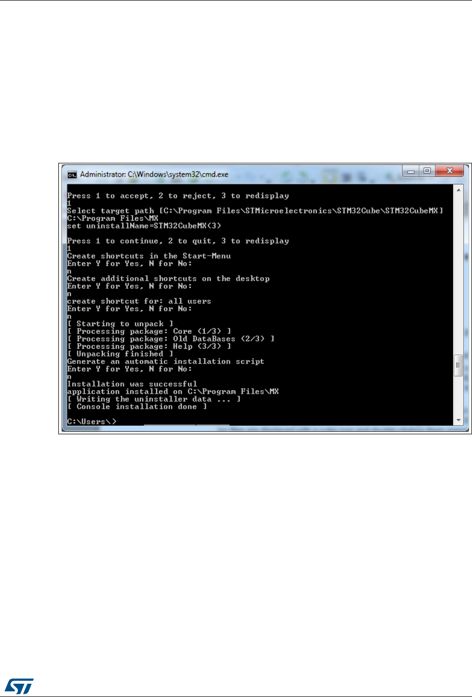
UM1718 Rev 26 25/345
UM1718 Installing and running STM32CubeMX
344
4.2.2 Installing STM32CubeMX from command line
There are two ways to launch an installation from a console window: either in console
interactive mode or via a script.
Interactive mode
To perform interactive installation, type the following command:
java –jar SetupSTM32CubeMX-4.14.0.exe –console
At each installation step, an answer is requested (see Figure 2).
Figure 2. Example of STM32CubeMX installation in interactive mode
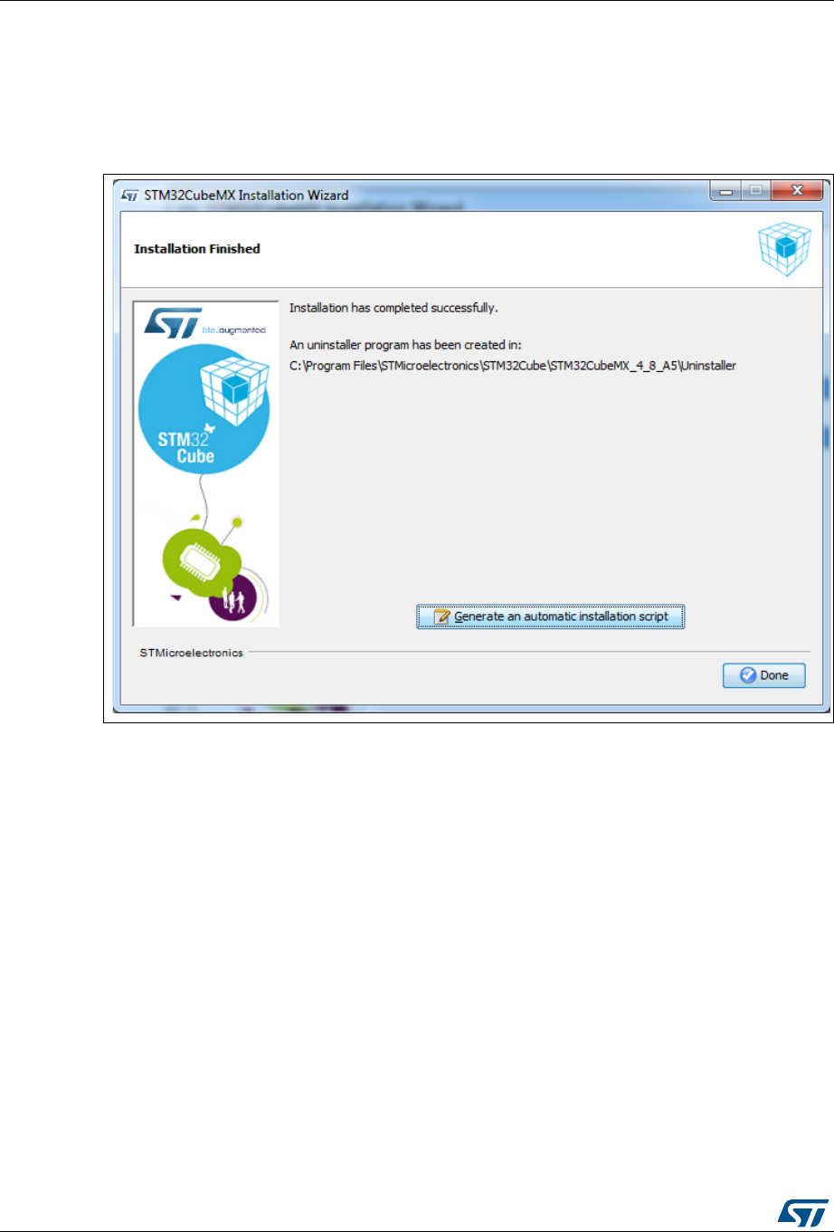
Installing and running STM32CubeMX UM1718
26/345 UM1718 Rev 26
Auto-install mode
At end of an installation, performed either using STM32CubeMX graphical wizard or console
mode, it is possible to generate an auto-installation script containing user installation
preferences (see Figure 3):
Figure 3. STM32Cube Installation Wizard
You can then launch the installation by typing the following command:
java –jar SetupSTM32CubeMX-4.14.0.exe auto-install.xml
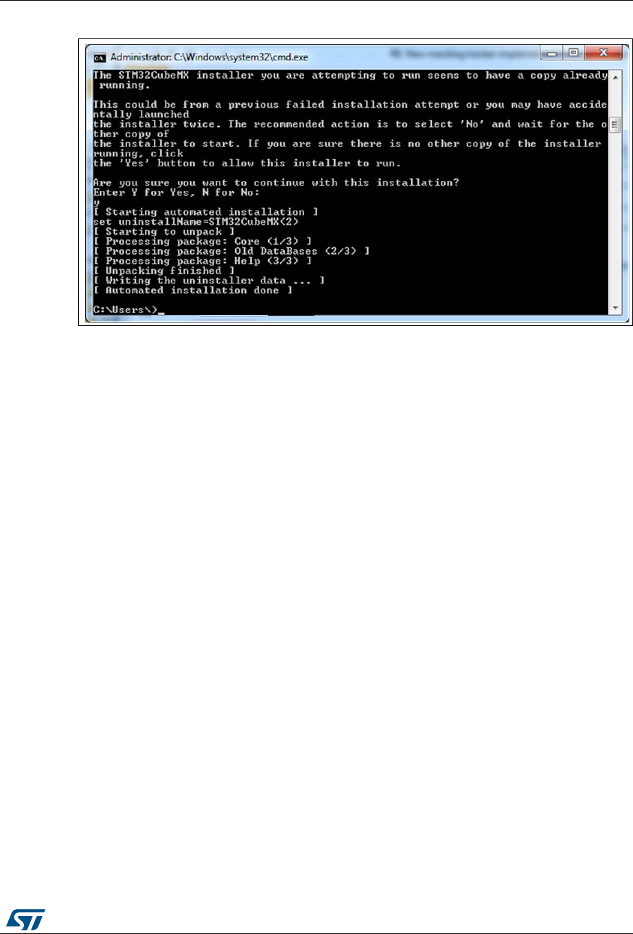
UM1718 Rev 26 27/345
UM1718 Installing and running STM32CubeMX
344
Figure 4. Auto-install command line
4.2.3 Uninstalling STM32CubeMX standalone version
Uninstalling STM32CubeMX on macOS
To uninstall STM32CubeMX on macOS, use the following command line:
java -jar <STM32CubeMX installation path>/Uninstaller/uninstaller.jar.
Uninstalling STM32CubeMX on Linux
There are three means to uninstall STM32CubeMX on Linux:
By using the following command line
java -jar <STM32CubeMX installation path>/Uninstaller/uninstaller.jar.
Through a Windows Explorer window:
a) Use a file explorer.
b) Go to the Uninstaller directory of STM32CubeMX installation.
c) Double-click the start uninstall desktop shortcut.
Uninstalling STM32CubeMX on Windows
There are three means to uninstall STM32CubeMX on Windows:
By using the following command line
java -jar <STM32CubeMX installation path>/Uninstaller/uninstaller.jar.
Through a Windows Explorer window:
a) Use a file explorer.
b) Go to the Uninstaller directory of STM32CubeMX installation.
c) Double-click the start uninstall desktop shortcut.
Through the Windows Control Panel:
a) Select Programs and Features from the Windows Control Panel to display the
list of programs installed on your computer.
b) Right-click STM32CubeMX and select uninstall.
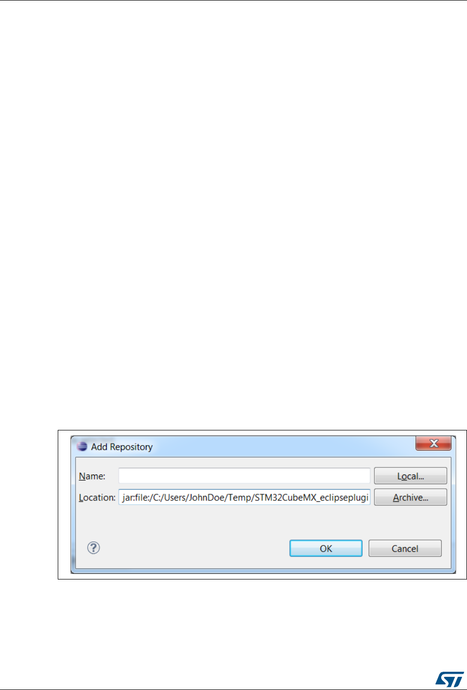
Installing and running STM32CubeMX UM1718
28/345 UM1718 Rev 26
4.3 Installing STM32CubeMX plug-in version
STM32CubeMX plug-in can be installed within Eclipse IDE development toolchain.
Installation related procedures are described in this section.
4.3.1 Downloading STM32CubeMX plug-in installation package
To download STM32CubeMX plug-in, follow the sequence below:
1. Go to http://www.st.com/stm32cubemx.
2. Download STM32CubeMX- Eclipse-plug-in .zip file to your local disk.
4.3.2 Installing STM32CubeMX as an Eclipse IDE plug-in
To install STM32CubeMX as an Eclipse IDE plug-in, follow the sequence below:
1. Launch the Eclipse environment.
2. Select Help > Install New Software from the main menu bar. The Available Software
window appears.
3. Click Add. The Add Repository window opens.
4. Click Archive. The Repository archive browser opens.
5. Select the STM32CubeMX- Eclipse-plug-in .zip file that you downloaded and click
Open (see Figure 5).
6. Click OK in the Add Repository dialog box,
7. Check STM32CubeMX_Eclipse_plug-in and click Next (see Figure 6).
8. Click Next in the Install Details dialog box.
9. Click ”I accept the terms of the license agreement” in the Review Licenses dialog box
and then click Finish.
10. Click OK in the Security Warning menu.
11. Click OK when requested to restart Eclipse IDE (see Section 4.4.2: Running
STM32CubeMX in command-line mode).
Figure 5. Adding STM32CubeMX plug-in archive
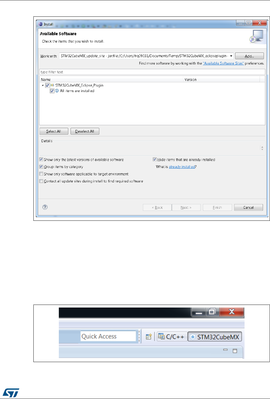
UM1718 Rev 26 29/345
UM1718 Installing and running STM32CubeMX
344
Figure 6. Installing STM32CubeMX plug-in
4.3.3 Uninstalling STM32CubeMX as Eclipse IDE plug-in
To uninstall STM32CubeMX plug-in in Eclipse IDE, follow the sequence below:
1. In Eclipse, right-click STM32CubeMX perspective Icon (see Figure 7) and select
Close.
2. From Eclipse Help menu, select Install New Software.
3. Click Installed Software tab, then select STM32CubeMX and click Uninstall.
4. Click Finish in Uninstall Details menu (see Figure 8).
Figure 7. Closing STM32CubeMX perspective


UM1718 Rev 26 31/345
UM1718 Installing and running STM32CubeMX
344
4.4 Launching STM32CubeMX
4.4.1 Running STM32CubeMX as standalone application
To run STM32CubeMX as a standalone application on Windows:
select STM32CubeMX from Program Files > ST Microelectronics > STM32CubeMX.
or double-click STM32CubeMX icon on your desktop.
To run STM32CubeMX as a standalone application on Linux, launch the STM32CubeMX
executable from STM32CubeMX installation directory.
To run STM32CubeMX as a standalone application on macOS, launch the STM32CubeMX
application from the launchpad.
Note: There is no STM32CubeMX desktop icon on macOS.
4.4.2 Running STM32CubeMX in command-line mode
To facilitate its integration with other tools, STM32CubeMX provides a command-line mode.
Using a set of commands, you can:
Load an MCU
Load an existing configuration
Save a current configuration
Set project parameters and generate corresponding code
Generate user code from templates.
Three command-line modes are available:
To run STM32CubeMX in interactive command-line mode, use the following command
line:
– On Windows:
java -jar STM32CubeMX.exe –i
– On Linux and macOS:
java -jar STM32CubeMX –i
The “MX>” prompt is then displayed to indicate that the application is ready to accept
commands.
To run STM32CubeMX in command-line mode getting commands from a script, use
the following command line:
– On Windows:
java -jar STM32CubeMX.exe –s <script filename>
– On Linux and macOS:
java -jar STM32CubeMX –s <script filename>
All the commands to be executed must be listed in the script file. An example of script
file content is shown below:
load STM32F417VETx
project name MyFirstMXGeneratedProject
project toolchain "MDK-ARM v4"
project path C:\STM32CubeProjects\STM32F417VETx
project generate

Installing and running STM32CubeMX UM1718
32/345 UM1718 Rev 26
exit
To run STM32CubeMX in command-line mode getting commands from a scripts and
without UI, use the following command line:
– On Windows:
java -jar STM32CubeMX.exe –q <script filename>
– On Linux and macOS:
java -jar STM32CubeMX –q <script filename>
Here again, the user can enter commands when the MX prompt is displayed.
See Table 1 for available commands.
Table 1. Command line summary
Command line Purpose Example
help This command displays the list of
available commands help
load <mcu> This command loads the selected MCU load STM32F101RCTx
load STM32F101Z(F-G)Tx
config load <filename> This command loads a previously saved
configuration config load C:\Cube\ccmram\ccmram.ioc
config save <filename> This command saves the current
configuration
config save
C:\Cube\ccmram\ccmram.ioc
config saveext <filename>
This command saves the current
configuration with all parameters,
including those for which values have
been kept to defaults (unchanged by
the user).
config saveext
C:\Cube\ccmram\ccmram.ioc
config saveas <filename> This command saves the current project
under a new name
config saveas
C:\Cube\ccmram2\ccmram2.ioc
csv pinout <filename>
This command exports the current pin
configuration as a csv file. This file
could later be imported into a board
layout tool.
Csv pinout mypinout.csv
script <filename>
This command runs all commands in
the script file. There must be one
command per line.
script myscript.txt
project couplefilesbyip <0|1>
This code generation option allows
choosing between 0 for generating the
peripheral initializations in the main or 1
for generating each peripheral
initialization in dedicated .c/.h files.
project couplefilesbyip 1

UM1718 Rev 26 33/345
UM1718 Installing and running STM32CubeMX
344
setDriver <Peripheral Name>
<HAL | LL>
For supported Series, STM32CubeMX
can generate peripheral initialization
code based on LL drivers or on HAL
drivers.
This command line allows choosing, for
each peripheral, between
HAL-based and LL-based code
generation.
By default code generation is based on
HAL drivers.
setDriver ADC LL
setDriver I2C HAL
generate code <path>
This command generates only
“STM32CubeMX generated” code and
not a complete project that would
include STM32Cube firmware libraries
and Toolchains project files.
To generate a project, use “project
generate”.
generate code C:\mypath
set tpl_path <path>
This command sets the path to the
source folder containing the .ftl user
template files.
All the template files stored in this folder
will be used for code generation.
set tpl_path C:\myTemplates\
set dest_path <path>
This command sets the path to the
destination folder that will hold the code
generated according to user templates.
set dest_path C:\myMXProject\inc\
get tpl_path This command retrieves the path name
of the user template source folder get tpl_path
get dest_path This command retrieves the path name
of the user template destination folder. get dest_path
project toolchain <toolchain>
This command specifies the toolchain to
be used for the project. Then, use the
“project generate” command to
generate the project for that toolchain.
project toolchain EWARM
project toolchain “MDK-ARM V4”
project toolchain “MDK-ARM V5”
project toolchain TrueSTUDIO
project toolchain SW4STM32
project name <name> This command specifies the project
name project name ccmram
project path <path> This command specifies the path where
to generate the project project path C:\Cube\ccmram
project generate Generate the full project project generate
exit End STM32CubeMX process exit
Table 1. Command line summary (continued)
Command line Purpose Example
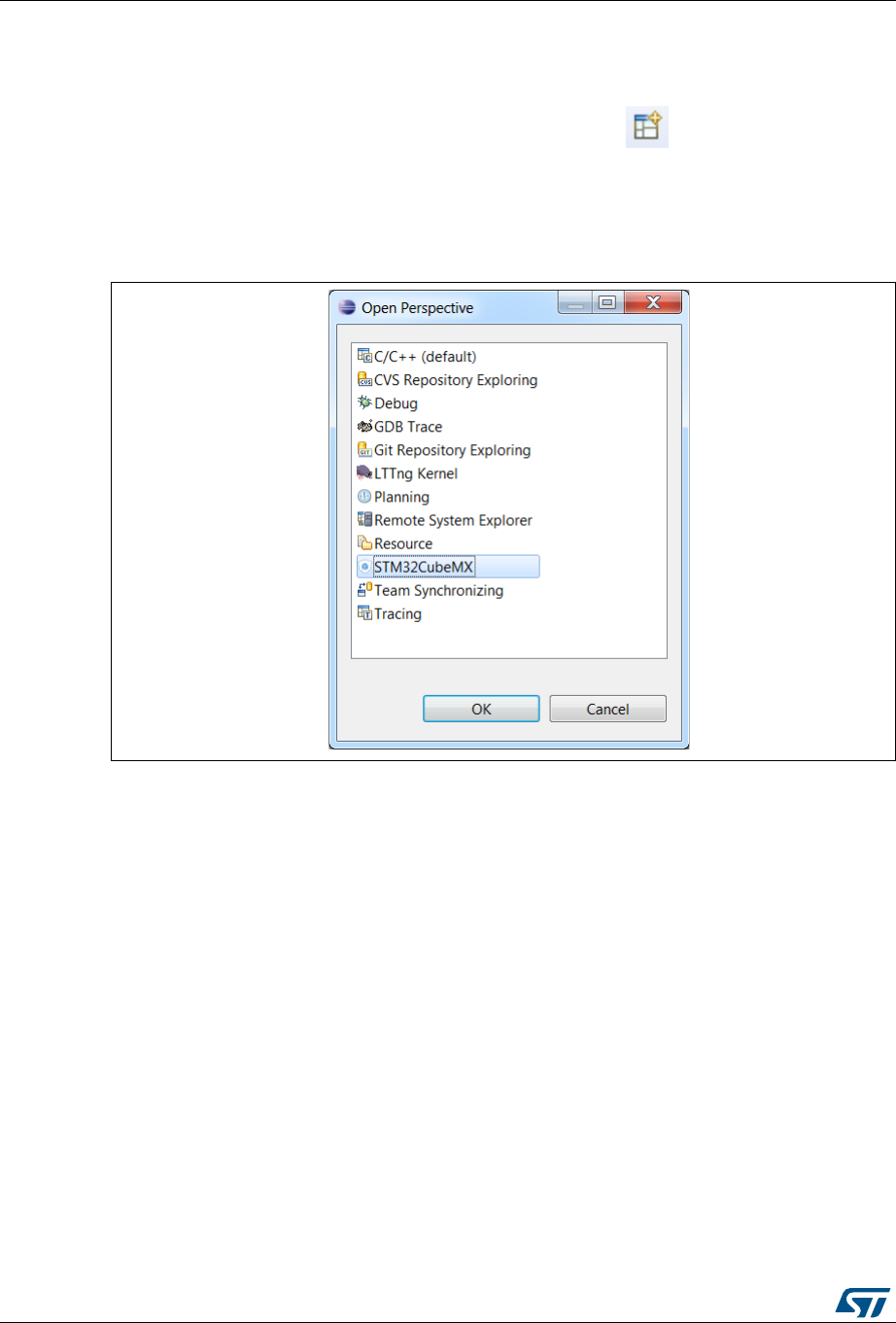
Installing and running STM32CubeMX UM1718
34/345 UM1718 Rev 26
4.4.3 Running STM32CubeMX plug-in from Eclipse IDE
To run STM32CubeMX plug-in from Eclipse:
1. Launch Eclipse environment.
2. Once Eclipse IDE is open, click open new perspective: .
3. Select STM32CubeMX to open STM32CubeMX as a perspective (see Figure 9).
4. STM32CubeMX perspective opens (see Figure 10). Enter STM32CubeMX user
interface via the Welcome menus.
Figure 9. Opening Eclipse plug-in
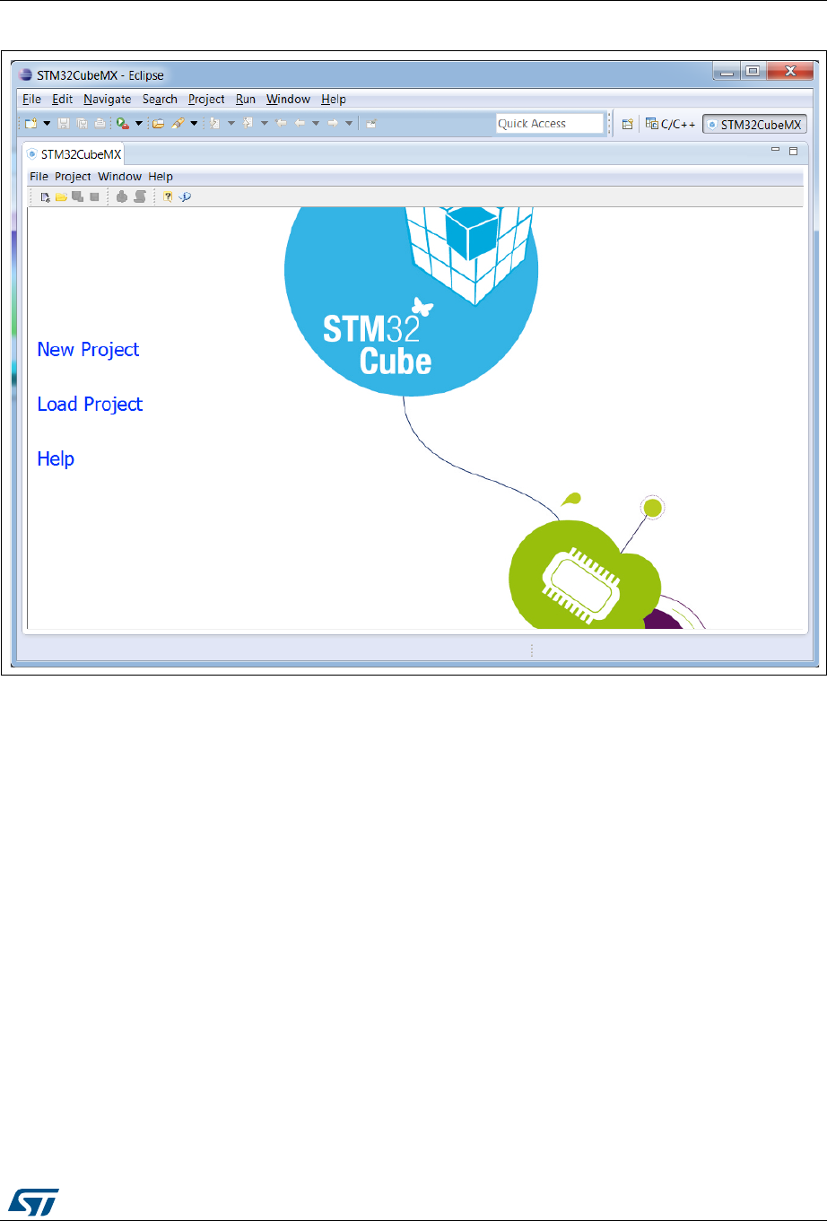
UM1718 Rev 26 35/345
UM1718 Installing and running STM32CubeMX
344
Figure 10. STM32CubeMX perspective
4.5 Getting updates using STM32CubeMX
STM32CubeMX implements a mechanism to access the Internet and to:
download embedded software packages: STM32Cube MCU packages (full releases
and patches) and third-party packages (.pack) based on the Arm® CMIS pack format,
manage a user-defined list of third-party packs,
check for STM32CubeMX and embedded software packages updates,
perform self-updates of STM32CubeMX,
refresh STM32 MCUs descriptions and documentation offer.
Installation and update related submenus are available under the Help menu.
Off-line updates can also be performed on computers without Internet access (see
Section 4.5.2: Installing STM32 MCU packages). This is done by browsing the filesystem
and selecting available STM32Cube MCU packages.
If the PC on which STM32CubeMX runs is connected to a computer network using a proxy
server, STM32CubeMX needs to connect to that server to access the Internet, get self-
updates and download firmware packages. Refer to Section 4.5.1 for a description of this
connection configuration.
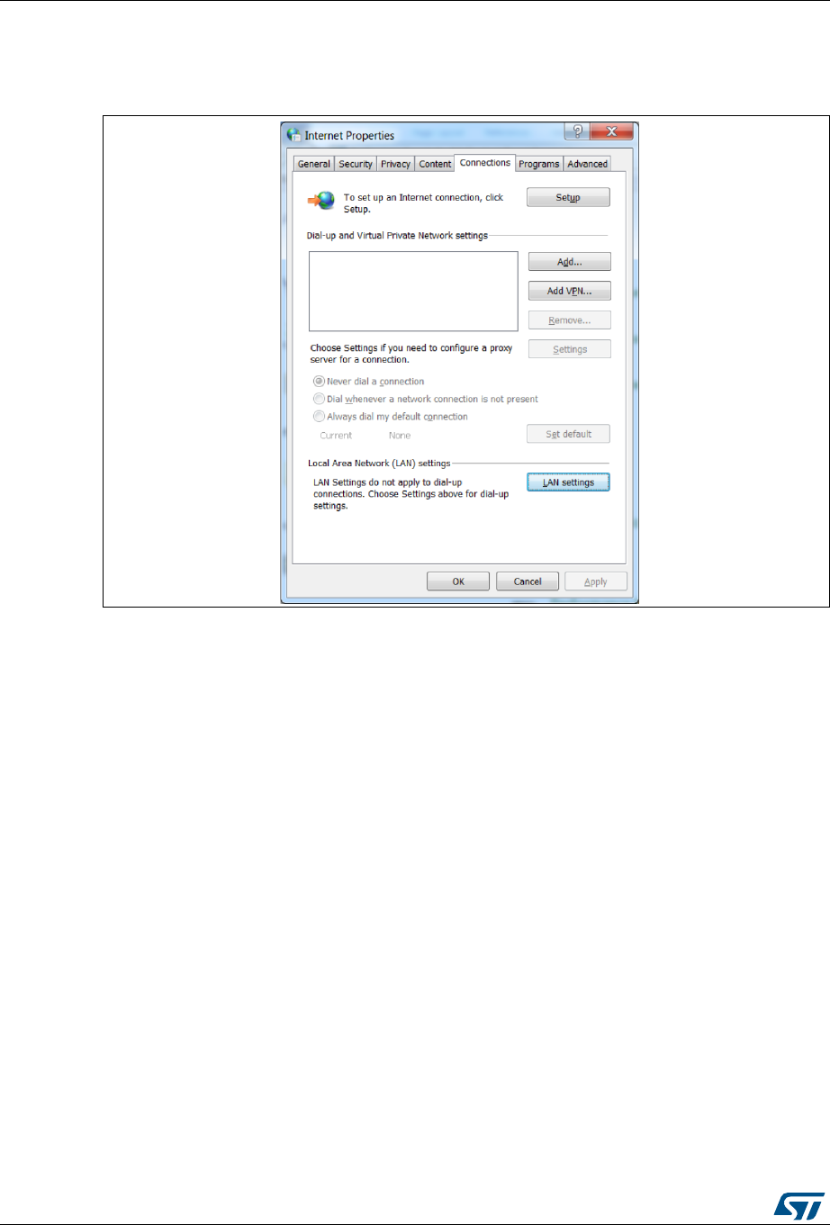
Installing and running STM32CubeMX UM1718
36/345 UM1718 Rev 26
To view Windows default proxy settings, select Internet options from the Control panel and
select LAN settings from the Connections tab (see Figure 11).
Figure 11. Displaying Windows default proxy settings
Several proxy types exist and different computer network configurations are possible:
Without proxy: the application directly accesses the web (Windows default
configuration).
Proxy without login/password
Proxy with login/password: when using an Internet browser, a dialog box opens and
prompts the user to enter its login/password.
Web proxies with login/password: when using an Internet browser, a web page opens
and prompts the user to enter its login/password.
If necessary, contact your IT administrator for proxy information (proxy type, http address,
port).
STM32CubeMX does not support web proxies. In this case, the user will not be able to
benefit from the update mechanism and will need to manually copy the STM32Cube MCU
packages from http://www.st.com/stm32cube to the repository. To do it, follow the sequence
below:
1. Go to http://www.st.com/stm32cube and download the relevant STM32Cube MCU
package from the Associated Software section.
2. Unzip the zip package to your STM32Cube repository. Find out the default repository
folder location in the Updater settings tab as shown in Figure 12 (you might need to
update it to use a different location or name).
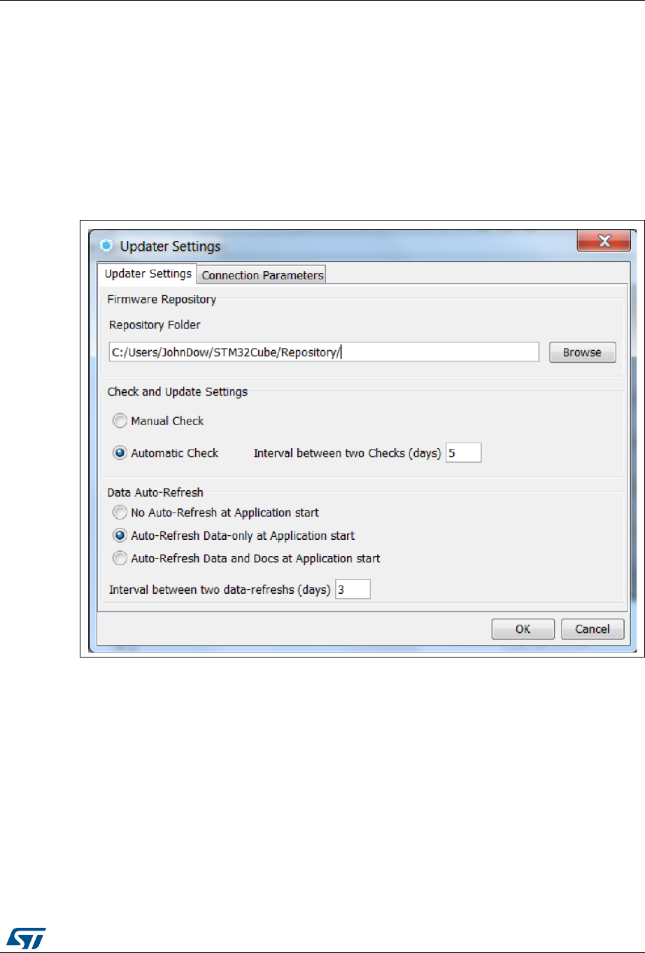
UM1718 Rev 26 37/345
UM1718 Installing and running STM32CubeMX
344
4.5.1 Updater configuration
To perform STM32Cube new library package installation or updates, the tool must be
configured as follows:
1. Select Help > Updater Settings to open the Updater Settings window.
2. From the Updater Settings tab (see Figure 12)
a) Specify the repository destination folder where the downloaded packages will be
stored.
b) Enable/Disable the automatic check for updates.
Figure 12. Updater Settings window
3. In the Connection Parameters tab, specify the proxy server settings appropriate for
your network configuration by selecting a proxy type among the following possibilities
(see Figure 13):
–No Proxy
– Use System Proxy Parameters
On Windows, proxy parameters will be retrieved from the PC system settings.
Uncheck “Require Authentication” if a proxy server without login/password
configuration is used.
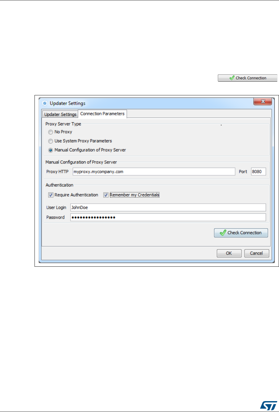
Installing and running STM32CubeMX UM1718
38/345 UM1718 Rev 26
– Manual Configuration of Proxy Server
Enter the Proxy server http address and port number. Enter login/password
information or uncheck “Require Authentication” if a proxy server without
login/password configuration is used.
4. Optionally uncheck Remember my credentials to prevent STM32CubeMX to save
encrypted login/password information in a file. This implies reentering login/password
information each time STM32CubeMX is launched.
5. Click the Check Connection button to verify if the connection works. A green check
mark appears to confirm that the connection operates correctly
Figure 13. Connection Parameters tab - Manual Configuration of Proxy Server
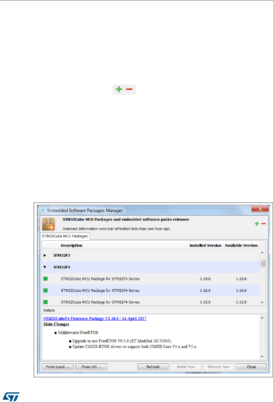
UM1718 Rev 26 39/345
UM1718 Installing and running STM32CubeMX
344
6. Select Help > Install New Libraries submenu to select among a list of possible
packages to install.
7. If the tool is configured for manual checks, select Help > Check for Updates to find out
about new tool versions or firmware library patches available to install.
4.5.2 Installing STM32 MCU packages
To download new STM32 MCU packages, follow the steps below:
1. Select Help > Manage embedded software packages to open the Embedded
Software Packages Manager (see Figure 14).
Expand/collapse buttons expands/collapses the list of packages,
respectively.
If the installation was performed using STM32CubeMX, all the packages available for
download are displayed along with their version including the version currently installed
on the user PC (if any), and the latest version available from http://www.st.com.
If no Internet access is available at that time, choose “Local File”. Then, browse to
select the zip file of the desired STM32Cube MCU package that has been previously
downloaded from st.com. An integrity check is performed on the file to ensure that it is
fully supported by STM32CubeMX.
The package is marked in green when the version installed matches the latest version
available from http://www.st.com.
2. Click the checkbox to select a package then “Install Now” to start the download.
See Figure 14 for an example.
Figure 14. Embedded Software Packages Manager window
Installing and running STM32CubeMX UM1718
40/345 UM1718 Rev 26
4.5.3 Installing STM32 MCU package patches
Use the procedure described in Section 4.5.2 to download STM32 MCU package patches.
A library patch, such as STM32Cube_FW_F7_1.4.1, can be easily identified by its version
number which third digit is non-null (e.g. ‘1’ for the 1.4.1 version).
The patch is not a complete library package but only the set of library files that need to be
updated. The patched files go on top of the original package (e.g.
STM32Cube_FW_F7_1.4.1 complements STM32Cube_FW_F7_1.4.0 package).
Prior to 4.17 version, STM32CubeMX copies the patches within the original baseline
directory (e.g. STM32Cube_FW_F7_V1.4.1 patched files are copied within the directory
called STM32Cube_FW_F7_V1.4.0).
Starting with STM32CubeMX 4.17, downloading a patch leads to the creation of a dedicated
directory. As an example, downloading STM32Cube_FW_F7_V1.4.1 patch creates the
STM32Cube_FW_F7_V1.4.1 directory that contains the original
STM32Cube_FW_F7_V1.4.0 baseline plus the patched files contained in
STM32Cube_FW_F7_V1.4.1 package.
Users can then choose to go on using the original package (without patches) for some
projects and upgrade to a patched version for others projects.
4.5.4 Installing embedded software packs
Starting from the release 4.24, STM32CubeMX offers the possibility to select third-party
embedded software packages coming in the Arm® Keil™ CMSIS-Pack format (.pack), which
contents are described thanks to the pack description (.pdsc) file. Reference documentation
is available from http://www.keil.com.
1. Select Help > Manage embedded software packages to open the New Libraries
Manager window (see Figure 15).
Use Expand/collapse buttons to expand/collapse the list of packages,
respectively.
UM1718 Rev 26 41/345
UM1718 Installing and running STM32CubeMX
344
Figure 15. Managing embedded software packages - Help menu
2. Click From Local … button to browse the computer filesystem and select an
embedded software package. STM32Cube MCU packages come as zip archives and
embedded software packs come as .pack archives.
This action is required in the following cases:
– No Internet access is possible but the embedded software package is available
locally on the computer.
– The embedded software package is not public and hence not available on
Internet. For such packages, STM32CubeMX cannot detect and propose updates.
3. Click From URL… button to specify the download location from Internet for either one
of the pack .pdsc file or the vendor pack index (.pidx).
Proceed as follow:
a) Choose From URL … and click New (see Figure 16).
b) Specify the .pdsc file url. As an example, the url of Oryx-Embedded middleware
pack is https://www.oryx-embedded.com/download/pack/Oryx-
Embedded.Middleware.pdsc (see Figure 17).
Installing and running STM32CubeMX UM1718
42/345 UM1718 Rev 26
Figure 16. Managing embedded software packages - Adding new url
c) Click the Check button to verify that the url provided is valid (see Figure 17).
Figure 17. Checking the validity of vendor pack .pdsc file url
d) Click OK. The pack pdsc information is now available in the user defined pack list
(see Figure 18).
To delete a url from the list, select the url checkbox and click Remove.
UM1718 Rev 26 43/345
UM1718 Installing and running STM32CubeMX
344
Figure 18. User-defined list of software packs
e) Click OK to close the window and start retrieving psdc information. Upon
successful completion, the available pack versions are shown in the list of libraries
that can be installed. Use the corresponding checkbox to select a given release
(see Figure 19).

Installing and running STM32CubeMX UM1718
44/345 UM1718 Rev 26
Figure 19. Selecting an embedded software pack release
f) Click Install Now to start downloading the software pack. A progress bar opens to
indicate the installation progress. If the pack comes with a license agreement, a
window pops up to ask for user’s acceptance (see Figure 20). When the
installation is successful, the check box turns green (see Figure 21).
The user will then be able to add software components from this pack to its
projects.

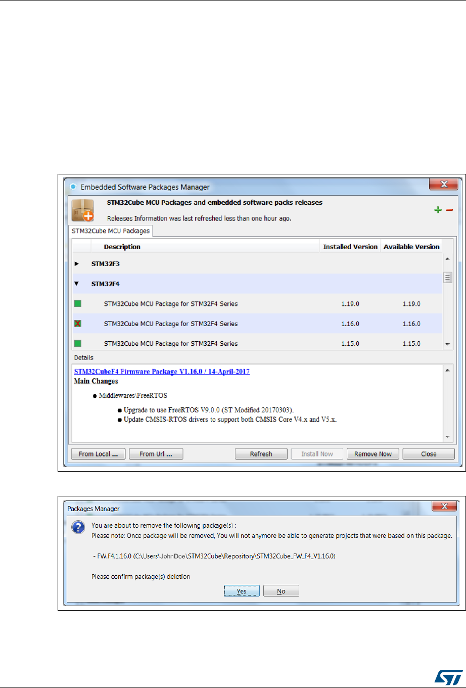
Installing and running STM32CubeMX UM1718
46/345 UM1718 Rev 26
4.5.5 Removing already installed embedded software packages
Proceed as follows to clean up the repository from old library versions thus saving disk
space:
1. Select Help > Manage embedded software packages to open the Embedded
Software Packages Manager.
2. Click a green checkbox to select a package available in stm32cube repository.
3. Click the Remove Now button and confirm. A progress window then opens to show the
deletion status.
Refer to Figure 22 to Figure 24 for an example.
Figure 22. Removing libraries
Figure 23. Removing library confirmation message
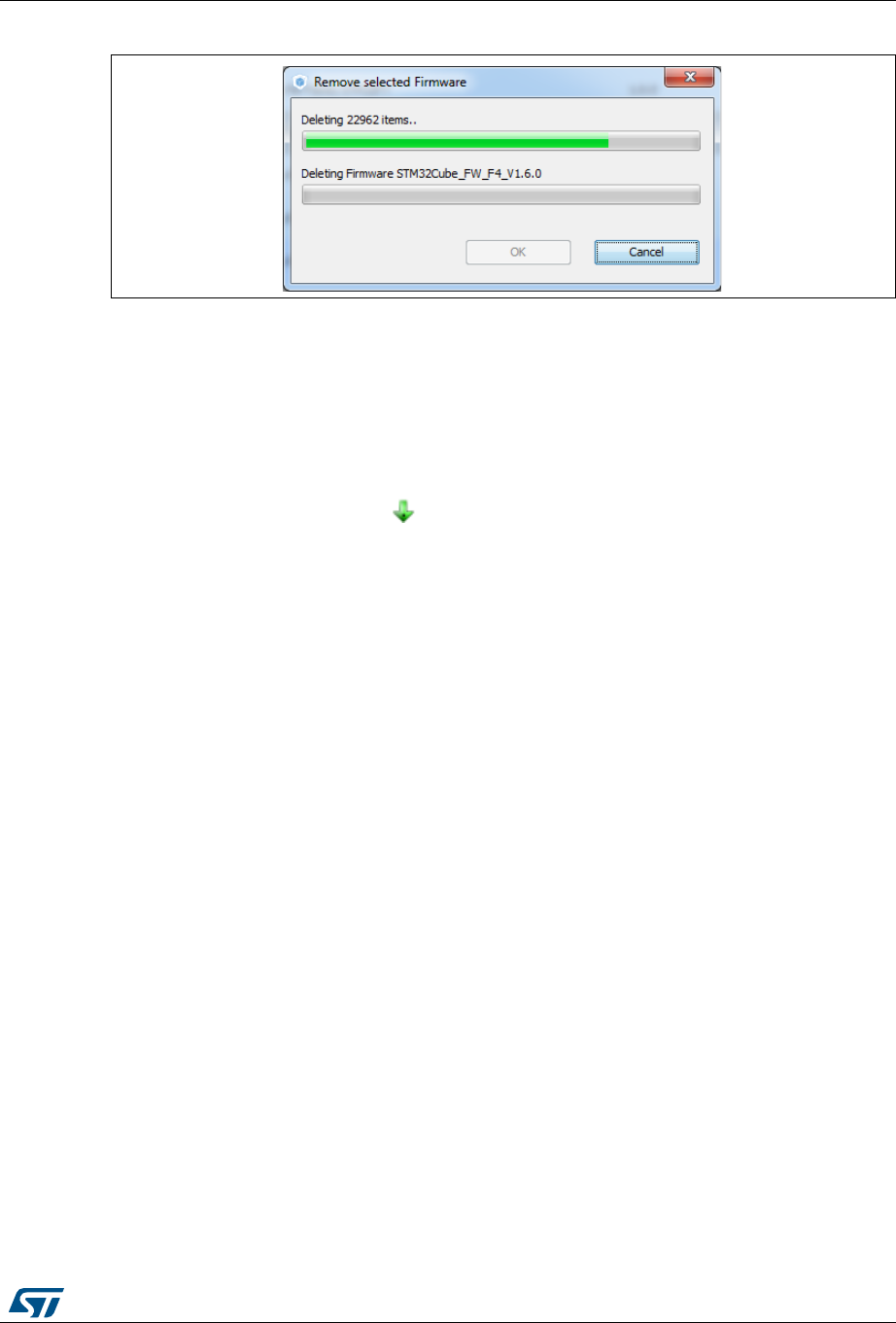
UM1718 Rev 26 47/345
UM1718 Installing and running STM32CubeMX
344
Figure 24. Library deletion progress window
4.5.6 Checking for updates
STM32CubeMX can check if updates are available for STM32CubeMX currently installed
version or for the embedded software packages installed in the repository folder (see
Figure 25).
When the updater is configured for automatic checks, it regularly verifies if updates are
available.
In this case, a green arrow icon appears on the tool bar.
When automatic checks have been disabled in the updater settings window, the user can
manually check if updates are available:
1. Click the icon to open the Update Manager window or Select Help > Check for
Updates. All the updates available for the user current installation are listed.
2. Click the check box to select a package, and then Install Now to download the update.
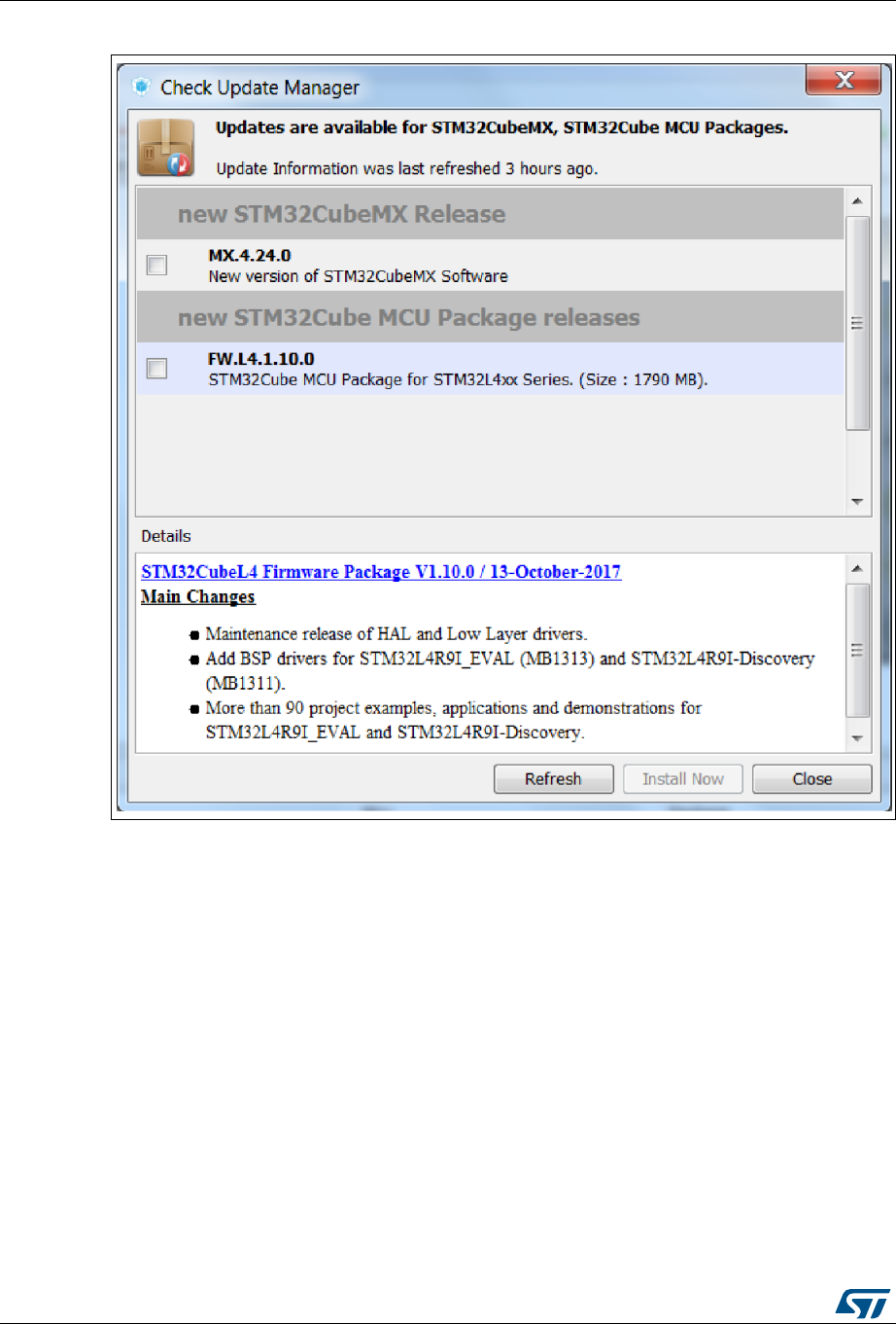

UM1718 Rev 26 49/345
UM1718 STM32CubeMX user interface
344
5 STM32CubeMX user interface
STM32CubeMX user interface consists first of a welcome page from which the user decides
to start a new project or load a recent one, then of a new project window in which the user
shall select a board or microcontroller part number to be used for the project, and finally the
project view with its main window, its menu bar, its toolbar, four configuration views (Pinout,
Configuration, Clock Configuration, Power Consumption Calculator) and a set of help
windows (MCUs selection, Update manager, About). All these user interface components
are described in the following sections.
For C code generation, although the user can switch back and forth between the different
configuration views, it is recommended to follow the sequence below:
1. Select the relevant features (peripherals, middlewares) and their operating modes from
the Pinout view.
2. Configure the clock tree from the clock configuration view.
In the Pinout view, configure the RCC peripheral by enabling the external clocks,
master output clocks, audio input clocks (when relevant for your application). This
automatically displays more options on the Clock tree view (see Figure 33).
3. Configure the parameters required to initialize the peripherals and middleware
operating modes from the configuration view.
4. Generate the initialization C code.
5.1 Welcome page
The Welcome page is the first window that opens up when launching STM32CubeMX
program. It remains open as long as the application is running. Closing it closes down the
application. Refer to Figure 26 and to Table 2 for a description of the Welcome page.
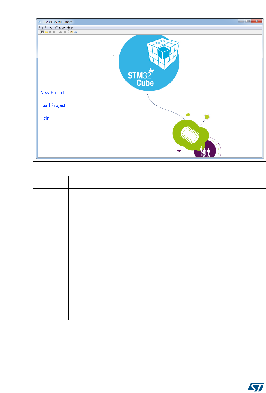
STM32CubeMX user interface UM1718
50/345 UM1718 Rev 26
Figure 26. STM32CubeMX Welcome page
Table 2. Welcome page shortcuts
Name Description
New Project
This shortcut launches STM32CubeMX new project creation by opening the New
project window (select an MCU from the MCU selector tab or a board configuration
from the Board selector tab).
Load Project
This shortcut opens a browser window to select a previously saved configuration
(.ioc file) and loads it.
When loading a project created with an older STM32CubeMX version, the user can
either select migrate to migrate it to the latest STM32CubeMX available database
and STM32Cube firmware version or continue.
Caution: Prior to STM32CubeMX 4.17, clicking continue still upgrades to the latest
database “compatible” with the SMT32Cube firmware version used by the
project.
Starting from STM32CubeMX 4.17, clicking continue keeps the database
used to create the project untouched. If the required database version is
not available on the computer, it will be automatically downloaded.
Caution: When upgrading to a new version of STM32CubeMX, make sure to
always backup your projects before loading the new project
(especially when the project includes user code).
Help This shortcut opens the user manual.
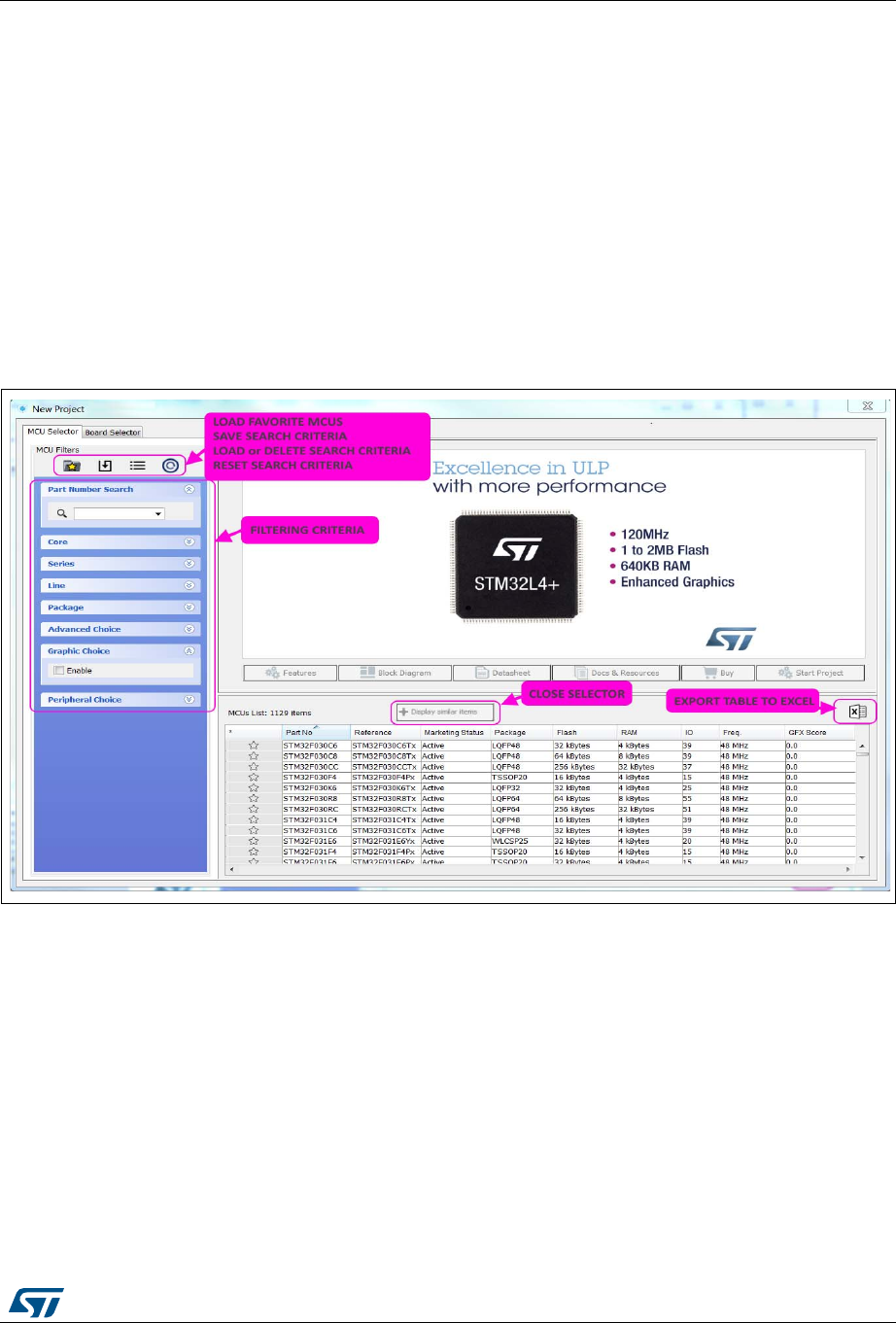
UM1718 Rev 26 51/345
UM1718 STM32CubeMX user interface
344
5.2 New project window
The main purpose here is to select from the STM32 portfolio a microcontroller or board part
number that best fits the user application needs.
This window shows two tabs to choose from:
the MCU selector tab offering a list of target processors
a Board selector tab showing a list of STMicroelectronics boards.
MCU selection
The MCU selector allows filtering on a combination of criteria: series, lines, packages,
peripherals, on additional MCU characteristics such as price, memory size or number of
I/Os (see Figure 27) and on MCU graphics capabilities as well.
Figure 27. New Project window - MCU selector
MCU selection based on graphics criteria
Selecting the checkbox to enable the Graphic Choice refreshes the MCU selector view (as
shown in Figure 28) with:
1. A set of Graphics specific filtering criteria
2. The list of MCUs, meeting these criteria along with their graphics performance score.
The graphics performance score is an indicative estimation of the graphics
performance that can be achieved using the MCU for the selected graphics system
configuration: the higher the score, better is the performance. It is shown in the GFX
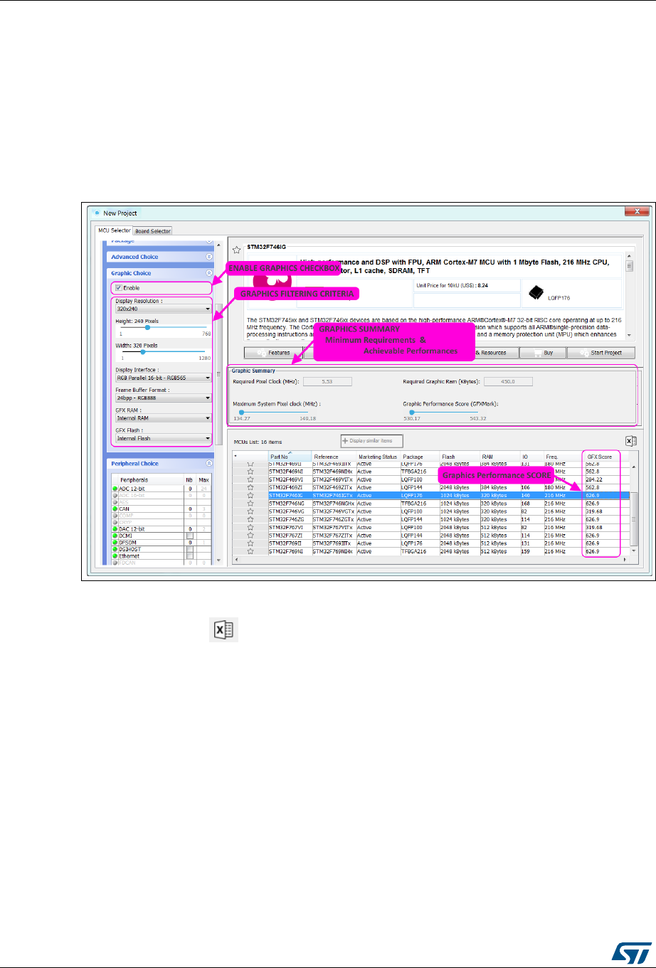
STM32CubeMX user interface UM1718
52/345 UM1718 Rev 26
column. Moreover, selecting an MCU from this list will allow to use graphical stacks in
the project.
3. A graphics summary panel, showing the minimum requirements for pixel clock and
graphics RAM size to meet the selected graphics criteria.
It also displays the performance ranges (maximum system clock and Graphics
performance score) that can be achieved with the current list of MCUs.
Parameters descriptions are provided in tooltips (to display: hover the mouse over the
parameter name).
Figure 28. Enabling graphics choice in MCU selector
Export to Excel feature
Clicking on the icon allows the user to save the MCU table information to an Excel file.
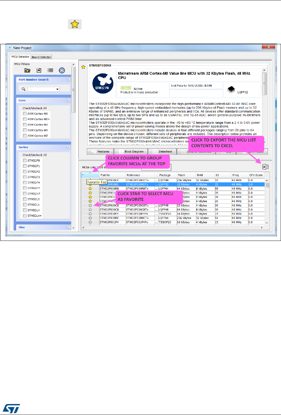
UM1718 Rev 26 53/345
UM1718 STM32CubeMX user interface
344
Show favorite MCUs feature
Clicking the icon for an MCU from the list marks it as favorite, see Figure 29.
Figure 29. Marking an MCU as a favorite
MCU close selector feature
When the number of MCUs found is lower than 50, the selector offers to list the MCUs with
close features (see Figure 30). Clicking the Display similar items button displays them
(see Figure 31): by default, MCUs are sorted first by matching ratio, then by part number.
For close MCUs (those with a matching ratio lower than 100%) rows are shown in gray and
non matching cells are highlighted in dark gray.

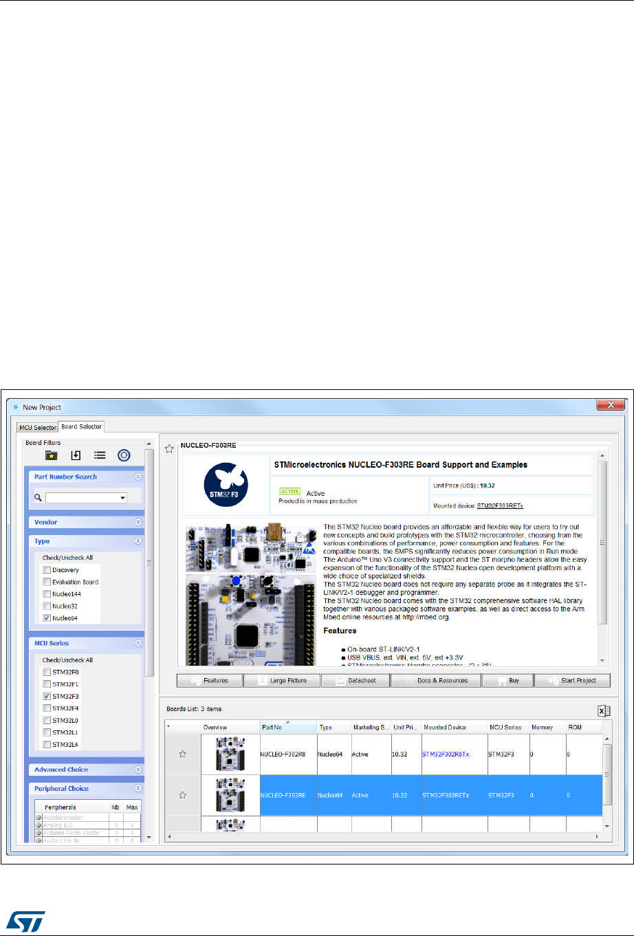
UM1718 Rev 26 55/345
UM1718 STM32CubeMX user interface
344
Note: A matching percentage is computed for each user selected criteria, for example:
- When requesting four instances of the CAN peripheral, the MCUs with only three instances
will reach a 75% match on the CAN criteria.
- If the maximum price criteria is selected, the matching ratio for a given MCU will be the
maximum requested price divided by the actual MCU price. In the case of a minimum price
criteria, the matching ratio will be the MCU price divided by the minimum requested price.
Finally, all criteria ratios are averaged to give the Match column percentage value.
The Board selector allows filtering on STM32 board types, Series and peripherals (see
Figure 32). Only the default board configuration is proposed. Alternative board
configurations obtained by reconfiguring jumpers or by using solder bridges are not
supported.
When a board is selected, the Pinout view is initialized with the relevant MCU part number
along with the pin assignments for the LCD, buttons, communication interfaces, LEDs, and
other functions (see Figure 34). Optionally, the user can choose to initialize it with the
default peripheral modes (see Figure 35).
When a board configuration is selected, the signals change to 'pinned', i.e. they cannot be
moved automatically by STM32CubeMX constraint solver (user action on the peripheral
tree, such as the selection of a peripheral mode, will not move the signals). This ensures
that the user configuration remains compatible with the board.
Figure 32. New Project window - board selector
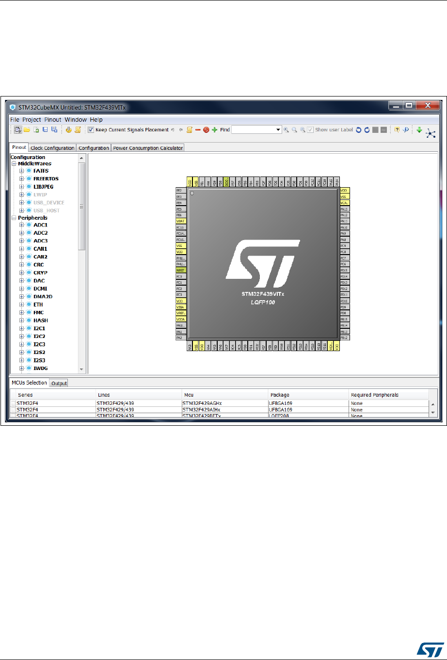
STM32CubeMX user interface UM1718
56/345 UM1718 Rev 26
5.3 Main window
Once an STM32 part number or a board has been selected or a previously saved project
has been loaded, the main window displays all STM32CubeMX components and menus
(see Figure 33). Refer to Section 5.3 for a detailed description of the toolbar and menus.
Figure 33. STM32CubeMX Main window upon MCU selection
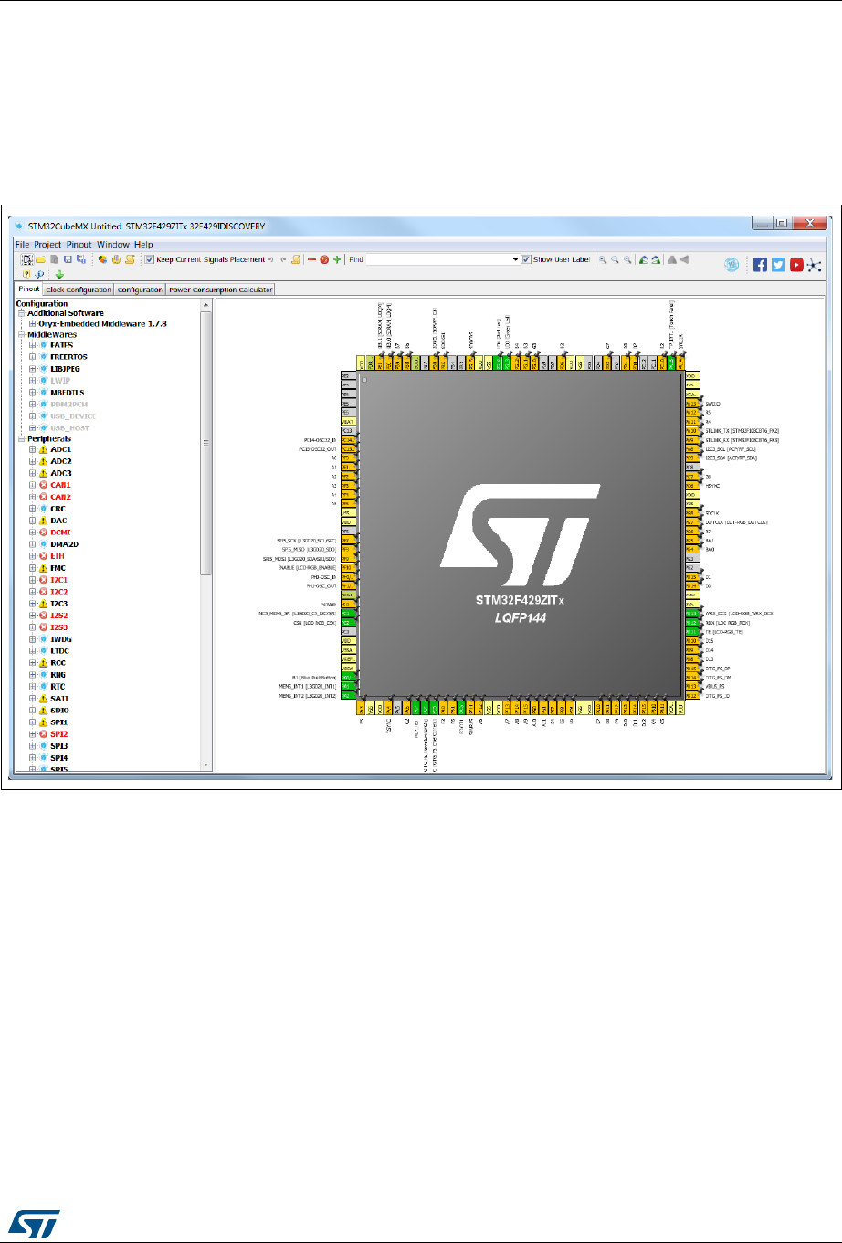
UM1718 Rev 26 57/345
UM1718 STM32CubeMX user interface
344
Selecting a board, then answering No in the dialog window requesting to initialize all
peripherals to their default mode, automatically sets the pinout for this board. However, only
the pins set as GPIOs are marked as configured, i.e. highlighted in green, while no
peripheral mode is set. The user can then manually select from the peripheral tree the
peripheral modes required for its application (see Figure 34).
Figure 34. STM32CubeMX Main window upon board selection
(Peripheral default option unchecked)
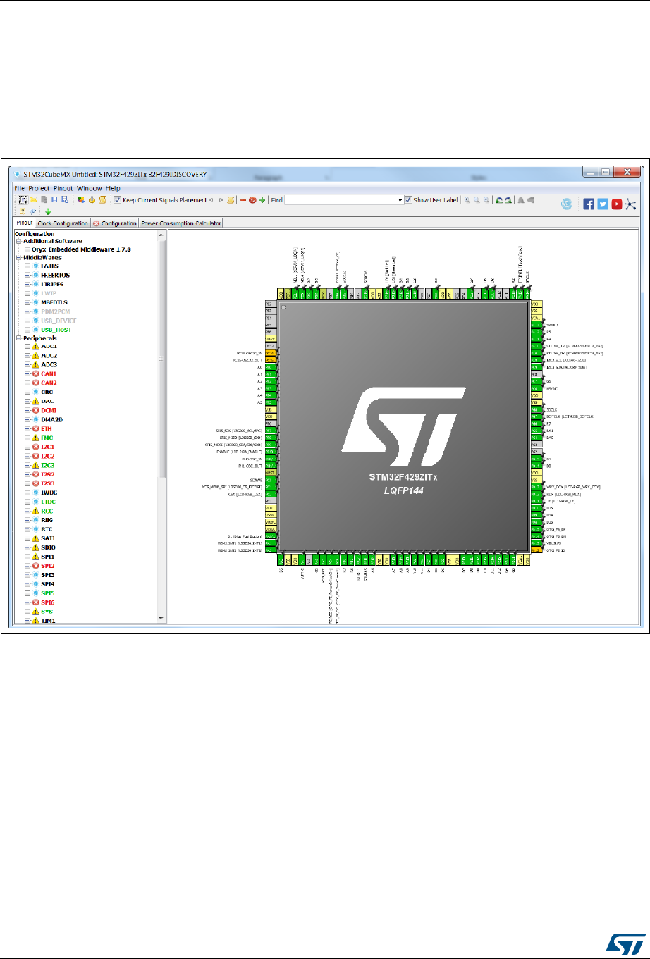
STM32CubeMX user interface UM1718
58/345 UM1718 Rev 26
Selecting a board, then accepting to initialize all peripherals to their default mode,
automatically sets both the pinout and the default modes for the peripherals available on the
board. This means that STM32CubeMX will generate the C initialization code for all the
peripherals available on the board and not only for those relevant to the user application
(see Figure 35).
Figure 35. STM32CubeMX Main window upon board selection
(Peripheral default option checked)

UM1718 Rev 26 59/345
UM1718 STM32CubeMX user interface
344
5.4 Toolbar and menus
The following menus are available from STM32CubeMX menu bar:
File menu
Project menu
Pinout menu (displayed only when the Pinout view has been selected)
Window menu
Help menu
STM32CubeMX menus and toolbars are described in the sections below.
5.4.1 File menu
Refer to Table 3 for a description of the File menu and icons.
Table 3. File menu functions
Icon Name Description
New Project
Opens a new project window showing all supported MCUs and a
set of STMicroelectronics boards to choose from.
Caution: To avoid any popup error messages at that stage, make
sure an Internet connection is available (Connection
Parameters tab under Help > Updater settings menu)
or that Data Auto-refresh settings are set to No Auto-
Refresh at application start (Updater Settings tab under
Help > Updater Settings menu).
Load Project …
Loads an existing STM32CubeMX project configuration by
selecting an STM32CubeMX configuration .ioc file.
Caution: When upgrading to a new version of STM32CubeMX,
make sure to always backup your projects before loading
the new project (especially when the project includes
user code).
Import Project
…
Opens a new window to select the configuration file to be imported
as well as the import settings.
The import is possible only if you start from an empty MCU
configuration. Otherwise, the menu is disabled.
A status window displays the warnings or errors detected when
checking for import conflicts. The user can then decide to cancel the
import.
Save Project
as …
Saves current project configuration (pinout, clock tree, peripherals,
middlewares, Power Consumption Calculator) as a new project.
This action creates an .ioc file with user defined name and located
in the destination folder.
Save Project Saves the current project.
No icon Close Project Closes the current project and switches back to the welcome page.
No icon Recent
Projects > Displays the list of five most recently saved projects
No icon Exit Proposes to save the project if needed, then closes the application.
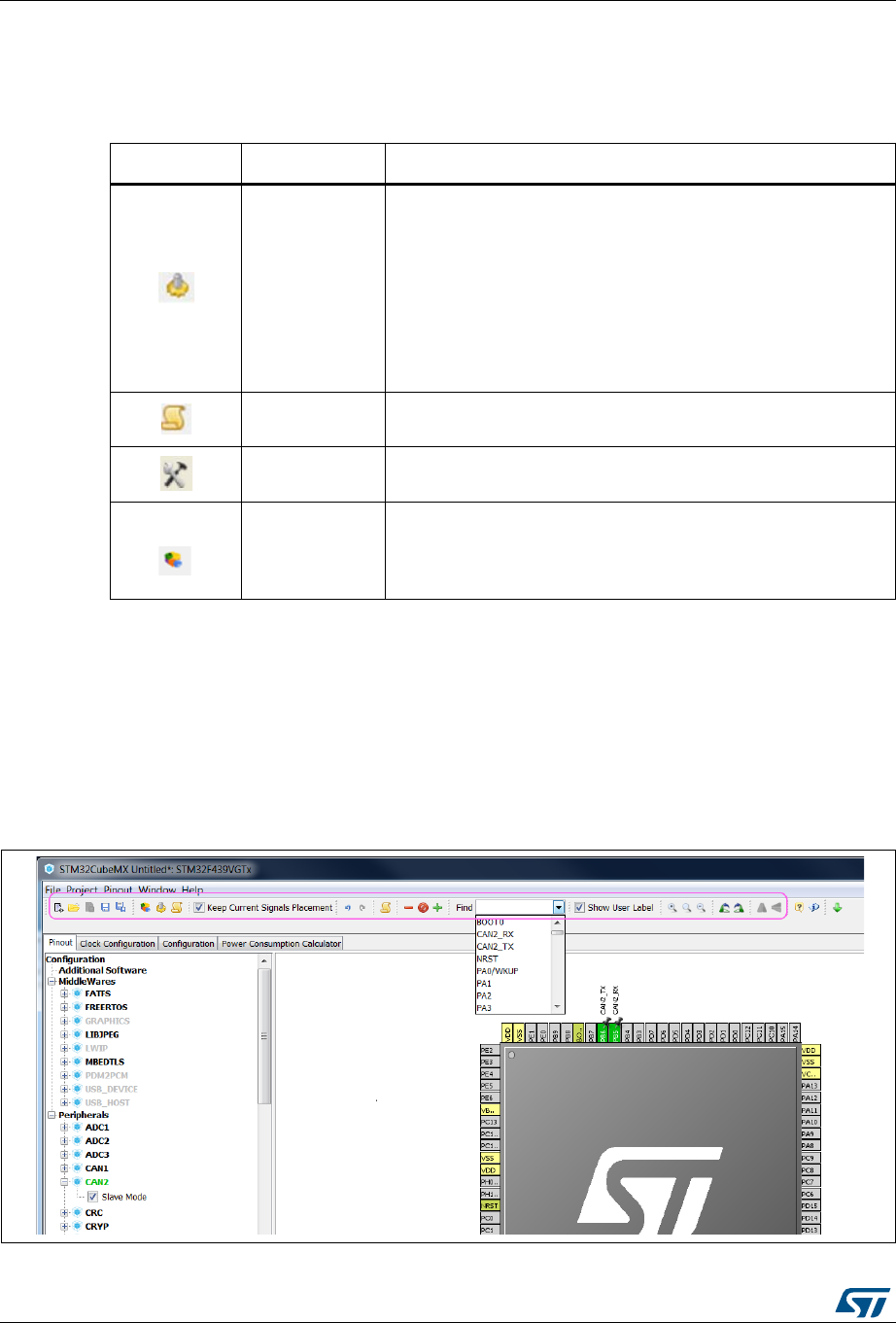
STM32CubeMX user interface UM1718
60/345 UM1718 Rev 26
5.4.2 Project menu
Refer to Table 4 for a description of the Project menu and icons.
5.4.3 Pinout menu
The Pinout menu and submenus shortcuts are available only when the Pinout tab is
selected (see Figure 36). They are hidden otherwise (see Figure 37). Refer to Table 5 for a
description of the Pinout menu and icons.
Figure 36. Pinout menus (Pinout tab selected)
Table 4. Project menu
Icon Name Description
Generate Code
This menu generates C initialization C code for current
configuration (pinout, clocks, peripherals and middleware).
Opens a window for project settings if they have not been
defined previously.
Note: It is recommended to backup the current projects when
upgrading to a new version of STM32CubeMX. The user
will be prompted to migrate to a new firmware library
version if any is available. Select Continue to keep the
previously used version.
Generate
Report(1)
1. If the project was previously saved, the reports are generated at the same location as the project
configuration .ioc file. Otherwise, the user can choose the destination folder, and whether to save the
project configuration as an .ioc file or not.
This menu generates current project configuration as a pdf file
and a text file.
Settings This menu opens the project settings window to configure project
name, folder, select a toolchain and C code generation options
Select additional
software
components
This menu allows the selection of the software components
delivered in embedded software packs.The user can install such
packages by selecting Manage embedded software packages
under the Help menu.
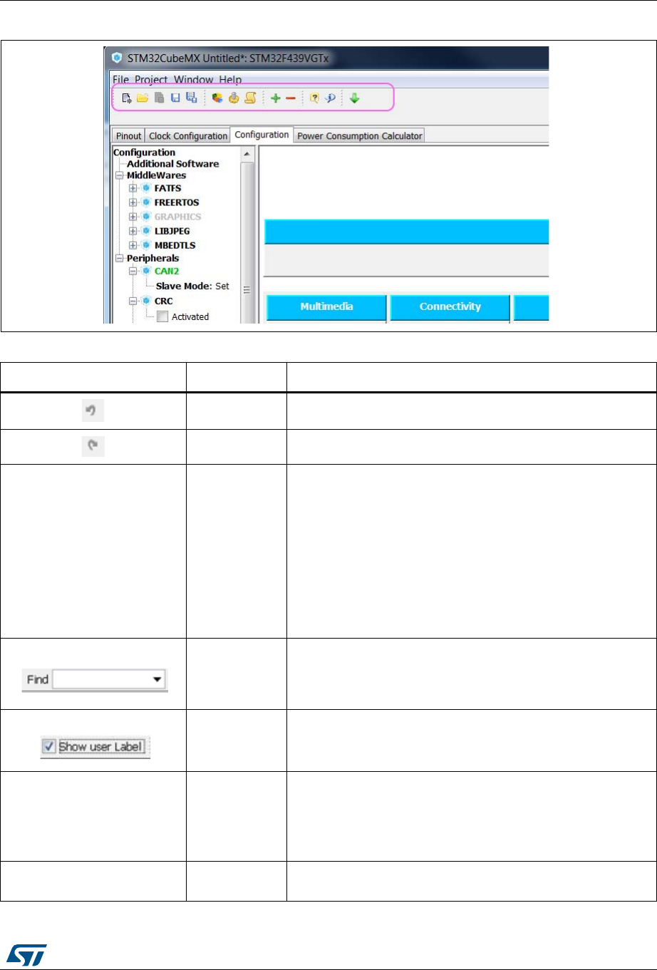
UM1718 Rev 26 61/345
UM1718 STM32CubeMX user interface
344
Figure 37. Pinout menus (Pinout tab not selected)
Table 5. Pinout menu
Icon Name Description
Undo Undoes last configuration steps (one by one)
Redo Redoes steps that have been undone (one by one)
No icon Pins/Signals
Options
Opens a window showing the list of all the configured pins
together with the name of the signal on the pin and a Label field
allowing the user to specify a label name for each pin of the list.
For this menu to be active, at least one pin must have been
configured.
Click the pin icon to pin/unpin signals individually.
Select multiple rows then right click to open contextual menu
and select action to pin or unpin all selected signals at once.
Click column header names to sort alphabetically by name or
according to placement on MCU.
Pinout search
field
Allows the user to search for a pin name, signal name or signal
label in the Pinout view. When it is found, the pin or set of pins
that matches the search criteria blinks on the Chip view. Click
the Chip view to stop blinking.
Show user
labels
Allows showing on the Chip view, the user-defined labels
instead of the names of the signals assigned to the pins.
No icon Clear Pinouts
Clears user pinout configuration in the Pinout window.
Note that this action puts all configured pins back to their reset
state and disables all the peripheral and middleware modes
previously enabled (whether they were using signals on pins or
not).
No icon Clear Single
Mapped Signals
Clears signal assignments to pins for signals that have no
associated mode (highlighted in orange and not pinned).
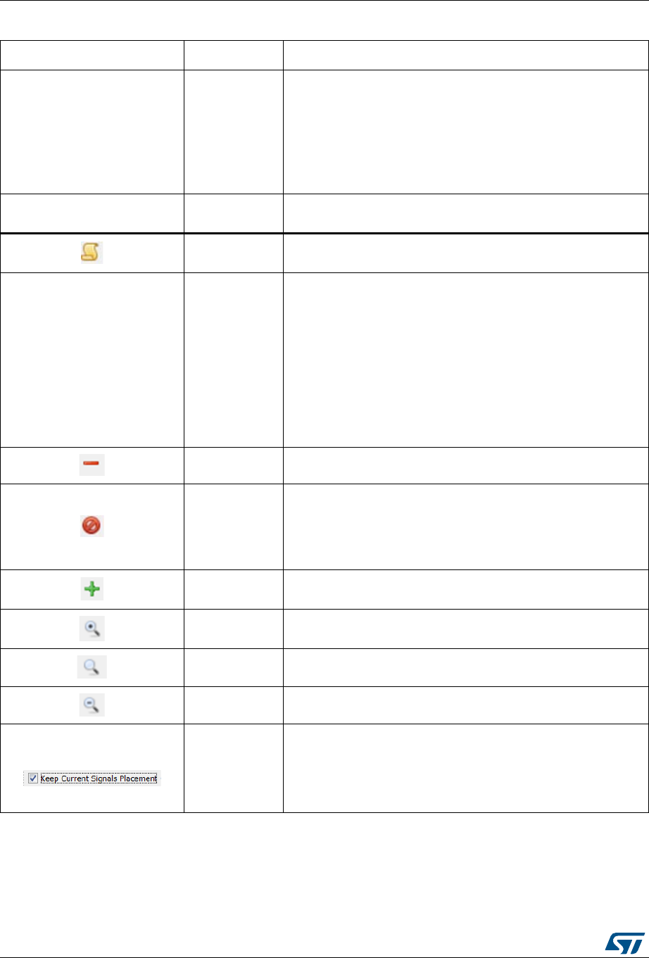
STM32CubeMX user interface UM1718
62/345 UM1718 Rev 26
No icon Set unused
GPIOs
Opens a window to specify the number of GPIOs to be configure
among the total number of GPIO pins that are not used yet.
Specify their mode: Input, Output or Analog (recommended
configuration to optimize power consumption).
Caution: Before using this menu, make sure the debug pins
(available under SYS peripheral) are set to access
microcontroller debug facilities.
No icon Reset used
GPIOs
Opens a window to specify the number of GPIOs to be freed
among the total number of GPIO pins that are configured.
Generate csv
text pinout file Generates pin configuration as a .csv text file
No Icon
List pinout
compatible
MCUs
Provides a list of MCUs that best match the pin configuration of
the current project. The matching can be:
– An exact match
– A partial match with hardware compatibility: pin locations are
the same, pin names may have been changed
– A partial match without hardware compatibility: all signals
could be mapped but not all at the same pin location
Refer to Section 12: Tutorial 5: Exporting current project
configuration to a compatible MCU for details on how to use this
feature.
Collapse All Collapses the Peripheral/Middleware tree view
Disable Modes
Resets to “Disabled” all peripherals and middleware modes that
have been enabled. The pins configured in these modes (green
color) are consequently reset to “Unused” (gray color).
Peripheral and middleware labels change from green to black
(when unused) or gray (when not available).
Expand All Expands the Peripheral/Middleware tree view to display all
functional modes.
Zooming in Zooms in the chip pinout diagram
Best Fit Adjusts the chip pinout diagram to the best fit size
Zooming out Zooms out the chip pinout diagram
Keep current
signals
Placement
Available from toolbar only.
Prevents moving pin assignments to match a new peripheral
operating mode. It is recommended to use the new pinning
feature that can block each pin assignment individually and
leave this checkbox unchecked.
Table 5. Pinout menu (continued)
Icon Name Description
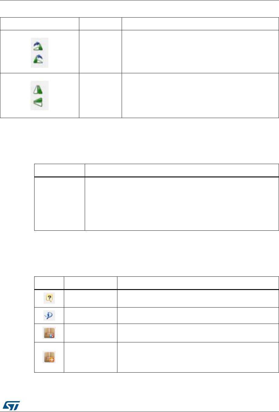
UM1718 Rev 26 63/345
UM1718 STM32CubeMX user interface
344
5.4.4 Window menu
The Window menu allows to access the Outputs function (see Table 6).
5.4.5 Help menu
Refer to Table 7 for a description of the Help menu and icons.
Rotate
clockwise
Counter
clockwise
Rotates the MCU core as well as its pins and mapped signals by
90 degrees clockwise or counterclockwise from the current view.
Click twice to rotate by 180 degrees, and three times to rotate by
270 degrees.
Flip
horizontal/flip
vertical
Available only for BGA packages.
Allows to flip horizontally or vertically between bottom and top
views. (then keep text as it is). The bottom view corresponds to
the bottom side of the BGA package (ball side up), and the top
view to the other side (ball side down, and ST logo clearly visible
if any).
Table 5. Pinout menu (continued)
Icon Name Description
Table 6. Window menu
Name Description
Outputs
Opens the MCUs selection window at the bottom of STM32CubeMX Main
window.
Opens two tabs at the bottom of STM32CubeMX main window:
–MCUs selection tab that lists the MCUs that match the user criteria selected
via the MCU selector.
–Outputs tab that displays STM32CubeMX messages, warnings and errors
encountered upon users actions.
Table 7. Help menu
Icons Name Description
Help Content Opens the STM32CubeMX user manual
About... Shows version information
Check for Updates Shows the software and firmware release updates available for
download.
Manage embedded
software packages
Shows all the embedded software packages available for
installation. A green check box indicates that the package is
already installed in the user repository folder (the repository folder
location is specified under Help > Updater Settings menu).

STM32CubeMX user interface UM1718
64/345 UM1718 Rev 26
5.4.6 Social links
Developer communities on popular social platforms such as Facebook, Twitter, STM32
YouTube channel, as well as ST Community can be accessed from STM32CubeMX toolbar
(see Figure 38).
Figure 38. Link to social platforms
5.5 Output windows
5.5.1 MCUs selection panel
This window lists all the MCUs of a given family that match the user criteria (Series,
peripherals, package..) when an MCU was selected last.
Note: Selecting a different MCU from the list resets the current project configuration and switches
to the new MCU. The user will be prompted to confirm this action before proceeding.
Updater Settings...
Opens the updater settings window to configure manual versus
automatic updates, proxy settings for Internet connections,
repository folder where the downloaded software and firmware
releases will be stored.
No icon Refresh Data
Opens a dialog window that proposes to refresh STM32CubeMX
database with STM32 MCU latest information (MCU description
and list of official documents) and allows the download of all
official documentation in one shot
No icon Docs & Resources Displays the official documentation available for the MCU used in
the current project.
Table 7. Help menu

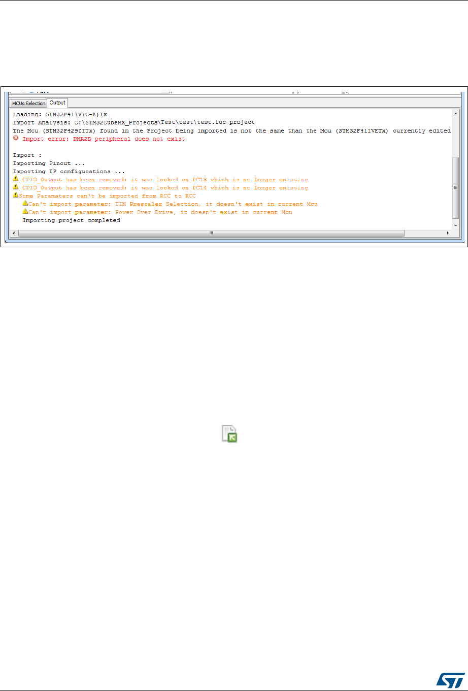
STM32CubeMX user interface UM1718
66/345 UM1718 Rev 26
5.5.2 Output panel
This panel displays a non exhaustive list of the actions performed, errors and raised
warnings (see Figure 40).
Figure 40. Output panel
5.6 Import Project window
The Import Project menu eases the porting of a previously-saved configuration to another
MCU.
By default the following settings are imported:
Pinout tab: MCU pins and corresponding peripheral modes.The import fails if the same
peripheral instances are not available in the target MCU.
Clock configuration tab: clock tree parameters.
Configuration tab: peripherals and middleware libraries initialization parameters.
Project settings: choice of toolchain and code generation options.
To import a project, proceed as follows:
1. Select the Import project icon that appears under the File menu after starting a
New Project and once an MCU has been selected.
The menu remains active as long as no user configuration settings are defined for the
new project, that is just after the MCU selection. It is disabled as soon as a user action
is performed on the project configuration.
2. Select File > Import Project for the dedicated Import project window to open. This
window allows to specify the following options:
– The STM32CubeMX configuration file (.ioc) pathname of the project to import on
top of current empty project.
– Whether to import the configuration defined in the Power Consumption
Calculator tab or not.
– Whether to import the project settings defined through the Project > Settings
menu: IDE selection, code generation options and advanced settings.
– Whether to import the project settings defined through the Project > Settings
menu: IDE selection and code generation options.

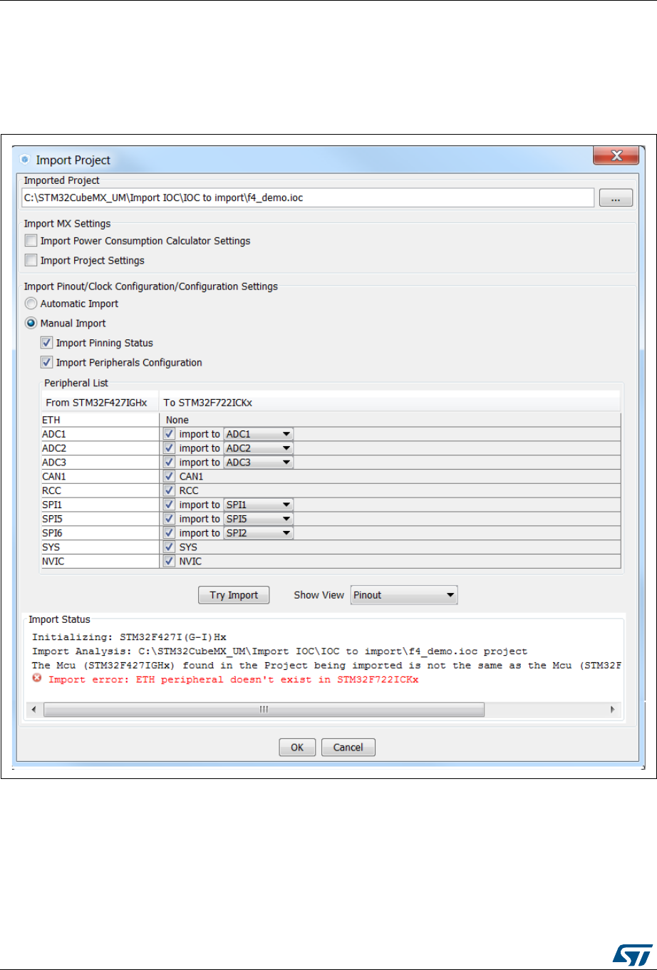

UM1718 Rev 26 69/345
UM1718 STM32CubeMX user interface
344
The Peripheral List indicates:
– The peripheral instances configured in the project to be imported
– The peripheral instances, if any exists for the MCU currently selected, to which the
configuration has to be imported. If several peripheral instances are candidate for
the import, the user needs to choose one.
Conflicts might occur when importing a smaller package with less pins or a lower-end
MCU with less peripheral options. Click the Try Import button to check for such
conflicts: the Import Status window and the Peripheral list get refreshed to indicate
errors (see Figure 43), warnings and whether the import has been successful or not:
– Warning icons indicate that the user has selected a peripheral instance more than
once and that one of the import requests will not be performed.
– A cross sign indicates that there is a pinout conflict and that the configuration can
not be imported as such.
The manual import can be used to refine import choices and resolve the issues raised
by the import trial. Figure 44 gives an example of successful import trial, that has been
obtained by deselecting the import request for some peripherals.
The Show View function allows switching between the different configuration tabs
(pinout, clock tree, peripheral configuration) for checking influence of the "Try Import"
action before actual deployment on current project (see Figure 44).

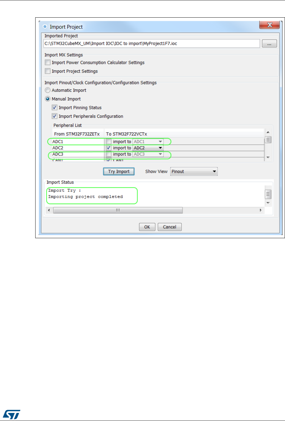
UM1718 Rev 26 71/345
UM1718 STM32CubeMX user interface
344
Figure 44. Import Project menu - Successful import after adjustments
3. Choose OK to import with the current status or Cancel to go back to the empty project
without importing.
Upon import, the Import icon gets grayed since the MCU is now configured and it is no
more possible to import a non-empty configuration.

STM32CubeMX user interface UM1718
72/345 UM1718 Rev 26
5.7 Set unused / Reset used GPIOs windows
These windows allow configuring several pins at a time in the same GPIO mode.
To open them:
Select Pinout > Set unused GPIOs from the STM32CubeMX menu bar.
Note: The user selects the number of GPIOs and lets STM32CubeMX choose the actual pins to
be configured or reset, among the available ones.
Figure 45. Set unused pins window
Select Pinout > Reset used GPIOs from the STM32CubeMX menu bar.
Depending whether the Keep Current Signals Placement option is checked or not on
the toolbar, STM32CubeMX conflict solver will be able to move or not the GPIO signals
to other unused GPIOs:
– When Keep Current Signals Placement is off (unchecked), STM32CubeMX
conflict solver can move the GPIO signals to unused pins in order to fit in another
peripheral mode.
– When Keep Current Signals Placement is on (checked), GPIO signals will not be
moved and the number of possible peripheral modes becomes limited.
Refer to Figure 47 and Figure 48 and check the limitation in available peripheral
modes.
Figure 46. Reset used pins window

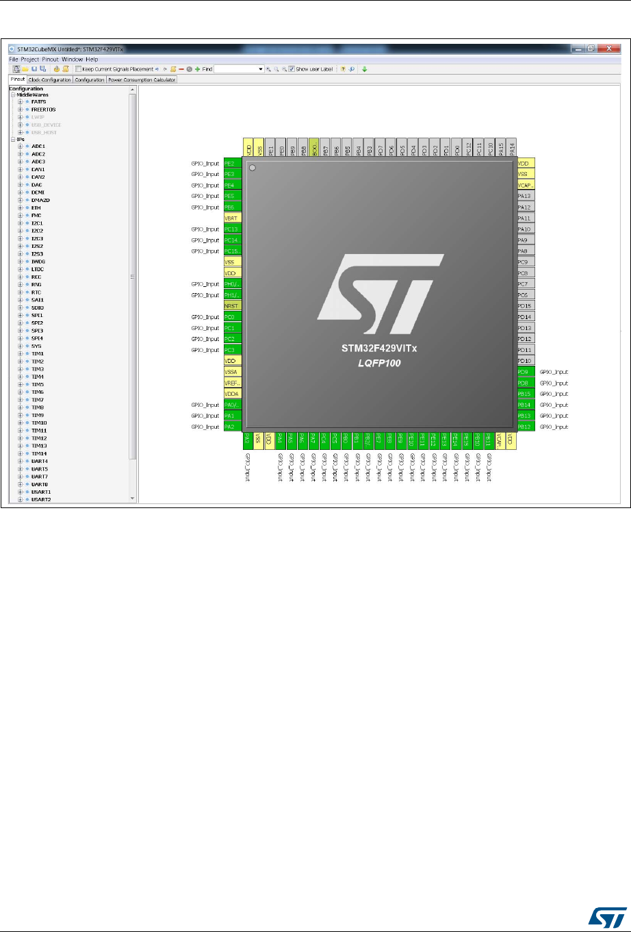
STM32CubeMX user interface UM1718
74/345 UM1718 Rev 26
Figure 48. Set unused GPIO pins with Keep Current Signals Placement unchecked
5.8 Project Settings window
This Project Settings windows includes three tabs:
A general project setting tab allowing to specify the project name, the location, the
toolchain, and the firmware version.
A code generation tab allowing to set code generation options such as the location of
peripheral initialization code, library copy/link options, and to select templates for
customized code.
An advanced settings tab dedicated to ordering STM32CubeMX initialization function
calls.
There are several ways to open the Project Settings window:
1. By selecting Project > Settings from the STM32CubeMX menu bar (see Figure 49).
The code generation will then be generated in the project folder tree shown in
Figure 50.
2. By clicking Project > Generate code for the first time.

UM1718 Rev 26 75/345
UM1718 STM32CubeMX user interface
344
3. By selecting Save As for a project that includes C code generation (and not only pin
configuration).
Note: Some project settings options become read-only once the project is saved. To modify these
options, the project must be saved as a new project using the File> Save Project as menu.
Figure 49. Project Settings window
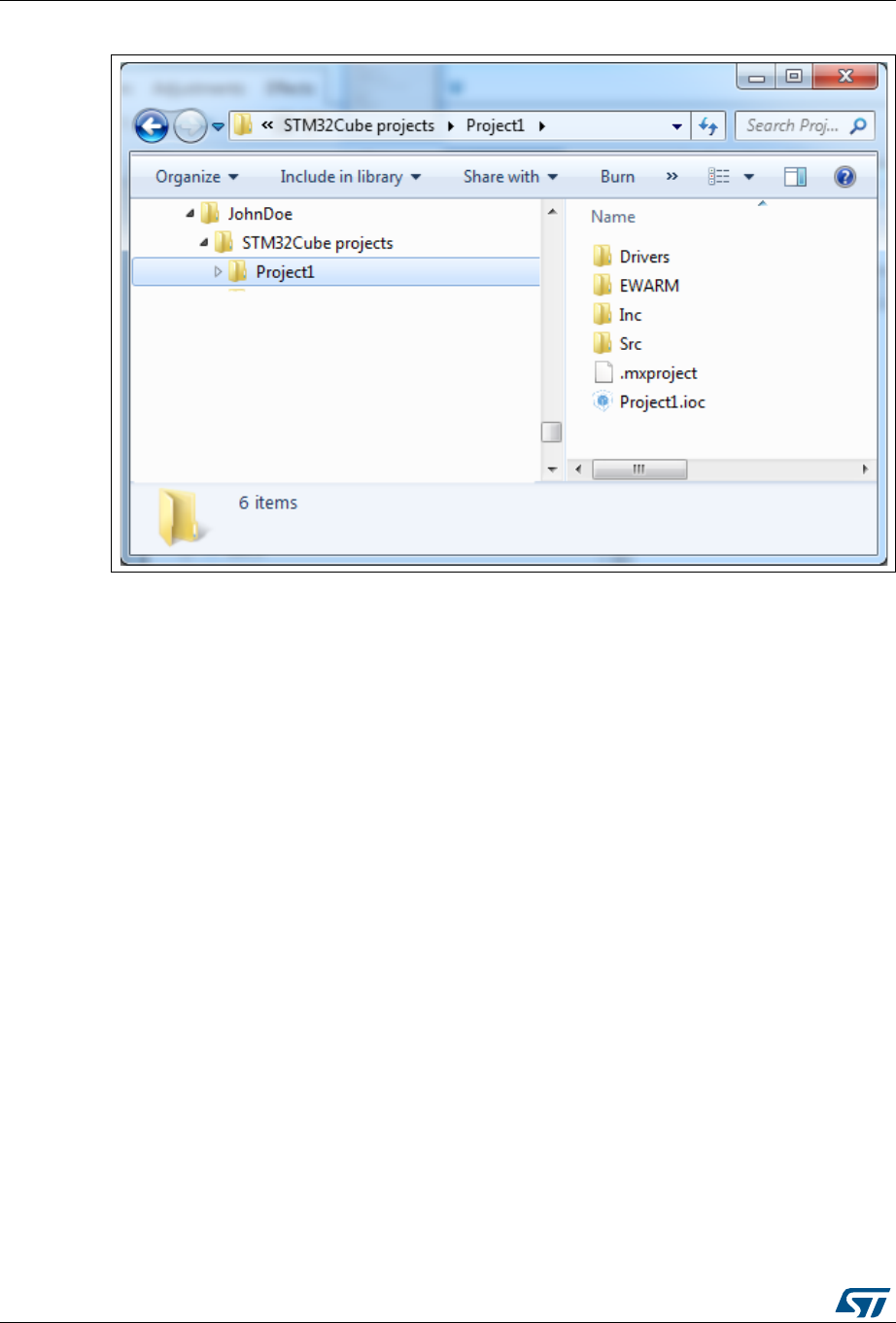
STM32CubeMX user interface UM1718
76/345 UM1718 Rev 26
Figure 50. Project folder
5.8.1 Project tab
The Project tab of the Project Settings window allows configuring the following options
(see Figure 49):
Project settings:
– Project name: name used to create the project folder and the .ioc file name at a
given project location
– Project location: directory where the project folder is stored.
– Application structure: select between Basic and Advanced options.
Basic structure: recommended for projects using one or no middleware. This
structure consists in placing the IDE configuration folder at the same level as the
sources, organized in sources and includes subfolders (see Figure 51)
Advanced structure: recommended when several middleware components are
used in the project. It makes the integration of middleware applications easier (see
Figure 52)
– Toolchain folder location: by default, it is located in the project folder at the same
level as the .ioc file.
– Toolchain/IDE: selected toolchain
Selecting Makefile under Toolchain/IDE leads to the generation of a generic gcc-based
makefile.
Selecting Other Toolchains (GPDSC) generates a gpdsc file. The gpdsc file provides a
generic description of the project, including the list and paths of drivers and other files
(such as startup files) that are required for building the project. This allows extending
STM32CubeMX project generation to any toolchain supporting gpdsc since the

UM1718 Rev 26 77/345
UM1718 STM32CubeMX user interface
344
toolchain will be able to load a STM32CubeMX generated C project by processing the
gpdsc file information. To standardize the description of embedded projects, the gpdsc
solution is based on CMSIS-Pack.
Additional project settings for SW4STM32 and Atollic TrueSTUDIO® toolchains:
Select the optional Generate under root checkbox to generate the toolchain project
files in STM32CubeMX user project root folder or deselect it to generate them under a
dedicated toolchain folder.
STM32CubeMX project generation under the root folder allows to benefit from the
following Eclipse features when using Eclipse-based IDEs such as SW4STM32 and
TrueStudio:
– Optional copy of the project into the Eclipse workspace when importing a project.
– Use of source control systems such as GIT or SVN from the Eclipse workspace.
However, it shall be noted that choosing to copy the project into workspace will prevent
any further synchronization between changes done in Eclipse and changes done in
STM32CubeMX as there will be two different copies of the project.
Linker settings: value of minimum heap and stack sizes to be allocated for the
application. The default values proposed are 0x200 and 0x400 for heap and stack
sizes, respectively. These values may need to be increased when the application uses
middleware stacks.
Firmware package selection when more than one version is available (this is the case
when successive versions implement the same API and support the same MCUs). By
default, the latest available version is used.
Firmware location selection option
The default location is the location specified under the Help > updater settings menu.
Deselecting the Use Default Firmware Location checkbox allows specifying a
different path for the firmware that will be used for the project (see Figure 53).


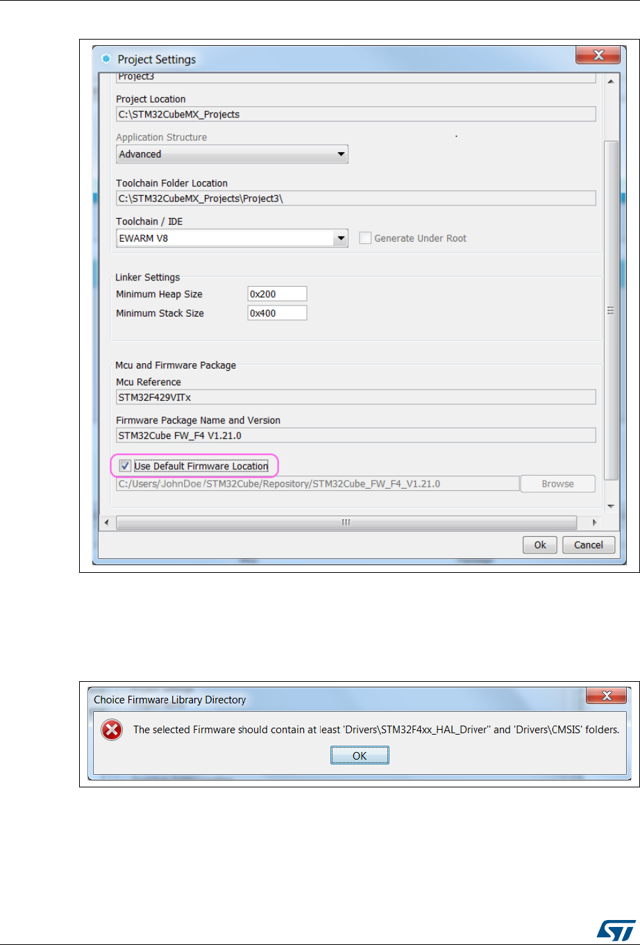
STM32CubeMX user interface UM1718
80/345 UM1718 Rev 26
Figure 53. Selecting a different firmware location
The new location should contain at least a Drivers directory containing the HAL and
CMSIS drivers from the relevant STM32Cube MCU package. An error message pops
up if the folders cannot be found (see Figure 54).
Figure 54. Firmware location selection error message
To reuse the same Drivers folder across all projects that use the same firmware
location, select the Add the library files as reference from the Code generator tab
allows (see Figure 55).
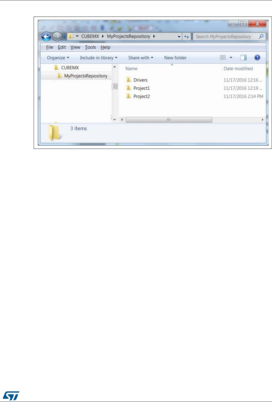
UM1718 Rev 26 81/345
UM1718 STM32CubeMX user interface
344
Figure 55. Recommended new firmware repository structure
Caution: STM32CubeMX manages firmware updates solely for this default location. Choosing
another location will prevent the user from benefiting from automatic updates. The user
must manually copy new driver versions to its project folder.
5.8.2 Code Generator tab
The Code Generator tab allows specifying the following code generation options (see
Figure 56):
STM32Cube Firmware Library Package option
Generated files options
HAL settings options
Custom code template options
STM32Cube Firmware Library Package option
The following actions are possible:
Copy all used libraries into the project folder
STM32CubeMX will copy to the user project folder, the drivers libraries (HAL, CMSIS)
and the middleware libraries relevant to the user configuration (e.g. FatFs, USB, ..).
Copy only the necessary library files:
STM32CubeMX will copy to the user project folder only the library files relevant to the
user configuration (e.g., SDIO HAL driver from the HAL library,…).
Add the required library as referenced in the toolchain project configuration file
By default, the required library files are copied to the user project. Select this option for
the configuration file to point to files in STM32CubeMX repository instead: the user
project folder will not hold a copy of the library files but only a reference to the files in
STM32CubeMX repository.

STM32CubeMX user interface UM1718
82/345 UM1718 Rev 26
Generated files options
This area allows defining the following options:
Generate peripheral initialization as a pair of .c/.h files or keep all peripheral
initializations in the main.c file.
Backup previously generated files in a backup directory
The .bak extension is added to previously generated .c/.h files.
Keep user code when regenerating the C code.
This option applies only to user sections within STM32CubeMX generated files. It does
not apply to the user files that might have been added manually or generated via ftl
templates.
Delete previously generated files when these files are no longer needed by the current
configuration. For example, uart.c/.h file are deleted if the UART peripheral, that was
enabled in previous code generation, is now disabled in current configuration.
HAL settings options
This area allows selection one HAL settings options among the following:
Set all free pins as analog to optimize power consumption
Enable/disable Use the Full Assert function: the Define statement in the
stm32xx_hal_conf.h configuration file will be commented or uncommented,
respectively.
Custom code template options
To generate custom code, click the Settings button under Template Settings, to open the
Template Settings window (see Figure 57).
The user will then be prompted to choose a source directory to select the code templates
from, and a destination directory where the corresponding code will be generated.
The default source directory points to the extra_template directory, within STM32CubeMX
installation folder, which is meant for storing all user defined templates. The default
destination folder is located in the user project folder.
STM32CubeMX will then use the selected templates to generate user custom code (see
Section 6.3: Custom code generation). Figure 58 shows the result of the template


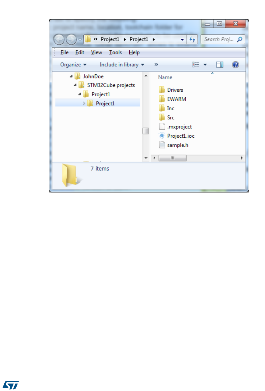
UM1718 Rev 26 85/345
UM1718 STM32CubeMX user interface
344
Figure 58. Generated project template
5.8.3 Advanced Settings tab
Figure 59 shows the peripheral and/or middleware selected for the project.
Ordering initialization function calls
By default, the generated code calls the peripheral/middleware initialization functions in the
order in which peripherals and middleware have been enabled in STM32CubeMX. The user
can then choose to re-order them by modifying the Rank number using the up and down
arrow buttons.
The reset button allows switching back to alphabetical order.
Disabling calls to initialization functions
If the “Not to be generated” checkbox is checked, STM32CubeMX does not generate the
call to the corresponding peripheral initialization function. It is up to the user code to do it.
Choosing between HAL and LL based code generation for a given peripheral
instance
Starting from STM32CubeMX 4.17 and STM32L4 Series, STM32CubeMX offers the
possibility for some peripherals to generate initialization code based on Low Layer (LL)
drivers instead of HAL drivers: the user can choose between LL and HAL driver in the
Driver Selector section. The code will be generated accordingly (see Section 6.2:
STM32Cube code generation using Low Layer drivers).
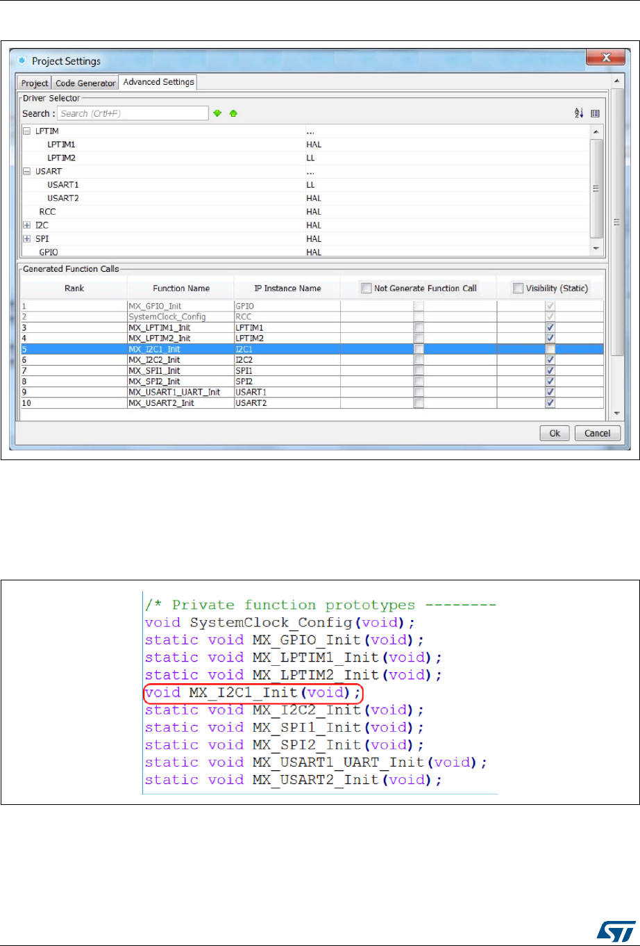
STM32CubeMX user interface UM1718
86/345 UM1718 Rev 26
Figure 59. Advanced Settings window
Unselecting the Visibility (Static) option, as shown for MX_I2C1_init function in Figure 59,
allows the generation of the function definition without the static keyword and hence extends
its visibility outside the current file (see Figure 60).
Figure 60. Generated init functions without C language “static” keyword

UM1718 Rev 26 87/345
UM1718 STM32CubeMX user interface
344
5.9 Update Manager windows
Three windows can be accessed through the Help menu available from STM32CubeMX
menu bar:
1. Select Help > Check for updates to open the Check Update Manager window and
find out about the latest software versions available for download.
2. Select Help > Manage embedded software packages to open the Embedded
Software Package Manager window and find out about the embedded software
packages available for download. It also allows checking for package updates and
removing previously installed software packages.
3. Select Help > Updater settings to open the Updater settings window and configure
update mechanism settings (proxy settings, manual versus automatic updates,
repository folder where embedded software packages are stored).
Refer to Section 4.5: Getting updates using STM32CubeMX for a detailed description of
these windows.
5.10 Additional software component selection window
This window can be open at any time when working on the project. It allows the selection of
additional software components for the current project.
It includes three panels:
Software component panel
It is located on the top right side of the window. It displays the list of the software
components that can be selected for the project.
Filter panel
It is located on the left side of the window and provides a set of criteria to filter the pack
component list.
Condition Resolution panel
It is located on the bottom right side of the window, and is displayed by clicking a
condition to be resolved. It provides a detailed description of the condition and
proposes solutions to solve it if any can be found in the software component list.
There are three ways to open the Additional Software Components selection window:
By selecting Project and then click Select additional software components
By clicking the menu icon on the toolbar
By using the Ctrl+E shortcut.
See Section 7: Support of additional software components using CMSIS-Pack standard for
more details on how to handle additional software components through STM32CubeMX
CMSIS-Pack integration.
5.10.1 Introduction on software components
Arm® Keil™ CMSIS-Pack standard defines a software component as a list of files. The
component or each of the corresponding individual files can optionally refer to a condition
that must resolve to true, otherwise the component or file is not applicable in the given
context.
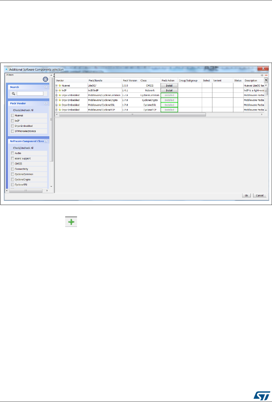
STM32CubeMX user interface UM1718
88/345 UM1718 Rev 26
There are no component names. Instead, each component is uniquely identified for a given
vendor pack by the combination of class name, group name and a version. Additional
categories, such as sub-group and variant can be assigned.
By default, the window shows a component list grouped by vendor name (first column) and
pack or bundle version (second column). Refer to Figure 61 for an example.
Figure 61. Additional software components - collapsed view showing packs and bundles
Clicking the button expands the view and displays all software components details (see
Figure 62).
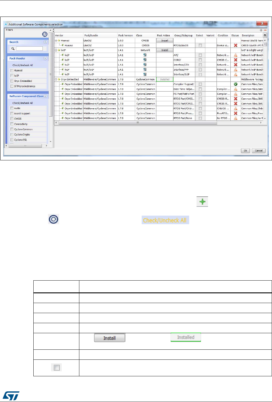
UM1718 Rev 26 89/345
UM1718 STM32CubeMX user interface
344
Figure 62. Additional software components - expanded view showing component details
5.10.2 Filter panel
To filter the software component list, choose pack vendor names and software component
classes or enter a text string in the search field.
The resulting software component table is collapsed. Click the button to expand it and
display all the components that match the filtering criteria.
Click to clear all filter checkboxes or to clear the filter for a given
category (pack vendors or component classes).
5.10.3 Software component table
STM32CubeMX parses the pack .pdsc file to extract the list of embedded software
components and the corresponding features.
Table 8. Software components
Column name Description
Vendor Pack vendor name, as found in the pack name.
Pack / Bundle Pack or bundle name.
Version Pack/bundle version.
Class(1) Component class the component belongs to.
Pack Action Click to install the pack, means that the pack is
already installed.
Group/SubGroup Group and optionally the subgroup the software component belongs to.
Selection checkbox allowing the addition of the software component to the
current project.
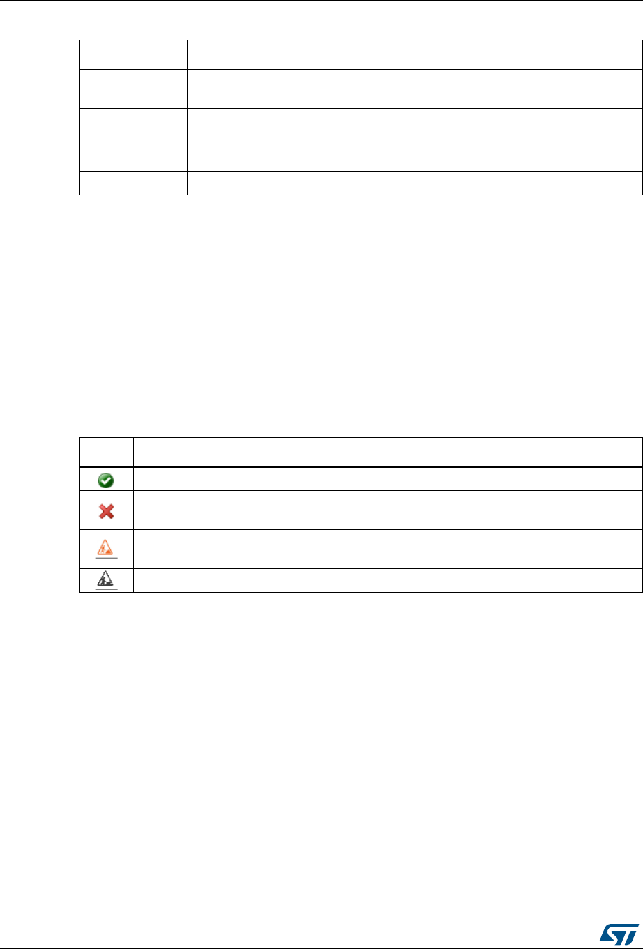
STM32CubeMX user interface UM1718
90/345 UM1718 Rev 26
5.10.4 Software component conditions
The conditions are dependency rules applying to a given software component. The software
component condition status is displayed using the icons shown in Table 9.
Variant Optional field for software components that come in different variants (such as
debug and release).
Condition Short name describing the condition (such as CMSIS-RTOS Dependencies).
Status Status of the condition to be met (see Table 9 for the different condition statuses).
Clicking the status opens the condition description in the bottom panel.
Description Software component short description.
1. The Arm® Keil™ CMIS-Pack website, http://www.keil.com, lists the following classes:
Data Exchange: Software components for data exchange
File System: File drive support and file system
Graphics: Graphic libraries for user interfaces
Network: Network stack using Internet protocols
RTOS: Real-time operating systems
Safety: Components for testing application software against safety standards
Security: Encryption for secure communication or storage
USB: Universal serial bus stack
Wireless: Communication stacks such as Bluetooth™, WiFi®, and ZigBee®.
Table 8. Software components (continued)
Column name Description
Table 9. Software component conditions icons
Icon Description
All software component conditions, if any, are resolved.
One or more software component conditions cannot be resolved with current pack list and
for currently selected MCU.
One or more conditions must be resolved using another software component of the same
pack.
One or more conditions must be resolved using software components from another pack.
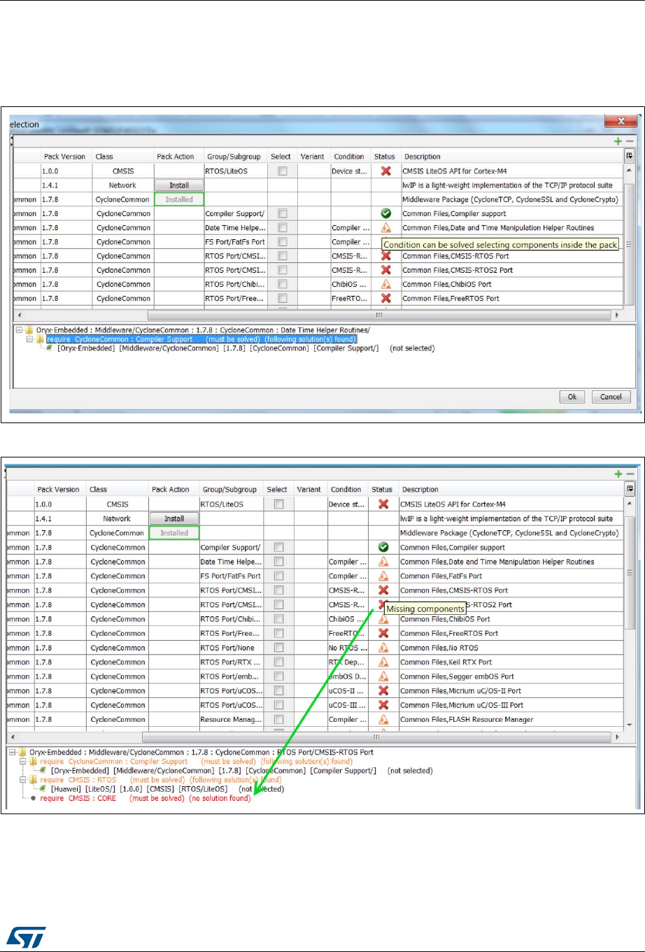
UM1718 Rev 26 91/345
UM1718 STM32CubeMX user interface
344
1. Click the condition status icon to display the conditions to be solved in the bottom
panel, together with their description and the software component that could solve the
issue, if any (see Figure 63 and Figure 64).
Figure 63. Dependency solving: solution found
Figure 64. Dependency solving: no solution found
2. Clicking a proposed solution in the bottom panel highlights the software component
selection checkbox in the component table above (see Figure 65).
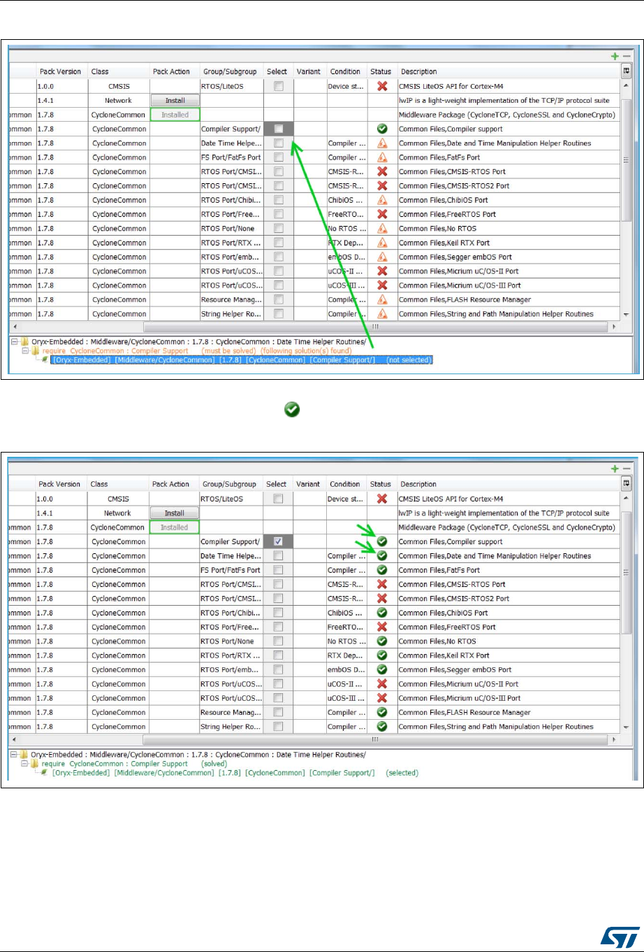
STM32CubeMX user interface UM1718
92/345 UM1718 Rev 26
Figure 65. Software components conditions - Solution proposals and guidance
3. Selecting the recommended software component resolves the condition. The condition
status changes to resolved, , (see Figure 66).
Figure 66. Software components conditions resolved
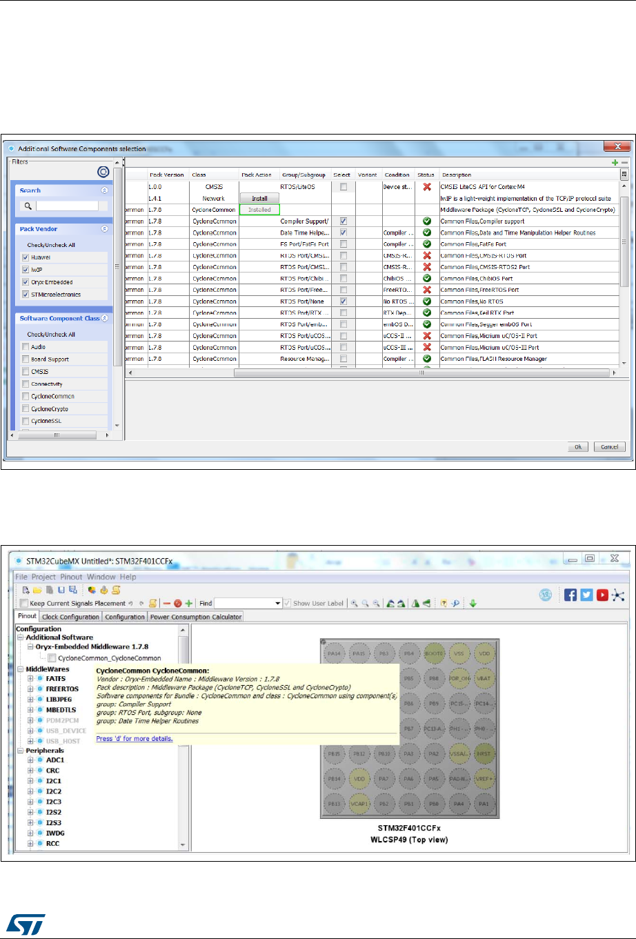
UM1718 Rev 26 93/345
UM1718 STM32CubeMX user interface
344
5.10.5 Updating the tree view for additional software components
Once the selection of the software components required for the application is complete (see
Figure 67), click OK to refresh STM32CubeMX window: the selected component appears in
the tree view under Additional Software (see Figure 68).
Figure 67. Selection of additional software components
The current selection of additional software components appears in the tree view (see
Figure 68).
Figure 68. Additional software components - Updated tree view
STM32CubeMX user interface UM1718
94/345 UM1718 Rev 26
5.11 About window
This window displays STM32CubeMX version information.
To open it, select Help > About from the STM32CubeMX menu bar.
Figure 69. About window
5.12 Pinout view
The Pinout view helps the user configuring the MCU pins based on a selection of
peripherals/middleware and of their operating modes.
Note: For some middleware (USB, FATS, LwIP), a peripheral mode must be enabled before
activating the middleware mode. Tooltips guide the user through the configuration.
For FatFs, a user-defined mode has been introduced. This allows STM32CubeMX to
generate FatFs code without a predefined peripheral mode. Then, it will be up to the user to
connect the middleware with a user-defined peripheral by updating the generated
user_diskio.c/.h driver files with the necessary code.
Since STM32 MCUs allow a same pin to be used by different peripherals and for several
functions (alternate functions), the tool searches for the pinout configuration that best fits the
set of peripherals selected by the user. STM32CubeMX highlights the conflicts that cannot
be solved automatically.
The Pinout view left panel shows the Peripheral and Middleware tree and the right panel,
a graphic representation of the pinout for the selected package (e.g. BGA, QFP...) where
each pin is represented with its name (e.g. PC4) and its current alternate function
assignment if any.
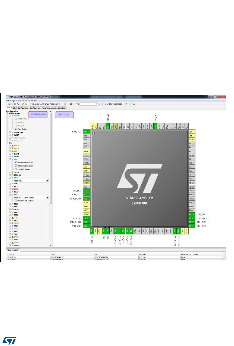
UM1718 Rev 26 95/345
UM1718 STM32CubeMX user interface
344
STM32CubeMX offers two ways to configure the microcontroller:
From the Peripheral and Middleware tree by clicking the peripheral names and
selecting the operating modes (see Section 5.12.1).
For advanced users, by clicking a pin on the Chip view to manually map it to a
peripheral function (see Section 5.12.2).
In addition, selecting Pinout > Set unused GPIOs allows configuring in one shot several
unused pins in a given GPIO mode.
Note: The Pinout view is automatically refreshed to display the resulting pinout configuration.
Pinout relevant menus and shortcuts are available when the Pinout view is active (see the
menu dedicated sections for details on the Pinout menus).
Figure 70. STM32CubeMX Pinout view
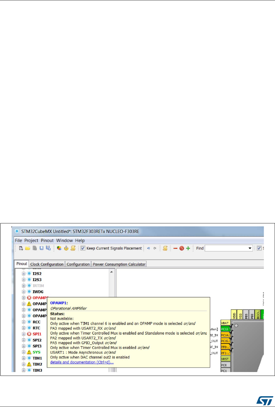
STM32CubeMX user interface UM1718
96/345 UM1718 Rev 26
5.12.1 Peripheral and Middleware tree panel
In this panel, the user can select the peripherals, services (DMA, RCC,...), middleware in
the modes corresponding to the application. This panel shows all peripherals, services
(DMA, RCC) and middleware available for the currently selected processor.
The user can select a set in the modes relevant to the project.
Note: The peripheral tree panel is also accessible from the Configuration view. However, only the
peripherals and middleware modes without influence on the pinout can be configured
through this menu.
Contextual help
The Contextual Help window is displayed when hovering the mouse over a peripheral or a
middleware short name.
By default, the window displays the extended name and source of configuration conflicts if
any (see Figure 71).
Clicking the details and documentation link (or CTRL+d) provides additional information
such as summary and reference documentation links (see Figure 72). For a given
peripheral, clicking Datasheet or Reference manual opens the corresponding document,
stored in STM32CubeMX repository folder, at the relevant chapter. Since microcontrollers
datasheets and reference manuals are downloaded to STM32CubeMX repository only upon
users’ request, a functional Internet connection is required:
To check your Internet connection, open the Connection tab from the Help > Updater
Settings menu.
To request the download of reference documentation for the currently selected
microcontroller, click Refresh from the Help > Refresh Data menu window.
Figure 71. Contextual Help Window (default)
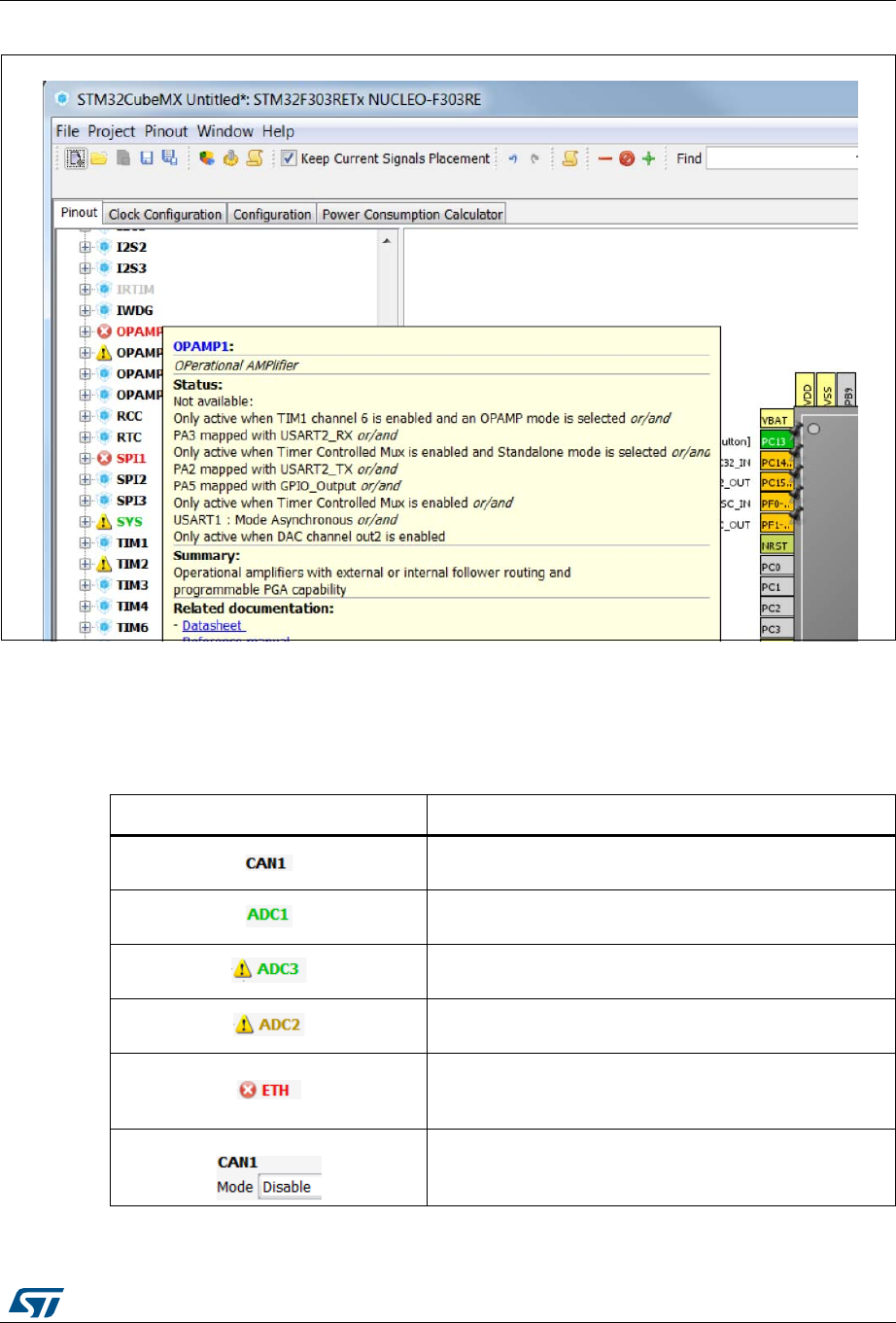
UM1718 Rev 26 97/345
UM1718 STM32CubeMX user interface
344
Figure 72. Contextual Help detailed information
Icons and color schemes
Table 10 shows the icons and color scheme used in the Peripheral and Middleware tree
panel.
Table 10. Peripheral and Middleware tree panel - icons and color scheme
Display Peripheral status
The peripheral is not configured (no mode is set) and all
modes are available.
The peripheral is configured (at least one mode is set) and
all other modes are available
The peripheral is configured (one mode is set) and at least
one of its other modes is unavailable.
The peripheral is not configured (no mode is set) and at
least one of its modes is unavailable.
The peripheral is not configured (no mode is set) and no
mode is available. Move the mouse over the peripheral
name to display the tooltip describing the conflict.
Available peripheral mode configurations are shown in
plain black.
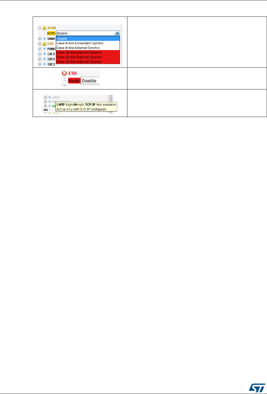
STM32CubeMX user interface UM1718
98/345 UM1718 Rev 26
5.12.2 Chip view
The Chip view shows, for the selected part number:
The MCU in a specific package (BGA, LQFP…)
The graphic representation of its pinout, each pin being represented with its name (e.g.
PC4: pin 4 of GPIO port C) and its current function assignment (e.g. ETH_MII_RXD0),
see Figure 73 for an example.
The Chip view is automatically refreshed to match the user configuration performed via the
peripheral tree. It shows the pins current configuration state.
Assigning pins through the Chip view instead of the peripheral panel requires a good
knowledge of the MCU since each individual pin can be assigned to a specific function.
Tips and tricks
Use the mouse wheel to zoom in and out.
Click and drag the chip diagram to move it. Click best fit to reset it to best suited
position and size (see Table 5).
Use Pinout > Generic CSV pinout text file to export the pinout configuration into text
format.
Some basic controls, such as insuring blocks of pins consistency, are built-in. See
Appendix A: STM32CubeMX pin assignment rules for details.
The warning yellow icon indicates that at least one mode
configuration is no longer available.
When no more configurations are left for a given peripheral
mode, this peripheral is highlighted in red.
Some modes depends on the configuration of other
peripherals or middleware modes. A tooltip explains the
dependencies when the conditions are not fulfilled.
Table 10. Peripheral and Middleware tree panel - icons and color scheme

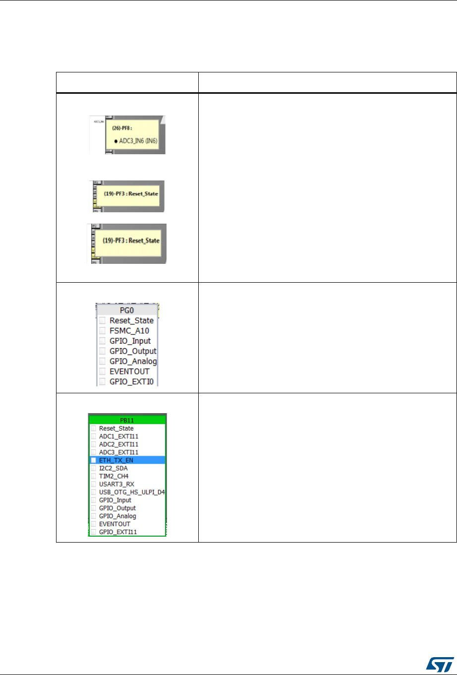
STM32CubeMX user interface UM1718
100/345 UM1718 Rev 26
Icons and color schemes
Table 11 shows the icons and color scheme used in the Chip view.
Table 11. STM32CubeMX Chip view - Icons and color scheme
Display Pin information
Tooltip indicates the selected pin current configuration:
alternate function name, Reset state or GPIO mode.
Move your mouse over the pin name to display it.
When a pin features alternate pins corresponding to the function
currently selected, a popup message prompts the user to
perform a CTRL + click to display them.
The alternate pins available are highlighted in blue.
List of alternate functions that can be selected for a given pin.
By default, no alternate function is configured (pin in reset state).
Click the pin name to display the list.
When a digital peripheral function has been mapped to the pin, it
is highlighted in blue.
When it corresponds to a well configured peripheral mode, the
list caption is shown in green.
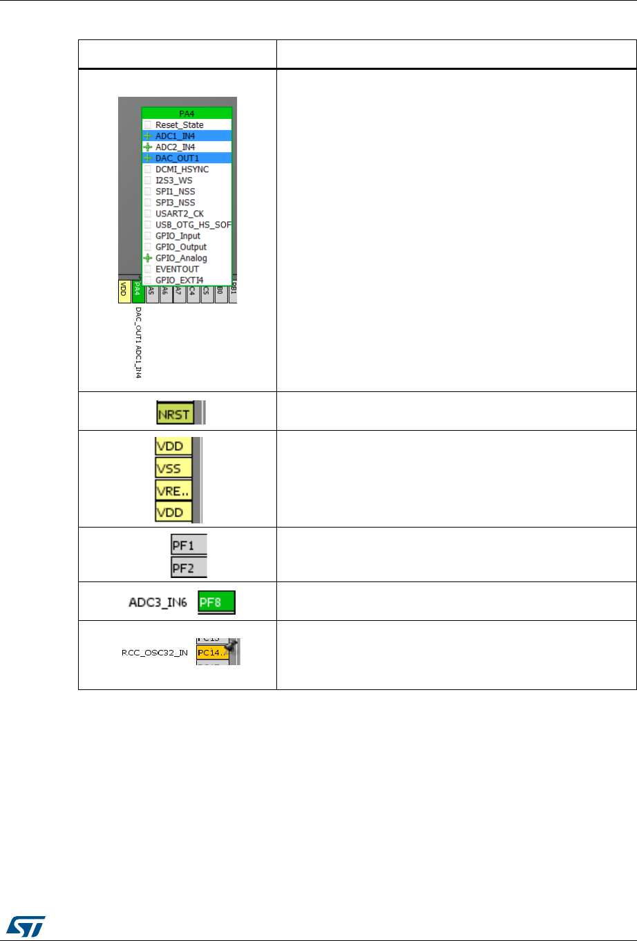
UM1718 Rev 26 101/345
UM1718 STM32CubeMX user interface
344
Analog signals can share the same pin. As an example,
DAC_OUT1 was first enabled on PA4, then ADC_IN4 is also
assigned to this pin.
Boot and reset pins are highlighted in khaki. Their configuration
cannot be changed.
Power dedicated pins are highlighted in yellow. Their
configuration cannot be changed.
Non-configured pins are shown in gray (default state).
When a signal assignment corresponds to a peripheral mode
without ambiguity, the pin color switches to green.
When the signal assignment does not correspond to a valid
peripheral mode configuration, the pin is shown in orange.
Additional pins need to be configured to achieve a valid mode
configuration.
Table 11. STM32CubeMX Chip view - Icons and color scheme (continued)
Display Pin information
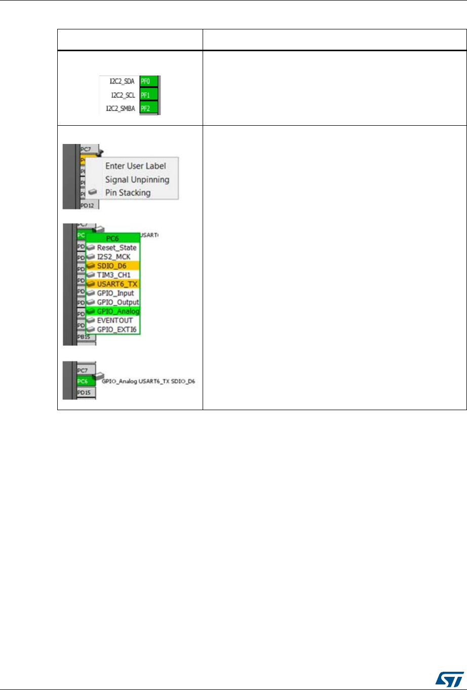
STM32CubeMX user interface UM1718
102/345 UM1718 Rev 26
Tooltips
Move the mouse over peripherals and peripheral modes that are unavailable or partially
available to display the tooltips describing the source of the conflict that is which pins are
being used by which peripherals.
As an example (see Figure 74), the Ethernet (ETH) peripheral is no longer available
because there is no possible mode configuration left. A tooltip indicates to which signal are
assigned the pins required for this mode (ADC1-IN0 signal, USART3 synchronous signal,
etc...).
When a signal assignment corresponds to a peripheral mode
without ambiguity, the pins are shown in green.
As an example, assigning the PF2 pin to the I2C2_SMBA signal
matches to I2C2 mode without ambiguity and STM32CubeMX
configures automatically the other pins (PF0 and PF1) to
complete the pin mode configuration.
The pin stacking function allows board designers to specify
multiple signals on a given pin, corresponding to multiple
configurations supported by the board (usually selected through
solder bridges).
Right click a pin to select pin stacking. Then, click to select the
signals to be stacked on that pin.
Table 11. STM32CubeMX Chip view - Icons and color scheme (continued)
Display Pin information
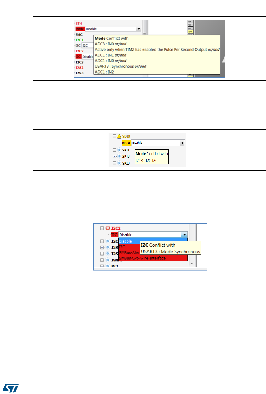
UM1718 Rev 26 103/345
UM1718 STM32CubeMX user interface
344
Figure 74. Red highlights and tooltip example - no mode configuration available
In the next example (see Figure 75), the SDIO peripheral is partially available because at
least one of its modes is unavailable: the necessary pins are already assigned to the I2C
mode of the I2C3 peripheral.
Figure 75. Orange highlight and tooltip example - some configurations unavailable
In this last example (see Figure 76) I2C2 peripheral is unavailable because there is no
mode function available. A tooltip shows for each function where all the remapped pins have
been allocated (USART3 synchronous mode).
Figure 76. Tooltip example - all configurations unavailable
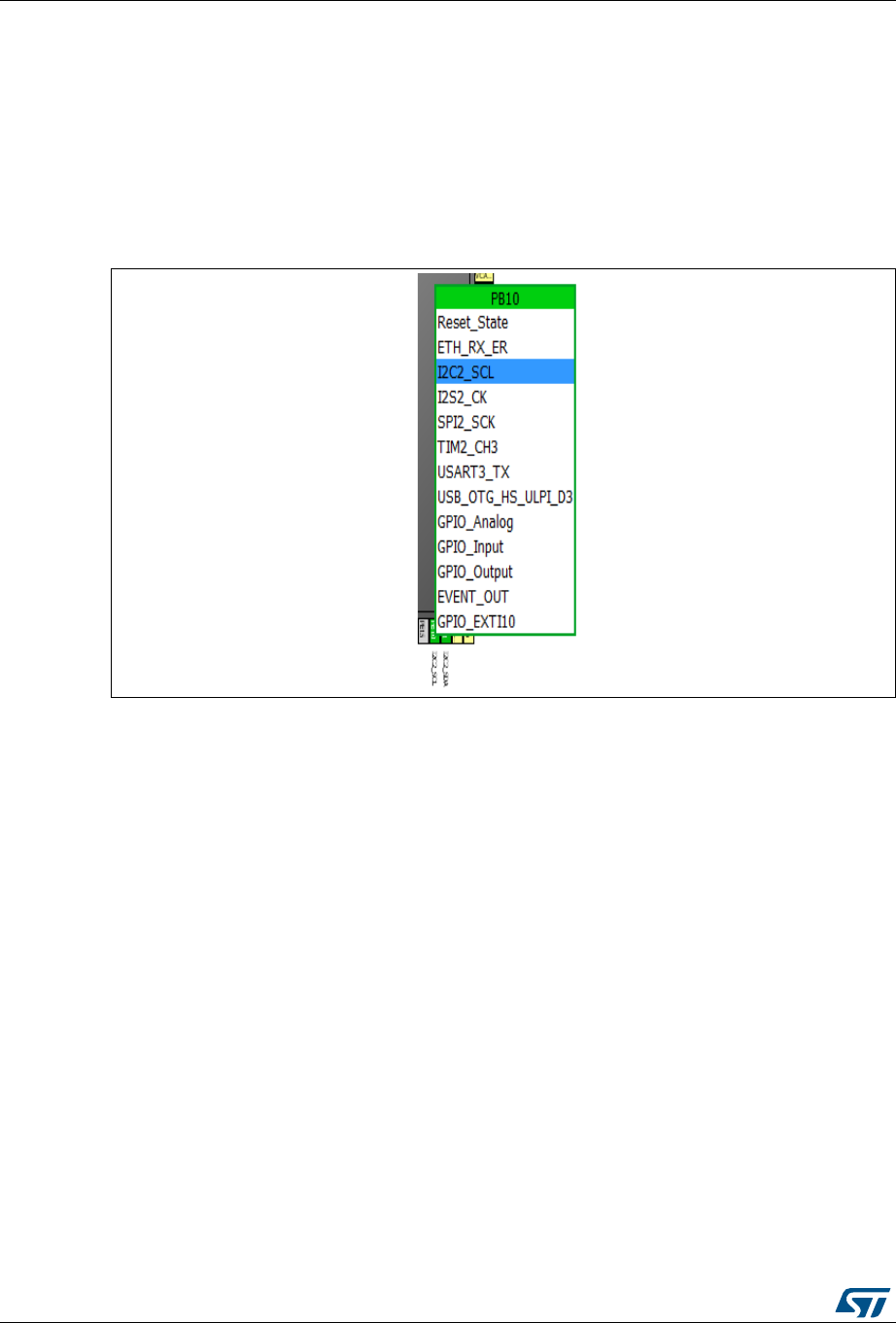
STM32CubeMX user interface UM1718
104/345 UM1718 Rev 26
5.12.3 Chip view advanced actions
Manually modifying pin assignments
To manually modify a pin assignment, follow the sequence below:
1. Click the pin in the Chip view to display the list of all other possible alternate functions
together with the current assignment highlighted in blue (see Figure 77).
2. Click to select the new function to assign to the pin.
Figure 77. Modifying pin assignments from the Chip view
Manually remapping a function to another pin
To manually remap a function to another pin, follow the sequence below:
1. Press the CTRL key and click the pin in the Chip view. Possible pins for relocation, if
any, are highlighted in blue.
2. Drag the function to the target pin.
Caution: A pin assignment performed from the Chip view overwrites any previous assignment.
Manual remapping with destination pin ambiguity
For MCUs with block of pins consistency (STM32F100x/ F101x/ F102x/ F103x and
STM32F105x/F107x), the destination pin can be ambiguous,e.g. there can be more than
one destination block including the destination pin. To display all the possible alternative
remapping blocks, move the mouse over the target pin.
Note: A "block of pins" is a group of pins that must be assigned together to achieve a given
peripheral mode. As shown in Figure 78, two blocks of pins are available on a
STM32F107xx MCU to configure the Ethernet Peripheral in RMII synchronous mode: {PC1,
PA1, PA2, PA7, PC4, PC5, PB11, PB12, PB13, PB5} and {PC1, PA1, PA2, PD10, PD9,
PD8, PB11, PB12, PB13, PB5}.
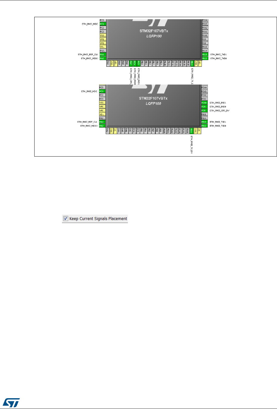
UM1718 Rev 26 105/345
UM1718 STM32CubeMX user interface
344
Figure 78. Example of remapping in case of block of pins consistency
Resolving pin conflicts
To resolve the pin conflicts that may occur when some peripheral modes use the same pins,
STM32CubeMX attempts to reassign the peripheral mode functions to other pins. The
peripherals for which pin conflicts could not be solved are highlighted in red or orange with a
tooltip describing the conflict.
If the conflict cannot be solved by remapping the modes, the user can try the following:
If the box is checked, try to select the peripherals in a
different sequence.
Uncheck the Keep Current Signals Placement box and let STM32CubeMX try all the
remap combinations to find a solution.
Manually remap a mode of a peripheral when you cannot use it because there is no
pin available for one of the signals of that mode.
5.12.4 Keep Current Signals Placement
This checkbox is available from the toolbar when the Pinout view is selected (see Figure 36
and Table 5). It can be selected or deselected at any time during the configuration. It is
unselected by default.
It is recommended to keep the checkbox unchecked for an optimized placement of the
peripherals (maximum number of peripherals concurrently used).
The Keep Current Signals Placement checkbox should be selected when the objective is
to match a board design.
Keep Current Signals Placement is unchecked
This allows STM32CubeMX to remap previously mapped blocks to other pins in order to
serve a new request (selection of a new peripheral mode or a new peripheral mode
function) which conflicts with the current pinout configuration.

STM32CubeMX user interface UM1718
106/345 UM1718 Rev 26
Keep Current Signals Placement is checked
This ensures that all the functions corresponding to a given peripheral mode remain
allocated (mapped) to a given pin. Once the allocation is done, STM32CubeMX cannot
move a peripheral mode function from one pin to another. New configuration requests are
served if it is feasible within current pin configuration.
This functionality is useful to:
Lock all the pins corresponding to peripherals that have been configured using the
Peripherals panel.
Maintain a function mapped to a pin while doing manual remapping from the Chip view.
Tip
If a mode becomes unavailable (highlighted in red), try to find another pin remapping
configuration for this mode by following the steps below:
1. From the Chip view, deselect the assigned functions one by one until the mode
becomes available again.
2. Then, select the mode again and continue the pinout configuration with the new
sequence (see Appendix A: STM32CubeMX pin assignment rules for a remapping
example). This operation being time consuming, it is recommended to deselect the
Keep Current Signals Placement checkbox.
Note: Even if Keep Current Signals placement is unchecked, GPIO_ functions (excepted
GPIO_EXTI functions) are not moved by STM32CubeMX.
5.12.5 Pinning and labeling signals on pins
STM32CubeMX comes with a feature allowing the user to selectively lock (or pin) signals to
pins: This will prevent STM32CubeMX from automatically moving the pinned signals to
other pins when resolving conflicts.There is also the possibility to label the signals: User
labels are used for code generation (see Section 5.1 for details).
STM32CubeMX comes with a feature allowing the user to selectively lock (or pin) signals to
pins. This prevents STM32CubeMX from automatically moving pinned signals to other pins
when resolving conflicts. Labels, that are used for code generation, can also be assigned to
the signals (see Section 6.1 for details).
There are several ways to pin, unpin and label the signals:
1. From the Chip view, right-click a pin with a signal assignment. This opens a contextual
menu:
a) For unpinned signals, select Signal Pinning to pin the signal. A pin icon is then
displayed on the relevant pin. The signal can no longer be moved automatically
(for example when resolving pin assignment conflicts).
b) For pinned signals, select Signal Unpinning to unpin the signal. The pin icon is
removed. From now on, to resolve a conflict (such as peripheral mode conflict),
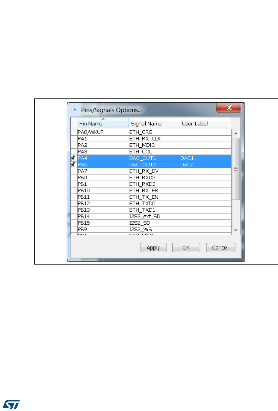
UM1718 Rev 26 107/345
UM1718 STM32CubeMX user interface
344
this signal can be moved to another pin, provided the Keep user placement option
is unchecked.
c) Select Enter User Label to specify a user defined label for this signal. The new
label will replacing the default signal name in the Chip view.
2. From the Pinout menu, select Pins/Signals Options
The Pins/Signals Options window (see Figure 79) lists all configured pins.
a) Click the first column to individually pin/unpin signals.
b) Select multiple rows and right-click to open the contextual menu and select
Signal(s) Pinning or Unpinning.
Figure 79. Pins/Signals Options window
c) Select the User Label field to edit the field and enter a user-defined label.
d) Order list alphabetically by Pin or Signal name by clicking the column header.
Click once more to go back to default i.e. to list ordered according to pin
placement on MCU.
Note: Even if a signal is pinned, it is still possible however to manually change the pin signal
assignment from the Chip view: click the pin to display other possible signals for this pin and
select the relevant one.
5.12.6 Setting HAL timebase source
By default, the STM32Cube HAL is built around a unique timebase source which is the
Arm®-Cortex® system timer (SysTick).
However, HAL-timebase related functions are defined as weak so that they can be
overloaded to use another hardware timebase source. This is strongly recommended when
the application uses an RTOS, since this middleware has full control on the SysTick
configuration (tick and priority) and most RTOSs force the SysTick priority to be the lowest.
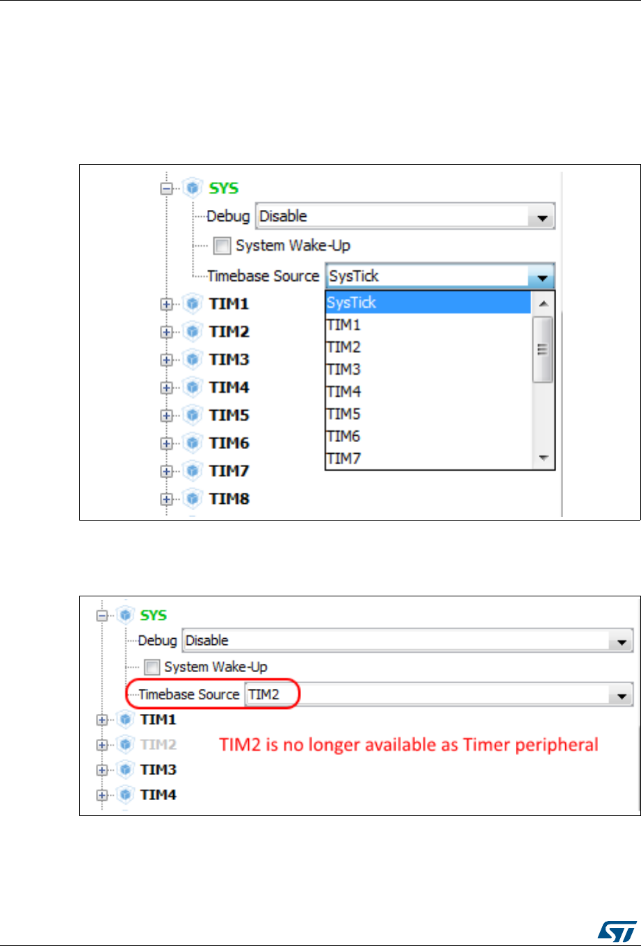
STM32CubeMX user interface UM1718
108/345 UM1718 Rev 26
Using the SysTick remains acceptable if the application respects the HAL programming
model, that is, does not perform any call to HAL timebase services within an Interrupt
Service Request context (no dead lock issue).
To change the HAL timebase source, go to the SYS peripheral in the Peripheral and
Middleware tree panel and select a clock among the available clock sources: SysTick,
TIM1, TIM2,... (see Figure 80).
Figure 80. Selecting a HAL timebase source (STM32F407 example)
When used as timebase source, a given peripheral is grayed and can no longer be selected
(see Figure 81).
Figure 81. TIM2 selected as HAL timebase source
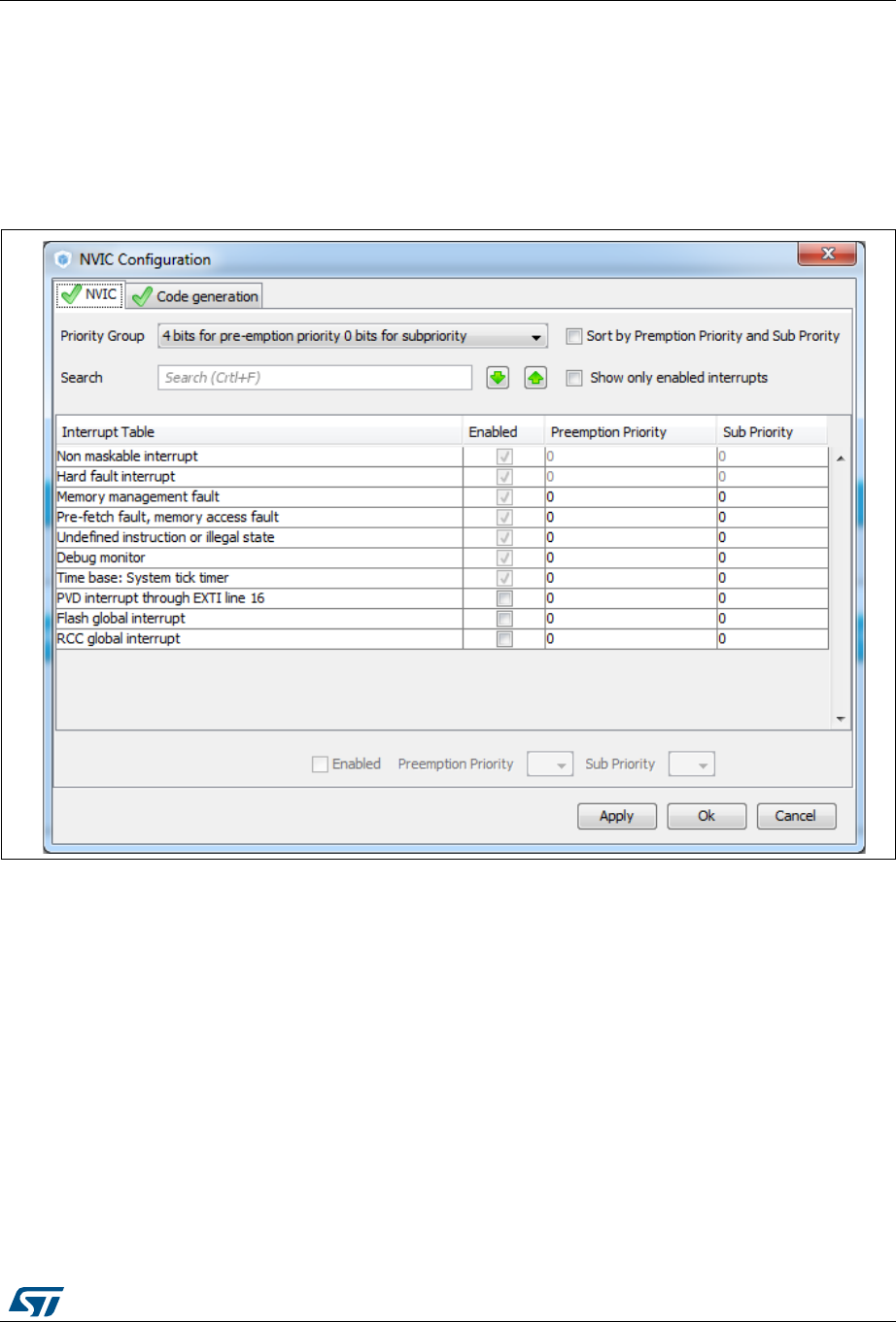
UM1718 Rev 26 109/345
UM1718 STM32CubeMX user interface
344
As illustrated in the following examples, the selection of the HAL timebase source and the
use of FreeRTOS influence the generated code.
Example of configuration using SysTick without FreeRTOS
As illustrated in Figure 82, the SysTick priority is set to 0 (High) when using the SysTick
without FreeRTOS.
Figure 82. NVIC settings when using SysTick as HAL timebase, no FreeRTOS
Interrupt priorities (in main.c) and handler code (in stm32f4xx_it.c) are generated
accordingly:
main.c file
/* SysTick_IRQn interrupt configuration */
HAL_NVIC_SetPriority(SysTick_IRQn, 0, 0);
stm32f4xx_it.c file
/**
* @brief This function handles System tick timer.
*/
void SysTick_Handler(void)
{
/* USER CODE BEGIN SysTick_IRQn 0 */
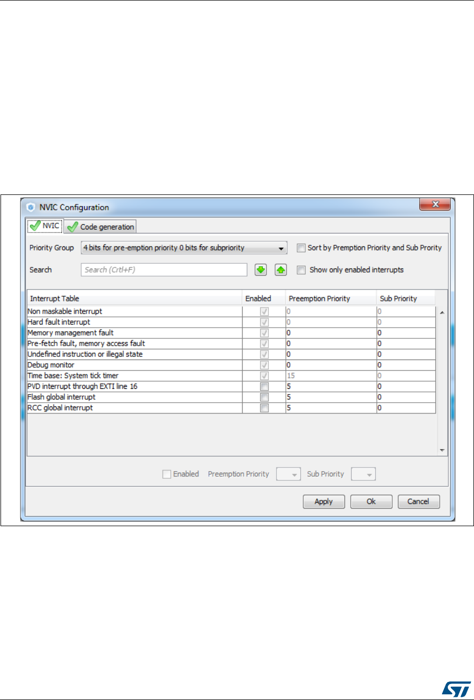
STM32CubeMX user interface UM1718
110/345 UM1718 Rev 26
/* USER CODE END SysTick_IRQn 0 */
HAL_IncTick();
HAL_SYSTICK_IRQHandler();
/* USER CODE BEGIN SysTick_IRQn 1 */
/* USER CODE END SysTick_IRQn 1 */
}
Example of configuration using SysTick and FreeRTOS
As illustrated in Figure 83, the SysTick priority is set to 15 (Low) when using the SysTick
with FreeRTOS.
Figure 83. NVIC settings when using FreeRTOS and SysTick as HAL timebase

UM1718 Rev 26 111/345
UM1718 STM32CubeMX user interface
344
As shown in the code snippets given below, the SysTick interrupt handler is updated to use
CMSIS-os osSystickHandler function.
main.c file
/* SysTick_IRQn interrupt configuration */
HAL_NVIC_SetPriority(SysTick_IRQn, 15, 0);
stm32f4xx_it.c file
/**
* @brief This function handles System tick timer.
*/
void SysTick_Handler(void)
{
/* USER CODE BEGIN SysTick_IRQn 0 */
/* USER CODE END SysTick_IRQn 0 */
HAL_IncTick();
osSystickHandler();
/* USER CODE BEGIN SysTick_IRQn 1 */
/* USER CODE END SysTick_IRQn 1 */
}
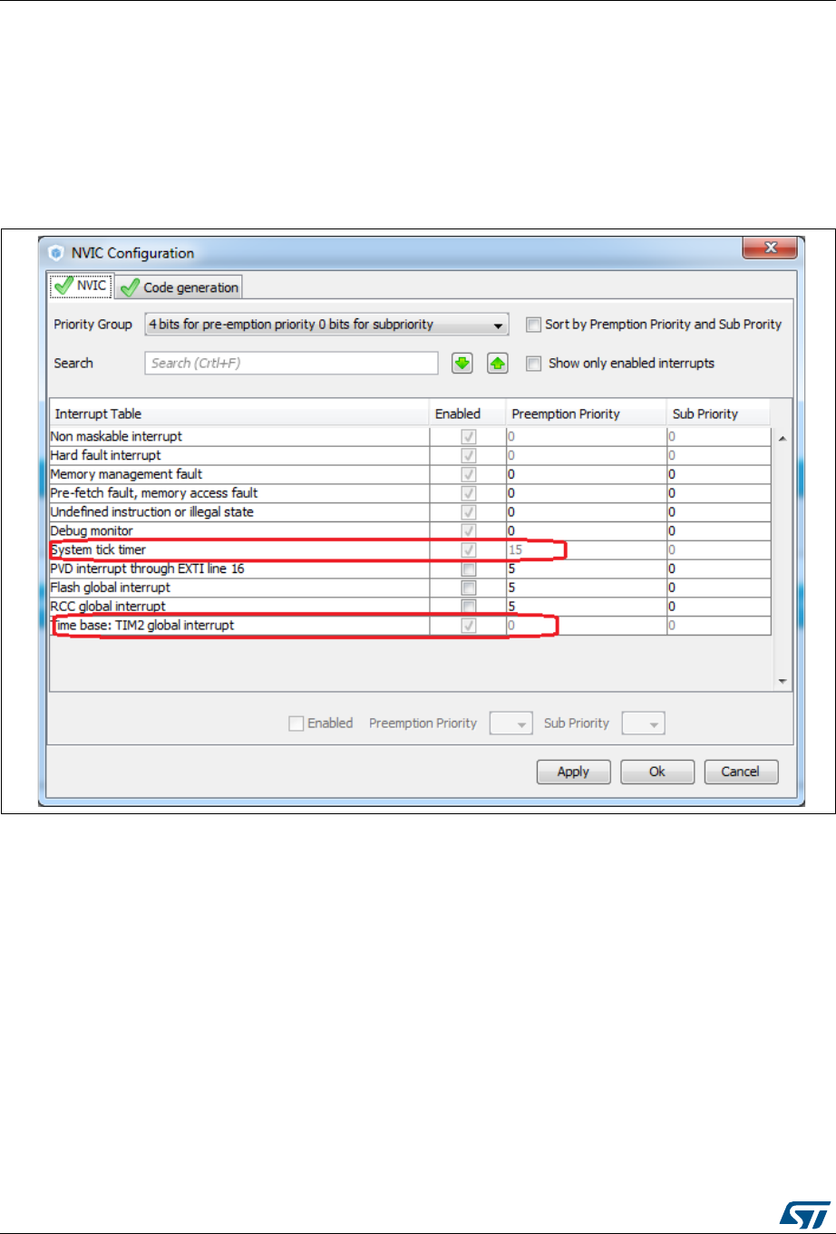
STM32CubeMX user interface UM1718
112/345 UM1718 Rev 26
Example of configuration using TIM2 as HAL timebase source
When TIM2 is used as HAL timebase source, a new stm32f4xx_hal_timebase_TIM.c file is
generated to overload the HAL timebase related functions, including the HAL_InitTick
function that configures the TIM2 as the HAL time-base source.
The priority of TIM2 timebase interrupts is set to 0 (High). The SysTick priority is set to 15
(Low) if FreeRTOS is used, otherwise it is set to 0 (High).
Figure 84. NVIC settings when using FreeRTOS and TIM2 as HAL timebase
The stm32f4xx_it.c file is generated accordingly:
SysTick_Handler calls osSystickHandler when FreeRTOS is used, otherwise it calls
HAL_SYSTICK_IRQHandler.
TIM2_IRQHandler is generated to handle TIM2 global interrupt.

UM1718 Rev 26 113/345
UM1718 STM32CubeMX user interface
344
5.13 Configuration view
STM32CubeMX Configuration window (see Figure 85) gives an overview of all the
software configurable components: GPIOs, peripherals and middleware. Clickable buttons
allow selecting the configuration options of the component initialization parameters that will
be included in the generated code. The button icon color reflects the configuration status:
Green checkmark: correct configuration
Warning sign: incomplete but still functional configuration
Red cross: for invalid configuration.
Note: GPIO and Peripheral modes that influence the pinout can be set only from the Pinout view.
They are read-only in the Configuration view.
In this view, the MCU is shown on the left panel by its Peripheral and Middleware tree and
on the right panel, by the list of peripherals and middleware organized in Middleware,
Multimedia, Connectivity, Analog, System and Control categories. Each peripheral instance
has a dedicated button to edit its configuration: as an example, TIM1 and TIM3 TIM
instances are shown as dedicated buttons in Figure 85.
Figure 85. STM32CubeMX Configuration view
A configuration button is associated to each peripheral in the Configuration window (see
Table 12).
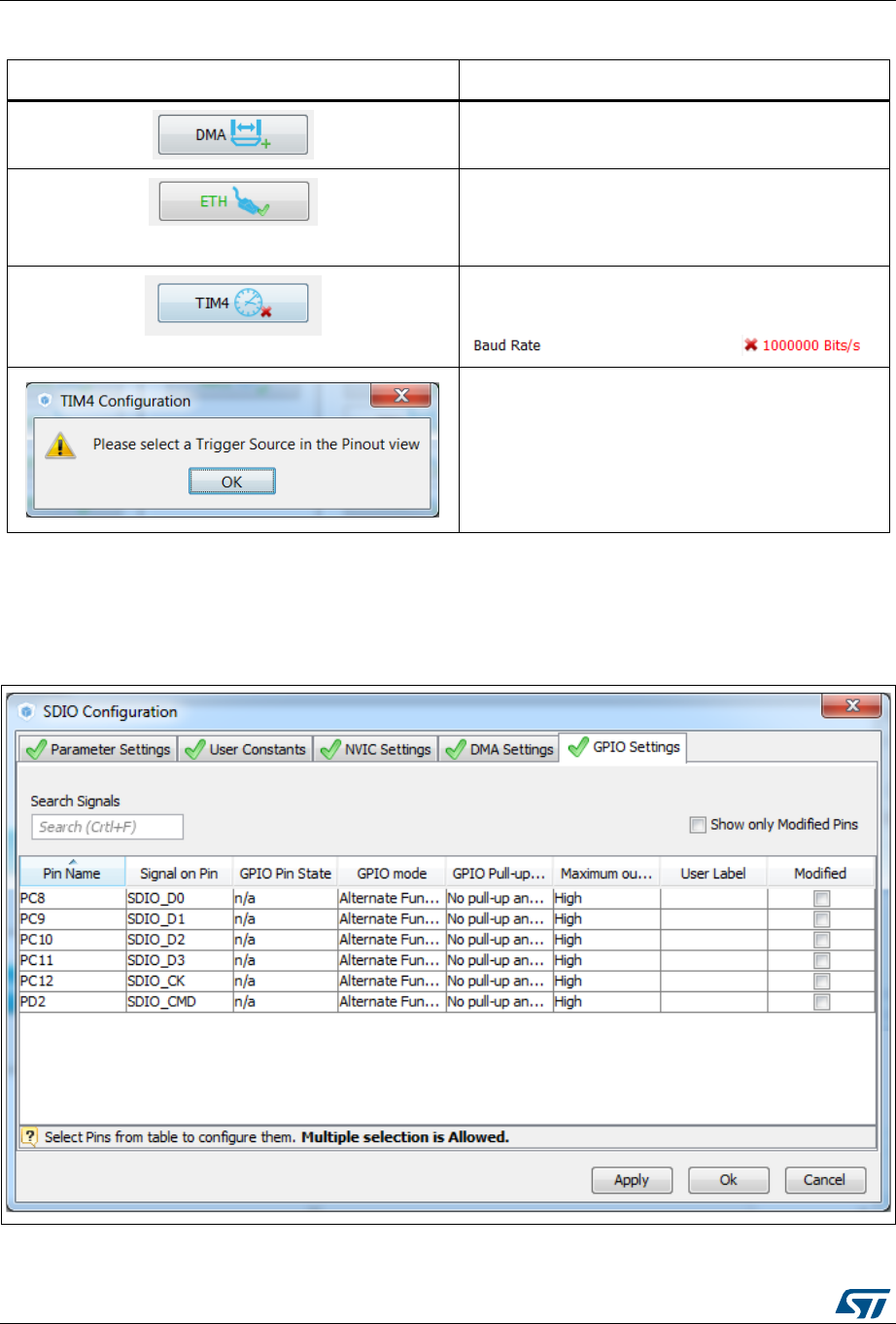
STM32CubeMX user interface UM1718
114/345 UM1718 Rev 26
GPIO, DMA and NVIC settings can be accessed either via a dedicated button like other
peripherals or via a tab in the other configuration windows of the peripherals which use them
(see Figure 86).
Figure 86. Configuration window tabs for GPIO, DMA and NVIC settings (STM32F4 Series)
Table 12. Peripheral and middleware configuration buttons
Format Peripheral Instance configuration status
Available but not fully configured yet. Click to open the
configuration window.
Well configured with default or user-defined settings
that allows proceeding with the generation of
corresponding initialization C code. Click to open the
configuration window.
Badly configured with some wrong parameter values.
Click to display the errors highlighted in red.
Other example (UART):
Dialog box that explains source of error. It shall be
fixed in another view.
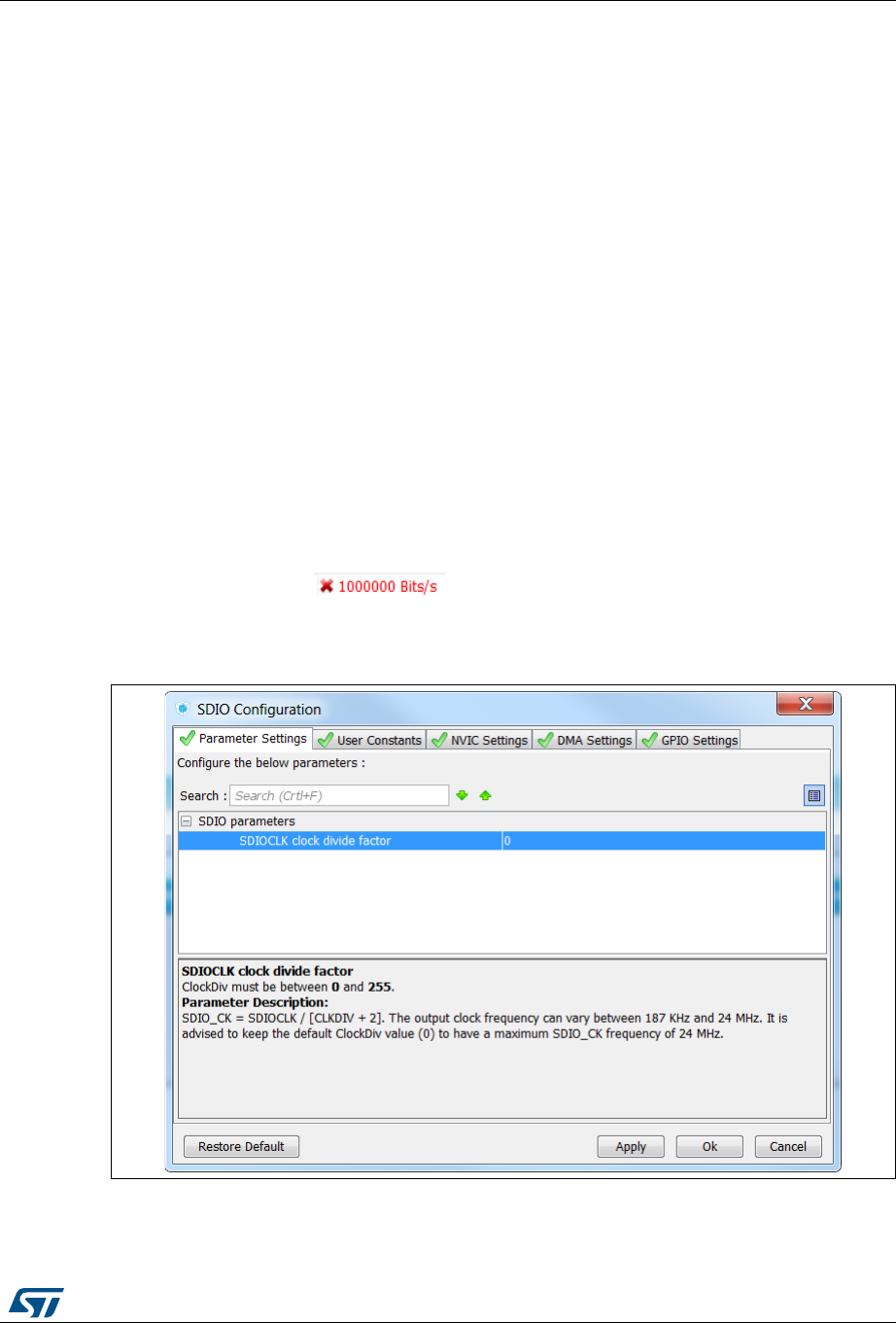
UM1718 Rev 26 115/345
UM1718 STM32CubeMX user interface
344
5.13.1 Peripherals and Middleware Configuration window
This window is open by clicking the peripheral instance or Middleware name from the
Configuration pane. It allows to configure the functional parameters that are required for
initializing the peripheral or the middleware in the selected operating mode. This
configuration is used to generate the corresponding initialization C code. Refer to Figure 87
for a Peripheral Configuration windows example.
The configuration window includes several tabs:
Parameter settings to configure library dedicated parameters for the selected
peripheral or middleware,
NVIC, GPIO and DMA settings to set the parameters for the selected peripheral (see
Section 5.13.5: NVIC Configuration window, Section 5.13.3: GPIO Configuration
window and Section 5.13.4: DMA Configuration windowfor configuration details).
User constants to create one or several user defined constants, common to the whole
project (see Section 5.13.2: User Constants configuration window for user constants
details).
Invalid settings are detected and are either:
Reset to minimum valid value if user choice was smaller than minimum threshold,
Reset to maximum valid value if user choice was greater than maximum threshold,
Reset to previous valid value if previous value was neither a maximum nor a minimum
threshold value,
Highlighted in red:
Table 13 describes peripheral and middleware configuration buttons and messages.
Figure 87. Peripheral Configuration window (STM32F4 Series)
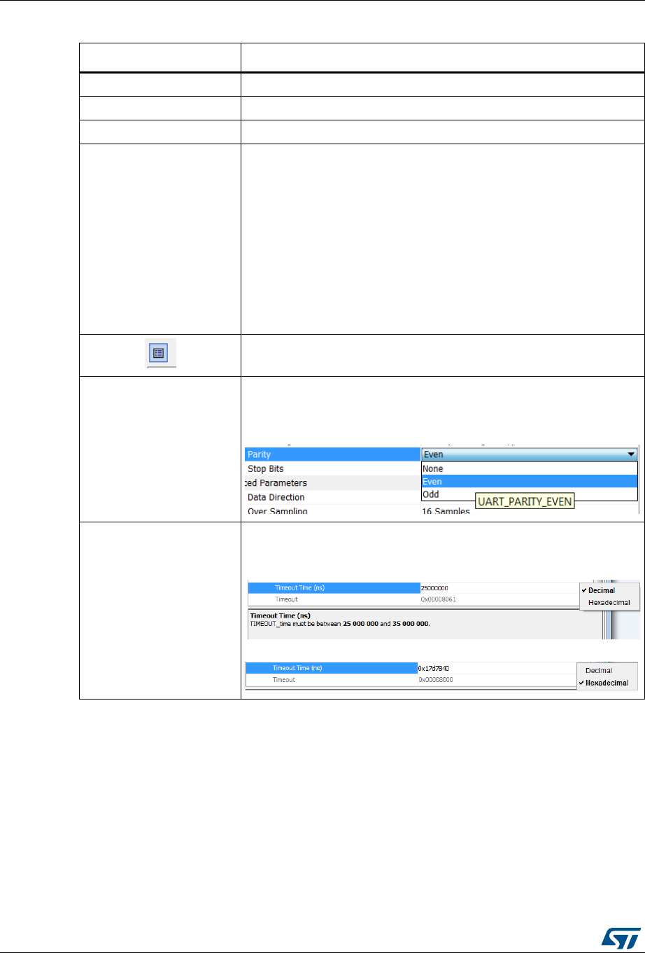
STM32CubeMX user interface UM1718
116/345 UM1718 Rev 26
Table 13. Peripheral and Middleware Configuration window buttons and tooltips
Buttons and messages Action
Apply Saves the changes without closing the window
OK Saves and closes the window
Cancel Closes and resets previously saved parameter settings
Restore Default
For the selected peripheral, the whole user configuration is reset to
STM32CubeMX default settings without clearing the project user
constants defined in the User Constants tab: STM32CubeMX default
values are restored on peripheral parameter, GPIO, NVIC and DMA
tabs.
Note: Restore default button is not available for GPIO/DMA and NVIC
windows as they address more than one peripheral.
Note: Clicking Cancel after Restore Default closes the window and
preserves the user configuration.
Caution: Clicking Apply after Restore Default saves the changes. In
this case the user original configuration cannot be restored.
Shows and Hides the description panel
Tooltip
Guides the user through the settings of parameters with valid min-max
range.
To display it, move the mouse over a parameter value from a list of
possible values.
Hexadecimal vs. decimal
values
Choose to display the field as an hexadecimal or a decimal value by
clicking the arrow on the right:
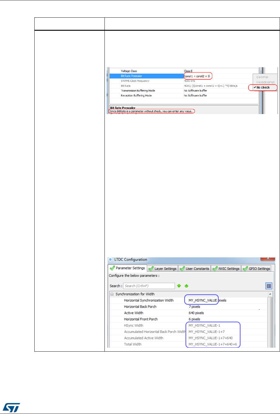
UM1718 Rev 26 117/345
UM1718 STM32CubeMX user interface
344
No check option
By default, STM32CubeMX checks that the parameter values entered
by the user are valid. You can bypass this check by selecting the option
No Check for a given parameter. This allows entering any value (such
as a constant) that might not be known by STM32CubeMX
configuration.
Note: The validity check can be bypassed only on parameters whose
values are of integer type (either hexadecimal or decimal). It
cannot be bypassed on parameters coming from a predefined
list of possible values or on those which are of non-integer or
text type.
To go back to the default mode, that is decimal or hexadecimal values
with validity check enabled, enter a decimal or hexadecimal value and
check the relevant option (hexadecimal or decimal check).
Caution: When a parameter depends on another parameter that is set
to No Check:
– Case of a parameter depending on another parameter for the
evaluation of its minimum or maximum possible value
If the other parameter is set to No Check, the minimum or maximum
value is no longer evaluated and checked.
– Case of a parameter depending on another parameter for the
evaluation of its current value
If the other parameter is set to No Check, the value is no longer
automatically derived. Instead, it is replaced with the formula text
showing as variable the string of the parameter set to No check.
Table 13. Peripheral and Middleware Configuration window buttons and tooltips
Buttons and messages Action
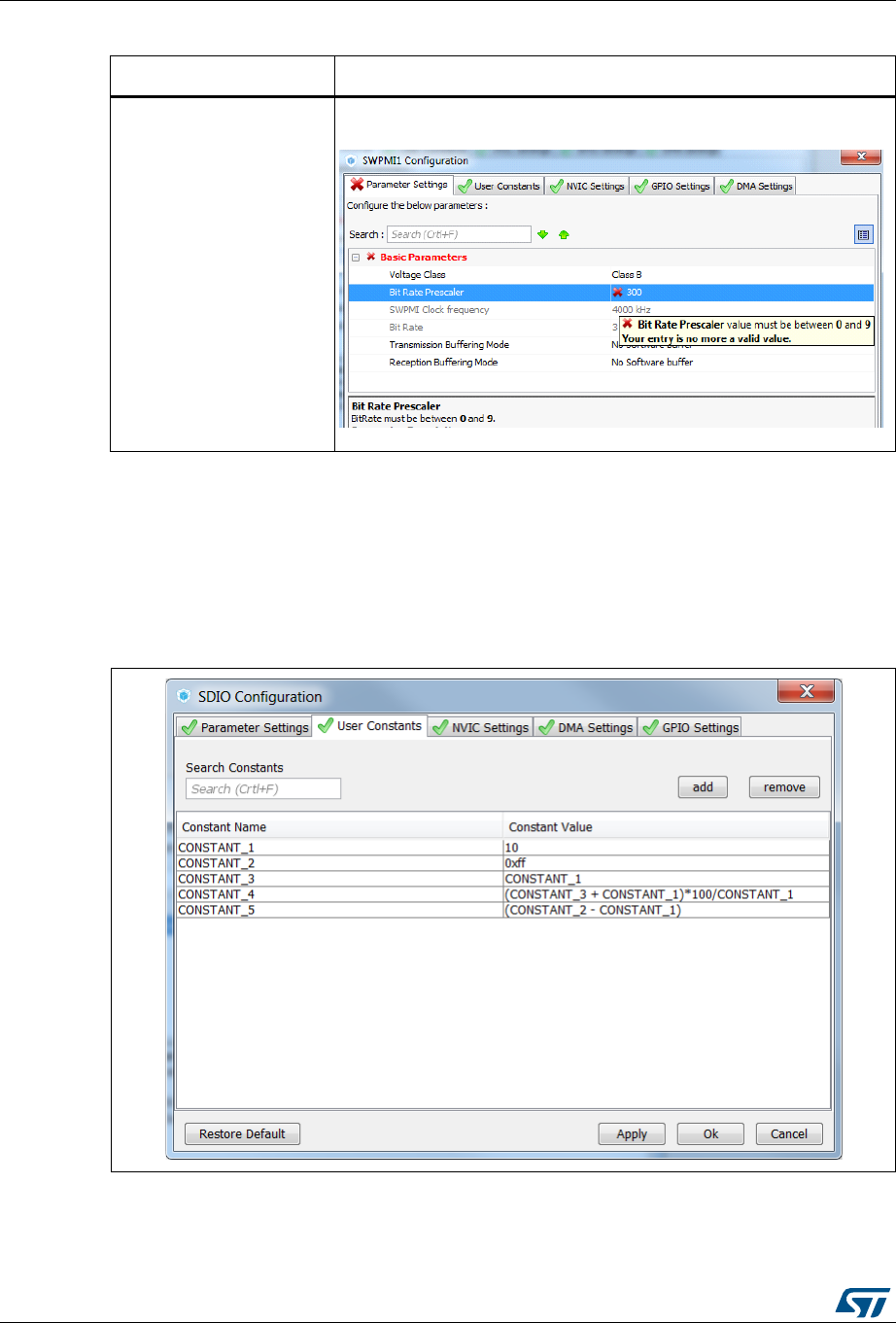
STM32CubeMX user interface UM1718
118/345 UM1718 Rev 26
5.13.2 User Constants configuration window
An User Constants window is available to define user constants (see Figure 88). Constants
are automatically generated in the STM32CubeMX user project within the main.h file (see
Figure 89). Once defined, they can be used to configure peripheral and middleware
parameters (see Figure 90).
Figure 88. User Constants window
Decimal and hexadecimal
check tooltip
If the value entered by the user is out of range, an the error will be
highlighted in red along with an explanatory tooltip:
Table 13. Peripheral and Middleware Configuration window buttons and tooltips
Buttons and messages Action

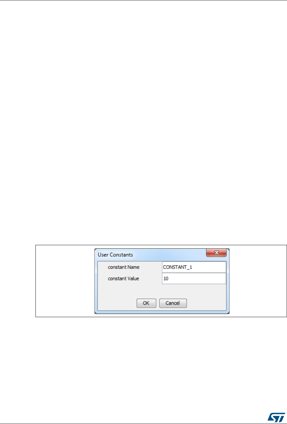
STM32CubeMX user interface UM1718
120/345 UM1718 Rev 26
Creating/editing user constants
Click the Add button to open the User Constants window and create a new user-defined
constant (see Figure 91).
A constant consists of:
A name that must comply with the following rules:
– It must be unique.
– It shall not be a C/C++ keyword.
– It shall not contain a space.
– It shall not start with digits.
A value
The constant value can be: (see Figure 88 for examples):
– a simple decimal or hexadecimal value
– a previously defined constant
– a formula using arithmetic operators (subtraction, addition, division, multiplication,
and remainder) and numeric value or user-defined numeric constants as
operands.
– a character string: the string value must be between double quotes (example:
“constant_for_usart”).
Once a constant is defined, its name and/or its value can still be changed: double- click the
row that specifies the user constant to be modified. This opens the User Constants window
for edition. The change of constant name is applied wherever the constant is used. This
does not affect the peripheral or middleware configuration state. However changing the
constant value impacts the parameters that use it and might result in invalid settings (e.g.
exceeding a maximum threshold). Invalid parameter settings will be highlighted in red with a
red cross.
Figure 91. Specifying user constant value and name
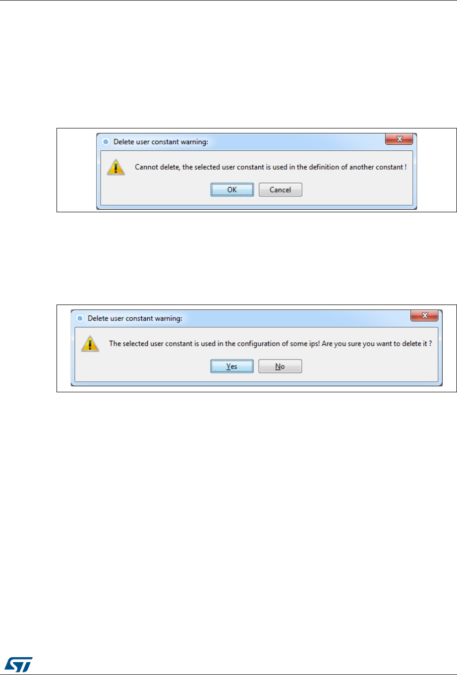
UM1718 Rev 26 121/345
UM1718 STM32CubeMX user interface
344
Deleting user constants
Click the Remove button to delete an existing user-defined constant.
The user constant is then automatically removed except in the following cases:
When the constant is used for the definition of another constant. In this case, a popup
window displays an explanatory message (see Figure 92).
Figure 92. Deleting user constant not allowed when the
constant is already used for another constant definition
When the constant is used for the configuration of a peripheral or middleware library
parameter. In this case, the user is requested to confirm the deletion since the constant
removal will result in a invalid peripheral or middleware configuration (see Figure 93).
Figure 93. Deleting an user constant used for parameter configuration -
Confirmation request
Clicking Yes leads to an invalid peripheral configuration (see Figure 94))

STM32CubeMX user interface UM1718
122/345 UM1718 Rev 26
Figure 94. Deleting a user constant used for peripheral configuration -
Consequence on peripheral configuration
Searching for user constants
The Search Constants field allows searching for a constant name or value in the complete
list of user constants (see Figure 95 and Figure 96).
Figure 95. Searching for a name in a user constant list
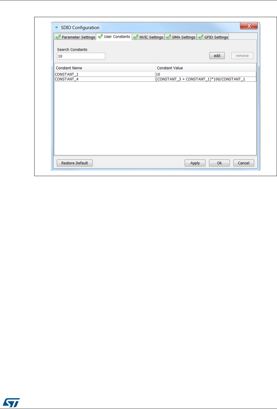
UM1718 Rev 26 123/345
UM1718 STM32CubeMX user interface
344
Figure 96. Searching for a value in a user constant list
5.13.3 GPIO Configuration window
Click GPIO in the Configuration panel to open the GPIO configuration window that allows
configuring the GPIO pin settings (see Figure 97). The configuration is populated with
default values that might not be adequate for some peripheral configurations. In particular,
check if the GPIO speed is sufficient for the peripheral communication speed and select the
internal pull-up whenever needed.
Note: GPIO settings can also be accessed for a specific peripheral instance via the dedicated
GPIO window in the peripheral instance configuration window.
In addition, GPIOs can be configured in output mode (default output level). The generated
code will be updated accordingly.
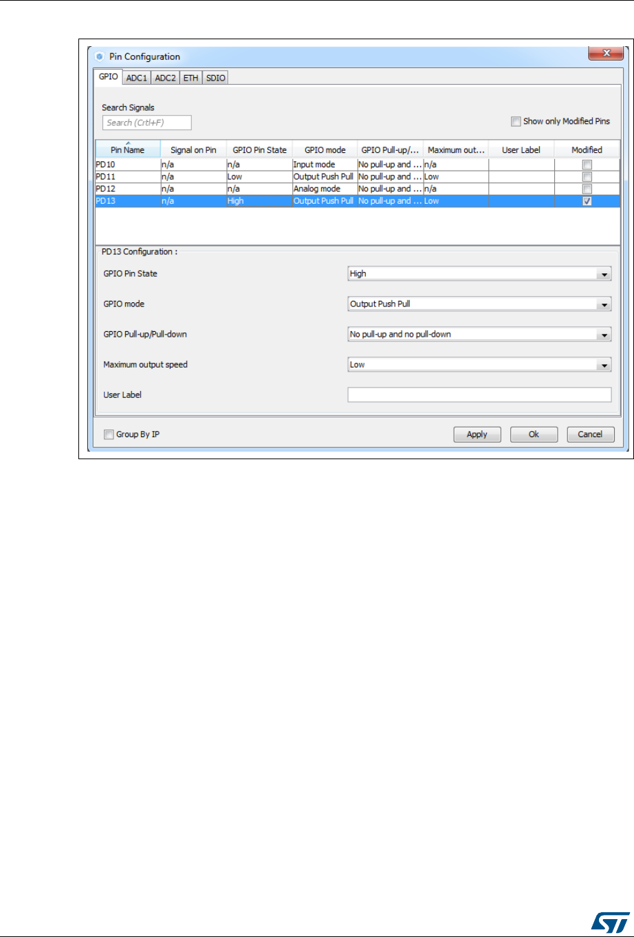
STM32CubeMX user interface UM1718
124/345 UM1718 Rev 26
Figure 97. GPIO Configuration window - GPIO selection
Click a row or select a set of rows to display the corresponding GPIO parameters (see
Figure 98):
GPIO PIN state
It changes the default value of the GPIO Output level. It is set to low by default and can
be changed to high.
GPIO mode (analog, input, output, alternate function)
Selecting a peripheral mode in the Pinout view automatically configures the pins with
the relevant alternate function and GPIO mode.
GPIO pull-up/pull-down
It is set to a default value and can be configured when other choices are possible.
GPIO maximum output speed (for communication peripherals only)
It is set to Low by default for power consumption optimization and can be changed to a
higher frequency to fit application requirements.
User Label
It changes the default name (e.g. GPIO_input) into a user defined name. The Chip
view is updated accordingly. The GPIO can be found under this new name via the Find
menu.

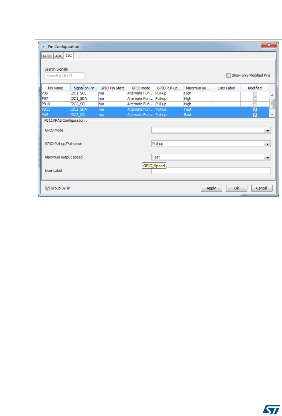
STM32CubeMX user interface UM1718
126/345 UM1718 Rev 26
As shown in Figure 100, row multi-selection can be performed to change a set of pins to a
given configuration at the same time.
Figure 100. Multiple Pins Configuration
5.13.4 DMA Configuration window
Click DMA in the Configuration panel to open the DMA configuration window.
This window allows to configure the generic DMA controllers available on the MCU. The
DMA interfaces allow to perform data transfers between memories and peripherals while the
CPU is running, and memory to memory transfers (if supported).
Note: Some peripherals such as USB or Ethernet, have their own DMA controller, which is
enabled by default or via the Peripheral Configuration window.
Clicking Add in the DMA configuration window adds a new line at the end of the DMA
configuration window with a combo box proposing to choose between possible DMA
requests to be mapped to peripherals signals (see Figure 101).
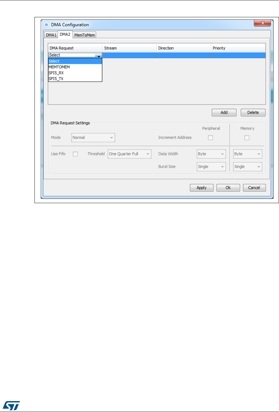
UM1718 Rev 26 127/345
UM1718 STM32CubeMX user interface
344
Figure 101. Adding a new DMA request
Selecting a DMA request automatically assigns a stream among all the streams available, a
direction and a priority. When the DMA channel is configured, it is up to the application code
to fully describe the DMA transfer run-time parameters such as the start address, etc....
The DMA request (called channel for STM32F4 MCUs) is used to reserve a stream to
transfer data between peripherals and memories (see Figure 102). The stream priority will
be used to decide which stream to select for the next DMA transfer.
DMA controllers support a dual priority system using the software priority first, and in case of
equal software priorities, a hardware priority that is given by the stream number.
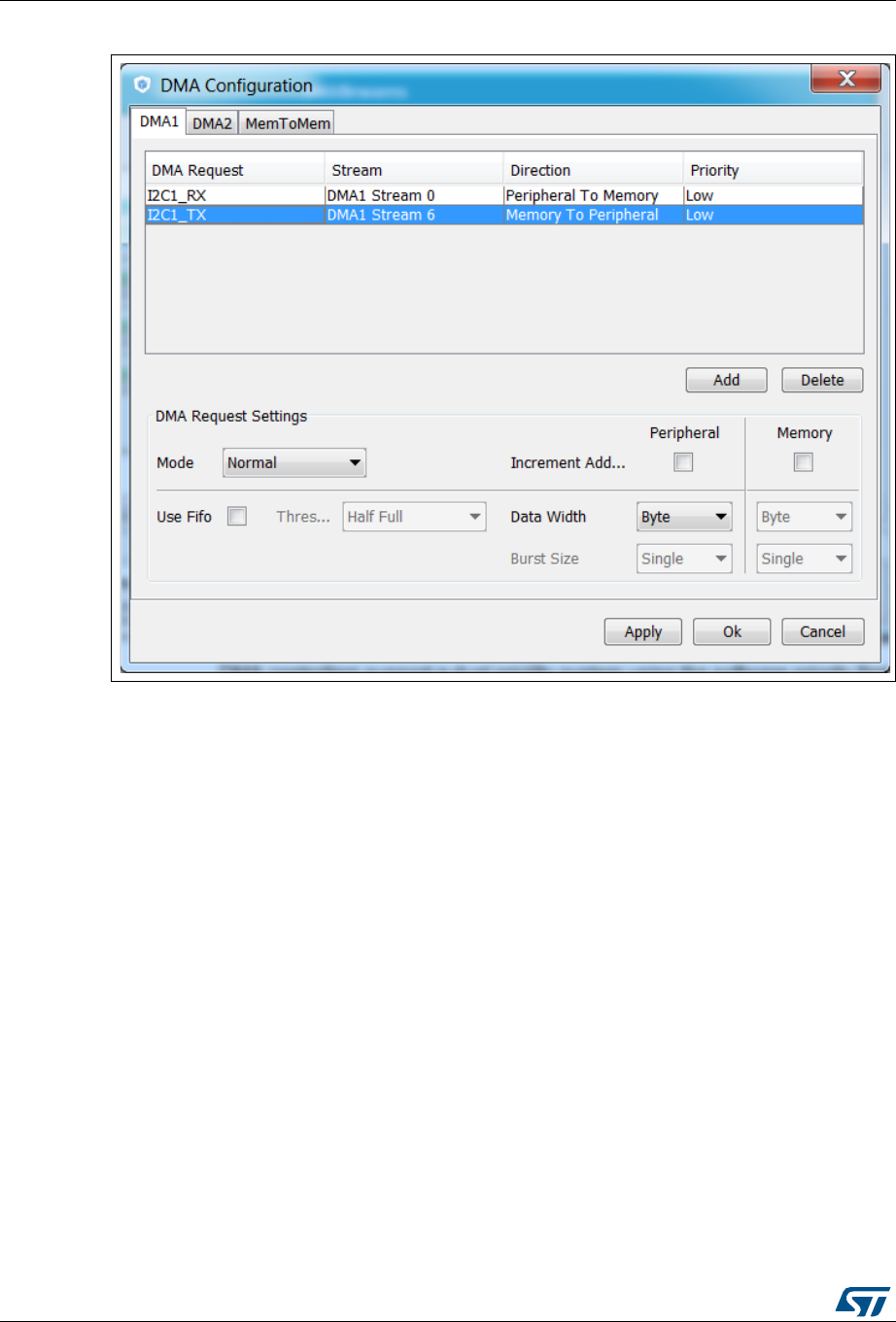
STM32CubeMX user interface UM1718
128/345 UM1718 Rev 26
Figure 102. DMA configuration
Additional DMA configuration settings can be done through the DMA configuration
window:
Mode: regular mode, circular mode, or peripheral flow controller mode (only available
for the SDIO peripheral).
Increment Add: the type of peripheral address and memory address increment (fixed
or post-incremented in which case the address is incremented after each transfer).
Click the checkbox to enable the post-incremented mode.
Peripheral data width: 8, 16 or 32 bits
Switching from the default direct mode to the FIFO mode with programmable threshold:
a) Click the Use FIFO checkbox.
b) Then, configure the peripheral and memory data width (8, 16 or 32 bits).
c) Select between single transfer and burst transfer. If you select burst transfer,
choose a burst size (1, 4, 8 or 16).
In case of memory-to-memory transfer (MemtoMem), the DMA configuration applies to a
source memory and a destination memory.
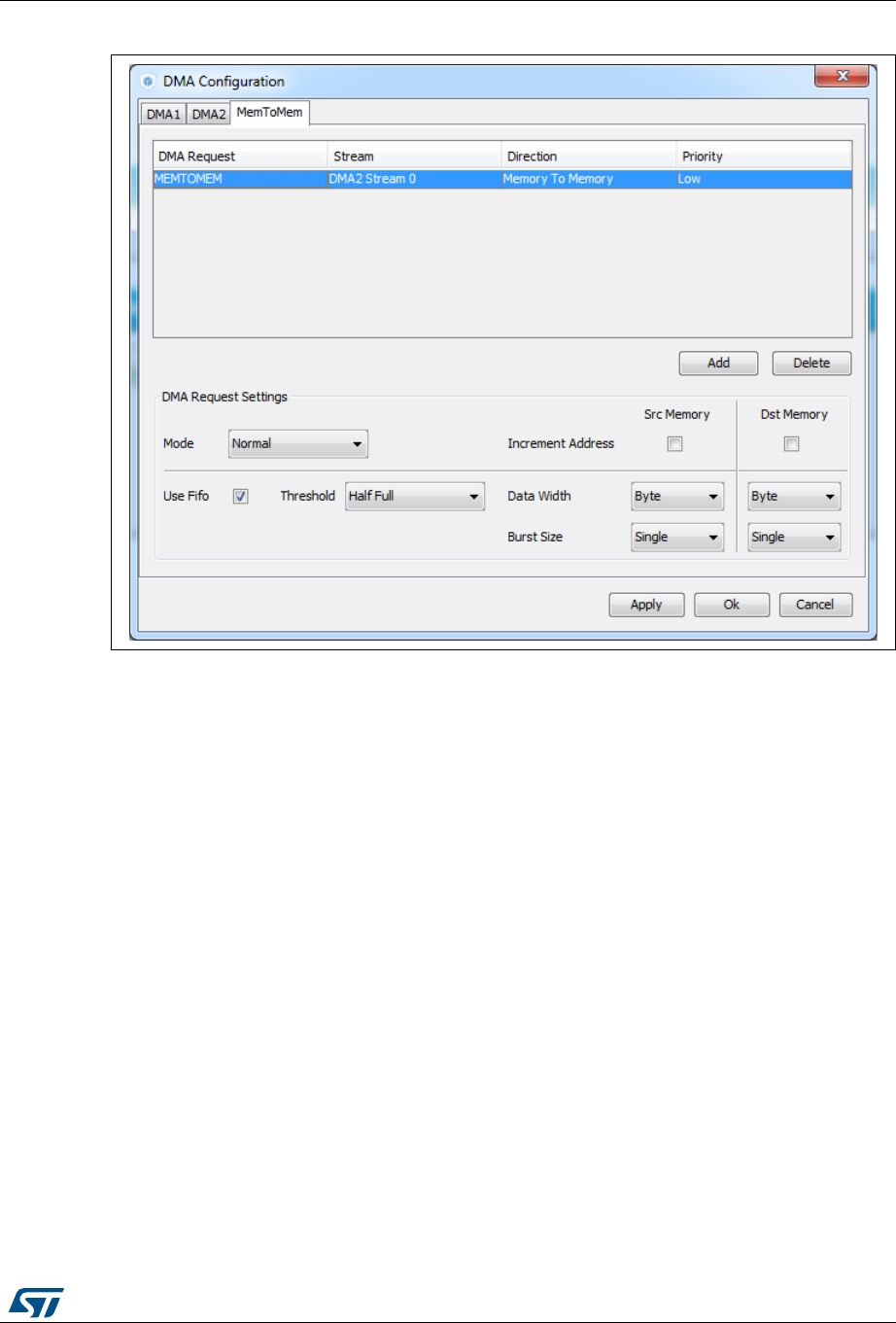
UM1718 Rev 26 129/345
UM1718 STM32CubeMX user interface
344
Figure 103. DMA MemToMem configuration
5.13.5 NVIC Configuration window
Click NVIC in the Configuration panel to open the Nested Vector interrupt controller
configuration window (see Figure 104).
Interrupt unmasking and interrupt handlers are managed within 2 tabs:
The NVIC tab allows enabling peripheral interrupts in the NVIC controller and setting
their priorities.
The Code generation tab allows selecting options for interrupt related code
generation.
Enabling interruptions using the NVIC tab view
The NVIC view (see Figure 104) does not show all possible interrupts but only the ones
available for the peripherals selected in the Pinout and Configuration panels. System
interrupts are displayed but can never be disabled.
Check/Uncheck the Show only enabled interrupts box to filter or not enabled interrupts.
Use the search field to filter out the interrupt vector table according to a string value. As an
example, after enabling UART peripherals from the Pinout panel, type UART in the NVIC
search field and click the green arrow close to it: all UART interrupts are then displayed.
Enabling a peripheral interrupt will generate of NVIC function calls
HAL_NVIC_SetPriority and HAL_NVIC_EnableIRQ for this peripheral.
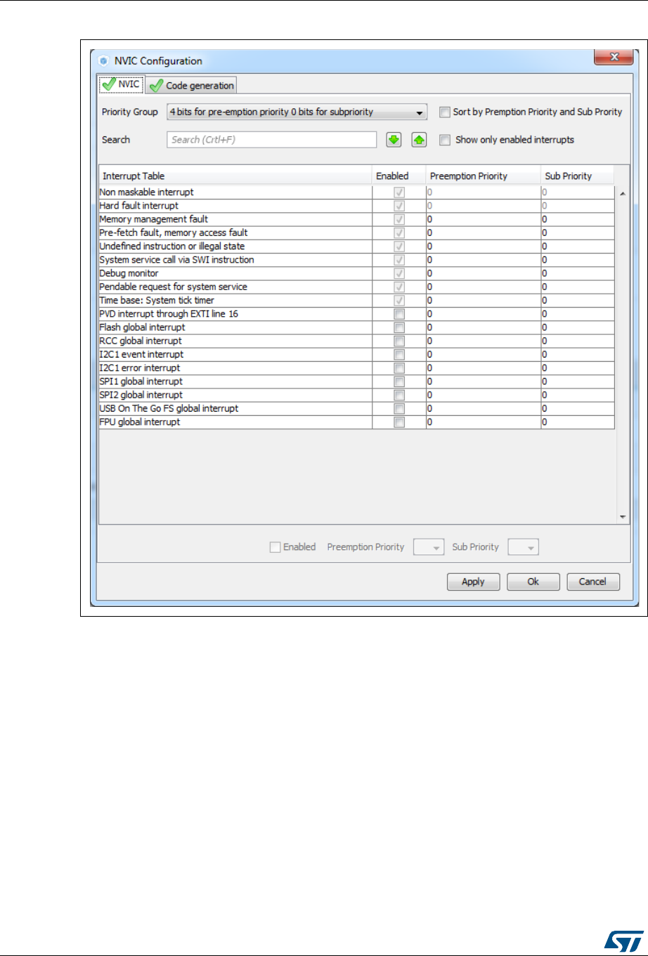
STM32CubeMX user interface UM1718
130/345 UM1718 Rev 26
Figure 104. NVIC Configuration tab - FreeRTOS disabled
When FreeRTOS is enabled, an additional column is shown (see Figure 105). In this case,
all the interrupt service routines (ISRs) that are calling the interrupt safe FreeRTOS APIs,
should have a priority lower than the priority defined in the
LIBRARY_MAX_SYSCALL_INTERRUPT_PRIORITY parameter (the highest the value, the
lowest the priority). The check in the corresponding checkbox guarantees that the restriction
is applied.
If an ISR does not use such functions, the checkbox can be unchecked and any priority level
can be set.
It is possible to check/uncheck multiple rows at a time (see rows highlighted in blue in
Figure 105).


STM32CubeMX user interface UM1718
132/345 UM1718 Rev 26
STM32CubeMX NVIC configuration consists in selecting a priority group, enabling/disabling
interrupts and configuring interrupts priority levels (preemption and sub-priority levels):
1. Select a priority group
Several bits allow to define NVIC priority levels. These bits are divided in two priority
groups corresponding to two priority types: preemption priority and sub-priority. For
example, in the case of STM32F4 MCUs, the NVIC priority group 0 corresponds to 0-
bit preemption and 4-bit sub-priority.
2. In the interrupt table, click one or more rows to select one or more interrupt vectors.
Use the widgets below the interrupt table to configure the vectors one by one or several
at a time:
–Enable checkbox: check/uncheck to enable/disable the interrupt.
–Preemption priority: select a priority level. The preemption priority defines the
ability of one interrupt to interrupt another.
–Sub-priority: select a priority level. The sub-priority defines the interrupt priority
level.
– Click Apply to save changes, and OK to close the window.
Code generation options for interrupt handling
The Code Generation view allows customizing the code generated for interrupt initialization
and interrupt handlers:
Selection/Deselection of all interrupts for sequence ordering and IRQ handler
code generation
Use the checkboxes in front of the column names to configure all interrupts at a time
(see Figure 107). Note that system interrupts are not eligible for init sequence
reordering as the software solution does not control it.
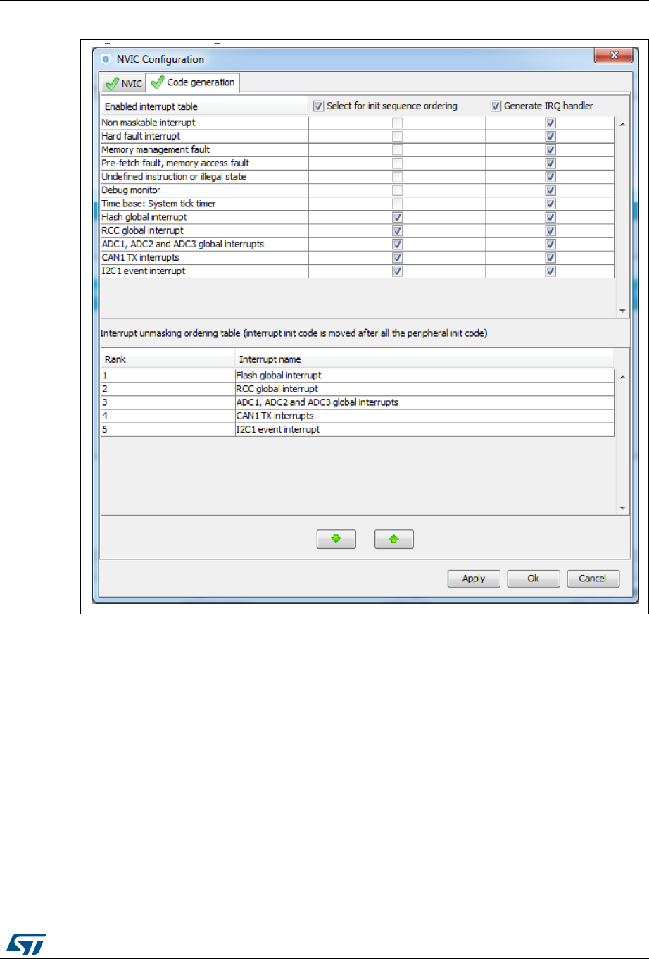
UM1718 Rev 26 133/345
UM1718 STM32CubeMX user interface
344
Figure 107. NVIC Code generation – All interrupts enabled
Default initialization sequence of interrupts
By default, the interrupts are enabled as part of the peripheral MSP initialization
function, after the configuration of the GPIOs and the enabling of the peripheral clock.
This is shown in the CAN example below, where HAL_NVIC_SetPriority and
HAL_NVIC_EnableIRQ functions are called within stm32xxx_hal_msp.c file inside the
peripheral msp_init function.
Interrupt enabling code is shown in bold:
void HAL_CAN_MspInit(CAN_HandleTypeDef* hcan)
{
GPIO_InitTypeDef GPIO_InitStruct;
if(hcan->Instance==CAN1)
{
/* Peripheral clock enable */
__CAN1_CLK_ENABLE();
/**CAN1 GPIO Configuration

STM32CubeMX user interface UM1718
134/345 UM1718 Rev 26
PD0 ------> CAN1_RX
PD1 ------> CAN1_TX
*/
GPIO_InitStruct.Pin = GPIO_PIN_0|GPIO_PIN_1;
GPIO_InitStruct.Mode = GPIO_MODE_AF_PP;
GPIO_InitStruct.Pull = GPIO_NOPULL;
GPIO_InitStruct.Speed = GPIO_SPEED_FREQ_VERY_HIGH;
GPIO_InitStruct.Alternate = GPIO_AF9_CAN1;
HAL_GPIO_Init(GPIOD, &GPIO_InitStruct);
/* Peripheral interrupt init */
HAL_NVIC_SetPriority(CAN1_TX_IRQn, 2, 2);
HAL_NVIC_EnableIRQ(CAN1_TX_IRQn);
}
}
For EXTI GPIOs only, interrupts are enabled within the MX_GPIO_Init function:
/*Configure GPIO pin : MEMS_INT2_Pin */
GPIO_InitStruct.Pin = MEMS_INT2_Pin;
GPIO_InitStruct.Mode = GPIO_MODE_EVT_RISING;
GPIO_InitStruct.Pull = GPIO_NOPULL;
HAL_GPIO_Init(MEMS_INT2_GPIO_Port, &GPIO_InitStruct);
/* EXTI interrupt init*/
HAL_NVIC_SetPriority(EXTI15_10_IRQn, 0, 0);
HAL_NVIC_EnableIRQ(EXTI15_10_IRQn);
For some peripherals, the application still needs to call another function to actually
activate the interruptions. Taking the timer peripheral as an example, the
HAL_TIM_IC_Start_IT function needs to be called to start the Timer input capture (IC)
measurement in interrupt mode.
Configuration of interrupts initialization sequence
Checking Select for Init sequence ordering for a set of peripherals moves the
HAL_NVIC function calls for each peripheral to a same dedicated function, named
MX_NVIC_Init, defined in the main.c. Moreover, the HAL_NVIC functions for each
peripheral are called in the order specified in the Code generation view bottom part
(see Figure 108).
As an example, the configuration shown in Figure 108 generates the following code:
/** NVIC Configuration
*/
void MX_NVIC_Init(void)
{
/* CAN1_TX_IRQn interrupt configuration */
HAL_NVIC_SetPriority(CAN1_TX_IRQn, 2, 2);
HAL_NVIC_EnableIRQ(CAN1_TX_IRQn);
/* PVD_IRQn interrupt configuration */
HAL_NVIC_SetPriority(PVD_IRQn, 0, 0);
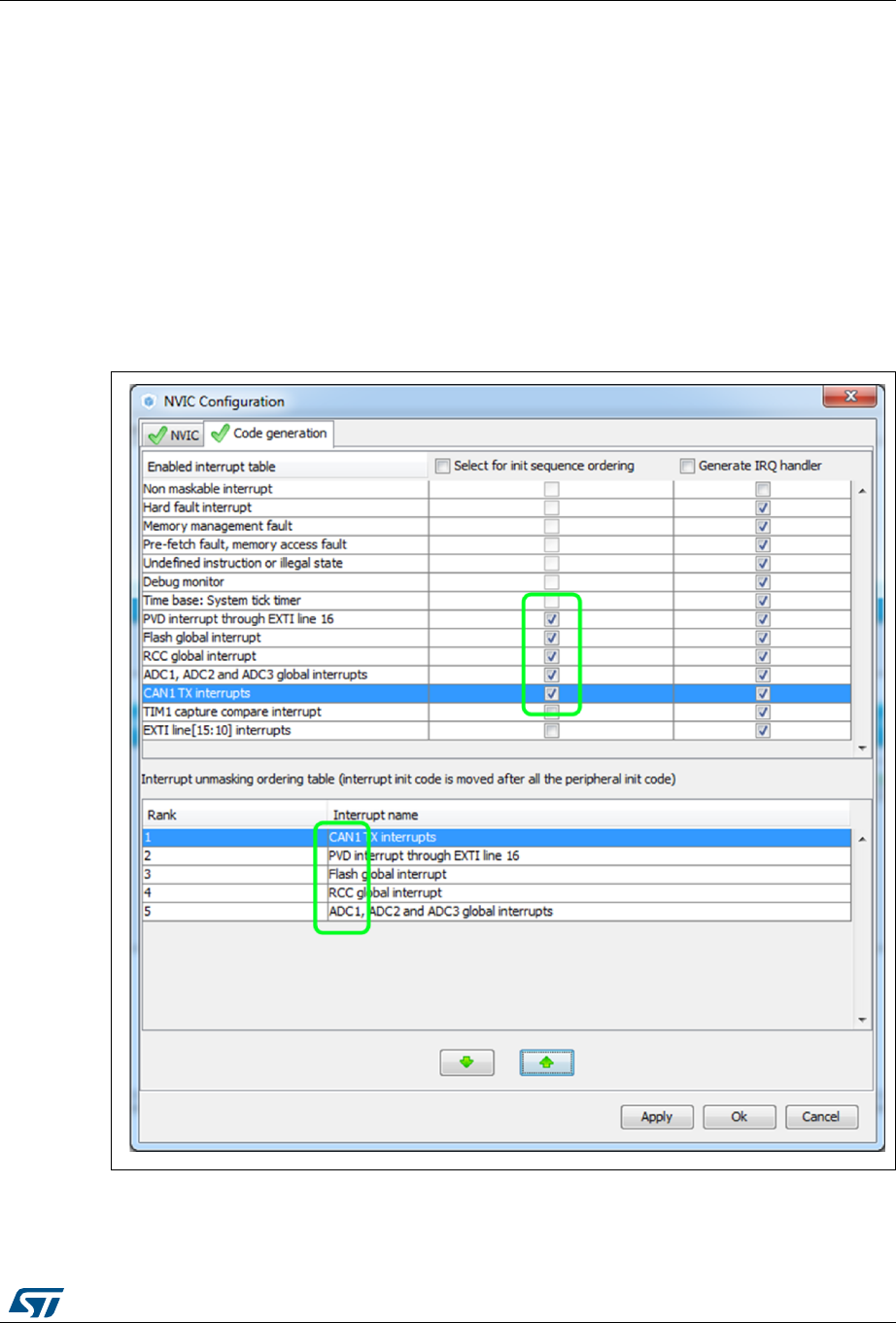
UM1718 Rev 26 135/345
UM1718 STM32CubeMX user interface
344
HAL_NVIC_EnableIRQ(PVD_IRQn);
/* FLASH_IRQn interrupt configuration */
HAL_NVIC_SetPriority(FLASH_IRQn, 0, 0);
HAL_NVIC_EnableIRQ(CAN1_IRQn);
/* RCC_IRQn interrupt configuration */
HAL_NVIC_SetPriority(RCC_IRQn, 0, 0);
HAL_NVIC_EnableIRQ(CAN1_IRQn);
/* ADC_IRQn interrupt configuration */
HAL_NVIC_SetPriority(ADC_IRQn, 0, 0);
HAL_NVIC_EnableIRQ(ADC_IRQn);
}
Figure 108. NVIC Code generation – Interrupt initialization sequence configuration
Interrupts handler code generation
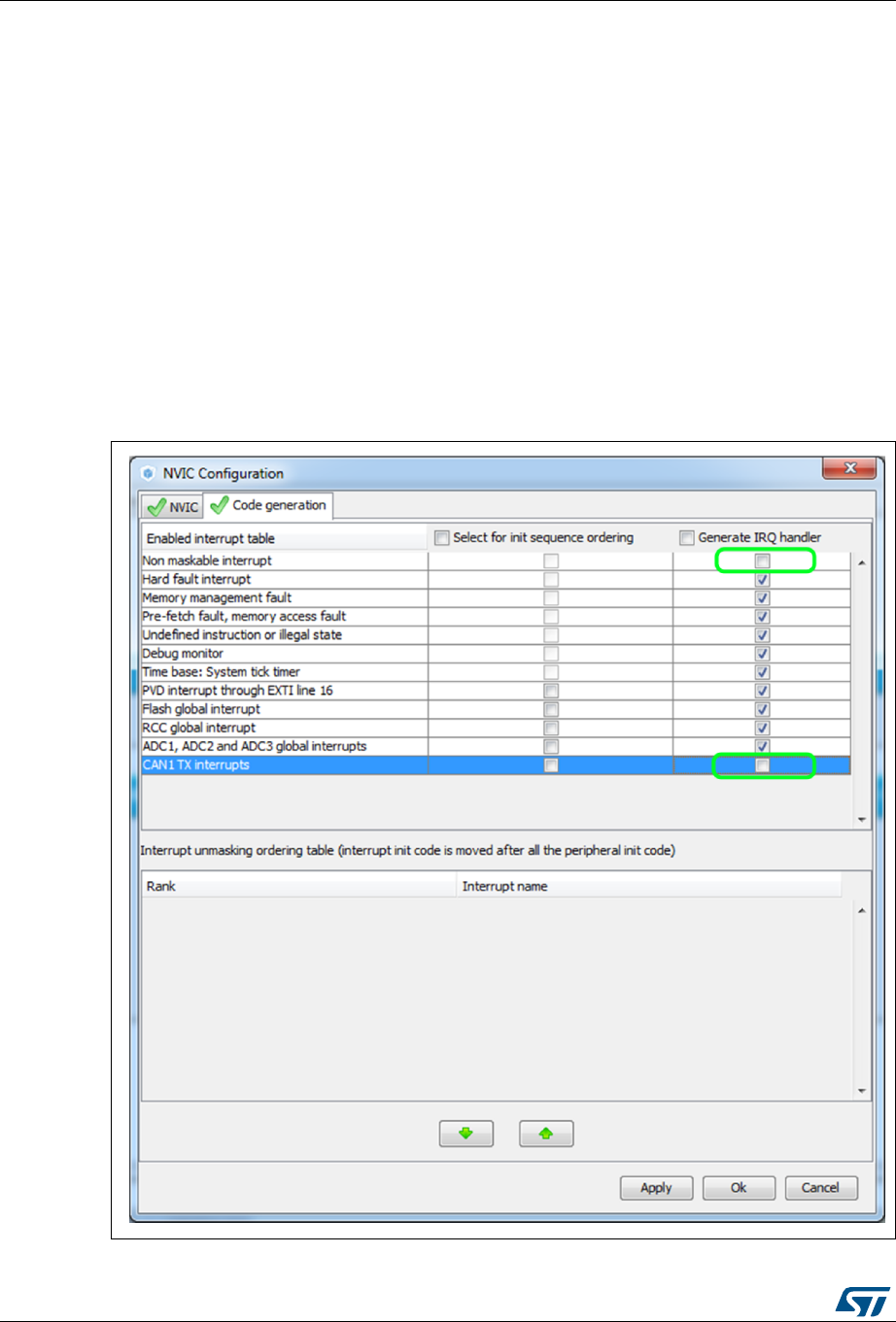
STM32CubeMX user interface UM1718
136/345 UM1718 Rev 26
By default, STM32CubeMX generates interrupt handlers within the stm32xxx_it.c file.
As an example:
void NMI_Handler(void)
{
HAL_RCC_NMI_IRQHandler();
}
void CAN1_TX_IRQHandler(void)
{
HAL_CAN_IRQHandler(&hcan1);
}
The column Generate IRQ Handler allows controlling whether the interrupt handler
function call shall be generated or not. Deselecting CAN1_TX and NMI interrupts from
the Generate IRQ Handler column as shown in Figure 108 removes the code
mentioned earlier from the stm32xxx_it.c file.
Figure 109. NVIC Code generation – IRQ Handler generation
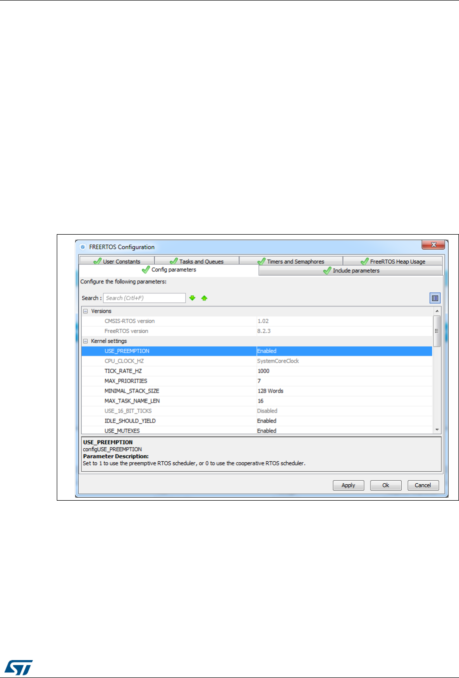
UM1718 Rev 26 137/345
UM1718 STM32CubeMX user interface
344
5.13.6 FreeRTOS middleware configuration view
Through STM32CubeMX FreeRTOS configuration window, the user can configure all the
resources required for a real-time OS application and reserve the corresponding heap.
FreeRTOS elements are defined and created in the generated code using CMSIS-RTOS
API functions. Follow the sequence below:
1. In the Configuration tab, enable FreeRTOS from the tree view.
2. Click FreeRTOS in the Configuration panel to open the FreeRTOS configuration
window (see Figure 110).
All tabs but the User Constants tab allow configuring FreeRTOS native configuration
parameters and objects, such as tasks, timers, queues, and semaphores.
The Config parameters values allow configuring Kernel and Software settings.
The Include parameters tab allows selecting only the API functions required by the
application and thus optimizing the code size.
Both Config and Include parameters will be part of the FreeRTOSConfig.h file.
Figure 110. FreeRTOS configuration view

STM32CubeMX user interface UM1718
138/345 UM1718 Rev 26
Tasks and Queues Tab
As any RTOS, FreeRTOS allows structuring a real-time application into a set of independent
tasks, with only one task being executed at a given time. Queues are meant for inter-task
communications: they allow to exchange messages between tasks or between interrupts
and tasks.
In STM32CubeMX, the FreeRTOS Tasks and Queues tab allows creating and configuring
such tasks and queues (see Figure 111). The corresponding initialization code will be
generated within main.c or freeRTOS.c if the option “generate code as pair of .c/.h files per
peripherals and middleware” is set in the Project Settings menu.
The corresponding initialization code will be generated within main.c by default or within
freeRTOS.c if the option “generate code as pair of .c/.h files per peripherals and
middleware” is set in the Project Settings menu.
Figure 111. FreeRTOS: configuring tasks and queues
Tasks
Under the Tasks section, click the Add button to open the New Task window where
task name, priority, stack size and entry function can be configured (see
Figure 112). These settings can be updated at any time: double-clicking a task row
opens again the new task window for editing.
The entry function can be generated as weak or external:
– When the task is generated as weak, the user can propose another definition than
the one generated by default.
– When the task is extern, it is up to the user to provide its function definition.
By default, the function definition is generated including user sections to allow
customization.
Queues
Under the Queues section, click the Add button to open the New Queue window
where the queue name, size and item size can be configured (see Figure 112). The
queue size corresponds to the maximum number of items that the queue can hold at a
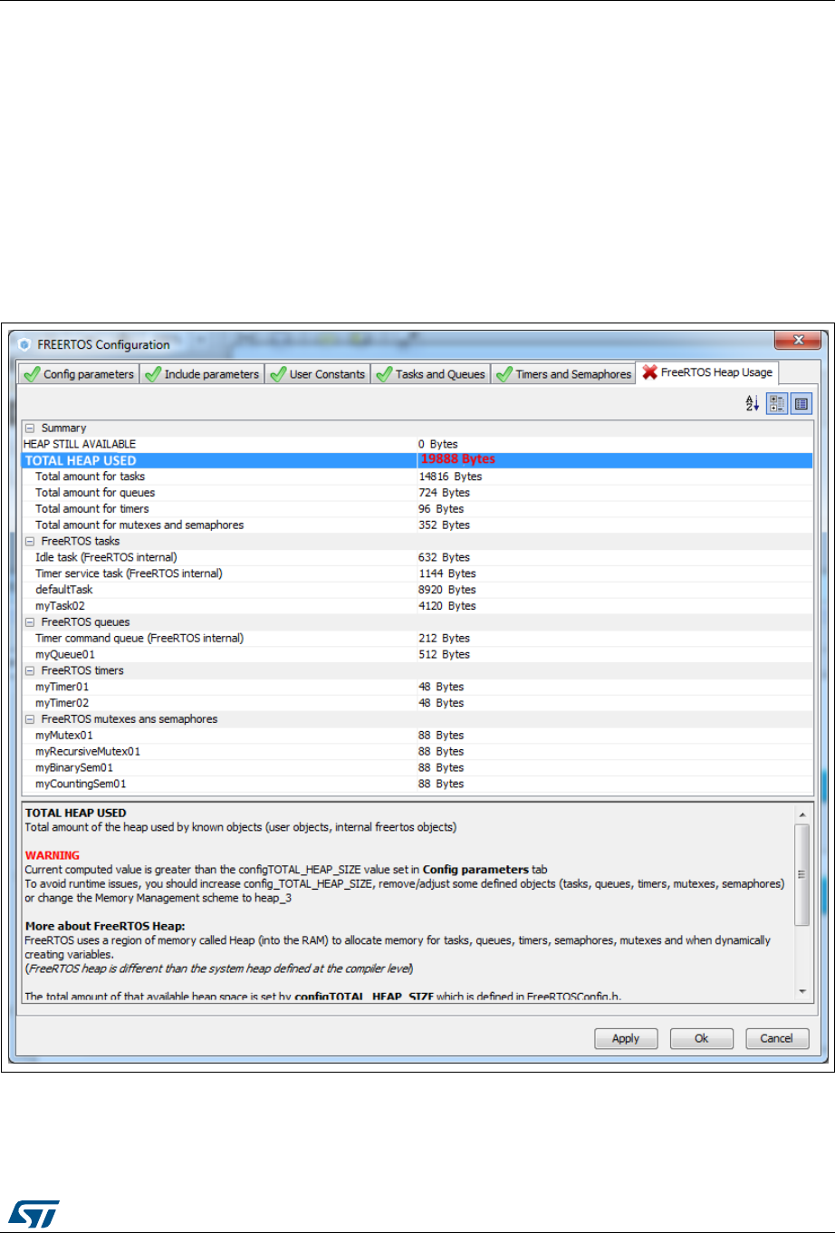
UM1718 Rev 26 139/345
UM1718 STM32CubeMX user interface
344
time, while the item size is the size of each data item stored in the queue. The item size
can be expressed either in number of bytes or as a data type:
1 byte for uint8_t, int8_t, char and portCHAR types
2 bytes for uint16_t, int16_t, short and portSHORT types
4 bytes for uint32_t, int32_t, int, long and float
8 bytes for uint64_t, int64_t and double
By default, the FreeRTOS heap usage calculator uses 4 bytes when the item size can
not be automatically derived from user input.
These settings can be updated at any time: double-clicking a queue row opens again
the new queue window for editing.
Figure 112. FreeRTOS: creating a new task

STM32CubeMX user interface UM1718
140/345 UM1718 Rev 26
The following code snippet shows the generated code corresponding to Figure 111.
/* Create the thread(s) */
/* definition and creation of defaultTask */
osThreadDef(defaultTask, StartDefaultTask, osPriorityNormal, 0, 128);
defaultTaskHandle = osThreadCreate(osThread(defaultTask), NULL);
/* definition and creation of Task_A */
osThreadDef(Task_A, StartTask_A, osPriorityHigh, 0, 128);
Task_AHandle = osThreadCreate(osThread(Task_A), NULL);
/* definition and creation of Task_B */
osThreadDef(Task_B, StartTask_B, osPriorityLow, 0, 256);
Task_BHandle = osThreadCreate(osThread(Task_B), NULL);
/* Create the queue(s) */
/* definition and creation of myQueue_1 */
osMessageQDef(myQueue_1, 16, 4);
myQueue_1Handle = osMessageCreate(osMessageQ(myQueue_1), NULL);
/* definition and creation of myQueue_2 */
osMessageQDef(myQueue_2, 32, 2);
myQueue_2Handle = osMessageCreate(osMessageQ(myQueue_2), NULL);
Timers, Mutexes and Semaphores
FreeRTOS timers, mutexes and semaphores can be configured via the FreeRTOS Timers
and Semaphores tab (see Figure 113).
Under each object dedicated section, clicking the Add button to open the corresponding
New <object> window where the object specific parameters can be specified. Object
settings can be modified at any time: double- clicking the relevant row opens again the New
<object> window for edition.
Note: Expand the window if the newly created objects are not visible.
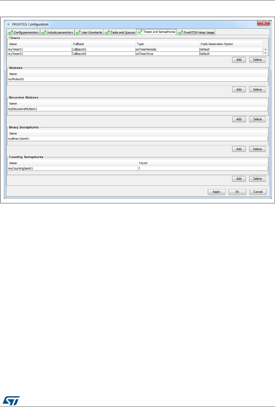
UM1718 Rev 26 141/345
UM1718 STM32CubeMX user interface
344
Figure 113. FreeRTOS - Configuring timers, mutexes and semaphores
Timers
Prior to creating timers, their usage (USE_TIMERS definition) must be enabled in the
software timer definitions section of the Configuration parameters tab. In the
same section, timer task priority, queue length and stack depth can be also configured.
The timer can be created to be one-shot (run once) or auto-reload (periodic). The timer
name and the corresponding callback function name must be specified. It is up to the
user to fill the callback function code and to specify the timer period (time between the
timer being started and its callback function being executed) when calling the CMSIS-
RTOS osTimerStart function.
Mutexes/Semaphores
Prior to creating mutexes, recursive mutexes and counting semaphores, their usage
(USE_ MUTEXES, USE_RECURSIVE_MUTEXES,
USE_COUNTING_SEMAPHORES definitions) must be enabled within the Kernel
settings section of the Configuration parameters tab.
The following code snippet shows the generated code corresponding to Figure 113:
FreeRTOS - Configuring timers, mutexes and semaphores).
/* Create the semaphores(s) */
/* definition and creation of myBinarySem01 */
osSemaphoreDef(myBinarySem01);
myBinarySem01Handle = osSemaphoreCreate(osSemaphore(myBinarySem01), 1);

STM32CubeMX user interface UM1718
142/345 UM1718 Rev 26
/* definition and creation of myCountingSem01 */
osSemaphoreDef(myCountingSem01);
myCountingSem01Handle = osSemaphoreCreate(osSemaphore(myCountingSem01),
7);
/* Create the timer(s) */
/* definition and creation of myTimer01 */
osTimerDef(myTimer01, Callback01);
myTimer01Handle = osTimerCreate(osTimer(myTimer01), osTimerPeriodic,
NULL);
/* definition and creation of myTimer02 */
osTimerDef(myTimer02, Callback02);
myTimer02Handle = osTimerCreate(osTimer(myTimer02), osTimerOnce, NULL);
/* Create the mutex(es) */
/* definition and creation of myMutex01 */
osMutexDef(myMutex01);
myMutex01Handle = osMutexCreate(osMutex(myMutex01));
/* Create the recursive mutex(es) */
/* definition and creation of myRecursiveMutex01 */
osMutexDef(myRecursiveMutex01);
myRecursiveMutex01Handle =
osRecursiveMutexCreate(osMutex(myRecursiveMutex01));
FreeRTOS heap usage
The FreeRTOS Heap usage tab displays the heap currently used and compares it to the
TOTAL_HEAP_SIZE parameter set in the Config Parameters tab. When the total heap
used crosses the TOTAL_HEAP_SIZE maximum threshold, it is shown in red and a red
cross appears on the tab (see Figure 114).
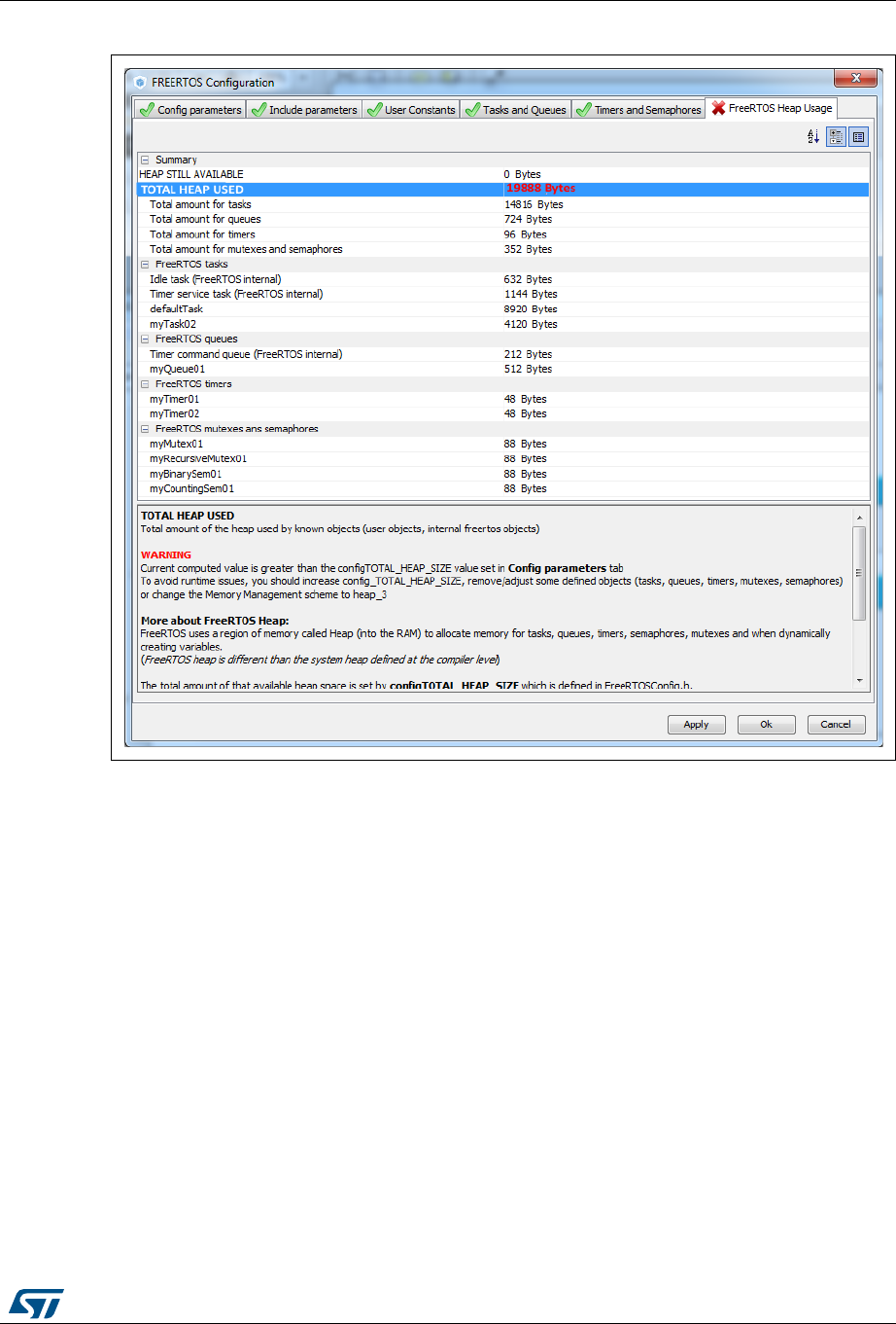
UM1718 Rev 26 143/345
UM1718 STM32CubeMX user interface
344
Figure 114. FreeRTOS Heap usage
5.13.7 Graphics frameworks and simulator
After selecting a graphics capable microcontroller (see MCU selection based on graphics
criteria), the user can select STemWin graphics framework.
For more details, refer to associated documentation and license terms available within
STM32CubeF4 and STM32CubeF7 embedded software packages.
Using the Graphics simulator, the user will be able to compare the Graphics current
configuration performances with simulated settings. These latter can be imported to be used
in the project.
Pinout view: enabling Graphics frameworks and prerequisites
In the pinout view, the necessary peripherals and middleware must be correctly configured
for a Graphics framework to be fully available. Hover the mouse over the framework name
to show the tooltip detailing the prerequisites (see Figure 115).
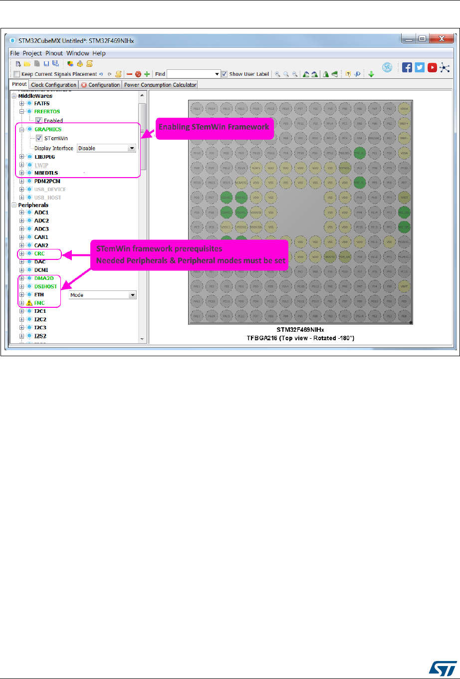
STM32CubeMX user interface UM1718
144/345 UM1718 Rev 26
Figure 115. Enabling STemWin Frameworks
Configuration view: GRAPHICS configuration window
After selecting in the pinout view a Graphics framework and the relevant Display interface,
the GRAPHICS configuration button is shown in green in the configuration view.
Clicking the GRAPHICS button opens the graphics configuration window for configuring
Graphics common parameters, framework specific parameters and launching framework
specific tools. See the tutorials dedicated to each framework for details.
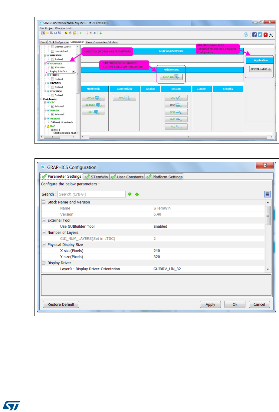
UM1718 Rev 26 145/345
UM1718 STM32CubeMX user interface
344
Figure 116. Configuration view for Graphics
Figure 117. Graphics configuration window
Configuration view: Graphics simulator
Clicking the GFXSIMULATOR button opens the Graphics simulator user interface.
In the left panel, the user can edit parameters to change the simulator default configuration.
In the right panel, the user can visualize the Graphics configuration of the current project.
In the bottom panels, the user can compare both configurations performance results for a
set of Graphics use cases.
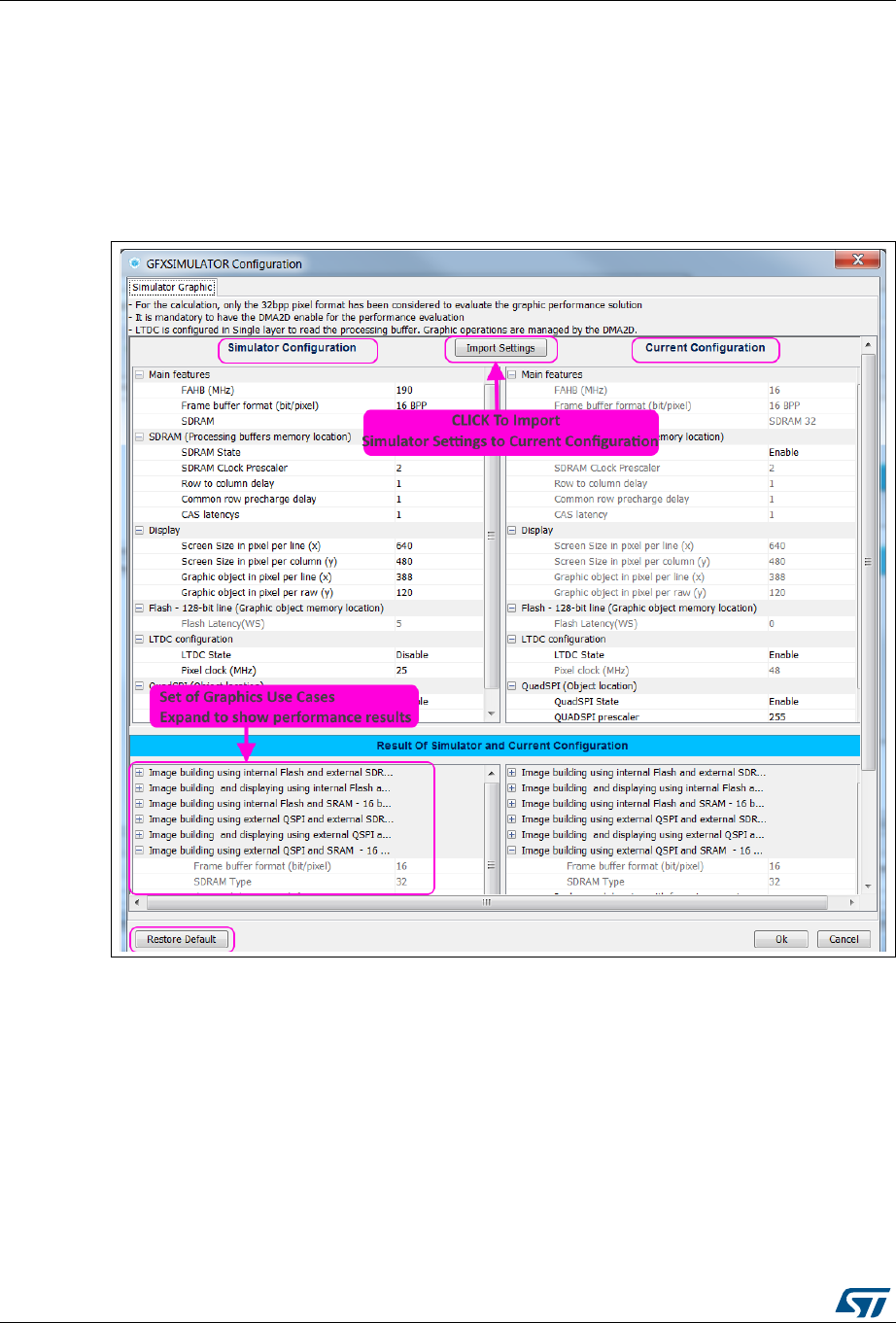
STM32CubeMX user interface UM1718
146/345 UM1718 Rev 26
If satisfied with simulator results, the user can click the Import Settings button to import
simulator settings in the current configuration.
Clicking Restore Default restores STM32CubeMX default settings for the Simulator
Configuration.
Clicking Ok saves the changes done within the Simulator Configuration panel and saved
settings will be used next time the GFXSIMULATOR window will be reopened.
Figure 118. Saving changes

UM1718 Rev 26 147/345
UM1718 STM32CubeMX user interface
344
5.14 Clock tree configuration view
STM32CubeMX Clock configuration window (see Figure 119) provides a schematic
overview of the clock paths, clock sources, dividers, and multipliers. Drop-down menus and
buttons allow modifying the actual clock tree configuration to meet user application
requirements.
Actual clock speeds are displayed and active. The clock signals that are used are
highlighted in blue.
Out-of-range configured values are highlighted in red to flag potential issues. A solver
feature is proposed to automatically resolve such configuration issues (see Figure 120).
Reverse path is supported: just enter the required clock speed in the blue filed and
STM32CubeMX will attempt to reconfigure multipliers and dividers to provide the requested
value. The resulting clock value can then be locked by right clicking the field to prevent
modifications.
STM32CubeMX generates the corresponding initialization code:
main.c with relevant HAL_RCC structure initializations and function calls
stm32xxxx_hal_conf.h for oscillator frequencies and VDD values.
5.14.1 Clock tree configuration functions
External clock sources
When external clock sources are used, the user must previously enable them from the
Pinout view available under the RCC peripheral.
Peripheral clock configuration options
Some other paths, corresponding to clock peripherals, are grayed out. To become active,
the peripheral must be properly configured in the Pinout view (e.g. USB). This view allows
to:
Enter a frequency value for the CPU Clock (HCLK), buses or peripheral clocks
STM32CubeMX tries to propose a clock tree configuration that reaches the desired
frequency while adjusting prescalers and dividers and taking into account other
peripheral constraints (such as USB clock minimum value). If no solution can be found,
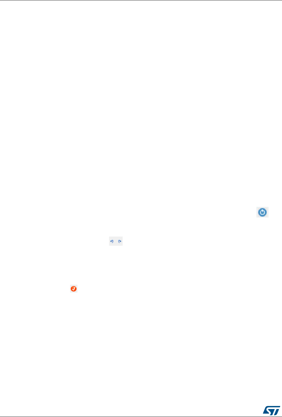
STM32CubeMX user interface UM1718
148/345 UM1718 Rev 26
STM32CubeMX proposes to switch to a different clock source or can even conclude
that no solution matches the desired frequency.
Lock the frequency fields for which the current value should be preserved
Right click a frequency field and select Lock to preserve the value currently assigned
when STM32CubeMX will search for a new clock configuration solution.
The user can unlock the locked frequency fields when the preservation is no longer
necessary.
Select the clock source that will drive the system clock (SYSCLK)
– External oscillator clock (HSE) for a user defined frequency.
– Internal oscillator clock (HSI) for the defined fixed frequency.
– Main PLL clock
Select secondary sources (as available for the product)
– Low-speed internal (LSI) or external (LSE) clock
– I2S input clock
–…
Select prescalers, dividers and multipliers values.
Enable the Clock Security system (CSS) on HSE when it is supported by the MCU
This feature is available only when the HSE clock is used as the system clock source
directly or indirectly through the PLL. It allows detecting HSE failure and inform the
software about it, thus allowing the MCU to perform rescue operations.
Enable the CSS on LSE when it is supported by the MCU
This feature is available only when the LSE and LSI are enabled and after the RTC or
LCD clock sources have been selected to be either LSE or LSI.
Reset the Clock tree default settings by using the toolbar Reset button ( ):
This feature reloads STM32CubeMX default clock tree configuration.
Undo/Redo user configuration steps by using the toolbar
Undo/Redo buttons ( )
Detect and resolve configuration issues
Erroneous clock tree configurations are detected prior to code generation. Errors are
highlighted in red and the Clock Configuration view is marked with a red cross (see
Figure 120).
Issues can be resolved manually or automatically by clicking the Resolve Clock Issue
button ( ) which is enabled only if issues have been detected.
The underlying resolution process follows a specific sequence:
a) Setting HSE frequency to its maximum value (optional).
b) Setting HCLK frequency then peripheral frequencies to a maximum or minimum
value (optional).
c) Changing multiplexers inputs (optional).
d) Finally, iterating through multiplier/dividers values to fix the issue. The clock tree is
cleared from red highlights if a solution is found. Otherwise an error message is
displayed.
Note: To be available from the clock tree, external clocks, I2S input clock, and master clocks shall
be enabled in RCC configuration in the Pinout view. This information is also available as
tooltips.

UM1718 Rev 26 149/345
UM1718 STM32CubeMX user interface
344
The tool will automatically perform the following operations:
Adjust bus frequencies, timers, peripherals and master output clocks according to user
selection of clock sources, clock frequencies and prescalers/multipliers/dividers values.
Check the validity of user settings.
Highlight invalid settings in red and provide tooltips to guide the user to achieve a valid
configuration.
The Clock tree view is adjusted according to the RCC settings (configured in RCC pinout
and configuration views) and vice versa:
If in RCC Pinout view, the external and output clocks are enabled, they become
configurable in the clock tree view.
If in RCC Configuration view, the Timer prescaler is enabled, the choice of Timer clocks
multipliers will be adjusted.
Conversely, the clock tree configuration may affect some RCC parameters in the
configuration view:
Flash latency: number of wait states automatically derived from VDD voltage, HCLK
frequency, and power over-drive state.
Power regulator voltage scale: automatically derived from HCLK frequency.
Power over-drive is enabled automatically according to HCLK frequency. When the
power drive is enabled, the maximum possible frequency values for AHB and APB
domains are increased. They are displayed in the Clock tree view.
The default optimal system settings that is used at startup are defined in the
system_stm32f4xx.c file. This file is copied by STM32CubeMX from the STM32CubeF4
MCU package. The switch to user defined clock settings is done afterwards in the main
function.
Figure 119 gives an example of Clock tree configuration view for an STM32F429x MCU and
Table 14 describes the widgets that can be used to configure each clock.

UM1718 Rev 26 151/345
UM1718 STM32CubeMX user interface
344
Table 14. Clock tree view widget
Format Configuration status of the Peripheral Instance
Active clock sources
Unavailable settings are blurred or grayed out (clock sources,
dividers,…)
Gray drop down lists for prescalers, dividers, multipliers selection.
Multiplier selection
User defined frequency values
Automatically derived frequency values
User-modifiable frequency field
Right click blue border rectangles, to lock/unlock a frequency field. Lock
to preserve the frequency value during clock tree configuration updates.
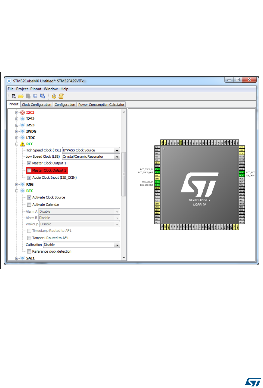
STM32CubeMX user interface UM1718
152/345 UM1718 Rev 26
5.14.2 Recommendations
The Clock tree view is not the only entry for clock configuration.
1. Go first through the RCC pinout configuration in the Pinout view to enable the clocks
as needed: external clocks, master output clocks and Audio I2S input clock when
available (see Figure 121).
Figure 121. Clock tree configuration: enabling RTC, RCC Clock source
and outputs from Pinout view
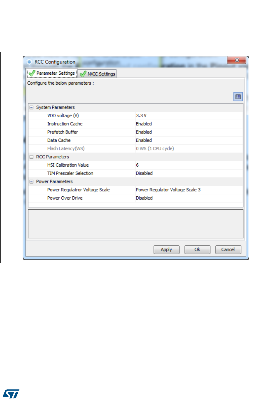
UM1718 Rev 26 153/345
UM1718 STM32CubeMX user interface
344
2. Then go to the RCC configuration in the Configuration view. The settings defined
there for advanced configurations will be reflected in the clock tree view. The settings
defined in the clock tree view may change the settings in the RCC configuration (see
Figure 122).
Figure 122. Clock tree configuration: RCC Peripheral Advanced parameters
5.14.3 STM32F43x/42x power-over drive feature
STM32F42x/43x MCUs implement a power over-drive feature allowing to work at the
maximum AHB/APB bus frequencies (e.g., 180 MHz for HCLK) when a sufficient VDD
supply voltage is applied (e.g VDD > 2.1 V).
Table 15 lists the different parameters linked to the power over-drive feature and their
availability in STM32CubeMX user interface.

STM32CubeMX user interface UM1718
154/345 UM1718 Rev 26
Table 16 gives the relations between power-over drive mode and HCLK frequency.
5.14.4 Clock tree glossary
Table 15. Voltage scaling versus power over-drive and HCLK frequency
Parameter STM32CubeMX panel Value
VDD voltage Configuration (RCC) User-defined within a predefined range.
Impacts power over-drive.
Power Regulator
voltage scaling Configuration (RCC) Automatically derived from HCLK frequency
and power over-drive (see Table 16).
Power Over Drive Configuration (RCC)
This value is conditioned by HCLK and VDD
values (see Table 16). It can be enabled only
if VDD ≥ 2.2 V
When VDD ≥2.2 V, it is either automatically
derived from HCLK or it can be configured by
the user if multiple choices are possible (e.g.,
HCLK = 130 MHz)
HCLK/AHB clock
maximum frequency value Clock Configuration
Displayed in blue to indicate the maximum
possible value. For example: maximum value
is 168 MHz for HCLK when power over-drive
cannot be activated (when VDD ≤ 2.1 V),
otherwise it is 180 MHz.
APB1/APB2 clock
maximum frequency value Clock Configuration Displayed in blue to indicate maximum
possible value
Table 16. Relations between power over-drive and HCLK frequency
HCLK frequency range:
VDD > 2.1 V required to enable power over-drive (POD)
Corresponding voltage scaling
and power over-drive (POD)
≤120 MHz Scale 3
POD is disabled
120 to 144 MHz Scale 2
POD can be either disabled or enabled
144 to 168 MHz Scale 1 when POD is disabled
Scale 2 when POD is enabled
168 to 180 MHz
POD must be enabled
Scale 1 (otherwise frequency range not
supported)
Table 17. Glossary
Acronym Definition
HSI High Speed Internal oscillator: enabled after reset, lower accuracy than HSE.
HSE High Speed External oscillator: requires an external clock circuit.
PLL Phase Locked Loop: used to multiply above clock sources.

UM1718 Rev 26 155/345
UM1718 STM32CubeMX user interface
344
5.15 Power Consumption Calculator view
For an ever-growing number of embedded systems applications, power consumption is a
major concern. To help minimizing it, STM32CubeMX offers the Power Consumption
Calculator tab (see Figure 123), which, given a microcontroller, a battery model and a user-
defined power sequence, provides the following results:
Average current consumption
Power consumption values can either be taken from the datasheet or interpolated from
a user specified bus or core frequency.
Battery life
Average DMIPs
DMIPs values are directly taken from the MCU datasheet and are neither interpolated
nor extrapolated.
Maximum ambient temperature (TAMAX)
According to the chip internal power consumption, the package type and a maximum
junction temperature of 105 °C, the tool computes the maximum ambient temperature
to ensure good operating conditions.
Current TAMAX implementation does not account for I/O consumption. For an accurate
TAMAX estimate, I/O consumption must be specified using the Additional Consumption
field. The formula for I/O dynamic current consumption is specified in the
microcontroller datasheet.
The Power Consumption Calculator view allows developers to visualize an estimate of
the embedded application consumption and lower it further at each power sequence step:
Make use of low power modes when any available
Adjust clock sources and frequencies based on the step requirements.
Enable the peripherals necessary for each phase.
For each step, the user can choose VBUS as possible power source instead of the battery.
This will impact the battery life estimation. If power consumption measurements are
available at different voltage levels, STM32CubeMX will also propose a choice of voltage
values (see Figure 127).
An additional option, the transition checker, is available for STM32L0, STM32L1, STM32L4
and STM32L4+ Series. When it is enabled, the transition checker detects invalid transitions
LSI Low Speed Internal clock: low power clocks usually used for watchdog timers.
LSE Low Speed External clock: powered by an external clock.
SYSCLK System clock
HCLK Internal AHB clock frequency
FCLK Cortex free running clock
AHB Advanced High Performance Bus
APB1 Low speed Advanced Peripheral Bus
APB2 High speed Advanced Peripheral Bus
Table 17. Glossary (continued)
Acronym Definition
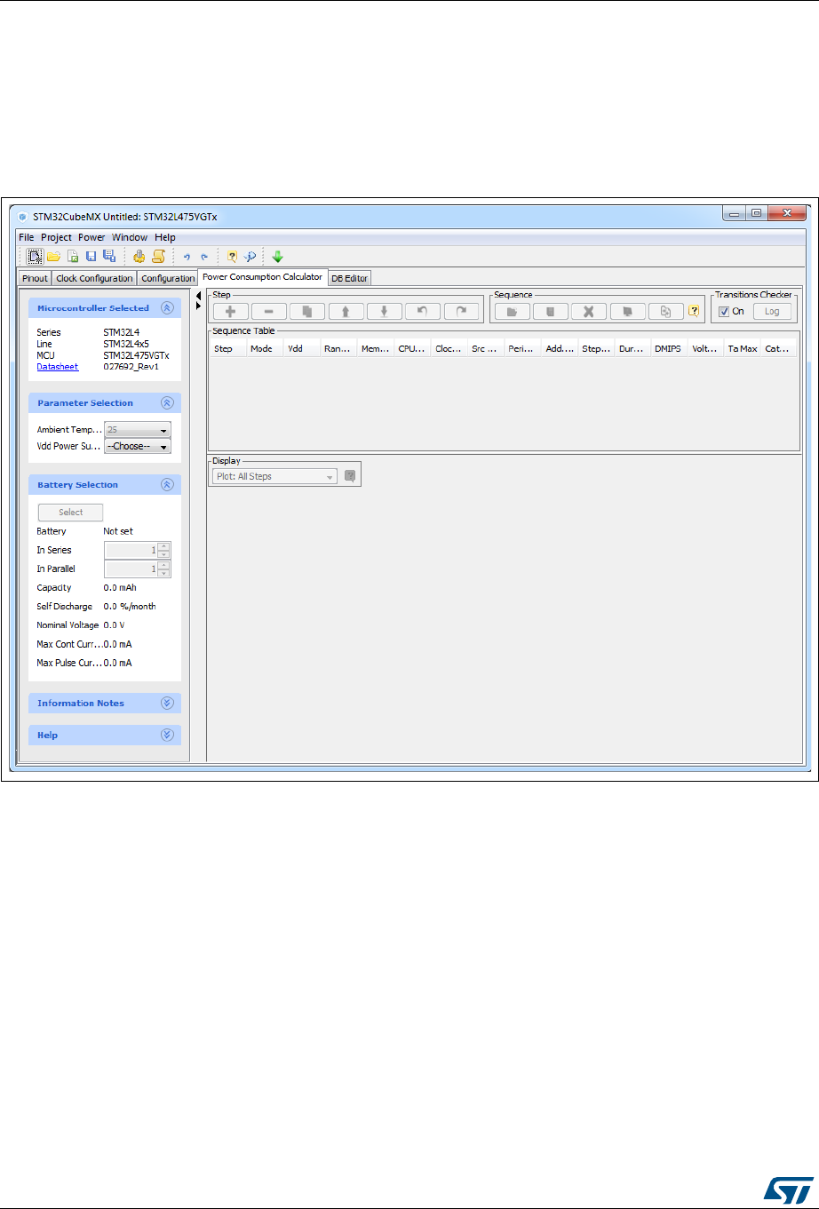
STM32CubeMX user interface UM1718
156/345 UM1718 Rev 26
within the currently configured sequence. It ensures that only possible transitions are
proposed to the user when a new step is added.
5.15.1 Building a power consumption sequence
The default starting view is shown in Figure 123.
Figure 123. Power Consumption Calculator default view
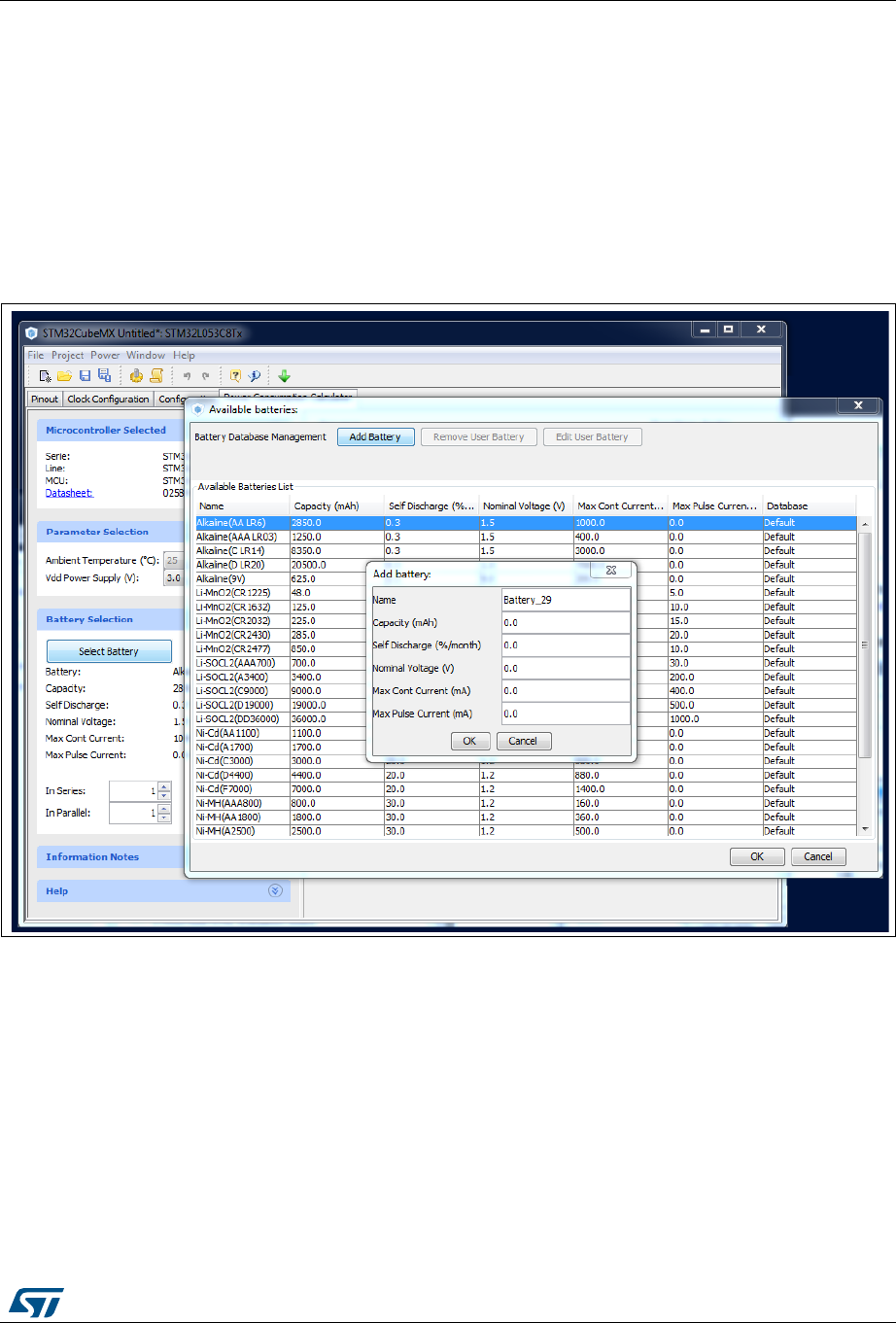
UM1718 Rev 26 157/345
UM1718 STM32CubeMX user interface
344
Selecting a VDD value
From this view and when multiple choices are available, the user must select a VDD value.
Selecting a battery model (optional)
Optionally, the user can select a battery model. This can also be done once the power
consumption sequence is configured.
The user can select a predefined battery or choose to specify a new battery that best
matches its application (see Figure 124).
Figure 124. Battery selection
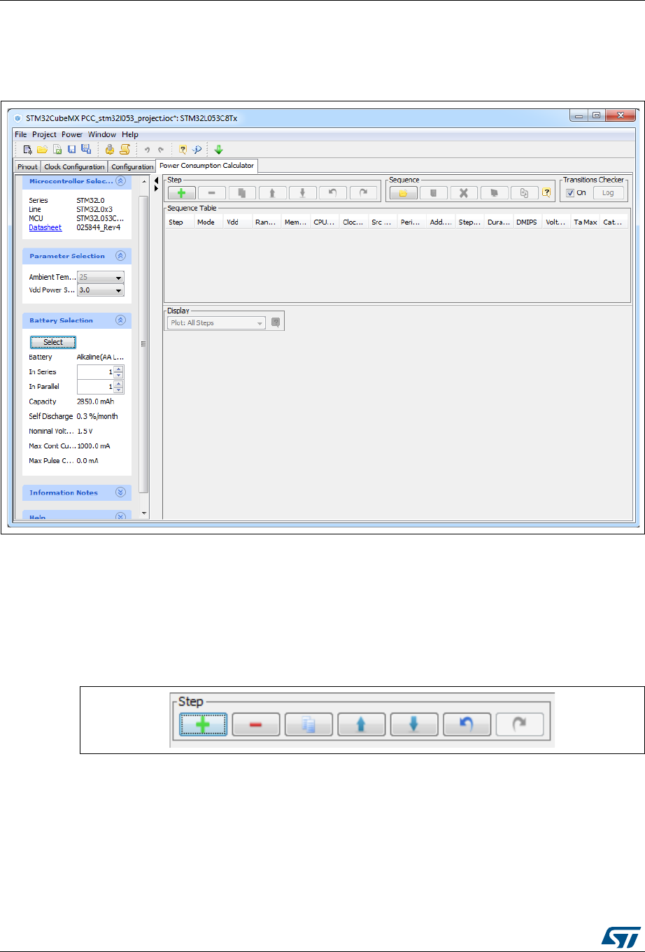
STM32CubeMX user interface UM1718
158/345 UM1718 Rev 26
Power sequence default view
The user can now proceed and build a power sequence (see Figure 125).
Figure 125. Building a power consumption sequence
Managing sequence steps
Steps can be reorganized within a sequence (Add new, Delete a step, Duplicate a step,
move Up or Down in the sequence) using the set of Step buttons (see Figure 126).
The user can undo or redo the last configuration actions by clicking the Undo button in the
Power Consumption Calculator view or the Undo icon from the main toolbar
Figure 126. Step management functions
Adding a step
There are two ways to add a new step:
Click Add in the Power Consumption panel. The New Step window opens with empty
step settings.
Or, select a step from the sequence table and click Duplicate. A New Step window
opens duplicating the step settings. (see Figure 127).


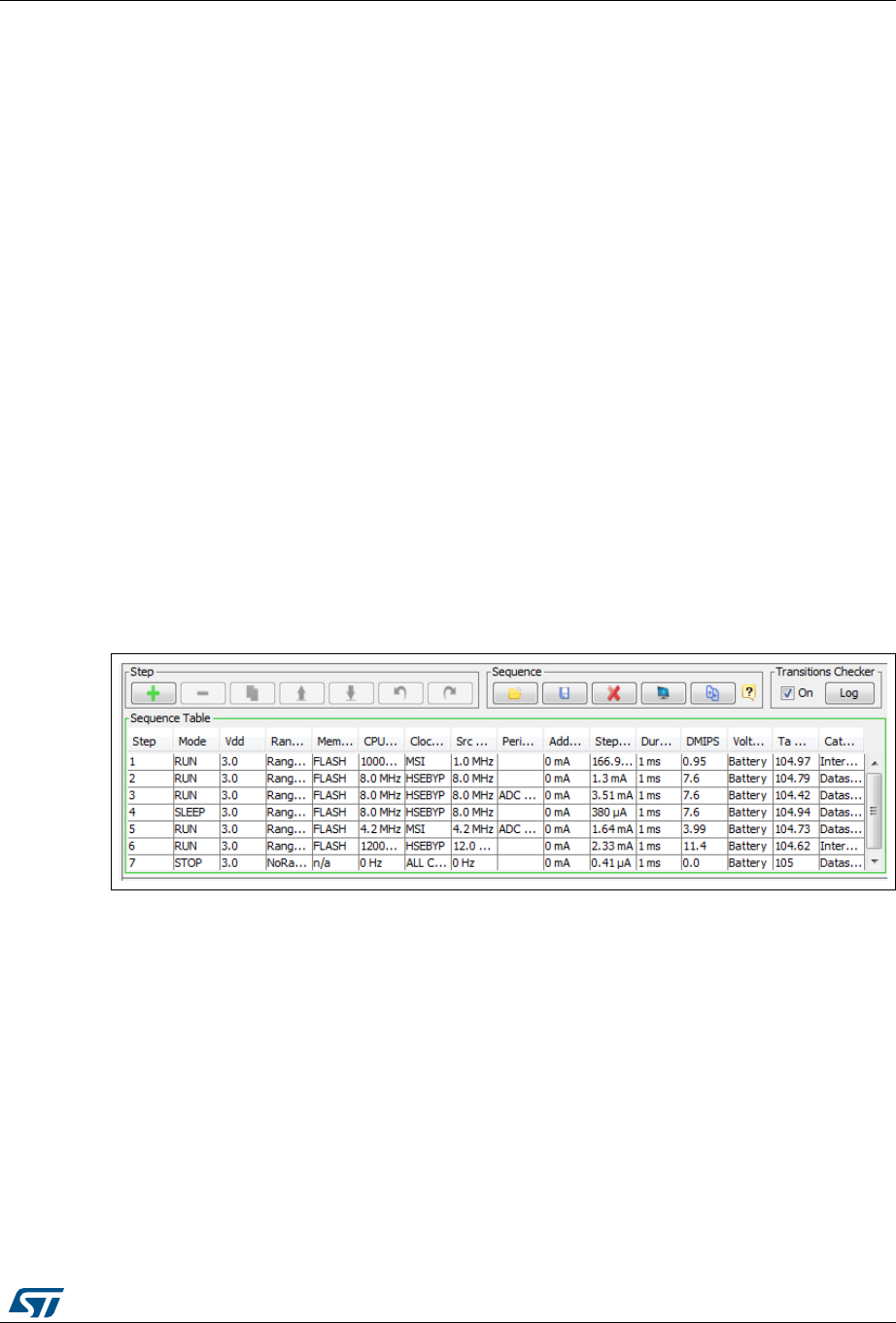
UM1718 Rev 26 161/345
UM1718 STM32CubeMX user interface
344
Moving a step
By default, a new step is added at the end of a sequence.
Click the step in the sequence table to select it and use the Up and Down buttons to move it
elsewhere in the sequence.
Deleting a step
Select the step to be deleted and click the Delete button.
Using the transition checker
Not all transitions between power modes are possible. The Power Consumption Calculator
proposes a transition checker to detect invalid transitions or restrict the sequence
configuration to only valid transitions.
Enabling the transition checker option prior to sequence configuration ensures the user will
be able to select only valid transition steps.
Enabling the transition checker option on an already configured sequence will highlight the
sequence in green (green frame) if all transitions are valid (see Figure 129), or in red if at
least one transition is invalid (red frame with description of invalid step highlighted in red)
(see Figure 130).
In this case, the user can click the Show log button to find out how to solve the transition
issue (see Figure 131).
Figure 129. Enabling the transition checker option on an
already configured sequence - All transitions valid


UM1718 Rev 26 163/345
UM1718 STM32CubeMX user interface
344
5.15.2 Configuring a step in the power sequence
The step configuration is performed from the Edit Step and New Step windows. The
graphical interface guides the user by forcing a predefined order for setting parameters.
Their naming may differ according to the selected MCU Series. For details on each
parameter, refer to Section 5.15.4 glossary and to Appendix D: STM32 microcontrollers
power consumption parameters or to the electrical characteristics section of the datasheet.
The parameters are set automatically by the tool when there is only one possible value (in
this case, the parameter cannot be modified and is grayed out). The tool proposes only the
configuration choices relevant to the selected MCU.
Proceed as follow to configure a new step:
1. Click Add or Duplicate to open the New step window or double-click a step from the
sequence table to open the Edit step window.
2. Within the open step window, select in the following order:
–The Power Mode
Changing the Power Mode resets the whole step configuration.
–The Peripherals
Peripherals can be selected/deselected at any time after the Power Mode is
configured.
–The Power scale
The power scale corresponds to the power consumption range (STM32L1) or the
power scale (STM32F4).
Changing the Power Mode or the Power Consumption Range discards all
subsequent configurations.
–The Memory Fetch Type
–The V
DD value if multiple choices available
– The voltage source (battery or VBUS)
–A Clock Configuration
Changing the Clock Configuration resets the frequency choices further down.
– When multiple choices are available, the CPU Frequency (STM32F4) and the
AHB Bus Frequency/CPU Frequency(STM32L1) or, for active modes, a user
specified frequency. In this case, the consumption value will be interpolated (see
Section : Using interpolation).
3. Optionally set
–A step duration (1 ms is the default value)
–An additional consumption value (expressed in mA) to reflect, for example,
external components used by the application (external regulator, external pull-up,
LEDs or other displays). This value added to the microcontroller power
consumption will impact the step overall power consumption.
4. Once the configuration is complete, the Add button becomes active. Click it to create
the step and add it to the sequence table.


UM1718 Rev 26 165/345
UM1718 STM32CubeMX user interface
344
Importing pinout
Figure 133 illustrates the example of the ADC configuration in the Pinout view: clicking
Import Pinout in the Power Consumption Calculator view selects the ADC peripheral and
GPIO A (Figure 134).
The Import pinout button allows to automatically select the peripherals that have been
configured in the Pinout view.
Figure 133. ADC selected in Pinout view
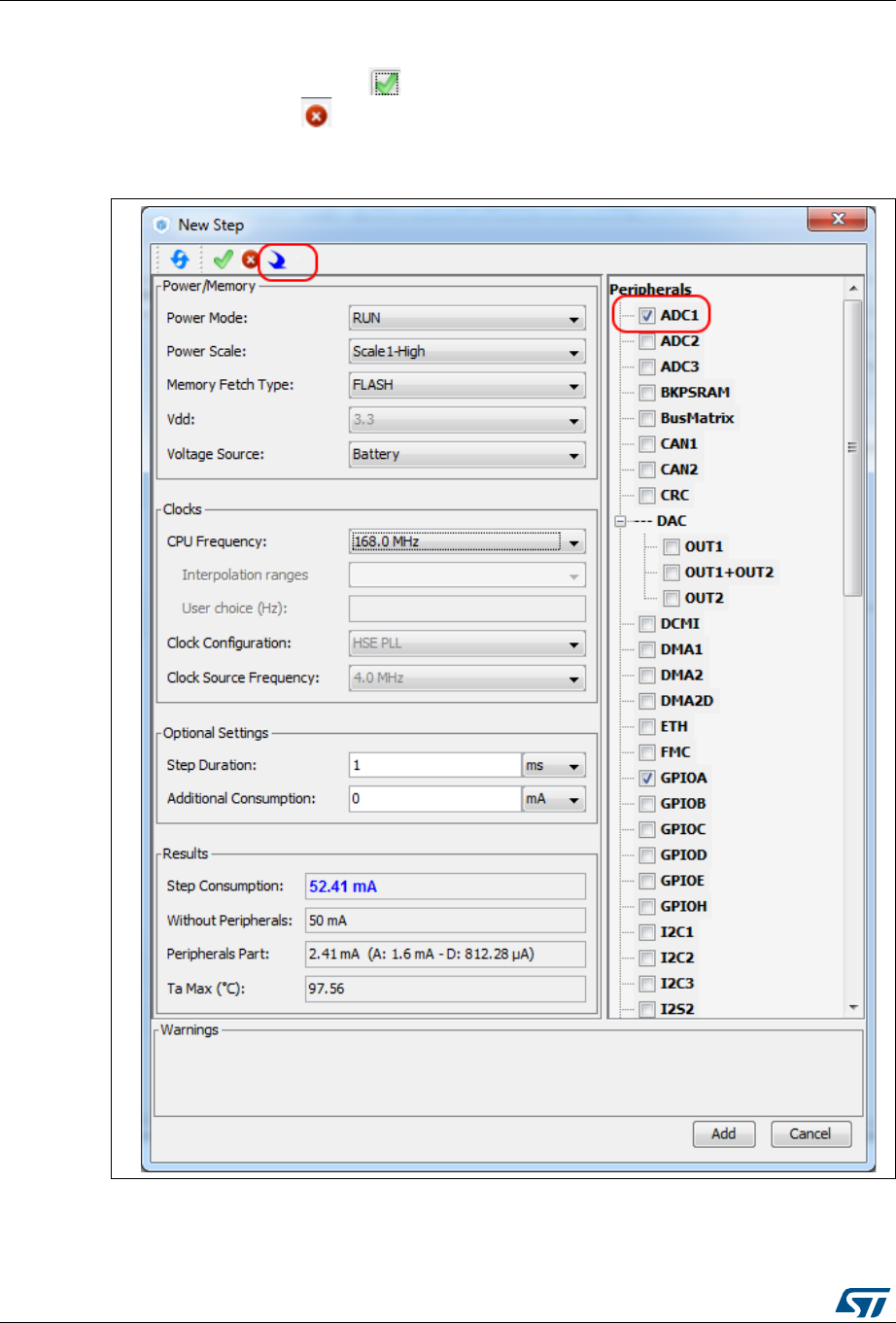
STM32CubeMX user interface UM1718
166/345 UM1718 Rev 26
Selecting/deselecting all peripherals
Clicking the Select All button allows selecting all peripherals at once.
Clicking Deselect All removes them as contributors to the consumption.
Figure 134. Power Consumption Calculator Step configuration window:
ADC enabled using import pinout
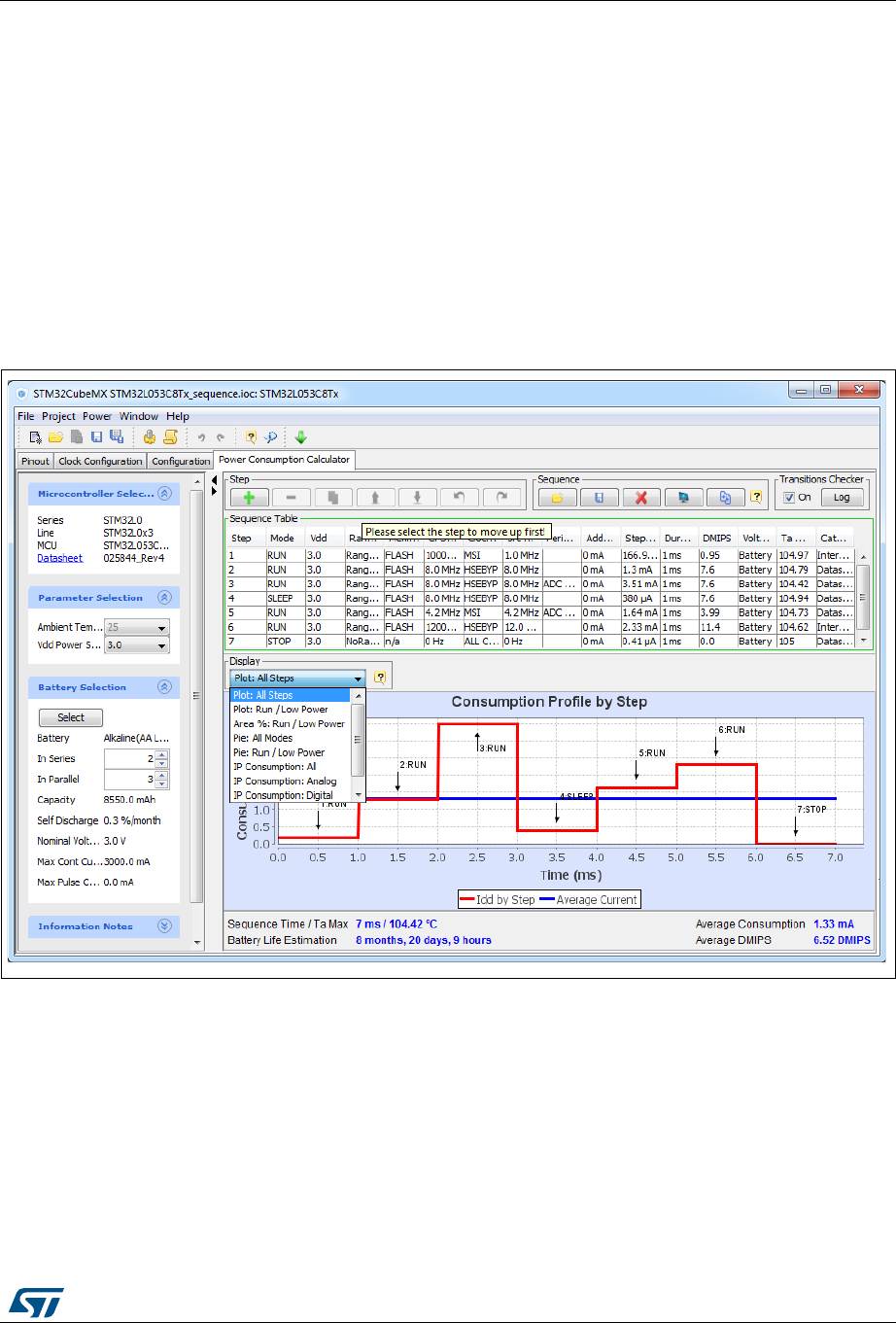
UM1718 Rev 26 167/345
UM1718 STM32CubeMX user interface
344
5.15.3 Managing user-defined power sequence and reviewing results
The configuration of a power sequence leads to an update of the Power Consumption
Calculator view (see Figure 135):
The sequence table shows all steps and step parameters values. A category column
indicates whether the consumption values are taken from the datasheet or are
interpolated.
The sequence chart area shows different views of the power sequence according to a
display type (e.g. plot all steps, plot low power versus run modes, ..)
The results summary provides the total sequence time, the maximum ambient
temperature (TAMAX), plus an estimate of the average power consumption, DMIPS, and
battery lifetime provided a valid battery configuration has been selected.
Figure 135. Power Consumption Calculator view after sequence building
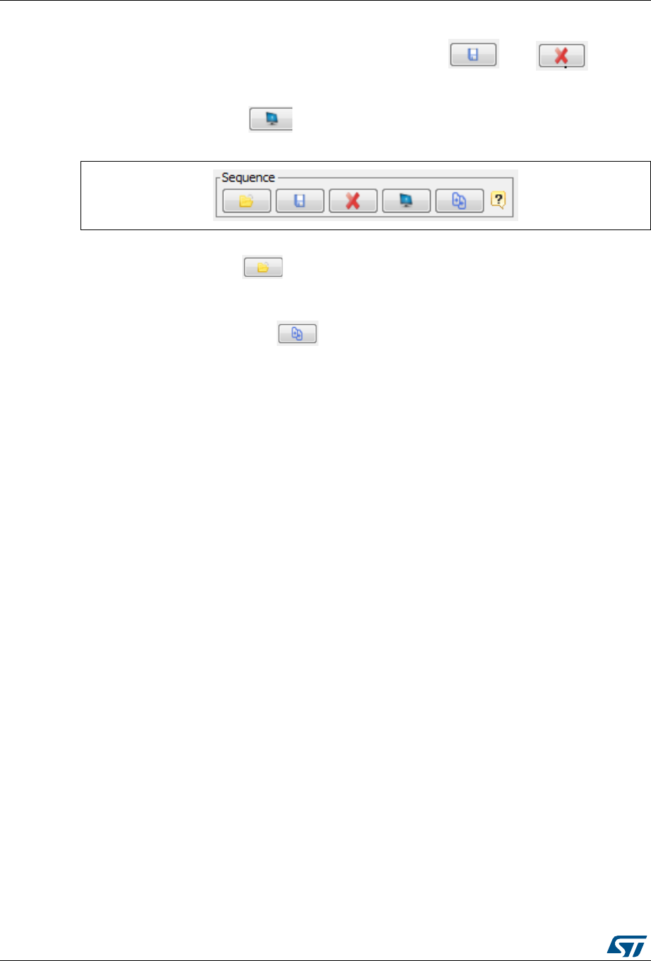
STM32CubeMX user interface UM1718
168/345 UM1718 Rev 26
Managing the whole sequence (load, save and compare)
The current sequence can be saved or deleted by clicking and ,
respectively.
In addition, a previously saved sequence can be either loaded in the current view or opened
for comparison by clicking (see Figure 136).
Figure 136. Sequence table management functions
To load a previously saved sequence:
1. Click the load button .
2. Browse to select the sequence to load.
To open a previously saved sequence for comparison:
1. Click the Compare button .
2. Browse and select the .pcs sequence file to be compared with the current sequence. A
new window opens showing the selected sequence details.
UM1718 Rev 26 169/345
UM1718 STM32CubeMX user interface
344
Managing the results charts and display options
In the Display area, select the type of chart to display (sequence steps, pie charts,
consumption per peripherals, ...). You can also click External Display to open the charts in
dedicated windows (see Figure 137).
Right-click on the chart to access the contextual menus: Properties, Copy, Save as png
picture file, Print, Zoom menus, and Auto Range to reset to the original view before zoom
operations. Zooming can also be achieved by mouse selecting from left to right a zone in
the chart and Zoom reset by clicking the chart and dragging the mouse to the left.
Figure 137. Power Consumption: Peripherals Consumption Chart
STM32CubeMX user interface UM1718
170/345 UM1718 Rev 26
Overview of the Results summary area
This area provides the following information (see Figure 138):
Total sequence time as the sum of the sequence steps durations.
Average consumption as the sum of each step consumption weighed by the step
duration.
The average DMIPS (Dhrystone Million Instructions per Second) based on Dhrystone
benchmark, highlighting the CPU performance for the defined sequence.
Battery life estimation for the selected battery model, based on the average power
consumption and the battery self-discharge.
TAMAX: highest maximum ambient temperature value encountered during the
sequence.
Figure 138. Description of the Results area
5.15.4 Power sequence step parameters glossary
The parameters that characterize power sequence steps are the following (refer to
Appendix D: STM32 microcontrollers power consumption parameters for more details):
Power modes
To save energy, it is recommended to switch the microcontroller operating mode from
running mode, where a maximum power is required, to a low-power mode requiring
limited resources.
VCORE range (STM32L1) or Power scale (STM32F4)
These parameters are set by software to control the power supply range for digital
peripherals.
Memory Fetch Type
This field proposes the possible memory locations for application C code execution. It
can be either RAM, FLASH or FLASH with ART ON or OFF (only for families that
feature a proprietary Adaptive real-time (ART) memory accelerator which increases the
program execution speed when executing from Flash memory).

UM1718 Rev 26 171/345
UM1718 STM32CubeMX user interface
344
The performance achieved thanks to the ART accelerator is equivalent to 0 wait state
program execution from Flash memory. In terms of power consumption, it is equivalent
to program execution from RAM. In addition, STM32CubeMX uses the same selection
choice to cover both settings, RAM and Flash with ART ON.
Clock Configuration
This operation sets the AHB bus frequency or the CPU frequency that will be used for
computing the microcontroller power consumption. When there is only one possible
choice, the frequencies are automatically configured.
The clock configuration drop-down list allows to configure the application clocks:
– The internal or external oscillator sources: MSI, HSI, LSI, HSE or LSE),
– The oscillator frequency,
– Other determining parameters: PLL ON, LSE Bypass, AHB prescaler value, LCD
with duty...
Peripherals
The peripheral list shows the peripherals available for the selected power mode. The
power consumption is given assuming that peripherals are only clocked (e.g. not in use
by a running program). Each peripheral can be enabled or disabled. Peripherals
individual power consumptions are displayed in a tooltip. An overall consumption due
to peripheral analog and digital parts is provided in the step Results area (see
Figure 139).
The user can select the peripherals relevant for the application:
– None (Disable All),
– Some (using peripheral dedicated checkbox),
– All (Activate All),
– Or all from the previously defined pinout configuration (Import Pinout).
Only the selected and enabled peripherals are taken into account when computing the
power consumption.
STM32CubeMX user interface UM1718
172/345 UM1718 Rev 26
Figure 139. Peripheral power consumption tooltip
Step duration
The user can change the default step duration value. When building a sequence, the
user can either create steps according to the application actual power sequence or
define them as a percentage spent in each mode. For example, if an application
spends 30% in Run mode, 20% in Sleep and 50% in Stop, the user must configure a 3-
step sequence consisting in 30 ms in Run, 20 ms in Sleep and 50 ms in Stop.
Additional Consumption
This field allows entering an additional consumption resulting from specific user
configuration (e.g. MCU providing power supply to other connected devices).

UM1718 Rev 26 173/345
UM1718 STM32CubeMX user interface
344
5.15.5 Battery glossary
Capacity (mAh)
Amount of energy that can be delivered in a single battery discharge.
Self-discharge (%/month)
This percentage, over a specified period, represents the loss of battery capacity when
the battery is not used (open-circuit conditions), as a result of internal leakage.
Nominal voltage (V)
Voltage supplied by a fully charged battery.
Max. Continuous Current (mA)
This current corresponds to the maximum current that can be delivered during the
battery lifetime period without damaging the battery.
Max. Pulse Current (mA)
This is the maximum pulse current that can be delivered exceptionally, for instance when
the application is switched on during the starting phase.
5.15.6 SMPS feature
Some microcontroller part numbers such as STM32L496xxxxP allow connecting an external
switched mode power supply (SMPS) to further reduce power consumption.
For such microcontrollers, the Power Consumption Calculator tool offer the following
features:
Selection of SMPS for the current project:
From the left panel, check the Use SMPS box to use SMPS (see Figure 140). By
default, ST SMPS model is used.
Selection of another SMPS model by clicking the Change button.
This opens the SMPS database management window in which the user can add a new
SMPS model (see Figure 141). The user can then select a different SMPS model for
the current sequence (see Figure 142, Figure 143 and Figure 144)
Check for invalid SMPS transitions in the current sequence by enabling the SMPS
checker.
To do this, select the checkbox to enable the checker and click the Help button to open
the reference state diagram (see Figure 145).
Configuration of SMPS mode for each step (see Figure 146).
If the SMPS checker is enabled, only the SMPS modes valid for the current step are
proposed.


STM32CubeMX C Code generation overview UM1718
178/345 UM1718 Rev 26
6 STM32CubeMX C Code generation overview
Refer to Section 5.4.2: Project menu for code generation and C project settings related
topics.
6.1 STM32Cube code generation using only HAL drivers
(default mode)
During the C code generation process, STM32CubeMX performs the following actions:
1. If it is missing, it downloads the relevant STM32Cube MCU package from the user
repository. STM32CubeMX repository folder is specified in the Help > Updater
settings menu.
2. It copies from the firmware package, the relevant files in Drivers/CMSIS and
Drivers/STM32F4_HAL_Driver folders and in the Middleware folder if a middleware
was selected.
3. It generates the initialization C code ( .c/.h files) corresponding to the user MCU
configuration and stores it in the Inc and Src folders. By default, the following files are
included:
–stm32f4xx_hal_conf.h file: this file defines the enabled HAL modules and sets
some parameters (e.g. External High Speed oscillator frequency) to predefined
default values or according to user configuration (clock tree).
–stm32f4xx_hal_msp.c (MSP = MCU Support package): this file defines all
initialization functions to configure the peripheral instances according to the user
configuration (pin allocation, enabling of clock, use of DMA and Interrupts).
–main.c is in charge of:
Resetting the MCU to a known state by calling the HAL_init() function that resets
all peripherals, initializes the Flash memory interface and the SysTick.
Configuring and initializing the system clock.
Configuring and initializing the GPIOs that are not used by peripherals.
Defining and calling, for each configured peripheral, a peripheral initialization
function that defines a handle structure that will be passed to the corresponding
peripheral HAL init function which in turn will call the peripheral HAL MSP
initialization function. Note that when LwIP (respectively USB) middleware is used,
the initialization C code for the underlying Ethernet (respectively USB peripheral)
is moved from main.c to LwIP (respectively USB) initialization C code itself.
–main.h file:
This file contains the define statements corresponding to the pin labels set from
the Pinout tab, as well as the user project constants added from the
Configuration tab (refer to Figure 147 and Figure 148 for examples):
#define MyTimeOut 10
#define LD4_Pin GPIO_PIN_12
#define LD4_GPIO_Port GPIOD
#define LD3_Pin GPIO_PIN_13
#define LD3_GPIO_Port GPIOD
#define LD5_Pin GPIO_PIN_14
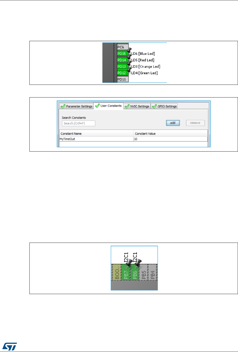
UM1718 Rev 26 179/345
UM1718 STM32CubeMX C Code generation overview
344
#define LD5_GPIO_Port GPIOD
#define LD6_Pin GPIO_PIN_15
#define LD6_GPIO_Port GPIOD
Figure 147. Labels for pins generating define statements
Figure 148. User constant generating define statements
In case of duplicate labels, a unique suffix, consisting of the pin port letter and the
pin index number, is added and used for the generation of the associated define
statements.
In the example of a duplicate I2C1 labels shown in Figure 149, the code
generation produces the following code, keeping the I2C1 label on the original port
B pin 6 define statements and adding B7 suffix on pin 7 define statements:
#define I2C1_Pin GPIO_PIN_6
#define I2C1_GPIO_Port GPIOB
#define I2C1B7_Pin GPIO_PIN_7
#define I2C1B7_GPIO_Port GPIOB
Figure 149. Duplicate labels

STM32CubeMX C Code generation overview UM1718
180/345 UM1718 Rev 26
In order for the generated project to compile, define statements shall follow strict
naming conventions. They shall start with a letter or an underscore as well as the
corresponding label. In addition, they shall not include any special character such
as minus sign, parenthesis or brackets. Any special character within the label will
be automatically replaced by an underscore in the define name.
If the label contains character strings between “[]” or “()”, only the first string listed
is used for the define name. As an example, the label “LD6 [Blue Led]”
corresponds the following define statements:
#define LD6_Pin GPIO_PIN_15
#define LD6_GPIO_Port GPIOD
The define statements are used to configure the GPIOs in the generated
initialization code. In the following example, the initialization of the pins labeled
Audio_RST_Pin and LD4_Pin is done using the corresponding define statements:
/*Configure GPIO pins : LD4_Pin Audio_RST_Pin */
GPIO_InitStruct.Pin = LD4_Pin | Audio_RST_Pin;
GPIO_InitStruct.Mode = GPIO_MODE_OUTPUT_PP;
GPIO_InitStruct.Pull = GPIO_NOPULL;
GPIO_InitStruct.Speed = GPIO_SPEED_LOW;
HAL_GPIO_Init(GPIOD, &GPIO_InitStruct);
4. Finally it generates a Projects folder that contains the toolchain specific files that match
the user project settings. Double-clicking the IDE specific project file launches the IDE
and loads the project ready to be edited, built and debugged.
6.2 STM32Cube code generation using Low Layer drivers
For STM32F0, STM32F3, STM32L0, STM32L1, STM32L4, STM32L4+, STM32F2,
STM32F4 and STM32F7 Series, STM32CubeMX allows generating peripheral initialization
code based either on the peripheral HAL driver or on the peripheral Low Layer (LL) driver.
The choice is made through the Project Settings window (see Section 5.8.3: Advanced
Settings tab).
The LL drivers are available only for the peripherals which require an optimized access and
do not have a complex software configuration. The LL services allow performing atomic
operations by changing the relevant peripheral registers content:
Examples of supported peripherals: RCC, ADC, GPIO, I2C, SPI, TIM, USART,…
Examples of peripherals not supported by LL drivers: USB, SDMMC, FSMC.
The LL drivers are available within the STM32CubeL4 package:
They are located next to the HAL drivers (stm32l4_hal_<peripheral_name>) within
the Inc and Src directory of the
STM32Cube_FW_L4_V1.6\Drivers\STM32L4xx_HAL_Driver folder.
They can be easily recognizable by their naming convention:
stm32l4_ll_<peripheral_name>
For more details on HAL and LL drivers refer to the STM32L4 HAL and Low-layer drivers
user manual (UM1884).
As the decision to use LL or HAL drivers is made on a peripheral basis, the user can mix
both HAL and LL drivers within the same project.
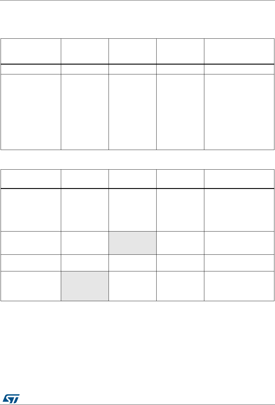
UM1718 Rev 26 181/345
UM1718 STM32CubeMX C Code generation overview
344
The following tables shows the main differences between the three possible
STM32CubeMX project generation options: HAL-only, LL-only, and mix of HAL and LL code.
Table 18. LL versus HAL code generation: drivers included in STM32CubeMX projects
Project configuration
and drivers to be
included
HAL only LL only Mix of HAL and
LL Comments
CMSIS Yes Yes Yes -
STM32xxx_HAL_Driver Only HAL driver
files Only LL driver files Mix of HAL and LL
driver files
Only the driver files
required for a given
configuration (selection of
peripherals) are copied
when the project settings
option is set to “Copy only
the necessary files”.
Otherwise (“all used
libraries” option) the
complete set of driver files
is copied.
Table 19. LL versus HAL code generation: STM32CubeMX generated header files
Generated header
files HAL only LL only Mix of HAL and
LL Comments
mai n.h Yes Yes Yes
This file contains the
include statements and the
generated define
statements for user
constants (GPIO labels and
user constants).
stm32xxx_hal_conf.h Yes No Yes
This file enables the HAL
modules necessary to the
project.
stm32xxx_it.h Yes Yes Yes Header file for interrupt
handlers
stm32xx_assert.h No Yes Yes
This file contains the assert
macros and the functions
used for checking function
parameters.
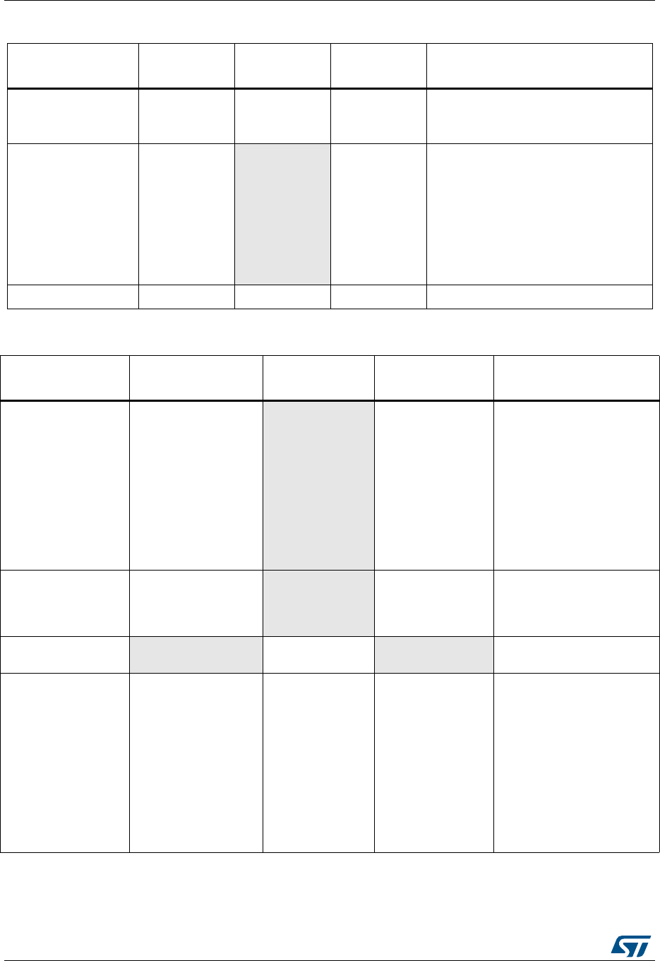
STM32CubeMX C Code generation overview UM1718
182/345 UM1718 Rev 26
Table 20. LL versus HAL: STM32CubeMX generated source files
Generated source
files HAL only LL only Mix of HAL
and LL Comments
main.c Yes Yes Yes
This file contains the main functions
and optionally STM32CubeMX
generated functions.
stm32xxx_hal_msp.c Yes No Yes
This file contains the following
functions:
– HAL_MspInit
– for peripherals using HAL drivers:
HAL_<Peripheral>_MspInit,
HAL_<Peripheral>_MspDeInit,
These functions are available only for
the peripherals that use HAL drivers.
stm32xxx_it.c Yes Yes Yes Source file for interrupt handlers
Table 21. LL versus HAL: STM32CubeMX generated functions and function calls
Generated source
files HAL only LL only Mix of HAL and LL Comments
Hal_init() Called in main.c Not used Called in main.c
This file performs the following
functions:
– Configuration of the Flash
prefetch and instruction and
data caches
– Selection of the SysTick
timer as timebase source
– Setting of NVIC Group
Priority
– MCU low-level MCU
initialization.
Hal_msp_init()
Generated in
stm32xxx_hal_msp.c
and called by HAL_init()
Not used
Generated in
stm32xxx_hal_msp.c
And called by
HAL_init()
This function performs the
peripheral resource
configuration(1).
LL_init() Not used Generated and
called in main.c Not used System and memory interrupt
configuration
MX_<Peripheral>_Init()
[1]
Peripheral configuration
and call to
HAL_<Peripheral>_Init()
[2]
Peripheral and
peripheral resource
configuration(1)
using LL functions.
Call to
LL_Peripheral_Init()
– When HAL driver is
selected for the
<Peripheral>,
function generation
and calls are done
following [1]
– When LL driver
selected for the
<Peripheral>,
function generation
and calls are done
following [2]
This file takes care of the
peripheral configuration.
When the LL driver is selected
for the <Peripheral>, it also
performs the peripheral
resource configuration(1).

UM1718 Rev 26 183/345
UM1718 STM32CubeMX C Code generation overview
344
HAL_<Peripheral>_Msp
Init()
[3]
Generated in
stm32xxx_hal_msp.c
when HAL driver
selected for the
<Peripheral>
Not used
Only HAL driver can
be selected for the
<Peripheral>: function
generation and calls
are done following [3]
Peripheral resource
configuration(1)
HAL_<Peripheral>_Msp
DeInit()
[4]
Generated in
stm32xxx_hal_msp.c
when HAL driver
selected for the
<Peripheral>
Not used
Only HAL driver can
be selected for the
<Peripheral>: function
generation and calls
are done following [4]
This function can be used to
free peripheral resources.
1. Peripheral resources include:
Peripheral clock
Pinout configuration (GPIO)
Peripheral DMA requests
Peripheral Interrupt requests and priorities
Table 21. LL versus HAL: STM32CubeMX generated functions and function calls (continued)
Generated source
files HAL only LL only Mix of HAL and LL Comments


STM32CubeMX C Code generation overview UM1718
186/345 UM1718 Rev 26
6.3 Custom code generation
STM32CubeMX supports custom code generation by means of a FreeMarker template
engine (see http://www.freemarker.org).
6.3.1 STM32CubeMX data model for FreeMarker user templates
STM32CubeMX can generate a custom code based on a FreeMarker template file (.ftl
extension) for any of the following MCU configuration information:
List of MCU peripherals used by the user configuration
List of parameters values for those peripherals
List of resources used by these peripherals: GPIO, DMA requests and interrupts.
The user template file must be compatible with STM32CubeMX data model. This means
that the template must start with the following lines:
[#ftl]
[#list configs as dt]
[#assign data = dt]
[#assign peripheralParams =dt.peripheralParams]
[#assign peripheralGPIOParams =dt.peripheralGPIOParams]
[#assign usedIPs =dt.usedIPs]
and end with
[/#list]
A sample template file is provided for guidance (see Figure 153: extra_templates folder –
default content).
STM32CubeMX will also generate user-specific code if any is available within the template.
As shown in the below example, when the sample template is used, the ftl commands are
provided as comments next to the data they have generated:
FreeMarker command in template:
${peripheralParams.get("RCC").get("LSI_VALUE")}
Resulting generated code:
LSI_VALUE : 32000 [peripheralParams.get("RCC").get("LSI_VALUE")]
6.3.2 Saving and selecting user templates
The user can either place the FreeMarker template files under STM32CubeMX installation
path within the db/extra_templates folder or in any other folder.
Then for a given project, the user will select the template files relevant for its project via the
Template Settings window accessible from the Project Settings menu (see Section 5.8:
Project Settings window)
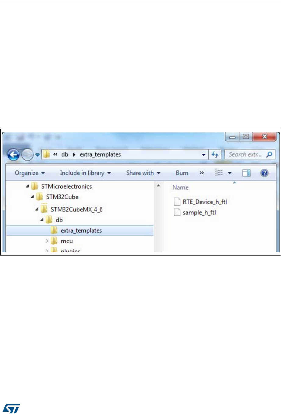
UM1718 Rev 26 187/345
UM1718 STM32CubeMX C Code generation overview
344
6.3.3 Custom code generation
To generate custom code, the user must place the FreeMarker template file under
STM32CubeMX installation path within the db/extra_templates folder (see Figure 154:
extra_templates folder with user templates).
The template filename must follow the naming convention <user filename>_<file
extension>.ftl in order to generate the corresponding custom file as <user filename>.<file
extension>.
By default, the custom file is generated in the user project root folder, next to the .ioc file
(see Figure 155: Project root folder with corresponding custom generated files).
To generate the custom code in a different folder, the user shall match the destination folder
tree structure in the extra_template folder (see Figure 156: User custom folder for
templates).
Figure 153. extra_templates folder – default content


STM32CubeMX C Code generation overview UM1718
190/345 UM1718 Rev 26
6.4 Additional settings for C project generation
STM32CubeMX allows specifying additional project settings through the .extSettings file.
This file must be placed in the same project folder and at the same level as the .ioc file.
As an example, additional settings can be used when external tools call STM32CubeMX to
generate the project and require specific project settings.
Possible entries and syntax
All entries are optional. They are organized under the followings three categories:
ProjectFiles, Groups or Others.
[ProjectFiles]: section where to specify additional include directories
Syntax
HeaderPath = <include directory 1 path>;< include directory 2 path >
Example
HeaderPath=../../IIR_Filter_int32/Inc ;
[Groups]: section where to create new groups of files and/or add files to a group
Syntax
<Group name> = <file pathname1>;< file pathname2>
Example
Doc=$ PROJ_DIR$\..\readme.txt
Lib=C:\libraries\mylib1.lib; C:\libraries\mylib2.lib;
Drivers/BSP/MyRefBoard = C:\MyRefBoard\BSP\board_init.c;
C:\MyRefBoard\BSP\board_init.h;
[Others] section where to enable HAL modules and/or specify preprocessor define
statements
– Enabling pre-processor define statements
Preprocessor define statements can be specified using the following syntax after
the [Others] line:
Syntax
Define = <define1_name>;<define2_name>
Example
Define= USE_STM32F429I_DISCO
– Enabling HAL modules in generated stm32f4xx_hal_conf.h
HAL modules can be enabled using the following syntax after the [Others] line:
Syntax
HALModule = <ModuleName1>; <ModuleName1>;
Example
HALModule=I2S;I2C
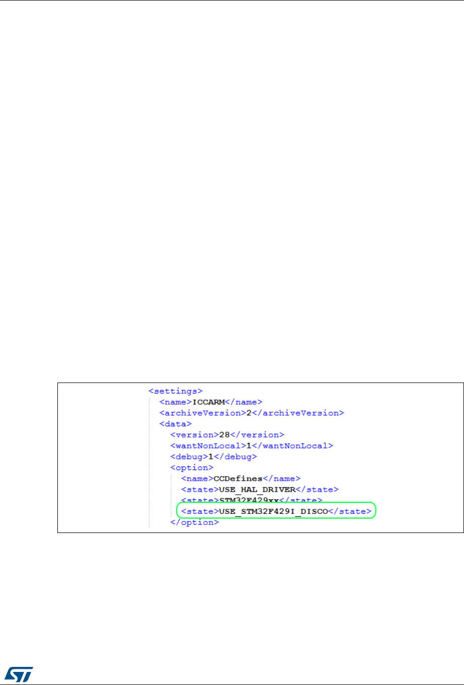
UM1718 Rev 26 191/345
UM1718 STM32CubeMX C Code generation overview
344
.extSettings file example and generated outcomes
For the purpose of the example, a new project is created by selecting the STM32F429I-
DISCO board from STM32CubeMX board selector. The EWARM toolchain is selected under
Project Settings. The project is saved as MyF429IDiscoProject. In the project folder, next
to the generated .ioc file, a .extSettings text file is placed with the following contents:
[Groups]
Drivers/BSP/STM32F429IDISCO=C:\Users\frq09031\STM32Cube\Repository\STM3
2Cube_FW_F4_V1.14.0\Drivers\BSP\STM32F429I-
Discovery\stm32f429i_discovery.c;
C:\Users\frq09031\STM32Cube\Repository\STM32Cube_FW_F4_V1.14.0\Drivers\
BSP\STM32F429I-Discovery\stm32f429i_discovery.h
Lib=C:\Users\frq09031\STM32Cube\Repository\STM32Cube_FW_F4_V1.14.0\
Middlewares\Third_Party\FreeRTOS\Source\portable\IAR\ARM_CM4F\portasm.s
Doc=$PROJ_DIR$\..\readme.txt
[Others]
Define = USE_ STM32F429I_DISCO
HALModule = UART;SPI
Upon project generation, the presence of this .extSettings file triggers the update of:
the project MyF429IDiscoProject.ewp file in EWARM folder (see Figure 158),
the stm32f4xx_hal_conf.h file in the project Inc folder (see Figure 159)
the project view within EWARM user interface as shown in Figure 160 and Figure 161.
Figure 158. Update of the project .ewp file (EWARM IDE)
for preprocessor define statements


Support of additional software components using CMSIS-Pack standard UM1718
194/345 UM1718 Rev 26
7 Support of additional software components using
CMSIS-Pack standard
The CMSIS-Pack standard describes a delivery mechanism for software components,
device parameters, and evaluation board support.
The XML-based package description (pdsc) file describes the content of a software pack
(file collection). It includes source code, header files, software libraries, documentation and
source code templates. A software pack consists of the complete file collection along with
the pdsc file, shipped in ZIP-format. After installing a software pack, all the included software
components are available to the development tools.
A software component is a collection of source modules, header and configuration files as
well as libraries. Packs containing software components can also include example projects
and user code templates.
Refer to http://www.keil.com website for more details.
STM32CubeMX supports third-party and other STMicroelectronics embedded software
solutions, delivered as software packs. STM32CubeMX enables to:
1. Install Software Packs and check for updates (see Section 4.5.4).
2. Select software components for the current project (see Section 5.10).
Once this is done, the selected components appear in the tree view. Use contextual
help to get more details on the selection (see Figure 162).
3. Enable the software component from the tree view (see Figure 163).
4. Configure software components (see Figure 164). This function is possible only for
components coming with files in STM32CubeMX proprietary format.
5. Generate the C project for selected toolchains (see Figure 165).
a) Software components files are automatically copied to the project.
b) Software component configuration and initialization code are automatically
generated. This function is possible only for components coming with files in
STM32CubeMX proprietary format.


Tutorial 1: From pinout to project C code generation using an STM32F4 MCU UM1718
198/345 UM1718 Rev 26
8 Tutorial 1: From pinout to project C code generation
using an STM32F4 MCU
This section describes the configuration and C code generation process. It takes as an
example a simple LED toggling application running on the STM32F4DISCOVERY board.
8.1 Creating a new STM32CubeMX Project
1. Select File > New project from the main menu bar or New project from the Welcome
page.
2. Select the MCU Selector tab and filter down the STM32 portfolio by selecting
STM32F4 as 'Series', STM32F407 as 'Lines', and LQFP100 as 'Package’ (see
Figure 166).
3. Select the STM32F407VGTx from the MCU list and click OK.
Figure 166. MCU selection


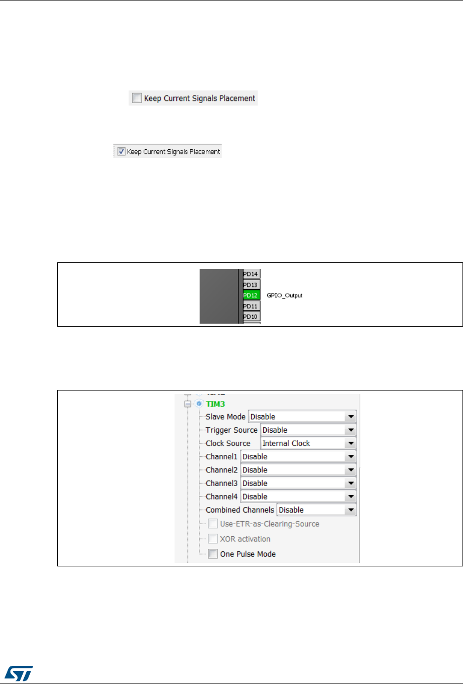
UM1718 Rev 26 201/345
UM1718 Tutorial 1: From pinout to project C code generation using an STM32F4 MCU
344
8.2 Configuring the MCU pinout
For a detailed description of menus, advanced actions and conflict resolutions, refer to
Section 5: STM32CubeMX user interface and Appendix A: STM32CubeMX pin assignment
rules.
1. By default, STM32CubeMX shows the Pinout view.
2. By default, is unchecked allowing STM32CubeMX to
move the peripheral functions around and to find the optimal pin allocation, that is the
one that accommodates the maximum number of peripheral modes.
Since the MCU pin configurations must match the STM32F4DISCOVERY board,
enable for STM32CubeMX to maintain the peripheral function
allocation (mapping) to a given pin.
This setting is saved as a user preference in order to be restored when reopening the
tool or when loading another project.
3. Select the required peripherals and peripheral modes:
a) Configure the GPIO to output the signal on the STM32F4DISCOVERY green LED
by right-clicking PD12 from the Chip view, then select GPIO_output:
Figure 169. GPIO pin configuration
b) Enable a timer to be used as timebase for toggling the LED. This is done by
selecting Internal Clock as TIM3 Clock source from the peripheral tree (see
Figure 170).
Figure 170. Timer configuration
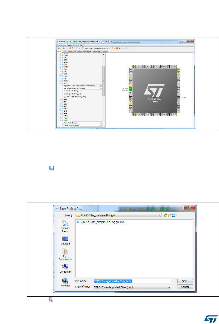
Tutorial 1: From pinout to project C code generation using an STM32F4 MCU UM1718
202/345 UM1718 Rev 26
c) You can also configure the RCC in order to use an external oscillator as potential
clock source (see Figure 171).
This completes the pinout configuration for this example.
Figure 171. Simple pinout configuration
Note: Starting with STM32CubeMX 4.2, the user can skip the pinout configuration by directly
loading ST Discovery board configuration from the Board selector tab.
8.3 Saving the project
1. Click to save the project.
When saving for the first time, select a destination folder and filename for the project.
The .ioc extension is added automatically to indicate this is an STM32CubeMX
configuration file.
Figure 172. Save Project As window
2. Click to save the project under a different name or location.
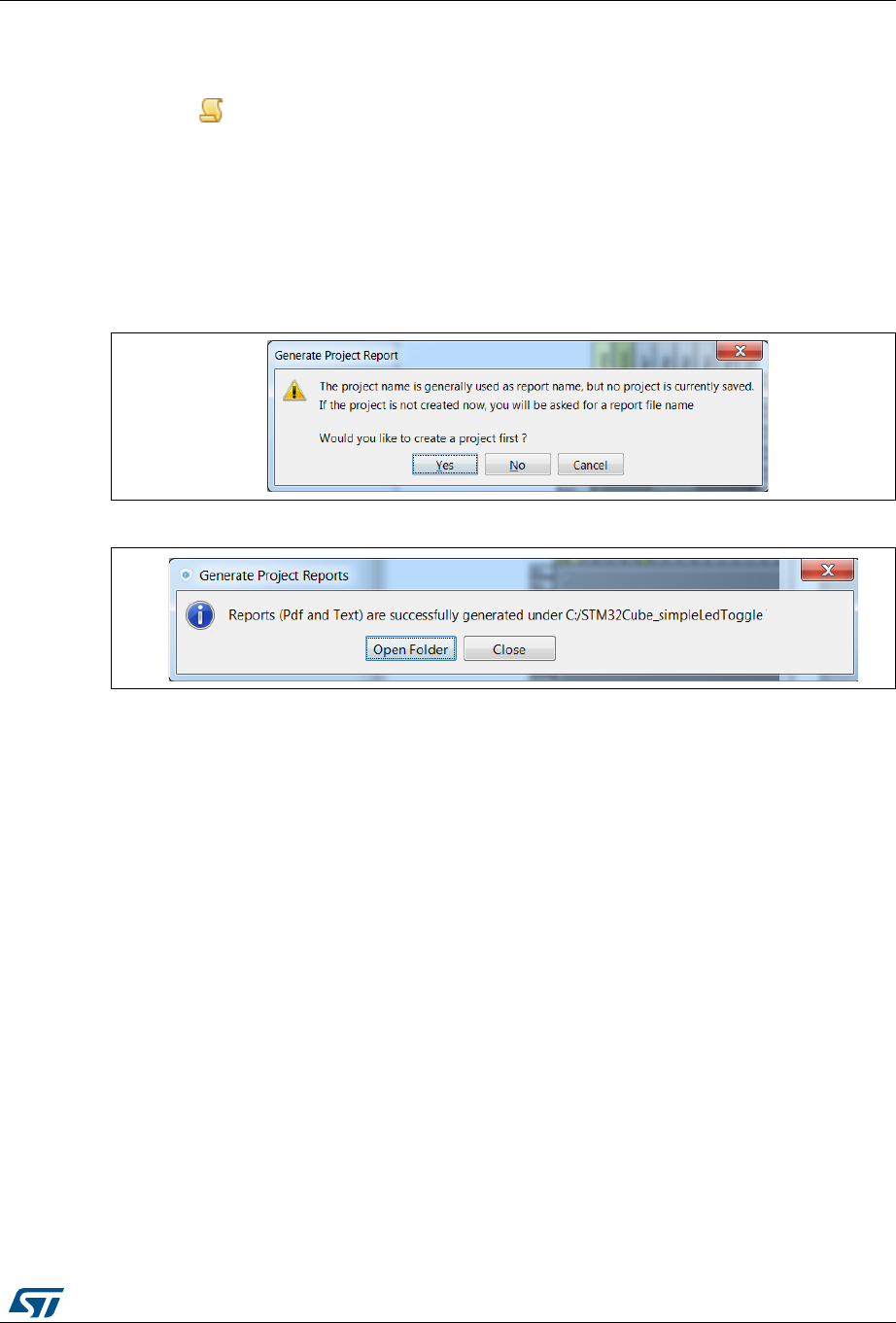
UM1718 Rev 26 203/345
UM1718 Tutorial 1: From pinout to project C code generation using an STM32F4 MCU
344
8.4 Generating the report
Reports can be generated at any time during the configuration:
1. Click to generate .pdf and .txt reports.
If a project file has not been created yet, a warning prompts the user to save the project
first and requests a project name and a destination folder (see Figure 173). An .ioc file
is then generated for the project along with a .pdf and .txt reports with the same name.
Answering No will require to provide a name and location for the report only.
A confirmation message is displayed when the operation has been successful (see
Figure 174).
Figure 173. Generate Project Report - New project creation
Figure 174. Generate Project Report - Project successfully created
2. Open the .pdf report using Adobe Reader or the .txt report using your favorite text
editor. The reports summarize all the settings and MCU configuration performed for the
project.
8.5 Configuring the MCU clock tree
The following sequence describes how to configure the clocks required by the application
based on an STM32F4 MCU.
STM32CubeMX automatically generates the system, CPU and AHB/APB bus frequencies
from the clock sources and prescalers selected by the user. Wrong settings are detected
and highlighted in red through a dynamic validation of minimum and maximum conditions.
Useful tooltips provide a detailed description of the actions to undertake when the settings
are unavailable or wrong. User frequency selection can influence some peripheral
parameters (e.g. UART baud rate limitation).
STM32CubeMX uses the clock settings defined in the Clock tree view to generate the
initialization C code for each peripheral clock. Clock settings are performed in the generated
C code as part of RCC initialization within the project main.c and in stm32f4xx_hal_conf.h
(HSE, HSI and External clock values expressed in Hertz).
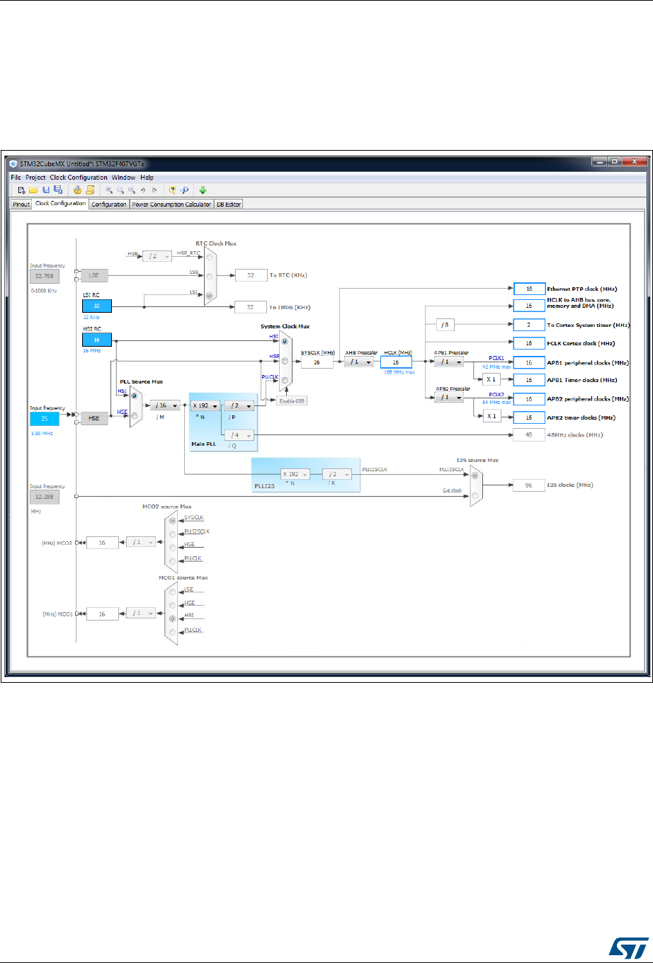
Tutorial 1: From pinout to project C code generation using an STM32F4 MCU UM1718
204/345 UM1718 Rev 26
Follow the sequence below to configure the MCU clock tree:
1. Click the Clock Configuration tab to display the clock tree (see Figure 175).
The internal (HSI, LSI), system (SYSCLK) and peripheral clock frequency fields cannot
be edited. The system and peripheral clocks can be adjusted by selecting a clock
source, and optionally by using the PLL, prescalers and multipliers.
Figure 175. Clock tree view
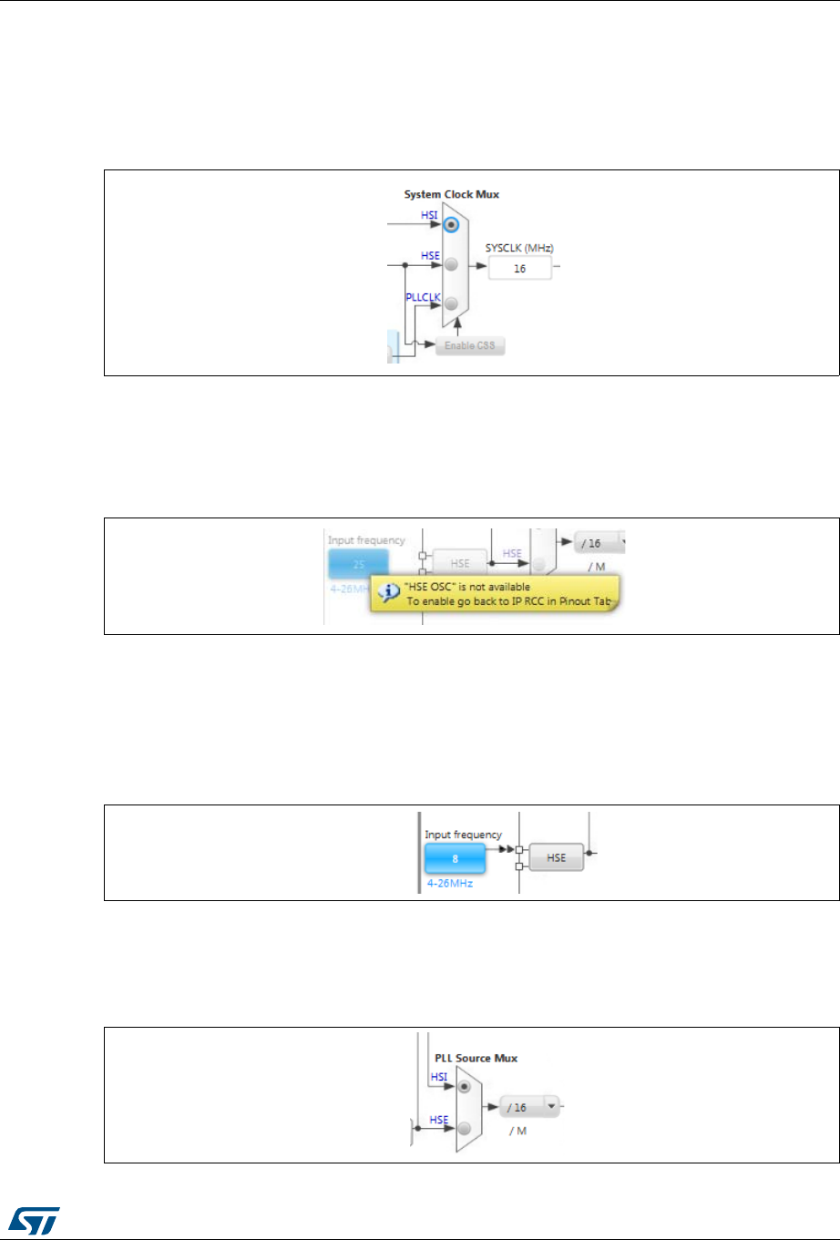
UM1718 Rev 26 205/345
UM1718 Tutorial 1: From pinout to project C code generation using an STM32F4 MCU
344
2. First select the clock source (HSE, HSI or PLLCLK) that will drive the system clock of
the microcontroller.
In the example taken for the tutorial, select HSI to use the internal 16 MHz clock (see
Figure 176).
Figure 176. HSI clock enabled
To use an external clock source (HSE or LSE), the RCC peripheral shall be configured
in the Pinout view since pins will be used to connect the external clock crystals (see
Figure 177).
Figure 177. HSE clock source disabled
Other clock configuration options for the STM32F4DISCOVERY board would have
been:
– To select the external HSE source and enter 8 in the HSE input frequency box
since an 8 MHz crystal is connected on the discovery board:
Figure 178. HSE clock source enabled
– To select the external PLL clock source and the HSI or HSE as the PLL input clock
source.
Figure 179. External PLL clock source enabled

Tutorial 1: From pinout to project C code generation using an STM32F4 MCU UM1718
206/345 UM1718 Rev 26
3. Keep the core and peripheral clocks to 16 MHz using HSI, no PLL and no prescaling.
Note: Optionally, further adjust the system and peripheral clocks using PLL, prescalers and
multipliers:
Other clock sources independent from the system clock can be configured as follows:
– USB OTG FS, Random Number Generator and SDIO clocks are driven by an
independent output of the PLL.
– I2S peripherals come with their own internal clock (PLLI2S), alternatively derived
by an independent external clock source.
– USB OTG HS and Ethernet Clocks are derived from an external source.
4. Optionally, configure the prescaler for the Microcontroller Clock Output (MCO) pins that
allow to output two clocks to the external circuit.
5. Click to save the project.
6. Go to the Configuration tab to proceed with the project configuration.
8.6 Configuring the MCU initialization parameters
Reminder
The C code generated by STM32CubeMX covers the initialization of the MCU
peripherals and middlewares using the STM32Cube firmware libraries.
8.6.1 Initial conditions
Select the Configuration tab to display the configuration view (see Figure 180).
Peripherals and middleware modes without influence on the pinout can be disabled or
enabled in the Peripheral and Middleware Tree panel. The modes that impact the pin
assignments can only be selected through the Pinout tab.
In the main panel, tooltips and warning messages are displayed when peripherals are not
properly configured (see Section 5: STM32CubeMX user interface for details).
Note: The RCC peripheral initialization will use the parameter configuration done in this view as
well as the configuration done in the Clock tree view (clock source, frequencies, prescaler
values, etc…).
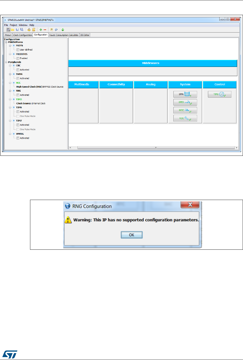
UM1718 Rev 26 207/345
UM1718 Tutorial 1: From pinout to project C code generation using an STM32F4 MCU
344
Figure 180. Configuration view
8.6.2 Configuring the peripherals
Each peripheral instance corresponds to a dedicated button in the main panel. Some
peripheral modes have no configurable parameters, as illustrated below.
Figure 181. Case of Peripheral and Middleware without configuration parameters
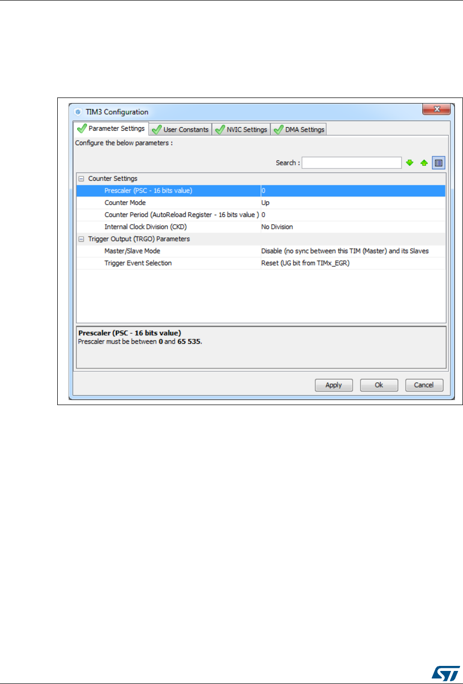
Tutorial 1: From pinout to project C code generation using an STM32F4 MCU UM1718
208/345 UM1718 Rev 26
Follow the steps below to proceed with peripheral configuration:
1. Click the peripheral button to open the corresponding configuration window.
In our example,
a) Click TIM3 to open the timer configuration window.
Figure 182. Timer 3 configuration window
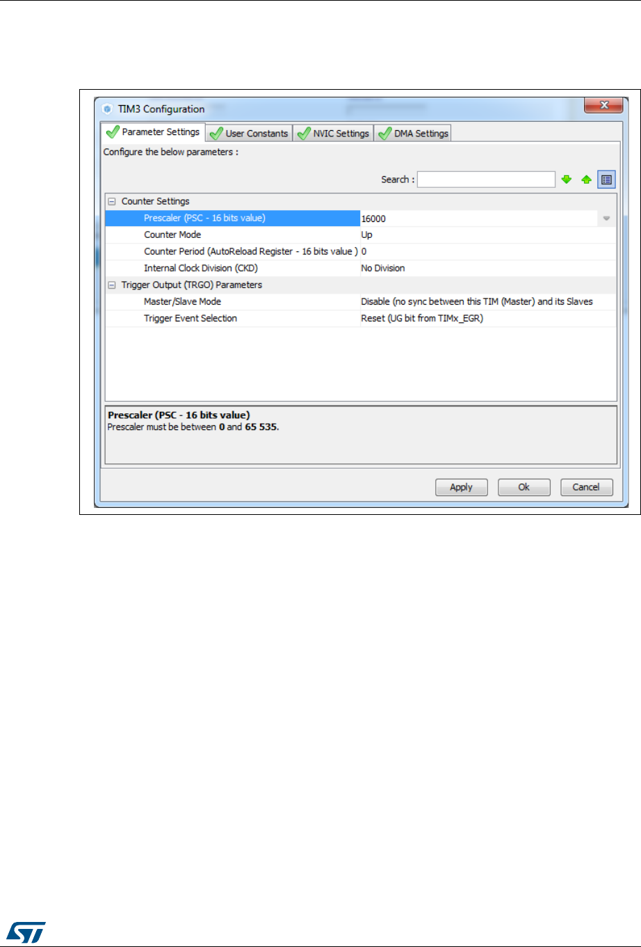
UM1718 Rev 26 209/345
UM1718 Tutorial 1: From pinout to project C code generation using an STM32F4 MCU
344
b) With a 16 MHz APB clock (Clock tree view), set the prescaler to 16000 and the
counter period to 1000 to make the LED blink every millisecond.
Figure 183. Timer 3 configuration
2. Optionally and when available, select:
–The NVIC Settings tab to display the NVIC configuration and enable interruptions
for this peripheral.
–The DMA Settings tab to display the DMA configuration and to configure DMA
transfers for this peripheral.
In the tutorial example, the DMA is not used and the GPIO settings remain
unchanged. The interrupt is enabled as shown in Figure 184.
–The GPIO Settings tab to display the GPIO configuration and to configure the
GPIOs for this peripheral.
– Insert an item:
–The User Constants tab to specify constants to be used in the project.
3. Modify and click Apply or OK to save your modifications.
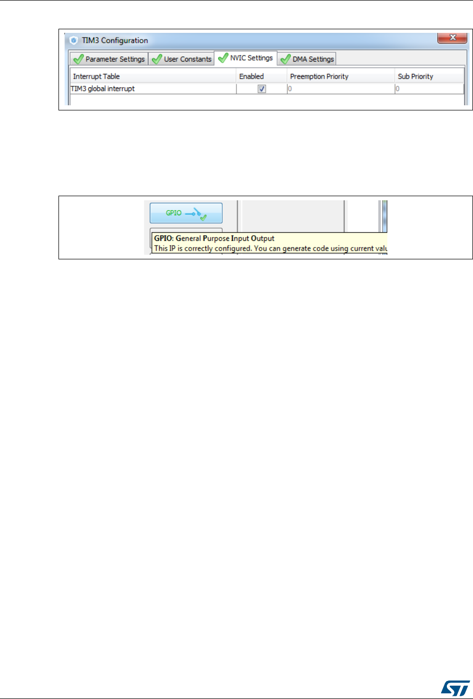
Tutorial 1: From pinout to project C code generation using an STM32F4 MCU UM1718
210/345 UM1718 Rev 26
Figure 184. Enabling Timer 3 interrupt
8.6.3 Configuring the GPIOs
The user can adjust all pin configurations from this window. A small icon along with a tooltip
indicates the configuration status.
Figure 185. GPIO configuration color scheme and tooltip
Follow the sequence below to configure the GPIOS:
1. Click the GPIO button in the Configuration view to open the Pin Configuration
window below.
2. The first tab shows the pins that have been assigned a GPIO mode but not for a
dedicated peripheral and middleware. Select a Pin Name to open the configuration for
that pin.
In the tutorial example, select PD12 and configure it in output push-pull mode to drive
the STM32F4DISCOVERY LED (see Figure 186).
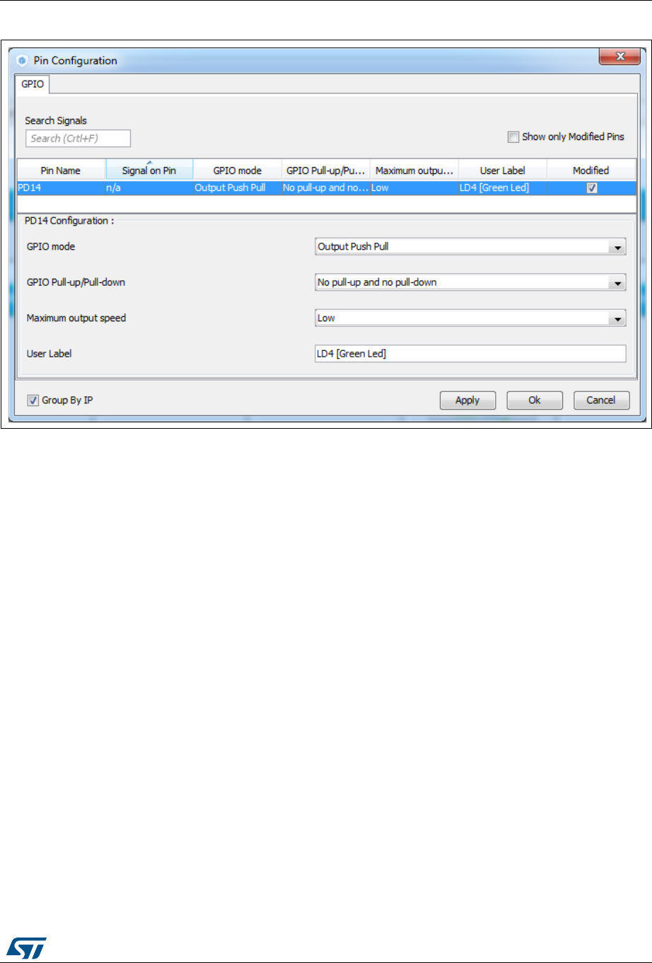
UM1718 Rev 26 211/345
UM1718 Tutorial 1: From pinout to project C code generation using an STM32F4 MCU
344
Figure 186. GPIO mode configuration
3. Click Apply then Ok to close the window.
8.6.4 Configuring the DMAs
This is not required for the example taken for the tutorial.
It is recommended to use DMA transfers to offload the CPU. The DMA Configuration
window provides a fast and easy way to configure the DMAs (see Figure 187).
1. Add a new DMA request and select among a list of possible configurations.
2. Select among the available streams.
3. Select the Direction: Memory to Peripheral or Peripheral to Memory.
4. Select a Priority.
Note: Configuring the DMA for a given peripheral and middleware can also be performed using
the Peripheral and Middleware configuration window.

Tutorial 1: From pinout to project C code generation using an STM32F4 MCU UM1718
212/345 UM1718 Rev 26
Figure 187. DMA Parameters configuration window
8.6.5 Configuring the middleware
This is not required for the example taken for the tutorial.
If a peripheral is required for a middleware mode, the peripheral must be configured in the
Pinout view for the middleware mode to become available. A tooltip can guide the user as
illustrated in the FatFs example below:
Figure 188. FatFs disabled
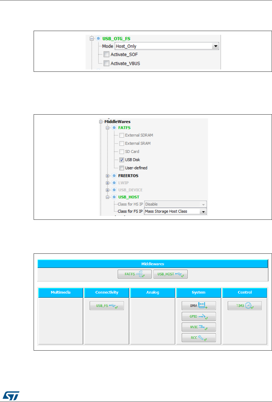
UM1718 Rev 26 213/345
UM1718 Tutorial 1: From pinout to project C code generation using an STM32F4 MCU
344
1. Configure the USB peripheral from the Pinout view.
Figure 189. USB Host configuration
2. Select MSC_FS class from USB Host middleware.
3. Select the checkbox to enable FatFs USB mode in the tree panel.
Figure 190. FatFs over USB mode enabled
4. Select the Configuration view. FatFs and USB buttons are then displayed.
Figure 191. Configuration view with FatFs and USB enabled
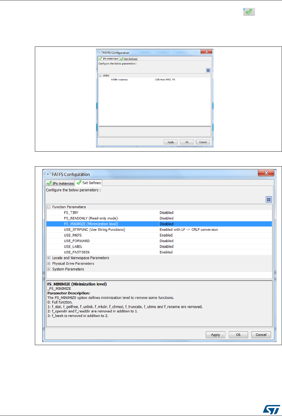
Tutorial 1: From pinout to project C code generation using an STM32F4 MCU UM1718
214/345 UM1718 Rev 26
5. FatFs and USB using default settings are already marked as configured . Click
FatFs and USB buttons to display default configuration settings. You can also change
them by following the guidelines provided at the bottom of the window.
Figure 192. FatFs peripheral instances
Figure 193. FatFs define statements
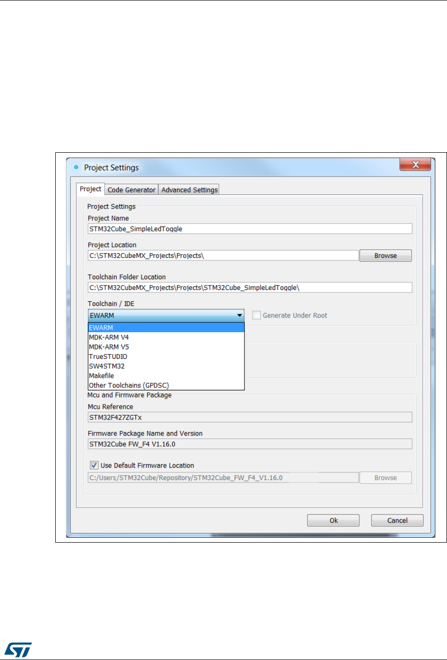
UM1718 Rev 26 215/345
UM1718 Tutorial 1: From pinout to project C code generation using an STM32F4 MCU
344
8.7 Generating a complete C project
8.7.1 Setting project options
Default project settings can be adjusted prior to C code generation as described in
Figure 194.
1. Select Settings from the Project menu to open the Project settings window.
2. Select the Project Tab and choose a Project name, location and a toolchain to
generate the project (see Figure 194).
Figure 194. Project Settings and toolchain selection
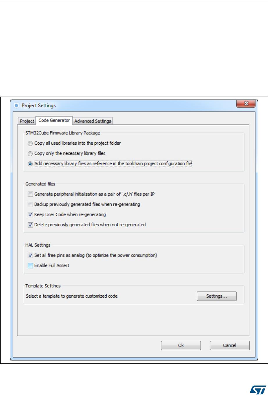
Tutorial 1: From pinout to project C code generation using an STM32F4 MCU UM1718
216/345 UM1718 Rev 26
3. Select the Code Generator tab to choose various C code generation options:
– The library files copied to Projects folder.
– C code regeneration (e.g. what is kept or backed up during C code regeneration).
– HAL specific action (e.g. set all free pins as analog I/Os to reduce MCU power
consumption).
In the tutorial example, select the settings as displayed in the figure below and click
OK.
Note: A dialog window appears when the firmware package is missing. Go to next section for
explanation on how to download the firmware package.
Figure 195. Project Settings menu - Code Generator tab
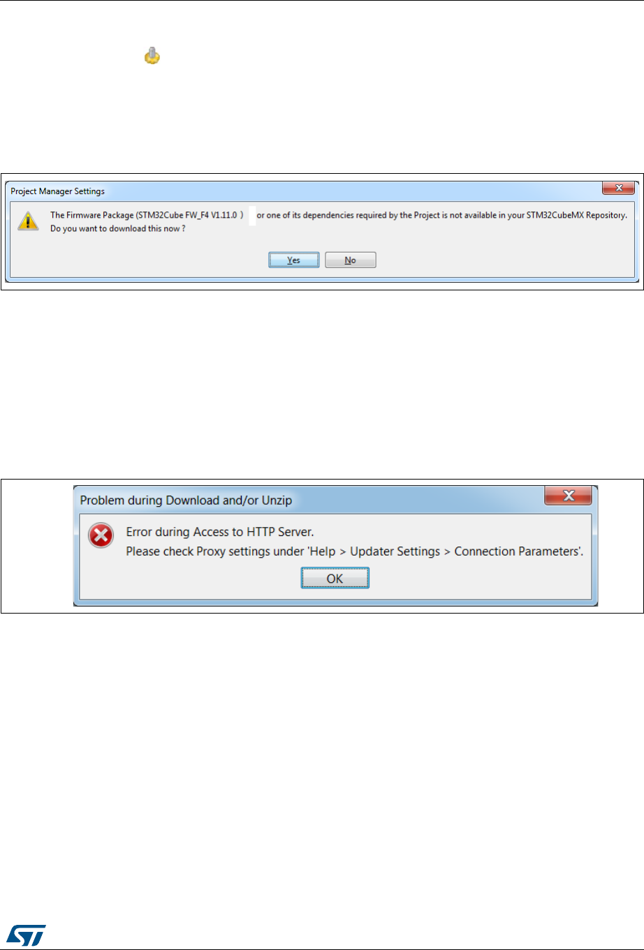
UM1718 Rev 26 217/345
UM1718 Tutorial 1: From pinout to project C code generation using an STM32F4 MCU
344
8.7.2 Downloading firmware package and generating the C code
1. Click to generate the C code.
During C code generation, STM32CubeMX copies files from the relevant STM32Cube
MCU package into the project folder so that the project can be compiled. When
generating a project for the first time, the firmware package is not available on the user
PC and a warning message is displayed:
Figure 196. Missing firmware package warning message
2. STM32CubeMX offers to download the relevant firmware package or to go on. Click
Download to obtain a complete project, that is a project ready to be used in the
selected IDE.
By clicking Continue, only Inc and Src folders will be created, holding STM32CubeMX
generated initialization files. The necessary firmware and middleware libraries will have
to be copied manually to obtain a complete project.
If the download fails, the below error message is displayed:
Figure 197. Error during download
To solve this issue, execute the next two steps. Skip them otherwise.
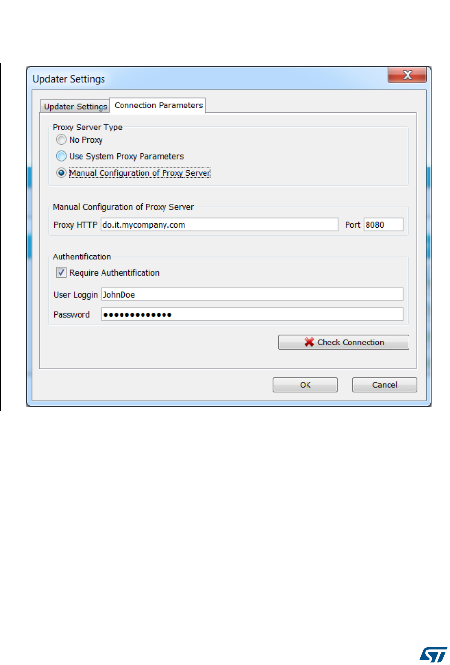
Tutorial 1: From pinout to project C code generation using an STM32F4 MCU UM1718
218/345 UM1718 Rev 26
3. Select Help > Updater settings menu and adjust the connection parameters to match
your network configuration.
Figure 198. Updater settings for download
4. Click Check connection. The check mark turns green once the connection is
established.
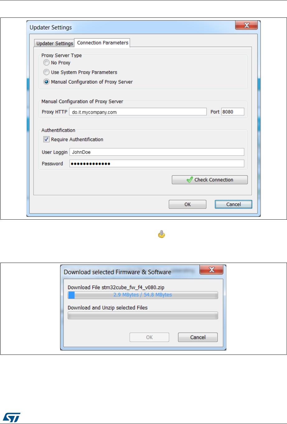
UM1718 Rev 26 219/345
UM1718 Tutorial 1: From pinout to project C code generation using an STM32F4 MCU
344
Figure 199. Updater settings with connection
5. Once the connection is functional, click to generate the C code. The C code
generation process starts and progress is displayed as illustrated in the next figures.
Figure 200. Downloading the firmware package

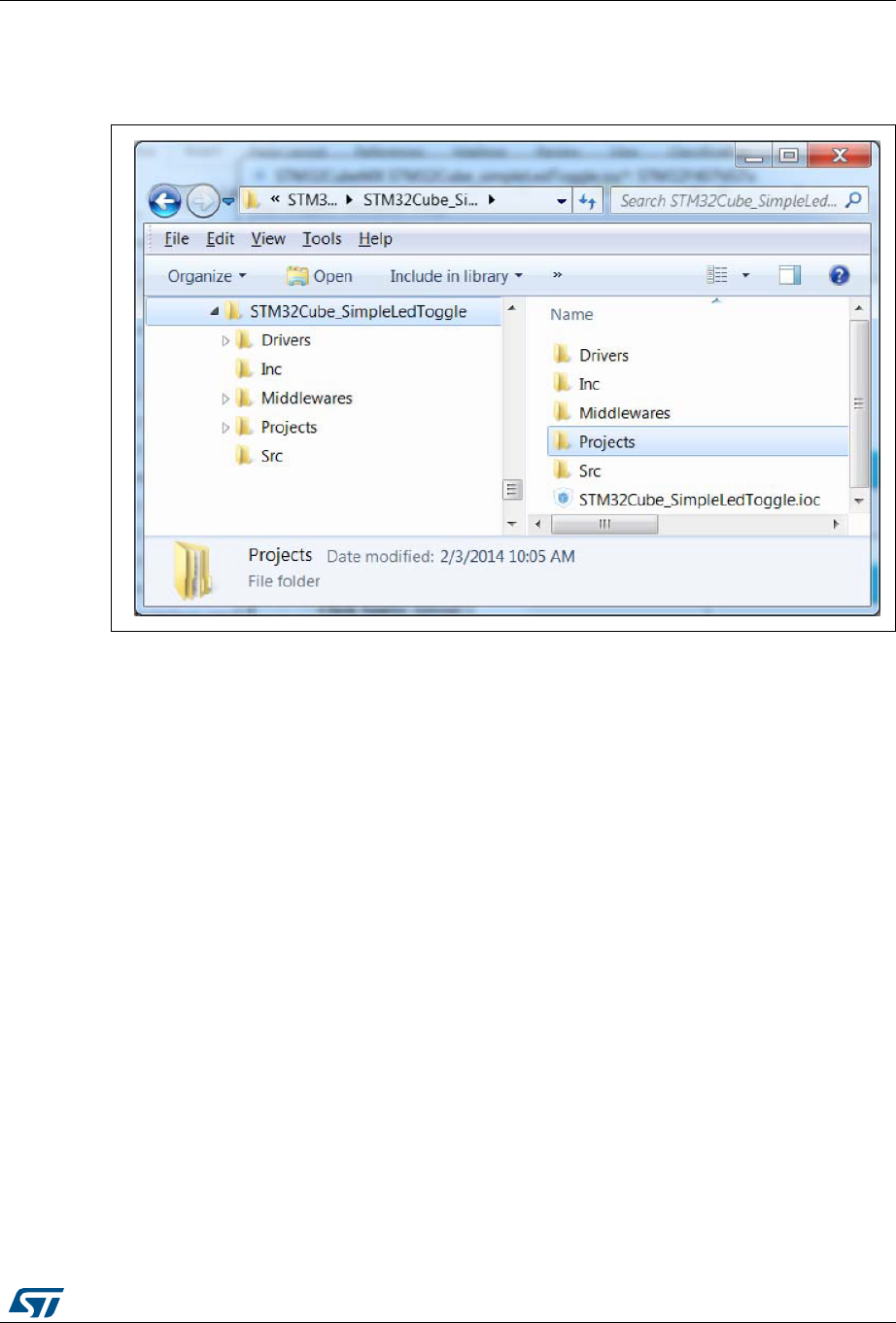
UM1718 Rev 26 221/345
UM1718 Tutorial 1: From pinout to project C code generation using an STM32F4 MCU
344
7. Click Open Folder to display the generated project contents or click Open Project to
open the project directly in your IDE. Then proceed with Section 8.8.
Figure 203. C code generation output folder
The generated project contains:
The STM32CubeMX .ioc project file located in the root folder. It contains the project
user configuration and settings generated through STM32CubeMX user interface.
The Drivers and Middlewares folders hold copies of the firmware package files relevant
for the user configuration.
The Projects folder contains IDE specific folders with all the files required for the project
development and debug within the IDE.
The Inc and Src folders contain STM32CubeMX generated files for middleware,
peripheral and GPIO initialization, including the main.c file. The STM32CubeMX
generated files contain user-dedicated sections allowing to insert user-defined C code.
Caution: C code written within the user sections is preserved at next C code generation, while C code
written outside these sections is overwritten.
User C code will be lost if user sections are moved or if user sections delimiters are
renamed.
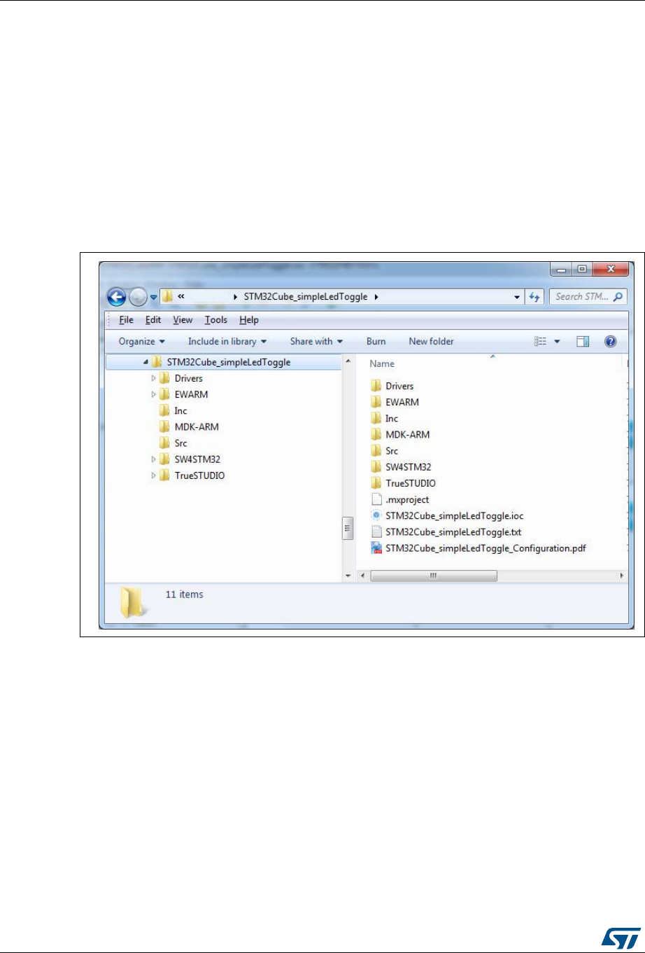
Tutorial 1: From pinout to project C code generation using an STM32F4 MCU UM1718
222/345 UM1718 Rev 26
8.8 Building and updating the C code project
This example explains how to use the generated initialization C code and complete the
project, within IAR™ EWARM toolchain, to have the LED blink according to the TIM3
frequency.
A folder is available for the toolchains selected for C code generation: the project can be
generated for more than one toolchain by choosing a different toolchain from the Project
Settings menu and clicking Generate code once again.
1. Open the project directly in the IDE toolchain by clicking Open Project from the dialog
window or by double-clicking the relevant IDE file available in the toolchain folder under
STM32CubeMX generated project directory (see Figure 202).
Figure 204. C code generation output: Projects folder


Tutorial 1: From pinout to project C code generation using an STM32F4 MCU UM1718
224/345 UM1718 Rev 26
3. Select the main.c file to open in editor.
Figure 206. STM32CubeMX generated project open in IAR™ IDE
The htim3 structure handler, system clock, GPIO and TIM3 initialization functions are
defined. The initialization functions are called in the main.c. For now the user C code
sections are empty.
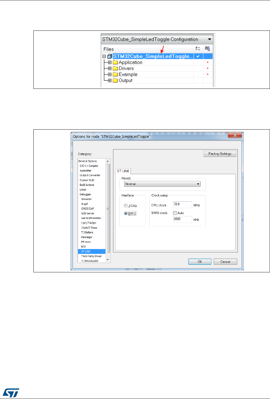
UM1718 Rev 26 225/345
UM1718 Tutorial 1: From pinout to project C code generation using an STM32F4 MCU
344
4. In the IAR™ IDE, right-click the project name and select Options.
Figure 207. IAR™ options
5. Click the ST-LINK category and make sure SWD is selected to communicate with the
STM32F4DISCOVERY board. Click OK.
Figure 208. SWD connection
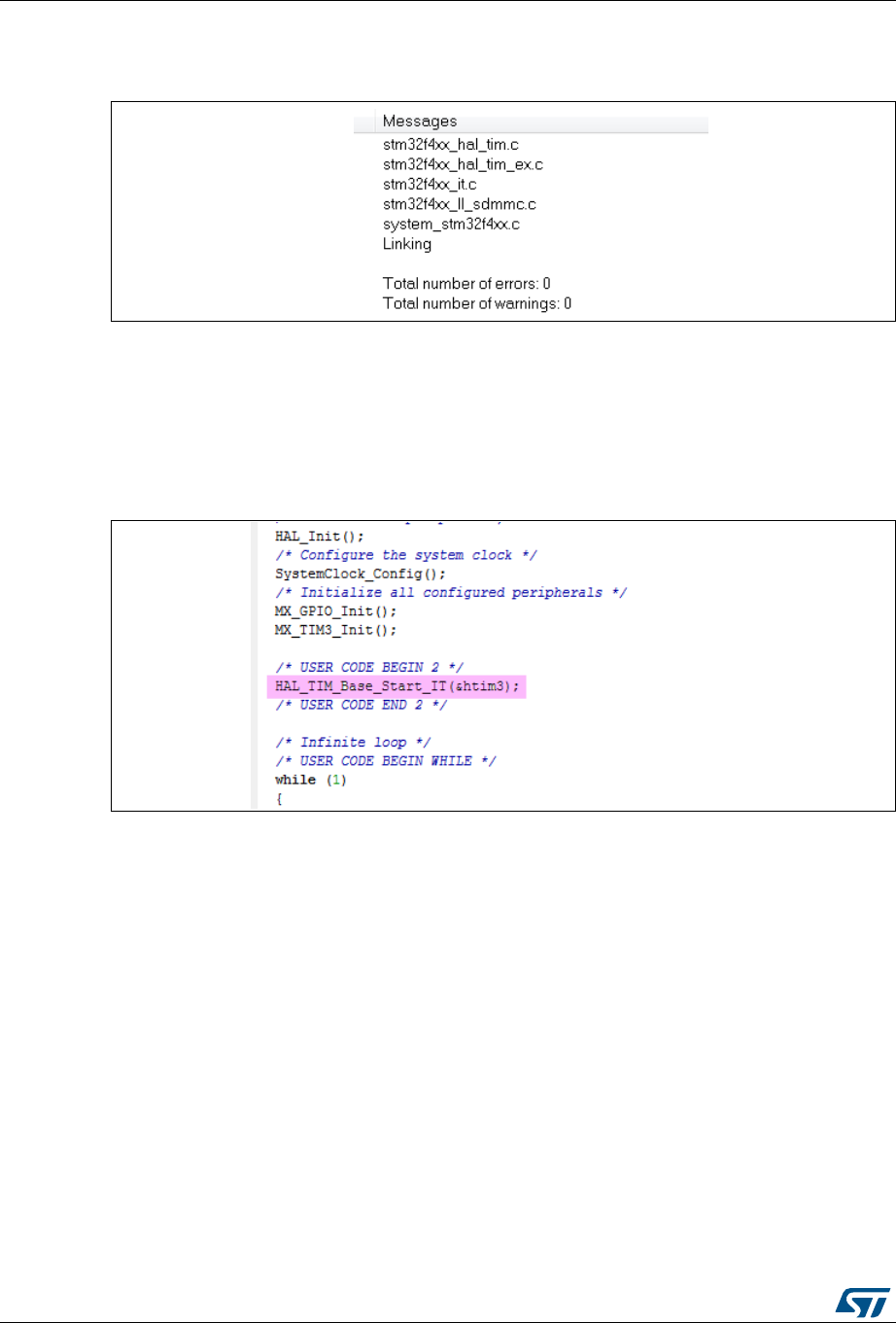
Tutorial 1: From pinout to project C code generation using an STM32F4 MCU UM1718
226/345 UM1718 Rev 26
6. Select Project > Rebuild all. Check if the project building has succeeded.
Figure 209. Project building log
7. Add user C code in the dedicated user sections only.
Note: The main while(1) loop is placed in a user section.
For example:
a) Edit the main.c file.
b) To start timer 3, update User Section 2 with the following C code:
Figure 210. User Section 2
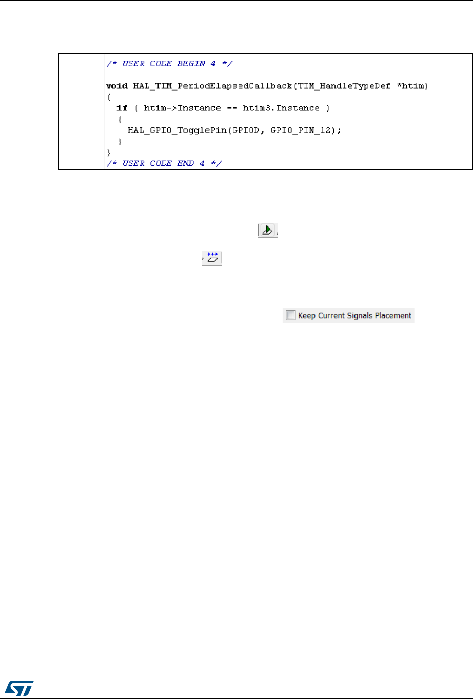
UM1718 Rev 26 227/345
UM1718 Tutorial 1: From pinout to project C code generation using an STM32F4 MCU
344
c) Then, add the following C code in User Section 4:
Figure 211. User Section 4
This C code implements the weak callback function defined in the HAL timer driver
(stm32f4xx_hal_tim.h) to toggle the GPIO pin driving the green LED when the
timer counter period has elapsed.
8. Rebuild and program your board using . Make sure the SWD ST-LINK option is
checked as a Project options otherwise board programming will fail.
9. Launch the program using . The green LED on the STM32F4DISCOVERY board
will blink every second.
10. To change the MCU configuration, go back to STM32CubeMX user interface,
implement the changes and regenerate the C code. The project will be updated,
preserving the C code in the user sections if option in
Project Settings is enabled.
8.9 Switching to another MCU
STM32CubeMX allows loading a project configuration on an MCU of the same Series.
Proceed as follows:
1. Select File > New Project.
2. Select an MCU belonging to the same Series. As an example, you can select the
STM32F429ZITx that is the core MCU of the 32F429IDISCOVERY board.
3. Select File > Import project. In the Import project window, browse to the .ioc file to
load. A message warns you that the currently selected MCU (STM32F429ZITx) differs
from the one specified in the .ioc file (STM32F407VGTx). Several import options are
proposed (see Figure 212).
4. Click the Try Import button and check the import status to verify if the import
succeeded (see Figure 213).
5. Click OK to really import the project. An output tab is then displayed to report the import
results.
6. The green LED on 32F429IDISCOVERY board is connected to PG13: CTRL+ right
click PD12 and drag and drop it on PG13.
7. Select Project > Settings to configure the new project name and folder location. Click
Generate icon to save the project and generate the code.
8. Select Open the project from the dialog window, update the user sections with the
user code, making sure to update the GPIO settings for PG13. Build the project and
flash the board. Launch the program and check that LED blinks once per second.

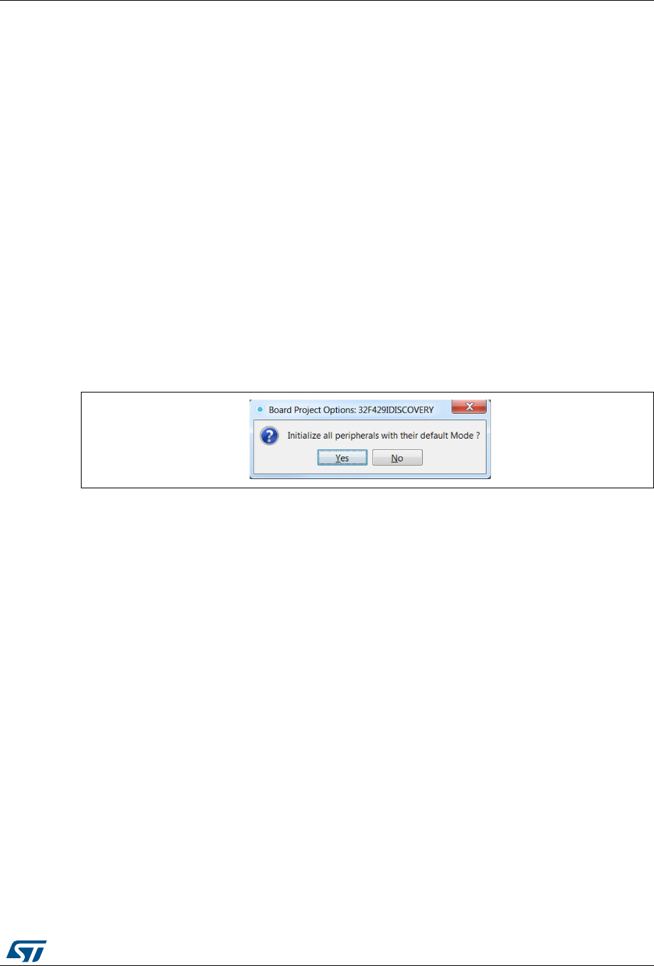
UM1718 Rev 26 229/345
UM1718 Tutorial 2 - Example of FatFs on an SD card using STM32429I-EVAL evaluation board
344
9 Tutorial 2 - Example of FatFs on an SD card using
STM32429I-EVAL evaluation board
The tutorial consists in creating and writing to a file on the STM32429I-EVAL1 SD card using
the FatFs file system middleware.
To generate a project and run tutorial 2, follow the sequence below:
1. Launch STM32CubeMX.
2. Select File > New Project. The Project window opens.
3. Click the Board Selector Tab to display the list of ST boards.
4. Select EvalBoard as type of Board and STM32F4 as Series to filter down the list.
5. Leave the option Initialize all peripherals with their default mode unchecked so that
the code is generated only for the peripherals used by the application.
6. Select the STM32429I-EVAL board and click OK. Answer No in the dialog box asking
to initialize all peripherals to their default modes (see Figure 214). The Pinout view is
loaded, matching the MCU pinout configuration on the evaluation board (see
Figure 215).
Figure 214. Board peripheral initialization dialog box

Tutorial 2 - Example of FatFs on an SD card using STM32429I-EVAL evaluation board UM1718
230/345 UM1718 Rev 26
Figure 215. Board selection
7. From the Peripheral tree on the left, expand the SDIO peripheral and select the SD 4
bits wide bus (see Figure 216).
Figure 216. SDIO peripheral configuration
8. Under the Middlewares category, check SD Card as FatFs mode (see Figure 217).
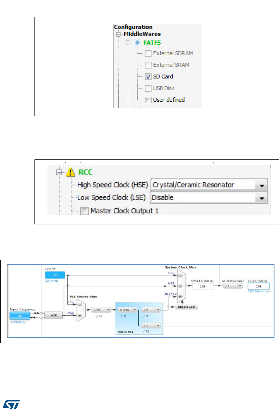
UM1718 Rev 26 231/345
UM1718 Tutorial 2 - Example of FatFs on an SD card using STM32429I-EVAL evaluation board
344
Figure 217. FatFs mode configuration
9. Configure the clocks as follows:
a) Select the RCC peripheral from the Pinout view (see Figure 218).
Figure 218. RCC peripheral configuration
b) Configure the clock tree from the clock tab (see Figure 219).
Figure 219. Clock tree view
10. In the Project Settings menu, specify the project name and destination folder. Then,
select the EWARM IDE toolchain.
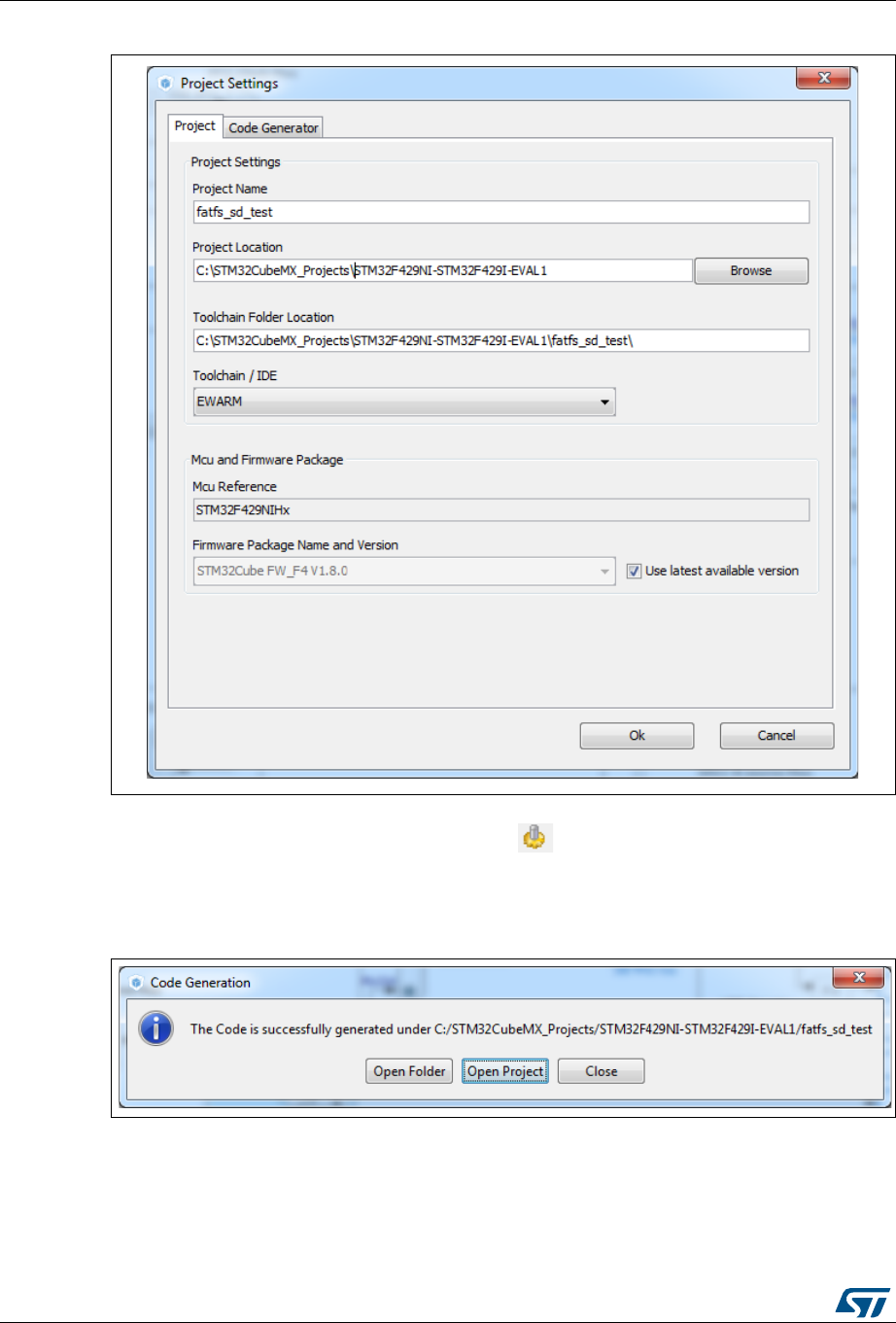
Tutorial 2 - Example of FatFs on an SD card using STM32429I-EVAL evaluation board UM1718
232/345 UM1718 Rev 26
Figure 220. Project Settings menu - Code Generator tab
11. Click Ok. Then, on the toolbar menu, click to generate the project.
12. Upon code generation completion, click Open Project in the Code Generation dialog
window (see Figure 221). This opens the project directly in the IDE.
Figure 221. C code generation completion message
13. In the IDE, check that heap and stack sizes are sufficient: right click the project name
and select Options, then select Linker. Check Override default to use the icf file from
STM32CubeMX generated project folder. Adjust the heap and stack sizes (see
Figure 222).
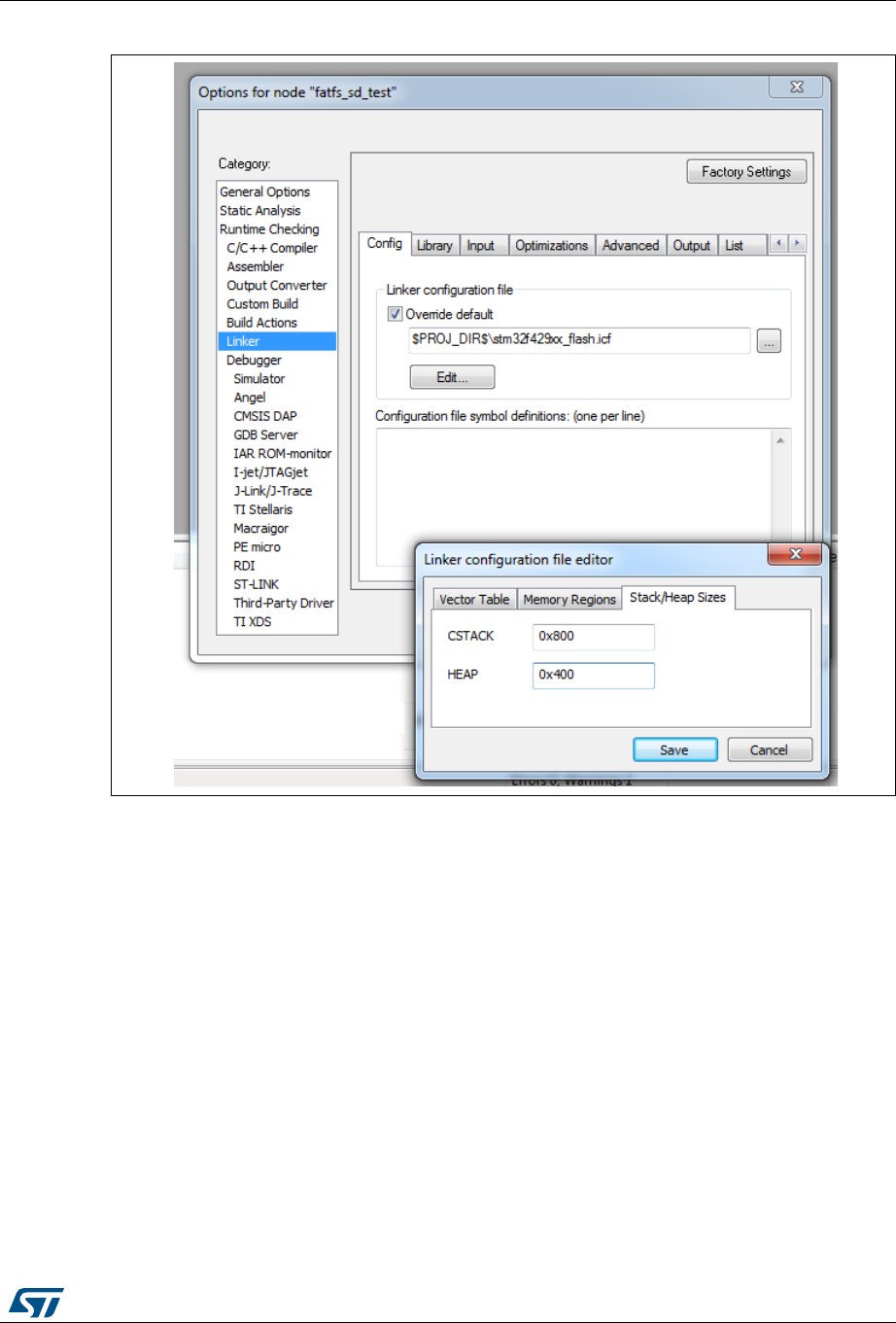
UM1718 Rev 26 233/345
UM1718 Tutorial 2 - Example of FatFs on an SD card using STM32429I-EVAL evaluation board
344
Figure 222. IDE workspace
Note: When using the MDK-Arm toolchain, go to the Application/MDK-ARM folder and
double- click the startup_xx.s file to edit and adjust the heap and stack sizes there.

Tutorial 2 - Example of FatFs on an SD card using STM32429I-EVAL evaluation board UM1718
234/345 UM1718 Rev 26
14. Go to the Application/User folder. Double-click the main.c file and edit it.
15. The tutorial consists in creating and writing to a file on the evaluation board SD card
using the FatFs file system middleware:
a) At startup all LEDs are OFF.
b) The red LED is turned ON to indicate that an error occurred (FatFs initialization,
file read/write access errors..).
c) The orange LED is turned ON to indicate that the FatFs link has been successfully
mounted on the SD driver.
d) The blue LED is turned ON to indicate that the file has been successfully written to
the SD Card.
e) The green LED is turned ON to indicate that the file has been successfully read
from file the SD Card.
16. For use case implementation, update main.c with the following code:
a) Insert main.c private variables in a dedicated user code section:
/* USER CODE BEGIN PV */
/* Private variables ------------------------------------------*/
FATFS SDFatFs; /* File system object for SD card logical drive */
FIL MyFile; /* File object */
const char wtext[] = "Hello World!";
const uint8_t image1_bmp[] = {
0x42,0x4d,0x36,0x84,0x03,0x00,0x00,0x00,0x00,0x00,0x36,0x00,0x00,0x00,
0x28,0x00,0x00,0x00,0x40,0x01,0x00,0x00,0xf0,0x00,0x00,0x00,0x01,0x00,
0x18,0x00,0x00,0x00,0x00,0x00,0x00,0x84,0x03,0x00,0x00,0x00,0x00,0x00,
0x00,0x00,0x00,0x00,0x00,0x00,0x00,0x00,0x00,0x00,0x00,0x00,0x29,0x74,
0x51,0x0e,0x63,0x30,0x04,0x4c,0x1d,0x0f,0x56,0x25,0x11,0x79,0x41,0x1f,
0x85,0x6f,0x25,0x79,0x7e,0x27,0x72,0x72,0x0b,0x50,0x43,0x00,0x44,0x15,
0x00,0x4b,0x0f,0x00,0x4a,0x15,0x07,0x50,0x16,0x03,0x54,0x22,0x23,0x70,
0x65,0x30,0x82,0x6d,0x0f,0x6c,0x3e,0x22,0x80,0x5d,0x23,0x8b,0x5b,0x26};
/* USER CODE END PV */
b) Insert main functional local variables:
int main(void)
{
/* USER CODE BEGIN 1 */
FRESULT res; /* FatFs function common result code */
uint32_t byteswritten, bytesread; /* File write/read counts */
char rtext[256]; /* File read buffer */
/* USER CODE END 1 */
/* MCU Configuration----------------------------------------*/
/* Reset of all peripherals, Initializes the Flash interface and the
Systick. */
HAL_Init();
c) Insert user code in the main function, after initialization calls and before the while
loop, to perform actual read/write from/to the SD card:
int main(void)
{
….

UM1718 Rev 26 235/345
UM1718 Tutorial 2 - Example of FatFs on an SD card using STM32429I-EVAL evaluation board
344
MX_FATFS_Init();
/* USER CODE BEGIN 2 */
/*##-0- Turn all LEDs off(red, green, orange and blue) */
HAL_GPIO_WritePin(GPIOG, (GPIO_PIN_10 | GPIO_PIN_6 | GPIO_PIN_7 |
GPIO_PIN_12), GPIO_PIN_SET);
/*##-1- FatFS: Link the SD disk I/O driver ##########*/
if(retSD == 0){
/* success: set the orange LED on */
HAL_GPIO_WritePin(GPIOG, GPIO_PIN_7, GPIO_PIN_RESET);
/*##-2- Register the file system object to the FatFs module ###*/
if(f_mount(&SDFatFs, (TCHAR const*)SD_Path, 0) != FR_OK){
/* FatFs Initialization Error : set the red LED on */
HAL_GPIO_WritePin(GPIOG, GPIO_PIN_10, GPIO_PIN_RESET);
while(1);
} else {
/*##-3- Create a FAT file system (format) on the logical drive#*/
/* WARNING: Formatting the uSD card will delete all content on the
device */
if(f_mkfs((TCHAR const*)SD_Path, 0, 0) != FR_OK){
/* FatFs Format Error : set the red LED on */
HAL_GPIO_WritePin(GPIOG, GPIO_PIN_10, GPIO_PIN_RESET);
while(1);
} else {
/*##-4- Create & Open a new text file object with write access#*/
if(f_open(&MyFile, "Hello.txt", FA_CREATE_ALWAYS | FA_WRITE) !=
FR_OK){
/* 'Hello.txt' file Open for write Error : set the red LED on */
HAL_GPIO_WritePin(GPIOG, GPIO_PIN_10, GPIO_PIN_RESET);
while(1);
} else {
/*##-5- Write data to the text file ####################*/
res = f_write(&MyFile, wtext, sizeof(wtext), (void
*)&byteswritten);
if((byteswritten == 0) || (res != FR_OK)){
/* 'Hello.txt' file Write or EOF Error : set the red LED on */
HAL_GPIO_WritePin(GPIOG, GPIO_PIN_10, GPIO_PIN_RESET);
while(1);
} else {
/*##-6- Successful open/write : set the blue LED on */
HAL_GPIO_WritePin(GPIOG, GPIO_PIN_12, GPIO_PIN_RESET);
f_close(&MyFile);
/*##-7- Open the text file object with read access #*/
if(f_open(&MyFile, "Hello.txt", FA_READ) != FR_OK){
/* 'Hello.txt' file Open for read Error : set the red LED on */
HAL_GPIO_WritePin(GPIOG, GPIO_PIN_10, GPIO_PIN_RESET);
while(1);
} else {
/*##-8- Read data from the text file #########*/
res = f_read(&MyFile, rtext, sizeof(wtext), &bytesread);
if((strcmp(rtext,wtext)!=0)|| (res != FR_OK)){

Tutorial 2 - Example of FatFs on an SD card using STM32429I-EVAL evaluation board UM1718
236/345 UM1718 Rev 26
/* 'Hello.txt' file Read or EOF Error : set the red LED on */
HAL_GPIO_WritePin(GPIOG, GPIO_PIN_10, GPIO_PIN_RESET);
while(1);
} else {
/* Successful read : set the green LED On */
HAL_GPIO_WritePin(GPIOG, GPIO_PIN_6, GPIO_PIN_RESET);
/*##-9- Close the open text file ################*/
f_close(&MyFile);
}}}}}}}
/*##-10- Unlink the micro SD disk I/O driver #########*/
FATFS_UnLinkDriver(SD_Path);
/* USER CODE END 2 */
/* Infinite loop */
/* USER CODE BEGIN WHILE */
while (1)

UM1718 Rev 26 237/345
UM1718 Tutorial 3 - Using the Power Consumption Calculator to optimize the embedded applica-
344
10 Tutorial 3 - Using the Power Consumption Calculator
to optimize the embedded application consumption
and more
10.1 Tutorial overview
This tutorial focuses on STM32CubeMX Power Consumption Calculator (Power
Consumption Calculator) feature and its benefits to evaluate the impacts of power-saving
techniques on a given application sequence.
The key considerations to reduce a given application power consumption are:
Reducing the operating voltage
Reducing the time spent in energy consuming modes
It is up to the developer to select a configuration that gives the best compromise
between low-power consumption and performance.
Maximizing the time spent in non-active and low-power modes
Using the optimal clock configuration
The core should always operate at relatively good speed, since reducing the operating
frequency can increase energy consumption if the microcontroller has to remain for a
long time in an active operating mode to perform a given operation.
Enabling only the peripherals relevant for the current application state and clock-gating
the others
When relevant, using the peripherals with low-power features (e.g. waking up the
microcontroller with the I2C)
Minimizing the number of state transitions
Optimizing memory accesses during code execution
– Prefer code execution from RAM to Flash memory
– When relevant, consider aligning CPU frequency with Flash memory operating
frequency for zero wait states.
The following tutorial shows how the STM32CubeMX Power Consumption Calculator
feature can help to tune an application to minimize its power consumption and extend the
battery life.
Note: The Power Consumption Calculator does not account for I/O dynamic current consumption
and external board components that can also affect current consumption. For this purpose,
an “additional consumption” field is provided for the user to specify such consumption value.

Tutorial 3 - Using the Power Consumption Calculator to optimize the embedded application con-
238/345 UM1718 Rev 26
10.2 Application example description
The application is designed using the NUCLEO-L476RG board based on a
STM32L476RGTx device and supplied by a 2.4 V battery.
The main purpose of this application is to perform ADC measurements and transfer the
conversion results over UART. It uses:
Multiple low-power modes: Low-power run, Low-power sleep, Sleep, Stop and Standby
Multiple peripherals: USART, DMA, Timer, COMP, DAC and RTC
– The RTC is used to run a calendar and to wake up the CPU from Standby when a
specified time has elapsed.
– The DMA transfers ADC measurements from ADC to memory
– The USART is used in conjunction with the DMA to send/receive data via the
virtual COM port and to wake up the CPU from Stop mode.
The process to optimize such complex application is to start describing first a functional only
sequence then to introduce, on a step by step basis, the low-power features provided by the
STM32L476RG microcontroller.
10.3 Using the Power Consumption Calculator
10.3.1 Creating a power sequence
Follow the steps below to create the sequence (see Figure 223):
1. Launch STM32CubeMX.
2. Click new project and select the Nucleo-L476RG board from the Board tab.
3. Click the Power Consumption Calculator tab to select the Power Consumption
Calculator view. A first sequence is then created as a reference.
4. Adapt it to minimize the overall current consumption. To do this:
a) Select 2.4 V VDD power supply. This value can be adjusted on a step by step basis
(see Figure 224).
b) Select the Li-MnO2 (CR2032) battery. This step is optional. The battery type can
be changed later on (see Figure 224).

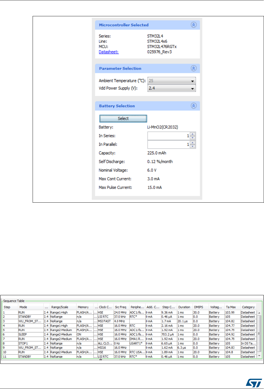
Tutorial 3 - Using the Power Consumption Calculator to optimize the embedded application con-
240/345 UM1718 Rev 26
Figure 224. VDD and battery selection menu
5. Enable the Transition checker to ensure the sequence is valid (see Figure 224). This
option allows verifying that the sequence respects the allowed transitions implemented
within the STM32L476RG.
6. Click the Add button to add steps that match the sequence described in Figure 224.
– By default the steps last 1 ms each, except for the wakeup transitions that are
preset using the transition times specified in the product datasheet (see
Figure 225).
– Some peripherals for which consumption is unavailable or negligible are
highlighted with ‘*’ (see Figure 225).
Figure 225. Sequence table
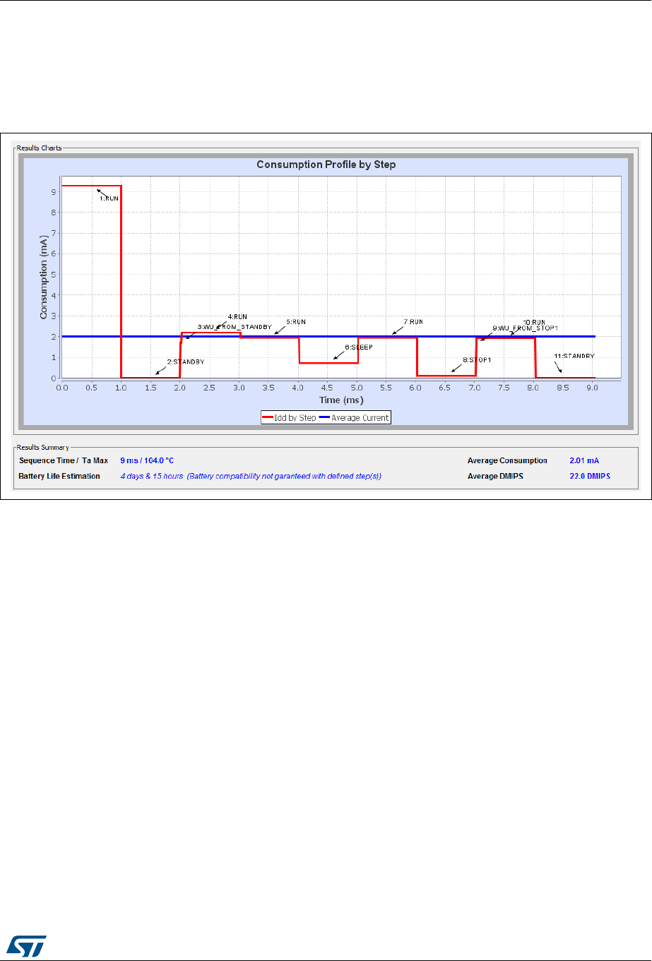
UM1718 Rev 26 241/345
UM1718 Tutorial 3 - Using the Power Consumption Calculator to optimize the embedded applica-
344
7. Click the Save button to save the sequence as SequenceOne.
The application consumption profile is the generated. It shows that the overall sequence
consumes an average of 2.01 mA for 9 ms, and the battery lifetime is only 4 days (see
Figure 226).
Figure 226. sequence results before optimization
10.3.2 Optimizing application power consumption
Let us now take several actions to optimize the overall consumption and the battery lifetime.
These actions are performed on step 1, 4, 5, 6, 7, 8 and 10.
The next figures show on the left the original step and on the right the step updated with
several optimization actions.
Step 1 (Run)
Findings
All peripherals are enabled although the application requires only the RTC.
Actions
– Lower the operating frequency.
– Enable solely the RTC peripheral.
– To reduce the average current consumption, reduce the time spent in this mode.
Results
The current is reduced from 9.05 mA to 2.16 mA (see Figure 227).

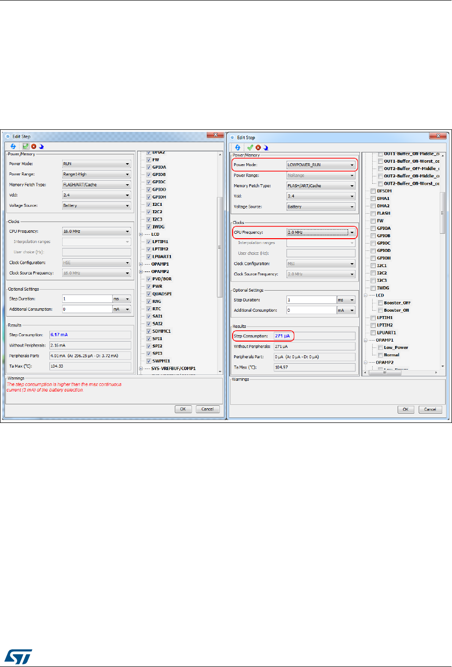
UM1718 Rev 26 243/345
UM1718 Tutorial 3 - Using the Power Consumption Calculator to optimize the embedded applica-
344
Step 5 (Run, ADC, DMA, RTC)
Actions
– Change to Low-power run mode.
– Lower the operating frequency.
Results
The current consumption is reduced from 6.17 mA to 271 µA (see Figure 228).
Figure 228. Step 5 optimization
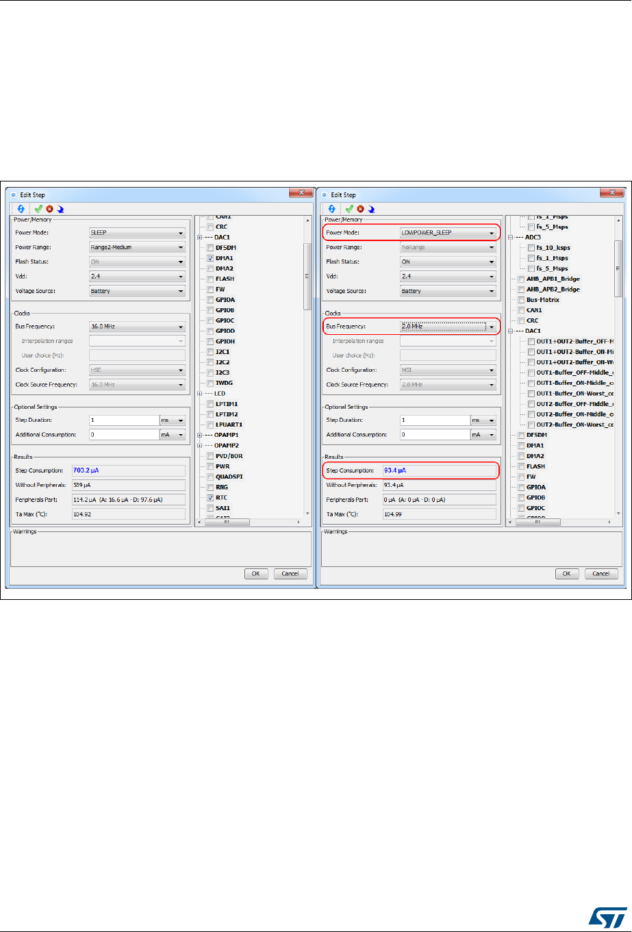
Tutorial 3 - Using the Power Consumption Calculator to optimize the embedded application con-
244/345 UM1718 Rev 26
Step 6 (Sleep, DMA, ADC,RTC)
Actions
– Switch to Lower-power sleep mode (BAM mode)
– Reduce the operating frequency to 2 MHz.
Results
The current consumption is reduced from 703 µA to 93 µA (see Figure 229).
Figure 229. Step 6 optimization
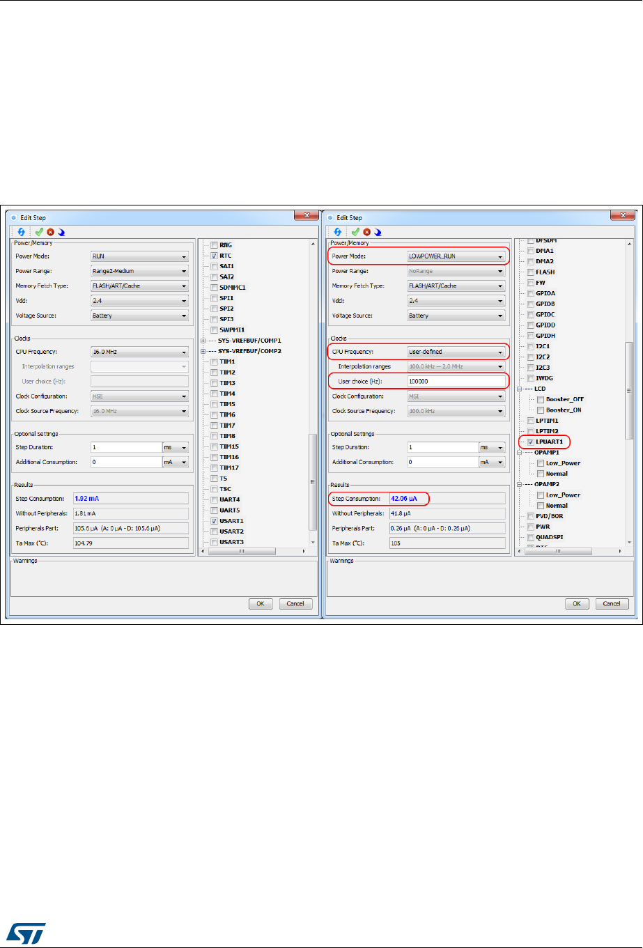
UM1718 Rev 26 245/345
UM1718 Tutorial 3 - Using the Power Consumption Calculator to optimize the embedded applica-
344
Step 7 (Run, DMA, RTC, USART)
Actions
– Switch to Lower-power run mode.
– Use the power-efficient LPUART peripheral.
– Reduce the operating frequency to 1 MHz using the interpolation feature.
Results
The current consumption is reduced from 1.92 µA to 42 µA (see Figure 230).
Figure 230. Step 7 optimization

Tutorial 3 - Using the Power Consumption Calculator to optimize the embedded application con-
246/345 UM1718 Rev 26
Step 8 (Stop 0, USART)
Actions:
– Switch to Stop1 low-power mode.
– Use the power-efficient LPUART peripheral.
Results
The current consumption is reduced from 110 µA to 6.65 µA (see Figure 231).
Figure 231. Step 8 optimization

UM1718 Rev 26 247/345
UM1718 Tutorial 3 - Using the Power Consumption Calculator to optimize the embedded applica-
344
Step 10 (RTC, USART)
Actions
– Use the power-efficient LPUART peripheral.
– Reduce the operating frequency to 1 MHz.
Results
The current consumption is reduced from 1.89 mA to 234 µA (see Figure 232).
The example given in Figure 233 shows an average current consumption reduction of
155 µA.
Figure 232. Step 10 optimization
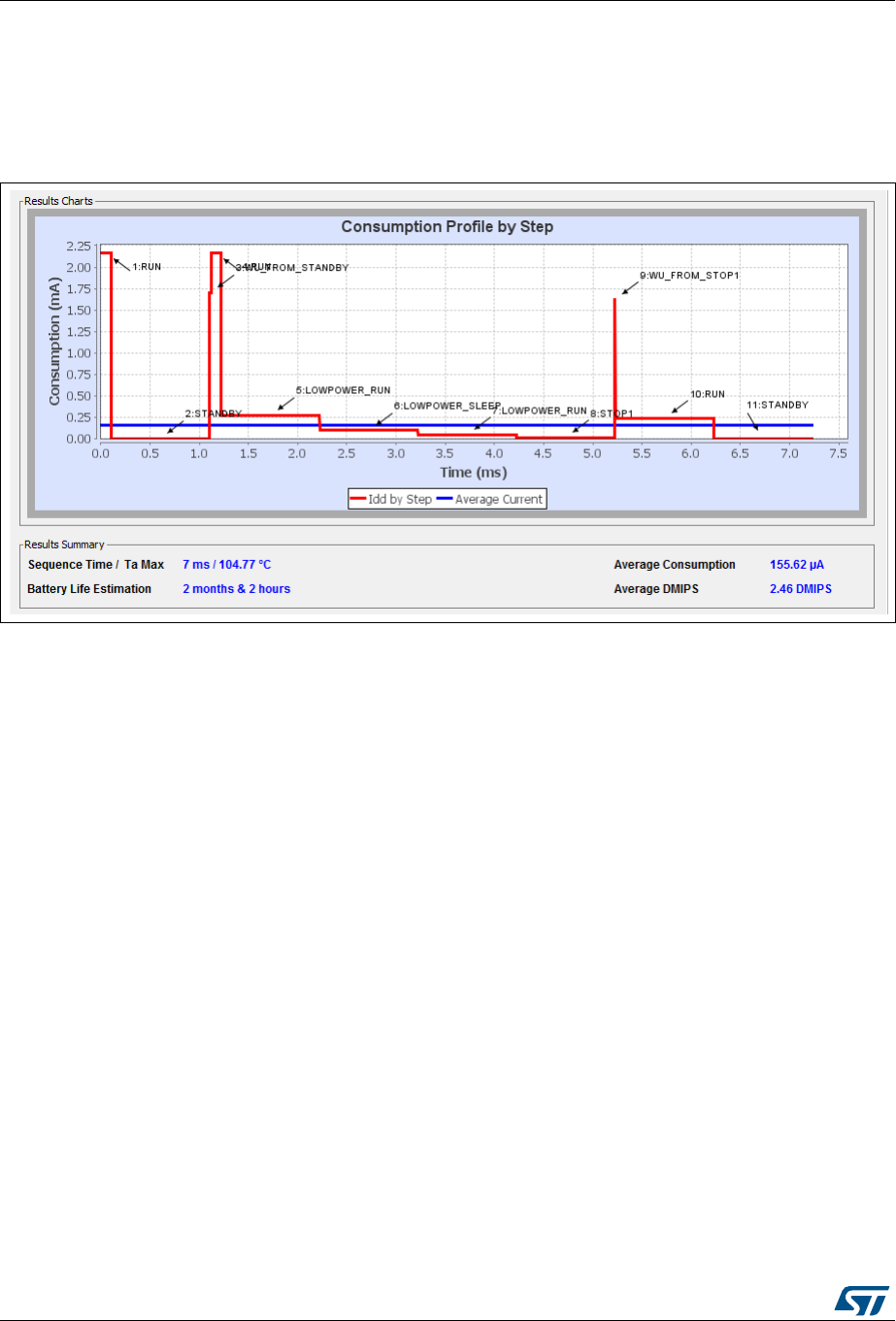
Tutorial 3 - Using the Power Consumption Calculator to optimize the embedded application con-
248/345 UM1718 Rev 26
See Figure 233 for the sequence overall results: 7 ms duration, about 2 month battery life,
and an average current consumption of 165.25 µA.
Use the compare button to compare the current results to the original ones saved as
SequenceOne.pcs.
Figure 233. Power sequence results after optimizations

UM1718 Rev 26 249/345
UM1718 Tutorial 4 - Example of UART communications with a STM32L053xx Nucleo board
344
11 Tutorial 4 - Example of UART communications with
a STM32L053xx Nucleo board
This tutorial aims at demonstrating how to use STM32CubeMX to create a UART serial
communication application for a NUCLEO-L053R8 board.
A Windows PC is required for the example. The ST-Link USB connector is used both for
serial data communications, and firmware downloading and debugging on the MCU. A
Type-A to mini-B USB cable must be connected between the board and the computer. The
USART2 peripheral uses PA2 and PA3 pins, which are wired to the ST-Link connector. In
addition, USART2 is selected to communicate with the PC via the ST-Link Virtual COM Port.
A serial communication client, such as Tera Term, needs to be installed on the PC to display
the messages received from the board over the virtual communication Port.
11.1 Tutorial overview
Tutorial 4 will take you through the following steps:
1. Selection of the NUCLEO-L053R8 board from the New Project menu.
2. Selection of the required features (debug, USART, timer) from the Pinout view:
peripheral operating modes as well as assignment of relevant signals on pins.
3. Configuration of the MCU clock tree from the Clock Configuration view.
4. Configuration of the peripheral parameters from the Configuration view
5. Configuration of the project settings in the Project Settings menu and generation of
the project (initialization code only).
6. Project update with the user application code corresponding to the UART
communication example.
7. Compilation, and execution of the project on the board.
8. Configuration of Tera Term software as serial communication client on the PC.
9. The results are displayed on the PC.
11.2 Creating a new STM32CubeMX project and
selecting the Nucleo board
To do this, follow the sequence below:
1. Select File > New project from the main menu bar. This opens the New Project
window.
2. Go to the Board selector tab and filter on STM32L0 Series.
3. Select NUCLEO-L053R8 and click OK to load the board within the STM32CubeMX
user interface (see Figure 234).


UM1718 Rev 26 253/345
UM1718 Tutorial 4 - Example of UART communications with a STM32L053xx Nucleo board
344
3. Select the Asynchronous mode for the USART2 peripheral (see Figure 237).
Figure 237. Selecting asynchronous mode for USART2
4. Check that the signals are properly assigned on pins (see Figure 238):
– SYS_SWDIO on PA13
– TCK on PA14
– USART_TX on PA2
– USART_RX on PA3
Figure 238. Checking pin assignment
Tutorial 4 - Example of UART communications with a STM32L053xx Nucleo board UM1718
254/345 UM1718 Rev 26
11.4 Configuring the MCU clock tree from the Clock Configuration
view
1. Go to the Clock Configuration tab and leave the configuration untouched, in order to
use the MSI as input clock and an HCLK of 2.097 MHz (see Figure 239).
Figure 239. Configuring the MCU clock tree
UM1718 Rev 26 255/345
UM1718 Tutorial 4 - Example of UART communications with a STM32L053xx Nucleo board
344
11.5 Configuring the peripheral parameters from the
Configuration view
1. From the Configuration tab, click USART2 to open the peripheral Parameter
Settings window and set the baud rate to 9600. Make sure the Data direction is set to
“Receive and Transmit” (see Figure 240).
2. Click OK to apply the changes and close the window.
Figure 240. Configuring USART2 parameters


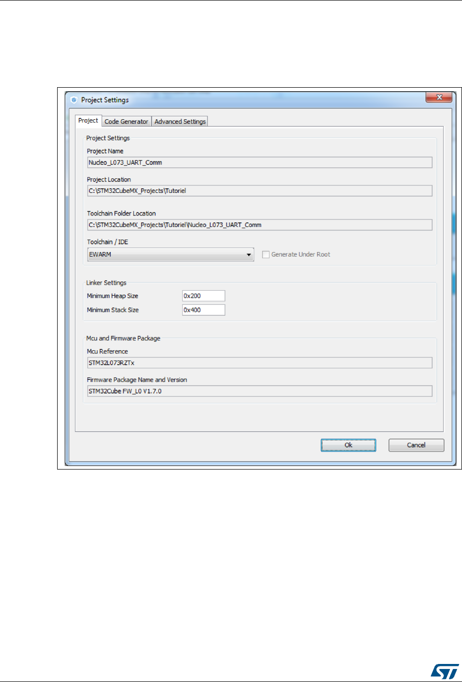
Tutorial 4 - Example of UART communications with a STM32L053xx Nucleo board UM1718
258/345 UM1718 Rev 26
11.6 Configuring the project settings and generating the project
1. In the Project Settings menu, specify the project name, destination folder, and select
the EWARM IDE toolchain (see Figure 243).
Figure 243. Project Settings menu
If the firmware package version is not already available on the user PC, a progress
window opens to show the firmware package download progress.
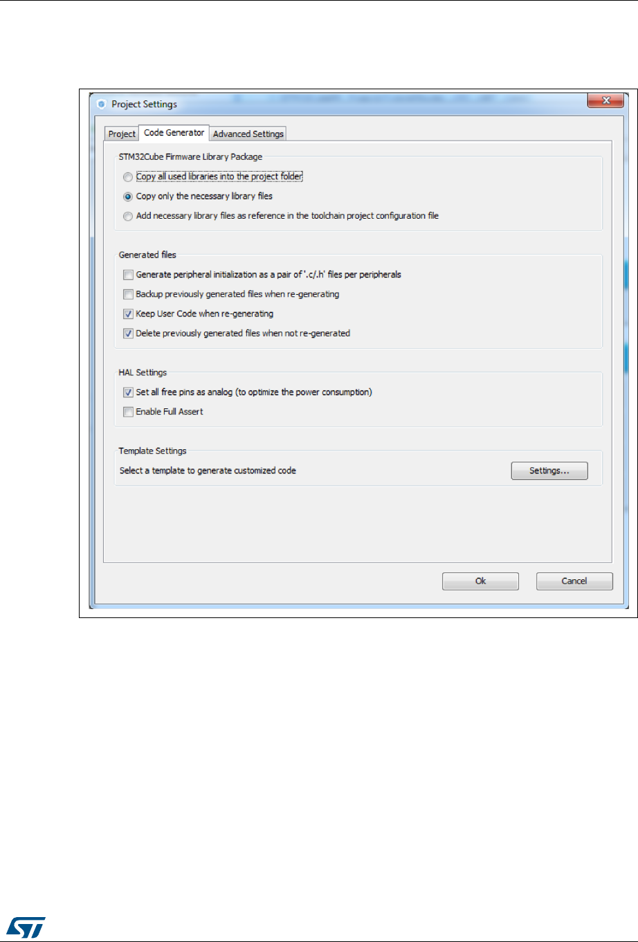
UM1718 Rev 26 259/345
UM1718 Tutorial 4 - Example of UART communications with a STM32L053xx Nucleo board
344
2. In the Code Generator tab, configure the code to be generated as shown in
Figure 244, and click OK to generate the code.
Figure 244. Generating the code
11.7 Updating the project with the user application code
Add the user code as follows:
/* USER CODE BEGIN 0 */
#include "stdio.h"
#include "string.h"
/* Buffer used for transmission and number of transmissions */
char aTxBuffer[1024];
int nbtime=1;
/* USER CODE END 0 */
Within the main function, start the timer event generation function as follows:
/* USER CODE BEGIN 2 */
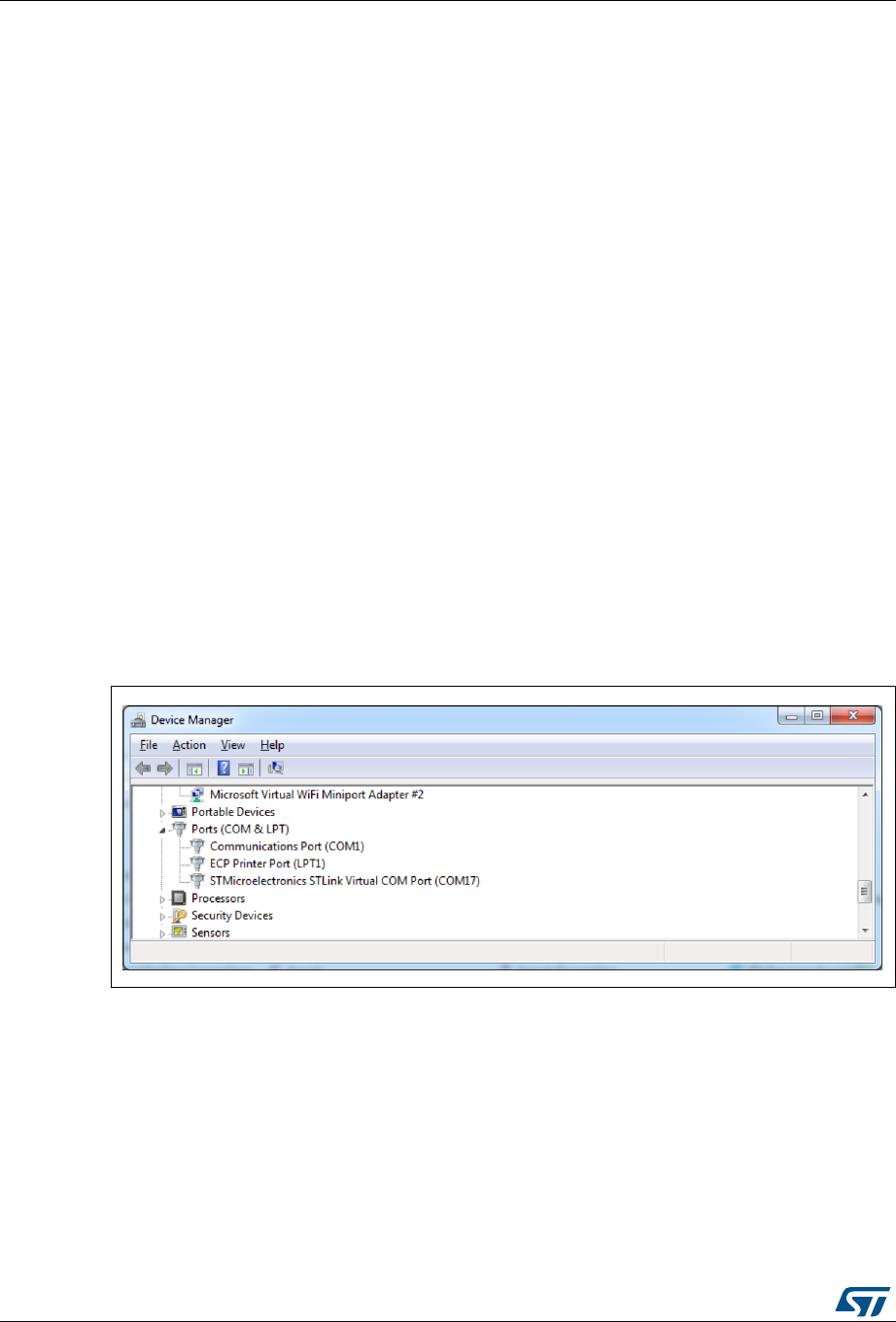
Tutorial 4 - Example of UART communications with a STM32L053xx Nucleo board UM1718
260/345 UM1718 Rev 26
/* Start Timer event generation */
HAL_TIM_Base_Start_IT(&htim2);
/* USER CODE END 2 */
/* USER CODE BEGIN 4 */
void HAL_TIM_PeriodElapsedCallback(TIM_HandleTypeDef *htim){
sprintf(aTxBuffer,"STM32CubeMX rocks %d times \t", ++nbtime);
HAL_UART_Transmit(&huart2,(uint8_t *) aTxBuffer, strlen(aTxBuffer), 5000);
}
/* USER CODE END 4 */
11.8 Compiling and running the project
1. Compile the project within your favorite IDE.
2. Download it to the board.
3. Run the program.
11.9 Configuring Tera Term software as serial communication
client on the PC
1. On the computer, check the virtual communication port used by ST Microelectronics
from the Device Manager window (see Figure 245).
Figure 245. Checking the communication port
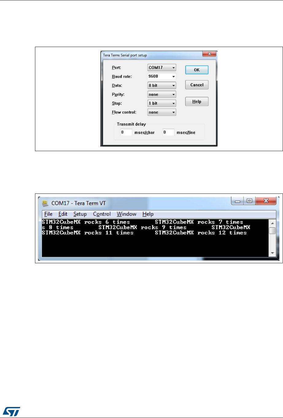
UM1718 Rev 26 261/345
UM1718 Tutorial 4 - Example of UART communications with a STM32L053xx Nucleo board
344
2. To configure Tera Term to listen to the relevant virtual communication port, adjust the
parameters to match the USART2 parameter configuration on the MCU (see
Figure 246).
Figure 246. Setting Tera Term port parameters
3. The Tera Term window displays a message coming from the board at a period of a few
seconds (see Figure 247).
Figure 247. Setting Tera Term port parameters
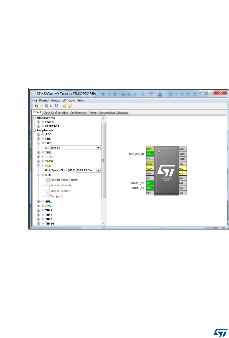
Tutorial 5: Exporting current project configuration to a compatible MCU UM1718
262/345 UM1718 Rev 26
12 Tutorial 5: Exporting current project configuration to
a compatible MCU
When List pinout compatible MCUs is selected from the Pinout menu, STM32CubeMX
retrieves the list of the MCUs which are compatible with the current project configuration,
and offers to export the current configuration to the newly selected compatible MCU.
This tutorial shows how to display the list of compatible MCUs and export your current
project configuration to a compatible MCU:
1. Load an existing project, or create and save a new project:
Figure 248. Existing or new project pinout
2. Go to the Pinout menu and select List Pinout Compatible MCUs. The Pinout
compatible window pops up (see Figure 249 and Figure 250).
If needed, modify the search criteria and the filter options and restart the search
process by clicking the Search button.
The row color shading and the Comments column indicate the level of matching:
– Bright green indicates an exact match: the MCU is fully compatible with the current
project (see Figure 250 for an example).
– Light green indicates a partial match with hardware compatibility: the hardware
compatibility can be ensured but some pin names could not be preserved. Hover
the mouse over the desired MCU to display an explanatory tooltip (see Figure 249
for an example).
UM1718 Rev 26 263/345
UM1718 Tutorial 5: Exporting current project configuration to a compatible MCU
344
– Yellow indicates a partial match without hardware compatibility: not all signals can
be assigned to the exact same pin location and a remapping will be required.
Hover the mouse over the desired MCU to display an explanatory tooltip (see
Figure 250 for an example).
Figure 249. List of pinout compatible MCUs - Partial match
with hardware compatibility
Figure 250. List of Pinout compatible MCUs - Exact and partial match
Tutorial 5: Exporting current project configuration to a compatible MCU UM1718
264/345 UM1718 Rev 26
3. Then, select an MCU to import the current configuration to, and click OK, Import:
Figure 251. Selecting a compatible MCU and importing the configuration
The configuration is now available for the selected MCU:
UM1718 Rev 26 265/345
UM1718 Tutorial 5: Exporting current project configuration to a compatible MCU
344
Figure 252. Configuration imported to the selected compatible MCU
4. To see the list of compatible MCUs at any time, select Outputs under the Window
menu.
To load the current configuration to another compatible MCU, double-click the list of
compatible MCUs.
5. To remove some constraints on the search criteria, several solutions are possible:
– Select the Ignore Pinning Status checkbox to ignore pin status (locked pins).
– Select the Ignore Power Pins checkbox not to take into account the power pins.
– Select the Ignore System Pins not take into account the system pins. Hover the
mouse over the checkbox to display a tooltip that lists the system pins available on
the current MCU.

Tutorial 6 – Adding embedded software packs to user projects UM1718
266/345 UM1718 Rev 26
13 Tutorial 6 – Adding embedded software packs to user
projects
In this tutorial, the Oryx-Embedded.Middleware.1.7.8. pack is taken as an example to
demonstrate how to a to add pack software components to STM32CubeMX projects. The
use of this package shall not be understood as an STMicroelectronics recommendation.
To add embedded software packs to your project, proceed as follows:
1. Install Oryx-Embedded.Middleware.1.7.8.pack using the .pdsc file available from
http://www.oryx-embedded.com (see Section 4.5.4: Installing embedded software
packs).
2. Select New project.
3. Select STM32F01CCFx from the MCU selector.
4. Select Add Pack software components menu to open the additional software
component window and choose the following software components: Compiler Support,
RTOS Port/None and Date Time Helper Routines from the CycloneCommon bundle
(see Section 5.10: Additional software component selection window).
5. Click OK to display the selected components on the tree view and click the checkbox to
enable the software components for the current project (see Figure 253).
Figure 253. Additional software components enabled for the current project
The pack name highlighted in green indicates that all conditions for the selected
software components resolve to true. If at least one condition is not resolved, the pack
name is highlighted in orange.
6. The current software component selection can also be kept for next projects:
a) Right-click the pack name and select Add pack into preferred pack list. It can be
removed later by clicking Remove pack from preferred pack list (see
Figure 254).
This way, the next time a project is created, the packs that correspond to a given
selection of software components will be automatically proposed under
Additional software.
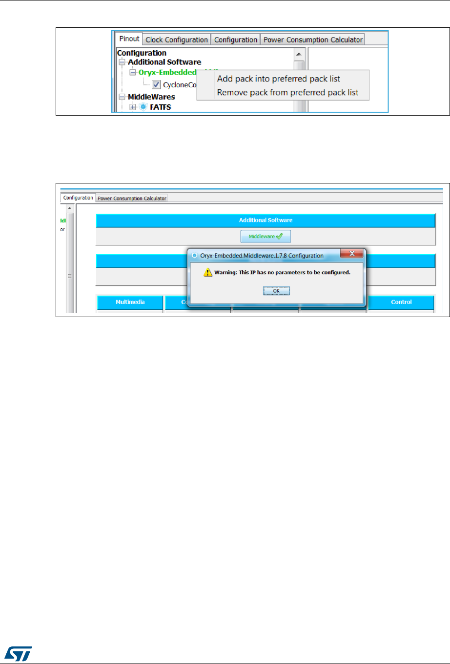
UM1718 Rev 26 267/345
UM1718 Tutorial 6 – Adding embedded software packs to user projects
344
Figure 254. Saving software component selection as user preferences
7. Check that no parameters can be configured in the Configuration tab (see
Figure 255).
Figure 255. Pack software components - no configurable parameters
8. Select Project, then Project settings to specify project parameters (see Figure 256),
and choose IAR™ EWARM as IDE.
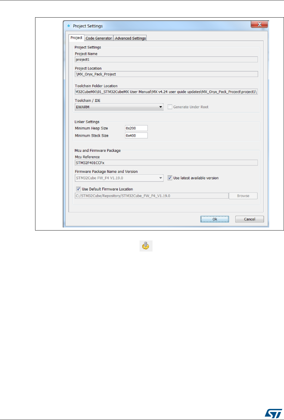
Tutorial 6 – Adding embedded software packs to user projects UM1718
268/345 UM1718 Rev 26
Figure 256. Pack tutorial - project settings
9. Generate your project by clicking . Accept to download the STM32CubeF4 MCU
package if it is not present in STM32Cube repository.
10. Click Open project. The Oryx software components are displayed n the generated
project (see Figure 257).

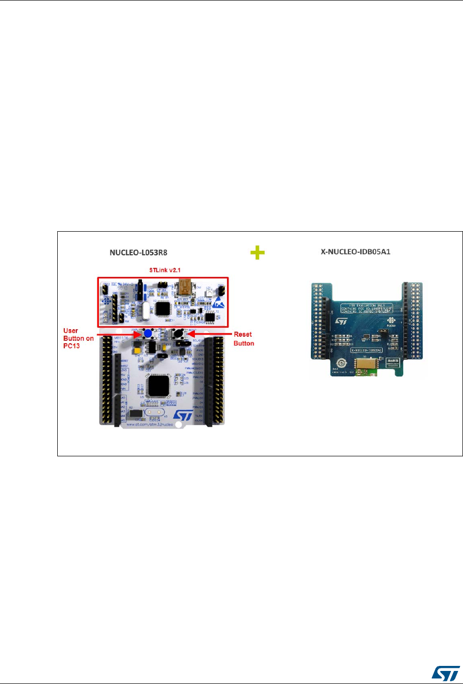
Tutorial 7 – Using the BlueNRG-MS software pack UM1718
270/345 UM1718 Rev 26
14 Tutorial 7 – Using the BlueNRG-MS software pack
This tutorial demonstrates how to achieve a functional project using the BlueNRG-MS
software pack.
Below the prerequisites to run this tutorial:
Hardware: NUCLEO-L053R8, X-NUCLEO-IDB05A1 and mini-USB cable (see
Figure 258)
Tools: STM32CubeMX, IDE (Atollic or any other toolchain supported by
STM32CubeMX)
Embedded software package: STM32CubeL0 (version 1.10.0 or higher), BlueNRG-MS
1.0.0 (see Figure 259).
Mobile application (see Figure 260): STMicroelectronics BlueNRG application for iOS
or Android
Figure 258. Hardware prerequisites

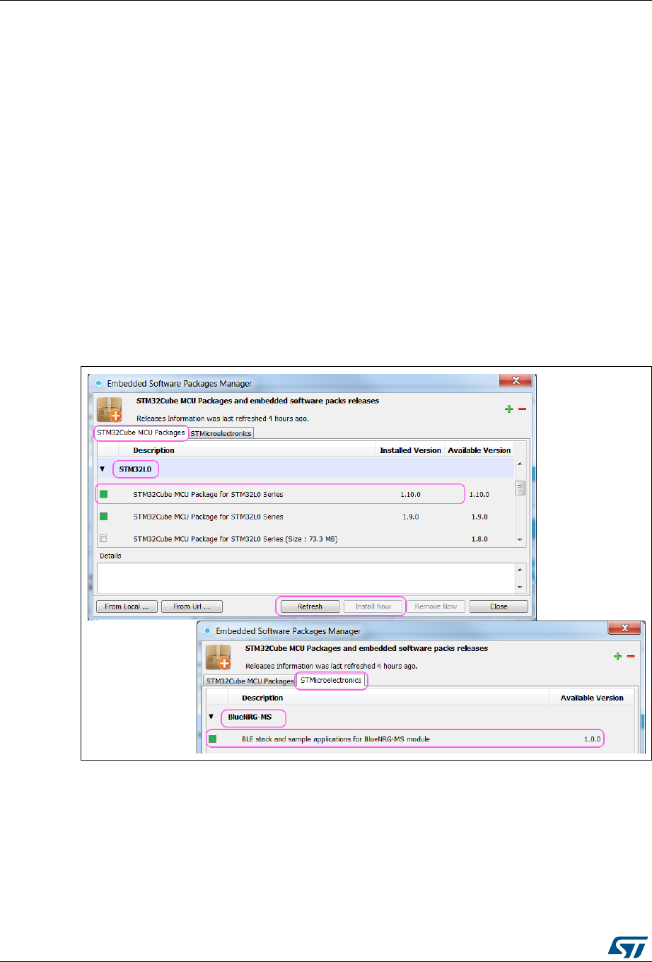
Tutorial 7 – Using the BlueNRG-MS software pack UM1718
272/345 UM1718 Rev 26
Proceed as follows to install and run the tutorial:
1. Check STM32CubeMX Internet connection:
a) Select the Help > Updater settings menu to open the updater window.
b) Verify in the Connection tab that the Internet connection is configured and up.
2. Install the required embedded software packages (see Figure 261):
a) Select the Help > Manage Embedded software packages menu to open the
embedded software package manager window.
b) Click the Refresh button to refresh the list with the latest available package
versions.
c) Select the STM32Cube MCU Package tab and check that the STM32CubeL0
firmware package version 1.10.0 or higher is installed (the checkbox must be
green). Otherwise select the checkbox and click Install now.
d) Select the STMicrolectronics tab and check that the BlueNRG-MS software pack
version 1.0.0 is installed (checkbox must be green). Otherwise, select the
checkbox and click Install now.
Figure 261. Installing Embedded software packages
3. Start a new project:
a) Select New Project to open the new project window.
b) Select the Board selector tab.
c) Select Nucleo64 as board type and STM32L0 as MCU Series.
d) Select the NUCLEO-L053R8 from the resulting board list (see Figure 262).
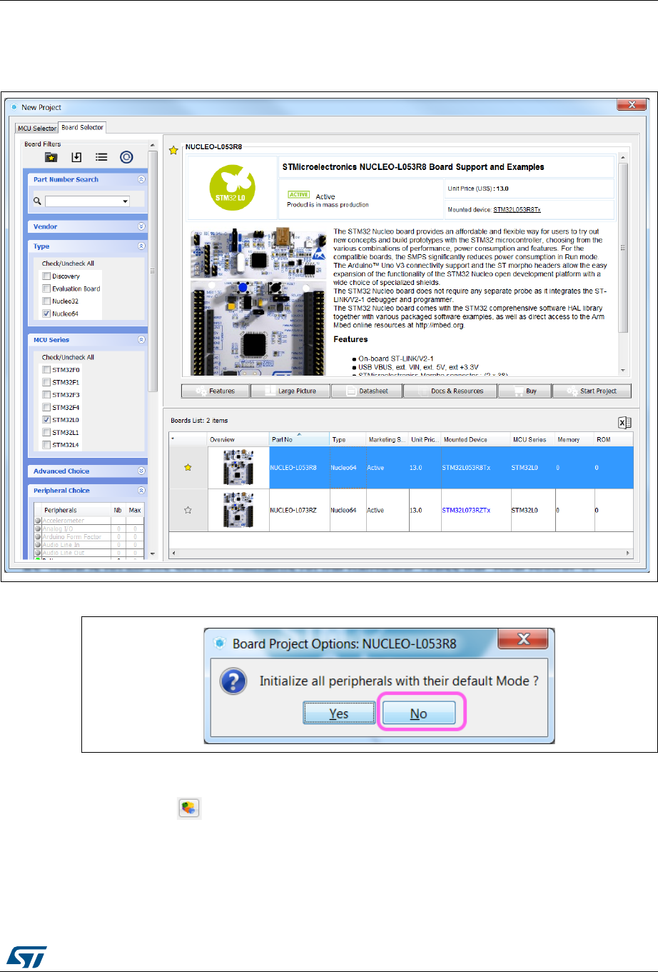
UM1718 Rev 26 273/345
UM1718 Tutorial 7 – Using the BlueNRG-MS software pack
344
e) Answer No when prompted to initialize all peripherals in their default mode (see
Figure 263).
Figure 262. Starting a new project - selecting the NUCLEO-L053R8 board
Figure 263. Starting a new project - initializing all peripherals
4. Add BlueNRG-MS components to the project:
a) Click to open the Additional Software component Selection window.
b) Select the relevant components (see Figure 264)
The Application group comes with a list of applications: the C files implement the
application loop, that is the MX_BlueNRG_MS_Process() function. From the
Application group, select the SensorDemo application.
Select the BlueNRG-MS Controller and Utils components
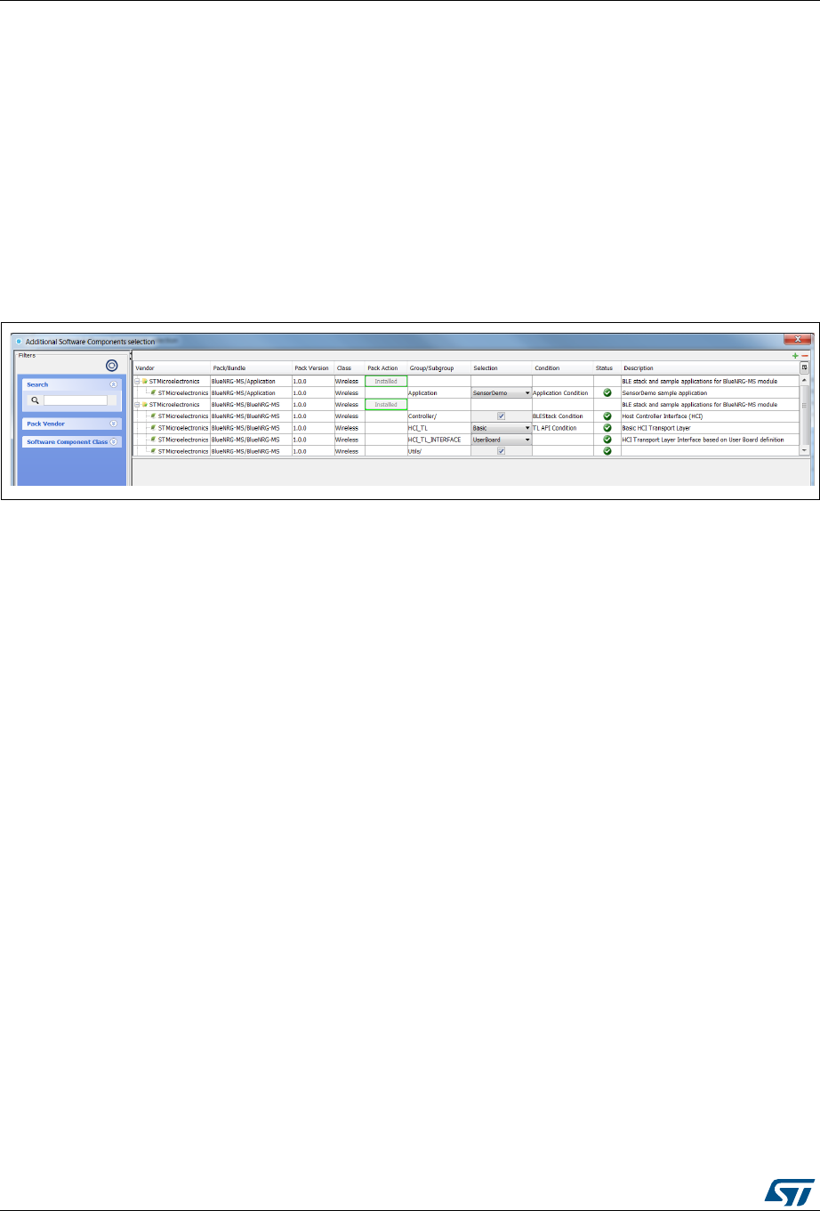
Tutorial 7 – Using the BlueNRG-MS software pack UM1718
274/345 UM1718 Rev 26
Select the Basic variant for the HCI_TL component. The Basic variant provides
the STMicroelectronics implementation of the HCI_TL API while the template
option requires the user to implement his own code.
Select the UserBoard variant as HCI_TL_INTERFACE component. Using the
UserBoard option generates the <boardname>_bus.c file, that is
nucleo_l053r8_bus.c for this tutorial, while the template option generates the
custom_bus.c file and requires the user to provide his own implementation.
Refer to the BlueNRG-MS pack documentation for more details on software
components.
c) Click OK to apply the selection to the project and close the window. The left panel
Additional Software section is updated accordingly.
Figure 264. Selecting BlueNRG-MS components
5. Enable peripherals and GPIOs from the Pinout tab (see Figure 265):
a) Configure USART2 in Asynchronous mode.
b) Configure SPI1 in Full-duplex master mode.
c) Left-click the following pins and configure them for the required GPIO settings:
PA0: GPIO_EXTI0
PA1: GPIO_Output
PA8: GPIO_Output
d) Enable Debug Serial Wire under SYS peripheral.
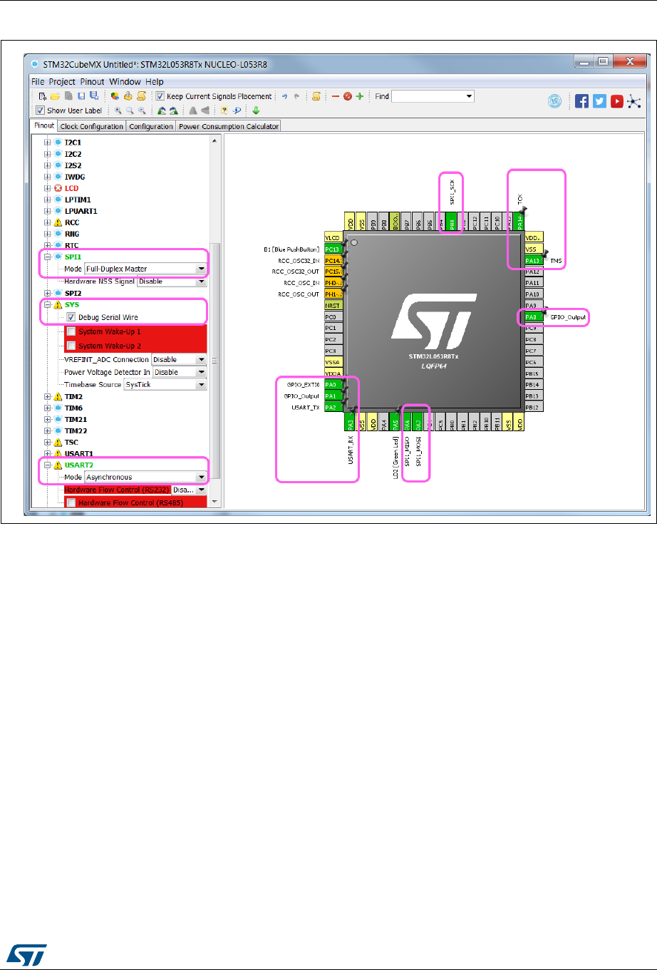
UM1718 Rev 26 275/345
UM1718 Tutorial 7 – Using the BlueNRG-MS software pack
344
Figure 265. Configuring peripherals and GPIOs
6. Configure the peripherals from the Configuration tab:
a) Click the NVIC button under the System section to open the NVIC configuration
window. Enable EXTI line 0 and line 1 interrupts and click OK (see Figure 266).
b) Click the SPI button under the Connectivity section to open the SPI
configuration window. Check that the data size is set to 8 bits and the prescaler
value to 16 so that HCLK divided by the prescaler value is less or equal to 8 MHz.
c) Click USART2 under the Connectivity section to open the Configuration window
and check the following parameter settings:
Under Parameter Settings:
Baud rate: 115200 bits/s
Word length: 8 bits (including parity)
Parity: none
Stop bits: 1
Under GPIO Settings:
User labels: USART_TX and USART_RX
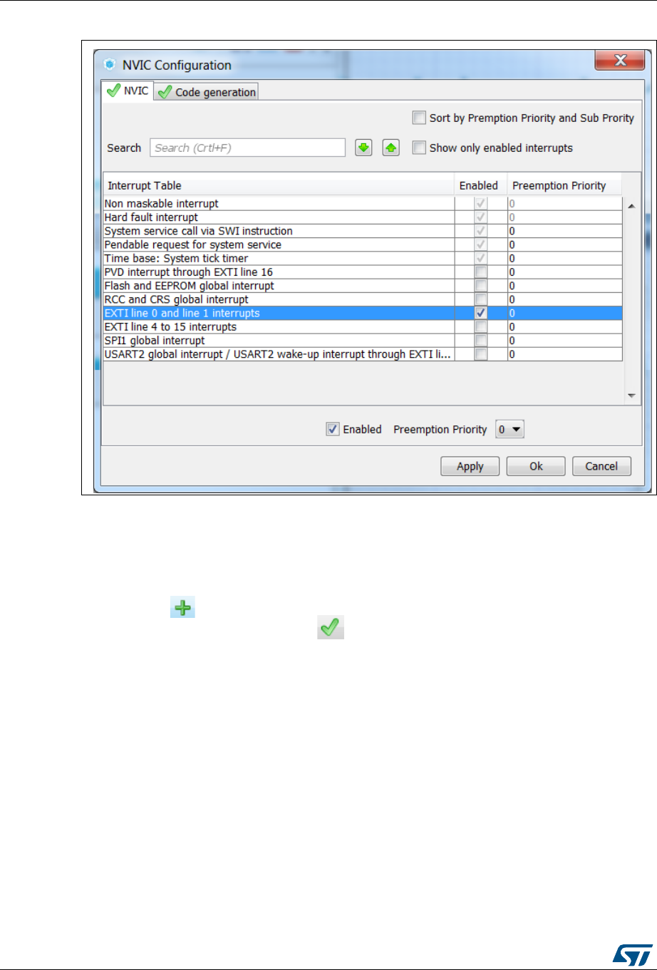
Tutorial 7 – Using the BlueNRG-MS software pack UM1718
276/345 UM1718 Rev 26
Figure 266. Configuring NVIC interrupts
7. Enable and Configure BlueNRG-MS components from the Configuration tab:
a) Click the check box from the tree view to enable BlueNRG-MS. The pack can then
be configured: a BlueNRG-MS button appears in the Additional Software Space
(see Figure 267).
The sign indicates that some parameter are not configured.
The button is marked with a once all parameters are correctly configured (see
Figure 267)
b) Click the BlueNRG-MS button to open the Configuration window.
c) Leave the Parameter Settings Tab unchanged.
d) Go the Platform settings tab:
Configure the connection with the hardware resources as follows (see Figure 268
and Table 22).
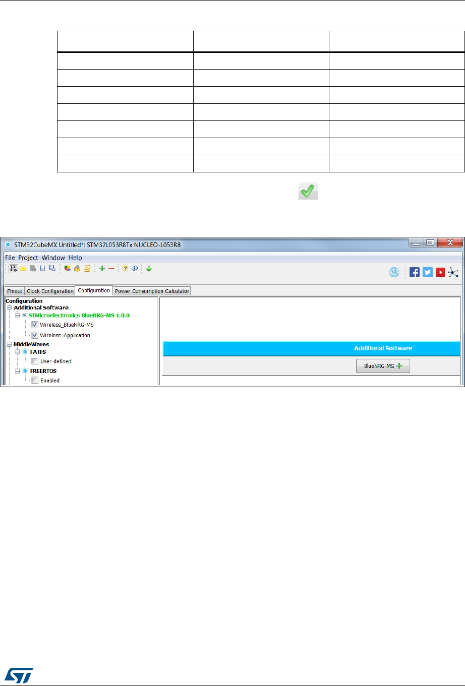
UM1718 Rev 26 277/345
UM1718 Tutorial 7 – Using the BlueNRG-MS software pack
344
Click Apply and check that the icon turns to . Click OK to close the
Configuration window.
Figure 267. Enabling BlueNRG-MS
Table 22. Connection with hardware resources
Name IPs or components Found solutions
BUS IO driver SPI in Full-duplex master mode SPI1
EXTI Line GPIO:EXTI PA0
CS Line GPIO:output PA1
Reset Line GPIO:output PA8
BSP LED GPIO:output PA5
BSP Button GPIO:EXTI PC13
BSP USART USART in Asynchronous mode USART2
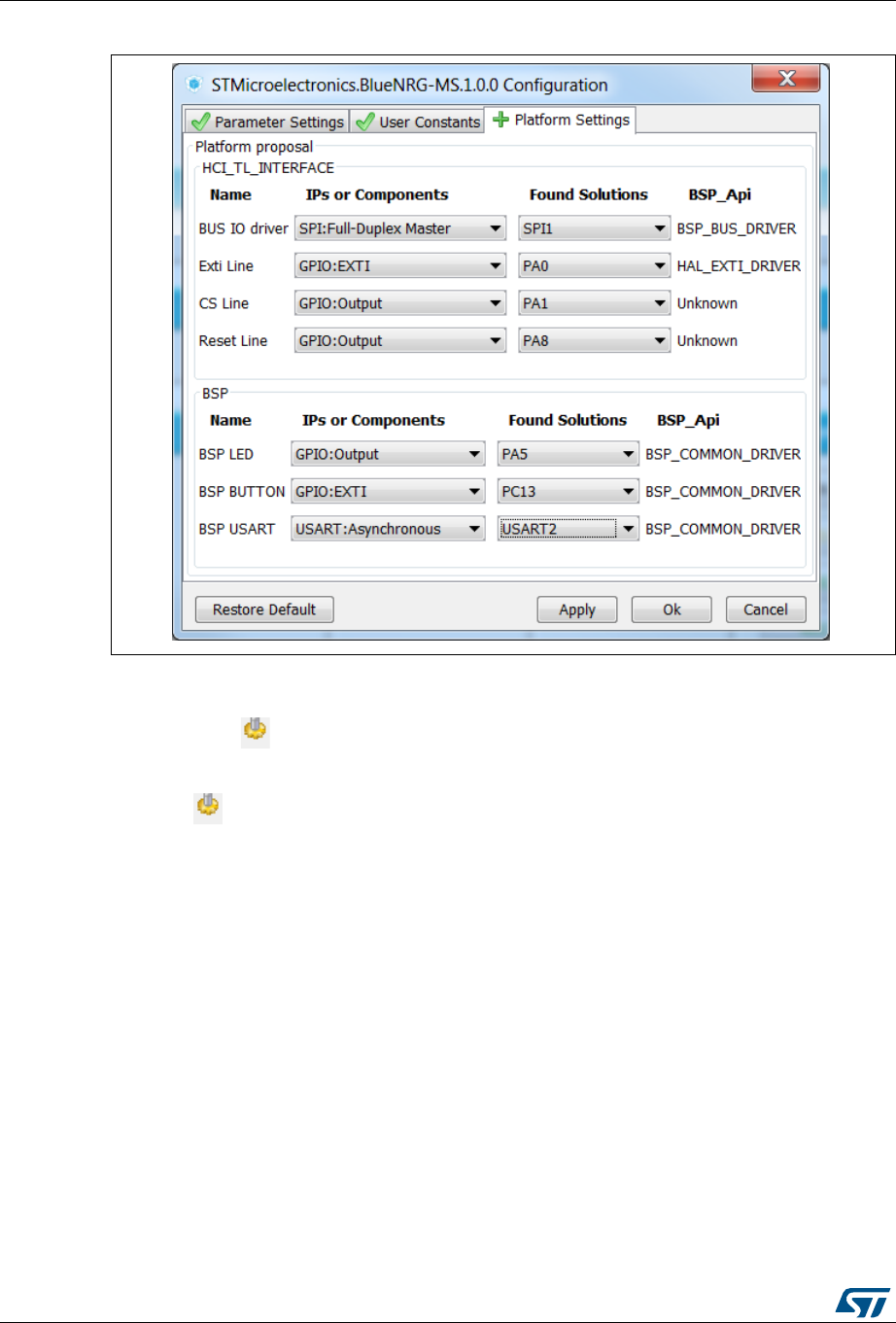
Tutorial 7 – Using the BlueNRG-MS software pack UM1718
278/345 UM1718 Rev 26
Figure 268. Configuring BlueNRG-MS
8. Generate the SensorDemo project:
a) Click to generate the code icon. The Project settings window opens if the
project has not yet been saved.
b) Once the project settings have been properly configured (see Figure 269), click
to generate the code icon. When the generation is complete, a dialog window
requests to open the project folder (Open Folder) or to open the project in IDE
toolchain (Open Project). Select Open Project (see Figure 270).
c) If .cproject files are associated to Atollic TrueStudio, TrueStudio is automatically
launched by clicking Open Project: from the TrueStudio launch window, create or
select an existing workspace (see Figure 271) and click OK. STM32CubeMX
generated project appears in the TrueStudio Project explorer panel (see
Figure 272)

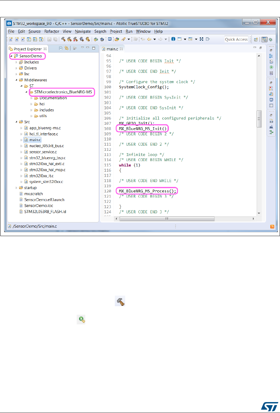
Tutorial 7 – Using the BlueNRG-MS software pack UM1718
280/345 UM1718 Rev 26
Figure 272. Viewing the SensorDemo project in AtollicTrueStudio
9. Build and Run the SensorDemo application from the Atollic TrueStudio:
a) Configure the project properties (see Figure 273)
From the Project explorer panel, right-click the project name (SensorDemo) and
select Properties to open the Properties window.
Select C/C++ Build and enable parallel build from the Behavior tab to speed the
build process up.
b) Click the build icon, , to build the project.
c) Connect your computer to the Nucleo board ST-link connector via the USB cable.
d) Click from the Run menu to run the project on the board.
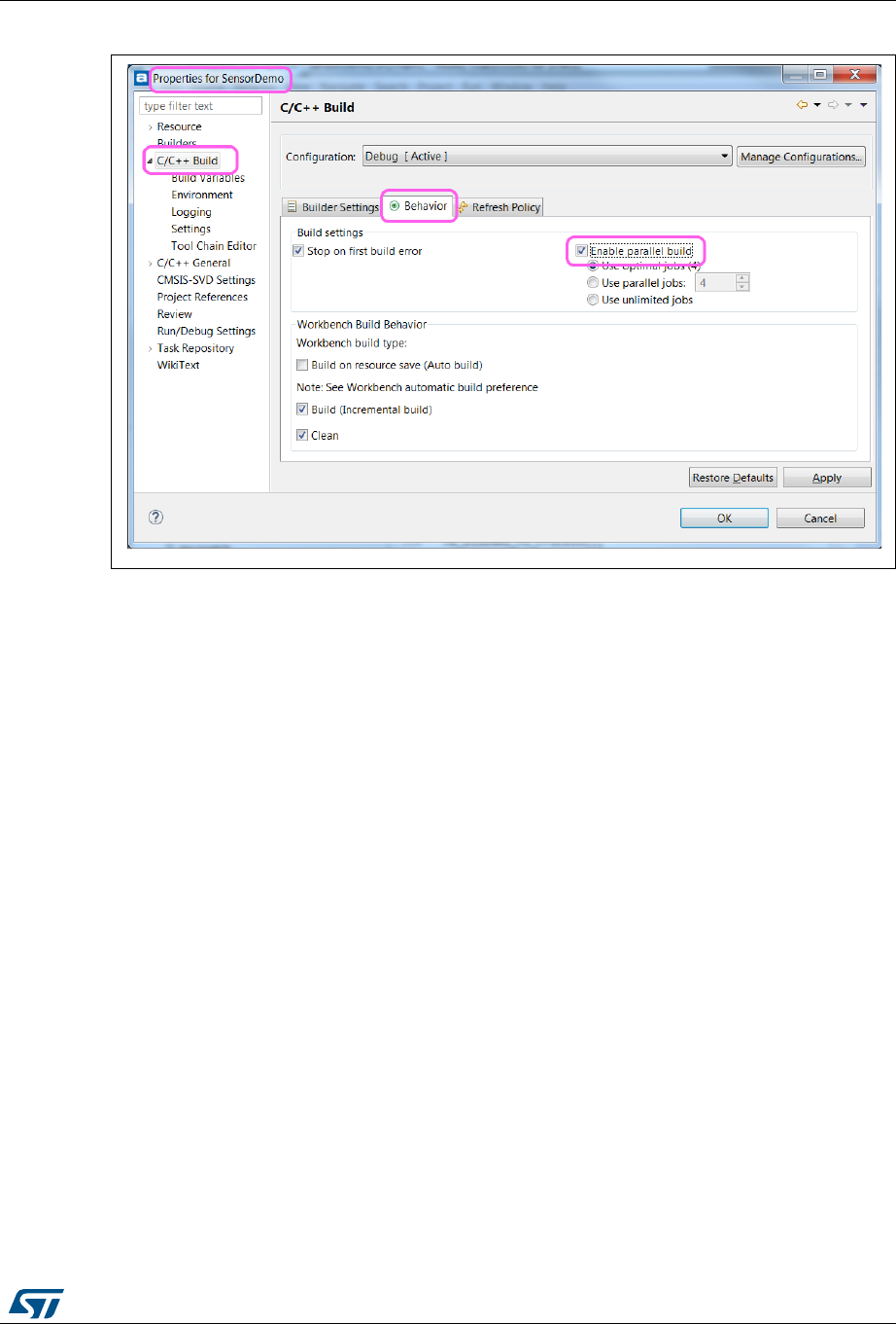
UM1718 Rev 26 281/345
UM1718 Tutorial 7 – Using the BlueNRG-MS software pack
344
Figure 273. Configuring the SensorDemo project in Atollic TrueStudio
10. Test the STM32 SensorDemo application by launching the BlueNRG application on the
phone:
e) Scan for nearby devices.
f) Select the BlueNRG device.
g) Since there is no MEMs sensing elements on the hardware, press the Blue
Button to simulate MEMs data: the ST cube rotates by a fixed value each time the
button is pressed (see Figure 274).


UM1718 Rev 26 283/345
UM1718 Tutorial 8 – Using STemWin Graphics framework
344
15 Tutorial 8 – Using STemWin Graphics framework
15.1 Step 1: Selecting an MCU for Graphics
First, Launch STM32CubeMX and click New Project to open the New Project window (see
Figure 275)
1. On the left panel, select the Enable checkbox under Graphics choice to display
Graphics related parameters, the Graphics summary panel and the list of suitable
MCUs.
2. Select the STM32F469NIHx from the MCUs list.
3. Click Start Project to open STM32CubeMX project main view.
Figure 275. Tutorial - Selecting an MCU for Graphics
15.2 Step 2: Enabling STemWin from the pinout view
To enable STemWin, the conflicts must be solved. Hover the mouse over the Graphics
framework selection field to display conflict details in tooltips (see Figure 276).
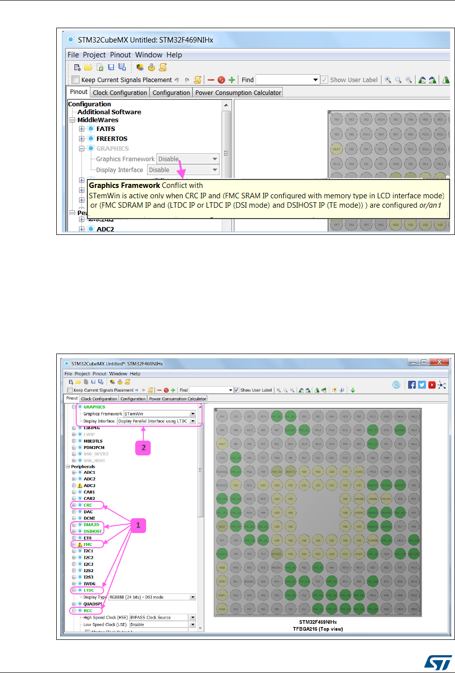
Tutorial 8 – Using STemWin Graphics framework UM1718
284/345 UM1718 Rev 26
Figure 276. Graphics frameworks tooltip
From the pinout view left panel (see Figure 277)
1. Enable the necessary peripherals: CRC, DMA2D (optional, for Graphics acceleration),
FMC SDRAM mode, RCC HSE, LTDC in DSI mode and DSI Host in Adapted
Command Mode with TE pin (for connection with Display interface). Under Graphics,
STemWin framework is now available for selection.
2. Select STemWin as the Graphics framework and Display Parallel interface using
LTDC as the Display Interface.
Figure 277. Enabling STemWin framework

UM1718 Rev 26 285/345
UM1718 Tutorial 8 – Using STemWin Graphics framework
344
15.3 Step 3: Configuring STemWin parameters from the
configuration window
1. Select the configuration view and click the GRAPHICS button to show STemWin
graphics framework configuration (see Figure 278)
2. Use the Parameter Settings panel to adjust Graphics parameters: under External Tools
group, enable the use of GUIBuilder tool before proceeding with next step.
Figure 278. STemWin Graphics framework configuration window
15.4 Step 4: Using STemWin GUIBuilder tool from the
configuration window
1. Make sure the use of GUIBuilder tool is enabled on the parameter settings panel.
2. Select the STemWin panel and configure the Application Category to be either Window
or WindowFrame (see Figure 279)
3. Click Execute to open the GUIBuilder user interface (see Figure 280).
Note: The project settings window pops-up when the project settings are not specified.
TrueStudio®, Makefile and other (GPDSC) toolchains are not supported with STemWin and
are grayed out in the user interface.
Note: The STM32CubeF4 embedded software package will be downloaded (if not available) in the
user’s STM32Cube repository when STM32CubeMX launches the GUIBuilder executable
file from this package.
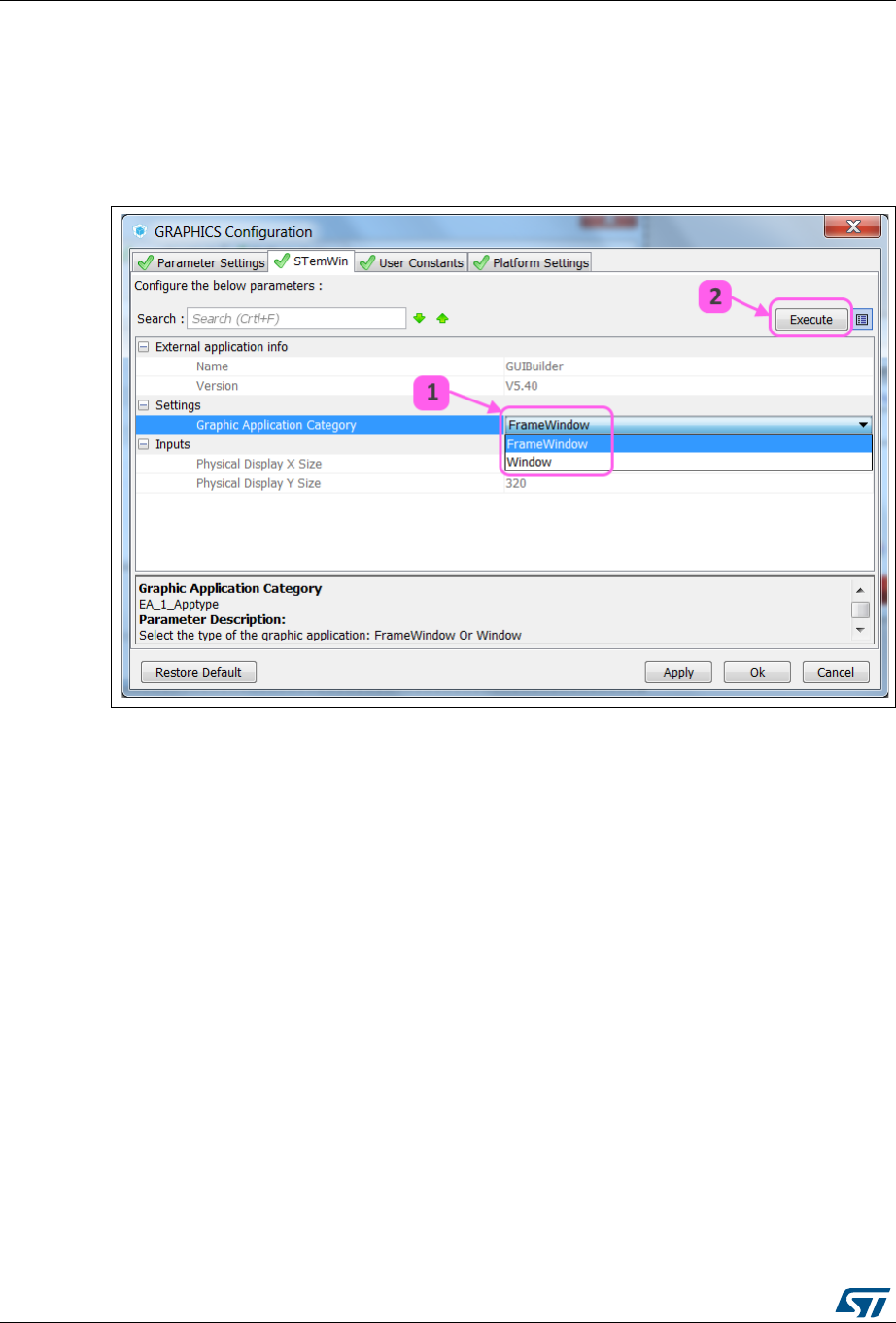
Tutorial 8 – Using STemWin Graphics framework UM1718
286/345 UM1718 Rev 26
Note: STM32CubeMX user interface is not accessible when the GUIBuilder tool is open.
4. Complete the GUI design work using GUIBuilder user interface and click File > Save to
generate the corresponding C file, respectively WindowDLG.c for Window type,
FramewinDLG.c for WindowFrame type.
5. Close GUIBuilder to return to STM32CubeMX user interface.
Figure 279. STemWin GUIBuilder configuration panel
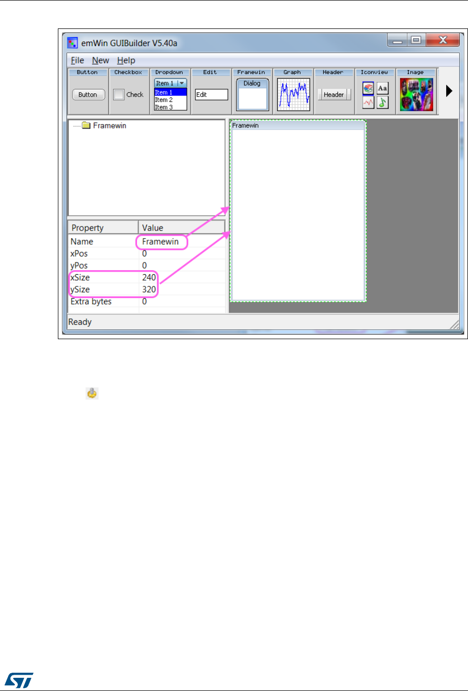
UM1718 Rev 26 287/345
UM1718 Tutorial 8 – Using STemWin Graphics framework
344
Figure 280. STemWin GUIBuilder
15.5 Step 5: Generating the embedded C project and updates
Click to generate the project (see Figure 281).
Application main files are generated under Core/Inc and Src folders.
STemWin library configuration files are generated under STemWin/App folder.
Hardware initialization and wrapper files under STemWin/Target folder.
Update the generated code by placing user code in dedicated sections, i.e. between //USER
START and //USER END tags.

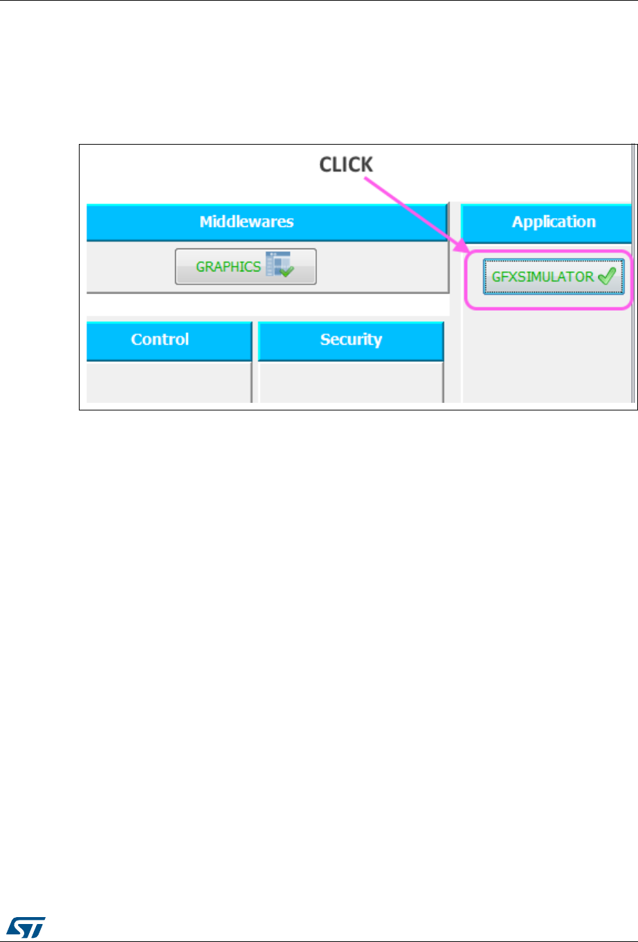
UM1718 Rev 26 289/345
UM1718 Tutorial 9: Using STM32CubeMX Graphics simulator
344
16 Tutorial 9: Using STM32CubeMX Graphics simulator
Click GFXSIMULATOR from the configuration view to open the Graphics simulator user
interface (see Figure 282).
Figure 282. GFXSIMULATOR in Configuration view
1. Check in the top panel the Simulator’s current working assumptions and the mandatory
configuration settings, e.g. if LTDC is not enabled, some results will show as NA (not
available). See Figure 283.
2. Adjust the simulator parameter values from the left center panel, compare to current
configuration settings in the right panel (see Figure 284).
3. Check in the bottom panel the results for a set of supported use cases.
4. Optionally, click Import Settings to update current project configuration with simulator
settings to reach same performance results.
– A confirmation message pops up.
– When relevant, a warning message pops up with the settings that could not be
imported (unused peripherals, out of range clock frequency value,...).
5. Close the Graphics simulator window to go back to STM32CubeMX configuration view.


FAQ UM1718
292/345 UM1718 Rev 26
17 FAQ
17.1 On the Pinout configuration panel, why does STM32CubeMX
move some functions when I add a new peripheral mode?
You may have deselected . In this case, the tool performs an
automatic remapping to optimize your placement.
17.2 How can I manually force a function remapping?
Use the Manual Remapping feature.
17.3 Why are some pins highlighted in yellow or in light green in
the Chip view? Why cannot I change the function of some
pins (when I click some pins, nothing happens)?
These pins are specific pins (such as power supply or BOOT) which are not available as
peripheral signals.
17.4 Why do I get the error “Java 7 update 45” when installing
“Java 7 update 45” or a more recent version of the JRE?
The problem generally occurs on 64-bit Windows operating system, when several versions
of Java™ are installed on your computer and the 64-bit Java™ installation is too old.
During STM32CubeMX installation, the computer searches for a 64-bit installation of
Java™.
If one is found, the ‘Java 7 update 45’ minimum version prerequisite is checked. If the
installed version is older, an error is displayed to request the upgrade.
If no 64-bit installation is found, STM32CubeMX searches for a 32-bit installation. If one
is found and the version is too old, the ‘Java 7 update 45’ error is displayed. The user
must update the installation to solve the issue.
To avoid this issue from occurring, it is recommended to perform one of the following
actions:
1. Remove all Java™ installations and reinstall only one version (32 or 64 bits) (Java 7
update 45 or more recent).
2. Keep 32-bit and 64-bit installations but make sure that the 64-bit version is at least
Java 7 update 45.
Note: Some users (Java developers for example) may need to check the PC environment
variables defining hard-coded Java paths (e.g. JAVA_HOME or PATH) and update them so
that they point to the latest Java installation.
On Windows 7 you can check the Java installation using the Control Panel. To do this,
double-click the icon from Control Panel\All Control Panel to open the Java™
settings window (see Figure 285).
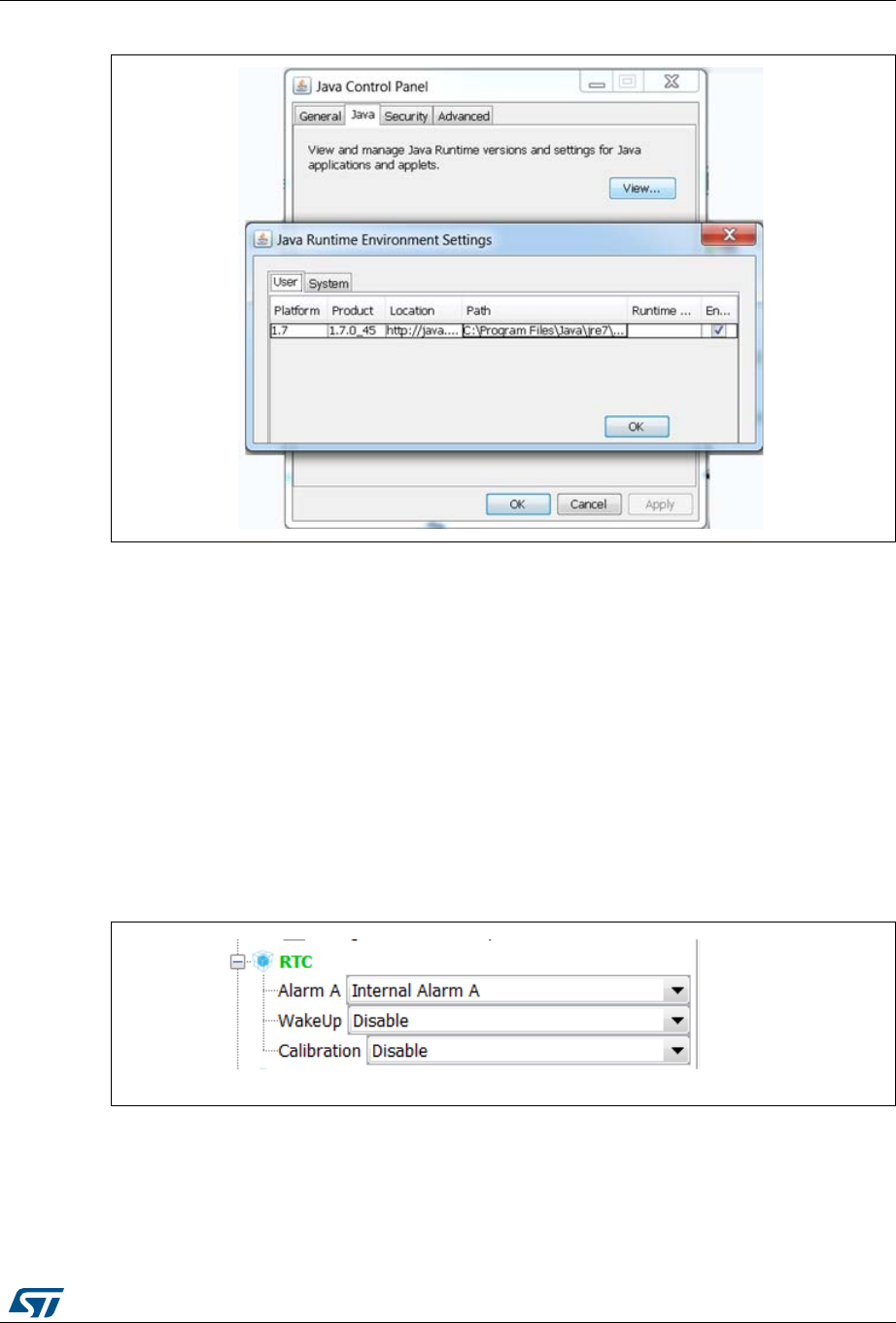
UM1718 Rev 26 293/345
UM1718 FAQ
344
Figure 285. Java™ Control Panel
You can also enter ‘java –version’ as an MS-DOS command to check the version of your
latest Java installation (the Java program called here is a copy of the program installed
under C:\Windows\System32):
java version “1.7.0_45“
Java (TM) SE Runtime Environment (build 1.7.0_45-b18)
Java HotSpot (TM) 64-Bit Server VM (build 24.45-b08, mixed mode)
17.5 Why does the RTC multiplexer remain inactive on the Clock
tree view?
To enable the RTC multiplexer, the user shall enable the RTC peripheral in the Pinout view
as indicated below.
Figure 286. Pinout view - Enabling the RTC
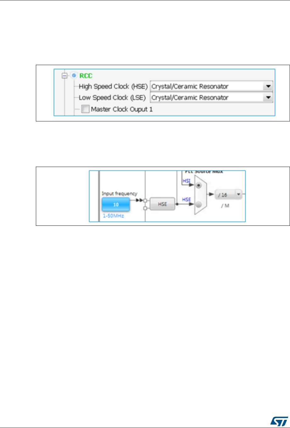
FAQ UM1718
294/345 UM1718 Rev 26
17.6 How can I select LSE and HSE as clock source and
change the frequency?
The LSE and HSE clocks become active once the RCC is configured as such in the Pinout
view. See Figure 287 for an example.
Figure 287. Pinout view - Enabling LSE and HSE clocks
The clock source frequency can then be edited and the external source selected, see
Figure 288.
Figure 288. Pinout view - Setting LSE/HSE clock frequency
17.7 Why STM32CubeMX does not allow me to configure PC13,
PC14, PC15 and PI8 as outputs when one of them
is already configured as an output?
STM32CubeMX implements the restriction documented in the reference manuals as a
footnote in table Output Voltage characteristics:
“PC13, PC14, PC15 and PI8 are supplied through the power switch. Since the switch only
sinks a limited amount of current (3 mA), the use of GPIOs PC13 to PC15 and PI8 in output
mode is limited: the speed should not exceed 2 MHz with a maximum load of 30 pF and
these I/Os must not be used as a current source (e.g. to drive a LED).”

UM1718 Rev 26 295/345
UM1718 FAQ
344
17.8 Ethernet Configuration: why cannot I specify DP83848
or LAN8742A in some cases?
For most Series, STM32CubeMX will adjust the list of possible PHY component drivers
according to the Ethernet mode that has been selected:
When the Ethernet MII mode is selected, the user will be able to choose between the
DP83848 component driver or a “User Phy”.
When the Ethernet RMII mode is selected, the user will be able to choose between the
LAN8742A component driver or a “User Phy”.
When “User Phy” is selected, the user will have to manually include the component drivers
to be used in its project.
Note: For STM32H7 Series, the PHY is seen as an external component and is no longer specified
under the Ethernet peripheral configuration. The user can select the PHY under LwIP
Platform settings tab. However, since the STM32H7 firmware package provides only the
driver code for the LAN8742A component that is available on all STM32H7 evaluation and
Nucleo boards, STM32CubeMX user interface offers only the choice between "User Phy"
and LAN8742.
When LAN8742 is selected, the BSP driver code is copied into the generated project.

STM32CubeMX pin assignment rules UM1718
296/345 UM1718 Rev 26
Appendix A STM32CubeMX pin assignment rules
The following pin assignment rules are implemented in STM32CubeMX:
Rule 1: Block consistency
Rule 2: Block inter-dependency
Rule 3: One block = one peripheral mode
Rule 4: Block remapping (only for STM32F10x)
Rule 5: Function remapping
Rule 6: Block shifting (only for STM32F10x)
Rule 7: Setting or clearing a peripheral mode
Rule 8: Mapping a function individually (if Keep Current Placement is unchecked)
Rule 9: GPIO signals mapping
A.1 Block consistency
When setting a pin signal (provided there is no ambiguity about the corresponding
peripheral mode), all the pins/signals required for this mode are mapped and pins are
shown in green (otherwise the configured pin is shown in orange).
When clearing a pin signal, all the pins/signals required for this mode are unmapped
simultaneously and the pins turn back to gray.
Example of block mapping with a STM32F107x MCU
If the user assigns I2C1_SMBA function to PB5, then STM32CubeMX configures pins and
modes as follows:
I2C1_SCL and I2C1_SDA signals are mapped to the PB6 and PB7 pins, respectively
(see Figure 289).
I2C1 peripheral mode is set to SMBus-Alert mode.
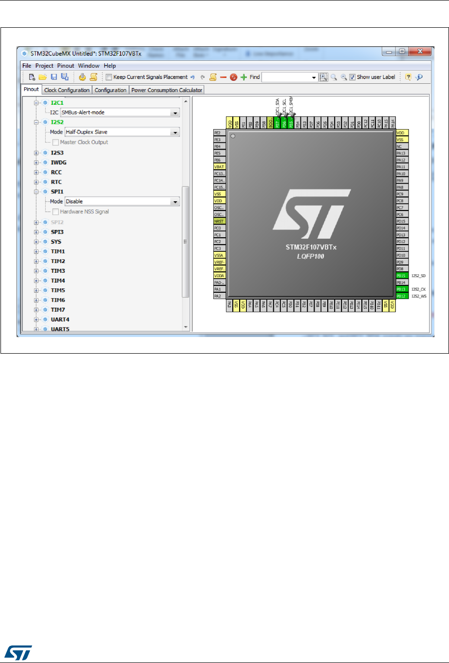
UM1718 Rev 26 297/345
UM1718 STM32CubeMX pin assignment rules
344
Figure 289. Block mapping
Example of block remapping with a STM32F107x MCU
If the user assigns GPIO_Output to PB6, STM32CubeMX automatically disables I2C1
SMBus-Alert peripheral mode from the peripheral tree view and updates the other I2C1 pins
(PB5 and PB7) as follows:
If they are unpinned, the pin configuration is reset (pin grayed out).
If they are pinned, the peripheral signal assigned to the pins is kept and the pins are
highlighted in orange since they no longer match a peripheral mode (see Figure 290).


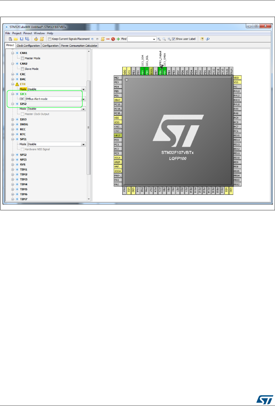
STM32CubeMX pin assignment rules UM1718
300/345 UM1718 Rev 26
Figure 292. Block remapping - Example 2
A.2 Block inter-dependency
On the Chip view, the same signal can appear as an alternate function for multiple pins.
However it can be mapped only once.
As a consequence, for STM32F1 MCUs, two blocks of pins cannot be selected
simultaneously for the same peripheral mode: when a block/signal from a block is selected,
the alternate blocks are cleared.
Example of block remapping of SPI in full-duplex master mode with a
STM32F107x MCU
If SPI1 full-duplex master mode is selected from the tree view, by default the corresponding
SPI signals are assigned to PB3, PB4 and PB5 pins (see Figure 293).
If the user assigns to PA6 the SPI1_MISO function currently assigned to PB4,
STM32CubeMX clears the PB4 pin from the SPI1_MISO function, as well as all the other
pins configured for this block, and moves the corresponding SPI1 functions to the relevant
pins in the same block as the PB4 pin (see Figure 294).
(by pressing CTRL and clicking PB4 to show PA6 alternate function in blue, then drag and
drop the signal to pin PA6)


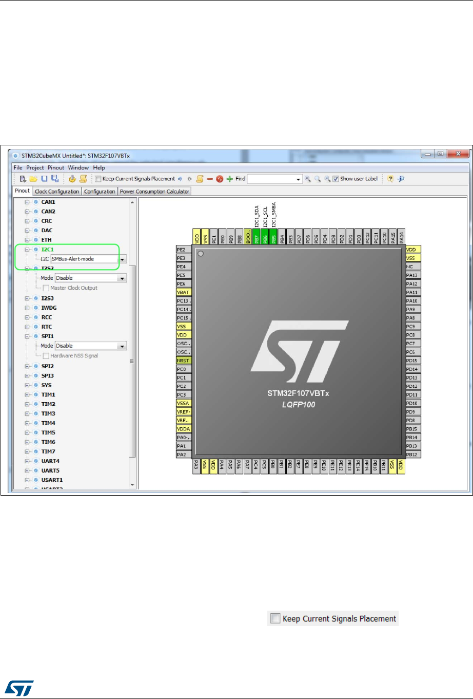
UM1718 Rev 26 303/345
UM1718 STM32CubeMX pin assignment rules
344
A.3 One block = one peripheral mode
When a block of pins is fully configured in the Chip view (shown in green), the related
peripheral mode is automatically set in the Peripherals tree.
Example of STM32F107x MCU
Assigning the I2C1_SMBA function to PB5 automatically configures I2C1 peripheral in
SMBus-Alert mode (see Peripheral tree in Figure 295).
Figure 295. One block = one peripheral mode - I2C1_SMBA function assigned to PB5
A.4 Block remapping (STM32F10x only)
To configure a peripheral mode, STM32CubeMX selects a block of pins and assigns each
mode signal to a pin in this block. In doing so, it looks for the first free block to which the
mode can be mapped.
When setting a peripheral mode, if at least one pin in the default block is already used,
STM32CubeMX tries to find an alternate block. If none can be found, it either selects the
functions in a different sequence, or unchecks , and remaps all
the blocks to find a solution.
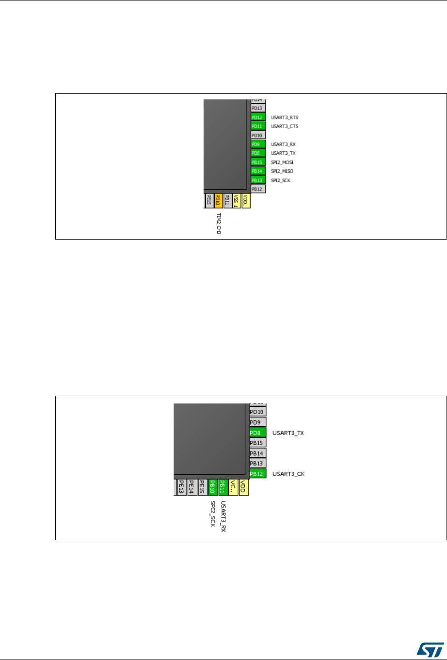
STM32CubeMX pin assignment rules UM1718
304/345 UM1718 Rev 26
Example
STM32CubeMX remaps USART3 hardware-flow-control mode to the (PD8-PD9-PD11-
PD12) block, because PB14 of USART3 default block is already allocated to the
SPI2_MISO function (see Figure 296).
Figure 296. Block remapping - Example 2
A.5 Function remapping
To configure a peripheral mode, STM32CubeMX assigns each signal of the mode to a pin.
In doing so, it will look for the first free pin the signal can be mapped to.
Example using STM32F415x
When configuring USART3 for the Synchronous mode, STM32CubeMX discovered that the
default PB10 pin for USART3_TX signal was already used by SPI. It thus remapped it to
PD8 (see Figure 297).
Figure 297. Function remapping example
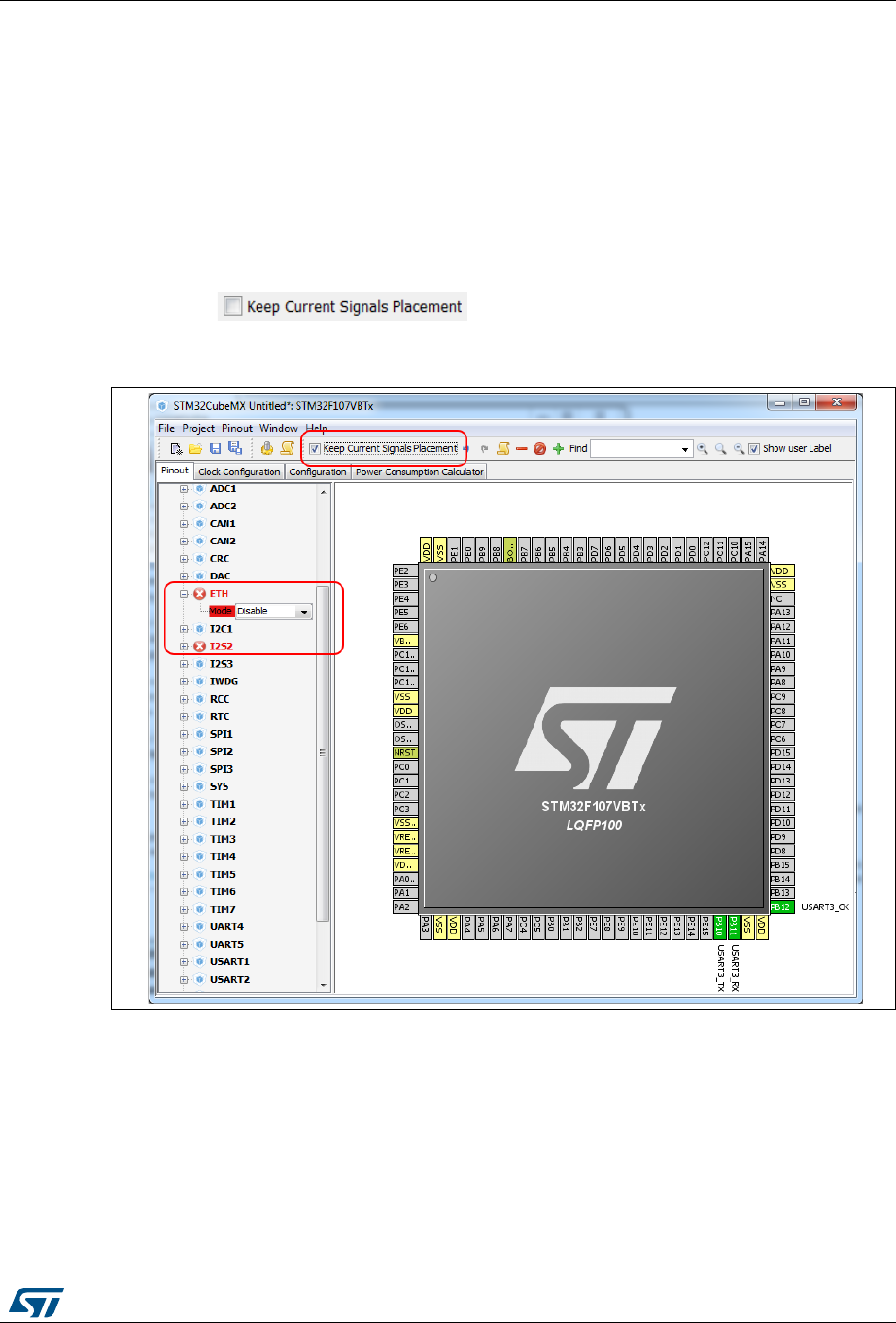
UM1718 Rev 26 305/345
UM1718 STM32CubeMX pin assignment rules
344
A.6 Block shifting (only for STM32F10x and when
“Keep Current Signals placement” is unchecked)
If a block cannot be mapped and there are no free alternate solutions, STM32CubeMX tries
to free the pins by remapping all the peripheral modes impacted by the shared pin.
Example
With the Keep current signal placement enabled, if USART3 synchronous mode is set first,
the Asynchronous default block (PB10-PB11) is mapped and Ethernet becomes unavailable
(shown in red) (see Figure 298).
Unchecking allows STM32CubeMX shifting blocks around
and freeing a block for the Ethernet MII mode. (see Figure 299).
Figure 298. Block shifting not applied
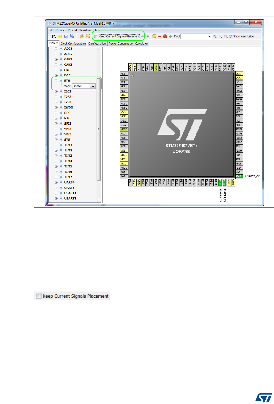
STM32CubeMX pin assignment rules UM1718
306/345 UM1718 Rev 26
Figure 299. Block shifting applied
A.7 Setting and clearing a peripheral mode
The Peripherals panel and the Chip view are linked: when a peripheral mode is set or
cleared, the corresponding pin functions are set or cleared.
A.8 Mapping a function individually
When STM32CubeMX needs a pin that has already been assigned manually to a function
(no peripheral mode set), it can move this function to another pin, only if
is unchecked and the function is not pinned (no pin icon).
A.9 GPIO signals mapping
I/O signals (GPIO_Input, GPIO_Output, GPIO_Analog) can be assigned to pins either
manually through the Chip view or automatically through the Pinout menu. Such pins can
no longer be assigned automatically to another signal: STM32CubeMX signal automatic
placement does not take into account this pin anymore since it does not shift I/O signals to
other pins.
The pin can still be manually assigned to another signal or to a reset state.

UM1718 Rev 26 307/345
UM1718 STM32CubeMX C code generation design choices and limitations
344
Appendix B STM32CubeMX C code generation design
choices and limitations
This section summarizes STM32CubeMX design choices and limitations.
B.1 STM32CubeMX generated C code and user sections
The C code generated by STM32CubeMX provides user sections as illustrated below. They
allow user C code to be inserted and preserved at next C code generation.
User sections shall neither be moved nor renamed. Only the user sections defined by
STM32CubeMX are preserved. User created sections will be ignored and lost at next C
code generation.
/* USER CODE BEGIN 0 */
(..)
/* USER CODE END 0 */
Note: STM32CubeMX may generate C code in some user sections. It will be up to the user to
clean the parts that may become obsolete in this section. For example, the while(1) loop in
the main function is placed inside a user section as illustrated below:
/* Infinite loop */
/* USER CODE BEGIN WHILE */
while (1)
{
/* USER CODE END WHILE */
/* USER CODE BEGIN 3 */
}
/* USER CODE END 3 */
B.2 STM32CubeMX design choices for peripheral initialization
STM32CubeMX generates peripheral _Init functions that can be easily identified thanks to
the MX_ prefix:
static void MX_GPIO_Init(void);
static void MX_<Peripheral Instance Name>_Init(void);
static void MX_I2S2_Init(void);
An MX_<peripheral instance name>_Init function exists for each peripheral instance
selected by the user (e.g, MX_I2S2_Init). It performs the initialization of the relevant handle
structure (e.g, &hi2s2 for I2S second instance) that is required for HAL driver initialization
(e.g., HAL_I2S_Init) and the actual call to this function:
void MX_I2S2_Init(void)
{
hi2s2.Instance = SPI2;
hi2s2.Init.Mode = I2S_MODE_MASTER_TX;
hi2s2.Init.Standard = I2S_STANDARD_PHILLIPS;

STM32CubeMX C code generation design choices and limitations UM1718
308/345 UM1718 Rev 26
hi2s2.Init.DataFormat = I2S_DATAFORMAT_16B;
hi2s2.Init.MCLKOutput = I2S_MCLKOUTPUT_DISABLE;
hi2s2.Init.AudioFreq = I2S_AUDIOFREQ_192K;
hi2s2.Init.CPOL = I2S_CPOL_LOW;
hi2s2.Init.ClockSource = I2S_CLOCK_PLL;
hi2s2.Init.FullDuplexMode = I2S_FULLDUPLEXMODE_ENABLE;
HAL_I2S_Init(&hi2s2);
}
By default, the peripheral initialization is done in main.c. If the peripheral is used by a
middleware mode, the peripheral initialization can be done in the middleware corresponding
.c file.
Customized HAL_<Peripheral Name>_MspInit() functions are created in the
stm32f4xx_hal_msp.c file to configure the low-level hardware (GPIO, CLOCK) for the
selected peripherals.
B.3 STM32CubeMX design choices and limitations for
middleware initialization
B.3.1 Overview
STM32CubeMX does not support C user code insertion in Middleware stack native files
although stacks such as LwIP might require it in some use cases.
STM32CubeMX generates middleware Init functions that can be easily identified thanks to
the MX_ prefix:
MX_LWIP_Init(); // defined in lwip.h file
MX_USB_HOST_Init(); // defined in usb_host.h file
MX_FATFS_Init(); // defined in fatfs.h file
Note however the following exceptions:
No Init function is generated for FreeRTOS unless the user chooses, from the Project
settings window, to generate Init functions as pairs of .c/.h files. Instead, a
StartDefaultTask function is defined in the main.c file and CMSIS-RTOS native function
(osKernelStart) is called in the main function.
If FreeRTOS is enabled, the Init functions for the other middlewares in use are called
from the StartDefaultTask function in the main.c file.
Example:
void StartDefaultTask(void const * argument)
{
/* init code for FATFS */
MX_FATFS_Init();
/* init code for LWIP */
MX_LWIP_Init();
/* init code for USB_HOST */
MX_USB_HOST_Init();
/* USER CODE BEGIN 5 */
/* Infinite loop */

UM1718 Rev 26 309/345
UM1718 STM32CubeMX C code generation design choices and limitations
344
for(;;)
{
osDelay(1);
}
/* USER CODE END 5 */
}
B.3.2 USB Host
USB peripheral initialization is performed within the middleware initialization C code in the
usbh_conf.c file, while USB stack initialization is done within the usb_host.c file.
When using the USB Host middleware, the user is responsible for implementing the
USBH_UserProcess callback function in the generated usb_host.c file.
From STM32CubeMX user interface, the user can select to register one class or all classes
if the application requires switching dynamically between classes.
B.3.3 USB Device
USB peripheral initialization is performed within the middleware initialization C code in the
usbd_conf.c file, while USB stack initialization is done within the usb_device.c file.
USB VID, PID and String standard descriptors are configured via STM32CubeMX user
interface and available in the usbd_desc.c generated file. Other standard descriptors
(configuration, interface) are hard-coded in the same file preventing support of USB
composite devices.
When using the USB Device middleware, the user is responsible for implementing the
functions in the usbd_<classname>_if.c class interface file for all device classes (e.g.,
usbd_storage_if.c).
USB MTP and CCID classes are not supported.
B.3.4 FatFs
FatFs is a generic FAT/exFAT file system solution well suited for small embedded systems.
FatFs configuration is available in ffconf.h generated file.
The initialization of the SDIO peripheral for the FatFs SD Card mode and of the FMC
peripheral for the FatFs External SDRAM and External SRAM modes are kept in the main.c
file.
Some files need to be modified by the user to match user board specificities (BSP in
STM32Cube embedded software package can be used as example):
bsp_driver_sd.c/.h generated files when using FatFs SD Card mode
bsp_driver_sram.c/.h generated files when using FatFs External SRAM mode
bsp_driver_sdram.c/.h generated files when using FatFs External SDRAM mode.
Multi-drive FatFs is supported, which means that multiple logical drives can be used by the
application (External SDRAM, External SRAM, SD Card, USB Disk, User defined). However
support of multiple instances of a given logical drive is not available (e.g. FatFs using two
instances of USB hosts or several RAM disks).
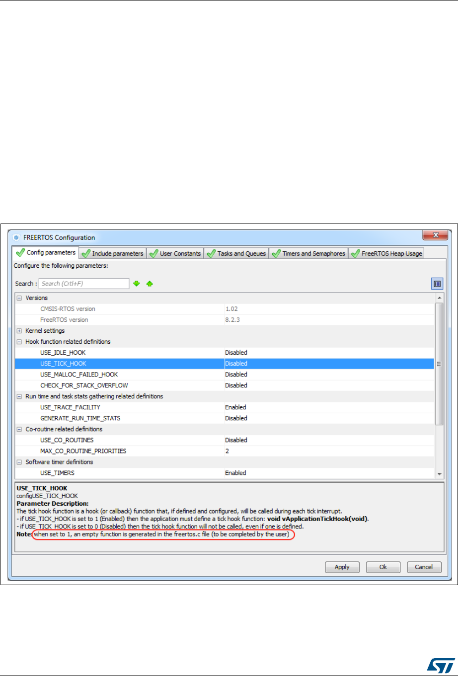
STM32CubeMX C code generation design choices and limitations UM1718
310/345 UM1718 Rev 26
NOR and NAND Flash memory are not supported. In this case, the user shall select the
FatFs user-defined mode and update the user_diskio.c driver file generated to implement
the interface between the middleware and the selected peripheral.
B.3.5 FreeRTOS
FreeRTOS is a free real-time embedded operating system well suited for microcontrollers.
FreeRTOS configuration is available in FreeRTOSConfig.h generated file.
When FreeRTOS is enabled, all other selected middleware modes (e.g., LwIP, FatFs, USB)
will be initialized within the same FreeRTOS thread in the main.c file.
When GENERATE_RUN_TIME_STATS, CHECK_FOR_STACK_OVERFLOW,
USE_IDLE_HOOK, USE_TICK_HOOK and USE_MALLOC_FAILED_HOOK parameters
are activated, STM32CubeMX generates freertos.c file with empty functions that the user
shall implement. This is highlighted by the tooltip (see Figure 300).
Figure 300. FreeRTOS HOOK functions to be completed by user
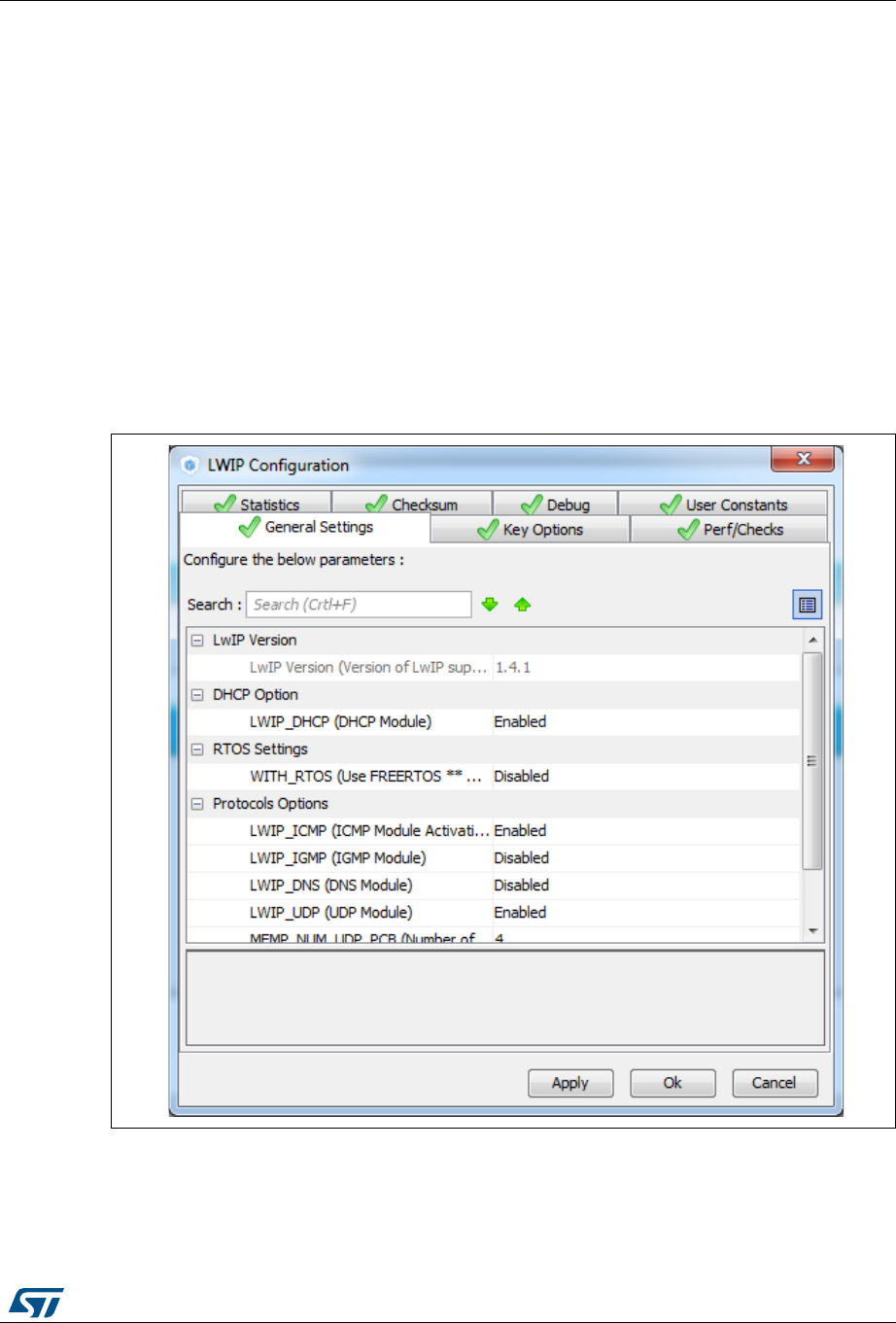
UM1718 Rev 26 311/345
UM1718 STM32CubeMX C code generation design choices and limitations
344
B.3.6 LwIP
LwIP is a small independent implementation of the TCP/IP protocol suite: its reduced RAM
usage makes it suitable for use in embedded systems with tens of kilobytes of free RAM.
LwIP initialization function is defined in lwip.c, while LwIP configuration is available in
lwipopts.h generated file.
STM32CubeMX supports LwIP over Ethernet only. The Ethernet peripheral initialization is
done within the middleware initialization C code.
STM32CubeMX does not support user C code insertion in stack native files. However, some
LwIP use cases require modifying stack native files (e.g., cc.h, mib2.c): user modifications
shall be backed up since they will be lost at next STM32CubeMX generation.
Starting with LwIP release 1.5, STM32CubeMX LwIP supports IPv6 (see Figure 302).
DHCP must be disabled, to configure a static IP address.
Figure 301. LwIP 1.4.1 configuration
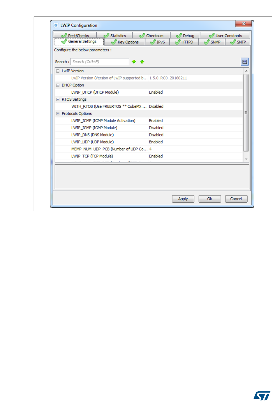
STM32CubeMX C code generation design choices and limitations UM1718
312/345 UM1718 Rev 26
Figure 302. LwIP 1.5 configuration
STM32CubeMX generated C code will report compilation errors when specific parameters
are enabled (disabled by default). The user must fix the issues with a stack patch
(downloaded from Internet) or user C code. The following parameters generate an error:
MEM_USE_POOLS: user C code to be added either in lwipopts.h or in cc.h (stack file).
PPP_SUPPORT, PPPOE_SUPPORT: user C code required
MEMP_SEPARATE_POOLS with MEMP_OVERFLOW_CHECK > 0: a stack patch
required
MEM_LIBC_MALLOC & RTOS enabled: stack patch required
LWIP_EVENT_API: stack patch required
In STM32CubeMX, the user must enable FreeRTOS in order to use LwIP with the netconn
and sockets APIs. These APIs require the use of threads and consequently of an operating
system. Without FreeRTOS, only the LwIP event-driven raw API can be used.

UM1718 Rev 26 313/345
UM1718 STM32CubeMX C code generation design choices and limitations
344
B.3.7 Libjpeg
Libjpeg is a widely used C-library that allows reading and writing JPEG files. It is delivered
within STM32CubeF7, STM32CubeH7, STM32CubeF2 and STM32CubeF4 embedded
software packages.
STM32CubeMX generates the following files, whose content can be configured by the user
through STM32CubeMX user interface:
libjpeg.c/.h
The MX_LIBJPEG_Init() initialization function is generated within the libjpeg.c file. It is
empty. It is up to the user to enter in the user sections the code and the calls to the
libjpeg functions required for the application.
jdata_conf.c
This file is generated only when FatFs is selected as data stream management type.
jdata_conf.h
The content of this file is adjusted according to the datastream management type
selected.
jconfig.h
This file is generated by STM32CubeMX. but cannot be configured.
jmorecfg.h
Some but not all the define statements contained in this file can be modified through
the STM32CubeMX libjpeg configuration menu.
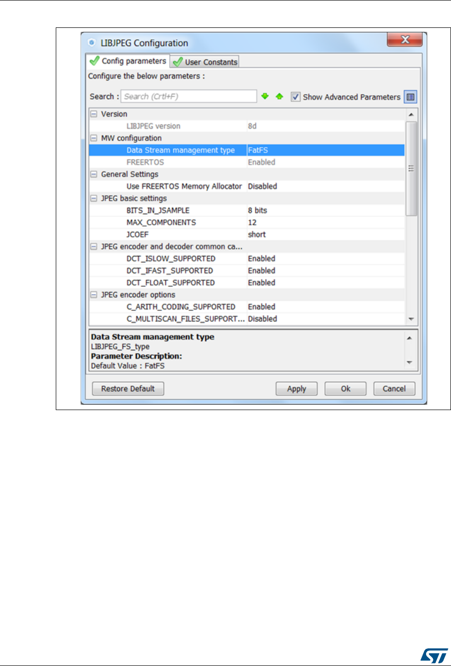
STM32CubeMX C code generation design choices and limitations UM1718
314/345 UM1718 Rev 26
Figure 303. Libjpeg configuration window
B.3.8 Mbed TLS
Mbed TLS is a C-library that allows including cryptographic capabilities to embedded
products. It handles Secure Sockets Layer (SSL) and Transport Layer Security (TLS)
protocols, that are used for establishing a secure, encrypted and authenticated link between
two parties over an insecure network. Mbed TLS comes with an intuitive API and minimal
coding footprint. Visit https://tls.mbed.org/ for more details.
Mbed TLS is delivered within STM32CubeF2, STM32CubeF4, STM32CubeF7 and
STM32CubeH7 embedded software packages.
Mbed TLS can work without LwIP stack (see Figure 304: Mbed TLS without LwIP).
If LwIP stack is used, FreeRTOS must be enabled as well (see Figure 305: Mbed TLS with
LwIP and FreeRTOS).
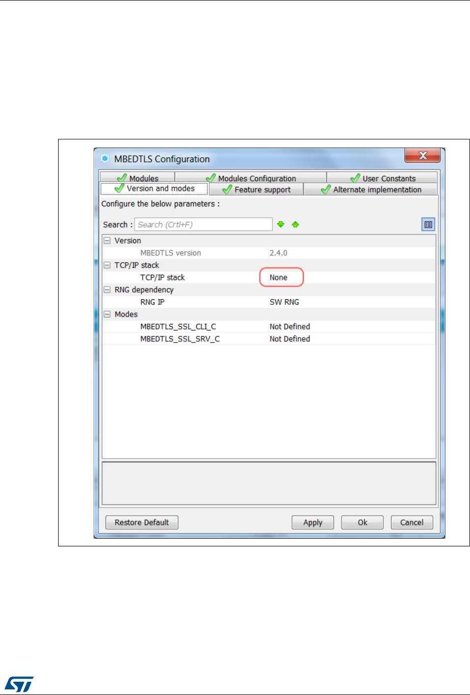
UM1718 Rev 26 315/345
UM1718 STM32CubeMX C code generation design choices and limitations
344
STM32CubeMX generates the following files, whose contents can be modified by the user
through STM32CubeMX user interface (see Figure 306: Mbed TLS configuration window)
and/or using user sections in the code itself:
mbedtls_config.h
mbedtls.h
net_sockets.c (generated only if LwIP is enabled)
mbedtls.c
Figure 304. Mbed TLS without LwIP

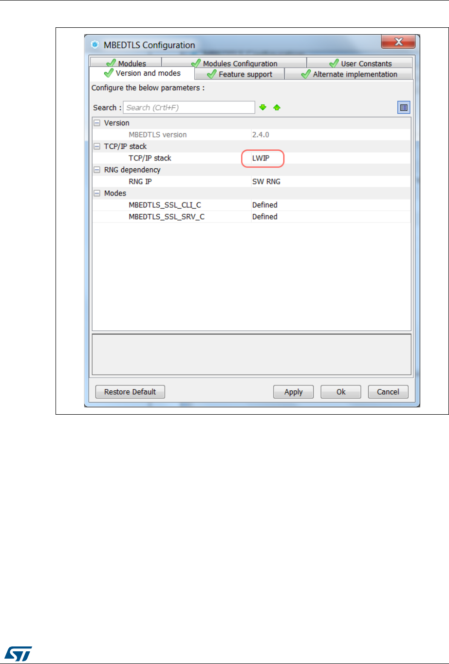
UM1718 Rev 26 317/345
UM1718 STM32CubeMX C code generation design choices and limitations
344
Figure 306. Mbed TLS configuration window
B.3.9 TouchSensing
The STM32 TouchSensing library is a C-library that allows the creation of higher-end human
interfaces by replacing conventional electromechanical switches by capacitive sensors with
STM32 microcontrollers.
It requires the touch-sensing peripheral to be configured on the microcontroller.
STM32CubeMX generates the following files, whose contents can be modified by the user
through STM32CubeMX user interface (see Figure 307: Enabling the TouchSensing
peripheral, Figure 308: Touch-sensing sensor selection panel and Figure 309:
TouchSensing configuration panel) and/or using user sections in the code itself:
touchsensing.c/.h
tsl_user.c/.h
tsl_conf.h


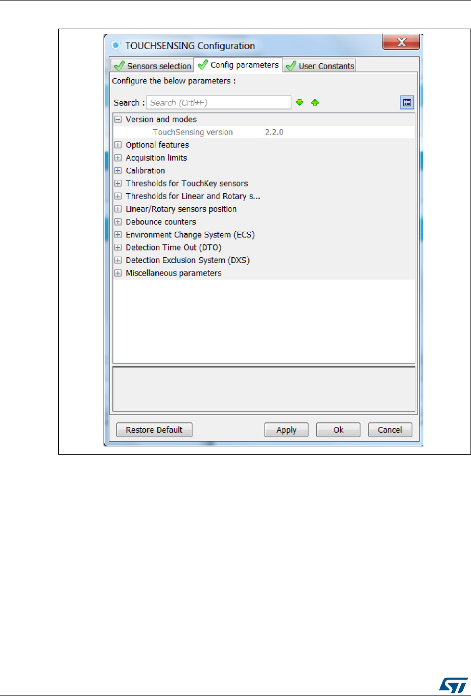
STM32CubeMX C code generation design choices and limitations UM1718
320/345 UM1718 Rev 26
Figure 309. TouchSensing configuration panel
B.3.10 PDM2PCM
The PDM2PCM library is a C-library that allows converting a pulse density modulated
(PDM) data output into a 16-bit pulse-code modulation (PCM) format. It requires the CRC
peripheral to be enabled.
STM32CubeMX generates the following files, whose contents can be modified by the user
through STM32CubeMX user interface and/or using user sections in the code itself:
pdm2pcm.h/.c
B.3.11 Graphics
STMicroelectronics has selected the STemWin framework for the STM32 portfolio, see the
dedicated tutorial sections on how to create projects for this framework using
STM32CubeMX.
UM1718 Rev 26 321/345
UM1718 STM32CubeMX C code generation design choices and limitations
344
The generated projects follow the embedded software architecture shown in Figure 310 with
a hardware initialization file and a wrapper file to address the graphical stack specificity.
Figure 310. Graphics application architecture
The graphical stack comes with a specific UI designer tool that can be called from
STM32CubeMX user interface to perform advanced design work:
GUIBuilder for STemWin framework
All C, C++ or other files generated through the tool end up in the STM32CubeMX project
folder.
069
*UDSKLFDODSSOLFDWLRQ
67HP:LQ
:UDSSLQJILOH
+:B,QLWFK

STM32 microcontrollers naming conventions UM1718
322/345 UM1718 Rev 26
Appendix C STM32 microcontrollers naming conventions
STM32 microcontroller part numbers are codified following the below naming conventions:
Device subfamilies
The higher the number, the more features available.
For example STM32L0 line includes STM32L051, L052, L053, L061, L062, L063
subfamilies where STM32L06x part numbers come with AES while STM32L05x do not.
The last digit indicates the level of features. In the above example:
– 1 = Access line
– 2 = with USB
– 3 = with USB and LCD.
Pin counts
– F = 20 pins
– G = 28 pins
– K = 32 pins
– T = 36 pins
– S = 44 pins
– C = 48 pins
– R = 64 (or 66) pins)
– M = 80 pins
– O = 90 pins
– V = 100 pins
– Q = 132 pins (e. g. STM32L162QDH6)
– Z = 144 pins
– I = 176 (+25) pins
– B = 208 pins (e. g. STM32F429BIT6)
– N = 216 pins
Flash memory sizes
– 4 = 16 Kbytes of Flash memory
– 6 = 32 Kbytes of Flash memory
– 8 = 64 Kbytes of Flash memory
– B = 128 Kbytes of Flash memory
– C = 256 Kbytes of Flash memory
– D = 384 Kbytes of Flash memory
– E = 512 Kbytes of Flash memory
– F = 768 Kbytes of Flash memory
– G = 1024 Kbytes of Flash memory
– I = 2048 Kbytes of Flash memory
Packages
– B = SDIP
–H = BGA


STM32 microcontrollers power consumption parameters UM1718
324/345 UM1718 Rev 26
Appendix D STM32 microcontrollers power consumption
parameters
This section provides an overview on how to use STM32CubeMX Power Consumption
Calculator.
Microcontroller power consumption depends on chip size, supply voltage, clock frequency
and operating mode. Embedded applications can optimize STM32 MCU power
consumption by reducing the clock frequency when fast processing is not required and
choosing the optimal operating mode and voltage range to run from. A description of STM32
power modes and voltage range is provided below.
D.1 Power modes
STM32 MCUs support different power modes (refer to STM32 MCU datasheets for full
details).
D.1.1 STM32L1 Series
STM32L1 microcontrollers feature up to 6 power modes, including 5 low-power modes:
Run mode
This mode offers the highest performance using HSE/HSI clock sources. The CPU
runs up to 32 MHz and the voltage regulator is enabled.
Sleep mode
This mode uses HSE or HSI as system clock sources. The voltage regulator is enabled
and the CPU is stopped. All peripherals continue to operate and can wake up the CPU
when an interrupt/event occurs.
Low- power run mode
This mode uses the multispeed internal (MSI) RC oscillator set to the minimum clock
frequency (131 kHz) and the internal regulator in low-power mode. The clock frequency
and the number of enabled peripherals are limited.
Low-power sleep mode
This mode is achieved by entering Sleep mode. The internal voltage regulator is in low-
power mode. The clock frequency and the number of enabled peripherals are limited. A
typical example would be a timer running at 32 kHz.
When the wakeup is triggered by an event or an interrupt, the system returns to the
Run mode with the regulator ON.
Stop mode
This mode achieves the lowest power consumption while retaining RAM and register
contents. Clocks are stopped. The real-time clock (RTC) an be backed up by using
LSE/LSI at 32 kHz/37 kHz. The number of enabled peripherals is limited. The voltage
regulator is in low-power mode.
The device can be woken up from Stop mode by any of the EXTI lines.
Standby mode
This mode achieves the lowest power consumption. The internal voltage regulator is
switched off so that the entire VCORE domain is powered off. Clocks are stopped and
the real-time clock (RTC) can be preserved up by using LSE/LSI at 32 kHz/37 kHz.

UM1718 Rev 26 325/345
UM1718 STM32 microcontrollers power consumption parameters
344
RAM and register contents are lost except for the registers in the Standby circuitry. The
number of enabled peripherals is even more limited than in Stop mode.
The device exits Standby mode upon reset, rising edge on one of the three WKUP pins,
or if an RTC event occurs (if the RTC is ON).
Note: When exiting Stop or Standby modes to enter the Run mode, STM32L1 MCUs go through a
state where the MSI oscillator is used as clock source. This transition can have a significant
impact on the global power consumption. For this reason, the Power Consumption
Calculator introduces two transition steps: WU_FROM_STOP and WU_FROM_STANDBY.
During these steps, the clock is automatically configured to MSI.
D.1.2 STM32F4 Series
STM32F4 microcontrollers feature a total of 5 power modes, including 4 low-power modes:
Run mode
This is the default mode at power-on or after a system reset. It offers the highest
performance using HSE/HSI clock sources. The CPU can run at the maximum
frequency depending on the selected power scale.
Sleep mode
Only the CPU is stopped. All peripherals continue to operate and can wake up the CPU
when an interrupt/even occurs. The clock source is the clock that was set before
entering Sleep mode.
Stop mode
This mode achieves a very low power consumption using the RC oscillator as clock
source. All clocks in the 1.2 V domain are stopped as well as CPU and peripherals.
PLL, HSI RC and HSE crystal oscillators are disabled. The content of registers and
internal SRAM are kept.
The voltage regulator can be put either in normal Main regulator mode (MR) or in Low-
power regulator mode (LPR). Selecting the regulator in low-power regulator mode
increases the wakeup time.
The Flash memory can be put either in Stop mode to achieve a fast wakeup time or in
Deep power-down to obtain a lower consumption with a slow wakeup time.
The Stop mode features two sub-modes:
– Stop in Normal mode (default mode)
In this mode, the 1.2 V domain is preserved in nominal leakage mode and the
minimum V12 voltage is 1.08 V.
– Stop in Under-drive mode
In this mode, the 1.2 V domain is preserved in reduced leakage mode and V12
voltage is less than 1.08 V. The regulator (in Main or Low-power mode) is in
under-drive or low-voltage mode. The Flash memory must be in Deep-power-
down mode. The wakeup time is about 100 µs higher than in normal mode.
Standby mode
This mode achieves very low power consumption with the RC oscillator as a clock
source. The internal voltage regulator is switched off so that the entire 1.2 V domain is
powered off: CPU and peripherals are stopped. The PLL, the HSI RC and the HSE
crystal oscillators are disabled. SRAM and register contents are lost except for
registers in the backup domain and the 4-byte backup SRAM when selected. Only RTC
and LSE oscillator blocks are powered. The device exits Standby mode when an

STM32 microcontrollers power consumption parameters UM1718
326/345 UM1718 Rev 26
external reset (NRST pin), an IWDG reset, a rising edge on the WKUP pin, or an RTC
alarm/ wakeup/ tamper/time stamp event occurs.
VBAT operation
It allows to significantly reduced power consumption compared to the Standby mode.
This mode is available when the VBAT pin powering the Backup domain is connected to
an optional standby voltage supplied by a battery or by another source. The VBAT
domain is preserved (RTC registers, RTC backup register and backup SRAM) and
RTC and LSE oscillator blocks powered. The main difference compared to the Standby
mode is external interrupts and RTC alarm/events do not exit the device from VBAT
operation. Increasing VDD to reach the minimum threshold does.
D.1.3 STM32L0 Series
STM32L0 microcontrollers feature up to 8 power modes, including 7 low-power modes to
achieve the best compromise between low-power consumption, short startup time and
available wakeup sources:
Run mode
This mode offers the highest performance using HSE/HSI clock sources. The CPU can
run up to 32 MHz and the voltage regulator is enabled.
Sleep mode
This mode uses HSE or HSI as system clock sources. The voltage regulator is enabled
and only the CPU is stopped. All peripherals continue to operate and can wake up the
CPU when an interrupt/event occurs.
Low-power run mode
This mode uses the internal regulator in low-power mode and the multispeed internal
(MSI) RC oscillator set to the minimum clock frequency (131 kHz). In Low-power run
mode, the clock frequency and the number of enabled peripherals are both limited.
Low-power sleep mode
This mode is achieved by entering Sleep mode with the internal voltage regulator in
low-power mode. Both the clock frequency and the number of enabled peripherals are
limited. Event or interrupt can revert the system to Run mode with regulator on.
Stop mode with RTC
The Stop mode achieves the lowest power consumption with, while retaining the RAM,
register contents and real time clock. The voltage regulator is in low-power mode. LSE
or LSI is still running. All clocks in the VCORE domain are stopped, the PLL, MSI RC,
HSE crystal and HSI RC oscillators are disabled.
Some peripherals featuring wakeup capability can enable the HSI RC during Stop
mode to detect their wakeup condition. The device can be woken up from Stop mode
by any of the EXTI line, in 3.5 µs, and the processor can serve the interrupt or resume
the code.
Stop mode without RTC
This mode is identical to “Stop mode with RTC “, except for the RTC clock which is
stopped here.
Standby mode with RTC
The Standby mode achieves the lowest power consumption with the real time clock
running. The internal voltage regulator is switched off so that the entire VCORE domain

UM1718 Rev 26 327/345
UM1718 STM32 microcontrollers power consumption parameters
344
is powered off. The PLL, MSI RC, HSE crystal and HSI RC oscillators are also switched
off. The LSE or LSI is still running.
After entering Standby mode, the RAM and register contents are lost except for
registers in the Standby circuitry (wakeup logic, IWDG, RTC, LSI, LSE Crystal 32 KHz
oscillator, RCC_CSR register).
The device exits Standby mode in 60 µs when an external reset (NRST pin), an IWDG
reset, a rising edge on one of the three WKUP pins, RTC alarm (Alarm A or Alarm B),
RTC tamper event, RTC timestamp event or RTC Wakeup event occurs.
Standby mode without RTC
This mode is identical to Standby mode with RTC, except that the RTC, LSE and LSI
clocks are stopped.
The device exits Standby mode in 60 µs when an external reset (NRST pin) or a rising
edge on one of the three WKUP pin occurs.
Note: The RTC, the IWDG, and the corresponding clock sources are not stopped automatically by
entering Stop or Standby mode. The LCD is not stopped automatically by entering Stop
mode.
D.2 Power consumption ranges
STM32 MCUs power consumption can be further optimized thanks to the dynamic voltage
scaling feature: the main internal regulator output voltage V12 that supplies the logic (CPU,
digital peripherals, SRAM and Flash memory) can be adjusted by software by selecting a
power range (STM32L1 and STM32L0) or power scale (STM32 F4).
Power consumption range definitions are provided below (refer to STM32 MCU datasheets
for full details).
D.2.1 STM32L1 Series features three VCORE ranges
High Performance Range 1 (VDD range limited to 2.0-3.6 V), with the CPU running at
up to 32 MHz
The voltage regulator outputs a 1.8 V voltage (typical) as long as the VDD input voltage
is above 2.0 V. Flash program and erase operations can be performed.
Medium Performance Range 2 (full VDD range), with a maximum CPU frequency of
16 MHz
At 1.5 V, the Flash memory is still functional but with medium read access time. Flash
program and erase operations are still possible.
Low Performance Range 3 (full VDD range), with a maximum CPU frequency limited to
4 MHz (generated only with the multispeed internal RC oscillator clock source)
At 1.2 V, the Flash memory is still functional but with slow read access time. Flash
Program and erase operations are no longer available.

STM32 microcontrollers power consumption parameters UM1718
328/345 UM1718 Rev 26
D.2.2 STM32F4 Series features several VCORE scales
The scale can be modified only when the PLL is OFF and when HSI or HSE is selected as
system clock source.
Scale 1 (V12 voltage range limited to 1.26-1.40 V), default mode at reset
HCLK frequency range = 144 MHz to 168 MHz (180 MHz with over-drive).
This is the default mode at reset.
Scale 2 (V12 voltage range limited to 1.20 to 1.32 V)
HCLK frequency range is up to 144 MHz (168 MHz with over-drive)
Scale 3 (V12 voltage range limited to 1.08 to 1.20 V), default mode when exiting Stop
mode
HCLK frequency ≤120 MHz.
The voltage scaling is adjusted to fHCLK frequency as follows:
STM32F429x/39x MCUs:
–Scale 1: up to 168 MHz (up to 180 MHz with over-drive)
–Scale 2: from 120 to 144 MHz (up to 168 MHz with over-drive)
–Scale 3: up to 120 MHz.
STM32F401x MCUs:
No Scale 1
–Scale 2: from 60 to 84 MHz
–Scale 3: up to 60 MHz.
STM32F40x/41x MCUs:
–Scale 1: up to 168 MHz
–Scale 2: up to 144 MHz
D.2.3 STM32L0 Series features three VCORE ranges
Range 1 (VDD range limited to 1.71 to 3.6 V), with CPU running at a frequency up to
32 MHz
Range 2 (full VDD range), with a maximum CPU frequency of 16 MHz
Range 3 (full VDD range), with a maximum CPU frequency limited to 4.2 MHz.
UM1718 Rev 26 329/345
UM1718 STM32Cube embedded software packages
344
Appendix E STM32Cube embedded software packages
Along with STM32CubeMX C code generator, embedded software packages are part of
STM32Cube initiative (refer to DB2164 databrief): these packages include a low-level
hardware abstraction layer (HAL) that covers the microcontroller hardware, together with an
extensive set of examples running on STMicroelectronics boards (see Figure 312). This set
of components is highly portable across the STM32 Series. The packages are fully
compatible with STM32CubeMX generated C code.
Figure 312. STM32Cube Embedded Software package
Note: STM32CubeF0, STM32CubeF1, STM32CubeF2, STM32CubeF3, STM32CubeF4,
STM32CubeL0 and STM32CubeL1 embedded software packages are available on st.com.
They are based on STM32Cube release v1.1 (other Series will be introduced progressively)
and include the embedded software libraries used by STM32CubeMX for initialization C
code generation.
The user should use STM32CubeMX to generate the initialization C code and the examples
provided in the package to get started with STM32 application development.
06Y9
8WLOLWLHV
$SSOLFDWLRQOHYHOGHPRQVWUDWLRQV
0LGGOHZDUHOHYHO
+$/$3,V
(YDOXDWLRQERDUGGHPRQVWUDWLRQ
'HPREXLOGHUIUDPHZRUN
7&3,3
,Z,3VWDFN
3RODU66/
86%
+RVW
'HYLFHOLEUDU\
+DUGZDUH$EVWUDFWLRQ/D\HU$3,V+$/ %RDUG6XSSRUW3DFNDJH%63
8WLOLWLHV
WLPHVWULQJILOH
&06,6
'LVFRYHU\ERDUGGHPRQVWUDWLRQ 'HGLFDWHGERDUGGHPRQVWUDWLRQ
0LGGOHZDUHH[DPSOHV
*UDSKLFDO
OLEUDU\
67(P:LQ
)$7ILOH
V\VWHP
)DW)V
(QKDQFHG
1$1'
PHPRU\
GULYHU
+$/H[DPSOHV
5726
)UHH5726
+DUGZDUH
0&86HULHV670)))) (YDOXDWLRQERDUGVGLVFRYHU\ERDUGV
GHGLFDWHGGHPRQVWUDWLRQERDUGV

Revision history UM1718
330/345 UM1718 Rev 26
18 Revision history
Table 23. Document revision history
Date Revision STM32CubeMX
release number Changes
17-Feb-2014 1 4.1 Initial release.
04-Apr-2014 2 4.2
Added support of STM32CubeF2 and STM32F2 Series in cover
page, Section 3.2: Key features, Section 5.13.1: Peripherals and
Middleware Configuration window, and Appendix E: STM32Cube
embedded software packages.
Updated Section 8.1: Creating a new STM32CubeMX Project,
Section 8.2: Configuring the MCU pinout, Section 8.6: Configuring
the MCU initialization parameters.
Section “Generating GPIO initialization C code move to Section 8:
Tutorial 3- Generating GPIO initialization C code (STM32F1 Series
only) and content updated.
Added Section 17.4: Why do I get the error “Java 7 update 45” when
installing “Java 7 update 45” or a more recent version of the JRE?.
24-Apr-2014 3 4.3
Added support of STM32CubeL0 and STM32L0 Series in cover
page, Section 3.2: Key features, Section 3.3: Rules and limitations
and Section 5.13.1: Peripherals and Middleware Configuration
window
Added board selection in Table 3: File menu functions,
Section 5.4.3: Pinout menu and Section 5.2: New project window.
Updated Table 5: Pinout menu.
Updated Figure 123: Power Consumption Calculator default view
and added battery selection in Section 5.15.1: Building a power
consumption sequence.
Updated note in Section 5.15: Power Consumption Calculator view
Updated Section 8.1: Creating a new STM32CubeMX Project.
Added Section 17.5: Why does the RTC multiplexer remain inactive
on the Clock tree view?, Section 17.6: How can I select LSE and
HSE as clock source and change the frequency?, and Section 17.7:
Why STM32CubeMX does not allow me to configure PC13, PC14,
PC15 and PI8 as outputs when one of them is already configured as
an output?.

UM1718 Rev 26 331/345
UM1718 Revision history
344
19-jun-2014 4 4.4
Added support of STM32CubeF0, STM32CubeF3, STM32F0 and
STM32F3 Series in cover page, Section 3.2: Key features,
Section 3.3: Rules and limitations,
Added board selection capability and pin locking capability in
Section 3.2: Key features, Table 2: Welcome page shortcuts,
Section 5.2: New project window, Section 5.4: Toolbar and menus,
Section 5.7: Set unused / Reset used GPIOs windows, Section 5.8:
Project Settings window, and Section 5.12: Pinout view. Added
Section 5.12.5: Pinning and labeling signals on pins.
Updated Section 5.13: Configuration view and Section 5.14: Clock
tree configuration view and Section 5.15: Power Consumption
Calculator view.
Updated Figure 33: STM32CubeMX Main window upon MCU
selection, Figure 49: Project Settings window, Figure 69: About
window, Figure 70: STM32CubeMX Pinout view, Figure 73: Chip
view, Figure 123: Power Consumption Calculator default view,
Figure 124: Battery selection, Figure 125: Building a power
consumption sequence, Figure 127: Power consumption sequence:
new step default view, Figure 135: Power Consumption Calculator
view after sequence building, Figure 136: Sequence table
management functions, Figure 88: PCC Edit Step window,
Figure 83: Power consumption sequence: new step configured
(STM32F4 example), Figure 133: ADC selected in Pinout view,
Figure 134: Power Consumption Calculator Step configuration
window: ADC enabled using import pinout, Figure 138: Description
of the Results area, Figure 139: Peripheral power consumption
tooltip, Figure 223: Power Consumption Calculation example,
Figure 155: Sequence table and Figure 156: Power Consumption
Calculation results.
Updated Figure 85: STM32CubeMX Configuration view and
Figure 39: STM32CubeMX Configuration view - STM32F1 Series
titles.
Added STM32L1 in Section 5.15: Power Consumption Calculator
view.
Removed Figure Add a new step using the PCC panel from
Section 8.1.1: Adding a step. Removed Figure Add a new step to
the sequence from Section 5.15.2: Configuring a step in the power
sequence.
Updated Section 8.2: Reviewing results.
Updated appendix B.3.4: FatFs and Appendix D: STM32
microcontrollers power consumption parameters. Added Appendix
D.1.3: STM32L0 Series and D.2.3: STM32L0 Series features three
VCORE ranges.
Table 23. Document revision history
Date Revision STM32CubeMX
release number Changes

Revision history UM1718
332/345 UM1718 Rev 26
19-Sep-2014 5 4.5
Added support of STM32CubeL1 Series in cover page, Section 3.2:
Key features, Section 3.3: Rules and limitations,
Updated Section 4.2.3: Uninstalling STM32CubeMX standalone
version.
Added off-line updates in Section 4.5: Getting updates using
STM32CubeMX, modified Figure 14: Embedded Software
Packages Manager window, and Section 4.5.2: Installing STM32
MCU packages.
Updated Section 5: STM32CubeMX user interface introduction,
Table 2: Welcome page shortcuts and Section 5.2: New project
window.
Added Figure 32: New Project window - board selector.
Updated Figure 56: Project Settings Code Generator.
Modified step 3 in Section 5.8: Project Settings window.
Updated Figure 39: STM32CubeMX Configuration view - STM32F1
Series.
Added STM32L1 in Section 5.13.1: Peripherals and Middleware
Configuration window.
Updated Figure 97: GPIO Configuration window - GPIO selection;
Section 5.13.3: GPIO Configuration window and Figure 103: DMA
MemToMem configuration.
Updated introduction of Section 5.14: Clock tree configuration view.
Updated Section 5.14.1: Clock tree configuration functions and
Section 5.14.2: Recommendations, Section 5.15: Power
Consumption Calculator view, Figure 127: Power consumption
sequence: new step default view, Figure 135: Power Consumption
Calculator view after sequence building, Figure 83: Power
consumption sequence: new step configured (STM32F4 example),
and Figure 134: Power Consumption Calculator Step configuration
window: ADC enabled using import pinout. Added Figure 137:
Power Consumption: Peripherals Consumption Chart and updated
Figure 139: Peripheral power consumption tooltip. Updated
Section 5.15.4: Power sequence step parameters glossary.
Updated Section 6: STM32CubeMX C Code generation overview.
Updated Section 8.1: Creating a new STM32CubeMX Project and
Section 8.2: Configuring the MCU pinout.
Added Section 9: Tutorial 2 - Example of FatFs on an SD card using
STM32429I-EVAL evaluation board and updated Section 8: Tutorial
3- Generating GPIO initialization C code (STM32F1 Series only).
Updated Section 5.15.2: Configuring a step in the power sequence.
Table 23. Document revision history
Date Revision STM32CubeMX
release number Changes

UM1718 Rev 26 333/345
UM1718 Revision history
344
19-Jan-2015 6 4.6
Complete project generation, power consumption calculation and
clock tree configuration now available on all STM32 Series.
Updated Section 3.2: Key features and Section 3.3: Rules and
limitations.
Updated Eclipse IDEs in Section 4.1.3: Software requirements.
Updated Figure 12: Updater Settings window, Figure 14: Embedded
Software Packages Manager window and Figure 32: New Project
window - board selector, Updated Section 5.8: Project Settings
window and Section 5.9: Update Manager windows.
Updated Figure 69: About window.
Removed Figure STM32CubeMX Configuration view -
STM32F1 Series.
Updated Table 11: STM32CubeMX Chip view - Icons and color
scheme.
Updated Section 5.13.1: Peripherals and Middleware Configuration
window.
Updated Figure 101: Adding a new DMA request and Figure 103:
DMA MemToMem configuration.
Updated Section 5.14.1: Clock tree configuration functions.
Updated Figure 124: Battery selection, Figure 125: Building a power
consumption sequence, Figure 88: PCC Edit Step window.
Added Section 6.3: Custom code generation.
Updated Figure 175: Clock tree view and Figure 180: Configuration
view.
Updated peripheral configuration sequence and Figure 182:
Timer 3 configuration window in Section 8.6.2: Configuring the
peripherals.
Removed Tutorial 3: Generating GPIO initialization C code
(STM32F1 Series only).
Updated Figure 186: GPIO mode configuration.
Updated Figure 223: Power Consumption Calculation example and
Figure 155: Sequence table.
Updated Appendix A.1: Block consistency, A.2: Block inter-
dependency and A.3: One block = one peripheral mode.
Appendix A.4: Block remapping (STM32F10x only): updated
Section : Example.
Appendix A.6: Block shifting (only for STM32F10x and when “Keep
Current Signals placement” is unchecked): updated Section :
Example
Updated Appendix A.8: Mapping a function individually.
Updated Appendix B.3.1: Overview.
Updated Appendix D.1.3: STM32L0 Series.
Table 23. Document revision history
Date Revision STM32CubeMX
release number Changes

Revision history UM1718
334/345 UM1718 Rev 26
19-Mar-2015 7 4.7
Section 3.2: Key features: removed Pinout initialization C code
generation for STM32F1 Series from; updated Complete project
generation.
Updated Figure 14: Embedded Software Packages Manager
window, Figure 32: New Project window - board selector.
Updated IDE list in Section 5.8: Project Settings window and
modified Figure 49: Project Settings window.
Updated Section 5.14.1: Clock tree configuration functions. Updated
Figure 119: STM32F429xx Clock Tree configuration view.
Section 5.15: Power Consumption Calculator view: added transition
checker option. Updated Figure 123: Power Consumption
Calculator default view, Figure 124: Battery selection and
Figure 125: Building a power consumption sequence. Added
Figure 129: Enabling the transition checker option on an already
configured sequence - All transitions valid, Figure 130: Enabling the
transition checker option on an already configured sequence - At
least one transition invalid and Figure 131: Transition checker option
- Show log. Updated Figure 135: Power Consumption Calculator
view after sequence building. Updated Section : Managing
sequence steps, Section : Managing the whole sequence (load,
save and compare). Updated Figure 88: PCC Edit Step window and
Figure 138: Description of the Results area.
Updated Figure 223: Power Consumption Calculation example,
Figure 155: Sequence table, Figure 156: Power Consumption
Calculation results and Figure 158: Power consumption results - IP
consumption chart.
Updated Appendix B.3.1: Overview and B.3.5: FreeRTOS.
28-May-2015 8 4.8 Added Section 4.2.2: Installing STM32CubeMX from command line
and Section 4.4.2: Running STM32CubeMX in command-line mode.
09-Jul-2015 9 4.9
Added STLM32F7 and STM32L4 microcontroller Series.
Added Import project feature. Added Import function in Table 3:
File menu functions. Added Section 5.6: Import Project window.
Updated Figure 127: Power consumption sequence: new step
default view, Figure 88: PCC Edit Step window, Figure 83: Power
consumption sequence: new step configured (STM32F4 example),
Figure 134: Power Consumption Calculator Step configuration
window: ADC enabled using import pinout and Figure 139:
Peripheral power consumption tooltip.
Updated command line to run STM32CubeMX in Section 4.4.2:
Running STM32CubeMX in command-line mode.
Updated note in Section 5.13: Configuration view.
Added new clock tree configuration functions in Section 5.14.1.
Updated Figure 188: FatFs disabled.
Modified code example in Appendix B.1: STM32CubeMX generated
C code and user sections.
Updated Appendix B.3.1: Overview.
Updated generated .h files in Appendix B.3.4: FatFs.
Table 23. Document revision history
Date Revision STM32CubeMX
release number Changes

UM1718 Rev 26 335/345
UM1718 Revision history
344
27-Aug-2015 10 4.10
Replace UM1742 by UM1940 in Section : Introduction.
Updated command line to run STM32CubeMX in command-line
mode in Section 4.4.2: Running STM32CubeMX in command-line
mode. Modified Table 1: Command line summary.
Updated board selection in Section 5.2: New project window.
Updated Section 5.13: Configuration view overview. Updated
Section 5.13.1: Peripherals and Middleware Configuration window,
Section 5.13.3: GPIO Configuration window and Section 5.13.4:
DMA Configuration window. Added Section 5.13.2: User Constants
configuration window.
Updated Section 5.14: Clock tree configuration view and added
reserve path.
Updated Section 8.1: Creating a new STM32CubeMX Project,
Section 8.5: Configuring the MCU clock tree, Section 8.6:
Configuring the MCU initialization parameters, Section 8.7.2:
Downloading firmware package and generating the C code,
Section 8.8: Building and updating the C code project. Added
Section 8.9: Switching to another MCU.
Updated Section 9: Tutorial 2 - Example of FatFs on an SD card
using STM32429I-EVAL evaluation board and replaced
STM32F429I-EVAL by STM32429I-EVAL.
16-Oct-2015 11 4.11
Updated Figure 14: Embedded Software Packages Manager
window and Section 4.5.6: Checking for updates.
Character string constant supported in Section 5.13.2: User
Constants configuration window.
Updated Section 5.14: Clock tree configuration view.
Updated Section 5.15: Power Consumption Calculator view.
Modified Figure 223: Power Consumption Calculation example.
Updated Section 10: Tutorial 3 - Using the Power Consumption
Calculator to optimize the embedded application consumption and
more.
Added Eclipse Mars in Section 4.1.3: Software requirements
03-Dec-2015 12 4.12
Code generation options now supported by the Project settings
menu.
Updated Section 4.1.3: Software requirements.
Added project settings in Section 5.6: Import Project window.
Updated Figure 41: Automatic project import; modified Manual
project import step and updated Figure 42: Manual project import
and Figure 43: Import Project menu - Try import with errors; modified
third step of the import sequence.
Updated Figure 120: Clock Tree configuration view with errors.
Added mxconstants.h in Section 6.1: STM32Cube code generation
using only HAL drivers (default mode).
Updated Figure 223: Power Consumption Calculation example to
Figure 232: Step 10 optimization.
Updated Figure 233: Power sequence results after optimizations.
Table 23. Document revision history
Date Revision STM32CubeMX
release number Changes
Revision history UM1718
336/345 UM1718 Rev 26
03-Feb-2016 13 4.13
Updated Section 3.2: Key features:
– Information related to .ioc files.
– Clock tree configuration
– Automatic updates of STM32CubeMX and STM32Cube.
Updated limitation related to STM32CubeMX C code generation in
Section 3.3: Rules and limitations.
Added Linux in Section 4.1.1: Supported operating systems and
architectures. Updated Java Run Time Environment release number
in Section 4.1.3: Software requirements.
Updated Section 4.2.1: Installing STM32CubeMX standalone
version, Section 4.2.3: Uninstalling STM32CubeMX standalone
version and Section 4.3.1: Downloading STM32CubeMX plug-in
installation package.
Updated Section 4.4.1: Running STM32CubeMX as standalone
application.
Updated Section 5.8: Project Settings window and Section 5.9:
Update Manager windows.
Updated Section 5.12.5: Pinning and labeling signals on pins.
Added Section 5.12.6: Setting HAL timebase source
Updated Figure 86: Configuration window tabs for GPIO, DMA and
NVIC settings (STM32F4 Series).
Added note related to GPIO configuration in output mode in
Section 5.13.3: GPIO Configuration window; updated Figure 97:
GPIO Configuration window - GPIO selection.
Modified Figure 123: Power Consumption Calculator default view,
Figure 125: Building a power consumption sequence, Figure 126:
Step management functions, Figure 129: Enabling the transition
checker option on an already configured sequence - All transitions
valid, Figure 130: Enabling the transition checker option on an
already configured sequence - At least one transition invalid.
Added import pinout button icon in Section : Importing pinout.
Added Section : Selecting/deselecting all peripherals. Modified
Figure 135: Power Consumption Calculator view after sequence
building. Updated Section : Managing the whole sequence (load,
save and compare). Updated Figure 138: Description of the Results
area and Figure 139: Peripheral power consumption tooltip.
Updated Figure 223: Power Consumption Calculation example and
Figure 225: Sequence table.
Updated Section 6.3: Custom code generation.
Updated Figure 167: Pinout view with MCUs selection and
Figure 168: Pinout view without MCUs selection window in
Section 8.1: Creating a new STM32CubeMX Project.
Updated Section 8.6.2: Configuring the peripherals.
Updated Figure 194: Project Settings and toolchain selection and
Figure 195: Project Settings menu - Code Generator tab in
Section 8.7.1: Setting project options, and Figure 196: Missing
firmware package warning message in Section 8.7.2: Downloading
firmware package and generating the C code.
Table 23. Document revision history
Date Revision STM32CubeMX
release number Changes

UM1718 Rev 26 337/345
UM1718 Revision history
344
15-Mar-2016 14 4.14
Upgraded STM32CubeMX released number to 4.14.0.
Added import of previously saved projects and generation of user
files from templates in Section 3.2: Key features.
Added MacOS in Section 4.1.1: Supported operating systems and
architectures, Section 4.2.1: Installing STM32CubeMX standalone
version, Section 4.2.3: Uninstalling STM32CubeMX standalone
version and Section 4.4.3: Running STM32CubeMX plug-in from
Eclipse IDE.
Added command lines allowing the generation of user files from
templates in Section 4.4.2: Running STM32CubeMX in command-
line mode.
Updated new library installation sequence in Section 4.5.1: Updater
configuration.
Updated Figure 36: Pinout menus (Pinout tab selected) and
Figure 37: Pinout menus (Pinout tab not selected) in Section 5.4.3:
Pinout menu.
Modified Table 6: Window menu.
Updated Section 5.5: Output windows.
Updated Figure 49: Project Settings window and Section 5.8.1:
Project tab.
Updated Figure 82: NVIC settings when using SysTick as HAL
timebase, no FreeRTOS and Figure 83: NVIC settings when using
FreeRTOS and SysTick as HAL timebase in Section 5.12.6: Setting
HAL timebase source.
Updated Figure 88: User Constants window and Figure 89: Extract
of the generated main.h file in Section 5.13.2: User Constants
configuration window.
Section 5.13.3: GPIO Configuration window: updated Figure 98:
GPIO Configuration window - Displaying GPIO settings, Figure 99:
GPIO configuration grouped by peripheral and Figure 100: Multiple
Pins Configuration.
Updated Section 5.13.5: NVIC Configuration window.
18-May-2016 15 4.15
Import project function is no more limited to MCUs of the same
Series (see Section 3.2: Key features, Section 5.4.1: File menu and
Section 5.6: Import Project window ).
Updated command lines in Section 4.4.2: Running STM32CubeMX
in command-line mode.
Table 1: Command line summary: modified all examples related to
config comands as well as set dest_path <path> example.
Added caution note for Load Project menu in Table 3: File menu
functions.
Updated Generate Code menu description in Table 4: Project menu.
Updated Set unused GPIOs menu in Table 5: Pinout menu.
Added case where FreeRTOS in enabled in Section : Enabling
interruptions using the NVIC tab view.
Added Section 5.13.6: FreeRTOS middleware configuration view.
Updated Appendix B.3.5: FreeRTOS and B.3.6: LwIP.
Table 23. Document revision history
Date Revision STM32CubeMX
release number Changes

Revision history UM1718
338/345 UM1718 Rev 26
23-Sep-2016 16 4.17
Replaced mxconstants.h by main.h in the whole document.
Updated Introduction, Section 4.1.1: Supported operating systems
and architectures and Section 4.1.3: Software requirements.
Added Section 4.5.3: Installing STM32 MCU package patches.
Updated Load project description in Table 2: Welcome page
shortcuts.
Updated Clear Pinouts function in Table 5: Pinout menu.
Updated Section 5.8.3: Advanced Settings tab to add Low Layer
driver.
Added No check and Decimal and hexadecimal check options in
Table 13: Peripheral and Middleware Configuration window buttons
and tooltips.
Updated Section : Tasks and Queues Tab and Figure 114:
FreeRTOS Heap usage.
Updated Figure 98: GPIO Configuration window - Displaying GPIO
settings.
Replaced PCC by Power Consumption Calculator in the whole
document.
Added Section 6.2: STM32Cube code generation using Low Layer
drivers; updated Table 20: LL versus HAL: STM32CubeMX
generated source files and Table 21: LL versus HAL:
STM32CubeMX generated functions and function calls.
Updated Figure 286: Pinout view - Enabling the RTC.
Added Section 11: Tutorial 4 - Example of UART communications
with a STM32L053xx Nucleo board.
Added correspondence between STM32CubeMX release number
and document revision.
21-Nov-2016 17 4.18
Removed Windows XP and added Windows 10 in Section 4.1.3:
Software requirements.
Updated Section 4.2.3: Uninstalling STM32CubeMX standalone
version.
Added setDriver command line in Table 1: Command line summary.
Added List pinout compatible MCUs feature:
– Updated Table 5: Pinout menu.
– Added Section 12: Tutorial 5: Exporting current project
configuration to a compatible MCU
Added Firmware location selection option in Section 5.8.1: Project
tab and Figure 49: Project Settings window.
Added Restore Default feature:
– Updated Table 13: Peripheral and Middleware Configuration
window buttons and tooltips
– Updated Figure 90: Using constants for peripheral parameter
settings.
Table 23. Document revision history
Date Revision STM32CubeMX
release number Changes

UM1718 Rev 26 339/345
UM1718 Revision history
344
12-Jan-2017 18 4.19
Project import no more limited to microcontrollers belonging to the
same Series: updated Introduction, Figure 41: Automatic project
import, Figure 42: Manual project import, Figure 43: Import Project
menu - Try import with errors and Figure 44: Import Project menu -
Successful import after adjustments.
Modified Appendix B.3.4: FatFs, B.3.5: FreeRTOS and B.3.6: LwIP.
Added Appendix B.3.7: Libjpeg.
02-Mar-2017 19 4.20
Table 11: STM32CubeMX Chip view - Icons and color scheme:
– Updated list of alternate function example.
– Updated example and description corresponding to function
mapping on a pin.
– Added example and description for analog signals sharing the
same pin.
Updated Figure 87: Peripheral Configuration window (STM32F4
Series), Figure 88: User Constants window, Figure 94: Deleting a
user constant used for peripheral configuration - Consequence on
peripheral configuration, Figure 95: Searching for a name in a user
constant list and Figure 96: Searching for a value in a user constant
list.
Added Section 5.15.6: SMPS feature.
Added Section 6.4: Additional settings for C project generation.
Added STM32CubeF4 to the list of packages that include Libjpeg in
Appendix B.3.7: Libjpeg.
05-May-2017 20 4.21
Minor modifications in Section 2: STM32Cube overview.
Updated Figure 27: New Project window - MCU selector and
Figure 49: Project Settings window.
Updated description of Project settings in Section 5.8.1: Project tab.
Updated Figure 59: Advanced Settings window.
In Appendix B.3.7: Libjpeg, added STM32CubeF2 and
STM32CubeH7 in the list of software packages in which Libjpeg is
embedded.
Modified Figure 312: STM32Cube Embedded Software package
look-and-feel.
Table 23. Document revision history
Date Revision STM32CubeMX
release number Changes

Revision history UM1718
340/345 UM1718 Rev 26
06-Jul-2017 21 4.22
Added STM32H7 to the list of supported STM32 Series.
Added MCU data and documentation refresh capability in
Section 4.5: Getting updates using STM32CubeMX and updated
Figure 12: Updater Settings window.
Added capability to identify close MCUs in Section 5.2: New project
window, updated Figure 27: New Project window - MCU selector,
added Figure 30: New Project window - MCU list with close MCUs
function and Figure 31: New Project window - MCU list showing
close MCUs., updated Figure 166: MCU selection.
Updated Figure 33: STM32CubeMX Main window upon MCU
selection.
Added Rotate clockwise/Counter clockwise and Top/Bottom view in
Table 5: Pinout menu.
Added Section 5.4.6: Social links.
Updated Figure 146: Configuring the SMPS mode for each step.
Updated Section 6.2: STM32Cube code generation using Low Layer
drivers.
Updated Figure 194: Project Settings and toolchain selection.
05-Sep-2017 22 4.22.1
Added STM32L4+ Series in Introduction, Section 5.15: Power
Consumption Calculator view and Section 6.2: STM32Cube code
generation using Low Layer drivers.
Added guidelines to run STM32CubeMX on MacOS in
Section 4.4.1: Running STM32CubeMX as standalone application.
Removed MacOS from Section 4.4.3: Running STM32CubeMX
plug-in from Eclipse IDE.
Added Section 17.8: Ethernet Configuration: why cannot I specify
DP83848 or LAN8742A in some cases?
18-Oct-2017 23 4.23
Added Section 1: General information.
Renamed Display close button into Display similar items in
Section 5.2: New project window.
Added Refresh Data and Docs & Resources menus in
Section 5.4.5: Help menu.
Added STM32F2, STM32F4 and STM32F7 Series in Section 6.2:
STM32Cube code generation using Low Layer drivers.
Added Appendix B.3.8: Mbed TLS.
Updated STM32CubeMX release number corresponding to user
manual revision 22.
Table 23. Document revision history
Date Revision STM32CubeMX
release number Changes

UM1718 Rev 26 341/345
UM1718 Revision history
344
16-Jan-2018 24 4.24
Replaced “STM32Cube firmware package” by “STM32Cube MCU
package”.
Updated Section 2: STM32Cube overview.
Updated MacOS in Section 4.1.1: Supported operating systems and
architectures. Updated Eclipse requirements in Section 4.1.3:
Software requirements.
Section 4.5: Getting updates using STM32CubeMX:
– updated section introduction
– updated Figure 13: Connection Parameters tab - No proxy
–Section 4.5.2 renamed into “Installing STM32 MCU packages”
and updated.
– renamed Section 4.5.3 into “Installing STM32 MCU package
patches”
– added Section 4.5.4: Installing embedded software packs
– updated Section 4.5.6: Checking for updates
Updated Figure 32: New Project window - board selector.
Updated Figure 34: STM32CubeMX Main window upon board
selection (Peripheral default option unchecked) and introductory
sentence.
Updated Figure 35: STM32CubeMX Main window upon board
selection (Peripheral default option checked) and introductory
sentence.
Added “Select additional software components” menu in Table 4:
Project menu.
“Install new libraries” menu renamed “Manage embedded software
packages” and corresponding description updated in Table 7: Help
menu.
Updated Section 4.5.5: Removing already installed embedded
software packages.
Updated Section 5.9: Update Manager windows
Updated Section 5.9: Update Manager windows. Added
Section 5.10: Additional software component selection window.
Added pin stacking function in Table 11: STM32CubeMX Chip view -
Icons and color scheme.
Section 6.2: STM32Cube code generation using Low Layer drivers:
added STM32F0, STM32F3, STM32L0 in the list of product Series
supporting low-level drivers.
Section 9: Tutorial 2 - Example of FatFs on an SD card using
STM32429I-EVAL evaluation board: updated Figure 215: Board
selection and modified step 6 of the sequence for generating a
project and running tutorial 2.
Section 11: Tutorial 4 - Example of UART communications with a
STM32L053xx Nucleo board: updated Figure 234: Selecting
NUCLEO_L053R8 board.
Added Section 13: Tutorial 6 – Adding embedded software packs to
user projects.
Table 23. Document revision history
Date Revision STM32CubeMX
release number Changes

Revision history UM1718
342/345 UM1718 Rev 26
16-Jan-2018 24
(cont’d) 4.24
Added Appendix B.3.9: TouchSensing and B.3.10: PDM2PCM.
Section 5.13.5: NVIC Configuration window/Default initialization
sequence of interrupts: changed color corresponding to interrupt
enabling code from green to black bold.
Table 23. Document revision history
Date Revision STM32CubeMX
release number Changes

UM1718 Rev 26 343/345
UM1718 Revision history
344
07-Mar-2018 25 4.25
Updated Introduction, Section 2: STM32Cube overview,
Section 3.3: Rules and limitations, Section 4.2.1: Installing
STM32CubeMX standalone version, Section 5: STM32CubeMX
user interface, Section 5.8.1: Project tab and Section 5.12.1:
Peripheral and Middleware tree panel.
Minor text edits across the whole document.
Updated Table 3: File menu functions and Table 16: Relations
between power over-drive and HCLK frequency.
Updated Figure 27: New Project window - MCU selector, Figure 28:
Enabling graphics choice in MCU selector, Figure 49: Project
Settings window, Figure 53: Selecting a different firmware location,
Figure 115: Enabling STemWin Frameworks, Figure 116:
Configuration view for Graphics, Figure 287: Pinout view - Enabling
LSE and HSE clocks and Figure 288: Pinout view - Setting
LSE/HSE clock frequency.
Added Export to Excel feature, Show favorite MCUs feature and
Section 5.13.7: Graphics frameworks and simulator.
Added Section 15: Tutorial 8 – Using STemWin Graphics
framework, Section 16: Tutorial 9: Using STM32CubeMX Graphics
simulator and their subsections.
Added Section B.3.11: Graphics.
Table 23. Document revision history
Date Revision STM32CubeMX
release number Changes

Revision history UM1718
344/345 UM1718 Rev 26
05-Sep-2018 26 4.27
Updated STM32Cube logo on cover page.
Replaced STMCube™ by STM32Cube™ in he whole document.
Updated Section 2: STM32Cube overview.
Updated Figure 1: Overview of STM32CubeMX C code generation
flow.
Updated Section 3.2: Key features to add new features: graphic
simulator feature, Support of embedded software packages in
CMSIS-Pack format and Contextual Help.
Changed Section 4.5 title into “Getting updates using
STM32CubeMX”. Suppressed figures Connection Parameters tab -
No proxy and Connection Parameters tab - Use System proxy
parameters. Updated Figure 15: Managing embedded software
packages - Help menu.
In Section 4.5.4: Installing embedded software packs, updated step
3f of the embedded software pack installation sequence and added
Figure 20: License agreement acceptance.
Section 5.2: New project window: updated Figure 27: New Project
window - MCU selector, Figure 29: Marking an MCU as a favorite
and Figure 32: New Project window - board selector.
Section 5.4.1: File menu: added caution note for New Project in
Table 3: File menu functions. Updated Figure 36: Pinout menus
(Pinout tab selected) and Figure 37: Pinout menus (Pinout tab not
selected).
Section 5.8: Project Settings window:
– Added note related to project saving (step 3).
– Updated Figure 49: Project Settings window
– Updated Section 5.8.1: Project tab and Figure 53: Selecting a
different firmware location.
Added Section 5.10.4: Software component conditions.
Added Section : Contextual help.
Added Section 7: Support of additional software components using
CMSIS-Pack standard.
Added Section 14: Tutorial 7 – Using the BlueNRG-MS software
pack.
Table 23. Document revision history
Date Revision STM32CubeMX
release number Changes

UM1718 Rev 26 345/345
UM1718
345
IMPORTANT NOTICE – PLEASE READ CAREFULLY
STMicroelectronics NV and its subsidiaries (“ST”) reserve the right to make changes, corrections, enhancements, modifications, and
improvements to ST products and/or to this document at any time without notice. Purchasers should obtain the latest relevant information on
ST products before placing orders. ST products are sold pursuant to ST’s terms and conditions of sale in place at the time of order
acknowledgement.
Purchasers are solely responsible for the choice, selection, and use of ST products and ST assumes no liability for application assistance or
the design of Purchasers’ products.
No license, express or implied, to any intellectual property right is granted by ST herein.
Resale of ST products with provisions different from the information set forth herein shall void any warranty granted by ST for such product.
ST and the ST logo are trademarks of ST. All other product or service names are the property of their respective owners.
Information in this document supersedes and replaces information previously supplied in any prior versions of this document.
© 2018 STMicroelectronics – All rights reserved
