Stp55 88m14 Sm Tg_ TM 551
User Manual: TM 551
Open the PDF directly: View PDF ![]() .
.
Page Count: 328 [warning: Documents this large are best viewed by clicking the View PDF Link!]

STP 55-88M14-SM-TG
Soldier's Manual and Trainer's Guide
88M, Motor Transport Operator
Skill Levels 1, 2, 3, and 4
OCTOBER 2004
DISTRIBUTION RESTRICTION: Approved for public release; distribution is unlimited.
HEADQUARTERS
DEPARTMENT OF THE ARMY

This publication is available at
Army Knowledge Online
www.us.army.mil
*STP 55-88M14-SM-TG
Distribution Restriction: Approved for public release, distribution is unlim ited.
*This publication supersedes STP 55-88M12-SM, 23 Decem ber 1993 and STP 55-88M34-SM-TG,
23 December 1993
i
SOLDIER TRAINING PUBLICATION HEADQUARTERS
No. 55-88M14-SM-TG DEPARTMENT OF THE ARMY
W ashington, D.C., 6 October 2004m
SOLDIER'S MANUAL AND TRAINER'S GUIDE
MOS 88M
Soldier's Manual and Trainer's Guide
88M, Motor Transport Operator,
Skill Levels 1, 2, 3, and 4
CONTENTS
PAGE
Preface.......................................................................................................................................................v
Chapter 1. Introduction ...........................................................................................................................1-1
1-1. General .......................................................................................................................... 1-1
1-2. Army Training System ................................................................................................... 1-1
1-3. Soldier’s Responsibilities............................................................................................... 1-2
1-4. NCO Self-Development and the Soldier’s Manual........................................................ 1-3
1-5. Training Support ............................................................................................................ 1-3
1-6. Task Summaries ............................................................................................................ 1-3
Chapter 2. Trainer's Guide......................................................................................................................2-1
2-1. General .......................................................................................................................... 2-1
2-2. Subject Area Codes ....................................................................................................... 2-2
2-3. Duty Position Training Requirements ............................................................................ 2-3
2-4. Critical Tasks List........................................................................................................... 2-5
Chapter 3. MOS/Skill Level Tasks..........................................................................................................3-1
Skill Level 1
Subject Area 1: Accident Forms
551-721-1388 Complete DD Form 518 and SF 91 ......................................................................... 3-1
Subject Area 3: Motor Vehicle Operator Maintenance
551-721-1352 Perform Preventive Maintenance Checks ............................................................... 3-3
STP 55-88M14-SM-TG
ii
PAGE
Subject Area 4: Motor Vehicle Operations
551-721-1314 Perform Coupling Operations .................................................................................. 3-7
551-721-1359 Operate Vehicle in a Convoy ................................................................................. 3-11
551-721-1364 Operate Vehicle With Standard or Automatic/Semiautomatic Transmission........ 3-13
551-721-1367 Back Vehicle With Semitrailer................................................................................ 3-16
551-721-1384 Perform as Wheeled Vehicle Ground Guide Day or Night .................................... 3-18
551-721-1500 Operate Palletized Load System ........................................................................... 3-29
551-721-1600 Operate the Movement Tracking System (MTS) ................................................... 3-31
551-721-1650 Operate the Driver's Vision Enhancer (DVE)......................................................... 3-46
Subject Area 5: Transport Cargo and Personnel
551-721-1386 Load and Unload Passengers for Transport in a Truck ......................................... 3-51
551-721-1411 Perform Tiedown Procedures ................................................................................ 3-53
551-721-1501 Perform Load/Unload Operations With Truck Palletized Load System (PLS)
in Automatic Mode................................................................................................ 3-62
551-721-1503 Transfer Flatrack Onto/From Palletized Load System (PLS) Trailer Using the
Load Handling System (LHS) ............................................................................... 3-64
551-721-1504 Conduct Loading/Unloading Operations in Manual Mode ..................................... 3-67
551-721-1505 Conduct Loading/Unloading Operations Using Container Handling Unit
(CHU).................................................................................................................... 3-72
551-721-1507 Conduct Container Roll-In/Roll-Out Platform (CROP) Load/Unload
Operations ............................................................................................................ 3-74
Subject Area 6: Adverse Terrain Operations
551-721-1360 Operate Cargo Vehicle on Secondary Roads/Trails/Cross-country ...................... 3-75
551-721-1368 Operate Vehicle With Semitrailer on Secondary Roads/Trails/Cross-country....... 3-77
Subject Area 7: Motor Vehicle Tactical Operations
551-721-1361 Operate Vehicle Under Adverse Conditions .......................................................... 3-79
551-721-1363 Operate Vehicle With or Without Trailer/Semitrailer Under Blackout
Conditions............................................................................................................. 3-84
551-721-1410 Read Strip Maps .................................................................................................... 3-86
Skill Level 2
Subject Area 2: Dispatcher Duties
551-721-2371 Perform Dispatcher Duties ..................................................................................... 3-89
Subject Area 3: Motor Vehicle Operator Maintenance
551-721-2393 Remove and Replace a Tire on a Wheeled Vehicle and Trailer............................ 3-93
Subject Area 4: Motor Vehicle Operations
551-721-2300 Operate the M1070/M1000 Semitrailer Combination With Disabled Bogie........... 3-97
551-721-2301 Operate the Gas Particulate Filter Unit (GPFU) on the M1070 Tractor................. 3-98
551-721-2302 Operate the APU on the M1000 Semitrailer .......................................................... 3-99
551-721-2303 Adjust the Gooseneck on the M1000 Semitrailer ................................................ 3-101
551-721-2304 Adjust the Platform Height on the M1000 Semitrailer.......................................... 3-102
551-721-2305 Operate the Loading Ramps on the M1000 Semitrailer ...................................... 3-103
551-721-2306 Manually Steer the M1000 Semitrailer................................................................. 3-104
551-721-2355 Prepare Vehicle for Inclement Weather Operation .............................................. 3-105
551-721-2385 Perform Coupling Operations With a Pintle-Connected Trailer ........................... 3-107
551-721-2407 Operate Vehicle-Mounted Crane ......................................................................... 3-116
STP 55-88M14-SM-TG
iii
PAGE
Subject Area 5: Transport Cargo and Personnel
551-721-2100 Conduct Refueling Operations Using Tactical Refueling Vehicles ...................... 3-118
551-721-2374 Assist in Loading/Unloading a Tracked/Wheeled Vehicle Onto/From
Semitrailer........................................................................................................... 3-128
551-721-2376 Assist in Loading/Unloading a Tracked/Wheeled Vehicle Onto/From a Heavy
Equipment Transporter (HET) ............................................................................ 3-132
551-721-2379 Transport Classified/Sensitive Cargo................................................................... 3-134
551-721-2381 Assist in Ammunition Loading/Unloading Operations on a Transporter .............. 3-136
551-721-2383 Transport Dangerous Cargo on a Transporter .................................................... 3-139
Subject Area 6: Adverse Terrain Operations
551-721-2389 Self-Recover a Wheeled Vehicle ......................................................................... 3-144
Subject Area 7: Motor Vehicle Tactical Operations
551-721-2357 Prepare Vehicle for Tactical Operations .............................................................. 3-150
551-721-2408 Implement Defensive Procedures When Under Attack/Ambush in a Truck
Convoy................................................................................................................ 3-152
551-721-2410 Operate Vehicle in a Contaminated Area ............................................................ 3-154
551-721-2415 Operate Night Vision Devices .............................................................................. 3-156
Skill Level 3
Subject Area 8: Duties of the Squad Leader/Section Sergeant
551-721-3335 Supervise Driver Training Program...................................................................... 3-164
551-721-3338 Supervise Personnel Performing Vehicle Recovery ............................................ 3-171
551-721-3340 Supervise Operation of Vehicle-mounted Crane ................................................. 3-174
551-721-3341 Supervise Personnel Loading/Unloading Equipment/Cargo Onto/From
Vehicle and Semitrailer....................................................................................... 3-177
551-721-3347 Supervise Preparation of Vehicle for Movement or Shipment............................. 3-184
551-721-3353 Review Vehicle Accident Reports ........................................................................ 3-188
Subject Area 9: Motor Pool Operations
551-721-3334 Supervise Preventive Maintenance Checks and Services .................................. 3-190
Subject Area 10: Convoy Operations
551-721-3336 Enforce Driver Safety Rules and Techniques...................................................... 3-193
551-721-3348 Perform Duties as Serial/March Unit Commander............................................... 3-196
551-721-3355 Instruct the Use of Maps in Motor Transport Operations..................................... 3-199
551-721-3600 Operate the Movement Tracking System (MTS) Control Station ........................ 3-209
Subject Area 11: Heavy Equipment Transporter (HET) Operation
551-721-3337 Drive A Heavy Equipment Transporter (HET) on Improved Roads ..................... 3-232
551-721-3345 Load Able/Disabled Tracked/Wheeled Vehicles Onto a Heavy Equipment
Transporter (HET) .............................................................................................. 3-234
551-721-3346 Unload Able/Disabled Tracked/Wheeled Vehicles Off a Heavy Equipment
Transporter (HET) .............................................................................................. 3-244
Skill Level 4
Subject Area 12: Motor Pool Management
551-721-4320 Manage Driver Training Program......................................................................... 3-246
551-721-4322 Manage Preventive Maintenance Checks and Services ..................................... 3-252
551-721-4323 Manage Motor Pool Operations ........................................................................... 3-257
551-721-4325 Establish Motor Transport Safety Program.......................................................... 3-259
551-721-4328 Prepare Unit Load Plans...................................................................................... 3-263

STP 55-88M14-SM-TG
iv
PAGE
Subject Area 13: Convoy Planning and Operation
551-721-4326 Perform Duties as Convoy Commander .............................................................. 3-265
551-721-4327 Conduct Reconnaissance of Convoy Route ........................................................ 3-272
Subject Area 14: Tactical Base of Operation
551-721-4329 Plan Truck Company Base of Operation Area..................................................... 3-274
551-721-4331 Prepare Truck Battalion Operation Order (OPORD) ........................................... 3-277
551-721-4332 Prepare a Fragmentary Order for a Truck Platoon .............................................. 3-279
551-721-4333 Coordinate Engineer Requirements to Support a Truck Battalion
OPLAN/OPORD ................................................................................................. 3-281
551-721-4335 Prepare Map Overlay........................................................................................... 3-282
Skill Level 9
Subject Area 5: Transport Cargo and Personnel
551-721-1380 Transport General Cargo in Trailer/Semitrailer.................................................... 3-284
Appendix A. Sample Hands-on Evaluation..........................................................................................A-1
Appendix B. Field Expedient Squad Book...........................................................................................B-1
Glossary ......................................................................................................................................Glossary-1
References ..............................................................................................................................References-1
STP 55-88M14-SM-TG
v
PREFACE
This soldier training publication (STP) is intended for soldiers holding MOS 88M, Skill Levels 1, 2, 3, and
4; and their supervisors, trainers, and commanders. It contains an MOS training plan that provides
information needed to plan, conduct, and evaluate unit training, one for the most important jobs of military
leaders. It includes standardized training objectives in the form of task summaries that can be used to
train and evaluate soldiers on critical tasks supporting unit missions during wartime.
Soldiers holding MOS 88M should have access to this publication. Trainers and first-line supervisors
should actively plan for soldier access, making it available in work areas, unit learning centers, and unit
libraries. However, it is not intended for an individual copy to be provided to each MOS holder. The TSP
is obtainable on-line from the Reimer Digital Library (RDL) at http://www.adtdl.army.mil/atdls.htm.
Tasks in this manual apply to active Army and reserve component soldiers.
The proponent of this publication is HQ TRADOC. Submit comments and recommendations on DA Form
2028 (Recommended Changes to Publications and Blank Forms) directly to: Department of the Army,
Training Directorate, Transportation Training Division, ATTN: ATCL-AT, 401 First Street, Suite 214, Fort
Lee, VA 23801-1511.
Unless this publication states otherwise, masculine nouns and pronouns do not refer exclusively to men.

STP 55-88M14-SM-TG
1-1
CHAPTER 1
Introduction
1-1. General. This manual identifies the individual military occupational specialty (MOS), training
requirement for soldiers in MOS 88M. Commanders, trainers, and soldiers should use it to plan,
conduct, and evaluate individual training in units. This manual is the primary MOS reference to
support the self-development and training for every soldier within this MOS. Use this manual with the
soldier’s manuals (SMs) of common tasks (soldier training publications [STP] 21-1-SMCT and 21-24-
SMCT), Army training and evaluation programs (ARTEPs) mission training plans (MTPs), and FM 7-
0, Chapter 2, Battle-Focused Training, to establish effective training plans and programs which
integrate soldier, leader, and collective tasks.
1-2. Army Training System.
a. Battle-Focused Training. Commanders train their units to be combat ready. Training is their
number one priority. Commanders achieve this using tough, realistic, and challenging training. At every
echelon, commanders must train their unit to the Army standard. Battle focus enables the commander to
train units for success on the battlefield. Using the Army Training Management Cycle, the commander
continuously plans, executes, and assesses the state of training in the unit. This cycle provides the
framework for commanders to develop their unit’ s METL, establish training priorities, and allocate
resources. Commanders and leaders at all echelons use the Principles of Training to develop and
execute effective training. As commanders train their units on METL tasks, senior commanders reinforce
training by approving and protecting training priorities and providing resources. The following are the ten
principles of training:
1 Commanders are responsible for training.
2 NCOs train individuals, crews, and small teams.
3 Train as a combined arms and joint team.
4 Train for proficiency.
Realistic conditions.
Performance-oriented.
5 Train to standard using appropriate doctrine.
6 Train to adapt.
7 Train to maintain and sustain.
8 Train using multi-echelon techniques.
9 Train to sustain proficiency.
10 Train and develop leaders.
b. Commanders are Responsible for Training. Commanders are responsible for the training
and performance of their soldiers and units. They are the primary training managers and trainers for their
organization, are actively engaged in the training process, and adhere to the principles shown in Figure 2-
1. To accomplish their training responsibility, commanders must--
Be present at training to maximum extent possible.
Base training on mission requirements.
Train to applicable Army standards.
Assess current levels of proficiency.
Provide the required resources.
Develop and execute training plans that result in proficient individuals, leaders, and units.
STP 55-88M14-SM-TG
1-2
Commanders delegate authority to NCOs in the support channel as the primary trainers of individuals,
crews, and small teams. Commanders hold NCOs responsible for conducting standards based,
performance-oriented, battle focused training and provide feedback on individual, crew, and team
proficiency.
c. NCOs Train Individuals, Crews, and Small Teams. NCOs continue the soldierization
process of newly assigned enlisted soldiers, and begin their professional development. NCOs are
responsible for conducting standards based, performance-oriented, battle focused training. They identify
specific individual, crew, and small team tasks that support the unit’ s collective mission essential tasks;
plan, prepare, rehearse, and execute training; and evaluate training and conduct after action reviews to
provide feedback to the commander on individual, crew, and small team proficiency. Senior NCOs coach
junior NCOs to master a wide range of individual tasks.
d. Train as a Combined Arms and Joint Team. The Army provides a Joint Force Commander
(JFC) with trained and ready forces that expand the command’ s range of military options in full spectrum
operations. Army commanders tailor and train forces to react quickly to any crisis. Army forces provide a
JFC the capability to--
Seize areas previously denied by the enemy.
Dominate land operations.
Provide support to civil authorities.
Army forces seldom operate unilaterally. Joint interdependence from the individual, crew, and small team
to the operational level requires training to develop experienced, adaptive leaders, soldiers, and
organizations prepared to operate with joint, and multinational forces and to provide interagency unity of
effort. The fundamental basis for the organization and operation of Army forces is combined arms.
Combined arms is the integrated application of several arms to achieve an effect on the enemy that is
greater than if each arm was used against the enemy separately or in sequence. Integration involves
arrangement of battlefield actions in time, space, and purpose to produce maximum relative effects of
combat power at a decisive place and time. Through force tailored organizations, commanders and their
staffs integrate and synchronize the Battlefield Operating Systems (BOS) to achieve combined arms
effects and accomplish the mission. Today's Army doctrine requires teamwork at all echelons. Well-
trained Army combined arms teams can readily perform in joint, multinational, and interagency
environments. When committed to battle, each unit must be prepared to execute operations without
additional training or lengthy adjustment periods. Leaders must regularly practice task organization of
habitually associated combat arms, combat support, and combat service support capabilities. Teams can
only achieve combined arms proficiency and cohesiveness when they train together. Similarly, peacetime
relationships must mirror wartime task organization to the greatest extent possible. Commanders are
responsible for training all warfighting systems. The full integration of the combined arms team is attained
through the task organization approach to training management. Task organizing is a temporary grouping
of forces designed to accomplish a particular mission. This approach acknowledges that the maneuver
commander integrates and synchronizes the BOS. In short, the maneuver commander, assisted by
higher echelon leaders, forges the combined arms team.
1-3. Soldier’s Responsibilities. Each soldier is responsible for performing individual tasks that the first-
line supervisor identifies based on the unit’s mission-essential task list (METL). The soldier must perform
the task to the standards listed in the STP. If a soldier has a question about how to do a task or which
tasks in this manual he must perform, it is the soldier’s responsibility to ask the first-line supervisor for
clarification. The first-line supervisor knows how to perform each task or can direct the soldier to the
appropriate training materials.

STP 55-88M14-SM-TG
1-3
1-4. NCO Self-Development and the Soldier's Manual. Self-development is one of the key
components of the leader development process. It is a planned progressive and sequential program
followed by leaders to enhance and sustain their military competencies. It consists of individual study,
research, professional reading, practice and self-assessment. Under the self-development concept, the
noncommissioned officer (NCO), as an Army professional, has the responsibility to remain current in all
phases of the MOS. The STP is the primary source for the NCO to use in maintaining MOS proficiency.
Numerous additional sources available to the NCO for self-development are:
The Army Training and Doctrinal Digital Library (http://155.217.58.58/).
The Army Correspondence Course Program (ACCP)
(http://www.atsc.army.mil/accp/aipdnew.asp).
The US Army Homepage under Enlisted Career Management
(http://www.army.mil/careers/enlisted.htm). This site contains many links to NCO academies
and colleges and universities.
Unit learning centers are valuable resources for planning out self-development programs. They can help
access enlisted career maps, training support products and extension training materials.
1-5. Training Support. This manual includes the following appendices and information, which provide
additional support information:
Appendix A, DA Form 5164-R (Hands-on Evaluation). The leader book referred to in FM
7-0, Battle-Focused Training (Appendix B) is used to record task performance and gives the
leader total flexibility on the method of recording training. The trainer may use DA Forms
5164-R (Hands-On Evaluation) and 5165-R (Field Expedient Squad Book) as part of the
leader book. The forms are optional and locally producible. STP 21-24-SMCT, Appendix C
contains a copy of the forms and instructions for their use. Digital versions are available at:
http://www.usapa.army.mil/USAPA_PUB_formnum_f.asp
Appendix B, DA Form 5165-R (Field Expedient Squad Book). The NCO trainer can use
this form to set up the leader book described in FM 7-0. The use of this form may help
preclude writing the soldier tasks associated with the unit’s METL and can become a part of
the leader book. This form is also available in digital format at:
http://www.usapa.army.mil/USAPA_PUB_formnum_f.asp.
Glossary. The glossary, which follows the appendices, is a single comprehensive list of
acronyms, abbreviations, definitions, and letter symbols.
References. This section contains two lists of references, required and related, which
support training of all tasks in this STP. Required references are listed in the conditions
statement and are required for the soldier to do the task. Related references are materials
that provide more detailed information and a more thorough explanation of task performance.
1-6. Task Summaries. Task summaries outline the wartime performance requirements of each critical
task in the soldier’s manual (SM). They provide the soldier and the trainer with the information necessary
to prepare, conduct, and evaluate critical task training. As a minimum, task summaries include
information you must know and the skills that you must perform to standard for each task. The format for
the task summaries included in this STP is as follows:
Task Title. Describes the required action with one action verb-object qualifier.
Task Number. Provides a unique, permanent identification number.

STP 55-88M14-SM-TG
1-4
Conditions. Describes the field conditions under which the task will be performed. The
condition expands on the information in the task title by identifying when, where, and why the
soldier performs the task as well as what materials, personnel, and equipment the soldier
must have to perform the task.
Standards. Establishes criteria for how well a task must be performed. The standard
specifies how well, completely, or accurately a process must be performed or product
produced.
Training and Evaluation Guide. Contains two sections:
a. Task performance steps that provide details required performing the task.
b. Performance Evaluation Guide that contains –
(1) Evaluation Preparation. Provides special setup procedures and instruction for
evaluating task performance (if required).
(2) Performance Measures with NO-GO criteria.
(3) Evaluation Guidance. Indicates requirements for receiving a “GO” and otherspecial
guidance (if required).
(4) References. This section identifies references that provide more detailed and
thorough explanations of task performance requirements than that given in the task summary
description. Identifies required and related references.
(5) Integrated Safety statement and environmental considerations. Provides special
safety requirements and environmental considerations identified during task analysis.
NOTE: Safety and environmental factors and considerations are included in the task steps as identified
during task analysis.

STP 55-88M14-SM-TG
2-1
CHAPTER 2
Trainer's Guide
2-1. General. The MOS Training Plan identifies the essential components of a unit training plan for
individual training. Units have different training needs and requirements based on differences in
environment, location, equipment, dispersion, and similar factors. Therefore, the MOS Training Plan
should be used as a guide for conducting unit training and not a rigid standard. The MOS Training Plan
consists of two parts. Each part is designed to assist the commander in preparing a unit training plan
which satisfies integration, cross training, training up, and sustainment training requirements for soldiers
in this MOS.
Part One of the MOS Training Plan shows the relationship of an MOS skill level between duty position
and critical tasks. These critical tasks are grouped by task commonality into subject areas.
Section I lists subject area numbers and titles used throughout the MOS Training Plan. These subject
areas are used to define the training requirements for each duty position within an MOS.
Section II identifies the total training requirement for each duty position within an MOS and provides a
recommendation for cross training and train-up/merger training.
Duty Position Column. This column lists the duty positions of the MOS, by skill level, which have
different training requirements.
Subject Area Column. This column lists, by numerical key (see Section I), the subject areas a soldier
must be proficient in to perform in that duty position.
Cross Train Column. This column lists the recommended duty position for which soldiers should be
cross trained.
Train-up/Merger Column. This column lists the corresponding duty position for the next higher skill
level or MOSC the soldier will merge into on promotion.
Part Two lists, by general subject areas, the critical tasks to be trained in an MOS and the type of training
required (resident, integration, or sustainment).
Subject Area Column. This column lists the subject area number and title in the same order as
Section I, Part One of the MOS Training Plan.
Task Number Column. This column lists the task numbers for all tasks included in the subject area.
Title Column. This column lists the task title for each task in the subject area.
Training Location Column. This column identifies the training location where the task is first trained
to soldier training publications standards. If the task is first trained to standard in the unit, the word
“Unit” will be in this column. If the task is first trained to standard in the training base, it will identify, by
brevity code (ANCOC, BNCOC, and so on), the resident course where the task was taught. Figure 2-1
contains a list of training locations and their corresponding brevity codes.
BNCOC Basic NCO Course
UNIT Trained in the Unit
ANCOC Advanced NCO Course
AIT Advanced Individual Training
AIT/UNIT Advanced Individual Tng (AA only)/Unit (RC only)
Figure 2-1. Training Locations

STP 55-88M14-SM-TG
2-2
Sustainment Training Frequency Column. This column indicates the recommended frequency at
which the tasks should be trained to ensure soldiers maintain task proficiency. Figure 2-2 identifies
the frequency codes used in this column.
BA - Biannually
AN - Annually
SA - Semiannually
QT - Quarterly
MO - Monthly
BW - Biweekly
WK - Weekly
Figure 2-2. Sustainment Training Frequency Codes
Sustainment Training Skill Level Column. This column lists the skill levels of the MOS for which
soldiers must receive sustainment training to ensure they maintain proficiency to soldier’s manual
standards.
2-2. Subject Area Codes.
Skill Level 1
1 Accident Forms
3 Motor Vehicle Operator Maintenance
4 Motor Vehicle Operations
5 Transport Cargo and Personnel
6 Adverse Terrain Operations
7 Motor Vehicle Tactical Operations
Skill Level 2
2 Dispatcher Duties
3 Motor Vehicle Operator Maintenance
4 Motor Vehicle Operations
5 Transport Cargo and Personnel
6 Adverse Terrain Operations
7 Motor Vehicle Tactical Operations
Skill Level 3
8 Duties of the Squad Leader/Section Sergeant
9 Motor Pool Operations
10 Convoy Operations
11 Heavy Equipment Transporter (HET) Operation
Skill Level 4
12 Motor Pool Management
13 Convoy Planning and Operation
14 Tactical Base of Operation

STP 55-88M14-SM-TG
2-3
2-3. Duty Position Training Requirements.
SKILL
LEVEL DUTY POSITION SUBJECT AREAS CROSS TRAIN TRAIN-UP/MERGER
1/2 Vehicle Driver 1,3,4,5,6,7 Vehicle Driver Sqd Ldr/Sec Sergeant
HET Vehicle Driver 1,3,4,5,6,7,8,11 Senior Vehicle
Driver
Sqd Ldr/Sec Sergeant
Heavy Vehicle Driver
(vehicles of more than 5-
ton cargo capacity
includes all truck tractors
with or without trailer)
1,3,4,5,6,7,8 Senior Vehicle
Driver
Sqd Ldr/Sec Sergeant
Chauffeur (Bn or
Squadron Command
Section)
1,3,4,5,6,7,8 Dispatcher Chauffeur (COL or
BG)
Chauffeur (Driver for
COL or BG)
1,3,4,5,6,7,8 Dispatcher Chauffeur
(MG or LG)
Courier 1,3,4,5,6,7,8 Vehicle Driver Dispatcher
Assistant Heavy Vehicle
Driver
1,3,4,5,6,7,8,11 Chauffeur Heavy Vehicle Driver
Senior Vehicle Driver 1,3,4,5,6,7,8 Heavy Vehicle
Driver
Sqd Ldr/Sec Sergeant
Dispatcher 2 Chauffeur Driver
3HET Vehicle Driver 1,3,4,5,6,7,11 Sqd
Leader/Section
Sergeant
PSG/Truckmaster
Chauffeur (Driver for MG
or LG)
1,3,4,5,6,7,8,9 Sqd
Leader/Section
Sergeant
PSG/Truckmaster
Chauffeur (Gen or
General of the Army)
Squad Leader/Section
Sergeant
8,9,10 Heavy Vehicle
Driver
PSG/Truckmaster
Driver Test Sergeant 1,3,4,5,6,7,9,11 Sqd
Leader/Section
Sergeant
PSG/Truckmaster
Truckmaster (USAREC
Recruiting Bn)
9 Heavy Vehicle
Driver
PSG/Truckmaster

STP 55-88M14-SM-TG
2-4
SKILL
LEVEL DUTY POSITION SUBJECT
AREAS CROSS TRAIN TRAIN-
UP/MERGER
4Chauffeur (Driver of Gen
or General of the Army)
1,3,4,5,6,7 Truckmaster/Operations
Sergeant
Senior
Transportation
Supervisor
Truckmaster/Operations
Sergeant
9,12,13,14 Platoon Sergeant Senior
Transportation
Supervisor
Detachment Sergeant 9,10,11,13,14 Truckmaster/Operations
Sergeant
Senior
Transportation
Supervisor
Platoon Sergeant 9,10,11,13,14 Truckmaster/Operations
Sergeant
Senior
Transportation
Supervisor
Fleet Management NCO 9,10,11,13,14 Truckmaster/Operations
Sergeant
Senior
Transportation
Supervisor
Senior Courier 1,3,4,5,6,7 Truckmaster/Operations
Sergeant
Senior
Transportation
Supervisor

STP 55-88M14-SM-TG
2-5
2-4. Critical Tasks List.
MOS TRAINING PLAN
88M14
CRITICAL TASKS
Task Number Title Training
Location Sust
Tng
Freq
Sust
Tng SL
Skill Level 1
Subject Area 1. Accident Forms
551-721-1388 Complete DD Form 518 and SF 91 AIT BM
Subject Area 3. Motor Vehicle Operator Maintenance
551-721-1352 Perform Preventive Maintenance Checks
Subject Area 4. Motor Vehicle Operations
551-721-1314 Perform Coupling Operations
551-721-1359 Operate Vehicle in a Convoy
551-721-1364 Operate Vehicle With Standard or
Automatic/Semiautomatic Transmission
AIT DA
551-721-1367 Back Vehicle With Semitrailer
551-721-1384 Perform as Wheeled Vehicle Ground Guide Day or Night AIT BM 1
551-721-1500 Operate Palletized Load System AIT BM
551-721-1600 Operate the Movement Tracking System (MTS)
551-721-1650 Operate the Driver's Vision Enhancer (DVE)
Subject Area 5. Transport Cargo and Personnel
551-721-1386 Load and Unload Passengers for Transport in a Truck AIT AN
551-721-1411 Perform Tiedown Procedures
551-721-1501 Perform Load/Unload Operations With Truck Palletized
Load System (PLS) in Automatic Mode
551-721-1503 Transfer Flatrack Onto/From Palletized Load System
(PLS) Trailer Using the Load Handling System (LHS)
551-721-1504 Conduct Loading/Unloading Operations in Manual Mode
551-721-1505 Conduct Loading/Unloading Operations Using Container
Handling Unit (CHU)
AIT AN 1-2
551-721-1507 Conduct Container Roll-In/Roll-Out Platform (CROP)
Load/Unload Operations
Subject Area 6. Adverse Terrain Operations
551-721-1360 Operate Cargo Vehicle on Secondary
Roads/Trails/Cross-country
551-721-1368 Operate Vehicle With Semitrailer on Secondary
Roads/Trails/Cross-country
AIT BM 1
Subject Area 7. Motor Vehicle Tactical Operations
551-721-1361 Operate Vehicle under Adverse Conditions AIT BM
551-721-1363 Operate Vehicle With or Without Trailer/Semitrailer Under
Blackout Conditions
551-721-1410 Read Strip Maps AIT BM

STP 55-88M14-SM-TG
2-6
Skill Level 2
Subject Area 2. Dispatcher Duties
551-721-2371 Perform Dispatcher Duties UNIT SA
Subject Area 3. Motor Vehicle Operator Maintenance
551-721-2393 Remove and Replace a Tire on a Wheeled Vehicle and
Trailer
UNIT SA
Subject Area 4. Motor Vehicle Operations
551-721-2300 Operate the M1070/M1000 Semitrailer Combination With
Disabled Bogie
UNIT SA
551-721-2301 Operate the Gas Particulate Filter Unit (GPFU) on the
M1070 Tractor
551-721-2302 Operate the APU on the M1000 Semitrailer
551-721-2303 Adjust the Gooseneck on the M1000 Semitrailer UNIT SA
551-721-2304 Adjust the Platform Height on the M1000 Semitrailer
551-721-2305 Operate the Loading Ramps on the M1000 Semitrailer UNIT SA
551-721-2306 Manually Steer the M1000 Semitrailer UNIT SA
551-721-2355 Prepare Vehicle for Inclement Weather Operation UNIT SA
551-721-2385 Perform Coupling Operations With a Pintle-Connected
Trailer
551-721-2407 Operate Vehicle-Mounted Crane
Subject Area 5. Transport Cargo and Personnel
551-721-2100 Conduct Refueling Operations Using Tactical Refueling
Vehicles
AIT/UNIT QT
551-721-2374 Assist in Loading/Unloading a Tracked/Wheeled Vehicle
Onto/From Semitrailer
UNIT SA
551-721-2376 Assist in Loading/Unloading a Tracked/Wheeled Vehicle
Onto/From a Heavy Equipment Transporter (HET)
UNIT SA
551-721-2379 Transport Classified/Sensitive Cargo UNIT AN
551-721-2381 Assist in Ammunition Loading/Unloading Operations on a
Transporter
551-721-2383 Transport Dangerous Cargo on a Transporter
Subject Area 6. Adverse Terrain Operations
551-721-2389 Self-Recover a Wheeled Vehicle UNIT SA
Subject Area 7. Motor Vehicle Tactical Operations
551-721-2357 Prepare Vehicle for Tactical Operations UNIT SA
551-721-2408 Implement Defensive Procedures When Under
Attack/Ambush in a Truck Convoy
551-721-2410 Operate Vehicle in a Contaminated Area UNIT QT
551-721-2415 Operate Night Vision Devices UNIT QT

STP 55-88M14-SM-TG
2-7
Skill Level 3
Subject Area 8. Duties of the Squad Leader/Section Sergeant
551-721-3335 Supervise Driver Training Program UNIT AN 3-4
551-721-3338 Supervise Personnel Performing Vehicle Recovery BNCOC AN 3-4
551-721-3340 Supervise Operation of Vehicle-mounted Crane BNCOC BM
551-721-3341 Supervise Personnel Loading/Unloading Equipment/
Cargo Onto/From Vehicle and Semitrailer
UNIT AN 3-4
551-721-3347 Supervise Preparation of Vehicle for Movement or
Shipment
BNCOC AN 3-4
551-721-3353 Review Vehicle Accident Reports BNCOC AN 30
Subject Area 9. Motor Pool Operations
551-721-3334 Supervise Preventive Maintenance Checks and Services BNCOC AN 3-4
Subject Area 10. Convoy Operations
551-721-3336 Enforce Driver Safety Rules and Techniques BNCOC AN 3-4
551-721-3348 Perform Duties as Serial/March Unit Commander BNCOC AN 3-4
551-721-3355 Instruct the Use of Maps in Motor Transport Operations BNCOC AN 3-4
551-721-3600 Operate the Movement Tracking System (MTS) Control
Station
Subject Area 11. Heavy Equipment Transporter (HET) Operation
551-721-3337 Drive A Heavy Equipment Transporter (HET) on Improved
Roads
UNIT SA 3-4
551-721-3345 Load Able/Disabled Tracked/Wheeled Vehicles Onto a
Heavy Equipment Transporter (HET)
UNIT SA 3-4
551-721-3346 Unload Able/Disabled Tracked/Wheeled Vehicles Off a
Heavy Equipment Transporter (HET)
UNIT SA 3-4
Skill Level 4
Subject Area 12. Motor Pool Management
551-721-4320 Manage Driver Training Program ANCOC AN 4
551-721-4322 Manage Preventive Maintenance Checks and Services ANCOC AN 4
551-721-4323 Manage Motor Pool Operations ANCOC AN 4
551-721-4325 Establish Motor Transport Safety Program ANCOC AN 4
551-721-4328 Prepare Unit Load Plans ANCOC AN 4
Subject Area 13. Convoy Planning and Operation
551-721-4326 Perform Duties as Convoy Commander ANCOC SA 4
551-721-4327 Conduct Reconnaissance of Convoy Route ANCOC SA 4
Subject Area 14. Tactical Base of Operation
551-721-4329 Plan Truck Company Base of Operation Area ANCOC SA 4
551-721-4331 Prepare Truck Battalion Operation Order (OPORD) ANCOC SA 4
551-721-4332 Prepare a Fragmentary Order for a Truck Platoon ANCOC SA 4
551-721-4333 Coordinate Engineer Requirements to Support a Truck
Battalion OPLAN/OPORD
ANCOC SA 4
551-721-4335 Prepare Map Overlay ANCOC SA 4
STP 55-88M14-SM-TG
3-1
CHAPTER 3
MOS/Skill Level Tasks
Skill Level 1
Subject Area 1: Accident Forms
Complete DD Form 518 and SF 91
551-721-1388
Conditions: Given an accident situation sheet, DD Form 518 (Accident-Identification Card), SF 91 (Motor
Vehicle Accident Report), and a pen or pencil.
Standards: You have successfully completed the DD Form 518 and SF 91 by following the situation
provided.
Performance Steps
1. Enter the following information on DD Form 518.
a. Date of accident.
b. Make and type of vehicle.
c. Registration number of vehicle.
d. Your name.
e. Your social security number (SSN) (optional).
f. Your rank.
g. Name of organization to which assigned.
2. Give DD Form 518 to any other person involved in the accident.
3. Place a DD Form 518 in or on the involved parked vehicle, notify local authorities, and stand by the
scene of the accident until the authorities arrive if the accident involves a parked car and the person
concerned is not present.
4. Enter the following information on SF 91.
a. Name of department or agency.
b. Name and location of organization to which assigned.
c. Operator identification in section 1.
d. Accident time and location in section 2.
e. Federal vehicle number in section 3.
f. Other vehicle involved in section 4.
g. Other property damage in section 5.
h. Person injured in section 6.
i. Occupants in your vehicle in section 7.
j. Occupants in other vehicle in section 8.
k. Witnesses and police in section 9.
l. Accident conditions in section 10.
m. Events after accident in section 11.
n. Other vehicle or property involved in section 12.
o. Diagram of what happened in section 13.
p. Operator's statement of accident and use of safety equipment in section 14.
q. Operator's signature.
r. Date signed.
5. Turn in report to the commanding officer or noncommissioned officer in charge (NCOIC).

STP 55-88M14-SM-TG
3-2
Evaluation Preparation: Setup: Give the soldier a DD Form 518, SF 91, identifying information about the
accident, and a pen.
Brief Soldier: Tell the soldier to complete all sections of the DD Form 518 and SF 91 legibly and
accurately using the information given. Tell the soldier to sign and date the SF 91 and turn it in to the
commanding officer or NCOIC. Tell the soldier that the SSN is optional.
Performance Measures GO NO GO
1. Entered information on DD Form 518. —— ——
2. Gave DD Form 518 to any person involved in the accident. —— ——
3. Placed DD Form 518 in or on the involved parked vehicle, notified local
authorities, and stood by the scene of the accident until the authorities arrived if
the accident involved a parked car and the person concerned was not present.
—— ——
4. Entered information on SF 91. —— ——
5. Turned in report to the commanding officer or noncommissioned officer in charge
(NCOIC).
—— ——
Evaluation Guidance: Score the soldier GO if all performance measures are passed. Score the soldier
NO-GO if any performance measure is failed. If any performance measure is failed, tell the soldier what
was done wrong and how to do it correctly.
References
Required Related
DD FORM 518 FM 21-305
SF 91
STP 55-88M14-SM-TG
3-3
Subject Area 3: Motor Vehicle Operator Maintenance
Perform Preventive Maintenance Checks
551-721-1352
Conditions: Given a clean tactical wheeled vehicle, trailer or other equipment requiring preventive
maintenance, basic issue items (BII), either DA Form 2404 (Equipment Inspection and Maintenance
Worksheet) or DA Form 5988-E (Equipment Inspection Maintenance Worksheet), rags and lubricants as
necessary, level ground to work, spare parts as available, -10, -12, and -14 series TM for the vehicle,
trailer or equipment, either DD Form 1970 (Motor Equipment Utilization Record) or DA Form 5987-E
(Motor Equipment Dispatch), hearing protection as necessary, and guidance on disposition of completed
maintenance worksheets.
Standards: You have determined how to read and interpret the applicable TM. You have removed all
watches, rings, and other jewelry for safety reasons. You have inspected the vehicle, trailer, or equipment
according to the preventive maintenance checks and services (PMCS) tables of the appropriate TM while
wearing hearing protection as necessary. You have adhered to all WARNINGS, CAUTIONS, and notes
concerning the items you have checked. You have distinguished between before, during, and after
operation maintenance checks. Regarding faults you have detected, you have corrected all detected
faults, when possible, within your level of maintenance. You have recorded all uncorrectable faults on
either DA Form 2404 or DA Form 5988-E completely, accurately, and legibly. You have properly
troubleshot faults as necessary according to the TM. Once all maintenance checks were completed, you
turned in the form to unit maintenance or your direct supervisor according to the unit standing operating
procedure (SOP). When vehicle or equipment required dispatch, made all operator entries on either DD
Form 1970 or DA Form 5987-E legibly, correctly, and accurately. All checks were completed without
injury to personnel or damage to equipment.
Performance Steps
1. Prepare for inspection.
a. Enter the name of the unit to which the vehicle belongs in block 1 of DA Form 2404.
b. Enter the noun abbreviation and the model of the equipment in block 2 of DA Form 2404 (for
example, Truck, Cargo, 5-Ton, 6x6, M923).
c. Enter the registration number or serial number in block 3 of DA Form 2404.
d. Enter the type of inspection service to be done in block 6 of DA Form 2404.
e. Enter number and date of the appropriate TM used in block 7 of DA Form 2404.
Note: When using the Unit Level Logistics System (ULLS) DA Form 5988-E, the Admin number,
Equipment Model, Equipment Noun, Equipment National Stock Number (NSN), Equipment Serial
Number, Registration Number, type Inspection, and publication numbers (with changes) will be retrieved
from the equipment data file. No entries from the operator/crew chief are needed in these areas.
Note: The operator/crew chief must ensure that data contained in these areas are correct prior to pulling
PMCS. If any fields are not current, notify the ULLS operator so he can update the data field through the
ULLS Menu process.
2. Perform before-operation inspection as listed in appropriate vehicle operator's manual (-10 series
TM) if deficiencies are noted (when using DA Form 2404/DA Form 5988-E).
a. Isolate the malfunction by applying step-by-step troubleshooting procedures.
b. Correct all deficiencies (faults) within the operator's level of maintenance.
c. Record all vehicle deficiencies correctly by replacing parts in column d of DA Form 2404/under
corrective action of DA Form 5988-E.
d. Record all uncorrectable deficiencies in column c of DA Form 2404/under fault description of
DA Form 5988-E.

STP 55-88M14-SM-TG
3-4
Performance Steps
e. When a deficiency or shortcoming is found using DA Form 5988-E, the operator or supervisor
signs and enters the rank. Complete blocks 4, 5, 8a, and columns a and b of DA Form 2404 as
follows:
(1) Enter the meter reading as of the date in block 5 in miles, kilometers, and hours as
applicable in block 4.
(2) Enter the current calendar date in block 5.
(3) Enter the signature and rank in block 8a.
(4) Write in the PMCS item number (from the operator/crew PMCS checklist in the
appropriate TM) in column a, that applies to the fault listed in column c. If the PMCS has
no item number, list the page, paragraph, or sequence number. Circle the fault, if the fault
is listed in the "Equipment is not ready/available" column of the PMCS.
(5) If the PMCS has no ready/available column, circle the TM item number, page, or
paragraph number of any faults that make the equipment non-mission capable (NMC).
(6) Enter the condition status symbol for all incorrect faults in column b.
f. If no deficiencies are noted, enter the date in column c of DA Form 2404.
3. Perform during-operation inspection as listed in the appropriate vehicle operator's manual (-10
series TM).
a. If no deficiencies are noted, make no entries on DA Form 2404.
b. If deficiencies are noted, follow steps 2a(1) through 2a(5) (in the -10 series TM).
4. Perform after operation-inspection as listed in the appropriate vehicle operator's manual (-10 series
TM.
a. If no deficiencies are noted, put initials in column e of DA Form 2404/DA Form 5988-E put your
initials in the initial column.
b. If deficiencies are noted follow steps 2a(1) through 2a(5) (in the -10 series TM).
5. Turn in DA Form 2404/DA Form 5988-E to the maintenance supervisor.
Evaluation Preparation: Setup: Inspect the vehicle to identify the deficiencies that would effect the
operational status of the vehicle. The operator must record uncorrectable faults on DA Form 2404 or DA
Form 5988-E. Ensure that faults are within the operator's level of maintenance, which must be corrected.
Brief Soldier: Tell the soldier to perform before-, during-, and after-operation maintenance checks and fill
out DA Form 2404 completely, correctly, and legibly as required. Correct all deficiencies within operator
level of maintenance and record all other deficiencies that cannot be immediately corrected by adjustment
or replacement of parts.
Performance Measures GO NO GO
1. Prepared for inspection. —— ——
a. Enter the name of the unit to which the vehicle belongs in block 1 of DA
Form 2404.
b. Enter the noun abbreviation and the model of the equipment in block 2 of DA
Form 2404 (example Truck, Cargo, 5-Ton, 6 X 6, M923).
c. Enter the registration number or serial number in block 3 of DA Form 2404.
d. Enter the type of inspection service to be done in block 6 of DA Form 2404.
e. Enter the number and date of the appropriate TM used in block 7 of DA
Form 2404.

STP 55-88M14-SM-TG
3-5
Performance Measures GO NO GO
2. Performed before-operation inspection as listed in appropriate vehicle operator's
manual (-10 series TM) if deficiencies are noted (when using DA Form 2404/DA
Form 5988-E).
—— ——
a. Isolate the malfunction by applying the step by-step troubleshooting
procedures as listed in the operator's manual.
b. Correct all deficiencies (faults) within the operator's level of maintenance.
c. Record, in column c of DA Form 2404, all vehicle deficiencies corrected by
replacing parts.
d. Record all uncorrectable deficiencies in column c of DA Form 2404.
e. Complete blocks 4, 5, 8a, and columns a and b of DA Form 2404 as follows:
(1) Enter the meter reading as of the date in block 5 in miles, kilometers,
and hours as applicable in block 4.
(2) Enter the current calendar date in block 5.
(3) Enter your signature and rank in block 8a.
(4) Write in the PMCS item number (from the operator/crew PMCS
checklist in the appropriate TM) in column a that applies to the fault
listed in column d.
Note: If the PMCS has no item number, list the page, paragraph, or sequence number.
Circle the fault, if the fault is listed in the "Equipment is not ready/available" column of
the PMCS. If the PMCS has no ready/available column, circle the TM item number,
page, or paragraph number of any fault that makes the equipment non-mission
capable (NMC).
(5) Enter the condition status symbol for all uncorrected faults in column b.
f. Enter the date in column c of DA Form 2404 if no deficiencies are noted.
3. Performed during-operation inspection as listed in the appropriate vehicle
operator's manual (-10 series TM).
—— ——
4. Performed after operation-inspection as listed in the appropriate vehicle
operator's manual (-10 series TM).
—— ——
a. Put your initials in column e of DA Form 2404 if no deficiencies are noted.
b. Follow steps 2e (1) through 2e (5) if deficiencies are noted.
5. Turned in DA Form 2404/DA Form 5988-E to the maintenance supervisor. —— ——
Evaluation Guidance: Score the soldier GO if all performance measures are passed. Score the soldier
NO-GO if any performance measure is failed. If any performance measure is failed, tell the soldier what
was done wrong and how to do it correctly.
References
Required Related
DA FORM 2404 DA PAM 738-750
DA FORM 5987-E
DA FORM 5988-E
DD FORM 1970
TM 9-2320-260-10
TM 9-2320-270-10
TM 9-2320-272-10
TM 9-2320-273-10
TM 9-2320-279-10-1
TM 9-2320-279-10-2
TM 9-2320-280-10
TM 9-2320-283-10
TM 9-2320-289-10
STP 55-88M14-SM-TG
3-6
References
Required Related
TM 9-2320-360-10
TM 9-2320-365-10
TM 9-2320-366-10-1
TM 9-2320-366-10-2
STP 55-88M14-SM-TG
3-7
Subject Area 4: Motor Vehicle Operations
Perform Coupling Operations
551-721-1314
Conditions: Given a tractor and semitrailer (uncoupled) with before-operation maintenance performed
and all coupling components lubricated as required, an area large enough to accommodate the operation,
chock blocks, and hearing protection, ground guides (where available) and work gloves.
Standards: You have coupled and uncoupled the semitrailer to/from the tractor without injury to
personnel or damage to vehicle or semitrailer.
Performance Steps
1. Couple semitrailer.
WARNING: Use ground guide when backing up to parked semitrailer. Failure to do this may result in
injury to personnel, or damage to equipment.
a. Prepare coupling devices.
(1) Check coupling devices on the tractor and semitrailer for good condition and working
order.
(2) Set the coupling jaws by swinging the locking plunger safety latch right or left to free the
locking plunger lever.
(3) Move the locking plunger lever toward the front of the truck until it stays in the forward
position. Coupling jaws are now unlocked.
b. Position the tractor.
CAUTION: Ensure that centerline of tractor and centerline of semitrailer are aligned during coupling
operation.
(1) Ensure that the coupling jaws line up with the semitrailer kingpin.
(2) Follow all applicable procedures from the TM for the tractor you are using. TM must be
current and possess all changes.
c. Make wedge adjustments to fifth wheel (if appropriate).
(1) Position wedges fully below the walking beam for highway operations and back and away
from the walking beam for cross-country operations. Do the following to position wedges:
(a) Remove the two caps from each wedge.
(b) Remove the wedges and reverse the position.
(c) Using the same holes, reinstall and tighten the cap screws.
d. Emplace chock blocks.
(1) Level Ground. Place one chock block in front of the wheel and behind the opposing wheel
on the same axle.
(2) Uphill. Place both chock blocks behind the rear axle of the semitrailer.
(3) Downhill. Place chock blocks in front of forward-most axle on semitrailer.
e. Line up tractor with semitrailer.
(1) Start the tractor (See TM for applicable vehicle used).
(2) Sound horn (if tactically permitted).
(3) Using ground guides if available, align centerline of tractor with centerline of semitrailer.
(4) Back the tractor up slowly and maneuver so that the kingpin of the semitrailer is in line
with coupling jaws of the tractor's fifth wheel.
(5) Stop the tractor in front of the semitrailer so that approach ramps are slightly under the
front edge of the semitrailer.
(6) Place transmission shift lever in neutral.
(7) Apply parking brakes.
f. Adjust height of semitrailer to match tractor's fifth wheel height. Use crank handle on the
semitrailer to raise or lower the landing legs so the semitrailer's lower front edge is slightly
lower than the tractor's fifth wheel.
STP 55-88M14-SM-TG
3-8
Performance Steps
g. Make tractor-to-semitrailer brake air line connections.
(1) Remove dummy couplings from the air connections on the semitrailer.
(2) Connect air lines hoses from the tractor to the semitrailer.
(3) Attach the emergency hose on the tractor (color code red) to the service coupling on the
semitrailer.
CAUTION: Ensure the service air hose from the tractor is connected to the service coupling, the
emergency air hose and to the emergency coupling on the semitrailer.
WARNING: Airbrake shutoff must be open at all times during the normal operation the tractor and the
semitrailer. Semitrailer brakes must be functional. Failure to do this may cause injury or death to
personnel.
(4) Position shutoff valves.
(a) For the lever shutoff valve, place levers in the down position. Place levers in the up
position to close the shutoff valves.
(b) For the handle shutoff valves, place the handle in the vertical (up) position. Place the
handles in the horizontal (down) position to close the shutoff valve.
h. Check security of tractor-to-semitrailer coupling.
(1) Pull down on trailer air brake control lever to engage the semitrailer brakes.
(2) Release the parking brake lever and place the transmission selector lever in reverse and
resume backing up.
(3) Stop the vehicle when the coupling jaws close around the semitrailer kingpin.
(4) Place the transmission selector lever in neutral and apply the parking brake lever.
(5) Visually check to make sure the jaws have completely closed.
(6) With the trailer airbrake control handle engaged, release the parking brake lever, place
the transmission selector lever in first or low gear range and slightly depress the
accelerator pedal. The tractor will not move forward if the fifth wheel is properly
connected to the semitrailer.
CAUTION: Stop the vehicle immediately if the tractor moves forward and repeat steps h(1) through h(6)
above.
i. Connect the electrical cable to the electric receptacle on the semitrailer.
j. Check the semitrailer lights.
(1) Turn the light switch to service drive.
(2) Operate turn signal switch and direct the ground guides to check for the proper operation
of the semitrailer signal lights.
(3) Depress the brake pedal and direct the ground guides to check for the proper operation of
the semitrailer stoplights.
k. Prepare semitrailer for movement.
(1) Turn the crank to raise the landing gear on the semitrailer. Be sure the crank handle is
stowed securely.
(2) Stow the landing gear pads in the racks, remove and stow the chock blocks.
(3) Check to operation of the semitrailer brakes using the brake hand control in the cab.
2. Uncouple semitrailer.
a. Remove chock blocks from stowage brackets.
b. Chock the semitrailer wheels.
(1) When parking uphill, place chock blocks behind the rear wheels on both sides of the
semitrailer.
(2) When parking downhill, place chock blocks in front of the rear wheels on both sides of the
semitrailer.
(3) When parking on level ground, place a chock block firmly in front of a wheel on one side
of the axle and firmly behind one wheel on the other side.

STP 55-88M14-SM-TG
3-9
Performance Steps
c. Remove float pads from stowage brackets and place under landing support legs.
d. Lower the landing support legs.
e. Disconnect the intervehicular cable from the semitrailer light receptacle and secure it to the
tractor.
f. Close air supply valves to the air brake lines on the tractor.
g. Disconnect the air brake lines from the air line couplings on the semitrailer and secure them to
the tractor hose stowage brackets.
h. Fit the dummy couplings on the semitrailer air line couplings.
i. Pull the plunger handle forward to open the fifth wheel coupling jaws and release wheel
disengages from the tractor.
j. Move the tractor forward until fifth wheel disengages from the semitrailer.
Evaluation Preparation: Setup: Give the soldier a tractor and semitrailer that are not coupled and an
area large enough to safely couple the semitrailer.
Brief Soldier: Tell the soldier to couple the semitrailer to the tractor without injuring personnel or damaging
the tractor, semitrailer, or surrounding area.
Performance Measures GO NO GO
1. Coupled semitrailer. —— ——
a. Prepared coupling devices.
b. Positioned tractor.
c. Made wedge adjustments (as necessary).
d. Emplaced chock blocks.
e. Lined up tractor with semitrailer.
f. Adjusted height of semitrailer to tractor's fifth wheel height.
g. Made tractor-to-semitrailer brake line connections.
h. Checked security of tractor to semitrailer.
i. Connected electrical intervehicular cable from tractor to semitrailer.
j. Checked semitrailer lights.
k. Prepared semitrailer for movement.
2. Uncoupled semitrailer. —— ——
a. Removed chock blocks from stowage brackets.
b. Chocked semitrailer wheels.
c. Removed float pads from stowage brackets and placed under landing
support legs.
d. Lowered the landing support legs.
e. Disconnected intervehicular cable from semitrailer light receptacle and
secured to tractor.
f. Close air supply valves.
g. Disconnect air brake lines.
h. Opened fifth wheel coupling jaws.
i. Moved tractor forward until fifth wheel disengaged from semitrailer.
Evaluation Guidance: Score the soldier GO if all performance measures are passed. Score the soldier
NO-GO if any performance measure is failed. If any performance measure is failed, tell the soldier what
was done wrong and how to do it correctly.
STP 55-88M14-SM-TG
3-10
References
Required Related
FM 21-305 TC 21-305-11
TM 9-2320-260-10 TC 21-305-6
TM 9-2320-272-10
TM 9-2320-283-10
TM 9-2320-366-10-1
TM 9-2320-366-10-2
TM 9-2330-359-14&P
STP 55-88M14-SM-TG
3-11
Operate Vehicle in a Convoy
551-721-1359
Conditions: Given a briefing by the convoy commander, a vehicle with before-operation maintenance
performed, hearing protection (as needed). Task must be performed under the march unit commander's
supervision.
Standards: You have operated the vehicle according to specific instructions from the convoy or march
unit commander. You have correctly maintained established convoy interval and speed. You have
correctly reacted to and relayed all hand signals and followed all highway warning and regulatory signs
according to FM 21-305. You have performed all requirements without injury to personnel or damage to
equipment.
Performance Steps
1. Start the engine upon receiving the signal or the order from the march unit commander.
a. Refer to the vehicle TM for starting procedures.
b. Fasten seat belt for operator and all passengers (if equipped).
c. Wear hearing protection while operating vehicle.
2. Set the vehicle in motion upon receiving signal or order to move out. Refer to vehicle TM for proper
procedures.
3. Operate the vehicle at the prescribed speed and within the proper interval between vehicles. Follow
guidance from convoy or serial/march unit commander.
4. Acknowledge hand signals by adjusting speed, interval, and position accordingly.
5. Relay hand signals received from the march unit commander to other drivers.
6. Park the vehicle, during halts, as directed.
7. Perform during-operation preventive maintenance checks.
8. Check vehicle load, during halts, for security (if loaded).
9. Shutdown engine (unless told otherwise by supervisor or serial/march unit commander).
a. Refer to vehicle TM for proper shutdown procedures.
b. Chock vehicle wheels as necessary.
10. Resume vehicle convoy operations (steps 1 through 6). Follow signals or orders from serial/march
unit commander.
11. Shutdown engine at destination (repeat step 9). Refer to vehicle TM for proper procedures.
12. Perform after-operation preventive maintenance checks.
a. Refer to vehicle TM for proper procedures.
b. Follow additional guidance from supervisor or serial/march unit commander.
Evaluation Preparation: Setup: Set up the convoy with six vehicles at the starting point. Select a route
for the convoy, which will not interfere with the regular traffic. Use a Noncommissioned Officer (NCO)
trained in convoy procedures to act as the convoy commander. Have the convoy commander brief the
soldier on convoy operations.
Brief Soldier: Tell the soldier to follow the instructions given in the convoy commander's briefing.

STP 55-88M14-SM-TG
3-12
Performance Measures GO NO GO
1. Started the engine upon receiving the signal or the order from the march unit
commander.
—— ——
2. Set the vehicle in motion. —— ——
3. Operated the vehicle at prescribed speed and within the proper interval between
vehicles.
—— ——
4. Acknowledged hand signals by adjusting speed, interval, and position. —— ——
5. Relayed hand signals received from the march unit commander. —— ——
6. Parked vehicle, during halts, as directed. —— ——
7. Performed during-operation preventive maintenance checks. —— ——
8. Checked vehicle load, during halts, for security. —— ——
9. Shutdown engine (unless told to otherwise by supervisor or march unit
commander.
—— ——
10. Resumed vehicle convoy operations (repeated step 1 through 6). —— ——
11. Shutdown vehicle at destination (repeated step 9). —— ——
12. Performed after-operation preventive maintenance checks. —— ——
Evaluation Guidance: Score the soldier GO if all performance measures are passed. Score the soldier
NO-GO if any performance measure is failed. If any performance measure is failed, tell the soldier what
was done wrong and how to do it correctly.
References
Required Related
FM 21-305
FM 4-01.30
FM 55-15
FM 55-30
TM 9-2320-260-10
TM 9-2320-272-10
TM 9-2320-279-10-1
TM 9-2320-279-10-2
TM 9-2320-280-10
TM 9-2320-283-10
TM 9-2320-360-10
TM 9-2320-364-10
TM 9-2320-365-10
TM 9-2320-366-10-1
TM 9-2320-366-10-2
TM 9-2330-357-14&P
TM 9-2330-385-14
STP 55-88M14-SM-TG
3-13
Operate Vehicle With Standard or Automatic/Semiautomatic Transmission
551-721-1364
Conditions: Given a tactical wheeled vehicle with a standard or automatic/semiautomatic transmission,
with before-operation maintenance performed, BII, dispatch, -10 series TM, accident forms, and guidance
on route to operate.
Standards: You have safely operated your vehicle by following all starting and operating procedures in
the referenced TM. You have shifted gears (manual transmission) and maintained control of the vehicle
during all movement (forward and backward). All driving maneuvers were completed without injury to
personnel or damage to vehicle.
Performance Steps
1. Prepare for vehicle operation.
a. Adjust the seats (as needed).
b. Adjust driving mirrors (as needed).
c. Fasten seat belt.
d. Ensure the parking brake is applied.
e. On vehicles with winch, ensure that power takeoff is disengaged.
f. Insert hearing protection prior to starting vehicle.
g. Start vehicle engine (refer to applicable vehicle TM for proper starting procedures).
h. Observe all instruments and warning lights and buzzers for proper operation.
i. Allow engine to warm up and brake system air tank warning buzzer to go off (as applicable).
2. Set the vehicle in motion.
a. Turn on lights as required.
b. Refer to TM for proper procedures for placing your vehicle into motion.
c. Check for approaching traffic.
d. Signal to indicate your direction of movement (if tactically permitted).
e. Release parking brake.
3. Shift the gears (as applicable). Bring vehicle to desired speed by shifting, as necessary through the
gear pattern (manual transmission) or selecting different gear ranges (automatic transmission).
4. Turn the vehicle.
a. Prepare to turn (full turn).
(1) Signal a right or left turn (when permitted).
(2) Observe responses of other vehicle to your signals.
(3) Reduce speed to make the turn safely. Keep in mind terrain and load (if applicable) when
determining your speed through the turn.
b. Start the turn. Rotate the top of the steering wheel in the direction of turn and adjust as
desired.
5. Stop the vehicle (nonemergency).
a. Remove foot from accelerator.
b. Apply engine retarder if equipped and as needed.
c. Apply service brakes as needed to bring vehicle to complete and safe stop.
6. Back the vehicle.
a. With vehicle at a complete stop, set the parking brake.
b. Place transmission in neutral (N).
c. Pose ground guides if available.
d. Check behind vehicle to ensure there are no obstructions or personnel.
e. Sound horn (if tactically permitted).
f. Place transmission in reverse (R).

STP 55-88M14-SM-TG
3-14
Performance Steps
g. Release parking brake.
h. If ground guide is posted, observe and adhere to signals to move vehicle into position.
i. If no ground guide is present, check all views through rear view mirrors and slowly steer the
vehicle backward into position. If necessary, repeat steps 6 a through g above to complete the
rearward movement.
j. Stop the vehicle.
7. Park the vehicle.
a. Place the transmission selector lever in neutral (N).
b. Set the parking brake.
c. Shutdown the engine (refer to TM).
d. Drain reservoir as needed.
e. Emplace chocks blocks as needed.
Evaluation Preparation: Setup: Provide the soldier with a vehicle and a route to follow.
Brief Soldier: Tell the soldier to drive the vehicle safely, shifting through all gear. Tell him to drive the
vehicle to preselected points and final destination and return to departure point.
Performance Measures GO NO GO
1. Prepared for vehicle operation. —— ——
a. Adjusted driver's seat (as needed).
b. Adjusted mirrors (as needed).
c. Fastened seat belt.
d. Ensured parking brake was set.
e. Ensured PTO was disengaged.
f. Started the vehicle.
g. Observed all instruments, warning lights and warning buzzers.
h. Allowed engine to warm up.
2. Set the vehicle in motion. —— ——
a. Turned on the lights (as needed).
b. Placed vehicle in motion using procedures referenced from the -10 series
TM.
c. Checked for traffic.
d. Signaled intention to move.
e. Released parking brake.
3. Shifted the gears. —— ——
a. Properly shifted gears or selected proper gear range.
b. Released and depressed accelerator as needed while maintaining control of
vehicle.
c. Shifted as needed to control movement of vehicle.
4. Turned the vehicle. —— ——
a. Prepared to turn by:
(1) Signaling.
(2) Observing responses of other vehicles.
(3) Reduced speed as needed to make turn.
b. Began the turn.
c. Completed the turn.
d. Maneuvered through road curves.

STP 55-88M14-SM-TG
3-15
Performance Measures GO NO GO
5. Stopped the vehicle (nonemergency). —— ——
a. Removed foot from accelerator.
b. Applied engine retarder as needed to slow vehicle.
c. Applied service brakes to bring vehicle to complete and safe stop.
6. Backed the vehicle. —— ——
a. Posted ground guides.
b. Sounded the horn.
c. Placed the transmission in reverse.
d. Released the parking brake.
e. Steered vehicle into position.
f. Stopped vehicle.
7. Parked the vehicle. —— ——
a. Placed transmission in neutral.
b. Set the parking brake.
c. Shutdown the vehicle.
d. Drained brake air reservoir as needed or applicable.
Evaluation Guidance: Score the soldier GO if all performance measures are passed. Score the soldier
NO-GO if any performance measure is failed. If any performance measure is failed, tell the soldier what
was done wrong and how to do it correctly.
References
Required Related
FM 21-305
TM 9-2320-260-10
TM 9-2320-272-10
TM 9-2320-279-10-1
TM 9-2320-280-10
TM 9-2320-364-10
TM 9-2320-365-10
STP 55-88M14-SM-TG
3-16
Back Vehicle With Semitrailer
551-721-1367
Conditions: Given a tractor coupled to a semitrailer with before-operation preventive maintenance
performed, hearing protection (as needed), and area to maneuver.
Standards: You have safely backed your tractor with semitrailer combination into designated position.
You have maintained full control during movement without injury to personnel or damage to surroundings
or equipment.
Performance Steps
1. Prepare to operate the vehicle.
a. Adjust the rear-view mirrors to obtain a clear view to both sides of the vehicle.
b. Adjust driver's seat as needed.
c. Fasten seat belt.
d. Start the tractor (refer to TM for proper starting procedures).
e. Check the vehicle instruments for proper readings (refer to TM).
f. Ensure that vehicle air system low air pressure warning buzzer has stopped (as applicable).
2. Set the vehicle in motion.
a. Check gauges to make sure the vehicle is ready for operation.
b. Place transmission in reverse.
c. Release the parking brake.
d. Depress the accelerator.
3. Back the semitrailer to the left.
a. Turn the tractor's steering wheel to the right until the trailer is headed in the desired direction.
b. Turn the tractor's steering wheel to the left to put the tractor in the line of travel as semitrailer.
4. Back the semitrailer to the right.
a. Turn the tractor's steering wheel to left until the trailer is headed in the desired direction.
b. Turn the tractor's steering wheel to the right to put the tractor in line of travel as semitrailer.
5. Back semitrailer without turning (straight-line).
a. Observe and react to visual hand signals of the ground guides (if available).
b. Use vehicle mirrors to aid in making steering adjustments.
c. Stop at designated point.
6. Park the semitrailer.
a. Align the tractor with the semitrailer.
b. Back the semitrailer into the desired position, using ground guides.
c. Apply the parking brake.
d. Shut off the engine.
Evaluation Preparation: Setup: Give the soldier a tractor and semitrailer, and an area that has been
marked for the driver to back the tractor and semitrailer into.
Brief Soldier: Tell the soldier to safely back the tractor with semitrailer to a predetermined spot, without
damaging the tractor and semitrailer or physical surroundings and without injuring personnel.

STP 55-88M14-SM-TG
3-17
Performance Measures GO NO GO
1. Prepared to operate the tractor. —— ——
2. Set the vehicle in motion. —— ——
3. Backed the semitrailer to the left. —— ——
4. Backed the semitrailer to the right. —— ——
5. Backed the semitrailer without turning (straight-line). —— ——
6. Parked the semitrailer. —— ——
Evaluation Guidance: Score the soldier GO if all performance measures are passed. Score the soldier
NO-GO if any performance measure is failed. If any performance measure is failed, tell the soldier what
was done wrong and how to do it correctly.
References
Required Related
FM 21-305
STP 55-88M14-SM-TG
3-18
Perform as Wheeled Vehicle Ground Guide Day or Night
551-721-1384
Conditions: During daylight and darkness, given a flashlight, assistant ground guide(s), vehicle with
driver, an area to maneuver, and hearing protection as needed.
Standards: You have positioned yourself and successfully portrayed each visual hand signals that
correctly represents the intended vehicle movement. You have influenced vehicular movement in
indicating visual signals of attention, mount, starting the engine, move forward, slow down, right or left
turn, move in reverse, open up, close up, increase speed, halt of stop, stop engine, and dismount. You
safely employed the visual hand signals for nighttime using a flashlight. There were no injuries to
personnel, or damage to vehicle or surroundings.
Performance Steps
1. Make preparations to ground guide a wheeled vehicle.
a. Ensure that a 360-degree walk around of the vehicle is done to ensure there are no
obstructions that will inhibit the vehicle's movement (applies to crew member, guide, or the
driver).
b. Coordinate with driver to ensure the following:
(1) That only one person gives hand signals to the driver (if using more than one ground
guide).
(2) For the driver to immediately stop vehicle if the driver looses sight of the ground guide or
flashlight (at night).
(3) If hand signals are not understood, the vehicle must stop and signals clarified.
(4) To follow the flashlight movements (at night) until the light goes out.
c. Determine best line-of-sight location for ground guiding (see Figures 3-1, 3-2, and 3-3).
d. Does not position as ground guide directly in front of or behind vehicle.
e. Ensure driver knows exact position of all ground guides before movement.
f. Ensure the driver knows to sound horn (if tactically permitted) before backing.
g. Use a blue-screened flashlight to guide vehicle at night.
h. Ensure that vehicle does NOT open either vehicle door while backing vehicle.
2. Reconnoiter the area the vehicle will be traveling through.
a. Ensure area of travel is large enough to accommodate size of vehicle.
b. Ensure path of travel is free of obstacles that would impede movement of both ground guide
and vehicle such as:
(1) Deep gullies.
(2) Fallen trees.
(3) Submerged areas (unless known to support vehicle travel).
(4) Overhead obstructions.
(5) Steep downgrades or upgrades.
(6) Restricted areas.
c. Inform driver if any obstacles that must be negotiated or any operational precautions (use 4-
wheel drive, or low range) to take before movement.
3. Employ visual hand signals to guide vehicle movement (see Figures 3-4 through 3-23).
Evaluation Preparation: Setup: Give the soldier a vehicle and driver, BII, and designated route during
both day and night.
Brief Soldier: Tell the soldier to ground guide the vehicle into a designated area during day and night.
STP 55-88M14-SM-TG
3-19
Figure 3-1. One Guide
Figure 3-2. Two Guides
STP 55-88M14-SM-TG
3-20
Figure 3-3. Three Guides
Figure 3-4. Come Ahead
Figure 3-5. Slow Down
STP 55-88M14-SM-TG
3-21
Figure 3-6. Stop or Halt
Figure 3-7. Move in Reverse
Figure 3-8. Left Turn
STP 55-88M14-SM-TG
3-22
Figure 3-9. Right Turn
Figure 3-10. Turn Off Engine
Figure 3-11. Increase Speed
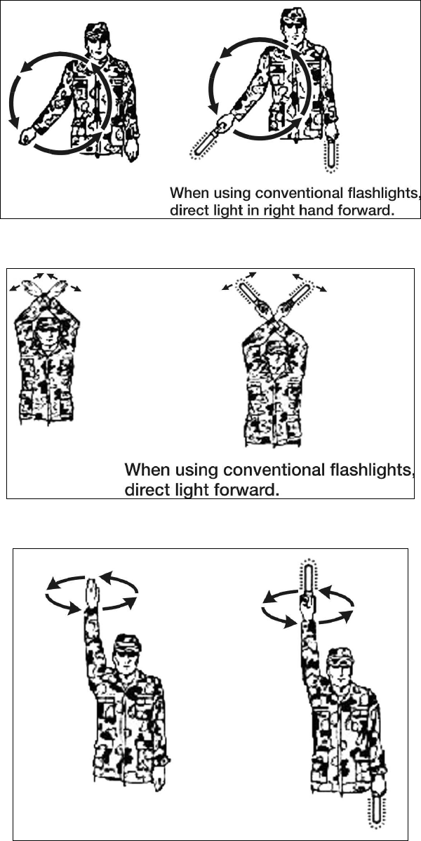
STP 55-88M14-SM-TG
3-23
Figure 3-12. Start Engines
Figure 3-13. As You Were
Figure 3-14. Assemble
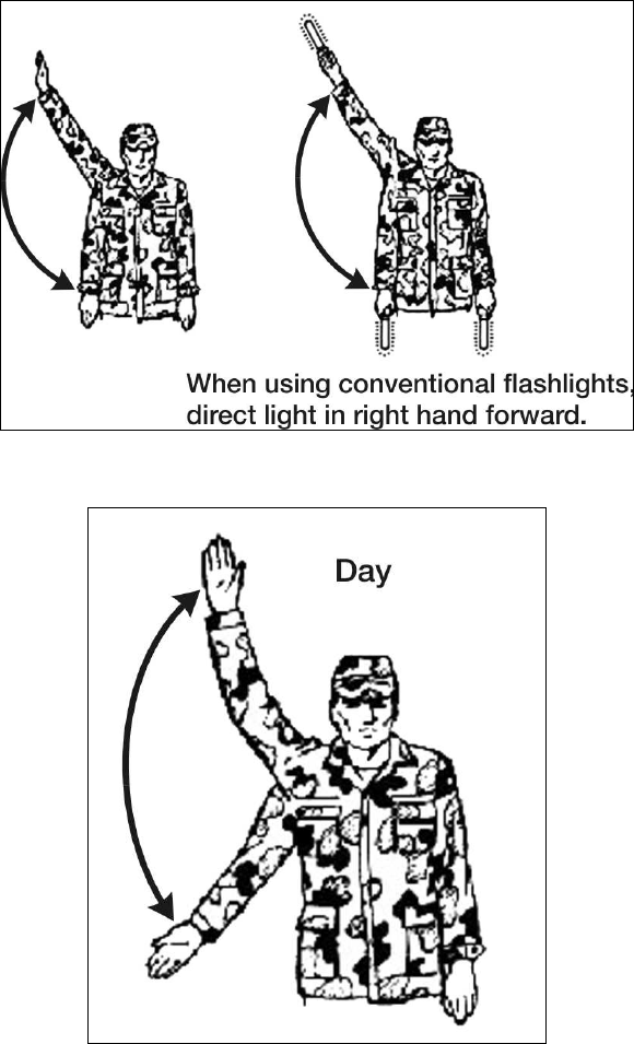
STP 55-88M14-SM-TG
3-24
Figure 3-15. Dismount
Figure 3-16. Mount Day Time
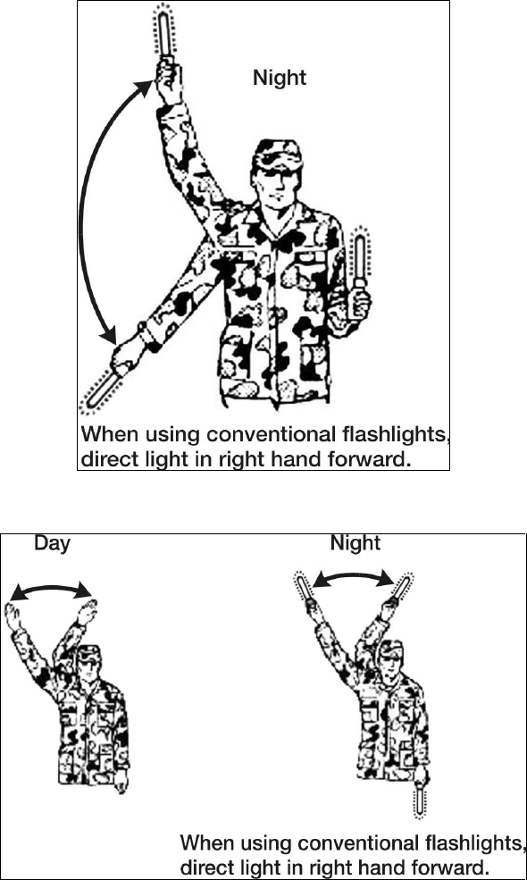
STP 55-88M14-SM-TG
3-25
Figure 3-17. Mount Night Time
Figure 3-18. Attention
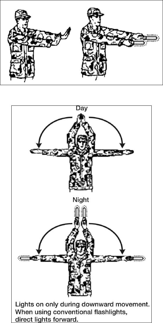
STP 55-88M14-SM-TG
3-26
Figure 3-19. Ready
Figure 3-20. Extend
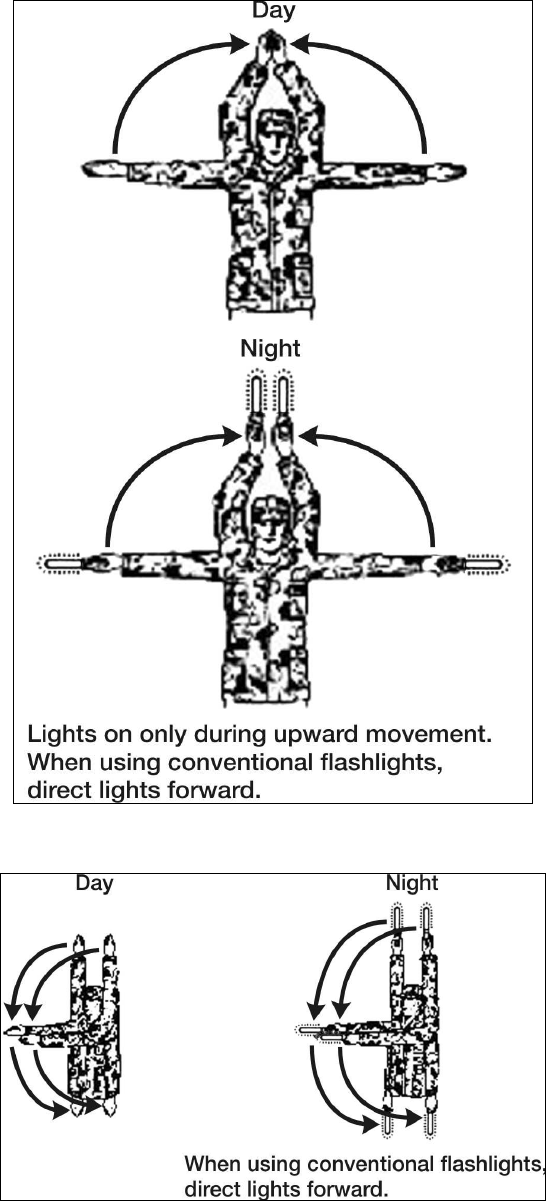
STP 55-88M14-SM-TG
3-27
Figure 3-21. Close Up
Figure 3-22. Close Up and Stop
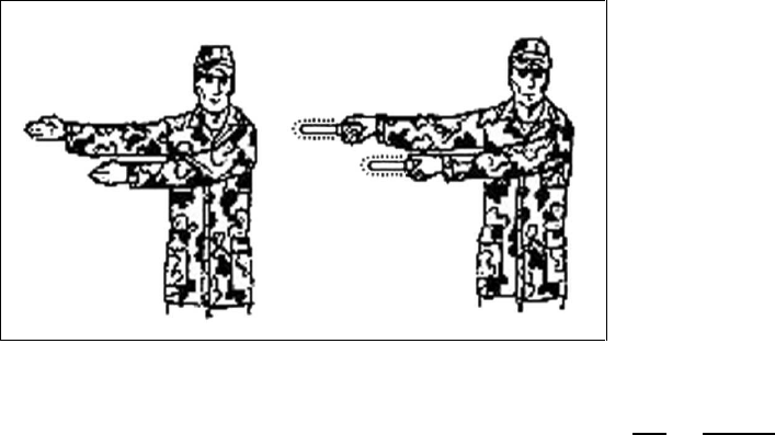
STP 55-88M14-SM-TG
3-28
Figure 3-23. By the Flank
Performance Measures GO NO GO
1. Made preparations to ground guide a wheeled vehicle. —— ——
2. Reconnoitered the area the vehicle will be traveling through. —— ——
3. Employed visual hand signals to guide vehicle movement. —— ——
Evaluation Guidance: Score the soldier GO if all performance measures are passed. Score the soldier
NO-GO if any performance measure is failed. If any performance measure is failed, tell the soldier what
was done wrong and how to do it correctly.
References
Required Related
FM 21-305
FM 21-60
STP 55-88M14-SM-TG
3-29
Operate Palletized Load System
551-721-1500
Conditions: Given a mission-ready, dispatched PLS/HEMTT LHS truck with before-operation inspections
performed, designated route to operate, hearing protection, TM, and all BII.
Standards: You have prepared the vehicle for operation by making all necessary driver adjustments;
performed all starting procedures; and operated the vehicle within its capabilities and limitations over
normal terrain, steep grades, and off-road. You have complied with all local traffic regulations and have
caused no injury to personnel or damage to vehicle during operation.
Performance Steps
1. Prepare vehicle for movement.
a. Change vehicle weight indicator as needed.
b. Install or stow foot rest.
c. Adjust driver seat.
d. Operate seat belt.
2. Operate vehicle on-road.
a. Drive. Refer to TM 9-2320-364-10, paragraph 2-19a, steps (1) through (29), pages 2-182 to 2-
188. Refer to subsequent paragraphs as noted in the TM.
b. Reverse. Refer to TM 9-2320-364-10, paragraph 2-19b, steps (1) to (19), pages 2-189 to 2-
193. Refer to subsequent paragraphs as noted in the TM.
c. Slippery conditions On road and Off road. Refer to TM 9-2320-364-10, paragraph 2-19c, steps
(1) to (5), pages 2-193 to 2-195. Refer to subsequent paragraphs as noted in the TM.
d. Comply with all WARNING and CAUTION statements in the TM regarding the procedures in
item 2a, b, and c above.
3. Operate vehicle off-road.
a. Refer to TM 9-2320-364-10, paragraph 2-20, steps a through s, pages 2-196 to 2-201. Refer to
subsequent paragraphs as noted in the TM.
b. Adhere to all WARNING and CAUTION statements in the TM for this procedure.
4. Operate vehicle on steep grades.
a. Refer to TM 9-2320-364-10, paragraph 2-21a, pages 2-202 to 2-206 for driving up moderate to
steep grades. Refer to subsequent paragraphs as needed in the TM.
b. Refer to TM 9-2320-364-10, paragraph 2-21b, page 2-207 to drive down steep grades. Refer to
subsequent paragraphs as needed in the TM.
c. Adhere so all applicable WARNING and CAUTION statements in the TM for this procedure.
Evaluation Preparation: Setup: Provide the soldier with a mission-ready PLS/HEMTT-LHS truck with
before-operation maintenance performed. Have a prescribed course to operate the vehicle that will allow
safe operation in maneuvering the vehicle through steep grades and on and off road.
Brief Soldier: You are required to operate the PLS/HEMTT-LHS truck over normal terrain as well as up
steep grades, down steep grades, and off-road. All preparation for operation and operation of vehicle
through the various terrain must be performed while adhering to all WARNING and CAUTION statements
and completing all required steps in the vehicle's TM. Failure to comply with the vehicle's TM with regard
to operational steps and safety will result in a NO-GO for this task. You are required to possess a valid
operator's permit or be accompanied by a licensed operator for this vehicle if you are operating in other
than a "controlled driving range."

STP 55-88M14-SM-TG
3-30
Performance Measures GO NO GO
1. Prepared vehicle for movement. —— ——
a. Changed vehicle weight indicator as need.
b. Installed or stow foot rest.
c. Installed or stow foot rest.
d. Operated seat belt.
2. Operated vehicle on-road. —— ——
a. Drive. Referred to TM 9-2320-364-10, paragraph 2-19a, steps (1) through
(29), pages 2-182 to 2-188. Refer to subsequent paragraphs as noted in the
TM.
b. Reverse. Referred to TM 9-2320-364-10, paragraph 2-19b, steps (1) to (19),
pages 2-189 to 2-193. Refer to subsequent paragraphs as noted in the TM.
c. Slippery conditions On road and Off road. Refer to TM 9-2320-364-10,
paragraph 2-19c, steps (1) to (5), pages 2-193 to 2-195. Refer to
subsequent paragraphs as noted in the TM.
d. Comply with all WARNING and CAUTION statements in the TM regarding
the procedures in item 2a, b, and c above.
3. Operated vehicle off-road. —— ——
a. Referred to TM 9-2320-364-10, paragraph 2-20, steps a through s, pages 2-
196 to 2-201. Refer to subsequent paragraphs as noted in the TM.
b. Adhered to all WARNING and CAUTION statements in the TM for this
procedure.
4. Operated vehicle on steep grades. —— ——
a. Referred to TM 9-2320-364-10, paragraph 2-21a, pages 2-202 to 2-206 for
driving up moderate to steep grades. Referred to subsequent paragraphs as
needed in the TM.
b. Referred to TM 9-2320-364-10, paragraph 2-21b, page 2-207 to drive down
steep grades. Referred to subsequent paragraphs as needed in the TM.
c. Adhered to all applicable WARNING and CAUTION statements in the TM for
this procedure.
Evaluation Guidance: Score the soldier GO if all performance measures are passed. Score the soldier
NO-GO if any performance measure is failed. If any performance measure is failed, tell the soldier what
was done wrong and how to do it correctly.
References
Required Related
TM 9-2320-364-10
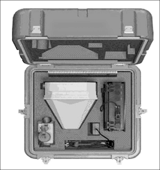
STP 55-88M14-SM-TG
3-31
Operate the Movement Tracking System (MTS)
551-721-1600
Conditions: Given a MTS Mobile Unit (V2), mounted into a tactical wheeled vehicle.
Standards: You have successfully applied power to system, completed the PLGR configuration and
system diagnostics, read, sent, and received messages, and properly shutdown the MTS mobile unit and
PLGR without injury to personnel or damage to equipment or vehicle.
Performance Steps
1. Identify MTS mobile unit (V2) components.
a. Make a visual check of the transit case (see Figure 3-24). Ensure all components are
accounted for by checking the equipment list (see Figure 3-25).
(1) V2 Transceiver (Satellite Modem) MT-2010.
(2) Precision Lightweight GPS Receiver (PLGR).
(3) Ruggedized Computer.
(4) Universal Power Adapter.
(5) Data cable.
(6) Power cable.
(7) PLGR Adapter.
Figure 3-24. V2 Transit Case Contents
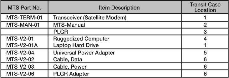
STP 55-88M14-SM-TG
3-32
Figure 3-25. Equipment List
Performance Steps
b. Ensure all cable connections are made properly and system is ready for power on (see
Figure 3-26).
(1) V2 Transceiver (Satellite Modem) MT-2010.
(a) Attach the transceiver (Term-001) to the A-Kit mounting bracket on the roof of the
vehicle.
(b) Attach the lanyard to the transceiver (Term-001).
(c) Connect the A-Kit power/data cable [A-2] to the transceiver. The power/data cable is
part of the A-Kit. It starts at the Control Box [A-1] and terminates with a connector
that attaches to the transceiver. When the transceiver is not mounted on the vehicle,
the power/data cable connector should be stowed on the A-Kit mounting bracket to
protect the cable connector.
(2) Ruggedized computer installation to the A-Kit.
(a) Attach the ruggedized computer (V2-01) to the A-Kit mounting bracket located inside
vehicle.
(b) Connect the data cable (V2-02) to J4 (COM2) that is on the bottom side of the
computer to the RS-422 port on the A-Kit's control box (A-1).
(c) Using the computer power cable (V2-03), connect port J1 on the computer to the
power port on the A-Kit's control box (A-1).
(3) V2 PLGR Installation (see Figure 3-27).
(a) Connect the military connector on the PLGR adapter cable (V2-06) to the ruggedized
computer's (V2-01) serial port (portJ3).
(b) Connect the 9-pin male connector on the PLGR adapter cable (V2-06) to the 9-pin
female connector on the PLGR cable.
(c) Connect the 15-pin female connector of the PLGR cable to the top port of the PLGR.
All ports on the PLGR can be found on the back of the device.
2. Conduct V2 configuration power on procedures.
a. Observe power indicator lights on A-Kit control box.
(1) The GREEN LED light indicates that the unit is running on auxiliary power (not vehicle)
and that terminal is fully charged.
(2) The RED LED light indicates that the A-Kit battery is running out or auxiliary power (not
vehicle). If the system is on, shutting down the ruggedized computer is recommended.
b. Turn on Control Box. Flip the power switch to ON. If connected properly, the LED lights on the
transceiver (MT-2010) will illuminate.
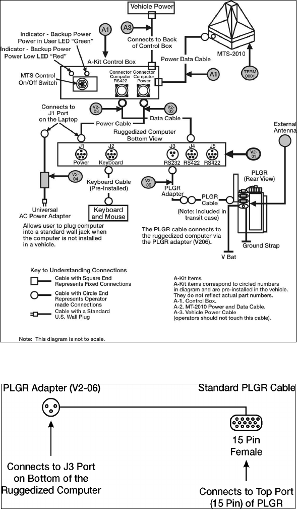
STP 55-88M14-SM-TG
3-33
Figure 3-26. Installation of H2 Hardware
Figure 3-27. V2 PLGR Connection
Performance Steps
c. Turn on the ruggedized computer.
(1) Press the power switch on the laptop computer. Wait for the computer to load/initialize
software.
(2) Read over security window and click OK if you agree to the terms (see Figure 3-28).
(3) When prompted, press CTRL-ALT-DEL to login.
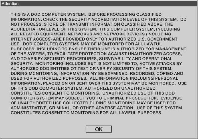
STP 55-88M14-SM-TG
3-34
Figure 3-28. Security Warning
Performance Steps
(4) Enter username and password, and then click OK. The Windows desktop should contain
MTS Messenger and TracerLink icons.
(5) Start the MTS Messenger software to see if the cables to the computer are correctly
attached.
d. Power and configure the AN/PSN PLGR.
(1) Press the ON button.
(2) Press the menu button.
(3) Press the right arrow until SETUP is flashing.
(4) Press the up arrow until you see SETUP MODE.
(5) Press the right arrow until FIX is flashing.
(6) Press the up arrow until CONT appears.
(7) Press the right arrow until you see and up and down arrow to the left of the letter P in the
lower right of the screen.
(8) Press the up arrow until the Timer function appears in the lower part of the screen.
(9) Press the right arrow until the time value is flashing.
(10) Press the up arrow until OFF appears.
(11) Press POS.
3. Start MTS Messenger (see Figure 3-29).
a. To start MTS Messenger double-click the MTS Messenger icon located on the desktop. Users
will be prompted to select the COM port.
b. V2 users select COM 3 (J4). If you receive the following error message stating: "No response
from Terminal-Check cables", go to Section 8, Troubleshooting in the MTS User's Manual.
c. V2 users select COM 1 (J3). After successfully starting MTS Messenger, the standard display
screen also known as the command reference will appear.
d. Ensure all status blocks are displayed at bottom of screen.
e. Wait for network registration. The bumper number and transceiver ID will appear in status block
4 at the bottom when network registration completes.
f. Refer to the MTS User's Manual, version 1.9.1, Section 8, Troubleshooting when directed or as
needed.
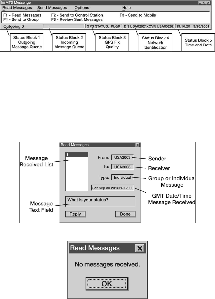
STP 55-88M14-SM-TG
3-35
Figure 3-29. MTS Messenger Main Window
Performance Steps
4. Read messages (see Figures 3-30 and 3-31).
a. Access the read messages pull down menu by either clicking with the mouse or using the
function keys (F1 and F6).
b. Select read messages - read current or press F1 to read messages.
c. In the message received list, click the message number you wish to read (will default to the
most recent message received). The text of the message will appear in the message text field.
Click the reply button to return a message to the sender, or "done" to go back to the main
window. Use up and down arrow keys to move between messages (see Figure 3-32).
Note: If you have not received any messages, (for example, right after you started MTS Messenger) you
selected read messages - read current via the pull down menu.
Figure 3-30. Read Current Messages
Figure 3-31. Read Messages Error Message
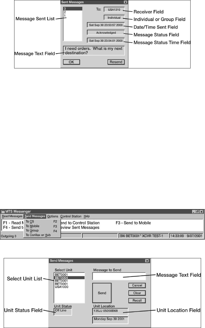
STP 55-88M14-SM-TG
3-36
Figure 3-32. Review Sent Messages
Performance Steps
5. Send messages.
a. To an individual unit.
(1) Select the send messages pull down menu or use the F2, F3 and F4 function keys on the
keyboard (see Figure 3-33).
(2) Send message to control station (CS) select send message - to CS or press F2 (see
Figure 3-34).
(3) Send a message to a mobile unit select send message - to mobile or press F3 Send
message to a Control Station).
(4) Choose recipient for your message by choosing a unit from select unit list. Before you
type a message, check the unit status field. This field will let you know if the intended
recipient is on line of off line. The unit location field will indicate the position of unit.
(5) Type the message into the message text field.
(6) Press send once the message is complete. Press cancel button to return to the main
window without sending. Press recall button to load the last sent message into the
message box. Press clear to clear.
(7) Go to read messages - review sent messages to see if the recipient received the
message.
Figure 3-33. Send Messages
Figure 3-34. Send Message to Control Station
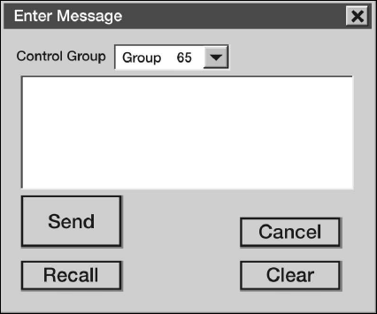
STP 55-88M14-SM-TG
3-37
Performance Steps
b. Send a message to all members of a control group (see Figure 3-35).
(1) Select send messages - to group, or press F4, to send a message to all members of the
control group, except the sender. Mobile units will only see one control group, while
control stations might be members of several control groups.
(2) Enter the text in the message text field and press the send button. Pressing recall button
will load the message box with the text from the last message sent. To close the window
without sending a message, press the cancel button. To erase any text in the message
text field press the clear button.
(3) After sending message, go to read messages - review sent messages to see if any group
members received the message.
Figure 3-35. Send Message to Control Group
6. Start TracerLink program.
a. Double-click on the TracerLink icon located on the desktop to start the TracerLink application.
TracerLink connects to the MTS Messenger program over a TCP/IP socket to receive position
data.
Note: In order for TracerLink to function, MTS Messenger must be running.
b. Identify the following program controls and indicators.
(1) Symbols (see Figure 3-36).
(a) Mobile Unit. Round symbols represent mobile units. A square lug on top of the
symbol indicates the unit is turned on and transmitting. No lug on top indicates the
unit is turned off.
(b) Control Station. Square symbols represent control stations. A square lug on top of
the symbol indicates the unit is turned on and transmitting. No lug on top indicates
the unit is turned off.
Note: A square lug at the bottom of a symbol indicated the vehicle is reporting valid GPS. If a unit is
powered on, but it not reporting valid GPS, then the location of the icon on the screen reflects the last
known position of the vehicle, and may not reflect the current position of the vehicle.
(2) Right Click Pop Up Menu. Simply right click with the mouse on the Map Viewer (see
Figure 3-37).
(3) Zoom the map. To zoom, right click on the map to show the pop up menu. Select Zoom
In or Zoom Out. Click on the map at the point you wish to become the center of the map.
The map will zoom with the point clicked becoming the new center of the map.
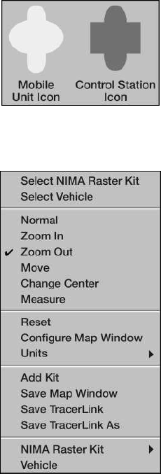
STP 55-88M14-SM-TG
3-38
Figure 3-36. MTS Mobile Unit and Control Station Symbols
Figure 3-37. Right Click Popup Menu
Performance Steps
(4) Change Center. Right click the mouse over the map to pop up the menu, select Change
Center. Click on the map and the map will move with the point clicked becoming the new
center of the map.
(5) Pan a Map (Move). Right click the mouse over the map to pop up the menu, select Move.
The cursor becomes a hand. Click on the map and hold down the left mouse button, then
drag the map to the desired position. When you release the mouse, the map will redraw
in the new position.
(6) Measure distance on a map. Right click on the map and then select Measure. Click and
drag the cursor from point A to point B on the map. Before releasing the button, look at
the scale display at the bottom of the map window. It displays the distance in kilometers,
nautical miles, or statute miles. Once you release the mouse, the distance measurement
will disappear (see Figure 3-38).
(7) Reset Map to Initial View. Right click on the map and select Reset.
(8) Units Changing Units of Measure. Right click on the map and select Unit. Select whether
you want the map in Kilometers, Nautical Miles or Statute Miles.
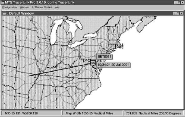
STP 55-88M14-SM-TG
3-39
Figure 3-38. Map of Measure Distance Function
Performance Steps
c. Navigate through the Server Vehicle Kit Control Window. Use the Server Vehicle Kit Control
Window (see Figure 3-39) to trace a vehicle's route, hide a vehicle or display a vehicle that was
previously hidden, or hide/display a vehicle's name and last position report time.
(1) Display the Server Kit Control Window.
(a) Method one. Right click the mouse and choose Select Vehicle on the pop up menu.
This will change your cursor into a hand with a pointed finger. Left click on the map
(with the hand) wither over a vehicle's icon or over a bare spot. If you clicked over a
vehicle's icon, the vehicle kit window will display the clicked vehicle(s) in the pane. If
you clicked over a bare spot the window will be empty.
(b) Method two. Slowly slide the cursor off the screen to the right side of the map.
When you approach the edge of the map the Kit Bar will appear (see Figure 3-40).
(2) Display information in the Server Kit Control Window.
(a) The Assignments Tab. Click on the Assignment Tab to display vehicle information in
a hierarchical fleet view (see Figure 3-41).
(b) The Selection Tab. Click on the Selection Tab to display vehicle information listed by
vehicle (see Figure 3-42).
(c) Enable Autotrack function (see Figure 3-43).
1) Right click on the map to get the pop up menu.
2) Choose the Select Vehicle option from the pop up window.
3) Click on the vehicle you wish to track. The Server Vehicle Kit Control window will
open with the Selection tab containing a list of vehicles.
4) Right click on the vehicle you wish to track, select State - Track.
Note: If the vehicle you are tracking is off the map, use the Assignments tab instead of the Selection tab
to make the change.
(d) Enable Trace function (see Figure 3-44).
1) Right click on the map to get the pop up menu.
2) Choose the Select Vehicle option from the pop up menu.
3) Click on the vehicle you wish to trace. The Server Vehicle Kit Control window will
open with the Selection tab containing a list of vehicles.
4) Right click on the vehicle you wish to trace, and then select Display - Trace.
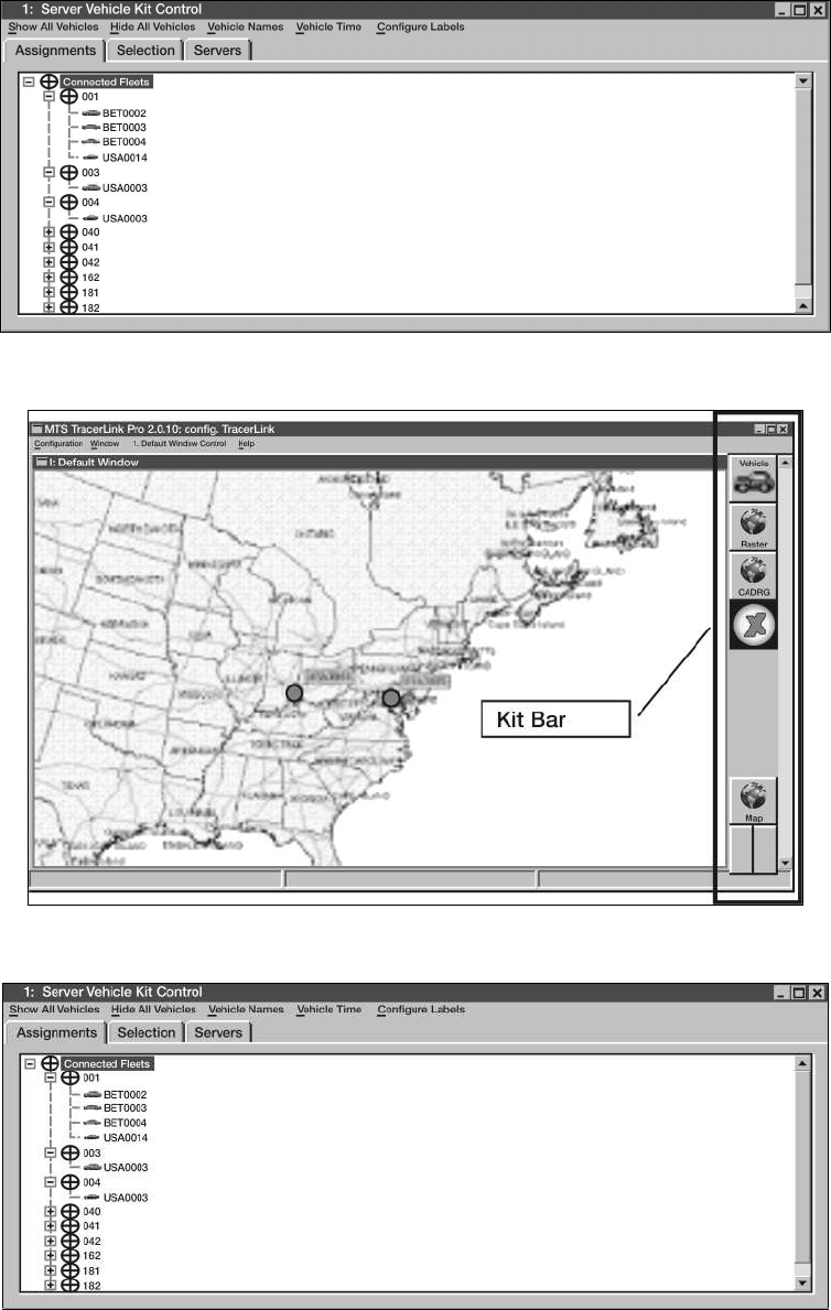
STP 55-88M14-SM-TG
3-40
Figure 3-39. Server Vehicle Kit Control Window
Figure 3-40. Kit Bar
Figure 3-41. The Assignments Tab
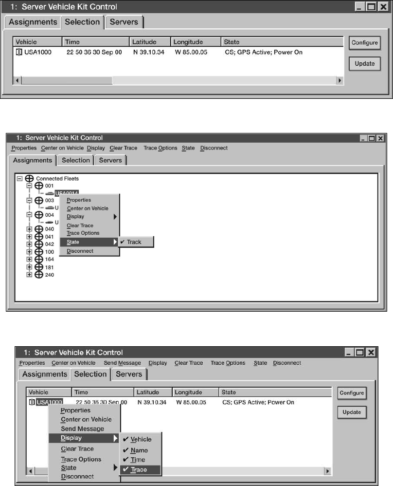
STP 55-88M14-SM-TG
3-41
Figure 3-42. The Selection Tab
Figure 3-43. Autotrack
Figure 3-44. Tracing a Vehicle
STP 55-88M14-SM-TG
3-42
Performance Steps
(e) Hiding/Show and individual vehicle's name (see Figure 3-45).
1) Right click on the map to get the pop up menu.
2) Choose Select Vehicle.
3) Click on the vehicle you wish to name (un-name). The Server Vehicle Kit Control
window will pop up listing the vehicles.
4) To turn the name on, right click on the name in the Server Vehicle Kit Control
window and select Display - Name.
(f) Hide/Show entire control groups (see Figure 3-46).
1) Right click on the map to get the pop up menu.
2) Choose Select Vehicle.
3) Click on the map so that the Server Vehicle Kit Control window pops up.
4) Select Assignments tab. The various control groups will be listed with expandable
plus boxes next to each one.
5) Right click on a Control Group (such as 001, 002, 003, and so forth), and select All
Vehicles - Hide. If a control group is already hidden, to show it, simply select All
Vehicles –Show (see Figure 3-47).
(g) Display/Hide Report Time Labels for an Individual Vehicle.
1) Right click on the map to get the pop up menu.
2) Choose Select Vehicle.
3) Click on the map with the mouse so that the Server Vehicle Kit Control window
pops up.
4) Select the Assignments tab.
5) Right click on a vehicle, and select Display - Time. If the time was not previously
displayed, it will be. If the time was previously displayed, it will be turned off.
(h) Display/Hide Report Time Labels for an Entire Control Group.
1) Right click on the map to get the pop up menu.
2) Choose Select Vehicle.
3) Click on the mouse so that the Server Vehicle Kit Control window pops up.
4) Select the Assignments tab.
5) Right click on the fleet name, and select All Vehicle -Time - Display or All Vehicles
- Time –Hide (see Figure 3-48).
(i) Center the map on a vehicle (see Figure 3-49).
1) Right click on the map to get the pop up menu.
2) Choose select vehicle.
3) Click on the map with the mouse so that the Server Vehicle Kit Control window
pops up.
4) Select the Assignments tab.
5) Open the control group, right click on the vehicle you wish to find, and select
Center on Vehicle.
7. Perform power off procedures.
CAUTION: Improper shut down of system may result in data loss.
a. Close all applications (MTS Messenger, TracerLink Vehicle Server, TracerLink Map Viewer).
b. Click the Start button in bottom left corner of the screen.
c. Select the Shut down option.
d. Select Shut down and then click OK.
e. When "It is now safe to turn off the computer" appears on the screen, press the Power ON/OFF
button on the Control Box.
f. On the PLGR, press OFF and wait for the timer, or press the OFF button two times to power
down immediately.
CAUTION: Failure to turn off the Power ON/OFF button on the Control Box will allow the terminal to
continue operation and drain the emergency battery.
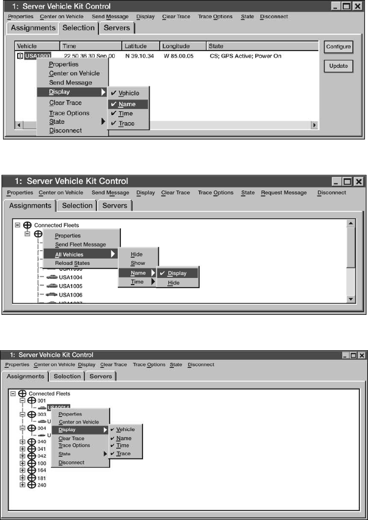
STP 55-88M14-SM-TG
3-43
Figure 3-45. Display Vehicles Name
Figure 3-46. Hide and Show Group of Vehicles
Figure 3-47. Hiding and Showing a Position
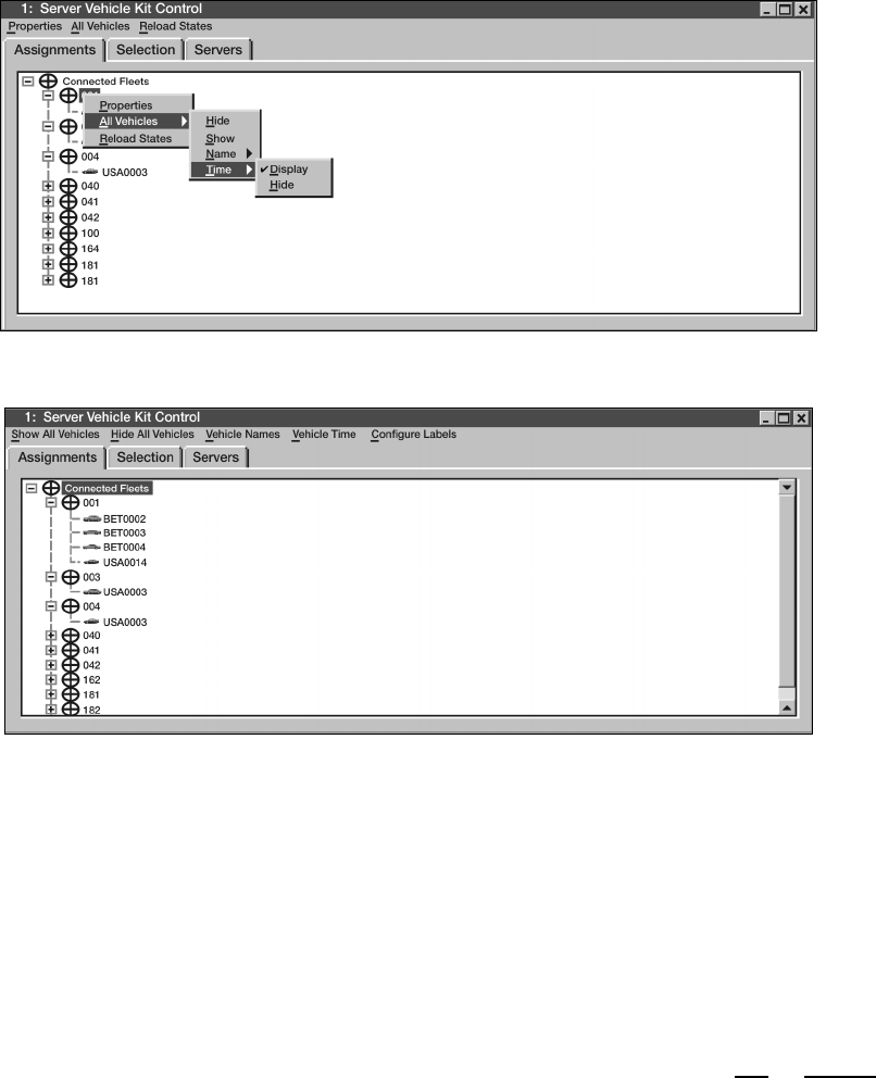
STP 55-88M14-SM-TG
3-44
Figure 3-48. Hiding and Showing Position Report for Fleet of Vehicles
Figure 3-49. Centering the Map on a Vehicle
Evaluation Preparation: Setup: Ensure that MTS mobile unit is installed in the vehicle to be used.
Provide information to the student for use in communication purposes.
Brief Soldier: You are required to ensure that all connections involved in the proper installation of the
mobile unit have been made and the unit is securely mounted. You will then be required to perform a
power on procedure followed by starting and operating the software for the system and finally, you will
perform the power off procedures. All procedures must be performed in sequence, if applicable. All
procedures and communication with other elements will be performed without injury to personnel or
damage to equipment.
Performance Measures GO NO GO
1. Identified MTS mobile unit (V2) components. —— ——
2. Conducted V2 configuration power on procedures. —— ——
3. Started MTS Messenger. —— ——
4. Read messages. —— ——
5. Sent messages. —— ——
6. Started TracerLink program. —— ——
7. Performed power off procedures. —— ——
STP 55-88M14-SM-TG
3-45
Evaluation Guidance: Score the soldier GO if all performance measures are passed. Score the soldier
NO-GO if any performance measure is failed. If any performance measure is failed, tell the soldier what
was done wrong and how to do it correctly.
References
Required Related
MTS USERS MANUAL
STP 55-88M14-SM-TG
3-46
Operate the Driver's Vision Enhancer (DVE)
551-721-1650
Conditions: This task should be done during the hours of darkness or limited visibility. Soldier must be a
licensed operator for the vehicle used. Given a tactical wheeled vehicle equipped with the driver's vision
enhancer already mounted and connected, route to maneuver, and conditions of limited visibility or
darkness.
Standards: Placed the DVE into operation then safely operated the vehicle through a pre-designated
route with limited visibility while relying on the use of the driver's vision enhancer to negotiate terrain. All
maneuvers were completed without personal injury or damage to equipment or surroundings.
Performance Steps
1. Start the vehicle. Refer to the applicable vehicle TM for proper starting procedures.
2. Perform initial setup procedures.
Note: Before powering up the unit, ensure that the following control positions are as indicated in the
following steps.
WARNING: Before operating the vehicle, ensure that the DVE azimuth and elevation controls are in the
locked positions. This will ensure that the DVE is looking straight ahead when operating the vehicle.
Manually verify forward and lock position prior to operating the vehicle.
WARNING: Helmets must always be worn when driving with the DVE installed. The DVE display should
be removed from its mount when not in use for extended driving operations to minimize the risk of head
strike injuries.
a. Rotate Sensor Assembly azimuth and elevation to straight ahead and level 00 detent positions.
b. Set DVE POWER switch to OFF (down position).
c. Set VIDEO switch to SENSOR (up position).
d. Set POLARITY switch to WHT-HOT (up position).
e. With DISPLAY BRIGHTNESS control turned fully ccw, rotate knob approximately ¼ turn cw.
f. Set SENSOR LEVEL and SENSOR GAIN controls to full ccw (AUTO) detent position.
3. Place DVE into operation.
a. Set POWER to ON position (up). Allow 5 minutes for system electronics to stabilize for
maximum image clarity.
b. Leave the VIDEO switch in the SENSOR (up position) for sensing input from the Sensor
Assembly to the display. For external input to display, set switch to EXT (down position) (see
Figure 3-50).
c. Adjust the seat height and/or Display module to place the display at eye level.
Note: If the display becomes degraded while driving the vehicle, such as the presence of dead pixels
and/or video noise that prevents the driver from performing his mission, then immediately bring the
vehicle to a safe stop to avoid a collision. If the problem cannot be fixed, report the situation to higher
level of maintenance.
d. Adjust the DISPLAY BRIGHTNESS control until the scene brightness is suitable for operator
viewing.
e. Select either the AUTO LEVEL or the MANUAL LEVEL position.

STP 55-88M14-SM-TG
3-47
Figure 3-50. Driver Screen Display
Performance Steps
f. Adjust the SENSOR GAIN control to automatic or manual position. The AUTO GAIN mode
should normally be used while driving the vehicle.
WARNING: The AUTO LEVEL and AUTO GAIN modes do not react instantly to rapidly changing
scenery (shade to sun, sun to shade). The AUTO LEVEL and AUTO GAIN modes require one or two
seconds to compensate. The automatic gain and level features will adjust faster than manual
adjustments. If necessary, slow vehicle.
WARNING: There are two short periods each day called crossover periods or diurnal cycle when most
natural objects are about the same temperature. This is when they have cooled down at night and as
they are heating up in the early morning. Since objects are near the same temperature, there is not much
temperature difference for the DVE to use, degrading the image display quality. This is also what
happens when a heavy rain makes all natural objects close to the same temperature.
g. Set scene POLARITY switch to either WHT-HOT (up position) or BLK-HOT (down position).
h. Set azimuth position by rotating Pan/Tilt Mechanism (PTM) (see Figure 3-51
) to desired setting.
Lock azimuth-locking mechanism.
i. Set elevation position to desired position. Lock elevation-locking mechanism.
4. Maneuver vehicle while relying on DVE for terrain negotiation.
a. Operate the vehicle while monitoring the DVE screen.
b. Adjust vehicle speed as necessary while DVE is making auto adjustments to conditions.
c. Exercise increased caution when operating vehicle, using DVE for navigation.
5. Shutdown DVE.
a. Press FORWARD POSITION switch.
b. Visually verify sensor is in the straight ahead and level position.
c. Set SENSOR LEVEL and GAIN controls to full ccw (AUTO) detent position.
d. With the DISPLAY BRIGHTNESS control turned fully ccw, rotate the knob approximately ¼
turn cw.
e. Set POLARITY switch to WHT-HOT (up) position.
f. Set VIDEO switch to SENSOR (up) position.
g. Set POWER switch to OFF position (down).
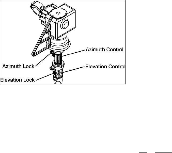
STP 55-88M14-SM-TG
3-48
Figure 3-51. Pan and Tilt Mechanism
Evaluation Preparation: Setup: Provide for the soldier a DVE-equipped vehicle in operational condition
and ready for operation.
Brief Soldier: You are required to prepare the vehicle for operation. You are also required to prepare the
DVE system for operation. Once both vehicle and system are operational, you are to operate the vehicle
while relying on the DVE for navigation over a designated route during periods of severe limited visibility
or at nighttime. You are to complete this task without injury to personnel or damage to equipment.
Performance Measures GO NO GO
1. Started the vehicle. —— ——
Note: The words "NO VIDEO" will appear within a black rectangle at the top-center of
the display only if the VIDEO switch is in the EXT position or the display circuitry has
no video input. The display circuitry senses the presence of video. If the video is
absent during operation, the words "..NO VIDEO.." are indicated. If the video returns,
the words are removed, but the no video indicator bar is cleared from the display by
recycling the power switch (power off and on).
2. Performed initial setup procedures. —— ——
WARNING: Before operating the vehicle, ensure that the DVE azimuth and elevation
controls are in the locked positions. This will ensure that the DVE is looking straight
ahead when operating the vehicle. Manually verify forward and lock position prior to
operating the vehicle.
WARNING: Helmets must always be worn when driving with the DVE installed. The
DVE display should be removed from its mount when not in use for extended driving
operations to minimize the risk of head strike injuries.
a. Rotate Sensor Assembly azimuth and elevation to straight ahead and level
00 detent positions.
b. Set DVE POWER switch to OFF (down position).
c. Set VIDEO switch to SENSOR (up position).
d. Set POLARITY switch to WHT-HOT (up position).
e. With DISPLAY BRIGHTNESS control turned fully ccw, rotate knob
approximately ¼ turn cw.
f. Set SENSOR LEVEL and SENSOR GAIN controls to full ccw (AUTO) detent
position.

STP 55-88M14-SM-TG
3-49
Performance Measures GO NO GO
3. Placed DVE into operation. —— ——
a. Set POWER to ON position (up).
Allow 5 minutes for system electronics to stabilize for maximum image
clarity.
b. Leave the VIDEO switch in the SENSOR (up position) for sensing input from
the Sensor Assembly to the display. For external input to display, set switch
to EXT (down position).
c. Adjust the seat height and/or Display module to place the display at eye
level.
WARNING: If the display becomes degraded while driving the vehicle, such as the
presence of dead pixels and/or video noise that prevents the driver from performing his
mission, then immediately bring the vehicle to a safe stop to avoid a collision. If the
problem cannot be fixed, report the situation to higher level of maintenance.
d. Adjust the DISPLAY BRIGHTNESS control until the scene brightness is
suitable for operator viewing.
e. Select either the AUTO LEVEL or the MANUAL LEVEL position.
f. Adjust the SENSOR GAIN control to automatic or manual position. The
AUTO GAIN mode should normally be used while driving the vehicle.
WARNING: The AUTO LEVEL and AUTO GAIN modes do not react instantly to
rapidly changing scenery (shade to sun, sun to shade). The AUTO LEVEL and AUTO
GAIN modes require one or two seconds to compensate. The automatic gain and
level features will adjust faster than manual adjustments. If necessary, slow vehicle.
WARNING: There are two short periods each day called crossover periods or diurnal
cycle when most natural objects are about the same temperature. This is when they
have cooled down at night and as they are heating up in the early morning. Since
objects are near the same temperature, there is not much temperature difference for
the DVE to use, degrading the image display quality. This is also what happens when
a heavy rain makes all natural objects close to the same temperature.
g. Set scene POLARITY switch to either WHT-HOT (up position) or BLK-HOT
(down position).
h. Set azimuth position by rotating Pan/Tilt Mechanism (PTM) to desired
setting. Lock azimuth-locking mechanism.
i. Set elevation position to desired position. Lock elevation-locking
mechanism.
4. Maneuvered vehicle while relying on DVE for terrain negotiation. —— ——
a. Operate the vehicle while monitoring the DVE screen.
Adjust vehicle speed as necessary while DVE is making auto adjustments to
conditions.
5. Shutdown DVE. —— ——
a. Press FORWARD POSITION switch.
b. Visually verify sensor is in the straight ahead and level position.
c. Set SENSOR LEVEL and GAIN controls to full ccw (AUTO) detent position.
d. With the DISPLAY BRIGHTNESS control turned fully ccw, rotate the knob
approximately ¼ turn cw.
e. Set POLARITY switch to WHT-HOT (up) position.
f. Set VIDEO switch to SENSOR (up) position.
g. Set POWER switch to OFF position (down).
STP 55-88M14-SM-TG
3-50
Evaluation Guidance: Score the soldier GO if all performance measures are passed. Score the soldier
NO-GO if any performance measure is failed. If any performance measure is failed, tell the soldier what
was done wrong and how to do it correctly.
References
Required Related
TM 11-5855-311-12&P-2
STP 55-88M14-SM-TG
3-51
Subject Area 5: Transport Cargo and Personnel
Load and Unload Passengers for Transport in a Truck
551-721-1386
Conditions: Given a tactical wheeled cargo vehicle equipped with troop seating, troop safety strap,
hearing protection, and passengers.
Standards: You have successfully prepared vehicle for loading, provided all passengers with the
appropriate safety briefing and rules governing transport by tactical wheeled vehicle, supervised and
assisted the loading, seating and unloading of all passengers without injury to personnel or damage to
vehicle.
Performance Steps
1. Prepare vehicle to receive passengers.
a. For standard transmissions, places gear selector in FIRST gear.
b. For automatic transmissions, places gear selector in PARK or NEUTRAL.
c. Apply parking or hand brake.
d. Shutdown engine, if running.
e. Chock vehicle wheel(s) if applicable or if not on level ground.
f. Troop seating is down and secured into position.
g. Troop safety strap is released and vehicle tailgate is lowered.
h. If under inclement weather, ensures that all canvas and bows are installed and secured
properly with end-curtain opened.
i. Ensure that cargo compartment is adequately ventilated.
2. Brief passengers on safety requirements.
a. All passengers must wear hearing protection.
b. All passengers must keep all parts of their bodies inside the vehicle at all times.
c. All passengers must remain seated while vehicle is in motion.
d. All passengers must secure their equipment and any loose items.
e. All passengers must mount and dismount from the tailgate only.
f. All passengers will not throw anything from the vehicle.
g. If equipped, all passengers must fasten seat belts.
h. In the event of and accident, all uninjured passengers must assist in moving the injured to
safety and summon medical attention.
i. Only the vehicle operator will install or remove the personnel safety strap and raise or lower the
tailgate.
j. No smoking for all occupants of a military vehicle.
k. Demonstrates safe method of mounting and dismounting vehicle cargo area.
3. Assist in loading passengers.
a. Ensure all passengers are seated properly.
b. Does not exceed passenger-seating capacity of vehicle.
4. Secure vehicle for movement.
a. Secures troop safety strap.
b. Raises and secures vehicle tailgate.
c. Secures canvas end-curtain.
d. Recovers and stows chock blocks if used.

STP 55-88M14-SM-TG
3-52
Performance Steps
5. Prepare vehicle for unloading of passengers.
a. If vehicle was moved, adhere to items 1a through 1d above.
b. Releases canvas end-curtain if used.
c. Releases troop safety strap.
d. Lowers vehicle tailgate.
e. Provides assistance as needed to unload passengers.
6. Assist in unloading passengers from vehicle.
a. Ensures passengers adhere to proper method of dismounting vehicle.
b. Ensures passengers use designated steps and hand holds on the vehicle.
7. Secure vehicle for movement.
a. Secure troop safety strap.
b. Raise and secure vehicle tailgate.
c. Secure canvas end-curtain.
d. Recover and stow chock blocks if used.
Evaluation Preparation: Setup: Give the soldier a cargo truck, passengers to be transported, and BII.
Brief Soldier: Tell the soldier to transport passengers in a truck and arrive at destination without injuring
passengers or damaging equipment. Tell the soldier to observe all safety procedures and local traffic laws
and the make sure the vehicle's passenger capacity is not exceeded.
Performance Measures GO NO GO
1. Prepared vehicle to receive passengers. —— ——
2. Briefed passengers on safety requirements. —— ——
3. Assisted in loading passengers. —— ——
4. Secured vehicle for movement. —— ——
5. Prepared vehicle for unloading passengers. —— ——
6. Assisted in unloading passengers from vehicle. —— ——
7. Secured vehicle for movement. —— ——
Evaluation Guidance: Score the soldier GO if all performance measures are passed. Score the soldier
NO-GO if any performance measure is failed. If any performance measure is failed, tell the soldier what
was done wrong and how to do it correctly.
References
Required Related
AR 385-55
FM 21-305
FM 55-30
STP 55-88M14-SM-TG
3-53
Perform Tiedown Procedures
551-721-1411
Conditions: Given either a 5-ton cargo vehicle loaded with general cargo, a tractor-semitrailer
combination loaded with a vehicle payload, or a HEMTT cargo vehicle loaded with ammunition, and all
necessary basic issue items, tools, and tiedown materials capable of securing the load to the vehicle.
The vehicle or vehicle combination has been properly parked for loading/unloading operations and
chocked to prevent movement. The load has been placed onto the vehicle but has not been secured. All
necessary pre-use inspections have been performed on vehicle and/or trailer/semitrailer.
Standards: You have ensured proper placement of the load on the vehicle, inspected the tiedown
materials to be used and secured the load by properly blocking and bracing (if needed) and using the
proper tiedown configuration. The load has been inspected by supervisor or other proper authority and
deemed secure and ready for movement.
Performance Steps
1. Ensure load is properly positioned for tiedown.
a. Check configuration of general cargo load.
(1) Ensure that cargo is placed on vehicle with the heaviest items on the bottom and spread
evenly across the vehicle both longitudinally and laterally (see Figures 3-52a and 3-52b).
(2) Ensure items are not stacked too high to allow for the lowest center-of-gravity.
(3) If the load extends more than 4 feet beyond the end of the bed, ensures that a red flag
(measuring not less than 12 x 12 inch square) is attached to the load. During nighttime,
uses a red light (if tactical situation permits).
(4) Check vehicle data plate and TM to ensure that vehicle weight and cube limitations have
not been exceeded.
b. Check configuration of ammunition (on HEMTT and PLS flatrack).
(1) Ensure that cargo is placed on vehicle/flatrack with the heaviest items on the bottom and
spread evenly across the vehicle both longitudinally and laterally (see Figures 3-52c and
3-52d).
(2) Ensure items are not stacked too high to allow for the lowest center-of-gravity.
(3) Ensure that load does not extend past vehicle cargo area perimeters and that cargo truck
tailgate is raised and locked in place.
(4) Check vehicle data plate and TM to ensure that vehicle weight and cube limitations have
not been exceeded.
c. Check configuration of vehicle payload.
(1) Ensure that payload vehicle center-of-gravity is located over the desired point on the
semitrailer. Center-of-gravity marking should be legible on both sides of payload vehicle.
(2) Ensure that all shackles are on the vehicle.
CAUTION: Do not use bumperettes, axles, towing pintles, or towing hooks as points of attachment for
chains.
(3) Remove or band canvas and bows to prevent wind damage (as applicable).
(4) Protect windshield of payload vehicle if needed.
(5) Ensure that fuel tank of payload vehicle is no more than three-quarters full.
(6) Reduce payload vehicle to lowest height configuration consistent with the operational
requirement and unit SOP.
(7) Secure any materials or equipment loaded in the beds of cargo vehicles by banding,
chains or cargo straps.
(8) Remove all sensitive or pilferable items that cannot be secured.
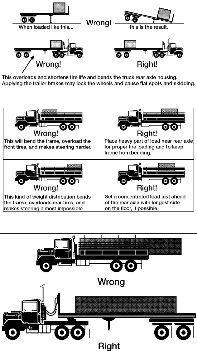
STP 55-88M14-SM-TG
3-54
Figure 3-52a. Load Balancing
Figure 3-52b. Load Balancing (continued)
Figure 3-52c. Load Balancing (continued)
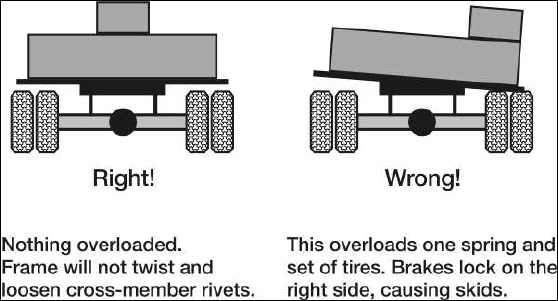
STP 55-88M14-SM-TG
3-55
Figure 3-52d. Load Balancing (continued)
Performance Steps
2. Inspect tiedown materials.
a. Chains and load binders (used for Vehicle Payload) (see Figure 3-53). Inspect chains including
the hooks, at least once a month; inspect those that are used for heavy and continuous loading
more frequently. Give particular attention to the small radius fillets at the neck of the hooks for
any deviation from the original inner arc. Examine each link and hook for small dents and
cracks, sharp nicks and cuts, worn surfaces and distortions. Replace any of those that show
any of these weaknesses. If several links are stretched or distorted, do not use the chain; it
probably was overloaded or hooked improperly, which weakened the entire chain; inspect load
binders for structural cracks in the metal; inspect chain and hooks using same criteria sited
above; if ratchet type, ensure mechanism works freely without binding; inspect lever pivot
mechanism for excessive signs of wear or stress on pin. Do not use if any portion of the load
binders possesses any of the above signs of wear or misuse.
b. Web tiedown straps (used for general cargo and ammunition tiedown). Before each use,
straps should be inspected for burns, tears, punctures, cuts, caustic damage, oil or grease
contamination, and fraying or broken stitches. Inspect metal parts for improper operation,
corrosion, cracks, or distortion. If any of these conditions exist, the tiedown should be
replaced. They should not be used for any mode of transport if they have been damaged. No
strength testing of straps will be made.
c. Blocking and Bracing Materials (as needed, depending on platform and load). Ensure that if
needed, the materials are of a size and configuration to support the tiedown of the load. Use
4X4 materials if available. All lumber used for blocking must be free of knots and strong
enough to provide a rigid and stable support for the load en route.
3. Secure general cargo to bed of 5-ton cargo truck using web tiedown straps.
Note: Not all loads will require blocking and bracing. Blocking and bracing is used for applications
involving a partially loaded vehicle to prevent from shifting.
a. Block and brace load as needed (see Figure 3-54).
b. Attach and secure all necessary web tiedown straps.
(1) Ensure all strap hooks are completely engaged and safety latches are completely closed
around tiedown anchor point.
(2) Ensure that strap is tensioned to form at least 1-1/2 turns on the takeup spool. This is
accomplished after web-to-web contact has been made on the takeup spool (see
Figure 3-55a). To prevent movement of cargo, each tiedown must be tightened until
about equal tension is applied throughout the tiedown arrangement.
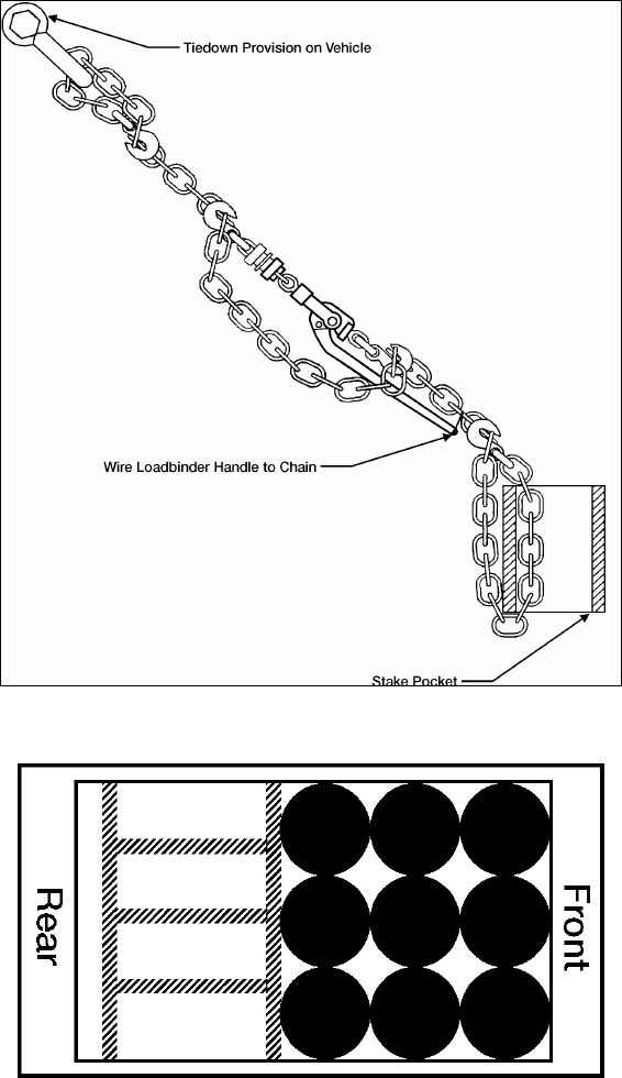
STP 55-88M14-SM-TG
3-56
Performance Steps
(3) After tensioning is completed, the takeup spool-locking latch must be checked to ensure
that it is fully seated at both ends of the spool in the matching locking notches (see
Figure 3-55b). The scuff sleeve may have to be removed to allow tightening of tiedowns.
Secure loose ends of straps by suitable means.
(4) Reinforce sharp edges of cargo with suitable materials to prevent both crushing edges of
the load when strap is tensioned and to prevent slicing into strap webbing.
Figure 3-53. Chain and Load Binder
Figure 3-54. Blocking and Bracing Sample
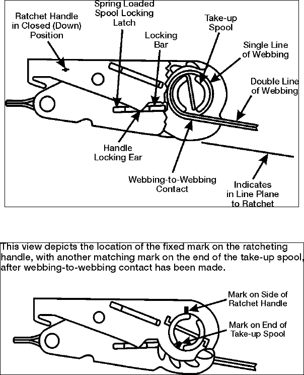
STP 55-88M14-SM-TG
3-57
Figure 3-55a. Web-to-Web Contact
Figure 3-55b. Locking Latches
Performance Steps
c. Lash the load and canvas to the truck (see Figure 3-56).
Note: Load lashing is done to protect the load and prevent casual observation for sensitive items.
(1) Fasten the end of one rope to one of the front lash hooks or rings (A1).
(2) Pass the rope diagonally across the top of the load through or under the second rope
support on the opposite side (A2).
(3) Pass the rope diagonally back across the top of the load through or under the third rope
support (A3). Pull the rope tight.
(4) Continue this process until you reach the rear of the vehicle. Secure the rope.
(5) With the second rope, repeat the entire process, starting at the front lash hook or ring
(B1).
4. Secure ammunition to cargo bed of HEMTT (M977/M985) using web straps.
WARNING: Be sure side panels are completely lowered. Side panels can slide off hinge pin when
vehicle is parked on grade. Falling side panel can cause serious personal injury.
a. Block and brace the load as needed.
b. Lower cargo side panels to gain access to cargo tiedown anchors as needed.
STP 55-88M14-SM-TG
3-58
Figure 3-56. Load Lashing
Performance Steps
c. Attach all web strap tiedown to load.
(1) Ensure all strap hooks are completely engaged and safety latches are completely closed
around tiedown anchor point.
(2) Ensure that strap is tensioned to form at least 1-1/2 turns on the takeup spool. This is
accomplished after web-to-web contact has been made on the takeup spool. To prevent
movement of cargo, each tiedown must be tightened until about equal tension is applied
throughout the tiedown arrangement.
(3) After tensioning is completed, the takeup spool-locking latch must be checked to ensure
that it is fully seated at both ends of the spool in the matching locking notches. The scuff
sleeve may have to be removed to allow tightening of tiedowns. Secure loose ends of
straps by suitable means.
(4) Reinforce sharp edges of cargo with suitable materials to prevent both crushing edges of
the load when strap is tensioned and to prevent slicing into strap webbing.
d. Lash the load and canvas to the truck.
(1) Fasten the end of one rope to one of the front lash hooks or rings (A1).
(2) Pass the rope diagonally across the top of the load through or under the second rope
support on the opposite side (A2).
(3) Pass the rope diagonally back across the top of the load through or under the third rope
support (A3). Pull the rope tight.
(4) Continue this process until you reach the rear of the vehicle. Secure the rope.
(5) With the second rope, repeat the entire process, starting at the front lash hook or ring
(B1).
5. Secure ammunition to PLS flatrack using web straps (see Figure 3-57).
Note: The M1077 and M1 flatracks are applicable to this step. Web straps are used to secure boxes,
pallets, and off shaped cargo.
Note: All items, no matter how small, should be secured in place.
a. Refer to flatrack data plate for particular characteristics regarding the flatrack you are using.
b. Use small tiedown rings for cargo no heavier than 10,000 pounds.

STP 55-88M14-SM-TG
3-59
Performance Steps
c. Use large tiedown rings for cargo no heavier than 25,000 pounds.
d. Check for proper center of gravity (CG) mark on flatrack and use as basis for load positioning.
CG markings on the M1077 and M1 are different.
(1) CG for the M1077 is 106 inches from front edge of flatrack.
(2) CG for the M1 is 116 inches from front edge of flatrack.
e. Attach all web strap tiedown to load.
(1) Ensure all strap hooks are completely engaged and safety latches are completely closed
around tiedown anchor point.
(2) Ensure that strap is tensioned to form at least 1-1/2 turns on the takeup spool. This is
accomplished after web-to-web contact has been made on the takeup spool. To prevent
movement of cargo, each tiedown must be tightened until about equal tension is applied
throughout the tiedown arrangement.
(3) After tensioning is completed, the takeup spool-locking latch must be checked to ensure
that it is fully seated at both ends of the spool in the matching locking notches. The scuff
sleeve may have to be removed to allow tightening of tiedowns. Secure loose ends of
straps by suitable means.
(4) Reinforce sharp edges of cargo with suitable materials to prevent both crushing edges of
the load when strap is tensioned and to prevent slicing into strap webbing.
WARNING: Extremely hazardous handling behavior can occur if payloads near the gross load rating are
loaded such that their CG falls rearward of the longitudinal center of the flatrack.
Note: Cargo such as boxes, pallets and odd shaped cargo should be loaded as far forward and as low as
possible on the flatrack.
Figure 3-57. Tiedown on Flatrack
6. Secure payload vehicle to semitrailer using load binders and chains (general procedures applicable
to M872 semitrailers, see Figure 3-58).
a. Emplace chock blocks as necessary.
b. Adhere to all safety issues concerning chains and load binders.
(1) Failure to use load binder properly may result in serious injury or even death.
(2) Do not operate load binder while standing on the load.
(3) Move handle with caution. It may whip - keep body clear.
(4) Keep yourself out of the path of the moving handle.
STP 55-88M14-SM-TG
3-60
Performance Steps
(5) You must be familiar with state and federal regulations regarding size and number of
chain systems required for securing loads on trucks.
(6) Always consider the safety of nearby workers as well as yourself when using load binder.
(7) While under tension, load binder must not bear against an object.
WARNING: Use caution when moving around load on semitrailer. A fall from the semitrailer could cause
serious injury.
WARNING: Never use a cheater pipe or handle extender to release handle. Use a steel bar and pry
under the handle and stay out of the path of handle as it moves upward.
Figure 3-58. Vehicle Payload on M872 Semitrailer
c. Attach chains and load binders to front and rear of vehicle.
Note: It is not possible to illustrate all possible configurations in this step of tying down a vehicle on the
M872 semitrailer. The vehicle included is the M998 HMMWV, 1 ¼ ton vehicle. Similar vehicles may be
used as substitute.
d. The following restrictions apply to this procedure (NTE = Not To Exceed).
(1) Vehicle payload NTE 12,000 lbs. Use 3/8-inch chain. One chain required for each corner
of vehicle.
(2) Vehicle payload NTE 17,000 lbs. Use 3/8-inch chain. One chain for left and right front
corners of payload vehicle. Two chains required for left and right of rear corners of
vehicle.
(3) Vehicle payload NTE 19,000 lbs. Use 7/16-inch chain. One chain for each front corner of
vehicle payload. Two chains required for left and right rear corners of vehicle payload.
(4) Vehicle payload NTE 27,000 lbs. Use 7/16-inch chain. One chain for left and right front
corners of payload vehicle. Two chains required for left and right rear corners of vehicle
payload.

STP 55-88M14-SM-TG
3-61
Performance Steps
(5) Vehicle payload NTE 48,000 lbs. Use ¾-inch chains. One chain for left and right front
corners of payload vehicle. Two chains required for left and right rear corners of vehicle
payload.
(6) Vehicle payload NTE 67,000 lbs. Use ¾-inch chains. One chain for left and right front
corners of payload vehicle. Two chains required for left and right rear corners of vehicle
payload.
CAUTION: All chains are attached to the cargo tiedown rings. DO NOT use the outside stake pockets of
the semitrailer for vehicle payloads.
Note: Additional chains are required on the rear of the vehicle, because forces seen when braking are
higher than when accelerating.
e. Use only tiedown provisions on the vehicle to attach chains (refer to 1c2 above).
f. Attach load binder hooks to chains so that open part of hook throat faces upward whenever
possible. Secure load binder handle by wiring to chain.
Evaluation Preparation: Setup: Provide for the soldier a loaded 5-ton cargo truck, M977/M985 Cargo
HEMTT, and a loaded M915/M872 semitrailer combination, web strap tiedown materials, tiedown chains
and load binders, work gloves, and blocking and bracing materials as needed.
Brief Soldier: You are required to ensure that the load has been positioned on each vehicle according to
its capabilities and limitations and is situated so as to not cause undue wear on the vehicle by being
improperly loaded. You are required to inspect all tiedown materials and use only items that pass
inspection. You are also required to install the appropriate number of tiedown devices that will
adequately secure each load to the vehicle or semitrailer. Your supervisor, upon completion, will evaluate
your efforts.
Performance Measures GO NO GO
1. Ensured load was properly positioned for tiedown. —— ——
2. Inspected tiedown materials. —— ——
3. Secured general cargo to bed of 5-ton cargo truck using web tiedown straps. —— ——
4. Secured ammunition to cargo bed of HEMTT (M977/M985) using web straps. —— ——
5. Secured ammunition to PLS flatrack using web straps. —— ——
6. Secured payload vehicle to semitrailer using load binders and chains. —— ——
Evaluation Guidance: Score the soldier GO if all performance measures are passed. Score the soldier
NO-GO if any performance measure is failed. If any performance measure is failed, tell the soldier what
was done wrong and how to do it correctly.
References
Required Related
FM 21-305 TC 21-305-1
FM 5-125 TC 21-305-10
FM 55-30 TC 21-305-3
MTMCTEA 96-55-20 TC 21-305-4
TM 9-2320-260-10 TC 21-305-8
TM 9-2320-272-10
TM 9-2320-279-10-1
TM 9-2320-279-10-2
TM 9-2320-280-10
TM 9-2320-364-10
STP 55-88M14-SM-TG
3-62
Perform Load/Unload Operations With Truck Palletized Load System (PLS) in Automatic Mode
551-721-1501
Conditions: Given an M1074/M1075 PLS Truck Tractor with before-operation performed, BII, flatrack
(loaded or unloaded), and hearing protection.
Standards: You have performed load/unloading operations using the truck tractor PLS in automatic
mode, without injury to personnel or damage to equipment.
Performance Steps
1. Position PLS tractor for loading operation.
WARNING: Check for overhead power lines or other obstructions before attempting LHS operation. LHS
reaches a height of 17 feet two inches (5.22m) with ISO container. Serious injury or death could result
from contact with electrical power lines.
a. Check ground conditions for firmness and extreme sideways inclination before picking up or
off-loading a flatrack. Any ground instability beneath road wheels could cause serious injury or
death to personnel.
b. Prior to and during any load or unload cycle, all personnel should stay clear of LHS and flatrack
or serious injury or death could result to personnel.
CAUTION: Engine speed must be at idle before using hydraulic selector switch, or damage to equipment
may result.
2. Load flatrack onto tractor.
CAUTION: Do not use Reverse (R) to back up truck while hook arm is attached to flatrack or damage to
LHS will occur.
WARNING: When loading or unloading flatracks on uneven ground (side slope or downgrades up to 10
degrees), it may be necessary to apply truck service brakes to prevent truck roll away or severe injury or
death could result.
CAUTION: If LHS overload lamp illuminates but loading operation continues, operator is cautioned that
LHS is nearing maximum capacity. In this situation operator should determine if payload is evenly
distributed on flatrack or if flatrack load exceeds 16.5 tons (14,983 kg). If any of these conditions exist,
operator must redistribute or reduce the payload or damage to equipment may occur.
a. Load must be evenly distributed on the pallet. Uneven load distribution may cause LHS
Overload indicator to give false signals and cause LHS to operate incorrectly. Damage to
equipment may result.
b. If LHS overload lamp illuminates and normal operation has stopped, return load to original
position and redistribute or reduce payload weight or equipment damage may occur.
c. Ensure that parking brake is not applied before starting load sequence or damage to equipment
may occur.
WARNING: Ensure that flatrack runners contact LHS rear rollers correctly. Failure to contact flatrack
runners correctly could result in serious injury to personnel and damage to equipment. Overload warning
light may illuminate when lifting flatrack from unusual conditions.
CAUTION: Reduce engine speed to idle before flatrack main rails contact rear rollers or damage to
flatrack may result. Engine speed must be at idle before using hydraulic selector switch, or damage to
equipment may result. Hydraulic selector switch must be in OFF position before driving or hydraulic
system could overheat.

STP 55-88M14-SM-TG
3-63
Performance Steps
3. Off-load flatrack from tractor.
CAUTION: Engine idle speed must be at idle before using hydraulic selector switch, or damage to
equipment may result.
CAUTION: Ensure parking brake is not applies during unload sequence or damage to equipment may
result.
WARNING: When loading or unloading flatracks on uneven ground (side slope or down grades up to 10
degrees), it may be necessary to apply truck service brakes to prevent truck roll away or severe injury or
death could result.
a. Check for overhead power lines or other obstructions before attempting LHS operation. LHS
reaches a height of 17 feet, two inches (5.22 m) with ISO container. Serious injury or death
could result from contact with electrical power lines.
b. Check ground conditions for firmness and extreme sideways inclination before picking-up or
off-loading a flatrack. Any ground instability beneath road wheels could cause serious injury or
death to personnel.
c. Prior to and during any load or unload cycle, all personnel should stay clear of LHS and flatrack
or serious injury or death could result to personnel.
CAUTION: Check ground conditions where flatrack will be placed can support the flatrack weight or
damage to flatrack or LHS may result.
d. Ensure rail transport locking pins are disengaged before unloading flatrack. Rail transport
locking pins are used for rail transport only. Failure to comply may result in damage to
equipment. Loading and unloading times are controlled by engine speed. Engine speed can
be increased to approximately 1500 rpm to reduce loading and unloading times.
CAUTION: Once the truck's rear suspension has been relieved of a flatrack load, do not continue in
UNLOAD position as possibility or jacking up rear end with hook arm may occur and damage to
equipment may result. If flatrack is extremely light or empty, it may be necessary to place transmission
range selector to Drive (D) to allow truck to move our from under flatrack.
CAUTION: Never drive with NO TRANS light illuminated.
Evaluation Preparation: Setup: Place a PLS Truck with flatrack (loaded or unloaded) on level ground
with room to maneuver the vehicle as needed for the operation. Include all vehicle BII, hearing
protection, and provide guidance to the soldier.
Brief Soldier: You are required to load and then off-load the flatrack (loaded or unloaded) onto/from the
PLS truck in the automatic mode. You are to follow all steps identified in the reference -10 series TM. All
steps are to be performed without injury to personnel or damage to equipment. You are to start the
operation with the flatrack on the ground.
Performance Measures GO NO GO
1. Positioned PLS tractor for loading operation. —— ——
2. Loaded flatrack onto tractor. —— ——
3. Off-loaded flatrack from tractor. —— ——
Evaluation Guidance: Score the soldier GO if all performance measures are passed. Score the soldier
NO-GO if any performance measure is failed. If any performance measure is failed, tell the soldier what
was done wrong and how to do it correctly.
References
Required Related
TM 9-2320-364-10
STP 55-88M14-SM-TG
3-64
Transfer Flatrack Onto/From Palletized Load System (PLS) Trailer Using the Load Handling
System (LHS)
551-721-1503
Conditions: Given a PLS Truck Tractor with flatrack, PLS trailer both with before-operation PMCS
performed, hearing protection, and an area to maneuver vehicle with trailer.
Standards: You have successfully transferred flatrack from truck to trailer then back to truck without
injury to personnel or damage to equipment.
Performance Steps
1. Position truck and trailer for loading/unloading operation.
WARNING: Prior to and during load or unload cycle, all personnel should stay clear of LHS and flatrack
or serious injury or death could result. Trailer wheels must be chocked during transfer operations or
serious injury or death could result.
CAUTION: Ensure that trailer drawbar is down against the ground during transfer operation or damage to
equipment may result.
a. Ensure air lines and cables are properly stowed to prevent damage to equipment (TM 9-2330-
385-14).
b. Both the trailer bumper points must be under the truck bumper stop flange and at least one of
the bumper points must contact the bumper stop. The trailer bumper point not contacting the
truck bumper stop cannot exceed 0.5 inches (12.7 mm) or flatrack will miss main rail guides
and equipment damage may result.
WARNING: When operating PLS truck with PLS trailer, the heaviest loaded flatrack must always be
placed on the truck, otherwise adverse handling and/or braking may result, causing injury or death to
personnel.
2. Load flatrack onto PLS trailer (automatic mode).
CAUTION: Engine speed must be at idle before using hydraulic selector switch or damage to equipment
may result.
Note: Do not move truck forward more than three inches (76.2 mm) to prevent flatrack from pulling away
from stops.
WARNING: Never drive with NO TRANS light illumination. An illuminated light means LHS is not fully
stowed. The load could break loose causing serious injury or death to personnel.
CAUTION: Engine speed must be at idle before using hydraulic selector switch or damage to equipment
may result.
Note: Hook arm does not need to be fully stowed if more transfer operations are going to be made.
a. Hydraulic selector switch must be in OFF position before driving or hydraulic system can
overheat causing damage to equipment.
b. Refer to TM 9-2320-364-10, paragraph 2-26f (11) through (32), pages 2-220 to 2-224.
STP 55-88M14-SM-TG
3-65
Performance Steps
3. Unload flatrack from trailer (automatic mode).
CAUTION: Load must be evenly distributed on flatrack pallet. Uneven load distribution may cause LHS
overload indicator to give false signals and cause LHS to operate incorrectly. Damage to equipment may
result.
a. There must be sufficient pressure in trailer air system to retract locks or damage to flatrack can
occur while attempting to load flatrack or trailer. If not, use truck to charge trailer air system
using trailer air charging hose. If air system cannot retract flatrack, use manual flatrack lock
retract procedures.
b. Ensure that trailer drawbar is down against the ground during transfer operation or damage to
equipment may result.
c. Ensure air lines and cables are properly stowed to prevent damage to equipment (TM 9-2330-
385-14).
d. Ensure both flatrack locks are fully retracted or damage to equipment may result.
4. Load flatrack onto trailer (manual mode).
WARNING: Trailer wheels must be chocked during transfer operations.
CAUTION: Ensure that trailer drawbar is down against the ground during transfer operations or damage
to equipment may result.
a. Ensure air lines and cables are properly stowed to prevent damage to equipment.
b. Both of the trailer bumper points must be under the truck bumper stop flange and at least one
of the bumper points must contact the bumper stop. The trailer bumper point not contacting the
truck bumper stop cannot exceed 0.5 inches (12.7 mm) or flatrack will miss main rail guides
and equipment damage may result.
c. Engine speed must be at idle before using hydraulic selector switch or damage to equipment
may result.
5. Unload flatrack from PLS trailer (manual mode).
CAUTION: There must be sufficient pressure in trailer air system to retract locks or damage to flatrack
can occur while attempting to load flatrack or trailer. If not, use truck to charge trailer air system using
trailer air charging hose. If air system cannot retract flatrack, use manual flatrack lock retract procedures.
a. Ensure that air lines and cables are properly stowed to prevent damage to equipment.
b. Ensure that trailer drawbar is down against the ground during transfer operations or damage to
equipment may result.
c. Ensure both flatrack locks are fully retracted or damage.
WARNING: Check for overhead power lines or other obstructions before attempting LHS operation. If
LHS reaches a height of CAUTION, there must be sufficient pressure in trailer air system to retract locks
or damage to flatrack can occur while attempting to load flatrack or trailer. If not, use truck to charge
trailer air system using trailer air charging hose. If air system cannot retract flatrack, use manual flatrack
lock retract procedures.
d. Ensure that air lines and cables are properly stowed to prevent damage to equipment.
e. Ensure that trailer drawbar is down against the ground during transfer operations or damage to
equipment may result.
f. Ensure both flatrack locks are fully retracted or damage.
WARNING: Check for overhead power lines or other obstructions before attempting LHS operation. LHS
reaches a height of 17 feet, two inches (5.22 m) with ISO container. Serious injury or death could result
from contact with electrical power lines.

STP 55-88M14-SM-TG
3-66
Performance Steps
g. Prior to and during any load or unload cycle, all personnel should stay clear of LHS and flatrack
or serious injury or death could result to personnel.
h. Check ground conditions for firmness and extreme sideways inclination before picking-up or
off-loading a flatrack. Any ground instability beneath road wheels could cause serious injury or
death to personnel.
Evaluation Preparation: Setup: Position a PLS truck tractor with flatrack and PLS trailer on level, hard
ground for operation. Provide hearing protection and guidance on what the soldier is required to do.
Brief Soldier: You are required to load then unload the PLS flatrack to and from the PLS trailer both in the
automatic and manual modes.
Performance Measures GO NO GO
1. Positioned truck and trailer for loading/unloading operation. —— ——
2. Loaded flatrack onto PLS trailer (automatic mode). —— ——
3. Unloaded flatrack from trailer (automatic mode). —— ——
4. Loaded flatrack onto trailer (manual mode). —— ——
5. Unloaded flatrack from PLS trailer (manual mode). —— ——
Evaluation Guidance: Score the soldier GO if all performance measures are passed. Score the soldier
NO-GO if any performance measure is failed. If any performance measure is failed, tell the soldier what
was done wrong and how to do it correctly.
References
Required Related
TM 9-2320-364-10 TC 21-305-10
TM 9-2330-385-14
STP 55-88M14-SM-TG
3-67
Conduct Loading/Unloading Operations in Manual Mode
551-721-1504
Conditions: Given a Truck Tractor PLS with flatrack with before-operation performed, hearing protection,
and solid level ground to maneuver.
Standards: You have successfully loaded and unloaded the flatrack onto/from the PLS truck without
injury to personnel or damage to equipment.
Performance Steps
1. Position PLS truck for loading/unloading operations.
CAUTION: To avoid equipment damage, ensure that hook arm cylinders do not complete full extension
while operating at engine speeds above idle.
CAUTION: Manual mode is used mainly in event of a failure of control electrical system. Greater care
must be exercised during operation of MANUAL mode for correct cycle of events to occur or damage to
equipment may result.
a. Change truck weight indicator to reflect load weight to be uploaded.
b. Adjust driver seat and controls as necessary.
c. Ensure vehicle fuel level is sufficient for mission. Refuel as needed.
d. Operate lights according to tactical situation.
e. Start vehicle. Normal starting procedures (see TM 9-2320-364-10 for details if necessary).
f. Check vehicle gauges, and warning buzzers for proper indication.
g. Operate service brakes and hand brakes as necessary.
(1) Ensure brake air pressure gauge reads 100 psi for proper operation of brake system.
(2) Operate trailer brakes as necessary.
h. Select proper gear range using transmission range selector.
i. Position vehicle for uploading operations.
(1) If available, always use a ground guide (1 or more) to maneuver vehicle into position.
(2) Chock vehicle wheels.
(3) Set parking brake as required.
(4) Prepare Load handling system for uploading.
2. Load flatrack onto PLS truck.
a. Set the transmission range selector to Reverse (R) and back truck up to the flatrack. Stop
approximately 5 feet (1.5 meters) from hook-bar. Check for overhead obstructions and firmness
of ground.
b. Apply the service brake pedal and set transmission range selector to Neutral (N).
CAUTION: To avoid equipment damage, ensure that hook arm cylinders do not complete full extension
while operating at engine speeds above idle.
CAUTION: Manual mode is used mainly in event of a failure of control electrical system. Greater care
must be exercised during operation of MANUAL mode for correct cycle of events to occur or damage to
equipment may result.
c. Turn the hydraulic selector switch to MAN H.A.
WARNING: Check for overhead power lines or other obstructions before attempting LHS operation. LHS
reaches a height of 17 feet, 2 inches (5.22 meters) with ISO container. Serious injury or death could
result from contact with electrical power lines. Check ground conditions for firmness and extreme
sideways inclination before picking-up or off-loading a flatrack. Any ground instability beneath road
wheels could cause serious injury or death to personnel.
WARNING: Prior to and during any load or unload cycle, all personnel should stay clear of LHS and
flatrack or serious injury or death could result to personnel.
STP 55-88M14-SM-TG
3-68
Performance Steps
d. Move joystick to UNLOAD and hold until hook arm cylinders are fully extended.
e. Release joystick.
CAUTION: Engine speed must be at idle before using hydraulic selector switch, or damage to equipment
may result. To avoid equipment damage, ensure that mainframe cylinders do not complete full extension
while operating at engine speeds above idle. Manual mode is used mainly in event of a failure of control
electrical system. Greater care must be exercised during operation of MANUAL mode for correct cycle of
events to occur or damage to equipment may result. If LHS had previously been used in Manual Mode
and not completely stowed in Auto Mode, the hook arm cylinders must be completely extended or the
LHS must be completely stowed using Auto Mode before the flatrack can be loaded. Failure to comply
may result in damage to the truck and flatrack.
f. Turn hydraulic selector switch to MAN M.F.
g. Move joystick to UNLOAD and hold until lift-hook has moved below level of flatrack hook-bar.
h. Apply service brake pedal and set transmission range selector to Reverse (R) and back truck
up to flatrack, aligning truck and flatrack as straight as possible with lift-hook to the middle of
hook-bar.
i. Stop truck when lift-hook touches flatrack.
j. Leave truck in reverse gear with engine at idle.
Note: Ensure parking brake is not applied during unload sequence or damage to equipment may result.
Do not use Reverse (R) to back up truck while hook arm is attached to flatrack or damage to LHS will
occur.
k. Move joystick to LOAD to engage lift-hook and hook-bar.
l. If lift-hook fails to engage hook-bar:
(1) Release joystick.
(2) Set transmission range selector to Drive (D), release service brake pedal and move truck
forward just clear of flatrack.
(3) Move joystick to UNLOAD until lift-hook is below level of hook-bar.
(4) Repeat steps j through k.
Note: When loading or unloading flatracks on uneven ground (side slope or downgrades up to 10
degrees) it may be necessary to apply truck service brakes to prevent truck roll away, or severe injury or
death could result. Prior to and during any load or unload cycle, all personnel should stay clear of LHS
and flatrack or serious injury or death could result to personnel.
m. Set transmission range selector to Neutral and release service brake pedal.
Note: If LHS overload lamp illuminates but loading operation continues, operator is cautioned that LHS is
nearing maximum capacity. In this situation operator should determine if payload is evenly distributed on
flatrack or if flatrack load exceeds 16.5 tons (14,969 kg). If any of these conditions exist, operator must
redistribute or reduce payload or damage to equipment may result. Ensure that parking brake is not
applied before starting load sequence or damage to equipment may result.
n. Move joystick to LOAD, allowing truck to be pulled under flatrack.
CAUTION: Ensure that flatrack runners contact LHS rear rollers correctly. Failure to contact flatrack
runners correctly could result in serious injury or death to personnel and damage to equipment
o. Before flatrack contacts rear rollers, reduce engine speed and apply service brake pedal.
p. Release the joystick. Set hydraulic selector switch to MAN H.A.
q. Move the joystick to LOAD until flatrack is approximately 2 feet (0.61 m) off the ground.
Release joystick.
r. Set the hydraulic selector switch to MAN M.F. operations.
s. After flatrack contacts rear rollers, increase engine speed to approximately 1500 rpm until main
frame cylinders have nearly completed full retraction.
t. Reduce engine speed to idle and continue loading until main frame cylinders are fully retracted.
u. Release the joystick.
v. Turn the hydraulic selector switch to MAN H.A.
w. Move the joystick to LOAD position and increase engine speed until flatrack is nearly loaded,
then reduce speed to idle.
STP 55-88M14-SM-TG
3-69
Performance Steps
x. Continue to load until LHS and flatrack is in transit position. LHS NO TRANS light will
extinguish.
y. Release joystick.
z. Apply parking brakes.
aa. Inspect that load locks have engaged and flatrack is fully down on truck. Turn the hydraulic
selector switch to MAN TRANS.
Note: Check for overhead power lines or other obstructions before attempting LHS operation. LHS
reaches a height of 17 feet, two inches (5.22 m) with ISO container. Serious injury or death could result
from contact with electrical power lines.
Note: Check ground conditions for firmness and extreme sideways inclination before picking-up or off-
loading a flatrack. Any ground instability beneath road wheels could cause serious injury or death to
personnel.
Note: Prior to and during any load or unload cycle, all personnel should stay clear of LHS and flatrack or
serious injury or death could result to personnel.
3. Offload flatrack from PLS truck.
a. Check for sufficient operating room at front and rear of truck. Check overhead clearance and
ground conditions.
b. Apply the service brake pedal and set transmission range selector to Neutral (N).
c. Turn the hydraulic selector switch to MAN H.A.
d. Move the joystick to UNLOAD until hook arm cylinders have fully extended. Maintain engine
speed at idle for approximately the first 18 inches (46 cm) and last 6 inches (15 cm) of
movement.
e. Release the joystick.
f. Turn the hydraulic selector switch to MAN M.F.
g. Move the joystick to UNLOAD.
h. When back edge of flatrack touches ground, release service brake pedal allowing truck to be
pushed straight from under flatrack.
i. Continue off-loading until front of flatrack is within 8 inches (203.2 cm) of ground, decrease
engine speed to idle and apply service brake pedal.
j. Continue off-loading until flatrack is on ground and rear suspension is unloaded.
k. Release joystick.
l. Set transmission range selector to Drive (D) and release service brake pedal.
m. Move the joystick to LOAD momentarily and then to UNLOAD to let lift-hook disengage from
hook-bar. Repeat Step until lift-hook disengages.
n. Move the truck forward approximately 5 feet (1.5 meters).
o. Stop the truck and set the transmission range selector to Neutral (N).
p. Move the joystick to LOAD and hold in this position until mainframe cylinders are fully retracted.
q. Turn the hydraulic selector switch to MAN H.A.
r. Hold the joystick in LOAD position until the hook arm cylinders are fully retracted.
s. Release joystick.
4. Shutdown engine.
a. Park the truck.
(1) Lift foot off of the throttle control. Let transmission automatic downshift slow truck.
(2) Push down on the service brake pedal until truck comes to complete stop.
(3) Pull out the PARKING BRAKE control.
(4) Press transmission range selector button to Neutral (N).
(5) Align the front tires in straight-ahead position.
(6) Chock wheels.

STP 55-88M14-SM-TG
3-70
Performance Steps
b. Shutdown engine.
(1) Push down and hold throttle control until tachometer reads 800 to 1000 rpm.
(2) Run engine at 800 to 1000 rpm for three to five minutes.
(3) Lift foot off throttle control.
(4) Turn engine OFF/ON/START switch to OFF.
Evaluation Preparation: Setup: Provide the soldier with a PLS truck with PLS flatrack with before-
operation PMCS completed, BII, hearing protection, and solid level ground to maneuver.
Brief Soldier: The soldier is required to load and then unload a flatrack onto/from the PLS truck using the
manual mode. All required steps are to be performed in accordance with the PLS TM without injury to
personnel or damage to equipment.
Performance Measures GO NO GO
1. Positioned PLS truck for loading/unloading operations. —— ——
a. Refer to TM 9-2320-364-10, paragraph 2-19, pages 2-161 and 2-162 for
applicable steps in this procedure.
WARNING: Do not park truck on steep grades. Serious injury to personnel could
result.
b. Rapid operation repeatedly of service brakes will consume compressed air
supply and cause automatic spring brake application. Failure to follow
proper service brake operating procedures may cause serious injury or
death to personnel.
CAUTION: Before shutting down engine, increase tachometer to 800-1000 rpm at no-
load for three to five minutes to allow turbocharger to slow down and cool off.
Turbocharger may be damaged if not allowed to cool off.
2. Loaded flatrack onto PLS truck. —— ——
a. Refer to TM 9-2320-364-10, paragraph 2-26d(3) to (25), 2-204 to 2-211 for
applicable steps for this procedure.
WARNING: Check for overhead power lines or other obstructions before attempting
LHS operation. LHS reaches a height of 17 feet, two inches (5.22 m) with ISO
container. Serious injury or death could result from contact with electrical power lines.
b. Check ground conditions for firmness and extreme sideways inclination
before picking-up or off-loading a flatrack. Any ground instability beneath
road wheels could cause serious injury or death to personnel.
c. Prior to and during any load or unload cycle, all personnel should stay clear
of LHS and flatrack or serious injury or death could result to personnel.
d. Overload warning light will come on when hook arm cylinders are fully
extended and joystick is activated.
e. Loading and unloading times are controlled by engine speed. Engine speed
can be increased to 1500 rpm to reduce loading and unloading times.

STP 55-88M14-SM-TG
3-71
Performance Measures GO NO GO
3. Offloaded flatrack from PLS truck. —— ——
CAUTION: Manual mode is used mainly in event of a failure of control electrical
system. Greater care must be exercised during operation or MANUAL mode for
correct cycle of events to occur or damage to equipment may result.
WARNING: Check for overhead power lines or other obstructions before attempting
LHS operation. LHS reaches a height of 17 feet, two inches (5.22 m) with ISO
container. Serious injury or death could result from contact with electrical power lines.
a. Check ground conditions for firmness and extreme sideways inclination
before picking-up or off-loading a flatrack. Any ground instability beneath
road wheels could cause serious injury or death to personnel.
b. Prior to and during any load or unload cycle, all personnel should stay clear
of LHS and flatrack or serious injury or death could result to personnel.
CAUTION: Reduce speed to idle in last 12 inches (30 cm) of travel to prevent damage
to cylinder.
c. To avoid equipment damage, ensure that hook arm cylinders do not
complete full extension while operating at engine speed above idle.
d. Ensure transport locking pins are disengaged before unloading flatrack. Rail
transport locking pins are used for rail transport only. Failure to comply may
result in damage to equipment.
4. Shutdown engine. —— ——
a. Refer to TM 9-2320-364-10, paragraph 2-19, pages 2-161 and 2-162 for
applicable steps in this procedure.
WARNING: Do not park truck on steep grades. Serious injury to personnel could
result.
b. Rapid operation repeatedly of service brakes will consume compressed air
supply and cause automatic spring brake application. Failure to follow
proper service brake operating procedures may cause serious injury or
death to personnel.
CAUTION: Before shutting down engine, increase tachometer to 800-1000 rpm at no-
load for three to five minutes to allow turbocharger to slow down and cool off.
Turbocharger may be damaged if not allowed to cool off.
Evaluation Guidance: Score the soldier GO if all performance measures are passed. Score the soldier
NO-GO if any performance measure is failed. If any performance measure is failed, tell the soldier what
was done wrong and how to do it correctly.
References
Required Related
TM 9-2320-364-10 TC 21-305-10
STP 55-88M14-SM-TG
3-72
Conduct Loading/Unloading Operations Using Container Handling Unit (CHU)
551-721-1505
Conditions: Given a PLS tractor equipped with the CHU, a container to be loaded (either of a 82, 72, 51,
or 48 inch tall), hearing protection, vehicle TM (-10 series), and assistance from others as needed.
Standards: You have safely and successfully loaded and unloaded a container using the Container
Handling Unit (CHU) without injury to personnel or damage to equipment.
Performance Steps
1. Prepare PLS truck for container mode.
Note: This task is abbreviated and all steps and performance measures required are referred to in the
applicable reference publication. Due to the considerable length of this operation, all actions to be
performed and evaluated are to be taken directly from the reference publication sited in each step. This
allows for more technical content. All WARNING and CAUTION statements list in the TM MUST be
adhered to.
a. Refer to TM 9-2320-364-10, paragraph 2-32 for all performance steps for this task.
b. Adhere to all WARNING and CAUTION statements listed in the reference publication while
performing this operation.
2. Load container onto a PLS truck using the CHU.
a. For container 82 inches tall, refer to and comply with TM 9-2320-364-10, paragraph 2-33a
pages 2-405 to 2-503.
b. For container 72 inches tall, refer to and comply with TM 9-2320-364-10, paragraph 2-34a
pages 2-444 to 2-470.
c. For container 51 inches tall, refer to and comply with TM 9-2320-364-10, paragraph 2-35a
pages 2-487 to 2-513.
d. For container 48 inches tall, refer to and comply with TM 9-2320-364-10, paragraph 2-36a
pages 2-532 to 2-555.
e. Adhere to all WARNINGS and CAUTIONS in the TM applicable to this procedure.
3. Unload a container (82, 72, 51, or 48 inches tall) from a PLS truck using the CHU.
a. For container 82 inches tall, refer to and comply with TM 9-2320-364-10, paragraph 2-33b
pages 2-430 to 2-430 to 2-443.
b. For container 72 inches tall, refer to and comply with TM 9-2320-364-10, paragraph 2-34b
pages 2-470 to 2-486.
c. For container 51 inches tall, refer to and comply with TM 9-2320-364-10, paragraph 2-35b
pages 2-514 to 2-531.
d. For container 48 inches tall, refer to and comply with TM 9-2320-364-10, paragraph 2-36b
pages 2-556 to 2-569.
e. Adhere to all WARNINGS and CAUTIONS in the TM applicable to this procedure.
Evaluation Preparation: Setup: Provide for the soldier a PLS or HEMTT-LHS truck tractor, CHU, ISO
container, hearing protection, work gloves, and assistance from ground guides. Ensure vehicle and
container are positioned on solid level ground.
Brief Soldier: You are required to perform all operational steps involved in the loading and unloading of
an ISO container on your vehicle. You are required to properly install the container handling unit, prepare
and position the vehicle for loading and unloading operations. You are required to perform this operation
without injuring anyone or causing damage to any of the equipment. A ground guide will assist you as
needed but will not interfere with your operation or provide any technical assistance. Any unsafe act is
cause for NO-GO.

STP 55-88M14-SM-TG
3-73
Performance Measures GO NO GO
1. Prepared PLS truck for container mode. —— ——
a. Refer to and comply with TM 9-2320-364-10, paragraphs 2-32 and 2-381
through 2-404.
b. Adhere to all Adhere to all WARNINGS and CAUTIONS in the TM applicable
to this step.
2. Loaded container onto a PLS truck using the CHU. —— ——
a. For container 82 inches tall, refer to and comply with TM 9-2320-364-10,
paragraph 2-33a, pages 2-405 to 2-503.
b. For container 72 inches tall, refer to and comply with TM 9-2320-364-10,
paragraph 2-34a, pages 2-444 to 2-470.
c. For container 51 inches tall, refer to and comply with TM 9-2320-364-10,
paragraph 2-35a, pages 2-487 to 2-513.
d. For container 48 inches tall, refer to and comply with TM 9-2320-364-10,
paragraph 2-36a, pages 2-532 to 2-555.
e. Adhere to all WARNINGS and CAUTIONS in the TM applicable to this
procedure.
3. Unloaded a container (82, 72, 51, or 48 inches tall) from a PLS truck using the
CHU.
—— ——
a. For container 82 inches tall, refer to and comply with TM 9-2320-364-10,
paragraph 2-33b, pages 2-430 to 2-430 to 2-443.
b. For container 72 inches tall, refer to and comply with TM 9-2320-364-10,
paragraph 2-34b, pages 2-470 to 2-486.
c. For container 51 inches tall, refer to and comply with TM 9-2320-364-10,
paragraph 2-35b, pages 2-514 to 2-531.
d. For container 48 inches tall, refer to and comply with TM 9-2320-364-10,
paragraph 2-36b, pages 2-556 to 2-569.
e. Adhere to all WARNINGS and CAUTIONS in the TM applicable to this
procedure.
Evaluation Guidance: Score the soldier GO if all performance measures are passed. Score the soldier
NO-GO if any performance measure is failed. If any performance measure is failed, tell the soldier what
was done wrong and how to do it correctly.
References
Required Related
TM 9-2320-364-10 TC 21-305-10

STP 55-88M14-SM-TG
3-74
Conduct Container Roll-In/Roll-Out Platform (CROP) Load/Unload Operations
551-721-1507
Conditions: Given a mission-ready PLS/HEMTT-LHS truck and a CROP with before operational
inspection performed and area to perform operation, and hearing protection and ground guide.
Special Conditions: Operator should have a valid driver's license or be accompanied by a licensed driver
or perform operation in a controlled driving range under direct supervision of a licensed driver/instructor.
During insertion procedure, at least one ground guide is required.
Standards: You have operated the PLS/HEMTT-LHS truck in loading/unloading operations involving the
Container Roll-on/Roll-off Platform (CROP). All functions of the operations were performed without injury
to personnel or damage to vehicle or equipment.
Performance Steps
1. Load ISO container.
a. Adhere to all WARNING and CAUTION statements in the TM regarding this procedure.
b. Refer to TM 9-3990-260-14&P, paragraph 2-16a, steps (1) through (23), pages 2-31 to 2-38 for
applicable procedures in loading ISO container. Refer to subsequent paragraphs if directed, as
needed in the TM.
2. Unload ISO container.
a. Adhere to all WARNING and CAUTION statements in the TM regarding this procedure.
b. Refer to TM 9-3990-260-14&P, paragraph 2-16b, steps (1) through (11), pages 2-39 to 2-41 for
applicable procedures in unloading ISO container. Refer to subsequent paragraphs if directed,
as needed in the TM.
Evaluation Preparation: Setup: Provide the soldier with a PLS or HEMTT-LHS truck, CROP, ISO
container, ground guide, BII from vehicle, and area for operation.
Brief Soldier: You are required to conduct loading and unloading operations involving a single or stack
(maximum 6) CROP. You are to use the PLS or HEMTT-LHS vehicle to perform this operation. You are
to observe and follow the hand and arm signals of your ground guide to prevent an unsafe situation from
developing. You are to insert the CROP(s) into the ISO container, secure the load, and close the doors.
Afterwards, you are to remove the CROP(s) from the ISO container and position, as designated by the
supervisor. You are to complete this operation without injury to personnel or damage to any equipment.
Performance Measures GO NO GO
1. Loaded ISO container. —— ——
2. Unloaded ISO container. —— ——
Evaluation Guidance: Score the soldier GO if all performance measures are passed. Score the soldier
NO-GO if any performance measure is failed. If any performance measure is failed, tell the soldier what
was done wrong and how to do it correctly.
References
Required Related
TM 9-3990-260-14&P FM 21-305
TC 21-305-10
STP 55-88M14-SM-TG
3-75
Subject Area 6: Adverse Terrain Operations
Operate Cargo Vehicle on Secondary Roads/Trails/Cross-country
551-721-1360
Conditions: Given a cargo vehicle with before-operation preventive maintenance checks performed,
hearing protection, and designated route over secondary roads/trails or cross-country.
Standards: You must safely operate a vehicle through various terrain conditions without injury to
personnel or damage to equipment and without getting stuck.
Performance Steps
1. Start engine.
2. Operate vehicle through shallow ditches.
a. Stop the vehicle.
b. Check the terrain for obstructions.
c. Place transmission shift lever into first gear.
d. Steer vehicle toward the ditch so that one wheel on an axle will leave the ditch as the other
wheel on the same axle enters it.
3. Operate vehicle through deep ditches.
a. Stop the vehicle.
b. Check terrain for obstructions.
c. Cut away both sides of ditch, if necessary.
d. Place transfer shift lever into all-wheel drive (if applicable).
e. Place vehicle into lowest forward gear and four-wheel drive (if applicable).
f. Approach the ditch at an angle.
g. Accelerate the vehicle enough to keep it rolling as it goes up the other side.
4. Operate vehicle through gullies and ravines.
a. Stop the vehicle.
b. Check the terrain for obstructions.
c. Place transmission shift lever into first gear.
d. Ease the front wheel over at a right angle to the edge of the ravine.
e. Steer a straight course so that both front wheels strike the bottom at the same time.
f. Accelerate enough so the vehicle can climb up the opposite bank.
5. Operate vehicle through wooded area.
a. Stop the vehicle.
b. Check the terrain for obstructions.
c. Remove the tarp and bows, as required.
d. Place transmission shift lever into first gear.
e. Maneuver around obstructions.
6. Operate vehicle through rocky terrain.
a. Stop the vehicle.
b. Check the terrain for obstructions.
c. Drive slowly, choosing route while advancing.
d. Remove stones between dual tires as often as required.
7. Operate vehicle through streams (fording).
a. Stop the vehicle.
b. Check the terrain for obstructions.
c. Check the stream for depth and firm support.

STP 55-88M14-SM-TG
3-76
Performance Steps
d. Place transfer shift lever into low range/all-wheel drive.
e. Place the transmission shift lever into first gear.
f. Drive through water, without shifting unless absolutely necessary.
g. Dry the brakes.
(1) Select a dry, level stretch of terrain.
(2) Apply the brakes a few times with a light steady pressure to obtain normal braking.
8. Operate vehicle through swamps and mud.
a. Stop the vehicle.
b. Check the terrain for obstructions.
c. Engage low-range/all-wheel drive.
d. Place transmission shift lever into first gear.
e. Drive through the area maintaining a steady speed.
9. Shut down engine and perform after-operation PMCS.
Evaluation Preparation: Setup: Provide the soldier a vehicle with cross-country capability. Brief Soldier:
Tell the soldier to operate the vehicle through varying terrains without injuring personnel or damaging
equipment and without getting stuck.
Performance Measures GO NO GO
1. Started the engine. —— ——
2. Operated vehicle through shallow ditches. —— ——
3. Operated vehicle through deep ditches. —— ——
4. Operated vehicle through gullies and ravines. —— ——
5. Operated vehicle through wooded area. —— ——
6. Operated vehicle through rocky terrain. —— ——
7. Operated vehicle through streams (fording). —— ——
8. Operated vehicle through swamps and mud. —— ——
9. Shut down engine and performed after-operation PMCS. —— ——
Evaluation Guidance: Score the soldier GO if all performance measures are passed. Score the soldier
NO-GO if any performance measure is failed. If any performance measure is failed, tell the soldier what
was done wrong and how to do it correctly.
References
Required Related
FM 21-305
TM 9-2320-260-10
TM 9-2320-272-10
TM 9-2320-279-10-1
TM 9-2320-279-10-2
TM 9-2320-280-10
TM 9-2320-360-10
TM 9-2320-364-10
TM 9-2320-365-10
TM 9-2320-366-10-1
STP 55-88M14-SM-TG
3-77
Operate Vehicle With Semitrailer on Secondary Roads/Trails/Cross-country
551-721-1368
Conditions: Given a tractor with semitrailer with before-operation maintenance performed, hearing
protection, as needed, and area to maneuver.
Standards: You have safely operated a tractor with semitrailer through varying terrain conditions, which
include but are not limited ditches, gullies and ravines, wooded areas, rocky terrain, streams, and
swamps and mud without injuring personnel, damaging the tractor or semitrailer, physical surroundings
and without getting mired.
Performance Steps
1. Drive tractor with semitrailer through shallow and deep ditches.
a. Shallow ditches.
(1) Stop the tractor.
(2) Check the terrain for obstructions.
(3) Place the transmission shift lever into first gear.
(4) Steer the tractor toward the ditch so that one wheel on the axle will leave the ditch as the
other wheel on the same axle enters it.
b. Deep ditches.
(1) Stop the tractor.
(2) Check the terrain for obstructions.
(3) Cut away sides of the ditch, if necessary.
(4) Place the transfer shift lever into all-wheel drive (if applicable).
(5) Place the tractor into its lowest forward gear and four-wheel drive (if applicable).
(6) Approach the ditch at an angle.
(7) Accelerate the tractor enough to keep it rolling as it goes up the other side.
2. Drive tractor with semitrailer through gullies and ravines.
a. Stop the tractor.
b. Check the terrain for obstructions.
c. Place the transmission shift lever into 1st gear.
d. Ease the front wheel over the edge and into the ravine.
e. Steer a straight course so that both front wheels strike the bottom at the same time.
f. Accelerate enough so that the tractor can climb up the opposite bank.
3. Drive tractor with semitrailer through wooded area.
a. Stop the tractor.
b. Check the terrain for obstructions.
c. Remove the tarp and bows, as necessary.
d. Place the transmission shift lever in first gear.
e. Maneuver around obstructions.
4. Drive tractor with semitrailer through rocky terrain.
a. Stop the tractor.
b. Check the terrain for obstructions.
c. Drive slowly choosing route while advancing.
d. Remove stones from between dual tires as required.
5. Drive tractor with semitrailer through streams (fording).
a. Stop the tractor.
b. Check the terrain for obstructions.
c. Check the stream for depth and firm support.
d. Place the transfer shift lever into low range/all-wheel drive.
e. Place the transmission shift lever into first gear.
f. Drive through water, not shifting unless absolutely necessary.

STP 55-88M14-SM-TG
3-78
Performance Steps
6. Dry the brakes.
a. Select a dry level stretch of terrain.
b. Apply the brakes a few times to obtain normal braking.
c. Drive a slow speed maintaining a light steady pressure on the brake pedal to cause a slight
drag.
7. Drive tractor with semitrailer through swamps and mud.
a. Stop the tractor.
b. Check the terrain for obstructions.
c. Engage low range/all-wheel drive.
d. Place the transmission shift lever into first gear.
e. Drive through the area maintaining a steady speed.
Evaluation Preparation: Setup: Provide the soldier with a tractor and semitrailer and an area with side
roads and unimproved roads.
Brief Soldier: Tell the soldier to safely drive the tractor with semitrailer on side roads and unimproved
roads without damaging the tractor and semitrailer or physical surroundings and without getting stuck.
Driving maneuvers must be performed without injuring personnel.
Performance Measures GO NO GO
1. Drove tractor with semitrailer through shallow and deep ditches. —— ——
2. Drove tractor with semitrailer through gullies and ravines. —— ——
3. Drove tractor with semitrailer through wooded area. —— ——
4. Drove tractor with semitrailer through rocky terrain. —— ——
5. Drove tractor with semitrailer through streams (fording). —— ——
6. Dried the brakes. —— ——
7. Drove tractor with semitrailer through swamps and mud. —— ——
Evaluation Guidance: Score the soldier GO if all performance measures are passed. Score the soldier
NO-GO if any performance measure is failed. If any performance measure is failed, tell the soldier what
was done wrong and how to do it correctly.
References
Required Related
FM 21-305
FM 55-30
STP 55-88M14-SM-TG
3-79
Subject Area 7: Motor Vehicle Tactical Operations
Operate Vehicle Under Adverse Conditions
551-721-1361
Conditions: Given a vehicle with before-operation maintenance performed and an area with snow-
covered and icy surfaces.
Standards: You must start the vehicle engine using cold weather starting procedures according to
appropriate TM. You must safely operate the vehicle following traffic regulations and rules of the road.
You must have full control of the vehicle at all times. All driving maneuvers must be made without
damaging the vehicle or physical surroundings and without injuring personnel.
Performance Steps
1. Operate vehicle in rain.
CAUTION: Road surfaces are especially slick just after a rain or drizzle begins. Loosed grease and oil
mix with raindrops, quickly covering the surface with a slippery film.
a. If CTIS equipped, select mode for this type of weather or terrain (as necessary). Watch for
indicator lamp showing correct mode selection on CTIS panel and adhere to speed restrictions.
(1) Recognizes that the M1078/1083 and M939 series vehicle CTIS starts automatically when
engine is started and adjusts pressure to highway mode.
(2) Start CTIS on M1074/1075 PLS trucks by:
(a) Pressing and holding start button on the controller for approximately 1 second to
activate.
(b) Observe green lights on controller to check system operation.
b. Accelerate moderately.
c. Reduce speed as necessary for conditions.
d. Moderately apply the brakes when slowing down.
e. Make no quick turns.
f. Allow at least twice the normal following distance.
g. Do not pump the brakes (ABS only).
h. Hold the brake pedal down and let the ABS system work.
i. During emergencies, steer and brake at the same time (ABS only).
j. Release enough pressure on the brakes to get the vehicle rolling again to regain steering (front
ABS only).
k. Recover from skid by:
(1) Staying off the brakes.
(2) Turning quickly. Turn the steering wheel in the direction you want the vehicle to go. This
lines the front of the vehicle up with the back.
(3) Countersteer-turn back the other way. As soon as the vehicle begins to straighten out,
turn the wheel back the other way so that the vehicle will not turn too far.
(4) Continue to correct you steering left and right until your recover from the skid.
(5) Turn back to straight ahead.
2. Operate vehicle in sand.
a. If CTIS equipped, select mode for this type of terrain, watch for indicator showing correct mode
selection on CTIS panel and adhere to speed restrictions.
b. Select a gear or range that will start you with a minimum of, or no clutch slippage (manual
transmission) and wheel spinning.
c. Accelerate slowly.
d. Maintain a steady and even rate of movement.
e. Avoid unnecessary shifting of gears (manual transmission).
f. Anticipate difficult spots and bypass if possible.
STP 55-88M14-SM-TG
3-80
Performance Steps
g. Approach a dune from the windward side slope at a 90-degree angle.
h. Follow the track of preceding vehicle or break a new path depending on conditions.
i. Make wide turns.
j. Let your vehicle roll to a halt is practicable.
k. Attempt to stop on a downhill slope.
3. Operate vehicle in muddy or swampy terrain.
a. If CTIS equipped, select mode for this type of terrain; watch for indicator showing correct mode
selection on CTIS panel and adhere to speed restrictions.
b. Select gear or range that will allow steady progress through the area.
c. Carefully maintain steady throttle until you reach solid ground.
4. Operate vehicle through streams.
a. If CTIS equipped, select mode for this type of terrain; watch for indicator showing correct mode
selection on CTIS panel and adhere to speed restrictions.
b. Follow the applicable steps provided in the vehicle TM for fording streams.
c. Check the bottom to see how firm a support can be expected.
d. Keep the cab door open when crossing frozen streams.
e. After reaching dry land, test brakes at a reduced speed by:
(1) Lightly applying and releasing brakes until normal braking is restored (Non ABS only).
(2) Apply light steady pressure on brakes until normal braking is restored (ABS only).
5. Operate vehicle in snow.
a. Start the vehicle using cold weather starting procedures referenced in the applicable vehicle
TM.
b. Turn on vehicle cab heater and adjust to defrost position to clear windows while engine is
warming up.
c. Remove ice and snow from windows.
d. If CTIS equipped, select mode for this type of terrain; watch for indicator showing correct mode
selection on CTIS panel and adhere to speed restrictions.
e. Place vehicle into motion by following general operating procedures in the applicable vehicle
TM under "operation under unusual conditions."
f. Begin movement in second or third gear (manual transmission) rather than first of low. Engage
clutch gradually to prevent wheel spin.
g. For automatic-transmission-vehicles use D2 range and gradually apply throttle.
h. Avoid quick acceleration.
i. Drive at reduced speed for better control and safer stops.
j. Display turn signals earlier than usual (if tactical situation permits).
k. Maintain at least double the normal following distance from the vehicle ahead.
l. Pump brakes to give early warning to those following of your intention to stop (Non ABS).
m. Apply steady brake pressure earlier when stopping for warn others of your intentions (ABS
only).
n. Descend moderate grades in the gear normally used to climb the same grade.
6. Operate vehicle on rocky terrain.
Note: If may be necessary to post a ground guide in front of vehicle to assist in navigating extremely
rocky terrain.
a. If CTIS equipped, select mode for this type of terrain; watch for indicator showing correct mode
selection on CTIS panel and adhere to speed restrictions.
b. Follow any applicable steps in the applicable TM under "operation under unusual conditions."
c. Do not straddle large boulders.
d. Move very slowly when driving over rocky terrain.
e. Upon leaving rocky areas, check for large rocks wedged between dual tires. Remove any large
rocks before continuing movement.

STP 55-88M14-SM-TG
3-81
Performance Steps
7. Operate vehicle across ditches.
a. If CTIS equipped, select mode for this type of terrain; watch for indicator showing correct mode
selection on CTIS panel and adhere to speed restrictions.
b. Follow any steps in the vehicle TM for operation in this type of terrain. Check under "operation
under unusual conditions."
c. Cross shallow ditches by shifting low gear or range and proceed slowly.
d. Enter the ditch obliquely so that on wheel leaves the ditch as the other wheel on the same axle
enters it.
e. Accelerate the motor enough to keep rolling as you go up the other side.
f. Cut away tops of the bank on both sides if necessary before attempting to cross.
8. Operate vehicle through gullies and ravines.
a. If CTIS equipped, select mode for this type of terrain; watch for indicator showing correct mode
selection on CTIS panel and adhere to speed restrictions.
b. Follow applicable steps in the vehicle TM for operation in this type of terrain. Check under
"operation under unusual conditions."
c. Look over terrain to determine the safest route to take.
d. Put your vehicle in low gear or low range.
e. Approach the ravine at a right angle to the edge.
f. Ease the front wheels into gully so that they touch bottom at the same time.
g. Bring engine up to normal operating speed as your wheels touch the opposite bank.
h. Accelerate enough to climb as your front wheels touch the opposite bank.
Evaluation Preparation: Setup: Give the soldier a vehicle capable of cross-country travel, and an area
that will subject vehicle and driver to gullies, ravines, ditches, snow/ice, rain, and sand.
Brief Soldier: Tell the soldier to drive the vehicle to preselected points and final destination and return to
departure point, without damaging the vehicle or physical surroundings, and without injuring personnel.
Performance Measures GO NO GO
1. Operated vehicle in rain. —— ——
a. If CTIS equipped, select mode for this type of terrain; watch for indicator
showing correct mode selection on CTIS panel and adhere to speed
restrictions.
(1) Recognized that the M1078/1083 and M939 series vehicle CTIS started
automatically when engine was started and adjusted pressure to
highway mode.
(2) Started CTIS on M1074/1075 PLS trucks by:
(a) Pressing and holding start button on the controller for
approximately 1 second to activate.
(b) Observed green lights on controller to check system operation.
b. Accelerated moderately.
c. Reduced speed as necessary for conditions.
d. Moderately applied the brakes.
e. Made no quick turns.
f. Allowed twice normal stopping distance.
g. Did not pump the brakes (ABS only).
h. Held the brake pedal down and let the ABS work.
i. During emergencies, steered and braked simultaneously (ABS only).
j. Released pressure on brakes.
k. Recovered from skid.

STP 55-88M14-SM-TG
3-82
Performance Measures GO NO GO
2. Operated vehicle in sand. —— ——
a. If CTIS equipped, selected mode for this type of terrain; watched for indicator
showing correct mode selection on CTIS panel and adhered to speed
restrictions.
b. Selected a gear range.
c. Accelerated slowly.
d. Maintained a steady and even rate of movement.
e. Avoided unnecessary shifting of gears (manual transmission).
f. Anticipated difficult spots and bypassed when possible.
g. Approach any dune from the windward side slope at a 9-degree angle.
h. Followed the track of preceding vehicle(s).
i. Made wide turns.
j. Let the vehicle roll to a stop when possible.
k. Attempted to stop on downhill slope.
3. Operated vehicle in muddy or swampy terrain. —— ——
4. Operated vehicle through streams. —— ——
5. Operated vehicle in snow. —— ——
a. If CTIS equipped, selected mode for this type of terrain; watched for indicator
showing correct mode selection on CTIS panel and adhered to speed
restrictions.
b. Turn on the vehicle cab heater and adjust to defrost position to clear
windows while engine is warming up.
c. Remove ice and snow from windows.
d. Selected proper mode on CTIS panel.
e. Placed vehicle in motion.
f. Began movement in proper gear or gear range.
g. Selected proper range and gradually applied throttle.
h. Avoided quick acceleration.
i. Drove at reduced speed.
j. Displayed turn signals earlier that usual.
k. Pumped brakes to give signals to give early warning to those following of
intention to stop (Non ABS).
l. Applied steady brake pressure (ABS only).
m. Descended moderate grades in the gear normally used to climb the same
grade.
6. Operated vehicle on rocky terrain. —— ——
a. If CTIS equipped, selected mode for this type of terrain; watched for indicator
showing correct mode selection on CTIS panel and adhered to speed
restrictions.
b. Followed applicable step in tech manual for this operation.
c. Did not straddle boulders.
d. Moved very slowly over rocky terrain.
e. Checked for, and removed, any rocks between dual wheels.

STP 55-88M14-SM-TG
3-83
Performance Measures GO NO GO
7. Operated vehicle across ditches. —— ——
a. If CTIS equipped, selected mode for this type of terrain; watched for indicator
showing correct mode selection on CTIS panel and adhered to speed
restrictions.
b. Followed steps in TM for this operation.
c. Crossed shallow ditches using low gear or range and proceeded slowly.
d. Entered the ditch obliquely.
e. Accelerated motor enough to get through area.
f. Cut away tops of bank as needed.
8. Operated vehicle through gullies and ravines. —— ——
a. If CTIS equipped, selected mode for this type of terrain; watched for indicator
showing correct mode selection on CTIS panel and adhered to speed
restrictions.
b. Followed applicable steps in TM.
c. Looked over terrain to determine safe route through.
d. Placed vehicle in low gear or gear range.
e. Approached ravine at right angle.
f. Eased front wheels into gully so that they touched bottom at the same time.
g. Brought engine up to normal operating speed through area.
h. Accelerated enough to climb as front wheels touch opposite bank.
Evaluation Guidance: Score the soldier GO if all performance measures are passed. Score the soldier
NO-GO if any performance measure is failed. If any performance measure is failed, tell the soldier what
was done wrong and how to do it correctly.
References
Required Related
FM 21-305 TM 9-2320-279-10-2
FM 55-30
TM 9-2320-260-10
TM 9-2320-272-10
TM 9-2320-279-10-1
TM 9-2320-364-10
TM 9-2320-365-10
TM 9-2320-366-10-1
TM 9-2320-366-10-2

STP 55-88M14-SM-TG
3-84
Operate Vehicle With or Without Trailer/Semitrailer Under Blackout Conditions
551-721-1363
Conditions: Given a vehicle, with or without trailer/semitrailer with before-operation maintenance
performed, hearing protection, and a lead vehicle.
Standards: You have operated the vehicle under blackout conditions at night using only blackout
operating lights as directed and maintained proper vehicle distance without injury to personnel or damage
to equipment.
Performance Steps
1. Ensure the proper operation of all blackout lights and markers.
a. Check blackout marker lights on both front and rear of vehicle.
b. Check blackout drive lights.
c. Check blackout stop light.
d. Ensure all lenses are free of dirt, mud, or paint.
2. Position windshield, for visibility, as directed.
3. Operate vehicle at a low speed (5 to 10 MPH/8 to 16 KMPH) or as directed during blackout
operations.
4. Maintain a proper interval (60 to 180 feet) from the vehicle ahead. If you are following the correct
distance, each pair of blackout lights appears as one red light.
WARNING: When operating in an assembly area, use dismounted ground guides for safety. Follow
nighttime hand and arm signals (guide using flashlight) as necessary.
Evaluation Preparation: Setup: Give the soldier a trailer/semitrailer that has operational blackout drive
and marker lights and a predetermined route.
Brief Soldier: Tell the soldier to drive the vehicle under blackout conditions without injuring personnel or
damaging the vehicle, trailer/semitrailer, or property. If applicable, tell the soldier to lower the windshield.
Performance Measures GO NO GO
1. Ensured the proper operation of all blackout lights and markers. —— ——
2. Positioned windshield, for visibility, as directed. —— ——
3. Operated vehicle at a low speed (5 to 10 MPH/8 to 16 KMPH). —— ——
4. Maintained a proper interval (60 to 180 feet) from the vehicle ahead. —— ——
Evaluation Guidance: Score the soldier GO if all performance measures are passed. Score the soldier
NO-GO if any performance measure is failed. If any performance measure is failed, tell the soldier what
was done wrong and how to do it correctly.
STP 55-88M14-SM-TG
3-85
References
Required Related
FM 21-305
TM 9-2320-211-10
TM 9-2320-260-10
TM 9-2320-272-10
TM 9-2320-279-10-1
TM 9-2320-279-10-2
TM 9-2320-280-10
TM 9-2320-283-10
TM 9-2320-360-10
TM 9-2320-364-10
TM 9-2320-365-10
TM 9-2320-366-10-1
TM 9-2320-366-10-2
STP 55-88M14-SM-TG
3-86
Read Strip Maps
551-721-1410
Conditions: Given a prepared strip map, protractor, route instructions, and mission information.
Standards: You have read and interpreted the strip map by identifying all plotted critical information
including, start point, check/critical points, release point, and primary and alternate route designations
applicable to your mission.
Performance Steps
1. Identify strip map symbols (see Figure 3-59).
a. Primary road(s) (see item 1).
b. Secondary road(s) (see item 2).
c. Other surfaced road(s) (see item 3).
d. Dirt road(s) (see item 4).
e. Trail(s) (see item 5).
f. Impassable section of road(s) (see item 6).
g. Main supply road(s) (see item 7).
h. Single-track railroad, broad gauge (see item 8).
i. Single-track railroad, narrow gauge (see item 9).
j. Double-track railroad, standard gauge (see item 10).
k. Crossings (see Figure 3-60).
l. Bridges (see Figure 3-61).
(1) Highway.
(2) Railroad.
Figure 3-59. Strip Map Symbols
Figure 3-60. Crossings
STP 55-88M14-SM-TG
3-87
Figure 3-61. Bridges
Performance Steps
2. Identify mission information.
a.
Start Point (SP). This is the point established as the beginning of the convoy's timeline tracking.
May be the start of the convoy from origin or a point along the designated route in which
convoy elements are to merge for the mission.
b. Release Point (RP). This point is designated as "release of convoy responsibility of all or part
of the convoy elements." May or may not be convoy destination.
c. Check/critical point (CP). This is a point along the convoy route that may serve as a
navigational aid, point of possible enemy ambush (critical point) or designated as a halt point.
This designation may apply to points along route identifying narrow roadways, or other
conditions that warrant special concern by convoy vehicle drivers.
d. Mileage between routes. Distance (Kilometers/Miles) between check/critical points along the
convoy route, a navigational aid.
e. Routes and route numbers. Usually normal road or highway numbers that are used to
delineate the route plotted for convoy travel.
f. Major cities and towns. Usually indicated on route to ensure awareness, navigation checking
or, if a specific location within the city or town is shown, may be a checkpoint along the convoy
route.
g. Rest and service areas (halt areas). Usually designated as one of the checkpoints or may be
an additional point along the route due to availability of space to accommodate vehicles.
h. Primary and alternate routes. Both should be indicated on map and strip map. Usually colored
differently or have a specific name assigned.
i. Unit designations (as applicable). Indicates a unit(s) that are located along route or could be
one of the destinations for convoy.
j. Legend information. Definitive information regarding the strip map in regards to the mission or
unit.
Note: If there are any additional unit-specific symbols or information applicable to the mission, it should
be identified on the strip map and defined in the legend.
Evaluation Preparation: Setup: Give the soldier a vehicle with before-operation maintenance performed,
a protective mask with protective hood and protective clothing, and a simulated contaminated area in
which to drive through.
Brief Soldier: Tell the soldier to drive the vehicle through the contaminated area and decontaminate
equipment using the M-11 decontamination apparatus.

STP 55-88M14-SM-TG
3-88
Performance Measures GO NO GO
1. Identified strip map symbols (see Figure 3-59). —— ——
a. Primary road(s) (see item 1).
b. Secondary road(s) (see item 2).
c. Other surfaced road(s) (see item 3).
d. Dirt road(s) (see item 4).
e. Trail(s) (see item 5).
f. Impassable section of road(s) (see item 6).
g. Main supply road(s) (see item 7).
h. Single-track railroad, broad gauge (see item 8).
i. Single-track railroad, narrow gauge (see item 9).
j. Double-track railroad, standard gauge (see item 10).
k. Crossings (see Figure 3-60).
l. Bridges (see Figure 3-61).
(1) Highway.
(2) Railroad.
2. Identified mission information. —— ——
a. Start Point (SP).
b. Release Point (RP).
c. Check/critical point (CP).
d. Mileage between routes.
e. Routes and route numbers.
f. Major cities and towns.
g. Rest and service areas (halt areas).
h. Primary and alternate routes.
i. Unit designations (as applicable).
j. Legend information.
Evaluation Guidance: Score the soldier GO if all performance measures are passed. Score the soldier
NO-GO if any performance measure is failed. If any performance measure is failed, tell the soldier what
was done wrong and how to do it correctly.
References
Required Related
FM 101-5-1
FM 21-305
FM 21-31
FM 3-25.26
STP 55-88M14-SM-TG
3-89
Skill Level 2
Subject Area 2: Dispatcher Duties
Perform Dispatcher Duties
551-721-2371
Conditions: Under the supervision of the truckmaster, given a request for a vehicle or equipment to be
dispatched, DA Form 2401 (Organization Control Record for Equipment) or DA Form 5982-E (Dispatch
Control Log), DD Form 1970 or DA Form 5987-E, pencil, ULLS workstation (if unit is so equipped), a list
of drivers and their qualifications, vehicle status board, and a copy of unit SOP.
Standards: You have accurately and legibly made dispatcher entries on DA Form 2401, DD Form 1970
or DA Form 5982-E (ULLS), confirmed driver qualifications and endorsements, selected driver(s) and
vehicle(s) for mission based on guidance from platoon sergeants. Upon completion of mission, you have
logged all mileage, load, and time data for vehicles, drivers, and load moved as required locally. You
have notified maintenance of any discrepancy of vehicle status and reported discrepancies on vehicle trip
reports to truckmaster.
Performance Steps
1. Process transportation requests.
a. Acquire vehicle(s) and driver(s) availability information from platoon sergeant(s) to be used for
mission. Complete initial dispatcher entries on forms.
b. Compile all appropriate forms in the equipment record folder. The following forms are required
at a minimum.
(1) DD Form 1970, Complete dispatcher entries.
(2) DD Form 518.
(3) SF 91.
(4) DA Form 5987-E (ULLS), Complete dispatcher entries.
(5) DA Form 5823 (Equipment Identification Card). This form goes on outside of record folder.
Dispatcher must verify vehicle status information before dispatch of vehicle.
2. Manually dispatch unit vehicle(s) for regular dispatch (units without ULLS).
a. For dispatch out:
(1) Verify driver's license and qualifications of driver with vehicle and load selected for
dispatch.
(2) Make dispatcher entries on DD Form 1970.
(a) Date form is started.
(b) Serial number.
(c) Bumper number.
(d) Organization.
(e) Miles or Kilometers.
(f) Hours (as applicable).
(g) Dispatcher signature.
(h) Print "report to" name.
(i) Noun nomenclature of vehicle.
(j) Print name of operator(s).
(3) Ensure operator makes the following entries on DD Form 1970.
(a) Signature.
(b) Time.
(c) Miles and hours.
(4) Logs vehicle out on DA Form 2401.
STP 55-88M14-SM-TG
3-90
Performance Steps
b. Upon return of vehicle from dispatch (dispatch in), the dispatcher verifies the following entries
on DD Form 1970.
(1) Miles and hours.
(2) Time in and total time.
(3) "Release by" signature.
(4) Fuel and oil, if required locally.
c. Collect dispatch equipment record folder from operator.
d. Log vehicle in from dispatch on DA Form 2401.
e. Annotate type cargo and tons moved, as applicable.
f. Report change in vehicle status to maintenance personnel as applicable.
g. Report discrepancies in trip records to truckmaster.
h. File trip records in accordance with local directives.
3. Dispatch unit vehicle(s) for regular dispatch (units supported by ULLS).
a. For dispatch out (departing on dispatch).
(1) Verify that operator is registered through ULLS as a licensed, qualified operator. If not
registered in ULLS, check operator OF 346 (U.S. Government Motor Vehicle Operator's
Identification Card).
(2) Issue dispatch equipment record folder to operator. Folder should contain:
(a) DA Form 5988-E, Equipment Maintenance and Inspection Worksheet (automated).
(b) DA Form 5987-E, Dispatch printout.
(c) DD Form 518 and SF 91, Vehicle Accident forms.
(3) Ensure operator makes required entries and signs dispatch printout.
(4) Dispatcher and operator check for services due.
(5) Dispatcher verifies through operator that before-operational maintenance checks have
been completed and vehicle is ready for dispatch.
b. For dispatch in (Return from dispatch):
(1) Collect dispatch equipment record folder from operator.
(2) Verify the following entries on DA Form 5982-E within ULLS with the following information.
(a) Fuel and oil added.
(b) Date and time of return.
(c) "Released by" signature.
(d) Miles and hours.
c. Check remarks section of dispatch for operator entries requiring maintenance support. Report
information to maintenance section.
d. Log vehicle in from dispatch through ULLS on DA Form 5982-E.
e. Report discrepancies in trip records to truckmaster.
f. Annotate type cargo and tons moved, as applicable.
g. File trip records in accordance with local directives.
Evaluation Preparation: Setup: Provide for the soldier a facility equipped with dispatching logs,
vehicle(s) to track for dispatching purposes, mission information requiring dispatch of vehicles.
Brief Soldier: You are to assume duties as dispatcher. You are to perform all tracking duties, and
dispatch vehicles as required for mission support. You are to log necessary vehicle and driver
information relevant to accounting for vehicle traffic.

STP 55-88M14-SM-TG
3-91
Performance Measures GO NO GO
1. Processed transportation requests. —— ——
a. Selected vehicle(s) and driver(s) to be used for mission. Complete initial
dispatcher entries on forms.
b. Compiled all appropriate forms in the equipment record folder. The following
forms are required at a minimum.
(1) DD Form 1970, Completed dispatcher entries.
(2) DD Form 518.
(3) SF 91.
(4) DA Form 5987-E (ULLS), Completed dispatcher entries.
(5) DA Form 5823. This form goes on outside of record folder. Dispatcher
must verify vehicle status information before dispatch of vehicle.
2. Manually dispatched unit vehicle(s) for regular dispatch (units without ULLS). —— ——
a. For dispatch out:
(1) Verified driver license and qualifications with vehicle selected for
dispatch.
(2) Made dispatcher entries on DD Form 1970.
(a) Date form is started.
(b) Serial number.
(c) Bumper number.
(d) Organization.
(e) Miles or Kilometers.
(f) Hours (as applicable).
(g) Dispatcher signature.
(h) Print "report to" name.
(i) Noun nomenclature of vehicle.
(j) Print name of operator(s).
(3) Ensured operator makes the following entries on DD Form 1970.
(a) Signature.
(b) Time.
(c) Miles and hours.
(4) Logged vehicle out on DA Form 2401.
b. Upon return of vehicle from dispatch (dispatch in), the dispatcher verified the
following entries on DD Form 1970.
(1) Miles and hours.
(2) Time in and total time.
(3) "Release by" signature.
(4) Fuel and oil, if required locally.
c. Collected dispatch equipment record folder from operator.
d. Logged vehicle in from dispatch on DA Form 2401.
e. Annotated type cargo and tons moved, as applicable.
f. Reported change in vehicle status to maintenance personnel as applicable.
g. Reported discrepancies in trip records to truckmaster.
h. File trip records in accordance with local directives.

STP 55-88M14-SM-TG
3-92
Performance Measures GO NO GO
3. Dispatched unit vehicle(s) for regular dispatch (units supported by ULLS). —— ——
a. For dispatch out (Departing on dispatch).
(1) Verified that operator is registered through ULLS as a licensed,
qualified operator. If not registered in ULLS, check operator OF 346.
(2) Issued dispatch equipment record folder to operator. Folder should
contain:
(a) DA Form 5988-E, Equipment Maintenance and Inspection
Worksheet (automated).
(b) DA Form 5987-E, Dispatch printout.
(c) DD Form 518 and SF 91, Vehicle Accident forms.
(3) Ensured operator makes required entries and signs dispatch printout.
(4) Dispatcher and operator checked for services due.
(5) Dispatcher verified through operator that before-operational
maintenance checks have been completed and vehicle is ready for
dispatch.
b. For dispatch in (return from dispatch).
(1) Collected dispatch equipment record folder from operator.
(2) Verified the following entries on DA Form 5982-E within ULLS with the
following information.
(a) Fuel and oil added.
(b) Date and time of return.
(c) "Released by" signature.
(d) Miles and hours.
c. Checked remarks section of dispatch for operator entries requiring
maintenance support. Report information to maintenance section.
d. Logged vehicle in from dispatch through ULLS on DA Form 5982-E.
e. Reported discrepancies in trip records to truckmaster.
f. Annotated type cargo and tons moved, as applicable.
g. Filed trip records in accordance with local directives.
Evaluation Guidance: Score the soldier GO if all performance measures are passed. Score the soldier
NO-GO if any performance measure is failed. If any performance measure is failed, tell the soldier what
was done wrong and how to do it correctly.
References
Required Related
DA FORM 2401
DA FORM 5823
DA FORM 5982-E
DA PAM 738-750
DD FORM 1970
FM 21-305
FM 55-30
OF 346
STP 55-88M14-SM-TG
3-93
Subject Area 3: Motor Vehicle Operator Maintenance
Remove and Replace a Tire on a Wheeled Vehicle and Trailer
551-721-2393
Conditions: Given a vehicle and trailer with a tire to replace, applicable BII, tools, and assistance as
needed.
Special Conditions: This task requires two personnel for vehicles 2 ½-ton and larger.
Standards: You have successfully removed the disabled/unserviceable wheel/tire assembly and
replaced it with serviceable spare without injuring personnel or damaging equipment. All required form
annotations were made as well as chain-of-command notification.
Performance Steps
1. Make preparations for tire/wheel assembly replacement.
a. Position vehicle or trailer on as level ground as possible.
b. Chock wheels opposite from flat to prevent inadvertent movement.
c. Remove spare tire from stowage location.
d. Gather all necessary tools to complete the tire-change.
e. Ensure spare tire is inflated to correct pressure.
f. If vehicle is equipped with CTIS system, ensure all components are removed and replaced
according to the vehicle TM. Steps may vary between front and rear tires.
Note: DO NOT use the CTIS system to attempt to maintain air pressure in flat tire.
2. Remove tire/wheel assembly from vehicle or trailer.
a. If CTIS equipped, remove system lines and fittings as directed in the applicable TM.
b. Using a lifting device, slightly raise vehicle or trailer till weight is off the tire but tire still contacts
the ground.
c. Using lug wrench, slightly loosen lug nuts in a crisscross pattern.
d. Raise vehicle or trailer high enough to remove and replace wheel/tire assembly. Use hydraulic
jack (BII) or other suitable lifting device. If using hydraulic jack, ensure base of jack is
supported by thick wood or other materials so that jack will not sink into the ground under
vehicle weight.
e. Block/support vehicle before handling tire using jack stands or any suitable item that will
support vehicle weight.
f. Finish loosening lug nuts and remove wheel/tire assembly.
g. Lay disabled wheel/tire assembly out of the way in such a manner that will prevent it from
falling and injuring personnel or damaging other equipment.
h. Adhere to all WARNING and CAUTION statements in the TM regarding this procedure.
3. Replace tire/wheel assembly.
a. With assistance, lift spare tire into position onto hub.
b. Secure all lug nuts hand tight.
c. Fully tighten lug nuts in a crisscross pattern. If necessary, lower vehicle until tire touches the
ground to prevent tire from turning.
d. Lower the vehicle or trailer to the ground.
e. Recheck tightness of all lug nuts.
f. If CTIS equipped, ensure all lines and fittings are re-connected. Ensure there are no leaks.
g. If CTIS equipped, notify organizational maintenance as soon as possible to ensure all CTIS
lines and fittings are reinstalled properly and tested.
h. Adhere to all WARNING and CAUTION statements in the TM regarding this procedure.

STP 55-88M14-SM-TG
3-94
Performance Steps
4. Stow disabled tire/wheel assembly.
a. Using assistance, move tire/wheel into position to be lifted.
b. Attach davit/lifting device to the rim of the wheel and lift into position on the vehicle or trailer.
c. If lifting device is not available as in the case with some trailers, ensure assistance is obtained
before attempting to lift tire/wheel into stowage location.
d. Secure with mounting brackets/hardware.
e. Adhere to all WARNING and CAUTION statements in the TM regarding this procedure.
5. Recover from tire/wheel change procedure.
a. Secured all tools and materials used to perform tire/wheel change.
b. Annotate of DA Form 2404/DA Form 5988-E that spare tire/wheel is unserviceable and to be
repaired as soon as possible to regain full "mission capable" status.
Note: Some CTIS equipped vehicles are considered "Not Fully Mission Capable" if one or more tires are
missing or unserviceable. Ensure chain of command is notified and tire is repaired or replaced to regain
"Full Mission Capability."
c. As soon as possible, take vehicle to organizational maintenance to torque hub lug nuts and
have the CTIS system checked (if applicable).
Evaluation Preparation: Setup: Provide for the soldier a vehicle and trailer in need of a tire
replacement. Provide all necessary tools and assistance needed. This will include BII for both vehicle
and trailer. If the vehicle used is 2.5 tons or larger, assistance will be needed.
Brief Soldier: You are to change a tire on a tactical wheeled vehicle and trailer. You have the necessary
tools and assistance from another soldier to perform this operation. Your performance must result in a
vehicle that is safe to operate and operational. All steps will be performed without injury to personnel,
adherence to all WARNING and CAUTION statements in the TM and without damage to vehicle or trailer.
Performance Measures GO NO GO
1. Made preparations for tire/wheel assembly replacement. —— ——
a. Position vehicle or trailer on as level ground as possible.
b. Chock wheels opposite from flat to prevent inadvertent movement.
c. Remove spare tire from stowage location.
d. Gather all necessary tools to complete the tire-change.
e. Ensure spare tire is inflated to correct pressure.
f. If vehicle is equipped with CTIS system, ensure all components are removed
and replaced according to the vehicle TM. Steps may vary between front
and rear tires.
g. Adhered to all WARNING and CAUTION statements in the TM.
2. Removed tire/wheel assembly from vehicle or trailer. —— ——
a. Using a lifting device, slightly raise vehicle or trailer till weight is off the tire
but tire still contacts the ground.
b. Using lug wrench, slightly loosened lug nuts in a crisscross pattern.
c. Raised vehicle or trailer high enough to remove and replace wheel/tire
assembly. Used hydraulic jack (BII) or other suitable lifting device. If
hydraulic jack was used, ensured base of jack was supported by thick wood
or other materials so that jack would not sink into the ground under vehicle
weight.
d. Blocked/supported vehicle before handling tire using jack stands or any
suitable item that will support vehicle weight.

STP 55-88M14-SM-TG
3-95
Performance Measures GO NO GO
e. Finished loosening lug nuts and removed wheel/tire assembly.
f. Finished loosening lug nuts and removed wheel/tire assembly.
g. Lay disabled wheel/tire assembly out of the way in such a manner that will
prevent it from falling and injuring personnel or damaging other equipment.
h. Adhere to all WARNING and CAUTION statements in the TM regarding this
procedure.
3. Replaced tire/wheel assembly. —— ——
a. With assistance, lifted spare tire into position onto hub.
b. Secured all lug nuts hand tight.
c. Fully tightened lug nuts in a crisscross pattern. If necessary, lowered vehicle
until tire touched the ground to prevent tire from turning.
d. Lowered the vehicle or trailer to the ground.
e. Rechecked tightness of all lug nuts.
f. If CTIS equipped, ensured all lines and fittings were re-connected. Ensured
there were no leaks.
g. If CTIS equipped, notified organizational maintenance as soon as possible to
ensure all CTIS lines and fittings were reinstalled properly and tested.
h. Adhere to all WARNING and CAUTION statements in the TM regarding this
procedure.
4. Stowed disabled tire/wheel assembly. —— ——
a. Using assistance, moved tire/wheel into position to be lifted.
b. Attached davit/lifting device to the rim of the wheel and lift into position on
the vehicle or trailer.
c. If lifting device is not available as in the case with some trailers, ensured
assistance is obtained before attempting to lift tire/wheel into stowage
location.
d. Secured with mounting brackets/hardware.
e. Adhered to all WARNING and CAUTION statements in the TM regarding this
procedure.
5. Recovered from tire/wheel change procedure. —— ——
a. Secured all tools and materials used to perform tire/wheel change.
b. Annotated of DA Form 2404/DA Form 5988-E that spare tire/wheel is
unserviceable and to be repaired as soon as possible to regain full "mission
capable" status.
c. As soon as possible, take vehicle to organizational maintenance to torque
hub lug nuts and have the CTIS system checked (if applicable).
Evaluation Guidance: Score the soldier GO if all performance measures are passed. Score the soldier
NO-GO if any performance measure is failed. If any performance measure is failed, tell the soldier what
was done wrong and how to do it correctly.
References
Required Related
FM 21-305
TM 9-2320-260-10
TM 9-2320-272-10
TM 9-2320-273-10
TM 9-2320-279-10-1
TM 9-2320-279-10-2
TM 9-2320-280-10
TM 9-2320-283-10
TM 9-2320-364-10
STP 55-88M14-SM-TG
3-96
References
Required Related
TM 9-2320-365-10
TM 9-2320-366-10-1
TM 9-2320-366-10-2
TM 9-2330-359-14&P
TM 9-2330-381-14
TM 9-2330-386-14&P

STP 55-88M14-SM-TG
3-97
Subject Area 4: Motor Vehicle Operations
Operate the M1070/M1000 Semitrailer Combination With Disabled Bogie
551-721-2300
Conditions: Given an M1000 HET Semitrailer with simulated or actual disabled bogie and the mission to
use the semitrailer for transport, semitrailer BII to include the axle isolation chain assembly, necessary
tools to cage the brakes of the effected bogie, assistance from other crewmen as necessary, and a level
area to park the semitrailer to perform operation.
Standards: You have properly caged the brakes of the disabled bogie, lowered the platform, and
prepared the disabled bogie to allow semitrailer movement without damaging equipment or injuring
personnel.
Performance Steps
1. Perform all steps required to cage the brakes of the affected bogie.
CAUTION: The tractor/semitrailer combination loaded or unloaded, is limited to operating with only one
disabled bogie. The following procedure specifically identifies how to prepare the semitrailer for
transport. If this procedure is not strictly followed, severe damage to equipment may result.
a. Refer to TM 9-2330-381-14, paragraph 2-33, pages 2-213 to 2-216.
b. Adhere to all listed WARNINGS and CAUTIONS in the TM for this operation.
2. Lower semitrailer platform until suspension (bogie) is completely compressed. Refer to TM 9-2330-
381-14, paragraph 2-19, pages 2-56 to 2-58.
3. Prepare disabled bogie to allow semitrailer movement.
a. Refer to TM 9-2330-381-14, paragraph 2-34n, pages 2-216 to 2-221.
b. Adhere to all WARNINGS and CAUTIONS in the TM for this operation.
Evaluation Preparation: Setup: Provide for the soldier a HETS that has a disabled bogie, level ground
to operate.
Brief Soldier: You are to configure the HET combination in such a manner as to allow you to operate the
system with a disabled bogie on the semitrailer. You are to make any adjustments according to the TM
without damaging the equipment or injuring personnel.
Performance Measures GO NO GO
1. Performed all steps required to cage the brakes of the affected bogie. —— ——
2. Lowered semitrailer platform until suspension (bogie) is completely compressed. —— ——
3. Prepared disabled bogie to allow semitrailer movement. —— ——
Evaluation Guidance: Score the soldier GO if all performance measures are passed. Score the soldier
NO-GO if any performance measure is failed. If any performance measure is failed, tell the soldier what
was done wrong and how to do it correctly.
References
Required Related
TM 9-2320-360-10 TC 21-305-9
TM 9-2330-381-14

STP 55-88M14-SM-TG
3-98
Operate the Gas Particulate Filter Unit (GPFU) on the M1070 Tractor
551-721-2301
Conditions: Given a M1070 HET Tractor with functioning GPFU, full protective MOPP gear to include
either the M25A1 or M42 Protective Masks.
Standards: Operated the Gas Particulate Filter Unit on the M1070 Tractor after assuming MOPP level 4
posture in such a manner as to allow mission continuance without injuring personnel or damaging any
equipment or surroundings.
Performance Steps
1. Assume a MOPP level 4 status.
a. Refer to FM 3-11.4.
b. Refer to TM 3-4240-280-10 for wear of the M24 protective mask.
c. Refer to TM 3-4240-300-10-2 for the M42 protective mask.
2. Perform all operational steps to operate the GPFU.
a. Refer to TM 9-2320-360-10, paragraph 2-20c to perform steps (1) through (7), and pages 2-
173 to 2-175.
b. Adhere to all WARNINGS and notes in the vehicle TM for this operation.
3. Remove the gas particulate filter hose.
a. Upon receiving the “all clear” signal, or when required to exit the vehicle, perform unmasking
procedures.
b. Refer to TM 9-2320-360-10, chapter 2-20d, to perform steps (1) through (5).
Evaluation Preparation: Setup: Position and provide for the soldier a HET Truck, M1070, individual
protective mask, and the requirement to operate the GPFU.
Brief soldier: You are required to operate the GPFU on the HET Tractor. You will be in MOPP level 4 for
this action.
Performance Measures GO NO GO
1. Assumed a MOPP level 4 status. —— ——
2. Performed all operational steps to operate the GPFU. —— ——
3. Removed the gas particulate filter hose. —— ——
Evaluation Guidance: Score the soldier GO if all performance measures are passed. Score the soldier
NO-GO if any performance measure is failed. If any performance measure is failed, tell the soldier what
was done wrong and how to do it correctly.
References
Required Related
FM 3-11.4
TM 3-4240-280-10
TM 3-4240-300-10-2
TM 9-2320-360-10
STP 55-88M14-SM-TG
3-99
Operate the APU on the M1000 Semitrailer
551-721-2302
Conditions: Given a HET semitrailer with functioning APU, semitrailer BII, and level ground to operate.
Standards: You have properly performed all required startup procedures for the APU without injury to
personnel or damage to equipment.
Performance Steps
1. Start the APU (normal conditions). Refer to TM 9-2330-381-14, paragraph 2-16a, pages 2-46 to 2-
50 for applicable procedures.
CAUTION: The hydraulic tank oil valve must be open prior to starting the APU or serious damage to the
hydraulic pump may result.
WARNING: Hearing protection is required within 10 feet (3m) of the APU when the APU is running or
injury to personnel may result.
CAUTION: Oil pressure light must go out within 15 seconds. If oil pressure light stays lit, shut down the
APU immediately or damage to equipment may result.
CAUTION: If the APU fails to start within 15 seconds, release the switch from the START position to
prevent overheating of the starter motor. Allow the starter motor to cool 1 to 2 minutes before trying
again. If the APU fails to start after four tries, notify unit maintenance.
CAUTION: Do not rotate START switch to the START position while the starter motor is still turning from
the previous try.
CAUTION: After starting the APU, rotate switch to OFF position or damage to equipment may result.
CAUTION: Do not subject the APU to any load until it has warmed up properly or premature failure may
occur and life of the engine may be shortened.
2. Start the APU (cold weather starting). Refer to TM 9-2330-381-14, paragraph 2-17, pages 2-51 and
2-52 for cold weather starting.
Note: The following procedures apply when ambient temperatures range from 40oF to -25oF (4oC to –
31oC). When the temperature is below -25oF (-31oC), refer to Arctic APU Starting in paragraph 2-31 of
the semitrailer TM.
3. Shutdown the APU. Refer to TM 9-2330-381-14, paragraph 2-16b, and pages 2-50 for proper
shutdown procedures.
4. Shutdown APU for extended storage (short and long term). Refer to TM 9-2330-381-14, paragraph
2-16b (3), (4), (5) for extended storage procedures.
Evaluation Preparation: Setup: Provide for the soldier a HET Truck Tractor, a HET Semitrailer with
functional APU, and parked on level ground.
Brief Soldier: You are required to perform all steps necessary to operate the APU on the M1000
Semitrailer. You will have assistance as necessary.

STP 55-88M14-SM-TG
3-100
Performance Measures GO NO GO
1. Started the APU (normal conditions). —— ——
2. Started the APU (cold weather starting). —— ——
3. Shutdown the APU. —— ——
4. Shutdown the APU for extended storage. —— ——
Evaluation Guidance: Score the soldier GO if all performance measures are passed. Score the soldier
NO-GO if any performance measure is failed. If any performance measure is failed, tell the soldier what
was done wrong and how to do it correctly.
References
Required Related
TM 9-2330-381-14

STP 55-88M14-SM-TG
3-101
Adjust the Gooseneck on the M1000 Semitrailer
551-721-2303
Conditions: Given an M1000 semitrailer with BII and functional APU, hearing protection, and work
gloves.
Standards: You have successfully made adjustments to gooseneck by raising or lowering as necessary.
All operational steps were performed without injury to personnel or damage to equipment.
Performance Steps
1. Start the APU.
a. Uncouple the semitrailer from the tractor if coupled.
b. Refer to TM 9-2330-381-14, paragraph 2-18a, for applicable steps.
2. Operate gooseneck control valves as necessary to raise or lower gooseneck (refer to TM 9-2330-
381-14, paragraph 2-18b, for applicable steps).
WARNING: Wear hearing protection while APU is running. Ensure that tractor is UNCOUPLED from
semitrailer before beginning operation. Adhere to all WARNINGS and CAUTION statements in the TM.
Prior to adjusting gooseneck height, ensure that both gooseneck isolation and suspension shut-off valve
handles have been pulled outward to the ADJUST position or injury to personnel from unexpected
movement or damage to equipment may result.
3. Shutdown APU (refer to TM 9-2330-381-14, paragraph 2-16b, 2-50 and 2-51).
Evaluation Preparation: Setup: Provide for the soldier an M1000 semitrailer, uncoupled from the M1070
HET tractor.
Brief Soldier: You are required to make adjustments to the gooseneck of the M1000 semitrailer. The
semitrailer should not be coupled to the tractor and the landing support legs should be lowered to support
the semitrailer before starting operation.
Performance Measures GO NO GO
1. Started the APU. —— ——
a. Uncoupled the semitrailer from the tractor if coupled (refer to TM 9-2320-
360-10).
b. Referred to TM 9-2330-381-14, paragraph 2-18a, for applicable steps.
2. Operated gooseneck control valves as necessary to raise or lower gooseneck
(refer to TM 9-2330-281-14, paragraph 2-18b, for applicable steps).
—— ——
3. Shutdown APU. —— ——
Evaluation Guidance: Score the soldier GO if all performance measures are passed. Score the soldier
NO-GO if any performance measure is failed. If any performance measure is failed, tell the soldier what
was done wrong and how to do it correctly.
References
Required Related
TM 9-2330-381-14

STP 55-88M14-SM-TG
3-102
Adjust the Platform Height on the M1000 Semitrailer
551-721-2304
Conditions: Given an M1000 semitrailer with BII and operational APU, hearing protection, and work
gloves.
Special Conditions: If semitrailer is loaded, the semitrailer must be coupled to tractor to perform height
adjustments. See semitrailer TM for details.
Standards: You have successfully made the required adjustments to the platform height of the
semitrailer without injury to personnel or damage to equipment.
Performance Steps
1. Start the APU.
a. Refer to TM 9-2330-381-14, paragraph 2-16a, pages 2-46 to 2-51.
b. Run APU at full throttle.
2. Prepare semitrailer for platform height adjustments. Refer to TM 9-2330-381-14, paragraph 2-19b,c,
d, and e.
Note: The brakes on the semitrailer should be released when making platform adjustments. If the
parking brakes are not released, platform adjustments will be much slower and harder to accomplish.
3. Raise platform height. Refer to TM 9-2330-381-14, paragraph 2-19f.
4. Lower platform height. Refer to TM 9-2330-381-14, paragraph 2-19g, page 2-56.
5. Make other platform height adjustments as necessary. Refer to TM 9-2330-381-14, paragraph 2-
19h(l) to (8) and i to m, page 2-57.
6. Shutdown the APU. Refer to TM 9-2330-381-14, paragraph 2-16b, and page 2-50.
Evaluation Preparation: Setup: Provide for the soldier a Heavy Equipment Transporter and a Heavy
Equipment Transport Semitrailer (HETS) positioned on level ground.
Brief Soldier: Inform the soldier that adjustments to the platform height are necessary and determination
must be made as to what steps are necessary to do so.
Performance Measures GO NO GO
1. Started the APU. —— ——
2. Prepared semitrailer for platform height adjustments. —— ——
3. Raised platform height. —— ——
4. Lowered platform height. —— ——
5. Made other platform height adjustments as necessary. —— ——
6. Shutdown the APU. —— ——
Evaluation Guidance: Score the soldier GO if all performance measures are passed. Score the soldier
NO-GO if any performance measure is failed. If any performance measure is failed, tell the soldier what
was done wrong and how to do it correctly.
References
Required Related
TM 9-2330-381-14

STP 55-88M14-SM-TG
3-103
Operate the Loading Ramps on the M1000 Semitrailer
551-721-2305
Conditions: Given an M1000 semitrailer with BII, hearing protection, work gloves, and assistance as
needed from other crew members.
Special Conditions: Position semitrailer on level ground when possible.
Standards: You have successfully operated the loading ramps on the M1000 semitrailer without injury to
personnel or damage to equipment.
Performance Steps
1. Adjust loading ramps. Refer to TM 9-2330-381-14, paragraph 2-20a and pages 2-58, 2-59, and 2-
60 for applicable steps.
2. Lower ramps. Refer to TM 9-2330-381-14, paragraph 2-20b, pages 2-61 and 2-62 for applicable
steps.
3. Raise ramps. Refer to TM 9-2330-381-14, paragraph 2-20c for applicable steps.
Evaluation Preparation: Setup: Emplace a Heavy Equipment Transport Semitrailer (HETS) onto level
ground. Provide an assistant.
Brief Soldier: Inform the soldier to lower and raise the loading ramps on the M1000 semitrailer without
injury to anyone or damage to the semitrailer. This is to be a two-person operation under your guidance.
Performance Measures GO NO GO
1. Adjusted loading ramps. —— ——
2. Lowered ramps. —— ——
3. Raised ramps. —— ——
Evaluation Guidance: Score the soldier GO if all performance measures are passed. Score the soldier
NO-GO if any performance measure is failed. If any performance measure is failed, tell the soldier what
was done wrong and how to do it correctly.
References
Required Related
TM 9-2320-360-10
TM 9-2330-381-14

STP 55-88M14-SM-TG
3-104
Manually Steer the M1000 Semitrailer
551-721-2306
Conditions: Given an M1000 semitrailer with BII and operational APU, hearing protection, work gloves,
and assistance as needed.
Special Condition: All operations involving the M1070 and M1000 require two persons.
Standards: You have successfully performed a manual steering operation using the M1000 semitrailer
without injury to personnel or damage to equipment.
Performance Steps
1. Start the APU. Refer to TM9-2330-381-14, paragraph 2-21a, page 2-65.
2. Prepare semitrailer for manual steering operation. Refer to TM 9-2330-381-14, paragraph 2-21b, c,
d, e, and f, page 2-66 for applicable steps.
3. Steer bogie(s) manually in desired direction. Reference TM 9-2330-381-14, paragraph 2-21g, h,
and i, page 2-66 for applicable steps.
4. Prepare semitrailer for travel. Refer to TM 9-2330-381-14, paragraph 2-21j(1) through (4), page 2-
66 and 2-67 for applicable steps.
5. Shutdown the APU. Refer to TM 9-2330-381-14, paragraph 2-21j(5), page 2-67 for applicable
steps.
Evaluation Preparation: Setup: Emplace a M1000 semitrailer on level ground.
Brief Soldier: You are required to manually steer the semitrailer by adhering to all steps and WARNING
and CAUTION statements in the TM. You may proceed as directed to move semitrailer.
Performance Measures GO NO GO
1. Started the APU. —— ——
2. Prepared semitrailer for manual steering operation. —— ——
3. Steered bogie(s) manually in desired direction. —— ——
4. Prepared semitrailer for travel. —— ——
5. Shutdown the APU. —— ——
Evaluation Guidance: Score the soldier GO if all performance measures are passed. Score the soldier
NO-GO if any performance measure is failed. If any performance measure is failed, tell the soldier what
was done wrong and how to do it correctly.
References
Required Related
TM 9-2320-360-10
TM 9-2330-381-14

STP 55-88M14-SM-TG
3-105
Prepare Vehicle for Inclement Weather Operation
551-721-2355
Conditions: Given a wheeled tactical vehicle with before-operation maintenance performed, BII, AAL,
vehicle TM (-10 series), designated weather conditions to prepare for, inclement weather clothing, and
hearing protection.
Standards: You have prepared the vehicle for inclement weather operation without injury to personnel or
damage to vehicle.
Performance Steps
1. Perform before-operation PMCS on the vehicle according to the operator’s vehicle TM.
a. Refer to applicable vehicle TM, chapter 2 for all steps in this procedure.
b. Ensure that all WARNING and CAUTION statements are adhered to in the TM applicable to
this procedure in chapter 2.
c. Adhere to cold-weather starting procedures when required in the vehicle TM.
2. Make vehicle preparations for inclement weather.
a. Remove all ice, snow, and fog from windows.
b. Ensure all tools assigned to the vehicle are mounted properly.
c. Check the tire pressure. Increase the tire pressure 10 percent for severe cold weather.
d. Mount snow chains if necessary.
e. Shield the lower half of the radiator in extreme cold weather.
f. Distribute loads evenly/reduce the load.
g. Warm up engine to operating temperature.
3. Protect vehicle load in inclement weather.
a. Install canvas and bows on cargo vehicle according to the operator’s vehicle TM.
b. Using load lashing procedures, install cargo cover over load on semitrailers.
Evaluation Preparation: Setup: Provide a vehicle and any inclement weather adaption kits necessary
for installation (depending on climate).
Brief Soldier: Inform the soldier they are to prepare the vehicle for inclement weather by taking the
necessary precautionary steps according to the weather conditions.
Performance Measures GO NO GO
1. Performed before-operation PMCS on vehicle. —— ——
2. Made vehicle preparations for inclement weather. —— ——
a. Removed all ice, snow, and fog from windows.
b. Ensured all tools assigned to the vehicle are mounted properly.
c. Checked tire pressure. Increased tire pressure 10 percent for severe cold
weather.
d. Mounted snow chains if necessary.
e. Shielded the lower half of the radiator in extreme cold weather.
f. Distributed loads evenly/reduce the load as necessary.
g. Warmed up engine to operating temperature.
3. Protected vehicle load in inclement weather. —— ——
a. Installed canvas and bows on cargo vehicle according to the vehicle
technical operator’s manual.
b. Used load-lashing procedures, by installing cargo cover over load on
semitrailers.
STP 55-88M14-SM-TG
3-106
Evaluation Guidance: Score the soldier GO if all performance measures are passed. Score the soldier
NO-GO if any performance measure is failed. If any performance measure is failed, tell the soldier what
was done wrong and how to do it correctly.
References
Required Related
FM 21-305
FM 55-30
TM 9-2320-260-10
TM 9-2320-272-10
TM 9-2320-279-10-1
TM 9-2320-279-10-2
TM 9-2320-280-10
TM 9-2320-360-10
TM 9-2320-364-10
TM 9-2320-365-10
TM 9-2320-366-10-1
TM 9-2320-366-10-2
TM 9-2330-359-14&P
TM 9-2330-381-14
TM 9-2330-386-14&P
STP 55-88M14-SM-TG
3-107
Perform Coupling Operations With a Pintle-Connected Trailer
551-721-2385
Conditions: Given a pintle-connected trailer, fully operational 2 ½-ton or larger prime mover or PLS truck
and PLS trailer (with before-operation maintenance checks performed), BII, hearing protection, and
assistance from a ground guide.
Standards: You have successfully coupled then uncoupled your pintle-lunette style trailer to/from your
prime mover. No injury was incurred to personnel or damage to equipment.
Performance Steps
1. Couple vehicle to trailer (for vehicle-trailer combinations other than PLS).
WARNING: All personnel must stand clear of towing vehicle and trailer during coupling operations.
Failure to comply may result in serious injury or death to personnel.
CAUTION: Have assistant direct you during backing operations. Damage to equipment may result if
caution is not followed.
a. Remove chock blocks from vehicle tires.
b. Start vehicle (see vehicle -10 series TM).
c. Following visual hand signals from ground guide, align vehicle with trailer and slowly back
vehicle until pintle is adjacent to drawbar ring.
d. Remove pintle lock pin and open pintle.
e. Release trailer hand brake.
f. Move trailer as required (with assistance) to engage drawbar ring in pintle.
g. Close pintle and install pintle lock pin.
h. Cross safety chains under drawbar ring and attach to towing vehicle eyebolts (see
Figure 3-62a).
i. Connect intervehicular cable to towing vehicle receptacle.
j. Connect service air hose to towing vehicle glad-hand. If coupling an M105A2C, also connects
emergency air hose to towing vehicle glad-hand (see Figure 3-62b).
k. Turn on towing vehicle air valves to apply vacuum or pressure as required (see Figure 3-62c).
l. Pull out release handle and at same time, begin raising adjustable caster assembly. Let go of
release handle while raising adjustable caster assembly.
WARNING: If cargo trailer is equipped with an old-style single wheel adjustable caster assembly, use
extreme caution to ensure that locking pin of handle has securely locked the adjustable caster assembly
in the raised position. If locking pin is not fully locked, adjustable caster assembly may fall, resulting in
serious injury.
m. Raise adjustable caster assembly until release handle locks adjustable caster assembly in
position. Ensure the release handle is fully engaged.
2. Uncouple the trailer from vehicle (for vehicle-trailer combinations other than PLS).
WARNING: All personnel must stand clear of towing vehicle and trailer during uncoupling operation.
Failure to follow this warning my result in serious injury or death. If cargo trailer is equipped with an old-
style single wheel adjustable caster assembly, use extreme caution to ensure that locking pin of handle
has securely locked the adjustable caster assembly in the raised position. If locking pin is not fully
locked, adjustable caster assembly may fall, resulting in serious injury.
a. Support adjustable caster assembly and at the same time pull out release handle. Lower
adjustable caster assembly. Ensure that release handle is fully engaged.
b. Disconnect air hose from towing vehicle glad-hand. If uncoupling from an M105A2C, also
disconnect emergency air hose from towing vehicle glad-hand.
c. Disconnect intervehicular cable from towing vehicle receptacle and stow on trailer.
d. Disconnect safety chains from towing vehicle eyebolts and stow on trailer.
WARNING: Ensure that trailer is prevented from movement prior to disconnecting from vehicle or sudden
movement could cause injury to personnel or damage to trailer.
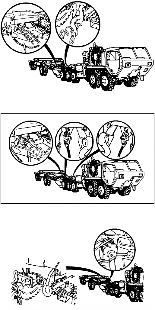
STP 55-88M14-SM-TG
3-108
Performance Steps
e. Ensure trailer brakes are set or trailer wheel is chocked prior to disconnecting trailer from
vehicle.
f. Remove pintle lock pin and open pintle.
g. With assistance, move trailer as required to disengage drawbar ring from pintle. Apply trailer
handbrakes.
h. Move vehicle a safe distance from trailer.
Figure 3-62a. Coupling
Figure 3-62b. Coupling (continued)
Figure 3-62c. Coupling (continued)
STP 55-88M14-SM-TG
3-109
Performance Steps
3. Couple PLS truck to PLS trailer (PLS/HEMTT-LHS systems only).
WARNING: Do not stand between trailer drawbar and truck coupler during hook-up procedures to
prevent being pinned between truck and trailer. Serious injury or death could result to personnel.
Wheels on trailer must be chocked to prevent trailer from moving during hook-up procedures. Serious
injury or death or injury to personnel could result.
Note: Align truck coupler with drawbar prior to beginning hookup procedures. Follow ground guide
signals.
a. Chock wheels of trailer.
b. Adjust drawbar if necessary.
c. Start truck (see vehicle TM) and following ground guide hand and arm signals, back truck to
within 6 inches from end of drawbar.
d. Apply parking brake and place transmission range selector in Neutral. Shut off truck.
Rotation locking pin should be in locked (UP) position to prevent coupler rotation during hook-up.
e. Lock rotation locking pin on coupler (see Figure 3-63).
f. Lift up locking gate on coupler.
g. Pull locking lever out and pull lever back at the same time to open coupler jaw.
Note: Air tank No. 1 must be charged with air for air assist lever to work. If it is not charged, remove the
charging hose from the trailer stowage box and perform steps h through t below. If air tank is charged,
perform step u.
h. Remove cover from emergency air glad-hand.
i. Connect charging hose glad-hand to emergency air glad-hand (see Figure 3-64).
j. Remove cover from charging hose connector.
k. Remove cover from trailer quick disconnect.
l. Connect charging hose connector to trailer quick disconnect.
m. With truck running, push trailer air supply valve on dash to charge No. 1 air tank.
n. When fully charged (three to five minutes), release trailer air supply valve on dash and shutoff
engine.
o. Disconnect charging hose connector from trailer quick disconnect.
p. Install cover on trailer disconnect.
q. Install cover on charging hose connector.
r. Disconnect charging hose glad-hand from emergency air glad-hand and stow in stowage box.
s. Install cover on emergency air glad-hand.
WARNING: Drawbar weighs 425 lbs, 850 lbs with drawbar extension, (if equipped). Drawbar may rise
quickly or fall suddenly to the ground when released from coupler. Do no allow feet or body to get under
or above drawbar. Serious injury to personnel my result.
t. Move air assist lever on drawbar air assist valve to UP position and raise drawbar to level of
coupler (see Figure 3-65).
u. Place air assist lever in neutral position.
WARNING: Do not stand between trailer drawbar and truck coupler during hook-up procedures to
prevent being pinned between truck and trailer. Serious injury of death could result to personnel. Wheels
on trailer must be chocked to prevent trailer from moving during hook-up procedures. Serious injury of
death could result to personnel.
v. Start truck and slowly back up until drawbar makes contact and locks with coupler.
w. Pull truck forward slightly to verify coupler has latched onto drawbar.
x. Shut off truck.
y. Release air pressure by moving air assist lever down for five seconds.
z. Close locking gate on coupler.
aa. Unlock rotation locking pin on coupler.
ab. Remove cover from truck receptacle.
ac. Connect load lock status line to truck receptacle.
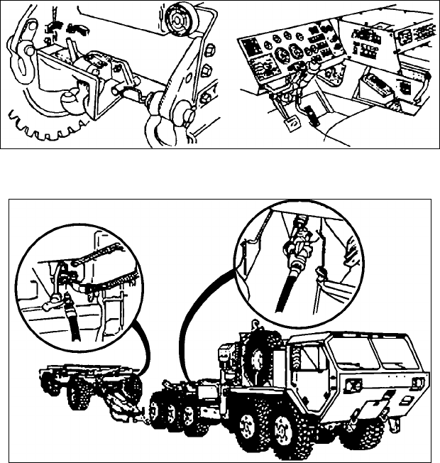
STP 55-88M14-SM-TG
3-110
Performance Steps
ad. Remove cover from 7-pin receptacle on trailer and connect 12-volt cable on receptacle (see
Figure 3-66).
CAUTION: Both the 12 and 24-volt cables must NOT be connected at the same time. Only one cable
can be hooked up during operation or damage to equipment will result. Ensure that receptacle latch is
engaged on cable or damage to cable may result. The 12-volt cable is standard for this trailer. Use the
24-volt cable system only when the 12-volt cable cannot be used or blackout lights are used. Perform
steps ad and ae for 12-volt system only. Cables are located in the stowage box.
ae. Lift receptacle cover on truck and connect 12-volt cable on receptacle.
Note: Perform steps af and ah for 24-volt system when not equipped with drawbar extension.
Note: Perform steps ag and ah for 24-volt system equipped with drawbar extension.
af. Remove cover from 12-pin receptacle on trailer and connect 24-volt cable on receptacle.
ag. Remove cover from 12-pin receptacle and connect 24-volt cable on receptacle.
ah. Lift upper right receptacle cover on the truck and connect 24-volt cable on receptacle.
ai. Remove two covers from air couplings.
aj. Install emergency air glad-hand to air coupling.
ak. Install service air glad-hand to air coupling.
al. Install safety chains on hooks from large links on chains.
am. Attach electrical cable brackets to hook on both sides of drawbar.
an. Unhook two safety chains from trailer and attach to truck clevises.
ao. Remove wheel chocks.
Figure 3-63. Locking Pin and Coupler
Figure 3-64. Air Coupler
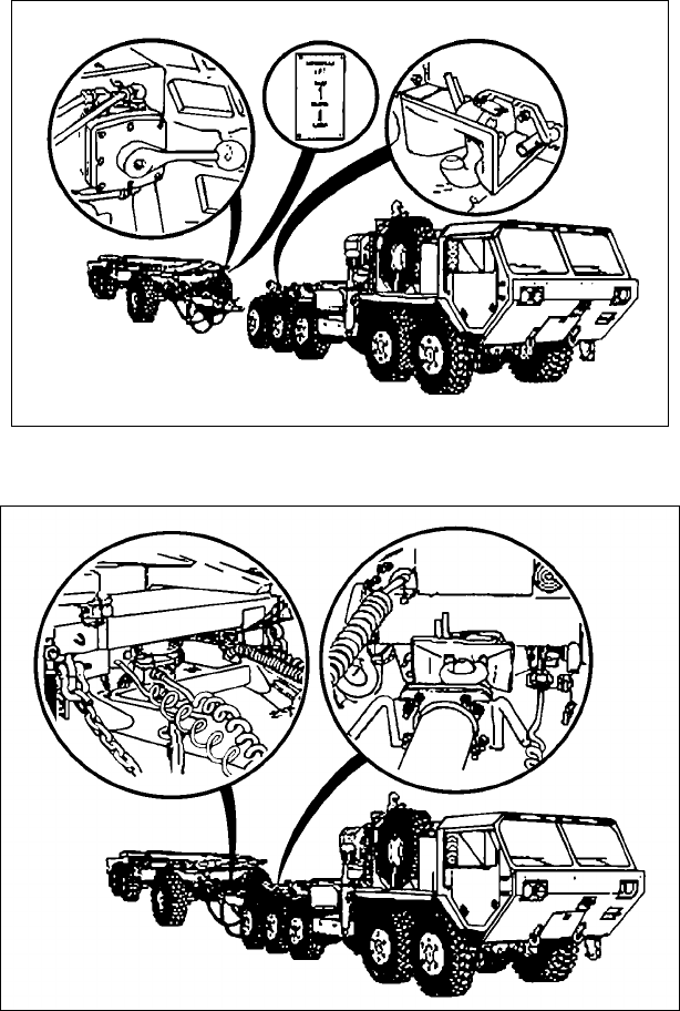
STP 55-88M14-SM-TG
3-111
Figure 3-65. Air Coupling
Figure 3-66. 12-24 Volt Receptacle
Performance Steps
4. Uncouple PLS truck from PLS trailer.
WARNING: Do not stand between trailer drawbar and truck coupler during hook-up procedures to
prevent being pinned between truck and trailer. Serious injury of death could result to personnel. Wheels
on trailer must be chocked to prevent trailer from moving during hook-up procedures. Serious injury of
death could result to personnel.
a. Chock wheels of trailer.
b. Unhook two safety chains from clevises and attach to trailer.
c. Hook safety chains to chain links.
d. Remove emergency glad-hand from air coupling and stow on stowage coupler.
e. Remove service air glad-hand from air coupling and stow on stowage coupler.

STP 55-88M14-SM-TG
3-112
Performance Steps
f. Install covers on air couplings.
CAUTION: Both the 12 and 24-volt cables must NOT be connected at the same time. Only one cable
can be hooked up during operation or damage to equipment will result.
g. Remove 24-volt cable from receptacle on truck and close receptacle cover.
h. Remove 24-volt cable on trailer from receptacle and install cover on receptacle and install
cover on receptacle and stow in trailer stowage box.
i. Remove 24-volt cable on trailer from receptacle and install cover on receptacle and stow in
trailer stowage box.
j. Remove 12-volt cable on truck from receptacle and close receptacle cover.
k. Remove 12-volt cable on trailer from receptacle and install cover on receptacle and stow in
trailer stowage box.
l. Remove load lock status line from truck receptacle and place on stowage hook.
m. Install cover to receptacle.
n. Lock rotation locking pin and check coupler to make sure it will not rotate.
o. Lift up locking gate on coupler.
p. Pull locking lever out while pulling lever back at the same time.
q. Release locking lever prior to releasing lever, to unlock coupler jaw.
WARNING: Drawbar weighs 425 lbs, 850 lbs with drawbar extension, (if equipped). Drawbar may raise
quickly or fall suddenly to the ground when released from coupler. Do no allow feet or body to get under
or above drawbar. Serious injury to personnel my result. Do not leave drawbar in elevated position after
disconnecting from truck. Drawbar could fall causing serious injury to personnel.
r. Use air assist valve to apply air pressure to hold drawbar from falling when released from
coupler.
s. Start truck, release parking brake and slowly pull forward until drawbar releases from coupler.
t. Apply parking brake and place transmission range selector to Neutral.
u. Push up on coupler jaw to close.
v. Close locking gate on coupler.
Evaluation Preparation: Setup: Provide for the soldier a tactical wheeled vehicle and a pintle-style
trailer, ground guide assistance, hearing protection, work gloves, level ground to operate.
Brief Soldier: You are required to perform a coupling operation with a pintle connected trailer and a prime
mover. This operation will involve you coupling and then uncoupling the trailer from the prime mover. All
steps must be performed successfully in order to pass this task. Entire operation must be performed
without injury to personnel or damage to equipment.
Performance Measures GO NO GO
1. Coupled vehicle to trailer (for vehicle-trailer combination other than PLS). —— ——
a. Removed chock blocks from vehicle tires.
b. Started vehicle (see vehicle -10 series TM).
c. Following visual hand signals from ground guide, aligned vehicle with trailer
and slowly back vehicle until pintle is adjacent to drawbar ring.
d. Removed pintle lock pin and open pintle.
e. Released trailer hand brake.
f. Moved trailer as required (with assistance) to engage drawbar ring in pintle.
g. Closed pintle and installed pintle lock pin.
h. Crossed safety chains under drawbar ring and attached to towing vehicle
eyebolts.
i. Connected intervehicular cable to towing vehicle receptacle.

STP 55-88M14-SM-TG
3-113
Performance Measures GO NO GO
j. Connected service air hose to towing vehicle glad-hand. If coupling an
M105A2C, also connected emergency air hose to towing vehicle glad-hand.
k. Turned on towing vehicle air valves to apply vacuum or pressure as
required.
l. Pulled out release handle and at same time, begin raising adjustable caster
assembly. Let go of release handle while raising adjustable caster
assembly.
m. Raised adjustable caster assembly until release handle locks adjustable
caster assembly in position. Ensured the release handle is fully engaged.
2. Uncoupled the trailer from vehicle (for vehicle-trailer combination other than PLS). —— ——
a. Supported adjustable caster assembly and at the same time pull out release
handle. Lowered adjustable caster assembly. Ensured that release handle
is fully engaged.
b. Disconnected air hose from towing vehicle glad-hand. If uncoupling from an
M105A2C, also disconnected emergency air hose from towing vehicle glad-
hand.
c. Disconnected intervehicular cable from towing vehicle receptacle and stow
on trailer.
d. Disconnected safety chains from towing vehicle eyebolts and stow on trailer.
e. Ensured trailer brakes are set or trailer wheel is chocked prior to
disconnecting trailer from vehicle.
f. Removed pintle lock pin and open pintle.
g. With assistance, moved trailer as required to disengage drawbar ring from
pintle. Apply trailer handbrakes.
h. Moved vehicle a safe distance from trailer.
3. Coupled PLS truck to PLS trailer (PLS/HEMTT-LHS systems only). —— ——
a. Chocked wheels of trailer.
b. Adjusted drawbar if necessary.
c. Started truck (see vehicle TM) and following ground guide hand and arm
signals, back truck to within 6 inches from end of drawbar.
d. Applied parking brake and place transmission range selector in Neutral.
Shut off truck.
e. Locked rotation locking pin on coupler.
f. Lifted up locking gate on coupler.
g. Pulled locking lever out and pull lever back at the same time to open coupler
jaw.
h. Removed cover from emergency air glad-hand.
i. Connected charging hose glad-hand to emergency air glad-hand.
j. Removed cover from charging hose connector.
k. Removed cover from trailer quick disconnect.
l. Connected charging hose connector to trailer quick disconnect.
m. With truck running, pushed trailer air supply valve on dash to charge No. 1
air tank.
n. When fully charged (three to five minutes), released trailer air supply valve
on dash and shutoff engine.
o. Disconnected charging hose connector from trailer quick disconnect.
p. Installed cover on trailer disconnect.
q. Installed cover on charging hose connector.

STP 55-88M14-SM-TG
3-114
Performance Measures GO NO GO
r. Disconnected charging hose glad-hand from emergency air glad-hand and
stow in stowage box.
s. Installed cover on emergency air glad-hand.
t. Moved air assist lever on drawbar air assist valve to UP position and raise
drawbar to level of coupler.
u. Placed air assist lever in neutral position.
v. Started truck and slowly back up until drawbar makes contact and locks with
coupler.
w. Pulled truck forward slightly to verify coupler has latched onto drawbar.
x. Shut off truck.
y. Released air pressure by moving air assist lever down for five seconds.
z. Closed locking gate on coupler.
aa. Unlocked rotation locking pin on coupler.
ab. Removed cover from truck receptacle.
ac. Connected load lock status line to truck receptacle.
ad. Removed cover from 7-pin receptacle on trailer and connect 12-volt cable on
receptacle.
4. Uncoupled PLS truck from PLS trailer. —— ——
a. Chocked wheels of trailer.
b. Unhooked two safety chains from clevises and attach to trailer.
c. Hooked safety chains to chain links.
d. Removed emergency glad-hand from air coupling and stow on stowage
coupler.
e. Removed service air glad-hand from air coupling and stow on stowage
coupler.
f. Installed covers on air couplings.
g. Removed 24-volt cable from receptacle on truck and close receptacle cover.
h. Removed 24-volt cable on trailer from receptacle and install cover on
receptacle and install cover on receptacle and stow in trailer stowage box.
i. Removed 24-volt cable on trailer from receptacle and install cover on
receptacle and stow in trailer stowage box.
j. Removed 12-volt cable on truck from receptacle and close receptacle cover.
k. Removed 12-volt cable on trailer from receptacle and install cover on
receptacle and stow in trailer stowage box.
l. Removed load lock status line from truck receptacle and place on stowage
hook.
m. Installed cover to receptacle.
n. Locked rotation locking pin and check coupler to make sure it will not rotate.
o. Lifted up locking gate on coupler.
p. Pulled locking lever out while pulling lever back at the same time.
q. Released locking lever prior to releasing lever to unlock coupler jaw.
r. Used air assist valve to apply air pressure to hold drawbar from falling when
released from coupler.
s. Started truck, release parking brake and slowly pull forward until drawbar
releases from coupler.
t. Applied parking brake and place transmission range selector to Neutral.
u. Pushed up on coupler jaw to close.
v. Closed locking gate on coupler.
STP 55-88M14-SM-TG
3-115
Evaluation Guidance: Score the soldier GO if all performance measures are passed. Score the soldier
NO-GO if any performance measure is failed. If any performance measure is failed, tell the soldier what
was done wrong and how to do it correctly.
References
Required Related
TM 9-2320-260-10
TM 9-2320-270-10
TM 9-2320-272-10
TM 9-2320-279-10-1
TM 9-2320-279-10-2
TM 9-2320-280-10
TM 9-2320-283-10
TM 9-2320-360-10
TM 9-2320-364-10
TM 9-2320-365-10
TM 9-2320-366-10-1
TM 9-2320-366-10-2
TM 9-2330-213-14&P
TM 9-2330-385-14
STP 55-88M14-SM-TG
3-116
Operate Vehicle-Mounted Crane
551-721-2407
Conditions: Given a vehicle equipped with a vehicle-mounted crane on which before-operation PMCS
has been performed, applicable TM, flat surface in which to operate, and directions/hands signals from
another person.
Standards: Setup vehicle-mounted crane for operation to include outriggers, as applicable. Operate the
crane while following visual hand and arm signals. Prepare crane and outriggers, as applicable, for
travel. All crane operations must be performed without injury to personnel or damage to any equipment
or load.
Performance Steps
1. Start vehicle engine (except LMTV).
a. M977 (HEMTT) crane-mounted vehicles. Refer to TM 9-2320-279-10-1.
b. M1074/M1075 (PLS) crane- mounted vehicles. Refer to TM 9-2320-364-10.
c. M1084/1086 MTV with MHE. Refer to TM 9-2320-366-10-1.
2. Prepare crane for use.
a. M1078 (LMTV) vehicles. Refer to TM 9-2320-365-10.
b. M1083 (MTV) vehicles. Refer to TM 9-2320-366-10-1.
c. M1084/1086 (MTV) vehicles. Refer to TM 9-2320-366-10-1.
d. M1074/M1075 (PLS) vehicles. Refer to TM 9-2320-364-10.
e. M977/M985 (HEMTT) vehicles. Refer to TM 9-2320-279-10-1.
3. Operate crane following visual hand and arm signals for movement.
a. M1078 (LMTV) vehicles. Refer to TM 9-2320-365-10.
b. M1083 (MTV) vehicles. Refer to TM 9-2320-366-10-1 (Light Material Handling Crane).
c. M1084/1086 (MTV) vehicles w/MHE. Refer to TM 9-2320-366-10-1 (Material Handling Crane).
d. M1074/M1075 (PLS) vehicles. Refer to TM 9-2320-364-10.
e. M977/M985 (HEMTT) vehicles. Refer to TM 9-2320-279-10-1.
4. Stow the crane for travel.
a. M1078 (LMTV) vehicles. Refer to TM 9-2320-365-10.
b. M1084/1086 (MTV) vehicles. Refer to TM 9-2320-366-10-1.
c. M1083 (MTV) vehicles. Refer to TM 9-2320-366-10-1.
d. M1074/M1075 (PLS) vehicles. Refer to TM 9-2320-364-10.
e. M977/M985 (HEMTT) vehicles. Refer to TM 9-2320-279-10-1.
5. Shutdown vehicle engine (except LMTV/MTV).
a. M1084/1086 (MTV) vehicles. Refer to TM 9-2320-366-10-1.
b. M1074/M1075 (PLS) vehicles. Refer to TM 9-2320-364-10.
c. M977/M985 (HEMTT) vehicles. Refer to TM 9-2320-279-10-1.
Evaluation Preparation: Setup: Provide soldier with a vehicle equipped with a vehicle-mounted crane
on which before-operation PMCS has been performed, applicable TM, flat surface in which to operate,
and directions/hands signals from another person.
Brief Soldier: You must prepare crane for operation and operate the crane while following hand and arm
signals given by another soldier. Then stow crane for travel.

STP 55-88M14-SM-TG
3-117
Performance Measures GO NO GO
1. Started vehicle engine. —— ——
2. Prepared crane for operation. —— ——
3. Operated crane while following visual hand and arm signals. —— ——
4. Stowed crane for travel. —— ——
5. Shutdown vehicle engine. —— ——
Evaluation Guidance: Score the soldier GO if all performance measures are passed. Score the soldier
NO-GO if any performance measure is failed. If any performance measure is failed, tell the soldier what
was done wrong and how to do it correctly.
References
Required Related
TM 9-2320-279-10-1
TM 9-2320-364-10
TM 9-2320-365-10
TM 9-2320-366-10-1
STP 55-88M14-SM-TG
3-118
Subject Area 5: Transport Cargo and Personnel
Conduct Refueling Operations Using Tactical Refueling Vehicles
551-721-2100
Conditions: Given an M931/932 or M1088 Tractor with M967 Tank Semitrailer with full or partial load of
fuel, BII, grounding and bonding materials, protective clothing and equipment, fire extinguishers, spill
containers, appropriate gauging equipment, dispensing log, assistance from another person, vehicle(s) to
refuel, level ground, and instructions on amount of fuel to dispense.
Special Conditions: Must have hazardous materials endorsement on operator’s license. Possess a fuel
handler’s card. Refueling operations requires two persons.
Standards: You have successfully emplaced your refueling vehicle, performed all pre-operation safety
checks, grounded and bonded properly, refueled designated vehicle(s) or storage area, contained and
recovered any spillage, and properly prepared for movement to subsequent locations without violating
any safety measures, causing injury to personnel, damage to equipment, or contaminating the
environment.
Performance Steps
1. Apply risk management procedures.
a. Refer to FM 100-14, chapter 3 and the appendix and local SOP for guidelines applicable to this
procedure. Ensure all aspects of these operations are assessed for the risk involved.
b. Fill out the risk assessment worksheet. Notify chain-of-command if assessment determines
requirement for approval from higher authority.
2. Perform before-operation preparations.
WARNING: Frequent inspection of equipment, safety devices, and working areas must be performed to
ensure personal and operational safety and to correct potential or actual hazards. The semitrailer must
not be operated if any of the following conditions exist.
Fuel leaks.
Damage to lighting fixtures, wiring or electrical conduits, or lights inoperative.
Damage to towing vehicle or semitrailer.
Primary or parking brake systems inoperative.
Vents plugged, inoperative, or removed.
Note: Pressure, vacuum, and fusible vents are installed to meet code requirements and to protect the
semitrailer from damage. A plugged or inoperative vent can cause extensive shell damage if design
pressure or vacuum is exceeded. The fusible vents are designed to operate at high temperatures. If
these vents are coated with paint, dirt, or other foreign material, the temperature when relief occurs may
be greatly increased.
WARNING: Ensure that grounding connections are made properly and firmly before any fueling
operations begin. This will ensure that grounding connections will not release, thus eliminating the
possibility of sparks caused by static electricity, which will ignite fuel.
a. Prior to starting engine.
WARNING: Before and after fuel servicing operations, all valves are to be in the closed position. Failure
to follow this warning could result in excessive spillage and create a fire hazard.
(1) Ensure all manually operated valves are closed. This is a must before either starting or
ending any fuel servicing operations.
(2) To prevent collapse of tank when filling or emptying tank, ensure that the top vent is
working properly.
STP 55-88M14-SM-TG
3-119
Performance Steps
(3) Ground and bond vehicle (see Figure 3-67).
(4) Remove fire extinguishers and bring them to the point of operation.
(5) Ensure engine fuel tank has enough fuel for operation.
(6) Remove engine dipstick and check oil level. Refill as needed.
(7) Check air cleaner restriction indicator. Clean or replace filter element as needed.
WARNING: Carbon monoxide can be deadly. DO NOT operate engine in an enclosed area unless it is
adequately ventilated.
b. Starting the engine (see Figure 3-68).
(1) Rotate engine switch to RUN. When engine is warm or restarted after short periods of
time, preheating is usually not necessary. In temperatures below 30oF, a longer
preheating period is needed.
(2) Rotate pre-heater switch to ON for about 1 minute. Ensure indicator light has illuminated.
(3) After 1 minute, continue to hold pre-heater switch and rotate starter switch to START.
(4) Release both starter and pre-heater switches after engine starts.
(5) Check the gauges for correct indication. Stop the engine if a system malfunction is
indicated.
c. Stopping engine (If not used for refueling operations).
CAUTION: Throttle engine to fast idle (1200 rpm) for about 5 minutes before stopping to allow for
gradual cooling of engine.
(1) Release throttle to low idle.
(2) Rotate engine switch to STOP.
d. Engine operation –High temperature.
(1) See the nothing obstructs the air flow to and from the engine oil cooler and the cylinder
cooling fins.
(2) See that shrouds are properly installed and in good condition.
e. Engine operation –Low temperature.
Note: If operating in cold weather, cover (dust boot) of fuel stop solenoid must be cut off. Cover stiffens
in cold temperatures and stops flow of fuel to engine.
(1) Ensure that engine has the proper oil and fuel for the existing temperatures.
(2) Keep batteries fully charged.
Note: Entire cold weather starting procedures may not be required. The colder the temperature, the
more pre-heating and cranking will be required.
(3) When temperatures are below 30oF, perform the following:
(a) Pull throttle about half way out.
(b) Engage pre-heater switch and leave turned on until engine has started,
approximately 5 minutes at coldest temperature.
(c) After 1 ¾ minutes, move engine switch to RUN position. Wait 15 seconds, then
engage starter switch to START position and crank engine for 15 seconds.
Disengage starter switch.
(4) Wait one minute and engage starter switch. Crank for one minute, or until running.
Engine should be firing. Disengage starter switch.
(5) If engine still has not started, engage starter switch and crank for one minute. Engine
should be firing. Disengage starter switch when engine is increasing speed.
(6) Turn off pre-heater switch.
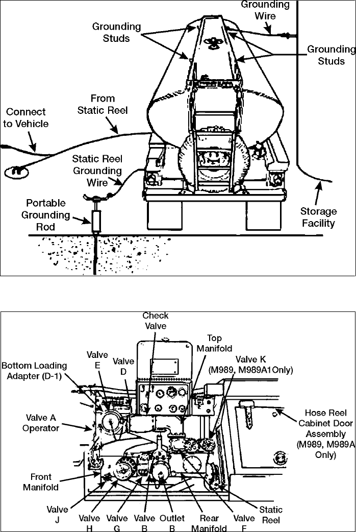
STP 55-88M14-SM-TG
3-120
Figure 3-67. Typical Grounding Connections
Figure 3-68. Engine and Pump Assembly
STP 55-88M14-SM-TG
3-121
Performance Steps
3. Conduct basic haul and fuel services (operation NOT involving engine and pump).
WARNING: Top loading should only be done when bottom loading is not possible. Bottom loading
minimizes the level of static electricity buildup. When top loading through fill cover, there is no automatic
shutdown. Man the loading hose to avoid fuel spillage. Use capacity indicator gauge and dipstick gauge
to determine amount of fuel loaded. Failure to follow this warning may result in uncontrolled fuel spillage
and a fire or explosion hazard. Ladder has narrow tread, be careful when climbing.
a. Top Loading (the product is not filtered or metered by the vehicle).
(1) Ensure all valves are closed.
(2) Ground and bond the semitrailer before opening the fill cover.
(3) Place fire extinguishers at point of operation.
(4) Slowly open fill cover. Insert hose far enough to keep the end of the hose in contact with
the bottom of the tank.
(5) Slowly begin the flow and fill the tank no further than to the bottom of the capacity
indicator (one person at storage tank valve or other fuel source, and other holding fill tube
into semitrailer).
(6) Remove fill hose. Close and secure the manhole cover.
(7) Drain accumulated water. Close all valves. Put the container under the manifold drain in
the piping control cabinet. Open the emergency operator valve. Slowly open the system
drain valves (see Figures 3-69a and 3-69b).
(8) Remove the grounding wires and store fire extinguishers.
b. Bottom loading (the product is not filtered or metered by the vehicle).
(1) Ensure all valves are closed.
(2) Ground and bond the vehicle.
(3) Remove cover from the bottom loading connection and connect the bottom loading hose
to the bottom loading connection.
(4) Remove the fire extinguishers and bring to point of operation.
(5) On the M967, put the selector valve in the LOAD position.
(6) Open the emergency valve operator.
(7) Begin the flow from the outside source.
WARNING: When filling the tank by means of bottom loading, a test of the pre-check valve is mandatory.
If this system is not functioning, stop all operations. Determine the problem and have it corrected by a
qualified technician. Failure of automatic shut-off to function may result in uncontrolled fuel spillage and
danger of fire and explosion.
(8) After the flow has begun, open the pre-check valve to pre-check the shutoff float. Flow
should stop after about 20 to 25 seconds to indicate that the float is functional. If it is not
working, stop all operations and notify higher maintenance.
(9) Close the pre-check valve. The flow will resume in about 20 seconds. Be prepared to
stop the fuel supply at the loading facility in event of shut-off float malfunction, if leaks are
apparent, or other unusual condition are seen.
(10) When tank is full, the flow should stop automatically. Close all valves, replace all covers,
and disconnect the hoses.
(11) Drain the accumulated water in the same manner as stated in 1a(8) above for top loading.
(12) Remove the grounding wires.
(13) Stow fire extinguishers.
c. Self-loading using vehicle engine and pump (see Figure 3-70). Product is not filtered.
(1) Ensure all valves are closed.
(2) Ground and bond the vehicle.
(3) Remove fire extinguishers and bring to point of operation.
(4) Start the engine and pump (see item 1 as necessary).
(5) Adjust idle speed on pump to 1000 to 1200 rpm.
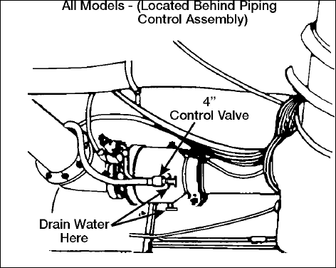
STP 55-88M14-SM-TG
3-122
Performance Steps
(6) Remove the 4-inch bulk fuel hose from the hose trough. Do this by disconnecting the
spring pins and turning the hose trough bars out of the way.
(7) Remove dust cap from the fuel outlets. Connect one end of the bulk fuel hose to the
outlet and the other end to the storage facility.
(8) Place the selector valve in the LOAD position.
(9) Open the operator valve, fuel outlet valve, and the manifold outlet valve.
(10) Shortly after the flow has started, open the pre-check valve to pre-check the shutoff float.
After about 20 to 25 seconds, the flow should stop to let you know the float is working
properly. If it is not working, stop all operations and notify higher maintenance.
(11) Close the pre-check valve. Flow will resume in about 20 seconds.
(12) When tank is full, the flow should stop automatically.
WARNING: In an emergency, close the operator’s valve or pull the emergency valve shutoff on the
opposite side of the semitrailer.
(13) At the end of operation, idle down the engine.
(14) Close all valves.
(15) Disconnect the 4-inch bulk fuel hose and put in the hose trough. Secure the hose trough
latches.
(16) Stop the engine.
(17) Drain accumulated water in the same manner as with top loading.
(18) Remove the ground wires.
(19) Recover and stow fire extinguishers.
4. Gauge petroleum tank vehicles.
a. Position tank vehicle.
b. Position fire extinguishers within 5 to 10 feet of operation.
c. Review shipping document to verify the type of fuel in the tank vehicle.
d. Ground and bond the vehicle.
e. Ground self from static electricity.
f. Open the manhole cover with the wind at your back to avoid breathing fuel vapor.
g. Insert thermometer as soon as each hatch is opened to measure the temperature.
h. Gauge the compartment using the tank vehicle gauge stick provided with the tank vehicle.
i. Repeat gauging procedure until two readings the same are obtained to ensure gauge is
accurate, and record on the gauge worksheet.
j. Remove the thermometer after the required time and record the temperature on the gauge
worksheet.
Figure 3-69a. Pilot Line Water Drains-1
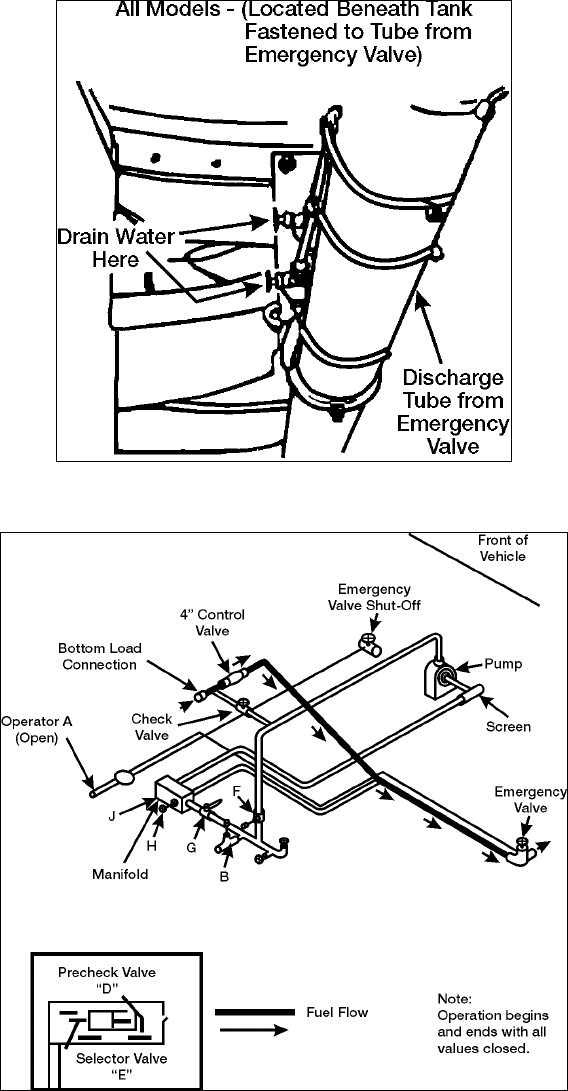
STP 55-88M14-SM-TG
3-123
Figure 3-69b. Pilot Lines Water Drains-2
Figure 3-70. Self-Load Flow Diagram

STP 55-88M14-SM-TG
3-124
Evaluation Preparation: Setup: Provide for the soldier and M967 Tank Semitrailer coupled to a prime
mover, BII for prime mover and semitrailer. Instructions to conduct refueling operations for one or more
vehicles and customer vehicle(s).
Brief Soldier: You are required to ensure your vehicle is prepared for refueling operation. You are to
refuel customer vehicle(s) safely while adhering to all safety aspects of the operation of the tank
semitrailer. If you are about to commit an unsafe act you will be immediately stopped and informed of
your performance.
Performance Measures GO NO GO
1. Applied risk management procedures. —— ——
a. Referred to FM 100-14, chapter 3 and the appendix and local SOP for
guidelines applicable to this procedure. Ensured all aspects of these
operations are assessed for the risk involved.
b. Filled out the risk assessment worksheet. Notified chain-of-command if
assessment determines requirement for approval from higher authority.
2. Performed before-operation preparations. —— ——
a. Prior to starting engine.
(1) Ensured all manually operated valves are closed. This is a must before
either starting or ending any fuel servicing operations.
(2) To prevent collapse of tank when filling or emptying tank, ensured that
the top vent is working properly.
(3) Grounded and bonded vehicle.
(4) Removed fire extinguishers and bring them to the point of operation.
(5) Ensured engine fuel tank has enough fuel for operation.
(6) Removed engine dipstick and check oil level. Refilled as needed.
(7) Checked air cleaner restriction indicator. Cleaned or replace filter
element as needed.
b. Starting the engine.
(1) Rotated engine switch to RUN.
(2) Rotated pre-heater switch to ON for about 1 minute. Ensured indicator
light has illuminated.
(3) After 1 minute, continued to hold pre-heater switch and rotated starter
switch to START.
(4) Released both starter and pre-heater switches after engine started.
(5) Checked the gauges for correct indication. Stopped the engine if a
system malfunction was indicated.
c. Stopping engine (if not used for refueling operations).
(1) Released throttle to low idle.
(2) Rotated engine switch to STOP.
d. Engine operation –High temperature.
(1) Saw that nothing obstructed the air flow to and from the engine oil
cooler and the cylinder cooling fins.
(2) Saw that shrouds are properly installed and in good condition.

STP 55-88M14-SM-TG
3-125
Performance Measures GO NO GO
e. Engine operation –Low temperature.
(1) Ensured that engine has the proper oil and fuel for the existing
temperatures.
(2) Kept batteries fully charged.
(3) When temperatures are below 30oF, performed the following:
(a) Pulled throttle about half way out.
(b) Engaged pre-heater switch and left turned on until engine started,
approximately 5 minutes at coldest temperature.
(c) After 1 ¾ minutes, moved engine switch to RUN position. Waited
15 seconds, then engaged starter switch to START position and
cranked engine for 15 seconds. Disengaged starter switch.
(4) Waited one minute and engaged starter switch. Cranked for one
minute, or until running. Engine should be firing. Disengaged starter
switch.
(5) If engine still has not started, engaged starter switch and crank for one
minute. Engine should be firing. Disengaged starter switch when
engine is increasing speed.
(6) Turned off pre-heater switch.
3. Conducted basic haul and fuel services (operation NOT involving engine and
pump).
—— ——
a. Top Loading (the product is not filtered or metered by the vehicle).
(1) Ensured all valves are closed.
(2) Grounded and bonded the semitrailer before opening the fill cover.
(3) Placed fire extinguishers at point of operation.
(4) Slowly opened fill cover. Inserted hose far enough to keep the end of
the hose in contact with the bottom of the tank.
(5) Slowly began the flow and filled the tank no further than to the bottom
of the capacity indicator. (One person at storage tank valve or other fuel
source, and other holding fill tube into semitrailer.)
(6) Removed fill hose. Closed and secured the manhole cover.
(7) Drained accumulated water. Closed all valves. Put the container under
the manifold drain in the piping control cabinet. Opened the emergency
operator valve. Slowly opened the system drain valves.
(8) Removed the grounding wires and store fire extinguishers.
b. Bottom loading (the product is not filtered or metered by the vehicle).
(1) Ensured all valves are closed.
(2) Grounded and bonded the vehicle.
(3) Removed cover from the bottom loading connection and connected the
bottom loading hose to the bottom loading connection.
(4) Removed the fire extinguishers and brought to point of operation.
(5) On the M967, put the selector valve in the LOAD position.
(6) Opened the emergency valve operator.
(7) Began the flow from the outside source.
(8) After the flow has begun, opened the pre-check valve to pre-check the
shutoff float. Flow stopped after about 20 to 25 seconds to indicate that
the float is functional. If it is not working, stop all operations and notify
higher maintenance.
(9) Closed the pre-check valve. The flow will resume in about 20 seconds.
(10) When tank was full, the flow stopped automatically. Closed all valves,
replaced all covers, and disconnected the hoses.

STP 55-88M14-SM-TG
3-126
Performance Measures GO NO GO
(11) Drained the accumulated water in the same manner as stated in 1a(8)
above for top loading.
(12) Removed the grounding wires.
(13) Stowed fire extinguishers.
c. Self-loading using vehicle engine and pump. Product is not filtered.
(1) Ensured all valves are closed.
(2) Grounded and bonded the vehicle.
(3) Removed fire extinguishers and brought to point of operation.
(4) Started the engine and pump (see item 1 as necessary).
(5) Adjusted idle speed on pump to 1000 to 1200 rpm.
(6) Removed the 4-inch bulk fuel hose from the hose trough. Did this by
disconnecting the spring pins and turning the hose trough bars out of
the way.
(7) Removed dust cap from the fuel outlets. Connected one end of the
bulk fuel hose to the outlet and the other end to the storage facility.
(8) Placed the selector valve in the LOAD position.
(9) Opened the operator valve, fuel outlet valve, and the manifold outlet
valve.
(10) Shortly after the flow had started, opened the pre-check valve to pre-
check the shutoff float. After about 20 to 25 seconds, the flow stopped
to let you know the float was working properly. If it was not working,
stopped all operations and notified higher maintenance.
(11) Closed the pre-check valve. Flow resumed in about 20 seconds.
(12) When tank was full, the flow stopped automatically.
(13) At the end of operation, idled down the engine.
(14) Closed all valves.
(15) Disconnected the 4-inch bulk fuel hose and put in the hose trough.
Secured the hose trough latches.
(16) Stopped the engine.
(17) Drained accumulated water in the same manner as with top loading.
(18) Removed the ground wires.
(19) Recovered and stowed fire extinguishers.
4. Gauged petroleum tank vehicles. —— ——
a. Positioned tank vehicle.
b. Positioned fire extinguishers within 5 to 10 feet of operation.
c. Reviewed shipping document to verify the type of fuel in the tank vehicle.
d. Grounded and bonded the vehicle.
e. Grounded self from static electricity.
f. Open the manhole cover with the wind at your back to avoid breathing fuel
vapor.
g. Inserted thermometer as soon as each hatch was opened to measure the
temperature.
h. Gauged the compartment using the tank vehicle gauge stick provided with
the tank vehicle.
i. Repeated gauging procedure until two readings the same were obtained to
ensure gauge is accurate, and recorded on the gauge worksheet.
j. Remove the thermometer after the required time and record the temperature
on the gauge worksheet.
STP 55-88M14-SM-TG
3-127
Evaluation Guidance: Score the soldier GO if all performance measures are passed. Score the soldier
NO-GO if any performance measure is failed. If any performance measure is failed, tell the soldier what
was done wrong and how to do it correctly.
References
Required Related
AR 600-55
FM 100-14
FM 10-67-1
TM 9-2320-272-10
TM 9-2320-279-10-1
TM 9-2320-279-10-2
TM 9-2320-366-10-1
TM 9-2320-366-10-2
TM 9-2330-356-14
STP 55-88M14-SM-TG
3-128
Assist in Loading/Unloading a Tracked/Wheeled Vehicle Onto/From Semitrailer
551-721-2374
Conditions: Given a tractor with semitrailer combination with before-operation maintenance performed,
payload vehicle, payload vehicle operator, payload vehicle characteristic information, Level ground to
operate, ground guide assistance as needed, chock blocks, hearing protection, and work gloves, loading
ramps, material handling crane with lifting sling, and guidance from supervisor or senior vehicle operator.
Special Conditions: This task covers loading operations only. Does not highlight tiedown of cargo.
Tiedown is a separate task.
Standards: You have assisted in loading the payload vehicle onto the semitrailer. The vehicle has been
positioned properly as indicated by supervisor or senior vehicle operator to allow for safe transport.
Performance Steps
1. Prepare for loading operation.
a. Material Handling Crane/Lifting Device (if used).
(1) Assist in positioning lifting device alongside semitrailer so that lifting device may lift and
swing payload vehicle onto semitrailer.
(2) Chock wheels or tracks as applicable.
(3) Prepare lifting device for operation (-10 series TM of applicable vehicle).
(4) Adhere to all WARNING and CAUTION statements in TM for this operation.
b. Tractor-semitrailer combination.
(1) Position tractor-semitrailer on level ground against a loading dock or suitable ramp for rear
loading. Ensure tractor/semitrailer is straight/in-line when docked.
(2) Set brakes and chock vehicle and semitrailer wheels to prevent movement.
(3) Shutdown tractor.
(4) Remove side boards if installed.
(5) Ensure semitrailer is clear of all obstructions, nails or any foreign objects that may
interfere with safe loading of payload vehicle.
(6) Emplace loading ramps between loading dock and rear of semitrailer if necessary.
(7) Gather all necessary tiedown materials for vehicle payload.
c. Payload vehicle.
(1) Reduce payload vehicle.
(a) Fold in mirrors (as applicable).
(b) Ensure canvas and bows, if installed, (wheeled payload) are removed or secured
tightly against payload vehicle to prevent loosening or loss during movement.
Remove payload vehicle canvas and bows if required.
(c) Secure payload vehicle cargo load (if applicable).
(d) Secure all payload vehicle weapons (is applicable).
(2) Position payload vehicle for lifting operation.
(3) Attach lifting sling to payload vehicle, and sling to lifting device (if lifting onto semitrailer).
(4) Position payload vehicle on loading dock directly in-line with rear of semitrailer (If using a
loading dock).
2. Load payload vehicle onto semitrailer.
a. Using a loading dock.
(1) Guide payload vehicle into position on semitrailer as directed by supervisor or senior
vehicle operator displaying hand and arm signals.
(2) Shutdown payload vehicle, set parking brake (in accordance with vehicle -10 series TM).
STP 55-88M14-SM-TG
3-129
Performance Steps
b. Using a lifting device.
(1) As directed, provide hand and arm signals to lifting device operator to position payload
onto semitrailer.
(2) Assist in enforcing control of suspended load is maintained throughout lifting operation.
(3) Adhere to all WARNING and CAUTION statements in lifting device TM.
3. Prepare for unloading operations.
a. Using a lifting device.
(1) Position lifting device or unloading operation.
(2) Chock wheels or track (as applicable).
(3) Prepare lifting device for operation.
(4) Adhere to all WARNING and CAUTION statement in TM.
b. Tractor-semitrailer.
(1) Position or assist in positioning tractor-semitrailer against loading dock (if used).
(2) Set brakes and chock vehicle and trailer wheels to prevent movement.
(3) Shutdown tractor.
(4) Remove side boards from semitrailer (if installed).
(5) Emplace loading ramps between loading dock and rear of semitrailer as necessary (if
loading dock is used).
(6) Assist in maneuvering tractor-semitrailer into position alongside lifting device (if used).
c. Payload vehicle.
(1) Remove payload vehicle tiedown materials.
(2) Remove chock blocks (if used).
(3) Attach lifting device to payload vehicle.
(4) Attach guide ropes to payload vehicle.
4. Unload payload vehicle from semitrailer.
a. Using a loading dock.
(1) Using hand and arm signals, guide payload vehicle driver to slowly back payload vehicle
onto loading dock.
(2) Signal payload vehicle operator to shutdown engine and set brakes.
b. Using a lifting device.
(1) Using hand and arm signals, guide lifting device operator to apply tension to sling and
raise payload vehicle clear of semitrailer deck.
(2) Using hand and arm signals, maneuver payload vehicle into designated position on the
ground.
(3) Remove lifting sling from payload vehicle.
(4) Signal lifting device operator to stow crane and shutdown (-10 series TM).
Evaluation Preparation: Setup: Provide for the soldier a truck tractor with flatbed semitrailer and
payload vehicle to load/unload.
Brief Soldier: You are required to position tractor/ semitrailer combination on level ground in a location
that will allow loading/offloading. You are to position your payload vehicle according to its center-of-
gravity properly on the semitrailer for transport.

STP 55-88M14-SM-TG
3-130
Performance Measures GO NO GO
1. Prepared for loading operation. —— ——
a. Material Handling Crane/Lifting Device (if used).
(1) Assisted in positioning lifting device alongside semitrailer so that lifting
device may lift and swing payload vehicle onto semitrailer.
(2) Chocked wheels or tracks as applicable.
(3) Prepared lifting device for operation (-10 series TM of applicable
vehicle).
(4) Adhered to all WARNING and CAUTION statements in TM for this
operation.
b. Tractor-Semitrailer combination.
(1) Positioned tractor-semitrailer on level ground against a loading dock or
suitable ramp for rear loading. Ensure tractor/semitrailer is straight/in-
line when docked.
(2) Set brakes and chocked vehicle and semitrailer wheels to prevent
movement.
(3) Removed side boards if installed.
(4) Ensured semitrailer is clear of all obstructions, nails or any foreign
objects that may interfere with safe loading of payload vehicle.
(5) Emplaced loading ramps between loading dock and rear of semitrailer if
necessary.
(6) Gathered all necessary tiedown materials for vehicle payload.
c. Payload vehicle.
(1) Reduced payload vehicle.
(a) Folded in mirrors (as applicable).
(b) Ensured canvas and bows, if installed, (wheeled payload) are
removed or secured tightly against payload vehicle to prevent
loosening or loss during movement. Removed payload vehicle
canvas and bows if required.
(c) Secured payload vehicle cargo load (if applicable).
(d) Secured all payload vehicle weapons (is applicable).
(2) Positioned payload vehicle for lifting operation.
(3) Attached lifting sling to payload vehicle, and sling to lifting device (if
lifting onto semitrailer).
(4) Positioned payload vehicle on loading dock directly in-line with rear of
semitrailer (if using a loading dock).
2. Loaded payload vehicle onto semitrailer. —— ——
a. Using a loading dock.
(1) Guided payload vehicle into position on semitrailer as directed by
supervisor or senior vehicle operator displaying hand and arm signals.
(2) Shutdown payload vehicle and set parking brake in accordance with
vehicle -10 series TM).
b. Using a lifting device.
(1) As directed, provided hand and arm signals to lifting device operator to
position payload onto semitrailer.
(2) Assisted in enforcing control of suspended load is maintained
throughout lifting operation.
(3) Adhered to all WARNING and CAUTION statements in lifting device
TM.

STP 55-88M14-SM-TG
3-131
Performance Measures GO NO GO
3. Prepared for unloading operation. —— ——
a. Using a lifting device.
(1) Positioned lifting device for unloading operation.
(2) Chocked wheels or track (as applicable).
(3) Prepared lifting device for operation.
(4) Adhered to all WARNING and CAUTION statements in TM.
b. Tractor-semitrailer.
(1) Positioned or assisted in positioning tractor-semitrailer against loading
dock (if used).
(2) Set brakes and chocked vehicle and trailer wheels to prevent
movement.
(3) Shutdown tractor.
(4) Removed side boards from semitrailer (if installed).
(5) Emplaced loading ramps between loading dock and rear of semitrailer
as necessary (if loading dock is used).
(6) Assisted in maneuvering tractor-semitrailer into position alongside lifting
device (if used).
c. Payload vehicle.
(1) Removed payload vehicle tiedown materials.
(2) Removed chock blocks (if used).
(3) Attached lifting device to payload vehicle.
(4) Attached guide ropes to payload vehicle.
4. Unloaded payload vehicle from semitrailer. —— ——
a. Using a loading dock.
(1) Using hand and arm signals, guided payload vehicle driver to slowly
back payload vehicle onto loading dock.
(2) Signaled payload vehicle operator to shutdown engine and set brakes.
b. Using a lifting device.
(1) Using hand and arm signals, guided lifting device operator to apply
tension to sling and raise payload vehicle clear of semitrailer deck.
(2) Using hand and arm signals, maneuvered payload vehicle into
designated position on the ground.
(3) Removed lifting sling from payload vehicle.
(4) Signaled lifting device operator to stow crane and shutdown (-10 series
TM).
Evaluation Guidance: Score the soldier GO if all performance measures are passed. Score the soldier
NO-GO if any performance measure is failed. If any performance measure is failed, tell the soldier what
was done wrong and how to do it correctly.
References
Required Related
FM 21-305
FM 21-60
TM 9-2320-260-10
TM 9-2320-272-10
TM 9-2330-357-14&P
STP 55-88M14-SM-TG
3-132
Assist in Loading/Unloading a Tracked/Wheeled Vehicle Onto/From a Heavy Equipment
Transporter (HET)
551-721-2376
Conditions: Given a Heavy Equipment Transporter (M1070), a Heavy Equipment Transport Semitrailer
(M1000) already coupled, blocking and bracing materials, OVE, hearing protection, a tracked vehicle to
be loaded, assistance from other crew members, and directions from supervisor.
Special Conditions: HETS (tractor and semitrailer combination) should be placed on solid level ground
with room to maneuver as necessary. Operations with the HETS require two persons to perform. One
person will be used assistance.
Standards: Provided assistance as directed in the loading of a tracked vehicle and assist in the proper
tiedown of vehicle on semitrailer without injury to personnel or damage to HETS or tracked vehicle being
loaded.
Performance Steps
1. Assist in preparing the M1070/M1000 HETS for loading operation.
a. Start the vehicle.
b. Ensure that the CTIS switch is set to the desired setting for the expected road conditions and
allow tractor to sit until selected CTIS indicator remains lit.
2. Assist in aligning the semitrailer, using the tractor, as close as possible to payload.
a. Payload should be approximately 15 feet (4.6m) on level ground when positioned.
WARNING: Load semitrailer on as level ground as possible. In adverse conditions, loading can be done
on grades up to 10 percent with a maximum offset angle of 10 degrees between tractor and semitrailer.
Avoid exceeding these limitations to prevent payload from rolling on semitrailer and causing serious injury
to personnel and damage to equipment.
b. Visually check tractor/semitrailer offset angle by having spotter check relationship between
steering wedge bolt and weld circle at bottom rear of pickup plate. If inside edge of bolt aligns
with outside edge of weld circle, offset angle is 10 degrees. Make any required adjustments.
c. Apply tractor parking brakes.
WARNING: Using the M1070 tractor, semitrailer will not back like a normal semitrailer because of
semitrailer steering system. The operator must back tractor/semitrailer by turning tractor steering wheel
in the opposite direction of what would be used for backing with a normal semitrailer or injury to personnel
and damage to equipment may result.
3. Assist in the preparation of the semitrailer to receive payload.
a. Refer to TM 9-2330-381-14, paragraph 2-26a(7) to 2-26a(29), pages 2-93 to 2-102.
b. Adhere to all WARNING and CAUTION statements in the semitrailer TM applicable to this
operation.
Note: Due to semitrailers being outfitted with various chains (1/2 inch and/or ¾-inch link sizes), all chains
must be inventoried in the platform storage compartment prior to placing chains on platform. Once
chains are inventoried, read and familiarize yourself with the information in steps a(20) (a) thru (h) of the
semitrailer TM to determine tiedown needed to properly secure the payload or injury to personnel and
damage to equipment may result.
4. Assist in loading payload onto semitrailer.
a. Refer to TM 9-2330-381-14, paragraph 2-26a(30) to 2-26a(40), pages 2-103 to 2-107.
b. Adhere to all cautions and warnings in the semitrailer TM applicable to this operation.

STP 55-88M14-SM-TG
3-133
Performance Steps
WARNING: Two spotters are required for loading and unloading operations. The payload operator must
know the position of spotters at all times or injury to personnel may result.
WARNING: Do not position a spotter or gooseneck if payload is to be backed onto semitrailer platform or
injury to personnel may result.
WARNING: Unnecessary personnel must stand well clear of the vehicles, especially behind the payload
(engine/turbine exhaust) during loading operations. At no time during any loading operation while the
payload is moving should personnel be on the semitrailer platform. The payload operator must drive the
payload slowly up the loading ramps and onto the platform or injury to personnel and damage to
equipment may result.
WARNING: Failure to set the payload parking brake could allow the payload to roll backward causing
injury to personnel and damage to equipment.
5. Assist in securing payload to semitrailer.
a. Refer to TM 9-2330-381-14, paragraph 2-26a(41) to 2-26a(48).
b. Adhere to all cautions and warnings in the semitrailer TM applicable to this operation.
CAUTION: The streetside angle rear payload tiedown chain must cross over the top of the curbside rear
payload tiedown chain or the chains will interfere with each other and damage to equipment may result.
CAUTION: Beacon warning light must be raised or loading ramps adjusted or damage to equipment will
occur.
Evaluation Preparation: Setup: Provide for the soldier a HET with HETS, able or disabled payload
vehicle, level ground to operate, assistance from another crew member.
Brief Soldier: You to load an able/disabled tracked/wheeled vehicle onto the Heavy Equipment
Transporter (HET). You are to use assistance as provided and will complete all required steps from the
TMs without injury to personnel or damage to system or payload vehicle.
Performance Measures GO NO GO
1. Assisted in preparing the M1070/M1000 HETS for loading operation. —— ——
2. Assisted in aligning the semitrailer, using the tractor, as close as possible to
payload.
—— ——
3. Assisted in the preparation of the semitrailer to receive payload. —— ——
4. Assisted in loading payload onto semitrailer. —— ——
5. Assisted in securing payload onto semitrailer. —— ——
Evaluation Guidance: Score the soldier GO if all performance measures are passed. Score the soldier
NO-GO if any performance measure is failed. If any performance measure is failed, tell the soldier what
was done wrong and how to do it correctly.
References
Required Related
TM 9-2320-360-10
TM 9-2330-381-14
STP 55-88M14-SM-TG
3-134
Transport Classified/Sensitive Cargo
551-721-2379
Conditions: You have a mission to transport classified/sensitive cargo. You are assigned by written
orders from your commander as courier. You possess a security clearance equal to or higher than the
cargo being transported. You have a DOD photo ID on your person. You have been entrusted with a
classified/sensitive cargo in a sealed container. DD Form 626 (Motor Vehicle Inspection (Transporting
Hazardous Materials)) and DD Form 836 (Dangerous Goods Shipping Paper/Declaration and Emergency
Response Information of Hazardous Materials Transported by Government Vehicles/Containers/Vessels)
are available for use as applicable.
Special Conditions: Operator must have appropriate security clearance that is equal to or greater than
the cargo to be transported.
Standards: You have successfully transported the classified/sensitive cargo to its destination. Cargo
was properly packaged to prevent unauthorized detection or tampering and no unauthorized person(s)
were allowed access. You maintained constant custody of cargo throughout movement to destination and
cargo was NOT compromised in any manner.
Performance Steps
1. Ensure cargo vehicle is prepared as required for transportation of classified/sensitive materials.
a. Ensure preventive maintenance checks have been completed and vehicle is ready for
movement (refer to vehicle -10 series TM).
b. If cargo is also considered hazardous material, ensure all additional vehicle inspections by
shipper (DD Form 626) have been performed and deficiencies corrected. If vehicle fails to
meet DD Form 626 standards, notify supervisor for replacement.
c. Position vehicle and chock vehicle wheels prior for loading operation.
d. Clean out cargo bed to allow room for cargo to be loaded.
e. Ensure tiedown materials are on hand to secure load to vehicle.
f. If cargo is also considered hazardous, ensure no compatibility restrictions are violated. See DA
Pamphlet 385-64, paragraph 2-5 for details regarding ammunition compatibility.
2. Prepare classified/sensitive cargo for movement.
a. Ensure shipper completes DD Form 836 and provides copy to accompany cargo (if cargo is
also considered hazardous material).
b. The courier must ensure the load is configured as applicable PRIOR to movement.
CAUTION: Classified material will be prepared for shipment, packaged, and sealed in ways that
minimize the risk of accidental exposure or undetected deliberate compromise.
(1) If the classified material is an inaccessible component of a packageable item of
equipment, the outer shell or body can be considered as the inner enclosure provided it
does not reveal classified information.
(2) If the classified material is an inaccessible internal component of a bulky item of
equipment, the outside or body of the item can be considered to be sufficient enclosure
provided it does not reveal classified information.
(3) If the classified material is an item or piece of equipment that is not easily packageable
and the shell of body is classified, it will be concealed with an opaque covering that will
hide all classified features.
(4) Specialized shipping containers including closed cargo transporters, can be considered
the outer wrapping or cover when used.
(5) NATO-restricted materials do not have to be double-wrapped when it is transmitted within
the United States. The marking “NATO CLASSIFIED” will not appear on the outermost
wrapper.
c. Cover the classified/sensitive cargo to prevent accidental exposure or undetected deliberate
compromise.

STP 55-88M14-SM-TG
3-135
Performance Steps
d. Secure load to prevent access to unauthorized personnel throughout custody.
Note: If cargo is classified SECRET or TOP SECRET, the cargo must have an attached receipt form to
be completed by the recipient and returned to the originator.
e. Ensure custody receipt is attached to the load.
f. Establish radio communications link with security team.
g. Ensure adequate armed security is available and ready for movement.
h. If cargo is sensitive and considered dangerous, ensure proper placarding it displayed on load-
carrying vehicle.
3. Conduct movement with classified/sensitive cargo.
a. Notify security personnel of start of movement.
b. Follow designated route to destination.
c. Notify chain-of-command as each route checkpoint is passed.
d. Maintain positive control of classified/sensitive cargo throughout movement.
e. Allow no unauthorized person(s) visual or physical access to cargo during movement.
f. Upon reaching destination, relinquish custody of classified/sensitive cargo to authorized
personnel with proper identification.
g. Obtain authorized signature from recipient on custody receipt (if cargo is classified as SECRET
or TOP SECRET).
h. Upon return to origin, ensure custody receipt is given to originator (if cargo is classified as
SECRET or TOP SECRET).
i. Transfer DD Form 836 to recipient of cargo (if cargo is also hazardous/dangerous).
Evaluation Preparation: Setup: Provide for the soldier a cargo vehicle, classified/sensitive load,
movement orders/information, route of march, and POC for receipt of shipment.
Brief Soldier: You are required to assume custody of a classified/sensitive shipment. You are to load,
secure and transport the cargo while maintaining security at all times. At no time will any unauthorized
person(s) be allowed access to cargo while in your possession. You are to transfer custody to the
designated person authorized to receipt of property.
Performance Measures GO NO GO
1. Ensured cargo vehicle is prepared as required for transportation of
classified/sensitive materials.
—— ——
2. Ensured that classified/sensitive cargo is prepared for movement. —— ——
3. Conducted movement with classified/sensitive cargo. —— ——
Evaluation Guidance: Score the soldier GO if all performance measures are passed. Score the soldier
NO-GO if any performance measure is failed. If any performance measure is failed, tell the soldier what
was done wrong and how to do it correctly.
References
Required Related
AR 190-11
AR 380-5
DA PAM 385-64
DD FORM 626
DD FORM 836
FM 21-305
FM 55-30
STP 55-88M14-SM-TG
3-136
Assist in Ammunition Loading/Unloading Operations on a Transporter
551-721-2381
Conditions: Given a load of ammunition to be loaded/unloaded, placarding materials, blocking and
bracing materials, tiedown materials, carpenter tools, loading diagram, slings, hearing protection, a
vehicle to assist in loading/offloading, DD Form 626, DD Form 836, material handling device, and
assistance as needed.
Special Conditions: If required to operate transporter or MHE during operation, soldier must be fully
licensed to operate the same. May be required to possess an ammunition handler’s card.
Standards: You have assisted in the loading and unloading of ammunition from a cargo vehicle, trailer,
or semitrailer with tiedown points. Completed operator entries on DD Form 626 and DD Form 836 as
applicable. All procedures have been completed without injury to personnel or damage to equipment, load
or surrounding area.
Performance Steps
1. Assist in preparing the transporter for loading operation.
a. Shutdown cargo vehicle/prime mover before beginning loading operation.
b. Set vehicle brakes.
c. Chock transporter wheels.
d. Clean out cargo area of transporter.
e. Ensure DD Form 626 vehicle inspection has been completed.
f. Correct all deficiencies noted by shipper from DD Form 626 inspection.
g. Obtain a copy of DD Form 836 from shipper to accompany the load.
h. Chock wheels.
i. Assist in enforcement of no smoking area restrictions.
j. Remove canvas, tarpaulin, and sideboards from transporter.
k. Assist as necessary in the preparation of the material handling device.
(1) Adhere to safety statements in MHE TM.
(2) Start up MHE according to TM.
(3) Position MHE for loading/unloading operation.
(4) Engage and emplace outriggers (as applicable) according to MHE TM.
l. Ensure two 10 BC type fire extinguishers are present and available for use prior to loading
ammunition.
m. Ensure boxes, crates, containers, if marked, are positioned as indicated.
n. If chemical munitions are involved, and as required, maintain the appropriate protective clothing
and equipment on-hand for emergency response.
o. Prepare placarding materials.
2. Assist in loading ammunition onto transporter.
a. Ensure boxes, crates, and containers, if marked, are positioned as indicated.
b. Load ammunition according to established unit loading diagram is required (Figures 3-71, 3-72,
and 3-73).
c. If operating MHE, follow hand signals from designated person only.
d. Control movement of suspended load by using guide ropes.
e. Place load onto transporter as directed.
f. Block and brace the load to prevent shifting during movement.
g. Assist in securing the load as needed or directed.
h. Assist in covering and lashing the load for protection.
i. Ensure driver receives copy of DD Form 626 and DD Form 836 prior to departure.
j. Ensure the appropriate placards are secured to load-carrying vehicle on front, rear and both
sides.
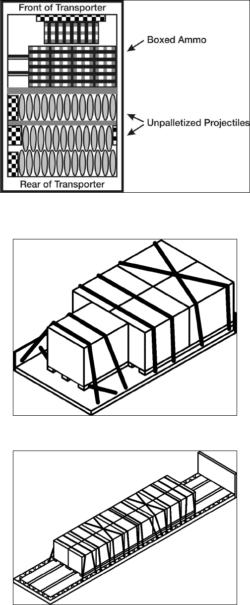
STP 55-88M14-SM-TG
3-137
Figure 3-71. Unpalletized Ammo Arrangement
Figure 3-72. Palletized Ammo Load 5-Ton
Figure 3-73. Palletized Ammo Load M872 Semitrailer

STP 55-88M14-SM-TG
3-138
Performance Steps
3. Assist in unloading ammunition from transporter.
a. Ensure vehicle engine is off during loading/unloading operations (unless needed to power lifting
device).
b. Ensure no smoking within 50 feet and no open flames within 100 feet.
c. Ensure two 10 BC fire extinguishers are present and available for use.
d. Ensure transporter wheels are chocked.
e. Assist in removing tarpaulin.
f. Assist in removing blocking and bracing materials.
g. Assist in inspecting ammunition for damage. Set aside all damaged items.
h. Assist in controlling movement of suspended load from vehicle.
i. If chemical ammunition is involved, ensure protective clothing and equipment is available in
case of emergency.
j. Assist in removal of placarding from vehicle once all ammunition has been unloaded.
Evaluation Preparation: Setup: Provide for the soldier a cargo-carrying vehicle or vehicle combination,
a designated load of ammunition to load/unload, all necessary materials to tied own the load, Material
handling equipment, DD Form 626 and DD Form 836.
Brief soldier: You are required to load and unload ammunition for transport. If the load requires the use
of MHE, ensure that its operation is according to the operator’s manual and that all safety precautions are
adhered to.
Performance Measures GO NO GO
1. Assisted in preparing the transporter for loading operation. —— ——
2. Assisted in loading ammunition onto transporter. —— ——
3. Assisted in unloading ammunition from transporter. —— ——
Evaluation Guidance: Score the soldier GO if all performance measures are passed. Score the soldier
NO-GO if any performance measure is failed. If any performance measure is failed, tell the soldier what
was done wrong and how to do it correctly.
References
Required Related
DD FORM 626
DD FORM 836
FM 21-305
FM 55-30
CAP-TV 2/4-79
STP 55-88M14-SM-TG
3-139
Transport Dangerous Cargo on a Transporter
551-721-2383
Conditions: Given a cargo vehicle or a tractor-semitrailer combination with before-operation PMCS
performed, BII, tiedown and lashing materials, placarding materials, lifting device, assistance from other
personnel, appropriate number and type of fire extinguishers, dangerous/hazardous cargo to be
transported, DD Form 626 and DD Form 836, and designated origin, route, and destination information.
Special Conditions: Loading/unloading area must be controlled access. If hazardous cargo consists of
ammunition or explosives, operator must be trained in the handling of such materials and possess
documentation.
Standards: You have successfully loaded (checked load if loaded by shipper), secured and covered the
load, transported the dangerous/hazardous cargo from origin to destination while taking all necessary
safety and environmental precautions. You have complied with all the required rules of the road without
injury to personnel, or damage to equipment, load, or surroundings.
Performance Steps
1. Prepare vehicle for loading dangerous/hazardous cargo (all types).
a. Ensure the vehicle is safe to operate and free of fire hazards.
b. Check to ensure there are no exposed wires.
c. Clean off excess oil or grease accumulated on the vehicle.
d. Check the fuel system for leaks.
e. Submit vehicle and trailer/semitrailer for safety inspection at origin by shipper.
f. Driver receives DD Form 626 from shipper after origin inspection.
g. Driver locates and corrects all driver-responsible deficiencies on vehicle.
h. If deficiencies cannot be corrected, driver notifies chain-of-command for vehicle replacement.
i. Move vehicle into loading area.
j. Set the vehicle brakes.
k. Chock at least one wheel of the vehicle.
l. Chock the semitrailer when uncoupled from tractor (prime mover).
m. Shutdown vehicle engine unless needed to power material handling equipment.
n. Clear the cargo area of any debris or obstructions/incompatible materials.
o. Remove any side-boarding or canvas if installed.
p. Keep smokers at least 50 feet away from the vehicle.
q. Ensure lifting device is ready and available to transfer the load to your vehicle. If operating a
vehicle with MHE, prepare for use in accordance with -10 series TM.
r. Gather any tiedown materials needed to secure load.
s. Gather required blocking and bracing materials if unit conducts loading and unloading.
t. Gather placarding materials applicable to the load.
2. Load dangerous/hazardous cargo onto truck or semitrailer.
a. Load or ensure the load is positioned properly on the vehicle or trailer.
b. Ensure that the shipper has properly blocked and braced the load.
c. Ensure that the vehicle is properly placarded according to the load.
d. Ensure hazardous cargo is marked with the proper shipping name, identification number, and
appropriate labels (see 49 CFR).
e. Allow no one to loiter near the vehicle loaded with dangerous/hazardous cargo.
f. Adheres to any local policies in effect for the material being loaded.
STP 55-88M14-SM-TG
3-140
Performance Steps
g. Ensure that the DD Form 836 is correctly completed before signing.
h. Cover and lash the load to protect it and to prevent casual observation (NA for tanker vehicles).
Note: During highway movement of chemical agents, hazardous chemicals, and chemical ammunition,
the driver should have a protective mask, protective clothing, and appropriate protective and first aid
items, such as burn ointment, as necessary.
3. Transport dangerous/hazardous cargo to destination.
a. Complies with all local traffic laws and regulations.
b. Allows no smoking inside vehicle.
c. Driver does not go through or near heavily populated areas.
d. Driver does not go where crowds are assembled, tunnels, narrow streets, or alleys.
e. Maintain attendance of the vehicle at all times while loaded with dangerous/hazardous
materials.
f. Driver remains awake at all times unless another qualified person is present during rest halts
en route. Qualifications are listed below:
(1) The unit has designated him/her to attend the vehicle.
(2) He is aware of the nature of the hazardous materials contained in the vehicle.
(3) Has been instructed on the procedures to follow in emergencies.
(4) He is authorized and has the ability to move the vehicle.
g. If the vehicle contains Class A or B explosives, does not, under any circumstances, park the
vehicle:
(1) On or within 5 feet of the traveled portion of a public street or highway.
(2) On private property (including premises of a fueling or eating facility) without the
knowledge and consent of the person who is in charge of the property and who is aware
of the nature of the hazardous materials the vehicle contains.
(3) Within 300 feet of a bridge, tunnel, dwelling, building, where people work, congregate, or
assemble except for brief periods when the necessities of operation require the vehicle to
be parked and make it impracticable to park the vehicle in any other place.
4. Unload dangerous/hazardous cargo at destination.
a. Do not allow smoking within 50 feet of unloading area.
b. Position vehicle on level ground.
c. Shutdown vehicle unless vehicle system needed to power MHE.
d. Chock wheels on vehicle and/or trailer/semitrailer.
e. With assistance from others, remove any sideboards or canvas.
f. Prepare material handling crane for use, if equipped.
g. Ensure chain of custody to receipt holder is accomplished.
h. Remove any blocking and bracing materials.
CAUTION: Use care when loosening tiedown straps as load may have shifted and become unstable
during movement. Failure may result in injury to personnel or damage to load or vehicle.
i. Remove tiedown straps securing load.
j. Conduct destination inspection and/or inventory of load, if required.
k. Connect lifting device and any guide ropes if needed.
l. Following hand and arm visual signals, lift load from vehicle into designated location. Continue
until unloading operation is completed.
m. Stow material handling crane (if equipped).
n. Remove placarding from vehicle and/or semitrailer.
o. Secure all tiedown materials.
p. Secure all blocking and bracing materials (if used). Dispose according to SOP.
q. Reinstall vehicle or trailer canvas and side boards.
r. Recover chock blocks and prepare for movement as instructed.
5. Comply with all SAFETY WARNING and CAUTION statements referenced in steps 1 through 4.

STP 55-88M14-SM-TG
3-141
Evaluation Preparation: Setup: Conduct operations in a controlled access area. Provide for the soldier
primary operators of both the ammunition carrying vehicle and the material handling equipment. Provide
a load of ammunition with which to assist in loading/unloading. Provide all necessary safety equipment to
include two fire extinguishers, and level ground with which to perform operation.
Brief Soldier: You are to transport dangerous cargo on a transporter. Safety is a major concern so you
will be evaluated on your ability to recognize and maintain the standards of handling ammunition with
respect to truck movement. All operations to include use of material handling devices are highlighted.
Ensure that at no time during the movement or transfer of ammunition loads that the load is mishandled in
any manner. All loading and unloading operations will be conducted without injury to personnel or
damage to equipment or loads.
Performance Measures GO NO GO
1. Prepared vehicle for loading dangerous/hazardous cargo (all types). —— ——
a. Ensured the vehicle is safe to operate and free of fire hazards.
b. Checked to ensure there are no exposed wires.
c. Cleaned off excess oil or grease accumulated on the vehicle.
d. Checked the fuel system for leaks.
e. Submitted vehicle and trailer/semitrailer for safety inspection at origin by
shipper.
f. Driver received DD Form 626 from shipper after origin inspection.
g. Driver located and corrected all driver-responsible deficiencies on vehicle.
h. If deficiencies could not be corrected, driver notified chain-of-command for
vehicle replacement.
i. Moved vehicle into loading area.
j. Set the vehicle brakes.
k. Chocked at least one wheel of the vehicle.
l. Chocked the semitrailer when uncoupled from tractor (prime mover).
m. Shutdown vehicle engine unless needed to power material handling
equipment.
n. Cleared the cargo area of any debris or obstructions/incompatible materials.
o. Removed any side-boarding or canvas, if installed.
p. Kept smokers at least 50 feet away from the vehicle.
q. Ensured lifting device is ready and available to transfer the load to your
vehicle. If operating a vehicle with MHE, prepare for use in accordance with
-10 series TM.
r. Gathered any tiedown materials needed to secure load.
s. Gathered required blocking and bracing materials if unit conducted loading
and unloading.
t. Gathered placarding materials applicable to the load.
u. Adhered to all SAFETY WARNING and CAUTION statements in listed in
performance steps.
2. Loaded dangerous/hazardous cargo onto truck or semitrailer. —— ——
a. Loaded or ensured the load was positioned properly on the vehicle or trailer.
b. Ensured that the shipper has properly blocked and braced the load.
c. Ensured that the vehicle is properly placarded according to the load.
d. Ensured hazardous cargo is marked with the proper shipping name,
identification number, and appropriate labels (see 49 CFR).
e. Allowed no one to loiter near the vehicle loaded with dangerous/hazardous
cargo.
f. Adhered to any local policies in effect for the material being loaded.
g. Ensured that the DD Form 836 is correctly completed before signing.

STP 55-88M14-SM-TG
3-142
Performance Measures GO NO GO
h. Covered and lash the load to protect it and to prevent casual observation
(NA for tanker vehicles).
i. Adhered to all SAFETY WARNING and CAUTION statements in listed in
performance steps.
3. Transported dangerous/hazardous cargo to destination. —— ——
a. Complied with all local traffic laws and regulations.
b. Allowed no smoking inside vehicle.
c. Driver did not go through or near heavily populated areas.
d. Driver did not go where crowds are assembled, tunnels, narrow streets, or
alleys.
e. Maintained attendance of the vehicle at all times while loaded with
dangerous/hazardous materials.
f. Driver remained awake at all times unless another qualified person is
present during rest halts en route. Qualifications are listed below:
(1) The unit has designated him to attend the vehicle.
(2) He was aware of the nature of the hazardous materials contained in the
vehicle.
(3) Has been instructed on the procedures to follow in emergencies.
(4) He was authorized and has the ability to move the vehicle.
g. If the vehicle contains Class A or B explosives, did not, under any
circumstances, park the vehicle:
(1) On or within 5 feet of the traveled portion of a public street or highway.
(2) On private property (including premises of a fueling or eating facility)
without the knowledge and consent of the person who is in charge of
the property and who is aware of the nature of the hazardous materials
the vehicle contains.
(3) Within 300 feet of a bridge, tunnel, dwelling, building, where people
work, congregate, or assemble except for brief periods when the
necessities of operation require the vehicle to be parked and make it
impracticable to park the vehicle in any other place.
4. Unloaded dangerous/hazardous cargo at destination. —— ——
a. Did not allow smoking within 50 feet of unloading area.
b. Positioned vehicle on level ground.
c. Shutdown vehicle unless vehicle system needed to power MHE.
d. Chocked wheels on vehicle and/or trailer/semitrailer.
e. With assistance from others, removed any sideboards or canvas.
f. Prepared material handling crane for use, if equipped.
g. Ensured chain of custody to receipt holder is accomplished.
h. Removed any blocking and bracing materials.
i. Removed tiedown straps securing load.
j. Conducted destination inspection and/or inventory of load, if required.
k. Connected lifting device and any guide ropes, if needed.
l. Following hand and arm visual signals, lifted load from vehicle into
designated location. Continued until unloading operation is completed.
m. Stowed material handling crane (if equipped).
n. Removed placarding from vehicle and/or semitrailer.
o. Secured all tiedown materials.
p. Secured all blocking and bracing materials (if used). Dispose according to
SOP.
q. Reinstalled vehicle or trailer canvas and side boards.

STP 55-88M14-SM-TG
3-143
Performance Measures GO NO GO
r. Recovered chock blocks and prepare for movement as instructed.
s. Adhered to all SAFETY WARNING and CAUTION statements in listed in
performance steps.
5. Complied with all SAFETY WARNING and CAUTION statements referenced in
steps 1 through 4.
—— ——
Evaluation Guidance: Score the soldier GO if all performance measures are passed. Score the soldier
NO-GO if any performance measure is failed. If any performance measure is failed, tell the soldier what
was done wrong and how to do it correctly.
References
Required Related
CFR 49
DA PAM 385-64
DD FORM 626
DD FORM 836
FM 21-305
FM 21-60
FM 55-17
TM 9-2320-260-10
TM 9-2320-272-10
TM 9-2320-279-10-1
TM 9-2320-279-10-2
TM 9-2320-360-10
TM 9-2320-364-10
TM 9-2320-365-10
TM 9-2320-366-10-1
TM 9-2320-366-10-2
TM 9-2330-359-14&P
TM 9-2330-384-14&P
TM 9-2330-386-14&P
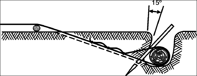
STP 55-88M14-SM-TG
3-144
Subject Area 6: Adverse Terrain Operations
Self-Recover a Wheeled Vehicle
551-721-2389
Conditions: Given a mired vehicle (with or without a winch), fiber rope, chains, timber, BII, stakes,
shackles, and applicable TM (-10 series), hearing protection, work gloves, and assistance from others as
needed.
Special Conditions: Vehicle self-recovery is a two-person job.
Standards: You have recovered the vehicle so that it could be operated under its own power without
injury to personnel or damage to equipment.
Performance Steps
1. Attempt to self-recover the vehicle using the Central Tire Inflation System (CTIS) in EMERGENCY
mode (if equipped).
a. Self-recover the M939 series vehicle. Refer to TM 9-2320-272-10.
b. Self-recover the M1074/M1075, PLS vehicle. Refer to TM 9-2320-364-10.
c. Self-recover the M1078, LMTV vehicle. Refer to TM 9-2320-365-10.
d. Self-recover the M1083, MTV vehicle. Refer to TM 9-2320-366-10-1.
2. Construct (if necessary) the type of anchor to use for winch recovery.
a. Deadman log anchor (see Figure 3-74).
(1) Select a place where the direction of pull is as nearly horizontal as possible, such as a
sharp bank or crest.
(2) Dig and slant the bank at least 15 degrees from the vertical and undercut toward the
disabled vehicle.
(3) Drive stake in front of the deadman at each end to hold it in place.
(4) Tie the deadline to the center of the deadman, so the main standing part of the line leads
from the bottom of the deadman.
(5) Dig a narrow trench for the deadline to the center of the deadman.
(6) Tie the deadline to the center of the deadman so that the main part of the line leads to the
bottom.
(7) Connect the deadline to the vehicle winch cable.
(8) Operate the winch according to the appropriate vehicle TM to pull the vehicle free.
(9) Stop the winch and remove winch cable, then rewind.
(10) Replace the dirt into the hole in which the anchor was constructed.
Figure 3-74. Deadman Log Anchor
STP 55-88M14-SM-TG
3-145
Performance Steps
b. Normal and reinforced picket holdfast (see Figure 3-75).
(1) Select two or more pickets at least 3 inches and 5 feet long.
(2) Drive the pickets 3 feet into the ground, 3 to 6 feet apart, and in line with the deadline.
(3) Tie the pickets together with fiber rope by first tying one end of the rope to the top of the
front picket with a clove hitch.
(4) Wrap four or six wraps of rope on the picket starting from the top of the front picket to the
bottom of the read picket.
(5) Tie the other end of the rope to the bottom of the rear picket with a clove hitch.
(6) Pass a stake between the rope wraps midway between the pickets.
(7) Tighten the rope by twisting it with the stake then drive the stake into the ground to hold
the tension.
(8) Repeat this process with each successive pair of pickets.
Figure 3-75. Normal and Reinforced Picket Holdfast
c. Natural anchor.
(1) Tree or tree stump.
(2) Large immovable rock.
(3) Another vehicle (may be used to construct a Scotch anchor as follows):
Note: Scotch anchors (see Figures 3-76a and 3-76b) are used to anchor a truck during winching
operations (the additional truck that is used to winch the mired vehicle out) when natural anchors are not
available.
(a) Select a log at least 6 inches in diameter and 2 feet wider than the vehicle.
(b) Dig a shallow trench about 3 to 4 inches deep parallel to the front axle, just ahead of
the front wheels.
(c) Lay a tow chain across the center of the trench.
(d) Move the vehicle forward until both front tires are against the log.
(e) Attach both chain ends to the bumper lifting shackles, and remove all slack from the
chain.
WARNING: Clear all personnel from the area where the winch cable is laid. Do not position anyone near
either the anchor or the mired vehicle unless the operator is required to operate the vehicle in assisting
the recovery. Should the cable snap, the tension created during the pull could cause the cable to
seriously injure or kill anyone in its path.
d. Sand Parachute (see Figure 3-77).
(1) Dig a large, deep hole and line it with a tarpaulin.
(2) Fill the tarpaulin with the dirt taken from the hole.
(3) Lash the four corners of the tarpaulin together and attach the rigging.
(4) Apply winch-operating procedures according to the appropriate vehicle TM.
STP 55-88M14-SM-TG
3-146
Figure 3-76a. Scotch Anchor 1
Figure 3-76b. Scotch Anchor 2
Figure 3-77. Sand Parachute
STP 55-88M14-SM-TG
3-147
Performance Steps
e. Construct an A-Frame (see Figure 3-78a) to recover a mired vehicle (see Figure 3-78b).
(1) Select two long poles with a large enough diameter to support the front end of the truck
once it is raised.
(2) Lash the poles together at the top with a figure eight hitch or girth hitch.
(3) Dig two 10 to 12 inch deep holes 5 to 6 feet apart to hold the legs in position when power
is applied.
(4) Place the A-frame into the hole.
(5) Lay the upper end of the A-frame against the vehicle's front.
(6) Attach the A-frame.
(7) Rig the winch cable for 2:1 mechanical advantage.
(8) Secure the end of the cable to the A-frame's apex.
(9) Wind in the winch.
(10) Suspend the truck over the ditch or hole.
(11) Fill in the ditch or hole with rocks, dirt or other materials so that the vehicle can be driven
forward or backward.
Figure 3-78a. Constructing An A-Frame With a Girth Hitch and a Figure Eight Hitch
Figure 3-78b. Recovering a Mired Vehicle Using An A-Frame
STP 55-88M14-SM-TG
3-148
Performance Steps
3. Self-recover the M998 series vehicle using a winch.
a. Refer to TM 9-2320-280-10.
b. Adhere to all WARNING and CAUTION statements in the TM applicable to this operation.
4. Self-recover the M809 series vehicle using a winch.
a. Refer to TM 9-2320-260-10.
b. Adhere to all WARNING and CAUTION statements in the TM applicable to this operation.
5. Self-recover the M939 series vehicle using a winch.
a. Refer to TM 9-2320-272-10.
b. Adhere to all WARNING and CAUTION statements in the TM applicable to this operation.
6. Self-recover the M977/M1120 series vehicle using a winch.
a. Refer to TM 9-2320-279-10-1&2.
b. Adhere to all WARNING and CAUTION statements in the TM applicable to this operation.
7. Self-recover the M1078/1083 series vehicle using a winch.
a. Refer to TM 9-2320-365-10 (M1078).
b. Refer to TM 9-2320-366-10-2 (M1083).
c. Adhere to all WARNING and CAUTION statements in the TM applicable to this operation.
8. Self-recover the M1074/1075 series vehicle using a winch.
a. Refer to TM 9-2320-364-10.
b. Adhere to all WARNING and CAUTION statements in the TM applicable to this operation.
9. Self-recover vehicle by using manpower (2 ½-Ton to 5-Ton without winch).
a. Find a solid length of timber or similar material approximately 8 feet long with a diameter that
will permit available personnel to handle it.
b. Place a suitable support (a log or rock that will not be moved when pressure is applied) near
the point of the lift.
c. Rig the lever under the bumper for the first lift.
d. Block the lift when you have gained all the leverage that you can.
e. Rig for a second lift with the point of the lever under the axle if possible.
f. Lift and block once again.
g. Repeat steps a through f until the vehicle can be backed off without too much trouble.
10. Self-recover the vehicle by using the dual-wheel operation (2 ½-Ton to 5-Ton without winch) (see
Figure 3-79).
a. Select natural anchor or construct a strong anchor. Refer to FM 9-43-2, pages 3-17 through
3-22.
b. Fasten one end of each rope to a rear wheel hub and the other to an anchor.
c. Place the rope between the duals and through one of the holes in the wheel disk.
d. Tie the rope around the hub where it will be clear of the valve stem.
e. Place the transmission gearshift lever in reverse to wind the rope.
f. Once free, unwind and remove rope from duals.
Figure 3-79. Dual-Wheel Recovery Method

STP 55-88M14-SM-TG
3-149
Evaluation Preparation: Setup: Provide for the soldier a mired vehicle with a winch, assistance from
other soldiers, and work gloves.
Brief Soldier: You are to perform a self-recovery of your vehicle.
Performance Measures GO NO GO
1. Attempted to self-recover the vehicle using the Central Tire Inflation System
(CTIS) in EMERGENCY mode (if equipped).
—— ——
2. Constructed (if necessary) the type of anchor to use for winch recovery. —— ——
3. Self-recovered the M998 series vehicle using a winch. —— ——
4. Self-recovered the M809 series vehicle using a winch. —— ——
5. Self-recovered the M939 series vehicle using a winch. —— ——
6. Self-recovered the M977/M1120 series vehicle using a winch. —— ——
7. Self-recovered the M1078/1083 series vehicle using a winch. —— ——
8. Self-recovered the M1074/1075 series vehicle using a winch. —— ——
9. Self-recovered vehicle by using manpower (2 ½-Ton to 5-Ton without winch). —— ——
10. Self-recovered the vehicle by using the dual-wheel operation (2 ½-Ton to 5-Ton
without winch).
—— ——
Evaluation Guidance: Score the soldier GO if all performance measures are passed. Score the soldier
NO-GO if any performance measure is failed. If any performance measure is failed, tell the soldier what
was done wrong and how to do it correctly.
References
Required Related
FM 21-305
FM 9-43-2
TM 9-2320-260-10
TM 9-2320-272-10
TM 9-2320-279-20-1
TM 9-2320-279-20-2
TM 9-2320-280-10
TM 9-2320-364-10
TM 9-2320-365-10
TM 9-2320-366-10-1
TM 9-2320-366-10-2
TM 9-243

STP 55-88M14-SM-TG
3-150
Subject Area 7: Motor Vehicle Tactical Operations
Prepare Vehicle for Tactical Operations
551-721-2357
Conditions: Given a wheeled tactical vehicle with before-operation maintenance performed, BII, AAL,
vehicle TM (-10 series), designated weather conditions to prepare for, inclement weather clothing, and
hearing protection.
Standards: You have prepared the vehicle for inclement weather operation without injury to personnel or
damage to vehicle.
Performance Steps
1. Prepare windshields and windows (M939 and M998 series only).
a. Lower the windshield or leave it in place when applicable (refer to TM -10).
b. Protect against heavy rains by leaving the windshield in place.
c. Use wire mesh to secure each window to protect against incoming grenades.
d. Use the windshield to protect from wire stretched across the road that could decapitate
personnel.
e. Remove or lower the windshield when it interferes with the use of weapons or during blackout
operations.
f. Place a piece of plywood or similar material covered with sandbags between the windshield
and the hood to prevent the lowered windshield from breakage by shock or vibration.
2. Harden the vehicle.
a. Cover the floor of troop-carrying vehicles with at least a double interlocking layer of sandbags.
b. Using a double layer of sandbags, place sandbags under the driver's seat and cab floors of all
vehicles.
c. Cover the sandbags with rubber or fiber mats to prolong the life of the sandbags and to help
reduce danger from fragments (such as sharp stones, sand, and metal vehicle parts).
d. Place sandbags on the gas tank, fenders, and hood for added protection.
e. Insert steel plates between the fuel tanks and the hanger straps to harden the fuel tanks.
Evaluation Preparation: Setup: Provide vehicle operator(s), vehicle(s), mission information, and SOP
guidance.
Brief Soldier: You are to supervise the preparation of vehicles for shipment/movement. Your supervision
and guidance must afford the vehicle operators the knowledge needed to properly prepare their vehicle
for movement/shipment by air, land, and sea. You will provide applicable guidance according to the
mode of transportation used and the types of vehicles transported.
Performance Measures GO NO GO
1. Prepared windshield and windows. —— ——
a. Lower the windshield or leave it in place when applicable.
b. Protect against heavy rains by leaving the windshield in place.
c. Use wire mesh to secure each window to protect against incoming grenades.
d. Use the windshield to protect from wire stretched across the road that could
decapitate personnel.
e. Remove or lower the windshield when it interferes with the use of weapons
or during blackout operations.
f. Place a piece of plywood or similar material covered with sandbags between
the windshield and the hood to prevent the lowered windshield from
breakage by shock or vibration.

STP 55-88M14-SM-TG
3-151
Performance Measures GO NO GO
2. Hardened the vehicle. —— ——
a. Cover the floor of troop-carrying vehicles with at least a double interlocking
layer of sandbags.
b. Using a double layer of sandbags, place sandbags under the driver's seat
and cab floors of all vehicles.
c. Cover the sandbags with rubber or fiber mats to prolong the life of the
sandbags and to help reduce danger from fragments (such as sharp stones,
sand, and metal vehicle parts).
d. Place sandbags on the gas tank, fenders, and hood for added protection.
e. Insert steel plates between the fuel tanks and the hanger straps to harden
the fuel tanks.
Evaluation Guidance: Score the soldier GO if all performance measures are passed. Score the soldier
NO-GO if any performance measure is failed. If any performance measure is failed, tell the soldier what
was done wrong and how to do it correctly.
References
Required Related
FM 21-305
FM 55-30
TM 9-2320-260-10
TM 9-2320-272-10
TM 9-2320-279-10-1
TM 9-2320-279-10-2
TM 9-2320-280-10
TM 9-2320-360-10
TM 9-2320-364-10
TM 9-2320-365-10
TM 9-2320-366-10-1
TM 9-2320-366-10-2
TM 9-2330-359-14&P
TM 9-2330-381-14
TM 9-2330-386-14&P
STP 55-88M14-SM-TG
3-152
Implement Defensive Procedures When Under Attack/Ambush in a Truck Convoy
551-721-2408
Conditions: As a vehicle operator within a convoy, given a vehicle with before-operation maintenance
performed, individually assigned weapon, LCE/w-Kevlar helmet, flak vest (if available), BII, and guidance
from convoy commander.
Standards: As a vehicle operator, you have successfully employed passive and active defensive
measures to counter enemy air attack, sniper fire, and ambush by following established convoy hand and
arm signals, reporting actions to higher authority, and reacting to incoming enemy fires. As a result,
higher authorities have been notified, your vehicle remained operational, and injuries to personnel and
damage to equipment were minimal.
Performance Steps
1. Implement active defense measures to counter enemy sniper fire.
a. Increase speed to get through area without stopping.
b. Use pre-designated signal to warn of sniper attack.
c. Wear individual LCE/w-Kevlar helmet and flak vest.
d. Notify higher authority of sniper attack.
2. Implement passive defense measures to counter sniper fire.
a. Have pre-designated signal for sniper attack.
b. Have pre-designated reactionary guidance for vehicle operation.
c. Cover/conceal load prior to movement.
3. Implement active defense measures to counter enemy ambush (road not blocked).
a. Harden vehicles.
b. Cover loads.
c. Wear protective clothing.
d. Use assistant drivers.
e. Use prearranged signals to warn the convoy of an ambush.
f. Receive briefing on immediate action drills.
g. Maintain proper vehicle interval.
h. Move through the kill zone, if possible.
i. If not yet in the kill zone, stop, dismount, take cover and await instructions.
j. Do not block the road.
k. Rapidly respond to orders.
l. Aggressively return fire, as directed.
m. Push disabled vehicle(s) off the road, as directed, if progress is blocked.
n. Take evasive maneuvers (with vehicle) as directed, to avoid enemy fire.
4. Implement passive defense measures to counter enemy ambush (road not blocked).
a. Do not present a profitable target.
b. Use OPSEC to deny the enemy foreknowledge of the convoy.
5. Implement active defense measures to counter enemy ambush (road blocked).
a. In the kill zone.
(1) Dismount by exiting the vehicle away from the direction of enemy fire.
(2) Take cover.
(3) Return maximum volume of fire on enemy position(s) as directed.
b. Not in the kill zone.
(1) Does not enter kill zone.
(2) Reacts quickly to orders.
(3) Pull off road in a defensive position (herringbone pattern).
(4) Dismount and take up a defensive firing position.

STP 55-88M14-SM-TG
3-153
Performance Steps
6. Implement passive defense measures to counter enemy ambush (road blocked).
a. Do not present a profitable target.
b. Use OPSEC to deny the enemy foreknowledge of the convoy.
Evaluation Preparation: Setup: Provide for the soldier a situation that must involve participation in a
convoy movement that has been attacked by an enemy force. Provide trucks to constitute a convoy,
vehicle operators, designated route, mission information, supervisory guidance, and organic assigned
weapons.
Brief Soldier: You are to participate in defending a convoy during movement. You must operate your
assigned weapon and engage targets consistent with active or passive defense measures. You are to
react to supervisory instructions or target engagement and actions to take in case of enemy attack on
convoy.
Performance Measures GO NO GO
1. Implemented active defense measures to counter enemy sniper fire. —— ——
2. Implemented passive defense measures to counter sniper fire. —— ——
3. Implemented active defense measures to counter enemy ambush (road not
blocked).
—— ——
4. Implemented passive defense measures to counter enemy ambush (road not
blocked).
—— ——
5. Implemented active defense measures to counter enemy ambush (road blocked). —— ——
6. Implemented passive defense measures to counter enemy ambush (road
blocked).
—— ——
Evaluation Guidance: Score the soldier GO if all performance measures are passed. Score the soldier
NO-GO if any performance measure is failed. If any performance measure is failed, tell the soldier what
was done wrong and how to do it correctly.
References
Required Related
FM 55-30
STP 55-88M14-SM-TG
3-154
Operate Vehicle in a Contaminated Area
551-721-2410
Conditions: Given a vehicle with before-operation maintenance performed, a protective mask with hood,
protective clothing, and vehicle-issued M11 or M13 Decontamination Apparatus (DAP) with DS2, rags,
scrub brushes, soapy water, and either an M291 or an M258A1 kit.
Standards: Prior to entering the contaminated area, assumed a MOPP level 4 posture. Recognized and
reacted to all NBC hazards; complied with all precautions while operating within the contaminated area;
upon exiting the contaminated area, performed skin decontamination, personal wipe-down and then
operator's spray-down without injury to personnel or damage to equipment or surrounding area.
Performance Steps
1. Prepare for entering a contaminated area.
a. Stop the vehicle.
b. Put on issued protective mask with hood and protective clothing (MOPP 4).
c. Ensure that M8/M9 paper is placed on clothing and equipment.
d. Ensure that chemical alarms, if available, are serviced and mounted on the vehicle.
e. Ensure M11 or M13 Decontamination Apparatus (DAP) is serviced, filled, and mounted on
vehicle.
f. Acquire an M291 or M258A1 kit.
2. Exercise precautions to prevent contamination.
a. Use a hard surface road if available.
b. Operate the vehicle safely through the contaminated area.
c. Avoid unnecessary splashing if roads are muddy.
d. Guard against splashes from tree branches.
e. Move through the area at extended intervals if in a convoy.
f. Move through the area, as quickly as all safety rules will allow.
WARNING: Use extreme caution at all times when handling DS2. Do not mix DS2 and STB because it
will cause a fire. Do not allow DS2 to spray on personnel or protective clothing. DS2 is c combustible
solution. Severe chemical burns can result if personnel fail to observe all safety precautions. DS2 can
severely injure eyes and skin, and if inhaled, can cause illness. DS2 can damage the NBC protective
overgarment. Long-term contact with DS2 can damage the NBC protective gloves, hood, and overboots.
3. Decontaminate self, vehicle, and equipment (immediate decontamination).
a. Proceed as directed to the decontamination point upon leaving contaminated area.
b. Perform skin decontamination.
c. Perform personal wipe-down.
d. Perform operator's spray-down.
Evaluation Preparation: Setup: Provide for the soldier the environment requiring precautions taken in a
chemically contaminated area. Setup will include vehicle, protective clothing, mask, and route information
requiring operation in a contaminated area.
Brief Soldier: You are required to operate your vehicle within a chemically contaminated area. You are to
take the necessary precautionary measures that will allow your safe passage without succumbing to the
effects of a chemical agent. Your protective clothing and protective mask are provided.

STP 55-88M14-SM-TG
3-155
Performance Measures GO NO GO
1. Prepared for entering a contaminated area. —— ——
2. Exercised precautions to prevent contamination. —— ——
3. Decontaminated self, vehicle, and equipment (immediate decontamination). —— ——
Evaluation Guidance: Score the soldier GO if all performance measures are passed. Score the soldier
NO-GO if any performance measure is failed. If any performance measure is failed, tell the soldier what
was done wrong and how to do it correctly.
References
Required Related
FM 21-305
FM 3-11
FM 3-5
STP 55-88M14-SM-TG
3-156
Operate Night Vision Devices
551-721-2415
Conditions: Given a set of night vision goggles (NVGs) (AN/PVS-7A or 7B) and a vehicle equipped with
the Driver's Vision Enhancer (DVE).
Special Conditions: Requires operation in a nighttime or limited visibility environment.
Standards: You have successfully performed all required actions to place the NVGs and the DVE into
operation and operate the vehicle (using DVE) and perform duties as vehicle assistant driver wearing the
NVGs.
Performance Steps
1. Prepare equipment for operation.
a. Assemble and/or adjust any component items necessary to place equipment into operation.
(1) For night vision goggles (refer to TM 11-5855-262-10-1 and TM 11-5855-262-10-2).
(a) Batteries.
(b) Head strap to helmet.
(c) Goggles to mounting bracket.
(d) Appropriate lens (3X or applicable).
(e) Remove lens cap.
(2) For the driver's vision enhancer (refer to TM 11-5855-311-12&P-2).
(a) Ruggedized computer.
(b) PLGR (refer to TB 11-5825-291-10-2).
(c) Antenna.
(d) Associated cables and connections.
b. Perform preventive maintenance checks and troubleshooting on AN/PVS-5A and AN/PVS-7B
Night Vision Goggles.
(1) Refer to TM 11-5855-262-10-1, paragraph 3-2 for AN/PVS-7A goggles.
(2) Refer to TM 11-5855-262-10-2, paragraph 3-1 for AN/PVS-7B goggles.
c. Record uncorrectable deficiencies found during inspection.
(1) Annotate on DA Form 2404 or DA Form 5988-E.
(2) Refer completed inspection form with deficiencies to your supervisor.
2. Operate the night vision goggles (helmet-mounted operation).
WARNING: The IR source is a light that is invisible to the unaided eye for use during conditions of
extreme darkness. However, the light can be detected by the enemy using night vision devices. The
purpose of the IR source is for viewing at close distances up to 2 meters. Also be aware that the green
glow emitted from the operating goggle can be seen with the naked eye. Be sure the eyecups block any
stray light.
a. AN/PVS-7A night vision goggles.
CAUTION: Operate the goggle under nighttime conditions only. Using the goggle during the day, in a
brightly lit room, or staring at a bright light source, even at night, can permanently damage the image
intensifier.
(1) With the NVG attached to the headmount assembly, turn the goggle ON by pulling the
switch knob away from the objective lens to the forward ON position.
(2) Adjust the eye relief and eye span distance for the most comfortable use of the goggle.
(3) Turn the eyepiece focus rings on each eyepiece lens for the sharpest view.
(4) Adjust the objective focus ring for the sharpest view.
(5) Repeat procedures 3 and 4 until best focus is achieved.
CAUTION: Operate the goggles only under darkened conditions or use the objective lens cap to cover
the objective lens for daylight operations.
STP 55-88M14-SM-TG
3-157
Performance Steps
b. AN/PVS-7B night vision goggles.
(1) Ensure batteries are installed.
(2) Don the helmet-mount. Per instructions listed in TM 11-5855-262-10-2, paragraph 2-6.
(3) Place the goggles in the socket of the helmet mount. Set your eye relief by depressing
the side buttons and carefully move the goggles fore or aft until the eyecups comfortably
seal around the eyes. Readjust the helmet straps as required for vertical adjustment.
(4) Turn power switch to ON. Adjust the tile by using the tilt adjustment lock knob until you
obtain a comfortable viewing angle.
(5) Adjust the interpupillary distance by sliding the eyepiece lenses together or apart so each
eye can observe the entire field-of-view at the same time. The eyepiece lenses adjust
independently. If necessary, readjust the eye relief.
(6) Fold the right eyecup over the eyepiece lens with your right thumb and forefinger to
obstruct view through the right eyepiece lens. Rotate the left diopter adjustment for the
clearest view of the image intensifier screen.
(7) Fold the left eyecup over the eyepiece lens with your left thumb or forefinger to obstruct
view through the left lens. Rotate the right diopter adjustment for the clearest view on the
image intensifier screen.
(8) Adjust the eye relief distance by pressing the eye relief adjustment and sliding goggles
fore or aft to obtain a full field-of-view of the image. Reset the diopter adjustments for best
image.
WARNING: It is critical that the goggles be turned off manually before placing them in the flipped up
position in order to avoid detection by the enemy.
(9) Adjust the objective lens focus while observing an object until the sharpest image is
obtained.
(10) To flip up, turn the power switch to the RESET/OFF position, place an open hand under
the goggles and rotate up and rearward until the latch is firmly engaged.
(11) To flip down, grasp the goggles and rotate down and forward until the latch is firmly
engaged.
(12) Turn the power switch to the ON position to resume viewing.
c. Shutdown the night vision goggles.
(1) AN/PVS-7A shutdown.
(a) Turn switch knob to the OFF position. Switch knob shall be aligned with knurled
corner of the goggle.
(b) Remove the goggle from the headmount assembly by depressing the release button
on the carriage and pulling the goggle away from your face. Allow goggle to hang by
the neck cord around your neck.
(c) Remove the headmount assembly and head strap.
(d) Remove the battery from the battery compartment and close the hatch.
(e) Remove eyecups, demist shields, and sacrificial window, if applicable.
(f) Remove goggle from around your neck. Replace eyepiece and objective lens caps.
(g) Ensure goggle is clean and dry before placing into carrying case.
(h) Replace all equipment in the carrying case.
(2) AN/PVS-7B shutdown.
(a) Turn the POWER switch to the OFF position.
(b) Remove the goggles from the headmount or helmet mount by depressing the latch
lever and removing the goggles from the headmount or helmet mount socket.
WARNING: Do not carry batteries in pockets containing metal objects such as coins, keys, and so on.
Metal object can cause the batteries to short circuit and become very hot.
(c) Unscrew battery cap and remove battery(ies).
(d) Inspect the battery compartment for corrosion or moisture. Clean and dry if
necessary.

STP 55-88M14-SM-TG
3-158
Performance Steps
(e) Replace battery cap.
(f) Remove the demit shields, sacrificial window, compass or 3X magnifier if installed.
Install objective lens cap.
(g) Place into carrying case.
3. Operate the driver's vision enhancer (see Figure 3-80).
Note: The time necessary for the system to stabilize depends on the ambient temperature. As ambient
temperature rises or cools, the stabilizing time changes slightly.
Note: The words "NO SENSOR VIDEO CHECK VIDEO SWITCH" will appear on the display only if the
VIDEO switch is in the EXT position or the display circuitry has no video input. If the video returns, the
words are removed.
a. Start the vehicle (see operator's manual for proper starting procedures).
b. Perform the initial setup procedures.
Note: Before powering up the unit, ensure that the following control positions are as indicated in the
following steps.
WARNING: Before operating the vehicle, ensure that the DVE azimuth and elevation controls are in the
locked positions. This will ensure that the DVE is looking straight ahead when operating the vehicle.
Manually verify forward and lock position prior to operating the vehicle.
Helmets must always be worn when driving with the DVE installed. The DVE display should be removed
from its mount when not in use for extended driving operations to minimize the risk of head injuries.
(1) Rotate Sensor Assembly azimuth and elevation to straight ahead and level 00 detent
positions.
(2) Set DVE POWER switch to OFF (down position).
(3) Set VIDEO switch to SENSOR (up position).
(4) Set POLARITY switch to WHT-HOT (up position).
(5) With DISPLAY BRIGHTNESS control turned fully ccw, rotate knob approximately ¼ turn
cw.
(6) Set SENSOR LEVEL and SENSOR GAIN controls to full ccw (AUTO) detent position.
Figure 3-80. Driver Screen Display
STP 55-88M14-SM-TG
3-159
Performance Steps
c. Place DVE into operation.
(1) Set POWER to ON position (up). Allow 5 minutes for system to stabilize for maximum
image clarity.
(2) Leave the VIDEO switch in the SENSOR (up position) for sensing input from the Sensor
Assembly to the display. For external input to display, set switch to EXT (down position).
(3) Adjust the seat height and/or display module to place the display at eye level.
WARNING: If the display becomes degraded while driving the vehicle, such as the presence of dead
pixels and/or video noise that prevents the driver from performing his mission, then immediately bring the
vehicle to a safe stop to avoid a collision. If the problem cannot be fixed, report the situation to higher
level of maintenance.
(4) Adjust the DISPLAY BRIGHTNESS control until the scene brightness is suitable for
operator viewing.
(5) Select either the AUTO LEVEL or the MANUAL LEVEL position.
(6) Adjust the SENSOR GAIN control to automatic or manual position. The AUTO GAIN
mode should normally be used while driving the vehicle.
WARNING: The AUTO LEVEL and AUTO GAIN modes do not react instantly to rapidly changing
scenery (shade to sun, sun to shade). The AUTO LEVEL and AUTO GAIN modes require one or two
seconds to compensate. The automatic gain and level features will adjust faster than manual
adjustments. If necessary, slow vehicle. There are two short periods each day called crossover periods
or diurnal cycle when most natural objects are about the same temperature. This is when they have
cooled down at night and as they are heating up in the morning. Since objects are near the same
temperature, there is not much temperature for the DVE to use, degrading the image display quality. This
is also what happens when a heavy rain makes all natural objects close to the same temperature.
(7) Set scene POLARITY switch to either WHT-HOT (up position) or BLK-HOT (down
position).
(8) Set azimuth position by rotating Pan/Tilt Mechanism (PTM) (see Figure 3-81) to desired
setting. Lock azimuth locking mechanism.
(9) Set elevation position to desired position. Lock elevation locking mechanism.
d. Maneuver vehicle while relying on DVE for terrain negotiation.
Note: Operate vehicle while monitoring the DVE screen. Adjust vehicle speed necessary while DVE is
making auto adjustments to conditions.
e. Shutdown DVE.
(1) Press FORWARD POSITION switch.
(2) Visually verify sensor is in the straight ahead and level position.
(3) Set SENSOR LEVEL and GAIN controls to full ccw (AUTO) detent position.
(4) With the DISPLAY BRIGHTNESS control turned fully ccw, rotate the knob approximately
¼ turn cw.
(5) Set POLARITY switch to WHT-HOT (up) position.
(6) Set VIDEO switch to SENSOR (up) position.
(7) Set POWER switch to OFF position (down).
Evaluation Preparation: Setup: Provide for the soldier a vehicle with and installed Driver's Vision
Enhancer, and AN/PVS-7A or B.
Note: The DVE system is NOT intended to replace the NVGs. They are used only by the vehicle
operator while the assistant operator uses the NVGs. This task is centered around the use of both
devices.
Brief Soldier: This task is centered around a mounted application of these devices. You are to operate
your vehicle using the DVE system and then alternately serve as vehicle assistant driver to employ the
use of the night vision goggles. You will be told as to where you are to negotiate your vehicle using these
devices.
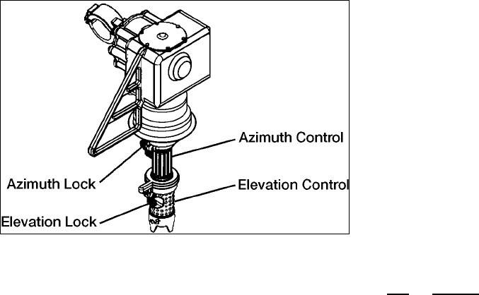
STP 55-88M14-SM-TG
3-160
Figure 3-81. Pan/Tile Mechanism
Performance Measures GO NO GO
1. Prepared equipment for operation. —— ——
a. Assemble and/or adjust any component items necessary to place equipment
into operation.
(1) For night vision goggles (refer to TM 11-5855-262-10-1 and TM 11-
5855-262-10-2).
(a) Batteries.
(b) Head strap to helmet.
(c) Goggles to mounting bracket.
(d) Appropriate lens (3X or applicable).
(e) Remove lens cap.
(2) For the driver's vision enhancer (refer to TM 11-5855-311-12&P-2).
(a) Ruggedized computer.
(b) PLGR (refer to TB 11-5825-291-10-2).
(c) Antenna.
(d) Associated cables and connections.
b. Perform preventive maintenance checks and troubleshooting on AN/PVS-5A
and AN/PVS-7B Night Vision Goggles.
(1) Refer to TM 11-5855-262-10-1, paragraph 3-2, page 3-1 for AN/PVS-
7A goggles.
(2) Refer to TM 11-5855-262-10-2, paragraph 3-1, page 3-1 for AN/PVS-
7B goggles.
Note: Perform preventive maintenance checks on Driver's Vision Enhancer (AN-VAS-
5).
c. Record uncorrectable deficiencies found during inspection.
(1) Annotate on DA Form 2404 or DA Form 5988-E.
(2) Refer completed inspection form with deficiencies to your supervisor.
2. Operated the night vision goggles (helmet-mounted position). —— ——
a. AN/PVS-7A night vision goggles.
(1) With the NVG attached to the headmount assembly, turn the goggle
ON by pulling the switch knob away from the objective lens to the
forward ON position.
(2) Adjust the eye relief and eye span distance for the most comfortable
use of the goggle.
(3) Turn the eyepiece focus rings on each eyepiece lens for the sharpest
view.

STP 55-88M14-SM-TG
3-161
Performance Measures GO NO GO
(4) Adjust the objective focus ring for the sharpest view.
(5) Repeat procedures 3 and 4 until best focus is achieved.
(6) Fold the right eyecup over the eyepiece lens with your right thumb and
forefinger to obstruct view through the right eyepiece lens. Rotate to left
Diopter adjustment for the clearest view of the image intensifier screen.
(7) Fold the left eyecup over the eyepiece lens with your left thumb or
forefinger to obstruct view through the left lens. Rotate the right diopter
adjustment for the clearest view on the image intensifier screen.
(8) Adjust the eye relief distance by pressing the eye relief adjustment and
sliding goggles fore or aft to obtain a full field-of-view of the image.
Reset the diopter adjustments for best image.
b. AN/PVS-7B night vision goggles.
(1) Ensured batteries were installed.
(2) Donned the helmet-mount (refer to TM 11-5855-262-10-2, paragraph 2-
6).
(3) Placed the goggles in the socket of the helmet mount. Set the eye
relief by depressing the side buttons and carefully moving the goggles
fore and aft until the eyecups comfortably sealed around the eyes.
Readjusted the helmet straps as required for vertical adjustment.
(4) Turned power switch to ON. Adjusted the tile by using the tilt
adjustment lock knob until a comfortable viewing angle was obtained.
(5) Adjusted the interpupillary distance by sliding the eyepiece lenses
together or apart so each eye could observe the entire field-of-view at
the same time.
(6) Folded the right eyecup over the eyepiece lens with right thumb and
forefinger to obstruct view through the right eyepiece lens. Rotated the
left diopter adjustment for clearest view of the image intensifier screen.
(7) Folded the left eyecup over the eyepiece lens with left thumb or
forefinger to obstruct view through left lens. Rotated the right diopter
adjustment for the clearest view on the image intensifier screen.
(8) Adjusted the eye relief distance by pressing the eye relief adjustment
and sliding goggles fore or aft to obtain full field-of-view of the image.
Reset the diopter adjustments for best image.
(9) Adjusted the objective lens focus while observing an object until the
sharpest image is obtained.
(10) To flip up, turn the power switch to the RESET/OFF position, place an
open hand under the goggles and rotated up and rearward until the
latch was firmly engaged.
(11) To flip down, grasped the goggles and rotated down and forward until
the latch was firmly engaged.
(12) Turned the power switch to the ON position to resume viewing.
c. Shutdown the night vision goggles.
(1) AN/PVS-7A shutdown.
(a) Turned switch to the OFF position. Switch knob was aligned with
knurled corner of the goggle.
(b) Removed the goggle from the headmount assembly by depressing
the release button on the carriage and pulling the goggle away
from face. Allowed goggle to hand by the neck cord around the
neck.
(c) Removed the headmount assembly and head strap.
(d) Removed the battery from the battery compartment and closed the
hatch.

STP 55-88M14-SM-TG
3-162
Performance Measures GO NO GO
(e) Removed eyecups, demist shields and sacrificial window, if
applicable.
(f) Removed goggle from neck. Replaced eyepiece and objective
lens caps.
(g) Ensured goggle was clean and dry before placing into carrying
case.
(2) AN/PVS-7B.
(a) Turned the POWER switch to the OFF position.
(b) Removed the goggles from the headmount or helmet mount by
depressing the latch lever and removing the goggles from the
headmount of helmet mount socket.
(c) Inspected the battery compartment for corrosion or moisture.
Cleaned and dried if necessary.
(d) Replaced battery cap.
(e) Removed the demist shields, sacrificial window, compass or 3X
magnifier if installed. Installed objective lens cap.
(f) Placed into carrying case.
3. Operated the driver's vision enhancer. —— ——
a. Started the vehicle (referred to vehicle TM).
b. Performed the initial setup procedures.
(1) Rotated sensor assembly azimuth and elevation to straight ahead and
level 00 detent positions.
(2) Set DVE POWER switch to OFF (down position).
(3) Set VIDEO switch to OFF (up position).
(4) Set POLARITY switch to WHT-HOT (up position).
(5) With DISPLAY BRIGHTNESS control turned fully ccw, rotated knob
approximately ¼-turn.
(6) Set SENSOR LEVEL and SENSOR GAIN controls to full ccw (AUTO)
detent position.
c. Placed DVE into operation.
(1) Set POWER to ON position (up). Allow 5 minutes for system to stabilize
for maximum image clarity.
(2) Left the VIDEO switch in the SENSOR (up position) for sensing input
from the Sensor Assembly to the display. For external input to display,
set switch to EXT (down position) (see Figure 1).
(3) Adjusted the seat height and/or display module to place the display at
eye level.
(4) Adjust the DISPLAY BRIGHTNESS control until the scene brightness is
suitable for operator viewing.
(5) Selected either the AUTO LEVEL or the MANUAL LEVEL position.
(6) Adjusted the SENSOR GAIN control to automatic or manual position.
The AUTO GAIN mode should normally be used while driving the
vehicle.
(7) Set scene POLARITY switch to either WHT-HOT (up position) or BLK-
HOT (down position).
(8) Set azimuth position by rotating Pan/Tilt Mechanism to desired setting.
(9) Set elevation position to desired position. Locked elevation
mechanism.
d. Maneuvered vehicle while relying on DVE for terrain negotiation. Adjusted
vehicle speed accordingly based on weather and terrain conditions.

STP 55-88M14-SM-TG
3-163
Performance Measures GO NO GO
e. Shutdown DVE.
(1) Pressed FORWARD POSITION switch.
(2) Visually verified sensor was in the straight ahead and level position.
(3) Set SENSOR LEVEL and GAIN controls to full ccw (AUTO) detent
position.
(4) With the DISPLAY BRIGHTNESS control turned fully ccw, rotated the
knob approximately ¼-turn cw.
(5) Set POLARITY switch to WHT-HOT (up) position.
(6) Set VIDEO switch to OFF position (down).
(7) Set POWER switch to OFF position (down).
Evaluation Guidance: Score the soldier GO if all performance measures are passed. Score the soldier
NO-GO if any performance measure is failed. If any performance measure is failed, tell the soldier what
was done wrong and how to do it correctly.
References
Required Related
DA FORM 2404
DA FORM 5988-E
TB 11-5825-291-10-2
TM 11-5855-262-10-1
TM 11-5855-262-10-2
TM 11-5855-311-12&P-2
STP 55-88M14-SM-TG
3-164
Skill Level 3
Subject Area 8: Duties of the Squad Leader/Section Sergeant
Supervise Driver Training Program
551-721-3335
Conditions: As a certified driver training instructor, given a driver testing and training device, designated
driver training and testing area, lesson plans and reference materials, dispatched vehicles, safety cones,
and qualified driver candidates.
Standards: You have completed the setup of the training and testing facilities, administered all physical
evaluation measures, ensured that student prerequisites were met, administered required driver training
instruction, controlled all student vehicle operation, enforced driver safety rules and techniques, tested
candidates according to regulation, and assisted in the licensing process of all drivers. All student
performance was documented and the appropriate actions taken. No injury to personnel or damage to
vehicles or driving facilities was incurred.
Performance Steps
1. Conduct preparations for driver/operator selection, training, and testing (see Figure 3-82).
a. Ensure all driver training lesson plans are present and up to date.
b. Ensure all reference materials are available (regulations and training circulars).
c. Ensure all vehicles are dispatched and ready for training.
d. Ensure driver testing and training device is available and in working condition.
(1) Perform trial test to familiarize with equipment and to ensure it is working condition.
(2) Construct equivalent testing instruments in lieu of availability of testing and training device
(must be made to accurately measure the same physical characteristics).
e. Conduct a risk analysis of the training to be conducted.
f. Setup the assigned driving range.
g. Setup road testing site, should include:
(1) Forward stop.
(2) Straight line backing.
(3) Right turn.
(4) Alley dock.
(5) Eight left and eight right turns.
(6) Straight section of urban business street.
(7) Two through intersections and two intersections requiring stop.
(8) Two railway crossings.
(9) Two curves, one left, one right.
(10) A two-lane rural or semi-rural road.
(11) A section of expressway.
(12) A downgrade.
(13) An upgrade.
(14) A downgrade for stopping.
(15) An upgrade for stopping.
(16) An underpass or low clearance and one bridge.
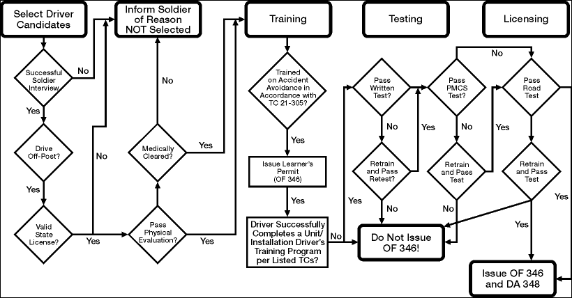
STP 55-88M14-SM-TG
3-165
Figure 3-82. The Driver/Operator Training Process
Performance Steps
2. Conduct physical evaluation, upon receipt of driver candidates, of each student (if required by
regulation).
a. Ensure all candidates have been interviewed and selected by the commander or his
designated representative.
b. Ensure all candidates possess a civilian driver's license (required if they are vehicle operators
and will be required to drive off-post).
c. Ensure the purpose and objective of physical evaluation (if used), is understood.
d. Ensure students meet minimum physical evaluation performance standards (if required) for:
(1) Visual acuity.
(2) Field of vision.
(3) Depth perception.
(4) Color perception.
(5) Foot reaction time.
(6) Hearing test.
e. Ensure results are posted to DA Form 348 (Equipment Operator's Qualification Record (Except
Aircraft)).
f. Ensure a Learner Permit OF 346/DA Form 5984-E (Operator's Permit Record)) is issued to
each candidate after they successfully complete the Accident Avoidance portion of training (if
required).
g. Issue learner permit.
3. Conduct review of examiner, instructor, and assistant instructor qualifications, to include:
a. Ensure they have been selected and are appointed in writing to train operators. Appointment
should be on the specific type of equipment/vehicle according to the regulations.
b. Ensure they are licensed to operate the type of equipment/vehicle being used for training.
c. Ensure they possess the technical knowledge and experience required for the
equipment/vehicle being used for training.
STP 55-88M14-SM-TG
3-166
Performance Steps
4. Conduct driver training instruction, to include:
a. Unit A - Introduction (to include safety briefing), organization of the course, materials review.
b. Unit B - Driver responsibilities and government liability.
c. Unit C - State, local, host nation, and post traffic regulations.
d. Unit D - Use of Army publications and blank forms, to include:
(1) DD Form 5987-E/DD Form 1970.
(2) DD Form 5988-E/DA Form 2404/DA Form 2408-14 (Uncorrected Fault Record).
(3) DD Form 518.
(4) SF 91.
e. Unit E - Vehicle inspection, preventive maintenance checks and services (PMCS).
f. Unit F - Accident avoidance.
g. Unit G - Driver energy and environmental consideration.
h. Unit H - Introduction to specific vehicles.
i. Unit I - Military convoy operations, including night driving.
j. Unit J - Off-road driving.
k. Unit K - Vehicle self-recovery operations.
l. Unit L - Vehicle driver performance evaluation.
m. Unit M - Response to emergency situations, vehicle malfunctions.
n. Unit N - Driving Range as setup by local commanders.
o. Unit O - Written examination.
p. Unit P - Preventive Maintenance (PMCS) test.
q. Unit Q - Road test (after completion of training).
r. Unit R - Additional course instruction should be included with respect to unit-specific vehicle
characteristics and ancillary devices as part of vehicle performance (for example
coupling/uncoupling semitrailer and crane/winch operation).
5. Conduct driver testing.
Note: Only driver-training candidates that have received the complete course of instruction are to be
tested.
a. Enforces vehicle safety and fire prevention measures.
b. Practice administers test to regular qualified driver on same type of vehicle.
c. Verifies that all examinees have completed the course of instruction as stipulated by AR 600-55
and local authority (SOP).
d. Administers written test.
e. Administers PMCS test.
f. Administers vehicle control test.
(1) Only tests those examinees that have successfully passed the PMCS test.
(2) Records examinee performance on DA Form 6125-R (Road Test Score Sheet).
g. Administers on-the-road test.
(1) Only tests those examinees that have successfully passed the vehicle control test.
(2) Records examinee performance on DA Form 6125-R.
h. Terminates the test on any examinee(s) that failed to achieve a passing score on any test.
(1) Records results on DA Form 6125-R.
(2) Conducts after action review for the examinee.
6. Conduct equipment operator training instruction, to include:
a. Mechanical equipment required by regulation or command policy.
b. Ground support equipment required by regulation or command policy.
c. Night vision goggles (if required).
d. Special equipment required by regulation or command policy.

STP 55-88M14-SM-TG
3-167
Performance Steps
7. Conduct equipment operator testing.
Note: Only candidates that have received the complete course of instruction are to be tested.
a. Ensure written examinations are administered according to regulatory guidance.
b. Enforces vehicle safety and fire prevention measures.
c. Verifies that all examinees have completed the course of instruction as stipulated by AR 600-55
and local authority (SOP).
d. Administers PMCS test.
e. Administers equipment-specific test.
(1) Only tests those examinees that have successfully passed the PMCS test.
(2) Records examinee performance on the equipment qualification record.
f. Terminates the test on any examinee(s) that failed to achieve a passing score on any test.
(1) Records results on equipment qualification record.
(2) Conducts after action review for the examinee.
8. Conduct sustainment and remedial training.
a. Ensure sustainment training is conducted as required for active Army soldiers.
b. Ensure sustainment training is conducted as required for Reserve Component soldiers.
c. Ensure remedial training is conducted when required.
d. Ensure refresher training is conducted when required.
9. Control the issue of operator permits (OF 346).
a. Ensure standard permits are issued according to the regulations.
b. Ensure special purpose permits are issued according to the regulations.
c. Ensure renewals are issued according to the regulations.
d. Ensure suspensions and revocations are controlled according to the regulations or local
command policy.
e. Ensure replacement permits are processed and issued according to the regulations.
Evaluation Preparation: Setup: Provide for the solder an established driver training program. Provide
driver records, training areas, driver candidates, and vehicles.
Brief Soldier: You have been designated, in writing, as a driver training instructor. You are to assume a
supervisory role over prospective driver candidates. You are to conduct interviews with candidates and
conduct and supervise driver selection, training, testing, and licensing. All required entries for drivers will
reflect the training they have received.
Performance Measures GO NO GO
1. Conducted preparations for driver/operator selection, training, and testing. —— ——
a. Ensured all driver training lesson plans are present and up to date.
b. Ensured all reference materials are available (regulations and training
circulars).
c. Ensured all vehicles are dispatched and ready for training.
d. Ensure driver testing and training device is available and in working
condition.
(1) Performed trial test to familiarize with equipment and to ensure it
working condition.
(2) Constructed equivalent testing instruments in lieu of availability of
testing and training device (must be made to accurately measure the
same physical characteristics).

STP 55-88M14-SM-TG
3-168
Performance Measures GO NO GO
e. Setup the assigned driving range.
f. Setup road testing site, should include:
(1) Forward stop.
(2) Straight line backing.
(3) Right turn.
(4) Alley dock.
(5) Eight left and eight right turns.
(6) Straight section of urban business street.
(7) Two through intersections and two intersections requiring stop.
(8) Two railway crossings.
(9) Two curves, one left, one right.
(10) A two-lane rural or semi-rural road.
(11) A section of expressway.
(12) A downgrade.
(13) An upgrade.
(14) A downgrade for stopping.
(15) An upgrade for stopping.
(16) An underpass or low clearance and one bridge.
2. Conducted physical evaluation, upon receipt of driver candidates, of each student
(if required by regulation).
—— ——
a. Stated purpose and objective of evaluation.
b. Tested students for:
(1) Visual acuity.
(2) Field of vision.
(3) Depth perception.
(4) Color perception.
(5) Foot reaction time.
(6) Hearing test.
3. Conducted review of examiner, instructor and assistant instructor qualifications, to
include:
—— ——
a. Ensured they have selected and are appointed in writing to train operators.
b. Ensured they were licensed to operate the type of equipment/ vehicle being
used for training.
c. Ensured they possessed the technical knowledge and experience required
for the equipment/vehicle being used for training.
4. Conducted driver training instruction, to include: —— ——
a. Unit A - Introduction (to include safety briefing), organization of the course,
materials review.
b. Unit B - Driver responsibilities and government liability.
c. Unit C - State, local, host nation, and post traffic regulations.
d. Unit D - Use of Army publications and blank forms, to include:
(1) DD Form 5987-E/DD Form 1970.
(2) DD Form 5988-E/DA Form 2404/DA Form 2408-14.
(3) DD Form 518.
(4) SF 91.
e. Unit E - Vehicle inspection, preventive maintenance checks and services
(PMCS).
f. Unit F - Accident avoidance.
g. Unit G - Driver energy and environmental consideration.
(1) Only tested those examinees that have successfully passed the vehicle
control test.
(2) Recorded examinee performance on DA Form 6125-R.

STP 55-88M14-SM-TG
3-169
Performance Measures GO NO GO
h. Unit H - Introduction to specific vehicles.
i. Unit I - Military convoy operations, including night driving.
j. Unit J - Off-road driving.
k. Unit K - Vehicle self-recovery operations.
l. Unit L - Vehicle driver performance evaluation.
m. Unit M - Response to emergency situations, vehicle malfunctions.
n. Unit N - Driving Range as setup by local commanders.
o. Unit O - Written examination.
p. Unit P - Preventive Maintenance (PMCS) test.
q. Unit Q - Road test (after completion of training).
5. Conducted driver testing. —— ——
Note: Only driver-training candidates that have received the complete course of
instruction are to be tested.
a. Enforced vehicle safety and fire prevention measures.
b. Practiced administers test to regular qualified driver on same type of vehicle.
c. Verified that all examinees have completed the course of instruction as
stipulated by AR 600-55 and local authority (SOP).
d. Administered written test.
e. Administered PMCS test.
f. Administered vehicle control test.
(1) Only tested examinees that have successfully passed the PMCS test.
(2) Recorded examinee performance on DA Form 6125-R.
g. Administered on-the-road test.
(1) Only tested those examinees that have successfully passed the vehicle
control test.
(2) Recorded examinee performance on DA Form 6125-R.
h. For any examinee(s) that failed to achieve a passing score on any test,
terminated the test.
(1) Recorded results on DA Form 6125-R.
(2) Conducted after action review for the examinee.
6. Conducted equipment operator training instruction, to include: —— ——
a. Mechanical equipment required by regulation or command policy.
b. Ground support equipment required by regulation or command policy.
c. Night vision goggles (if required).
d. Special equipment required by regulation or command policy.
7. Conducted equipment operator testing. —— ——
a. Ensured written examinations are administered according to regulatory
guidance.
b. Enforced vehicle safety and fire prevention measures.
c. Verified that all examinees have completed the course of instruction as
stipulated by AR 600-55 and local authority (SOP).
d. Administered PMCS test.
e. Administered equipment-specific test.
(1) Only tested those examinees that successfully passed the PMCS test.
(2) Recorded examinee results on the equipment qualification record.
f. For any examinee(s) that failed to achieve a passing score on any test,
terminated that test.
(1) Recorded results on equipment qualification record.
(2) Conducts after action review for the examinee.

STP 55-88M14-SM-TG
3-170
Performance Measures GO NO GO
8. Conducted sustainment and remedial training. —— ——
a. Ensured sustainment training was conducted as required for active Army
soldiers.
b. Ensured sustainment training was conducted as required for Reserve
Component soldiers.
c. Ensured remedial training was conducted when required.
d. Ensured refresher training was conducted when required.
9. Controlled the issue of operator permits (OF 346). —— ——
a. Ensured that standard permits were issued according to the regulations.
b. Ensured special permits were issued according to the regulations.
c. Ensured renewals were issued according to the regulations.
d. Ensured suspensions and revocations are controlled according to the
regulations or local command policy.
e. Ensured replacement permits are processed and issued according to the
regulations.
Evaluation Guidance: Score the soldier GO if all performance measures are passed. Score the soldier
NO-GO if any performance measure is failed. If any performance measure is failed, tell the soldier what
was done wrong and how to do it correctly.
References
Required Related
AR 385-55
AR 600-55
AR 611-5
DA FORM 2404
DA FORM 2408-14
DA FORM 348
DA FORM 5984-E
DA FORM 5987-E
DA FORM 5988-E
DA FORM 6125-R
DD FORM 1970
DD FORM 518
FM 21-305
FM 55-30
OF 346
SF 91
STP 55-88M14-SM-TG
3-171
Supervise Personnel Performing Vehicle Recovery
551-721-3338
Conditions: Given a mired/disabled vehicle with/without a winch, tow chain, tow bar, rope, timber, steel
beam, tarpaulin, BII, AAL, hearing protection, and personnel to supervise.
Standards: Your supervision has resulted in the successful recovery of the mired vehicle. No injury to
personnel or further damage to equipment was incurred.
Performance Steps
1. Supervise self-recovery operation using the Central Tire Inflation System (CTIS).
a. Ensure the adherence to applicable steps from the applicable TM.
(1) Self-recover the M939 series vehicle (refer to TM 9-2320-272-10).
(2) Self-recover the M1074/1075 series vehicle (refer to TM 9-2320-364-10).
(3) Self-recover the M1078 series vehicle (refer to TM 9-2320-365-10).
(4) Self-recover the M1083 series vehicle (refer to TM 9-2320-366-10-1).
2. Supervise use of manpower to recover vehicle (without winch).
a. Instruct personnel to locate a length of timber or similar material about 8 feet long and with a
diameter that personnel can handle.
b. Instruct personnel to place a suitable fulcrum (a log or rock that will not move when pressure is
applied) near the point of lift.
c. Instruct personnel to rig the lever under the bumper for the first lift.
d. Instruct personnel to block the lift when they have gained all the lift they can.
e. Instruct personnel to rig for a second lift, if possible, with the point of lever under the axle.
f. Instruct personnel to repeat this procedure until the vehicle can be backed off without too much
trouble.
3. Supervise use of the dual-wheel operation to recover the vehicle (without winch).
a. Ensure that two lengths of a strong rope are available for use.
b. Determine if a natural anchor is available (a tree or large boulder). The anchor used must be
as close as possible in line with direction of pull.
c. Supervise personnel in the construction of an anchor if no natural anchor is available. It should
be a type of anchor that would be suited to the surrounding terrain and available materials.
This may include any one of the following types. See FM 9-43-2, chapter 3 for details.
(1) Deadman log anchor.
(2) Normal or reinforced picket holdfast.
(3) Sand parachute.
d. Instruct the following actions for recovery operation.
(1) Fasten one end of the rope to a rear wheel hub and the other to an anchor.
(2) Place the rope between the duals and through one of the holes on the wheel disk.
(3) Tie the rope around the hub where it will be clear of the valve stem.
(4) Place the transmission gearshift lever in reverse to wind the rope.
(5) Once free, unwind and remove the rope from duals.
4. Ensure self-recovery of vehicle (with winch).
a. Ensure the vehicle winch cable is securely attached to anchor or vehicle.
b. Self-recover the M998 series vehicle (refer to TM 9-2320-280-10).
c. Self-recover the M809 series vehicle (refer to TM 9-2320-260-10).
d. Self-recover the M939 series vehicle (refer to TM 9-2320-272-10).
e. Self-recover the M977 series vehicle (refer to TM 9-2320-279-10-1).
f. Self-recover the M1074/1075 series vehicle (refer to TM 9-2320-364-10).
g. Self-recover the M1078/1083 series vehicle (refer to TM 9-2320-365-10 and 366-10-1).

STP 55-88M14-SM-TG
3-172
Evaluation Preparation: Setup: Provide the soldier with a mired or disabled vehicle to be recovered.
Provide additional personnel to supervise or for assistance as needed. Vehicle should not be capable of
moving under its own power. Provide for the soldier a recovery/like vehicle with crew/operators.
Brief Soldier: Inform soldier that his direct supervision and guidance must result in a successful recovery
of mired/disabled vehicle that is capable of moving under its own power (mired vehicle) without injury to
personnel or further damage to equipment.
Performance Measures GO NO GO
1. Supervised self-recovery operation using the Central Tire Inflation System (CTIS). —— ——
a. Ensure the adherence to applicable steps from the applicable TM.
(1) Self-recover the M939 series vehicle (refer to TM 9-2320-272-10).
(2) Self-recover the M1074/1075 series vehicle (refer to TM 9-2320-364-
10).
(3) Self-recover the M1078 series vehicle (refer to TM 9-2320-365-10).
(4) Self-recover the M1083 series vehicle (refer to TM 9-2320-366-10-1).
2. Supervised use of manpower to recover vehicle (without winch). —— ——
a. Instructed personnel to locate a length of timber or similar material about 8
feet long and with a diameter that available personnel can handle.
b. Instructed personnel to place a suitable fulcrum (a log or rock that will not
move when pressure is applied) near the point of lift.
c. Instructed personnel to rig the lever under the bumper for the first lift.
d. Instructed personnel to block the lift when they have gained all the lift they
can.
e. Instructed personnel to rig for a second lift with the point of lever under the
axle, if possible.
f. Instructed personnel to repeat this procedure until the vehicle can be backed
off without too much trouble.
3. Supervised use of the dual-wheel operation to recover the vehicle (without winch). —— ——
a. Ensured that two lengths of a strong rope are available for use.
b. Determined if a natural anchor is available (a tree or large boulder). The
anchor used must be as close as possible in line with direction of pull.
c. If no natural anchor is available, instruct and supervise personnel in the
construction of an anchor. It should be a type of anchor that would be suited
to the surrounding terrain and available materials. This may include any one
of the following types. See FM 9-43-2, chapter 3 for details.
(1) Deadman log anchor.
(2) Normal or Reinforced Picket Holdfast.
(3) Sand Parachute.
4. Ensured self-recovery of vehicle (with winch). —— ——
a. Ensure the vehicle winch cable is securely attached to anchor or vehicle.
b. Self-recover the M998 series vehicle (refer to TM 9-2320-280-10).
c. Self-recover the M809 series vehicle (refer to TM 9-2320-260-10).
d. Self-recover the M939 series vehicle (refer to TM 9-2320-272-10).
e. Self-recover the M977 series vehicle (refer to TM 9-2320-279-10-1).
f. Self-recover the M1074/1075 series vehicle (refer to TM 9-2320-364-10).
g. Self-recover the M1078/1083 series vehicle (refer to TM 9-2320-365-10 and
366-10-1).
Evaluation Guidance: Score the soldier GO if all performance measures are passed. Score the soldier
NO-GO if any performance measure is failed. If any performance measure is failed, tell the soldier what
was done wrong and how to do it correctly.
STP 55-88M14-SM-TG
3-173
References
Required Related
FM 21-305
FM 9-43-2
TM 9-2320-260-10
TM 9-2320-272-10
TM 9-2320-279-10-1
TM 9-2320-279-10-2
TM 9-2320-280-10
TM 9-2320-364-10
TM 9-2320-365-10
TM 9-2320-366-10-1
TM 9-243
STP 55-88M14-SM-TG
3-174
Supervise Operation of Vehicle-mounted Crane
551-721-3340
Conditions: Given soldiers to supervise, vehicle-mounted crane, BII, load to lift, hearing protection, and
flat surface to operate.
Standards: Your supervision has resulted in a successful operation of the vehicle-mounted crane to
transfer a load to or from the vehicle to the ground or another vehicle. Operation was conducted without
injury to personnel or damage to equipment.
Performance Steps
1. Supervise starting procedures.
a. Ensure that operator is wearing hearing protection (as applicable).
b. Ensure the vehicle operator adheres to all procedural steps listed in the appropriate vehicle TM
for engine starting.
c. Ensure the vehicle operator adheres to all SAFETY and WARNING statements in the vehicle
TM for this procedure.
2. Supervise preparation of crane for use.
a. Ensure that operator is wearing hearing protection (as applicable).
b. Ensure that operator adheres to all steps listing in the TM for this procedure.
c. Ensure that the operator has chocked the vehicle wheels prior to operation.
d. Ensure that load to be lifted is positioned and prepared and does not exceed weight limitations
of the crane.
e. For M977/M985 vehicles, refer to TM 9-2320-279-10-1.
f. For M1074 vehicle, refer to TM 9-2320-364-10.
g. For M1078 (LMTV) vehicles, refer to TM 9-2320-365-10.
h. For M1083 (MTV) vehicles, refer to TM 9-2320-366-10-1.
i. Never allow personnel to stand under a suspended load.
3. Supervise the operation of the crane.
a. Ensure operator explicitly follows visual hand and arm signals.
b. Ensure that crane-lifting hook is properly connected to the load being lifted.
c. Ensure that operator maintains control of crane and load during movement.
d. Ensure that operator places load as directed.
e. Never allow personnel to stand under a suspended load.
f. For M977/M985 vehicles, refer to TM 9-2320-279-10-1.
g. For M1074 vehicles, refer to TM 9-2320-364-10.
h. For M1078 vehicles, refer to TM 9-2320-365-10.
4. Supervise stowage of crane.
a. Ensure that operator completes all steps outlined in the vehicle TM applicable to this
procedure.
b. Ensure that operator adheres to all WARNING and CAUTION statements in the vehicle TM
applicable to this procedure.
c. Ensure that operator safely follows all visual hand and arm signals.
d. For M977/985 vehicle, refer to TM 9-2320-279-10-1.
e. For M1074 vehicles, refer to TM 9-2320-364-10.
f. For M1078 vehicles, refer to TM 9-2320-365-10.
g. For M1083 vehicle, refer to TM 9-2320-366-10-1.

STP 55-88M14-SM-TG
3-175
Evaluation Preparation: Setup: Give the soldier any one of the following vehicles: M977 HEMTT with
Crane; M1074 PLS Truck w/Crane; M1078 2.5-Ton Cargo Truck with Crane; or M1083 5-Ton Cargo
Truck with Crane.
Brief Soldier: Tell the soldier he is to operate the crane according to each performance step/applicable
TM without damaging the equipment or physical surroundings and without injuring personnel.
Performance Measures GO NO GO
1. Supervised starting procedures. —— ——
a. Ensure that operator is wearing hearing protection (as applicable).
b. Ensured the vehicle operator adheres to all procedural steps listed in the
appropriate vehicle TM for engine starting (as appropriate).
2. Supervised preparation of crane for use. —— ——
a. Ensure that operator is wearing hearing protection (as applicable).
b. Ensured that operator adheres to all steps listing in the TM for this
procedure.
c. Ensured that load to be lifted is positioned and prepared and does not
exceed limitations of the crane.
d. For M977/M985 vehicles, refer to TM 9-2320-279-10-1.
e. For M1074 vehicle, refer to TM 9-2320-364-10.
f. For M1078 (LMTV) vehicles, refer to TM 9-2320-365-10.
g. For M1083 (MTV) vehicles, refer to TM 9-2320-366-10-1.
h. Ensured the vehicle operator adheres to all SAFETY and WARNING
statements in the vehicle TM for this procedure.
3. Supervised operation of the crane. —— ——
a. Ensured operator explicitly follows visual hand and arm signals.
b. Ensured that crane hook is properly connected to the load being lifted.
c. Ensured that operator maintains control of crane and load during movement.
d. Ensured that operator places load as directed.
e. For M977/M985 vehicles, refer to TM 9-2320-279-10-1.
f. For M1074 vehicles, refer to TM 9-2320-364-10.
g. For M1078 vehicles, refer to TM 9-2320-365-10.
h. For M1083 vehicles, refer to TM 9-2320-366-10-1.
4. Supervised stowage of crane. —— ——
a. Ensured that operator completes all steps outlined in the vehicle TM
applicable to this procedure.
b. Ensured that operator adhered to all WARNING and CAUTION statements
in the vehicle TM applicable to this procedure.
c. Ensured that operator safely following all visual hand and arm signals.
d. For M977/985 vehicle, refer to TM 9-2320-279-10-1.
e. For M1074 vehicles, refer to TM 9-2320-364-10.
f. For M1078 vehicles, refer to TM 9-2320-365-10.
g. For M1083 vehicle, refer to TM 9-2320-366-10-1.
Evaluation Guidance: Score the soldier GO if all performance measures are passed. Score the soldier
NO-GO if any performance measure is failed. If any performance measure is failed, tell the soldier what
was done wrong and how to do it correctly.
STP 55-88M14-SM-TG
3-176
References
Required Related
FM 21-60
TM 9-2320-279-10-1
TM 9-2320-364-10
TM 9-2320-365-10
TM 9-2320-366-10-1
STP 55-88M14-SM-TG
3-177
Supervise Personnel Loading/Unloading Equipment/Cargo Onto/From Vehicle and Semitrailer
551-721-3341
Conditions: Given either a cargo vehicle or a tractor with semitrailer combination with before-operation
completed, personnel to supervise, non-hazardous load to be loaded or unloaded, tiedown materials,
blocking and bracing materials, hearing protection, work gloves, and assistance as needed from
additional personnel.
Standards: Your direct supervision has resulted in the successful loading/unloading of the
vehicle/trailer/semitrailer. If loading, the load was securely tied down to the vehicle and blocked and
braced properly as needed. The load was loaded in such a manner as to expedite unloading at
destination. If unloading, the unloading operation was conducted in a safe manner using all available
equipment and personnel. The operation was conducted successfully without injury to personnel or
damage to equipment.
Performance Steps
1. Supervise loading operations.
a. Cargo vehicle.
(1) Ensure that the vehicle to be loaded is chocked and hand brake set.
(2) Prepare cargo area for loading.
(a) Lower vehicle tailgate (as applicable).
(b) Remove canvas and bows as necessary.
(c) Ensure cargo area is cleaned out and ready to load cargo.
(d) Ensure sufficient tiedown materials are on hand to secure cargo.
(e) Ensure sufficient blocking and bracing materials are on hand as needed.
(3) Ensure heavier cargo items are placed on bottom and lighter items are on top.
(4) Ensure that all heavy cargo is distributed as evenly as possible over the bed to maintain a
safe weight distribution.
(5) Keep the load as low as possible. A high load may make the vehicle difficult to control
and may cause it to overturn.
(6) Fill the cargo space to the maximum weight allowable.
(7) For multiple-stop loads, separate cargo by destination for easy off-loading.
(8) Ensure that drums and barrels are loaded either upright or on their sides. If blocked on
their sides, their length should be parallel to the sides of the truck.
(9) If MHE is employed to load vehicle, ensure that all operational guidelines to include
SAFETY is adhered to according to the operator's TM.
(10) Ensure that once loading is complete, all tiedowns are secure and blocking and bracing
has been correctly emplaced. Refer to items listed below.
(a) Block and brace cargo with lumber or other materials to keep the load from shifting or
falling off the vehicle while en route (as applicable).
(b) Block crates, boxes, and barrels to keep them from shifting en route.
(c) Use crib blocking whenever possible. It need not be nailed to the floor or sides if
placed tightly against the cargo to reduce damage to the floor and sideboards of the
vehicle.
(d) If a gap exists between pipes or lumber and the end of the trailer, block the load with
a gate constructed with 4X4 boards to prevent it from slipping.
(e) All lumber used for blocking must be free of knots and strong enough to provide a
rigid and stable support for the load en route.
(f) Use available tiedown straps for general cargo or large component items.
Use available tiedown chains or wire rope and turnbuckles as needed for tiedown of
vehicles, CONEXs, or MILVANs that are not connected directly to the transporter.
Tiedown the load with available tiedown materials.
STP 55-88M14-SM-TG
3-178
Performance Steps
(11) Recheck entire load to ensure nothing is overlooked prior to allowing vehicle to move.
(12) During loading, ensure that no person is allowed to stand or walk underneath a
suspended load.
(13) If load lashing is needed, ensure it is done correctly and securely. See FM 21-305, page
18-13 for details on lashing.
(14) Re-install canvas and bows (if removed for loading).
(15) Ensure all required load documentation is present and completed correctly. This may
include:
(a) DD Form 1384 (Transportation Control and Movement Document).
(b) DD Form 626.
(c) DD Form 836.
(d) DA Form 2062 (Hand Receipt/Annex Number).
Note: Ensure operator possesses the correct form(s) to support the load.
b. Trailer/semitrailer.
(1) Ensure that the trailer/semitrailer to be loaded is chocked.
(2) Prepare cargo area for loading.
(a) Lower tailgate (as applicable).
(b) Remove canvas and bows as necessary.
(c) Remove sideboards.
(d) Ensure cargo area is cleaned out and ready to load cargo.
(e) Ensure sufficient tiedown materials are on hand to secure cargo.
(f) Ensure sufficient blocking and bracing materials are on hand as needed.
(3) Ensure heavier cargo items are placed on bottom and lighter items are on top.
(4) Ensure that all heavy cargo is distributed as evenly as possible over the bed to maintain a
safe weight distribution.
(5) Keep the load as low as possible. A high load may make the vehicle difficult to control
and may cause it to overturn.
(6) Fill the cargo space to the maximum weight allowable.
(7) For multiple-stop loads, separate cargo by destination for easy off-loading.
(8) Ensure that drums and barrels are loaded either upright or on their sides. If blocked on
their sides, their length should be parallel to the sides of the trailer/semitrailer.
(9) If MHE is employed to load vehicle, ensure that all operational guidelines to include
SAFETY is adhered to according to the operator's TM.
(10) Ensure that once loading is complete, all tiedowns are secure and blocking and bracing
has been correctly emplaced. Refer to items listed below.
(a) Block and brace cargo with lumber or other materials to keep the load from shifting or
falling off the vehicle while en route (as applicable).
(b) Block crates, boxes, and barrels to keep them from shifting en route.
(c) Use crib blocking whenever possible. It need not be nailed to the floor or sides if
placed tightly against the cargo to reduce damage to the floor and sideboards of the
vehicle.
(d) If a gap exists between pipes or lumber and the end of the trailer, block the load with
a gate constructed with 4X4 boards to prevent it from slipping.
(e) All lumber used for blocking must be free of knots and strong enough to provide a
rigid and stable support for the load en route.
(f) Tiedown the load with available tiedown materials. Use tiedown straps for general
cargo or large component items. Use tiedown chains or wire rope and turnbuckles
as needed for tiedown of vehicles, CONEXs, or MILVANs that are not connected
directly to the transporter.
(11) Recheck entire load to ensure nothing is overlooked prior to allowing vehicle to move.
(12) During loading, ensure that no person is allowed to stand or walk underneath a
suspended load.
STP 55-88M14-SM-TG
3-179
Performance Steps
(13) If load lashing is needed, ensure it is done correctly and securely.
(14) Re-install canvas and bows (if removed for loading).
(15) Ensure all required load documentation is present and completed correctly. This may
include DD Form 1384 (TCMD).
2. Supervise unloading operations.
a. Cargo vehicle or trailer/semitrailer.
(1) Ensure that vehicle to be unloaded is chocked and brakes set.
(2) Prepare cargo area for unloading.
(a) Lower vehicle tailgate (as applicable).
(b) Remove canvas and bows as necessary.
(c) Unlash and remove tarpaulin, if installed.
(d) Lower side-panels as needed (HEMTT Cargo).
(e) Remove sideboards as needed (M871 or 872 series semitrailers).
WARNING: Always be cautious when removing tiedown materials. Load may have shifted during
movement and could fall when tension is released. Ensure precautions are taken when loosening
tiedowns. Failure to comply may result in injury to personnel and/or damage to load.
b. Remove tiedowns securing load. If partial delivery, ensure only tiedowns securing that portion
of load are removed. Check remainder of load for security.
3. Ensure MHE operator follows designated hand and arm signals for any movement.
4. Position and emplace MHE lifting device to remove load or portion of load.
5. Attach guide ropes as needed, if unloading large, palletized items or heavy equipment, to control
load during removal from vehicle.
WARNING: When cutting banding on pallets, be cautious of heavy items falling free from pallet. Ensure
all items are restrained to prevent falling. Failure to comply may result in injury to personnel or damage
to load.
WARNING: When removing banding materials that are holding a pallet together the pressure on the
bands may cause the band to snap back. Ensure personnel are clear of banding during cutting process.
Failure to comply may result in injury to personnel.
6. Remove banding (if banded), if load is palletized and pallets must be broken for a partial unload, by
cutting only the necessary bands. Watch for falling pallet contents.
7. Secure any remaining items, once unloading has been completed, for further transport (as
necessary).
8. Ensure transfer of custody is accomplished and all records are annotated as needed and all items
are accounted for prior to departure.
9. Secure MHE and stow or reposition to allow cargo vehicle to move.
10. Recover and stow all slings, guide ropes, and blocking materials as necessary prior to departure.
11. Recover wheel chocks from vehicle and semitrailer prior to movement.
Evaluation Preparation: Setup: Provide for the soldier a load, tactical cargo vehicle, MHE, soldiers to
supervise, level area, and mission information.
Brief Soldier: You are required to supervise the safe operation of loading and unloading cargo to and
from a vehicle or semitrailer.

STP 55-88M14-SM-TG
3-180
Performance Measures GO NO GO
1. Supervised loading operations. —— ——
a. Cargo vehicle.
(1) Ensured that the vehicle to be loaded is chocked and brakes set.
(2) Prepared cargo area for loading.
(a) Lowered tailgate (as applicable).
(b) Removed canvas and bows as necessary.
(c) Ensured cargo area is cleaned out and ready.
(d) Ensured sufficient tiedown materials are on hand.
(e) Ensured sufficient blocking and bracing are on hand, if needed.
(3) Ensured heavier cargo items are placed on bottom and lighter items are
on top.
(4) Ensured that all heavy cargo items are distributed as evenly as possible
over the bed to maintain a safe weight distribution.
(5) Kept the load as low as possible. A high load may make the vehicle
difficult to control and may cause it to overturn.
(6) Filled the cargo space to the maximum weight allowable.
(7) For multiple-stop loads, separated cargo by destination for easy off-
loading.
(8) Ensured that drums and barrels are loaded either upright or on their
sides. If blocked on their sides, their length should be parallel to the
sides of the truck.
(9) If MHE is employed to load vehicle, ensured that all operational
guidelines to include SAFETY are adhered to according to the
operator's manual.
(10) Ensured that once loading is complete, all tiedowns are secure and
blocking and bracing has been correctly emplaced. Refer to items
listed below. If shipper is other than owning unit, ensure that all items
below are checked by driver prior to departing.
(a) Blocked and braced the load with lumber or other materials to
keep the load from shifting or falling off the vehicle while en route
(as applicable).
(b) Blocked crates, boxes, and barrels to keep them from shifting en
route.
(c) Used crib blocking whenever possible. It need not be nailed to the
floor or sides if placed tightly against the cargo to reduce damage
to the floor and sideboards.
(d) If a gap exists between pipes or lumber and the end of the trailer,
blocked the load with a gate constructed with 4X4 boards to
prevent it from slipping.
(e) Ensured that all lumber used for blocking and bracing must be free
of knots and strong enough to provide a rigid and stable support
for the load en route.
(f) Tiedown the load with the available tiedown materials.
(11) Rechecked entire load to ensure that nothing is overlooked prior to
allowing vehicle to move.
(12) During loading, ensured that no person is allowed to stand or walk
under a suspended load.
(13) Ensured load is lashed securely as needed.
(14) Ensured all load documentation is completed and accurate. All
required hand receipts or DD Form 1384 (TCMD) will accompany load
as applicable.

STP 55-88M14-SM-TG
3-181
Performance Measures GO NO GO
b. Trailer/semitrailer.
(1) Prepared cargo area.
(a) Ensured that the trailer/semitrailer to be loaded is chocked.
(b) Removed canvas and bows as necessary.
(c) Removed sideboards.
(d) Ensured cargo area is cleaned out and ready for loading.
(e) Ensured sufficient tiedown materials are on hand.
(2) Ensured heavier items are loaded on the bottom and lighter items are
loaded on the top.
(3) Ensured that all heavy cargo is distributed as evenly as possible over
the bed to maintain a safe weight distribution.
(4) Kept the load as low as possible. A high load may make the vehicle
difficult to control and may cause it to overturn.
(5) Filled the cargo space to the maximum weight allowable.
(6) For multiple-stop loads, separated cargo by destination for easy off-
loading.
(7) Ensured that drums and barrels are loaded either upright or on their
sides. If blocked on their sides, their length should be parallel to the
sides of the trailer/semitrailer.
(8) If MHE is employed to load vehicle, ensured that all operational
guidelines to include SAFETY is adhered to according to the operator's
TM.
(9) Ensured that once loading is complete, all tiedowns are secure and
blocking and bracing has been correctly emplaced. Refer to items
listed below.
(a) Blocked and braced cargo with lumber or other materials to keep
the load from shifting or falling off the vehicle while en route (as
applicable).
(b) Blocked crates, boxes, and barrels to keep them from shifting en
route.
(c) Used crib blocking whenever possible. It need not be nailed to the
floor or sides if placed tightly against the cargo to reduce damage
to the floor and sideboards of the vehicle.
(d) If a gap exists between pipes or lumber and the end of the trailer,
blocked the load with a gate constructed with 4X4 boards to
prevent it from slipping.
(e) Ensured all lumber used for blocking must be free of knots and
strong enough to provide a rigid and stable support for the load en
route.
(f) Tiedown the load with available tiedown materials. Used tiedown
straps for general cargo or large component items. Used tiedown
chains or wire rope and turnbuckles as needed for tiedown of
vehicles, CONEXs, or MILVANs that are not connected directly to
the transporter.
(10) Rechecked entire load to ensure nothing is overlooked prior to allowing
vehicle to move.
(11) During loading, ensured that no person is allowed to stand or walk
underneath a suspended load.
(12) If load lashing is needed, ensured it is done correctly and securely.
(13) Re-installed canvas and bows (if removed for loading).
(14) Ensured all required load documentation is present and completed
correctly.

STP 55-88M14-SM-TG
3-182
Performance Measures GO NO GO
2. Supervised unloading operations. —— ——
a. Cargo vehicle or trailer/semitrailer.
(1) Ensured that vehicle/trailer/semitrailer to be unloaded is chocked and
brakes set.
(2) Prepared cargo area for unloading.
(a) Lowered tailgate of truck or trailer.
(b) Removed canvas and bows as necessary.
(c) Unlashed and removed tarpaulin, if installed.
(d) Lowered side-panels as needed (HEMTT Cargo).
(e) Removed sideboards as needed (M871 or M872).
(f) Removed tiedowns securing load. If partial delivery, ensure only
tiedowns securing that portion of the load are removed. Check
remainder of load for security.
3. Ensured MHE operator follows designated hand and arm signals for any
movement.
—— ——
4. Positioned and emplaced MHE lifting devices to remove load or portion of load. —— ——
5. Attached guide ropes as needed, if unloading large, palletized items or heavy
equipment, to control load during removal from vehicle.
—— ——
6. Removed banding (if banded), if load is palletized and pallets must be broken for
a partial unload, by cutting only the necessary bands. Watch for falling pallet
contents.
—— ——
7. Secured any remaining items, once unloading has been completed, for further
transport (as necessary).
—— ——
8. Ensured transfer of custody was accomplished and all records were annotated as
needed and all items were accounted for prior to departure.
—— ——
9. Secured MHE and stowed or repositioned to allow cargo vehicle to move. —— ——
10. Recovered and stowed all slings, guide ropes, and blocking and bracing materials
prior to departure.
—— ——
11. Recovered wheel chocks from vehicle and semitrailer prior to movement. —— ——
Evaluation Guidance: Score the soldier GO if all performance measures are passed. Score the soldier
NO-GO if any performance measure is failed. If any performance measure is failed, tell the soldier what
was done wrong and how to do it correctly.
STP 55-88M14-SM-TG
3-183
References
Required Related
DA FORM 2062
DD FORM 1384
DD FORM 626
DD FORM 836
FM 21-305
FM 21-60
FM 55-30
TM 9-2320-260-10
TM 9-2320-272-10
TM 9-2320-279-10-1
TM 9-2320-364-10
TM 9-2320-365-10
TM 9-2320-366-10-1
STP 55-88M14-SM-TG
3-184
Supervise Preparation of Vehicle for Movement or Shipment
551-721-3347
Conditions: You are a truck platoon squad leader. Given a vehicle(s), vehicle operator(s) to supervise,
-10 series TM, DA Form 2408-14 or ULLS DA Form 5988-E with parts listing, DA Form 2404, vehicle
tiedown materials, blocking and bracing materials, load plans, and guidance from higher headquarters as
to intended method of shipment or movement.
Standards: Ensured that operator has prepared the vehicle by cleaning, performing required
maintenance, recording faults, ensuring vehicle has no fuel, oil, or coolant leaks, securing vehicle load (if
loaded), and configuring the vehicle in accordance with regulations/movement orders for
movement/shipment. All preparations have been made without injury to personnel or damage to vehicle
and load has been approved by the appropriate local authority.
Performance Steps
1. Ensure that all required operator preventive maintenance is completed prior to movement/shipment.
a. Ensure that vehicle/equipment is cleaned thoroughly to include any specific areas identified in
unit SOP.
b. Ensure that all uncorrected faults are recorded on either DA Form 2408-14 or DA Form 5988-E
(automated ULLS) and reported to organizational maintenance.
c. Ensure the vehicle is mechanically sound, free of leaks, drips, and other operational defects.
2. Ensure that vehicle's fuel levels are at the appropriate level.
a. Vehicles may contain fuel in tank (not to exceed one-half tank full). Ensure tanks are securely
closed.
b. Do not exceed one-half tank full on an aircraft cargo ramp with the fuel tank openings located
on the high side of the ramp.
c. Ensure that fuel cans are empty and secured to vehicle using original installed mounts.
d. Do not fill trailer-mounted equipment containing combustion engines, such as generator sets, to
more than one-half of their fuel capacity.
e. Ship 5-gallon fuel cans three-quarters full of diesel fuel if they are shipped in approved vehicle
storage racks. Inspect fuel cans for serviceable lid gaskets, leaks, and other defects prohibiting
their use as fuel containers.
3. Ensure installed batteries are protected.
Note: To prevent short circuit and secure the battery so that fluid will not leak. To secure the battery
from short circuit, completely protect the terminal posts from contact (such as tape, rubber boots, and so
on). When prepared in this manner, it is not required to disconnect the battery or remove it from the
equipment.
4. Ensure that all originally installed equipment (BII/AAL) is secured to vehicle.
a. Securely fasten all original installed equipment in properly configured and approved holders.
b. Do not leave removable crew-served weapons, such as spare barrels, and other sensitive
items, mounted or stored in the vehicle. Instead, consolidate them and place in a secure
container. Seal the container and lock it with an appropriate locking device.
c. Equip all vehicles with serviceable and proper lifting/tiedown devices or shackles.
d. Secure ignition keys on the steering wheel with wire. The wire must be long enough to reach
the ignition.
e. Do not cover headlights, windshields, or mirrors with tape.
f. Ensure fire extinguishers are in the approved mounting bracket if they are kept with vehicles
during shipment.
g. Keep driver compartments and steering wheels unlocked.
h. Store radios in secured containers to avoid moisture damage to them. If radios are shipped
mounted in the vehicle, secure them with chain and lock; then cover them with plastic. Treat
COMSEC equipment as classified materials.

STP 55-88M14-SM-TG
3-185
Performance Steps
5. Ensure that vehicle is reduced (as necessary).
a. Reduce vehicle length and width by folding in side-mounted mirrors and removing storage
baskets that overhand the vehicle's fixed dimensions.
b. Remove antennas.
c. Keep windshields and cab canvas in the up position.
d. Leave exhaust stacks in place. If removal is necessary, place metal can over exposed exhaust
pipe and remove before starting vehicle.
e. Reduce height as needed for rail clearance. Check with the ITO.
f. Reduce the length, width, and height only if it is specified in movement order.
g. Do NOT reduce tire pressure to conform with height restrictions.
6. Ensure cargo is configured properly on the vehicle, if vehicle is loaded with cargo (nested), for
movement/shipment.
a. Maximize use of all vehicles cargo capacity, particularly cargo vehicles and trailers. If trailer is
nested in the back of a cargo truck, load cargo under and around the trailer.
b. Do not exceed payload capacity.
c. Securely restrain the equipment and cargo in the vehicle body or chassis.
d. Ensure there is no metal-to-metal contact of loaded cargo (for example, a container loaded in a
5-ton cargo truck must have plywood between its bottom and the metal cargo bed).
e. After loading cargo into cargo bed, cover it with canvas. Secure the canvas by lashing with
manila rope. If steel strapping must be used, use enough padding to prevent damage to the
canvas.
f. If vehicle is equipped with a built up shelter, comply with the following:
(1) Built up vehicles will not be transported on vessels or commercial conveyances without
MACOM approval (see FM 4-01.011).
(2) When permitted, the vehicle height will not exceed the height of the authorized shelter.
Authorized shelters height is designed to accommodate both the vehicles vertical balance
and overhead clearance on selected transportation modes.
Evaluation Preparation: Setup: Provide for the soldier designated vehicle(s) that are to undergo
movement/shipment, soldier/operator(s), vehicle BII, and all other miscellaneous tools, equipment, or
tiedown materials needed.
Brief Soldier: You are to supervise your soldiers preparing the vehicle(s) for movement/shipment. All
requirements of preparing your vehicle(s) must be accomplished. If preparations involve reducing the
vehicle, this should also be accomplished.
Performance Measures GO NO GO
1. Ensured that all required operator preventive maintenance is completed prior to
movement/shipment.
—— ——
a. Ensured that vehicle was cleaned thoroughly to include any specific areas
identified in unit SOP.
b. Ensured that all uncorrected faults were recorded on either DA Form 2408-
14 or DA Form 5988-E (automated ULLS) and reported to organizational
maintenance.
c. Ensured the vehicle was mechanically sound, free of leaks, drips, and other
operational defects.

STP 55-88M14-SM-TG
3-186
Performance Measures GO NO GO
2. Ensured that vehicle's fuel tank is filled (or drained) to the appropriate level. —— ——
a. Vehicles may contain fuel in tank (not to exceed one-half tank full). Ensure
tanks are securely closed.
b. Vehicles may contain fuel in tank not to exceed three-fourths tank full when
transported under the authority of paragraph 3.7 (units transported under
this chapter may contain additional quantities of fuel in tank based on
operational necessity). Ensure tanks are securely closed.
c. Did not exceed one-half tank full on an aircraft cargo ramp with the fuel tank
openings located on the high side of the ramp.
3. Ensured installed batteries are protected. —— ——
Note: Prevented short circuit and secured so that battery fluid would not leak. To
secure the battery from short circuit, completely protect the terminal posts from contact
(such as tape, rubber boots, and so on). When prepared in this manner, it is not
required to disconnect the battery or remove it from the equipment. Ensured installed
batteries are protected.
4. Ensured that all originally installed equipment (BII/AAL) is secured to vehicle. —— ——
a. Securely fastened all original installed equipment in properly configured and
approved holders.
b. Did not leave removable crew-served weapons, such as spare barrels, and
other sensitive items, mounted or stored in the vehicle. Instead,
consolidated them and placed in a secure container. Sealed the container
and locked it with an appropriate locking device.
c. Equipped all vehicles with serviceable and proper lifting/tiedown devices or
shackles.
d. Secured ignition keys on the steering wheel with wire. The wire must be
long enough to reach the ignition.
e. Did not cover headlights, windshields, or mirrors with tape.
f. Ensured fire extinguishers are in the approved mounting bracket if they are
kept with vehicles during shipment.
g. Kept driver compartments and steering wheels unlocked.
h. Stored radios in secured containers to avoid moisture damage to them. If
radios are shipped mounted in the vehicle, secured them with chain and
lock; then covered them with plastic. Treated COMSEC equipment as
classified materials.
5. Ensured that vehicle is reduced (as necessary). —— ——
a. Reduced vehicle length and width by folding in side-mounted mirrors and
removing storage baskets that overhand the vehicle's fixed dimensions.
b. Removed antennas.
c. Keep windshields and cab canvas in the up position.
d. Leave exhaust stacks in place. If removal is necessary, place metal can over
exposed exhaust pipe and remove before starting vehicle.
e. Reduce height as needed for rail clearance. Check with the ITO.
f. Reduce the length, width, and height only if it is specified in movement order.
6. Ensured cargo was configured properly on the vehicle, if vehicle is loaded with
cargo (nested), for movement/shipment.
—— ——
a. Maximized use of all vehicles cargo capacity, particularly cargo vehicles and
trailers. If trailer is nested in the back of a cargo truck, loaded cargo under
and around the trailer.
b. Did not exceed payload capacity.

STP 55-88M14-SM-TG
3-187
Performance Measures GO NO GO
c. Securely restrained the equipment and cargo in the vehicle body or chassis.
d. Ensured there was no metal-to-metal contact of loaded cargo (for example, a
container loaded in a 5-ton cargo truck must have plywood between its
bottom and the metal cargo bed).
e. After loading cargo into cargo bed, covered it with canvas. Secured the
canvas by lashing with manila rope. If steel strapping was used, used
enough padding to prevent damage to the canvas.
f. If vehicle was equipped with a built up shelter, complied with the following:
(1) Built up vehicles will not be transported on vessels or commercial
conveyances without MACOM approval (see FM 4-01.011).
(2) When permitted, the vehicle height will not exceed the height of the
authorized shelter. Authorized shelters height is designed to
accommodate both the vehicles vertical balance and overhead
clearance on selected transportation modes.
Evaluation Guidance: Score the soldier GO if all performance measures are passed. Score the soldier
NO-GO if any performance measure is failed. If any performance measure is failed, tell the soldier what
was done wrong and how to do it correctly.
References
Required Related
DA FORM 2404
DA FORM 2408-14
DA FORM 5988-E
DA PAM 738-750
FM 4-01.011
TM 38-250
STP 55-88M14-SM-TG
3-188
Review Vehicle Accident Reports
551-721-3353
Conditions: You are the supervisor of a soldier involved in a Army motor vehicle accident. The soldier
involved in the accident has completed the SF 91 and has provided the SF 91 for supervisor review and
completion.
Standards: You have reviewed the SF 91 and conferred with the vehicle driver to verify accuracy of
information. You have completed the supervisory sections of the form and ensured that the form is turned
in to the unit commander or his designated representative.
Performance Steps
1. Review SF 91 for operator entries (pages 1, 2, 3).
Note: Verify by asking driver that DD Form 518 has been completed and provided to the other driver(s)
involved in the accident at the accident scene.
Note: This form is used to record vital information about the accident and given to the commander of the
person(s) involved in the accident.
a. Ensure that sections I through IX are filled out by the vehicle operator. Information must be
entered clearly, accurately, and completely. Sections follow:
I - Federal Vehicle Data - Self-explanatory, see form.
II - Other Vehicle Data - Self-explanatory, see form.
III - Killed or Injured - Self-explanatory, see form.
IV - Accident Time and Location - Follow instructions on form.
V - Witness/ Passenger - Self-explanatory, see form.
VI - Property Damage - Self-explanatory, see form.
VII - Police Information - Self-explanatory, see form.
VIII - Extra Details - Self-explanatory, see form. Use this section if needed but be clear and
detailed in providing information and indicate which section you refer from.
IX - Federal Driver's Certification - Driver will read the privacy act statement and sign the form
indicating information provided is correct.
2. Complete supervisor entries of SF 91.
a. Complete section X, items 72 to 82c (page 3) as follows (self-explanatory).
72 - Origin.
73 - Destination.
74 - Exact purpose of trip.
75 - Date and Time (when trip began).
76 - Date and Time (when accident occurred).
77 - Authority for the trip.
78 - Deviation form direct route.
79 - Was the trip during established working hours?
80 - Did the operator, while en route, engage in any activity other than that for which the trip
was authorized.
81a - Did the accident occur within the employee's scope of duty?
81b - Comments.
82a - Name and title of supervisor.
82b - Supervisor's signature and date.
82c - Telephone number.
b. Refer form to unit commander or accident investigator as applicable.

STP 55-88M14-SM-TG
3-189
Evaluation Preparation: Setup: Provide a completed SF 91 from a subordinate vehicle operator.
Brief Soldier: You are to review the accident report and provide your input to the form as the soldier's
supervisor and turn the form in to your commander.
Performance Measures GO NO GO
1. Reviewed SF 91 for operator entries (pages 1, 2, 3). —— ——
a. I - Federal Vehicle Data - Self-explanatory, see form.
II - Other Vehicle Data - Self-explanatory, see form.
III - Killed or Injured - Self-explanatory, see form.
IV - Accident Time and Location - Follow instructions on form.
V - Witness/ Passenger - Self-explanatory, see form.
VI - Property Damage - Self-explanatory, see form.
VII - Police Information - Self-explanatory, see form.
VIII - Extra Details - Self-explanatory, see form. Use this section if needed
but be clear and detailed in providing information and indicate which section
you refer from.
IX - Federal Driver's Certification - Driver will read the privacy act statement
and sign the form indicating information provided is correct.
2. Completed supervisor entries of SF 91. —— ——
a. Complete section X, items 72 to 82c (page 3) as follows (self-explanatory).
72 - Origin.
73 - Destination.
74 - Exact purpose of trip.
75 - Date and Time (when trip began).
76 - Date and Time (when accident occurred).
77 - Authority for the trip.
78 - Deviation form direct route.
79 - Was the trip during established working hours?
80 - Did the operator, while en route, engage in any activity other than that
for which the trip was authorized.
81a - Did the accident occur within the employee's scope of duty?
81b - Comments.
82a - Name and title of supervisor.
82b - Supervisor's signature and date.
82c - Telephone number.
b. Refer form to unit commander or accident investigator as applicable.
Evaluation Guidance: Score the soldier GO if all performance measures are passed. Score the soldier
NO-GO if any performance measure is failed. If any performance measure is failed, tell the soldier what
was done wrong and how to do it correctly.
References
Required Related
DD FORM 518
FM 21-305
SF 91
STP 55-88M14-SM-TG
3-190
Subject Area 9: Motor Pool Operations
Supervise Preventive Maintenance Checks and Services
551-721-3334
Conditions: Given soldier(s) to supervise that are all equipped to perform preventive maintenance with
the following items: either DA Form 2404 or DA Form 5988-E, black ink pen, applicable -10 series TM,
hearing protection, vehicles, trailers or equipment to perform the maintenance on, local maintenance
SOP, and any other tools (OVM, BII, AAL) or cleaning items needed.
Standards: Supervisor has ensured that all soldiers have properly performed preventive maintenance
according to the applicable TM by detecting all faults on the equipment and either immediately correcting
detected faults, or annotating uncorrectable faults on the available forms (DA Form 2404 or DA Form
5988-E), and by notifying their supervisor (you) as required. Ensured the proper use of tools and all
safety precautions were adhered to. The operators performed all applicable maintenance checks without
injury to personnel or damage to tools, equipment or vehicles.
Performance Steps
1. Ensure that soldier(s) are prepared to begin preventive maintenance inspection.
a. All forms (DA Form 2404 or DA Form 5987-E) are available and filled out properly in
accordance with DA Pamphlet 738-750.
b. The applicable and up-to-date TM or extracts are being used.
c. All equipment or vehicle-issued tools and/or equipment needed for inspection are present and
in serviceable condition.
d. Ensure that no jewelry is worn during maintenance that may pose a safety hazard to personnel.
Refer to vehicle or equipment TM as needed.
e. Ensure that hearing protection or any other applicable safety equipment/clothing is available
and used as needed/required.
f. Ensure that vehicle or equipment is properly grounded, as applicable.
2. Ensure the operator(s) are complying with established standards in the vehicle or equipment TM
while performing before-operation checks.
a. Ensure that operator(s) refer to applicable maintenance tables for the before-operation
inspection.
b. Solicit feedback on deficiencies found during inspection.
c. Assist the soldier(s) as needed, in determining replacement part availability.
d. Monitor and ensure maintenance support availability as needed.
e. Ensure that maintenance element is informed of any changes in vehicle operational status as a
result of the inspection.
f. Ensure operator(s) immediately correct noted faults or properly annotate the uncorrectable fault
on the maintenance worksheet.
g. Ensure the operator(s) make the required entries on the maintenance worksheet that reflects
the completion of before-operation checks. Operator signed and dated in appropriate block if
deficiencies are found.
3. Ensure the operator(s) are complying with established standards in the vehicle or equipment TM
while performing during-operation inspection.
a. Monitor and spot-check the operation of the vehicle(s) or equipment being operated under your
supervision by soliciting feedback from operators.
b. Ensure that organizational maintenance is informed of any changes in vehicle or equipment
operational status as a result of during-operation inspection.
c. Prohibit any operator from operating any vehicle or equipment if the operation or inspection of
this equipment is determined to be unsafe and/or non-mission capable (NMC).
STP 55-88M14-SM-TG
3-191
Performance Steps
d. Ensure the operator(s) make the required entries on the maintenance worksheet that reflects
the completion of during-operation checks. Operator signed and dated in appropriate block if
deficiencies are found.
e. Ensures that operator adheres to all safety WARNINGS and CAUTIONS applicable to the
maintenance procedures being performed.
4. Ensure the operator(s) are complying with established standards in the vehicle or equipment TM
while performing after-operation inspection.
a. Monitor and spot-check the operation of the vehicle(s) or equipment being operated under your
supervision by observation and soliciting feedback from operators.
b. Ensure that organizational maintenance is informed of any changes in vehicle or equipment
operational status as a result of after-operation inspection.
c. Prohibit any operator from operating any vehicle or equipment if the operation or inspection of
this equipment is determined to be unsafe and/or determined to be non-mission capable
(NMC).
d. Ensure the operator(s) make the required entries on the maintenance worksheet that reflects
the completion of after-operation checks.
(1) Operator signed and dated in appropriate block if deficiencies are found.
(2) Turns in worksheet to supervisor or maintenance personnel according to local SOP.
(3) Today's date entered in appropriate block if no deficiencies are found.
(4) Retains for further use until uncorrectable faults are noted.
5. Ensure that all inspection worksheets are turned in to organizational maintenance in accordance
with local maintenance SOP.
a. Makes final check of entries made by operator of all maintenance worksheets.
b. As supervisor, signs inspection worksheet as necessary.
c. Instructs driver to turn in maintenance worksheets as applicable.
6. Ensure that all vehicles and equipment are secured upon completion of maintenance.
a. Close and secure all OVM boxes.
b. Stow all tools properly in stowage trays/brackets.
c. Close and secure all access covers and engine compartment hoods.
d. If moving vehicle, remove chocks and ensures that ground guides are available to assist.
e. Ensure that all tools and maintenance related materials are secured before movement.
f. If vehicle is to remain parked, replace drip pans and chocks in accordance with local SOP.
g. Ensure operator(s) recover grounding device(s) prior to movement, as applicable.
Evaluation Preparation: Setup: Soldiers to supervise, either DA Form 2404 or DA Form 5988-E, black
ink pen, applicable -10 series TM, hearing protection, vehicles, trailers or equipment to perform the
maintenance on, local maintenance SOP, and any other tools (OVM, BII, and AAL) or cleaning items
needed.
Brief Soldier: Ensure that all soldiers have properly performed preventive maintenance according to the
applicable TM by detecting all faults on the equipment and either immediately correcting detected faults
or annotating uncorrectable faults on the available forms (DA Form 2404 or DA Form 5988-E), and by
notifying the supervisor, as required. Ensure the proper use of tools and all safety precautions were
adhered to.

STP 55-88M14-SM-TG
3-192
Performance Measures GO NO GO
1. Ensured that soldier(s) were prepared to begin preventive maintenance
inspection.
—— ——
2. Ensured the operator(s) were complying with established standards in the vehicle
or equipment TM while performing before-operation checks.
—— ——
3. Ensured the operator(s) were complying with established standards in the vehicle
or equipment TM while performing before-operation inspection.
—— ——
4. Ensured the operator(s) were complying with established standards in the vehicle
or equipment TM while performing before-operation inspection.
—— ——
5. Ensured that all inspection worksheets were turned in to organizational
maintenance in accordance with local maintenance SOP.
—— ——
6. Ensured that all vehicles and equipment were secured upon completion of
maintenance.
—— ——
Evaluation Guidance: Score the soldier GO if all performance measures are passed. Score the soldier
NO-GO if any performance measure is failed. If any performance measure is failed, tell the soldier what
was done wrong and how to do it correctly.
References
Required Related
DA FORM 2404 ACCP OD 0973
DA FORM 2408-14 ACCP OD 1009
DA FORM 5987-E TC 43-35
DA PAM 738-750
FM 21-305
FM 55-30
STP 55-88M14-SM-TG
3-193
Subject Area 10: Convoy Operations
Enforce Driver Safety Rules and Techniques
551-721-3336
Conditions: Given soldiers to train or supervise, vehicles or equipment to operate, proper personnel and
vehicle safety equipment, and local SOP.
Standards: You have enforced the safe operation of vehicles being operated under your supervision. All
applicable safety restrictions and guidelines have been adhered to in performing preventive maintenance
checks and during the loading and operation and unloading of all vehicles. All procedures were safely
executed without injury to personnel or damage to equipment.
Performance Steps
1. Ensure that all operators check the proper operation and serviceability of the following vehicle items
prior to dispatch of vehicle.
a. Improper functioning or adjustment of steering, lights, wipers, horns, warning signals, side or
rearview mirrors, and restraint system.
b. Improper condition of windshields, windows, mirrors, lights, or reflectors.
c. Defective, inoperable, or out-of-adjustment service or parking brakes.
d. Leaks.
e. Any condition likely to cause injuries to personnel or failure of a component.
f. Improperly secured loads.
g. Vehicle loaded beyond design load limits.
h. Unsafe transportation of personnel.
2. Ensure that all operators clean all reflective surfaces (such as windows, reflectors, and mirrors) prior
to vehicle operation.
3. Ensure that all operators adhere to the following safe operating procedures.
a. Perform a 360-degree walk-around of vehicle prior to movement.
b. When vision is obscured or when operating large vehicles, ground guides are used.
c. Does not run vehicle engine in closed areas.
d. Uses proper support when changing wheels.
e. Does not move vehicle when windows or mirrors are obscured in any way.
f. Does not smoke, eat, or drink while operating vehicle.
g. Does not drive vehicle too fast for driving conditions.
h. Does not smoke during refueling operations.
i. Always bonds and/or grounds vehicle when refueling or being refueled.
j. Always wears seat belts, eye protection, and hearing protection as required.
k. Always uses proper hand signals when operating vehicles or ground guiding others (as
needed).
l. Always maintains safe following distance from leading vehicles.
m. Uses vehicle safety warning devices when disabled.
n. Removes jewelry (especially watches and rings) when working around vehicles.
4. Ensure that all operators adhere to the following guidelines when carrying hazardous materials, non-
hazardous materials, or passengers.
a. For vehicles transporting hazardous materials-
(1) Follow a preplanned route.
(2) Park in areas where exposure to inhabited buildings and public gatherings is limited.
b. Vehicles carrying ammunition-
(1) Loaded to meet hazard classification and compatibility standards.
(2) Off loaded before major maintenance is performed.

STP 55-88M14-SM-TG
3-194
Performance Steps
(3) Inspected prior to loading and when entering an Army establishment before unloading
using DD Form 626.
(4) Have brakes set and at least one wheel chocked during all loading or unloading and
tiedown operations.
(5) No person will be allowed to ride on or in the cargo compartment of a motor vehicle
transporting explosives, fuel, or other hazardous materials.
(6) Will have an assistant driver when transporting hazardous materials.
c. Vehicles carrying passengers-
(1) Vehicle must have fixed seating.
(2) All passengers will remain seated while vehicle is in motion.
(3) Will not be the last vehicle in a convoy.
Evaluation Preparation: Setup: Provide an SOP for guidance, vehicles or equipment for which the
guidelines apply, personnel, and vehicle safety equipment.
Brief Soldier: Inform the soldier of the requirement to perform the task. The soldier is to enforce driver
safety rules and techniques by observing and making the necessary on-the-spot corrections in order to
maintain a high standard and prevent a dangerous situation or potential problem from developing.
Performance Measures GO NO GO
1. Ensured that all operators checked the proper operation and serviceability of
vehicle items prior to dispatch of vehicle.
—— ——
a. Improper functioning or adjustment of steering, lights, wipers, horns, warning
signals, side or rearview mirrors, and restraint system.
b. Improper condition of windshields, windows, mirrors, lights, or reflectors.
c. Defective, inoperable, or out-of-adjustment service or parking brakes.
d. Leaks.
e. Any condition likely to cause injuries to personnel or failure of a component.
f. Improperly secured loads.
g. Vehicle loaded beyond vehicle design load limits.
2. Ensured that all operators cleaned all reflective surfaces (such as reflectors,
windows, and mirrors) prior to vehicle operation.
—— ——
3. Ensured that all operators adhered to the following safe operating procedures. —— ——
a. Performed a 360-degree walk-around of vehicle prior to movement.
b. When vision was obscured or when operating large vehicles, ground guides
are used.
c. Did not run vehicle engine in closed areas.
d. Used proper support when changing wheels.
e. Did not move vehicle when windows or mirrors are obscured in any way.
f. Did not smoke, eat, or drink while operating vehicle.
g. Did not drive vehicle too fast for driving conditions.
h. Did not smoke during refueling operations.
i. Always bonded and/or grounded vehicle when refueling or being refueled.
j. Always wore seat belts, eye protection, and hearing protection as required.
k. Always used proper hand signals when operating vehicles or ground guiding
others (as needed).
l. Always maintained safe following distance from leading vehicles.
m. Used vehicle safety warning devices when disabled.
n. Removed jewelry (especially watches and rings) when working around
vehicles.

STP 55-88M14-SM-TG
3-195
Performance Measures GO NO GO
4. Ensured that all operators adhered to the following guidelines when carrying
hazardous materials, non-hazardous materials, or passengers.
—— ——
a. For vehicles transporting hazardous materials-
(1) Followed a preplanned route.
(2) Parked in areas where exposure to inhabited buildings and public
gatherings is limited.
b. Vehicles carrying ammunition-
(1) Loaded to meet hazard classification and compatibility standards.
(2) Off loaded before major maintenance is performed.
(3) Inspected prior to loading and when entering an Army establishment
before unloading using DD Form 626.
(4) Had brakes set and at least one wheel chocked during all loading or
unloading and tiedown operations.
(5) No person was allowed to ride on or in the cargo compartment of a
motor vehicle transporting explosives, fuel, or other hazardous
materials.
(6) Had an assistant driver when transporting hazardous materials.
c. Vehicles carrying passengers-
(1) Had fixed seating.
(2) All passengers remained seated while vehicle is in motion.
(3) Was not be the last vehicle in a convoy.
Evaluation Guidance: Score the soldier GO if all performance measures are passed. Score the soldier
NO-GO if any performance measure is failed. If any performance measure is failed, tell the soldier what
was done wrong and how to do it correctly.
References
Required Related
AR 385-55
DD FORM 626
FM 21-305
FM 21-60
FM 4-01.30
STP 55-88M14-SM-TG
3-196
Perform Duties as Serial/March Unit Commander
551-721-3348
Conditions: Given the responsibility as serial/march unit commander, briefing by convoy commander,
and enough vehicles to warrant a serial/march unit, maps, material to be transported, and personnel as
vehicle drivers.
Standards: As serial/march unit commander, you have successfully ensured that all predeparture checks
were completed for your vehicles, enforced all safe-driving measures during movement, ensured your
vehicle operators conducted all at-halt checks/duties, and that all drivers completed the required
checks/duties at destination prior to release. All procedures were performed without injury to personnel
or damage to vehicles or equipment.
Performance Steps
1. Perform predeparture checks/duties.
a. Check to see that before-operations checks have been performed.
(1) Check air hose couplings for proper connection and leakage.
(2) Check oil and lubrication levels.
(3) Check cooling systems for proper coolant level and leakage.
(4) Check brakes.
(5) Check tires for cuts and general condition.
(6) Check batteries for obvious defect (such as cracked case, burnt, broken or loose battery
terminals).
b. Check lineup of vehicles.
(1) Ensure march columns, regardless of size, have three parts. A head is the first task
vehicle of the column in the order of march.
(2) Ensure the main body of the column follows immediately after the first task vehicle.
(3) Ensure the trail is the last element of the march column.
c. Check to see that vehicles are properly marked.
(1) Place a blue flag on the front of the first task vehicle.
(2) Place a green flag on the rear vehicle.
(3) Place a black and white flag on the convoy commander or serial commander vehicle.
(4) Place a "convoy follows" sign on the front of the first task vehicle.
(5) Place a "convoy ahead" sign on the rear of the last vehicle.
(6) Place a "convoy commander" sign on the front and rear of the convoy commander's
vehicle.
d. Select pacesetter.
(1) This is normally an officer or senior noncommissioned officer (SNCO) at the head to
ensure that the column is following the proper route.
(2) The pacesetter rides in the first vehicle and sets the pace necessary to meet the travel
schedule.
(3) This officer or SNCO also checks at scheduled points and receives orders or changes in
orders.
e. Check weapons on the vehicles to make sure they are operational.
(1) Correct existing minor deficiencies on the spot.
(2) If major deficiencies exist, have the weapon and vehicle returned to the parent unit and
request an operational replacement.
f. Check to ensure that the sandbags are installed correctly on the floor of the troop-carrying
vehicles and on the cab floors of all vehicles.
(1) Cover the floors of troop-carrying vehicles with at least a double interlocking layer of
sandbags.
(2) Cover the cab floors of all vehicles with a double layer of sandbags under the driver's
seat.
STP 55-88M14-SM-TG
3-197
Performance Steps
g. Check the cargo to ensure it is secured and covered correctly.
(1) Cover the cargo to protect it from being damaged by prevailing weather conditions.
(2) Cover the cargo if necessary to deny intelligence information while providing protection
from elements.
h. Brief the drivers on the rules of the road, traffic laws and regulations, speed limits, time and
distance gaps, routing plans, review schedules, and march discipline.
i. Give the signal/order to start engine.
j. Give the signal/order to move out.
2. Enforce the correct driving procedures while the convoy is underway.
3. Instruct drivers at halt checks/duties.
a. Inform the drivers of details at halts.
(1) Time, duration, and purpose of convoy operations.
(2) Review the location of convoy.
(3) Review the duties of personnel during the convoy.
b. Control activities of the drivers.
(1) Tell the drivers to inspect their vehicles and loads.
(2) Tell the drivers to perform at-halt maintenance.
c. Check to see that the drivers are performing during-operation checks.
(1) Tell the drivers to perform necessary during-operation checks using the appropriate -10
series TM.
(2) Tell the drivers to check for and have items repaired, fill fluid levels, or adjust drive belts or
other items.
d. Check the security of the loads.
e. Check to see that the area is policed before moving out.
f. Give the signal/order to reform and start engines.
g. Give the signal/order to move out.
4. Perform all required checks/duties at the release point.
a. Update the drivers on additional orders/instructions from the convoy commander.
(1) Instruct the drivers to comply with the SOP in dispersing their vehicles.
(2) Inform the drivers of the time and place to assemble for the return trip.
b. Check to see that after-operation checks are performed.
(1) Tell the drivers to perform necessary after-operation checks using the appropriate -10
series TM.
(2) Tell the drivers to check for and have repaired all discrepancies found, fill fluid levels, or
adjust drive belts or other items.
c. Recommend disciplinary action for those drivers who violated driving rules during the convoy
operation.
d. Dismiss drivers.
Evaluation Preparation: Setup: Evaluate this task during a field training exercise or normal training
session.
Brief Soldiers: Tell the soldier he will be evaluated on his ability to properly perform duties as a
serial/march unit commander.

STP 55-88M14-SM-TG
3-198
Performance Measures GO NO GO
1. Performed predeparture checks/duties. —— ——
2. Enforced the correct driving procedures while the convoy is underway. —— ——
3. Instructed drivers at halt checks/duties. —— ——
4. Performed all required checks/duties at the release point. —— ——
Evaluation Guidance: Score the soldier GO if all performance measures are passed. Score the soldier
NO-GO if any performance measure is failed. If any performance measure is failed, tell the soldier what
was done wrong and how to do it correctly.
References
Required Related
FM 21-10
FM 21-60
FM 4-01.30
FM 55-30
TM 9-2320-260-10
TM 9-2320-272-10
TM 9-2320-279-10-1
TM 9-2320-279-10-2
TM 9-2320-280-10
TM 9-2320-360-10
TM 9-2320-364-10
TM 9-2320-365-10
TM 9-2320-366-10-1
TM 9-2320-366-10-2
STP 55-88M14-SM-TG
3-199
Instruct the Use of Maps in Motor Transport Operations
551-721-3355
Conditions: Applied to a tactical environment, given dispatched vehicle(s), vehicle operator(s), vehicle
navigator(s) (assistant drivers), topographic, and grid maps, and strip map information, plotting protractor,
map markers, legend information, route information, and communications equipment.
Special Conditions: The soldiers receiving the instruction are given the duty as vehicle navigator. The
navigator will be the only person making movement decisions within each vehicle involved. Driver will
NOT attempt to assist as this action as it seriously increases the possibility of vehicle accident during
movement.
Note: The focus of this task is to emphasize the motor transport operator's ability to navigate while
mounted using various types of maps. In contrast to dismounted land navigation, the mounted navigator
and vehicle operator must consider the vehicle's ability to maneuver through varying terrain as a factor of
their selection of routes.
Note: The duties of a navigator are so important that he should not be given any other duties. The leader
should never try to be the navigator, since his normal responsibilities are heavy, and one or the other job
would suffer.
Standards: As a result of your instruction, all vehicles were navigated to their destination without
becoming disoriented or traveling on unauthorized routes thus endangering the transport mission. The
navigator of each vehicle was able to properly identify, and plot all route and mission essential information
on topographic maps or tourist road maps. Strip maps were prepared based on maps sheets used for
mission and accurately depicted applicable route information that successfully contributed to the mission.
Performance Steps
1. Define mounted navigator (assistant driver) duties.
a. Assembling Equipment. The navigator must gather all the equipment that will help him perform
his job (maps, pencils, and so forth). He must do this before the mission starts.
b. Servicing Equipment. It is the navigator's duty to make sure that all the equipment he may use
or require is working. This may include but is not limited to a compass or a Precision
Lightweight GPS Receiver (PLGR).
c. Recording Data for Precise Locations. During movement, the navigator must make sure that
the correct direction and distance are recorded and followed. Grid coordinates of locations
must be recorded and plotted.
d. Supply Data to Subordinate Leaders. During movement, any change in direction or distance
must be given to the subordinate leaders in sufficient time to allow them to react.
e. Maintaining Liaison with Commander. The commander normally selects the route that he
desires to use. The navigator is responsible for following that route; however, there may be
times when the route must be changed during a tactical operation. For this reason, the
navigator must maintain constant communication with the commander. The navigator must
inform the commander when checkpoints are reached, when a change in direction of
movement is required, and how much distance is traveled.
STP 55-88M14-SM-TG
3-200
Performance Steps
2. Orient the map.
a. First technique.
(1) With the map in a horizontal position, take the straightedge on the left side of the compass
and place it alongside the north-south grid line with the cover of the compass pointing
toward the top of the map. This procedure places the fixed black index line of the
compass parallel to north-south grid lines of the map.
(2) Keeping the compass aligned as directed above, rotate the map and compass together
until the magnetic arrow is below the fixed black index line on the compass. At this time,
the map is close to being oriented.
(3) Rotate the map and compass in the direction of the declination diagram.
(4) If the magnetic north arrow on the map is to the left of the grid north, check the compass
reading to see if it equals the grid-magnetic (GM) angle given in the declination diagram.
b. Second technique.
(1) Determine the direction of the declination diagram and its value from the declination
diagram.
(2) Using any north-south on the map as a base, draw a magnetic azimuth equal to the GM
angle given in the declination diagram with the protractor.
(3) If the declination is easterly (right), the drawn line is equal to the value of the GM angle.
Then align the straightedge, which is on the left side of the compass, alongside the drawn
line on the map. Rotate the map and compass until the magnetic arrow of the compass is
below the fixed black index line. The map is now oriented.
c. Using terrain association. A map can be oriented by terrain association when a compass is not
available or when the user has to make many quick references as he moves across country.
Using this method requires careful examination of the map and the ground, and the user must
know his approximate location.
3. Explain the details of a topographic map.
Note: This is a map that portrays terrain features in a measurable way (usually through use of contour
lines), as well as the horizontal positions of the features represented. The vertical positions, or relied, are
normally represented by contour lines on military maps. On maps showing relief, the elevations and
contours are measured from a specific vertical datum plane, usually mean sea level.
Note: This is the military map that is most commonly used by maneuvering units to navigate. The
standard scale is 1:50,000.
a. Identify and/or determine topographic symbols such as:
(1) The map's legend. It normally contains the symbols used in a particular series or on that
specific map sheet. Therefore, the legend should be referred to each time a new map
sheet is used. The symbol should reflect as closely as possible what the feature is
intended to be.
(2) Military symbols are added to give additional significance to the military application at the
time the map is used. Refer to FM 101-5-1, Appendixes A and B for friendly and enemy
unit symbols.
b. Identify terrain features on the map.
c. Determine grid coordinates using the military grid reference system.
d. Determine distance on the map from one point to another.
4. Explain the details of a road map.
Note: These are maps of a region in which the main means of transportation and areas of interest are
shown. Some of these maps show secondary networks of roads, historic sites, museums, and beaches
in detail. They may contain road and time distance between points. Careful consideration should be
exercised about the scale when using these maps.
a. Scale of the map if different than a topographic map. Determine to the best extent possible
what the scale is of the map you are using.
b. Origin and destination.
STP 55-88M14-SM-TG
3-201
Performance Steps
c. Selected routes.
d. Cities and towns.
e. Four-lane divided highways, principle highways, and other thruways and roads.
f. Width and height of bridges and overpasses.
g. Rest and service areas.
h. Distance (miles, kilometers) from point of origin to destination.
i. Map symbols.
j. Special features on the map.
k. Alternate route(s).
5. Explain the details of a strip map.
Note: A strip map is an unscaled drawing of routes or a march including the critical points along those
routes (see Figure 3-83). It may be prepared either as an overlay or as a schematic of the map itself. It
is similar to a route overlay but not to scale. The purpose of a strip map is to graphically portray a routs
of movement over a distance that may exceed standard military map sheets of that requires multiple map
sheets.
a. Explain the following regarding strip maps.
(1) Origin and destination.
(2) Start Point (SP) and Release Point (RP) if different from 4a above.
(3) Routes and route numbers.
(4) Major towns.
(5) Major roads and crossroads.
(6) Mileage between points.
(7) Bivouac, rest, halt and refuel point.
(8) Directional arrows.
(9) Legend transferred from the map onto the strip map.
(10) Alternate route(s).
(11) Critical point(s).
b. Present the following information concerning characteristics of a strip map:
(1) A strip map may be prepared from a route overlay, a route reconnaissance report, or a
map reconnaissance. It is drawn on a standard sheet of paper to give the user the
necessary information to reach his destination.
(2) A strip map is generally distributed to squad leaders, convoy commanders, drivers, or
route guides and normally shows only one route (see Figure 3-84).
(3) A strip map used as an appendix or annex could have many routes on it and could include
bypasses for each route (see Figure 3-85).
(4) A strip map may indicate a sketch of a march, which may or may not be drawn to scale.
6. Prepare a strip map.
a. Orientation. Place the symbol for grid north on the sketch. Label it with an N to designate the
general direction of north. Do not make any other orientation or grid references.
b. Plot the details.
(1) Draw the route of movement.
(2) Plot all critical points or areas along a route where movement may occur or where timing
is critical. These include SPs, checkpoints, RPs, phase lines, bridges, tunnels, road
junctions, city or town intersections where passage could be confusing, and areas or halts
for messing, and refueling.
(3) Plot the SPs, and RPs. Label them with their abbreviation or number if appropriate.
(4) Place the distance between critical points in kilometers or miles (use a measurement that
would be applicable based on the movement).
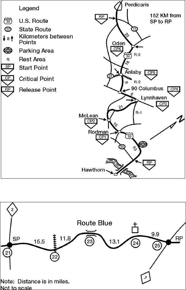
STP 55-88M14-SM-TG
3-202
Figure 3-83. Route Strip Map
Figure 3-84. Single Route Strip Map
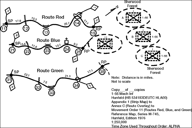
STP 55-88M14-SM-TG
3-203
Figure 3-85. Multiple Route Strip Map
Performance Steps
c. Create the Heading.
(1) An example of a title is Appendix 1 (strip map) to Annex C (route overlay) to movement
order 11 (Routes Red. Blue, and Green to Sherwood forest).
(2) Map references for a strip map are normally the same as for the operation order that the
strip map supports.
d. When a strip map is prepared as an appendix or annex issued separately this is when it is to
have wide distribution), then the order must have a heading, and ending, and a classification,
as does the overlay.
e. Strip maps for general use that are to be distributed to the lowest level will have only the
information pertaining to that level (example: squad leader, vehicle commander, or driver).
(1) The detail on such a map is the same as for a strip map used as an appendix or annex
except no unit symbols or designation are used. If the map is extracted from a strip map
with multiple routes, the only route that is included is the one the user needs.
(2) Use the title that alludes to the order, but does not mention the order by name, number, or
letter. Use the route name or a name that would be applicable for the movement; for
example, Route Blue to Sherwood Forest.
(3) These maps are not classified. However, caution personnel on the sensitivity of the
document. Do not issue the strip map until the last possible moment.
7. Conduct mounted vehicular movement.
Note: This performance step is the practical application of navigating along a specified route using one or
more of the maps previously covered. Navigation will be accomplished using necessary route and
mission information (local SOP) that has been plotted on the map being used by the person(s) receiving
this instruction.
a. Via a road network.
(1) In most cases, the motor transport operator will have a route that has been cleared by
reconnaissance in order to conduct movement. However, this is not always the case.
(2) Determine your exact starting location and that of your destination.
(3) Using either of the types of maps previously discussed, instruct your driver to begin
movement along the route that has been selected.
STP 55-88M14-SM-TG
3-204
Performance Steps
(4) Unlike dismounted land navigation, mounted navigating requires greater vigilance in
determining your progress along the route while monitoring the map. Selected points may
pass much faster than anticipated.
(5) Compare your location relative to the following:
(a) Your directional orientation.
(b) The direction and distances to your destination.
(c) Other landmarks and features (towns, intersections, lakes, streams, and so forth).
(d) Any impassible terrain, the enemy, and danger areas.
(e) Both the advantages and disadvantages presented by the terrain between you and
your objective.
(6) Use terrain features as checkpoints. You will use plotted checkpoints along the route but
if there are long distances between points you will want to use terrain features that cross
your path that are easily identifiable to check your progress.
Note: Always consider the tactical aspects of your movement. Avoid "skylining" if at all possible as your
chances of detection are increased. Use the "cliché "expect the unexpected" along your route. Up-to-
date intelligence degrades with time.
(7) Determine distance. Get the total distance to be traveled and the approximate distance
between points. Plan to use the vehicle odometer to keep track of distance traveled.
b. Via cross-country.
(1) Travel over across-country route may be much more difficult in that there are not always
road networks that are plotted on the map. A route that has not been used in long periods
of time may be overgrown or washed out. This is where route reconnaissance pays off.
Using alternate routes when this occurs will ensure mission success.
(2) Vehicle capabilities. When determining a route to be used when mounted, consider the
capabilities of the vehicles to be used. Most military vehicles are limited in the degree of
slope they can climb and the type of terrain they can negotiate. Swamps, thickly wooded
areas, or deep streams may present no problems to dismounted soldiers, but the same
terrain may completely stop mounted soldiers. The navigator must consider this when
selecting a route.
(3) Most military vehicles will knock down a tree. The bigger the vehicle, the bigger the tree it
can knock down. Vehicles cannot knock down several trees at once. It is best to find
paths between trees that are wide enough for your vehicle. Military vehicles are designed
to climb 60 percent slopes on a dry, firm surface.
(4) Determine slope by referring to map sheet. A typical road map will not have contour lines;
therefore, refer to topographic maps).
(a) Check selected route on the map. Determine the slope by checking to see if there is
a contour line in any 100 meters of map distance. If so, it is a 10 percent slope. If
there are two contour lines, it is a 20 percent slope and so forth.
(b) Side slope is even more important than the slope you can climb. Normally, a 30
percent slope is the maximum in good weather. If you traverse a side slope, do it
slowly and without turns.
c. Recheck your progress along the route by comparing the map's terrain features and plotted
checkpoints. Note any discrepancies that conflict with intelligence or reconnaissance reports
and notify higher headquarters in accordance with local SOP.

STP 55-88M14-SM-TG
3-205
Evaluation Preparation: Setup: Provide for the NCO a vehicle(s), vehicle operator(s), topographic
map(s), or street map(s), marginal information, mission information, designated route information,
protractor(s), and pencil(s).
Brief Soldier: Inform the NCO that he is appointed as instructor for the use of maps in a motor transport
application. He is to provide instructional information regarding the use of maps in motor transport
operations and evaluate them on their performance in mounted land navigation. They will perform duties
as vehicle navigator over a designated course that will prompt them to exercise their newly acquire skills
and knowledge. You are to oversee their performance by using radio communication and first hand
observations throughout the course. Provide immediate feedback to each soldier following their
performance.
Performance Measures GO NO GO
1. Defined mounted navigator (assistant driver) duties. —— ——
a. Assembling equipment. The navigator must have gathered all the
equipment that will help him perform his job (maps, pencils, and so forth).
He must have done this before the mission started.
b. Servicing equipment. It is the navigator's duty to make sure that all the
equipment he may use or require is working. This may include but is not
limited to a compass or a Precision Lightweight GPS Receiver (PLGR). This
included the Movement Tracking System if installed on vehicles.
c. Recording Data for Precise Locations. During movement, the navigator
must have made sure that the correct direction and distance were recorded
and followed. Grid coordinates of locations must have been recorded and
plotted.
d. Supply Data to Subordinate Leaders. During movement, any change in
direction or distance must be given to the subordinate leaders in sufficient
time to allow them to react.
e. Maintaining Liaison with Commander. The commander normally selects the
route that he desires to use. The navigator is responsible for following that
route; however, there may be times when the route must be changed during
a tactical operation. For this reason, the navigator must maintain constant
communication with the commander. The navigator must inform the
commander when checkpoints are reached, when a change in direction of
movement is required, and how much distance is traveled.
2. Oriented the map. —— ——
Note: Using a compass. A map is oriented when it is in a horizontal position with its
north and south corresponding to the north and south on the ground.
a. First technique.
(1) With the map in a horizontal position, take the straightedge on the left
side of the compass and place it alongside the north-south grid line with
the cover of the compass pointing toward the top of the map. This
procedure places the fixed black index line of the compass parallel to
north-south grid lines of the map.
(2) Keeping the compass aligned as directed above, rotate the map and
compass together until the magnetic arrow is below the fixed black
index line on the compass. At this time, the map is close to being
oriented.
(3) Rotate the map and compass in the direction of the declination
diagram.
(4) If the magnetic north arrow on the map is to the left of the grid north,
check the compass reading to see if it equals the GM angle given in the
declination diagram.

STP 55-88M14-SM-TG
3-206
Performance Measures GO NO GO
b. Second technique.
(1) Determine the direction of the declination diagram and its value from
the declination diagram.
(2) Using any north-south on the map as a base, draw a magnetic azimuth
equal to the GM angle given in the declination diagram with the
protractor.
(3) If the declination is easterly (right), the drawn line is equal to the value
of the GM angle. Then align the straightedge, which is on the left side
of the compass, alongside the drawn line on the map. Rotate the map
and compass until the magnetic arrow of the compass is below the
fixed black index line. The map is now oriented.
c. Use Terrain Association. A map can be oriented by terrain association when
a compass is not available or when the user has to make many quick
references as he moves across country. Using this method requires careful
examination of the map and the ground, and the user must know his
approximate location using terrain association.
3. Explained the details of a topographic map. —— ——
a. Identified and/or determined topographic symbols such as:
(1) The map's legend. It normally contains the symbols used in a particular
series or on that specific map sheet. Therefore, the legend should be
referred to each time a new map sheet is used. The symbol should
reflect as closely as possible what the feature is intended to be.
(2) Military symbols are added to give additional significance to the military
application at the time the map is used. Refer to FM 101-5-1,
Appendixes A and B for friendly and enemy unit symbols.
b. Identified terrain features on the map.
c. Determined grid coordinates using the military grid reference system.
d. Determined distance on the map from one point to another.
4. Explained the details of a road map. —— ——
a. Scale of the map if different than a topographic map. Determine to the best
extend possible what the scale is of the map you are using.
b. Origin and destination.
c. Selected routes.
d. Cities and towns.
e. Four-lane divided highways, principle highways, and other thruways and
roads.
f. Width and height of bridges and overpasses.
g. Rest and service areas.
h. Distance (miles, kilometers) from point of origin to destination.
i. Map symbols.
j. Special features on the map.
k. Alternate route(s).
5. Explained the details of a strip map. —— ——
a. Explained the following regarding strip maps:
(1) Origin and destination.
(2) Start Point (SP) and Release Point (RP) if different from 4a above.
(3) Routes and route numbers.
(4) Major towns.
(5) Major roads and crossroads.
(6) Mileage between points.
(7) Bivouac, rest, halt and refuel point.

STP 55-88M14-SM-TG
3-207
Performance Measures GO NO GO
(8) Directional arrows.
(9) Legend transferred from the map onto the strip map.
(10) Alternate route(s).
(11) Critical point(s).
b. Presented the following information concerning characteristics of a strip
map:
(1) A strip map may be prepared from a route overlay, a route
reconnaissance report, or a map reconnaissance. It is drawn on a
standard sheet of paper to give the user the necessary information to
reach his destination.
(2) A strip map is generally distributed to squad leaders, convoy
commanders, drivers, or route guides and normally shows only one
route.
(3) A strip map used as an appendix or annex could have many routes on
it and could include bypasses for each route.
(4) A strip map may indicate a sketch of a march, which may or may not be
drawn to scale.
6. Prepared a strip map. —— ——
a. Orientation. Placed the symbol for grid north on the sketch. Labeled it with
a N to designate the general direction of north. Did not make any other
orientation or grid references.
b. Plotting detail.
(1) Drew the route of movement.
(2) Plotted all critical points or areas along a route where movement may
occur or where timing is critical. These include SPs, checkpoints, RPs,
phase lines, bridges, tunnels, road junctions, city or town intersections
where passage could be confusing, and areas or halts for messing, and
refueling.
(3) Plotted the SPs, and RPs. Label them with their abbreviation or number
if appropriate.
(4) Placed the distance between critical points in kilometers or miles (use a
measurement that would be applicable based on the movement).
c. Created a heading.
(1) The detail on such a map is the same as for a strip map used as an
appendix or annex except no unit symbols or designation are used. If
the map is extracted from a strip map with multiple routes, the only
route that is included is the one the user needs.
(2) Used the title that alludes to the order, but did not mention the order by
name, number, or letter. Used the route name or a name that would be
applicable for the movement (for example, Route Blue to Sherwood
Forest).
(3) Did not issue the strip map until the last possible moment.
7. Conducted mounted vehicular movement. —— ——
a. Via a road network.
(1) Determined exact starting location and that of your destination.
(2) Using either of the types of maps previously discussed, instructed your
driver to begin movement along the route that has been selected.
(3) Unlike dismounted land navigation, mounted navigating requires
greater vigilance in determining your progress along the route while
monitoring the map. Selected points may pass much faster than
anticipated.

STP 55-88M14-SM-TG
3-208
Performance Measures GO NO GO
(4) Compared location relative to the following:
(a) Your directional orientation.
(b) The direction and distances to your destination.
(c) Other landmarks and features (towns, intersections, lakes,
streams, and so forth).
(d) Any impassible terrain, the enemy, and danger areas.
(e) Both the advantages and disadvantages presented by the terrain
between you and your objective.
(5) Used terrain features as checkpoints.
(6) Determined distance. Got the total distance to be traveled and the
approximate distance between points. Planned to use the vehicle
odometer to keep track of distance traveled.
b. Via cross-country.
(1) Used alternate routes when road were washed out.
(2) Considered vehicle capabilities while navigating route.
(3) Considered vehicle capabilities while navigating route.
(a) Checked selected route on the map. Determine the slope by
checking to see if there is a contour line in any 100 meters of map
distance. If so, it is a 10 percent slope. If there are two contour
lines, it is a 20 percent slope and so forth.
(b) If you traverse a side slope was accomplished, it was done slowly
and without turns.
c. Rechecked progress along the route by comparing the map's terrain features
and plotted checkpoints. Noted any discrepancies that conflicted with
intelligence or reconnaissance reports and notify higher headquarters in
accordance with local SOP.
Evaluation Guidance: Score the soldier GO if all performance measures are passed. Score the soldier
NO-GO if any performance measure is failed. If any performance measure is failed, tell the soldier what
was done wrong and how to do it correctly.
References
Required Related
FM 101-5-1
FM 21-305
FM 3-25.26
STP 21-1-SMCT
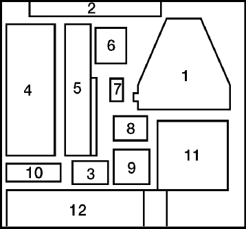
STP 55-88M14-SM-TG
3-209
Operate the Movement Tracking System (MTS) Control Station
551-721-3600
Conditions: As an assistant truckmaster assigned to the company headquarters section, given an
installed and fully operational MTS Control Station, target MTS Mobile Units assigned to your network,
mission, and routing information.
Standards: You have operated the MTS Control Station either by direct input or by supervising the
operator in your operations section to direct/redirect vehicle movement in support of your unit's ongoing
mission. During operations you were able to detect and adjust system controls in order to send and
receive digital traffic to all linked MTS mobile units.
Performance Steps
1. Identify each component item of the MTS Control Station.
a. Ensure that all items are present prior to attempting any installation. A complete system set of
components is necessary for a successful operation.
b. MTS Control Station Box Layout (see Figure 3-86) and MTS Control Station Layout Listing (see
Figure 3-87).
(1) Transceiver Satellite Modem.
(2) MTS Manual.
(3) Open cavity.
(4) Printer.
(5) Laptop computer.
(6) Port expander.
(7) Power adapter, printer.
(8) Battery, spare, printer.
(9) Color cartridge, printer.
(10) Power adapter, laptop.
(11) 100' cable, date, control box.
(12) Port expander cable.
(13) Control box.
(14) Cable date, (control box to printer).
(15) 10' cable, data, printer.
(16) Power cable, printer.
Note: The Control Station is designed to operate in a fixed location or in a contingency location such as a
Tactical Operations Center (TOC). The Control Station is designed primarily to operate with AC power,
but the system can work on backup or emergency power for a number of hours.
Figure 3-86. MTS Control Station Box Layout
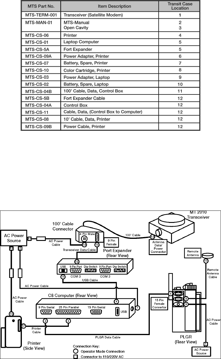
STP 55-88M14-SM-TG
3-210
Figure 3-87. MTS Control Station Layout Listing
Performance Steps
2. Install control station component items.
a. Transceiver (MT2010) installation and MTS Control Station Connections (see Figure 3-88).
(1) Place the MT 2010 (TERM 001) in a location with a clear view of the sky, avoiding
blockage or shadowing from trees and buildings.
(2) Connect the 100-foot power/data cable (CS-04B) from the control box to the side of the
transceiver.
Figure 3-88. Control Station Connection Diagram
STP 55-88M14-SM-TG
3-211
Performance Steps
b. Laptop installation.
(1) Using the USB Cable [CS-05], connect the USB port on the laptop [CS-01] to the USB
port on the port expander [CS-05]. The Port Expander should already be fastened to the
laptop with Velcro. If it has become detached, please refasten the port expander to the
laptop.
CAUTION: Do not connect the USB cable into the lower laptop USB port. Doing so may result in
incorrectly configured port assignments upon start-up.
(2) Using the RS422 data cable [CS-11], connect the port expander to the Control Box.
Connect one end of the cable to COM3 on the port expander device [CS-05] and connect
the other end to the RS422 port on the Control Box [CS-04A].
(3) Connect the laptop power adapter [CS-03] to an AC power source. The power port on the
laptop can be found on the left side rear of the laptop. It does not necessarily need to be
the same AC power source as the Control Box.
Note: The laptop can work on internal batteries for up to four hours per battery.
c. Control station printer installation.
(1) Using the printer cable [CS-08], connect the printer to the laptop. One end of the cable will
have a connector with a set of 25 pins; connect this end to the DB25 port (the large 25 pin
port) on the rear of the laptop. Connect the other end of the cable to the printer.
(2) Using the printer power adapter [CS-09A & CS-09B] and printer cable, connect the printer
to the AC power supply.
d. Control Box installation. Plug the Control Box [CS-04A] power cable to an AC power source.
The Control Box can take AC power input with the following characteristics, 85 - 256 VAC and
47 - 440Hz.
e. Control station PLGR installation.
(1) Connect the 9-pin female RS232 port connector of the PLGR cable to COM1 port on the
laptop computer. COM1 is the only RS232 on the laptop. Figure 3-88 shows the two
connectors on a standard PLGR cable.
(2) Connect the 15-pin female connector of the PLGR cable to the top port of the PLGR. All
ports on the PLGR can be found on the back of the device.
(3) Connect the remote PLGR antenna cable to the second port of the PLGR. Connect the
remote PLGR "hockey puck" antenna to the antenna cable.
(4) Connect PLGR AC power adapter cable to the third PLGR port. Plug the PLGR power
supply into the wall outlet making sure the voltage selector is in the proper position
(110/220) (see Figure 3-88, MTS CS PLGR Cable Setup).
Note: The PLGR cable and PLGR is not included in the standard Control Station delivery, however the
cable should be included with a PLGR.
3. Perform control station power-on procedures (see Figure 3-89).
a. Control box. To turn on the Control Station Control Box, flip the MTS MASTER SWITCH to
ON. If connected correctly, the LED lights on the transceiver (MT 2010) will illuminate.
b. Laptop.
(1) Press the power switch on the laptop computer. Wait for the computer to load/initialize
software.
(2) Eventually you will see a security window (see Figure 3-90) and read over the text in the
window, and click OK if you agree to the terms.
(3) When prompted, press CTRL-ALT-DEL to login.
(4) Enter username and password, and then click OK. The Windows desktop should contain
the MTS Messenger and TracerLink icons. Start the MTS Messenger software to see if
the cables to the computer are correctly attached.
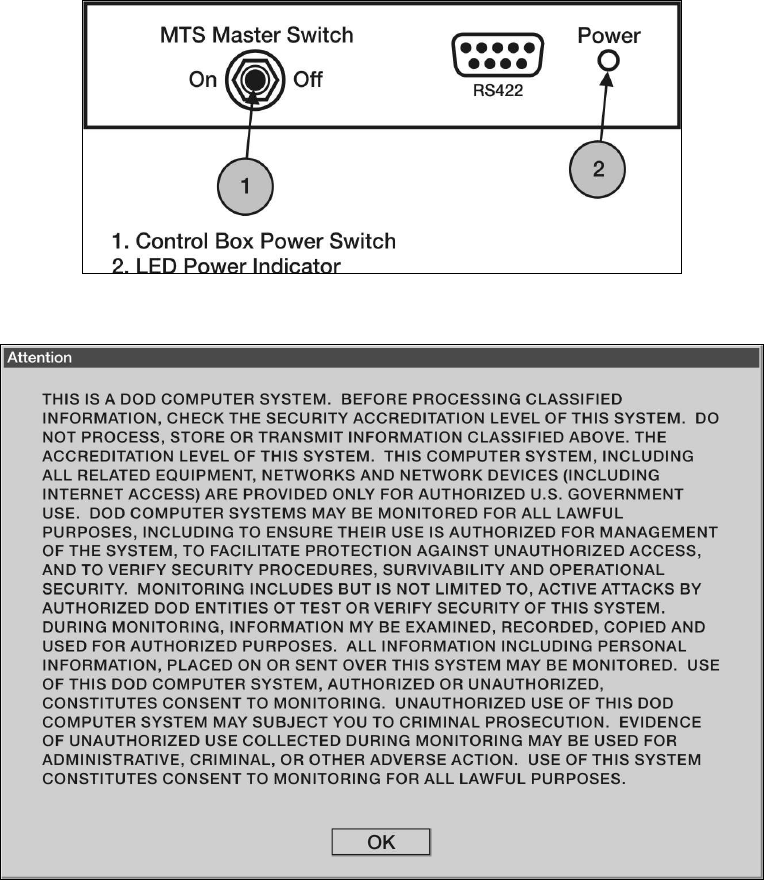
STP 55-88M14-SM-TG
3-212
Figure 3-89. Control Station Control Box
Figure 3-90. Security Warning
Performance Steps
c. Control station printer (see Figure 3-91). To turn the printer on, simply push the button once.
The small indicator light (above the power button) will illuminate if the printer is on. If the printer
is running on battery power, the power indicator light (the furthermost light on the left) will
illuminate.
Note: The Control Station Printer can draw power from two sources, an internal battery or an AC wall
outlet. The power button is located on the front of the printer. It is the button on the right, of the three
available buttons.
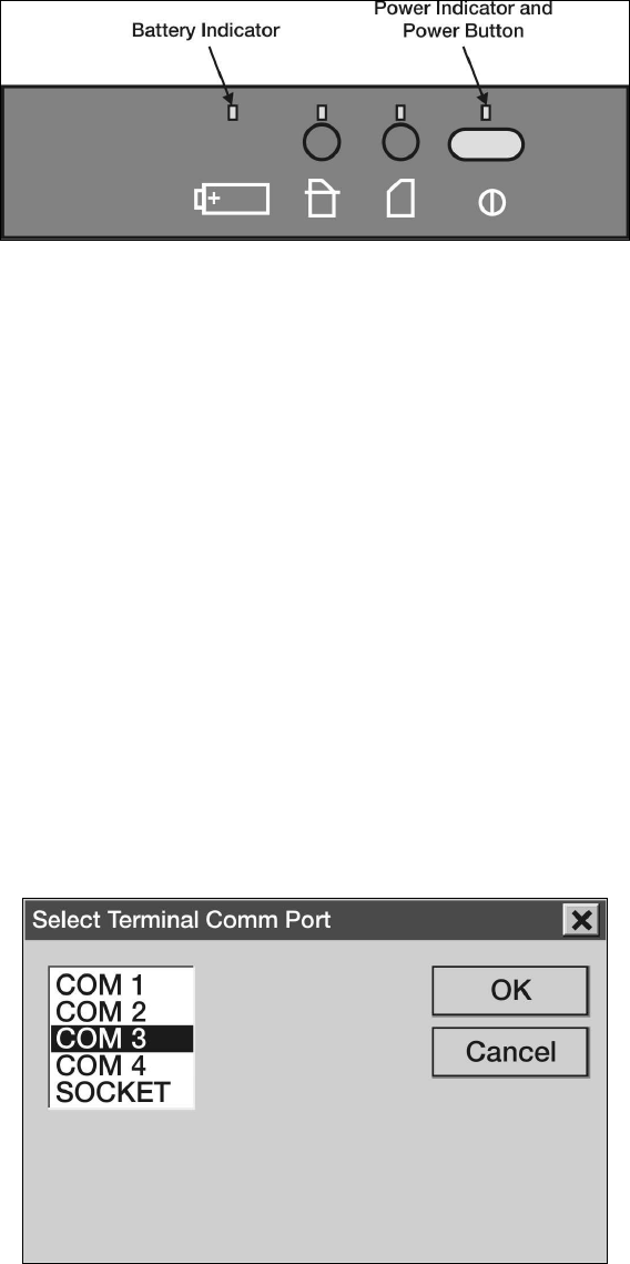
STP 55-88M14-SM-TG
3-213
Figure 3-91. Printer Controls
Performance Steps
4. Start MTS Messenger.
Note: Your computer should be configured to automatically open MTS Messenger. If this function is not
enabled, follow the steps listed below.
a. To start MTS Messenger, double-click the MTS Messenger icon located on the desktop. Users
will be prompted to select the COMM port (see Figure 3-92).
b. Control station users use COMM 3.
Note: If you receive the following error message stating: "No response from Terminal-Check Cables," go
to Troubleshooting.
c. Users will be prompted to select a COMM port for the PLGR. Select COMM 1 for control
station. After successfully starting MTS Messenger, the standard display screen also known as
the command reference will appear (see Figure 3-93).
d. Ensure that all status blocks appear at the bottom of the screen (see Figure 3-93).
e. Wait for Network registration. The bumper number and transceiver ID will appear in status
block 4 at the bottom when network registration completes.
Note: Until network registration is received, the operator cannot send or receive messages.
Note: Ensure that transceiver is unobstructed. The transceiver should not be under trees, inside a
building, or shadowed by large objects.
f. Refer to the MTS User's Manual Version 1.9.1, Section 8, Troubleshooting, when directed or as
needed.
Figure 3-92. Communication Port Window
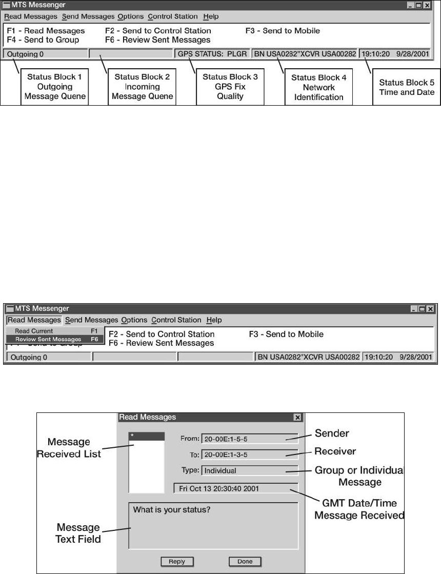
STP 55-88M14-SM-TG
3-214
Figure 3-93. MTS Messenger Window
Performance Steps
5. Read messages.
a. Access the read messages pull down menu (see Figure 3-94) by either clicking with the mouse
or using the function keys (F1 and F6).
b. Select read messages - read current or press F1 to read messages (see Figure 3-95).
c. In the Message Received List, click the message number you wish to read. It will default to the
most recent message received. The text of the message will appear in the Message Text Field.
Click the Reply button to return a message to the sender or "Done" to go back to the main
window. Use the up and down arrow keys to move between messages.
Note: If you did not receive any messages (for example, right after you started MTS Messenger) or you
selected read messages - read current via the pull down menu and you had no messages, you will
receive an error message (see Figure 3-96).
Figure 3-94. Read Messages Pull Down Menu
Figure 3-95. Read Current Message Window
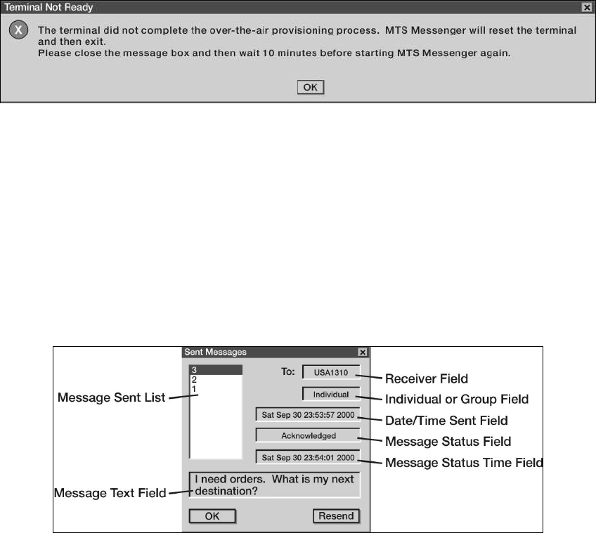
STP 55-88M14-SM-TG
3-215
Figure 3-96. Error Message
Performance Steps
d. Review a sent message. Select read messages - review sent messages or press F6. The
message window should show all message sent (see Figure 3-97).
Note: Select a message number by using the up and down arrows to move between messages in the
Message Sent List. The text and status of the sent message will populate the other fields in the window.
The Message Status Field indicates whether the message was received at its destination. A status of
Sent means it was recently sent and there has been no response yet. A status of "Acknowledged" means
the message was received. A status of "Negative Acknowledged" means it was not received because the
destination was offline or not in view of the satellite. A status of "Timed Out" means the sending unit (you)
was blocked and cannot communicate with the satellite. In the case of a message to the entire Control
Group the "Acknowledged" status will contain a list of the units that actually received the message.
Figure 3-97. Review Sent Messages
6. Send messages.
a. Send message to Control Station.
(1) Select the Send Messages pull-down menu (see Figure 3-98) or use one of the function
keys on the keyboard (F2, F3, and F4).
(2) Select the Send Messages pull-down menu or use one of the function keys on the
keyboard (F2, F3, and F4).
(3) To choose a recipient for your message, choose a unit from Select Unit List. Before you
type a message, check the Unit Status Field. This field will let you know if the intended
recipient is on line or off line. The Unit Location Field will indicate the position of unit.
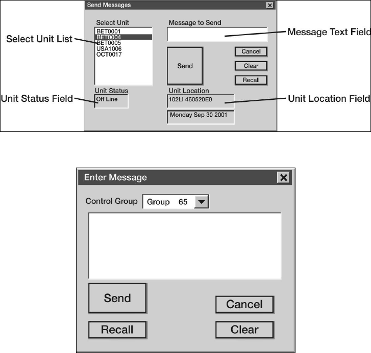
STP 55-88M14-SM-TG
3-216
Performance Steps
(4) Type message into Message Text Field.
(5) Once satisfied that your message is complete, press the Send button. Press the Cancel
button to return to the main window without sending. Push the Recall button to load the
last sent message into the Message Box. Press Clear to clear. Go to Read Messages -
Review Sent Messages to see if the recipient received the message.
Note: Immediately after completing network registration (startup of MTS Messenger), the Select Unit list
will not contain many MTS units. The list will grow as MTS Messenger receives position reports from all
the active units in the group. Position reports are only sent once every five minutes for each unit.
Therefore, it can take up to five minutes for the menu to completely populate.
b. Send message to all members of the control group.
(1) Select Enter Message - To Group, or press F4, to send a message to all members of the
Control Group except the sender. Control Stations will have to use the pull down menu to
select the appropriate group (see Figure 3-99).
(2) Enter the text in the Message Text Field and press the Send button. Pressing the Recall
button will load the message box with the text from the last message sent. To close the
window without sending a message, press the Cancel button. To erase any text in the
Message Text Field press the Clear button.
(3) After sending a message, go to Read Messages - Review Sent Messages to see if any
group members received the message.
Figure 3-98. Send Message to Control Station
Figure 3-99. Enter Message Window
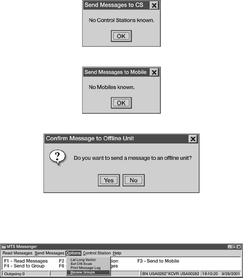
STP 55-88M14-SM-TG
3-217
Performance Steps
c. Send message to outside group. A unit can exist outside any Control Group. If a unit has not
been assigned a Control Group the user will not be able to send a message to any other unit. If
the user does attempt to send a message, the user will see one of the following messages
shown in Figure 3-100 or Figure 3-101.
d. Send message to offline unit. When sending a MTS message to a unit that is Offline, a dialog
box will appear asking for confirmation before sending the message (see Figure 3-102).
Figure 3-100. Message to Control Station Unknown
Figure 3-101. Message to Mobile Unit-Mobile Unknown
Figure 3-102. Message to Offline Unit
7. Review vehicle groups.
a. To review the vehicles assigned to various groups, select Review Groups from the Options
Menu of MTS Messenger (see Figure 3-103).
Figure 3-103. Review Vehicle Groups
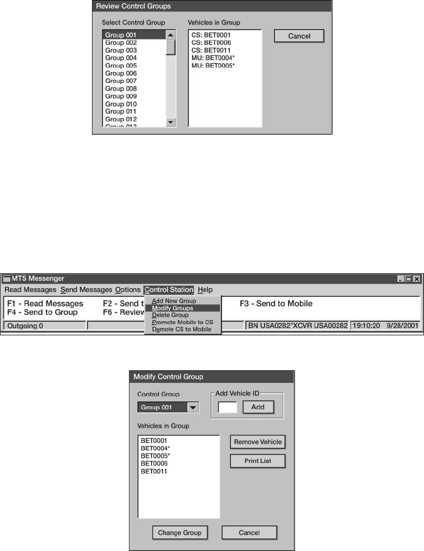
STP 55-88M14-SM-TG
3-218
Performance Steps
b. The Review Control Groups window will appear. Select a group from the Select Control Group.
The vehicles assigned within the selected group will be displayed in the Vehicles in Group box
(see Figure 3-104).
Figure 3-104. Review Control Groups
c. Modify Groups.
(1) To Modify Existing Groups, Select Control Station from the MTS Messenger menu (see
Figure 3-105).
(2) Select the control group to be modified (see Figure 3-106). From here, select their
modification needed (for example, add vehicle or remove vehicle).
Note: MTS units can be moved from one group to another. This allows the Control Station operator,
System Administrator, or CSSAMO the ability to customize control group to suit the mission. After
selecting Modify Group, the Modify Control Group dialog box will appear.
Figure 3-105. Modify Groups Menu
Figure 3-106. Modify Control Groups Dialog Box
STP 55-88M14-SM-TG
3-219
Performance Steps
8. Start TracerLink.
Note: In order for TracerLink to function, MTS Messenger must be running.
a. Double-click on the TracerLink icon located on the desktop to start the TracerLink application
(see Figure 3-107). TracerLink connects to the MTS Messenger program over a TCP/IP socket
to receive position data.
Figure 3-107. TracerLink Icons on Desktop
b. Identify the following program controls and indicators.
(1) Symbols (see Figure 3-108).
(a) Mobile Unit. Round symbols represent mobile units. A square lug on top of the
symbol indicated the unit is turned on and transmitting. No lug on top indicated the
unit is turned off.
(b) Control station. Square symbols represent control stations. A square lug on top of
the symbol indicates the unit is turned on and transmitting. No lug on top indicates
the unit is turned off.
(2) Right click the Pop Up Menu (see Figure 3-109).
(3) Zoom the Map. To zoom, right click on the map to show the pop up menu. Select Zoom
In or Zoom Out. Click on the map at the point you wish to become the center of the map.
The map will zoom with the point clicked becoming the new center of the map.
(4) Change Center. Right click the mouse over the map to pop up the menu, select Change
Center. Click on the map and the map will move with the point clicked becoming the new
center of the map.
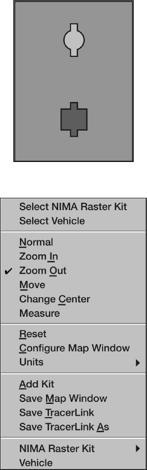
STP 55-88M14-SM-TG
3-220
Performance Steps
(5) Pan a Map (Move). Right click the mouse over the map to pop up the menu, select Move.
The cursor becomes a hand. Click on the map and hold down the left mouse button, then
drag the map to the desired position. When you release the mouse, the map will redraw
in the new position.
(6) Measure Distance on a Map. Right click on the map and then select Measure. Click and
drag the cursor from point A to point B on the map. Before releasing the button, look at
the scale display at the bottom of the map window. It displays the distance in kilometers,
nautical miles, or statute miles (see Figure 3-110). Once you release the mouse, the
distance measurement will disappear.
(7) Reset Map to Initial View. Right click on the map and select Reset.
Figure 3-108. Mobile Unit and Control Station Symbols
Figure 3-109. Right Click Popup Menu
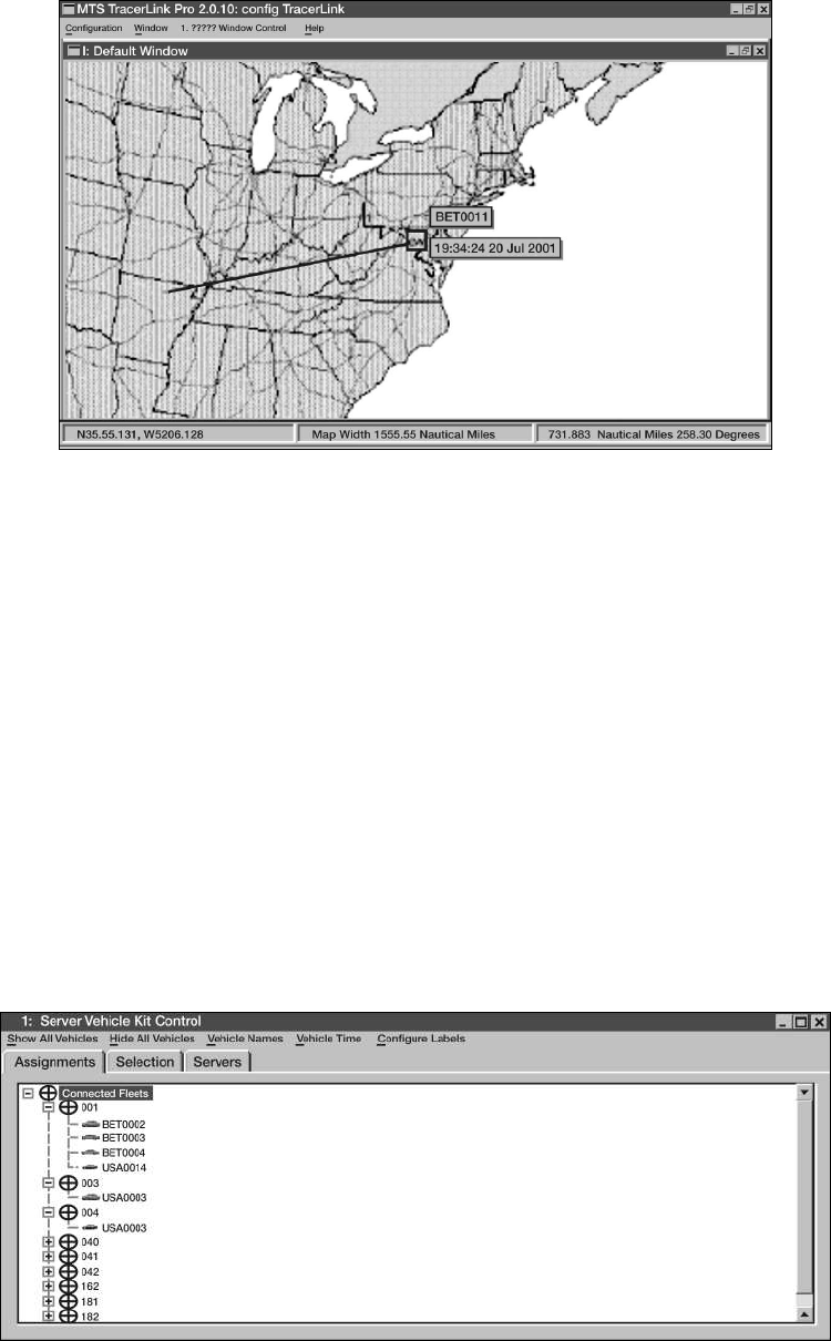
STP 55-88M14-SM-TG
3-221
Figure 3-110. Map Showing Distances Function
Performance Steps
c. Navigate through the Server Kit Control Window (see Figure 3-111). Use the Server Kit
Control Window to trace a vehicle's route, hide a vehicle or display a vehicle that was
previously hidden, or hide/display a vehicle's name and last position report time.
(1) Display the Server Kit Control Window.
(a) Method 1. Right click on the mouse and choose Select Vehicle on the pop up menu.
This will change your cursor into a hand with a pointed finger. Left click on the map
(with the hand) while over a vehicle's icon or over a bare spot. If you clicked over a
vehicle's icon, the vehicle kit window will display the clicked vehicle(s) in the pane. If
you clicked over a bare spot the window will be empty.
(b) Method 2. Slowly slide the cursor off the screen to the right side of the map. When
you approach the edge of the map the Kit Bar will appear. Select the vehicle image
at the top (see Figure 3-112).
(2) Display the information in the Server Kit Control Window.
(a) The Assignments Tab. Click on the Assignment Tab (see Figure 3-113) to display
vehicle information in a hierarchical fleet view.
(b) The Selection Tab. Click on the Selection Tab (see Figure 3-114) to display vehicle
information listed by vehicle.
Figure 3-111. Server Kit Control Window
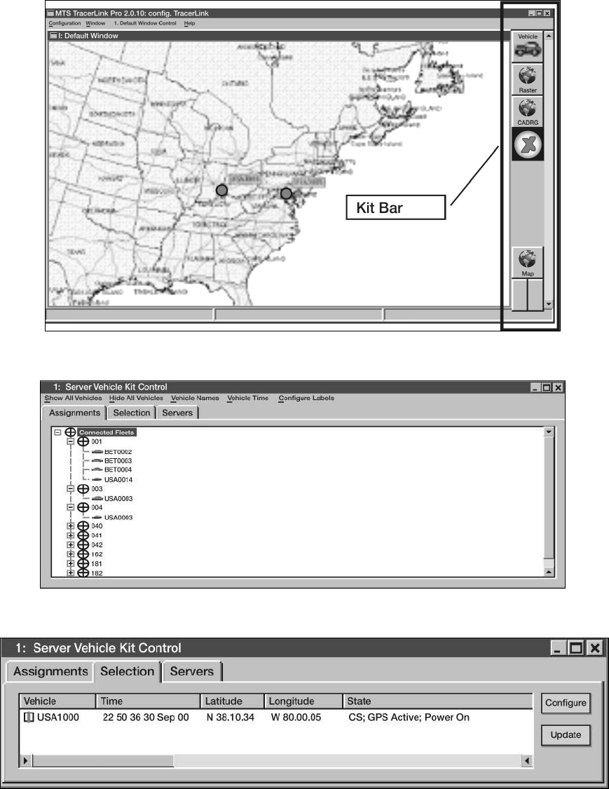
STP 55-88M14-SM-TG
3-222
Figure 3-112. Kit Bar
Figure 3-113. The Assignments Tab
Figure 3-114. The Selection Tab
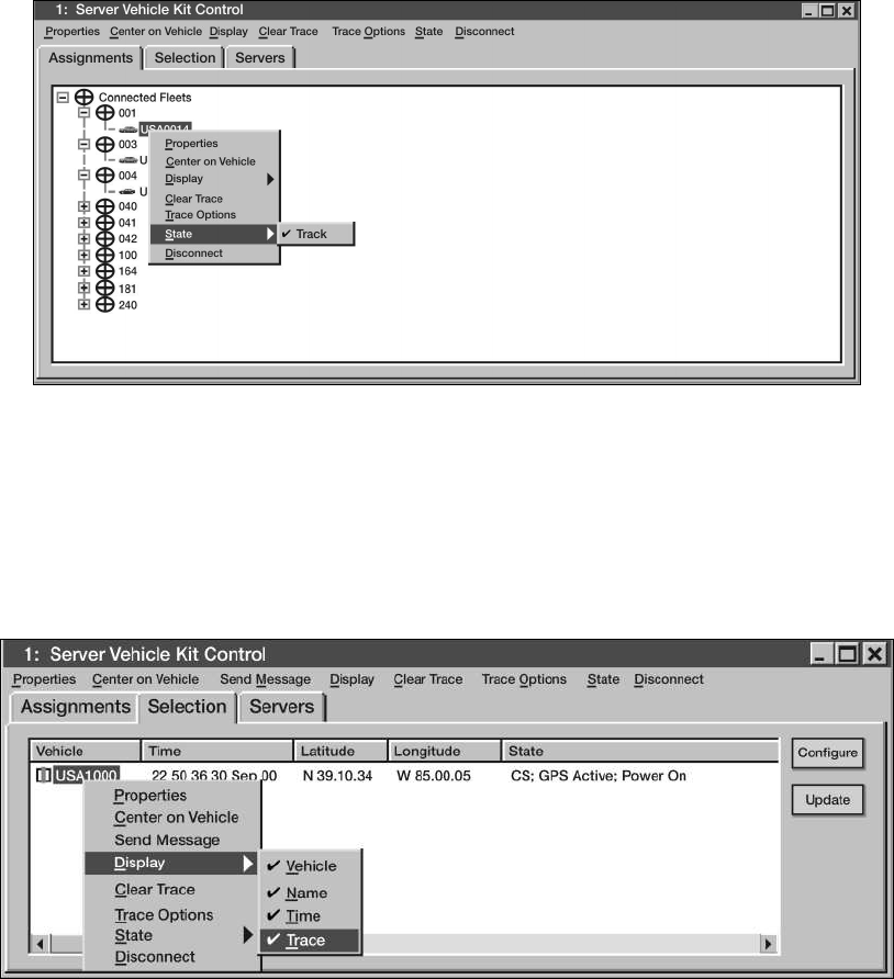
STP 55-88M14-SM-TG
3-223
Performance Steps
d. Enable Autotrack function (see Figure 3-115).
(1) Right click on the map to get the pop up menu.
(2) Choose the Select Vehicle option from the pop up window.
(3) Click on the vehicle you wish to track. The Server Vehicle Kit Control Window will open
with the Selection tab containing a list of vehicles.
(4) Right click on the vehicle you wish to track, select State then Track.
Note: If the vehicle you are tracking is off the map, use the Assignments tab instead of the Selection tab
to make the change.
Figure 3-115. Autotrack Function
e. Enable Trace Function (see Figure 3-116).
(1) Right click on the map to get the pop up menu.
(2) Choose the Select Vehicle option from the pop up menu.
(3) Click on the vehicle you wish to trace. The Server Kit Vehicle Kit Control window will open
with the Selection tab containing a list of vehicles.
(4) Right click on the vehicle you wish to trace and then select Display Trace.
Figure 3-116. Trace Function
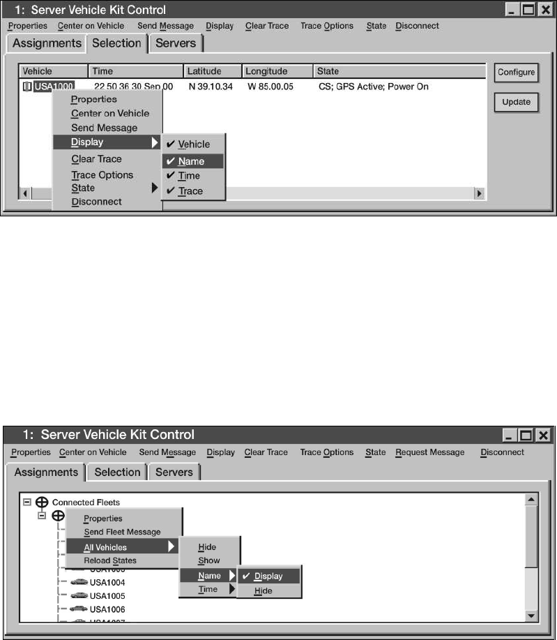
STP 55-88M14-SM-TG
3-224
Performance Steps
f. Hide/Show an Individual vehicle's name (see Figure 3-117).
(1) Right click on the map and get the pop up menu.
(2) Choose Select Vehicle.
(3) Click on the vehicle you wish to name/unname. The Server Vehicle Kit Control Window
will pop up listing the vehicles.
(4) To turn the name on, right click on the names in the Server Vehicle Kit Control window
and select Display Name.
Figure 3-117. Display Vehicle Name
g. Hide/Show entire control groups (see Figure 3-118).
(1) Right click on the map to get the pop up menu.
(2) Choose Select Vehicle.
(3) Click on the map so that the Server Vehicle Kit Control Window pops up.
(4) Select Assignments tab. The various control groups will be listed with expandable plus
boxes next to each one.
(5) Right click on a Control Group (for example: 001, 002, 003, and so forth) and select All
Vehicles Hide. If a control group is already hidden, to show it, simply select All Vehicles
Show.
Figure 3-118. Display/Hide Entire Group of Vehicles
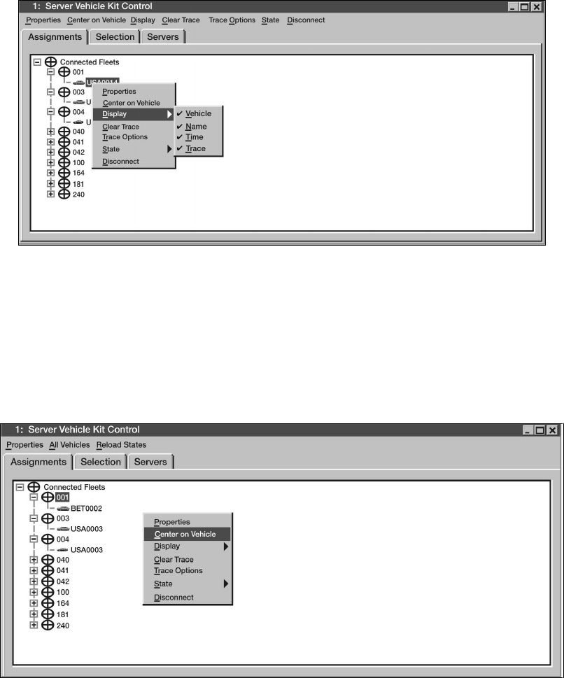
STP 55-88M14-SM-TG
3-225
Performance Steps
h. Display/Hide report time labels for an individual vehicle (see Figure 3-119).
(1) Right click on the map to get the pop up menu.
(2) Choose Select Vehicle.
(3) Click on the map with the mouse so that the Server Vehicle Kit Control window pops up.
(4) Select the Assignments tab.
(5) Right click on a vehicle, select Display Time. If the time was not previously displayed, it
will be. If the time was previously displayed, it will be turned off.
Figure 3-119. Display/Hide Individual Vehicles
i. Center the map on a vehicle (see Figure 3-120).
(1) Right click on the map to get the pop up menu.
(2) Choose Select Vehicle.
(3) Click on the map with the mouse so that the Server Vehicle Kit Control Window pops up.
(4) Select Assignments tab.
(5) Open the control group, right click on the vehicle you wish to find, and select Center on
Vehicle.
Figure 3-120. Center Map on Vehicle

STP 55-88M14-SM-TG
3-226
Performance Steps
9. Perform power-off procedures.
CAUTION: Improper shut down of system may result in data loss.
a. Close all applications (MTS Messenger, Tracerlink Vehicle Server, and Tracerlink Map Viewer).
b. Click the Start button in bottom left corner of the screen.
c. Select Shut down option.
d. Select Shut down and then click OK.
e. When "It is now safe to turn off your computer" appears on the screen, press the Power
ON/OFF button on the Control Box.
f. On the PLGR, press OFF and wait for the timer or press the OFF button two times to power
down immediately.
CAUTION: Failure to turn off the Power ON/OFF button on the Control Box will allow the terminal to
continue operation and drain the emergency battery.
Evaluation Preparation: Setup: In a tactical setting, provide a complete, installed, and operational MTS
Control Station and established MTS Mobile Units with operators. All elements should be entered into the
communications network and linked to the satellite, mission information, to relay to mobile unit(s).
Brief Soldier: Using the MTS Control Station, conduct communications with MTS Mobile Units in your
network. You are to receive traffic and send traffic, tasking the mobile units to move to locations in
support of the unit's mission.
Performance Measures GO NO GO
1. Identified each component item of the MTS Control Station. —— ——
a. Ensured that all items were present prior to attempting any installation as
listed below.
(1) Transceiver Satellite Modem.
(2) MTS Manual.
(3) Open cavity.
(4) Printer.
(5) Laptop computer.
(6) Port expander.
(7) Power adapter, printer.
(8) Battery, spare, printer.
(9) Color cartridge, printer.
(10) Power adapter, laptop.
(11) 100' cable, date, control box.
(12) Port expander cable.
(13) Control box.
(14) Cable date (control box to printer).
(15) 10' cable, data, printer.
(16) Power cable, printer.
2. Installed control station component items. —— ——
a. Installed transceiver (MT2010).
(1) Placed the MT 2010 (TERM 001) in a location with a clear view of the
sky, avoiding blockage or shadowing from trees and buildings.
(2) Connected the 100-foot power/data cable (CS-04B) from the control
box to the side of the transceiver.

STP 55-88M14-SM-TG
3-227
Performance Measures GO NO GO
b. Installed laptop.
(1) Using the USB Cable [CS-05], connected the USB port on the laptop
[CS-01] to the USB port on the port expander [CS-05].
(2) Using the RS422 data cable [CS-11], connected the port expander to
the Control Box. Connected one end of the cable to COM3 on the port
expander device [CS-05] and connected the other end to the RS422
port on the Control Box [CS-04A].
(3) Connected the laptop power adapter [CS-03] to an AC power source.
c. Installed control station printer.
(1) Using the printer cable [CS-08], connected the printer to the laptop.
Connected the other end of the cable to the printer.
(2) Using the printer power adapter [CS-09A & CS-09B] and printer cable,
connected the printer to the AC power supply.
d. Installed control box. Plugged the Control Box [CS-04A] power cable to an
AC power source.
e. Installed control station PLGR.
(1) Connected the 9-pin female RS232 port connector of the PLGR cable
to COM1 port on the laptop computer.
(2) Connected the 15-pin female connector of the PLGR cable to the top
port of the PLGR.
(3) Connected the remote PLGR antenna cable to the second port of the
PLGR. Connected the remote PLGR "hockey puck" antenna to the
antenna cable.
(4) Connected PLGR AC power adapter cable to the third PLGR port.
Plugged the PLGR power supply into the wall outlet making sure the
voltage selector was in the proper position (110/220).
3. Performed control station power-on procedures. —— ——
a. Control box. Flipped the MTS MASTER SWITCH to ON. If connected
correctly, the LED lights on the transceiver (MT 2010) will illuminate.
b. Laptop.
(1) Pressed the power switch on the laptop computer. Wait for the
computer to load/initialize software.
(2) Read over the text in the window and clicked.
(3) When prompted, pressed CTRL-ALT-DEL to login.
(4) Entered username and password and then clicked OK. Started the
MTS Messenger software to see if the cables to the computer were
correctly attached.
c. Control station printer. Pushed the button once to turn on the printer. The
small indicator light (above the power button) will illuminate if the printer is
on. If the printer is running on battery power, the power indicator light (the
furthermost light on the left) will illuminate.
4. Started MTS Messenger. —— ——
a. To START MTS Messenger, double-clicked the MTS Messenger icon
located on the desktop. Users will be prompted to select the COM port.
b. Control station users use COMM 3.
c. Users will be prompted to select a COMM port for the PLGR. Selected
COMM 1 for control station. After successfully starting MTS Messenger, the
standard display screen also known as the command reference will appear.
d. Ensured that all status blocks appear at the bottom of the screen.
e. Waited for Network registration. The bumper number and transceiver ID will
appear in status block 4 at the bottom when network registration completes.

STP 55-88M14-SM-TG
3-228
Performance Measures GO NO GO
5. Read messages. —— ——
a. Accessed the read messages pull down menu by either clicking with the
mouse or using the function keys (F1 and F6).
b. Selected read messages - read current, or pressed F1 to read messages.
c. In the Message Received List, clicked the message number you wish to
read. It will default to the most recent message received. The text of the
message will appear in the Message Text Field. Click the Reply button to
return a message to the sender or "Done" to go back to the main window.
Use the up and down arrow keys to move between messages.
d. Reviewed a sent message. Select read messages - review sent messages
or press F6. The message window should show all messages sent.
6. Sent messages. —— ——
a. Sent message to Control Station.
(1) Selected the Send Messages pull-down menu (Figure 3-95) or use one
of the function keys on the keyboard (F2, F3, and F4).
(2) Selected the Send Messages pull-down menu or used one of the
function keys on the keyboard (F2, F3, and F4).
(3) To choose a recipient for your message, chose a unit from Select Unit
List. Before you typed a message, checked the Unit Status Field. This
field will let you know if the intended recipient is on line or off line. The
Unit Location Field will indicate the position of unit.
(4) Typed message into Message Text Field.
(5) Once satisfied that your message was completed, pressed the Send
button. Pressed the Cancel button to return to the main window without
sending. Pushed the Recall button to load the last sent message into
the Message Box. Pressed Clear to clear. Go to Read Messages -
Review Sent Messages to see if the recipient received the message.
b. Sent message to all members of the control group.
(1) Selected Send Messages - To Group, or press F4, to send a message
to all members of the Control Group except the sender. Control
Stations will have to use the pull down menu to select the appropriate
group.
(2) Entered the text in the Message Text Field and pressed the Send
button. Pressing the Recall button loaded the message box with the
text from the last message sent.
(3) After sending a message, went to Read Messages - Review Sent
Messages to see if any group members received the message.
c. Sent message to outside group.
d. Sent message to offline unit.
7. Reviewed vehicle groups. —— ——
a. Selected Review Groups from the Options Menu of MTS Messenger.
b. Selected a group from the Select Control Group. The vehicles assigned
within the selected group will be displayed in the Vehicles in Group box.
c. Modified Groups.
(1) Selected Control Station from the MTS Messenger menu.
(2) Selected the control group to be modified. From here, selected their
modification needed (for example, add vehicle or remove vehicle).

STP 55-88M14-SM-TG
3-229
Performance Measures GO NO GO
8. Started TracerLink. —— ——
a. Double-clicked on the TracerLink icon located on the desktop to start the
TracerLink application. TracerLink connected to the MTS Messenger
program over a TCP/IP socket to receive position data.
b. Identified the following program controls and indicators.
(1) Symbols.
(a) Mobile Unit. Round symbols represent mobile units. A square lug
on top of the symbol indicated the unit is turned on and
transmitting. No lug on top indicated the unit is turned off.
(b) Control station. Square symbols represent control stations. A
square lug on top of the symbol indicates the unit is turned on and
transmitting. No lug on top indicates the unit is turned off.
(2) Right clicked the Pop Up Menu.
(3) Zoomed the Map. To zoom, right clicked on the map to show the pop
up menu. Selected Zoom In or Zoom Out. Clicked on the map at the
point you wish to become the center of the map. The map zoomed with
the point clicked becoming the new center of the map.
(4) Changed Center. Right clicked the mouse over the map to pop up the
menu, select Change Center. Clicked on the map and the map will
move with the point clicked becoming the new center of the map.
(5) Panned a Map (Move). Right clicked the mouse over the map to pop
up the menu, select Move. The cursor becomes a hand. Clicked on
the map and held down the left mouse button, then drag the map to the
desired position. When you released the mouse, the map will redraw in
the new position.
(6) Measured Distance on a Map. Right clicked on the map and then
selected Measure. Clicked and drug the cursor from point A to point B
on the map. Before releasing the button, looked at the scale display at
the bottom of the map window. It displayed the distance in kilometers,
nautical miles, or statute miles. Once you released the mouse, the
distance measurement disappeared.
(7) Reset Map to Initial View. Right clicked on the map and selected
Reset.
c. Navigated through the Server Kit Control Window.
(1) Displayed the Server Kit Control Window.
(a) Method 1. Right clicked on the mouse and choose Select Vehicle
on the pop up menu. This will change your cursor into a hand with
a pointed finger. Left clicked on the map (with the hand) while
over a vehicle's icon or over a bare spot.
(b) Method 2. Slowly slid the cursor off the screen to the right side of
the map. When you approached the edge of the map, the Kit Bar
appeared. Selected the vehicle image at the top.
(2) Displayed the information in the Server Kit Control Window.
(a) The Assignments Tab. Clicked on the Assignment Tab to display
vehicle information in a hierarchical fleet view.
(b) The Selection Tab. Clicked on the Selection Tab to display
vehicle information listed by vehicle.

STP 55-88M14-SM-TG
3-230
Performance Measures GO NO GO
d. Displayed the information in the Server Kit Control Window.
(1) The Assignments Tab. Clicked on the Assignment Tab to display
vehicle information in a hierarchical fleet view.
(2) The Selection Tab. Clicked on the Selection Tab to display vehicle
information listed by vehicle.
(a) Right clicked on the map to get the pop up menu.
(b) Chose the Select Vehicle option from the pop up window.
(c) Clicked on the vehicle you wished to track. The Server Vehicle Kit
Control Window opened with the Selection tab containing a list of
vehicles.
(d) Right clicked on the vehicle you wish to track, select State Track.
(e) If the vehicle you are tracking was off the map, used the
Assignments tab instead of the Selection tab to make the change.
e. Enabled Trace Function.
(1) Right clicked on the map to get the pop up menu.
(2) Chose the Select Vehicle option from the pop up menu.
(3) Clicked on the vehicle you wish to trace. The Server Kit Vehicle Kit
Control window opened with the Selection tab containing a list of
vehicles.
(4) Right clicked on the vehicle you wish to trace and then selected Display
Trace.
f. Hid/Showed an individual vehicle's name.
(1) Right clicked on the map and get the pop up menu.
(2) Chose Select Vehicle.
(3) Clicked on the vehicle you wish to name/unname. The Server Vehicle
Kit Control Window will pop up listing the vehicles.
(4) To turn the name on, right clicked on the names in the Server Vehicle
Kit Control window and selected Display Name.
g. Hid/Showed entire control groups.
(1) Right clicked on the map to get the pop up menu.
(2) Chose Select Vehicle.
(3) Clicked on the map so that the Server Vehicle Kit Control Window pops
up.
(4) Selected Assignments tab. The various control groups will be listed
with expandable plus boxes next to each one.
(5) Right clicked on a Control Group (for example: 001, 002, 003, and so
forth) and select All Vehicles Hide. If a control group is already hidden,
to show it, simply selected All Vehicles Show.
h. Displayed/Hid report time labels for an individual vehicle.
(1) Right clicked on the map to get the pop up menu.
(2) Chose Select Vehicle.
(3) Clicked on the map with the mouse so that the Server Vehicle Kit
Control window pops up.
(4) Selected the Assignments tab.
(5) Right clicked on a vehicle, selected Display Time.
i. Displayed/Hid Report Time Labels for Entire Control Group.
(1) Right clicked on the map to get the pop up menu.
(2) Chose Select Vehicle.
(3) Clicked on the mouse so that the Server Vehicle Kit Control Window
pops up.
(4) Selected Assignments tab.
(5) Right clicked on fleet name, and select All Vehicle, Time Display, or All
Vehicles Time Hide.

STP 55-88M14-SM-TG
3-231
Performance Measures GO NO GO
j. Centered the map on a vehicle.
(1) Right clicked on the map to get the pop up menu.
(2) Chose Select Vehicle.
(3) Clicked on the map with the mouse so that the Server Vehicle Kit
Control Window pops up.
(4) Selected Assignments tab.
(5) Opened the control group, right clicked on the vehicle you wish to find,
and selected Center on Vehicle.
9. Performed power-off procedures. —— ——
a. Closed all applications (MTS Messenger, TracerLink Vehicle Server, and
TracerLink Map Viewer).
b. Clicked the Start button in bottom left corner of the screen.
c. Selected Shut down option.
d. Selected Shut down and then clicked OK.
e. When "It is now safe to turn off your computer" appeared on the screen,
pressed the Power ON/OFF button on the Control Box.
f. On the PLGR, pressed OFF and waited for the timer or pressed the OFF
button two times to power down immediately.
Evaluation Guidance: Score the soldier GO if all performance measures are passed. Score the soldier
NO-GO if any performance measure is failed. If any performance measure is failed, tell the soldier what
was done wrong and how to do it correctly.
References
Required Related
MTS USERS MANUAL
STP 55-88M14-SM-TG
3-232
Subject Area 11: Heavy Equipment Transporter (HET) Operation
Drive A Heavy Equipment Transporter (HET) on Improved Roads
551-721-3337
Conditions: On an improved roadway, given an M1070 coupled to an M1000 Semitrailer (loaded or
unloaded) with before-operation preventive maintenance performed, hearing protection, route to
maneuver, and ground guides as necessary.
Standards: You have safely operated the Heavy Equipment Transporter coupled with the Heavy
Equipment Transport Semitrailer on improved roadway without injury to personnel or damage to
equipment or surroundings.
Performance Steps
1. Prepare HET with HETS for operation.
Note: As the referenced TM is updated, the specific location within the manual for referenced procedures
may change.
a. Adjust the driver's seat as needed.
b. Adjust all mirrors as needed.
c. Ensure that load is secured properly to the semitrailer (if loaded).
d. Start vehicle engine (refer to TM 9-2320-360-10, paragraph 2-12a and b for starting
procedures).
e. Monitor all gauges for proper readings and allow engine to warm up.
f. Ensure all low air pressure warning lights and buzzers go out as intended by TM.
g. Adhere to all WARNINGS and CAUTIONS in the TM applicable to this procedure.
2. Place HETS into motion.
a. Refer to TM 9-2320-360-10, paragraph 2-9a for proper operating procedures.
b. Adhere to all WARNINGS and CAUTIONS in the TM applicable to this procedure.
3. Navigate HET through normal traffic situations and road conditions.
a. Use brake retarder (unless road conditions prohibit use).
b. Use alternate transfer gear range (as needed).
c. Adhere to all restricted speed ranges for the appropriate driving conditions/load.
d. Monitor vehicle indicator lights and gauges, during movement, for proper indications (part of
during-operation maintenance).
e. Maintain awareness of vehicle operation to include-
(1) Unusual engine noises or vibration.
(2) Unusual handling characteristics or erratic behavior.
(3) Vehicle position on the roadway.
(4) Upcoming obstacles that may hinder vehicle progress.
f. Negotiate tractor semitrailer combination through the following obstacles-
(1) Right or left turns.
(2) Heavy traffic areas.
(3) Over bridges.
(4) Through underpasses.
(5) Steep upgrades or downgrades.
(6) Curves in the roadway.
(7) Intersections (for stopping and not stopping).
4. Shutdown vehicle. Refer to TM 9-2320-360-10, paragraph 2-12g, page 2-139 for proper shutdown
procedures.

STP 55-88M14-SM-TG
3-233
Evaluation Preparation: Setup: Provide for the soldier a coupled Heavy Equipment Transporter (HET)
that has before-operational maintenance checks performed and has been dispatched for operation and a
route of improved roads on which to travel.
Brief Soldier: Instruct the soldier to mount the vehicle, make the necessary driver adjustments, and follow
the designated route to destination. All vehicle operations must occur without injury to any personnel or
damage to vehicle or surroundings.
Performance Measures GO NO GO
1. Prepared HET with HETS for operation. —— ——
2. Placed HETS into motion. —— ——
3. Navigated HET through normal traffic situations and road conditions. —— ——
4. Shutdown vehicle. —— ——
Evaluation Guidance: Score the soldier GO if all performance measures are passed. Score the soldier
NO-GO if any performance measure is failed. If any performance measure is failed, tell the soldier what
was done wrong and how to do it correctly.
References
Required Related
TM 9-2330-381-14
DA FORM 2404
DA FORM 5987-E
DA FORM 5988-E
DD FORM 1970
FM 21-305
TM 9-2320-360-10
STP 55-88M14-SM-TG
3-234
Load Able/Disabled Tracked/Wheeled Vehicles Onto a Heavy Equipment Transporter (HET)
551-721-3345
Conditions: Given an able/disabled tracked/wheeled vehicle for loading onto HET, HET BII, a coupled
HETS with pre-operational maintenance checks performed, assistance from other crew members, and
level ground to conduct loading operations.
Special Conditions: Two-person operation. Assistance from another crew member is required.
Standards: You have completed the loading operation of an able/disabled tracked/wheeled vehicle,
positioned vehicle properly, and secured vehicle to prevent movement during transport. All procedures
were accomplished safely without injury to personnel, damage to HETS, or vehicle payload.
Performance Steps
1. Prepare M1070 HET.
Note: The operator will perform this step.
a. Ensures CTIS rotary switch is at the appropriate setting.
b. Aligns M1070 HET and M1000 semitrailer as close as possible to the disabled M-1 tank
(approximately 15 feet) on as level ground as possible.
c. Assistant operator visually checks the HET and semitrailer offset angle. Adjusts angle as
necessary.
d. Moves transmission range selector to "N" (neutral position).
e. Applies HET parking brakes.
f. Turns on PTO switch.
g. Turns on beacon light switch.
h. Chocks M1070 Front (1st) axle in front and behind each tire.
i. Lays out curbside angled rear payload tiedown chain(s).
j. Lays out streetside angled rear payload tiedown chain(s).
k. Lowers warning light on streetside of platform.
2. Prepare M1000 semitrailer.
Note: The operator and crew members will perform this step.
a. Removes manila rope from semitrailer stowage compartment.
b. Unwinds manila rope and positions on semitrailer.
c. Positions front streetside payload chock approximately 10 inches from forward edge of platform
steps.
d. Positions front curbside payload chock approximately 14 inches from forward edge of platform.
e. Aligns streetside and curbside front payload chock with fourth hole on outboard payload chock
mounting brackets on platform.
f. Secures both payload chocks with cap screws, washers, and nuts.
g. Aligns curbside rear payload chock on streetside front edge above bogie #1.
h. Positions streetside payload chock next to bogies #4 rear of semitrailer.
i. Removes front and rear curb guides stowage brackets from platform area.
j. Removes all 12 curb guides from platform recessed stowage area.
k. Aligns and installs 10 curb guides into second hole inboard from platform edge with pin facing
outward. Sets remaining two curb guides aside.
l. Inventories and removes all tiedown chains, load binders, and shackles from semitrailer
stowage compartment.
m. Positions two front tiedown chains through two front tiedown rings recessed in platform.
n. Extends four load binders to show 6 1/2 inches of thread on both ends. Positions two large
shackles and load binders near rear payload tiedown rings.
o. Using two shackles, secures each set of load binders with small pear end facing toward load
binder to each rear payload tiedown ring.
STP 55-88M14-SM-TG
3-235
Performance Steps
p. Adjusts each set of load binders by placing one load binder parallel with edge of platform and
one angled toward center of platform. Positions handles inboard.
q. Lays out streetside parallel tiedown chain(s).
r. Lays out curbside parallel tiedown chain(s).
s. Lays out streetside parallel tiedown chain(s).
t. Lays out curbside parallel tiedown chain(s).
u. Lays out curbside angled rear payload tiedown chain(s).
v. Lays out streetside angled rear payload tiedown chain(s).
w. Lowers warning light on streetside of platform.
3. Adjust loading ramps.
a. Opens load binder on streetside and removes ramp stow chain hook from slotted hole in
platform.
b. Connects ramp stow chain hook to forward (large) mounting hole on ISO container bracket and
closes load binder.
c. Removes hitch pin and crowbar from rear of platform below loading ramps. Reinstalls hitch pin
to secure isolation valve handle.
d. Operator inserts small end of crowbar through hole in streetside ramp lift lever and into bar
strip.
e. Assistant operator stands on beavertail section, pushes ramp rearward against ramp stow
chain until ramp is perpendicular to platform.
f. Operator pushes or pulls on crowbar in direction required to slide ramp outboard from center.
g. Continues to place crowbar into bar strip holes until ramp is at furthest outboard position.
h. Repeat above steps to adjust curbside loading ramp.
4. Lower ramps.
a. Opens load binder on streetside and removes ramp stow chain hook from platform and
attaches hook into ramp lever. Closes load binder.
b. Standing between both ramps, grasps lower handle on streetside loading ramp and pulls
downward. As ramp swings downward, transitions to upper handle and applies pressure until
ramp is below horizontal position and then pulls down until ramp is on the ground.
c. Repeat above steps to lower the curbside loading ramp.
5. Adjust platform height.
Note: The operator and crew members will perform this step.
a. Operator starts and runs APU.
b. Opens hydraulic control panel and pulls suspension shut-off valve handle outward to adjust
position.
c. Releases semitrailer park brakes.
d. Operator and crew members adjust platform height to preloading position, lowers rear support
legs and loading ramps.
e. Applies semitrailer parking brakes.
f. Aligns and installs two curb guides on rear of platform.
6. Start winching operations.
a. Raises and secures winch guard.
b. Releases auxiliary winch kickout lever counterclockwise.
c. Removes two large shackles from rear payload tiedown rings.
d. Crew members unhook auxiliary winch cable from stowage point, pulls cable rearward to front
of disabled M-1 tank.
e. Attaches and secures two large shackles to both upper recovery eyes on disabled M-1 tank.
f. Attaches and secures two large shackles to both upper recovery eyes on disabled M-1 tank.
STP 55-88M14-SM-TG
3-236
Performance Steps
g. Crew member opens auxiliary snatch block and passes auxiliary winch cable through snatch
block and closes auxiliary snatch block. Tightens retaining bolt to secure side housing in the
closed position.
h. Pulls auxiliary winch cable forward along curbside of gooseneck to passenger side winch cable.
i. Operator pays out passenger side winch cable, crew members pull cable out and attaches
passenger side winch cable clevis to auxiliary winch cable clevis.
j. Operator pays in auxiliary winch cable and pays out passenger side winch cable to pull
passenger side winch cable rearward to auxiliary snatch block.
k. Crew member continues to pull passenger side cable out until winch cable touches the ground.
l. Disconnects passenger side winch cable from auxiliary winch cable and lays cable on ground
in front of disabled M-1 tank.
m. Crew members pull auxiliary winch cable forward over platform until cable reaches front of
platform and toward driver's side winch cable and stops.
n. Operator pays out driver's side winch cable and disconnects from storage point.
o. Crew members attach auxiliary winch cable to driver's side winch cable.
p. Crew members attach auxiliary winch cable to driver's side winch cable.
q. Crew member routes driver's side winch cable through gooseneck cable guide.
r. Operator continues to pay in auxiliary winch cable to pull drivers side winch cable rearward to
auxiliary snatch block and stops approximately 12 inches from snatch block.
s. Crew member pulls additional cable out until driver's side winch cable touches the ground and
stops.
t. Crew members disconnect driver's side winch cable from auxiliary winch cable, lays cable on
the ground, and installs shouldered pins and cotter pins to both clevises.
7. Stow snatch block and auxiliary winch cable.
a. Unscrew retaining bolt and rotates side housing on auxiliary snatch block to open snatch block.
b. Removes auxiliary winch cable from the auxiliary snatch block and rotates side housing to
close. Tightens retaining bolt to secure side housing in closed position.
c. Removes auxiliary snatch block from shackle and places back into storage on HET.
d. Operator pushes downward on auxiliary winch cable while a crew member maintains tension
on the auxiliary winch cable and restows on stow hook.
8. Continue winching operations.
a. Crew members attach and secure both driver's side and passenger side winch cables to
disabled M-1 tank upper recovery eyes.
b. Operator directs crew members to stand on each side of the payload to provide directional
control (curbside and streetside).
c. Operator clears the area of all nonessential personnel.
d. Operator pays in driver's side and passenger side winch cables to remove all slack in cables.
e. Continues to winch disabled M-1 tank up the ramps and on the semitrailer until streetside track
makes contact with curbside front payload chock.
f. Operator stops winching operation.
g. Crew member chocks rear streetside of disabled M-1 tank with payload chock.
9. Adjust platform height.
a. Starts and runs APU at full throttle.
b. Releases semitrailer parking brakes.
c. Operator and crew members adjust platform to normal running height.
d. Applies semitrailer parking brakes.
10. Secure disabled tank to platform.
a. Attaches and secures two front tiedown chains to front of disabled M-1 tank.
b. Crew member removes two shackles from semitrailer stowage compartment and attaches
shackles to lower towing lugs on front of disabled M-1 tank.
STP 55-88M14-SM-TG
3-237
Performance Steps
c. Crew member removes curbside rear payload chock from front streetside of platform.
d. Operator continues to pay in driver's side and passenger side winch cables until crew members
signal that both front tiedown chains are tight and front road wheels are firmly on top of front
payload chocks.
e. Crew members chock rear of disabled M-1 tank with two rear payload chocks firmly under
tracks.
f. Operator pays out both driver's side and passenger side winch cables until cables touch top of
HET tires.
g. Crew members check both driver's side and passenger side winch cables for twist.
h. Crew members slowly and carefully remove cotter pins and shouldered pins from clevises from
driver's side and passenger side winch cables.
i. Removes two large shackles from both upper recovery eyes on disabled M-1 tank.
j. Installs two large shackles and four load binders on rear payload tiedown rings.
k. Removes two shackles from semitrailer stowage compartment.
l. Attaches streetside parallel chain and curbside rear angled tiedown chain to streetside towing
lug using shackle.
m. Attaches curbside parallel tiedown chain and streetside rear angled tiedown chain to curbside
rear towing lug, using shackle.
n. Attaches both parallel chains to each parallel load binders.
o. Attaches both curbside and streetside rear angled tiedown chains to angled load binders as
follows:
(1) Tightens each load binder as tight as possible.
(2) Passes free end of streetside rear angled tiedown chain over top of curbside rear angled
tiedown chain and attaches to streetside rear angled load binder.
(3) Tightens each load binder as tight as possible and ensures disabled M-1 tank is securely
against rear payload chocks.
(4) Passes two utility chains through two tiedown rings in front of each payload chock and
connects chains to them.
(5) Passes free end of both chains through handles of two rear payload chocks lay ends in
center of platform.
(6) Checks that small load binder is attached to two utility chains and closes load binder.
11. Prepare HETS for transport.
Note: The operator and crew members will perform this step.
a. Checks that shouldered pins and cotter pins are installed to each clevis on both winch cables.
b. Removes both winch cables from gooseneck cable guides.
c. Operator pays in driver's side winch cable while crew members keep tension on winch cable.
d. Operator pays in passenger side winch cable while crew members keep tension on winch
cable.
e. Crew members ensure cables are wrapped evenly on drums without tangles, kinks, or twist.
Cable coils should be tight and close together.
f. Crew members attach cable clevis to HET stowage point and signals operator to take up slack
and watch to prevent cables from winding over the drum flanges.
g. Operator disengages engine speed control switch to low idle.
h. Operator lowers winch guard and locks in place.
i. Removes and secures six curb guides in platform recess area.
(1) Grasps upper handle on ramp and pull upward. Releases upper handle as ramp passes
horizontal position. Grasps lower handle and applies pressure until ramp is firmly against
beavertail.
(2) Opens load binder and unhooks ramp chain hook at ramp lifting lever.
STP 55-88M14-SM-TG
3-238
Performance Steps
(3) Connects ramp chain hook to front-most (large) mounting hole on ISO container mounting
bracket. Closes load binder.
(4) Operator inserts small end of crowbar through hole in streetside ramp lift lever and into
bar strip.
(5) Positions assistant operator on beavertail section of platform to push streetside loading
ramp rearward until ramp is perpendicular to platform. Operator must push or pull on
crowbar in direction required to slide ramp inboard.
(6) Continues to place crowbar into holes along bar strip and moves ramp to furthest inboard
position.
(7) Repeat above steps to adjust curbside loading ramp.
(8) Opens load binders, removes ramp chain hooks from ISO container bracket holes, and
connects hooks in center of platform. Closes load binders.
(9) Removes hitch pin and reinstalls crowbar below loading ramps, then reinstalls hitch.
k. Raises beacon warning light.
l. Operator pushes suspension shut-off valve handle inward to the shut-off position.
m. Shuts down APU, then closes and secures control panel.
n. Raises and secures both rear support legs.
o. Checks that all BII is stowed in semitrailer stowage compartment.
p. Removes and stows all chock blocks.
q. Turns off PTO switch.
r. Moves transmission range selector to the appropriate range.
s. Releases HET parking brakes.
Note: To unload disabled M-1 tank, perform the following performance steps.
12. Prepare M1070 HET.
Note: The operator will perform this step.
a. Ensures CTIS rotary switch is at the appropriate setting.
b. Aligns M1070 HET and M1000 semitrailer as close as possible to the disabled M-1 tank
(approximately 15 feet) on as level ground as possible.
c. Assistant operator visually checks the HET and semitrailer offset angle. Adjusts angle as
necessary.
d. Moves transmission range selector to "N" neutral position.
e. Turns on PTO switch.
f. Turns on beacon light switch.
g. Chocks M1070 front (1st) axle in front and behind each tire.
13. Prepare M1000 semitrailer.
Note: The operator and crew members will perform this step.
a. Removes manila rope from semitrailer stowage compartment.
b. Unwinds manila rope and positions on semitrailer.
c. Positions front streetside payload chock approximately 10 inches from forward edge of
platform.
d. Positions front curbside payload chock approximately 14 inches from forward edge of platform.
e. Aligns streetside and curbside front payload chock with fourth hole on outboard payload chock
mounting brackets on platform.
f. Secures both payload chocks with cap screws, washers, and nuts.
g. Aligns curbside rear payload chock on streetside front edge above bogie #1.
h. Positions streetside payload chock next to bogie #4 rear of semitrailer.
i. Removes front and rear curb guides stowage brackets from platform area.
j. Removes all 12 curb guides from platform recessed stowage area.
k. Aligns and installs 10 curb guides into second hole inboard from platform edge with pin facing
outward. Sets remaining two curb guides aside.
STP 55-88M14-SM-TG
3-239
Performance Steps
l. Inventories and removes all tiedown chains, load binders, and shackles from semitrailer
stowage compartment.
m. Positions two front tiedown chains through two front tiedown rings recessed in platform.
n. Extends four load binders to show 6 1/2 inches of thread on both ends. Positions two large
shackles and load binders near rear payload tiedown rings.
o. Using two shackles, secures each set of load binders with small pear end facing toward load
binder to each rear payload tiedown ring.
p. Adjusts each set of load binders by placing one load binder parallel with edge of platform and
one angled toward center of platform. Positions handles inboard.
q. Lays out streetside parallel tiedown chain(s).
r. Lays out curbside parallel tiedown chain(s).
s. Lays out curbside angled rear payload tiedown chain(s).
t. Lays out streetside angled rear payload tiedown chain(s).
u. Lowers warning light on streetside of platform.
14. Adjust loading ramps.
a. Opens load binder on streetside and removes ramp stow chain hook from slotted hole in
platform.
b. Connects ramp stow chain hook to forward (large) mounting hole on ISO container bracket and
closes load binder.
c. Removes hitch pin and crowbar from rear of platform below loading ramps. Reinstalls hitch pin
to secure isolation valve handle.
d. Operator inserts small end of crowbar through hole in streetside ramp lift lever and into bar
strip.
e. Assistant operator stands on beavertail section, pushes ramp rearward against ramp stow
chain until ramp is perpendicular to platform.
f. Operator pushes or pulls on crowbar in direction required to slide ramp outboard from center.
g. Continues to place crowbar into bar strip holes until ramp is at furthest outboard position.
h. Repeat above steps to adjust curbside loading ramp.
15. Lower ramps.
a. Opens load binder on streetside and removes ramp stow chain hook from platform and
attaches hook into ramp lever. Closes load binder.
b. Standing between both ramps, grasps lower handle on streetside loading ramp and pulls
downward. As ramp swings downward, transitions to upper handle and applies pressure until
ramp is below horizontal position and then pulls down until ramp is on the ground.
c. Repeat above steps to lower the curbside loading ramp.
16. Adjust platform height.
Note: The operator and crew members will perform this step.
a. Operator starts and runs APU.
b. Opens hydraulic control panel and pulls suspension shut-off valve handle outward to adjust
position.
c. Releases semitrailer park brakes.
d. Operator and crew members adjust platform height to preloading position, lowers rear support
legs and loading ramps.
e. Applies semitrailer parking brakes.
f. Aligns and installs two curb guides on rear of platform.
17. Start winching operations.
a. Raises and secures winch guard.
b. Releases auxiliary winch kickout lever counterclockwise.
c. Removes two large shackles from rear payload tiedown rings.
STP 55-88M14-SM-TG
3-240
Performance Steps
d. Crew members unhook auxiliary winch cable from stowage point, pulls cable rearward to front
of disabled M-1 tank.
e. Attaches and secures two large shackles to both upper recovery eyes on disabled M-1 tank.
f. Attaches auxiliary snatch block to upper left recovery eye on disabled M-1 tank.
g. Crew member opens auxiliary snatch block and passes auxiliary winch cable through snatch
block and closes auxiliary snatch block. Tightens retaining bolt to secure side housing in the
closed position.
h. Pulls auxiliary winch cable forward along curbside of gooseneck to passenger side winch cable.
i. Operator pays out passenger side winch cable, crew members pull cable out and attaches
passenger side winch cable clevis to auxiliary winch cable clevis.
j. Operator pays in auxiliary winch cable and pays out passenger side winch cable to pull
passenger side winch cable rearward to auxiliary snatch block.
k. Crew member continues to pull passenger side cable out until winch cable touches the ground.
l. Disconnects passenger side winch cable from auxiliary winch cable and lays cable on ground
in front of disabled M-1 tank.
m. Crew members pull auxiliary winch cable forward over platform until cable reaches front of
platform and toward driver's side winch cable and stops.
n. Operator pays out driver's side winch cable and disconnects from storage point.
o. Crew members attach auxiliary winch cable to driver's side winch cable.
p. Operator pays in auxiliary winch cable to pull driver's side winch cable back to auxiliary snatch
block.
q. Crew member routes driver's side winch cable through gooseneck cable guide.
r. Operator continues to pay in auxiliary winch cable to pull driver's side winch cable rearward to
auxiliary snatch block and stops approximately 12 inches from snatch block.
s. Crew member pulls additional cable out until driver's side winch cable touches the ground and
stops.
t. Crew members disconnect driver's side winch cable from auxiliary winch cable, lays cable on
the ground, and installs shouldered pins and cotter pins to both clevises.
18. Stow snatch block and auxiliary winch cable.
a. Unscrew retaining bolt and rotates side housing on auxiliary snatch block to open snatch block.
b. Removes auxiliary winch cable from the auxiliary snatch block and rotates side housing to
close. Tightens retaining bolt to secure side housing in closed position.
c. Removes auxiliary snatch block from shackle and places back into storage on HET.
d. Operator pushes downward on auxiliary winch cable while a crew member maintains tension
on the auxiliary winch cable and restows on stow hook.
19. Continue winching operations.
a. Operator directs crew members to stand on each side of the payload to provide directional
control (curbside and streetside).
b. Operator clears the area of all nonessential personnel.
c. Operator pays in driver's side and passenger side winch cables to remove all slack in cables.
d. Continues to winch disabled M-1 tank up the ramps and on the semitrailer until streetside track
makes contact with curbside front payload chock.
e. Operator stops winching operation.
f. Crew member chocks rear streetside of disabled M-1 tank with payload chock.
20. Adjust platform height.
a. Starts and runs APU at full throttle.
b. Releases semitrailer parking brakes.
c. Operator and crew members adjust platform to normal running height.
d. Applies semitrailer parking brakes.
STP 55-88M14-SM-TG
3-241
Performance Steps
21. Secure disabled tank to platform.
a. Attaches and secures two front tiedown chains to front of disabled M-1 tank.
b. Crew member removes two shackles from semitrailer stowage compartment and attaches
shackles to lower towing lugs on front of disabled M-1 tank.
c. Crew member removes curbside rear payload chock from front streetside of platform.
d. Operator continues to pay in driver's side and passenger side winch cables until crew members
signal that both front tiedown chains are tight and front road wheels are firmly on top of front
payload chocks.
e. Crew members chock rear of disabled M-1 tank with two rear payload chocks firmly under
tracks.
f. Operator pays out both driver's side and passenger side winch cables until cables touch top of
HET tires.
g. Crew members check both driver's side and passenger side winch cables for twist.
h. Crew members slowly and carefully remove cotter pins and shouldered pins from clevises from
driver's side and passenger side winch cables.
i. Removes two large shackles from both upper recovery eyes on disabled M-1 tank.
j. Installs two large shackles and four load binders on rear payload tiedown rings.
k. Removes two shackles from semitrailer stowage compartment.
l. Attaches streetside parallel chain and curbside rear angled tiedown chain to streetside towing
lug using shackle.
m. Attaches curbside parallel tiedown chain and streetside rear angled tiedown chain to curbside
rear towing lug, using shackle.
n. Attaches both parallel chains to each parallel load binders.
o. Tightens each load binder as tight as possible.
p. Attaches both curbside and streetside rear angled tiedown chains to angled load binders as
follows:
(1) Attaches free end of curbside rear angled tiedown chain to curbside rear angled load
binder.
(2) Passes free end of streetside rear angled tiedown chain over top of curbside rear angled
tiedown chain and attaches to streetside rear angled load binder.
(3) Tightens each load binder as tight as possible and ensures disabled M-1 tank is securely
against rear payload chocks.
(4) Passes two utility chains through two tiedown rings in front of each payload chock and
connects chains to them.
(5) Passes free end of both chains through handles of two rear payload chocks, lays ends in
center of platform.
(6) Checks that small load binder is attached to two utility chains and closes load binder.
22. Prepare HETS for transport.
Note: The operator and crew members will perform this step.
a. Checks that shouldered pins and cotter pins are installed to each clevis on both winch cables.
b. Removes both winch cables from gooseneck cable guides.
c. Operator pays in driver's side winch cable while crew members keep tension on winch cable.
d. Operator pays in passenger side winch cable while crew members keep tension on winch
cable.
e. Crew members ensure cables are wrapped evenly on drums without tangles, kinks, or twist.
Cable coils should be tight and close together.
f. Crew members attach cable clevis to HET stowage point and signals operator to take up slack
and watch to prevent cables from winding over the drum flanges.
g. Operator disengages engine speed control switch to low idle.
h. Operator lowers winch guard and locks in place.

STP 55-88M14-SM-TG
3-242
Performance Steps
i. Removes and secures six curb guides in platform recess area.
j. Raise and adjust ramps span width to furthest inboard position and stow loading ramps for
transport.
(1) Grasps upper handle on ramp and pull upward. Releases upper handle as ramp passes
horizontal position. Grasps lower handle and applies pressure until ramp is firmly against
beavertail.
(2) Opens load binder and unhooks ramp chain hook at ramp lifting lever.
(3) Connects ramp chain hook to front-most (large) mounting hole on ISO container mounting
bracket. Closes load binder.
(4) Operator inserts small end of crowbar through hole in streetside ramp lift lever and into
bar strip.
(5) Positions assistant operator on beavertail section of platform to push streetside loading
ramp rearward until ramp is perpendicular to platform. Operator must push or pull on
crowbar in direction required to slide ramp inboard.
(6) Continues to place crowbar into holes along bar strip and moves ramp to furthest inboard
position.
(7) Repeat above steps to adjust curbside loading ramp.
(8) Opens load binders, removes ramp chain hooks from ISO container bracket holes, and
connects hooks in center of platform. Closes load binders.
(9) Removes hitch pin and reinstalls crowbar below loading ramps, then reinstalls hitch pin.
k. Raises beacon warning light.
l. Operator pushes suspension shut-off valve handle inward to the shut-off position.
m. Shuts down APU, then closes and secures control panel.
n. Raises and secures both rear support legs.
o. Checks that all BII is stowed in semitrailer stowage compartment.
p. Removes and stows all chock blocks.
q. Turns off PTO switch.
r. Moves transmission range selector to the appropriate range.
s. Releases HET parking brakes.
Evaluation Preparation: Setup: Provide the soldier with a coupled operational HET, able/disabled
payload to load, level ground, assistance from another crew member, hearing protection, BII for
semitrailer and truck.
Brief Soldier: Instruct the soldier that the payload vehicle must be loaded onto the M1000 Semitrailer,
positioned properly, and secured for movement without injury to personnel or damage to payload vehicle
or HETS.
Performance Measures GO NO GO
1. Prepared M1070 HET. —— ——
2. Prepared M1000 semitrailer. —— ——
3. Adjusted loading ramps. —— ——
4. Lowered ramps. —— ——
5. Adjusted platform height. —— ——
6. Started winching operations. —— ——
7. Stowed snatch block and auxiliary cable. —— ——

STP 55-88M14-SM-TG
3-243
Performance Measures GO NO GO
8. Continued winching operations. —— ——
9. Adjusted platform height. —— ——
10. Secured disabled tank to platform. —— ——
11. Prepared HETS for transport. —— ——
Note: To unload disabled M-1 tank, perform the following performance measures.
12. Prepared M1070 HET. —— ——
13. Prepared M1000 semitrailer. —— ——
14. Adjusted loading ramps. —— ——
15. Lowered ramps. —— ——
16. Adjusted platform height. —— ——
17. Started winching operations. —— ——
18. Stowed snatch block and auxiliary cable. —— ——
19. Continued winching operations. —— ——
20. Adjusted platform height. —— ——
21. Secured disabled tank to platform. —— ——
22. Prepared HETS for transport —— ——
Evaluation Guidance: Score the soldier GO if all performance measures are passed. Score the soldier
NO-GO if any performance measure is failed. If any performance measure is failed, tell the soldier what
was done wrong and how to do it correctly.
References
Required Related
TM 9-2320-360-10 FM 21-60
TM 9-2330-381-14 TC 21-305-9

STP 55-88M14-SM-TG
3-244
Unload Able/Disabled Tracked/Wheeled Vehicles Off a Heavy Equipment Transporter (HET)
551-721-3346
Conditions: As a heavy vehicle operator, given a coupled Heavy Equipment Transporter with before-
operational maintenance performed, assistance from other crew members, chock blocks, vehicle and
semitrailer BII, and an able/disabled tracked or wheeled vehicle payload.
Special Conditions: This task requires at least two persons.
Standards: You have safely completed the unloading operation of an able/disabled tracked/wheeled
vehicle from your HET semitrailer without injury to personnel, damaging the vehicle payload, semitrailer,
or physical surroundings.
Performance Steps
1. Prepare HETS for unloading operation.
a. Position HET on level ground or within 10 percent offset or 10 degrees difference between
tractor and semitrailer. Follow hand and arm signals from ground guide.
b. Chock vehicle and semitrailer wheels as needed.
c. Refer to TM 9-2320-360-10, paragraph 2-26b, pages 2-112 through 2-122.
d. Adhere to all WARNING and CAUTION statements listed in technical reference for this
operation.
2. Unload able tracked/wheeled vehicle payload from HET.
a. Refer to TM 9-2330-381-14, paragraph 2-26b, page 2-112.
b. Adhere to all WARNING and CAUTION statements in the reference manual for this operation.
3. Unload disabled tracked/wheeled vehicle payload from HET.
a. Refer to TM 9-2330-381-14, paragraph 2-27b, page 2-141 for detailed procedures in unloading
a non-free-rolling vehicle payload.
b. Refer to TM 9-2330-381-14, paragraph 2-27c, page 2-162 for detailed procedures in unloading
a free-rolling vehicle payload.
Evaluation Preparation: Setup: Provide for the soldier a complete, coupled HETS with before-
operational maintenance checks performed, payload vehicle loaded on the M1000 semitrailer, BII for
truck and semitrailer, and level ground to operate.
Brief Soldier: You are required to unload the payload vehicle according to the system's technical
reference manuals from the semitrailer using assistance from other crewman without injury to personnel
or damage to equipment.
Performance Measures GO NO GO
1. Prepared HETS for unloading operation. —— ——
a. Completed all steps referenced in the vehicle and semitrailer technical
operator's manual for this operation.
b. Adhered to all WARNING and CAUTION statement for this operation.
2. Unloaded able tracked/wheeled vehicle payload from HET. —— ——
a. Completed all steps referenced in the vehicle and semitrailer technical
operator's manual for this operation.
b. Adhered to all WARNING and CAUTION statement for this operation.

STP 55-88M14-SM-TG
3-245
Performance Measures GO NO GO
3. Unloaded disabled tracked/wheeled vehicle payload from HET. —— ——
a. Completed all steps referenced in the vehicle and semitrailer technical
operator's manual for this operation.
b. Adhered to all WARNING and CAUTION statement for this operation.
Evaluation Guidance: Score the soldier GO if all performance measures are passed. Score the soldier
NO-GO if any performance measure is failed. If any performance measure is failed, tell the soldier what
was done wrong and how to do it correctly.
References
Required Related
TM 9-2320-360-10
TM 9-2330-381-14
STP 55-88M14-SM-TG
3-246
Skill Level 4
Subject Area 12: Motor Pool Management
Manage Driver Training Program
551-721-4320
Conditions: You have been reassigned as NCOIC of an established battalion driver-training program.
Given an established driver training course of instruction, instructor and examiner cadre, driver
candidates, driving record documentation for each candidate, qualification records for cadre, driver
training area complete with organic vehicles used for training, and complete facilities for classroom
instruction and ranges.
Special Conditions: Certified in writing by commander as an instructor. Qualified to operate without
restriction, all the vehicles used in training. Appointed by commander to train or instruct.
Standards: You have managed the driver-training program by ensuring instructors and examiners are
fully qualified and certified to teach and test driver candidates. You have conducted proper coordination
with company truckmasters for driver candidates. You have ensured that all driver candidates are fully
qualified to start the driver training by appropriate interview process and selection. You have ensured
that issuance of driver's licenses are in accordance with AR 600-55. You have ensured that all driver
candidates that fail driver training or are not qualified to start training are counseled.
Performance Steps
1. Ensure all driver training cadre are fully qualified and certified by the commander to train or instruct.
a. All instructors and assistant instructors must be qualified and licensed to operate
vehicles/equipment used in training.
b. All instructors and assistant instructors are appointed in writing by commander to train or
instruct on an authorized type of vehicle.
c. The commander to ensure proper knowledge of subject materials and teaching ability certifies
all instructors and assistant instructors in writing.
d. Test examiners should be qualified in proper driving techniques and completely impartial in all
examination procedures.
e. Instructors have experience adequate to instruct with authority.
f. Instructors have adequate technical knowledge.
g. Instructors have the personality and desire to instruct.
2. Ensure that DA Form 348 or DA Form 5984-E (automated) is completed properly and legibly for
each driver or driver candidate (if duties as assigned).
a. Review all driving records on file annually for:
(1) Safety awards.
(2) Expiration of permits.
(3) Accidents and moving traffic violations.
(4) Remedial, required, or refresher training.
(5) Reexamination.
(6) License suspension.
b. Issue new DA Form 348 or DA Form 5984-E (automated) when individual is first examined.
c. All DA Forms 348 are original (cannot be photocopied).
d. When individuals are transferred or released from regular driver or operator duties, ensure all
the following information has been properly posted on DA Form 348 or DA Form 5984-E
(automated):
(1) Information on official qualifications.
(2) Background and experience.
STP 55-88M14-SM-TG
3-247
Performance Steps
(3) Examination findings.
(4) Performance record.
(5) Driver or operator awards.
3. Ensure preparations are made for driver training and testing.
a. Coordinate with company truckmasters/first sergeants for driver candidates.
b. Instructors interview all driver candidates (if duties include as assigned) should consider the
following areas (in accordance with AR 600-55, paragraph 5-1c).
(1) Maturity.
(2) Attitude.
(3) Past driving record.
(4) Hearing.
(5) Extreme nervousness.
(6) Any abnormal characteristics.
(7) Medication, if used on regular basis.
c. Cadre check with appropriate medical personnel regarding doubts or concerns about
medications that are taken by driver candidates on a regular basis.
d. Ensure individual possesses a valid state driver's license, if candidate is to operate vehicle off-
post and that will not expire prior to completion of training.
e. Instructors counsel those driver candidates that fail interview process.
f. Instructors, assistant instructors, and other cadre prepare all facilities, equipment, training
materials, vehicles, ranges, and testing area prior to start of training.
(1) Facilities. Classrooms for training and testing, driving ranges and maneuver stations,
motor park for storage of vehicles and preventive maintenance, and maintenance shop
are ready and will support training load.
(2) Training materials. Ensure all training materials to include lesson plans, slide material,
applicable training circulars (TC), Army regulations (AR), Field Manuals (FM), Technical
Manuals (TM) or student handouts are up to date, and structured to contain lesson
Terminal Learning Objectives (TLO) that are relevant, understandable, and obtainable.
(3) Testing materials. All copies are legible and accounted for and custody of examination
materials are controlled to prevent unauthorized access or loss. Storage of all exam
materials must be in accordance with AR 611-5.
(4) Training aids. All training aids are present and in good working condition (as applicable).
(5) Personnel. All driver training cadre (instructors/assistant instructors/examiners/other
support personnel) duties are assigned and personnel have a clear understanding of their
duties and ready for training.
4. Ensure driver candidates, prior to issuance of OF 346 or DA Form 5984-R (automated) (learners
permit), receive instruction and evaluation in the following areas:
a. Ensure that each subject lesson has a task, condition, and standard that complies with AR 600-
55 and the applicable training circular for the vehicle is being used for training.
b. Vehicle or equipment orientation.
c. Safety briefing to include driver attitude.
d. Local laws and road conditions.
e. Emergency procedures.
f. Physical evaluation measures.
5. Ensure that drivers receive instruction on HAZMAT (as required).
a. At a minimum, military vehicle operators must receive training in the following areas.
(1) Definition of hazardous materials.
(2) Placarding requirements.
(3) Handling (loading and unloading) hazardous materials.
(4) Regulations and procedures pertaining to transporting hazardous materials.
(5) Operation of emergency equipment to include fire extinguishers.
STP 55-88M14-SM-TG
3-248
Performance Steps
(6) Forms and records (includes accident reporting).
(7) Blocking and bracing.
(8) Emergency response procedures (for example, spillage).
(9) Vehicle parking rules.
(10) Route selection.
(11) Host nation requirements (if applicable).
6. Ensure proper issue of learner's permits.
a. Verify that all candidates have received required training prior to issue.
b. Verify candidate information is correct on OF 346 or DA Form 5984-E learner's permit.
c. Verify presence of commander's signature on OF 346 or DA Form 5984-E.
d. Annotate ledger with (as issuing authority):
(1) Date of issue.
(2) Expiration date.
(3) Permit number (first letter of the last name and last four digits of SSN of licensee).
(4) Name and SSN of licensee.
(5) Type of equipment qualified to operate.
(6) Remarks.
(7) If automated, will include all information stated above.
7. Ensure continuation of driver training in the following areas:
a. Publications and blank forms.
b. Vehicle inspection and preventive maintenance check and services.
c. Accident avoidance.
d. Military convoy operations to include night driving.
e. Off-road operations.
f. Self-recovery methods.
g. Operation of vehicle at driving range as set up by local commands.
8. Ensure driver testing is conducted in the following areas:
a. Written examination - Candidate must pass to continue with testing.
b. PMCS examination - Candidate must pass to continue with testing.
c. Road test - Candidate must pass.
d. Maintain custody of examination materials in accordance with AR 611-5, Chapter 2.
9. Ensure conduct of remedial driver training.
a. For drivers of at-halt accidents.
b. Traffic violations.
c. Misuse of vehicle.
d. Other demonstrated need for additional training.
Evaluation Preparation: Setup: This will involve the use of existing facilities in which the soldier will
assume responsibilities of driver training management. Will consist of motor pool to include driver
records, vehicles, and drivers.
Brief Soldier: You are required to assume the managerial responsibilities of a driver's training program.
You are to review driver records, conduct driver interviews or direct that supervisors conduct driver
interviews, interview and select driver training instructors, and manage the conduct of the driver training
program. You are also to provide feedback and guidance to the commander on corrections/suggestions
made based on your observations. All managerial aspects of the program must be integrated into the
local SOP for sustainment of a driver base for mission support.

STP 55-88M14-SM-TG
3-249
Performance Measures GO NO GO
1. Ensured all driver training cadre were fully qualified and certified by the
commander to train or instruct.
—— ——
a. All instructors and assistant instructors were fully qualified and licensed to
operate vehicles/equipment used in training.
b. All instructors and assistant instructors were appointed in writing by the
commander to train or instruct on an authorized type of vehicle.
c. All instructors and assistant instructors were certified in writing by the
commander to ensure proper knowledge of subject materials and teaching
ability.
d. Test examiners were qualified in proper driving techniques and completely
impartial in all examination procedures.
e. Instructors had experience adequate to instruct with authority.
f. Instructors had adequate technical knowledge.
g. Instructors had the personality and desire to instruct.
2. Ensured that DA Dorm 348 or DA Form 5984-E were completed properly and
legibly for each driver candidate.
—— ——
a. All driving records on file were reviewed annually for:
(1) Safety awards.
(2) Expiration dates.
(3) Accidents and moving traffic violations.
(4) Remedial, required, or refresher training.
(5) Reexamination.
(6) License suspension.
b. Issued new DA Form 348 or DA Form 5984-E when individual was first
examined.
c. All DA Forms 348 were original (were not photocopied).
d. When individuals were transferred or released from regular driver duties,
ensured the following information was properly posted on DA Form 348 or
DA Form 5984-E:
(1) Information on official qualifications.
(2) Background and experience.
(3) Examination findings.
(4) Performance record.
(5) Driver awards.
3. Ensured preparations were made for driver training and testing. —— ——
a. Coordinated with company truckmasters/first sergeants for driver candidates.
b. Instructors/examiners interviewed driver candidates considering the following
areas (as required):
(1) Maturity.
(2) Attitude.
(3) Past driving record.
(4) Hearing.
(5) Extreme nervousness.
(6) Any abnormal characteristics.
(7) Medication, if taken on regular basis.
c. If candidate was to operate off post, ensured individual possessed a valid
state driver's license that would not expire prior to completion of training.
d. Candidates were counseled in cases where driver interview process was a
failure.

STP 55-88M14-SM-TG
3-250
Performance Measures GO NO GO
e. Instructor cadre prepared all driver training course resources for start of
driver training. Included the following:
(1) Facilities. Classrooms for training and testing, driving ranges and
maneuver stations, motor park for storage of vehicles and preventive
maintenance, and maintenance shop.
(2) Training materials. Ensured all training materials were up to date, and
structured to contain lesson terminal learning objectives that are
understandable and obtainable.
(3) Testing materials. For performance-based examinations, all copies
were legible and accounted for and custody of examination materials
were controlled to prevent unauthorized access or loss. All exam
materials were stored in accordance with AR 611-5.
(4) Training aids. All training aids are present and in good working
condition.
(5) Personnel. All driver training cadre duties are assigned and personnel
have a clear understanding of their duties and ready for training.
4. Ensured driver candidates, prior to issuance of OF 346 or DA Form 5984-R
(automated) (learners permit), received instruction and evaluation in the following
areas:
—— ——
a. Ensured that each subject lesson has a task, condition and standard that
complies with AR 600-55 and the applicable training circular for the vehicle
was being used for training.
b. Vehicle or equipment orientation.
c. Safety briefing to include driver attitude.
d. Local laws and road conditions.
e. Emergency procedures.
f. Physical evaluation measures.
5. Ensured that drivers received instruction on HAZMAT (as required). —— ——
a. At a minimum, military vehicle operators received training in the following
areas.
(1) Definition of hazardous materials.
(2) Placarding requirements.
(3) Handling (loading and unloading) hazardous materials.
(4) Regulations and procedures pertaining to transporting hazardous
materials.
(5) Operation of emergency equipment to include fire extinguishers.
(6) Forms and records (includes accident reporting).
(7) Blocking and bracing.
(8) Emergency response procedures (for example, spillage).
(9) Vehicle parking rules.
(10) Route selection.
(11) Host nation requirements (if applicable).
6. Ensured proper issue of learner's permits. —— ——
a. Verified that all candidates have received required training prior to issue.
b. Verified candidate information was correct on OF 346 or DA Form 5984-E
learner's permit.
c. Verified presence of commander's signature on OF 346 or DA Form 5984-E.
d. Annotated ledger with (as issuing authority):
(1) Date of issue.
(2) Expiration date.
(3) Permit number (First letter of the last name and last four digits of SSN
of licensee).

STP 55-88M14-SM-TG
3-251
Performance Measures GO NO GO
(4) Name and SSN of licensee.
(5) Type of equipment qualified to operate.
(6) Remarks.
(7) If automated, will include all information stated above.
7. Ensured continuation of driver training in the following areas: —— ——
a. Publications and blank forms.
b. Vehicle inspection, preventive maintenance checks and services.
c. Accident avoidance.
d. Military convoy operations to include night driving.
e. Off-road operations.
f. Self-recovery methods.
g. Operation of vehicle at driving range as set up by local commands.
8. Ensured driver testing was conducted in the following areas: —— ——
a. Written examination - Candidate must pass to continue with testing.
b. PMCS examination - Candidate must pass to continue with testing.
c. Road test - Candidate must pass.
d. Maintain custody of examination materials in accordance with AR 611-5,
Chapter 2.
9. Ensured conduct of remedial driver training. —— ——
a. For drivers of at-halt accidents.
b. Traffic violations.
c. Misuse of vehicle.
d. Other demonstrated need for additional training.
Evaluation Guidance: Score the soldier GO if all performance measures are passed. Score the soldier
NO-GO if any performance measure is failed. If any performance measure is failed, tell the soldier what
was done wrong and how to do it correctly.
References
Required Related
AR 385-10
AR 385-55
AR 600-55
AR 611-5
DA FORM 2404
DA FORM 2408-14
DA FORM 348
DA FORM 5984-E
FM 21-305
FM 55-30
OF 346
TC 21-305-1
TC 21-305-10
TC 21-305-11
TC 21-305-2
TC 21-305-3
TC 21-305-4
TC 21-305-5
TC 21-305-6
TC 21-305-7
TC 21-305-8
TC 21-305-9
STP 55-88M14-SM-TG
3-252
Manage Preventive Maintenance Checks and Services
551-721-4322
Conditions: You are assigned duties as a platoon sergeant. You are given platoon assets consisting of
soldiers and vehicles assigned to your platoon. You are also provided with all TMs issued for each
vehicle, BII, lubricants, access to company maintenance personnel and maintenance facilities,
maintenance worksheets, and maintenance records. Some replacement parts are available.
Standards: You have managed the performance of preventive maintenance checks and services of your
platoon vehicles. You have provided proper instructions to your squad leaders in the performance of their
roles during the vehicle inspection process. Upon completion of platoon preventive maintenance checks
and services, your platoon, under your guidance, has identified all deficiencies according to each TM and
either made corrections on the spot or recorded the deficiency properly on the maintenance inspection
worksheet. All forms have been completed properly. Replacement parts were either available and
replaced or properly placed on order through the company maintenance section. Scheduled services
were identified and applicable vehicle(s) and operator(s) reported to company maintenance section which
prepared to complete the service under the guidance of company maintenance section personnel.
Performance Steps
1. Ensure squad leaders have made preparations to perform maintenance inspections.
a. Vehicles are positioned at a 360-degree walkaround, with wheel chocks in place.
b. Drip pans are positioned under vehicles (if available).
c. Technical manuals, tools, and inspection forms are present.
d. Squad leaders are present and actively involved and have current status of vehicles during
preparation.
e. Squad leaders acquire any available replacement parts that can be installed by the operator.
2. Ensure squad leaders supervise the performance of before, during, after, weekly, or monthly
operational preventive maintenance checks.
a. Squad leaders are present and actively involved in the maintenance inspection process.
b. Squad leaders report any needed urgent repairs.
c. Squad leaders check with maintenance section for any replacement parts.
d. Squad leaders mentor their subordinates in correct inspection procedure and criteria.
e. Squad leaders and their subordinates adhere to all safety and environmental restrictions,
according to unit SOP, regarding no smoking areas, oil and lubricant disposal, and refueling.
f. Squad leaders and vehicle drivers adhere to all WARNING and CAUTION statements covered
in the applicable vehicle TMs within the maintenance inspection tables.
g. Squad leaders check all vehicle operator inspection worksheets for proper completion.
3. Conduct random vehicle inspections to ensure operators are performing thorough maintenance
checks.
a. Check operator maintenance worksheet for entries and verify upon check of vehicle.
b. Check to ensure that all inspections are performed according to intervals in the TM.
c. Inform squad leader of any discrepancies found and direct corrections to be made.
4. Coordinate with maintenance section for necessary maintenance support beyond operator
capability.
a. Provide maintenance section with status of vehicles needing repairs.
b. Schedule appropriate time for vehicle repairs according to maintenance section availability.
c. Ensure vehicle(s) and operator(s) are available to report, at allotted time, to maintenance
section.
d. Ensure replacement parts are properly installed on vehicle.
STP 55-88M14-SM-TG
3-253
Performance Steps
5. Coordinate with other platoon sergeants for maintenance support (as necessary).
a. Identify need for additional personnel support to perform maintenance on your platoon vehicles.
b. Identify need for additional personnel requested by other platoons for maintenance assistance.
6. Ensure squad leaders have accounted for all maintenance worksheets, upon completion of
maintenance checks, for each vehicle inspected.
a. Squad leaders check validity of entries on maintenance worksheets.
b. Ensure a signature is entered as appropriate, if so stated in unit SOP, in the "Maintenance
Supervisor" (block 9a, DA Form 2404) or Operator's Supervisor" signature block on DA Form
5988-E.
c. Ensure all parts on order have been properly logged into ULLS on the applicable vehicle's DA
Form 5988-E or annotated on DA Form 2408-14 by unit maintenance section for each vehicle.
d. Inspection worksheet is turned in to unit maintenance section if faults are found and recorded
for future correction.
7. Ensure all vehicles and equipment are secured upon completion of maintenance checks.
a. Squad leaders account for all vehicles BII and other tools and ensure all tools are stowed
properly.
b. Squad leaders ensure their vehicles with drivers report to maintenance section for repairs as
necessary.
c. Squad leaders ensure security of all vehicles.
d. Squad leaders report their squad operational status.
8. Ensure that scheduled vehicle services are conducted.
a. Coordinate with maintenance section for scheduled times for services.
b. Ensure squad leaders prepare the vehicle and operator for reporting for services.
(1) Daily PMCS must be completed and all faults corrected or parts ordered.
(2) Vehicle must be clean to include undercarriage.
(3) Inspection worksheets must be completed and available to maintenance section.
(4) Any additional requirements identified in maintenance SOP.
c. Conduct follow-up checks with maintenance section to ensure service completion with minimal
delay.
d. Ensure squad leader and/or vehicle operator remains present during service according to SOP
guidelines.
e. Have squad leader report vehicle status at completion of service.
9. Report platoon vehicle status to platoon leader and/or maintenance section sergeant/company
truckmaster.
a. Number of vehicles fully mission capable by bumper number.
b. Number of vehicles in service or due service.
c. Number of vehicle that are non-mission capable.
Evaluation Preparation: Setup: Provide for the soldier an established company-level motor pool to
include organic assets. This will include vehicle, company personnel (consisting of supervisors, vehicle
operators, and assistant operators), maintenance section, mission information, equipment records, driver
records, parts stockage listing, and maintenance forms.
Brief Soldier: You are to manage a preventive maintenance program at the company level. Your
responsibilities include spot checking records, spot checking vehicles, receiving feedback from
supervisors, providing guidance to supervisors and operators, and referring and complying with locally
established guidance (SOP).

STP 55-88M14-SM-TG
3-254
Performance Measures GO NO GO
1. Ensured squad leaders had made preparations to perform maintenance
inspections.
—— ——
a. Vehicles were positioned a 360-degree walkaround, with wheel chocks in
place.
b. Drip pans were positioned under vehicles (if available).
c. Technical manuals, tools and inspection forms were present.
d. Squad leaders were present and actively involved and had current status of
vehicles during preparation.
e. Squad leaders acquired available replacement parts that could be operator-
installed.
2. Ensured squad leaders supervised the performance of before, during and after,
weekly, or monthly operational preventive maintenance checks.
—— ——
a. Squad leaders were present and actively involved in the maintenance
inspection process.
b. Squad leaders reported any urgent repairs needed.
c. Squad leaders checked with maintenance section for any replacement parts.
d. Squad leaders mentored their subordinates in correct inspection procedure
and criteria.
e. Squad leaders and their subordinates adhered to all safety and
environmental restrictions regarding no smoking areas, oil and lubricant
disposal, and refueling, according to unit SOP.
f. Squad leaders and vehicle drivers adhered to all WARNING and CAUTION
statements covered in the applicable vehicle TMs within the maintenance
inspection tables.
g. Squad leaders checked all vehicle operator inspection worksheets for proper
completion.
3. Conducted random vehicle inspections to ensure operators are performing
thorough maintenance checks.
—— ——
a. Checked operator maintenance worksheet for entries and verified upon
check of vehicle.
b. Check to ensure that all inspections are performed according to intervals in
the TM.
c. Informed squad leader of any discrepancies found and directed corrections
to be made.
4. Coordinated with maintenance section for necessary maintenance support
beyond operator capability.
—— ——
a. Provided maintenance section with status of vehicles needing repairs.
b. Scheduled appropriate time for vehicle repairs according to maintenance
section availability.
c. Ensured vehicle(s) and operator(s) were available to report to maintenance
section at allotted time.
d. Ensured replacement parts were properly installed on vehicle.
5. Coordinated with other platoon sergeants for maintenance support (as
necessary).
—— ——
a. Identified need for additional personnel support to perform maintenance on
your platoon vehicles.
b. Identified need for additional personnel requested by other platoons for
maintenance assistance.

STP 55-88M14-SM-TG
3-255
Performance Measures GO NO GO
6. Ensured squad leaders have accounted for all maintenance worksheets, upon
completion of maintenance checks, for each vehicle inspected.
—— ——
a. Squad leaders checked validity of entries on maintenance worksheets.
b. Ensured a signature is entered as appropriate in the "Maintenance
Supervisor" (block 9a, DA Form 2404), or Operator's Supervisor" signature
block on DA Form 5988-E, if so stated in unit SOP.
c. Ensured all parts on order have been properly logged into ULLS on the
applicable vehicle's DA Form 5988-E or annotated on DA Form 2408-14 by
unit maintenance section for each vehicle.
d. Inspection worksheet was turned in to unit maintenance section if faults were
found and recorded for future correction.
7. Ensured all vehicles and equipment are secured upon completion of maintenance
checks.
—— ——
a. Squad leaders accounted for all vehicles BII and other tools and ensured all
tools are stowed properly.
b. Squad leaders ensured their vehicles with drivers report to maintenance
section for repairs as necessary.
c. Squad leaders ensured security of all vehicles.
d. Squad leaders reported their squad operational status to you.
8. Ensured that scheduled vehicle services are conducted. —— ——
a. Coordinated with maintenance section for scheduled times for services.
b. Ensured squad leaders prepared the vehicle and operator for reporting for
services to include:
(1) Daily PMCS was completed and all faults corrected or parts ordered.
(2) Vehicle was cleaned to include undercarriage.
(3) Inspection worksheets were completed and available to maintenance
section.
(4) Any additional requirements identified in maintenance SOP were
completed.
c. Conducted follow-up checks with maintenance section to ensure service
completion with minimal delay.
d. Ensured squad leader and/or vehicle operator remains present during
service according to SOP guidelines.
e. At completion of service, had squad leader report vehicle status to you.
9. Reported platoon vehicle status to platoon leader and/or maintenance section
sergeant/company truckmaster.
—— ——
a. Number of vehicles fully mission capable by bumper number.
b. Number of vehicles in service or due service.
c. Number of vehicle that are non-mission capable.
Evaluation Guidance: Score the soldier GO if all performance measures are passed. Score the soldier
NO-GO if any performance measure is failed. If any performance measure is failed, tell the soldier what
was done wrong and how to do it correctly.
STP 55-88M14-SM-TG
3-256
References
Required Related
DA FORM 2404 AR 750-1
DA FORM 2408-14 DA PAM 750-35
DA FORM 5988-E
DA PAM 738-750
FM 21-305
FM 55-30
STP 55-88M14-SM-TG
3-257
Manage Motor Pool Operations
551-721-4323
Conditions: You have been assigned duties as the company truckmaster. Your unit has established a
tactical motor pool site for mission support. You are provided with company assets consisting of unit
vehicles, assigned operators, support from company platoon sergeants and their platoons, and company
maintenance section. Facilities have been erected to support motor pool operations. Communication
has been established between company headquarters and the motor pool. Mission commitments and
perimeter defense plans are provided.
Standards: You have managed motor pool operations to facilitate mission support. Your maintenance
and dispatch operations were effective and you have accurately accounted for vehicle movement and
accountability and mission readiness. All necessary vehicle status reporting has been according to
regulation and unit SOP. Perimeter security has been enforced.
Performance Steps
1. Enforce safety and environmental guidelines.
a. Ensure safety precautions are implemented and understood.
(1) During preventive maintenance.
(2) During refueling operations.
(3) During vehicle movement within the motor pool.
(4) Ensure adherence to establish no smoking areas.
b. Spot-check locations around motor pool to ensure platoons are complying with established
safety rules while working in and around vehicles or equipment.
c. Ensure every effort is made to reduce or eliminate damage to environment.
(1) Ensure that all POL products are stored in designated storage areas.
(2) Ensure that spillage is recovered immediately.
d. If so stated in unit SOP, ensure that drip pans are placed under vehicles when parked.
e. Enforce the use of ground guides in motor pool.
f. Enforce the speed limits.
2. Enforce occupation and traffic plans for motor pool operations.
a. Coordinate with platoons to ensure that traffic plan is adhered to.
b. Designate entry and exit points.
c. Designate emergency exits and guidelines for using them.
3. Coordinate for mission support.
a. With platoon leaders and platoon sergeants for available vehicles.
b. With platoon leaders and platoon sergeants for available vehicle operators.
c. With maintenance sergeant for status of vehicles due maintenance or service.
4. Oversee dispatching and commitment of company vehicles.
a. Match available company assets to commitment requirements.
(1) Determine vehicle load requirements.
(2) Formulate each commitment into convoy movement plans as appropriate.
b. Ensure that platoons load and secure all cargo that is to be moved from motor pool on
commitment (applicable).
c. Ensure that all personnel involved in each commitment are briefed on requirements.
d. Ensure convoy leaders are briefed and have convoy route information as well as latest threat
information.
e. If road clearances are required, coordinate with company headquarters for clearance in
advance of the need. This applies to route restrictions as well as oversized loads.
f. Inform company commander of vehicle status on a daily basis or as often as SOP dictates.

STP 55-88M14-SM-TG
3-258
Performance Steps
5. Enforce preventive maintenance procedures.
a. Ensure all inspection worksheets are available, completed properly, and turned in to
maintenance section (if necessary) at completion of maintenance inspection.
b. Check driver maintenance through platoon sergeants or squad leaders.
c. Check with maintenance sergeant for the repair of vehicles requiring services beyond driver's
ability.
6. Enforce security and defense procedures.
a. Movement security.
(1) Ensure that loads, including classified loads, are provided security prior to departure.
(2) Coordinate with platoons for personnel to provide convoy security.
(3) Coordinate with company headquarters for security support.
b. Perimeter security. Coordinate with platoons for personnel to occupy defensive positions.
c. Review company SOP to ensure that provisions are present to man and secure motor pool
area during normal operations and during enemy attack.
d. Maintain communications and communications security (COMSEC) with company
headquarters and between vehicles on commitment and motor pool operations.
e. Ensure cover and concealment techniques are maximized.
(1) Cover glass and mirrors.
(2) Use camouflage screen and support systems.
(3) Enforce use of local vegetation and existing natural cover whenever possible.
(4) Disperse vehicles and platoons as much as possible and still maintain security.
Evaluation Preparation: Setup: Provide for the soldier an established operational company level motor
pool to include all organic equipment and personnel. You are to assume management responsibilities
over all operations.
Brief Soldier: You are to assume management responsibilities over the motor pool operations. You are
to track and troubleshoot all aspect of the operation. You are to ensure that company missions are always
supported through a smooth flow of mission information dissemination and guidance. Commitments will
not be adversely affected by your performance.
Performance Measures GO NO GO
1. Enforced safety and environmental guidelines. —— ——
2. Enforced occupation and traffic plans for motor pool operations. —— ——
3. Coordinated for mission support. —— ——
4. Oversaw dispatching and commitment of company vehicles. —— ——
5. Enforced preventive maintenance procedures. —— ——
6. Enforced security and defense procedures. —— ——
Evaluation Guidance: Score the soldier GO if all performance measures are passed. Score the soldier
NO-GO if any performance measure is failed. If any performance measure is failed, tell the soldier what
was done wrong and how to do it correctly.
References
Required Related
DA PAM 750-35 DA PAM 738-750
FM 21-305
FM 55-30
STP 55-88M14-SM-TG
3-259
Establish Motor Transport Safety Program
551-721-4325
Conditions: Given available and existing safety guidelines and references (AR 385-55, Prevention of
Motor Vehicle Accidents; FM 21-305, Manual for the Wheeled Vehicle Driver; AR 700-68, Storage and
Handling of Compressed Gasses and Gas Liquids in Cylinders and of Cylinders; DA PAM 750-35, Motor
Pool Operations; FM 55-30, Army Motor Transport Units and Operations; and AR 600-55, The Army
Driver and Operator Standardization Program), the truck master will create a motor safety transport
program in a tactical environment during day and night conditions to prepare soldiers for a variety of
environments, situations, and obstacles (including fire, convoy operations, and adverse environmental
conditions).
Standards: You have reviewed available and existing safety guidelines to determine what (if any)
changes need to be made. You have provided guidance on fire prevention, vehicle operations, general
safety, security, environmental protection (adverse conditions), asphyxiation, transport of hazardous
material, convoy operations, personnel movement, and risk management based on accident reports,
Army regulations, driver proficiency, and suggested areas. You have submitted recommendations to unit
commander for approval.
Performance Steps
1. Review available and existing safety guidelines.
a. Existing local company and battalion SOP.
b. Applicable regulations including AR 385-55 and FM 55-30.
2. Suggest changes to safety guidelines and operations based on:
a. Accident Reports.
b. Army Regulations.
c. Driver proficiency/evaluation reports.
d. Provide guidance on:
(1) Fire Prevention.
(a) Permit smoking only in designated areas.
(b) Never permit smoking within 50 feet of vehicles or stored flammables or within
applicable ammunition guidelines.
(c) Never use gasoline as a cleaning solution.
(d) Train personnel to properly use fire extinguishers.
(e) Vehicles transporting explosives will be equipped with two fire extinguishers that are
appropriate for the type of explosive being transported.
(f) No smoking while operating any government vehicle.
(g) Refueling vehicles will be properly grounded when parked, and grounded and
bonded when refueling.
(h) All refueling vehicles will have the fire extinguisher un-mounted and at point of use
during refueling operations.
(2) Vehicle Operations.
(a) Use ground guides whenever a vehicle is being moved in the motor pool or company
operational location.
(b) Use two ground guides when backing a vehicle.
(c) Ground guides and vehicle operators must be visible to each other at all times. The
front ground guide must be visible to the driver at all times.
(d) Ground guides must know the proper hand and arm signals.
(e) Ground guides must never stand between a moving vehicle and a stationary object.
(f) When ground guiding at night, guide will have a clearly observable flashlight or
chemical light that can be seen by vehicle operator (when tactically permitted).
When direct line of sight is broken, driver will halt vehicle immediately.
STP 55-88M14-SM-TG
3-260
Performance Steps
(g) Do not leave vehicles unattended with the engine running.
(h) Make no mention of tracked vehicles. Placement of personnel during transport with
respect to cargo loads will be reflective of Unit Commanders guidance, and army
regulations.
(i) Use personnel safety straps when transporting personnel in vehicle cargo beds.
(j) Personnel will only be transported in vehicles equipped with fixed troop seating in the
cargo area.
(k) Use seat belts when the vehicle is so equipped.
(l) Only properly licensed drivers will start and operate vehicles.
(m) Drivers will not be assigned to drive for more than 10 continuous hours, nor will the
combined duty period exceed 12 hours in any 24-hour period without at least 8
consecutive hours of rest.
(n) If more than 10 hours are needed to complete operations, a qualified assistant driver
must be assigned to each vehicle.
(o) Drivers will take 15-minute rest breaks every 2 to 3 hours of driving or every 100 to
150 miles, whichever occurs first.
(p) With the exception of hearing protection, the use of headphones or earphones while
driving Army motor vehicles is prohibited.
(q) All vehicle or equipment operators will strictly adhere to ALL WARNING and
CAUTION statement in the respective TM.
(3) General Safety.
(a) Do not permit horseplay.
(b) Use hearing protection in areas with high noise levels.
(c) Secure loose parts, tools and loads before vehicle movement.
(4) Security.
(a) Harden vehicles with at least double interlocking layer of sandbags (there are
additional hardening measures listed in FM 21-305) Hardening of vehicle also
depends on availability of materials and type of vehicles used.
(b) Camouflage and concealment will be maximized when vehicle(s) are parked in
company areas (tactical).
(c) All vehicle shiny areas such as mirrors, windows will be covered when vehicle is
parked for extended periods (tactical).
(d) All sensitive items will be accounted for by platoon leadership before and after all
missions. Platoons will designate location and person accountable for ensuring
proper security. Missing sensitive items will be reported to Chain-of-Command
IMMEDIATELY.
(e) All platoons will occupy perimeter defensive locations upon occupation of platoon-
designated areas within the company operational area (tactical).
(f) All platoons will report to company operations upon return to company area.
(g) Spacing and arrangement of parked vehicles will provide ready access and fire
lanes.
(5) Environmental Protection (Adverse Environmental/Terrain Conditions).
(a) Turn in used or contaminated POL products through the maintenance
section/designated disposal point.
(b) Keep the entire area highly policed.
(c) Protect waste oil storage from contamination and entry into local water source.
(d) Ensure that vehicles are equipped and maintained (good tires, lights, wipers, and
chains) to cope with potential adverse conditions.
(e) Ensure that drivers know and follow established emergency procedures in case of
vehicle rollover.
STP 55-88M14-SM-TG
3-261
Performance Steps
(6) Asphyxiation.
(a) Vehicle inspections will highlight any exhaust leakage. Do not idle engines any
longer than absolutely necessary or unless used for operation of MHE.
(b) Sleeping in parked vehicles with the engine or heater running is prohibited.
(7) Transport of Hazardous Material.
(a) All drivers tasked with transporting hazardous material will be trained and certified to
do so. They must have certification card on their person.
(b) Bilingual placards that comply with part 171, title 49, Code of Federal Regulations will
be placed on all sides of transports of hazardous materials. Loads will be blocked
and braced to prevent shifting.
(c) Drivers will follow a preplanned route that minimizes exposure in densely populated
areas and park in areas where exposure to inhabited buildings and public gatherings
is limited.
(d) (Not necessary in tactical environment.) No person(s) will be allowed to ride on or in
the cargo compartment of a vehicle transporting hazardous materials.
(e) Explosives will not be transported in the passenger compartment of vehicles.
(f) An assistant must be used when transporting hazardous materials.
(g) Trucks hauling passengers will be separated from any vehicle hauling hazardous
cargo by at least one buffer vehicle hauling general cargo.
(8) Convoy Operations.
(a) Reconnaissance will be performed in advance for oversized vehicles.
(b) Do not place a passenger-vehicle in a convoy as the last vehicle.
(c) Drivers will not back any type of vehicle before first checking for clearance and giving
warning.
(d) Ground guides will be used in congested areas.
(e) If convoys will be traveling at night, the convoy commander should make every effort
to keep the convoy small, use secured routes if at all possible that the drivers know
and have rehearsed. Tell drivers to make maximum use of night vision devices, and
conduct leader reconnaissance whenever possible before the convoy begins.
(f) In the event of an air attack, the convoy commander must prescribe alarm signals,
give instructions for actions to take while under attack, prescribe actions to take in
the absence of orders, ensure that defense procedures are rehearsed, and review
procedures with convoy personnel before the convoy moves out.
(g) In the event of sniper fire, extreme caution must be taken to ensure that return fire
does not enter a no-fire zone.
(h) In the event of an ambush, parts of the convoy not trapped in the kill zone must take
up defensive position and await instructions from the convoy commander. They
must not rush into the kill zone.
(i) Decide between an open and closed column defense lineup in convoys.
(j) Prepare for terrain obstacles through map studies and route reconnaissance. If the
area that you will be traveling through is open to attack, prepare alternate routes.
(9) Personnel Movement.
(a) When more than one person (besides the driver) is transported in a cargo truck,
there must be adequate fixed seating.
(b) Before starting the engine, drivers transporting passengers in cargo trucks will make
sure all passengers are seated and all safety equipment is in place.
(c) Drivers will warn passengers not to jump from passenger beds and, upon
dismounting, move away from traveled portions of the roadway.
(d) Drivers will refuse to move any vehicle in which anyone is in an unsafe position.

STP 55-88M14-SM-TG
3-262
Performance Steps
(10) Risk Management.
(a) Integrate risk management into mission planning, preparation, and execution.
(b) Make risk decisions at the appropriate level in the chain of command.
(c) Accept no unnecessary risk.
(d) Conduct a risk assessment prior to each mission.
3. Submit recommendations to unit commander for approval.
Evaluation Preparation: Setup: Provide the soldier with the necessary regulations regarding motor
transport safety guidelines.
Brief Soldier: You have been delegated to establish a motor transport safety program for a new unit
being activated in your area. You are to use existing doctrinal information to include safety in your
recommendations that you submit to the commander for approval.
Performance Measures GO NO GO
1. Reviewed available and existing guidelines. —— ——
a. Reviewed the local SOP (company, battalion, and platoon, if available).
b. Reviewed applicable regulations and other preexisting guidelines.
2. Suggested changes to safety guidelines and operations based on: —— ——
a. Accident Reports.
b. Army Regulations.
c. Driver proficiency/evaluation reports.
d. Provided guidance on:
(1) Fire Prevention.
(2) Vehicle Operations.
(3) General Safety.
(4) Security.
(5) Environmental Protection (Adverse Environmental/Terrain Conditions).
(6) Asphyxiation.
(7) Transport of Hazardous Material.
(8) Convoy Operations.
(9) Personnel Movement.
(10) Risk Management.
3. Submitted recommendations to unit commander for approval. —— ——
Evaluation Guidance: Score the soldier GO if all performance measures are passed. Score the soldier
NO-GO if any performance measure is failed. If any performance measure is failed, tell the soldier what
was done wrong and how to do it correctly.
References
Required Related
AR 385-55
AR 600-55
AR 700-68
CFR 49
DA PAM 750-35
FM 100-14
FM 21-305
FM 55-30
STP 55-88M14-SM-TG
3-263
Prepare Unit Load Plans
551-721-4328
Conditions: Your unit is preparing for possible deployment. You are the company truckmaster and are
tasked with preparing your unit's load plans to support a unit contingency. You will prepare the load plan
with guidance from your unit movement officer and the unit commander.
Standards: You have prepared your unit's load plans according to guidance from your unit movement
officer, unit commander, established regulations, and currently used load plans. All aspects of unit
movement were identified, addressed, and included in your plan. The unit commander approved the
proposed plan.
Performance Steps
1. Review existing unit load plans.
a. Any updates or changes in unit TOE (such as personnel, vehicles, or equipment).
b. Changes in unit task organization.
c. Confer with all platoon sergeants in the company for changes and/or updates to their existing
platoon vehicle load plans.
2. Identify what needs to be moved.
a. Identify personnel to be moved either as passengers or as vehicle operators or
supporting/attached personnel.
b. Equipment to be moved, to include:
(1) Oversized/overweight/outsized or hazardous cargo/equipment.
(2) Any equipment/cargo/ammunition that must be drawn prior to movement.
(3) Any equipment/cargo/ammunition that must be cross-leveled within the company prior to
movement.
(4) Containers or containerized cargo.
(5) Equipment to accompany troops (TAT).
(6) Any equipment classified as "due-in" that will be received prior to movement.
3. Set the following cargo categories with guidance from UMOs.
Note: This is to assist unit movement planning personnel in consolidating items for movement and
develop loading plans for individual vehicles.
a. Classified, hazardous, or sensitive items which require special security and handling or
movement procedures.
b. Organizational equipment to be loaded in cargo carrying organic vehicles.
c. Organizational equipment to move by rail or commercial truck modes.
d. Organizational equipment to move by command controlled or borrowed assets.
e. Movement flow of advance, main body, and rear elements.
4. Integrate into the unit load plans, a plan to maximize cargo space of organic cargo vehicles.
a. Vehicle rated load capacity will not be exceeded. On vehicles with highway and cross-country
ratings use only cross-country ratings. The highway rating is no longer valid.
b. Vehicle loads will not extend above or beyond the vehicle's normal operational limitations. The
loading teams will properly stow and secure cargo for movement.
c. Vehicles for rail or highway commercial movement will be loaded as follows:
(1) Secondary cargo will be loaded and secured only in cargo carrying or van-type vehicles.
(2) Cargo will be blocked and braced to prevent movement.
(3) The unit must check with DMC/ITO to see if vehicle reductions in route clearance is
required.
(4) Basic Issue Items (BII) for vehicles should be boxed and shipped or secured inside
vehicles.
Note: The shipping unit or activity is responsible for loading and tiedown of supplies and equipment on to
their vehicles. Units will request aid through appropriate command channels.

STP 55-88M14-SM-TG
3-264
Performance Steps
5. Document, using the following forms, the unit load plans.
a. FORSCOM Form 285-R (Vehicle Load Card). Will reflect a general description and location of
all items in the cargo bed to include boxed/crated items.
b. DA Form 5748-R (Shipment Unit Packing List and Load Diagram). Used for developing and
recording organic vehicle cargo plans and included in the unit's movement plan.
c. DD Form 1750 (Packing List) and DA Form 5748-R. Will be used to document any secondary
cargo.
Note: Load plans for upload of military equipment on commercial conveyances are not required. A
secondary cargo load plan for the military vehicle (if loaded) is still required.
6. Ensure all vehicle-loading plans are physically tested. Coordinate with all platoon leaders to ensure
the vehicles are actually loaded and the test verified on the load card. If load changes, the test must
be repeated and the load card revalidated.
7. Submit proposed unit load plans to UMO and company commander for approval.
a. Once all vehicle load plans have been validated by UMO.
b. Submit the validated unit load plan to company commander for approval.
Evaluation Preparation: Setup: Provide for the soldier all items listed in the conditions statement.
Brief Soldier: You are required to prepare unit load plans according to guidance from the UMO and
company commander. Plans must be validated, physically tested, and approved by company
commander.
Performance Measures GO NO GO
1. Reviewed existing unit load plans. —— ——
2. Identified what needs to be moved. —— ——
3. Set the following cargo categories with guidance from UMOs. —— ——
4. Integrated into the unit load plans, a plan to maximize cargo space of organic
cargo vehicles.
—— ——
5. Documented the unit load plans. —— ——
6. Ensured all vehicle-loading plans are physically tested. Coordinated with all
platoon leaders to ensure the vehicles are actually loaded and the test verified on
the load card. If load changes, the test must be repeated and the load card
revalidated.
—— ——
7. Submitted proposed unit load plans to UMO and company commander for
approval.
—— ——
Evaluation Guidance: Score the soldier GO if all performance measures are passed. Score the soldier
NO-GO if any performance measure is failed. If any performance measure is failed, tell the soldier what
was done wrong and how to do it correctly.
References
Required Related
DA FORM 5748-R
DD FORM 1750
FM 4-01.011
FORSCOM FORM 285-R
FORSCOM REG 55-1
STP 55-88M14-SM-TG
3-265
Subject Area 13: Convoy Planning and Operation
Perform Duties as Convoy Commander
551-721-4326
Conditions: Given a mission by the company commander to serve as convoy commander, vehicles,
operators, subordinate NCOs to serve as serial/march unit commanders, information from the
commander's operation order and map overlays, cargo to transport, and a timeline to follow.
Standards: You have successfully planned, prepared, and executed the mission of commanding a
convoy. All supporting elements were notified and able to support the movement. All receiving units have
been informed with complete details of the mission. You have allocated the correct number of vehicles to
support movement of all designated cargo. A route reconnaissance was conducted. All personnel were
properly briefed and performed their duties as expected. The convoy completed all actions while adhering
to timeline without injury to personnel or damage to vehicles or cargo.
Performance Steps
1. Plan the convoy movement.
a. Consider the following as key factors in the planning process of a convoy.
(1) Mission, Enemy, Troops, Terrain-Time (METT-T).
(2) The state of the training of drivers.
(3) Types of loads.
(4) Number of vehicles involved.
(5) Traffic conditions.
(6) Quality of road networks.
b. Besides convoy control and organization, convoy commanders must consider the following
elements during the planning process.
(1) Advanced/quartering party.
(2) Convoy control personnel.
(3) Start and release points.
(4) Halts.
(5) Gaps and march rate.
(6) Submission of movement bid (if applicable).
(7) Communications.
(8) Route reconnaissance.
(9) Escort and security elements.
(10) Convoy support.
Note: Convoy commander should always refer to the unit SOP in regards to standardized information
concerning convoy guidelines. Whenever the SOP fails to provide the needed information, the convoy
commander should solicit information from the unit chain of command and applicable regulations.
c. Review operation order.
(1) Determine the number of vehicles needed.
(2) Determine number of personnel required.
(3) Determine if special hauling permit is required.
(4) Determine necessity of available supporting elements (fire support, close air support,
engineer, chemical, or refueling support).
(5) Determine if a movement bid or convoy clearance is necessary. If so, submit request (DD
Form 1265 (Request for Convoy Clearance)). This requirement is based on local
guidelines (SOP) and the selected route for the convoy. In NATO controlled areas,
STANAG 2154 and STANAG 2155 are applicable. Submit at least 10 days prior to
planned move.
STP 55-88M14-SM-TG
3-266
Performance Steps
(6) Determine if request for oversized vehicles/loads is required. If so, submit DD Form 1266
(Request for Special Hauling Permit). Request must reach approving authority 15 days
before the planned move.
(7) Determine selected convoy route.
d. Conduct a map and route reconnaissance of convoy route. Use engineer reconnaissance
report information (DA Form 1711-R (Engineer Reconnaissance Report), if available) to
determine route characteristics that may play a key part in your convoy mission.
(1) Select an alternate route if possible.
(2) Determine all critical/check points.
(3) Determine situational requirements.
(4) Determine choke points along the route that may endanger the mission.
(5) Plot all necessary items on map.
(6) Plot scheduled halts.
e. Perform a risk assessment in accordance with FM 100-14.
f. Determine the size of serial/march units.
g. Determine march rate (if not covered by SOP).
h. Determine vehicle march order, interval, and location of key vehicles within the convoy.
i. Determine pre-departure assembly area. Seek command guidance if information not provided
in OPORD.
j. Determine security requirements. Consider the following:
(1) Noise and light discipline.
(2) Front, flank, and rear security.
(3) Security during halts.
(4) Air cover.
(5) Fire support.
(6) Communications security.
(7) Deception.
k. Determine necessity and availability of spare vehicle (bobtails) for recovery.
l. Determine maintenance support.
m. Determine medical support.
(1) Assistant convoy commander.
(2) Serial/March unit commanders.
(3) Pacesetter.
(4) Trail Officer.
(5) Trail maintenance officer.
n. Delegate responsibility to construct strip maps for all drivers.
o. Determine if and how many route guides are necessary.
p. Determine time/distance factors. Consider driver limitations, maximum driving time per shift,
and co-drivers.
q. Coordinate with squad leaders and maintenance sergeant and other platoon sergeants on
availability of vehicles to support the movement.
r. Determine preparation timeline for-
(1) Loading of vehicles.
(2) Marshalling vehicles.
s. Determine makeup and duties of advance/quartering party to be performed at destination (as
applicable). Consider the following:
(1) NCOIC.
(2) Other key personnel.
(3) Ensuring that the convoy is able to move quickly off the route and into the marshalling
area.
(4) Positioning of vehicles within the marshalling area.
STP 55-88M14-SM-TG
3-267
Performance Steps
2. Prepare for convoy movement.
Note: The convoy commander must perform specific actions to prepare the convoy. A limited amount of
time is available to accomplish the following (select and reconnoiter the route, submit a movement bid if
required [DD Form 1265], effect coordination for en route security, give instructions to subordinate
element commanders and other supervisory personnel, inspect personnel and vehicles, and brief convoy
personnel).
a. Submit request for convoy clearance and oversized vehicle/load permits (if applicable).
b. Assign key convoy duty positions within the convoy. Should include-
(1) Assistant convoy commander.
(2) Serial/March Unit commanders.
(3) Pacesetter.
(4) Trail officer.
(5) Trail Maintenance officer.
(6) Route guides (if necessary).
(7) Security NCOIC and force.
c. Brief and dispatch the advance/quartering party to destination (as applicable).
d. Ensure the following pre-departure actions are accomplished prior to movement.
(1) Instruct the serial/march unit commander(s) to:
(a) Supervise and spot check all preventive maintenance of convoy vehicles.
(b) Ensure that all vehicles are dispatched according to unit SOP.
(c) Ensure that all personnel involved in the convoy are prepared and have in their
possession all items identified by unit SOP for the convoy mission.
(d) Ensure that all vehicles to include trailers and support vehicles are loaded and
prepared for movement as directed.
(e) Ensure that all personnel have in their possession all applicable accident and load
forms required by SOP and regulation (DD Form 518 and SF 91 [accident forms] and
DD Form 626 and DD Form 836 [if transporting HAZMAT] prior to movement.
(f) Ensure that all vehicles are marked with convoy clearance numbers (if movement is
over a controlled route).
(g) Ensure convoy control vehicles are marked with appropriate flags, signs, or lights (as
applicable).
(h) Relay all necessary communications information.
(i) Hand out all strip maps to vehicle crews.
(j) Perform sensitive items check, to be verified during convoy briefing.
(2) Once all vehicles, loads, and personnel have been checked, supervise the staging of
vehicles in the designated assembly area by order of march and serial/march unit.
(3) Coordinate to obtain artillery support (if available).
e. Ensure that all of the following questions are answered (Convoy Commander's Checklist) prior
to movement.
(1) Where is the SP? The RP?
(2) What route is to be used?
(3) Has reconnaissance been made? Condition of route determined?
(4) Can bridges, tunnels, underpasses, and defiles safely accommodate all loaded and
tracked (if applicable) vehicles?
(5) Are critical points known and listed on the map?
(6) What is the size of serials?
(7) What is the size of march units?
(8) What is the rate of march?
(9) What is the vehicle interval on an open road? Built up road?
(10) What type of column will be used?
(11) What provision has been made for refueling (if applicable)?
STP 55-88M14-SM-TG
3-268
Performance Steps
(12) Has a suitable operations area been selected?
(13) Have suitable rest and mess-halt area been selected?
(14) Have convoy clearances been obtained? What date?
(15) Is escort required? Has it been requested?
(16) Are spare truck available for emergencies?
(17) Are vehicles fully serviced and ready for loading?
(18) Are loads properly blocked and braced, neat, and balanced?
(19) Are drivers properly briefed? By whom? When? Strip Maps furnished?
(20) Is convoy marked front and rear of each march unit? With convoy number when required?
Is each vehicle marked? Are convoy flags on the vehicles?
(21) Are guides in place? Have arrangements been made to post and recover them?
(22) Are blackout lights functioning?
(23) Have maintenance services been alerted?
(24) Is maintenance truck in rear? Are medics in rear?
(25) Are all interested parties advised of ETA?
(26) Is the officer at the rear of the convoy ready to take necessary corrective action, such as
investigating accidents and unusual incidents and changing loads?
(27) Who is the trail officer?
(28) Is there a truck unloading plan? Who is responsible? Do they have the necessary
equipment?
(29) ) Is there a plan for feeding personnel?
(30) Have times been established for loading trucks?
(31) Has time been established for formation of convoy?
(32) Have times been established for unloading trucks?
(33) Has time been established for releasing trucks? Who is responsible?
(34) Is there a carefully conceived plan known to all convoy personnel that can be used in case
of an attack?
(35) Is a written OPORD on hand if required?
(36) Will a log of road movement be required at end of trip? Are necessary forms on hand?
(37) Has a weather forecast been obtained?
(38) Do all personnel have proper clothing and equipment?
(39) Is there a communications plan? Where will communications equipment be located? Has
all communications equipment been serviced?
(40) If transporting hazardous materials, have all involved vehicles been appropriately
placarded? Are load manifests in the driver's door pocket or otherwise readily available
and known by convoy personnel?
(41) Have vehicles containing HAZMAT been placed at appropriate locations within the convoy
to reduce residual damage in case of enemy attack?
(42) Has every effort been made to camouflage vehicles to the extent possible during
movement? At halts?
f. Conduct convoy briefing.
Note: The convoy commander's briefing is given after all other movement preparations have been
completed and verified by all responsible parties and the convoy is prepared to move.
Note: Gather applicable information from the commander's operation order (OPORD) and local SOP to
complete your convoy briefing. Provide as much applicable information as possible that may affect the
convoy movement. Apply the information in the following format.
(1) Situation.
(a) Enemy forces.
(b) Friendly forces.
(c) Support Units.
STP 55-88M14-SM-TG
3-269
Performance Steps
(2) Mission.
(a) Type of cargo (to include hazardous materials precautions and guidelines).
(b) Origin.
(c) Destination.
(3) Execution.
(a) General organization.
(b) Time schedule.
(c) Convoy speed.
(d) Catch up speed.
(e) Vehicle distance.
(f) Emergency measures (for accidents, breakdowns, and separation from convoy).
(g) Actions of convoy and security personnel if attacked.
(h) Medical support.
(4) Administration and Logistics.
(a) Personnel control.
(b) Billeting.
(c) Messing.
(d) Refueling and servicing of vehicles, complying with spill prevention guidelines.
(5) Command and signal.
(a) Convoy commander's location.
(b) Assistant convoy commander's designation (succession of command).
(c) Actions of security force commander.
(d) Serial commander's responsibilities.
(e) Arm and hand signals.
(f) Other prearranged signals.
(g) Radio frequencies and call signs (for control personnel, security force commanders,
fire support elements, reserve security elements, and medical evacuation).
(6) Safety.
(a) Hazards of the route.
(b) Weather conditions.
(c) Defensive driving.
(7) Environmental protection.
(a) Spill prevention.
(b) Transporting HAZMAT.
3. Conduct convoy movement.
Note: Convoy commander should maintain a log of events during the convoy that may be required in the
convoy commander's report upon completion of convoy movement.
Note: It is imperative that the convoy commander is able to monitor and control all aspects of vehicle
operations within the convoy. The convoy commander is ultimately responsible for ensuring that all
assets arrive safely at the destination with a minimal amount of losses. The convoy commander's ability
to delegate authority and enforce march discipline are key factors in mission accomplishment.
a. Conduct a communications check of all systems in the convoy radio net. Correct all
communications deficiencies on the spot.
b. Signal all drivers to start engines.
c. Give signal to begin movement and depart assembly area (at time designated in movement
order). Use closed column formation until entry onto main convoy route.· If expressways are
used, instruct drivers to close to approximately 20 meter vehicle interval when entering
acceleration ramp.
d. Ensure convoy reaches SP according to established timeline.
e. Monitor radio traffic.
f. Ensure trail officer relays passing SP on established timeline.
STP 55-88M14-SM-TG
3-270
Performance Steps
g. Ensure pacesetter maintains established speed.
h. Signal drivers to adjust speed and interval accordingly.
i. Notify higher headquarters upon passing each check/critical point on the route (as directed by
SOP or commander).
j. During halts, ensure that serial/march unit commanders (if entire convoy is at halt) complete
halt checks on personnel, vehicles, and loads.
(1) Ensure that vehicles are staged so as to facilitate rapid movement. Vehicles should
remain in the same order of march as during movement.
(2) Ensure that security is posted to prevent pilferage or compromise by enemy forces.
(3) Exchange drivers if operating limits have been reached. Do not exceed authorized driving
times as listed in AR 385-55, paragraph 2-6.
k. As terrain dictates, direct the column into open or closed formations. Movement through urban
areas will facilitate closing the formation to established vehicle intervals.
l. Enforce passive and active defense measures within the convoy.
m. Enforce Operations Security (OPSEC) and Communications Security (COMSEC).
n. Report any enemy contact made during movement to higher headquarters. Include attack
location, size of enemy force if known, types and number of weapons used, damage inflicted
on convoy assets, reactive measures taken, casualties incurred, and any information covered
in unit SOP.
o. As convoy passes RP, ensure that vehicle accountability is conducted and that control is
relinquished (as applicable) for those elements (supply convoy) in which custody and control
will change and elements may continue to other destinations.
p. Contact trail/trail maintenance officer for updates on any/all vehicle breakdowns, actions taken,
and status of effected equipment/loads/personnel.
4. Conduct convoy closure operations.
Note: For those convoy assets that are relinquished upon crossing the release point (RP), ensure that
the chain of custody is not broken and that all command and control of released assets is delegated to
authorized personnel.
Note: For those convoy assets that remain under current convoy control upon crossing release point
(RP), the following steps apply.
a. Ensure that persons designated as ground guides (either assistant drivers or advanced party
personnel) escort vehicles off the convoy route and into the assembly area in a timely manner
to minimize congestion.
b. Enforce security measures in assembly area.
c. Ensure that all vehicles are positioned in the assembly area as to facilitate security and for off-
loading operations as necessary.
d. Instruct serial/march unit commanders/squad leaders to conduct sensitive items checks and
supervise after-operation maintenance on vehicles.
e. Ensure vehicles with hazardous cargo are positioned away from facilities according to
regulations (AR 385-55, paragraph 2-13).
f. Maintain contact with trail/trail maintenance officer for closure through RP.
g. Facilitate the recovery of damaged or other non-operational vehicles upon arrival at assembly
area.
h. Coordinate with trail/trail maintenance officer for information regarding any vehicle accident
reports that may be necessary (DA Form 285 [U.S. Army Accident Report]).
i. Report closure and convoy status to higher headquarters according to unit SOP.
j. If required, submit convoy commander's report to higher headquarters according to FM 55-15,
Chapter 3 and FM 55-30, Appendix R.

STP 55-88M14-SM-TG
3-271
Evaluation Preparation: Setup: Evaluate this task during a field training exercise or normal training
session. Provide the soldier with the items listed in the conditions statement.
Brief Soldier: Tell the soldier he will be evaluated on his ability to properly perform duties as a convoy
commander.
Performance Measures GO NO GO
1. Planned the convoy movement. —— ——
2. Prepared for convoy movement. —— ——
3. Conducted convoy movement. —— ——
4. Conducted convoy closure operations. —— ——
Evaluation Guidance: Score the soldier GO if all performance measures are passed. Score the soldier
NO-GO if any performance measure is failed. If any performance measure is failed, tell the soldier what
was done wrong and how to do it correctly.
References
Required Related
AR 385-55
AR 55-162
DA FORM 1711-R
DA FORM 285
DD FORM 1265
DD FORM 1266
DD FORM 518
DD FORM 626
DD FORM 836
FM 100-14
FM 101-5
FM 21-305
FM 21-60
FM 4-01.30
FM 5-170
FM 55-15
FM 55-30
SF 91
STANAG 2154
STANAG 2155
STP 55-88M14-SM-TG
3-272
Conduct Reconnaissance of Convoy Route
551-721-4327
Conditions: You have been tasked to conduct a road reconnaissance in support of an upcoming convoy
movement. You are the convoy commander and have received operations order information and general
area containing several possible routes. You have the necessary vehicle, equipment, and personnel.
Standards: You have successfully conducted a road reconnaissance of the convoy route. You have
selected an appropriate primary and alternate route that will support your movement. All critical points
have been identified. Friendly and enemy units in the vicinity have been identified and plotted on your
overlay. You have indicated halt and release point locations. You have recorded and reported all
necessary route information for higher headquarters and for use on your convoy movement.
Performance Steps
1. Conduct reconnaissance preparations.
a. If convoy route has already been selected, obtain overlay information from commander or
battalion S-3. If not, obtain guidance from commander/OPORD.
b. Select personnel, vehicles, and equipment involved in reconnaissance effort and provide this
information to the commander prior to departure.
c. Conduct a map reconnaissance of selected route.
(1) Select a tentative route (if not selected by S-3) based on the following:
(a) Time/Distance factors.
(b) Current and expected enemy activities.
(c) Availability of security forces.
(d) Fire support along the selected route.
(e) Trafficability of roadbed.
(f) Restrictions of transporting hazardous cargo through populated areas.
(g) Tentative checkpoints.
(h) Ascertain possible critical points and ambush sites. If available, contact the Division
Transportation Officer (DTO) or servicing Movement Control Team (MCT) through
whose area the convoy will pass.
(i) Possible fording locations.
(j) Built-up areas along the route.
(k) Availability of alternate route(s).
d. Establish communications with unit prior to departure.
e. Contact units through whose area (in the combat zone) the convoy will pass.
2. Conduct road reconnaissance.
a. Record the following information on the map.
(1) Indicate the location for scheduled halts.
(2) Draw in a bypass or alternate route.
(3) Indicate the location of problem areas along the route.
(4) Indicate release point.
b. Verify and record the following information from map reconnaissance.
(1) Critical/check points along the route.
(2) Condition of roadbed (will it support the convoy traffic)?
(3) Location of any halt areas.
(4) Defiles and ambush sites.
(5) Condition of major intersections.
(6) Condition of bridges.
c. Progress along route at established convoy speed to track/verify timeline.

STP 55-88M14-SM-TG
3-273
Performance Steps
3. Conduct closure procedures upon completion of road reconnaissance.
a. Mark the following points on the map and overlay.
(1) Start point.
(2) Release point.
(3) Check point.
(4) Critical points.
(5) Halt areas.
(6) Alternate route.
(7) Problem areas.
b. Relay route information to higher headquarters (in accordance with SOP). This should include:
(1) Condition of roadbed.
(2) Location of any halt areas.
(3) Condition of major intersections and bridges.
(4) Defiles and ambush sites.
(5) Report current enemy force activity along route.
(6) Bypass or alternate route selected.
c. If engineer support is available, request support to repair roadway or bridge(s) as needed.
Evaluation Preparation: Setup: Provide for the soldier the necessary vehicles and personnel necessary
to perform a route reconnaissance of a convoy route to include communications equipment and mission
information.
Brief Soldier: You are required to conduct a reconnaissance of the convoy route. You are to determine all
danger areas and areas that may not support the vehicle traffic from the convoy. You are to confirm any
route information that is provided. Upon closure of reconnaissance you are to inform your chain of
command and update any intelligence issues and request needed support that you may have identified
along the route.
Performance Measures GO NO GO
1. Conducted reconnaissance preparations. —— ——
2. Conducted road reconnaissance. —— ——
3. Conducted closure procedures upon completion of road reconnaissance. —— ——
Evaluation Guidance: Score the soldier GO if all performance measures are passed. Score the soldier
NO-GO if any performance measure is failed. If any performance measure is failed, tell the soldier what
was done wrong and how to do it correctly.
References
Required Related
FM 5-170
FM 55-30
STP 55-88M14-SM-TG
3-274
Subject Area 14: Tactical Base of Operation
Plan Truck Company Base of Operation Area
551-721-4329
Conditions: Given a general area from which to select a site and guidance from the commander to select
a site suitable and large enough to accommodate the truck company, and all necessary materials to
record the decisions made in planning.
Standards: Planned the truck company base of operation that included selecting a site that is large
enough and suitable enough to support the existing mission. Completed the layout of the location to
allow for orderly operations in support of the transportation mission. All planning factors have been
included with respect to doctrine and local SOP guidelines.
Performance Steps
1. Designate composition of advance party element.
Note: This task is designed for planning purposes only. The person executing this task will ensure that
the steps are included when the mission requires this function to be performed.
Note: This party will include at a minimum a two-party method (first sergeant, truckmaster, platoon
representatives, NBC NCO, mess personnel, senior wheeled vehicle repairman, a wireman, and added
troops for labor and security) and an RSOP method (officer in charge, noncommissioned officer in
charge, security team, NBC team, minesweeping team, and ground guides).
2. Ensure that RSOP/advance party is equipped for the mission.
a. Coordinate with organic or external elements as necessary to determine availability of
equipment and supplies.
b. RSOP normally requires the following items:
(1) Truck Cargo, 2 ½-ton or 5-ton.
(2) Truck utility with radio set.
(3) Detecting set, mine, portable, metallic, and nonmetallic.
(4) Radiacmeter, IN-174/PD.
(5) Telephone set, TA-312/PT and cable, telephone WD-1.
(6) Marking stakes.
(7) Maps of the area of operation.
(8) Binoculars and Night Vision Devices.
(9) Camouflage screen system.
(10) Machine Gun, 7.62mm with tripod.
(11) Sufficient water rations and POL for 24 hours.
3. Ensure the RSOP/advance party OIC/NCOIC conducts at least three types of reconnaissance, if
possible, per mission.
a. Ensure that applicable map sheet(s) and overlays are available.
b. Map Reconnaissance.
(1) Primary route (if not dictated from higher headquarters).
(2) Alternate route.
(3) New location.
(4) Overhead clearances.
(5) Bridge classifications.
(6) Route trafficability.
(7) Roadway width.
(8) Harbor/hide areas along the primary and secondary routes.
(9) Proximity to built-up areas.
STP 55-88M14-SM-TG
3-275
Performance Steps
c. Route reconnaissance (conducted en route to the new position). Also, upon entering new or
proposed location, perform the following:
(1) Dismount on access road leading to position.
(2) Disperse vehicles in Herringbone pattern.
(3) OIC notifies unit of arrival.
(4) Designate at least two soldiers to guard vehicles and monitor communications.
(5) OIC gives stayback personnel a five-point contingency plan:
(a) Who is going with the OIC/NCOIC.
(b) How long the OIC/NCOIC element will be gone.
(c) What to do if the OIC/NCOIC element does not return.
(d) What to do if another element becomes engaged.
(e) What to do if they become engaged.
d. Site Reconnaissance. OIC determines that the site is suitable and informs the parent unit via
radio. The following criterion is used to determine if the site is acceptable.
(1) Is it defendable?
(2) Is it large enough to accommodate unit vehicles and equipment?
(3) Is the internal road network sufficient?
(4) Does it have a firm, well-drained surface for maintenance and dispersion?
(5) Does it have a minimum of one entrance and exit?
(6) Does it have natural cover and concealment?
4. Ensure that the location is laid out to include the following elements.
a. Command post.
b. Maintenance area.
c. Fuel tanker/tank and pump unit (must be protected and located for easy use).
d. Troop area.
e. Mess facilities.
f. Latrines.
g. Ammunition storage (must be protected).
h. Mark the location of all major sub-elements within the unit.
i. Ensure that all personnel are updated on any mission changes and the current challenge and
password information.
5. Enforce PASSIVE defense measures.
a. Establish priority of work.
b. Employ night vision devices (NVGs).
c. Employ early warning devices.
d. Maximize use of cover and concealment.
e. Control movement of vehicles and personnel.
f. Enforce noise and light discipline.
g. Enforce communication discipline.
h. Designate location of individual and crew-served fighting positions.
i. Create range cards to support perimeter defense.
j. Create platoon sector sketches and provide copy to company CP.
k. Construct individual and crew-served fighting positions.
6. Enforce ACTIVE defense measures (actions on contact with enemy force).
a. Alert subordinate leaders and forward observers.
b. Report situation to commanding officer.
c. Call in OPs when possible.
d. Initiates long-range direct fires on command from commander.
e. All personnel return to pre-designated fighting positions and prepare to fire on order.

STP 55-88M14-SM-TG
3-276
Evaluation Preparation: Setup: Provide for the soldier battalion SOP information, current threat
information, guidance on occupation of position, and location to be used for occupation.
Brief Soldier: You are required to play an active part in the planning to occupy a company-sized tactical
location. All aspects of planning to include reconnaissance, composition of elements, and occupation
must be covered and disseminated to the company element.
Performance Measures GO NO GO
1. Designated composition of advance party element. —— ——
2. Ensured that RSOP/advance party is equipped for the mission. —— ——
3. Ensured the RSOP/advance party OIC/NCOIC conducts at least three types of
reconnaissance, if possible, per mission.
—— ——
4. Ensured that the location is laid out to include the following elements. —— ——
5. Enforced PASSIVE defense measures. —— ——
6. Enforced ACTIVE defense measures (actions on contact with enemy force). —— ——
Evaluation Guidance: Score the soldier GO if all performance measures are passed. Score the soldier
NO-GO if any performance measure is failed. If any performance measure is failed, tell the soldier what
was done wrong and how to do it correctly.
References
Required Related
FM 55-30
FM 7-8
STP 55-88M14-SM-TG
3-277
Prepare Truck Battalion Operation Order (OPORD)
551-721-4331
Conditions: You are required to prepare a truck battalion operation order (OPORD). Given the
requirement to prepare a truck battalion OPORD to deploy units within the battalion.
Standards: You must prepare a truck battalion OPORD informing units within the battalion of all the
necessary information needed in order to complete the movement in accordance with FM 55-30.
Performance Steps
1. Classify OPORD by listing the following:
a. Transportation battalion receiving OPORD.
b. Location of transportation battalion.
c. Operation order number.
d. Maps and map sheet numbers used in the operation plan.
2. Identify the situation in an area of operation by collecting information on the following:
a. Enemy forces and their capabilities.
b. Friendly forces and their capabilities.
(1) Use of aerial observation aircraft.
(2) Use of artillery support available.
(3) Use of engineer support.
(4) Medical support.
(5) Security force and tactical force support.
3. Designate mission to units.
a. Assigns missions appropriate to units.
b. Informs units of start and finish points.
4. Execute concept of operations to units by informing units of the following:
a. Day mission will take place.
b. Unit to which missions are assigned.
c. Amount of cargo units will haul.
d. Start and finish point of convoys.
e. Date and location where units will return.
f. Number of required task vehicles and necessary support and control vehicles.
g. List of additional security conditions available (for instance, tanks, gunships, and pre-positioned
artillery).
5. Design convoy organization as follows:
a. Selects routes.
b. Selects check points.
c. Plans conduct of march.
d. Plans defense plan.
e. Plans maintenance procedures.
f. Coordinates instructions.
6. Plan administration and logistics support by deciding the following:
a. Type of supply source needed.
b. Amount of Class I, II, III, and Class IV supplies needed.
c. Maintenance support needed before staging and while en route.
d. Where casualties will be evacuated to by aerial MEDEVAC.

STP 55-88M14-SM-TG
3-278
Performance Steps
7. Plan command and communications by doing the following:
a. Designating command by deciding the task organization.
b. Identifying unit responsibility for operational control.
c. Identifying communications-electronics to be used.
8. Ensure that the appropriate authority signs the OPORD.
Evaluation Preparation: Setup: Provide for the soldier a copy of the battalion OPORD/OPLAN,
company commander's guidance on mission, and commitment/task listing.
Brief Soldier: You are the company truckmaster. You are required to construct a company OPORD to
support your company's mission. You must review all pertinent information from battalion OPORD along
with company tasks/commitments and commander's guidance and construct the company's OPORD.
Performance Measures GO NO GO
1. Classified OPORD. —— ——
2. Identified the situation in an area of operation. —— ——
3. Designated mission to units. —— ——
4. Executed concept of operations to units. —— ——
5. Designed convoy organization. —— ——
6. Planned administration and logistics support. —— ——
7. Planned command and communications. —— ——
8. Ensured that the appropriate authority signs the OPORD. —— ——
Evaluation Guidance: Score the soldier GO if all performance measures are passed. Score the soldier
NO-GO if any performance measure is failed. If any performance measure is failed, tell the soldier what
was done wrong and how to do it correctly.
References
Required Related
FM 55-30
STP 55-88M14-SM-TG
3-279
Prepare a Fragmentary Order for a Truck Platoon
551-721-4332
Conditions: Your platoon has been given a mission that will support the company's mission. You are
required to formulate information to disseminate to your platoon. Given operations order information and
guidance from the company commander and battalion S-3 in a tactical environment.
Standards: You have successfully compiled the necessary information into a written Fragmentary Order
format. You have provided your platoon with all the necessary information to support the company's
mission.
Performance Steps
1. Review tactical information provided by commander.
a. Review all OPORD information provided by commander and determine what items should be
placed into FRAGO for your platoon. Include the information into your written FRAGO in the
following format:
Classification
Copy __of__ copies
Issuing headquarters
Place of Issue
Date-time group of signature
Message reference number
FRAMENTARY ORDER__________
References: (Mandatory) Reference the order being modified
Time Zone Used Throughout the Order (Optional)
1. SITUATION. (Mandatory) Include any changes to the existing order.
2. MISSION. (Mandatory) List the new mission.
3. EXECUTION.
Intent: (Optional)
a. Concept of operations. (Mandatory)
b. Tasks to subordinate units. (Mandatory) Include statement, "Current overlay remains in effect"
or "See change 1 to Annex C, Operations Overlay." Mark changes to control measures on overlay or
issue a new overlay.
4. SERVICE SUPPORT. Include any changes to existing order or statement, "No change to OPORDxx."
5. COMMAND AND SIGNAL. Include any changes to existing order or statement, "No change to
OPORDxx."
ACKNOWLEDGE: (Mandatory)
NAME (Commander's last name)
RANK (Commander's rank)
OFFICIAL: (Optional)
ANNEXES: (Optional)
DISTRIBUTION: (Optional)
(Classification)
b. Review unit tactical SOP in areas regarding your platoon's mission.
2. Construct the FRAGO using the information gathered from OPORD.
a. Follow the format listed in performance step 1.
b. Address FRAGO to:
(1) Each commander required to take action.
(2) Higher and adjacent headquarters for information.

STP 55-88M14-SM-TG
3-280
Performance Steps
c. Include brief outline in FRAGO.
(1) Outline the situation that generated the requirement for the order.
(2) State the mission.
(3) Provide brief, specific, and clear instructions if changed.
d. Request acknowledgement of FRAGO from receiving units.
e. Ensure the FRAGO contains the proper classification.
f. Ensure the FRAGO has command approval.
Evaluation Preparation: Setup: Provide OPORD information and guidance from the company
commander and battalion S-3 in a tactical environment.
Brief Soldier: You must formulate information from the OPORD and guidance given to disseminate to
your platoon.
Performance Measures GO NO GO
1. Reviewed tactical information provided by commander. —— ——
2. Constructed the FRAGO using the information gathered from OPORD. —— ——
Evaluation Guidance: Score the soldier GO if all performance measures are passed. Score the soldier
NO-GO if any performance measure is failed. If any performance measure is failed, tell the soldier what
was done wrong and how to do it correctly.
References
Required Related
FM 101-5

STP 55-88M14-SM-TG
3-281
Coordinate Engineer Requirements to Support a Truck Battalion OPLAN/OPORD
551-721-4333
Conditions: You are required to coordinate engineer requirements to support a truck battalion
OPLAN/OPORD. Given the necessary information on what type of support is needed and a pen or pencil.
Standards: You must coordinate engineer support by correctly requesting the type of support needed to
accomplish the mission.
Performance Steps
1. Prepare the request, as indicated.
a. Date and time the support is needed.
b. Location where the support is needed.
c. Type of support needed (for instance, repair of roads, clearing out of land mines, and checking
bridge for weight limit).
d. Friendly forces situation (if in combat zone).
e. Enemy forces situation (if in combat zone).
2. Ensure that requested support is adequate.
3. Follow up on the request to ensure engineer support is available.
4. Incorporate engineer support needed into the OPLAN/OPORD.
Note: There is no standard format for coordinating engineer requirements to support a truck battalion
OPLAN/OPORD. Request should be based on official correspondence procedures.
Evaluation Preparation: Setup: Provide for the soldier OPORD information, external support request
forms (locally produced), and requirements for support elements.
Brief Soldier: You are required to determine the external support requirements for a truck battalion
OPORD/OPLAN. You must review the OPORD information and solicit command guidance on the need
for external support. You must then submit for approval, your requirements as part of the battalion's
OPORD for approval/corrections.
Performance Measures GO NO GO
1. Prepared the request. —— ——
2. Ensured that requested support is adequate. —— ——
3. Followed up on the request to ensure engineer support is available. —— ——
4. Incorporated engineer support needed into the OPLAN/OPORD. —— ——
Evaluation Guidance: Score the soldier GO if all performance measures are passed. Score the soldier
NO-GO if any performance measure is failed. If any performance measure is failed, tell the soldier what
was done wrong and how to do it correctly.
References
Required Related
AR 25-50

STP 55-88M14-SM-TG
3-282
Prepare Map Overlay
551-721-4335
Conditions: Given a clear sheet of overlay material, colored pencils, 1:50,000-scale military map,
protractor, guidance from commander, and information from OPORD.
Standards: You have completely, legibly, and accurately constructed a map overlay and have included
all relevant information required.
Performance Steps
1. Place overlay materials over the map area to be annotated (see Figure 3-121).
a. If possible, attach the edges of the map to the overlay materials with tape.
b. Unlike strip maps, a map overlay is drawn to the same scale as the map.
Figure 3-121. Map Graphic
2. Trace the grid intersection nearest the two opposite corners of the overlay (placed in performance
step 1). Use a straight edge and label each with the proper grid coordinates from the map.
Note: It is imperative that absolute accuracy be maintained in plotting the register marks, as the smallest
mistake will throw off the overlay.
3. Plot detail information.
a. Use standard topographic or military symbols where possible.
Note: Nonstandard symbols invented by the author must be identified in a legend on the overlay.
b. Plot new observed topographic or cultural features not on the map onto the overlay. Use the
standard topographic symbols and place as accurately as possible.
Note: If difficulty in seeing through the overlay material is encountered while plotting or tracing detail, lift
the overlay from time to time to check orientation of information being added in reference to the base.

STP 55-88M14-SM-TG
3-283
Performance Steps
4. Record marginal information.
a. Title and objective.
b. Time and date.
c. Map reference.
d. Author.
e. Legend.
f. Security classification.
g. Additional information as required.
Evaluation Preparation: Setup: Provide for the soldier, mission information, grid map sheet, and
guidance to produce the overlay.
Brief Soldier: You must construct a map overlay that includes all required relevant information.
Performance Measures GO NO GO
1. Placed overlay material over the map area to be annotated. —— ——
2. Traced the grid intersection nearest the two opposite corners of the overlay. —— ——
3. Plotted detail information. —— ——
4. Recorded marginal information. —— ——
Evaluation Guidance: Score the soldier GO if all performance measures are passed. Score the soldier
NO-GO if any performance measure is failed. If any performance measure is failed, tell the soldier what
was done wrong and how to do it correctly.
References
Required Related
FM 101-5-1
FM 3-25.26
STP 55-88M14-SM-TG
3-284
Skill Level 9
Subject Area 5: Transport Cargo and Personnel
Transport General Cargo in Trailer/Semitrailer
551-721-1380
Conditions: Provided either a loaded cargo vehicle with trailer or a loaded tractor/semitrailer combination
with before-operation PMCS performed, completed DD Form 1384 (TCMD) (as applicable), and
applicable vehicle -10 series TM.
Standards: You have loaded or assisted in loading the cargo onto the trailer/semitrailer ensuring the
weight and cube limits were not exceeded and that cargo was securely tied down. Transported the cargo
to the destination safely. Unloaded or assisted in unloading cargo at destination. All phases of cargo
movement have been completed without injury to personnel, or damage to vehicle/trailer/semitrailer or
cargo being transported.
Performance Steps
1. Load cargo onto trailer/semitrailer.
a. Ensure that vehicle and trailer/semitrailer is chocked and hand brake is set.
b. Prepare trailer/semitrailer for loading operation.
(1) Ensure adequate tiedown materials are on hand and prepared for use.
(2) Remove canvas tarpaulin, or other cover if installed.
(3) Check trailer/ semitrailer bed and ensure cargo area is clear.
(4) Remove any sideboards as necessary, if installed.
(5) If using MHE, prepare device for operation (see applicable TM).
c. Place heavy items on the bottom and lighter cargo on top.
d. Distribute heavy cargo as evenly as possible over the bed to maintain a safe weight
distribution.
e. Keep the load as low as possible. A high load may make the vehicle difficult to control and
may cause it to overturn.
f. Fill the cargo space to the maximum weight allowable.
g. For multi-stop loads, separate cargo by destination for easy offloading.
h. If possible, load items of uniform size and weight together.
i. Load drums and barrels either upright or on their sides. If blocked on their sides, their length
should be parallel to the sides of the truck.
2. Secure cargo onto trailer/semitrailer.
a. Block and brace cargo with lumber or other materials to keep the load from shifting or falling off
the vehicle while en route.
b. Block crates, boxes, and barrels to keep them from shifting en route.
c. Use crib blocking whenever possible. It need not be nailed to the floor or sides if placed tightly
against the cargo to reduce damage to the floor and sideboards of the vehicle.
d. If a gap exists between pipes or lumber and the end of the trailer, block the load with a gate
constructed with 4X4 inch boards to prevent it from slipping.
e. All lumber used for blocking must be free of knots and strong enough to provide a rigid and
stable support for the load en route.
f. Tiedown the load with available tiedown materials.
(1) Use available tiedown straps for general cargo or large component items.
(2) Use available tiedown chains or wire rope and turnbuckles as needed for tiedown of
vehicles, CONEXs, or MILVANs that are not connected directly to the transporter.
WARNING: Ensure that both the weight limitations of the tiedown straps (or other devices used) and the
tiedown anchors on the vehicle cargo bed are not exceeded or injury to personnel or damage to
equipment may result.

STP 55-88M14-SM-TG
3-285
Performance Steps
g. When the load must be protected from the weather, pad the corners of boxes or crates to
prevent damage to the tarpaulin.
h. Lash the load with a tarpaulin and rope as necessary to prevent pilferage, weather damage or
casual observation if sensitive.
3. Deliver cargo on trailer/semitrailer.
a. Obey all traffic laws and rules of the road.
b. Do not make quick starts or stops.
c. Slow down on curves or rough roadways.
d. Keep watch on load and tarp using mirrors and rear windows.
e. Monitor load during movement for possible shifting.
f. During halts, check load for security and shifting.
4. Unload cargo from trailer/semitrailer.
a. Position and chock vehicle to prevent movement during unloading.
b. Prepare vehicle for unloading.
c. Unlash the load.
d. Remove all blocking and bracing materials.
e. Remove all tiedown materials.
f. Unload or assist in unloading the cargo. If MHE is used, and the vehicle driver is the MHE
operator, adhere to all SAFETY and WARNING statements in the applicable MHE operator's
manual. If assisting by guiding MHE operator or holding guide-rope, vehicle operator should
pay close attention to the operation and adhere to all SAFETY restrictions.
g. Transfer all required documentation associated with the cargo to the receiving unit or element
as necessary. Ensure the relinquishment of responsibilities regarding the cargo load once load
has been offloaded.
Evaluation Preparation: Setup: Give the soldier a vehicle with trailer/semitrailer, appropriate TM, DD
Form 1384, a pen, tarpaulin, two 60 to 70 foot ropes, cargo, and personnel to load cargo. Brief Soldier:
Tell the soldier to transport general cargo with given equipment to destination.
Performance Measures GO NO GO
1. Loaded cargo onto trailer/semitrailer. —— ——
2. Secured cargo onto trailer/semitrailer. —— ——
3. Delivered cargo on trailer/semitrailer. —— ——
4. Unloaded cargo from trailer/semitrailer. —— ——
Evaluation Guidance: Score the soldier GO if all performance measures are passed. Score the soldier
NO-GO if any performance measure is failed. If any performance measure is failed, tell the soldier what
was done wrong and how to do it correctly.
STP 55-88M14-SM-TG
3-286
References
Required Related
DD FORM 1384
FM 21-305
FM 55-30
TM 9-2320-272-10
TM 9-2320-279-10-1
TM 9-2320-365-10
TM 9-2320-366-10-1
TM 9-2330-358-14&P
TM 9-2330-359-14&P

STP 55-88M14-SM-TG
A-1
APPENDIX A
SAMPLE HANDS-ON EVALUATION
HANDS-ON EVALUATION (DA FORM 5164-R)
INSTRUCTIONS
(Excerpted from STP 21-24-SMCT, Appendix C)
DA Form 5164-R (Hands-On Evaluation) allows the trainer to keep a record of the performance measures
a soldier passes or fails on each task.
Before evaluation:
1. Obtain a blank copy of DA Form 5164-R, which you may locally reproduce on 8 ½ x 11 paper.
2. Enter the task title and 10-digit number from the STP task summary.
3. In Column a, enter the performance measure numbers from the task summary.
4. In Column b, enter the performance measure corresponding to the number in Column a (you may
abbreviate this information, if necessary).
5. Locally reproduce the partially completed form when evaluating more than one soldier on the task or
when evaluating the same soldier more than once.
During evaluation:
1. Enter the date just before evaluating the soldier's task performance.
2. Enter the evaluator's name, the soldier's name, and the unit.
3. For each performance measure in Column b, enter a check in Column c (PASS) or Column d (FAIL),
as appropriate.
4. Compare the number of performance measures the soldier passes (and, if applicable, which ones)
against the task standards specified in the task summary. If the standards are met or exceeded,
check the GO block under STATUS; otherwise, check the NO-GO block.

STP 55-88M14-SM-TG
B-1
APPENDIX B
FIELD EXPEDIENT SQUAD BOOK
FIELD EXPEDIENT SQUAD BOOK (DA FORM 5165-R)
INSTRUCTIONS
(Excerpted from STP 21-24-SMCT, Appendix C)
DA Form 5165-R (Field Expedient Squad Book) allows the trainer to keep a record of task proficiency for
a group of soldiers.
Before evaluation:
1. Obtain a blank copy of DA Form 5165-R, which you may locally reproduce on 8 ½„ x 11„ paper.
2. Locally reproduce the partially completed form if you are evaluating more than nine soldiers.
During evaluation:
1. Enter the names of the soldiers you are evaluating, one name per column, at the top of the form.
2. Under STATUS, record (in pencil) the date in the GO block if the soldier demonstrated task
proficiency to soldier's manual standards. Keep this information current by always recording the most
recent date on which the soldier demonstrated task proficiency. Record the date in the NO-GO block
if the soldier failed to demonstrate task proficiency to soldier's manual standards. Soldiers who failed
to perform the task should be retrained and reevaluated until they can meet the standards. When the
standards are met, enter the date in the appropriate GO block and erase the previous entry from the
NO-GO block.
After evaluation:
1. Read down each column (GO/NO-GO) to determine the training status of an individual. This will give
you a quick indication of which tasks a soldier needs training on.
2. Read across the rows for each task to determine the training status of all soldiers. You can readily
see which tasks to focus training on.
3. Line through the STATUS column of any soldier who leaves the unit.

STP 55-88M14-SM-TG
Glossary-1
GLOSSARY
Section I
Acronyms & Abbreviations
AA active Army
AAL additional authorization list
ABS Anti-lock Brake System
ACCP Army Correspondence Course Program
AIT advanced individual training
AN annually
ANCOC Advanced Noncommissioned Officer Course
APU auxiliary power unit
AR Army regulation
ARTEP Army Training and Evaluation Program
ATTN attention
BA biannually
BC bicarbonate
BG Brigadier General
BII basic issue items
BM bimonthly
Bn battalion
BNCOC Basic Noncommissioned Officer Course
BOS Battlefield Operating Systems
BW biweekly
CCelsius
ccw counterclockwise
CFR Code of Federal Regulations
CG center of gravity
CHU container handling unit
STP 55-88M14-SM-TG
Glossary-2
cm centimeter(s)
COL Colonel
COMSEC communications security
CONEX container express
CP checkpoint or critical point
CROP Container(ized) Roll-In/Roll-Out Platform
CS control station
CTIS central tire inflation system
cw clockwise
DDrive
DA Department of the Army; daily
DAP Decontamination Apparatus
D.C. District of Columbia
DD Department of Defense
DMC Division Movement Control
DOD Department of Defense
DS2 decontaminating solution #2
DTO division transportation office(r)
DVE Driver's Vision Enhancer
ETA estimated time of arrival
FFahrenheit
FM field manual
FORSCOM Forces Command
FRAGO fragmentary order
Freq frequency
Gen General
GM grid-magnetic
STP 55-88M14-SM-TG
Glossary-3
GPFU Gas Particulate Filter Unit
GPS Global Positioning System
HAZMAT hazardous material
HEMTT Heavy Expanded Mobility Tactical Truck
HEMTT-LHS Heavy Expanded Mobility Tactical Truck-Load Handling System
HET Heavy Equipment Transporter
HETS Heavy Equipment Transport Semitrailer
HMMWV high-mobility multipurpose wheeled vehicle
HQ headquarters
ID identification
Ind individual
ISO International Standard Organization
ITO installation transportation officer
JFC Joint Forces Commander
kg kilogram(s)
KMPH kilometers per hour
lbs pounds
LCE load carrying equipment
Ldr Leader
LED light emitting diode
LG Lieutenant General
LHS Load Handling System
LMHC light material handling crane
LMTV light medium tactical vehicle
Mmeter(s)
MCT movement control team
MEDEVAC medical evacuation
METL mission essential task list
STP 55-88M14-SM-TG
Glossary-4
METT-T mission, enemy, terrain, troops, and time available
MG Major General
MHE materials handling equipment
MILVAN military van
mm millimeter(s)
MO monthly
Mob mobility
MOPP mission oriented protective posture
MOS military occupational specialty
MOSC military occupational specialty code
MPH miles per hour
Msg message
MTMCTEA Military Traffic Management Command Transportation Engineering Agency
MTP mission training plan
MTS Movement Tracking System
MTV medium tactical vehicle
NNeutral
NA not applicable
NATO North Atlantic Treaty Organization
NBC nuclear, biological, and chemical
NCO noncommissioned officer
NCOIC noncommissioned officer in charge
NMC non-mission capable
No. number
NSN national stock number
NTE not to exceed
NVG night vision goggle
STP 55-88M14-SM-TG
Glossary-5
OF optional form
OIC officer in charge
OP observation point
OPLAN operations plan
OPORD operations order
OPSEC operations security
OVE on vehicle equipment
OVM organizational vehicle maintenance
PAM pamphlet
PLGR precision lightweight global positioning system (GPS) receiver
PLS Palletized Load System
PMCS preventive maintenance checks and services
POC point of contact
POL petroleum, oils, and lubricants
PSG platoon sergeant
psi pounds per square inch
PTM pan/tilt mechanism
PTO Power Take-Off
QT quarterly
RReverse
RC Reserve Component
RDL Reimer Digital Library
RP release point
rpm revolutions per minute
RSOP reconnaissance selection occupation of position
SA semiannually
Sec Section
SF standard form
STP 55-88M14-SM-TG
Glossary-6
SL skill level
SM soldier's manual
SMCT soldier’s manual of common tasks
SNCO senior noncommissioned officer
SOP standing operating procedure
SP start point
Sqd squad
SSN social security number
STANAG Standardization Agreement
STP soldier training publication
Sust sustainment
TAT to accompany troops
TB technical bulletin
TC training circular
TCMD Transportation Control Movement Document
TCP/IP transmission control protocol with Internet protocol
TG trainer's guide
TLO terminal learning objective
TM technical manual
Tng training
TOC Tactical Operations Center
TRADOC Training and Doctrine Command
(U) UNCLASSIFIED
ULLS Unit Level Logistics System
UMO unit movement officer
UNIT Trained in the unit
Unk unknown

STP 55-88M14-SM-TG
Glossary-7
US United States
USAREC United States Army Recruiting Command
USB Universal Serial Bus
VA Virginia
VAC volts alternating current
Veh vehicle
WHT white
WK weekly
Section II
Terms
BC Type Fire Extinguisher
Fire extinguishers are separated (based on the types of fire) into four classifications. A Class A
extinguisher is for ordinary combustible materials (such as paper, wood, cardboard, and most plastics). A
Class B extinguisher is for fires that involve flammable or combustible liquids (such as gasoline,
kerosene, grease, and oil). A Class C extinguisher is for fires that involve electrical equipment (such as
appliances, wiring, circuit breakers, and outlets). A Class D extinguisher is commonly found in a chemical
laboratory. Therefore a BC type fire extinguisher is one that can extinguish fires that consist of flammable
or combustible liquids and also electrical equipment.
Critical task
See "task," critical collective task," and "critical individual task."
Critical Task.
A collective or individual task determined to be essential to wartime mission, duty accomplishment, or
survivability. Critical individual tasks are trained in the training base and/or unit, and they are reinforced in
the unit.
Field Manual (FM)
A DA publication that contains doctrine that prescribes how the Army and its organizations function on the
battlefield in terms of missions, organizations, personnel, and equipment. The level of detail should
facilitate an understanding of "shat" and "how" for commanders and staffs to execute their missions and
tasks. The FM may also be used to publish selected alliance doctrinal publications that are not readily
integrated into other doctrinal literature.

STP 55-88M14-SM-TG
References-1
REFERENCES
Required Publications
Required publications are sources of information that are required in order to understand this publication.
Army Regulations
AR 25-50 Preparing and Managing Correspondence 3 June 2002
AR 55-162 Permits For Oversize, Overweight, or Other Special Military Movements
On Public Highways In the United States 1 January 1979
AR 190-11 Physical Security of Arms, Ammunition, and Explosives
12 February 1998
AR 380-5 Department of the Army Information Security Program
29 September 2000
AR 385-10 The Army Safety Program 29 February 2000
AR 385-55 Prevention of Motor Vehicle Accidents 12 March 1987
AR 600-55 The Army Driver and Operator Standardization Program (Selection,
Training, Testing, and Licensing) 31 December 1993
AR 611-5 Army Personnel Selection and Classification Testing 10 June 2002
AR 700-68 Storage and Handling of Compressed Gases and Gas Liquids in
Cylinders and of Cylinders 16 January 1990
Except where otherwise indicated below, the following forms are available as follows: DA forms are
available on the Army Electronic Library (AEL) and the APD web site, www.apd.army.mil. DD Forms are
available from the OSD web site, www.dior.whs.mil.
Department of Army Forms
DA FORM 285 U.S. Army Accident Report
DA FORM 348 Equipment Operator's Qualification Record (Except Aircraft)
DA FORM 1711-R Engineer Reconnaissance Report
DA FORM 2028 Recommended Changes to Publications and Blank Forms
DA FORM 2062 Hand Receipt/Annex Number
DA FORM 2401 Organization Control Record for Equipment
DA FORM 2404 Equipment Inspection and Maintenance Worksheet
DA FORM 2408-14 Uncorrected Fault Record
DA FORM 5164-R Hands-On Evaluation
DA FORM 5165-R Field Expedient Squad Book
DA FORM 5748-R Shipment Unit Packing List and Load Diagram
DA FORM 5823 Equipment Identification Card
DA FORM 5982-E Dispatch Control Log
DA FORM 5984-E Operator's Permit Record
DA FORM 5987-E Motor Equipment Dispatch
DA FORM 5988-E Equipment Inspection Maintenance Worksheet
DA FORM 6125-R Road Test Score Sheet
Department of Army Pamphlets
DA PAM 385-64 Ammunition and Explosives Safety Standards 1 February 2000
DA PAM 738-750 Functional Users Manual for The Army Maintenance Management
System (TAMMS) 1 August 1994
DA PAM 750-35 Guide for Motor Pool Operations 1 August 1994

STP 55-88M14-SM-TG
References-2
Field Manuals
FM 3-5 NBC Decontamination (MCWP 3-37.3) 28 July 2000
FM 3-11 Multiservice Tactics, Techniques, and Procedures for Nuclear, Biological,
and Chemical Defense Operations (MCWP 3-37.1; NWP 3-11; AFTTP (I)
3-2.42) 10 March 2003
FM 3-11.4 Multiservice Tactics, Techniques, and Procedures for Nuclear, Biological,
and Chemical (NBC) Protection (MCWP 3-37.2; NTTP 3-11.27; AFTTP
(I) 3-2.46) 2 June 2003
FM 3-25.26 Map Reading and Land Navigation 20 July 2001
FM 4-01.011 Unit Movement Operations 31 October 2002
FM 4-01.30 Movement Control 1 September 2003
FM 5-125 Rigging Techniques, Procedures, and Applications 3 October 1995
FM 5-170 Engineer Reconnaissance 5 May 1998
FM 7-0 Training The Force 22 October 2002
FM 7-8 Infantry Rifle Platoon and Squad 22 April 1992
FM 9-43-2 Recovery and Battlefield Damage Assessment and Repair (FMFRP 4-34;
TO 36-1-181) 3 October 1995
FM 10-67-1 Concepts and Equipment of Petroleum Operations 2 April 1998
FM 21-10 Field Hygiene and Sanitation 21 June 2000
FM 21-31 Topographic Symbols 19 June 1961
FM 21-60 Visual Signals 30 September 1987
FM 21-305 Manual for the Wheeled Vehicle Driver (AFMAN 24-306)
27 August 1993
FM 55-15 Transportation Reference Data 27 October 1997
FM 55-17 Cargo Specialists' Handbook 16 February 1999
FM 55-30 Army Motor Transport Units and Operations 27 June 1997
FM 100-14 Risk Management 23 April 1998
FM 101-5 Staff Organization and Operations 31 May 1997
FM 101-5-1 Operational Terms and Graphics (MCRP 5-2A) 30 September 1997
The OF Form and SF Form below are available through from the GSA website, www.gsa.gov.
Other Product Types
CFR 49 Code of Federal Regulations, Title 49, Transportation 1 October 2002
DD FORM 518 Accident-Identification Card
DD FORM 626 Motor Vehicle Inspection (Transporting Hazardous Materials)
DD FORM 836 Dangerous Goods Shipping Paper/Declaration and Emergency
Response Information of Hazardous Materials Transported by
Government Vehicles/Containers/Vessels
DD FORM 1265 Request for Convoy Clearance
DD FORM 1266 Request for Special Hauling Permit
DD FORM 1384 Transportation Control and Movement Document
DD FORM 1750 Packing List
DD FORM 1970 Motor Equipment Utilization Record
FORSCOM FORM 285-R Vehicle Load Card
FORSCOM REG 55-1 Unit Movement Planning 1 March 2000
MTMCTEA 96-55-20 Tiedown Handbook for Truck Movements 1 September 1997
MTS USERS MANUAL Movement Tracking System 1 October 2001
STP 55-88M14-SM-TG
References-3
OF 346 U.S. Government Motor Vehicle Operator's Identification Card
SF 91 Motor Vehicle Accident Report
STANAG 2154 Regulations for Military Motor Vehicle Movement by Road 19 June 1992
STANAG 2155 Road Movement Bid and Credit 26 August 1994
Soldier Training Publications
STP 21-1-SMCT Soldier's Manual of Common Tasks Skill Level 1 31 August 2003
STP 21-24-SMCT Soldier's Manual of Common Tasks (SMCT) Skill Levels 2-4
31 August 2003
Technical Bulletins
TB 11-5825-291-10-2 Soldiers Guide for Precision Lightweight GPS Receiver (PLGR) AN/PSN-
11 and AN/PSN-11(V) 1 December 1996
Technical Manuals
TM 3-4240-280-10 Operator's Manual for Mask, Chemical-Biological: Aircraft, ABC-M24 and
Accessories and Mask, Chemical-Biological, Tank, M25A1 and
Accessories 15 March 1988
TM 3-4240-300-10-2 Operator's Manual for Chemical-Biological Mask: Combat Vehicle, M42
Small, Medium, Large 30 August 1988
TM 9-243 Use and Care of Hand Tools and Measuring Tools (M6290-AJ-MAN-010;
TO 32-1-101; TM-10209-10/1) 12 December 1983
TM 9-2320-211-10 Operator's Manual for Truck, Chassis: 5-Ton, 6X6, M39, M39A2, M40,
M40A1, M40A2, M40A1C, M40A2C, M61, M61A1, M61A2, M63, M63A1,
M63A2, M63C, M63A1C, M63A2C, M63A1D, M63A2D, M139A1,
M139A2, M139C, M139A2C, M139D, M139A2D, M139F, M139A1F,
M139A2F; Truck, Cargo: M41, M41A2, M54, M54A1, M54A2, M54A1C,
M54A2C, M55, M55A1, M55A2; Truck, Dump: M51, M51A1, M51A2;
TRUCK, TRACTOR: M52, M52A1, M52A2; Truck, Tractor: Wrecker,
M246, M246A1, M246A2; Truck, Van: Expansible, M291A1, M291A2,
M291A1C, M291A2C, M291A1D, M291A2D; Truck, Wrecker: Medium,
M62, M543, M543A1, M543A2; Truck, Bridging: M139, M328A1, M328A2
and Truck, Logging: M748A1 and M748A2 30 November 1977
TM 9-2320-260-10 Operator's Manual for Truck, 5-Ton, 6X6, M809 Series (Diesel): Truck,
Cargo: M813, M813A1 and M814; Truck, Bolster, Logging; M815; Truck,
Wrecker, Medium: M816; Truck, Dump: M817; Truck, Tractor: M818;
Truck, Tractor, Wrecker: M819; Truck, Van, Expansible: M820, M820A1
and M820A2 and Truck, Stake, Bridge Transporting: M821 (TO 36A12-
1C-481) 14 June 1985
TM 9-2320-270-10 Operator's Manual for Truck, Tractor, Commercial Heavy Equipment
Transporter (C-HET), 85,000 GVWR, 8x6, M911 2 December 1983
TM 9-2320-272-10 Operator's Manual for Truck, 5-Ton, 6X6, M939, M939A1, and M939A2;
Series Trucks (Diesel), Truck, Cargo: 5-Ton, 6X6 Dropside, M923,
M923A1, M923A2, M925, M925A1, M925A2; Truck, Cargo: 5-Ton, 6X6
XLWB, M927, M927A1, M27A2, M928, M928A1, M928A2; Truck, Dump:
5-Ton, 6X6, M929, M929A1, M929A2, M930, M930A1, M930A; Truck,
Tractor: 5-Ton, 6X6, Truck, Van, Expansible: 5-Ton, 6X6, M934,
M934A1, M931, M931A1, M931A2, M932, M923A1, M932A2; Truck,
Van, Expansible: 5-Ton, 6X6, M934, M934A1, M934A2; Truck, Medium
Wrecker: 5-Ton, 6X6, M936, M936A1, M936A2, (TO 36A12-1C-441)
15 August 1996
STP 55-88M14-SM-TG
References-4
TM 9-2320-273-10 Truck Tractor, Line Haul, 50,000 GVWR, 6X4, M915; Light Equipment
Transporter (LET), 56,000 GVWR, 6X6, w/Winch, M916; Medium
Equipment Transporter (MET) 75,000 GVWR, 8X6, w/Winch, M920;
Truck Chassis, 75,000 GVWR, 8X6 for 20-Ton Dump Truck, M917,
56,000 GVWR, 6X6 for Bituminous Distributor Truck, M918, 75,000
GVWR, 8X6, for Concrete-Mobile Mixer Truck, M919 15 May 1980
TM 9-2320-279-10-1 Operators Manual for M977 Series 8X8 Heavy Expanded Mobility
Tactical Trucks (HEMTT), Truck, Cargo, With Winch, M977; Truck,
Cargo, With Winch, M977A2; Truck, Cargo, With Winch, M977A2R1;
Truck, Cargo, Without Winch, M977; Truck, Cargo, Without Winch,
M977A2; Truck, Cargo, Without Winch, M977A2R1; Truck, Tank, Fuel,
With Winch, M978; Truck, Tank, Fuel, With Winch, M978A2; Truck, Tank,
Fuel, With Winch, M978A2R1; Truck, Tank, Fuel, Without Winch, M978;
Truck, Tank, Fuel, Without Winch, M978A2; Truck, Tank, Fuel, Without
Winch, M978A2R1; Truck, Tractor, With Winch, Without Crane, M983;
Truck, Tractor, With Winch, Without Crane, M983A2; Truck, Tractor, With
Winch, Without Crane, M983A2R1; Truck, Tractor, With Winch, With
Crane, M983; Truck, Wrecker-Recovery, M984; Truck, Wrecker-
Recovery, M984A1; Truck, Wrecker-Recovery, M984A2; Truck, Wrecker-
Recovery, M984A2R1; Truck, Cargo, With Winch, M985; Truck, Cargo,
With Winch, M985A2; Truck, Cargo, With Winch, M985A2R1; Truck,
Cargo, Without Winch, M985; Truck, Cargo, Without Winch, M985A2;
Truck, Cargo, Without Winch, M985A2R1; Truck, Cargo, With Winch,
M985E1; Truck, Cargo, With Winch, M985E1A2; Truck, Cargo, With
Winch, M985E1A2R1 21 November 1986
TM 9-2320-279-10-2 Operator's Manual for M977 Series, 8X8 Heavy Expanded Mobility
Tactical Trucks (HEMTT) Truck, Cargo, With Winch M977; Truck, Cargo,
With Winch, M977A2; Truck, Cargo, With Winch, M977A2R1; Truck,
Cargo, Without Winch, M977; Truck, Cargo, Without Winch, M977A2;
Truck, Cargo, Without Winch, M977A2R1; Truck, Tank, Fuel, With
Winch, M978; Truck, Tank, Fuel, With Winch, M978A2; Truck, Tank,
Fuel, With Winch, M978A2R1; Truck, Tank, Fuel, Without Winch, M978;
Truck, Tank, Fuel, Without Winch, M978A2; Truck, Tank, Fuel, Without
Winch, M978A2R1; Truck, Tractor, With Winch, Without Crane, M983;
Truck, Tractor, With Winch, Without Crane, M983A2; Truck, Tractor, With
Winch, Without Crane, M983A2R1; Truck, Tractor, With Winch, With
Crane, M983; Truck, Wrecker-Recovery, M984; Truck, Wrecker-
Recovery, M984A1; Truck, Wrecker-Recovery, M984A2; Truck, Wrecker-
Recovery, M984A2R1; Truck, Cargo, With Winch, M985; Truck, Cargo,
With Winch, M985A2; Truck, Cargo, With Winch, M985A2R1; Truck,
Cargo, Without Winch, M985; Truck, Cargo, Without Winch, M985A2;
Truck, Cargo, Without Winch, M985A2R1; Truck, Cargo, With Winch,
M985E1; Truck, Cargo, With Winch, M985E1A2; Truck, Cargo, With
Winch, M985E1A2R1 15 June 1987
TM 9-2320-279-20-1 Maintenance Instructions for Organizational Maintenance M977 Series,
8X8 Heavy Expanded Mobility Tactical Trucks (HEMTT) Truck, Cargo,
With Winch M977; Truck, Cargo, Without Winch M977; Truck, Tank,
Fuel, With Winch M978; Truck, Tank, Fuel, Without Winch M978; Truck,
Tractor, With Winch, Without Crane M983; Truck, Tractor, With Winch,
With Crane M983; Truck, Wrecker-Recovery M984; Truck, Wrecker-
Recovery M984E1; truck, cargo, truck, cargo, with winch M985; Truck,
Cargo, Without Winch M985; Truck, Cargo, With Winch M985E1; Truck,
Cargo Without Winch M985E1 7 April 1987
STP 55-88M14-SM-TG
References-5
TM 9-2320-279-20-2 Maintenance Instructions for Organizational Maintenance for M977
Series, 8X8 Heavy Expanded Mobility Tactical Trucks (HEMTT) Truck,
Cargo, With Winch M977; Truck, Cargo, With Winch, M977A2; Truck,
Cargo, With Winch, M977A2R1; Truck, Cargo, Without Winch, M977;
Truck, Cargo, Without Winch, M977A2; Truck, Cargo, Without Winch,
M977A2R1; Truck, Tank, Fuel, With Winch, M978; Truck, Tank, Fuel,
With Winch, M978A2; Truck, Tank, Fuel, With Winch, M978A2R1; Truck,
Tank, Fuel, Without Winch, M978; Truck, Tank, Fuel, Without Winch,
M978A2; Truck, Tank, Fuel, Without Winch, M978A2R1; Truck, Tractor,
With Winch, Without Crane, M983; Truck, Tractor, With Winch, Without
Crane, M983A2; Truck, Tractor, With Winch, Without Crane, M983A2R1;
Truck, Tractor, With Winch, With Crane, M983; Truck, Wrecker-
Recovery, M984; Truck, Wrecker-Recovery, M984A1; Truck, Wrecker-
Recovery, M984A2; Truck, Wrecker-Recovery, M984A2R1; Truck,
Cargo, With Winch, M985; Truck, Cargo, With Winch, M985A2; Truck,
Cargo, With Winch, M985A2R1; Truck, Cargo, Without Winch, M985;
Truck, Cargo, Without Winch, M985A2; Truck, Cargo, Without Winch,
M985A2R1; Truck, Cargo, With Winch, M985E1; Truck, Cargo, With
Winch, M985E1A2; Truck, Cargo, With Winch, M985E1A2R1
7 April 1987
TM 9-2320-280-10 Operator's Manual for Truck, Utility: Cargo/Troop Carrier, 1-1/4 Ton, 4X4,
M998, M998A1; Truck, Utility: Cargo/Troop Carrier, 1-1/4 Ton, 4X4,
w/Winch, M1038, M1038A1; Truck, Utility: Heavy Variant, 4X4, M1097,
M1097A1, M1097A2; Truck, Utility: Tow Carrier, Armored, 1-1/4 Ton,
4X4, M966, M966A1; Truck, Utility: Tow Carrier, Armored, 1-1/4 Ton,
4X4, w/Winch, M1036; Truck, Utility: Tow Carrier, w/Supplemental
Armor, 1-1/4 Ton, 4X4, M1045, M1045A1, M1045A2; Truck, Utility: Tow
Carrier, w/Supplemental Armor, 1-1/4 Ton, 4X4, w//Winch, M1046,
M1046A1; Truck, Utility: Armament Carrier, Armored, 1-1/4 Ton, 4X4,
M1025, M1025A1, M1025A2; Truck, Utility: Armament Carrier, Armored,
1-1/4 Ton, 4X4, w/Winch, M1026, M1026A1; Truck, Utility: Armament
Carrier, w/Supplemental Armor, 1-1/4 Ton, 4X4, M1043, M1043A1,
M1043A2; Truck, Utility: Armament Carrier, w/Supplemental Armor, 1-1/4
Ton, 4X4, w/Winch, M1044, M1044A1; Truck, Utility: S250 Shelter
Carrier, 4X4, M1037; Truck, Utility: S250 Shelter Carrier, 4x4, w/Winch,
M1042; Truck, Ambulance, 2-Litter, Armored, 4X4, M996, M996A1;
Truck, Ambulance, 4-Litter, Armored, 4X4, M997, M997A1, M997A2;
Truck, Ambulance, 2-Litter, Soft Top, 4X4, M1035, M1035A1, M1035A2
(TO 36A12-1A-2091-1; TM 2320-10/6B) 31 January 1996
TM 9-2320-283-10 Operator's Manual For Truck Tractor, Line Haul; 50,000 GVWR, 6X4,
M915A1 27 June 1983
TM 9-2320-289-10 Operator's Manual For Truck, Cargo, Tactical, 1-1/4 Ton, 4X4, M1008;
Truck, Cargo, Tactical, 1-1/4 Ton, 4X4, M1008A1; Truck, Utility, Tactical,
3/4 Ton, 4X4, M1009; Truck, Ambulance, Tactical, 1-1/4 Ton, 4X4,
M1010; Truck, Shelter Carrier, Tactical, 1-1/4 Ton, 4X4, M1028; Truck,
Shelter Carrier w/PTO, Tactical, 1-1/4 Ton, 4X4, M1028A1; Truck,
Shelter Carrier, w/PTO, Tactical 1-1/4 Ton, 4X4, M1028A2; Truck,
Shelter Carrier, Tactical, 1-1/4 Ton, 4X4, M1028A3; Truck, Chassis,
Tactical, 1-1/4 Ton, 4X4, M1031 (TO 36A12-1A-2081; TM 2320-10/1)
4 July 1986
TM 9-2320-360-10 Operator's Manual for Truck, Tractor, M1070, 8X8, Heavy Equipment
Transporter (HET) 31 March 1994
TM 9-2320-364-10 Operator's Manual for Truck, Tractor, M1074 and M1075 Palletized Load
System (PLS) 1 August 1999
STP 55-88M14-SM-TG
References-6
TM 9-2320-365-10 Operator's Instructions Manual for M1078 Series, 2-1/2 Ton, 4X4 Light
Medium Tactical Vehicles (LMTV) Trk, Car., LMTV, M1078 w/Wn, w/o
Wn; Trk, Van, LMTV, M1078 w/Wn, w/o Wn; Trk, Chas, LMTV, M1080;
Trk, Car., LMTV, LVAD, M1081 w/Wn, w/o Wn 17 June 1998
TM 9-2320-366-10-1 Operator's Instructions Manual for M1083 Series, 5-Ton, 6X6, Medium
Tactical Vehicles (MTV) Volume No. 1 of 2 Trk, Car., MTV, M1083 w/Wn,
w/o Wn; Trk, Car., MTV, w/Matl Hdlg Eqpt (MHE) M1084; Trk, Car., MTV,
LWB, M1085 w/Wn, w/o Wn; Trk, Car., MTV, LWB, w/Matl Hdlg Eqpt
(MHE) M1086; Trk, Tractor, MTV, M1088 w/Wn, w/o Wn; Trk, Wkr, MTV,
M1089; Trk, Dump, MTV, M1090 w/Wn, w/o Wn; Trk, Chas, MTV,
M1092; Trk, Car., MTV, Air Drop, M1093 w/Wn, w/o Wn; Trk, Dump,
MTV, Air Drop, M1094 w/Wn, w/o Wn; Trk, Chas, MTV, LWB, M1096
(TO 36A12-1C-1091-1) 15 September 1998
TM 9-2320-366-10-2 Operator's Instructions Manual for M1083 Series, 5-Ton, 6X6, Medium
Tactical Vehicles (MTV) Volume No. 2 of 2 Trk, Car., MTV, M1083 w/Wn,
w/o Wn; Trk, Car., MTV, w/Matl Hdlg Eqpt (MHE) M1084; Trk, Car., MTV,
LWB, M1085 w/Wn, w/o Wn; Trk, Car., MTV, LWB, w/Matl Hdlg Eqpt
(MHE) M1086; Trk, Tractor, MTV, M1088 w/Wn, w/o Wn; Trk, Wkr, MTV,
M1089; Trk, Dump, MTV, M1090 w/Wn, w/o Wn; Trk, Chas, MTV,
M1092; Trk, Car., MTV, Air Drop, M1093 w/Wn, w/o Wn; Trk, Dump,
MTV, Air Drop, M1094 w/Wn, w/o Wn; Trk, Chas, MTV, LWB, M1096
(TO 31A12-1C-1091-2) 15 September 1998
TM 9-2330-213-14&P Operator's, Unit, Direct Support and General Support Maintenance
(Including Repair Parts and Special Tools Lists) for Trailer, Chassis: 1
1/2-Ton, 2-Wheel, M103A1, M103A3 and Trailer, Cargo: 1 1/2-Ton, 2-
Wheel, M105A1, M105A2, M105A2C; Trailer, Tank, Water: 1 1/2-Ton, 2-
Wheel, 400 Gallon, M107A1, M107A2, M107A2C; Trailer, Van, Shop:
Folding Sides, 1 1/2-Ton, 2-Wheel, M448 9 October 1990
TM 9-2330-356-14 Operator's, Unit, Direct Support, and General Support Maintenance
Manual for Semitrailer, Tank: 5000 Gallon, Bulk Haul, Self-Load/Unload
M967, M967A1; Semitrailer, Tank: 5000 Gallon, Fuel Dispensing,
Automotive M969, M969A1; Semitrailer, Tank: 5000 Gallon, Fuel
Dispensing, Under/Overwing Aircraft M970, M970A1 26 October 1990
TM 9-2330-357-14&P Operator's, Organizational, Direct Support, and General Support
Maintenance Manual (Including Repair Parts and Special Tools Lists) for
Semitrailer, Flatbed, Radar Set and Launching Station M860A1
4 May 1993
TM 9-2330-359-14&P Operator's, Organizational, Direct Support and General Support
Maintenance Manual (Including Repair Parts and Special Tools Lists) for
Semitrailer, Flatbed: Breakbulk/Container Transporter, 34 Ton M872
(Theurer Greenville Corp. and Southwest Truck Body Co.), M872A1
(Theurer Greenville Corp. and Heller Corp.), M872A2 (Theurer Greenville
Corp. And Heller Corp.), M872A3 (Southwest Truck Body Co.)
8 October 1991
TM 9-2330-381-14 Operator's, Unit, Direct Support and General Support Maintenance
Manual for Heavy Equipment Transporter Semitrailer, 70 Ton, M1000
30 November 1994
TM 9-2330-385-14 Operator's, Unit, Direct Support and General Support Maintenance
Manual for Palletized Load System Trailer (PLST) Model M1076
1 August 1999
TM 9-2330-386-14&P Operator's, Organizational, Direct Support, and General Support
Maintenance Manual (Including Repair Parts and Special Tools Lists) for
Semitrailer, Tactical, Dual Purpose, Breakbulk/Container Transporter,
22-1/2 Ton M871A2 28 September 1990
STP 55-88M14-SM-TG
References-7
TM 9-3990-260-14&P Operator's, Unit, Direct Support and General Support Maintenance
Manual (Including Repair Parts and Special Tools List) for Container
Roll-In/Out Platform (CROP) Model M3, Container Roll-In/ Out Platform
(CROP) Model M3A1 27 July 2001
TM 11-5855-262-10-1 Operator's Manual for Night Vision Goggle, AN/PVS-7A 15 March 1993
TM 11-5855-262-10-2 Operator's Manual for Night Vision Goggles (NVG) AN/PVS-7B and
AN/PVS-7D 1 June 2000
TM 11-5855-311-12&P-2 Operator's and Unit Maintenance Manual for Driver's Vision Enhancer
(DVE) 15 July 2003
TM 38-250 Preparing Hazardous Materials for Military Air Shipments (AFJM 24-204;
NAVSUP Pub 505; MCO P4030.19G; DLAI 4145.3) 12 December 2001
Training Circulars
TC 21-305-1 Training Program for the Heavy Expanded Mobility Tactical Truck
(HEMTT) 3 October 1995
TC 21-305-2 Training Program for Night Vision Goggle Driving Operations
4 September 1998
TC 21-305-3 Training Program for the M939 Series 5-Ton Tactical Cargo Truck
1 August 1997
TC 21-305-4 Training Program for the High Mobility Multipurpose Wheeled Vehicle
31 May 1991
TC 21-305-5 Training Program for Equipment Transporters (C-HET, MET, and LET)
12 December 1991
TC 21-305-6 Training Program for the Tractor and Semitrailer (M915, M931, and
M932) 31 December 1991
TC 21-305-7 Training Program for the Light Vehicles 16 September 1992
TC 21-305-8 Training Program for Medium Vehicles 16 September 1992
TC 21-305-9 Training Program for the Heavy Equipment Transporter System
5 June 1997
TC 21-305-10 Training Program for the Palletized Load System 20 September 1994
TC 21-305-11 Training Program for the Family of Medium Tactical Vehicles Operator
20 May 1999
Related Publications
Related publications are sources of additional information. They are not required in order to understand
this publication.
Army Correspondence Course Program Subcourses
ACCP OD 0973 Motor Pool Operations
ACCP OD 1009 Maintenance Procedures
Army Regulations
AR 750-1 Army Materiel Maintenance Policy 18 August 2003
Department of Army Pamphlets
DA PAM 738-750 Functional Users Manual for The Army Maintenance Management
System (TAMMS) 1 August 1994
DA PAM 750-35 Guide for Motor Pool Operations 1 August 1994
STP 55-88M14-SM-TG
References-8
Field Manuals
FM 21-60 Visual Signals 30 September 1987
FM 21-305 Manual for the Wheeled Vehicle Driver (AFMAN 24-306)
27 August 1993
Technical Manuals
TM 9-2320-279-10-2 Operator's Manual for M977 Series, 8X8 Heavy Expanded Mobility
Tactical Trucks (HEMTT) Truck, Cargo, With Winch M977; Truck, Cargo,
With Winch, M977A2; Truck, Cargo, With Winch, M977A2R1; Truck,
Cargo, Without Winch, M977; Truck, Cargo, Without Winch, M977A2;
Truck, Cargo, Without Winch, M977A2R1; Truck, Tank, Fuel, With
Winch, M978; Truck, Tank, Fuel, With Winch, M978A2; Truck, Tank,
Fuel, With Winch, M978A2R1; Truck, Tank, Fuel, Without Winch, M978;
Truck, Tank, Fuel, Without Winch, M978A2; Truck, Tank, Fuel, Without
Winch, M978A2R1; Truck, Tractor, With Winch, Without Crane, M983;
Truck, Tractor, With Winch, Without Crane, M983A2; Truck, Tractor, With
Winch, Without Crane, M983A2R1; Truck, Tractor, With Winch, With
Crane, M983; Truck, Wrecker-Recovery, M984; Truck, Wrecker-
Recovery, M984A1; Truck, Wrecker-Recovery, M984A2; Truck, Wrecker-
Recovery, M984A2R1; Truck, Cargo, With Winch, M985; Truck, Cargo,
With Winch, M985A2; Truck, Cargo, With Winch, M985A2R1; Truck,
Cargo, Without Winch, M985; Truck, Cargo, Without Winch, M985A2;
Truck, Cargo, Without Winch, M985A2R1; Truck, Cargo, With Winch,
M985E1; Truck, Cargo, With Winch, M985E1A2; Truck, Cargo, With
Winch, M985E1A2R1 15 June 1987
Training Circulars
TC 21-305-1 Training Program for the Heavy Expanded Mobility Tactical Truck
(HEMTT) 3 October 1995
TC 21-305-3 Training Program for the M939 Series 5-Ton Tactical Cargo Truck
1 August 1997
TC 21-305-4 Training Program for the High Mobility Multipurpose Wheeled Vehicle
31 May 1991
TC 21-305-6 Training Program for the Tractor and Semitrailer (M915, M931, and
M932) 31 December 1991
TC 21-305-8 Training Program for Medium Vehicles 16 September 1992
TC 21-305-9 Training Program for the Heavy Equipment Transporter System
5 June 1997
TC 21-305-10 Training Program for the Palletized Load System 20 September 1994
TC 21-305-11 Training Program for the Family of Medium Tactical Vehicles Operator
20 May 1999
TC 43-35 Recovery Training 3 October 1995

STP 55-88M14-SM-TG
6 OCTOBER 2004
By order of the Secretary of the Army:
PETER J. SCHOOMAKER
General, United States Army
Chief of Staff
Official:
JOEL B. HUDSON
Administrative Assistant to the
Secretary of the Army
0425106
DISTRIBUTION:
Active Army, Army National Guard, and U.S. Army Reserve: To be distributed in
accordance with the initial distribution number 112634, requirements for STP 55-
88M12-SM and initial distribution number 112636, requirements for STP 55-88M34-
SM-TG.
PIN: 081858-000
