Sanwa MT 4 Operating Manual
User Manual: Sanwa MT-4 Operating Manual
Open the PDF directly: View PDF ![]() .
.
Page Count: 88

Page 1

Page 2
Packaging
The packaging of your Airtronics MT-4 2.4GHz FHSS-4T radio control system has been specially designed for the safe transportation
and storage of the radio control system's components. After unpacking your radio control system, do not discard the
packaging materials. Save the packaging materials for future use if you ever need to send your radio control system to us for
service or to store your radio control system if you don't plan on using it for an extended period of time.
TaBLE OF cOnTEnTS
Introduction ............................................................................................................................................................................Page 3
Safety ..............................................................................................................................................................................Page 3
FCC Compliance Statement ............................................................................................................................................Page 3
Usage Precautions ................................................................................................................................................................Page 4
2.4GHz Frequency Band Precautions .............................................................................................................................Page 4
Transmitter Precautions ...................................................................................................................................................Page 4
Receiver Precautions ......................................................................................................................................................Page 4
Features and Specications ..................................................................................................................................................Page 5
System Features .............................................................................................................................................................Page 5
System Specications .....................................................................................................................................................Page 5
Servo Recommendations ................................................................................................................................................Page 5
Features Familiarization ........................................................................................................................................................Page 6
Transmitter Features Diagrams .......................................................................................................................................Page 6
Receiver Features Diagram .............................................................................................................................................Page 8
Transmitter and Receiver Features Descriptions .............................................................................................................Page 8
Servo Connectors ............................................................................................................................................................Page 9
Transmitter Safety Alarms and LED Condition Indicators ................................................................................................Page 9
System Connections............................................................................................................................................................Page 11
Transmitter Battery Options ...........................................................................................................................................Page 11
Alkaline Battery Installation ...........................................................................................................................................Page 11
Transmitter Battery Charging Options ...........................................................................................................................Page 11
Warnings if Using Li-Po or Li-Fe/A123 Transmitter Batteries ........................................................................................Page 11
Receiver Connections and Mounting .............................................................................................................................Page 12
Telemetry Connections and Mounting ...........................................................................................................................Page 13
Adjustments and Options ....................................................................................................................................................Page 14
Throttle Trigger Position Adjustment ..............................................................................................................................Page 14
Throttle Trigger Angle Adjustment .................................................................................................................................Page 14
Grip ................................................................................................................................................................................Page 14
Throttle Trigger and Steering Wheel Spring Tension Adjustment ..................................................................................Page 15
Steering Wheel Travel Adjustment ................................................................................................................................Page 15
Wrist Strap Anchor .........................................................................................................................................................Page 15
LCD and Programming Keys ...............................................................................................................................................Page 16
Top Screen and Telemetry Screen Overview ................................................................................................................Page 16
Programming Keys Overview and Functions ................................................................................................................Page 17
Transmitter and Receiver Binding .......................................................................................................................................Page 18
Programming Menus ...........................................................................................................................................................Page 19
Overview (Includes Complete Programming Menu List) ...............................................................................................Page 19
System Menus .....................................................................................................................................................................Page 51
Overview (Includes Complete System Menu List) .........................................................................................................Page 51
Reference ............................................................................................................................................................................Page 73
Troubleshooting Guide ...................................................................................................................................................Page 73
Glossary of Terms ..........................................................................................................................................................Page 74
Index ..............................................................................................................................................................................Page 79
Notes .............................................................................................................................................................................Page 87
Page 3
Additional 2.4GHz receivers can be purchased and paired with the MT-4 transmitter through the Binding operation. Due
to differences in the implementation of 2.4GHz technology among different manufacturers, only Airtronics brand 2.4GHz
FHSS-2, FHSS-3 and FHSS-4T surface receivers are compatible with your radio control system. Telemetry functions are available
only when used with Telemetry-capable receivers. Please see your Airtronics dealer or www.airtronics.net for more information.
inTRODUcTiOn
We appreciate your purchase of the new Airtronics MT-4 2.4GHz FHSS-4T radio control system. This Operating Manual is
intended to acquaint you with the many unique features of your state of the art Telemetry-capable radio control system. Please
read this operating manual carefully prior to use so that you may obtain maximum success and enjoyment from the operation of
your new radio control system.
The MT-4 2.4GHz FHSS-4T radio control system has been designed for the utmost in comfort and precise control of all types of
model cars and boats. We wish you the best of success and fun with your new purchase!
Fcc cOMPLiancE STaTEMEnT
This equipment has been tested and found to comply with the limits for a Class B digital device, pursuant to Part 15 of the FCC
Rules. These limits are designed to provide reasonable protection against harmful interference in a residential installation. This
equipment generates, uses, and can radiate radio frequency energy and, if not installed and used in accordance with the operating
instructions, may cause harmful interference to radio communications. However, there is no guarantee that interference will not
occur in a particular installation.
If this equipment does cause harmful interference to radio or television reception, which can be determined by turning the
equipment off and on, the user is encouraged to try to correct the interference by one or more of the following measures:
l Reorient or relocate the receiving antenna.
l Increase the separation between the equipment and the receiver.
l Connect the equipment into an outlet on a circuit different from that to which the receiver is connected.
l Consult the dealer or an experienced technician for help.
This device complies with Part 15 of the FCC Rules and with RSS-210 of Industry Canada. Operation is subject to the following
two conditions:
1) This device may not cause harmful interference, and....
2) This device must accept any interference received, including interference that may cause undesired operation.
WARNING: Changes or modications made to this equipment not expressly approved by Airtronics may void the FCC authorization
to operate this equipment.
RF Exposure Statement
This transmitter has been tested and meets the FCC RF exposure guidelines when used with the Airtronics accessories supplied
or designated for this product, and provided at least 20cm separation between the antenna the user's body is maintained. Use of
other accessories may not ensure compliance with FCC RF exposure guidelines.
This is a high-output full-range radio control system that should well exceed the range needed for any surface model. For
safety, the user should perform a range test at the area of operation to ensure that the radio control system has complete
control of the model at the farthest reaches of the operational area. Rather than operating the model, we recommend that the user
enlist the help of a fellow modeler to walk the model to the farthest reaches of the track (or for boats, to walk the shore line well in
excess of the operational distance of the boat), then test for proper operation.
This radio control system operates on the 2.4GHz frequency band. The 2.4GHz connection is determined by the transmitter
and receiver pair. Unlike ordinary crystal-based systems, your model can be used without frequency control.
l Be certain to read this Operating Manual in its entirety.
l 'Safety First' for yourself, for others, and for your equipment.
l Observe all the rules of the eld, track, or lake where you
operate your radio control equipment.
l If at any time during the operation of your model, should
you feel or observe erratic operation or abnormality, end
your operation as quickly and safely as possible. DO NOT
operate your model again until you are certain the problem
has been corrected. TAKE NO CHANCES.
l Your model can cause serious damage or injury, so please
use caution and courtesy at all times.
l Do not expose the radio control system to water or excessive
moisture.
l Waterproof the receiver and servos by placing them in a
water-tight radio box when operating R/C model boats.
l If you have little to no experience operating R/C models, we
strongly recommend you seek the assistance of experienced
modelers or your local hobby shop for guidance.
l The Low Voltage Alarm will sound when the transmitter
battery voltage drops to the minimum threshold. If this
occurs, stop using the transmitter as soon as possible,
then replace or recharge the transmitter battery.
SaFETY
GENERAL
Page 4
l The receiver antenna consists of a coaxial cable and a reception wire (the thin tip at the end of the coaxial cable). When you
mount the receiver antenna, do not bend the reception wire. Reception performance decreases if the reception wire is bent.
l The antenna wire is delicate, therefore, handle with care. Do not pull on the antenna wire with
force. Do not cut or extend the antenna wire.
l The coaxial cable (the thicker portion of the antenna) can be bent into gentle curves, however, do
not bend the coaxial cable acutely, or repeatedly bend it, or the antenna core can be damaged.
l The antenna wire should be installed into a vertical plastic tube per your particular model's assembly instructions. Keep the
receiver antenna as far away from the motor, battery, and ESC as possible.
l There is a danger of runaway operation if connectors shake loose during use. Make sure that the receiver, servo(s), and switch
connectors are securely tted.
l The receiver is susceptible to vibration, shock, and moisture. Take appropriate measures to protect against
vibration and moisture. Failure to take appropriate measures could result in runaway operation or damage
to the receiver. We suggest wrapping the receiver in shock-absorbing foam or securing it with double-sided
foam tape when installing it into your model.
l When installing the receiver and routing the receiver antenna, avoid contact with any carbon or metal chassis
components. Contact between metal parts mounted on a model can result in electrical noise, which can
adversely effect receiver performance and possibly result in runaway operation or damage to your model.
l With electric-powered models, be sure to t any brushed motors with a noise suppression capacitor. Without
a noise suppression capacitor, excessive electrical noise generation can cause runaway operation and/or
result in damage to your model.
l Use rubber vibration absorbers with servos. Direct transmission of engine vibration to servos can cause servo failure and
possibly result in runaway operation with damage to your model.
USagE PREcaUTiOnS
TRanSMiTTER PREcaUTiOnS
In addition to the Safety and FCC Compliance sections on the previous page, please observe the following precautions
regarding the 2.4GHz frequency band and using your new Airtronics MT-4 2.4GHz FHSS-4T radio control system. In addition,
pay careful attention to the information in the Receiver Precautions section regarding installing the receiver into your model.
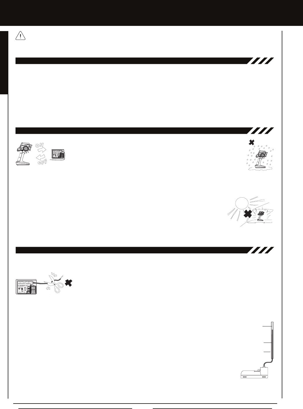
l Turn the transmitter 'ON' rst and then turn the receiver 'ON'. After using your model,
turn the receiver 'OFF' rst, then turn the transmitter 'OFF'. It can be dangerous if you
activate the components in reverse order as the servos may start up inadvertently.
l Before use, double-check that the transmitter and receiver batteries have sufcient
power.
l The MT-4 2.4GHz FHSS-4T transmitter features an internal antenna installed inside the vertical back portion
of the carrying handle. Do NOT grab the carrying handle during use! Doing so can block the RF signal, resulting in the loss of
control of your model.
l During use, hold the transmitter so that the antenna is orientated as close to vertical as possible at all times. This provides the
best RF signal between the transmitter and the receiver. You should never point the antenna directly
at your model, nor should you ever 'follow' your model with the antenna, as this results in a weakened
RF signal. For more information, see the Transmitter Features Diagrams section on page 6.
l Do not expose the transmitter or any other components to excessive heat, moisture, fuel, exhaust
residue, etc.
l If the outer case becomes dirty, it can be cleaned with a soft dry cloth. If the outer case becomes soiled, it can be cleaned with
a damp cloth and liquid detergent. Do not use any solvents to clean the outer case. Solvents will damage the nish.
REcEivER PREcaUTiOnS
2.4gHz FREqUEncY BanD PREcaUTiOnS
l The 2.4GHz frequency band may be used by other devices, or other devices in the immediate area may cause interference on
the same frequency band. Always before use, conduct a bench test to ensure that the servos operate properly. Also, conduct
checks with the transmitter as distant as possible from your model.
l The response speed of the receiver can be affected if used where multiple 2.4GHz radio controllers are being used, therefore,
carefully check the area before use. Also, if response seems slow during use, stop your model immediately and discontinue use.
l If the 2.4GHz frequency band is saturated (too many radio controllers on at once), as a safety precaution, the radio control
system may not Bind. This ensures that your radio control system does not get hit by interference. Once the frequencies have
been cleared, or the saturation level has dropped, your radio control system should be able to Bind without any problems.
Antenna Tube
Coaxial Cable
Antenna
Reception Wire

Page 5
FEaTURES anD SPEciFicaTiOnS
SYSTEM FEaTURES
SYSTEM SPEciFicaTiOnS
Transmitter
Model: MT-4 Telemetry System
Output Power: 100mW
Nominal Input Voltage: 4.8v ~ 7.4v
Operating Voltage Range: 4.0v ~ 9.6v
Dry Weight: 13.68oz (388gr)
Frequency: 2.4GHz FHSS-4T
Receiver
Model: 92010 (RX-461) Telemetry
Frequency: 2.4GHz FHSS-4T
Nominal Input Voltage: 4.8v ~ 7.4v
Weight: 0.34oz (9.6gr)
Dimensions: 1.43 x 1.04 x 0.64in (36.2 x 26.5 x 16.3mm)
Fail Safe Limit: 3.5v ~ 7.4v (FH4T) / 3.5v ~ 5.0v (FH2/FH3)
Torque: 80oz/in (5.8kg/cm @ 4.8v)
89oz/in (6.4kg/cm @ 6.0v)
Speed: 0.10 sec/60º @ 4.8v
0.08 sec/60º @ 6.0v
Dimensions: 1.59 x 0.83 x 1.04in
(40.4 x 21.1 x 26.4mm)
Weight: 1.77oz (50gr)
Torque: 50oz/in (3.6kg/cm @ 4.8v)
61oz/in (4.4kg/cm @ 6.0v)
Speed: 0.17 sec/60º @ 4.8v
0.14 sec/60º @ 6.0v
Dimensions: 1.54 x 0.79 x 1.42in
(39.1 x 20.0 x 36.0mm)
Weight: 1.55oz (43.9gr)
94780M (SDX-901) Digital High-Power Metal Gear Dual Ball Bearing Servo
Torque: 361oz/in (26.0kg/cm @ 4.8v)
423oz/in (30.5kg/cm @ 6.0v)
Speed: 0.19 sec/60º @ 4.8v
0.15 sec/60º @ 6.0v
Dimensions: 1.60 x 0.83 x 1.50in
(40.6 x 21.1 x 38.1mm)
Weight: 2.33oz (66gr)
94722 (SDX-1322) Digital Standard Ball Bearing Servo
Both analog and digital servos will work with your MT-4 2.4GHz FHSS-4T radio control system. To get the most out of your
experience, we recommend the use of digital servos in SHR or SSR mode. For more information about using different types
of servos and the different Servo Mode Types, see the Changing the Mode Setting section on page 55.
94746M (SDX-801) Digital Metal Gear Low-Prole Dual Ball Bearing Servo
Torque: 124oz/in (8.9kg/cm @ 4.8v)
151oz/in (10.9kg/cm @ 6.0v)
Speed: 0.17 sec/60º @ 4.8v
0.13 sec/60º @ 6.0v
Dimensions: 1.54 x 0.78 x 1.50in
(39.0 x 20.0 x 37.4mm)
Weight: 1.93oz (56gr)
94775M (SDX-772) Digital High-Power Metal Gear Dual Ball Bearing Servo
We recommend using Airtronics brand servos with your MT-4 2.4GHz FHSS-4T radio control system. These are a few of our
more popular servos. See your local Airtronics dealer or www.airtronics.net for pricing, availability and more selection.
SERvO REcOMMEnDaTiOnS
l 4-Channel 2.4GHz FHSS-4T Digital High-Response Computer Radio with Advanced Programming
l Telemetry System Features Updated Temperature, RPM/Speed and Voltage Displays in Real-Time on the Telemetry Screen
l High-Power FHSS-4T Technology Provides the Best Reception and Connectivity, Giving Racers Added Assurance
l 4-Cell Battery Holder for Lighter Weight - Also Accepts Optional Ni-Cd/MH Batteries or 2S Li-Po or 2S Li-Fe/A123 Battery Packs
l Adjustable Grip
l Variable Rate Adjustment
l Model Naming
l Model Select
l Model Select Shortcut (Direct Model)
l Model Clear
l Selectable Modulation Type
l Multi-Function LCD Contrast
l Adjustable Key Volume and Tone
l Programmable Low Voltage Alarm
l Inactivity and Over Voltage Alarms
l Digital Battery Voltage Monitor
l 18 Model Memory
l Telemetry Logging
l Channel Set Menu
l Servo Reversing
l Steering, Throttle and Brake Dual Rate
l End Point Adjustment
l Exponential and ARC Adjustment
l Servo Speed Adjustment
l Anti-Lock Braking
l Throttle Offset
l Lap and Interval Timers
l Total, Best and Individual Lap Display
l Four Wheel Steering Mixing
l Dual Throttle Mixing w/Dig & Burn
l Normal, SSR and SHR Servo Modes
l Center or Parallel Trim Types
l Step Auxiliary
l Point Auxiliary
l Auxiliary Mixing
l Programmable Fail Safe
l Receiver Battery Voltage Fail Safe
l Digital Trims
l Servo Sub-Trim
l Adjustable Throttle Trigger
l Programmable Switches, Lever and Dial
l Adjustable Steering Wheel
GENERAL

Page 6
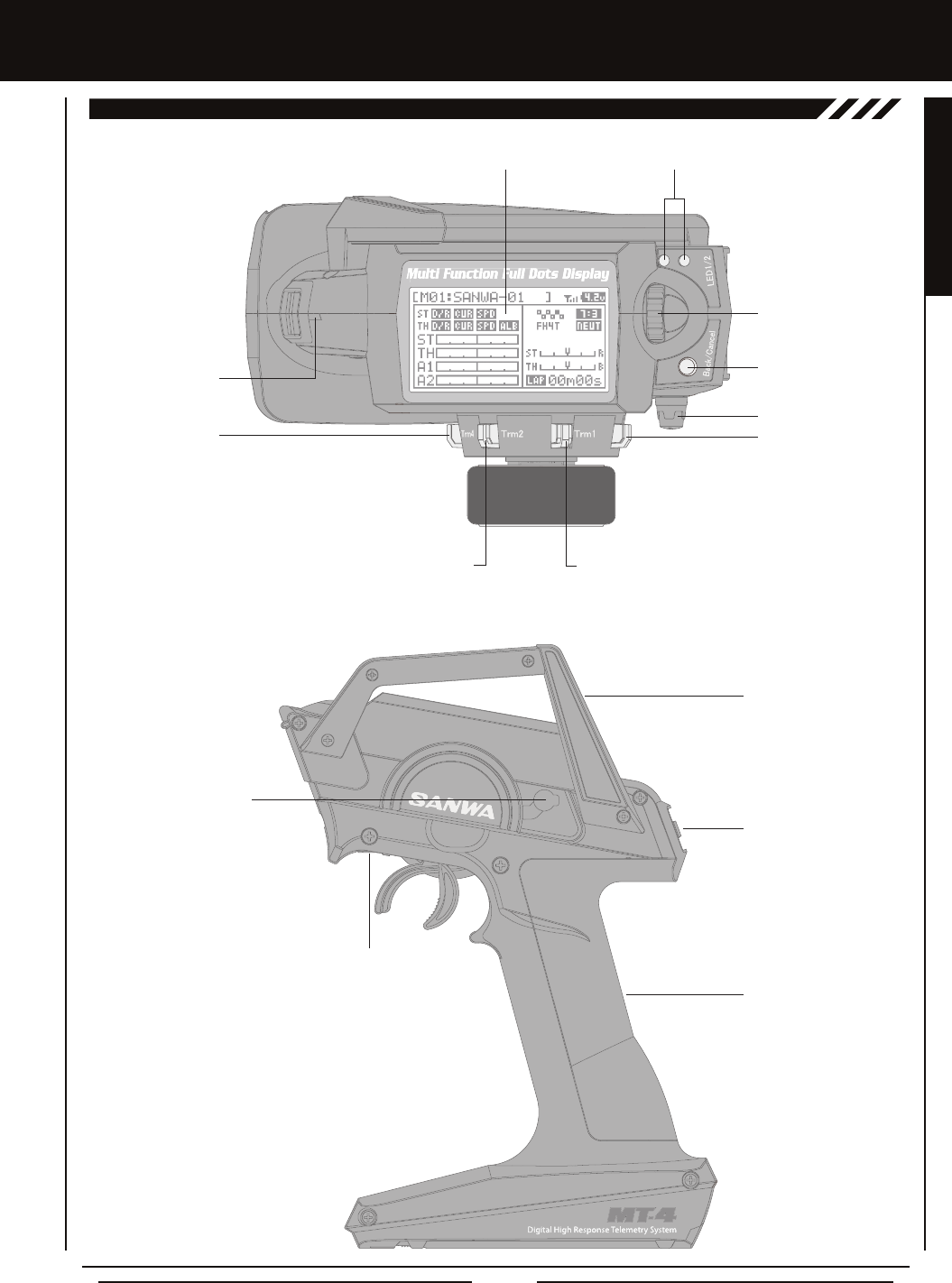
FEaTURES FaMiLiaRizaTiOn
Antenna
(Inside Handle)
Trim Switch (Trm1)
Steering Wheel
Battery Compartment
Dial Knob
Throttle Trigger
Grip
Throttle Trigger Position
Adjustment Screw
Power Switch
TRanSMiTTER FEaTURES DiagRaMS
Use the diagrams in this section to familiarize yourself with the basic features of your MT-4 2.4GHz FHSS-4T transmitter.
Descriptions of these features can be found in the Transmitter and Receiver Features Descriptions section on pages 8 and 9.
The transmitter antenna is mounted internally and is located in the vertical back portion of the carrying handle. When you're
driving your model, hold the transmitter so that the antenna is orientated as close to vertical as possible at all times. This
provides the best RF signal between the transmitter and the receiver. You should never point the antenna directly at your model,
nor should you ever 'follow' your model with the antenna. Doing so can result in a weakened RF signal.
Push-Button
Switch (Sw1)
Trim Switch (Trm2)
Trim Switch (Trm3)
Trim Switch (Trm4)
Auxiliary Lever
FROnT viEw
RigHT SiDE viEw
Steering Wheel Tension
Adjustment Screw
Throttle Trigger Tension
Adjustment Screw
Push-Button
Switch (Sw2)
Page 7
FEaTURES FaMiLiaRizaTiOn
TRanSMiTTER FEaTURES DiagRaMS, cOnTinUED....
Multi-Function LCD LED 1/2
Push-Button
Rotary Dial
(Up/Down/Enter Key)
Back/Cancel Key
Dial Knob
TOP viEw
Trim Switch (Trm1)Trim Switch (Trm2)
Trim Switch (Trm3)Trim Switch (Trm4)
Wrist Strap
Anchor Slot
Charging Jack
LEFT SiDE viEw
Throttle Trigger Position
Adjustment Indicator
Power Switch
Antenna
Grip
GENERAL
Page 8
FEaTURES FaMiLiaRizaTiOn
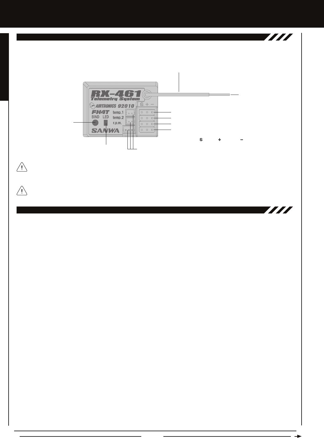
Use the diagram below to familiarize yourself with the 92010 (RX-461) 4-Channel 2.4GHz FHSS-4T Telemetry receiver included
with your MT-4 2.4GHz FHSS-4T radio control system. Descriptions of these features can be found in the Transmitter and Receiver
Features Descriptions section below.
REcEivER FEaTURES DiagRaM
The receiver battery can be plugged into any channel slot to power the receiver. To utilize all channels and a separate
receiver battery, a Y-Harness (not included) must be used. For more information, see the Receiver Mounting and Connections
section on page 12.
Antenna: Transmits the signal from the transmitter to the receiver in the model. Never touch the Antenna during use. Doing so
may result in a weakened RF signal or complete loss of control of your model.
Antenna Reception Wire: The portion of the receiver antenna that receives the transmitter signal. The Antenna Reception Wire
should never be bent or it could be damaged and limit the range of your model.
Auxiliary Lever: The Auxiliary Lever is programmable and will perform a different function depending on what function is assigned
to it. For example, it can be used to control Auxiliary 1 Channel 3 or to control the Servo Speed function.
Back/Cancel Key: Pressing the Back/Cancel Key returns the Programming Cursor to the previous menu. Press and HOLD the
Back/Cancel Key to return to the Top Screen.
Battery Compartment: Houses the four 'AA' Alkaline cells that power the transmitter. Alternatively, the transmitter can be
powered using four 'AA' Ni-Cd or Ni-MH rechargeable batteries or a 2S Li-Po or 2S Li-Fe/A123 battery pack.
Bind Button: Used in the process of Binding the transmitter and receiver.
Bind LED: Displays the current status of the receiver.
Charging Jack: Used for onboard charging of optional Ni-Cd or Ni-MH batteries. Do not attempt to charge Alkaline batteries.
Only the recommended Airtronics 110v AC charger should be used through the Charging Jack. If using an after-market
Peak-Detection charger or other type of fast charger, the batteries should be removed from the transmitter to avoid damage to the
transmitter circuitry and/or your batteries. Do not attempt to charge a Li-Po or Li-Fe/A123 battery pack through the Charging Jack.
Coaxial Cable: The portion of the receiver antenna that extends the Antenna Reception Wire. The Coaxial Cable can be bent into
gentle curves, however, do not bend it acutely, or repeatedly bend it, or the antenna core can be damaged. The Coaxial Cable
should be installed into a nylon tube (antenna tube) and positioned vertically in your model for the best reception.
Dial Knob: The Dial Knob can rotate 360º and is programmable to perform a different function depending on what function is
assigned to it. For example, it can be used to increase and decrease programming values, control a Trim function or control an
Auxiliary Channel.
Grip: The Grip is molded from rubber in an ergonomic shape for increased comfort, control and feel. An optional Grip is included
that is molded in a different shape that some users may nd feels more comfortable.
LED 1/2: Displays the current signal output status of the transmitter (LED 1 - Blue) and the Telemetry connection (LED 2 - Red).
In addition, one or both LEDs are used to indicate various transmitter conditions. For example, when a Throttle Offset percentage
value is programmed, the blue LED will ash.
Multi-Function LCD: The heart of the programming and display features of the transmitter. All programming and transmitter
display functions are shown on the Multi-Function LCD.
TRanSMiTTER anD REcEivER FEaTURES DEScRiPTiOnS
For information about connecting the Telemetry Sensors, see the Telemetry Connections and Mounting section on page 13.
Bind Button
Coaxial Cable
Antenna
Reception
Wire
Bind LED
= Signal = Positive = Negative
Telemetry Inputs
Steering (CH 1)
Throttle (CH 2)
Auxiliary 1 (CH 3)
Auxiliary 2 (CH 4)
Page 9
FEaTURES FaMiLiaRizaTiOn
TRanSMiTTER anD REcEivER FEaTURES DEScRiPTiOnS, cOnTinUED....
Power Switch: Turns the transmitter 'ON' and 'OFF'.
Push-Button Rotary Dial: The Push-Button Rotary Dial (also referred to as the Up Key, Down Key, or Enter key) is used along
with the Back/Cancel Key to facilitate transmitter programming. It allows you to quickly and easily navigate the various Programming
Menus and switch between the Top Screen and the Telemetry Screen.
Push-Button Switch: The transmitter features two separate Push-Button Switches in different locations (Sw1 and Sw2). Each
Push-Button Switch is programmable and will perform a different function depending on what function is assigned to it. For
example, Sw1 can be used to operate a reverse servo in a gas- or glow-powered model and Sw2 can be used to toggle Anti-Lock
Braking 'ON' and 'OFF'.
Steering Wheel: Proportionally operates the model's right and left steering control. The Steering Wheel features a foam grip for
increased comfort, control and feel. In addition, the Steering Wheel spring tension and travel limits can be adjusted.
Steering Wheel Tension Adjustment Screw: Used to adjust the spring tension of the steering wheel to best suit the feel of the
user. Turning the Steering Wheel Tension Adjustment Screw clockwise increases steering wheel tension and turning the Steering
Wheel Tension Adjustment Screw counter-clockwise decreases steering wheel tension.
Telemetry Inputs: Located under a removable protective cover, the Telemetry Inputs are where you plug the Temperature and
RPM Sensors into. Two separate temperature inputs and one RPM input are available.
Throttle Trigger: Controls the speed of the model, both forward and backward, or the model's brake. The Throttle Trigger position,
angle and spring tension can all be adjusted.
Throttle Trigger Position Adjustment Indicator: Indicates the current position of the Throttle Trigger. As the throttle trigger
position is adjusted forward or backward, the Throttle Trigger Position Adjustment Indicator will move forward or backward.
Throttle Trigger Tension Adjustment Screw: Used to adjust the spring tension of the throttle trigger to best suit the feel of the
user. Turning the Throttle Trigger Tension Adjustment Screw clockwise increases throttle trigger tension and turning the Throttle
Trigger Tension Adjustment Screw counter-clockwise decreases throttle trigger tension.
Throttle Trigger Position Adjustment Screw: Used to adjust the position of the Throttle Trigger either forward or backward.
Trim Switch: The transmitter features four separate Trim Switches positioned around the steering wheel (Trm1, Trm2, Trm3 and
Trm4). Each Trim Switch is programmable and will perform a different function depending on what function is assigned to it. For
example, Trm1 and Trm2 can be used to adjust steering and throttle Trim and Trm4 and Trm5 can be used to adjust Dual Rate
and steering EPA.
Wrist Strap Anchor Slot: Used to attach the wrist strap anchor to the transmitter.
The 92010 (RX-461) 4-Channel 2.4GHz FHSS-4T Telemetry receiver included with your MT-4 2.4GHz FHSS-4T radio control
system uses Airtronics 'Z' connectors which are electronically compatible with the servos of other radio control system
manufacturers. The connectors are rugged, but should be handled with care.
When unplugging the servo connector, it's best not to pull on the servo wire itself. This could result in damage to the servo
wire pins in the plastic plug. Always grasp the plastic connector itself.
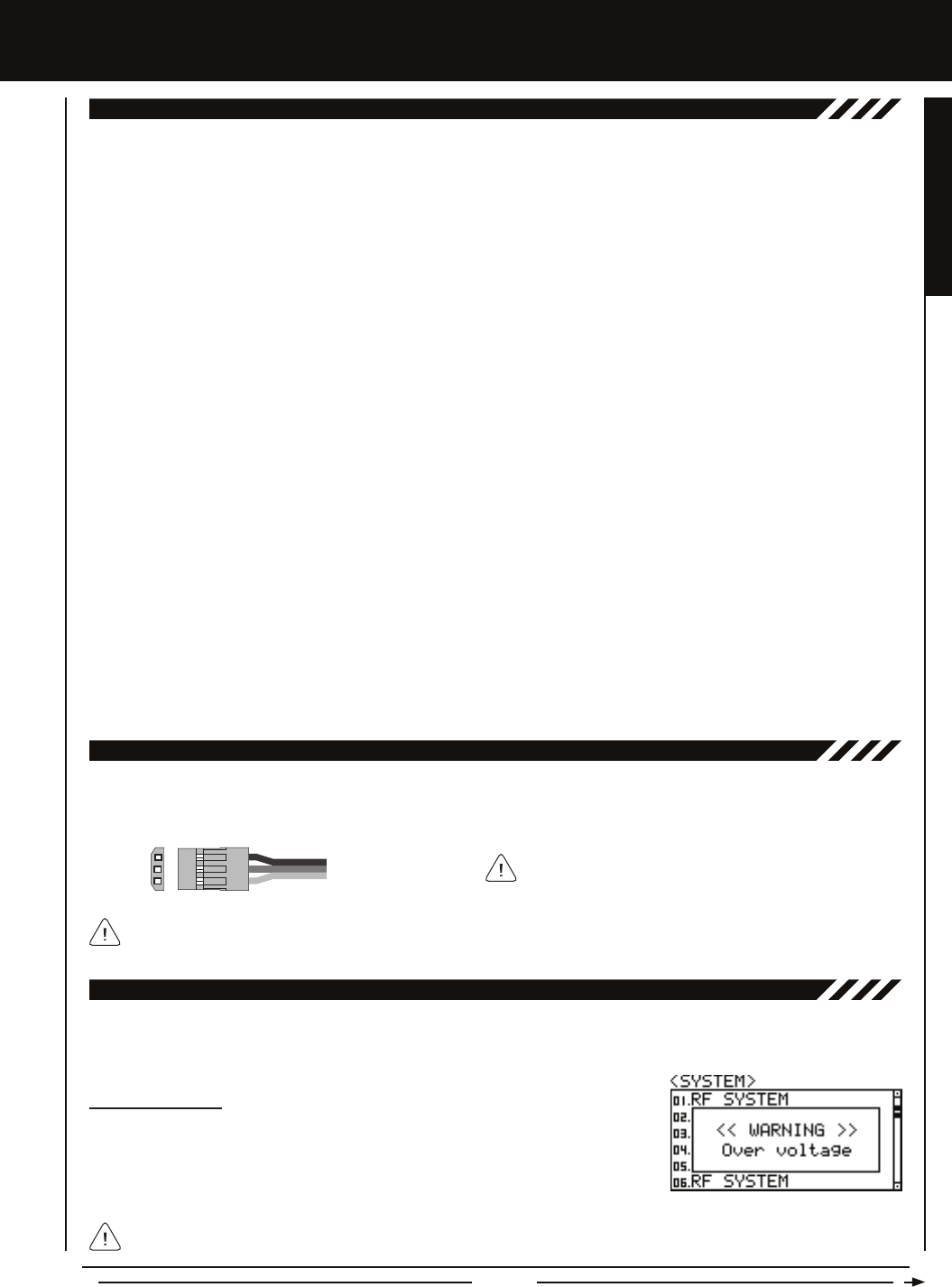
SERvO cOnnEcTORS
- = Negative (Black)
+ = Positive (Red)
S = Signal (Blue)
TRanSMiTTER SaFETY aLaRMS anD LED cOnDiTiOn inDicaTORS
The MT-4 2.4GHz FHSS-4T transmitter is equipped with several different safety alarms to warn you of an abnormal transmitter
condition. In addition, LED 1 and LED 2 can also be used to indicate various transmitter conditions.
Over Voltage Alarm
The Over Voltage Alarm will sound if the transmitter battery voltage is greater than 9.6
volts. To clear this alarm, turn the transmitter 'OFF' and replace the transmitter battery with
one that when fully charged does not exceed 9.6 volts.
The MT-4 2.4GHz FHSS-4T transmitter's Operating Voltage Range is 4.0 ~ 9.6 volts. DO NOT use a transmitter battery
with a voltage greater than 9.6 volts or the transmitter can be damaged!
If using another brand of servo, double-check the polarity
of the servo connector prior to plugging it into the receiver.
GENERAL
Page 10
FEaTURES FaMiLiaRizaTiOn
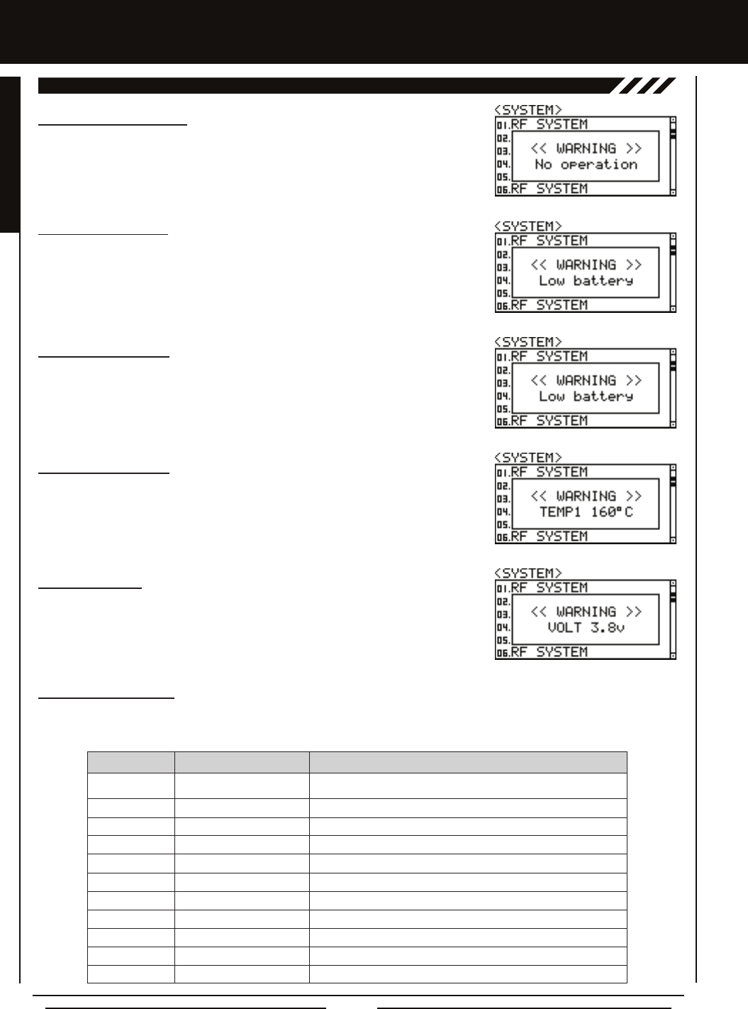
Low Voltage Alert Alarm
The Low Voltage Alert alarm will sound when the transmitter batteries reach the Alert
Voltage value programmed in the SYSTEM - ALARM menu. The alarm will sound each
time the transmitter battery voltage decreases by 0.1 volt. To clear this alarm, press the
Back/Cancel key or the Push-Button Rotary Dial. For more information, see the Voltage
Alarm section on pages 64 and 65.
TRanSMiTTER SaFETY aLaRMS anD LED cOnDiTiOn inDicaTORS, cOnTinUED....
Temperature Alert Alarm
The Temperature Alert alarm will sound when the TEMP1 and/or TEMP2 temperature
reaches the Alert Temperature value programmed in the SYSTEM - TELEMETRY menu.
To clear this alarm, press the Back/Cancel key or the Push-Button Rotary Dial. For more
information, see the Changing the Alert Temperature Value section on page 67.
Voltage Alert Alarm
The Voltage Alert alarm will sound when the receiver battery in your model reaches the
Alert Voltage value you've programmed in the SYSTEM - TELEMETRY menu. To clear
this alarm, press the Back/Cancel key or the Push-Button Rotary Dial. For more information,
see the Changing the Alert Voltage Value section on pages 68 and 69.
Blue
Blue
Blue
Blue
Red
Red
Red
Blue and Red
Blue and Red
Blue and Red
Blue and Red
RF Output Signal OK
Throttle Offset Value ON with Positive or Negative Value Programmed
Telemetry Logger Function Operating
Anti-Lock Braking Function Operating
No Transmitter/Receiver Telemetry Connection
Telemetry Alarm Started
Low Voltage Alert Alarm Started
Bind Command Transmitted
Inactivity (Power ON) Alarm Started
Low Voltage Limit Alarm Started
Over Voltage Alarm Started
LED COLOR LED CONDITION DESCRIPTION
LED CONDITION
ON
Flash
Slow Flash
Fast Flash
ON
Flash
Flash
Flash Alternately
Flash
Fast Flash Alternately
Fast Flash Alternately
Inactivity (Power ON) Alarm
The Inactivity Alarm will sound if the transmitter is left on for a period of 10 minutes without
any control input from the user. This alarm alerts you to prevent unwanted draining of
the transmitter battery. To clear this alarm, either turn the transmitter 'OFF' or press the
Back/Cancel key or the Push-Button Rotary Dial.
Low Voltage Limit Alarm
The Low Voltage Limit alarm will sound when the transmitter batteries reach the Limit Volt-
age value programmed in the SYSTEM - ALARM menu. This alarm can only be cleared by
turning the transmitter 'OFF' and recharging or replacing the transmitter batteries. For more
information, see the Voltage Alarm section on pages 64 and 65.
LED Condition Indicators
LED 1 (Blue) and LED 2 (Red) can be used to determine various transmitter conditions at a glance. The LEDs will alert you to
various warnings and other transmitter conditions, as shown in the table below.

Page 11
l Do NOT charge your Li-Po or Li-Fe/A123 battery pack through the transmitter Charging Jack. The battery pack MUST be
removed from the transmitter for charging or the transmitter could be damaged.
l Use a charger specically designed to charge Li-Po or Li-Fe/A123 batteries.
lWhen changing the connector on your battery pack to match the battery power plug in the base of
the transmitter or on the receiver's on/off switch, please observe correct polarity. Connecting with
reverse polarity will damage the transmitter and/or receiver.
l Observe all safety precautions provided with your Li-Po or Li-Fe/A123 battery pack.
l Damage to the transmitter and/or receiver caused by improper use, wrong battery type, incorrect voltage or reverse polarity
will not be covered under warranty.
SYSTEM cOnnEcTiOnS
aLkaLinE BaTTERY inSTaLLaTiOn
1) Remove the battery cover from the bottom
of the transmitter by pushing rmly on the
battery cover in the direction of the arrow.
2) Install four fresh 'AA' Alkaline batteries
into the battery holder, making sure that
the polarity is correct. The direction that
each battery should be installed is molded into the bottom of the battery holder (+ Positive and - Negative).
3) Slide the battery cover back onto the transmitter and push it rmly until it 'clicks' closed.
The MT-4 2.4GHz FHSS-4T transmitter's Operating Voltage Range is 4.0 ~ 9.6 volts. This allows you to use several different
battery options (not included), depending on your preference.
Alkaline - In the default conguration, the transmitter is designed to be powered using four 'AA' Alkaline batteries. This results in
a transmitter that is lightweight and well-balanced for unmatched comfort.
Ni-Cd/Ni-MH - Rechargeable Ni-Cd or Ni-MH batteries of desired capacity can be used in place of the Alkaline batteries. Using
rechargeable Ni-Cd or Ni-MH batteries is more convenient and cheaper in the long run. The higher capacity batteries will also
provide longer usage time than most Alkaline batteries.
Li-Po or Li-Fe/A123 - A 2 cell Li-Po battery pack or a 2 cell Li-Fe/A123 battery pack can be used to power the transmitter. These
battery packs are popular due to their light weight and high capacity for long usage time between charges.
TRanSMiTTER BaTTERY OPTiOnS
Transmitter power output, range, and speed are the same, regardless of the battery voltage and type used. If using a Li-Po or
Li-Fe/A123 battery pack, please obverse the warnings in the Warnings if Using Li-Po or Li-Fe/A123 Batteries section below.
waRningS iF USing Li-PO OR Li-FE/a123 BaTTERiES
l Use ONLY a 2 Cell Li-Po or Li-Fe/A123 battery pack of desired capacity.
- = Negative (Black)
+ = Positive (Red)
TRanSMiTTER BaTTERY cHaRging OPTiOnS
The MT-4 2.4GHz FHSS-4T transmitter features a Charging Jack that can be used with the Airtronics 95034 Dual Output charger
(available separately) to charge the optional Ni-Cd or Ni-MH batteries. This allows you to charge these batteries without removing
them from the transmitter.
WARNING: Do NOT attempt to recharge Alkaline batteries. Only Ni-Cd or Ni-MH batteries should be charged through the
transmitter's Charging Jack, using only the Airtronics 95034 Dual Output charger or equivalent. DO NOT attempt to charge
Li-Po or Li-Fe/A123 batteries through the Charging Jack. Do Not use the Charging Jack with a fast charger or a peak-detection
charger, or the transmitter could be damaged.
If you use a fast charger or a peak-detection charger to charge the transmitter batteries, the battery holder must be removed
from the transmitter rst. The circuitry within the transmitter will interfere with the peak-detection charger's normal operation,
resulting in over-charging and damaging the battery and possibly the transmitter itself. In addition, the higher charge rate common
in many fast chargers can damage the transmitter's circuitry. Damage caused by fast-charging through the transmitter or using
an incorrect battery type will not be covered under warranty.
Both the transmitter and receiver have a Nominal Input Voltage of 4.8 ~ 7.4 volts. DO NOT USE A 3 CELL LI-PO OR
LI-FE/A123 BATTERY PACK or the transmitter and/or receiver will be damaged.
GENERAL
Page 12
SYSTEM cOnnEcTiOnS
REcEivER cOnnEcTiOnS anD MOUnTing
l We suggest Binding the transmitter and receiver and making all receiver connections to check for correct operation prior to
mounting the receiver in your model.
l The receiver should be mounted as far away from any electrical components as possible.
l Route the receiver antenna up through a plastic tube so that it is in the vertical position.
l To protect the receiver from vibration and other damage, we recommend wrapping the receiver in shock absorbing foam or
using double-sided foam tape when installing it in your model.
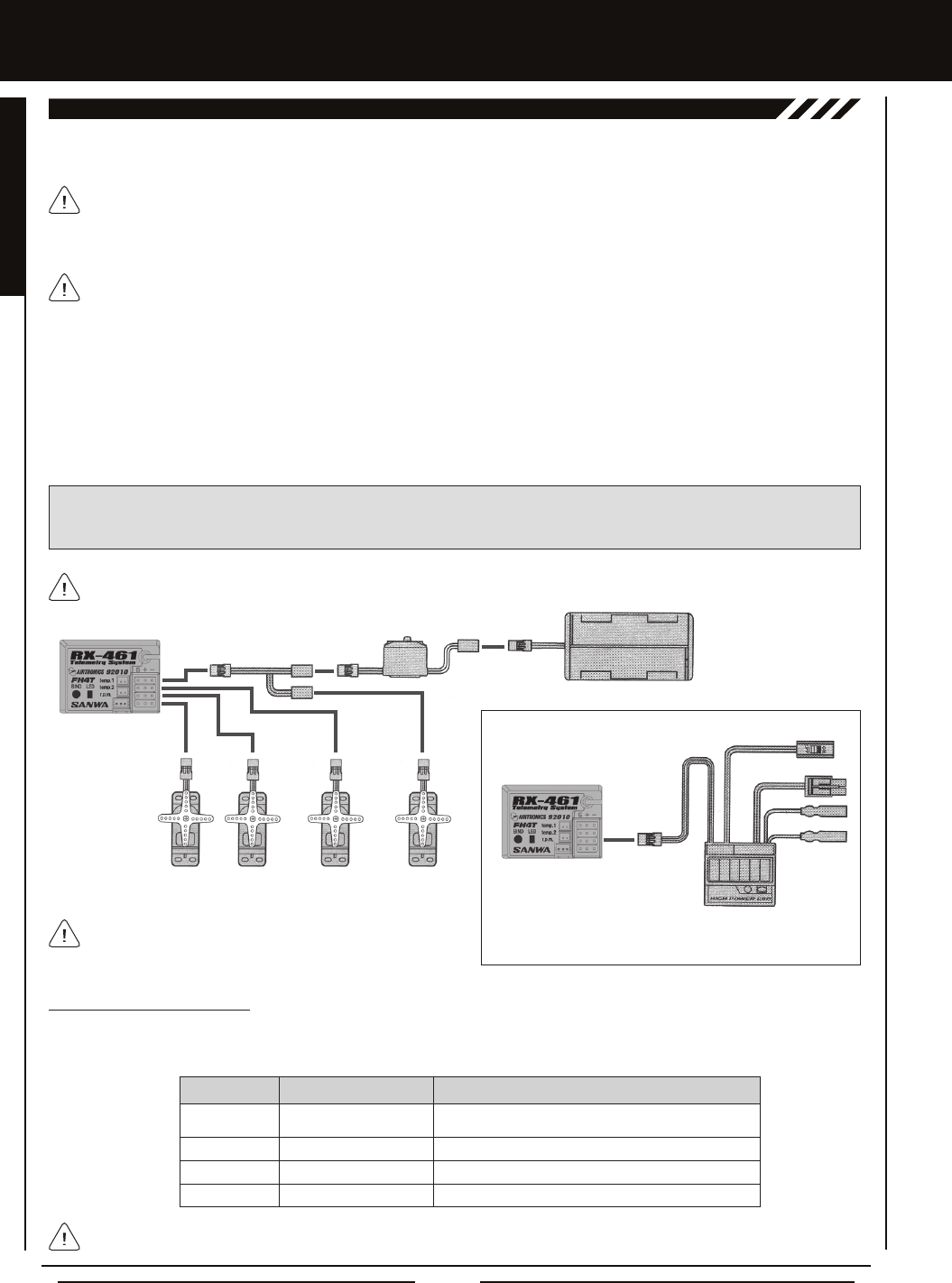
IMPORTANT: The receiver battery can be plugged into any channel slot to power the receiver. To utilize all channels and a
separate receiver battery, a Y-Harness (not included) must be used. Not all items shown in the illustration below are included
with your radio control system.
As a safety precaution, set your model on a stand so the wheels are off the ground before turning on your radio control
system or connecting your motor for the rst time.
Use the diagram below to make the connections to the 92010 (RX-461) 4-Channel 2.4GHz FHSS-4T Telemetry receiver included
with your MT-4 2.4GHz FHSS-4T radio control system.
The 92010 (RX-461) receiver's Nominal Input Voltage is 4.8 ~ 7.4 volts. A 2 cell Li-Po or 2 cell Li-Fe/A123 battery pack can
be used to power the receiver without the use of a voltage regulator. In addition, this allows you to take advantage of the
higher torque and speed provided by using 7.4 volt digital servos. Only use a 2 cell Li-Po or 2 cell Li-Fe/A123 battery pack if
your servos are rated to handle the higher voltage.
If you're using an Electronic Speed Control with BEC circuitry, verify that it reduces the voltage to between 4.8 and 7.4 volts
before making your connections and turning your radio control system 'ON'.
Switch 'AA' Dry Cell Battery Holder,
4.8v ~ 6.0v Ni-Cd/Ni-MH or
2S Li-Po or 2S Li-Fe/A123
Steering
Channel 1
Throttle
TH Channel 2
Auxiliary
AUX1 Channel 3
Auxiliary
AUX2 Channel 4
Y-Harness
Receiver
Receiver
Switch
To Battery
To Motor
ESC
Throttle
Channel 2
Glow/Gas or
MSC Setup
Electronic Speed
Control Setup
For information about connecting and mounting the Telemetry Sensors, see the Telemetry Connections and Mounting section
on the next page.
Blue
Blue
Blue
Green
Receiving RF Signal
Binding Operation
Receiving Signal Command
Telemetry RPM Sensor Connected and Receiving Input
LED COLOR LED CONDITION DESCRIPTION
LED CONDITION
ON
Slow Flash
Flash
ON
Bind LED Condition Indicator
The Bind LED on the receiver can be used to determine receiver condition at a glance. The Bind LED will alert you to various
receiver conditions, as shown in the table below.
Do NOT use servos rated for 4.8 or 6.0 volts with a 2S Li-Po
or Li-Fe/A123 receiver battery pack or damage to the servos
could result.
*When using an ESC, the ESC connector
plugs into Throttle Channel 2.
Page 13
GENERAL
TELEMETRY cOnnEcTiOnS anD MOUnTing
Telemetry Sensor Overview
The MT-4 2.4GHz FHSS-4T radio control system includes one Temperature Sensor and one RPM Sensor, in addition to the Voltage
Sensor built into the receiver. These sensors can be installed in your model to give you Temperature and RPM or Speed feedback
in real-time displayed on the transmitter's Telemetry Screen.
SYSTEM cOnnEcTiOnS
Plugging the Telemetry Sensors into the Receiver
1) Use your ngernail to carefully pry up and remove the plastic dust cover from over the Telemetry Sensor inputs on the
receiver.
2) Plug the Telemetry Sensor(s) into their respective inputs in the receiver. The Temperature Sensor can be plugged into either
the TEMP 1 or the TEMP 2 input and the RPM Sensor is plugged into the RPM input. The sensor plugs are indexed so they
can be plugged in only one direction.
The receiver supports the use of two different Temperature Sensors at the same time. If desired, an extra Temperature
Sensor can be purchased separately. For more information, see your local Airtronics retailer or visit our website at
www.airtronics.net. Telemetry is NOT supported when using FHSS-2 or FHSS-3 receivers.
Make sure to push the sensor plugs rmly into their inputs in the receiver to ensure a good connection. When routing
sensor wires inside your model, be careful that they cannot come into contact with any moving parts or can be damaged in
the event of a crash. The sensor wires should be securely mounted and protected against damage.
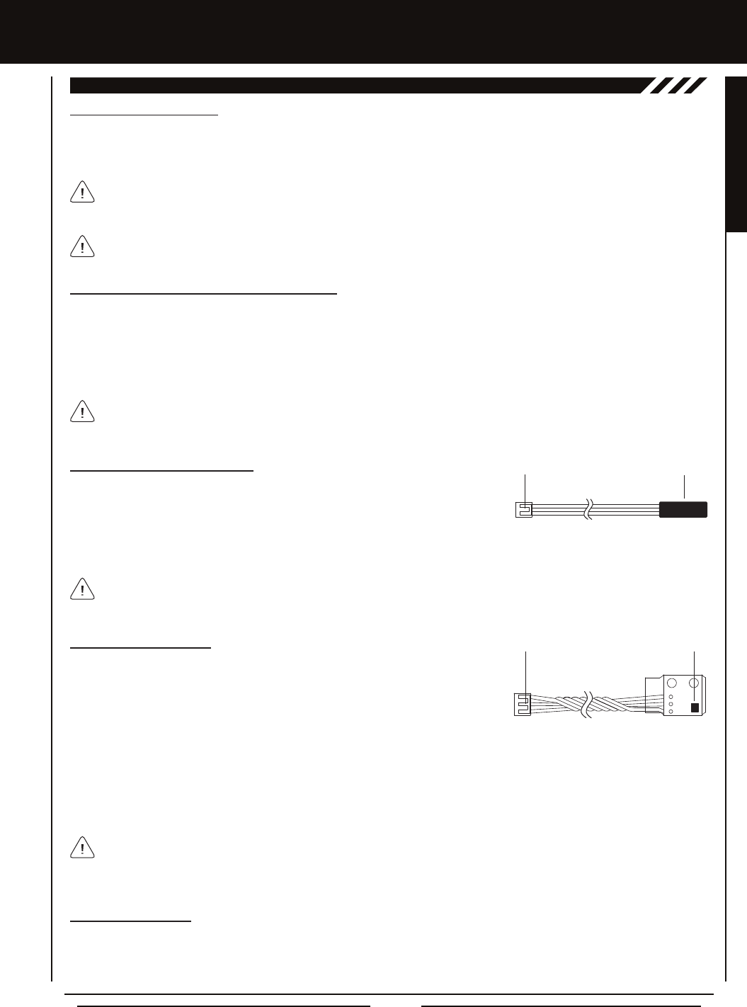
Mounting the Temperature Sensor
The Sensor End should be secured directly against the part of your engine, motor
or battery you want to monitor temperature readings from. For example, to monitor
the cylinder head temperature of your nitro-powered model, the best place to secure
the Sensor End is where the bottom of the cylinder head meets the top of the engine
case. The Sensor End can be held in place using a nylon cable tie wrapped around your engine. To monitor the temperature of
your battery pack or electric motor, clear tape can be used to secure the Sensor End to the spot you want to monitor.
Mounting the RPM Sensor
The RPM Sensor uses infrared technology to record RPM data from a rotating part,
such as a ywheel or a spur gear. One Black and one White reective decal are
included that is attached to the rotating part so that the RPM Sensor can 'see' it as
it passes in front of the Sensor Pickup.
Install the RPM Sensor into your model, making sure that it's held securely in place. For optimal operation, the Sensor
Pickup should be positioned approximately 1mm away from the back of the moving part (ywheel, spur gear, etc.)
So that the RPM Sensor can work properly, one of the two reective decals included needs to be applied to the back of the
moving part so that when the part rotates, the reective decal passes in front of the Sensor Pickup. If the ywheel or spur
gear is metallic-colored (silver, aluminum, chrome, etc.), apply the BLACK reective decal. If the ywheel or gear is dark-colored
(black, blue or another dark color), apply the WHITE reective decal.
Sensor End
Input Plug
Do not try to bend the Sensor End or damage it in any way. The Sensor End should be held in place with a nylon cable tie
(tightened only enough to hold the Sensor End securely) or clear tape. In some cases, you may need to use high-temperature
tape to ensure strong adhesion at higher temperatures.
Sensor Pickup
Input Plug
When installed, it's important that the Sensor Pickup face the ywheel, spur gear or other moving part. The Black or White
reective decal should be applied to the back side of the ywheel or spur gear and positioned so that the reective decal passes
in front of the Sensor Pickup when the ywheel or spur gear is rotated. It's important that the reective decal you apply contrasts
with the ywheel or spur gear it's applied to and the Sensor Pickup should be approximately 1mm away from the reective decal.
RPM Sensor Bind LED
When the Sensor Pickup is receiving input, the Bind LED on the receiver will turn Green. For example, when you rotate the spur
gear, the Bind LED will ash Green each time the reective decal on the spur gear passes in front of the Sensor Pickup. This
feedback is used to calibrate the RPM Sensor to display the speed of your model in either MPH or KM/H. For more information,
see the Calibrating the RPM Sensor section on page 70.
The range of the Telemetry System is approximately 260 feet (80 meters), although the range can vary based on many
environmental factors. Use the Telemetry Signal Indicator to determine the quality of the signal.
Page 14
Moving the throttle trigger position does not affect the physical movement of the throttle trigger. Do not attempt to adjust
the throttle trigger position beyond the limits indicated by the Throttle Trigger Position Adjustment Indicator or damage to
the transmitter may result.
aDjUSTMEnTS anD OPTiOnS
The position of the throttle trigger can be adjusted forward or backward to change the feel of the throttle trigger during use.
Some users may prefer the throttle trigger positioned farther forward and some users my prefer the throttle trigger positioned
farther back. It all depends on your personal preference.
A
B
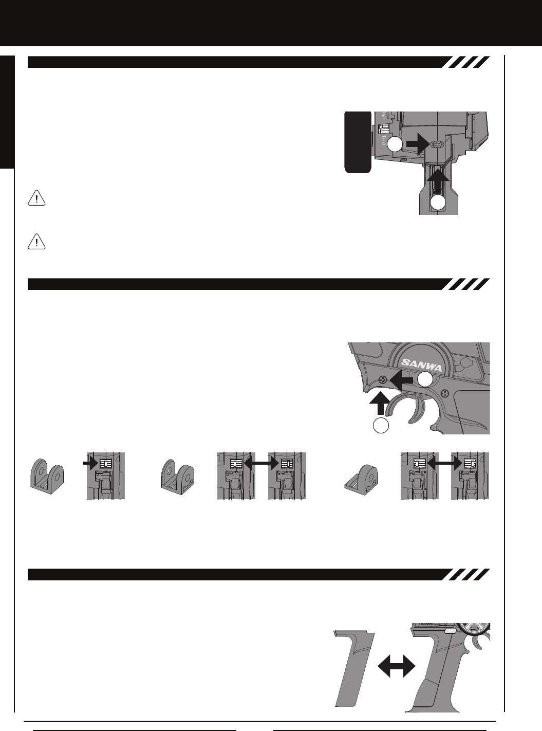
THROTTLE TRiggER POSiTiOn aDjUSTMEnT
To adjust the throttle trigger position, follow the step below:
1) To move the throttle trigger backward, use a # 1 philips head screwdriver to turn
the Throttle Trigger Position Adjustment Screw (A) counter-clockwise. To move
the throttle trigger forward, turn the Throttle Trigger Position Adjustment Screw
clockwise.
As you adjust the throttle trigger position, the Throttle Trigger Position Adjustment
Indicator (B) will move, indicating the current position of the throttle trigger.
The angle of the throttle trigger can be adjusted right or left to change the feel of the throttle trigger during use. Some users
may prefer the throttle trigger straight while some users my prefer the throttle trigger angled toward the right or left. It all depends
on your personal preference. Throttle trigger adjustment plates are included to ne-tune the angle.
A
B
THROTTLE TRiggER angLE aDjUSTMEnT
To adjust the throttle trigger angle, follow the steps below:
1) Use a # 1 philips head screwdriver to remove the throttle trigger mounting screw (A)
from the left side of the transmitter.
2) Use the tip of a modeling knife to carefully pop the trigger adjustment plate (B) out
of the transmitter.
3) Carefully press the desired trigger adjustment plate into the transmitter, making sure to orientate it in the direction you want
to angle the throttle trigger, then reinstall and tighten the throttle trigger mounting screw.
A - Throttle Trigger Centered (Stock) B - Throttle Trigger Angled Slightly.
Angle Right or Left Depending on Orientation.
C - Throttle Trigger Angled More.
Angle Right or Left Depending on Orientation.
Included is an optional molded rubber grip that is shaped differently from the stock grip that's preinstalled on the transmitter. The
optional grip is larger and straight near the bottom, which some users may nd more comfortable.
gRiP
To install the optional grip, follow the steps below:
1) Remove the original grip from the handle by rmly pulling down on the back of
the grip (at the top), then by pulling the grip out along its front edges.
2) To install the new grip, align the molded tabs in the grip with the matching slots
in the handle, then rmly push the molded tabs into the slots, working your way
around the grip until the edges of the grip are ush with the handle.

Page 15
GENERAL
The maximum right and left travel of the steering wheel can be adjusted to best suit the feel of the steering wheel and your driving
style. Some drivers prefer to limit the travel of the steering wheel as it makes them feel more 'connected' to their model.
STEERing wHEEL TRavEL aDjUSTMEnT
To adjust the maximum travel of the steering wheel, follow the steps below:
1) Remove the foam steering wheel grip from the steering wheel by rmly pulling it straight off.
2) To limit the maximum travel of the steering wheel, use a 1.5mm hex wrench to turn both grub
screws (A) clockwise equally the desired amount. To maximize the travel of the steering wheel,
turn both grub screws counter-clockwise equally the desired amount.
After making steering wheel travel adjustments, you must use the Variable Rate Adjustment
function to ensure your steering servo travel limits are equal. For more information, see the
Variable Rate Adjustment section on page 71.
Limiting the maximum travel of the steering wheel will increase the sensitivity of the steering.
We recommend setting negative Exponential to soften the control feel around Neutral. For
more information, see the Exponential and ARC Adjustment section on pages 23 ~ 25.
To adjust the steering wheel spring tension, follow the step below:
1) To increase the spring tension of the steering wheel (rmer), use a 1.5mm hex
wrench to turn the Steering Wheel Tension Adjustment Screw (A) clockwise.
To decrease the spring tension of the steering wheel (looser), turn the Steering
Wheel Tension Adjustment Screw counter-clockwise. A
aDjUSTMEnTS anD OPTiOnS
The spring tension of the throttle trigger and steering wheel can be adjusted to best suit the user. Some users may prefer the
throttle trigger and/or steering wheel to feel 'rmer' and some users may prefer them to feel 'softer'. It all depends on your
personal preference.
A
THROTTLE TRiggER anD STEERing wHEEL SPRing TEnSiOn aDjUSTMEnT
To adjust the throttle trigger spring tension, follow the step below:
1) To increase the spring tension of the throttle trigger (rmer), use a 1.5mm hex
wrench to turn the Throttle Trigger Tension Adjustment Screw (A) clockwise. To
decrease the spring tension of the throttle trigger (looser), turn the Throttle Trigger
Tension Adjustment Screw counter-clockwise.
A wrist strap anchor is included that can be installed onto the transmitter to facilitate the use of a wrist strap (not included).
wRiST STRaP ancHOR
A
B
To install the wrist strap anchor, follow the steps below:
1) Remove the self-tapping screw (A) from the transmitter, using a # 1 philips
head screwdriver.
2) Slide the wrist strap anchor into the mounting slot in the back of the transmitter,
then reinstall and tighten the self-tapping screw.
When installing the wrist strap anchor, note its orientation. The U-Shaped
groove in the base of the wrist strap anchor should be pointing down.
Page 16
LcD anD PROgRaMMing kEYS
The MT-4 2.4GHz FHSS-4T transmitter features a Push-Button Rotary Dial and a Back/Cancel key that are used to facilitate
transmitter programming. This section describes the main areas of the different Multi-Function LCD screens, in addition to
summarizing the functions of the Push-Button Rotary Dial and the Back/Cancel key.
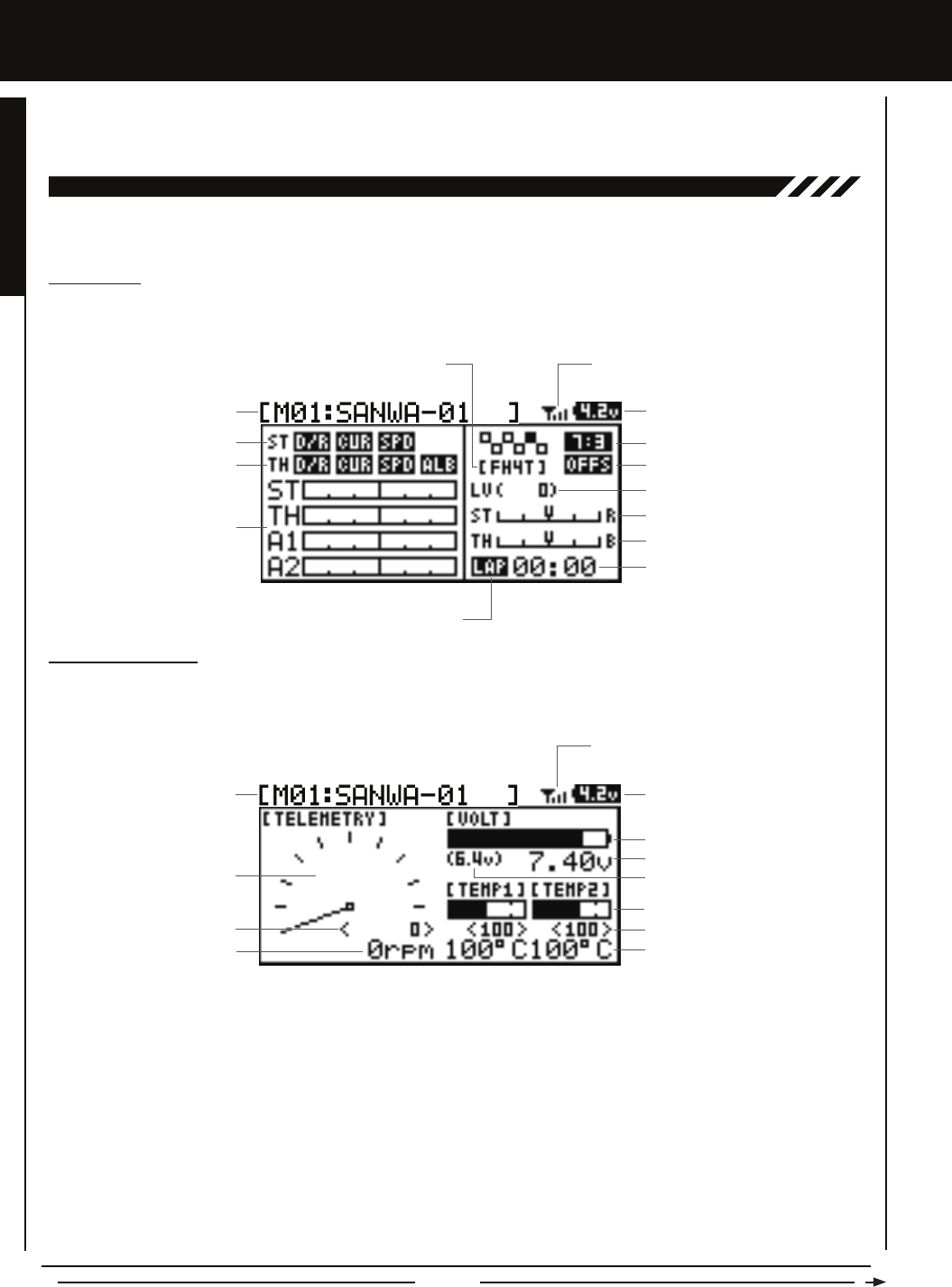
TOP ScREEn anD TELEMETRY ScREEn OvERviEw
Model Number and Name
Timer Display
Digital Voltage Indicator
Steering Trim Display
Throttle Trim Display
Servo Monitor Display
Use the diagrams in this section to familiarize yourself with the layout and different indicators and displays that comprise the Top
Screen and the Telemetry Screen.
Telemetry Signal Indicator
Throttle Mode Indicator
Throttle Offset Indicator
Auxiliary Lever Position Display
Timer Type Indicator
Steering Program Indicator
Throttle Program Indicator
Modulation Type Indicator
TOP SCREEN
The Top Screen is displayed when you turn the transmitter 'ON'. The Top Screen displays all pertinent information, such as the
Model Name, Modulation Type, Timer, Servo Monitor and much more.
TELEMETRY SCREEN
The Telemetry Screen displays all pertinent Telemetry information, such as RPM, Temperature and Receiver Voltage. To display the
Telemetry Screen, from the Top Screen scroll DOWN using the Push-Button Rotary Dial.
Auxiliary Lever Position Display: Displays the current position of the Auxiliary Lever.
Digital RPM Display: Displays the current RPM from the RPM Sensor in digital format.
Digital Temperature Display: Displays the current temperature from the TEMP1 and TEMP2 Temperature Sensors in digital format.
Digital Voltage Indicator: Indicates the current Voltage of the transmitter batteries.
High RPM Display: Displays the last highest RPM value. This value can be Reset. For more information, see the Telemetry
Clear Function section on page 71.
High Temperature Display: Displays the last highest Temperature value. These values can be Reset. For more information, see
the Telemetry Clear Function section on page 71.
Modulation Type Indicator: Indicates the current Modulation Type that the transmitter is set to.
Model Number and Name: Displays the Model Number and Model Name of the currently selected model.
Receiver Voltage Display: Displays the current voltage of the receiver battery.
Model Number and Name Digital Voltage Indicator
Receiver Voltage Display
Digital Temperature Display
RPM Display Monitor
Digital RPM Display
High RPM Display
Telemetry Signal Indicator
High Temperature Display
Voltage Alert Indicator
Temperature Display Monitor
Voltage Display Monitor
Page 17
GENERAL
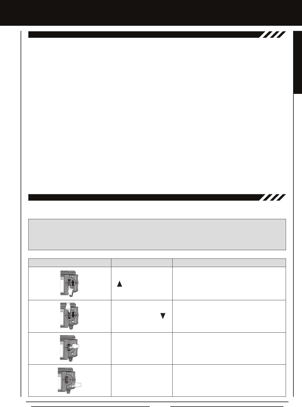
LcD anD PROgRaMMing kEYS
Scrolls the cursor Right or Up. In addition, increases
programming values.
Scrolls the cursor Left or Down. In addition, decreases
programming values.
PROGRAMMING KEY NAME FUNCTION
Push-Button Rotary
Dial Push (ENTER)
Opens the selected menu or programming option.
Press and HOLD to reset the selected programming
option to its default value.
Back/Cancel Key Returns to the previous menu. Press and HOLD to return
to the Top Screen.
Push-Button Rotary
Dial (Scroll UP)
Push-Button Rotary
Dial (Scroll DOWN)
PROgRaMMing kEYS OvERviEw anD FUncTiOnS
Moving around the different Multi-Function LCD screens and programming the transmitter is accomplished using the Push-Button
Rotary Dial and the Back/Cancel key.
RPM Display Monitor: Displays the current RPM from the RPM Sensor in graphical format.
Servo Monitor Display: Displays the output levels of the four different channels in bar graph form, allowing you to monitor servo
operation in a virtual manner.
Steering Program Indicator: Indicates up to four different programming options that are currently programmed to the Steering
channel. The Steering Program Indicator will only be displayed if a Steering channel programming value is programmed.
Steering Trim Display: Displays the current position of the Steering Trim Switch.
Telemetry Signal Indicator: Indicates the current signal strength of the Telemetry connection between the transmitter and
receiver. The Telemetry Signal Indicator will only be displayed when the receiver is turned 'ON' and there is a Telemetry
connection Active.
Temperature Display Monitor: Displays the current TEMP1 and TEMP2 temperatures in bar graph format.
Throttle Mode Indicator: Indicates the current Throttle Mode type.
Throttle Offset Indicator: Indicates that the Throttle Offset function is programmed. The Throttle Offset Indicator will only be
displayed if a Throttle Offset percentage value is programmed.
Throttle Program Indicator: Indicates up to four different programming options that are currently programmed to the Throttle
channel. The Throttle Program Indicator will only be displayed if a Throttle channel programming value is programmed.
Throttle Trim Display: Displays the current position of the Throttle Trim Switch.
Timer Display: Displays the time of the currently selected Timer.
Timer Type Indicator: Indicates the current Timer Type selected, either LAP or INT (Interval).
Voltage Alert Indicator: Indicates the currently programmed Voltage value that the receiver Voltage Alert alarm will sound at.
Voltage Display Monitor: Displays the current receiver battery voltage in bar graph format.
TOP ScREEn anD TELEMETRY ScREEn OvERviEw, cOnTinUED....
PRO TIP: While navigating Programming Menus and changing programming values, keep the following in mind: to choose
an option to program, scroll UP or DOWN to highlight the desired option. Press the ENTER key and the highlighted option will
ash, indicating the programming value can be changed. Once you've changed the programming value, press the ENTER
key again or press the Back/Cancel key and the highlighted option will stop ashing, indicating you can scroll UP or DOWN to
highlight another programming option.
Page 18
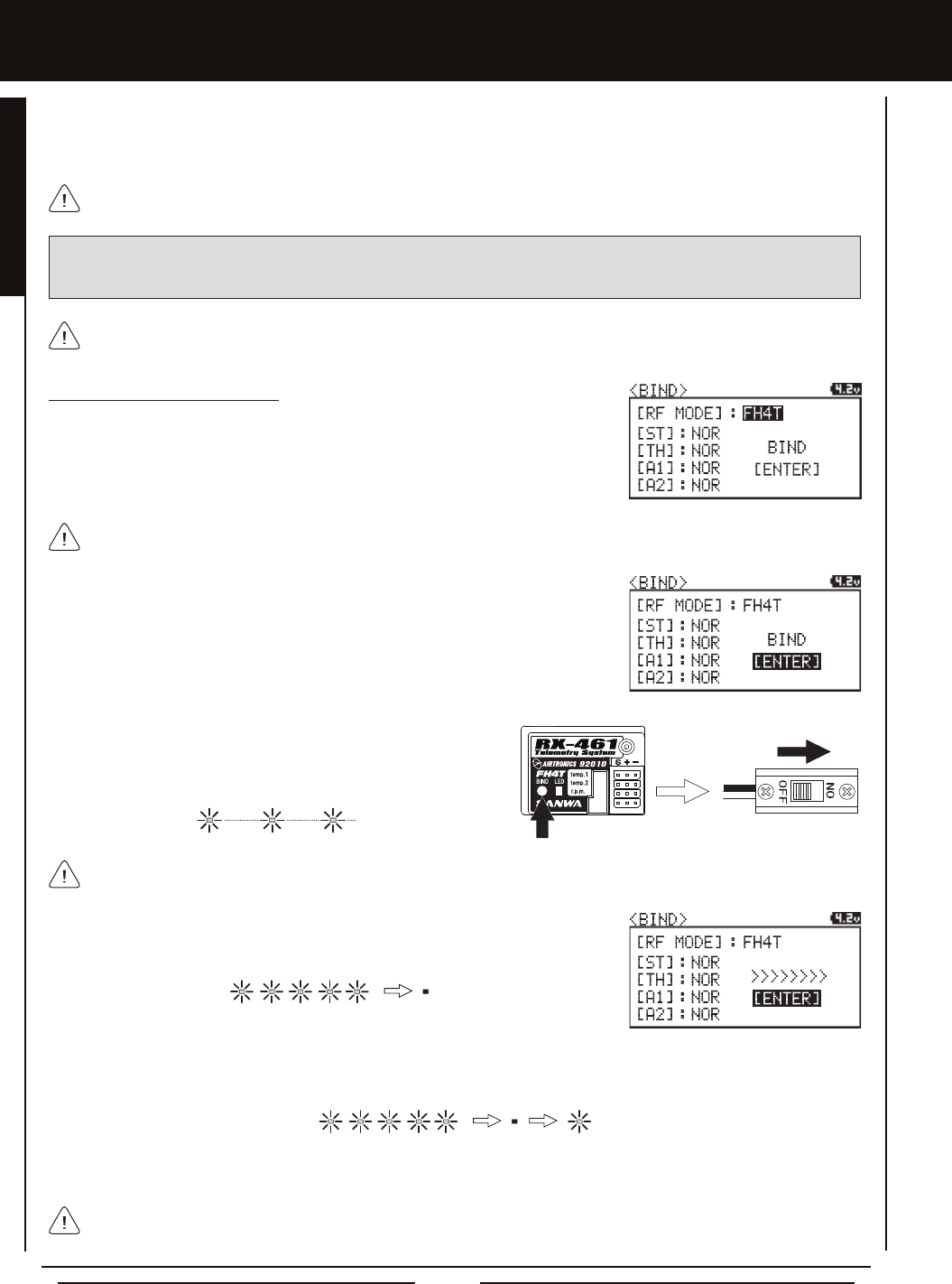
TRanSMiTTER anD REcEivER BinDing
The Binding function allows you to 'Bind' the transmitter and receiver pair. When new, it is necessary to pair the transmitter and
receiver to prevent interference from transmitters operated by other users. This operation is referred to as 'Binding'. Once the
Binding process is complete, the setting is remembered even when the transmitter and receiver are turned 'OFF'. Therefore, this
procedure usually only needs to be done once.
Under some circumstances, the receiver may not operate after turning the transmitter and receiver 'ON'. If this occurs,
perform the Binding process again.
Before beginning the Binding process, connect your servos and receiver battery pack to the receiver. For more information,
see the Receiver Connections and Mounting section on page 12. The transmitter and the receiver should be turned 'OFF'.
3) While holding down the Bind Button on the receiver, turn the receiver
'ON'. The Bind LED on the receiver will ash slowly. After approximately
2 seconds, release the Bind Button. The Bind LED on the receiver
will continue to ash slowly.
Use the tip of a non-conductive instrument to press the Bind Button on the receiver. Do NOT use a sharp object!
Transmitter and Receiver Binding
1) Turn the transmitter 'ON'. The Top Screen will be displayed. Press the ENTER key
(Push-Button Rotary Dial) to open the Programming Menu list, then scroll UP or
DOWN to highlight the SYSTEM menu. Press the ENTER key to open the SYSTEM
menu, then scroll DOWN to highlight the BIND menu. Press the ENTER key to open
the BIND menu.
When the Binding procedure is successful, the Bind LED on the receiver and LED 1 on the transmitter will illuminate solid
blue. If the Bind LED on the receiver is ashing rapidly or is not illuminated at all, the transmitter and receiver are not paired.
In this case, turn both the transmitter and receiver 'OFF', then repeat the Binding procedure again.
4) Press the ENTER key. The [ENTER] command will begin to ash and the Bind LED
on the receiver will ash rapidly, then go out.
5) After the Bind LED on the receiver goes out, press the ENTER key a second time. The Bind LED on the receiver will illuminate
solid blue and LED 2 on the transmitter will go out, indicating that the Binding procedure is complete and a Telemetry
connection has been made.
Verify that [RF MODE]: FH4T is displayed. If it isn't, change the Modulation Type to FH4T. For more information, see the
Changing the Modulation Type section on page 54.
2) Scroll UP or DOWN to highlight the [ENTER] command.
IMPORTANT: This section details Binding the 92010 (RX-461) 4-Channel 2.4GHz FHSS-4T Telemetry receiver with Digital or
Analog servos set to Normal mode. If you are Binding an FHSS-2 or FHSS-3 receiver to the transmitter, or if you prefer to change
the Servo Operating Mode, see the Binding, Modulation Type and Servo Mode section on pages 54 and 55.
6) Move the steering wheel and throttle trigger to verify that the servos are operating normally, then press and HOLD the
Back/Cancel key to return to the Top Screen.

Page 19
PROGRAMMING MENUS
[[PROgRaMMing MEnUS
01.cH-SET (cHannEL SET)
The Channel Set function allows you to make programming changes to each of the four channels without the need to enter each
Programming Menu separately. Essentially, the Channel Set function encompasses the most common programming options in
one convenient location. For example, you can make all of your desired programming changes, such as End Point Adjustment,
Exponential, Servo Speed, Fail Safe settings, etc., for each channel, all from within the same menu.
To access the various Programming Menus, turn the transmitter 'ON', then press the ENTER key (Push-Button Rotary Dial). A list
of Programming Menus will be displayed along the right side of the screen and the last Programming Menu when the transmitter
was turned 'OFF' will be highlighted. The currently highlighted Programming Menu will be displayed in the background.
The following Programming Menus are available by scrolling UP or DOWN using the Push-Button Rotary Dial:
OvERviEw
01.CH-SET
02.D/R
03.EPA
04.CURVE
05.SPEED
06.ALB
07.OFFSET
08.AUX1
09.AUX2
10.TRIM
11.REV
12.TIMER
13.LAP
14.F/S
15.LOGGER
16.SYSTEM
Channel Set
Dual Rate
End Point Adjustment
Curve
Servo Speed
Anti-Lock Braking
Throttle Offset
Auxiliary 1
Auxiliary 2
Servo Trim
Servo Reversing
Lap and Interval Timers
Lap Times
Fail Safe
Telemetry Logging
System Menu
Change Common Programming Options in One Convenient Location
Adjust Channel Dual Rates
Adjust Channel End Points
Adjust Channel Exponential or Adjustable Rate Control (ARC)
Slow Down Servo Speed in the Forward and Return to Neutral Directions
Program the Anti-Lock Braking Function
Program the Throttle Offset Position
Choose and Adjust Auxiliary 1 Channel 3 Functions and Programming
Choose and Adjust Auxiliary 2 Channel 4 Functions and Programming
Adjust Servo Trim and Servo Sub-Trim
Change the Direction that the Servos Travel
Program the Lap Timer and the Interval Timer
Displays Current, Past and Best Lap Times
Program Fail Safe Settings
View Logs of Temperature, Voltage and RPM Telemetry Data
Access the System Menu
MENU MENU NAME MENU DESCRIPTION
PROGRAMMING MENUS
1) From the Top Screen, press the ENTER key to open the Programming Menu list.
2) Scroll UP or DOWN to highlight the CH-SET menu, then press the ENTER key. The
CH-SET menu will be displayed and the cursor will default to [ST].
This section details how to use the Channel Set function. For information about programming each of the Programming
Menus within the CH-SET menu, refer to the specic Programming Menu sections on the pages shown in the table above.
PAGE #
PG. 19
PG. 20
PG. 22
PG. 23
PG. 25
PG. 27
PG. 28
PG. 29
PG. 36
PG. 42
PG. 44
PG. 44
PG. 47
PG. 48
PG. 49
PG. 51
3) Scroll DOWN to move the cursor to the channel you would like to make programming
value changes to. Choose from <CH-SET> [ST] (Steering), <CH-SET> [TH] (Throttle),
<CH-SET> [A1] (Auxiliary 1) or <CH-SET> [A2] (Auxiliary 2).

Page 20
01.cH-SET (cHannEL SET), cOnTinUED....
6) After changing the desired programming value, press the ENTER key or the Back/Cancel key and the highlighted option will
stop ashing, indicating you can scroll UP or DOWN to highlight another programming option. To change to another channel,
press the Back/Cancel key, then scroll UP or DOWN to select the desired channel. Repeat steps 4 and 5 above to change
the desired programming values for that channel.
7) When complete, press and HOLD the Back/Cancel key to return to the Top Screen.
4) Press the ENTER key to highlight the programming value in the upper right corner.
5) Scroll UP or DOWN to highlight the programming value you would like to change,
then press the ENTER key to select it. The highlighted programming value will ash
indicating you can change the programming value. Scroll UP or DOWN to change the
programming value
01.D/R - RATE
02.EPA - L/R
03.EPA - LEFT
04.EPA - RIGHT
05.CURVE - RATE
06.CURVE - POINT
07.SPEED - FORWARD
08.SPEED - RETURN
09.TRIM
10.SUB-T
11.REV - NOR/REV
12.F/S
01.D/R - TH
02.D/R - BR
03.EPA - HIGH
04.EPA - LOW
05.CURVE - RATE-H
06.CURVE - POINT-H
07.CURVE - RATE-B
08.CURVE - RATE-H
09.SPEED - FORWARD
10.SPEED - RETURN
11.ALB - POINT
12.ALB - STROKE
13.ALB - LAG
14.ALB - RELEASE
15.ALB - HOLD
16.TRIM
17.SUB-T
18.REV - NOR/REV
19.F/S
01.EPA - HIGH
02.EPA - LOW
03.CURVE - RATE
04.CURVE - POINT
05.CURVE
06.CURVE
07.SPEED - FORWARD
08.SPEED - RETURN
09.TRIM
10.SUB-T
11.REV - NOR/REV
12.F/S
01.EPA - HIGH
02.EPA - LOW
03.CURVE - RATE
04.CURVE - POINT
05.CURVE
06.CURVE
07.SPEED - FORWARD
08.SPEED - RETURN
09.TRIM
10.SUB-T
11.REV - NOR/REV
12.F/S
[ST] STEERING [TH] THROTTLE [A1] AUXILIARY 1 [A1] AUXILIARY 2
The following Programming Menus are available from within the Channel Set menu:
02.D/R (DUaL RaTE)
Dual Rate is a percentage of End Point Adjustment. For example, if you set the Steering Dual Rate percentage value to
100%, the steering will travel the same amount as dened by your End Point Adjustment programming. If you set the Steering
Dual Rate percentage value to 50%, the steering will travel half that amount.
The Dual Rate function allows you to change the control authority of the Steering, Throttle High Side and Throttle Brake Side by
changing the amount of servo travel relative to control input. For example, by increasing the Steering Dual Rate, you can make
the steering servo travel more which might prevent your model from pushing during turns. If your model oversteers during turns,
you can reduce the amount of Steering Dual Rate.
[[PROgRaMMing MEnUS
IMPORTANT: Prior to programming the Dual Rate function, you should adjust the maximum Left and Right (or High and
Low) End Points, using the End Point Adjustment function. For more information, see the End Point Adjustment section on
pages 22 and 23.
Page 21
PROGRAMMING MENUS
D/R ST RATE setting range is 0% to 100%. The default setting is 100%.
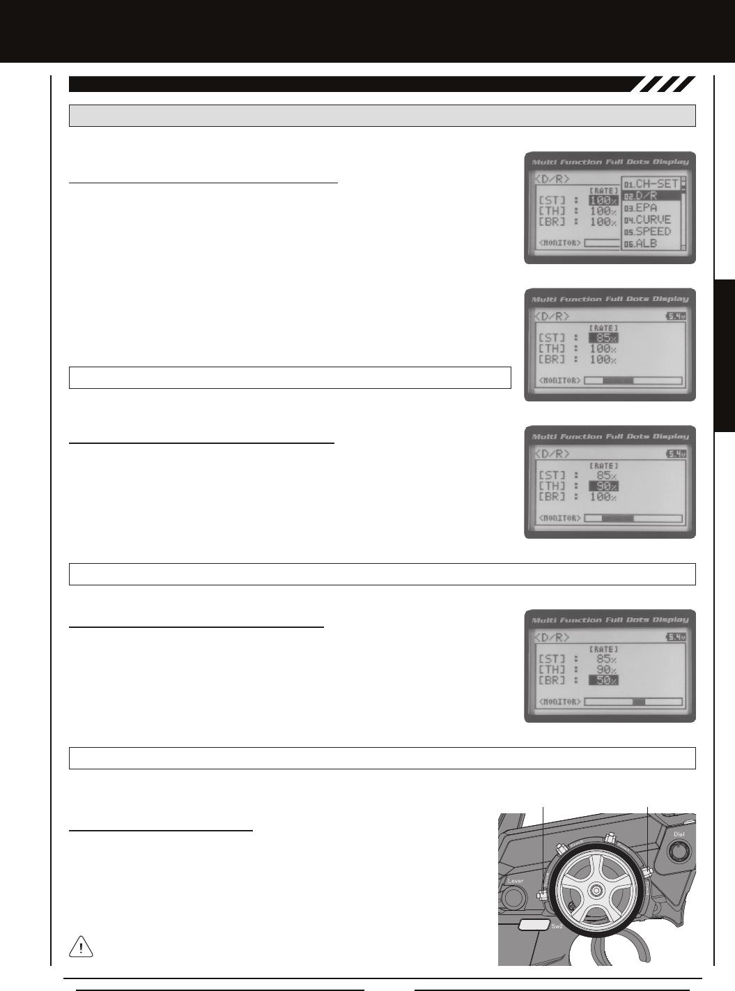
3) Press the ENTER key, then scroll UP or DOWN to increase or decrease the Steering
Dual Rate percentage value. When the Steering Dual Rate percentage value is decreased,
steering servo travel is decreased. When the Steering Dual Rate percentage value is
increased, steering servo travel is increased.
02.D/R (DUaL RaTE), cOnTinUED....
Adjusting the Steering Dual Rate Percentage Value
1) From the Top Screen, press the ENTER key to open the Programming Menu list.
2) Scroll UP or DOWN to highlight the D/R menu, then press the ENTER key. The D/R
menu will be displayed and [ST] : RATE 100% will be highlighted.
[[PROgRaMMing MEnUS
Adjusting the Throttle Dual Rate Percentage Value
1) From within the D/R menu, scroll UP or DOWN to highlight [TH] : RATE 100%.
2) Press the ENTER key, then scroll UP or DOWN to increase or decrease the Throttle
Dual Rate percentage value. When the Throttle Dual Rate percentage value is decreased,
Throttle High side servo travel is decreased. When the Throttle Dual Rate percentage
value is increased, Throttle High side servo travel is increased.
D/R TH RATE setting range is 0% to 100%. The default setting is 100%.
Adjusting the Brake Dual Rate Percentage Value
1) From within the D/R menu, scroll UP or DOWN to highlight [BR] : RATE 100%.
2) Press the ENTER key, then scroll UP or DOWN to increase or decrease the Brake
Dual Rate percentage value. When the Brake Dual Rate percentage value is decreased,
Throttle Brake side servo travel is decreased. When the Brake Dual Rate percentage
value is increased, Throttle Brake side servo travel is increased.
D/R BR RATE setting range is 0% to 100%. The default setting is 100%.
PRO TIP: Use the Servo Monitor at the bottom of the Dual Rate menu to see your programming changes in virtual real time.
Trm3 [ST]
Trm4 [TH]
Controlling the Dual Rate Function
1) By assigning the Steering, Throttle and Brake Dual Rate programming functions
to one or more of the Trim Switches, Auxiliary Lever or Dial Knob, these functions
can be adjusted while driving without accessing the Programming Menu. In
addition, these functions can be toggled 'OFF' and 'ON' by assigning them to one
or more Push-Button Switches. For more information, see the Key Assignments
section on pages 56 ~ 61.
In the default conguration, the Steering and Throttle Dual Rate programming
functions are adjusted using Trim Switch Trm3 and Trim Switch Trm4, respectively.

Page 22
[[PROgRaMMing MEnUS
03.EPa (EnD POinT aDjUSTMEnT)
The End Point Adjustment function allows you to adjust servo travel in each direction. This makes it possible to balance servo
travel in both directions and set the maximum desired amount of servo travel. For example, on a gas-powered model, if you pull
the throttle trigger and the carburetor does not open completely, you can increase the Throttle High End Point Adjustment so
that the carburetor opens completely. Another example is with steering. If your model turns sharper to the right than to the left,
you can increase the Steering Left End Point Adjustment to balance the steering. The End Point Adjustment function can be
adjusted for the Steering channel (Right and Left), the Throttle channel (Throttle High Side and Throttle Brake Side), Auxiliary 1
Channel 3 (High and Low) and Auxiliary 2 Channel 4 (High and Low).
PRO TIP: Use the Servo Monitor at the bottom of the End Point Adjustment menu to see your programming changes in
virtual real time.
WARNING End Point Adjustment percentage values should not be increased to the point where your linkages and servos
bind when moved all the way to the right or left. Binding will cause the servos to 'buzz', resulting in a quicker loss of battery
power and eventual damage to the servos.
1) From the Top Screen, press the ENTER key to open the Programming Menu list.
2) Scroll UP or DOWN to highlight the EPA menu, then press the ENTER key. The EPA
menu will be displayed and [ST] : EPA L100% will be highlighted.
Before making End Point Adjustments, the servo horn needs to be centered. Install the servo horn onto the servo, making
sure it's as close to being centered as possible, then use the Servo Sub-Trim function to center the servo arm exactly. For
more information, see the Adjusting the Servo Sub-Trim Values section on page 42.
Adjusting the Steering End Point Adjustment Percentage Values
Your model’s turning radius can differ from left to right because of variations in linkage, suspension balance, tire diameter, or
weight distribution. In such cases, Left Steering servo travel and Right Steering servo travel are adjustable using the End Point
Adjustment function.
EPA ST R setting range is 0% to 150%. The default setting is 100%.
4) From within the EPA menu, scroll DOWN to highlight [ST] : EPA R100%. Press the
ENTER key, then scroll UP or DOWN to increase or decrease the Steering Right End
Point Adjustment percentage value. Increasing the percentage value will increase
steering servo travel in that direction and decreasing the percentage
value will decrease steering servo travel in the direction.
3) Press the ENTER key, then scroll UP or DOWN to increase or decrease the Steering Left
End Point Adjustment percentage value. Increasing the percentage value will increase
steering servo travel in that direction and decreasing the percentage value will decrease
steering servo travel in the that direction.
EPA ST L setting range is 0% to 150%. The default setting is 100%.
Adjusting the Throttle End Point Adjustment Percentage Values
Your model's carburetor may not open completely, or it may open too much and cause the throttle servo to bind. If you're using an
Electronic Speed Control, the Electronic Speed Control may not command full power, or the brake may not engage adequately.
In such cases, Throttle High servo travel and Throttle Brake servo travel are adjustable using the End Point Adjustment function.
Steering EPA L/R can be adjusted from within the Channel Set menu. This option changes both Left and Right Steering
End Point Adjustment percentage values equally at the same time, which is similar to adjusting Steering Dual Rate.
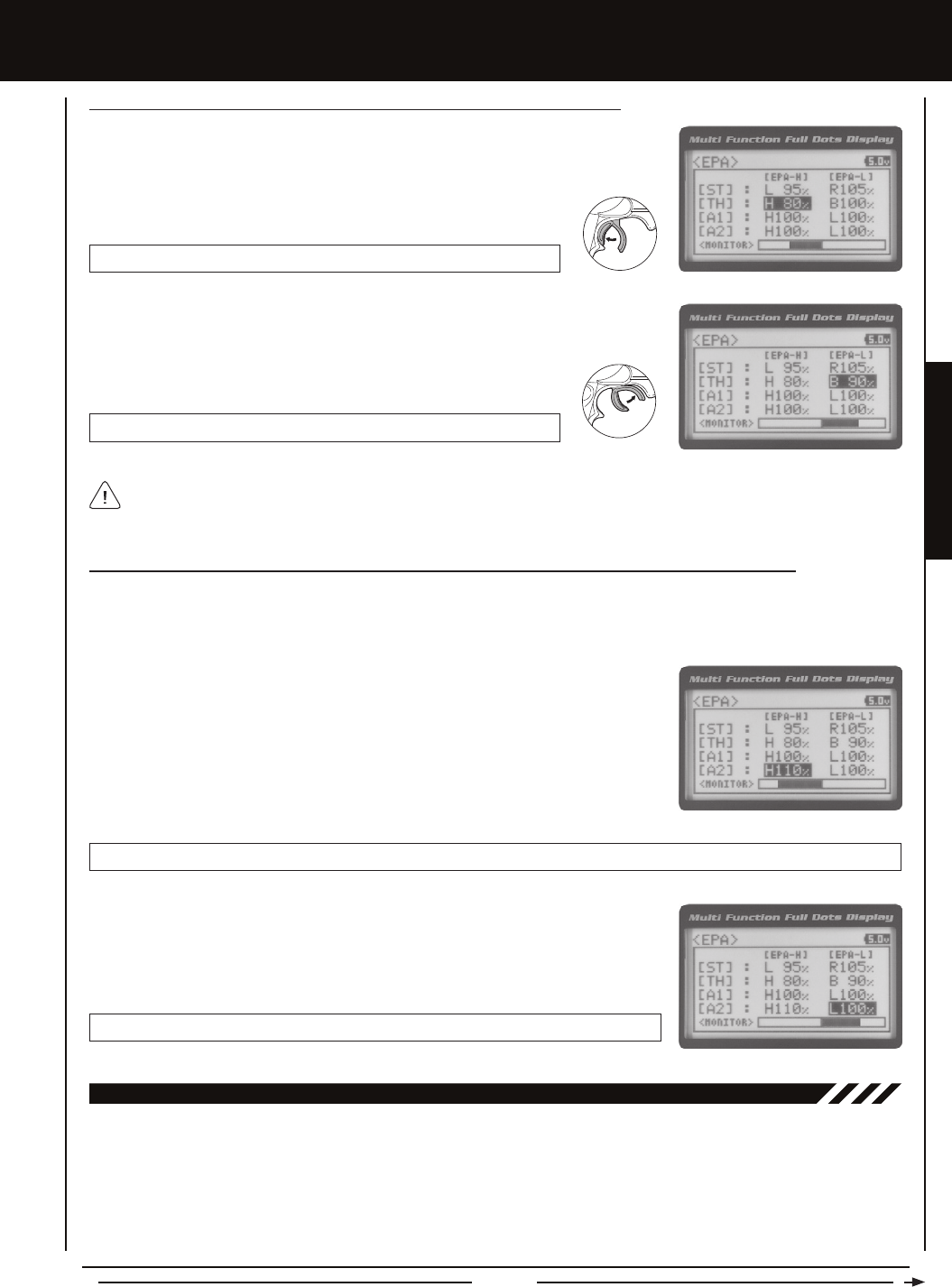
Page 23
PROGRAMMING MENUS
[[PROgRaMMing MEnUS
If you're using an Electronic Speed Control, the Throttle High and the Throttle Brake End Point Adjustment percentage
values are both generally set to 100%, although the Throttle High direction may need to be increased to achieve full power.
In some cases the End Point Adjustments can also be set directly via the Electronic Speed Control.
1) From within the EPA menu, scroll UP or DOWN to highlight [TH] : EPA H 100%.
2) Press the ENTER key, then scroll UP or DOWN to increase or decrease the Throttle High
End Point Adjustment percentage value. Increasing the percentage value will increase
Throttle High servo travel in that direction and decreasing the percentage
value will decrease Throttle High servo travel in that direction.
EPA TH H setting range is 0% to 150%. The default setting is 100%.
Adjusting the Throttle End Point Adjustment Percentage Values, Continued....
EPA TH B setting range is 0% to 150%. The default setting is 100%.
3) From within the EPA menu, scroll DOWN to [TH] : EPA B100%. Press the ENTER
key, then scroll UP or DOWN to increase or decrease the Throttle Brake End Point
Adjustment percentage value. Increasing the percentage value will increase Throttle
Brake servo travel in that direction and decreasing the percentage val-
ue will decrease Throttle Brake servo travel in that direction.
Adjusting the Auxiliary 1 Channel 3 and Auxiliary 2 Channel 4 End Point Adjustment Percentage Values
Auxiliary 1 Channel 3 and Auxiliary 2 Channel 4 can be used for a number of different uses. One of the more common uses would
be for the reverse function in a glow-powered monster truck. Often, the transmission only requires a small amount of throw, but
the servo binds because of too much servo travel. In such a case, Auxiliary High servo travel and Auxiliary Low servo travel are
adjustable using the End Point Adjustment function.
1) From within the EPA menu, scroll UP or DOWN to highlight [A1] : EPA H 100% or
[A2] : EPA H 100%.
2) Press the ENTER key, then scroll UP or DOWN to increase or decrease the Auxiliary
High End Point Adjustment percentage value. Increasing the percentage value will
increase auxiliary servo travel in that direction and decreasing the percentage value
will decrease auxiliary servo travel in that direction.
EPA A1 H and EPA A2 H setting range is 0% to 150%. The default setting is 100%.
EPA A1 L and EPA A2 L setting range is 0% to 150%. The default setting is 100%.
3) From within the EPA menu, scroll UP or DOWN to highlight [A1] : EPA L100% or
[A2] : EPA L100%. Press the ENTER key, then scroll UP or DOWN to increase or
decrease the Auxiliary Low End Point Adjustment percentage value. Increasing the
percentage value will increase auxiliary servo travel in that direction and decreasing the
percentage value will decrease auxiliary servo travel in that direction.
04.cURvE (EXPOnEnTiaL anD aRc aDjUSTMEnT)
The Exponential and Adjustable Rate Control (ARC) functions allow you to vary the amount of servo travel in relation to the
movement of the steering wheel, throttle trigger and auxiliary lever near the Neutral positions to change the way those functions
react to control movement. Decreasing the Exponential or Adjustable Rate Control percentage values will soften the control feel
around Neutral and increasing the Exponential or Adjustable Rate Control percentage values will heighten the control feel around
Neutral. Using a lower negative value allows for smoother control. Using a higher positive value may result in more 'twitchy'
control response. The Exponential and Adjustable Rate Control functions can be adjusted for the Steering channel, the Throttle
channel (Throttle High and Throttle Brake), Auxiliary 1 Channel 3 and Auxiliary 2 Channel 4. A graph that depicts the Exponential
or Adjustable Rate Control curve is featured to help visualize the changes you make.
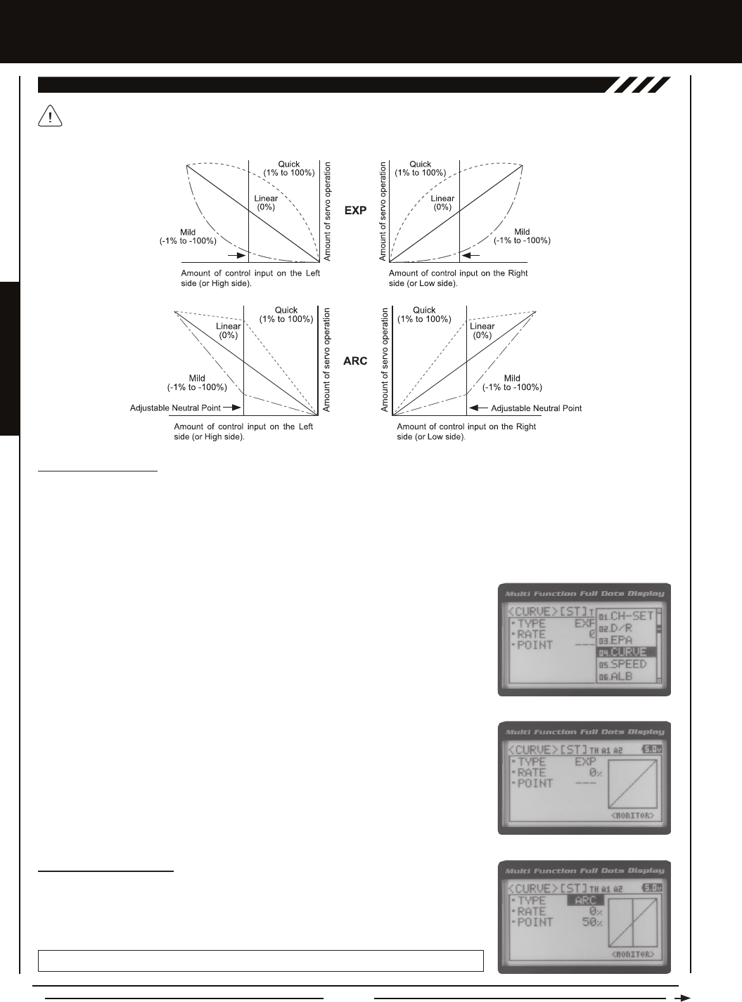
Page 24
[[PROgRaMMing MEnUS
04.cURvE (EXPOnEnTiaL anD aRc aDjUSTMEnT, cOnTinUED....)
Choosing the Channel
Exponential or Adjustable Rate Control percentage values can be adjusted from Mild through Linear to Quick to allow you to set
the most effective control response for your model. For example, if your model over-steers, reduce the Steering Exponential or
Adjustable Rate Control percentage value, and if your model under-steers, increase the Steering Exponential or Adjustable Rate
Control percentage value. As another example, reduce the Throttle Exponential or Adjustable Rate Control percentage value on a
slippery track or with a model that has a higher-torque motor or engine, and increase the Throttle Exponential or Adjustable Rate
Control percentage value on a high-grip track or with a model that has a lower-torque motor or engine.
The Exponential and Adjustable Rate Control functions work the same, except the Exponential Rate percentage value is
programmed from a xed Neutral Point of 50% and the Adjustable Rate Control Rate percentage value is programmed
from a user-adjustable Neutral Point, giving you even greater programming control.
1) From the Top Screen, press the ENTER key to open the Programming Menu list.
2) Scroll UP or DOWN to highlight the CURVE menu, then press the ENTER key. The
CURVE menu will be displayed and the cursor will default to [ST].
3) Scroll DOWN to move the cursor to the channel you would like to make programming
value changes to. Choose from <CURVE> [ST] (Steering), <CURVE> [TH] (Throttle),
<CURVE> [A1] (Auxiliary 1) or <CURVE> [A2] (Auxiliary 2).
Choosing the Curve Type
1) Press the ENTER key to highlight TYPE EXP. Press the ENTER key a second time, then
scroll UP or DOWN to choose the desired Curve Type. If you are programming the Curve
function for the Throttle channel, you have the option of adjusting the Curve Type for the
Throttle High Side (TYPE-H) and the Throttle Brake Side (TYPE-B) independently.
CURVE TYPE setting range is EXP and ARC. The default setting is EXP.
Fixed Neutral Point Fixed Neutral Point
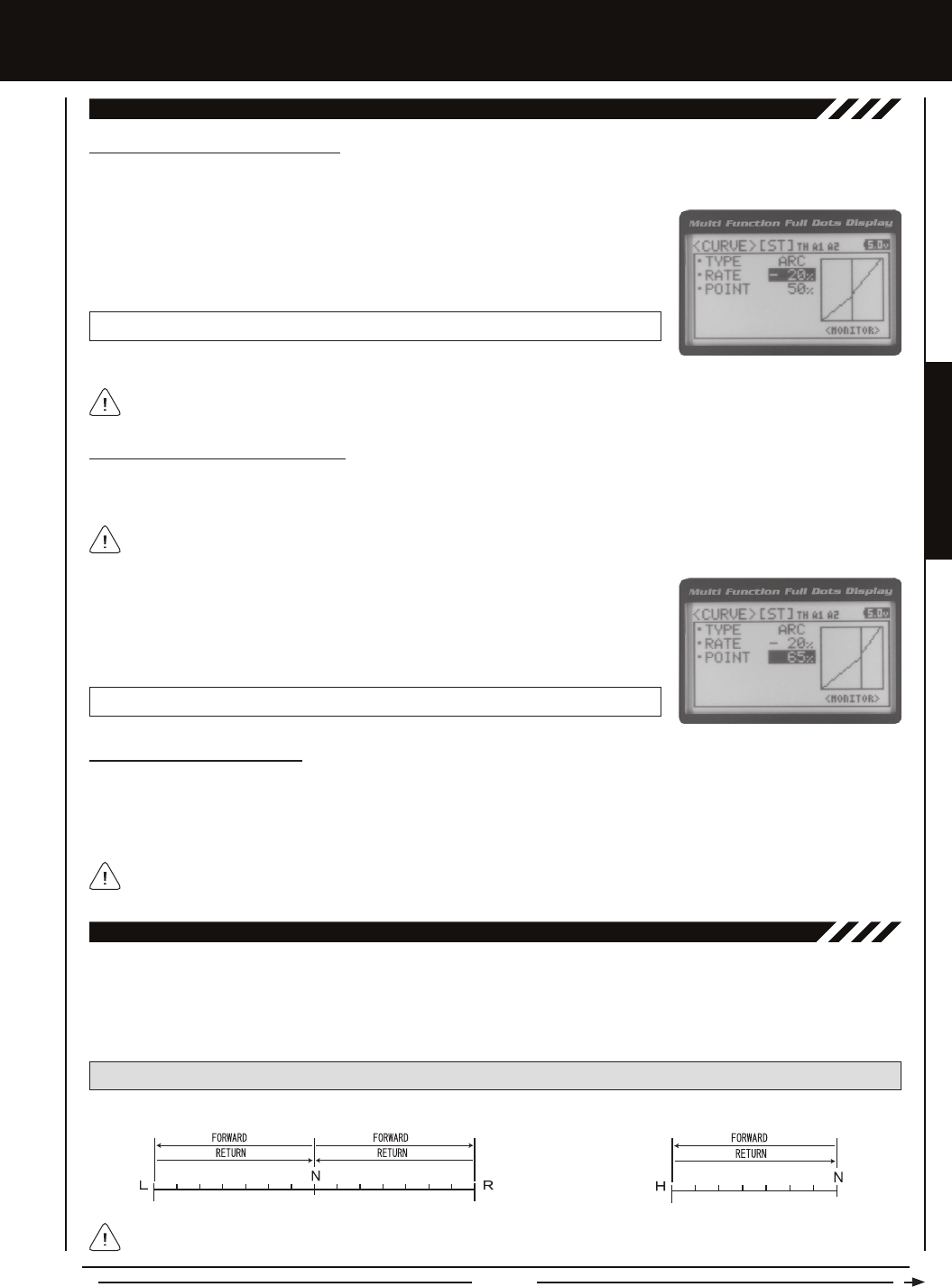
Page 25
PROGRAMMING MENUS
[[PROgRaMMing MEnUS
04.cURvE (EXPOnEnTiaL anD aRc aDjUSTMEnT, cOnTinUED....)
Adjusting the Rate Percentage Value
The Rate percentage value determines the desired amount and type of Exponential or Adjustable Rate Control.
1) From within the CURVE menu, scroll DOWN to highlight RATE 0%. Press the ENTER
key, then scroll UP or DOWN to increase or decrease the Rate percentage value. Using
a negative Rate percentage value will soften the control feel around Neutral and using
a positive Rate percentage value will heighten the control feel around Neutral.
CURVE RATE setting range is -100% (Mild) to 100% (Quick). The default setting is 0% (Linear).
Changes to the Rate percentage value affects both the channel High side and Low side equally, except for the Throttle
channel, which can be adjusted independently.
The Servo Speed function allows you to slow the transit speed of the Steering, Throttle, Auxiliary 1 and Auxiliary 2 servos. Servo
transit speed can be slowed in both the Forward and the Return to Neutral directions independently. When driving your model,
proper steering and throttle control are vital. For example, lowering the transit speed of the steering servo can help to limit
excessive steering, which will enable you to achieve smoother cornering. In addition, lowering the throttle servo speed can help
to ensure smooth throttle control.
05.SPEED (SERvO SPEED)
PRO TIP: Use the Servo Monitor at the bottom of the Speed menu to see your programming changes in virtual real time.
Adjusting the Point Percentage Value
The Point percentage value determines the Neutral Point where the Rate percentage value begins. For example, you may not
want the Point to be centered between the High and Low End Points. You may want the Point to be offset from the center position.
The Point percentage value option is available ONLY when the TYPE ARC option is selected.
1) From within the CURVE menu, scroll DOWN to highlight POINT 50%. Press the ENTER
key, then scroll UP or DOWN to increase or decrease the Point percentage value.
Increasing the Point percentage value will shift the Neutral Point to one side of center
and decreasing the Point percentage value will shift the Neutral Point to the opposite
side of center.
CURVE POINT setting range is 5% to 95%. The default setting is 50% (Centered).
Controlling the Curve Function
1) By assigning the Steering, Throttle High and Throttle Brake Rate and Point programming functions to one or more of the Trim
Switches, Auxiliary Lever or Dial Knob, these functions can be adjusted while driving without accessing the Programming
Menu. In addition, the Steering Curve and Throttle Curve functions can be Toggled 'OFF' and 'ON' by assigning them to one
or more Push-Button Switches. For more information, see the Key Assignments section on pages 56 ~ 61.
Auxiliary 1 and Auxiliary 2 Rate and Point programming functions cannot be assigned.
Neutral Right End PointLeft End Point NeutralHigh Side End Point
Steering, Auxiliary 1 and Auxiliary 2 Throttle
Throttle Servo Speed affects only the Throttle High Side. The Throttle Brake Side is unaffected.
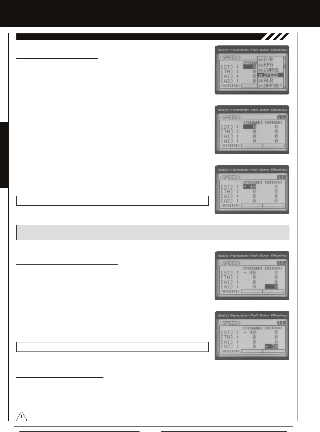
Page 26
[[PROgRaMMing MEnUS
3) Scroll UP or DOWN to highlight the desired channel you would like to change the
Forward Speed value for. Choose from either [ST] : FORWARD 0 (Steering),
[TH] : FORWARD 0 (Throttle), [A1] : FORWARD 0 (Auxiliary 1) or [A2] : FORWARD 0
(Auxiliary 2).
4) Press the ENTER key, then scroll DOWN to decrease servo Speed in the Forward
direction. Decreasing the Forward Speed value will cause the servo transit time to slow
down when it moves from the Neutral position to either End Point.
SPEED FORWARD setting range is -100 to 0. The default setting is 0 (Normal Speed).
Adjusting the Return to Neutral Speed Value
1) From within the SPEED menu, scroll UP or DOWN to highlight the desired channel you
would like to change the Return to Neutral Speed value for. Choose from either [ST] :
RETURN 0 (Steering), [TH] : RETURN 0 (Throttle), [A1] : RETURN 0 (Auxiliary 1) or
[A2] : RETURN 0 (Auxiliary 2).
2) Press the ENTER key, then scroll DOWN to decrease servo Speed in the Return to
Neutral direction. Decreasing the Return to Neutral Speed value will cause the servo
transit time to slow down when it moves from either End Point to the Neutral position.
SPEED RETURN setting range is -100 to 0. The default setting is 0 (Normal Speed).
Adjusting the Forward Speed Value
1) From the Top Screen, press the ENTER key to open the Programming Menu list.
2) Scroll UP or DOWN to highlight the SPEED menu, then press the ENTER key. The
SPEED menu will be displayed and [ST] : FORWARD 0 will be highlighted.
05.SPEED (SERvO SPEED), cOnTinUED....
Controlling the Servo Speed Function
1) By assigning the Steering and Throttle Forward and Return to Neutral Speed programming functions to one or more of the
Trim Switches, Auxiliary Lever or Dial Knob, these functions can be adjusted while driving without accessing the Programming
Menu. In addition, the Steering Speed and Throttle Speed functions can be Toggled 'OFF' and 'ON' by assigning them to one
or more Push-Button Switches. For more information, see the Key Assignments section on pages 56 ~ 61.
Auxiliary 1 and Auxiliary 2 Forward and Return to Neutral Speed programming functions cannot be assigned.
IMPORTANT: Throttle Servo Speed affects only the Throttle High Side. The Throttle Brake Side is unaffected. See Throttle
diagram on previous page.
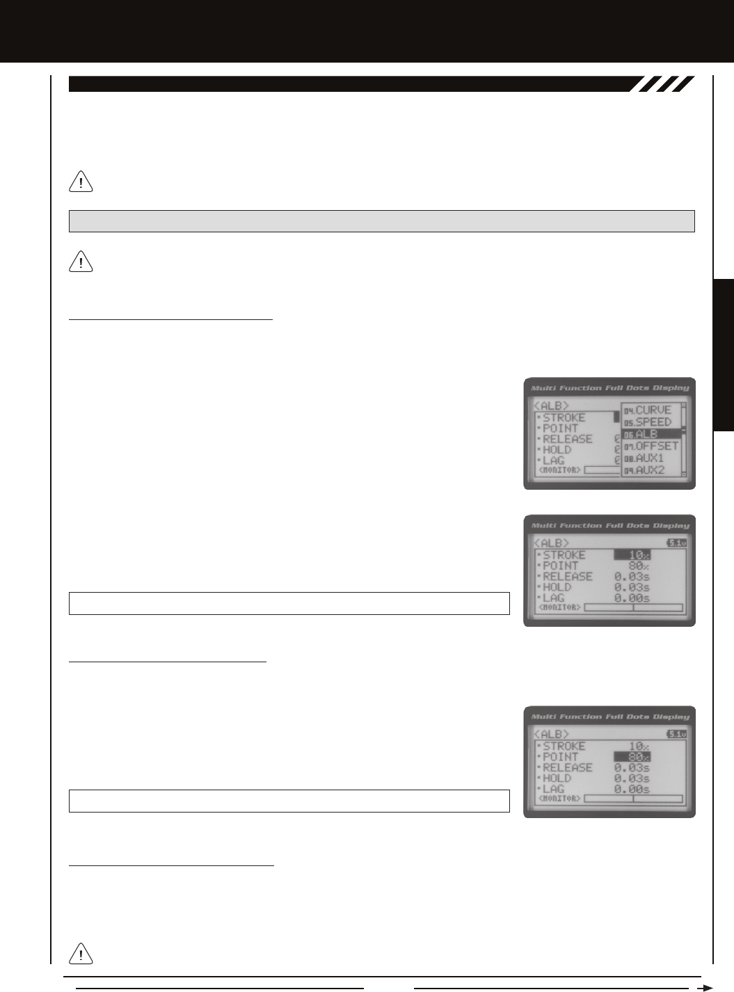
Page 27
PROGRAMMING MENUS
[[PROgRaMMing MEnUS
The Anti-Lock Braking function makes it possible to achieve stable braking even on a slippery surface. With stable braking, your
model is better able to trace an exact line under braking. The Anti-Lock Braking function also enables you to set different braking
characteristics depending on your particular model. Different Anti-Lock Braking function options can be custom programmed,
including the how quickly the brake pulsates, the point at which the Anti-Lock Braking function starts and more.
06.aLB (anTi-LOck BRaking)
The Anti-Lock Braking function operates only when the throttle trigger is moved from Neutral to the Brake side. Set the
hardest braking you can obtain from your model by carefully setting the Anti-Lock Braking function at the point right before
the tires fully lock up but do not slip and lose traction.
PRO TIP: Use the Servo Monitor at the bottom of the ALB menu to see your programming changes in virtual real time.
1) From the Top Screen, press the ENTER key to open the Programming Menu list.
2) Scroll UP or DOWN to highlight the ALB menu, then press the ENTER key. The ALB
menu will be displayed and STROKE OFF will be highlighted.
Adjusting the Stroke Percentage Value
The Stroke percentage value determines the amount of Brake that's applied automatically when the Anti-Lock Braking function
Activates. When set to 'OFF', the Anti-Lock Braking function will not work. A percentage value of 1% or greater must be
programmed for the Anti-Lock Braking function to operate.
3) Press the ENTER key, then scroll UP or DOWN to increase or decrease the Stroke
percentage value. Increasing the Stroke percentage value will increase throttle servo
travel in the Brake direction and decreasing the Stroke percentage value will decrease
throttle servo travel in the Brake direction.
ALB STROKE setting range is OFF to 100%. The default setting is OFF.
Adjusting the Point Percentage Value
The Point percentage value determines the position along the servo travel that the Anti-Lock Braking function Activates.
1) From within the ALB menu, scroll DOWN to highlight POINT 80%. Press the ENTER
key, then scroll UP or DOWN to increase or decrease the Point percentage value.
Increasing the Point percentage value will cause the Anti-Lock Braking function to
Activate later and decreasing the Point percentage value will cause the Anti-Lock
Braking function to Activate sooner.
ALB POINT setting range is 5% to 100%. The default setting is 80%.
Adjusting the Release and Hold Values
The Release and Hold values determine the speed at which the brake pulsates. By adjusting the Release and Hold values, you
can make the brake pulsate faster or slower. The Release value determines how quickly the Brake moves from Neutral to the
percentage value determined by the Stroke setting and the Hold value determines how quickly the Brake moves from the Stroke
setting to Neutral.
We recommend using equal Release and Hold values, although different values can be used to ne-tune how the Brake
pulsates. Using lower values make the Brake pulsate faster and using higher values make the Brake pulsate slower.
When the Anti-Lock Braking function is Active, LED 1 (Blue) will ash rapidly.
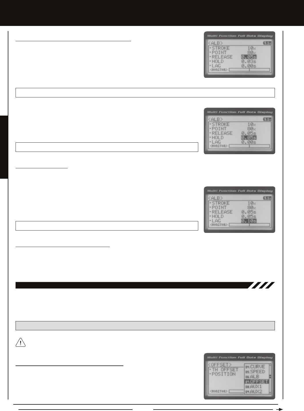
Page 28
Adjusting the Lag Value
The Lag value determines the amount of delay before the Anti-Lock Braking function Activates after reaching the POINT setting.
1) From within the ALB menu, scroll DOWN to highlight LAG 0.00s. Press the ENTER
key, then scroll UP and DOWN to increase or decrease the Lag value. Increasing the
Lag value increases the delay time to Activate the Anti-Lock Braking function after
reaching the Point setting and decreasing the Lag value decreases the delay time to
Activate the Anti-Lock Braking function after reaching the Point setting.
ALB LAG setting range is 0.00s to 1.00s. The default setting is 0.00s.
Controlling the Anti-Lock Braking Function
1) By assigning the Anti-Lock Braking Point, Stroke, Lag, Hold and Release programming functions to one or more of the Trim
Switches, Auxiliary Lever or Dial Knob, these functions can be adjusted while driving without accessing the Programming Menu.
In addition, the Anti-Lock Braking function can be Toggled 'OFF' and 'ON' by assigning it to one of the Push-Button Switches.
For more information, see the Key Assignments section on pages 56 ~ 61.
[[PROgRaMMing MEnUS
Adjusting the Release and Hold Values, Continued....
1) From within the ALB menu, scroll DOWN to highlight RELEASE 0.03s. Press the ENTER
key, then scroll UP or DOWN to increase or decrease the Release value. Increasing the
Release value will cause the Brake to move from Neutral to the Stroke setting slower
and decreasing the Release value will cause the Brake to move from Neutral to the
Stroke setting faster.
ALB RELEASE setting range is 0.01s to 1.00s. The default setting is 0.03s.
2) From within the ALB menu, scroll DOWN to highlight HOLD 0.03s. Press the ENTER
key, then scroll UP or DOWN to increase or decrease the Hold value. Increasing the
Hold value will cause the Brake to move from the Stroke setting to the Neutral position
slower and decreasing the Hold value will cause the Brake to move from the Stroke
setting to the Neutral position slower.
ALB HOLD setting range is 0.01s to 1.00s. The default setting is 0.03s.
The Throttle Offset function allows you to shift the Neutral position of the throttle servo, either toward the High Side or the Brake
Side. When used in conjunction with a Push-Button Switch, this function can be used several different ways. For example, if you're
driving a glow- or gas-powered model, you can program the Throttle Offset function to shut down your engine with the press of a
button. In addition, you can program the Throttle Offset function to increase to a steady idle while you're refueling during a race.
07.OFFSET (THROTTLE OFFSET)
PRO TIP: Use the Servo Monitor at the bottom of the OFFSET menu to see your programming changes in virtual real time.
The Throttle Offset function shifts the Neutral position of the throttle servo without affecting the High or Low End Points.
Turning the Throttle Offset Function 'ON' or 'OFF'
1) From the Top Screen, press the ENTER key to open the Programming Menu list.
2) Scroll UP or DOWN to highlight the OFFSET menu, then press the ENTER key. The
OFFSET menu will be displayed and TH OFFSET OFF will be highlighted.

Page 29
PROGRAMMING MENUS
[[PROgRaMMing MEnUS
Turning the Throttle Offset Function 'ON' or 'OFF', Continued....
3) Press the ENTER key, then scroll UP or DOWN to change the Throttle Offset value to
'ON' or 'OFF'.
OFFSET TH OFFSET setting range is OFF to ON. The default setting is OFF.
Although the Throttle Offset value is set to 'ON', the Throttle Offset function will not operate until a Position percentage
value is programmed.
Adjusting the Throttle Offset Position Percentage Value
1) From within the OFFSET menu, scroll DOWN to highlight POSITION 0%. Press the
ENTER key, then scroll UP to shift the throttle servo Neutral position the desired
amount toward the Throttle High Side or scroll DOWN to shift the throttle servo Neutral
position the desired amount toward the Throttle Brake Side.
OFFSET POSITION setting range is H100% to B100%. The default setting is 0%.
When a Position percentage value is programmed and the Throttle Offset function is Active, LED 1 (Blue) will ash rapidly
and OFFS will be displayed on the Top Screen.
The Auxiliary 1 Programming function allows you to program the ve different Auxiliary Programming functions that are controlled
by Auxiliary 1 Channel 3. Use the table below to determine the different functions that are available:
08.aUX1 (aUXiLiaRY 1 PROgRaMMing)
FUNCTION FUNCTION NAME FUNCTION DESCRIPTION
S_AUX
P_AUX
4WS
MOA
A_MIX
Step Auxiliary
Point Auxiliary
Four Wheel Steering Mixing
Motor On Axle Dual Throttle Mixing
Auxiliary Mixing
Controls Step Values That the Auxiliary Servo Travels
Controls Specic Points That the Auxiliary Servo Travels
Controls Four Wheel Steering Options
Controls Dual Throttle Options
Controls User-Dened Auxiliary 1 Channel 3 Mixing Options
IMPORTANT: Prior to programming an Auxiliary 1 Programming function you must rst choose the desired Auxiliary
Programming function in the SYSTEM AUX TYPE menu. Only one Auxiliary 1 Programming function can be Active at any
given time.
The Step Auxiliary function allows you to program the Auxiliary 1 servo to move a dened amount when toggled 'ON' and 'OFF'
using a Push-Button Switch. For example, if you assign Auxiliary 1 to a Push-Button Switch, then program the Step Auxiliary
percentage value to 50%, the Auxiliary 1 servo will travel from the Neutral position to 50% of travel when the Push-Button Switch
is pressed. Press the Push-Button switch a second time and the Auxiliary 1 servo will travel back to the Neutral position. This is
useful to control simple ON/OFF functions, such as a reverse servo for a transmission or a mechanical switch to turn lights 'ON'
and 'OFF', etc.
Controlling the Throttle Offset Function
1) By assigning the Throttle Offset Position programming function to one of the Trim Switches, Auxiliary Lever or Dial Knob, this
function can be adjusted while driving without accessing the Programming Menu. In addition, the Throttle Offset function can be
Toggled 'OFF' and 'ON' by assigning it to one of the Push-Button Switches. For more information, see the Key Assignments
section on pages 56 ~ 61.
The Step Auxiliary Position value can be adjusted while you're driving using one of the four Trim Switches, the Rotary Dial
or the Auxiliary Lever. The Step Auxiliary function can be toggled 'OFF' and 'ON' by assigning Auxiliary 1 to one of the two
Push-Button Switches. This allows you to control when the Auxiliary 1 servo travels to the programmed Step Auxiliary position.
STEP (STEP aUXiLiaRY)
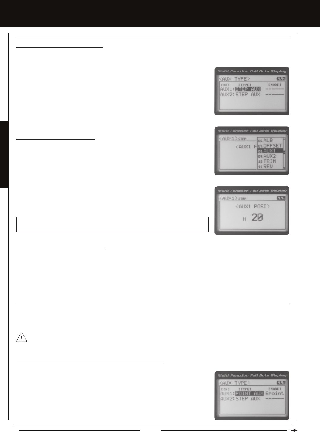
Page 30
[[PROgRaMMing MEnUS
STEP (STEP aUXiLiaRY), cOnTinUED....
POinT (POinT aUXiLiaRY)
The Point Auxiliary function allows you to program the Auxiliary 1 servo to move up to 6 different Points along its travel, then cycle
through those Points using one of the Trim Switches or the Rotary Dial. For example, if your model requires a separate 3-position
or more switch to operate a feature, the Point Auxiliary function can be customized to control this.
Adjusting the Step Auxiliary Value
1) From the Top Screen, press the ENTER key to open the Programming Menu list.
2) Scroll UP or DOWN to highlight the AUX1 menu, then press the ENTER key. The AUX1
STEP menu will be displayed and <AUX1 POSI> 0 will be shown.
3) Press the ENTER key, then scroll UP or DOWN to change the Auxiliary 1 Position
value. Increasing the value toward the High side (H) or Low side (L) will cause the
Auxiliary 1 servo to travel to that specic position when you Activate the Auxiliary 1 Step
function.
AUX1 STEP AUX1 POSI setting range is H100 to L100. The default setting is 0. This
value is a percentage of Auxiliary 1 servo travel.
2) Scroll UP or DOWN to highlight the SYSTEM menu, then press the ENTER key. Scroll
DOWN to highlight the AUX TYPE menu, then press the ENTER key.
3) Press the ENTER key, then scroll UP or DOWN to choose the AUX 1: STEP AUX
function.
Choosing the Step Auxiliary Function
1) From the Top Screen, press the ENTER key to open the Programming Menu list.
Use one of the four Trim Switches or the Rotary Dial to cycle through the Point positions while you're driving. The Point
Auxiliary function can be toggled 'OFF' and 'ON' while you're driving by assigning Auxiliary 1 to one of the two Push-Button
Switches.
2) Scroll UP or DOWN to highlight the SYSTEM menu, then press the ENTER key. Scroll
DOWN to highlight the AUX TYPE menu, then press the ENTER key.
3) Press the ENTER key, then scroll UP or DOWN to choose the AUX 1: POINT AUX
function.
Choosing the Point Auxiliary Function and the Number of Points
1) From the Top Screen, press the ENTER key to open the Programming Menu list.
Controlling the Step Auxiliary Function
1) In the default conguration, Auxiliary 1 is controlled by the Rotary Dial which allows the Step Auxiliary function to be adjusted
while driving without accessing the Programming Menu. Turn the Rotary Dial clockwise to increase the Position High Side
value and turn the Rotary Dial counter-clockwise to increase the Position Low Side value. In addition, Auxiliary 1 can be
assigned to one of the four Trim Switches or the Auxiliary Lever. The Step Auxiliary function can be toggled 'OFF' and 'ON' by
assigning Auxiliary 1 to one of the two Push-Button Switches. This allows you to control when the Auxiliary 1 servo travels to
the programmed Step Auxiliary position. For more information, see the Key Assignments section on pages 56 ~ 61.
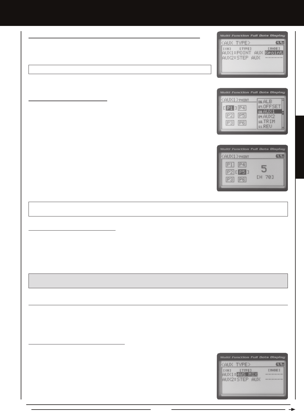
Page 31
PROGRAMMING MENUS
[[PROgRaMMing MEnUS
Choosing the Point Auxiliary Function and the Number of Points, Continued....
4) From within the AUX TYPE menu, scroll DOWN to highlight [MODE] 6 POINT. Press
the ENTER key, then scroll UP or DOWN to choose the desired number of Points you
would like to program.
AUX TYPE POINT setting range is 2point to 6point. The default setting is 6point.
Adjusting the Point Auxiliary Values
1) From the Top Screen, press the ENTER key to open the Programming Menu list.
2) Scroll UP or DOWN to highlight the AUX1 menu, then press the ENTER key. The AUX1
POINT menu will be displayed and the last Point selected will be highlighted.
3) Scroll UP or DOWN to move the brackets to the Point you would like to change, then
press the ENTER key to highlight that Point.
4) Press the ENTER key, then scroll UP or DOWN to change the Point value. Increasing
the Point value toward the High side (H) or Low side (L) will cause the Auxiliary 1 servo
to travel to that specic position when you cycle through the various Points.
5) Repeat steps 3 and 4 to change the desired remaining Point values.
AUX1 POINT setting range is H100 to L100. The default setting for Point 1 is L100, for Point 2 is L60, for Point 3 is L20, for
Point 4 is H20, for Point 5 is H60, and for Point 6 is H100. These values are a percentage of Auxiliary 1 servo travel.
Controlling the Point Auxiliary Function
1) In the default conguration, Auxiliary 1 is controlled by the Rotary Dial. Turn the Rotary Dial clockwise to cycle Forward
through the programmed Point Auxiliary positions and turn the Rotary Dial counter-clockwise to cycle Backward through the
programmed Point Auxiliary positions. The Auxiliary 1 servo will move to the specied Point positions as you cycle through the
different Points. In addition, Auxiliary 1 can be assigned to one of the four Trim Switches. The Point Auxiliary function can be
toggled 'OFF' and 'ON' by assigning Auxiliary 1 to one of the two Push-Button Switches. For more information, see the Key
Assignments section on pages 56 ~ 61.
IMPORTANT: To operate correctly, the TRIM or DIAL Step value must be set to 1. If set to a value other than 1, Point
positions will be skipped as you cycle through them. For more information, see the Key Assignments section on pages 56 ~ 61.
4wS (FOUR wHEEL STEERing MiXing)
The Four Wheel Steering Mixing function allows you to use Auxiliary 1 Channel 3 as a second steering channel, allowing you
to use two separate steering servos for Front and Rear steering. The Four Wheel Steering Mixing function allows you to control
either the Front or Rear steering independently, or Mix the Front and Rear steering to have Parallel Four Wheel Steering or
Tandem Four Wheel Steering.
2) Scroll UP or DOWN to highlight the SYSTEM menu, then press the ENTER key. Scroll
DOWN to highlight the AUX TYPE menu, then press the ENTER key.
3) Press the ENTER key, then scroll UP or DOWN to choose the AUX 1: 4WS MIX function.
Choosing the Four Wheel Steering Function
1) From the Top Screen, press the ENTER key to open the Programming Menu list.

Page 32
[[PROgRaMMing MEnUS
Choosing Four Wheel Steering Mixing Options
1) From the Top Screen, press the ENTER key to open the Programming Menu list.
2) Scroll UP or DOWN to highlight the AUX1 menu, then press the ENTER key. The AUX1
4WS menu will be displayed and the last Steering option selected will be highlighted.
3) Scroll UP or DOWN to move the brackets to the Four Wheel Steering option you would
like to use, then press the ENTER key to highlight that option. The highlighted option is
now Active.
PRO TIP: Use the Servo Monitor at the bottom of the AUX 1 4WS menu to see your programming changes in virtual real time.
The following Four Wheel Steering Mixing options are available:
Rear Wheel Steering - When highlighted, only the Rear Steering will operate.
Parallel (Normal) Four Wheel Steering - When highlighted, both the Front and
Rear Steering will operate in Parallel.
Tandem (Reverse) Four Wheel Steering - When highlighted, both the Front
and Rear Steering will operate in Tandem.
Front Wheel Steering - When highlighted, only the Front Steering will operate.
If the steering servos do not operate as described above, you can use the Servo Reversing function to change the direction
that each servo operates. For more information, see the Servo Reversing section on page 44.
4wS (FOUR wHEEL STEERing MiXing), cOnTinUED....
Use the Rotary Dial or one of the four Trim Switches to cycle through the different Four Wheel Steering options while
you're driving. The Four Wheel Steering Mixing function can be toggled 'OFF' and 'ON' while you're driving by assigning
Auxiliary 1 to one of the two Push-Button Switches.
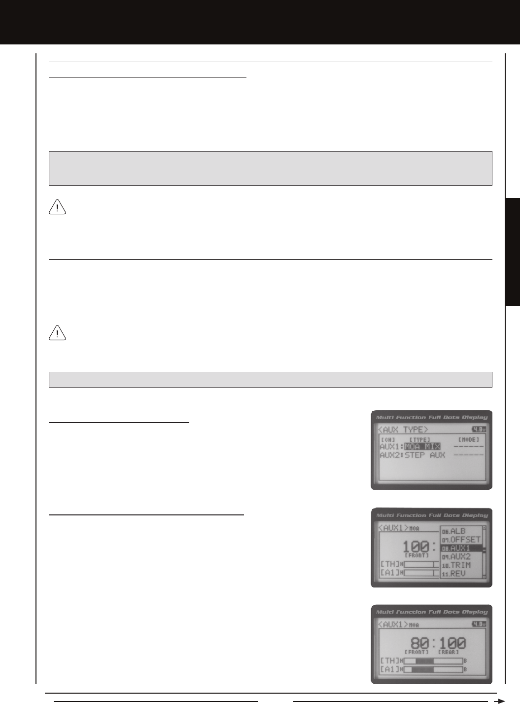
Page 33
PROGRAMMING MENUS
[[PROgRaMMing MEnUS
Controlling the Four Wheel Steering Mixing Function
1) In the default conguration, Auxiliary 1 is controlled by the Rotary Dial. Turn the Rotary Dial clockwise to cycle Forward
through the Four Wheel Steering options (FRONT > REAR > NORMAL > REVERSE) and turn the Rotary Dial counter-clockwise
to cycle Backward through the Four Wheel Steering options (REVERSE > NORMAL > REAR > FRONT). In addition, Auxiliary
1 can be assigned to one of the four Trim Switches. The Four Wheel Steering Mixing function can be toggled 'OFF' and 'ON'
by assigning Auxiliary 1 to one of the two Push-Button Switches. For more information, see the Key Assignments section
on pages 56 ~ 61.
IMPORTANT: To operate correctly, the DIAL or TRIM Step value must be set to 1. If set to a value other than 1, Four
Wheel Steering Mixing options will be skipped as you cycle through them. For more information, see the Key Assignments
section on pages 56 ~ 61.
When using Four Wheel Steering, it's important to adjust the Steering Channel 1 and Auxiliary 1 Channel 3 Sub-Trim
values to center both servos. This will ensure that your model tracks straight. In addition, remember that you are able
to independently adjust the Auxiliary 1 Channel 3 Dual Rate, Exponential, Sub-Trim, Servo Speed settings and more to allow for
the optimum Four Wheel Steering Mixing setup.
4wS (FOUR wHEEL STEERing MiXing), cOnTinUED....
MOa (MOTOR On aXLE MiXing)
The Motor on Axle Mixing function allows you to use Auxiliary 1 Channel 3 as a second throttle channel, allowing you to use
two separate throttle servos or ESCs. The Motor on Axle Mixing function is typically used in Rock Crawling and allows you to
control either the Front and Rear motors together or independently, giving you Normal (Balanced), Dig and Burn functions. And
when
coupled with the ability to variably change the power distribution between the Front and Rear motors, allows the utmost
in func
tionality.
Choosing the Motor on Axle Function
1) From the Top Screen, press the ENTER key to open the Programming Menu list.
2) Scroll UP or DOWN to highlight the SYSTEM menu, then press the ENTER key. Scroll
DOWN to highlight the AUX TYPE menu, then press the ENTER key.
3) Press the ENTER key, then scroll UP or DOWN to choose the AUX 1: MOA MIX function.
Changing Motor on Axle Power Distribution Options
You are able to program Normal (Balanced), Dig and Burn functions by changing the
Power Distribution between the two motors.
1) From the Top Screen, press the ENTER key to open the Programming Menu list.
2) Scroll UP or DOWN to highlight the AUX1 menu, then press the ENTER key. The AUX1
MOA menu will be displayed.
PRO TIP: Use the Servo Monitor at the bottom of the AUX 1 MOA menu to see your programming changes in virtual real time.
3) Press the ENTER key, then scroll UP or DOWN to change the Power Distribution
between the Front and Rear motors. Scrolling UP will reduce the available power to the
Rear motor (Dig) and scrolling DOWN will reduce the power to the Front motor (Burn).
Use the Rotary Dial, one of the four Trim Switches or the Auxiliary Lever to Activate the Dig and Burn functions while you're
driving. The Motor on Axle Mixing function can be toggled 'OFF' and 'ON' while you're driving by assigning Auxiliary 1 to
one of the two Push-Button Switches.

Page 34
Front Throttle BURN - When set to 0:100, power will only be distributed to the
Rear motor (Burn). Power can be distributed proportionally between the Front
and Rear motors from 0:100 to 99:100.
Rear Throttle DIG - When set to 100:0, power will only be distributed to the Front
motor (Dig). Power can be distributed proportionally between the Front and Rear
motors from 100:0 to 100:99.
Normal (Balanced) - When set to 100:100, power will be evenly distributed
between the Front and Rear motors.
[[PROgRaMMing MEnUS
Changing Motor on Axle Power Distribution Options, Continued....
The following Motor on Axle Mixing options are available:
Controlling the Motor on Axle Mixing Function
1) In the default conguration, Auxiliary 1 is controlled by the Rotary Dial. Turn the Rotary Dial clockwise to reduce the available
power to the Rear motor (Dig) and turn the Rotary Dial counter-clockwise to reduce the power to the Front motor (Burn).
In addition, Auxiliary 1 can be assigned to one of the four Trim Switches or to the Auxiliary Lever. The Motor on Axle Mixing
function can be toggled 'OFF' and 'ON' by assigning Auxiliary 1 to one of the two Push-Button Switches. For more information,
see the Key Assignments section on pages 56 ~ 61.
IMPORTANT: In the default conguration, the Rotary Dial Step value is set to 5. This allows you to adjust the Power Distribution in
5 percent increments. If you prefer to control the Dig and Burn functions as if they were assigned to an ON/OFF switch, change
the DIAL Step value to 100. Alternately, the Motor on Axle Mixing function can be controlled by the Auxiliary Lever. This allows
you to quickly switch between the Dig and Burn functions and still have the ability to variably change the Power Distribution
between the Front and Rear motors. To set this up, change the Auxiliary Lever Function to AUX1, then change the TWEAK (H)
value to +100 and the TWEAK (L) value to -100. For more information, see the Key Assignments section on pages 56 ~ 61.
When using the Motor on Axle function, it's important to adjust the Throttle Channel 2 and Auxiliary 1 Channel 3 Sub-Trim
values so both motors' idle (or 'OFF') settings are equal. This will ensure correct function. In addition, remember that you
are able to independently adjust the Auxiliary 1 Channel 3 Dual Rate, Exponential, Sub-Trim, Servo Speed settings and more to
allow for the optimum Motor on Axle Mixing setup.
aUX MiX (aUXiLiaRY MiXing)
The Auxiliary Mixing function allows you to Mix either Steering Channel 1 or Throttle Channel 2 to Auxiliary 1 Channel 3, while
maintaining separate Sub-Trim, End Point Adjustments, Servo Reversing and other channel-specic settings. The Auxiliary
Mixing function is used when a custom Mix is necessary. For example, if your monster truck features dual Front steering servos,
instead of using a Y-Harness to join the two steering servos together, you can use Steering Mixing to operate both steering servos
together and still be able to make adjustments to each servo separately. In addition, if your model features a third-channel brake,
you could use Throttle Mixing to control it along with the channel 2 brake.
The Auxiliary Mixing Rate percentage value can be adjusted while you're driving using one of the four Trim Switches,
the Rotary Dial or the Auxiliary Lever. The Auxiliary Mixing function can be toggled 'OFF' and 'ON' while you're driving
by assigning Auxiliary 1 to one of the two Push-Button Switches.
PRO TIP: Use the Servo Monitor at the bottom of the AUX 1 AUX MIX menu to see your programming changes in virtual
real time.
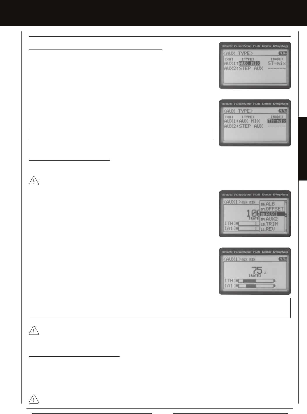
Page 35
PROGRAMMING MENUS
[[PROgRaMMing MEnUS
Choosing the Auxiliary Mixing Function and the Mixing Type
1) From the Top Screen, press the ENTER key to open the Programming Menu list.
2) Scroll UP or DOWN to highlight the SYSTEM menu, then press the ENTER key. Scroll
DOWN to highlight the AUX TYPE menu, then press the ENTER key.
3) Press the ENTER key, then scroll UP or DOWN to choose the AUX 1: AUX MIX function.
4) From within the AUX TYPE menu, scroll DOWN to highlight [MODE] ST-mix. Press the
ENTER key, then scroll UP or DOWN to choose the desired Mixing type you would like
to program. Choose from either ST-mix (Steering Mixing) or TH-mix (Throttle Mixing).
AUX TYPE MIX setting range is ST-mix and TH-mix. The default setting is ST-mix.
Adjusting the Rate Percentage Value
The Rate percentage value denes how far the Auxiliary 1 servo travels relative to either the Steering servo or the Throttle servo.
1) From the Top Screen, press the ENTER key to open the Programming Menu list.
2) Scroll UP or DOWN to highlight the AUX1 menu, then press the ENTER key. The AUX1
AUX MIX menu will be displayed.
3) Press the ENTER key, then scroll UP or DOWN to change the Rate percentage value.
Decreasing the Rate percentage value will reduce the amount the Auxiliary 1 servo
travels relative to the Steering servo or Throttle servo and increasing the Rate
percentage value will increase the amount the Auxiliary 1 servo travels relative to the
Steering servo or Throttle servo.
AUX1 AUX MIX RATE setting range is 100% to 0%. The default setting is 100%. This Mix is Linear. For example, if the Rate
percentage value is set to 100%, the Auxiliary 1 servo will travel the same amount as the Steering servo. Additionally, if the
Rate percentage value is set to 50%, the Auxiliary 1 servo will travel half the amount as the Steering servo.
The Master channel (either Steering Channel 1 or Throttle Channel 2) always controls the Slave channel (Auxiliary 1
Channel 3).
Controlling the Auxiliary Mixing Function
1) In the default conguration, Auxiliary 1 is controlled by the Rotary Dial. Turn the Rotary Dial clockwise to increase the Rate
percentage value and turn the Rotary Dial counter-clockwise to decrease the Rate percentage value. In addition, the Auxiliary
Mixing Rate function can be assigned to one of the four Trim Switches or the Auxiliary Lever. The Auxiliary Mixing function
can be toggled 'OFF' and 'ON' by assigning Auxiliary 1 to one of the two Push-Button Switches. For more information, see the
Key Assignments section on pages 56 ~ 61.
aUX MiX (aUXiLiaRY MiXing), cOnTinUED....
In the default conguration, the Auxiliary 1 servo will travel in the same direction as the Steering servo or Throttle servo. To
apply the Mix in the opposite direction, change the Servo Reversing value of Auxiliary 1 Channel 3. For more information,
see the Servo Reversing section on page 44.
Remember that you are able to independently adjust the Auxiliary 1 Channel 3 Dual Rate, Exponential, Sub-Trim, Servo
Speed settings and more to allow for the optimum Auxiliary Mixing setup.
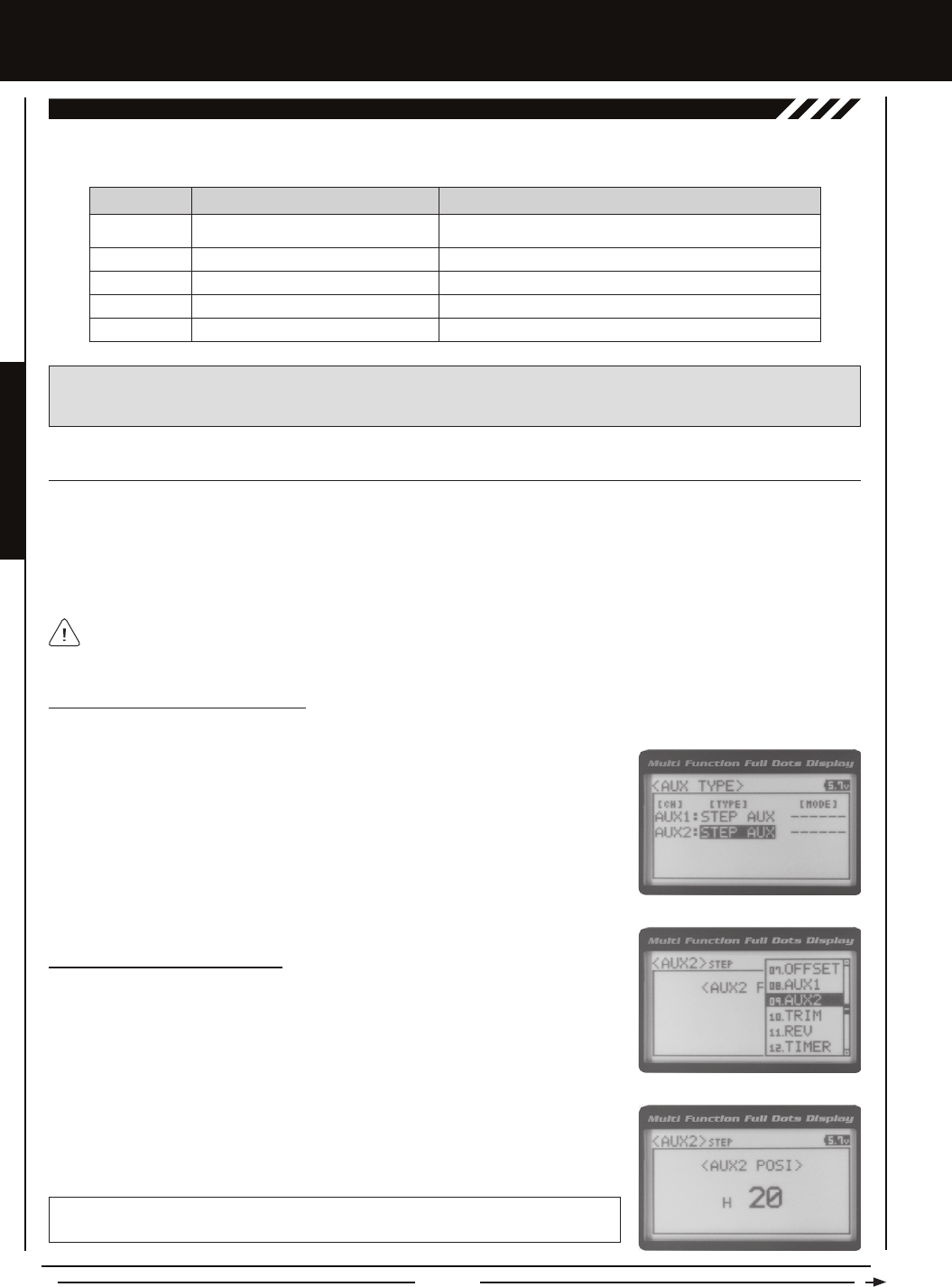
Page 36
[[PROgRaMMing MEnUS
The Auxiliary 2 Programming function allows you to program the ve different Auxiliary Programming functions that are controlled
by Auxiliary 2 Channel 4. Use the table below to determine the different functions that are available:
09.aUX2 (aUXiLiaRY 2 PROgRaMMing)
FUNCTION FUNCTION NAME FUNCTION DESCRIPTION
S_AUX
P_AUX
4WS
MOA
A_MIX
Step Auxiliary
Point Auxiliary
Four Wheel Steering Mixing
Motor On Axle Dual Throttle Mixing
Auxiliary Mixing
Controls Step Values That the Auxiliary Servo Travels
Controls Specic Points That the Auxiliary Servo Travels
Controls Four Wheel Steering Options
Controls Dual Throttle Options
Controls User-Dened Auxiliary 2 Channel 4 Mixing Options
IMPORTANT: Prior to programming an Auxiliary 2 Programming function you must rst choose the desired Auxiliary
Programming function in the SYSTEM AUX TYPE menu. Only one Auxiliary 2 Programming function can be Active at any
given time.
The Step Auxiliary function allows you to program the Auxiliary 2 servo to move a dened amount when toggled 'ON' and 'OFF'
using a Push-Button Switch. For example, if you assign Auxiliary 2 to a Push-Button Switch, then program the Step Auxiliary
percentage value to 50%, the Auxiliary 2 servo will travel from the Neutral position to 50% of travel when the Push-Button Switch
is pressed. Press the Push-Button switch a second time and the Auxiliary 2 servo will travel back to the Neutral position. This is
useful to control simple ON/OFF functions, such as a reverse servo for a transmission or a mechanical switch to turn lights 'ON'
and 'OFF', etc.
The Step Auxiliary Position value can be adjusted while you're driving using one of the four Trim Switches, the Rotary Dial
or the Auxiliary Lever. The Step Auxiliary function can be toggled 'OFF' and 'ON' by assigning Auxiliary 2 to one of the two
Push-Button Switches. This allows you to control when the Auxiliary 2 servo travels to the programmed Step Auxiliary position.
STEP (STEP aUXiLiaRY)
Adjusting the Step Auxiliary Value
1) From the Top Screen, press the ENTER key to open the Programming Menu list.
2) Scroll UP or DOWN to highlight the AUX2 menu, then press the ENTER key. The AUX2
STEP menu will be displayed and <AUX2 POSI> 0 will be shown.
3) Press the ENTER key, then scroll UP or DOWN to change the Auxiliary 2 Position
value. Increasing the value toward the High side (H) or Low side (L) will cause the
Auxiliary 2 servo to travel to that specic position when you Activate the Auxiliary 2 Step
function.
AUX2 STEP AUX2 POSI setting range is H100 to L100. The default setting is 0. This
value is a percentage of Auxiliary 2 servo travel.
2) Scroll UP or DOWN to highlight the SYSTEM menu, then press the ENTER key. Scroll
DOWN to highlight the AUX TYPE menu, then press the ENTER key.
3) Press the ENTER key, then scroll UP or DOWN to choose the AUX 2: STEP AUX
function.
Choosing the Step Auxiliary Function
1) From the Top Screen, press the ENTER key to open the Programming Menu list.
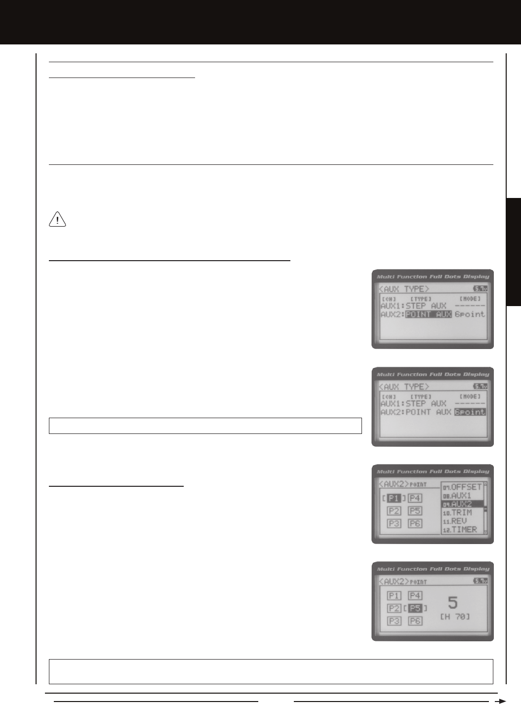
Page 37
PROGRAMMING MENUS
[[PROgRaMMing MEnUS
Controlling the Step Auxiliary Function
1) In the default conguration, Auxiliary 2 is controlled by the Rotary Dial which allows the Step Auxiliary function to be adjusted
while driving without accessing the Programming Menu. Turn the Rotary Dial clockwise to increase the Position High Side
value and turn the Rotary Dial counter-clockwise to increase the Position Low Side value. In addition, Auxiliary 2 can be
assigned to one of the four Trim Switches or the Auxiliary Lever. The Step Auxiliary function can be toggled 'OFF' and 'ON' by
assigning Auxiliary 2 to one of the two Push-Button Switches. This allows you to control when the Auxiliary 2 servo travels to
the programmed Step Auxiliary position. For more information, see the Key Assignments section on pages 56 ~ 61.
STEP (STEP aUXiLiaRY), cOnTinUED....
POinT (POinT aUXiLiaRY)
The Point Auxiliary function allows you to program the Auxiliary 2 servo to move up to 6 different Points along its travel, then cycle
through those Points using one of the Trim Switches or the Rotary Dial. For example, if your model requires a separate 3-position
or more switch to operate a feature, the Point Auxiliary function can be customized to control this.
Use one of the four Trim Switches or the Rotary Dial to cycle through the Point positions while you're driving. The Point
Auxiliary function can be toggled 'OFF' and 'ON' while you're driving by assigning Auxiliary 2 to one of the two Push-Button
Switches.
2) Scroll UP or DOWN to highlight the SYSTEM menu, then press the ENTER key. Scroll
DOWN to highlight the AUX TYPE menu, then press the ENTER key.
3) Press the ENTER key, then scroll UP or DOWN to choose the AUX 2: POINT AUX
function.
Choosing the Point Auxiliary Function and the Number of Points
1) From the Top Screen, press the ENTER key to open the Programming Menu list.
4) From within the AUX TYPE menu, scroll DOWN to highlight [MODE] 6 POINT. Press
the ENTER key, then scroll UP or DOWN to choose the desired number of Points you
would like to program.
AUX TYPE POINT setting range is 2point to 6point. The default setting is 6point.
Adjusting the Point Auxiliary Values
1) From the Top Screen, press the ENTER key to open the Programming Menu list.
2) Scroll UP or DOWN to highlight the AUX1 menu, then press the ENTER key. The AUX2
POINT menu will be displayed and the last Point selected will be highlighted.
3) Scroll UP or DOWN to move the brackets to the Point you would like to change, then
press the ENTER key to highlight that Point.
4) Press the ENTER key, then scroll UP or DOWN to change the Point value. Increasing
the Point value toward the High side (H) or Low side (L) will cause the Auxiliary 2 servo
to travel to that specic position when you cycle through the various Points.
5) Repeat steps 3 and 4 to change the desired remaining Point values.
AUX2 POINT setting range is H100 to L100. The default setting for Point 1 is L100, for Point 2 is L60, for Point 3 is L20, for
Point 4 is H20, for Point 5 is H60, and for Point 6 is H100. These values are a percentage of Auxiliary 2 servo travel.
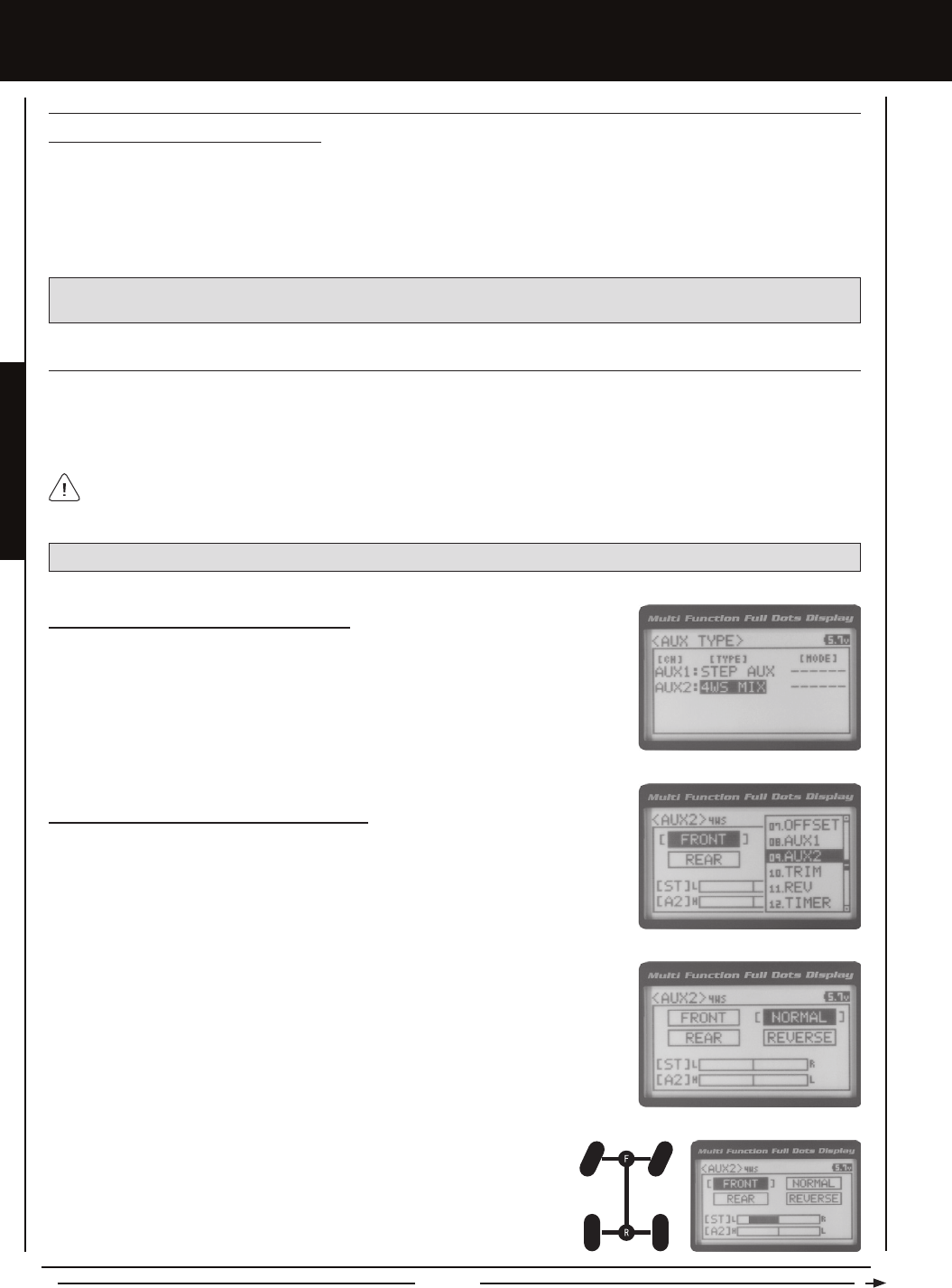
Page 38
[[PROgRaMMing MEnUS
POinT (POinT aUXiLiaRY), cOnTinUED....
Controlling the Point Auxiliary Function
1) In the default conguration, Auxiliary 2 is controlled by the Rotary Dial. Turn the Rotary Dial clockwise to cycle Forward
through the programmed Point Auxiliary positions and turn the Rotary Dial counter-clockwise to cycle Backward through the
programmed Point Auxiliary positions. The Auxiliary 2 servo will move to the specied Point positions as you cycle through the
different Points. In addition, Auxiliary 2 can be assigned to one of the four Trim Switches. The Point Auxiliary function can be
toggled 'OFF' and 'ON' by assigning Auxiliary 2 to one of the two Push-Button Switches. For more information, see the Key
Assignments section on pages 56 ~ 61.
IMPORTANT: To operate correctly, the TRIM or DIAL Step value must be set to 1. If set to a value other than 1, Point
positions will be skipped as you cycle through them. For more information, see the Key Assignments section on pages 56 ~ 61.
4wS (FOUR wHEEL STEERing MiXing)
The Four Wheel Steering Mixing function allows you to use Auxiliary 2 Channel 4 as a second steering channel, allowing you
to use two separate steering servos for Front and Rear steering. The Four Wheel Steering Mixing function allows you to control
either the Front or Rear steering independently, or Mix the Front and Rear steering to have Parallel Four Wheel Steering or
Tandem Four Wheel Steering.
Choosing the Four Wheel Steering Function
1) From the Top Screen, press the ENTER key to open the Programming Menu list.
2) Scroll UP or DOWN to highlight the SYSTEM menu, then press the ENTER key. Scroll
DOWN to highlight the AUX TYPE menu, then press the ENTER key.
3) Press the ENTER key, then scroll UP or DOWN to choose the AUX 2: 4WS MIX function.
Choosing Four Wheel Steering Mixing Options
1) From the Top Screen, press the ENTER key to open the Programming Menu list.
2) Scroll UP or DOWN to highlight the AUX2 menu, then press the ENTER key. The AUX2
4WS menu will be displayed and the last Steering option selected will be highlighted.
3) Scroll UP or DOWN to move the brackets to the Four Wheel Steering option you would
like to use, then press the ENTER key to highlight that option. The highlighted option is
now Active.
PRO TIP: Use the Servo Monitor at the bottom of the AUX 2 4WS menu to see your programming changes in virtual real time.
Use the Rotary Dial or one of the four Trim Switches to cycle through the different Four Wheel Steering options while
you're driving. The Four Wheel Steering Mixing function can be toggled 'OFF' and 'ON' while you're driving by assigning
Auxiliary 2 to one of the two Push-Button Switches.
Front Wheel Steering - When highlight led, only the Front Steering will operate.
The following Four Wheel Steering Mixing options are available:
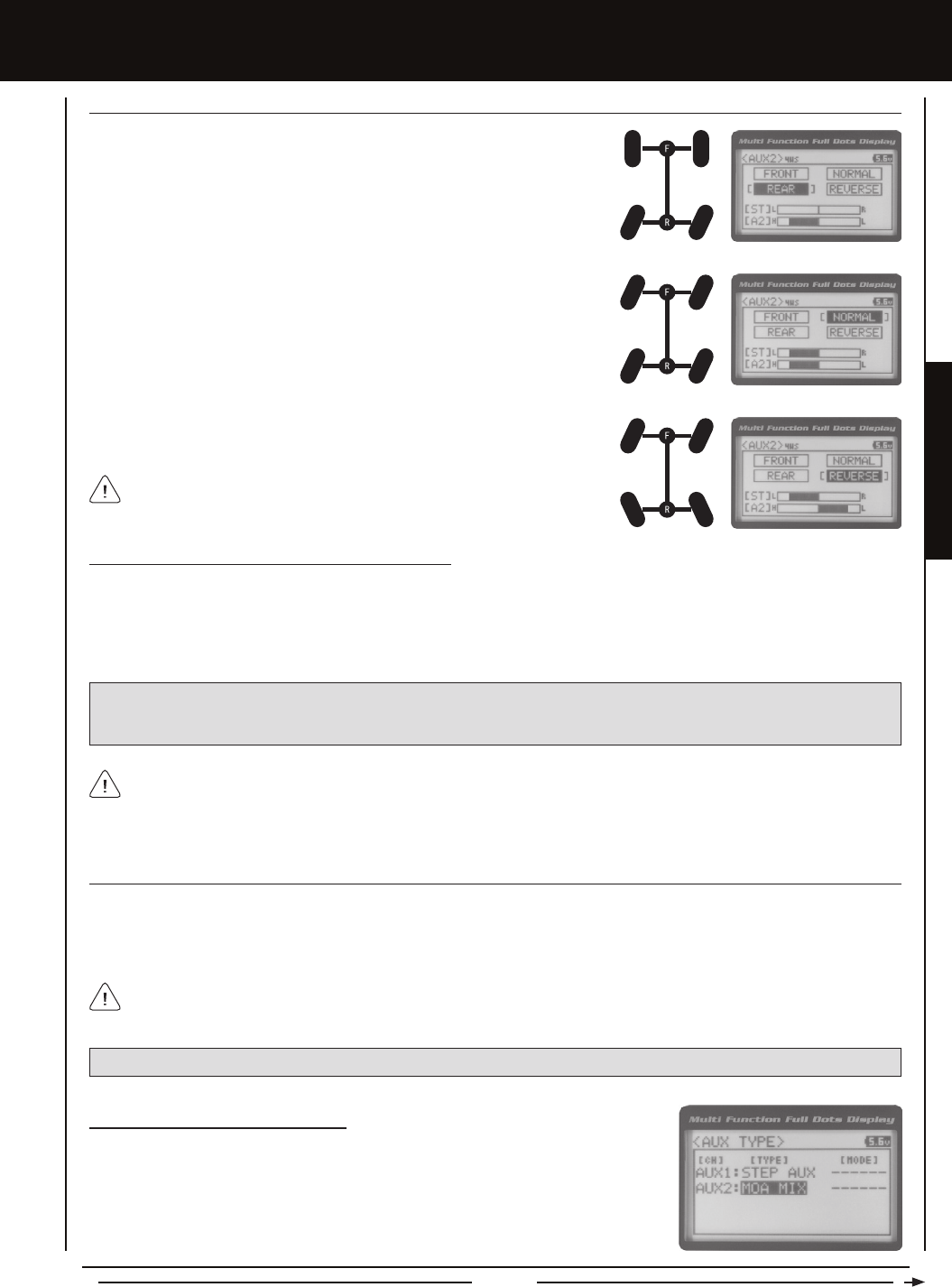
Page 39
PROGRAMMING MENUS
[[PROgRaMMing MEnUS
4wS (FOUR wHEEL STEERing MiXing), cOnTinUED....
Rear Wheel Steering - When highlighted, only the Rear Steering will operate.
Parallel (Normal) Four Wheel Steering - When highlighted, both the Front and
Rear Steering will operate in Parallel.
Tandem (Reverse) Four Wheel Steering - When highlighted, both the Front
and Rear Steering will operate in Tandem.
If the steering servos do not operate as described above, you can use the
Servo Reversing function to change the direction that each servo operates.
For more information, see the Servo Reversing section on page 44.
Controlling the Four Wheel Steering Mixing Function
1) In the default conguration, Auxiliary 2 is controlled by the Rotary Dial. Turn the Rotary Dial clockwise to cycle Forward through
the Four Wheel Steering options (FRONT > REAR > NORMAL > REVERSE) and turn the Rotary Dial counter-clockwise to cycle
Backward through the Four Wheel Steering options (REVERSE > NORMAL > REAR > FRONT). In addition, Auxiliary 2 can be
assigned to one of the four Trim Switches. The Four Wheel Steering Mixing function can be toggled 'OFF' and 'ON' by assigning
Auxiliary 2 to one of the two Push-Button Switches. For more information, see the Key Assignments section on pages 56 ~ 61.
IMPORTANT: To operate correctly, the DIAL or TRIM Step value must be set to 1. If set to a value other than 1, Four
Wheel Steering Mixing options will be skipped as you cycle through them. For more information, see the Key Assignments
section on pages 56 ~ 61.
When using Four Wheel Steering, it's important to adjust the Steering Channel 1 and Auxiliary 2 Channel 4 Sub-Trim
values to center both servos. This will ensure that your model tracks straight. In addition, remember that you are able
to independently adjust the Auxiliary 2 Channel 4 Dual Rate, Exponential, Sub-Trim, Servo Speed settings and more to allow for
the optimum Four Wheel Steering Mixing setup.
MOa (MOTOR On aXLE MiXing)
The Motor on Axle Mixing function allows you to use Auxiliary 2 Channel 4 as a second throttle channel, allowing you to use two
separate throttle servos or ESCs. The Motor on Axle Mixing function is typically used in Rock Crawling and allows you to control
either the Front and Rear motors together or independently, giving you Normal (Balanced), Dig and Burn functions. And when
coupled with the ability to variably change the power distribution between the Front and Rear motors, allows the utmost in func
tionality.
PRO TIP: Use the Servo Monitor at the bottom of the AUX 2 MOA menu to see your programming changes in virtual real time.
Use the Rotary Dial, one of the four Trim Switches or the Auxiliary Lever to Activate the Dig and Burn functions while you're
driving. The Motor on Axle Mixing function can be toggled 'OFF' and 'ON' while you're driving by assigning Auxiliary 2 to
one of the two Push-Button Switches.
Choosing the Motor on Axle Function
1) From the Top Screen, press the ENTER key to open the Programming Menu list.
2) Scroll UP or DOWN to highlight the SYSTEM menu, then press the ENTER key. Scroll
DOWN to highlight the AUX TYPE menu, then press the ENTER key.
3) Press the ENTER key, then scroll UP or DOWN to choose the AUX 2: MOA MIX function.
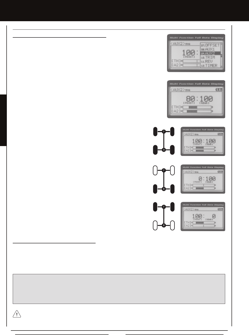
Page 40
MOa (MOTOR On aXLE MiXing), cOnTinUED....
Changing Motor on Axle Power Distribution Options
You are able to program Normal (Balanced), Dig and Burn functions by changing the
Power Distribution between the two motors.
1) From the Top Screen, press the ENTER key to open the Programming Menu list.
2) Scroll UP or DOWN to highlight the AUX2 menu, then press the ENTER key. The AUX1
MOA menu will be displayed.
3) Press the ENTER key, then scroll UP or DOWN to change the Power Distribution
between the Front and Rear motors. Scrolling UP will reduce the available power to the
Rear motor (Dig) and scrolling DOWN will reduce the power to the Front motor (Burn).
Front Throttle BURN - When set to 0:100, power will only be distributed to the
Rear motor (Burn). Power can be distributed proportionally between the Front
and Rear motors from 0:100 to 99:100.
Rear Throttle DIG - When set to 100:0, power will only be distributed to the Front
motor (Dig). Power can be distributed proportionally between the Front and Rear
motors from 100:0 to 100:99.
Normal (Balanced) - When set to 100:100, power will be evenly distributed
between the Front and Rear motors.
The following Motor on Axle Mixing options are available:
Controlling the Motor on Axle Mixing Function
1) In the default conguration, Auxiliary 2 is controlled by the Rotary Dial. Turn the Rotary Dial clockwise to reduce the available
power to the Rear motor (Dig) and turn the Rotary Dial counter-clockwise to reduce the power to the Front motor (Burn).
In addition, Auxiliary 2 can be assigned to one of the four Trim Switches or to the Auxiliary Lever. The Motor on Axle Mixing
function can be toggled 'OFF' and 'ON' by assigning Auxiliary 2 to one of the two Push-Button Switches. For more information,
see the Key Assignments section on pages 56 ~ 61.
IMPORTANT: In the default conguration, the Rotary Dial Step value is set to 5. This allows you to adjust the Power Distribution in
5 percent increments. If you prefer to control the Dig and Burn functions as if they were assigned to an ON/OFF switch, change
the DIAL Step value to 100. Alternately, the Motor on Axle Mixing function can be controlled by the Auxiliary Lever. This allows
you to quickly switch between the Dig and Burn functions and still have the ability to variably change the Power Distribution
between the Front and Rear motors. To set this up, change the Auxiliary Lever Function to AUX2, then change the TWEAK (H)
value to +100 and the TWEAK (L) value to -100. For more information, see the Key Assignments section on pages 56 ~ 61.
When using the Motor on Axle function, it's important to adjust the Throttle Channel 2 and Auxiliary 2 Channel 4 Sub-Trim
values so both motors' idle (or 'OFF') settings are equal. This will ensure correct function. In addition, remember that you
are able to independently adjust the Auxiliary 2 Channel 4 Dual Rate, Exponential, Sub-Trim, Servo Speed settings and more to
allow for the optimum Motor on Axle Mixing setup.
[[PROgRaMMing MEnUS
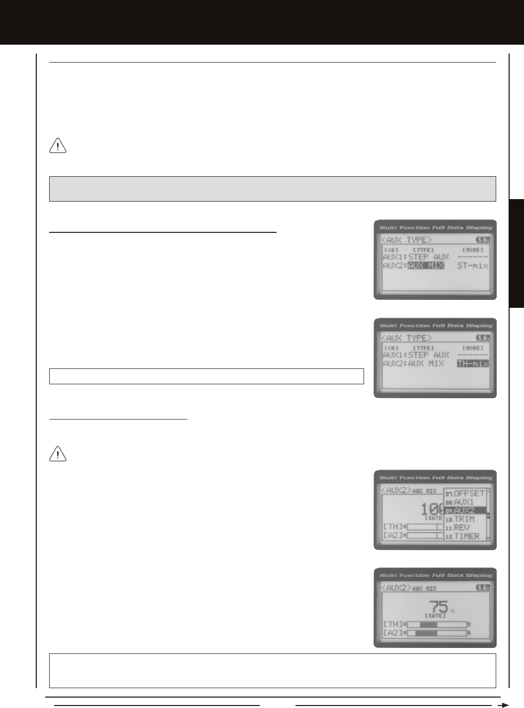
Page 41
PROGRAMMING MENUS
aUX MiX (aUXiLiaRY MiXing)
The Auxiliary Mixing function allows you to Mix either Steering Channel 1 or Throttle Channel 2 to Auxiliary 2 Channel 4, while
maintaining separate Sub-Trim, End Point Adjustments, Servo Reversing and other channel-specic settings. The Auxiliary
Mixing function is used when a custom Mix is necessary. For example, if your monster truck features dual Front steering servos,
instead of using a Y-Harness to join the two steering servos together, you can use Steering Mixing to operate both steering ser-
vos together and still be able to make adjustments to each servo separately. In addition, if your model features a fourth-channel
brake, you could use Throttle Mixing to control it along with the channel 2 brake.
The Auxiliary Mixing Rate percentage value can be adjusted while you're driving using one of the four Trim Switches,
the Rotary Dial or the Auxiliary Lever. The Auxiliary Mixing function can be toggled 'OFF' and 'ON' while you're driving
by assigning Auxiliary 2 to one of the two Push-Button Switches.
PRO TIP: Use the Servo Monitor at the bottom of the AUX 2 AUX MIX menu to see your programming changes in virtual
real time.
Choosing the Auxiliary Mixing Function and the Mixing Type
1) From the Top Screen, press the ENTER key to open the Programming Menu list.
2) Scroll UP or DOWN to highlight the SYSTEM menu, then press the ENTER key. Scroll
DOWN to highlight the AUX TYPE menu, then press the ENTER key.
3) Press the ENTER key, then scroll UP or DOWN to choose the AUX 2: AUX MIX function.
4) From within the AUX TYPE menu, scroll DOWN to highlight [MODE] ST-mix. Press the
ENTER key, then scroll UP or DOWN to choose the desired Mixing type you would like
to program. Choose from either ST-mix (Steering Mixing) or TH-mix (Throttle Mixing).
AUX TYPE MIX setting range is ST-mix and TH-mix. The default setting is ST-mix.
Adjusting the Rate Percentage Value
The Rate percentage value denes how far the Auxiliary 2 servo travels relative to either the Steering servo or the Throttle servo.
1) From the Top Screen, press the ENTER key to open the Programming Menu list.
2) Scroll UP or DOWN to highlight the AUX2 menu, then press the ENTER key. The AUX2
AUX MIX menu will be displayed.
3) Press the ENTER key, then scroll UP or DOWN to change the Rate percentage value.
Decreasing the Rate percentage value will reduce the amount the Auxiliary 2 servo
travels relative to the Steering servo or Throttle servo and increasing the Rate
percentage value will increase the amount the Auxiliary 2 servo travels relative to the
Steering servo or Throttle servo.
AUX2 AUX MIX RATE setting range is 100% to 0%. The default setting is 100%. This Mix is Linear. For example, if the Rate
percentage value is set to 100%, the Auxiliary 2 servo will travel the same amount as the Steering servo. Additionally, if the
Rate percentage value is set to 50%, the Auxiliary 2 servo will travel half the amount as the Steering servo.
The Master channel (either Steering Channel 1 or Throttle Channel 2) always controls the Slave channel (Auxiliary 2
Channel 4).
[[PROgRaMMing MEnUS
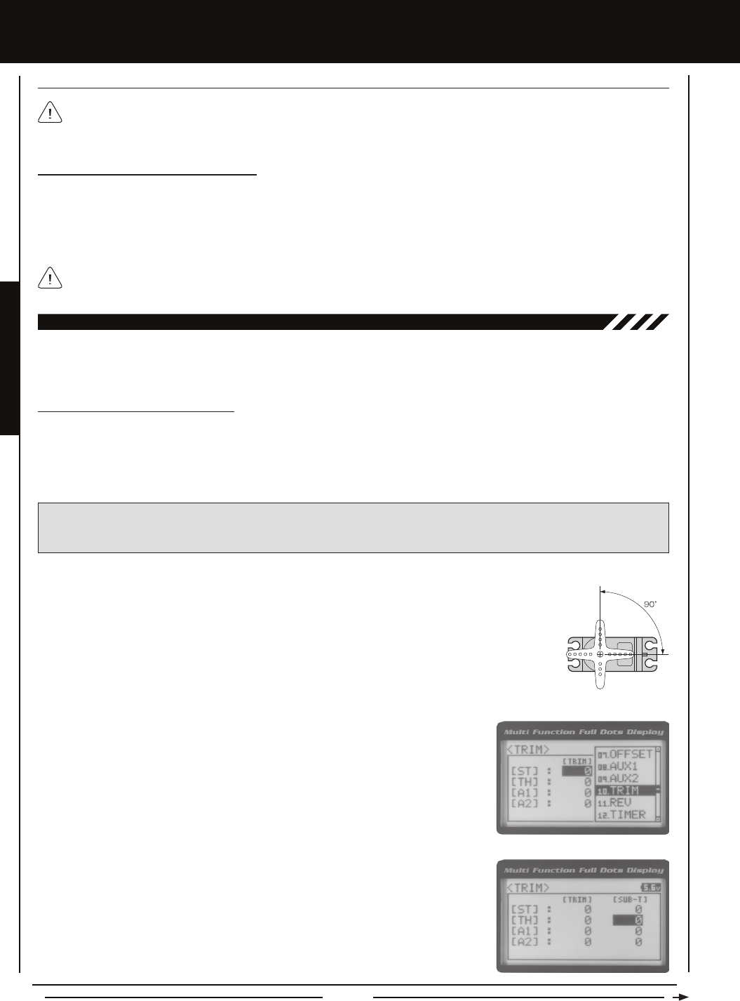
Page 42
aUX MiX (aUXiLiaRY MiXing), cOnTinUED....
Controlling the Auxiliary Mixing Function
1) In the default conguration, Auxiliary 2 is controlled by the Rotary Dial. Turn the Rotary Dial clockwise to increase the Rate
percentage value and turn the Rotary Dial counter-clockwise to decrease the Rate percentage value. In addition, the Auxiliary
Mixing Rate function can be assigned to one of the four Trim Switches or the Auxiliary Lever. The Auxiliary Mixing function
can be toggled 'OFF' and 'ON' by assigning Auxiliary 1 to one of the two Push-Button Switches. For more information, see the
Key Assignments section on pages 56 ~ 61.
In the default conguration, the Auxiliary 2 servo will travel in the same direction as the Steering servo or Throttle servo. To
apply the Mix in the opposite direction, change the Servo Reversing value of Auxiliary 2 Channel 4. For more information,
see the Servo Reversing section on page 44.
Remember that you are able to independently adjust the Auxiliary 2 Channel 4 Dual Rate, Exponential, Sub-Trim, Servo
Speed settings and more to allow for the optimum Auxiliary Mixing setup.
[[PROgRaMMing MEnUS
The Trim function allows you to view the currently programmed Trim value of each of the four channels and, if desired, allows
you to change the Trim values using the Push-Button Rotary Dial from within the Trim menu. In addition to the Trim function,
the Servo Sub-Trim function allows you to ne-tune the Neutral position of each servo.
10.TRiM (TRiM anD SERvO SUB-TRiM)
Adjusting the Servo Sub-Trim Values
It's not unusual that when you center a servo and install the servo horn, the servo horn is not perfectly centered as well. The
Servo Sub-Trim function allows you to correct the Neutral Trim setting for the Steering, Throttle, Auxiliary 1 and Auxiliary 2
channels, making it possible to center the Trim Switches while ensuring the Steering, Throttle, Auxiliary 1 and Auxiliary 2 servo
horns remain centered.
IMPORTANT: Before using the Servo Sub-Trim function, you should verify that all four Trim values are set to 0 (Centered).
If they are not set to 0, adjust the Trim values to 0 using the Trim function. For more information, see the Adjusting the Trim
Values sections on the next page.
1) Install the servo horn (or servo saver for the Steering servo) onto your servo, making sure that the
servo horn (or servo saver) is as close to being centered as possible. In some cases, you can get the
servo horn closer to being centered by rotating the servo horn 180º and reinstalling it.
2) From the Top Screen, press the ENTER key to open the Programming Menu list.
3) Scroll UP or DOWN to highlight the TRIM menu, then press the ENTER key. The TRIM
menu will be displayed and [ST] : TRIM 0 will be highlighted.
4) Scroll UP or DOWN to highlight the desired channel you would like to change the
Sub-Trim value for. Choose from either [ST] : [SUB-T] 0 (Steering), [TH] : [SUB-T] 0
(Throttle), [A1] : [SUB-T] 0 (Auxiliary 1) or [A2] : [SUB-T] 0 (Auxiliary 2).
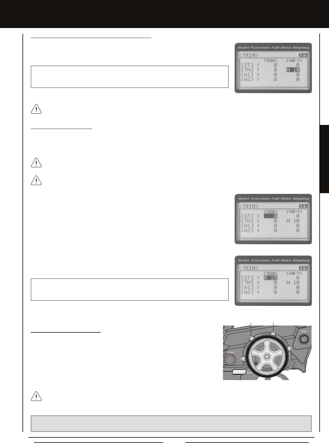
Page 43
PROGRAMMING MENUS
[[PROgRaMMing MEnUS
Adjusting the Trim Values
The MT-4 2.4GHz FHSS-4T transmitter features Digital Trim Memory. Any amount of Trim that you set during use using the Trim
Switches is automatically stored in memory for that specic channel and for that specic model. The Trim values for each model
will automatically be loaded when the transmitter is turned 'ON'.
2) Press the ENTER key, then scroll UP or DOWN to increase or decrease the Trim value
in the desired direction.
TRIM TRIM setting range for the Steering channel is R100 to L100, for the Throttle
channel is H100 to B100 and for Auxiliary 1 Channel 3 and Auxiliary 2 Channel 4 is H100
to L100. The default setting for all channels is 0.
Before adjusting the Trim values, you should rst adjust the servo Sub-Trim values to center the servo horns. For more
information, see the Adjusting the Servo Sub-Trim Values section on the previous page.
1) From within the TRIM menu, scroll UP or DOWN to highlight the desired channel you
would like to change the Trim value for. Choose from either [ST] : [TRIM] 0 (Steering),
[TH] : [TRIM] 0 (Throttle), [A1] : [TRIM] 0 (Auxiliary 1) or [A2] : [TRIM] 0 (Auxiliary 2).
The current Steering and Throttle Trim values are displayed on the Trim Indicator on the Top Screen.
5) Press the ENTER key, then scroll UP or DOWN to increase or decrease the Sub-Trim
value to center the servo horn.
TRIM SUB-T setting range for the Steering channel is R150 to L150, for the Throttle
channel is H150 to B150 and for Auxiliary 1 Channel 3 and Auxiliary 2 Channel 4 is H150
to L150. The default setting for all channels is 0.
Adjusting the Servo Sub-Trim Values, Continued....
After adjusting the Sub-Trim value, use the End Point Adjustment function to set the desired amount of maximum servo
travel in both directions. For more information, see the End Point Adjustment section on pages 22 and 23.
Each time you move a Trim Switch a single audible tone is heard. When the Trim value reaches 0 (Centered), an audible
double-tone sounds. This indicates to you that the Trim is centered without the need to look down at the Trim Indicator on
the Top Screen while you're driving.
Trm1 [ST]
Trm2 [TH]
Controlling the Trim Function
1) In the default conguration, Trim Switch Trm1 controls the Steering Right and Left
Trim and Trim Switch Trm2 controls the Throttle High and Brake Trim. When you
move the Trim Switches, the Trim percentage value changes in 5% increments.
When you use the Trim function to change the Trim value, the Trim value changes
in 1% increments. Auxiliary 1 Trim and Auxiliary 2 Trim can be assigned to the
remaining two Trim Switches, the Rotary Dial or the Auxiliary Lever. For more
information, see the Key Assignments section on pages 56 ~ 61.
PRO TIP: The Trim function features two different Trim Type options that you can choose from. Choose from either Center
Trim or Parallel Trim. For more information, see the Trim Type section on pages 61 and 62.
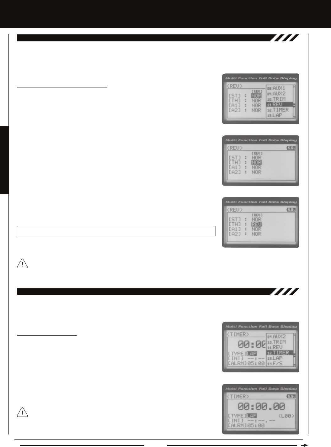
Page 44
[[PROgRaMMing MEnUS
The Servo Reversing function allows you to electronically switch the direction of servo travel. For example, if you rotate the steering
wheel to the right, and the steering servo moves to the left, you can use the Servo Reversing function to make the steering servo
move to the left. The Servo Reversing function is available for all four channels.
11.REv (SERvO REvERSing)
Changing the Servo Reversing Values
1) From the Top Screen, press the ENTER key to open the Programming Menu list.
2) Scroll UP or DOWN to highlight the REV menu, then press the ENTER key. The REV
menu will be displayed and [ST] : NOR will be highlighted.
3) Scroll UP or DOWN to highlight the desired channel you would like to change the Servo
Reversing value for. Choose from either [ST] : NOR (Steering), [TH] : NOR (Throttle),
[A1] : NOR (Auxiliary 1) or [A2] : NOR (Auxiliary 2).
4) Press the ENTER key, then scroll UP or DOWN to change the direction of servo
travel.
REV setting range is NOR and REV. The default setting for all channels is NOR.
When you change the direction of servo travel, the servo horn may no longer be centered. If this occurs, use the Servo
Sub-Trim function to center the servo horn. For more information, see the Adjusting the Servo Sub-Trim Values section on
pages 42 and 43.
The Track Timers function features three different Timers. Timers are provided for measuring Lap Times, Interval Times, and
Countdown Times. Timers are displayed in the following format: 00:00.00 (Minutes:Seconds.1/100th of a Second).
12.TiMER (TRack TiMERS)
Choosing the Timer Type
1) From the Top Screen, press the ENTER key to open the Programming Menu list.
2) Scroll UP or DOWN to highlight the TIMER menu, then press the ENTER key. The
TIMER menu will be displayed and [TYPE] LAP will be highlighted.
3) Press the ENTER key, then scroll UP and DOWN to select the desired Timer Type.
Choose from LAP, INT (Interval) and DOWN (Countdown).
To program the Lap Timer function, see the Lap Timer section on the next page. To
program the Interval Timer function, see the Interval Timer section on page 46.
To program the Countdown Timer function, see the Countdown Timer section on
page 47.
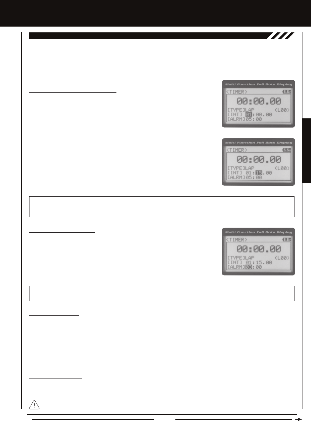
Page 45
PROGRAMMING MENUS
[[PROgRaMMing MEnUS
[LaP (LaP TiMER)
The Lap Timer function allows you to measure and record times for up to 99 laps. The number of laps completed is displayed in
the Timer menu, and when a lap is completed, the lap time is displayed momentarily on the Top Screen. An Alarm (Goal Time)
is featured that will sound when you reach your Goal Time and, if desired, the Interval Timer (Target Time) can be programmed
within the Lap Timer to alert you of your Target Time separately from your Goal Time.
Setting the Interval Timer (Target Time)
1) From within the TIMER menu, scroll DOWN to highlight [INT] : --.
2) Press the ENTER key, then scroll UP or DOWN to set the desired Interval Timer
Minutes value.
12.TiMER (TRack TiMERS), cOnTinUED....
TIMER INT setting range is -- : -- . -- to 99 : 59 : 99. The default setting is -- : -- . -- (OFF). When the Lap Timer is counting up,
an audible double-tone will sound each time the Lap Timer reaches the Interval Timer value. For example, if you set the Interval
Timer for 30 Seconds, an audible double-tone will sound every 30 seconds.
Setting the Alarm (Goal Time)
1) From within the TIMER menu, scroll DOWN to highlight [ALRM] 05.
2) Press the ENTER key, then scroll UP or DOWN to set the desired Alarm Minutes value.
3) To set the Alarm Seconds value, press the ENTER key, then scroll DOWN to highlight
00. Press the ENTER key a second time, then scroll UP and DOWN to set the desired
Alarm Seconds value.
TIMER ALRM setting range is 00:00 to 99:59. The default setting is 5:00 minutes. An audible tone will sound in 1 second
intervals 5 seconds before reaching the Goal Time. When the Goal Time is reached, a long audible tone will sound.
3) To set the Interval Timer Seconds value, press the ENTER key, then scroll DOWN to
highlight --. Press the ENTER key a second time, then scroll UP and DOWN to set the
desired Interval Timer Seconds value.
4) To set the Interval Timer 1/100th Seconds value, press the ENTER key, then scroll
DOWN to highlight --. Press the ENTER key a second time, then scroll UP and DOWN
to set the desired Interval Timer 1/100th Seconds value.
Starting the Lap Timer
1) In the default conguration, Push-Button Switch Sw2 controls the Lap Timer. Press and HOLD the Push-Button Switch for
3 seconds. An audible double-tone will sound and LAP will ash on the Top Screen indicating the Lap Timer is in Stand-by.
To start the Lap Timer, press the Push-Button Switch a second time or pull the Throttle Trigger. An audible double-tone will
sound and the Lap Timer will start counting up. Pressing the Push-Button Switch a second time will store the rst Lap Time,
then begin counting a second Lap Time. Each time you press the Push-Button Switch, an audible tone sounds, the previous
Lap Time is stored, a new Lap Time begins and the current Lap Time is displayed momentarily on the Top Screen. If desired,
the Timer Function can be assigned to Push-Button Switch Sw1. For more information, see the Key Assignments section on
pages 56 ~ 61.
Stopping the Lap Timer
1) To stop the Lap Timer, press and HOLD the Push-Button Switch for 3 seconds. An audible double-tone will sound indicating
the Lap Timer is stopped and the Cumulative Time will be displayed on the Top Screen and in the TIMER menu.
The Cumulative Time cannot be manually cleared. It will be automatically cleared when the Lap Timer is put in Stand-by
again.
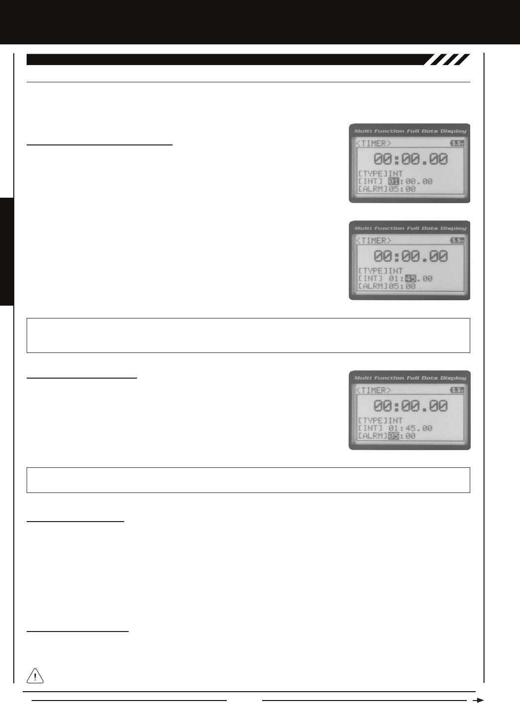
Page 46
[[PROgRaMMing MEnUS
inT (inTERvaL TiMER)
The Interval Timer (Target Time) function noties you when a set interval elapses while you are driving, giving you an idea of how
close you are to your Target Time. An Alarm (Goal Time) is featured that will sound when you reach your Goal Time.
12.TiMER (TRack TiMERS), cOnTinUED....
Setting the Interval Timer (Target Time)
1) From within the TIMER menu, scroll DOWN to highlight [INT] : --.
2) Press the ENTER key, then scroll UP or DOWN to set the desired Interval Timer
Minutes value.
TIMER INT setting range is -- : -- . -- to 99 : 59 : 99. The default setting is -- : -- . -- (OFF). When the Interval Timer is started,
an audible double-tone will sound each time the Interval Timer reaches the Interval Timer value. For example, if you set the
Interval Timer for 1 Minute, an audible double-tone will sound every Minute.
3) To set the Interval Timer Seconds value, press the ENTER key, then scroll DOWN to
highlight --. Press the ENTER key a second time, then scroll UP and DOWN to set the
desired Interval Timer Seconds value.
4) To set the Interval Timer 1/100th Seconds value, press the ENTER key, then scroll
DOWN to highlight --. Press the ENTER key a second time, then scroll UP and DOWN
to set the desired Interval Timer 1/100th Seconds value.
Setting the Alarm (Goal Time)
1) From within the TIMER menu, scroll DOWN to highlight [ALRM] 05.
2) Press the ENTER key, then scroll UP or DOWN to set the desired Alarm Minutes value.
3) To set the Alarm Seconds value, press the ENTER key, then scroll DOWN to highlight
00. Press the ENTER key a second time, then scroll UP and DOWN to set the desired
Alarm Seconds value.
TIMER ALRM setting range is 00:00 to 99:59. The default setting is 5:00 minutes. An audible tone will sound in 1 second
intervals 5 seconds before reaching the Goal Time. When the Goal Time is reached, a long audible tone will sound.
Starting the Interval Timer
1) In the default conguration, Push-Button Switch Sw2 controls the Interval Timer. Press and HOLD the Push-Button Switch for
3 seconds. An audible double-tone will sound and INT will ash on the Top Screen indicating the Interval Timer is in Stand-by.
To start the Interval Timer, press the Push-Button Switch a second time or pull the Throttle Trigger. An audible double-tone
will sound and the Interval Timer will start counting up. Each time the programmed Interval Time elapses, an audible double-tone
will sound and the Interval Timer will restart from zero and the Cumulative Time will be displayed on the Top Screen. You
can manually restart the Interval Timer from zero by pressing the Push-Button Switch while the Interval Timer is running. If
desired, the Timer Function can be assigned to Push-Button Switch Sw1. For more information, see the Key Assignments
section on pages 56 ~ 61.
Stopping the Interval Timer
1) To stop the Interval Timer, press and HOLD the Push-Button Switch for 3 seconds. An audible double-tone will sound indicating
the Interval Timer is stopped and the Cumulative Time will be displayed on the Top Screen and in the TIMER menu.
The Cumulative Time cannot be manually cleared. It will be automatically cleared when the Interval Timer is put in
Stand-by again.

Page 47
PROGRAMMING MENUS
[[PROgRaMMing MEnUS
DOwn (cOUnTDOwn TiMER)
The Countdown Timer function can be used to notify you of your model’s running time. For example, you can set the Countdown
Timer to alert you when it's time to refuel. When the Countdown Timer expires, a long audible tone will sound and the Count
Up Timer function begins automatically. This allows you to check the time elapsed since the Countdown Timer ran out.
12.TiMER (TRack TiMERS), cOnTinUED....
Setting the Alarm
1) From within the TIMER menu, scroll DOWN to highlight [ALRM] 05.
2) Press the ENTER key, then scroll UP or DOWN to set the desired Alarm Minutes value.
3) To set the Alarm Seconds value, press the ENTER key, then scroll DOWN to highlight
00. Press the ENTER key a second time, then scroll UP and DOWN to set the desired
Alarm Seconds value.
TIMER ALRM setting range is 00:00 to 99:59. The default setting is 5:00 minutes. An audible tone will sound in 1 second intervals 5
seconds before reaching the Countdown Alarm Time. When the Countdown Alarm Time is reached, a long audible tone will sound.
Starting the Countdown Timer
1) In the default conguration, Push-Button Switch Sw2 controls the Countdown Timer. Press and HOLD the Push-Button
Switch for 3 seconds. An audible double-tone will sound and DWN will ash on the Top Screen indicating the Countdown
Timer is in Stand-by. To start the Countdown Timer, press the Push-Button Switch a second time or pull the Throttle Trigger.
An audible double-tone will sound and the Countdown Timer will start counting down. An audible tone will sound in 1 second
intervals 5 seconds before reaching zero. When zero is reached, a long audible tone will sound and the Countdown Timer
will begin counting Up. You can manually stop the Countdown Timer at any time by pressing the Push-Button Switch. Press
the Push-Button Switch again will start the Countdown Timer from where it was stopped. If desired, the Timer Function can
be assigned to Push-Button Switch Sw1. For more information, see the Key Assignments section on pages 56 ~ 61.
Stopping the Countdown Timer
1) To stop the Countdown Timer, press and HOLD the Push-Button Switch for 3 seconds. An audible double-tone will sound
indicating the Countdown Timer is stopped and either the remaining Countdown Time or elapsed Count Up Time will be
displayed on the Top Screen and in the TIMER menu.
The remaining Countdown Time or Count Up Time cannot be manually cleared. It will be automatically cleared when the
Countdown Timer is put in Stand-by again.
The Lap Times menu displays a total of up to 99 laps that are recorded using the Lap Timer function. Each Lap Time is displayed
along with the Best Lap Time and the Total (Cumulative) Lap Time.
13.LaP (LaP TiMES)
Viewing Lap Times
1) From the Top Screen, press the ENTER key to open the Programming Menu list.
2) Scroll UP or DOWN to highlight the LAP menu, then press the ENTER key. The LAP
menu will be displayed and the last Lap selected will be highlighted.
3) Scroll UP and DOWN to view the stored Lap Times. Lap Times are stored from the time
you start the Lap Timer to the time you Stop the Lap Timer. The Total (Cumulative) Lap
Time and your Best Lap Time are always displayed at the top of the list.
Lap Times are stored until you restart the Lap Timer function. When the Lap Timer
function is restarted, old Lap Times are cleared and new Lap Times are stored.

Page 48
The Fail Safe function automatically moves the servos to a predetermined position in the event that the signal between the
transmitter and the receiver is interrupted, whether due to signal degradation or to low transmitter battery. Several different
setting options are available. The Fail Safe function can be set to Hold the servos in the last position they were in when the signal
was lost, or each of the servos can be set to move to a custom position when the signal is lost. For example, the throttle servo
moves to the Brake Side to engage the brakes and stop your model. If you're driving a gas- or glow-powered boat, the Fail Safe
function could be set to lower the throttle to idle and turn the rudder slightly left or right so that the boat will continue in slow circles.
In addition, a Receiver Battery Voltage Fail Safe function is available which allows you to set a custom voltage that the Receiver
Battery Fail Safe function will Activate at. This is useful if you're using servos with a higher than normal current draw that might
run out of power before the receiver does.
14.F/S (FaiL SaFE)
[[PROgRaMMing MEnUS
Setting the Fail Safe
Fail Safe settings can be programmed for each of the four channels individually. In addition, Fail Safe settings are Model-specic,
meaning you can have different Fail Safe settings for each Model in memory. The Fail Safe settings will be retained even if the
transmitter loses power or if the transmitter and receiver must be paired again. Three Fail Safe options are available for each
channel as described below:
FREE - Fail Safe is disabled for this channel. Servos can move freely when the signal is lost.
HOLD - When Fail Safe Activates, the servo will be held in the last position it was in when the signal was lost.
% (PERCENTAGE) - When Fail Safe Activates, the servo will travel to the programmed position when the signal is lost.
IMPORTANT: The Fail Safe function will NOT OPERATE if the receiver loses power. It will operate only if the transmitter
and receiver signal is interrupted or if the transmitter loses power.
1) From the Top Screen, press the ENTER key to open the Programming Menu list.
2) Scroll UP or DOWN to highlight the F/S menu, then press the ENTER key. The F/S
menu will be displayed and [ST] : FREE will be highlighted.
5) To program a Fail Safe percentage value, move the control the amount you want the
servo to move to when the Fail Safe function Activates and HOLD it in that position,
then press and HOLD the ENTER key until an audible tone sounds. The percentage
and direction the servo will travel will be displayed. For example, to set the Throttle
Brake to engage when the Fail Safe function Activates, push the throttle trigger toward
the Brake side the desired amount, HOLD the throttle trigger in that position, then press
and HOLD the ENTER key. The percentage value programmed will be indicated by two
hash marks on the Servo Monitor.
3) Scroll UP or DOWN to highlight the desired channel you would like to change the Fail
Safe option for.
4) Press the ENTER key, then scroll UP or DOWN to choose the desired Fail Safe option
for that channel. If you choose to program a % value, see step 5 below.
F/S setting range is FREE, HOLD, or %. The default setting is FREE.
PRO TIP: Use the Servo Monitor at the bottom of the F/S menu to see your programming changes in virtual real time.
6) Check to ensure your Fail Safe settings are working properly prior to running your model. For safety, it's preferable to have
someone hold your model. To check the Fail Safe settings, make sure that both the transmitter and receiver are turned 'ON',
then, while someone is holding your model, turn the transmitter 'OFF'. The servos should react correctly based on the Fail
Safe options chosen.
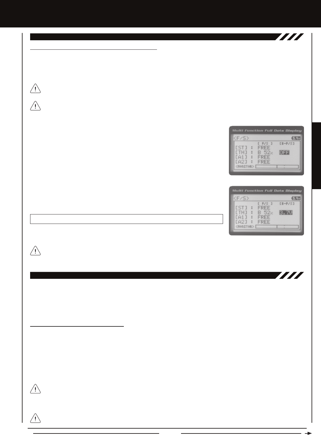
Page 49
PROGRAMMING MENUS
[[PROgRaMMing MEnUS
14.F/S (FaiL SaFE), cOnTinUED....
Setting the Receiver Battery Voltage Fail Safe Function
The Receiver Battery Voltage Fail Safe function allows you to set a custom voltage that the Receiver Battery Voltage Fail Safe
function will Activate at. When your receiver battery voltage drops to the programmed voltage, the throttle servo will move to the
predetermined position you programmed in step 5 in the Setting the Fail Safe section on the previous page. If this occurs, recharge
or replace your receiver batteries.
If FREE or HOLD is chosen for the Throttle channel, you cannot Activate the Receiver Battery Voltage Fail Safe function.
A % value must be chosen for the Throttle channel to be able to program and use the Receiver Battery Fail Safe function.
The Receiver Battery Voltage Fail Safe function works only with FHSS-4T and FHSS-3 receivers. When using an FHSS-2
receiver, these Fail Safe features are not supported. In this case, Fail Safe must be programmed through the receiver. For
more information, follow the instructions provided with your FHSS-2 receiver.
1) Follow steps 1 through 5 in the Setting the Fail Safe section on the previous page to
program a Throttle Fail Safe percentage value.
2) From within the F/S menu, press the ENTER key, then scroll DOWN to highlight
[B-F/S] OFF.
3) Press the ENTER key, then scroll UP or DOWN to choose the desired Receiver Battery
Fail Safe Voltage value.
F/S B-F/S setting range is 3.5v to 7.4v. The default setting is OFF.
The receiver will operate down to 2.5 volts, however, the minimum operating voltage of most servos is higher than that.
The Receiver Battery Fail Safe Voltage should be set to a value that will allow all of your servos to operate. You will need
to check your servo's specications to determine the minimum voltage required for the compliment of servos you're using.
The Telemetry Log function allows you to view a log of the Telemetry Data that is sent from the receiver to the transmitter. You
are able to view Telemetry Data for both Temperature outputs, the RPM output and the receiver's Voltage. This information can
be used to track specic information about your model, such as cylinder head temperature if you're running a nitro-powered
model. The interval that Telemetry Data is read and stored can be adjusted so that Telemetry Data can be stored for up to 90
minutes of use. The Telemetry Log can store 120 different data entries at intervals ranging from 00.1 seconds to 45.9 seconds.
15.LOggER (TELEMETRY LOg)
Starting and Stopping the Telemetry Log
The Telemetry Log function must be Started in order for the transmitter to read and store Telemetry Data from the receiver.
1) In the default conguration, Push-Button Switch Sw1 controls the Telemetry Log. To start the Telemetry Log, press the
Push-Button switch. LED1 (Blue) will ash, indicating the Telemetry Log is storing data. Telemetry Data is stored for all four
Telemetry functions, whether the Telemetry Sensors are hooked up or not.
2) To stop the Telemetry Log, press the Push-Button Switch a second time. If desired, the Telemetry Log Function can be
assigned to Push-Button Switch Sw2. For more information, see the Key Assignments section on pages 56 ~ 61.
Each time the Telemetry Log is started, any old Telemetry Data is automatically erased. In addition, the Telemetry Log will
stop automatically once the Telemetry Log is lled. The Telemetry Log can store 120 separate entries. If the Log Interval is
set to 00.1 seconds, the Telemetry Log can record for 12 seconds. If the Log Interval is set to 45.1 seconds, the Telemetry Log
can record for 90 minutes. To change the Log Interval value, see the Changing the Telemetry Log Step Value section on page 71.
If a Telemetry Sensor is not connected, default Telemetry Data for that input will be shown in the Telemetry Log. Telemetry
is NOT supported when using FHSS-2 or FHSS-3 receivers.
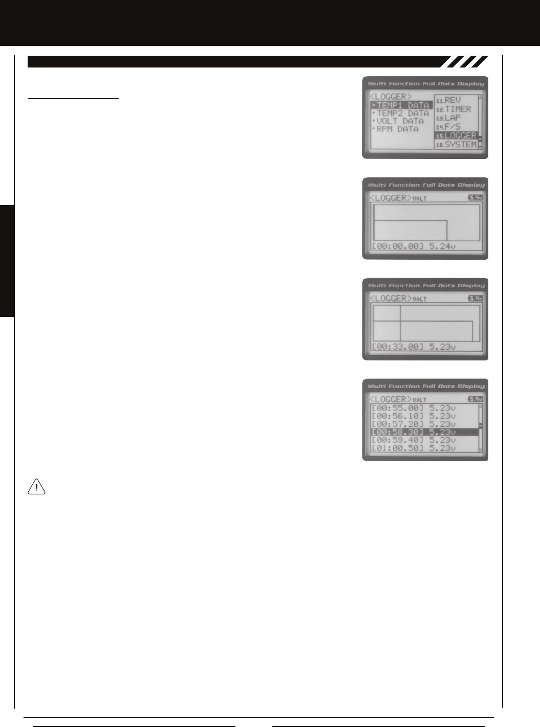
Page 50
[[PROgRaMMing MEnUS
15.LOggER (TELEMETRY LOg), cOnTinUED....
Viewing Telemetry Data
1) From the Top Screen, press the ENTER key to open the Programming Menu list.
2) Scroll UP or DOWN to highlight the LOGGER menu, then press the ENTER key. The
LOGGER menu will be displayed and TEMP1 DATA will be highlighted.
3) From within the LOGGER menu, scroll UP or DOWN to highlight the desired Telemetry
Data you would like to view. Choose from TEMP1 DATA, TEMP2 DATA, VOLT DATA or
RPM DATA.
4) Press the ENTER key to open the Telemetry Log.
5) Telemetry Data can be viewed a couple of different ways. To view the Telemetry Data
at a specic point along the graph, scroll UP or DOWN to move the vertical line right or
left. The Telemetry Data for each point the vertical line is at is displayed at the bottom
of the screen.
6) To view all of the Telemetry Data points, press the ENTER key to open the Telemetry
Data List, then scroll DOWN to view all of the recorded Telemetry Data entries.
The Telemetry Log can be started and stopped while viewing Telemetry Data. To start the Telemetry Log, press and HOLD
the ENTER key and to stop the Telemetry Log, press and HOLD the ENTER key a second time.
THIS SPACE INTENTIONALLY LEFT BLANK
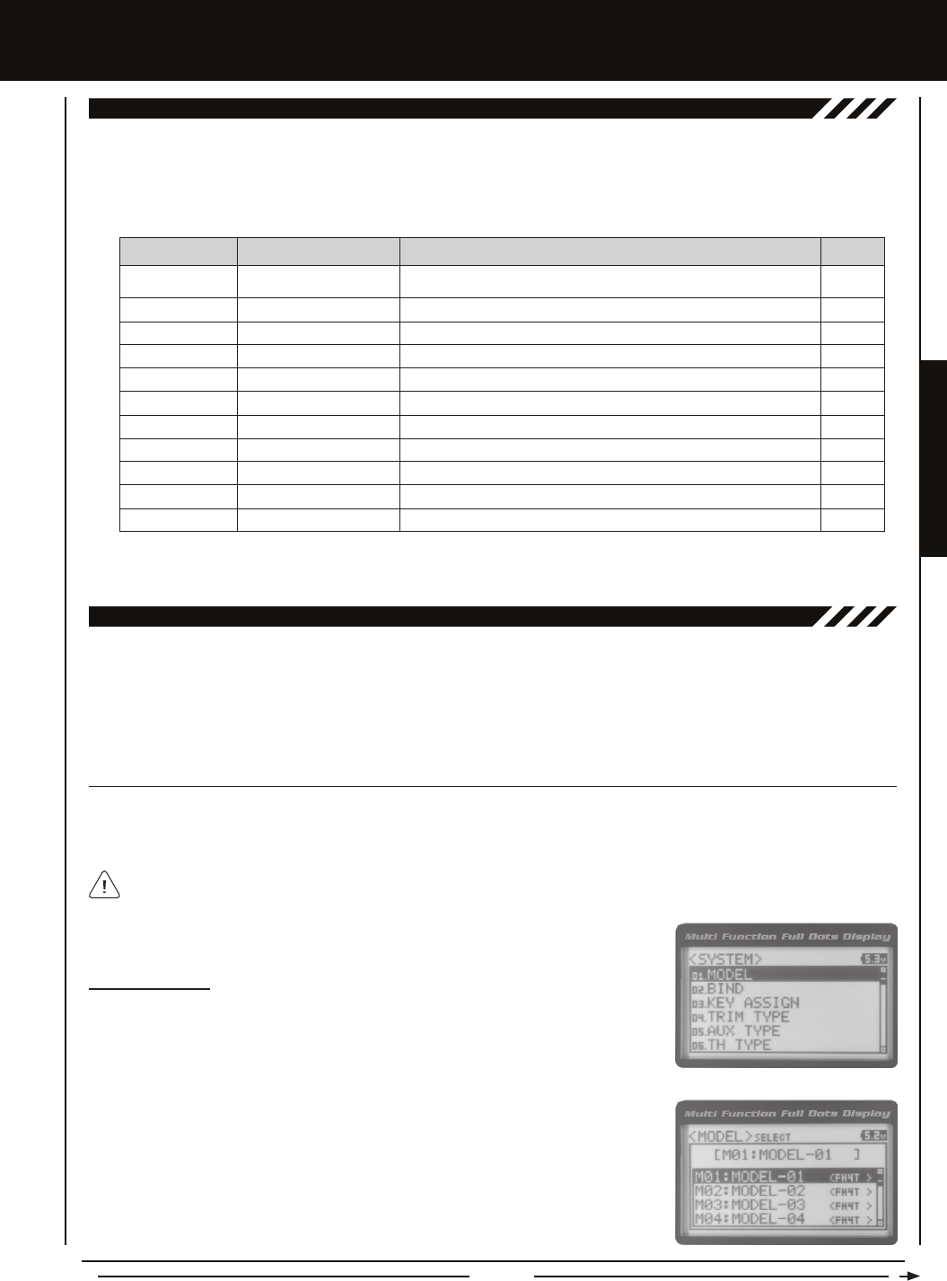
Page 51
SYSTEM MENUS
SYSTEM MEnUS
01.MODEL (MODEL SELEcT, naMing, cOPY anD cLEaR)
The Model menu allows you to select different models using the Model Select function, name your saved models, using the
Model Naming function, and copy Programming Data from one model to another, or clear Programming Data from one or more
models using the Model Copy and Model Clear functions. Programming Data for up to 18 different models can be stored in the
transmitter's memory. This allows you to use the transmitter with different models and quickly and easily select the Programming
Data for each of them. In addition, a Model Select Shortcut function is also featured for quick access to the Model Select (Direct
Model) function.
To access the various System Menus, turn the transmitter 'ON', then press the ENTER key (Push-Button Rotary Dial) to open the
Programming Menu list. Scroll DOWN to SYSTEM, then press the ENTER key a second time to open the System Menu. A list of
System Menus will be displayed and the rst System Menu will be highlighted.
The following System Menus are available by scrolling UP or DOWN using the Push-Button Rotary Dial:
OvERviEw
01.MODEL
02.BIND
03.KEY ASSIGN
04.TRIM TYPE
05.AUX TYPE
06.TH TYPE
07.BUZZER
08.BATTERY
09.LCD
10.TELEMETRY
11.VR ADJUST
Model
Binding
Key Assignments
Servo Trim Type
Auxiliary Type
Throttle Type
Audible Key Tone
Voltage Alarm
Contrast
Telemetry
Variable Rate Adjustment
Model Select, Model Naming, Model Copy and Model Clear
Bind the Transmitter and Receiver, Select Modulation Type and Servo Mode
Assign Functions to the Switches Rotary Dial and Auxiliary Lever
Change the Servo Trim Type
Choose the Auxiliary 1 and Auxiliary 2 Programming Functions
Change the Throttle Servo Travel Proportion
Turn Audible Key Tones 'ON' or 'OFF' and Control Their Pitch and Volume
Specify the Low Voltage and Limit Alarms for the Transmitter Battery
Adjust the Contrast of the Multi-Function LCD Screen
Program Telemetry Screen and Telemetry Log Options
Calibrate Steering, Throttle, and Auxiliary Lever Controls
MENU MENU NAME MENU DESCRIPTION
SYSTEM MENUS
PAGE #
PG. 51
PG. 54
PG. 56
PG. 61
PG. 62
PG. 63
PG. 63
PG. 64
PG. 65
PG. 66
PG. 71
MODEL SELEcT (MODEL SELEcT)
The Model Select function allows you to load the Programming Data for the particular model you wish to drive. The Model Select
menu displays the currently selected model, along with a list of available models that can be selected. The Modulation Type for
each model is also displayed. The transmitter can store Programming Data for up to 18 different models.
Selecting a Model
1) From within the SYSTEM menu, scroll UP or DOWN to highlight the MODEL menu.
2) Press the ENTER key to open the MODEL menu. MODEL SELECT will be highlighted.
3) Press the ENTER key. The MODEL SELECT menu will be displayed and the currently
selected model in the Model Select List will be highlighted.
When a model is selected and loaded, the Programming Data for that model will be loaded immediately.
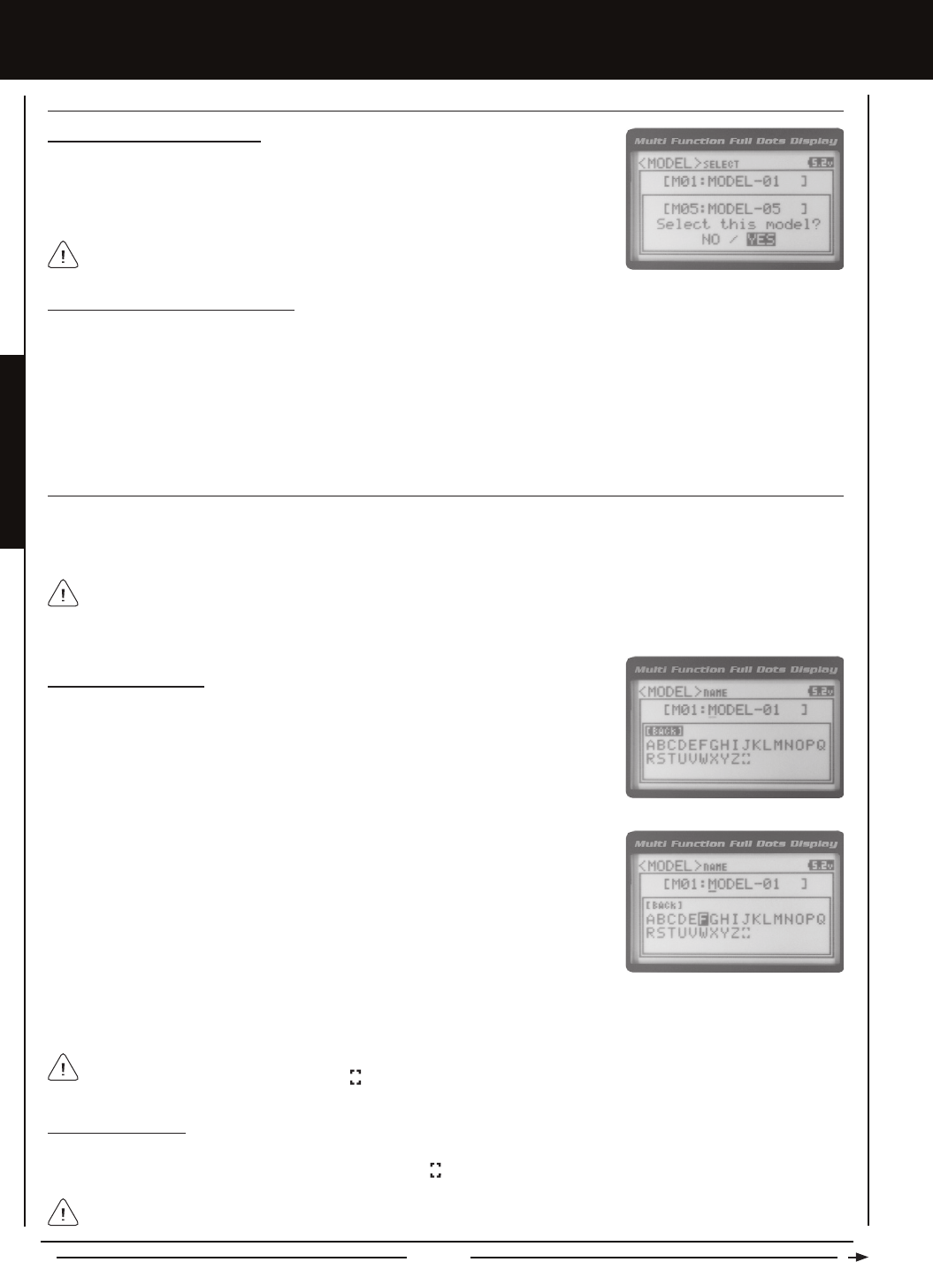
Page 52
When a model is selected, the Programming Data for that model will be loaded
immediately.
Selecting a Model, Continued....
4) Scroll UP or DOWN to highlight the model you would like to select, then press the
ENTER key. Select this model? NO/YES will be displayed. Scroll DOWN to highlight
YES, then press the ENTER key. The model that you just selected will be displayed
above the Model Select List.
MODEL SELEcT (MODEL SELEcT), cOnTinUED....
Model Select Shortcut (Direct Model)
The Model Select Shortcut function allows you to jump directly to the DIRECT MODEL menu when you turn the transmitter 'ON'.
This menu works the same as the MODEL SELECT menu and makes it much quicker select your desired model.
1) Turn the transmitter 'OFF'.
2) Press and HOLD the Back/Cancel key, then turn the transmitter 'ON'. The DIRECT MODEL menu will be displayed. To select
a model, follow step 4 in the Selecting a Model section above.
SYSTEM MEnUS
Deleting a Character
1) Scroll UP or DOWN to move the underscore under the character in your Model Name you want to delete. Press the ENTER
key, then scroll UP or DOWN to highlight [BACK] or the icon in the Character List and press the ENTER key.
MODEL naME (MODEL naMing)
The Model Naming function allows you to name each of the 18 individual models. This makes it easy to keep track of multiple
models. The Model Name can consist of up to 10 letters, numbers, or symbols. Choose from capital letters, lower case letters,
numbers, and various symbols.
Entering a Model Name
1) From within the MODEL menu, scroll DOWN to highlight MODEL NAME.
2) Press the ENTER key. The MODEL NAME menu will be displayed, [BACK] will be
highlighted and the underscore will be ashing under the rst editable character in the
Model Name.
A model must be selected before a Model Name can be entered or modied. In the default conguration, M01:MODEL-1
is selected. To enter a Model Name for another model, that model must rst be selected using the Model Select function or
the Model Select Shortcut function. For more information, see the Model Select section on pages 51 and 52.
3) Scroll UP or DOWN to move the underscore to the character you would like change.
4) Press the ENTER key, then scroll UP or DOWN to highlight a character in the Character
List. Press the ENTER key a second time to select the highlighted character. That
character will be displayed and the underscore will move to the next space in the
Model Name.
5) Repeat steps 3 and 4 to enter the rest of the characters. Up to ten characters can be entered. Press the Back/Cancel key to
re-gain control of the underscore (the underscore will ash indicating you can scroll UP or DOWN to move it Forward or Back).
To select lower case letters, numbers or symbols, continue to scroll UP or DOWN through the various Character Lists. To
add a space in your Model Name, use the icon.
If you can't move the underscore, press the Back/Cancel key to re-gain control of the underscore (the underscore will ash
indicating you can scroll UP or DOWN to move it Forward or Back).
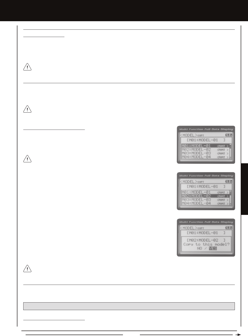
Page 53
SYSTEM MENUS
SYSTEM MEnUS
Deleting a Model Name
1) Scroll DOWN to move the underscore under the last character in your Model Name.
2) Press the ENTER key. Scroll UP or DOWN to highlight [BACK], then continuously press the ENTER key to delete each character
in your Model Name.
MODEL naME (MODEL naMing), cOnTinUED....
MODEL cOPY (MODEL PROgRaMMing DaTa cOPY)
The Model Copy function allows you to copy the Programming Data from one model to another model. For example, if you have
two models that are similar, you can copy the Programming Data from the rst model to the second model to use as a base to start
ne-tuning the programming for the second model.
3) Scroll UP or DOWN to highlight the model you would like to copy the Programming
Data TO.
Copying Model Programming Data
1) From within the MODEL menu, scroll DOWN to highlight MODEL COPY.
2) Press the ENTER key. The MODEL COPY menu will be displayed and the rst model
in the Model Copy List will be highlighted.
The currently selected model is be displayed above the Model Copy List.
The Model Copy function allows you to copy Programming Data FROM the currently selected model TO any other model
in the Model Copy List. Make sure that prior to using the Model Copy function, you rst select and load the desired Model
Programming Data you want to copy FROM, using the Model Select function.
4) Press the ENTER key. Copy to this model? NO/YES will be displayed. Scroll DOWN
to highlight YES, then press the ENTER key. After ~3 seconds, Executed will ash,
indicating the Programming Data has been copied to the highlighted model.
All model-specic Programming Data, including the Model Name will be copied to the highlighted model. If you want to go
back and change models or you don't want to copy the Programming Data for any reason, press the Back/Cancel key.
MODEL cLEaR (MODEL PROgRaMMing DaTa RESET)
The Model Clear function allows you to Reset model-specic Programming Data for any model back to the factory default
settings.
Clearing Model Programming Data
1) Using the Model Select function, select the model you would like to Reset the Programming Data for.
WARNING: When the Model Clear function is Executed, all custom Programming Data for that model will be lost!
If you can't move the underscore, press the Back/Cancel key to re-gain control of the underscore (the underscore will ash
indicating you can scroll UP or DOWN to move it Forward or Back).
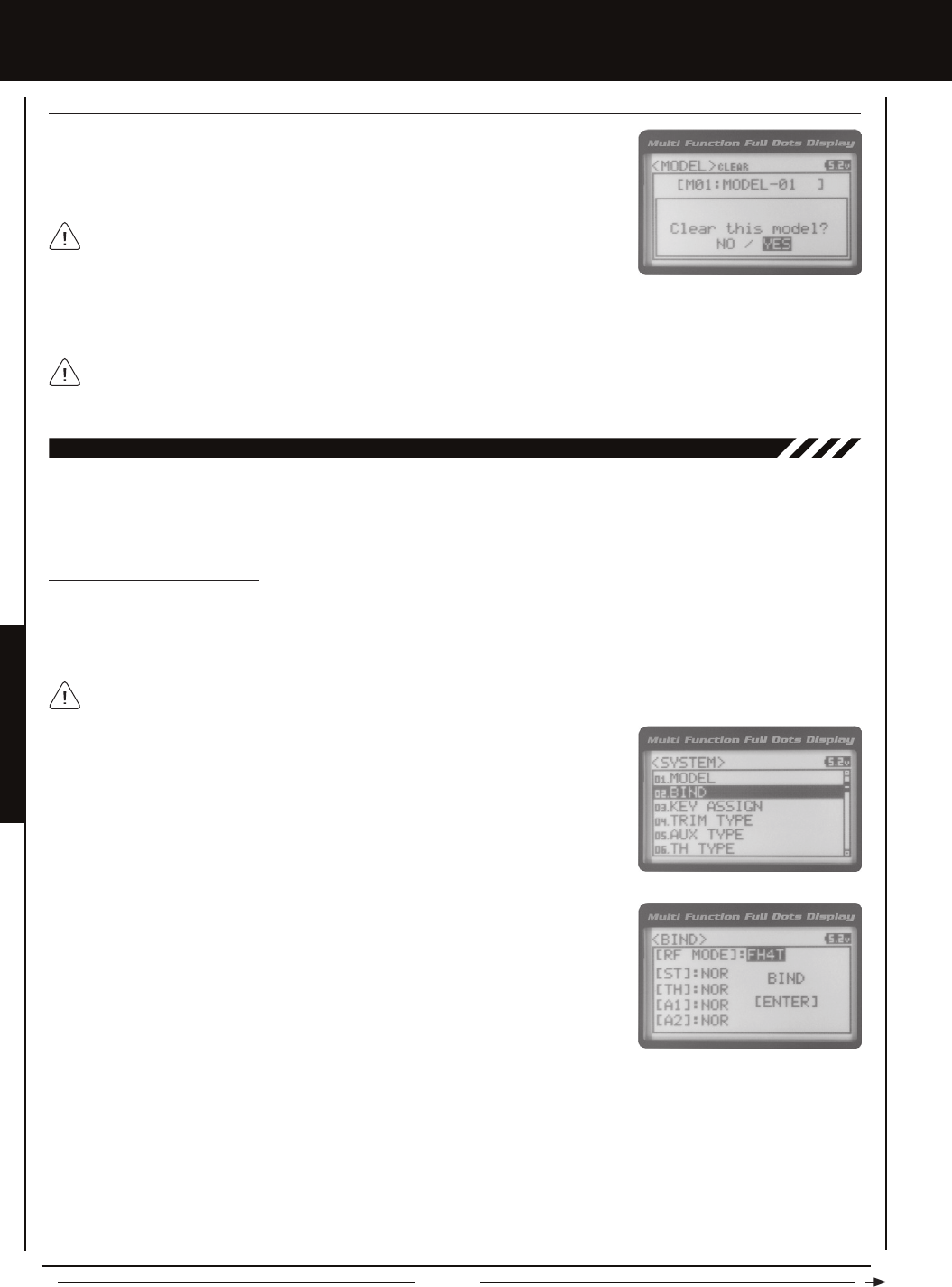
Page 54
SYSTEM MEnUS
4) Scroll DOWN to highlight YES, then press the ENTER key. After ~3 seconds, Executed will ash, indicating the Programming
Data has been Reset to the default values.
All model-specic Programming Data, including the Model Name and Modulation Type will be Reset to the default values.
In addition, if you want to go back and change models or you don't want to Reset the Programming Data for any reason,
press the Back/Cancel key.
MODEL cLEaR (MODEL PROgRaMMing DaTa RESET), cOnTinUED....
2) From within the MODEL menu, scroll DOWN to highlight MODEL CLEAR.
3) Press the ENTER key. Clear this model? NO/YES will be displayed.
The currently selected model is displayed at the top of the MODEL CLEAR menu.
02.BinDing (BinDing, MODULaTiOn TYPE anD SERvO MODE)
The Binding function allows you to 'Bind' the transmitter and receiver pair. When new, it is necessary to pair the transmitter and
receiver to prevent interference from transmitters operated by other users. This operation is referred to as 'Binding'. Once the
Binding process is complete, the setting is remembered even when the transmitter and receiver are turned 'OFF'. Therefore, this
procedure usually only needs to be done once. In addition, the Modulation Type and Servo Mode Setting can also be changed.
Changing the Modulation Type
The Modulation Type function allows you to choose the transmitter Modulation Type. The Modulation Type can be changed to
match the receiver you're using. For example, if you wish to use an Airtronics 2.4GHz FHSS-2 receiver with your transmitter, you
would need to change the Modulation Type to FH2 prior to Binding your transmitter and receiver. Modulation Type is model-specic,
meaning that you can have one model use FH4T Modulation and another model use FH2 Modulation, etc.
1) From within the SYSTEM menu, scroll UP or DOWN to highlight the BIND menu.
The following Modulation Type options are available:
FH2 - Select this Modulation Type when using Airtronics 2.4GHz FHSS-2 surface receivers.
FH3 - Select this Modulation Type when using Airtronics 2.4GHz FHSS-3 receivers.
FH3F - This Modulation Type is NOT used in North America. This Modulation Type is typically used in France.
FH4T - Select this Modulation Type when using Airtronics 2.4GHz FHSS-4T Telemetry receivers.
FH4TF - This Modulation Type is NOT used in North America. This Modulation Type is typically used in France.
2) Press the ENTER key. The BIND menu will be displayed and [RF MODE] : FH4T will be
highlighted.
3) Press the ENTER key, then scroll UP or DOWN to select the desired Modulation Type.
4) Press the ENTER key a second time. Set to (Modulation Type) NO/YES will be
displayed. Scroll DOWN to highlight YES, then press the ENTER key.
The Modulation Type must be chosen prior to Binding the transmitter and receiver. Make sure the Modulation Type you
choose matches the Modulation Type of the receiver you're using.
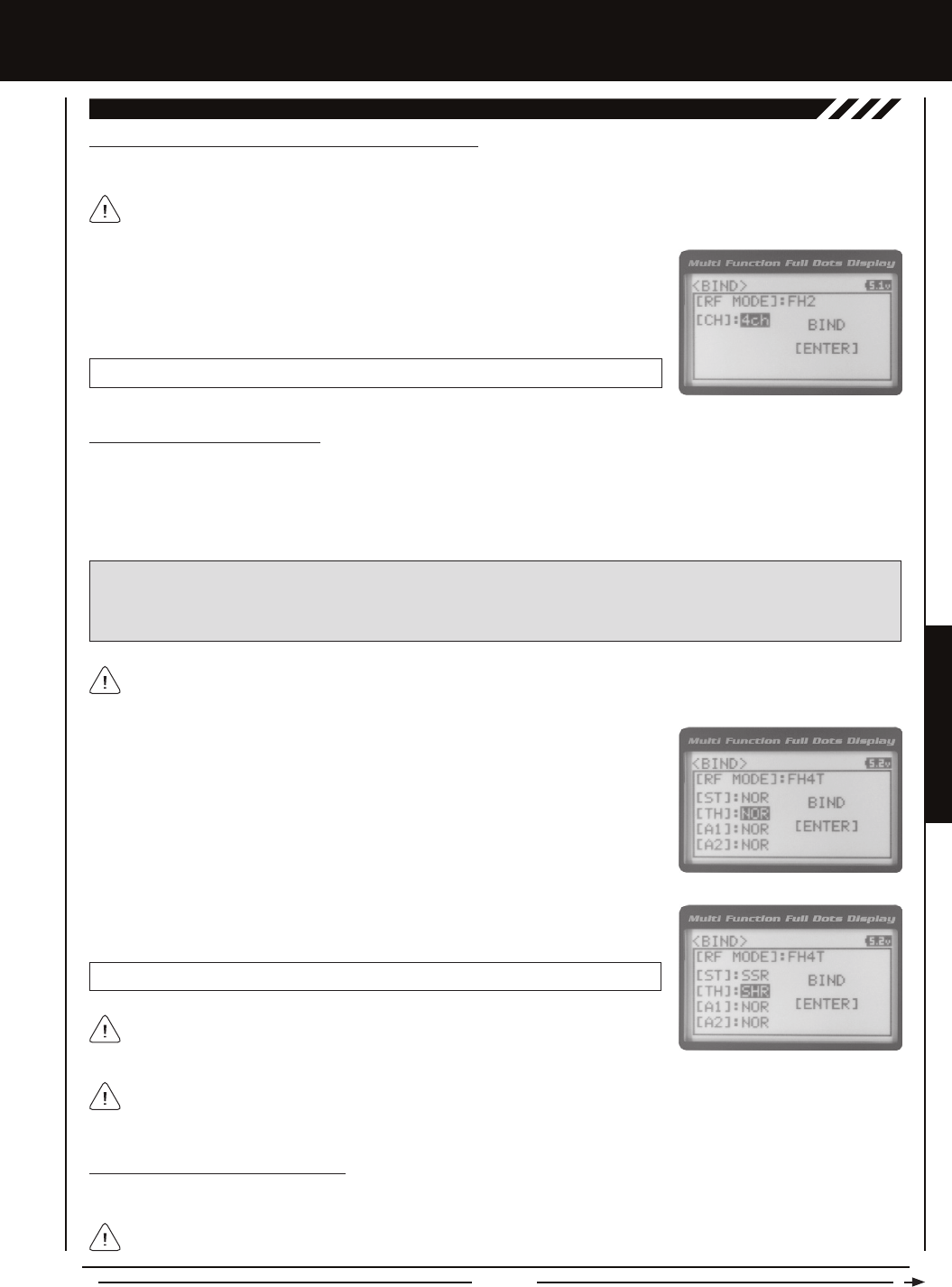
Page 55
SYSTEM MENUS
SYSTEM MEnUS
02.BinDing (BinDing, MODULaTiOn TYPE anD SERvO MODE), cOnTinUED....
Changing the Channel Mode - FH2 Modulation Type Only
If FH2 Modulation is chosen, you can choose to operate the transmitter in either 2-Channel Mode or 4-Channel Mode.
This option is available ONLY when [RF MODE] FH2 is chosen.
1) From within the BIND menu, scroll DOWN to highlight [CH] : 4ch.
2) Press the ENTER key, then scroll UP or DOWN to choose the desired Channel Mode.
Selecting 2CH will enable 2-channel operation (Steering and Throttle). Selecting 4CH
will enable 4-channel operation (Steering, Throttle, Auxiliary 1 and Auxiliary 2).
BIND CH setting range is 2CH and 4CH. The default setting is 4CH.
Changing the Servo Mode Setting
The Servo Mode setting can be changed to suit the type of servos you're using in your model. For example, using the SHR
setting with Digital servos will increase the servo's response time, even above the manufacturer's stated specication. If you're
using Airtronics SRG Digital servos, you can use the SSR setting for the fastest response time. The combination of using Digital
servos and using the correct Servo Mode setting results in the ultimate feel and response, making you feel more in control of
your model than ever.
SHR and SSR Servo Modes should only be used with Digital servos. While the SHR Servo Mode can be used with any
Digital servo, the SSR Servo Mode should ONLY be used with Airtronics SRG Digital servos.
WARNING: If you're using Analog servos in your model, DO NOT use SHR or SSR Servo Mode options for that channel.
Use the NOR (Normal) Servo Mode with Analog servos. Using SHR or SSR Servo Mode options with Analog servos can result
in poor performance or even damage to the servos or the receiver! In addition, not all ESCs are compatible with SHR or SSR
Servo Modes. If your ESC does not operate correctly, change the Throttle Channel Servo Mode setting to NOR (Normal).
1) From within the BIND menu, scroll UP or DOWN to highlight the desired channel you
would like to change the Servo Mode option for. Choose from either [ST] : NOR
(Steering), [TH] : NOR (Throttle), [A1] : NOR (Auxiliary 1) or [A2] : NOR (Auxiliary 2).
Servo Mode options are not supported when the FH2 Modulation Type is chosen.
2) Press the ENTER key, then scroll UP or DOWN to choose the desired Servo Mode
option for that channel.
SERVO MODE setting range is NOR, SHR and SSR. The default setting is NOR.
Binding the Transmitter and Receiver
To Bind the transmitter and receiver, please see the separate Transmitter and Receiver Binding section on page 18.
We recommend that you choose your desired Servo Mode options prior to Binding the transmitter and receiver. Servo
Mode option changes will not take effect immediately. If you change the Servo Mode after Binding the transmitter and
receiver, you must Bind the transmitter and receiver a second time to initialize the changes.
Prior to Binding the transmitter and receiver, make sure to choose the desired Modulation Type and Servo Mode options.
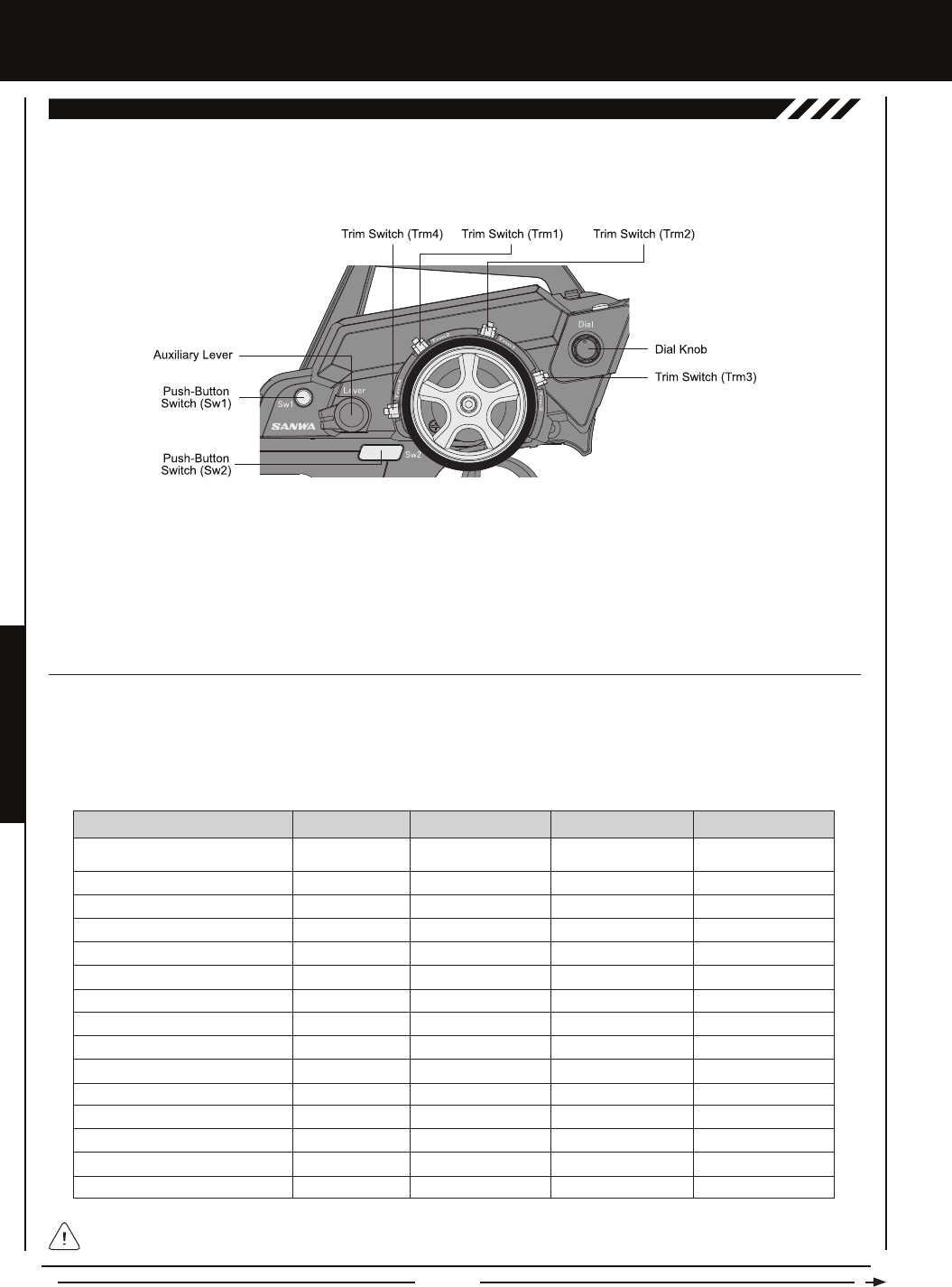
Page 56
SYSTEM MEnUS
SwiTcH (PUSH-BUTTOn SwiTcH kEY aSSignMEnTS)
The Key Assignments function allows you to assign the ON/OFF control of various functions to Push-Button Switches Sw1 and
Sw2. This allows you to use the Push-Button Switches to turn functions 'OFF' and 'ON' during use. One function can be assigned
to each Push-Button switch, although both Push-Button Switches can be 'OFF' or 'ON' at the same time. In addition, the ON/OFF
behavior of some Push-Button Switch Key functions can be changed.
Trm1 - Steering Trim
Trm2 - Throttle Trim
Trm3 - Steering Dual Rate
Trm4 - Brake Dual Rate
Sw1 - Telemetry Logger ON/OFF
Sw2 - Timer ON/OFF
Dial Knob - Auxiliary 1 Channel 3
Auxiliary Lever - Auxiliary 2 Channel 4
03.kEY aSSign (kEY aSSignMEnTS)
This table shows the different functions that can be programmed to the two Push-Button Switches.
The Key Assignments function allows you to assign different functions to each of the two Push-Button Switches, the four Trim
Switches, the Dial Knob and the Auxiliary Lever. In addition, the ON/OFF behavior of some Push-Button Switch functions can
be changed. The Key Assignments function also allows you to change the Direction of Travel and the Trim Resolution of the four
Trim Switches and the Rotary Dial. This allows you to ne-tune the movement of the servos when the Trim Switches are pressed
and the Rotary Dial is turned.
The following functions are programmed in the default conguration:
OFF
D/R-ST
D/R-TH
D/R-BR
CUR-ST
CUR-TH
SPD-ST
SPD-TH
ALB
OFFSET
AUX1
AUX2
TIMER
TE-CLR
LOGGER
Inhibited
Dual Rate-Steering
Dual Rate-Throttle
Dual Rate-Brake
Curve-Steering
Curve-Steering
Servo Speed-Steering
Servo Speed-Throttle
Anti-Lock Braking
Throttle Offset
Auxiliary 1 Channel 3
Auxiliary 2 Channel 4
Lap, Interval and Countdown Timers
Telemetry Clear
Telemetry Logger
Sw2
Sw1
FUNCTION MENU DEFAULT SWITCH
------
Toggle
Toggle
Toggle
Toggle
Toggle
Toggle
Toggle
Toggle
Toggle
Toggle
Toggle
------
------
------
DEFAULT MODE
------
ON
ON
ON
ON
ON
ON
ON
ON
ON
ON
ON
OFF
OFF
OFF
DEFAULT ON/OFF
When you program a function, that function is 'ON' (Active) by default, unless the function's default ON/OFF value is 'OFF'
as noted in the table above. To toggle the function 'OFF' and 'ON' it must be assigned to a Push-Button Switch.

Page 57
SYSTEM MENUS
SYSTEM MEnUS
Changing the Push-Button Switch Function
1) From within the SYSTEM menu, scroll UP or DOWN to highlight the KEY ASSIGN
menu.
2) Press the ENTER key to open the KEY ASSIGN menu. SWITCH will be highlighted.
3) Press the ENTER key. The SWITCH menu will be displayed and SW1 : LOGGER will
be highlighted.
4) Scroll UP or DOWN to highlight the function you would like to change for either SW1
or SW2.
5) Press the ENTER key, then scroll UP or DOWN to choose the desired function for either
SW1 or SW2. A list of functions that can be assigned to the Push-Button Switches is
shown in the table on the previous page.
SwiTcH (PUSH-BUTTOn SwiTcH kEY aSSignMEnTS), cOnTinUED....
Changing the Switch Mode
Some functions allow you to change how the Push-Button Switch operates. The following Switch Modes are available:
TOGGLE - When selected, press the Push-Button Switch to turn the function 'ON' and press the Push-Button Switch a
second time to turn the function 'OFF'. See note at the bottom of the previous page.
PUSH - When selected, press and HOLD the Push-Button Switch to turn the function 'ON'. When the Push-Button Switch is
released, the function will be turned 'OFF'.
1) From within the KEY ASSIGN SWITCH menu, scroll DOWN to highlight the MODE you
would like to change for either SW1 or SW2.
2) Press the ENTER key, then scroll UP or DOWN to choose the desired Switch Mode
setting, either TOGGLE or PUSH.
The Switch Mode cannot be changed for all functions. When [MODE] ------, the
Push-Button Switch will act as if it were in Toggle Mode.
TRiM, DiaL anD LEvER (TRiM, DiaL anD LEvER kEY aSSignMEnTS)
The Key Assignments function allows you to assign different functions to Trim Switches Trm1, Trm2, Trm3 and Trm4, the Rotary
Dial and the Auxiliary Lever. This allows you to use the Trim Switches, Rotary Dial and Auxiliary Lever to control those functions
while you're driving. In addition, the Direction of Travel (REV) and the Trim Resolution (Step value) of each Trim Switch and the
Rotary Dial can be changed. The High and Low Travel Limits and the Direction of Travel of the Auxiliary Lever can be changed, too.
This table shows the different functions that can be programmed to the Trim Switches, Rotary Dial and Auxiliary Lever.
OFF
TRIM-ST
TRIM-TH
Inhibited
Trim-Steering
Trim-Throttle
Trm1
Trm2
FUNCTION MENU DEFAULT SWITCH
------
5
5
DEFAULT STEP VALUE DEFAULT REV VALUE
------
NOR
NOR
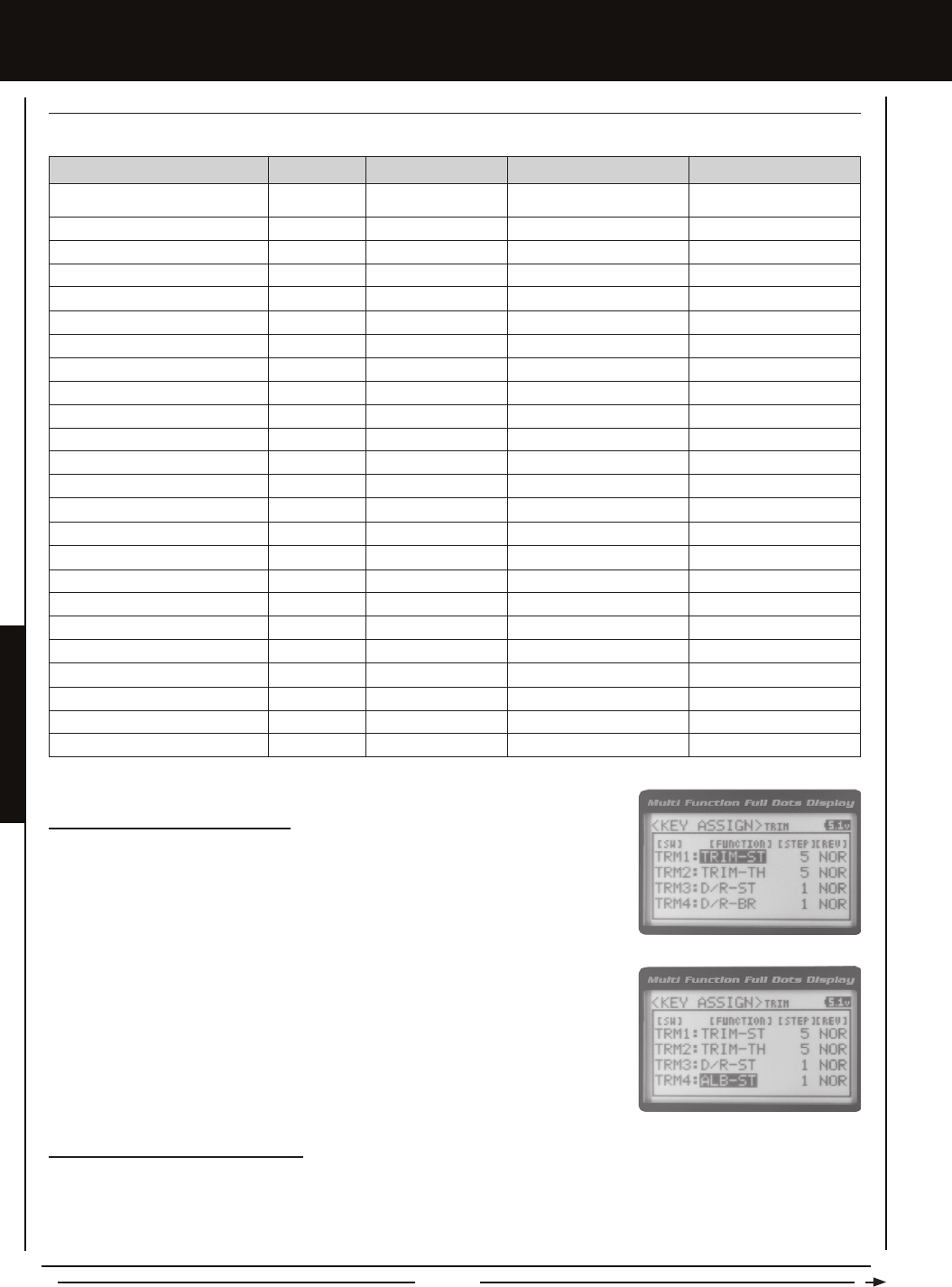
Page 58
SYSTEM MEnUS
TRIM-A1
TRIM-A2
D/R-ST
D/R-TH
D/R-BR
CU-R-ST
CU-P-ST
CU-R-TH
CU-P-TH
CU-R-BR
CU-P-BR
SP-ST-F
SP-ST-R
SP-TH-F
SP-TH-R
ALB-PO
ALB-ST
ALB-LG
ALB-HL
ALB-RE
OFFSET
AUX1
AUX2
INC/DEC
Trim-Auxiliary 1
Trim-Auxiliary 2
Dual Rate-Steering
Dual Rate-Throttle
Dual Rate-Brake
Curve-Rate-Steering
Curve-Point-Steering
Curve-Rate-Throttle
Curve-Point-Throttle
Curve-Rate-Brake
Curve-Point-Brake
Speed-Steering-Forward
Speed-Steering-Return to Neutral
Speed-Throttle-Forward
Speed-Throttle-Return to Neutral
Anti-Lock Braking-Point
Anti-Lock Braking-Stroke
Anti-Lock Braking-Lag
Anti-Lock Braking-Hold
Anti-Lock Braking-Release
Throttle Offset
Auxiliary 1 Channel 3
Auxiliary 2 Channel 4
Increase/Decrease Programming Values
Trm3
Trm4
Rotary Dial
Auxiliary Lever
FUNCTION MENU DEFAULT SWITCH
1
1
5
N/A
------
DEFAULT STEP VALUE DEFAULT REV VALUE
NOR
NOR
NOR
N/A
------
TRiM, DiaL anD LEvER (TRiM, DiaL anD LEvER kEY aSSignMEnTS) cOnTinUED....
This table shows the different functions that can be programmed to the Trim Switches, Rotary Dial and Auxiliary Lever.
Changing the Trim Switch Function
1) From within the KEY ASSIGN menu, scroll UP or DOWN to highlight TRIM.
2) Press the ENTER key. The TRIM menu will be displayed and TRM1 : TRIM-ST will be
highlighted.
3) Scroll UP or DOWN to highlight the function you would like to change for either TRM1,
TRM2, TRM3 or TRM4.
4) Press the ENTER key, then scroll UP or DOWN to choose the desired function for Trim
Switch Trm1, Trm2, Trm3 or Trm4. A list of functions that can be assigned to the Trim
Switches is shown in the table above and on the previous page.
Changing the Trim Switch Step Value
The Step function allows you to adjust how far the servos travel when the Trim Switches are pressed. You can increase the
Trim Resolution by decreasing the Step value, so that the servos travel less when you press the Trim Switches. This makes it
possible to ne-tune servo movement extremely accurately. Alternately, you could decrease the Trim Resolution by increasing
the Step values, so that the servos travel more when you press the Trim Switches. This setting may not be as accurate, although
it allows you to command large amounts of servo travel at a time.
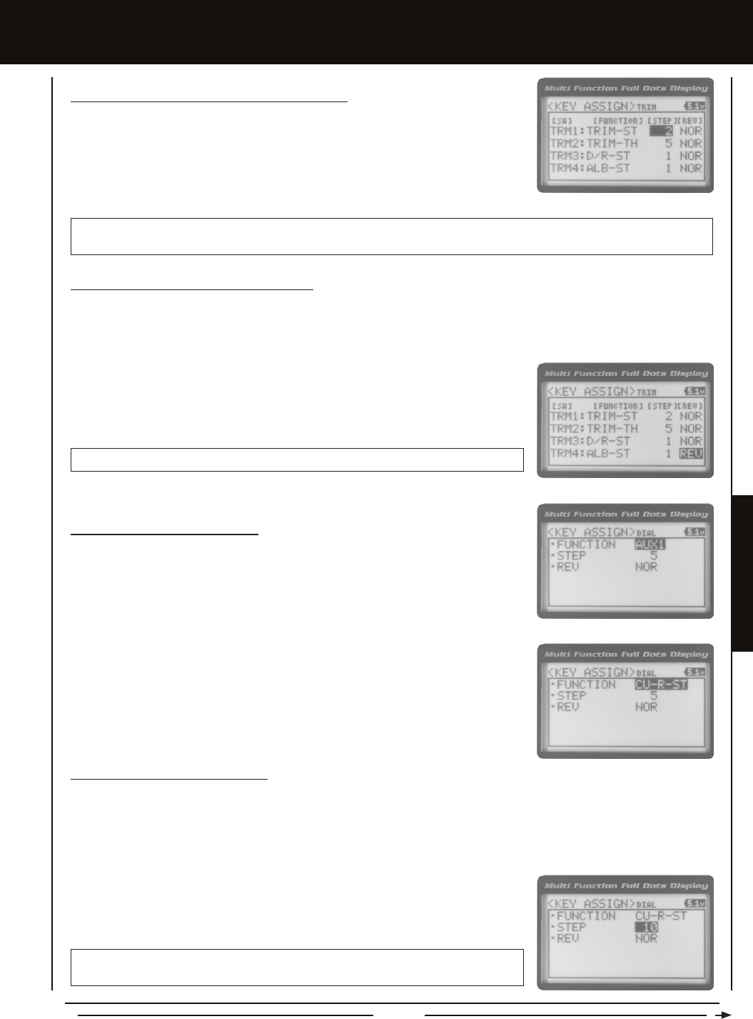
Page 59
SYSTEM MENUS
SYSTEM MEnUS
Changing the Trim Switch Step Value, Continued....
1) From within the TRIM menu, scroll UP or DOWN to highlight the Step value you would
like to change for either TRM1, TRM2, TRM3 or TRM4.
2) Press the ENTER key, then scroll UP or DOWN to choose the desired Step value for
Trim Switch Trm1, Trm2, Trm3 or Trm4.
TRIM STEP setting range is 1 to 100. The default setting for TRM1 is 5, for TRM2 is 5, for TRM3 is 1 and for TRM4 is 1. The
Step value is a percentage of servo travel.
Changing the Trim Switch Direction of Travel
The direction that the Trim Switches move the servos can be changed from Normal to Reverse. In Normal mode, the Trim Switches
will move the servos toward the High Side when the Trim Switches are pushed Forward. In Reverse mode, the Trim Switches will
move the servos toward the Low Side (the opposite direction) when the Trim Switches are pushed Forward.
1) From within the TRIM menu, scroll UP or DOWN to highlight the REV value you would
like to change for either TRM1, TRM2, TRM3 or TRM4.
2) Press the ENTER key, then scroll UP or DOWN to choose the desired REV value for
Trim Switch Trm1, Trm2, Trm3 or Trm4.
TRIM REV setting range is NOR and REV. The default setting for all Trim Switches is NOR.
Changing the Rotary Dial Function
1) From within the KEY ASSIGN menu, scroll UP or DOWN to highlight DIAL.
2) Press the ENTER key. The DIAL menu will be displayed and FUNCTION AUX1 will be
highlighted.
3) Press the ENTER key, then scroll UP or DOWN to choose the desired function for the
Rotary Dial. A list of functions that can be assigned to the Rotary Dial is shown in the
table on pages 57 and 58.
Changing the Rotary Dial Step Value
The Step function allows you to adjust how far the servo travels when the Rotary Dial is turned. You can increase the Dial
Resolution by decreasing the Step value, so that the servo travels less when you turn the Rotary Dial. This makes it possible to
ne-tune servo movement extremely accurately. In addition, you could decrease the Dial Resolution by increasing the Step value,
so that the servo travels more when you turn the Rotary Dial. This setting may not be as accurate, although it allows you to
command large amounts of servo travel at a time.
1) From within the DIAL menu, scroll UP or DOWN to highlight STEP 5.
2) Press the ENTER key, then scroll UP or DOWN to choose the desired Step value for
the Rotary Dial.
DIAL STEP setting range is 1 to 100. The default setting is 5. The Step value is a
percentage of servo travel.

Page 60
SYSTEM MEnUS
Changing the Rotary Dial Direction of Travel
The direction that the Rotary Dial moves the servo can be changed from Normal to Reverse. In Normal mode, the Rotary Dial will
move the servo toward the High Side when the Rotary Dial is turned clockwise. In Reverse mode, the Rotary Dial will move the
servo toward the Low Side (the opposite direction) when the Rotary Dial is turned clockwise.
1) From within the DIAL menu, scroll UP or DOWN to highlight REV NOR.
2) Press the ENTER key, then scroll UP or DOWN to choose the desired REV value for
the Rotary Dial.
DIAL REV setting range is NOR and REV. The default setting is NOR.
TRiM, DiaL anD LEvER (TRiM, DiaL anD LEvER kEY aSSignMEnTS) cOnTinUED....
Changing the Auxiliary Lever Function
In general, the Auxiliary Lever is used to control Auxiliary 1 Channel 3 or Auxiliary 2 Channel 4. Adjusting the High and Low
Tweak values determines how far and in which direction the Auxiliary servo travels when the Auxiliary Lever is moved Up and
Down. For example, if you assign AUX2 to the Auxiliary Lever and adjust the Tweak values to +50 and -50, the Auxiliary 2 servo
will be centered when the Auxiliary Lever is centered and will travel 50% in one direction when the Auxiliary Lever is moved Up
and travel 50% in the other direction when the Auxiliary Lever is moved Down. This allows you to use the Auxiliary Lever like a
2- or 3-position switch.
In addition, the Auxiliary Lever can be used to control the same parameter functions as the Trim Switches and the Rotary Dial. For
example, if you assign TRIM-ST and adjust the Tweak values to +100 and -100, the Auxiliary Lever will control Steering channel
Trim. The direction and amount the Trim moves when you move the Auxiliary Lever Up or Down is dependent on the Positive
and Negative Tweak values.
To control either the Auxiliary 1 or the Auxiliary 2 servos using the Auxiliary Lever, the Auxiliary Type in the AUX TYPE menu
must be either STEP AUX or POINT AUX. For more information, see the Auxiliary Type section on page 62.
1) From within the KEY ASSIGN menu, scroll UP or DOWN to highlight LEVER.
2) Press the ENTER key. The LEVER menu will be displayed and FUNCTION AUX2 will
be highlighted.
3) Press the ENTER key, then scroll UP or DOWN to choose the desired function for the
Auxiliary Lever. A list of functions that can be assigned to the Auxiliary Lever is shown
in the table on pages 57 and 58.
When you use the Auxiliary Lever to control a function, such as Steering Dual Rate
or Exponential, the change in values will not be displayed on the Top Screen like they
are when you use the Trim Switches or the Rotary Dial to make the same changes. Instead,
the current position of the Auxiliary Lever is displayed on the Top Screen.
Auxiliary Lever Position Display
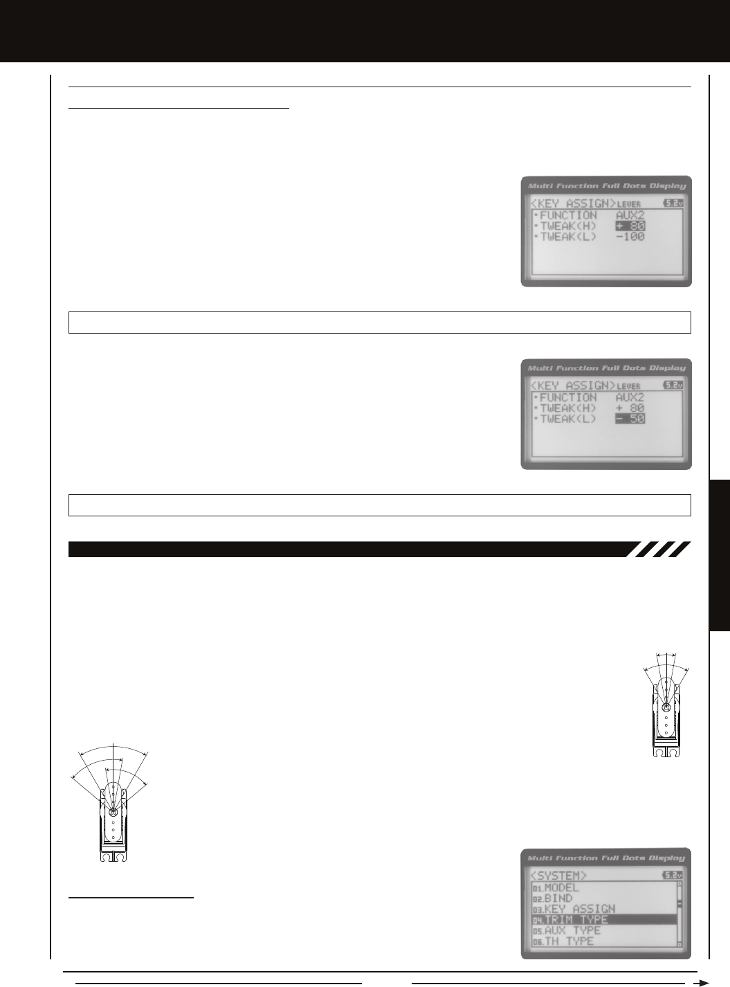
Page 61
SYSTEM MENUS
SYSTEM MEnUS
04.TRiM TYPE (TRiM TYPE)
The Trim Type function allows you choose the way servo Trim and servo End Point Adjustments interact with each other. When
you apply Trim to a servo, the Neutral point of the servo shifts toward the High Side or the Low Side. When you do this, the servo
travels less in one direction and more in the other direction because the servo End Points are stationary. In order to balance the
servo travel, you would need to manually readjust the servo End Points. Using the Trim Type function allows you to make the
servo End Points shift toward the High Side or the Low Side when you apply Trim. This maintains balanced servo travel without
the need to manually readjust the servo End Points.
Two Trim Types are available:
CENTER - When selected, servo End Points are stationary. In order to balance servo travel, you would need to
manually readjust the servo End Points.
PARALLEL - When selected, servo End Points shift toward the High Side or the Low Side automatically
when you apply Trim. This maintains balanced servo travel without the need to manually readjust the servo
End Points.
Changing the Trim Type
1) From within the SYSTEM menu, scroll UP or DOWN to highlight the TRIM TYPE menu.
3) Scroll DOWN to highlight TWEAK(L) -100.
4) Press the ENTER key, then scroll UP or DOWN to choose the desired Low Side Tweak
value. Decreasing the Tweak value will increase servo travel in the Low Side direction
and increasing the Tweak value will decrease servo travel in the Low Side direction.
Using a positive value will change the direction of servo travel.
LEVER TWEAK(L) setting range is -100 to +100. The default setting is -100.
1) From within the LEVER menu, scroll DOWN to highlight TWEAK(H) +100.
2) Press the ENTER key, then scroll UP or DOWN to choose the desired High Side Tweak
value. Increasing the Tweak value will increase servo travel in the High Side direction
and decreasing the Tweak value will decrease servo travel in the High Side direction.
Using a negative value will change the direction of servo travel.
LEVER TWEAK(H) setting range is -100 to +100. The default setting is +100.
Changing the High and Low Tweak Values
The High and Low Tweak values determine the direction and amount of Auxiliary 1 or Auxiliary 2 servo travel. In addition the
High and Low Tweak values determine the direction and amount of parameter function changes, such as Steering Trim or the
Anti-Lock Braking Point percentage value.
TRiM, DiaL anD LEvER (TRiM, DiaL anD LEvER kEY aSSignMEnTS) cOnTinUED....
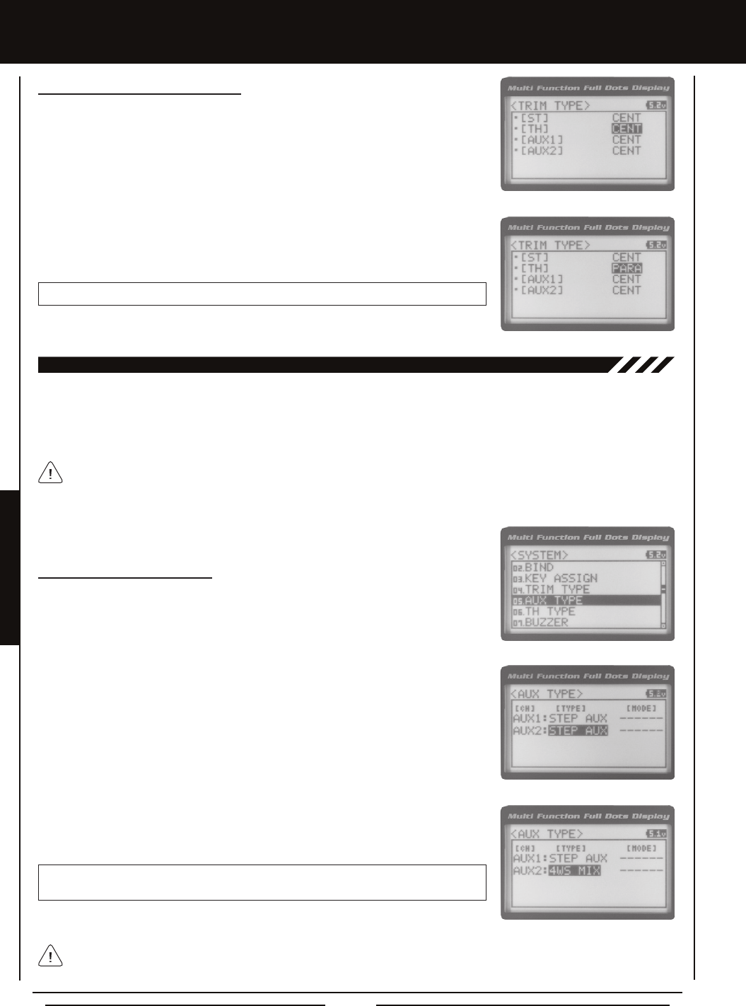
Page 62
05.aUX TYPE (aUXiLiaRY TYPE)
The Auxiliary Type function allows you choose which Auxiliary function is assigned to Auxiliary 1 Channel 3 or Auxiliary 2 Channel
4. One Auxiliary function can be assigned to each Auxiliary Channel and both Auxiliary Channels can be Active and controlled at
the same time using different controls. For example, you can control Auxiliary 1 Channel 3 using the Rotary Dial and Auxiliary 2
Channel 4 using the Auxiliary Lever.
This section details how to assign the different Auxiliary functions to the Auxiliary Channels. For details about programming
and using each of the Auxiliary functions, see the Auxiliary 1 Programming section on pages 29 ~ 35 or the Auxiliary 2
Programming section on pages 36 ~ 42.
Changing the Auxiliary Function
1) From within the SYSTEM menu, scroll UP or DOWN to highlight the AUX TYPE menu.
2) Press the ENTER key. The AUX TYPE menu will be displayed and AUX1 : STEP AUX
will be highlighted.
3) Scroll UP or DOWN to highlight the desired channel you would like to change the
Auxiliary function for, either AUX1 [TYPE] (Auxiliary 1) or AUX 2 [TYPE] (Auxiliary 2).
4) Press the ENTER key, then scroll UP or DOWN to choose the desired Auxiliary function
to be controlled by that channel.
AUX TYPE setting range is STEP AUX, POINT AUX, 4WS MIX, MOA MIX and AUX MIX.
The default setting for both channels is STEP AUX.
Some Auxiliary functions allow you to change the Mode. Details of the various Mode options and how to change them
from within the Auxiliary Type function menu can be found in the specic Auxiliary function programming sections
detailed in the Auxiliary 1 Programming section on pages 29 ~ 35 or the Auxiliary 2 Programming section on pages 36 ~ 42.
SYSTEM MEnUS
Changing the Trim Type, Continued....
2) Press the ENTER key. The TRIM TYPE menu will be displayed and [ST] CENT will be
highlighted.
3) Scroll UP or DOWN to highlight the desired channel you would like to change the
Trim Type option for. Choose from either [ST] CENT (Steering), [TH] CENT (Throttle),
[AUX1] CENT (Auxiliary 1) or [AUX2] CENT (Auxiliary 2).
4) Press the ENTER key, then scroll UP or DOWN to choose the desired Trim Type option
for that channel.
TRIM TYPE setting range is CENT and PARA. The default setting for all channels is CENT.
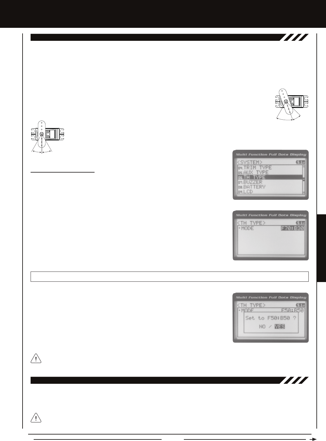
Page 63
SYSTEM MENUS
SYSTEM MEnUS
06.TH TYPE (THROTTLE TYPE)
The Throttle Type function allows you to change the proportion between Throttle High Side servo travel and Throttle Brake Side
servo travel. In the default conguration, the Throttle Type is set to F70:B30. This Throttle Type shifts the throttle Neutral point
toward the Brake Side, resulting in more servo travel toward the High Side and less servo travel toward the Brake Side. Some
users may prefer the proportion between Throttle High Side servo travel and Throttle Brake Side servo travel to be balanced
(F50:B50). The F70:B30 Throttle Type is most common for general use and racing, while the F50:B50 Throttle Type is most
common for Rock Crawling.
Two Throttle Types are available:
F70:B30 - When selected, the throttle Neutral point is shifted toward the Brake Side. This is most common for
general use and racing.
F50:B50 - When selected, the throttle Neutral point is centered. This is most common for Rock Crawling.
Changing the Throttle Type
1) From within the SYSTEM menu, scroll UP or DOWN to highlight the TH TYPE menu.
2) Press the ENTER key. The TH TYPE menu will be displayed and MODE F70:B30 will
be highlighted.
3) Press the ENTER key, then scroll UP or DOWN to choose the desired Throttle Type
option.
TH TYPE setting range is F70:B30 and F50:B50. The default setting is F70:B30.
The current Throttle Type will be displayed on the Top Screen. 7:3 will be displayed to indicate the current Throttle
Type is F70:B30 or 5:5 will be displayed to indicate the current Throttle Type is F50:B50.
4) Press the ENTER key. Either Set to F70:B30? NO/YES will be displayed or Set to
F50:B50? NO/YES will be displayed. Scroll DOWN to highlight YES, then press the
ENTER key to Activate the chosen Throttle Type.
07.BUzzER (aUDiBLE kEY TOnE)
The Audible Key Tone function allows you to change the Volume and Tone of the audible sounds that are made when you use
the Trim Switches, Rotary Dial, Auxiliary Lever, Push-Button Rotary Dial and the Timer function. The Volume can be Increased
or Decreased (or Muted) and the Tone can be changed to suit your preference.
Changes made using the Audible Key Tone function also affect the audible sounds that are part of the Timer function.
For example, if you Mute the Audible Key Tones, the sounds that are part of the Timer function will also be Muted.
Transmitter warning alarms, such as the Low Voltage Alert alarm, are unaffected.
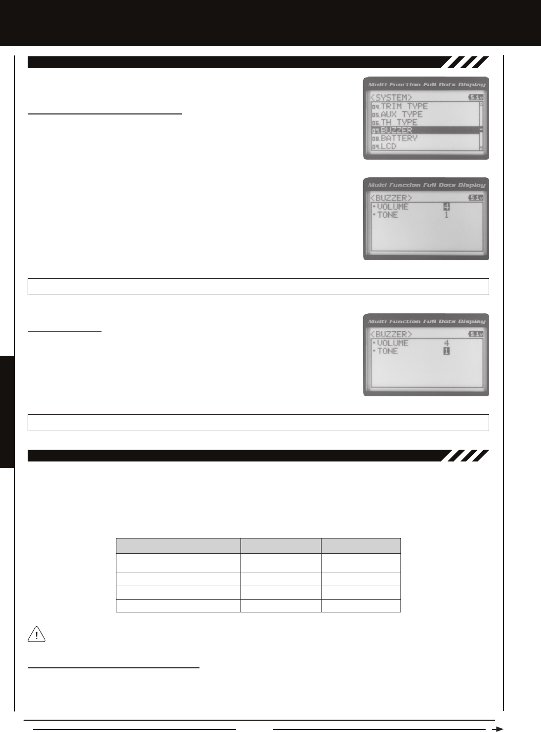
Page 64
SYSTEM MEnUS
Changing the Audible Key Tone Volume
1) From within the SYSTEM menu, scroll UP or DOWN to highlight the BUZZER menu.
2) Press the ENTER key. The BUZZER menu will be displayed and VOLUME 4 will be
highlighted.
3) Press the ENTER key, then scroll UP or DOWN to choose the desired Volume value.
Increasing the Volume value will increase the Volume of the Audible Key Tones and
decreasing the Volume value will decrease the Volume of the Audible Key Tones.
BUZZER VOLUME setting range is OFF to 5. The default setting is 4. When OFF is selected, Audible Key Tones will be Muted.
Changing the Tone
1) From within the BUZZER menu, scroll DOWN to highlight TONE 1.
2) Press the ENTER key, then scroll UP or DOWN to choose the desired Tone value.
Increasing the Tone value will increase the Tone of the Audible Key Tones and decreasing
the Tone value will decrease the Tone of the Audible Key Tones.
BUZZER TONE setting range is 1 to 7. The default setting is 1.
07.BUzzER (aUDiBLE kEY TOnE), cOnTinUED....
08.BaTTERY (vOLTagE aLaRM)
The Voltage Alarm function allows to specify the voltage at which the Low Voltage Alert and Low Voltage Limit alarms will sound.
This allows you to choose custom voltage settings to match the type of transmitter battery you're using. For example,if you're
using a 6 cell Ni-MH battery pack or a 2S Li-Po battery pack, you can set the Low Voltage Alert alarm and the Low Voltage Limit
alarm voltage values to suit.
Changing the Low Voltage Alert Alarm Value
The Low Voltage Alert alarm will sound to indicate the transmitter batteries are getting low and should be replaced or recharged.
We suggest stopping use as soon as safely possible and replacing or recharging the transmitter batteries. The Low Voltage Alert
alarm will sound each time the transmitter battery voltage decreases by 0.1 volt. To clear this alarm, press the Back/Cancel key
or the Push-Button Rotary Dial.
4.6 Volts
7.0 Volts
7.2 Volts
6.3 Volts
4 Cell Alkaline
6 Cell Ni-CD/Ni-MH
2S Li-Po
2S Li-Fe/A123
4.4 Volts
6.6 Volts
6.8 Volts
5.8 Volts
BATTERY TYPE ALERT VOLTAGE LIMIT VOLTAGE
To ensure the safety of your model and your transmitter battery, we suggest using the Alert and Limit Voltage values
shown in the table above. We don't suggest using values lower than recommended.
This table shows the different Alert and Limit Voltage values we recommend programming.
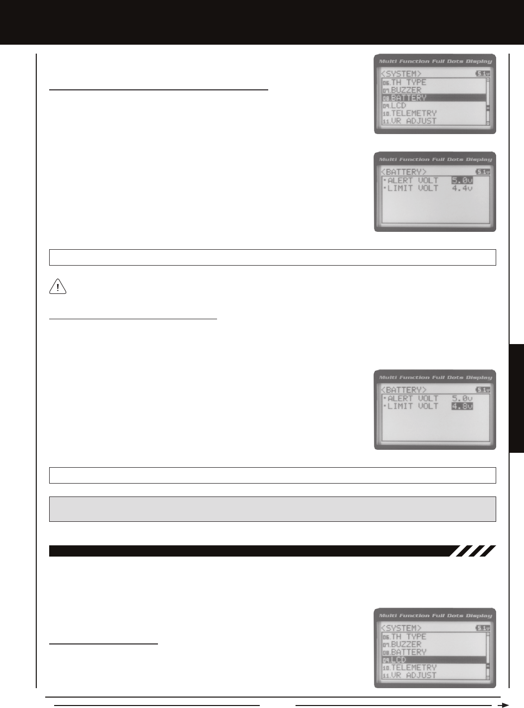
Page 65
SYSTEM MENUS
SYSTEM MEnUS
2) Press the ENTER key. The BATTERY menu will be displayed and ALERT VOLT 4.6v
will be highlighted.
3) Press the ENTER key, then scroll UP or DOWN to choose the desired Low Voltage
Alert alarm value. Increasing the Low Voltage Alert alarm value will cause the Low
Voltage Alert alarm to sound at a higher voltage and decreasing the Low Voltage Alert
alarm value will cause the Low Voltage Alert alarm to sound at a lower voltage.
BATTERY ALERT VOLT setting range is 4.1v to 9.0v. The default setting is 4.6v.
The Low Voltage Alert alarm voltage value cannot be set lower than the Low Voltage Limit alarm voltage value.
Changing the Low Voltage Alert Alarm Value, Continued....
1) From within the SYSTEM menu, scroll UP or DOWN to highlight the BATTERY menu.
1) From within the BATTERY menu, scroll DOWN to highlight LIMIT VOLT 4.4v.
2) Press the ENTER key, then scroll UP or DOWN to choose the desired Low Voltage
Limit alarm value. Increasing the Low Voltage Limit alarm value will cause the Low
Voltage Limit alarm to sound at a higher voltage and decreasing the Low Voltage Limit
alarm value will cause the Low Voltage Limit alarm to sound at a lower voltage.
Changing the Low Voltage Limit Alarm Value
The Low Voltage Limit alarm will sound to indicate the transmitter batteries are dangerously low and should be replaced or
recharged right away. The Low Voltage Limit alarm cannot be cancelled. When the Low Voltage Limit alarm sounds, you should
stop use as soon as it's safe, then replace or recharge the transmitter batteries.
BATTERY LIMIT VOLT setting range is 4.0v to 4.9v. The default setting is 4.4v.
WARNING: Continuing to use the transmitter after the Low Voltage Limit alarm sounds can result in loss of control of your
model. When the Low Voltage Alert alarm sounds, stop use as soon as is safe, then replace or recharge the transmitter batteries.
9.LcD (LcD cOnTRaST)
The LCD Contrast function allows you to change the contrast of the Multi-Function LCD to make it easier to read in all types
of lighting conditions. In general, increasing the Contrast will make the Multi-Function LCD easier to read in bright sunlight and
decreasing the Contrast will make the Multi-Function LCD easier to read in low light levels.
Changing the Contrast Value
1) From within the SYSTEM menu, scroll UP or DOWN to highlight the LCD menu.

Page 66
SYSTEM MEnUS
Increasing or decreasing the LCD Contrast values to the extreme limits can result in blacking out the Multi-Function LCD,
making it impossible to read. We do not suggest using an LCD Contrast value lower than 5 or higher than 22.
Changing the Contrast Value, Continued....
2) Press the ENTER key. The LCD menu will be displayed and CONTRAST 15 will be
highlighted.
3) Press the ENTER key, then scroll UP or DOWN to choose the desired LCD Contrast
value. Increasing the LCD Contrast value will increase the Contrast of the Multi-Function
LCD and decreasing the LCD Contrast value will decrease the Contrast of the
Multi-Function LCD.
LCD CONTRAST setting range is 0 to 30. The default setting is 15.
10.TELEMETRY (TELEMETRY)
The Telemetry menu allows you to change different options to congure how the various Telemetry functions are displayed on
the Telemetry Screen, and how the Telemetry Logger operates. For example, you are able to change the Telemetry Temperature
reading from Fahrenheit to Celsius, change the values at which Telemetry Sensor alarms sound and more. In addition, you are also
able to change the Telemetry Log Interval, to customize how much Telemetry Data can be stored for review later.
For information about plugging the Telemetry Sensors into your receiver and installing them into your model, see the
Telemetry Connections and Mounting section on page 13. For information about using the Telemetry function, see the
Telemetry Screen section on page 16. Telemetry is NOT supported when using FHSS-2 or FHSS-3 receivers.
TEMP1 anD TEMP2 SETTing (TEMPERaTURE TELEMETRY DiSPLaY OPTiOnS)
The Temperature 1 and Temperature 2 Settings allow you change how Temperature information is displayed on the Telemetry
Screen and when the Temperature Alert alarm sounds.
3) Scroll UP or DOWN to highlight TEMP1 SETTING or TEMP2 SETTING.
4) Press the ENTER key. The TEMP1 or TEMP2 menu will be displayed and TEMP UNIT ºF
will be highlighted.
5) Press the ENTER key, then scroll UP or DOWN to change the Temperature Unit to
the desired value. When ºF is chosen, all Telemetry Temperatures will be displayed
in Fahrenheit and when ºC is chosen, all Telemetry Temperatures will be displayed in
Celsius.
TELEMETRY TEMP UNIT setting range is ºF and ºC. The default setting is ºF.
The MT-4 2.4GHz FHSS-4T radio control system includes one Temperature Sensor. If you want to utilize both Temperature
Inputs on the receiver at the same time, you will need to purchase a second Temperature Sensor separately. For more
information, see your local Airtronics retailer or the Airtronics website at www.airtronics.net.
Changing the Temperature Unit Value
If desired, the Temperature Unit value can be changed from Fahrenheit to Celsius.
1) From within the SYSTEM menu, scroll UP or DOWN to highlight the TELEMETRY
menu.
2) Press the ENTER key. The TELEMETRY menu will be displayed and TEMP1 SETTING
will be highlighted.
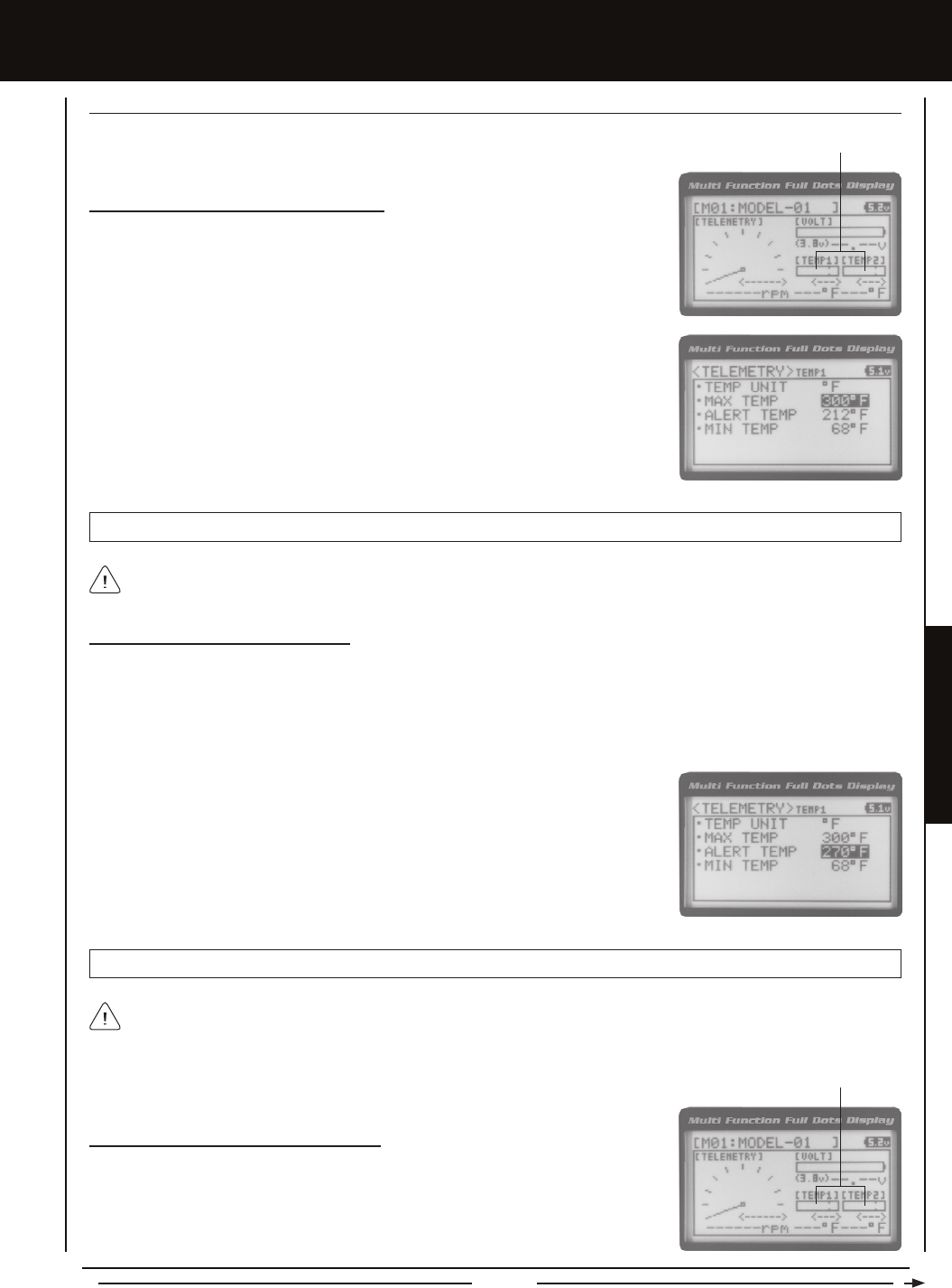
Page 67
SYSTEM MENUS
SYSTEM MEnUS
1) From within the TEMP1 or TEMP2 menu, scroll UP or DOWN to highlight MAX TEMP
248ºF (or 120ºC).
2) Press the ENTER key, then scroll UP or DOWN to change the Maximum Temperature
value. The Temperature Display Monitor on the Telemetry Screen will not display
temperature values above the Maximum Temperature value programmed.
Changing the Maximum Temperature Value
The Maximum Temperature value determines the maximum temperature shown on the
[TEMP1] or [TEMP2] Telemetry Screen Temperature Display Monitors. This allows you to
calibrate each Temperature Display Monitor to match what the Temperatures Sensor is
attached to. This setting does not effect the TEMP1 or TEMP2 Digital Displays.
TELEMETRY MAX TEMP setting range is 68ºF to 302ºF (0ºC to 150ºC). The default setting is 248ºF (120ºC).
The Maximum Temperature value cannot be set lower than the Alert Temperature value or the Minimum Temperature value.
In some cases, you may need to lower the Alert Temperature value prior to lowering the Maximum Temperature value.
Temperature Display Monitors
1) From within the TEMP1 or TEMP2 menu, scroll UP or DOWN to highlight ALERT TEMP
212ºF (or 100ºC).
2) Press the ENTER key, then scroll UP or DOWN to change the Alert Temperature value.
The Alert Temperature value is the temperature that the Temperature Alert alarm will
sound at.
Changing the Alert Temperature Value
The Alert Temperature value determines the temperature at which the Temperature Alert alarm will sound. For example, you can
set an Alert Temperature value for your Nitro engine that will alert you when your engine's cylinder head temperature is getting
too hot. When the Alert Temperature value is reached, the Temperature Alert alarm will sound and LED2 (Red) will ash. The
Temperature Alert alarm will sound for approximately 5 seconds, however, LED2 will continue to ash until the temperature
drops below the Alert Temperature value. The audible portion of the Temperature Alert alarm can be cleared by pressing the
Back/Cancel key or the Push-Button Rotary Dial.
TELEMETRY ALERT TEMP setting range is 68ºF to 302ºF (0ºC to 150ºC). The default setting is 212ºF (100ºC).
The Alert Temperature value cannot be set higher than the Maximum Temperature value. In addition, the Alert Temperature
value cannot be set lower than the Minimum Temperature value. In some cases, you may need to lower the Minimum
Temperature value prior to lowering the Alert Temperature value.
Changing the Minimum Temperature Value
The Minimum Temperature value determines the Minimum temperature shown on the
[TEMP1] or [TEMP2] Telemetry Screen Temperature Display Monitors. This allows you to
calibrate each Temperature Display Monitor to match what the Temperatures Sensor is
attached to. This does not effect the TEMP1 or TEMP2 Digital Displays.
Temperature Display Monitors
TEMP1 anD TEMP2 SETTing (TEMPERaTURE TELEMETRY DiSPLaY OPTiOnS), cOnTinUED....

Page 68
SYSTEM MEnUS
Changing the Minimum Temperature Value, Continued....
1) From within the TEMP1 or TEMP2 menu, scroll UP or DOWN to highlight MIN TEMP
68ºF (or 20ºC).
2) Press the ENTER key, then scroll UP or DOWN to change the Minimum Temperature
value. The Temperature Display Monitor on the Telemetry screen will not display
temperature values below the Minimum Temperature value programmed.
TELEMETRY MIN TEMP setting range is 32ºF to 302ºF (0ºC to 150ºC). The default setting is 68ºF (20ºC).
The Minimum Temperature value cannot be set higher than the Alert Temperature value or the Maximum Temperature
value. In some cases, you may need to increase these values prior to increasing the Minimum Temperature value.
vOLT SETTing (REcEivER BaTTERY vOLTagE TELEMETRY DiSPLaY OPTiOnS)
The Voltage Setting you to change the way receiver battery Voltage information is displayed on the Telemetry Screen and when
the Voltage Alert alarm sounds.
1) From within the TELEMETRY menu, scroll UP or DOWN to highlight VOLT SETTING.
2) Press the ENTER key. The VOLT menu will be displayed and MAX VOLT 9.0v will be
highlighted.
Changing the Maximum Voltage Value
The Maximum Voltage value determines the maximum receiver battery Voltage that will be
shown on the [VOLT] Telemetry Screen Display Monitor. This allows you to calibrate the
Voltage Display Monitor to match your model's receiver battery. This setting does not effect
the VOLT Digital Display.
The Maximum Voltage value cannot be set lower than the Alert Voltage value. If necessary, you may need to lower the Alert
Voltage value prior to lowering the Maximum Voltage value.
Voltage Display Monitor
TELEMETRY MAX VOLT setting range is 3.0v to 9.0v. The default setting is 9.0v.
3) Press the ENTER key, then scroll UP or DOWN to change the Maximum Voltage value.
The Voltage Display Monitor on the Telemetry Screen will not display receiver battery
Voltage values above the Maximum Voltage value programmed.
Changing the Alert Voltage Value
The Alert Voltage value determines the voltage at which the Voltage Alert alarm will sound. For example, you can set the Alert
Voltage value to alert you to when your model's receiver battery is getting low and needs to be recharged. When the Alert Voltage
value is reached, the Voltage Alert alarm will sound and LED2 (Red) will ash. The Voltage Alert alarm will sound for approximately
5 seconds, however, LED2 will continue to ash until you recharge the receiver battery. The audible portion of the Voltage Alert
alarm can be cleared by pressing the Back/Cancel key or the Push-Button Rotary Dial.
Refer to the manufacturer of your model's receiver battery to determine the safest Alert Voltage value to use. In general,
the Alert Voltage value should be high enough to alert you when it's time to recharge your receiver battery, but not so low
that the receiver battery loses power and can no longer control your model.
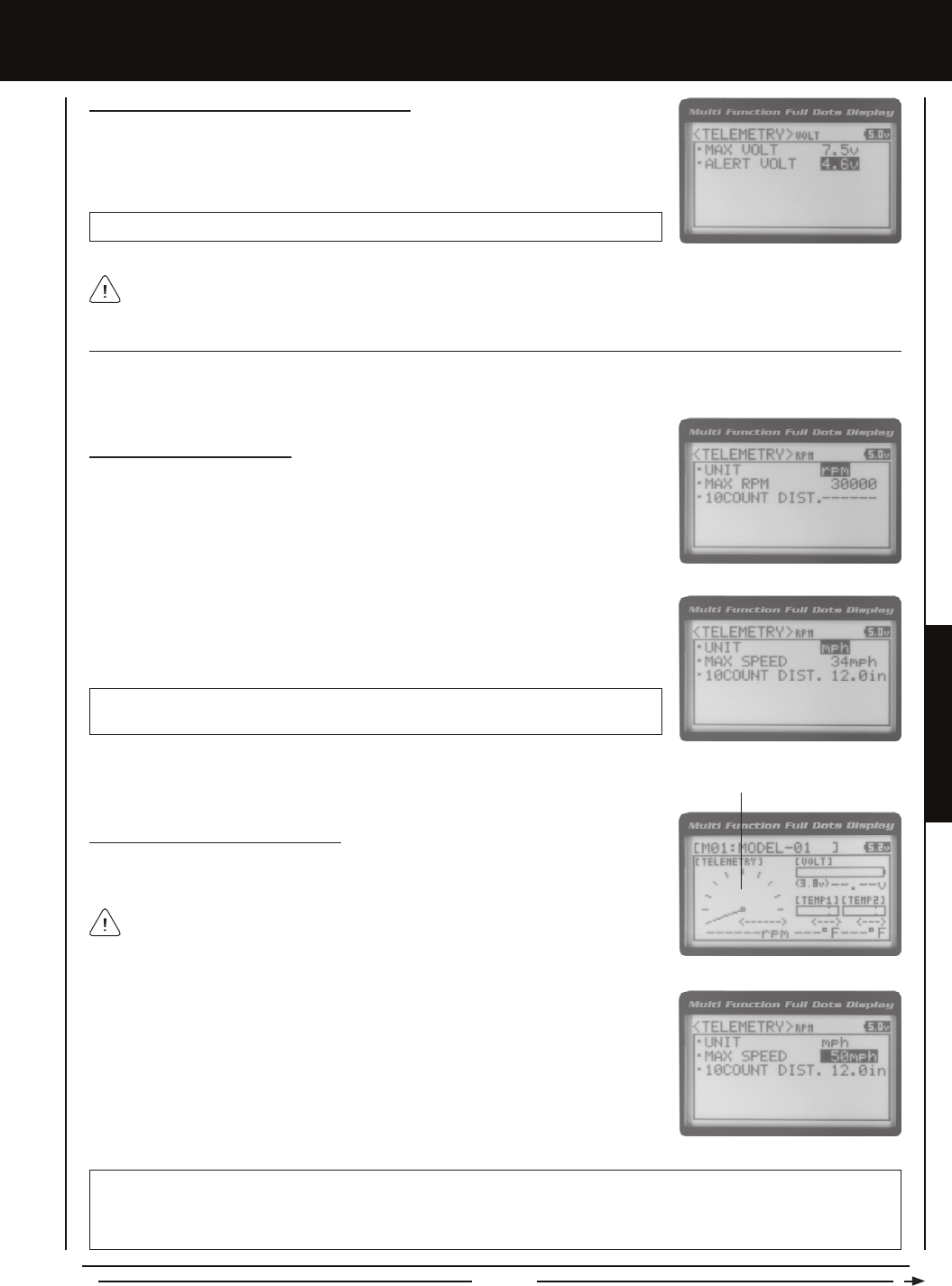
Page 69
SYSTEM MENUS
SYSTEM MEnUS
Changing the Alert Voltage Value, Continued....
1) From within the VOLT menu, scroll UP or DOWN to highlight ALERT VOLT 3.8v.
2) Press the ENTER key, then scroll UP or DOWN to change the Alert Voltage value. The
Alert Voltage value is the voltage that the Voltage Alert alarm will sound at.
TELEMETRY ALERT VOLT setting range is 3.0v to 9.0v. The default setting is 3.8v.
The Alert Voltage value cannot be set higher than the Maximum Voltage value. In some cases, you may need to raise the
Maximum Voltage value prior to raising the Alert Voltage value.
RPM SETTing (RPM TELEMETRY DiSPLaY OPTiOnS)
The RPM Setting allows you to change the way RPM information is displayed on the Telemetry Screen. For example, you can
choose to display RPMs, MPH or KM/H. In addition, if MPH or KM/H is chosen, the RPM sensor can be calibrated to ensure
that the most accurate speed is displayed.
Changing the RPM Unit Value
1) From within the TELEMETRY menu, scroll UP or DOWN to highlight RPM SETTING.
2) Press the ENTER key. The RPM menu will be displayed and UNIT RPM will be
highlighted.
3) Press the ENTER key, then scroll UP or DOWN to change the RPM Unit to the desired
value. When RPM is chosen, the Revolutions Per Minute of whatever the RPM Sensor
is attached to will displayed. When MPH or KM/H is chosen, the speed of your model
will be displayed in either Miles Per Hour or Kilometers Per Hour, respectively.
TELEMETRY RPM UNIT setting range is RPM, MPH and KM/H. The default setting
is RPM.
1) From within the RPM menu, scroll UP or DOWN to highlight MAX RPM 30000 (or MAX
SPEED 34mph or MAX SPEED 54km/h).
2) Press the ENTER key, then scroll UP or DOWN to change the Maximum RPM or
Maximum Speed value. The RPM Gauge on the Telemetry Screen will not display RPM
or Speed values above the Maximum value programmed.
RPM Gauge
TELEMETRY MAX RPM setting range is 500 to 127500. The default setting is 30000. TELEMETRY MAX SPEED setting
range is 1mph to 335mph (1km/h to 539km/h). The default setting is 34mph (54km/h). The Maximum Speed setting range will
vary based on the 10 Count Distance value programmed when you calibrate the RPM Sensor. For more information, see the
Calibrating the RPM Sensor section on page 70.
Changing the Maximum Speed Value
The Maximum Speed value determines the maximum RPM or Speed value that will be
shown on the Telemetry RPM Gauge. This setting does not effect the RPM Digital Display.
The RPM Gauge and RPM Digital Display names will change from RPM to MPH or
KM/H depending on the RPM Unit value chosen.
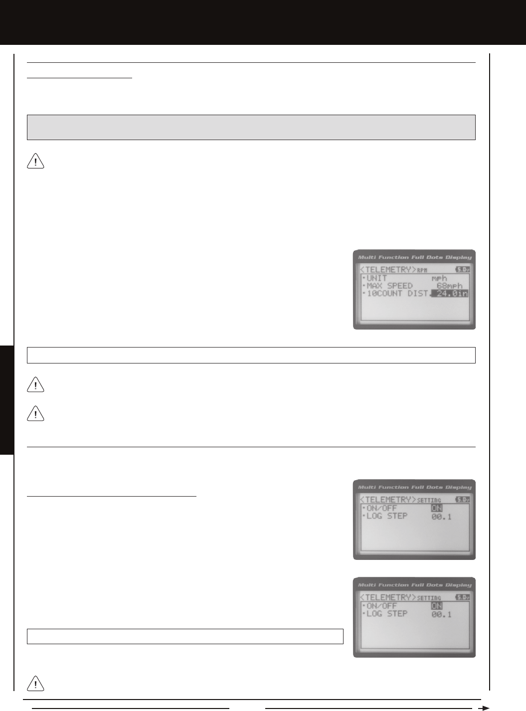
Page 70
RPM SETTing (RPM TELEMETRY DiSPLaY OPTiOnS), cOnTinUED....
Calibrating the RPM Sensor
When you choose to use the RPM Sensor to display MPH or KM/H, the RPM Sensor must be calibrated to ensure that the most
accurate speed is displayed.
3) From within the RPM menu, scroll UP or DOWN to highlight 10COUNT DIST. 12.0in
(or 10COUNT DIST. 30cm).
4) Press the ENTER key, then scroll UP or DOWN to change the 10 Count Distance
value to the measurement obtained in step 2 above. For example, if your model
traveled 2 feet (61cm) to complete 10 full revolutions, enter 24.0in (61cm).
1) With the MT-4 2.4GHz FHSS-4T radio control system turned 'ON' and the RPM Sensor installed on your model as described
in the Mounting the RPM Sensor section page 13, place your model on the ground.
2) Measuring from where you set your model on the ground, push your model and measure the distance covered to complete
10 full revolutions of the RPM Sensor (the Bind LED on the receiver will ash 10 times, indicating 10 full revolutions).
When the reective tape attached to your model's clutch bell, ywheel, etc., crosses the RPM sensor, the Bind LED on
the receiver will ash Green once. This indicates 1 full revolution. Use this as a guide during the calibration process.
IMPORTANT: Prior to Calibrating the RPM Sensor, you must connect the RPM Sensor to the receiver and correctly install
the RPM Sensor onto your model. For more information, see the Mounting the RPM Sensor section page 13.
TELEMETRY 10COUNT DIST setting range is 0.5in to 118.0in (1cm to 300cm). The default setting is 12.0in (30cm).
RPM Sensor calibration is only required if you choose to use the RPM Sensor to display MPH or KM/H. Calibration is
not required if you're displaying RPM.
TELEMETRY SETTing (TELEMETRY anD TELEMETRY LOg OPTiOnS)
The Telemetry Setting allows you to choose whether the Telemetry System is turned 'ON' or 'OFF' and change the interval that
Telemetry Data is read and stored.
3) Press the ENTER key, then scroll UP or DOWN to change the Telemetry ON/OFF
value. When ON is selected, the Telemetry System is turned 'ON'. When OFF is selected,
the Telemetry System is turned 'OFF'.
TELEMETRY SETTING ON/OFF setting range is ON or OFF. The default setting is ON.
Turning the Telemetry System 'ON' and 'OFF'
1) From within the TELEMETRY menu, scroll UP or DOWN to highlight TELEMETRY
SETTING.
2) Press the ENTER key. The SETTING menu will be displayed and ON/OFF ON will
be highlighted.
SYSTEM MEnUS
Adjusting the 10 Count Distance value will change the Maximum Speed value you changed in the previous step. After
calibration, you should go back and reset the Maximum Speed value to the desired setting.
If the Telemetry Log function is started when the Telemetry System is 'OFF', default values will be stored in the Telemetry
Log. This is normal.
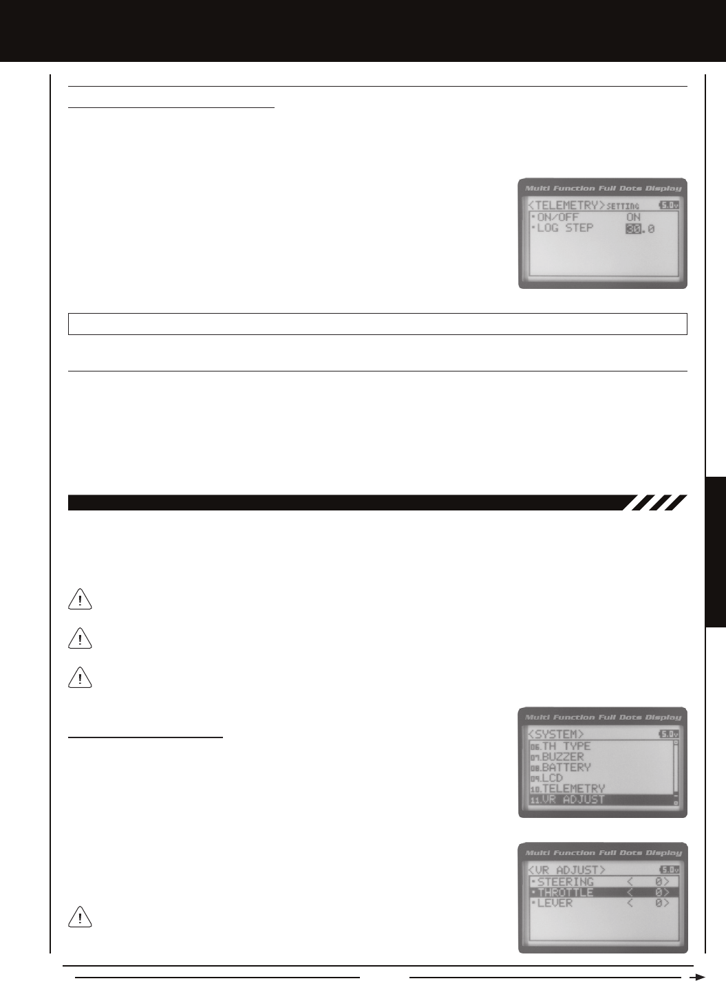
Page 71
SYSTEM MENUS
TELEMETRY SETTing (TELEMETRY LOg OPTiOnS), cOnTinUED....
Changing the Telemetry Log Step Value
The Telemetry Log Step value can be changed to customize how much Telemetry Data and the time interval Telemetry Data is
recorded. The Telemetry Log can store up to 120 separate entries. If the Log Step value is set to 00.1 seconds, the Telemetry
Log can record for 12 seconds. If the Log Step value is set to 45.1 seconds, the Telemetry Log can record for 90 minutes.
TELEMETRY LOG STEP setting range is 00.1 to 45.9. The default setting is 00.1.
1) From within the SETTING menu, scroll UP or DOWN to highlight LOG STEP 00.1.
2) Press the ENTER key, then scroll UP or DOWN to change the Telemetry Log Step
value. Programming a lower Telemetry Log Step value results in narrower, higher
resolution readings, but for a shorter period of time. Programming a higher Telemetry
Log Step value results in broader, lower resolution readings, but for a longer period
of time.
11.vR aDjUST (vaRiaBLE RaTE aDjUSTMEnT)
Over time during use, it's possible that the End Points and/or Neutral positions of the controls may change slightly or you may
purposely limit the travel of the Steering Wheel to suit the best feel of the steering wheel and your driving style. The Variable Rate
Adjustment function allows you to calibrate the operation of the Steering Wheel, Throttle Trigger and Auxiliary Lever End Points
and Neutral positions to ensure precise operation.
After using the Variable Rate Adjustment function, you should double-check the End Point Adjustments of each saved
model. If the End Points have moved, they will need to be readjusted using the End Point Adjustment function.
The Steering Wheel, Throttle Trigger and Auxiliary Lever are calibrated individually.
Calibrating Control Operation
1) From within the SYSTEM menu, scroll UP or DOWN to highlight the VR ADJUST menu.
2) Press the ENTER key. The VR ADJUST menu will be displayed and STEERING <0>
will be highlighted.
3) Scroll UP or DOWN to highlight the control you would like to calibrate. Choose from
STEERING <0>, THROTTLE <0> or LEVER <0>.
<0> indicates the current position of the specic channel relative to its specic control.
For example, if the Steering Wheel is in the Neutral position, but an L or R value is
displayed, the Steering Channel 1 Neutral position has shifted and should be calibrated.
SYSTEM MEnUS
We recommend using this function as part of a periodic maintenance schedule or after adjusting Steering Wheel travel as
described in the Steering Wheel Travel Adjustment section on page 15.
TE-cLR (TELEMETRY cLEaR FUncTiOn)
The Telemetry Clear function allows you to Reset the High Temperature 1, High Temperature 2 and High RPM values that are
displayed on the Telemetry Screen. The Telemetry Clear function can be assigned to either Push-Button Switch Sw1 or Push-Button
Switch Sw2. When you press the Push-Button Switch the Telemetry Clear function is assigned to, the High Temperature 1, High
Temperature 2 and High RPM values will be Reset the Current values read by the Telemetry Sensors. For more information see
the Push-Button Key Assignments section on pages 56 and 57.

Page 72
Calibrating Control Operation, Continued....
4) With the Steering Wheel, Throttle Trigger or Auxiliary Lever in the Neutral position,
press the ENTER key. [NEUT] POS <-----> will be displayed.
The Auxiliary Lever features a detent to indicate its Neutral position.
5) Press the ENTER key a second time. A menu with several position indicators will be
displayed.
6) Slowly move the Steering Wheel, Throttle Trigger or Auxiliary Lever all the way in one
direction. Allow the control to return to Neutral, then slowly move the Steering Wheel,
Throttle Trigger or Auxiliary Lever all the way in the opposite direction. A series of
values and Adjust ok? NO/YES will be displayed.
7) Scroll DOWN to highlight YES, then press the ENTER key. Executed will ash,
indicating that the calibration process is complete.
To cancel the calibration process, scroll UP or DOWN to highlight NO, then press the ENTER key. You can then return to
VR ADJUST menu by pressing the Back/Cancel key.
8) If necessary, repeat steps 3 through 7 to calibrate the remaining controls.
SYSTEM MEnUS
THIS SPACE INTENTIONALLY LEFT BLANK
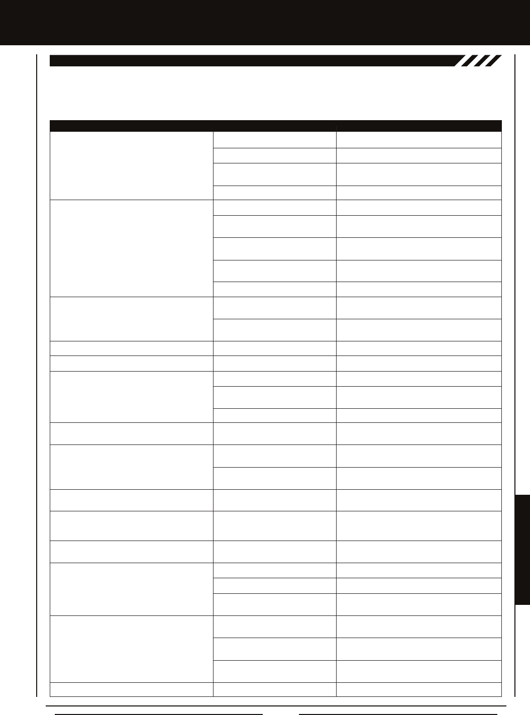
Page 73
REFERENCE
Transmitter does not turn 'ON'
Transmitter will not bind to receiver
Alarm beeps continuously
No sound when keys are pressed
No Timer function sounds
Servo movement is slow
Servo does not move when using Trim Switch
Inadequate transmitting range
Servo moves too much, or doesn't move enough,
when Trim Switch is moved
Throttle servo or ESC moves to programmed
position without input
Cannot program receiver Battery Fail Safe
Voltage level
No Telemetry connection
RPM Sensor not functioning
Can't read Multi-Function LCD
REFEREncE
This troubleshooting guide can help you diagnose and solve some of the more common problems that you may encounter with
your MT-4 2.4GHz FHSS-4T radio control system. If you cannot solve the problem using this troubleshooting guide, please contact
Airtronics Customer Service using the information on the back cover of this Operating Manual.
PROBLEM caUSE SOLUTiOn
Batteries not installed correctly Reinstall batteries. Observe correct polarity
Battery tray not plugged in Plug in battery tray. Observe correct polarity
Damage caused by using incorrect Contact Airtronics Customer Service
charger or reverse polarity
Low transmitter battery voltage Replace or recharge transmitter batteries
Modulation incorrect Change Modulation Type to match receiver
Too much time elapsed after pressing Quickly press the ENTER key in the BIND menu
receiver Bind Button after releasing the receiver Bind Button
Attempting to bind incompatible Use only Airtronics 2.4GHz FHSS-2, FHSS-3 or
receiver FHSS-4T surfaces receivers
Using ESC with BEC Disconnect ESC and use dry cell battery for Binding
procedure, then reconnect ESC after binding
Low receiver battery voltage Recharge receiver battery
Transmitter battery voltage at Low Replace or recharge transmitter batteries
Voltage Limit
Transmitter left 'ON' more than 10 Move steering wheel or throttle trigger, or press any
minutes without control input button to continue use
Audible Key Tones are Muted Increase Audible Key Tone volume
Audible Key Tones are Muted Increase Audible Key Tone volume
Receiver battery voltage low Recharge receiver battery
A negative Servo Speed value is Increase Servo Speed programming value
programmed
Control linkages binding Adjust control linkages to operate smoothly
Trim is outside of operational range Reset Trim to zero and center the servo horn and
control linkage
Low transmitter or receiver battery Replace or recharge transmitter and receiver batteries
voltage
Receiver antenna not mounted Mount receiver antenna as recommended
correctly in your model
Trim Step resolution requires Adjust Trim Step resolution
adjustment
Receiver battery voltage has reached Recharge receiver battery
the programmed Battery Fail Safe
voltage level
Throttle channel Fail Safe set to FREE Set Throttle channel Fail Safe to a percentage value
or HOLD
Using FHSS-2 or FHSS-3 receiver Use FHSS-4T receiver
Telemetry System turned 'OFF' Turn Telemetry System 'ON'
Distance between transmitter and Shorten distance between transmitter and receiver
receiver too far
Sensor Pickup not facing reective Mount RPM Sensor so that Sensor Pickup faces
decal and is aligned with reective decal
Not using reective decal for Sensor Use contrasting reective decal included for Sensor
Pickup Pickup
Sensor Pickup too far away from Pickup Sensor should be 1mm away from reective
reective decal decal
Contrast setting too high or too low Readjust Multi-function LCD contrast setting
TROUBLESHOOTing gUiDE

Page 74
REFEREncE
Activate: To turn 'ON' a particular function.
Antenna: Transmits the signal from the transmitter to the receiver in the model. Never touch the Antenna during use. Doing so
may result in a weakened RF signal or complete loss of control of your model.
Antenna Reception Wire: The portion of the receiver antenna that receives the transmitter signal. The Antenna Reception Wire
should never be bent or it could be damaged and limit the range of your model.
Anti-Lock Braking: Makes it possible to achieve stable braking even on slippery surfaces. With stable braking, your model is
better able to trace an exact line under braking.
ARC: Adjustable Rate Control (ARC) allows you to vary the amount of servo travel in relation to the movement of the steering
wheel, throttle trigger and auxiliary lever near the Neutral positions to change the way those functions react to control movement.
The position that the Rate can be controlled from is adjustable along the length of control travel.
Audible Key Tone: An audible tone that is emitted from the transmitter each time the Push-Button Rotary Dial, Trim Switch,
Push-Button Switch or Rotary Dial is used.
Auxiliary Lever: The Auxiliary Lever is programmable and will perform a different function depending on what function is assigned
to it. For example, it can be used to control Auxiliary 1 Channel 3 or to control the Servo Speed function. The Auxiliary Lever features
a detent and an audible tone to let you know it's in the Neutral position.
Auxiliary Lever Position Display: Displays the current position of the Auxiliary Lever on the Top Screen.
Auxiliary Mixing: Allows you to Mix either Steering Channel 1 or Throttle Channel 2 to Auxiliary 1 Channel 3 or Auxiliary 2
Channel 4, while maintaining separate Sub-Trim, End Point Adjustments, Servo Reversing and other channel-specic settings.
The Auxiliary Mixing function is used when a custom Mix is necessary.
Back/Cancel Key: Returns to the previous menu. Press and HOLD to return to the Top Screen. In addition, cancels certain warning
alarms, such as the Low Voltage Alert alarm.
Battery Compartment: Houses the four 'AA' Alkaline cells that power the transmitter. Alternatively, the transmitter can be
powered using four 'AA' Ni-Cd or Ni-MH rechargeable batteries or a 2S Li-Po or 2S Li-Fe/A123 battery pack.
Binding: The act of pairing the transmitter and receiver to prevent interference from transmitters operated by other users. The
transmitter and receiver must be paired so that the two can 'talk' to each other. Once the Binding process is complete, the setting
is remembered even when the transmitter and receiver are turned 'OFF'.
Bind Button: Used in the process of Binding the transmitter and receiver.
Bind LED: Displays the current status of the receiver.
Brake Side: Refers to the throttle trigger stroke that engages the brakes on your model (pushing the throttle trigger).
Burn: Used with the Motor on Axle function (dual ESCs), the front motor is inhibited while keeping full control of the rear motor
during rock crawling.
Center Trim Type: A Trim technology, that when selected, the servo End Points remain stationary when you apply Trim using the
Trim Switches. This can result in unbalanced servo travel. In order to balance servo travel, servo End Points need to be manually
readjusted.
Channel Set: Allows you to make programming changes to each of the four channels without the need to enter each Programming
Menu separately.
Charging Jack: Used for onboard charging of optional Ni-Cd or Ni-MH batteries. Do not attempt to charge Alkaline batteries.
Only the recommended Airtronics 110v AC charger should be used through the Charging Jack. If using an after-market
Peak-Detection charger or other type of fast charger, the batteries should be removed from the transmitter to avoid damage to the
transmitter circuitry and/or your batteries. Do not attempt to charge a Li-Po or Li-Fe/A123 battery pack through the Charging Jack.
Coaxial Cable: The portion of the receiver antenna that extends the Antenna Reception Wire. The Coaxial Cable can be bent into
gentle curves, however, do not bend it acutely, or repeatedly bend it, or the antenna core can be damaged. The Coaxial Cable
should be installed into a nylon tube (antenna tube) and positioned vertically in your model for the best reception.
Countdown Timer: Used to notify you of your model’s running time. For example, you can set the Countdown Timer to alert
you when it's time to refuel. When the Countdown Timer expires a long audible tone will sound and the Count Up Timer function
begins automatically. This allows you to check the time elapsed since the timer ran out.
Dial Knob: The Dial Knob can rotate 360º and is programmable to perform a different function depending on what function is
assigned to it. For example, it can be used to increase and decrease programming values, control a Trim function or control an
Auxiliary Channel.
gLOSSaRY OF TERMS

Page 75
REFERENCE
Dig: Used with the Motor on Axle function (dual ESCs), the rear motor is inhibited while keeping full control of the front motor
during rock crawling.
Digital RPM Display: Displays the current RPM from the RPM Sensor in digital format on the Telemetry Screen.
Digital Temperature Display: Displays the current temperature from the TEMP1 and TEMP2 Temperature Sensors in digital format
on the Telemetry Screen.
Dual Rate: The Dual Rate function allows you to change the control authority of the Steering, Throttle High Side and Throttle
Brake Side by changing the amount of servo travel relative to control input. For example, by increasing the Steering Dual Rate,
you can make the steering servo travel more which might prevent your model from pushing during turns. If your model oversteers
during turns, you can reduce the amount of Steering Dual Rate.
Digital Trim Memory: Allows the transmitter to store Trim values in its memory. Any amount of Trim that you set during use
using the Trim Switches is automatically stored in memory for that specic channel and for that specic model. The Trim values
for each model will automatically be loaded when the transmitter is turned 'ON'.
Digital Voltage Indicator: Indicates the current Voltage of the transmitter batteries on both the Top Menu and the Telemetry
Screen.
End Point Adjustment: Used to adjust the desired amount of servo travel in both directions independently. This makes it
possible to balance servo travel in both directions.
Enter Key: Opens the selected menu or programming option. Press and HOLD to reset the selected programming option to its
default value.
Exponential: Allows you to vary the amount of servo travel in relation to the movement of the steering wheel, throttle trigger and
auxiliary lever near the Neutral positions to change the way those functions react to control movement. The position that the Rate
can be controlled from is xed.
Fail Safe: Automatically moves the servos to a predetermined position in the event that the signal between the transmitter and
the receiver is interrupted, whether due to signal degradation or low transmitter battery.
FH2 Modulation: Frequency Hopping 2nd generation FHSS technology. FH2 Modulation is used in legacy Airtronics 2.4GHz
FHSS-2 transmitters and receivers, such as the Airtronics M11, M11 FHSS-2, and MX-3FG radio control systems.
FH3 Modulation: Frequency Hopping 3rd generation FHSS technology. FH3 Modulation is used in new-generation Airtronics
radio control systems, such as the M11X and MX-3X.
FH3F Modulation: Frequency Hopping 3rd generation FHSS technology used only in France. This is a special modulation type
typically used in France. It should not be selected for use in North America.
FH4T Modulation: Frequency Hopping 4th generation FHSS technology. FH4T Modulation is the latest Airtronics 2.4GHz
frequency modulation and supports Telemetry.
FHSS: Frequency Hopping Spread Spectrum. FHSS is a modulation type which transmits data across the entire frequency
spectrum by transmitting data on different channels at an extremely fast interval.
Four Wheel Steering Mixing: Used to control either the Front or Rear steering independently, or Mix the Front and Rear steering
so that they can be used together. Front or Rear Independent Steering, Parallel Four Wheel Steering and Tandem Four Wheel
Steering options are available.
Grip: The Grip is molded from rubber in an ergonomic shape for increased comfort, control and feel. An optional Grip is included
that is molded in a different shape that some users may nd feels more comfortable.
High RPM Display: Displays the last highest RPM value on the Telemetry Screen.
High Temperature Display: Displays the last highest Temperature value on the Telemetry Screen.
High Side: Refers to the throttle trigger stroke that opens the throttle and powers your model (pulling the throttle trigger).
Hold: Determines how quickly the Brake moves from the Stroke setting to Neutral when the Anti-Lock Braking function is Active.
Inactivity Alarm (Power ON Alarm): The Inactivity Alarm will sound if the transmitter is left on for a period of 10 minutes without
any control input from the user. This alarm alerts you to prevent unwanted draining of the transmitter battery. To clear this alarm,
either turn the transmitter 'OFF' or press the Back/Cancel key or the Push-Button Rotary Dial.
Inhibit: To deactivate or turn 'OFF' a particular function.
REFEREncE
gLOSSaRY OF TERMS, cOnTinUED....

Page 76
Interval Timer: Noties you when a set interval elapses while you are driving, giving you an idea of how close you are to your
target time.
KM/H: Kilometers per Hour.
Lag: Controls the amount of delay before the Anti-Lock Brake Activates after reaching the POINT setting.
Lap Timer: Allows you to measure and record times for up to 99 laps. The number of laps completed is displayed in the Timer
menu, and when a lap is completed, the lap time is displayed momentarily on the Top Screen.
LED 1/2: Displays the current signal output status of the transmitter (LED 1 - Blue) and the Telemetry connection (LED 2 - Red).
In addition, one or both LEDs are used to indicate various transmitter conditions. For example, when a Throttle Offset percentage
value is programmed, the blue LED will ash.
Low Voltage Alert Alarm: The Low Voltage Alert alarm will sound when the transmitter batteries reach the Alert Voltage value
programmed in the SYSTEM - ALARM menu. The alarm will sound each time the transmitter battery voltage decreases by 0.1
volt. To clear this alarm, press the Back/Cancel key or the Push-Button Rotary Dial.
Low Voltage Limit Alarm: The Low Voltage Limit alarm will sound when the transmitter batteries reach the Limit Voltage value
programmed in the SYSTEM - ALARM menu. This alarm can only be cleared by turning the transmitter 'OFF' and recharging or
replacing the transmitter batteries.
Multi-Function LCD: The heart of the programming and display features of the transmitter. All programming and transmitter
display functions are shown on the Multi-Function LCD.
Modulation Type Indicator: Indicates the current Modulation Type on the Top Screen that the transmitter is set to.
Model Number and Name: Displays the Model Number and Model Name of the currently selected model on both the Top Screen
and the Telemetry Screen.
Model Clear: Used to reset the selected model's Programming Data to the default values. All model-specic Programming Data,
including the Model Name and Modulation Type will be Reset to the default values.
Model Naming: Used to name the different models you have saved in the transmitter. This makes it easy to keep track of multiple
models. The Model Name can consist of up to 10 letters, numbers, or symbols. Choose from capital letters, lower case letters,
numbers, and various symbols.
Model Select: Used to store and retrieve Programming Data for any model 1 through 18. If you have Programming Data stored
for more than one model, using the Model Select function to load the Programming Data for the particular model that you wish
to use. The currently selected Model Number and Model Name is displayed on both the Top Screen and the Telemetry Screen.
Motor on Axle Mixing: Used to control either the Front and Rear throttles together or independently, giving you Dig and Burn
functions. These functions are mostly used in Rock Crawling.
MPH: Miles Per Hour.
Operating Voltage: The safe voltage that the transmitter or receiver can operate within. Exceeding the minimum operating voltage
can result in loss of power to the device(s). Exceeding the maximum operating voltage can result in damage to the devices(s).
Output Power: The power (in Milliwatts) that your transmitter transmits a signal. Output power is dened by government
guidelines and differs by region.
Over Voltage Alarm: The Over Voltage Alarm will sound if the transmitter battery voltage is greater than 9.6 volts. To clear this
alarm, turn the transmitter 'OFF' and replace the transmitter battery with one that when fully charged does not exceed 9.6 volts.
Parallel Steering: Used with Four Wheel Steering, both front and rear wheels pivot right and left together.
Parallel Trim: A Trim technology that when selected, the servo End Points move in equal amounts as the Trim when you use the
Trim Switches. This results in balanced servo travel without the need to manually readjust the End Points.
Point Setting: Locates the actual point in the servo travel that you want a specic programming setting to occur. This setting can
vary depending on the actual programming setting the Point setting is controlling.
Point Auxiliary: Used to program Auxiliary Channel 3 or Auxiliary Channel 4 to move the servo to up to 6 different points along
its travel, then cycle through those Points. For example, if your model requires a separate 3-position or more switch to operate a
feature, the Point Auxiliary function can be customized to control this.
Power Switch: Turns the transmitter 'ON' and 'OFF'.
Push-Button Rotary Dial: The Push-Button Rotary Dial (also referred to as the Up Key, Down Key, or Enter key) is used along
with the Back/Cancel Key to facilitate transmitter programming. It allows you to quickly and easily navigate the various Programming
and System Menus and switch between the Top Screen and the Telemetry Screen.
REFEREncE
gLOSSaRY OF TERMS, cOnTinUED....

Page 77
REFERENCE
Push-Button Switch: The transmitter features two separate Push-Button Switches in different locations (Sw1 and Sw2). Each
Push-Button Switch is programmable and will perform a different function depending on what function is assigned to it.
Receiver Battery Voltage Fail Safe: Used to set a custom voltage that the Receiver Battery Fail Safe function will Activate at.
When your receiver battery voltage drops to the programmed voltage, the throttle servo will move to the predetermined position
programmed using the Fail Safe function. If this occurs, recharge or replace your receiver batteries.
Receiver Voltage Display: Displays the current voltage of the receiver battery on the Telemetry Screen.
Release: Determines how quickly the Brake moves from Neutral to the percentage value determined by the Stroke setting
when the Anti-Lock Braking function is Active.
RPM: Revolutions Per Minute.
RPM Display Monitor: Displays the current RPM on the Telemetry Screen from the RPM Sensor in graphical format.
Servo Monitor Display: Displays the output levels of the four different channels in bar graph form, allowing you to monitor servo
operation in a virtual manner.
Servo Reversing: Used to electronically switch the direction of servo travel. For example, if you move the steering wheel to the
right, and the steering servo moves to the left, you can use the Servo Reversing function to make the steering servo move to
the left.
Servo Speed: Used to slow down the transit speed of the servos. Servo transit speed can be slowed in both the Forward and
the Return to Center directions.
Servo Sub-Trim: Used to correct the Neutral Trim setting for the servos, making it possible to center the Trim switches while
ensuring the servo horns remain centered.
SHR Servo Mode: Using this setting with Digital servos will increase the servo's response time, even above the manufacturer's
stated specication. Do not use with Analog servos!
SSR Servo Mode: If you're using Airtronics SRG Digital servos, you can use the SSR setting for the fastest response time. This
results in the ultimate feel and response, making you feel more in control of your model than ever. Use only with Airtronics SRG
Digital servos!
Steering Program Indicator: Indicates up to four different programming options that are currently programmed to the Steering
channel. The Steering Program Indicator will only be displayed if a Steering channel programming value is programmed.
Steering Trim Display: Displays the current position of the Steering Trim Switch on the Top Screen.
Steering Wheel: Proportionally operates the model's right and left steering control. The Steering Wheel features a foam grip for
increased comfort, control and feel. In addition, the Steering Wheel spring tension and travel limits can be adjusted.
Steering Wheel Tension Adjustment Screw: Used to adjust the spring tension of the steering wheel to best suit the feel of
the user.
Step Auxiliary: Allows you to program the Auxiliary 1 servo or Auxiliary 2 servo to move a dened amount when toggled 'ON'
and 'OFF' using a Push-Button Switch.
Step Value: A preset amount that the servo will travel when a Trim Switch is pressed once. The step value can be adjusted so
that the servo either moves more or moves less when the Trim Switch is pressed.
Stroke: Determines the amount of Brake that's applied automatically when the Anti-Lock Braking function Activates.
Suppression Capacitor: Primarily used on brushed electric motors, a suppression capacitor helps eliminate electrical noise that
could interfere with the operation of your radio control system.
Tandem Steering: Used with Four Wheel Steering, the front wheels pivot opposite to the rear wheels.
Telemetry: A connection between the receiver and the transmitter that transfers Sensor data from the receiver to the transmitter
that can be viewed in real-time on the Telemetry Screen. Data such as Temperature, Receiver Voltage and RPM or Speed can
be viewed.
Telemetry Inputs: Located under a removable protective cover, the Telemetry Inputs are where you plug the Temperature and
RPM Sensors into. Two separate temperature inputs and one RPM input are available.
Telemetry Signal Indicator: Indicates the current signal strength of the Telemetry connection between the transmitter and
receiver. The Telemetry Signal Indicator will only be displayed when the receiver is turned 'ON' and there is a Telemetry
connection Active.
REFEREncE
gLOSSaRY OF TERMS, cOnTinUED....

Page 78
Temperature Alert Alarm: The Temperature Alert alarm will sound when the TEMP1 and/or TEMP2 temperature reaches the Alert
Temperature value programmed in the SYSTEM - TELEMETRY menu. To clear this alarm, press the Back/Cancel key or the
Push-Button Rotary Dial.
Temperature Display Monitor: Displays the current TEMP1 and TEMP2 temperatures in bar graph format on the Telemetry
Screen.
Throttle Mode Indicator: Indicates the current Throttle Mode type on the Top Screen.
Throttle Offset: Allows you to shift the Neutral position of the throttle servo, either toward the High Side or the Brake Side. When
used in conjunction with a Push-Button Switch, this function can be used several different ways. For example, if you're driving a
glow- or gas-powered model, you can program the Throttle Offset function to shut down your engine with the press of a button. In
addition, you can program the Throttle Offset function to increase to a steady idle while you're refueling during a race.
Throttle Offset Indicator: Indicates that the Throttle Offset function is programmed. The Throttle Offset Indicator will only be
displayed if a Throttle Offset percentage value is programmed.
Throttle Program Indicator: Indicates up to four different programming options that are currently programmed to the Throttle
channel. The Throttle Program Indicator will only be displayed if a Throttle channel programming value is programmed.
Throttle Trigger: Controls the speed of the model, both forward and backward, or the model's brake. The Throttle Trigger position,
angle and spring tension can all be adjusted.
Throttle Trigger Position Adjustment Indicator: Indicates the current position of the Throttle Trigger. As the throttle trigger
position is adjusted forward or backward, the Throttle Trigger Position Adjustment Indicator will move forward or backward.
Throttle Trigger Position Adjustment Screw: Used to adjust the position of the Throttle Trigger either forward or backward.
Throttle Trigger Tension Adjustment Screw: Used to adjust the spring tension of the throttle trigger to best suit the feel of the
user. Turning the Throttle Trigger Tension Adjustment Screw clockwise increases throttle trigger tension and turning the Throttle
Trigger Tension Adjustment Screw counter-clockwise decreases throttle trigger tension.
Throttle Trim Display: Displays the current position of the Throttle Trim Switch on the Top Screen.
Timer Display: Displays the time of the currently selected Timer on the Top Screen.
Timer Type Indicator: Indicates the current Timer Type selected, either LAP or INT (Interval) on the Top Screen.
Trim Switch: The transmitter features four separate Trim Switches positioned around the steering wheel (Trm1, Trm2, Trm3 and
Trm4). Each Trim Switch is programmable and will perform a different function depending on what function is assigned to it. For
example, Trm1 and Trm2 can be used to adjust steering and throttle Trim and Trm4 and Trm5 can be used to adjust Dual Rate
and steering EPA.
Trim Step Resolution: Used to adjust how far the servos travel when the Trim Switches are pressed. You can increase the
resolution, so that the servos travel less when you press the Trim Switches. This makes it possible to ne-tune the settings
extremely accurately. In addition, you could decrease the resolution, so that the servos travel more when you press the Trim
Switches. This setting may not be as accurate, although you can set large amounts of Trim faster.
Variable Rate Adjustment: The Variable Rate Adjustment function allows you to recalibrate the operation of the Steering,
Throttle and Auxiliary Lever End Points and Neutral positions to ensure precise control operation.
Voltage Alert Alarm: The Voltage Alert alarm will sound when the receiver battery in your model reaches the Alert Voltage value
you've programmed in the SYSTEM - TELEMETRY menu. To clear this alarm, press the Back/Cancel key or the Push-Button
Rotary Dial.
Voltage Alert Indicator: Indicates the currently programmed Voltage value on the Telemetry Screen that the receiver Voltage
Alert alarm will sound at.
Voltage Display Monitor: Displays the current receiver battery voltage on the Telemetry Screen in bar graph format.
Wrist Strap Anchor Slot: Used to attach the wrist strap anchor to the transmitter.
Z-Connector: The type of servo and battery connector used by Airtronics. The Z-Connector is a universal connector which is
electronically compatible with the airborne components of other radio control system manufacturers.
REFEREncE
gLOSSaRY OF TERMS, cOnTinUED....

Page 79
REFERENCE
REFEREncE
inDEX
Symbols
2.4GHz Frequency Band Precautions 4
2CH Mode, Changing 55
4CH Mode, Changing 55
A
Activate, Denition of 74
Alarms. See Over Voltage Alarm
See Inactivity (Power ON) Alarm
See Low Voltage Alert Alarm
See Low Voltage Limit Alarm
See Temperature Alert Alarm
See Voltage Alert Alarm
Antenna - Receiver, Orientation of 4
Antenna Reception Wire - Receiver, Denition of 8, 74
Antenna Reception Wire - Receiver, Diagram of 8
Antenna - Transmitter, Denition of 8, 74
Antenna - Transmitter, Diagram of 6, 7
Antenna - Transmitter, Orientation of 6
Anti-Lock Braking, Adjusting the Lag Value 28
Anti-Lock Braking, Adjusting the Point Percentage Value 27
Anti-Lock Braking, Adjusting the Release and Hold Values 27
Anti-Lock Braking, Adjusting the Stroke Percentage Value 27
Anti-Lock Braking, Controlling 28
Anti-Lock Braking, Denition of 74
Anti-Lock Braking, Overview 27
ARC (Adjustable Rate Control). See Exponential and ARC Adjustment, Overview
ARC (Adjustable Rate Control), Denition of 74
Audible Key Tone, Overview 63
Audible Key Tone, Changing the Audible Key Tone Volume 64
Audible Key Tone, Changing the Tone 64
Audible Key Tone, Denition of 74
Auxiliary 1 Programming, Function Chart 29
Auxiliary 2 Programming, Function Chart 36
Auxiliary Lever, Denition of 8, 74
Auxiliary Lever, Diagram of 6
Auxiliary Lever Key Assignments, Changing the Auxiliary Lever Function 60
Auxiliary Lever Key Assignments, Changing the High and Low Tweak Values 61
Auxiliary Lever Key Assignments, Overview and Function Table 57
Auxiliary Lever Position Display, Denition of 16, 74
Auxiliary Lever Position Display, Diagram of 16
Auxiliary Mixing, Adjusting the Rate Percentage Value 35
Auxiliary Mixing, Choosing the Auxiliary Mixing Function and the Mixing Type 35
Auxiliary Mixing, Controlling 35
Auxiliary Mixing, Denition of 74
Auxiliary Mixing, Overview 34
Auxiliary Type, Changing the Auxiliary Function 62
Auxiliary Type, Overview 62
B
Back/Cancel Key. See also Programming Keys
Back/Cancel Key, Diagram of 7
Battery Compartment, Denition of 8, 74
Battery Compartment, Diagram of 6
Battery Installation. See Transmitter, Battery Installation
Battery Options, Transmitter 11
Battery Plug - Transmitter, Diagram of 11
Battery - Receiver, Installation 12
Bind Button, Denition of 8, 74
Bind Button, Diagram of 8
Binding. See also Transmitter and Receiver Binding

Page 80
REFEREncE
inDEX, cOnTinUED....
B
Binding, Changing the Channel Mode (FH2 Modulation Only) 55
Binding, Changing the Modulation Type 54
Binding, Changing the Servo Mode Setting 55
Binding, Denition of 74
Binding, Overview 54
Bind LED. See also Receiver Bind LED Condition Indicator
Bind LED, Denition of 8, 74
Bind LED, Diagram of 8
Brake Side, Denition of 74
Burn. See Motor on Axle Mixing, Changing Motor on Axle Power Distribution Options
Burn, Denition of 74
C
Center Trim. See Trim Type
Center Trim Type, Denition of 74
Channel Mode, Changing the Channel Mode (FH2 Modulation Type Only) 55
Channel Set Menu, Functions List 20
Channel Set Menu, Using 19
Channel Slots. See Receiver Channel Slots
Charging. See Transmitter Battery Charging, Options
Charging Jack, Denition of 8, 74
Charging Jack, Diagram of 7
Coaxial Cable - Receiver, Denition of 8, 74
Coaxial Cable - Receiver, Diagram of 8
Contrast. See Multi-Function LCD, Changing the Contrast Value
Countdown Timer, Denition of 74
Countdown Timer, Overview 47
Countdown Timer, Setting the Alarm 47
Countdown Timer, Starting the Countdown Timer 47
Countdown Timer, Stopping the Countdown Timer 47
Curves. See Exponential and ARC Adjustment
D
Dial Knob, Denition of 8, 74
Dial Knob, Diagram of 6, 7
Dig. See Motor on Axle Mixing, Changing Motor on Axle Power Distribution Options
Dig, Denition of 75
Digital RPM Display, Denition of 75
Digital RPM Display, Diagram of 16
Digital Temperature Display, Denition of 75
Digital Temperature Display, Diagram of 16
Digital Voltage Indicator, Diagram of 16
Dual Rate, Adjusting the Brake Dual Rate Percentage Value 21
Dual Rate, Adjusting the Dual Rate Steering Percentage Value 21
Dual Rate, Adjusting the Throttle Dual Rate Percentage Value 21
Dual Rate, Controlling 21
Dual Rate, Overview 20
E
End Point Adjustment, Adjusting the Auxiliary 1 Channel 3 and Auxiliary 2 Channel 4 End Point Adjustment Percentage Values 23
End Point Adjustment, Adjusting the Steering End Point Adjustment Percentage Values 22
End Point Adjustment, Adjusting the Throttle End Point Adjustment Percentage Values 22
End Point Adjustment, Denition of 75
End Point Adjustment, Overview 22
Enter Key. See Programming Keys
Exponential and ARC Adjustment, Adjusting the Point Percentage Value (ARC Only) 25
Exponential and ARC Adjustment, Adjusting the Rate Percentage Value 25
Exponential and ARC Adjustment, Choosing a Channel 24
Exponential and ARC Adjustment, Choosing the Curve Type 24
Exponential and ARC Adjustment, Controlling 25

Page 81
REFERENCE
REFEREncE
inDEX, cOnTinUED....
E
Exponential and ARC Adjustment, Overview 23
Exponential, Denition of 75
F
Fail Safe, Denition of 75
Fail Safe Limit, Receiver Specication 5
Fail Safe, Overview 48
Fail Safe, Receiver Battery Voltage Fail Safe Function. See Setting the Receiver Battery Voltage Fail Safe Function
Fail Safe, Setting the Fail Safe 48
Fail Safe, Setting the Receiver Battery Voltage Fail Safe Function 49
FCC Compliance Statement 3
Features. See System Features
FH2 Modulation, Denition of 75
FH3F Modulation, Denition of 75
FH3 Modulation, Denition of 75
FH4T Modulation, Denition of 75
FHSS, Denition of 75
Four Wheel Steering Mixing, Choosing Four Wheel Steering Mixing Options 32
Four Wheel Steering Mixing, Choosing the Four Wheel Steering Function 31
Four Wheel Steering Mixing, Controlling 33
Four Wheel Steering Mixing, Denition of 75
Four Wheel Steering Mixing, Overview 31
Front Wheel Steering. See Four Wheel Steering Mixing, Choosing Four Wheel Steering Mixing Options
G
Grip, Changing 14
Grip, Denition of 8, 75
Grip, Diagram of 6, 7
H
High RPM Display, Denition of 75
High RPM Display, Diagram of 16
High Side, Denition of 75
High Temperature Display, Denition of 75
High Temperature Display, Diagram of 16
Hold, Denition of 75
I
Inactivity Alarm (Power ON Alarm), Denition of 75
Inactivity (Power ON) Alarm, Overview 10
Inhibit, Denition of 75
Input Voltage. See Nominal Input Voltage, Receiver Specication
See Nominal Input Voltage, Transmitter Specication
Interval Timer, Denition of 76
Interval Timer, Overview 46
Interval Timer, Setting the Alarm (Goal Time) 46
Interval Timer, Setting the Interval Timer (Target Time) 46
Interval Timer, Starting the Interval Timer 46
Interval Timer, Stopping the Interval Timer 46
K
Key Assignments. See Push-Button Switch Key Assignments
See Auxiliary Lever Key Assignments
See Rotary Dial Key Assignments
See Trim Switch Key Assignments
Key Assignments, Diagram of Default Key Assignments 56
Key Tone. See Audible Key Tone
KM/H, Acronym 76
L
Lag, Denition of 76

Page 82
REFEREncE
inDEX, cOnTinUED....
L
Lap Timer, Denition of 76
Lap Timer, Overview 45
Lap Timer, Setting the Alarm (Goal Time) 45
Lap Timer, Setting the Interval Timer (Target Time) 45
Lap Timer, Starting the Lap Timer 45
Lap Timer, Stopping the Lap Timer 45
Lap Times, Viewing Lap Times 47
LCD. See Multi-Function LCD
LED 1/2 Condition Indicators, Overview 10
LED 1/2, Denition of 8, 76
LED 1/2, Diagram of 7
Li-Po, Li-Fe/A123 Batteries, Using with Receiver 12
Li-Po, Li-Fe/A123 Batteries, Using with Transmitter 11
Li-Po, Li-Fe/A123 Batteries, Warnings When Using 11
Low Voltage Alert Alarm, Changing the Low Voltage Alert Alarm Value 64
Low Voltage Alert Alarm, Denition of 76
Low Voltage Alert Alarm, Overview 10
Low Voltage Alert Alarm, Voltage Recommendations Table 64
Low Voltage Limit Alarm, Changing the Low Voltage Limit Alarm Value 65
Low Voltage Limit Alarm, Denition of 76
Low Voltage Limit Alarm, Overview 10
Low Voltage Limit Alarm, Voltage Recommendation Table 64
M
Model Clear, Clearing Model Programming Data 53
Model Clear, Overview 53
Model Copy, Copying Model Programming Data 53
Model Copy, Overview 53
Model Naming, Deleting a Character 52
Model Naming, Deleting a Model Name 53
Model Naming, Entering a Model Name 52
Model Naming, Overview 52
Model Number and Name, Denition of 76
Model Number and Name, Diagram of 16
Model Select, Denition of 76
Model Select, Overview 51
Model Select, Selecting a Model 51
Model Select, Using the Model Select Shortcut Function (Direct Model) 52
Modulation Type, Changing the Modulation Type 54
Modulation Type Indicator, Denition of 76
Modulation Type Indicator, Diagram of 16
Modulation Type, Overview 54
Motor on Axle Mixing, Changing Motor on Axle Power Distribution Options 33
Motor on Axle Mixing, Choosing the Motor on Axle Mixing Function 33
Motor on Axle Mixing, Controlling 34
Motor on Axle Mixing, Denition of 76
Motor on Axle Mixing, Overview 33
MPH, Acronym 76
Multi-Function LCD, Changing the Contrast Value 65
Multi-Function LCD, Denition of 8, 76
Multi-Function LCD, Diagram of 7
N
Nominal Input Voltage, Receiver Specication 5
Nominal Input Voltage, Transmitter Specication 5
O
Offset. See Throttle Offset, Overview
Operating Voltage, Denition of 76
Operating Voltage Range, Receiver Specication 5

Page 83
REFERENCE
REFEREncE
inDEX, cOnTinUED....
O
Operating Voltage Range, Transmitter Specication 5
Output Power, Denition of 76
Output Power, Transmitter Specication 5
Over Voltage Alarm, Denition of 76
Over Voltage Alarm, Overview 9
P
Packaging 2
Parallel Steering. See Four Wheel Steering Mixing, Choosing Four Wheel Steering Mixing Options
Parallel Steering, Denition of 76
Parallel Trim. See Trim Type
Parallel Trim, Denition of 76
Point Auxiliary, Adjusting the Point Values 31
Point Auxiliary, Choosing the Point Auxiliary Function and the Number of Points 30
Point Auxiliary, Controlling 31
Point Auxiliary, Denition of 76
Point Auxiliary, Overview 30
Point Setting, Denition of 76
Power Indicator, Denition of 76
Power Indicator Light, Denition of 76
Power Indicator Light, Diagram of 6
Power Switch, Denition of 9, 76
Power Switch, Diagram of 6, 7
Precautions, Receiver 4. See also Receiver Precautions
Precautions, Transmitter 4. See also Transmitter Precautions
Programming Keys, Overview 17
Programming Menus, Overview and Menu List 19
Push-Button Rotary Dial. See also Programming Keys, Overview
Push-Button Rotary Dial, Denition of 9, 76
Push-Button Rotary Dial, Diagram of 7
Push-Button Switch, Denition of 9, 76
Push-Button Switches, Diagram of 6
Push-Button Switch Key Assignments, Changing the Push-Button Switch Function 57
Push-Button Switch Key Assignments, Changing the Switch Mode 57
Push-Button Switch Key Assignments, Overview and Function Table 56
R
Rear Wheel Steering. See Four Wheel Steering Mixing, Choosing Four Wheel Steering Mixing Options
Receiver Antenna Wire Routing Diagram 4
Receiver Battery Voltage Fail Safe, Denition of 76
Receiver Battery Voltage Fail Safe Function. See Fail Safe, Setting the Receiver Battery Voltage Fail Safe Function
Receiver Bind LED Condition Indicator 12
Receiver Channel Slots, Diagram of 8
Receiver Connections and Mounting 12
Receiver Features Diagram 8
Receiver Input Voltage Specication 5
Receiver Precautions 4
Receiver Specications 5
Receiver, Using 7.4 Volt Servos 12
Receiver Voltage Display, Denition of 77
Receiver Voltage Display, Diagram of 16
Release, Denition of 77
RF Exposure Statement 3
Rotary Dial Key Assignments, Changing the Rotary Dial Direction of Travel 60
Rotary Dial Key Assignments, Changing the Rotary Dial Function 59
Rotary Dial Key Assignments, Changing the Rotary Dial Step Value 59
Rotary Dial Key Assignments, Overview and Function Table 57
RPM, Acronym 77
RPM Display Monitor, Denition of 77
RPM Display Monitor, Diagram of 16
RPM Sensor, Calibrating the RPM Sensor 70

Page 84
S
Safety 3
Servo Connectors, Overview 9
Servo Mode, Changing the Servo Mode Setting 55
Servo Mode, Overview 55
Servo Monitor Display, Denition of 77
Servo Monitor Display, Diagram of 16
Servo Recommendations 5
Servo Reversing, Changing the Servo Reversing Values 44
Servo Reversing, Denition of 77
Servo Reversing, Overview 44
Servo Speed, Adjusting the Forward Speed Value 26
Servo Speed, Adjusting the Return to Neutral Speed Value 26
Servo Speed, Controlling 26
Servo Speed, Denition of 77
Servo Speed, Overview 25
Servo Sub-Trim. See Trim and Servo Sub-Trim, Overview
Servo Sub-Trim, Denition of 77
Servos, Using 7.4 Volt. See Receiver, Using 7.4 Volt Servos
Servos, Using Analog, SHR or SRG Digital. See Changing the Servo Mode Setting
SHR Servo Mode. See Servo Mode, Changing the Servo Mode Setting
SHR Servo Mode, Denition of 77
Specications, Transmitter and Receiver 5
SSR Servo Mode. See Servo Mode, Changing the Servo Mode Setting
SSR Servo Mode, Denition of 77
Steering Mixing. See Auxiliary Mixing, Overview
Steering Program Indicator, Denition of 77
Steering Program Indicator, Diagram of 16
Steering Trim Display, Denition of 77
Steering Trim Display, Diagram of 16
Steering Wheel, Denition of 9, 77
Steering Wheel, Diagram of 6
Steering Wheel Spring Tension, Changing 15
Steering Wheel Tension Adjustment Screw, Denition of 9, 77
Steering Wheel Tension Adjustment Screw, Diagram of 6
Steering Wheel Travel, Changing 15
Step Auxiliary, Adjusting the Step Auxiliary Value 30
Step Auxiliary, Choosing the Step Auxiliary Function 30
Step Auxiliary, Controlling 30
Step Auxiliary, Denition of 77
Step Auxiliary, Overview 29
Step Value, Denition of 77
Stroke, Denition of 77
Sub-Trim. See Trim and Servo Sub-Trim, Overview
Suppression Capacitor. See Receiver Precautions
Suppression Capacitor, Denition of 77
System Features 5
System Menus, Overview and Menu List 51
T
Tandem Steering. See Four Wheel Steering Mixing, Choosing Four Wheel Steering Mixing Options
Tandem Steering, Denition of 77
Telemetry, Calibrating the RPM Sensor 70
Telemetry Clear Function, Overview and Using 71
Telemetry Data. See Telemetry Log, Viewing Telemetry Data
Telemetry, Denition of 77
Telemetry Inputs, Denition of 9, 77
Telemetry Inputs, Diagram of 8
Telemetry Log, Changing the Telemetry Log Step Value 71
Telemetry Log, Overview 49
Telemetry Log, Starting and Stopping the Telemetry Log 49
inDEX, cOnTinUED....
REFEREncE

Page 85
inDEX, cOnTinUED....
T
Telemetry Log, Viewing Telemetry Data 50
Telemetry, Mounting the RPM Sensor 13
Telemetry, Mounting the Temperature Sensor 13
Telemetry, Overview 66
Telemetry RPM Display, Changing the Maximum Speed Value 69
Telemetry RPM Display, Changing the RPM Unit Value 69
Telemetry RPM Sensor, Diagram of 13
Telemetry Screen, Overview and Using 16
Telemetry Sensors, Connecting to Receiver 13
Telemetry Sensors, Overview 13
Telemetry Signal Indicator, Denition of 77
Telemetry Signal Indicator, Diagram of 16
Telemetry Temperature Display, Changing the Alert Temperature Value 67
Telemetry Temperature Display, Changing the Maximum Temperature Value 67
Telemetry Temperature Display, Changing the Minimum Temperature Value 67
Telemetry Temperature Display, Changing the Temperature Unit Value 66
Telemetry Temperature Sensor, Diagram of 13
Telemetry, Turning 'ON' and 'OFF' 70
Telemetry Voltage Display, Changing the Alert Voltage Value 68
Telemetry Voltage Display, Changing the Maximum Voltage Value 68
Temperature Alert Alarm 78
Temperature Alert Alarm, Overview 10
Temperature Display Monitor, Denition of 78
Temperature Display Monitor, Diagram of 16
Temperature Sensor, Mounting the Temperature Sensor 13
Throttle Mixing. See Auxiliary Mixing, Overview
Throttle Mode Indicator, Denition of 78
Throttle Mode Indicator, Diagram of 16
Throttle Offset, Adjusting the Throttle Offset Position Percentage Value 29
Throttle Offset, Controlling 29
Throttle Offset, Denition of 78
Throttle Offset Indicator, Denition of 78
Throttle Offset Indicator, Diagram of 16
Throttle Offset, Overview 28
Throttle Offset, Turning the Throttle Offset Function 'ON' or 'OFF' 28
Throttle Program Indicator, Diagram of 16
Throttle Program Indicator, Denition of 78
Throttle Trigger Angle Adjustment, Changing 14
Throttle Trigger, Denition of 9, 78
Throttle Trigger, Diagram of 6
Throttle Trigger Position Adjustment, Changing 14
Throttle Trigger Position Adjustment Indicator, Denition of 9, 78
Throttle Trigger Position Adjustment Indicator, Diagram of 7
Throttle Trigger Position Adjustment Screw, Denition of 9, 78
Throttle Trigger Position Adjustment Screw, Diagram of 6
Throttle Trigger Spring Tension, Changing 15
Throttle Trigger Tension Adjustment Screw, Denition of 9, 78
Throttle Trigger Tension Adjustment Screw, Diagram of 6
Throttle Trim Display, Denition of 78
Throttle Trim Display, Diagram of 16
Throttle Trim Switch, Denition of 8, 74
Throttle Trim Switch, Diagram of 6
Throttle Type, Changing the Throttle Type 63
Throttle Type, Overview 63
Timer Display, Diagram of 16
Timer Type Indicator, Denition of 78
Timer Type Indicator, Diagram of 16
Top Screen, Overview 16
REFEREncE
REFERENCE

Page 86
T
Track Timers. See Lap Timer, Overview
See Interval Timer, Overview
See Countdown Timer, Overview
Track Timers, Choosing the Timer Type 44
Track Timers, Overview 44
Transmitter and Receiver Binding 18
Transmitter Battery Charging Options 11
Transmitter Battery Holder Connector, Diagram of 11
Transmitter Battery Installation 11
Transmitter Features Diagrams 6
Transmitter Input Voltage 11
Transmitter Precautions 4
Transmitter Specications 5
Transmitter, Using Alkaline Batteries 11
Transmitter, Using Li-Po or Li-Fe/A123 Batteries 11
Transmitter, Using Ni-Cd or Ni-MH Batteries 11
Trim and Servo Sub-Trim, Adjusting the Servo Sub-Trim Values 42
Trim and Servo Sub-Trim, Adjusting the Trim Values 43
Trim and Servo Sub-Trim, Controlling Trim 43
Trim and Servo Sub-Trim, Overview 42
Trim Step Resolution, Denition of 78
Trim Switch, Denition of 9, 78
Trim Switches, Diagram of 6, 7
Trim Switch Key Assignments, Overview and Function Table 57
Trim Switch Key Assignments, Changing the Trim Switch Direction of Travel 59
Trim Switch Key Assignments, Changing the Trim Switch Function 58
Trim Switch Key Assignments, Changing the Trim Switch Step Value 58
Trim Type, Changing the Trim Type 61
Trim Type, Overview 61
Troubleshooting Guide 73
V
Variable Rate Adjustment, Calibrating Control Operation 71
Variable Rate Adjustment, Denition of 78
Variable Rate Adjustment, Overview 71
Voltage Alert Alarm, Denition of 78
Voltage Alert Alarm, Overview 10
Voltage Alert Indicator, Denition of 78
Voltage Alert Indicator, Diagram of 16
Voltage Display Monitor, Denition of 78
Voltage Display Monitor, Diagram of 16
Voltage Indicator. See also Digital Voltage Indicator
W
Wrist Strap Anchor, Denition of 8, 78
Wrist Strap Anchor, Installing 15
Wrist Strap Anchor Slot, Denition of 9
Wrist Strap Anchor Slot, Diagram of 7
Z
Z-Connector. See Servo Connectors, Overview
Z-Connector, Denition of 78
inDEX, cOnTinUED....
REFEREncE
THIS SPACE INTENTIONALLY LEFT BLANK

Page 87
nOTES
REFERENCE

Page 88
Airtronics is Distributed Exclusively in North America by:
Global Hobby Distributors
18480 Bandilier Circle
Fountain Valley, CA 92708
Telephone: (714) 963-0329
Fax: (714) 964-6236
Email: service@airtronics.net
http://globalservices.globalhobby.com
http://www.airtronics.net
Features and Specications are Subject to Change Without Notice.
All contents © 2011 Airtronics, Inc.
All Rights Reserved. Revision 1-01.28.2011
