Sanwa SD 10G Operating Manual V2
User Manual: Sanwa SD-10G Operating Manual V2
Open the PDF directly: View PDF ![]() .
.
Page Count: 212 [warning: Documents this large are best viewed by clicking the View PDF Link!]
Page 1

Page 2
table of CONTENTS
The packaging of your Airtronics SD-10G 2.4GHz FHSS-3 radio control system has been specially designed for the safe
transportation and storage of the radio control system's components.
. Save the packaging materials for future use if you ever need to send your radio control system to us
for service, or to store your radio control system if you don't plan on using it for an extended period of time.
IMPORTANT When you receive your SD-10G 2.4GHz FHSS-3 radio control system, the transmitter battery may be
unplugged. Before attempting to charge the transmitter battery, open the battery cover by rst pushing the two latches inward,
then by pulling up on the bottom of the battery cover. Carefully plug the connector from the battery into the matching slot in the
transmitter case. The battery connector is polarized and can therefore be plugged in only one way.
Page 3
INTRODUCTION
We appreciate your purchase of the new Airtronics SD-10G 2.4GHz FHSS-3 radio control system. This Operating Manual
is intended to acquaint you with the many unique features of your new state of the art SD-10G 2.4GHz FHSS-3 radio control
system. In designing the SD-10G 2.4GHz FHSS-3 radio control system, our engineers listened to input from our test-pilots and
feedback from our users to design a radio control system that will allow you to extract the maximum performance from your
model, while at the same time making the programming process as easy as possible to accomplish.
Because the SD-10G 2.4GHz FHSS-3 radio control system is highly advanced and is packed with many features for different
model types, this Operating Manual is quite long. Don't be intimidated! This Operating Manual is laid out in such a way as to make
it as easy as possible to nd, understand, and learn to use the features you require. Please read this Operating Manual carefully
so that you may obtain maximum success and enjoyment from the operation of your new SD-10G 2.4GHz FHSS-3 radio control
system. The SD-10G 2.4GHz FHSS-3 radio control system has been designed for the utmost in comfort and precise control of
all types of models. We wish you the best of success and fun with your new purchase.
An index is provided in the back of this Operating Manual to make it easy to nd the information that you're looking for.
Keep this Operating Manual in a safe place with your SD-10G transmitter so that you can use it as a reference book
for any questions you might have regarding your SD-10G 2.4GHz FHSS-3 radio control system.
This equipment has been tested and found to comply with the limits for a Class B digital device, pursuant to Part 15 of the FCC
Rules. These limits are designed to provide reasonable protection against harmful interference in a residential installation. This
equipment generates, uses, and can radiate radio frequency energy and, if not installed and used in accordance with the operating
instructions, may cause harmful interference to radio communications, however, there is no guarantee that interference will not
occur in a particular installation.
If this equipment does cause harmful interference to radio or television reception, which can be determined by turning the
equipment off and on, the user is encouraged to try to correct the interference by one or more of the following measures:
l Reorient or relocate the receiving antenna.
l Increase the separation between the equipment and the receiver.
lConnect the equipment into an outlet on a circuit different from that to which the receiver is connected.
l Consult the dealer or an experienced technician for help.
This device complies with Part 15 of the FCC Rules and with RSS-210 of Industry Canada. Operation is subject to the following
two conditions:
1) This device may not cause harmful interference, and....
2) This device must accept any interference received, including interference that may cause undesired operation.
WARNING: Changes or modications made to this equipment not expressly approved by Airtronics may void the FCC authorization
to operate this equipment.
RF Exposure Statement
The SD-10G transmitter has been tested and meets the FCC RF exposure guidelines when used with the Airtronics accessories
supplied or designated for this product, and provided at least 20 cm separation between the antenna the user's body is
maintained. Use of other accessories may not ensure compliance with FCC RF exposure guidelines.
This is a high-output full-range radio control system that should well exceed the range needed for any model. For safety, the user
should perform a range check at the area of operation to ensure that the radio control system has complete control of the model
a the farthest reaches of the operational area. A range check can be accomplished using Low Power Mode. For more information,
see page 25 or 36.
Additional 2.4GHz receivers can be purchased and paired with the SD-10G transmitter through the Binding operation. Please
note that due to differences in the implementation of 2.4GHz technology among different manufacturers, only Airtronics brand
2.4GHz FHSS-3 and FHSS-1 aircraft receivers are compatible with your radio control system.
Current compatible receivers include the 92104 10-Channel 2.4GHz FHSS-3 receiver and the 92824 8-Channel, 92674
7-Channel, 92224 6-Channel Mini, 92664 6-Channel Park Flyer, and 92124 5-Channel Mini 2.4GHz FHSS-1 aircraft receivers.
GENERAL
Page 4
l Be certain to read this Operating Manual in its entirety.
l 'Safety First' for yourself, for others, and for your equipment.
l Observe all the rules of the ying site or anywhere you
operate your radio control equipment.
l If at any time during the operation of your model should
you feel or observe erratic operation or abnormality, end
your operation as quickly and safely as possible. DO NOT
operate your model again until you are certain the problem
has been corrected. TAKE NO CHANCES.
l Your model can cause serious damage or injury, so please
use caution and courtesy at all times.
l Do not expose the radio control system to water or excessive
moisture.
l Please waterproof the receiver and servos by placing them
in a water-tight radio box when operating model boats.
l If you have little to no experience operating models, we
strongly recommend you seek the assistance of experienced
modelers or your local hobby shop for guidance.
l The low voltage alarm will sound when the transmitter
battery voltage drops to 6.7 volts. If this occurs, stop
using the transmitter as soon as possible, then recharge
the transmitter battery. For more information, see page 19.
This radio control system operates on the 2.4GHz frequency band. The 2.4GHz connection is determined by the transmitter
and receiver pair. Unlike ordinary crystal-based systems, your model can be used without frequency control.
In addition to the FCC Compliance section on the previous page, please observe the following safety and usage precautions
when installing and using your new Airtronics SD-10G 2.4GHz FHSS-3 radio control system.
l The 2.4GHz frequency band may be used by other devices, or other devices in the immediate area may cause interference on
the same frequency band. Always before use, conduct a bench test to ensure that the servos operate properly. Also, conduct a
range check at the area of operation to ensure that the radio control system has complete control of the model at the farthest
reaches of the operational area.
l The response speed of the receiver can be affected if used where multiple 2.4GHz radio control systems are being used,
therefore, carefully check the area before use. Also, if response seems slow during use, discontinue use as quickly as possible.
l If the 2.4GHz frequency band is saturated (too many radio controllers on at once), as a safety precaution, the radio control
system may not bind. This ensures that your radio control system does not get hit by interference. Once the frequencies have
been cleared, or the saturation level has dropped, your radio control system should be able to bind without any problems.
l Observe any applicable laws and regulations in place at your ying site when using the 2.4GHz radio control system.
l Unlike frequency bands used with earlier radio control systems, reception with this 2.4GHz radio control system can be
adversely affected by large obstructions and concrete or steel structures between your model and the transmitter. Also, wire
mesh and similar barriers can adversely affect operation. Keep this mind to ensure the safety of your model.
safety and usage precautions
l Turn the transmitter ON rst and then turn the receiver ON. After using your model, turn the receiver
OFF rst, then turn the transmitter OFF. It can be dangerous if you activate the components in reverse
order as the servos may start up inadvertently.
l Before use, double-check that the transmitter and receiver batteries are sufciently charged.
l Never touch the transmitter antenna during use. Doing so may cause loss of transmitter output, making
it impossible to control your model.
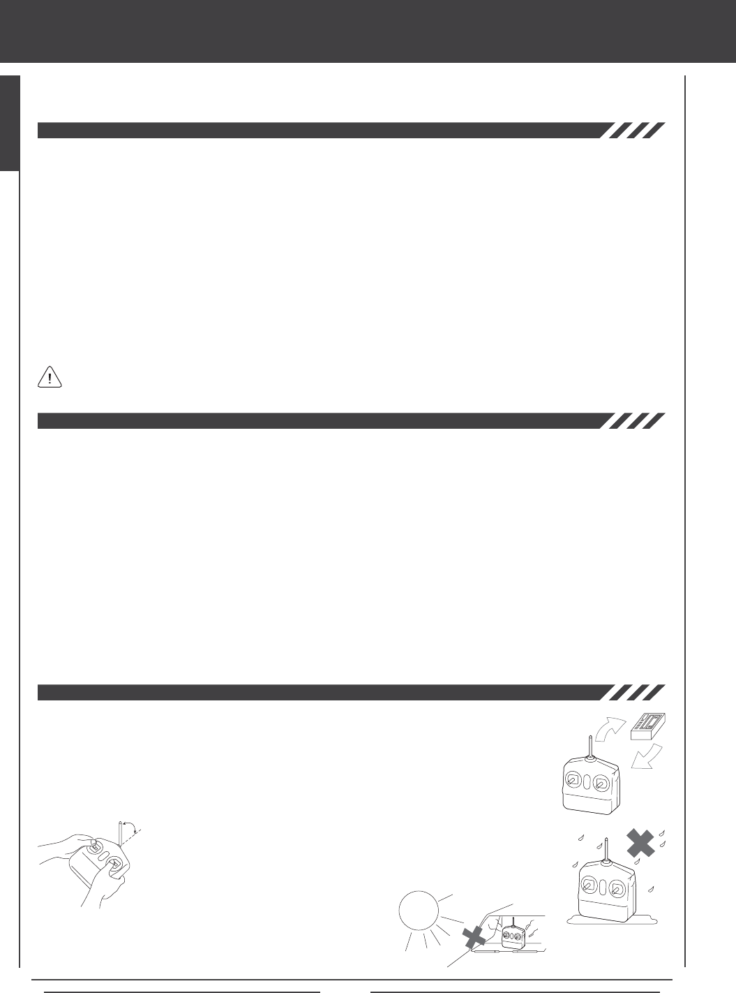
l Before use, the transmitter antenna should be rotated and angled so that the
antenna is as close to perpendicular to the ground as possible during use. After
use, to prevent any chance of damaging the antenna, the antenna should be
rotated and moved into the horizontal stowed position.
l Do not expose the transmitter to water or
excessive moisture.
l Do not expose the transmitter to excessive heat or direct sunlight.
Leaving the transmitter out in direct sunlight can damage the
LCD Display.
ON
OFF
Keep Antenna
Perpendicular
to Ground
Do Not Expose to Moisture
or Direct Sunlight
Page 5
Academy of Model Aeronautics
5151 East Memorial Drive
Muncie, IN 47302
Phone (800) 435-9262
Fax (765) 741-0057
www.modelaircraft.org
l The receiver antenna wires consist of two coaxial cables and two reception wires (the thin tip at the end of the coaxial cables).
When you mount the receiver antenna wires, do not bend the reception wires. Reception performance decreases if the reception
wires are bent.
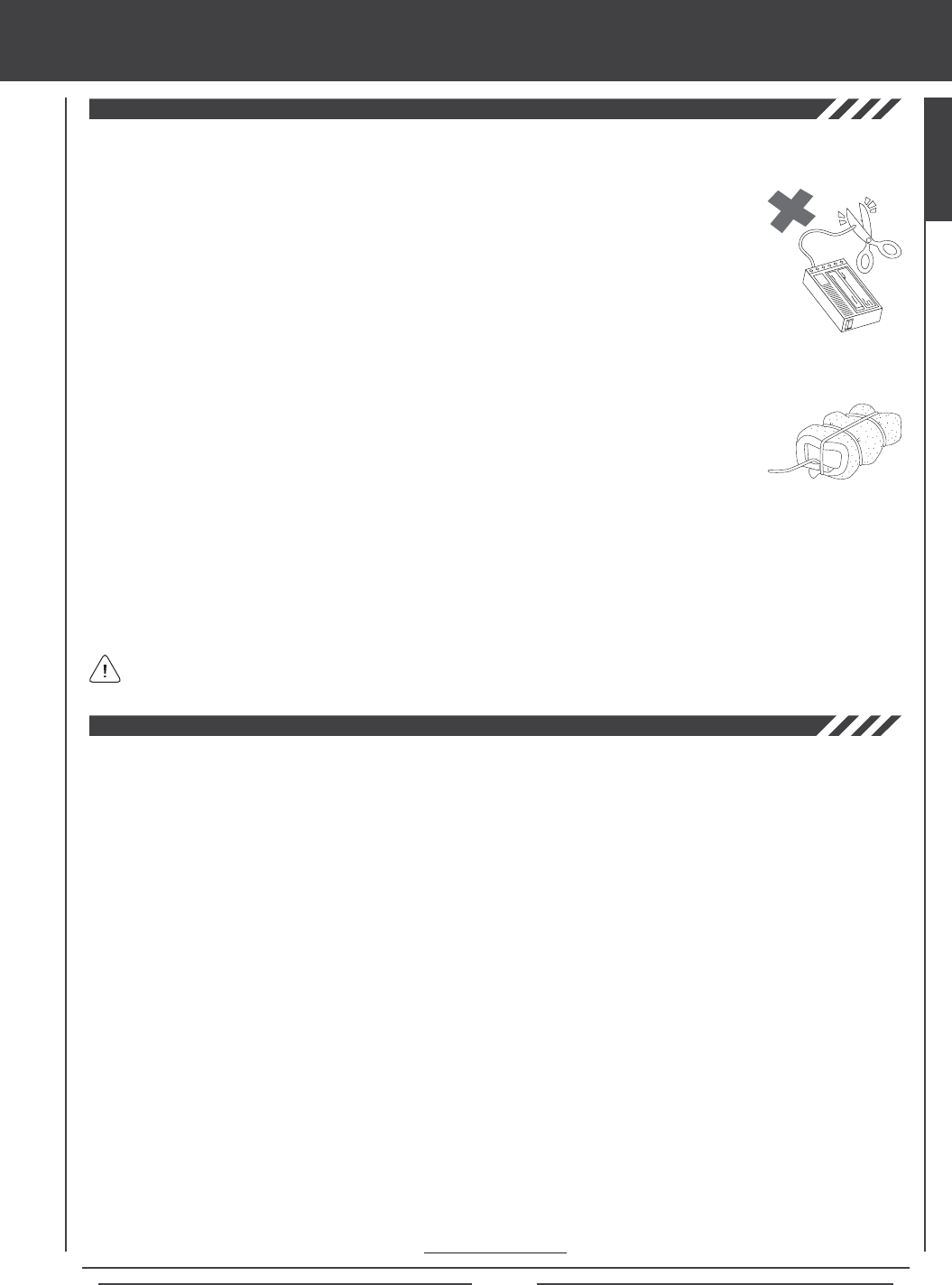
l The receiver antenna wires are delicate, therefore, handle with care. Do not pull on the receiver
antenna wires with force. Do not cut or extend the receiver antenna wires.
l The coaxial cables can be bent into gentle curves, however, do not bend the coaxial cables acutely, or
repeatedly bend them, or the antenna cores can be damaged.
l When installed in an electric-powered model, keep the receiver antenna wires as far away as possible
from the motor, battery, and electronic speed control (ESC).
l There is a danger of runaway operation if connectors shake loose during use. Make sure that the receiver, servo(s), and switch
harness connectors are securely tted.
l The receiver is susceptible to vibration and moisture. Take appropriate measures to
protect against vibration and moisture. The receiver should be wrapped in foam and the
foam should be secured around the receiver to hold it in place. The foam should not be
secured too tightly or the vibration dampening quality will be reduced. Failure to take
appropriate measures could result in damage to the receiver.
l When installing the receiver, the antenna reception wires (the thin tip at the end of the coaxial cables) should not come into
contact with any carbon or metal components (conductive components). Aircraft fuselages and helicopter frames may contain
conductive components. If mounting the receiver surrounded by conductive materials (for example, a carbon ber fuselage),
mount the receiver so that the antenna reception wires can be extended outside of the model. Reception can be blocked if the
antenna reception wires are shielded inside a carbon ber fuselage.
l The manufacturer disclaims all responsibility for damages resulting from use of components other than genuine Airtronics
components.
safety and usage precautions
The Academy of Model Aeronautics (AMA) is a national organization representing modelers in the United States. We urge you
to examine the benets of membership, including liability protection in the event of certain injuries. The Academy has adopted
simple and sane rules which are especially pertinent for radio controlled ight as the Ofcial AMA National Model Aircraft Safety
Code, which we have partially reprinted below:
l I will not y my model aircraft in sanctioned events, airshows or model ying demonstrations until it has been proven to be
airworthy by having been previously, successfully ight tested.
l I will not y my model higher than approximately 400 feet within 3 miles of an airport without notifying the airport operator.
I will give the right-of-way and avoid ying in the proximity of full-scale aircraft. Where necessary, an observer shall be
utilized to supervise ying to avoid having models y in the proximity of full-scale aircraft. Where established, I will abide by
the safety rules for the ying site I use, and I will not willfully and deliberately y my models in a careless, reckless and/or
dangerous manner.
l I will have completed a successful radio equipment ground range check before the rst ight of a new or repaired model.
l I will not y my model aircraft in the presence of spectators until I become a qualied yer, unless assisted by an experienced
helper.
l I will perform my initial turn after takeoff away from the pit or spectator areas, unless beyond my control.
It is extremely important to install the receiver and route the receiver antenna wires correctly in your model. This will ensure
that your model receives control signals no matter what its posture, attitude, or heading. For more information, see page 24.
Wrap Receiver
in Foam to Protect From
Vibration and Damage
GENERAL

Page 6
FEATURES AND SPECIFICATIONS
l 10-Channel Digital Proportional Computer Radio with Advanced Programming for Competition Aircraft, Helicopters, and Sailplanes
l New 2.4GHz FHSS-3 Technology
l Full-Range 92104 10-Channel 2.4GHz FHSS-3 Receiver
l Compatible with Airtronics 2.4GHz FHSS-1 Aircraft Receivers
l 6 Cell 1500mAH Rechargeable Ni-MH Transmitter Battery
l Direct Model Select
l Safety Link Model / Receiver Binding (FHSS-3 Receivers Only)
l Programmable Custom Menu
l Easy-to-Read LCD Display
l Simple Wing and Model Templates
l Servo Reversing, Centering, End Point Adjustments, and Limits
l Six Digital Trim Switches
l LCD-Only Display Switch
l 3-Axis Triple Rates and Bi-Directional Exponential
l 3-Position Programmable Switches
l 2 Programmable Side Levers and Programmable Dial Knob
l Servo Monitor
l Stick Monitor
l A/E/R Triple Rates
l A/E/R Bi-Directional Exponential
l 9-Point Throttle Curve
l Throttle Hold
l Throttle Cut
l Optional 'Stiff' Control Springs to Fine-Tune Gimbals
l Optional Throttle Stick Stops
l User Naming, Model Naming and Model Select
l FHSS-1, FHSS-3, and PPM-8 Modulation Selection
l Low-Power Range Check Mode
l 10-Channel Programmable Fail Safe
l Adjustable Receiver Battery Fail Safe Voltage
l Trainer System
l User-Selectable Modes
l Programmable Channel Assignments
l Stick Switch Functions
l Stop Watch, Rhythm, System, and Integral Timers
l Data Copy, Reset, and Transfer
l 20 Model Memory
l Add-On Memory Expansion Card and PC Connectivity
l Cross-Trim
l 2 Programmable Snap Rolls
l 10 Programmable Mixes
l 5 C-Mixes with 9-Point Curves
l Variable Resistance Lever Assign
l 5 Flight Modes
l Flight Mode Copy, Delay, and Naming
l Idle Down
l Aileron Differential
l A/E/R Offset
l Channel Delay
l Trim
l Trim Step Resolution
l Trim Authority
l Trim Authority
l Cross-Trim
l 11 Programmable Mixes
l 5 C-Mixes with 9-Point Curves
l Variable Resistance Lever Assign
l 5 Flight Modes
lFlight Mode Copy, Delay, and Naming
l Six Servo Wing Capability
l Landing Override Mode
l Servo Monitor
l Stick Monitor
l A/E/R Triple Rates
l A/E/R Bi-Directional Exponential
lAileron Differential
l Landing Differential
l Landing Flap Freeze Point
l Landing Crow
l Camber and Camber Point
l Channel Delay
l Trim
lTrim Step Resolution
l 3 Gyro Gains
l 3 Governors
l 3 Programmable Mixes Plus Revo Mixing
l 5 C-Mixes with 9-Point Curves
l Variable Resistance Lever Assign
l 5 Flight Modes
l Flight Mode Copy, Delay, and Naming
l Advanced Swashplate Control
l Servo Monitor
l Stick Monitor
l A/E/R Triple Rates
l A/E/R Bi-Directional Exponential
l 9-Point Throttle and Pitch Curves
l Throttle Cut
l 7-Point Hovering Throttle
l 7-Point Hovering Pitch
l A/E/R Offset
l Channel Delay
l Trim
l Trim Step Resolution
l Trim Authority
Page 7
Transmitter
Model: SD-10G (90100)
Output Power: 100mW
Operating Voltage: 6.7v~10.2v
Power Supply: 7.2v 1500mAH Ni-MH (NH6N-1500S)
Current Drain: 240mA
Temperature Range: 32ºF~122ºF (0ºC~50ºC)
Pulse Width: 0.9msec~2.1msec
Weight with Battery: 32.8oz (930gr)
Frequency: 2.4GHz FHSS-3/FHSS-1 Selectable
Model Memory: 20
Memory Expansion Card: Proprietary, 20 Models
Receiver
Model: 92104
Frequency: 2.4GHz FHSS-3
Input Voltage: 4.8v~6.0v
Weight: 0.52oz (15gr)
Dimensions: 1.94 x 1.05 x 0.61in (49.5 x 26.8 x 15.5mm)
Battery Fail Safe Limit: 3.8v~4.6v Adjustable
Connector Type: Universal 'Z'
978411 Aluminum Carrying Case
99103 Adjustable Neck Strap
FEATURES AND SPECIFICATIONS
96750 Stick Tip Extensions
97107 Trainer Cable
Due to the extremely high frame rate that the 92104 10-Channel receiver included with your SD-10G 2.4GHz FHSS-3 radio
control system operates at, we strongly recommend the use of digital servos. If you use analog servos and experience
problems, you will need to either upgrade to digital servos or use one of the available Airtronics 2.4GHz FHSS-1 aircraft receivers.
Airtronics FHSS-1 aircraft receivers operate at a lower frame rate, therefore, analog servos can be used with them without issue.
We recommend using Airtronics brand servos with your SD-10G 2.4GHz FHSS-3 radio control system. See your local Airtronics
dealer for more information and availability.
Torque: 361oz/in (26.0kg/cm @ 4.8v)
423oz/in (30.5kg/cm @ 6.0v)
Speed: 0.19 sec/60º @ 4.8v
0.15 sec/60º @ 6.0v
Dimensions: 1.60 x 0.83 x 1.50in
(40.6 x 21.0 x 38.1mm)
Weight: 2.33oz (66gr)
94780M Digital High-Torque Metal Gear Ball Bearing Servo
Torque: 55oz/in (4.0kg/cm @ 4.8v)
66oz/in (4.8kg/cm @ 6.0v)
Speed: 0.15 sec/60º @ 4.8v
0.12 sec/60º @ 6.0v
Dimensions: 1.06 x 0.47 x 1.18in
(26.9 x 11.9 x 29.9mm)
Weight: 0.80oz (23gr)
94761Z Digital Micro High-Torque High-Speed Ball Bearing Servo
Torque: 92oz/in (6.6kg/cm @ 4.8v)
114oz/in (8.2kg/cm @ 6.0v)
Speed: 0.13 sec/60º @ 4.8v
0.10 sec/60º @ 6.0v
Dimensions: 1.54 x 0.79 x 1.47in
(39.1 x 20.1 x 37.3mm)
Weight: 1.98oz (56gr)
94774M Digital High-Speed Metal Gear Ball Bearing Servo
96817 Memory Expansion Card
97025 USB Adapter Cable
Torque: 42oz/in (3.0kg/cm @ 4.8v)
53oz/in (3.8kg/cm @ 6.0v)
Speed: 0.20 sec/60º @ 4.8v
0.16 sec/60º @ 6.0v
Dimensions: 1.54 x 0.79 x 1.42in
(39.1 x 20.1 x 36.0mm)
Weight: 1.59oz (45gr)
94702Z Digital Standard Servo
Torque: 124oz/in (8.9kg/cm @ 4.8v)
151oz/in (10.8kg/cm @ 6.0v)
Speed: 0.17 sec/60º @ 4.8v
0.13 sec/60º @ 6.0v
Dimensions: 1.54 x 0.79 x 1.47in
(39.1 x 20.1 x 37.3mm)
Weight: 1.98oz (56gr)
94775M Digital High-Power Metal Gear Ball Bearing Servo
Torque: 80oz/in (5.1kg/cm @ 4.8v)
89oz/in (6.4kg/cm @ 6.0v)
Speed: 0.10 sec/60º @ 4.8v
0.08 sec/60º @ 6.0v
Dimensions: 1.59 x 0.83 x 1.04in
(40.3 x 21.0 x 26.4mm)
Weight: 1.77oz (50gr)
94746M Digital Low-Prole Metal Gear Ball Bearing Servo
GENERAL
The nominal input voltage of the 92104 receiver is 4.8v
to 6.0v. A 4 cell Ni-MH or Ni-Cd battery pack is 4.8v and
a 5 cell Ni-MH or Ni-Cd battery pack is 6.0v. If you use a 2 cell
Li-Po battery pack, you MUST use a voltage regulator. For more
information, see page 20.
Page 8
basic model setup order
The information on this page describes the Basic Model Setup Order that you can use to setup a new model. Regardless of the
model you are ying, using the basic functions of the SD-10G transmitter for most applications is easy and will get your model
setup quickly. It's a simple 5-step process.
1) Bind the Receiver to the Transmitter and Position the Receiver Antennas:
l Turn the transmitter ON and navigate to the SYSTEM>MODULATION menu.
l Hold down the Bind Button on the receiver. While holding down the Bind Button on the receiver, turn the receiver ON.
l Release the Bind Button on the receiver. The Bind LED will slowly blink.
lScroll down to TRANSMIT BIND CODE and press the YES/+ key. The Bind LED will blink rapidly.
l After the Bind LED stops blinking rapidly, press the END key. The Bind LED will turn solid.
l Install the receiver in your model, making sure that the two receiver antenna wires are mounted 90º to each other.
l Rotate the transmitter antenna so that it is positioned at a 45º angle toward you.
2) Choose a Model Type:
l Navigate to the SYSTEM>TYPE menu. Press the YES/+ or NO/- keys to select the Model Type that matches your
model, either AERO (Powered Aircraft), GLID (Sailplane), or HELI (Helicopter).
3) Make Model Type Selections:
l Scroll down to choose the various options related to the Model Type you've chosen.
AERO - Select what type of wing (Normal or Delta), the number of aileron servos (1 or 2), the number of ap servos (1 or 2),
the type of tail (Normal, V-Tail, or Dual Elevator Servos), and how many engines (1 or 2) your model features.
GLID - Select what type of wing (Normal or Delta), the number of aileron servos (2 or 4), the number of ap servos (1, 2,
or 4), and the type of tail (Normal or V-Tail) your model features.
HELI - Select the type of swashplate your model features. Each Swashplate Type features a diagram showing where the
servos are positioned on the swashplate. Choose the Swashplate Type that matches your model.
l After making your selections, press the ENTER key, then the YES/+ key. The pre-programmed model template will be
loaded into the transmitter.
4) Name Your Model:
l Navigate to the SYSTEM>MODEL NAME menu and input a name for your model. This will allow you to easily choose this
model again for later use. The Model Name will be displayed on the Top menu so that you know which model is currently
in use.
5) Plug In Servos and Setup Control Surfaces:
lNavigate to the Surface menu (it's directly below SYSTEM on the Top menu). The upper portion of the Surface menu
displays which servos plug into which channel slots in the receiver. Use this information to plug your servos into the
receiver in the correct order.
l Use the Surface menu to adjust direction of travel (NOR/REV), centering (CENT) and maximum travel (EPA) in both
directions for each of your servos. Adjust the settings for each servo separately to ensure that the movements are correct
and that the swashplate, dual ailerons, dual elevators, etc, are moving the same amount.
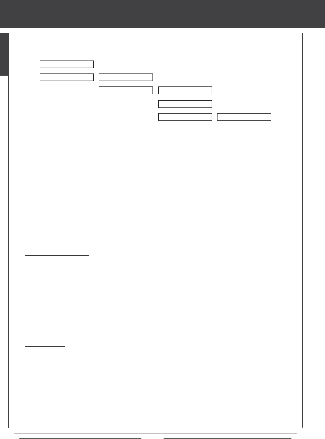
MODULATION
6
6
TYPE
MODEL NAME
6
SURFACE
6
TRANSMIT BIND CODE
AERO, GLID, OR HELI
6
6
REV, CENT, EPA, LIMT
6
SYSTEM
Page 9
tips and suggestions
lTo view our expanding library of specic transmitter setup sheets, visit the SD-10G section of our website at http://www.airtronics.net.
Available transmitter setup sheets are saved in PDF format and bundled in a .zip le.
l When you see in the lower right corner of a page, this indicates that the current section is continued at the top of the
next page.
lA voltage regulator is required if your receiver battery voltage output is higher than 6.0 volts.
l An after-market peak-detection charger and/or cycler can be used to charge the Ni-MH transmitter battery, however, the
battery must rst be removed from the transmitter to be charged. The circuitry within the transmitter will interfere with the
peak-detection charger's normal operation, resulting in over-charging and damaging the battery and possibly the transmitter itself.
l Up to 10 servos can be plugged into the receiver separately. To utilize the Channel 9/BATT or the Channel 10/BATT slots along
with a battery, you must plug a Y-Harness into the channel slot, then plug the servo into one side of the Y-Harness and the
battery switch harness into the other side of the Y-Harness.
l It is extremely important that the receiver antenna wires be mounted as described. This will ensure that your model receives
control signals no matter what its posture, altitude, or heading.
l All receiver channel assignments can be programmed to suit the user. For example, in the default conguration, receiver
channel slot 1 controls Elevator, however, this channel slot can be programmed to control Aileron or control Rudder, etc.
This allows the utmost control for nearly any custom conguration you may require.
l All switches (right- and left-hand switch arrays), auxiliary levers, auxiliary push-buttons, and the Auxiliary Dial Knob can be
programmed to perform different functions depending on the user's preference. Some of these switches and buttons are
pre-programmed with specic functions based on the Model Type. For default function assignments, please see those specic
sections of this Operating Manual.
l The radio control system is range checked using the Low Power Mode function. Do not attempt to y with the transmitter in
Low Power Mode. You will be unable to control your model once it is a certain distance away from you.
l The SD-10G transmitter features a Type function which allows you to quickly set up the transmitter's low-level mixing based
on the type of model you're ying. Common templates for AERO, GLIDER, and HELI model types are provided. For example,
if your model features two aileron servos, two ap servos, and dual elevator servos, choosing these options will automatically
change the transmitter's programming to accommodate this setup. This takes the guess-work out of setting up more complex
models.
Model Type selection is used when setting up a new model and should be done prior to making any programming
changes to your model. When the Model Type selection is changed for the currently selected model, all programming
(including custom programming) for that model will be reset.
l The SD-10G transmitter features several different safety features that will sound an audible alarm when triggered. If you turn
your SD-10G transmitter ON and it beeps, this is more than likely a safety alarm.
l The Display Key activates the transmitter's LCD Display without actually turning the transmitter ON. This allows you to
check and/or change programming settings without actually turning the transmitter ON. To turn only the LCD Display ON,
press and hold the DISPLAY Key for ~2 seconds. To turn the LCD Display OFF, press the DISPLAY Key once.
l The SD-10G transmitter is compatible with FHSS-3 and FHSS-1 Airtronics 2.4GHz aircraft receivers. To bind the transmitter to
an FHSS-1 receiver, the transmitter modulation must rst be changed to FH1.
l Pressing the YES/+ key when a System menu or an F-Mode menu selection is highlighted will add that selection to the Custom
menu. Selections added to the Custom menu are denoted by a .
l Models stored on the Memory Expansion Card (if installed), are denoted with an 'M' (i.e. M21:SANWA-04).
l In the default conguration, the Model Select List contains 10 AERO model types and 10 HELI model types. The Model Type for
any of the 20 models in the Model Select List can be changed using the Type menu.
l The Direct Model Select function allows you to select one of three of your most-used models from memory without going
through the Model Select menu. This makes it much quicker and easier to load the programming for your three favorite models.
Many of the Tips and Suggestions on the following pages can be found throughout this Operating Manual, however, we have
listed the most important ones here for your convenience.
GENERAL

Page 10
tips and suggestions
l Pressing both the YES/+ and NO/-keys together will Reset the highlighted programming selection to the Factory Default Setting.
l When the Top menu is displayed, pressing both the YES/+ and NO/- keys together will Reset the Timer display.
l You can assign multiple functions to one switch by assigning the same Switch Position Number for each function. For example,
you could assign Elevator Dual Rate 2, Aileron Dual Rate 2, and Rudder Dual Rate 2 on one switch so that all three Dual
Rate functions can be changed at once.
l Like many SD-10G programming features, Switch Assignments are model-specic. If you would like to keep the same Switch
Assignments from model-to-model for continuity, use the Data Copy function to save the time and effort necessary to re-program
the Switch Assignments for each model.
l When you use the Data Reset function, ALL model-specic Flight Mode data, Surface Menu data, and model-specic
System programming, such as Switch Assignments, Model Name, Fail Safe settings, and Stick Switches will be Reset to the
factory default settings. Model Type and Modulation settings will NOT be Reset.
l Increasing LCD Display Contrast can drain the battery more quickly than using a decreased (lower) setting.
l Unless otherwise noted, all programming changes take effect immediately.
l When the Memory Expansion Card is installed and Initialized, it is treated as an extension of the SD-10G transmitter's internal
model memory, therefore, model-specic programming data can be created, copied, deleted, etc., directly through the various
System menu selections. You do not need to enter the Memory Pack menu to make changes to models stored on the Memory
Expansion Card.
l An audible tone is heard when the trim switches reach the center position. This allows you to know when the trim switches
reach the center position without the need to look at the Trim Indicators on the Top menu.
l The SD-10G transmitter features Digital Trim Memory. Any amount of trim that you set during ight, using either the trim
switches or the YES/+ and NO/- keys from within the Trim menu, is automatically stored in memory for that specic channel
and model, and for that specic Flight Mode (if enabled). The Trim percentage values for each model will automatically be
loaded when the transmitter is turned ON and your model is selected.
l There is always one Flight Mode Active at all times. In the default conguration, F-MODE N (Normal) is Active. When GLID
Model Type is selected, F-MODE 4 (Land) will be Active when the ap control stick is pulled all the way back.
l The F-MODE key is used to facilitate programming the individual Flight Modes only and does not turn the Flight Modes ON
or OFF.
l Prior to takeoff, check the position of the Dual Rate switches to ensure that they are in the positions you want. We recommend
programming maximum control throw when the three-position dual rate switches are either all the way forward or all the way
back, whichever you prefer.
l The channels displayed in the Surface menu will vary based on Model Type and Model Type selection options selected in the
SYSTEM>MODEL TYPE menu. For example, if your model features dual elevator servos, LE (Left Elevator) and RE (Right
Elevator) will be displayed.
l End Point Adjustment is not the same as Limits and should not be used in the same manner as Limits. Whereas Limits will
Limit the maximum servo travel in either direction, End Point Adjustment does not. End Point Adjustment is designed to balance
the control throw on both sides of servo travel and can be overridden by other settings, such as Dual Rate. For example, if
you have your End Point Adjustment set to 100%, and you set your Dual Rate to 150%, the servo will travel more than 100%
when Dual Rate is ON, however, if you have your Limits set to 100%, the servo will travel only 100%, regardless of the End
Point Adjustment setting or the Dual Rate setting.
l Many F-Mode menu functions feature Common or Separate choices. When set to COM (Common), the function settings will be
the same regardless of which Flight Mode the transmitter is operating in. When set to SEP (Separate), you can program different
function settings separately for each Flight Mode.
l The Delay function does not affect when the servo starts to respond to control stick movement. The Delay affects only the
transit time of the servo.
Page 11
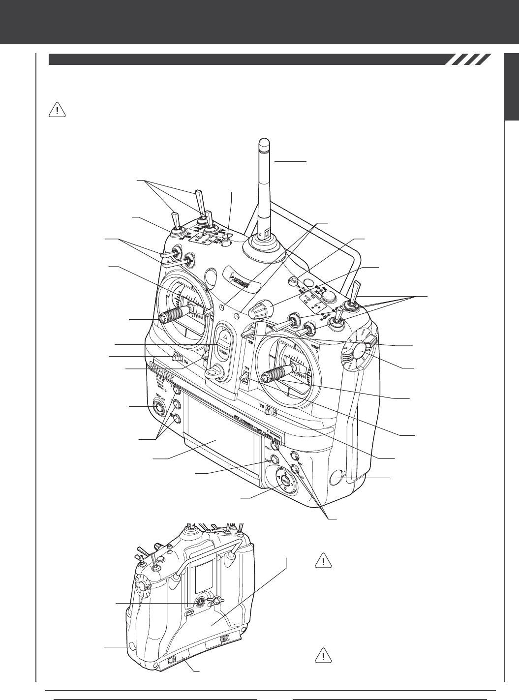
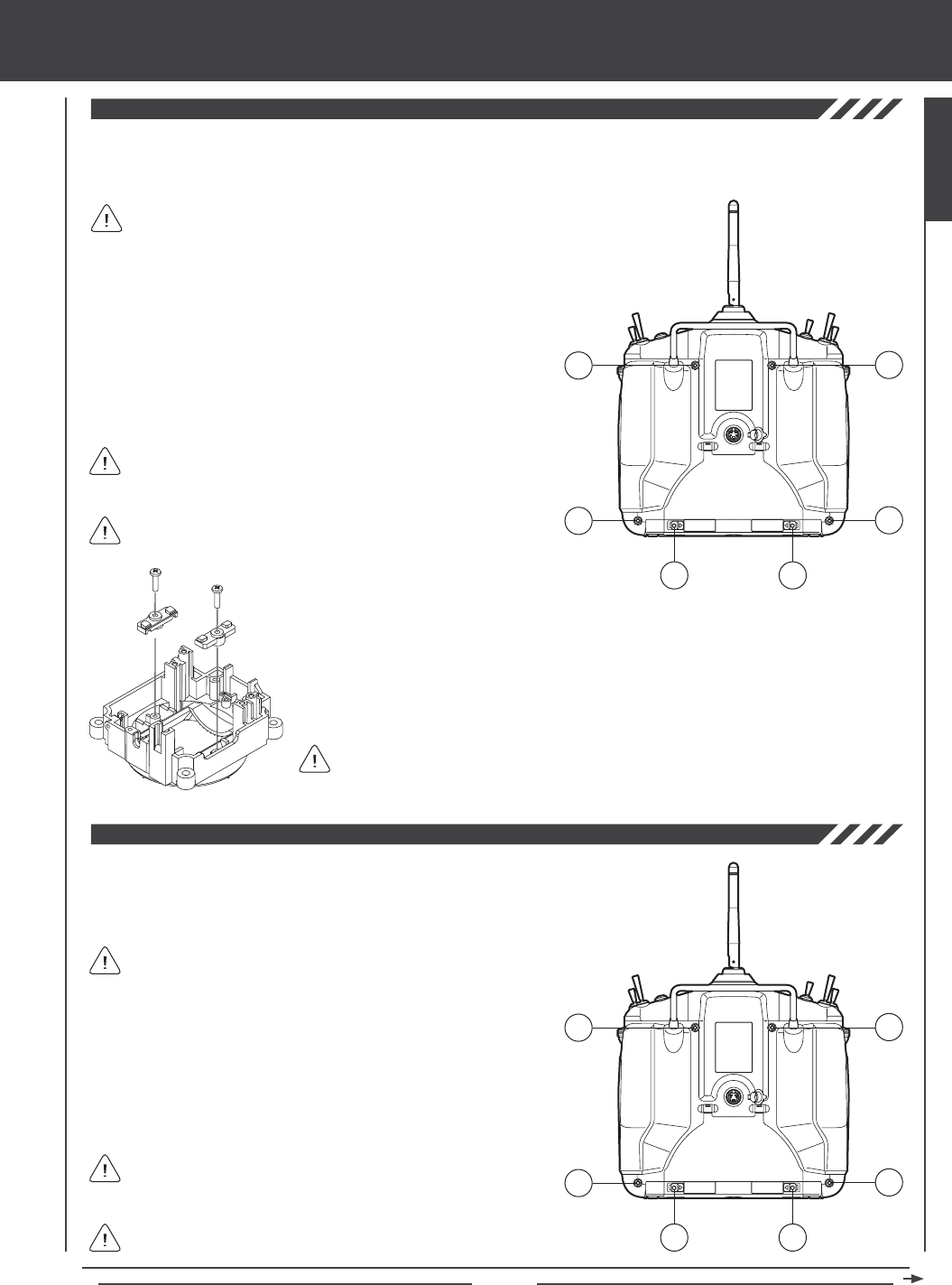
features familiarization
Antenna
Use the diagrams below to familiarize yourself with the different control features of your new SD-10G transmitter. Descriptions of
these features can be found on pages 12 through 13.
FRONT
The features referenced below are general in nature. Features specic to the Model Type (aircraft, helicopter, or sailplane)
can be found in those specic sections of this Operating Manual.
BACK
Throttle/Rudder
Control Stick (Mode 2)
Left-Hand
Switch Array
Right-Hand
Switch Array
Power Switch
Display Key
Direct Model Select Keys
LCD Display
Charging Jack
Aileron/Elevator
Control Stick (Mode 2)
Trim Switch (T2)
Trim Switch (T1)
Trim Switch (T5)
Auxiliary Dial Knob (VR7)
RF Output
Indicators
Trim Switch (T4)
Trim Switch (T3)
Trim Switch (T6)
Navigation Pad
Flight Mode Key
Programming Keys
Auxiliary Lever (VR5)
Auxiliary Lever (VR6)
DIN
Connector
Push-Button
Switch
Push-Button Switch
Left-Hand
Switch Array
Charging
Jack
All switches (right- and left-hand switch arrays),
auxiliary levers, auxiliary push-buttons, and
the Auxiliary Dial Knob can be programmed to
perform different functions depending on the user's
preference. Some of these switches and buttons
are pre-programmed with specic functions based
on the Model Type. For default function assignments,
please see those specic sections of this Operating
Manual.
In the default conguration, the control sticks
are set to Mode 2 as shown above. The
transmitter can be set to Mode 1, Mode 3, or Mode 4.
For more information, see page 41.
Battery
Compartment
Memory Expansion Card Slot
(Inside Battery Compartment)
GENERAL
Page 12
Aileron/Elevator Control Stick: Controls the Aileron and Elevator axes in the default Mode 2 conguration. For information on
changing transmitter modes, see page 41.
Antenna: Transmits the signal from the transmitter to the receiver in the model. The Antenna should be pivoted into the vertical
position during use. When not in use, the Antenna should be pushed down and collapsed into the horizontal position to prevent
damage during handling and transport.
Antenna Reception Wires: The portion of each of the receiver antenna wires that actually receives the transmitter signal.
The Antenna Reception Wires should never be bent or they could be damaged and limit the range of the receiver.
Auxiliary Dial Knob: The Auxiliary Dial Knob is programmable and will perform a different function depending on what function
is assigned to it. For example, the Auxiliary Dial Knob can be programmed to remotely adjust your engine's carburetor mixture.
Auxiliary Lever: Two Auxiliary Levers are featured, one on each side of the transmitter. Each Auxiliary Lever is programmable
and will perform a different function depending on what function is assigned to it. For example, an Auxiliary Lever can be
programmed to control the tow hook release on a glider.
Battery Compartment: Houses the 6 cell 1500mAH Ni-MH battery that powers the transmitter. The transmitter uses a 6 cell battery
for lighter weight and better feel, while still providing long usage time.
Bind Button and Bind LED: Used in the process of Binding the transmitter and receiver. For information on Binding the transmitter
and receiver, see page 23 or 35.
Charging Jack: Used for onboard charging of the 6 cell 1500mAH Ni-MH battery. For information on charging the transmitter
battery, see page 19.
features familiarization
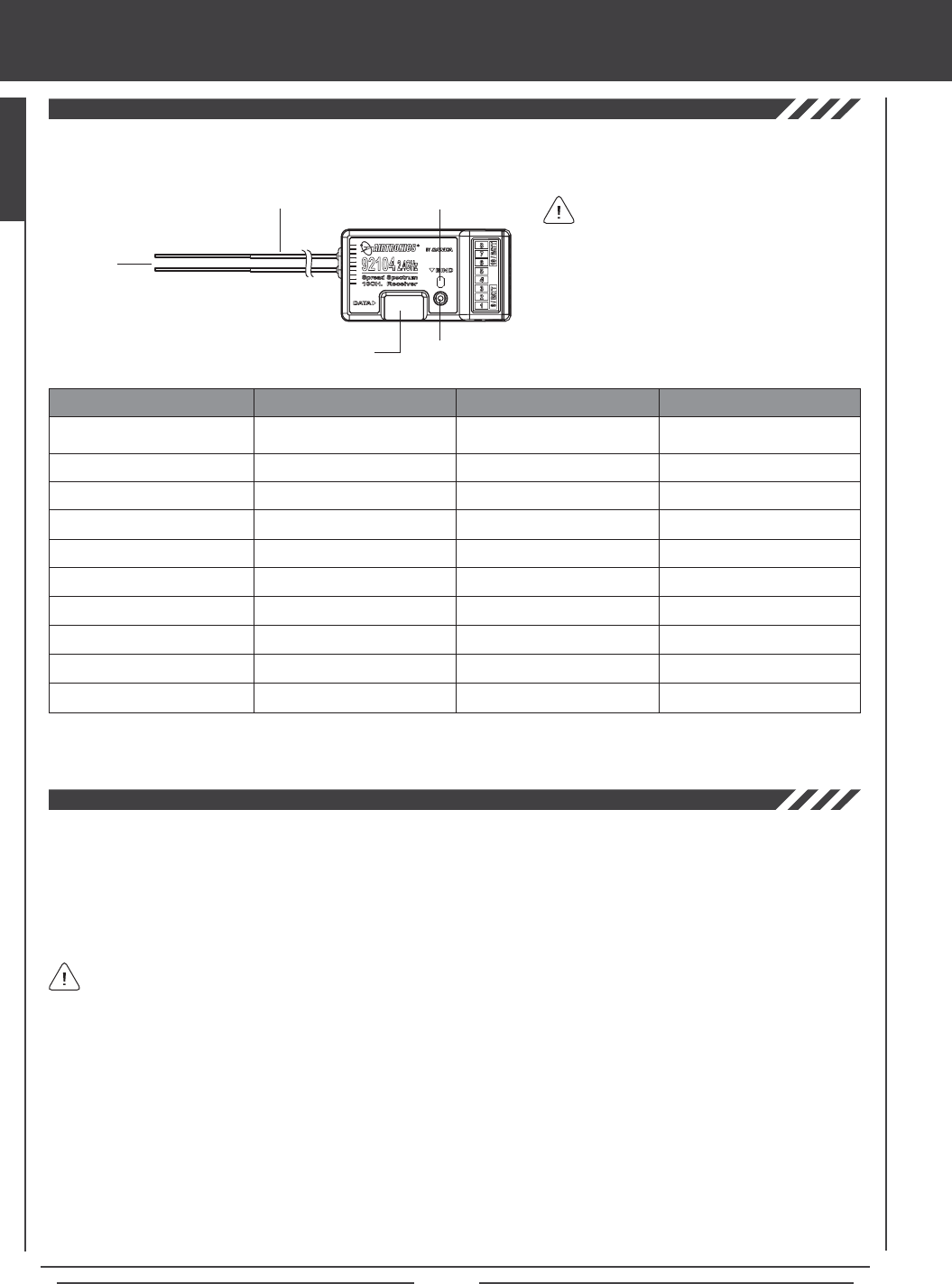
Use the diagram below to familiarize yourself with the 92104 10-Channel receiver included with your new SD-10G 2.4GHz FHSS-3
radio control system. Descriptions of these features can be found below.
All receiver channel assignments can be
programmed to suit the user. For example,
in the default conguration, receiver channel slot
1 controls Elevator, however, this channel slot can
be programmed to control Aileron or control
Rudder, etc. This allows the utmost control for
nearly any custom conguration you may require.
The default receiver channel slot congurations
are shown in the table below:
RECEIVER CHANNEL SLOT AERO GLIDER HELI
Channel Slot 1
Channel Slot 2
Channel Slot 3
Channel Slot 4
Channel Slot 5
Channel Slot 6
Channel Slot 7
Channel Slot 8
Channel Slot 9/BATT**
Channel Slot 10/BATT**
Elevator
Aileron
Throttle
Rudder
Gear
Flaps
Auxiliary 4
Auxiliary 3
Auxiliary 2 and Battery
Auxiliary 1 and Battery
Elevator
Left Aileron
Motor
Rudder
Gear
Right Aileron
Flaps
Auxiliary 3
Auxiliary 2 and Battery
Auxiliary 1 and Battery
Elevator (Fore/Aft Cyclic)
Aileron (Left/Right Cyclic)
Throttle
Rudder (Tail Rotor)
Gyro
Pitch (Collective)
Governor
Auxiliary 3
Auxiliary 2 and Battery
Auxiliary 1 and Battery
Bind Button
Bind LEDCoaxial Cables
Antenna
Reception
Wires
Data Port*
*Data Port for
Sanwa/Airtronics Software
** To utilize this channel slot along with the battery, you must plug a Y-Harness into the channel slot, then plug the servo into one
side of the Y-Harness and the battery switch harness into the other side of the Y-Harness. For more information, see page 20.

Page 13
The 92104 10-Channel receiver included with your new SD-10G 2.4GHz FHSS-3 radio control system uses universal Airtronics
'Z' connectors which are electronically compatible with the servos of other radio control system manufacturers. The connectors
are rugged, but should be handled with care.
features familiarization
Coaxial Cables: The portion of each antenna wire that extends the Antenna Reception Wires. The Coaxial Cables can be bent
into gentle curves, however, do not bend the Coaxial Cables acutely, or repeatedly bend them, or the antenna wire's cores can
be damaged. For information on mounting the receiver and orientating the receiver antenna wires, see page 24.
DIN Connector: The DIN Connector is where the trainer cable (available separately) is plugged into. It is also used to plug the
Airtronics USB data cable (available separately) between the transmitter and your computer. An adapter to use the transmitter
with a ight simulator can also be plugged into the DIN Connector.
Direct Model Select Keys: The Direct Model Select Keys allow you to select one of three of your most-used models from
memory without going through the Model Select menu. For information on using the Direct Model Select Function, see page 31.
Display Key: Activates the transmitter's LCD Display without actually turning the transmitter ON. This allows you to check
and/or change programming settings without actually turning the transmitter ON. To turn only the LCD Display ON, press and
hold the DISPLAY Key for ~2 seconds. To turn the LCD Display OFF, press the DISPLAY Key once.
Flight Mode Key: Allows you to cycle through the ve different Flight Modes while in the Flight Mode Programming menu.
LCD Display: The heart of the programming and display features of the transmitter. All programming and transmitter display
functions are shown on the LCD Display. The Navigation Pad, the three Programming Keys, and the F-MODE Key to the right of
the LCD Display facilitate transmitter programming. The contrast of the LCD Display can be customized by the user to make it
easily readable in multiple lighting conditions.
Left-Hand Switch Array: The switches grouped on the left side of the transmitter are programmable and each will perform a
different function depending on what function is assigned to it. Each switch has a molded reference number next to it that
corresponds to the programming function in the Switch Assignment menu (the printed label corresponds to the two switches on
the front of the transmitter). Each of the ve switches is a three-position toggle switch except for the switch labeled 19/20/21
which is a spring-loaded switch.
Memory Expansion Card Slot: Holds the Memory Expansion Card (available separately). For information on installing the
Memory Expansion Card, see page 59.
Navigation Pad: The Navigation Pad is used in conjunction with the Programming Keys and the F-MODE Key to facilitate
transmitter programming. The Navigation Pad allows you to quickly and easily move the Programming Cursor up and down, and
right and left. The ENTER Key in the center of the Navigation Pad is used to open the selected menu or programming option.
Power Switch: Turns the transmitter ON and OFF.
Programming Keys: The Programming Keys are used in conjunction with the Navigation Pad and the F-MODE Key to facilitate
transmitter programming. The three Programming Keys consist of the YES/+ (Increase) Key, the NO/- (Decrease) Key, and the
END Key.
Push-Button Switch: Two Push-Button Switches are featured. Each Push-Button Switch is programmable and will perform a
different function depending on what function is assigned to it. For example, a Push-Button Switch can be programmed to control
the Stopwatch function.
RF Output Indicators: Both indicators illuminate when the transmitter is turned ON and transmitting a signal. If one or both of
the RF Output Indicators fails to illuminate, RF output is limited or non-existent. In this case, you should not y.
Right-Hand Switch Array: The switches grouped on the right side of the transmitter are programmable and each will perform
a different function depending on what function is assigned to it. Each switch has a molded reference number next to it that
corresponds to the programming function in the Switch Assignment menu (the printed label corresponds to the two switches on
the front of the transmitter). Each of the four switches is a three-position switch.
Throttle/Rudder Control Stick: Controls the Throttle and Rudder axes in the default Mode 2 conguration. For information on
changing transmitter modes, see page 41.
Trim Switch: Six separate Trim Switches (T 1, T 2, T 3, T 4, T 5, and T 6) are featured. Each Trim Switch will control a different
trim axis depending on which Model Type is selected.
- = Negative (Black)
+ = Positive (Red)
S = Signal (Blue)
When unplugging the servo connectors, it's best not to pull on the servo wire itself. This could result in damage to the servo
wire pins in the plastic plug.
GENERAL
Page 14
Low Voltage Alarm
Throttle High Warning Alarm
Flight Mode Warning Alarm
Trainer Mode Warning Alarm
Power Switch Warning Alarm
transmitter alarms
The SD-10G transmitter is equipped with a Low Voltage Alarm that will sound when the transmitter battery reaches 6.7 volts. If
the Low Voltage Alarm sounds while you are ying, you should land immediately, then recharge the transmitter battery.
If the Low Voltage Alarm sounds even after the transmitter battery has been fully charged it indicates that there is a problem
with either the transmitter or the transmitter battery. If this occurs, please contact Airtronics Customer Service.
The SD-10G transmitter is equipped with a safety feature that will not allow you to use the transmitter if the throttle control stick is not
in the lowest position when you turn the transmitter ON. If the throttle control stick is not in the lowest position when you turn the
transmitter ON, the Throttle High Warning alarm will sound continuously, the red RF Output Indicator will blink, and the LCD Display
will read TH-STICK Hi !! To clear the Throttle High Warning, pull the throttle control stick down to the lowest position. The LCD Display
will read normally, the Throttle High Warning alarm will cease, and both the red and green RF Output Indicators will be illuminated.
The SD-10G transmitter is equipped with a safety feature that will not allow you to use the transmitter if the Flight Mode is not set
to 'N' (Normal) when you turn the transmitter ON. If the Flight Mode is not set to 'N' when you turn the transmitter ON, the Flight
Mode Warning alarm will sound continuously, the red RF Output Indicator will blink, and the LCD Display will read F-MODE
NOT 'N' !! To clear the Flight Mode Warning, set the Flight Mode to 'N' using the Flight Mode Switch (this is different from the
F-MODE Key). The LCD Display will read normally, the Flight Mode Warning alarm will cease, and both the red and green RF
Output Indicators will be illuminated.
The SD-10G transmitter is equipped with a safety feature that will warn you when the transmitter is set to Trainer - Master or
Trainer - Slave when the transmitter is turned ON. If the transmitter is set to Trainer - Master when you turn the transmitter ON,
the Trainer Mode Warning alarm will sound continuously, the red RF Output Indicator will blink, and the LCD Display will read
TRAINER MODE MASTER !! If the transmitter is set to Trainer - Slave when you turn the transmitter ON, the Trainer Mode
Warning alarm will sound continuously, the red RF Output Indicator will blink, and the LCD Display will read TRAINER MODE
SLAVE !! To clear either of the Trainer Mode Warnings, press any of the three Programming Keys, the F-MODE Key, or the
ENTER Key. The LCD Display will read normally, the Trainer Mode Warning alarm will cease, and both the red and green RF
Output Indicators will be illuminated (if set to Slave, only the green RF Output Indicator will blink).
Clearing the Trainer Mode Warning does not change the Trainer setting of the transmitter. When the Trainer Mode Warning
is cleared, the transmitter will still be in Trainer Mode - either set to Master or set to Slave.
The SD-10G transmitter is equipped with a Power Switch Warning alarm that will warn you when the transmitter is turned ON and
there has been no movement of the control sticks or switches for 15 minutes. If the transmitter is left on for 15 minutes or longer
without any input the Power Switch Warning alarm will sound continuously and the LCD Display will read POWER SW ON !! To
clear the Power Switch Warning, either turn the transmitter OFF or press any of the three Programming Keys, the F-MODE Key,
or the ENTER Key.
The SD-10G transmitter features several different safety features that will sound an audible alarm when triggered.
Safety features vary depending on the Model Type selected. Default conguration shown in parenthesis.
ALARM DISPLAY AERO GLIDER HELI
ALWAYS ACTIVE
ACT/INH (ACTIVE)
ACT/INH (ACTIVE)
ALWAYS ACTIVE
ACT/INH (ACTIVE)
ALWAYS ACTIVE
N/A
ACT/INH (INHIBITED)
ALWAYS ACTIVE
ACT/INH (ACTIVE)
ALWAYS ACTIVE
ACT/INH (ACTIVE)
ACT/INH (ACTIVE)
ALWAYS ACTIVE
ACT/INH (ACTIVE)
In the default AERO conguration, Flight Mode N (Normal) is switch position 10. In the default HELI conguration, Flight
Mode N (Normal) is switch position 22. In the default GLID conguration, the Flight Mode Warning alarm is INHIBITED.
Page 15
custom transmitter ADJUSTMENTS
Every effort has been made to engineer the optimum transmitter weight, balance, and feel in the design of your SD-10G 2.4GHz
FHSS-3 radio control system. For example, the transmitter control sticks are ball bearing-supported for smooth control and use
springs that result in superior feel for most pilots. Some aspects of the transmitter are customizable though, to suit the user's
particular taste.
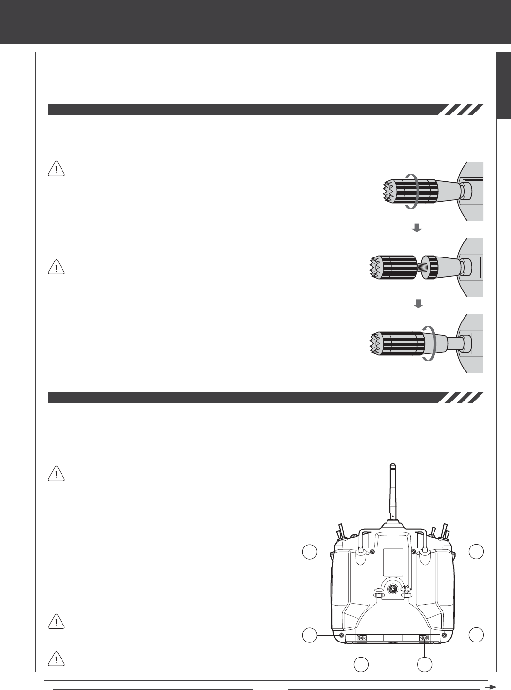
The length of the control sticks can be adjusted to best suit the way you hold them. In general, pilots who place their thumbs on
top of the control sticks prefer the control sticks to be shorter, and pilots who grasp the control sticks prefer the control sticks to
be longer.
3) Once your are satised with the length of the control stick, thread the bottom half of
the control stick up and tighten it gently against the top half of the control stick.
In the default conguration, the control sticks are adjusted to the shortest length.
1) While holding the base of the control stick, turn the top half of the control stick
counter-clockwise to loosen it.
When lengthening the control sticks, we strongly suggest that you leave at least
four threads inside the top half of each control stick. This will ensure that the
control sticks maintain optimum mechanical security. If you thread the control sticks out
too far, the control sticks might come loose during use.
2) To lengthen the control stick, turn the top half of the control stick counter-clockwise.
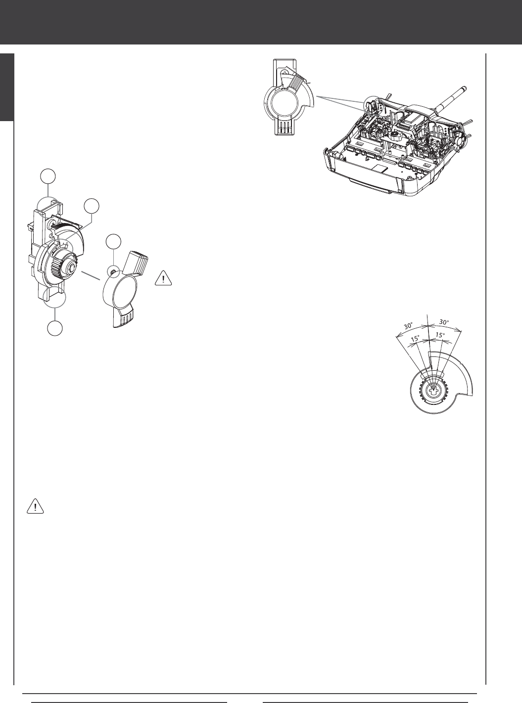
The spring tension of the control sticks can be adjusted to suit your preference. Increasing the spring tension makes the control
stick's movement rmer. Decreasing the spring tension makes the control stick's movement softer. The throttle control stick ratchet
can also be adjusted. Loosening the throttle control stick ratchet will make the throttle detents less noticeable. Tightening the
throttle control stick ratchet will make the throttle detents rmer. The throttle detents can even be eliminated for those helicopter
pilots who prefer to have no throttle ratchet.
B
AA
B
B
B
1) Open the battery cover by rst pushing the two latches (A) inward,
then by pulling up on the bottom of the battery cover.
2) Unplug the battery from the transmitter and remove it. Set the battery
aside for now.
3) Remove the four Phillips head screws (B) from the back of the
transmitter, then very carefully pull the back half of the transmitter off.
There are no wires attached between the back half of the transmitter
and the circuit boards inside the transmitter. When the back half of
the transmitter is removed, it can be safely set aside.
Pull the back half of the transmitter straight off to avoid bending or
damaging the battery pins.
GENERAL
Your transmitter includes a set of 'stiff' control stick springs that can be installed in place
of the stock control springs. Install these control stick springs if you prefer an even stiffer
control stick feel than provided after tightening the control stick spring tension as described in
this section. For more information about installing the springs, refer to the spring-specic details
in the Changing Throttle Ratchets and Spring for Mode 1 and Mode 3 on pages 41 and 42.
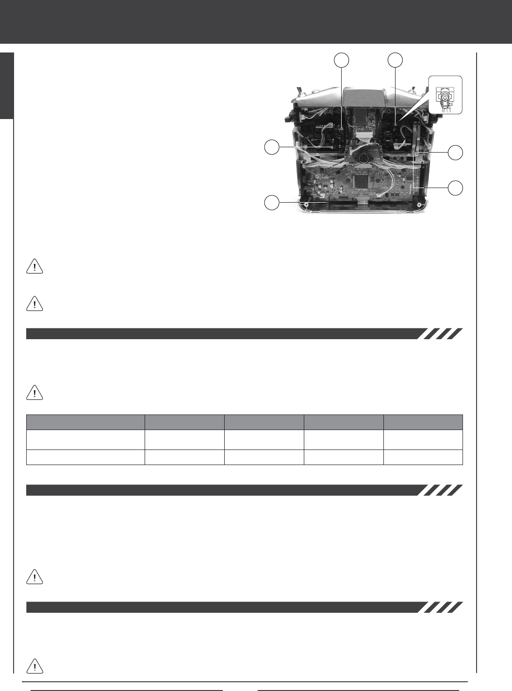
Page 16
4) To increase the spring tension of the control sticks, tighten
(turn clockwise) the three socket-cap screws (C), using a
1.5mm hex wrench. To decrease the spring tension of the
control sticks, loosen (turn counter-clockwise) the three
socket-cap screws (C), using a 1.5mm hex wrench.
5) To make the throttle control stick detents less noticeable,
loosen the socket-cap screw on the outer ratchet plate (D),
using a 1.5mm hex wrench. To make the throttle control stick
detents rmer, tighten the socket-cap screw on the outer
ratchet plate (D), using a 1.5mm socket-cap wrench.
6) Some helicopter pilots prefer to eliminate the throttle ratchet
completely. To do this, loosen the socket-cap screw on the
outer ratchet plate (D), using a 1.5mm hex wrench until the
throttle detents can't be felt anymore. Next, tighten the socket-cap
screw on the inner throttle plate (E), until you're satised with
the throttle control stick resistance.
custom transmitter ADJUSTMENTS
Any modications made to the transmitter other than adjusting the control stick tension and changing Operating Modes
(see below) will void any and all warranties covered by Airtronics, Inc.
C
CD
When reinstalling the back half of the transmitter, be very careful that you don't bend or otherwise damage the battery pins (F).
These long battery pins should be carefully slid through the matching holes in the back half of the transmitter before pushing
it down into place.
F
7) When satised with the results carefully reinstall the back half of the transmitter, then reinstall the transmitter battery and plug
it back in. The battery connector is polarized and can therefore be plugged in only one way.
The SD-10G transmitter has the ability to operate in four different Modes as shown in the table below. Changing Operating Modes
can be done by the user and requires changing the Mode Setting in the System menu, then swapping the throttle ratchets and
spring on the control sticks. For information on changing Operating Modes, see page 41.
Left-Side Control Stick
Right-Side Control Stick
CONTROL STICK MODE 1 MODE 2 MODE 3
Rudder/Elevator
Throttle/Aileron
Throttle/Rudder
Elevator/Aileron
Elevator/Aileron
Throttle/Rudder
In the default conguration, the transmitter is set to Mode 2, which is most commonly used in North America.
MODE 4
Throttle/Aileron
Elevator/Rudder
E
The SD-10G transmitter features a Trainer System that allows you to connect two SD-10G transmitters together for the purpose
of training a new pilot or for training a more experienced pilot on a new model. For information on connecting two SD-10G
transmitters together, and programming and using the Trainer System, see page 39.
The Trainer System is compatible ONLY with another SD-10G transmitter. You MUST use the SD-10G Trainer Cable. See
your local Airtronics dealer for more information and availability.
C
Spring
Adjuster
The Memory Expansion Card allows you to store up to 40 models (20 in the SD-10G transmitter and 20 on the Memory Expansion
Card). The Memory Expansion Card can be removed and installed into a different SD-10G transmitter, so that model-specic
programming data can be shared with fellow SD-10G transmitter owners in the eld. When the Memory Expansion Card is installed
and Initialized, it is treated as an extension of the SD-10G transmitter's internal model memory, therefore, model-specic programming
data can be created, copied, deleted, etc., directly through the various System menu selections. There is no need to access the
Memory Expansion Card separately. For more information on installing and initializing the Memory Expansion Card, see page 59.
The Memory Expansion Card is proprietary and can be used only with SD-10G transmitters. See your local Airtronics
dealer for more information and availability.
Page 17
custom transmitter ADJUSTMENTS
The SD-10G 2.4GHz FHSS-3 radio control system includes two throttle stick stops which can be installed to limit the physical
travel of the throttle control stick. In the default conguration, both control sticks move up and down the same amount. Some users,
particularly helictopter pilots, prefer it when the physical travel of the throttle control stick is less than that of the other control stick.
B
AA
B
B
B
1) Open the battery cover by rst pushing the two latches (A) inward,
then by pulling up on the bottom of the battery cover.
2) Unplug the battery from the transmitter and remove it. Set the battery
aside for now.
3) Remove the four Phillips head screws (B) from the back of the
transmitter, then very carefully pull the back half of the transmitter off.
There are no wires attached between the back half of the transmitter
and the circuit boards inside the transmitter. When the back half of
the transmitter is removed, it can be safely set aside.
Pull the back half of the transmitter straight off to avoid bending or
damaging the battery pins.
4) Install the throttle stick stops, using the self-tapping screws provided. You can install both
throttle stick stops to limit both high and low throttle control stick travel, or you can install only
one of the two throttle stick stops to limit either high OR low throttle control stick travel.
5) When satised with the results carefully reinstall the back half of the transmitter, then reinstall
the transmitter battery and plug it back in. The battery connector is polarized and can
therefore be plugged in only one way.
It's important that after you install the throttle stick stops that you recalibrate the control
sticks, following the information in the Control Stick Calibration - User Option section on
page 43. This will ensure that the throttle control stick commands maximum servo travel and
correct End Points even though the physical travel of the throttle control stick is limited.
The amount that transmitter Auxiliary Levers (VR6 and VR7) physically travel can be adjusted to
suit your preference. For example, some users prefer less overall movement and other users
prefer more overall movement. The amount that each Auxiliary Level travels can be adjusted from
15º to 30º in each direction (or 30º and 60º of movement overall).
B
AA
B
B
B
1) Open the battery cover by rst pushing the two latches (A) inward,
then by pulling up on the bottom of the battery cover.
2) Unplug the battery from the transmitter and remove it. Set the battery
aside for now.
3) Remove the four Phillips head screws (B) from the back of the
transmitter, then very carefully pull the back half of the transmitter off.
There are no wires attached between the back half of the transmitter
and the circuit boards inside the transmitter. When the back half of
the transmitter is removed, it can be safely set aside.
Pull the back half of the transmitter straight off to avoid bending or
damaging the battery pins.
When reinstalling the back half of the transmitter, be very careful that you don't bend
or otherwise damage the battery pins. These long battery pins should be carefully slid
through the matching holes in the back half of the transmitter before pushing it down into place.
GENERAL
Changing how much each Auxiliary Lever physically travels does
not change the overall control travel of the servos.
Page 18
custom transmitter ADJUSTMENTS
5) While holding the Auxiliary Lever mounting tabs (C) rmly between your thumb and
index nger, grasp and gently pull the lever off of the mount.
4) Working with one Auxiliary Lever at a time, carefully pull it up
and out of the transmitter case, being careful not to damage
the connected wiring.
6) Reinstall the lever, making sure that the small tab is aligned with the corresponding tick mark that
provides the travel distance and lever position desired.
Notice on the lever a small tab (A) and notice on the mount several molded tick marks
and a hash mark (B).
7) Reinstall the Auxiliary Lever by pushing the mounting tab down into the case, being careful not to damage the connected wiring.
8) Repeat the previous procedures to change the amount of travel and lever position of the second Auxiliary Lever.
9) When satised with the results carefully reinstall the back half of the transmitter, then reinstall the transmitter battery and plug
it back in. The battery connector is polarized and can therefore be plugged in only one way.
A
B
THIS SPACE INTENTIONALLY LEFT BLANK
C
C
When reinstalling the back half of the transmitter, be very careful that you don't bend or otherwise damage the battery pins.
These long battery pins should be carefully slid through the matching holes in the back half of the transmitter before
pushing it down into place.
Page 19
Charging the battery
The SD-10G 2.4GHz FHSS-3 transmitter features a 6 cell 7.2v 1500mAH Ni-MH battery for lighter weight and longer battery life.
The battery is charged directly through the SD-10G transmitter, using the charging jack located in the left side of the SD-10G
transmitter. Please observe the Safety Precautions and Charging Warnings below when charging the transmitter battery.
l Always follow the charging procedures described below to ensure safe and correct use of your Ni-MH battery.
l The Ni-MH battery is not fully charged when purchased. It is necessary to charge the Ni-MH battery before operation.
l Before charging the Ni-MH battery, double-check that the transmitter power switch is in the OFF position.
l Do not plug the charger into anything other than an AC 110v power outlet. Plugging the charger into anything other than
AC 110v outlet may result in smoking, sparks, or re.
l Do not throw the Ni-MH battery or abuse it in any manner. Do not dispose of the Ni-MH battery in the re or allow it to overheat.
l Do not short-circuit the Ni-MH battery terminals with wire or any other object.
An after-market Li-Po battery can be used in place of the stock 6 cell 7.2v 1500mAH Ni-MH transmitter battery. If you decide to
replace the stock battery with a Li-Po battery, please observe the following:
l Use ONLY a 2 Cell 7.4v Li-Po battery of desired capacity. DO NOT USE A 3 CELL 11.1v LI-PO BATTERY.
l You MUST remove the battery from the transmitter to charge the battery.
lWhen you change the connector on your Li-Po battery, please observe correct polarity. See servo plug diagram above.
WARNING An after-market peak-detection charger and/or cycler can be used to charge the Ni-MH transmitter battery,
however, the battery must rst be removed from the transmitter to be charged. The circuitry within the transmitter will
interfere with the peak-detection charger's normal operation, resulting in over-charging and damaging the battery and possibly
the transmitter itself. Damage caused by charging the battery through the transmitter using anything other than the charger
included with the SD-10G transmitter will not be covered under warranty.
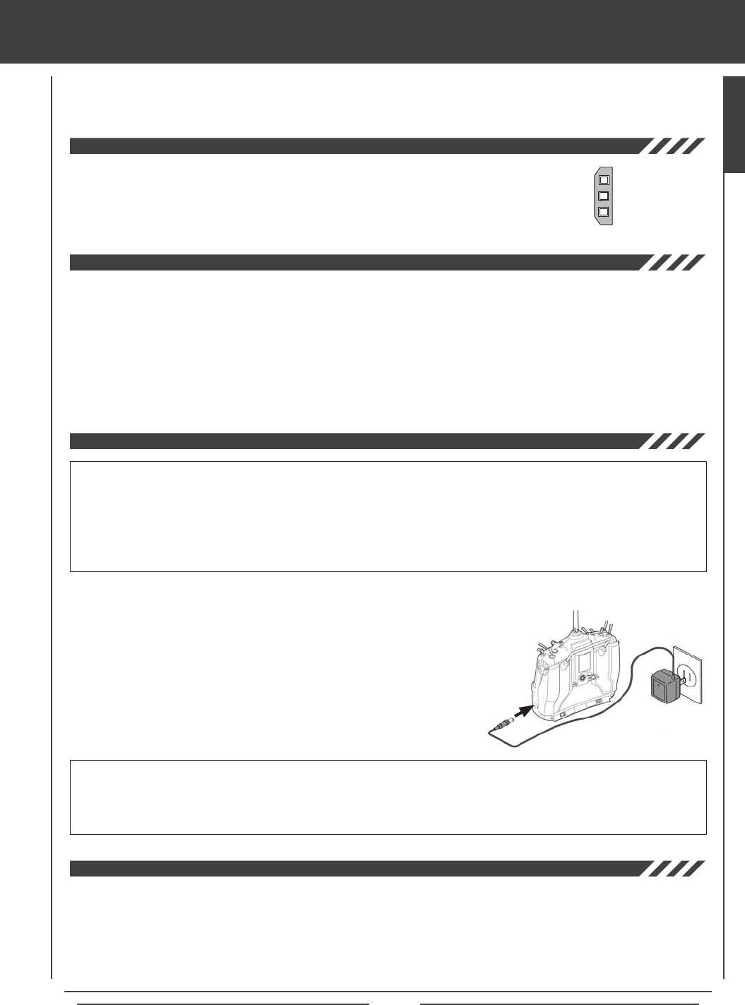
2) Plug the round connector from the charger into the charging jack in the right
side of the transmitter. The charger LED will illuminate red, indicating that the
charger is charging.
3) Transmitter charger output is 150mAH, therefore, it will take approximately 10
hours to recharge a fully-discharged battery. We suggest leaving the charger
on overnight. Once fully-charged, the charger LED will once again illuminate
green. See IMPORTANT note above regarding the rst 5 charges.
110v Wall
Outlet
Charger
To
Charging
Jack
Model: OE-156C
Input Voltage: 110v
Tx Output Voltage: 8.5v@150mA
When you receive your SD-10G 2.4GHz FHSS-3 radio control system, the transmitter battery may be
unplugged. Before attempting to charge the transmitter battery, open the battery cover by rst pushing
the two latches inward, then by pulling up on the bottom of the battery cover. Carefully plug the connector
from the battery into the matching slot in the transmitter case. The battery connector is polarized and
can therefore be plugged in only one way.
- = Negative (Black)
+ = Positive (Red)
- = Negative (Black)
IMPORTANT The battery charger included with your SD-10G transmitter is a capacity-sensing charger. During the
charging process, the charger will sense the battery's maximum capacity, then switch to a 20mAH trickle charge, which
can be left on the transmitter for up to 72 hours after the charging light turns green.
To ensure maximum battery capacity and transmitter usage time, we suggest that the rst 5 charges are 24 hour-total
charges, regardless of when the charging light turns green. For the rst 5 times that you charge the battery, charge for a 24 hour
period, then discharge the battery under normal use until the low voltage alarm sounds. After charging the battery for the rst 5
times using this method, you can subsequently charge the battery for the standard amount of time (until the charging light turns green).
1) Plug the supplied charger into a 110v AC wall socket. The charger LED will illuminate green, indicating that the charger is
plugged in.
GENERAL
Page 20
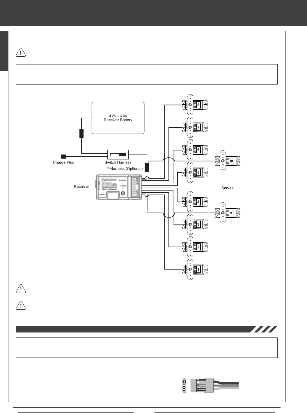
airborne system connections
Use the diagram below to familiarize yourself with how to connect the switch harness, servos, and receiver battery to your 92104
10-Channel receiver.
An after-market Li-Po battery can be used to power the receiver instead of the standard Ni-Cd or Ni-MH battery. If you decide to
use a Li-Po battery to power the receiver, please observe the following:
l Use ONLY a 2 Cell 7.4v Li-Po battery of desired capacity with a voltage
regulator. SEE WARNING ABOVE.
l When you change the connector on your Li-Po battery, please observe correct polarity.
WARNING The receiver can use a battery pack rated from 4.8v to 6.0v. A 2 cell Li-Po battery pack is 7.4v. Because of
the higher voltage, you MUST use a voltage regulator* plugged in between the switch harness and the Li-Po battery to
drop the Li-Po battery voltage to 6.0 volts. If you do not use a voltage regulator, damage to the receiver will result.
- = Negative (Black)
+ = Positive (Red)
S = Signal (Blue)
A receiver battery is not included. The receiver can be powered by a 4.8v (4 cell Ni-MH or Ni-Cd) or a 6.0v (5 cell Ni-MH
or Ni-Cd) battery pack of desired capacity.
Up to 10 servos can be plugged into the receiver separately. To utilize the Channel 9/BATT or the Channel 10/BATT slots
along with a battery, you must plug a Y-Harness into the channel slot, then plug the servo into one side of the Y-Harness
and the battery switch harness into the other side of the Y-Harness.
WARNING Some high-capacity Ni-MH batteries can put out more than 6.0 volts when fully charged. If the battery that you're
using is puts out more than 6.0 volts, a voltage regulator, plugged in between the switch harness and the battery should
be used to drop the battery voltage to 6.0 volts. If you do not use a voltage regulator, damage to the receiver may result.
A vOLTAgE rEguLATOr IS rEquIrEd IF YOur
rECEIvEr BATTErY vOLTAgE OuTPuT IS HIgHEr
THAN 6.0 vOLTS. WE rECOmmENd A SWITCHINg
TYPE rEguLATOr ANd IT muST BE ABLE TO HANdLE
THE AmPErAgE dEmANdS OF THE SErvOS uSEd IN
YOur mOdEL.
The battery can be plugged into any of the channel slots and still power the receiver.
Page 21
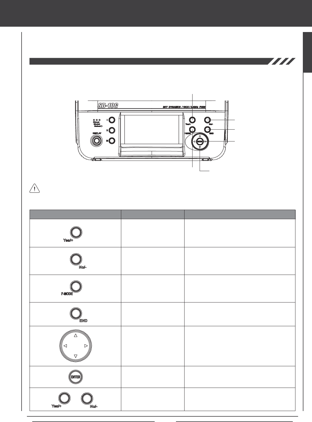
LCD display and programming keys
The SD-10G 2.4GHz FHSS-3 transmitter features three Programming Keys, an F-MODE key, and a Navigation Pad and ENTER
Key, all used in conjunction to facilitate programming. This section summarizes the functions of these features in addition to
detailing the main areas of the LCD Display.
Increases numerical programming values and selects
ON/OFF, NOR/REV, and ACT/INH programming
options. Also veries function settings.
F-MODE Key
Cycles through the five Flight Modes within the
Fllight Mode menu. Also locks/unlocks programming
changes in the Surface menu.
KEY NAME FUNCTION
Returns to the previous menu. Press several times to
return to the Top menu.
ENTER Key
Moves the Programming Cursor Up 5, Down 6,
Right 4, and Left 3.
Opens the selected menu or programming option.
Advances the cursor in the User Name and Model
Name menus.
YES/+ NO/-
Key Sequence (Reset)
Pressing both keys together will Reset the selection
to the Factory Default Setting. Also resets the Timer
display on the Top menu.
END Key
YES/+ Key
Moving around the LCD Display and programming the transmitter is accomplished using the Navigation Pad and ENTER key,
the three Programming Keys, and the F-MODE key positioned on the right half of the transmitter.
YES/+ Key
END Key
NO/- Key
ENTER Key
F-MODE Key Navigation Pad
NO/- Key
Decreases numerical programming values and
selects ON/OFF and NOR/REV programming
options.
Navigation Pad
The Display Key activates the transmitter's LCD Display without actually turning the transmitter ON. This allows you to
check and/or change programming settings without actually turning the transmitter ON. To turn only the LCD Display ON,
press and hold the DISPLAY Key for ~2 seconds. To turn the LCD Display OFF, press the DISPLAY Key once.
GENERAL
Page 22
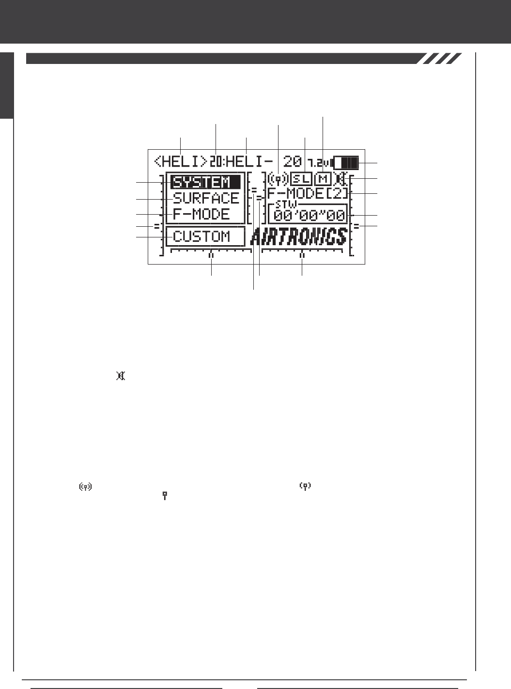
LCD display and programming keys
Active Flight Mode: Displays the currently active Flight Mode.
Flight Mode Menu Selection: Displays the Flight Mode menu programming options for each of the ve programmable Flight
Modes. Flight Mode menu programming options vary depending on the Model Type selected.
Key Mute Status: Displays the current status of the Key Mute function. When active an audible tone will sound with each
key-press. When disabled the audible tone will be muted with each key-press.
Memory Card Status: Displays when the Memory Expansion Card is installed in the transmitter.
Model Name: Displays the name of the currently selected model.
Model Number: Displays the number (1-20) of the currently selected model. Models saved to the Memory Expansion Card are
displayed with an 'M'. Models saved to the transmitter and to the Memory Expansion Card can be accessed independently.
Model Type: Displays the currently active Model Type loaded into memory, either AERO, GLID, or HELI.
RF Output Status: Displays the current RF Output Status of the transmitter. When the transmitter is turned ON and transmitting
a strong signal is displayed. When the signal is low or otherwise degraded is displayed. When the transmitter is turned
OFF, but the LCD Display is turned ON is displayed.
Shortcut Menu Selection: Displays a shortcut to any single System or F-Mode menu or to the Custom menu (default).
Surface Menu: Displays the Control Surface menu programming options. Surface menu programming options vary depending on
the Model Type selected.
System Menu: Displays the System menu programming options. System menu programming options are the same for each of
the three Model Types.
Timer / Stick Monitor: Displays the currently active Timer. Can also display the currently active Stick Monitor.
Trainer Status: Displays when the transmitter Trainer function is active. If the transmitter is in Master mode, MS will be displayed.
If the transmitter is in Slave mode, SL will be displayed.
Trim 1-6: Displays the current position of the specic trim switch [T1 Elevator, T2 Aileron, T3 Throttle, T4 Rudder, T5 Hovering
Throttle (HELI Model Type only), and T6 Hovering Pitch (HELI Model Type only)]. When each of the trim switches are moved to
center (zero), an audible tone will sound.
Voltage: Displays the current voltage of the transmitter battery. When the voltage reaches 6.7 volts, a low voltage alarm will sound.
Model Number
Model Type
Shortcut Menu Selection
Trim 3
Trim 4
Trim 1
Trim 2
Trim 6
Trim 5
System Menu Selection
Surface Menu Selection
Model Name
Timer / Stick Monitor
Active Flight Mode
Voltage
RF Output
Status Trainer
Status
Key Mute Status
Memory Card
Status
Flight Mode Menu Selection
Use the diagram below to familiarize yourself with the layout and different indicators that make up the LCD Display.
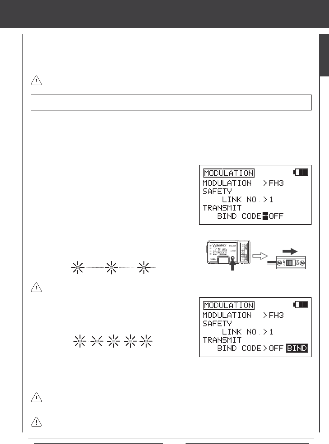
Page 23
transmitter and receiver binding
When new, it is necessary to pair the transmitter and receiver to prevent interference from radio controllers operated by other
users. This operation is referred to as 'binding'. Once the binding process is complete, the setting is remembered even when the
transmitter and receiver are turned OFF, therefore, this procedure usually only needs to be done once.
A Safety Link function is featured which can be used to program a unique bind code to each receiver/model pair, preventing the
transmitter from controlling a model that it's not currently programmed for.
3) Press the Navigation Pad 6 to highlight MODULATION, then press the
ENTER key to display the MODULATION menu. The cursor will default
to MODULATION>FH3.
4) Press the Navigation Pad 6 to move the cursor to SAFETY LINK NO.
By default the number should be 1, which matches the currently
selected default model (01:SANWA-01).
5) Press the Navigation Pad 6 to move the cursor to TRANSMIT BIND
CODE. OFF will be displayed.
6) While holding down the Bind Button on the receiver, turn the receiver
ON. The Bind LED on the receiver will blink slowly. After ~2 seconds
release the Bind Button. The Bind LED on the receiver will continue to
blink slowly.
Although the SD-10G transmitter can be used with any Airtronics FHSS-1 2.4GHz aircraft receiver, the Safety Link feature
is not supported.
When the binding procedure is successful, the Bind LED on the receiver will stay solid blue when both the transmitter and
receiver are turned ON. If the Bind LED on the receiver is blinking rapidly or not ON at all, the transmitter and receiver
are not paired. In this case, turn both the transmitter and receiver OFF, then repeat the binding procedure.
The SD-10G transmitter is compatible with FHSS-3 and FHSS-1 Airtronics 2.4GHz aircraft receivers. To bind the
transmitter to an FHSS-1 aircraft receiver, the transmitter modulation must rst be changed to FH1. For more information,
see page 36.
Use the tip of a pencil or a 1.5mm hex wrench to reach the Bind Button in the receiver.
1) Turn the transmitter ON. If this is the rst receiver/model pair you are binding, verify that the currently selected model number
is 01:SANWA-01 (new radio default model). If it is not, select model 01 via the MODEL SELECT menu. For more information,
see page 30.
2) Verify that SYSTEM is highlighted, then press the ENTER key to display the System menu. If SYSTEM is not highlighted,
press the END key until SYSTEM is highlighted.
5) Quickly press the YES/+ key. The green RF Output Indicator will blink,
the TRANSMIT BIND CODE selection will change to ON, and BINDING
will blink. The Bind LED on the receiver will blink rapidly for ~3 seconds,
then go out.
6) After Bind LED on the receiver goes out, press the END key. The Bind LED on the receiver, as well as the green RF Output
Indicator, will turn solid and the LCD Display will revert to the System menu indicating the binding process is complete. Press
the END key two times to return to the Top menu.
IMPORTANT The information in this section assumes that you're binding a new SD-10G transmitter and receiver in the
default conguration. For more information on Modulation and Safety Link settings, and how they're used, see page 34.
GENERAL
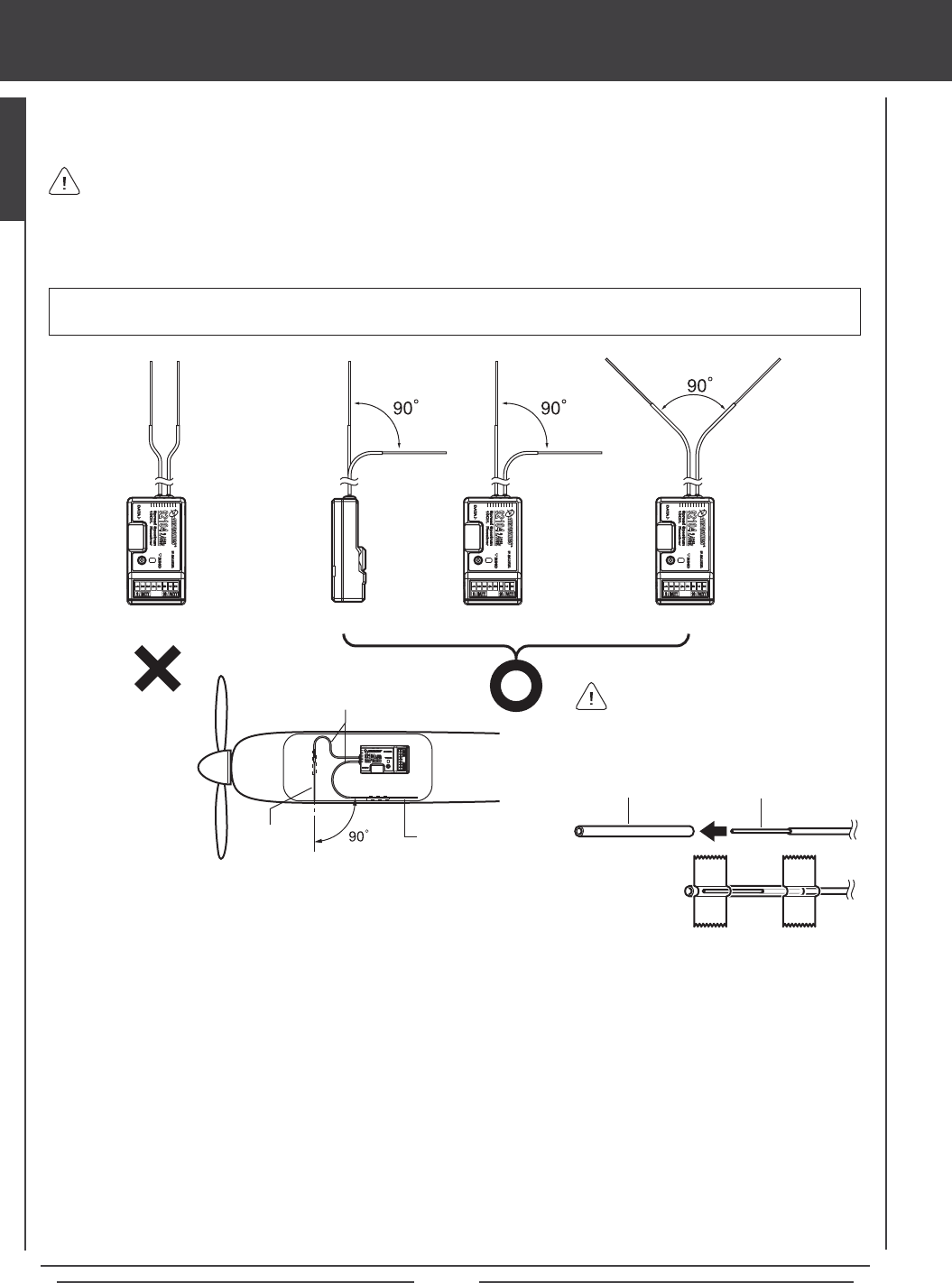
Page 24
mounting the receiver
When mounting the receiver in your model, it's important to mount the receiver exactly as described. In addition, the receiver
should be wrapped in foam rubber to protect it from vibration. Failure to mount the receiver antenna wires as described can
result in poor reception, or in some cases, complete loss of reception.
We recommend that you bind the transmitter and receiver prior to mounting the receiver into your model.
The receiver should be mounted securely in your model and the receiver antenna wires installed per the diagram below. The
two receiver antenna wires should be mounted to a wood or plastic non-conductive part of your model and angled so that the
reception wires are positioned 90º apart. Under no circumstances should the antenna reception wires be parallel to each other.
WARNING It is extremely important that the receiver antenna wires be mounted as described. This will ensure that your
model receives control signals no matter what its posture, attitude, or heading.
Receiver Receiver Receiver Receiver
Coaxial Cables
Reception WireReception
Wire
l The receiver antenna wires consists of two coaxial cables and two reception wires (the thin tip at the end of the coaxial cables).
When you mount the receiver antenna wires, do not bend the reception wires. Reception performance decreases if the reception
wires are bent.
l The receiver antenna wires are delicate, therefore, handle with care. Do not pull on the receiver antenna wires with force. Do
not cut or extend the receiver antenna wires.
l The coaxial cables can be bent into gentle curves, however, do not bend the coaxial cables acutely, or repeatedly bend them,
or the antenna cores can be damaged.
l When installed in an electric-powered model, keep the receiver antenna wires as far away from the motor, battery, and
electronic speed control (ESC) as possible.
l When installing the receiver, the antenna reception wires (the thin tip at the end of the coaxial cables) should not come into
contact with any carbon or metal components (conductive components). Aircraft fuselages and helicopter frames may contain
conductive components. If mounting the receiver surrounded by conductive materials (for example, a carbon ber fuselage),
mount the receiver so that the antenna reception wires can be extended outside of the model. Reception can be blocked if the
antenna reception wires are shielded inside a carbon ber fuselage.
Tape can be used to secure the antenna reception wires to your model. Alternatively, cut two short
pieces of plastic tube and slide one antenna reception wire into each piece of tube, then tape or
glue the tube to your model. The tubes will protect the antenna reception wires from damage.
Plastic Tube Reception Wire
If mounting inside a carbon fiber
fuselage, the antenna reception wires
must be run outside of the model as
described in the notation below.
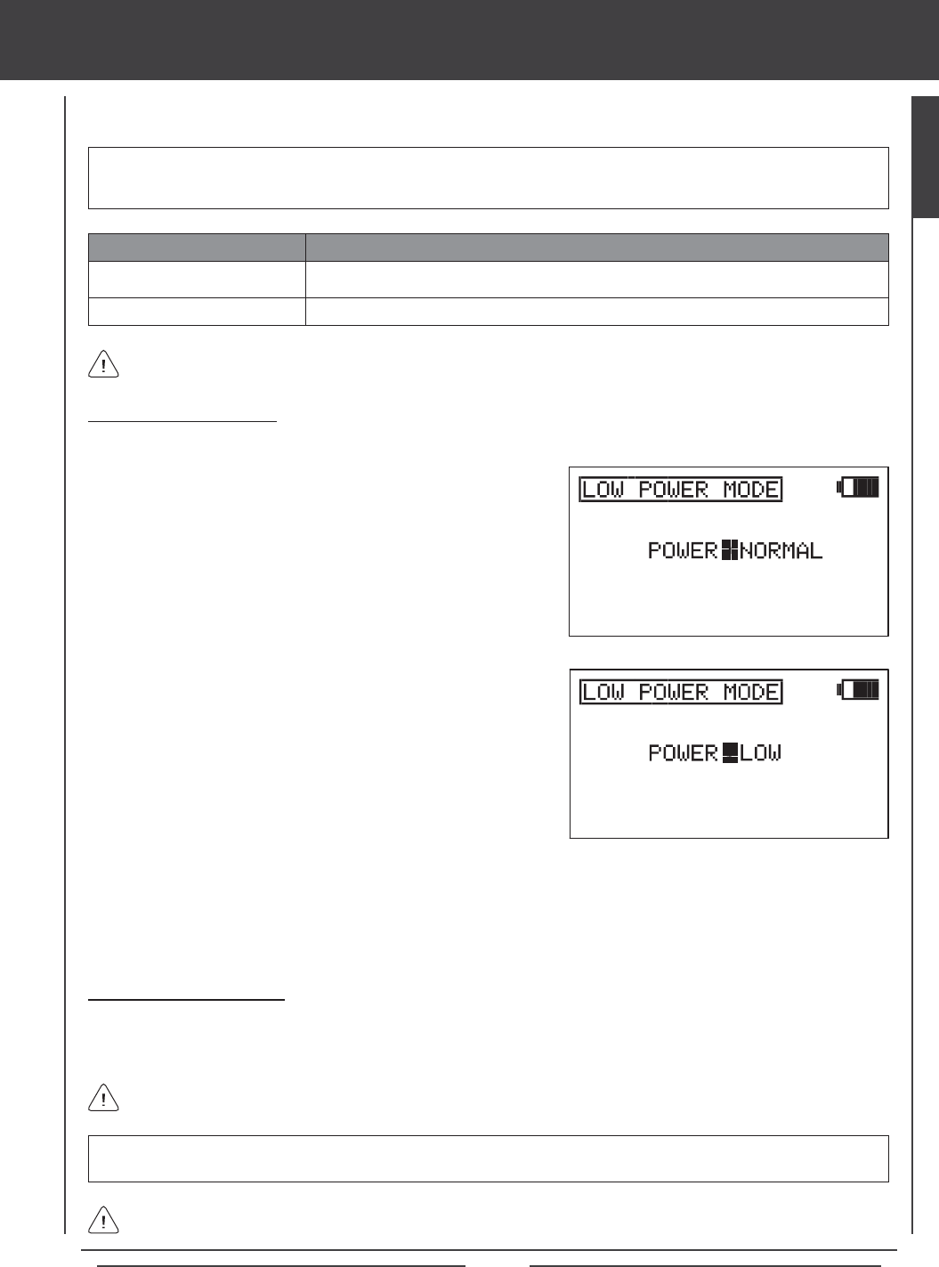
Page 25
range checking (low power mode)
IMPORTANT The radio control system should be Range Checked prior to the day's rst ight and prior to the rst ight
after a hard landing or after a repair. This will ensure that the transmitter and receiver are communicating properly prior to
ight. This ensures the safety of your model, yourself, and the people around you.
3) Press the YES/+ or NO/+ keys to place the transmitter in Low Power
Mode. The green RF Output Indicator will blink, the POWER selection
will change to LOW, and an audible alarm will sound. The transmitter is
now in Low Power Mode and you can begin the Range Check process.
4) With the transmitter in Low Power Mode, walk approximately 30 paces from your model (approximately 90 feet) and,
with the help of another person, check to make sure that the servos move without any problems. If there is a problem
with servo movement, try moving to a different position while still maintaining the same distance from your model, then
check servo movement again. If there is still a problem, DO NOT FLY. Check to make sure that all receiver, servos,
switch, and onboard battery connections are correct and secure. Check to ensure that the receiver antenna wires are
correctly mounted as described previously.
WARNING Do not attempt to y with the transmitter in Low Power Mode. You will be unable to control your model once
it is a certain distance away from you.
If, after checking all airborne system components and verifying correct antenna wire mounting, your radio control system
still fails the Range Check, DO NOT FLY. Please contact Airtronics Customer Service.
The transmitter will stay in Low Power Mode until you place in back into NORMAL mode.
Turning Off Low Power Mode
1) After you have completed your range check, press the YES/+ or NO/- keys to place the transmitter back into NORMAL mode.
In NORMAL mode, the RF Output Indicator will be solid green, the POWER selection will change to NORMAL, and the
audible alarm will cease. Press the END key two times to return to the Top menu.
Low Power Mode
Normal Mode
POWER MODE TRANSMITTER STATUS
Green RF Output Indicator Blinks, Power Selection >LOW, Audible Alarm
Red and Green Output Indicators Solid, Power Selection >NORMAL, No Audible Alarm
Low Power Mode can only be Activated with the transmitter turned ON. Low Power Mode cannot be Activated with only
the LCD Display turned ON.
Activating Low Power Mode
1) Turn the transmitter ON. Verify that SYSTEM is highlighted, then press the ENTER key to display the System menu. If SYSTEM is
not highlighted, press the END key until SYSTEM is highlighted.
The Low Power Mode function lowers the transmitter's RF output level to check radio signal reception (Range Check). Use
this function to check radio signal reception on the ground, prior to ight.
2) Press the Navigation Pad 6 to highlight LOW POWER MODE, then
press the ENTER key to display the LOW POWER MODE menu. The
cursor will default to POWER>NORMAL.
GENERAL
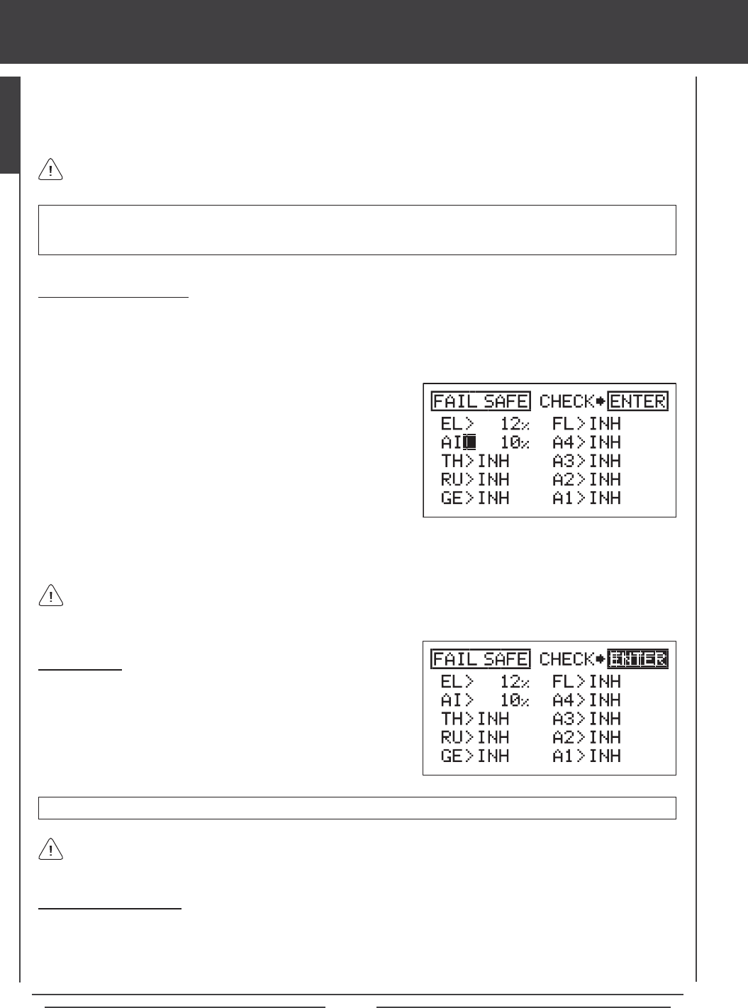
Page 26
fail safe
The Fail Safe function automatically sets the servos to a predetermined position in the event that the signal between the transmitter
and the receiver is interrupted, whether due to signal degradation or to a low transmitter battery. The Fail Safe function can be set
to Hold the servos in the last position they were in when the signal was lost, or each of the servos can be set to move to a custom
position when the signal is lost. For example, for a model aircraft, the Fail Safe can be set so that the throttle servo returns to low,
the elevator moves slightly up, and the ailerons move slightly right or left, to result in a shallow downward decent.
IMPORTANT In the default conguration, all Fail Safe settings are INHIBITED. In this conguration, if the signal between
the transmitter and the receiver is interrupted, whether due to signal degradation or to a low transmitter battery, the servos will
stay in the last position they were in when the signal was lost. The Fail Safe will not function if power to the receiver is lost.
This section describes the Fail Safe function setup for the 92104 FHSS-3 receiver included with the SD-10G radio
control system. For Fail Safe function setup for use with Airtronics 2.4GHz FHSS-1 aircraft receivers, see page 38.
IMPORTANT Make sure that the control surfaces are moving the correct direction when the Fail Safe function is Activated.
Changing Fail Safe Settings
1) Turn the transmitter ON. Verify that SYSTEM is highlighted, then press the ENTER key to display the System menu. If
SYSTEM is not highlighted, press the END key until SYSTEM is highlighted.
2) Press the Navigation Pad 6 to highlight FAIL SAFE, then press the ENTER key to display the FAIL SAFE menu. The cursor
will default to EL>INH.
3) With the cursor next to EL>INH move the elevator control stick in the
direction and the amount you want the elevator to move to when the
Fail Safe activates.
4) While holding the elevator control stick in position, press the YES/+ key
to set the elevator Fail Safe position. A percentage value will be displayed.
5) Press the Navigation Pad 6to move the cursor to AI>INH, then follow
the same procedures to set the pre-programmed aileron Fail Safe
position.
6) Repeat the same procedures to set the custom Fail Safe positions for the desired remaining channels. After setting the Fail
Safe positions, check the Fail Safe settings by following the procedures in the Fail Safe Check section below.
The percentage value is the percentage the servo will move. The percentage value will be either negative or positive and is
determined by the REV/NOR status of the channel. Regardless of the REV/NOR setting, the control surface will move the
same direction the control stick is moved. If you change a servo direction AFTER setting the Fail Safe values, you should reset
that Fail Safe value to ensure that the servo moves the correct direction.
Fail Safe Check
1) With the cursor anywhere in the FAIL SAFE menu, press the ENTER
key to check the Fail Safe settings. The servos will move to the
predetermined positions for ~5 seconds, then return to normal.
2) After verifying correct operation, press the END key two times to return
to the Top menu.
Fail Safe settings are specic to each model. For example, you can have certain Fail Safe settings for Model 1 and different
Fail Safe settings for Model 2, and so on. The Fail Safe settings will be retained even if the transmitter loses power or if
the transmitter and receiver must be paired again.
Clearing Fail Safe Settings
1) In the FAIL SAFE menu, press the Navigation Pad 3456 to move the cursor to the desired channel you would like to clear
the Fail Safe setting from.
2) To reset the Fail Safe setting to INH, press the YES/+ and NO/- keys at the same time, then repeat these procedures to reset
the Fail Safe setting for the desired remaining channels. Press the END key two times to return to the Top menu.

Page 27
system MENU contents
SYSTEM
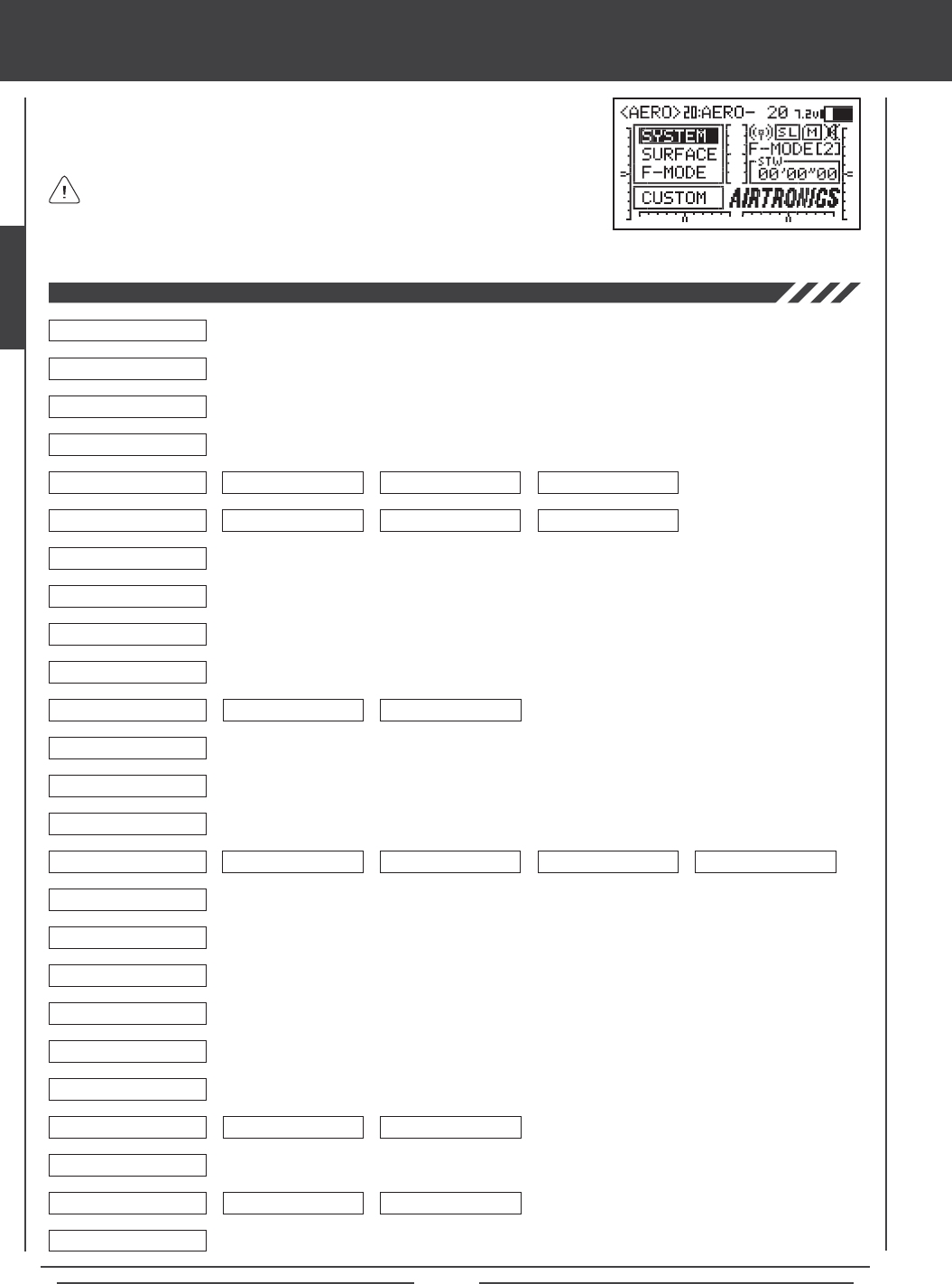
Page 28
SYSTEM MENU
The System menu is where all transmitter-specic programming takes place. Use this
menu to make changes to Model Name, Model Select, Model Type, Modulation, Switch
Assignments, and much more.
Use this Flow Chart to familiarize yourself with the System menu structure. Descriptions regarding all
System menu functions and programming are found on pages 29 through 61.
System menu selections are the same for all three Model Types. A small number
of sub-menu selections vary by Model Type. These are noted in the pertinent
menu descriptions.
04.DIRECT MODEL SELECT
03.MODEL SELECT
02.MODEL NAME
01.USER NAME
05.TYPE
06.MODULATION
07.LOW POWER MODE
08.FAIL SAFE
09.BATTERY FAIL SAFE
10.TRAINER
11.MODE SETUP
12.CH ASSIGN
13.SW ASSIGN
14.STICK SWITCH
15.TIMER
16.DATA COPY
17.DATA RESET
18.DATA TRANSFER
19.CONTRAST
20.CLICK
21.ALARM
22.TOP MENU ARRANGE
23.CUSTOM MENU
24.MEMORY PACK
25.SYSTEM INFORMATION
System Menu
STOP WATCH RHYTHM INTEGRAL TIMER SYSTEM TIMER
LIST INITIAL
MENU DISPLAY
MODE NEUTRAL/TRAVEL
MODULATION SAFETY LINK BIND CODE
AERO GLIDER HELI
6
6
6
6
6
6
6
6
6
6
6
6
6
6
6
6
6
6
6
6
6
6
6
6
6
6
6
6
6
6
6
6
6
6
6
6
6
6
6 6
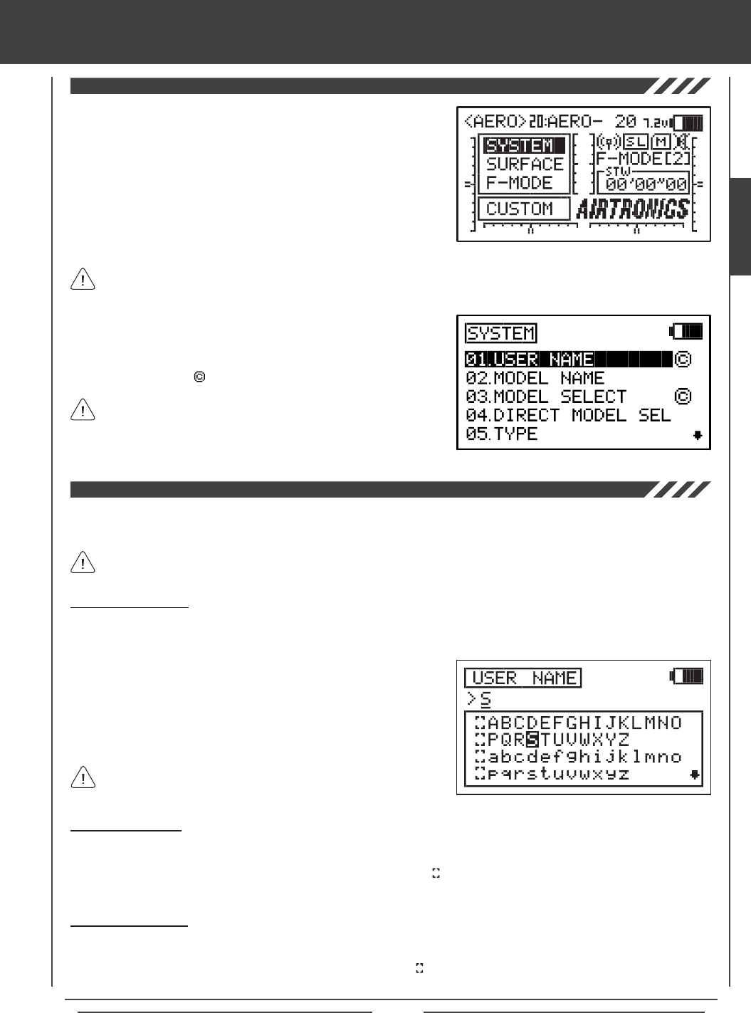
Page 29
Deleting a User Name
1) Press the YES/+ and NO/- keys at the same time to move the underline under the rst character.
2) Press the Navigation Pad 3456 to highlight the Erase Bracket , then press the ENTER key repeatedly to erase the entire
User Name.
SYSTEM MENU
The User Name function allows you to input a User Name to register the transmitter. The User Name can consist of up to 8
letters, numbers, or symbols. Choose from capital letters, lower case letters, numbers, and various symbols.
The User Name is displayed in the User Name sub-menu. It is not displayed on the Top menu.
Press the Navigation Pad 56 repeatedly to scroll up and down the
list of characters.
2) Press the Navigation Pad 3456 to highlight a character, then press
the ENTER key to select the highlighted character. That character will be
displayed and the underline will move to the next space.
3) Repeat step 2 to enter the rest of the characters. Up to eight characters
can be entered.
Deleting a Character
1) Press the YES/+ or NO/- keys to move the underline under the character you want to erase.
2) Press the Navigation Pad 3456 to highlight the Erase Bracket , then press the ENTER key to erase the underlined
character.
Entering a User Name
1) Press the Navigation Pad 56 to highlight USER NAME, then press the ENTER key to display the USER NAME menu. The
cursor will default to the left side of the top row of letters.
To access the System menu, turn the transmitter ON. Verify that SYSTEM
is highlighted, then press the ENTER key to display the System menu.
From within any menu, press the END key continuously to return to the
Top menu.
Unless otherwise noted, all programming changes take effect immediately.
If SYSTEM is not highlighted, press the END key until SYSTEM is highlighted, then press the ENTER key to display the
System menu.
Pressing the YES/+ key when a System menu selection is highlighted will
add that selection to the Custom menu. Selections added to the Custom
menu are denoted by a . For more information, see page 59.
Sub-menus cannot be added to the Custom menu.
SYSTEM
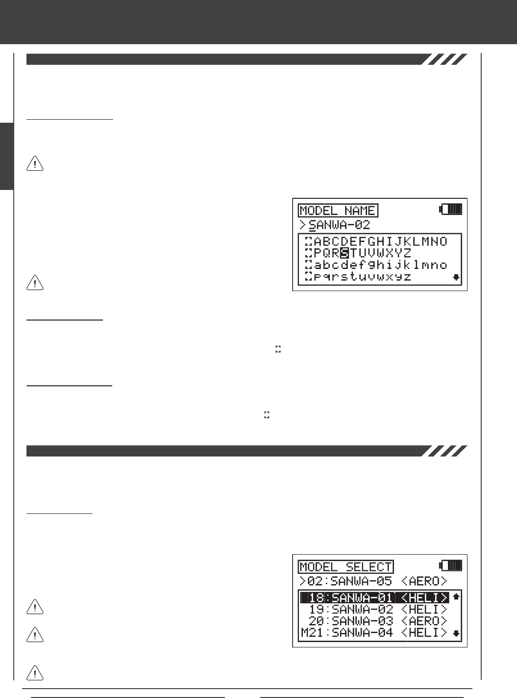
Page 30
The Model Name function allows you to name each of your individual models. This makes it easy to keep track of multiple
models. When you select a model, all of the programming for that model is loaded. The Model Name can consist of up to 8
letters, numbers, or symbols. Choose from capital letters, lower case letters, numbers, and various symbols.
Entering a Model Name
1) Press the Navigation Pad 56 to highlight MODEL NAME, then press the ENTER key to display the MODEL NAME menu.
The cursor will default to the left side of the top row of letters.
Deleting a Character
1) Press the YES/+ or NO/- keys to move the underline under the character you want to erase.
2) Press the Navigation Pad 3456 to highlight the Erase Bracket , then press the ENTER key to erase the underlined
character.
Deleting a Model Name
1) Press the YES/+ and NO/- keys at the same time to move the underline under the rst character.
2) Press the Navigation Pad 3456 to highlight the Erase Bracket , then press the ENTER key repeatedly to erase the entire
Model Name.
SYSTEM MENU
The Model select function allows you to load the programming for the particular model you wish to y. The Model Select menu
displays the currently selected model, along with a list of available models that can be selected. The specic Model Type is
displayed for each of the models. The programming for all of your models is accessed through the Model Select menu.
A model must be selected before a Model Name can be entered or modied. In the default conguration, Model:01 is
selected. To enter a Model Name for another model, that model must rst be selected using the Model Select menu. For
more information, see the 03.MODEL SELECT section below.
Selecting a Model
1) Press the Navigation Pad 56 to highlight MODEL SELECT, then press the ENTER key to display the MODEL SELECT
menu. The cursor will default to the currently selected model in the Model Select List.
2) Press the Navigation Pad 56 to highlight the model you would like to
select, then press the ENTER key to select the highlighted model. That
model will be displayed above the Model Select List.
When you press the ENTER key to select a model, the programming
for that model will be loaded.
Models stored on the Memory Expansion Card (if installed), are
denoted with an 'M' (i.e. M21:SANWA-04).
In the default conguration, the Model Select List contains 10 AERO model types and 10 HELI model types. The Model Type
for any of the 20 models in the Model Select List can be changed using the Type menu. For more Information, see page 31.
2) Press the Navigation Pad 3456 to highlight a character, then press
the ENTER key to select the highlighted character. That character will be
displayed and the underline will move to the next space.
3) Repeat step 2 to enter the rest of the characters. Up to eight characters
can be entered. The name of your model will be displayed on the
Top menu (i.e. 01:XTra300S).
Press the Navigation Pad 56 repeatedly to scroll up and down the
list of characters.
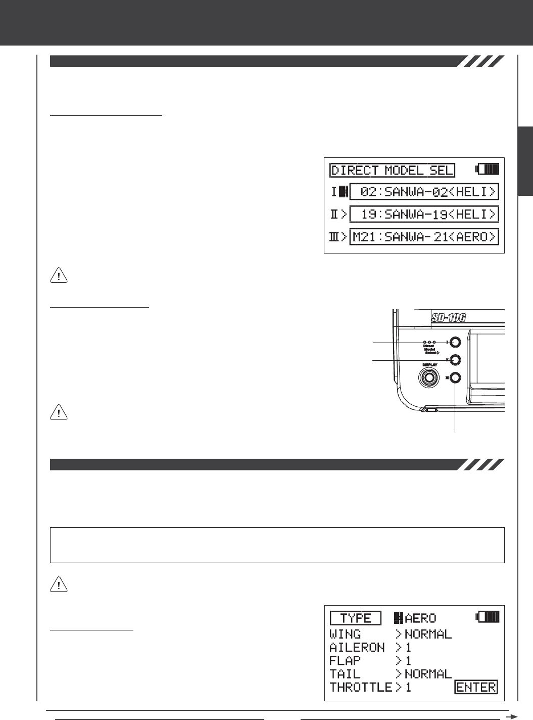
Page 31
The Direct Model Select function allows you to select one of three of your most-used models from memory without going through
the Model Select menu. This makes it much quicker and easier to load the programming for your three favorite models.
SYSTEM MENU
Designating a Favorite Model
1) Press the Navigation Pad 56 to highlight DIRECT MODEL SELECT, then press the ENTER key to display the DIRECT
MODEL SELECT menu. The cursor will default to the rst model selection I>.
2) Press the YES/+ or NO/- keys to change the name of the model to the
model you want to designate as Direct Model Select I.
3) Press the Navigation Pad 6 to highlight II>, then press the YES/+ or
NO/- keys to change the name of the model to the model you want to
designate as Direct Model Select II.
4) Repeat step 3 to designate a model for Direct Model Select III.
You can designate the same model to more than one Direct Model Select number if you desire.
Using Direct Model Select
Direct Model Select I
Direct Model Select II
Direct Model Select III
1) Turn the transmitter OFF.
2) Press and hold the Direct Model Select key of the model you
wish to y, then turn the transmitter ON. The Model Name of
the model that you designated to the Direct Model Select key
that you pressed will be displayed on the Top menu and the
programming for that model will be loaded.
Before ying, verify that the Model Name displayed on the
Top menu is the actual model that you'll be ying.
The Type function allows you to quickly set up the transmitter's low-level mixing based on the type of model you're ying.
Common templates for AERO, GLIDER, and HELI model types are provided. For example, if your powered aircraft features two
aileron servos, two ap servos, and dual elevator servos, choosing these options will automatically change the transmitter's
programming to accommodate this setup. This takes the guess-work out of setting up more complex models.
WARNING Model Type selection is used when setting up a new model and should be done prior to making any programming
changes to your model. When the Model Type selection is changed for the currently selected model, all programming (including
custom programming) for that model will be reset.
Individual TYPE selection options can be reset to the default setting by pressing the YES/+ and NO/- keys at the same time.
Changing Model Type
1) Press the Navigation Pad 56 to highlight TYPE, then press the ENTER
key to display the TYPE menu. The cursor will default to >AERO.
2) Press the YES/+ or NO/- keys to change the selection option. Choose
from AERO, GLID, or HELI.
SYSTEM
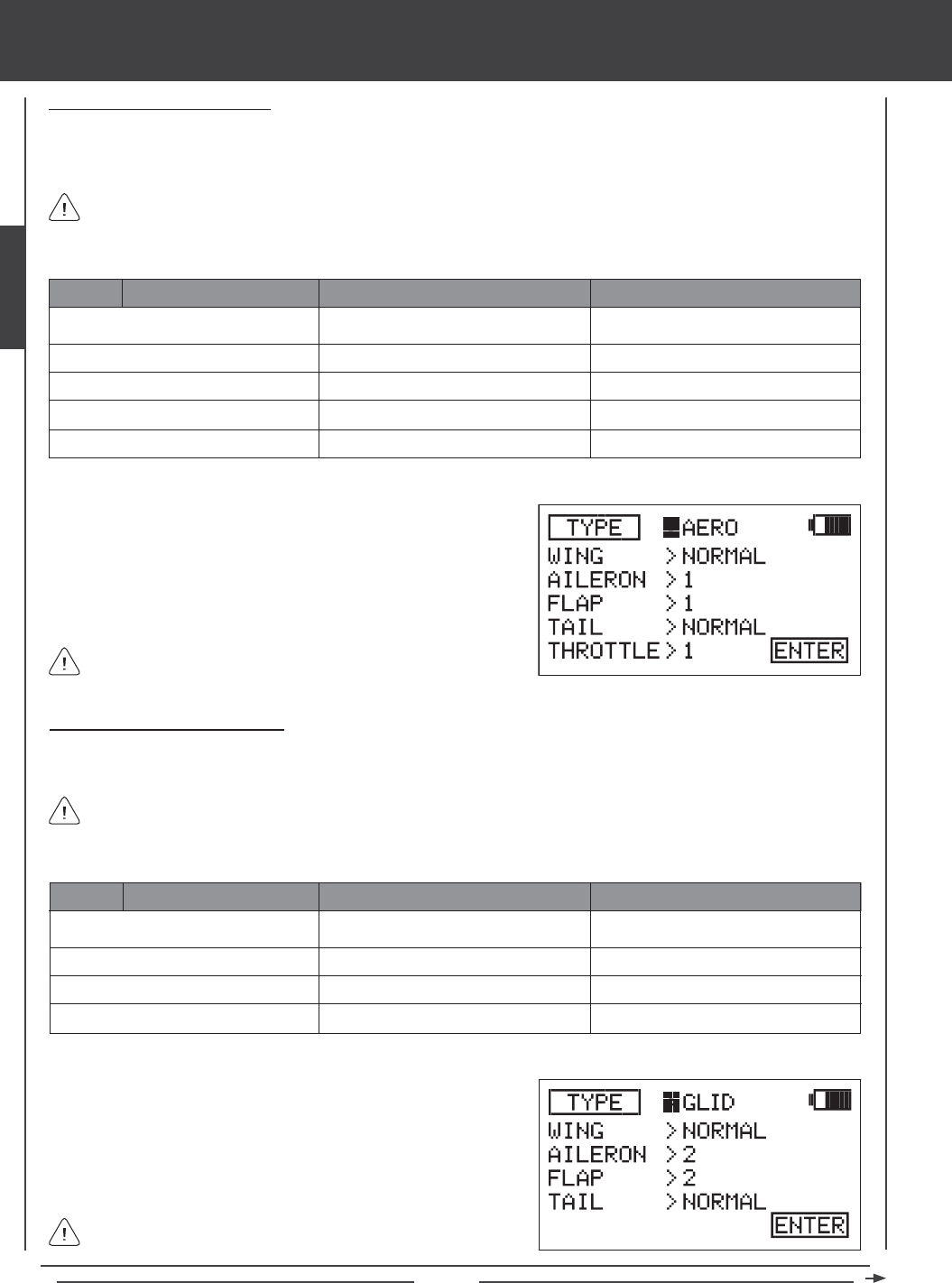
Page 32
SELECTION DEFAULT OPTION
WING (Type)
AILERON (Servos)
FLAP (Servos)
TAIL (Type)
THROTTLE (Servos)
NORMAL
1
1
NORMAL
1
DELTA* (Elevons)
2
2
V-TAIL or 2 x EL**
2
SYSTEM MENU
AERO
2) Press the Navigation Pad 56 to highlight the AERO selection you
wish to change, for example, AILERON.
3) Press the YES/+ or NO/- keys to change the selection option.
4) Repeat steps 2 and 3 to change the options for any of the other
selections you wish to change to suit your model setup.
Some selection options are dependent on other selection options
and may not be able to be changed.
Making GLIDER Selection Options
Choose GLID selection options that suit the aircraft that you're setting up. For example, if your aircraft features a six-servo wing,
choose AILERON>4 and FLAP>2. If your aircraft features a V-Tail, choose TAIL>V-TAIL, and so on.
SELECTION DEFAULT OPTION
WING (Type)
AILERON (Servos)
FLAP (Servos)
TAIL (Type)
NORMAL
2
1
NORMAL
DELTA* (Elevons)
4
4
V-TAIL**
GLID
2) Press the Navigation Pad 56 to highlight the GLID selection you wish
to change, for example, WING.
3) Press the YES/+ or NO/- keys to change the selection option.
4) Repeat steps 2 and 3 to change the options for any of the other
selections you wish to change to suit your model setup.
Making AERO Selection Options
Choose AERO selection options that suit the aircraft that you're setting up. For example, if your aircraft is a ying wing and is
controlled by elevons, choose WING>DELTA. If your aircraft features separate aileron servos and split elevator halves that use
one elevator servo on each elevator half, choose AILERON>2 and TAIL>2xEL, and so on.
*Delta mixing is sometimes referred to as Elevon mixing.
*Delta mixing is sometimes referred to as Elevon mixing.
Channel Assignments will change based on the selection options chosen. To verify which channel slots to plug your servos
into, navigate to the CH ASSIGN menu after saving your Model Type selection options. For more information, see page 44.
1) Press the YES/+ or NO/- keys to change the selection option to TYPE>AERO.
Channel Assignments will change based on the selection options chosen. To verify which channel slots to plug your servos
into, navigate to the CH ASSIGN menu after saving your Model Type selection options. For more information, see page 44.
Some selection options are dependent on other selection options
and may not be able to be changed.
1) Press the YES/+ or NO/- keys to change the selection option to TYPE>GLID.
**So that both servos will move the same direction, you will need to Reverse one of the channels.
**So that both servos will move the same direction, you will need to Reverse one of the channels.
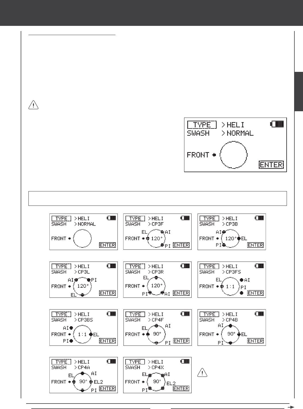
Page 33
Making HELICOPTER Selection Options
Choose the HELI Swashplate Type that suits your helicopter. There are three basic Swashplate Types available:
Normal - In this conguration the swashplate does not control pitch. It only controls right, left, fore, and aft cyclic. Usually the
servos are installed 90º apart but do not mix with collective to control pitch. This conguration is generally used for xed-pitch
helicopters or helicopters that have a completely separate control system to control collective pitch.
3-Point CCPM - In this conguration the cyclic and collective controls are mixed. The servos that control the swashplate are
installed either 120º to 140º apart, depending on the conguration.
4-Point CCPM - In this conguration the cyclic and collective controls are mixed. The servos that control the swashplate are
installed 90º apart. A total of three or four servos can be used, depending on the conguration.
SYSTEM MENU
WARNING There are a number of different Swashplate Types available. Make sure that the Swashplate Type you choose
matches exactly the Swashplate Type used by your helicopter. Refer to your helicopter's Operating Manual for more information.
The following Swashplate Types are available for Model Type HELI. The
diagrams display the swashplate geometry, the number of servos used, and the specic placement of those servos.
120º, 90º, and 1:1* refers to the
physical relationship and geometry
of the servo placements on the swashplate.
> NORMAL: Non-CCPM > CP3F 120º with 3 Servos > CP3B 120º with 3 Servos
> CP3L 120º with 3 Servos > CP3R 120º with 3 Servos > CP3FS 1:1* with 3 Servos (2 Offset)
> CP3BS 1:1* with 3 Servos (2 Offset) > CP4F 90º with 3 Servos > CP4B 90º with 3 Servos
> CP4A 90º with 4 Servos > CP4X 90º with 4 Servos *1:1 is sometimes referred to as 140º.
Channel Assignments will change based on the selection options chosen. To verify which channel slots to plug your servos
into, navigate to the CH ASSIGN menu after saving your Model Type selection options. For more information, see page 44.
1) While in the TYPE menu and the cursor in the >AERO or >GLID
position, press the YES/+ or NO/- keys to highlight >HELI.
2) Press the Navigation Pad 56 to highlight the SWASH selection.
3) Press the YES/+ or NO/- keys to change the SWASH selection option.
SYSTEM
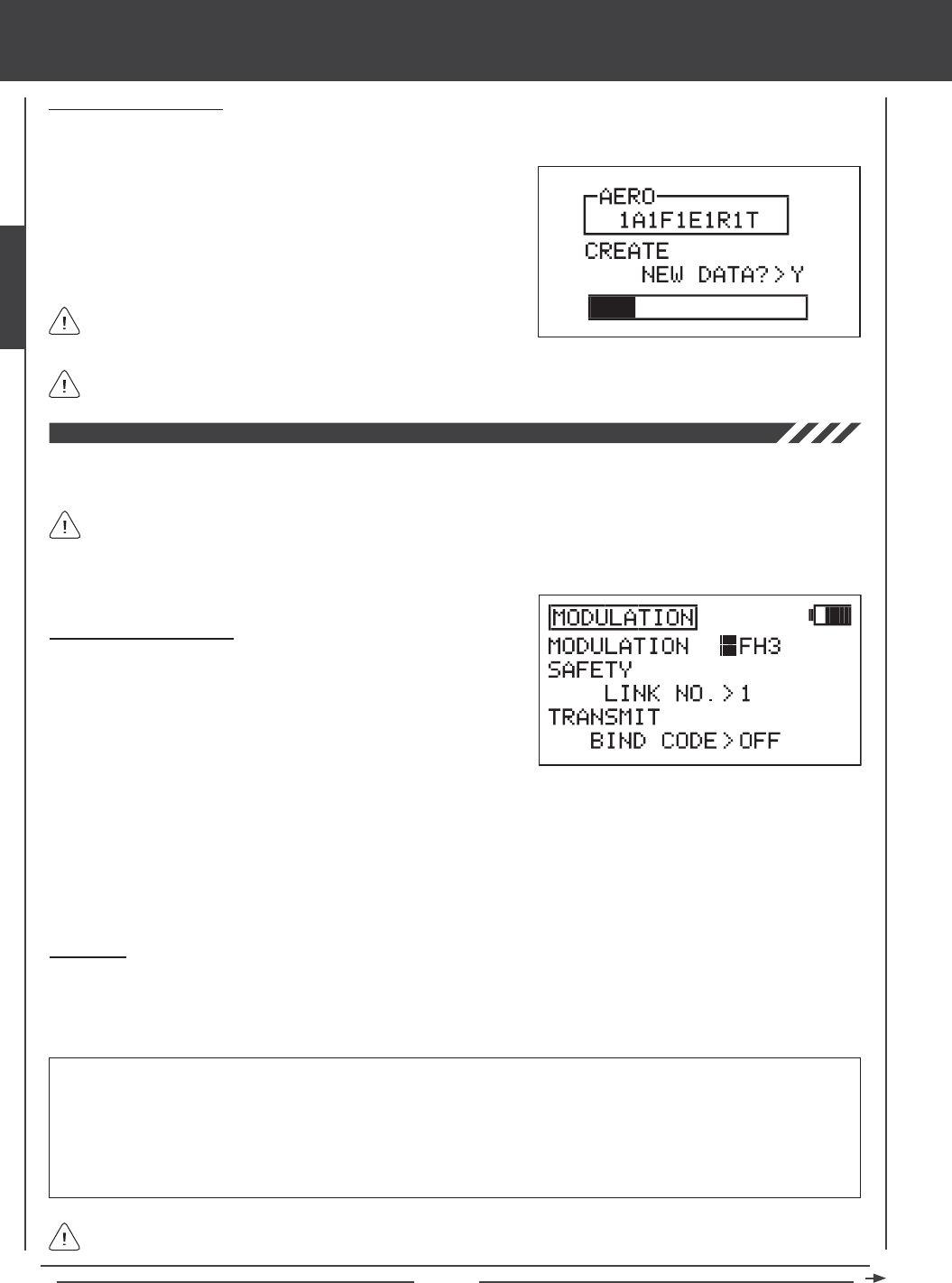
Page 34
SYSTEM MENU
The Modulation menu consists of three different functions. You are able to change the Modulation Type, modify the Safety Link
settings, and Bind the transmitter and receiver.
Changing Modulation Type
1) Press the Navigation Pad 56 to highlight MODULATION, then press
the ENTER key to display the MODULATION menu. The cursor will
default to MODULATION>FH3.
2) Press the YES/+ or NO/- keys to change the Modulation Type.
The following Modulation Type options are available:
FH1 - Select this Modulation Type when using the SD-10G transmitter with an Airtronics 2.4GHz FHSS-1 aircraft receiver.
FH3 - Select this Modulation Type when using the SD-10G transmitter with an Airtronics 2.4GHz FHSS-3 receiver.
PPM8 - Select this Modulation Type when using the SD-10G transmitter with a computer-based ight simulator.
All Modulation menu functions are model-specic. For example, you can program Model 01 to use FH3 modulation with
Safety Link No. 01, and you can program Model 02 set to use FH1 modulation, and so on.
1) Press the ENTER key. The screen will display the selected settings for
verication. For example, 2A1F1E1R1T (2 Aileron servos, 1 Flap servo,
1 Elevator servo, 1 Rudder servo, and 1 Throttle servo).
2) After verifying that the settings are correct, press the YES/+ key to
Create New Data. After ~10 seconds, the new programming data will
be loaded into the transmitter as indicated by the progress bar.
If you want to go back and change the settings or you don't want to
create the new settings for any reason, press the NO/- or END keys.
When the Model Type selection is saved, the Model Type is updated in both the Model Select menu and on the Top menu.
Saving Selection Options
Once a selection option is changed, ENTER will blink in the lower right corner of the display.
Safety Link
The Safety Link function is used to program a unique bind code to each receiver/model pair, preventing the transmitter from
controlling a model that it's not currently programmed for. In addition, the Safety Link Number can be changed separately from
the Model Select number to allow you to bind multiple receivers to the same model. For example, you can bind two receivers to
one model so that you are able to use redundant airborne components, yet still maintain the Safety Link function between models.
The Safety Link feature can be used ONLY with the Airtronics 92104 10-Channel 2.4GHz FHSS-3 receiver. Safety Link is
not supported for use with Airtronics FHSS-1 receivers.
WARNING For the Safety Link feature to function correctly, the Safety Link Number MUST match the number of the currently
selected model. For example, if the current model is 01:XTra300S, when you bind the receiver in that model to the transmitter, set
the SAFETY LINK NO to 01. To bind another model using the Safety Link feature, select a new model (i.e. 02) and name it. The
new model name will be displayed on the Top menu. When you bind the receiver in that model to the transmitter, set the SAFETY
LINK NO to 02. In this way, the transmitter will 'talk' only to the matching receiver.
If you are using more than one receiver in one model (for redundancy purposes), set the SAFETY LINK NO to the same number
for both receivers.
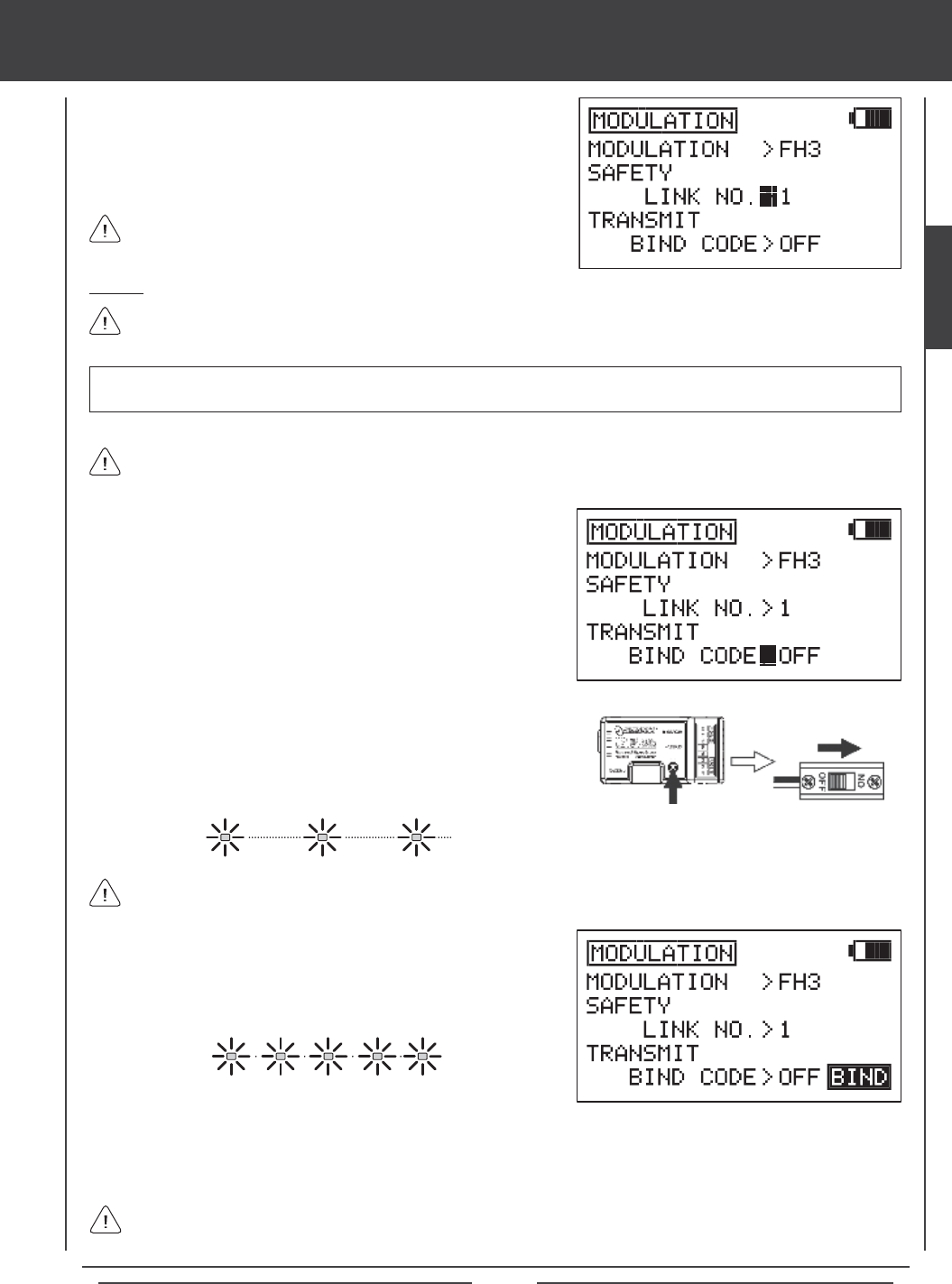
Page 35
1) While in the MODULATION menu, press the Navigation Pad 56 to
highlight SAFETY LINK NO.
2) Press the YES/+ or NO/- keys to change the Safety Link number.
Remember, for the Safety Link feature to function correctly, the Safety
Link Number MUST match the number of the currently selected model.
Binding
When the binding procedure is successful, the Bind LED on the receiver will stay solid blue when both the transmitter and
receiver are turned ON. If the Bind LED on the receiver is blinking rapidly or not ON at all, the transmitter and receiver
are not paired. In this case, turn both the transmitter and receiver OFF, then repeat the binding procedure.
Use the tip of a pencil or a 1.5mm hex wrench to reach the Bind Button in the receiver.
3) Quickly press the YES/+ key. The green RF Output Indicator will blink,
the TRANSMIT BIND CODE selection will change to ON, and BINDING
will blink. The Bind LED on the receiver will blink rapidly for ~3 seconds,
then go out.
4) After Bind LED on the receiver goes out, press the END key. The Bind LED on the receiver, as well as the green RF Output
Indicator, will turn solid and the LCD Display will revert to the System menu indicating the binding process is complete. Press
the END key two times to return to the Top menu.
1) While in the MODULATION menu, press the Navigation Pad 56 to
highlight TRANSMIT BIND CODE.
Before binding the transmitter and receiver, verify that the Modulation and Safety Link settings are accurate for the receiver
type you're using.
2) While holding down the Bind Button on the receiver, turn the receiver
ON. The Bind LED on the receiver will blink slowly. After ~2 seconds
release the Bind Button. The Bind LED on the receiver will continue to
blink slowly.
IMPORTANT The SD-10G transmitter is compatible with FHSS-3 and FHSS-1 Airtronics 2.4GHz aircraft receivers. To bind
the transmitter to an FHSS-1 receiver, the transmitter modulation must rst be changed to FH1.
SYSTEM MENU
The Binding procedure is the same whether you're binding an FHSS-3 receiver or an FHSS-1 receiver. Just keep in mind
that if you're binding an FHSS-1 receiver, the transmitter modulation must rst be changed to FH1.
SYSTEM
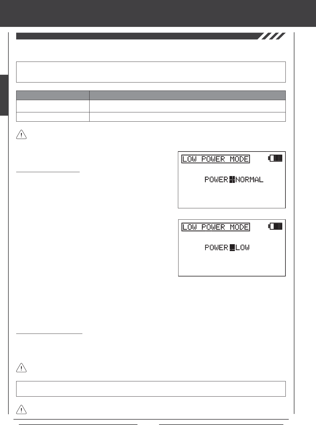
Page 36
SYSTEM MENU
The Low Power Mode function lowers the transmitter's RF output level to check radio signal reception (Range Check). Use
this function to check radio signal reception on the ground, prior to ight.
2) Press the YES/+ or NO/+ keys to place the transmitter in Low Power
Mode. The green RF Output Indicator will blink, the POWER selection
will change to LOW, and an audible alarm will sound. The transmitter is
now in Low Power Mode and you can begin the Range Check process.
3) With the transmitter in Low Power Mode, walk approximately 30 paces from your model (approximately 90 feet) and,
with the help of another person, check to make sure that the servos move without any problems. If there is a problem
with servo movement, try moving to a different position while still maintaining the same distance from your model, then
check servo movement again. If there is still a problem, DO NOT FLY. Check to make sure that all receiver, servos,
switch, and onboard battery connections are correct and secure. Check to ensure that the receiver antenna wires are
correctly mounted as described previously.
WARNING Do not attempt to y with the transmitter in Low Power Mode. You will be unable to control your model once
it is a certain distance away from you.
If, after checking all airborne system components and verifying correct antenna wire mounting, your radio control system
still fails the Range Check, DO NOT FLY. Please contact Airtronics Customer Service.
The transmitter will stay in Low Power Mode until you place in back into NORMAL mode.
IMPORTANT The radio control system should be Range Checked prior to the day's rst ight and prior to the rst ight
after a hard landing or after a repair. This will ensure that the transmitter and receiver are communicating properly prior to
ight. This ensures the safety of your model, yourself, and the people around you.
Activating Low Power Mode
1) Press the Navigation Pad 56 to highlight LOW POWER MODE, then
press the ENTER key to display the LOW POWER MODE menu. The
cursor will default to POWER>NORMAL.
Turning Off Low Power Mode
1) After you have completed your range check, press the YES/+ or NO/- keys to place the transmitter back into NORMAL mode.
In NORMAL mode, the RF Output Indicator will be solid green, the POWER selection will change to NORMAL, and the
audible alarm will cease.
Low Power Mode
Normal Mode
POWER MODE TRANSMITTER STATUS
Green RF Output Indicator Blinks, Power Selection >LOW, Audible Alarm
Red and Green Output Indicators Solid, Power Selection >NORMAL, No Audible Alarm
Low Power Mode can only be Activated with the transmitter turned ON. Low Power Mode cannot be Activated with only
the LCD Display turned ON.
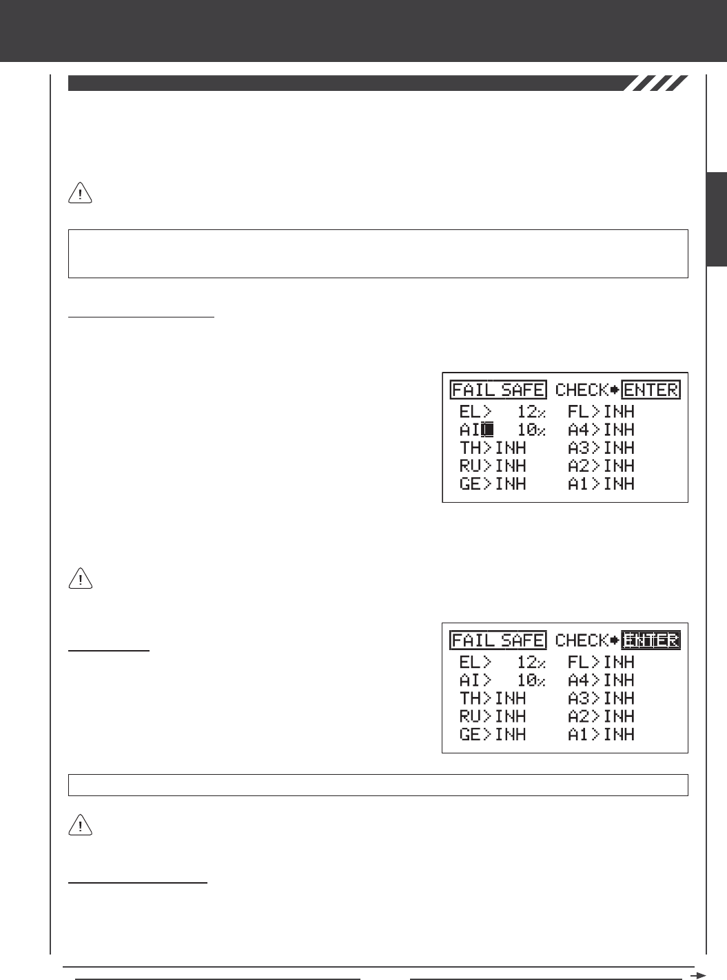
Page 37
SYSTEM MENU
The Fail Safe function automatically sets the servos to a predetermined position in the event that the signal between the transmitter
and the receiver is interrupted, whether due to signal degradation or to a low transmitter battery. The Fail Safe function can be set
to Hold the servos in the last position they were in when the signal was lost, or each of the servos can be set to move to a custom
position when the signal is lost. For example, for a model aircraft, the Fail Safe can be set so that the throttle servo returns to low,
the elevator moves slightly up, and the ailerons move slightly right or left, to result in a shallow downward decent.
IMPORTANT In the default conguration, all Fail Safe settings are INHIBITED. In this conguration, if the signal between
the transmitter and the receiver is interrupted, whether due to signal degradation or to a low transmitter battery, the servos will
stay in the last position they were in when the signal was lost. The Fail Safe will not function if power to the receiver is lost.
This section describes the Fail Safe function setup for the 92104 FHSS-3 receiver included with the SD-10G radio
control system. For Fail Safe function setup for use with Airtronics 2.4GHz FHSS-1 aircraft receivers, see page 38.
IMPORTANT Make sure that the control surfaces are moving the correct direction when the Fail Safe function is Activated.
Changing Fail Safe Settings
1) Press the Navigation Pad 56 to highlight FAIL SAFE, then press the ENTER key to display the FAIL SAFE menu. The cursor
will default to EL>INH.
2) With the cursor next to EL>INH move the elevator control stick in the
direction and the amount you want the elevator to move to when the
Fail Safe activates.
3) While holding the elevator control stick in position, press the YES/+ key
to set the elevator Fail Safe position. A percentage value will be displayed.
4) Press the Navigation Pad 6to move the cursor to AI>INH, then follow
the same procedures to set the pre-programmed aileron Fail Safe
position.
5) Repeat the same procedures to set the custom Fail Safe positions for the desired remaining channels. After setting the Fail
Safe positions, check the Fail Safe settings by following the procedures in the Fail Safe Check section below.
The percentage value is the percentage the servo will move. The percentage value will be either negative or positive and is
determined by the REV/NOR status of the channel. Regardless of the REV/NOR setting, the control surface will move the
same direction the control stick is moved. If you change a servo direction AFTER setting the Fail Safe values, you should reset
that Fail Safe value to ensure that the servo moves the correct direction.
Fail Safe Check
1) With the cursor anywhere in the FAIL SAFE menu, press the ENTER
key to check the Fail Safe settings. The servos will move to the
predetermined positions for ~5 seconds, then return to normal.
2) After verifying correct operation, press the END key two times to return
to the Top menu.
Fail Safe settings are specic to each model. For example, you can have certain Fail Safe settings for Model 1 and different
Fail Safe settings for Model 2, and so on. The Fail Safe settings will be retained even if the transmitter loses power or if
the transmitter and receiver must be paired again.
Clearing Fail Safe Settings
1) In the FAIL SAFE menu, press the Navigation Pad 3456 to move the cursor to the desired channel you would like to clear
the Fail Safe setting from.
2) To reset the Fail Safe setting to INH, press the YES/+ and NO/- keys at the same time, then repeat these procedures to reset
the Fail Safe setting for the desired remaining channels. Press the END key two times to return to the Top menu.
SYSTEM
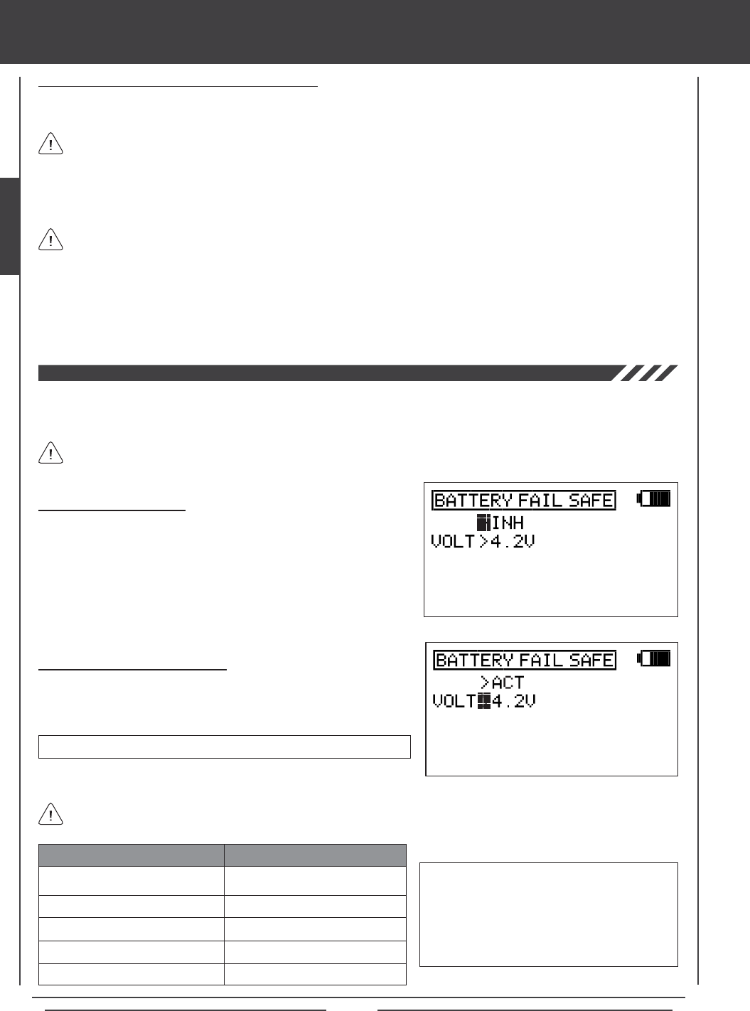
Page 38
SYSTEM MENU
The Battery Fail Safe function allows you to set a custom receiver voltage, that when reached, will provide feedback to you by
quickly cycling the throttle servo up and down in 1 minute intervals to indicate that the receiver battery has reached the programmed
Battery Fail Safe voltage. This feedback will help prevent you from ying too long and losing receiver battery power.
The Battery Fail Safe function is not supported when used with FHSS-1 receivers.
Activating Battery Fail Safe
1) Press the Navigation Pad 56 to highlight BATTERY FAIL SAFE, then
press the ENTER key to display the BATTERY FAIL SAFE menu. The
cursor will default to >INH.
2) Press the YES/+ key to Activate the Battery Fail Safe function. ACT will
be displayed.
Adjusting Battery Fail Safe Voltage
1) Press the Navigation Pad 6 to highlight VOLT>4.2V, then press the
YES/+ or NO/- keys to increase or decrease the receiver voltage at
which the Battery Fail Safe Alarm will Activate.
VOLT setting range is 3.8V to 4.6V. The default setting is 4.2V.
Using the Fail Safe Function with FHSS-1 Receivers
If you are using the SD-10G transmitter with an FHSS-1 receiver, the Fail Safe setup procedures described previously do not
apply. Use the procedures described below to utilize the Fail Safe function with your FHSS-1 receiver.
3) Move the transmitter control sticks to the desired Fail Safe position. While holding the transmitter control sticks in those
positions (generally throttle at idle and a minimal amount of elevator and/or aileron), press and hold the Bind Button on the
receiver. After ~2 seconds, the Bind LED will begin to blink slowly. Continue holding the Bind Button until the Bind LED begins
to blink rapidly (~2 more seconds). Once the Bind LED begins to blink rapidly, release the Bind Button.
4) Turn the transmitter OFF to test Fail Safe operation. The servos should move to the positions that you set in step 3.
The Fail Safe settings will be erased if you re-bind the transmitter/receiver pair. If you bind the same transmitter/receiver
pair you MUST repeat these procedures to setup the Fail Safe function again.
1) Drop the throttle control stick all the way back to the Low Throttle position, then turn the transmitter ON.
2) Turn the receiver ON. The Bind LED on the receiver should illuminate solid blue, indicating that the transmitter and receiver
are paired, then move the transmitter control sticks to verify that the servos are operating.
Programmable Fail Safe is available on channels 1 through 4 only.
Use the table below to help you decide at what voltage to set the Battery Fail Safe to. The voltage should be set so that
under no circumstances can the receiver battery be allowed to drop below its safe discharge level.
4 Cell Ni-Cd 4.8 Volt
5 Cell Ni-Cd 6.0 Volt
4 Cell Ni-MH 4.8 Volt
5 Cell Ni-MH 6.0 Volt
2 Cell Li-Po with 6.0 Volt Regulator
BATTERY TYPE RECOMMENDED VOLTAGE
3.8 Volts
4.6 Volts
4.0 Volts
4.6 Volts
4.6 Volts
IMPORTANT When the receiver battery voltage
drops to the programmed voltage setting, the
throttle servo will quickly cycle up and down in
1 minute intervals. The Bind LED on the receiver
will also illuminate RED. When this occurs, we
strongly suggest you land as soon as possible
and recharge your receiver battery.
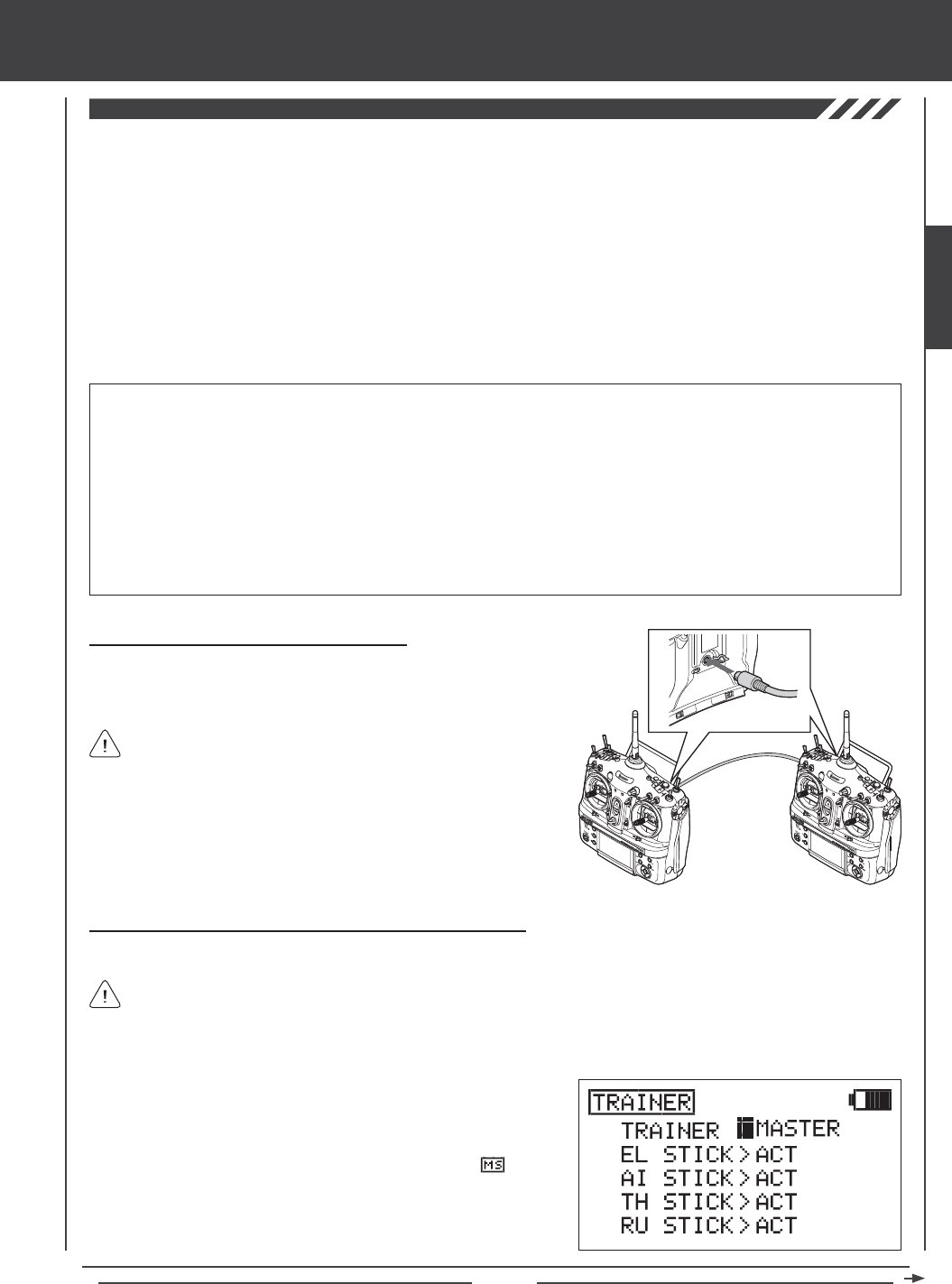
Page 39
You MUST use the SD-10G Trainer Cable. See your local Airtronics
dealer for more information and availability.
The Trainer function must be Activated on both transmitters separately. The Instructor's transmitter is set to Master and the
Student's transmitter is set to Slave. To Activate the Student's transmitter, see page 40.
SYSTEM MENU
Connecting the Master and Slave Transmitters
1) Plug one end of the Trainer Cable into the back of one SD-10G
transmitter, then plug the other end of the Trainer Cable into the second
SD-10G transmitter.
IMPORTANT INFORMATION ABOUT THE TRAINER SYSTEM
l The Trainer System is compatible ONLY with another SD-10G transmitter.
l You MUST use the SD-10G Trainer Cable. See your local Airtronics dealer for more information and availability.
l During use, the Master transmitter is turned ON and the Slave transmitter is turned OFF. Take precaution that the Slave
transmitter not be turned ON during use.
l Both transmitters must be programmed identically for the Trainer System to function properly. For example, servo reversing,
centering, end points, and other settings must be identical.
l In the default conguration, the Trainer function is not assigned to a switch. We strongly suggest assigning the Trainer function
to the spring-loaded switch 21, or to one of the two push-button switches 32 or 34.
Master Slave
Activating the Trainer Function [Instructor (Master) Transmitter]
Follow the steps below to Activate the Trainer function on the Instructor's transmitter.
2) Press the YES/+ key to change the current transmitter's Trainer mode
to MASTER. TRAINER>MASTER will be displayed and will be
displayed on the Top menu, indicating that the transmitter is operating
in MASTER mode.
1) Press the Navigation Pad 56 to highlight TRAINER, then press the ENTER key to display the TRAINER menu. The cursor
will default to TRAINER>INH.
The SD-10G transmitter features a Trainer System that allows you to connect two SD-10G transmitters together for the purpose
of training a new pilot or for training a more experienced pilot on a new model.
During use, one transmitter acts as the Master (Instructor) and the other transmitter acts as the Slave (Student). The Instructor
controls the Student's model as long as the Trainer Switch is released. Once the Instructor maneuvers the model to a safe
altitude, the Instructor holds the Trainer Switch and the Student has control of the model. The Student will have control of the
model as long as the Instructor holds the Trainer Switch. Once the Trainer Switch is released, the Instructor will have control
of the model once again. If at any time the Instructor feels that the Student is in a situation that endangers the model, the
Instructor releases the Trainer Switch and control of the model returns instantly to the Instructor.
In addition, when the SD-10G transmitter is set to MASTER mode, the option of Activating or Inhibiting the four basic ight controls
of the Student's transmitter can be made. When a control stick is Inhibited, that specic control surface cannot be operated by the
Student. This is useful when the Instructor does not want the Student to worry about using one or more controls.
The following Modulation congurations can be used:
Master: FH3 to Slave: FH3
Master: FH3 to Slave: FH1
Master: FH1 to Slave: FH3
Master: FH1 to Slave: FH1
SYSTEM
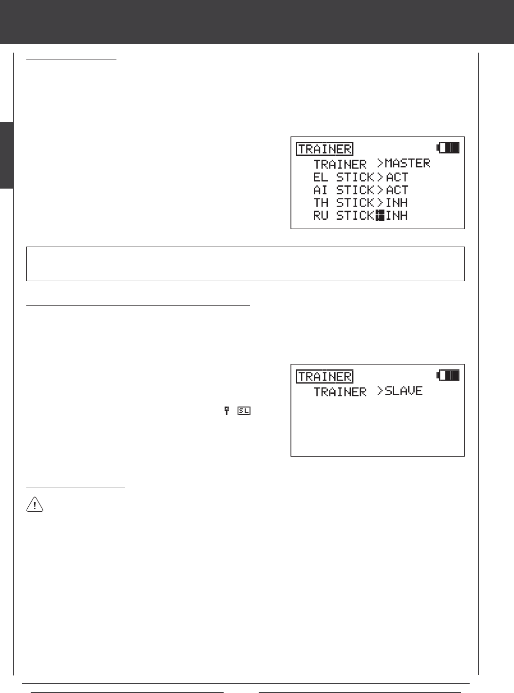
Page 40
SYSTEM MENU
Activating the Trainer Function [Student (Slave) Transmitter]
Follow the steps below to Activate the Trainer function on the Student's transmitter.
1) From within the System menu, press the Navigation Pad 56 to highlight TRAINER, then press the ENTER key to display
the TRAINER menu. The cursor will default to TRAINER>INH.
2) Press the NO/- key to change the transmitter's Trainer mode to
SLAVE. TRAINER>SLAVE will be displayed. The RED RF Indicator
will go out, the GREEN RF Indicator will blink, and will be
displayed on the Top menu, indicating that the transmitter is operating
in SLAVE mode.
Using the Trainer Function
1) The Trainer Cable should be connected between the two transmitters and the Trainer function on both transmitters should
be Activated as described previously. The Instructor's transmitter (Master) should be turned ON and the Student's transmitter
(Slave) should be turned OFF.
2) Turn on the model you're using for training and verify that the Instructor's transmitter controls the model's control surfaces
correctly.
3) Activate the Trainer function by holding the Trainer Switch continuously and verify that the Student's transmitter controls the
model's control surfaces correctly.
4) When the Trainer Switch is released, the Instructor will have full control over the model. When the Trainer Switch is held
continuously, the Student has control over the model. As soon as the Trainer Switch is released, the Instructor will have full
control over the model once again.
In the default conguration, the Trainer function is not assigned to a switch. We strongly suggest assigning the Trainer
function to the spring-loaded switch 21, or to one of the two push-button switches 32 or 34. If you y with thumbs,
we suggest using one of the two push-button switches. This allows you to comfortably use your index nger to operate the
push-button switch. If you y with ngers, we suggest using the spring-loaded switch. This allows you to comfortably use your
middle nger to operate the spring-loaded switch. For information on assigning the Trainer function to a switch, see page 45.
1) Press the Navigation Pad 56 to highlight the control(s) you would like
to Inhibit for the Student, then press the YES/+ or NO/- keys to select
the INH option.
Inhibiting Control Sticks
When the transmitter is set to MASTER mode, the option of Activating or Inhibiting the four basic ight controls of the Student's
transmitter can be made. When a control stick is Inhibited, that specic control surface cannot be operated by the Student. This
is useful when the Instructor does not want the Student to worry about using one or more controls. For example, TH STICK and
RU STICK can be Inhibited so that the Student can focus on controlling only the elevator and aileron controls. In this scenario,
the throttle and rudder control surfaces cannot be moved by the Student, even if the Student moves the throttle or rudder control
sticks by mistake.
IMPORTANT Control sticks that are set to INH (Inhibited) can still be controlled by the Instructor's transmitter when the
Trainer function is in use. For example, if the throttle and rudder are set to INH when the Student is ying, the Student will only
be able to control the elevator and aileron controls while the Instructor will be able to control the throttle and rudder controls.
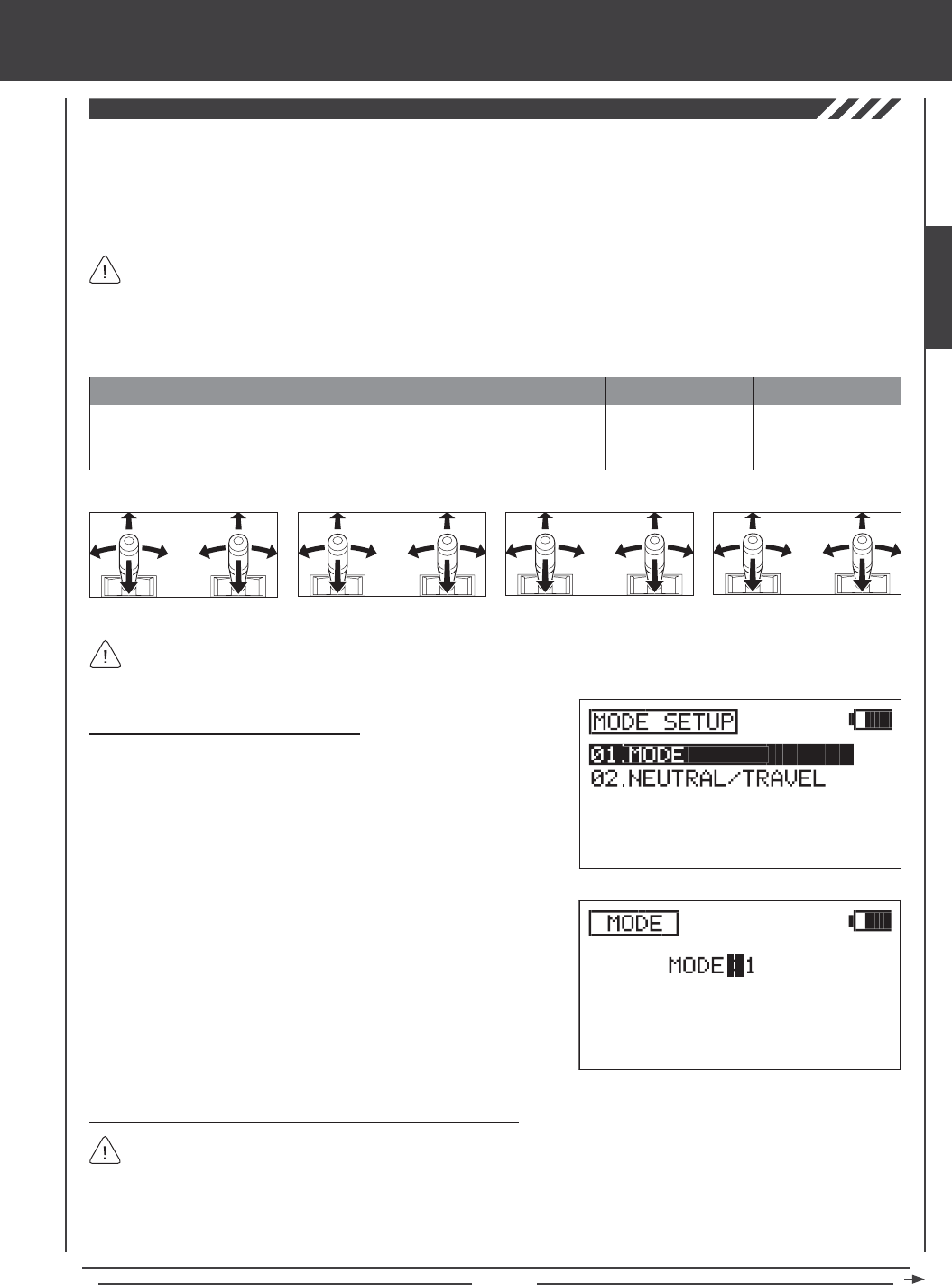
Page 41
Changing Transmitter Operating Modes
1) Press the Navigation Pad 56 to highlight MODE SETUP, then press
the ENTER key to display the MODE SETUP menu. The MODE
sub-menu will be highlighted by default.
2) Press the ENTER key to display the MODE menu. The cursor will
default to MODE>2.
SYSTEM MENU
3) Press the YES/+ or NO/- keys to change the transmitter Operating
Mode. Use the table and diagrams above to choose the Operating
Mode you desire, for example, MODE>1.
4) Press the END key to return to the MODE SETUP menu.
Changing Throttle Ratchets and Spring for Mode 1 and Mode 3
If you've changed your transmitter to Mode 4 from Mode 2, it's not necessary to change the throttle ratchet and spring. Skip
to the Control Stick Calibration - User Option section on page 43.
If you change the transmitter Operating Mode to Mode 1 or to Mode 3, the throttle ratchet and the spring must be swapped, in
addition to making the MODE programming change described above. This will ensure correct control stick behavior.
The following tools will be required: # 1 and # 2 Phillips head screwdrivers, small needle nose pliers, and a 1.5mm hex wrench.
Left-Side Control Stick
Right-Side Control Stick
CONTROL STICK MODE 1 MODE 2 MODE 3
Rudder/Elevator
Throttle/Aileron
Throttle/Rudder
Elevator/Aileron
Elevator/Aileron
Throttle/Rudder
MODE 4
Throttle/Aileron
Elevator/Rudder
MODE 1
Rudder/Elevator Throttle/Aileron
MODE 2 MODE 3 MODE 4
Throttle/Rudder Elevator/Aileron Elevator/Aileron Throttle/Rudder Throttle/Aileron Elevator/Rudder
Mode 1 and Mode 3 require swapping the throttle ratchets and spring. Mode 2 and Mode 4 do not.
The Mode Setup function allows you to change the SD-10G transmitter's Operating Modes. Four Operating Modes are available as
shown in the table below. The Mode Setup function also includes a Neutral/Travel function that allows you to calibrate the control
sticks to ensure accurate control centering, regardless of servo brand used. The Travel function allows you to adjust the servos to
move 100% of their maximum travel if you choose to limit the movement of the control sticks. For example, if you limit the throttle
control stick to move only 50% of it's maximum movement, the throttle servo will move only 50% of its maximum travel. The Travel
function will allow you to calibrate the servo to move 100% of its maximum travel with only 50% control stick movement.
In the default conguration, the transmitter is set to Mode 2, which is most commonly used in North America.
If you y using Mode 1, Mode 3, or Mode 4, you can change the Operating Mode without needing to send the transmitter for
service. Changing the Operating Mode requires changing the Mode Setting, swapping the throttle ratchets and spring on the
control sticks, then recalibrating the neutral and end-point positions of the control sticks.
SYSTEM
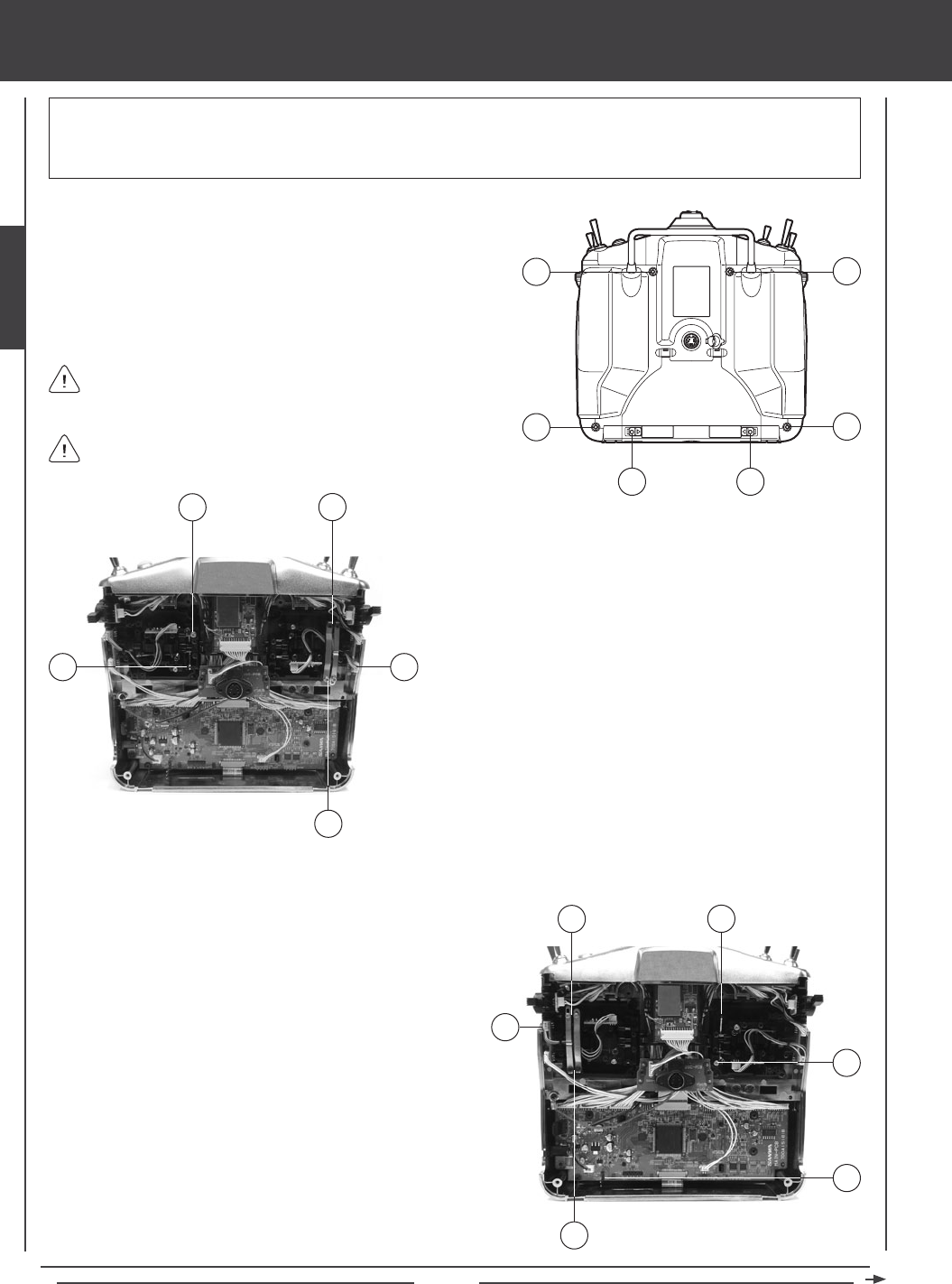
Page 42
SYSTEM MENU
Carefully install the return plate, spring, spring adjuster block, throttle ratchet, and throttle ratchet plates onto the opposite gimbals.
I
K
J
L
M
MODE 1 / MODE 3 CONFIGURATION
8) Slide the return plate under the gimbal pins, then hook the
return plate over the hinge at the top of the gimbal (I). Attach the
spring and spring adjuster block assembly to the other side of
the return plate, then pull the spring adjuster block up and slide
it down into its mount (J).
9) Very carefully unplug the wire harness from the circuit board
(K), then slide it though the throttle ratchet. Install the throttle
ratchet, using one mounting screw to hold it into place.
10) Carefully plug both wire harnesses back into their circuit
boards and push the wires down into the retaining clips to hold
them in place.
11) Carefully install the two throttle ratchet plates over the
throttle ratchet. Use two Phillips head screws (L) to secure
the throttle ratchet plates to the bottom of the gimbal and
use two socket-cap adjusting screws (M) to secure the throttle
ratchet plates to the top of the gimbal.
F
1) Open the battery cover by rst pushing the two latches (A) inward,
then by pulling up on the bottom of the battery cover.
2) Unplug the battery from the transmitter and remove it. Set the battery
aside for now.
3) Remove the four Phillips head screws (B) from the back of the
transmitter, then very carefully pull the back half of the transmitter off.
B
AA
B
B
B
There are no wires attached between the back half of the transmitter
and the circuit boards inside the transmitter. When the back half of
the transmitter is removed, it can be safely set aside.
Pull the back half of the transmitter straight off to avoid bending or
damaging the battery pins.
WARNING Be very careful not to damage any of the components inside the transmitter. This procedure requires modication
to the control stick gimbals and requires removal and reinstallation of two electrical connectors. If you do not feel comfortable
making these changes, please send the transmitter to Airtronics Customer Service where this procedure can be completed
for a small fee.
G
DE
F
C
4) Carefully pull the spring adjuster block (C) straight up and out of
its mount, then carefully pull the return plate (D) up off its hinge
at the bottom of the gimbal. Pull it out from under the gimbal
pins, using a pair of small needle nose pliers.
5) Very carefully unplug the wire harness (E) from the circuit board.
6) Remove the two throttle ratchet plates by rst unscrewing
the two socket-cap adjusting screws (F), using a 1.5mm hex
wrench, then by unscrewing the two mounting screws (G), using
a # 1 Phillips head screwdriver.
7) Remove the throttle ratchet (located directly below the two
throttle ratchet plates you just removed) by unscrewing the
mounting screw, using a # 1 Phillips head screwdriver. Carefully
slide the throttle ratchet off of the wire harness.
MODE 2 / MODE 4 CONFIGURATION
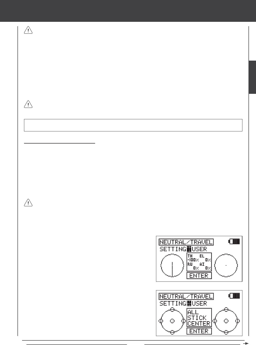
Page 43
SYSTEM MENU
Control Stick Calibration - User Option
The Control Stick Calibration function serves several different purposes:
l After changing the Operating Mode, it is necessary to recalibrate the control sticks to ensure accurate control centering and
maximum travel.
l Different brands of servos center differently, so if you use a different brand of servos, or mix different brands of servos with
Airtronics servos, the Neutral position should be recalibrated to ensure optimum centering.
l Some pilots prefer to use Stick Stops to limit the movement of the control sticks. The Travel function allows you to adjust the
servos to move 100% of their maximum travel if you choose to limit the movement of the control sticks.
2) Press the Navigation Pad 6 to highlight NEUTRAL/TRAVEL, then
press the ENTER key to display the NEUTRAL/TRAVEL menu. The
cursor will default to SETTING>FACTORY.
3) Press the YES/+ or NO/- keys to choose the SETTING>USER option.
When reinstalling the back half of the transmitter, be very careful that you don't bend or otherwise damage the battery
pins (F). These long battery pins should be carefully slid through the matching holes in the back half of the transmitter
before pushing it down into place.
12) Adjust the throttle ratchet plates to your preference. To make the throttle control stick detents less noticeable, loosen the
socket-cap screw on the outer ratchet plate, using a 1.5mm hex wrench. To make the throttle control stick detents rmer,
tighten the socket-cap screw on the outer ratchet plate, using a 1.5mm socket-cap wrench.
13) Some helicopter pilots prefer to eliminate the throttle ratchet completely. To do this, loosen the socket-cap screw on the outer
ratchet plate , using a 1.5mm hex wrench until the throttle detents can't be felt anymore. Next, tighten the socket-cap screw
on the inner throttle plate, until you're satised with the throttle control stick resistance.
14) Test the control sticks to ensure that they are operating smoothly and to your liking.
15) When satised with the results carefully reinstall the back half of the transmitter, then reinstall the transmitter battery and
plug it back in. The battery connector is polarized and can therefore be plugged in only one way.
The throttle ratchet plate with a V-Shape in it should be installed toward the outside of the transmitter.
IMPORTANT After changing the Operating Mode, it is necessary to recalibrate the control sticks to ensure accurate control
centering and maximum travel. See the Control Stick Calibration - User Option section below.
1) Press the Navigation Pad 56 to highlight MODE SETUP, then press the ENTER key to display the MODE SETUP menu.
The MODE sub-menu will be highlighted by default.
4) Press the ENTER key to begin the NEUTRAL/CALIBRATION process.
ALL STICK CENTER will be displayed in the prompt window.
5) Center both control sticks, then press the ENTER key.
Limiting the maximum movement of the control sticks while maintaining 100% servo travel will increase the sensitivity of
the servos. We recommend setting negative Exponential to soften the control feel around neutral. For more information,
see page 77 (AERO), page 118 (GLID), or page 161 (HELI).
SYSTEM
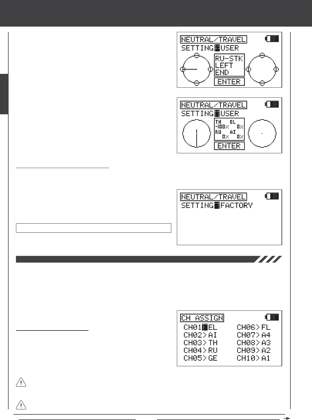
Page 44
SYSTEM MENU
6) The RU-STK LEFT END prompt will be displayed. Move the rudder
control stick completely to the left, then press the ENTER key.
7) Follow the prompts to calibrate the remaining control stick movements,
making sure to press the ENTER key after each control stick movement
to continue to the next prompt. When completed, the Calibration Top
screen will be displayed.
Control Stick Calibration - Factory Option
The Control Stick Calibration Factory Option overrides any previously programmed User calibration settings and restores the
Factory default Neutral and maximum Travel positions.
1) From within the NEUTRAL/TRAVEL menu, press the YES/+ or NO/-
keys to choose the SETTING>FACTORY option. This will reset the
control stick calibration parameters to the default settings.
NEUTRAL/TRAVEL factory default setting is 1.5ms/Maximum travel.
The Channel Assignment function allows you to assign a Control function to a different receiver channel. This is helpful if you
are using a receiver that is less than 10 Channels. For example, your aircraft features two aileron servos, two elevator servos,
one rudder servo, and one throttle servo, and you are using a 7-Channel receiver. In the default conguration, the Right Elevator
servo would need to be plugged into receiver channel slot 8. However, since you're using a 7-Channel receiver, there is no
receiver channel slot 8. Using the Channel Assignment function, you can assign the Right Elevator Control function to the
unused receiver channel slot 5. This allows you to take advantage of your aircraft's advanced control setup without the need
to use a 10-Channel receiver.
Changing Channel Assignments
1) Press the Navigation Pad 56 to highlight CH ASSIGN, then press
the ENTER key to display the CH ASSIGN menu. The cursor will
default to CH01>EL.
The Control functions displayed will vary depending on the Model Type and Model Type selection options you have
chosen. For a complete list of available Control functions, see the tables on the next page.
If desired, you can assign the same Control function to two different channel numbers. For example, if you use two rudder
servos in tandem, you can assign the rudder Control function to channels 4 and 5. Please note that you will not have
independent servo adjustments, such as Reversing, Centering, End Points.
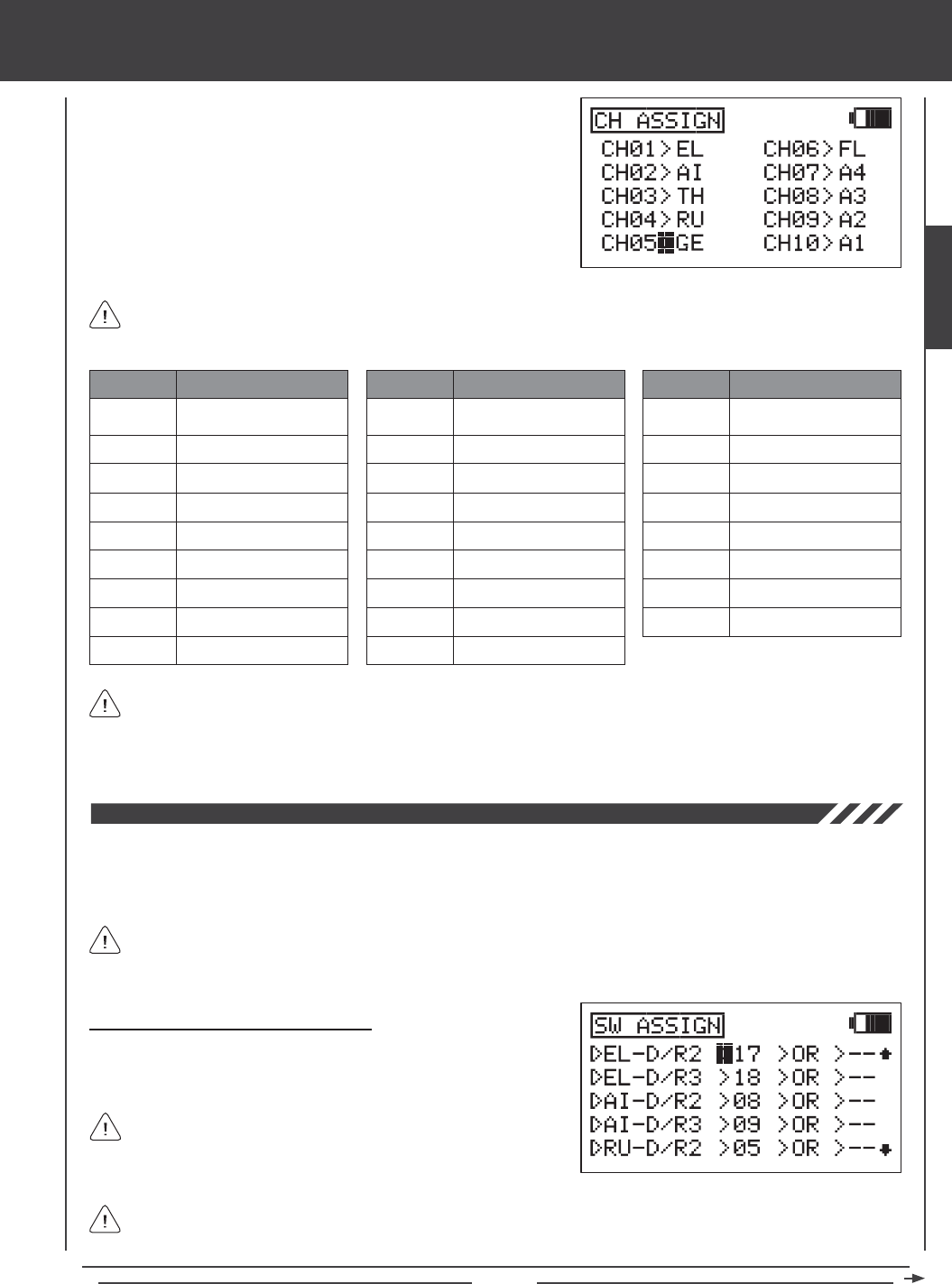
Page 45
2) Press the Navigation Pad 5634to move the cursor to the channel
number you would like to change the Control function of, for example,
CH05>GE.
3) Press the YES/+ or NO/- keys to change the Control function associated
with the highlighted channel number. The Control function that you
choose will now be controlled by that receiver channel.
4) Repeat the same procedures to change the Control function for the
desired remaining channels.
SYSTEM MENU
LOF
ROF
LIF
RIF
GY
PI
GV
A1~A4
A description of each of the available Control functions is shown in the table below. Not all Control functions will be
available to change. Control functions displayed in the CH ASSIGN menu will vary based on the Model Type and Model
Type selection options you have programmed.
EL
AI
TH
RU
GE
FL
EL2
LA
RA
LT
RT
LOA
ROA
LIA
RIA
LF
RF
MT
ABBR. FUNCTION
Elevator
Aileron
Throttle
Rudder
Gear
Flap
Elevator 2
Left Aileron
Right Aileron
ABBR. FUNCTION
Left Throttle
Right Throttle
Left Outside Aileron
Right Outside Aileron
Left Inside Aileron
Right Inside Aileron
Left Flap
Right Flap
Motor
ABBR. FUNCTION
Left Outside Flap
Right Outside Flap
Left Inside Flap
Right Inside Flap
Gyro
Pitch
Governor
AUX1~AUX4
The channel numbers in the CH ASSIGN menu correspond to the receiver channel slot numbers. When you plug your
servos into the receiver, plug them into the channel slot numbers using the CH ASSIGN menu as a guide. The Surface
menu will indicate which servos to plug into which channel slots in the receiver, too. For example, if you set up an AERO model
with 2 aileron servos and dual elevator servos, the Surface menu will show exactly which channel slots in the receiver to plug
each of the servos into. For more information, see page 63.
The Switch Assignment function allows you to assign a function, such as Gear, Dual Rate, F-Mode, Snap Roll, Stopwatch,
etc, to any of the 9 three-position switches and the 2 push-button switches (31 positions total). Switches can be programmed
to operate in the standard fashion, or they can be made to operate interdependently using the Boolean conditions OR/AND.
Switches can also be programmed to always be ON.
The Switch Assignment functions and the default Switch Position Numbers displayed will vary depending on the Model
Type you have chosen. For a complete list of the default Switch Assignments, including the different Switch Assignment
functions available, see the tables on page 47.
The control sticks can also be programmed to function as switches
(Stick Switches) and those switches can be assigned to a function.
For more information, see page 48.
Changing or Adding Switch Assignments
1) Press the Navigation Pad 56 to highlight SW ASSIGN, then press
the ENTER key to display the SW ASSIGN menu. The cursor will
default to EL-D/R2>17.
You can assign multiple functions to one switch by assigning the same Switch Position Number for each function. For
example, you could assign Elevator Dual Rate 2, Aileron Dual Rate 2, and Rudder Dual Rate 2 on one switch so that all
three Dual Rate functions can be changed at once.
SYSTEM
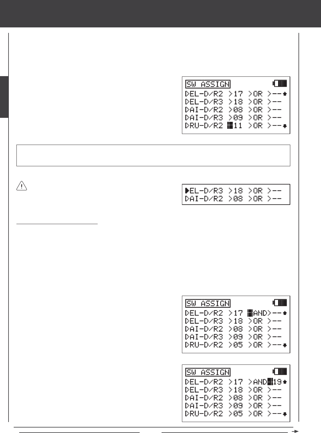
Page 46
SYSTEM MENU
Switches are assigned based on function and number. Notice that all transmitter switches have a number that corresponds to the
switches position. This Switch Position Number is what is changed in the SW ASSIGN menu to assign the switch to a particular
function. For example, in the default AERO conguration, EL-D/R2 (Elevator Dual Rate 2) is assigned to switch position 17 and
EL-D/R3 (Elevator Dual Rate 3) is assigned to switch position 18. With the switch in position 16, the Default Rate (Elevator
Dual Rate 1) is Active. Elevator Dual Rate 2 will Activate when the switch is moved to position 17 and Elevator Dual Rate 3 will
Activate when the switch is moved to position 18.
2) Press the Navigation Pad 56 to highlight the function you want to
assign to a switch. Functions that are assigned to a switch will display a
Switch Position Number and functions that aren't assigned to a Switch
Position Number will display dashes.
3) Determine the Switch Position Number on the transmitter that you want
to assign the highlighted function to, then press the YES/+ or NO/- keys
to change the Switch Position Number to match.
When a function is Activated by a switch, the triangle to the left
of the function will become highlighted. This allows you to visually
see how the different switches are operating as you assign them. For
example, Elevator Dual Rate 3 is currently Active and Aileron Dual Rate
2 is currently OFF.
IMPORTANT Switch Position Numbers can be changed from -- (Unassigned), 01~34 (Three-Position Switches and
Push-Button Switches), S1~S5 (Stick Switches), or ON (Always On). For information on programming Stick Switches, see
page 48.
Using Boolean Conditions OR/AND
Switches can be made to operate interdependently using the Boolean conditions OR/AND.
OR - You can assign a function to two different switches and have them operate independently. For example, you can assign
the Stopwatch function to push-button switch position 34 OR to push-button switch position 32. When either switch is depressed,
the Stopwatch function will Activate.
AND - You can assign a function to two different switches and make them dependent on one another. For example, the Snap
Roll function can be assigned to switch position 21 AND to switch position 24 (Gear). Doing this will allow the Snap Roll
function to work ONLY when the landing gear is retracted. This makes the operation of the Snap Roll function dependent on
the landing gear being retracted. This would prevent a crash if you accidently hit the Snap Roll switch instead of the landing
gear switch after takeoff.
1) Press the Navigation Pad 56 to highlight the function you want to
change the Boolean condition for. If a Switch Position Number isn't
assigned to the function yet, do that now by following the previous
procedures.
2) Press the Navigation Pad 4to move the cursor to >OR. To change the
Boolean condition to AND, press the YES/+ or NO/- keys.
3) Press the Navigation Pad 4to move the cursor to >--, then press the
YES/+ or NO/- keys to change the Switch Position Number to the
desired switch position.
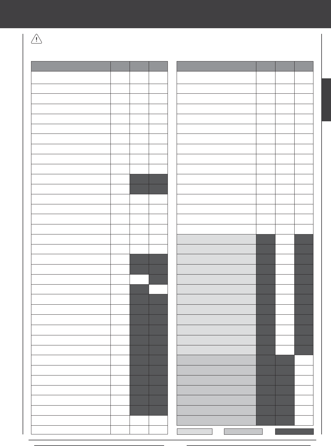
Page 47
FLAP (Flap)
MOTOR (Motor)
AI4RU1 (Aileron to Rudder Mixing 1)
AI4RU2 (Aileron to Rudder Mixing 2)
AI4RU3 (Aileron to Rudder Mixing 3)
AI4FL1 (Aileron to Flap Mixing 1)
AI4FL2 (Aileron to Flap Mixing 2)
FL4EL (Flap to Elevator Mixing)
GE4EL (Gear to Elevator Mixing)
MT4EL (Motor>Elevator Mixing)
CB4EL (Camber>Elevator Mixing)
EL4CB (Elevator>Camber Mixing)
GOVER2 (Governor 2)
GOVER3 (Governor 3)
GYRO2 (Gyro 2)
GYRO3 (Gyro 3)
EL4TH (Elevator to Throttle Mixing)
AI4TH (Aileron to Throttle Mixing)
RU4TH (Rudder>Throttle Mixing)
14
15
08
09
11
12
23
24
06
01
03
28
30
32
17
18
08
09
05
06
11
12
01
03
24
32
14
15
17
18
08
09
11
12
23
24
30
S1
13
15
SYSTEM MENU
A description of each of the available Switch Assignment functions, along with the default Switch Position Numbers for the
AERO, GLID, AND HELI model types are shown in the table below. Functions that are blacked out are not relevant to that
Model Type and functions that are blank are available, but are not assigned to a Switch Position Number.
EL-D/R2 (Elevator Dual Rate 2)
EL-D/R3 (Elevator Dual Rate 3)
AI-D/R2 (Aileron Dual Rate 2)
AI-D/R3 (Aileron Dual Rate 3)
RU-D/R2 (Rudder Dual Rate 2)
RU-D/R3 (Rudder Dual Rate 3)
F-MODE 1 (Flight Mode 1)
F-MODE 2 (Flight Mode 2)
F-MODE 3 (Flight Mode 3)
F-MODE 4 (Flight Mode 4)
SNAP RL1 (Snap Roll 1)
SNAP RL2 (Snap Roll 2)
AUX1L (Auxiliary 1 Low)
AUX1H (Auxiliary 1 High)
AUX2L (Auxiliary 2 Low)
AUX2H (Auxiliary 2 High)
AUX3L (Auxiliary 3 Low)
AUX3H (Auxiliary 3 High)
AUX4L (Auxiliary 4 Low)
AUX4H (Auxiliary 4 High)
GEAR (Gear)
TH-CUT (Throttle Cut)
FLAP1 (Flap 1)
FLAP2 (Flap 2)
EL4FL (Elevator to Flap Mixing)
AI4RU (Aileron to Rudder Mixing)
TH4EL (Throttle to Elevator Mixing)
TH4RU (Throttle to Rudder Mixing)
RU4EL (Rudder to Elevator Mixing)
RU4AI (Rudder to Aileron Mixing)
RU4TH (Rudder to Throttle Mixing)
FL4EL (Flap to Elevator Mixing)
IDL-DOWN (Idle Down)
TH-HOLD (Throttle Hold)
CH-DLY1 (Channel Delay 1)
CH-DLY2 (Channel Delay 2)
FUNCTION AERO GLID HELI
19
19
17
18
19
19
01
02
03
CH-DLY3 (Channel Delay 3)
CH-DLY4 (Channel Delay 4)
CH-DLY5 (Channel Delay 5)
C-MIX1 (Compensation Mixing 1)
C-MIX2 (Compensation Mixing 2)
C-MIX3 (Compensation Mixing 3)
C-MIX4 (Compensation Mixing 4)
C-MIX5 (Compensation Mixing 5)
INC (Increase Value)
DEC (Decrease Value)
START (Start Stopwatch)
STOP (Stop Stopwatch)
RHYTHM1 (Rhythm Timer 1)
RHYTHM2 (Rhythm Timer 2)
RHYTHM3 (Rhythm Timer 3)
TRAINER (Trainer)
FUNCTION AERO GLID HELI
GLID Only HELI Only Not Relevant
SYSTEM
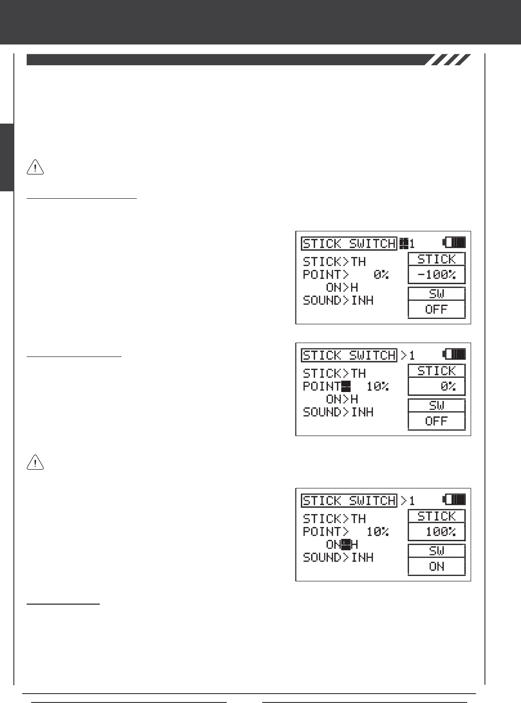
Page 48
SYSTEM MENU
The Stick Switch function allows you to convert one or more control stick axes into a switch (Stick Switch), then assign a function
to that Stick Switch, using the procedures in the SW ASSIGN menu section. For example, if you are ying a glider that features
spoilers, you can assign the Flap function to the throttle control stick. When the throttle control stick is pushed all the way forward,
the spoilers are retraced. When you pull the throttle control stick all the way down, the spoilers deploy. This is useful for making
spot landings where you need to deploy the spoilers quickly and accurately to reduce lift. Being able to place this function on the
throttle control stick is extremely convenient and user-friendly. Five programmable Stick Switch axes are available. Either side
of the Stick Switch can be programmed ON or OFF and the Point that the Stick Switch turns ON and OFF can be adjusted. An
audible tone can also be programmed to indicate when the Stick Switch turns ON and OFF.
Choosing a Stick Switch Axis
1) Press the Navigation Pad 56 to highlight STICK SWITCH, then press the ENTER key to display the STICK SWITCH menu.
The cursor will default to STICK SWITCH>1.
After a Stick Switch is programmed, it must be assigned to a function as described in the SW ASSIGN menu section.
Stick Switches are denoted in the SW ASSIGN menu as S1 through S5. For more information, see page 45.
Setting the ON/OFF Point
1) Press the Navigation Pad 6 to highlight POINT>0%. This is the
point at which the Stick Switch will turn ON or OFF.
2) Move the control stick to the Point at which you want the Stick
Switch to turn ON or OFF, then press the YES/+ key. The ON/OFF
Point will be displayed as a percentage of control stick movement
For example, POINT>10% will be displayed.
2) Press the YES/+ or NO/- keys to choose which Stick Switch to program.
You can program up to 5 different stick switches. If this is the rst Stick
Switch you're programming, choose STICK SWITCH>1.
3) Press the Navigation Pad 6 to highlight STICK>EL.
4) Press the YES/+ or NO/- keys to choose which control stick axis
you would like to use as a Stick Switch. Available functions will vary
based on the Model Type currently selected.
The current position of the control stick is displayed in the STICK dialog box. If you want the ON/OFF Point to be at the
neutral position, press the YES/+ and NO/- keys at the same time to choose 0% regardless of control stick position.
3) Press the Navigation Pad 6 to highlight ON>H.
4) Press the YES/+ or NO/- keys to program the side that the Stick Switch
will turn ON. Choose from H (High) or L (Low). For example, if you
program the Throttle control stick ON/OFF Point at 10% and ON>H, the
switch function will Activate at 10% and greater movement. The switch
function will be OFF at 9% and less movement. The ON and OFF status
is displayed in the SW dialog box.
Stick Switch Sound
1) Press the Navigation Pad 6 to highlight SOUND>INH.
2) Press the YES/+ or NO/- keys to choose which sound option you desire to use. When set to INH, no audible tone will be heard.
ON<>OFF - An audible tone is heard when the Stick Switch turns ON and when the Stick Switch turns OFF.
ON>OFF - An audible tone is heard only when the Stick Switch turns OFF.
OFF>ON - An audible tone is heard only when the Stick Switch turns ON.
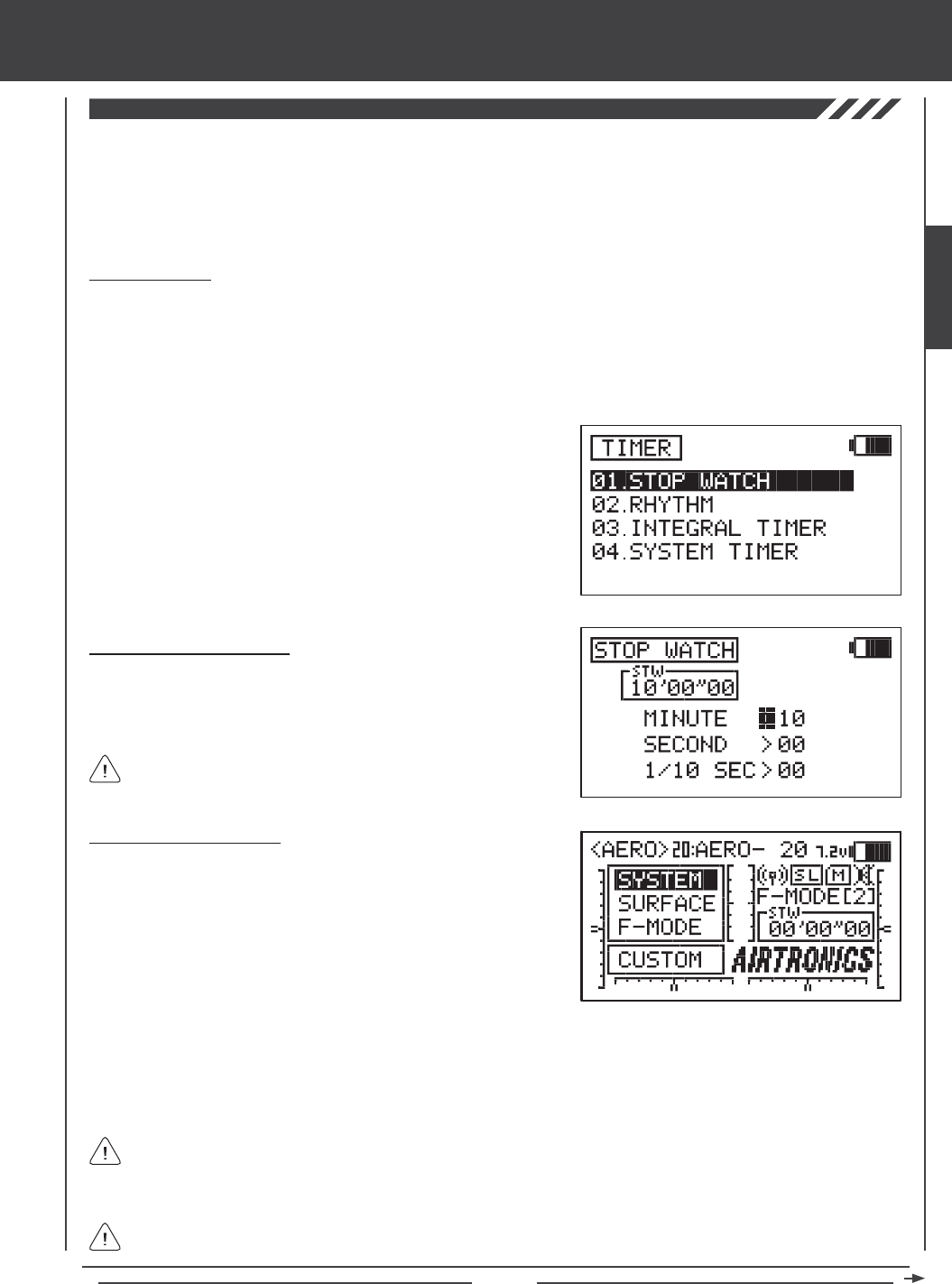
Page 49
SYSTEM MENU
The Timer function consists of four different types of timers. A Stopwatch timer, a Rhythm timer, an Integral timer, and a System
timer. The Stop Watch timer and the Rhythm timer can be programmed separately for each individual model. The Stop Watch
timer, the Integral timer, and the System timer status can each be displayed on the Top menu. The Stop Watch and the three
individual Rhythm timers can each be controlled by their own switch. The Stop Watch can also be controlled directly from the
Top menu using the YES/+ and NO/- keys so that you don't need to enter the TIMER menu each time you need to use it.
1) Press the Navigation Pad 56 to highlight TIMER, then press the
ENTER key to display the TIMER menu. The STOP WATCH sub-menu
will be highlighted by default.
2) Press the ENTER key to display the STOP WATCH menu. The cursor
will default to MINUTE>00.
Setting the Stop Watch Timer
1) The Minute, Second, and 1/10 Second times can be set independently.
Press the Navigation Pad 56 to highlight the time interval you would
like to program, then press the YES/+ or NO/- keys to set the desired
Start time. The Start time will be displayed in the STW dialog box.
Using the Stop Watch Timer
1) By default, the Stop Watch timer is displayed in the Timer Display
(STW) on the Top menu. In this conguration, the Stop Watch timer
can be controlled using the YES/+ and NO/- keys.
START - Press the YES/+ key to Start the Stop Watch timer.
STOP - Press the YES/+ key again to Stop the Stop Watch timer.
RESET - Press the YES/+ and NO/- keys at the same time to Reset the
Stop Watch timer to the programmed Start Time.
Stop Watch Timer
The Stop Watch timer is used to either count down from a programmed Start time (Count Down mode) or to count up from zero if
no Start time is programmed (Count Up mode). In Count Down mode, an audible tone will sound in 1 second intervals when the
Stop Watch reaches 10 seconds from zero. When zero is reached, a long audible tone will sound and the Stop Watch will begin
to count up. In Count Up mode, an audible tone will sound at 1 minute intervals to remind you that the count down time (zero) has
been surpassed. The Stop Watch timer can be utilized for a number of different uses, but one of the more popular uses is to use it
as a fuel usage indicator to remind you to land within an allotted amount of time to ensure that your model doesn't run out of fuel.
The Stop Watch timer is displayed in Minutes, Seconds, and
1/10 Seconds. 00' (Minutes) 00" (Seconds) 00 (1/10 Seconds).
2) The Stop Watch timer can be assigned to a switch, which can make it more convenient to control. For more information, see
page 45. To turn the Stop Watch timer ON and OFF, assign the same Switch Position Number for both the START and the
STOP functions in the SW ASSIGN menu. For example, assign both the START function and the STOP function to Switch
Position 33. Pressing the push-button switch 33 once will Start the Stop Watch timer and pressing it again will Stop the Stop
Watch timer.
In order to control the Stop Watch timer using the YES/+ and NO/- keys, the Stop Watch timer MUST be displayed
on the Top menu as indicated by the STW dialog box. If the Stop Watch timer is assigned to a switch, the Stop
Watch timer can be controlled by the switch even if it's not displayed on the Top menu. In this situation, if you need to
Reset the Stop Watch timer, you would need to do so through the STOP WATCH menu.
The Stop Watch timer can be used in Count Up mode by starting the Stop Watch timer from zero.
SYSTEM
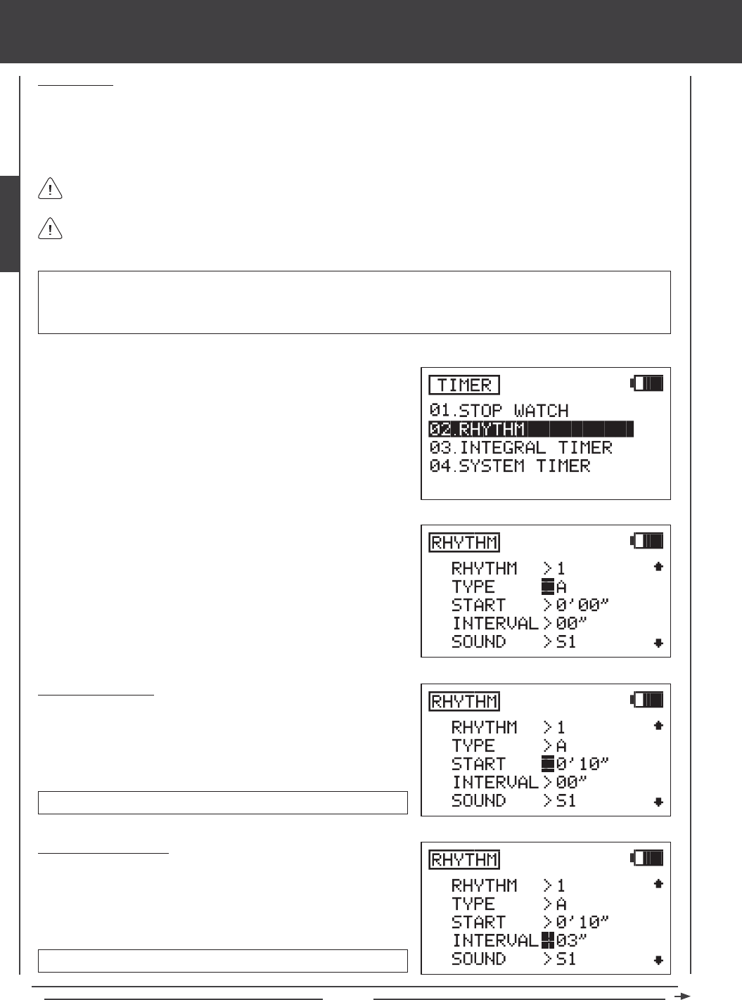
Page 50
SYSTEM MENU
Rhythm Timer
The Rhythm timer can be programmed to provided a selected sequence of audible tones, which can be used for pacing aerobatics
or for practicing precision landings. Three separate Rhythm timers can be programmed and each Rhythm timer can be turned ON
separately by assigning them to different switch positions. Each Rhythm timer features ve programmable Types. Within each
Type, the Start time, the Interval time, the Sound, and the Count can be programmed individually. This allows for a near innite
combination of audible tones to suit nearly any situation.
1) Press the Navigation Pad 56 to highlight TIMER, then press the
ENTER key to display the TIMER menu. The STOP WATCH sub-menu
will be highlighted by default.
2) Press the Navigation Pad 6 to highlight RHYTHM, then press the
ENTER key to display the RHYTHM menu.
3) The cursor will default to RHYTHM>1. Press the YES/+ or NO/- keys
to choose which Rhythm timer you would like to program. There are
three separate Rhythm timers that can be programmed. If this is the
rst Rhythm timer you're programming, choose RHYTHM>1.
4) Five separate Rhythm Types can be programmed independently for
each of the three Rhythm timers. Types are not pre-programmed.
They consist of the Start time, the Interval time, the Sound, and the
Count you program in the next few procedures. Press the Navigation
Pad 6 to highlight TYPE>A.
Unlike other timers, the Rhythm timers are not displayed on the Top menu. They operate strictly in the background.
After programming a RHYTHM timer (either RHYTHM 1, RHYTHM 2, OR RHYTHM 3), it must be assigned to a Switch
Position Number as described in the SW ASSIGN menu section. For more information, see page 45.
Setting the Start Time
The Start Time is the time (in Minutes and Seconds) that the Rhythm timer
will begin after the Rhythm timer is switched ON. For example, if set to 10
Seconds, the Rhythm timer will Start 10 seconds after being turned ON.
START time setting range is 0' 00" to 9' 59".
Setting the Interval Time
The Interval time is the time (in Seconds) that the audible tone will sound
while the Rhythm timer is switched ON. For example, if set to 3 seconds,
the audible tone will sound once every 3 seconds.
INTERVAL time setting range is 00" to 59".
1) Press the Navigation Pad 6 to highlight START>0' 00", then press the
YES/+ or NO/- keys to set the desired Start time.
1) Press the Navigation Pad 6 to highlight INTERVAL>00", then press
the YES/+ or NO/- keys to set the desired Interval time.
IMPORTANT Once a Rhythm timer is started, it will continue to run until the Count nishes. If you need to stop the Rhythm
timer before the Count nishes, open the Rhythm timer menu, highlight INTERVAL, then press the YES/+ and NO/- keys at
the same time to Reset the INTERVAL to 00". When set to 00", the Rhythm timer will stop. To restart the Rhythm timer, set the
Interval to the desired setting.
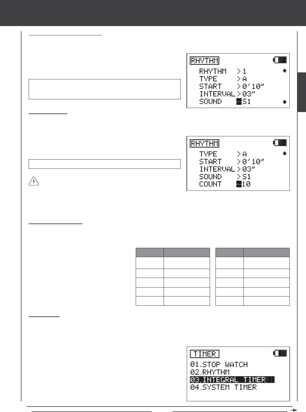
Page 51
Setting the Sound (Audible Tone)
The Sound setting adjusts the length and type of the audible tone played at each Interval time. For example, if set to S1, a short
single audible tone will be played at each Interval time.
1) Press the Navigation Pad 6 to highlight SOUND>S1, then press the
YES/+ or NO/- keys to set the desired Sound.
SOUND setting range is S1 - Short single audible tone, S2 - Short
double audible tone, L1 - Long single audible tone, and L2 - Long
double audible tone.
SYSTEM MENU
Setting the Count
The Count setting indicates how many times the audible tone will repeat while the Rhythm timer is ON. For example, when set to
10, the audible tone will repeat 10 times, then turn OFF.
To hear an audible tone, you MUST set the COUNT number to a
value other than 0. If a value of 0 is selected, the Rhythm timer will
not operate.
COUNT setting range is 0 to 60.
1) Press the Navigation Pad 6 to highlight COUNT>0, then press the
YES/+ or NO/- keys to set the desired amount of times you would like
the audible tone to sound while the Rhythm timer is ON.
2) If it's necessary to create a more complex Rhythm timer to suit your application, choose TYPE>B, C, D, or E and repeat
the previous procedures to set different Start time, Interval time, Sound, and Count options. See the example below.
TYPE
START
INTERVAL
SOUND
COUNT
TIMER 1
A
0' 10"
03"
S1
10
TYPE
START
INTERVAL
SOUND
COUNT
TIMER 1
B
0' 15"
05"
L2
5
In this example, when the Rhythm timer is turned
ON, the TYPE A options will begin 10 seconds
later. A short single audible tone will sound every 3
seconds, a total of 10 times. At the same time, the
TYPE B options will begin 15 seconds after the
Rhythm timer is turned ON. A long double audible
tone will sound every 5 seconds, a total of 5 times.
Using the Rhythm Timer
1) The Rhythm timers operate in the background and require that each one be assigned to a Switch Position Number to be
turned ON. To start a Rhythm timer, turn ON the switch you assigned the Rhythm timer to.
Integral Timer
The Integral timer is a Count Up timer that displays the time that the SD-10G transmitter has been turned ON (either via the
Power switch or the Display key) since the last time the Integral timer was Reset. The Integral timer is not model-specic, so, for
example, it is good to use as an indicator to chart the usage time between battery charges.
1) Press the Navigation Pad 56 to highlight TIMER, then press the
ENTER key to display the TIMER menu. The STOP WATCH sub-menu
will be highlighted by default.
2) Press the Navigation Pad 6 to highlight INTEGRAL TIMER, then
press the ENTER key to display the Integral timer.
SYSTEM
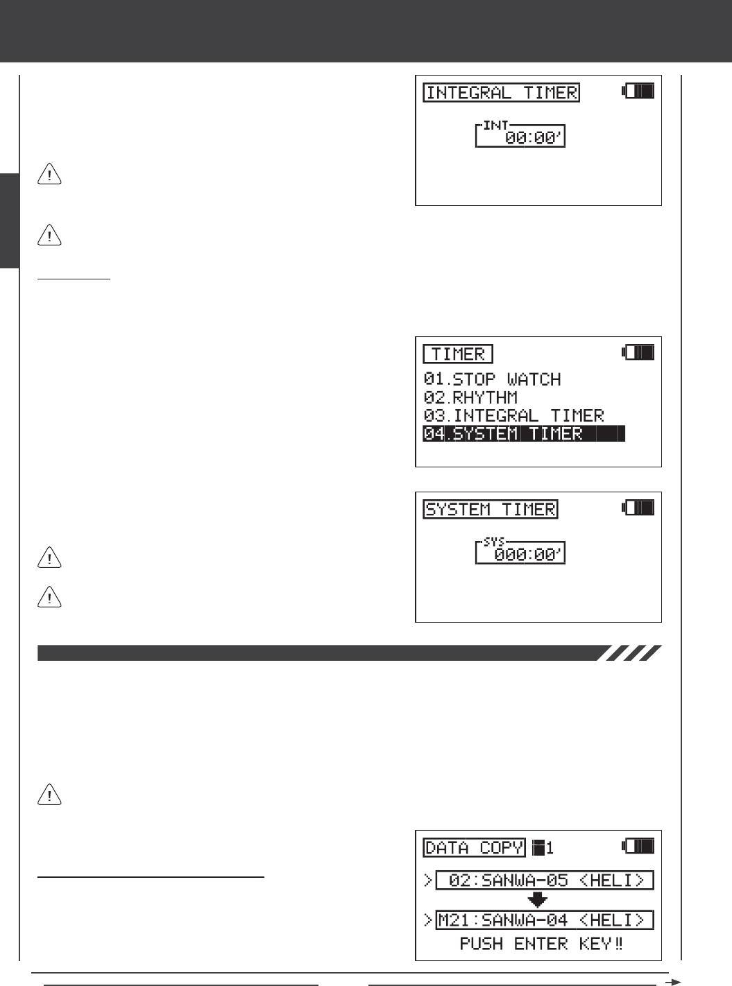
Page 52
SYSTEM MENU
3) The total time that the SD-10G transmitter has been turned ON since
the last time the Integral timer was Reset is displayed in the INT dialog
box. Press the YES/+ and NO/- keys at the same time to Reset the
Integral timer to zero.
System Timer
The System timer is a Count Up timer that displays the total time that the SD-10G transmitter has been turned ON (either via the
Power switch or the Display key) since it was new. The System timer cannot be Reset.
1) Press the Navigation Pad 56 to highlight TIMER, then press the
ENTER key to display the TIMER menu. The STOP WATCH sub-menu
will be highlighted by default.
2) Press the Navigation Pad 6 to highlight SYSTEM TIMER, then press
the ENTER key to display the System timer.
The Integral timer can be displayed in the Timer Display (INT) on the Top menu. For more information, see page 57.
The Integral timer is displayed in Hours and Minutes. 00 (Hours)
00' (Minutes).
3) The total time that the SD-10G transmitter has been turned ON since it
was new is displayed in the SYS dialog box.
The System timer can be displayed in the Timer Display (SYS) on the
Top menu. For more information, see page 57.
The System timer is displayed in Hours and Minutes. 000 (Hours)
00' (Minutes).
The Data Copy function allows you to copy the programming data from one model to another model. This is convenient if you
have similar Model Types. For example, if you have two aerobatic aircraft that are similar, you can copy the programming data
from the rst model to the second model to use as a base to start ne-tuning the programming for the second model. Programming
data can be copied in single-model format or in groups of ten models. Programming data can also be copied from the transmitter
to the Memory Expansion Card and from the Memory Expansion Card to the transmitter* so that you can share programming
data with fellow SD-10G transmitter users in the eld.
Like many SD-10G programming features, Switch Assignments are model-specic. If you would like to keep the same
Switch Assignments from model-to-model for continuity, use the Data Copy function to save the time and effort necessary
to re-program the Switch Assignments for each model.
Copying Model Data (Single-Model Format)
1) Press the Navigation Pad 56 to highlight DATA COPY, then press
the ENTER key to display the DATA COPY menu. The cursor will
default to DATA COPY>1.
*Memory Expansion Card available separately. See your local Airtronics dealer for more information.
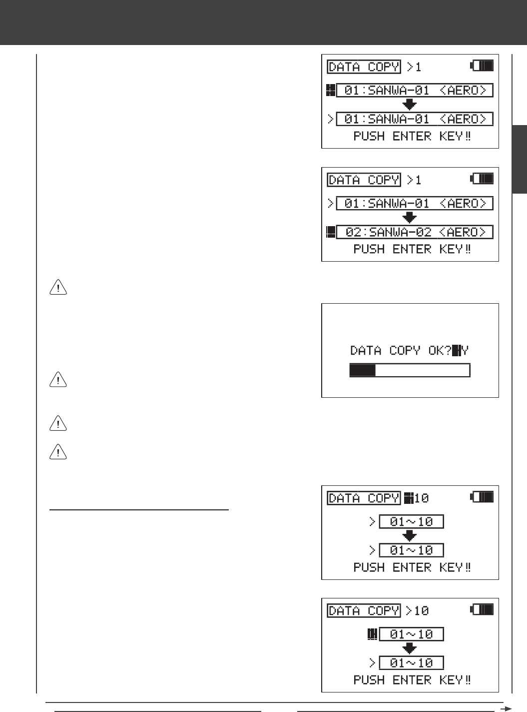
Page 53
SYSTEM MENU
2) Press the Navigation Pad 6 to highlight the upper model dialog box.
The currently selected model will be displayed. Press the YES/+ or
NO/- keys to select the model you would like to copy the programming
data FROM.
3) Press the Navigation Pad 6 to highlight the lower model dialog box,
then press the YES/+ or NO/- keys to select the model you would like to
copy the programming data TO.
4) Press then ENTER key. DATA COPY OK?>Y will be displayed.
5) Press the YES/+ key to begin the Data Copy process. When the Data
Copy process is completed the DATA COPY menu will be displayed,
indicating that the programming data has been copied.
All model-specic programming data, including the Model Name will
be copied to the selected model.
It's not possible to copy the programming data from one model to the same model. If you attempt to execute this, SAME
MODEL?? will be displayed and the process will not execute.
Models stored on the Memory Expansion Card (if installed), are denoted with an 'M' (i.e. M21:SANWA-04).
Copying Model Data (Ten-Model Group Format)
1) Press the Navigation Pad 56 to highlight DATA COPY, then press
the ENTER key to display the DATA COPY menu. The cursor will
default to DATA COPY>1.
2) Press the YES/+ or NO/- keys to select DATA COPY>10.
3) Press the Navigation Pad 6 to highlight the upper model group dialog
box, then press the YES/+ or NO/- keys to select the group of ten
models you would like to copy the programming data FROM.
If you want to go back and change the models or you don't want to copy the model programming data for any reason,
press the NO/- or END keys.
SYSTEM
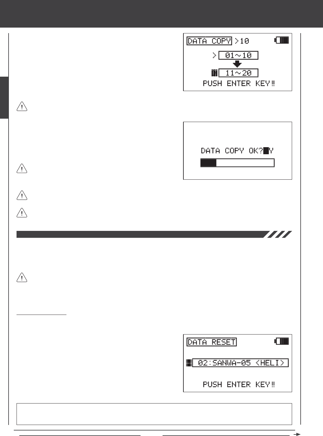
Page 54
SYSTEM MENU
5) Press then ENTER key. DATA COPY OK?>Y will be displayed.
6) Press the YES/+ key to begin the Data Copy process. When the Data
Copy process is completed the DATA COPY menu will be displayed,
indicating that the programming data has been copied.
All model-specic programming data, including the Model Names will
be copied to the selected model group.
Models stored on the Memory Expansion Card (if installed), are denoted with an 'M' (i.e. M21:SANWA-04).
4) Press the Navigation Pad 6 to highlight the lower model group dialog
box, then press the YES/+ or NO/- keys to select the group of ten
models you would like to copy the programming data TO.
It's not possible to copy the programming data from one model group to the same model group. If you attempt to execute
this, SAME MODEL?? will be displayed and the process will not execute.
If you want to go back and change the models or you don't want to copy the model programming data for any reason,
press the NO/- or END keys.
The Data Reset function allows you to Reset model-specic programming data for each model back to the factory default settings.
Individual programming settings can be Reset to the factory default settings by pressing the YES/+ and NO/- keys at the same
time, however, this is time consuming if you want to change all of the selected model's programming settings back to default.
Using the Data Reset function makes doing this much quicker and more accurate, since nothing will be missed.
Resetting Model Data
1) Press the Navigation Pad 56 to highlight DATA RESET, then press the ENTER key to display the DATA RESET menu.
The cursor will default to the currently selected model.
2) Press the YES/+ or NO/- keys to select the model you would like to
Reset the programming data for.
Although Model Type and Modulation are model-specic, the Data Reset function does NOT Reset them. This is useful
if you have two similar models, but different programming needs for each. For example, if you have two similar gliders
that use the same Model Type but different programming, you can copy the rst model's programming data, using the Data
Copy function, then use the Data Reset function to Reset the programming data except the Model Type. This saves time by
not needing to re-enter the Model Type.
IMPORTANT When you use the Data Reset function, ALL model-specic Flight Mode data, Surface Menu data, and
model-specic System programming, such as Switch Assignments, Model Name, Fail Safe settings, and Stick Switches will
be Reset to the factory default settings. Model Type and Modulation settings will NOT be Reset.
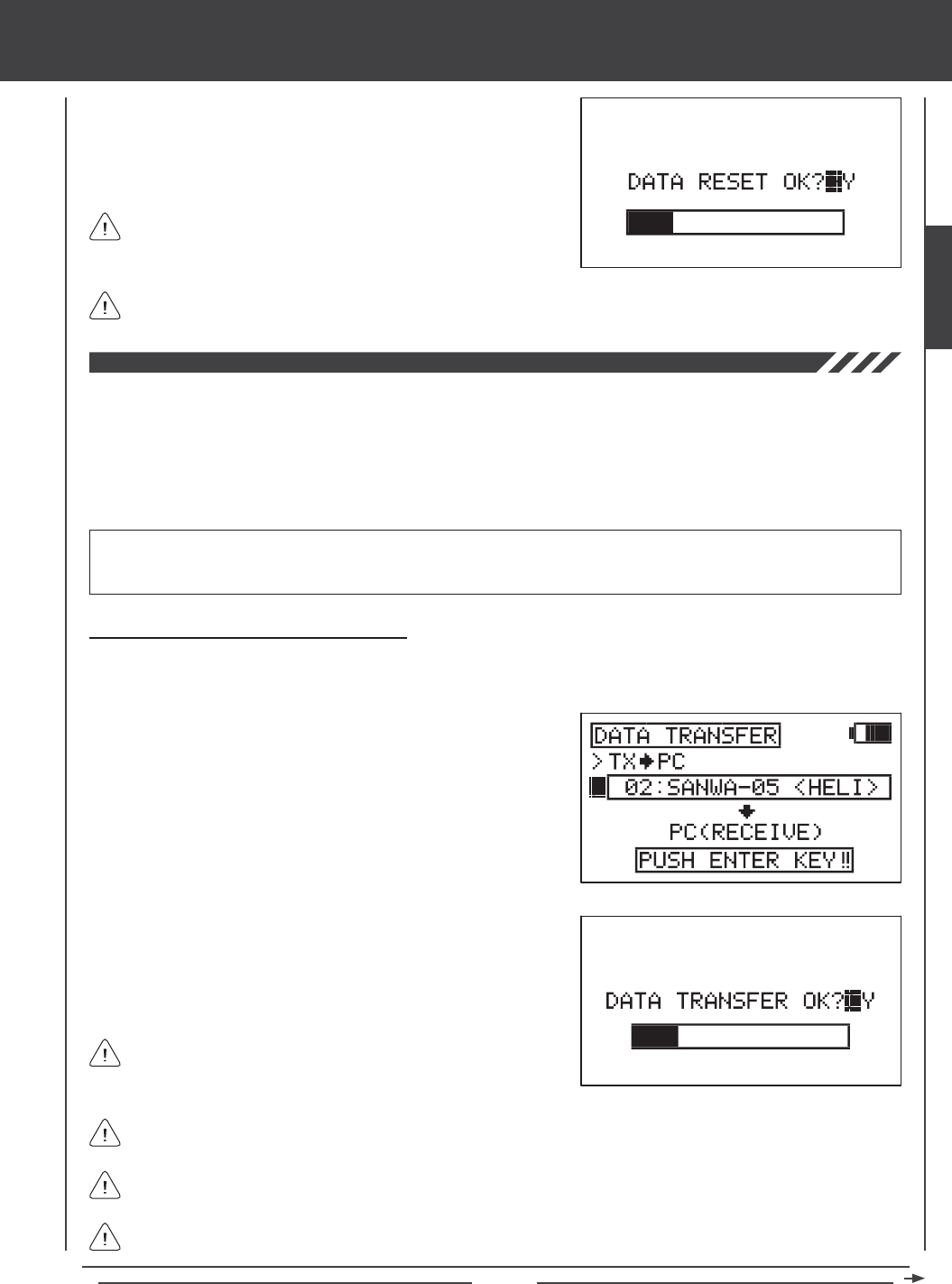
Page 55
SYSTEM MENU
3) Press then ENTER key. DATA RESET OK?>Y will be displayed.
4) Press the YES/+ key to begin the Data Reset process. When the Data
Reset process is complete the DATA RESET menu will be displayed,
indicating that the programming data has been Reset.
Models stored on the Memory Expansion Card (if installed), are denoted with an 'M' (i.e. M21:SANWA-04).
If you want to go back and change the model or you don't want to
Reset the model programming data for any reason, press the NO/-
or END keys.
The Data Transfer function allows you to transfer programming data from the SD-10G transmitter to your PC and from your PC
to your SD-10G transmitter*. This allows you to back up model programming data, install saved model programming data back
onto your transmitter, or install SD-10G-specic model programming data that you've downloaded from the Internet. For example,
you can copy your current model's programming data to your PC, then email the data to your fellow modeler that ies the same
model. He or she can then copy that programming data to their SD-10G transmitter so that it can be used with their model.
*USB adapter cable and software required available separately. See your local Airtronics dealer for more information. Visit http://www.airtronics.net to download software
and check system compatibility and installation instructions.
Transferring Programming Data from TX to PC
1) Press the Navigation Pad 56 to highlight DATA TRANSFER, then press the ENTER key to display the DATA TRANSFER
menu. The cursor will default to >TX4PC. PC (RECEIVE) will be displayed.
2) Press the Navigation Pad 6 to highlight the currently selected model,
then press the YES/+ or NO/- keys to select the model you would like
to copy the programming data FROM to your PC.
3) Press then ENTER key. DATA TRANSFER OK?>Y will be displayed.
4) Press the YES/+ key to begin the Data Transfer process. When the
Data Transfer process is completed the DATA TRANSFER menu will be
displayed, indicating that the data has been transferred.
All model-specic programming data, including the Model Name will
be transferred to your PC.
Models stored on the Memory Expansion Card (if installed), are denoted with an 'M' (i.e. M21:SANWA-04).
If you want to go back and change the model or you don't want to transfer the model programming data for any reason,
press the NO/- or END keys.
If there is a problem with the Data Transfer procedure, for example, if the SD-10G transmitter is not connected to your
PC, TIMEOUT ERROR will be displayed. If this occurs, press the any key to return to the Data Transfer menu.
IMPORTANT Prior to using the Data Transfer function, your PC must be turned ON, the Transfer Tool software must be
running, and the SD-10G transmitter must be connected to the PC using the USB adapter cable. One side of the USB adapter
cable plugs into a USB port on your PC and the other side plugs into the DIN connector on the back of the SD-10G transmitter.
SYSTEM
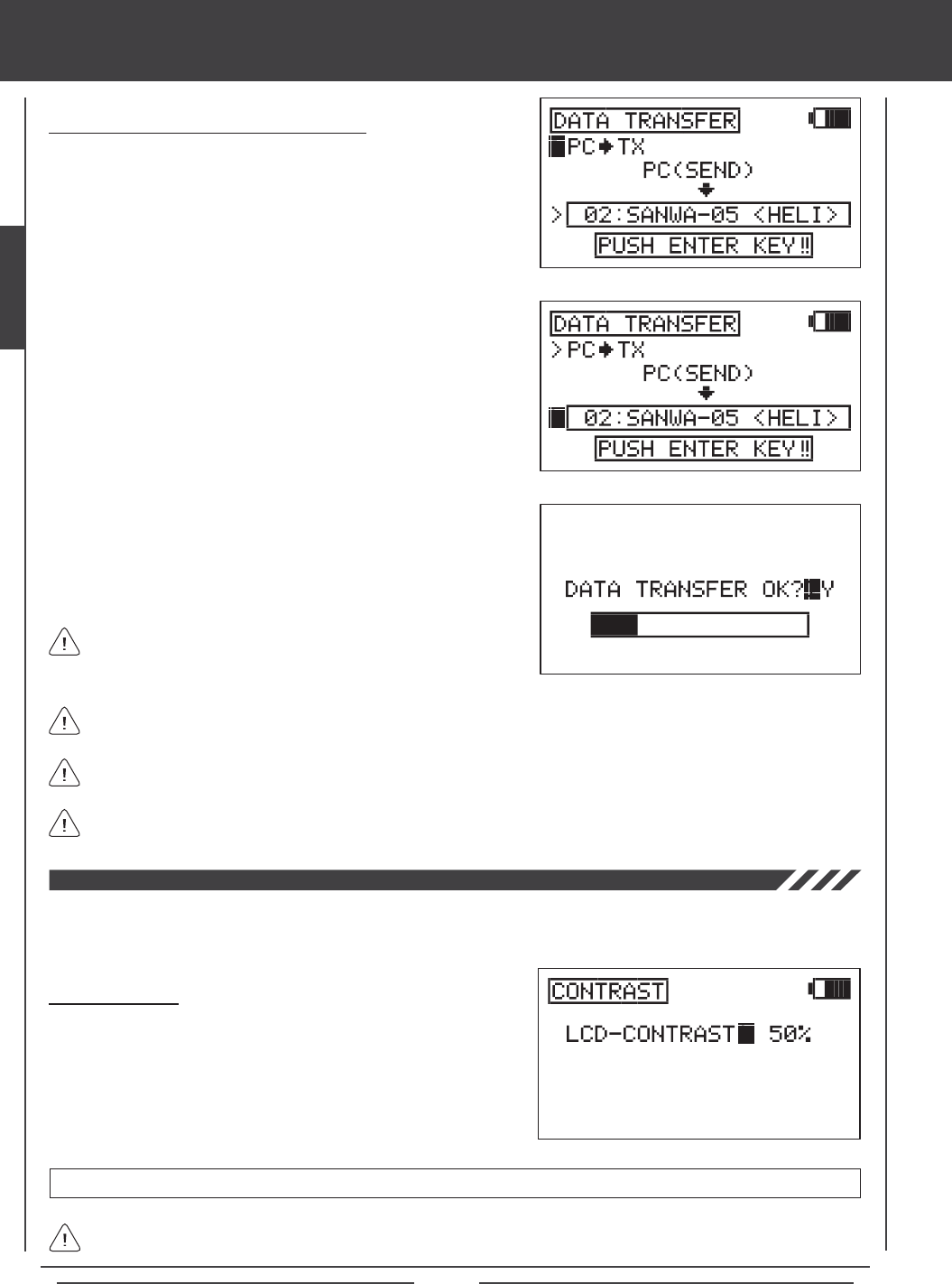
Page 56
SYSTEM MENU
Transferring Programming Data from PC to TX
1) Press the Navigation Pad 56 to highlight DATA TRANSFER, then
press the ENTER key to display the DATA TRANSFER menu. The
cursor will default to >TX4PC.
2) Press the YES/+ or NO/- keys to choose >PC4TX. PC (SEND) will
be displayed.
3) Press the Navigation Pad 6 to highlight the currently selected model,
then press the YES/+ or NO/- keys to select the model you would like
the programming data from your PC to be written to.
4) Press then ENTER key. DATA TRANSFER OK?>Y will be displayed.
5) Press the YES/+ key to begin the Data Transfer process. When the
Data Transfer process is completed the DATA TRANSFER menu will be
displayed, indicating that the data has been transferred.
All model-specic programming data, including the Model Name will
be transferred to the selected model number.
Models transferred to the Memory Expansion Card (if installed), will be denoted with an 'M' (i.e. M21:SANWA-04).
If you want to go back and change the model or you don't want to transfer the model programming data for any reason,
press the NO/- or END keys.
If there is a problem with the Data Transfer procedure, for example, if the SD-10G transmitter is not connected to your
PC, TIMEOUT ERROR will be displayed. If this occurs, press the any key to return to the Data Transfer menu.
The Contrast function allows you to change the contrast of the LCD Display to make it easier to read in all types of lighting conditions.
In general, increasing the contrast will make the LCD Display easier to read in bright sunlight and decreasing the contrast will
make the LCD Display easier to read in low light levels.
Adjusting Contrast
1) Press the Navigation Pad 56 to highlight CONTRAST, then press the
ENTER key to display the CONTRAST menu. The cursor will default to
LCD-CONTRAST>50%.
2) Press the YES/+ or NO/- keys to increase or decrease the
LCD-CONTRAST setting in 5% increments.
Increasing LCD Display Contrast can drain the battery more quickly than using a decreased (lower) setting.
CONTRAST setting range is 0% to 100%.
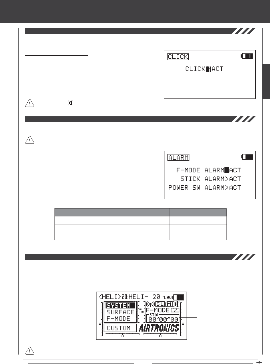
Page 57
SYSTEM MENU
The Click function allows you to set the audible key tones ON (ACT) or OFF (INH).
Setting Click (Audible Key Tone)
1) Press the Navigation Pad 56 to highlight CLICK, then press the
ENTER key to display the CLICK menu. The cursor will default to
CLICK>ACT.
2) Press the YES/+ or NO/- keys to select INH (Inhibit) or ACT (Active).
When set to ACT, an audible tone will sound with each key-press.
When set to INH, no audible tone will sound with each key-press.
The Alarm function allows you to set a selection transmitter alarms ON (ACT) or OFF (INH).
Turning an alarm OFF will disable that particular alarm and you will no longer receive a warning that the transmitter is in a
non-normal state. For a description of alarms, see page 14.
When set to INH, will be displayed on the Top menu.
Changing the Alarm Status
1) Press the Navigation Pad 56 to highlight ALARM, then press the
ENTER key to display the ALARM menu. The cursor will default to
F-MODE>ACT.
2) Press the Navigation Pad 56 to highlight the specic alarm you want
to change the status of, then press the YES/+ or NO/- keys to select
INH (Inhibit) or ACT (Active). When set to ACT, the alarm will Activate.
When set to INH, the alarm will be Deactivated.
AERO GLIDER HELI
F-MODE ALARM
STICK ALARM*
POWER SWITCH ALARM
F-MODE ALARM
POWER SWITCH ALARM
F-MODE ALARM
STICK ALARM*
POWER SWITCH ALARM
The Top Menu Arrange function allows you to customize several Top menu display elements. Both the Shortcut Menu and the
Timer / Stick Monitor display can be changed. The Shortcut Menu can be changed to display a shortcut to any number of menus
including the Custom menu. This makes it convenient to access your most-used menu without the need to scroll through the
SYSTEM or F-MODE menus to access it. The Timer / Stick Monitor display can be changed to display three different timers or
four different stick monitors.
Shortcut Menu
Timer / Stick Monitor
Options displayed will vary depending on the Model Type you have chosen. For a list of available options, see page 58.
*Throttle control stick only.
SYSTEM
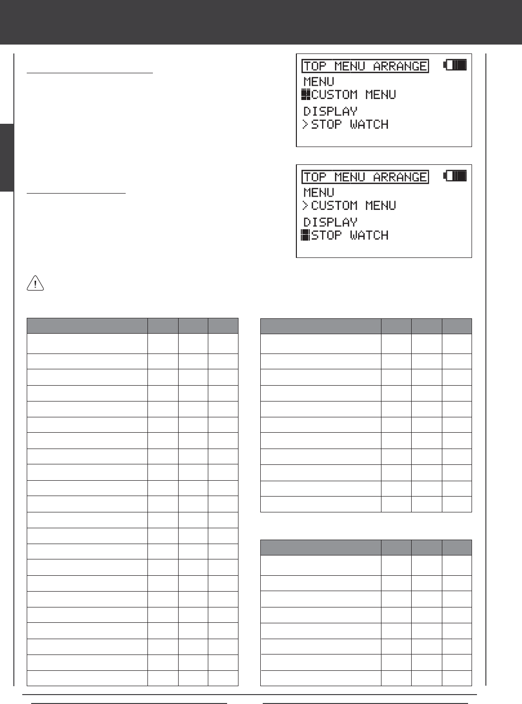
Page 58
CUSTOM MENU
MEMORY PACK
SYSTEM INFORMATION
SX MONITOR
STICK MONITOR
D/R
EXP
LANDING
CAMBER
CAMBER POINT
TH-CURVE
PI-CURVE
TH-HOLD
TH-CUT
HOV-TH
HOV-PI
IDLE DOWN
AI DIFFERENTIAL
OFFSET
CH DELAY
TRIM
TRIM STEP
TRIM AUTH
GYRO
GOVERNOR
CROSS-TRIM
SNAP-ROLL
MIXING
C-MIX
VR ASSIGN
F-MODE COPY
F-MODE DELAY
F-MODE NAME
SYSTEM MENU
STOP WATCH
INTEGRAL TIMER
SYSTEM TIMER
STICK MONITOR TH
STICK MONITOR AI
STICK MONITOR EL
STICK MONITOR RU
STICK MONITOR FL
Choosing Shortcut Menu Options
1) Press the Navigation Pad 56 to highlight TOP MENU ARRANGE,
then press the ENTER key to display the TOP MENU ARRANGE menu.
The cursor will default to MENU>CUSTOM MENU.
2) Press the YES/+ or NO/- keys to choose which Menu shortcut option
you would like to be displayed in the Shortcut menu.
Options displayed in the Timer / Stick Monitor Display are not selectable. They are displayed only. The option displayed in
the Shortcut menu is selectable. Press the Navigation Pad 6 to highlight the Shortcut menu option, then press the ENTER
key to open that menu. The Shortcut menu and Display options are shown in the tables below.
Choosing Display Options
1) From within the TOP MENU ARRANGE menu, press the Navigation
Pad 6 to highlight DISPLAY, then press the YES/+ or NO/- keys to
choose which Display option you would like to be displayed in the
Timer / Stick Monitor display.
X
X
X
X
X
X
X
X
X
X
X
X
X
X
X
X
MENU AERO GLID HELI
X
X
X
X
X
X
X
X
X
X
X
X
X
X
X
X
X
X
X
X
X
X
X
X
X
X
X
X
X
X
X
X
X
X
X
X
X
X
X
MENU AERO GLID HELI
X
X
X
X
X
X
X
X
X
X
X
X
X
X
X
X
X
X
X
X
X
X
X
X
DISPLAY AERO GLID HELI
X
X
X
X
X
X
X
X
X
X
X
X
X
X
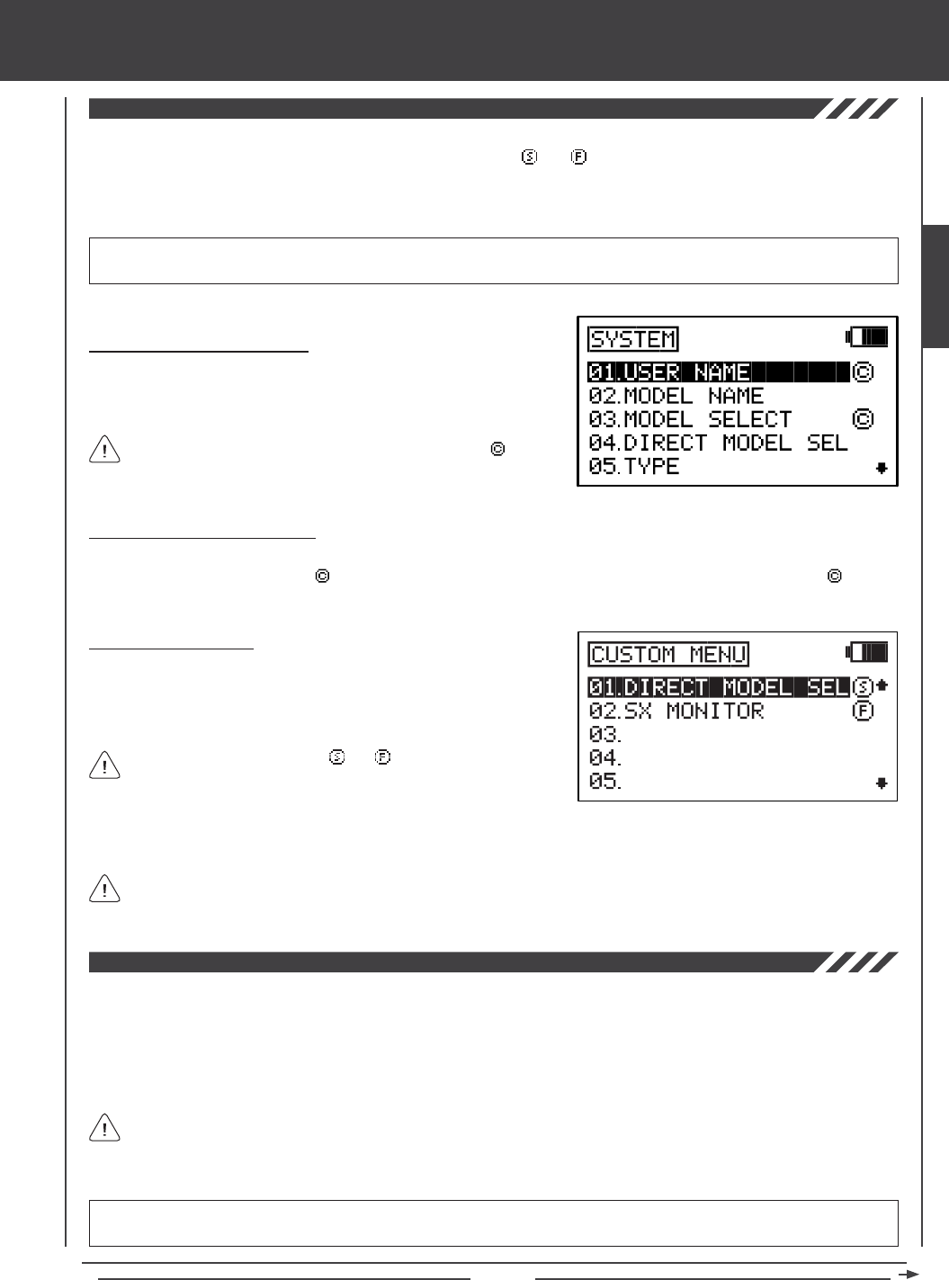
Page 59
Selections added to the Custom menu are denoted by a .
The Custom menu function allows you to store shortcuts to your most-used System menu and F-Mode menu selections. You
can store up to 10 menu shortcuts. Each shortcut is denoted with a or a to indicate which menu the shortcut belongs to -
either the System menu or the F-Mode menu, respectively. If desired, the Top Menu Arrange function can then be used to create
a shortcut to the Custom menu, providing you with a quick and easy way to access your most-used menu functions without the
need to scroll through the SYSTEM or F-MODE menus to access them.
SYSTEM MENU
Using the Custom Menu
1) Press the Navigation Pad 56 to highlight CUSTOM MENU, then press
the ENTER key to display the CUSTOM MENU menu. 01 will be
highlighted by default and Custom menu shortcuts that you added will
be displayed.
Adding Custom Menu Shortcuts
1) While navigating through either the System menu or the F-Mode menu,
pressing the YES/+ key when a menu selection is highlighted will add a
shortcut to that menu selection to the Custom menu.
Each shortcut is denoted with a or a to indicate which menu the
shortcut belongs to - either the System menu or the F-Mode menu,
respectively.
Deleting Custom Menu Shortcuts
1) While navigating through either the System menu or the F-Mode menu, highlight the System menu or the F-Mode menu
selection that is denoted with a , then press the YES/+ key to delete that shortcut from the Custom menu. The icon will
be removed, indicating that the menu selection shortcut will not be displayed in the Custom menu.
IMPORTANT Custom menu shortcuts are not added or removed directly from the Custom menu. They are added or removed
only from the System menu or the F-Mode menu. Sub-menus cannot be added to the Custom menu.
2) Press the Navigation Pad 56 to highlight the desired menu shortcut, then press the ENTER key to go directly to that menu.
If desired, the Top Menu Arrange function can then be used to create a shortcut to the Custom menu, providing you with a
quick and easy way to access your most-used menu functions without the need to scroll through the SYSTEM or F-MODE
menus to access them. For more information, see page 57.
The Memory Pack function allows you to utilize the Memory Expansion Card* which allows you to store up to 40 models (20 in
the SD-10G transmitter and 20 on the Memory Expansion Card). Use the Memory Pack function to Initialize either a new or a
previously used Memory Expansion Card, and to view a List of the models currently saved to the Memory Expansion Card. The
Memory Expansion Card can be removed and installed into a different SD-10G transmitter, so that model-specic programming
data can be shared with fellow SD-10G transmitter owners in the eld.
When the Memory Expansion Card is installed and Initialized, it is treated as an extension of the SD-10G transmitter's
internal model memory, therefore, model-specic programming data can be created, copied, deleted, etc., directly through
the various System menu selections. You do not need to enter the Memory Pack menu to make changes to models stored on
the Memory Expansion Card.
*Memory Expansion Card available separately. See your local Airtronics dealer for more information.
WARNING The SD-10G transmitter must be turned OFF when installing or removing the Memory Expansion Card. Failure to
do so can result in damage to the Memory Expansion Card and/or the SD-10G transmitter.
SYSTEM
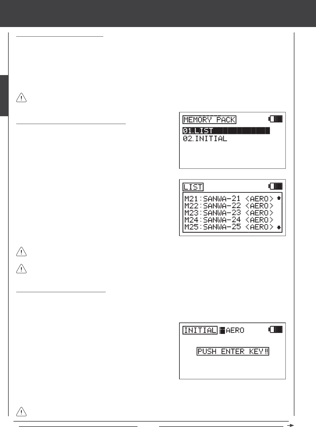
Page 60
SYSTEM MENU
Installing the Memory Expansion Card
1) Open the battery cover by rst pushing the two latches inward, then by pulling up on the bottom of the battery cover.
2) Carefully remove the plug that covers the Memory Expansion Card slot (adjacent to the battery connector) by rmly pulling it
up and out.
3) Make sure that the SD-10G transmitter is turned OFF, then carefully install the Memory Expansion Card, making sure that the tab
on the bottom of the Memory Expansion Card lines up with the groove in the Memory Expansion Card slot and that the mounting
pins line up with the pin receptacle. Gently push the Memory Expansion Card down into place and verify that it's fully seated.
3) Press the ENTER key to display the models currently stored on the
Memory Expansion Card. The Model Number, Model Name, and Model
Type (AERO, GLID, or HELI) will be displayed for each model.
The Memory Expansion Card stores up to 20 models. Models stored on the Memory Expansion Card are denoted with
an 'M'. Models stored on the Memory Expansion Card are numbered M21~M40.
If the Memory Expansion Card is not installed, or if it is not Initialized, PACK NOT READY? will be displayed. If this occurs,
press any key to return to the Memory Pack menu.
Initializing the Memory Expansion Card
After the Memory Expansion Card is installed, but before it can be used, it must be Initialized.
1) Turn the SD-10G transmitter ON, press the Navigation Pad 56 to highlight the System menu, then press the ENTER key.
If the Memory Expansion Card is brand new or if you want to reset the programming data of the models stored on the
Memory Expansion Card, see the Initializing the Memory Expansion Card section below.
2) Press the Navigation Pad 56 to highlight MEMORY PACK, then press
the ENTER key to display the MEMORY PACK menu. The LIST
sub-menu will be highlighted by default.
3) Press the Navigation Pad 6 to highlight INITIAL, then press the
ENTER key to display the INITIAL menu. The cursor will default to
INITIAL>HELI and PUSH ENTER KEY!! will be displayed.
4) Press the YES/+ or NO/- keys to choose which default Model Type you would like to Initialize the Memory Expansion Card
with. Choose from AERO, GLID, or HELI.
When Initialized, all 20 models will be of the same Model Type you chose to Initialize the Memory Expansion Card with.
Model Types can be changed after Initialization through the Model Select and Model Type menus.
Listing Contents of the Memory Expansion Card
1) Turn the SD-10G transmitter ON. Highlight the System menu, then
press the ENTER key.
2) Press the Navigation Pad 56 to highlight MEMORY PACK, then press
the ENTER key to display the MEMORY PACK menu. The LIST
sub-menu will be highlighted by default.
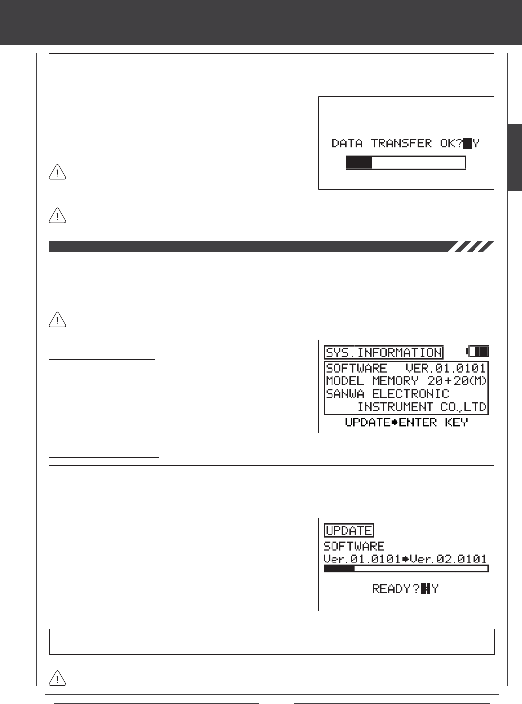
Page 61
SYSTEM MENU
If there is a problem with the Initialization procedure, for example, if the Memory Expansion Card is not installed, PACK
NOT READY? will be displayed. If this occurs, press any key to return to the Data Initial menu.
5) Press then ENTER key. DATA INITIAL OK?>Y will be displayed.
6) Press the YES/+ key to begin the Initialization process. When the
Initialization process is complete, COMPLETE! (20) MODEL will be
displayed. Press the END key twice to return to the MEMORY PACK
menu.
WARNING If there is already programming data stored on the Memory Expansion Card, Initializing the Memory Expansion
Card will erase all programming data and replace it with the default programming data of the Model Type you have chosen.
The System Information function allows you to view the current software version and the model memory capacity of your SD-10G
transmitter. It also allows you to update the SD-10G transmitter operating software via your PC* to ensure that you are always
running the latest software version.
*USB adapter cable required available separately. See your local Airtronics dealer for more information.
Viewing System Information
1) Press the Navigation Pad 56 to highlight SYS INFORMATION, then
press the ENTER key to display the SYS INFORMATION menu and
UPDATE4ENTER KEY will be displayed. This menu displays the
software version currently in use, and the current model memory
capacity, including model memory stored on the Memory Expansion
Card (if installed).
For information on obtaining software updates, please visit http://www.airtronics.net.
Updating Operating Software
1) From within the SYS INFORMATION menu, press the ENTER key.
READY?>Y will be displayed.
2) Press the YES/+ key. The current software version will be displayed
along with the updated software version.
3) To begin the Update process, press the YES/+ key. When the Update
process is completed the SYS INFORMATION menu will be displayed
and the SOFTWARE VER should display the software version you
updated to, indicating that the data has been transferred.
IMPORTANT Prior to updating the operating software, your PC must be turned ON, the Transfer Tool software must be
running, and the SD-10G transmitter must be connected to the PC using the USB adapter cable. One side of the USB adapter
cable plugs into a USB port on your PC and the other side plugs into the DIN connector on the back of the SD-10G transmitter.
IMPORTANT After completing the Update process, but before using the SD-10G transmitter, turn the SD-10G transmitter
OFF, then turn it back ON to verify the new software version number.
If there is a problem with the Update procedure, turn the SD-10G transmitter OFF, then turn it back ON and run the
Update procedure again.
The Initialization process will take several minutes. Ensure that
the transmitter battery is charged sufciently, and don't turn the
transmitter OFF during the Initialization process.
SYSTEM

Page 62
surface MENU CONTENTS
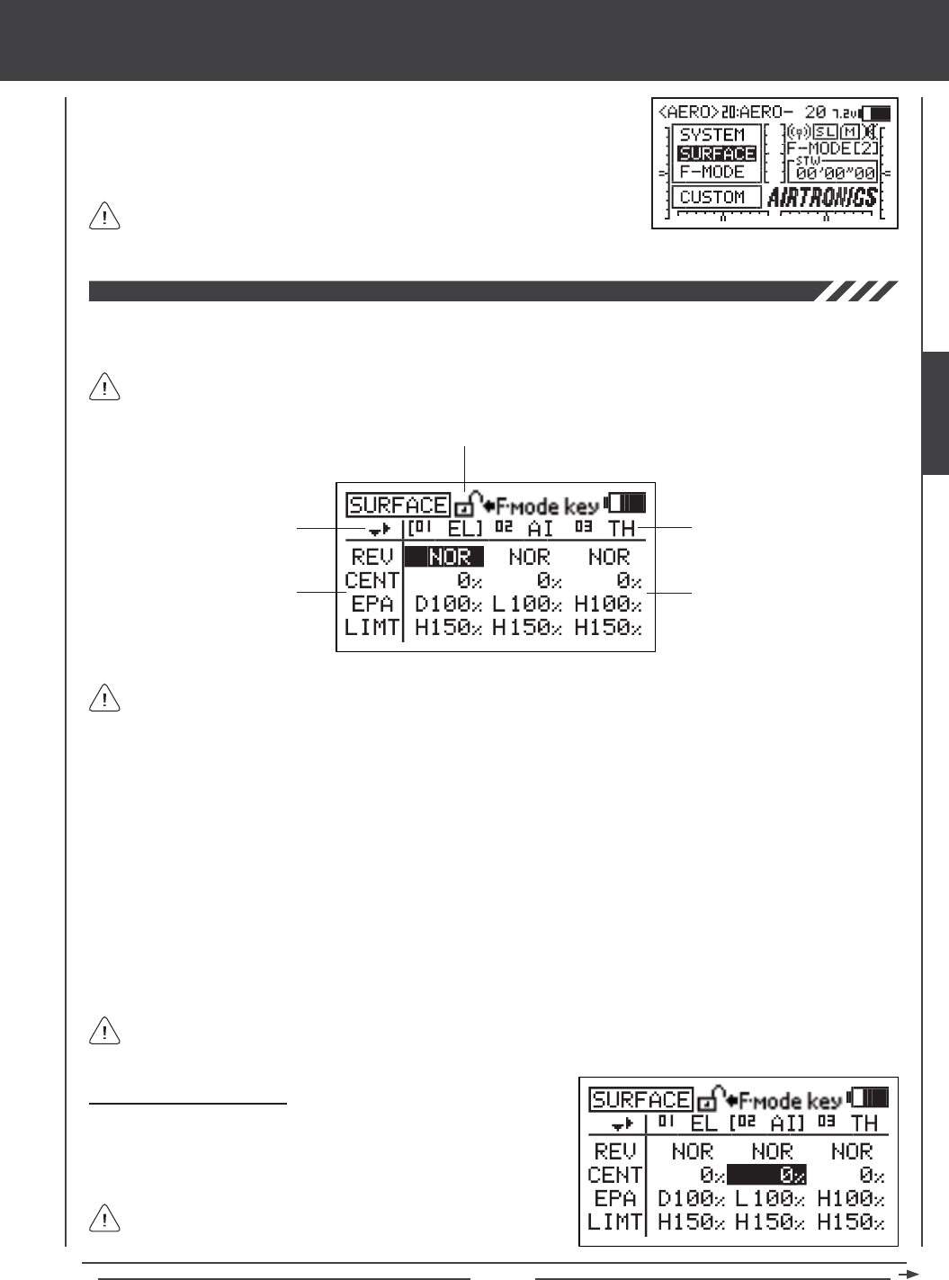
Page 63
surface MENU
The Surface menu is where all basic adjustments to the control surfaces of your model
are made. Adjustment Options include Reversing, Centering, End Point Adjustments,
Limits, and CCPM and Swashplate settings (HELI Model Type), in an easy-to-follow
spreadsheet format. Individual Adjustment Options can also be 'locked' to prevent
unwanted or accidental changes.
Surface menu Adjustment Options are the same for AERO, GLID, and HELI
Model Types. There are also several HELI Model Type-specic Adjustment
Options. These are noted in the section headers (HELI Model Type Only). Surface Menu
To access the Surface menu, turn the transmitter ON. From the Top menu, press the Navigation Pad 56 to highlight SURFACE,
then press the ENTER key to display the Surface menu.
If the Top menu is not displayed when you turn the transmitter ON, continuously press the END key until the Top menu
is displayed.
Directional Arrows Channel Assignments
Adjustment Options Adjustment Values
Adjustment Options Lock
Navigating the Surface Menu
1) Press the Navigation Pad 3456 to highlight the Adjustment Value
that you would like to change. For example, if you would like to change
the CENT (Centering) Adjustment Value for CH02 AI (Aileron), highlight
the Adjustment Value adjacent to CENT and below 02 AI.
As you scroll through the Surface menu, the Directional Arrows will
change, indicating which direction you can move the cursor.
Directional Arrows: Indicates in which direction you can navigate through the Surface menu using the Navigation Pad.
Adjustment Options: Indicates which control surface options can be adjusted. Adjustment Options vary based on the current
Model Type.
Adjustment Options Lock: Indicates if the individual Adjustment Options are either Locked or Unlocked. When the padlock
is Open (Unlocked), Adjustment Values for that specic Adjustment Option can be changed. When the padlock is Closed
(Locked), Adjustment Values for that specic Adjustment Option cannot be changed.
Channel Assignments: Indicates the actual channel/control surface that the Adjustment Values affect. Channel Assignments
vary based on the current Model Type, specic Model Type selection options, and Channel Assignment options.
Adjustment Values: Indicates the current values for each of the Channel Assignment Adjustment Options. Highlight a specic
Adjustment Value, then press the YES/+ or NO/- keys to change its value.
Adjustment Values can be changed for all Channel Assignments unless otherwise noted. If an Adjustment Value cannot
be changed, three dashes (---) will be displayed.
Unless otherwise noted, all programming changes take effect immediately. From within any menu, press the END key
continuously to return to the Top menu.
SURFACE
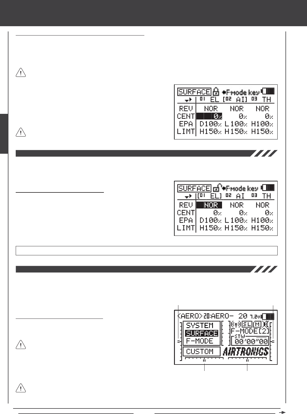
Page 64
Locking and Unlocking Surface Menu Adjustment Options
Individual Adjustment Options (REV, CENT, etc.), can be Locked to prevent unwanted or accidental changes to those specic
Adjustment Values. The current Locked/Unlocked state of each of the Adjustment Options is indicated by the padlock icon at
the top of the Surface menu. When the padlock is Open (Unlocked), Adjustment Values for that specic Adjustment Option can
be changed. When the padlock is Closed (Locked), Adjustment Values for that specic Adjustment Option cannot be changed.
1) Press the Navigation Pad 56 to highlight an Adjustment Value
adjacent to the Adjustment Option you would like to Lock. For example,
to Lock the CENT Adjustment Option, highlight the Adjustment Value
adjacent to CENT, then press the F-MODE key.
2) To Unlock the Adjustment Option, press the F-MODE key a second time.
In the default conguration, all Adjustment Options are Unlocked.
surface MENU
Individual Adjustment Options can be Locked or Unlocked separately. For example, you can Lock REV Adjustment
Options, but leave EPA Adjustment Options Unlocked.
The Reversing function electronically switches the direction of servo travel. For example, if you pull the elevator control stick
back for Up elevator, but your elevator moves Down, you can use the Reversing function to switch the direction of servo travel
to make the elevator move Up.
Changing Reversing Adjustment Values
1) Press the Navigation Pad 34 to highlight the REV Adjustment Value
for the channel that you would like to change.
2) Press the YES/+ or NO/- keys to change the REV Adjustment Value
to set the direction of servo travel, then change the desired remaining
REV Adjustment Values using the same techniques.
REV setting range is NOR/REV. The default setting is NOR.
The Centering function allows you to ne-tune the Center (Neutral) position of each servo. It's not unusual that when you install
the servo horn onto your servo that the servo horn is not perfectly centered. Centering allows you to center the servo horn perfectly.
Centering also makes it possible to keep the trim switches centered while ensuring that the servo horns remain centered. For
more information, see the Zeroing Out Trim section on the next page.
Changing Centering Adjustment Values
1) Before changing the CENT Adjustment Values, be sure to set the trim
switches to the center positions as displayed on the Top menu.
An audible tone is heard when the trim switches reach the center
position. This allows you to know when the trim switches reach the
center position without the need to look at the Trim Indicators on the
Top menu.
Trim 3
Trim 4
Trim 1
Trim 2
The SD-10G transmitter features Digital Trim Memory. Any amount of trim that you set during ight, using either the
trim switches or the YES/+ and NO/- keys from within the Trim menu, is automatically stored in memory for that specic
channel and model, and for that specic Flight Mode (if enabled). The Trim percentage values for each model will automatically
be loaded when the transmitter is turned ON and your model is selected. For more information, see page 89.
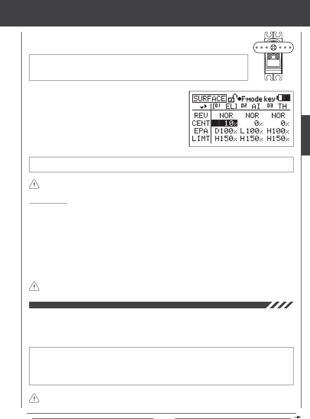
Page 65
surface MENU
2) Install the servo horn onto the servo, making sure that the servo horn is as close to being centered
as possible. In some cases you can get the servo arm closer to being centered by rotating the servo
arm 180º and reinstalling it.
3) Press the Navigation Pad 3456 to highlight the CENT Adjustment
Value for the channel that you would like to change.
4) Press the YES/+ or NO/- keys to change the CENT Adjustment Value.
5) Change the desired remaining CENT Adjustment Values using the same
techniques.
CENT setting range is -150% to 150%. The default setting is 0%. Increase or decrease the CENT Adjustment Values to center
the servo horn.
Zeroing Out Trim
Although trim switch settings are automatically stored in memory for each individual model, some users may wish to always keep
their trim switch settings at zero (centered) for all models. For example, after test-ying your model, if you have had to add trim
to make your model y straight and level, you can use the Centering function to add that amount of trim back into the servo(s),
then move the trim switches back to center. This ensures that your trim switches are always centered.
1) After ying your model, check your model's control surfaces to see how much trim was necessary to achieve straight and
level ight.
2) From within the Surface menu, highlight the CENT Adjustment Value for the channel you need to add Centering trim to.
3) Recenter the trim switch, then change the CENT Adjustment Value until the control surface is in the same position it was prior
to recentering the trim switch.
The End Point Adjustment function allows you to adjust servo travel in each direction. This makes it possible to balance control
surface throw in both directions. For example, if you want your elevator to move Up and Down two inches in each direction, but
the elevator moves Down more than two inches, decrease the End Point Adjustment in the Down direction, so that the elevator
moves Up and Down the same amount. Another example is with ailerons. If your aircraft rolls faster to the right than to the left,
increase the End Point Adjustment in the Left direction until the aircraft rolls the same speed in both directions.
IMPORTANT End Point Adjustment is not the same as Limits and should not be used in the same manner as Limits.
Whereas Limits will Limit the maximum servo travel in either direction, End Point Adjustment does not. End Point Adjustment
is designed to balance the control throw on both sides of servo travel and can be overridden by other settings, such as Dual
Rate. For example, if you have your End Point Adjustment set to 100%, and you set your Dual Rate to 150%, the servo will
travel more than 100% when Dual Rate is ON, however, if you have your Limits set to 100%, the servo will travel only 100%,
regardless of the End Point Adjustment setting or the Dual Rate setting.
When changing End Point Adjustments for HELI Model Types that use CCPM, changing the End Point Adjustment value on
one channel, for example, pitch, affects all the cyclic servos (due to CCPM). If you need to make End Point Adjustments to
individual servos without affecting the other cyclic servos, use the CEPA function. For more information, see page 67.
IMPORTANT It is always recommended to install the servo horn as close to being centered as
possible, prior to changing the CENT Adjustment Values. After you change the CENT Adjustment Values
to center the servo horn, only then should you manually adjust the control linkage to center the control
surface.
The SD-10G transmitter utilizes Parallel Trim Technology. This allows you to change the CENT Adjustment Values to
center the servo horn and still maintain full servo travel (up to 150%) in each direction.
In the default conguration, the same trim settings are stored across all Flight Modes. This option can be changed to
allow you to store different trim settings for each individual Flight Mode. For more information, see page 89.
SURFACE
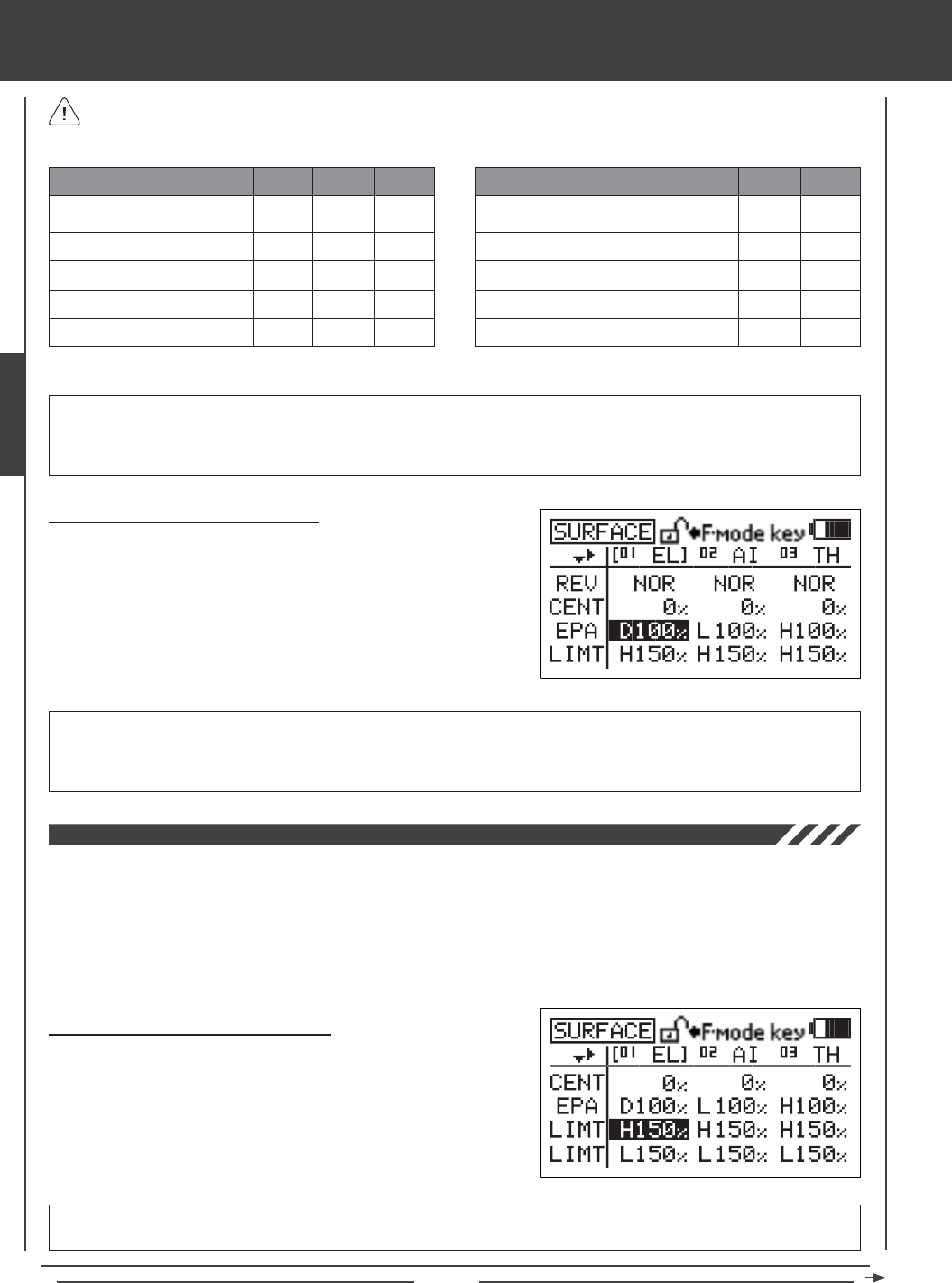
Page 66
The Limits function allows you to set a hard limit for servo travel in each direction (H - High or L - Low). This means that
regardless of the End Point Adjustment, Dual Rate, and/or Mixing Adjustment Values programmed, the servo will never rotate past
the specied Limits. Limits should be used to Limit the maximum required physical travel of the servo in each direction, so that the
servo can never rotate further than intended. For example, if when you set up your model the elevator control linkage binds when
full elevator control is commanded, use the Limits function to decrease the servo travel and prevent binding. Another example
is with the use of aps and a mixing function that utilizes aps. Under no circumstances would you want the aps to move up. In
this situation, you can use the Limits function to set the ap Up servo travel to zero. With this setting there would be no way for
the aps to move up since the servo travel Limit in that direction is zero.
LIMT H setting range is 0% to 150%. The default setting is 150%. Increasing the LIMT H Adjustment Value increases the servo
travel High-side Limit and decreasing the LIMT H Adjustment Value decreases the servo travel High-side Limit.
Changing Limit Adjustment Values - High
1) Press the Navigation Pad 3456 to highlight the LIMT H Adjustment
Value for the channel that you would like to change.
2) Press the YES/+ or NO/- keys to change the LIMT H Adjustment Value.
3) Adjust the desired remaining LMT H Adjustment Values using the same
techniques.
surface MENU
The tables below show the End Point Adjustment travel direction options for the Default channel for each Model Type.
Channels will vary based on current Model Type and specic Model Type selection options. End Point Adjustment values
for the Flap channel and the Auxiliary channels can be set individually for all three Switch Positions.
CH01
CH02
CH03
CH04
CH05
U/D
L/R
L*/H
R/L
L*/H
DEFAULT CHANNEL AERO GLID HELI
U/D
L/R
L*/H
R/L
L*/H
U/D
L/R
L*/H
L/R
---
CH06
CH07
CH08
CH09
CH10
N/1/2
L*/N/H
L*/N/H
L*/N/H
L*/N/H
DEFAULT CHANNEL AERO GLID HELI
L/R
N/1/2
L*/N/H
L*/N/H
L*/N/H
L*/H
---
L*/N/H
L*/N/H
L*/N/H
U/D = Up/Down L/R = Left/Right L*/H = Low/High R/L = Right/Left N/1/2 = Neutral/Position 1/Position 2 L*/N/H = Low/Neutral/High
Changing End Point Adjustment Values
1) Press the Navigation Pad 3456 to highlight the EPA Adjustment
Value for the channel that you would like to change.
2) Move the control stick or switch in the direction of servo travel you would
like to change the EPA Adjustment Value for, then press the YES/+ or
NO/- keys to change the EPA Adjustment Value.
3) Adjust the desired remaining EPA Adjustment Values using the same
techniques.
EPA setting range for the primary ight controls is 0% to 150%. The default setting is 100%. EPA setting range for Flaps and
Auxiliary channels is -150% to 150%. The default setting range varies based on current Model Type and specic Model
Type selection options, and the positions of the Flap and Auxiliary channel switches. Increasing the EPA Adjustment Value
increases servo travel and decreasing the EPA Adjustment Value decreases servo travel.
IMPORTANT In front of each EPA Adjustment Value is a specic icon. To set the EPA Adjustment Value for the desired
direction of servo travel, the control stick or switch must be moved in the direction of servo travel you want to change the EPA
Adjustment Value for. For example, if you want to change the EPA Adjustment Value for Down elevator, push the elevator
control stick forward, then release it. 'D' will be displayed in front of the EL EPA Adjustment Value.
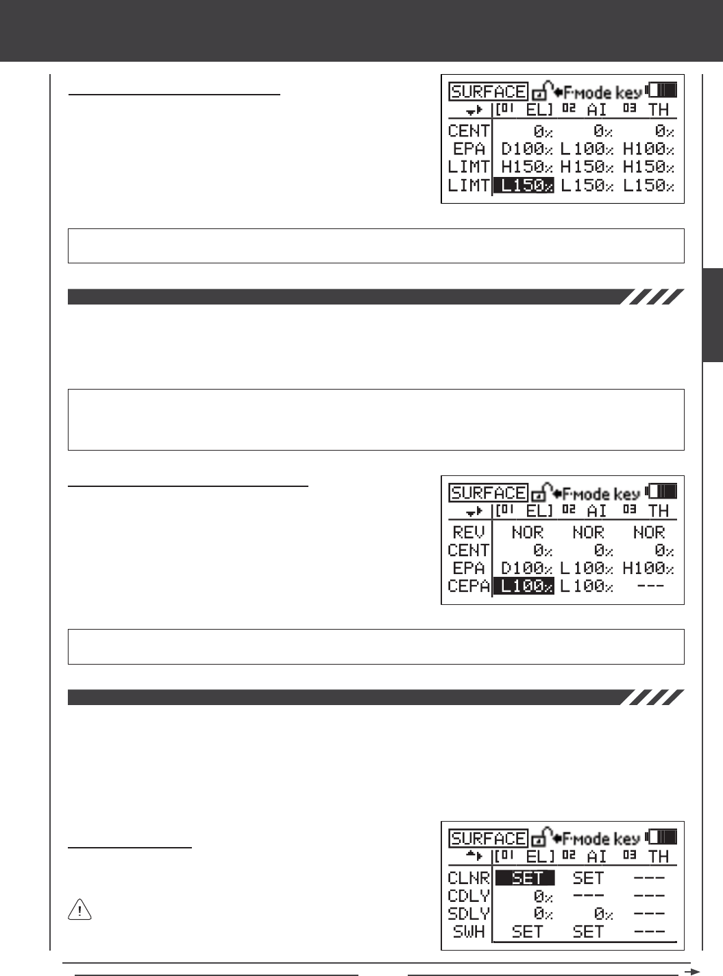
Page 67
surface MENU
LIMT L setting range is 0% to 150%. The default setting is 150%. Increasing the LIMT L Adjustment Value increases the servo
Low-side travel Limit and decreasing the LIMT L Adjustment Value decreases the servo Low-side travel Limit.
Changing Limit Adjustment Values - Low
1) Press the Navigation Pad 3456 to highlight the LIMT L Adjustment
Value for the channel that you would like to change.
2) Press the YES/+ or NO/- keys to change the LIMT L Adjustment Value.
3) Adjust the desired remaining LMT L Adjustment Value using the same
techniques.
The CCPM End Point Adjustment function allows you to adjust servo travel in each direction for the elevator, aileron, and pitch
servos independently. Unlike standard End Point Adjustment, which affects all the cyclic servos, CCPM End Point Adjustment
allows you to adjust each cyclic servo independently without any affect on the other cyclic servos. For example, you can
change the End Point Adjustment on the pitch servo without affecting the elevator or the aileron servos. This allows for the
utmost control is setting up your swashplate for the most accurate movement.
Changing CCPM End Point Adjustment Values
1) Press the Navigation Pad 3456 to highlight the CEPA Adjustment
Value for the channel that you would like to change.
2) Move the throttle control stick in the direction of servo travel you would
like to change the CEPA Adjustment Value for, then press the YES/+ or
NO/- keys to change the CEPA Adjustment Value.
3) Adjust the desired remaining CEPA Adjustment Values using the same
techniques.
IMPORTANT In front of each CEPA Adjustment Value is a specic H or L icon (High or Low, respectively). To set the CEPA
Adjustment Value for the desired direction of servo travel, the throttle control stick must be moved in the direction of servo travel
you want to change the CEPA Adjustment Value for. For example, if you want to change the CEPA Adjustment Value for the
High side Elevator, push the throttle control stick all the way forward. 'H' will be displayed in front of the EL CEPA Adjustment Value.
CEPA setting range is 0% to 150%. The default setting is 100%. Increasing the CEPA Adjustment Value increases servo
travel and decreasing the CEPA Adjustment Value decreases servo travel.
The CCPM Servo Linear function converts the rotary output of the servo(s) to a Linear approximation and helps correct any
abnormal cyclic movement caused by off-center control arms when at full positive or negative End Points and allows you to
adjust the overall Rates for the elevator, aileron, and pitch servos independently. For example, if you were to take a measurement
of the cyclic when the servos are at their neutral positions and you moved the ailerons from right to left, you may see the cyclic
move 15º right and 15º left. Now move the cyclic up to full pitch and make the same measurements. The cyclic may no longer
move 15º right and 15º left. The CCPM Servo Linear function can be used to set the cyclic at 15º when at full pitch while ensuring
adequate servo travel.
Setting Channel Offsets
1) Press the Navigation Pad 3456 to highlight the CLNR SET option
for either the elevator, the aileron, or the pitch channel.
CLNR values can be changed for the elevator, aileron, and pitch
channels at the same time, regardless of which CLNR SET option
you highlight.
SURFACE
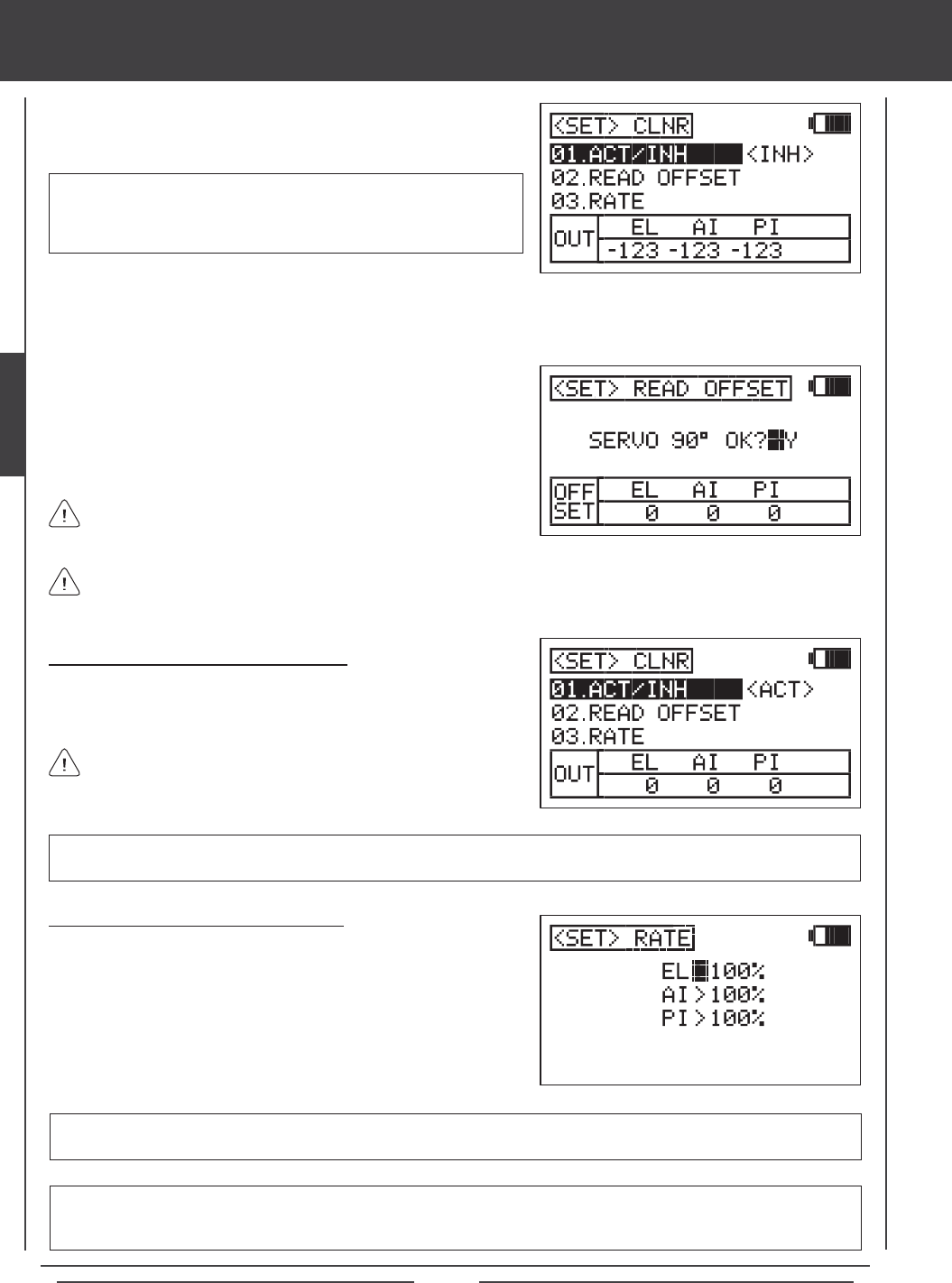
Page 68
surface MENU
4) Press the Navigation Pad 6 to highlight READ OFFSET, then press the
ENTER key to display the <SET>READ OFFSET menu. SERVO
90º OK?>Y will be displayed.
5) Press the YES/+ key to verify the OFFSET value, then press the END
key to return to the <SET>CLNR menu.
IMPORTANT Prior to starting to use the Read Offset function below,
the elevator, aileron, and pitch servos MUST be centered (servo arms
set to 90º) and the Servo Reversing settings should be made, using the
CENT and REV functions.
If you press the YES/+ key and values are displayed other than zero, the control sticks are not centered. This is usually
caused by the throttle control stick not being centered. If this occurs, move the throttle control stick slightly toward center,
then press the YES/+ key again. Repeat as necessary until all OFFSET values read zero.
Activating the CCPM Servo Linear Function
1) After verifying that the READ OFFSET values are all zero, press the
Navigation Pad 5 to highlight ACT/INH, then press the YES/+ key to
change the value to <ACT> (Activated).
You MUST set the Channel Offsets prior to Activating the CCPM
Servo Linear function. If you don't and you attempt to change the
Rates, the CCPM Servo Linear function will always revert to INH (Inhibited).
Changing Channel Rate Adjustment Values
The Rate settings are used to ne-tune the swashplate and make it as
close to level as possible throughout the entire pitch range.
1) Press the Navigation Pad 56 to highlight the channel you would like to
change the RATE Adjustment Value for, then press the YES/+ or NO/-
keys to change the RATE Adjustment Value.
2) Adjust the desired remaining RATE Adjustment Values using the same
techniques.
EL, AI, and PI setting range is 0% to 120%. The default setting is 100%. Increasing the RATE Adjustment Value increases servo
travel and decreasing the RATE Adjustment Value decreases servo travel. Do NOT adjust more than 20% in either direction.
2) Press the ENTER key to display the <SET>CLNR menu. ACT/INH will
be highlighted and <INH> (Inhibited) will be selected by default.
When using either CP4A or CP4X Swashplate Types, EL2 values will
be displayed in addition to the EL, AI, and PI values.
3) Move both control sticks to the center (neutral) position. The center position is veried using the OUT display at the bottom of
the <SET>CLNR menu. When both control sticks are centered all values will read zero. With the control sticks centered, the
servo arms should be centered, as described above.
IMPORTANT Do NOT change the CENT Adjustment Values after Activating the CCPM Servo Linear function. CENT
Adjustment Values should be made prior to Activating the CCPM Servo Linear function.
IMPORTANT When the CCPM Linear function is Activated, cyclic servo travel is compressed as a result of changing the
output from rotary to Linear. If when you change the Rate Adjustment Values the control throws are still not enough, you can
increase the control throws as necessary by increasing the End Point Adjustments or the SWH Adjustment Values.
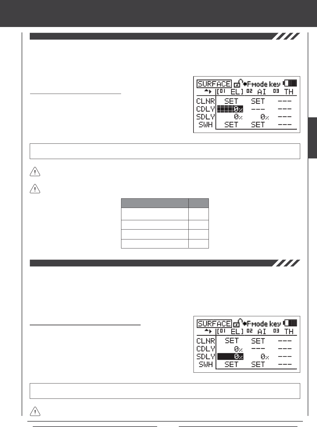
Page 69
surface MENU
The CP3 Delay function allows you to slow down the two forward channels when using CCPM. For example, on some helicopters,
when using CCPM you will nd that the elevator is a little more sensitive than the ailerons. You can use the CP3 Delay function
to slow down the two forward channels to ne-tune the feel of the swashplate controls. The goal is to adjust elevator control to
feel the same as aileron control and vice-versa depending on the Swashplate Type selected.
CDLY setting range is 0% to 100%. The default setting is 0%. Increasing the CDLY Adjustment Value slows down the two
forward channels and decreasing the CDLY Adjustment Value returns the two forward channels toward their normal speed.
Changing CP3 Delay Adjustment Values
1) Press the Navigation Pad 3456 to highlight the CDLY Adjustment
Value for the channel that you would like to change.
2) Press the YES/+ or NO/- keys to change the CDLY Adjustment Value.
The CP3 Delay function can be adjusted on the Swashplate Types and the Channels shown in the table below.
CP3F
CP3B
CP3R
CP3L
EL
EL
AI
AI
SWASHPLATE TYPE CH
The CCPM Servo Delay function allows you to adjust the speed of the elevator, aileron, and pitch servos independently. Even
though the servos may be of the same type, not all servos operate at the same exact speed. If one or more servos controlling
the swashplate is operating faster than another servo, this can cause swashplate geometry issues and even result in binding of
the swashplate linkage assemblies. For example, adjusting the CCPM Servo Delay to slow down the faster servo(s) to match the
slower servo(s) helps to ne-tune the swashplate, ensuring the most accurate and smoothest movement as possible throughout
the entire deection range. If desired, you could slow down each of the servos the same percentage to slow the overall feel of
the swashplate controls.
Changing CCPM Servo Delay Adjustment Values
1) Press the Navigation Pad 3456 to highlight the SDLY Adjustment
Value for the channel that you would like to change.
2) Press the YES/+ or NO/- keys to change the SDLY Adjustment Value.
3) Adjust the desired remaining SDLY Adjustment Values using the same
techniques.
SDLY setting range is 0% to 100%. The default setting is 0%. Increasing the SDLY Adjustment Value slows down the servo in
both directions and decreasing the SDLY Adjustment Value speeds up the servo in both directions.
When the SDLY Adjustment Value is set to 0%, the servo will operate at is normal speed.
When the CDLY Adjustment Value is set to 0%, the two forward channels will operate at their normal speed.
SURFACE
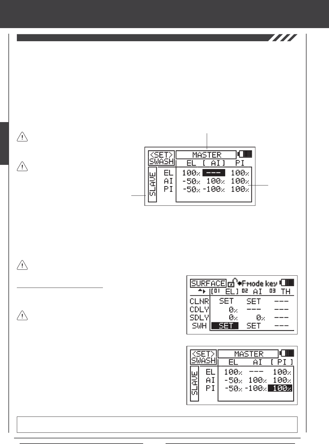
Page 70
surface MENU
The Swash function allows you to control a number of different functions related to the swashplate. Using the Swash function, you
are able to reverse individual elevator, aileron, and pitch functions. For example, even if you select the correct Swashplate Type
for your particular helicopter there may be a situation where instead of the swashplate rising for positive collective it may be
necessary for the swashplate to fall for positive collective. Instead of 'fooling' the swashplate by selecting the opposite Swashplate
Type and swapping the aileron and pitch channels in the receiver, then adjusting the servo Reversing, the Swash function
allows you simply reverse the pitch function by changing PI Master/PI Slave Adjustment Value opposite to what is displayed
(e.g., change 100% to -100% to change the direction of travel for the pitch function). In addition, the Swash function also allows
you to control the overall throw of the elevator, aileron, and pitch functions by increasing or decreasing the Adjustment Values.
The Swash function also allows you to mix elevator, aileron, and pitch functions together without the need to use a separate
mixer. For example, if you do a loop and the helicopter wants to roll out in one direction or another, you can change the Mixing
Adjustment Values of the Elevator Master to the Aileron Slave at either the low or the high collective stick to trim out this tendency.
When using either CP4A or CP4X Swashplate Types, EL2 Slave values will be displayed in addition to the EL, AI,
and PI values.
The <SET>SWASH menu consists of a row of MASTER functions along the top and a column of SLAVE functions along the left
side. In all cases, the MASTER function controls the SLAVE function. For example, if you want to increase the servo travel of the
aileron function when the throttle control stick is moved forward, increase the PI MASTER/AI SLAVE Adjustment Value.
If you want to change the rotation of servo travel for a function, for example, the pitch function, highlight PI MASTER/PI SLAVE
and change the Adjustment Value to the opposite of the current Adjustment Option Value (e.g., 100% to -100%).
SLAVE Functions
Adjustment
Values
MASTER Functions
2) Press the ENTER key to display the <SET>SWASH menu. The cursor
will default to EL MASTER/EL SLAVE.
3) Press the Navigation Pad 3456 to highlight the Adjustment Value
you would like to change, then press the YES/+ or NO/- keys to change
the Adjustment Value.
4) Adjust the desired remaining <SET>SWASH menu Adjustment Values
using the same techniques.
<SET>SWASH menu setting range varies based on Swashplate Type currently selection. To display the default Adjustment
Values, highlight a specic Adjustment Value and press the YES/+ and NO/- keys at the same time.
Changing Swash Adjustment Values
1) Press the Navigation Pad 3456 to highlight the SWASH SET option
for either the elevator, aileron, or pitch channel.
SWH values can be changed for the elevator, aileron, and pitch
channels at the same time, regardless of which SWASH SET option
you highlight.
Depending on your model's specic setup, it may
be necessary to decrease the Adjustment Value
to keep from over-driving the servos.
In the default conguration, the <SET>SWASH
menu displays the default Adjustment Value for
the current Swashplate Type.
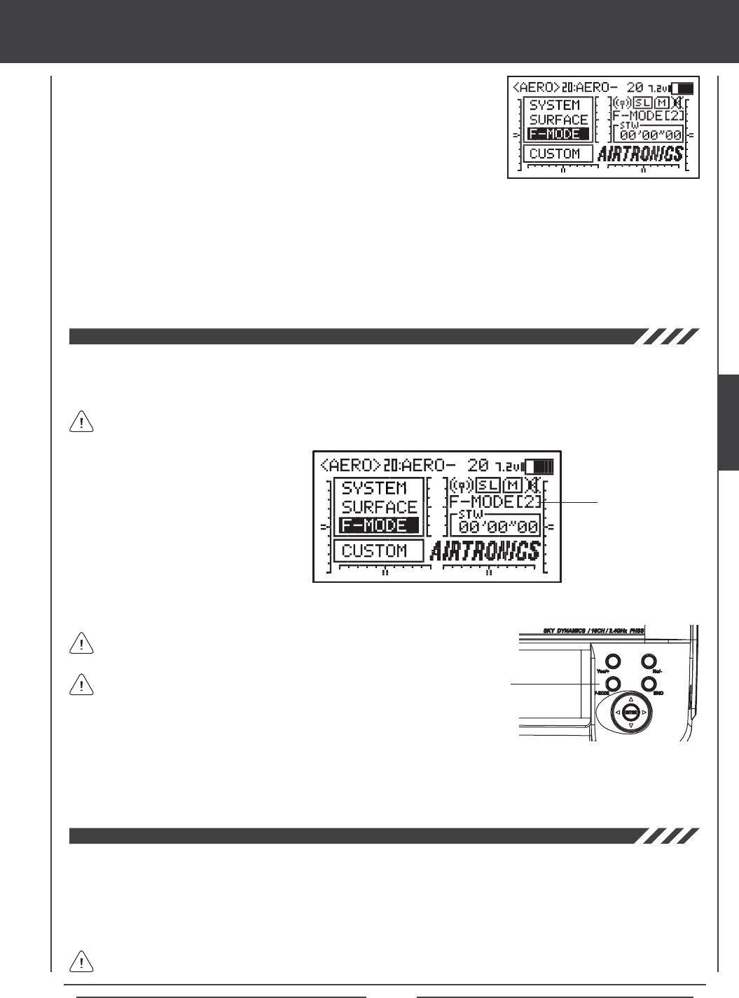
Page 71
Flight Modes
The SD-10G transmitter model programming is based around Flight Modes. Each
Model Type (AERO, GLID, and HELI) feature ve independently programmable Flight
Modes. Within these Flight Modes is where the core of the model programming takes
place. Features such as Dual Rate, Exponential, Throttle Curves, Pitch Curves, Mixing,
Compensation Mixing, and much more can be individually programmed to each of the
ve ight Modes. Each Flight Mode can then be assigned to a switch position so that
they can be turned ON and OFF during ight. Flight Modes can also be named to keep
easier track of them, and Flight Modes can be copied to make programming multiple
Flight Modes quicker.
There are ve Flight Modes that can be individually programmed for each Model Type. The current Flight Mode (N, 1, 2, 3, or 4)
is displayed on the Top menu. The currently Active Flight Mode name is displayed, along with the corresponding Flight Mode
number. If the Flight Mode has not been named, F-MODE will be displayed, along with the corresponding Flight Mode number.
Flight Mode Display
The SD-10G transmitter is equipped with a safety feature that will not allow you to use the transmitter if the Flight Mode is not set
to 'N' (Normal) when you turn the transmitter ON. If the Flight Mode is not set to 'N' when you turn the transmitter ON, the Flight
Mode Warning alarm will sound continuously, the red RF Output Indicator will blink, and the LCD Display will read F-MODE
NOT 'N' !! To clear the Flight Mode Warning, set the Flight Mode to 'N' using the Flight Mode Switch (this is different from the
F-MODE Key). The LCD Display will read normally, the Flight Mode Warning alarm will cease, and both the red and green RF
Output Indicators will be illuminated.
In the default AERO conguration, Flight Mode N (Normal) is switch position 10. In the default HELI conguration, Flight
Mode N (Normal) is switch position 22. In the default GLID conguration, the Flight Mode Warning alarm is INHIBITED.
Flight Modes are turned ON and OFF using
switches, or in the case of the GLID Flight
Mode, switches and the ap control stick.
These switches, along with the default control
layout for each of three Model Types are
described in each Model Type Flight Mode
programming section.
There is always one Flight Mode active at all times and will vary based on the positions of the Flight Mode switches.
F-MODE Key
Flight Mode programming instructions are separated by Model Type as follows: AERO - Pages 72 through 112,
GLID - Pages 112 through 155, and HELI - Pages 156 through 194.
The F-MODE key is used to facilitate programming the individual
Flight Modes only and does not turn the Flight Modes ON or OFF.
Many Flight Mode programming options can be agged either COM (Common) or SEP (Separate). Options agged as Common
are common among all Flight Modes. Options agged as Separate can be programmed separately for each Flight Mode from the
same programming menu.
F-MODE Menu
Flight Modes allow you to change the ying characteristics of your model with the ip of a switch. For example, if you y
helicopters, you can have one Flight Mode for basic ying and a second Flight Mode for aerobatic ying. Flip the Flight Mode
switch from 'Basic' to 'Aerobatic' and your helicopter is now programmed with all of your 'Aerobatic' Flight Mode programming. With
ve programmable Flight Modes available for each Model Type, the combinations of model programming is almost limitless.
When assigning and using multiple Flight Modes to more than one
switch, it's important to note that higher numbered Flight Modes
override lower numbered Flight Modes. For example, if you have Flight
Mode 1 and Flight Mode 2 Active at the same time, Flight Mode 2 will
override Flight Mode 1.
FLIGHT MODES

Page 72
aero Flight Mode Contents
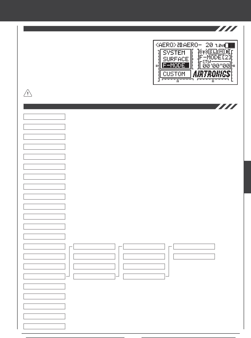
Page 73
aero Flight Mode Menu
04.EXP
03.D/R
02.STICK MONITOR
01.SX MONITOR
05.TH-CURVE
06.TH-HOLD
07.TH-CUT
08.IDLE DOWN
09.AI DIFFERENTIAL
10.OFFSET
11.CH DELAY
12.TRIM
13.TRIM STEP
14.TRIM AUTH
15.CROSS-TRIM
16.SNAP-ROLL
17.MIXING
18.C-MIX
19.VR ASSIGN
20.F-MODE COPY
21.F-MODE DELAY
22.F-MODE NAME
6
6
6
6
6
6
6
6
6
6
6
6
6
6
6
6
6
6
6
6
6
06.TH>RU
07.RU>EL
08.RU>AI
09.RU>TH
10.FL>EL
6
6
6
01.FLAPERON
02.AILVATOR
03.EL>FL
04.AI>RU
05.TH>EL
6
6
6
6
6
To access the F-Mode menu, turn the transmitter ON. From the Top menu,
press the Navigation Pad 56 to highlight F-MODE, then press the ENTER
key to display the F-Mode menu.
From within any menu, press the END key continuously to return to the
Top menu.
Unless otherwise noted, all programming changes take effect immediately.
If the Top menu is not displayed when you turn the transmitter ON, continuously press the END key until the Top menu
is displayed.
6
6
Use this Flow Chart to familiarize yourself with the AERO Flight Mode menu structure. Descriptions
regarding all AERO Flight Mode menu functions and programming are found on pages 74
through 112.
AERO
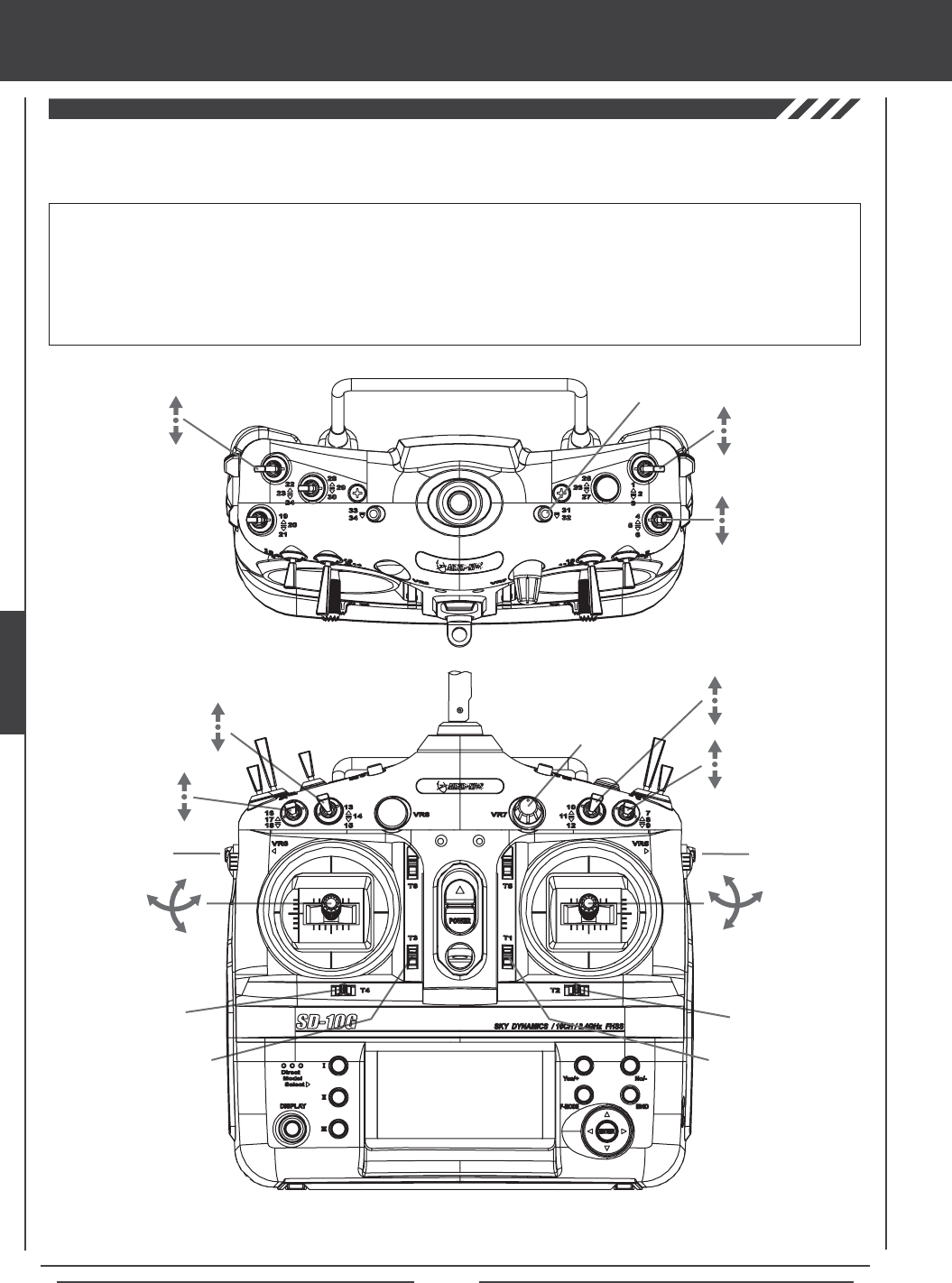
Page 74
The diagrams below show the default transmitter control stick and switch layout in the AERO Model Type Flight Mode N (Normal)
conguration. This is the base from which you can start to change or add functions to switch assignments, modify Flight Modes, and
change or assign functions or channels to the Auxiliary Levers (VR5 and VR6) and the Auxiliary Dial (VR7).
Throttle Trim Switch
Rudder Trim Switch
Rudder
Control Stick
Throttle
Control Stick
Elevator Dual
Rate 1,2,3
Flap N,1,2
Flight
Mode N,1,2
Aileron Dual
Rate 1,2,3
Aileron
Control Stick
Elevator
Control Stick
Aileron Trim Switch
Elevator Trim Switch
Gear Auxiliary 3L
Auxiliary 3H
Rudder Dual
Rate 1,2,3
Auxiliary
Lever (VR6)*
Flap 1 Trim
Auxiliary
Dial (VR7)
AUX1
Auxiliary
Lever (VR5)
AUX2
*Auxiliary Lever (VR6) controls the Variable Flap Trim when the flap switch is in Switch Position 1. For more information,
see page 91.
IMPORTANT Since each of the ve Flight Modes can be programmed separately, before making programming changes,
verify that you are in the Flight Mode you want to make programming changes to. To avoid confusion, we suggest leaving the
Flight Mode Switch (10,11,12) in the N (Normal) position and use the F-MODE key from within the programming menus to
choose which Flight Mode you would like to make programming changes to.
Keep in mind that many of the functions, particularly Mixes and Auxiliary functions, MUST be assigned to a Switch Position
Number to be Activated. We suggest that you assign the function to a Switch Position Number prior to programming the
function. This will avoid confusion and make it easier to test your programming values.
aero Flight Mode menu
Throttle Cut
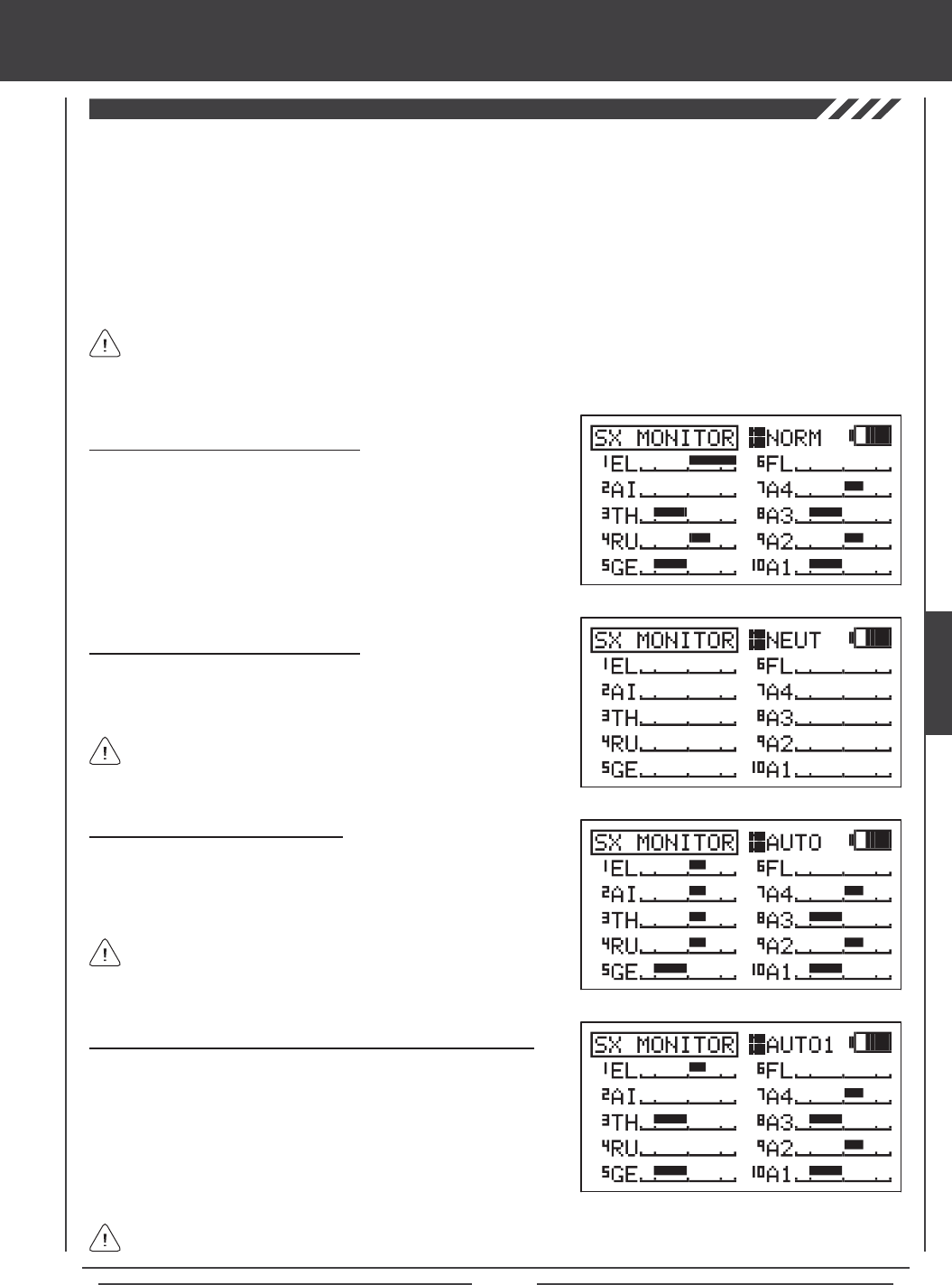
Page 75
The Servo Monitor function displays the output levels of each of the 10 channels in bar graph form, allowing you to monitor servo
operation in a virtual manner. This is helpful to see servo movement when the control sticks and switches are moved, and it allows
you to visualize what is occurring with servo movements when you apply different mixing values. When used in conjunction with
the Display key, the Servo Monitor function allows you to see servo movement virtually and make programming changes without
the SD-10G transmitter actually transmitting a signal.
When both the SD-10G transmitter and the receiver are turned ON, the Servo Monitor function has the ability to continuously
cycle the primary ight control servos back and forth to verify operation. You are also able to individually cycle any of the primary
ight control servos and check the Neutral position of each of the servos (or automatically center all of the servos).
Using the Servo Monitor - Normal Mode
1) Press the Navigation Pad 56 to highlight SX MONITOR, then press
the ENTER key to display the SX MONITOR menu. The cursor will
default to >NORM.
2) Moving the control sticks and channel switches (if assigned) will display
the position and movement of each of the servos.
Using the Servo Monitor - Neutral Mode
1) Press the YES/+ key to choose >NEUT. When set to NEUT, all servos
will move to the Neutral position until you either change the Servo
Monitor Mode or exit the Servo Monitor menu.
While in Neutral Mode, all ight controls are Inhibited.
Using the Servo Monitor - Auto1, Auto2, Auto3, and Auto4 Modes
1) Press the YES/+ key to choose >AUTO1. When set to AUTO1,
the elevator servo(s) will cycle back and forth equally until you either
change the Servo Monitor Mode or exit the Servo Monitor menu.
2) Press the YES/+ key again to choose >AUTO2 and so on. AUTO2 will
cycle the aileron servo(s), AUTO3 will cycle the throttle servo(s), and
AUTO4 will cycle the rudder servo.
The ight control for the currently Active servo will be Inhibited, however, the remaining channels remain Active so that
you can continue using them.
The channels displayed will vary based on Model Type and Model Type selection options currently selected. For example,
if your model features dual elevator servos, LE and RE will be displayed and both servos will move when the AUTO1
option is used. Depending on the current servo reversing settings, the bar graphs may not move the same direction as the control
sticks. This is normal.
aero Flight Mode Menu
Using the Servo Monitor - Auto Mode
1) Press the YES/+ key to choose >AUTO. When set to AUTO, the
primary ight control servos will cycle back and forth at the same time,
until you either change the Servo Monitor Mode or exit the Servo Monitor
menu.
While in Auto Mode, the primary flight controls are Inhibited,
however, the remaining channels remain Active so that you can
continue using them.
AERO
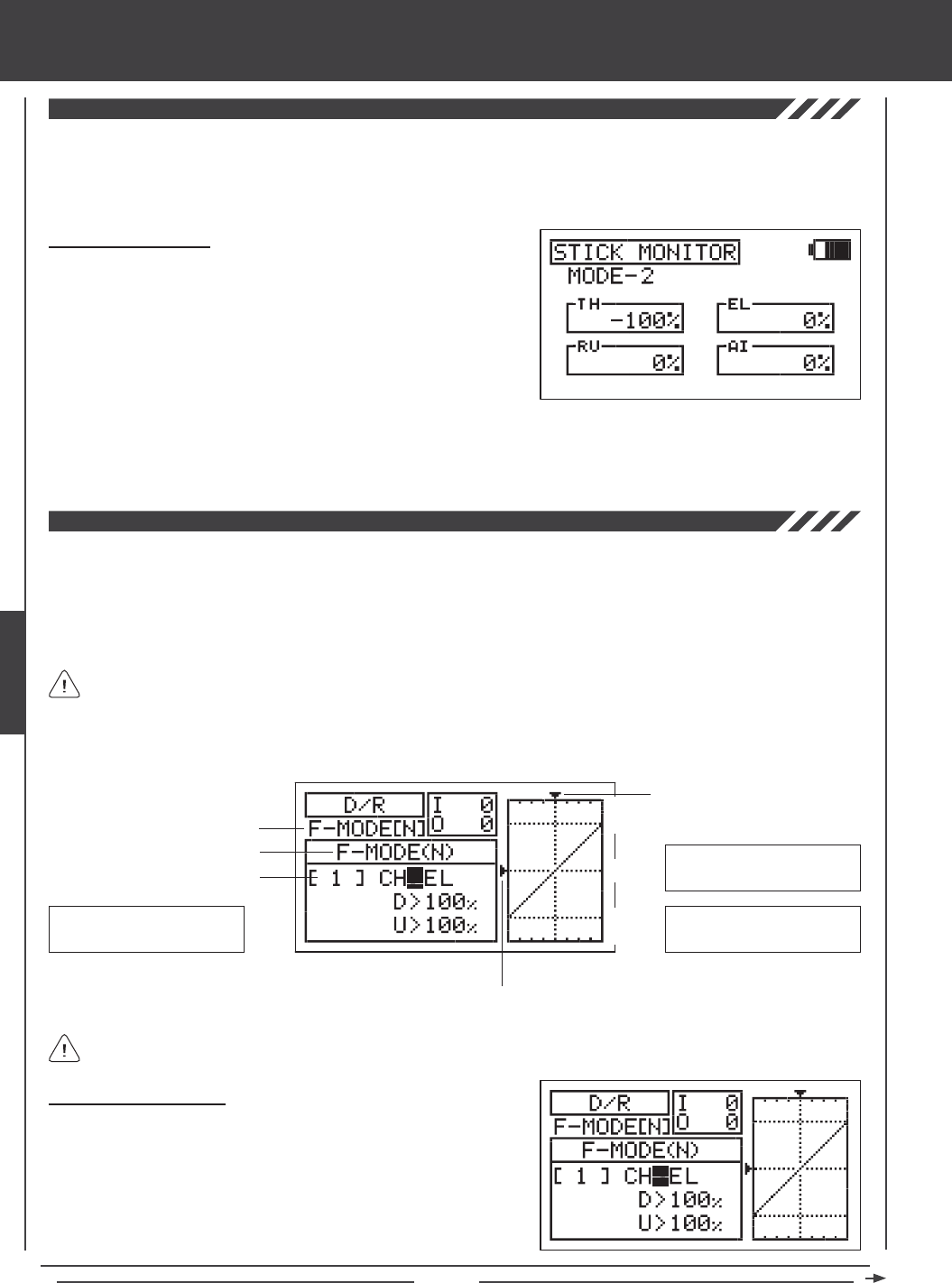
Page 76
The Stick Monitor function displays the current position of the control sticks as a percentage of total control stick movement in 1%
increments, and is used to determine if the control sticks require calibration. For example, if you move the throttle control stick all
the way forward and 95% is displayed, this indicates that the throttle control stick requires calibration. In addition, the Stick Monitor
function allows you to visually check exactly what position the control sticks are in relative to the control surface you're setting up.
Using the Stick Monitor
1) Press the Navigation Pad 56 to highlight STICK MONITOR, then
press the ENTER key to display the STICK MONITOR menu. The
current Mode that the SD-10G transmitter is operating in will be displayed.
2) Move the control sticks and watch the percentage displays. When the
control sticks are centered, 0% should be displayed, and when the
control sticks are moved to their stops, -100% or 100% should be
displayed, based on the direction of movement.
3) If 0% is not displayed when the control sticks are centered, or if -100% and 100% are not displayed when the control sticks
are moved to their stops, use the NEUTRAL/TRAVEL>USER setting in the System Mode menu to recalibrate the control sticks.
For more information, see page 43.
The Dual Rate function allows you to change the control authority of the control surfaces by changing the amount of servo
travel. For example, if you are ying an aerobatic aircraft that requires a lot of control throw for aerobatics, but that same amount
of control throw makes the aircraft difcult to control during normal ight, you can use Dual Rate to lower the control throw for
normal ight with just the ip of the Dual Rate switch. Three Dual Rate settings are available each for the Elevator, Aileron, and
Rudder channels, and different Dual Rate settings can be programmed separately for each of the ve Flight Modes. An Input
and Output display, along with a graph, help with programming visualization.
Dual Rate is a percentage of End Point Adjustment. For example, if you set Dual Rate 2 to 50% and Activate it, the servo
will travel half the amount than if Dual Rate 2 was not Active. Prior to takeoff, check the position of the Dual Rate switches
to ensure that they are in the positions you want. If you assign two different channel Dual Rates to more than one switch, it's
important to note that the higher numbered Dual Rate will override the lower numbered Dual Rates. For example, if you have
Dual Rate 2 and Dual Rate 3 Active at the same time, Dual Rate 3 will override Dual Rate 2.
Choosing the Flight Mode
1) Press the Navigation Pad 56 to highlight D/R, then press the ENTER
key to display the D/R menu. The cursor will default to CH>EL.
2) Press the F-MODE key to choose the F-MODE number you would like
to program the Dual Rate function for. Choose from N, 1, 2, 3, or 4. The
F-MODE (N) display will change, indicating which Flight Mode you are
programming the Dual Rate function for.
Transmitter F-MODE
Dual Rate Number
aero Flight Mode menu
Programming F-MODE
Stick Input (I)
Servo Output (O)
Transmitter F-MODE refers to the Flight Mode that the transmitter is currently operating in. Programming F-MODE refers
to the Flight Mode that you would like to change the programming for.
150%
100%
100%
150%
0%
EL-D/R Default Switch
Position Numbers: 16,17,18
AI-D/R Default Switch
Position Numbers: 07,08,09
RU-D/R Default Switch
Position Numbers: 04,05,06
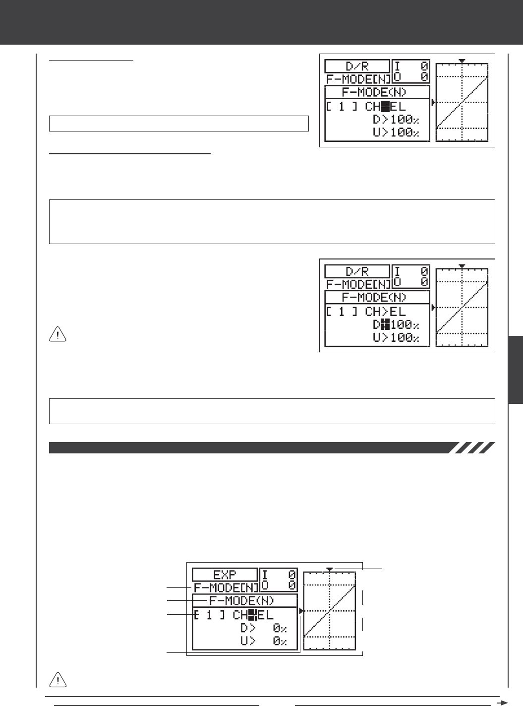
Page 77
aero Flight Mode Menu
Choosing the Channel
1) Press the Navigation Pad 56 to highlight CH>EL.
2) If you would like to set the Dual Rate for another channel, press the
YES/+ or NO/- keys to choose CH>AI or CH>RU.
Changing the Dual Rate Percentage Values
Three different Dual Rate settings can be programmed to each three-position switch. We recommend that Dual Rate 1 be set to
the maximum control surface throw you desire, then set Dual Rate 2 and Dual Rate 3 to different values that are less than
maximum. For example, set Dual Rate 1 to 100%, Dual Rate 2 to 75%, and Dual Rate 3 to 50%.
3) Press the Navigation Pad 6 to move the cursor to U>100% (R>100% if setting aileron or rudder Dual Rate), then press the
YES/+ or NO/- keys to set the desired Up (or Right) Dual Rate percentage value.
WARNING Keep in mind that it's possible to set the Dual Rate higher than the End Point Adjustment. For example,
with the End Point Adjustment set to 100% and the Dual Rate set to 150% the servo will move more than 100% when
the Dual Rate is Activated. We strongly recommend that you set the Dual Rate 1 percentage value to no more than
100%. This will prevent any chance of exceeding your End Point Adjustment and overdriving your control linkage.
As you change the Dual Rate percentage values, you can use the
graph and I/O numbers to visualize the ratio between control stick
movement and servo travel throughout the entire deection range.
D/R setting range is 0% to 150%. The default setting is 100%. Increasing the D/R percentage value increases servo travel
when Dual Rate is Activated. Decreasing the D/R percentage value decreases servo travel when Dual Rate is Activated.
1) Move the Dual Rate Switch for the channel you are setting to the position
you would like to set a Dual Rate percentage value for, either 1, 2, or 3.
2) Press the Navigation Pad 6 to move the cursor to D>100% (L>100% if
setting aileron or rudder Dual Rate), then press the YES/+ or NO/- keys
to set the desired Down (or Left) Dual Rate percentage value.
The Exponential function allows you to vary the amount of servo travel in relation to the movement of the elevator, aileron, and
rudder control sticks near the neutral positions to change the way the control surfaces react to control stick movement. Increasing
the Exponential value will soften the control feel around neutral and decreasing the Exponential value will heighten the control
feel around neutral. For example, using a positive Exponential value allows for smoother control by lessening the amount of
servo travel in relation to the amount of control stick movement. Using a negative Exponential value may result in more 'twitchy'
control response because the amount of servo travel will be increased in relation to the amount of control stick movement. The
Exponential function is linked directly to your Dual Rate switches. This allows you to program Exponential for each of the three
Dual Rate positions separately. In addition, Exponential can be programmed separately for each of the ve Flight Modes. An
Input and Output display, along with a graph, help with programming visualization.
Transmitter F-MODE
Dual Rate Number
Programming F-MODE
Stick Input (I)
Function Output (O)
150%
100%
100%
150%
0%
Dual Rate can be set for EL (Elevator), AI (Aileron), and RU (Rudder).
Transmitter F-MODE refers to the Flight Mode that the transmitter is currently operating in. Programming F-MODE refers
to the Flight Mode that you would like to change the programming for.
AERO
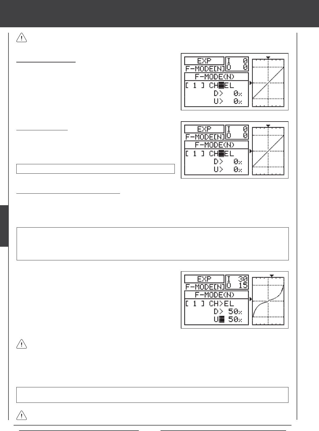
Page 78
Choosing the Flight Mode
1) Press the Navigation Pad 56 to highlight EXP, then press the ENTER
key to display the EXP menu. The cursor will default to CH>EL.
2) Press the F-MODE key to choose the F-MODE number you would like to
program the Exponential function for. Choose from N, 1, 2, 3, or 4. The
F-MODE (N) display will change, indicating which Flight Mode you are
programming the Exponential function for.
Choosing the Channel
1) Press the Navigation Pad 56 to highlight CH>EL.
2) If you would like to set the Exponential for another channel, press the
YES/+ or NO/- keys to choose CH>AI or CH>RU.
Exponential can be set for EL (Elevator), AI (Aileron), and RU (Rudder).
Changing the Exponential Percentage Values
The Exponential function is linked directly to your Dual Rate switches. This allows you to program Exponential for each of the
three Dual Rate positions separately. For example, with the Dual Rate switch in position 1 (maximum travel), you can set 30%
Exponential, with the Dual Rate switch in position 2, you can set 10% Exponential, and with the Dual Rate switch in position 3,
you can set 0% Exponential (Linear).
4) Press the Navigation Pad 6 to move the cursor to U>0% (R>0% if setting aileron or rudder Exponential), then press the
YES/+ or NO/- keys to set the desired Up (or Right) Exponential percentage value.
As you change the Exponential percentage values, you can use the graph and I/O numbers to visualize the ratio between
control stick movement and servo travel throughout the entire deection range. Notice that as you increase Exponential,
the servo travel is decreased near the neutral position in relation to control stick movement, and as you decrease Exponential, the
servo travel is increased near the neutral position in relation to control stick movement.
EXP setting range is -100% to 100%. The default setting is 0% (Linear). Increasing the EXP percentage value softens the
control feel around neutral. Decreasing the EXP percentage value heightens the control feel around neutral.
1) Move the Dual Rate Switch for the channel you are setting to the
position you would like to set an Exponential percentage value for,
either 1, 2, or 3.
2) Press the Navigation Pad 6 to move the cursor to D>0% (L>0% if
setting aileron or rudder Exponential).
3) Press the YES/+ or NO/- keys to set the desired Down (or Left)
Exponential percentage value.
WARNING If you have not used Exponential functions in the past, we suggest that you start with a small percentage
of Exponential (approximately 10%~20%) until you get used to the feel of how Exponential affects the control feel of
your model. You will find that Exponential is most useful where strong control response is desired at extreme control
stick positions, but softer control response to small control stick movements is desired in order to make very accurate
small corrections to the flight path.
When the Exponential value is set to 0%, the ratio between servo travel and control stick movement will be Linear. For
example, when you move the control stick 50%, the servo will travel 50%, too.
Exponential does not change the total amount of servo travel at maximum control stick deection. Exponential affects
the ratio between servo travel and control stick movement at less than 100% control stick deection.
aero Flight Mode menu
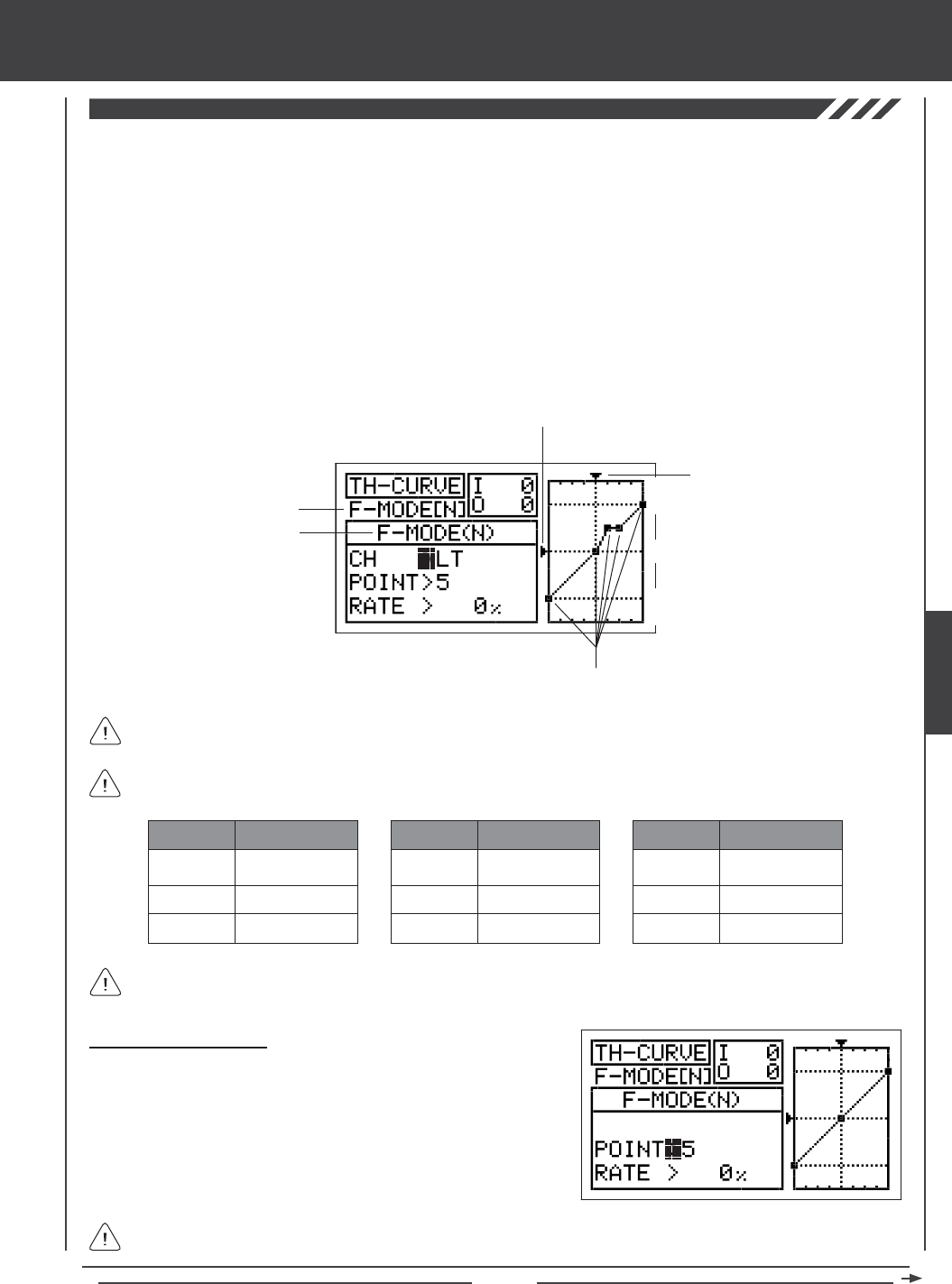
Page 79
aero Flight Mode Menu
The Throttle Curve function allows you to vary the amount of servo travel in relation to the movement of the throttle control stick
at different points throughout the entire range of deection. Nine custom-programmable Points ensure an extremely precise
Throttle Curve to suit any situation. For example, many glow and gas engines are very non-Linear, meaning that when the throttle
control stick is at half, the engine is not at half power. In addition, many times the difference between three-quarter power and
full power is almost indistinguishable. By adjusting the Throttle Curve, you can change the way the engine reacts to power based
on the position of the throttle control stick. For example, you can change the Throttle Curve so that three-quarter stick feels like
three-quarter throttle.
The Throttle Curve function is also extremely useful when setting up a twin-engine aircraft. In a twin-engine aircraft, it can
be difcult to achieve the exact same throttle response for both engines. The SD-10G transmitter allows you adjust the Throttle
Curve for the Right and Left engines separately. For example, you can change the Throttle Curve on one engine to match the
response of the other engine, from idle all the way to full throttle.
The Throttle Curve function can be programmed separately for each of the ve Flight Modes. An Input and Output display,
along with a graph, help with programming visualization.
Transmitter F-MODE
Programming F-MODE
Stick Input (I)
Function Output (O)
150%
100%
100%
150%
0%
Point Positions
Transmitter F-MODE refers to the Flight Mode that the transmitter is currently operating in. Programming F-MODE refers
to the Flight Mode that you would like to change the programming for.
Choosing the Flight Mode
1) Press the Navigation Pad 56 to highlight TH-CURVE, then press the
ENTER key to display the TH-CURVE menu. The cursor will default to
POINT>5.
2) Press the F-MODE key to choose the F-MODE number you would like
to program the Throttle Curve function for. Choose from N, 1, 2, 3, or 4.
The F-MODE (N) display will change, indicating which Flight Mode you
are programming the Throttle Curve function for.
When Model Type Setting Option THROTTLE>2 is chosen, the cursor will default to CH>LT
The tables below show the default Point and Rate values. Settings shown in parentheses are the default percentage
values when those Points are Activated by the user.
1
2
3
-100%
INH (-75%)
INH (-50%)
POINT DEFAULT RATE
7
8
9
INH (50%)
INH (75%)
100%
POINT DEFAULT RATE
4
5
6
INH (-25%)
0%
INH (25%)
POINT DEFAULT RATE
In the default conguration the Throttle Curve is Linear. For example, when you move the throttle control stick from 0% to
100%, the servo will travel from 0% to 100%, too.
AERO
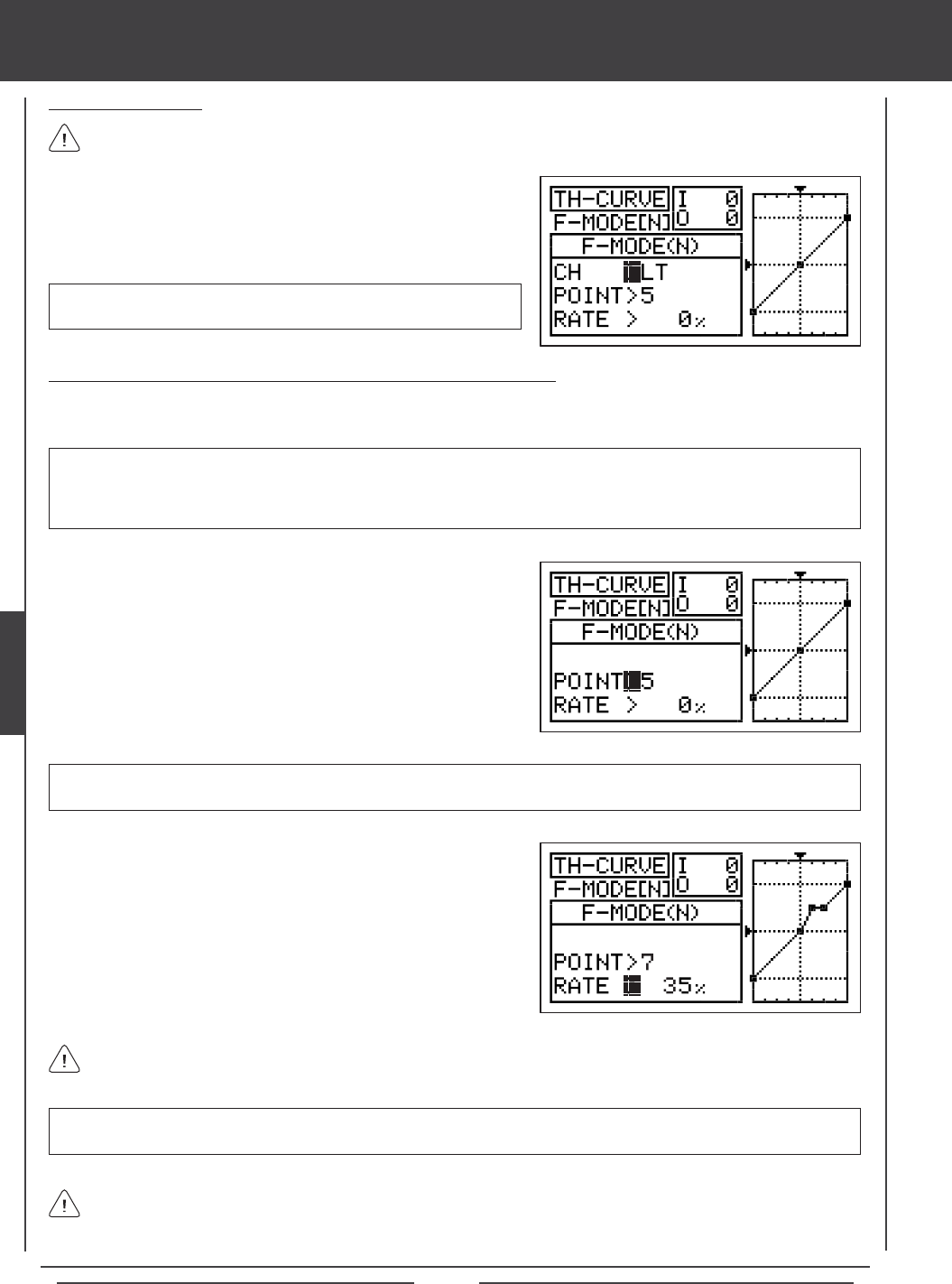
Page 80
Changing the Throttle Curve Point Values and the Rate Percentage Values
Nine different Points with varying Rates can be programmed onto the Throttle Curve. Each Point will be displayed on the graph to
give you a visual interpretation of the position of the Point on the Throttle Curve. The Point that is currently selected will blink.
WARNING Keep in mind that it's possible to set the Throttle Curve Points higher or lower than the throttle End Point
Adjustment. For example, with the throttle End Point Adjustment set to 100% and POINT>9 set to 150% the servo will move
150%. We strongly recommend that you set your Throttle Curve Points no higher than your throttle End Point Adjustment unless
specically necessary for your particular setup. This will prevent any chance of overdriving your control linkage.
Choosing the Channel
When Model Type Setting Option THROTTLE>2 is chosen, the Throttle
Curve can be set for LT (Left Throttle) and RT (Right Throttle).
This option is only available when Model Type Setting Option THROTTLE>2 is chosen. Unless you are setting up a
multi-engine aircraft, skip to the Setting Throttle Curve Point and Rate section below.
1) Press the Navigation Pad 56 to highlight CH>LT.
2) If you would like to set the Throttle Curve for the Right Throttle, press
the YES/+ or NO/- keys to choose CH>RT.
aero Flight Mode menu
As you change the Point and Rate percentage values, you can use the graph and I/O numbers to visualize the ratio
between control stick movement and servo travel throughout the entire deection range.
RATE setting range is -150% to 150%. POINT 1 default RATE percentage value is -100%, POINT 5 default RATE percentage
value is 0%, POINT 9 default RATE percentage value is 100%.
3) Press the Navigation Pad 6 to highlight RATE>.
4) Press the YES/+ or NO/- keys to set the desired Rate percentage value.
1) Press the Navigation Pad 56 to highlight POINT>5.
2) Press the YES/+ or NO/- keys to choose which Point you would like to
set a Rate percentage value for.
POINT setting range is 1 through 9. Point 1 is at the low end of the Throttle Curve and Point 9 is at the high end of the Throttle
Curve. Point 5 is a the center of the Throttle Curve.
5) Repeat the previous procedures to change the desired remaining Point and Rate percentage values.
When you change the Rate percentage value for Points 2, 3, 4, 6, 7, and 8, INH will be displayed. When you press the
YES/+ or NO/- keys, INH will change to the default percentage value (e.g., POINT>4 RATE -25%).
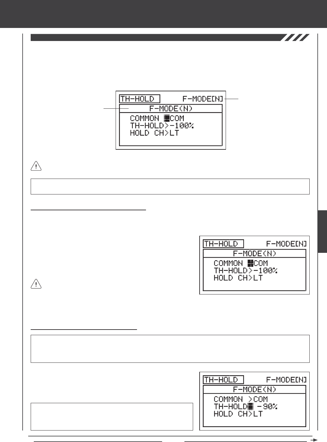
Page 81
aero Flight Mode Menu
The Throttle Hold function allows you to set a specic position that the throttle servo will Hold and not respond to the throttle
control stick. This function is typically used when ying twin-engine aircraft. The SD-10G transmitter allows you program Throttle
Hold for the Right or the Left engine separately. For example, you can set Throttle Hold at idle for the right engine. After starting
and tuning the right engine, you can use the Throttle Hold function to Hold the right engine at idle while you start, warm-up,
and tune the second engine. The Throttle Hold function can be programmed separately for each of the ve Flight Modes or you
can use the same Throttle Hold programming across all ve Flight Modes.
Transmitter F-MODE
Programming F-MODE
Transmitter F-MODE refers to the Flight Mode that the transmitter is currently operating in. Programming F-MODE refers
to the Flight Mode that you would like to change the programming for.
IMPORTANT TH-HOLD must be assigned to a Switch Position Number before it can be Activated. For more information,
see page 45.
Choosing the Flight Mode - Common or Separate
When set to COM (Common), the TH-HOLD setting will be the same regardless of which Flight Mode the transmitter is
operating in. You cannot program TH-HOLD settings separately for each Flight Mode. When set to SEP (Separate), you can
program TH-HOLD separately for each Flight Mode.
3) Press the F-MODE key to choose the F-MODE number you would like to program the Throttle Hold function for. Choose from N, 1,
2, 3, or 4. The F-MODE (N) display will change, indicating which Flight Mode you are programming the Throttle Hold function for.
Changing the Throttle Hold Percentage Value
1) Press the Navigation Pad 6 to highlight TH-HOLD>-100%.
2) Press the YES/+ or NO/- keys to set the position you would like the
throttle servo to Hold at when TH-HOLD is Activated.
WARNING Keep in mind that it's possible to set the Throttle Hold lower than the throttle End Point Adjustment. For example,
with the throttle End Point Adjustment set to -100% and the Throttle Hold set to -150% the servo will move -150% when the
Throttle Hold is Activated. We strongly recommend that you set your Throttle Hold no lower than your throttle End Point Adjustment
unless specically necessary for your particular setup. This will prevent any chance of overdriving your control linkage.
TH-HOLD setting range is -150% to 0%. The default setting is -100%.
Increasing the TH-HOLD percentage value will increase the position at
which the throttle servo will Hold at and decreasing the TH-HOLD percentage
value will decrease the position at which the throttle servo will Hold at.
1) Press the Navigation Pad 56 to highlight TH-HOLD, then press the
ENTER key to display the TH-HOLD menu. The cursor will default to
COMMON>COM.
2) Press the YES/+ or NO/- keys to choose either COM or SEP.
If set to COM, skip to the Setting the Throttle Hold percentage value
below. If set to SEP, see step 3 below.
AERO
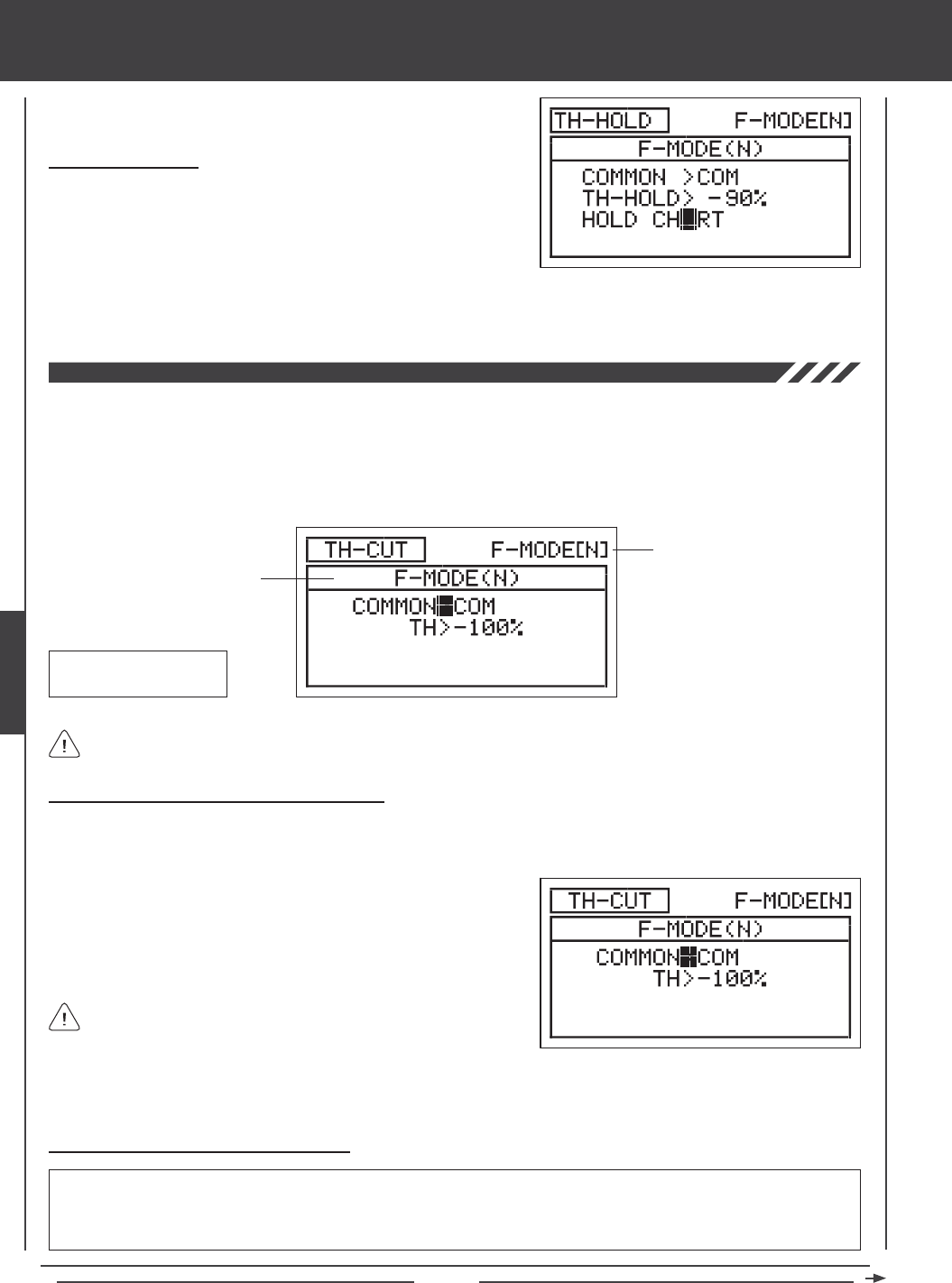
Page 82
aero Flight Mode menu
The Throttle Cut function allows you to set a specic position that the throttle servo will move to. The Throttle Cut function is primarily
used to shut down your engine after ight. For example, if your engine idles when the throttle control stick is at the -100% position,
you can set the Throttle Cut to -120% to shut down your engine when the Throttle Cut function is Activated. The SD-10G
transmitter allows you to program the Throttle Cut percentage values for the Right and the Left engines independently to take
into account any differences between throttle linkages. The Throttle Cut function can be programmed separately for each of the
ve Flight Modes or you can use the same Throttle Cut programming across all ve Flight Modes.
Transmitter F-MODE
Programming F-MODE
Transmitter F-MODE refers to the Flight Mode that the transmitter is currently operating in. Programming F-MODE refers
to the Flight Mode that you would like to change the programming for.
TH-CUT Default Switch
Position Number: 32
Choosing the Flight Mode - Common or Separate
When set to COM (Common), the TH-CUT setting will be the same regardless of which Flight Mode the transmitter is operating in.
You cannot program TH-CUT settings separately for each Flight Mode. When set to SEP (Separate), you can program TH-CUT
separately for each Flight Mode.
3) Press the F-MODE key to choose the F-MODE number you would like to program the Throttle Cut function for. Choose from N, 1,
2, 3, or 4. The F-MODE (N) display will change, indicating which Flight Mode you are programming the Throttle Cut function for.
1) Press the Navigation Pad 56 to highlight TH-CUT, then press the
ENTER key to display the TH-CUT menu. The cursor will default to
COMMON>COM.
2) Press the YES/+ or NO/- keys to choose either COM or SEP.
Changing the Throttle Cut Percentage Value
WARNING Keep in mind that it's possible to set the Throttle Cut lower than the throttle End Point Adjustment. For example,
with the throttle End Point Adjustment set to -100% and the Throttle Cut set to -150% the servo will move -150% when the
Throttle Cut is Activated. We strongly recommend that you set your Throttle Cut no lower than your throttle End Point Adjustment
unless specically necessary for your particular setup. This will prevent any chance of overdriving your control linkage.
If set to COM, skip to the Setting the Throttle Cut percentage value
below. If set to SEP, see step 3 below.
2) Press the YES/+ or NO/- keys to choose which throttle you would like the Throttle Hold function to control, either LT (Left
Throttle) or RT (Right Throttle).
Choosing the Throttle
1) If you have programmed Model Type Setting Option THROTTLE>2,
press the Navigation Pad 6 to highlight HOLD CH>LT.
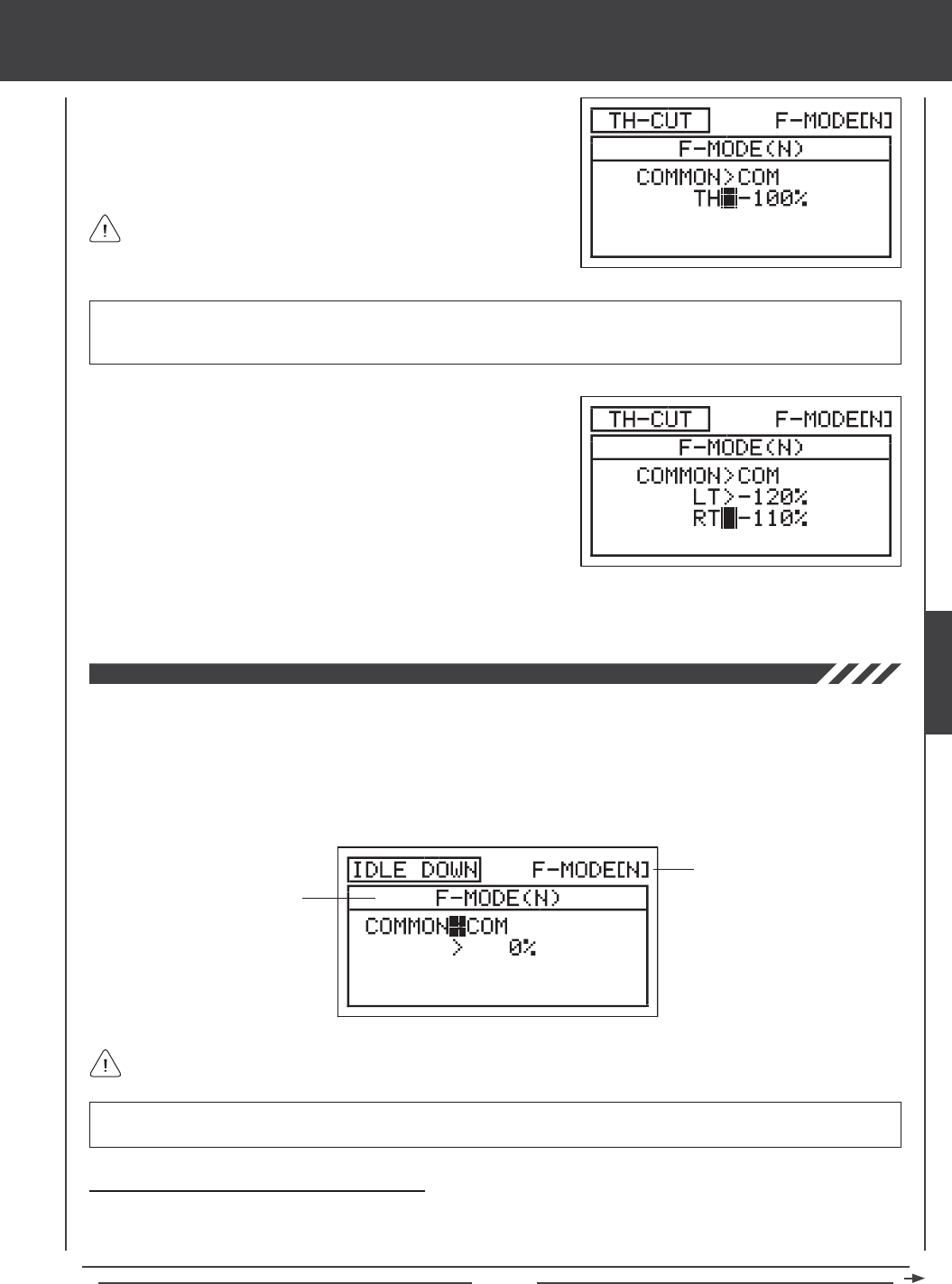
Page 83
aero Flight Mode Menu
1) Press the Navigation Pad 6 to highlight TH>-100%.
2) Press the YES/+ or NO/- keys to set the position you would like the
throttle servo to move to when TH-CUT is Activated.
TH-CUT setting range is -150% to 0%. The default setting is -100%. Increasing the TH-CUT percentage value will increase
the position that the throttle servo is moved to and decreasing the TH-CUT percentage value will decrease the position that the
throttle servo is moved to.
3) If you have programmed Model Type Setting Option THROTTLE>2
press the Navigation Pad 6 to highlight LT>-100%.
4) Press the YES/+ or NO/- keys to set the position you would like the Left
throttle servo to move to when TH-CUT is Activated.
The Idle Down function allows you to set a specic position that the throttle servo will move to. The Idle Down function is similar to
the Throttle Cut function, however, whereas the Throttle Cut function is designed to be used to shut down your engine, the Idle Down
function is designed to be used to set your engine to a specic idle speed that is different from the idle speed provided when the throttle
control stick is pulled all the way back, yet still maintain the full range of throttle travel. For example, you can set one idle speed that
you use during normal ight using the throttle trim switch, then you can program a slower idle speed using the Idle Down function for
use during landing or when you want your aircraft to stay in position while idling on a paved runway. The Idle Down function can be
programmed separately for each of the ve Flight Modes or you can use the same Idle Down programming across all ve Flight Modes.
Transmitter F-MODE
Programming F-MODE
Transmitter F-MODE refers to the Flight Mode that the transmitter is currently operating in. Programming F-MODE refers
to the Flight Mode that you would like to change the programming for.
IMPORTANT IDLE DOWN must be assigned to a Switch Position Number before it can be Activated. For more information,
see page 45.
Choosing the Flight Mode - Common or Separate
When set to COM (Common), the IDLE DOWN setting will be the same regardless of which Flight Mode the transmitter is
operating in. You cannot program IDLE DOWN settings separately for each Flight Mode. When set to SEP (Separate), you can
program IDLE DOWN separately for each Flight Mode.
5) Press the Navigation Pad 6 to highlight RT>-100%, then press the YES/+ or NO/- keys to the position you would like the
Right throttle servo to move to when TH-CUT is Activated.
When the Throttle Cut function is Activated, the throttle control stick
will be disabled.
AERO
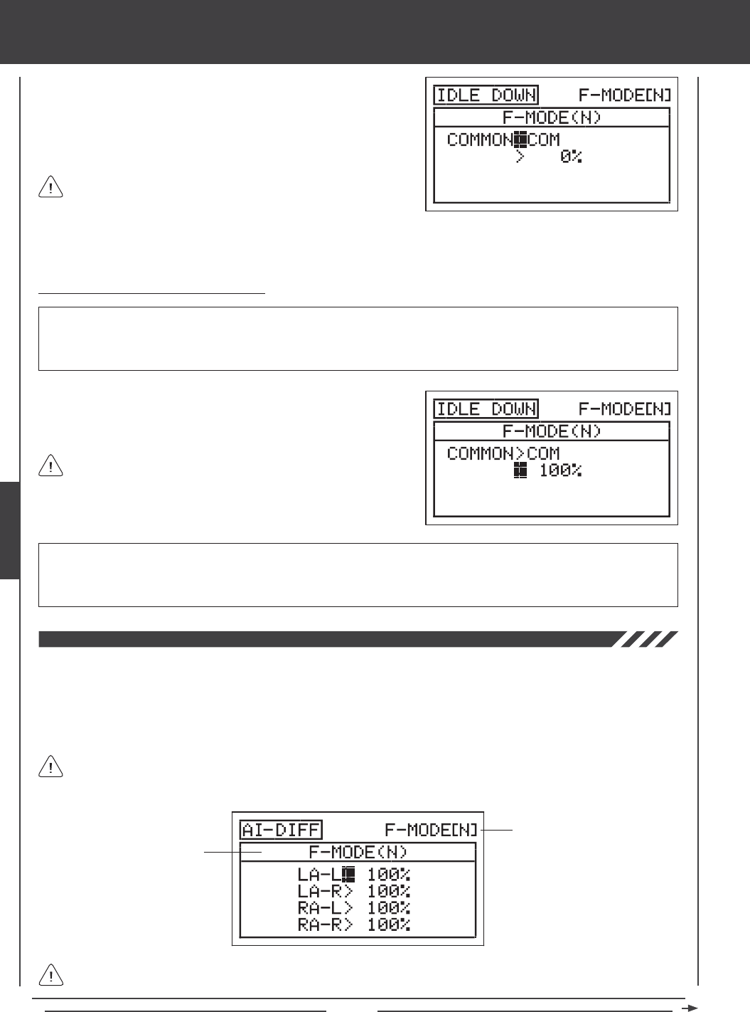
Page 84
3) Press the F-MODE key to choose the F-MODE number you would like to program the Idle Down function for. Choose from N, 1,
2, 3, or 4. The F-MODE (N) display will change, indicating which Flight Mode you are programming the Idle Down function for.
1) Press the Navigation Pad 56 to highlight IDLE DOWN, then press the
ENTER key to display the IDLE DOWN menu. The cursor will default to
COMMON>COM.
2) Press the YES/+ or NO/- keys to choose either COM or SEP.
If set to COM, skip to the Setting the Idle Down percentage value
section. If set to SEP, see step 3 below.
aero Flight Mode menu
Changing the Idle Down Percentage Value
WARNING Keep in mind that it's possible to set the Idle Down lower than the throttle End Point Adjustment. For example, with
the throttle End Point Adjustment set to -100% and the Idle Down set to -150% the servo travel will increase in that direction when
Idle Down is Activated. We strongly recommend that you set your Idle Down no lower than your throttle End Point Adjustment
unless specically necessary for your particular setup. This will prevent any chance of overdriving your control linkage.
1) Press the Navigation Pad 6 to highlight >0%, then press the YES/+ or
NO/- keys to set the position you would like the throttle servo to move
to when IDLE DOWN is Activated.
IDLE DOWN setting range is -150% to 150%. The default setting is 0%. The IDLE DOWN setting is a percentage of total trim.
The throttle trim bug on the Top menu will move when the Idle Down function is Activated, indicating where the throttle trim is
currently located. Increasing the IDLE DOWN percentage value will increase the position that the throttle servo is moved to and
decreasing the IDLE DOWN percentage value will decrease the position that the throttle servo is moved to.
The Idle Down function will only operate when the throttle control
stick is near the idle position. The IDLE DOWN setting is a percentage
of total trim. For example, when the Idle Down percentage value is set to
100%, the idle will be moved to the top of the trim range when the Idle
Down function is Activated.
The Aileron Differential function allows you change the ratio of the Up to Down movement of each aileron. For example, many
aircraft exhibit a yaw tendency when the ailerons are used. Although this can affect any aircraft, it's noticed mostly on high-wing
aircraft and aerobatic aircraft. The Aileron Differential function can be used to eliminate the yaw tendency by adding more movement
to the upward moving aileron than the downward moving aileron. For example, if your aircraft tends not to stay in a straight line
during rolls, you can adjust the Aileron Differential to make the aircraft roll more axially and therefore in a straight line. The Aileron
Differential function can be programmed separately for each of the ve Flight Modes.
Transmitter F-MODE
Programming F-MODE
Transmitter F-MODE refers to the Flight Mode that the transmitter is currently operating in. Programming F-MODE refers
to the Flight Mode that you would like to change the programming for.
Although the Aileron Differential settings can be made through the AI-DIFF menu if your model uses only one aileron servo,
the Aileron Differential function is intended to be used when your model features two separate aileron servos (one servo
controlling each aileron). When only one aileron servo is used, changing AI-DIFF percentage values is essentially the same as
changing End Point Adjustment.
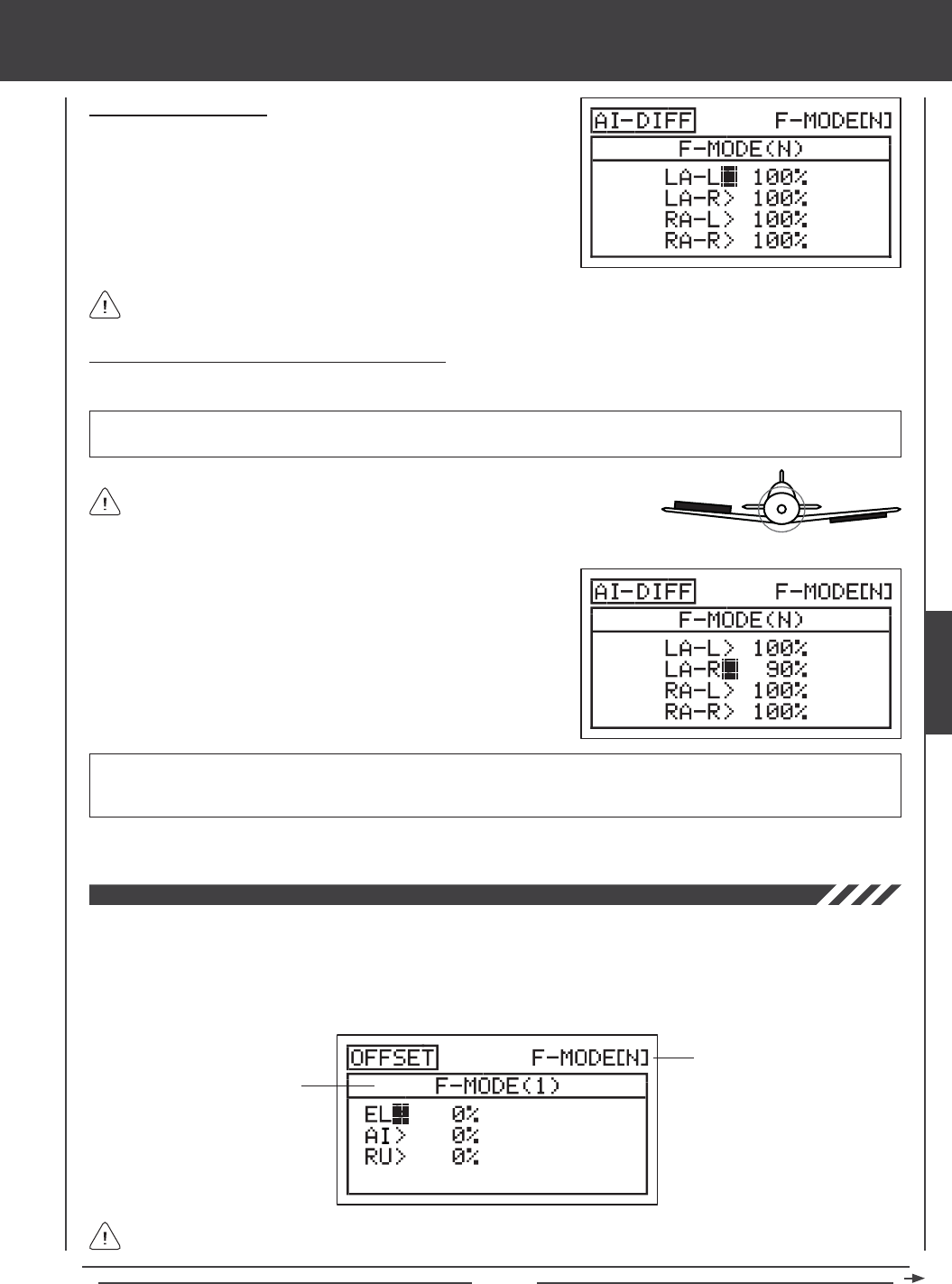
Page 85
aero Flight Mode Menu
Choosing the Flight Mode
1) Press the Navigation Pad 56 to highlight AI DIFFERENTIAL, then
press the ENTER key to display the AI-DIFF menu. The cursor will
default to LA-L>100%.
2) Press the F-MODE key to choose the F-MODE number you would like
to program the Aileron Differential function for. Choose from N, 1, 2, 3,
or 4. The F-MODE (N) display will change, indicating which Flight Mode
you are programming the Aileron Differential function for.
When Model Type Setting Option AILERON>1 is chosen, the cursor will default to AI-L>100%
Changing the Aileron Differential Percentage Values
Aileron Differential is achieved by reducing the amount of DOWN movement in the required aileron.
Aileron Differential is a percentage of the control throw differential between the
ailerons. For example, if you set LA-R (Left Aileron-Right) to 90%, the Left Aileron
will move Down less than what the Right Aileron moves Up.
1) Press the Navigation Pad 56 to highlight the desired aileron travel
direction you would like to change the Aileron Differential setting for. For
example, if you need the Right Aileron to move Up more than the Left
Aileron moves Down (per the diagram above right), you would decrease
the LA-R>100% (Left Aileron-Right) percentage value.
2) Press the YES/+ or NO/- keys to set the desired Aileron Differential
percentage value.
AI-DIFF setting range is 0% to 100%. The default setting is 100%. Decreasing the AI-DIFF percentage value will decrease
the movement for that specic aileron and direction of travel. The Aileron Differential percentage value is a percentage of
End Point Adjustment.
3) Repeat the previous procedures to set the desired remaining Aileron Differential percentage values.
IMPORTANT Prior to setting the Aileron Differential, you should use the Surface menu EPA Adjustment Option to ensure
that each aileron is moving UP and DOWN the same amount.
The Offset function allows you to shift and hold the neutral position of the desired elevator, aileron, and rudder servo(s) during ight.
For example, if you are ying a large scale aircraft that requires a certain amount of Up elevator trim during descent or landing, you
can use the Offset function to shift the neutral position of the elevator servo Up, so that when the Offset function is Activated when
you change to the Flight Mode you've programmed the Offset function in, the elevator moves Up the desired amount. This prevents
the need to constantly add elevator trim using the elevator trim switch. Offsets can be programmed for one direction of servo travel
on each of the elevator, aileron, and rudder servos independently, and can be programmed separately for each of the ve Flight Modes.
Transmitter F-MODE
Programming F-MODE
Transmitter F-MODE refers to the Flight Mode that the transmitter is currently operating in. Programming F-MODE refers
to the Flight Mode that you would like to change the programming for.
UP = More
Movement
DOWN = Less
Movement
Diagram of Differential
AERO
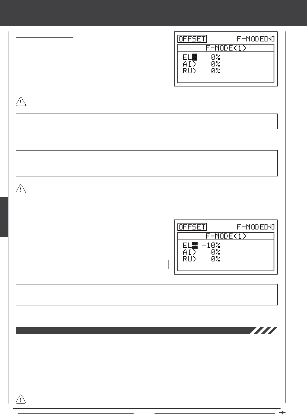
Page 86
Choosing the Flight Mode
1) Press the Navigation Pad 56 to highlight OFFSET, then press the
ENTER key to display the OFFSET menu. The cursor will default
to EL>0%.
2) Press the F-MODE key to choose the F-MODE number you would like
to program the Offset function for. Choose from N, 1, 2, 3, or 4. The
F-MODE (N) display will change, indicating which Flight Mode you are
programming the Offset function for.
IMPORTANT To avoid confusion from Offset servo positions causing an unexpected trim problem (such as taking off with
the servos in an Offset position, we recommend programming the Offset to a Flight Mode other than your Normal Flight Mode.
Changing the Offset Percentage Values
OFFSET setting range is -100% to 100%. The default setting is 0%.
3) Repeat the previous procedures to set the desired remaining Offset percentage values.
The neutral position of the servo will shift the same percentage that you set the Offset percentage value for when the Offset
function is Activated, regardless of control stick position. For example, if you set 10% elevator Offset and the elevator control
stick is at neutral, the elevator servo neutral position will shift 10% (Up or Down) when the Offset function is Activated. If you're
holding a certain amount of elevator, then Activate the Offset function, the elevator will move 10% further (Up or Down) from the
currently held position.
aero Flight Mode menu
IMPORTANT The Offset function shifts the neutral position of the servo, along with the two End Points. For example, with the
elevator Offset set to 10% in the Up direction, when the Offset function is Activated using the Flight Mode switch, the elevator
control surface will move Up 10% further and Down 10% less. 100% percent control deection is maintained, however, the
neutral position of the servo (and the control surface) is shifted 10% in the Up direction.
1) Press the Navigation Pad 56 to highlight the desired channel you
would like to change the Offset setting for.
2) Press the YES/+ or NO/- keys to set the desired Offset percentage
value.
The Channel Delay function allows you to adjust the speed of individual servos. This function has several uses. For example,
not all servos operate at the same exact speed. If your model uses two separate elevator servos, you may nd that even though
the servos are the same, one servo may move faster than the other. You can use the Channel Delay function to slow down the
faster servo to match the slower servo. The Channel Delay function can also be used to slow down a servo that controls aps or
mechanical retractable landing gear to achieve a more scale transit time.
The Channel Delay function can be programmed to operate in a number of different combinations to suit just about any model
setup or control function need. Up to ve Channel Delay functions can be programmed separately for each of the ve Flight
Modes or you can use the same Channel Delay programming across all ve Flight Modes.
The Channel Delay function does not affect when the servo starts to respond to control stick movement. The Channel
Delay function affects only the transit time of the servo.
The channels displayed will vary based on Model Type and Model Type selection options currently selected. For example,
if your model features dual elevator servos, LE and RE will be displayed and the Offset for both servos can be adjusted.
WARNING Depending on the ratio between your servo Limits setting and your Offset setting, there could be limited usable
control throw. For example, if your servo Limits are set to 100% and your Offset is set to 50%, this will result in only 50%
usable control throw in one direction.
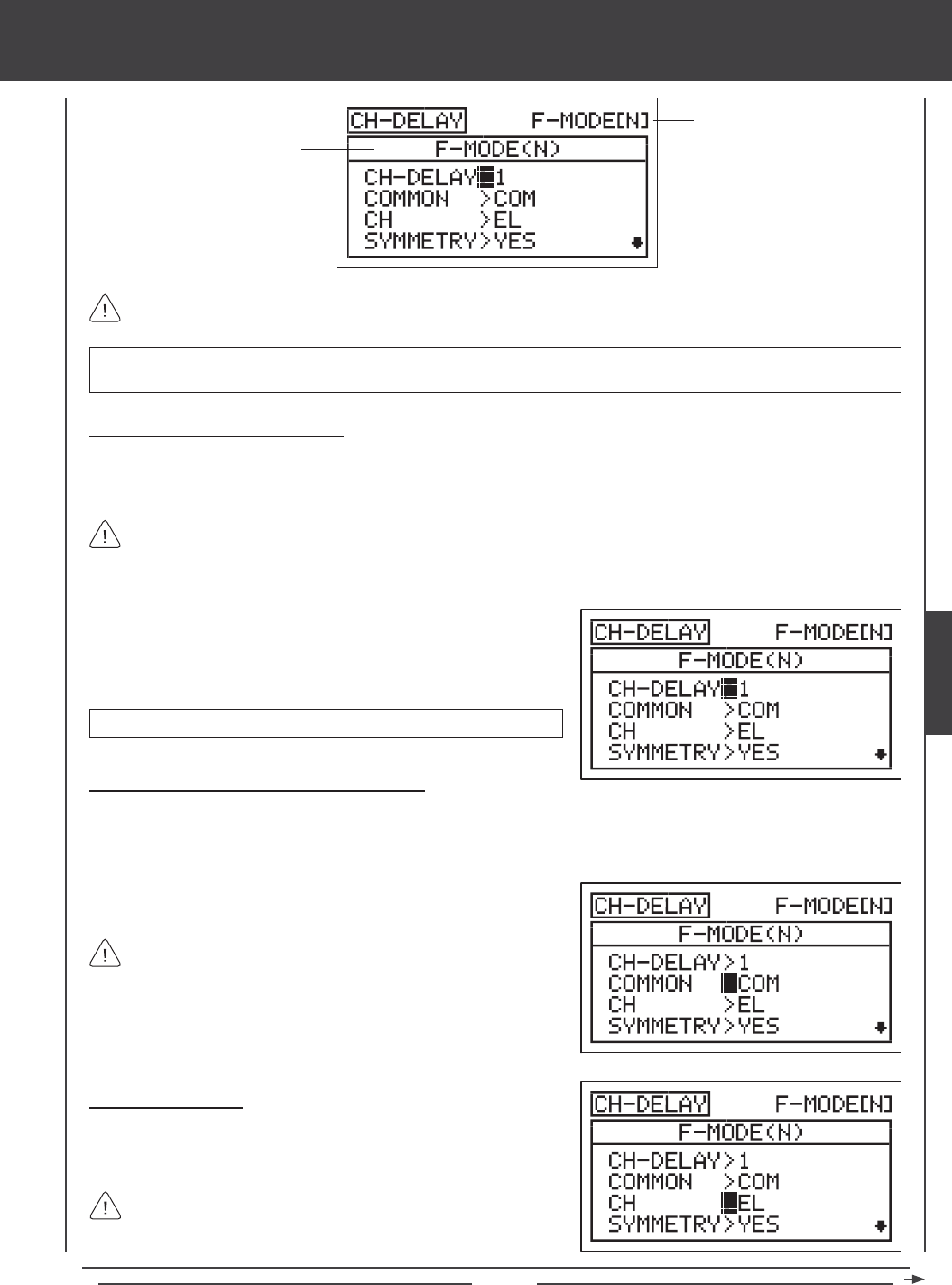
Page 87
aero Flight Mode Menu
Transmitter F-MODE
Programming F-MODE
Transmitter F-MODE refers to the Flight Mode that the transmitter is currently operating in. Programming F-MODE refers
to the Flight Mode that you would like to change the programming for.
Choosing the Channel Delay Number
Up to ve separate Channel Delay functions can be programmed for each Flight Mode, however, only one channel can be
assigned to one Channel Delay function at a time. For example, if you want to program Channel Delay for the elevator and the
aileron channels, you would need to program Elevator to CH-DELAY 1 and Aileron to CH-DELAY 2.
IMPORTANT Each CH-DELAY function (CH-DELAY 1, 2, 3, 4, and 5) must be assigned to a Switch Position Number before
it can be Activated. For more information, see page 45.
1) Press the Navigation Pad 56 to highlight CH-DELAY, then press the
ENTER key to display the CH-DELAY menu. The cursor will default to
CH-DELAY>1. Press the YES/+ and NO/- keys to choose the CH-DELAY
number you would like to program Channel Delay for.
Although only one channel can be assigned to one Channel Delay function at a time, you can still Activate multiple
Channel Delay Functions at the same time by assigning the Channel Delay functions to the same Switch Position Number.
For example, assign both CH-DELAY 1 and CH-DELAY 2 to Switch Position 23. This is particularly useful if want to program the
same Channel Delay percentage values to a model that uses two different aileron servos or two different elevator servos.
CH-DELAY setting range is 1, 2, 3, 4, or 5.
2) Press the F-MODE key to choose the F-MODE number you would like
to program the Channel Delay function for. Choose from N, 1, 2, 3,
or 4. The F-MODE (N) display will change, indicating which Flight Mode
you are programming the Channel Delay function for.
If set to COM, skip to the Choosing the Channel section. If set to SEP,
see step 2 below.
Choosing the Channel
1) Press the Navigation Pad 6 to highlight CH>EL, then press the YES/+
or NO/- keys to choose which Channel you want to program Channel
Delay for.
The channel options displayed will vary based on Model Type and
Model Type selection options currently selected. For example, if your
model features dual aileron servos, LA and RA will be separate options.
Choosing the Flight Mode - Common or Separate
When set to COM (Common), the CH-DELAY setting will be the same regardless of which Flight Mode the transmitter is
operating in. You cannot program CH-DELAY settings separately for each Flight Mode. When set to SEP (Separate), you can
program different CH-DELAY settings separately for each Flight Mode.
1) Press the Navigation Pad 6 to highlight COMMON>COM, then press
the YES/+ or NO/- keys to choose either COM or SEP.
AERO
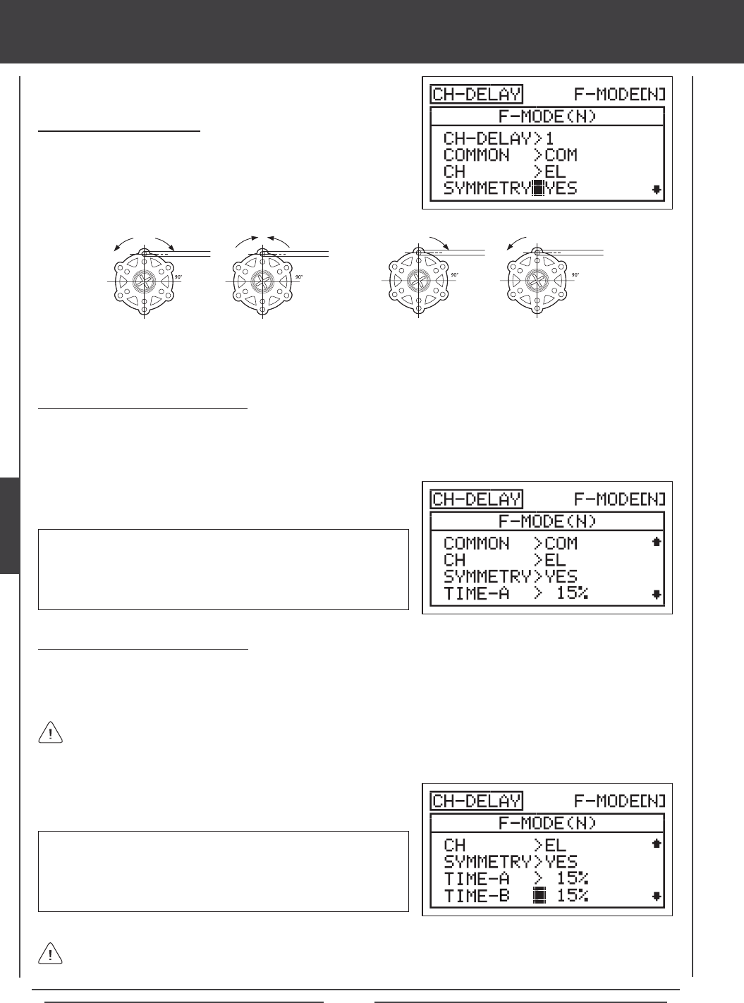
Page 88
aero Flight Mode menu
Changing the Symmetry Value
1) Press the Navigation Pad 6 to highlight SYMMETRY>YES, then press
the YES/+ or NO/- keys to change the Symmetry option.
The following Symmetry options are available:
YES - Selecting this option results in the
Channel Delay function affecting the speed
of the servo in both directions equally.
NO - Selecting this option results in the
Channel Delay function affecting the speed
of the servo in only one direction.
Changing the Time-A Percentage Value
The Time-A setting adjusts the Channel Delay when the servo moves from the neutral position to either End Point (Symmetry
YES), and in a single direction (Symmetry NO), either clockwise or counter-clockwise, depending on the Servo Reversing setting
in the Surface menu.
1) Press the Navigation Pad 6 to highlight TIME-A>0%, then press the
YES/+ or NO/- keys to change the Time-A percentage value.
TIME-A setting range is 0% to 100%. The default setting is 0%. When
the Time-A percentage value is increased, the servo transit time will be
slowed down. At 0%, the servo moves at its normal speed. At 100%, the
servo takes approximately 15 seconds to move from the neutral position
to 100% or -100% travel.
Changing the Time-B Percentage Value
The Time-B setting adjusts the Channel Delay when the servo moves from either End Point to the neutral position (Symmetry
YES), and in a single direction (Symmetry NO), either clockwise or counter-clockwise, depending on the Servo Reversing setting
in the Surface menu.
1) Press the Navigation Pad 6 to highlight TIME-B>0%, then press the
YES/+ or NO/- keys to change the Time-B percentage value.
TIME-B setting range is 0% to 100%. The default setting is 0%. When
the Time-B percentage value is increased, the servo transit time will be
slowed down. At 0%, the servo moves at its normal speed. At 100%,
the servo takes approximately 15 seconds to move from one 100% or
-100% travel to the neutral position.
If a Time-A percentage value is set with SYMMETRY>NO, the Time-B setting will affect the Channel Delay function in the
direction opposite the Time-A Channel Delay setting, regardless of the Servo Reversing setting.
If you want to ensure that a servo will move at the same speed in both directions, for example, to match the speed of a
second servo, make sure the Symmetry is set to YES and the that both the Time-A and the Time-B percentage values are
the same.
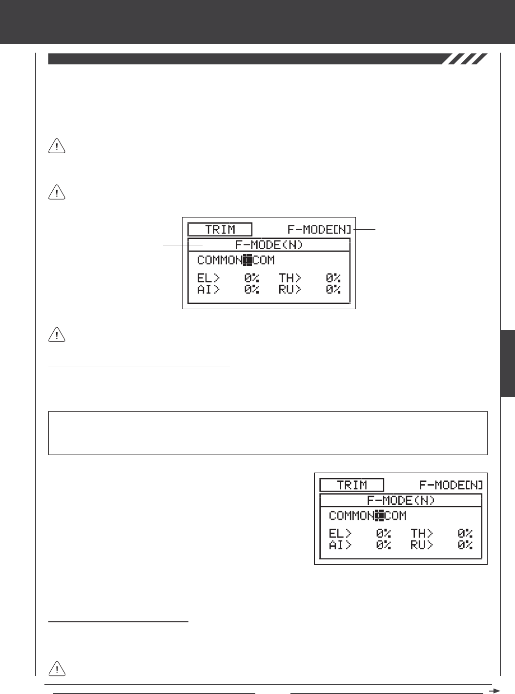
Page 89
aero Flight Mode Menu
The Trim function allows you to view the current Digital Trim Positions of the four ight control surfaces. In addition, you are able
to ne-tune the Digital Trim Positions, using the YES/+ and No/- keys. For example, in the default conguration, when you move
the elevator trim switch, the Trim percentage value changes in 6% increments. When you press the YES/+ and NO/- keys to
change the elevator Trim percentage value, the Trim percentage value changes in 1% increments. You can also choose to
program specic Trim percentage values separately for each of the ve Flight Modes or you can use the same Trim percentage
values across all ve Flight Modes.
The Trim percentage values are displayed as a percentage of total trim. They are not displayed as a percentage of
servo travel.
The SD-10G transmitter features Digital Trim Memory. Any amount of trim that you set during ight, using either the
trim switches or the YES/+ and NO/- keys from within the Trim menu, is automatically stored in memory for that specic
channel and model, and for that specic Flight Mode (if enabled). The Trim percentage values for each model will automatically
be loaded when the transmitter is turned ON and your model is selected.
Transmitter F-MODE
Programming F-MODE
Transmitter F-MODE refers to the Flight Mode that the transmitter is currently operating in. Programming F-MODE refers
to the Flight Mode that you would like to change the programming for.
Choosing the Flight Mode - Common or Separate
When set to COM (Common), the TRIM settings will be the same regardless of which Flight Mode the transmitter is operating in.
You cannot program or store TRIM settings separately for each Flight Mode. When set to SEP (Separate), you can program and
store different TRIM settings separately for each Flight Mode.
3) Press the F-MODE key to choose the F-MODE number you would like to program the Trim function for. Choose from N, 1, 2,
3, or 4. The F-MODE (N) display will change, indicating which Flight Mode you are programming the Trim function for.
1) Press the Navigation Pad 56 to highlight TRIM, then press the
ENTER key to display the TRIM menu. The cursor will default to
COMMON>COM.
2) Press the YES/+ or NO/- keys to choose either COM or SEP. If set to
COM, skip to the Changing the Trim Percentage Values section. If
set to SEP, see step 3 below.
IMPORTANT When the Flight Mode is set to Separate, Trim percentage values are stored in the specic Flight Mode you're
using when you change the Trim percentage values, whether with the trim switches or with the YES/+ and NO/- keys within the
Trim menu. For example, you could have 10% elevator trim in Flight Mode N (Normal) and 5% elevator trim in Flight Mode 1.
Be cautious of this when switching between Flight Modes during ight.
Changing the Trim Percentage Values
The current Trim percentage values for each of the ight control surfaces is displayed. The Trim percentage values can be
changed, if desired, using either the trim switches or the YES/+ and NO/- keys (from within the Trim menu only).
An audible tone is heard when the trim switches reach the center position. This allows you to know when the trim
switches reach the center position without the need to look at the Trim Indicators on the Top menu.
AERO
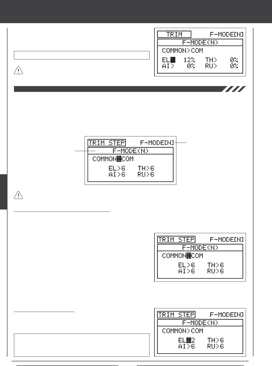
Page 90
aero Flight Mode menu
TRIM setting range is -150% to 150%. The default setting is 0%.
1) Press the Navigation Pad 3456 to highlight the channel you would
like to change the Trim percentage value for, then press the YES/+ or
NO/- keys to change the Trim percentage value.
Press the YES/+ and NO/- keys at the same time to set the Trim
percentage value to 0% for the selected channel.
The Trim Step function allows you to adjust how far the servo travels when the trim switch is moved. This allows you to change the
Trim function resolution to suit your preference. For example, in the default conguration, when you move the elevator trim switch,
the Trim percentage value changes in 6% increments. You can increase the resolution by decreasing the Trim Step value, so that
the servo travels less when you move the trim switch. This makes it possible to ne-tune the trim settings extremely accurately. In
addition, you could decrease the resolution by increasing the Trim Step value, so that the servo travels more when you move the
trim switch. This makes setting large amounts of trim faster, but the trim setting may not be as accurate. You can choose to program
Trim Step values separately for each of the ve Flight Modes or you can use the same Trim Step programming values across all
ve Flight Modes.
Transmitter F-MODE
Programming F-MODE
Transmitter F-MODE refers to the Flight Mode that the transmitter is currently operating in. Programming F-MODE refers
to the Flight Mode that you would like to change the programming for.
Choosing the Flight Mode - Common or Separate
When set to COM (Common), the TRIM STEP settings will be the same regardless of which Flight Mode the transmitter is operating
in. You cannot program TRIM STEP settings separately for each Flight Mode. When set to SEP (Separate), you can program
different TRIM STEP settings separately for each Flight Mode.
3) Press the F-MODE key to choose the F-MODE number you would like to program the Trim Step function for. Choose from N,
1, 2, 3, or 4. The F-MODE (N) display will change, indicating which Flight Mode you are programming the Trim Step function for.
1) Press the Navigation Pad 56 to highlight TRIM STEP, then press the
ENTER key to display the TRIM STEP menu. The cursor will default to
COMMON>COM.
2) Press the YES/+ or NO/- keys to choose either COM or SEP. If set to
COM, skip to the Setting the Trim Step Values section. If set to SEP,
see step 3 below.
Changing the Trim Step Values
1) Press the Navigation Pad 3456 to highlight the channel you would
like to change the Trim Step value for, then press the YES/+ or NO/- keys
to change the Trim Step value.
TRIM STEP setting range is 1 to 30. The default setting is 6. Increasing
the Trim Step value causes the servo to travel more when the trim switch
is moved (lower resolution). Decreasing the Trim Step value causes the
servo to move less when the trim switch is moved (higher resolution).
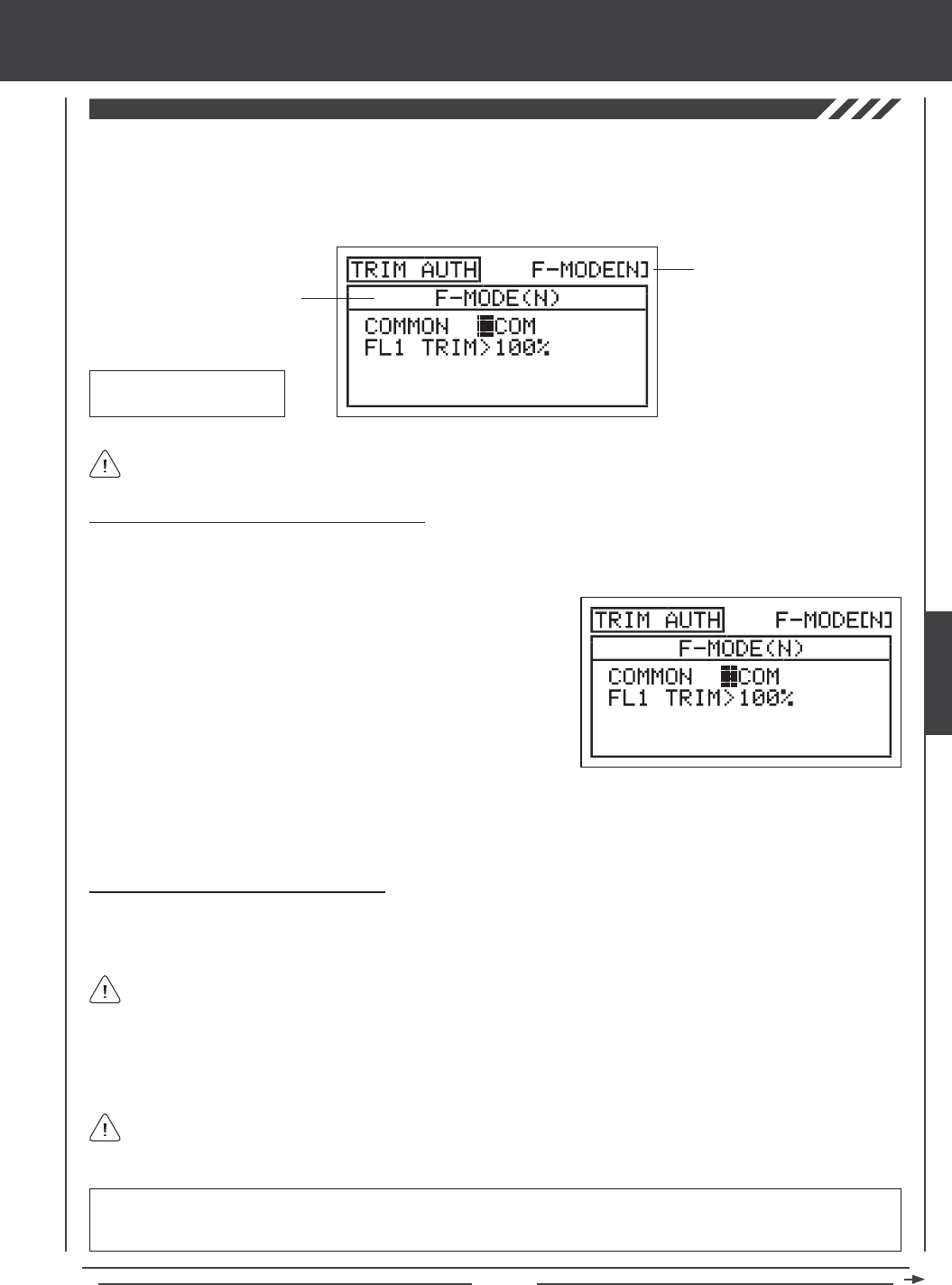
Page 91
aero Flight Mode Menu
The Trim Authority function allows you to control the ap channel using one of the Auxiliary Levers (VR5 or VR6) or the Auxiliary
Dial (VR7) when the ap switch is in Flap Position 1. In the default conguration, this function is assigned to Auxiliary Lever (VR6).
This allows you not only to have the option of using the three-position ap switch to control the aps, but also the option of using
an auxiliary lever to variably control the aps. You can choose to program Trim Authority values separately for each of the ve
Flight Modes or you can use the same Trim Authority programming values across all ve Flight Modes.
Transmitter F-MODE
Programming F-MODE
Transmitter F-MODE refers to the Flight Mode that the transmitter is currently operating in. Programming F-MODE refers
to the Flight Mode that you would like to change the programming for.
Choosing the Flight Mode - Common or Separate
When set to COM (Common), the TRIM AUTH settings will be the same regardless of which Flight Mode the transmitter is operating
in. You cannot program TRIM AUTH settings separately for each Flight Mode. When set to SEP (Separate), you can program
different TRIM AUTH settings separately for each Flight Mode.
3) Press the F-MODE key to choose the F-MODE number you would like to program the Trim Authority function for. Choose from
N, 1, 2, 3, or 4. The F-MODE (N) display will change, indicating which Flight Mode you are programming the Trim Authority
function for.
1) Press the Navigation Pad 56 to highlight TRIM AUTH, then press the
ENTER key to display the TRIM AUTH menu. The cursor will default to
COMMON>COM.
2) Press the YES/+ or NO/- keys to choose either COM or SEP. If set to
COM, skip to the Changing the Flap 1 Trim Percentage Value section.
If set to SEP, see step 3 below.
Changing the Flap 1 Trim Percentage Value
In the default conguration, the aps are programmed to a three-position switch. When the switch is in Flap Position N, the aps
are full up. When the switch is in Flap Position 1, the aps are 50% down [with Auxiliary Lever (VR6) centered], and when the
switch is in Flap Position 2, the aps are 100% down. This can be seen by looking at the FL (Flap) channel in the Surface menu.
Auxiliary Lever (VR6)
Flap 1 Trim
When the Flap 1 Trim Authority percentage value is set to 100%, Auxiliary Lever (VR6) will control the aps variably from 0%
to 100% travel. When the Flap 1 Trim Authority percentage value is set to 0%, Auxiliary Lever (VR6) is Inhibited and will NOT
control the aps at all. When the Flap 1 Trim Authority percentage value is set anywhere between the 0% and 100%, the ap's
center position will be lowered and the overall travel when Auxiliary Lever (VR6) is used to control the aps will be decreased.
Auxiliary lever VR6 will variably control the ap channel ONLY when the ap switch is in Flap Position 1.
If the Flap 1 Trim Authority percentage value is set lower than 100%, the center position of the aps will be lowered when
the ap switch is in Flap Position 1. In this situation, to raise the aps completely, the ap switch must be moved to Flap
Position N.
IMPORTANT Auxiliary lever VR6 cannot control the ap servo movement more than 100% travel. If your Flap Position 2 End
Point Adjustment is set to a percentage value greater than 100%, you will need to move the ap switch to Flap Position 2 to
lower the aps beyond the 100% that is controlled by Auxiliary Lever (VR6) while the aps are in Flap Position 1.
AERO
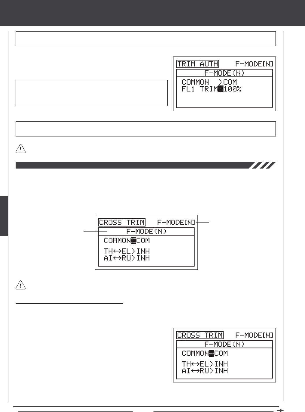
Page 92
The Cross-Trim function allows you to electronically swap trim switch functions. Some pilots prefer this over the standard
arrangement in which the trim switches adjacent to the control sticks control the trim for that control function. For example, in the
default conguration, the throttle trim switch will control the throttle trim and the elevator trim switch will control the elevator trim.
With TH34EL Cross-Trim Activated, the throttle trim switch will control the elevator trim and the elevator trim switch will control
the throttle trim. You can choose to program Cross-Trim separately for each of the ve Flight Modes or you can use the same
Cross-Trim programming across all ve Flight Modes.
aero Flight Mode menu
Transmitter F-MODE
Programming F-MODE
Transmitter F-MODE refers to the Flight Mode that the transmitter is currently operating in. Programming F-MODE refers
to the Flight Mode that you would like to change the programming for.
Choosing the Flight Mode - Common or Separate
When set to COM (Common), the CROSS-TRIM settings will be the same regardless of which Flight Mode the transmitter is
operating in. You cannot program CROSS-TRIM settings separately for each Flight Mode. When set to SEP (Separate), you can
program different CROSS-TRIM settings separately for each Flight Mode.
3) Press the F-MODE key to choose the F-MODE number you would like to program the Cross-Trim function for. Choose from N, 1,
2, 3, or 4. The F-MODE (N) display will change, indicating which Flight Mode you are programming the Cross-Trim function for.
1) Press the Navigation Pad 56 to highlight CROSS-TRIM, then press
the ENTER key to display the CROSS-TRIM menu. The cursor will
default to COMMON>COM.
2) Press the YES/+ or NO/- keys to choose either COM or SEP. If set to
COM, skip to the Changing the Throttle/Elevator Cross-Trim section. If
set to SEP, see step 3 below.
FL 1 TRIM setting range is 0% to 100%. The default setting is 100%.
Decreasing the FL 1 TRIM percentage value lowers the ap center
position and decreases the overall travel when Auxiliary Lever (VR6) is
used to control the aps.
1) Press the Navigation Pad 6 to highlight FL1 TRIM>100%, then press
the YES/+ or NO/- keys to change the FL1 TRIM percentage value.
IMPORTANT In the default conguration, Auxiliary Lever (VR6) variably controls the ap channel when the ap switch is in Flap
Position 1. Prior to setting your ap End Point Adjustments in the Surface menu, make sure that Auxiliary Lever (VR6) is centered.
IMPORTANT When the ap switch is moved to Flap Position 1, the aps will move to the position where Auxiliary Lever
(VR6) was last left in.
The Trim Authority Flap 1 VR Auxiliary Lever Override function can be turned OFF by changing the FLAP1>VR6 setting in
the VR ASSIGN menu. For more information, see page 108.
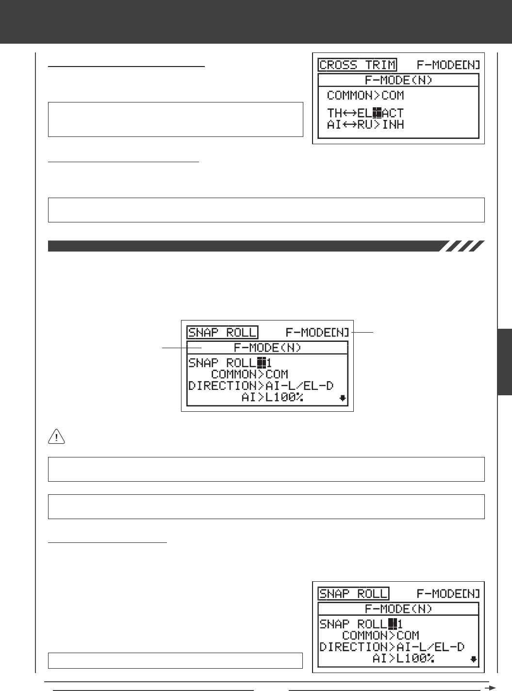
Page 93
aero Flight Mode Menu
Changing the Throttle/Elevator Cross-Trim
1) Press the Navigation Pad 6 to highlight TH34EL>INH, then press the
YES/+ or NO/- keys to change the TH34EL Cross-Trim setting.
CROSS-TRIM setting range is INH/ACT. The default setting is INH.
When Activated, the throttle trim switch will control the elevator trim and
the elevator trim switch will control the throttle trim.
Changing the Aileron/Rudder Cross-Trim
1) Press the Navigation Pad 6 to highlight AI34RU>INH, then press the YES/+ or NO/- keys to change the AI34RU
Cross-Trim setting.
CROSS-TRIM setting range is INH/ACT. The default setting is INH. When Activated, the aileron trim switch will control the
rudder trim and the rudder trim switch will control the aileron trim.
The Snap Roll function allows you to program a custom Snap Roll setting and assign it to a Switch Position Number. Some
pilots prefer to use a switch to perform a snap roll instead of performing the snap roll by hand. The Snap Roll function can be
programmed to perform snap rolls in both the left and right, and the up and down directions. Each of the three control surfaces
can also be adjusted separately to ne-tune the control throws. Two different Snap Roll functions can be programmed and you
can choose to program the Snap Roll function separately for each of the ve Flight Modes or you can use the same Snap Roll
programming across all ve Flight Modes.
Transmitter F-MODE
Programming F-MODE
Transmitter F-MODE refers to the Flight Mode that the transmitter is currently operating in. Programming F-MODE refers
to the Flight Mode that you would like to change the programming for.
IMPORTANT Each SNAP ROLL function (SNAP ROLL>1 and SNAP ROLL>2) must be assigned to a Switch Position
Number before it can be Activated. For more information, see page 45.
WARNING For ease of use, we strongly recommend that the Snap Roll function be assigned to the spring-loaded switch.
For example, assign SNAP ROLL>1 to Switch Position 19 or 21.
Choosing the Snap Roll Number
Two separate Snap Roll functions can be programmed. For example, you could program SNAP ROLL>1 to snap roll to the
left and up, and program SNAP ROLL>2 to snap roll to the right and down. You can then assign each Snap Roll function to a
separate Switch Position Number.
1) Press the Navigation Pad 56 to highlight SNAP ROLL, then press the
ENTER key to display the SNAP ROLL menu. The cursor will default to
SNAP ROLL>1.
2) Press the YES/+ and NO/- keys to choose the SNAP ROLL number you
would like to program the Snap Roll function for.
SNAP ROLL setting range is 1 or 2. The default setting is 1.
AERO
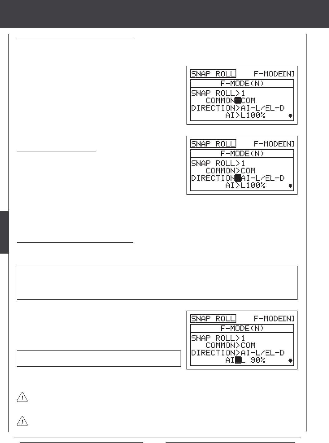
Page 94
aero Flight Mode menu
Choosing the Snap Roll Direction
1) Press the Navigation Pad 6 to highlight DIRECTION>AI-L/EL-D.
2) Press the YES/+ or NO/- keys to choose which direction you want the
ailerons and the elevator to move (i.e., which directions you want the
aircraft to perform the snap roll).
WARNING Keep in mind that it's possible to set the control surface percentage values higher than the End Point Adjustments.
For example, with the aileron End Point Adjustment set to 100% and the Aileron Left percentage value set to 150% the servo
will move 150% when the Snap Roll function is Activated. We strongly recommend that you set your control surface percentage
values no higher than your End Point Adjustments unless specically necessary for your particular setup. This will prevent any
chance of overdriving your control linkage.
The channels displayed will vary based on Model Type and Model Type selection options currently selected. For example,
if your model features dual aileron servos and dual elevator servos, LA, RA, LE, and RE will be displayed and the control
surface percentage values can be changed for each servo individually.
The following Snap Roll Direction options are available:
AI-L/EL-D - Ailerons Left, Elevator, Down, and Rudder Right.
AI-R/EL-D - Ailerons Right, Elevator Down, and Rudder Left.
Changing the Control Surface Percentage Values
Changing the control surface percentage values allows you to ne-tune the control throws so that the aircraft will perform the
snap roll in the desired manner intended.
1) Press the Navigation Pad 6 to highlight AI>L100% (AI>R100% if
AI-R/EL-D or AI-R/EL-U is selected).
2) Press the YES/+ or NO/- keys to change the Aileron control surface
percentage value.
If you decrease the percentage values to 0% and beyond, the percentage values will begin to increase in the opposite
direction. We don't suggest doing this unless you would like to use the percentage values to create your own custom control
throw conguration.
AI setting range is R150% to L150%. The default setting is L100%
(R100% if AI-R/EL-D or AI-R/EL-U is selected).
3) Repeat the previous procedures to change the desired remaining control surface percentage values.
Choosing the Flight Mode - Common or Separate
When set to COM (Common), the SNAP ROLL settings will be the same regardless of which Flight Mode the transmitter is operating
in. You cannot program SNAP ROLL settings separately for each Flight Mode. When set to SEP (Separate), you can program
different SNAP ROLL settings separately for each Flight Mode.
1) Press the Navigation Pad 6 to highlight COMMON>COM, then press
the YES/+ or NO/- keys to choose either COM or SEP. If set to COM,
skip to the Choosing the Snap Roll Direction section. If set to SEP, see
step 2 below.
2) Press the F-MODE key to choose the F-MODE number you would like
to program the Snap Roll function for. Choose from N, 1, 2, 3, or 4. The
F-MODE (N) display will change, indicating which Flight Mode you are
programming the Snap Roll function for.
AI-L/EL-U - Ailerons Left, Elevator Up, and Rudder Left.
AI-R/EL-U - Ailerons Right, Elevator Up, and Rudder Right.
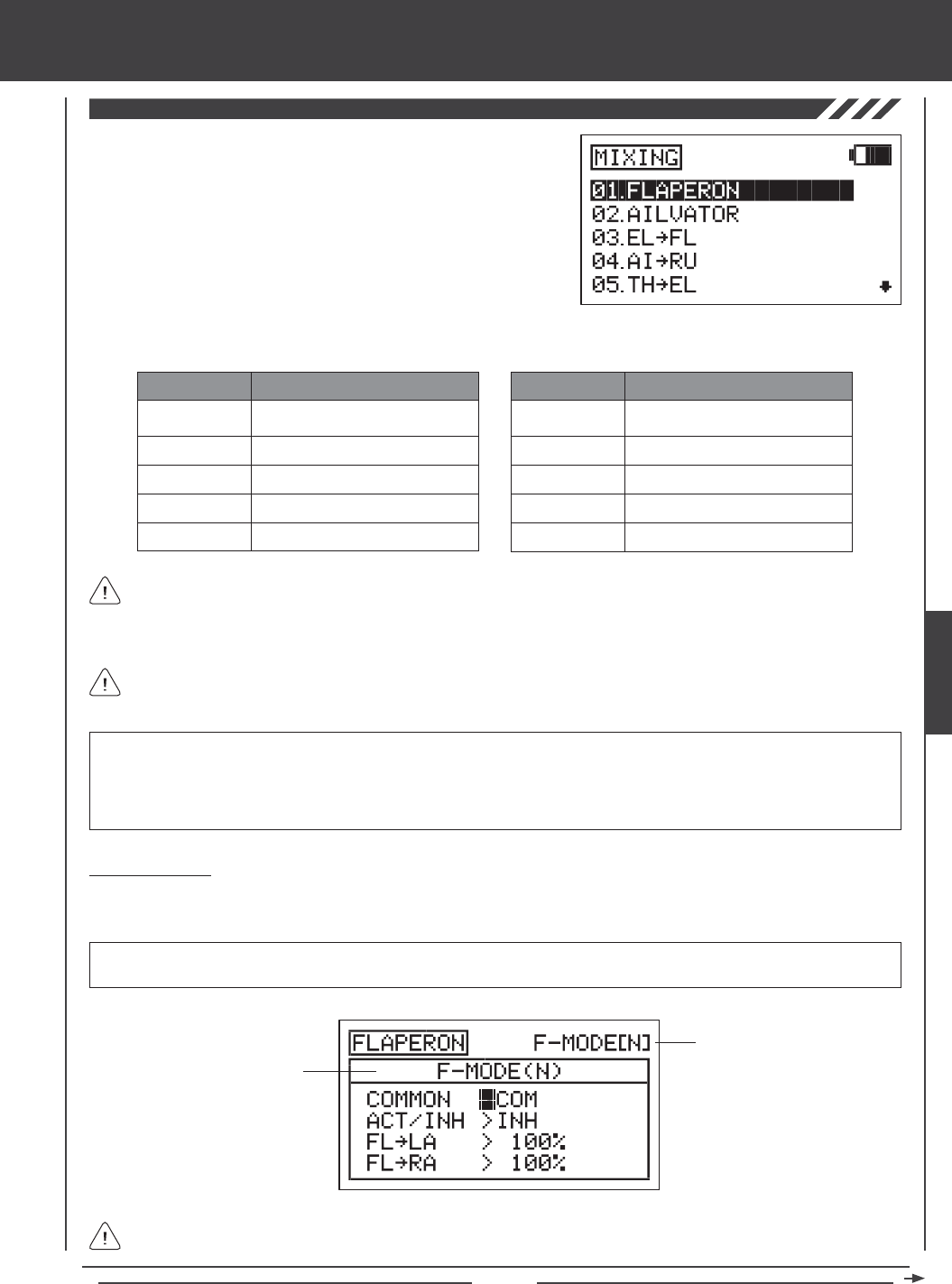
Page 95
aero Flight Mode Menu
The SD-10G transmitter features a number of pre-programmed mixes that
can all be adjusted to suit just about any model setup or mixing need that
you might have. If for some reason one of the pre-programmed mixes will
not sufce, you can custom-program one or more of the available ve
Compensation Mixers. For more information, see page 104.
1) Press the Navigation Pad 56 to highlight MIXING, then press the
ENTER key to display the MIXING menu. The FLAPERON sub-menu
will be highlighted by default.
FLAPERON
AILVATOR
EL4FL
AI4RU
TH4EL
MIX
Flaperon (Flap/Aileron) Mixing
Ailvator (Taileron) Mixing
Elevator to Flap Mixing
Aileron to Rudder Mixing
Throttle to Elevator Mixing
DESCRIPTION
TH4RU
RU4EL
RU4AI
RU4TH
FL4EL
MIX
Throttle to Rudder Mixing
Rudder to Elevator Mixing
Rudder to Aileron Mixing
Rudder to Throttle Mixing
Flap to Elevator Mixing
DESCRIPTION
General Overview
Each of the ten mixes can be programmed separately for each of the ve Flight Modes or you can use the same Mixing programming
across all ve Flight Modes.
Transmitter F-MODE refers to the Flight Mode that the transmitter is currently operating in. Programming F-MODE refers
to the Flight Mode that you would like to change the programming for.
IMPORTANT Each Mixing function, except Flaperon and Ailvator, must be assigned to a Switch Position Number before it
can be Activated. For more information, see page 45.
Transmitter F-MODE
Programming F-MODE
The pre-programmed mixes shown in the tables below are available.
All pre-programmed mixes are Linear. For example, if you Activate the EL4FL mix and set the mixing percentage value to
50%, the ap servo will travel half the amount that the elevator servo moves at any given control stick position.
Aside from the Flaperon and Ailvator mixes, all pre-programmed mixes are described in the following manner: Master4Slave.
For example, For the EL4FL mix, the Elevator channel is the Master and the Flap channel is the Slave. In all cases, the
Master channel always controls the Slave channel.
WARNING When a pre-programmed mix is Activated, including the Flaperon and the Ailvator mixes, you still have separate
control over the Slaved channel, however, depending on the mixing percentage value, the Slave channel End Point Adjustment
could be exceeded. We strongly recommend that if you use the pre-programmed mixes that you set your Slave channel Limits no
higher than that channel's End Point Adjustment unless specically necessary for your particular setup. This will prevent any chance
of overdriving your control linkage when the mix is used.
AERO
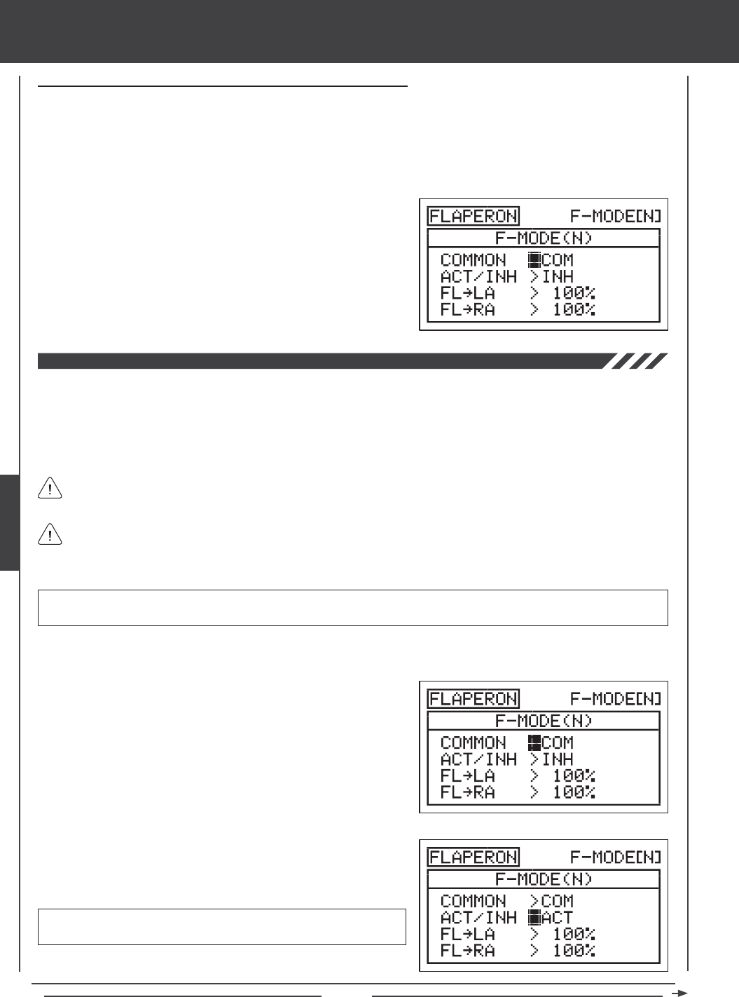
Page 96
Flaperon Mixing
The Flaperon Mixing function mixes aps and ailerons, allowing you to use the ailerons as aps if your model does not feature
separate aps. When Activated, both ailerons are moved down at the same time to provide the function of aps, while still providing
aileron roll control. Both ailerons can also be programmed to move up at the same time (spoilerons) to rapidly decrease lift. On
some aircraft, moving both ailerons up slightly can induce greater speeds and also aid in trimming.
To be able to Activate Flaperon mixing, your model must feature two separate aileron servos (one servo controlling each
aileron) and AILERON>2 must be selected SYSTEM4TYPE menu.
2) Press the ENTER key to display the FLAPERON menu. The cursor will
default to COMMON>COM.
3) Press the YES/+ or NO/- keys to choose the desired COM or SEP
option as described previously.
4) Press the Navigation Pad 6 to highlight ACT/INH>INH, then press
the YES/+ or NO/- keys to change the ACT/INH setting.
FLAPERON setting range is INH/ACT. The default setting is INH. When
Activated, the ap switch will control the Flaperons.
The Flaperons are controlled by the ap switch. Flap End Point Adjustments and Auxiliary Lever (VR6) programming
settings will carry over when the Flaperon mixing function is Activated. For example, to set the control throws for the
Flaperons, change the ap switch Switch Position N, 1, and 2 End Point Adjustment Values in the Surface menu. For more
information on Auxiliary Lever (VR6) programming, see page 91.
1) Press the Navigation Pad 56 to highlight MIXING, then press the ENTER key to display the MIXING menu. The FLAPERON
sub-menu will be highlighted by default.
aero Flight Mode menu
Choosing the Flight Mode - Common or Separate (All Mixing Options)
When set to COM (Common), the mixing settings will be the same regardless of which Flight Mode the transmitter is operating in.
You cannot program mixing settings separately for each Flight Mode. When set to SEP (Separate), you can program different
mixing settings separately for each Flight Mode.
1) Press the Navigation Pad 6 to highlight COMMON>COM, then press the YES/+ or NO/- keys to choose either COM or SEP.
If set to COM, skip to the Activating or the Percentage Value Selections sections. If set to SEP, see step 2 below.
2) Press the F-MODE key to choose the F-MODE number you would like
to program the mixing function for. Choose from N, 1, 2, 3, or 4. The
F-MODE (N) display will change, indicating which Flight Mode you are
programming the mixing function for.
Flaperons - Both ailerons down Spoilerons - Both ailerons up.
IMPORTANT To mix Elevator to Flaperons/Spoilerons for 3D aerobatic aircraft, a C-Mix must be used. For more information,
see page 104.
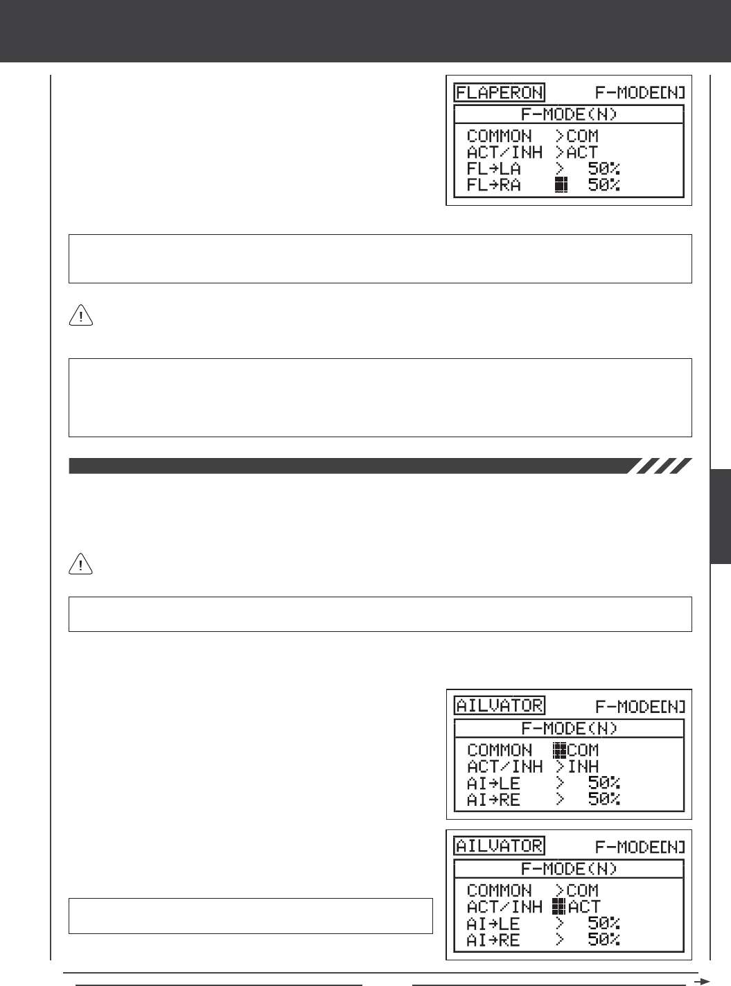
Page 97
aero Flight Mode menu
IMPORTANT Adjusting the FL4LA and FL4RA percentage values changes the percentage of Flaperon travel in relation to
the ap channel End Point Adjustment. For example, if the ap switch Flap Position 2 End Point Adjustment is set to 100%
and the Flaperons move down 2", changing the FL4LA and FL4RA percentage values to 50% will cause the Flaperons to
move down 1". In addition, changing the FL4LA and FL4RA percentage values to -50% will cause the Flaperons to move up
1" (Spoilerons).
5) The Flaperon mixing percentage values can be changed for each aileron
separately. Press the Navigation Pad 6 to highlight FL4LA>100%,
then press the YES/+ or NO/- keys to change the Flaperon4Left Aileron
percentage value.
6) Press the Navigation Pad 6 to highlight FL4RA>100%, then press the
YES/+ or NO/- keys to change the Flaperon4Right Aileron percentage
value.
FL4LA and FL4RA setting range is -100% to 100%. The default setting is 100%. When the percentage value is decreased
from 100% to 0%, Flaperon travel will decrease in one direction. When the percentage value is decreased from 0% to -100%,
Flaperon travel will increase in the opposite direction.
FL4LA and FL4RA percentage values will vary based on the NOR/REV Adjustment Value of the two aileron servos when
set up in the Surface menu. For example, depending on the NOR/REV status of the aileron servos, increasing the percentage
values may cause the Flaperons to move up (Spoilerons), instead of down (Flaperons).
Ailvator Mixing
The Ailvator Mixing function mixes ailerons and elevator, allowing you to have both roll control and pitch control on the elevator,
separate from the ailerons. When Activated, not only will the two elevator halves move up and down together, but each elevator
half can move up and down independently like ailerons. This function is commonly referred to as tailerons (or stabilators), and
is normally found on aircraft that feature full-ying stabilizers.
To be able to Activate Ailvator mixing, your model must feature two separate elevator servos (one servo controlling each
elevator half) and TAIL>2xEL must be selected in the SYSTEM4TYPE menu.
IMPORTANT In order for the Ailvator mixing function to work as intended, one of the elevator servos must be reversed
(using the NOR/REV setting in the Surface menu), so that both elevator servos move the same direction up and down.
2) Press the Navigation Pad 6 to highlight AILVATOR, then press the
ENTER key to display the AILVATOR menu. The cursor will default to
COMMON>COM.
3) Press the YES/+ or NO/- keys to choose the desired COM or SEP
option as described previously.
1) Press the Navigation Pad 56 to highlight MIXING, then press the ENTER key to display the MIXING menu. The FLAPERON
sub-menu will be highlighted by default.
4) Press the Navigation Pad 6 to highlight ACT/INH>INH, then press
the YES/+ or NO/- keys to change the ACT/INH setting.
AILVATOR setting range is INH/ACT. The default setting is INH. When
Activated, the two elevator halves will function like elevators and ailerons.
AERO
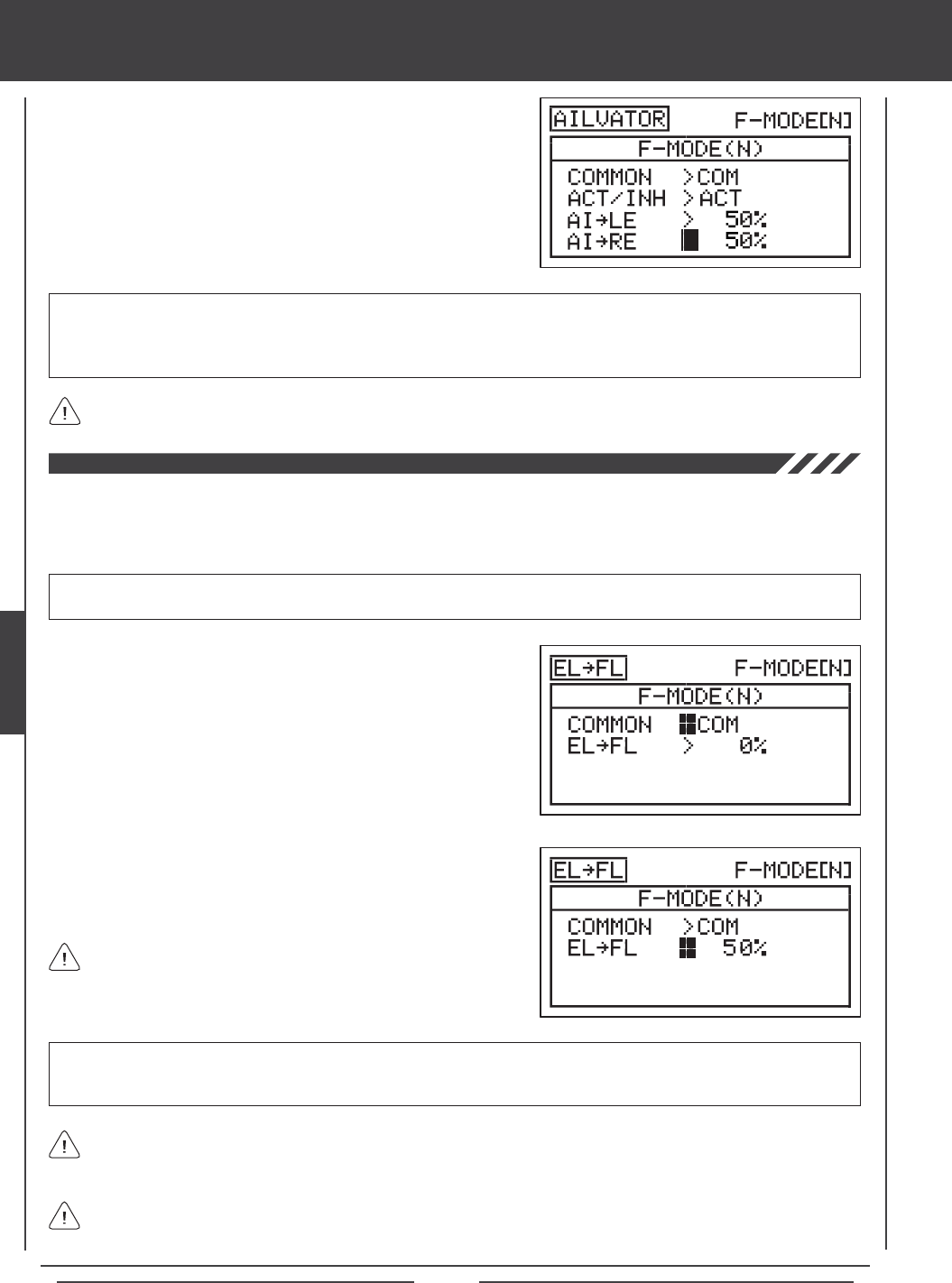
Page 98
aero Flight Mode Menu
5) The Ailvator mixing percentage values can be changed for each
elevator servo separately. Press the Navigation Pad 6 to highlight
AI4LE>50%, then press the YES/+ or NO/- keys to change the
Aileron4Left Elevator percentage value.
6) Press the Navigation Pad 6 to highlight AI4RE>50%, then press the
YES/+ or NO/- keys to change the Aileron4Right Elevator percentage
value.
AI4LE and AI4RE setting range is -100% to 100%. The default setting is 50%. Adjusting the percentage values will change
the ratio of elevator roll travel to elevator pitch travel. For example, when the Aileron4Left Elevator and the Aileron4Right
Elevator percentage values are both set to 50%, the elevator roll travel will be half the amount of the elevator pitch travel at
any given control stick position.
Setting one percentage value opposite of the other percentage value will cause both elevator servos to move together
when the elevator/aileron control stick is moved in both the up and down, and the right and left directions.
Elevator to Flap Mixing
The Elevator to Flap Mixing function allows you to mix a percentage of ap control with elevator control. When you move the
elevator up and down, the aps will move up and down. The Elevator to Flap Mixing function is typically used with Fun-Fly aircraft
to enable near-instantaneous pitch changes. The amount and the direction that the aps move with elevator control is adjusted
by changing the Elevator4Flap mixing percentage value either positive or negative.
IMPORTANT The Elevator to Flap Mixing function must be assigned to a Switch Position Number before it can be Activated.
For more information, see page 45.
1) Press the Navigation Pad 56 to highlight MIXING, then press the
ENTER key to display the MIXING menu. The FLAPERON sub-menu
will be highlighted by default.
2) Press the Navigation Pad 6 to highlight EL4FL, then press the
ENTER key to display the EL4FL menu. The cursor will default to
COMMON>COM.
3) Press the YES/+ or NO/- keys to choose the desired COM or SEP
option as described previously.
The channel options displayed will vary based on Model Type and Model Type selection options currently selected. For
example, if your model features dual ap servos, EL4LF (Left Flap) and EL4RF (Right Flap) percentage values can be
changed separately.
4) Press the Navigation Pad 6 to highlight EL4FL>0%.
5) Press the YES/+ or NO/- keys to change the Elevator4Flap mixing
percentage value.
EL4FL setting range is -100% to 100%. The default setting is 0%. When the percentage value is increased from 0% to 100%,
flap travel will increase in one direction in relation to elevator travel. When the percentage value is decreased from 0%
to -100%, ap travel will increase in the opposite direction in relation to elevator travel.
The Elevator4Flap mixing percentage value is a ratio of ap travel
to elevator travel. For example, when the Elevator4Flap mixing
percentage value is set to 50%, the aps will travel half the amount that the
elevator travels. This mix is Linear.
Elevator4Flap mixing will cause the aps to move up when you move the elevator control stick. If you don't want the aps
to move up (you want them to only move down with EL4FL mixing Active), set the ap channel Limit Adjustment Value to
0% in the Surface menu for the ap up direction.
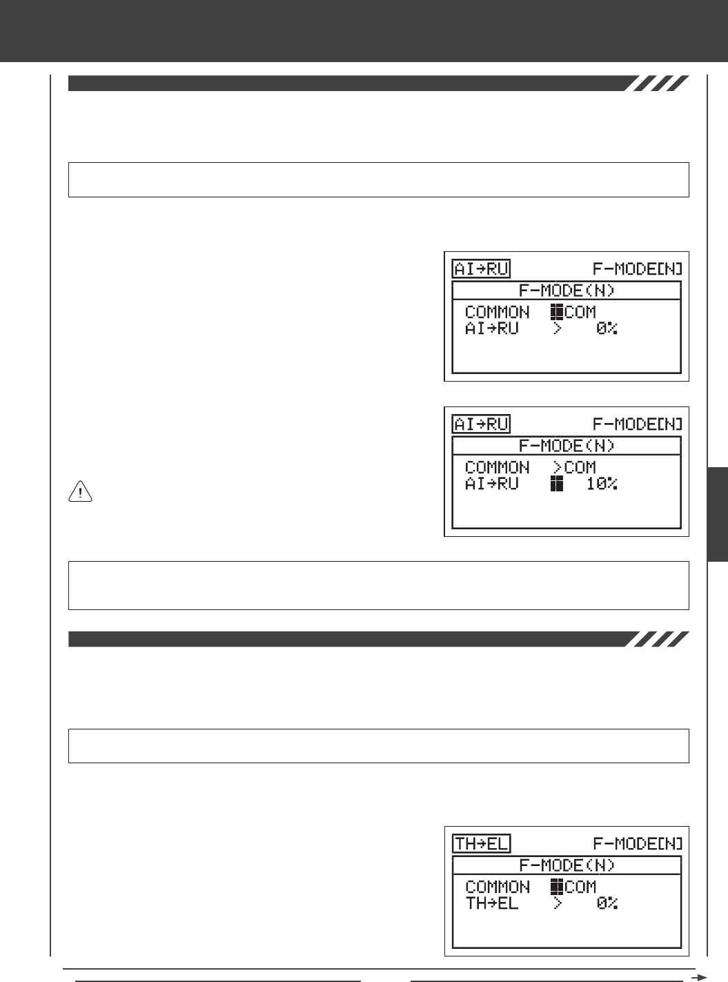
Page 99
aero Flight Mode menu
Aileron to Rudder Mixing
The Aileron to Rudder Mixing function allows you to mix a percentage of rudder control with aileron control. When you move the
ailerons right and left, the rudder will move right and left. The Aileron to Rudder Mixing function is typically used on many high
wing or scale models to automatically make coordinated turns. The amount and the direction that the rudder moves with aileron
control is adjusted by changing the Aileron4rudder mixing percentage value either positive or negative.
IMPORTANT The Aileron to Rudder Mixing function must be assigned to a Switch Position Number before it can be
Activated. For more information, see page 45.
2) Press the Navigation Pad 6 to highlight AI4RU, then press the
ENTER key to display the AI4RU menu. The cursor will default to
COMMON>COM.
3) Press the YES/+ or NO/- keys to choose the desired COM or SEP
option as described previously.
4) Press the Navigation Pad 6 to highlight AI4RU>0%.
5) Press the YES/+ or NO/- keys to change the Aileron4Rudder mixing
percentage value.
AI4RU setting range is -100% to 100%. The default setting is 0%. When the percentage value is increased from 0% to 100%,
rudder travel will increase in one direction in relation to aileron travel. When the percentage value is decreased from
0% to -100%, rudder travel will increase in the opposite direction in relation to aileron travel.
The Aileron4Rudder mixing percentage value is a ratio of rudder
travel to aileron travel. For example, when the Aileron4Rudder
mixing percentage value is set to 10%, the rudder will travel 1/10th the
amount that the ailerons travel. This mix is Linear.
1) Press the Navigation Pad 56 to highlight MIXING, then press the ENTER key to display the MIXING menu. The FLAPERON
sub-menu will be highlighted by default.
Throttle to Elevator Mixing
The Throttle to Elevator Mixing function allows you to mix a percentage of elevator control with throttle control. When you
increase the throttle, the elevator will move up or down. The Throttle to Elevator Mixing function is typically used on scale aircraft
to reduce minor pitch changes when increasing or decreasing power. The amount and the direction that the elevator moves when
you increase the throttle is adjusted by changing the Throttle4Elevator mixing percentage value either positive or negative.
IMPORTANT The Throttle to Elevator Mixing function must be assigned to a Switch Position Number before it can be
Activated. For more information, see page 45.
1) Press the Navigation Pad 56 to highlight MIXING, then press the ENTER key to display the MIXING menu. The FLAPERON
sub-menu will be highlighted by default.
2) Press the Navigation Pad 6 to highlight TH4EL, then press the
ENTER key to display the TH4EL menu. The cursor will default to
COMMON>COM.
3) Press the YES/+ or NO/- keys to choose the desired COM or SEP
option as described previously.
AERO
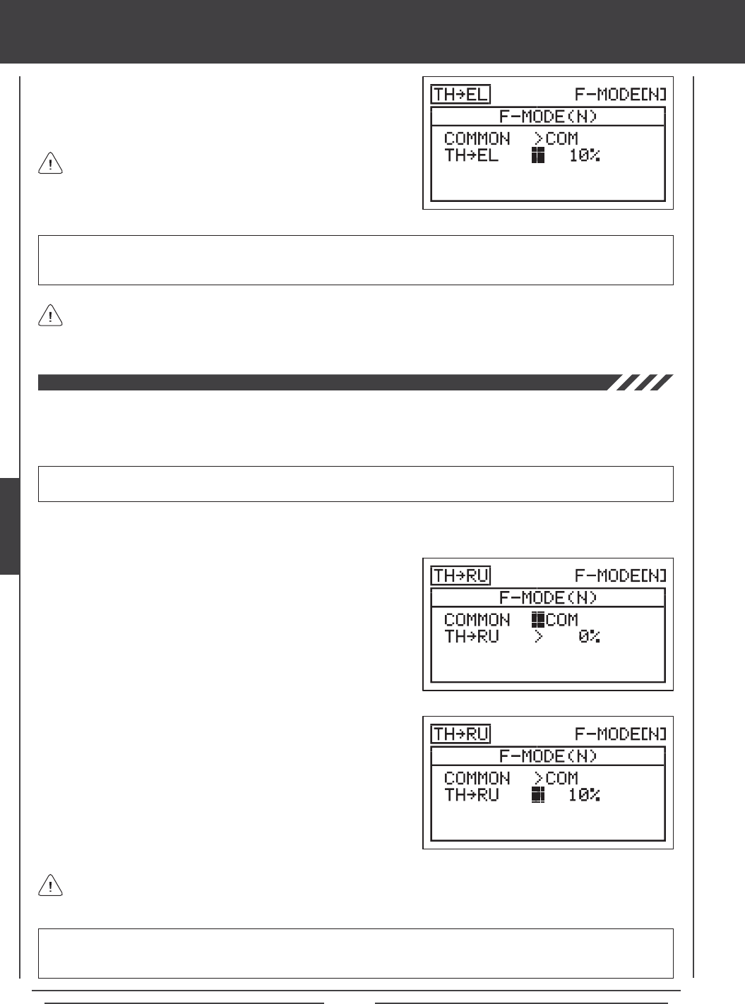
Page 100
aero Flight Mode menu
4) Press the Navigation Pad 6 to highlight TH4EL>0%.
5) Press the YES/+ or NO/- keys to change the Throttle4Elevator mixing
percentage value.
The Throttle4Elevator mixing percentage value is a ratio of elevator
travel to throttle travel. For example, when the Throttle4Elevator
mixing percentage value is set to 10%, the elevator will travel 1/10th the
amount that the throttle travels. This mix is Linear.
The channel options displayed will vary based on Model Type and Model Type selection options currently selected. For
example, if your model features dual elevator servos, TH4LE (Left Elevator) and TH4RE (Right Elevator) percentage
values can be set separately.
TH4EL setting range is -100% to 100%. The default setting is 0%. When the percentage value is increased from 0% to
100%, elevator travel will increase in one direction in relation to increased throttle travel. When the percentage value
is decreased from 0% to -100%, elevator travel will increase in the opposite direction in relation to increased throttle travel.
Throttle to Rudder Mixing
The Throttle to Rudder Mixing function allows you to mix a percentage of rudder control with throttle control. When you increase
the throttle, the rudder will move right or left. The Throttle to Rudder Mixing function is typically used to reduce minor yaw changes
when increasing power. The amount and the direction that the rudder moves when the throttle is increased is adjusted by
changing the Throttle4Rudder mixing percentage value either positive or negative.
IMPORTANT The Throttle to Rudder Mixing function must be assigned to a Switch Position Number before it can be
Activated. For more information, see page 45.
1) Press the Navigation Pad 56 to highlight MIXING, then press the ENTER key to display the MIXING menu. The FLAPERON
sub-menu will be highlighted by default.
2) Press the Navigation Pad 6 to highlight TH4RU, then press the
ENTER key to display the TH4RU menu. The cursor will default to
COMMON>COM.
3) Press the YES/+ or NO/- keys to choose the desired COM or SEP
option as described previously.
4) Press the Navigation Pad 6 to highlight TH4RU>0%.
5) Press the YES/+ or NO/- keys to change the Throttle4Rudder mixing
percentage value.
The Throttle4Rudder mixing percentage value is a ratio of rudder travel to throttle travel. For example, when the
Throttle4Rudder mixing percentage value is set to 10%, the rudder will travel 1/10th the amount that the throttle
travels. This mix is Linear.
TH4RU setting range is -100% to 100%. The default setting is 0%. When the percentage value is increased from 0% to
100%, rudder travel will increase in one direction in relation to increased throttle travel. When the percentage value
is decreased from 0% to -100%, rudder travel will increase in the opposite direction in relation to increased throttle travel.
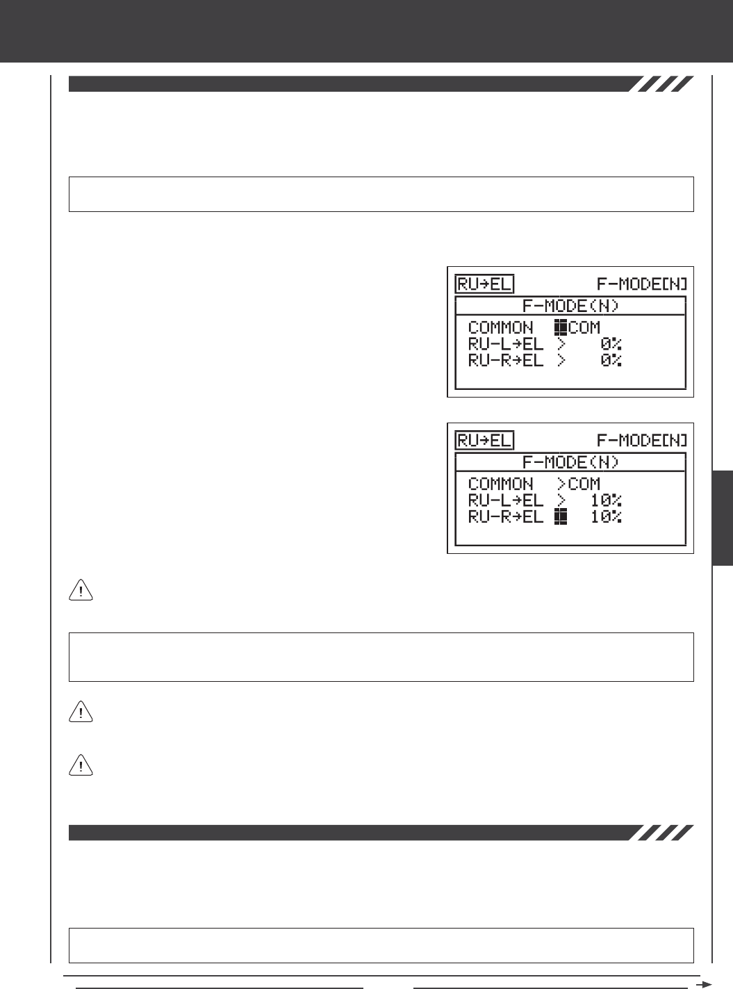
Page 101
aero Flight Mode menu
Rudder to Elevator Mixing
The Rudder to Elevator Mixing function allows you to mix a percentage of elevator control with rudder control. When you move
the rudder right or left, the elevator will move up or down. The Rudder to Elevator Mixing function is typically used on many
scale models to minimize pitch coupling. The amount and the direction that the elevator moves with rudder control is adjusted
by changing the Rudder4Elevator mixing percentage value either positive or negative. Separate mixes can be programmed for
right and left rudder throw.
IMPORTANT The Rudder to Elevator Mixing function must be assigned to a Switch Position Number before it can be
Activated. For more information, see page 45.
2) Press the Navigation Pad 6 to highlight RU4EL, then press the
ENTER key to display the RU4EL menu. The cursor will default to
COMMON>COM.
3) Press the YES/+ or NO/- keys to choose the desired COM or SEP
option as described previously.
4) Press the Navigation Pad 6 to highlight RU-L4EL>0%.
5) Press the YES/+ or NO/- keys to change the Rudder-Left4Elevator
mixing percentage value.
6) Press the Navigation Pad 6 to highlight RU-R4EL>0%, then press
the YES/+ or NO/- keys to change the Rudder-Right4Elevator mixing
percentage value.
RU-L4EL and RU-R4EL setting range is -100% to 100%. The default settings are 0%. When the percentage values are
increased from 0% to 100%, elevator travel will increase in one direction in relation to rudder travel. When the percentage
values are decreased from 0% to -100%, elevator travel will increase in the opposite direction in relation to rudder travel.
The Rudder4Elevator mixing percentage value is a ratio of elevator travel to rudder travel. For example, when the
Rudder-Left4Elevator and the Rudder-Right4Elevator mixing percentage values are set to 10%, the elevator will travel
1/10th the amount that the rudder travels in both directions. This mix is Linear.
1) Press the Navigation Pad 56 to highlight MIXING, then press the ENTER key to display the MIXING menu. The FLAPERON
sub-menu will be highlighted by default.
Because you can program the Rudder4Elevator percentage value separately for both directions of rudder travel, it's
possible to program the mix to either make the elevator move up or down with right and left rudder control, make the elevator
move up and down with right and left rudder control, or make the elevator move up or down with right or left rudder control.
Rudder to Aileron Mixing
The Rudder to Aileron Mixing function allows you to mix a percentage of aileron control with rudder control. When you move the
rudder right or left, the ailerons will move up or down. The Rudder to Aileron Mixing function is typically used on aerobatic aircraft
to minimize rolling while in knife edge ight. The amount and the direction that the ailerons move with rudder control is adjusted
by changing the Rudder4Aileron mixing percentage value either positive or negative. Separate mixes can be programmed for
right and left rudder throw.
IMPORTANT The Rudder to Aileron Mixing function must be assigned to a Switch Position Number before it can be
Activated. For more information, see page 45.
The channel options displayed will vary based on Model Type and Model Type selection options currently selected. For
example, if your model features dual elevator servos, RU-L/R4LE (Left Elevator) and RU-L/R4RE (Right Elevator) will
be displayed and the percentage values can be changed separately.
AERO
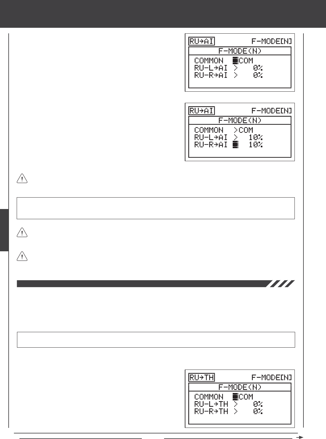
Page 102
aero Flight Mode menu
4) Press the Navigation Pad 6 to highlight RU-L4AI>0%.
5) Press the YES/+ or NO/- keys to change the Rudder-Left4Aileron
mixing percentage value.
6) Press the Navigation Pad 6 to highlight RU-R4AI>0%, then press the
YES/+ or NO/- keys to change the Rudder-Right4Aileron mixing
percentage value.
1) Press the Navigation Pad 56 to highlight MIXING, then press the
ENTER key to display the MIXING menu. The FLAPERON sub-menu
will be highlighted by default.
2) Press the Navigation Pad 6 to highlight RU4AI, then press the
ENTER key to display the RU4AI menu. The cursor will default to
COMMON>COM.
3) Press the YES/+ or NO/- keys to choose the desired COM or SEP
option as described previously.
RU-L4AI and RU-R4AI setting range is -100% to 100%. The default settings are 0%. When the percentage values are
increased from 0% to 100%, aileron travel will increase in one direction in relation to rudder travel. When the percentage values
are decreased from 0% to -100%, aileron travel will increase in the opposite direction in relation to rudder travel.
The Rudder4Aileron mixing percentage value is a ratio of aileron travel to rudder travel. For example, when the
Rudder-Left4Aileron and the Rudder-Right4Aileron mixing percentage values are set to 10%, the ailerons will travel
1/10th the amount that the rudder travels in both directions. This mix is Linear.
Because you can program the Rudder4Aileron percentage value separately for both directions of rudder travel, it's
possible to program the mix to either make the ailerons move up or down with right and left rudder control, make the ailerons
move up and down with right and left rudder control, or make the ailerons move up or down with right or left rudder control.
The channel options displayed will vary based on Model Type and Model Type selection options currently selected. For
example, if your model features dual aileron servos, RU-L/R4LA (Left Aileron) and RU-L/R4RA (Right Aileron) percentage
values can be changed separately.
Rudder to Throttle Mixing
The Rudder to Throttle Mixing function allows you to mix a percentage of throttle control with rudder control. When you move the
rudder right or left, the throttle will increase or decrease. The Rudder to Throttle Mixing function is typically used on twin-engine
aircraft to vary the throttle of each engine while taxiing. If can also be used to increase power during turns while taxiing. This is
helpful for oat planes or scale aircraft. The amount and the direction that the throttle moves with rudder control is adjusted by
changing the Rudder4Throttle mixing percentage value either positive or negative. Separate mixes can be programmed for right
and left rudder throw.
IMPORTANT The Rudder to Throttle Mixing function must be assigned to a Switch Position Number before it can be
Activated. For more information, see page 45.
1) Press the Navigation Pad 56 to highlight MIXING, then press the ENTER key to display the MIXING menu. The FLAPERON
sub-menu will be highlighted by default.
2) Press the Navigation Pad 6 to highlight RU4TH, then press the
ENTER key to display the RU4TH menu. The cursor will default to
COMMON>COM.
3) Press the YES/+ or NO/- keys to choose the desired COM or SEP
option as described previously.
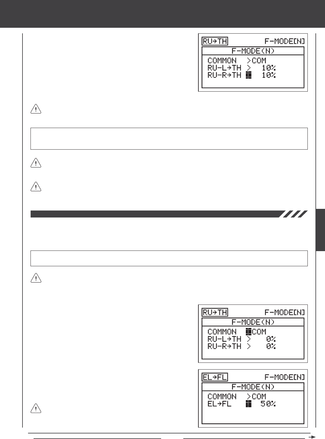
Page 103
aero Flight Mode menu
4) Press the Navigation Pad 6 to highlight RU-L4TH>0%.
5) Press the YES/+ or NO/- keys to change the Rudder-Left4Throttle
mixing percentage value.
6) Press the Navigation Pad 6 to highlight RU-R4THI>0%, then press
the YES/+ or NO/- keys to change the Rudder-Right4Throttle mixing
percentage value.
RU-L4TH and RU-R4TH setting range is -100% to 100%. The default settings are 0%. When the percentage values are
increased from 0% to 100%, throttle travel will increase in one direction in relation to rudder travel. When the percentage values
are decreased from 0% to -100%, throttle travel will increase in the opposite direction in relation to rudder travel.
The Rudder4Throttle mixing percentage value is a ratio of throttle travel to rudder travel. For example, when the
Rudder-Left4Throttle and the Rudder-Right4Throttle mixing percentage values are set to 10%, the throttle will travel
1/10th the amount that the rudder travels in both directions. This mix is Linear.
Because you can program the Rudder4Throttle percentage value separately for both directions of rudder travel, it's possible
to program the mix to either make the throttle increase or decrease with right and left rudder control, make the throttle
increase and decease with right and left rudder control, or make the throttle increase or decrease with right or left rudder control.
The channel options displayed will vary based on Model Type and Model Type selection options currently selected. For
example, if your model features dual throttle servos, RU-L/R4LT (Left Throttle) and RU-L/R4RT (Right Throttle) percentage
values can be changed separately.
Flap to Elevator Mixing
The Flap to Elevator Mixing function allows you to mix a percentage of elevator control with ap control. When you move the aps
up and down, the elevator will move up and down. The Flap to Elevator Mixing function is typically used to reduce the ballooning
tendency that most aircraft exhibit when the aps are deployed. The amount and the direction that the elevator moves with ap
control is adjusted by changing the Flap4Elevator mixing percentage value either positive or negative.
IMPORTANT The Flap to Elevator Mixing function must be assigned to a Switch Position Number before it can be Activated.
For more information, see page 45.
1) Press the Navigation Pad 56 to highlight MIXING, then press the ENTER key to display the MIXING menu. The FLAPERON
sub-menu will be highlighted by default.
2) Press the Navigation Pad 6 to highlight FL4EL, then press the
ENTER key to display the FL4EL menu. The cursor will default to
COMMON>COM.
3) Press the YES/+ or NO/- keys to choose the desired COM or SEP
option as described previously.
4) Press the Navigation Pad 6 to highlight FL4EL>0%.
5) Press the YES/+ or NO/- keys to change the Flap4Elevator mixing
percentage value.
The Flap4Elevator mixing percentage value is a ratio of elevator
travel to ap travel. For example, when the Flap4Elevator mixing
percentage value is set to 10%, the elevator will travel 1/10th the amount
that the aps travel. This mix is Linear.
In the majority of cases, you will want to program the Flap to Elevator Mixing function to move the elevator down enough
to minimize ballooning when the aps are lowered.
AERO
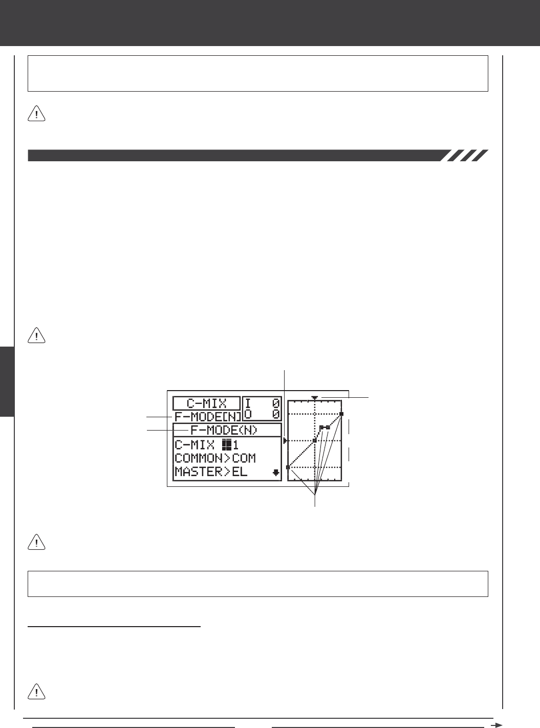
Page 104
The channel options displayed will vary based on Model Type and Model Type selection options currently selected. For
example, if your model features dual elevator servos, FL4LE (Left Elevator) and FL4RE (Right Elevator) percentage
values can be changed separately.
FL4EL setting range is -100% to 100%. The default setting is 0%. When the percentage value is increased from 0% to 100%,
elevator travel will increase in one direction in relation to flap travel. When the percentage value is decreased from 0%
to -100%, elevator travel will increase in the opposite direction in relation to ap travel.
aero Flight Mode menu
The C-Mix function allows you to program custom mixes that can control any number of desired functions in different combinations.
It is used to create your own custom mix if one of the pre-programmed mixes is not suitable. For example, you can create a
custom mix that mixes aperons and spoilerons to elevator, so that when you move the elevator up and down, the aperons will
move up and down, providing near-instantaneous extreme pitch changes while still enabling aileron roll control.
Like with pre-programmed mixes, Compensation Mixes are composed of a Master channel and a Slave channel. The Master
channel always controls the Slave channel. Any of the available ten channels can be programmed as a Master or a Slave. The
same channel can even be programmed as both a Master and a Slave. For example, if you want to program throttle Dual Rate,
you can set both the Master and the Slave to throttle, then adjust Point 1 and Point 9 Rate percentage values to provide the
amount of travel you want when the C-Mix function is Activated. The C-Mix function includes nine custom-programmable Points
to ensure an extremely precise channel Curve to suit any situation. You can also program a Delay for the Slave function that
works independently (or with) the dedicated Channel Delay function described on page 86.
Up to ve C-Mix functions can be programmed separately for each of the ve Flight Modes or you can use the same C-Mix
programming across all ve Flight Modes. An Input and Output display, along with a graph, help with programming visualization.
Transmitter F-MODE
Programming F-MODE
Stick Input (I)
Function Output (O)
150%
100%
100%
150%
0%
Point Positions
Transmitter F-MODE refers to the Flight Mode that the transmitter is currently operating in. Programming F-MODE refers
to the Flight Mode that you would like to change the programming for.
Choosing the Compensation Mixing Number
Up to ve separate Compensation Mixing functions can be programmed for each Flight Mode, however, only one Master/Slave
channel can be assigned to one Compensation Mixing function at a time. For example, if you want to program elevator
to aperons/spoilerons, you would need to program one Compensation Mixer for Master>Elevator to Slave>Left Aileron and a
second Compensation Mixer for Master>Elevator to Slave>Right Aileron.
More than one Compensation Mixer can be assigned to the same Switch Position Number, so that they can be Activated
at the same time. For example, assign both C-Mix 1 and C-Mix 2 to Switch Position 23 to Activate Elevator to Flaperon/
Spoileron mixing in the example above.
IMPORTANT Each C-Mix function must be assigned to a Switch Position Number before it can be Activated. For more
information, see page 45.
In all cases, the Master channel always controls the Slave channel. In the default conguration, all Compensation Mixes
can be programmed to be Linear, or precise channel Curves can be created by programming up to nine Points along
the Curve.
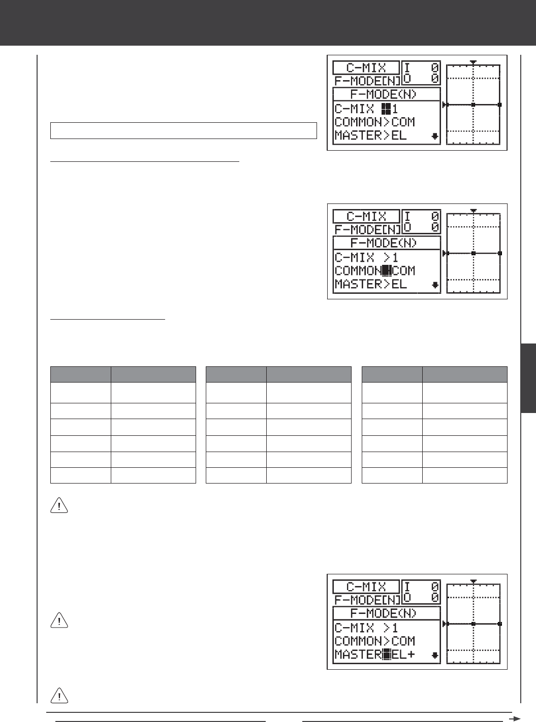
Page 105
aero Flight Mode menu
1) Press the Navigation Pad 56 to highlight C-MIX, then press the ENTER
key to display the C-MIX menu. The cursor will default to C-MIX>1.
2) Press the YES/+ and NO/- keys to choose the C-MIX number you would
like to program Compensation Mixing for.
C-MIX setting range is 1, 2, 3, 4, or 5. The default setting is 1.
Choosing the Flight Mode - Common or Separate
When set to COM (Common), the C-MIX settings will be the same regardless of which Flight Mode the transmitter is operating in.
You cannot program C-MIX settings separately for each Flight Mode. When set to SEP (Separate), you can program different
C-MIX settings separately for each Flight Mode.
1) Press the Navigation Pad 6 to highlight COMMON>COM, then press
the YES/+ or NO/- keys to choose either COM or SEP. If set to COM,
skip to the Choosing the Master Channel section. If set to SEP, see
step 2 below.
2) Press the F-MODE key to choose the F-MODE number you would like
to program the Compensation Mixing function for. Choose from N, 1,
2, 3, or 4. The F-MODE (N) display will change, indicating which Flight
Mode you are programming the Compensation Mixing function for.
Choosing the Master Channel
The Master channel is the channel that controls the Slave channel. For example, if you set the Master channel to EL (Elevator),
when you move the elevator control stick, the Slave channel that's mixed to the elevator channel will move. Depending on the Model
Type and Model Type selection options you've chosen in the Model Type menu, the following Master channels are available.
EL / EL+
AI / AI+
TH / TH+
RU / RU+
GE / GE+
FL / FL+
ABBR. FUNCTION
Elevator
Aileron
Throttle
Rudder
Gear
Flap
AUX1 / AUX1+
AUX2 / AUX2+
AUX3 / AUX3+
AUX4 /AUX4+
LE+
RE+
ABBR. FUNCTION
Auxiliary 1
Auxiliary 2
Auxiliary 3
Auxiliary 4
Left Elevator
Right Elevator
LA+
RA+
LT+
RT+
LF+
RF+
ABBR. FUNCTION
Left Aileron
Right Aileron
Left Throttle
Right Throttle
Left Flap
Right Flap
Master channels denoted with a plus sign (+) indicate that Dual Rate, Exponential, Trim, and/or Channel Delay settings affect
not only the Master channels but also the Slave channels when the Compensation Mixing function is Activated. For example,
if MASTER>EL+ is selected, any programmed elevator Dual Rate or Exponential percentage values will affect both the Master
elevator channel and the Slave channel when the elevator Dual Rate switch is Activated while the Compensation Mixing function is
Active. If you select MASTER>EL, any programmed elevator Dual Rate or Exponential percentage values will only affect the Master
elevator channel when the Compensation Mixing function is Active. Dual Rate and Exponential affect only the elevator, aileron, and
rudder channels. The Channel Delay function referenced is not the same as the Delay function in the C-MIX menu.
1) Press the Navigation Pad 6 to highlight MASTER>EL, then press the
YES/+ or NO/- keys to choose which channel you want to program the
Master channel for.
The channel options displayed will vary based on Model Type and
Model Type selection options currently selected. For example, if your
model features dual elevator servos, LE and RE will be separate options.
When using dual servos for elevators, ailerons, throttles, and/or aps, the
(+) option will only be available for the servos separately (e.g. LE+ and
RE+, but not for EL).
If you want Dual Rate, Exponential, Trim, and/or independent Channel Delay control over the Slave channel, make sure to
choose a Master channel with a plus sign (+).
AERO
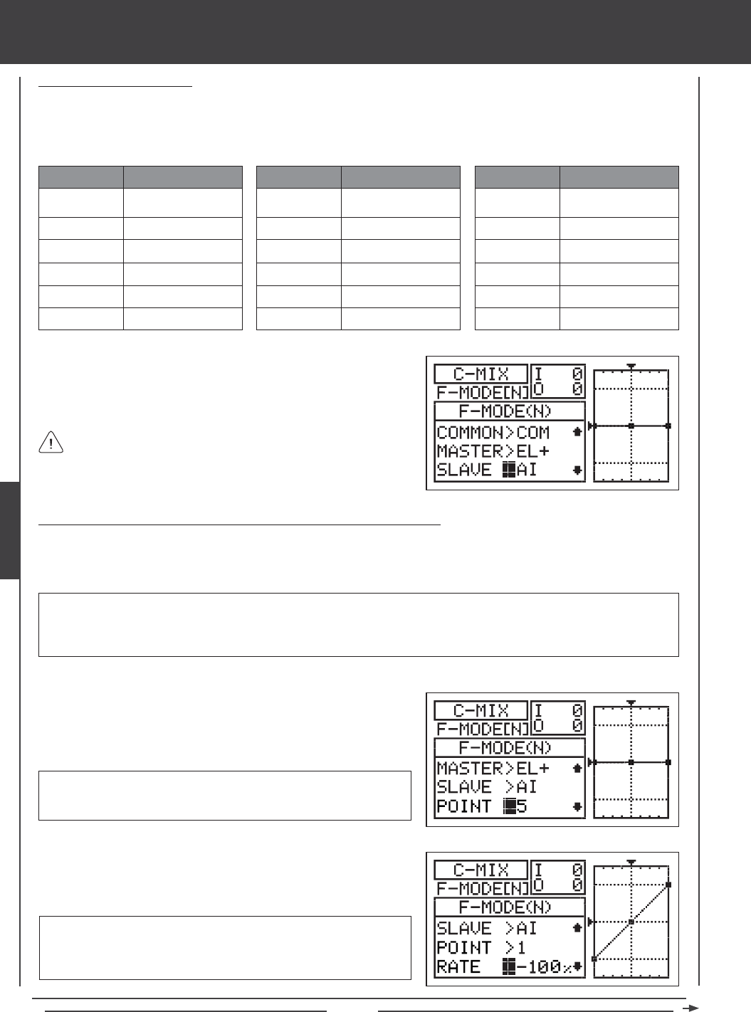
Page 106
aero Flight Mode menu
Choosing the Slave Channel
The Slave channel is the channel that is controlled by the Master channel. For example if you set the Master channel to
EL (Elevator) and the Slave channel to AI (Aileron), when you move the elevator control stick, the ailerons will move. Depending
on the Model Type and Model Type selection options you've chosen in the Model Type menu, the following Slave channels
are available.
EL
AI
TH
RU
GE
FL
ABBR. FUNCTION
Elevator
Aileron
Throttle
Rudder
Gear
Flap
AUX1
AUX2
AUX3
AUX4
LE
RE
ABBR. FUNCTION
Auxiliary 1
Auxiliary 2
Auxiliary 3
Auxiliary 4
Left Elevator
Right Elevator
LA
RA
LT
RT
LF
RF
ABBR. FUNCTION
Left Aileron
Right Aileron
Left Throttle
Right Throttle
Left Flap
Right Flap
1) Press the Navigation Pad 6 to highlight SLAVE>AI, then press the
YES/+ or NO/- keys to choose which channel you want to program the
Slave channel for.
The channel options displayed will vary based on Model Type and
Model Type selection options currently selected. For example, if your
model features dual aileron servos, LA and RA will be separate options.
Changing the Channel Curve Point Values and the Rate Percentage Values
Nine different Points with varying Rates can be programmed onto the channel Curve. Each Point will be displayed on the graph
to give you a visual interpretation of the position of the Point on the channel Curve. The Point that is currently selected will blink.
RATE setting range is -150% to 150%. POINT 1 default RATE percentage
value is 0%, POINT 5 default RATE percentage value is 0%, and POINT
9 default RATE percentage value is 0%. POINT 2, 3, 4, 6, 7, and 8 RATE
values are INH (Inhibited).
3) Press the Navigation Pad 6 to highlight RATE>0%.
4) Press the YES/+ or NO/- keys to set the desired Rate percentage value.
1) Press the Navigation Pad 6 to highlight POINT>5.
2) Press the YES/+ or NO/- keys to choose which Point you would like to
set a Rate percentage value for.
POINT setting range is 1 through 9. Point 1 is at the low end of the
channel Curve and Point 9 is at the high end of the channel Curve. Point
5 is a the center of the channel Curve.
WARNING When a Compensation Mixer is Activated, you still have separate control over the Slaved channel, however,
depending on the Rate percentage value, the Slave channel End Point Adjustment could be exceeded. We strongly recommend
that you set your Slave channel Limits no higher than that channel's End Point Adjustment unless specically necessary for
your particular setup. This will prevent any chance of overdriving your control linkage when Compensation Mixing is used.
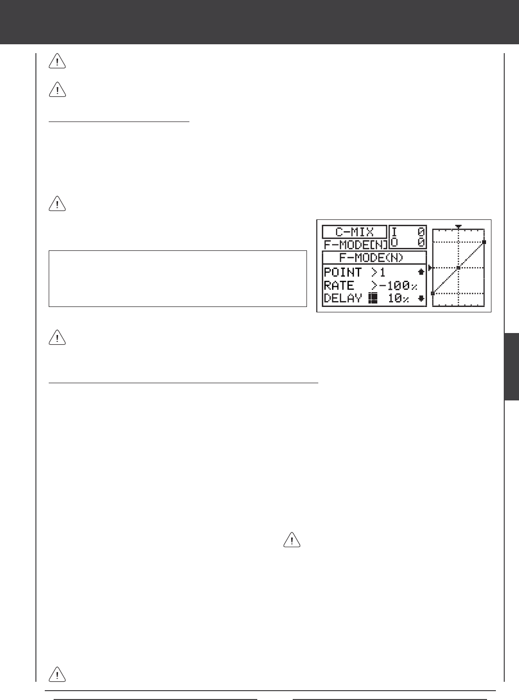
Page 107
aero Flight Mode menu
As you change the Point and Rate percentage values, you can use the graph and I/O numbers to visualize the ratio
between control stick movement and servo travel throughout the entire deection range.
The Rate percentage value is a ratio of Slave channel servo travel to Master channel servo travel. For example, if the Rate
percentage value is set to 10%, the Slave channel servo will travel 1/10th the amount that the Master channel servo travels.
Changing the Delay Percentage Value
Changing the Delay percentage value allows you to adjust the speed of Slave channel servo when moved in the direction of
the Master channel control stick when the Compensation Mixing function is Active. For example, if you program Compensation
Mixing to provide Elevator to Flaperon/Spoileron mixing, both of the ailerons will move up and down when the elevator moves up
and down. The ailerons can also be moved right and left to maintain roll control. Setting a Delay percentage value will cause both
aileron servos to slow down ONLY in the up and down directions when the elevator is moved up and down. Servo speed in the
right and left directions for roll control will be normal, unless you have programmed aileron Channel Delay separately.
The Delay function does not affect when the servo starts to respond to control stick movement. The Delay affects only
the transit time of the servo.
1) Press the Navigation Pad 6 to highlight DELAY>0%, then press the
YES/+ or NO/- keys to change the Delay percentage value.
DELAY setting range is 0% to 100%. The default setting is 0%. When
the Delay percentage value is increased, the Slave servo transit time will
be slowed down. At 0%, the Slave servo moves at its normal speed. At
100%, the Slave servo takes approximately 15 seconds to move from
neutral to 100% or -100% travel.
The Delay function will cause the Slave servo transit time to slow down not only from neutral to one End Point, but also on
the return from one End Point to neutral. The Delay percentage value is not Point-dependent.
Compensation Mixing Sample - Mixing Elevator to Flaperons/Spoilerons
The sample below describes how to mix elevator to aperons using two Compensation Mixers assigned to a single Switch
Position Number. This mix is common for use in 3D aerobatic aircraft where you want both ailerons to move up and down with the
elevator, yet still maintain full roll control. In the example below, the aircraft features two aileron servos and two elevator servos.
1) Assign C-MIX1 and C-MIX2 to the same Switch Position Number in the Switch Assign menu. For example, use Switch
Position Number 23.
2) Verify that the elevator and aileron control surfaces are operating as desired. If necessary, change the servo reversing setting
on one of the elevator servos so that both elevator servos move the same direction.
3) Set the two Compensation Mixing programming values as shown:
C-MIX>1
COMMON>COM
MASTER>LE+
SLAVE>LA
POINT>1 / RATE>-100%
POINT>9 / RATE>100%
C-MIX>2
COMMON>COM
MASTER>RE+
SLAVE>RA
POINT>1 / RATE>100%
POINT>9 / RATE>-100%
In this example, Points 1 and 9 are set to -100% and 100% on C-MIX1, and Points 1 and 9 are set to 100% and -100% on C-MIX2.
When both Compensation Mixers are Active, this results in both aileron servos moving together. When up elevator is commanded,
both ailerons move down (aperons) and when down elevator is commanded, both ailerons move up (spoilerons). With the
Rate setting at -100% and 100%, both aileron servos will move up and down at the same time the same amount as the elevator
servos. This also results in a Linear channel Curve. If you wanted to lessen the aperon/spoileron travel, decrease the Rate for
Points 1 and 9.
The positive and negative values shown in the example above may vary based on the NOR/REV status of your aileron and
elevator servos. You may need to change the percentage values to suit.
The Point 1 and Point 9 Rate percentage values for
C-MIX>2 are opposite those of C-MIX>1. This ensures
that both aileron servos move up and down together.
AERO
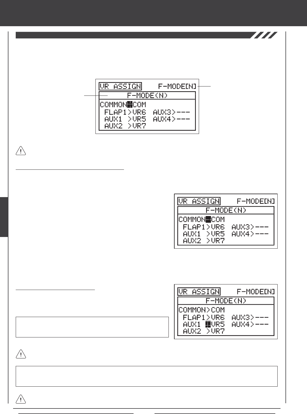
Page 108
The VR Assign function allows you to assign the auxiliary channels and the Flap 1 function to either of the two Auxiliary Levers
(VR5 or VR6) or the Auxiliary Dial Knob (VR7). For example, you could use the Auxiliary Dial Knob (VR7) to control your engine's
throttle mixture remotely. You can choose to program VR Assignments separately for each of the ve Flight Modes or you can use
the same VR Assignments programming across all ve Flight Modes.
Transmitter F-MODE
Programming F-MODE
Transmitter F-MODE refers to the Flight Mode that the transmitter is currently operating in. Programming F-MODE refers
to the Flight Mode that you would like to change the programming for.
Choosing the Flight Mode - Common or Separate
When set to COM (Common), the VR ASSIGN settings will be the same regardless of which Flight Mode the transmitter is operating
in. You cannot program VR ASSIGN settings separately for each Flight Mode. When set to SEP (Separate), you can program
different VR ASSIGN settings separately for each Flight Mode.
3) Press the F-MODE key to choose the F-MODE number you would like to program the VR Assignments for. Choose from
N, 1, 2, 3, or 4. The F-MODE (N) display will change, indicating which Flight Mode you are programming the VR
Assignments for.
1) Press the Navigation Pad 56 to highlight VR ASSIGN, then press the
ENTER key to display the VR ASSIGN menu. The cursor will default to
COMMON>COM.
2) Press the YES/+ or NO/- keys to choose either COM or SEP. If set to
COM, skip to the Choosing VR Channel Assignments section. If set to
SEP, see step 3 below.
IMPORTANT Both sides of each auxiliary channel (High and Low), can be assigned to a Switch Position Number, using the
SW ASSIGN menu. If an auxiliary channel is assigned to both a switch and an Auxiliary Lever, the switch takes precedence
over the Auxiliary Lever in all cases.
aero Flight Mode menu
Choosing VR Channel Assignments
1) Press the Navigation Pad 5634 to highlight the channel you would
like to change the VR Assignment for, then press the YES/+ or NO/- keys
to change the VR Assignment.
VR ASSIGN setting range is ---, VR5, VR6, and VR7. The default setting
for FLAP1 is VR6. The default setting for AUX1 is VR5 and the default
setting for AUX2 is VR7. The default settings for AUX3 and AUX4 is ---.
In the default conguration, FLAP1 is assigned to VR6. When the ap switch is in Flap Position 1, Auxiliary Lever (VR6)
will variably control the aps. For more information, see page 91.
To disable an Auxiliary Lever or the Auxiliary Dial Knob, assign --- to the desired channel. For example, if you don't want
Auxiliary Lever (VR6) to control the aps when the ap switch is in Switch Position 1, change FLAP1>VR6 to FLAP1>---.
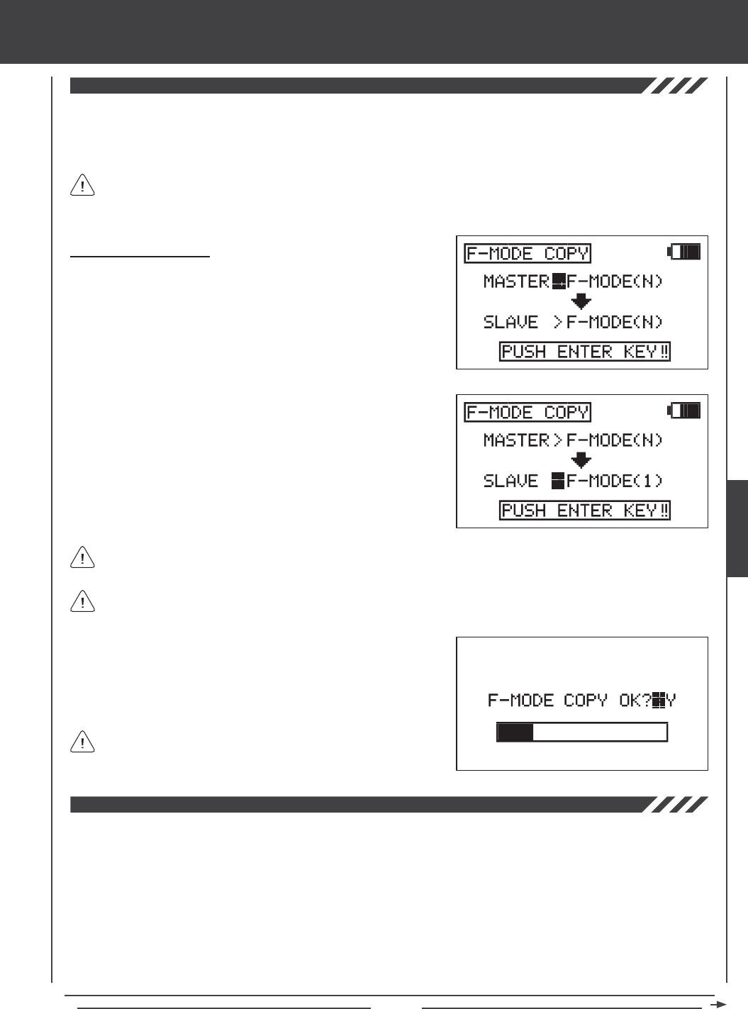
Page 109
aero Flight Mode Menu
The Flight Mode Copy function allows you to copy the Flight Mode programming data from one Flight Mode to another Flight
Mode. This is convenient if you want to use two or more different Flight Modes on one model, but only need to change a few
Flight Mode programming values for the new Flight Mode. This allows you to use the Flight Mode programming data from the
rst Flight Mode to use as a base to start ne-tuning the programming for the second Flight Mode.
You can only copy Flight Mode programming data from one Flight Mode to another Flight Mode within the same model.
To copy Flight Mode programming data from one model's Flight Mode to another model's Flight Mode, you must copy
the actual model programming data to the other model. For more information, see page 52.
Copying Flight Mode Data
1) Press the Navigation Pad 56 to highlight F-MODE COPY, then press
the ENTER key to display the F-MODE COPY menu. The cursor
will default to MASTER>F-MODE(N).
2) Press the F-MODE key to select the Flight Mode you would like to copy
the Flight Mode programming data FROM (MASTER). Select from
F-MODE (N, 1, 2, 3, or 4).
3) Press the Navigation Pad 6 to highlight SLAVE>F-MODE(N).
4) Press the F-MODE key to select the Flight Mode you would like to
copy the Flight Mode programming data TO (SLAVE). Select from
F-MODE (N, 1, 2, 3, 4, or ALL).
5) Press then ENTER key. F-MODE COPY OK?>Y will be displayed.
6) Press the YES/+ key to begin the F-MODE Copy process. When the
F-MODE Copy process is completed the F-MODE COPY menu will be
displayed, indicating that the Flight Mode programming data has been
copied.
It's not possible to copy the Flight Mode programming data from one Flight Mode to the same Flight Mode. If you attempt
to execute this, SAME F-MODE?? will be displayed and the process will not execute.
If you want to go back and change the Flight Mode or you don't want
to copy the Flight Mode programming data for any reason, press the
NO/- or END keys.
Selecting ALL will copy the MASTER Flight Mode programming data to the remaining four Flight Modes.
The Flight Mode Delay function allows you to program custom delays for each of the channel functions within each of the
separate Flight Modes. This function helps to prevent drastic changes in channel settings when switching between Flight Modes.
For example, if you are ying an electric aerobatic aircraft, you might have one Flight Mode set up for sport ying and a second
Flight Mode set up for 3D aerobatic ying. Within each of those two Flight Modes you might have programmed different Throttle
Curves. The Flight Mode Delay function allows you to program a Delay in the throttle channel so that the transition to the different
Throttle Curves when you switch back and forth between Flight Modes is smooth.
If you program Flight Mode Delays for all ve Flight Modes separately, you can program up to 10 different Delays for each Flight
Mode. If you are using fewer Flight Modes, you can program more than 10 different Delays for each of the Flight Modes that you're
using. You are able to program 50 different Delays in total. The Flight Mode Delay function can be programmed for each of the
channels you're using, and separate Flight Mode Delays can be programmed in both directions. For example, when switching from
Flight Mode N (Normal) to Flight Mode 1 and back from Flight Mode 1 to Flight Mode N (Normal).
AERO
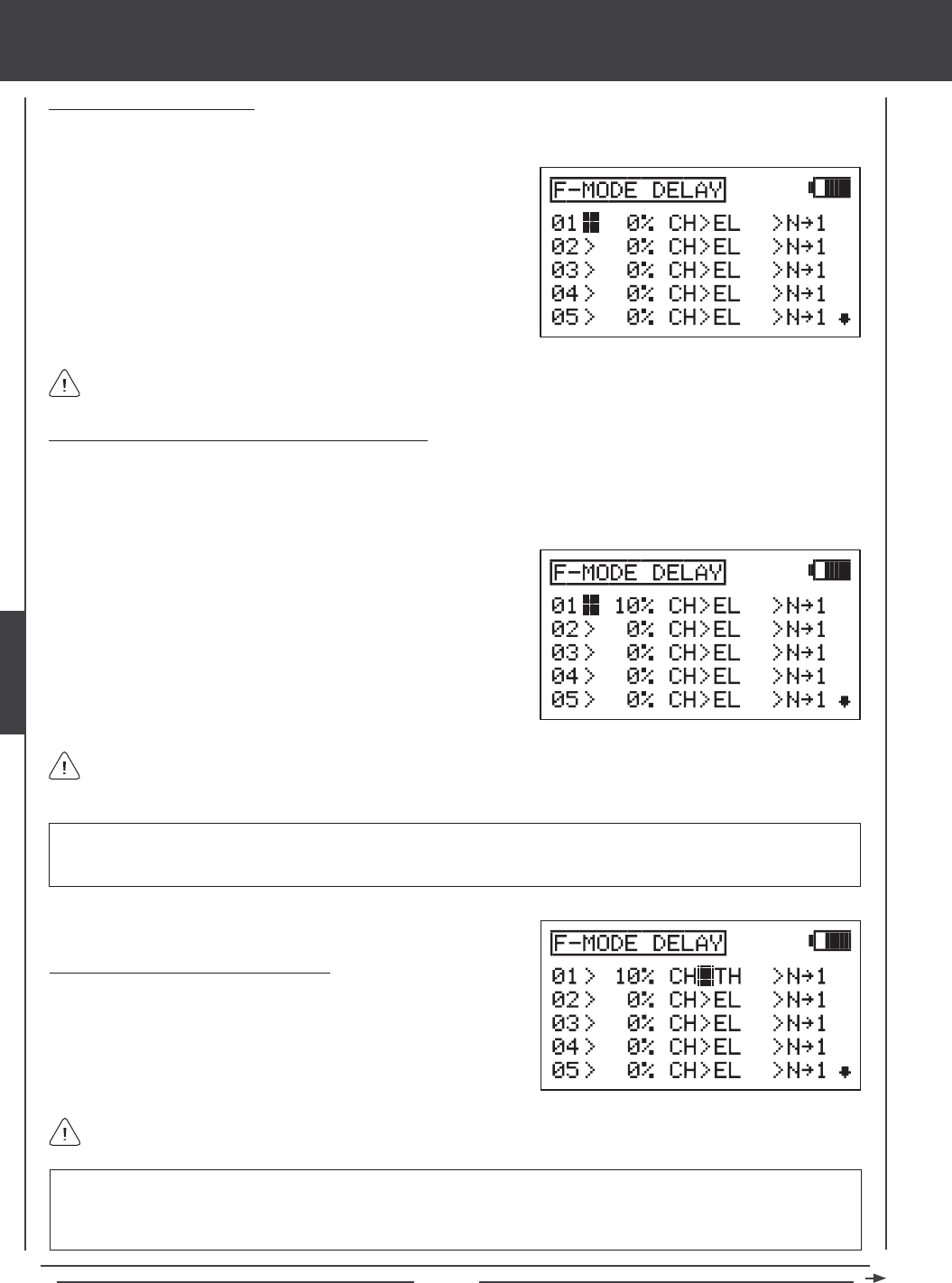
Page 110
aero Flight Mode Menu
Choosing a Flight Mode Delay
1) Press the Navigation Pad 56 to highlight F-MODE DELAY, then press the ENTER key to display the F-MODE DELAY
menu. The cursor will default to 01>0% CH>EL >N41.
Flight Mode Delays do not have to programmed in sequence (e.g., 01, 02, 03), but programming them in sequence does
make it easier to keep track of them.
Changing the Flight Mode Delay Rate Percentage Value
The Rate percentage value changes the speed of the servos as they move to their new positions when you switch between Flight
Modes. For example, if you're ying at half throttle in Flight Mode N (Normal) and your throttle servo is at 50% travel, but in Flight
Mode 1 at half throttle your throttle servo is programmed to be at 70% travel, increasing the Rate percentage value will slow the
speed at which the servo will move to 70% travel when you Activate Flight Mode 1. This allows the throttle to smoothly rise to the
new travel position instead of instantly jumping to the new travel position.
RATE setting range is 0% to 100%. The default setting is 0%. When the Rate percentage value is set to 0%, there is no Delay
when switching between Flight Modes. When the Rate percentage value is increased, the Delay when switching between
Flight Modes is increased.
The Rate percentage value is displayed as a percentage of Delay time and is based on the amount of change in servo
travel when switching between different Flight Modes. When the Rate percentage value is set to 100%, the servo will take
approximately 15 seconds to travel from neutral to 100% or -100%.
1) Press the YES/+ and NO/- keys to change the Rate percentage value
for the selected Flight Mode Delay.
IMPORTANT Channels that use two servos, such as dual aileron servos or dual elevator servos will be displayed separately
(e.g., RE, LE, RA, LA, etc). In this situation, the Flight Mode Delay function will affect not the whole channel, but the individual
servo. In most cases, you will want to program a second matching Flight Mode Delay for the second servo, so that both servos
are affected equally.
Choosing the Flight Mode Delay Channel
1) Press the Navigation Pad 4 to highlight CH>EL.
2) Press the YES/+ and NO/- keys to choose which channel you would
like the Flight Mode Delay to affect.
The channels options displayed will vary based on Model Type and Model Type selection options currently selected. For
example, if your model features dual elevator servos, LE or RE will be display as an option.
2) Press the Navigation Pad 56 to highlight the Flight Mode Delay you
would like to program. If this is the rst Flight Mode Delay that you're
programming, choose 01>0%
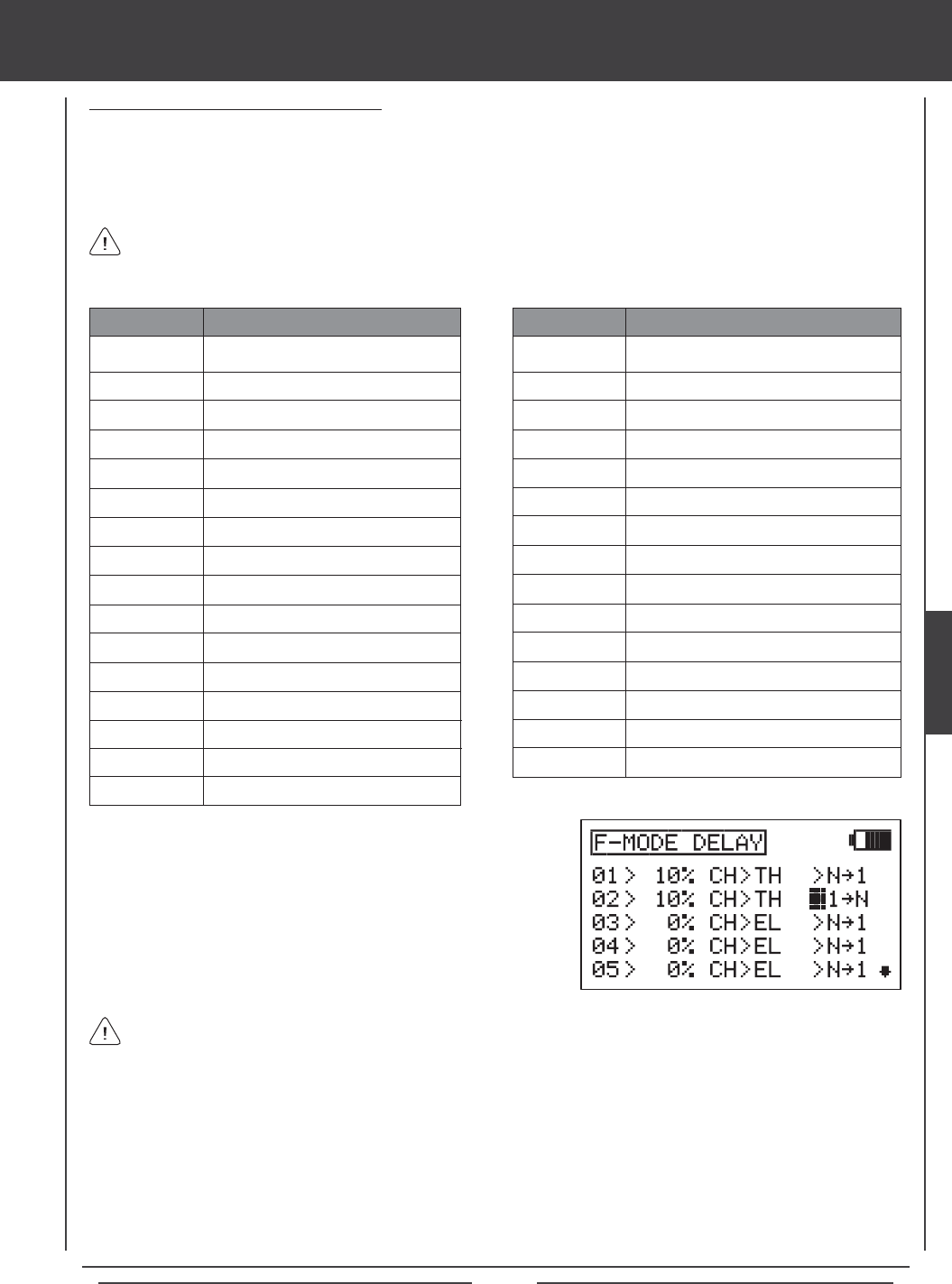
Page 111
aero Flight Mode Menu
Changing the Flight Mode Delay Sequence
The Flight Mode Delay sequence denes the direction you want the Flight Mode Delay going TO and FROM, as shown in the
tables below. For example, if you choose N41, the Flight Mode Delay function will Activate when you switch from Flight Mode N
(Normal) to Flight Mode 1. If you choose N44, the Flight Mode Delay function will Activate when you switch from Flight Mode N
to Flight Mode 4. If you choose 44N, the Flight Mode Delay function will Activate when you switch from Flight Mode 4 to Flight
Mode N (Normal).
341
342
344
34*
44N
441
442
443
44*
*4N
*41
*42
*43
*44
*4*
FROM Flight Mode 3 to Flight Mode 1
FROM Flight Mode 3 to Flight Mode 2
Flight Mode 3 TO Flight Mode 4
Flight Mode 3 TO All Flight Modes
FROM Flight Mode 4 to Flight Mode N
FROM Flight Mode 4 to Flight Mode 1
FROM Flight Mode 4 to Flight Mode 2
FROM Flight Mode 4 to Flight Mode 3
Flight Mode 4 TO All Flight Modes
FROM All Flight Modes to Flight Mode N
FROM All Flight Modes to Flight Mode 1
FROM All Flight Modes to Flight Mode 2
FROM All Flight Modes to Flight Mode 3
FROM All Flight Modes to Flight Mode 4
FROM All Flight Modes TO All Flight Modes
SEQUENCE DESCRIPTION
N41
N42
N43
N44
N4*
14N
142
143
144
14*
24N
241
243
244
24*
34N
Flight Mode N TO Flight Mode 1
Flight Mode N TO Flight Mode 2
Flight Mode N TO Flight Mode 3
Flight Mode N TO Flight Mode 4
Flight Mode N TO All Flight Modes
FROM Flight Mode 1 to Flight Mode N
Flight Mode 1 TO Flight Mode 2
Flight Mode 1 TO Flight Mode 3
Flight Mode 1 TO Flight Mode 4
Flight Mode 1 TO All Flight Modes
FROM Flight Mode 2 to Flight Mode N
FROM Flight Mode 2 to Flight Mode 1
Flight Mode 2 TO Flight Mode 3
Flight Mode 2 TO Flight Mode 4
Flight Mode 2 TO All Flight Modes
FROM Flight Mode 3 to Flight Mode N
SEQUENCE DESCRIPTION
Delay sequences that include an Asterisk indicate that the Flight Mode Delay function will be Activated across all Flight
Modes. For example, if you choose N4*, the Flight Mode Delay function will Activate on all Flight Modes regardless of
the Flight Mode you switch to.
1) Press the Navigation Pad 4 to highlight N41.
2) Press the YES/+ and NO/- keys to choose which Flight Mode Delay
sequence you would like to use.
Use the tables of Delay sequences above to help you choose which Flight Mode Delay sequence you would like to use.
3) Repeat the previous procedures to program more Flight Mode Delay functions. For example, if you want to set a Flight Mode
Delay for the throttle channel when you switch from Flight Mode N (Normal) to Flight Mode 1, and from when you switch back
from Flight Mode 1 to Flight Mode N (Normal), program the following:
01>10% CH>TH >N41
02>10% CH>TH >14N
This programming will result in a 10% delay in the throttle channel when you switch from Flight Mode N (Normal) to Flight
Mode 1 and when you switch back from Flight Mode 1 to Flight Mode N (Normal). This will not Activate the Flight Mode Delay
when you switch to any other Flight Mode. For example, when you switch from Flight Mode N (Normal) to Flight Mode 2.
AERO
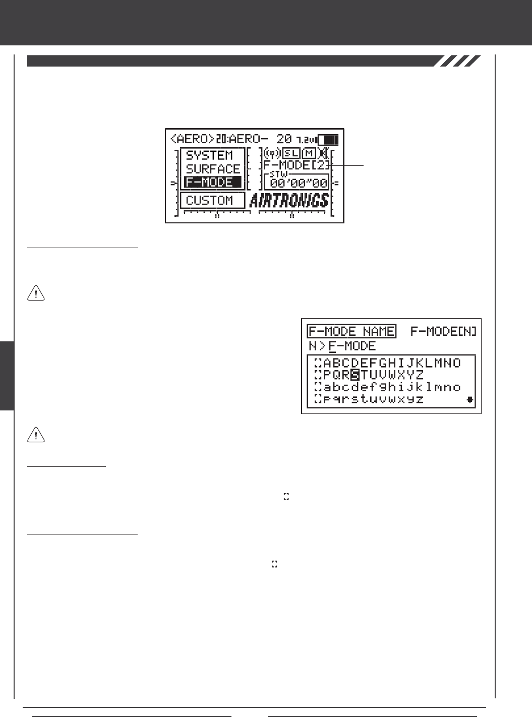
Page 112
aero Flight Mode Menu
The F-Mode Name function allows you to name each of your individual F-Modes. This makes it easier to keep track of which
F-Mode is currently in use. The currently Active Flight Mode name is displayed, along with the corresponding Flight Mode number
on the Top menu and on the various F-MODE programming menus. The F-Mode Name can consist of up to 6 letters, numbers,
or symbols. Choose from capital letters, lower case letters, numbers, and various symbols.
Entering a Flight Mode Name
1) Press the Navigation Pad 56 to highlight F-MODE NAME, then press the ENTER key to display the F-MODE NAME menu.
The cursor will default to the left side of the top row of letters.
Deleting a Character
1) Press the YES/+ or NO/- keys to move the underline under the character you want to erase.
2) Press the Navigation Pad 3456 to highlight the Erase Bracket , then press the ENTER key to erase the underlined
character.
Deleting a Flight Mode Name
1) Press the YES/+ and NO/- keys at the same time to move the underline under the rst character.
2) Press the Navigation Pad 3456 to highlight the Erase Bracket , then press the ENTER key repeatedly to erase the entire
Flight Mode Name.
Press the F-MODE key to cycle through the ve different F-Modes. The F-Mode that you are currently naming is shown to
the left of the Flight Mode Name. For example, N>F-MODE.
2) Press the Navigation Pad 3456 to highlight a character, then press
the ENTER key to select the highlighted character. That character will be
displayed and the underline will move to the next space.
3) Repeat step 2 to enter the rest of the characters. Up to six characters
can be entered.
Press the Navigation Pad 56 repeatedly to scroll up and down the list of characters.
Flight Mode Name
and Number
THIS SPACE INTENTIONALLY LEFT BLANK

Page 113
glid Flight Mode contents
GLID
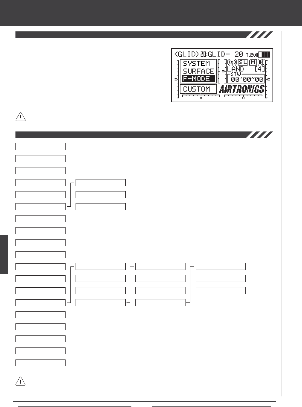
Page 114
glid Flight Mode menu
To access the F-Mode menu, turn the transmitter ON. From the Top menu,
press the Navigation Pad 56 to highlight F-MODE, then press the ENTER
key to display the F-Mode menu.
From within any menu, press the END key continuously to return to the
Top menu.
Unless otherwise noted, all programming changes take effect immediately.
If the Top menu is not displayed when you turn the transmitter ON, continuously press the END key until the Top menu
is displayed.
Use this Flow Chart to familiarize yourself with the GLID Flight Mode menu structure. Descriptions
regarding all GLID Flight Mode menu functions and programming are found on pages 115
through 155.
04.EXP
03.D/R
02.STICK MONITOR
01.SX MONITOR
05.AI DIFFERENTIAL
06.LANDING
07.CAMBER
08.CAMBER POINT
09.CH DELAY
10.TRIM
11.TRIM STEP
12.TRIM AUTH
13.CROSS-TRIM
14.MIXING
15.C-MIX
16.VR ASSIGN
17.F-MODE COPY
18.F-MODE DELAY
19.F-MODE NAME
6
6
6
6
6
6
6
6
6
6
6
6
6
6
6
6
6
6
06.FL>EL
07.RU>AI
08.GE>EL
09.MT>EL
10.CB>EL
6
6
6
01.AI>RU1
02.AI>RU2
03.AI>RU3
04.AI>FL1
05.AI>FL2
6
6
6
6
6
6
6
01.FLAP FREEZE POINT
02.CROW
03.LANDING DIFF
6
6
6
11.EL>CB
6
The ve Flight Modes have been pre-named for your convenience, however, they have not been pre-programmed. The
Flight Modes have been named as follows: NORMAL (N), FLOAT (1), LAUNCH (2), REFLEX (3), and LAND (4).
See the IMPORTANT note on the next page regarding Flight Modes.
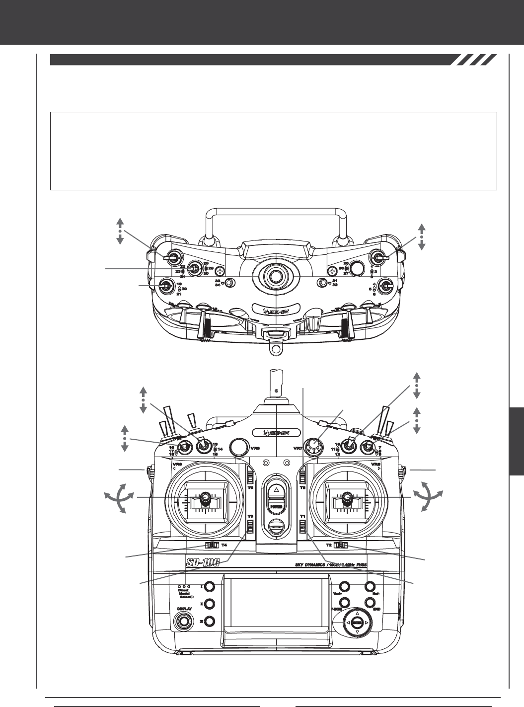
Page 115
glid Flight Mode menu
The diagrams below show the default transmitter control stick and switch layout in the GLID Model Type conguration. This is
the base from which you can start to change or add functions to switch assignments, modify Flight Modes, and change or assign
functions or channels to the Auxiliary Levers (VR5 and VR6) and the Auxiliary Dial (VR7).
Flap Trim Switch
Rudder Trim Switch
Rudder
Control Stick
Flap Control Stick*/Flight
Mode N and Flight Mode 4
Elevator Dual
Rate 1,2,3
AUX2
Rudder Dual
Rate 1,2,3
Aileron Dual
Rate 1,2,3
Aileron
Control Stick
Elevator
Control Stick
Aileron Trim Switch
Elevator Trim Switch
Auxiliary
Lever (VR6)
Camber
Auxiliary
Dial (VR7)
AUX1
Auxiliary
Lever (VR5)
*In the default configuration the flap control stick operates the flaps. For normal flight the flap control stick should be
pushed all the way forward. To lower the flaps for landing, pull the flap control stick back.
IMPORTANT When the ap control stick is pulled all the way back, Flight Mode 4 (Land) will be Activated and will override all
other Flight Modes. To Activate Flight Modes N, 1, 2, or 3, push the ap control stick all way forward, then Activate the desired
Flight Mode using one of the Flight Mode switches described below. Since each of the ve Flight Modes can be programmed
separately, before making programming changes, verify that you are in the Flight Mode you want to make programming changes to.
Keep in mind that many of the functions, particularly Mixes and Auxiliary functions, MUST be assigned to a Switch Position
Number to be Activated. We suggest that you assign the function to a Switch Position Number prior to programming the
function. This will avoid confusion and make it easier to test your programming values.
Flight
Mode N,1,2
Start/Stop
Timer
Flight Mode 3
AI>RU
Mixing 1,2,3
Camber
Preset Trim
Switch
GLID
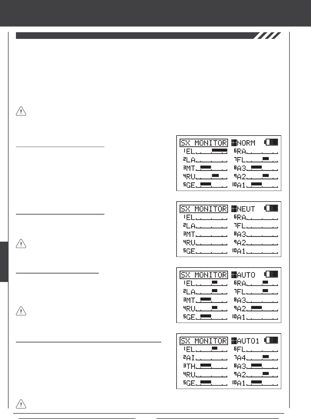
Page 116
glid Flight Mode menu
The Servo Monitor function displays the output levels of each of the 10 channels in bar graph form, allowing you to monitor servo
operation in a virtual manner. This is helpful to see servo movement when the control sticks and switches are moved, and it allows
you to visualize what is occurring with servo movements when you apply different mixing values. When used in conjunction with
the Display key, the Servo Monitor function allows you to see servo movement virtually and make programming changes without
the SD-10G transmitter actually transmitting a signal.
When both the SD-10G transmitter and the receiver are turned ON, the Servo Monitor function has the ability to continuously
cycle the primary ight control servos back and forth to verify operation. You are also able to individually cycle any of the primary
ight control servos and check the Neutral position of each of the servos (or automatically center all of the servos).
Using the Servo Monitor - Normal Mode
1) Press the Navigation Pad 56 to highlight SX MONITOR, then press
the ENTER key to display the SX MONITOR menu. The cursor will
default to >NORM.
2) Moving the control sticks and channel switches (if assigned) will display
the position and movement of each of the servos.
Using the Servo Monitor - Neutral Mode
1) Press the YES/+ key to choose >NEUT. When set to NEUT, all servos
will move to the Neutral position until you either change the Servo
Monitor Mode or exit the Servo Monitor menu.
While in Neutral Mode, all ight controls are Inhibited.
Using the Servo Monitor - Auto1, Auto2, Auto3, and Auto4 Modes
1) Press the YES/+ key to choose >AUTO1. When set to AUTO1, the
elevator servo will cycle back and forth equally until you either change
the Servo Monitor Mode or exit the Servo Monitor menu.
2) Press the YES/+ key again to choose >AUTO2 and so on. AUTO2 will
cycle the aileron servos, AUTO3 will cycle the ap servo(s), and AUTO4
will cycle the rudder servo.
The ight control for the currently Active servo will be Inhibited, however, the remaining channels remain Active so that
you can continue using them.
The channels displayed will vary based on Model Type and Model Type selection options currently selected. For example,
if your model features four aileron servos, ROA, LOA, RIA, and LIA will be displayed and all four servos will move when
the AUTO2 option is used. Depending on the current servo reversing settings, the bar graphs may not move the same direction
as the control sticks. This is normal.
Using the Servo Monitor - Auto Mode
1) Press the YES/+ key to choose >AUTO. When set to AUTO, the
primary ight control servos will cycle back and forth at the same time,
until you either change the Servo Monitor Mode or exit the Servo Monitor
menu.
While in Auto Mode, the primary flight controls are Inhibited,
however, the remaining channels remain Active so that you can
continue using them.
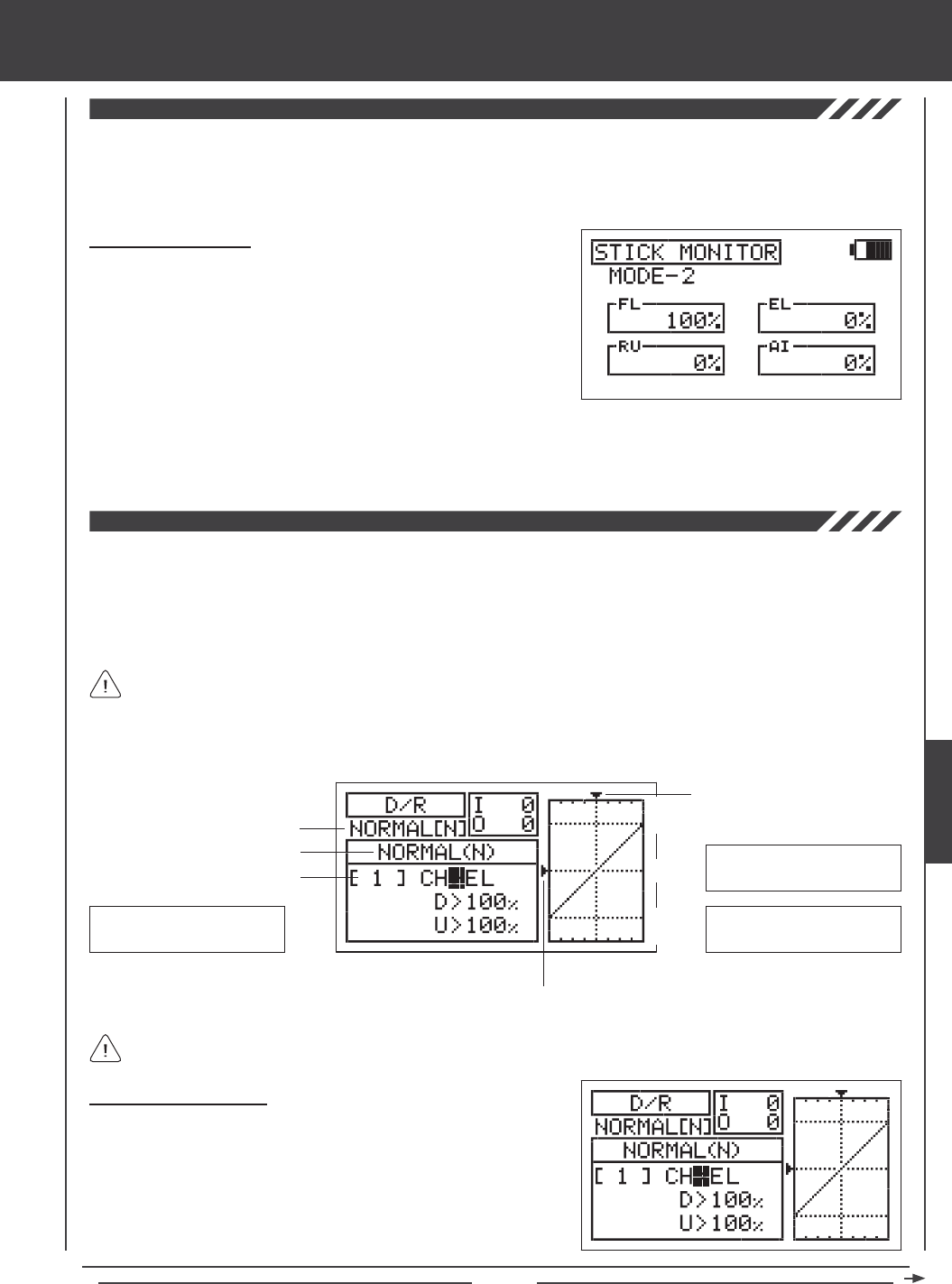
Page 117
glid Flight Mode menu
The Stick Monitor function displays the current position of the control sticks as a percentage of total control stick movement in
1% increments, and is used to determine if the control sticks require calibration. For example, if you move the ap control stick
all the way forward and 95% is displayed, this indicates that the ap control stick requires calibration. In addition, the Stick Monitor
function allows you to visually check exactly what position the control sticks are in relative to the control surface you're setting up.
Using the Stick Monitor
1) Press the Navigation Pad 56 to highlight STICK MONITOR, then
press the ENTER key to display the STICK MONITOR menu. The
current Mode that the SD-10G transmitter is operating in will be displayed.
2) Move the control sticks and watch the percentage displays. When the
control sticks are centered, 0% should be displayed, and when the
control sticks are moved to their stops, -100% or 100% should be
displayed, based on the direction of movement.
3) If 0% is not displayed when the control sticks are centered, or if -100% and 100% are not displayed when the control sticks
are moved to their stops, use the NEUTRAL/TRAVEL>USER setting in the System Mode menu to recalibrate the control sticks.
For more information, see page 43.
The Dual Rate function allows you to change the control authority of the control surfaces by changing the amount of servo travel.
For example, if you are ying a sailplane that requires more control throw for low-speed ight, but that same amount of control
throw makes the aircraft difcult to control during high-speed ight, you can use Dual Rate to lower the control throw for high-speed
ight with just the ip of the Dual Rate switch. Three Dual Rate settings are available each for the Elevator, Aileron, and Rudder
channels, and different Dual Rate settings can be programmed separately for each of the ve Flight Modes. An Input and Output
display, along with a graph, help with programming visualization.
Dual Rate is a percentage of End Point Adjustment. For example, if you set Dual Rate 2 to 50% and Activate it, the servo
will travel half the amount than if Dual Rate 2 was not Active. Prior to ight, check the position of the Dual Rate switches
to ensure that they are in the positions you want. If you assign two different channel Dual Rates to more than one switch, it's
important to note that the higher numbered Dual Rate will override the lower numbered Dual Rates. For example, if you have
Dual Rate 2 and Dual Rate 3 Active at the same time, Dual Rate 3 will override Dual Rate 2.
Choosing the Flight Mode
1) Press the Navigation Pad 56 to highlight D/R, then press the ENTER
key to display the D/R menu. The cursor will default to CH>EL.
2) Press the F-MODE key to choose the F-MODE number you would like
to program the Dual Rate function for. Choose from N, 1, 2, 3, or 4. The
NORMAL (N) display will change, indicating which Flight Mode you are
programming the Dual Rate function for.
Transmitter F-MODE
Dual Rate Number
Programming F-MODE
Stick Input (I)
Servo Output (O)
Transmitter F-MODE refers to the Flight Mode that the transmitter is currently operating in. Programming F-MODE refers
to the Flight Mode that you would like to change the programming for.
150%
100%
100%
150%
0%
EL-D/R Default Switch
Position Numbers: 16,17,18
AI-D/R Default Switch
Position Numbers: 07,08,09
RU-D/R Default Switch
Position Numbers: 10,11,12
GLID
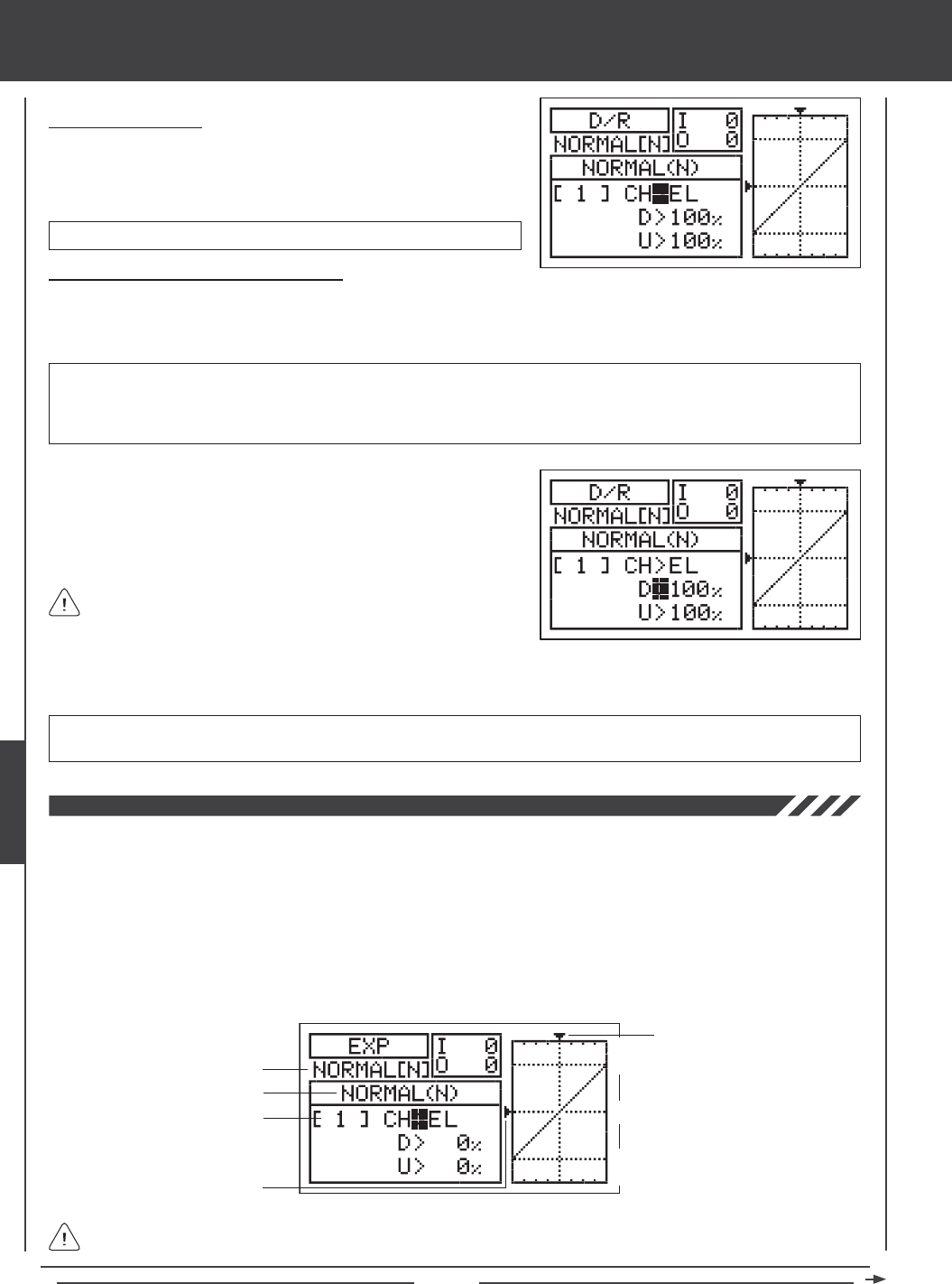
Page 118
glid Flight Mode menu
Choosing the Channel
1) Press the Navigation Pad 56 to highlight CH>EL.
2) If you would like to set the Dual Rate for another channel, press the
YES/+ or NO/- keys to choose CH>AI or CH>RU.
Changing the Dual Rate Percentage Values
Three different Dual Rate settings can be programmed to each three-position switch. We recommend that Dual Rate 1 be set to
the maximum control surface throw you desire, then set Dual Rate 2 and Dual Rate 3 to different values that are less than
maximum. For example, set Dual Rate 1 to 100%, Dual Rate 2 to 75%, and Dual Rate 3 to 50%.
3) Press the Navigation Pad 6 to move the cursor to U>100% (R>100% if setting aileron or rudder Dual Rate), then press the
YES/+ or NO/- keys to set the desired Up (or Right) Dual Rate percentage value.
WARNING Keep in mind that it's possible to set the Dual Rate higher than the End Point Adjustment. For example,
with the End Point Adjustment set to 100% and the Dual Rate set to 150% the servo will move more than 100% when
the Dual Rate is Activated. We strongly recommend that you set the Dual Rate 1 percentage value to no more than
100%. This will prevent any chance of exceeding your End Point Adjustment and overdriving your control linkage.
As you change the Dual Rate percentage values, you can use the
graph and I/O numbers to visualize the ratio between control stick
movement and servo travel throughout the entire deection range.
D/R setting range is 0% to 150%. The default setting is 100%. Increasing the D/R percentage value increases servo travel
when Dual Rate is Activated. Decreasing the D/R percentage value decreases servo travel when Dual Rate is Activated.
1) Move the Dual Rate Switch for the channel you are setting to the position
you would like to set a Dual Rate percentage value for, either 1, 2, or 3.
2) Press the Navigation Pad 6 to move the cursor to D>100% (L>100% if
setting aileron or rudder Dual Rate), then press the YES/+ or NO/- keys
to set the desired Down (or Left) Dual Rate percentage value.
Dual Rate can be set for EL (Elevator), AI (Aileron), and RU (Rudder).
The Exponential function allows you to vary the amount of servo travel in relation to the movement of the elevator, aileron, and
rudder control sticks near the neutral positions to change the way the control surfaces react to control stick movement. Increasing
the Exponential value will soften the control feel around neutral and decreasing the Exponential value will heighten the control
feel around neutral. For example, using a positive Exponential value allows for smoother control by lessening the amount of servo
travel in relation to the amount of control stick movement. Using a negative Exponential value may result in more 'twitchy' control
response because the amount of servo travel will be increased in relation to the amount of control stick movement.
The Exponential function is linked directly to your Dual Rate switches. This allows you to program Exponential for each of the
three Dual Rate positions separately. In addition, Exponential can be programmed separately for each of the ve Flight Modes.
An Input and Output display, along with a graph, help with programming visualization.
Transmitter F-MODE
Dual Rate Number
Programming F-MODE
Stick Input (I)
Function Output (O)
150%
100%
100%
150%
0%
Transmitter F-MODE refers to the Flight Mode that the transmitter is currently operating in. Programming F-MODE refers
to the Flight Mode that you would like to change the programming for.
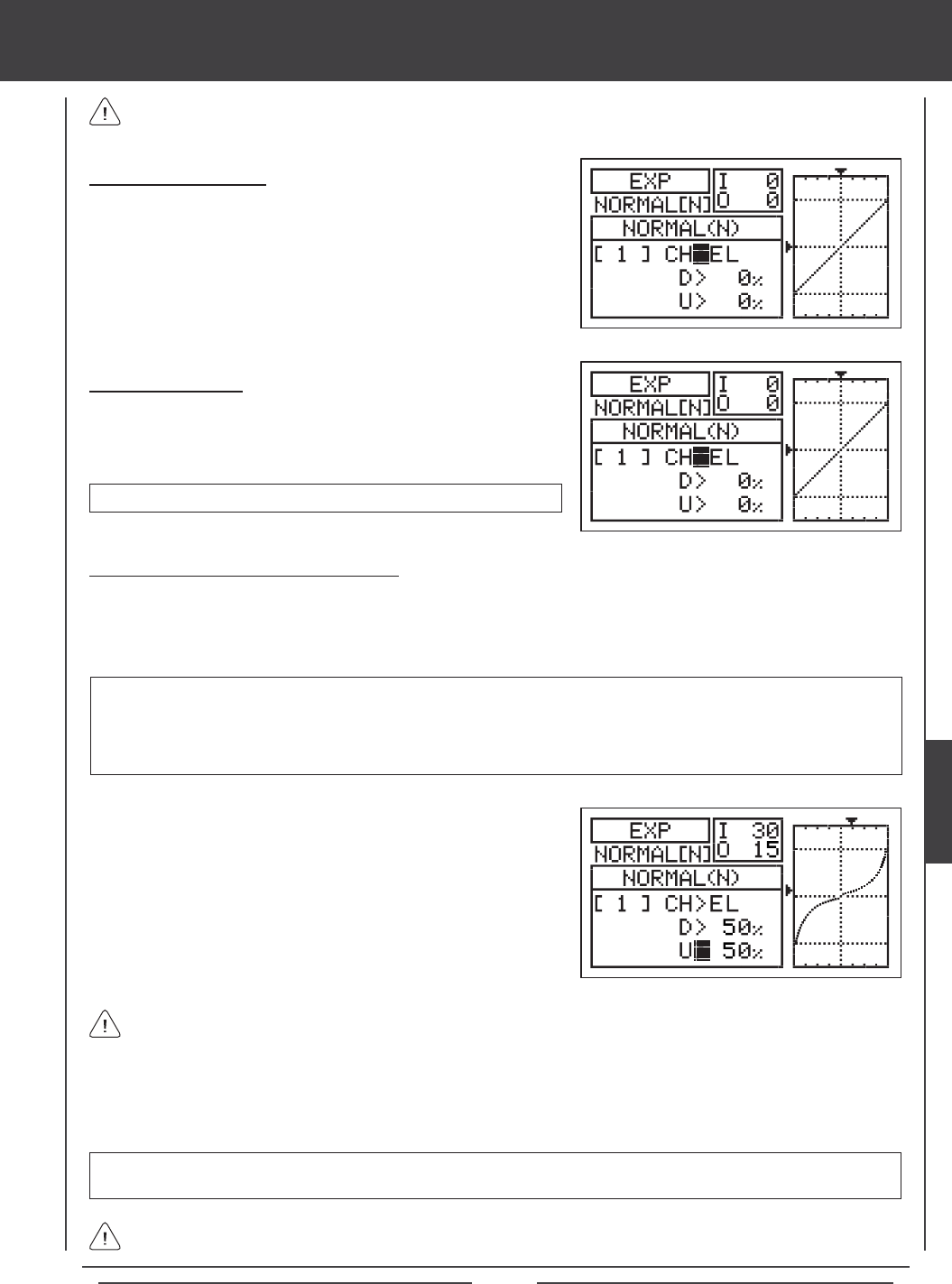
Page 119
glid Flight Mode menu
Choosing the Flight Mode
1) Press the Navigation Pad 56 to highlight EXP, then press the ENTER
key to display the EXP menu. The cursor will default to CH>EL.
2) Press the F-MODE key to choose the F-MODE number you would like to
program the Exponential function for. Choose from N, 1, 2, 3, or 4. The
NORMAL (N) display will change, indicating which Flight Mode you are
programming the Exponential function for.
Choosing the Channel
1) Press the Navigation Pad 56 to highlight CH>EL.
2) If you would like to set the Exponential for another channel, press the
YES/+ or NO/- keys to choose CH>AI or CH>RU.
Exponential can be set for EL (Elevator), AI (Aileron), and RU (Rudder).
Changing the Exponential Percentage Values
The Exponential function is linked directly to your Dual Rate switches. This allows you to program Exponential for each of the
three Dual Rate positions separately. For example, with the Dual Rate switch in position 1 (maximum travel), you can set 30%
Exponential, with the Dual Rate switch in position 2, you can set 10% Exponential, and with the Dual Rate switch in position 3,
you can set 0% Exponential (Linear).
4) Press the Navigation Pad 6 to move the cursor to U>0% (R>0% if setting aileron or rudder Exponential), then press the
YES/+ or NO/- keys to set the desired Up (or Right) Exponential percentage value.
As you change the Exponential percentage values, you can use the graph and I/O numbers to visualize the ratio between
control stick movement and servo travel throughout the entire deection range. Notice that as you increase Exponential,
the servo travel is decreased near the neutral position in relation to control stick movement, and as you decrease Exponential, the
servo travel is increased near the neutral position in relation to control stick movement.
EXP setting range is -100% to 100%. The default setting is 0% (Linear). Increasing the EXP percentage value softens the
control feel around neutral. Decreasing the EXP percentage value heightens the control feel around neutral.
1) Move the Dual Rate Switch for the channel you are setting to the
position you would like to set an Exponential value percentage for,
either 1, 2, or 3.
2) Press the Navigation Pad 6 to move the cursor to D>0% (L>0% if
setting aileron or rudder Exponential).
3) Press the YES/+ or NO/- keys to set the desired Down (or Left)
Exponential percentage value.
WARNING If you have not used Exponential functions in the past, we suggest that you start with a small percentage
of Exponential (approximately 10%~20%) until you get used to the feel of how Exponential affects the control feel of
your model. You will find that Exponential is most useful where strong control response is desired at extreme control
stick positions, but softer control response to small control stick movements is desired in order to make very accurate
small corrections to the flight path.
When the Exponential value is set to 0%, the ratio between servo travel and control stick movement will be Linear. For
example, when you move the control stick 50%, the servo will travel 50%, too.
Exponential does not change the total amount of servo travel at maximum control stick deection. Exponential affects
the ratio between servo travel and control stick movement at less than 100% control stick deection.
GLID
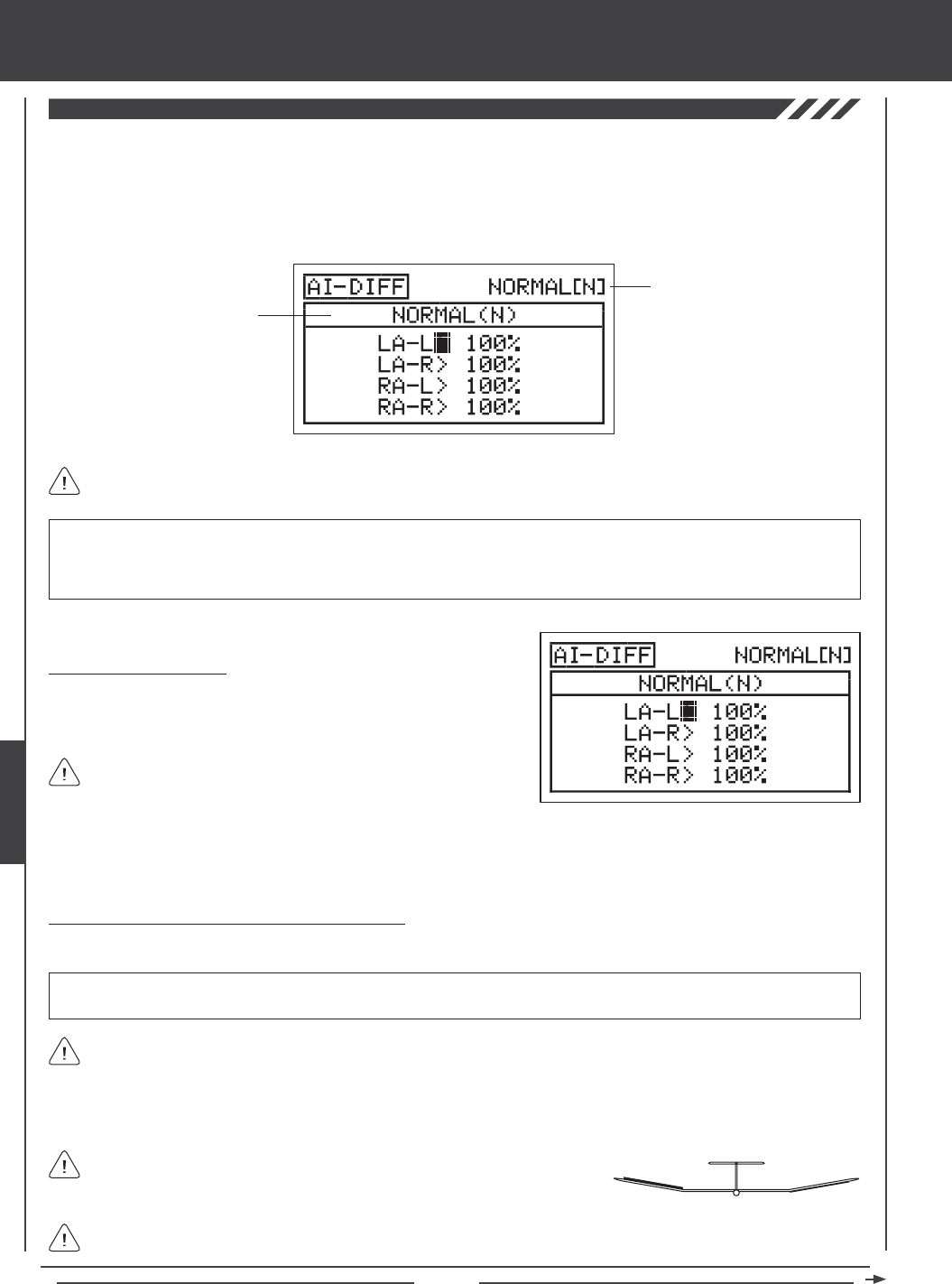
Page 120
glid Flight Mode menu
The Aileron Differential function allows you change the ratio of the Up to Down movement of each aileron. For example, many
aircraft exhibit a yaw tendency when the ailerons are used. This can affect any aircraft, and is common in sailplanes, especially
when a lot of aileron control throw is used. The Aileron Differential function can be used to eliminate the yaw tendency by adding
more movement to the upward moving aileron than the downward moving aileron. For example, if your aircraft tends to yaw during
aileron turns, you can adjust the Aileron Differential to make the aircraft turn more axially, which requires less use of the rudder to
compensate. The Aileron Differential function can be programmed separately for each of the ve Flight Modes.
Transmitter F-MODE
Programming F-MODE
Transmitter F-MODE refers to the Flight Mode that the transmitter is currently operating in. Programming F-MODE refers
to the Flight Mode that you would like to change the programming for.
Aileron Differential is a percentage of the control throw differential between the
ailerons. For example, if you set LA-R (Left Aileron-Right) to 90%, the Left Aileron
will move Down less than what the Right Aileron moves Up.
Choosing the Flight Mode
1) Press the Navigation Pad 56 to highlight AI DIFFERENTIAL, then
press the ENTER key to display the AI-DIFF menu. The cursor will
default to LA-L>100%.
When Model Type Setting Option AILERON>4 is chosen, the cursor
will default to LOA-L>100%
Changing the Aileron Differential Percentage Values
Aileron Differential is achieved by reducing the amount of DOWN movement in the required aileron.
IMPORTANT Prior to setting the Aileron Differential, you should use the Surface menu EPA Adjustment Option to ensure
that each aileron is moving UP and DOWN the same amount.
UP = More
Movement
DOWN = Less
Movement
Diagram of Differential
2) Press the F-MODE key to choose the F-MODE number you would like to program the Aileron Differential function for. Choose
from N, 1, 2, 3, or 4. The NORMAL (N) display will change, indicating which Flight Mode you are programming the Aileron
Differential function for.
IMPORTANT The Aileron Differential function is only effective when the aps are up. The Landing Differential function will
always override the Aileron Differential function in the same Flight Mode when the Landing Differential Function is Activated
and the aps are deployed, either using the ap control stick, or if you've moved the ap function to a three-position switch.
For more information, see page 45.
Aileron Differential can be programmed for each aileron. The channels displayed will vary based on Model Type and Model
Type selection options currently selected. For example, if your model features four aileron servos, LOA-L (Left Outside
Aileron - Left), LOA-R (Left Outside Aileron - Right), ROA-L (Right Outside Aileron - Left) ROA-R (Right Outside Aileron - Right),
LIA-L (Left Inside Aileron - Left), LIA -R (Left Inside Aileron - Right), RIA-L (Right Inside Aileron - Left), and RIA-R (Right Inside
Aileron - Right) will be displayed and the Aileron Differential can be adjusted for each of the servos individually.
The Aileron Differential percentage value is a percentage of End Point Adjustment.
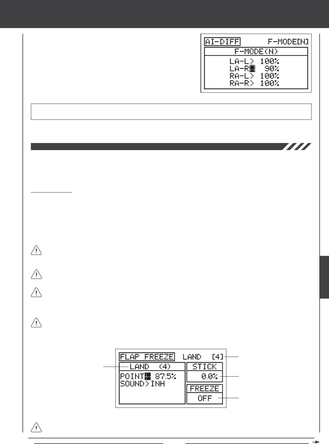
Page 121
glid Flight Mode menu
1) Press the Navigation Pad 56 to highlight the desired aileron travel
direction you would like to change the Aileron Differential setting for. For
example, if you need the Right Aileron to move Up more than the Left
Aileron moves Down (per the diagram on the previous page), you would
decrease the LA-R>100% (Left Aileron-Right) percentage value.
2) Press the YES/+ or NO/- keys to set the desired Aileron Differential
percentage value.
AI-DIFF setting range is 0% to 100%. The default setting is 100%. Decreasing the AI-DIFF percentage value will decrease the
movement for that specic aileron and direction of travel.
3) Repeat the previous procedures to set the desired remaining Aileron Differential percentage values.
The Landing menu consists of three different functions. The Flap Freeze Point function, the Crow function, and the Landing
Differential function. Although all three functions can be programmed separately for each of the ve Flight Modes. These
functions are intended to be used when the aircraft is in landing mode [e.g., the transmitter is in Flight Mode 4 (Land) or the aps
are deployed]. In the default conguration, Flight Mode 4 (Land) is Active when the ap control stick is pulled back.
Flap Freeze Point
The Flap Freeze Point function allows you to set a predetermined amount of ap deection, based on ap control stick position,
then variably control the remainder of ap travel, using the ap control stick. For example, if you set the Flap Freeze Point
percentage value to 50%, the aps will deploy to that ap control stick position when the ap control stick is moved from Flight
Mode 1 (Normal) to Flight Mode 4 (Land). Once you pull the ap control stick down below the 50% control stick position, the aps
will variably move down relative to the position of the ap control stick. To raise the aps completely and turn off Flight Mode 4
(Land), move the ap control stick all the way forward. An audible tone can be programmed to indicate when the Flap Freeze
Point turns ON and OFF.
The Flap Freeze Point function will only work if the aps are controlled by a control stick (in the default conguration, the
ap control stick). The Flap Freeze Point function will not work if the aps have been reassigned to a switch.
In the default conguration, Flight Mode 4 (Land) becomes Active when the ap control stick position reaches 87.5%. If
you want to disable the Flap Freeze Point function, set the Flap Freeze Point to 87.5% (press the YES/+ and NO/- keys
at the same time when adjusting the Point percentage value. This will provide variable ap deection for the entire amount of
ap control stick movement.
If you reassign the Camber function to the ap control stick (CAMBER>STK in the VR ASSIGN menu), it is normal for
the ap servo(s) to move with the aileron servos to produce Camber, even though the Flap Freeze Point might be Active.
For more information, see page 151.
Transmitter F-MODE
Programming F-MODE
Transmitter F-MODE refers to the Flight Mode that the transmitter is currently operating in. Programming F-MODE refers
to the Flight Mode that you would like to change the programming for.
Flap Control Stick Position
Flap Freeze Status
When the ap control stick is above the Flap Freeze Point position, the aps will not move until either the ap control stick
is moved down below the Flap Freeze Point position or the ap control stick is moved all the way forward to raise the aps
completely and turn off Flight Mode 4 (Land).
GLID
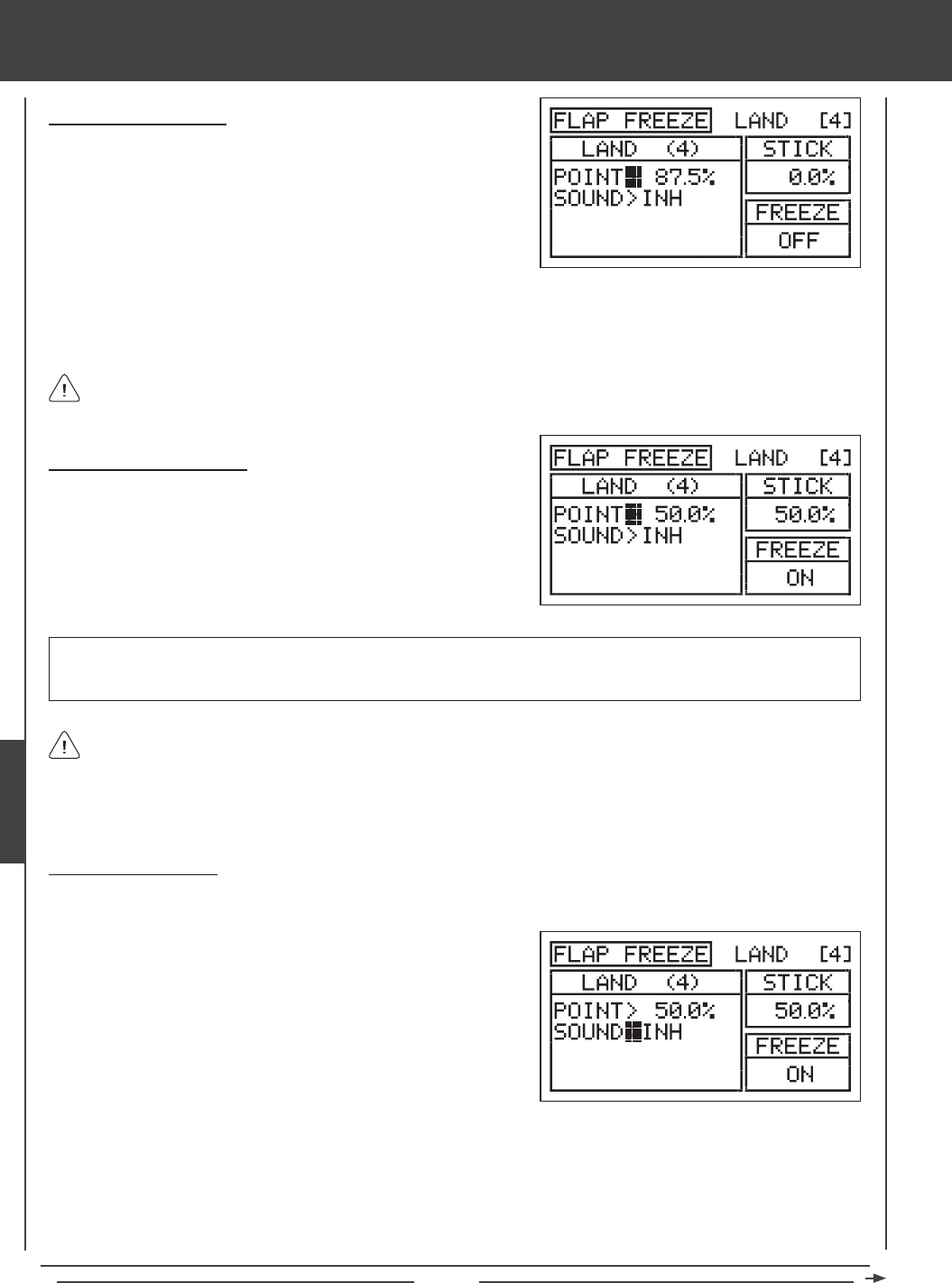
Page 122
glid Flight Mode menu
Setting the Flap Freeze Point
1) Press the Navigation Pad 56 to highlight POINT>87.5%. This is the
position at which the Flap Freeze Point function will turn ON and OFF.
2) Move the ap control stick to the position at which you want the Flap
Freeze Point to turn ON and OFF, then press the YES/+ key. ON will
be displayed in the FREEZE dialog box.
The current position of the ap control stick is displayed in the STICK dialog box. If you want to disable the Flap Freeze
Point function, so that you will have variable ap deection for the entire amount of ap control stick movement, set the
Flap Freeze Point to the same percentage value the ap control stick switches Flight Modes. For example, if you've previously
reset the Flap Stick Switch Point percentage value to 50% using the Stick Switch menu (causing the ap control stick to switch
to and from Flight Mode 4 (Land) at 50% control stick movement, set the Flap Freeze Point percentage value to 50%, too.
Choosing the Flight Mode
1) Press the Navigation Pad 56 to highlight LANDING, then press the
ENTER key to display the LANDING menu. The cursor will default to
the FLAP FREEZE POINT sub-menu.
2) Press the ENTER key to display the FLAP FREEZE POINT menu. The
cursor will default to POINT>87.5%.
Although the Flap Freeze Point function can be programmed for use in any Flight Mode, it is intended to be used only
during landing, so we suggest choosing the Flight Mode that you have designated for landing.
3) Press the F-MODE key to choose the F-MODE number you would like to program the Flap Freeze Point function for. Choose
from N, 1, 2, 3, or 4. The LAND (4) display will change, indicating which Flight Mode you are programming the Flap Freeze
Point function for.
IMPORTANT If you set the Point percentage value to 0%, you will not have variable control of the aps. The aps will deploy
to their maximum deection when Flight Mode 4 (Land) is Activated. When you turn off Flight Mode 4 (Land), the aps will
retract completely.
Flap Freeze Point Sound
An audible tone can be programmed to alert you to the status of the Flap Freeze Point function.
ON<>OFF - An audible tone is heard when the Flap Freeze Point function turns ON and when the Flap Freeze Point function
turns OFF.
ON>OFF - An audible tone is heard only when the Flap Freeze Point function turns OFF.
OFF>ON - An audible tone is heard only when the Flap Freeze Point function turns ON.
1) Press the Navigation Pad 6 to highlight SOUND>INH.
2) Press the YES/+ or NO/- keys to choose which sound option you desire
to use. When set to INH, no audible tone will be heard when the Flap
Freeze Point function turns ON and OFF.
The following Sound options are available:
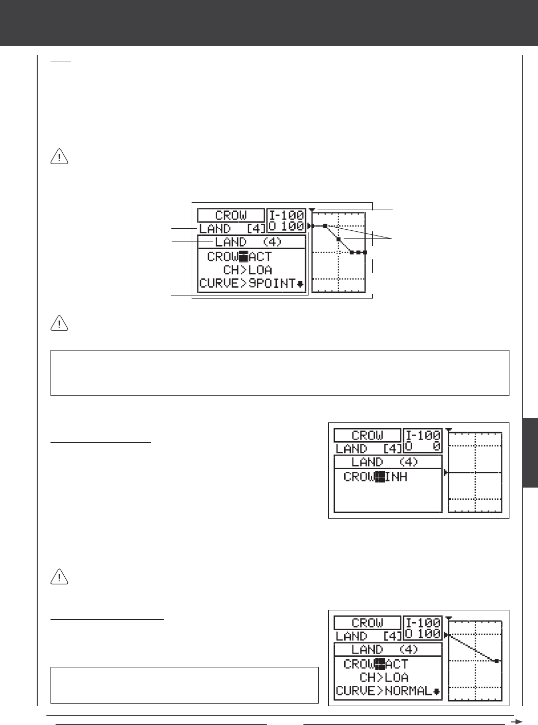
Page 123
glid Flight Mode menu
Crow
The Crow function allows you to use the ailerons and the aps simultaneously to control the lift of the aircraft, while still allowing
aileron roll control. Crow is typically used to quickly reduce lift, ensuring pin-point spot landings in nearly any situation. When
the Crow function is Activated, all of the ailerons should move Up and all of the aps should move Down when the aps are
deployed. The Crow function can be adjusted separately for each aileron servo and you have the choice of making each of those
adjustments Linear or Curved by programming each of the nine custom-programmable Points. The amount of deection and the
position at which the Crow function Activates during ap deployment can also be changed. An Input and Output display, along
with a graph, help with programming visualization.
The Crow function works in conjunction with the aps. If the Flap Freeze Point function is used, the Crow function will still
operate variably with the ap control stick even when the aps are deployed to your predetermined amount of deection
(Flap Freeze Point function ON). Once the Flap Freeze Point function is OFF, the aps will work variably with the ap control stick
to produce Crow all the way to full ap deection.
Transmitter F-MODE
Programming F-MODE
Stick Input (I)
Function Output (O)
150%
100%
100%
150%
0%
Transmitter F-MODE refers to the Flight Mode that the transmitter is currently operating in. Programming F-MODE refers
to the Flight Mode that you would like to change the programming for.
Choosing the Flight Mode
1) Press the Navigation Pad 56 to highlight LANDING, then press the
ENTER key to display the LANDING menu. The cursor will default to
the FLAP FREEZE POINT sub-menu.
2) Press the Navigation Pad 6 to highlight CROW, then press the ENTER
key to display the CROW menu. The cursor will default to CROW>INH.
Although the Crow function can be programmed for use in any Flight Mode, it is intended to be used only during landing,
so we suggest choosing the Flight Mode that you have designated for landing.
3) Press the F-MODE key to choose the F-MODE number you would like to program the Crow function for. Choose from N, 1,
2, 3, or 4. The LAND (4) display will change, indicating which Flight Mode you are programming the Crow function for.
Activating the Crow Function
1) Press the Navigation Pad 56 to highlight CROW>ACT.
2) Press the YES/+ or NO/- keys to choose the desired the ACT/INH setting.
Points
IMPORTANT Prior to Activating and programming the Crow function, it's important that the ailerons and aps are centered
(all control surfaces should be even with the trailing edge of the wing) with the transmitter in Flight Mode N (Normal). All End
Point Adjustments and Limits should be set for Flight Mode N (Normal), too. The aps should be centered when the ap control
stick pushed all the way forward.
CROW setting range is ACT or INH. The default setting is ACT. When set
to ACT, the Crow function will be Activated for that Flight Mode. When set
to INH, the Crow function will be Inhibited for that Flight Mode.
GLID
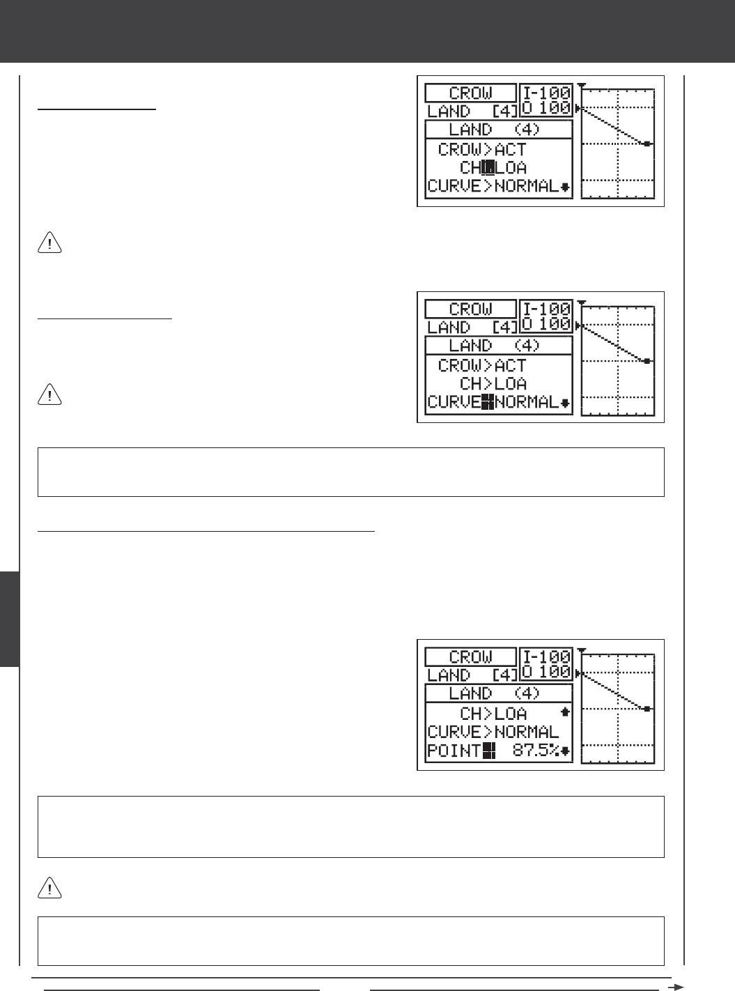
Page 124
glid Flight Mode menu
Choosing the Channel
1) Press the Navigation Pad 6 to highlight CH>LOA.
2) Press the YES/+ or NO/- keys to choose the channel you would like
to set the Curve value, Point percentage value, and Rate percentage
value for.
The channels displayed will vary based on Model Type selection options currently selected. For example, if your model
features four aileron servos, LOA (Left Outside Aileron), ROA (Right Outside Aileron), LIA (Left Inside Aileron), and RIA
(Right Inside Aileron) will be displayed and the Curve value, Point percentage value, and Rate percentage value can be adjusted
for each of the servos individually.
Choosing the Curve Type
1) Press the Navigation Pad 6 to highlight CURVE>NORMAL.
2) Press the YES/+ or NO/- keys to choose the desired Curve type.
CURVE setting range is NORMAL and 9POINT. The default setting is NORMAL. When set to NORMAL, the Crow function will
operate in a Linear fashion. When set to 9POINT, each of the nine individual points can be changed to create a channel Curve
when the Crow function operates. This allows for greater exibility and ne-tuning for specic aircraft.
If you choose CURVE>9POINT, skip to the Changing the Point and
Rate Percentage Values - 9 Point Curve section on the next page.
Changing the Point and Rate Percentage Values - Normal Curve
The Point percentage value determines the position that the Crow function begins to operate based on the position of the ap
control stick. For example, you could set the Point percentage value so that the Crow function begins to operate when the ap
control stick is centered, however, still maintain only ap control at higher ap control stick positions. The Rate percentage
value denes the maximum amount of servo travel desired when the Crow function is used.
POINT setting range is 0.0% to 100%. The default setting is 87.5%. The Point percentage value will vary and should be set so
that the aileron is centered when the ap control stick is in the position you desire to begin adding Crow. For example, if you
want to begin adding Crow when the ap control stick is centered, center the ap control stick, then change the Point percentage
value to move the aileron back to the centered position.
Decreasing the Point percentage value will lessen the available Crow aileron servo travel. You can add more Crow aileron
servo travel by adjusting the Rate percentage value described on the next page.
1) Press the Navigation Pad 6 to highlight POINT>87.5%
WARNING Keep in mind that when the Crow function is used, the aileron servo travel can exceed the End Point
Adjustment value that you set previously in the Surface menu, however, the aileron servo travel will not exceed the
Limits adjustment value. Be careful when setting the Rate percentage value that you don't overdrive your control linkage.
2) Move the ap control stick to the position you would like the Crow
function to begin to operate.
3) Press the YES/+ or NO/- keys to move the aileron servo back so that
the aileron is centered. In the majority of cases, you'll program a lower
Point percentage value to bring the aileron back to the centered position.
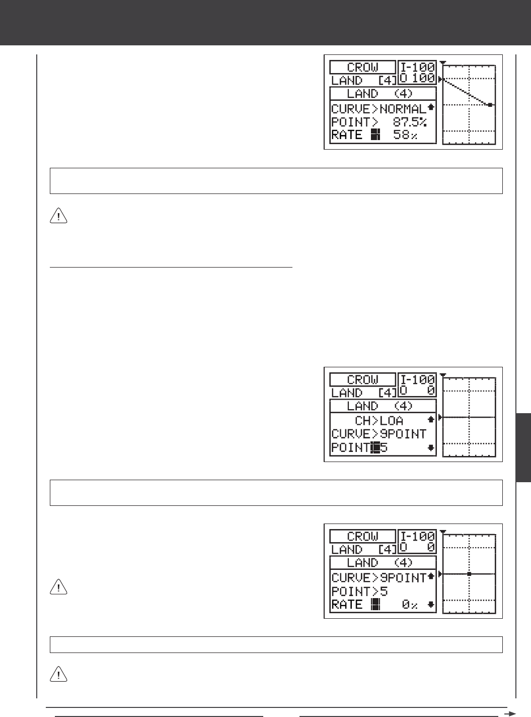
Page 125
glid Flight Mode menu
4) Press the Navigation Pad 6 to highlight RATE>58%
5) Press the YES/+ or NO/- keys to set the desired Rate percentage value.
As you change the Point and Rate percentage values, you can use the graph and I/O numbers to visualize the ratio
between ap control stick movement and Crow aileron servo travel throughout the entire deection range.
RATE setting range is -150% to 150%. The default setting is 58%. When the Rate percentage value is increased, Crow aileron
servo travel will increase. When the Rate percentage value is decreased, Crow aileron servo travel will decrease.
6) Repeat the previous procedures to change the Point and Rate percentage values for the desired remaining aileron servos.
Changing the Point and Rate Percentage Values - 9 Point Curve
Programming the Point and Rate percentage values on a Curve allows you to achieve maximum exibility and ne-tuning for specic
uses. For example, one of the top F3J sailplanes uses a Crow setting where at half ap the ailerons are down (Camber for Crawl
mode) and at full ap that ailerons are up (Crow for deceleration). In this conguration, with the aps half down, the ailerons
are down and at full ap, the ailerons are up. Programming the Point and Rate percentage values on a Curve allow you do this.
The Point and Rate percentage values work together to determine the position and the amount of servo travel of the ailerons based
on the position of the ap control stick. Nine different Points with varying Rates can be programmed onto the Curve. Use the Input
and Output display, along with the graph, to help with programming visualization. The Point that is currently selected will blink.
As you change the Point and Rate percentage values, you can use the graph and I/O numbers to visualize the ratio
between control stick movement and servo travel throughout the entire deection range.
RATE setting range is -150% to 150%. POINT 1, 5, and 9 default Rate percentage values are 0%.
3) Press the Navigation Pad 6 to highlight RATE>0%.
4) Press the YES/+ or NO/- keys to set the desired Rate percentage value.
1) Press the Navigation Pad 6 to highlight POINT>5.
2) Press the YES/+ or NO/- keys to choose which Point you would like to
set a Rate percentage value for.
POINT setting range is 1 through 9. Point 1 is at the low end of the Curve and Point 9 is at the high end of the Curve. Point 5
is a the center of the Curve. The default Point is Point 5.
5) Repeat the previous procedures to change the Point and Rate percentage values for the desired remaining aileron servos.
When you change the Rate percentage value for Points 2, 3, 4, 6,
7, and 8, INH will be displayed. When you press the YES/+ or NO/-
keys, INH will change to 0%.
GLID
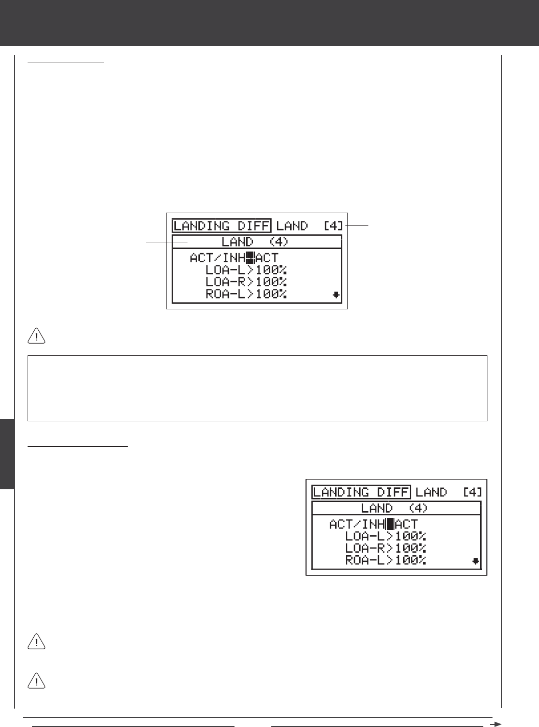
Page 126
Landing Differential
The Landing Differential function allows you to program Aileron Differential (in this case, referred to as Landing Differential)
separately that operates only when the aps are deployed. This allows you to program Aileron Differential (using the AI-DIFF
menu) for any Flight Mode, then program a separate Landing Differential for use only in the Flight Mode you use for landing when
the aps are deployed. When the aps are deployed, the amount of Landing Differential smoothly increases or decreases based
on ap travel.
The Landing Differential function allows you change the ratio of the Up to Down movement of each aileron. For example, many
aircraft exhibit a yaw tendency when the ailerons are used. This can affect any aircraft, and is common in sailplanes, especially
when a lot of aileron control throw is used. The Landing Differential function can be used to eliminate the yaw tendency by adding
more movement to the upward moving aileron than the downward moving aileron. For example, if your aircraft tends to yaw
during aileron turns, you can adjust the Landing Differential to make the aircraft turn more axially, which requires less use of the
rudder to compensate. The Landing Differential function can be programmed separately for each of the ve Flight Modes, but
only operates when the aps are deployed.
glid Flight Mode menu
Transmitter F-MODE
Programming F-MODE
Transmitter F-MODE refers to the Flight Mode that the transmitter is currently operating in. Programming F-MODE refers
to the Flight Mode that you would like to change the programming for.
IMPORTANT The Landing Differential function operates only when the aps are deployed. The Landing Differential function
will always override the Aileron Differential function in the same Flight Mode when the Landing Differential Function is Activated
and the aps are deployed, either using the ap control stick or if you've moved the ap function to a three-position switch. For
example, if you've programmed Aileron Differential in Flight Mode 2 (Launch) and you Activate and program Landing Differential
in Flight Mode 2 (Launch), when the aps are up, the Aileron Differential settings will be effective, however, when you deploy
the aps the Landing Differential settings will become effective and override the Aileron Differential settings.
In the default conguration, when the ap control stick is pulled back, Flight Mode 4 (Land) becomes Active. In this
situation, we suggest programming the Aileron Differential setting that you want to use for landing in Flight Mode 4 (Land)
in the AI-DIFF menu and Inhibiting the Landing Differential function in Flight Mode 4 (Land). Programming the Landing Differential
setting will typically be used only if you move Flight Mode 4 (Land) from the ap control stick onto a three-position switch.
Choosing the Flight Mode
1) Press the Navigation Pad 56 to highlight LANDING, then press the ENTER key to display the LANDING menu. The cursor
will default to the FLAP FREEZE POINT sub-menu.
Although the Landing Differential function can be programmed for use in any Flight Mode, it is intended to be used only
during landing and will only operate when the aps are deployed, so we suggest choosing the Flight Mode that you have
designated for landing.
3) Press the F-MODE key to choose the F-MODE number you would like to program the Landing Differential function for.
Choose from N, 1, 2, 3, or 4. The LAND (4) display will change, indicating which Flight Mode you are programming the
Landing Differential function for.
2) Press the Navigation Pad 6 to highlight LANDING DIFF, then press the
ENTER key to display the LANDING DIFF menu. The cursor will default
to ACT/INH>ACT.
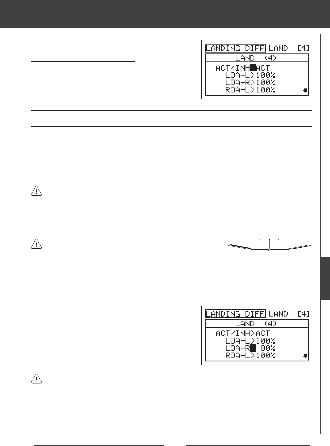
Page 127
glid Flight Mode menu
Landing Differential is a percentage of the control throw differential between
the ailerons. For example, if you set LOA-R (Left Outside Aileron-Right) to 90%,
the Left Outside Aileron will move Down less than what the Right Aileron(s) moves Up.
Landing Differential can be programmed for each aileron. The channels displayed will vary based on Model Type and
Model Type selection options currently selected. For example, if your model features four aileron servos, LOA-L (Left
Outside Aileron - Left), LOA-R (Left Outside Aileron - Right), ROA-L (Right Outside Aileron - Left) ROA-R (Right Outside
Aileron - Right), LIA-L (Left Inside Aileron - Left), LIA -R (Left Inside Aileron - Right), RIA-L (Right Inside Aileron - Left), and RIA-R
(Right Inside Aileron - Right) will be displayed and the Landing Differential can be adjusted for each of the servos individually.
Changing the Landing Differential Percentage Values
Landing Differential is achieved by reducing the amount of DOWN movement in the required aileron.
IMPORTANT Prior to setting the Landing Differential, you should use the Surface menu EPA Adjustment Option to ensure
that each aileron is moving UP and DOWN the same amount.
UP = More
Movement
DOWN = Less
Movement
Diagram of Differential
Flaps Down
1) Press the Navigation Pad 56 to highlight the desired aileron travel direction you would like to change the Landing Differential
setting for. For example, if you need the Right Outside Aileron to move Up more than the Left Outside Aileron moves Down
(per the diagram above right), you would decrease the LOA-R>100% (Left Outside Aileron-Right) percentage value.
LANDING DIFF setting range is 0% to 100%. The default setting is 100%. Decreasing the LANDING DIFF percentage value
will decrease the movement for that specic aileron and direction of travel. Keep in mind that Landing Differential only
operates when the aps are deployed. When the aps are deployed, the amount of Landing Differential smoothly increases
or decreases based on ap travel.
3) Repeat the previous procedures to set the desired remaining Landing Differential percentage values.
Activating the Landing Differential Function
1) Press the Navigation Pad 56 to highlight ACT/INH>ACT.
2) Press the YES/+ or NO/- keys to choose the desired the ACT/INH setting.
ACT/INH setting range is ACT or INH. The default setting is ACT. When set to ACT, the Landing Differential function will be
Activated for that Flight Mode. When set to INH, the Landing Differential function will be Inhibited for that Flight Mode.
The Landing Differential percentage value is a percentage of End Point Adjustment.
2) Press the YES/+ or NO/- keys to set the desired Landing Differential
percentage value.
GLID
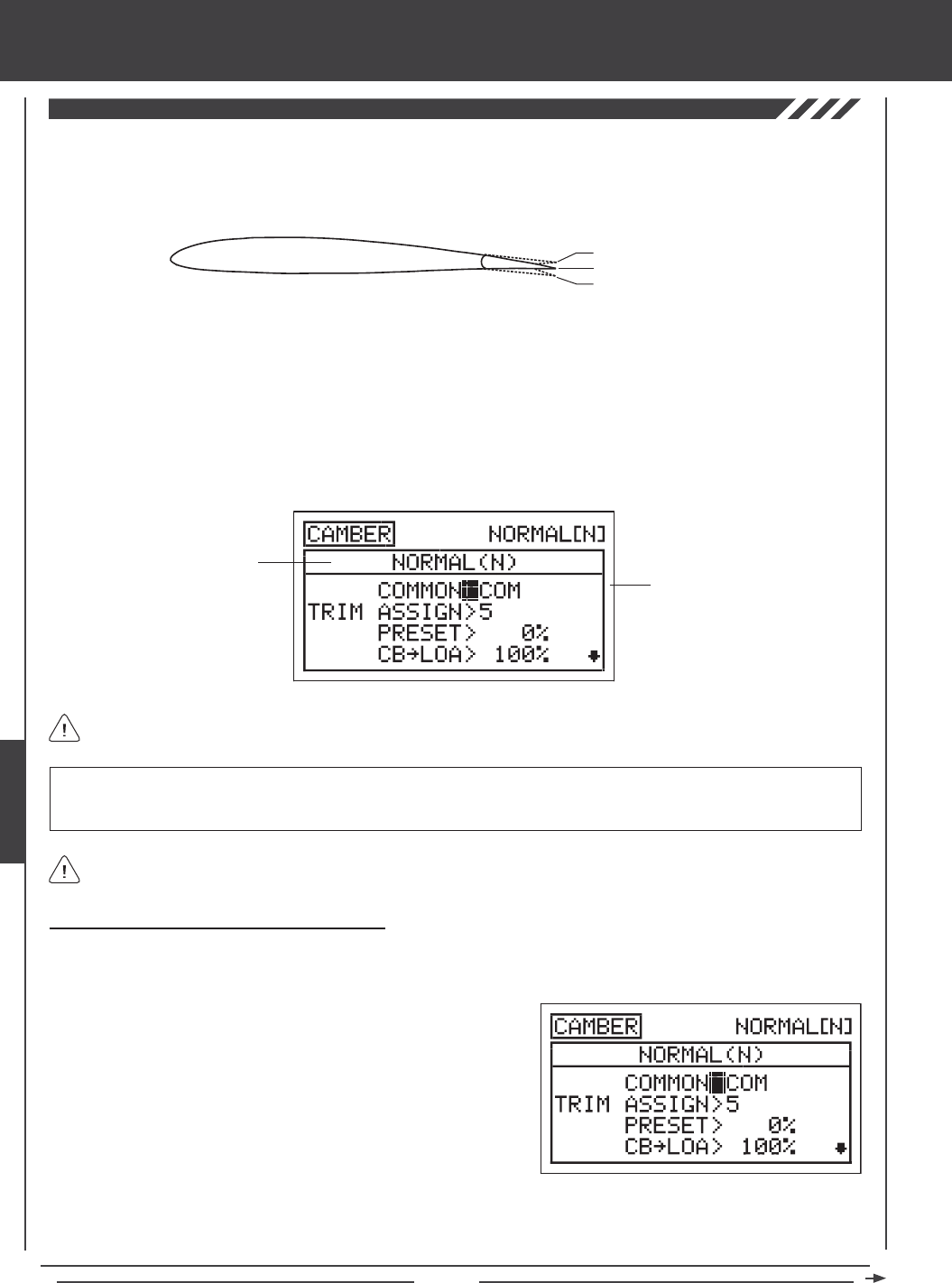
Page 128
glid Flight Mode menu
The Camber function allows you to program either Camber or Reex into the trailing edge of the wing to change the ight
characteristics of your aircraft. When the entire trailing edge of the wing (ailerons and aps) drops, this is referred to as Camber,
and when the entire trailing edge of the wing (ailerons and aps) rises, this is referred to as Reex. Camber is typically used
during launch to maximize lift and Reex is typically used in normal ight to maximize speed.
Transmitter F-MODE
Programming F-MODE
Transmitter F-MODE refers to the Flight Mode that the transmitter is currently operating in. Programming F-MODE refers
to the Flight Mode that you would like to change the programming for.
IMPORTANT Prior to programming the Camber function, we strongly suggest programming the Camber Point function.
This will ensure that your Camber settings are not changed if and when you program the Camber Point function. For more
information, see page 130.
Choosing the Flight Mode - Common or Separate
When set to COM (Common), the CAMBER settings will be the same regardless of which Flight Mode the transmitter is operating in.
You cannot program CAMBER settings separately for each Flight Mode. When set to SEP (Separate), you can program different
CAMBER settings separately for each Flight Mode.
3) Press the F-MODE key to choose the F-MODE number you would like to program the Camber function for. Choose from
N, 1, 2, 3, or 4. The NORMAL (N) display will change, indicating which Flight Mode you are programming the Camber
function for.
1) Press the Navigation Pad 56 to highlight CAMBER, then press the
ENTER key to display the CAMBER menu. The cursor will default to
COMMON>COM.
2) Press the YES/+ or NO/- keys to choose either COM or SEP. If set to
COM, skip to the Changing the Camber Trim Switch Assignment section.
If set to SEP, see step 3 below.
In the default conguration, the Camber function is controlled proportionally by Auxiliary Lever (VR6). The Camber function can
also be Preset to a specic position using Trim Switch (T5), while still maintaining proportional control via Auxiliary Lever (VR6).
For example, you might program the Camber Preset in Flight Mode 2 (Launch), so that the trailing edge of the wing is down
to maximize lift for launching. At the same time, you can program the Camber Preset in Flight Mode 3 (Reex), so that the
trailing edge of the wing is up to maximize speed during high-speed ight. The trailing edge will automatically move to the
programmed Preset when you switch Flight Modes.
You can choose to program Camber separately for each of the ve Flight Modes or you can use the same Camber programming
across all ve Flight Modes.
Trailing Edge - Centered
Trailing Edge Up - Reex
Trailing Edge Down - Camber
Camber can be programmed for each of the ailerons and each of the aps separately. The channels displayed will vary
based on Model Type and Model Type selection options currently selected.
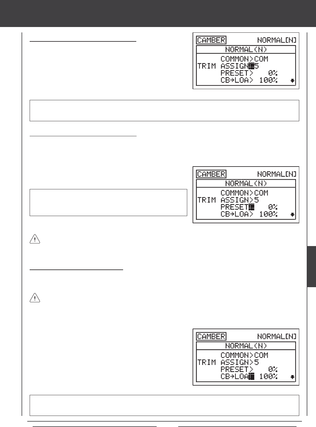
Page 129
glid Flight Mode menu
Changing the Camber Trim Switch Assignment
The Camber Preset can be assigned to a different trim switch, or it can be
Inhibited.
1) Press the Navigation Pad 6 to highlight TRIM ASSIGN>5, then press
the YES/+ or NO/- keys to choose which trim switch you would like to
assign the Camber Preset to, or if you would like to Inhibit the Camber
Preset.
TRIM ASSIGN setting range is 5, 6, and INH. The default setting is 5. When set to 5, Camber Preset will be controlled by the
Trim Switch (T5). When set to 6, Camber Preset will be controlled by the Trim Switch T6. When set to INH, Camber Preset
will be Inhibited.
Changing the Camber Preset Percentage Value
The Camber Preset percentage value denes the preset amount of Camber (trailing edge down) or Reex (trailing edge up) used
in your aircraft and is separate from adjusting the Camber using Auxiliary Lever (VR6). Although this setting can be changed by
pressing the YES/+ and NO/- keys from within the Camber menu, it can also be adjusted during ight by moving the trim switch
you've assigned it to. In the default conguration, this is Trim Switch (T5).
When the Camber Preset percentage value is changed using the YES/+ and NO/- keys through the Camber menu, the
percentage values are changed in 1% increments. When the Camber Preset percentage value is adjusted using the trim
switch, the percentage values are changed in 6% increments. If desired, the trim switch resolution can be changed through the
Trim Step menu. For more information, see page 135.
1) Press the Navigation Pad 6 to highlight PRESET>0%, then press the
YES/+ or NO/- keys to change the Camber Preset percentage value.
PRESET setting range is -192% to 192%. The default setting is 0%.
Adjust the Camber Preset percentage value to either move the trailing
edge of the wing down (Camber) or move the trailing edge of the wing
up (Reex).
Changing the Camber Percentage Values
The Camber percentage values dene the maximum amount of Camber travel (trailing edge down) or Reex travel (trailing edge
up) when adjusting the Camber angle using Auxiliary Lever (VR6).
CB setting range is -150% to 150%. The default setting is 100%. Decreasing the CB percentage value will decrease the amount
of Camber or Reex travel for that specic aileron or ap. Increasing the CB percentage value will increase the amount of
Camber or Reex travel for that specic aileron or ap.
The total amount the trailing edge moves up and/or down will vary based on how you program the Camber Point function.
For example, if you set the Camber Point percentage value to 0% in the Camber Point menu, the trailing edge may move
up and down 1/4" in each direction when you move Auxiliary Lever (VR6) from the center detent to either end point. If you set the
Camber Point percentage value to 100%, the trailing edge will move down twice that amount (1/2") in one direction when Auxiliary
Lever (VR6) is moved from one end point to the other end point. For more information, see page 130.
1) Press the Navigation Pad 56 to highlight the CB percentage value for
the channel that you would like to change.
2) Press the YES/+ or NO/- keys to change the CB percentage value to set
the desired maximum amount of travel for each of the aileron and ap
servos. In most cases, the percentage values should be set so that all
aileron and ap control surfaces deect the same amount.
3) Repeat the previous procedures to set the desired remaining Camber
percentage values.
GLID
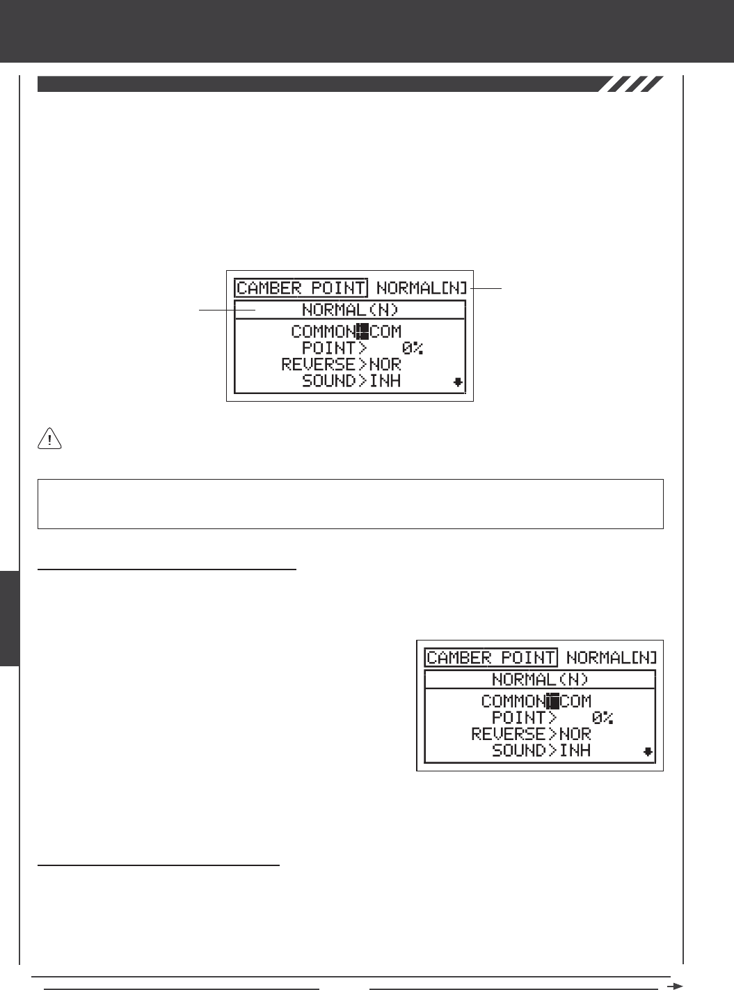
Page 130
The Camber Point function allows you to dene how Auxiliary Lever (VR6) controls Camber. Based on the Camber Point setting,
you can control both Camber and Reex, or you can control only Camber or Reex. When programmed to control only Camber
or Reex, the amount of servo travel will be doubled. This is useful for those pilots who want more overall travel, but in only one
direction. For example, if you set the Camber Point percentage value to 0%, the trailing edge may move up and down 1/4" in each
direction when you move Auxiliary Lever (VR6) from the center detent to either end point. If you set the Camber Point percentage
value to 100%, the trailing edge will move down twice that amount (1/2") in one direction when Auxiliary Lever (VR6) is moved
from one end point to the other end point. The direction that Auxiliary Lever (VR6) controls the Camber function can be reversed,
and an audible tone can be programmed to indicate when Auxiliary Lever (VR6) reaches the Camber Point setting.
You can choose to program Camber Point separately for each of the ve Flight Modes or you can use the same Camber Point
programming across all ve Flight Modes.
Transmitter F-MODE
Programming F-MODE
Transmitter F-MODE refers to the Flight Mode that the transmitter is currently operating in. Programming F-MODE refers
to the Flight Mode that you would like to change the programming for.
glid Flight Mode menu
IMPORTANT If you change the Camber Point function programming settings after you've programmed the Camber function,
your Camber settings can be altered. In this situation we suggest that you double-check your Camber settings and adjust them
as necessary.
Choosing the Flight Mode - Common or Separate
When set to COM (Common), the CAMBER POINT settings will be the same regardless of which Flight Mode the transmitter is
operating in. You cannot program CAMBER POINT settings separately for each Flight Mode. When set to SEP (Separate), you
can program different CAMBER POINT settings separately for each Flight Mode.
3) Press the F-MODE key to choose the F-MODE number you would like to program the Camber Point function for. Choose from
N, 1, 2, 3, or 4. The NORMAL (N) display will change, indicating which Flight Mode you are programming the Camber Point
function for.
1) Press the Navigation Pad 56 to highlight CAMBER POINT, then press
the ENTER key to display the CAMBER POINT menu. The cursor will
default to COMMON>COM.
2) Press the YES/+ or NO/- keys to choose either COM or SEP. If set to
COM, skip to the Changing the Camber Point Percentage Value section.
If set to SEP, see step 3 below.
Changing the Camber Point Percentage Value
The Camber Point percentage value denes how Auxiliary Lever (VR6) controls Camber. In the default conguration, with Auxiliary
Lever (VR6) in the center detent and the Camber Point percentage value set to 0%, you can control both Camber and Reex
by moving Auxiliary Lever (VR6) forward and backward. Changing the Camber Point percentage value allows you to change
the position that Auxiliary Lever (VR6) is in when the trailing edge is at neutral. For example, if you change the Camber Point
percentage value to 100%, the bottom of Auxiliary Lever (VR6) will be all the way forward to neutralize the trailing edge. This
allows for trailing edge movement in only one direction, however, the amount of movement is doubled, allowing you more total
control throw in that direction.
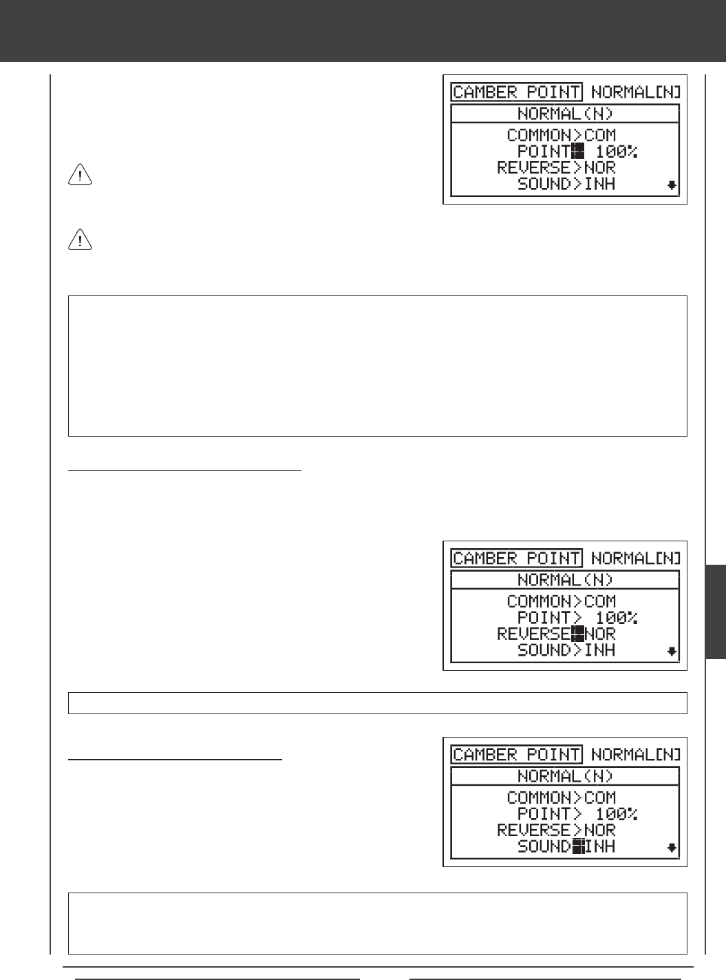
Page 131
glid Flight Mode menu
POINT setting range is -100% to 100%. The default setting is 0%. When the Camber Point percentage value is set to 0%, the
trailing edge will be at neutral when Auxiliary Lever (VR6) is at the center detent. Auxiliary Lever (VR6) will control both Camber
and Reex the same amount in both directions. When the Camber Point percentage value is set to 100%, the trailing edge
will be at neutral when the bottom of Auxiliary Lever (VR6) is pushed all the way forward. When the Camber Point percentage
value is set to -100%, the trailing edge will be at neutral when the bottom of Auxiliary Lever (VR6) is pulled all the way back.
When the Camber Point percentage value is set to -100% or 100%, Auxiliary Lever (VR6) will control either Camber or Reex
in only one direction, based on the Camber Point REV setting. When the Camber Point percentage value is set to a value
between -99% and -1%, or between 1% and 99%, Auxiliary Lever (VR6) will control Camber and Reex based on the Camber
Point percentage value. For example, if you set the Camber Point percentage value to 75%, moving Auxiliary Lever (VR6) will
result in 75% Camber travel and 25% Reex travel from the trailing edge neutral position.
1) Press the Navigation Pad 6 to highlight POINT>0%.
2) Press the YES/+ or NO/- keys to set the desired Camber Point
percentage value.
For example, if you want the trailing edge of the wing to be at neutral when the bottom of Auxiliary Lever (VR6) is pushed
all the way forward, change the Camber Point percentage value to 100%. In this example, Auxiliary Lever (VR6) cannot
control Reex, however, you will have double the amount of Camber travel when the bottom of Auxiliary Lever (VR6) is pulled
all the way back.
The Camber Point percentage value is a percentage of servo travel
set via the Camber menu.
Changing the Camber Point Reversing Value
The Camber Point Reversing value changes the direction that the trailing edge will move in relation to the direction Auxiliary Lever
(VR6) is moved. For example, if you move the bottom of Auxiliary Lever (VR6) forward and the trailing edge moves down, but
you would rather have the trailing edge move up, change the Camber Point Reversing value to make the trailing edge move up
when the bottom of Auxiliary Lever (VR6) is moved forward.
1) Press the Navigation Pad 6 to highlight REVERSE>NOR.
2) Press the YES/+ or NO/- keys to set the desired Camber Point
travel direction.
REVERSE setting range is NOR and REV. The default setting is NOR.
Changing the Camber Point Sound Value
An audible tone can be Activated to alert you when Auxiliary Lever (VR6)
reaches the Camber Point percentage value position that you've programmed.
1) Press the Navigation Pad 6 to highlight SOUND>INH.
2) Press the YES/+ or NO/- keys to Activate the Camber Point audible
tone.
SOUND setting range is ACT and INH. The default setting is INH. When set to INH, no audible tone will be heard when
Auxiliary Lever (VR6) reaches the Camber Point percentage value position that you've programmed. When set to ACT, an
audible tone will alert you when Auxiliary Lever (VR6) reaches the Camber Point percentage value position that you've
programmed.
GLID
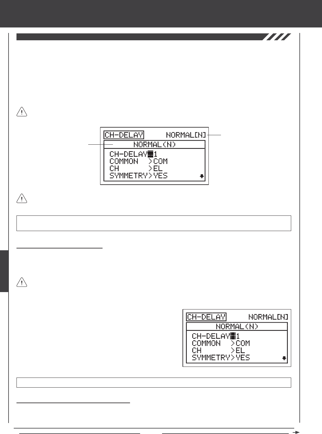
Page 132
The Channel Delay function allows you to adjust the speed of individual servos. This function has several uses. For example, not
all servos operate at the same exact speed. If your model uses separate aileron and ap servos, you may nd that even though
the servos are the same, one servo may move faster than the other. You can use the Channel Delay function to slow down the
faster servo to match the slower servo. The Channel Delay function can also be used to slow down a servo that controls a specic
function to achieve a more scale transit time, for example, to open and close a canopy on a scale aircraft.
The Channel Delay function can be programmed to operate in a number of different combinations to suit just about any model
setup or control function need. Up to ve Channel Delay functions can be programmed separately for each of the ve Flight
Modes or you can use the same Channel Delay programming across all ve Flight Modes.
The Channel Delay function does not affect when the servo starts to respond to control stick movement. The Channel
Delay function affects only the transit time of the servo.
glid Flight Mode menu
Transmitter F-MODE
Programming F-MODE
Transmitter F-MODE refers to the Flight Mode that the transmitter is currently operating in. Programming F-MODE refers
to the Flight Mode that you would like to change the programming for.
Choosing the Channel Delay Number
Up to ve separate Channel Delay functions can be programmed for each Flight Mode, however, only one channel can be
assigned to one Channel Delay function at a time. For example, if you want to program Channel Delay for the elevator and the
aileron channels, you would need to program Elevator to CH-DELAY 1 and Aileron to CH-DELAY 2.
IMPORTANT Each CH-DELAY function (CH-DELAY 1, 2, 3, 4, and 5) must be assigned to a Switch Position Number before
it can be Activated. For more information, see page 45.
1) Press the Navigation Pad 56 to highlight CH-DELAY, then press the
ENTER key to display the CH-DELAY menu. The cursor will default to
CH-DELAY>1.
2) Press the YES/+ and NO/- keys to choose the CH-DELAY number you
would like to program Channel Delay for.
Although only one channel can be assigned to one Channel Delay function at a time, you can still Activate multiple
Channel Delay Functions at the same time by assigning the Channel Delay functions to the same Switch Position Number.
For example, assign both CH-DELAY 1 and CH-DELAY 2 to Switch Position 23. This is particularly useful if want to program the
same Channel Delay percentage values to a model that uses two different aileron servos or two different elevator servos.
CH-DELAY setting range is 1, 2, 3, 4, or 5.
Choosing the Flight Mode - Common or Separate
When set to COM (Common), the CH-DELAY setting will be the same regardless of which Flight Mode the transmitter is
operating in. You cannot program CH-DELAY settings separately for each Flight Mode. When set to SEP (Separate), you can
program different CH-DELAY settings separately for each Flight Mode.
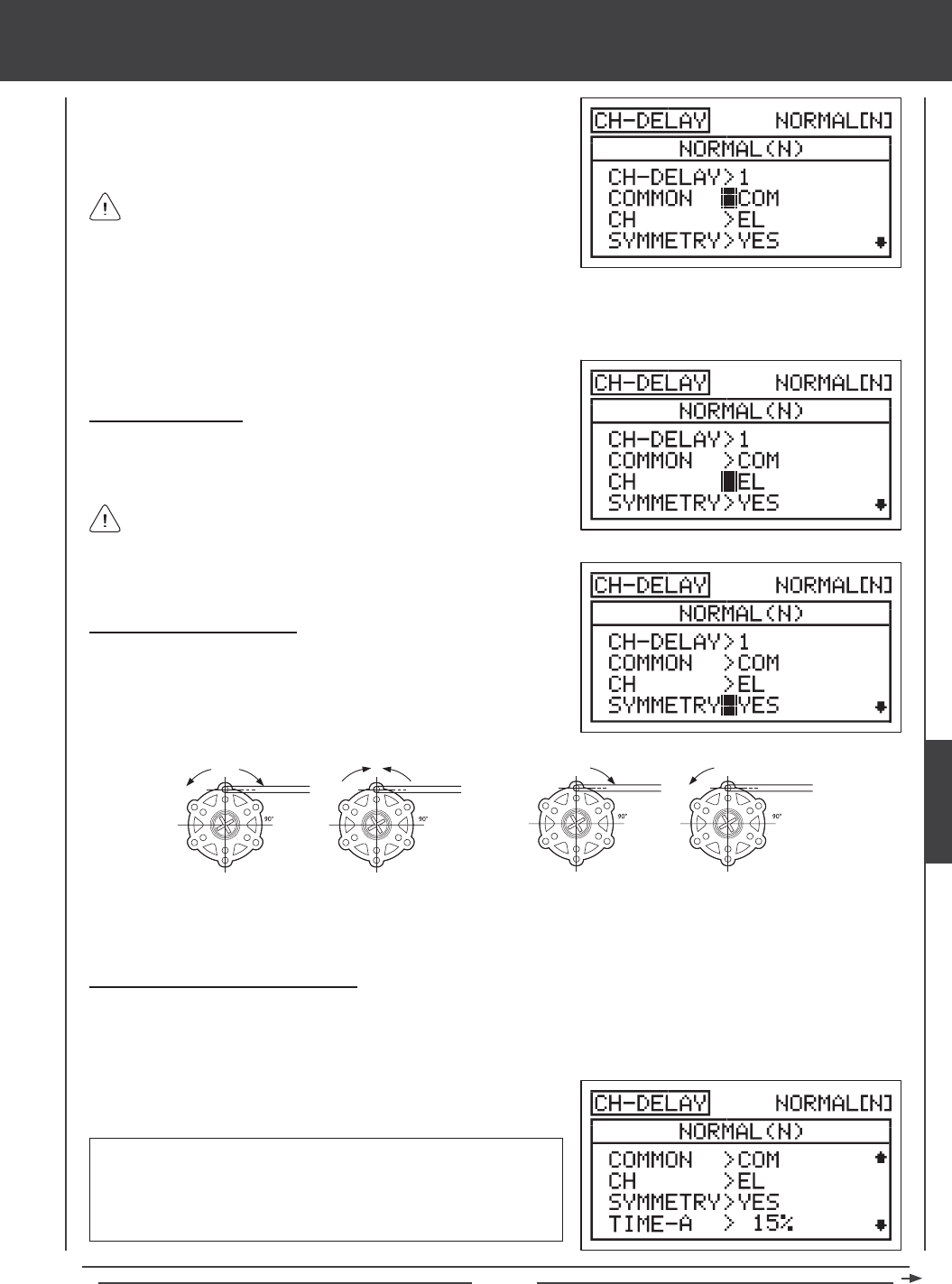
Page 133
glid Flight Mode menu
2) Press the F-MODE key to choose the F-MODE number you would like to program the Channel Delay function for. Choose
from N, 1, 2, 3, or 4. The NORMAL (N) display will change, indicating which Flight Mode you are programming the Channel
Delay function for.
If set to COM, skip to the Choosing the Channel section. If set to SEP,
see step 2 below.
Choosing the Channel
1) Press the Navigation Pad 6 to highlight CH>EL, then press the YES/+
or NO/- keys to choose which Channel you want to program Channel
Delay for.
The channel options displayed will vary based on Model Type and
Model Type selection options currently selected. For example, if your
model features four aileron servos, LOA, ROA, LIA, and RIA will be
separate options.
1) Press the Navigation Pad 6 to highlight COMMON>COM, then press
the YES/+ or NO/- keys to choose either COM or SEP.
Changing the Symmetry Value
1) Press the Navigation Pad 6 to highlight SYMMETRY>YES, then press
the YES/+ or NO/- keys to change the Symmetry option.
The following Symmetry options are available:
YES - Selecting this option results in the
Channel Delay function affecting the speed
of the servo in both directions equally.
NO - Selecting this option results in the
Channel Delay function affecting the speed
of the servo in only one direction.
Changing the Time-A Percentage Value
The Time-A setting adjusts the Channel Delay when the servo moves from the neutral position to either End Point (Symmetry
YES), and in a single direction (Symmetry NO), either clockwise or counter-clockwise, depending on the Servo Reversing setting
in the Surface menu.
1) Press the Navigation Pad 6 to highlight TIME-A>0%, then press the
YES/+ or NO/- keys to change the Time-A percentage value.
TIME-A setting range is 0% to 100%. The default setting is 0%. When
the Time-A percentage value is increased, the servo transit time will be
slowed down. At 0%, the servo moves at its normal speed. At 100%, the
servo takes approximately 15 seconds to move from the neutral position
to 100% or -100% travel.
GLID
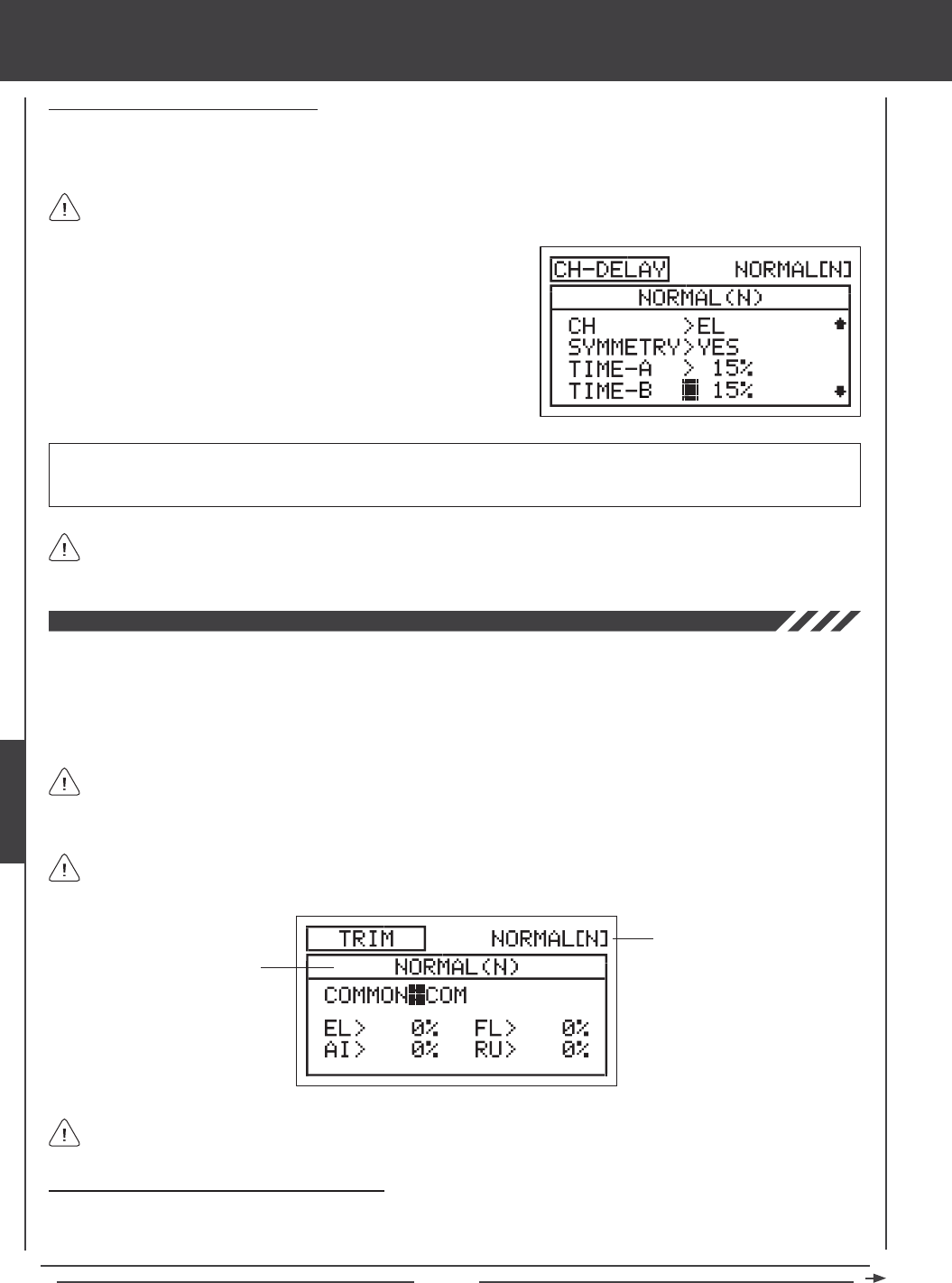
Page 134
Changing the Time-B Percentage Value
The Time-B setting adjusts the Channel Delay when the servo moves from either End Point to the neutral position (Symmetry
YES), and in a single direction (Symmetry NO), either clockwise or counter-clockwise, depending on the Servo Reversing setting
in the Surface menu.
1) Press the Navigation Pad 6 to highlight TIME-B>0%, then press the
YES/+ or NO/- keys to change the Time-B percentage value.
TIME-B setting range is 0% to 100%. The default setting is 0%. When the Time-B percentage value is increased, the servo
transit time will be slowed down. At 0%, the servo moves at its normal speed. At 100%, the servo takes approximately 15
seconds to move from one 100% or -100% travel to the neutral position.
If a Time-A percentage value is set with SYMMETRY>NO, the Time-B setting will affect the Channel Delay function in the
direction opposite the Time-A Channel Delay setting, regardless of the Servo Reversing setting.
If you want to ensure that a servo will move at the same speed in both directions, for example, to match the speed of a
second servo, make sure the Symmetry is set to YES and the that both the Time-A and the Time-B percentage values are
the same.
glid Flight Mode menu
The Trim function allows you to view the current Digital Trim Positions of the four ight control surfaces. In addition, you are able
to ne-tune the Digital Trim Positions, using the YES/+ and No/- keys. For example, in the default conguration, when you move
the elevator trim switch, the Trim percentage value changes in 6% increments. When you press the YES/+ and NO/- keys to
change the elevator Trim percentage value, the Trim percentage value changes in 1% increments. You can also choose to
program specic Trim percentage values separately for each of the ve Flight Modes or you can use the same Trim percentage
values across all ve Flight Modes.
The SD-10G transmitter features Digital Trim Memory. Any amount of trim that you set during ight, using either the
trim switches or the YES/+ and NO/- keys from within the Trim menu, is automatically stored in memory for that specic
channel and model, and for that specic Flight Mode (if enabled). The Trim percentage values for each model will automatically
be loaded when the transmitter is turned ON and your model is selected.
Transmitter F-MODE
Programming F-MODE
Transmitter F-MODE refers to the Flight Mode that the transmitter is currently operating in. Programming F-MODE refers
to the Flight Mode that you would like to change the programming for.
An audible tone is heard when the trim switches reach the center position. This allows you to know when the trim
switches reach the center position without the need to look at the Trim Indicators on the Top menu.
Choosing the Flight Mode - Common or Separate
When set to COM (Common), the TRIM settings will be the same regardless of which Flight Mode the transmitter is operating in.
You cannot program or store TRIM settings separately for each Flight Mode. When set to SEP (Separate), you can program and
store different TRIM settings separately for each Flight Mode.
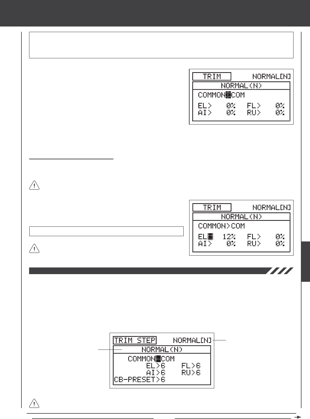
Page 135
glid Flight Mode menu
The Trim percentage values are displayed as a percentage of total trim. They are not displayed as a percentage of
servo travel.
3) Press the F-MODE key to choose the F-MODE number you would like to program the Trim function for. Choose from N, 1, 2,
3, or 4. The NORMAL (N) display will change, indicating which Flight Mode you are programming the Trim function for.
1) Press the Navigation Pad 56 to highlight TRIM, then press the
ENTER key to display the TRIM menu. The cursor will default to
COMMON>COM.
2) Press the YES/+ or NO/- keys to choose either COM or SEP. If set to
COM, skip to the Changing the Trim Percentage Values section. If
set to SEP, see step 3 below.
Changing the Trim Percentage Values
The current Trim percentage values for each of the ight control surfaces is displayed. The Trim percentage values can be
changed, if desired, using either the trim switches or the YES/+ and NO/- keys (from within the Trim menu only).
TRIM setting range is -150% to 150%. The default setting is 0%.
1) Press the Navigation Pad 3456 to highlight the channel you would
like to change the Trim percentage value for, then press the YES/+ or
NO/- keys to change the Trim percentage value.
Press the YES/+ and NO/- keys at the same time to set the Trim
percentage value to 0% for the selected channel.
IMPORTANT When the Flight Mode is set to Separate, Trim percentage values are stored in the specic Flight Mode you're
using when you change the Trim percentage values, whether with the trim switches or with the YES/+ and NO/- keys within the
Trim menu. For example, you could have 10% elevator trim in Flight Mode N (Normal) and 5% elevator trim in Flight Mode 1.
Be cautious of this when switching between Flight Modes during ight.
The Trim Step function allows you to adjust how far the servo travels when the trim switch is moved. This allows you to change
the Trim function resolution to suit your preference. For example, in the default conguration, when you move the elevator trim
switch, the Trim percentage value changes in 6% increments. You can increase the resolution by decreasing the Trim Step value,
so that the servo travels less when you move the trim switch. This makes it possible to ne-tune the trim settings extremely
accurately. In addition, you could decrease the resolution by increasing the Trim Step value, so that the servo travels more when
you move the trim switch. This makes setting large amounts of trim faster, but the trim setting may not be as accurate. You can
choose to program Trim Step values separately for each of the ve Flight Modes or you can use the same Trim Step programming
values across all ve Flight Modes.
Transmitter F-MODE
Programming F-MODE
Transmitter F-MODE refers to the Flight Mode that the transmitter is currently operating in. Programming F-MODE refers
to the Flight Mode that you would like to change the programming for.
GLID
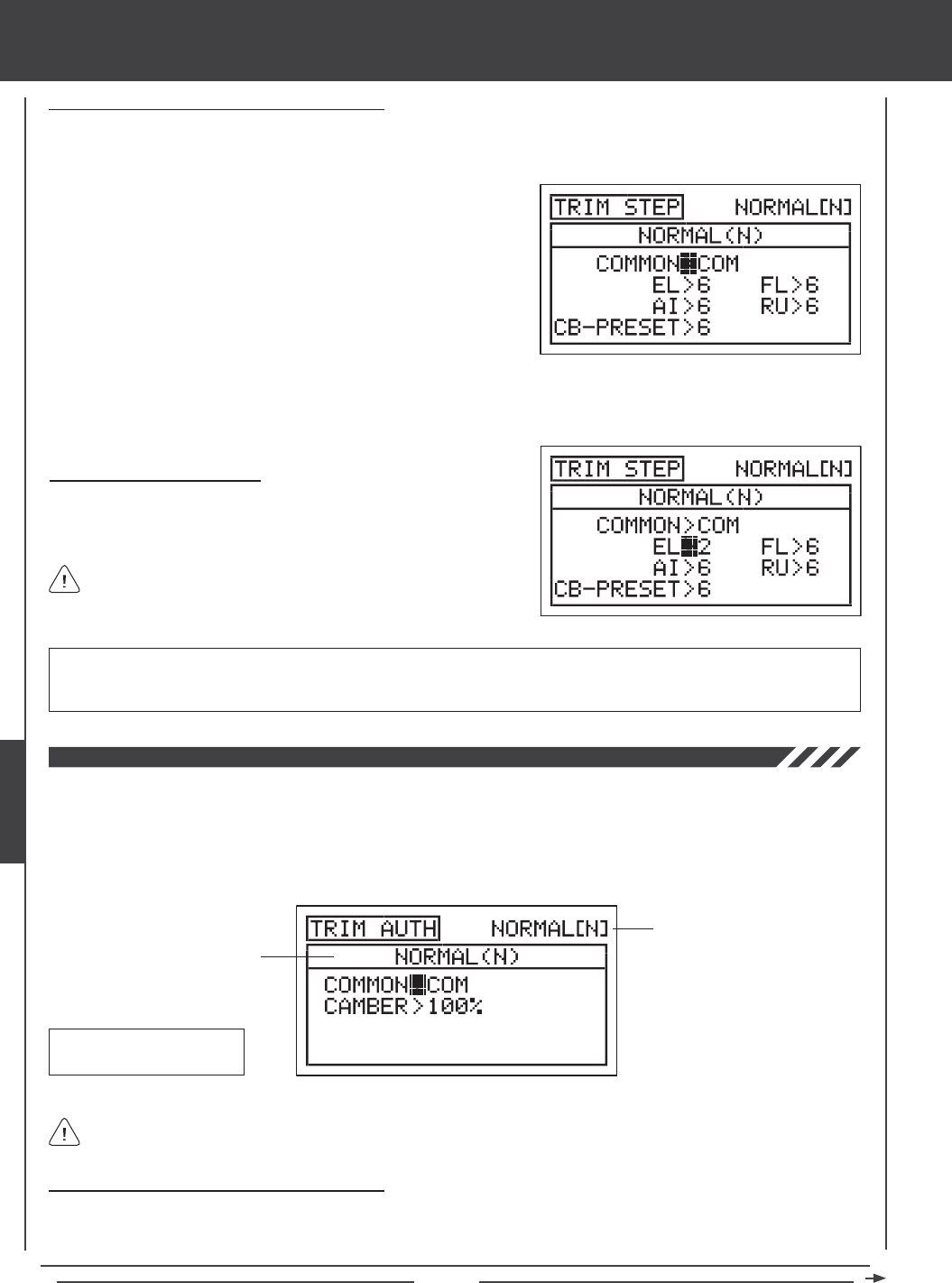
Page 136
glid Flight Mode menu
Choosing the Flight Mode - Common or Separate
When set to COM (Common), the TRIM STEP settings will be the same regardless of which Flight Mode the transmitter is operating
in. You cannot program TRIM STEP settings separately for each Flight Mode. When set to SEP (Separate), you can program
different TRIM STEP settings separately for each Flight Mode.
3) Press the F-MODE key to choose the F-MODE number you would like to program the Trim Step function for. Choose from N,
1, 2, 3, or 4. The NORMAL (N) display will change, indicating which Flight Mode you are programming the Trim Step function for.
1) Press the Navigation Pad 56 to highlight TRIM STEP, then press the
ENTER key to display the TRIM STEP menu. The cursor will default to
COMMON>COM.
2) Press the YES/+ or NO/- keys to choose either COM or SEP. If set to
COM, skip to the Setting the Trim Step Values section. If set to SEP,
see step 3 below.
Changing the Trim Step Values
1) Press the Navigation Pad 3456 to highlight the channel you would
like to change the Trim Step value for, then press the YES/+ or NO/- keys
to change the Trim Step value.
TRIM STEP setting range is 1 to 30. The default setting is 6. Increasing the Trim Step value causes the servo to travel more
when the trim switch is moved (lower resolution). Decreasing the Trim Step value causes the servo to move less when the trim
switch is moved (higher resolution).
The CB-PRESET channel controls the Camber Preset and is assigned
to the Trim Switch (T5).
Choosing the Flight Mode - Common or Separate
When set to COM (Common), the TRIM AUTH settings will be the same regardless of which Flight Mode the transmitter is operating
in. You cannot program TRIM AUTH settings separately for each Flight Mode. When set to SEP (Separate), you can program
different TRIM AUTH settings separately for each Flight Mode.
The Trim Authority function allows you to change the amount of Camber or Reex travel relative to how far Auxiliary Lever (VR6)
is moved. For example, if you set the Trim Authority Camber percentage value to 50%, the trailing edge will move half as much
using Auxiliary Lever (VR6) as it would if the Trim Authority Camber percentage value was set to 100%. You can choose to
program Trim Authority values separately for each of the ve Flight Modes or you can use the same Trim Authority programming
values across all ve Flight Modes.
Transmitter F-MODE
Programming F-MODE
Transmitter F-MODE refers to the Flight Mode that the transmitter is currently operating in. Programming F-MODE refers
to the Flight Mode that you would like to change the programming for.
Auxiliary Lever (VR6)
Camber
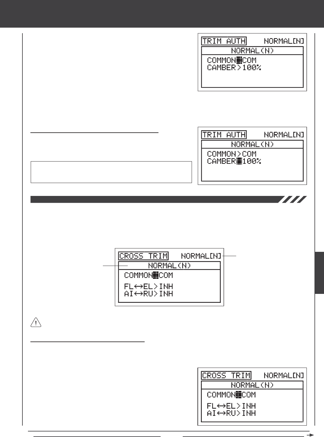
Page 137
glid Flight Mode menu
3) Press the F-MODE key to choose the F-MODE number you would like to program the Trim Authority function for. Choose from
N, 1, 2, 3, or 4. The NORMAL (N) display will change, indicating which Flight Mode you are programming the Trim Authority
function for.
1) Press the Navigation Pad 56 to highlight TRIM AUTH, then press the
ENTER key to display the TRIM AUTH menu. The cursor will default to
COMMON>COM.
2) Press the YES/+ or NO/- keys to choose either COM or SEP. If set to
COM, skip to the Changing the Camber Trim Authority Percentage
Value section. If set to SEP, see step 3 below.
Changing the Camber Trim Authority Percentage Value
1) Press the Navigation Pad 6 to highlight CAMBER>100%, then press
the YES/+ or NO/- keys to change the Camber Trim Authority percentage
value.
CAMBER setting range is 0% to 100%. The default setting is 100%.
Decreasing the CAMBER percentage value decreases the overall Camber
or Reex travel when Auxiliary Lever (VR6) is used to control Camber.
The Cross-Trim function allows you to electronically swap trim switch functions. Some pilots prefer this over the standard
arrangement in which the trim switches adjacent to the control sticks control the trim for that control function. For example, in the
default conguration, the ap trim switch will control the ap trim and the elevator trim switch will control the elevator trim. With
FL34EL Cross-Trim Activated, the ap trim switch will control the elevator trim and the elevator trim switch will control the ap trim.
You can choose to program Cross-Trim separately for each of the ve Flight Modes or you can use the same Cross-Trim programming
across all ve Flight Modes.
Transmitter F-MODE
Programming F-MODE
Transmitter F-MODE refers to the Flight Mode that the transmitter is currently operating in. Programming F-MODE refers
to the Flight Mode that you would like to change the programming for.
Choosing the Flight Mode - Common or Separate
When set to COM (Common), the CROSS-TRIM settings will be the same regardless of which Flight Mode the transmitter is
operating in. You cannot program CROSS-TRIM settings separately for each Flight Mode. When set to SEP (Separate), you can
program different CROSS-TRIM settings separately for each Flight Mode.
1) Press the Navigation Pad 56 to highlight CROSS-TRIM, then press
the ENTER key to display the CROSS-TRIM menu. The cursor will
default to COMMON>COM.
2) Press the YES/+ or NO/- keys to choose either COM or SEP. If set to
COM, skip to the Changing the Flap/Elevator Cross-Trim section. If set
to SEP, see step 3 below.
GLID
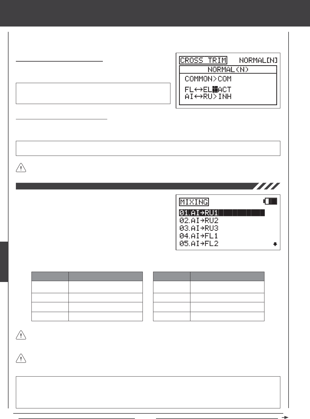
Page 138
glid Flight Mode menu
3) Press the F-MODE key to choose the F-MODE number you would like to program the Cross-Trim function for. Choose
from N, 1, 2, 3, or 4. The NORMAL (N) display will change, indicating which Flight Mode you are programming the Cross-Trim
function for.
Changing the Flap/Elevator Cross-Trim
1) Press the Navigation Pad 6 to highlight FL34EL>INH, then press the
YES/+ or NO/- keys to change the FL34EL Cross-Trim setting.
CROSS-TRIM setting range is INH/ACT. The default setting is INH.
When Activated, the ap trim switch will control the elevator trim and the
elevator trim switch will control the ap trim.
Changing the Aileron/Rudder Cross-Trim
1) Press the Navigation Pad 6 to highlight AI34RU>INH, then press the YES/+ or NO/- keys to change the AI34RU
Cross-Trim setting.
CROSS-TRIM setting range is INH/ACT. The default setting is INH. When Activated, the aileron trim switch will control the
rudder trim and the rudder trim switch will control the aileron trim.
The Camber Preset function on Trim Switch (T5) is not affected by the FL34EL Cross-Trim settings.
The SD-10G transmitter features a number of pre-programmed mixes that
can all be adjusted to suit just about any model setup or mixing need that
you might have. If for some reason one of the pre-programmed mixes will
not sufce, you can custom-program one or more of the available ve
Compensation Mixers. For more information, see page 147.
1) Press the Navigation Pad 56 to highlight MIXING, then press the
ENTER key to display the MIXING menu. The AI4RU1 sub-menu will
be highlighted by default.
AI4RU1~RU3
AI4FL1~2
FL4EL
RU4AI
MIX
Aileron to Rudder Mixing (1~3)
Aileron to Flap Mixing (1~2)
Flap to Elevator Mixing
Rudder to Aileron Mixing
DESCRIPTION
GE4EL
MT4EL
CB4EL
EL4CB
MIX
Gear to Elevator Mixing
Motor to Elevator Mixing
Camber to Elevator Mixing
Elevator to Camber Mixing
DESCRIPTION
The pre-programmed mixes shown in the tables below are available.
All pre-programmed mixes are Linear unless otherwise noted. For example, if you Activate the AI4RU1 mix and set the
mixing percentage value to 50%, the aileron servos will travel half the amount that the rudder servo moves at any given
control stick position.
All pre-programmed mixes are described in the following manner: Master4Slave. For example, For the AI4RU1 mix, the
Aileron channel is the Master and the Rudder channel is the Slave. In all cases, the Master channel always controls the
Slave channel.
WARNING When a pre-programmed mix is Activated, you still have separate control over the Slaved channel, however,
depending on the mixing percentage value, the Slave channel End Point Adjustment could be exceeded. We strongly
recommend that if you use the pre-programmed mixes that you set your Slave channel Limits no higher than that channel's
End Point Adjustment unless specically necessary for your particular setup. This will prevent any chance of overdriving your
control linkage when the mix is used.
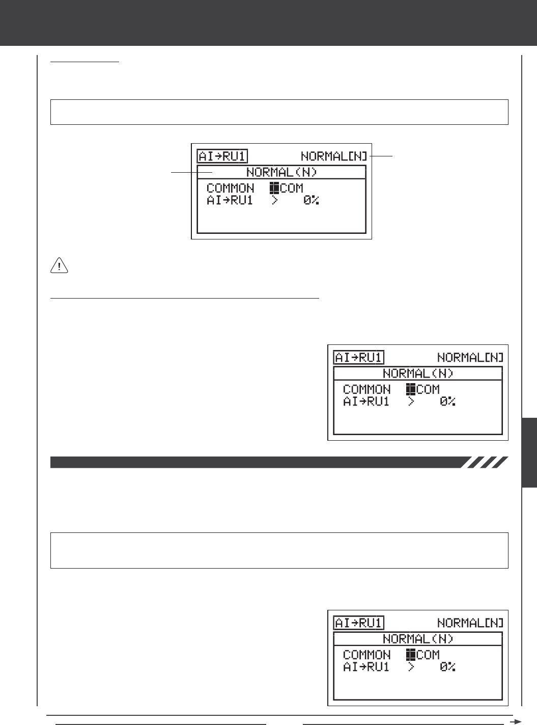
Page 139
glid Flight Mode menu
General Overview
Each of the eight mixes can be programmed separately for each of the ve Flight Modes or you can use the same Mixing
programming across all ve Flight Modes.
Transmitter F-MODE refers to the Flight Mode that the transmitter is currently operating in. Programming F-MODE refers
to the Flight Mode that you would like to change the programming for.
IMPORTANT Each Mixing function must be assigned to a Switch Position Number before it can be Activated. For more
information, see page 45.
Transmitter F-MODE
Programming F-MODE
Choosing the Flight Mode - Common or Separate (All Mixing Options)
When set to COM (Common), the mixing settings will be the same regardless of which Flight Mode the transmitter is operating in.
You cannot program mixing settings separately for each Flight Mode. When set to SEP (Separate), you can program different
mixing settings separately for each Flight Mode.
1) Press the Navigation Pad 6 to highlight COMMON>COM, then press
the YES/+ or NO/- keys to choose either COM or SEP. If set to COM,
skip to the Percentage Value or Point Selections sections. If set to
SEP, see step 2 below.
2) Press the F-MODE key to choose the F-MODE number you would like
to program the mixing function for. Choose from N, 1, 2, 3, or 4. The
NORMAL (N) display will change, indicating which Flight Mode you are
programming the mixing function for.
Aileron to Rudder Mixing
The Aileron to Rudder Mixing function allows you to mix a percentage of rudder control with aileron control. When you move the
ailerons right and left, the rudder will move right and left. The Aileron to Rudder Mixing function is typically used to automatically
make coordinated turns. The amount and the direction that the rudder moves with aileron control is adjusted by changing the
Aileron4Rudder mixing percentage value either positive or negative. Three separate Aileron4Rudder mixes are available so
that you can have three separate Aileron4Rudder mixes for each Flight Mode.
IMPORTANT The three Aileron to Rudder Mixing functions are each pre-assigned to Switch Position Numbers 1, 2, and
3. If you choose to change the default switch assignments, be aware that only one Aileron4Rudder mix can be Active at one
time. In all cases, the higher number Aileron4Rudder mix will override the lower number Aileron4Rudder mix.
2) Press the Navigation Pad 56 to highlight which of the three AI4RU
mixing functions you would like to program, then press the ENTER
key to display the AI4RU1, AI4RU2, or AI4RU3 menus. The cursor
will default to COMMON>COM. In this example, AI4RU1 is displayed.
3) Press the YES/+ or NO/- keys to choose the desired COM or SEP
option as described previously.
1) Press the Navigation Pad 56 to highlight MIXING, then press the ENTER key to display the MIXING menu. The AI4RU1
sub-menu will be highlighted by default.
GLID
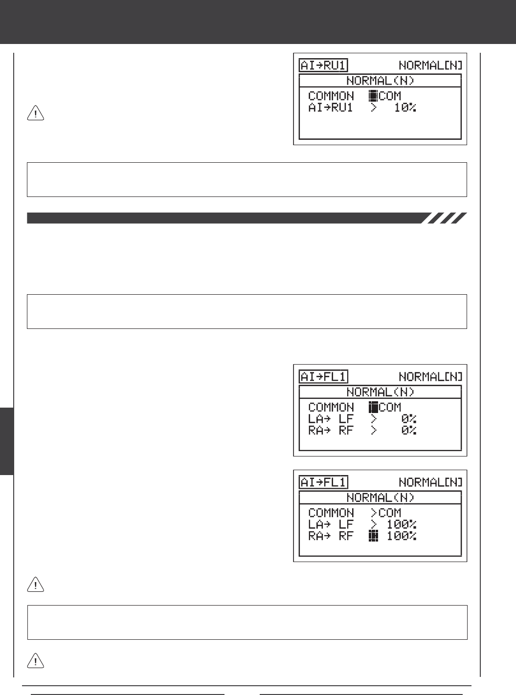
Page 140
glid Flight Mode menu
4) Press the Navigation Pad 6 to highlight AI4RU1>0%.
5) Press the YES/+ or NO/- keys to change the Aileron4Rudder1 mixing
percentage value.
AI4RU1 setting range is -100% to 100%. The default setting is 0%. When the percentage value is increased from 0% to 100%,
rudder travel will increase in one direction in relation to aileron travel. When the percentage value is decreased from
0% to -100%, rudder travel will increase in the opposite direction in relation to aileron travel.
The Aileron4Rudder1 mixing percentage value is a ratio of rudder
travel to aileron travel. For example, when the Aileron4Rudder1
mixing percentage value is set to 10%, the rudder will travel 1/10th the
amount that the ailerons travel. This mix is Linear.
Aileron to Flap Mixing
The Aileron to Flap Mixing function allows you to mix a percentage of ap control with aileron control. When you move the
ailerons right and left, the aps will move up and down. The Aileron to Flap Mixing function is typically used when you have two
or more separate aps (one or two on each wing half). You can then use the Aileron to Flap Mixing function to move the aps up
and down in concert with the ailerons (full span ailerons) to achieve higher roll control authority. The amount and the direction that
the aps move with aileron control is adjusted by changing the Aileron4Flap mixing percentage value either positive or negative.
Two separate Aileron4Flap mixes are available so that you can have two separate Aileron4Flap mixes for each Flight Mode.
IMPORTANT Each of the Aileron to Flap Mixing functions must be assigned to a Switch Position Number before it can
be Activated. For more information, see page 45. Be aware that only one Aileron4Flap mix can be Active at one time. In all
cases, the higher number Aileron4Flap mix will override the lower number Aileron4Flap mix.
1) Press the Navigation Pad 56 to highlight MIXING, then press the ENTER key to display the MIXING menu. The AI4RU1
sub-menu will be highlighted by default.
2) Press the Navigation Pad 6 to highlight which of the two AI4FL
mixing functions you would like to program, then press the ENTER
key to display the AI4FL1 or AI4FL2 menus. The cursor will default
to COMMON>COM. In this example, AI4FL1 is displayed.
3) Press the YES/+ or NO/- keys to choose the desired COM or SEP
option as described previously.
AI4FL1 setting range is -100% to 100%. The default setting is 0%. When the percentage value is increased from 0% to 100%,
flap travel will increase in one direction in relation to aileron travel. When the percentage value is decreased from 0%
to -100%, ap travel will increase in the opposite direction in relation to aileron travel.
The Aileron4Flap1 mixing percentage value is a ratio of ap travel to aileron travel. For example, when the Aileron4Flap1
mixing percentage value is set to 100%, the aps will travel the same amount that the ailerons travel. This mix is Linear.
4) Press the Navigation Pad 6 to highlight LA4LF>0%.
5) Press the YES/+ or NO/- keys to change the Aileron4Left Flap mixing
percentage value.
6) Press the Navigation Pad 6 to highlight RA4RF>0%, then press the
YES/+ or NO/- keys to change the Aileron4Right Flap mixing percentage
value.
The channel options displayed will vary based on Model Type and Model Type selection options currently selected. For
example, if your model features four ap servos, LOF (Left Outside Flap), LIF (Left Inside Flap), ROF (Right Outside
Flap), and RIF (Right Inside Flap) will be displayed and the percentage values can be changed separately.
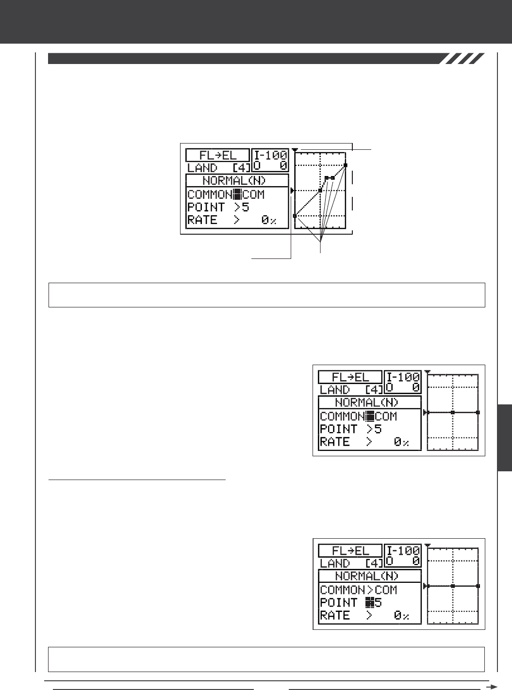
Page 141
glid Flight Mode menu
Flap to Elevator Mixing
The Flap to Elevator Mixing function allows you to mix a percentage of elevator control with ap control. The Flap to Elevator
Mixing function is typically used to reduce the ballooning tendency that most aircraft exhibit when the aps are deployed. For
example, if your aircraft pitches up when the aps are deployed, you can mix in down elevator to help compensate for the pitch
changes. This can be useful during landing to help prevent the aircraft from pitching up when the aps are deployed. The amount
and the direction that the elevator moves with ap control is adjusted by changing the Flap4Elevator mixing percentage value
either positive or negative. An Input and Output display, along with a graph, help with programming visualization.
IMPORTANT The Flap to Elevator Mixing function must be assigned to a Switch Position Number before it can be Activated.
For more information, see page 45.
Stick Input (I)
Function Output (O)
150%
100%
100%
150%
0%
Point Positions
1) Press the Navigation Pad 56 to highlight MIXING, then press the ENTER key to display the MIXING menu. The AI4RU1
sub-menu will be highlighted by default.
2) Press the Navigation Pad 6 to highlight FL4EL, then press the
ENTER key to display the FL4EL menu. The cursor will default to
COMMON>COM.
3) Press the YES/+ or NO/- keys to choose the desired COM or SEP
option as described previously.
Changing the Point and Rate Percentage Values
Programming the Point and Rate percentage values on a Curve allows you to achieve maximum exibility and ne-tuning for specic
uses. The Point and Rate percentage values work together to determine the amount of elevator travel in relation to ap travel. Nine
different Points with varying Rates can be programmed onto the Curve. Use the Input and Output display, along with the graph, to
help with programming visualization. The Point that is currently selected will blink.
1) Press the Navigation Pad 6 to highlight POINT>5.
2) Press the YES/+ or NO/- keys to choose which Point you would like to
set a Rate percentage value for.
POINT setting range is 1 through 9. Point 1 is at the low end of the Curve and Point 9 is at the high end of the Curve. Point 5
is a the center of the Curve. The default Point is Point 5.
GLID
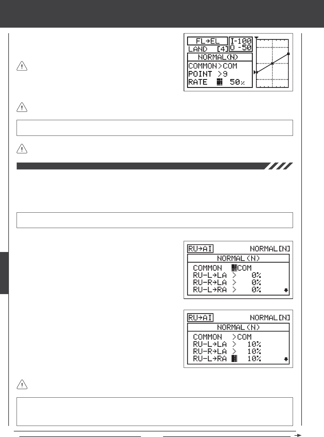
Page 142
glid Flight Mode menu
As you change the Point and Rate percentage values, you can use the graph and I/O numbers to visualize the ratio
between control stick movement and ap travel throughout the entire deection range.
RATE setting range is -150% to 150%. POINT 1, 5, and 9 default Rate percentage values are 0%. The direction of elevator
travel in relation to ap travel can be changed by programming positive or negative Rate percentage values.
3) Press the Navigation Pad 6 to highlight RATE>0%.
4) Press the YES/+ or NO/- keys to set the desired Rate percentage value.
When you change the Rate percentage value for Points 2, 3, 4, 6, 7, and 8, INH will be displayed. When you press the
YES/+ or NO/- keys, INH will change to 0%.
When you program the mix Curve so that the line is straight, this
results in a Linear Curve. For example, if you set the Point 1
percentage value to -50% and the Point 9 percentage value to 50%, the
elevator will move half the amount that the aps move in both directions at
any given ap control stick position.
Rudder to Aileron Mixing
The Rudder to Aileron Mixing function allows you to mix a percentage of aileron control with rudder control. When you move the
rudder right or left, the ailerons will move up or down. For example, if your aircraft rolls when rudder is applied, you can mix in
opposite aileron to help eliminate the roll. The amount and the direction that the ailerons move with rudder control is adjusted by
changing the Rudder4Aileron mixing percentage value either positive or negative. Separate mixes can be programmed for right
and left rudder throw and to each of the aileron servos separately.
IMPORTANT The Rudder to Aileron Mixing function must be assigned to a Switch Position Number before it can be
Activated. For more information, see page 45.
4) Press the Navigation Pad 6 to highlight RU-L4LA>0%.
5) Press the YES/+ or NO/- keys to change the Rudder-Left4Left Aileron
mixing percentage value.
6) Press the Navigation Pad 6 to highlight each of the desired remaining
options (RU-R4LA>0%, RU-L4RA>0%, and RU-R4RA>0%), then
press the YES/+ or NO/- keys to change the mixing percentage values.
RU-L4LA, RU-R4LA, RU-L4RA, and RU-R4RA setting range is -100% to 100%. The default settings are 0%. When
the percentage values are increased from 0% to 100%, aileron travel will increase in one direction in relation to rudder travel.
When the percentage values are decreased from 0% to -100%, aileron travel will increase in the opposite direction in relation
to rudder travel.
The channel options displayed will vary based on Model Type and Model Type selection options currently selected. For
example, if your model features four aileron servos, LOA, LIA, ROA, and RIA percentage values can be changed separately.
1) Press the Navigation Pad 56 to highlight MIXING, then press the
ENTER key to display the MIXING menu. The AI4RU1 sub-menu will
be highlighted by default.
2) Press the Navigation Pad 6 to highlight RU4AI, then press the
ENTER key to display the RU4AI menu. The cursor will default to
COMMON>COM.
3) Press the YES/+ or NO/- keys to choose the desired COM or SEP
option as described previously.
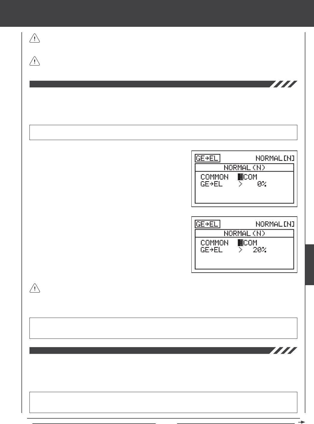
Page 143
glid Flight Mode menu
Because you can program the Rudder4Aileron percentage value separately for both directions of rudder travel, it's
possible to program the mix to either make the ailerons move up or down with right and left rudder control, make the ailerons
move up and down with right and left rudder control, or make the ailerons move up or down with right or left rudder control.
The Rudder4Aileron mixing percentage value is a ratio of aileron travel to rudder travel. For example, when the
Rudder-Left4Left Aileron and the Rudder-Right4Left Aileron mixing percentage values are set to 10%, the left aileron will
travel 1/10th the amount that the rudder travels in both directions. This mix is Linear.
Gear to Elevator Mixing
The Gear to Elevator Mixing function allows you to mix a percentage of elevator control with landing gear control. When you raise
and lower the landing gear, the elevator will move up and down. The Gear to Elevator Mixing function is typically used on scale
sailplanes that feature retractable landing gear. It is used to compensate for pitch changes when the landing gear is lowered.
The amount and the direction that the elevator moves when the landing gear is raised and lowered is adjusted by changing the
Gear4Elevator mixing percentage value either positive or negative.
IMPORTANT The Gear to Elevator Mixing function must be assigned to a Switch Position Number before it can be
Activated. The landing gear function must be assigned to a Switch Position Number, too. For more information, see page 45.
1) Press the Navigation Pad 56 to highlight MIXING, then press the
ENTER key to display the MIXING menu. The AI4RU1 sub-menu will
be highlighted by default.
2) Press the Navigation Pad 6 to highlight GE4EL, then press the
ENTER key to display the GE4EL menu. The cursor will default to
COMMON>COM.
3) Press the YES/+ or NO/- keys to choose the desired COM or SEP
option as described previously.
4) Press the Navigation Pad 6 to highlight GE4EL>0%.
5) Press the YES/+ or NO/- keys to change the Gear4Elevator mixing
percentage value.
GE4EL setting range is -100% to 100%. The default setting is 0%. When the percentage value is increased from 0% to 100%,
elevator travel will increase in one direction in relation to landing gear travel. When the percentage value is decreased
from 0% to -100%, elevator travel will increase in the opposite direction in relation to landing gear travel.
The Gear4Elevator mixing percentage value is a ratio of elevator travel to landing gear travel. Because the landing gear is
assigned to a non-proportional switch, the Gear4Elevator mixing percentage value programmed will result in only half the
programmed movement. For example, when the Gear4Elevator mixing percentage value is set to 20%, the elevator will travel
1/10th the amount that the landing gear travels. Since the landing gear channel is not proportional, the elevator will jump
to the Gear4Elevator mixing percentage value programmed.
Motor to Elevator Mixing
The Motor to Elevator Mixing function allows you to mix a percentage of elevator control with motor control. When the motor is
turned on and off, the elevator will move up and down. The Motor to Elevator Mixing function is typically used to compensate for
pitch changes when the motor is turned on and off. For example, when the motor is turned on, the aircraft might pitch up more
than desired. You can mix in down elevator to compensate for this. The amount and the direction that the elevator moves when
the motor is turned on and off is adjusted by changing the Motor4Elevator mixing percentage value either positive or negative.
IMPORTANT The Motor to Elevator Mixing function must be assigned to a Switch Position Number before it can be
Activated. The motor function must be assigned to a Switch Position Number, too. For more information, see page 45. The
motor function can also be assigned to a control stick or an Auxiliary Lever, too. For more information, see page 151.
GLID
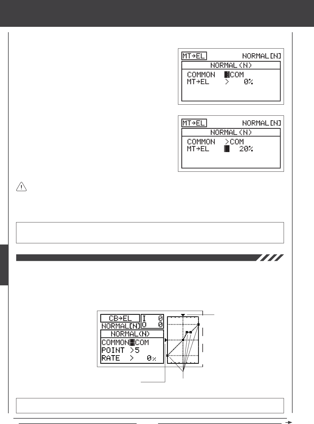
Page 144
1) Press the Navigation Pad 56 to highlight MIXING, then press the ENTER key to display the MIXING menu. The AI4RU1
sub-menu will be highlighted by default.
2) Press the Navigation Pad 6 to highlight MT4EL, then press the
ENTER key to display the MT4EL menu. The cursor will default to
COMMON>COM.
3) Press the YES/+ or NO/- keys to choose the desired COM or SEP
option as described previously.
4) Press the Navigation Pad 6 to highlight MT4EL>0%.
5) Press the YES/+ or NO/- keys to change the Motor4Elevator mixing
percentage value.
glid Flight Mode menu
MT4EL setting range is -100% to 100%. The default setting is 0%. When the percentage value is increased from 0% to 100%,
elevator travel will increase in one direction in relation to motor travel. When the percentage value is decreased from
0% to -100%, elevator travel will increase in the opposite direction in relation to motor travel.
The Motor4Elevator mixing percentage value is a ratio of elevator travel to motor travel. Regardless if the motor function
is assigned to a non-proportional switch or to a control stick, or an Auxiliary Lever, the Motor4Elevator mixing percentage
value programmed will result in only half the programmed movement. For example, when the Motor4Elevator mixing percentage
value is set to 20%, the elevator will travel 1/10th the amount that the motor travels. Even if the motor is assigned to a control
stick or an Auxiliary Lever, the elevator will jump to the Motor4Elevator mixing percentage value programmed, as if it
were assigned to a non-proportional switch.
Camber to Elevator Mixing
The Camber to Elevator Mixing function allows you to mix a percentage of elevator control with Camber or Reflex control.
The Camber to Elevator Mixing function is typically used to reduce pitch changes associated with adding Camber or Reflex.
For example, the aircraft may pitch up when Camber is added. You can mix down elevator to help eliminate the pitch
change. The amount and the direction that the elevator moves when Camber or Reflex is added is adjusted by changing
the Camber4Elevator mixing percentage value either positive or negative. An Input and Output display, along with a
graph, help with programming visualization.
IMPORTANT The Camber to Elevator Mixing function must be assigned to a Switch Position Number before it can be
Activated. For more information, see page 45.
Stick Input (I)
Function Output (O)
150%
100%
100%
150%
0%
Point Positions

Page 145
glid Flight Mode menu
2) Press the Navigation Pad 6 to highlight CB4EL, then press the
ENTER key to display the CB4EL menu. The cursor will default to
COMMON>COM.
3) Press the YES/+ or NO/- keys to choose the desired COM or SEP
option as described previously.
Changing the Point and Rate Percentage Values
Programming the Point and Rate percentage values on a Curve allows you to achieve maximum exibility and ne-tuning
for specic uses. The Point and Rate percentage values work together to determine the amount of elevator travel in relation to
Camber or Reex travel. Nine different Points with varying Rates can be programmed onto the Curve. Use the Input and Output
display, along with the graph, to help with programming visualization. The Point that is currently selected will blink.
1) Press the Navigation Pad 6 to highlight POINT>5.
2) Press the YES/+ or NO/- keys to choose which Point you would like to
set a Rate percentage value for.
POINT setting range is 1 through 9. Point 1 is at the low end of the Curve and Point 9 is at the high end of the Curve. Point 5
is a the center of the Curve. The default Point is Point 5.
As you change the Point and Rate percentage values, you can use the graph and I/O numbers to visualize the ratio
between Camber or Reex travel and elevator travel throughout the entire deection range.
RATE setting range is -150% to 150%. POINT 1, 5, and 9 default Rate percentage values are 0%. The direction of elevator
travel in relation to Camber or Reex travel can be changed by programming positive or negative Rate percentage values.
3) Press the Navigation Pad 6 to highlight RATE>0%.
4) Press the YES/+ or NO/- keys to set the desired Rate percentage value.
When you change the Rate percentage value for Points 2, 3, 4, 6, 7, and 8, INH will be displayed. When you press the
YES/+ or NO/- keys, INH will change to 0%.
When you program the mix Curve so that the line is straight, this results in a Linear Curve. For example, if you set the
Point 1 percentage value to -50% and the Point 9 percentage value to 50%, the elevator will move half the amount that
Camber or Reex moves in both directions for the entire range of deection.
1) Press the Navigation Pad 56 to highlight MIXING, then press the ENTER key to display the MIXING menu. The AI4RU1
sub-menu will be highlighted by default.
GLID
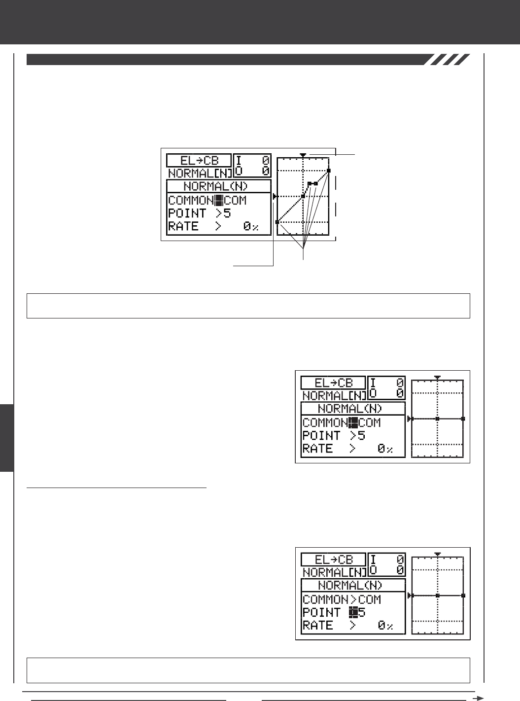
Page 146
glid Flight Mode menu
Elevator to Camber Mixing
The Elevator to Camber Mixing function allows you to mix a percentage of Camber or Reex control with elevator control. The
Elevator to Camber Mixing function is typically used in high-performance sailplanes to make the wing more efcient and to increase
turning performance. For example, if you want to increase turning performance to enable sharper turns for pylon racing, you
would want to mix Camber when you pull up elevator. The amount and the direction of Camber or Reex travel when the elevator
is moved up and down is adjusted by changing the Elevator4Camber mixing percentage value either positive or negative. An
Input and Output display, along with a graph, help with programming visualization.
IMPORTANT The Elevator to Camber Mixing function must be assigned to a Switch Position Number before it can be
Activated. For more information, see page 45.
Stick Input (I)
Function Output (O)
150%
100%
100%
150%
0%
Point Positions
2) Press the Navigation Pad 6 to highlight EL4CB, then press the
ENTER key to display the EL4CB menu. The cursor will default to
COMMON>COM.
3) Press the YES/+ or NO/- keys to choose the desired COM or SEP
option as described previously.
1) Press the Navigation Pad 56 to highlight MIXING, then press the ENTER key to display the MIXING menu. The AI4RU1
sub-menu will be highlighted by default.
Changing the Point and Rate Percentage Values
Programming the Point and Rate percentage values on a Curve allows you to achieve maximum exibility and ne-tuning for
specic uses. The Point and Rate percentage values work together to determine the amount of Camber or Reex travel in relation
to elevator travel. Nine different Points with varying Rates can be programmed onto the Curve. Use the Input and Output display,
along with the graph, to help with programming visualization. The Point that is currently selected will blink.
1) Press the Navigation Pad 6 to highlight POINT>5.
2) Press the YES/+ or NO/- keys to choose which Point you would like to
set a Rate percentage value for.
POINT setting range is 1 through 9. Point 1 is at the low end of the Curve and Point 9 is at the high end of the Curve. Point 5
is a the center of the Curve. The default Point is Point 5.
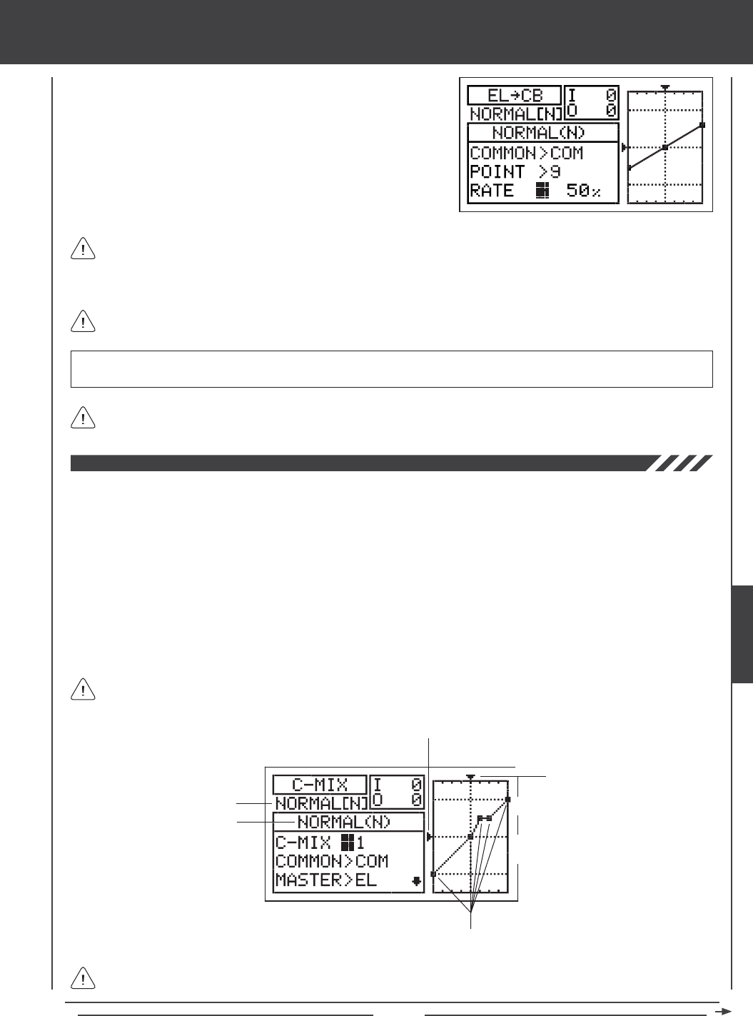
Page 147
glid Flight Mode menu
As you change the Point and Rate percentage values, you can use the graph and I/O numbers to visualize the ratio
between control stick movement and Camber or Reex travel throughout the entire deection range.
RATE setting range is -150% to 150%. POINT 1, 5, and 9 default Rate percentage values are 0%. The direction of Camber
or Reex travel in relation to elevator travel can be changed by programming positive or negative Rate percentage values.
3) Press the Navigation Pad 6 to highlight RATE>0%.
4) Press the YES/+ or NO/- keys to set the desired Rate percentage value.
When you change the Rate percentage value for Points 2, 3, 4, 6, 7, and 8, INH will be displayed. When you press the
YES/+ or NO/- keys, INH will change to 0%.
When you program the mix Curve so that the line is straight, this results in a Linear Curve. For example, if you set
the Point 1 percentage value to -50% and the Point 9 percentage value to 50%, Camber or Reex travel will be half the
amount that the elevator travels in both directions for the entire range of deection. If you wanted only Camber travel with up
elevator travel, you can set the Point 1 percentage value to 50%, and the Point 5 and Point 9 percentage values to 0%.
In all cases, the Master channel always controls the Slave channel. In the default conguration, all Compensation Mixes
can be programmed to be Linear, or precise channel Curves can be created by programming up to nine Points along
the Curve.
Transmitter F-MODE
Programming F-MODE
Stick Input (I)
Function Output (O)
150%
100%
100%
150%
0%
Point Positions
Transmitter F-MODE refers to the Flight Mode that the transmitter is currently operating in. Programming F-MODE refers
to the Flight Mode that you would like to change the programming for.
The C-Mix function allows you to program custom mixes that can control any number of desired functions in different combinations.
It is used to create your own custom mix if one of the pre-programmed mixes is not suitable. For example, you can create a
custom mix that mixes Camber to rudder, that can be used to help eliminate the need to use elevator during some turns, allowing
you to y with only the rudder control stick.
Like with pre-programmed mixes, Compensation Mixes are composed of a Master channel and a Slave channel. The Master
channel always controls the Slave channel. Any of the available ten channels can be programmed as a Master or a Slave. The
same channel can even be programmed as both a Master and a Slave. The C-Mix function includes nine custom-programmable
Points to ensure an extremely precise channel Curve to suit any situation. You can also program a Delay for the Slave function
that works independently (or with) the dedicated Channel Delay function described on page 86.
Up to ve C-Mix functions can be programmed separately for each of the ve Flight Modes or you can use the same C-Mix
programming across all ve Flight Modes. An Input and Output display, along with a graph, help with programming visualization.
GLID
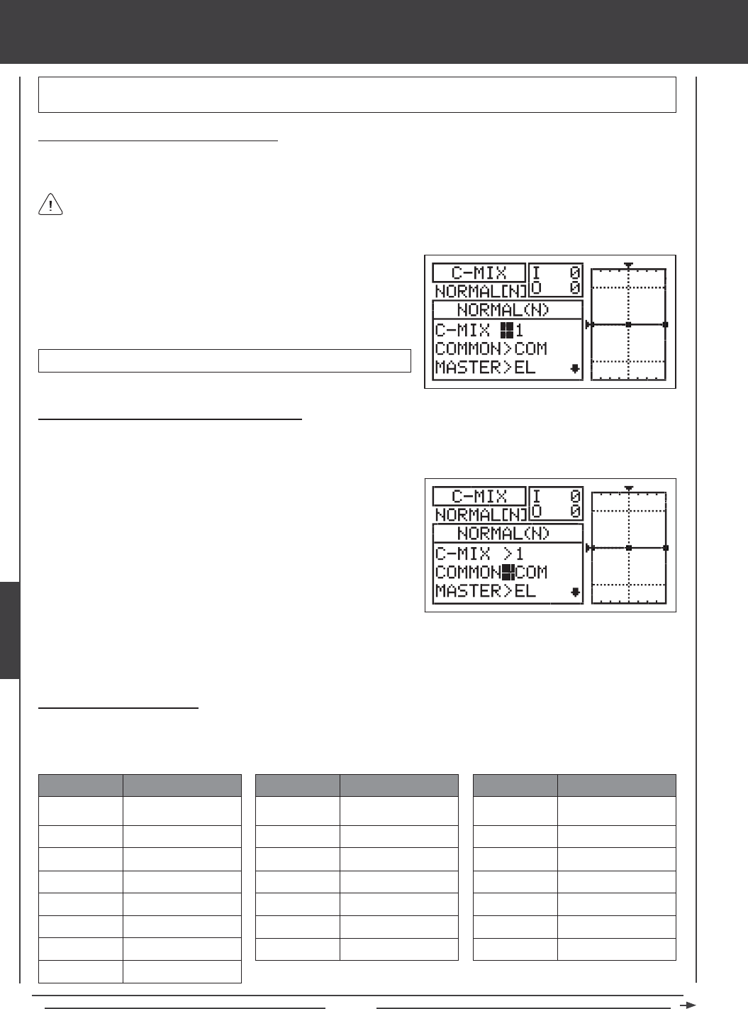
Page 148
glid Flight Mode menu
Choosing the Compensation Mixing Number
Up to ve separate Compensation Mixing functions can be programmed for each Flight Mode, however, only one Master/Slave
channel can be assigned to one Compensation Mixing function at a time.
More than one Compensation Mixer can be assigned to the same Switch Position Number, so that they can be Activated at
the same time. For example, assign both C-Mix 1 and C-Mix 2 to Switch Position 5 to Activate both Compensation Mixers
at the same time.
IMPORTANT Each C-Mix function must be assigned to a Switch Position Number before it can be Activated. For more
information, see page 45.
1) Press the Navigation Pad 56 to highlight C-MIX, then press the ENTER
key to display the C-MIX menu. The cursor will default to C-MIX>1.
2) Press the YES/+ and NO/- keys to choose the C-MIX number you would
like to program Compensation Mixing for.
C-MIX setting range is 1, 2, 3, 4, or 5. The default setting is 1.
Choosing the Flight Mode - Common or Separate
When set to COM (Common), the C-MIX settings will be the same regardless of which Flight Mode the transmitter is operating in.
You cannot program C-MIX settings separately for each Flight Mode. When set to SEP (Separate), you can program different
C-MIX settings separately for each Flight Mode.
1) Press the Navigation Pad 6 to highlight COMMON>COM, then press
the YES/+ or NO/- keys to choose either COM or SEP. If set to COM,
skip to the Choosing the Master Channel section. If set to SEP, see
step 2 below.
Choosing the Master Channel
The Master channel is the channel that controls the Slave channel. For example, if you set the Master channel to EL (Elevator),
when you move the elevator control stick, the Slave channel that's mixed to the elevator channel will move. Depending on the Model
Type and Model Type selection options you've chosen in the Model Type menu, the following Master channels are available.
EL / EL+
AI
MT / MT+
RU / RU+
GE / GE+
FL
LF+
RF+
ABBR. FUNCTION
Elevator
Aileron
Motor
Rudder
Gear
Flap
Left Flap
Right Flap
AUX1 / AUX1+
AUX2 / AUX2+
AUX3 / AUX3+
LA+
RA+
LOA+
ROA+
ABBR. FUNCTION
Auxiliary 1
Auxiliary 2
Auxiliary 3
Left Aileron
Right Aileron
Left Outside Aileron
Right Outside Aileron
LIA+
RIA+
LOF+
ROF+
LIF+
RIF+
CB/CB+
ABBR. FUNCTION
Left Inside Aileron
Right Inside Aileron
Left Outside Flap
Right Outside Flap
Left Inside Flap
Right Inside Flap
Camber
2) Press the F-MODE key to choose the F-MODE number you would like to program the Compensation Mixing function for.
Choose from N, 1, 2, 3, or 4. The NORMAL (N) display will change, indicating which Flight Mode you are programming the
Compensation Mixing function for.
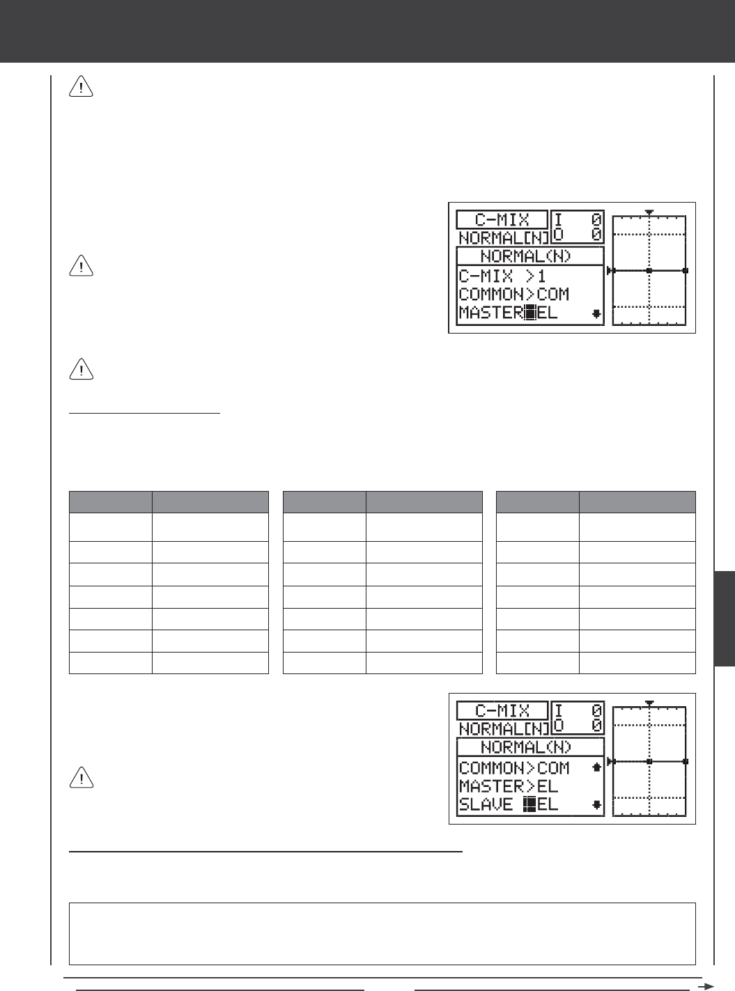
Page 149
glid Flight Mode menu
Master channels denoted with a plus sign (+) indicate that Dual Rate, Exponential, Trim, and/or Channel Delay settings
affect not only the Master channels but also the Slave channels when the Compensation Mixing function is Activated. For
example, if MASTER>EL+ is selected, any programmed elevator Dual Rate or Exponential percentage values will affect both the
Master elevator channel and the Slave channel when the elevator Dual Rate switch is Activated while the Compensation Mixing
function is Active. If you select MASTER>EL, any programmed elevator Dual Rate or Exponential percentage values will only
affect the Master elevator channel when the Compensation Mixing function is Active. Dual Rate and Exponential affect only the
elevator, aileron, and rudder channels. The Channel Delay function referenced is not the same as the Delay function in the
C-MIX menu.
1) Press the Navigation Pad 6 to highlight MASTER>EL, then press the
YES/+ or NO/- keys to choose which channel you want to program the
Master channel for.
The channel options displayed will vary based on Model Type and
Model Type selection options currently selected. For example, if your
model features four aileron servos, LOA+, ROA+, LIA+, and RIA+ will be
separate options. When using dual or quad servos for ailerons or aps,
the (+) option will only be available for the servos separately (e.g. LF+ and
RF+, but not for FL).
If you want Dual Rate, Exponential, Trim, and/or independent Channel Delay control over the Slave channel, make sure to
choose a Master channel with a plus sign (+).
Choosing the Slave Channel
The Slave channel is the channel that is controlled by the Master channel. For example if you set the Master channel to
EL (Elevator) and the Slave channel to AI (Aileron), when you move the elevator control stick, the ailerons will move. Depending
on the Model Type and Model Type selection options you've chosen in the Model Type menu, the following Slave channels
are available.
1) Press the Navigation Pad 6 to highlight SLAVE>EL, then press the
YES/+ or NO/- keys to choose which channel you want to program the
Slave channel for.
The channel options displayed will vary based on Model Type and
Model Type selection options currently selected. For example, if your
model features dual ap servos, LF and RF will be separate options.
EL
MT
RU
GE
LA
RA
FL
ABBR. FUNCTION
Elevator
Motor
Rudder
Gear
Left Aileron
Right Aileron
Flap
AUX1
AUX2
AUX3
CB
LOA
ROA
LIA
ABBR. FUNCTION
Auxiliary 1
Auxiliary 2
Auxiliary 3
Camber
Left Outside Aileron
Right Outside Aileron
Left Inside Aileron
RIA
LF
RF
LOF
ROF
LIF
RIF
ABBR. FUNCTION
Right Inside Aileron
Left Flap
Right Flap
Left Outside Flap
Right Outside Flap
Left Inside Flap
Right Inside Flap
Changing the Channel Curve Point Values and the Rate Percentage Values
Nine different Points with varying Rates can be programmed onto the channel Curve. Each Point will be displayed on the graph
to give you a visual interpretation of the position of the Point on the channel Curve. The Point that is currently selected will blink.
WARNING When a Compensation Mixer is Activated, you still have separate control over the Slaved channel, however,
depending on the Rate percentage value, the Slave channel End Point Adjustment could be exceeded. We strongly recommend
that you set your Slave channel Limits no higher than that channel's End Point Adjustment unless specically necessary for
your particular setup. This will prevent any chance of overdriving your control linkage when Compensation Mixing is used.
GLID
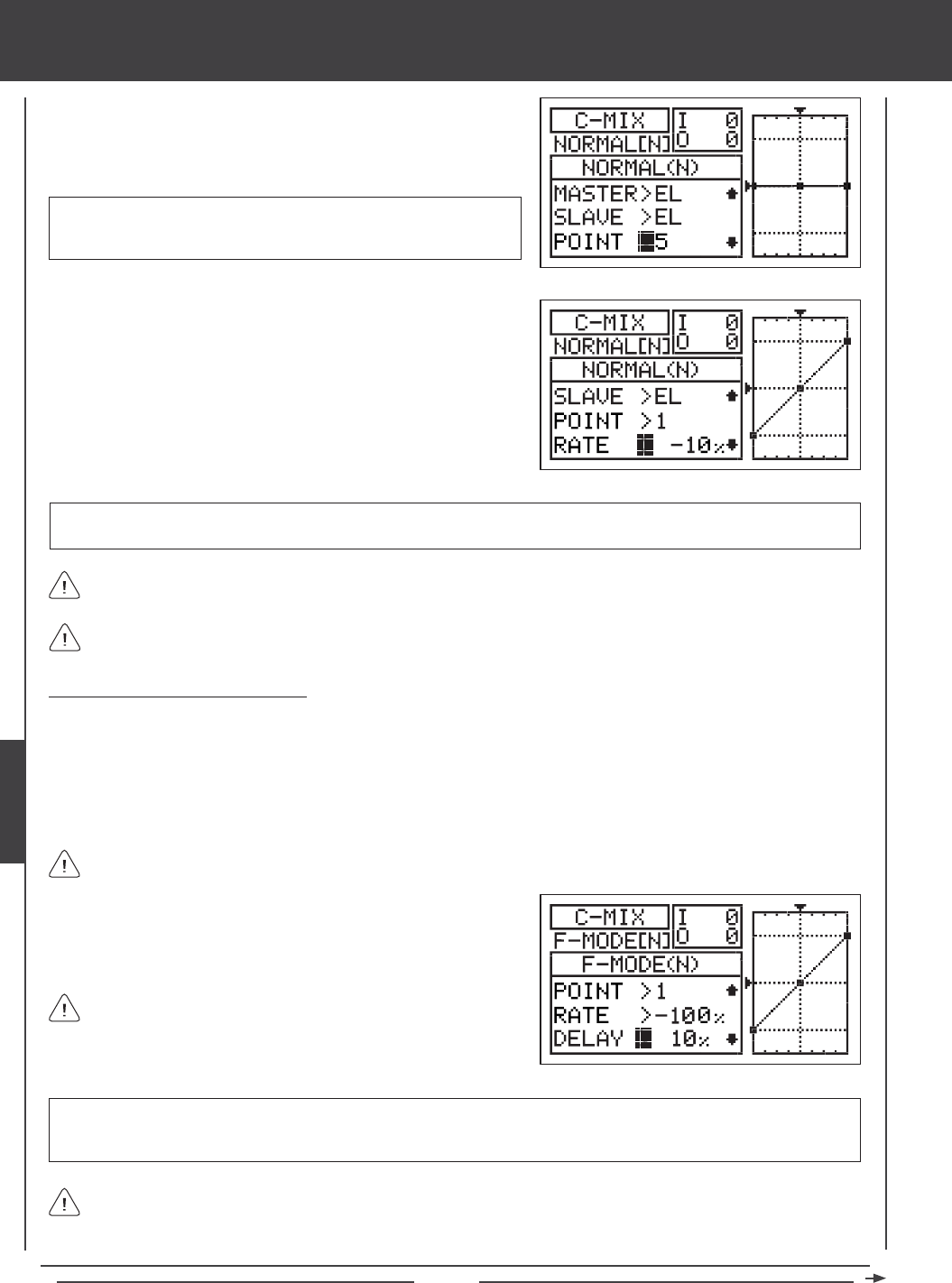
Page 150
RATE setting range is -150% to 150%. POINT 1 default RATE percentage value is 0%, POINT 5 default RATE percentage
value is 0%, and POINT 9 default RATE percentage value is 0%. POINT 2, 3, 4, 6, 7, and 8 RATE values are INH (Inhibited).
3) Press the Navigation Pad 6 to highlight RATE>0%.
4) Press the YES/+ or NO/- keys to set the desired Rate percentage value.
1) Press the Navigation Pad 6 to highlight POINT>5.
2) Press the YES/+ or NO/- keys to choose which Point you would like to
set a Rate percentage value for.
POINT setting range is 1 through 9. Point 1 is at the low end of the
channel Curve and Point 9 is at the high end of the channel Curve. Point
5 is a the center of the channel Curve.
glid Flight Mode menu
As you change the Point and Rate percentage values, you can use the graph and I/O numbers to visualize the ratio
between control stick movement and servo travel throughout the entire deection range.
The Rate percentage value is a ratio of Slave channel servo travel to Master channel servo travel. For example, if the Rate
percentage value is set to 10%, the Slave channel servo will travel 1/10th the amount that the Master channel servo travels.
Changing the Delay Percentage Value
Changing the Delay percentage value allows you to adjust the speed of the Slave channel servo when moved in the direction
of the Master channel control stick (or switch) when the Compensation Mixing function is Active. For example, if you program
Compensation Mixing to provide Camber to rudder mixing, the trailing edge will move down when the rudder moves right and
left. The Camber and Reex can also be controlled separately using Auxiliary Lever (VR6). Setting a Delay percentage value will
cause the ap and aileron servos to slow down ONLY in the up and down directions when the when the rudder is moved right
and left. Servo speed in the right and left directions for roll control will be normal, unless you have programmed aileron Channel
Delay separately.
The Delay function does not affect when the servo starts to respond to control stick movement. The Delay affects only
the transit time of the servo.
1) Press the Navigation Pad 6 to highlight DELAY>0%, then press the
YES/+ or NO/- keys to change the Delay percentage value.
DELAY setting range is 0% to 100%. The default setting is 0%. When the Delay percentage value is increased, the Slave
servo transit time will be slowed down. At 0%, the Slave servo moves at its normal speed. At 100%, the Slave servo takes
approximately 15 seconds to move from neutral to 100% or -100% travel.
The Delay function will cause the Slave servo transit time to slow down not only from neutral to one End Point, but also
on the return from one End Point to neutral, unless the Master channel is assigned to a switch. If the Master channel is
assigned to a switch, the Delay function will only affect the Slave servo in the neutral to End Point direction of travel. The Delay
function will not affect the Slave servo in the return to neutral direction of travel.
The Delay percentage value is not Point-dependent.
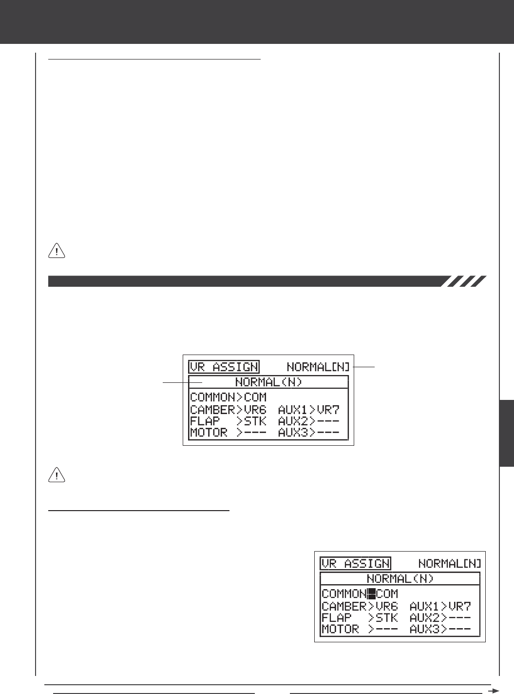
Page 151
glid Flight Mode menu
Compensation Mixing Sample - Mixing Camber to Rudder
The sample below describes how to mix Camber to rudder using one Compensation Mixer assigned to a Switch Position
Number. This mix can be used to help eliminate the need to use elevator during some turns, allowing you to y with only
the left control stick.
1) Assign C-MIX1 to a Switch Position Number in the Switch Assign menu. For example, use Switch Position Number 05.
2) Verify that the rudder control surface and the Camber function are operating as desired.
3) Set the Compensation Mixing programming values as shown:
C-MIX>1
COMMON>COM
MASTER>RU+
SLAVE>CB
POINT>1 / RATE>20%
POINT>9 / RATE>20%
In this example, Points 1 and 9 are both set to 20%. When the Compensation Mixer is Active,
this results in Camber movement when the rudder is moved either right or left. With the Rate
setting at 20%, the trailing edge will move down 1/20th the amount that the rudder moves
right or left. This results in a Linear channel Curve. To increase or decrease Camber travel,
increase or decrease the Point 1 and Point 9 Rate percentage values, respectively.
The positive values shown in the example above may vary based on the NOR/REV status of your servos. You may need
to change the percentage values to suit.
The VR Assign function allows you to assign the auxiliary channels and the Camber, Flap, and Motor functions to either of the two
Auxiliary Levers (VR5 or VR6) or the Auxiliary Dial Knob (VR7). For example, you could use the Auxiliary Lever (VR5) to variably
control your motor, instead of assigning the motor to a Switch Position Number via the Switch Assign menu. You can choose to
program VR Assignments separately for each of the ve Flight Modes or you can use the same VR Assignments programming
across all ve Flight Modes.
Transmitter F-MODE
Programming F-MODE
Transmitter F-MODE refers to the Flight Mode that the transmitter is currently operating in. Programming F-MODE refers
to the Flight Mode that you would like to change the programming for.
Choosing the Flight Mode - Common or Separate
When set to COM (Common), the VR ASSIGN settings will be the same regardless of which Flight Mode the transmitter is operating
in. You cannot program VR ASSIGN settings separately for each Flight Mode. When set to SEP (Separate), you can program
different VR ASSIGN settings separately for each Flight Mode.
3) Press the F-MODE key to choose the F-MODE number you would like to program the VR Assignments for. Choose from N, 1,
2, 3, or 4. The NORMAL (N) display will change, indicating which Flight Mode you are programming the VR Assignments for.
1) Press the Navigation Pad 56 to highlight VR ASSIGN, then press the
ENTER key to display the VR ASSIGN menu. The cursor will default to
COMMON>COM.
2) Press the YES/+ or NO/- keys to choose either COM or SEP. If set to
COM, skip to the Choosing Channel VR Assignments section. If set
to SEP, see step 3 below.
GLID
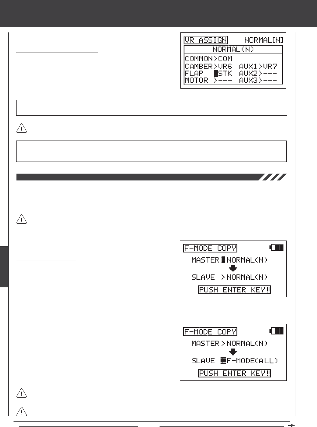
Page 152
glid Flight Mode menu
IMPORTANT Both sides of each auxiliary channel (High and Low), can be assigned to a Switch Position Number, using the
SW ASSIGN menu. If the Flap and Motor channels, or an auxiliary channel is assigned to both a switch and an Auxiliary Lever,
the switch takes precedence over the Auxiliary Lever in all cases.
Choosing Channel VR Assignments
1) Press the Navigation Pad 5634 to highlight the channel you would
like to change the VR Assignment for, then press the YES/+ or NO/- keys
to change the VR Assignment.
VR ASSIGN setting range is ---, STK, VR5, VR6, and VR7. The default setting for CAMBER is VR6. The default setting for FLAP
is STK, and the default setting for AUX1 is VR7. The default settings for MOTOR, AUX2 and AUX3 is ---.
To disable an Auxiliary Lever, Auxiliary Dial Knob or the control stick, assign --- to the desired channel. For example, if you
don't want Auxiliary Lever (VR6) to control Camber, change CAMBER>VR6 to CAMBER>---.
The Flight Mode Copy function allows you to copy the Flight Mode programming data from one Flight Mode to another Flight
Mode. This is convenient if you want to use two or more different Flight Modes on one model, but only need to change a few
Flight Mode programming values for the new Flight Mode. This allows you to use the Flight Mode programming data from the
rst Flight Mode to use as a base to start ne-tuning the programming for the second Flight Mode.
You can only copy Flight Mode programming data from one Flight Mode to another Flight Mode within the same model.
To copy Flight Mode programming data from one model's Flight Mode to another model's Flight Mode, you must copy
the actual model programming data to the other model. For more information, see page 52.
Copying Flight Mode Data
1) Press the Navigation Pad 56 to highlight F-MODE COPY, then press
the ENTER key to display the F-MODE COPY menu. The cursor
will default to MASTER>NORMAL(N).
3) Press the Navigation Pad 6 to highlight SLAVE>NORMAL(N).
4) Press the F-MODE key to select the Flight Mode you would like to copy
the Flight Mode programming data TO (SLAVE). Select from NORMAL
(N), FLOAT (1), LAUNCH (2), REFLEX (3), LAND (4), or ALL.
It's not possible to copy the Flight Mode programming data from one Flight Mode to the same Flight Mode. If you attempt
to execute this, SAME F-MODE?? will be displayed and the process will not execute.
Selecting ALL will copy the MASTER Flight Mode programming data to the remaining four Flight Modes.
2) Press the F-MODE key to select the Flight Mode you would like to copy the Flight Mode programming data FROM (MASTER).
Select from NORMAL (N), FLOAT (1), LAUNCH (2), REFLEX (3), or LAND (4).
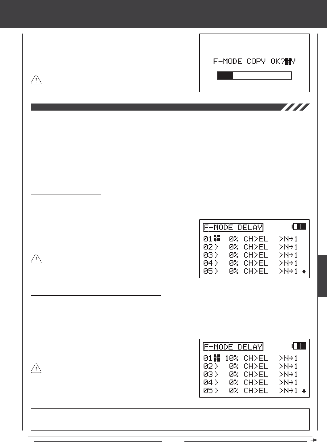
Page 153
glid Flight Mode menu
5) Press then ENTER key. F-MODE COPY OK?>Y will be displayed.
6) Press the YES/+ key to begin the F-MODE Copy process. When the
F-MODE Copy process is completed the F-MODE COPY menu will be
displayed, indicating that the Flight Mode programming data has been
copied.
If you want to go back and change the Flight Mode or you don't want
to copy the Flight Mode programming data for any reason, press the
NO/- or END keys.
The Flight Mode Delay function allows you to program custom delays for each of the channel functions within each of the
separate Flight Modes. This function helps to prevent drastic changes in channel settings when switching between Flight Modes.
For example, if you switch from Flight Mode N (Normal) to Flight Mode 4 (Land), the aps will immediately deploy to the position that
the ap control stick is in. The Flight Mode Delay function allows you to program a Delay in the ap channel, so that the transition
to the ap position when you switch back and forth between Flight Modes is smooth.
If you program Flight Mode Delays for all ve Flight Modes separately, you can program up to 10 different Delays for each Flight
Mode. If you are using fewer Flight Modes, you can program more than 10 different Delays for each of the Flight Modes that you're
using. You are able to program 50 different Delays in total. The Flight Mode Delay function can be programmed for each of the
channels you're using, and separate Flight Mode Delays can be programmed in both directions. For example, when switching from
Flight Mode N (Normal) to Flight Mode 4 (Land) and back from Flight Mode N (Normal) to Flight Mode 4 (Land).
Choosing a Flight Mode Delay
1) Press the Navigation Pad 56 to highlight F-MODE DELAY, then press the ENTER key to display the F-MODE DELAY
menu. The cursor will default to 01>0% CH>EL >N41.
Flight Mode Delays do not have to programmed in sequence (e.g.,
01, 02, 03), but programming them in sequence does make it easier
to keep track of them.
2) Press the Navigation Pad 56 to highlight the Flight Mode Delay you
would like to program. If this is the rst Flight Mode Delay that you're
programming, choose 01>0%
Changing the Flight Mode Delay Rate Percentage Value
The Rate percentage value changes the speed of the servos as they move to their new positions when you switch between
Flight Modes. For example, if you're ying with aps up in Flight Mode N (Normal), but the aps fully deploy when you pull the
ap control stick all the way back, increasing the Rate percentage value will slow the speed at which the ap servos will move to
their maximum travel when you Activate Flight Mode 4 (Land). This allows the aps to smoothly lower to the new travel position
instead of immediately jumping to the new travel position.
RATE setting range is 0% to 100%. The default setting is 0%. When the Rate percentage value is set to 0%, there is no Delay
when switching between Flight Modes. When the Rate percentage value is increased, the Delay when switching between
Flight Modes is increased.
The Rate percentage value is displayed as a percentage of Delay
time and is based on the amount of change in servo travel when
switching between different Flight Modes. When the Rate percentage value
is set to 100%, the servo will take approximately 15 seconds to travel from
neutral to 100% or -100%.
1) Press the YES/+ and NO/- keys to change the Rate percentage value
for the selected Flight Mode Delay.
GLID
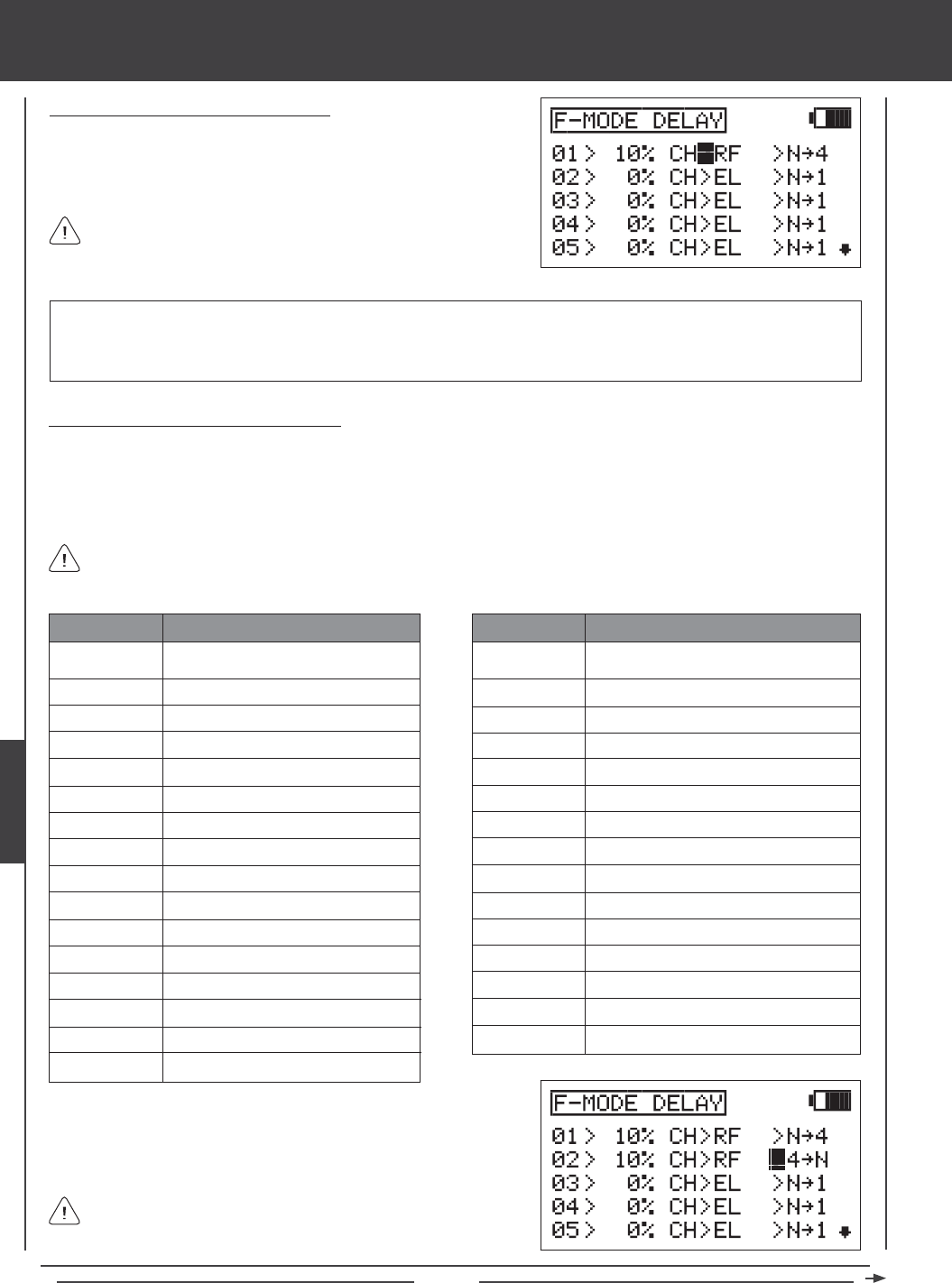
Page 154
glid Flight Mode menu
IMPORTANT Channels that use two or more servos, such as quad aileron servos or dual rudder servos will be displayed
separately (e.g., LOA, ROA, LIA, RIA, LF, RF, etc). In this situation, the Flight Mode Delay function will affect not the whole
channel, but the individual servo. In most cases, you will want to program a second matching Flight Mode Delay for the second,
third, or fourth servos, so that each servo is affected equally.
Choosing the Flight Mode Delay Channel
1) Press the Navigation Pad 4 to highlight CH>EL.
2) Press the YES/+ and NO/- keys to choose which channel you would
like the Flight Mode Delay to affect.
The channels options displayed will vary based on Model Type and
Model Type selection options currently selected. For example, if your
model features dual ap servos, RF or LF will be display as an option.
Changing the Flight Mode Delay Sequence
The Flight Mode Delay sequence denes the direction you want the Flight Mode Delay going TO and FROM, as shown in the
tables below. For example, if you choose N41, the Flight Mode Delay function will Activate when you switch from Flight Mode N
(Normal) to Flight Mode 1 (Float). If you choose N44, the Flight Mode Delay function will Activate when you switch from Flight
Mode N (Normal) to Flight Mode 4 (Land). If you choose 44N, the Flight Mode Delay function will Activate when you switch from
Flight Mode 4 (Land) to Flight Mode N (Normal).
341
342
344
34*
44N
441
442
443
44*
*4N
*41
*42
*43
*44
*4*
FROM Flight Mode 3 to Flight Mode 1
FROM Flight Mode 3 to Flight Mode 2
Flight Mode 3 TO Flight Mode 4
Flight Mode 3 TO All Flight Modes
FROM Flight Mode 4 to Flight Mode N
FROM Flight Mode 4 to Flight Mode 1
FROM Flight Mode 4 to Flight Mode 2
FROM Flight Mode 4 to Flight Mode 3
Flight Mode 4 TO All Flight Modes
FROM All Flight Modes to Flight Mode N
FROM All Flight Modes to Flight Mode 1
FROM All Flight Modes to Flight Mode 2
FROM All Flight Modes to Flight Mode 3
FROM All Flight Modes to Flight Mode 4
FROM All Flight Modes TO All Flight Modes
SEQUENCE DESCRIPTION
N41
N42
N43
N44
N4*
14N
142
143
144
14*
24N
241
243
244
24*
34N
Flight Mode N TO Flight Mode 1
Flight Mode N TO Flight Mode 2
Flight Mode N TO Flight Mode 3
Flight Mode N TO Flight Mode 4
Flight Mode N TO All Flight Modes
FROM Flight Mode 1 to Flight Mode N
Flight Mode 1 TO Flight Mode 2
Flight Mode 1 TO Flight Mode 3
Flight Mode 1 TO Flight Mode 4
Flight Mode 1 TO All Flight Modes
FROM Flight Mode 2 to Flight Mode N
FROM Flight Mode 2 to Flight Mode 1
Flight Mode 2 TO Flight Mode 3
Flight Mode 2 TO Flight Mode 4
Flight Mode 2 TO All Flight Modes
FROM Flight Mode 3 to Flight Mode N
SEQUENCE DESCRIPTION
Delay sequences that include an Asterisk indicate that the Flight Mode Delay function will be Activated across all Flight
Modes. For example, if you choose N4*, the Flight Mode Delay function will Activate on all Flight Modes regardless of
the Flight Mode you switch to.
1) Press the Navigation Pad 4 to highlight N41.
2) Press the YES/+ and NO/- keys to choose which Flight Mode Delay
sequence you would like to use.
Use the tables of Delay sequences on the previous page to help you
choose which Flight Mode Delay sequence you would like to use.
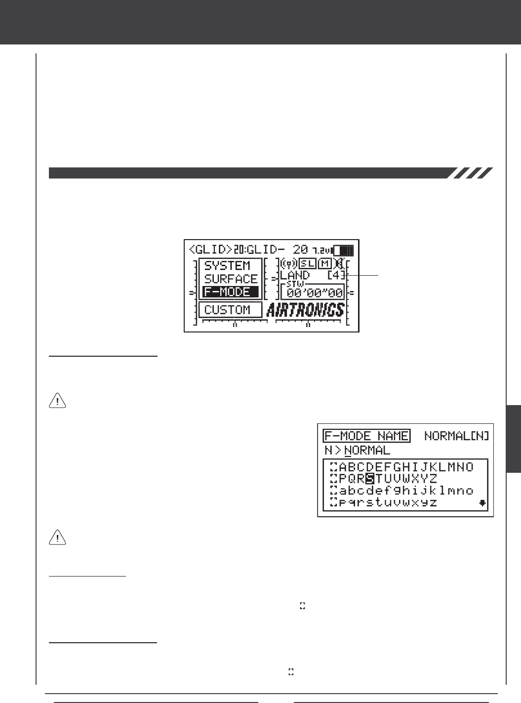
Page 155
3) Repeat the previous procedures to program more Flight Mode Delay functions. For example, if you want to set a Flight Mode
Delay for the ap channel when you switch from Flight Mode N (Normal) to Flight Mode 4 (Land), and from when you switch
back from Flight Mode 4 (Land) to Flight Mode N (Normal), program the following:
01>10% CH>LF >N44
02>10% CH>RF >N44
This programming will result in a 10% delay in the ap channel when you switch from Flight Mode N (Normal) to Flight Mode 4
(Land) and when you switch back from Flight Mode 4 (Land) to Flight Mode N (Normal). This will not Activate the Flight Mode Delay
when you switch to any other Flight Mode. For example, when you switch from Flight Mode N (Normal) to Flight Mode 2 (Launch).
glid Flight Mode menu
The F-Mode Name function allows you to name each of your individual F-Modes. This makes it easier to keep track of which
F-Mode is currently in use. The currently Active Flight Mode name is displayed, along with the corresponding Flight Mode number
on the Top menu and on the various F-MODE programming menus. The F-Mode Name can consist of up to 6 letters, numbers,
or symbols. Choose from capital letters, lower case letters, numbers, and various symbols.
Entering a Flight Mode Name
1) Press the Navigation Pad 56 to highlight F-MODE NAME, then press the ENTER key to display the F-MODE NAME menu.
The cursor will default to the left side of the top row of letters.
Press the F-MODE key to cycle through the ve different F-Modes. The F-Mode that you are currently naming is shown to
the left of the Flight Mode Name. For example, N>NORMAL.
Flight Mode Name
and Number
2) Press the Navigation Pad 3456 to highlight a character, then press
the ENTER key to select the highlighted character. That character will be
displayed and the underline will move to the next space.
3) Repeat step 2 to enter the rest of the characters. Up to six characters
can be entered.
Press the Navigation Pad 56 repeatedly to scroll up and down the list of characters.
Deleting a Character
1) Press the YES/+ or NO/- keys to move the underline under the character you want to erase.
2) Press the Navigation Pad 3456 to highlight the Erase Bracket , then press the ENTER key to erase the underlined
character.
Deleting a Flight Mode Name
1) Press the YES/+ and NO/- keys at the same time to move the underline under the rst character.
2) Press the Navigation Pad 3456 to highlight the Erase Bracket , then press the ENTER key repeatedly to erase the entire
Flight Mode Name.
03>10% CH>LF >44N
04>10% CH>RF >44N
GLID

Page 156
heli Flight Mode contents
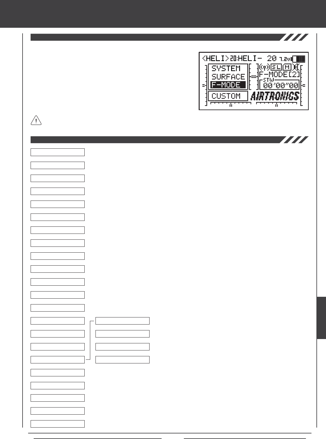
Page 157
heli Flight Mode menu
To access the F-Mode menu, turn the transmitter ON. From the Top menu,
press the Navigation Pad 56 to highlight F-MODE, then press the ENTER
key to display the F-Mode menu.
From within any menu, press the END key continuously to return to the
Top menu.
Unless otherwise noted, all programming changes take effect immediately.
If the Top menu is not displayed when you turn the transmitter ON, continuously press the END key until the Top menu
is displayed.
Use this Flow Chart to familiarize yourself with the HELI Flight Mode menu structure. Descriptions
regarding all HELI Flight Mode menu functions and programming are found on pages 158
through 194.
04.EXP
03.D/R
02.STICK MONITOR
01.SX MONITOR
05.TH-CURVE
06.PI-CURVE
07.TH-CUT
08.HOV-TH
09.HOV-PI
10.OFFSET
11.CH DELAY
12.TRIM
13.TRIM STEP
14.TRIM AUTH
15.GYRO
16.GOVERNOR
17.MIXING
18.C-MIX
19.VR ASSIGN
6
6
6
6
6
6
6
6
6
6
6
6
6
6
6
6
6
6
01.REVO MIX
02.EL>TH
03.AI>TH
04.RU>TH
6
6
6
6
20.F-MODE COPY
21.F-MODE DELAY
22.F-MODE NAME
6
6
6
HELI
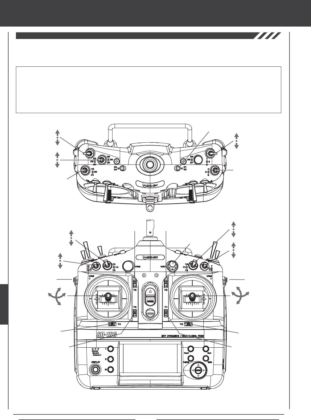
Page 158
heli Flight Mode menu
The diagrams below show the default transmitter control stick and switch layout in the HELI Model Type Flight Mode N (Normal)
conguration. This is the base from which you can start to change or add functions to switch assignments, modify Flight Modes, and
change or assign functions or channels to the Auxiliary Levers (VR5 and VR6) and the Auxiliary Dial (VR7).
Throttle Trim Switch
Rudder Trim Switch
Rudder
Control Stick
Throttle/Pitch
Control Stick
Aileron
Control Stick
Elevator
Control Stick
Aileron Trim Switch
Elevator Trim Switch
Flight
Mode N,1,2 Auxiliary 2L
Auxiliary 2H
Aileron Dual
Rate 1,2,3
Auxiliary
Lever (VR6)
Low-Pitch Trim
Auxiliary
Dial (VR7)
AUX1
Auxiliary
Lever (VR5)
High-Pitch Trim
*The Hovering Throttle and Hovering Pitch trim switches are Active only in F-MODE N (Normal). To use these features in
other Flight Modes, they must be Activated in those specific Flight Modes. For more information, see pages 168 and 170.
IMPORTANT Since each of the ve Flight Modes can be programmed separately, before making programming changes,
verify that you are in the Flight Mode you want to make programming changes to. To avoid confusion, we suggest leaving the
Flight Mode Switches (6, 22, 23, and 24) in the N (Normal) position and use the F-MODE key from within the programming
menus to choose which Flight Mode you would like to make programming changes to.
Keep in mind that many of the functions, particularly Mixes and Auxiliary functions, MUST be assigned to a Switch Position
Number to be Activated. We suggest that you assign the function to a Switch Position Number prior to programming the
function. This will avoid confusion and make it easier to test your programming values.
Throttle Cut
Elevator Dual
Rate 1,2,3
Rudder Dual
Rate 1,2,3
Flight
Mode 4
Auxiliary 3L
Auxiliary 3H
Start/Stop
Timer
Gyro 1,2,3
Hovering
Throttle Trim
Switch
Hovering
Pitch Trim
Switch
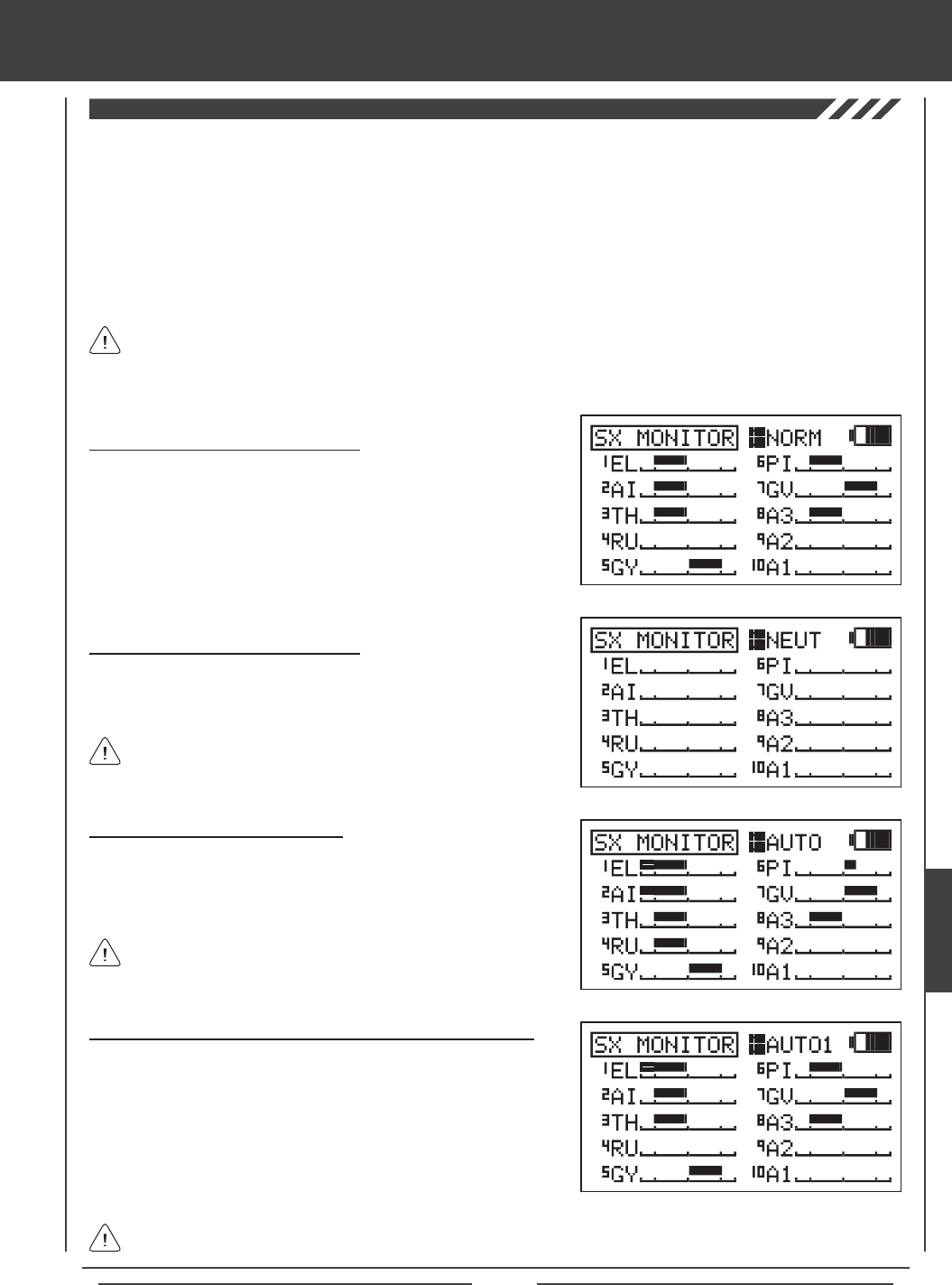
Page 159
heli Flight Mode menu
The Servo Monitor function displays the output levels of each of the 10 channels in bar graph form, allowing you to monitor servo
operation in a virtual manner. This is helpful to see servo movement when the control sticks and switches are moved, and it allows
you to visualize what is occurring with servo movements when you apply different mixing values. When used in conjunction with
the Display key, the Servo Monitor function allows you to see servo movement virtually and make programming changes without
the SD-10G transmitter actually transmitting a signal.
When both the SD-10G transmitter and the receiver are turned ON, the Servo Monitor function has the ability to continuously
cycle the primary ight control servos back and forth to verify operation. You are also able to individually cycle any of the primary
ight control servos and check the Neutral position of each of the servos (or automatically center all of the servos).
Using the Servo Monitor - Normal Mode
1) Press the Navigation Pad 56 to highlight SX MONITOR, then press
the ENTER key to display the SX MONITOR menu. The cursor will
default to >NORM.
2) Moving the control sticks and channel switches (if assigned) will display
the position and movement of each of the servos.
Using the Servo Monitor - Neutral Mode
1) Press the YES/+ key to choose >NEUT. When set to NEUT, all servos
will move to the Neutral position until you either change the Servo
Monitor Mode or exit the Servo Monitor menu.
While in Neutral Mode, all ight controls are Inhibited.
Using the Servo Monitor - Auto Mode
1) Press the YES/+ key to choose >AUTO. When set to AUTO, the
primary ight control servos will cycle back and forth at the same time,
until you either change the Servo Monitor Mode or exit the Servo Monitor
menu.
While in Auto Mode, the primary flight controls are Inhibited,
however, the remaining channels remain Active so that you can
continue using them.
Using the Servo Monitor - Auto1, Auto2, Auto3, and Auto4 Modes
1) Press the YES/+ key to choose >AUTO1. When set to AUTO1, the
elevator, aileron, and pitch servos will cycle back and forth at the same
time, until you either change the Servo Monitor Mode or exit the Servo
Monitor menu.
2) Press the YES/+ key again to choose >AUTO2 and so on. AUTO2 will
cycle the aileron and pitch servos, AUTO3 will cycle all CCPM servos,
and AUTO4 will cycle the rudder servo.
The ight control for the currently Active servo will be Inhibited, however, the remaining channels remain Active so that
you can continue using them.
The channels displayed will vary based on Model Type and Swashplate selection options currently selected. For example,
if your model features a CP4A swashplate, both elevator servos will be displayed and both servos will move when the
AUTO1 option is used. Depending on the current servo reversing settings, the bar graphs may not move the same direction as
the control sticks. This is normal.
HELI
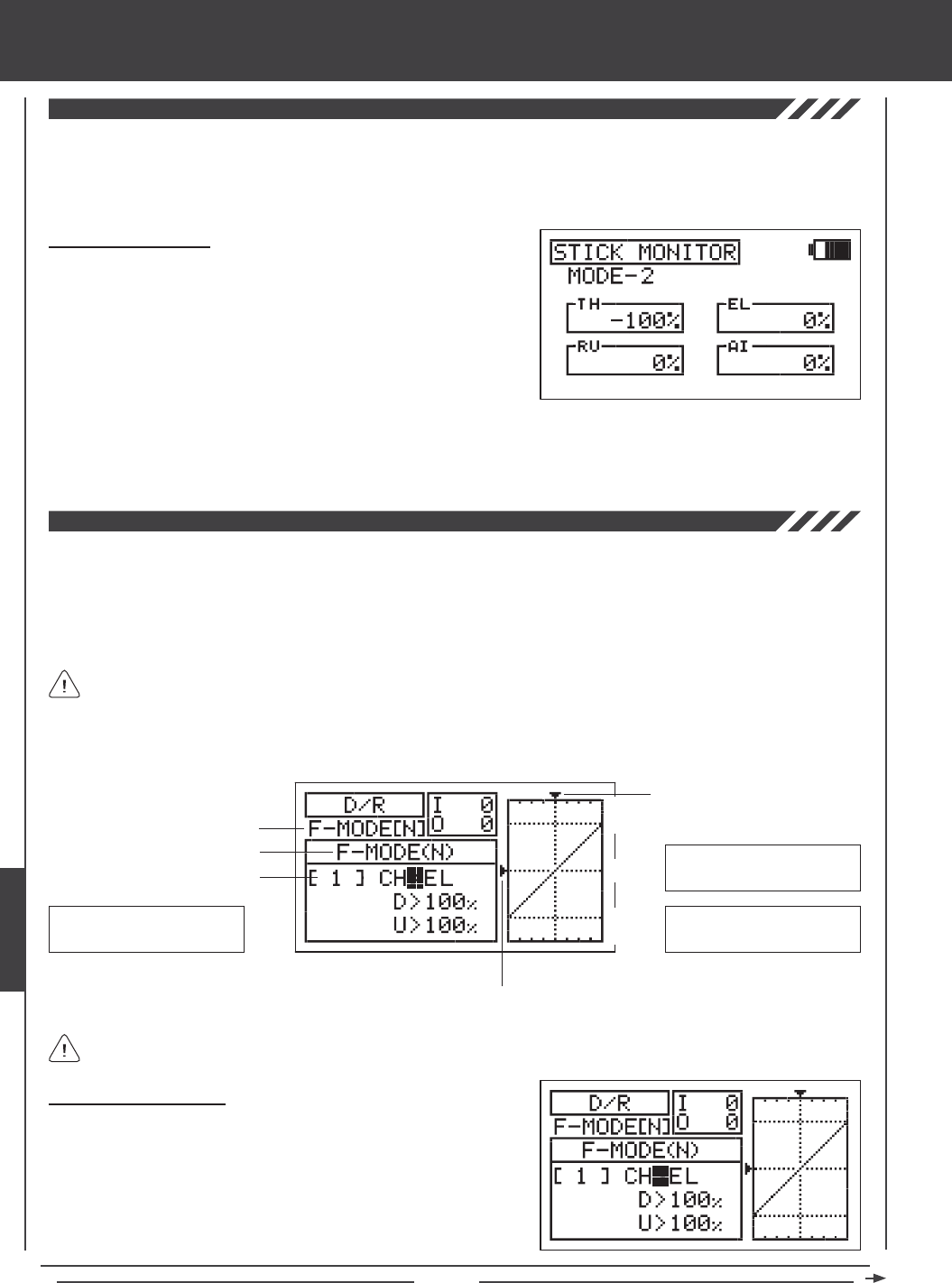
Page 160
The Stick Monitor function displays the current position of the control sticks as a percentage of total control stick movement in 1%
increments, and is used to determine if the control sticks require calibration. For example, if you move the throttle control stick all
the way forward and 95% is displayed, this indicates that the throttle control stick requires calibration. In addition, the Stick Monitor
function allows you to visually check exactly what position the control sticks are in relative to the control surface you're setting up.
Using the Stick Monitor
1) Press the Navigation Pad 56 to highlight STICK MONITOR, then
press the ENTER key to display the STICK MONITOR menu. The
current Mode that the SD-10G transmitter is operating in will be displayed.
2) Move the control sticks and watch the percentage displays. When the
control sticks are centered, 0% should be displayed, and when the
control sticks are moved to their stops, -100% or 100% should be
displayed, based on the direction of movement.
3) If 0% is not displayed when the control sticks are centered, or if -100% and 100% are not displayed when the control sticks
are moved to their stops, use the NEUTRAL/TRAVEL>USER setting in the System Mode menu to recalibrate the control sticks.
For more information, see page 43.
The Dual Rate function allows you to change the control authority of the control surfaces by changing the amount of servo travel.
For example, if you are ying an aerobatic helicopter that requires a lot of control throw for aerobatics, but that same amount of
control throw makes the helicopter difcult to control during normal ight, you can use Dual Rate to lower the control throw for
normal ight with just the ip of the Dual Rate switch. Three Dual Rate settings are available each for the Elevator, Aileron, and
Rudder channels, and different Dual Rate settings can be programmed separately for each of the ve Flight Modes. An Input
and Output display, along with a graph, help with programming visualization.
Dual Rate is a percentage of End Point Adjustment. For example, if you set Dual Rate 2 to 50% and Activate it, the servo
will travel half the amount than if Dual Rate 2 was not Active. Prior to takeoff, check the position of the Dual Rate switches
to ensure that they are in the positions you want. If you assign two different channel Dual Rates to more than one switch, it's
important to note that the higher numbered Dual Rate will override the lower numbered Dual Rates. For example, if you have
Dual Rate 2 and Dual Rate 3 Active at the same time, Dual Rate 3 will override Dual Rate 2.
Choosing the Flight Mode
1) Press the Navigation Pad 56 to highlight D/R, then press the ENTER
key to display the D/R menu. The cursor will default to CH>EL.
2) Press the F-MODE key to choose the F-MODE number you would like
to program the Dual Rate function for. Choose from N, 1, 2, 3, or 4. The
F-MODE (N) display will change, indicating which Flight Mode you are
programming the Dual Rate function for.
Transmitter F-MODE
Dual Rate Number
Programming F-MODE
Stick Input (I)
Servo Output (O)
Transmitter F-MODE refers to the Flight Mode that the transmitter is currently operating in. Programming F-MODE refers
to the Flight Mode that you would like to change the programming for.
150%
100%
100%
150%
0%
EL-D/R Default Switch
Position Numbers: 13,14,15
AI-D/R Default Switch
Position Numbers: 07,08,09
RU-D/R Default Switch
Position Numbers: 10,11,12
heli Flight Mode menu
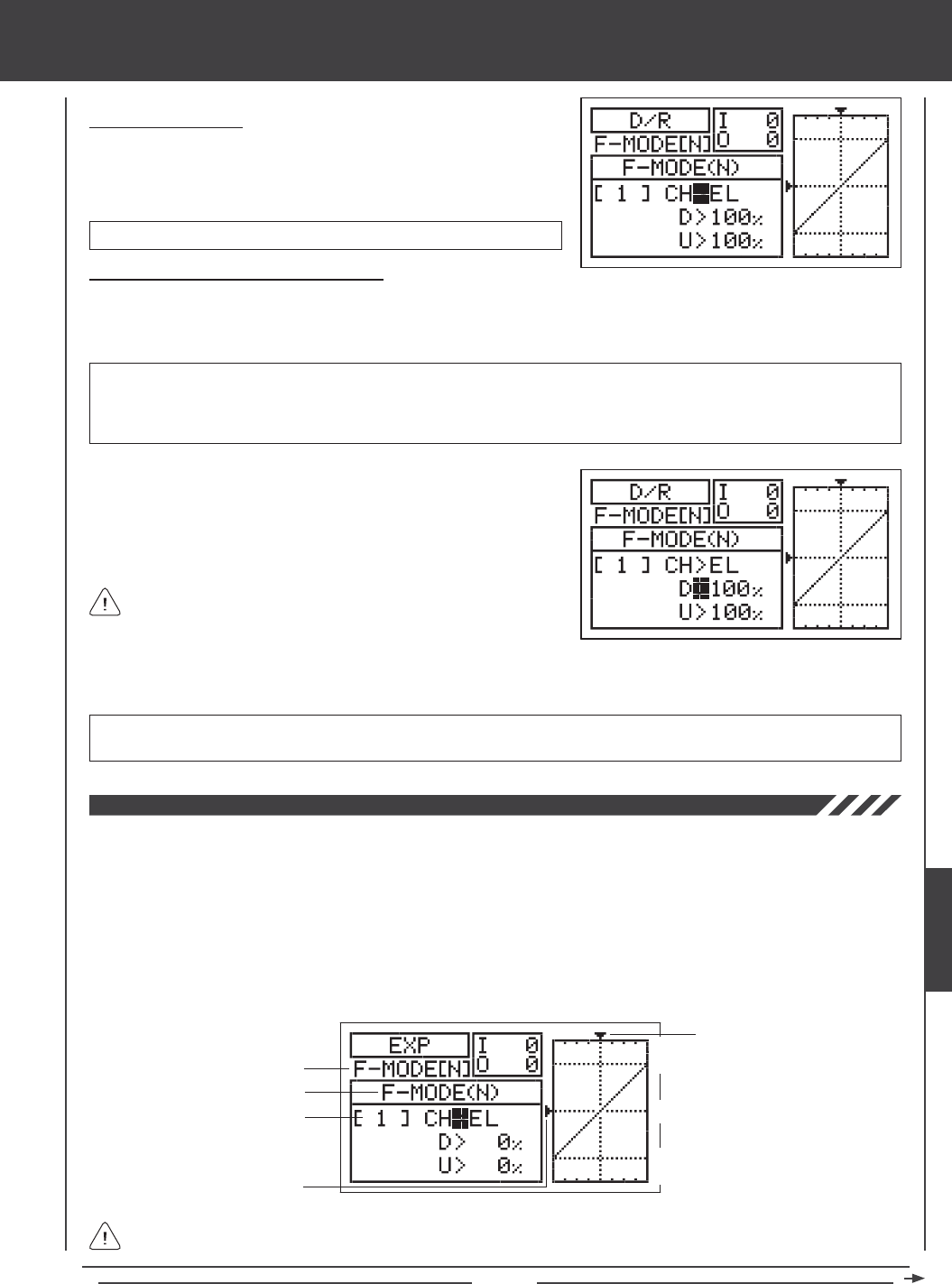
Page 161
Choosing the Channel
1) Press the Navigation Pad 56 to highlight CH>EL.
2) If you would like to set the Dual Rate for another channel, press the
YES/+ or NO/- keys to choose CH>AI or CH>RU.
Changing the Dual Rate Percentage Values
Three different Dual Rate settings can be programmed to each three-position switch. We recommend that Dual Rate 1 be set to
the maximum control surface throw you desire, then set Dual Rate 2 and Dual Rate 3 to different values that are less than
maximum. For example, set Dual Rate 1 to 100%, Dual Rate 2 to 75%, and Dual Rate 3 to 50%.
3) Press the Navigation Pad 6 to move the cursor to U>100% (R>100% if setting aileron or rudder Dual Rate), then press the
YES/+ or NO/- keys to set the desired Up (or Right) Dual Rate percentage value.
WARNING Keep in mind that it's possible to set the Dual Rate higher than the End Point Adjustment. For example,
with the End Point Adjustment set to 100% and the Dual Rate set to 150% the servo will move more than 100% when
the Dual Rate is Activated. We strongly recommend that you set the Dual Rate 1 percentage value to no more than
100%. This will prevent any chance of exceeding your End Point Adjustment and overdriving your control linkage.
As you change the Dual Rate percentage values, you can use the
graph and I/O numbers to visualize the ratio between control stick
movement and servo travel throughout the entire deection range.
D/R setting range is 0% to 150%. The default setting is 100%. Increasing the D/R percentage value increases servo travel
when Dual Rate is Activated. Decreasing the D/R percentage value decreases servo travel when Dual Rate is Activated.
1) Move the Dual Rate Switch for the channel you are setting to the position
you would like to set a Dual Rate percentage value for, either 1, 2, or 3.
2) Press the Navigation Pad 6 to move the cursor to D>100% (L>100% if
setting aileron or rudder Dual Rate), then press the YES/+ or NO/- keys
to set the desired Down (or Left) Dual Rate percentage value.
Dual Rate can be set for EL (Elevator), AI (Aileron), and RU (Rudder).
The Exponential function allows you to vary the amount of servo travel in relation to the movement of the elevator, aileron, and
rudder control sticks near the neutral positions to change the way the control surfaces react to control stick movement. Increasing
the Exponential value will soften the control feel around neutral and decreasing the Exponential value will heighten the control
feel around neutral. For example, using a positive Exponential value allows for smoother control by lessening the amount of servo
travel in relation to the amount of control stick movement. Using a negative Exponential value may result in more 'twitchy' control
response because the amount of servo travel will be increased in relation to the amount of control stick movement.
The Exponential function is linked directly to your Dual Rate switches. This allows you to program Exponential for each of the
three Dual Rate positions separately. In addition, Exponential can be programmed separately for each of the ve Flight Modes.
An Input and Output display, along with a graph, help with programming visualization.
Transmitter F-MODE
Dual Rate Number
Programming F-MODE
Stick Input (I)
Function Output (O)
150%
100%
100%
150%
0%
Transmitter F-MODE refers to the Flight Mode that the transmitter is currently operating in. Programming F-MODE refers
to the Flight Mode that you would like to change the programming for.
heli Flight Mode menu
HELI
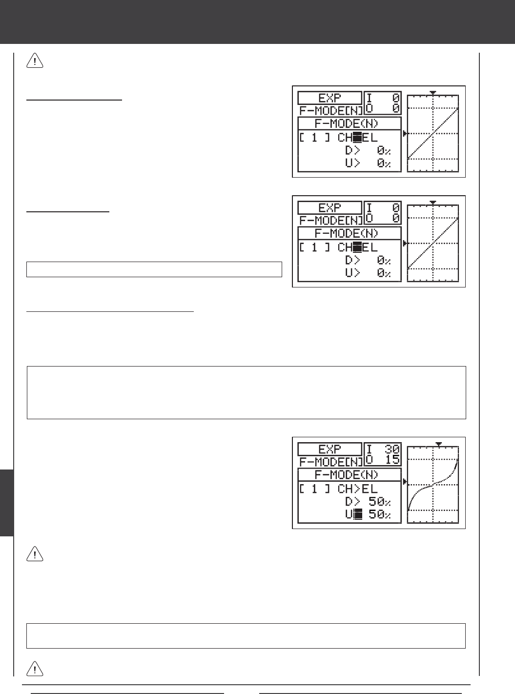
Page 162
Choosing the Flight Mode
1) Press the Navigation Pad 56 to highlight EXP, then press the ENTER
key to display the EXP menu. The cursor will default to CH>EL.
2) Press the F-MODE key to choose the F-MODE number you would like to
program the Exponential function for. Choose from N, 1, 2, 3, or 4. The
F-MODE (N) display will change, indicating which Flight Mode you are
programming the Exponential function for.
Choosing the Channel
1) Press the Navigation Pad 56 to highlight CH>EL.
2) If you would like to set the Exponential for another channel, press the
YES/+ or NO/- keys to choose CH>AI or CH>RU.
Exponential can be set for EL (Elevator), AI (Aileron), and RU (Rudder).
Changing the Exponential Percentage Values
The Exponential function is linked directly to your Dual Rate switches. This allows you to program Exponential for each of the
three Dual Rate positions separately. For example, with the Dual Rate switch in position 1 (maximum travel), you can set 30%
Exponential, with the Dual Rate switch in position 2, you can set 10% Exponential, and with the Dual Rate switch in position 3,
you can set 0% Exponential (Linear).
4) Press the Navigation Pad 6 to move the cursor to U>0% (R>0% if setting aileron or rudder Exponential), then press the
YES/+ or NO/- keys to set the desired Up (or Right) Exponential percentage value.
As you change the Exponential percentage values, you can use the graph and I/O numbers to visualize the ratio between
control stick movement and servo travel throughout the entire deection range. Notice that as you increase Exponential,
the servo travel is decreased near the neutral position in relation to control stick movement, and as you decrease Exponential, the
servo travel is increased near the neutral position in relation to control stick movement.
EXP setting range is -100% to 100%. The default setting is 0% (Linear). Increasing the EXP percentage value softens the
control feel around neutral. Decreasing the EXP percentage value heightens the control feel around neutral.
1) Move the Dual Rate Switch for the channel you are setting to the
position you would like to set an Exponential percentage value for,
either 1, 2, or 3.
2) Press the Navigation Pad 6 to move the cursor to D>0% (L>0% if
setting aileron or rudder Exponential).
3) Press the YES/+ or NO/- keys to set the desired Down (or Left)
Exponential percentage value.
WARNING If you have not used Exponential functions in the past, we suggest that you start with a small percentage
of Exponential (approximately 10%~20%) until you get used to the feel of how Exponential affects the control feel of
your model. You will find that Exponential is most useful where strong control response is desired at extreme control
stick positions, but softer control response to small control stick movements is desired in order to make very accurate
small corrections to the flight path.
When the Exponential value is set to 0%, the ratio between servo travel and control stick movement will be Linear. For
example, when you move the control stick 50%, the servo will travel 50%, too.
Exponential does not change the total amount of servo travel at maximum control stick deection. Exponential affects
the ratio between servo travel and control stick movement at less than 100% control stick deection.
heli Flight Mode menu
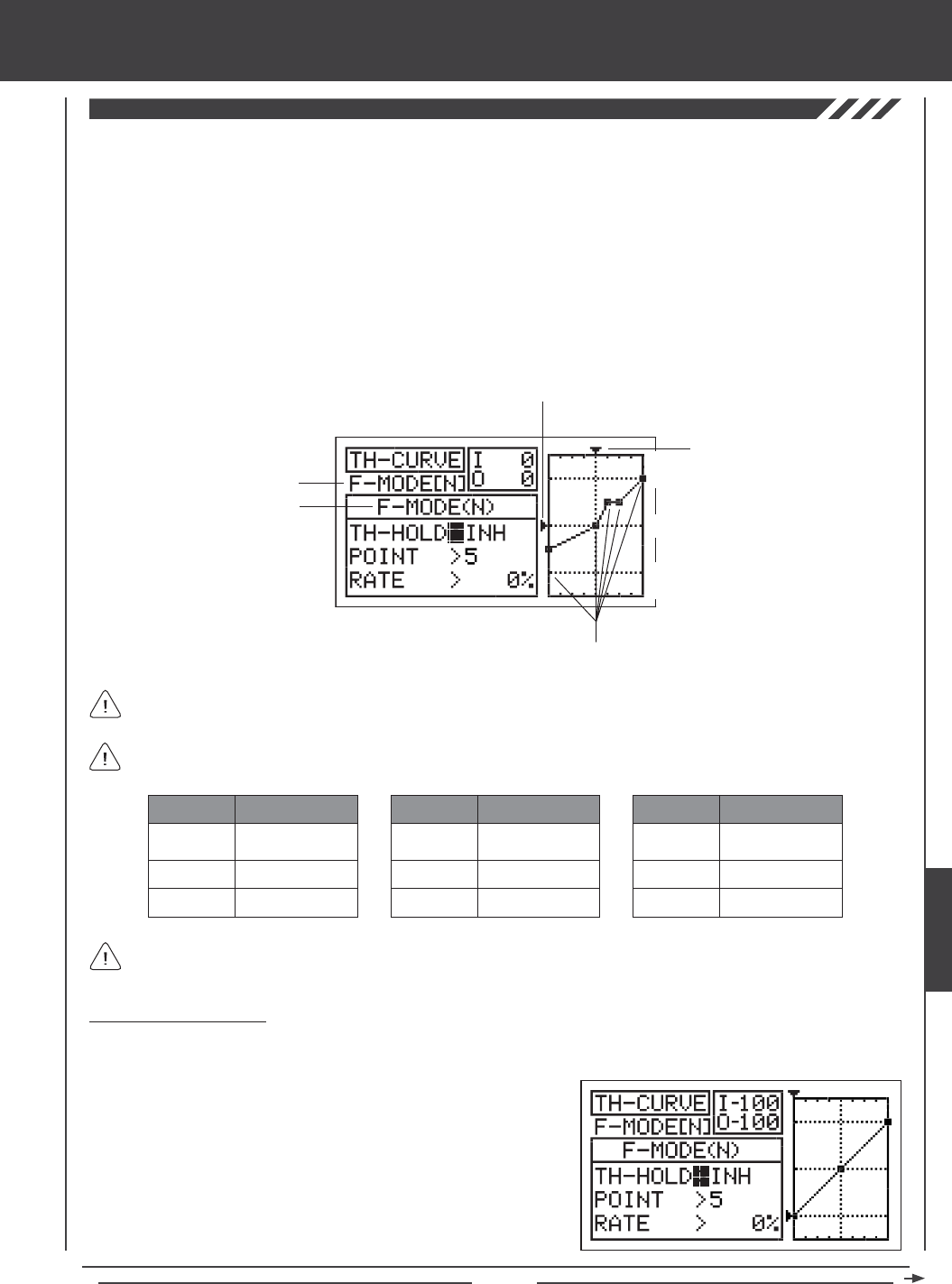
Page 163
The Throttle Curve function allows you to vary the amount of throttle servo travel in relation to the movement of the throttle control
stick at different points throughout the entire range of deection. Nine custom-programmable Points ensure an extremely precise
Throttle Curve to suit any type of situation. For example, if you are doing 3D ying, you can adjust the Throttle Curve so that you
have maximum power and rotor head speed at both the low throttle control stick position and the high throttle control stick position
when you have full negative and positive collective pitch for aerobatics, but reduced power when the throttle control stick is near
the center, so that the rotor head will not overspeed with reduced collective.
Included within the Throttle Curve function is the Throttle Hold function. The Throttle Hold function allows you to set a specic
position that the throttle servo will Hold and not respond to the throttle control stick. This function is typically used to hold the
throttle at idle or low speed, while still allowing you full pitch control. This is ideal for practicing auto-rotations and is also a good
safety feature on electric helicopters, because when Activated, the rotor head will not spin up if you accidentally bump the throttle
control stick up. Both the Throttle Curve function and the Throttle Hold function can be programmed separately for each of the
ve Flight Modes. An Input and Output display, along with a graph, help with programming visualization.
Transmitter F-MODE
Programming F-MODE
Stick Input (I)
Function Output (O)
150%
100%
100%
150%
0%
Point Positions
Transmitter F-MODE refers to the Flight Mode that the transmitter is currently operating in. Programming F-MODE refers
to the Flight Mode that you would like to change the programming for.
The tables below show the default Throttle Curve Point and Rate values. Settings shown in parentheses are the default
percentage values when those Points are Activated by the user.
1
2
3
-100%
INH (-75%)
INH (-50%)
POINT DEFAULT RATE
7
8
9
INH (50%)
INH (75%)
100%
POINT DEFAULT RATE
4
5
6
INH (-25%)
0%
INH (25%)
POINT DEFAULT RATE
In the default conguration the Throttle Curve is Linear. For example, when you move the throttle control stick from 0% to
100%, the throttle servo will travel from 0% to 100%, too.
2) Press the F-MODE key to choose the F-MODE number you would like
to program the Throttle Curve function or the Throttle Hold function for.
Choose from N, 1, 2, 3, or 4. The F-MODE (N) display will change,
indicating which Flight Mode you are programming the Throttle Curve
function or the Throttle Hold function for.
Choosing the Flight Mode
1) Press the Navigation Pad 56 to highlight TH-CURVE, then press the ENTER key to display the TH-CURVE menu. The
cursor will default to TH-HOLD>INH.
heli Flight Mode menu
HELI
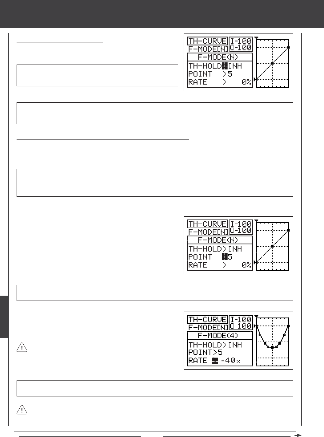
Page 164
Activating the Throttle Hold Function
1) Press the Navigation Pad 56 to highlight TH-HOLD>INH, then
press the YES/+ or NO/- keys to change the ACT/INH setting.
IMPORTANT When the Throttle Hold function is Activated, you cannot program the Throttle Curve Function. If you Activate
the Throttle Hold function, skip to the Changing the Throttle Hold Percentage Value - Throttle Hold Function Active section
on page 165, otherwise, continue below to program the desired Throttle Curve Point values and the Rate percentage values.
TH-HOLD setting range is INH/ACT. The default setting is INH. When
Activated, the Throttle Hold function will be Active for that Flight Mode.
The TH-HOLD percentage value and the TH-TRIM option will be displayed.
Changing the Throttle Curve Point Values and the Rate Percentage Values
Nine different Points with varying Rates can be programmed onto the Throttle Curve. Each Point will be displayed on the graph to
give you a visual interpretation of the position of the Point on the Throttle Curve. The Point that is currently selected will blink.
WARNING Keep in mind that it's possible to set the Throttle Curve Points higher or lower than the throttle End Point
Adjustment. For example, with the throttle End Point Adjustment set to 100% and POINT>9 set to 150% the servo will move
150%. We strongly recommend that you set your Throttle Curve Points no higher than your throttle End Point Adjustment unless
specically necessary for your particular setup. This will prevent any chance of overdriving your control linkage.
As you change the Point and Rate percentage values, you can use the graph and I/O numbers to visualize the ratio
between control stick movement and servo travel throughout the entire deection range.
RATE setting range is -150% to 150%. POINT 1 default RATE percentage value is -100%, POINT 5 default RATE percentage
value is 0%, POINT 9 default RATE percentage value is 100%. This results in a Linear Throttle Curve.
3) Press the Navigation Pad 6 to highlight RATE>.
4) Press the YES/+ or NO/- keys to set the desired Rate percentage value.
1) Press the Navigation Pad 6 to highlight POINT>5.
2) Press the YES/+ or NO/- keys to choose which Point you would like to
set a Rate percentage value for.
POINT setting range is 1 through 9. Point 1 is at the low end of the Throttle Curve and Point 9 is at the high end of the Throttle
Curve. Point 5 is a the center of the Throttle Curve.
5) Repeat the previous procedures to change the desired remaining Point and Rate percentage values.
When you change the Rate percentage value for Points 2, 3, 4, 6,
7, and 8, INH will be displayed. When you press the YES/+ or NO/-
keys, INH will change to the default percentage value (e.g., POINT>4
RATE -25%).
heli Flight Mode menu
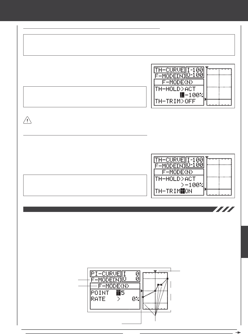
Page 165
Changing the Throttle Hold Percentage Value - Throttle Hold Function Active
1) Press the Navigation Pad 6 to highlight >-100%.
2) Press the YES/+ or NO/- keys to set the position you would like the
throttle servo to Hold at.
WARNING Keep in mind that it's possible to set the Throttle Hold lower than the throttle End Point Adjustment. For example,
with the throttle End Point Adjustment set to -100% and the Throttle Hold set to -150% the servo will move -150% when the
Throttle Hold is Activated. We strongly recommend that you set your Throttle Hold no lower than your throttle End Point Adjustment
unless specically necessary for your particular setup. This will prevent any chance of overdriving your control linkage.
TH-HOLD setting range is -150% to 0%. The default setting is -100%.
Increasing the TH-HOLD percentage value will increase the position at
which the throttle servo will Hold at and decreasing the TH-HOLD percentage
value will decrease the position at which the throttle servo will Hold at.
Turning ON the Throttle Trim Function - Throttle Hold Function Active
The Throttle Trim function allows you to have throttle trim control even with the Throttle Hold function Active. This allows you
make minor adjustments to your throttle speed as required.
1) Press the Navigation Pad 6 to highlight TH-TRIM>OFF.
2) Press the YES/+ or NO/- keys to change the OFF/ON setting.
TH-TRIM setting range is OFF/ON. The default setting is OFF. When set
to ON, you will control of the full range of throttle trim from the position
that the Throttle Hold percentage value is set at. When the Throttle Trim
function is set to OFF, the Throttle trim switch will be disabled.
When the Throttle Hold function is Activated, the Throttle Hover trim switch will be disabled and you will not be able to
control the Hovering Throttle function. This is normal.
The Pitch Curve function allows you to vary the amount of pitch travel in relation to the movement of the throttle control stick at
different points throughout the entire range of deection. Nine custom-programmable Points ensure an extremely precise Pitch
Curve to suit any type of situation. For example, if you are doing 3D ying, you may want a Linear Pitch Curve with maximum
negative pitch when the throttle control stick is at low, maximum positive pitch when the throttle control stick is at high, and
0 degrees of pitch when the throttle control stick is centered. Alternatively, for a more docile ying helicopter, you may want
minimum negative pitch when the throttle control stick is all the way back and gradually increase pitch in small increments as
the throttle control stick moves from low to high, to produce a smooth transition from low to high throttle.
The Pitch Curve function can be programmed separately for each of the ve Flight Modes. An Input and Output display, along
with a graph, help with programming visualization.
Transmitter F-MODE
Programming F-MODE
Stick Input (I)
150%
100%
100%
150%
0%
Point Positions
Function Output (O)
heli Flight Mode menu
HELI

Page 166
Transmitter F-MODE refers to the Flight Mode that the transmitter is currently operating in. Programming F-MODE refers
to the Flight Mode that you would like to change the programming for.
The tables below show the default Pitch Curve Point and Rate values. Settings shown in parentheses are the default
percentage values when those Points are Activated by the user.
1
2
3
-100%
INH (-75%)
INH (-50%)
POINT DEFAULT RATE
7
8
9
INH (50%)
INH (75%)
100%
POINT DEFAULT RATE
4
5
6
INH (-25%)
0%
INH (25%)
POINT DEFAULT RATE
In the default conguration the Pitch Curve is Linear. For example, when you move the throttle control stick from 0% to
100%, the elevator, aileron, and pitch servos will travel from 0% to 100%, too.
Changing the Pitch Curve Point Values and the Rate Percentage Values
Nine different Points with varying Rates can be programmed onto the Pitch Curve. Each Point will be displayed on the graph to give
you a visual interpretation of the position of the Point on the Pitch Curve. The Point that is currently selected will blink.
WARNING Keep in mind that it's possible to set the Pitch Curve Points higher or lower than the pitch End Point Adjustment.
For example, with the pitch End Point Adjustment set to 100% and POINT>9 set to 150% the collective servos will move more
than 100%. We strongly recommend that you set your Pitch Curve Points no higher than your pitch End Point Adjustment unless
specically necessary for your particular setup. This will prevent any chance of overdriving your control linkage.
2) Press the F-MODE key to choose the F-MODE number you would like
to program the Pitch Curve function for. Choose from N, 1, 2, 3, or 4.
The F-MODE (N) display will change, indicating which Flight Mode
you are programming the Pitch Curve function for.
Choosing the Flight Mode
1) Press the Navigation Pad 56 to highlight PI-CURVE, then press the ENTER key to display the PI-CURVE menu. The
cursor will default to POINT>5.
1) Press the Navigation Pad 56 to highlight POINT>5.
2) Press the YES/+ or NO/- keys to choose which Point you would like to
set a Rate percentage value for.
POINT setting range is 1 through 9. Point 1 is at the low end of the Pitch Curve and Point 9 is at the high end of the Pitch Curve.
Point 5 is a the center of the Pitch Curve.
IMPORTANT In the default conguration, Auxiliary Lever (VR5) and Auxiliary Lever (VR6) control the high (Point 9) and low
(Point 1) points of the Pitch Curve, respectively. For example, you can manually adjust the high and low points of the Pitch
Curve during ight to ne-tune the adjustments. Before changing the Pitch Curve Point values and the Rate percentage
values, make sure that both Auxiliary Levers are centered (in the center detent).
heli Flight Mode menu
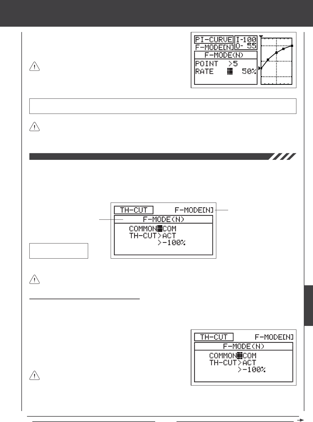
Page 167
As you change the Point and Rate percentage values, you can use the graph and I/O numbers to visualize the ratio
between control stick movement and servo travel throughout the entire deection range.
RATE setting range is -150% to 150%. POINT 1 default RATE percentage value is -100%, POINT 5 default RATE percentage
value is 0%, POINT 9 default RATE percentage value is 100%. This results in a Linear Pitch Curve.
3) Press the Navigation Pad 6 to highlight RATE>.
4) Press the YES/+ or NO/- keys to set the desired Rate percentage value.
5) Repeat the previous procedures to change the desired remaining Point and Rate percentage values.
When you change the Rate percentage value for Points 2, 3, 4, 6,
7, and 8, INH will be displayed. When you press the YES/+ or NO/-
keys, INH will change to the default percentage value (e.g., POINT>4
RATE -25%).
The Throttle Cut function allows you to set a specic position that the throttle servo will move to. The Throttle Cut function is primarily
used in glow- or gas-powered helicopters to shut down your engine after ight. For example, if your engine idles when the throttle
control stick is at the -100% position, you can set the Throttle Cut to -120% to shut down your engine when the Throttle Cut
function is Activated. The Throttle Cut function can be programmed separately for each of the ve Flight Modes or you can use
the same Throttle Cut programming across all ve Flight Modes.
Transmitter F-MODE
Programming F-MODE
Transmitter F-MODE refers to the Flight Mode that the transmitter is currently operating in. Programming F-MODE refers
to the Flight Mode that you would like to change the programming for.
TH-CUT Default Switch
Position Number: 32
Choosing the Flight Mode - Common or Separate
When set to COM (Common), the TH-CUT setting will be the same regardless of which Flight Mode the transmitter is operating in.
You cannot program TH-CUT separately for each Flight Mode. When set to SEP (Separate), you can program TH-CUT separately
for each Flight Mode.
3) Press the F-MODE key to choose the F-MODE number you would like to program the Throttle Cut function for. Choose from
N, 1, 2, 3, or 4. The F-MODE (N) display will change, indicating which Flight Mode you are programming the Throttle Cut
function for.
1) Press the Navigation Pad 56 to highlight TH-CUT, then press the
ENTER key to display the TH-CUT menu. The cursor will default to
COMMON>COM.
2) Press the YES/+ or NO/- keys to choose either COM or SEP.
If set to COM, skip to the Setting the Throttle Cut percentage value on
page 168. If set to SEP, see step 3 below.
heli Flight Mode menu
HELI
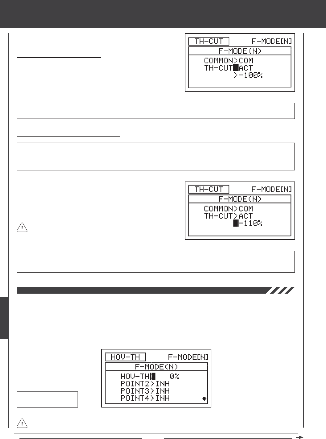
Page 168
Changing the Throttle Cut Percentage Value
WARNING Keep in mind that it's possible to set the Throttle Cut lower than the throttle End Point Adjustment. For example, with
the throttle End Point Adjustment set to -100% and the Throttle Cut set to -150% the servo will move -150% when the Throttle Cut
function is used. We strongly recommend that you set your Throttle Cut no lower than your throttle End Point Adjustment unless
specically necessary for your particular setup. This will prevent any chance of overdriving your control linkage.
Activating the Throttle Cut Function
1) Press the Navigation Pad 6 to highlight TH-CUT>ACT, then press
the YES/+ or NO/- keys to change the ACT/INH setting.
TH-CUT setting range is ACT/INH. The default setting is ACT. When Activated, the Throttle Cut function can be used for that
Flight Mode. When Inhibited, the Throttle Cut function will be disabled for that Flight Mode.
1) Press the Navigation Pad 6 to highlight >-100%.
2) Press the YES/+ or NO/- keys to set the position you would like the
throttle servo to move to when the Throttle Cut function is used.
TH-CUT setting range is -150% to 0%. The default setting is -100%. Increasing the TH-CUT percentage value will increase
the position that the throttle servo is moved to and decreasing the TH-CUT percentage value will decrease the position that the
throttle servo is moved to.
When the Throttle Cut function is used, the throttle control stick will
be disabled.
The Hovering Throttle function allows you to adjust specic Throttle Curve Points to ne-tune the Throttle Curve at any throttle
control stick position, not just the hovering position. The Hovering Throttle function is controlled by the Hovering Throttle Trim
Switch (T5). You are able to Activate and control one or more Points on the Throttle Curve. For example, you can Activate Point 2
through Point 8, so that all the Throttle Curve Points can be ne-tuned, or you can Activate only Point 3 to ne-tune that particular
Throttle Curve Point. These adjustments can be viewed on the TH-CURVE menu graph to help you visualize the changes. In
addition, the resolution of the Hovering Throttle trim switch can be adjusted, using the Trim Step function, to ensure a high degree
of accuracy. The Hovering Throttle function can be programmed separately for each of the ve Flight Modes.
Transmitter F-MODE
Programming F-MODE
Transmitter F-MODE refers to the Flight Mode that the transmitter is currently operating in. Programming F-MODE refers
to the Flight Mode that you would like to change the programming for.
HOV-TH Default Trim
Switch: T5
heli Flight Mode menu
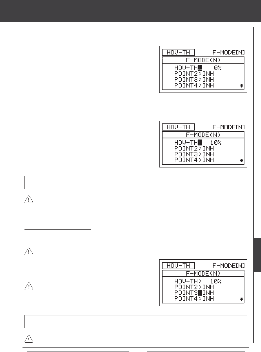
Page 169
2) Press the F-MODE key to choose the F-MODE number you would like
to program the Hovering Throttle function for. Choose from N, 1, 2, 3,
or 4. The F-MODE (N) display will change, indicating which Flight Mode
you are programming the Hovering Throttle function for.
Choosing the Flight Mode
1) Press the Navigation Pad 56 to highlight HOV-TH, then press the ENTER key to display the HOV-TH menu. The cursor
will default to HOV-TH>0%.
Changing the Hovering Throttle Percentage Value
The Hovering Throttle percentage value can be changed by pressing the YES/+ and NO/- keys from within the HOV-TH menu or
it can changed during ight by moving the Hovering Throttle trim switch.
When the Hovering Throttle percentage value is changed using the YES/+ and NO/- keys through the HOV-TH menu, the
percentage value is changed in 1% increments. When the Hovering Throttle percentage value is changed using the Hovering
Throttle trim switch, the percentage value is changed in 2% increments. If desired, the Hovering Throttle trim switch resolution
can be changed through the Trim Step menu. For more information, see page 176.
HOV-TH setting range is -32% to 32%. The default setting is 0%. When increased, the Active Point Rate percentage value(s)
will increase. When decreased, the Active Point Rate Percentage value(s) will decrease.
1) Press the Navigation Pad 56 to highlight HOV-TH>0%, then press
the YES/+ or NO/- keys to change the Hovering Throttle percentage
value. Alternately, you could move the Hovering Throttle trim switch to
change the Hovering Throttle percentage value.
Activating Hovering Throttle Points
The Hovering Throttle Points displayed in the HOV-TH menu correspond directly with the Throttle Curve Points. You are able to
Activate one or more Hovering Throttle Points to be controlled by the Hovering Throttle trim switch.
All Activated Hovering Throttle Points will move at the same time and at the same Rate as dened by the Hovering
Throttle percentage value.
POINT2 through POINT8 setting range is INH/ACT. In Flight Mode N (Normal), the POINT5 default setting is ACT. The remaining
POINT default settings are INH. In all other Flight Modes, all POINT default settings are INH.
1) Press the Navigation Pad 56 to highlight which Hovering Throttle
Point you would like to Activate, then press the YES/+ or NO/- keys to
change the ACT/INH setting.
An audible tone is heard when the Hovering Throttle trim switch reaches the center position (0%). This allows you to know
when the trim switch reaches the center position without the need to look at the Trim Indicator on the Top menu.
If all Hovering Throttle Points are set to INH, no Hovering Throttle
Trim Indicator will be displayed on the Top menu and the Hovering
Throttle trim switch will not function. At least one Hovering Throttle Point
must be set to ACT for the Hovering Throttle Trim Indicator to be displayed
on the Top menu and the Hovering Throttle trim switch to function.
heli Flight Mode menu
HELI
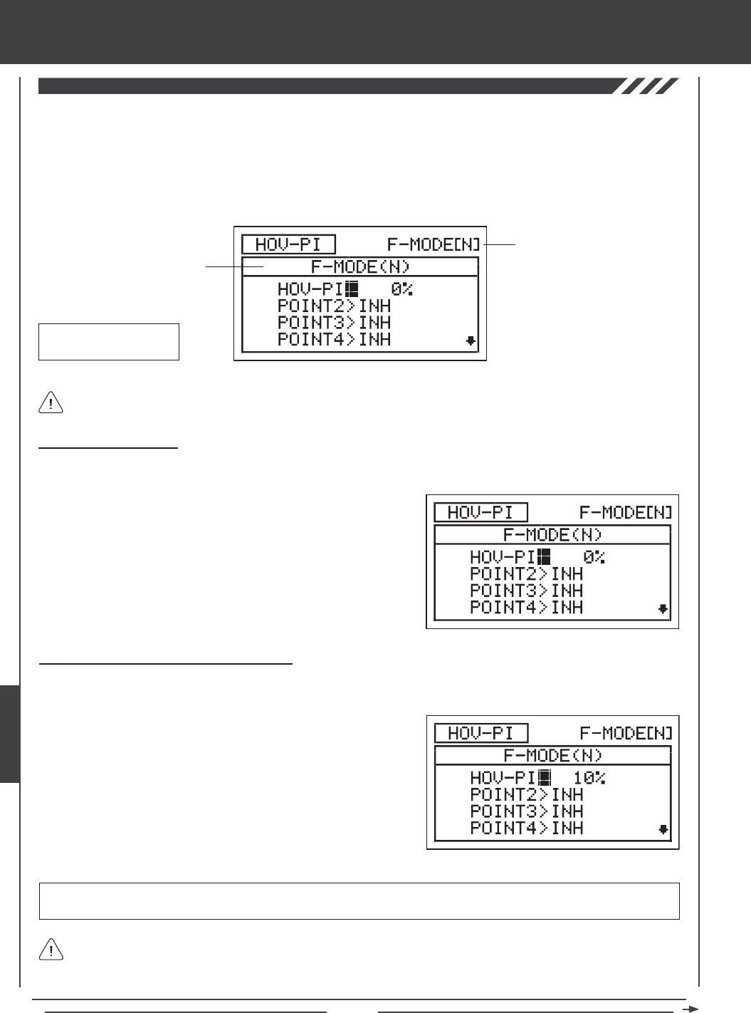
Page 170
The Hovering Pitch function allows you to adjust specic Pitch Curve Points to ne-tune the Pitch Curve at any throttle control
stick position, not just the hovering position. The Hovering Pitch function is controlled by the Hovering Pitch Trim Switch (T6). You
are able to Activate and control one or more Points on the Pitch Curve. For example, you can Activate Point 2 through Point 8,
so that all the Pitch Curve Points can be ne-tuned, or you can Activate only Point 3 to ne-tune that particular Pitch Curve Point.
These adjustments can be viewed on the PI-CURVE menu graph to help you visualize the changes. In addition, the resolution of
the Hovering Pitch trim switch can be adjusted, using the Trim Step function, to ensure a high degree of accuracy. The Hovering
Pitch function can be programmed separately for each of the ve Flight Modes.
Transmitter F-MODE
Programming F-MODE
Transmitter F-MODE refers to the Flight Mode that the transmitter is currently operating in. Programming F-MODE refers
to the Flight Mode that you would like to change the programming for.
HOV-TH Default Trim
Switch: T6
2) Press the F-MODE key to choose the F-MODE number you would like
to program the Hovering Pitch function for. Choose from N, 1, 2, 3, or 4.
The F-MODE (N) display will change, indicating which Flight Mode you
are programming the Hovering Pitch function for.
Choosing the Flight Mode
1) Press the Navigation Pad 56 to highlight HOV-PI, then press the ENTER key to display the HOV-PI menu. The cursor will
default to HOV-PI>0%.
Changing the Hovering Pitch Percentage Value
The Hovering Pitch percentage value can be changed by pressing the YES/+ and NO/- keys from within the HOV-PI menu or it
can changed during ight by moving the Hovering Pitch trim switch.
When the Hovering Pitch percentage value is changed using the YES/+ and NO/- keys through the HOV-PI menu, the
percentage value is changed in 1% increments. When the Hovering Pitch percentage value is changed using the Hovering
Pitch trim switch, the percentage value is changed in 2% increments. If desired, the Hovering Pitch trim switch resolution can be
changed through the Trim Step menu. For more information, see page 176.
HOV-PI setting range is -32% to 32%. The default setting is 0%. When increased, the Active Point Rate percentage value(s)
will increase. When decreased, the Active Point Rate Percentage value(s) will decrease.
1) Press the Navigation Pad 56 to highlight HOV-PI>0%, then press the
YES/+ or NO/- keys to change the Hovering Pitch percentage value.
Alternately, you could move the Hovering Pitch trim switch to change
the Hovering Pitch percentage value.
heli Flight Mode menu
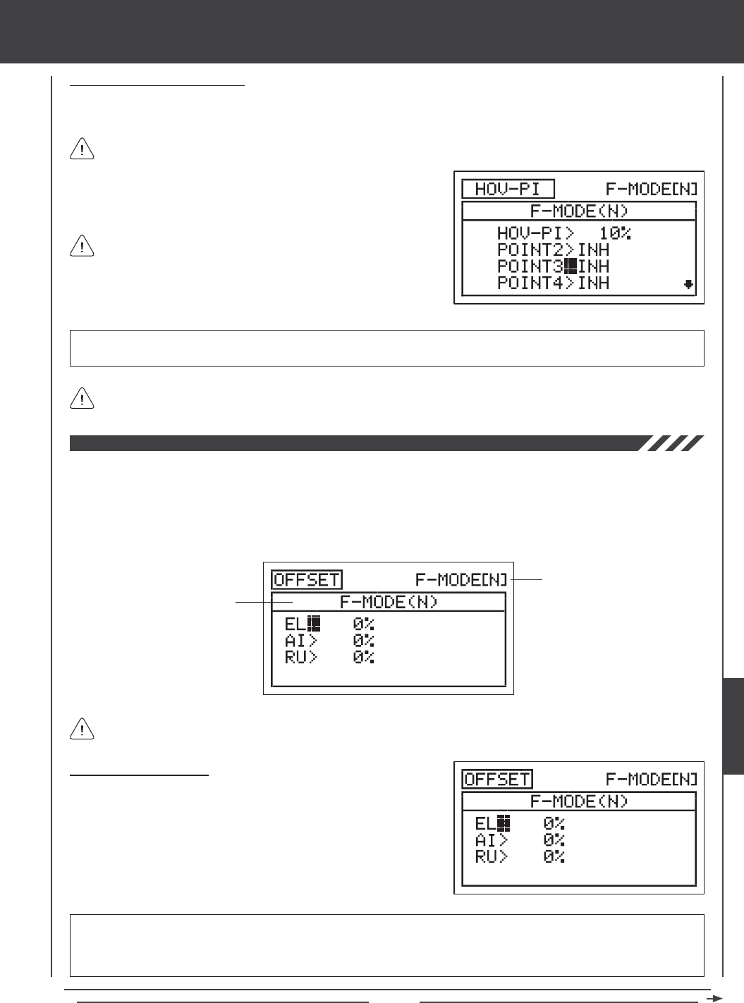
Page 171
Activating Hovering Pitch Points
The Hovering Pitch Points displayed in the HOV-PI menu correspond directly with the Pitch Curve Points. You are able to Activate
one or more Hovering Pitch Points to be controlled by the Hovering Pitch trim switch.
All Activated Hovering Pitch Points will move at the same time and at the same Rate as defined by the Hovering
Pitch percentage value.
POINT2 through POINT8 setting range is INH/ACT. In Flight Mode N (Normal), the POINT5 default setting is ACT. The remaining
POINT default settings are INH. In all other Flight Modes, all POINT default settings are INH.
1) Press the Navigation Pad 56 to highlight which Hovering Pitch Point
you would like to Activate, then press the YES/+ or NO/- keys to
change the ACT/INH setting.
An audible tone is heard when the Hovering Pitch trim switch reaches the center position (0%). This allows you to know
when the trim switch reaches the center position without the need to look at the Trim Indicator on the Top menu.
If all Hovering Pitch Points are set to INH, no Hovering Pitch Trim
Indicator will be displayed on the Top menu and the Hovering Pitch
trim switch will not function. At least one Hovering Pitch Point must be set
to ACT for the Hovering Pitch trim indicator to be displayed on the Top
menu and the Hovering Pitch trim switch to function.
The Offset function allows you to shift the neutral position of the elevator, aileron, and rudder servos. This allows you another
option to center the servos without the need to use the Centering function in the Surface menu (which can affect the overall
collective pitch setup). For example, if you set up your helicopter with the swashplate perfectly square to the main shaft, however,
when you test-y the helicopter, it wants to roll to the left, you can adjust the aileron Offset to compensate without affecting the
aileron trim. Offsets can be programmed for one direction of servo travel on each of the elevator, aileron, and rudder servos
independently, and can be programmed separately for each of the ve Flight Modes.
Transmitter F-MODE
Programming F-MODE
Transmitter F-MODE refers to the Flight Mode that the transmitter is currently operating in. Programming F-MODE refers to
the Flight Mode that you would like to change the programming for.
Choosing the Flight Mode
1) Press the Navigation Pad 56 to highlight OFFSET, then press the
ENTER key to display the OFFSET menu. The cursor will default
to EL>0%.
2) Press the F-MODE key to choose the F-MODE number you would like
to program the Offset function for. Choose from N, 1, 2, 3, or 4. The
F-MODE (N) display will change, indicating which Flight Mode you are
programming the Offset function for.
IMPORTANT If you use the Offset function to adjust servo centering, make sure to program the same Offset percentage
value(s) for each Flight Mode that you use, to avoid trim changes when you switch Flight Modes, unless different Offset
percentage values are required for each Flight Mode. For example, different Offset percentage values might be required if you
have different head speeds in different Flight Modes.
heli Flight Mode menu
HELI
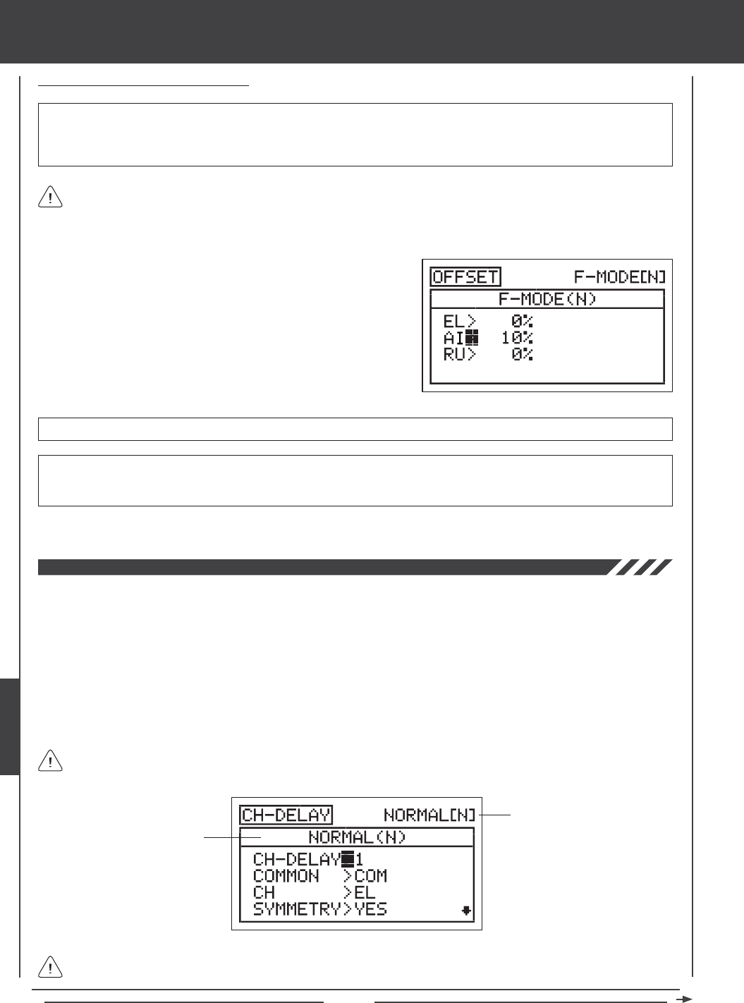
Page 172
Changing the Offset Percentage Values
OFFSET setting range is -100% to 100%. The default setting is 0%.
3) Repeat the previous procedures to set the desired remaining Offset percentage values.
The neutral position of the servo will shift the same percentage that you set the Offset percentage value for when the Offset
function is Activated, regardless of control stick position. For example, if you set 10% aileron Offset and the aileron control
stick is at neutral, the aileron servo neutral position will shift 10% (Right or Left) when the Offset function is Activated. If you're
holding a certain amount of roll cyclic, then Activate the Offset function, the roll cyclic will move 10% further (Right or Left) from
the currently held position.
IMPORTANT The Offset function shifts the neutral position of the servo, along with the two End Points. For example, with
the aileron Offset set to 10% in the Right direction, when the Offset function is Activated using the Flight Mode switch, the roll
cyclic will move Right 10% further and Down 10% less. 100% percent control deection is maintained, however, the neutral
position of the servo (and the roll cyclic) is shifted 10% in the Right direction.
1) Press the Navigation Pad 56 to highlight the desired channel you
would like to change the Offset setting for.
2) Press the YES/+ or NO/- keys to set the desired Offset percentage
value.
WARNING Depending on the ratio between your servo Limits setting and your Offset setting, there could be limited usable
control throw. For example, if your servo Limits are set to 100% and your Offset is set to 50%, this will result in only 50%
usable control throw in one direction.
The Channel Delay function allows you to adjust the speed of individual servos. This function has several uses. For example, not
all servos operate at the same exact speed. You may nd that even though the elevator, aileron, throttle, and pitch servos are
the same, one servo may move faster than the others. You can use the Channel Delay function to slow down the faster servo to
match the slower servos. In addition, you can use the Channel Delay function to slow down channels, such as the pitch channel.
For example, you can slow down the pitch channel to help make your helicopter more docile in the pitch range. The Channel
Delay function can also be used to slow down a servo that controls mechanical landing gear in a scale helicopter to achieve a
more scale transit time.
The Channel Delay function can be programmed to operate in a number of different combinations to suit just about any model
setup or control function need. Up to ve Channel Delay functions can be programmed separately for each of the ve Flight
Modes or you can use the same Channel Delay programming across all ve Flight Modes.
The Channel Delay function does not affect when the servo starts to respond to control stick movement. The Channel
Delay function affects only the transit time of the servo.
Transmitter F-MODE
Programming F-MODE
Transmitter F-MODE refers to the Flight Mode that the transmitter is currently operating in. Programming F-MODE refers
to the Flight Mode that you would like to change the programming for.
heli Flight Mode menu
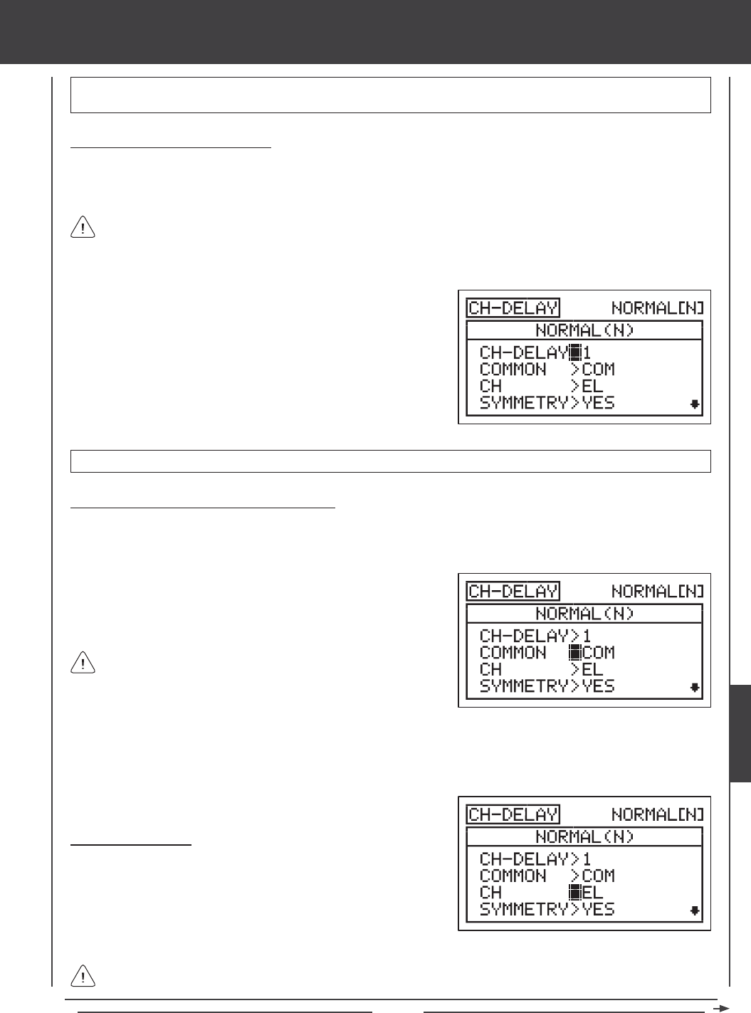
Page 173
IMPORTANT Each CH-DELAY function (CH-DELAY 1, 2, 3, 4, and 5) must be assigned to a Switch Position Number before
it can be Activated. For more information, see page 45.
Choosing the Channel Delay Number
Up to ve separate Channel Delay functions can be programmed for each Flight Mode, however, only one channel can be
assigned to one Channel Delay function at a time. For example, if you want to program Channel Delay for the elevator and the
aileron channels, you would need to program Elevator to CH-DELAY 1 and Aileron to CH-DELAY 2.
1) Press the Navigation Pad 56 to highlight CH-DELAY, then press the
ENTER key to display the CH-DELAY menu. The cursor will default to
CH-DELAY>1.
2) Press the YES/+ and NO/- keys to choose the CH-DELAY number you
would like to program Channel Delay for.
Although only one channel can be assigned to one Channel Delay function at a time, you can still Activate multiple
Channel Delay Functions at the same time by assigning the Channel Delay functions to the same Switch Position Number.
For example, assign both CH-DELAY 1 and CH-DELAY 2 to Switch Position 23. This is particularly useful if need to program
Channel Delay percentage values for both the aileron and the elevator servos in the CCPM setup.
CH-DELAY setting range is 1, 2, 3, 4, or 5.
Choosing the Flight Mode - Common or Separate
When set to COM (Common), the CH-DELAY setting will be the same regardless of which Flight Mode the transmitter is
operating in. You cannot program CH-DELAY settings separately for each Flight Mode. When set to SEP (Separate), you can
program different CH-DELAY settings separately for each Flight Mode.
2) Press the F-MODE key to choose the F-MODE number you would like to program the Channel Delay function for. Choose
from N, 1, 2, 3, or 4. The NORMAL (N) display will change, indicating which Flight Mode you are programming the Channel
Delay function for.
If set to COM, skip to the Choosing the Channel section. If set to SEP,
see step 2 below.
1) Press the Navigation Pad 6 to highlight COMMON>COM, then press
the YES/+ or NO/- keys to choose either COM or SEP.
Choosing the Channel
1) Press the Navigation Pad 6 to highlight CH>EL, then press the YES/+
or NO/- keys to choose which Channel you want to program Channel
Delay for.
The channel options displayed will vary based on Model Type and Swashplate selection options currently selected. For
example, if your model features two elevator servos, EL and EL2 will be separate options.
heli Flight Mode menu
HELI
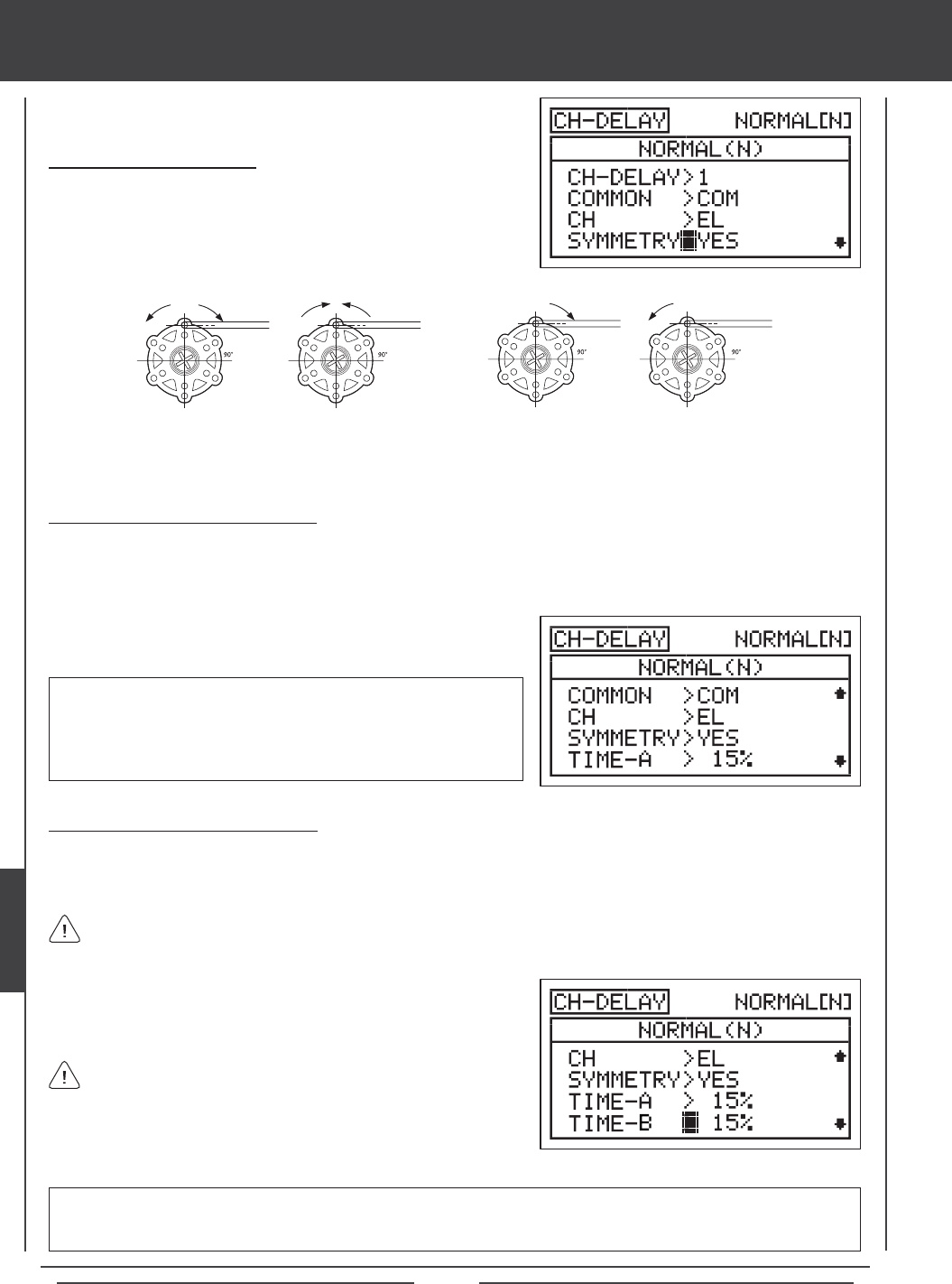
Page 174
Changing the Symmetry Value
1) Press the Navigation Pad 6 to highlight SYMMETRY>YES, then press
the YES/+ or NO/- keys to change the Symmetry option.
The following Symmetry options are available:
YES - Selecting this option results in the
Channel Delay function affecting the speed
of the servo in both directions equally.
NO - Selecting this option results in the
Channel Delay function affecting the speed
of the servo in only one direction.
Changing the Time-A Percentage Value
The Time-A setting adjusts the Channel Delay when the servo moves from the neutral position to either End Point (Symmetry
YES), and in a single direction (Symmetry NO), either clockwise or counter-clockwise, depending on the Servo Reversing setting
in the Surface menu.
1) Press the Navigation Pad 6 to highlight TIME-A>0%, then press the
YES/+ or NO/- keys to change the Time-A percentage value.
TIME-A setting range is 0% to 100%. The default setting is 0%. When
the Time-A percentage value is increased, the servo transit time will be
slowed down. At 0%, the servo moves at its normal speed. At 100%, the
servo takes approximately 15 seconds to move from the neutral position
to 100% or -100% travel.
Changing the Time-B Percentage Value
The Time-B setting adjusts the Channel Delay when the servo moves from either End Point to the neutral position (Symmetry
YES), and in a single direction (Symmetry NO), either clockwise or counter-clockwise, depending on the Servo Reversing setting
in the Surface menu.
1) Press the Navigation Pad 6 to highlight TIME-B>0%, then press the
YES/+ or NO/- keys to change the Time-B percentage value.
TIME-B setting range is 0% to 100%. The default setting is 0%. When the Time-B percentage value is increased, the servo
transit time will be slowed down. At 0%, the servo moves at its normal speed. At 100%, the servo takes approximately 15
seconds to move from one 100% or -100% travel to the neutral position.
If a Time-A percentage value is set with SYMMETRY>NO, the Time-B setting will affect the Channel Delay function in the
direction opposite the Time-A Channel Delay setting, regardless of the Servo Reversing setting.
If you want to ensure that a servo will move at the same speed in
both directions, for example, to match the speed of a second servo,
make sure the Symmetry is set to YES and the that both the Time-A and the
Time-B percentage values are the same.
heli Flight Mode menu
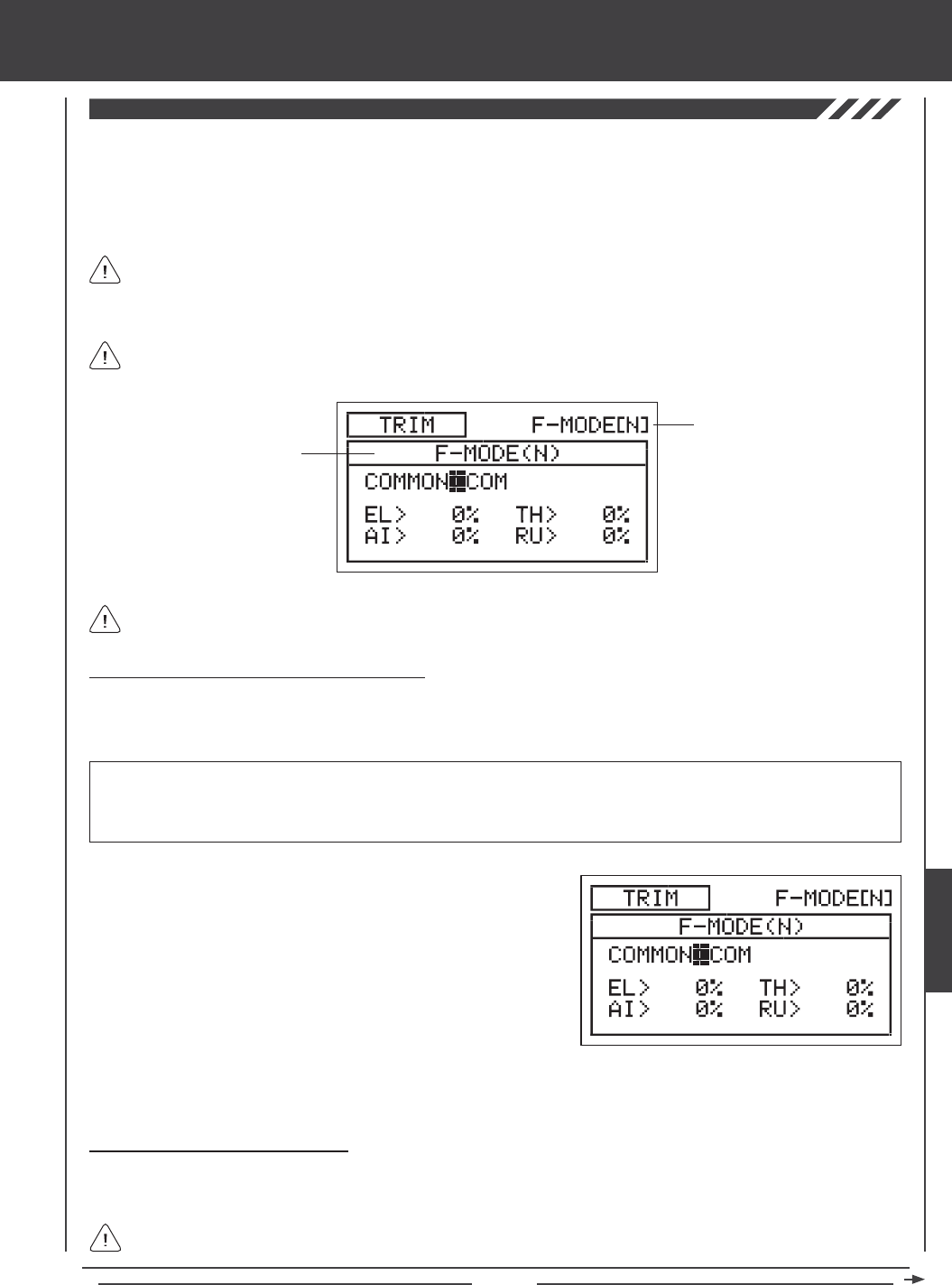
Page 175
The Trim function allows you to view the current Digital Trim Positions of the four ight control surfaces. In addition, you are able
to ne-tune the Digital Trim Positions, using the YES/+ and No/- keys. For example, in the default conguration, when you move
the elevator trim switch, the Trim percentage value changes in 6% increments. When you press the YES/+ and NO/- keys to
change the elevator Trim percentage value, the Trim percentage value changes in 1% increments. You can also choose to
program specic Trim percentage values separately for each of the ve Flight Modes or you can use the same Trim percentage
values across all ve Flight Modes.
The Trim percentage values are displayed as a percentage of total trim. They are not displayed as a percentage of
servo travel.
The SD-10G transmitter features Digital Trim Memory. Any amount of trim that you set during ight, using either the
trim switches or the YES/+ and NO/- keys from within the Trim menu, is automatically stored in memory for that specic
channel and model, and for that specic Flight Mode (if enabled). The Trim percentage values for each model will automatically
be loaded when the transmitter is turned ON and your model is selected.
Transmitter F-MODE
Programming F-MODE
Transmitter F-MODE refers to the Flight Mode that the transmitter is currently operating in. Programming F-MODE refers
to the Flight Mode that you would like to change the programming for.
Choosing the Flight Mode - Common or Separate
When set to COM (Common), the TRIM settings will be the same regardless of which Flight Mode the transmitter is operating in.
You cannot program or store TRIM settings separately for each Flight Mode. When set to SEP (Separate), you can program and
store different TRIM settings separately for each Flight Mode.
3) Press the F-MODE key to choose the F-MODE number you would like to program the Trim function for. Choose from N, 1, 2,
3, or 4. The F-MODE (N) display will change, indicating which Flight Mode you are programming the Trim function for.
1) Press the Navigation Pad 56 to highlight TRIM, then press the
ENTER key to display the TRIM menu. The cursor will default to
COMMON>COM.
2) Press the YES/+ or NO/- keys to choose either COM or SEP. If set to
COM, skip to the Changing the Trim Percentage Values section. If
set to SEP, see step 3 below.
IMPORTANT When the Flight Mode is set to Separate, Trim percentage values are stored in the specic Flight Mode you're
using when you change the Trim percentage values, whether with the trim switches or with the YES/+ and NO/- keys within the
Trim menu. For example, you could have 10% elevator trim in Flight Mode N (Normal) and 5% elevator trim in Flight Mode 1.
Be cautious of this when switching between Flight Modes during ight.
Changing the Trim Percentage Values
The current Trim percentage values for each of the ight control surfaces is displayed. The Trim percentage values can be
changed, if desired, using either the trim switches or the YES/+ and NO/- keys (from within the Trim menu only).
An audible tone is heard when the trim switches reach the center position. This allows you to know when the trim
switches reach the center position without the need to look at the Trim Indicators on the Top menu.
heli Flight Mode menu
HELI
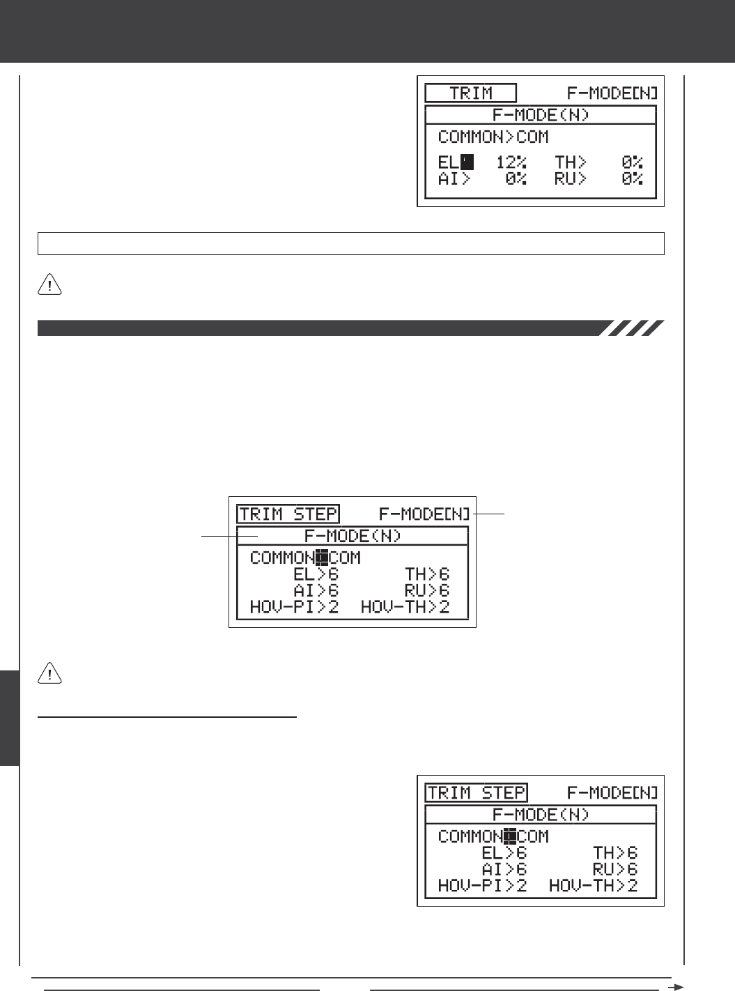
Page 176
TRIM setting range is -150% to 150%. The default setting is 0%.
1) Press the Navigation Pad 3456 to highlight the channel you would
like to change the Trim percentage value for, then press the YES/+ or
NO/- keys to change the Trim percentage value.
Press the YES/+ and NO/- keys at the same time to set the Trim percentage value to 0% for the selected channel.
The Trim Step function allows you to adjust how far the servo travels when the trim switch is moved. This allows you to change
the Trim function resolution to suit your preference. For example, in the default conguration, when you move the elevator trim
switch, the Trim percentage value changes in 6% increments. You can increase the resolution by decreasing the Trim Step value,
so that the servo travels less when you move the trim switch. This makes it possible to ne-tune the trim settings extremely
accurately. In addition, you could decrease the resolution by increasing the Trim Step value, so that the servo travels more when
you move the trim switch. This makes setting large amounts of trim faster, but the trim setting may not be as accurate.
You can choose to program Trim Step values separately for each of the ve Flight Modes or you can use the same Trim Step
programming values across all ve Flight Modes.
Transmitter F-MODE
Programming F-MODE
Transmitter F-MODE refers to the Flight Mode that the transmitter is currently operating in. Programming F-MODE refers
to the Flight Mode that you would like to change the programming for.
Choosing the Flight Mode - Common or Separate
When set to COM (Common), the TRIM STEP settings will be the same regardless of which Flight Mode the transmitter is operating
in. You cannot program TRIM STEP settings separately for each Flight Mode. When set to SEP (Separate), you can program
different TRIM STEP settings separately for each Flight Mode.
3) Press the F-MODE key to choose the F-MODE number you would like to program the Trim Step function for. Choose from
N, 1, 2, 3, or 4. The F-MODE (N) display will change, indicating which Flight Mode you are programming the Trim Step
function for.
1) Press the Navigation Pad 56 to highlight TRIM STEP, then press the
ENTER key to display the TRIM STEP menu. The cursor will default to
COMMON>COM.
2) Press the YES/+ or NO/- keys to choose either COM or SEP. If set to
COM, skip to the Setting the Trim Step Values section. If set to SEP,
see step 3 below.
heli Flight Mode menu
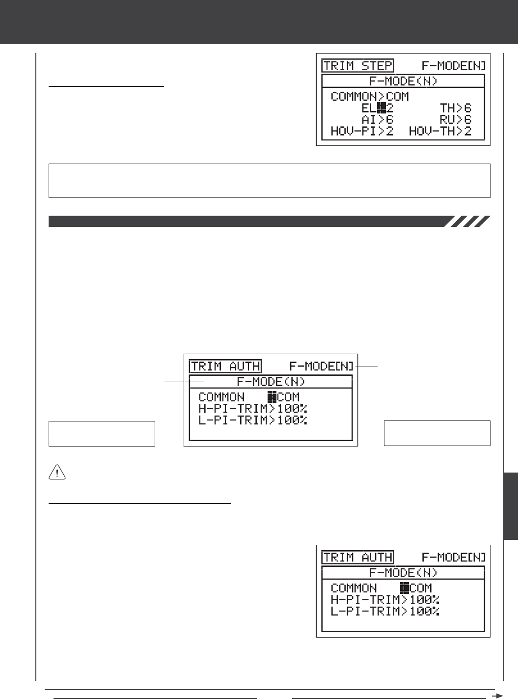
Page 177
Changing the Trim Step Values
1) Press the Navigation Pad 3456 to highlight the channel you would
like to change the Trim Step value for, then press the YES/+ or NO/- keys
to change the Trim Step value.
TRIM STEP setting range is 1 to 30. The default setting for EL, AI, TH, and RU is 6. The default setting for HOV-PI and HOV-TH
is 2. Increasing the Trim Step value causes the servo to travel more when the trim switch is moved (lower resolution). Decreasing
the Trim Step value causes the servo to move less when the trim switch is moved (higher resolution).
The Trim Authority function allows you to change the amount that Point 9 and Point 1 of the Pitch Curve move relative to how
far Auxiliary Lever (VR5) and Auxiliary Lever (VR6) are moved. In the default conguration, Auxiliary Lever (VR5) and Auxiliary
Lever (VR6) control the high (Point 9) and low (Point 1) points of the Pitch Curve, respectively. For example, you can manually
adjust the high and low points of the Pitch Curve during ight to ne-tune the adjustments. The Trim Authority function allows you
to change the amount of high and low Pitch Curve travel relative to how far Auxiliary Lever (VR5) and Auxiliary Lever (VR6) are
moved. For example, if you set the Trim Authority High Pitch Trim percentage value to 50%, the High Pitch End Point (Point 9 on
the Pitch Curve) will move half as much using Auxiliary Lever (VR5) as it would if the Trim Authority High Pitch Trim percentage
value was set to 100%. For example, when set to 100%, Auxiliary Lever (VR5) will move Point 9 on the Pitch Curve 25% in either
direction. If set to 50%, Auxiliary Lever (VR5) will move Point 9 on the Pitch Curve 12% in either direction. You can choose to
program Trim Authority values separately for each of the ve Flight Modes or you can use the same Trim Authority programming
values across all ve Flight Modes.
Transmitter F-MODE
Programming F-MODE
Transmitter F-MODE refers to the Flight Mode that the transmitter is currently operating in. Programming F-MODE refers
to the Flight Mode that you would like to change the programming for.
Auxiliary Lever (VR5)
High Pitch Curve End Point
Auxiliary Lever (VR6)
Low Pitch Curve End Point
Choosing the Flight Mode - Common or Separate
When set to COM (Common), the TRIM AUTH settings will be the same regardless of which Flight Mode the transmitter is operating
in. You cannot program TRIM AUTH settings separately for each Flight Mode. When set to SEP (Separate), you can program
different TRIM AUTH settings separately for each Flight Mode.
3) Press the F-MODE key to choose the F-MODE number you would like to program the Trim Authority function for. Choose from
N, 1, 2, 3, or 4. The NORMAL (N) display will change, indicating which Flight Mode you are programming the Trim Authority
function for.
1) Press the Navigation Pad 56 to highlight TRIM AUTH, then press the
ENTER key to display the TRIM AUTH menu. The cursor will default to
COMMON>COM.
2) Press the YES/+ or NO/- keys to choose either COM or SEP. If set
to COM, skip to the Changing the High Pitch Trim Authority Percentage
Value section on page 178. If set to SEP, see step 3 below.
heli Flight Mode menu
HELI
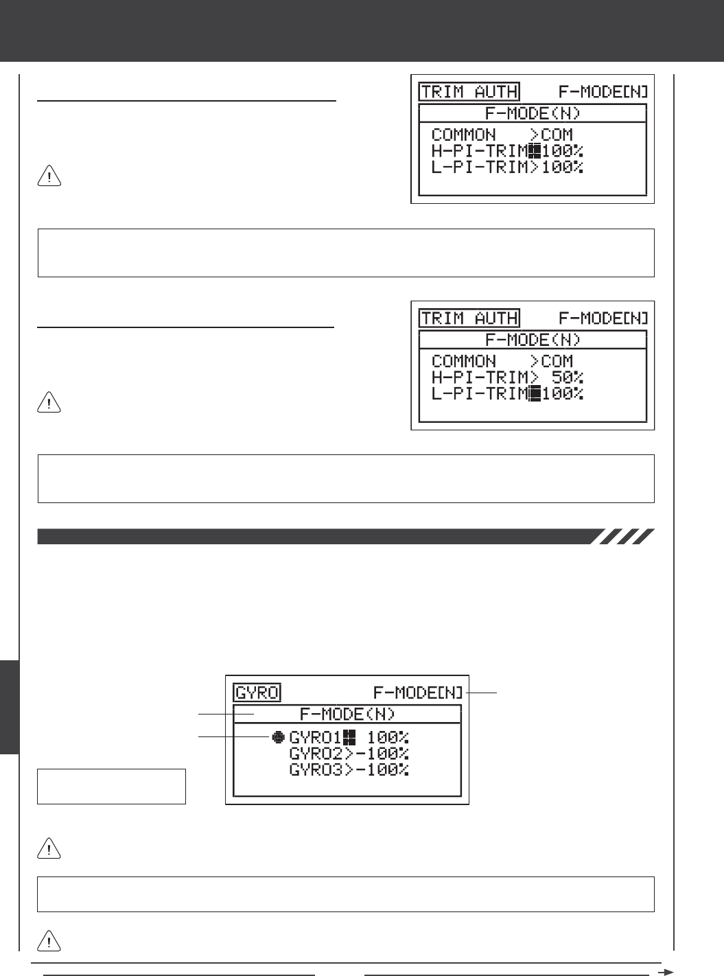
Page 178
Changing the High Pitch Trim Authority Percentage Value
1) Press the Navigation Pad 6 to highlight H-PI-TRIM>100%, then press
the YES/+ or NO/- keys to change the High Pitch Trim Authority
percentage value.
H-PI-TRIM setting range is 0% to 100%. The default setting is 100%. Decreasing the H-PI-TRIM percentage value decreases
the overall High Pitch End Point travel when Auxiliary Lever (VR5) is used to control Point 9 of the Pitch Curve. When set to
100%, Auxiliary Lever (VR5) will move Point 9 of the Pitch Curve 25% in either direction from the center detent.
Changing the Low Pitch Trim Authority Percentage Value
1) Press the Navigation Pad 6 to highlight L-PI-TRIM>100%, then press
the YES/+ or NO/- keys to change the Low Pitch Trim Authority
percentage value.
L-PI-TRIM setting range is 0% to 100%. The default setting is 100%. Decreasing the L-PI-TRIM percentage value decreases
the overall Low Pitch End Point travel when Auxiliary Lever (VR6) is used to control Point 1 of the Pitch Curve. When set to
100%, Auxiliary Lever (VR6) will move Point 1 of the Pitch Curve 25% in either direction from the center detent.
Auxiliary Lever (VR5) will control High Pitch Trim only when the
throttle control stick is at 1% or higher control stick position.
Auxiliary Lever (VR6) will control Low Pitch Trim only when the
throttle control stick is at -1% or lower control stick position.
The Gyro function allows you to control Heading Hold mode gain and Rate mode gain remotely. Three separate Gyro function
settings can be programmed and each can be selected at any time using a three-position switch. For example, you might want
100% gain for aerobatic ight, but then switch to 75% gain for sport ying. In essence, when you assign a Gyro percentage
value to each of the three Gyro function settings, you effectively have triple-rates for your gyro, just like you have triple rates
for your elevator, aileron, and rudder control surfaces. Depending on the Gyro percentage value, you can adjust the gain in
either Heading Hold mode or Rate mode. In addition, you can program a Heading Hold gain percentage value and a Rate gain
percentage value separately, then switch between the two to aid in setting up your gyro. The Gyro function can be programmed
separately for each of the ve Flight Modes.
Transmitter F-MODE
Programming F-MODE
Current Switch Selection
Gyro Default Switch
Position Numbers: 16,17,18
Transmitter F-MODE refers to the Flight Mode that the transmitter is currently operating in. Programming F-MODE refers
to the Flight Mode that you would like to change the programming for.
IMPORTANT In order to use this feature, your gyro must support Remote Gain. For more information, and before using this
function, please refer to your gyro's Operating Guide to familiarize yourself with its setup and use.
The Current Switch Selection icon displays which Gyro function (gain percentage value) is currently Active for the current
Flight Mode.
heli Flight Mode menu
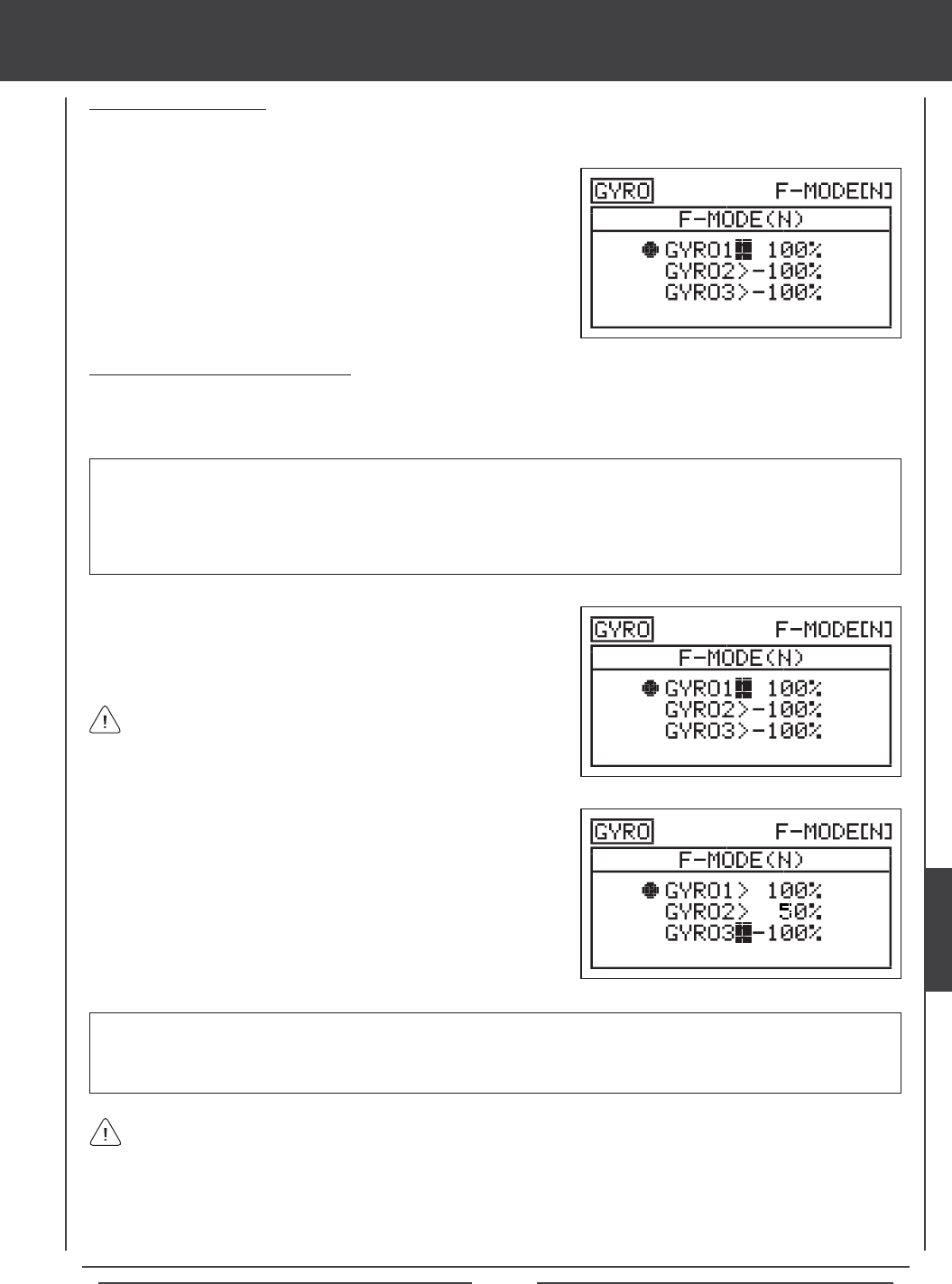
Page 179
2) Press the F-MODE key to choose the F-MODE number you would like
to program the Gyro function for. Choose from N, 1, 2, 3, or 4. The
F-MODE (N) display will change, indicating which Flight Mode you are
programming the Gyro function for.
Changing the Gyro Percentage Values
The Gyro percentage values determine both the amount of gain and the gyro operating mode - either Heading Hold mode or Rate
mode. In general, positive values will result in your gyro operating in Heading Hold mode and negative values will result in your
gyro operating in Rate mode. The amount of gain is determined by the percentage value.
1) Press the Navigation Pad 56 to highlight GYRO1>100%, then press
the YES/+ or NO/- keys to change the Gyro 1 percentage value.
Choosing the Flight Mode
1) Press the Navigation Pad 56 to highlight GYRO, then press the ENTER key to display the GYRO menu. The cursor will
default to GYRO1>100%.
IMPORTANT Whether you use positive or negative Gyro percentage values to program your gyro in either Heading Hold
mode or Rate mode will be determined by the NOR/REV settings of the gyro channel in the Surface menu. For example, if the
gyro channel is set to NOR (Normal) in the Surface menu, positive Gyro percentage values may result in your gyro operating
in Heading Hold mode, but if the gyro channel is set to REV (Reverse) in the Surface menu, positive Gyro percentage values
may result in your gyro operating in Rate mode. You will need to test your gyro to ensure that it's operating in the desired
mode based on the percentage values, then adjust the percentage values accordingly to achieve the desired amount of gain.
GYRO1, GYRO2, and GYRO3 setting range is -150% to 150%. The GYRO1 default setting is 100%. The GYRO2 and GYRO3
default settings are -100%. Decreasing the GYRO percentage values decreases gyro gain and increasing the GYRO percentage
values increases gyro gain. See the IMPORTANT note above regarding the use of positive and negative Gyro percentage
values and how they may change your gyro operating mode.
If you prefer to use the same Gyro function settings across all Flight Modes, instead of programming separate Gyro function
settings for each Flight Mode, you can control up to two separate Gyro function settings via a three-position switch. To do
this, plug your gyro into the AUX2 channel and adjust the AUX2 channel High and Low End Point Adjustments in the Surface
menu to set the desired Gyro percentage values. Positive or negative values will determine your gyro operating mode - either
Heading Hold mode or Rate mode, as described above. In the default conguration, Switch Position 1 is AUX2L and Switch
Position 3 is AUX2H. For example, with the switch in Switch Position 1, you might have 100% End Point Adjustment for maximum
gain in Heading Hold mode and with the switch in Switch Position 3, you might have 75% End Point Adjustment for decreased gain
in Heading Hold mode. When the switch is in Switch Position 2 (centered), the gyro will be will be in 'pass-through' mode (e.g., OFF).
When the Gyro 1 percentage value is set to 0%, the gyro will be in
'pass-through' mode (e.g., OFF) for that selected Gyro function only.
2) Press the Navigation Pad 6 to move the cursor to GYRO2>-100%,
then press the YES/+ or NO/- keys to change the Gyro 2 percentage
value.
3) Press the Navigation Pad 6 to move the cursor to GYRO3>-100%,
then press the YES/+ or NO/- keys to change the Gyro 3 percentage
value.
heli Flight Mode menu
HELI
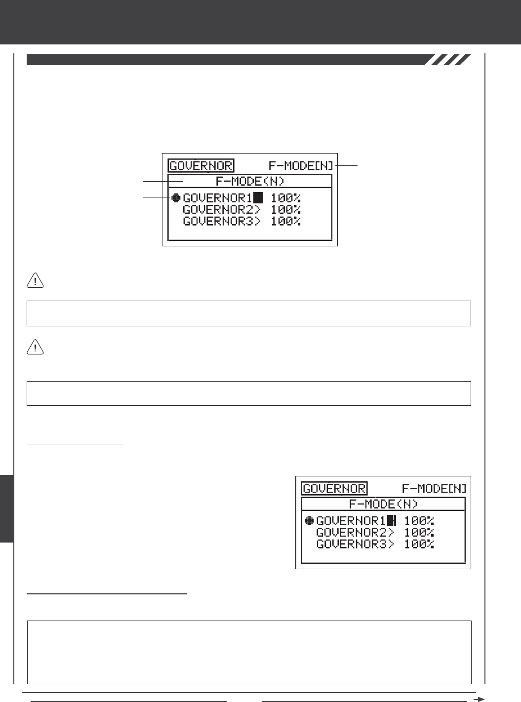
Page 180
A Governor is an electronic device used on glow-powered helicopters, that, coupled with a high-speed servo, is used to control
the helicopter's rotor head speed. The Governor function allows you to program Governor percentage values and therefore
control rotor head speed via your helicopter's governor remotely. Three separate Governor function settings can be programmed
and each can be selected at any time using a three-position switch. For example, you might want 100% RPM for maximum rotor
head speed for aerobatic ight, but then switch to 75% RPM to slow down rotor head speed for sport ying. The Governor
function can be programmed separately for each of the ve Flight Modes.
Transmitter F-MODE
Programming F-MODE
Current Switch Selection
Transmitter F-MODE refers to the Flight Mode that the transmitter is currently operating in. Programming F-MODE refers
to the Flight Mode that you would like to change the programming for.
IMPORTANT Before using this function, please refer to your governor's Operating Guide to familiarize yourself with its setup
and use.
The Current Switch Selection icon displays which Governor is currently Active for the current Flight Mode.
IMPORTANT Each GOVERNOR function (GOVERNOR 1, 2, and 3) must be assigned to a Switch Position Number before
it can be Activated. For more information, see page 45.
2) Press the F-MODE key to choose the F-MODE number you would like
to program the Governor function for. Choose from N, 1, 2, 3, or 4. The
F-MODE (N) display will change, indicating which Flight Mode you are
programming the Governor function for.
Choosing the Flight Mode
1) Press the Navigation Pad 56 to highlight GOVERNOR, then press the ENTER key to display the GOVERNOR menu. The
cursor will default to GOVERNOR1>100%.
Changing the Governor Percentage Values
The Governor percentage values determines the RPM that your governor will regulate your helicopter's rotor head speed at.
IMPORTANT Whether you use positive or negative Governor percentage values will be determined by the NOR/REV
settings of the governor channel in the Surface menu. For example, if the governor channel is set to NOR (Normal) in the Surface
menu, positive Governor percentage values may result in increased rotor head speed, but if the governor channel is set to REV
(Reverse) in the Surface menu, positive Governor percentage values may result in decreased rotor head speed. You will need
to test your governor to ensure that it's operating as desired, then adjust the Governor percentage values accordingly to either
increase or decrease rotor head speed. For more information, refer to your governor's Operating Guide.
heli Flight Mode menu
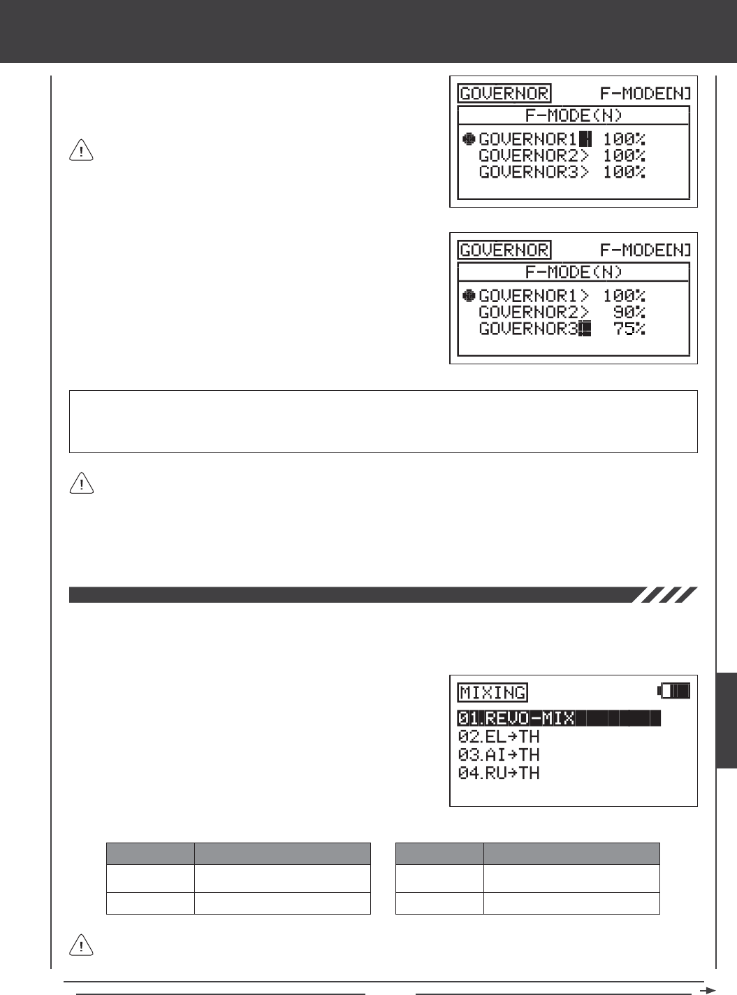
Page 181
1) Press the Navigation Pad 56 to highlight GOVERNOR1>100%, then
press the YES/+ or NO/- keys to change the Governor 1 percentage
value.
GOVERNOR1, GOVERNOR2, and GOVERNOR3 setting range is -150% to 150%. The default setting for each is 100%.
Decreasing the GOVERNOR percentage values decreases rotor head speed and increasing the GOVERNOR percentage
values increases rotor head speed. See the IMPORTANT note on the bottom of the previous page regarding the use of positive
and negative Governor percentage values and how they affect the use of your governor.
When the Governor 1 percentage value is set to 0%, the governor
will be in 'pass-through' mode (e.g., OFF). This value can vary by
manufacturer. Make sure to check your governor's Operating Guide for
more information. For example, some governors may be OFF when the
percentage value is set anywhere between -5% and 5%.
2) Press the Navigation Pad 6 to move the cursor to GOVERNOR2>100%,
then press the YES/+ or NO/- keys to change the Governor 2
percentage value.
3) Press the Navigation Pad 6 to move the cursor to GOVERNOR3>100%,
then press the YES/+ or NO/- keys to change the Governor 3
percentage value.
If you prefer to use the same Governor function settings across all Flight Modes, instead of programming separate Governor
function settings for each Flight Mode, you can control up to two separate Governor function settings via a three-position
switch. To do this, plug your governor into the AUX3 channel and adjust the AUX3 channel High and Low End Point Adjustments
in the Surface menu to set the desired Governor percentage values. In the default conguration, Switch Position 28 is AUX3L and
Switch Position 30 is AUX3H. For example, with the switch in Switch Position 28, you might have 100% End Point Adjustment for
maximum rotor head speed and with the switch in Switch Position 30, you might have 75% End Point Adjustment for decreased rotor
head speed. When the switch is in Switch Position 29 (centered), the governor will be will be in 'pass-through' mode (e.g., OFF).
The SD-10G transmitter features the most common pre-programmed mixes that can all be adjusted to suit just about any model
setup or mixing need that you might have. If for some reason one of the pre-programmed mixes will not sufce, you can
custom-program one or more of the available ve Compensation Mixers. For more information, see page 187.
REVO-MIX
EL4TH
MIX
Revolution Mixing
Elevator to Throttle Mixing
DESCRIPTION
AI4TH
RU4TH
MIX
Aileron to Throttle Mixing
Rudder to Throttle Mixing
DESCRIPTION
The pre-programmed mixes shown in the tables below are available.
Aside from Revolution Mixing, all pre-programmed mixes are described in the following manner: Master4Slave. For
example, For the EL4TH mix, the Elevator channel is the Master and the Throttle channel is the Slave. In all cases, the
Master channel always controls the Slave channel.
1) Press the Navigation Pad 56 to highlight MIXING, then press the
ENTER key to display the MIXING menu. The REVO-MIX sub-menu
will be highlighted by default.
heli Flight Mode menu
HELI
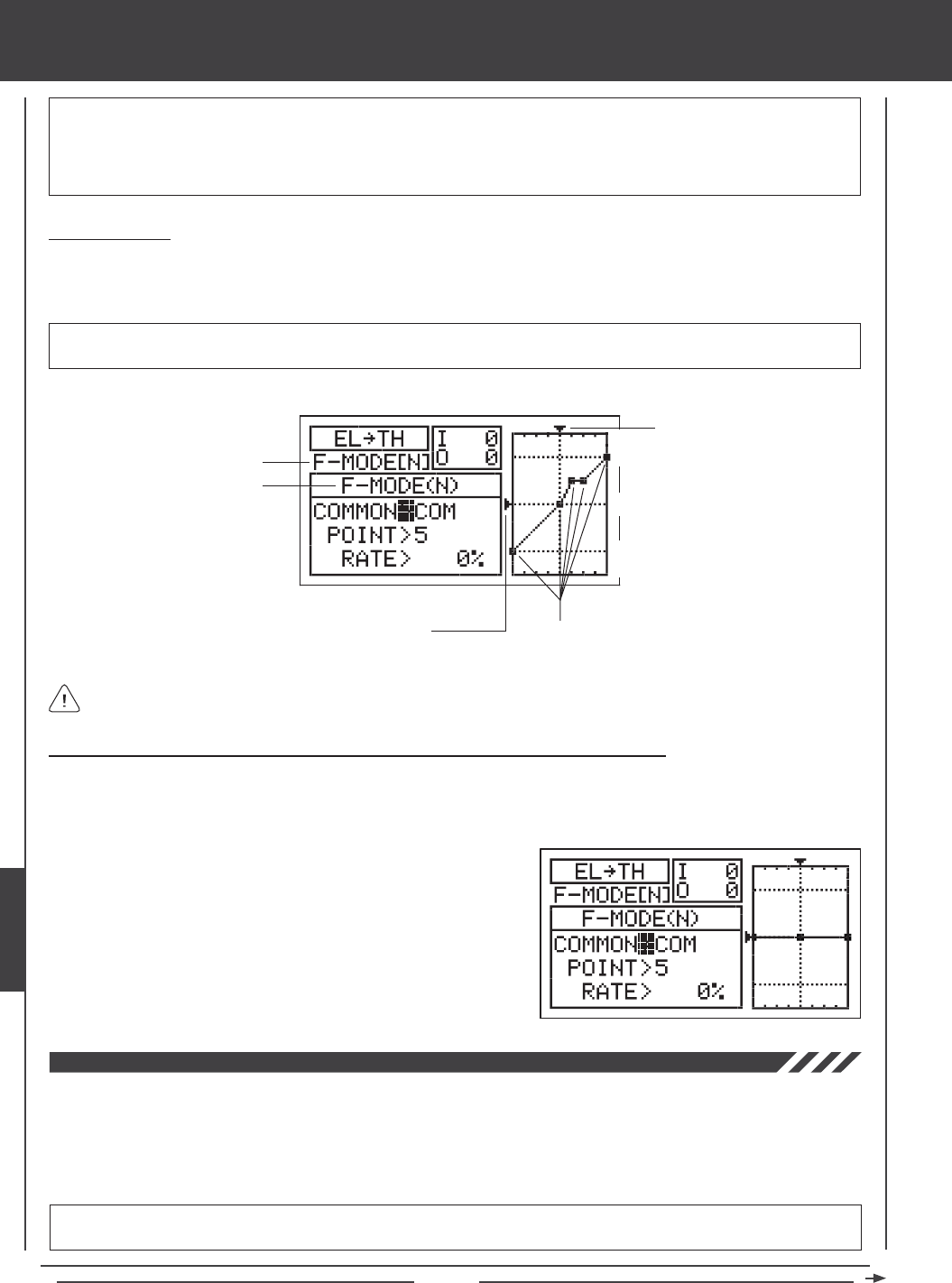
Page 182
WARNING When a pre-programmed mix is Activated, you still have separate control over the Slaved channel, however,
depending on the mixing percentage value, the Slave channel End Point Adjustment could be exceeded. We strongly
recommend that if you use the pre-programmed mixes that you set your Slave channel Limits no higher than that channel's
End Point Adjustment unless specically necessary for your particular setup. This will prevent any chance of overdriving your
control linkage when the mix is used.
General Overview
Each of the four mixes can be programmed separately for each of the ve Flight Modes or you can use the same Mixing
programming across all ve Flight Modes (except Revolution mixing). Programming the Point and Rate percentage values on a
Curve allows you to achieve maximum exibility and ne-tuning for specic uses.
Transmitter F-MODE refers to the Flight Mode that the transmitter is currently operating in. Programming F-MODE refers
to the Flight Mode that you would like to change the programming for.
IMPORTANT Each Mixing function (except Revolution mixing) must be assigned to a Switch Position Number before it can
be Activated. For more information, see page 45. Revolution Mixing will be Activated/Inhibited when switching Flight Modes.
Transmitter F-MODE
Programming F-MODE
Stick Input (I)
Function Output (O)
150%
100%
100%
150%
0%
Point Positions
Choosing the Flight Mode - Common or Separate (All Mixing Options Except Revo Mixing)
When set to COM (Common), the mixing settings will be the same regardless of which Flight Mode the transmitter is operating in.
You cannot program mixing settings separately for each Flight Mode. When set to SEP (Separate), you can program different
mixing settings separately for each Flight Mode.
1) Press the Navigation Pad 6 to highlight COMMON>COM, then press
the YES/+ or NO/- keys to choose either COM or SEP. If set to COM,
skip to the Changing the Point and Rate Percentage Values sections. If
set to SEP, see step 2 below.
2) Press the F-MODE key to choose the F-MODE number you would like
to program the mixing function for. Choose from N, 1, 2, 3, or 4. The
F-MODE (N) display will change, indicating which Flight Mode you are
programming the mixing function for.
Revo (Revolution) Mixing
The Revo Mixing function mixes rudder and collective pitch controls, which makes the helicopter more stable when collective
pitch is increased. For example, when you increase collective pitch, as the rotor head speed and pitch increase, the torque that
it creates can cause the tail of the helicopter to pivot. Adding Revolution mixing helps prevent this from occurring, which makes
the helicopter more stable in the yaw axis. The amount and the direction that the rudder moves with collective pitch control is
adjusted by changing the Rate percentage value either positive or negative. An Input and Output display, along with a graph, help
with programming visualization.
IMPORTANT We DO NOT recommend using Revolution mixing with a Heading Hold mode or AVCS mode gyro. Revolution
Mixing should only be used with a Rate mode gyro or in the event that no gyro is used.
heli Flight Mode menu
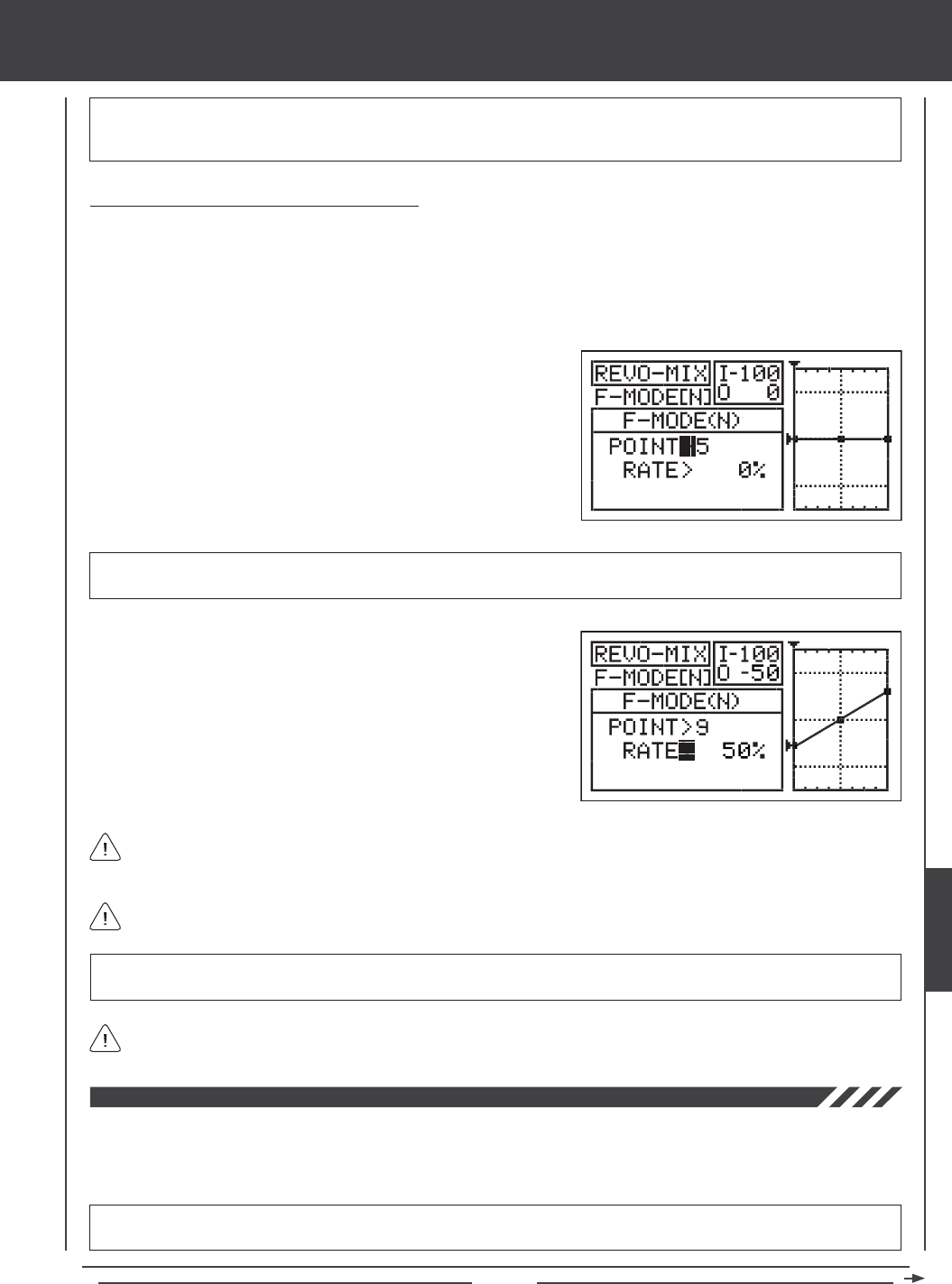
Page 183
IMPORTANT The Revo Mixing function is not assigned directly to a Switch Position Number. It is designed for use in a
specic Flight Mode (or Flight Modes). For example, you may have programmed your gyro for Heading Hold mode in Flight
Mode N (Normal) and Rate mode in Flight Mode 1. In this case, you might program Revolution mixing only in Flight Mode 1.
Changing the Point and Rate Percentage Values
Programming the Point and Rate percentage values on a Curve allows you to achieve maximum exibility and ne-tuning for
specic uses. The Point and Rate percentage values work together to determine the amount of rudder travel in relation to
collective pitch travel. Nine different Points with varying Rates can be programmed onto the Curve. Use the Input and Output
display, along with the graph, to help with programming visualization. The Point that is currently selected will blink.
1) Press the Navigation Pad 56 to highlight MIXING, then press the ENTER key to display the MIXING menu. The REVO-MIX
sub-menu will be highlighted by default.
1) Press the ENTER key to highlight the REVO-MIX menu. The cursor will
default to POINT>5.
2) Press the YES/+ or NO/- keys to choose which Point you would like to
set a Rate percentage value for.
POINT setting range is 1 through 9. Point 1 is at the low end of the Curve and Point 9 is at the high end of the Curve. Point 5
is a the center of the Curve. The default Point is Point 5.
As you change the Point and Rate percentage values, you can use the graph and I/O numbers to visualize the ratio
between collective control stick movement and rudder travel throughout the entire deection range.
RATE setting range is -150% to 150%. POINT 1, 5, and 9 default Rate percentage values are 0%. The direction of rudder travel
in relation to collective pitch travel can be changed by programming positive or negative Rate percentage values.
3) Press the Navigation Pad 6 to highlight RATE>0%.
4) Press the YES/+ or NO/- keys to set the desired Rate percentage value.
When you change the Rate percentage value for Points 2, 3, 4, 6, 7, and 8, INH will be displayed. When you press the
YES/+ or NO/- keys, INH will change to 0%.
When you program the mix Curve so that the line is straight, this results in a Linear Curve. For example, if you set the
Point 1 percentage value to -50% and the Point 9 percentage value to 50%, the rudder will move half the amount that the
collective pitch moves in both directions at any given collective control stick position.
Elevator to Throttle Mixing
The Elevator to Throttle Mixing function allows you to mix a percentage of throttle control with elevator control. The Elevator to
Throttle Mixing function is typically used during 3D ying to provide a momentary burst of throttle under hard cyclic load. The
amount and the direction that the throttle travels when you move the elevator cyclic is adjusted by changing the Elevator4Throttle
Rate percentage value either positive or negative.
IMPORTANT The Elevator to Throttle Mixing function must be assigned to a Switch Position Number before it can be
Activated. For more information, see page 45.
heli Flight Mode menu
HELI
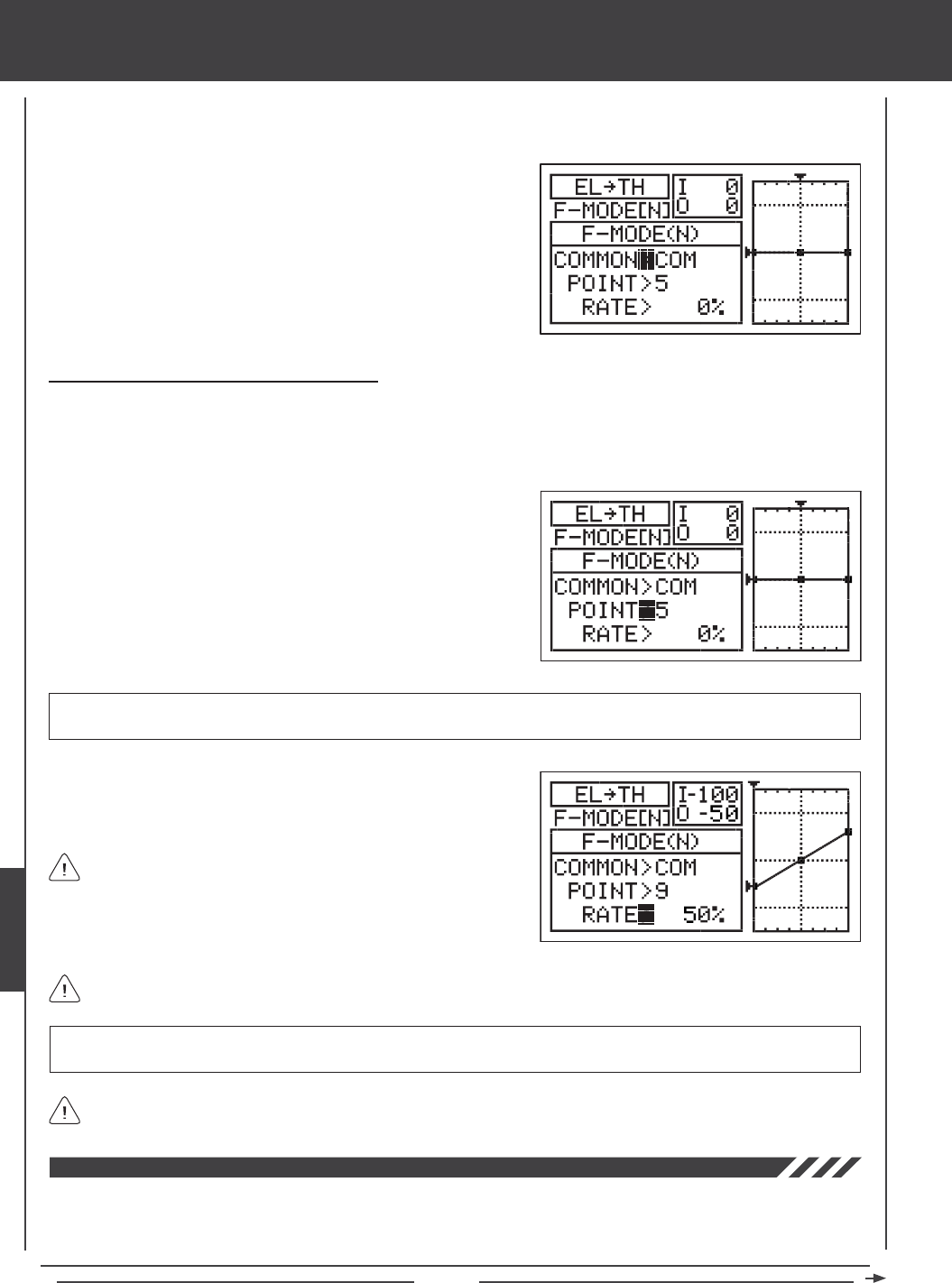
Page 184
1) Press the Navigation Pad 56 to highlight MIXING, then press the ENTER key to display the MIXING menu. The REVO-MIX
sub-menu will be highlighted by default.
2) Press the Navigation Pad 6 to highlight EL4TH, then press the
ENTER key to display the EL4TH menu. The cursor will default to
COMMON>COM.
3) Press the YES/+ or NO/- keys to choose the desired COM or SEP
option as described previously.
Changing the Point and Rate Percentage Values
Programming the Point and Rate percentage values on a Curve allows you to achieve maximum exibility and ne-tuning for
specic uses. The Point and Rate percentage values work together to determine the amount of throttle travel in relation to elevator
cyclic travel. Nine different Points with varying Rates can be programmed onto the Curve. Use the Input and Output display, along
with the graph, to help with programming visualization. The Point that is currently selected will blink.
1) Press the Navigation Pad 6 to highlight POINT>5.
2) Press the YES/+ or NO/- keys to choose which Point you would like to
set a Rate percentage value for.
POINT setting range is 1 through 9. Point 1 is at the low end of the Curve and Point 9 is at the high end of the Curve. Point 5
is a the center of the Curve. The default Point is Point 5.
3) Press the Navigation Pad 6 to highlight RATE>0%.
4) Press the YES/+ or NO/- keys to set the desired Rate percentage value.
When you program the mix Curve so that the line is straight, this
results in a Linear Curve. For example, if you set the Point 1
percentage value to -50% and the Point 9 percentage value to 50%, the
throttle will increase or decrease half the amount that the elevator cyclic
moves in both directions at any given elevator control stick position.
As you change the Point and Rate percentage values, you can use the graph and I/O numbers to visualize the ratio
between elevator control stick movement and throttle travel throughout the entire deection range.
RATE setting range is -150% to 150%. POINT 1, 5, and 9 default Rate percentage values are 0%. The direction of throttle
travel in relation to elevator cyclic travel can be changed by programming positive or negative Rate percentage values.
When you change the Rate percentage value for Points 2, 3, 4, 6, 7, and 8, INH will be displayed. When you press the
YES/+ or NO/- keys, INH will change to 0%.
Aileron to Throttle Mixing
The Aileron to Throttle Mixing function allows you to mix a percentage of throttle control with aileron control. The Aileron to
Throttle Mixing function is typically used during 3D ying to provide a momentary burst of throttle under hard cyclic load. The
amount and the direction that the throttle travels when you move the aileron cyclic is adjusted by changing the Aileron4Throttle
Rate percentage value either positive or negative.
heli Flight Mode menu
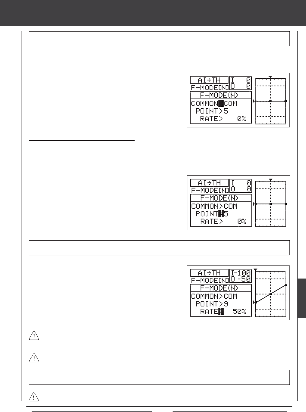
Page 185
IMPORTANT The Aileron to Throttle Mixing function must be assigned to a Switch Position Number before it can be
Activated. For more information, see page 45.
1) Press the Navigation Pad 56 to highlight MIXING, then press the ENTER key to display the MIXING menu. The REVO-MIX
sub-menu will be highlighted by default.
2) Press the Navigation Pad 6 to highlight AI4TH, then press the
ENTER key to display the AI4TH menu. The cursor will default to
COMMON>COM.
3) Press the YES/+ or NO/- keys to choose the desired COM or SEP
option as described previously.
Changing the Point and Rate Percentage Values
Programming the Point and Rate percentage values on a Curve allows you to achieve maximum exibility and ne-tuning for
specic uses. The Point and Rate percentage values work together to determine the amount of throttle travel in relation to aileron
cyclic travel. Nine different Points with varying Rates can be programmed onto the Curve. Use the Input and Output display, along
with the graph, to help with programming visualization. The Point that is currently selected will blink.
1) Press the Navigation Pad 6 to highlight POINT>5.
2) Press the YES/+ or NO/- keys to choose which Point you would like to
set a Rate percentage value for.
POINT setting range is 1 through 9. Point 1 is at the low end of the Curve and Point 9 is at the high end of the Curve. Point 5
is a the center of the Curve. The default Point is Point 5.
3) Press the Navigation Pad 6 to highlight RATE>0%.
4) Press the YES/+ or NO/- keys to set the desired Rate percentage value.
As you change the Point and Rate percentage values, you can use the graph and I/O numbers to visualize the ratio
between aileron control stick movement and throttle travel throughout the entire deection range.
RATE setting range is -150% to 150%. POINT 1, 5, and 9 default Rate percentage values are 0%. The direction of throttle
travel in relation to aileron cyclic travel can be changed by programming positive or negative Rate percentage values.
When you change the Rate percentage value for Points 2, 3, 4, 6, 7, and 8, INH will be displayed. When you press the
YES/+ or NO/- keys, INH will change to 0%.
When you program the mix Curve so that the line is straight, this results in a Linear Curve. For example, if you set the
Point 1 percentage value to -50% and the Point 9 percentage value to 50%, the throttle will increase or decrease half the
amount that the aileron cyclic moves in both directions at any given aileron control stick position.
heli Flight Mode menu
HELI
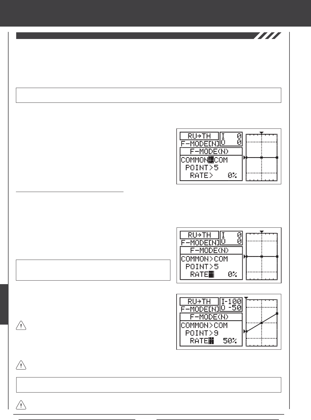
Page 186
Rudder to Throttle Mixing
The Rudder to Throttle Mixing function allows you to mix a percentage of throttle control with rudder control. The Rudder to
Throttle Mixing function is typically used to reduce the tendency of the helicopter to slightly rise and fall as you pirouette. For
example, when you command a pirouette to the left, the helicopter will rise slightly and will require you to reduce throttle, and
when you command a pirouette to the right, the helicopter will fall slightly and will require you to increase throttle. With the Rudder
to Throttle Mixing function Active, the throttle will increase and decrease the desired amount when you apply left or right rudder.
The amount and the direction that the throttle increases or decreases when you move the rudder control stick is adjusted by
changing the Rudder4Throttle Rate percentage value either positive or negative.
IMPORTANT The Rudder to Throttle Mixing function must be assigned to a Switch Position Number before it can be
Activated. For more information, see page 45.
1) Press the Navigation Pad 56 to highlight MIXING, then press the ENTER key to display the MIXING menu. The REVO-MIX
sub-menu will be highlighted by default.
2) Press the Navigation Pad 6 to highlight RU4TH, then press the
ENTER key to display the RU4TH menu. The cursor will default to
COMMON>COM.
3) Press the YES/+ or NO/- keys to choose the desired COM or SEP
option as described previously.
Changing the Point and Rate Percentage Values
Programming the Point and Rate percentage values on a Curve allows you to achieve maximum exibility and ne-tuning for
specic uses. The Point and Rate percentage values work together to determine the amount of throttle travel in relation to rudder
travel. Nine different Points with varying Rates can be programmed onto the Curve. Use the Input and Output display, along with
the graph, to help with programming visualization. The Point that is currently selected will blink.
1) Press the Navigation Pad 6 to highlight POINT>5.
2) Press the YES/+ or NO/- keys to choose which Point you would like to
set a Rate percentage value for.
POINT setting range is 1 through 9. Point 1 is at the low end of the Curve
and Point 9 is at the high end of the Curve. Point 5 is a the center of the
Curve. The default Point is Point 5.
As you change the Point and Rate percentage values, you can use the graph and I/O numbers to visualize the ratio
between rudder control stick movement and throttle travel throughout the entire deection range.
RATE setting range is -150% to 150%. POINT 1, 5, and 9 default Rate percentage values are 0%. The direction of throttle
travel in relation to rudder travel can be changed by programming positive or negative Rate percentage values.
3) Press the Navigation Pad 6 to highlight RATE>0%.
4) Press the YES/+ or NO/- keys to set the desired Rate percentage value.
When you change the Rate percentage value for Points 2, 3, 4, 6, 7, and 8, INH will be displayed. When you press the
YES/+ or NO/- keys, INH will change to 0%.
When you program the mix Curve so that the line is straight, this
results in a Linear Curve. For example, if you set the Point 1
percentage value to -50% and the Point 9 percentage value to 50%, the
throttle will move half the amount that the rudder moves in both directions
at any given rudder control stick position.
heli Flight Mode menu
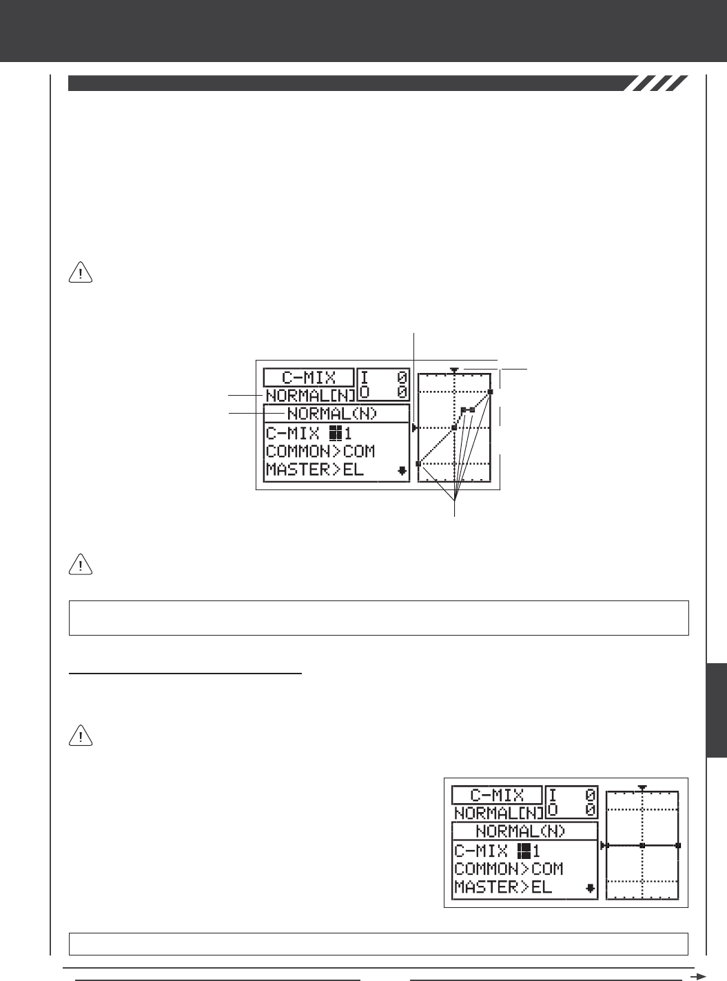
Page 187
In all cases, the Master channel always controls the Slave channel. In the default conguration, all Compensation Mixes
can be programmed to be Linear, or precise channel Curves can be created by programming up to nine Points along
the Curve.
Transmitter F-MODE
Programming F-MODE
Stick Input (I)
Function Output (O)
150%
100%
100%
150%
0%
Point Positions
Transmitter F-MODE refers to the Flight Mode that the transmitter is currently operating in. Programming F-MODE refers
to the Flight Mode that you would like to change the programming for.
The C-Mix function allows you to program custom mixes that can control any number of desired functions in different combinations.
It is used to create your own custom mix if one of the pre-programmed mixes is not suitable.
Like with pre-programmed mixes, Compensation Mixes are composed of a Master channel and a Slave channel. The Master
channel always controls the Slave channel. Any of the available ten channels can be programmed as a Master or a Slave. The
same channel can even be programmed as both a Master and a Slave. The C-Mix function includes nine custom-programmable
Points to ensure an extremely precise channel Curve to suit any situation. You can also program a Delay for the Slave function
that works independently (or with) the dedicated Channel Delay function described on page 172.
Up to ve C-Mix functions can be programmed separately for each of the ve Flight Modes or you can use the same C-Mix
programming across all ve Flight Modes. An Input and Output display, along with a graph, help with programming visualization.
Choosing the Compensation Mixing Number
Up to ve separate Compensation Mixing functions can be programmed for each Flight Mode, however, only one Master/Slave
channel can be assigned to one Compensation Mixing function at a time.
More than one Compensation Mixer can be assigned to the same Switch Position Number, so that they can be Activated at
the same time. For example, assign both C-Mix 1 and C-Mix 2 to Switch Position 5 to Activate both Compensation Mixers
at the same time.
IMPORTANT Each C-Mix function must be assigned to a Switch Position Number before it can be Activated. For more
information, see page 45.
1) Press the Navigation Pad 56 to highlight C-MIX, then press the ENTER
key to display the C-MIX menu. The cursor will default to C-MIX>1.
2) Press the YES/+ and NO/- keys to choose the C-MIX number you would
like to program Compensation Mixing for.
C-MIX setting range is 1, 2, 3, 4, or 5. The default setting is 1.
heli Flight Mode menu
HELI
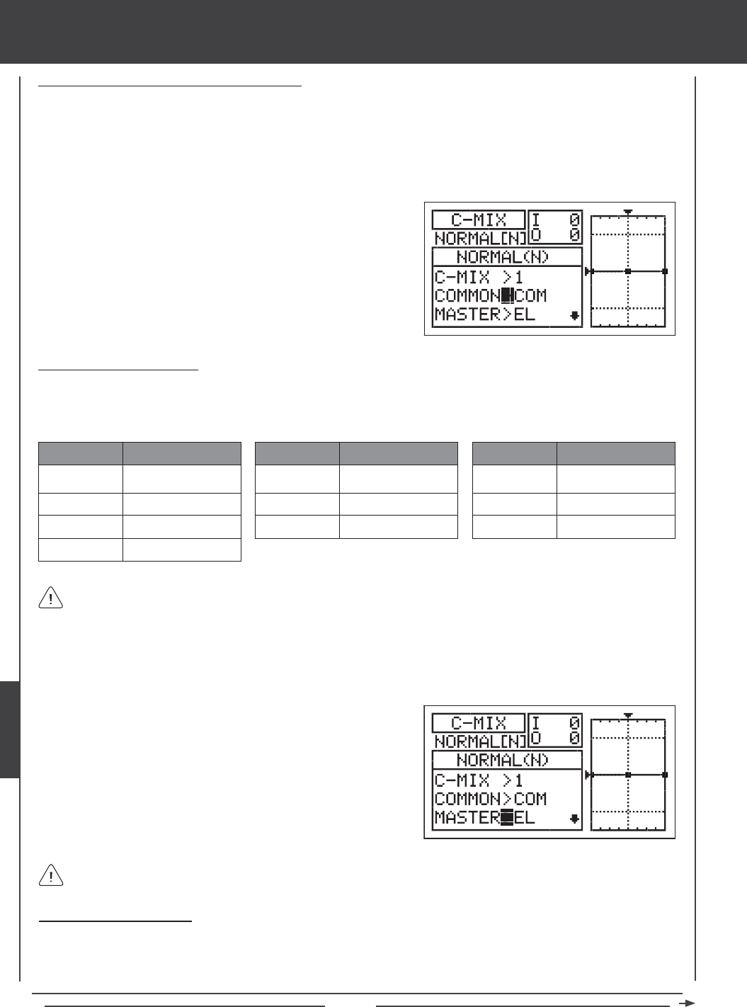
Page 188
Choosing the Flight Mode - Common or Separate
When set to COM (Common), the C-MIX settings will be the same regardless of which Flight Mode the transmitter is operating in.
You cannot program C-MIX settings separately for each Flight Mode. When set to SEP (Separate), you can program different
C-MIX settings separately for each Flight Mode.
1) Press the Navigation Pad 6 to highlight COMMON>COM, then press the YES/+ or NO/- keys to choose either COM or SEP.
If set to COM, skip to the Choosing the Master Channel section. If set to SEP, see step 2 below.
Choosing the Master Channel
The Master channel is the channel that controls the Slave channel. For example, if you set the Master channel to EL (Elevator),
when you move the elevator control stick, the Slave channel that's mixed to the elevator channel will move. Depending on the Model
Type and Swashplate selection options you've chosen in the Model Type menu, the following Master channels are available.
EL / EL+
AI/AI+
TH / TH+
RU / RU+
ABBR. FUNCTION
Elevator
Aileron
Throttle
Rudder
GY / GY+
PI/PI+
GV/GV+
ABBR. FUNCTION
Gyro
Pitch
Governor
AUX3/AUX3+
AUX2 / AUX2+
AUX1 / AUX1+
ABBR. FUNCTION
Auxiliary 3
Auxiliary 2
Auxiliary 1
Master channels denoted with a plus sign (+) indicate that Dual Rate, Exponential, Trim, and/or Channel Delay settings
affect not only the Master channels but also the Slave channels when the Compensation Mixing function is Activated. For
example, if MASTER>EL+ is selected, any programmed elevator Dual Rate or Exponential percentage values will affect both
the Master elevator channel and the Slave channel when the elevator Dual Rate switch is Activated while the Compensation
Mixing function is Active. If you select MASTER>EL, any programmed elevator Dual Rate or Exponential percentage values will
only affect the Master elevator channel when the Compensation Mixing function is Active. Dual Rate and Exponential affect only
the elevator, aileron, and rudder channels. The Channel Delay function referenced is not the same as the Delay function in the
C-MIX menu.
1) Press the Navigation Pad 6 to highlight MASTER>EL, then press the
YES/+ or NO/- keys to choose which channel you want to program the
Master channel for.
If you want Dual Rate, Exponential, Trim, and/or independent Channel Delay control over the Slave channel, make sure
to choose a Master channel with a plus sign (+).
Choosing the Slave Channel
The Slave channel is the channel that is controlled by the Master channel. For example if you set the Master channel to EL
(Elevator) and the Slave channel to AI (Aileron), when you move the elevator control stick, the aileron servo will move. Depending
on the Model Type and Swashplate selection options you've chosen in the Model Type menu, the following Slave channels
are available (shown at the top of the next page).
2) Press the F-MODE key to choose the F-MODE number you would like
to program the Compensation Mixing function for. Choose from N, 1, 2,
3, or 4. The NORMAL (N) display will change, indicating which Flight
Mode you are programming the Compensation Mixing function for.
heli Flight Mode menu
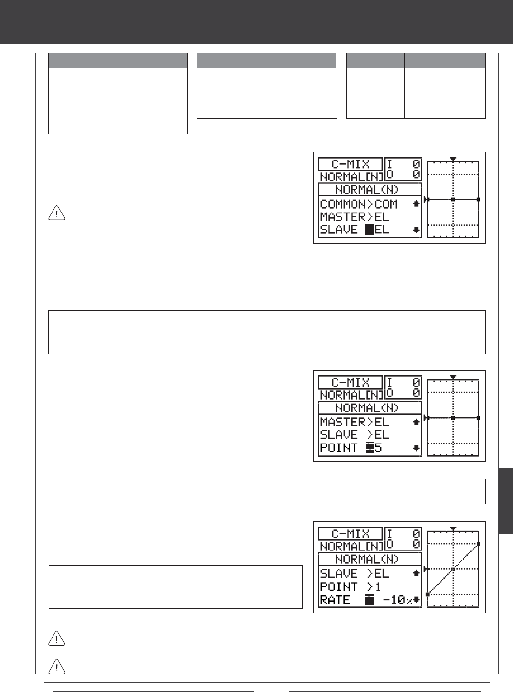
Page 189
1) Press the Navigation Pad 6 to highlight SLAVE>EL, then press the
YES/+ or NO/- keys to choose which channel you want to program the
Slave channel for.
The channel options displayed will vary based on Model Type and
Swashplate selection options currently selected. For example, if your
model features dual elevator servos, EL and EL2 will be separate options.
EL
AI
TH
RU
ABBR. FUNCTION
Elevator
Aileron
Throttle
Rudder (Tail Rotor)
GY
PI
GV
EL2
ABBR. FUNCTION
Gyro
Pitch
Governor
Elevator 2
AUX3
AUX2
AUX1
ABBR. FUNCTION
Auxiliary 3
Auxiliary 2
Auxiliary 1
Changing the Channel Curve Point Values and the Rate Percentage Values
Nine different Points with varying Rates can be programmed onto the channel Curve. Each Point will be displayed on the graph
to give you a visual interpretation of the position of the Point on the channel Curve. The Point that is currently selected will blink.
WARNING When a Compensation Mixer is Activated, you still have separate control over the Slaved channel, however,
depending on the Rate percentage value, the Slave channel End Point Adjustment could be exceeded. We strongly recommend
that you set your Slave channel Limits no higher than that channel's End Point Adjustment unless specically necessary for
your particular setup. This will prevent any chance of overdriving your control linkage when Compensation Mixing is used.
RATE setting range is -150% to 150%. POINT 1 default RATE percentage
value is 0%, POINT 5 default RATE percentage value is 0%, and POINT
9 default RATE percentage value is 0%. POINT 2, 3, 4, 6, 7, and 8 RATE
values are INH (Inhibited).
3) Press the Navigation Pad 6 to highlight RATE>0%.
4) Press the YES/+ or NO/- keys to set the desired Rate percentage value.
1) Press the Navigation Pad 6 to highlight POINT>5.
2) Press the YES/+ or NO/- keys to choose which Point you would like to
set a Rate percentage value for.
POINT setting range is 1 through 9. Point 1 is at the low end of the channel Curve and Point 9 is at the high end of the channel
Curve. Point 5 is a the center of the channel Curve.
As you change the Point and Rate percentage values, you can use the graph and I/O numbers to visualize the ratio
between control stick movement and servo travel throughout the entire deection range.
The Rate percentage value is a ratio of Slave channel servo travel to Master channel servo travel. For example, if the Rate
percentage value is set to 10%, the Slave channel servo will travel 1/10th the amount that the Master channel servo travels.
heli Flight Mode menu
HELI
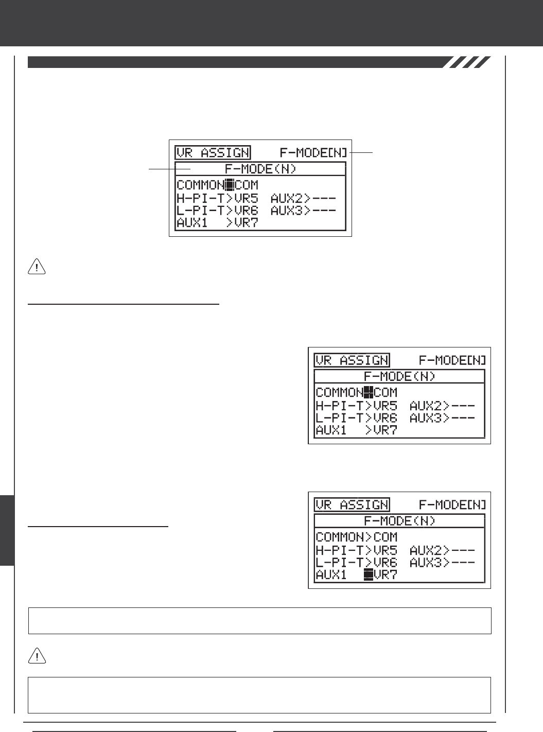
Page 190
The VR Assign function allows you to reassign the High Pitch Trim and the Low Pitch Trim, and/or assign the auxiliary channels
to either of the two Auxiliary Levers (VR5 or VR6) or the Auxiliary Dial Knob (VR7). For example, you could use the Auxiliary
Dial Knob (VR7) to control your glow-powered helicopter's engine throttle mixture remotely. You can choose to program
VR Assignments separately for each of the ve Flight Modes or you can use the same VR Assignments programming across all
ve Flight Modes.
Transmitter F-MODE
Programming F-MODE
Transmitter F-MODE refers to the Flight Mode that the transmitter is currently operating in. Programming F-MODE refers
to the Flight Mode that you would like to change the programming for.
Choosing the Flight Mode - Common or Separate
When set to COM (Common), the VR ASSIGN settings will be the same regardless of which Flight Mode the transmitter is operating
in. You cannot program VR ASSIGN settings separately for each Flight Mode. When set to SEP (Separate), you can program
different VR ASSIGN settings separately for each Flight Mode.
3) Press the F-MODE key to choose the F-MODE number you would like to program the VR Assignments for. Choose from
N, 1, 2, 3, or 4. The NORMAL (N) display will change, indicating which Flight Mode you are programming the VR Assignments for.
1) Press the Navigation Pad 56 to highlight VR ASSIGN, then press the
ENTER key to display the VR ASSIGN menu. The cursor will default to
COMMON>COM.
2) Press the YES/+ or NO/- keys to choose either COM or SEP. If set to
COM, skip to the Choosing Channel VR Assignments section. If set
to SEP, see step 3 below.
IMPORTANT Both sides of each auxiliary channel (High and Low), can be assigned to a Switch Position Number, using the
SW ASSIGN menu. If an auxiliary channel is assigned to both a switch and an Auxiliary Lever or the Auxiliary Dial Knob, the
switch takes precedence over the Auxiliary Lever or the Auxiliary Dial Knob in all cases.
Choosing Channel VR Assignments
1) Press the Navigation Pad 5634 to highlight the channel you would
like to change the VR Assignment for, then press the YES/+ or NO/- keys
to change the VR Assignment.
VR ASSIGN setting range is ---, VR5, VR6, and VR7. The default setting for H-PI-T is VR5. The default setting for L-PI-T is VR6,
and the default setting for AUX1 is VR7. The default settings for MOTOR, AUX2 and AUX3 is ---.
To disable an Auxiliary Lever or the Auxiliary Dial Knob, assign --- to the desired channel. For example, if you don't want
Auxiliary Lever (VR6) to control Low Pitch Trim, change L-PI-T>VR6 to L-PI-T>---.
heli Flight Mode menu
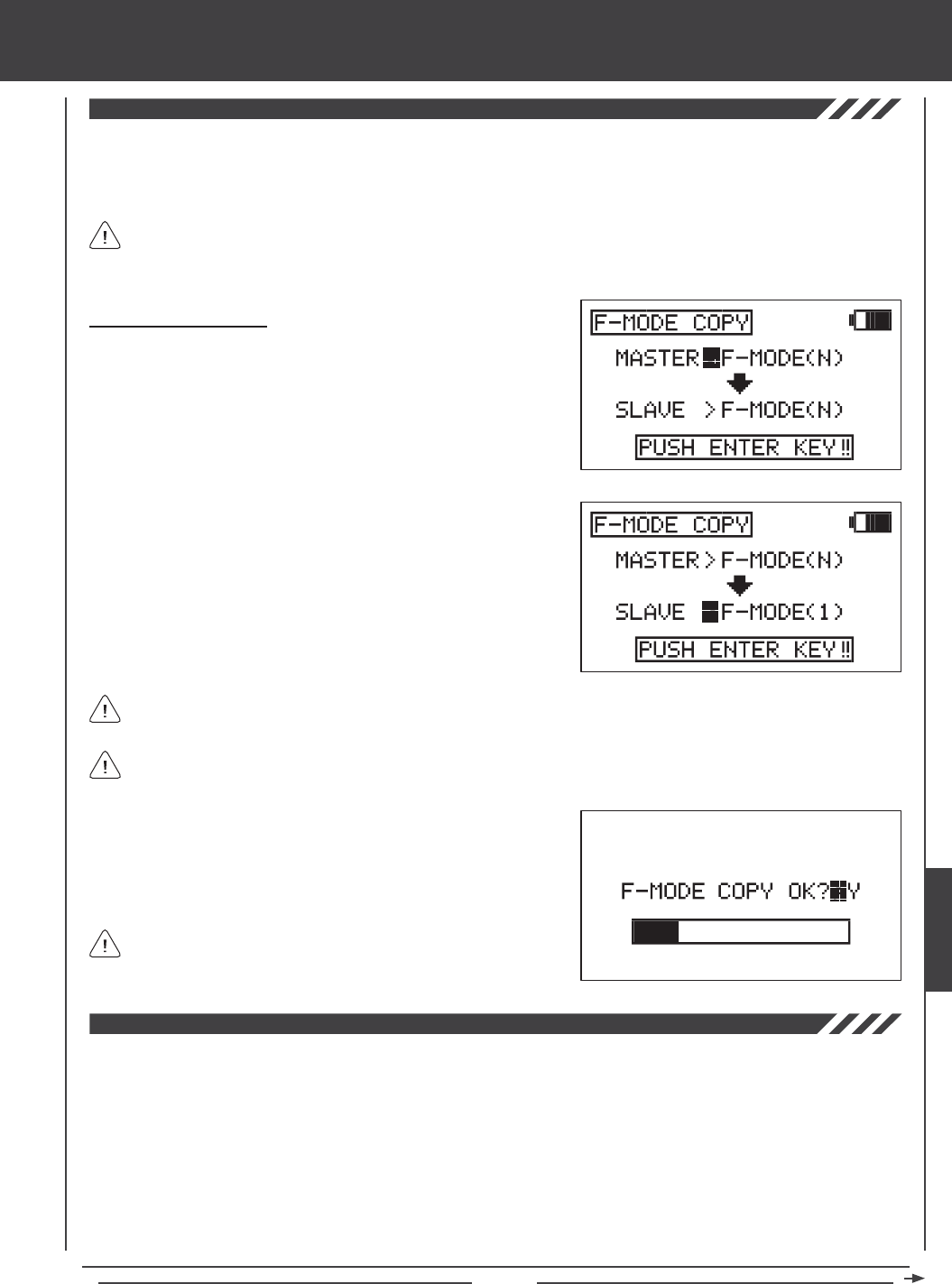
Page 191
The Flight Mode Copy function allows you to copy the Flight Mode programming data from one Flight Mode to another Flight
Mode. This is convenient if you want to use two or more different Flight Modes on one model, but only need to change a few
Flight Mode programming values for the new Flight Mode. This allows you to use the Flight Mode programming data from the
rst Flight Mode to use as a base to start ne-tuning the programming for the second Flight Mode.
You can only copy Flight Mode programming data from one Flight Mode to another Flight Mode within the same model.
To copy Flight Mode programming data from one model's Flight Mode to another model's Flight Mode, you must copy
the actual model programming data to the other model. For more information, see page 52.
Copying Flight Mode Data
1) Press the Navigation Pad 56 to highlight F-MODE COPY, then press
the ENTER key to display the F-MODE COPY menu. The cursor
will default to MASTER>F-MODE(N).
2) Press the F-MODE key to select the Flight Mode you would like to copy
the Flight Mode programming data FROM (MASTER). Select from
F-MODE (N, 1, 2, 3, or 4).
3) Press the Navigation Pad 6 to highlight SLAVE>F-MODE(N).
4) Press the F-MODE key to select the Flight Mode you would like to
copy the Flight Mode programming data TO (SLAVE). Select from
F-MODE (N, 1, 2, 3, 4, or ALL).
5) Press then ENTER key. F-MODE COPY OK?>Y will be displayed.
6) Press the YES/+ key to begin the F-MODE Copy process. When the
F-MODE Copy process is completed the F-MODE COPY menu will be
displayed, indicating that the Flight Mode programming data has been
copied.
It's not possible to copy the Flight Mode programming data from one Flight Mode to the same Flight Mode. If you attempt
to execute this, SAME F-MODE?? will be displayed and the process will not execute.
If you want to go back and change the Flight Mode or you don't want
to copy the Flight Mode programming data for any reason, press the
NO/- or END keys.
Selecting ALL will copy the MASTER Flight Mode programming data to the remaining four Flight Modes.
The Flight Mode Delay function allows you to program custom delays for each of the channel functions within each of the
separate Flight Modes. This function helps to prevent drastic changes in channel settings when switching between Flight Modes.
For example, if you are ying an aerobatic helicopter, you might have one Flight Mode set up for aerobatic ying and a second
Flight Mode set up for general sport ying. Within each of those two Flight Modes you might have programmed different Throttle
Curves. The Flight Mode Delay function allows you to program a Delay in the Throttle channel so that the transition to the different
Throttle Curves when you switch back and forth between Flight Modes is smooth.
If you program Flight Mode Delays for all ve Flight Modes separately, you can program up to 10 different Delays for each Flight
Mode. If you are using fewer Flight Modes, you can program more than 10 different Delays for each of the Flight Modes that you're
using. You are able to program 50 different Delays in total. The Flight Mode Delay function can be programmed for each of the
channels you're using, and separate Flight Mode Delays can be programmed in both directions. For example, when switching from
Flight Mode N (Normal) to Flight Mode 1 and back from Flight Mode 1 to Flight Mode N (Normal).
heli Flight Mode menu
HELI
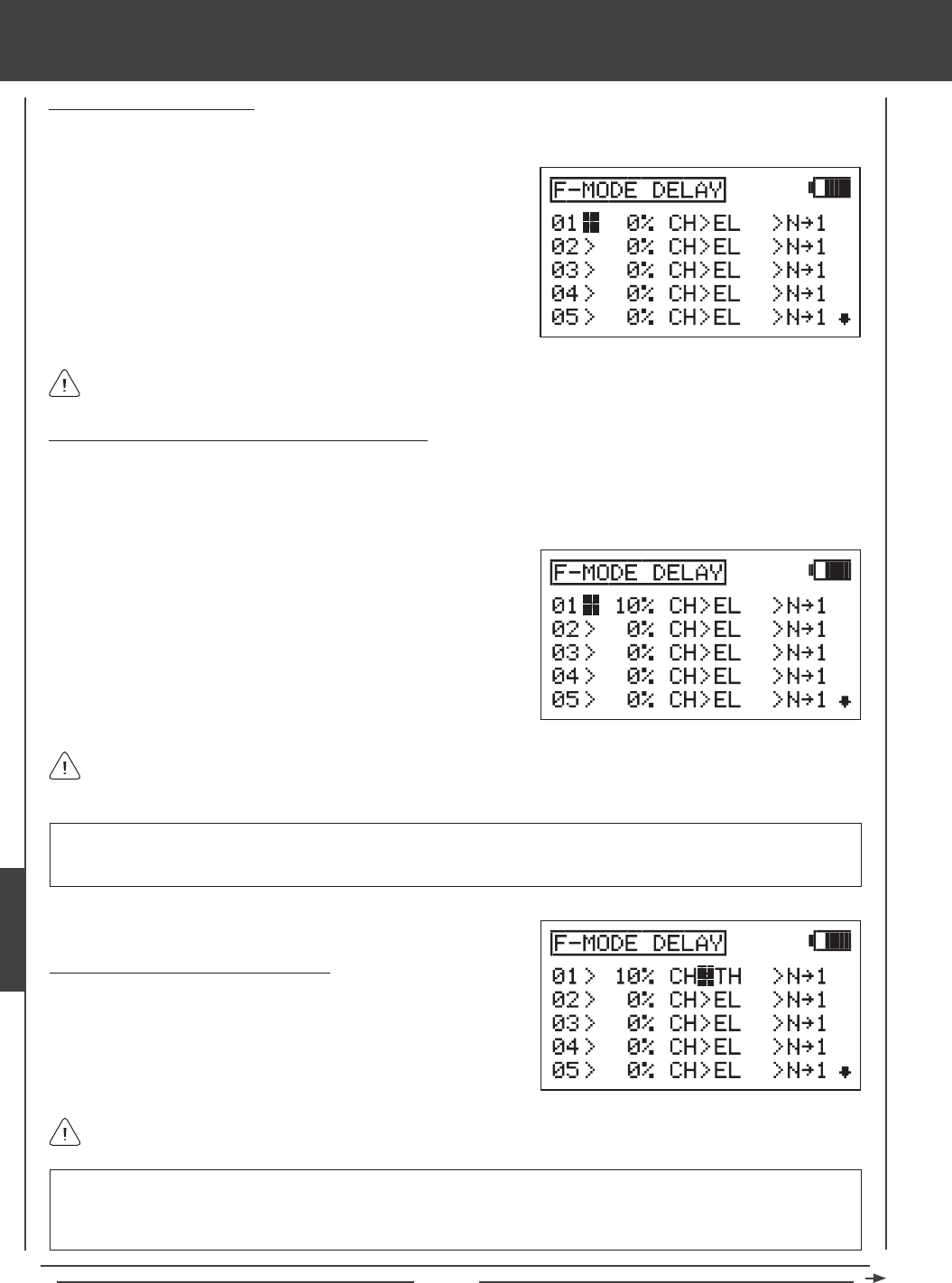
Page 192
Choosing a Flight Mode Delay
1) Press the Navigation Pad 56 to highlight F-MODE DELAY, then press the ENTER key to display the F-MODE DELAY
menu. The cursor will default to 01>0% CH>EL >N41.
Flight Mode Delays do not have to programmed in sequence (e.g., 01, 02, 03), but programming them in sequence does
make it easier to keep track of them.
2) Press the Navigation Pad 56 to highlight the Flight Mode Delay you
would like to program. If this is the rst Flight Mode Delay that you're
programming, choose 01>0%
Changing the Flight Mode Delay Rate Percentage Value
The Rate percentage value changes the speed of the servos as they move to their new positions when you switch between Flight
Modes. For example, if you're ying at half throttle in Flight Mode N (Normal) and your throttle servo is at 50% travel, but in Flight
Mode 1 at half throttle your throttle servo is programmed to be at 70% travel, increasing the Rate percentage value will slow the
speed at which the servo will move to 70% travel when you Activate Flight Mode 1. This allows the throttle to smoothly rise to the
new travel position instead of instantly jumping to the new travel position.
RATE setting range is 0% to 100%. The default setting is 0%. When the Rate percentage value is set to 0%, there is no Delay
when switching between Flight Modes. When the Rate percentage value is increased, the Delay when switching between
Flight Modes is increased.
The Rate percentage value is displayed as a percentage of Delay time and is based on the amount of change in servo
travel when switching between different Flight Modes. When the Rate percentage value is set to 100%, the servo will take
approximately 15 seconds to travel from neutral to 100% or -100%.
1) Press the YES/+ and NO/- keys to change the Rate percentage value
for the selected Flight Mode Delay.
IMPORTANT Channels that use two servos, such as Swashplate Types that use two elevator servos will be displayed
separately (e.g., EL and EL2). In this situation, the Flight Mode Delay function will affect not the whole channel, but the
individual servo. In most cases, you will want to program a second matching Flight Mode Delay for the second servo, so that
both servos are affected equally.
Choosing the Flight Mode Delay Channel
1) Press the Navigation Pad 4 to highlight CH>EL.
2) Press the YES/+ and NO/- keys to choose which channel you would
like the Flight Mode Delay to affect.
The channels options displayed will vary based on Model Type and Swashplate selection options currently selected. For
example, if your model features two elevator servos, EL or EL2 will be display as an option.
heli Flight Mode menu
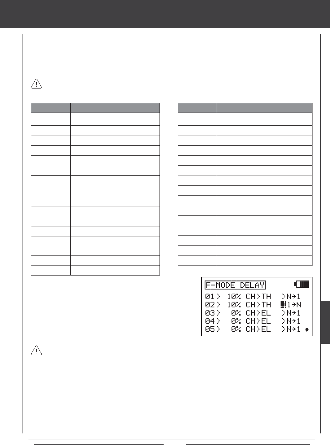
Page 193
Changing the Flight Mode Delay Sequence
The Flight Mode Delay sequence denes the direction you want the Flight Mode Delay going TO and FROM, as shown in the
tables below. For example, if you choose N41, the Flight Mode Delay function will Activate when you switch from Flight Mode N
(Normal) to Flight Mode 1. If you choose N44, the Flight Mode Delay function will Activate when you switch from Flight Mode N
(Normal) to Flight Mode 4. If you choose 44N, the Flight Mode Delay function will Activate when you switch from Flight Mode
4 to Flight Mode N (Normal).
341
342
344
34*
44N
441
442
443
44*
*4N
*41
*42
*43
*44
*4*
FROM Flight Mode 3 to Flight Mode 1
FROM Flight Mode 3 to Flight Mode 2
Flight Mode 3 TO Flight Mode 4
Flight Mode 3 TO All Flight Modes
FROM Flight Mode 4 to Flight Mode N
FROM Flight Mode 4 to Flight Mode 1
FROM Flight Mode 4 to Flight Mode 2
FROM Flight Mode 4 to Flight Mode 3
Flight Mode 4 TO All Flight Modes
FROM All Flight Modes to Flight Mode N
FROM All Flight Modes to Flight Mode 1
FROM All Flight Modes to Flight Mode 2
FROM All Flight Modes to Flight Mode 3
FROM All Flight Modes to Flight Mode 4
FROM All Flight Modes TO All Flight Modes
SEQUENCE DESCRIPTION
N41
N42
N43
N44
N4*
14N
142
143
144
14*
24N
241
243
244
24*
34N
Flight Mode N TO Flight Mode 1
Flight Mode N TO Flight Mode 2
Flight Mode N TO Flight Mode 3
Flight Mode N TO Flight Mode 4
Flight Mode N TO All Flight Modes
FROM Flight Mode 1 to Flight Mode N
Flight Mode 1 TO Flight Mode 2
Flight Mode 1 TO Flight Mode 3
Flight Mode 1 TO Flight Mode 4
Flight Mode 1 TO All Flight Modes
FROM Flight Mode 2 to Flight Mode N
FROM Flight Mode 2 to Flight Mode 1
Flight Mode 2 TO Flight Mode 3
Flight Mode 2 TO Flight Mode 4
Flight Mode 2 TO All Flight Modes
FROM Flight Mode 3 to Flight Mode N
SEQUENCE DESCRIPTION
Delay sequences that include an Asterisk indicate that the Flight Mode Delay function will be Activated across all Flight
Modes. For example, if you choose N4*, the Flight Mode Delay function will Activate on all Flight Modes regardless of
the Flight Mode you switch to.
1) Press the Navigation Pad 4 to highlight N41.
2) Press the YES/+ and NO/- keys to choose which Flight Mode Delay
sequence you would like to use.
Use the tables of Delay sequences above to help you choose which Flight Mode Delay sequence you would like to use.
3) Repeat the previous procedures to program more Flight Mode Delay functions. For example, if you want to set a Flight Mode
Delay for the throttle channel when you switch from Flight Mode N (Normal) to Flight Mode 1, and from when you switch back
from Flight Mode 1 to Flight Mode N (Normal), program the following:
01>10% CH>TH >N41
02>10% CH>TH >14N
This programming will result in a 10% delay in the throttle channel when you switch from Flight Mode N (Normal) to Flight
Mode 1 and when you switch back from Flight Mode 1 to Flight Mode N (Normal). This will not Activate the Flight Mode Delay
when you switch to any other Flight Mode. For example, when you switch from Flight Mode N (Normal) to Flight Mode 2.
heli Flight Mode menu
HELI
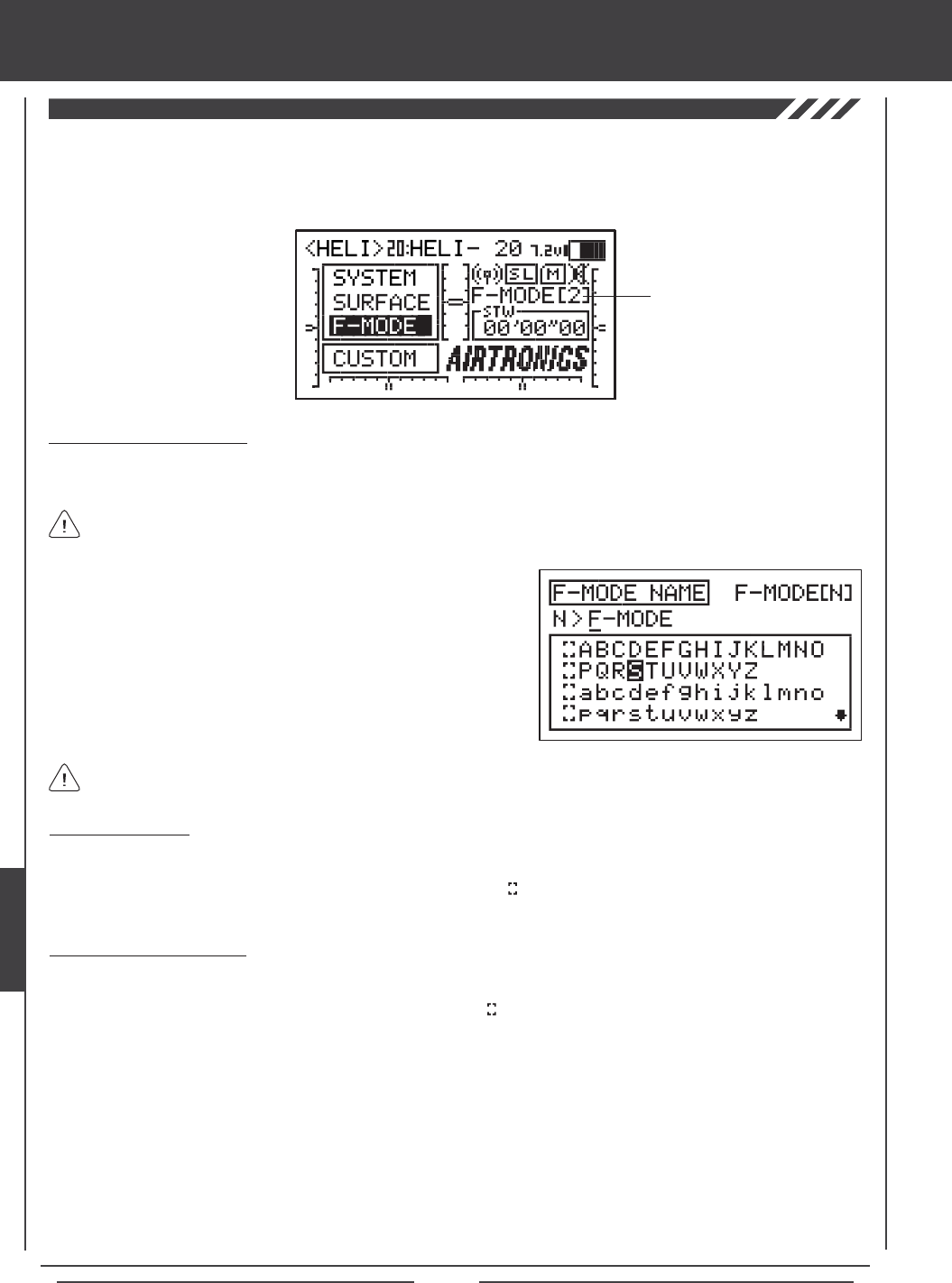
Page 194
The F-Mode Name function allows you to name each of your individual F-Modes. This makes it easier to keep track of which
F-Mode is currently in use. The currently Active Flight Mode name is displayed, along with the corresponding Flight Mode number
on the Top menu and on the various F-MODE programming menus. The F-Mode Name can consist of up to 6 letters, numbers,
or symbols. Choose from capital letters, lower case letters, numbers, and various symbols.
Entering a Flight Mode Name
1) Press the Navigation Pad 56 to highlight F-MODE NAME, then press the ENTER key to display the F-MODE NAME menu.
The cursor will default to the left side of the top row of letters.
Press the F-MODE key to cycle through the ve different F-Modes. The F-Mode that you are currently naming is shown to
the left of the Flight Mode Name. For example, N>F-MODE.
2) Press the Navigation Pad 3456 to highlight a character, then press
the ENTER key to select the highlighted character. That character will be
displayed and the underline will move to the next space.
3) Repeat step 2 to enter the rest of the characters. Up to six characters
can be entered.
Press the Navigation Pad 56 repeatedly to scroll up and down the list of characters.
Flight Mode Name
and Number
Deleting a Character
1) Press the YES/+ or NO/- keys to move the underline under the character you want to erase.
2) Press the Navigation Pad 3456 to highlight the Erase Bracket , then press the ENTER key to erase the underlined
character.
Deleting a Flight Mode Name
1) Press the YES/+ and NO/- keys at the same time to move the underline under the rst character.
2) Press the Navigation Pad 3456 to highlight the Erase Bracket , then press the ENTER key repeatedly to erase the entire
Flight Mode Name.
THIS SPACE INTENTIONALLY LEFT BLANK
heli Flight Mode menu
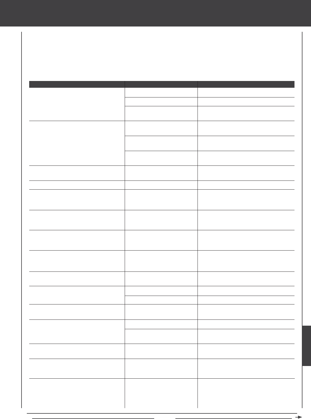
Page 195
Transmitter does not turn ON
Transmitter will not bind to receiver
F-MODE NOT 'N'!! message displayed
Alarm beeps continuously
TH-STICK Hi!! message displayed along with
continuous beeping
POWER SWITCH ON!! message displayed
along with continuous beeping
TRAINER MODE MASTER!! message
displayed along with continuous beeping
TRAINER MODE SLAVE!! message displayed
along with continuous beeping
Transmitter operating time seems low
Servo movement is slow
Control sticks don't display 100% movement
in Stick Monitor menu
LCD display difcult to read
Desired function cannot be controlled
Throttle servo cycles up and down
In Heli Flight Mode, high and low pitch End
Points out of adjustment
Battery not fully charged
Battery not plugged in
Damage caused by using incorrect
charger or reverse polarity
Modulation incorrect
Too much time elapsed after
pressing Bind Button
Attempting to bind incompatible
receiver
Transmitter not in Flight Mode N
when turned ON
Low battery voltage
Throttle control stick not in its
lowest position when transmitter
is turned ON
Transmitter left ON more than
15 minutes without control stick
movement
Transmitter in Trainer>Master
mode when turned ON
Transmitter in Trainer>Slave
mode when turned ON
Transmitter battery is new
Receiver battery low
Channel Delay function Active
Control sticks require calibration
LCD display contrast set too low
Reading LCD display in direct
sunlight
Function(s) not assigned to a switch
position number (or numbers)
Receiver battery voltage has
reached the programmed Battery
Fail Safe voltage level
High and low pitch End Points
controlled by Auxiliary Levers
(VR6 and VR7)
Fully charge battery
Plug in battery. Observe correct polarity
Contact Airtronics Customer Service
Ensure FH3/FH1 modulation selection matches
the type of receiver you're using
Quickly press the YES/+ key after releasing
the Bind Button
Transmitter is compatible only with Airtronics
brand 2.4GHz FHSS-3 and FHSS-1 receivers
Adjust Flight Mode switches to turn ON Flight
Mode 1 as displayed on the Top menu
Fully charge battery
Pull throttle control stick all the way back to its
lowest position
Turn transmitter OFF or press any programming
key to continue use.
Press any key to use transmitter in
Trainer>Master mode or Inhibit the Trainer
function to use transmitter normally
Press any key to use transmitter in
Trainer>Slave mode or Inhibit the Trainer
function to use transmitter normally
Transmitter battery must be cycled 3-5 times
before it will achieve maximum capacity
Fully charge receiver battery
Inhibit Channel Delay function
Calibrate control sticks using Stick Monitor
Calibration function
Increase LCD display contrast
Increase LCD display contrast or orient
transmitter out of direct sunlight
Assign the desired function(s) to a switch
position number (or numbers)
Fully charge receiver battery. If ying, land
immediately
Center Auxiliary Levers (VR6 and VR7). In
addition, Auxiliary Levers (VR6 and VR7) can
be disabled to avoid confusion, although you
lose the ability to remotely change Pitch Curve
End Points during ight
TROUBLESHOOTING GUIDE
This troubleshooting guide has been provided to help you diagnose and solve most problems that you may encounter with your
SD-10G 2.4GHz FHSS-3 radio control system. Most problems encountered can be solved by following the problem-cause-solution
sections. If you cannot solve the problem using this troubleshooting guide, please contact us directly using the information on the
back page of this Operating Manual.
PROBLEM CAUSE SOLUTION
HELP
Page 196
TROUBLESHOOTING GUIDE
Inadequate transmitting range
Servo will not move to the end of its range
Safety Link system not functioning
Cannot copy programming data
Cannot copy Flight Mode programming data
Custom menu display empty
PACK NOT READY!! message displayed
when Initializing Memory Expansion Card
Cannot change Surface menu Adjustment
Values
Control linkages bind when using the available
pre-programmed mixes or a C-Mix
Servo moves too much, or doesn't move
enough, when trim switch is moved
Drastic control changes when switching
between Flight Modes
One or more mixes do not function
Control surface trim changes when switching
between Flight Modes
Transmitter/receiver range check fails
Camber trim changes when you change
camber percentage value
Battery not fully charged
Receiver antennas not mounted
correctly in your model
Transmitter in Low Power mode
Transmitter operating in
Trainer>Slave mode
Servo Limit Adjustment Value
set too low
Safety Link number does not
match Model Memory number
Using FHSS-1 receiver
Attempting to copy programming
data to the same model memory
number
Attempting to copy Flight Mode
programming data to the same
Flight Mode number
No shortcuts added to Custom
menu
Memory Expansion Card not
installed
Adjustment Options Lock is
engaged
Mixes can cause servos to move
beyond the programmed EPA
Adjustment Values
Trim Step resolution requires
adjustment to suit your preference
Flight Mode Delay function not
utilized
Mixes not assigned to switch
Trim set to SEP in Trim Flight
Mode menu
Low transmitter and/or receiver
batteries
Receiver antennas not mounted
correctly in your model
Aircraft sitting in tall grass
(usually sailplanes only)
Camber Point is incorrect
Fully charge battery
Mount receiver antennas as recommended
Inhibit Low Power mode to operate in Normal
mode
Inhibit the Trainer function to use transmitter
normally
Adjust servo Limit Adjustment Value in the
surface menu
Change Safety Link number to match Model
Memory number of current model
Use FHSS-3 receiver. Safety Link is compatible
only with FHSS-3 receivers.
Copy programming data to a different model
memory number
Copy Flight Mode programming data to a
different Flight Mode number
Add shortcuts to your favorite menus by
highlighting the desired menu, then pressing
the YES/+ key
Install Memory Expansion Card and make sure
it's fully seated into position
Inhibit Adjustment Options Lock
Use the Limits function in the Surface menu to
set the maximum allowable travel of your servo
Adjust Trim Step resolution to suit your
preference
Program Flight Mode Delays to smooth the
transition of servo movement when switching
between Flight Modes
Assign mixes to a switch (or switches).
Set Trim to COM in Trim Flight Mode menu
Fully charge transmitter and receiver batteries
Mount receiver antennas as described
Lift model out of grass for range check
With the Camber Preset percentage value set
to 0%, Auxiliary Lever (VR6) must be centered.
With the percentage value set to 100%, the
bottom of Auxiliary Lever (VR6) must be
pushed all the way forward. With the percentage
value set to -100%, the bottom of Auxiliary
Lever (VR6) must be pulled all the way back
PROBLEM CAUSE SOLUTION

Page 197
glossary of terms
Activate: To turn ON a particular function.
Ailvator: Ailvator mixes ailerons and elevator, allowing you to have both roll control and pitch control on the elevator, separate
from the ailerons. When Activated, not only will the two elevator halves move up and down together, but each elevator half can
move up and down independently like ailerons. This function is commonly referred to as tailerons or stabilators.
Antenna: Transmits the signal from the transmitter to the receiver in the model. The Antenna should be extended and pivoted
into the vertical position during use. When not in use, the Antenna should be retracted and collapsed into the horizontal position
to prevent damage during handling and transport.
Antenna Reception Wires: The portion of each of the receiver antenna wires that actually receives the transmitter signal. The
Antenna Reception Wires should never be bent or they could be damaged and limit the range of the receiver.
Auxiliary Dial Knob: The Auxiliary Dial Knob is programmable and will perform a different function depending on what function
is assigned to it.
Auxiliary Lever: Two Auxiliary Levers are featured, one on each side of the transmitter. Each
Auxiliary Lever is programmable and will perform a different function depending on what function is assigned to it.
Battery Compartment: Houses the 6 cell 1500mAH Ni-MH battery that powers the transmitter. The transmitter uses a 6 cell
battery for lighter weight and better feel, while still providing long usage time.
Battery Fail Safe: The Battery Fail Safe function allows you to set a custom receiver voltage, that when reached, will provide
feedback to you by quickly cycling the throttle servo up and down in 1 minute intervals to indicate that the receiver battery has
reached the programmed Battery Fail Safe voltage. This feedback will help prevent you from ying too long and losing receiver
battery power.
Binding: The act of pairing the transmitter and receiver to prevent interference from radio controllers operated by other users.
The transmitter and receiver must be paired so that the two can 'talk' to each other. Once the Binding process is complete, the
setting is remembered even when the transmitter and receiver are turned OFF.
Camber: Camber is typically used on sailplanes and refers to the function of lowering the entire trailing edge of the wing to
change airfoil of the wing, and therefore, the ight characteristics of your aircraft. Camber is typically used during launch to
maximize lift.
Camber Point: The Camber Point function allows you to dene how Auxiliary Lever (VR6) controls Camber. Based on the
Camber Point setting, you can control both Camber and Reex, or you can control only Camber or Reex. When programmed to
control only Camber or Reex, the amount of servo travel will be doubled. This is useful for those pilots who want more overall
travel, but in only one direction.
CCPM: Collective, Cyclic, Pitch Mixing. CCPM is software-controlled mixing that allows control of the collective, cyclic and pitch
using three (and sometimes four) servos. This allows lower mechanical complexity and greater control precision. In this
conguration the cyclic and collective controls are mixed. 3-Point and 4-Point mixes are featured.
CCPM Servo End Point Adjustment: The CCPM End Point Adjustment function allows you to adjust servo travel in each direction
for the elevator, aileron, and pitch servos independently. Unlike standard End Point Adjustment, which affects all the cyclic servos,
CCPM End Point Adjustment allows you to adjust each cyclic servo independently without any affect on the other cyclic servos.
CCPM Servo Linear: The CCPM Servo Linear function converts the rotary output of the servo(s) to a Linear approximation and
helps correct any abnormal cyclic movement caused by off-center control arms when at full positive or negative End Points and
allows you to adjust the overall Rates for the elevator, aileron, and pitch servos independently.
CCPM Servo Delay: The CCPM Servo Delay function allows you to adjust the speed of the elevator, aileron, and pitch servos
independently. Even though the servos may be of the same type, not all servos operate at the same exact speed. If one or more
servos controlling the swashplate is operating faster than another servo, this can cause swashplate geometry issues and even
result in binding of the swashplate linkage assemblies. Slowing down the faster servo(s) to match the slower servo(s) helps to
ne-tune the swashplate, ensuring the most accurate and smoothest movement as possible throughout the entire deection range.
Channel Delay: The Channel Delay function allows you to adjust the speed of individual servos. This function has several uses.
For example, not all servos operate at the same exact speed. If your model uses separate aileron and ap servos, you may nd
that even though the servos are the same, one servo may move faster than the other. You can use the Channel Delay function
to slow down the faster servo to match the slower servo. The Channel Delay function can also be used to slow down a servo
that controls a specic function to achieve a more scale transit time, for example, to open and close a canopy on a scale aircraft.
The Channel Delay function operates independently of the CCPM Servo Delay and CP3 Servo Delay functions in HELI mode.
Channel Offset: The Offset function allows you to shift and hold the neutral position of the desired elevator, aileron, and rudder
servo(s) during ight.
REFERENCE

Page 198
glossary of terms
Charging Jack: Used for onboard charging of the 6 cell 1500mAH Ni-MH battery.
Channel Curve Programming: Programming the Point and Rate percentage values on a Curve allows you to achieve maximum
exibility and ne-tuning for specic uses by changing the amount of servo travel in relation to control stick travel at any point (or
points) along the Curve.
Coaxial Cables: The portion of each antenna wire that extends the Antenna Reception Wires. The Coaxial Cables can be bent
into gentle curves, however, do not bend the Coaxial Cables acutely, or repeatedly bend them, or the antenna wire's cores can
be damaged.
Compensation Mixing: Allows you to mix two channels together, then apply that mixing to the channels themselves. Useful if
you need to program a mix that is not already pre-programmed.
CP3 Channel Delay: The CP3 Delay function allows you to slow down the two forward channels when using CCPM. On some
helicopters, when using CCPM you will nd that the elevator is a little more sensitive than the ailerons. You can use the CP3
Delay function to slow down the two forward channels to ne-tune the feel of the swashplate controls. The goal is to adjust
elevator control to feel the same as aileron control and vice-versa depending on the Swashplate Type selected.
Cross-Trim: The Cross-Trim function allows you to electronically swap trim switch functions. Some pilots prefer this over the
standard arrangement in which the trim switches adjacent to the control sticks control the trim for that control function.
Crow: The Crow function allows you to use the ailerons and the aps simultaneously to control the lift of the aircraft, while still
allowing aileron roll control. Crow is typically used to quickly reduce lift, ensuring pin-point spot landings in nearly any situation.
When the Crow function is Activated, all of the ailerons should move Up and all of the aps should move Down.
Custom Menu: The Custom menu function allows you to store shortcuts to your most-used System menu and F-Mode menu
selections. You can store up to 10 menu shortcuts. If desired, the Top Menu Arrange function can then be used to create a
shortcut to the Custom menu, providing you with a quick and easy way to access your most-used menu functions without the
need to scroll through the SYSTEM or F-MODE menus to access them.
Differential: The Differential function allows you change the ratio of the Up to Down movement of each aileron. The Aileron
Differential function can be used to eliminate aircraft yaw tendency by adding more movement to the upward moving aileron than
the downward moving aileron.
DIN Connector: The DIN Connector is where the trainer cable (available separately) is plugged into. It is also used to plug the
Airtronics USB data cable (available separately) between the transmitter and your computer. An adapter to use the transmitter
with a ight simulator can also be plugged into the DIN Connector.
Direct Model Select: Direct Model Select allows you to select one of three of your most-used models from memory without going
through the Model Select menu.
Display Key: Activates the transmitter's LCD Display without actually turning the transmitter ON. This allows you to check
and/or change programming settings without actually turning the transmitter ON.
Dual Rate: The Dual Rate function allows you to change the control authority of the control surfaces by changing the amount of
servo travel. You can use Dual Rate to lower the control throw with just the ip of the Dual Rate switch. Three Dual Rate settings
are available each for the Elevator, Aileron, and Rudder channels.
Elevons: Elevons combine the use of aileron and elevator from two separate control surfaces to provide both roll and pitch
control. Elevons are generally found on delta wing (ying wing) aircraft which do not feature separate horizontal stabilizer.
End Point Adjustment: The End Point Adjustment function allows you to adjust servo travel in each direction. This makes it
possible to balance control surface throw in both directions. For example, if you want your elevator to move Up and Down two
inches in each direction, but the elevator moves Down more than two inches, decrease the End Point Adjustment in the Down
direction, so that the elevator moves Up and Down the same amount.
Exponential: The Exponential function allows you to vary the amount of servo travel in relation to the movement of the
elevator, aileron, and rudder control sticks near the neutral positions to change the way the control surfaces react to control stick
movement. Increasing the Exponential value will soften the control feel around neutral and decreasing the Exponential value will
heighten the control feel around neutral.
Fail Safe: The Fail Safe function automatically sets the servos to a predetermined position in the event that the signal between
the transmitter and the receiver is interrupted, whether due to signal degradation or to a low transmitter battery. The Fail Safe
function can be set to Hold the servos in the last position they were in when the signal was lost, or each of the servos can be set
to move to a custom position when the signal is lost.
FH1 Modulation: Frequency Hopping 1st generation FHSS technology. The SD-10G 2.4GHz FHSS-3 transmitter modulation
can be changed to FH1 to allow you to use Airtronics 2.4GHz FHSS-1 aircraft receivers. This allows you to use your transmitter
with nearly any type of aircraft you might want.

Page 199
glossary of terms
FH3 Modulation: Frequency Hopping 3rd generation FHSS technology. FH3 Modulation is used in the Airtronics SD-10G
2.4GHz FHSS-3 transmitter and matching 92104 10-Channel receiver.
FHSS: Frequency Hopping Spread Spectrum. FHSS is a modulation type which transmits data across the entire frequency
spectrum by transmitting data on different channels at an extremely fast interval.
Flap Freeze Point: Used with sailplanes, the Flap Freeze Point function allows you to set a predetermined amount of ap
deection, based on ap control stick position, then variably control the remainder of ap travel, using the ap control stick. An
audible tone can be programmed to indicate when the Flap Freeze Point turns ON and OFF.
Flaperons: Flaperons is a mix of aps and ailerons, allowing you to use the ailerons as aps if your model does not feature
separate aps. When Activated, both ailerons are moved down at the same time to provide the function of aps, while still providing
aileron roll control.
Flight Modes: Flight Modes allow you to change the ying characteristics of your model with the ip of a switch. Each Model
Type (AERO, GLID, and HELI) feature ve independently programmable Flight Modes. Within these Flight Modes is where the
core of the model programming takes place. Features such as Dual Rate, Exponential, Throttle Curves, Pitch Curves, Mixing,
Compensation Mixing, and much more can be individually programmed to each of the ve ight Modes. Each Flight Mode can
then be assigned to a switch position so that they can be turned ON and OFF during ight. For example, you can have one Flight
Mode for basic ying and a second Flight Mode for aerobatic ying. Flip the Flight Mode switch from 'Basic' to 'Aerobatic' and
your model is now programmed with all of your 'Aerobatic' Flight Mode programming.
Flight Mode Key: Allows you to cycle through the ve different Flight Modes while in the Flight Mode Programming menu.
Governor: A Governor is an electronic device used on glow-powered helicopters, that, coupled with a high-speed servo, is used
to control a helicopter's rotor head speed.
Gyro: A Gyro is an electronic device, that coupled with a high-speed servo linked to the tail rotor control arm, is used to stabilize
a helicopter's yaw axis.
Hovering Throttle: The Hovering Throttle function allows you to adjust specic Throttle Curve Points to ne-tune the Throttle
Curve at any throttle control stick position, not just the hovering position. The Hovering Throttle function is controlled by the
Hovering Throttle Trim Switch (T5).
Hovering Pitch: The Hovering Pitch function allows you to adjust specic Pitch Curve Points to ne-tune the Pitch Curve at any
throttle control stick position, not just the hovering position. The Hovering Pitch function is controlled by the Hovering Pitch Trim
Switch (T6).
Inhibit: To deactivate or turn OFF a particular function.
Integral Timer: The Integral timer is a Count Up timer that displays the time that the SD-10G transmitter has been turned ON
(either via the Power switch or the Display key) since the last time the Integral timer was Reset. The Integral timer is not
model-specic, so, for example, it is good to use as an indicator to chart the usage time between battery charges.
Idle Down: The Idle Down function allows you to set a specic position that the throttle servo will move to. The Idle Down
function is similar to the Throttle Cut function, however, whereas the Throttle Cut function is designed to be used to shut down
your engine, the Idle Down function is designed to be used to set your engine to a specic idle speed that is different from the idle
speed provided when the throttle control stick is pulled all the way back, yet still maintain the full range of throttle travel.
LCD Display: Liquid Crystal Display. The LCD Display displays all of the transmitter programming and related information.
The LCD Display contrast can be customized.
Linear Channel Programming: Allows you to program servo travel directly in relation with the amount of control stick travel for
the entire range of deection.
Low Power Mode: The Low Power Mode function lowers the transmitter's RF output level to check radio signal reception (Range
Check). Use this function to check radio signal reception on the ground, prior to ight. The radio control system should be Range
Checked prior to the day's rst ight and prior to the rst ight after a hard landing or after a repair. This will ensure that the
transmitter and receiver are communicating properly prior to ight.
Memory Expansion Card: The Memory Expansion Card allows you to store up to 40 models (20 in the SD-10G transmitter
and 20 on the Memory Expansion Card). The Memory Expansion Card can be removed and installed into a different SD-10G
transmitter, so that model-specic programming data can be shared with fellow SD-10G transmitter owners in the eld. When
the Memory Expansion Card is installed and Initialized, it is treated as an extension of the SD-10G transmitter's internal model
memory, therefore, model-specic programming data can be created, copied, deleted, etc., directly through the various System
menu selections.
Memory Expansion Card Slot: Holds the Memory Expansion Card (available separately).
REFERENCE

Page 200
glossary of terms
Model Name: The Model Name function allows you to name each of your individual models. This makes it easy to keep track of
multiple models. The Model Name can consist of up to 8 letters, numbers, or symbols. Choose from capital letters, lower case
letters, numbers, and various symbols.
Model Select: The Model select function allows you to load the programming for the particular model you wish to y. The
programming for all of your models is accessed through the Model Select menu.
Navigation Pad: The Navigation Pad is used in conjunction with the Programming Keys and the F-MODE Key to facilitate
transmitter programming. The Navigation Pad allows you to quickly and easily move the Programming Cursor up and down, and
right and left. The ENTER Key in the center of the Navigation Pad is used to open the selected menu or programming option.
NiMH: Short for Nickel Metal Hydride, the NiMH battery typically has about two to three times the capacity of an equivalently
sized Ni-Cd (Nickel Cadmium) battery, therefore, they are ideal for use to power both the transmitter and the receiver. The
SD-10G transmitter features a 6 cell 1500mAH NiMH battery for light weight and long usage time.
Operating Voltage: The safe voltage that the transmitter or receiver can operate within. Exceeding the minimum operating voltage
can result in loss of power to the device(s). Exceeding the maximum operating voltage can result in damage to the devices(s).
Output Power: The power (in Milliwatts) that your transmitter transmits a signal. Output power is dened by government
guidelines and differs by region.
Pitch Curve: The Pitch Curve function allows you to vary the amount of pitch travel in relation to the movement of the throttle
control stick at different points throughout the entire range of deection.
Power Switch: Turns the transmitter ON and OFF.
PPM8 Modulation: A modulation type that is strictly used only when using the SD-10G transmitter with a computer-based ight
simulator. Using this modulation allows the transmitter to communicate with your computer's ight simulator software.
Programming Keys: The Programming Keys are used in conjunction with the Navigation Pad and the F-MODE Key to facilitate
transmitter programming. The three Programming Keys consist of the YES/+ (Increase) Key, the NO/- (Decrease) Key, and the
END Key.
Push-Button Switch: Two Push-Button Switches are featured. Each Push-Button Switch is programmable and will perform a
different function depending on what function is assigned to it.
Reex: Reex is typically used on sailplanes and refers to the function of raising the entire trailing edge of the wing to change
airfoil of the wing, and therefore, the ight characteristics of your aircraft. Reex is typically used during high-speed ight to
increase speed. Reex is also commonly used on delta wing aircraft that use elevon mixing for control.
RF Output Indicators: Both indicators illuminate when the transmitter is turned ON and transmitting a signal. If one or both of
the RF Output Indicators fails to illuminate, RF output is limited or non-existent. In this case, you should not y.
Rhythm Timer: The Rhythm timer can be programmed to provided a selected sequence of audible tones, which can be used for
pacing aerobatics or for practicing precision landings. Three separate Rhythm timers can be programmed and each Rhythm timer
can be turned ON separately by assigning them to different switch positions. Each Rhythm timer features ve programmable
Types. Within each Type, the Start time, the Interval time, the Sound, and the Count can be programmed individually. This allows
for a near innite combination of audible tones to suit nearly any situation.
Safety Link: The Safety Link function is used to program a unique bind code to each receiver/model pair, preventing the transmitter
from controlling a model that it's not currently programmed for. In addition, the Safety Link Number can be changed separately from
the Model Select number to allow you to bind multiple receivers to the same model. The Safety Link feature can be used ONLY with
the Airtronics 92104 10-Channel 2.4GHz FHSS-3 receiver. Safety Link is not supported for use with Airtronics FHSS-1 receivers.
Servo Monitor: The Servo Monitor function displays the output levels of the four different channels in bar graph form, allowing
you to monitor servo operation in a virtual manner. Using the Servo Monitor function while making setting changes can make it
easier to understand the setting changes you're making.
Servo Reversing: Electronically switches the direction of servo travel. For example, if you move the elevator control stick
forward, and the elevator moves up, you can use the Servo Reversing function to make the elevator move down.
Servo Centering: The Centering function allows you to ne-tune the Center (Neutral) position of each servo. It's not unusual
that when you install the servo horn onto your servo that the servo horn is not perfectly centered. Centering allows you to center
the servo horn perfectly.
Servo Limits: The Limits function allows you to set a hard limit for servo travel in each direction (H - High or L - Low). This means
that regardless of the End Point Adjustment, Dual Rate, and/or Mixing Adjustment Values programmed, the servo will never rotate
past the specied Limits. Limits should be used to Limit the maximum required physical travel of the servo in each direction, so
that the servo can never rotate further than intended.

Page 201
glossary of terms
Spoilerons: Spoilerons is a mix of spoilers and ailerons, allowing you to use the ailerons as spoilers if your model does not
feature separate spoilers. When Activated, both ailerons are moved up at the same time to provide the function of spoilers, while
still providing aileron roll control.
Stick Monitor: The Stick Monitor function displays the current position of the control sticks as a percentage of total control stick
movement in 1% increments, and is used to determine if the control sticks require calibration.
Stick Switch: The Stick Switch function allows you to convert one or more control stick axes into a switch, then assign a function
to that Stick Switch.
Stopwatch Timer: The Stop Watch timer is used to either count down from a programmed Start time (Count Down mode) or
to count up from zero if no Start time is programmed (Count Up mode). In Count Down mode, an audible tone will sound in 1
second intervals when the Stop Watch reaches 10 seconds from zero. When zero is reached, a long audible tone will sound and
the Stop Watch will begin to count up. In Count Up mode, an audible tone will sound at 1 minute intervals to remind you that the
count down time (zero) has been surpassed. The Stop Watch timer can be utilized for a number of different uses, but one of the
more popular uses is to use it as a fuel usage indicator to remind you to land within an allotted amount of time to ensure that your
model doesn't run out of fuel.
Swashplate: The swashplate changes the pilot's linear cyclic (and often collective) control inputs into rotary blade pitch angle
changes in the main rotor. It is the position of the swashplate that determines which direction the rotor disk will move in.
Switch Assignment: The Switch Assignment function allows you to assign a function, such as Gear, Dual Rate, F-Mode, Snap
Roll, Stopwatch, etc, to any of the 9 three-position switches and the 2 push-button switches (31 positions total). Switches can be
programmed to operate in the standard fashion, or they can be made to operate interdependently using the Boolean conditions
OR/AND. Switches can also be programmed to always be ON.
System Timer: The System timer is a Count Up timer that displays the total time that the SD-10G transmitter has been turned
ON (either via the Power switch or the Display key) since it was new.
Throttle Cut: The Throttle Cut function allows you to set a specic position that the throttle servo will move to. The Throttle Cut
function is primarily used to shut down your engine after ight. The SD-10G transmitter allows you to program the Throttle Cut
percentage values for the Right and the Left engines independently to take into account any differences between throttle linkages
on twin-engine aircraft.
Throttle Hold: The Throttle Hold function allows you to set a specic position that the throttle servo will Hold and not respond
to the throttle control stick. This function is typically used when ying twin-engine aircraft or helicopters. The SD-10G transmitter
allows you program Throttle Hold for the Right or the Left engine separately.
Trainer System: Provides a way of training pilots to y. During use, one transmitter acts as the Master (Instructor) and the other
transmitter acts as the Slave (Student). The Instructor controls the Student's model as long as the Trainer Switch is released.
Once the Instructor maneuvers the model to a safe altitude, the Instructor holds the Trainer Switch and the Student has control
of the model. The Student will have control of the model as long as the Instructor holds the Trainer Switch. Once the Trainer
Switch is released, the Instructor will have control of the model once again. If at any time the Instructor feels that the Student is
in a situation that endangers the model, the Instructor releases the Trainer Switch and control of the model returns instantly to
the Instructor.
Trim Authority: The Trim Authority function allows you to change the amount of control surface travel relative to how far Auxiliary
Lever (VR6) is moved. You are only able to change the Trim Authority for the specic control surface that is assigned to the
Auxiliary Lever (VR6), such as aps in AERO mode, camber in GLID mode, and high and low pitch trim in HELI mode.
Trim Step Resolution: The Trim Step function allows you to adjust how far the servo travels when the trim switch is moved. This
allows you to change the Trim function resolution to suit your preference. You can increase the resolution by decreasing the Trim
Step value, so that the servo travels less when you move the trim switch. This makes it possible to ne-tune the trim settings
extremely accurately. In addition, you could decrease the resolution by increasing the Trim Step value, so that the servo travels
more when you move the trim switch. This makes setting large amounts of trim faster, but the trim setting may not be as accurate.
Trim Switch: Adjusts the trim of the four main ight controls, enabling you to trim your model for level ight. Six separate Trim
Switches (T 1, T 2, T 3, T 4, T 5, and T 6) are featured. Each Trim Switch will control a different trim axis depending on which
Model Type is selected and different trim settings can be programmed separately for each Flight Mode.
Type (Model Type): The Type function allows you to quickly set up the transmitter's low-level mixing based on the type of model
you're ying. Common templates for AERO, GLIDER, and HELI model types are provided. This takes the guess-work out of
setting up more complex models.
User Name: The User Name function allows you to input a User Name to register the transmitter. The User Name can consist of
up to 8 letters, numbers, or symbols. Choose from capital letters, lower case letters, numbers, and various symbols.
Variable Rate Assign: The VR Assign function allows you to assign specic functions to the two Auxiliary Levers (VR5 and VR6)
and to the Auxiliary Dial Knob (VR7).
REFERENCE

Page 202
index
Symbols
2.4GHz Frequency Band, Precautions 4
A
Aileron Differential, Programming - GLID Model Type 120
Aileron Differential, Programming - AERO Model Type 84
Aileron to Flap Mixing, Programming - GLID Model Type 140
Aileron to Rudder Mixing, Programming - AERO Model Type 99
Aileron to Rudder Mixing, Programming - GLID Model Type 139
Aileron to Throttle Mixing, Programming - HELI Model Type 184
Ailvator, Denition of 197
Ailvator Mixing, Programming - AERO Model Type 97
Alarms, Flight Mode Warning 14
Alarms, Low Voltage 14
Alarms, Power Switch Warning 14
Alarms, Programming 57
Alarms, Throttle High Warning 14
Alarms, Trainer Mode Warning 14
Analog Servos, Using 7
Antenna Reception Wires 12
Antenna Reception Wires, Denition of 197
Antenna Reception Wires, Mounting 24
Antenna, Transmitter 12
Antenna, Transmitter, Denition of 197
Antenna, Transmitter - Extending 11
Antenna, Transmitter - Orientation 4
Auxiliary Dial Knob 11, 12
Auxiliary Dial Knob, Denition of 197
Auxiliary Dial Knob, Programming - AERO Model Type 108
Auxiliary Dial Knob, Programming - GLID Model Type 151
Auxiliary Dial Knob, Programming - HELI Model Type 190
Auxiliary Lever 11, 12
Auxiliary Lever, Changing Camber Trim Authority - GLID Model Type 136
Auxiliary Lever, Changing Flap 1 Trim Authority - AERO Model Type 91
Auxiliary Lever, Changing Pitch Trim Authority - HELI Model Type 177
Auxiliary Lever, Changing Travel Adjustment 17
Auxiliary Lever, Denition of 197
Auxiliary Lever, Low and High Pitch Trim - HELI Model Type 166
Auxiliary Lever, Programming. See VR Assign (Variable Rate Lever Assign), Programming - AERO Model Type
Auxiliary Lever, Programming. See VR Assign (Variable Rate Lever Assign), Programming - GLID Model Type
Auxiliary Lever, Programming. See VR Assign (Variable Rate Lever Assign), Programming - HELI Model Type
Auxiliary Lever, Using with Camber Point - GLID Model Type 128
B
Battery Compartment, Denition of 197
Battery Compartment 11, 12
Battery Connector, Transmitter 19
Battery Fail Safe 38
Battery Fail Safe, Activating 38
Battery Fail Safe, Adjusting 38
Battery Fail Safe, Denition of 197
Bind Button 12
Bind Button, Using 23, 35
Binding, Denition of 197
Binding, Transmitter and Receiver 23, 35
Bind LED 12
Bind LED, Use in Binding 23, 35

Page 203
index
C
Camber, Denition of 197
Camber Point, Denition of 197
Camber Point, Programming - GLID Model Type 130
Camber Preset, Programming - GLID Model Type 129
Camber Preset Trim Switch - GLID Model Type 115
Camber, Programming - GLID Model Type 128
Camber to Elevator Mixing, Programming - GLID Model Type 144
Camber, Using 128
CCPM, Denition of 128
CCPM Servo Delay, Denition of 128
CCPM Servo Delay, Programming - HELI Model Type 69
CCPM Servo End Point Adjustment, Denition of 128
CCPM Servo End Point Adjustment, Programming - HELI Model Type 67
CCPM Servo Linear, Denition of 197
CCPM Servo Linear, Programming - HELI Model Type 67
Centering. See Servo Centering, Programming
Channel Assignments, Changing. See Receiver, Channel Assignments
Channel Curve Programming, Denition of 198
Channel Delay, Denition of 197
Channel Delay, Programming - AERO Model Type 86
Channel Delay, Programming - GLID Model Type 132
Channel Delay, Programming - HELI Model Type 172
Channel Offset. See Offsets, Programming - HELI Model Type
See Offsets, Programming - AERO Model Type
Channel Offset, Denition of 197
Charging Jack 11, 12
Charging Jack, Denition of 198
Click Menu 57
C-Mix. Also Referred to as Compensation Mixing
Coaxial Cables 12
Coaxial Cables, Denition of 198
Coaxial Cables, Mounting 24
Compensation Mixing, Denition of 198
Compensation Mixing, Programming - AERO Model Type 104
Compensation Mixing, Programming - GLID Model Type 147
Compensation Mixing, Programming - HELI Model Type 187
Contrast, Adjusting 56
Control Sticks, Calibrating 43
CP3 Channel Delay, Denition of 198
CP3 Channel Delay, Programming - HELI Model Type 69
Cross-Trim, Denition of 198
Cross-Trim, Programming - AERO Model Type 92
Cross-Trim, Programming - GLID Model Type 137
Crow, Denition of 198
Crow, Programming - GLID Model Type 123
Current Drain, Transmitter 7
Custom Menu 59
D
Data Copy 52
Data Reset 54
Data Transfer, from PC to TX 56
Data Transfer, from TX to PC 55
Differential. See Aileron Differential, Programming - AERO Model Type
See Aileron Differential, Programming - GLID Model Type
See Landing Differential, Programming - GLID Model Type
REFERENCE

Page 204
index
Differential, Denition of 198
Digital Servos, Using 7
Digital Trim Memory. See Trim, Programming - AERO Model Type
See Trim, Programming - GLID Model Type
See Trim, Programming - HELI Model Type
DIN Connector 11, 13
DIN Connector, Denition of 198
Direct Model Select 30
Direct Model Select, Denition of 198
Direct Model Select Keys 11, 13
Display Key 11, 13
Display Key, Denition of 198
Display Key, Using 21
Dual Rate, Default Switch Assignments - All Model Types 47
Dual Rate, Denition of 198
Dual Rate, Programming - AERO Model Type 76
Dual Rate, Programming - GLID Model Type 117
Dual Rate, Programming - HELI Model Type 160
Dual Rate, Using with Compensation Mixing - AERO Model Type 105
Dual Rate, Using with Compensation Mixing - GLID Model Type 149
Dual Rate, Using with Compensation Mixing - HELI Model Type 188
E
Elevator to Camber Mixing, Programming - GLID Model Type 146
Elevator to Flaperon/Spoileron Mixing, Programming Using a C-Mix - AERO Model Type 107
Elevator to Flap Mixing, Programming - AERO Model Type 98
Elevator to Throttle Mixing, Programming - HELI Model Type 183
END Key, Denition of 200
END Key, Using 21
End Point Adjustment, Denition of 198
End Point Adjustment, Programming 65
EPA. Also Referred to as End Point Adjustment
Expo. Also Referred to as Exponential
Exponential, Denition of 198
Exponential, Programming - AERO Model Type 77
Exponential, Programming - GLID Model Type 118
Exponential, Programming - HELI Model Type 118
Exponential, Using with Compensation Mixing - AERO Model Type 65
Exponential, Using with Compensation Mixing - GLID Model Type 149
Exponential, Using with Compensation Mixing - HELI Model Type 188
F
Fail Safe, Changing, Checking, and Clearing Settings 26, 37
Fail Safe, Denition of 198
Fail Safe, Using with FHSS-1 Receivers 39
FH1 Modulation, Changing. See Modulation, Changing Modulation Type
FH1 Modulation, Denition of 198
FH3 Modulation, Changing. See Modulation, Changing Modulation Type
FH3 Modulation, Denition of 199
FHSS, Denition of 199
Flaperon Mixing, Programming - AERO Model Type 96
Flaperons, Denition of 199
Flap Freeze Point, Denition of 199
Flap Freeze Point, Programming - GLID Model Type 121
Flap to Elevator Mixing, Programming - AERO Model Type 103
Flap to Elevator Mixing, Programming - GLID Model Type 141
Flight Mode Copy - AERO Model Type 109

Page 205
index
Flight Mode Copy - GLID Model Type 152
Flight Mode Copy - HELI Model Type 191
Flight Mode Delay, Programming - AERO Model Type 109
Flight Mode Delay, Programming GLID Model Type 153
Flight Mode Delay, Programming - HELI Model Type 191
Flight Mode Display 71
Flight Mode Name - AERO Model Type 112
Flight Mode Name - GLID Model Type 155
Flight Mode Name - HELI Model Type 194
Flight Modes 71
Flight Modes, Common or Separate Options 74
Flight Modes, Default Switch Assignments - All Model Types 47
Flight Modes, Denition of 199
Flight Mode Warning Alarm 14, 71
F-MODE Key 11, 13
F-MODE Key, Denition of 199
F-MODE Key, Using 21
G
Gear to Elevator Mixing, Programming - GLID Model Type 142
Governor, Denition of 199
Governor, Programming - HELI Model Type 180
Gyro, Denition of 199
Gyro, Programming - HELI Model Type 178
H
Hovering Pitch, Denition of 199
Hovering Pitch, Programming - HELI Model Type 170
Hovering Pitch Trim Switch - HELI Model Type 158
Hovering Throttle, Denition of 199
Hovering Throttle, Programming - HELI Model Type 168
Hovering Throttle Trim Switch - HELI Model Type 158
I
Idle Down, Denition of 199
Idle Down, Programming - AERO Model Type 83
Inhibit, Denition of 199
Input Voltage, Receiver 7
Input Voltage, Transmitter Charger 19
Integral Timer 51
Integral Timer, Denition of 199
K
Key Mute. See Click Menu
Key Mute Status, Display 22
L
Landing Differential, Programming - GLID Model Type 126
LCD Display 11, 13, 21
LCD Display, Changing Contrast 56
LCD Display, Denition of 199
Limits. See Servo Limits, Programming
Linear Channel Programming, Denition of 199
Li-Po Battery, Using with Receiver 20
Li-Po Battery, Using with Transmitter 19
Low Power Mode 25, 36
Low Power Mode, Denition of 199
Low Voltage Alarm 14
REFERENCE

Page 206
index
M
Memory Card Status 22
Memory Expansion Card 16, 59
Memory Expansion Card, Denition of 199
Memory Expansion Card, Initializing 60
Memory Expansion Card Slot 11, 13
Memory Expansion Card Slot, Denition of 199
Memory Expansion Card Status, Display 22
Mixing - AERO Model Type 95
Mixing - GLID Model Type 138
Mixing - HELI Model Type 181
Mixing, Aileron to Flap - AERO Model Type. See Elevator to Flap Mixing, Programming - AERO Model Type
Mixing, Aileron to Flap - GLID Model Type. See Aileron to Flap Mixing, Programming - GLID Model Type
Mixing, Aileron to Rudder - AERO Model Type. See Aileron to Rudder Mixing, Programming - AERO Model Type
Mixing, Aileron to Rudder - GLID Model Type. See Aileron to Rudder Mixing, Programming - GLID Model Type
Mixing, Aileron to Throttle - HELI Model Type. See Aileron to Throttle Mixing, Programming - HELI Model Type
Mixing, Ailvator - AERO Model Type. See Ailvator Mixing, Programming - AERO Model Type
Mixing, Camber to Elevator - GLID Model Type. See Camber to Elevator Mixing, Programming - GLID Model Type
Mixing, Elevator to Camber - GLID Model Type. See Elevator to Camber Mixing, Programming - GLID Model Type
Mixing, Elevator to Flaperon/Spoileron - AERO Model Type. See Elevator to Flaperon/Spoileron Mixing
Mixing, Elevator to Throttle - HELI Model Type. See Elevator to Throttle Mixing, Programming - HELI Model Type
Mixing, Flaperon - AERO Model Type. See Flaperon Mixing, Programming - AERO Model Type
Mixing, Flap to Elevator - AERO Model Type. See Flap to Elevator Mixing, Programming - AERO Model Type
Mixing, Flap to Elevator - GLID Model Type. See Flap to Elevator Mixing, Programming - GLID Model Type
Mixing, Gear to Elevator - GLID Model Type. See Gear to Elevator Mixing, Programming - GLID Model Type
Mixing, Motor to Elevator - GLID Model Type. See Motor to Elevator Mixing, Programming - GLID Model Type
Mixing, Revolution Mixing - HELI Model Type. See Revolution Mixing, Programming - HELI Model Type
Mixing, Rudder to Aileron - AERO Model Type. See Rudder to Aileron Mixing, Programming - AERO Model Type
Mixing, Rudder to Aileron - GLID Model Type. See Rudder to Aileron Mixing, Programming - GLID Model Type
Mixing, Rudder to Elevator - AERO Model Type. See Rudder to Elevator Mixing, Programming - AERO Model Type
Mixing, Rudder to Throttle - AERO Model Type. See Rudder to Throttle Mixing, Programming - AERO Model Type
Mixing, Rudder to Throttle - HELI Model Type. See Rudder to Throttle Mixing, Programming - HELI Model Type
Mixing, Throttle to Elevator - AERO Model Type. See Throttle to Elevator Mixing, Programming - AERO Model Type
Mixing, Throttle to Rudder - AERO Model Type. See Throttle to Rudder Mixing, Programming - AERO Model Type
Model Name, Denition of 200
Model Name, Display 22
Model Name, Entering or Deleting 30
Model Name, Listing on Memory Expansion Card 60
Model Name, Using with Direct Model Select 31
Model Number, Display 22
Model Number, Listing on Memory Expansion Card 60
Model Select 30
Model Select, Denition of 200
Model Select, Using with Direct Model Select 31
Model Type 31
Model Type, Changing 31
Model Type, Display 22
Model Type, Information When Resetting Model Programming Data 54
Model Type, Initializing Memory Expansion Card 60
Model Type, Options - AERO Model Type 32
Model Type, Options - GLID Model Type 32
Model Type, Options - HELI Model Type 33
Modulation, Changing Modulation Type 34
Motor to Elevator Mixing, Programming - GLID Model Type 143
N
Navigation Pad 11, 13

Page 207
index
Navigation Pad, Denition of 200
Navigation Pad, Using 21
Neck Strap 7
NiMH, Denition of 200
NO/- Key, Using 21
O
Offsets, Programming - AERO Model Type 85
Offsets, Programming - HELI Model Type 171
Operating Modes 16
Operating Modes, Changing 41
Operating Software, Updating 61
Operating Software, Viewing Version Number 61
Operating Voltage, Denition of 200
Operating Voltage, Transmitter 7
Output Power, Denition of 200
Output Power, Transmitter 7
P
Peak-Detection Charger, Using with Transmitter 19
Pitch Curve, Denition of 200
Pitch Curve, Programming - HELI Model Type 165
Power Supply, Transmitter 7
Power Switch 11, 13
Power Switch, Denition of 200
Power Switch Warning Alarm 14
PPM8 Modulation, Denition of 200
Programming Keys 11, 13
Programming Keys, Denition of 200
Programming Keys, Using 21
Push-Button Switch 11, 13
Push-Button Switch, Denition of 200
R
Range Checking. See Low Power Mode
Receiver 13
Receiver, Airborne Connections 20
Receiver, Antenna Wires. See Antenna Reception Wires
Receiver, Binding 23, 35
Receiver, Channel Assignments 44
Receiver, Compatible with SD-10G Transmitter 3
Receiver, Features 12
Receiver, Mounting 24
Receiver, Precautions 5
Receiver, Safety Link 34
Receiver, Voltage 20
Reception Wires 24
Reex, Denition of 200
Reex, Programming - GLID Model Type 128
Revolution Mixing, Programming - HELI Model Type 182
RF Output Indicators 11, 13
RF Output Indicators, Denition of 200
Rhythm Timer, Denition of 200
Rhythm Timer, Programming 50
Rudder to Aileron Mixing, Programming - AERO Model Type 101
Rudder to Elevator Mixing, Programming - AERO Model Type 101
Rudder to Elevator Mixing, Programming - GLID Model Type 142
Rudder to Throttle Mixing, Programming - AERO Model Type 102
Rudder to Throttle Mixing, Programming - HELI Model Type 184
REFERENCE

Page 208
index
S
Safety Link 34
Safety Link, Changing the Safety Link Number 35
Safety Link, Denition of 200
Servo Centering, Denition of 200
Servo Centering, Programming 64
Servo Connectors, Pin-Out Diagram 13
Servo Frame Rate 7
Servo Limits, Denition of 200
Servo Limits, Difference Between Limits and End Point Adjustments 65
Servo Limits, Programming 66
Servo Monitor - AERO Model Type 75
Servo Monitor, Denition of 200
Servo Monitor - GLID Model Type 116
Servo Monitor - HELI Model Type 159
Servo Reversing, Denition of 200
Servo Reversing, Programming 64
Snap Roll, Programming - AERO Model Type 93
Spoilerons, Denition of 201
Stick Monitor - AERO Model Type 76
Stick Monitor, Denition of 201
Stick Monitor - GLID Model Type 117
Stick Monitor - HELI Model Type 160
Stick Switch, Denition of 201
Stick Switch, Programming 48
Stop Watch Timer, Denition of 201
Stop Watch Timer, Programming 49
Surface Menu 22, 63
Surface Menu, Locking and Unlocking 64
Swashplate, Denition of 201
Swashplate, Type Selection Options 33
Switch Assignment, Denition of 201
Switch Assignments, Changing 45
Switch Assignments, Default Layout 47
Switch Assignments, Using Boolean Conditions 46
Switch Position Numbers. See Switch Assignments, Default Layout
System Information, Updating Operating Software 61
System Information, Viewing Operating Software Version Number 61
System Menu 22, 29
System Timer 52
System Timer, Denition of 201
T
Throttle Curve, Programming - AERO Model Type 79
Throttle Curve, Programming - HELI Model Type 163
Throttle Cut, Denition of 201
Throttle Cut, Programming - AERO Model Type 82
Throttle Cut, Programming - HELI Model Type 167
Throttle High Warning Alarm 14
Throttle Hold, Denition of 201
Throttle Hold, Programming - AERO Model Type 81
Throttle Hold, Programming - HELI Model Type 164
Throttle Hold Trim Function, Activating - HELI Model Type 165
Throttle Stick Stops, Installing 17
Throttle to Elevator Mixing, Programming - AERO Model Type 99
Throttle to Rudder Mixing, Programming - AERO Model Type 100
Timers, Integral. See Integral Timer

Page 209
index
Timers, Rhythm. See Rhythm Timer, Programming
Timers, Stop Watch. See Stop Watch Timer, Programming
Timers, System. See System Timer
Top Menu 57
Top Menu, Display Options 58
Top Menu, Menu Shortcuts 58
Trainer Cable 7, 16
Trainer Cable, Connecting 39
Trainer Mode Warning Alarm 14
Trainer System 16
Trainer System, Denition of 201
Trainer System, Using 39
Transmitter Battery, Charging 19
Transmitter Battery, Low Voltage Alarm 14
Transmitter Battery, Plugging In 19
Transmitter Battery, Safety 19
Transmitter Modes. See Operating Modes, Changing
Trim Authority, Denition of 201
Trim Authority, Programming - AERO Model Type 91
Trim Authority, Programming - GLID Model Type 136
Trim Authority, Programming - HELI Model Type 177
Trim, Programming - AERO Model Type 89
Trim, Programming - GLID Model Type 134
Trim, Programming - HELI Model Type 175
Trim Step Resolution, Denition of 201
Trim Step Resolution, Programming - AERO Model Type 90
Trim Step Resolution, Programming - GLID Model Type 135
Trim Step Resolution, Programming - HELI Model Type 176
Trim Switch 11, 13
Trim Switch, Denition of 201
Trim Switches, Default Layout - AERO Model Type 74
Trim Switches, Default Layout - GLID Model Type 115
Trim Switches, Default Layout - HELI Model Type 158
Type (Model Type). See Model Type
Type (Model Type), Denition of 201
U
Updating Operating Software 61
USB Adapter Cable 7
USB Adapter Cable, Using for Data Transfer 55
USB Data Cable, Using for Operating Software Update 61
User Name 29
User Name, Denition of 201
V
Variable Rate Assign, Denition of 201
Voltage Regulator, Using with Receiver 20
VR Assign (Variable Rate Lever Assign), Programming - AERO Model Type 108
VR Assign (Variable Rate Lever Assign), Programming - GLID Model Type 151
VR Assign (Variable Rate Lever Assign), Programming - HELI Model Type 190
Y
YES/+ Key, Using 21
Z
Zeroing Out Trim 65
REFERENCE

Page 210
NOTES

Page 211
NOTES
REFERENCE

Page 212
Airtronics is Distributed Exclusively in North America by:
Global Hobby Distributors
18480 Bandilier Circle
Fountain Valley, CA 92708
Telephone: (714) 963-0329
Fax: (714) 964-6236
Email: service@airtronics.net
http://globalservices.globalhobby.com
http://www.airtronics.net
Features and Specications are Subject to Change Without Notice.
All contents © 2009 Airtronics, Inc.
All Rights Reserved. Revision 2-10.22.2009
