12NPR 04 03 14 1 Reason For Revision 42D Section
User Manual: 42D
Open the PDF directly: View PDF ![]() .
.
Page Count: 35
12NPR 04-03-14-1 Reason For Revision
1) RV-12 SkyView Touch Avionics Kit
2) RV-12 SkyView AP-Knob Panels Kit (58)
3) Add instructions for installation of F-00062.
4) Allow use of lighter springs on RV-12 throttle
5) Improve functionality of canopy latch. Add switch to detect open canopy before takeoff. Re-Write ditching instructions in
POH.
6) Placarding changes to match KAI and POH to the actual placarding on the aircraft.
7) Make a new optional section for installation of a rudder trim tab.
KAI Page 42D-29 Rev 2: Replace references to “SV-D1000” with “display”.
“CAUTION: Only use a battery…” was “NOTE: Only use battery...”
Add before Step 6 “NOTE: If the SkyView AP-Knob Panels kit Section 58 has been installed, skip Step 2. When
using the knobs modules the trim rate will be controlled by the SV-AP-PANEL module which is pre-set with
factory settings when the latest firmware-settings file is installed from the Van's Aircraft web site.“
KAI Page 42D-30 Rev 2: Replace references to “SV-D1000” with “display”.
In Step 5 “Section 42M” was “Page 42C-02”
PAGEREVISION:DATE:
VAN'S AIRCRAFT, INC.
SECTION 42D:
SKYVIEW UPDATE
INSTRUCTIONS
DATE OF COMPLETION:
10/03/11
PARTICIPANTS:
0RV-12 42D-01
F-00026-L
INST STACK ANGLE
F-00026-R
INST STACK ANGLE
WH-00042
INTERCOM
CONVERSION
HARNESS
WH-00028
SKYVIEW
SL-40 HARNESS
101690-000
SENSOR
WH-00026
OPTION
CONVERSION
HARNESS
WH-00036
TUNNEL
CONVERSION
HARNESS
F-00027-L
COM SUPPORT
F-00036
FUEL PRESSURE
SENSOR BRACKET
NOTE: DOUBLE CHECK THAT YOU
HAVE INCORPORATED ALL PLANS
REVISIONS BY CHECKING THE VAN'S
AIRCRAFT WEB SITE BEFORE
STARTING THIS SECTION.
REFERENCES IN THIS SECTION NOT
IN YOUR MANUAL WILL BE THE
RESULT OF UPDATES NOT YET
COMPLETED.

Step 12: Disconnect the WH-RV12-SL-40 Com Wiring Harness from the back of the AV CONTROL BOARD 12. See Page 42-09,
Figure 1. Remove the com wiring harness from the AV GARMIN SL40 Com Radio Tray. The com wiring harness will not be used
again, but be sure to set aside the hardware that secured the com wiring harness to com radio tray for later use.
Remove the hardware securing the com radio tray to the aircraft structure then fold the com radio tray and WH-RV12-SL40-ANT
Com Antenna Cable forward against the firewall. The tray/antenna cable assembly will later be reinstalled.
Step 13: Disconnect the WH-RV12-TX-ANT Transponder Antenna Cable from the back of the transponder. See Page 42-06, Figure
1 for AV GARMIN GTX327 Digital Transponder or Page 42-08, Figure 1 for AV GARMIN GTX328 Digital Mode S Transponder.
Disconnect the transponder wiring harness from the back of the AV CONTROL BOARD 12. See Page 42-06, Figure 1 for AV
GARMIN GTX327 Digital Transponder or Page 42-08, Figure 1 for AV GARMIN GTX328 Digital Mode S Transponder.
Remove the transponder tray from the F-1202J-L & -R Inst Stack Angles and the F-1202K-L & -R Inst Stack Supports (see Page
42-06, Figure 1 for Garmin GTX-327) or F-12328 Brackets (see Page 42-08, Figure 1 for Garmin GTX-328).
Step 14: Remove the SB750-10 Snap Bushings from the F-1202K-L & -R Inst Stack Angles and set them aside for later use.
Step 15: Remove the F-1202T Inst Panel Left D-180 from the AV CONTROL BOARD 12 and F-1202B Panel Base. See Page
42-04, Figure 2. The inst panel left D-180 will not be used again.
Step 16: Detach any remaining harnesses from the back of the AV CONTROL BOARD 12. Detach the AV CONTROL BOARD 12
ground wire from the left ES CPU FAN screw. See Page 42-03, Figures 1 and 2.
Step 17: Remove the AV CONTROL BOARD 12. The control board will not be used again.
NOTE: Throughout this section the CT CHOKE CABLE-12 Rotax Carb Choke Cable will be referred to as Choke Cable. The
CT THROTTLE CABLE-12 Rotax Carb Throttle Cable will be referred to as the Throttle Cable. The CT A-740 BLACK Push
Pull Cable will be referred to as the Cabin Heat Cable.
Step 18: Loosen the CT-00100 Outer Set Screw. See Page 50-06, Figure 2.
Pull the Choke Cable from the cable mount tube and conduit.
Step 19: Loosen the Rotax Locking Nut on the Throttle Cable. See Page 50-05 Figure 1.
Loosen and remove the M6 Nut and the CT-00101 Stop Nut.
Step 20: Loosen the cushioned clamps that hold the Throttle Cable and Choke Cable as they pass over the WD-1221 Engine
Mount Standoff. See Page 50-04, Figure 1.
Step 21: Loosen the cushioned clamps that hold the Throttle Cable, Choke Cable, and the Cabin Heat Cable to the bottom of the
F-1202B Panel Base. See Page 50-03, Figure 1 and Page 49-08, Figure 2.
Loosen the nuts on the forward side of the F-1202A-1 Instrument Panel which attach the Throttle Cable, Choke Cable, and the
Cabin Heat Cable to the aft side of the instrument panel. See Page 50-03, Figure 1.
Step 22: Remove the Choke Cable and set aside for later use.
Remove the Throttle Cable and set aside for later use.
Step 23: Loosen the rod-end bearing jam nut that bears against the FF-1210 Cable End. See Page 49-10, Figure 3.
Un-thread the cable end from the rod-end bearing enough to relieve the pressure on the cotter pin then remove the cotter pin from
the cable end.
Remove the safety wire from the cushion clamp shown on Page 49-10, Figure 3.
Step 24: Remove the FF-00002 Friction Comb and set aside for later use. See Page 49-09, Figure1.
Step 25: Remove the Cabin Heat Cable and set aside for later use. See Page 49-08, Figure 2.
Step 26: Label then cut the wires coming from the WH-RV12-APDC Autopilot Disconnect six inches behind the F-1202A-1
Instrument Panel. Remove the autopilot disconnect and set aside for later use. See Page 31-07.
PAGE REVISION: DATE:
VAN'S AIRCRAFT, INC.
Step 1: Record hobbs time from the IF DYNON DEK 180-12 Dynon
EFIS/EMS. If autopilot servos are installed update the firmware in the
Dynon EFIS/EMS (and subsequently servos) to the latest release.
Step 2: Remove the WH-P149 (WHT) Battery Ground Cable from the negative battery terminal as shown on Page 45-03, Figure 3.
Step 3: Remove the F-1240 Assembly (Forward Top Skin). See Page 29-07, Figure 2.
Step 4: Disconnect the WH-RV12-DYNON harness from the back of the IF DYNON DEK 180-12 Dynon EFIS/EMS and the AV
CONTROL BOARD 12 as shown on Page 42-05, Figure 1.
Disconnect the WH-RV12-EGT Exhaust Gas Temp Wiring Harness from the Dynon EFIS/EMS as shown on Page 45-04, Figure 1.
Disconnect Pitot and Static lines from Dynon EFIS/EMS as shown on Page 45-04, Figure 2.
Step 5: Remove the cushioned clamp near the ES CPU FAN as shown on Page 45-04, Figure 2 and set it aside for later use.
Step 6: Cut the Static Line approximately three inches outboard from where it passes through the snap bushing in the F-1202K-L
Inst Stack Support as shown on Page 42-05, Figure 1.
Step 7: Remove the IF DYNON DEK 180-12 Dynon EFIS/EMS from the Dynon 100422-000 D-100 Series Mounting Tray. The
Dynon EFIS/EMS will not be used again.
IF the Section 29 Mapbox is Installed AND...
you would like the ELT remote and intercom to remain in the right panel: The location of the intercom and ELT remote has
moved to the left side of the panel in a standard SkyView panel. To avoid detaching and reattaching the mapbox use the F-00031
SkyView Update Panel provided in this kit. This panel does not have the holes for the ELT remote and intercom.
you would like the ELT remote and intercom (if applicable) in the left panel: Detach the mapbox from the F-1202U Inst Panel
Right Mapbox and discard the panel and mapbox door. Reinstall the new style mapbox by ordering the following (assuming you still
have all the parts and hardware originally supplied in the Fuselage kit):
F-00035 SkyView Inst Panel Right Mapbox
6 inches of AN257-P3 Hinge
F-00021 Map Box Door
Printed copy of Section 29A
IF the Section 43 Dual Display is installed: The IF DYNON-D100 EFIS is not compatible with SkyView. This screen may also
exceed the power limitations of the RV-12 electrical system depending upon the other options installed in the aircraft.
Remove the electrical connectors, pitot line, and static line from the IF DYNON D100 EFIS. Remove the Dynon D100 EFIS from its
mounting tray and install one of the mapbox choices above. See Page 43-08, Figure 1 and Page 43-10, Figure 2.
Step 8: Disconnect all antenna's on Page 42-13, Step 2 and the WH-RV12-296-496 GPS Wiring Harness from the back of the AV
GARMIN X96 GPS. Remove the AV GARMIN X96 GPS unit as shown on Page 42-13, Figure 1.
Step 9: Slide the AV GARMIN SL40 Com Radio out of its tray as shown on Page 42-09 Figure 1. Set the com radio aside in a safe
location.
Step 10: Disconnect the WH-RV12-GTX327 Transponder Wiring Harness and WH-RV12-TX-ANT Transponder Antenna Cable from
the back of the AV GARMIN GTX327 Transponder.
Slide the AV GARMIN GTX327 Digital Transponder out of its tray. See Page 42-06, Figure 1. Set the transponder aside in a safe
location.
Step 11: Remove the F-1202S GPS Mounting Bracket and the F-12121 Standoffs from the back of F-1202A-1 Instrument Panel as
shown on Page 42-12, Figure 4.ure 4
NOTE: As an option the AV GARMIN X96 GPS may be installed with new SkyView Avionics kit. Keep all harnesses installed
in the aircraft if using the GPS in the future, otherwise remove all antennas and WH-RV12-296-496 GPS Wiring Harnesses.
07/24/13
PAGE42D-02 RV-12 REVISION: 1DATE:
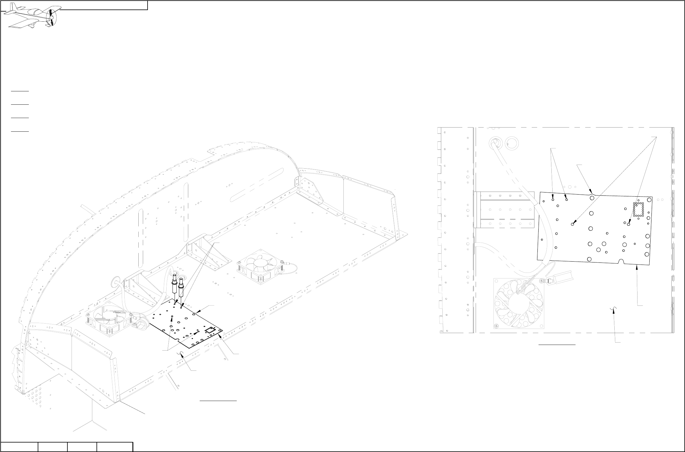
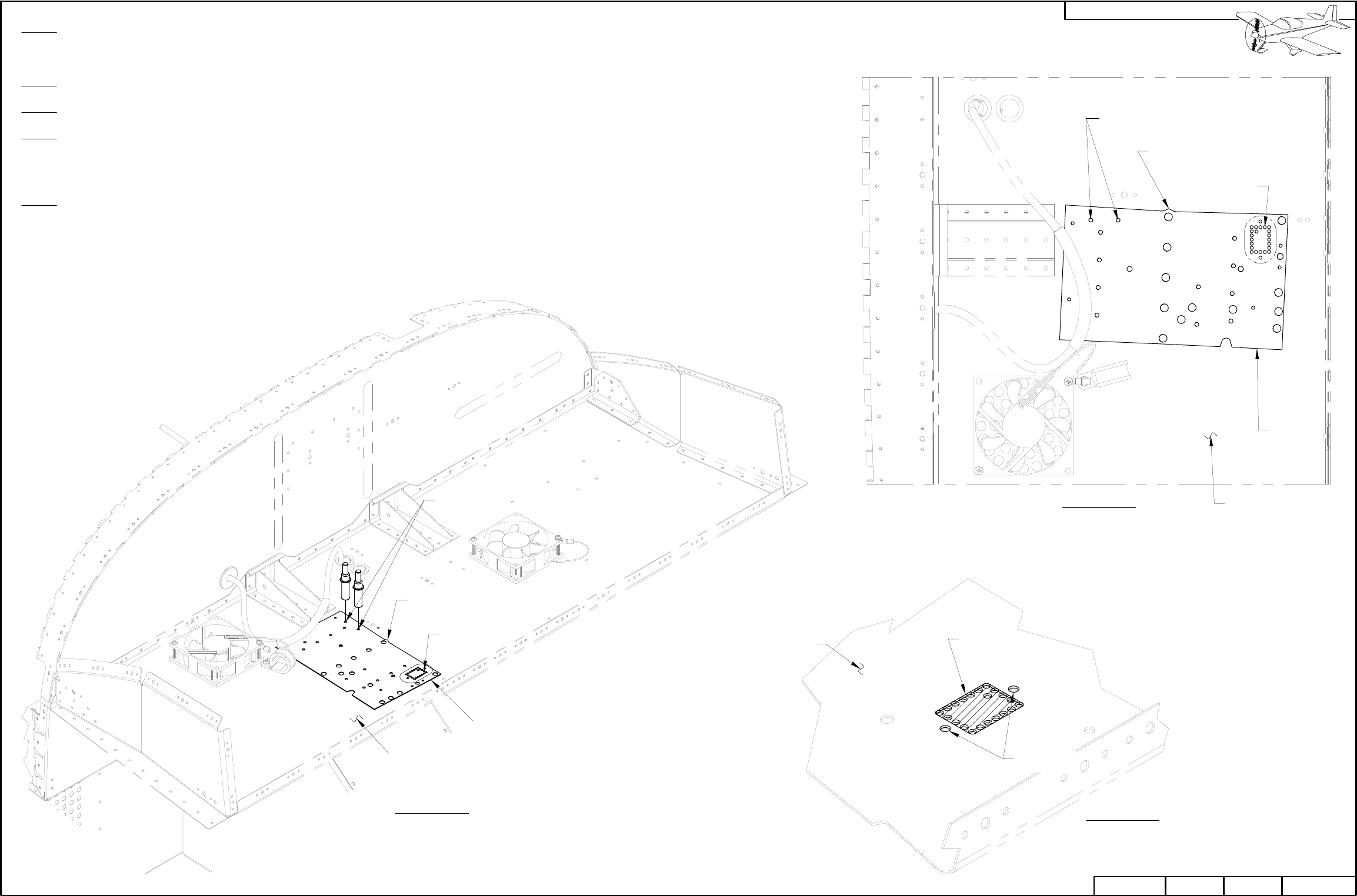
Step 1: Clamp a small board or metal angle across the bottom aft edge of the F-1202B Panel Base to prevent it from getting buckled/damaged.
Step 2: Remove the rivets that attach the F-1202J-L & -R Stack Angles, and F-1202K-L & -R Inst Stack Supports to the F-1202B Panel Base.
See Page 29-04 Figure 4.
Remove the rivets attaching the F-1202A-1 Instrument Panel to the F-1202B Panel Base. See Page 29-07 Figure 1.
Remove the F-1202A-1 Instrument panel.
NOTE: In the SkyView installation the connection of the pitot and static lines to their pressure transducers
is made in the tailcone. The plastic tube running from the forward fuselage to the tailcone was previously
used as the Static Line has now become the Aft Pitot Line.
Step 3: Pull the Aft Pitot Line back through the F-1202B Panel base and all the bulkheads back to
the area of the fuel pump behind the F-1204 Center Section Assembly.
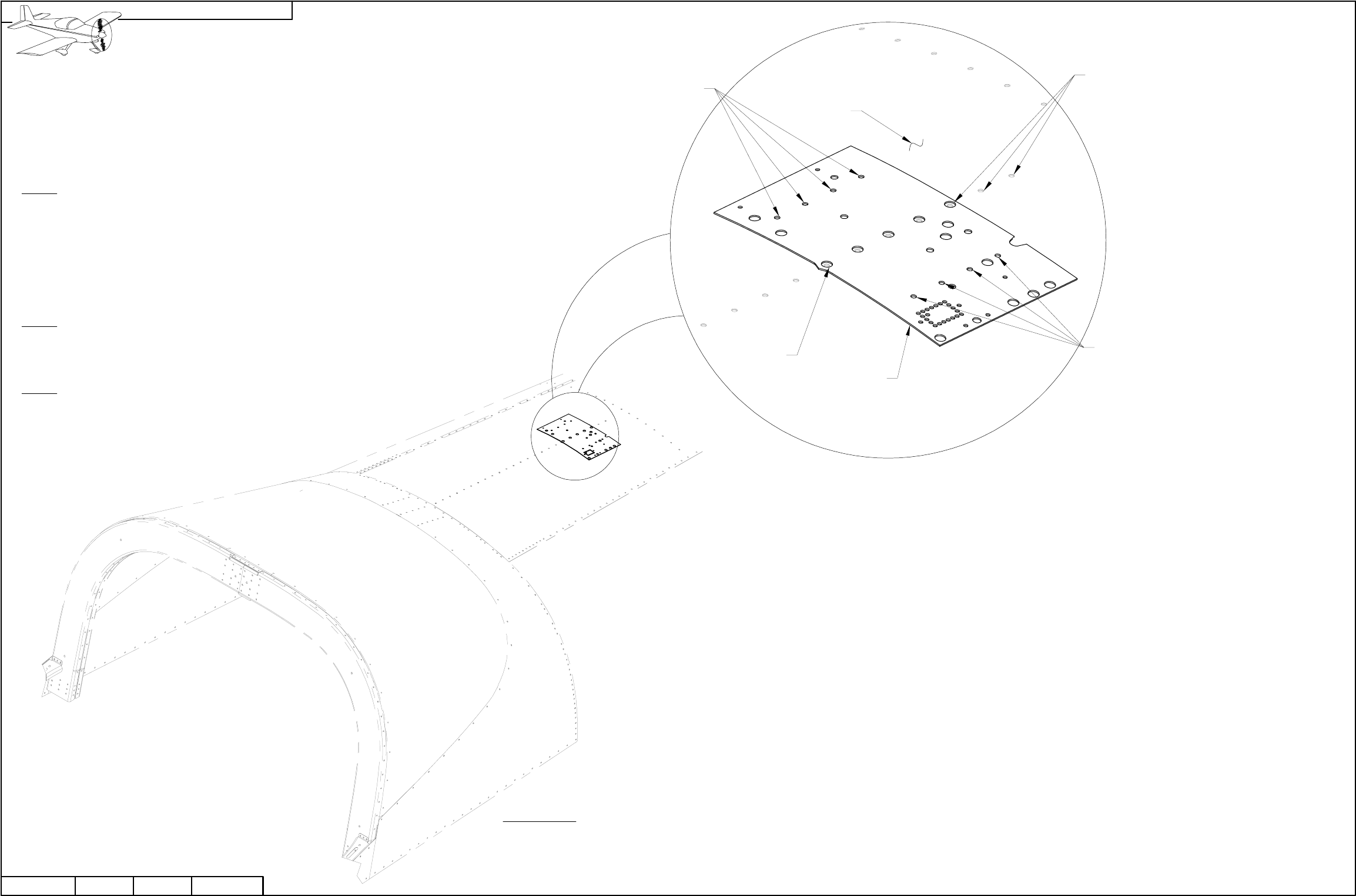
NOTE: Making holes and cutouts in this section will result in metal debris that must be
removed fromthe aircraft. Layout a cloth beneath the working area to help with cleanup.
Deburr all holes after drilling. See Section 5B.
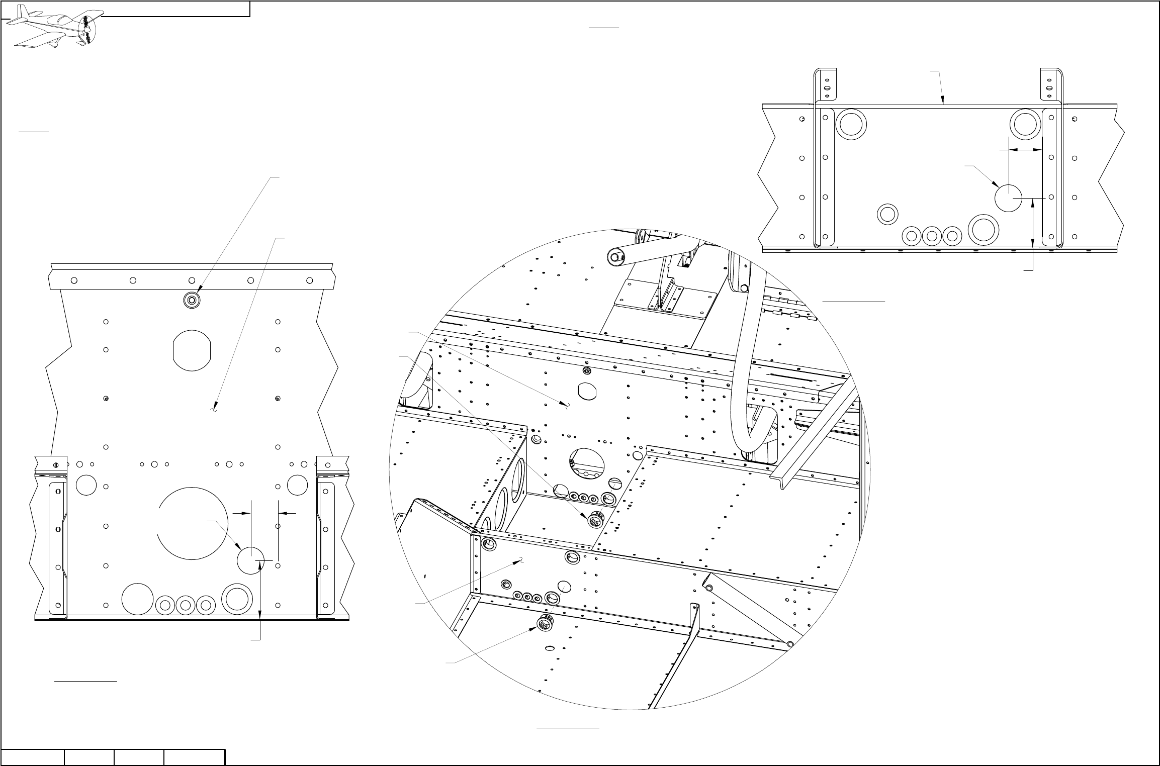
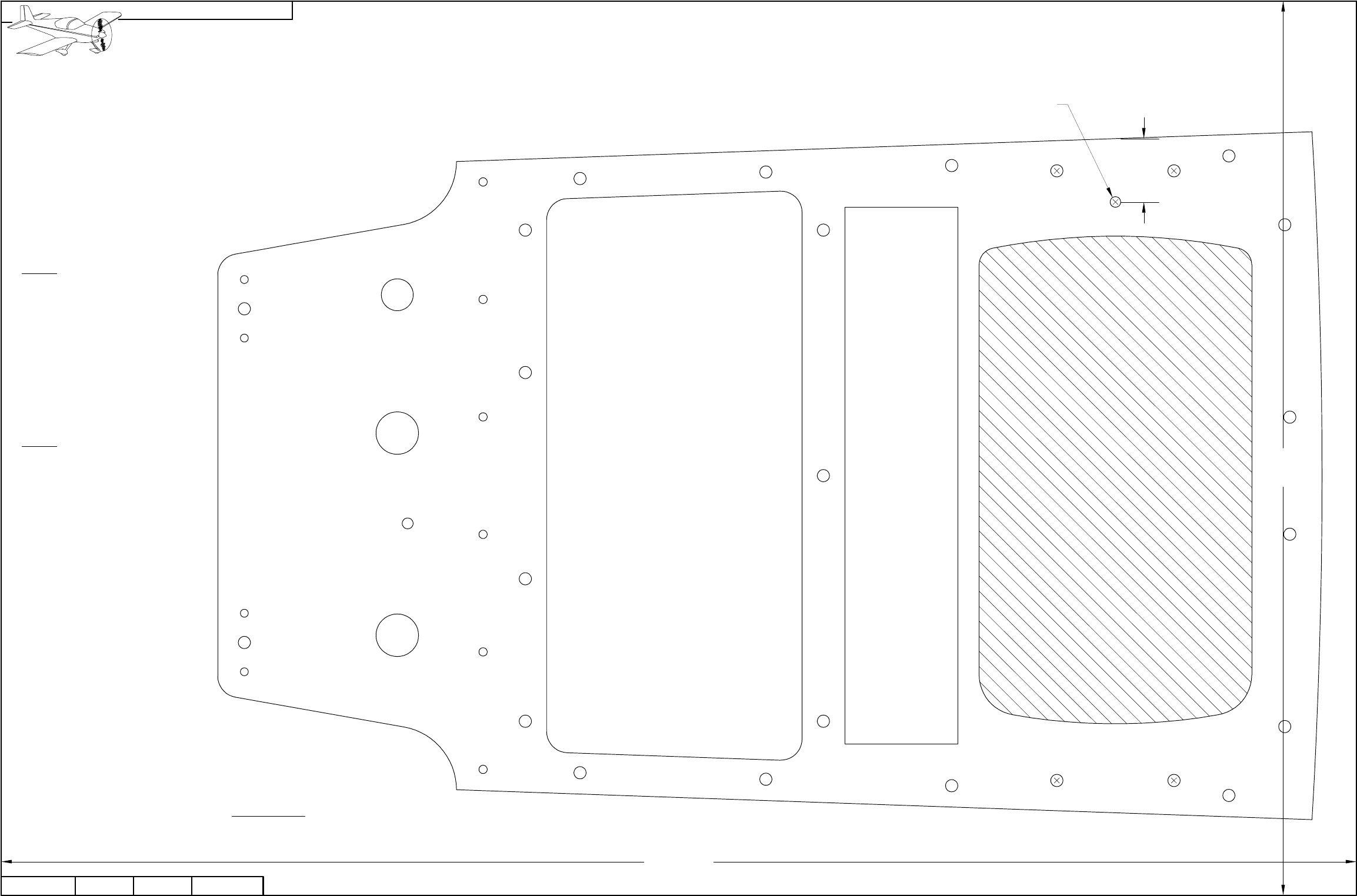
Step 4: Final-Drill #27 the center six holes in the F-1202B Panel Base. See Figure 2.
Draw a center line across the center of the six #27 holes to help in orienting the
nutplates for the next step. See Figure 2.
Step 5: Use a #6 screw to position a nutplate as a drill template at each of the
six holes final-drilled in Step 2. Use the center line to show when the nutplate
is horizontal.
Match-Drill #40 each nutplate's attach holes into the F-1202B Panel Base.
Cleco the first nutplate attach hole before match-drilling the second hole.
Step 6: Dimple the 12 nutplate attach holes made in Step 3.
Step 7: Dimple then rivet nutplates to the F-1202B Panel Base as
shown in Figure 1.
PAGEREVISION:DATE:
VAN'S AIRCRAFT, INC.
MATCH-DRILL #40,
12 PL
FIGURE 2:
DRILL FOR NUTPLATE
INSTALLATION
FINAL-DRILL #27,
6 PL
CENTER LINE
F-1202B
SEE
FIGURE 2
DATE:
F-1202B
FIGURE 1: AFT PITOT LINE
CONNECTION AND
NUTPLATE INSTALLATION
2X AN426AD3-3.5
K1000-06
9X
42D-03
010/03/11 REVISION: RV-12 PAGE
FF-1216 (SHOWN
FOR REFERENCE ONLY;
SUPPLIED IN THE
POWERPLANT KIT)
AFT PITOT
LINE
NOTE: Beginning on this page the use of the F-00011 SkyView Template for adding required holes is depicted. If your kit was
supplied with parts already having the holes you are instructed to make using the template, ignore that step and continue.
The F-00011 SkyView Template has many holes. This could become confusing because only a few holes in the template are
used for any given step. Before drilling a set of holes, study the plans carefully and mark the holes to be drilled on the template.
When drilling is complete remove the marks on the template with solvent before moving on to the next drilling operation.
Step 1: Cleco the F-00011 SkyView Template to the two referenced rivet holes in the F-1202B Panel Base as shown in Figure 1.
Step 2: Match-Drill #30 the two locations indicated in Figures 1 and 2.
Step 3: Remove the F-00011 SkyView Template.
Step 4: Final-Drill #19 the two #30 holes drilled in Step 2.
PAGE REVISION: DATE:
VAN'S AIRCRAFT, INC.
MATCH-DRILL #30
FINAL-DRILL #19
10/03/11
PAGE42D-04 RV-12 REVISION: 0DATE:
F-1202B
FIGURE 1:
MAKING THE BACKUP
BATTERY ATTACH HOLES
ISOMETRIC VIEW
CLECO HOLES
IN TEMPLATE
POINT AIMS
INBOARD
F-00011
MATCH-DRILL #30
FINAL-DRILL #19
FIGURE 2:
MAKING THE BACKUP
BATTERY ATTACH HOLES
TOP VIEW
F-00011
F-1202B
CLECO HOLES
IN TEMPLATE
POINT AIMS
INBOARD
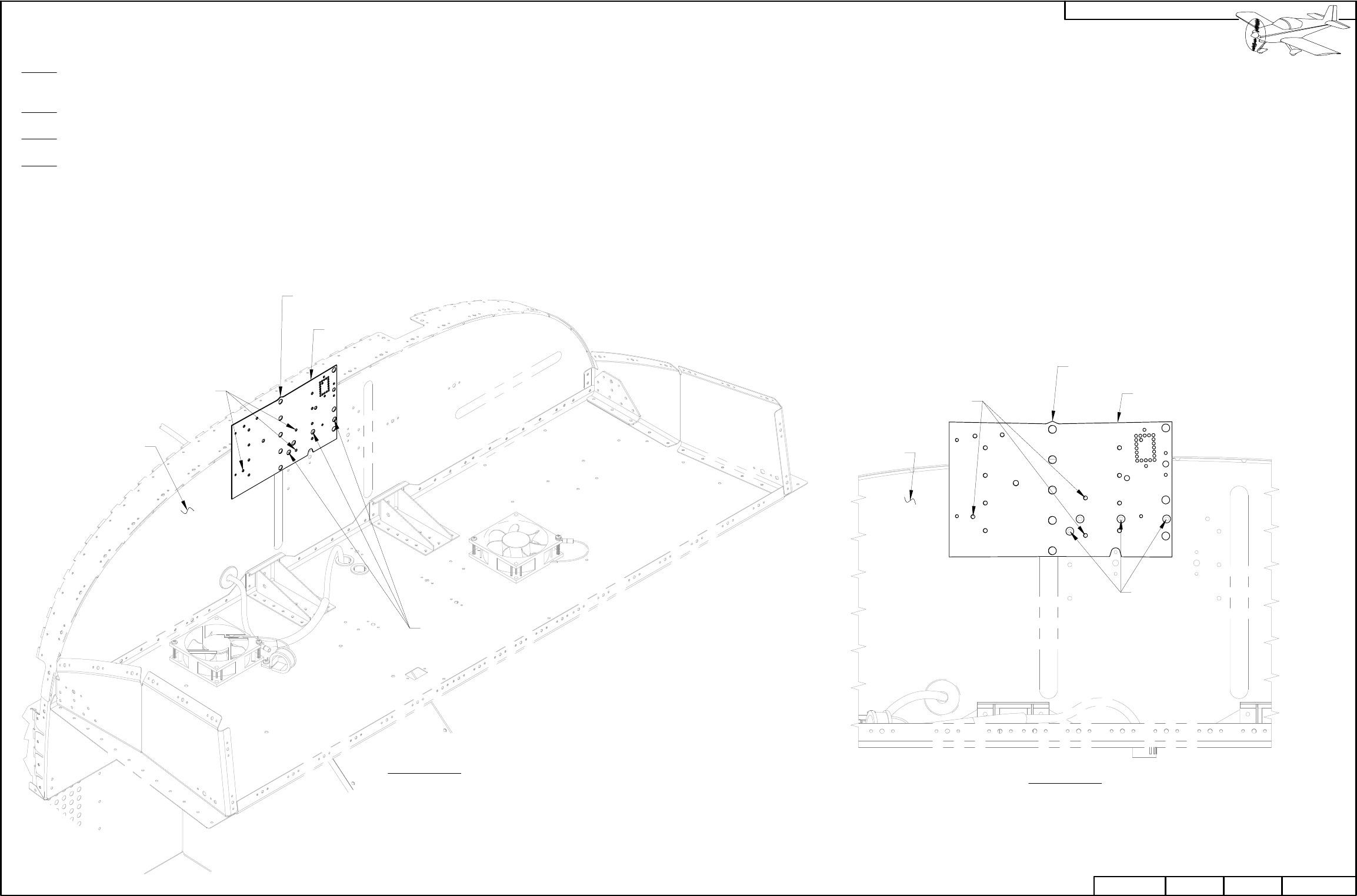
Step 1: Cleco the F-00011 SkyView Template to the two referenced rivet holes in the F-1202B Panel Base as shown in Figure 1.
NOTE: If a tool with a small diameter rotating cutting disk is available, drill only the four corner holes of the rectangular pattern.
Step 2: Match-Drill #40 the hole pattern shown in Figures 1 and 2. Cleco after drilling the first hole to maintain alignment.
Step 3: Remove the F-00011 SkyView Template.
Step 4: Remove material from the F-1202B Panel Base in the shaded area shown in Figure 3. A small side cutters can be used to clip the
material between each hole, or cut with small cutting disk.
File the edges smooth.
Step 5: Final-Drill #30 the two holes indicated in Figure 3.
FIGURE 1:
MAKING THE USB
CONNECTOR OPENING
ISOMETRIC VIEW
F-1202B
POINT AIMS
INBOARD
CLECO HOLES
IN TEMPLATE
MATCH-DRILL
#40, 23 PL
F-00011
F-1202B
FIGURE 2:
MAKING THE BACKUP
BATTERY ATTACH HOLES
TOP VIEW
FIGURE 3:
USB CUTOUT
DETAIL
DATE:
FINAL
DRILL #30
F-1202B
REMOVE
SHADED
AREA AFTER
DRILLING
42D-05
010/03/11 REVISION: RV-12 PAGE
POINT AIMS
INBOARD
F-00011
MATCH-DRILL
#40, 23 PL
CLECO HOLES
IN TEMPLATE
REVISION:DATE:
VAN'S AIRCRAFT, INC.
PAGE REVISION: DATE:
VAN'S AIRCRAFT, INC.
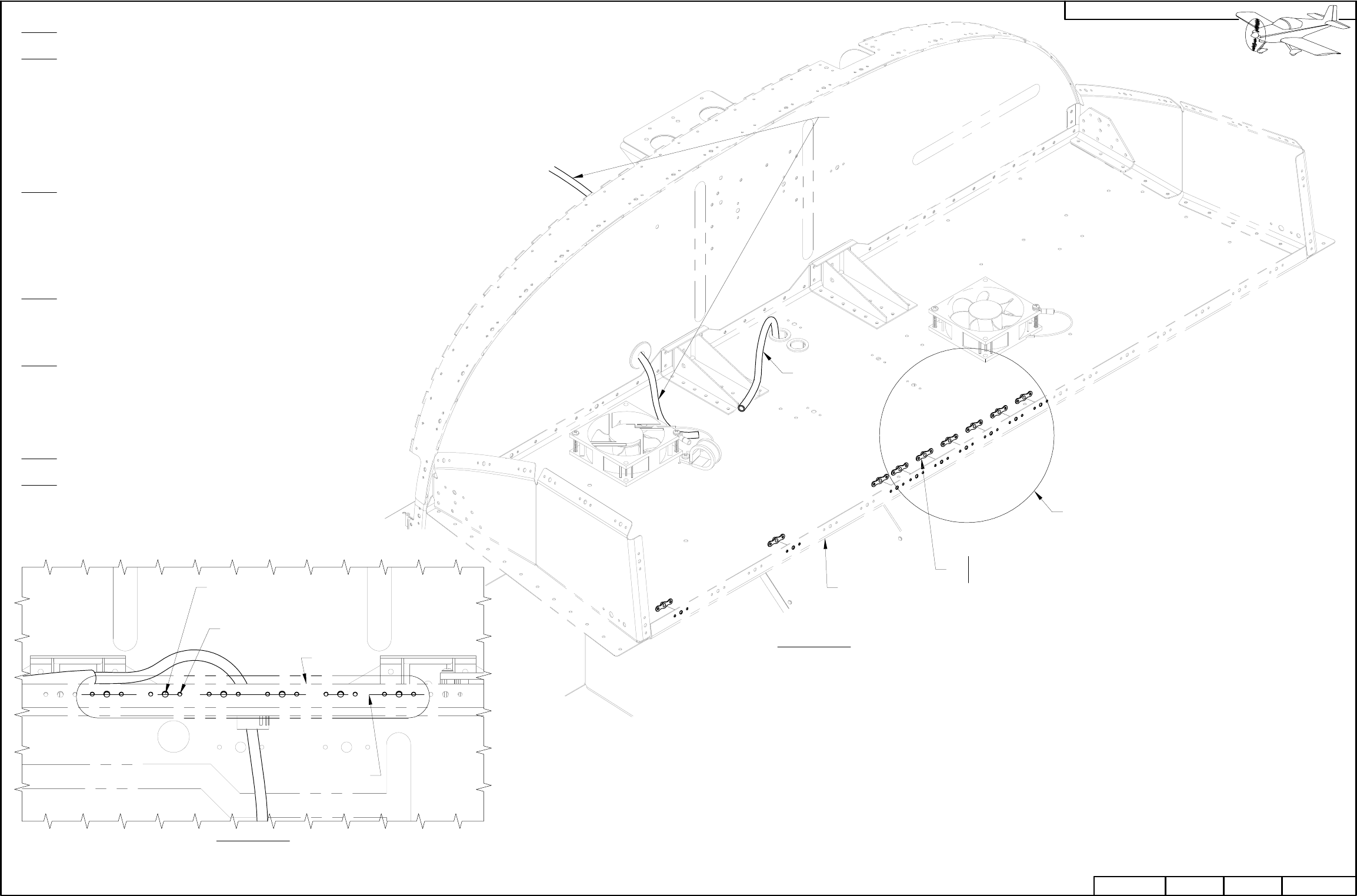
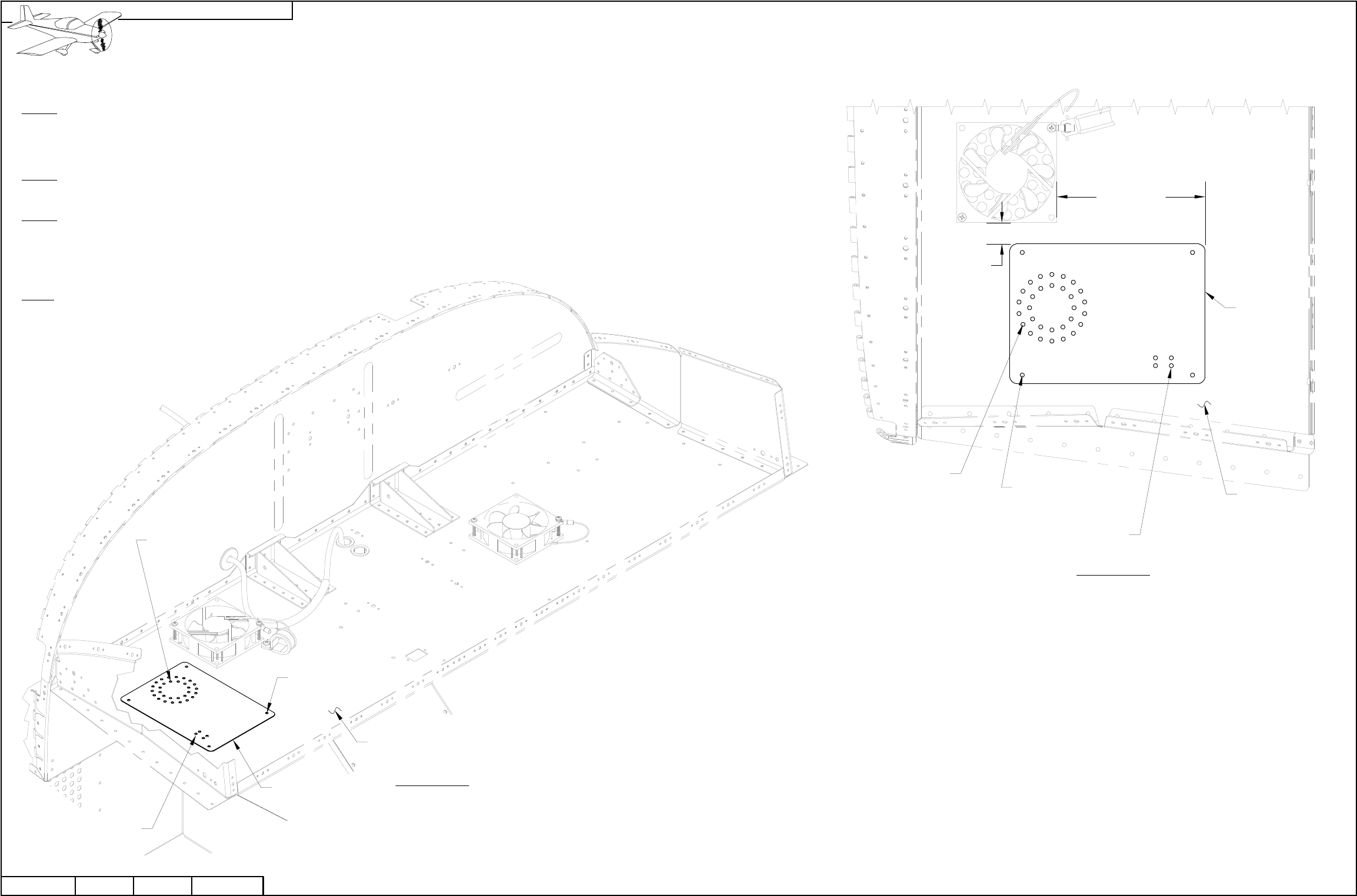
CAUTION: Use care when drilling through the drill guide to prevent damage to the brake reservoir and brake lines (if installed).
Step 1: Position the ES-50029 AV-50000 Drill Guide as shown in Figures 1 and 2. Measure from the fan to the drill guide as shown in
Figure 2.
Make sure the fwd edge of the drill guide is parallel with the aft surface of the firewall.
Step 2: Match-Drill #30 the four corner holes shown in Figure 1 from the ES-50029 AV-5000 Drill Guide into the F-1202B Panel Base.
Cleco each hole as you drill.
Step 3: Match Drill #30 the circular pattern of holes from the ES-50029 AV-50000 Drill Guide into the F-1202B Panel Base.
Remove the AV-50000 drill guide.
Use a step drill to enlarge the #30 holes in the the circular hole pattern to 5/16.
Step 4 Final-Drill #27 the four #30 holes drilled in Step 2.
DATE:
MATCH-DRILL #30
STEP-DRILL 5/16,
30 PL
RV-1242D-06
PAGE REVISION: 0
ES-50029 FIGURE 1:
MAKING THE CONTROL
MODULE ATTACH &
VENTILATION HOLES
ISOMETRIC VIEW
10/03/11
MATCH-DRILL #30
FINAL-DRILL #27,
4 PL
F-1202B
F-1202B
MATCH-DRILL #30
STEP-DRILL 5/16,
30 PL MATCH-DRILL #30
FINAL-DRILL #27,
4 PL
FIGURE 2:
MAKING THE CONTROL
MODULE ATTACH &
VENTILATION HOLES
TOP VIEW
4 11/16
[118.5 mm]
11/16
[17.0 mm]
ES-50029
DO NOT DRILL,
4 PL
DO NOT DRILL,
4 PL
PAGEREVISION:DATE:
VAN'S AIRCRAFT, INC.
F-1201A
FIGURE 1:
MAKING THE
TRANSPONDER
ATTACH HOLES
ISOMETRIC VIEW
ALIGN HOLES IN
TEMPLATE WITH
RIVET HEADS
MATCH-DRILL #30
FINAL-DRILL #19
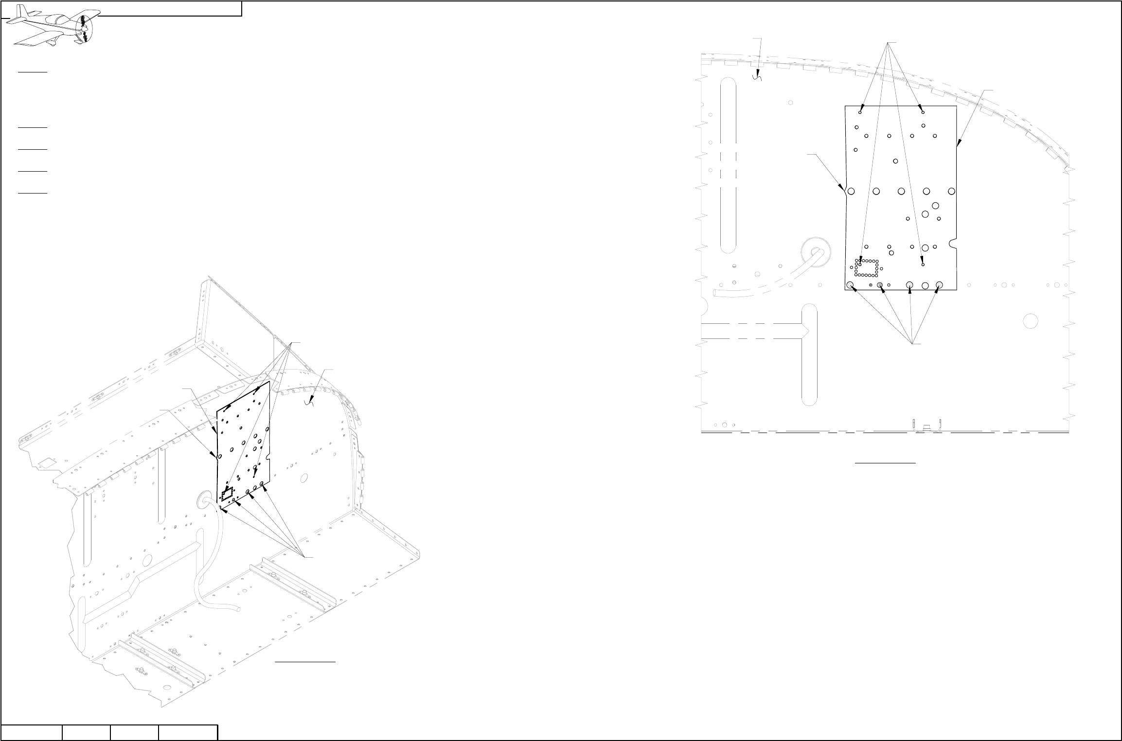
NOTE: When drilling stainless steel (F-1201A Firewall Upper) use a lubricant such as BOELUBE on bits. During the drilling
process firmly hold a block of wood on the opposite side of the Firewall Upper from the location being drilled.
Step 1: Align the F-00011 SkyView Template to the F-1201A Firewall Upper by placing the holes in the template over the rivet heads in
the firewall as shown in Figures 1 and 2.
Step 2: Match-Drill #30 the three locations indicated in Figures 1 and 2. Cleco each hole as you drill.
Step 3: Remove the F-00011 SkyView Template.
Step 4: Final-Drill #19 the three #30 holes drilled in Step 2.
POINT
AIMS UP
F-00011
MATCH-DRILL #30
FINAL-DRILL #19
ALIGN HOLES IN
TEMPLATE WITH
RIVET HEADS
10/03/11
DATE:
FIGURE 2:
MAKING THE
TRANSPONDER
ATTACH HOLES
TOP VIEW
F-1201A
RV-12
REVISION: 042D-07
PAGE
F-00011
POINT
AIMS UP
Step 1: Remove the cushioned clamp which holds the fuel pressure sensor (if installed) from the firewall. See Page 45-02, Figure 3.
Align the F-00011 SkyView Template to the F-1201A Firewall Upper by placing the holes in the template over the rivet heads and bolt hole
in the firewall as shown in Figures 1 and 2.
Step 2: Match-Drill #30 the four locations indicated in Figures 1 and 2. Cleco each hole as you drill.
Step 3: Remove the F-00011 SkyView Template.
Step 4: Final-Drill #12 the four #30 holes drilled in step 2.
Step 5: Re-install the cushioned clamp and fuel pressure sensor to the firewall as shown on Page 45-02, Figure 3.
MATCH-DRILL #30
FINAL-DRILL #12
POINT AIMS
INBOARD
F-00011
DATE:
RV-1242D-08
PAGE REVISION: 0
FIGURE 1:
MAKING THE
EMS MODULE
ATTACH HOLES
ISOMETRIC VIEW
10/03/11
ALIGN HOLES IN
TEMPLATE WITH
RIVET HEADS AND
BOLT HOLE
F-1201A
ALIGN HOLES IN
TEMPLATE WITH
RIVET HEADS AND
BOLT HOLE
FIGURE 2:
MAKING THE
EMS MODULE
ATTACH HOLES
FRONT VIEW
MATCH-DRILL #30
FINAL-DRILL #12
POINT AIMS
INBOARD
F-1201A
F-00011
REVISION: DATE:
VAN'S AIRCRAFT, INC.
PAGEREVISION:DATE:
VAN'S AIRCRAFT, INC.
F-1201A
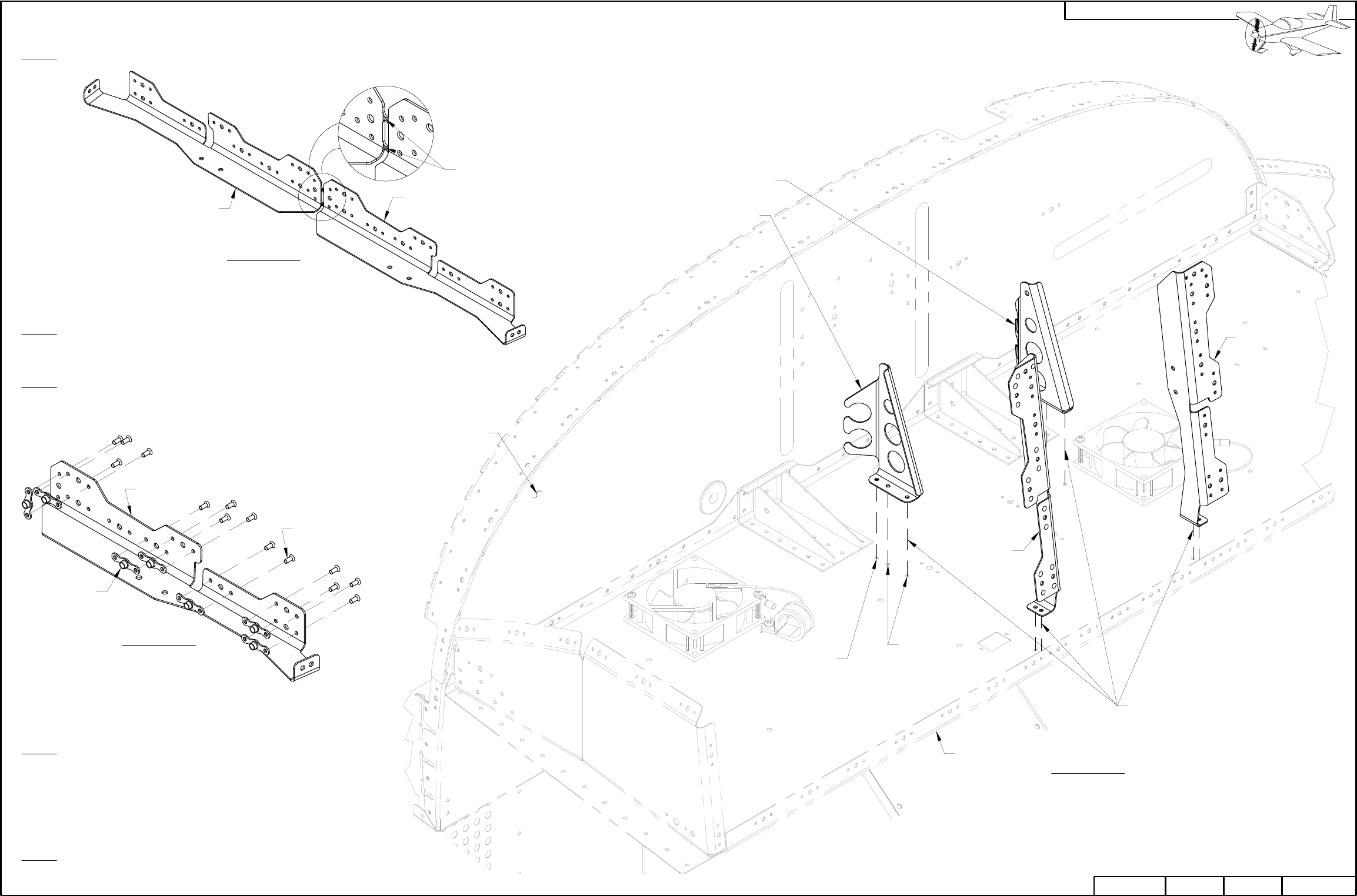
Step 4: Cleco the F-00027-L & -R Com Supports to the
F-1202B Panel base as shown in Figure 3.
Match-Drill #30 the most forward hole in each com support into
the panel base as shown in Figure 3.
Remove the com supports and deburr the match-drilled holes in the panel base.
Step 5: Attach the F-00026-L & -R Inst Stack Angles and the F-00027-L & -R
Com Supports to the F-1202B Panel Base using the rivets called-out in Figure 3.
FIGURE 2:
INST STACK ANGLE
NUTPLATE INSTALLATION
F-00026-L
K1000-06,
TYP
AN426AD3-3.5,
TYP
NOTE: This page only applies if installing the AV GARMIN SL40 Com Radio.
Step 1: Separate the F-00026 Inst Stack Angle into F-00026-L & -R Inst Stack Angles as shown in Figure 1.
FIGURE 1:
SEPARATING THE
INST STACK ANGLE
Step 2: Machine countersink all the .098 diameter holes in the F-00026-L & -R
Inst Stack Angles to fit the head of an AN426AD3 rivet. See Figure 2 to
determine which surface to countersink.
Step 3: Install nutplates on the F-00026-L & -R Inst Stack Angles in the
locations shown in Figure 2. Note that there are two locations on each inst
stack angle which do not have nutplates installed.
F-00026-R
REMOVE
HATCHED
AREA
F-00026-L
07/24/13
LP4-3,
TYP
FIGURE 3:
INST STACK ANGLE
& COM SUPPORT
INSTALLATION
DATE:
CLECO
HERE
MATCH-DRILL
HERE
F-1202B
F-00026-L
RV-12
REVISION: 142D-09
PAGE
F-00027-R
F-00027-L
F-00026-R
MATCH-DRILL #30,
4 PL
FIGURE 1: MATCH-DRILLING
FOR THE ADAHRS
BRACKETS
NOTE: The following instructions in this section
assumes the Fuel Tank (See Section 37) and F-1207F
Baggage Bulkhead Corrugation (See Page 33-03, Figure
4) have been removed.
NOTE: Remember to lay out a cloth in the tailcone area
to catch metal debris.
Step 1: See Page 42-18. Remove the ES 9 PIN
BACKSHELL 2 from the DYNON 100323-000 EDC-10A
Magnetometer.
Remove the magnetometer from the F-1208B-L & -R Mag
Brackets.
Drill out the rivets attaching the mag brackets to the F-1208
Fuselage Frame.
Step 2: Curve the F-00011 SkyView Template to match the
curvature of the F-1278 Top Skin. Make the curve by sliding
the SkyView template back and forth over the edge of a
table.
Step 3: Position the F-00011 SkyView Template on the
F-1278 Top Skin as shown in Figure 1.
Match-Drill #30 the holes indicated in Figure 1 into the
F-1278 Top Skin.
Cleco each hole as you drill.
10/03/11
PAGE 42D-10 RV-12 REVISION: 0DATE:
AFT HOLE
OF TEMPLATE
ALIGNED WITH
THIRD HOLE
MATCH-DRILL #30,
4 PL
POINT
FACING
FORWARD F-00011
F-1278
REVISION: DATE:
VAN'S AIRCRAFT, INC.
NOTE: The snap bushing inserted on this page will be used for
wires routed to the tailcone area in the remainder of this section.
Step 1: Drill #30 a pilot hole above the upper of the two wire run holes
(now filled with snap bushings) in the lower part of the F-1207D-L
Baggage Bulkhead Channel. Place the hole above the upper hole the
same distance as is in between the lower two holes. See Figure 1.
Use a step drill to enlarge the #30 hole to 3/8.
Insert a snap bushing into the hole per the callout in Figure 1.
F-1207D-L
EXISTING
WIRE RUNS
SB375-4
DRILL #30
ENLARGE 3/8
42D-11
010/03/11 REVISION: RV-12 PAGEDATE: PAGEREVISION:DATE:
VAN'S AIRCRAFT, INC.
FIGURE 1: ADDING A
WIRE RUN BUSHING
Step 2: Unplug and discard the short piece
of Static Line going from the F PLASTIC
TEE to the Left Side Static Port.
Remove and set aside F PLASTIC TEE for
later use.
Step 3: Cut the Static Line
going from the F PLASTIC TEE to the
Right Side Static Port, at the
centerline of the aircraft.
See Figure 2.
FIGURE 2: D-180 STATIC LINE
STATIC LINE
CUT STATIC
LINE HERE
RIGHT SIDE
STATIC PORT
LEFT SIDE
STATIC
PORT
F PLASTIC TEE
PITOT LINE
SHORT STATIC LINE
FIGURE 1: RIVETING THE ADAHRS
BRACKETS TO THE TOP SKIN
(MANY PARTS NOT SHOWN FOR CLARITY)
F-00009-L
F-00009-R
LP4-3,
TYP
Step 1: Rivet the
F-00009-L & -R
ADAHRS Brackets
to the F-1278 Top
Skin as shown in
Figure 1. F-1278
F-1208
PAGE REVISION: DATE:
VAN'S AIRCRAFT, INC.
10/03/11
PAGE42D-12 RV-12 REVISION: 0DATE:
TIE-WRAP PITOT
AND STATIC
TOGETHER
FIGURE 1: REINSTALLING
THE STATIC TEE
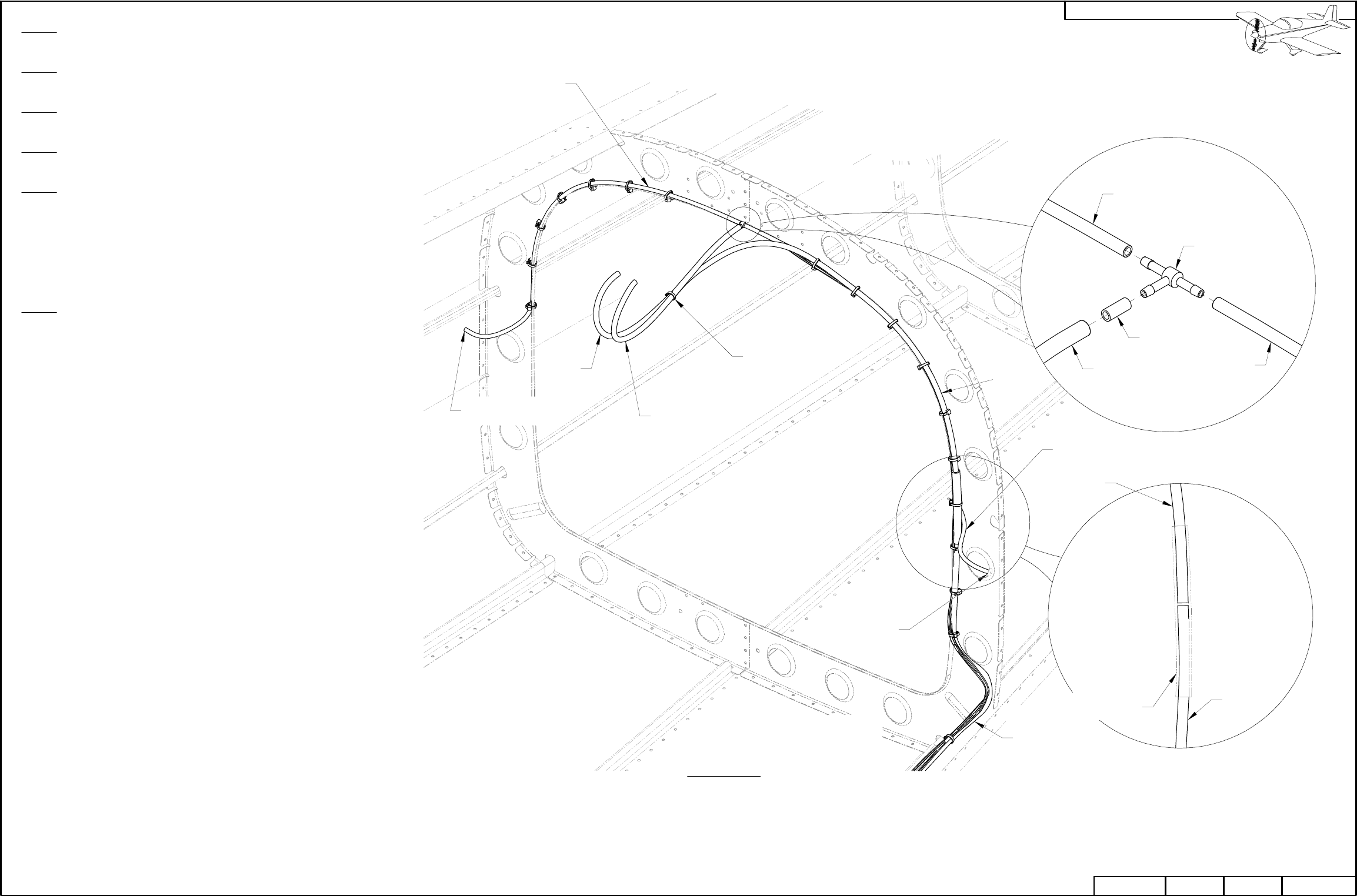
Step 1: Cut a length of PT 1/8 CLR PLASTIC 24 inches long to make the
F-00012 Static Line Port - Tee.
Step 2: Cut a length of PT 1/8 CLR PLASTIC 7/16 inches long to make
the F-00014 Static Line Tee Upsize.
Step 3: Cut a length of PT 1/4 OD TUBE 15 inches long to make the
F-00013 Static Line Tee - ADAHRS.
Step 4: Cut a length of PT 1/4 OD TUBE 33 inches long to make the
F-00015 Pitot Line Extension.
Step 5: Heat then slide the F-00014 Static Line Tee Upsize and F-00013
Static Line Tee - ADAHRS over the forward facing leg of the F PLASTIC
TEE as shown in the detail view in Figure 1.
Heat then slide the F-00012 Static Line Port - Tee onto the left leg of the
F PLASTIC TEE.
Heat then slide the Static Line onto the right leg of the F PLASTIC TEE.
Step 6: Heat a PT 1/4IDX3/8ODX4" Pitot Tube Joiner. Use the pitot tube
joiner to join the F-00015 Pitot Line Extension and Aft Pitot Tube
together. See the detail view in Figure 1.
RIGHT SIDE
STATIC PORT
AFT
PITOT
LINE
STATIC
LINE
F-00012
PITOT LINE
LEFT SIDE
STATIC
PORT
PT 1/4IDX3/8ODX4"
(SHOWN TRANSPARENT)
AFT
PITOT
LINE
F-00015
F PLASTIC TEE
F-00012
F-00015 F-00013
F-00014
STATIC LINE
F-00013
42D-13
010/03/11 REVISION: RV-12 PAGEDATE: PAGEREVISION:DATE:
VAN'S AIRCRAFT, INC.
NOTE: Snap bushings inserted on this page are
to be used for wires routed through the F-1202F
and F-1203A Bulkheads in the remainder of this
section.
Step 1: Drill #30 a pilot hole in F-1203A Bulkhead
using the dimensions given in Figure 1.
Use a step drill to enlarge the #30 hole to 3/4.
Insert a snap bushing into the hole per the callout
in Figure 2.
Step 2: Drill #30 a pilot hole in
F-1202F Bulkhead using the
dimensions given in Figure 3.
Use a step drill to enlarge the
#30 hole to 3/4.
Insert a snap bushing into the
hole per the callout in Figure 2.
FIGURE 2: INSTALLING SNAP
BUSHINGS
FIGURE 3: UPDATING THE F-1202F BULKHEAD
(VIEW FROM FORWARD SIDE LOOKING AFT)
SB750-10
SB750-10
F-1202F
F-1203A
15/16
[23.7 mm]
F-1202F
DRILL #30
ENLARGE 3/4
FIGURE 1: UPDATING THE F-1203A BULKHEAD
(VIEW FROM FORWARD SIDE LOOKING AFT)
3/4
[19.1 mm]
1 5/8
[41.3 mm]
(DISTANCE FROM BOTTOM SKIN)
1 3/8
[34.9 mm]
(DISTANCE FROM BOTTOM SKIN)
DRILL #30
ENLARGE 3/4
F-1203A
PAGE REVISION: DATE:
VAN'S AIRCRAFT, INC.
10/03/11
PAGE42D-14 RV-12 REVISION: 0DATE:
AUX MUSIC JACK

NOTE: There are three paths to choose from when upgrading the
wiring: NOTE: This section will require crimping of several open barreled
crimps. Please read chapter 5W Open Barrel Crimp before
continuing.
ES HST-3/16X1' shall be referred to as heat shrink for the remainder of this
document.
For the remainder of this section figures may not always be given in
conjunction with the text. Use other sections in your manual such as
Sections 31,40,42,43,44 and 45 for figures to help understand the text.
Harness Equivalents
The following list lists equivalents to new updated SkyView harnesses. This
reference information will be useful when completing Section 42C.
WH-RV12-TUNNEL + WH-00036 = WH-00046
WH-RV12-OPTIONAL + WH-00026 = WH-00045 & WH-00025 (SEE BELOW)
WH-RV12-FLIGHTCOM403 + WH-00042 = WH-00027
WH-RV12-TX-ANT + WH-00055 = WH-00050
WH-RV12-SL40-ANT = WH-00051
WH-RV12-OAT + WH-00008 = WH-00060
AV AV-17 = AV-00008
The WH-00026 Option Conversion Harness combines both the WH-00045
Options Harness and WH-00025 SkyView AutoPilot Harnesses into one
harness that make the same two connections to the AV-50000A RV-12
Control Module. When asked in Section 42C to install either the options or
autopilot harnesses simply install the appropriately labeled harness on the
WH-00025 instead.
Conversion Harnesses) This update kit supplies the conversion
harnesses necessary for an easy transition to SkyView. Simply plug
the harnesses into the existing harnesses in your kit and after routing a
few new wires included in these harnesses your wiring will be updated.
Pin Swaps) Use the PDF posted at www.vansaircraft.com/..... to
convert your own harnesses pin by pin. Van's Aircraft does not
recommend this option as there are many chances of error. Van's
Aircraft will not be held responsible for any errors made using this
method and also reserves the right to provide limited or no technical
support for this method...you are on your own!
Harness Replacement) As a more expensive and time consuming
option the wiring harnesses and plans from Section 31B may be
purchased from the Finish Kit. This option would replace all the wiring
in the fuselage of the aircraft.
Q: Will I lose any functionality with the conversion harnesses or
pin swaps versus harness replacement?
A: Your functionality will be slightly different, read below.
1) The headphone jack was grounded to the seat pan. In the new
SkyView system both headphone and mic jacks have been isolated
with their grounds going back to the AV-50000A RV-12 Control Module.
This change will have no affect on system performance if your system
was working correctly already using the old configuration.
2) The Aux Music Jack (see Page 31-10) will not be upgraded from a
TRS jack to a TRRS jack. The letters stand for tip, ring and sleeve. The
extra ring on the new jack may be used to remotely control devices
connected to the jack such as a compatible smart phone or music
player. For further information see Section 42C and 31B. If you wish to
have this upgraded functionality order:
WH-00056 Aux Music Jack
ES-00044 Molex Plug 6 Position Micro-Fit
ES-00045 Molex Receptacle 6 Position Micro-Fit
Two (or more if you are not used to crimping these) ES-00046 Molex
Micro-Fit Sockets (20-24). See section 5W Crimping Open-Barreled
Connectors for further crimping information.
42D-15
103/05/12 REVISION: RV-12 PAGEDATE: PAGEREVISION:DATE:
VAN'S AIRCRAFT, INC.
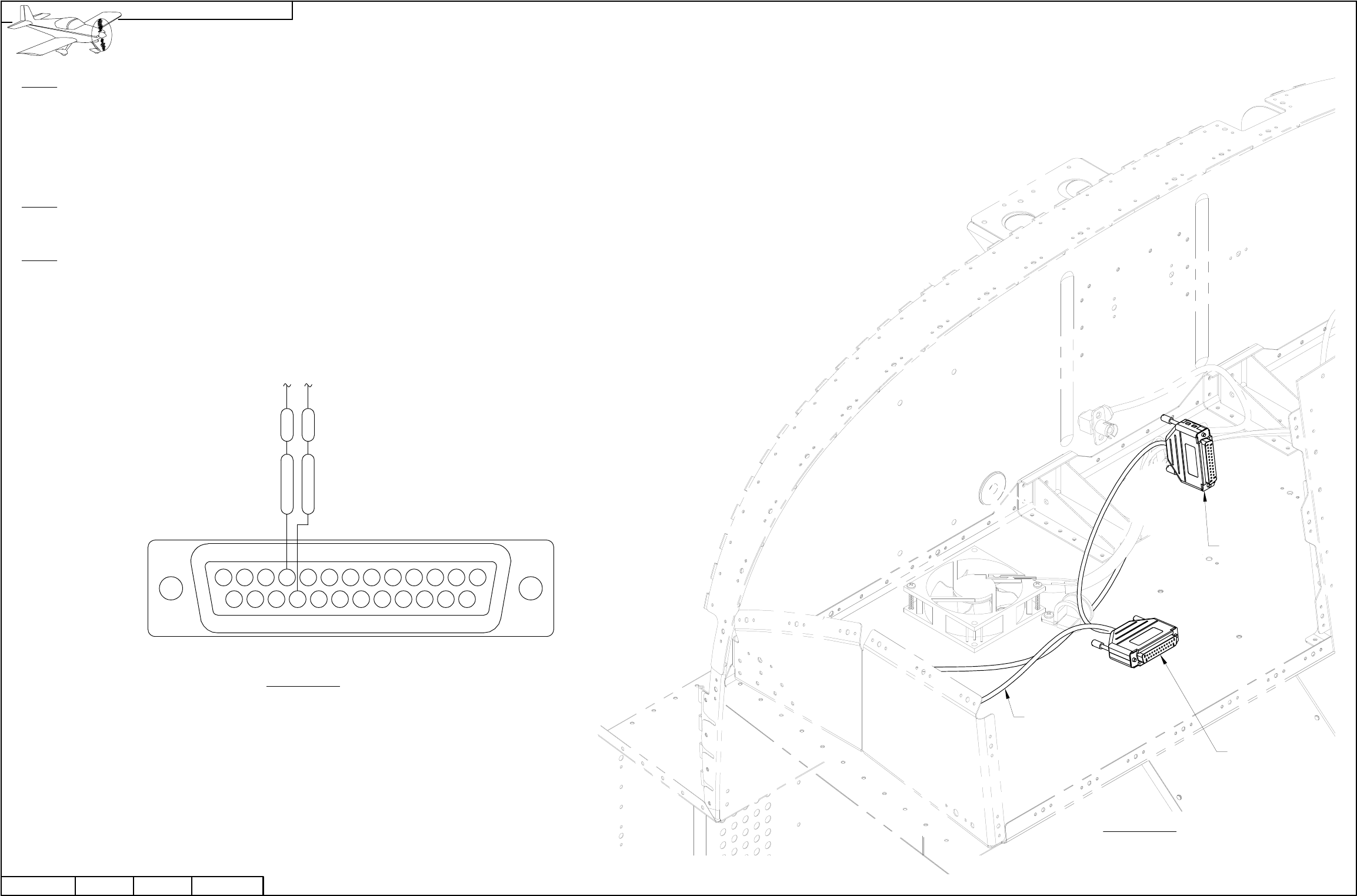
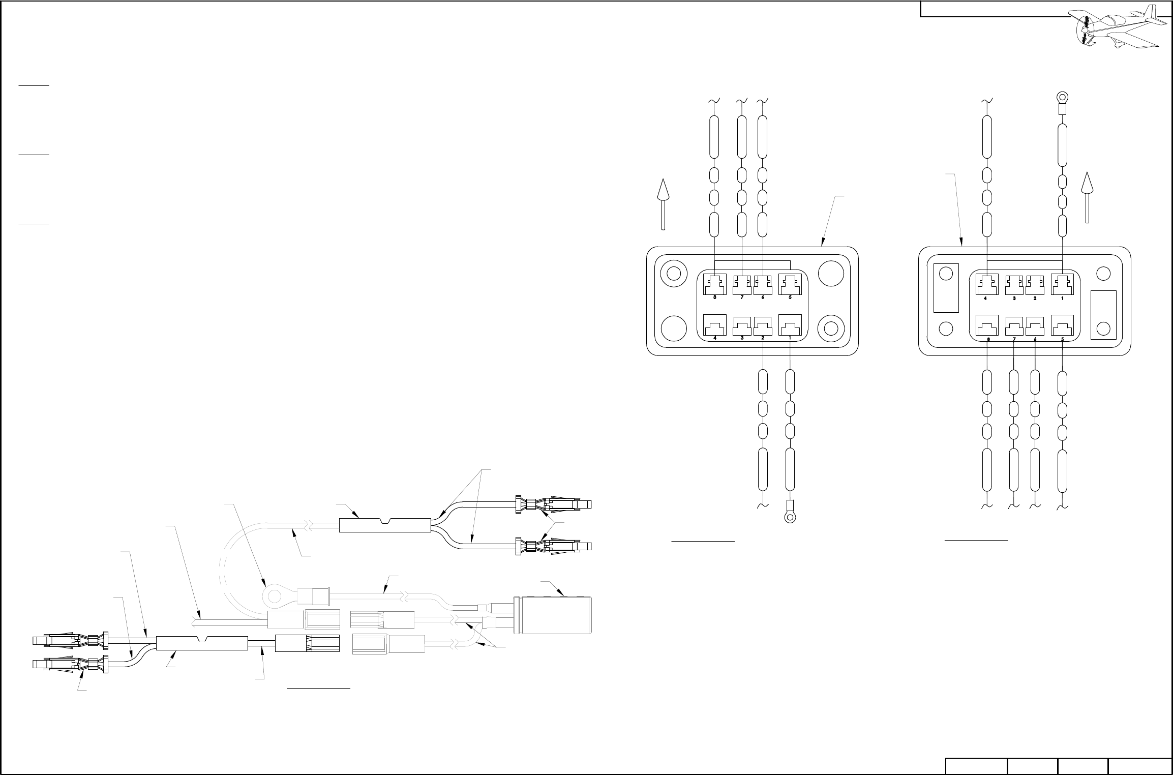
FIGURE 2: OPTIONAL HARNESS
CONNECTIONS
F192 ORN
WHT/BLK
F193
25
13
2422 23
10 11
19 20
678 9
21
16 17
345
14
1 2
15 18
12
FIGURE 1: INSTALLING
WIRES IN THE OPTIONAL
HARNESS D-SUB
(REAR VIEW / PIN INSERTION SIDE)
Step 1: Remove the backshell from the main 25-pin d-sub on the WH-RV12-OPTIONAL harness. See Section 5W
Electrical Wiring Notes, Backshell Assembly.
Check that WH-F193 (WHT/BLK) and WH-F192 (ORN) are installed as shown in Figure 1.
If the wires are not installed but loose in the harness install ES SA-1017 Female D-Sub Sockets on the end of each
wire per the instructions in Section 5W Electrical Wiring Notes, Repairing D-Sub Pins then insert them into the correct
locations as shown in Figure 1.
Step 2: Find the wires going to the AP-74 25-pin d-sub from the main 25-pin d-sub on the WH-RV12-OPTIONAL
harness. The AP-74 25-pin d-sub will be no longer used with the SkyView system. Coil and tie-wrap this d-sub in a
safe location. As an option cut off this d-sub and heat shrink over the end of each wire.
Step 3: Install the backshell assembly back onto the main 25-pin d-sub on the WH-RV12-OPTIONAL harness.
PAGE REVISION: DATE:
VAN'S AIRCRAFT, INC.
10/03/11
PAGE42D-16 RV-12 REVISION: 0DATE:
AP-74
25 PIN D-SUB
MAIN 25 PIN
D-SUB
WH-RV12-OPTIONAL
NOTE: This page only applies if
installing the AV GARMIN SL40 Com
Radio.
NOTE: This summarizes the
replacement of the WH-RV12-SL40
COM Wiring Harness. Skip Step 1
and Step 2 on this page if you have
not yet installed an avionics kit.
Step 1: Attach the 25-pin d-sub on the
WH-00028 SkyView SL-40 Harness
without a backshell to the back of the
AV GARMIN SL40 Com Radio tray.
Use the hardware previously removed
in this section when detaching the
WH-RV12-SL40 Com Wiring Harness.
See Figure 1.
Step 2: Tie-Wrap the WH-00028
SkyView SL-40 Harness to the back of
the AV GARMIN SL40 Com Radio tray
as shown in Figure 1.
Route the SkyView SL-40 harness
through the cushioned clamp near the
left ES CPU FAN.
Step 3: Install the WH-00055 Xpndr Ant
Cable Extension onto the end of the
WH-RV12-TX-ANT Transponder
Antenna Cable as shown in Figure 1.
FIGURE 1: INSTALLING THE
SKYVIEW SL-40 HARNESS
WH-00028
AV GARMIN SL40
COM RADIO TRAY
(TRAY WILL BE INSTALLED TO
SUPPORTS IN SECTION 42C)
TIE-WRAP
CUSHIONED CLAMP
ES CPU FAN
F-00027-L
42D-17
107/24/13 REVISION: RV-12 PAGEDATE: PAGEREVISION:DATE:
VAN'S AIRCRAFT, INC.
WH-00055
WH-RV12-TX-ANT
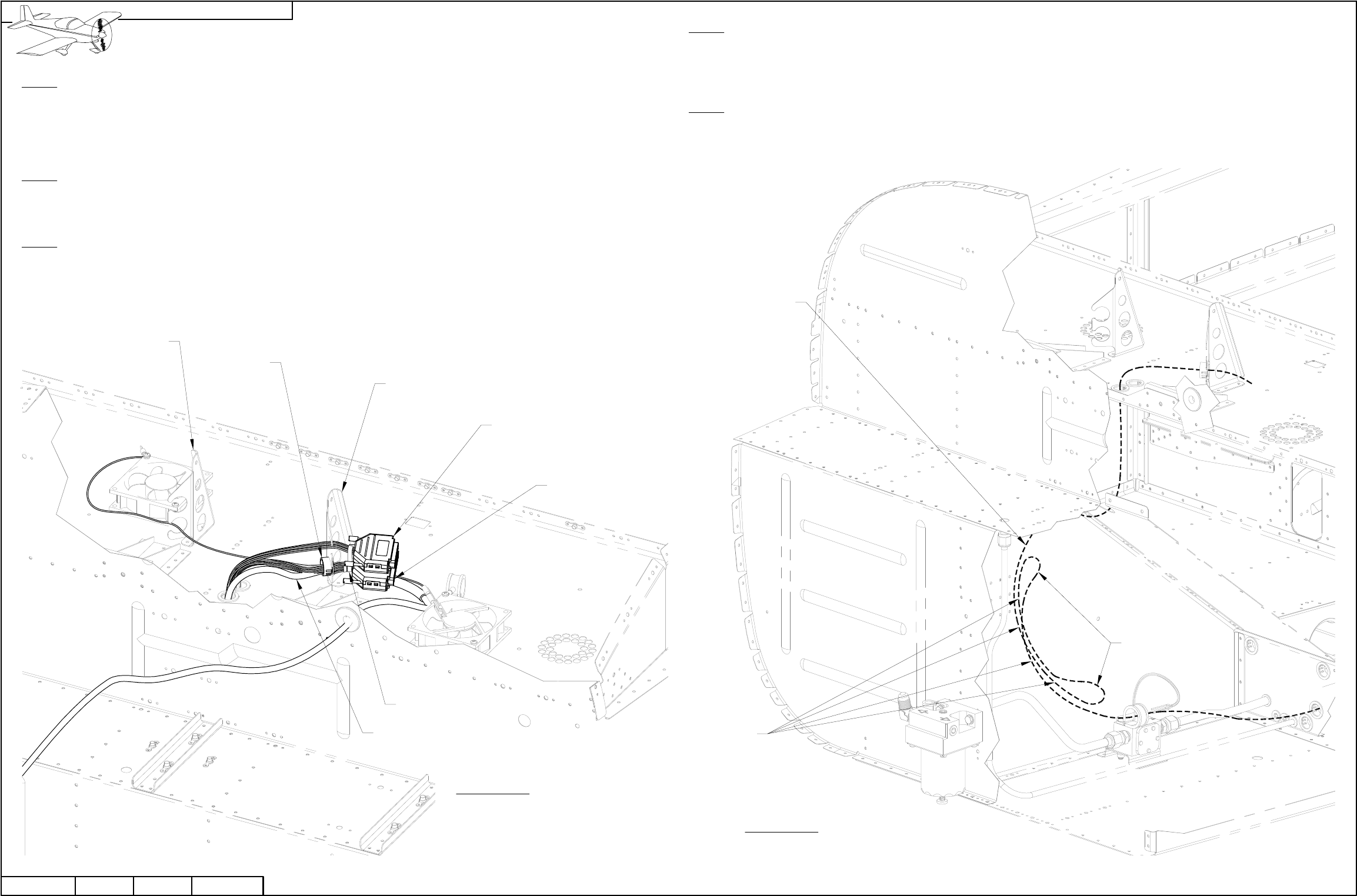
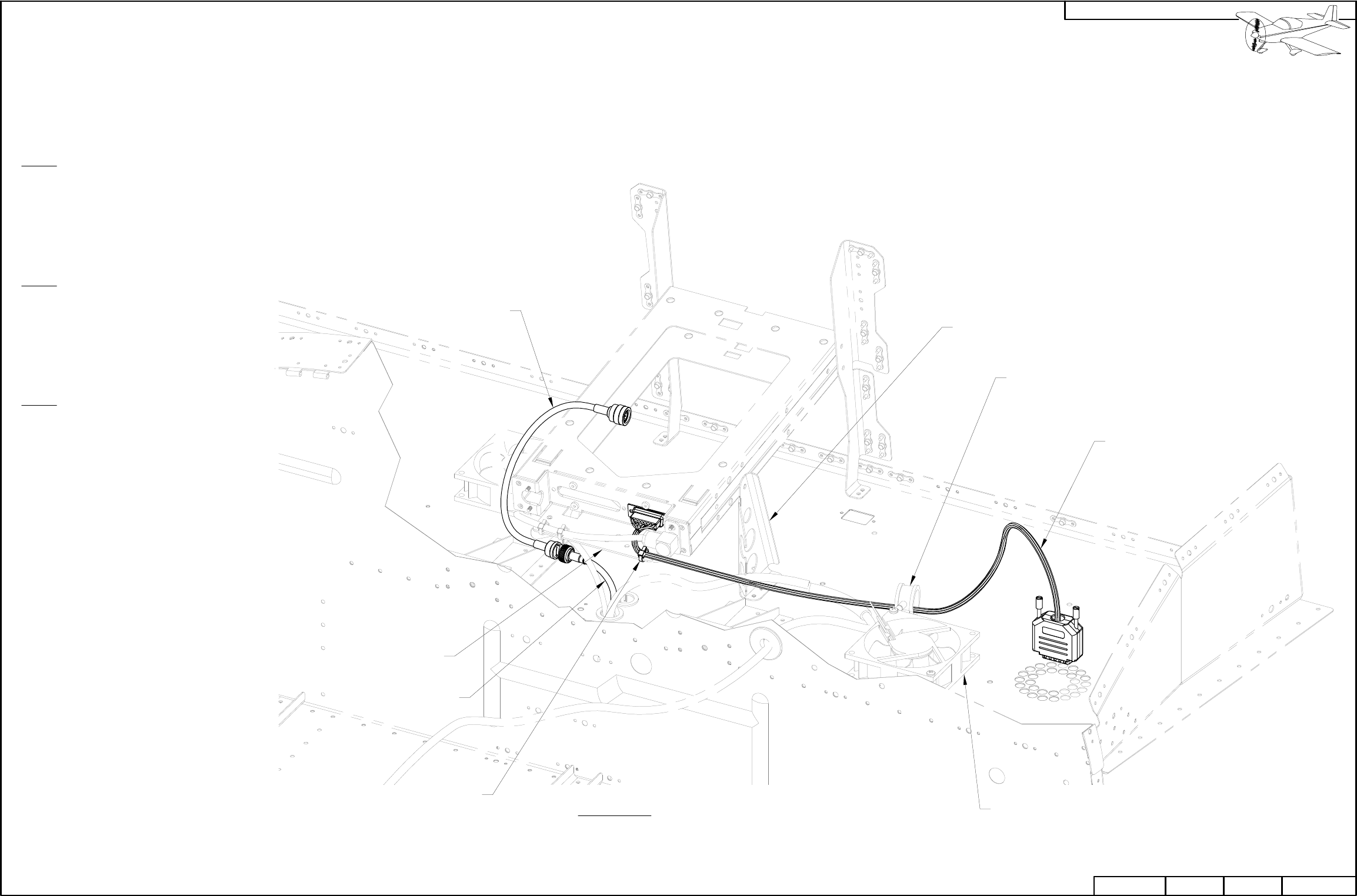
FIGURE 1: REPOSITIONING
THE TUNNEL AND OPTIONAL
HARNESSES
Step 1: Pull excess wire from the the WH-RV12-TUNNEL and WH-RV12-OPTIONAL harnesses down
through the F-1202B Panel Base until the backshells of these harnesses are in the approximate location
shown in Figure 1.
Route the WH-RV12-TUNNEL and WH-RV12-OPTIONAL wiring harnesses through the slots for snap
bushings in the F-00027-L Com Support as shown in Figure 1.
Step 2: Slit a snap bushing saved from the F-1202K-L & -R Inst Stack Supports previously in this section
then install it around all wires and the Aft Pitot Tube going through the F-00027-L Com Support except the
WH-RV12-OPTIONAL harness. Insert the bushing into the lower snap bushing slot in the com support. See
Figure 1.
Step 3: Tie-Wrap the WH-RV12-TUNNEL harness to the Aft Pitot Line where the wires exit the backshell on
the harness.
Tie-Wrap the WH-RV12-OPTIONAL harness to the WH-RV12-TUNNEL harness where the wires exit the
backshell on both harnesses.
Step 4: Loosen the F-12125 Over Rudder Wireway.
See Page 31-13 Figure 1.
NOTE: When making loops in wires do not loop wires around other wires! This may induce errant
electrical signals into data or audio wires.
Step 5: Pull the excess wires from the WH-RV12-TUNNEL and WH-RV12-OPTIONAL wiring harnesses into
the tunnel area.
Loop then tie-wrap the excess wires back on themselves as shown in Figure 2. Use a generous radius six
times the diameter of each bundle.
FIGURE 2: RESTRAINING EXCESS
WIRE LENGTH
TIE-WRAP,
2 PL
WH-RV12-TUNNEL
(BOTTOM)
WH-RV12-OPTIONAL
(TOP)
AFT PITOT LINE
SB750-10
F-00027-L
F-00027-R
TIE-WRAP
EXAMPLE HARNESS PATH
WIRE LOOP
PAGE REVISION: DATE:
VAN'S AIRCRAFT, INC.
10/03/11
PAGE42D-18 RV-12 REVISION: 0DATE:
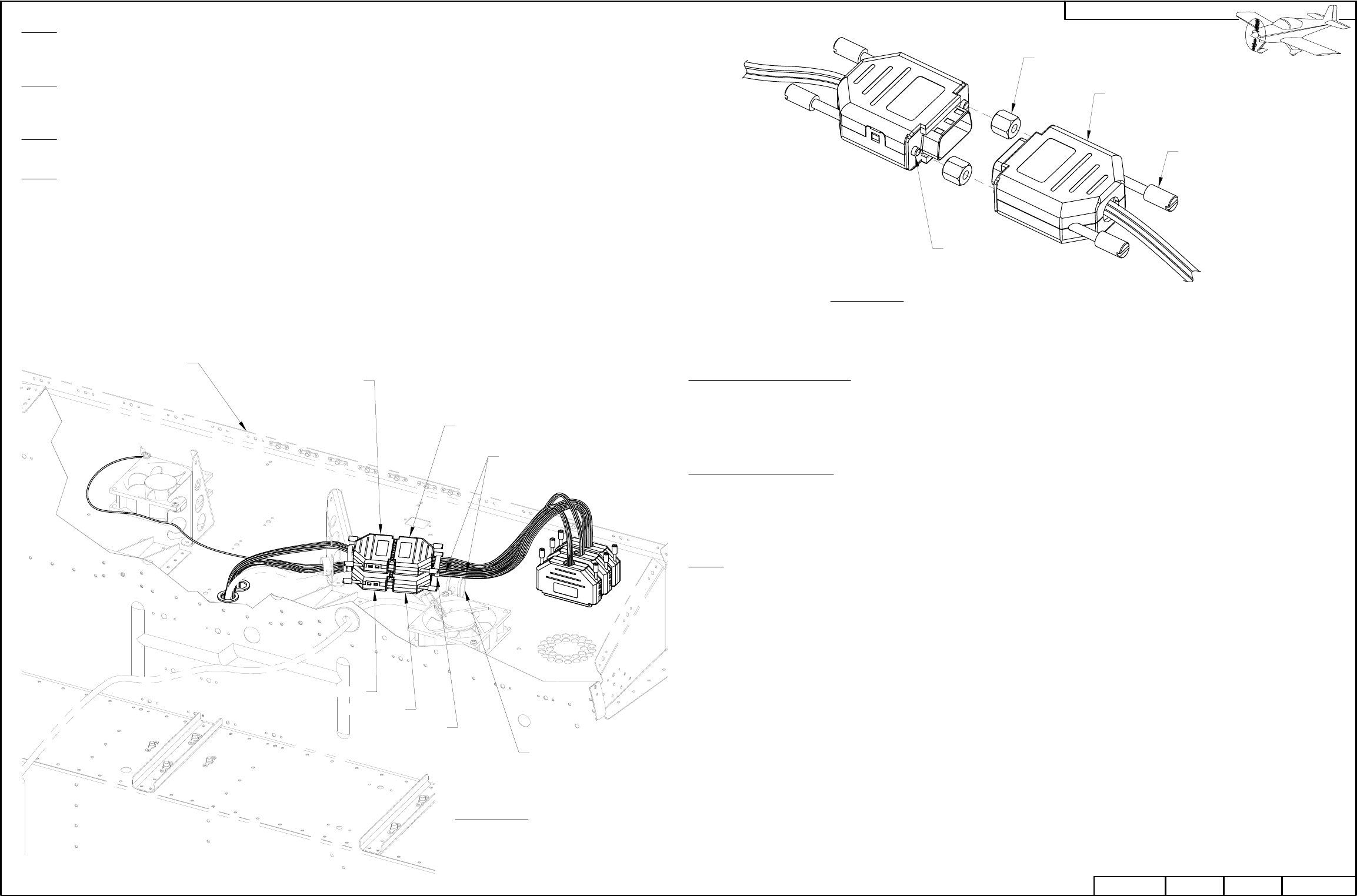
FIGURE 1: ADDING UPDATE
HARNESSES OVERVIEW
Step 1: Attach the WH-00036 Tunnel Conversion Harness to the WH-RV12-TUNNEL harness using
ES-00164 4-40 F/F .250 1/4 Hex Standoff. Place a drop of blue Loctite on the threads of each thumb screw
then fully tighten them into the d-sub backshell interconnects. See Figures 1 and 2.
Step 2: Attach the WH-00026 Option Conversion Harness to the WH-RV12-OPTIONAL harness using
ES-00164 D-Sub Backshell Interconnects. Place a drop of blue Loctite on the threads of each thumb screw
then fully tighten them into the d-sub backshell interconnects. See Figures 1 and 2.
Step 3: Tie-Wrap the WH-00036 Tunnel Conversion Harness to the WH-00026 Option Conversion Harness
where the wires exit each backshell.
Step 4: Tie a note to the cushioned clamp to tie-wrap the WH-RV12-TUNNEL harness to the wires going
through the cushioned clamp near the left ES CPU FAN on either side of the clamp when all wiring has been
completed in Section 42C. This will allow the update harnesses to be moved during installation of the
SkyView avionics system.
TIE-WRAP
ADD NOTE
TIE-WRAP EACH SIDE OF
CUSHIONED CLAMP
CUSHIONED CLAMP
WH-00026
WH-00036
WH-RV12-TUNNEL
WH-RV12-OPTIONAL
FIGURE 2: CONNECTING UPDATE
HARNESSES EXAMPLE
ES-00164,
2 PL
BACKSHELL,
2 PL
THUMB SCREW,
4 PL
BLUE LOCTITE,
4 PL
F-1202B
42D-19
010/03/11 REVISION: RV-12 PAGEDATE: PAGEREVISION:DATE:
VAN'S AIRCRAFT, INC.
Step 5 (No Lighting Kit Installed): Route WH-L435 (YEL/PRP) and WH-L436 (YEL/GRN) wires coming from
the WH-00026 RV-12 Option Conversion Harness down through the F-1202B Panel Base. Follow the ES RS
279-374 Phone Cable as described on Page 31-03 to the location of the ELT.
Cover the exposed end of each wire in heat shrink, coil the wire and tie-wrap the wire to the wires going to
the ELT.
Step 5 (Lighting Kit Installed): Find the WH-L435 (YEL/PRP) and WH-L436 (YEL/GRN) wires coming from
the WH-00026 RV-12 Option Conversion Harness.
Cut both wires three inches from the d-sub connector they are attached to.
Cover the end of each wire in heat shrink.
Step 6: There are several long wires left coming from the WH-00026 Option Conversion Harness and
WH-00036 Tunnel Conversion Harness. Route these wires down through a snap bushing in the F-1202B
Panel Base then follow the path of the WH-RV12-TUNNEL harness through the to the F-1202F Bulkhead.
Use the new wire run holes made in this section to route the harnesses to the aft side of the F-1203A
Bulkhead.
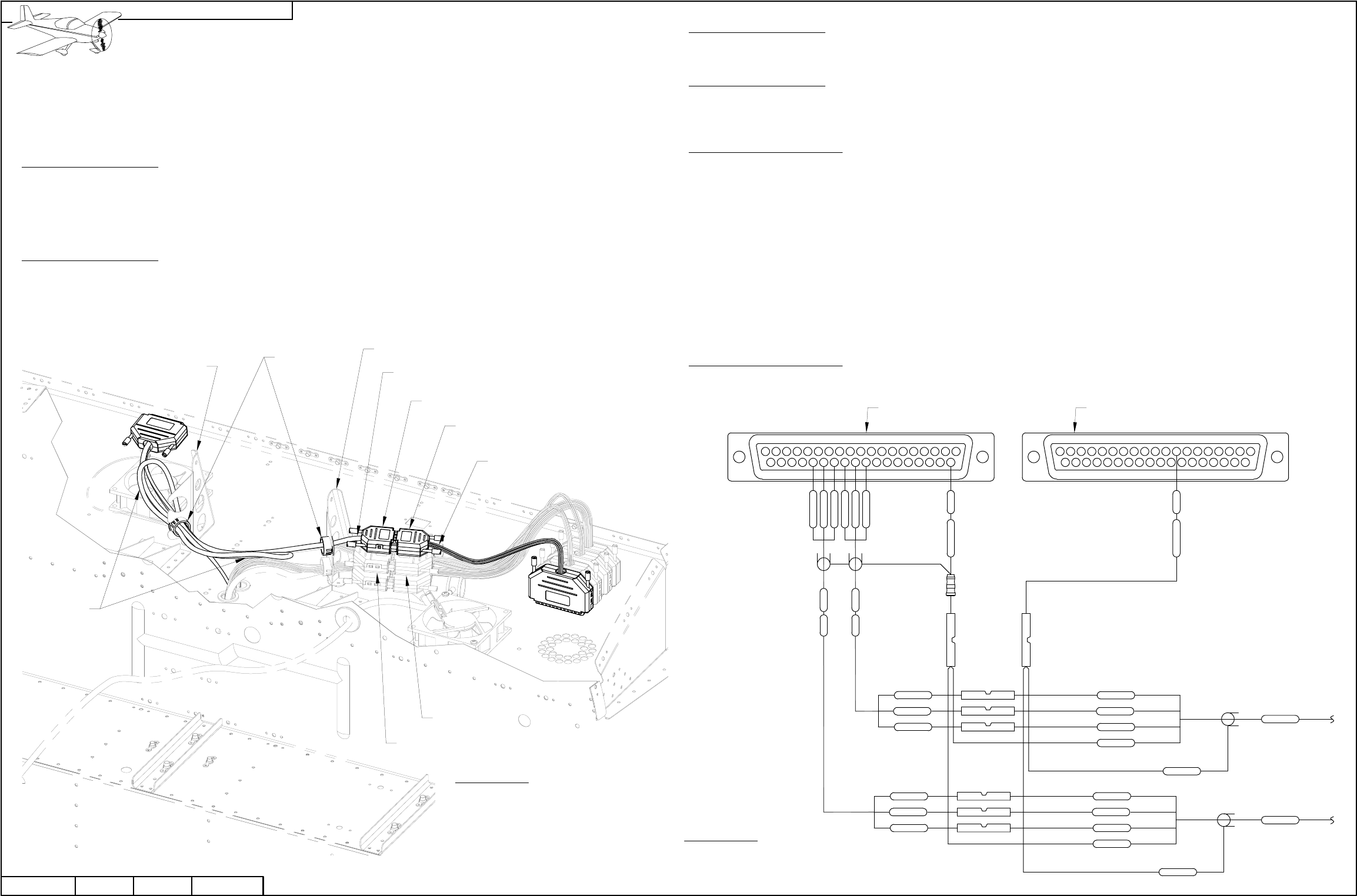
FIGURE 1: ADDING UPDATE
HARNESSES
NOTE: Steps 1-4 on this page only apply if you have already purchased an avionics kit. Steps 5-6 apply if
you have not yet purchased an avionics kit.
CAUTION: The AV GARMIN SL40 Com Radio emits a large electromagnetic field when transmitting. Avoid
routing excess wire beneath the com radio if possible. See 42D-17 for reference.
Step 1 (D-180 Avionics Kit): Route the WH-RV12-FLTCOM403 Intercom Wiring Harness through the snap bushing
slot in the F-00027-L & -R Com Stack Supports as shown in Figure 1.
Fold extra wire length from the intercom wiring harness back along its own length then tie-wrap the harness to itself.
Tie-wrap the harness to the WH-RV12-OPTIONAL harness where the wires exit each backshell.
Step 2 (D-180 Avionics Kit): Slit snap bushings saved from the F-1202K-L & -R Inst Stack Supports previously in
this section and install one around all wires going through the F-00027-R Com Support. Insert the snap bushing into
the lower snap bushing slot in the com support. See Figure 1.
Install the second snap bushing around the WH-RV12-OPTIONAL harness and WH-RV12-FLTCOM403 Intercom
Wiring Harness going through the F-00027-L Com Support. Insert the snap bushing into the upper snap bushing
slot in the com support. See Figure 1.
WH-00042
WH-RV12-FLTCOM403
TIE-WRAP
Step 3 (D-180 Avionics Kit): Attach the WH-00042 Intercom Conversion Harness to the WH-RV12-FLTCOM403 Intercom Wiring
Harness using ES-00164 4-40 F/F .250 1/4 Hex Standoff by placing a drop of blue Loctite on the threads of each thumb screw then
fully tightening them into the d-sub backshell interconnects. See Page 42-19, Figure 2.
Step 4 (D-180 Avionics Kit): Tie-Wrap the WH-00042 Intercom Conversion Harness to the WH-00026 Option Conversion Harness
where the wires exit each backshell.
Crimp splices to the ends of the WH-RZ941 (WHT/GRN) and wires coming from WH-RZ942 (WHT) and WH-RZ943 (WHT).
Step 5 (No D-180 Avionics Kit): Find the WH-RV12-HEADSET wiring harness routed up through the F-1202B Panel Base
comprised of two four conductor shielded wires WH-RZ194 (WHT) and WH-RZ195 (WHT). Cut off any connectors leaving as much
wire as possible.
Crimp the (WHT/BLK) shield wire coming from WH-RZ194 (WHT) and WH-RZ195 (WHT) into one end of a splice. Find the
WH-RZ944 (WHT/BLK) wire coming from the WH-00026 Option Conversion Harness, strip then double this wire over and crimp the
doubled wire into the other end of the splice. See Figure 2.
Crimp the (WHT/GRN) conductor wire coming from WH-RZ194 (WHT) and WH-RZ195 (WHT) into one end of a splice. Find the
WH-RZ941 (WHT/GRN) wire coming from the option conversion harness, strip then double this wire over and crimp the doubled
wire into the other end of the splice. See Figure 2.
Strip the ends of the (WHT/ORN), (WHT) and (WHT/BLU) wires coming from the WH-RZ942 (WHT) and WH-RZ943 (WHT) three
conductor shielded wires in the option conversion harness. Crimp these wires to the remaining wires coming from the headset
wiring harness as shown in Figure 2.
Step 6 (No D-180 Avionics Kit): Tie-wrap the wires from Step 5 to the wires coming from the backshells at the junction of the
WH-00026 Option Conversion harness and the WH-RV12-OPTIONAL harness.
SB750-10
F-00027-R
F-00027-L
TIE-WRAP
WH-00026
TIE-WRAP
WH-RV12-OPTIONAL
PAGE REVISION: DATE:
VAN'S AIRCRAFT, INC.
04/13/12
PAGE42D-20 RV-12 REVISION: 2DATE:
21
21
20 33272422
3 54
23
7
25
6
26
8
30
10
28
9
29
11 13
31
12
32
14
36
1615
34
17
35
1918
37
FIGURE 2: CONNECTING
THE HEADSET
HARNESS
37
18 19
35
17
34
15 16
36
14
32
12
31
1311
29
9
28
10
30
8
26
6
25
7
23
4 53
22 24 27 3320
1 2
21
WH-00026
"OPTIONS" WH-00026
"AUTOPILOT"
WHT/BLK
RZ944
RZ942 WHT
RZ943 WHT
RZ941 WHT/GRN
WHT
WHT/BLU
WHT/BLU
WHT/ORN
WHT
WHT/ORN
ES 320562
ES 320562
WHT/BLK
WHT/GRN
WHT/BLU
WHT
WHT/ORN
WHT/ORN
WHT
WHT/BLU
WHT/GRN
WHT/BLK
ES 320559
ES 320559
ES 320559
ES 320559
ES 320559
ES 320559
RZ194
RZ195
WHT/ORN
WHT
WHT/BLU
WHT/BLU
WHT
WHT/ORN
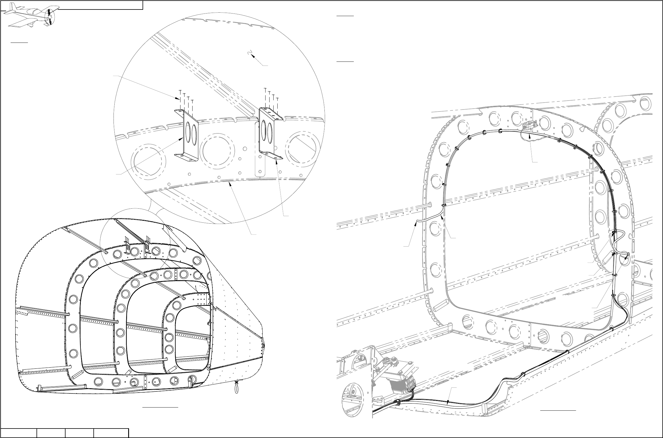
Step 1: Find the wires that were routed from the WH-00026 Option Conversion Harness and
WH-00036 Tunnel Conversion Harness through the F-1203A Bulkhead.
Step 2: Route the WH-P325 (WHT/RED) wire along the path of the ES RS 279-374 Phone Cable
as described on Page 31-03 to the location of the ELT.
Strip the routed end of the wire then crimp on a ES-320559 Splice.
For future use tie-wrap the wire to other wires going to the ELT.
Step 3: Route the WH-P323 (WHT) four conductor shielded wire, twisted WH-F319 (GRN) and
WH-F320 (BLU) wires and twisted WH-F321 (WHT/GRN) and WH-322 (WHT/BLU) wires along
the path of the WH-RV12-TUNNEL wiring harness to the tailcone area location of the
magnetometer. See Page 31-05 and 31-12.
Step 4: Tie-wrap routed wires as required.
FIGURE 1: INSTALLING PINS INTO
THE ADAHRS D-SUB CONNECTOR
(REAR VIEW / PIN INSERTION SIDE)
F319
F320
F321
F322
WHTP323
TWISTED
WHT/RED
RED
BLK
WHT/BLU
WHT/GRN
GRN
BLU
WHT/BLK
TWISTED
NOTE: Reference Page 31-12 for the remaining steps on this
page.
Step 5: Find the ES 9 PIN BACKSHELL 2 on the end of the
WH-RV12-TUNNEL wiring harness disconnected previously from
the DYNON 100323-000 EDC-10A Magnetometer.
Remove and set aside the backshell for use in the following steps.
See Section 5W Electrical Wiring Notes, Backshell Assembly.
Extract the YEL, RED and BLU pins from positions 2, 7 and 8
respectively using the TOOL ICM INSERT/EXTRACT D-Sub Tool
provided in the kit. Separate these wires for later conversion of the
OAT.
Extract the remaining wires from the ES-205203-3 9-Pin D-Sub.
These wires will no longer be used or connected at the
AV-50000A RV-12 Control Module. Fold the wires back and
tie-wrap them to the wire run along the F-1208 Bulkhead.
Set aside the 9-pin d-sub for use in the following steps.
Step 6: Find the WH-P323 (WHT) four conductor shielded wire,
twisted WH-F319 (GRN) and WH-F320 (BLU) wires and twisted
WH-F321 (WHT/GRN) and WH-322 (WHT/BLU) wires routed
previously to the tailcone area coming from the WH-00036 RV-12
Tunnel Conversion Harness and insert them into the ES-205203-3
9-Pin D-Sub as shown in Figure 1.
Install the ES 9 PIN BACKSHELL 2 onto the 9-Pin D-Sub.
FIGURE 2: CONVERTING THE OAT
HEAT SHRINK
(SHOWN TRANSPARENT)
Step 7: Separate out the WH-RV12-OAT
wiring harness RED, YEL and BLU from
the wires removed in Step 5. These come
from a multi conductor shielded wire.
Remove 3 inches of the shield then clip
the RED wire 1 inch from the end of the shield.
Cover the exposed shield (and RED wire)
with a piece of heat shrink. See Section
5W Electrical Wiring Notes, Shielded Wires.
Clip off the d-sub sockets from the end of
the BLU and YEL wires.
Strip the ends of the BLU and YEL wires.
Attach the BLU and YEL wires to the
WH-00008 SkyView OAT Connector Harness
using the butt splices called out in Figure 2.
42D-21
010/03/11 REVISION: RV-12 PAGEDATE: PAGEREVISION:DATE:
VAN'S AIRCRAFT, INC.
ES 320559,
2 PLACES
YEL
WIRE
YEL
WIRE
BLU
WIRE
WH-00008
WH-RV12-OAT
4
76 8
21 3
9
5
Step 1: Find the WH-P350 (WHT) Power Outlet Wire coming from the WH-00026 RV-12 Option Conversion Harness
previously routed through the F-1203A Bulkhead.
Strip the routed end of the WH-P350 (WHT) wire and crimp on a spade connector as shown in Figure 1.
Disconnect the WH-B148 (WHT) wire from the back of the power outlet and connect the WH-P350 (WHT) in its place.
Tie-Wrap the WH-P350 (WHT) to itself as shown in Figure 1.
Step 2: Using Page 31-10 and Section 45 as a guide remove the WH-B148 (WHT) Power Outlet +V Wire and ES
ZC-210B In-Line Fuse Holder from the aircraft.
Step 3: The WH-P440 (ORN/BLK) Audio Power wire coming from the WH-00026 RV-12 Option Conversion Harness
splits near the F-1203A Bulkhead into the shorter WH-P600 (ORN/BLK) wire and longer WH-P601 (ORN/BLK) wire.
The split in the wire needs be located between the F-1202F Bulkhead and the F-1203A Bulkhead.
Route the longer wire to the right side F-00032 Fuselage Side Cover opening through the snap bushings in the
F-1215-L & -R Seat Ribs. See Page 31-09, Figure 1.
Route the shorter wire to the left side opening.
Cover the ends of each wire with heat shrink then tie-wrap them to the headset jacks. See Page 31-10.
FUEL FLOW
CUSHIONED
CLAMP
ES 421-0108
POSITIVE
TERMINAL
NEGATIVE
TERMINAL
TIE-WRAP
WH-P350 TO ITSELF
TO CLEAR FLIGHT
CONTROLS
WH-P350
(WHT)
WH-RV12-MUSIC
AUDIO JACK
ES AS212
TIE-WRAP
FIGURE 1: REPLACING THE
POWER OUTLET WIRE
PAGE REVISION: DATE:
VAN'S AIRCRAFT, INC.
10/03/11
PAGE42D-22 RV-12 REVISION: 0DATE:
NOTE: This page is intended for builders who have completed the steps marked D-180 EFIS in Section 31A
Wing Electrical Interconnect Update, Page 31A-08. If Section 31A was completed with the intent of updating
your system directly to SkyView (Page 31A-08 steps marked SV-D1000 EFIS) then ignore the steps on this
page.
Step 1: Remove the WH-B268 (WHT) Lighting Power Jumper Wire and corresponding ES-00079 Floating
Connector Pin 16-20 AWG from the left side ES-00077 Floating 8 Pos Connector Female position 6 as shown in
Figure 2. See Figure 1 for reference on the overall fuselage configuration.
Cut off the floating connector and cover the end of the wire in heat shrink.
Step 2: Remove the WH-B268 (WHT) Lighting Power Jumper Wire and corresponding ES-00079 Floating
Connector Pin 16-20 AWG from the right side ES-00078 Floating 8 Pos Connector Male position 6 as shown in
Figure 3.
Cut off the floating connector and cover the end of the wire in heat shrink.
Step 3: Find the WH-L439 (YEL/RED) Nav Power Wire coming from the WH-00026 RV-12 Option Conversion
Harness previously routed through the F-1203A Bulkhead.
The nav power wire splits near the F-1203A Bulkhead into the shorter WH-L456 (YEL/RED) wire and longer
WH-L458 (YEL/RED) wire. The split in the wire needs to be located between the F-1202F Bulkhead and the
F-1203A Bulkhead.
Route the longer wire to the right side F-00032 Fuselage Side Cover opening through the snap bushings in the
F-1215-L & -R Seat Ribs. See Page 31-09, Figure 1.
Route the shorter wire to the left side opening.
Crimp a ES-00079 Floating Connector Pin 16-20 AWG on the end of each wire then insert them into position 6 on
the floating 8 position connectors.
POSITIVE WIRES
WH-L72 (YEL/RED)
GROUND SCREW
ON SEAT RIB
ES-00079
WH-P274 (WHT)
(LIGHTING KIT)
WH-B268 (WHT)
(LIGHTING KIT)
ES-320562
FIGURE 1: NOISE FILTER
DETAIL - D180 EFIS
WH-B184 (WHT)
WH-P274 (WHT)
ES-320562
GROUND WIRE ES-00103
WH-B268 (WHT)
(LIGHTING KIT)
ES-00079
ES-00078
UP
ES-00077
B268183
WHT
FIGURE 3: RIGHT FUSELAGE
CONNECTOR MALE
BACK VIEW
D-180 CONFIGURATION
FIGURE 2: LEFT FUSELAGE
CONNECTOR FEMALE
BACK VIEW
D-180 CONFIGURATION
27
100BRN/YEL
WHT
22
18
F57
B183
57
107
3WHT
WHT
YEL
B26818
18 B740
20 L73
YEL/BLU10720L88
57
3
3
P274
B740
18
18
B268 18
WHT
WHT
WHT
UP
B183 5318 WHT
42D-23
010/03/11 REVISION: RV-12 PAGEDATE: PAGEREVISION:DATE:
VAN'S AIRCRAFT, INC.
PAGE REVISION: DATE:
VAN'S AIRCRAFT, INC.
10/03/11
PAGE42D-24 RV-12 REVISION: 0DATE:
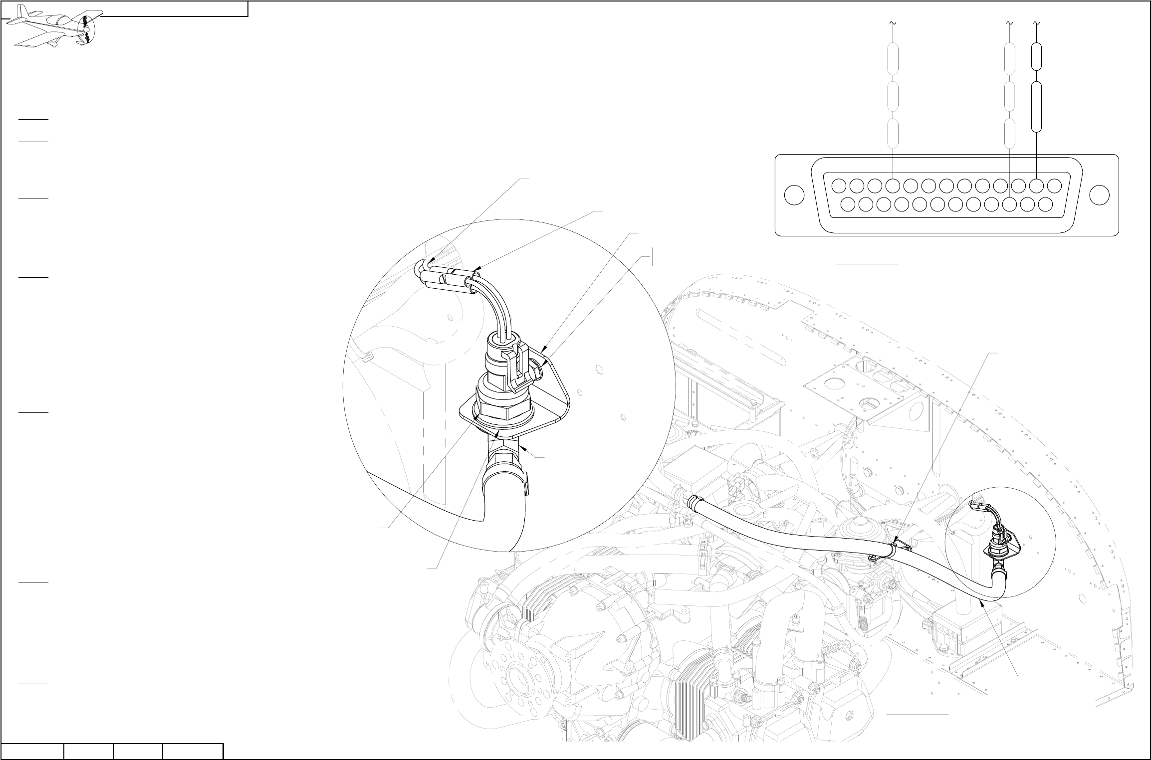
NOTE: The steps on this page apply only if you already have installed a powerplant kit and wish to upgrade to the next
generation fuel pressure sender at your own cost. Order the 101690-000 Fuel Pressure Sensor from Dynon and the
remaining parts and hardware in Figure 1 from Van's Aircraft.
Step 1: Remove the 100411-000 Fuel Pressure Sensor from the VA-216 Fuel Return Asy. See Page 46-11, Figure 4.
Step 2: Disconnect the WH-Q143 (BRN) and WH-Q144 (BRN) wires from the 100411-000 Fuel Pressure Sensor. See Page 45-05,
Figure 1.
Cut the spade connector off the end of each wire.
Step 3: Find the 25-pin backshell on the end of the WH-RV12-ROTAX Fwall Fwd Wiring Harness.
Use a multimeter to find the BRN wire going to position 16. Mark the cut end of this wire "sensor".
Use a multimeter to fine the BRN wire going to position 10.
Mark the cut end of this wire "ground".
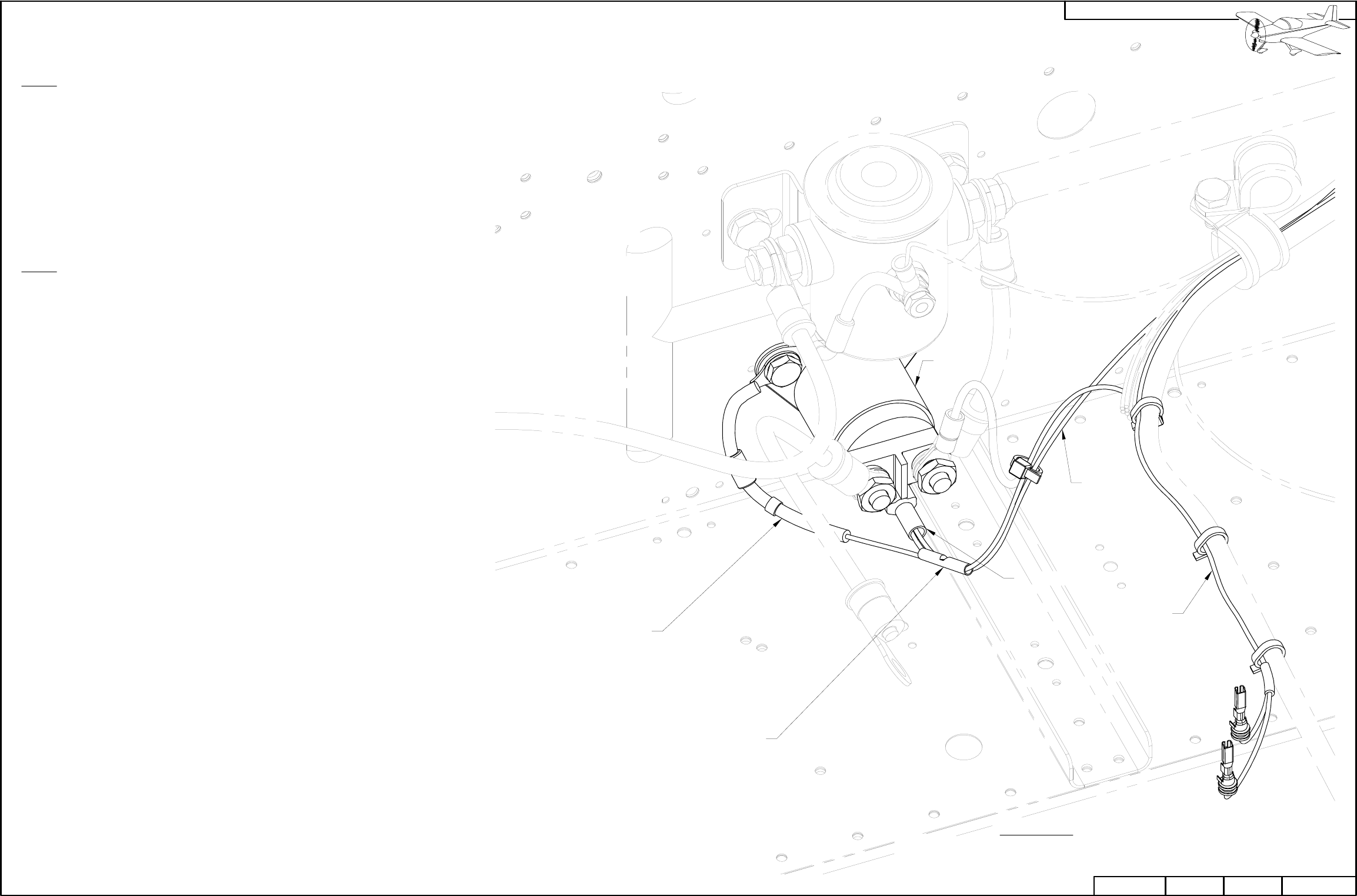
Step 4: Deburr the edges of the F-00036 Fuel Pressure Sensor Bracket.
Inlarge the hole in the grommet called out in Figure 1 to snugly fit over the
F 4 DTX-S Elbow's end with female pipe thread. Use the method described
on Page 31-02.
Insert the grommet into the large hole in the fuel pressure sensor bracket
as called out in Figure 1.
Mount the fuel pressure sensor bracket to the F-1201A Firewall Upper
using the hardware called out in Figure 1.
Step 5: Insert the F 4 DTX-S Elbow's end with female pipe thread into
the grommet from below as shown in Figure 1.
Attach the 101690-000 sensor into the elbow from above using a
small amount of pipe thread sealant.
Attach the VA-216 Fuel Return Asy. to the flared
end of the F 4 DTX-S Elbow.
Adjust the position of the fuel return assembly hose to follow a natural path
to the sensor eliminating side force on the sensor and bracket.
Repace the tie-wrap to the top of the left carburetor if necessary.
See Figure 1.
Step 6: Cut the three wires coming from the sensor 1 1/2 inches
from the top of the 101690-000 sensor and strip the ends.
Use a splice to connect the GRN wire coming from the sensor to the
BRN wire marked "sensor" in Step 3.
Use a splice to connect the BLK wire coming from the sensor to the BRN wire
marked "ground" in Step 3.
Step 7: Find the WH-Q741 (RED) Fuel Pressure Power Wire supplied in the kit . Insert the end
with a d-sub pin into position 2 on the WH-RV12-ROTAX Fwall Fwd Wiring Harness. See Figure 2.
Use a splice to connect the RED wire coming from the sensor to the fuel pressure
power wire. See Figure 1.
FIGURE 1: REPLACING THE FUEL
PRESSURE SENDER
FIGURE 2: INSTALLING THE POWER PIN
IN THE FWL FWD D-SUB
(REAR VIEW / PIN INSERTION SIDE)
Q741 RED
BRN
Q144
Q143 BRN
PLASTIC TIE-WRAP 8"
TIE-WRAP TO
BRACKET ON CARB
VA-216
F-00036
WH-Q143 (BRN)
WH-Q144 (BRN)
WH-Q741 (RED)
AN931-6-16
101690-000
ES-320559,
3 PL
AN3-3A
NAS1149F0332P
GND
SNS
F 4 DTX-S
(ALREADY INCLUDED
IN POWERPLANT KIT)
12
18 15
2 1
14
543
17 1621
9876
20 19
11 10
23 2224
13
25
NOTE: The steps on this page apply
only if you already have installed a
powerplant kit.
Step 1: Locate the WH-K47 (ORN) wire
going to the ES 421-0108 spade
connector on the 992 819 Relay. Some
engines may also have a WH-00007
(PRP) wire going to this spade
connector.
Cut the WH-K47 (ORN) wire roughly two
inches from where the wire exits the
spade connector.
Strip both ends of the cut WH-K47
(ORN) wire.
Step 2: Crimp a splice called out in
Figure 1 to the cut WH-K47 (ORN) wire
coming from the spade connector and
the wire coming from the ES-00165
Starter Relay Protection Diode.
Crimp the remaining cut WH-K47 (ORN)
wire into the other end of the splice.
Remove the right bolt and washer
holding the 992 819 Relay to the firewall.
Slip the washer and ring terminal on the
starter relay protection diode over the
bolt then re-install the bolt.
PAGE
RV-12
REVISION:
10/03/11 0 42D-25
DATE: PAGEREVISION:DATE:
VAN'S AIRCRAFT, INC.
WH-K47
(ORN)
992 819
FIGURE 1: RELAY PROTECTION
(TERMINAL BOOTS NOT SHOWN INSTALLED FOR CLARITY)
ES 421-0108
WH-00007
(PRP)
ES-00165
ES 320559
07/24/13
PAGE42D-26 RV-12 REVISION: 1DATE:PAGE REVISION: DATE:
VAN'S AIRCRAFT, INC.
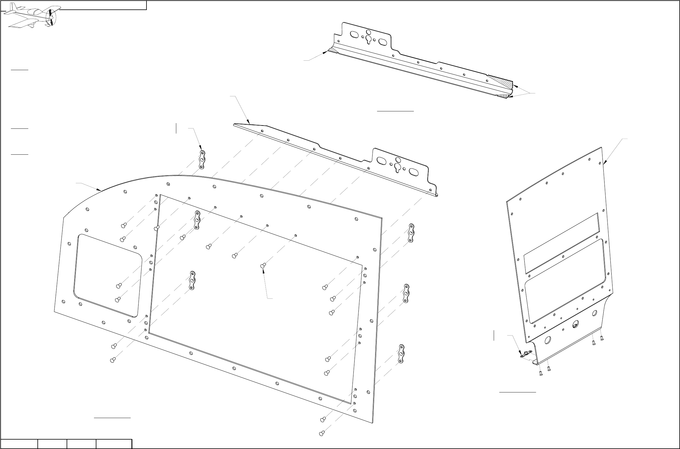
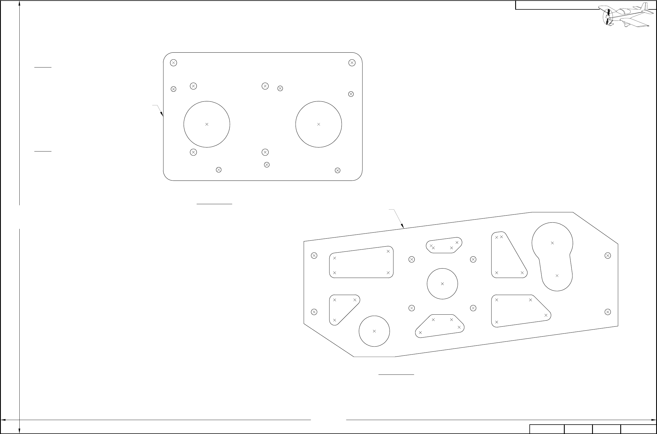
FIGURE 2: F-00030 SKYVIEW
REINF ANGLE
FIGURE 3: CENTER INSTRUMENT
PANEL PREP
K1000-06
AN426AD3-3.5 2X
F-00023
REMOVE HATCHED AREA
REMOVE HATCHED AREA
2X AN426AD3-4
K1000-06 6X
F-00031
FIGURE 1: INSTRUMENT PANEL
PREP
AN426AD3-4,
6 PL
F-00030
NOTE: This page only applies if
installing the AV GARMIN SL40
Com Radio.
Step 1: Remove the hatched areas
from the F-00030 SkyView Reinf
Angle as shown in Figure 2.
Attach the Skyview reinf angle to
the F-00031 Skyview Update Panel
using the hardware called out in
Figure 1.
Step 2: Attach the remaining
hardware to the F-00031 Skyview
Update Panel called out in Figure 1.
Step 3: Rivet two nutplates to the
bottom of the F-00023 SV Center
Inst Panel SL-40 as shown in
Figure 3.
PAGE
RV-12
REVISION:
10/03/11 0 42D-27
DATE: PAGEREVISION:DATE:
VAN'S AIRCRAFT, INC.
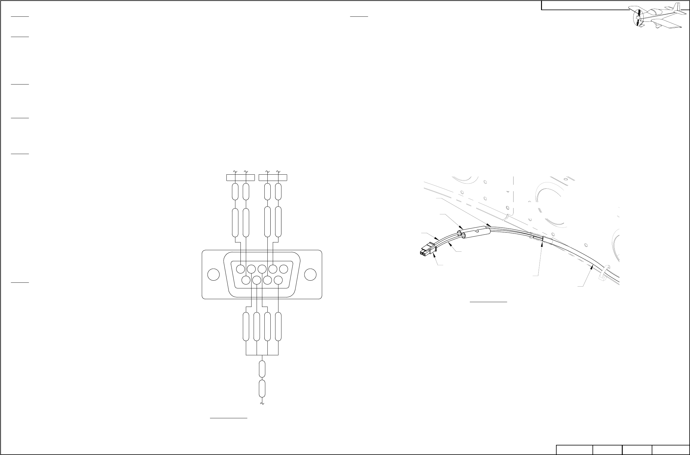
Step 3 (No Autopilot):
Store the autopilot
disconnect switch for
later use.
Fill the autopilot
disconnect switch pilot
hole with a rivet.
Step 3 (Autopilot): Use
a step-drill to enlarge
the existing pilot hole
for the
WH-RV12-APDC
Autopilot Disconnect in
the F-00023 SV Inst
Panel SL-40 to 1/2 inch
diameter.
Deburr the hole.
Install the autopilot
disconnect into the
F-00023 SV Inst Panel
SL-40 as shown in
Figure 3.
Insert the pins on the
end of the autopilot
disconnect into a
ES-00008 Molex Plug
as shown in Figure 4.
Insert the ES-00007
Molex Receptacle into
the Molex plug as
shown in Figure 3.
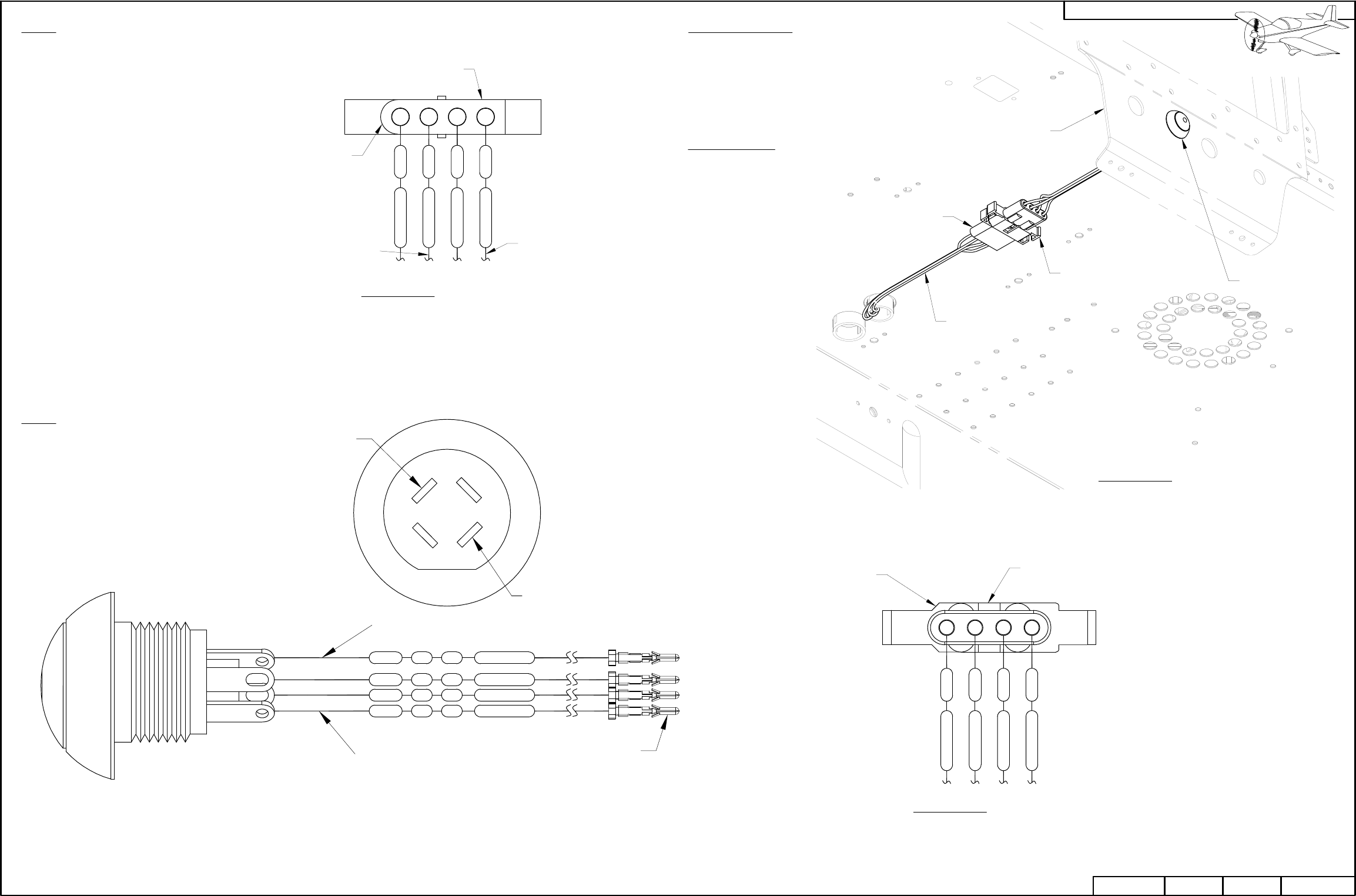
Step 1: Find the wires previously cut in
Page 42D-02, Step 26 for the
WH-RV12-APDC Autopilot Disconnect
that are still attached to the fuselage.
Crimp ES-00006 Molex Sockets to the
end of each of autopilot disconnect
wires.
Insert each wire into a ES-00007 Molex
Receptacle as shown in Figure 1.
Step 2: Crimp ES-00005 Molex Pins to the wires
coming from the WH-RV12-APDC Autopilot
Disconnect as shown in Figure 2.
NOTE ROUND
13
2 4
FIGURE 1: AUTOPILOT
HARNESS DIAGRAM
(VIEW FROM WIRE INSERTION SIDE)
ES-00007
TO WH-RV12-OPTIONAL
25-PIN D-SUB
TO SPLICE ADDED
ON PAGE 31-07
BLK
F178
REDF177
WHT
BLKF79
F78
ES-00005,
4 PLACES
22F178 6 BLK
6
22
F78
6
22
F79 BLK
WHT
622F177 RED
LIGHTING -
LIGHTING +
LIGHTING -
LIGHTING +
+
ES-00008
NOTE CHAMFER
4321
FIGURE 4: AUTOPILOT
DISCONNECT DIAGRAM
(VIEW FROM WIRE INSERTION SIDE)
F78
F79 BLK
WHT
F177 RED
F178 BLK
FIGURE 3: REINSTALLING
THE WH-RV12-APDC
(AUTOPILOT ONLY)
F-00023
ES-00007
WH-RV12-APDC
(PREVIOUSLY
CUT)
WH-RV12-APDC
(PREVIOUSLY
CUT)
ES-00008
PAGE REVISION: DATE:
VAN'S AIRCRAFT, INC.
DATE:
1
REVISION:
RV-1242D-28
PAGE 07/24/13
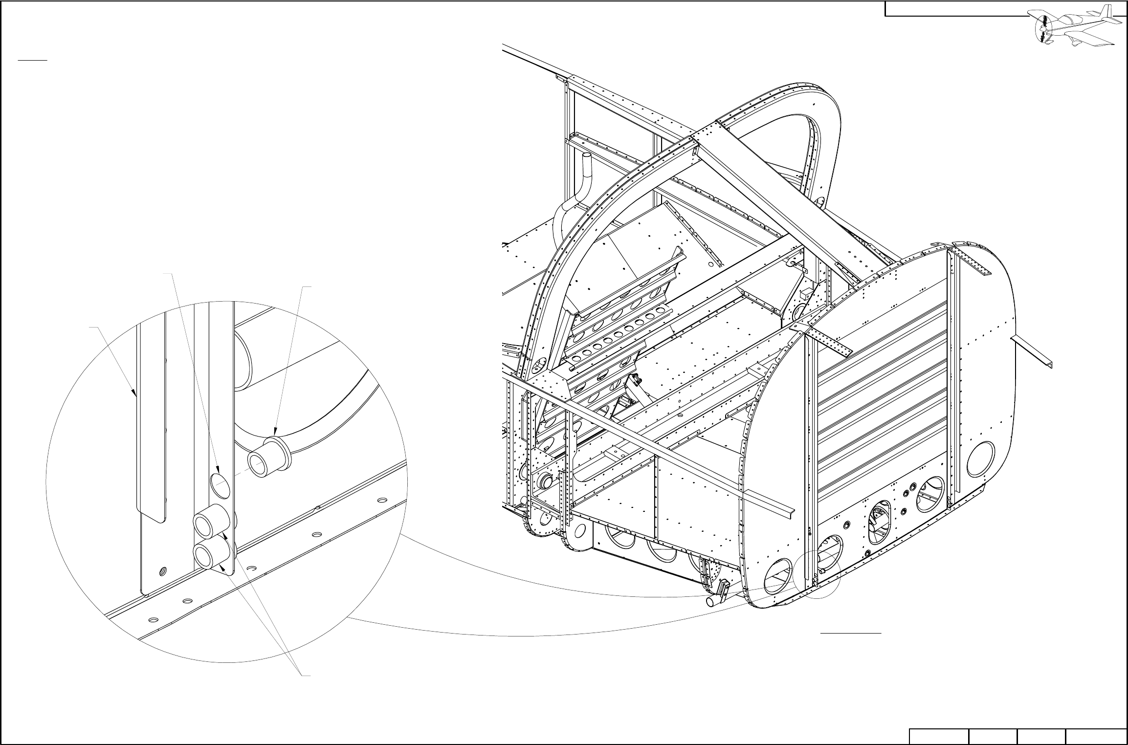
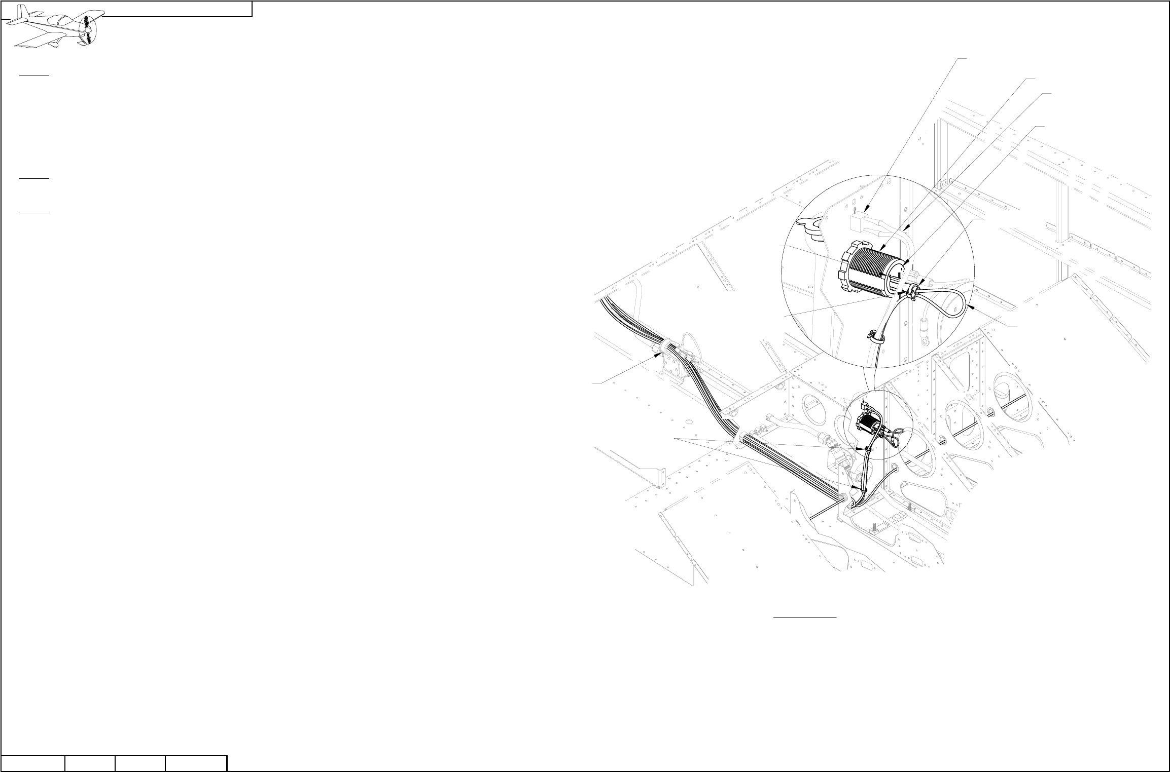
FF-1216 (SHOWN
FOR REFERENCE ONLY;
SUPPLIED IN THE
POWERPLANT KIT)
FIREWALL
PENETRATION
GROMMET
ES CPU FAN
SV-EMS-220
WH-RV12-EGT
PT 1/4 ID X 3/8 OD X4"
AV-50001
CUSHIONED CLAMP
AV-50000A
WH-RV12-ROTAX
WH-RV12-POWER
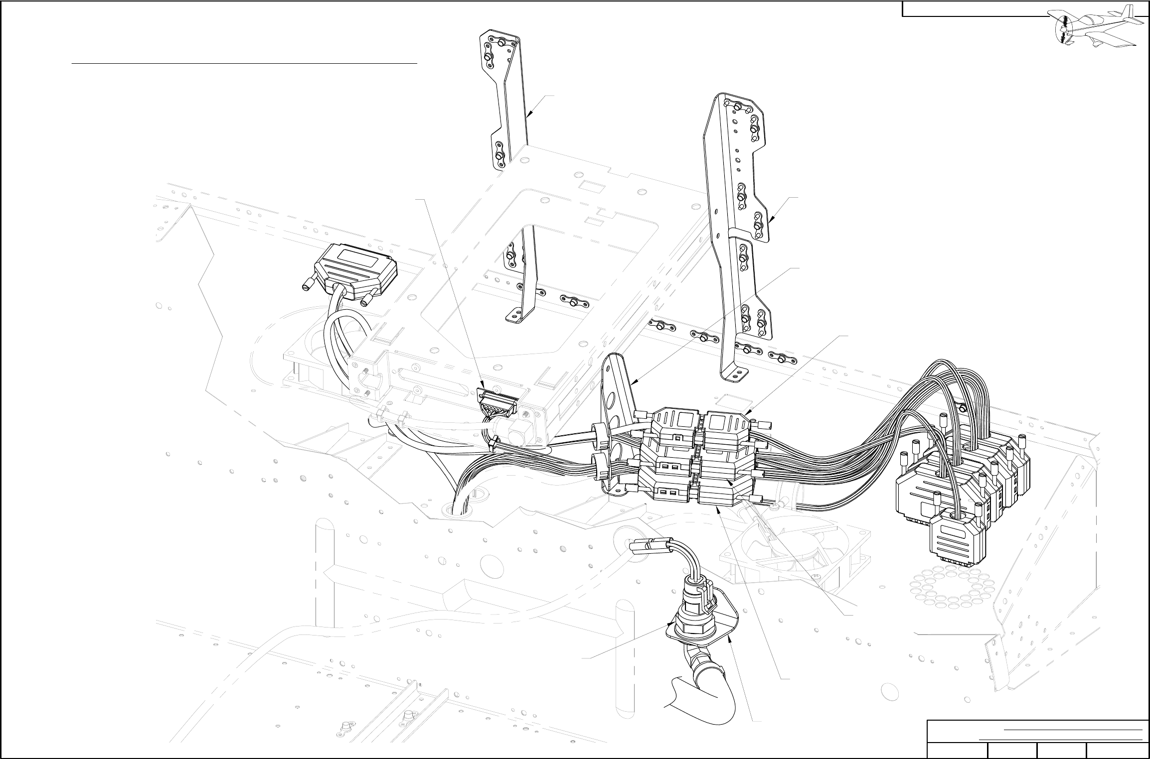
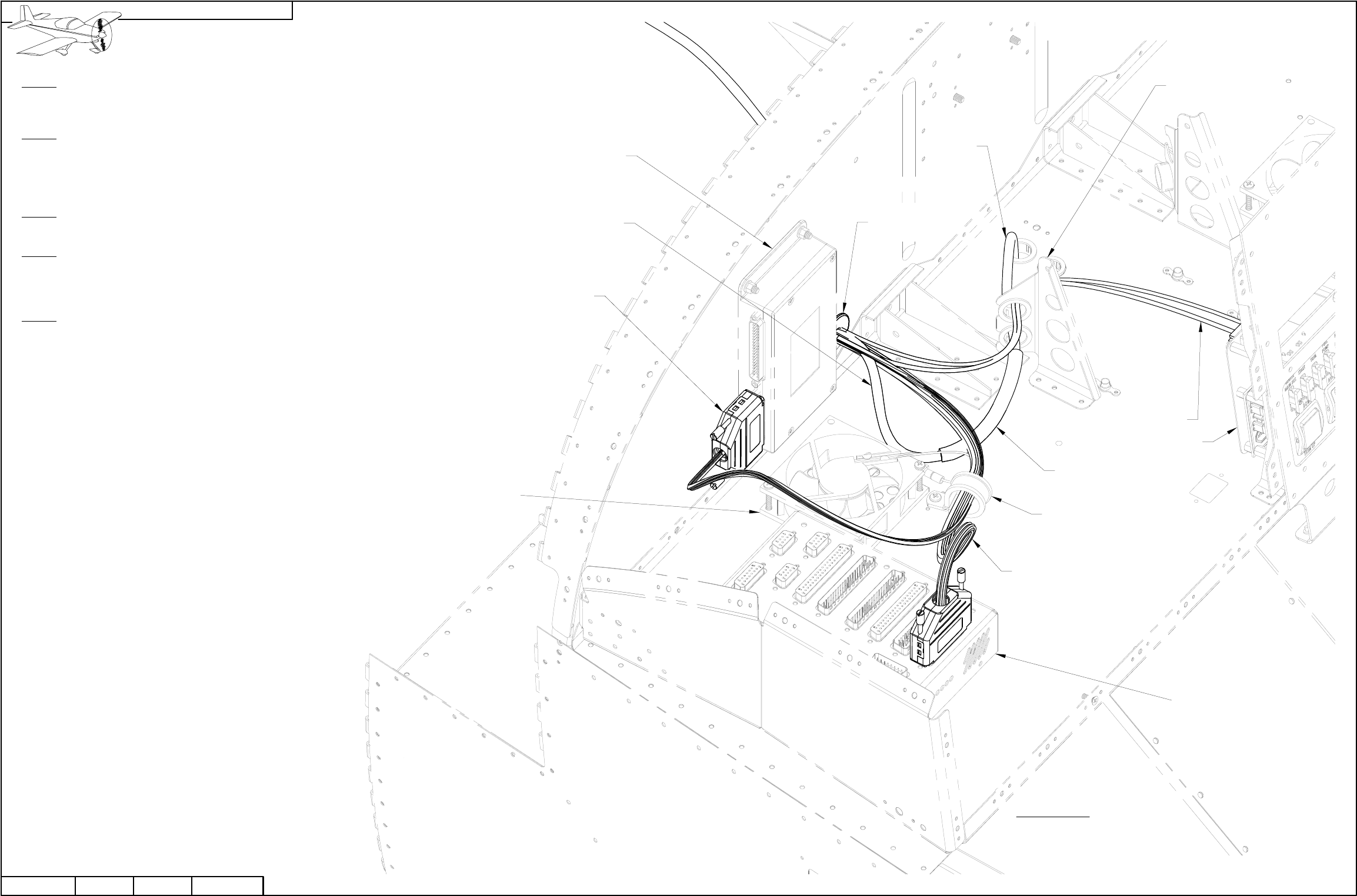
FIGURE 1: INSTALLING
THE POWER AND FWL
FWD HARNESSES
COM SUPPORT
BRACKET
AFT
PITOT
LINE
Step 1: Install the WH-RV12-ROTAX Fwall Fwd Wiring Harness 25-pin
d-sub to the top of the AV-50000A RV-12 Control Module as shown in
Figure 1.
Step 2: Install the WH-RV12-POWER wiring harness to the back of the
AV-50001 Power & Switch Module as shown in Figure 1 and Page 45A-01.
Route the power wiring harness through a snap bushing in the com support
bracket.
Step 3: Install the WH-RV12-EGT Exhaust Gas Temp Wiring Harness to the
SV-EMS-220 Engine Monitoring Module as shown in Figure 1.
Step 4: Route the Aft Pitot Line forward through bulkheads from behind the
F-1204 Center Section Assembly (see Page 42D-03) up through the
F-1202B Panel Base and through the com support bracket as shown in
Figure 1.
Step 5: Install the PT 1/4 ID X 3/8 OD X4" Pitot Tube Joiner by inserting two
inches of the Aft Pitot Line into one end of the pitot tube joiner. If the
FF-1216 Pitot Line has already been installed, insert it into the other end of
the pitot tube joiner until the ends of the pitot line and aft pitot line are within
1/4 inch of each other. See Figure 1.
If the pitot tube joiner is difficult to install, it can be warmed in hot water prior
to inserting the pitot lines.
PAGE
RV-12
REVISION:
04/03/14 2 42D-29
DATE: PAGEREVISION:DATE:
VAN'S AIRCRAFT, INC.
NOTE: Steps on this page are for builders who have completed the powerplant kit installation ahead of the avionics kit and
builders with flying aircraft.
Step 1: Leave the WH-P149 (WHT) Battery Ground Cable disconnected from the negative battery ground cable until section 42C is
complete then reinstall the cable as shown on Page 45-03, Figure 3.
Step 2: Re-install the Choke Cable, Throttle Cable and Cabin Heat Cable in the reverse order that they were removed. See Page
42D-02, Steps 18 through 25.
Step 3: Rebalance the carburetors on the Rotax engine.
Step 4: Update the hobbs time on the SkyView EFIS system to match the hobbs time from the D-180.
CAUTION: Do not un-plug or plug in any connector in the aircraft electrical system with the electrical system turned on or
any avionics component running off a backup battery!
Only adjust potentiometers using the TOOL-00000 Trimmer Adjustment Tool. If necessary carefully sand down the tip
diameter of the trimmer adjustment tool to fit within the adjustment holes in the case of the AV-50000A Control Module.
When adjusting the potentiometers it is possible to run off the end of the adjustment range. The item being adjusted will
then be completely turned off. If this happens turn the pot back into the normal adjustment range. The potentiometer has a
built in clutch system which prevents damage if the potentiometer is turned past the end of its travel.
The four screws that attach the AV-50000A Control Module to the F-1202B Panel Base provide a ground connection. Do
not power up the electrical system without the control module attached to the panel base!
Step 5: Make the potentiometers easily accessible. Remove the SkyView display then temporarily remove the four mounting
screws that retain the AV-50000A Control Module. Gently pull the control module through the display opening in the panel leaving
all the harnesses attached. If the routing of your harnesses prevent this remove the F-1240 Upper Forward Fuselage Skin to grant
easy access to the control module.
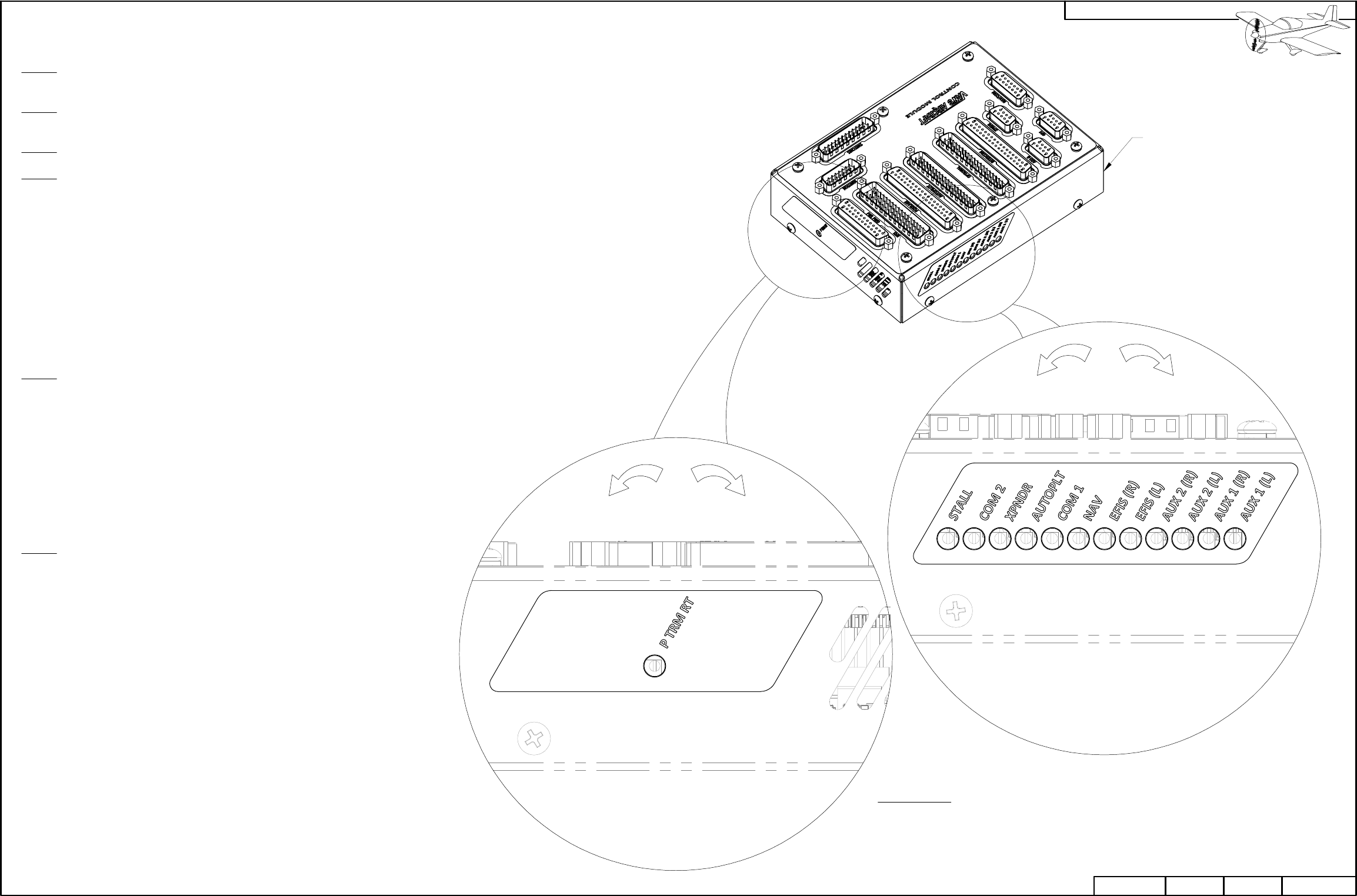
AV-50000A
FIGURE 1: CONTROL MODULE
SETTINGS
CAUTION: Only use a battery charger compatible with your battery's specifications.
NOTE: If the SkyView AP-Knob Panels kit Section 58 has been installed, skip Step
2. When using the knobs modules the trim rate will be controlled by the
SV-AP-PANEL module which is pre-set with factory settings when the latest
firmware-settings file is installed from the Van's Aircraft web site.
Step 6: Double check that trim tab motion properly corresponds to trim switch input.
Use a battery charger to bring the bus voltage to approximately 13.6 volts.
Verify the time to run the trim motor stop to stop is approximately 25 seconds.
The potentiometer is a 25 turn device. Turning the potentiometer clockwise will
slow the motor travel, conversely turning it counter clockwise will speed the
motor travel. After the first flight this setting may be fine tuned to
builder preference.
SLOWER
(CW)
FASTER
(CCW)
SOFTER
(CW)
LOUDER
(CCW)
PAGE REVISION: DATE:
VAN'S AIRCRAFT, INC.
04/03/14
42D-30 RV-12 REVISION:REVISION: 2DATE:DATE:
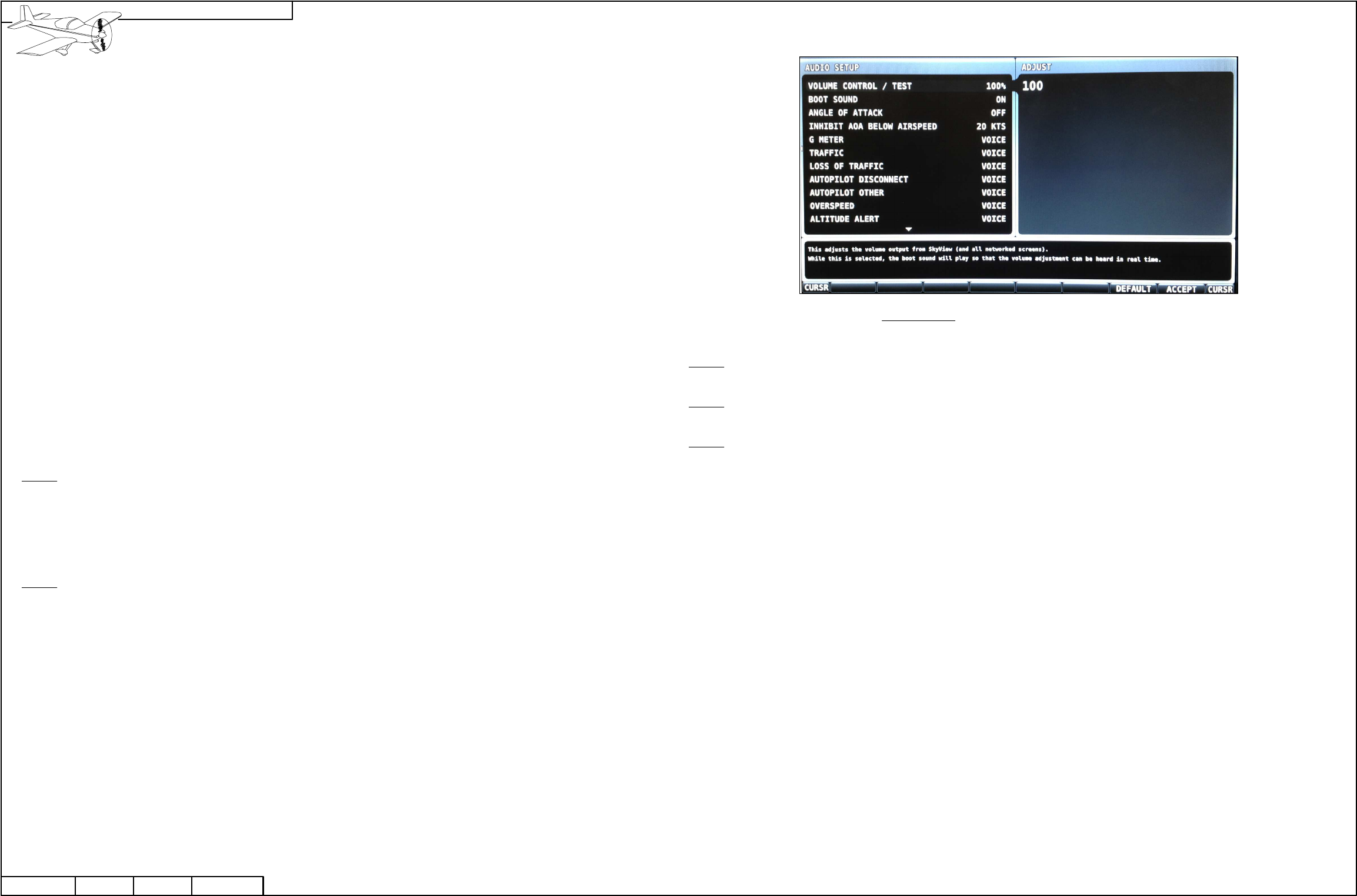
FIGURE 1: SKYVIEW VOLUME CONTROL
Stall
Com 2
Xpndr
AutoP
Com 1
Nav
EFIS (R)
EFIS (L)
Aux 2 (R)
Aux 2 (L)
Aux 1 (R)
Aux 1 (L)
Volume max
Volume off
Volume off
Volume off
Volume max
Volume off
Volume 3 turns CCW from off
Volume 3 turns CCW from off
Volume off
Volume off
Volume max
Volume max
NOTE: This page describes how to make final adjustments to obtain the best performance from the audio mixer.
Before starting remove any outside voltage sources such as a battery charger.
What is an audio mixer? The design intent of an audio mixer is to combine audio signals together from many
different sources into one balanced signal that then will be fed into an intercom. The potentiometers over which you
have control first reduce each audio signal, the signals are combined then amplified back to a useable output level
for the intercom.
The following is a list of the factory preset levels for the audio mixer. Levels are preset at the factory and should
work well "out of the box". Levels are included here for future reference.
Volume max = 25 turns counter clockwise (CCW)
Volume off = 25 turns clockwise (CW)
Turning more than 25 turns will ensure the max or off condition.
Step 3: Plug a headset into the pilot headset jacks. If the headset has volume control adjust the volume to the middle of the range.
Turn on all audio devices connected to the board. Use a local ATIS or AWOS for radio input.
Step 4: Adjust the radio volume knob to full volume. Adjust the Com 1 sound level potentiometer on the AV-50000A Control Module
until the radio is too loud and slightly distorted.
Step 5: Install the AV-50000A back onto the F-1202B Panel Base as shown in Section 42M.
Step 1: Plug in and turn on a music device such as an iPod to the auxiliary music jack. Set the output volume of the device to
75% of full. Practice turning the potentiometers that control the Aux 1 (L) and Aux 1 (R) levels. Become familiar with the feel
when tool is actually engaging the potentiometers and changing the output volume.
Notice that a very small range (possibly 6 depending on the music device you are using) of the pots 25 available turns are
useful. Going back to the description of an audio mixer this means that some audio signals may need large reductions (more
turns of the potentiometer) to match the strength of a weak audio signal.
Step 2: When you are comfortable adjusting the potentiometers make the following changes to the EFIS (L) and EFIS (R)
levels. The goal is to maximize the EFIS alert output level while minimizing the background noise. There are background
"noises" inherent to SkyView. By turning the EFIS (L) and (R) levels down as far as possible the "noise" is reduced as much
as possible. To make the EFIS audio alerts loud enough to hear, turn the volume output up within the SkyView itself. Note
the SkyView volume control only affects the volume of the alerts not the "noise". We have then minimized the noise while
maximizing the audio alert volume.
Enter the Audio Setup menu within the SkyView display and set the Volume Control / Test to 100%. See Figure 1. If the
audio from the display sounds distorted the audio mixer potentiometers in the control module are now set too high.
Slowly turn both the EFIS (L) and (R) levels down 1/2 turn at a time until the distortion disappears. Note that if the volume
disappears altogether you have turned the potentiometer completely off. Turn the potentiometer back CCW until the volume
comes back.
It may not be possible to obtain the perfect level setting. In this case turn down the volume within the display to remove the
last hint of distortion. This should result in a sound level of 80% - 100% within the screen. The closer to 100% the quieter the
"noise" will be.
Now that the setup has been maximized and distortion removed turn the screen volume level down even further if the
maximized level is too loud for your combination of hearing health and headset quality.
PAGE
RV-12
REVISION:
07/24/13 2 42D-31
DATE: PAGEREVISION:DATE:
VAN'S AIRCRAFT, INC.
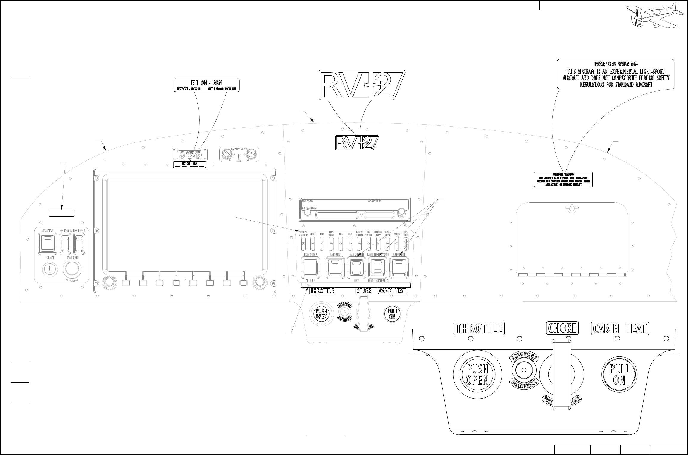
NOTE: Some labels are integrated into the parts themselves. Fuse labels, and instrument panel switch markings are integrated as shown in Figure 1. If not installing the
corresponding option for the switches shown in Figure 1, the switches must be labeled as inoperable.
F-1200 Interior Label Sheet labels are printed on a thin sheet of metal. Bending the interior label sheet labels may cause creasing or even break the label. To make removal of the labels from the
label sheet easier, cut the label sheet with scissors then peel the paper backing off the back of the label. Take care when placing the labels that the surface is clean and dry (denatured alcohol
works well) and that the labels are properly aligned. Press labels firmly to adhere.
Step 1: Install the F-1200 Interior Label
Sheet labels on the left, center, and right
instrument panel sections as shown in
Figure 1. A piece of narrow masking tape
placed below the transponder makes
alignment of the throttle, choke, and cabin
heat labels easier. See Figure 1.
FUSE AND
PANEL SWITCH
MARKINGS,
TYP
NOTE: The custom aircraft identification number or "N"
number for the instrument panel may be purchased at a
local sign or trophy shop or created using a label printer.
The placard should be clearly legible. The font type used on
the other placards is "Gill Sans MT Condensed".
Step 2: Install aircraft identification number or "N" number label
on the instrument panel left as shown in Figure 1.
Step 3: Tie-Wrap all wires as required and re-install all parts and
hardware of the aircraft removed to facilitate the upgrade.
Step 4: Update the weight and balance of the aircraft.
Update the POH and aircraft logbook.
NARROW TAPE
INSTRUMENT
PANEL LEFT
AIRCRAFT
IDENTIFICATION
NUMBER
INSTRUMENT
PANEL CENTER
SWITCHES FOR
OPTIONAL KITS
INSTRUMENT
PANEL RIGHT
FIGURE 1: INSTRUMENT
PANEL LABEL PLACEMENT
PAGE REVISION: DATE:
VAN'S AIRCRAFT, INC.
01/28/13
42D-32 RV-12 REVISION:REVISION: 1DATE:DATE:
FINAL-DRILL #30
FIGURE 1: GPS CUTOUT
TEMPLATE
3/4
[19.0 mm]
NOTE: This page summarizes
the optional installation of a AV
GARMIN X96 GPS. Since this
series of GPS is no longer in
production this page has been
added for builder convenience
only.
Required hardware for this
optional installation has not
been provided in the SkyView
update kit and must be
purchased separately.
Step 1: Make a cutout in the
upper F-00023 SV Center Inst
Panel Overlay using the template
given in Figure 1.
This cutout will not allow the AV
GARMIN X96 GPS body to be
removed through the panel. If
removal is desired enlarge the
cutout slightly and final-drill #30 a
hole for the release mechanism
as shown in Figure 1.
Step 2: Deburr the cutouts in the
F-00023 SV Center Inst Panel
Overlay.
16
[406.4 mm]
10 9/16
[268.3 mm]
NOTE: CHECK PRINTED SCALE 1:1 PER SECTION 3 BEFORE USING THE TEMPLATE!
PAGE
RV-12
REVISION:
04/11/12 1 42D-33
DATE: PAGEREVISION:DATE:
VAN'S AIRCRAFT, INC.
.125 2024-T3
ALCLAD
FIGURE 2: GPS MOUNT BRACKET TEMPLATE
.040 2024-T3
ALCLAD
FIGURE 1: RETAINING PLATE TEMPLATE
F-1201Z
F-1202S
NOTE: This page summarizes
the optional installation of a
AV GARMIN X96 GPS. Since
this series of GPS is no longer
in production this page has
been added for builder
convenience only.
Step 1: The Garmin 295 through
496 series GPS has been
discontinued from production.
Van's Aircraft will no longer
produce the F-1201Z Retaining
Plate and F-1202S GPS Mount
Bracket.
If needed use the flat patterns in
Figure 1 and Figure 2 to produce
the retaining plate and GPS
mount bracket.
Step 2: Install the 145-00452-00
Dock supplied with the AV
GARMIN X96 GPS as shown on
Page 42-12.
NOTE: CHECK PRINTED SCALE 1:1 PER SECTION 3 BEFORE USING THE TEMPLATE!
16
[406.4 mm]
10 9/16
[268.3 mm]
PAGE REVISION: DATE:
VAN'S AIRCRAFT, INC.
04/11/12
42D-34 RV-12 REVISION:REVISION: 1DATE:DATE:
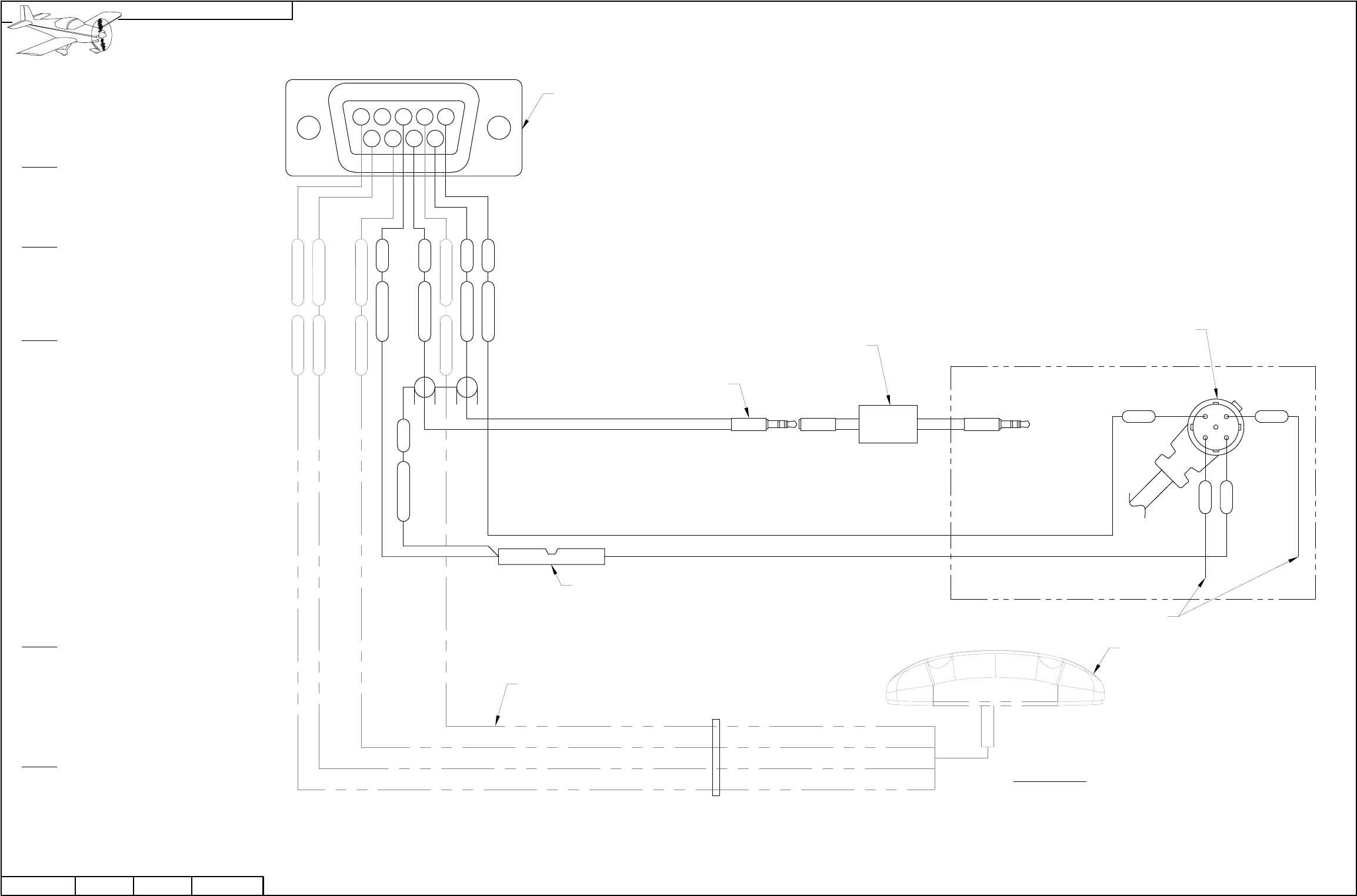
NOTE: This page summarizes the
optional installation of a AV GARMIN
X96 GPS. Since this series of GPS is no
longer in production this page has been
added for builder convenience only.
Step 1: Remove the backshell, heatshrink
and d-sub pins from the end of the
WH-RV12-296-496 GPS Wiring Harness
using the TOOL ICM INSERT/EXTRACT
D-Sub Tool. See Page 42-13.
Step 2: Find the short green shield wire
coming from the wires going to the 1/8 Inch
Audio Plug on the WH-RV12-296-496 GPS
Wiring Harness and cut off the pin.
Strip the end of this wire.
Step 3: Find the black wire coming from
the Garmin Power Data Cable Connector
on the WH-RV12-296-496 GPS Wiring
Harness.
Cut this wire two inches from the d-sub pin.
Strip both the cut wire with the d-sub pin
and the wire going to Garmin Power Data
Cable Connector.
Crimp the black wire with d-sub pin and the
shield wire from Step 2 into one end of a
splice as shown in Figure 1.
Crimp the black wire going to the Garmin
Power Data Cable Connector into the
other end of the splice.
Insert this wire into the ES-00140 9-Pin
Male D-Sub on the WH-00034 SkyView
GPS-250 Harness as shown in Figure 1.
Step 4: Cover the ends of the blue and
yellow wires coming from the Garmin
Power Data Cable Connector on the
WH-RV12-296-496 GPS Wiring Harness in
heat shrink.
Fold the blue and yellow wires back and
tie-wrap them to the GPS wiring harness.
Step 5: Insert the remaining wires coming
from the WH-RV12-296-496 GPS Wiring
Harness into the ES-00140 9-Pin Male
D-Sub on the WH-00034 SkyView
GPS-250 Harness as shown in Figure 1.
8
45
9
13 2
7 6
FIGURE 1: INSTALLING PINS
IN THE WH-00034
CONNECTOR
(REAR VIEW / PIN INSERTION SIDE)
WH-00034
GARMIN POWER DATA CABLE CONNECTOR
GRY/PRP
GRY/ORN
SVGPS250
SVGPS250
BLKSVGPS250
ORNSVGPS250
COVER ENDS IN HEAT SHRINK
GDC BLK
SV-GPS-250
AV GROUND LOOP
1/8 INCH AUDIO PLUG
ES 320559
GDC
AC
RED
BLK
REDAC
S1 GRN
ES-00140
TWISTEDTWISTED
AV GARMIN X96 GPS
RED
BLK
YEL
BLU
