Service_Bulletins Service Bulletins
User Manual: Service_Bulletins
Open the PDF directly: View PDF ![]() .
.
Page Count: 11
~
---..
.-
...
~
.~::..
:1.
•
\0.01'
I - .... ' !
TX
NO
1110
TO:
M Abrahams
D
Baum
p.
Eruer
R
Burton
....
Carson
l
C Cobb
D Cowdin
W
Garrison
R
Geyer
R
Gutosky
T
DeLaFuente
RED
R
Havlick
E
Heston
-
Hoy
B
Hull
A
Jager
B
Keller
D
Leek
H
Leggett
B.
rvey
C
~arrone
B
HcNeese
L I G H T
C
McNutt
E.
Miguel
G
Orlowski
A
Powers
C
Sheldon
R
Sundius
B
Wicks
B
Williams
G
Wipperfuerth
B
~·right
B
Zinsmeister
ALE
R T 0561
EFFECTIVITY:
Fujitisu
Eagle
Disk
Drives
PROBLEM:
Local
cc:
J
Bogdan
D
Calderara
D
Carver
D
Corts
B
Daley
R
Diodati
H
Johnson
W
May
tan
D
Petucci
L
Stevens
G
Whittaker
R
Poland
J
Hill
The
disk
will
not
power
up when
the
system
is
first
received.
SOLUTION:
-
Reset
connector
CJN502 on
the
head/deckassembly.
To
gain
access
to
the
connector,
the
card
cage
on
the
left
side
of
the
disk
must
be
lifted"out.
The
connector
is
on
the
bottom
of
the
HDA.
Seating
of
this
connector
is
apparently
disturbed
while
the
vibration
damping
foam
block
is
installed
or
removed.
CONCLUSION:
This
information
will
be
contained
in
the
service
manual
in
the
black
book.
BEn
Wright
Qantel
4."
f5.L
SE~Uc)
tJl\
DATA
!?J6--1
/J
If.
t)-'U
.,
re..
,,/,.
111-
Tt..sr
~SSt',6/~
JI~·Ad
S.dt,t:.-{-
.
Prv,6J~WJ
{<.<.f./
~
t:-Co.
f{;;Al·~J
13
~J$.
fossi
.J,/~
/3J
Dr
f);r-
t7
H~J
If
"SSi
.tIJ/.f.
CIt"',
J-I
..
iA.~
~t.ep<"
tAw·
n4,--
To
CD.,
.r.
...
,.,
LD"J
Hu/
A,..,.
i?
(1\.-,
LJR
1ft
744-
~..,
~c".
#'-1"c.
~
.
DI"Se.
Of(
F.E..
k-l-AY~II\.
fo!r;6/(
S't.
.....
t.10
PJ/I.~l'
FI';'~YC
0"
fos;hDlle,..
.
GtAt-;"
If
Co
..
.p,.
~-fltAcJ..
.oi
t'K'Ehc/OS~Y
-
\
/{4!f'/#o
c.-
A~l!~,I,I'1
IV
'O.tr"
;',."
0", 57ii
TCAS
Ru."
-Yf;~uf
Or
U5..(..
(Kano
fo
1",it,"Ji
zc,
OnJ{ 'I
tJ.L
J
S~c.
.,,,,
)~-S+<'''1
1'1
/!..£-
RE
STci'()
I+
FrD""
.
i3F1LF
Il
:
Lta\JC,.
Sf-u
'"
r..,se
....
V
l<y~t".~J
,--.-.IS(!I'Aflr.
f6;
lv.rL:
I<IlJO/H..f-
A~soc.
B,",ls.
.D·ft",J;
"1
{'h
srATlAf:
~fA."
M,'c
r
".
f/?°Co
A"'''/~r
*Flx~£cr
rJ
BFILFIL
All
/l.;f
t3
..
c<
s(cA",.
T"
T~
.It..
Rc."
Foy"".{-
DISc...
rf
r-~,J~J..:
,r<...~DIAC~
..
:
DiSc.
E,.,<.I.
;"rc~
A/f~Yl'ttd.(.
~5~doy
If
1flXSEc
lJAS
t.d"t',l ;
fro~/""7
S,c..-:.ft-
.....
IA-I",
;~
BAD
R~f!".e
...
lJj5
(..
t",c!cs.t,v
..D
...
:
0<.
/.s
()~""1V4-:0-...J
(3i,c
r$"ctf7lV'",tE
IS
",,,t-:
"
fr{)~
~
til
",,.,.
(~
r,. A
1.
L
ar~~.'
M-.
j
'"
p".o~
I
~tt1
SCOL-.f...".
!/lc,I S
If]
<..
R.A
J!.IA
:
,.cJ
M.<
'f
A~s,s
Wi4~
('(7
II.
,
, .
Sc.lsr..tG-r
A
......
AS:
Co~iYO
II~~
Ow.
(j
..
J..
Su-~:
(;
...
1,.,
C(J.~r
I/OC~hs
i
'CA.tII.f..
'O~;II'(
",. '
l-E..10'1
1-°1;"',
a..4
lt
CD
...
n..o
'/t",
7i1Mt~
Ser,,,,,s
o~
f../I«
....
C
...
~
/(l./,
I,.
(-t.
f,
W-t.V'"
5
&A.fr'
y
TtM-<'
O,..IIJ
~
""'" II
C"lo/'$
()"
1;.,
Vo/~,.f.
[)~fJ
$
rSllh.
-<-
To
t)1\.A,.
13
,..J,
-r
/?tflloc
...
r+
r t
O"(~Q
II
Lo,.J
It71.....
f,.oA)~
IYI
~
cA~ck
C",,..,.,,,11;,..;
S~Hi"1·(tr1Jr?)
~(f'''t.
-<...
,fo~
..
,...SIA('
./
f~>f~c-r
Asuh7-6li.(,r:
j).tu. J 2-
1.).( t/.
J.(
2.
T()~·
J.{~
..tr~J
114dr
l3~r
~J/<-
foss;
),/011..
P4
Sif;
017.f.",
Fit;
14
r'-{
/Jelf'Ti.,riDt1
(e.,ll-<~
~.ffI4(~
Ad
j
/A;d
It-
/(,,1"";
~
WAtfrJ,
NG
.','
{<t.fl""
~
"l}s;.f;Olt
~rl
j)}SK
£'t1t:./".I~
r
Disk
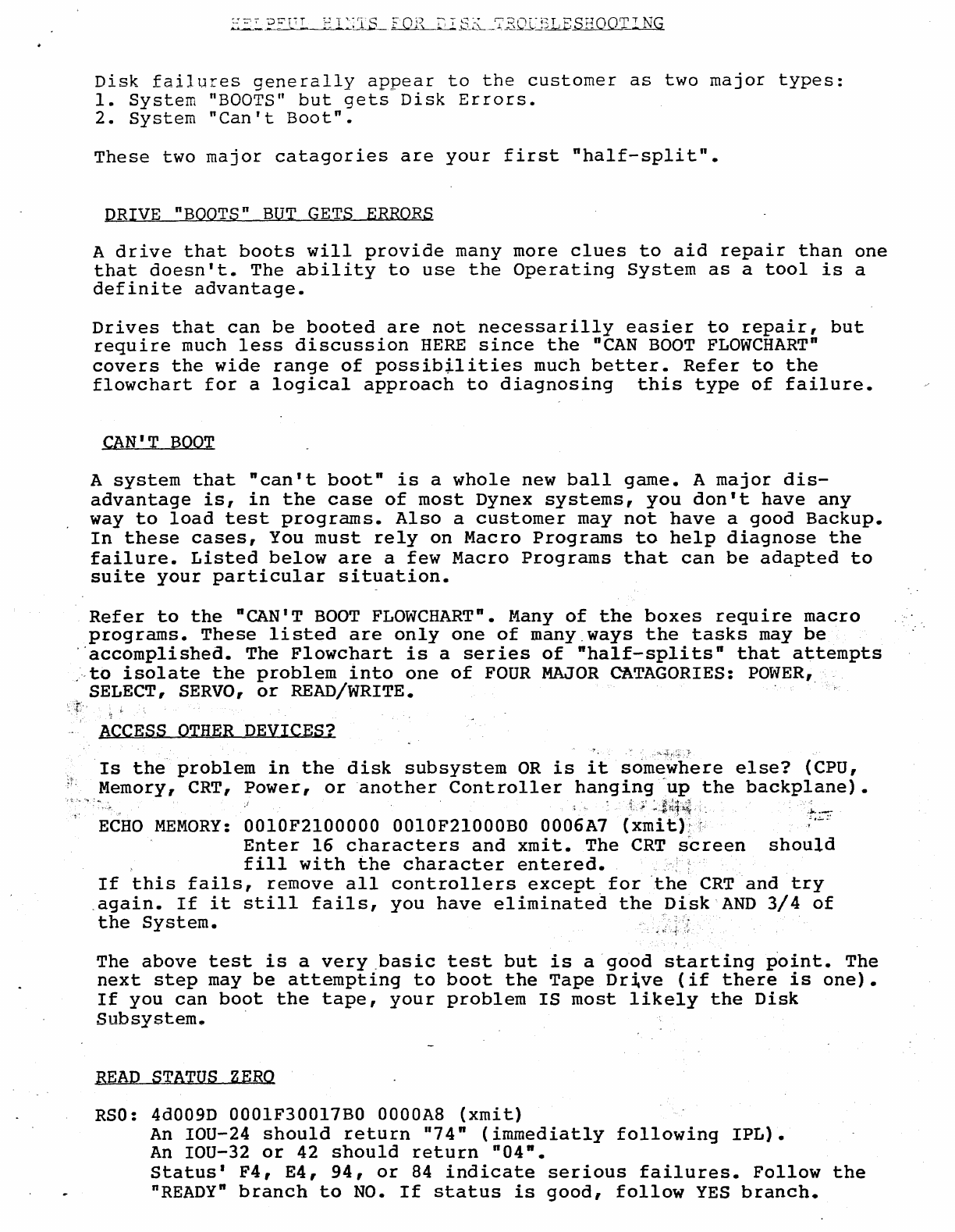
failures
generally
appear
to
the
customer
as
two
major
types:
1.
System
"BOOTS"
but
gets
Disk
Errors.
2.
System
"Can't
Boot".
These
two
major
catagories
are
your
first
nhalf-split".
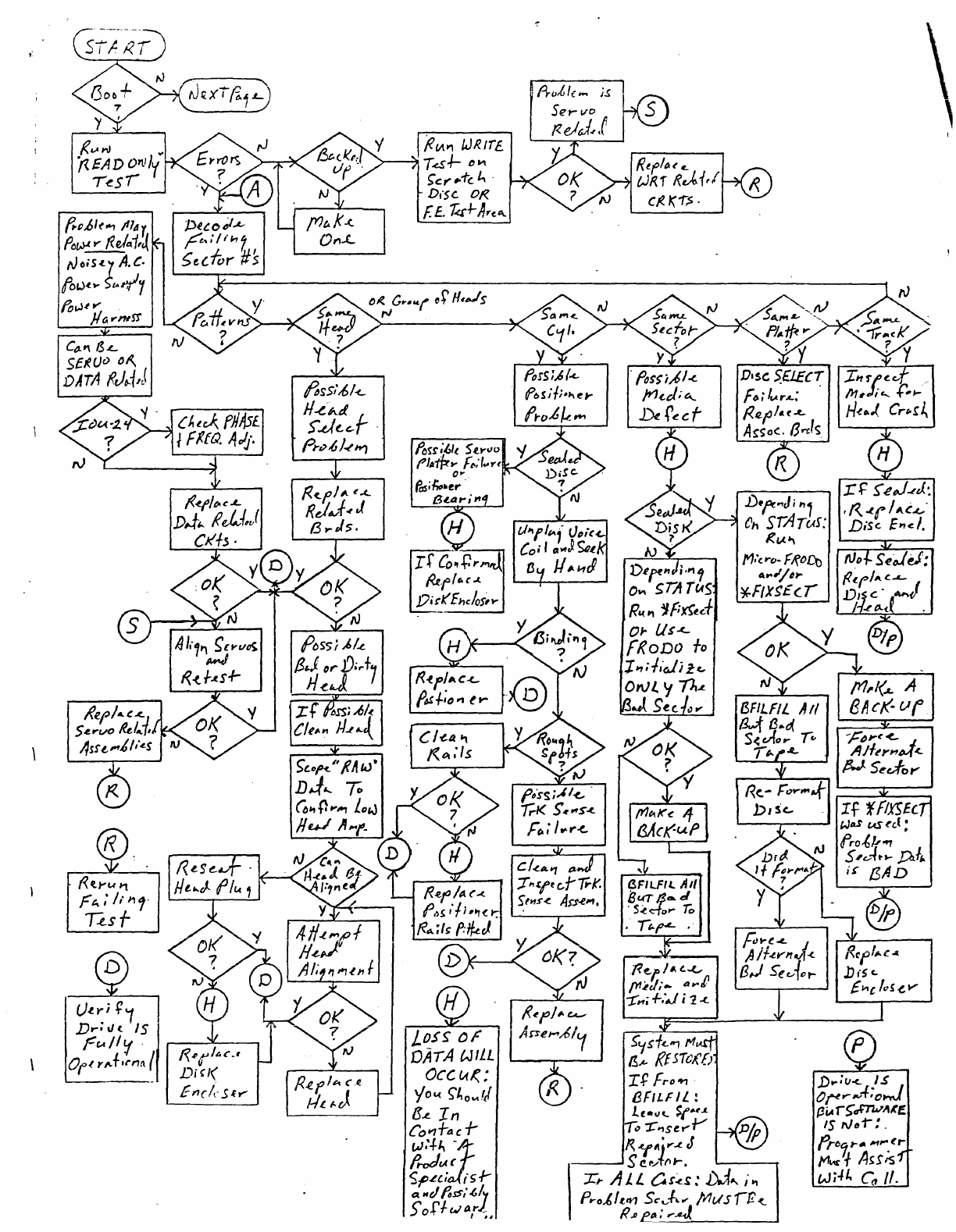
DRIVE "BOOTS"
BUT
GETS
ERRORS
A
drive
that
boots
will
provide
many more
clues
to
aid
repair
than
one
that
doesn't.
The
ability
to
use
the
Operating
System
as
a
tool
is
a
definite
advantage.
Drives
that
can
be
booted
are
not
necessarilly
easier
to
repair,
but
require
much
less
discussion
HERE
since
the
"CAN
BOOT
FLOWCHART"
covers
the
wide
range
of
possibilities
much
better.
Refer
to
the
flowchart
for
a
logical
approach
to
diagnosing
this
type
of
failure.
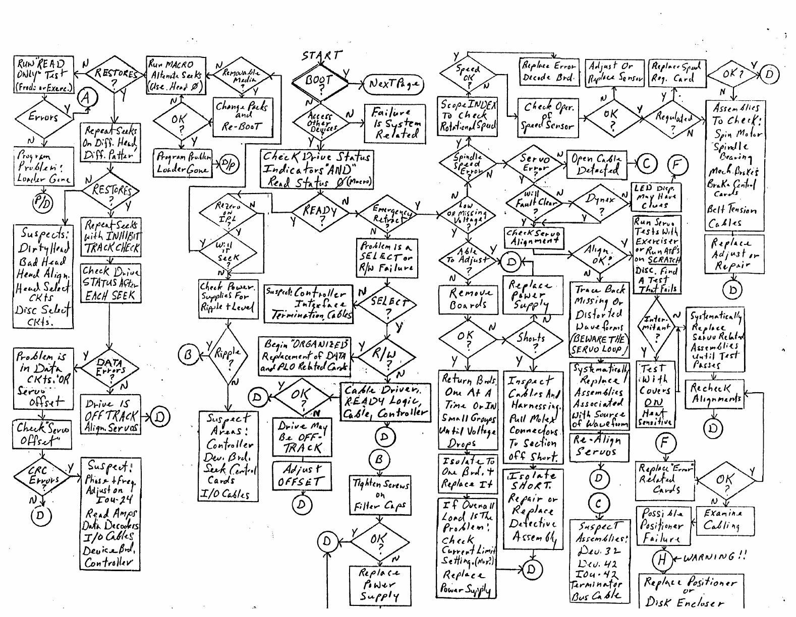
CAN'T
BOOT
A
system
that
"can't
boot"
is
a
whole
new
ball
game.
A
major
dis-
advantage
is,
in
the
case
of
most
Dynex
systems,
you
don't
have
any
way
to
load
test
programs.
Also
a
customer
may
not
have
a
good
Backup.
In
these
cases,
You
must
rely
on
Macro
Programs
to
help
diagnose
the
failure.
Listed
below
are
a
few
Macro
Programs
that
can
be
adapted
to
suite
your
particular
situation.
Refer
to
the
"CAN'T
BOOT
FLOWCHART".
Many
of
the
boxes
require
macro
programs.
These
listed
are
only
one
of
many.ways
the
tasks
may
be
·"accomplished.
The
Flowchart
is
a
series
of
"half-splits"
that
attempts
,,·to
isolate
the
problem
into
one
of
FOUR
MAJOR
CATAGORIES:
POWER,
SELECT,
SERVO,
or
READ/WRITE. .
ACCESS
OTHER
DEVICES?
Is
the
problem
in
the
disk
subsystem
OR
is
it
somewhere
else?
(CPU,
Memory, CRT,
Power,
or
another
Controller
hanging
"up
the
backplane)
•
.I;"
>1~1:4:'
,.\..
.
__
.~
.
..;....,
;'
ECHO
MEMORY:
0010F2100000
OOlOF21000BO 0006A7
(xmitl~T'
Enter
16
characters
and
xmi
t.
The
CRT
s'creen
should
fill
with
the
character
entered.
If
this
fails,
remove
all
controllers
except
for
'the
CRT
and
try
.again.
If
it
still
fails,
you
have
eliminate~
the
Disk
AND
3/4
of
the
System.
The
above
test
is
a
very
,basic
test
but
is
a
good
starting
point.
The
next
step
may
be
attempting
to
boot
the
Tape
Dr~ve
(if
there
is
one).
If
you
can
boot
the
tape,
your
problem
IS
most
likely
the
Disk
~l1bsvstem.
-
--
-~
, ,
READ
STATUS
ZERO
RSO:
4d009D 000lF30017BO 00aaA8
(xmit)
An
IOU-24
should
return
1174"
(immediatly
following
IPL).
An
IOU-32
or
42
should
return
n04".
Status'
F4,
E4,
94,
or
84
indicate
serious
failures.
Follow
the
nREADY"
branch
to
NO.
If
status
is
good,
follow
YES
branch.
~"'--.
l"!-~~"""
;
'~
.. '
~:
... I
..
,:_
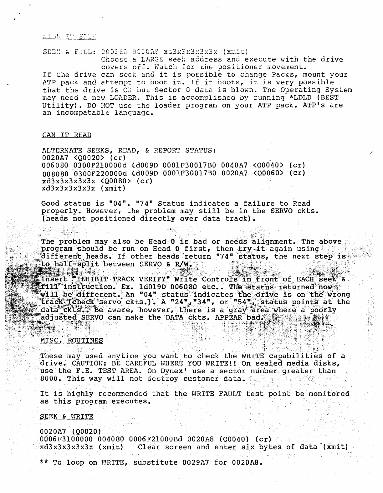
S~EX
&
FILL:
C0056C
J~CGA8
xt3x3~3~3x3x
(x~i~)
Choose
2
LARGE
seek
address
and
execute
with
the
drive
covers
off.
Watch
for
~he
positioner
movement.
If
the
drive
can
seek
and
it
is
possible
to
change
Packs,
mount
your
ATP
pack
and
attempt
to
boot
i~.
If
it
boots,
it
is
very
possible
that
the
drive
is
O~
but
Sector
0
data
is
blown.
The
Operating
System
may
need
a ne'-l
LOADER.
This
is
accomplished
by
running
*LDLD
(BEST
utility).
DO
NOT
use
the
loader
program
on
your
ATP
pack.
ATP's
are
an
incompatable
language.
CAN
IT
READ
ALTERNATE
SEEKS,
READ,
&
REPORT
STATUS:
0020A7 <Q0020>
(cr)
_
006080
0300F2l0000d
4d009D OOOlF30017BO
OO~OA7
<Q0040>
(er)
008080
0300F220000d
4d009D
OOOlF30017BO 002DA7 <Q0060>
(er)
xd3x3x3x3x3x
<Q0080>
(er)
xd3x3x3x3x3x
(xmit)
Good
status
is
"04".
n74n
Status
indicates
a
failure
to
Read
properly.
However,
the
problem
may
still
be
in
the
SERVO
ckts.
(heads
not
positioned
directly
over
data
track).
,
problem
may
also
be
Head-a
is
bad
or
need~
·al~lgnment.
The
above
~,!program
"should
be
run
on
Head
O,first,
then
",try,"it
again
using
~,
,,:>
,:,I:,l>differeritheads.
If
other
heads"return
n74·,,~status,
the
next
step'is
.
ha'I~;:s~1~f~:
:b~~ween
SE~VO:c'~i?c~il
.
·.Ji~~,t'
;:f~~~;\,
.
"Y:i!j~;ij;~.·
IBIT
,TRACK
VERIFY·
Write
Controls:'"in
'ron't
'"of
EACH·
seeK"&
'.
ructlon~':
Ex.
ld019D
006080
'etc.
• Th*e":{statns'
:retllrne'd:\b()w.':~"
'1,'itl
be~::aItf:er~ent.An
D04
a
status'~:;indicate~tbe"-d(iv'e
1s
O'n"tllE(\'irong
·:~~t"i~rc1C~~:t~~'ec't~'servo"
qkts.")
'. A
D24~~,1I3411,
or
'1I,54:t1';;~:'~E;t:a~Us
'point$:a't'
the
a~a";~ckY~:~~~"Beawa're,
however,
th'e"r'e
is
a
'g'
ray
3
~i:lr"ea:'wb·ere!·:.a
'Poorly
us:t~~r<!(c~~~~vocan
make
the
'DATA'
ckts.
A~P'E~::?Ci,~':~-
I~il;~~;\i;:~l~':~j~:
" .
",::t:
:
MI
s~cy:~~:~~~~s:
. .
.,
;l¥~
l,l,~,R<,~,·;.{:·~ir~·
ri:t~fr·
·
r.
"'I
:i·~'~~.
:",!>.~
..
,
;.,:_,
These
may
'used
anytime
you
want
to
"theck
the
VJRIT'E;::~Ipabili{l~s'
of
a
drive~
CAUTION:
BE
CAREFUL
WHERE
YOU
WRITE!!
On
seaiedmediadisks,
,
'use
the
F
.E.
TEST
AREA.
On
Dynex
I
use
a
'sector
number,
greater
than
8000.
Thisltlay
will
not
destroy"
customer
data.,
"
It
is
highly
recommended
that
the
vlRITE
FAULT
test
point
be
monitored
as
this
program
executes.
SEEK
&
WRITE
0020A7
(Q0020)
0006F3l00000
004080
0006F21000Bd
0020A8
(Q0040),
(cr)
'··xd3x3x3x3x3x
(xmit)
Clear
screen
and
enter
six
bytes
of
dat'a~(xmit)
** To
loop
on
WRITE,
substitute
0029A7
for
0020A8.

SEEK
&
READ
To
verify
the
data
just
written,
the
following
program
will
dump
what
you
just
wrote
back
to
the
CRT.
0020A7 <Q0020)
(cr)
004080
0006F220000d
0006F32000BO 0020A8 <Q0040)
(cr)
xd3x3x3x3x3x
(xmit)
EMS
MESSAGE
NUMBER
156
026/00053
15:24
03/12
HERK
(CJC133:REDLT,LISVC,MEND)
TX
NO
133
TO:
M Abrahams
D
Saum
R
Bruer
R
Burton
T
Carson
C
Cobb
D.
Cowdin
W
Garrison
R Geyer
R
Gutosky
T DeLaFuente
RED
R
Havlicek
E
Heston
T
Hoy
B
Hull
A
Jager
B.
Keller
D Leek
H
Leggett
B.
Ivey
C Marrone
B McNeese
L I G H T
C McNutt
E.
Miguel
G
Orlowski
A Powers
C
Sheldon
R
Sundius
A.
Rodman
B
Williams
G
Wipperfuerth
B
Wright
B
Zinsmeister
R.
Biegun
'
ALE
R T
11564
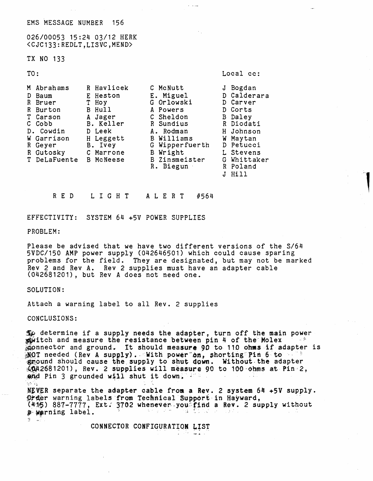
EFFECTIVITY:
SYSTEM
64
+5V
POWER
SUPPLIES
PROBLEM:
Local
cc:
J Bogdan
D
Calderara
D
Carver
D
Corts
B
Daley
R
Diodati
H
Johnson
W
May
tan
D
Petucci
L
Stevens
G
Whittaker
R
Poland
J
Hill
Please
be
advised
that
we
have
two
different
versions
of
the
3/64
5VDC/150
AMP
power
supply
(042646501)
which
could
cause
sparing
problems
for
the
field.
They
are
designated,
but
may
not
be marked
Rev
2 and
Rev
A.
Rev
2
supplies
must
have
an
adapter
cable
(042681201),
but
Rev
A
does
not
need
one.
SOLUTION:
Attach
a
warning
label
to
all
Rev. 2
supplies
CONCLUSIONS:
~
determine
if
a
supply
nee,ds
the
adapter
l
turn
off
the
main power
~i
tch
and
measure
the
resistance
between
pin
4
of
the"
Molex'~'
~~nnector
and
ground..
It
should
measure
90 to,
110
ohms
if·
adapter
is
~N"OT
needed
(Rev A
supply).·
:'With
power
"bn',
$hortin.g~'·
Pin
6
to-
"
~:
'~~und
should
cause
tne,
supply
to
shut
doWn.
Wi
thout
,.
the
adapter
{~~t268120
1) , Rev. 2
~upplies
will
measure
90
to
100·
at-uns
at
Pin;
2,
i~~'
Pin
3
grounded
w~ll
shut
it
down~'
;
';
~,~~;:..
. t'
:t
,N}:V:~R
separate
the
adapter
cable
frOll a
Rev.
2
system
64
+5V
supply.
f)j"~r
warning
labels'
'from
Techr!lical -
Support·
in
Hayward,
(4'1~)
887-1111,
Ext:
3702
whenever"you~:',r1nd
a Rev. 2
supply
without
'::lIftrning
label.
;;,.
i
..
:":
",'10
CONNECTOR
COHFIGURAT~QN
~~Sr
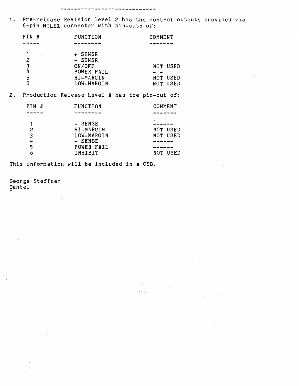
1.
Pre-release
Revision
level
2
has
the
control
outputs
provided
via
6-pin
MOLEX
connector
with
pin-outs
of:
PIN
II
-~---
1
2
3
4
5
6
2.
, Prod
uction
PIN
II
-----
1
2
3
4
5
6
FUNCTION
--------
+
SENSE
-
SENSE
ON/OFF
POWER
FAIL
HI-MARGIN
LOW-MARGIN
Release
Level
FUNCTION
--------
+
SENSE
HI-MARGIN
LOW-MARGIN
-
SENSE
POWER
FAIL
INHIBIT
A
has
the
COMMENT
NOT
USED
NOT
USED
NOT
USED
pin-out
of:
COMMENT
--------
------
NOT
USED
NOT
USED
------
------
NOT
USED
This
information
will
be
included
in
a
CSB.
George
Steffner
Qantel
A
EMS
MESSAGE
NUMBER
268
008/00016
11:26
03/26
HERK
(CJC102:REDLT,LISVC,MEND)
TX
NO
102
TO:
M Abrahams
D
Baum
R
Bruer
R
Burton
T
Carson
C
Cobb
D.
Cowdin
W
Garrison
R Geyer
R
Gutosky
T DeLaFuente
RED
R
Havlicek
E
Heston
T
Hoy
B
Hull
A
Jager
B.
Keller
D Leek
H
Leggett
B.
Ivey
C Marrone
B McNeese
T.
Elder
L I G H T
C McNutt
E.
Miguel
G
Orlowski
A Powers
C
Sheldon
R
Sundius
A.
Rodman
B
Williams
G
Wipperfuerth
D.
Crandall
B
Zinsmeister
R.
Biegun
ALE
R T
11566
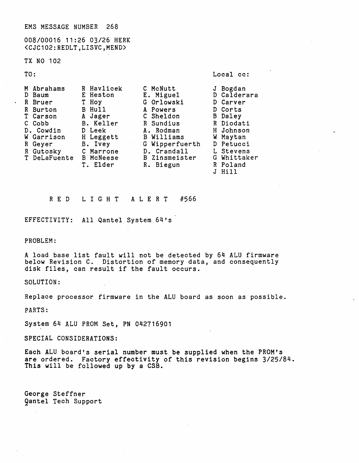
EFFECTIVITY:
All
Qantel
System
64's
PROBLEM:
Local
cc:
J Bogdan
D
Calderara
D
Carver
D
Corts
B
Daley
R
Diodati
H
Johnson
W
May
tan
D
Petucci
L
Stevens
G
Whittaker
R
Poland
J
Hill
A
load
base
list
fault
will
not
be
detected
by 64
ALU
firmware
below
Revision
C.
Distortion
of
memory
data,
and
consequently
disk
files,
can
result
if
the
fault
occurs.
SOLUTION:
Replace
processor
firmware
in
the
ALU
board
as
soon
as
possible.
PARTS:
System
64
ALU
PROM
Set,
PN
042716901
SPECIAL
CONSIDERATIONS:
Each
ALU
board's
serial
number
must
be sUDDlied when
the
PROM's
are
ordered.
Factory
effectivity
of
this·
revision
begins
3/25/84.
This
will
be
followed
up
by
a eSB.
George
Steffner
Qantel
Tech
Support
,..
EMS
MESSAGE
NUMBER
197
013/00012
16:20
04/02
EAST
<CJC221:REDLT,LISVC,MEND)
TX
NO
221
April
2,
1984
TO:
M Abrahams R
Havlicek
C McNutt
D
Baum
E
Heston
E.
Miguel
R
Bruer
T
Hoy
G
Orlowski
R
Burton
B
Hull
A Powers
T
Carson
A
Jager
C
Sheldon
C Cobb B.
Keller
R
Sundius
D.
Cowdin D Leek
A.
Rodman
W
Garrison
H
Leggett
B
Williams
R
Geyer
B.
Ivey
G
Wipperfuerth
R
Gutosky
C Marrone
D.
Crandall
T DeLaFuente B McNeese B
Zinsmeister
T.
Elder
R.
Biegun
RED
L I G H T
ALE
R T
11568
EFFECTIVITY:
Qantel
System
64
PROBLEM:
Local
cc:
.
J Bogdan
D
Calderara
D
Carver
D
Corts
B
Daley
R
Diodati
H
Johnson
W
May
tan
D
Petucci
L
Stevens
G
Whittaker
R
Poland
J
Hill
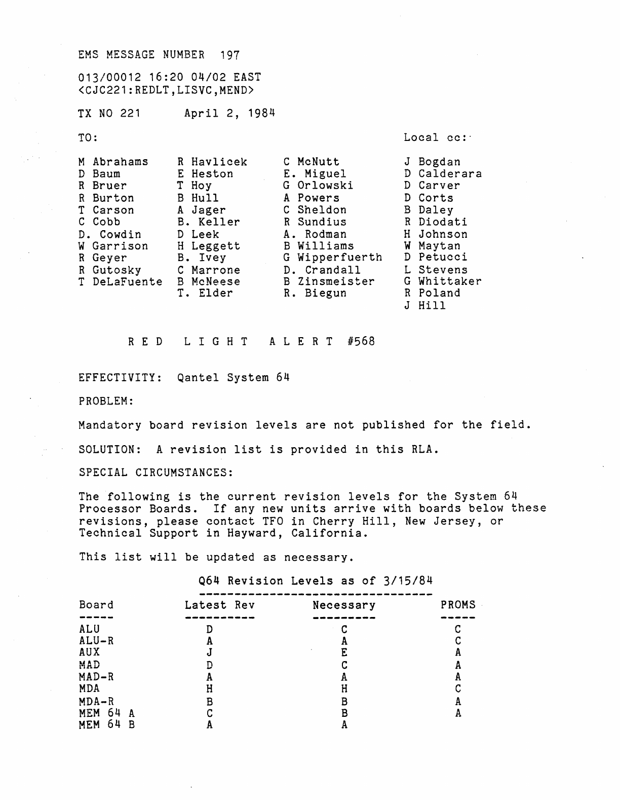
Mandatory
board
revision
levels
are
not
published
for
the
field.
SOLUTION:
A
revision
list
is
provided
in
this
RLA.
SPECIAL
CIRCUMSTANCES:
The
following
is
the
current
reV1Slon
levels
for
the
System
64
Processor
Boards.
If
any
new
units
arrive
with
boards
below
these
revisions,
please
contact
TFO
in
Cherry
Hill,
New
Jersey,
or
Technical
Support
in
Hayward,
California.
This
list
will
be
updated
as
necessary.
Q64
Revision
Levels
as
of
3/15/84
Board
Latest
Rev
Necessary
-----
---------- ----------
ALU
D C
ALU-R
A A
AUX
J E
...
1\1'\
lW
Il1.lJ
D C
MAD-R
A A
MDA
H H
MDA-R
B B
MEM
64
A C B
MEM
64 B A A
PROMS·
c
C
A
A
A
C
A
A
RED
L I G H T
ALE
R T 0567
EFFECTIVITY:
Qantel
IOU39Q
CRT
Controller
PROBLEM:
An
excessive
time
addressed
"0"
can
Data
transmission
will
be
stalled.
streaming
mode.
SOLUTION:
out
delay
on
the
IOU39Q
CRT
controller
cause
too
much
delay
during
a
streaming
backup.
to
the
streaming
tape
drive,
on
he
System
64,
The
tape
drive
will
then
ramp
down
out
of
The
standard
time
out
delay
for
the
IOU39Q
is
fifteen
mili-seconds.
Do
not
extend
the
delay
for
the
IOU39Q
addressed
"0".
Extended
delays
should
only
be
necessary
for
remote
communications
over
modems.
SPECIAL
CONSIDERATIONS:
It
has
been
reported
that
some
error
30's
and
string
hang
problems
were
relieved
by
increasing
the
IOU39Q
time
out
delay.
That
delay
can
slow
operation
of
the
system
as
well
as
interfere
with
streaming
backup.
CONCLUSION:
All
non-remote
operating
IOU39Q
CRT
controllers
should
have
minimum
time
out
delay
(15
mili-seconds).
If
failures
occur
at
that
setting,
please
notify
Product
Support
in
Hayward,
CA
and
TFO
by
WINC.
George
Steffner
Qantel
Tech
Support
A
