Service Manual R&S FSH3 FSH CD ROM/FSH7.10 (D)/Manuals/Service_Manual_FSH
Service_Manual_FSH Service_Manual_FSH
User Manual: R&S FSH CD-ROM/FSH7.10 (D)/Manuals/Service_Manual_FSH
Open the PDF directly: View PDF ![]() .
.
Page Count: 72
- Title Page
- Contents
- Safety Instructions
- Certificate of quality
- Spare Parts Express Service
- List of R&S Representatives
- Contents of Manual for Spectrum Analyzer R&S FSH (Service and Repair)
- Performance Test
- Adjustment
- Repair
- Instrument Design and Functional Description
- Description of the block diagram
- Attenuator
- RF to IF conversion
- Tracking generator (Model 1145.5850.13/23/26 only)
- RF/IF control
- Mainboard
- Power and battery management
- Processing of measured data detectors
- Resolution bandwidths (RBW)
- Video bandwidths (VBW)
- Detectors
- Keypad control
- Serial optical interface
- Power sensor
- Color LCD module
- Module Replacement
- Overview of the modules
- Opening the instrument
- Closing the instrument
- Replacing the battery
- Replacing the housing
- Replacing the front unit for R&S FSH
- Replacing the Color LCD Module
- Replacing the RF/IF module
- Replacing the mainboard
- Replacing the N connector
- Replacing the binder and BNC connector block
- Replacing the power/audio connections
- Replacing a cable from the cable set
- Troubleshooting
- Instrument Design and Functional Description
- Software Updates / Installing Options
- Documents

1145.5973.82-05- 1
Test and Measurement
Division
Service Manual
Handheld Spectrum Analyzer
R&S FSH
1145.5850.03
1145.5850.06
1145.5850.13
1145.5850.23
1145.5850.26
1145.5973.82-05- 2
Dear Customer,
R&S® is a registered trademark of Rohde & Schwarz GmbH & Co. KG.
Trade names are trademarks of the owners.

R&S FSH Contents
1145.5973.82 I.1 E-5
Contents
Safety Instructions
Certificate of Quality
Spare Parts Express Service
List of R&S Representatives
Contents of Manuals for Spectrum Analyzer R&S FSH
Service and Repair
1 Performance Test.......................................................................................................................1.1
Test Instructions...............................................................................................................................1.1
Measuring Equipment and Accessories ........................................................................................1.1
Performance Test .............................................................................................................................1.2
Checking the frequency accuracy...............................................................................................1.2
Checking the level accuracy and the frequency response..........................................................1.3
Checking the accuracy of the RF attenuator ..............................................................................1.5
Checking the accuracy of the IF gain setting..............................................................................1.6
Checking the displayed average noise floor ...............................................................................1.7
Checking the phase noise...........................................................................................................1.8
Checking the display linearity......................................................................................................1.9
Performance Test Tracking Generator............................................................................................1.11
Checking output level / frequency response.............................................................................1.11
Performance Test Report...............................................................................................................1.12
Performance Test Report Tracking Generator ............................................................................1.19

Contents R&S FSH
1145.5973.82 I.2 E-5
2 Adjustment....................................................................................................................................2.1
Quick Verification.............................................................................................................................2.1
Measurement Equipment and Accessories for Quick Verification..............................................2.2
Verifying on/off functionality........................................................................................................2.2
Verifying power and AF connections .........................................................................................2.2
Verifying the display....................................................................................................................2.3
Verifying the level and noise .......................................................................................................2.3
Verify the tracking generator output level ...................................................................................2.4
Adjustment functions......................................................................................................2.4
Adjustment ........................................................................................................................................2.5
Adjustment Instructions ..............................................................................................................2.5
Measurement Equipment and Accessories ...................................................................................2.6
Adjusting the reference frequency accuracy...............................................................................2.6
Adjusting the level accuracy .......................................................................................................2.7
Frequency Response Correction....................................................................................................2.8

R&S FSH Contents
1145.5973.82 I.3 E-5
3 Repair..............................................................................................................................................3.1
Instrument Design and Functional Description ............................................................................3.1
Description of the block diagram ................................................................................................3.2
Attenuator ...................................................................................................................................3.2
RF to IF conversion.....................................................................................................................3.2
Tracking generator (Model 1145.5850.13/23/26 only)................................................................3.4
RF/IF control ...............................................................................................................................3.4
Mainboard...................................................................................................................................3.4
Power and battery management.................................................................................................3.4
Processing of measured data detectors .....................................................................................3.5
Resolution bandwidths (RBW)....................................................................................................3.5
Video bandwidths (VBW)............................................................................................................3.5
Detectors.....................................................................................................................................3.6
Keypad control ............................................................................................................................3.6
Serial optical interface.................................................................................................................3.6
Power sensor..............................................................................................................................3.6
Color LCD module ......................................................................................................................3.6
Module Replacement........................................................................................................................3.7
Overview of the modules ............................................................................................................3.9
Opening the instrument.............................................................................................................3.10
Closing the instrument ..............................................................................................................3.10
Replacing the battery................................................................................................................3.11
Replacing the housing ..............................................................................................................3.12
Replacing the front unit for R&S FSH .......................................................................................3.13
Replacing the Color LCD Module .............................................................................................3.14
Replacing the RF/IF module .....................................................................................................3.15
Replacing the mainboard..........................................................................................................3.16
Replacing the N connector........................................................................................................3.17
Replacing the binder and BNC connector block .......................................................................3.18
Replacing the power/audio connections ...................................................................................3.19
Replacing a cable from the cable set........................................................................................3.20
Troubleshooting .............................................................................................................................3.21
Overview of errors, causes, and possible corrective actions....................................................3.22
Troubleshooting problems in switching on the instrument...........................................3.22

Contents R&S FSH
1145.5973.82 I.4 E-5
4 Software Updates / Installing Options ..............................................................................4.1
Installing New R&S FSH Software ..................................................................................................4.1
Installing the Options.......................................................................................................................4.1
5 Documents....................................................................................................................................5.1
Shipping of Instrument and Ordering of Spare Parts...................................................................5.1
Shipping of instrument ................................................................................................................5.1
Shipping of a module ..................................................................................................................5.1
Ordering spare parts...................................................................................................................5.2
Refurbished modules..................................................................................................................5.2
Return of defective replaced modules ........................................................................................5.2
Spare Parts........................................................................................................................................5.3
Safety Instructions
This unit has been designed and tested in accordance with the EC Certificate of Conformity and has left the
manufacturer’s plant in a condition fully complying with safety standards.
To maintain this condition and to ensure safe operation, the user must observe all instructions and warnings
given in this operating manual.
Safety-related symbols used on equipment and documentation from R&S:
Observe op-
erating in-
structions
Weight
indication for
units >18 kg
PE terminal Ground
terminal Danger!
Shock hazard Warning!
Hot surfaces Ground Attention!
Electrostatic
sensitive de-
vices require
special care
1. The unit may be used only in the operating con-
ditions and positions specified by the manufac-
turer. Unless otherwise agreed, the following
applies to R&S products:
IP degree of protection 2X, pollution severity 2
overvoltage category 2, only for indoor use, alti-
tude max. 2000 m.
The unit may be operated only from supply net-
works fused with max. 16 A.
Unless specified otherwise in the data sheet, a
tolerance of ±10% shall apply to the nominal
voltage and of ±5% to the nominal frequency.
2. For measurements in circuits with voltages Vrms
> 30 V, suitable measures should be taken to
avoid any hazards.
(using, for example, appropriate measuring
equipment, fusing, current limiting, electrical
separation, insulation).
3. For permanently installed units without built-in
fuses, circuit breakers or similar protective de-
vices, the supply circuit must be fused such as
to provide suitable protection for the users and
equipment.
4. Prior to switching on the unit, it must be ensured
that the nominal voltage set on the unit matches
the nominal voltage of the AC supply network.
If a different voltage is to be set, the power fuse
of the unit may have to be changed accordingly.
5. If the unit has no power switch for disconnection
from the AC supply, the plug of the connecting
cable is regarded as the disconnecting device.
In such cases it must be ensured that the power
plug is easily reachable and accessible at all
times (length of connecting cable approx. 2 m).
Functional or electronic switches are not suit-
able for providing disconnection from the AC
supply.
If units without power switches are integrated in
racks or systems, a disconnecting device must
be provided at system level.
6. Applicable local or national safety regulations
and rules for the prevention of accidents must
be observed in all work performed.
Prior to performing any work on the unit or open-
ing the unit, the latter must be disconnected
from the supply network.
Any adjustments, replacements of parts, main-
tenance or repair may be carried out only by au-
thorized R&S technical personnel.
Only original parts may be used for replacing
parts relevant to safety (eg power switches,
power transformers, fuses). A safety test must
be performed after each replacement of parts
relevant to safety.
(visual inspection, PE conductor test, insulation-
resistance, leakage-current measurement, func-
tional test).
7. Ensure that the connections with information
technology equipment comply with IEC950 /
EN60950.
8. NiMH batteries must not be exposed to high
temperatures or fire.
Keep batteries away from children.
If the battery is replaced improperly, there is
danger of explosion. Only replace the battery by
R&S type (see spare part list).
NiMH batteries are suitable for environmentally-
friendly disposal or specialized recycling. Dis-
pose them into appropriate containers, only.
Do not short-circuit the battery.
9. Equipment returned or sent in for repair must be
packed in the original packing or in packing with
electrostatic and mechanical protection.
10. Electrostatics via the connectors may dam-
age the equipment. For the safe handling and
operation of the equipment, appropriate
measures against electrostatics should be im-
plemented.

Safety Instructions
11. The outside of the instrument is suitably
cleaned using a soft, lint-free dustcloth. Never
use solvents such as thinners, acetone and
similar things, as they may damage the front
panel labeling or plastic parts.
12. Any additional safety instructions given in this
manual are also to be observed.

Qualitätszertifikat
Sehr geehrter Kunde,
Sie haben sich für den Kauf eines Rohde &
Schwarz-Produktes entschieden. Hiermit
erhalten Sie ein nach modernsten Ferti-
gungsmethoden hergestelltes Produkt. Es
wurde nach den Regeln unseres Qualitäts-
managementsystems entwickelt, gefer-
tigt und geprüft. Das Rohde & Schwarz-
Qualitätsmanagementsystem ist u.a. nach
ISO 9001 und ISO14001 zertifiziert.
Certificate of quality
Dear Customer,
You have decided to buy a Rohde &
Schwarz product. You are thus assured of
receiving a product that is manufactured
using the most modern methods available.
This product was developed, manufac-
tured and tested in compliance with our
quality management system standards.
The Rohde & Schwarz quality manage-
ment system is certified according to stan-
dards such as ISO9001 and ISO14001.
Certificat de qualité
Cher client,
Vous avez choisi d'acheter un produit
Rohde & Schwarz. Vous disposez donc
d'un produit fabriqué d'après les métho-
des les plus avancées. Le développement,
la fabrication et les tests respectent nos
normes de gestion qualité. Le système de
gestion qualité de Rohde & Schwarz a été
homologué, entre autres, conformément
aux normes ISO 9001 et ISO14001.
Certified Quality System
ISO 9001
Certified Environmental System
ISO 14001
DQS REG. NO 1954 QM
DQS REG. NO 1954 UM

1007.9016
Spare Parts Express Service
Phone: +49 89 4129 - 12465
Fax: +49 89 41 29 - 13306
E-mail:werner.breidling@rsd.rohde-schwarz.com
In case of urgent spare parts requirements for this Rohde &
Schwarz unit, please contact our spare parts express
service.
Outside business hours, please leave us a message or
send a fax or e-mail. We shall contact you promptly.

Adressen/Addresses
FIRMENSITZ/HEADQUARTERS
Phone
Fax
E-mail
Rohde & Schwarz GmbH & Co. KG
Mühldorfstraße 15 · D-81671 München
Postfach 80 14 69 · D-81614 München
+49 (89) 41 29-0
+49 89 4129-121 64
-
WERKE/PLANTS
Rohde & Schwarz Messgerätebau GmbH
Riedbachstraße 58 · D-87700 Memmingen
Postfach 1652 · D-87686 Memmingen
+49 (8331) 108-0
+49 (8331) 108-11 24
-
Rohde & Schwarz GmbH & Co. KG
Werk Teisnach
Kaikenrieder Straße 27 · D-94244 Teisnach
Postfach 1149 · D-94240 Teisnach
+49 (9923) 857-0
+49 (9923) 857-11 74
-
Rohde & Schwarz GmbH & Co. KG
Dienstleistungszentrum Köln
Graf-Zeppelin-Straße 18 · D-51147 Köln
Postfach 98 02 60 · D-51130 Köln
+49 (2203) 49-0
+49 (2203) 49 51-308
info@rsdc.rohde-schwarz.com
service@rsdc.rohde-schwarz.com
TOCHTERUNTERNEHMEN/
Rohde & Schwarz Vertriebs-GmbH
Mühldorfstraße 15 · D-81671 München
Postfach 80 14 69 · D-81614 München
+49 (89) 41 29-137 74
+49 (89) 41 29-137 77
-
Rohde & Schwarz International GmbH
Mühldorfstraße 15 · D-81671 München
Postfach 80 14 60 · D-81614 München
+49 (89) 41 29-129 84
+49 (89) 41 29-120 50
-
Rohde & Schwarz Engineering and Sales
GmbH
Mühldorfstraße 15 · D-81671 München
Postfach 80 14 29 · D-81614 München
+49 (89) 41 29-137 11
+49 (89) 41 29-137 23
-
R&S BICK Mobilfunk GmbH
Fritz-Hahne-Str. 7 · D-31848 Bad Münder
Postfach 2062 · D-31844 Bad Münder
+49 (5042) 998-0
+49 (5042) 998-105
-
Rohde & Schwarz FTK GmbH
Wendenschlossstraße 168, Haus 28
D-12557 Berlin
+49 (30) 658 91-122
+49 (30) 655 50-221
-
Rohde & Schwarz SIT GmbH
Agastraße 3
D-12489 Berlin
+49 (30) 658 84-0
+49 (30) 658 84-183
ADRESSEN DEUTSCHLAND/
ADDRESSES GERMANY
Rohde & Schwarz Vertriebs-GmbH
Mühldorfstraße 15 · D-81671 München
Postfach 80 14 69 · D-81614 München
+49 89 4129-133 74
+4989 4129-133 77
-
Zweigniederlassungen der Rohde &
Schwarz Vertriebs-GmbH/Branch offices of
Rohde & Schwarz Vertriebs-GmbH
Zweigniederlassung Nord, Geschäftsstelle
Berlin
Ernst-Reuter-Platz 10 · D-10587 Berlin
Postfach 100620 · D-10566 Berlin
+49 (30) 34 79 48-0
+49 (30) 34 79 48 48
-
Zweigniederlassung Büro Bonn
Josef-Wirmer-Straße 1-3 · D-53123 Bonn
Postfach 140264 · D-53057 Bonn
+49 (228) 918 90-0
+49 (228) 25 50 87
-
Zweigniederlassung Nord, Geschäftsstelle
Hamburg
Steilshooper Alle 47 · D-22309 Hamburg
Postfach 60 22 40 · D-22232 Hamburg
+49 (40) 63 29 00-0
+49 (40) 630 78 70
-
Zweigniederlassung Mitte, Geschäftsstelle
Köln
Niederkasseler Straße 33 · D-51147 Köln
Postfach 900 149 · D-51111 Köln
+49 (2203) 807-0
+49 (2203) 807-650
-
Zweigniederlassung Süd, Geschäftsstelle
München
Mühldorfstraße 15 · D-81671 München
Postfach 80 14 69 · D-81614 München
+49 (89) 41 86 95-0
+49 (89) 40 47 64
-
Zweigniederlassung Süd, Geschäftsstelle
Nürnberg
Donaustraße 36
D-90451 Nürnberg
+49 (911) 642 03-0
+49 (911) 642 03-33
-
Zweigniederlassung Mitte, Geschäftsstelle
Neu-Isenburg
Siemensstraße 20
D-63263 Neu-Isenburg
+49 (6102) 20 07-0
+49 (6102) 20 07 12
-
ADRESSEN WELTWEIT/
ADDRESSES WORLDWIDE
siehe / see AustriaAlbania
ROHDE & SCHWARZ
Bureau d'Alger
5B Place de Laperrine
16035 Hydra-Alger
+213 (21) 48 20 18
+213 (21) 69 46 08
Algeria
PRECISION ELECTRONICA S.R.L.
Av. Pde Julio A. Roca 710 - 6° Piso
(C1067ABP) Buenos Aires
+541 (14) 331 41 99
+541 (14) 334 51 11
alberto_lombardi@prec-elec.com.ar
Argentina
ROHDE & SCHWARZ (AUSTRALIA) Pty. Ltd.
Sales Support
Unit 6
2-8 South Street
Rydalmere, N.S.W. 2116
+61 (2) 88 45 41 00
+61 (2) 96 38 39 88
lyndell.james@rsaus.rohde-
schwarz.com
Australia
ROHDE & SCHWARZ-ÖSTERREICH
Ges.m.b.H.
Am Euro Platz 3
Gebäude B
1120 Wien
+43 (1) 602 61 41-0
+43 (1) 602 61 41-14
rs-austria@rsoe.rohde-schwarz.com
Austria
ROHDE & SCHWARZ Azerbaijan
Liaison Office Baku
ISR Plaza
340 Nizami Str.
370000 Baku
+994 (12) 93 31 38
+994 (12) 93 03 14
RS-Azerbaijan@RUS.Rohde-
Schwarz.com
Azerbaijan
siehe / see DenmarkBaltic
Countries
BIL Consortium Ltd.
Corporate Office
House-33, Road-4, Block-F
Banani
Dhaka-1213
+880 (2) 881 06 53
+880 (2) 882 82 91
Bangladesh
ROHDE & SCHWARZ BELGIUM N.V.
Excelsiorlaan 31 Bus 1
1930 Zaventem
+32 (2) 721 50 02
+32 (2) 725 09 36
info@rsb.rohde-schwarz.com
Belgium
ROHDE & SCHWARZ DO BRASIL LTDA.
Av. Alfredo Egidio de Souza Aranha n° 177,
1° andar - Santo Amaro
04726-170 Sao Paulo - SP
+55 (11) 56 44 86 11 (general)
+55 (11) 56 44 86 25 (sales)
+55 (11) 56 44 86 36
sales-brazil@rsdb.rohde-
schwarz.com
Brazil
GKL Equipment PTE Ltd.
#11-01 BP Tower
396 Alexandra Road
Singapore 119954
+65 (6) 276 06 26
+65 (6) 276 06 29
gkleqpt@singnet.com.sg
Brunei
ROHDE & SCHWARZ ÖSTERREICH
Representation Office Bulgaria
39, Fridtjof Nansen Blvd.
1000 Sofia
+359 (2) 963 43 34
+359 (2) 963 21 97
rohdebg@rsoe.rohde-schwarz.com
Bulgaria
siehe / see SloveniaBosnia-
Herzegovina

Adressen/Addresses
ROHDE & SCHWARZ CANADA Inc.
555 March Rd.
Kanata, Ontario K2K 2M5
+1 (613) 592 80 00
+1 (613) 592 80 09
cgirwarnauth@rscanada.ca
Canada
TEKTRONIX CANADA Inc.
Test and Measurement
4929 Place Olivia
Saint-Laurent, Pq
Montreal H4R 2V6
+1 (514) 331 43 34
+1 (514) 331 59 91
Canada
DYMEQ Ltda.
Av. Larrain 6666
Santiago
+56 (2) 339 20 00
+56 (2) 339 20 10
dymeq@dymeq.com
Chile
ROHDE & SCHWARZ China Ltd.
Representative Office Shanghai
Central Plaza
227 Huangpi North Road
RM 807/809
Shanghai 200003
+86 (21) 63 75 00 18
+86 (21) 63 75 91 70
China
ROHDE & SCHWARZ China Ltd.
Representative Office Beijing
Room 602, Parkview Center
2 Jiangtai Road
Chao Yang District
Beijing 100016
+86 (10) 64 31 28 28
+86 (10) 64 37 98 88
info.rschina@rsbp.rohde-
schwarz.com
China
ROHDE & SCHWARZ China Ltd.
Representative Office Guangzhou
Room 2903, Metro Plaza
183 Tianhe North Road
Guangzhou 510075
+86 (20) 87 55 47 58
+86 (20) 87 55 47 59
China
ROHDE & SCHWARZ China Ltd.
Representative Office Chengdu
Unit G, 28/F, First City Plaza
308 Shuncheng Avenue
Chengdu 610017
+86 (28) 86 52 76 05 to 09
+86 (28) 86 52 76 10
rsbpc@mail.sc.cninfo.net
China
ROHDE & SCHWARZ China Ltd.
Unit 3115
31/F Entertainment Building
30 Queen's Road Central
Hongkong
+85 (2) 21 68 06 70
+85 (2) 21 68 08 99
China
ROHDE & SCHWARZ China Ltd.
Representative Office Xi'an
Room 10125, Jianguo Hotel Xi'an
No. 2, Huzhu Road
Xi'an 710048
+86 (29) 321 82 33
+86 (29) 329 60 15
sherry.yu@rsbp.rohde-schwarz.com
China
ROHDE & SCHWARZ China Ltd.
Representative Office Shenzhen
No. 2002 Jiabin Road
Luohu District
Shenzhen 518001
+86 (755) 25 18 50 18
+86 (755) 25 18 50 18
jessica.lia@rsbp.rohde-schwarz.com
China
Shanghai ROHDE & SCHWARZ
Communication Technology Co.Ltd.
China
Beijing ROHDE & SCHWARZ Communication
Technology Co.Ltd.
Room 106, Parkview Centre
No. 2, Jiangtai Road
Chao Yang District
Beijing 100016
+86 (10) 64 38 80 80
+86 (10) 64 38 97 06
China
siehe / see SloveniaCroatia
HINIS TELECAST LTD.
Agiou Thoma 18
Kiti
Larnaca 7550
+357 (24) 42 51 78
+357 (24) 42 46 21
hinis@logos.cy.net
Cyprus
ROHDE & SCHWARZ - Praha s.r.o.
Hadovka Office Park
Evropská 33c
16000 Praha 6
+420 (2) 24 31 12 32
+420 (2) 24 31 70 43
office@rscz.rohde-schwarz.com
Czech Republic
ROHDE & SCHWARZ DANMARK A/S
Ejby Industrivej 40
2600 Glostrup
+45 (43) 43 66 99
+45 (43) 43 77 44
Denmark
REPRESENTACIONES MANFRED
WEINZIERL
Vía Láctea No. 4 y Via Sta. Inés
P.O.Box 17-22-20309
1722 Cumbayá-Quito
+593 (22) 89 65 97
+593 (22) 89 65 97
mweinzierl@plus.net.ec
Ecuador
U.A.S. Universal Advanced Systems
31 Manshiet El-Bakry Street
Heliopolis
11341 Cairo
+20 (2) 455 67 44
+20 (2) 256 17 40
an_uas@link.net
Egypt
siehe / see MexicoEl Salvador
ROHDE & SCHWARZ DANMARK A/S
Estonian Branch Office
Narva mnt. 13
10151 Tallinn
+372 (6) 14 31 23
+372 (6) 14 31 21
margo.fingling@rsdk.rohde-
schwarz.com
Estonia
Orbis Oy
P.O.Box 15
00421 Helsinki 42
+358 (9) 47 88 30
+358 (9) 53 16 04
info@orbis.fi
Finland
ROHDE & SCHWARZ FRANCE
Immeuble "Le Newton"
9-11, rue Jeanne Braconnier
92366 Meudon La Forêt Cédex
+33 (1) 41 36 10 00
+33 (1) 41 36 11 73
contact@rsf.rohde-schwarz.com
France
Niederlassung/Subsidiary Rennes
37 Rue du Bignon
Bât. A
F-35510 Cesson Sevigne
+33 (0) 299 51 97 00
+33 (0) 299 51 98 77
-
France
Niederlassung/Subsidiary Toulouse
Technoparc 3
B.P. 501
F-31674 Labège Cédex
+33 (0) 561 39 10 69
+33 (0) 561 39 99 10
-
France
Aix-en-Provence +33 (0) 494 07 39 94
+33 (0) 494 07 55 11
-
France
Office Lyon +33 (0) 478 29 88 10
+33 (0) 478 79 18 57
France
Office Nancy +33 (0) 383 54 51 29
+33 (0) 383 54 82 09
France
KOP Engineering Ltd.
P.O. Box 11012
3rd Floor Akai House, Osu
Accra North
+233 (21) 77 89 13
+233 (21) 701 06 20
Ghana
MERCURY S.A.
6, Loukianou Str.
10675 Athens
+302 (10) 722 92 13
+302 (10) 721 51 98
mercury@hol.gr
Greece
siehe / see Mexico Guatemala
siehe / see Mexico Honduras
Electronic Scientific Engineering
9/F North Somerset House
Taikoo Place
979 King's Road
Hong Kong
+852 (25) 07 03 33
+852 (25) 07 09 25
stephenchau@ese.com.hk
Hong Kong
ROHDE & SCHWARZ
Budapesti Iroda
Váci út 169
1138 Budapest
+36 (1) 412 44 60
+36 (1) 412 44 61
RS-Hungary@rshu.rohde-
schwarz.com
Hungary
siehe / see DenmarkIceland

Adressen/Addresses
ROHDE & SCHWARZ India Pvt. Ltd.
Bangalore Office
No. 24, Service Road, Domlur
2nd Stage Extension
Bangalore - 560 071
+91 (80) 535 23 62
+91 (80) 535 03 61
rsindiab@rsnl.net
India
ROHDE & SCHWARZ India Pvt. Ltd.
Hyderabad Office
302 & 303, Millenium Centre
6-3-1099/1100, Somajiguda
Hyderabad - 500 016
+91 (40) 23 32 24 16
+91 (40) 23 32 27 32
rsindiah@nd2.dot.net.in
India
ROHDE & SCHWARZ India Pvt. Ltd.
244, Okhla Industrial Estate, Phase-III
New Delhi 110020
+91 (11) 26 32 63 81
+91 (11) 26 32 63 73
sales@rsindia.rohde-schwarz
services@rsindia.rohde-schwarz.com
India
ROHDE & SCHWARZ India Pvt. Ltd.
RS India Mumbai Office
B-603, Remi Bizcourt, Shah Industrial
Estate, Off Veera Desai Road
Mumbai - 400 058
+91 (22) 26 30 18 10
+91 (22) 26 73 20 81
rsindiam@rsnl.net
India
PT ROHDE & SCHWARZ Indonesia
Graha Paramita 5th Floor
Jln. Denpasar Raya Blok D-2
Jakarta 12940
+62 (21) 252 36 08
+62 (21) 252 36 07
sales@rsbj.rohde-schwarz.com
services@rsbj.rohde-schwarz.com
Indonesia
ROHDE & SCHWARZ IRAN
Groundfloor No. 1, 14th Street
Khaled Eslamboli (Vozara) Ave.
15117 Tehran
+98 (21) 872 42 96
+98 (21) 871 90 12
rs-tehran@neda.net
Iran
siehe / see United KingdomIreland
EASTRONICS LTD.
Messtechnik / T&M Equipment
11 Rozanis St.
P.O.Box 39300
Tel Aviv 61392
+972 (3) 645 87 77
+972 (3) 645 86 66
david_hasky@easx.co.il
Israel
J.M. Moss (Engineering) Ltd.
Kommunikationstechnik/ Communications
Equipment
9 Oded Street
P.O.Box 967
52109 Ramat Gan
+972 (3) 631 20 57
+972 (3) 631 40 58
jmmoss@zahav.net.il
Israel
ROHDE & SCHWARZ ITALIA S.p.a.
Centro Direzionale Lombardo
Via Roma 108
20060 Cassina de Pecchi (MI)
+39 (02) 95 70 42 03
+39 (02) 95 30 27 72
ornella.crippa@rsi.rohde-
schwarz.com
Italy
ROHDE & SCHWARZ ITALIA S.p.a.
Via Tiburtina 1182
00156 Roma
+39 (06) 41 59 82 18
+39 (06) 41 59 82 70
Italy
Rohde & Schwarz
Support Center Japan K.K.
711 bldg., Room 501 (5th floor)
7-11-18 Nishi-Shinjuku
Shinjuku-ku
Tokyo 160-0023
+81 (3) 59 25 12 88
+81 (3) 59 25 12 90
Akihiko Yoshimura/RSJP@RSJP
Japan
ADVANTEST
Sales Promotion Department
Shinjuku-NS bldg.
2-4-1, Nishi-Shinjuku
Shinjuku-ku
Tokyo 160-0880
+81 (3) 33 42 75 52
+81 (3) 53 22 72 70
mkoyama@ns.advantest.co.jp
Japan
Jordan Crown Engineering & Trading Co.
Jabal Amman, Second Circle
Youssef Ezzideen Street
P.O.Box 830414
Amman, 11183
+962 (6) 462 17 29
+962 (6) 465 96 72
jocrown@go.com.jo
Jordan
ROHDE & SCHWARZ Kazakhstan
Representative Office Almaty
Pl. Respubliki 15
480013 Almaty
+7 (32) 72 63 55 55
+7 (32) 72 63 46 33
RS-Kazakhstan@RUS-Rohde-
Schwarz.com
Kazakhstan
Excel Enterprises Ltd
Dunga Road
P.O.Box 42 788
Nairobi
+254 (2) 55 80 88
+254 (2) 54 46 79
Kenya
ROHDE & SCHWARZ Korea Ltd.
83-29 Nonhyun-Dong, Kangnam-Ku
Seoul 135-010
+82 (2) 514 45 46
+82 (2) 514 45 49
sales@rskor.rohde-schwarz.com
service@rskor.rohde-schwarz.com
Korea
Group Five Trading & Contracting Co.
Mezanine Floor
Al-Bana Towers
Ahmad Al Jaber Street
Sharq
+965 (244) 91 72/73/74
+965 (244) 95 28
jk_agarwal@yahoo.com
Kuwait
ROHDE & SCHWARZ DANMARK A/S
Latvian Branch Office
Merkela iela 21-301
1050 Riga
+371 (7) 50 23 55
+371 (7) 50 23 60
rsdk@rsdk.rohde-schwarz.com
Latvia
ROHDE & SCHWARZ
Liaison Office Riyadh
P.O.Box 361
Riyadh 11411
+966 (1) 465 64 28 Ext. 303
+966 (1) 465 64 28 Ext. 229
chris.porzky@rsd.rohde-schwarz.com
Lebanon
Netcom
P.O.Box 55199
Op. Ex-Presidential Palace
Horsh Tabet
Beirut
+961-1-48 69 99
+961-1-49 05 11
netcom@inco.com.lb
Lebanon
siehe / see SwitzerlandLiechtenstein
ROHDE & SCHWARZ DANMARK A/S
Lithuanian Office
Lukiskiu 5-228
2600 Vilnius
+370 (5) 239 50 10
+370 (5) 239 50 11
Lithuania
siehe / see BelgiumLuxembourg
siehe / see SloveniaMacedonia
DAGANG TEKNIK SDN. BHD.
No. 9, Jalan SS 4D/2
Selangor Darul Ehsan
47301 Petaling Jaya
+60 (3) 27 03 55 68
+60 (3) 27 03 34 39
maryanne@danik.com.my
Malaysia
ITEC International Technology Ltd
B'Kara Road
San Gwann SGN 08
+356 (21) 37 43 00 or 37 43 29
+356 (21) 37 43 53
sales@itec.com.mt
Malta
Rohde & Schwarz de Mexico (RSMX)
S. de R.L. de C.V.
German Centre Oficina 4-2-2
Av. Santa Fé 170
Col. Lomas de Santa Fé
01210 Mexico D.F.
+52 (55) 85 03 99 13
+52 (55) 85 03 99 16
latinoamerica@rsd.rohde-
schwarz.com
Mexico
Rohde & Schwarz de Mexico (RSMX)
Av. Prol. Americas No. 1600, 2° Piso
Col. Country Club
Guadalajara, Jal.
Mexico CP, 44610
+52 (33) 36 78 91 70
+52 (33) 36 78 92 00
Mexico
siehe / see RomaniaMoldavia
ICTC Pvt. Ltd.
Hattisar, Post Box No. 660
Kathmandu
+977 (1) 443 48 95
+977 (1) 443 49 37
ictc@mos.com.np
Nepal
ROHDE & SCHWARZ NEDERLAND B.V.
Perkinsbaan 1
3439 ND Nieuwegein
+31 (30) 600 17 00
+31 (30) 600 17 99
info@rsn.rohde-schwarz.com
Netherlands

Adressen/Addresses
Nichecom
1 Lincoln Ave.
Tawa, Wellington
+64 (4) 232 32 33
+64 (4) 232 32 30
rob@nichecom.co.nz
New Zealand
siehe / see MexicoNicaragua
Ferrostaal Abuja
Plot 3323, Barada Close
P.O.Box 8513, Wuse
Off Amazon Street
Maitama, Abuja
+234 (9) 413 52 51
+234 (9) 413 52 50
fsabuja@rosecom.net
Nigeria
ROHDE & SCHWARZ NORGE AS
Enebakkveien 302 B
1188 Oslo
+47 (23) 38 66 00
+47 (23) 38 66 01
Norway
Mustafa Sultan Science & Industry Co.LLC.
For Test & Measurement ONLY
Way No. 3503
Building No. 241
Postal Code 112
Al Khuwair, Muscat
+968 636 000
+968 607 066
m-aziz@mustafasultan.com
Oman
Siemens Pakistan
23, West Jinnah Avenue
Islamabad
+92 (51) 227 22 00
+92 (51) 227 54 98
reza.bokhary@siemens.com.pk
Pakistan
siehe / see Mexico Panama
siehe / see AustraliaPapua New
Guinea
Rohde & Schwarz (Philippines) Ltd.
PBCom Tower
Ayala Ave. cor. Herrera Sts.
Makati City/ Philippines
+63 (2)
+63 (2)
Philippines
ROHDE & SCHWARZ Österreich SP.z o.o.
Przedstawicielstwo w Polsce
ul. Stawki 2, Pietro 28
00-193 Warszawa
+48 (22) 860 64 94
+48 (22) 860 64 99
rohdepl@rsoe.rohde-schwarz.com
Poland
Rohde & Schwarz Portugal, Lda.
Alameda Antonio Sergio
7-R/C - Sala A
2795-023 Linda-a-Velha
+351 (21) 415 57 00
+351 (21) 415 57 10
info@rspt.rohde-schwarz.com
Portugal
ROHDE & SCHWARZ
Representation Office Bucharest
Str. Uranus 98
Sc. 2, Et. 5, Ap. 36
76102 Bucuresti, Sector 5
+40 (21) 410 68 46
+40 (21) 411 20 13
rohdero@rsoe.rohde-schwarz.com
Romania
ROHDE & SCHWARZ
Representative Office Moscow
119180, Yakimanskaya nab., 2
Moscow
+7 (095) 745 88 50 to 53
+7 (095) 745 88 54
rs-russia@rsru.rohde-schwarz.com
Russian
Federation
Rohde & Schwarz Liaison Office Riyadh
c/o Haji Abdullah Alireza Co. Ltd.
P.O.Box 361
Riyadh 11411
+966 (1) 465 64 28 Ext. 303
+966 (1) 465 6428 Ext. 229
chris.porzky@rsd.rohde-schwarz.com
Saudi Arabia
GENTEC
Haji Abdullah Alireza & Co. Ltd.
P.O.Box 43054
Riyadh
+966 (1) 465 64 28
+966 (1) 465-64 28
akanbar@gentec.com.sa
Saudi Arabia
Representative Office Belgrade
Tose Jovanovica 7
11030 Beograd
+381 (11) 305 50 25
+381 (11) 305 50 24
Serbia-
Montenegro
INFOTEL TECHNOLOGIES Ltd.
19 Tai Seng Drive
#02-01 HeShe Building
Singapore 535227
+65 65 80 77 77
+65 62 87 65 77
general @infotel.com.sg
Singapore
ROHDE & SCHWARZ
Support Centre Asia PTE Ltd.
1 Kaki Bukit View
#04-05/07 Techview
Singapore 415 941
+65 68 46 37 10
+65 67 49 17 91
rsca@rssg.rohde-schwarz.com
Singapore
Specialne systemy a software, a.s.
Svrcia ul.
841 04 Bratislava
+421 (2) 65 42 24 88
+421 (2) 65 42 07 68
stefan.lozek@special.sk
Slovak
Republic
ROHDE & SCHWARZ
Representation Ljubljana
Tbilisijska 89
1000 Ljubljana
+386 (1) 423 46 51
+386 (1) 423 46 11
rohdesi@rsoe.rohde-schwarz.com
Slovenia
Protea Data Systems (Pty.) Ltd.
Communications and Measurement Division
Private Bag X19
Bramley 2018
+27 (11) 719 57 00
+27 (11) 786 58 91
unicm@protea.co.za
South Africa
Protea Data Systems (Pty.) Ltd.
Cape Town Branch
Unit G9, Centurion Business Park
Bosmandam Road
Milnerton
Cape Town, 7441
+27 (21) 555 36 32
+27 (21) 555 42 67
unicm@protea.co.za
South Africa
ROHDE & SCHWARZ ESPANA S.A.
Salcedo, 11
28034 Madrid
+34 (91) 334 10 70
+34 (91) 329 05 06
rses@rses-rohde-schwarz.com
Spain
Dynatel Communications (PTE) Ltd.
451/A Kandy Road
Kelaniya
+94 (1) 90 80 01
+94 (1) 91 04 69
dyna-svc@sltnet.lk
Sri Lanka
SolarMan Co. Ltd.
P.O.Box 11 545
North of Fraouq Cementry 6/7/9 Bldg. 16
Karthoum
+249 (11) 47 31 08
+249 (11) 47 31 38
solarman29@hotmail.com
Sudan
ROHDE & SCHWARZ SVERIGE AB
Marketing Div.
Flygfältsgatan 15
128 30 Skarpnäck
+46 (8) 605 19 00
+46 (8) 605 19 80
info@rss.se
Sweden
Roschi Rohde & Schwarz AG
Mühlestr. 7
3063 Ittigen
+41 (31) 922 15 22
+41 (31) 921 81 01
sales@roschi.rohde-schwarz.com
Switzerland
Electro Scientific Office
Baghdad Street
Dawara Clinical Lab. Bldg
P.O.Box 8162
Damascus
+963 (11) 231 59 74
+963 (11) 231 88 75
memo@hamshointl.com
Syria
Rohde & Schwarz Taiwan Ltd.
14F, No. 13, Sec. 2, Pei-Tou Road
Taipei
+886 (2) 28 93 10 88
+886 (2) 28 91 72 60
alice.chen@rstw.rohde-schwarz.com
Taiwan
SSTL Group
P.O. Box 7512
Dunga Street Plot 343/345
Dar es Salaam
+255 (22) 276 00 37
+255 (22) 276 02 93
sstl@ud.co.tz
Tanzania
Schmidt Electronics (Thailand) Ltd.
63 Government Housing Bank Bldg.
Tower II, 19th floor, Rama 9 Rd.
Huaykwang, Bangkapi
Bangkok 10320
+66 (2) 643 13 30 to 39
+66 (2) 643 13 40
kamthoninthuyot@schmidtthailand.c
om
Thailand
TPP Operation Co., Ltd.
41/5 Mooban Tarinee
Boromrajchonnee Road
Talingchan, Bangkok 10170
+66 (2) 880 93 47
+66 (2) 880 93 47
thipsukon@tpp-operation.com
Thailand

Adressen/Addresses
siehe / see MexicoTrinidad
&Tobago
TELETEK
71, Rue Alain Savary
Residence Alain Savary (C64)
1003 Tunis
Tunisia
ROHDE & SCHWARZ International GmbH
Liaison Office Istanbul
Bagdad Cad. 191/3, Arda Apt. B-Blok
81030 Selamicesme-Istanbul
+90 (216) 385 19 17
+90 (216) 385 19 18
rsturk@superonline.com
Turkey
ROHDE & SCHWARZ
Representative Office Kiev
4, Patris Loumoumba ul
01042 Kiev
+38 (044) 268 60 55
+38 (044) 268 83 64
rohdeukr@rsoe.rohde-schwarz.com
Ukraine
ROHDE & SCHWARZ International GmbH
Liaison Office Abu Dhabi
P.O. Box 31156
Abu Dhabi
+971 (2) 633 56 70
+971 (2) 633 56 71
michael.rogler@rsd.rohde-
schwarz.com
United Arab
Emirates
ROHDE & SCHWARZ Bick Mobile
Communication
P.O.Box 17466
Dubai
+971 (4) 883 71 35
+971 (4) 883 71 36
www.rsbick.de
United Arab
Emirates
ROHDE & SCHWARZ Emirates L.L.C.
Ahmed Al Nasri Building, Mezzanine Floor,
P.O.Box 31156
Off old Airport Road
Behind new GEMACO Furniture
Abu Dhabi
+971 (2) 631 20 40
+971 (2) 631 30 40
rsuaeam@emirates.net.ae
United Arab
Emirates
ROHDE & SCHWARZ UK Ltd.
Ancells Business Park
Fleet
Hampshire
GU 51 2UZ England
+44 (1252) 81 88 88 (sales)
+44 (1252) 81 88 18 (service)
+44 (1252) 81 14 47
sales@rsuk.rohde-schwarz.com
United
Kingdom
AEROMARINE S.A.
Cerro Largo 1497
11200 Montevideo
+598 (2) 400 39 62
+598 (2) 401 85 97
mjn@aeromarine.com.uy
Uruguay
ROHDE & SCHWARZ, Inc.
Broadcast & Comm. Equipment
(US Headquarters)
8661-A Robert Fulton Drive
Columbia, MD 21046-2265
+1 (410) 910 78 00
+1 (410) 910 78 01
rsatv@rsa.rohde-schwarz.com
rsacomms@rsa.rohde-schwarz.com
USA
Rohde & Schwarz Inc.
Marketing & Support Center / T&M
Equipment
2540 SW Alan Blumlein Way
M/S 58-925
Beaverton, OR 97077-0001
+1 (503) 627 26 84
+1 (503) 627 25 65
info@rsa.rohde-schwarz.com
USA
Rohde & Schwarz Inc.
Systems & EMI Products
8080 Tristar Drive
Suite 120
Irving, Texas 75063
+1 (469) 713 53 00
+1 (469) 713 53 01
info@rsa.rohde-schwarz.com
USA
EQUILAB TELECOM C.A.
Centro Seguros La Paz
Piso 6, Local E-61
Ava. Francisco de Miranda
Boleita, Caracas 1070
+58 (2) 12 34 46 26
+58 (2) 122 39 52 05
r_ramirez@equilabtelecom.com
Venezuela
REPRESENTACIONES BOPIC S.A.
Calle C-4
Qta. San Jose
Urb. Caurimare
Caracas 1061
+58 (2) 129 85 21 29
+58 (2) 129 85 39 94
incotr@cantv.net
Venezuela
Schmidt Vietnam Co., (H.K.) Ltd.,
Representative Office in Hanoi
Intern. Technology Centre
8/F, HITC Building
239 Xuan Thuy Road
Cau Giay, Tu Liem
Hanoi
+84 (4) 834 61 86
+84 (4) 834 61 88
svnhn@schmidtgroup.com
Vietnam
siehe / see MexicoWest Indies

R&S FSH Manuals
1145.5973.82 0.1 E-4
Contents of Manual for Spectrum Analyzer R&S FSH
Service Manual - Instrument
The Service Manual - Instrument describes how to check compliance with rated specifications, as well
as instrument function, repair, troubleshooting and fault elimination. It contains all information required
when repairing the R&S FSH by replacing modules.
This Service Manual consists of four chapters and an annex (chapter 5) that describes how to ship the instru-
ment and to order spare parts.
Chapter 1 provides all the information necessary to check for compliance with rated specifica-
tions. The required test equipment is also specified.
Chapter 2 describes the manual adjustment of the calibration source and of the frequency ac-
curacy as well as the automatic adjustment of individual module data following mod-
ule replacement.
Chapter 3 describes the design as well as simple measures for repair and fault diagnosis, in-
cluding in particular the replacement of modules.
Chapter 4 contains information about extensions and modifications by installing instrument
software and retrofitting options.
Chapter 5 describes how to ship the instrument and order spare parts, and contains spare
parts lists.
Operating Manual
The Operating Manual provides information about the technical specifications, the controls and connec-
tors on the front and rear panel, required steps for placing the instrument into operation, the basic oper-
ating concept, as well as manual and remote control.
Typical measurement tasks are explained in detail using the functions of the user interface and program
examples.
The Operating Manual also provides useful information on preventive maintenance and fault diagnosis
by means of warnings and error messages output by the unit.
Quick Start Manual
The Quick Start Manual provides information about typical measurement tasks, the basic operation
concept, as well as manual and remote control. Each of these items is explained in detail using the func-
tions of the user interface and program examples.

Manuals R&S FSH
1145.5973.82 0.2 E-4
Service and Repair
If your equipment requires service or repair or if you want to order spare parts and modules, please
contact your Rohde & Schwarz support center or our spare parts express service.
Rohde & Schwarz representatives and the address of our spare parts express service are listed in the
front section of this service manual.
You will need to provide the following information in order for us to respond to your inquiries quickly and
accurately and to determine whether the warranty for your instrument is still valid:
• Instrument model
• Serial number
• Firmware version
• Detailed error description in case of repair
• Contact partner for checkbacks
Rohde & Schwarz offers the following calibrations:
• Calibration on R&S-type test systems. The calibration documentation meets the requirements of the
quality management system ISO 9000.
• Calibration at an R&S calibration center approved by the German Calibration Service (DKD). The
calibration documentation consists of the DKD calibration certificate.
Refer to Chapter 5 for a detailed description of how to ship the instrument and to order spare parts.

R&S FSH Test Instructions
1145.5973.82 1.1 E-5
1 Performance Test
Test Instructions
• The rated specifications of the analyzer are tested after a warm-up time of at least 15 minutes. Only
by adhering to this requirement can compliance with the guaranteed data be ensured.
• Values specified in the following sections are not guaranteed. Only the technical specifications
provided on the data sheet are binding.
• The values specified in the data sheet are the guaranteed limits.
• Inputs for settings during measurements are shown as following:
[<KEY>] Press a key on the front panel, eg [SPAN]
[<SOFTKEY>] Press a softkey, e.g. [MARKER -> PEAK].
[<nn unit>] Enter a value and terminate by entering the unit, e.g. [12 kHz].
Successive entries are separated by [:], e.g. [ BW : MANUAL RES BW : 3 kHz ].
Measuring Equipment and Accessories
Item Type of
equipment Specifications recommended Equipment
recommended R&S order
no. Use
1 Signal generator Frequency:
R&S°FSH3 10 MHz to 3 GHz
R&S°FSH6 10 MHz to 6 GHz
Uncertainty of frequency: 0.1 ppm
Phase noise at 500 MHz:
< -100 dBc (1Hz) @ 10 kHz
< -110 dBc (1Hz) @ 100 kHz
< -130 dBc (1Hz) @ 1 MHz
R&S SML03
R&S SMT06
1090.3000.13
1039.2000.06
Frequency response
Frequency accuracy of
reference oscillator
2 6-dB divider
(power splitter) Weinschel
1506A Frequency response
3 Power meter R&S NRVD 0857.8008.02
Frequency response
4 Power sensor 1 MHz to 6 GHz
RSS ≤ 0.8%
Meter noise ≤ 20 pW
R&S NRV-Z4 0828.3618.02 Frequency response
5 N cable Attenuation < 1 dB to 6 GHz Tracking generator output
level
6 50-Ω
termination 1 MHz to 6 GHz
Return loss ≤ -10 dB
Noise display

Performance Test R&S FSH
1145.5973.82 1.2 E-5
Performance Test
Checking the frequency accuracy
Test equipment: Signal generator (refer to section "Measurement Equipment and
Accessories", item 1)
Test setup: ¾ Connect the signal generator to the RF input of the R&S FSH.
Signal generator settings: - Frequency 1 GHz
- Level -30 dBm
R&S FSH settings: - [ PRESET ]
- [ FREQ : 1 GHz ]
- [ SPAN : 100 kHz ]
- [ BW : MANUAL RES BW : 10 kHz ]
- [ MARKER : MARKER MODE : FREQ COUNT ]
Measurement: ¾ Read out the frequency value (Count:) of the marker.
Nominal frequency:............................................................1.0 GHz ± 1 kHz
Note: The frequency of the reference oscillator can be adjusted by means of a
service function (refer to Chapter 2 "Adjustment").

R&S FSH Performance Test
1145.5973.82 1.3 E-5
Checking the level accuracy and the frequency response
Test equipment: - Signal generator (refer to section "Measurement Equipment and
Accessories", item 1)
- Power meter (refer to section "Measurement Equipment and
Accessories", item 3)
- Power sensor (refer to s ection "Measurement Equipment and
Accessories", item 4)
- 6-dB p ower splitter (refer to section "Measurement Equipment and
Accessories", item 2)
Determining the level accuracy at 100 MHz
Test setup: ¾ Connect the power sensor (item 4) to the power meter and execute
function ´ZERO´ when there is no signal applied to the power sensor.
¾ Connect the RF output of the signal generator to the input of the
divider.
¾ Connect output 1 of the divider to the power sensor / power meter.
¾ Connect output 2 of the divider to the RF input of the R&S FSH.
Signal generator settings: - Frequency 100 MHz
- Level 6 dBm
¾ Determine the output power of the signal generator with the power
meter. Adjust the output power of the generator until the power meter
shows
0 dBm.
R&S FSH settings: - [ PRESET ]
- [ FREQ : 100 MHz ]
- [ AMPT: 0 dBm ]
- [ SPAN : 100 kHz ]
- [ BW : MANUAL RES BW : 10 kHz ]
- [ TRACE : DETECTOR : RMS ]
¾ Set the marker to the peak of the signal.
- [ MARKER: SET MARKER: PEAK ]
Evaluation: The difference between the signal levels measured with the power meter
and the level reading of the marker reflects the absolute level error of the
R&S FSH. It can be calculated as:
Level error100 MHz = L - Lpowermeter

Performance Test R&S FSH
1145.5973.82 1.4 E-5
Checking the frequency response
For the measurement of the frequency response, the value at 100 MHz for each reference level setting is
used as the reference. The reference level influences the RF attenuation (RF attenuation = +10 dBm +
reference level).
Test setup: ¾ Connect the RF output of the signal generator to the input of the
divider.
¾ Connect output 1 of the divider to the power sensor / power meter.
¾ Connect output 2 of the divider to the RF input of the SA..
Signal generator settings: - Frequency {fin} *
- Level -4 dBm
Determine the output power of the signal generator with the power meter.
Adjust the output power of the generator until the power meter shows
-10 dBm.
R&S FSH settings: - [ PRESET ]
- [ AMPT : Ref_Lev*) ]
- [ SPAN : 100 kHz ]
- [ BW : MANUAL RES BW : 10 kHz ]
- [ TRACE : DETECTOR : RMS ]
- [ FREQ : CENTER : {fin} * ]
- [ SETUP : Hardware Setup: Low Noise]
*) Refer to table under “Performance Test Report” for values of Ref_Lev
and fin.
If the a RF preamplifier is installed, its frequency response has to be
checked also. To switch it on please enter:
- [ SETUP : Hardware Setup: Preamp: ON ]
Reference measurement: ¾ Determine signal level Lpowermeter.
¾ Set the marker to the peak of the signal.
- [ MARKER: SET MARKER: PEAK ]
The signal level L is displayed by the level reading of the marker.
Ref100MHz = L - Lpowermeter
Measurement
Signal generator settings:
- Frequency {fin}
Refer to table under “Performance Test Report” for values of {fin}.
Power meter settings: Determine the signal level Lpowermeter. To achieve higher accuracy,
compensating the frequency response of the power sensor is
recommended.
R&S FSH settings: - [ FREQ : {fin} ]
Refer to table under “Performance Test Report” for values of {fin}.
¾ Set the marker to the peak of the signal.
- [ MARKER: SET MARKER: PEAK ]
The signal level L is displayed by the level reading of the marker.
Evaluation: The frequency response can be calculated as:
Frequency response = L - Lpowermeter - Ref100 MHz

R&S FSH Performance Test
1145.5973.82 1.5 E-5
Checking the accuracy of the RF attenuator
Test principle: The RF attenuator of the R&S FSH can be switched from 0 to 30 dB in
10-dB increments by changing the reference level (RF attenuation = +10
dBm + reference level).
Test equipment: - Signal generator (refer to section "Measurement Equipment and
Accessories", item 3)
Frequency 100 MHz
Maximum level ≥ 6 dBm
Test setup: ¾ Connect the RF output of the signal generator to the input of the
divider.
¾ Connect output 1 of the divider to the power sensor / power meter.
¾ Connect output 2 of the divider to the RF input of the R&S FSH.
Signal generator settings: - Frequency 100 MHz
- Level -14 dBm
¾ Determine the output power of the signal generator with the power
meter. Adjust the output power of the signal generator until the power
meter shows -20 dBm ± 0.2 dB.
R&S FSH settings: - [ PRESET ]
- [ FREQ : 100 MHz ]
- [ SPAN : 10 kHz ]
- [ BW : MANUAL RES BW : 1 kHz ]
- [ BW : MANUAL VIDEO BW : 100 Hz ]
- [ TRACE : DETECTOR : RMS ]
- [ AMPT: 0 dBm ]
- [ SETUP : Hardware Setup: Low Noise ]
Reference measurement: ¾ Set the marker to the peak of the signal.
[ MARKER: SET MARKER: PEAK ]
The signal level L is displayed by the level reading of the marker.
Ref0dBm = L - Lpowermeter
Measurement
Signal generator settings: - Frequency 100 MHz
- Level Ref_Lev *) – 14 dB
*) Refer to table under “Performance Test Report” for values of {Ref_Lev}.
¾ Determine the output power of the signal generator with the power
meter. Adjust the output power of the generator until the power meter
shows the value Ref_Lev – 10 dB.
R&S FSH settings: - [ AMPT : {Ref_Lev} ]
- [ MARKER: SET MARKER: PEAK ]
Evaluation: The signal level L is displayed by the level reading of the marker.
The difference between the level inaccuracy of the R&S FSH and Ref0dBm
(at 10 dB RF-Att) is the uncertainty of the RF attenuation:
IF-Gainaccuracy = (L - Lpowermeter ) – Ref0dBm

Performance Test R&S FSH
1145.5973.82 1.6 E-5
Checking the accuracy of the IF gain setting
Test principle: The IF gain of the R&S FSH can be switched from 0 to 15 dB by changing
the reference level.
Test equipment: - Signal generator (refer to section "Measurement Equipment and
Accessories", item 3)
Frequency 100 MHz
Maximum level ≥ -10 dBm
Test setup: ¾ Connect the RF output of the signal generator to the input of the
divider.
¾ Connect output 1 of the divider to the power sensor / power meter.
¾ Connect output 2 of the divider to the RF input of the SA.
Signal generator settings: - Frequency 100 MHz
- Level -4 dBm
¾ Determine the output power of the signal generator with the power
meter. Adjust the output power of the generator until the power meter
shows -10 dBm ± 0.2 dB.
R&S FSH settings: - [ PRESET ]
- [ FREQ: 100 MHz ]
- [ SPAN : 10 kHz ]
- [ BW : MANUAL RES BW: 1 kHz ]
- [ BW : MANUAL VIDEO BW : 100 Hz ]
- [ TRACE : DETECTOR : RMS ]
- [ AMPT : Ref_Lev *)]
*) Refer to table under “Performance Test Report” for values of {Ref_Lev}.
Reference measurement: ¾ Set the marker to the peak of the signal.
- [ MARKER: SET MARKER: PEAK ]
The signal level L is displayed by the level reading of the marker.
Ref-10dBm = L - Lpowermeter
Measurement
Signal generator settings: - Frequency 100 MHz
- Level Ref_Lev + 6 dB
¾ Determine the output power of the signal generator with the power
meter. Adjust the output power of the generator until the power meter
shows the value Ref_Lev ± 0.2 dB.
R&S FSH settings: - [ AMPT : {Ref_Lev} ]
*) Refer to table under “Performance Test Report” for values of Ref_Lev.
- [MARKER: SET MARKER: PEAK ]
Evaluation: The signal level L is displayed by the level reading of the marker.
The difference between the level inaccuracy of the R&S FSH and Ref-
10dBm (at 0 dB IF gain) is the uncertainty of the IF gain:
IF-Gainaccuracy = (L - Lpowermeter ) - Ref-10dBm

R&S FSH Performance Test
1145.5973.82 1.7 E-5
Checking the displayed average noise floor
Test equipment: 50-Ω termination (refer to section "Measurement Equipment and
Accessories", item 6)
Test setup: ¾ Terminate the RF input of the R&S FSH with 50 Ω.
R&S FSH settings: - [ PRESET ]
- [ SPAN : ZERO SPAN ]
- [ Manual Res BW : 1 kHz ]
- [ Manual Video BW : 10 Hz ]
- [ TRACE : TRACE MODE: AVERAGE ]
- [ AMPT : -30 dBm ]
- [ FREQ : {fn} ]
Refer to table under “Performance Test Report” for values of fn.
Measurement: ¾ Read out the marker level.
Evaluation: The displayed average noise floor is displayed by the level reading of the
marker.

Performance Test R&S FSH
1145.5973.82 1.8 E-5
Checking the phase noise
Test equipment: Signal generator (refer to section "Measurement Equipment and
Accessories", item 3)
Frequency 500 MHz
Level ≥ 0 dBm
Phase noise at 500 MHz: < -100 dBc (1Hz) @ 10 kHz
< -110 dBc (1Hz) @ 100 kHz
< -120 dBc (1Hz) @ 1 MHz
Test setup: ¾ Connect the RF output of the signal generator to the RF input of the
R&S FSH.
Signal generator settings: - Frequency 500 MHz
- Level 8 dBm *)
*) The overrange of the AD converter is used for higher dynamic range.
R&S FSH settings: - [ PRESET ]
- [ FREQ : 500 MHz ]
- [ AMPT : 0 dBm ]
- [ SPAN : {span} ]
- [ BW : RBW MANUAL : {RBW} ]
Depending on the offset, refer to the table below for values of RBW and
span.
- [ TRACE : TRACE MODE: AVERAGE ]
- Marker to peak
[MARKER: SET MARKER: PEAK ]
- Delta marker to {offset}
[MARKER: DELTA: {offset}: kHz ]
- Set marker mode to noise measurement
[MARKER: MARKER MODE: NOISE ]
Evaluation: The phase noise is displayed in the marker field by the reading
Delta [dBc/Hz]´.
Phase noise measurement settings
Offset Span RBW
30 kHz 100 kHz 1 kHz
100 kHz 220 kHz 10 kHz
1 MHz 2.2 MHz 100 kHz

R&S FSH Performance Test
1145.5973.82 1.9 E-5
Checking the display linearity
Test equipment: - Signal generator (refer to section "Measurement Equipment and
Accessories", item 1)
- Power meter (refer to section "Measurement Equipment and
Accessories", item 3)
- Power sensor (refer to section "Measurement Equipment and
Accessories", item 4)
- 6-dB power splitter (refer to section "Measurement Equipment and
Accessories", item 2)
Test setup: ¾ Connect the power sensor (item 4) to the power meter and execute
function ´ZERO´ when there is no signal applied to the power sensor.
¾ Connect the RF output of the signal generator to the input of the
divider.
¾ Connect output 1 of the divider to the power sensor / power meter.
¾ Connect output 2 of the divider to the RF input of the R&S FSH.
1st Measurement
0 to 30 dB below reference level
Signal generator settings: - Frequency 100 MHz
- Level + 6 dBm
¾ Determine the output power of the signal generator with the power
meter. Adjust the output power of the generator until the power meter
shows
0 dBm.
R&S FSH settings: - [ PRESET ]
- [ AMPT: 0 dBm ]
- [ FREQ: 100 MHz ]
- [ SPAN : 10 kHz ]
- [ Manual Res BW : 1 kHz ]
- [ Manual SWPTime : 1 s ]
- [ TRACE : DETECTOR : RMS ]
Reference measurement: ¾ Set the marker to the peak of the signal.
- [MARKER: SET MARKER: PEAK ]
The signal level L is displayed by the level reading of the marker.
Ref0dBm = L - Lpowermeter
Signal generator settings: - Frequency 100 MHz
- Level Sig_Lev + 6 dB
Refer to table under “Performance Test Report” for values of {Sig_Lev}.
¾ Determine the output power of the signal generator with the power
meter. Adjust the output power of the generator until the power meter
shows the value of {Sig_Lev}.

Performance Test R&S FSH
1145.5973.82 1.10 E-5
Evaluation: The signal level L is displayed by the level reading of the marker.
The difference between the level inaccuracy of the R&S FSH and Ref0dBm
is the uncertainty of the display linearity:
Linearityuncertainty = (L - Lpowermeter ) – Ref0dBm
2nd Measurement
30 to 50 dB below reference
level
Because the sensitivity of the power meter is limited, the internal RF
attenuator of the Galaxy is used to increase the dynamic range of the
input signal.
R&S FSH settings: - [ AMPT: 20 dBm ]
Signal generator settings: - Frequency 100 MHz
- Level - 4 dBm
¾ Determine the output power of the signal generator with the power
meter. Adjust the output power of the generator until the power meter
shows
-10 dBm.
Reference measurement: ¾ Set the marker to the peak of the signal.
- [MARKER: SET MARKER: PEAK ]
The signal level L is displayed by the level reading of the marker.
With the result of the 1st linearity measurement, a new correction factor is
to be calculated. “Linearityuncertainty (-30dB)” is the measured uncertainty of
the R&S FSH linearity at 30 dB below reference level.
Ref20dBm = (L - Lpowermeter ) – Linearityuncertainty (-30dB)
Signal generator settings: - Frequency 100 MHz
- Level Sig_Lev + 6 dB
Refer to table under “Performance Test Report” for values of {Sig_Lev}.
¾ Determine the output power of the signal generator with the power
meter. Adjust the output power of the generator until the power meter
shows the value Sig_Lev ± 0.2 dB.
Evaluation: The signal level L is displayed by the level reading of the marker.
The difference between the level inaccuracy of the R&S FSH and
Ref20dBm is the uncertainty of the display linearity:
Linearityuncertainty = (L - Lpowermeter ) – Ref20dBm

R&S FSH Performance Test Tracking Generator
1145.5973.82 1.11 E-5
Performance Test Tracking Generator
(Model 1145.5973.13, 1145.5973.23 or 1145.5973.26 only)
Checking output level / frequency response
Test equipment: - N cable (refer to section "Measurement Equipment and Accessories“,
item 5)
Frequency up to 3 GHz
Maximum attenuation < 0.2 dB
Test setup: ¾ Connect the tracking generator output to the RF input of the R&S FSH.
R&S FSH settings: - [ PRESET ]
- [ MEAS: TRACKING GENERATOR ]
- [ AMPT : REF: 10 dB ]
- [ FREQ : START FREQ 10 MHz ]
In the model 1145.5973.23 the output level of the tracking generator can
be set to 0 dBm. Check the output level also with this setting:
- [ PRESET ]
- [ MEAS: TRACKING GENERATOR ]
- [ Output Level : 0 dBm ]
- [ AMPT : REF: 10 dB ]
In the FSH6 the output level of the tracking generator is measured with
two different frequency settings :
1)
- [ FREQ : START FREQ 10 MHz ]
- [ FREQ : STOP FREQ 3 GHz ]
2)
- [ FREQ : START FREQ 3 GHz ]
- [ FREQ : STOP FREQ 6 GHz ]
Measurement: Tune the marker to the maximum level of the trace.
- [MARKER: <tune the marker> ]
Read out the marker level.
Tune the marker to the minimum value of the trace.
Read out the marker level.

Performance Test Report R&S FSH
1145.5973.82 1.12 E-5
Performance Test Report
Table 1-1 Performance Test Report
ROHDE & SCHWARZ Performance Test Report Spectrum Analyzer Version 2 April 2004
Model ( ):
Order number:
Serial number:
Test person:
Date:
Sign:
Characteristic Included in Min. value Actual value Max. value Unit Measurement
uncertainty
Frequency accuracy
Reference oscillator
Page 1.2
0.999999
________
1.000001
GHz
Level accuracy
at 100 MHz with
Ref_Lev = 0 dBm
Page 1.3
-0.5
________
+0.5
dB

R&S FSH Performance Test Report
1145.5973.82 1.13 E-5
Characteristic Included in Min. value Actual value Max. value Unit Measurement
uncertainty
Frequency response
with
Ref_Lev = 20 dBm
ffresp
10 MHz
100 MHz
500 MHz
1000 MHz
1500 MHz
2000 MHz
2500 MHz
2990 MHz
R&S°FSH6 only :
3500 MHz
4000 MHz
4500 MHz
5000 MHz
5500 MHz
5990 MHz
Page 1.3
-1
-1
-1
-1
-1
-1
-1
-1
-1
-1
-1
-1
-1
________
Reference
________
________
________
________
________
________
________
________
________
________
________
________
+1
+1
+1
+1
+1
+1
+1
+1
+1
+1
+1
+1
+1
dB
dB
dB
dB
dB
dB
dB
dB
dB
dB
dB
dB
dB
dB
Frequency response
with
Ref_Lev = 10 dBm
ffresp
10 MHz
100 MHz
500 MHz
1000 MHz
1500 MHz
2000 MHz
2500 MHz
2990 MHz
R&S°FSH6 only :
3500 MHz
4000 MHz
4500 MHz
5000 MHz
5500 MHz
5990 MHz
Page 1.3
-1
-1
-1
-1
-1
-1
-1
-1
-1
-1
-1
-1
-1
________
Reference
________
________
________
________
________
________
________
________
________
________
________
________
+1
+1
+1
+1
+1
+1
+1
+1
+1
+1
+1
+1
+1
dB
dB
dB
dB
dB
dB
dB
dB
dB
dB
dB
dB
dB
dB

Performance Test Report R&S FSH
1145.5973.82 1.14 E-5
Characteristic Included in Min. value Actual value Max. value Unit Measurement
uncertainty
Frequency response
with
Ref_Lev = 0 dBm
ffresp
10 MHz
100 MHz
500 MHz
1000 MHz
1500 MHz
2000 MHz
2500 MHz
2990 MHz
R&S°FSH6 only :
3500 MHz
4000 MHz
4500 MHz
5000 MHz
5500 MHz
5990 MHz
Page 1.3
-1
-1
-1
-1
-1
-1
-1
-1
-1
-1
-1
-1
-1
________
Reference
________
________
________
________
________
________
________
________
________
________
________
________
+1
+1
+1
+1
+1
+1
+1
+1
+1
+1
+1
+1
+1
dB
dB
dB
dB
dB
dB
dB
dB
dB
dB
dB
dB
dB
dB
Frequency response
with
Ref_Lev = -10 dBm
ffresp
10 MHz
100 MHz
500 MHz
1000 MHz
1500 MHz
2000 MHz
2500 MHz
2990 MHz
R&S°FSH6 only :
3500 MHz
4000 MHz
4500 MHz
5000 MHz
5500 MHz
5990 MHz
Page 1.3
-1
-1
-1
-1
-1
-1
-1
-1
-1
-1
-1
-1
-1
________
Reference
________
________
________
________
________
________
________
________
________
________
________
________
+1
+1
+1
+1
+1
+1
+1
+1
+1
+1
+1
+1
+1
dB
dB
dB
dB
dB
dB
dB
dB
dB
dB
dB
dB
dB
dB

R&S FSH Performance Test Report
1145.5973.82 1.15 E-5
Characteristic Included in Min. value Actual value Max. value Unit Measurement
uncertainty
Frequency response
with PreAmp = ON
(only if PreAmp is
implemented)
Ref_Lev = -15 dBm
ffresp
10 MHz
100 MHz
500 MHz
1000 MHz
1500 MHz
2000 MHz
2500 MHz
2990 MHz
R&S°FSH6 only :
3500 MHz
4000 MHz
4500 MHz
5000 MHz
5500 MHz
5990 MHz
Page 1.3
-1
-1
-1
-1
-1
-1
-1
-1
-1
-1
-1
-1
-1
________
Reference
________
________
________
________
________
________
________
________
________
________
________
________
+1
+1
+1
+1
+1
+1
+1
+1
+1
+1
+1
+1
+1
dB
dB
dB
dB
dB
dB
dB
dB
dB
dB
dB
dB
dB
dB
Frequency response
with PreAmp = ON
(only if PreAmp is
implemented)
Ref_Lev = -25 dBm
ffresp
10 MHz
100 MHz
500 MHz
1000 MHz
1500 MHz
2000 MHz
2500 MHz
2990 MHz
R&S°FSH6 only :
3500 MHz
4000 MHz
4500 MHz
5000 MHz
5500 MHz
5990 MHz
Page 1.3
-1
-1
-1
-1
-1
-1
-1
-1
-1
-1
-1
-1
-1
________
Reference
________
________
________
________
________
________
________
________
________
________
________
________
+1
+1
+1
+1
+1
+1
+1
+1
+1
+1
+1
+1
+1
dB
dB
dB
dB
dB
dB
dB
dB
dB
dB
dB
dB
dB
dB

Performance Test Report R&S FSH
1145.5973.82 1.16 E-5
Characteristic Included in Min. value Actual value Max. value Unit Measurement
uncertainty
Attenuator accuracy
RF_Att / Ref_Lev :
0 dB / -10 dBm
10 dB / 0 dBm
20 dB / 10 dBm
30 dB / 20 dBm
PreAmp = ON
(only if PreAmp is
implemented)
0 dB / -15 dBm
Page 1.5
-0.5
-
-0.5
-0.5
-0.5
________
Reference
________
________
________
+0.5
-
+0.5
+0.5
+0.5
dB
-
dB
dB
dB
IF gain
Switching accuracy
Reference level
-10 dBm
-15 dBm
-20 dBm
-25 dBm
Page 1.5
-
-0.5
-0.5
-0.5
Reference
________
________
________
-
+0.5
+0.5
+0.5
-
dB
dB
dB
Displayed average
Noise floor
fnoise:
9.9 MHz
101 MHz
501 MHz
1001 MHz
1501 MHz
2001 MHz
2501 MHz
2999 MHz
R&S°FSH6 only :
3501 MHz
4001 MHz
4501 MHz
4999 MHz
5501 MHz
5999 MHz
Page 1.7
-
-
-
-
-
-
-
-
-
-
-
-
-
-
________
________
________
________
________
________
________
________
________
________
________
________
________
________
-105
-105
-105
-105
-105
-105
-105
-105
-103
-103
-103
-103
-96
-96
dBm
dBm
dBm
dBm
dBm
dBm
dBm
dBm
dBm
dBm
dBm
dBm
dBm
dBm

R&S FSH Performance Test Report
1145.5973.82 1.17 E-5
Characteristic Included in Min. value Actual value Max. value Unit Measurement
uncertainty
Displayed average
Noise floor with
PreAmp = ON
(only if PreAmp is
implemented)
fnoise:
9.9 MHz
101 MHz
501 MHz
1001 MHz
1501 MHz
2001 MHz
2499 MHz
2999 MHz
R&S°FSH6 only :
3501 MHz
4001 MHz
4501 MHz
4999 MHz
5501 MHz
5999 MHz
Page 1.7
-
-
-
-
-
-
-
-
-
-
-
-
-
-
________
________
________
________
________
________
________
________
________
________
________
________
________
________
-120
-120
-120
-120
-120
-120
-120
-115
-115
-115
-115
-115
-105
-105
dBm
dBm
dBm
dBm
dBm
dBm
dBm
dBm
dBm
dBm
dBm
dBm
dBm
dBm
Phase noise
at 500 MHz
Offset frequency:
30 kHz
100 kHz
1 MHz
Page 1.8
-
-
-
________
________
________
-85
-100
-120
dBc (1Hz)
dBc (1Hz)
dBc (1Hz)

Performance Test Report R&S FSH
1145.5973.82 1.18 E-5
Characteristic Included in Min. value Actual value Max. value Unit Measurement
uncertainty
Display linearity
0 to -30 dB
Reference level:
0 dBm
Sig_Lev :
0 dBm
-5 dBm
-10 dBm
-15 dBm
-20 dBm
- 25 dBm
- 30 dBm
Page 1.9
-
-0.2
-0.2
-0.2
-0.2
-0.2
-0.2
Reference
________
________
________
________
________
________
-
+0.2
+0.2
+0.2
+0.2
+0.2
+0.2
-
dB
dB
dB
dB
dB
dB
Display linearity
-30 to -50 dB
Reference level:
20 dBm
Sig_Lev :
-10 dBm
-15 dBm
-20 dBm
- 25 dBm
- 30 dBm
Page 1.9
-
-0.3
-0.3
-0.3
-0.3
Reference
________
________
________
________
-
+0.3
+0.3
+0.3
+0.3
-
dB
dB
dB
dB

R&S FSH Performance Test Report Tracking Generator
1145.5973.82 1.19 E-5
Performance Test Report Tracking Generator
(model 1145.5850.13, 1145.5850.23 or 1145.5850.26 only)
Table 1-2 Performance Test Report
ROHDE & SCHWARZ Performance Test Report Option -B9 Version 2 April 2004
Serial number:
Test person:
Date:
Sign:
Characteristic Included in Min. value Actual value Max. value Unit Measurement
uncertainty
R&S°FSH3:
Level accuracy
output level: -20 dBm
Maximum value
Minimum value
Page 1.11
-3
-7
________
________
+5
-1
dB
dB
R&S°FSH3:
Level accuracy
output level: 0 dBm
(model 1145.5850.23
only)
Maximum value
Minimum value
Page 1.11
-3
-7
________
________
+5
-1
dB
dB
R&S°FSH6:
Level accuracy
10 MHz to: 3 GHz
Maximum value
Minimum value
3 GHz to 6 GHz
Maximum value
Minimum value
Page 1.11
-2
-5
2
-11
________
________
________
________
+6
+4
11
6
dB
dB
dB
dB

R&S FSH Quick Verification
1145.5973.82 2.1 E-4
2 Adjustment
This chapter describes the adjustment of the software-controlled module data following the replacement
of modules.
Adjustments can be performed only by using the adjustment program that is available from the R&S
Service Board on the R&S Internet site. Using this program prevents mistakes in the calibration data.
The R&S FSH permits the following manual adjustments:
• Adjustment of the 10-MHz reference oscillator that determines the frequency accuracy of the
R&S FSH.
• Adjustment of the level accuracy of the R&S FSH for different attenuator settings.
Adjustment enables you to maintain and restore the data integrity of the instrument.
Manual adjustments must be performed at an ambient temperature between +20°C and +30°C after the
instrument has warmed up.
After the adjustments have been performed, the R&S FSH is ready for use and offers full data integrity.
This can be verified by performing the Performance Test as described in Chapter 1.
Verifying the functionality of the R&S FSH is recommended before you start performing adjustments or
the performance test. The verification procedure is described in the following section, ”Quick
Verification”.
Quick Verification
The quick verification procedure verifies hardware functionality before full testing can start. Testing of
the following is recommended:
• On/off functionality
• Connections of the power adapter and the AF output
• Display
• Level and noise

Measurement Equipment and Accessories for Quick Verification R&S FSH
1145.5973.82 2.2 E-4
Measurement Equipment and Accessories for Quick
Verification
The quick verification procedure requires a very limited amount of equipment.
Item Type of
equipment Specifications recommended Equipment
recommended R&S order
no. Use
1 Signal generator Frequency: 10 MHz to 3 GHz
R&S SML Level
2 N-cable Attenuation: < 0.2 dB to 3 GHz Tracking generator output
level
Verifying on/off functionality
Test equipment None
R&S FSH settings Switch instrument ON.
Measurement ¾ Verify that the instrument switches ON.
Verifying power and AF connections
Test equipment None
Accessories AC power adapter
Headphone
R&S FSH settings Switch instrument ON.
Connect the AC power supply.
Reference measurement ¾ Verify in the display that the battery symbol changes to a power plug
.
R&S FSH settings Connect the headphone.
- [ Marker : MARKER DEMOD : AM ]
Reference measurement ¾ Verify that a noise signal is heard on the headphone.

R&S FSH Measurement Equipment and Accessories for Quick Verification
1145.5973.82 2.3 E-4
Verifying the display
Test equipment None
R&S FSH settings Switch instrument ON.
Reference measurement ¾ Check the display for disturbance.
Verifying the level and noise
Test principle The RF attenuator of the R&S FSH can be switched from 0 to 30 dB by
changing the reference level in the instrument.
Test equipment - Signal generator (refer to section "Measurement Equipment and
Accessories for Quick Verification", item 1).
Frequency 100 MHz
Maximum level ≥ 6 dBm
Test setup ¾ Connect the RF output of the signal generator to the input of the
R&S FSH.
Signal generator settings - Frequency 100 MHz
- Level - 20 dBm
R&S FSH settings - [ PRESET ]
- [ FREQ : 100 MHz ]
- [ SPAN : 10 kHz ]
- [ BW : RES BW MANUAL : 1 kHz ]
- [ BW : VIDEO BW MANUAL : 100 Hz ]
- [ TRACE : DETECTOR : RMS ]
- [ AMPT: 0 dBm ]
Verification ¾ Read the level and verify that it shows -20 dBm +/- 2 dB.
¾ Verify that the noise level in the display is < - 60 dBm.
Check 30 dB attenuation
Change signal generator setting - Level -30 dBm
Change R&S FSH setting - [ AMPT : -10 dBm]
Verification ¾ Read the level and verify that it shows -30 dBm +/- 2 dB.
Check 10 dB attenuation
Change signal generator setting - Level -10 dBm
Change R&S FSH setting - [ AMPT : 10 dBm ]
Verification ¾ Read the level and verify that it shows -10 dBm +/- 2 dB.
Check 0 dB attenuation
Change signal generator setting - Level 0 dBm
Change R&S FSH setting - [ AMPT : 20 dBm ]
Verification ¾ Read the level and verify that it shows 0 dBm +/- 2 dB.

Measurement Equipment and Accessories for Quick Verification R&S FSH
1145.5973.82 2.4 E-4
Verify the tracking generator output level
Test principle The generator output must be connected to the RF input and verified.
Test equipment None
Test setup ¾ Connect the generator output of the R&S FSH to the RF input.
R&S FSH settings - [ PRESET ]
- [ MEAS : TRACKING GEN :]
Verification ¾ Verify that the level of the sweep shows 0 dB +5 /-7 dB.
¾ Following internal calibration, verify that the level shows 0 +/-1 dB.
Adjustment functions
Caution:
Only qualified personnel should carry out the re-alignment since any change
substantially influences the measurement accuracy of the instrument. For this
reason, the calibration program is available only on the R&S Service Board.

R&S FSH Adjustment
1145.5973.82 2.5 E-4
Adjustment
This section describes the measurement equipment and accessories required for the manual
adjustment of the R&S FSH, the appropriate preparations of the equipment, and the individual
adjustments.
An adjustment program provides the instructions for the input settings.
Adjustment Instructions
• The adjustment of the analyzer must be performed after a warm-up time of at least 30 minutes. Only
by adhering to this requirement can compliance with the guaranteed data be ensured.
• Inputs for setting the R&S FSH during adjustment will be programmed automatically.

Measurement Equipment and Accessories R&S FSH
1145.5973.82 2.6 E-4
Measurement Equipment and Accessories
Item Type of
equipment Specifications recommended Equipment
recommended R&S order
no. Use
1 Signal generator Frequency: 10 MHz to 3 GHz
Uncertainty of frequency: 0.1 ppm
Phase noise at 500 MHz:
< -100 dBc (1Hz) @ 10 kHz
< -110 dBc (1Hz) @ 100 kHz
< -130 dBc (1Hz) @ 1 MHz
R&S SML Frequency accuracy of
reference oscillator
2 6-dB divider
(power splitter) Frequency response
3 Power meter R&S NRVD 0857.8008.02
Frequency response
4 Power sensor 1 MHz to 3 GHz
RSS ≤ 0.8%
Meter noise ≤ 20 pW
R&S NRV-Z4 0828.3618.02 Frequency response
Adjusting the reference frequency accuracy
Test equipment Signal generator (refer to section "Measurement Equipment and
Accessories", item 2)
Test setup ¾ Connect the generator to the RF input.
Generator settings - Frequency 1 GHz
- Level -30 dBm
R&S FSH settings - [ PRESET ]
- [ FREQ : 1 GHz ]
- [ SPAN : 100 kHz ]
- [ BW : MANUAL RES BW : 10 kHz ]
- [ MARKER : MARKER MODE : FREQ COUNT ]
Adjustment The program will adjust the reference oscillator to 10 MHz ± 1 ppm.

R&S FSH Measurement Equipment and Accessories
1145.5973.82 2.7 E-4
Adjusting the level accuracy
Test equipment - Signal generator (refer to section "Measurement Equipment and
Accessories ", item 1)
- Power meter (refer to section "Measurement Equipment and
Accessories ", item 3)
- Power sensor (refer to section "Measurement Equipment and
Accessories ", item 4)
- 6-dB power splitter (refer to section "Measurement Equipment and
Accessories ", item 2)
Determining the level accuracy at 100 MHz
Test setup ¾ Connect the power sensor (item 4) to the power meter and execute
function ´ZERO´ when there is no signal applied to the power
sensor.
¾ Connect the RF output of the signal generator to the input of the
divider.
¾ Connect output 1 of the divider to the power sensor / power meter.
¾ Connect output 2 of the divider to the RF input of the R&S FSH.
Signal generator settings - Frequency 100 MHz
- Level 6 dBm
¾ Determine the output power of the signal generator with the power
meter. Adjust the output power of the generator until the power
meter shows the expected level “Ampt”. This level is displayed on
the PC display during adjustment.
R&S FSH settings - Performed automatically via the adjustment program.
Adjustment The program will guide you through the required adjustments for
different levels.
Save calibration data If the measured values are within the programmed limits, the new
constants will be automatically stored in the R&S FSH and will be
used for future measurements.

Frequency Response Correction R&S FSH
1145.5973.82 2.8 E-4
Frequency Response Correction
Frequency response correction is part of the RF/IF module and is delivered with the module in an
EEPROM. Any change requires the use of a special test program and test setup. If necessary, the
module must be sent to R&S Service.
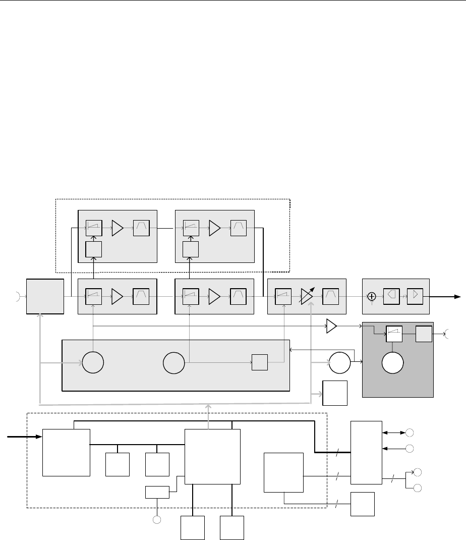
R&S FSH Instrument Design and Functional Description
1145.5973.82 3.1 E-5
3 Repair
This chapter describes the design of the R&S FSH, simple measures for repair and troubleshooting,
and, in particular, the replacement of modules.
Firmware updates and the installation of the DTF option are described in Chapter 4.
Instrument Design and Functional Description
The following figure shows a block diagram of the R&S FSH.
4 - 7 GHz
IN
100 kHz ..
6 GHz
Protection
Attenuator
LowPass Filter
IF 1a
Mixer Filter
IF 2a
Mixer Filter
IF 3
Mixer Buffer
To
Mainboard
3.2 GHz 800 MHz
0 - 3
GHz
4031
MHz
831.25
MHz
31.25
MHz
4 - 7
GHz 3.2
GHz : 4
Oscillator 1
(LO 1)
Oscillator 2
(LO 2)
Synthesizer
Noise
12
ADC
10
MHz
TCXO
3615.6
or 4031.2
MHz
Mixer
TG OUT
REF
Reference
Oscillator
(TG)
12
12
Audio
OUT
Power
Adapter
18 V
Battery
+
Temp
Sense
Key pad LCD
Module
EEPROM
Inter-
connection
Board
Trigger
Power
Sensor
Power and
Battery
Management
Risc
Controller
Data
Memory
Program
Memory
DATA Detector
Address, DATA and Control Bus
Audio and TRIGGER
Optical
Interface
Optical
Adapter
Mainboard
Filter
IF 1b
Mixer Filter
IF 2b
Mixer
7231
MHz
3 - 6
GHz
x2
5.1 - 6.6 GHz
x2
3.2 GHz
xN
N = 1 for f < 3 GHz
N = 2 for f > 3 GHz
FSH6 only
Fig. 3-1 Block Diagram R&S FSH

Instrument Design and Functional Description R&S FSH
1145.5973.82 3.2 E-5
Description of the block diagram
The R&S FSH is a triple-conversion super-heterodyne receiver for the frequency range 100 kHz to
3 GHz. After signals are received, they are processed by the RF/IF board and the mainboard.
The RF/IF board contains the functions as described below.
Attenuator
The RF signal passes from the input connector RF INPUT to the programmable input attenuator, which
can be switched from 0 dB to 30 dB in increments of 10 dB. The circuitry is protected from overvoltage.
RF to IF conversion
The RF/IF board converts the received frequencies in the range 100 kHz to 3 GHz to the low 31.25 MHz
IF, which is digitized with 25 MHz before it is sent to the mainboard for digital processing. The RF/IF
board also includes the required local oscillators and associated frequency processing circuits. The unit
is housed in silver-plated aluminum packaging.
The input signal passes via the input attenuator and the lowpass filter to the first mixer. The lowpass
filter provides suppression of the image frequency (image = LO+ IF) to keep the conversion
unambiguous. In the 1st mixer the input signal is up-converted to an IF of 4031.25 MHz by means of the
first LO (4031.25 MHz to 7031.25 MHz). The mixer is followed by a low noise IF amplifier, which
compensates for the loss due to mixing. The signal then passes a filter with a 3-dB bandwidth of
approximately 400 MHz for filtering the first IF. The local oscillator frequency required for this conversion
is also generated on the board. This signal is generated by three VCOs synchronized to 100 MHz, which
in turn is synchronized to a Temperature Compensated 10-MHz Xtal Oscillator (TCXO). This TCXO is
electrically calibrated.
The signal from the 1st IF filter is converted to the 2nd IF of 831.25 MHz. The signal is routed to an
831.25 MHz filter with a 3-dB bandwidth of 20 MHz for further signal processing. The filter is followed by
the 3rd mixer, which converts to 31.25 MHz and utilizes an IF filter that has a -3-dB bandwidth of
approximately 2 MHz.
The frequency range above 3°GHz in the R&S FSH6 is converted via two additional mixers to a first IF
of 7231.25°MHz and to the same 2nd IF as in the FSH3 of 831.25 MHz. As LO signals the oscillator
signals of the FSH3 are doubled.
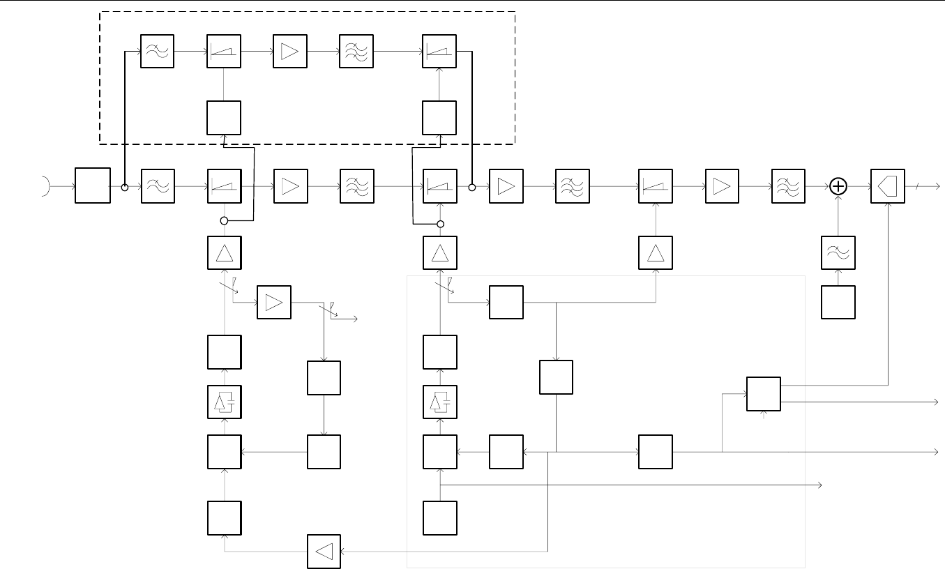
R&S FSH Instrument Design and Functional Description
1145.5973.82 3.3 E-5
0..30dB
Protect.
/ Att.
100 kHz
to 3 GHz
1st Mixer 2nd Mixer
3x
VCO
1st IF Amp
4031.25 MHz
B= 400 MHz
1st IF Filter 2nd IF Amp
831.25 MHz
B= 20 MHz
3rd Mixer 3rd IF Amp
loopfilter
30 kHz
VCO
2nd IF Filter
loopfilter
30 kHz
1/4
1/8
1st LO
4031.25 .. 7031.25 MHz
2nd LO
3200 MHz
3rd LO
800 MHz
800 MHz
100 MHz20 MHz
1/32
or
1/64
noise
25 MHz
3rd IF Filter
31.25 MHz
B= 2 MHz
TCXO
1/2
50 MHz
25 MHz
12
ADC
126..188 MHz
or 94..110 MHz
10 MHz
100kHz
LO1_TG
1/21/5 50 MHz
1/M
M= 2..15
Syn-
con PDPD :2
:1
:2
:1
REF_TG
100 MHz
(DDC, DCON)
(Spider)
Disable
1st Mixer 2nd Mixer1st IF Amp
7231.25 MHz
B= 600 MHz
1st IF Filter
x 2
x 2
6.4 GHz10.23 to 13.23 GHz
RF
Input
3 to 6 GHz
R&S FSH6 only
Fig. 3-2 Block Diagram: RF to IF Conversion and Synthesizer

Instrument Design and Functional Description R&S FSH
1145.5973.82 3.4 E-5
Tracking generator (Model 1145.5850.13/23/26 only)
The LO frequency of the 1st mixer is routed via isolation amplifiers to the TG mixer. The other input of
the mixer is a fixed frequency of 4031.25 MHz generated with a VCO locked to the TCXO frequency.
The resulting IF signal is routed to the generator output connector.
RF/IF control
The microcontroller available on the mainboard controls the RF/IF setting by programming registers via
an internal serial bus.
For calibration purposes the level correction values are stored in an EEPROM. This EEPROM also
contains module-specific information.
The temperature of the module is continuously measured, and the measured levels will be compensated
for drift if the temperature change is too great.
Mainboard
The mainboard is a combination of the power supply and the functions controlled by a dedicated RISC
controller (ARM 720).
Power and battery management
The ON/OFF key is de-bounced with the real-time clock in the controller. The ON/OFF function is
completely software controlled. This implies that the controller must be operational in order for the the
instrument to be switched ON. The µP-clock (50 MHz) is derived from the RF/IF board, thus requiring
that this board be present. This frequency will always be present if the power adapter is connected or
the instrument is in the ON state.
If the instrument is in the OFF state and the power supply is connected, the µP will control the charging
function of the battery depending on the battery condition. The maximum charging current is 1000 mA,
which drops to a trickle charge of about 100 mA if the battery is fully loaded. To prevent damage to the
battery, the charging stops if the battery temperature reaches ≤ 0°C or > 45°C. In the OFF state, the
charging current is approximately 90 mA.
This power supply and battery management arrangement uses a dedicated IC. The instrument can be
switched ON only if the battery is in operating condition. Thus, if the battery is completely empty, the
instrument cannot be switched ON until the charging current has re-loaded the battery, which takes
several minutes.
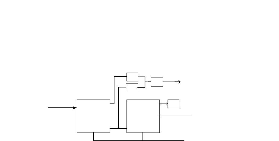
R&S FSH Instrument Design and Functional Description
1145.5973.82 3.5 E-5
Processing of measured data detectors
The measured data is processed in two dedicated ICs to reduce the sample rate of the input signal to a
value that can be handled by the hardware. The DDC converts the digital IF signal to I/Q base band and
filters the base band signals using low pass filters with programmable bandwidth. In addtiotion it delivers
the AM or FM demodulated audio signal. The DCON Asic detects the envelope of the filtered and
combined base band signal and calculates its logarithm. It contains also the video filter and the different
detectors. In addition it is resposible for the sweep control of the FSH.
DDC
DCON
Detectors
Filters
Counter
Control
RAM
AM
DAC
FM
DAC Audio
Amp
Address, DATA and control bus
12
Measurement
data
TRIGGER
AF OUT
Fig. 3-3 Measured Data Processing
Resolution bandwidths (RBW)
The resolution bandwidths are implemented in the R&S FSH through digital processing in the DDC
ASIC (Digital Down Converter). The RBW can be selected from within the range 1 kHz to 1 MHz in 1-, 3-
or 10-unit increments. The DDC first mixes its input IF to the baseband using an NCO (Numeric
Controlled Oscillator) and then filters the resulting IQ signals via a combination of HDF (High Decimation
Filter) and an FIR (Finite Impulse Response) stages. At the end of the DDC processing chain, the IQ
signal is split into magnitude and phase.
For AF demodulation the amplitude information is used. In the case of FM the phase information is used
and fed to the headphone connector. In the analyzer mode the signal at the position of the marker can
be demodulated. In this case the R&S FSH stops the sweep for a selectable period of time and
demodulates the input signal. The volume can be adjusted.
For a standard log display of the analyzed spectrum, the magnitude data is converted from linear to
logarithmic in the DCON ASIC (Digital CONtroller).
Video bandwidths (VBW)
The video filters can be adjusted between 10 Hz and 3 MHz in increments of 1/3/10. They are designed
as digital lowpass filters for the video signals in the DCON ASIC. Software can couple the VBW to the
RBW, or the VBW can be set independently.

Instrument Design and Functional Description R&S FSH
1145.5973.82 3.6 E-5
Detectors
The R&S FSH uses a detector for the positive peak and the negative peak value. In the “sample” mode
the measured value is routed directly to the display. In the RMS“ mode the detector determines the rms
value of the input signal for one specific point in the display during the measured time.
Keypad control
Keypad control is a dedicated function of the controller. For the implementation of the rotary knob, an
encoder is used that is detected with a dedicated CPLD (Complex Programmable Logic Device). This
“One Time Programmable” CPLD is programmed during production.
Serial optical interface
The interface to an external PC has been implemented with optical technology to avoid electrical loops.
The protocol is RS-232-based and is implemented in the instrument by the UART of the controller. It
requires a special optical RS-232 cable for communication (R&S FSH-Z34, delivered with the
instrument). The maximum baud rate is 115200.
Power sensor
The power sensor uses the display of the R&S FSH. Communication is achieved with a separate UART
from the controller.
Color LCD module
The ¼ VGA passive matrix display is backlighted by an FCC backlight, whose light output can be
adjusted to an optimum between visibility and battery use.
R&S FSH Module Replacement
1145.5973.82 3.7 E-5
Module Replacement
This section describes the service concept and contains the spare parts list and the basic documents for
the R&S FSH instrument.
Note: The numbers indicated in brackets refer to items in the mechanical exploded drawings.
Note: The words “left” and “right” in the manual always refer to the front view of the instrument.
Caution!
Wrist strap with cord
Building ground
Floor mat
Ground connection
of operational site
Heel strap
• Please pay close attention to the safety instructions in
the front section of this manual.
• Disconnect the power connector from the instrument
before opening the case.
• Safeguard the replacement site against electrostatic
discharge to prevent damage to electronic components
of the modules.
• The following two methods of ESD protection can be
used together or separately:
- Wrist strap with cord to ground connection
- Conductive floor mat and heel strap combination
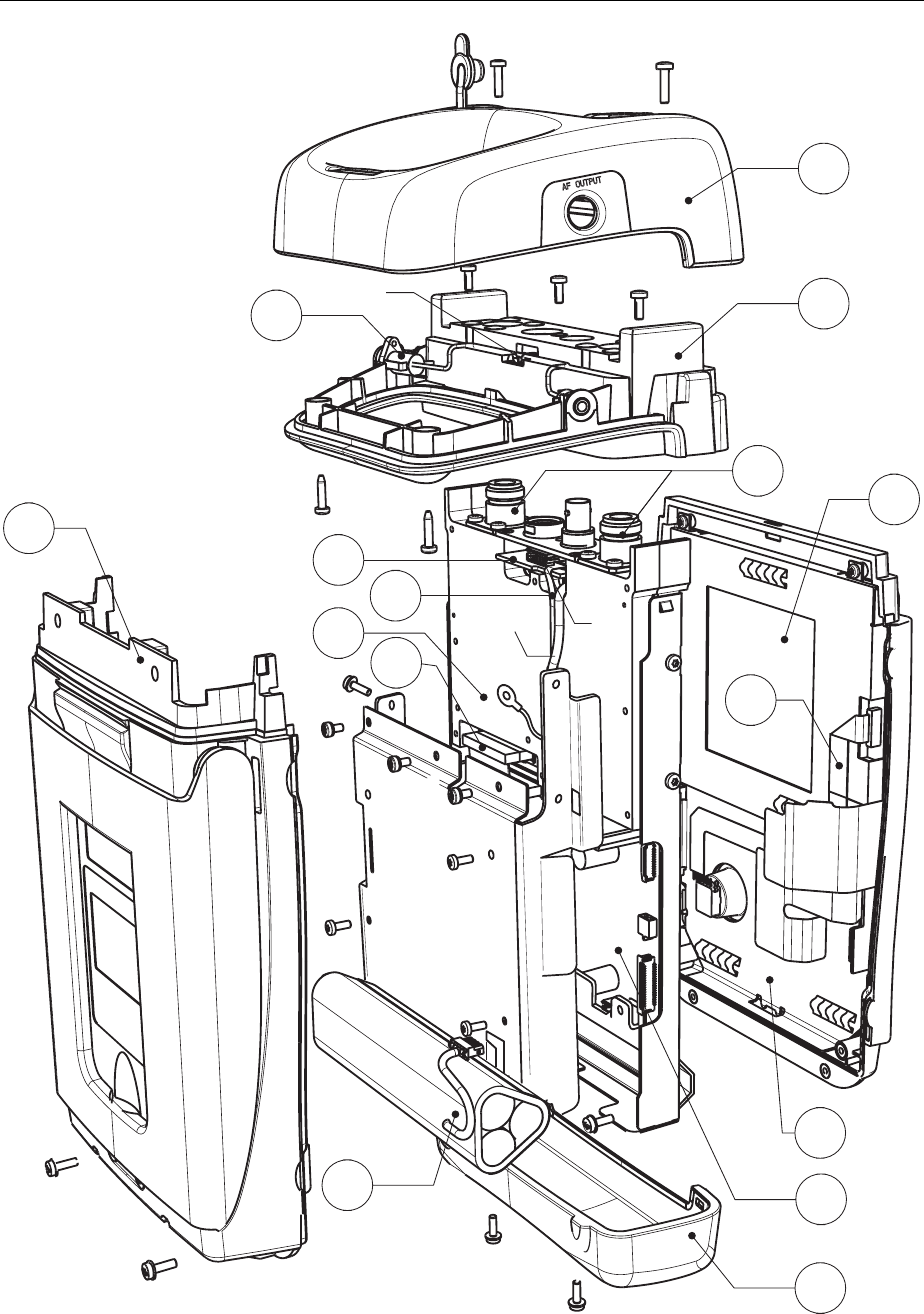
Module Replacement R&S FSH
1145.5973.82 3.8 E-5
3
2.2
2.1
2.3
1
5
7
9
8
6
S3
S4
S4 S4
S4
S4
S4
S4
S4
S4
S3
S1
S1
S1
S1
S2 S2 S2
W1 X2
4
S1
S1
2.4
X2
10.1
10.2
10.3
Fig. 3-4 Exploded View

R&S FSH Module Replacement
1145.5973.82 3.9 E-5
Overview of the modules
Table 3-1 List of spare parts and order numbers
Reference Part R&S Order Number
1 Battery Pack for R&S FSH
(R&S FSH-Z32)
1145.5796.02
2 Housing R&S FSH without top holster 1157.3258.00
Top holster for FSH without tracking
generator
1157.3487.00 2.4
Top holster for FSH with tracking generator 1157.3493.00
Front unit for R&S FSH3 1157.3241.00 3
Front unit for R&S FSH6 1300.7591.00
LCD module 1157.3229.00
LCD plane for FSH3 1300.7704.00
4
LCD plane for FSH6 1300.7710.00
RF/IF module for R&S FSH3 without tracking
generator
1157.3606.00
RF/IF Module for R&S FSH3 with tracking
generator
1157.3612.00
RF/IF Module for R&S FSH6 without tracking
generator
1300.7604.00
5
RF/IF Module for R&S FSH6 with tracking
generator
1300.7610.00
6 Mainboard for R&S FSH 1157.3570.00
7 N connector 1157.3235.00
8 Interconnection board 1157.3587.00
9 Input unit (power and audio connectors,
including wire tree)
1157.3270.00
10 Set of cables for R&S FSH 1157.3329.00
21 AC mains adapter for R&S FSH
(EU Version)
1157.3293.00
22 AC mains adapter for R&S FSH
(UK Version)
1157.3306.00
23 AC mains adapter for R&S FSH
(US Version)
1157.3312.00
AC mains adapter for R&S FSH
(AUS Version)
1157.3370.00
See exploded drawing on the previous page.
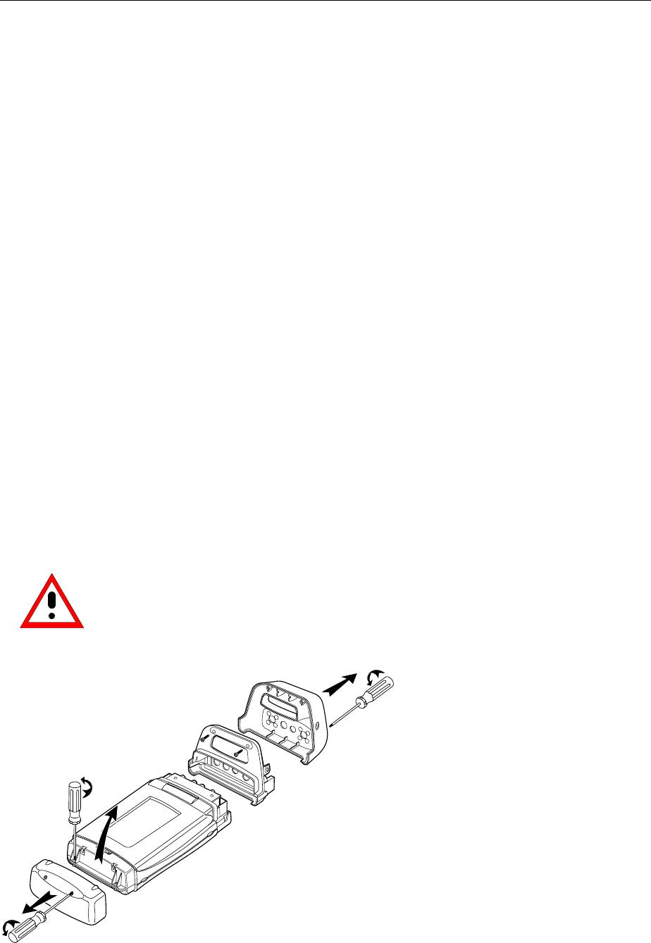
Module Replacement R&S FSH
1145.5973.82 3.10 E-5
Opening the instrument
(See exploded drawing for related numbers.)
¾ Disconnect the power plug.
¾ Switch the instrument to OFF.
¾ Loosen the six (S1) screws and remove the top cover (2.4) and bottom cover (2.1).
¾ Disconnect the connector (X2).
¾ Loosen the three (S2) screws and remove the grip cover (2.3).
¾ Loosen the two (S3) screws and remove the rear case (2.2).
¾ Loosen the nine (S4) screws and remove the mainboard shielding.
Closing the instrument
¾ Mount the mainboard shielding and fasten the nine (S4) screws.
Note that the shielding of wire-tree (W1) is reconnected again.
¾ Mount the rear case (2.2) and fasten the two (S3) screws.
¾ Mount the grip cover and fasten the three (S2) screws.
¾ Connect the connector (X2).
¾ Mount the top cover (2.4) and bottom cover (2.1).
¾ Fasten the six (S1) screws .
¾ Perform the quick verification test.
Refer to Chapter 2 “Adjustment”.
Caution! Note that the connecting cables are still connected.
¾ Note: When detaching the connectors, proceed with caution.
Fig. 3-5 Opening the instrument
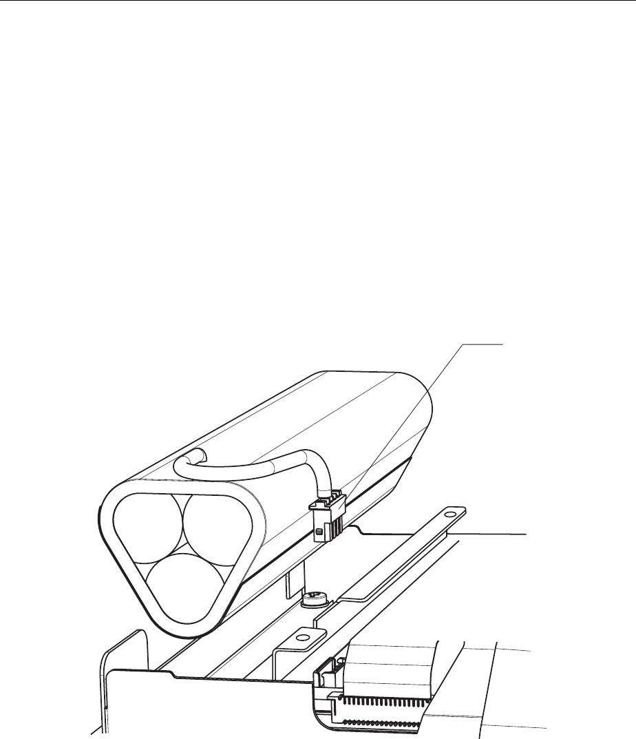
R&S FSH Module Replacement
1145.5973.82 3.11 E-5
Replacing the battery
¾ Open the instrument.
¾ Disconnect connector (X1).
¾ Replace the battery.
¾ Connect (X1).
¾ Close the instrument.
¾ Charge the battery.
¾ Perform the quick verification test.
Refer to Chapter 2 “Adjustment”.
¾ Note: It is recommended that battery charging be performed with the instrument switched OFF and
the AC power connected to the mains. The charging time for a full battery is about 4 hours.
X1
Fig. 3-6 Replacing the battery
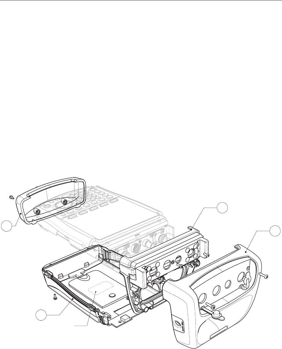
Module Replacement R&S FSH
1145.5973.82 3.12 E-5
Replacing the housing
Housing parts:
2.1: Bottom cover
2.2: Rear case
2.3: Grip cover
2.4: Top cover
Notes: When replacing the rear case, the existing type plate must be placed on the new rear
case, or the old series number must be written on the new type plate.
When the grip cover is replaced, the “input unit power/audio connections” have to be
placed in the new grip cover. See also Replacing the power/audio connections.
¾ Open the instrument.
¾ Replace the specific housing part.
¾ Close the instrument.
¾ Perform the quick verification test.
Refer to Chapter 2 “Adjustment”.
Type Plate
2.1
2.2
2.3
2.4
Fig. 3-7 Replacing the housing
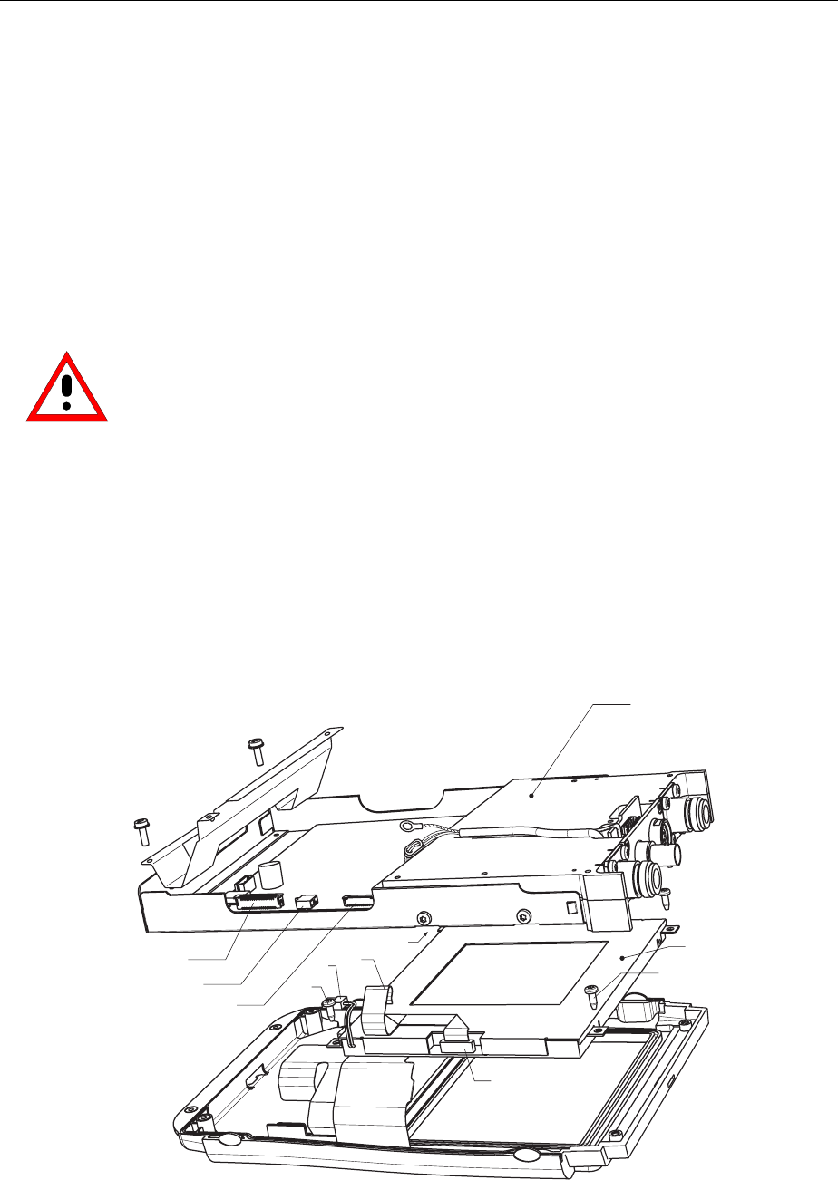
R&S FSH Module Replacement
1145.5973.82 3.13 E-5
Replacing the front unit for R&S FSH
¾ Open the instrument.
¾ Remove the battery .
¾ Remove the Main Unit:
¾ Disconnect the connectors (X3), (X4), and (X5).
¾ Remove the main unit by unscrewing the two (S5) screws.
¾ Remove the LCD colour module:
¾ Losen the four (S6) screws.
¾ Remove the LCD colour module.
¾ Use the new front unit to assemble the instrument again.
Before mounting the unit, make sure that no dust is present between the front unit and
the LCD colour module.
¾ Mount the LCD colour module with the four (S6) screws.
¾ Mount the Main Unit with the two (S5) screws.
¾ Connect the connectors (X3), (X4), and (X5).
¾ Mount the battery.
¾ Close the instrument.
¾ Perform the quick verification test.
Refer to Chapter 2 “Adjustment”.
X3
X4
X5
X5
X4
S5
S5
S6
S6
S6
S6
Main Unit
Color LCD
Module
X3
X6
Fig. 3-8 Replace Front Unit
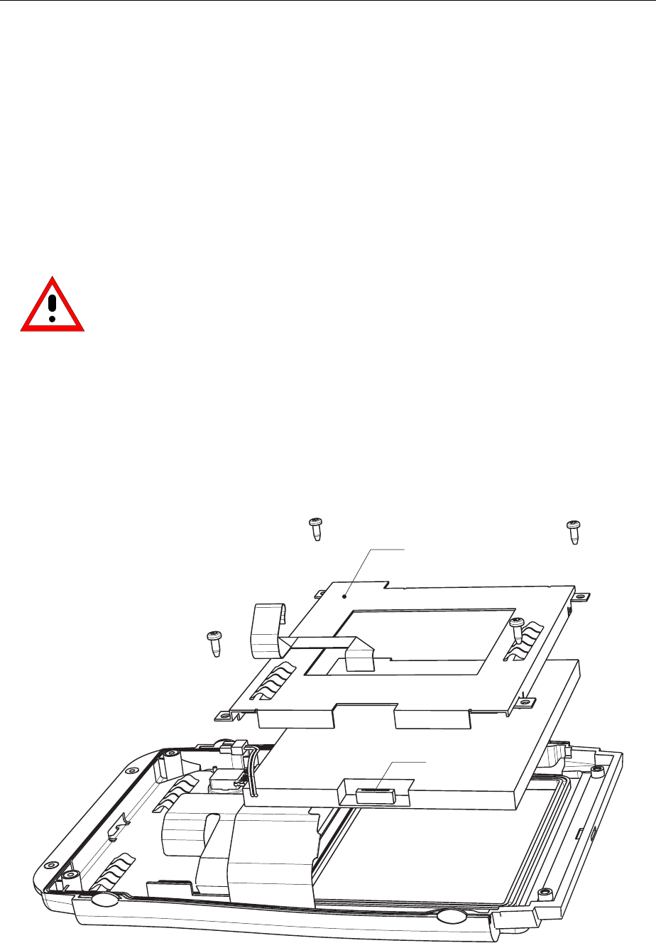
Module Replacement R&S FSH
1145.5973.82 3.14 E-5
Replacing the Color LCD Module
¾ Open the instrument.
¾ Remove the battery
¾ Remove the Main Unit:
¾ Disconnect the connectors (X3), (X4), and (X5).
¾ Remove the main unit by unscrewing the two (S5) screws.
¾ Remove the LCD colour module:
¾ Disconnect the connector (X6).
¾ Losen the four (S6) screws.
¾ Remove the LCD colour module.
¾ Use the new module to assemble the instrument again.
Before mounting the unit, make sure that no dust is present between the front unit and
the colour module.
¾ Mount the LCD colour module with the four (S6) screws.
¾ Mount the Main Unit with the two (S5) screws.
¾ Connect the connectors (X3), (X4), and (X5).
¾ Mount the battery.
¾ Close the instrument.
¾ Perform the quick verification test.
Refer to Chapter 2 “Adjustment”.
X3
X6
X6
X5
X4
S6 S6
S6
S6
LCD Retaining Plate
Fig. 3-9 Replacing the Color LCD Module
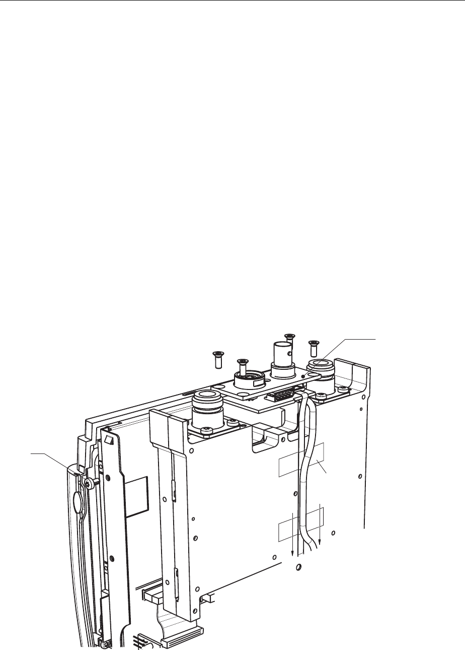
R&S FSH Module Replacement
1145.5973.82 3.15 E-5
Replacing the RF/IF module
¾ Open the instrument.
¾ Disconnect the flat cable (X8) and remove the tape.
¾ Disconnect the connectors (X7) and (X9).
¾ Remove the RF/IF module by unscrewing (S7).
¾ Remove the binder and BNC connector block:
¾ Loosen the four (S8) screws.
¾ Remove the connector block.
¾ Mount the new RF/IF module.
¾ Mount the binder and BNC connector block with the four (S8) screws.
¾ Connect connectors (X7) and (X9).
¾ Mount the flat cable (X8), including the ferrite.
¾ Fasten the flat calbe with the tape.
¾ Close the instrument.
¾ Perform the manual adjustment.
Refer to Chapter 2 “Adjustment”.
S8 S8
S8 S8
S7
X9
X8
X7
Binder and BNC
Connector Block
Tape
Fig. 3-10 Replacing the RF/IF Module
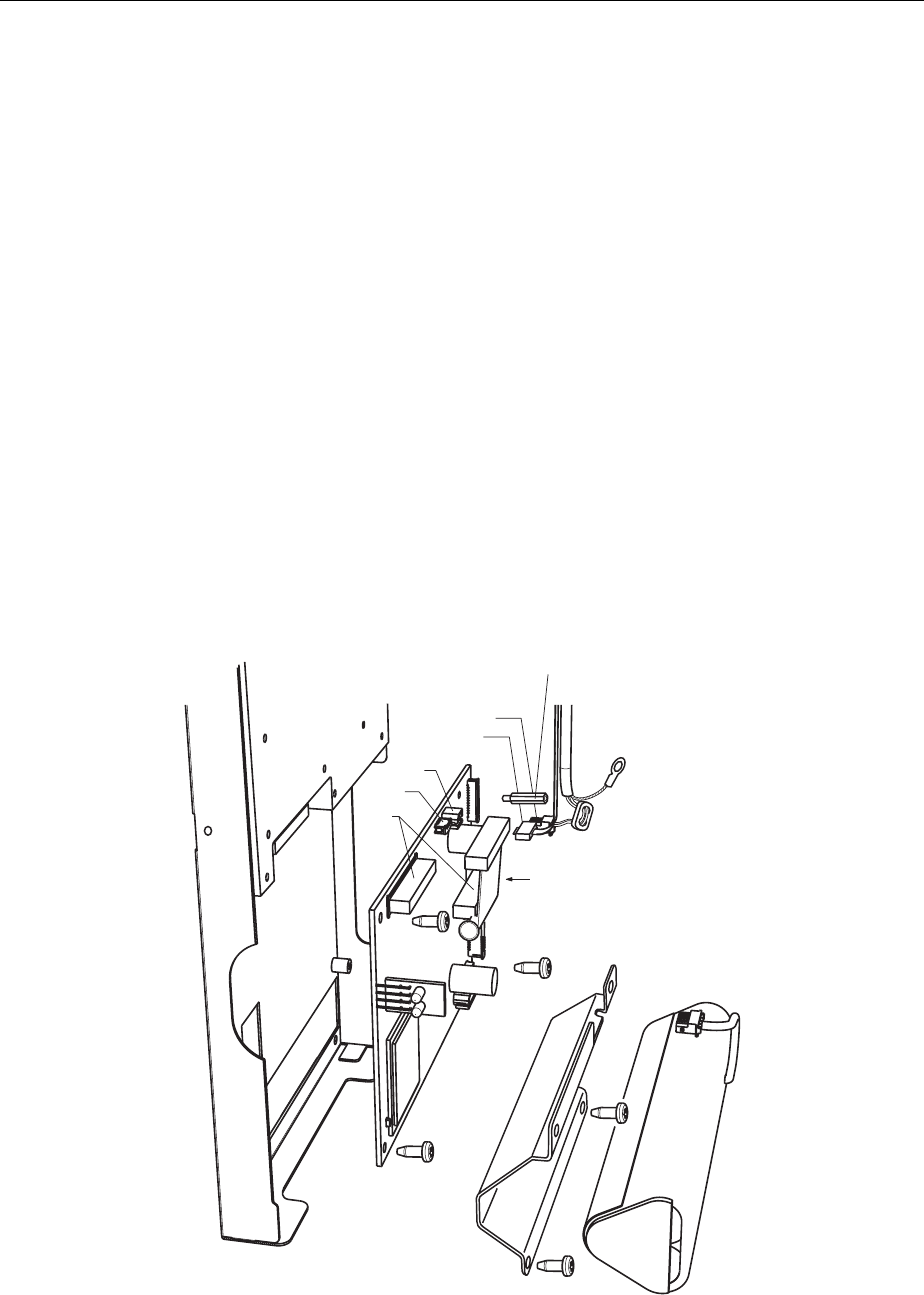
Module Replacement R&S FSH
1145.5973.82 3.16 E-5
Replacing the mainboard
The mainboard contains information about the instrument like the serial number. Special tools are
necessary to update this information after replacement of the mainboard. Therefore the exchange of the
mainboard is possible in a R&S Service Center, only.
¾ Open the instrument.
¾ Remove the battery.
¾ Loosen the two (S5) screws.
¾ Disconnect the connectors (X3), (X4), (X5), (X7), (X8) and (X9).
¾ Loosen the three screws (S11) and the remove the board.
Note that the two lower screws are isolated.
¾ Remove the distance screw (S12)
¾ Mount the new board and fasten (S11) and (S12).
¾ Connect connectors (X3), (X4), (X5), (X7), (X8) and (X9).
¾ Mount the Battery.
¾ Close the instrument.
¾ Perform the manual adjustment.
Refer to Chapter 2 “Adjustment”.
X9
X8
X7 X5
X3
X7
X8
X1
X4
S11
S11
S5
S5
S11
S12
Fig. 3-11 Replacing the Main Board
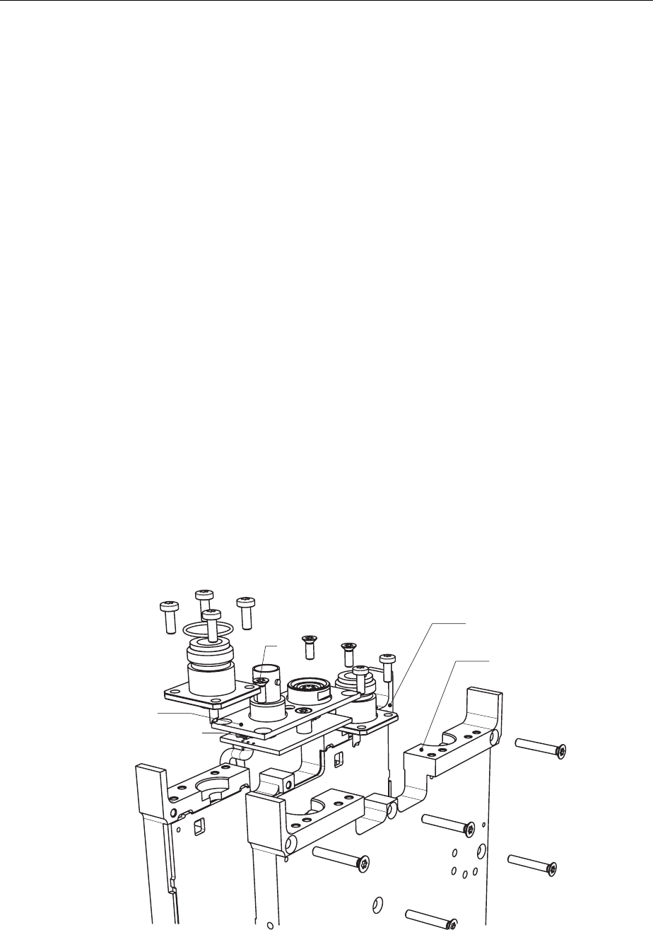
R&S FSH Module Replacement
1145.5973.82 3.17 E-5
Replacing the N connector
¾ Open the instrument.
¾ Remove the battery.
¾ Remove the RF/IF module by unscrewing (S7).
¾ Disconnect the flat cable (X8).
¾ Disconnect the connectors (X7) and (X9).
¾ Remove the binder and BNC connector block:
¾ Loosen the four (S8) screws.
¾ Remove the connector block.
¾ Loosen the two screws (S9) from front RF housing for each N connector.
¾ Loosen the 9 screws (S10) from the RF housing.
¾ Remove the front RF housing.
¾ Clean the center contact of solder left from the N connector to be replaced.
¾ Loosen the other two screws (S9) from the appropriate N connector.
¾ Mount the new connector by first screwing it into the rear RF housing.
¾ Solder the center connection.
¾ Mount the front RF housing (S10).
¾ Fasten the two screws (S9) to the front RF housing for each the N connector.
¾ Mount the binder and BNC connector block with the (S8) screws.
¾ Mount the flat cable (X8), including the ferrite.
¾ Connect the connectors (X7) and (X9).
¾ Mount the RF/IF module (S7).
¾ Mount the Battery and close the instrument.
¾ Perform the manual adjustment.
Refer to Chapter 2 “Adjustment”.
X10
S10
S10
S10
S10
S10
S9 S9
S9 S9
S8 S8
S8 S9 S9
Binder and BNC
Connector Block
Rear RF Housing
Front RF Housing
Fig. 3-12 Replacing the N-Connector
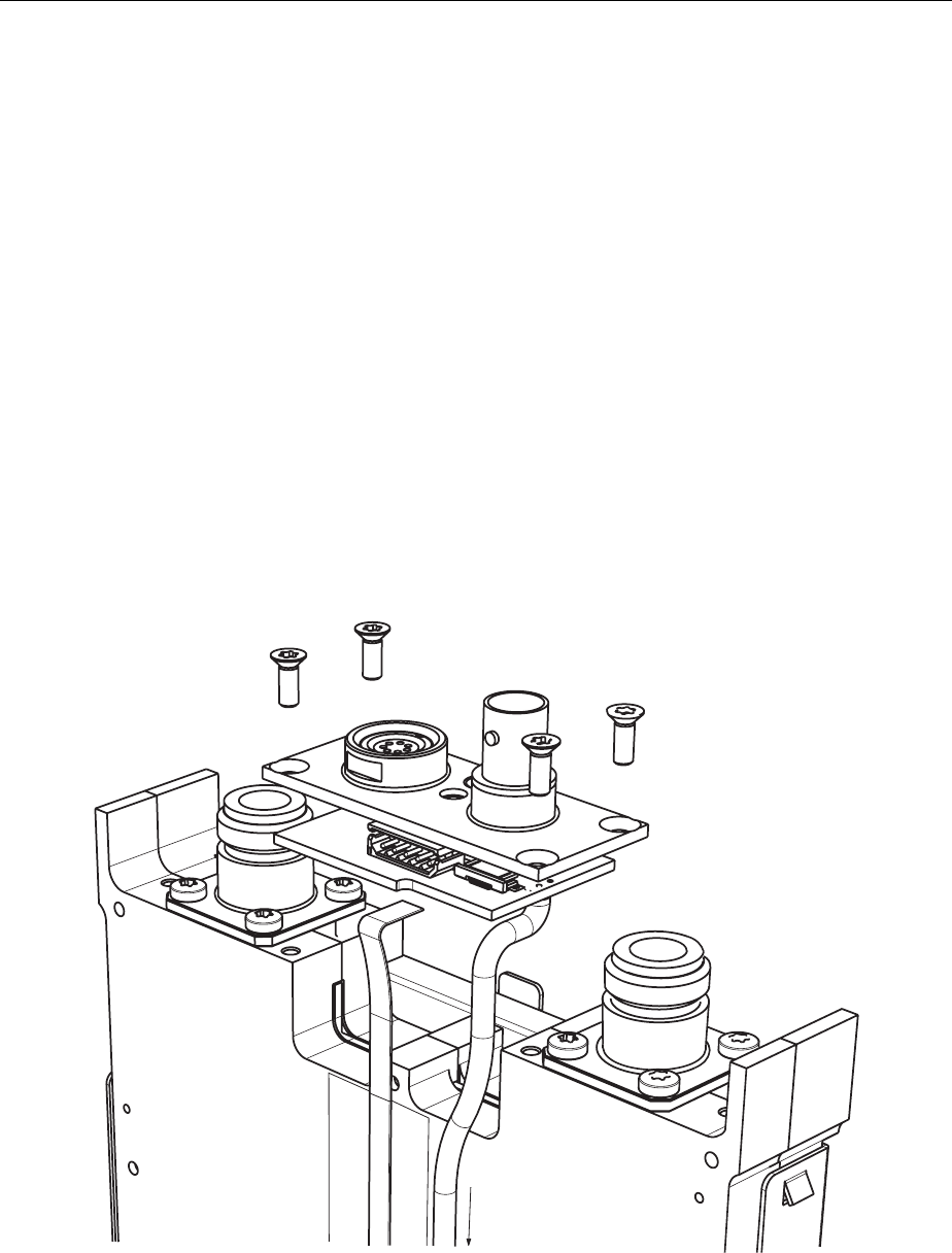
Module Replacement R&S FSH
1145.5973.82 3.18 E-5
Replacing the binder and BNC connector block
(See exploded view for references).
¾ Open the instrument.
¾ Disconnect the flat cable (X10).
¾ Disconnect the connector (X7).
¾ Remove the binder and BNC connector block:
¾ Loosen the four (S8) screws.
¾ Remove the connector block.
¾ Mount the binder and BNC connector block with the four (S8) screws.
¾ Connect the connectors (X7).
¾ Mount the flat cable (X10).
¾ Close the instrument.
¾ Perform the quick verification test.
Refer to Chapter 2 “Adjustment”.
S8
S8
S8
S8
X10
X7
Fig. 3-13 Replacing the Binder and BNC connector block
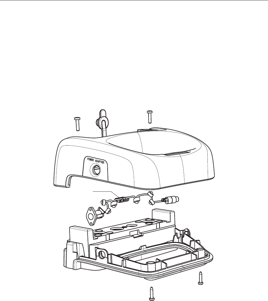
R&S FSH Module Replacement
1145.5973.82 3.19 E-5
Replacing the power/audio connections
¾ Remove the top cover.
¾ Disconnect the connector (X2)
¾ Remove the connection wire tree from the grip cover.
¾ Mount the wire tree again.
¾ Mount the top cover.
¾ Perform the quick verification test.
Refer to Chapter 2 “Adjustment”.
X2
Fig. 3-14 Replacing the Power/ Audio Connections
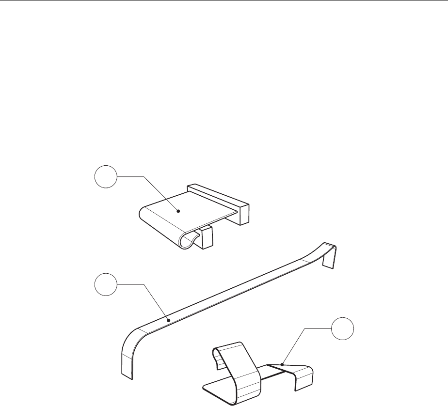
Module Replacement R&S FSH
1145.5973.82 3.20 E-5
Replacing a cable from the cable set
Note: The cable set is needed in the event that a cable is damaged during the replacement of
one of the modules.
Cables from the set:
¾ 10.1: 50-p
10.2: Flat flexible cable, 8 connections
10.3: Flat cable 22-p
For replacement instructions, refer to the individual modules.
10.2
10.3
10.1
Fig. 3-15 Cable set

R&S FSH Troubleshooting
1145.5973.82 3.21 E-5
Troubleshooting
Malfunctions can have simple causes but can also be due to faulty components or modules.
These troubleshooting instructions can be used to locate causes of error down to the board level and to
return the instrument to operability by replacing boards.
We recommend that the instrument be shipped to our experts at the service centers (refer to address
list) for module replacement and further error correction.
Warning! Do not plug or unplug boards without first disconnecting the battery and
the AC Power Supply!
Note: When problems occur, first check whether any connections (cables, plug-in connections of
boards, etc) are damaged or incorrectly connected.

Troubleshooting R&S FSH
1145.5973.82 3.22 E-5
Overview of errors, causes, and possible corrective actions
This section lists various errors, the probable module causing the problem, and the suggested corrective
action.
Troubleshooting problems in switching on the instrument
• Error: R&S FSH cannot be switched on.
Note: When the instrument is switched on, a beep is issued to indicate that the instrument has
started.
Troubleshooting procedure Possible cause of error and further steps
Verify that the AC power is present.
⇓
Connect the adapter to the mains and wait several
minutes until the charger has recharged the battery.
Press the On button for > 5 s.
⇓
This will force the instrument to perform a software reset
and a reset of the internal RAM. The instrument firm-
ware will restart and all data will be reset.
Open the instrument and check the battery.
⇓
Voltage > 7.2 V.
Check the connectors from the AC power
supply: X2 and X7 (refer to section “Repair”).
Power connector broken.
Replace the power and audio connections.
Replace the mainboard (refer to “Replacing the
module”).
• Error: Display remains dark although the beep indicated that the software was started.
Troubleshooting procedure Possible cause of error and further steps
Open the instrument and check X4 (backlight
connector).
Backlight connection open or backlight converter
broken.
Connect again, or replace the mainboard or LCD colour
module.

R&S FSH Troubleshooting
1145.5973.82 3.23 E-5
• Error: Display has erroneous colours and characters.
Troubleshooting procedure Possible cause of error and further steps
Open the instrument and check X5 and X6
(LCD data).
Data connection broken, or circuitry on the mainboard
defective.
Connect again, or replace the mainboard or LCD colour
module
• Error: Frequency response not compliant with specification.
This response can only be corrected at the service center. Replace the RF/IF module.
• Error: Level display very noisy.
Troubleshooting procedure Possible cause of error and further steps
Check the N connector.
⇓
The N connector is soiled.
Clean or replace the N connector.
Replace the RF/IF module.
• Error: Several keys on the keypad do not respond.
Troubleshooting procedure Possible cause of error and further steps
Check X3.
The connection is not operational or the keypad is
broken.
Correct the connection, or replace the front unit.
• Error: Power sensor does not respond properly.
Troubleshooting procedure Possible cause of error and further steps
Check X8 and X10.
The connection is not operating correctly, the binder
connector is broken, the mainboard is broken, or the
cables are broken.
Correct the connection.
Replace the binder and BNC connector block.
Replace the mainboard.
Replace any broken cable in the cable set.

R&S FSH Installing New R&S FSH Software
1145.5973.82 4.1 E-4
4 Software Updates / Installing Options
This chapter provides information on software updates and how to install options on the R&S FSH.
Additional manuals supplied along with software/firmware updates or with options obtained later can be
recorded here.
Installing New R&S FSH Software
A new firmware version can be installed via the R&S website. You can download the newest software
version, and the new software can be loaded onto the R&S FSH by using the setup program.
The instructions are included in the program.
Installing the Options
The following options are available with the R&S FSH:
Distance to Fault Measurement for R&S FSH
R&S FSH-B1
1145.5750.02
Remote Control via RS-232-C
R&S FSH-K1
1145.3458.02
Vector Transmission and Reflection Measurements
R&S FSH-K2
1145.3387.02

R&S FSH Shipping of Instrument and Ordering of Spare Parts
1145.5973.82 5.1 E-5
5 Documents
This chapter provides information on how to order spare parts, and it also contains the spare parts list.
Shipping of Instrument and Ordering of Spare Parts
Please contact your Rohde & Schwarz support center or our spare parts express service if you need to
request service, repair your equipment, or order spare parts and modules.
The list of Rohde & Schwarz representatives and the address of our spare parts express service are
provided in the front section of this service manual.
You will need to provide the following information in order for us to respond to your inquiries quickly and
accurately and to determine whether the warranty for your instrument is still valid:
• Instrument model
• Serial number
• Detailed error description in case of repair
• Contact partner for checkbacks
Shipping of instrument
When shipping the instrument, be sure to provide sufficient mechanical and anti-static protection:
¾ Repack the instrument as it was originally packed. The antistatic packing foil prevents unintentional
electrostatic charging from occurring.
¾ If you do not use the original packaging, include sufficient padding to prevent the instrument from
slipping inside the package. Wrap antistatic packing foil around the instrument to protect it from elec-
trostatic charging.
Shipping of a module
When shipping a module, be sure to provide sufficient mechanical and antistatic protection:
¾ Ship the module in a sturdy, padded box.
¾ Wrap the board in antistatic foil.
If the packaging is antistatic but not conductive, additional conductive packaging is required. The ad-
ditional packaging is not required if the enclosed packaging is conductive.

Shipping of Instrument and Ordering of Spare Parts R&S FSH
1145.5973.82 5.2 E-5
Ordering spare parts
To deliver replacement parts promptly and correctly, we need the following information:
• R&S order number (refer to the spare part lists in this chapter)
• Designation
• Number of units
• Instrument type for the replacement part
• Contact person for possible questions
The R&S order number to be used when ordering replacement parts and modules as well as power
cables can be found further below.
Refurbished modules
¾ Refurbished modules are an economical alternative to original modules. It should be kept in mind that
refurbished modules are not new, but repaired and fully tested parts. They may have signs of use but
they are electrically and mechanically equivalent to new modules.
¾ To find out which refurbished modules are available, please contact your Rohde & Schwarz represen-
tative (or the central service division at Rohde & Schwarz in Munich).
Return of defective replaced modules
¾ Defective modules of the replacement program that can be repaired may be returned within 3
months after delivery of the replaced module. A repurchasing value is credited.
¾ Excluded are parts that cannot be repaired, e.g. PCBs that are burned, broken or damaged by repair
attempts, incomplete modules, or parts that have endured heavy mechanical damage.
¾ Defective parts must be sent back with an accompanying document of returned items containing
the following information:
• R&S order number, serial number and designation of the removed part
• Precise description of the error
• R&S order number, serial number and designation of the instrument the part was removed from
• Date of part removal
• Name of the technician who exchanged the part
¾ A document of returned items is provided along with each replacement module.

R&S FSH Spare Parts
1145.5973.82 5.3 E-5
Spare Parts
The R&S Order numbers necessary for ordering replacement parts and modules can be found in the
spare part lists provided below.
List of R&S FSH spare parts
The following table lists available spare parts together with their R&S order numbers.
Reference Part R&S Order Number
1 Battery Pack for R&S FSH
(R&S FSH-Z32)
1145.5796.02
2 Housing R&S FSH without top holster 1157.3258.00
Top holster for FSH without tracking genera-
tor 1157.3487.00 2.4
Top holster for FSH with tracking generator 1157.3493.00
Front unit for R&S FSH3 1157.3241.00 3
Front unit for R&S FSH6 1300.7591.00
LCD module 1157.3229.00
LCD plane for FSH3 1300.7704.00
4
LCD plane for FSH6 1300.7710.00
RF/IF module for R&S FSH3 without tracking
generator 1157.3606.00
RF/IF Module for R&S FSH3 with tracking
generator 1157.3612.00
RF/IF Module for R&S FSH6 without tracking
generator 1300.7604.00
5
RF/IF Module for R&S FSH6 with tracking
generator 1300.7610.00
6 Mainboard for R&S FSH 1157.3570.00
7 N connector 1157.3235.00
8 Interconnection board 1157.3587.00
9 Input unit (power and audio connectors, in-
cluding wire tree) 1157.3270.00
10 Set of cables for R&S FSH 1157.3329.00
21 AC mains adapter for R&S FSH
(EU Version) 1157.3293.00
22 AC mains adapter for R&S FSH
(UK Version) 1157.3306.00
23 AC mains adapter for R&S FSH
(US Version) 1157.3312.00
AC mains adapter for R&S FSH
(AUS Version) 1157.3370.00

Spare Parts R&S FSH
1093.4820.82 5.4 E-5
Note: The reference can be found in the exploded drawing in Chapter 3.
Important Note!
When replacing a module, please pay careful attention to the safety instructions
and the repair instructions provided in chapter 3 and at the beginning of this ser-
vice manual.
When shipping a module, be sure to provide sufficient mechanical and antistatic
protection.
