Shimano_XT_M775_usermanual_bleedprocedure Shimano XT M775 Usermanual Bleedprocedure
User Manual: Shimano_XT_M775_usermanual_bleedprocedure
Open the PDF directly: View PDF ![]() .
.
Page Count: 3
Disc Brake System
•Remove the spacer for bleeding (yellow), and then set the wheel which has the rotor onto the
frame.
•Install the brake pads.
Install the accessory caps as shown in the illustration to prevent the bolts from loosening.
General Safety Information
WARNING ■Burn-in period
•Disc brakes have a burn-in period, and the braking force will gradually increase
as the burn-in period progresses. Make sure that you are aware of any such
increases in braking force when using the brakes during the burn-in period. The
same thing will happen when the brake pads or rotor are replaced.
■When cleaning with a compressor
•If disassembling the caliper body to clean the internal parts using a compressor,
note that moisture from the compressed air may remain on the caliper
components. Let the caliper components dry sufficiently before reassembling the
calipers.
Note
•The 203 mm and 180 mm rotors have a larger diameter than the 160 mm and
140 mm rotors for cross-country bicycles, and so the flexing of these rotors is
greater. As a result, they will interfere with the brake pads.
•If the brake caliper mounting boss and the dropout are not parallel, the rotor and
caliper may touch.
•When the bicycle wheel has been removed, it is recommended that pad spacers
should be installed. The pad spacers will prevent the piston from coming out if
the brake lever is depressed while the wheel is removed.
•If the brake lever is depressed without the pad spacers installed, the pistons will
protrude further than is normal. Use a flat-tipped screwdriver or similar tool to
push back the brake pads, while being careful not to damage the surfaces of the
brake pads. (If the brake pads are not installed, push the pistons straight back
in, while being careful not to damage them.)
If it is difficult to push the brake pads or pistons back, remove the reservoir tank
cover and then try again. (Note that some oil may overflow from the reservoir
tank at this time.)
•Use isopropyl alcohol, soapy water or a dry cloth when carrying out cleaning
and maintenance of the brake system. Do not use commercially-available brake
cleansers or silencing agents, as they can cause damage to parts such as
seals.
•Do not remove the pistons when disassembling the calipers.
•If the rotor is worn, cracked or warped, it should be replaced.
•Parts are not guaranteed against natural wear or deterioration resulting from
normal use.
•For maximum performance we highly recommend Shimano lubricants and
maintenance products.
•The 203 mm and 180 mm rotors provide a higher braking force than the 160 mm rotors.Make
sure that you have a complete feel for the braking characteristics before using the brakes.
•Please use extra caution to keep your fingers away from the rotating disc
brake rotor during installing or servicing the wheel. The rotor is sharp enough
to inflict severe injury to your fingers if caught within the openings of moving
rotor.
•The calipers and rotor will become hot when the brakes are operated, so do not touch them
while riding or immediately after dismounting from the bicycle, otherwise you may get burned.
Check that the brake components have cooled down sufficiently before attempting to adjust the
brakes.
•The required braking distance will be longer during wet weather.
Reduce your speed and apply the brakes early and gently.
•If the road surface is wet, the tires will skid more easily.If the tires skid, you may fall off the
bicycle. To avoid this, reduce your speed and apply the brakes early and gently.
•Always make sure that the front and rear brakes are working correctly before you ride the
bicycle.
•Be careful not to allow any oil or grease to get onto the rotor and brake pads, otherwise the
brakes may not work correctly.
•If any oil or grease do get on the pads, you should replace the pads.If any
oil or grease gets on the rotor, you should clean the rotor. If this is not done,
the brakes may not work correctly.
•Before riding the bicycle, check that the thickness of each pad is 0.5 mm or
more.
•Vapor lock may occur if the brakes are applied continuously.To relieve this
condition, momentarily release the lever.
•Use only genuine Shimano mineral oil.If other types of oil are used, it may cause problems
with brake operation, and cause the system to be unuseable.
•Be sure to use only oil from a freshly-opened container, and do not re-use oil which has been
drained from the bleed nipple. Old oil or already-used oil may contain water which could cause
vapor lock in the brake system.
•Be careful not to let water or air bubbles to get into the brake system, otherwise vapor lock may
occur. Be particularly careful when removing the cover of the reservoir tank.
•If cutting the brake hose in order to adjust the length of the hose, or when changing over the
brake hose from left to right or vice versa, be sure to bleed the air from the hose by carrying
out steps (5), (8) to (10) given in “Adding mineral oil and bleeding air” in the Service
Instructions.
•When turning the bicycle upside down or on its side the brake system may have some air
bubbles inside the reservoir tank which are still there when the reservoir tank cover is replaced,
or which accumulate in various parts of the brake system when it is used for long periods. The
M775 disc brake system is not designed to be turned upside down. If the bicycle is turned
upside down or on its side, the air bubbles inside the reservoir tank may move in the direction
of the calipers. If the bicycle is ridden in this condition, there is the danger that the brakes may
not operate and a serious accident could occur.
If the bicycle has been turned upside down or on its side, be sure to operate the brake lever a
few times to check that the brakes operate normally before riding the bicycle. If the brakes do
not operate normally, adjust them by the following procedure.
•If fluid leaks occur, immediately stop using the brakes and carry out the appropriate repairs.If
you continue riding the bicycle while fluid is leaking, there is the danger that the brakes may
suddenly stop working.
•If the quick release lever is on the same side as the rotor, there is the danger that it may
interfere with the rotor, so check that it does not interfere.
•It is important to completely understand the operation of your bicycle's brake system.Improper
use of your bicycle's brake system may result in a loss of control or an accident, which could
lead to severe injury. Because each bicycle may handle differently, be sure to learn the proper
braking technique (including brake lever pressure and bicycle control characteristics) and
operation of your bicycle. This can be done by consulting your professional bicycle dealer and
the bicycle's owners manual, and by practicing your riding and braking technique.
•If the front brake is applied too strongly, the wheel may lock and the bicycle may fall forward,
and serious injury may result.
•Shimano disc brake systems are not compatible with tandem bicycles.Because tandem
bicycles have a high overall weight, the load on the brake system increases during brake
operation. If hydraulic disc brakes are used with tandem bicycles, the oil temperature will
become too high and vapor locks or ruptures in the brake hoses may occur, and this will cause
the brakes to fail.
•Obtain and read the service instructions carefully prior to installing the parts. Loose, worn
or damaged parts may cause the bicycle to fall over and serious injury may occur as a result.
We strongly recommend only using genuine Shimano replacement parts.
•Read these Technical Service Instructions carefully, and keep them in a safe place for later
reference.
•A01S brake pads are designed to reduce the amount of noise which is generated
between the pads and the rotor when the brakes are operated. A longer running-
in period is required for this type of pad compared to M06 pads.
■Handling the mineral oil
•Use safety glasses when handling, and avoid contact with eyes.Contact with eyes may result in
irritation.
In the event of eye contact, flush with fresh water and seek medical assistance immediately.
•Use gloves when handling.Contact with skin may cause a rash and discomfort.
In the event of skin contact, wash well with soap and water.
•Inhalation of oil mist or vapors may cause nausea.Cover nose and mouth with a respirator type
mask and use in a well ventilated area.
If mist or vapor is inhaled, go immediately to an area with fresh air. Cover up with a blanket.
Stay warm and stable and seek professional medical advice.
•Do not drink.May cause vomiting or diarrhea.
•Keep out of reach of children.
•Do not cut, heat, weld or pressurize the oil container, as this may cause explosion or fire.
•Disposal of Used Oil :Follow local county and/or state codes for disposal.Use care when
preparing oil for disposal.
•Directions :Keep the container sealed to prevent foreign objects and moisture from getting
inside, and store it in a cool, dark area away from direct sunlight or heat.
CAUTION
Vapor lock is a phenomenon in which the oil inside the brake system becomes heated,
which causes any water or air bubbles inside the brake system to expand. This can then
result in a sudden increase in the brake lever stroke.
< If brake operation is sluggish when the lever is depressed >
Gently depress the brake lever several times and wait for the bubbles to return to the
reservoir tank. It is recommended that you then remove the reservoir tank cover and fill the
reservoir tank with mineral oil until no bubbles remain.
If the brakes still operate sluggishly, bleed the air from the brake system.
(Refer to "Adding the mineral oil and bleeding air".)
One Holland, Irvine, California 92618, U.S.A. Phone: +1-949-951-5003
Industrieweg 24, 8071 CT Nunspeet, The Netherlands Phone: +31-341-272222 3-77 Oimatsu-cho, Sakai-ku, Sakai-shi, Osaka 590-8577, Japan
* Service Instructions in further languages are available at :
http://techdocs.shimano.com
Please note: specifications are subject to change for improvement without notice. (English)
©Sep.2010 by Shimano Inc. XBC IZM Printed in Japan.
This service instruction explains how to use and maintain the Shimano bicycle
parts which have been used on your new bicycle.
For any questions regarding your bicycle or other matters which are not related
to Shimano parts, please contact the place of purchase or the bicycle
manufacturer.
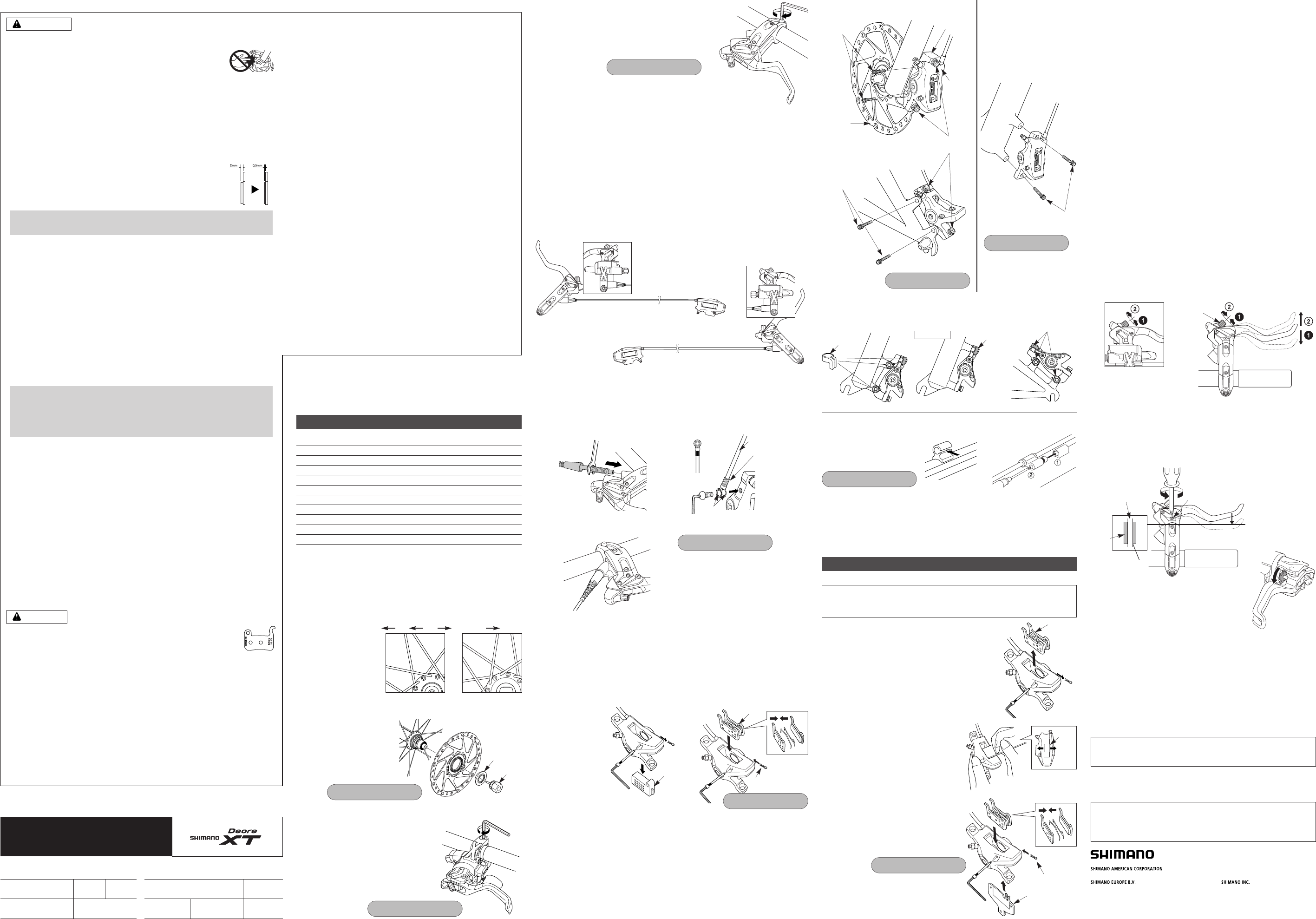
■Installation of the calipers (BR-M775 / M776) and securing the hose.
< Front >
< Front > < Rear >
< Front >
< Rear >
Te chnica l S e r v ice In st ructi on s SI-8EP0A-007
Caliper
Hose
Rotor
Brake Lever
BR-M775 BR-M776
SM-BH59 SM-BH63
SM-RT78
ST-M775 / BL-M775
Cable Supporter
Mineral Oil
Brake pad unit Resin Pads
Metal Pads
SM-HANG
SM-DB-OIL
A01S
M06
In order to realize the best performance, we recommend that the following
combination be used.
Brake pads
Spacer for bleeding
Tightening torque:
2 - 4 N·m {18 - 35 in. lbs.}
Tightening torque:
6 - 8 N·m {53 - 69 in. lbs.}
Tightening torque:
6 - 8 N·m {53 - 69 in. lbs.}
Caliper
Rotor
Caps
Caps
Caps
Post type
Adapter
Caliper
fixing bolts
Caliper
fixing bolts
Adapter
fixing bolts
Adapter
fixing bolts
For C-shaped guides and the usual
type of cable stoppers, use the
special Shimano cable supporter
(sold separately) to secure as
shown in the illustration.
Operate the brake lever several times and check whether the brakes operate normally or
not. Also check that there are no oil leaks visible.
Tightening torque:
0.3 - 0.5 N·m {2.7 - 4.4 in. lbs.}
Tightening torque:
5 - 7 N·m {44 - 60 in. lbs.}
Tightening torque:
2 - 4 N·m {18 - 35 in. lbs.}
< C-shaped guide > < Usual type of cable stopper >
■Brake pad replacement
Maintenance
Note: The M775 brake system is designed so that as the brake pads become worn,
the pistons gradually move outward to automatically adjust the clearance between
the rotor and the brake pads. Therefore, you need to push the pistons back to
their original positions when replacing the brake pads.
If oil adheres to the brake pads after oil is added, or if
the brake pads are worn down to a thickness of 0.5 mm,
or if the brake pad presser springs are interfering with
the rotor, replace the brake pads.
1. Remove the wheel from the frame, and remove the
brake pads as shown in the illustration.
2. Clean the pistons and surrounding area.
3. Remove the reservoir tank cover while referring to the
step (1) in "Adding mineral oil".
For international-standard mounts, attach adapters to calipers for post-type mounts.
(Separate front and rear adapters are available.)
1. Loosen the caliper fixing bolts so that the caliper can move sideways, and then install the
adapter to the frame.
2. Depress the brake lever so that the rotor is being clamped by the pads, and then tighten the
caliper fixing bolts.
●International standard mounting type ●Post mounting type
4. Push the piston back in as far as it will
go, while being careful not to twist it.
(Note that some oil may overflow from
the reservoir tank at this time.)
5. Install the new brake pads, and then
install the pad spacers (red). Make
sure that you do not forget to install the
snap rings at this time also.
■Mineral oil replacement
It is recommended that you replace the oil inside the reservoir tank if it becomes
severely discolored.
Attach a tube with a bag to the bleed nipple, and then open the bleed nipple and
drain out the oil. You can operate the brake lever at this time to help the oil to
drain out. After draining the fluid, pour in fresh brake fluid while referring to
"Adding the mineral oil and bleeding air". Use only genuine Shimano mineral oil.
Dispose of the waste oil according to proper country and/or state disposal
regulations.
Be sure to read the service instructions for the “Adding mineral oil
and bleeding air” in conjunction with these service instructions.
Brake pads
Pad spacer (red)
Snap ring
Snap ring
Provisionally install the caliper to
the frame (so that the caliper can
move sideways), depress the
brake lever so that the rotor is
being clamped by the pads, and
then tighten the caliper fixing
bolts.
Piston
■Wheel spoke lacing
Check that the spokes have been laced as shown in the illustration.
A radial assembly cannot be used.
Lace the spokes as shown in Figure 1 below for the left side of the front wheel
(the side where the rotor is installed), and the left and right sides of the rear
wheel, and as shown in Figure 2 below for the right side of the front wheel.
■Installation of the rotor
(SM-RT78)
SM-RT78L (203mm)
SM-RT78M (180mm)
SM-RT78 (160mm)
Rotating
direction of
wheel
Front left Rear left Rear right Front right
Fig. 2Fig. 1
The following tools are needed to assemble this product.
Usage location
Rotor fixing lock ring
Brake lever fixing bolt
Caliper fixing bolt
Brake pad fixing shaft
Reservoir tank cover
Cable supporter
Brake hose fixing bolt
Bleed nipple
TL-LR15
Allen key 4 mm
Allen key 5 mm
Adapter (post type) fixing bolt Allen key 5 mm
Allen key 3 mm
Phillips screwdriver #1
Phillips screwdriver #2
8 mm wrench / Allen key 3 mm
Socket wrench 7 mm
Tool
Tightening torque:
40 - 50 N·m {350 - 435 in. lbs.}
< BL-M775 >
Secure the brake lever as shown in the illustration. (Check
that the brake lever does not interfere with the shifting lever
during operation. Refer to the Service Instructions for the
shifting lever also. Some types might require the shifting
lever to be installed first, due to the position of the shifting
lever fixing bolts.)
When installing the components to carbon frame/handle bar surfaces, verify with the
manufacturer of the carbon frame/parts for their recommendation on tightening torque in order to
prevent over tightening that can cause damage to the carbon material and/or under tightening
that can cause lack of fixing strength for the components.
Brake lever Tightening torque:
6 - 8 N·m {53 - 69 in. lbs.}
Rotor fixing
lock ring
TL-LR15
Installation
■Installation of the brake lever
< ST-M775 >
Secure the brake lever as shown in the
illustration.
Brake lever Tightening torque:
6 - 8 N·m {53 - 69 in. lbs.}
■Installation of the hose
For left lever
At brake lever end At caliper end
For right lever
Refer to the Service Instructions for the SM-BH59 brake
hose (SI-8H20) for details on installing the hose.
Do not let the hose become twisted when installing.
Make sure that the calipers and levers are in the
positions shown in the illustrations.
BL-M775
BR-M775
BR-M776
ST-M775
Reach
adjustment bolt
■Reach adjustment
Tighten the reach adjustment bolt (clockwise direction) to make the reach
narrower, and loosen it (counterclockwise direction) to make the reach wider.
< ST-M775 >
< BL-M775 >
Free stroke
adjustment screw
Rotor
Pad
Contact
Pad contact point
■Free stroke adjustment
When the free stroke adjustment screw is loosened, the free stroke of the
brake lever will increase, so that you can adjust it to the desired setting.
< BL-M775 >
< ST-M775 >
< BR-M775 / SM-BH59 >
< BR-M776 / SM-BH63 >
Refer to the Service Instructions for the SM-BH63 brake hose (SI-8H40) for details on installing
the hose. Do not let the hose become twisted when installing.
Hose
Banjo
O-rings
8 mm wrench
Allen key 3 mm
SI-8EP0A-007-00
6. Depress the brake lever several times to check that the operation becomes
stiff.
7. Remove the pad spacers, install the wheel, and then check that there is no
interference between the rotor and the caliper. If they are touching, adjust
while referring to "Installation of the caliper".
8. After checking the oil level, replace the reservoir tank cover.
9. Return the brake lever to its original position.
■Adjustment when the pistons are not operating correctly
The caliper mechanism includes two pistons. If these pistons do not operate
properly or if they protrude unevenly, or if the brake pads remain in contact with
the rotor, adjust the pistons by the following procedure.
1. Remove the wheel and the brake pads.
Clean the pistons and surrounding area, and remove the reservoir tank cover.
2. Push the piston back in straight, without bending it. Note that some oil may
overflow from the reservoir tank at this time.
3. Install the brake pads and the pad spacers (red).
4. Depress the brake lever as far as it will go, and then operate it several more
times so that the two pistons all move to their initial positions.
5. Remove the pad spacers, install the wheel, and then check that there is no
interference between rotor and the calipers. If they are touching, adjust using
shims.
6. After checking the oil level, replace the reservoir tank cover.
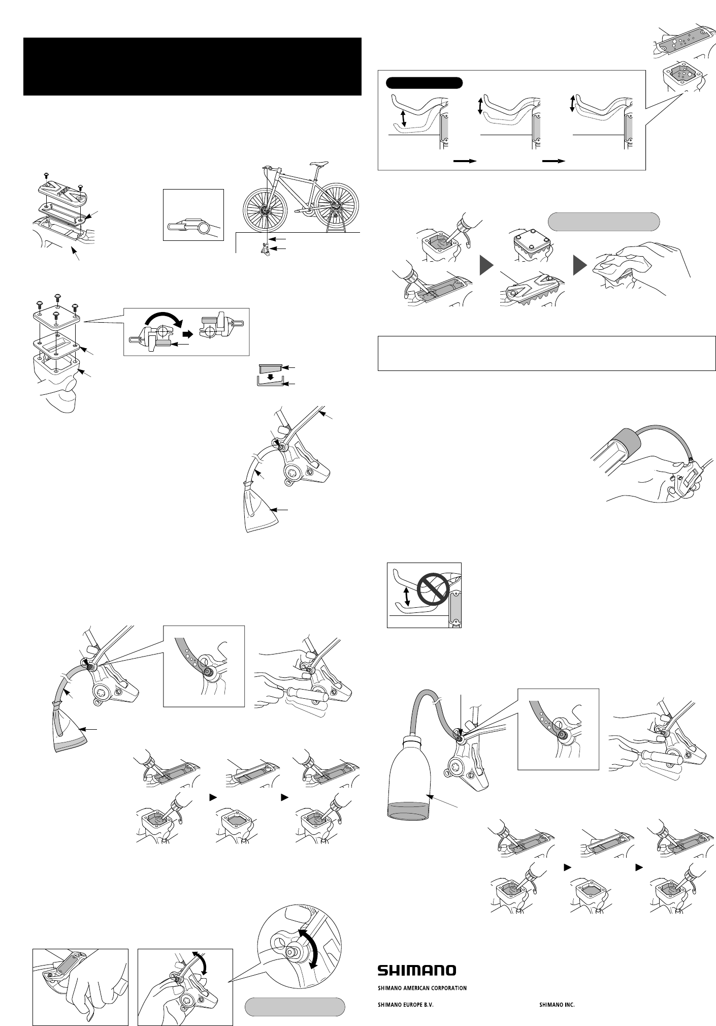
Oil bottle
Bleed nipple
1. Place the reservoir tank so that it is parallel to the ground,
and then remove the reservoir tank cover.
(Refer to step 1 in "Adding oil and bleeding air at the
reservoir tank")
2. Attach a 7 mm socket wrench, and fill the syringe with oil
and connect a hose to the bleed nipple. Then loosen the
bleed nipple by 1/8 of a turn to open it. Push the plunger of
the syringe to add oil. The oil will start coming out from the
reservoir tank. Continue adding oil until there is no more air
mixed in with the oil that is coming out. (If using the Shimano bleeding tool, be sure to read the
service instructions for the Shimano bleeding tool.)
3. Once air stops coming out, temporarily close the bleed nipple. (If the Shimano bleeding tool has
been installed to the brake lever at this time, remove the Shimano bleeding tool.)
4. Connect the oil bottle to the bleed nipple, and then loosen the bleed nipple. After a little while, the
oil and air will flow naturally from the bleed nipple into the tube of the oil bottle. In this way it will be
possible to easily extract the greater part of the air remaining inside the brake system.
It may help to shake the hose gently or to tap the reservoir tank or caliper gently with a screwdriver
or move the position of the caliper at this time.
Do not continually squeeze and release the lever at this point.
If this is not observed, air bubbles may remain mixed in with the oil inside
the caliper, and it will take longer to bleed the air. (If the lever is
continually squeezed and released, drain out all of the oil and then add oil
again.)
Note:
Do not use brake fluid fillers, as they can cause small bubbles of air to form, and such bubbles
can cause severe drops in braking performance.
9. Fill the reservoir tank with oil and then replace the reservoir tank cover. Fill the reservoir tank to
overflowing with oil while replacing the cover to ensure that no air bubbles remain inside the
reservoir tank. In addition, be careful not to get any oil on parts such as the rotor and brake pads.
10. Return the brake lever to its original position.
6. Once air stops coming out from the bleed nipple, temporarily tighten the bleed nipple.
7. With the brake lever depressed, open and close the bleed nipple in rapid succession (for
approximately 0.5 seconds each time) to release any air bubbles
which may be in the calipers. Repeat this procedure about 2 to 3
times.
Then tighten the bleed nipple again.
One Holland, Irvine, California 92618, U.S.A. Phone: +1-949-951-5003
Industrieweg 24, 8071 CT Nunspeet, The Netherlands Phone: +31-341-272222 3-77 Oimatsu-cho, Sakai-ku, Sakai-shi, Osaka 590-8577, Japan
Please note: specifications are subject to change for improvement without notice. (English) © May 2008 by Shimano Inc. XBC IZM Printed in Japan.
Hose
Diaphragm
Diaphragm
Base of reservoir tank
Diaphragm
Reservoir tank
Reservoir tank
Calipers
Lever operation
Loose Slightly stiff Stiff
1. With the spacer for bleeding (yellow) still attached to the calipers, place the bicycle into a bicycle
stand or similar as shown in the illustration.
Set so that the brake lever is
parallel to the ground, and then
remove the reservoir tank cover.
Turn the lever unit so that the top of the reservoir tank is parallel to the
ground, and then remove the reservoir tank cover.
Note : When reassembling, set the
diaphragm so that it is aligned at the
same angle as the base of the
reservoir tank.
< BL type >
< ST type >
3. Loosen the bleed nipple by 1/8th of a turn to open it, and
then pour oil into the reservoir tank. Gently operate the
brake lever while doing this to help prime the system with
the oil.
4. Oil will come out periodically from the bleed nipple about every 5 minutes.
5. After a little while, the oil and air will flow naturally from the bleed nipple into the tube. In this way it
will be possible to easily extract the greater part of the air remaining inside the brake system.
It may help to shake the hose gently or to tap the reservoir tank or caliper gently with a screwdriver
or move the position of the caliper at this time.
8. If the brake lever is then operated, air bubbles in the system will rise up
through the port into the reservoir tank. Once the bubbles stop appearing,
depress the brake lever as far as it will go.
The normal condition is for the lever to be stiff at this point.
Brake lever
should be parallel
to ground
Socket wrench
(7mm)
Tub e
Bleed nipple
Bag
2. Set a 7mm socket wrench in place, attach a bag to the tube,
and then place the tube onto the bleed nipple as shown in
the illustration.
Tub e
Bleed nipple
Bag
Reservoir tank
Te c h n ical Se r v i c e I n str u c tion s SI-0037A-002
Adding mineral oil and bleeding air
■Adding oil and bleeding air at the reservoir tank
■Adding oil and bleeding air at the caliper using a syringe
(including Shimano bleeding kit)
Tightening torque:
0.3 - 0.5 N·m {2.7 - 4.4 in. lbs.}
Tightening torque:
4 - 6 N·m {35 - 53 in. lbs.}
The oil level in the reservoir
tank will drop at this time, so
be sure to keep adding oil to
maintain the oil level so that
air is not drawn in through
the port (so that air does not
enter through the port).
5. Carry out steps 6 to 10 in "Adding oil and bleeding air at the reservoir tank".
The oil level in the reservoir
tank will drop at this time, so
be sure to keep adding oil to
maintain the oil level so that
air is not drawn in through
the port (so that air does not
enter through the port).

Please note: specifications are subject to change for improvement without notice. (English) © Oct. 2009 by Shimano Inc. XBC IZM Printed in Japan.
(English)
One Holland, Irvine, California 92618, U.S.A. Phone: +1-949-951-5003 Industrieweg 24, 8071 CT Nunspeet, The Netherlands Phone: +31-341-272222 3-77 Oimatsu-cho, Sakai-ku, Sakai-shi, Osaka 590-8577, Japan
SI-0109A-001
Points to note for
bleeding the air when
adjusting the brake hose
If cutting the brake hose in order to adjust
the length of the hose, or when changing
over the brake hose from left to right or vice
versa, be sure to bleed the air from the hose
by carrying out steps (5), (8) to (10) given in
“Adding mineral oil and bleeding air” in the
Service Instructions.
(Spanish)
SI-0109A-001
Puntos a tener en
cuenta para purgar el
aire cuando ajuste la
manguera de frenos.
Si corta la manguera de frenos de manera
de ajustar el largo de la manguera, o
cuando cambia la manguera de frenos de
izquierda a derecha o vice versa,
asegúrese de purgar el aire de la manguera
de acuerdo con los pasos (5), (8) a (10)
indicados en "Agregando aceite mineral y
purgando el aire" en las Instrucciones de
servicio.
(Japanese)
SI-0109A-001
ブレーキホース調整時の
気泡抜きに関するご注意
ブレーキホースの長さを調整するためにホース
の切断や、ブレーキホースの左右の入替えを行
った場合は、必ず“ミネラルオイルの注入と気
泡抜き”の取扱い説明書(5)および(8)から(10)
の手順に従って、気泡抜き作業を行ってください。
(French)
SI-0109A-001
Remarques pour purger
l'air lors de l'ajustement
du tube de frein
Si l'on coupe le tube de frein pour ajuster la
longueur du tube, ou lorsqu'on permute le
tube de frein de gauche à droite ou vice
versa, veiller à purger l'air du tube en
effectuant les étapes (5), (8) à (10)
indiquées dans la section "Ajout de l'huile
minérale et purge de l'air" des instructions
de montage.
製品改良のため、仕様の一部を予告なく変更することがあります。
