PDF Siemens Saturn IIE EPABX General Description
Saturn IIE EPABX General Description Saturn IIE EPABX General Description
User Manual: PDF T E X T F I L E S
Open the PDF directly: View PDF ![]() .
.
Page Count: 359 [warning: Documents this large are best viewed by clicking the View PDF Link!]

Siemens Practices A30808-X5130-AllO-l-8918
General Series Issue 1, May 1986
Issued by Office Systems Group
5500 Sroken Sound Boulevard N.W., Boca Raton, Florida 33431
Siemen.s Information Systems, Inc.
(305) 994-8100 e Telex: 515052
___-
Printed in U.S.A.
Siemens Practices
General Series
0 Siemens Information Systems, Inc., 1985
All rights reserved.
A30808-X5130-AllO-l-8918 .
Issue 1, May 1986
This material is proprietary to Siemens Information Systems, Inc. Any unauthorized
reproduction, use or disclosure of this material, or any part thereof, is strictly prohibited.
Siemens reserves the right to make changes in specifications at any time and without
notice. The information furnished by Siemens in this material is believed to be accurate
and reliable. However, no responsibility is assumed by Siemens for its use.
SATURN is a registered trademark of Siemens Information Systems, Inc.

SATURN IIE EPABX A30808-X5130-AllO-l-B918
General Description Issue 1, May 1986
CONTENTS
SECTION PAGE
1.00 INTRODUCTION ........................... l-1
Purpose .................................. l-l
Scope.. .................................. l-l
Siemens SATURN IIE Practices ................ l-l
Siemens Customer Support Services. ........... l-l
2.00 SYSTEM OVERVIEW. ........ , ............ 2-1
General .................................. 2-1
Features ................................. 2-l
Hardware Description ....................... 2-3
Software Description. ....................... 2-7
System Capacities and Specifications .......... 2-7
3.00 SATURN IIE EQUIPMENT CABINET ........... 3-l
Cabinet Layout ............................. 3-1
Lineflunk Unit Shelf ........................ 3-5
Basic Shelf. ............................... 3-6
4.00 POWER SUPPLIES ........................ 4-l
Main Power Section ......................... 4-l
Power System Unit. ......................... 4-l
Basic Shelf Power Supply .................... 4-l
Memory Support Module ..................... 4-l
Control Logic .............................. 4-3
Ring Generator ............................ 4-3
Power Supply Circuit Breakers. ................ 4-3
Linemunk Unit Power Supply .................. 4-3
4a-Volt
Power Supply ........................ 4-3
5.00 MISCELLANEOUS MODULE ASSEMBLIES ..... 5-l
Floppy Disk Drive. .......................... 5-l
6.00 PRINTED CIRCUIT BOARDS ........ , ....... 6-1
Dimensions ................................ 6-l
Controller/Input-Output Processor .............. 6-2
Signal Multiplexer/Tone Generator .............. 6-2
Parallel/Serial Converter ...................... 6-2
Memory Control and Attenuation ............... 6-2
Conference. ............................... 6-2
Memory .................................. 6-2
Dual-Tone Multifrequency Receiver. ............. 6-2
Remote Access UniUPotis .................... 6-2
Line/Trunk Unit Control ...................... 6-3
Subscriber Line Module Analog - Station ........ 6-3
Subscriber Line Module Analog -
Off-Premises Station ....................... 6-3
Subscriber Line Module Analog - 16 Lines ...... 6-15
Premium Instrument Module Digital ............ 6-15
Subscriber Line Module Digital ............... 6-15
Trunk Types. .............................. 6-15
Two-Wire E&M Trunk. ....................... 6-15
Four-Wire E&M Trunk ....................... 6-15
Central Office Trunk ........................ 6-15
Direct Inward Dialing Trunk. .................. 6-15
7.00 SATURN IIE ANCILLARY EQUIPMENT . , ... , ... 7-l
Service Terminal ............................ 7-l
Attendant Console : ......................... 7-3
8.00 STATION MESSAGE DETAIL RECORDING .... , . 8-l
General. ..................................
a-i
Call Record Items .......................... 8-l
Special SMDR Messages .................... 8-3
FIGURE
LIST OF FIGURES
PAGE
2.00 SATURN IIE System - Basic Cabinet Only 2-4
2.01 SATURN IIE System - Including
Expansion Cabinet . 2-5
2.02 SATURN IIE System Block Diagram 2-6
3.00 SATURN IIE Basic System - Front View . 3-2
3.01 SATURN IIE Expanded System - Front View 3-3
3.02 SATURN IIE Expanded System - Rear View 3-4
3.03 Linefiunk Unit Shelf . . . . . 3-5
3.04 Basic Shelf . . . . . . . . 3-6
4.00 Power Supplies . . . . . . . . 4-2
6.00 Controller/Input-Output Processor Printed
Circuit Board . . . . . . . . . . 6-4
6.01 Signal Multiplexer/Tone Generator Printed
Circuit Board . . . . . . . 6-5
6.02 Parallel/Serial Converter Printed Circuit Board . 6-6
6.03 Memory Control and Attenuation Printed
Circuit Board 6-7
6.04 Conference Printed ‘Circuit Board : : : : 1 1 : 1 1 1 : : : 1 6-8
6.05 Memory 3 (MEMB) Printed Circuit Board . 6-9
6.06 Memory 4 (MEM4) Printed Circuit Board 6-10
6.07 Dual-Tone Multifrequency Receiver
Printed Circuit Board . . . . 6-11
6.08 Remote Access Unit/Ports Printed Circuit Board 6-12
6.09 Line/Trunk Unit Control Printed Circuit Board . 6-13
6.10 Subscriber Line Module Analog - Station
Printed Circuit Board . . . . . . . . . 6-14
6.11 Subscriber Line Module Analog - Off-Premises
Printed Circuit Board . . . . . . . . . . 6-16
6.12 Subscriber Line Module Analog - 16 Lines
Printed Circuit Board . . . . . . 6-17
6.13 Premium Instrument Module Digital
Printed Circuit Board . . . . . 6-18
6.14 Subscriber Line Module Digital Printed
Circuit Board . . . . . 6-19
6.15 Two-Wire E&M Trunk (TMBA-2) Printed
Circuit Board . . . . . 6-21
6.16 Four-Wire E&M Trunk (TMBA-4) Printed
Circuit Board . . . 6-22
6.17 Central Office Trunk (TMBM) Printed
Circuit Board . . . 6-23
6.18 Direct Inward Dialing Trunk (TMIE) Printed
Circuit Board . , . . 6-24
7.00 Example of Administrative CMU Procedure
7-1
7.01 SATURN Attendant Console . . . : : : : : : 7-3
8.00 Example of SMDR Printout . . . . . . . 8-4
LIST OF TABLES
TABLE PAGE
1.00 Mnemonics Used in This Practice
2.00 SATURN IIE Features - Alphabetica; Listing . l-l
by Major Categories . . . . . . . . 2-1
2.01 SATURN IIE System Capacities and Specifications . 2-8
2.02 Input/Output Impedance, Leak Resistance,
and Loop Characteristics , . . . . . . 2-13
2.03 SATURN IIE Supervisory Audible Tones . . 2-13
3.00 LTU Printed Circuit Boards on LTU Shelf and
Basic Shelf , . . . . . . . 3-6
3.01 Common Equipment Printed Circuit Boards . . 3-7
6.00 SATURN IIE Printed Circuit Boards . 6-l
6.01 Trunk Types Used in the SATURN IIE System 6-20
6.02 Trunk Signaling and Supervision . . . . . . . 6-20

SATURN IIE EPABX A30808-X5130-AllO-l-B918
General Description Issue 1, May 1986
SECTION 1.00 INTRODUCTlON
1.01 Purpose. This practice provides a general description
of the SATURN IIE digital Electronic Private Automatic Branch
Exchange (EPABX), including the hardware, software, tech-
nical characteristics, and functional block diagram.
1.02 Scope. Section 2 of this practice provides an overview
of the SATURN IIE System, including information on the hard-
ware and software configurations, plus data pertaining to sys-
tem features and characteristics. Sections 3 through 5 provide
information on the SATURN IIE System equipment cabinets
and shelves, and their related power supplies and module
assemblies. Descriptions of the various printed circuit boards
used in the SATURN IIE System are presented in Section 6.
Section 7 presents information on a standard service termi-
nal and the attendant console, and peripheral station equip-
ment. Finally, Section 8 describes Station Message Detail
Recording (SMDR). Table 1.00 defines the common mnemon-
ics used in this practice.
1.03 Siemens SATURN HE Practices. The practices, issue
numbers and dates for the SATURN IIE EPABX are listed in the
Practices Documentation Index A30808-X5130-AlgO- * -8987.
NOTE: Always refer to the latest issue of the applicable in-
dex to obtain the latest issue number of a practice.
1.04 Siemens Customer Support Services. Siemens
maintains a nationwide network of field service offices. Con-
tact the Siemens regional office for any engineering as-
sistance which may be required.
Table 1.00 Mnemonics Used in This Practice
MNEMONIC DESCRIPTION
ACC
ACD
ANA
ATT
AUD
ccs
CCSA
CIOP
CMU
co
CODEC
CONF
CPU
DCI
DEST
DID
DISA
DIT
DTMF
E&M
EPABX
EPSCS
FDD
FX
LCR
LDN
LED
LTU
LTUC
LTUPS
MCA
MDF
MMC
MEM3
MEM4
MSM
NAK
OPR
PCB
PCM
PFI
PIMD
Access
Automatic Call Distribution
Assigned Night Answer
Attendant
Audible
Hundred Call-Seconds
Common Control Switching Arrangement
Controller/Input-Output Processor
Customer Memory Update
Central Office
Coder/Decoder
Conference
Central Processing Unit
Data Communications Interface
Destination
Direct Inward Dialing
Direct Inward System Access
Dedicated Incoming Trunk
Dual Tone Multifrequency
Receive and Transmit
Electronic Private Automatic Branch Exchange
Enhanced Private Switched Communications Service
Floppy Disk Drive
Foreign Exchange
Least Cost Routing
Listed Directory Number
Light Emitting Diode
Line/Trunk Unit
LineiTrunk Unit Control
Line/Trunk Unit Power Supply
Memory Control and Attenuator
Main Distribution Frame
Meet-Me Conference
Memory 3 (256K)
Memory 4 (1 Megabyte)
Memory Support Module
Negative Acknowledgement
Operator Call Queue Answer
Printed Circuit Board
Pulse Code Modulation
Power Failure Interrupt
Premium Instrument Module Digital
SATURN IIE EPABX
General Description
A30808-X5130-AllO-l-8918
Issue 1, May 1986
Table 1.00 Mnemonics Used in This Practice (Continued)
MNEMONIC DESCRIPTION
PROM
PSC
PSU
RAM
RAUP
RCL
RGEN
RLS
RT
see
SDT
SLA16
SLMA-0
SLMA-S
SLMD
SMDR
SMXTG
SNAP
SPCL
SRC
TM BA-2
TM BA-4
TMBM
TMIE
TSU
UNA
WATS
ZUNA
Programmable Read Only Memory
Parallel/Serial Converter
Power System Unit
Random Access Memory
Remote Access Unit/Ports
Recall Queue Answer
Ring Generator
Release Individual Party
Route
Specialized Common Carrier
Siemens Digital Telephone
Subscriber Line Module Analog - 16 Lines
Subscriber Line Module Analog - Off-Premises
Subscriber Line Module Analog - Station
Subscriber Line Module Digital
Station Message Detail Recording
Signal Multiplexerflone Generator
Special Night Answer Position
Special
Source
Two-Wire E&M Trunk
Four-Wire E&M Trunk
Central Office Trunk
Direct Inward Dialing Trunk
Time Switching Unit
Universal Night Answer
Wide Area Telephone Service
Zoned Universal Night Answer
1-2 (2 pages)
SATURN IIE EPABX A30808-X5130-AllO-1-8918
General Description Issue 1, May 1986
SECTION 2.00 SYSTEM OVERVIEW
2.01 General. The SATURN IIE System is a state-of-the-art,
digital, stored-program EPABX that uses Pulse Code Modu-
lation (PCM)/time division switching techniques. The system
is capable of supporting up to 992 ports (lines and trunks).
Analog-to-digital and digital-to-analog conversion is provid-
ed by a codec per port. The system provides extensive busi-
ness features previously found only in the largest private
telephone systems, plus a number of new innovative features.
The system can handle conventional telephones (rotary or
tone dialing) and can also be equipped with Siemens Digital
Telephones (SDTs).
2.02 Features. The SATURN IIE System is software-
controlled; therefore, it can be programmed by the customer
to allow for features desired in a particular application. This
flexibility allows the system to be arranged to operate with
attendant completion of incoming calls, Direct Inward Dial-
ing (DID), Dedicated Incoming Trunks (DITs), or any combi-
nation thereof. The features are assignable as: system-level;
station-, trunk-, or attendant console-related; and maintenance.
As the requirements of the customer change, the various fea-
tures may be assigned and/or reassigned among the users.
When additional features become available, each system may
be enhanced via easy-to-use Customer Memory Update
(CMU) procedures and/or new load program disks. Refer to
the Siemens practice, SATURN IIE EPABX Feature Descrip-
tions, for a comprehensive description of all features. A sum-
mary of these features is listed in Table 2.00.
Table 2.00 SATURN IIE Features
Alphabetical Listing by Major Categories
SYSTEM FEATURES
ACD Recorded Announcement Service
Additional Input/Output Devices
Alarm Indication - Major
Alarm Indication - Minor
Alternate Routing
Assigned Night Answer
Automatic On-Line Diagnostic Testing and
Reporting
Brownout Protection
Code Call Access
Convection Cooling
Customer Memory Updating
CCSA Access
Central Office (City) Trunk Access
Daytime Trunk Control
Dedicated Incoming Trunks
Dictation Access
Digital Pad Switching
Direct Inward Dialing
Direct Inward System Access
Direct Inward System Access - Shared
Direct Outward Dialing
DID Flexible Station Numbering
DTMF System Outpulsing
DTMF-to-Dial-Pulse Conversion
Eight-Digit Toll Code Restriction
End-to-End DTMF Signaling
EPSCS Access
External Extension Numbering
SATURN IIE Features
by Major Categories (Continued)
SYSTEM FEATURES (Continued)
Fifteen-Digit Toll Code Restriction
Flexible Intercept Facilities
Flexible System Numbering Plan
FX Trunk Access
High Traffic Capacity
Incoming Class-of-Service Blocking
Least Cost Routing
Least Cost Routing with Provisions for
Specialized Common Carrier
Line Lockout - Attendant Intercept
Line Lockout - Automatic
Low Power Consumption
Manual On-Line Diagnostic Testing
Memory Support
Multiple Listed Directory Number
Music on Hold - Line or Trunk Access
Music on Hold - Paging
Music on Hold - System
Night Service Automatic Switching
Off-Premises Station
Power Failure Restart - Floppy Disk
Recall to ANA
Remote Alarm Identification
Remote Customer Memory Updating
Remote On-Line Diagnostic Testing
Remote Traffic and Feature Usage Measurement
Special Night Answer Position
Station Class-of-Service
Station Extension Numbering
Station Message Detail Recording
Station-to-Station Calling
Station-to-Station Class-of-Service Blocking
SMDR Account Codes
System Site ID
Tl Interface
Tandem Trunking
Tie Trunk Access
Traffic and Feature Usage Measurement
Trunk Group Class-of-Service
Trunk-to-Trunk Connections
Uniform Station Distribution Wiring
Variable Timing Parameters
Voice Mail Interface
Voice Paging Access - Zoned and Area
WATS Trunk Access
Zoned Universal Night Answer
ATTENDANT FEATURES
Alert Busy Attendant Indication
Attendant Control of Station Dial Restrictions
Attendant Selective Answering Priority
Automatic Recall on Camp-On
Automatic Recall on Hold
Automatic Recall on No Answer
Automatic Recall Redial
Busy Verification of Station Lines
Busy Verification of Trunks
Call Hold
2-l
!3QWRN IIE EPABX
General Description
Table 2.00 SATURN HE Features
A@habeticai Listing by Major Categories (Continued)
ATTENDANT FEATURES (Continued)
Call Type Display
Call Waiting Indication
Called Extension Status Display
Called Station Number Display
Called Trunk Number Display
Calling Station Number Display
Calling Trunk Number Display
Camp-On
Cfass of Call Exclusion - Key(s)
Cfass of Call Exclusion - Programmed
Conference
Console Operation
Control of Facilities
Control of SMDR Facilities
Digital Clock Display
BZErect Trunk Access
iT%rect Trunk Group Access
Extension of Calls
Flexible Key Assignments
linterGonsole Calling and Transfer
Locked Loop Operation
UR Route Number Display
Minor Alarm Identification
Night Service Control
Numerical Call Waiting Display
Override
Senderized Operation
Serial Calling
Special Account Code Entry - Single-Line Telephone
Special Overflow Answer Position
Switched Loop Operation
Trunk Flash Capability
Trunk Group Alphanumeric Display
Trunk Group Indicators
Volume Control - Audible Alert
Volume Control - Audio
STATION FEATURES
automatic Call Distribution
Add-On Conference
Attendant Override Security
Automatic Callback on Held Call
Call Forwarding - All Calls
Call Forwarding - Busy Lines
Call Forwarding - Fixed
Call Forwarding - No Answer
Gall Forwarding - Return
Call Forwarding - Secretarial
Call Forwarding to Public Network
Call
Hold
Call
Hold - Flip Flop (Broker)
(Call Park
Call
Pickup - Directed
Call Pickup
- Group
Call Tracing
Call Transfer
Call Transfer Security
Call Transfer with Automatic Camp-On
Call Waiting Indication
Consultation Hold
Data Line Security
Table 2.00 SATURN IIE Features
Alphabetical Listing by Major Categories (Continued)
STATION FEATURES (Continued)
Dial Access to Attendant
Distinctive Ringing
Do Not Disturb
DTMF Dialing
Executive Override
Executive Override - Automatic
Executive Override Security
Executive Override Without Warning Tone
Hold to Attendant
Hot Line Service
Immediate Ringing
Internal Call Queuing - Callback
Internal Call Queuing - Standby
Last Number Redial
Meet-Me Conference
Message Waiting - Automatic Callback
Message Waiting - Cancellation
Message Waiting Capability
Mobile Authorization Codes
Multiline Pickup
Originate Only Service
Outgoing Call Queuing - Callback
Outgoing Call Queuing - Standby
Pilot Number Access
Rotary Dialing
Single-Line Telephone - Special
Account Code Entry
Speed Calling - Group
Speed Calling - Individual
Station-Controlled Conference
Station Forced Disconnect
Station Hunting - Busy Advance
Station Hunting - Circular
Station Hunting - No Answer Advance
Station Hunting - Secretarial
Station Hunting - Terminal
Stop Hunt
Terminate Only Service
SDT FEATURES
Abbreviated Ringing - Station Busy
Attendant Identification on Display
Automatic Answer
Automatic Intercom
Automatic Line Preference
Bridged Call
Call Forwarding Display
Call Park Location Number Display
Call Pickup Source Display
Call Privacy
Call Release
Call Transfer to Attendant
Call Waiting Display
Callback Number Display
Common Audible Ringing
Conference Mode Display
Dial Input Verification Display
Direct Station Selection
Direct Trunk Group Selection
Direct Trunk Selection
Duration of Call Display
,<,’
SATURN IIE EPABX
General Description
Table 2.00 SATURN IIE Features
Alphabetical Listing by Major Categories (Continued)
SDT FEATURES (Continued)
Exclusive Hold
Executive Intercom
Feature Buttons
Forced Call Forwarding
Hands-Free Mute
Hands-Free Operation
I-Use indication
Incoming Call Display
Manual Hold
Manual Intercom
Message Waiting - Selective Automatic Callback
Message Waiting - Selective Cancellation
Message Waiting Source Display
Multiline Pickup
On-Hook Dialing
Pickup Buttons
Recall Identification Display
Saved Number Redial
Speed Calling - Individual List Display
Station-Defined Direct Dial
Station Ringer Cutoff
Station Senderized Operation
SMDR Account Code Display
Time-of-Day Display
Timed-Reminder Service
Voice Announce
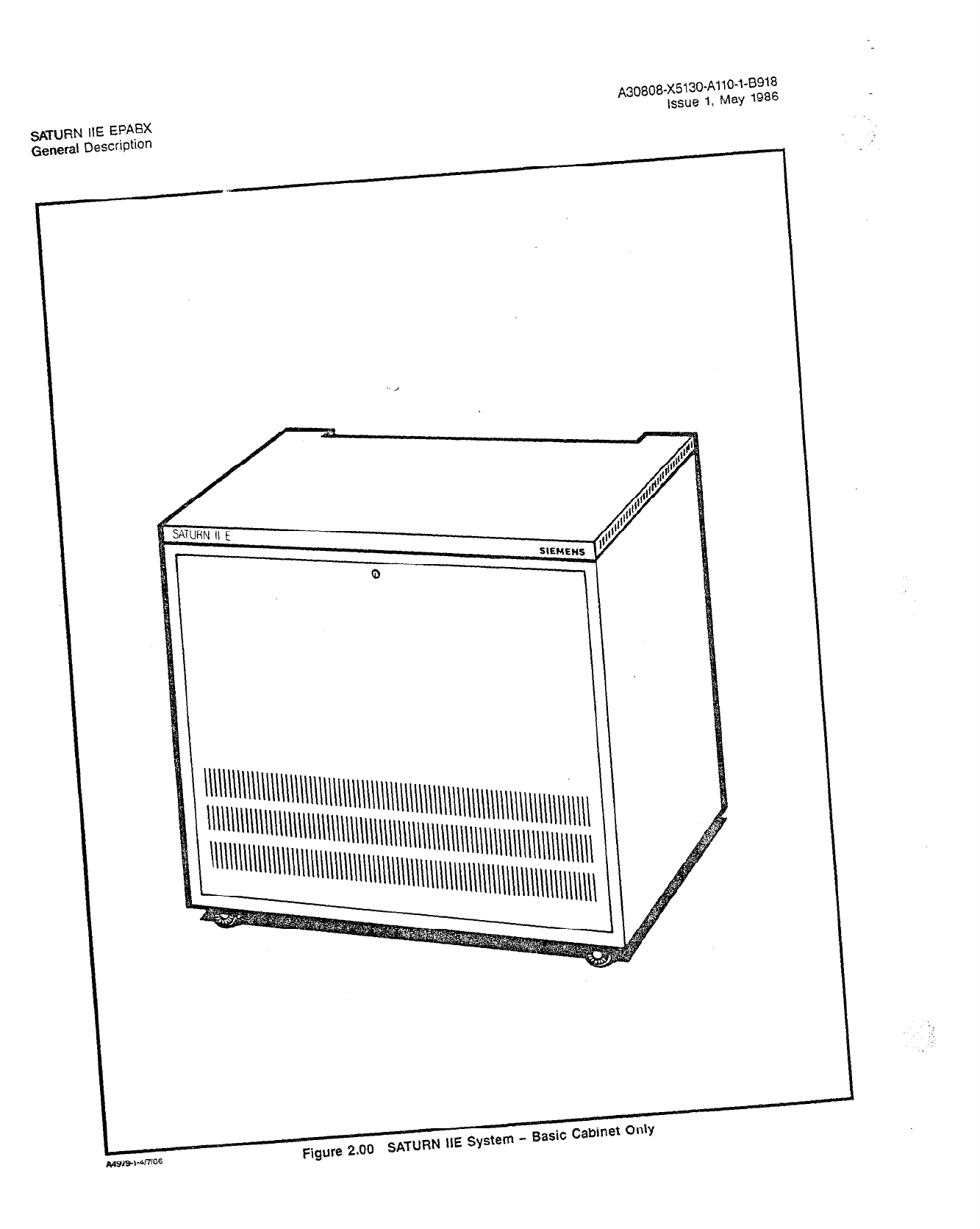
2.03 Hardware Description. In its basic configuration, the
SATURN IIE System is housed in a single light-weight equip-
ment cabinet, called the basic cabinet (shown in Figure 2.00).
In its expanded configuration, the SATURN IIE System is
housed in a basic cabinet plus an expansion cabinet, as
shown in Figure 2.01. The equipment cabinet(s) contain all
functional units of the system. The system is divided into five
functional blocks of circuits as shown in the block diagram
of Figure 2.02. These functional blocks may be directly relat-
ed to the system’s hardware groups. The functional blocks
are as follows:
a. Line/Trunk
b. Switching
c. Control
d. Power
e. Ancillary Equipment
The LINE/TRUNK block circuitry is distributed between the
basic shelf and the Line/lirunk Unit (LTU) shelf or shelves. It
contains the interfacing circuitry for trunks, station lines, SDTs,
Dual-Tone Multifrequency (DTMF) receivers, and the
Line/Trunk Unit Control (LTUC) circuitry for LTU shelves.
All trunks (incoming and outgoing) are connected to appropri-
ate trunk circuits. (The trunk circuits carry various designa-
tions, depending on their type, such as: TMBA, TMBM, TMIE,
etc. These are described in Section 6 of this document.) The
trunk circuits interface two- and four-wire E&M, loop start,
ground start, and DID trunks to the system.
All conventional telephones (rotary dial and DTMF) are con-
nected to a Subscriber Line Module Analog - Station (SLMA-S
or SLA16) or Subscriber Line Module Analog - Off-Premises
A30808-X5130-AllO-l-B918
Issue 1, May 1986
Station (SLMA-0). SDTs are connected to the system via Sub-
scriber Line Modules Digital (SLMD). Premium Instrument
Modules - Digital (PIMD) serve as special line interface cir-
cuits that connect attendant consoles to the system. The
DTMF receivers are used to detect and validate DTMF tones
and detect dial tone on outgoing trunk calls.
The LTUC multiplexes and demultiplexes both the signal and
the voice highways, and provides the timing signals neces-
sary to address the LTU circuits allocated in an LTU shelf. The
LTUC also provides the necessary interface to the CONTROL
and.SWlTCHlNG blocks from the LTU shelf LINE/TRUNK
block. The LTUC circuitry is not required in the basic shelf
because the line and trunks circuits there have direct access
to the CONTROL and SWITCHING blocks. Each LTU shelf
may be equipped with a maximum of two LTUCs.
The CONTROL and SWITCHING block circuitry is contained
in the basic shelf. The CONTROL block consists of the Sig-
nal Multiplexer/Clock/Tone Generator (SMXTG);the Signal
Buffer, Controller/Input-Output Processor (CIOP); the System
Memory (MEM3 and MEM4); the Remote Access Unit/Ports
(RAUP); two 5-l/4 inch Floppy Disk Drives (FDDs); and a TTY
service terminal interface. The CONTROL BLOCK circuitry
receives circuit status signals from the LINE/TRUNK block,
evaluates these signals, and determines what type of action
is required for the proper processing of the call in progress.
This can be one of a number of actions, such as setting up
a dial tone connection or interconnection of two circuits. The
command signals for the required action are sent to the
SWITCHING and LINE/TRUNK blocks for processing.
The SMXTG is divided into three functional parts: a signal
multiplexer, the system clock generator, and the tone gener-
ator. The signal multiplexer is a hardware-controlled scan-
ner/distributor that provides com’munication between the LTU
PCBs (via LTUCs, except for those located on the basic shelf)
and the CIOR The signal multiplexer also handles control and
status signals for the 32 speech highways, each of which has
32 time slots. The clock generator produces the 8.19 MHz,
4.096 MHz, 2.048 MHz, and 250 Hz clocking signals required
to properly operate the SATURN IIE System. The tone gener-
ator produces all of the required supervisory tones (e.g., dial,
busy, ringback, etc.), plus DTMF tones for system outdialing,
and provides timing windows for tone and dial pulse
cadencing.
The Controller/Input-Output Processor (CIOP) consists of the
Signal Buffer (SIB) and the main processor. It provides all of
the processor and input/output functions required of a basic
system. The SIB contains the circuitry that interfaces the sig-
nal multiplexer to the CIOP and also provides the interface
for the service terminal. The main processor directly provides
inputs to the FDD controllers and performs all system con-
trol functions. It uses Programmable Array Logic (PAL) and
contains Programmable Read-Only Memory (PROM), Ran-
dom Access Memory (RAM), a microprocessor, and a bus
clock.
The minimum system main Memory (MEM) is 1.25 megabytes,
consisting of one l-megabyte RAM module (MEM4) and one
256K RAM module (MEM3). The memory can be expanded
by using either MEM3 or MEM4 modules, depending on
memory capacity requirements. The memory functions are
controlled via a RAM controller and accessed via a
common
bus.
A~0808-X5130-A110-~-8918
Issue 1, May 1986

SATURN IIE EPABX
General Description
A30808-X5130-AllO-l-B918
issue 1, May 1986
ANCILLARY
EQUIPMENT
LINE MODULE -
LINE/TRUNK
LTU SHELF
SUBSCRIBER
r-- ---- --------)
LINE/TRUNK I
I
I
I
I I
I I I
SUBSCRIBER
SLMA-0 ;;EDuLE +I I
SLMA-S .
1 SLA16 i-
I
,
I
TRUNK :; I
TMBA 214 MODULE
TMBM c
I
TMIE
I’ 11
I
BASIC SHELF
r---- ------------
1
I
CONFERENCE
SWITCHING 1
I
NETWORK ,
I
I
I
L-
SUBSCRIBER
- LINE MODULE -
DIGITAL
SLMD [
SOT
ANCILLARY
EQUIPMENT
‘TWO LTU CONTROL PCBs PER LTU SHELF (MAXIMUM)
CONTROLLER/INPUT-OUTPUT PROCESSOR
FOO
_-_---------
MEM4 COMMON ’
CONTROL I
I
I
--I----J
r---- -_--------
I , I----y
1
I .,,Ir,-, 1 1 /
POWER. RING GEN.
POWER SUPPLIES RING SYNC, I
AND MP.INTENANCE I
I
A4931.l-4/3/66
Figure 2.02 SATURN HE System Block Diagram


SATURN IIE EPABX
General Description
A30808-X5130-AllO-l-8918
Issue 1, May 1986
The system also includes two 5-l/4 inch floppy disk drives
(FDDs) with one megabyte of memory on each disk for generic
and customer data base backup and for CMU procedures.
The Remote Access Unit/Ports (RAUP) module has three (two
external) Electronics Industries Association RS-232-C serial
asynchronous ports. The two external ports are used for Sta-
tion Message Detail Recording (SMDR), traffic metering,
maintenance, and/or CMU features. The other port is dedi-
cated to the internal RAUP modem (self-setting to either 300
or 1200 baud, depending on the frequency received). Use of
the modem provides access for administration and main-
tenance from a remote service terminal.
The SWITCHING block is under the direction of the CON-
TROL block. It switches digital signaling data between the
LINE/TRUNK block and the CONTROL block and digital voice
message data between the SWITCHING block and the
LINE/TRUNK block. The SWITCHING block also distributes
coded digital control and status data to the CONTROL block
circuitry.
The Parallel/Serial Converter (PSC) converts the serial PCM
voice signals from the LTUs to eight-bit parallel bytes, which
are then multiplexed onto an eight-bit-wide parallel highway
and sent to the Memory Control and Attenuator (MCA) cir-
cuitry for further processing. The reverse function is also per-
formed to provide serial voice signals back to the LTUs.
The MCA is divided into two functional parts: a time switch
unit and the memory control. The time switch unit makes all
two-port connections and provides attenuation (as required)
for all calls being processed by the system. The memory con-
trol receives control data from the processor and causes the
time switch unit to make the required connections.
Another element of the SWITCHING block is the Conference
(CONF) circuit. The CONF circuit is required for simultane-
ous connections involving three to seven parties (plus the at-
tendant).
The POWER block of the SATURN IIE System makes use of
distributed power to ensure maximum efficiency and reliabil-
ity. The main POWER section is located on the bottom shelf
of the basic cabinet, and one LTU Power Supply (LTUPS) is
located next to the left end of each LTU shelf. The main POW-
ER section contains the Power System Unit (PSU) and either
one or two -48 Vdc power supplies (-48PS). One of the -48
Vdc power supplies comes with the basic cabinet of the
SATURN IIE System. The second -48 Vdc power supply is ad-
ded when the system is expanded to also contain the expan-
sion cabinet. The PSU contains an ac-dc power supply to
provide the +5, -5, +12, and -12 dc voltages used by the basic
shelf, a Ring Generator (RGEN), an optional Memory Sup-
port Module (MSM) with battery, a fuse/circuit-breaker panel,
and maintenance/power logic circuitry.
The ANCILLARY EQUIPMENT block contains the devices
which are external to the SATURN IIE System, such as a ter-
minal, the attendant console(s), and the individual telephone
sets and SDTs. Additional information regarding the ancillary
equipment is presented in Section 7 of this document.
2.04 Software Description. The SATURN IIE System uses
software-programmed switching. The system software is con-
tained in two basic areas: on-line (resident) and off-line (non-
resident and stored on two 5-l/4 inch floppy disks). The on-line
memory is divided into three segments: the generic system
software, the customer memory, and an overlay area. Switch-
ing control, performed by the Central Processing Unit (CPU),
uses data which is stored in generic software. The software
that controls the activation of these features resides in the
customer memory area, and is alterable via the CMU proce-
dures. (The generic software may not be altered by the cus-
tomer.) The overlay area of memory contains the
administrative and maintenance programs, which are read in
from the 5-l/4 inch floppy disks for execution when required
by system craft personnel.
The SATURN IIE software is structured such that maintenance
and feature upgrade can be easily performed. The SATURN
IIE software uses state-event, device-oriented decision tables
with a single clock interrupt, event and common queues, and
multiple processing levels. A clock interrupt occurs every four
milliseconds in the system. These interrupts activate the
preprocessor software level which, in turn, processes any
change in state condition detected by the peripheral cards.
These changes are then queued for processing at the base
level processor. The queue is subject to the priority and func-
tion of the change.
If, for example, an off-hook state is detected by the preproces-
sor, it is sorted, prioritized, and queued for the base level
processor. After the action request is removed from the queue,
the base level processor verifies line appearance and class
of service. The base level processor then determines, via the
state-event table, the appropriate action required (e.g., to
return dial tone to the off-hook line appearance). The base
level processor then sends appropriate messages to form a
network connection between the line appearance and tone
generator circuit ports.
Note that dial tone is generated by the tone generator circuit.
The idle level processor (the third level) occurs when free (idle)
processing time is used for deferrable maintenance, adminis-
trative, and other background testing activities.
Since the features of the SATURN IIE System may be con-
trolled by the customer, an extremely flexible selection and
arrangement of the large number of features is possible. In
most cases, the features are provided and controlled exclu-
sively by the software routines and require no additional hard-
ware. These features may be added, changed, or deleted by
entering the appropriate input commands. In some cases,
hardware modifications may be required. These modifications
require the installation of one or more printed circuit boards
or modification of strapping on existing hardware. Activation
of the feature via software is done after completion of any such
hardware or wiring changes.
Software changes to the system may be made quickly and
with ease. The system accepts simplified, coded instructions
via a data entry terminal. The instructions are entered as al-
phanumeric keywords in response to plain English prompt-
ing by the system.
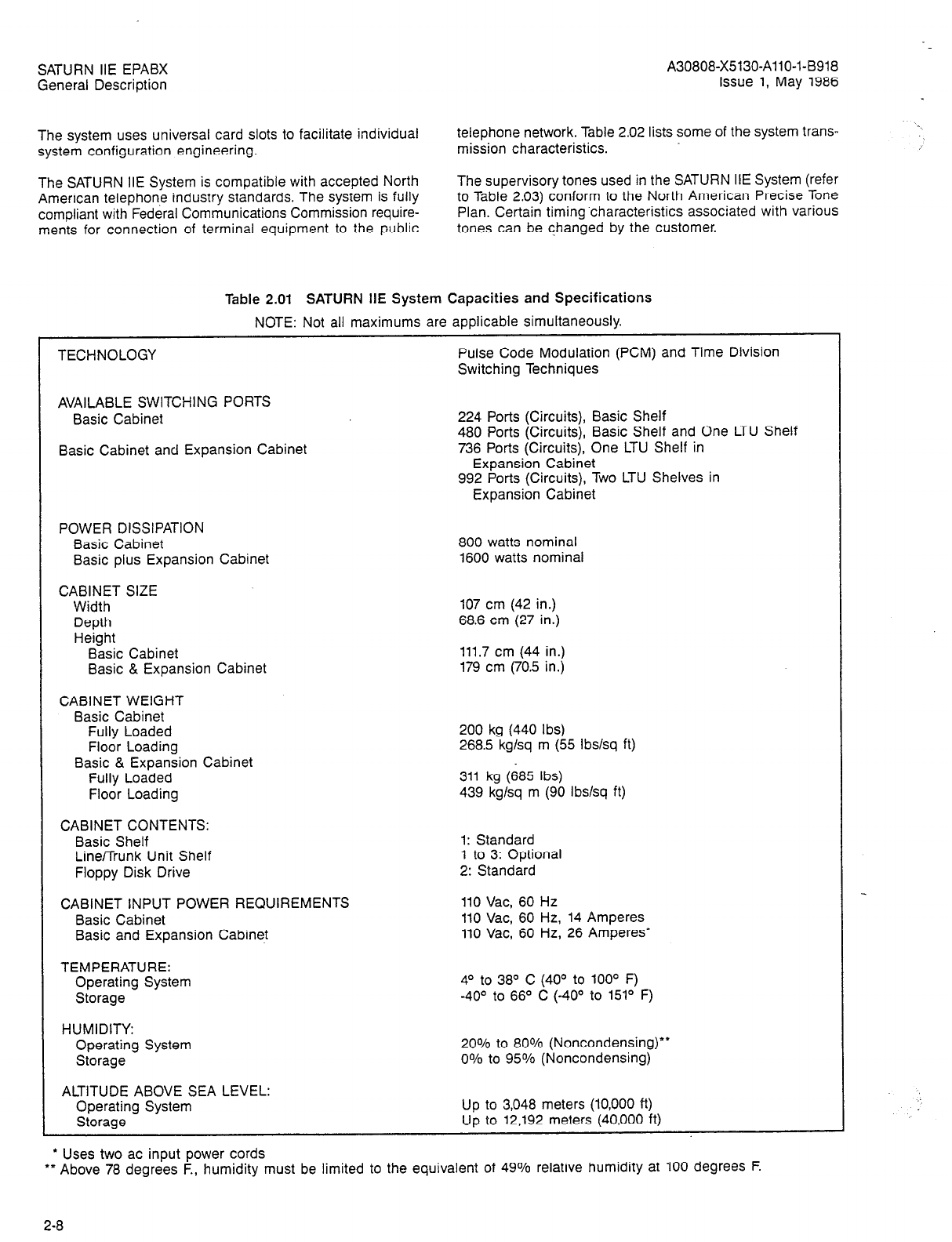
2.05 System Capacities and Specifications. This section
of the practice lists the various capacities and specifications
pertaining to the SATURN IIE System. The system capaci-
ties are outlined in Table 2.01. This table shows the various
quantities of stations, trunks, attendant consoles and other
related apparatus that are considered maximum for the
SATURN IIE System. Note that all system maximums are not
necessarily simultaneously available.
2-7
SATURN IIE EPABX A30808-X5130-AllO-l-B918
General Description Issue 1, May 1986
The system uses universal card slots to facilitate individual
system configuration engineering.
The SATURN IIE System is compatible with accepted North
American telephone industry standards. The system is fully
compliant with Federal Communications Commission require-
ments for connection of terminal equipment to the public
telephone network. Table 2.02 lists some of the system trans-
mission characteristics.
The supervisory tones used in the SATURN IIE System (refer
to Table 2.03) conform to the North American Precise Tone
Plan. Certain timing.characteristics associated with various
tones can be changed by the customer.
Table 2.01 SATURN HE System Capacities and Specifications
NOTE: Not all maximums are applicable simultaneously.
TECHNOLOGY Pulse Code Modulation (PCM) and Time Division
Switching Techniques
AVAILABLE SWITCHING PORTS
Basic Cabinet
Basic Cabinet and Expansion Cabinet
224 Ports (Circuits), Basic Shelf
480 Ports (Circuits), Basic Shelf and One LTU Shelf
736 Ports (Circuits), One LTU Shelf in
Expansion Cabinet
992 Ports (Circuits), Two LTU Shelves in
Expansion Cabinet
POWER DISSIPATION
Basic Cabinet
Basic plus Expansion Cabinet 800 watts nominal
1600 watts nominal
CABINET SIZE
Width
Depth
Height
Basic Cabinet
Basic & Expansion Cabinet
107 cm (42 in.)
68.6 cm (27 in.)
111.7 cm (44 in.)
179 cm (70.5 in.)
CABINET WEIGHT
Basic Cabinet
Fully Loaded
Floor Loading 200 kg (440 Ibs)
268.5 kglsq m (55 lbslsq ft)
Basic & Expansion Cabinet
Fully Loaded
Floor Loading
CABINET CONTENTS:
Basic Shelf
Line/Trunk Unit Shelf
Floppy Disk Drive
311 kg (685 Ibs)
439 kg/sq m (90 Ibs/sq ft)
1: Standard
1 to 3: Optional
2: Standard
CABINET INPUT POWER REQUIREMENTS
Basic Cabinet
Basic and Expansion Cabinet
110 Vat, 60 Hz
110 Vat, 60 Hz, 14 Amperes
110 Vat, 60 Hz, 26 Amperes’
TEMPERATURE:
Operating System
Storage
HUMIDITY:
Operating System
Storage
4O to 38O C (40° to 100’ F)
-40° to 66O C (-40° to 151” F)
20% to 80% (Noncondensing)“”
0% to 95% (Noncondensing)
ALTITUDE ABOVE SEA LEVEL:
Operating System
Storage
l
Uses two ac input power cords
Up to 3,048 meters (10,000 ft)
Up to 12,192 meters (40,000 ft)
l
* Above 78 degrees F., humidity must be limited to the equivalent of 49% relative humidity at 100 degrees F.
2-8
.
SATURN IIE EPABX A30808-X5130-AllO-l-6918
General Description Issue 1, May 1986
Table 2.01 SATURN HE System Capacities and Specifications (Continued)
NOTE: Not all maximums are applicable simultaneously.
DTMF RECEIVERS
SWITCHING NETWORK TRAFFIC CAPACITY
TONE CHANNELS
INPUT/OUTPUT INTERFACES
32
36 CCS per port or 1 Erlang per port (non-blocking)
30 Available
3: RS-232-C
1: Modem
8-PORT CONFERENCE CIRCUITS
4-PORT CONFERENCE CIRCUITS
SYSTEM FEATURES
4
24
LEAST COST ROUTING
Area/Office Code Combinations 128,000
Specialized Common Carriers up to 3
Digit Number Analysis Full
Least Cost Routes 50
Trunk Group Elements Within a Route 8
Class-of-Service Priorities 16
Quantity of User On-Hook Queuing Callback Attempts 0 to 9
Dial Tone Detection Available Full
Time Bands Available 168 (Hour of Day & Day of Week)
Time Schedules Available 8
STATION MESSAGE DETAIL RECORDING
Call Buffers 255
Standard Account Codes - Numbers 255
Account Codes - Length 1 to 11 Digits per Code
NIGHT SERVICE
Zoned Universal Night Answer
l
Number of Zones 4
l
Trunks per Zone 100%
l
Station Access per Zone 100%
Assigned Night Answer
l
Trunk-to-Station Assignments 255
l
LDN to ANA Assignments (for DID) 1 per DID Trunk Group
l
Special Night Answer Position 1 Station or Hunt Group per System
VOICE MAIL INTERFACE 1 per System
CODE CALLING
Calling Channels 1
Answerback Channels Unlimited
AUTHORIZATION CODES
Direct Inward System Access/Mobile
Authorization Codes 2000
SHORT ANNOUNCEMENT SERVICE
Recorded Announcement Channels for ACD Groups 1
DIAL DICTATION
Channels 4 (Maximum)
ATTENDANT CONSOLE
NUMBER OF CONSOLES PER SYSTEM
ATTENDANT KEYS
Loop Keys
Fixed Function Keys
Assignable Function Keys
12 (Maximum)
4
12
18
(Rev. 5115186) 2-9
SATURN IIE EPABX
General Description
A30808-X5130-AllO-143918
Issue 1, May 1986
Table 2.01 SATURN IIE System Capacities and Specifications (Continued)
NOTE: Not all maximums are applicable simultaneously.
ATTENDANT QUEUES
Operator Calls (Shared)
Incoming Calls (Shared)
Recalls (Shared)
Trunk Queuing Callback (Shared)
DISPLAYS AND INDICATORS
Number of Display Characters
Indicators per Function Key
Trunk Group Busy Indicators
Miscellaneous Indicators
ATTENDANT OVERFLOW FACILITY
Assigned Positions per System
DISTANCE FROM SYSTEM
TRUNKS
NUMBER OF TRUNK GROUPS PER SYSTEM 32
48
255
48
5 (per Console)
40
1
24
6
1 Station or 1 Hunt Group
610 Cable Meters (2000 Cable Feet)
NUMBER OF TRUNKS
Total Trunks per System
Total per Trunk Group
Dedicated Incoming Trunks
E&M Type Trunks
TRUNK GROUP CLASSES OF SERVICE
TRUNK GROUP IDENTITY CODES
Number Available
Characters per Code
ALTERNATE ROUTES PER TRUNK GROUP
255
100
255
255
1 per Trunk Group
1 per Trunk Group
8
3 (Without LCR)
8 Elements per Route with LCR
TRUNK PRIORITY LEVELS
(for Attendant Console Queuing)
DIRECT INWARD DIALING (DID)
DID Trunk Groups
Number of Digit Translation Tables
Digits Expected from Central Office
Digits Absorbed
Digits Prefixed
Digits Translated
Recorded Announcement Channels for Intercept
OUTGOING TRUNK QUEUING
32
32
4
2 to 5
0 to 3
oto2 -
2 (Maximum)
1
Trunk Groups Assigned with Outgoing Trunk Queuing
(Callback and/or Standby)
Simultaneous Station Queuing for a Trunk
(Callback and/or Standby Shared with Station
Automatic Callback)
STATIONS
32
80
CONVENTIONAL TELEPHONES
SIEMENS DIGITAL TELEPHONES
* 16 SLMD cards maximum per shelf.
992 (Maximum)
‘512 (Maximum)
2-10

. .
SATURN IIE EPAEX
General Description
A30808-X5130-AllO-l-8918
issue 1, May 1986
Table 2.01 SATURN HE System Capacities and Specifications (Conticued)
NOTE: Not all maximums are applicable simultaneously.
STATION FEATURES
STATION CLASSES OF SERVICE
CODE RESTRICTION LISTS
Eight-Digit Lists
Eight-Digit Numbers
Fifteen-Digit Lists
Fifteen-Digit Numbers
HUNTING
Terminal Hunt Groups
Terminal Hunt Group Members
Circular Hunt Groups
Circular Hunt Group Members
Voice/Data Automa?ic Call Distribution
(ACD) Hunt Groups
Voice ACD Hunt Group Members
Data ACD Hunt Group Members
Pilot Number Access Hunt Groups
Pilot Number Access Hunt Group Members
CALL PARK
System Park Locations
Station Park Locatiohs (Call Hold)
CALL FORWARDING
Call Forwarding
- Variable
l
Availability
l
Simultaneously Active
Call Forwarding
- Busy Line
l
Availability
l
Simultaneously Active
Call Forwarding
- No Answer
l
Availability
l
Simultaneously Active
Call Forwarding
- Secretarial Intercept
l
Availability
l
Simultaneously Active
l
Answering Positions
Call Forwarding to Public Network
l
Availability
l
Simultaneously Active
l
Digits per Network Number
CALL PICKUP
Dial Call Pickup Group
Members per Dial Call Pickup Group
Directed Call Pickup Availability
CONSULTATION, TRANSFER, AND
ADD-ON CONFERENCE
Availability
Simultaneous Consultations
Simultaneous Transfers
Simultaneous Add-On Conferences
32
16
16 per List Average (256 Flexible)
4
8 per List Average (32 Flexible)
Unlimited
30 per Group
Unlimited
30 per Group
64
96 per Group
96 per Group
Unlimited
30 per Group
10
1 per Station
100% of Lines
Unlimited
100% of Lines
Unlimited
100% of Lines
Unlimited
100% of Lines
Unlimited
64
100% of Lines
32
18 (Includes Access Code)
Unlimited
30
100% of Lines
100% of Lines
Unlimited
Unlimited
24
2-11
SATURN IIE EPABX
General Description A30808-X5130-AllO-l-6918
Issue 1, May 1986
Tabie 2.01 SATURN IIE System Capacities and Specifications (Continued)
NOTE: Not all maximums are applicable simultaneously.
S-i:TION FEATURES (Continued)
CALL WAITING
Call Waiting Originating
l
Availability
Call Waiting Terminating
l
Availability
Simultaneous Calls Waiting
l
Per System
l
Per Line
STATION CAMP-ON AND AUTOMATIC CALLBACK
Availability
Simultaneous Stations Queued for Callback
MESSAGE WAITING LAMPS ON STATIONS
Availability
Simultaneous Messages Waiting
e Number per System
l
Per Conventional Telephone
l
Per Siemens Digital Telephone (18- and
26-button)
100% of Lines
100% of Lines
100% of Lines
1 station & any number of trunks
100% of Lines
80
100% of stations
108
4
SPEED CALLING
Individual
l
Lists per System
0 Numbers per List
l
Digits per Number
l
Availability
Group
* Lists per System
* Numbers per List
* Digits per Number
l
Availability
System
LAST NUMBER REDIAL
Numbers Stored in System
Numbers Stored per Station
Digits per Number
Availability (Stations)
NONDIAL LINE SERVICES
Direct Attendant Signaling Lines
Switched Direct Line Service
Nondial Line Destinations
TEMPORARY CLASS-OFSCRVICE CHANGE
BY ATTENDANT
Simultaneously Active
SIEMENS DIGITAL TELEPHONES
64
10
18
1 Station per List
:4
18
100% per List
(See Speed Calling - Group)
255
1
18
255
100% of Stations
100% of Stations
32
Unlimited
Siemens Digital Telephone (SDT) “512 (Maximum)
Distinct Line Appearances 864
Buttons per Station 16, 18, or 26
Button Appearances per Line 8
Button Maps per System 32
Distance from System 610 Cable Meters (2,000 Cable Feet)
+ 16 SLMD cards maximum per shelf.
SATURN IIE EPABX
General Description A30808-X5130-AllO-l-8918
Issue 1, May
1986
Table 2.02 Input/Output Impedance, Leak Resistance, and Loop Characteristics
INPUT/OUTPUT IMPEDANCE
Lines
Trunks (Strappable) 600 ohms, nominal
600 ohms, or Bell City Trunk Termination
(OPS Compromise Network)
LOOP CHARACTERISTICS
Stat;at;l;nterfaced via SLMA-S or SLA16 1,200 ohms, maximum loop resistance,
including telephone
15,000 ohms minimum leak resistance
Stations interfaced via
l
SLMA-0 Module 1,800 ohms, maximum loop resistance
30,000 ohms minimum leak resistance
Central Office Trunks
via TMBM Module 1,200 ohms, maximum loop
resistance, with 48-volt (nominal) battery
30,000 ohms minimum leak resistance
Direct Inward Dial Trunks 2,450 ohms, maximum loop resistance
via TMIE Module 30,000 ohms minimum leak resistance
* SLMA-0 module is registered with FCC for Class C operation
Tone Name
Dial Tone
Reorder Tone
Busy Tone
Audible Ring Tone
Recall Dial Tone
Special Audible Ring Tone
Intercept Tone
Call Waiting Tone(s)
Busy Override Tone
(also, Attendant
Override Tone)
Executive Override Tone
Confirmation Tone
Camp-On Tone (also, Low
Tone or Uninterrupted
BusyTone)
Table 2.03 SATURN IIE Supervisory Audible Tones
Frequency
350 + 440 Hz
480 + 620 Hz
480 + 620 Hz
440 + 480 Hz
350 + 440 Hz
440 + 620 Hz
440 + 620 Hz
440 Hz
440 Hz
440 Hz
350 + 440 Hz
480 + 620 Hz
Timing Rate
Steady tone.
Repetition of tone ON for 0.25 second and tone OFF for
0.25 second.
Repetition of tone ON for 0.5 second and tone OFF for
0.5 second.
Repetition of tone ON for 0.8 - 1.2 seconds and tone
OFF for 2.7 - 3.3 seconds.
Three bursts of tone ON for 0.08 - 0.12 second and tone
OFF for 0.08 - 0.12 second, followed by dial tone.
Repetition of combined tone ON for 0.8 - 1.2 seconds,
followed by 440 Hz tone ON for 0.2 second and tone
OFF for 2.7 - 3.3 seconds.
Repetition of alternating the two frequencies, each ON
for 0.16 - 0.3 second, with a total cycle duration of 0.5
second.
One burst of tone ON for 0.1 - 0.3 second for a waiting
station call. Two bursts of tone ON for 0.1 - 0.3
second apart for a waiting attendant or trunk call.
Three bursts of tone ON for 0.25 second and tone OFF
for 1.75 seconds, followed by attendant connection.
One burst of tone ON for 2.0 - 4.0 seconds before
overriding station intrudes.
Three bursts of tone ON for 0.08 - 0.12 second,
0.08 - 0.12 second apart.
Steady tone.
SATURN IIE EPABX
General Description
A30808-X5130-AllO-l-8918
issue 1, May 1986
Table 2.03 SATURN IIE Suoervisorv Audible Tones (Continued1
Tone Name
Invalid Camp-On Tone
Frequency
480 + 620 Hz
Timing Rate
Repetition of tone ON for 0.125 second and tone OFF
for 0.125 second.
Conference Tone 440 Hz One burst of tone ON for 0.4 - 0.6 second, followed by
conferee connection.
Quiet Tone 0 Hz Steady tone.
Busy Override Injection 440 Hz Bursts of tone ON for 0.25 second, 8 - 20 seconds
Tone (also, Privacy Tone) apart, applied while an overriding party is present
on a connection
Route Advance Tone
(for Least Cost Routing
- LCR)
350 + 440 Hz One burst of tone ON for 0.08 - 0.12 second.
Warning Tone
(also, Expensive
Facility Tone - LCR)
440 Hz One burst of tone ON for 0.8 - 0.12 second.
Test Tone
Negative
Acknowledgement
(NAK) Tone
1004 Hz
480 + 620 Hz
Steady tone.
1.5 seconds (i.e., three cycles) of reorder tone.
SATURN IIE EPABX A30808-X5130-AllO-l-8918
General Description Issue 1, May 1986
SECTION 3.00 SATURN IIE EQUIPMENT CABINET
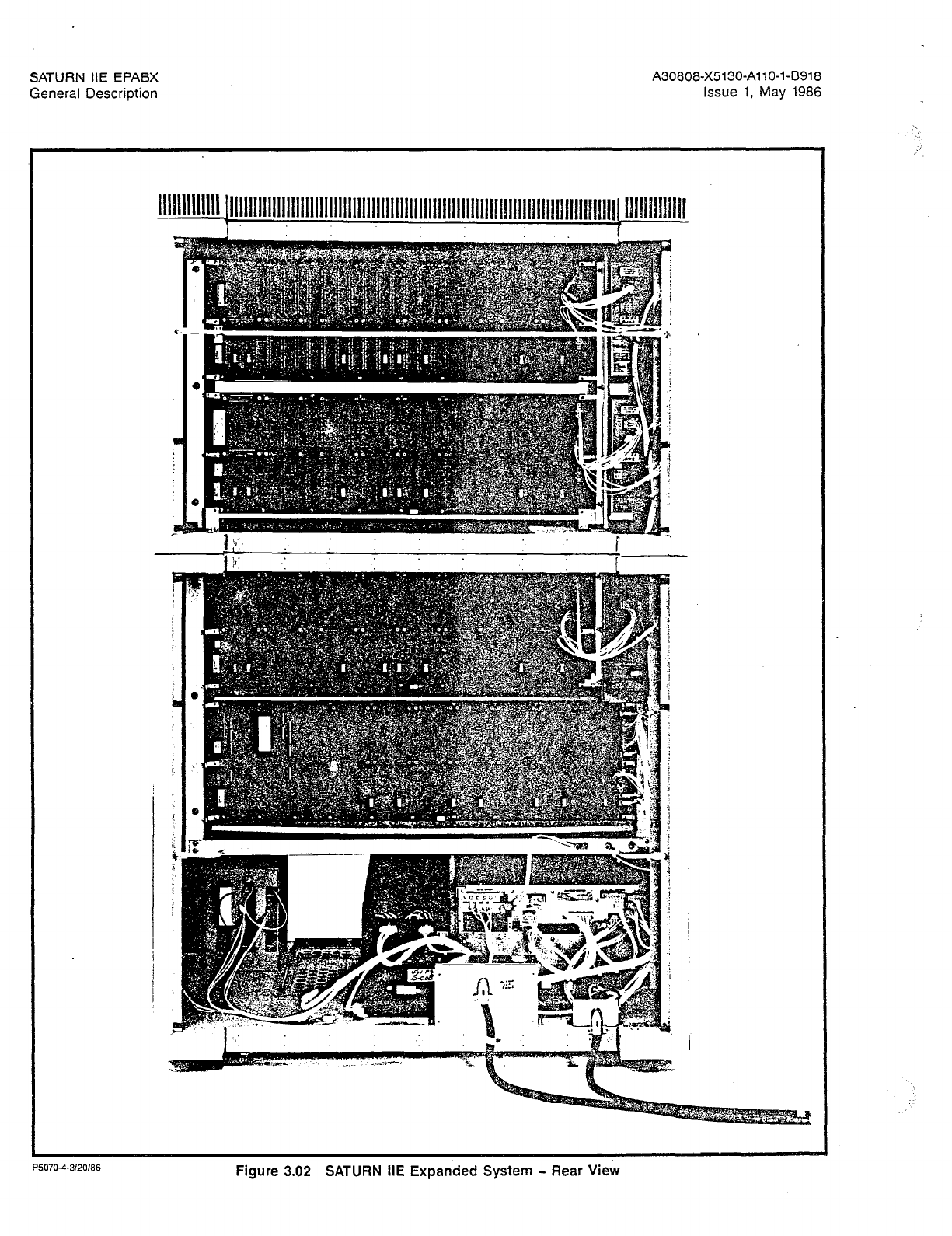
3.01 Cabinet Layout. The SATURN IIE System consists of
either a basic cabinet only (Figure 3.00) or a basic cabinet
plus an expansion cabinet as shown in Figures 3.01 and 3.02.
The basic cabinet contains an LTU shelf, a basic shelf, and
an area at the bottom of the cabinet where the main power
section and floppy disk drives are located.
The basic shelf is always equipped in the system. It contains
all the PCBs that make up the common control and switch-
ing circuitry for the SATURN IIE System, plus seven LTU chan-
nel groups containing 224 port circuits.
One LTU shelf may optionally be equipped in the basic cabi-
net. It provides an additional 256 ports in eight channel groups
for a total of 480 ports in the basic cabinet. This LTU shelf
requires an LTU Power Supply (LTUPS).
The expansion cabinet, which mounts on top of the basic cabi-
net, expands the basic cabinet by either one or two addition-
al LTU shelves (Figures 3.01 and 3.02). Each of these shelves
has its own LTUPS and provides eight channel groups for a
total of 256 ports per shelf. Thus, when the expansion cabi-
net is added, the expanded system may have a total of either
736 or 992 ports. When the expansion cabinet is added, the
top cover is removed from the basic cabinet and reinstalled
as the top cover of the expansion cabinet.
The LTU portion of the system is arranged in channel groups
of 32 channels each, one channel being used for each port.
Each channel group consists of universal card slots. Some
of the channel groups contain four card slots each, and the
others contain two card slots each. Each card in a channel
group contains either two, four, eight, or sixteen circuits, de-
pending on the card type. Each circuit uses one port on the
system (except in the case of the PIMD card, each circuit of
which takes up two ports).
The main power section is located at the bottom of the cabi-
net. This section contains the Power System Unit (PSU), one
or two -48 Vdc power supplies depending upon whether or
not the expansion cabinet is equipped, and the two FDDs re-
quired by the system. The following units are housed within
the PSU:
a. acldc power supply to supply +5, -5, +12, and -12 Vdc
to the basic shelf.
Ring generator.
Memory Support Module (MSM), optional, with battery.
Fuse/circuit breaker panel
Control Logic PCB.

JRN IIE EPABX A30808-X5130-AllO-l-B918
val Description Issue 1, May 1986
PSU
LTU
SHELF
BASIC
SHELF
FDDs
- -48PS -48PS (Optional)
85171%l-4/17/66
Figure
3.00
SATURN
IIE
Basic
System
-
Front
View

A30808-X5130-AllO-l-8918
Issue 1, May 1986
SATURN IIE *1m*a*s
/
t
/
P5070.l-3120/86
Figure 3.01 SATURN IIE Expanded System - Front View
SATURN IIE EPABX
General Description
A30808-X5130-AllO-l-8918
Issue 1, May 1986
P5070-4-3120186
Figure 3.02 SATURN HE Expanded System - Rear View
SATURN IIE EPABX
General Description A30808-X5130-AllO-l-8918
Issue 1, May 1986
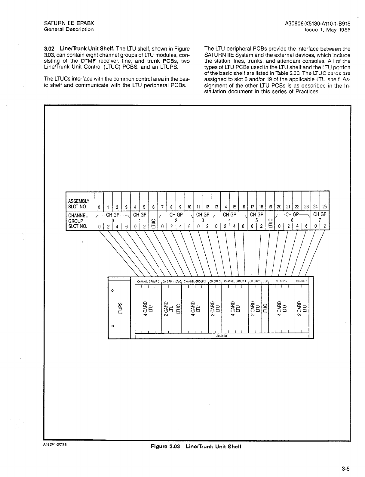
3.02 Line/Trunk Unit Shelf. The LTU shelf, shown in Figure
3.03, can contain eight channel groups of LTU modules, con-
sisting of the DTMF receiver, line, and trunk PCBs, two
LineiTrunk Unit Control (LTUC) PCBS, and an LTUPS.
The LTUCs interface with the common control area in the bas-
ic shelf and communicate with the LTU peripheral PCBs.
The LTU peripheral PCBs provide the interface between the
SATURN IIE System and the external devices, which include
the station lines, trunks, and attendant consoles. All of the
types of LTU PCBs used in the LTU shelf and the LTU portion
of the basic shelf are listed in Table 3.00. The LTUC cards are
assigned to slot 6 and/or 19 of the applicable LTU shelf. As-
signment of the other LTU PCBs is as described in the In-
stailation document in this series of Practices.
ASSEMBLY
SLOT NO.
0 1 2 3 4 5 6 7 6 9 10 11 12 13 14 15 16 17 16 19 20 21 22 23 24 25
CHANNEL ,--CH GP---, CH GP -CH GP+-, CH GP -CH GP-, CH GP ,-CH GP- CH GP
GROUP 0
10 2 3 4 5 6 7
SLOT NO.
0121416
2
0 2 % 0 2 416 012 012 4 6 012 5 0121416 012
Figure 3.03 Line/Trunk Unit Shelf
3-5
SATURN IIE EPABX A30808-X5130-AllO-l-0918
General Description issue 1, May 1986
Table 3.00 LTU Printed Circuit Boards on LTU Shelf and Basic Shelf
I
DESIGNATION
r-
DTMF
I
LTUC (LTU shelf only)
PIMD
1 SLMA-S
I
SLMD
TMBA-2
I
TMBA-4
DUAL-TONE MULTIFREQUENCY RECEIVER (Equip per Data Base Preparation Tables)
LINE/TRUNK UNIT CONTROL (One per four channel groups)
PREMIUM INSTRUMENT MODULE DIGITAL
SUBSCRIBER LINE MODULE ANALOG - 16 LINES
SUBSCRIBER LINE MODULE ANALOG - OFF-PREMISES STATION I
SUBSCRIBER LINE MODULE ANALOG - STATION I
SUBSCRIBER LINE MODULE DIGITAL
I
2-WIRE E&M TRUNK
4-WIRE E&M TRUNK
CENTRAL OFFICE TRUNK
DIRECT INWARD DIALING TRUNK
ASSEMBLY
SLOT NO II I z 3 4 5 6 7 8 9 10 II 12 13 14 15 16 17
Ia
; 1 19 ( 20 1 21 ( 22 ( 23 1 24 ( 25 ( 26 27 26 29 30 31
-l-zM+H
CHANNEL /-CHGP-, CHGP /-CHGP-, CHGP ,-CHGP-,
CH-GP CH~GPl IpI 1,. 1 In
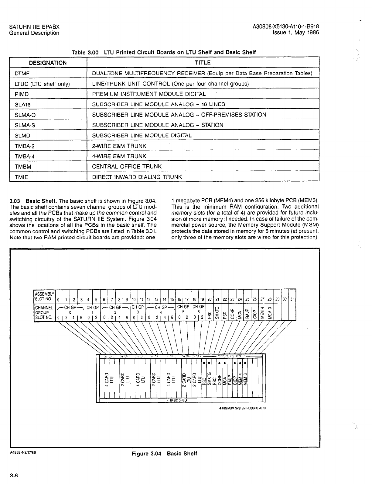
3.03 Basic Shelf. The basic shelf is shown in Figure 3.04.
The basic shelf contains seven channel groups of LTU mod-
ules and all the PCBs that make up the common control and
switching circuitry of the SATURN IIE System. Figure 3.04
shows the locations of all the PCBs in the basic shelf. The
common control and switching PCBs are listed in Table 3.01.
Note that two RAM printed circuit boards are provided: one
1 megabyte PCB (MEM4) and one 256 kilobyte PCB (MEM3).
This is the minimum RAM configuration. Two additional
memory slots (for a total of 4) are provided for future inclu-
sion of more memory if needed. In case of failure of the com-
mercial power source, the Memory Support Module (MSM)
protects the data stored in memory for 5 minutes (at present,
only three of the memory slots are wired for this protection).
II
. BASIC SHELF I]
.MIN,M”M SYSTEM REOUIREMENT
A4838-l-2/17/86
Figure 3.04 Basic Shelf
3-6
SATURN IIE EPABX
General Description
DESIGNATION
PSC
I
CONF
A30808-X5130-AllO-l-8918
Issue 1, May 1986
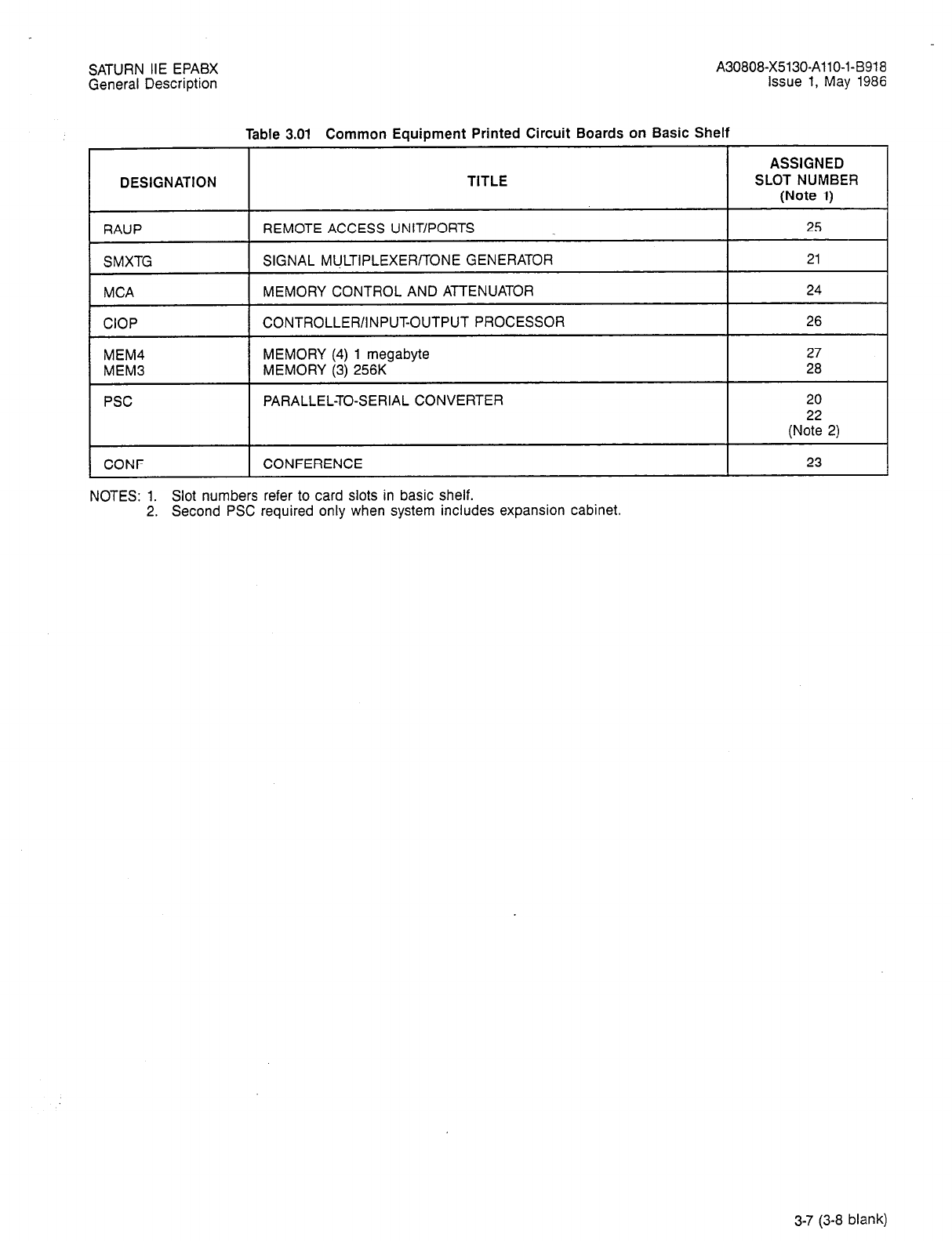
rable 3.01 Common Equipment Printed Circuit Boards on Basic Shelf
ASSIGNED
TITLE SLOT NUMBER
(Note 1)
REMOTE ACCESS UNIT/PORTS I 25
SIGNAL MULTIPLEXER/TONE GENERATOR I 21
MEMORY CONTROL AND ATTENUATOR 24
CONTROLLER/INPUT-OUTPUT PROCESSOR 26
MEMORY (4) 1 megabyte 27
MEMORY (3) 256K 28
PARALLEL-TO-SERIAL CONVERTER 20
(No:: 2)
CONFERENCE 23
NOTES: 1. Slot numbers refer to card slots in basic shelf.
2. Second PSC required only when system includes expansion cabinet.
3-7 (3-8 blank)
SATURN IIE EPABX A30808-X5130-AllO-l-6918
General Description Issue 1, May 1986
SECTION 4.00 POWER SUPPLIES
4.01 Main Power Section. As noted previously, the SATURN
IIE System makes use of distributed power in the cabinet.
Several power supplies are used within the system, some in
the main power section located at the bottom of the basic cabi-
net, some on the LTU shelves (see Figure 4.00). These pow-
er supplies provide +5 Vdc, -5 Vdc, +12 Vdc, -12 Vdc, -48 Vdc,
and 90 Vat at 20 Hz for ringing voltage. The standard input
power for the system is a 110 Vat, 60 Hz commercial source.
The main power section consists of the Power System Unit
(PSU) and one or two -48 Vdc power supplies: one if there
is only the basic cabinet, two if the expansion cabinet is also
equipped. (In systems where only the basic cabinet is used,
there is a single ac power inlet at the rear of the cabinet; when
the expansion cabinet is also used, a second ac power inlet
at the rear of the basic cabinet is provided. The Installation
practice in this series gives a full description of the steps
necessary when making this change.)
Two floppy-disk drives (FDDO
and
FDDl) are located on the
same shelf as the main power section.
4.02 Power System Unit. The PSU is an integrated assem-
bly containing the following functional elements (described
in paragraphs 4.03 through 4.07):
a. Basic shelf power supply
b. Memory Support Module (MSM), optional
c. Control logic
d. Ring generator
e. Power supply circuit breakers
4.03 Basic Shelf Power Supply. The basic shelf power sup-
ply is an ac-to-dc converter that provides +5, -5, +12, and
-12 Vdc power to the basic shelf.
4.04 Memory Support Module. The Memory Support Mod-
ule (MSM) assembly is an optional battery backup package
that provides +5 Vdc to the RAM memory when the commer-
cial ac power source fails. In the event of such failure, the
battery maintains the data stored in memory for at least five
minutes. When the ac power source is restored within this
period, the memory does not have to be reloaded from disk;
system operation can begin immediately. The MSM is capa-
ble of another 5-minute backup cycle after 30 minutes of
recharging. (The unit includes the battery charging appara-
tus and is under a “float” charge during normal operation.)
For power failure periods longer than 5 minutes, program
memory is automatically reloaded from floppy disk when pow-
er is restored.

SATURN IIE EPABX A30808-X5130-AllO-l-B918
General Description issue 1, May 1986
SECTION 4.00 POWER SUPPLIES
4.01 Main Power Section. As noted previously, the SATURN
IIE System makes use of distributed power in the cabinet.
Several power supplies are used within the system, some in
the main power section located at the bottom of the basic cabi-
net, some on the LTU shelves (see Figure 4.00). These pow-
er supplies provide +5 Vdc, -5 Vdc, +12 Vdc, -12 Vdc, -48 Vdc,
and 90 Vat at 20 Hz for ringing voltage. The standard input
power for the system is a 110 Vat, 60 Hz commercial source.
The main power section consists of the Power System Unit
(PSU) and one or two -48 Vdc power supplies: one if there
is only the basic cabinet, two if the expansion cabinet is also
equipped. (In systems where only the basic cabinet is used,
there is a single ac power inlet at the rear of the cabinet; when
the expansion cabinet is also used, a second ac power inlet
at the rear of the basic cabinet is provided. The Installation
practice in this series gives a full description of the steps
necessary when making this change.)
Two floppy-disk drives (FDDO and FDDl) are located on the
same shelf as the main power section.
4.02 Power System Unit. The PSU is an integrated assem-
bly containing the following functional elements (described
in paragraphs 4.03 through 4.07):
a. Basic shelf power supply
b. Memory Support Module (MSM), optional
c. Control logic
d. Ring generator
e. Power supply circuit breakers
4.03 Basic Shelf Power Supply. The basic shelf power sup-
ply is an ac-to-dc converter that provides +5, -5, +12, and
-12 Vdc power to the basic shelf.
4.04 Memory Support Module. The Memory Support Mod-
ule (MSM) assembly is an optional battery backup package
that provides +5 Vdc to the RAM memory when the commer-
cial ac power source fails. In the event of such failure, the
battery maintains the data stored in memory for at least five
minutes. When the ac power source is restored within this
period, the memory does not have to be reloaded from disk;
system operation can begin immediately. The MSM is capa-
ble of another 5-minute backup cycle after 30 minutes of
recharging. (The unit includes the battery charging appara-
tus and is under a “float” charge during normal operation.)
For power failure periods longer than 5 minutes, program
memory is automatically reloaded from floppy disk when pow-
er is restored.
SATURN IIE EPABX
General Description
4.05 Control Logic. The control logic performs the follow-
ing functions:
a. Power Failure Interrupt (PFI). Generates a nonmaska-
ble interrupt to the CIOP when input power drops to
the brown-out level (95 to 97.5 Vat) and returns to nor-
mal when power becomes higher than 100 Vat.
b. Ring synchronization. Generates the timing signals for
operating and releasing ringing relays.
c. Ringing/message-waiting control. Selects either ring
output or message-waiting output for connection to the
ringing bus.
d. Fuse alarms. Monitors each fuse z -?d causes an alarm
upon any fuse failure.
4.06 Ring Generator. The ring generator is a single-
frequency power supply that provides 90 Vat rms at 20 Hz
for station ringing, and 97 Vdc (nominal) for message waiting
indications. It provides sufficient power to ring up to 42 sta-
tions simultaneously (21 stations each on two different phases
A30808-X5130-AllO-l-8918
Issue 1, May 1986
of ringing) and to provide a message-waiting indication on
108 stations simultaneously.
4.07 Power Supply Circuit Breakers. There are circuit
breakers for each of the ac inputs to the system (e.g., to the
basic shelf power supply, each LTUPS, each -48PS etc).
4.08 Line/Trunk Unit Power Supply. The LTUPS module as-
sembly is an ac-to-dc converter which provides +5, -5. +12,
and -12 Vdc power to its associated LTU shelf. This supply,lo-
cated adjacent to the left side of each LTU shelf, powers one
entire LTU shelf.
4.09 48-Volt Power Supply. The -48 Volt Power Supply
(-48PSn, where n is designated 0 through 1 in the cabinet)
module assembly is an ac-to-dc converter that provides two
-48 Vdc outputs. One -48 Vdc output is used for talk battery
for analog lines (SLTs), and the other -48 Vdc output is used
for PlMDlSLMD applications (i.e., powering attendant con-
soles and SDTs, respectively) and power input to the ringing
generator in the PSU. The system cabinet may contain either
one or two -48PS module assemblies: one for the basic cabi-
net and a second when the expansion cabinet is equipped.
4-3 (4-4 blank)

SATURN IIE EPABX
General Description
A30808-X5130-AllO-I-8918
Issue 1, May 1986
SECTION 5.00 MISCELLANEOUS MODULE ASSEMBLIES
5.01 Floppy Disk Drive. Two FDDs are used as random-
access storage devices, each using a floppy disk as the back-
up memory storage medium. The double-sided, quad-density,
5-114 inch, removable disks are capable of storing one mega-
byte of formatted data each.
SATURN HE EPABX A30808-X5130-AllO-l-9918
General Description Issue 1, May 1986
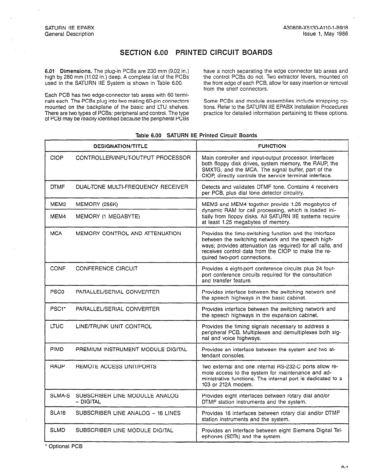
SECTION 6.00 PRINTED CIRCUIT BOARDS
6.01 Dimensions. The plug-in PCBs are 230 mm (9.02 in.)
high by 280 mm (11.02 in.) deep. A complete list of the PCBs
used in the SATURN IIE System is shown in Table 6.00.
have a notch separating the edge connector tab areas and
the control PCBs do not. Two extractor levers, mounted on
the front edge of each PCB, allow for easy insertion or removal
from the shelf connectors.
Each PCB has two edge-connector tab areas with 60 termi-
nals each. The PCBs plug into two mating 60-pin connectors
mounted on the backplane of the basic and LTU shelves.
There are two types of PCBs: peripheral and control. The type
of PCB may be readily identified because the peripheral PCBs
Some PCBs and module assemblies include strapping op-
tions. Refer to the SATURN HE EPABX Installation Procedures
practice for detailed information pertaining to these options.
CIOP
Table 6.00 SATURN III
DESIGNATION/TITLE
CONTROLLER/iNPUFOUTPUT PROCESSOR
DTMF DUAL-TONE MULTI-FREQUENCY RECEIVER
MEM3 MEMORY (256K)
MEM4 MEMORY (1 MEGABYTE)
MCA MEMORY CONTROL AND ATTENUATION
CONF CONFERENCE CIRCUIT
PSCO PARALLEL/SERIAL CONVERTER
PSCl’ PARALLEL/SERIAL CONVERTER
LTUC LINE/TRUNK UNIT CONTROL
PIMD PREMIUM INSTRUMENT MODULE DIGITAL
RAUP REMOTE ACCESS UNIT/PORTS
SLMA-S SUBSCRIBER LINE MODULLE ANALOG
- DIGITAL
SLA16 SUBSCRIBER LINE ANALOG - 16 LINES
SLMD SUBSCRIBER LINE MODULE DIGITAL
* Optional PCB
Printed Circuit Boards
FUNCTION
Main controller and input-output processor. Interfaces
both floppy disk drives, system memory, the RAUP, the
SMXTG, and the MCA. The signal buffer, part of the
CIOP, directly controls the service terminal interface.
Detects and validates DTMF tone. Contains 4 receivers
per PCB, plus dial tone detector circuitry.
MEM3 and MEM4 together provide 1.25 megabytes of
dynamic RAM for call processing, which is loaded ini-
tially from floppy disks. All SATURN IIE systems require
at least 1.25 megabytes of memory.
Provides the time-switching function and the interface
between the switching network and the speech high-
ways; provides attenuation (as required) for all calls, and
receives control data from the CIOP to make the re-
quired two-port connections.
Provides 4 eight-port conference circuits plus 24 four-
port conference circuits required for the consultation
and transfer feature.
Provides interface between the switching network and
the speech highways in the basic cabinet.
Provides interface between the switching network and
the speech highways in the expansion cabinet.
Provides the timing signals necessary to address a
peripheral PCB. Multiplexes and demultiplexes both sig-
nal and voice highways.
Provides an interface between the system and two at-
tendant consoles.
Two external and one internal RS-232-C ports allow re-
mote access to the system for maintenance and ad-
ministrative functions. The internal port is dedicated to a
103 or 212A modem.
Provides eight interfaces between rotary dial and/or
DTMF station instruments and the system.
Provides 16 interfaces between rotary dial and/or DTMF
station instruments and the svstem.
Provides an interface between eight Siemens Digital Tel-
ephones (SDTs) and the system.
SATURN IIE EPABX
General Description A30808-X5130-AllO-l-6918
Issue 1, May 1986
Table 6.00 SATURN HE Printed Circuit Boards (Continued)
FUNCTION DESIGNATION/TITLE
SLMA-0 SUBSCRIBER LINE MODULE ANALOG -
OFF-PREMISES STATION Provides an interface between the sys-
tem and four Off-Premises Stations (OPS). This module
is resgistered with the FCC for Class C off-premises
operation.
SMXTG SIGNAL MULTIPLEXER/TONE GENERATOR
(32 CHANNEL)
TM BA-2 2-WIRE E&M TRUNK
TMBA-4 4-WIRE E&M TRUNK
TMBM CENTRAL OFFICE TRUNK
TMIE DIRECT INWARD DIALING TRUNK
6.02 Controller/Input-Output Processor. The CIOP board,
shown in Figure 6.00, contains the main processor (consist-
ing of a microprocessor and related bus circuitry), signal in-
terface circuitry, PROM and RAM. The CIOP board also
contains timing circuitry, maintenance and reinitialization
switches, status indicators and a Signal Buffer (SIB).
The main processor provides the input/output function for the
floppy-disk-drive controllers. The SIB processor controls the
RS-232-C interface to the service terminal (TTY).
6.03 Signal Multiplexer/Tone Generator. The SMXTG PCB,
shown in Figure 6.01, contains three circuits. Two of these con-
sist of the signal multiplexer and the clock generator. The sig-
nal multiplexer circuit is a hardware-controlled
scanner/distributor that provides communication between the
peripheral PCBs and the CIOP It also handles the control and
status signals for the 32 speech highways, each of which has
32 time slots.
The clock generator portion consists of a crystal-controlled
oscillator and down counter which produces the 8.19 MHz,
4.096 MHz, 2.048 MHz, and 250 Hz clocking signals required
by various elements of the SATURN IIE System.
The tone generator produces all of the required supervisory
tones (e.g., dial tone, ringback tone, busy tone, etc.) and pro-
vides software-controlled timing windows for dial pulse tim-
ing and tone cadences.
6.04 Parallel/Serial Converter. The PSC board, shown in
Figure 6.02, converts the serial PCM voice signals from the
LTUs to eight-bit parallel bytes, which are then multiplexed
onto an eight-bit-wide parallel highway and sent to the MCA
circuitry for further processing. The PSC also provides this
function in reverse to provide a serial voice path back to the
Distributes control signals; receives
status signals from the 992 ports; contains the system
clock source; produces all of the required supervisory
signals (e.g., dial tone, busy tone, ringback tone) and
the DTMF tone pairs required for system outpulsing.
Provides four trunk circuits, each arranged for either
one-way or two-way direct inward and outward service
with two-wire E&M signaling.
Provides four trunk circuits, each arranged for either
one-way or two-way direct inward and outward service
with four-wire E&M signaling.
Provides four trunk circuits, each arranged for either
one-way or two-way direct inward and outward service
for CO, FX, and WATS applications.
Provides four trunk circuits, each arranged for one-way
direct inward dialing service applications from the CO.
LTUs. One PSC is required for the basic shelf, and another
is added when the expansion cabinet is equipped.
6.05 Memory Control and Attenuation. The Memory Con-
trol and Attenuation (MCA) PCB, shown in Figure 6.03, con-
tains two circuits: the Time Switch Unit (TSU) and the control
memory. The TSU makes all two-port connections and pro-
vides attenuation for all calls being processed with the
SATURN IIE System.
The control memory receives control data from the main
processor and causes the PSU and the conference units to
make the required connections.
6.06 Conference. The CONF board, shown in Figure 6.04,
is required for all conference connections involving three to
seven parties. It provides four 8-port conference circuits and
twenty-four 4-port conference circuits required for consulta-
tion and transfer features.
6.07 Memory. One 256K PCB (MEM3), shown in Figure 6.05,
and one l-megabyte PCB (MEM4), shown in Figure 6.06, are
supplied with the system to provide the overall minimum re-
quired memory of 1.25 megabytes. The memory functions are
controlled via a RAM controller and accessed via a common
bus.
6.08 Dual-Tone Multifrequency Receiver. The DTMF board,
shown in Figure 6.07, provides the means for detecting and
validating DTMF tones and dial tone. Each DTMF board con-
tains four separate DTMF and dial tone receiver circuits (num-
bered 0, 2, 4, and 6).
6.09 Remote Access Unit/Ports. The Remote Access
Unit/Ports (RAUP) PCB, shown in Figure 6.08, has three (two
external) Electronics Industries Association RS-232-C serial

SATURN IIE EPABX
General Description
asynchronous ports. The two external ports are used for Sta-
tion Message Detail Recording (SMDR), traffic metering,
maintenance, and/or CMU features. The other port is dedi-
cated to the internal RAUP modem (self-setting to either 300
or 1200 baud, depending on the frequency received). Use of
the ,modem provides access for administration and main-
tenance from a remote service terminal.
6.10 Line/Trunk Unit Control. The LTUC, shown in Figure
6.09, multiplexes and demultiplexes both the signal highway
and the voice highway, and provides the timing signals neces-
sary to address the LTU circuits allocated in an LTU shelf. The
LTUC also provides the necessary interface to the control and
switching blocks from the LTU circuitry. The LTUC is not re-
quired in the basic shelf because the line and trunks circuits
there have direct access to the control and switching circuitry.
Each LTU shelf requires one LTUC for every four channel
groups, for a maximum of two LTUCs per LTU shelf.
A30808-X5130-AllO-l-8918
Issue 1, May 1986
6.11 Subscriber Line Module Analog - Station. The
SLMA-S board, shown in Figure 6.10 provides an interface
between conventional rotary-dial or DTMF-signaling telephone
sets and the SATURN IIE System. The SLMA-S provides eight
ports. Each of the eight circuits (numbered 0 through 7) pro-
vides the required supervision and signaling for its associat-
ed -peripheral equipment.
6.12 Subscriber Line Module Analog - Off-Premises Sta-
tion. The SLMA-0 board, shown in Figure 6.11, provides an
interface between Off-Premises Stations (OPS) and the
SATURN IIE System. The Off-Premises Stations can be ro-
tary dial or DTMF signaling telephones. The SLMA-0 provides
four ports. Each of the four circuits (numbered 0, 2, 4 and 6)
provides the required supervision and signaling for its as-
sociated peripheral equipment. The OPS stations can oper-
ate over a loop of 0 to 1800 ohms.

SATURN IIE EPABX A30808-X5130-AllO-l-8918
General Description Issue 1, May 1986
P5070-14.3/20/86
Figure 6.00 Controller/Input-Output Processor Printed Circuit Board

SATURN IIE EPABX A30808-X5130-AllO-i-B918
General Description Issue 1, May
1986
Figure 6.01 Signal Multiplexer/Tone Generator Printed Circuit Board
SATURN IIE EPABX A30808-X5130-AllO-l-B918
General Description Issue 1, May 1986
P5070-15.3/20/86
Figure 6.02 Parallel/Serial Converter Printed Circuit Board

SATURN IIE EPABX A30808-X5130-AllO-l-8918
General Description Issue 1, May 1986
Figure 6.03 Memory Control and Attenuation Printed Circuit Board
6-7
SATURN IIE EPABX
General Description
A30808-X5130-AllO-l-8918
issue 1, May 1986
P5070-Z-3/20/66
Figure 6.04 Conference Printed Circuit Board
SATURN IIE EPABX
General Description
A30808-X5130-AllO-l-B918
Issue 1, May 1986
P5070-17.3/20/86
Figure 6.05 Memory 3 (MEM3) Printed Circuit Board
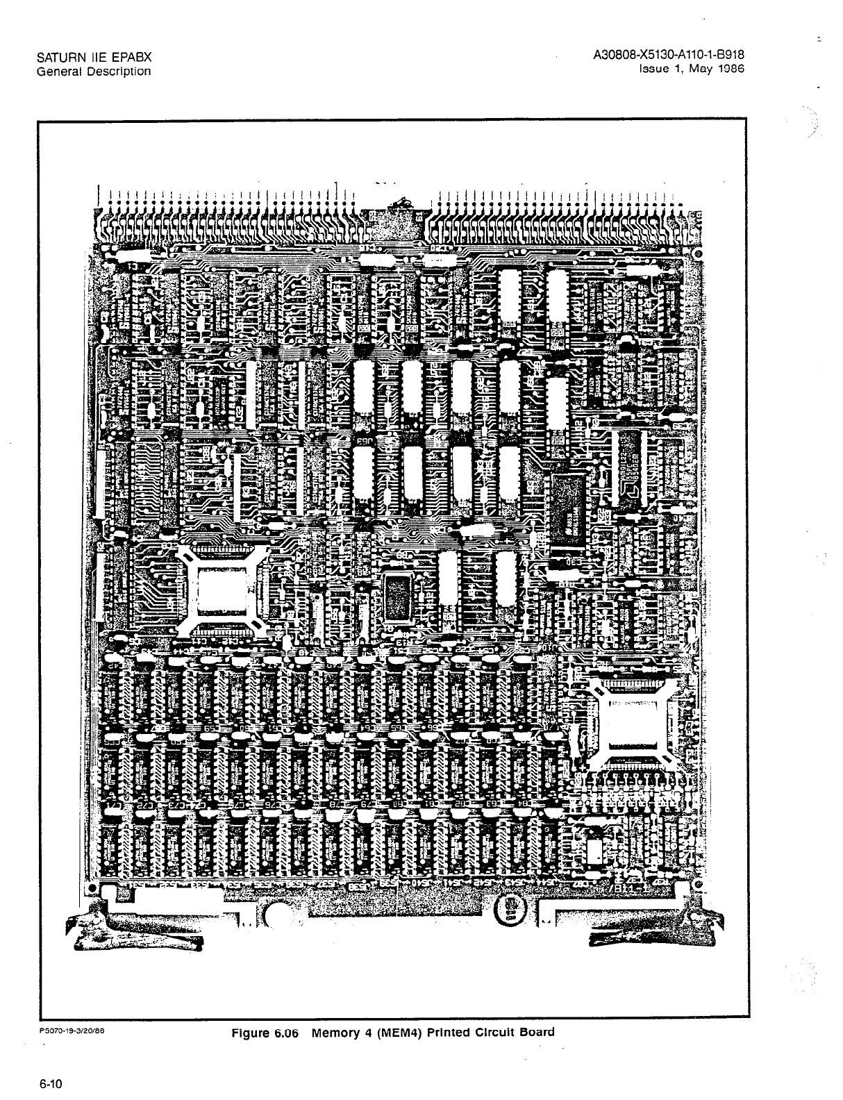
SATURN IIE EPABX
General Description
. .
P5070.19.3/20/66
Figure 6.06 Memory 4 (MEM4) Printed Circuit Board
6-10

SATURN IIE EPABX
General Description A30808-X5130-AllO-l-B918
Issue 1, May 1986
Figure 6.07 Dual-Tone Multifrequency Receiver Printed Circuit Board
6-11

SATURN IIE EPABX
General Description
A30808-X5130-AllO-l-B918
Issue 1, May 1986
P5070-13-3/20/W
Figure 6.08 Remote Access Unit/Ports Printed Circuit Board
6-12
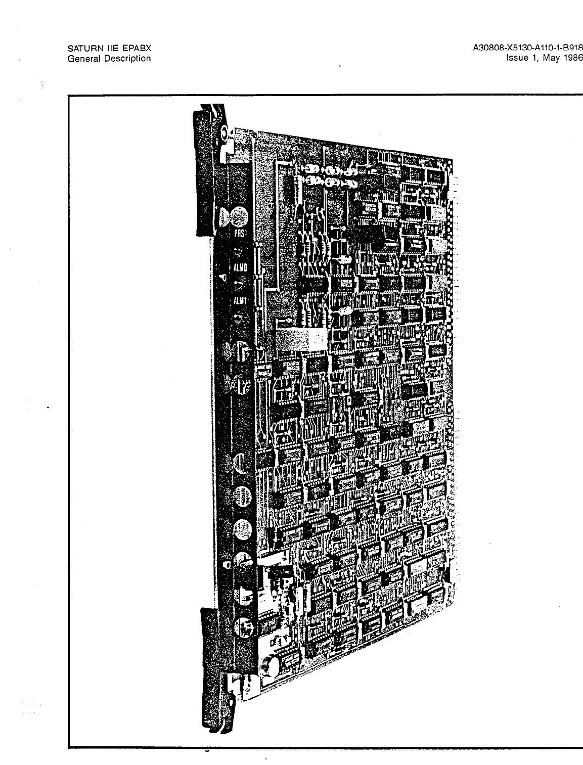
SATURN IIE EPABX
General Description
A30808-X5130-AllO-l-B918
Issue 1, May
1986
Figure 6.09 Line/Trunk Unit Control Printed Circuit Board
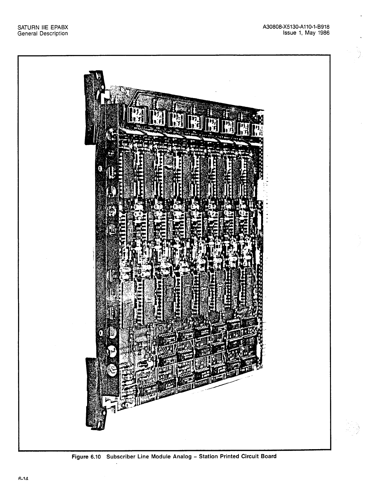
SATURN IIE EPABX
General Description
A30808-X5130-AllO-l-8918
Issue 1, May 1986
Figure 6.10 Subscriber Line Module Analog - Station Printed Circuit Board
FLIA

SATURN IiE EPABX
General Description
6.13 Subscriber Line Module Analog - 16 Lines. The
SLA16 board, shown in Figure 6-12, provides an interface be-
tween conventional rotary dial or DTMF-signaling telephone
sets and the SATURN IIE system. The SLA16 provides 16 cir-
cuits, numbered 0 through 15, which, in installed systems, are
renumbered as two sets of 0 through 7 as explained in the
Installation practice. Each circuit provides the required super-
vision and signaling for its associated peripheral equipment.
6.14 Premium Instrument Module Digital. The PIMD board
shown in Figure 6.13, serves as a special line interface cir-
cuit connecting attendant consoles to the SATURN IIE Sys-
tem. The PIMD circuitry communicates with the system via
digitally-encoded messages. (The codecs and filters for the
analog-to-digital conversion are located within the attendant
consoles.) Each PIMD contains two dual-channel circuits, and
is capable of serving two attendant consoles.
6.15 Subscriber Line Module Digital. The SLMD board,
shown in Figure 6.14, serves as a special line interface cir-
cuit connecting SDTs to the SATURN IIE System. The SLMD
circuitry communicates with the system via digitally-encoded
messages. (The codecs and filters for the analog-to-digital
conversion are located within the SDT). Each SLMD contains
eight circuits (numbered 0 through 7).
6.16 Trunk Types. The SATURN IIE System can be equipped
with a variety of common trunk types. A list of these trunk types
and the corresponding trunk designations used in the SATURN
IIE System is provided in Table 6.01. Examples of the types
of signaling and supervision available are shown in Table 6.02.
The signaling/supervision options within a particular trunk type
are available on a strappable basis on the individual PCB. Refer
to the Installation Procedures practice for more detailed infor-
mation regarding the strapping options.
6.17 Two-Wire E&M Trunk. The Siemens Two-Wire Both-Way
Trunk Module (TMBA-2) PCB, shown in Figure 6.15, provides
A30808X5130-AllO-l-8918 -
Issue 1, May 1986
either one-way or two-way, direct inward and outward private
line facility service, with E&M signaling. The TMBA-2 contains
four separate trunk circuits (numbered 0, 2, 4, and 6). Each
circuit provides two-wire analog service between the SATURN
IIE System and private line facility equipment. Separate E&M
signaling leads are provided. The trunk circuits translate the
incoming analog signals into PCM signals (and the outgoing
PCM-signals into analog signals).
6.18 Four-Wire E&M Trunk. The Siemens Four-Wire Both-
Way Trunk Module (TMBA-4) PCB, shown in Figure 6.16, pro-
vides either one-way or two-way, direct inward and outward
private line facility service, with E and M signaling. The
TMBA-4 contains four separate trunk circuits (numbered 0,
2, 4, and 6). Each circuit provides four-wire analog service
between the SATURN IIE System and private line facility
equipment. Separate E & M signaling pairs are provided. The
trunk circuits translate the incoming analog signals into PCM
signals (and the outgoing PCM signals into analog signals).
6.19 Central Office Trunk. The Siemens Both-Way Trunk
Module (TMBM) PCB, shown in Figure 6.17, provides either
one-way or two-way, inward and/or outward trunk service for
Central Office (CO), Foreign Exchange (FX), and Wide Area
Telephone Service (WATS) applications. The TMBM contains
four separate trunk circuits (numbered 0, 2, 4, and 6). Each
circuit provides two-wire analog service between the SATURN
IIE System and a CO loop-start or ground-start trunk. The
trunk circuits translate the incoming analog signals into PCM
signals (and the outgoing PCM signals into analog signals).
6.20 Direct Inward Dialing Trunk. The Siemens Incoming
Trunk Module (TMIE) PCB, shown in Figure 6.18, provides one-
way DID service from the CO to the SATURN IIE System. Each
TMIE contains four separate trunk circuits (numbered 0, 2,
4, and 6). The trunk circuits translate the incoming analog
signals into PCM signals (and the outgoing PCM signals into
analog signals).
6-15

SATURN IIE EPABX
General Description
A30808-X5130-AllO-l-8918
Issue 1, May 1986
Figure 6.11 Subscriber Line Module Analog - Off-Premises Station Printed Circuit Board
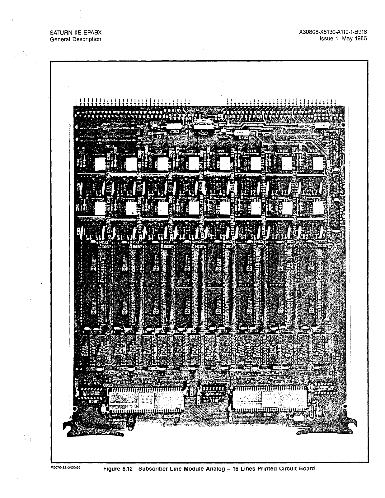
SATURN IIE EPABX
General Description
A30808-X5130-AllO-l-6918
Issue 1, May 1986
P5070.22.3/20/86
Figure 6.12 Subscriber Line Module Analog - 16 Lines Printed Circuit Board

SATURN IIE EPABX
General Description
A30808-X5130-A110-143918
Issue 1, May 1986
Figure 6.13 Premium instrument Module Digital Printed Circuit Board

SATURN IIE EPABX
General Description
A30808-X5130-AllO-l-8918
Issue 1, May
1986
‘L--r)
Figure 6.14 Subscriber Line Module Digital Printed Circuit Board

SATURN IIE EPABX
General Description
A30808-X5130-AllO-l-6918
Issue 1, May 1986
TMBM
Table 6.01 Trunk Types Used in the SATURN IIE System
TRUNK PCB
DESIGNATION/TITLE APPLICATION
- CENTRAL OFFICE (CO) Bothway (Two-Way)
Incoming (One-Way)
Outgoing (One-Way)
- FOREIGN EXCHANGE (FX)
- WIDE AREA TELEPHONE SERVICE (WATS)
TMIE - DIRECT INWARD DIALING (DID) Direct Inward Dialing Trunks
(One-Way Incoming)
TMBA-2 - TIE TRUNK (2 WIRE)
E&M Bothway (Two-Way)
Incoming (One-Way)
Outgoing (One-Way)
TMBA-4 - TIE TRUNK (4 WIRE) Bothway (Two-Way)
E&M Incoming (One-Way)
Outgoing (One-Way)
Table 6.02 Trunk Signaling and Supervision
SATURN TRUNK TYPE I
SIGNALING/SUPERVISION TYPE TMBM
(CO, FX, WATS)
SUPERVISION (Answer & Disconnect)
Loop
Loop/Reverse Battery
E&M, Type I
E&M, Type II
X
X
INCOMING SEIZURE
Loop Closure
Ground Start (Tip Ground)
E-Lead Off-Hook (1) X
INCOMING ADDRESS SIGNALING
Dial Pulse
DTMF (2)
Automatic (Ring Down) (3)
INCOMING OR CO SENDER START
Delay Dial
Immediate Dial
Wink Start
X (DISA)
X
OUTGOING ADDRESS SIGNALING
Dial Pulse
DTMF
OUTGOING SENDER START
Delay Dial
Immediate Dial
Dial Tone Detection
Wink Start
Manual (None)
TMIE
(DID)
X
X
X
X
NIA
NIA
N/A
N/A
NIA
NIA
N/A
TMBA-2 TMBA-2
TMBA-4 TMBA-4
(E&M) (E&M)
X X
X X
X X
X X
X X
X X
X X
X X
X X
X X
X X
X X
1 1
X X
X X
X X
X X
NOTES: 1. Applicable to E&M types I and II.
2. DTMF address signals are expected on DISA trunks after answer.
3. Incoming seizure is automatic (ringdown) on TMBM. Incoming address signals are not expected prior to
answer.
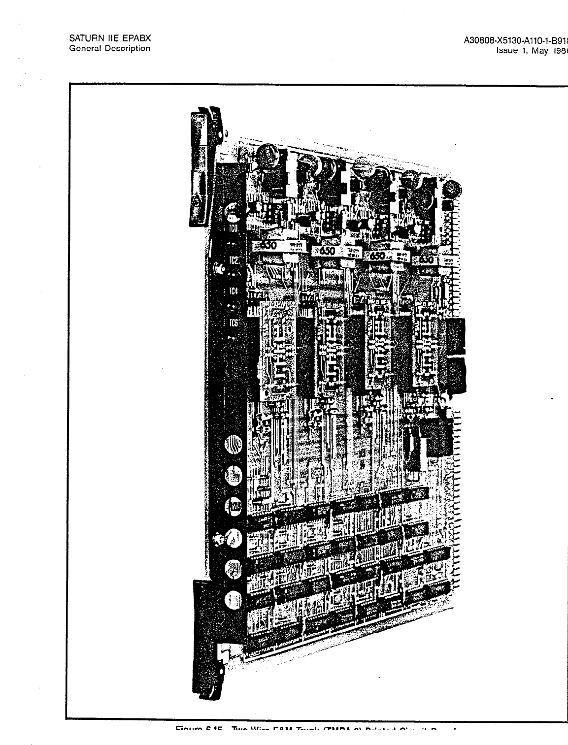
SATURN IIE EPABX
General Description A30808-X5130-AllO-l-8918
Issue 1, May
1986
Figure 6.15 Two-Wire E&M Trunk (TMBA-2) Printed Circuit Board

SATURN IIE EPABX
General Description A30808-X5130-AllO-l-B918
issue 1, May 1986
Figure 6.16 Four-Wire E&M Trunk (TMBA-4) Printed Circuit Board
6-22
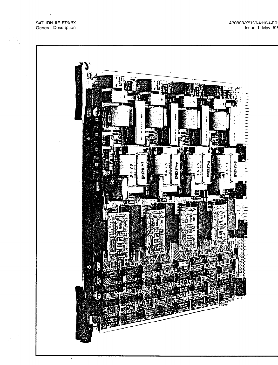
SATURN IIE EPABX
General Description A30808-X5130-AllO-143918
Issue 1, May
1986
Figure 6.17 Central Office Trunk (TMBM) Printed Circuit Board
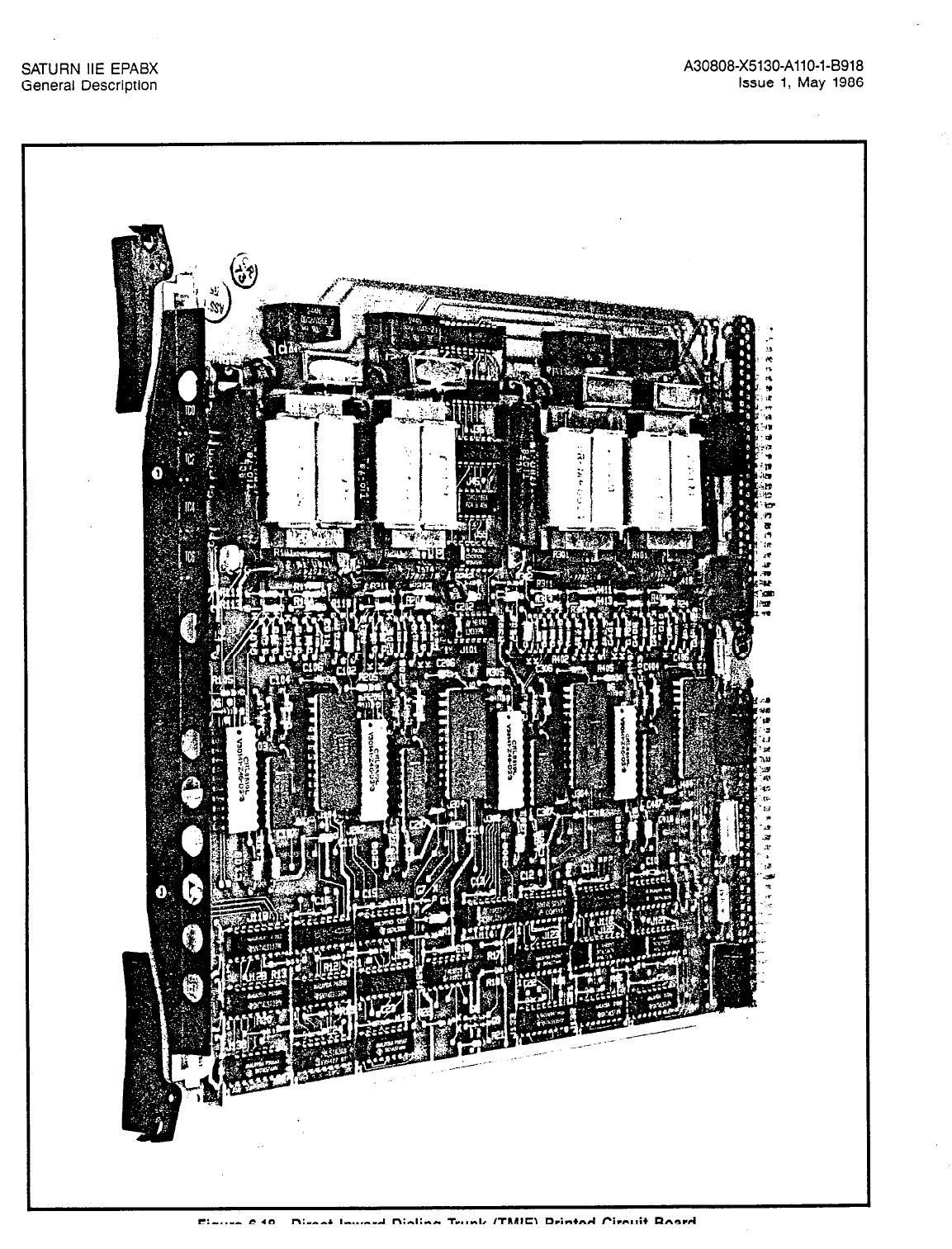
SATURN IIE EPABX
General Description
A30808-X5130-AllO-I-8918
Issue 1, May 1986
Figure 6.18 Direct Inward Dialing Trunk (TMIE) Printed Circuit Board
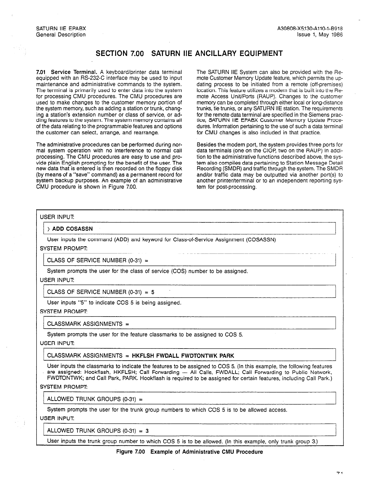
SATURN IIE EPABX A30808-X5330-AllO-l-8918
General Description Issue 1, May 1986
SECTION 7.00 SATURN IIE ANCILLARY EQUIPMENT
7.01 Service Terminal. A keyboard/printer data terminal
equipped with an RS-232-C interface may be used to input
maintenance and administrative commands to the system.
The terminal is primarily used to enter data into the system
for processing CMU procedures. The CMU procedures are
used to make changes to the customer memory portion of
the system memory, such as adding a station or trunk, chang-
ing a station’s extension number or class of service, or ad-
ding features to the system. The system memory contains all
of the data relating to the programmable features and options
the customer can select, arrange, and rearrange.
The SATURN IIE System can also be provided with the Re-
mote Customer Memory Update feature, which permits the up-
dating process to be initiated from a remote (off-premises)
location. This feature utilizes a modem that is built into the Re-
mote Access Unit/Ports (RAUP). Changes to the customer
memory can be completed through either local or long-distance
trunks, tie trunks, or any SATURN IIE station. The requirements
for the remote data terminal are specified in the Siemens prac-
tice, SATURN IIE EPABX Customer Memory Update Proce-
d.ures. Information pertaining to the use of such a data terminal
for CMU changes is also included in that practice.
The administrative procedures can be performed during nor-
mal system operation with no interference to normal call
processing. The CMU procedures are easy to use and pro-
vide plain English prompting for the benefit of the user. The
new data that is entered is then recorded on the floppy disk
(by means of a “save” command) as a permanent record for
system backup purposes. An example of an administrative
CMU procedure is shown in Figure 7.00.
Besides the modem port, the system provides three ports for
data terminals (one on the CIOP, two on the RAUP) In addi-
tion to the administrative functions described above, the sys-
tern also compiles data pertaining to Station Message Detail
Recording (SMDR) and traffic through the system. The SMDR
and/or traffic data may be outputted via another port(s) to
another printer/terminal or to an independent reporting sys-
tern for post-processing.
USER INPUT:
)ADD COSASSN I
User inputs the command (ADD) and keyword for Class-of-Service Assignment (COSASSN)
SYSTEM PROMPT:
CLASS OF SERVICE NUMBER (O-31) =
System prompts the user for the class of service (COS) number to be assigned.
USER INPUT
CLASS OF SERVICE NUMBER (O-31) = 5
User inputs “5” to indicate COS 5 is being assigned.
SYSTEM PROMPT
CLASSMARK ASSIGNMENTS =
System prompts the user for the feature classmarks to be assigned to COS 5.
USER INPUT:
CLASSMARK ASSIGNMENTS = HKFLSH FWDALL FWDTONTWK PARK
User inputs the classmarks to indicate the features to be assigned to COS 5. ‘(In this example, the following features
are assigned: Hookflash, HKFLSH; Call Forwarding - All Calls, FWDALL; Call Forwarding to Public Network,
NVDTONTWK; and Call Park, PARK. Hookflash is required to be assigned for certain features, including Call Park.)
SYSTEM PROMPT:
ALLOWED TRUNK GROUPS (O-31) = I
System prompts the user for the trunk group numbers to which COS 5 is to be allowed access.
USER INPUT:
ALLOWED TRUNK GROUPS (O-31) = 3
User inputs the trunk group number to which COS 5 is to be allowed. (In this example, only trunk group 3.)
Figure 7.00 Example pf Administrative CMU Procedure
SATURN IIE EPABX
General Description A30808-X5130-AllO-l-8918
issue 1, May 1986
SYSTEM PROMPT
TOLL CODE REST LIST NUMS (O-19) =
System prompts the user for the toll code restriction list(s) to apply to COS 5.
USER INPUT:
1
TOLL CODE REST LIST NUMS (O-19) = 7
User inputs the toll code restriction list(s) to which COS 5 is to be allowed access. (In this example, only toll
code
restriction list 7.)
SYSTEM PROMPT
RESTRICTED ACD GROUP NUMS (O-63) =
System prompts the user for the ACD group number(s) from which COS 5 is restricted from accessing.
USER INPUT:
RESTRICTED ACD GROUP NUMS (O-63) =
User does not wish to assign a restricted ACD group at this time, therefore no entry is made. (“Enter”
key
is depressed
to obtain next prompt or response.)
SYSTEM PROMPT:
RESTRICTED STATION COS’S (O-31) =
System prompts the user for the station class of service number(s) from which COS 5 is restricted from accessing.
USER INPUT:
RESTRICTED STATION COS’S (O-31) =
User does not wish to assign a restricted station COS at this time, therefore no entry is made. (“Enter” key is depressed
to obtain next prompt or response.)
SYSTEM RESPONSE:
ADD STNCOS 83-01-03 11:41:47
CLASS OF SERVICE ADDED
System acknowledges addition of the new class of service, followed by the calendar date (January 3, 1983) and the
current time (11:41:47).
USER INPUT
) SAVE CUSTDATA
User inputs the command (SAVE) and the keyword for Customer Data (CUSTDATA) to save the changed data to the
floppy disk. (In the event of a system restart, the system reloads automatically from the floppy disk. Therefore, any
changed data that has not been “saved” must be reentered.)
Figure 7.00 Example of Administrative CMU Procedure (Continued)

SATURN IIE EPABX A30808-X5130-AllO-l-8918
General Description Issue 1, May 1986
7.02 Attendant Console. The attendant console, shown in
Figure 7.01, is a desk-top unit with which the attendant
processes calls, using pushbutton keys and an alphanumer-
ic display. It is 46.99 cm (18.5 in.) wide, 13.08 cm (5.15 in.) high,
and 26.47 cm (10.42 in.) deep. A maximum of twelve atten-
dant consoles can be provided in the SATURN IIE System.
A telephone handset is furnished with the console. An op-
tional headset may be substituted for the handset. Both tone
and visual indicators alert the attendant to incoming calls. The
level of the tone signal may be controlled by a volume con-
trol located at the front edge of the console.
The attendant console provides switched-loop operation, with
single-loop appearance to simplify call handling. The advan-
tages of stored-program processing allow the attendant to
have complete information about calls directed to the con-
sole. The attendant has complete control over calls directed
to the console and a number of other features by means of
the preset and programmable console keys and the display.
The attendant console is microprocessor-controlled, and con-
tains a codec/filter for voice analog/digital conversion. The
console receives its required power from the main system,
which can be up to a distance of 610 cable meters (2,000 ca-
Connections to the console are made through industry-
standard, modular, connector-ended cables that provide voice,
control signals, and power. A standard two-pair cable is used
to make the connection from the SATURN IIE System to a
modular jack located near the console.
The upper portion of the console contains the display sec-
tion, which gives the attendant the necessary information to
correctly identify the call being serviced. The display section
includes a 40-character, alphanumeric vacuum-fluorescent
display. The following types of indications are provided by the
display:
a. Time of day
b. Station numbers of calling and called parties
c. Class of service of calling station
d. Busy/idle/out-of-service status
e. Intercept information
f. Call queuing lengths (This information is presented to
the attendant automatically between the servicing of
ble feet). calls.)
Figure 7.01 SATURN Attendant Console
SATURN IIE EPABX A30808-X5130-AllO-l-8918
General Description Issue 1, May 1986
In addition to the call data information listed above, the dis-
play may also be used for both call data display and for dis-
playing system status to the attendant (such as the system’s
failure history) plus major and minor alarm indicators.
The lower portion of the console contains a keyboard assem-
bly that allows the attendant to process the various types of
calls, initiate station and trunk calls, and access special fea-
tures (such as conferencing, paging, and night service). All
keys are nonlocking and have single built-in Light-Emitting
Diode (LED) indicators that light steadily or flash to indicate
a particular operating condition. A full explanation of the oper-
ation of the attendant console is provided in the Siemens prac-
tice, SATURN EPABX Attendant Console General Description
and Operating Instructions.
Eighteen keys on the attendant console are fully assignable
by the customer to meet customized needs. The remaining
sixteen keys are preset for the functions required in all sys-
tems. These keys are labeled and assigned as follows:
ANS Answer (System selects type of call:
operator, incoming, or recall)
ATT RLS Attendant release from all parties
AUD ON/OFF Audible signal control - on/off
BOTH Both source and destination party select
DEST Destination party select
TIME Time display
INC Incoming call queue answer
LOOPn Loop selection (Loop 1 through Loop 4)
NIGHT Night operation
OPR Operator call queue answer
RCL Recall queue answer
RLS Release of individual party
SRC Source party select
Calls requiring attendant assistance are directed automati-
cally to one of three call identification keys. Each key has a
corresponding holding queue that allows the attendant to
select one of the three types of calls: incoming trunk calls;
operator (“dial 0”) calls; or recalls (calls that have already been
serviced by the attendant and for some reason have returned
to the console for additional attendant assistance). By me-
ans of an LED indicator, the call identification keys indicate
to the attendant the type of call waiting to be serviced
and
thereby permit the attendant to process each call selectively.
In addition to the above three keys, an “answer” key is provid-
ed. This key can be used to answer waiting calls on a “first-
in, first-out” basis. When the attendant uses the answer key,
the longest waiting call (regardless of whether the call is in
the incoming, operator, or recall queue) is presented to the
console for servicing.
SATURN IIE EPABX A30808-X5130-AllO-l-B918
General Description Issue 1, May 1986
SECTION 8.00 STATION MESSAGE DETAIL RECORDING
8.01 General. Station Message Detail Recording (SMDR) pro-
vides detailed records of incoming and outgoing trunk calls.
The SATURN System records all detail information for outgo-
ing CO, WATS, FX and Tie trunk calls and incoming CO, WATS,
FX and Tie trunk calls. Intra-switch, station-to-station, station-
to-attendant, and attendant-to-station calls are not recorded.
The SMDR program is resident in the system and can be ac-
tivated/deactivated by the attendant on a per-trunk-group ba-
sis. When activated, the SMDR program remains on-line and
runs continuously until it is deactivated. While running, it pro-
vides chronological reports of calls via one of the output port(s)
of the RAUP or the TTY port on the CIOP
The SMDR output device is assignable from the service ter-
minal and this information is saved such that, if the system
is reloaded, SMDR resumes operation automatically to its as-
signed output port.
The recording of calls is customer selectable on a
per-incomingtrunk-group basis and on a per-outgoing-LCR-
route-element basis, or on a per-outgoing-trunk-group basis
if direct trunk group access is used.
When a call detail recording buffer is not available and an
internal or outgoing call is attempted, the call will be either
blocked or allowed to proceed without recording, based on
a system option flag (defined via a CMU procedure). Incom-
ing calls are never blocked.
8.02 Call Record Items. The call data items that are includ-
ed in the SMDR report are described in below. An example
of an SMDR printout is provided in Figure 8.00.
a. Record Type. This single-character field precedes the
Source Identity field and does not have a heading. The
character indicates the record type as follows: “T” for
call trace, and blank for voice call.
b. Source Identity. This field identifies the originating (i.e.,
calling) party of the call on record. It includes the sub-
scriber extension number for an outgoing call or the
trunk group and trunk group member number for an
incoming trunk call.
The source identity is left blank for calls originated by,
and not extended from, an attendant.
c. Destination Identity. This data identifies the terminat-
ing (i.e., answering) party of the call on record. It is the
trunk group and trunk group member number of the
trunk used for the outgoing call or the subscriber ex-
tension number in the case of an incoming trunk call.
The destination identity is left blank for incoming calls
terminated at, but not extended (or transferred) from,
an attendant, Special Night Answer Position (SNAP),
Zoned Universal Night Answer (ZUNA), Assigned Night
Answer (ANA), or Special Overflow Answering Posi-
tion (SOAP). If the incoming call is extended (or trans-
ferred) by the attendant, SNAP, ZUNA, ANA, or SOAP,
the destination identity identifies the transferred-to-
subscriber extension number or, trunk group and trunk
group member number (i.e., trunk-to-trunk connection).
d.
e.
f.
h.
Least Cost Route Selection Route Number. This data
identifies the route member used to route the call. This
field is blank for internal and incoming calls and out-
going calls that do not utilize LCR (i.e., Direct Access
trunks).
Access Code. This data identifies the routing access
code dialed by the user after going off-hook (and
receiving internal dial tone).
When speed calling is used, this field contains the ef-
fective routing access code, rather than the speed call-
ing access code.
Dialed Digits or Called Number. These are the digits
dialed by the user after dialing any routing access
code. The number of digits may vary up to a maximum
of 16. They may include, for example, in chronological
order, either of the following:
l
International Gateway Code, plus country code.
plus remaining digits for International Direct Dis-
tance Dialing.
l
Prefix 0 or 1, plus area code (3 digits), plus Office
Code (3 digits) plus Station Number (4 digits), i.e.,
up to 11 digits for domestic Direct Distance Dial-
ing. Note that either prefix and/or area code may
not be required for many local area calls.
When speed calling is used, this field contains the ef-
fective destination address rather than the speed call-
ing access code and member number dialed by the
user.
When Least Cost Routing (LCR) is used, this field con-
tains the effective address dialed by the user rather
than those outpulsed as a result of the LCR outdial-
ing rule.
Authorization Code Index. (See Account Code/Authori-
zation Code for the definition of “authorization code”).
When an authorization code is entered and it is not
“displayable” (i.e., is secret), a two-character index to
the authorization code is listed in this field. A person
with the proper authorization can use this index to ob-
tain the full authorization code, and unauthorized per-
sons are restricted from obtaining it.
For some applications, such as for resale of services.
a large number of authorization codes may be required.
In such cases, if the index exceeds 99, the ” ** ” is
printed in this two-character field.
Starting Time of Call. This field indicates the time of
day, in hours, minutes and seconds at which record-
ing commenced. For incoming calls, this is the time
at which the call is answered. For outgoing calls over
trunks that return answer supervision, this is the time
at which answer supervision is received. For outgoing
calls over trunks not returning answer supervision, this
is the end of outpulsing time incremented by a cus-
tomer adjustable filtering time. (If the holding time does
not exceed the filtering time, the call is not recorded.)
SATURN IIE EPABX
General Description
.
A30808-X5130-AllO-l-8918
Issue 1, May 1986
i. Call Duration. Call duration is the elapsed time from
the starting time of the call until the call is released.
The duration is recorded in hours, minutes and se-
conds with the leading zeros and colon suppressed
for hours.
If the system time of day is adjusted while recording
is in progress, it will not affect the validity of the reported
call duration.
j.
Special Identity. Whenever an attendant, SNAP, ZUNA,
ANA, or SOAP is involved in answering an incoming
trunk call, or whenever the attendant is involved in plac-
ing an outgoing trunk call, or whenever LCR routes a
call over an expensive facility or a specialized com-
mon carrier, or whenever a call is forwarded to the pub-
lic network, a special identity character is recorded.
The following special identity characters are defined
for this field:
1-12 - Attendant Console 1-12
S - SNAP
Z L ZUNA
A - ANA
0 - SOAP
E - LCR Expensive Facility
F - Call Forwarding to Public Network
6, C, D - LCR Specialized Common Carrier. Iden-
tity of SCCs 0, 1, and 2, respectively.
k. Account Code/Authorization Code. This field usually
provides the account code data associated with the call
record. However, if an authorization code is entered,
and it is defined as “displayable” (i.e., the code is not
secret), then this code is printed instead of the account
code.
An authorization code is a special security code (up
to 6 digits) to allow an authorized subscriber to up-
grade, for that call only, the class of service giving the
user a special feature or otherwise unauthorized fa-
cility. When an authorization code is required, it is
usually entered after the access code and prior to di-
aling the called number digits. Use of authorization
codes include calls made from a restricted telephone
using the Mobile Authorization Code feature and in-
coming calls on Direct Inward System Access trunks.
The account code data is either the standard (i.e.,
default) account code assigned for the station or the
special account code entered by the station user or
the attendant, if applicable, for the outgoing call; the
standard account code assigned for the station is used
in the case of an incoming calf.
When a station accesses an LCR route element or a
direct access trunk group not marked for special ac-
count codes, the standard account code assigned to
the station is recorded. If no account code is assigned,
the field is left blank.
Authorization codes will be prefixed by “#‘I to distin-
guish them from account codes.
I. Pooled Modem Group. Refer to Siemens practice OC
II General Description and Feature Supplement.
The following special considerations are applicable to
the call data items:
Station Call Transfer. A separate call record is
generated each time a call is transferred by a sta-
tion, except for incoming trunk calls transferred by
a SNAP, ANA, ZUNA, or SOAP station, in which
case the same call record is continued and a spe-
cial identity character is recorded.
Starting Time of DISA Call. On an incoming DISA
call, an SMDR record shows the start time as the
answer time of the destination, and not as the an-
swer time of the DISA trunk.
Attendant Controlled Conference. The source or
destination identity for a party connected to an
attendant-controlled conference is ‘ACC X” with
“X” representing the conference circuit (l-8). “ACC
X” appears as the source identity for parties called
by an attendant and added to the conference. “ACC
X” appears as the destination identity for parties
who call into an attendant and are added to the
conference.
Meet-Me Conference. The source or destination
identity for a party connected to a meet-me con-
ference is “MMC X” with “X” representing the con-
ference circuit (l-8). “MMC X” appears as the
source identity for parties called by an attendant
and added to the conference. “MMC X” appears
as the destination identity for parties who dialed
directly into the conference or call into an atten-
dant and are added to the conference. Any account
code applied to a meet-me conference must be en-
tered by an attendant.
Alternate Trunk Groups. If a trunk is accessed via
direct trunk group access, the SMDR option to
record or not record the call is based on the as-
signment of the primary trunk group, even when
an alternate route is selected. When LCR is used,
the SMDR option is based on the LCR route ele-
ment used.
Station Hunting. The account code and destina-
tion identity is that of the final (i.e., answering)
station.
Call Forwarding (internal). The account code is that
of the forwarded (i.e., dialed) station and the desti-
nation identity is that of the forwarded-to (i.e., an-
swering) station.
Call Forwarding to Public Network. When an in-
coming trunk calls a station which is forwarded to
the public network, two SMDR records are gener-
ated: one showing the incoming trunk as the
source ID and the forwarded station as the desti-
nation ID; the other showing the forwarded station
as the source ID and the out-going trunk as the
destination ID. An internal station calling the for-
warded station generates one SMDR call record
showing the forwarded station as the source ID and
the outgoing trunk as the destination ID. All records
show the account code of the forwarded station.
’
SATURN IIE EPABX
\ General Description A30808-X5130-AllO-l-8918
Issue 1, May 1986
8.03 Special SMDR Messages. The list below defines spe-
cial messages, that is, messages other than call records, that
are printed on the SMDR device.
a. Page Header. Each new page of SMDR call records
is preceded by the page header. The page header iden-
tifies the current
date
and time (24-hour notation), and
the page number of that date’s report. The page header
also provides the data headings for the call detail
record items.
b. Daily Trailer. The call record report is concluded for the
current data at midnight with the daily trailer. The daily
trailer identifies the date of the report and the total num-
ber of pages printed for that date. The next day’s report
is automatically started at the top of the next page.
c. Attendant Activated (SMDR) Recording. The following
message is printed when the attendant activates the
SMDR recording for a particular trunk group:
l
** SMDR ACTIVATED FOR TRUNK GROUP xx BY
ATTENDANT yy AT zz:zz:zz
l
**
(where xx = activated trunk group number, yy = at-
tendant number, zz:zz:zz = time of activation).
d. Attendant Deactivated (SMDR) Recording. The follow-
ing message is printed when the attendant deactivates
the SMDR recording for a particular trunk group:
*** SMDR DEACTIVATED FOR TRUNK GROUP xx BY
ATTENDANT yy AT zz:zz:zz ***
(where xx = deactivated trunk group number, yy =
-attendant number, zz:zz:zz = time of deactivation).
e. Annoyance Call Trace. The annoyance call trace fea-
ture prints a message formatted identically to a call
record, with the following exceptions:
l
A “T” is printed in the Record Type field.
l
The source identity shows the subscriber extension
number of the station activating the annoyance call
trace.
l
The destination identity shows the subscriber ex-
tension number of the trunk group and trunk
group
member number of the connected party.
l
Nothing is shown for RT, ACC. CODE, DIALED
DIGITS, AUTH IDX., CALL DURATION, SPCL ID,
and ACCT CODElAUTH CODE.
l
The START TIME shows the time at which the an-
noyance call trace was made.

SATURN IIE EPABX A30808-X5130-AllO-l-B918
General Description Issue 1, May 1986
SRCE MST ACC A”*” START CALL SPCL ACCT CODE I
ID ID RT CDDE DIALED DIGITS IDX TIWE DURATION ID Y)TH CODE “!J
----- ----- -- __-- ________L_--__-_ -- - ---____ ---- -_-- ____ -__- ------ __
7100 02100 ii0 9
7216 OBlOl 03 9
22109 10100 12
1496 07/01 09 9
7234 19/O, 04 9
71c4 oe/oo 09 9
7344 02/02 00 9
7234 19/o, 04 9
12% OS/O2 09 9
7623 02103 00 9
7403 02/04 00 9
T 7003 04/1X
7409 03,OL 04 9
7100 02100 00 9
7220 IO/O0 12
22,OI 718b
‘1234 19,CZ 04 9
4222 11/00 01 9
22104 7233
22102 7286
7108 08/O, 03 9
4312 03/02 81
7409 05,OI 04 9
22/09 7122
7235 OS/02 03 9
I1100 7420
7149 07/00 03 9
7235 owo2 03 9
400: IO/O. *2
7235 08/02 ii 9
22/03 7380
7428 07102 09 9
7189 19101 04 9
ll/OO 7410
22/03 32*7
7344 02105 00 9
1231 02103 00 9
nrtc 1 03lOO 02 9
7219 02,Ol 00 9
7183 oe/o1 03 9
03103 4320
7234 19,02 04 9
7381 02/00 00 9
22104 7197
*cc 2 03/02 81
7344 02/00 00 9
1250 07101 03 9
7623 02100 00 9
22111 *o/o0 I2
7342 oz/qo 00 9
7183 OBIOZ 03 9
22/05 72’32
11113 4444
17/05 3312
01100 7250
02/O? 4352
3ea45.3
17375354
7541
632380 I
Im94242400
5e33487
403056 I
16D94242400
4456234
3689721
4870049
13166435943
48392Otl
7520
lbD94242400
0112233317826
10630545
4367
13168435543
15522171
19047857503
lbLJS077
754,
lS13L658077
7417556
14684225302
483056 1
9427916
9949950
7511030
17377400
1L.094242400
18004320190
4320
4SM561
lSl3P573200
3917954
i5St
9735165
17377400
13 57 09
13 52 71
13 51 IS
13.57 24
13 97 32
13 57 10
13.5S 09
13 57 54
13-54 01
13 ¶Y 20
13 50 41
13 51 0.
13 58.51
13 5e 37
13 59 14
13 59 24
03 13 59 II
13 5s 57
13 56 29
14 00 52
14
38
40
14 01 37
14 00 22
14 02’31
15 02 32
13 02 31
I5 03.01
15 03 15
13 02 5e
15 03 41
15 03 52
15 04 21
I5 03 09
I5 03 20
15 04 13
15 05 02
I5 04 44
I5 05 22
15 04:02
13 OL 20
I5 04 43
I5 04 47
13 02 2b
13 05 47
13 07 02
15 07 17
15 05 95
15 07 39
15 o-a 16
19 08 16
15 08 36
I3 07 51
10 I2 10
19 22 19
21 LB 01
II 39 28
0 1*
4 5e
b 14
0 16
0 10
0 39
0 01
0 39
4 34
0 31
8. 13
0 06
0 29
0 16
@ II
0 32
1 2s
2 22
0 IC
2 -IO
0 23
2 00
0 09
0 30
0 29
0 19
0 12
1-w 2
0 30
0 21
0 22
I 40
I 33
0 51
0 02
0 37
0 02 2
I 5,
0 03
1 .I
I 44
4 15
I 26
0 13 3
0 02
1 .5
0 1s
0 00
0 I4
0 10
L 00
0 40 s
1 22 2
2 33 0
5 II A
END SPIDR RECORDS F(R Jute 12. 1984
TOTAL PAGES FOR THI8 DATE 2
&200
3500
m
7x0
5320
3230
7300
5320
5730
WOO
0800
sxm
5970
7600
2100
3320
730”
7800
7800
S7439803.7
WOO
5300
MO
woo
5910
no0
7300
7710
5210
7800
moo
n10
5230
5910
MO
x20
4125~352225
7300
7710
woo
A3437.l-5120185
Figure 8.00 Example of SMDR Printout
8-4 (4 pages)
Siemers Practices A30808-X5130-A120-l-8918
General Series Issue 1, May 1986
SATURN” IIE EPABX
ATURE DESCRIPTIONS
Issued by Office Systems Group
5500 Broken Sound Boulevard N.W., Boca Raton, Florida 33431 (305) 994-8100
l
Telex: 515052
Siemens Information Systeins, Inc. Printed in U.S.A.
Siemens Practices
General Series
0 Siemens Information Systems, Inc., 1985
All rights reserved.
A30808-X5130-A120-l-8918
Issue 1, May 1986
This material is proprietary to Siemens Information Systems, Inc. Any unauthorized
reproduction, use or disclosure of this material, or any part thereof, is strictly prohibited.
Siemens reserves the right to make changes in specifications at any time and without
notice. The information furnished by Siemens in this material is believed to be accurate
and reliable. However, no responsibility is assumed by Siemens for its use.
SATURN is a registered trademark of Siemens Information Systems, Inc.

SATURN IIE EPABX A30808-X5130-AllO-l-8918 -
Feature Descriptions Issue 1, May 1986
CONTENTS
SECTION PAGE SECTION PAGE
1.00 INTRODUCTION .......................... l-1
Purpose of Document ....................... l-1.
General Information about Features. ........... l-l
2.00 SYSTEM FEATURES ...................... 2-1
System Overview. .......................... 2-l
General Features .......................... 2-2
Administration Features ..................... 2-3
Flexible Numbering Features ................. 2-4
Night Answering Features ................... 2-5
System Dialing Features. .................... 2-6
System Alarm Features ............. , ....... 2-6
Line Lockout Features ...................... 2-7
Intercept Features .......................... 2-7
Access to Customer-Provided
Equipment Features ...................... 2-7
Restriction Features ........................ 2-8
Diagnostic and Maintenance
Testing Features ......................... 2-8
Trunking Features .......................... 2-9
Transfer Features ................
Conference Features : ............
Queuing Features ................
Call Forwarding Features ..........
Call Pickup Features .............
Speed Calling Features ...........
Station Hunting Features ... : ......
Message Waiting Features .........
Privacy Features .................
Special Station Assignment Features
Additional Features. ..............
4-2
4-2
4-2
4-3
4-5
4-5
4-5
4-7
4-7
4-8
4-8
. .
5-l
5-l
5-l
5-2
5-2
5-3
5-3
3.00 ATTENDANT FEATURES. .................. 3-1
Attendant Console Overview ................. 3-l
General Features .......................... 3-l
Call Handling Features. ..................... 3-l
Recall Features. ........................... 3-3
Display Features ........................... 3-3
Direct Access Features. ..................... 3-4
Control Features ........................... 3-4
Volume Control Features .................... 3-8
System Status Features ..................... 3-9
Busy Verification Features .................. 3-10
4.00 STATION FEATURES ...................... 4-1
Station Overview ........................... 4-l
General Features .......................... 4-l
Hold Features ............................. 4-l
5.00 SIEMENS DIGITAL TELEPHONE FEATURES
Overview ..............................
General Features .......................
Ringing Features. .......................
Direct Access Features. ..................
Hold Features ..........................
intercom Features. ......................
Display Features (18- and 26-Button
SDTs only) ............................
Message Waiting Features. ...............
Privacy Features ........................
Special Station Operation Features .........
5-4
5-5
5-5
5-5
LIST OF TABLES
TABLE PAGE
1.00 SATURN IIE EPABX Features. .
1.01 Mnemonics Used in This Practice.
2.00 Station Class-of-Service Features
2.01 Traffic and Feature Usage Measurement Table
4.00 Station instrument Codes Used in
l-1
l-5
2-5
2-6
This Practice . . . . . . . 4-l
SATURN IIE EPABX A30808-X5130-A120-l-8918
Feature Descriptions Issue 1, May
1986
SECTION 1.00 INTRODUCTION
1.01 Purpose of Document
The purpose of this document is to provide descriptions of
all SATURN IIE (SATURN II - Expanded) Electronic Private
Automatic Branch Exchange (EPABX) features. In this docu-
ment, these SATURN IIE features are divided into the follow-
ing four major categories:
- System Features
- Attendant Console Features.
- Station Features
- Siemens Digital Telephone (SDT) Features.
An alphabetical list of these features, separated by category,
is provided ir. ,Table 1.00. All mnemonics used in this docu-
ment are listed and defined in Table 1.01.
1.02 General Information about Features
Features are the characteristics and capabilities of a
telephone
switching system. The features provided by the SATURN
IIE
EPABX System include the basic calling features such
as
Station-to-Station Calling, Call Transfer, and Call
Forwarding.
More elaborate features are also included, such as
Least-Cost
Routing, Station Message Detail Recording, and 15-Digit
Toll
Code Restriction.
The SATURN IIE EPABX features are designed to provide
flexible and powerful telephone switching system that
satis-
fies the user’s communication requirements.
Table 1.00 SATURN IIE EPABX Features
SYSTEM FEATURES PARAGRAPH
Additional Input/Output Devices .................................................................
Alarm Indication - Major .2.02(a)
......................................................................
Alarm Indication - Minor .2.07(a)
Alternate Routing.. ................................................
................................................... . .2.07(b)
. . . . . . . . . . . . . . . . . . . . ::.2.13(a)
Assigned NightAnswer........................................................................2.05(a
)
Automatic Call Distribution Recorded Announcement Service ........................................
Automatic On-Line Diagnostic Testing and Reporting .2.09(a)
............................................... .2.12(a)
BrownoutProtection...........................................................................2.02(b
)
CentralOffice(City)TrunkAccess ......................................................... .2.13(b)
CodeCallAccess.....................................................................:::~::..2.lO(a
)
Convection Cooling
CustomerMemory Updating..
......................................................................................................... . .2.02(c)
Common Control Switching Arrangement Access (CCSA). ::::::::::::::::..2.03(a)
...........................................
Daytime Trunk Control .2.13(c)
........................................................................
Dedicated Incoming Trunks .....................................................................
.2.11(c)
Dictation Access .2.13(d)
...............................................................................................................................................................................................................
::.
Digital Pad Switching .2.10(b)
Direct Inward Dialing ‘.2,02(d)
Direct Inward System Access : : : : .2.06(a)
DirectlnwardSystemAccess-Shared..
...................................................................................... .2.06(b)
Direct Outward Dialing. ::::::::::::::::::.2.06(~)
.......................................................................
Direct Inward Dialing - Flexible Station Numbering .2.06(d)
................................................
Dual-Tone Multifrequency System Outpulsing .2.04(a)
......................................................
DTMF-to-Dial Pulse Conversion .2.02(f)
.................................................................
Eight-Digit Toll Code Restriction For Direct Trunk Group Access .2.02(e)
......................................
End-to-End DTMF Signaling .2.11(a)
...................................................... : ............
Enhanced Private Switched Communication Service Access .2.02(g)
.........................................
External Extension Numbering .2.13(e)
..................................................................
Fifteen-Digit Toll Code Restriction For Direct Trunk Group Access .....................................
Flexible Intercept Facilities .2.11(b)
....................................................................
Flexible System Numbering Plan .,2.09(b)
...............................................................
Foreign ExchangeTrunk Access .2.04(b)
HighTrafficCapacity
............................................................... ..2.13( 9
.......................................................................
Incoming Class-of-Service Blocking. ,.,2.02(h)
.............................................................. .2.11(d)
LeastCostRouting............................................................................2.13(g )
LCR with Provisions for Specialized Common Carrier. ..............................................
Line Lockout - Attendant Intercept .2.13(h)
..............................................................
Line Lockout - Automatic .2.08(a)
.....................................................................
Low PowerConsumption .2.08(b)
.....................................................................
Manual On-Line Maintenance Testing. ..2.02~)
...........................................................
Memory Support.. .2.12(b)
..........................................................................
Multiple Listed Directory Numbers ..2.02~)
.............................................................. .2.04(c)
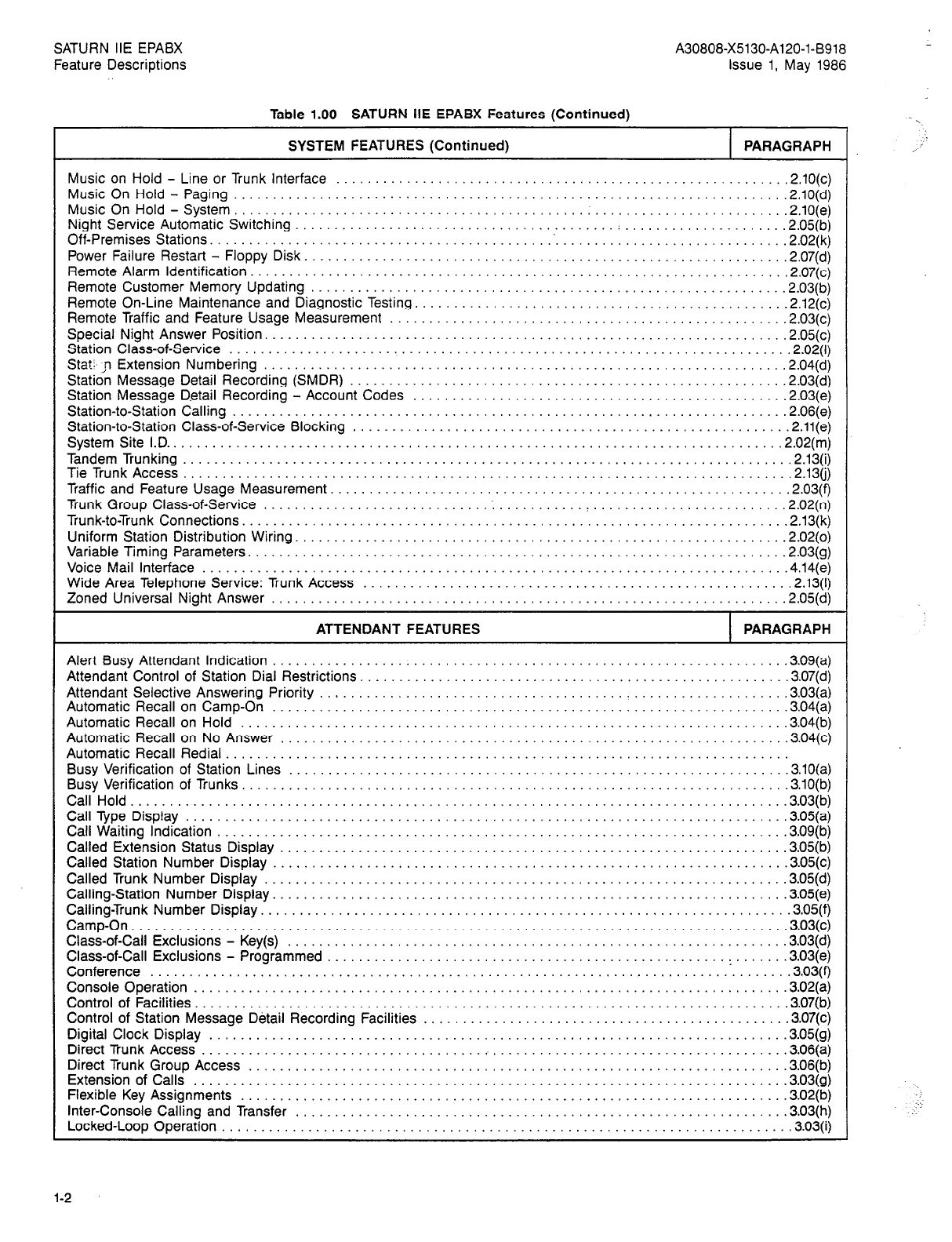
SATURN IIE EPABX A30808-X5130-Al20-l-8918
Feature Descriptions issue 1, May 1986
Table 1.00 SATURN IIE EPABX Features (Continued)
SYSTEM FEATURES (Continued) PARAGRAPH
Music on Hold - Line or Trunk Interface ......................................................... .2.10(c)
Music On Hold - Paging ...................................................................... .2.10(d)
Music On Hold - System. ..................................................................... .2.10(e)
Night Service Automatic Switching ......................................... : .................... .2.05(b)
Off-Premises Stations............................................~.............................2.02(k )
Power Failure Restart - Floppy Disk. ............................................................ .2,07(d)
Remote Alarm Identification. ................................................................... .2,07(c)
Remote Customer Memory Updating ............................................................ .2.03(b)
Remote On-Line Maintenance and Diagnostic Testing. .............................................. .2,12(c)
Remote Traffic and Feature Usage Measurement .................................................. .2.03(c)
Special Night Answer Position. ................................................................. .2.05(c)
Station Class-of-Service ....................................................................... ,2.02(l)
Stat. ,n Extension Numbering .................................................................. .2.04(d)
Station Message Detail Recording (SMDR) ....................................................... .2.03(d)
Station Message Dstail Recording - AccountCodes ............................................. .,.2.03(e)
Station-to-Station Calling ...................................................................... .2.06(e)
Station-to-Station Class-of-Service Blocking ....................................................... .2.11(e)
System SiteI.D...............................................................................2.02(m )
TandemTrunking..............................................................................2.13~ )
TieTrunkAccess..............................................................................2.13~ )
Traffic and Feature Usage Measurement. ......................................................... .2.03(f)
Trunk Group Class-of-Service ............................. : ........... : ........................ .2.02(n)
Trunk-to-Trunk Connections......................................................................2.13(k )
Uniform Station Distribution Wiring. ............................................................. .2.02(o)
Variable Timing Parameters. ................................................................... .2.03(g)
Voice Mail Interface ........................................................................ .,.4.14(e)
Wide Area Telephone Service: Trunk Access ...................................................... .2.13(l)
Zoned Universal Night Answer ................................................................. .2.05(d)
ATTENDANT FEATURES PARAGRAPH
Alert Busy Attendant Indication ................................................................. .3.09(a)
Attendant Control of Station Dial Restrictions. ..................................................... .3.07(d)
Attendant Selective Answering Priority ........................................................... .3.03(a)
Automatic Recall on Camp-On ................................................................. .3.04(a)
Automatic Recall on Hold ..................................................................... .3.04(b)
Automatic Recall on No Answer ................................................................ .3.04(c)
Automatic Recall Redial ........................................................................
Busy Verification of Station Lines ............................................................... .3.10(a)
Busy Verification of Trunks. .................................................................... .3.10(b)
CallHold....................................................................................3.03(b )
CallType Display.. ......................................................................... ..~05(a)
Call Waiting Indication ........................................................................ .3.09(b)
Called Extension Status Display ................................................................ .3.05(b)
Called Station Number Display ................................................................. .3.05(c)
Called Trunk Number Display .................................................................. .3.05(d)
Calling-Station Number Display. ................................................................ .3.05(e)
Calling-Trunk Number Display. .................................................................. .3.05(f)
Camp-On....................................................................................~O3(c )
Class-of-Call Exclusions - Key(s) ............................................................... .3.03(d)
Class-of-Call Exclusions - Programmed ................................................... : ...... .3.03(e)
Conference ............................................................................... .,.3.03(f)
ConsoleOperation.. ....................................................................... .,.3.02(a)
Control of Facilities. .......................................................................... .3.07(b)
Control of Station Message Detail Recording Facilities .............................................. .3.07(c)
Digital Clock Display ......................................................................... .3.05(g)
DirectTrunkAccess...........................................................................~O6(a )
Direct Trunk Group Access .................................................................. .,.3.06(b)
Extension of Calls .......................................................................... ..~03(g)
Flexible Key Assignments ..................................................................... .3.02(b)
Inter-Console Calling and Transfer .............................................................. .3.03(h)
Locked-LoopOperation.........................................................................3.03(i )
l-2
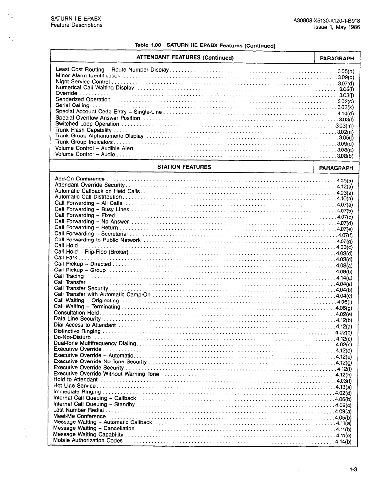
SATURN IIE EPABX
Feature Descriptions A30808-X5130-A120-l-8918 -
Issue 1, May 1986
Table 1.00 SATURN IIE EPABX Features (Continued)
ATTENDANT FEATURES (Continued) PARAGRAPH
Least Cost Routing - Route Number Display. . . . . . . . . . . . . .3.05(h)
MinorAlarmldentification . . . . . . . . . . . . . . . . . . . . . . . . . . . . . . . . . . . . . . . . . . . . . . . . ::::::::::::::::::::..3.09(c)
Night Service Control . . . . . . . . . . . . . . . . . .3.07(d)
Numerical Call Waiting Display . . . . . . . .‘.‘.‘.1.‘.‘.‘.‘.‘.‘,‘.‘.‘.‘.‘.‘.’.’.’.~.’.’.’.‘.~.~.‘.~.’.’ ’ ” ’ ‘. .3.06(i)
Override.............................................~........,......................:::: ::..3.03(j)
SenderizedOperation.................................................,...................,..,.3.02(~)
Serial Calling . . . . . . . . . . . . . . . . . . . . . . . . . . . . . . . . . . . . . . . . . . . . . . . . . . . . .3.03(k)
SpecialAccountCodeEntry-Single-Line . . . . . . . . . . . . . . . . . . . . . . . . . . . . . ::::::::::::::::::::::::::..4.14(6)
Special Overflow Answer Position . . . . . . . , . . . . . . . . . . . . .3.03(l)
Switched LoopOperation . . . . . . . . . . . . . . . . . . . . . . . . . . . . . . . . . . . . . . . . . . ::::“““““““““““::3,03(m)
Trunk Flash Capability . . . . . . . . . . . . . . . . . . . . . . . . . . . .‘.‘.‘.‘.‘.‘.~.‘,‘.‘.‘.‘.‘.‘.‘.‘.’.’.~.~.’.’. .3.02(n)
Trunk Group Alphanumeric Display . . . . . . . . , . . . . . . . . . . . . . . . . .3.05(j)
Trunk Group Indicators . . . . . . . . . . . , . . . . . . . . . . . . . . . . , . . . . . . ‘. ‘. ‘. ‘. ‘. ‘. ‘. ‘. ‘. ‘. ‘. ‘. ‘. ‘. ‘. . . ‘. ‘. ‘... 3.09(d)
Volum,e Control - Audible Alert . . . . . . . . . . . . . . . . . . . . . . . . . . . . . . . . . . . . . . . . . . . . : : .3.08(a)
Volume Control - Audio . . . . . . . . . . . . . . . . . . . . . . . . . . . . . . . . . . . . . . . . . . . . . . . .3.08(b)
STATION FEATURES PARAGRAPH
Add-On Conference . . . . . . . . . . . . . . . . . . . . . . . . . . . . . . . . . . . . . . . . . . . . . . . . . . . . . . . . . . . . . . . . . . . . . . . . ...4.05(a)
Attendant Override Security. . . . . . . . . . . . . . . . . . . . . . . . . . . . . . . . . . . . . . . . . . . . . . . . . . . . , . . . . .4.12(a)
Automatic Callback on Held Calls. . . . . . . . . . . . . . . . . . . . .4.03(a)
AutomaticCallDistribution . . . . . . . . . . . . . . . . . . . . . . . . . . . . . . . . . ::::::::::::::::::::::::::::::::::::.4,lO(h)
Call Forwarding - All Calls . . . . . . . . . . . . . . . . . . . . . . . . . . . . . . . . . . . . . . . . . . . . . . . . . .4.07(a)
Call Forwarding - Busy Lines . . . . . . . . . . . . . . . . . . . . . . . . . . . . . . . . . . . . . .4.07(b)
CarlForwarding-Fixed..................................,..............:::::::::::::::::~::~;.4.07(~)
Call Forwarding - No Answer . . . . . . . . . . . . . . . . . . . . . , . . . . . . . .4.07(d)
CallForwarding-Return . . . . . . . . . . . . . . . . . . . . . . . . . . . . . . . . . . . . . . . . . . . . . . . . ::::::::::::::::::::::.4.07(e)
Call Forwarding - Secretarial . . . . . . . . . . . . . . . . . . . . . . . . . . . . . . . . . . . . . . . . . . . . . . :. . . . . . .4.07(f)
Call Forwarding to Public Network . . . . . . . . . , . . . . . . . . . . .4*07(g)
CallHold...............................................:::::::::::::::::::::~::~~~~~~~::~~;.4.03(c)
Call Hold - Flip-Flop (Broker) . . . . . . . . . . . . . . . . . . . . . . . . . . . . . . . . . . . . . . . . . . .4.03(d)
Call Park....................................................................................4.03(d)
Call Pickup - Directed . . . . . . . . . . . . , . . . . . . . . . . . . . . . . . . . . . . . . . . . . . . . , . .4.08(a)
Call Pickup-Group . . . . . . . . . . . . . . . . . . . . . . . . . . . . . . . . . . . . . . . . . . . . . . . . . . . . . . . . . . . . . . . . . . . . . . . ...4.08(b)
Call Tracing............................................................. .4.14(a)
CallTransfer . . . . . . . . . . . . . . . . . . . . . . . . . . . . . . . . . . . . . . . . . . . . . . . . . . . . . . . . . . . . I:::::::::::::::::::.4.04(a)
CallTransferSecurity..........................................................................4.04(b)
Call Transfer with Automatic Camp-On . . . . . . . . . . . . . . . . . . . . . . . . . . . . . . . . . . . .4.04(c)
Call Waiting -Originating.. . . . . . . . . . . . . . . . . . . . . . . . . . . . . . . . . . . .‘.‘.‘.‘...‘.‘.‘...‘.‘.....‘.‘.‘.’.’. . .4.06(f)
Call Waiting - Terminating. . . . . . . . . . . . . . . . . . . . . . . . . . . . . . . . . . . . . . . . . . . . . . . . . . . . . . .4.06(g)
Consultation Hold.............................................................................4.02(e)
Data Line Security . . . . . . . . . . . . . . . . . . . . . . . . . . . . . . . . . . . . . . . . , . . . . . . . . . . . . . . . . . .4.12(b)
Dial Access to Attendant . . . . . . . . . . . . . . . . . . . . . . . . . . . . . . . . . . . . . . . . . . . . . . . . . . .4.12(a)
Distinctive Ringing . . . . . . . . . . . . . . . . . . . . . . . . . . . . . 1 . . . . . . . . . . . . . . . : .’ .’ : : : : .’ : : : : : : : : .’ : : :.4.02(b)
Do-Not-Disturb.............................,..................... .4.12(c)
Dual-Tone Multifrequency Dialing. . . . . . . . . . . . . . . . . . . . . . . . . . . . . . . . . . : : 1 : : : : : : : 1 : : : : : : : : : : 1 : : : 1 : :.4.02(c)
Executive Override............................................................. .4.12(d)
Executiveoverride-Automatic . . . . . . . . . . . . . . . . . . . . . . . . . . . . . . . . . . . . . . . . . . . . . . . . . . . ::::::::::::::.4.12(e)
Executive Override No Tone Security . . . . . . . . . . . . . . . . . . . . . . . . . . . . . . . . . . . . . . . . . . . . . . . . . . . . .4.12(g)
Executive Override Security . . . . . . . . . . . . . . . . . . . . . . . . . . . . . . . . . . . . . . . . . . . . . . . . . . .4.12(f)
Executive Override Without Warning Tone . . . . . . . . . . . . . . . . . . . . . . . . . . . . . . . . . . . . . . . .‘.‘.‘.‘.‘.‘.‘.‘.‘.‘.‘.‘.‘.4.12(h)
Holdto Attendant . . . . . . . . . . . . . . . . . . . . . . . . . . . . . . . . . . . . . . . . . . . . . . . . . . . . . . . . . . . . . . . . . . . . . . . . . . . ..4.03(9
HotLineService............................................................... . . . . . . . . . . ...4.13(a)
Immediate Ringing . . . . . . . . . . . . . . . . . . . . . . . . . . . . . . . . . . . . . . . . . . . . . . . . . . . . . . . . .’ . . . . . . . . . . . .4.02(d)
internal Call Queuing - Callback . . . . . . . . . . . . . . . . . . . . . . . . . . . . . . . . . . . . . . . . . . . . . . . . . .4.06(b)
InternalCallQueuing-Standby . . . . . . . . . . . . . . . . . . . . . . . . . . . . . . . . . . . . . . . . . . . . . . . . . . . . . ::::::::::..4.06(~)
LastNumberRedial..............................................................,............4.09(a)
Meet-Me Conference . . . . . . . . . . . . . . . . . . . . . . . . . . . . . . . . . . . . . . . . . . . . . . . . . . . . . . . . . . . . . . . . . . . . . . . .4.05(b)
Message Waiting - Automatic Callback . . . . . . . . . . . . . . . . . . . . . . . . . . , . . . . . . . . . . . . . . . . . . . .‘... .4.11(a)
Message Waiting - Cancellation . . . . . . . . . . . . . . . . . . . . . . . . . . . . . . . . . . .4.11(b)
Message Waiting Capability . . . . . . . . . . . . . . . . . . . . . . . . . . . . . . . . . . . . . . . . . . . . . . . . . . . . . . . :::::::::::: .,4.11(c)
Mobile Authorization Codes. . . . . . . . . . . . . . . . . . . . . . . . . . . . . . . . . . . . . . . . . . . . . . . . . . . . . . . . . . . . .4.14(b)
1-3
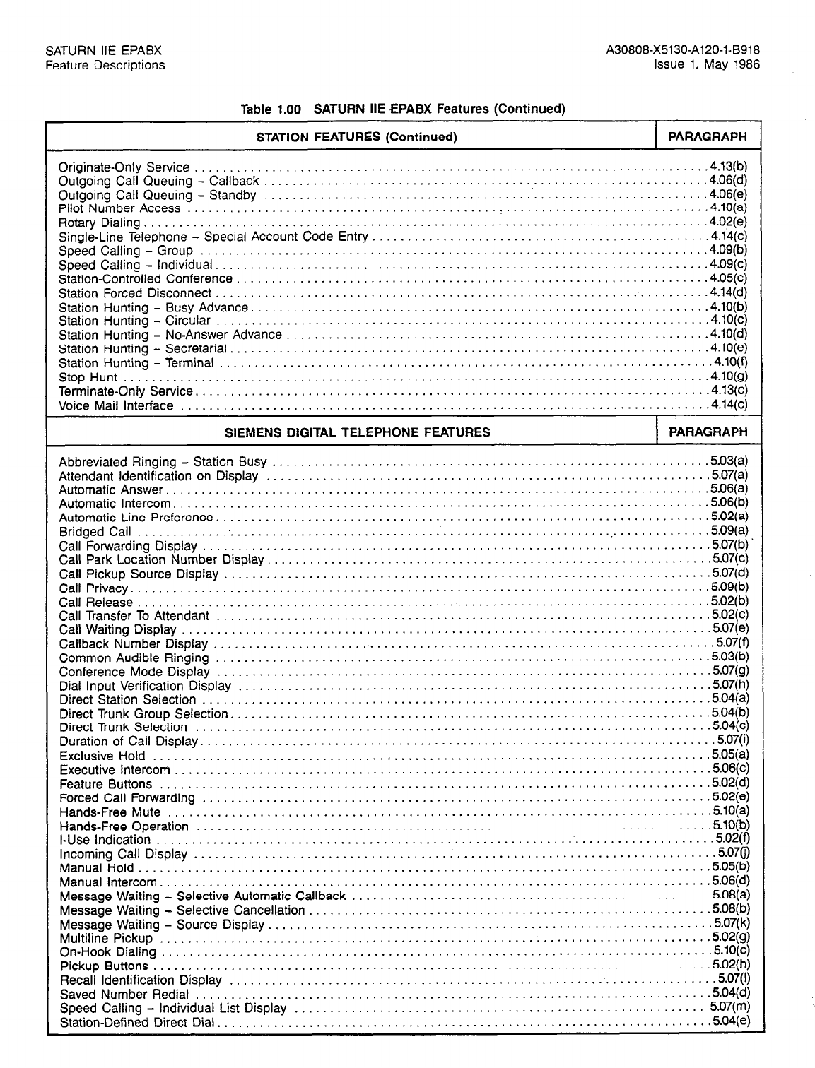
SATURN IIE EPABX A30808-X5130-Al20-l-6918
Feature Descriptions Issue 1, May 1986
Table 1.00 SATURN IIE EPABX Features (Continued)
STATION FEATURES (Continued) PARAGRAPH
Originate-Only Service ........................................................................ .4.13(b)
Outgoing Call Queuing - Callback ............................................................... .4.06(d)
Outgoing Call Queuing - Standby .............................................................. .4.06(e)
Pilot Number Access ............................... ..~..........I.............................4.lO(a)
Rotary Dialing................................................................................4.02(e )
Single-Line Telephone - Special Account Code Entry ............................................... .4.14(c)
Speed Calling-Group ..................................................................... ...4.09(b)
Speed Calling - Individual. .................................................................... .4.09(c)
Station-Controlled Conference .................................................................. .4.05(c)
Station Forced Disconnect.......................................................................4.14(d )
Station Hunting - Busy Advance. ............................................................... .4.10(b)
Station Hunting - Circular ..................................................................... .4.10(c)
Station Hunting - No-Answer Advance ........................................................... .4.10(d)
Station Hunting - Secretarial. .................................................................. .4.10(e)
Station Hunting - Terminal ..................................................................... .4.10(f)
StopHunt...................................................................................4.lO(g )
Terminate-OnlyService.........................................................................4.13(~ )
Voice Mail Interface ........................................................................ ...4.14(c)
SIEMENS DIGITAL TELEPHONE FEATURES PARAGRAPH
Abbreviated Ringing - Station Busy ............................................................. .503(a)
Attendant Identification on Display .............................................................. .507(a)
AutomaticAnswer.............................................................................5.06(a )
Automatic Intercom. .......................................................................... .5.06(b)
Automatic Line Preference. .................................................................... .5.02(a)
Bridged Call..................................................................................5.09(a )
Call Forwarding Display........................................................................~O7(b) .
Call Park Location Number Display. ............................................................. .5.07(c)
Call Pickup Source Display .................................................................... .5.07(d)
Call Privacy..................................................................................5.09(b )
CallRelease.............................................~...................................5.02(b )
Call Transfer To Attendant ..................................................................... .5.02(c)
Call Waiting Display .......................................................................... .5.07(e)
Callback Number Display ...................................................................... .5.07(f)
Common Audible Ringing ..................................................................... .5.03(b)
Conference Mode Display ..................................................................... .5.07(g)
Dial Input Verification Display .................................................................. .5.07(h)
Direct Station Selection ....................................................................... .5.04(a)
Direct Trunk Group Selection. .................................................................. .5.04(b)
DirectTrunkSelection ...................................................................... .,.5.04(c)
Duration of Call Display. ....................................................................... .5.07(i)
Exclusive Hold ................................. . .......................................... ...5.05(a)
Executivelntercom............................................................................5.06(~ )
Feature Buttons ........................................................................... ...5.02(d)
Forced Catl Forwarding ..................................................................... ...5.02(e)
Hands-Free Mute ........................................................................... ..5.lO(a)
Hands-Free Operation ........................................................................ .5.10(b)
I-Use Indication
............................................................................. ..5.02( 9
Incoming Call Display.. ................................ ..~.....................................5.07~)
ManualHold.................................................................................5.05(b )
Manuallntercom..............................................................................5.06(d )
Message Waiting - Selective Automatic Callback .................................................. .5.08(a)
Message Waiting - Selective Cancellation ........................................................ .5.08(b)
Message Waiting - Source Display. ............................................................. .5.07(k)
MultitinePickup ........................................................................... ...5.02(g)
On-HookDialing..............................................................................5.10(~ )
Pickup Buttons...............................................................................5.02(h )
Recall Identification Display ..................................................................... .5.07(l)
Saved Number Redial ...................................................................... .,.5.04(d)
Speed Calling - Individual List Display .......................................................... 5.07(m)
Station-Defined Direct Dial. .................................................................... .504(e)
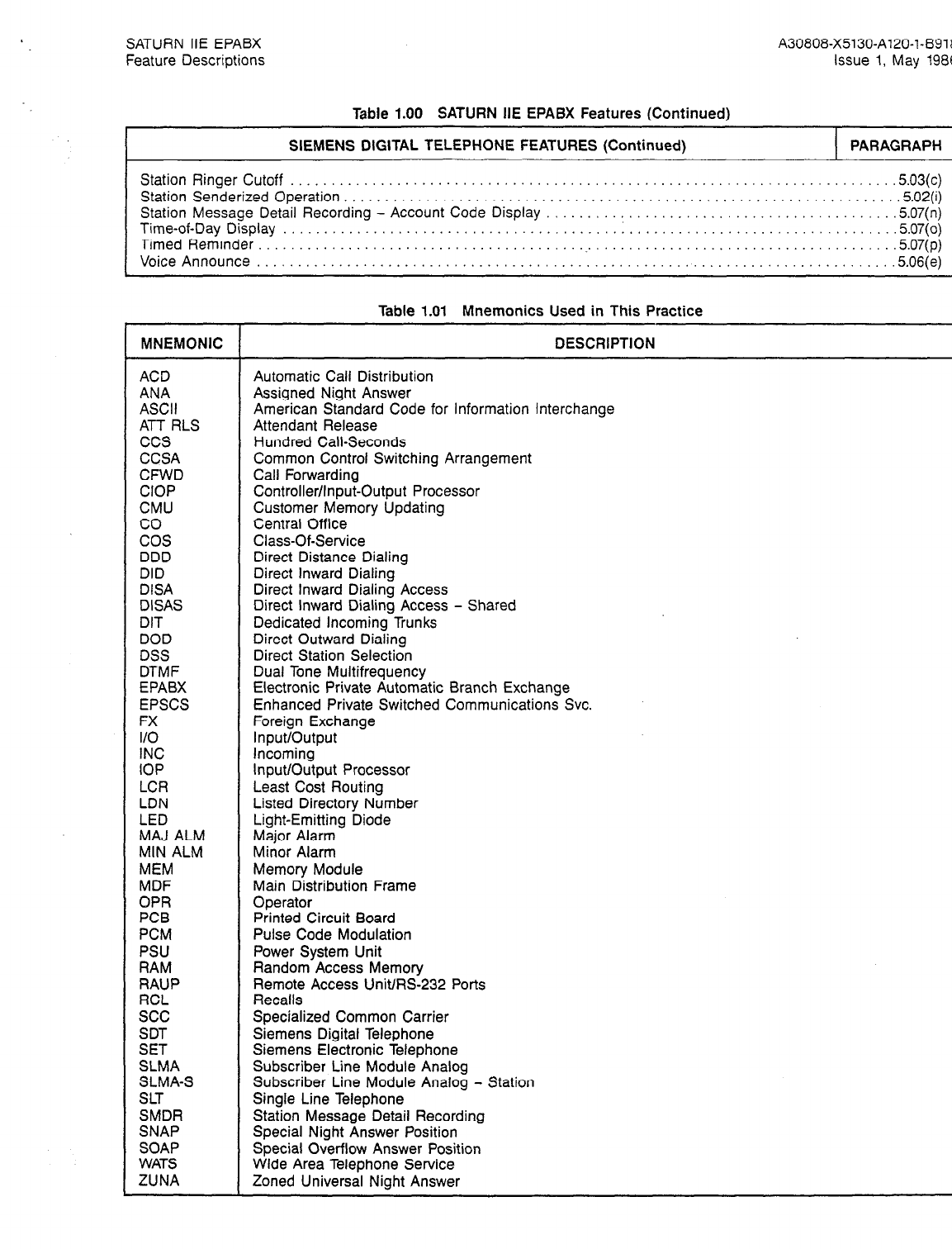
SATURN IIE EPABX A30808-X5130-A120-1-6918
Feature Descriptions Issue 1, May
1986
Table 1.00 SATURN IIE EPABX Features (Continued)
SIEMENS DIGITAL TELEPHONE FEATURES (Continued) PARAGRAPH
Station Ringer Cutoff . . . . . . . . . . . . . . . . . . . . . . . . . . . . . . . . . . . . . . . . . . . . . . . . . . . . . . . . . . . . . . . . . . . . . . . ...5.03(c)
Station Senderized Operation. . .5.02(i)
Station Message Detail Recording - Account Code Display .5.07(n)
Time-of-Day Display . . . .507(o)
Timed Reminder..............................................................................5.07(p)
VoiceAnnounce...........................................................................,..5.06(e)
L
Table 1.01 Mnemonics Used in This Practice
MNEMONIC DESCRIPTION
ACD Automatic Call Distribution
ANA Assigned Night Answer
ASCII American Standard Code for information Interchange
ATT RLS Attendant Release
ccs Hundred Call-Seconds
CCSA Common Control Switching Arrangement
CFWD Call Forwarding
CIOP Controller/Input-Output Processor
CMU Customer Memory Updating
co Central Office
cos Class-Of-Service
DDD Direct Distance Dialing
DID Direct Inward Dialing
DISA Direct Inward Dialing Access
DISAS Direct Inward Dialing Access - Shared
DIT Dedicated Incoming Trunks
DOD Direct Outward Dialing
DSS Direct Station Selection
DTMF Dual Tone Multifrequency
EPABX Electronic Private Automatic Branch Exchange
EPSCS Enhanced Private Switched Communications Svc.
FX Foreign Exchange
I/O Input/Output
INC Incoming
IOP Input/Output Processor
LCR Least Cost Routing
LDN Listed Directory Number
LED Light-Emitting Diode
MAJ ALM Major Alarm
MIN ALM Minor Alarm
MEM Memory Module
MDF Main Distribution Frame
OPR Operator
PCB Printed Circuit Board
PCM Pulse Code Modulation
PSU Power System Unit
RAM Random Access Memory
RAUP Remote Access Unit/RS-232 Ports
RCL Recalls
see Specialized Common Carrier
SDT Siemens Digital Telephone
SET Siemens Electronic Telephone
SLMA Subscriber Line Module Analog
SLMA-S Subscriber Line Module Analog - Station
SLT Single Line Telephone
SMDR Station Message Detail Recording
SNAP Special Night Answer Position
SOAP Special Overflow Answer Position
WATS Wide Area Telephone Service
ZUNA Zoned Universal Night Answer
1-5
(1-6
blank)
SATURN IiE EPABX
Feature Descriptions
SECTION 2.00 SYSTEM FEATURES
2.01 System Overview
The SATURN IIE System is a stored-program controlled Elec-
tronic Private Automatic Branch Exchange (EPABX), which
uses Pulse Code Modulation (PCM)!Time Division switching.
The SATURN IIE EPABX System is capable of switching both
voice and data.
The SATURN IIE System is housed in a light-weight equip-
ment cabinet called the Basic Cabinet. In its expanded con-
figuration, the SATURN IIE System is housed in a Basic
Cabinet plus an Expansion Cabinet. The Equipment Cabi-
net(s) contain all functional units of the system.
Plug-in printed circuit boards (PCBs) are installed in the cabi-
net. These PCBs contain the circuits for common control,
switching, and for the peripherals required in system opera-
tion. The SATURN IIE EPABX provides from 224 to 480 ports
in the basic cabinet. The expanded cabinet (stacked atop the
basic cabinet) provides an additional 256 to 512 ports (992
ports maximum).
A30808-X5130-A120-l-8918
Issue 1. May
1986
An optional Remote Access Unit board provides two
AS-232-C
ports for general use and one modem port for remote
access.
A-single RS-232-C port is provided by the CIOP board in
the
basic system for system interface.
The SATURN IIE EPABX System can be arranged to
accom-
modate conventional telephones (rotary dialing and
dual-tone
multifrequency (DTMF) dialing) as well as Siemens Digital
Tel-
ephones (SDTs). The SATURN IIE EPABX can be
equipped
with a maximum of I2 attendant consoles or it can be
operat-
ed without any consoles. One cable pair is required to
inter-
connect each SDT to the SATURN IIE EPABX
switching
system.
Administrative additions and changes are made by input
of
simplified instructions in plain English format via a local
or
remote service terminal. These modifications can be
made
during system operation without interference to normal
call
processing.
The following paragraphs describe the features that
are
characteristic for the SATURN IIE EPABX System.
SATURN IIE EPABX
Feature Descrtptions A30808-X5130-A120-l-B918
Issue 1, May 1986
2.02
a.
General Features
Additional Input/Output Devices
designed to be non-blocking. This network provides
up to 36 CCS (1 Erlang) per port.
i. Low Power Consumption
The SATURN IIE EPABX is capable of connecting in-
put/output devices via three RS-232-C interface 110
ports and one port connected to a modem to allow re-
mote access. All I/O ports can include, but are not limit-
ed to, local service terminal, Station Message Detail
Recording (SMDR), automatic traffic measurement
reporting, and on-line maintenance and administrative
access. The RAUP contains an internal modem with
a dedicated RS-232-C interface which provides a re-
mote dial-up maintenance port (line or trunk interface).
The SATURN IIE EPABX has been designed to pro-
vide maximum efficient use and distribution of power
via distributed power supplies. Power consumption de-
pends on the system configuration: the total number
and combination of lines, trunks, SDTs, attendant con-
soles, and any auxiliary equipment. A fully-equipped
basic cabinet uses a nominal 800 Watts. A fully-
equipped system with basic and expansion cabinets
uses a nominal 1600 Watts.
b. Brownout Protection j. Memory Support
The SATURN IIE EPABX power supply is designed to
tolerate frequency deviations of as much as 3 Hz above
or below the normal input frequency (60 Hz) and in-
put voltage variations from 95 to 130 Vat.
C.
Convection Cooling
If an ac power failure occurs, the optional memory sup-
port battery supplies the necessary power to maintain
the Random Access Memory (RAM) for a minimum of
3 minutes. When power is restored, the internal bat-
tery backup, after 30 minutes of charging, is capable
of another 3-minute cycle.
The SATURN IIE EPABX, because of its low power con-
sumption and efficient equipment layout, does not re-
quire the use of forced-cooling fans or similar
equipment. The cabinet is designed to make full use
of convection cooling of all the equipment while main-
taining temperature design limits. However, the system
must be located within an ambient environment rang-
ing from 4 degrees C to 38 degrees C (40 degrees F
to 100 degrees F), and a relative humidity range of 20%
t0 aovb.
k. Off-Premises, Stations
The SATURN IIE EPABX extends the station line cir-
cuits to industry-standard telephones located at a site
remote (off-premises) to the system.
I. Station Class-of-Service
d. Digital Pad Switching
The SATURN IIE EPABX inserts the proper gain or loss
into all connection paths to ensure correct transmis-
sion levels.
The SATURN IIE EPABX provides a maximum of 32
station classes-of-service. Each class-of-service can be
arranged in memory to allow or deny access to any
combination of features included in the system. For
each station, class-of-service codes are stored in
memory. These codes can be changed at any time by
using the Customer Memory Updating (CMU)
procedures.
e. DTMF-to-Dial Pulse Conversion
MMF-toDial Pulse Conversion enables MMF stations
to complete outgoing central office (CO) calls over dial
pulse CO trunks. The SATURN IIE EPABX translates
the MMF station-generated signals and converts them
to dial pulse digits for transmission to the CO.
Table 2.00 lists the features which can be assigned to
individual stations through class-of-service codes.
m. System Site Identification (ID)
f. Dual-Tone Multifrequency System Outpulsing
DualTone Multi-frequency (MMF) tones are generat-
ed as a SATURN IIE EPABX function on outward-dialed
calls over MMF Central Office (CO) trunks. DTMF out-
pulsing can be provided, regardless of the station di-
aling type (DTMF, digital, or rotary).
The SATURN IIE EPABX enables the entry of a specific
customer’s site identification into the customer portion
of the system memory: site location, site name, site
number, and/or similar information. These data can
contain up to I6 characters and are printed out, via the
terminal, as a heading at the beginning and end of
each CMU session.
n. Trunk Group Class-of-Service
End-to-End DTMF Signaling
The SATURN IIE EPABX sends DTMF tones through
the public network to the distantbnd. The transmis-
sion of DTMF tones is used for a variety of purposes,
including computer access, control functions, and in-
ward call completion at the distant switching system.
h. High Traffic Capacity
The SATURN IIE EPABX allows the assignment of a
variety of attributes to each trunk group in the system.
Data established on a per-trunk-group basis include:
applicable toll code restriction lists, restricted station
classesof-service, alternate trunk groups for routing
purposes, incoming/outgoing control signaling informa-
tion, incoming/outgoing call-usage types, attendant
console answering priority, Direct Inward Dialing (DID)
prefixing/deletion/conversion information, night answer-
ing assignments, and assigned trunk group alphanu-
meric display characters.
The switching network of the SATURN IIE EPABX is
:\
.:
2
‘..
2-2 (Rev. 5/l/86)
SATURN IIE EPABX
Feature Descriptions A30808-X5130-A120-l-8918
Issue 1, May 1986
0.
2.03
a.
b.
C.
d.
Uniform Station Distribution Wiring
The SATURN IIE EPABX maintains consistent cabling
requirements regarding size, type, and number of ca-
bling pairs connecting all types of station instruments
such as single-line telephones (SLTs) and Siemens Dig-
ital Telephones (SDTs). A maximum of one cable pair
is required between each instrument and the system.
Administration Features
Customer Memory Updating
The CMU feature allows authorized personnel at a
designated service terminal to enter and make changes
to customer memory during normal system operation
with no interference to current call processing.
Customer memory, a portion of the complete system
memory, contains the data relating to system configu-
ration, including programmable features and options
which the customer can select and arrange. Changes
to customer memory are made by using plain English
terms rather than numeric codes, thereby simplifying
data base updates.
Remote Customer Memory Updating
This feature allows authorized personnel at a service
terminal to enter and make changes to customer
memory from a central depot or off-premises location.
Changes can be made during normal system opera-
tion with no interference to current call processing. The
service terminal must be equipped with a type 103/113-
or 212A-compatible modem of the originate-type. The
SATURN IIE EPABX is provided with a compatible mod-
em of the answer-type equipped (internally) in the
RAUP
Access to the SATURN IIE EPABX is gained by dial-
ing a preassigned public or private network number.
Refer to the feature, “Customer Memory Updating.”
Remote Traffic and Feature Usage Measurement
Detailed traffic and feature usage measurement infor-
mation is obtained from a service terminal that is lo-
cated remote to the SATURN IIE EPABX. The service
terminal must be equipped with a type 1031113. or 21%
compatible modem of the originate-type.
The SATURN IIE EPABX is provided with a compati-
ble modem of the answer-type equipped (internally) in
the RAUP Access to the SATURN IIE EPABX is gained
by dialing a preassigned public or private network num-
ber. Refer to the feature, “Traffic and Feature Usage
Measurement.”
Station Message Detail Recording (SMDR)
The Station Message Detail Recording feature provides
a detailed record of all completed incoming and/or out-
going trunk calls by trunk group. lntraswitch station-
to-station, station-to-attendant, and attendantto-station
calls are not-recorded. The following information is
recorded:
-
Access Code
Account Code/Authorization Code
Authorization Code Index
Call Duration
Destination Identity
Dialed Digits or Called Number
LCR Route Selection Number
Record Type
Source Identity
Special Identity
Starting Time of Call.
The monitored data can be recorded on a suitable
printer (via an RS-232-C interface) for hard-copy prin-
tout reports. Suitable accounting devices (e.g., SMDR
unit) can also be connected to this interface.
The SMDR feature allows a service terminal user to
enable or disable the following:
- SMDR call record output for all incoming and/or
outgoing calls over all trunk groups;
- SMDR call record output for all incoming calls over
a particular trunk group;
‘- SMDR call record output for all outgoing calls over
a particular trunk group.
Station Message Detail Recording (SMDR) Account
Codes
Account codes can be used in conjunction with SMDR
on incoming and outgoing trunk calls for such pur-
poses as cost accounting or client billing. The account
codes can be up to 11 numeric digits in length.
Two types of account codes are used: (i) standard (or
default) account codes and (ii) special account codes.
Default account codes are assigned to stations and are
automatically activated when a station user originates
or receives a call over a trunk. Special account codes
must be entered from the user’s telephone after the
user has dialed a trunk group access code (e.g., “9”
for a CO trunk) or after an LCR access code and
desired destinations number. A station user may also
override a default account code or previously entered
special account code with another special account
code at any time during an established trunk call.
Recall dial tone is heard when a special account code
is required. If a special account code is not entered
when requested by the system, the user is restricted
from making the call. Only the number of account-code
digits is checked by the SATURN IIE EPABX System.
Attendant consoles and SDTs can be assigned an ac-
count button, thus obviating the need for the user to
display and change account codes on a per-call basis.
Traffic and Feature Usage Measurement
This feature provides the SATURN IIE EPABX with the
capability of automatically or manually monitoring and
recording various system operations for which traffic
and feature usage information is desirable.
2-3
SATURN IIE EPABX
Feature Descriptions A30808-X5130-A120-l-8918
Issue 1, May 1986
Two different types of measurements are provided. The
first type is event (peg) counts, which give an actual
count of the number of times a particular operation has
occurred in the system. The second type is usage
counts, which give the approximate total time a par-
ticular resource is in use during a certain time inter-
val. This count is given in CCS (hundred call-seconds).
The traffic and feature usage measurement data are
stored in system memory. These data can be transmit-
ted as output to a service terminal at designated inter-
vals (15 minutes to 24 hours, in increments of 1 minute),
or on request. Normally, reporting periods are speci-
fied in multiples of 15 minutes.
For a list of the types of event counts and usage counts
that are monitored and recorded in the SATURN IIE
EPABX, refer to Table 2.01, “Traffic and Feature Usage
Measurement.”
g. Variable Timing Parameters
This feature provides for authorized personnel to
change the timing parameters of system operating
functions. The timing parameters are changed by us-
ing CMU procedures.
2.04 Flexible Numbering Features
a. DID Flexible Station Numbering
Direct Inward Dialing (DID) calls from the CO are rout-
ed through the SATURN IIE EPABX to the appropriate
station. The CO, forwards the last 2, 3, 4, or 5 digits
of the directory number as an EPABX station address.
The SATURN IIE EPABX can either absorb or prefix
the leading digit(s) which are forwarded to it.
For example, if the CO forwards 48801 and the station
number plan uses numbers 0 through 999, the Saturn
IIE EPABX System can delete the 48 so that station
801 is rung. On the other hand, if the CO forwards only
01 and the stations are numbered from 800 through
899, then the number “8” is prefixed by the SATURN
IIE EPABX, and station 801 is rung.
The SATURN IIE EPABX System can also translate
numbers into another range. For example, if the CO
forwards the numbers 300 through 399 but the inter-
nal station numbering plan starts with 500 (500 through
599), the “3” (the hundreds digit) can be translated
to a “5” by the system. This number translation is also
provided for the tens digit (in a 2-digit numbering plan)
and the thousands digit (in a 4digit numbering plan).
With this DID flexible numbering concept, the exter-
nal CO numbering plan can be made to agree with the
internal station addresses.
Table 2.00 Station Class-of-Service Features
FEATURES
ACD Group Access
Apparatus Test Access
Attendant Call Hold Retrieve
Attendant Override Security
Automatic Answer - Automatic and Executive
Intercom
Automatic Answer - Prime Line
Call Forwarding - All Calls/Busy Lines/No Answer
Call Forwarding - Fixed
Call Forwarding - Secretarial
Call Forwarding to Public Network
Call Hold
Call Hold - Flip-Flop (Broker)
Call Park
Call Pickup - Directed
Call Pickup - Group
Call Tracing
Code Call Access
Data Line Security
Diagnostic Test Access
Dictation Access
Do-Not-Disturb
Eight-Digit Toll Code Restriction Lists
Executive Override
Executive Override - Automatic
Executive Override No Tone Security
Executive Overiide Security
Executive Override Without Warning Tone
Fifteen-Digit Toll Code Restriction Lists
Forced Release
Ignore Flash
Internal Call Queuing - Callback/Standby
Internal Call Queuing - Standby (Originating)
Internal Call Queuing - Standby (Terminating)
Last Number Dialed
Least Cost Routing Access
LCR Alternate Trunk Group Advance
(Immediate, Timed, or No Advance)
LCR User Priority Level
Meet-Me Conference
Message Waiting Activation
Message Waiting - Automatic Callback; and
Message Waiting - Cancellation
Outgoing Call Queuing - Callback
Outgoing Call Queuing - Standby
Ringback
Saved-Number Redial
Speed Calling - Group (1 - 4 Groups)
Speed Calling - Individual
Station Class-of-Service Exclusion
Station-Controlled Conference
Station-Controlled Trunk-to-Trunk Connection
Station Hunting - Busy Advance
Station Hunting - No Answer Advance
Stop Hunt
Terminating Trunk Group Call Exclusion
Trunk Group Access
Trunk-to-Trunk Connection
Voice Page Access (Specific Zone or Combination of
Zones)
Zoned Universal Night Answer
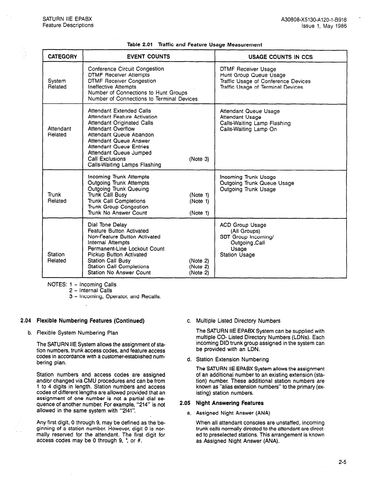
SATURN IIE EPABX
Feature Descriptions A30808-X5130-AlZO-l-B918 -
Issue 1, May 1986
Table 2.01 Traffic and Feature Usage Measurement
CATEGORY EVENT COUNTS USAGE COUNTS IN CCS
Conference Circuit Congestion DTMF Receiver Usage
DTMF Receiver Attempts Hunt Group Queue Usage
System DTMF Receiver Congestion Traffic Usage of Conference Devices
Related Ineffective Attempts Traffic Usage of Terminal Devices
Number of Connections to Hunt Groups
Number of Connections to Terminal Devices
Attendant
Related
Attendant Extended Calls
Attendant Feature Activation
Attendant Originated Calls
Attendant Overflow
Attendant Queue Abandon
Attendant Queue Answer
Attendant Queue Entries
Attendant Queue Jumped
Call Exclusions
Calls-Waiting Lamps Flashing
Attendant Queue Usage
Attendant Usage
Calls-Waiting Lamp Flashing
Calls-Waiting Lamp On
(Note 3)
Trunk
Related
Station
Related
Incoming Trunk Attempts
Outgoing Trunk Attempts
Outgoing Trunk Queuing
Trunk Call Busy
Trunk Call Completions
Trunk Group Congestion
Trunk No Answer Count
Dial Tone Delay
Feature Button Activated
Non-Feature Button Activated
internal Attempts
Permanent-Line Lockout Count
Pickup Button Activated
Station Call Busy
Station Call Completions
Station No Answer Count
(Note 1)
(Note 1)
(Note 1)
(Note 2)
(Note 2)
(Note 2)
Incoming Trunk Usage
Outgoing Trunk Queue Usage
Outgoing Trunk Usage
ACD Group Usage
(All Groups)
SDT Group incoming/
Outgoing Call
Usage
Station Usage
NOTES: 1 - Incoming Calls
2 - Internal Calls
3 - Incoming, Operator, and Recalls.
2.04 Flexible Numbering Features (Continued)
b. Flexible System Numbering Plan
The SATURN IIE System allows the assignment of sta-
tion numbers, trunk access codes, and feature access
codes in accordance with a customer-established num-
bering plan.
Station numbers and access codes are assigned
and/or changed via CMU procedures and can be from
1 to 4 digits in length. Station numbers and access
codes of ‘different lengths are allowed provided that an
assignment of one number is not a partial dial se-
quence of another number. For example, “214” is not
allowed in the same system with “2141”.
Any first digit, 0 through 9, may be defined as the be-
ginning of a station number. However, digit 0 is nor-
mally reserved for the attendant. The first digit for
access codes may be 0 through 9,
l
, or #.
c. Multiple Listed Directory Numbers
The SATURN IIE EPABX System can be supplied with
multiple CO- Listed Directory Numbers (LDNs). Each
incoming DID trunk group assigned in the system can
be provided with an LDN.
d. Station Extension Numbering
The SATURN IIE EPABX System allows the assignment
of an additional number to an existing extension (sta-
tion) number. These additional station numbers are
known as “alias extension numbers” to the primary (ex-
isting) station numbers.
2.05 Night Answering Features
a. Assigned Night Answer (ANA)
When all attendant consoles are unstaffed, incoming
trunk calls normally directed to the attendant are direct-
ed to preselected stations. This arrangement is known
as Assigned Night Answer (ANA).
2-5
SATURN IIE EPABX
Feature Descriptions A30808-X5130-A120-l-8918
Issue 1, May 1986
The night answering station(s) can be an individual sta-
tion or the pilot number of a hunt group. The assign-
ment of trunks or LDNs to ANA stations (for SATURN
IIE Systems served by DID trunks) is performed via a
CMU procedure.
The night answering stations can make inside and out-
side calls and can access system features in the nor-
mal manner. When in night service, handling of the
incoming trunk calls is accomplished by use of the sta-
tion Call Transfer feature.
b. Night Service Automatic Switching
If an incoming CO call to the attendant console is not
answered within a predetermined period of time (vari-
able via a CMU procedure), this feature automatically
switches the SATURN IIE System into the night serv-
ice mode.
c. Special Night Answer Position (SNAP)
The Special Night Answer Position is either a single
EPABX station, the pilot number of a hunt group or an
Automatic Call Distribution (ACD) group designated to
handle incoming night calls which have not been as-
signed to any other night answering mode.
The SNAP station can access station-related features
in the normal manner. Handling of incoming trunk calls
is accomplished by use of the Station Call Transfer fea-
ture. SNAP stations are also alerted for night answer
Transfer With No Answer or Zoned Universal Night An-
swer (ZUNA) No Answer conditions.
d. Zoned Universal Night Answer (ZUNA)
Arrangements can be made for incoming trunk calls,
normally directed to the attendant, to activate a sig-
naling device (bells, gongs, etc.) on the customer’s
premises when the attendant consoles are unstaffed.
This feature is known as Zoned Universal Night An-
swer (ZUNA).
A maximum of 4 zones, each having an associated sig-
naling device, can be provided in the SATURN IIE Sys-
tem. Incoming calls to a particular zone can be
answered by code. Incoming calls are handled by us-
ing the station Call Transfer feature. Sounding of a par-
ticular signalling device within a zone is accomplished
on a per-trunk basis. DID trunks are handled on a trunk-
group basis only.
2.06 System Dialing Features
a. Direct Inward Dialing (DID)
This feature allows an incoming call from the CO to
reach a SATURN IIE EPABX station without using at-
tendant assistance. Stations having this feature are as-
signed Fdigit telephone numbers within the numbering
range of the DID serving CO.
b. Direct Inward System Access (DISA)
The DISA feature allows an outside party to gain ac-
cess to its facilities by dialing directly into the SATURN
IIE EPABX, without attendant assistance. To use this
feature, the party dials a non-published directory num-
ber to connect to the SATURN IIE EPABX via a dedi-
cated CO trunk. The user waits for dial tone and then
dials a 2- to 6-digit authorization code. After the code
has been validated by the system, the party then
receives dial tone again and can place a call or use
a feature as if the party were at a SATURN IIE EPABX
station having the class-of-sewice associated with that
authorization code.
DISA trunks can be accessed during daytime and
nighttime service. DISA trunks may not be used for out-
going service as part of another trunk group. The sta-
tion class-ofservice can be arranged in SATURN IIE
memory to include any combination of call privileges.
Two thousand authorization codes (DISA or Mobile) are
provided in the system.
Each authorization code may be marked as being print-
able or not printable for SMDR output. If both an account
code and a printable authorization code are used on a
particular call, then the associated SMDR call record will
only contain the authorization code. If a non-printable
authorization code is used, then the authorization code
index and the account code (if any) are printed.
c. Direct Inward System Access - Shared (DISAS)
The DISA - Shared feature is similar in all respects
to DISA, except that the trunk group, which is serving
this feature, is shared between DISA and normal oper-
ation. When the trunk group is marked as DISAS in
the SATURN IIE software, calls to the special DISA
directory number are handled as incoming calls as long
as atJeast one attendant console is in operation. These
calls are routed to an attendant.
If the system is in the night mode of operation (e.g.,
no consoles are active), the call is routed via the DI-
SAS trunk group, as described in the feature, “Direct
Inward System Access.”
d. Direct Outward Dialing (DOD)
The Direct Outward Dialing feature allows authorized
station users to complete outward calls without atten-
dant assistance.
e. Station-to-Station Calling
This feature permits any station user to dial other sta-
tions within the SATURN IIE EPABX directly without
attendant assistance. Note that station calling restric-
tions may prevent stations of one class-of-service from
calling stations of another class-of-service.
2.07 System Alarm Features
a. Alarm Indication - Major
A Major Alarm indicator is provided in the Control Logic
Board within the PSU panel. The alarm indicator lights
steadily when the system is in a non-operative state
and system-failure transfer is active.
b. Alarm Indication - Minor
A Minor Alarm indicator is provided on the main-
tenance panel and lights steadily when the system is
2-6
SATURN IIE EPABX
Feature Descriptions A30808-X5130-A120-l-8918
Issue 1, May
1986
operative and has detected a minor alarm condition.
A minor alarm can be the result of a system-detected
error, either internal or external, a system event of note,
such as an annoyance call trace record, or a failure
during an on-line diagnostic test. The indicator remains
lit until the alarm is displayed by the system adminis-
trator via the appropriate CMU procedure. The system
administrator can control, via CMU procedure, the set
of detectable errors or events that will be reported as
minor alarms.
A Minor Alarm LED (MIN ALM) is also provided on the
attendant console and lights steadily for a selected sub-
set (also controllable by the system administrator) of
system minor alarms. The indicator remains lit until the
alarm is displayed by the system administrator via the
CMU procedures, or until the alarm is displayed by the
attendant on the attendant console.
c. Remote Alarm Identification
Dry contact closures are used as the interface for iden-
tifying both Major and Minor Alarm conditions exist-
ing in the SATURN IIE EPABX. The contacts are
located in the Power System Unit (PSU) and can be
wired to the Main Distributing Frame (MDF). The con-
tact closures can be distributed further, via cable pairs,
to a remote location and can be used to activate audi-
ble or visual alarms, as needed.
d. Power Failure Restart - Floppy Disk
This feature is used to reload the system memory from
the floppy disks when volatile memory can no longer
be maintained during a commercial power failure.
When commercial power has been restored, the flop-
py disk drives are automatically activated to reload the
various elements of system memory. After reloading
is completed, the system is capable of full operation.
2.08 Line Lockout Features
a. Line Lockout - Attendant Intercept
Any station user who remains off-hook without dialing
or remains connected to a busy station for more than
a predetermined time interval, may be automatically
routed to the attendant queue. This feature is provid-
ed as an alternative to the normal Line Lockout - Au-
tomatic treatment.
b. Line Lockout - Automatic
This feature helps to to prevent a tie-up of the SATURN’
IIE System’s common equipment, such as DTMF
receivers. Whenever a telephone handset is left off-
hook, listening to dial tone (without dialing), busy tone,
reorder tone, intercept tone, etc., for longer than a
predetermined period of time, the system automatically
releases the station from the SATURN IIE EPABX
switching equipment.
When line lockout occurs, the station is disconnected
from the system and prevented from making or receiv-
ing calls. Placing the telephone handset on-hook or
momentarily pressing the hookswitch returns the sta-
tion
to
an
operable
condition.
2.09 Intercept Features
a. Automatic Call Distribution Recorded-Announcement
Service
The SATURN IIE EPABX is provided with the
capabili-
ty of connecting an incoming trunk call to a
recorded
announcement device when all stations in an
ACD
group are busy.
If that particular feature option is provided, an
an-
nouncement advises the caller of a possible delay
(e.g.,
a “Please hold” message). After the call has been
con-
nected to the announcement, the SATURN IIE
EPABX
automatically routes the call to an idle ACD
station
when one becomes available.
Only one recorded-announcement for intercepts is
per-
mitted per system.
b. Flexible Intercept Facilities
Calls that cannot be completed because of
class-of-
service restrictions, unassigned station numbers, or
ac-
cess codes are routed to an intercept facility. The
in-
tercept assignment is made via a CMU procedure.
For DID and tie trunk calls, the intercept is either
to
the attendant, a recorded announcement, or to a
re-
order tone if no recorded announcement is
available.
For station and attendant calls, the intercept is
always
to intercept tone. The only exception occurs when
a
station call is intercepted as the result of an
attendant-
imposed dial restriction. In that case the call is
routed
to the attendant. Only one recorded announcement
per
intercept is permitted per system.
2.10 Access to Customer-Provided Equipment Features
a. Code Call Access
Station users can dial an access code and a l- to
4-digit
called-party code to activate customer-provided
code
call equipment, which controls signaling
devices
throughout the premises. The signaling devices
can
be audible and/or visual. The called party can then
an-
swer the code call and connect to the calling party
by
dialing a code call answerback code from any
station
served by the SATURN IIE EPABX.
b. Dictation Access
This feature allows station users access to customer-
provided dictation equipment in order to record
voice
messages or play back previously-recorded messages.
The dictation equipment is seized by dialing the
as-
signed dictation access code.
Dictation equipment functions such as start, stop,
and
playback are controlled by dialing the digits assigned
for the various functions. A maximum of four dictation
channels can be provided in the SATURN IIE EPABX.
c. Music On Hold - Line or Trunk Interface
The SATURN IIE EPABX is able to interface with
customer-provided
audio
equipment
in
order
to
provide
SATURN IIE EPABX
Feature Descriptions A30808-X5130-A120-l-6918
issue 1, May 1986
d. Music-On-Hold - Paging
This SATURN IIE EPABX System feature allows the
customerprovided Music-On-Hold source to be rout-
ed to the paging equipment. This arrangement pro-
vides music, instead of silence, to the paging zone
whenever the paging equipment is idle.
e. Music-On-Hold - System
The SATURN IIE EPABX is able to interface with
customer-provided audio equipment in order to provide
music to “held call” conditions. The held call can be
the result of Attendant Call Hold, Station Call Hold, Call
Park, Manual Hold, and Exclusive Hold Conditions.
2.11
a.
Restriction Features
Eight-Digit Toll Code Restriction For Direct Trunk Group
Access
This feature permits SATURN IIE EPABX to allow or
deny stations access to specific CO exchanges, area
codes, service codes, operator, and other services en-
countered on the Direct Distance Dialing (DDD) net-
work. The SATURN IIE EPABX can provide 16 separate
and different a-digit toll code restriction lists. One or
more lists may be assigned to each trunk group.
A total of 256 entries may be assigned to the 16 lists.
Each entry within a restriction list can be from 1 to 8
digits in length. Each list can be either the “allow” or
the “deny” type, and is assigned to stations on a class
of-service basis.
b. Fifteen-Digit Toll Code Restriction For Direct Trunk
Group Access
This feature permits SATURN IIE EPABX to allow or
deny stations access to specific CO exchanges, area
codes, service codes, operator, and other services en-
countered on the Direct Distance Dialing (DDD) net-
work. The SATURN IIE EPABX can provide 4 separate
and different 15-digit toll code restriction lists. One or
more lists may be assigned to each trunk group.
A total of 32 entries may be assigned to the 4 lists. Each
entry within a restriction list can be from 1 to 15 digits
in length. Each list can be either the “allow” or the
“deny” type, and is assigned to stations on a class-of-
service basis.
c. Daytime Trunk Control
The SATURN IIE EPABX System can be arranged to
restrict specific trunk groups from access by stations
for outgoing calls during daytime operation, and to re-
store access availability when the system is in night
service mode. While daytime trunk control is in effect,
music to “held-call” conditions. The held call can be
the result of Attendant Call Hold, Station Cali Hold, Call
Park, Manual Hold, or Exclusive Hold conditions.
The Music-On-Hold interface may be assigned as an
E&M trunk circuit or as a line circuit (and includes
SLMA-S and SLA-16). d.
e.
2.12
a.
b.
c.
only the attendant has access to these trunk groups.
Station users who attempt calls over trunks under day-
time trunk control are routed to the attendant recall
queue. Once answered, the call can be completed at
the attendant’s discretion.
Incoming Class-of Service Blocking
This feature prevents an attendant from extending a
call if the station’s class-of-service is blocked for the
classof-service assigned to the trunk.
Station-to-Station Class-of-Service Blocking
This feature prevents stations assigned to a certain
class-of-service from accessing stations assigned to
another class-of-service. An intercept tone is provid-
ed to station users dialing stations that are blocked by
their class-of-service.
Diagnostic and Maintenance Testing Features
Automatic On-Line Diagnostic Testing and Reporting
The SATURN IIE EPABX is provided with software self-
test routines which verify that certain software and
hardware operations, initiated by the main controller,
have been successfully completed. If an error occurs,
software records the error(s) in the “Failure History
Memory,” and the minor alarm is activated. Appropri-
ate recovery procedures are executed automatically,
if necessary.
The SATURN IIE EPABX is also provided with a reper-
toire of audits that test the SATURN IIE EPABX com-
mon control equipment. Each audit performs a specific
test and can be individually enabled or disabled by
maintenance personnel via the service terminal.
When the audit is run, detected failures are recorded
in the “Failure History Memory,” and the minor alarm
is activated. Appropriate recovery programs are execut-
ed automatically on the failing equipment. All audits
do not interfere with normal call-processing activities.
Manual On-Line Maintenance Testing
The SATURN IIE EPABX software package includes
test programs that permit test calls to be initiated into
and through the system to verify correct operation of
the peripheral equipment and selected common equip-
ment, such as the tone generator.
Resulting visual and audible responses from these
tests make it possible to verify correct operation or to
detect and isolate a major portion of system malfunc-
tions. These test programs are accessed from a main-
tenance classmarked telephone.
Remote On-Line Maintenance and Diagnostic Testing
Maintenance testing can be performed at a location
remote from the SATURN IIE EPABX. Access to the
Maintenance tests is available on a dial-up basis via
local or long-distance trunks by using the DISA facility.
Diagnostic testing can also be performed from a re-
mote service terminal via dial-up access to the mod-
em port on the optional RAUP board.
,
SATURN IIE EPABX
Feature Descriptions
2.13 Trunking Features
a. Alternate Routing
The SATURN HE EPABX provides automatic routing
of outgoing calls via alternate trunk groups when all
circuits in the primary trunk group are busy. A maxi-
mum of three alternate trunk groups can be assigned
when direct trunk group access is used. Least Cost
Routing (LCR) allows up to seven alternates.
b. Central Office (City) Trunk Access
Access to CO trunks by SATURN IIE EPABX station
users is made by dialing an access code. Digit “9” is
most-commonly used for such access.
c. Common Control Switching Arrangement (CCSA)
Access
This feature allows station users access to a CCSA net-
work by dialing an access code. A network call is
placed by dialing the CCSA number of the desired
party. Features available to service incoming and out-
going calls to and from the CCSA network are similar
to those available to incoming and outgoing CO calls.
d. Dedicated Incoming Trunks
The use of Dedicated Incoming Trunks (DITs) permits
a call to bypass the attendant console and ring at a
preassigned internal station or hunt group. An unan-
swered call can be sent to a night answering arrange-
ment (e.g., ANA, UNA, etc.). via the DIT when the
following circumstances exist:
a) the system is not equipped with a console
b) the console is in night service or
c) the console is out-of-service.
All call-forwarding functions apply to DITs, including the
transferring of DIT trunk calls to the attendant when
the console is in service. A maximum of 255 DlTs are
provided in the SATURN IIE EPABX.
e. Enhanced Private Switched Communication Service
Access
SATURN IIE EPABX station users access an Enhanced
Private Switched Communications Service (EPSCS)
network by dialing a preassigned access code. By us-
ing the EPSCS facility, they may either dial the EPSCS
network number of the desired party or an off-network
number.
Features available to service incoming calls from the
network and outgoing calls to the network are similar
to the features available to incoming and outgoing CO
calls.
f. Foreign Exchange Trunk Access
An FX trunk is a trunk facility between the EPABX and
a CO located beyond the local service area of the sets-
ing CO. Such facilities permit the SATURN IIE EPABX
System to provide local service to and from the dis-
tant service area. Station users gain access to FX
trunks by dialing an access code.
Issue 1, May
1986
g. Least Cost Routing (LCR)
The SATURN IIE EPABX routes outgoing calls over
the
lowest cost route available at the time of call
placement.
A station user accesses the LCR feature on a
per-call
basis by dialing the LCR feature access code
before
dialing the outside number. The routing of the call
is
selected from a predefined list of eligible trunk
groups
based on the digits dialed by the user, the user’s
class-
of-service, and the time of day.
Trunk groups are ranked from first to last choice
(i.e.,
lowest to highest cost), thus providing the lowest
cost
routing for the existing busy/idle condition of the
eligi-
ble trunks.
The LCR feature provides Outgoing (trunk) Call
Queu-
ing Callback and Call Queuing - Standby
capabilities.
To activate the Outgoing Call Queuing - Callback
fea-
ture, the station user dials the LCR access code and
the
desired destination number. Assuming all routes are
busy,
the station user waits for a steady low tone. Upon
receiv-
ing the steady low tone, the station user places the
hand-
set on-hook in order to be placed on queue.
Once on-queue, the station is called back when a
trunk
becomes available. The queue is handled on a
first-
in, first-out basis. One queue per station is allowed
at
any time. If another attempt is made to invoke a
call-
back queue on the same station, the previously
queued
call is removed from the queue and replaced with
the
latest request.
When the Outgoing Call Queuing - Callback
feature
is .active, the activating station user may receive
or
originate other calls. The Outgoing Call Queuing
Call-
back feature can be cancelled at any time via a
dialed
cancellation code.
The LCR Outgoing Call Queuing - Standby feature
is
an extension of the LCR Callback feature
described
above. To invoke this feature, the station user waits
off-
hook in a standby queuing mode and listens to
silence
or music (if it is provided). The standby queuing
mode
eliminates the user going on-hook to be called
back
when a trunk becomes available. When a trunk
does
become available, the station is connected to the
trunk.
The station user may convert from standby
queuing
to callback queuing by going on-hook.
The LCR feature is capable of routing calls over
trunks
in the public network (i.e., CO, FX, WATS trunks),
pri-
vate network including Common Control Switching
Ar-
rangement and tie trunks, as well as over
Specialized
Common Carriers (SCCs).
The LCR feature provides the following additional
route
selection criteria:
1. LCR User Priority. Each station class-of-service
user is assigned priority codes that indicate
eligi-
ble routes. access is permitted only to those
routes
assigned a priority code which matches one of
the
priority codes associated with the user’s COS.
2. Time-of-Day and Day-of-Week. Time bands
(e.g.,
1 PM through 6 PM, 6 PM through 12
midnight,
SATURN IIE EPABX
Feature Descriptions
called schedules, are assignable on one-hour
boundaries for each hour of the day and each day
of the week.
A “minutes offset” is provided for each schedule to
accommodate rate changes that do not occur on the
hour. The selection of a route for a given dialing pat-
tern is variable, depending on the current schedule.
3. Alternate Trunk Group Advance. When an all-
trunks-busy condition exists, three modes of ad-
vancing from first-choice to lesser-choice trunk
groups are provided:
a) Immediate Advance
b) Timer-Controlled Advance
c) No Advance (i.e., the call is routed over the first-
choice trunk group only).
The option of which method to use is stored as a
classmark in the station’s class-of-service. Atten-
dants are always provided with the Immediate Ad-
vance mode.
4. Wide-band tone detectors used in conjunction with
flexible outpulsing rules with the SATURN IIE Sys-
tem are used to detect special dial tone provided
by several Specialized Common Carriers.
5. The SATURN IIE EPABX may be programmed to
switch from DTMF, detect dial tone, to dial pulse
in order to route calls via LCR through a switched
tandem network. The system is capable of “tog-
gling” from one mode to another, as required for
such operation.
6. In order to speed up cut-through on trunk group
calls, the LCR feature can be used to analyze the
trunk group call digit strings.
7. The SATURN IIE EPABX provides the option of not
providing dial tone after dialing the LCR access
code on LCR calls.
8. The SATURN IIE EPABX also provides the option
to prohibit confirmation tone from being returned
after LCR route-selection is completed.
9. The LCR feature provides a filtered dial tone de-
tection option to aliow rejection of busy, reorder, and
ringback tones.
10
11.
Equal Access to Prime Carrier. The LCR feature
is also used to route long-distance calls over all
customer selected carriers without dialing a spe-
cial access code.
For example: The SATURN IIE System user dials
9 + 1 + NAX + NNX + XXXX. If the route list’s
outdial rule for the prime carrier is satisfied, the
system outdials 1 + NAX + NNX + XXXX; if the
route list’s outdial rule for a secondary carrier is
satisfied, the system outdials 10XxX + NAX +
NNX + XXXX.
The LCR feature also provides a means for
rechecking a lower-cost route even though the call
h.
i.
j.
k.
I.
A30808-X5130-A120-l-8918
Issue 1, May 1986
--
has advanced to, and is in queue for, a more-costly
route. This “look back” queuing capability allows
a call to be routed over a previously busy but lower-
cost route, if a trunk within that trunk group be-
comes available before the more-costly route is
used.
._
;.,
/
Least Cost Routing with Provisions for Specialized
Common Carrier
The LCR feature is capable of routing calls via an SCC
through dial or dedicated access. The SCC’s directo-
ry number and authorization code may be stored in
SATURN IIE memory for outdialing. Because an SCC
can be accessed over local CO trunks (i.e., dial-up ac-
cess), the SATURN IIE EPABX provides the capability
to turn such access on or off, from an attendant con-
sole and/or from a service terminal. Up to three SCCs
can be accommodated in the SATURN IIE EPABX.
Tandem Trunking
The SATURN IIE EPABX can act as a tandem switch,
routing incoming calls from one switching system to
another, without the need for attendant assistance. The
major use of this feature is in association with dial tan-
dem tie trunk networks to allow tie trunk connections,
and in some cases, to allow incoming tie trunk calls
automatic access to the CO trunk for completion of lo-
cal CO calls.
Tie Trunk Access
This feature allows station users dial access to one-
way or two-way tie trunk circuits interconnecting the
SATURN IIE EPABX with another switching system.
The trunks can be furnished with E&M signaling, and
configured for automatic or dial repeating operation
with or without second dial tone. Two-wire or four-wire
type E&M trunks are available.
Trunk-to-Trunk Connections
This feature allows the attendant to extend an incom-
ing trunk call to an outgoing trunk. Connections can
be made among CO, Foreign Exchange (FX), Wide
Area Telephone Service (WATS), Direct Inward Dialing
(DID), and tie trunks.
All combinations of these trunks can be connected by
the attendant. The only restriction is that the incom-
ing call must have been completed through a trunk that
provides disconnect supervision (generally ground start
trunks or E&M trunks). If disconnect supervision is not
provided and the attendant attempts to make the con-
nection, a three-minute (variable) timer is started. When
the timer times out, the trunk-to-trunk connection is
recalled to the attendant.
Wide Area Telephone Service Trunk Access
This feature allows station users access to WATS by
dialing an access code. WATS enables customers to
make calls over extensive geographic areas at special
billing rates.
‘1
\
:-:
2-10 (10 pages)

SATURN IIE EPABX
Feature Descriptions A30808-X5130-A120-l-8918 -
Issue 1, May 1986
SECTION 3.00 ATTENDANT FEATURES
3.01 Attendant Console Overview
The attendant console is a desk-top-position console from
which the attendant handles calls by using pushbutton keys.
A maximum of 12 attendant consoles can be provided in the
SATURN IIE EPABX.
A telephone handset is furnished with the console. An op-
tional headset may be substituted for the handset. Both tone
and visual indicators alert the attendant to incoming calls. The
tone may be controlled via a volume control located at the
front edge of the console.
The attendant console is provided with a 12-button keypad
(digits 0 - 9, * , #) which allows the attendant to complete
all types of calls. The dialed digits are digitally encoded, and
transmitted to the SATURN IIE EPABX System for processing.
Each attendant console has a 40-character upper- and lower-
case alphanumerlc display, which presents call information
to the attendant. This information includes the station num-
ber or trunk type, the number of the called and calling par-
ties, and the calling station class-of-service. The alphanumeric
display also allows the attendant to monitor the system alarm
conditions.
Connections to the console are made through a three-pair
modular connector-ended cable which provides voice, con-
trol signals, and power. The cable is installed through the bot-
tom rear of the console via a plug-in jack. Two of the pairs
are used for data transmit and receive, plus SATURN-provided
power. The third pair to the modular jack is a spare pair.
The attendant console(s) can be located up to 2000 cable feet
(610 meters) from the SATURN IIE EPABX.
The following paragraphs describe the features that are relat-
ed to the attendant console only. Refer to SECTION 4.00: STA-
TION FEATURES, for additional console-related features.
3.02 General Features
a. Console Operation
Incoming calls are uniformly distributed among the at-
tendant consoles. Any station user can dial-access a
selected attendant when multiple consoles are
provided.
The SATURN EPABX can also function without an at-
tendant console. For consoleless operation, assigned
UNA and/or ANA stations can handle incoming calls
by utilization of the Call Transfer and Internal Call Queu-
ing - Standby features.
b. Flexible Key Assignments
The attendant console is equipped with one digital
12button keypad and 34 non-locking keys, each con-
taining one internal status indicator Light-Emitting Di-
ode (LED). Sixteen keys have fixed assignments, and
provide the basic control functions for the console. The
remaining 18 keys are flexibly assignable by using
CMU procedures. These keys can be programmed to
provide the following functions:
C.
3.03
a.
b.
1. Attendant Conference (up to three keys can be as-
signed.)
2. Attendant Control of Facilities (one or more keys
can be assigned)
3. Attendant Override
4. Attendant Overflow
5. Call Park
6. Direct Trunk Group Access (one or more keys can
be assigned)
7. Message Waiting - Activate
8. Message Waiting - Cancel
9. Minor Alarm
10. SMDR Account Code Input
11. Trunk Flash
12. Volume Control - Audio (receive only)
13. Class of Call Exclusion Keys (up to three keys can
be assigned).
Senderized Operation
The attendant may dial as many digits as required to
reach a destination. The attendant does not have to
remain on the call once dialing is completed.
Call Handling Features
Attendant Selective Answering Priority
Three separate call answering keys on the console al-
low the attendant to manually select among Incoming
(INC), Recalls (RCL), and Operator (OPR) calls.
These calls are answered according to customer-
established priorities. Additionally, each trunk group
can be assigned an answering priority level code that
allows incoming trunk calls in higher-priority trunk
groups to be connected to the attendant before longer-
waiting calls in lower-priority trunk groups.
However, any call waiting in a lower-priority trunk group
for longer than a preset time, is connected before any
calls waiting in a higher-priority trunk group. Trunk calls
within the same priority trunk group(s) are connected
on a first-in-first-out basis.
Call Hold
This feature allows the attendant to place a station or
trunk call on hold so that the attendant can place
another call, or perform other activities such as pag-
ing. Four loop keys and associated LEDs are provid-
ed on the console to facilitate the hold capability.
A call is placed on hold by depressing an idle loop key
on the console. The loop LED provides supervision
over the call. The loop LED winks when a call is being
held, flashes on recalls, and lights steadily when the
attendant reconnects to the held call.
This feature also allows a held call to be connected
to an incoming call. After answering a call, the atten-
dant can connect the two calls by depressing the Des-
tination (DEST) key, followed by the loop key associated
with the call being held.
3-1

SATURN IIE EPABX
Feature Descriptions
To retrieve an attendant-held call, a station user hav-
ing the proper class-of-service goes off-hook, then keys
the Attendant Call Hold Retrieve access code, followed
by a three-digit Attendant Call Hold location number.
The Attendant Call Hold location number consists of
the Attendant number (01 through 12) plus the Hold
Loop Key number (1 through 4) used by the particular
attendant; e.g., the Access Code + 021 (Attendant
number 02, Hold Loop Key number 1).
To retrieve the held call, a station user must go from
an idle on-hook condition to off-hook, and receive regu-
lar dial tone. If the call in the accessed call location
is a two-party (Le., locked loop) call, has already been
retrieved, or has already been disconnected by the held
party, the station user receives reorder tone after dial-
ing the complete Attendant Call Hold Retrieve access
code.
Additionally, the Call Hold feature allows the attendant
to page a party, and request the paged party to retrieve
a held loop call. The paged party can retrieve the held
call by dialing an announced retrieval code from any
SATURN IIE EPABX station having the proper class-
of-service.
c. Camp-On
This feature allows the attendant to extend a trunk call
to a busy station. When this feature is invoked, the
trunk party is automatically placed in a waiting mode
while a call-waiting tone is directed to the busy station.
The called party, upon hearing the call-waiting tone,
can connect to the waiting call by going on-hook and
being recalled, or by using the Call Hold - Flip-Flop
(Broker) feature. A maximum of two trunk calls can be.
camped-on to a busy station.
d. Class-of-Call Exclusions - Key(s)
The SATURN IIE EPABX attendant(s) can control cer-
tain types of traffic incoming to the console(s) by oper-
ating assignable exclusion keys corresponding to the
type of call (incoming calls (INC), operator calls (OPR),
and or recalls (RCL).
e. Class-of-Call Exclusions - Programmed
The SATURN IIE System can exclude certain types of
traffic from designated attendant consoles via CMU
procedures. Such types of calls may be incoming
(INC), operator (OPR), and/or recalls (RCL).
f. Conference
This feature allows the attendant to establish a con-
ference of up to seven parties (assignable via CMU
procedures). The attendant gains access to a confer-
ence circuit, and adds members to the conference by
operating a Conference key. Status information is
provided to the attendant by a LED located within the
Conference key. A maximum of three Conference keys
can be provided on the console.
g. Extension of Calls
The attendant may extend all types of incoming calls.
Incoming trunk calls may be extended to a SATURN
A30808-X5130-A120-l-8918
Issue 1, May 1986
IIE EPABX station, or to another trunk. Incoming sta-
tion calls (dial “O”, attendant recall, etc.) may be ex-
tended to a trunk or to another station.
Inter-Console Calling and Transfer
This feature allows an attendant at one attendant con-
sole to call an attendant, or transfer a call to an atten-
dant, at another attendant console. Each attendant
console must be assigned a unique number.
Locked Loop Operation
This feature allows the attendant, who normally works
in a switched-loop environment, to retain supervision
or recall capability on any particular call by placing the
call on an attendant loop rather than releasing it. While
the loop is “locked,” its use is dedicated to that call,
and may not be used for processing other calls.
Four loop keys are used for locked-loop operation. The
attendant “locks’ a call on the loop by depressing an
idle loop key. This action simultaneously releases the at-
tendant from the connection. The attendant is then able
to process other calls. The attendant may lock any
twoparty call on a loop, including station-to-station, station-
to-trunk, trunk-to-station, and trunk-to-trunk calls.
The attendant may reenter a locked loop connection
by depressing the associated loop key. Before the at-
tendant reenters the connection, conference tone is
provided to the two talking parties. The attendant is
then immediately connected in conference with both
parties on the loop. Once the attendant has reentered
the connection, the attendant may:
Split one of the parties to talk privately by depress-
ing the Source (SRC) or Destination (DEST) key.
Release from the loop with the two other parties
remaining connected on the loop.
Release the locked loop connection (both parties
released) by depressing the Release (RLS) key:
As a customer-definable system option, the attendants may
be denied the ability to reenter a locked loop connection held
on a console unless specifically recalled by the station user.
Secrecy is implemented by providing automatic splitting of
the trunk party when the attendant enters the connection af-
ter being recalled by the station. This action allows the sta-
tion user to speak privately with the attendant.
j. Override
This feature allows the attendant, when connected to
an incoming trunk call, to enter into an existing busy
station-to-station or station-to-trunk connection and in-
form the station user about the waiting trunk call. The
Override feature is generally used to announce high-
priority or emergency calls.
A warning tone is provided to both parties before the
conversation is overridden. The attendant can break
into any established two-party call or three-way call,
provided that no feature restricting attendant override
is active (i.e., Attendant Override Security or Data Line
Security).
A30808-X5130-A120-1-5918
Issue 1, May
1986
k.
m. Switched Loop Operation
n.
3.04
a.
SATURN IIE EPABX
Feature Descriptions
Serial Calling
This feature allows the attendant to connect an incom-
ing trunk
party
to a series of stations, without having
the incoming trunk party hang up and redial the at-
tendant for each call.
The attendant initiates a serial call by connecting the
trunk party to the first desired station, and ““locking”
the call on the attendant loop. When station discon-
nect is detected, the SATURN IIE EPABX System au-
tomatically places the trunk in the recall queue.
A unique display of the recall appears on the alphanu-
meric display. The attendant continues the serial call by
answering the recall, then dialing the next requested sta-
tion number and locking the call on the attendant loop.
Special Overflow Answer Positions
The console attendant can depress a special overflow
key during high traffic conditions, and divert the over-
flow of incoming calls to a Special Overflow Answer
Position (SOAP).
When the attendant depresses the overflow key, all calls
presently in, or intended for, the incoming call queue that
exceed a predefined threshold value are routed to the
SOAP Additionally, incoming trunk calls that have wait-
ed in the attendant incoming call queue beyond a
predetermined period of time are routed to the SOAP
The SOAP can be a ZUNA facility, SNAP position, ACD
hunt group, pilot number hunt group, or an individual sta-
tion. The SOAP can access station-related features in
the normal manner. Handling of incoming trunk calls is
accomplished by use of the station Call Transfer feature.
This feature allows the attendant to extend an EPABX
station or trunk call to another station or trunk by
depressing the Attendant Release (ATT RLS) key.
Depression of the ATT RLS key automatically releases
the loop and allows the attendant to process other calls.
The attendant is allowed to release from the call before
the second party answers, either in the camp-on or in
the ringing state. No call supervision is provided;
however, a means for recalling unanswered calls on a
timed basis is provided.
Trunk Flash Capability
The attendant console can be provided with a special
key allowing the attendant to simulate a hookswitch flash
to request toll operator assistance on outgoing calls.
Recall Features
Automatic Recall on Camp-On
The attendant is automatically recalled if the attendant
extends an incoming trunk call to a busy station, and
the called party does not answer the waiting call with-
in a preset time. The timing period is variable, and is
assigned in customer memory by using a CMU proce-
dure. A visual indication appears on the alphanumer-
ic display consoles to identify the recall.
b. Automatic Recall on Hold
The attendant is automatically recalled on calls
held
by the attendant past a predetermined period of
time.
A visual indication appears on the console‘s
alphanu-
meric display to identify each type of recall. The
tim-
ing period is variable, and is assigned in
customer
memory by using a CMU procedure.
C.
Automatic Recall on No Answer
In the SATURN IIE EPABX System, the attendant is
au-
tomatically recalled if a trunk call being processed
has
remained unanswered past a predetermined period
of
time. A visual indication appears on the console’s
al-
phanumeric display to identify a recall, thus
allowing
the attendant to respond appropriately. The timing
peri-
od is variable, and is assigned in customer
memory
by using a CMU procedure.
d. Automatic Recall Redial
When an attendant has been recalled by a station
or
trunk call that was originally extended by the
attendant,
the original destination of the call appears on the
con-
sole display. By activation of a single key on the
con-
sole, the attendant can reextend the call to the
same
destination without keying in the entire number.
3.05
a.
Display Features
Call Type Display
The types of calls appearing at the attendant’s
posi-
tion are visually displayed, allowing the attendant
answer each call with an appropriate verbal
response.
The display indicates whether the call is an
Incoming,
Recall, or Operator call.
b. Called Extension Status Display
The alphanumeric display indicates the following
formation about the called station:
BUSY - Attendant extended to a
busy
station.
RINGING - Attendant extended to an
idle
CALL PICK-UP -
CFWD RINGING -
DATA PRIVACY -
DONT DISTURB -
station.
Attendant extended to a
station
that is being picked up
another station.
Attendant extended to a call
for-
warded station; destination
idle.
Attendant extended to a
busy
data-private station.
Attendant extended to a
station
which has activated
Do-Not-
Disturb.
HUNT RINGING - Attendant extended to a
busy
station in a hunt group and
the
call hunted to an idle
station
that group.
SATURN IIE EPABX A30808-X5130-A120-l-8918
Feature Descriptions Issue 1, May 1986
LINE LOCKOUT - Attendant extended to a locked-
out station.
OUT OF SVC - Attendant extended to an out-of-
service station.
ACD RINGING - Attendant extended to a ACD
group.
console handset is plugged in but not processing calls
(idle), the actual number of calls waiting to be answered
is displayed on the alphanumeric display. The num-
ber of calls waiting is numerically displayed by call type
(i.e., Incoming, Recall, and Operator). The display is
updated approximately every three seconds.
i.
Trunk Group Alphanumeric Display
BY-OV - Attendant override of a busy
station.
CWBY - Attendant extended to a call for-
warded station, destination busy.
CFWD TO NTWK - Attendant extended to a station
that is call forwarded to the pub-
lic network.
Arrangements can be made in customer memory to
provide a trunk group alphanumeric display as part of
the calling trunk display and called trunk number dis-
play featuresThe trunk group alphanumeric display is
customer-defined by the assignment of alphanumeric
characters to represent the trunk type for each trunk
group (i.e., INWATS for an incoming call via an INWATS
trunk, LOCAL for an incoming call via a local CO,
FX555 for an incoming FX trunk from exchange 555,
etc.). Up to eight alphanumeric characters may be as-
signed by the customer for each trunk group.
VACANT NUMBER - Attendant extended to a vacant
number or code.
c. Called Station Number Display
When the attendant places a call to a SATURN IIE
EPABX station, the extension number and class-of-
service of the called station are displayed on the al-
phanumeric display.
d. Called Trunk Number Display
When the attendant places an outgoing call, the trunk
number and trunk group number of the connected
trunk are displayed on the alphanumeric display.
e. Calling Station Number Display
When the attendant receives a station call, the exten-
sion number and class of service of the calling station
are displayed on the alphanumeric display.
f. Calling Trunk Number Display
When the attendant receives an incoming call, the
trunk number and trunk group number of the connect-
ed trunk are displayed on the alphanumeric display.
g. Digital Clock Display
The current time-of-day and date are displayed on the
alphanumeric display when the console is idle and be-
tween calls. When the console is busy, the attendant
may obtain the time and date by depressing the TIME
key. The time is displayed in hours and minutes in
either a 1Bhour or 24hour format, depending on a
preassigned system option. The attendant can also set
the digital clock time and date from the console.
h. Least Cost Routing Route Number Display
For SATURN IIE EPABX Systems provided with the
LCR feature, a visual display of the route taken by the
attendant completed outgoing calls is provided to the
attendant. The display is provided to the attendant
upon completion of dialing the public network number.
i. Numerical Call Waiting Display
Between calls and during periods when the attendant
3-4
3.06
a.
b.
3.07
a.
b.
,
Direct Access Features
Direct Trunk Access
This feature allows the attendant to select and access
individual trunk circuits. Access to a specific trunk is
made by dialing a unique access code, the trunk group
number, and the trunk member number. After the trunk
is seized, the attendant can place a call over the trunk.
Direct Trunk Group Access
This feature allows the attendant to access a trunk
group by depressing a key rather than dialing an ac-
cess code.
Control Features
Attendant Control of Station Dial Restrictions
This feature allows the attendant to temporarily change
the class-of-service (COS) of individual stations via the
attendant console. The temporary COS may either res-
trict or add to existing features established by the origi-
nal COS.
The attendant activates the feature by keying an ac-
cess code. The attendant is prompted to key the sta-
tion extension number and the temporary COS
number. A confirmation tone is returned to the atten-
dant. The attendant releases the call and the console
display and operation return to normal.
The temporary COS can be cancelled and the origi-
nal COS reinstated by keying a cancellation access
code, and the extension number of the changed Sta-
tion. When the station extension number is keyed, the
original COS is reinstated and a confirmation tone is
returned to the attendant.
Control of Facilities
This feature allows the attendant to gain control of a
system facility in order to regulate when station users
may or may not gain access to that facility. The atten-
\
._
_’
dant gains control of a facility by depressing a preas-
SATURN IIE EPABX
Feature Descriptions A30808-X5130-A120-l-8918 -
Issue 1, May 1986
3.08
a.
b.
3.09
a.
b.
signed key. One or more keys can be assigned on the
attendant console to control each of the following: trunk
groups, voice paging zones, dial dictation equipment,
&port conference circuits (Meet-Me Conference and
Station Controlled Conference), and code calling. When
a station user dials an access code or activates a fea-
ture button on an SDT corresponding to a facility that
is under attendant control, the call is routed to the at-
tendant. Once answered, access to the desired facili-
ty is provided at the attendant’s discretion.
An LED located within each control key provides the
status of the associated facility. A dark LED indicates
the facility is not under attendant control at this time
and a lighted LED indicates the facility is presently be-
ing controlled by the attendant.
Control of Station Message Detail Recording Facilities
The SMDR feature allows trunk group calls to be selec-
tively recorded. This feature is enabled via a CMU
procedures. The recording of calls on these trunk
groups can also be deactivated and reactivated by the
attendant.
Night Service Control
Placing the SATURN IIE EPABX system in the night
service mode is performed by the attendant depress-
ing the NIGHT key on the console. When multiple con-
soles are provided, all attendants must depress the
NIGHT key before the SATURN System goes in night
service. Refer to the system features, “Assigned Night
Answer” and “Zoned Universal Night Answer.”
Volume Control Features
Volume Control - Audible Alert
The attendant may adjust the volume of the audible
alerting device by using a rotary volume control knob
located on the console. The alerting device is used to
signal the attendant of all incoming calls, recalls, and
the occurrence of minor system alarms.
Volume Control - Audio
This feature allows the attendant, by depressing a con-
sole key, to increase the voice level by a fixed gain on
the receive portion of the voice connection. The voice
gain may be cancelled any time during the call by the
attendant depressing the same button a second time;
otherwise the gain is automatically cancelled when the
attendant releases from the call.
System Status Features
Alert Busy Attendant Indication
Calls directed to an attendant who is busy handling
another call generate a single burst of tone in the at-
tendant’s headset/handset. This tone alerts the atten-
dant to the other incoming call(s).
Call Waiting Indication
A call waiting LED on the attendant console provides
the attendant with a visual indication that calls are wait-
C.
d.
3.10
a.
b.
ing to be answered. The call waiting LED lights stead-
ily when a preset number of calls are waiting to be
answered. The LED flashes when the number of calls
waiting reaches a second preset number; when the
LED is dark, no calls are waiting.
Minor Alarm Identification
When a minor alarm condition occurs, the MIN ALM
LED lights. Failures causing a system minor alarm con-
dition can be displayed by the attendant depressing
the Minor Alarm (MIN ALM) key. Depression of the MIN
ALM key displays the most recent alarm condition. Ad-
ditional depressions of the minor alarm key display ad-
ditional alarm causes, if present. Each minor alarm
display consists of the alarm type (e.g., line/trunk unit
shelf, memory parity, fuse failure, etc.), the failing
equipment location, and the date and time of the
failure.
Trunk Group Indicators
A group of 24 LEDs are provided on the attendant con-
sole. The LEDs are assigned to reflect the busy/idle
condition of trunk groups i-24, respectively. The LED
states reflect the following conditions:
1. Steadily lit -All trunks in the associated trunk group
are busy.
2. Flashing - The number of busy trunks in the as-
sociated trunk group has reached or exceeded a
preset threshold. The threshold limit is assigned
via a CMU procedure.
3. Dark-The number of busy trunks in the associat-
ed trunk group has not exceeded the threshold
limit.
Busy Verification Features
Busy Verification of Station Lines
The attendant may verify whether a station line is busy,
idle, or in an out-of-service (lockout) state by keying in
the station number from the attendant console. The
system responds with ringback tone and a display on
the console that correlates with a console-to-station call
if the station is idle. If the station is busy, the attendant
receives busy tone and the display indicates the sta-
tion number, class of service, and other call informa-
tion pertaining to that connection, including the station
or trunk number of the other party. If the station is out
of service (lockout), the display indicates this condition.
Busy Verification of Trunks
This feature allows the attendant to determine the
busy/idle status of a specific trunk (CO,FX, tie trunk,
etc.) without bridging to the trunk. Busy verification of
a trunk is performed by the attendant dialing a unique
access code and the trunk group number followed by
the trunk group member number. If the trunk is busy,
the attendant hears busy tone and receives a display
identifying the trunk group/number (e.g., 05/03) and the
connected party (e.g., extension 1219). If the trunk is
idle, the attendant hears dial tone and receives a dis-
play identifying the connected trunk.
3-5 (3-6 blank)

SATURN IIE EPABX
Feature Descriptions
SECTION 4.00 STATION FEATURES
4.01 Station Overview
This section of the practice describes those features that are
related to single-line telephones (rotary and DTMF dialing).
Some of these features are also related to the attendant con-
sole and the SDT Following the title of each feature descrip-
tion is one or more codes in parentheses which denote the
type of instrument(s) to which the feature applies. Table 4.00
lists these codes and their definitions.
Table 4.00 Station instrument Codes Used in This Practice
1 CODE
I
SLT
:. J
1 Al-l-
SDT
INSTRUMENT
Single Line Telephone
Attendant Console.
An asterisk (*) following ATT indicates a
button can be assigned to the console to
simplify feature operation.
Siemens Digital Telephone.
An asterisk (‘) following SDT indicates a
button can be assigned to the SDT to sim-
plify feature operation.
4.02 General Features
a. Dial Access to Attendant (SLTSDT)
Station users may dial the feature access code as-
signed for general attendant service or dial a discrete
attendant extension for a specific attendant.
b. Distinctive Ringing (SLTSDT)
Several types of distinctive ringing patterns are provid-
ed to allow SATURN IIE EPABX station users to distin-
guish between the different types of incoming calls.
The ringing patterns are:
1. One-burst ringing - Identifies an incoming call from
another station served by the SATURN IIE EPABX
System.
2. Two-burst ringing - Identifies an incoming trunk call
(CO, FX, WATS, DID, Tie trunks) and attendant-
extended trunk calls.
3. Three-burst ringing - Identifies calls initiated by in-
ternal call queuing -callback, outgoing call queu-
ing - callback, station-controlled conference recall
to conference master, call transfer security recall,
automatic callback on held calls, executive inter-
com calls (SDT only), and automatic intercom calls
(SDT only).
c. DTMF Dialing (SLT)
DTMF dialing allows SLTs equipped for tone dialing to
be used with the SATURN IIE EPABX System.
d. Immediate Ringing (SLTSDT)
Immediate ringing is provided on all calls to stations
within the SATURN IIE EPABX System. The called sta-
A30808-X5130-A120-l-8918
Issue 1, May
1986
e.
4.03
a.
b.
C.
d.
e.
f.
tion rings immediately without the need for waiting
through the silent period of a ringing cycle.
Rotary Dialing (SLT)
Rotary dialing allows SLTs equipped with a rotary
dial
to be used with the SATURN IIE EPABX System.
Hold Features
Automatic Callback on Held Call (SLTSDT)
A trunk call that remains on hold beyond a predefined
period of time is automatically recalled to the station
that
held the call or to the attendant (according to a
pre-
assigned system option). The predefined period of time
is a nominal five minutes but variable via CMU
proce-
dures. The automatic callback applies only to trunk calls
placed on hold via the Call Hold, Call Park, Manual
Hold,
and Exclusive Hold features. If the system is optioned
to route the held call to the station instead of to the
at-
tendant and the callback goes unanswered for a prede-
fined period of time (18 seconds nominal also variable
via CMU procedures) or the station to be recalled is
busy
(possible only for the call hold and call park recalls),
the
recall is routed to the attendant recall queue.
Call Hold (SLTSDT’)
This feature allows a station user to place any call
on
hold and hang up without losing the call. After hold-
ing the call, the user may originate or receive other
calls on the same line and alternate between the two
calls (holding one call while speaking to the other).
Call Hold - Flip - Flop (Broker) (SLTSDT’)
This feature allows a station user receiving a call wait-
ing tone to place the call on hold and immediately
es-
tablish a connection to the waiting call. When no call
is waiting, this feature allows the user to place any
es-
tablished call on hold and originate another call on the
same line. In either case, the user can return to the
held call or alternate between the two calls (holding
one call while speaking to the other).
Call Park (SLT,ATT*,SDT*)
This feature allows a station user to place a station
or
trunk call on “system hold” (referred to as “parked”) and
return to the parked party from the same station or from
another SATURN IIE station. A maximum of 10 call park
locations are available in the SATURN IIE EPABX.
Consultation Hold (SLTSDT’)
This feature allows a station user to place a call on hold
and consult with another party on the same line. After
consulting with the other party, the user may remain
offhook and be automatically connected to the origi-
nal party when the consulted party hangs up.
Hold to Attendant (SLTSDT)
This feature allows trunk calls held for station transfer
security to be routed to the attendant instead of the
transferring station.
SATURN IIE EPABX A30808-X5130-A120-l-8918
Feature Descriptions Issue 1, May 1986
4.04 Transfer Features
a. Call Transfer (SLTSDT’)
This feature allows a station user engaged in a two-
party talking connection to transfer the other party to
another destination. The following types of transfers
are allowed:
conference master can add members, remove mem-
bers, leave the conference to consult with a conferee
privately, or call the attendant. If the conference master
releases from the conference, the position of confer-
ence master can be obtained by any station conference
member.
. station-to-station
l
trunk-to-attendant
. station-to-trunk
l
trunk-to-trunk.
The maximum number of parties allowed in the con-
ference is seven. However, the attendant can enter the
conference as an eighth party. The number of trunk
parties allowed in the conference is variable (maximum
of three) and set by a CMU procedure.
Trunk-to-trunk transfers are allowed only when the
trunkto-trunk connection option is assigned and call
disconnect supervision is provided on at least one of
the trunks. All transfers are allowed in the ringing-state.
4.06
a.
Queuing Features
Call-Waiting Indication (SLTSDT)
b. Call Transfer Security (SLTSDT)
If a trunk call is transferred from one station to another
and the second station does not answer within a
predetermined time interval, the SATURN IIE EPABX
recalls the held party to the station that originally trans-
ferred the call or to the attendant recall queue, depend-
ing on the pre-assigned system option. This facility also
protects against lost trunk calls due to the improper
utilization of transfer routines by station users.
A call-waiting tone is directed toward a busy station
upon activation of the Internal Call Queuing - Stand-
by, Executive Override - Automatic, or Attendant
Camp-On features. The call-waiting tone notifies the
called party that a call is waiting to be answered.
Distinctive call-waiting tone signals are provided to in-
dicate whether the call is from a station or trunk. A sin-
gle burst of tone represents a waiting-station call and
a double burst of tone represents a waiting-trunk call.
Call waiting is denied and busy tone is returned to the
calling station if the called station is not in a two-party
connection.
c. Call Transfer with Automatic Camp-On (SLTSDT)
This feature, when used in conjunction with the Call
Transfer and Internal Call Queuing-Standby features,
allows a station user to transfer an outside call to a busy
station. The outside call is camped-on to the busy
station.
The call waiting indication is provided upon initial
camp-on of the station. If the called station user does
not answer the waiting call within a predefined time
(nominal 10 seconds), a second tone is directed toward
the called station. The delay interval for the second
tone is variable via a CMU procedure.
4.05 Conference Features b. Internal Call Queuing - Callback (SLTSDT) .
a. Add-On Conference (SLT,SDT*)
This feature allows a station user to add a third party
to an existing two-party connection. The three-party
conference can consist of two stations and one trunk
or two trunks and one station.
This feature allows a station user, after dialing a busy
station, to wait in a queue and be called back when
the station becomes idle.
b. Meet-Me Conference (SLT,AlT,SDT’)
The meet-me conference is prearranged by station
users, who dial an access code to be connected to the
conference circuit. Trunk conferees are connected to
the conference circuit by the attendant. A conference
tone is heard by all connected conferees as each new
conferee enters the conference. A maximum of seven
parties can be connected in the conference at any one
time, plus the attendant. The number of trunk parties
allowed is variable (maximum of three) and set by CMU
procedures.
A station user that encounters a busy tone after dial-
ing a busy station number can establish an automatic
callback condition by remaining off-hook until the busy
tone changes to low tone. The user can then go on-
hook. When both the called station and the activating
station become idle, the activating station is rung. Upon
answering, the called station is rung. A talking connec-
tion is made when the called station user answers.
While the automatic callback is active, the activating
station user may receive or originate other calls. The
automatic callback can be cancelled at any time by di-
aling a cancellation code.
c. Station-Controlled Conference (SLTSDT)
This feature allows a station user to access a confer-
ence circuit and progressively add internal and/or ex-
ternal parties to the conference connection without the
assistance of an attendant. The station user that
originates the conference is the conference master. The
The SATURN IIE EPABX System can support up to 80
stations simultaneously while waiting for a callback via
the Internal Call Queuing - Callback and Outgoing Call
Queuing - Callback features. A station may be in only
one callback queue at any one time.
C. Internal Call Queuing - Standby (SLTSDT)
This feature allows a call to a busy station to be held
waiting in a special standby queuing mode. While in
4-2

SATURN IIE EPABX
Feature Descriptions A30808-X5130-A120-l-8918
issue 1, May 1986
the standby queuing mode, the calling party is provid-
ed with special ringback tone while a call waiting tone
is directed toward the busy station user. The busy sta-
tion user may connect to the calling party either by go-
ing on-hook and being recalled or by using the Call
Hold - Flip - Flop (Broker) feature. This feature is
provided to a station on an automatic originat-
ing/terminating or manual originating basis.
1. Automatic Originating -A station assigned this type
of standby queuing is automatically placed in the
standby queuing mode immediately after originat-
ing a call to any busy internal station.
2. Automatic Terminating - A station assigned this
type of standby queuing receives a call-waiting sig-
nal on any call attempting to terminate on the user’s
station when the user is busy on another call.
3. Manual originating - This type of standby queuing
is provided as an additional procedure option for the
Internal Call Queuing - Callback feature. After di-
aling a busy station and receiving busy tone, the
user can establish a standby queuing condition by
listening to busy tone until busy tone changes to a
steady low tone and then to special ringback tone.
Once the special ringback tone is heard, a call-
waiting tone is applied toward the busy station which
notifies the busy party of a waiting call.
The activating station user may convert from a
standby queuing to an automatic-callback condition
at any time by going on-hook. Refer to the Internal
Call Queuing Callback feature for further details.
d. Outgoing Call Queuing - Callback (SLT,AIT,SDT)
This feature allows a station user, after dialing a busy
outgoing trunk group, to wait in a queue and be called
back when a trunk in the trunk group becomes availa-
ble. The queue is handled on a first-in first-out basis.
A station user that encounters a busy tone after dial-
ing a trunk group access code can invoke the Outgo-
ing Call Queuing Callback feature by remaining
off-hook until busy tone changes to low tone and then
returning on-hook. When a trunk becomes available
and the user is next in queue, the SATURN IIE EPABX
System automatically calls back the station user. The
station user can complete the calf originally attempt-
ed by going off-hook, listening for dial tone, and dial-
ing the desired outside destination number.
While automatic callback is active, the activating sta-
tion user may receive or originate other calls. The au-
tomatic callback can be cancelled at any time by
dialing a cancellation code. This feature provides the
attendant with the additional capability of extending a
callback to an SLT or SDT party connected on the con-
sole. Also, when the attendant is in the queue, the at-
tendant is given priority over SLT and SDT calls.
Each SLT and SDT is allowed only one callback queue
request at any one time. Each attendant is allowed up
to five queue requests.
e. Outgoing Call Queuing - Standby (SLT,AlT,SDT)
This feature is an extension of the Outgoing Call Queu-
ing - Callback feature. With Outgoing Call Queuing -
Standby, instead of going on-hook to be called back
when a trunk becomes available, the station user is
allowed to wait off-hook in a standby queuing mode
and listens to silence or music, if provided. When a
trunk becomes available, the station is connected au-
tomatically to the trunk. The user may convert from
standby queuing to callback queuing at any time by
going on-hook. Refer to the Outgoing Call Queuing -
Callback feature.
The call-waiting indication is provided upon initial cam-
pon of the station. If the called-station user does not
answer the waiting call within a preset time interval
(nominal 10 seconds), a second tone is directed toward
the called station. The delay interval for the second
tone is variable via a CMU procedure.
f. Call Waiting - Originating
This feature permits stations having the proper class-
ofservice to have originating call waiting service. When
a station with this feature directs a call to a busy sta-
tion, the calling party is “camped-on” to the busy sta-
tion in a call waiting state. This occurs regardless of
whether the called station is classmarked for call wait-
ing or not. A call waiting indication is directed to the
busy station user. If the busy station is a member of
a hunt group, hunting is attempted before camp-on is
applied.
g. Call Waiting - Terminating
Assigned on a per-station basis and working in con-
junction with the system’s camp-on facilities, this fea-
ture permits a given station to receive any type of call
waiting indication. When a call is directed to a busy
station with this feature, the calling party is “camped-
on” to the busy station in a call waiting state. A call
waiting indication is directed to the busy station user.
If the busy station is a member of a hunt group, hunt-
ing is attempted before camp-on is applied. If the call-
ing party is a station, Direct Inward System Access
(DISA) trunk, or tie trunk, special audible ring tone is
connected to the calling party while the call is in the
waiting mode. If the calling party is a Direct Inward Di-
aling (DID) trunk, audible ring tone is connected to the
calling party while the call is in the waiting mode. This
feature is allowed only if the called station user is in
a stable two-party talk state. Call Waiting is denied if
the call is in a transient state. If denied call waiting,
the calling party receives busy tone.
4.07 Call Forwarding Features
a. Call-Forwarding - All Calls (SLTSDT’)
This feature allows a station user to have all incoming
calls terminating at the user’s station, forwarded to
another station or to the attendant console. As a
reminder that call forwarding is activated, the forward-
ing station hears one short burst of ringing each time
a call is forwarded. The station that originated call for-
warding may continue to originate other calls while call
forwarding is in effect.
If a call is forwarded to a member of a hunt group that
is busy, the system hunts for the first idle member in
4-3
SATURN IIE EPABX A30808-X5130-A120-l-8918
Feature Descriptions issue 1, May 1986
that hunt group. If no idle member is found, the Camp-
On, Call Waiting, or Automatic Callback features may
be applied on the FWD-TO station. A station within the
hunt group that has this feature in effect is skipped dur-
ing hunting. If the station is called direct (not part of
a hunt sequence) the call is forwarded as described
in the above paragraph.
Activation of the Call Forwarding - All Calls feature via
SDTs is performed on a per-line basis.
b. Call Forwarding - Busy Line (SLTSDT’)
This feature allows a station user to have all incoming
calls terminating at the user’s station, forwarded to
another station or to the attendant when the station is
busy. If the station that has the Call Forwarding Busy
Lines feature in effect is idle, calls to that station are
completed as usual. If the forwarded-to-station is busy,
call forwarding does not occur.
If a call is forwarded to a member of a hunt group that
is busy, the system hunts for the first idle member in
that hunt group. If no idle member is found, the Camp-
On , Call Waiting or Automatic Callback features may
be applied on the FWD-TO station. A station within a
hunt group that has this feature in effect is skipped dur-
ing hunting.
If the station is called direct (not part of a hunt se-
quence) the call is forwarded as described in the above
paragraph. Both the Call Forwarding - Busy Lines fea-
ture and the Call Forwarding - No Answer feature can
be active from the same station at the same time;
however, the forwarded-to station must be the same.
Activation of the Call Forwarding - Busy Lines feature
via SDTs is performed on a per-line basis.
c. Call Forwarding - Fixed (SLTSDT)
This feature allows a station user to have incoming calls
forwarded to a fixed location if the called station is busy
or does not answer. When Call Forwarding - Secretarial
is assigned, all calls are forwarded. A station can have
Fixed or Secretarial Call Forwarding, but not both. For
station users allowed to access a Voice Mail System,
it is necessary that this feature be assigned to the
user’s class-of-service.
The station user activates Call Forwarding - Secretar-
ial by dialing the Call Forwarding - Fixed access code.
Call Forwarding - Fixed is an option, assignable by
CMU, via STNASSN CMU procedure. Calls to the sta-
tion are then forwarded to the designated station.
If Call Forwarding - Fixed is assigned and the station
user activates one of the other call forwarding features
(e.g., Call Forwarding -All Calls) the new selected fea-
ture will take precedence over Call Forwarding - Fixed.
Call Forwarding - Secretarial is cancelled by the user
dialing a cancellation code.
d. Call Forwarding - No Answer (SLT,SDT’)
This feature allows a station user to have all incoming
calls forwarded to another station or to the attendant
when a call directed to that station remains unanswered
for a preset time interval (nominal 18 seconds).
If a call is forwarded to a member of a hunt group that
is busy, the system hunts for an idle member in that
hunt group. If no member is found, the forwarding sta-
tion continues to ring for another no-answer time in-
terval. At the end of the time interval, the forwarding
process is attempted again. A station within a hunt
group that has thus feature in effect is skipped during
hunting. If the station is called direct (not part of a hunt
sequence) the call is forwarded, as described in the
above paragraph.
Both the Call Forwarding - No Answer feature and the
Call Forwarding - Busy Lines feature can be active
from the same station at the same time. However, the
forwarded-to station must be the same. Activation of
the Call Forwarding - Busy Line feature via SDT is per-
formed on a per-line basis.
e. Call Forwarding - Return (SLTSDT)
This feature allows a station user that has received a
forwarded call to transfer the call to the station from
which call forwarding is active. The operation of this
feature is identical to the feature “Call Transfer” ex-
cept instead of dialing the forwarding-station number,
the user dials the Call Forwarding - Return feature ac-
cess code.
f. Call Forwarding - Secretarial (SLTSDT’)
This feature allows’s station user to have all incoming
calls terminating at the user’s station, forwarded to a
pre-assigned station.
A station user activates this feature by dialing the Call
Forwarding - Fixed feature access code.
Calls to the station- are then forwarded to the desig-
nated station. As a reminder that the Secretarial Inter-
cept feature is activated, the station user hears one
short burst of ringing each time a call is forwarded. Call
Forwarding - Secretarial is canceled by the user dial-
ing a Call Forwarding - Fixed cancellation code or Call
Forward cancel code.
Activation of the Call Forwarding - Secretarial feature
via SDTs is performed on a per-line basis.
g. Call Forwarding to Public Network (SLTSDT)
This feature allows a station user to have all incoming
calls terminating at the user’s station, forwarded to an
“outside” directory number. While call forwarding is ac-
tivated, the forwarding station receives one short burst
of ringing for each incoming call to remind the user
that forwarding is in effect.
The station user that activated call forwarding may con-
tinue to originate other calls while call forwarding is
in effect.
Activation of the Call Forwarding to Public Network fea-
ture via SDTs is performed on a per-line basis.
4-4

SATURN IIE EPABX
Feature Descriptions
4.08 Call Pickup Features
a. Call Pickup - Directed (SLTSDT”)
This feature allows a station user to answer any ring-
ing station within the SATURN IIE EPABX System by
dialing an access code and then the station number
of the ringing station. The feature is usually limited by
its nature to areas where the station to be picked up
can be observed either by a positive audible indica-
tion or a visual means (a local ringing indicator).
Any number of stations are capable of being provided with
the Call Pickup - Directed feature.
b. Call Pickup - Group (SLT,SDT*)
This’feature allows a station user to answer an incom-
ing call that is ringing at another station within a prede-
fined pickup group by dialing an access code. The
pickup group consists of a group of stations, general-
ly within hearing distance of ringing, for which any ring-
ing station may be answered by any group member.
The SATURN IIE EPABX System is capable of providing any
required number of pickup groups. The maximum number
of stations allowed in a pickup group is 30.
4.09 Speed Calling Features
a. Last Number Redial (SLT,SDT*)
This feature allows a station user to have the last num-
ber dialed from the user’s station automatically redi-
aled, by dialing an access code. This feature is useful
when the user has dialed a busy destination and
desires to make the call at a later time without having
to redial the full number.
b. Speed Calling - Group (SLT,An,SDT’)
This feature allows station users to reach frequent-
lycalled numbers normally associated with outgoing
trunk calls by dialing abbreviated dial codes instead
of full numbers.
Each abbreviated code consists of an access code and
a two digit number associated with the external num-
ber. Speed calling codes are established and main-
tained via CMU procedures. The abbreviated codes
can be dialed from any station assigned the Speed
Calling - Group feature. The SATURN IIE EPABX Sys-
tem has the capability of providing up to four speed
calling groups and storing in memory a maximum of
64 frequently-called numbers per group. Each num-
ber can be a maximum of 18 digits long.
c. Speed Calling - Individual (SLTSDT’)
This feature allows a station user to reach frequent-
lycalled number by dialing abbreviated dial codes in-
stead of full numbers. The station user provided with
the Speed Calling - Individual feature programs the
numbers into system memory from the user’s station
set. The abbreviated codes can be dialed only from
the station set at which they were programmed.
The SATURN IIE EPABX System has the capability of
providing the Speed Calling - Individual feature to a
A30606X5130-A120-l-B918
Issue 1, May
1986
maximum of 128 stations. A maximum of 10 frequently-
called numbers can be programmed from each
station.
Each number can be a maximum of 18 digits long.
NOTE: The Jr. DYAD provides an inherent Speed Dial
fea-
ture button which stores in its own memory a
maxi-
mum of 10 frequently-called numbers. Each number
can be a maximum of 25 digits long.
4.10
a.
b.
C.
Station Hunting Features
Pilot Number Access (SLTSDT)
This feature allows a station user to dial a pre-assigned
pilot number and automatically be connected to an
idle
station within a pre-assigned hunt group. Station
hunt-
ing occurs only when the hunt group is accessed
via
the pilot number. The pilot number is a number
that
is not assigned to a station. Pilot number hunting
searches through a prearranged group for an idle
sta-
tion from the first assigned designated station in
the
group to the end of the group. The call is completed
to the first idle station encountered. If all stations
are
busy, busy tone is heard. Stations within a pilot
hunt
group can be called directly by dialing the normal
as-
signed extension number, in which case no hunting
occurs.
Station Hunting - Busy Advance
This feature allows the system to search for an idle
sta-
tion in a hunt group if the station called is busy.
The
feature is activated when a call is made to a busy
sta-
tion within a hunt group. If the station is busy, the
sys-
tem only checks the class-of-service of the hunt
group
member who was called and proceeds through
the
group as if each member in the hunt group had
the
same class-of-service as the member to whom the
call
was made.
This feature is selected by setting the Busy Advance
classmark (HUNTBUSY) in the station Class-of-Service
(COS).
In a system where neither Busy Advance (HUNTBUSY)
nor No Answer Advance (HUNTNOANS) classmarks
are set, the system performs both functions. If HUNT
BUSY alone is set within COS, the HUNTNOANS
func-
tion is deleted. If HUNTNOANS alone is set
within
COS, the HUNTBUSY function is deleted. If both
class-
marks are set, both functions will be performed.
Station Hunting - Circular (SLTSDT)
An incoming call to a busy station assigned to a
circu-
lar hunt group causes the SATURN IIE EPABX
Sys-
tem to progressively search for an idle station
within
that hunt group. The hunting sequence starts with
the
called station and ends after all stations in the
hunt
group are checked, thus completing the call to the
first
idle station encountered. If all stations are busy,
busy
tone is heard.
If a call is forwarded to a member of a circular
hunt
group that is busy, the system hunts for the first
idle
member in that hunt group. If no idle member is
found
and the Call Forwarding - No Answer feature is
in

SATURN IIE EPABX A30808-X5130-A120-l-8918
Feature Descriptions Issue 1, May 1986
effect, the forwarding station continues to ring for
another no answer interval. At the end of the time in-
terval, the forwarding process is attempted again. If the
Call Forwarding - All Calls or Call Forwarding - Busy
Lines feature is in effect, the forwarding station user
may activate the Internal Call Queuing - Standby or
Internal Call Queuing Callback features. A station with-
in the circular hunt group that has this feature in ef-
fect is skipped during hunting. If the station is called
direct (not part of a hunt sequence) the call is forwarded
as described previously.
The hunting sequence can be arranged for either
consecutive or non-consecutive numbers. The
SATURN IIE EPABX System is capable of providing any
required number of circular hunt groups. A maximum
of 30 stations can be assigned to each circular hunt
group.
d. Station Hunting - No Answer Advance (SLTSDT)
This feature searches for another idle station in a hunt
group if a ringing station is not answered within a
predetermined period of time. The search for call com-
pletion advances until the last station is reached, in
which case the last station rings until an automatic
recall is initiated.
e. Station Hunting - Secretarial (SLTSDT)
This feature allows calls to a busy hunt group to be
automatically routed to a common station or to a com-
mon hunt group. The common station or hunt group
can be assigned to handle overflow calls from one or
several hunt groups. Two circular hunt groups cannot
be combined.
f. Station Hunting - Terminal (SLT, SDT)
An incoming call to a.busy station, assigned to a ter-
minal hunt group, causes the SATURN IIE EPABX
System to progressively search for an idle station with-
in that hunt group. The hunting sequence starts with
the called station and ends with the last station in the
group completing the call to the first idle station en-
countered. If all stations are busy, busy tone is heard.
If a call is forwarded to a member of a terminal hunt
group that is busy, the system hunts for an idle mem-
ber in that hunt group.
If no idle member is found and the Call Forwarding -
No Answer feature is in effect, the forwarding station
continues to ring for another no answer interval. At the
end of the time interval, the forwarding process is
attempted again. If the Call Forwarding - All Calls or
Call Forwarding - Busy Line feature is in effect, the
forwarding station user can activate the Internal Call
Queuing - Standby or Internal Call Queuing Callback
features.
A station within the terminal hunt group that has this
feature in effect is skipped during hunting. If the sta-
tion is called direct (not part of a hunt sequence) the
call is forwarded
as
previously described.
The hunting sequence can be arranged for either con-
secutive or non-consecutive numbers. The SATURN
IIE EPABX is capable of providing any required num-
ber of terminal hunt groups. A maximum of 30 stations
can be assigned to each terminal hunt group.
g. Stop Hunt (SLTSDT)
This feature provides the capability for hunt groups to
be temporarily reduced in size. The hunt list is short-
ened by a station user dialing the stop hunt access
code from the station in which all succeeding stations
are to be excluded from the hunting list.
For example, if the hunt sequence included extensions
234-235-236-237-238 and the stop hunt access code
is dialed at extension 236, the new hunt sequence
would be extensions 234,235,236. The hunt group can
be returned to its full size by a station user dialing the
stop hunt cancellation code from the station at which
the Stop Hunt feature was activated.
h. Automatic Call Distribution (SLT,SDT)’
l
ACD Incoming Call Completion.
When an incom-
ing (CO) call is directed to an ACD group and no
station within that group is immediately available
for assignment, completion of the call takes place
in the following sequence: ringing is detected and
continues for a timed period. The caller is then con-
nected to the announcement, if provided. After that,
the caller is connected to silence or music, if
provided.
. FIFO Queue Operation.
Answering of all incom-
ing (CO) calls to the same ACD hunt group is per-
formed on a strictly first-in/first-out (FIFO) basis. For
instance, if the oldest call is connected to an an-
nouncement and is only part way through it when
a station becomes available, the call is immediately
disconnected from the announcement and con-
nected to the available station.
l
Timing of CO Ringing.
If announcement capabil-
ity is used in the ACD hunt group, answer super-
vision is not returned to the central office until the
station selected actually answers.
If the announcement capability is used in the
group, ringing continues until either the selected
station answers or the announcement is connected.
When either of these occurs, answer supervision
is returned to the central office.
l
Music-on-Hold (MOH) Delay.
When this feature
is implemented, waiting callers receive MOH,
which continues until a station is assigned to the
call. When a station is assigned, the caller receives
ringback tone until the station answers.
l
These four features are basic SATURN features; ad-
ditional SATURN ACD features are also available.
“ACD” has been referred to as “UCD” in previous
sales literature.
SATURN IIE EPABX
Feature Descriptions
4.11
a.
b.
c.
4.12
a.
b.
C.
Message Waiting Features
Message Waiting - Automatic Callback (SLTSDT’)
A station user that receives a message waiting indica-
tion, can have the SATURN IIE EPABX System auto-
matically attempt a connection to the activating station
by dialing an access code.
Message Waiting - Cancellation (SLTSDT’)
A station user that receives a message from, or sends
a message to another station, may cancel the message
by dialing the appropriate cancellation access code.
When a station user invokes the Message Waiting -
Automatic Callback feature, the associated message
waiting indication is automatically cancelled as soon
as the station from which the message waiting was
originated is answered.
Message Waiting Capability (SLT, ATT*,SDT*)
This feature allows a station user to send a message
waiting indication to a party at another station. The
message waiting indication consists of a fiashing lamp
and/or a display on the alphanumeric display (SDT 18-
and 26-button sets only).
The message Waiting feature can be activated toward
any SATURN IIE EPABX System station as long as the
station has the capability to receive Message Waiting
indications. Activation of the Message Waiting feature
can be performed either immediately after dialing a
busy station number or without first attempting a call
to the destination station.
Only one message may terminate at an SLT at any one
time. The maximum number of messages that can ter-
minate at an SDT is four.
Privacy Features
Attendant Override Security (SLTSDT)
Stations assigned this feature may not be overridden
by the attendant.
Data Line Security (SLTSDT)
Stations assigned this feature may not be overridden,
camped-on, or receive any other signals (e.g., call wait-
ing tone) when the station is busy.
Do-Not-Disturb (SLTSDT’)
A station user that wishes not to be disturbed by in-
coming calls may activate the Do-Not-Disturb feature
and make the user’s station appear busy. When this
feature is active, all calls to the station receive a busy
tone. The user may originate calls in the normal man-
ner. However, each time the user goes off-hook, recall
dial tone is heard as a reminder that the station is in
the Do-Not-Disturb mode. Activation of the Do-Not-
Disturb feature via SDTS is performed on a per-line ba-
sis. Intercom calls and Voice calls are not affected by
activation of the Do-Not-Disturb feature. Message Wait-
ing may be activated to a station that has the Do-Not-
Disturb feature active.
d.
e.
f.
h.
A30808-X5130-A120-l-6918 _
Issue 1, May 1986
Executive Override (SLTSDT’)
This feature allows a station user, upon encountering
a busy or special ringback tone on an internal call, to
enter into the existing connection for the intended pur-
pose of announcing a high priority or emergency call.
A.warning tone is provided to both parties before the
conversation is overridden. (This tone may be repeat-
ed.) Executive Override cannot be invoked if the called
station is not in a stable two-party state, established
in a three-way connection, assigned with Data Line
Security or Executive Override Security, connected to
an attendant or customer-provided equipment (paging,
dictation, code calling), or no 4 port conference bridge
is available. If the called station is in the Do-Not-Disturb
mode, this feature is overridden causing the station to
ring as in a station-to-station call.
Executive Override - Automatic (SLTSDT)
This feature allows a station user to camp-on to a busy
station and automatically break into the call in progress
if the called party does not answer within a predeter-
mined period of time. Before the call is overridden, a
warning tone is heard by the two conversing parties,
alerting them of the impending override. The override
function does not occur if the called station is not in
a stable two-party talk state, established in a three-way
connection, assigned with Data Line Security, or Ex-
ecutive Override Security, connected to an attendant
or customer-provided equipment (paging, dictation,
code calling), or no 4 port conference bridge is availa-
ble. If the called station is in the Do-Not-Disturb mode,
this feature is overridden causing the station to ring
as in a station-to-station call.
Executive Override Security (SLT, SDT)
Stations assigned this feature may not be overriden
by individuals employing the Executive Override
Without Warning Tone feature.
Executive Override No Tone Security (SLT, SDT)
Stations assigned this feature may not be overriden
by individuals employing the Executive Override
Without Warning Tone feature.
Executive Override Without Warning Tone (SLT, SDT)
This feature allows station users, upon encountering
busy or special ringback tone on an internal call, to
enter into the existing connection for the purpose of
announcing a high priority or emergency call. No warn-
ing tone is provided to the conversing parties. This fea-
ture cannot be invoked if the called station is not in
a stable two-party connection, established in a three-
way connection classmarked with Data Line Security
or Executive Override Security - No Tone, connected
to an attendant or customer-provided equipment (pag-
ing, dictation, code calling), or no 4 port conference
bridge is available. If the called station is in the Do-
Not-Disturb mode, this feature is overridden causing
the station to ring as in a station-to-station call.
Both features, Executive Override (With Warning Tone)
and Executive Override Without Warning Tone, may
4-7

SATURN IIE EPABX
Feature Descriptions
coexist in the system. Stations may be assigned either,
both, or neither feature, based upon their individual
class-of-service. The type of override performed, when
allowed, is determined by the access code dialed.
While listening to busy or special ringback tone, the
calling party depresses the hookswitch and receives
recall dial tone. The calling party then dials the access
code assigned to Executive Override Without Warn-
\, rng Tone. After a steady, low tone is received, a third
‘<party IS connected to the existing conversation.
4.13
a.
b.
C.
4.14
a.
b.
If either talking party’s class-of-service is classmarked
for Data Line Security or Executive Override Security
- No Tone, reorder tone is returned to the calling party.
WARNING
The use of the Executive Override Without Warning
Tone feature may be contrary to law and could result
in criminal penalties in some jurisdictions, Kw should
consult your attorney before using this feature.
Special Station Assignment Features
Hot Line Service (SLTSDT)
This feature allows stations to be programmed for auto-
matic dialing of a predetermined destination number
upon the station user going off-hook. The destination may
be any place which can be reached by dialing (SATURN
IIE EPABX station or attendant, exchange network tele-
phone, etc). Calls terminate at these stations in the nor-
mal manner. Any number of SATURN IIE EPABX stations
can have this service. However, the maximum number
of allowed destinations is 32.
Originate-Only Service (SLTSDT)
A station user at a station assigned this feature is al-
lowed to originate calls only. Calls cannot terminate at
this station.
Terminate-Only Service (SLTSDT)
A station user at a station assigned this feature is al-
lowed to receive calls only. Calls are not allowed to be
originated from this station.
Additional Features
Call Tracing (SLT,ATT,SDT)
This feature allows a station user to have certain call
data recorded on an SMDR device (e.g., printer). The
SMDR device records the calling number (if an inter-
nal call) or the incoming trunk or trunk group number
(if an external call), the called number, and the date
and time of the call.
Mobile Authorization Codes (SLTSDT)
This feature allows individuals to dial a two-to-six digit
. A30808-X5130-A120-l-8918
Issue 1, May 1986
-.
authorization code from any SATURN IIE EPABX sta-
tion and temporarily gain access to a pre-assigned
class-of-service. The individual then can place a call
or activate a feature that otherwise would be restricted
from the station. An authorization code is assigned to
a class-of-service by using a CMU procedure. After the
authorization code is dialed, recall dial tone is returned
to the individual to indicate that the class-of-service de-
fined by- the authorization code is in effect.
. ; :
i
The user then can dial the number that otherwise
would have been restricted by the station’s class-of-
service.
After the individual goes on-hook, the class-of-service
defined by the authorization code is removed, and the
station’s original class-of-service becomes active.
Two thousand authorization codes (DISA or Mobile) are
provided in the SATURN IIE EPABX System.
The Single-Line Telephone Special Account Code En-
try WV
This feature allows SLT station users, while engaged
in a call, to change the account code to which the call
is charged to a special account number.
While engaged in a conversation with a trunk party
(either incoming or outgoing), the station user momen-
tarily depresses the hookswitch and receives recall dial
tone.
The user then dials the access code for the SLT - Spe-
cial Account Code Entry feature, gets recall dial tone
again, then dials the special account code. The user
then receives confirmation tone and is reconnected to
the trunk party.
Station Forced Disconnected (SLT)
A station used with automatic answering equipment
(e.g., paging, dictation, modems, etc.), which is inter-
faced via an SLMA-S, can be provided with a loop cur-
rent interrupt immediately after a calling party
disconnect is detected to prevent the equipment from
remaining in a busy state. This feature is assigned via
the line class-of-service.
Voice Mail Interface (SLT,SDT)
The Voice Mail Interface feature allows the SATURN
IIE EPABX System to interface with voice mail systems.
Operation of the voice mail system must be in accor-
dance with the manufacturer’s specifications for the
voice mail system used.
Call Forwarding - Fixed, Call Forwarding - Variable,
or Call Forwarding - Busy may be used to direct calls
to the system when acctivating voice mail.
:;.
,::I
’
4-8 (8 pages)
SATURN IIE EPABX
Feature Descriptions A30808-X5130-A120-1-8918
Issue 1, May
1986
SECTION 5.00 SIEMENS DIGITAL TELEPHONE FEATURES
5.01 Siemens Digital Telephone Overview (SDT)
The SATURN SDT is a sophisticated, digital electronic tele-
phone which is available in three configurations: l6-button
Jr. DYAD, 18-button DYAD, and 26-button DYAD, respectively.
The buttons can be flexibly assigned to several lines, trunks,
and/or features.
An alphanumeric liquid crystal display is provided on the 18-
and 26-button SDTs. The alphanumeric display provides var-
ious information about a call or feature such as the digits
dialed from the SDT, identity of an incoming call, messages,
etc.
All SMs are provided with a built-in speaker and separate
volume controls for adjusting the receive loudspeaker volume
and the audible alerting tones. (Refer to the User Guide for
adjustment instructions.)
Each SDT is equipped with a single communication channel
which is used exclusively for voice communications. The SD%
can be located up to 2,000 cable feet (610 meters) from the
SATURN IIE EPABX.
The DYAD is also equipped with a built-in microphone; the
speaker/microphone combination arrangement allows the
DYAD to be provided with Hands-Free Operation features.
Refer to Section 4.00 for additional SD%related features.
5.02 General Features
a. Automatic Line Preference
Connection to a given pick-up line on an SDT can be
provided on an automatic basis. Each SDT can be
assigned one originating and one terminating prefer-
ence. The originating preference options are: Prime
Line Preference, Last Line Preference, and Idle Line
Preference. The terminating preference options are:
Ringing Line Preference and Incoming Line Prefer-
ence. If an automatic line preference is not assigned,
the SDT user must manually depress a pick-up button
each time the user originates and answers a call.
1. Originating Line Preferences
a) Prime Line Preference. This preference option
automatically selects for the SDT station user,
the prime line pick-up button when the user
goes off-hook to originate a call.
b) Last Line Preference. This preference option
automatically selects for the SDT station user
that goes off-hook, the same line pick-up but-
ton to which the user was connected the last
time the user was off-hook on the SDT.
c) Idle Line Preference. This preference option au-
tomatically selects for the SDT station user, an
idle EPABX line pick-up button when the user
goes off-hook to originate a call.
2. Terminating Line Preferences
Ringing Line Preference. This preference
op-
tion automatically selects for the on-hook
SDT
station user, a pick-up button associated
with
a call in the ringing state. Pick-up buttons
as-
sociated with lines that are not assigned to
ring
on the SDT are not selected.
Incoming Line Preference. This preference
op-
tion automatically selects for the on-hook
SDT
station user, a pick-up button associated
with
an incoming call. The line pick-up button
as-
sociated with an incoming call is selcrted
regardless of whether the line is in the ringing
or alerting state at that SDT.
A terminating line preference takes precedence over
an
originating line preference when a terminating call exists.
The
SDT user may override an automatic preference by preselect-
ing a
b. Call Release
pick-up button prior to going off-hook. -
C.
d.
e.
In applications where the on-hook (or off-hook)
state
of the SDT cannot be provided by way of the
hook-
switch, the user can obtain the on-hook (off-hook)
state
by depressing the release feature button. The Release
feature button is normally assigned to SDTs from which
the user makes use of a headset instead of a
hand-
set, or when the user attaches the handset to
an
acoustically-coupled device (i.e., modem).
Call Transfer to Attendant
An SDT station user engaged on an incoming or
out-
going call may transfer the call to the attendant for
fur-
ther assistance by depressing the Attendant Transfer
feature button and going on-hook. Alternatively,
the
user may depress the Attendant Transfer button,
wait
until the attendant answers, announce the call,
and
then go on-hook to transfer the call.
Feature Buttons
Feature buttons are non-locking pushbuttons on
the
SDT assigned to provide direct access to SATURN
IIE
EPABX System features in lieu of the more traditional
requirement of dialing feature access codes. An
LED
located within each feature button, except in buttons
5 and 10 at the bottom on the 18- and 26-button
SDTs
and the bottom eight buttons on the %-button SW,
pro-
vides the active/inactive status of most features.
Forced Cal! Forwarding
This feature allows an SDT station user to forward
a
waiting or ringing call to a preassigned station
by
depressing the Forced Call Forwarding feature button.
The forwarded-to station is assigned via a CMU
proce-
dure. If the forwarded-to station does not answer
the
call within 30 seconds (adjustable via a CMU
proce-
dure), the call is transferred to the attendant console.
SATURN IIE EPABX
Feature Descriptions
f.
h.
i.
5.03
a.
5-2
I-Use Indication
This feature is used by the SDT station user to deter-
mine which line the user is presently utilizing. The SDT
user activates this feature by depressing the I-Use fea-
ture button. This causes all button LEDs to momen-
tarily go dark with the exception of the button LED
corresponding to the line in use by the user. The I-Use
Indication lasts for a period of 1.5 seconds. This fea-
ture is activated automatically when the user goes off-
hook or depresses a pick-up button for pre-selection.
Multiline Pickup
This feature allows a SDT station user to have access
to several lines. Each line is assigned to a separate
pick-up button and corresponds to an EPABX line, CO
trunk, WATS trunk, FX trunk, etc. Calls may be origi-
nated from or received at any appearance of a partic-
ular line by operation of the appropriate pick-up button.
Each pick-up button is provided with an LED that indi-
cates the status of the associated line.
Each digital telephone set must have one (and only
one) Prime Line assigned. This line may have appear-
ances at other sets but may not be the Prime Line for
those sets. In addition to the Prime Line, each set may
have line appearances which are not Prime Lines for
any set. Such lines are known as “phantom” lines.
Phantom lines may also have multiple appearances.
A maximum of 128 phantom lines may be assigned in
all loads within the SATURN IIE EPABX System. Phan-
tom lines are not to be confused with “alias” numbers,
which are multiple station numbers assigned to the
same station without separate pick-up buttons. (Alias
numbers also apply to single-line telephone sets.)
Single-line telephone sets may also have a line appear-
ance or multiple line appearances on digital telephone
sets.
Pickup Buttons
Pick-up buttons are non-locking pushbuttons on the
SDT assigned to provide direct originating and/or ter-
minating access to an EPABX line, trunk, intercom or
system facility (e.g., paging). An LED located within
each feature button, except in buttons 5 and 10 at the
bottom on the 18- and 26-button SDTs and the bottom
eight buttons on the 16-button SW, provides the cur-
rent busy/idle status of the associated facility.
Station Senderized Operation
Individual SDTs only transmit inaudible digital signals
to the SATURN IIE EPABX System common control
equipment. If the call is intended to leave the system,
the common control equipment stores the digital sig-
nals and converts them to dial pulses or DTMF signals,
as required, for further transmission to the connect-
ing office. A tone generator, located inside each SW,
produces an audible tone each time a keypad key is
depressed as confirmation of a key depression.
Ringing features
Abbreviated Ringing - Station Busy
Abbreviated ringing is provided when an SDT station
b.
C.
5.04
a.
b.
C.
A30808X5130-A120-l-8978
Issue 1, May 1986 P
user is active on a call and an incoming call appears
on another pick-up button that is programmed to ring
on the SDT. When the call first appears, one short burst
of tone is heard. The tone is heard only once. The LED
within the associated pick-up button flashes, as nor-
mal, to indicate the alerting call. If the user goes on-
hook to answer the incoming call, the normal ringing
tone pattern is heard.
_’
,7
Common Audible Ringing
Each pick-up line on a multiple line SOT is assigned
as either a ringing or non-ringing appearance. A line
that appears on more than one SDT can ring on one,
a combination, all, or none of the line appearances.
Station Ringer Cutoff :. ;
The feature allows the SDT station user to disable the
SDT’s audible alert tone by depressing the Station
Ringer Cutoff feature button. When the audible alert
tone is disabled, all ringing features associated with
line appearances are turned off regardless of the call
type and/or ringing assignments for the SDT. The sta-
tion user may enable the audible alert tone function
by again depressing the Station Ringer Cutoff feature
button.
Direct Access Features
Direct Station Selection
The Direct Station Selection (DSS) feature allows au-
tomatic dialing of a preassigned station number when
the SDT station user goes off-hook on a pick-up line
and depresses the appropriate DSS feature button.
Each SDT can be equipped with one or more DSS fea-
ture buttons, each corresponding to a station number
assigned via a CMU procedure. An LED, located wi-
thin each DSS feature button, provides a visual indi-
cation of the busy/idle status of the associated station.
Direct Trunk Group Selection
A pick-up button can be assigned on one or more SDTs
for direct, rather than dial, access of a trunk group. Up
to eight SDTs can have an appearance of the trunk
group. The busy/idle status of the trunk group is indi-
cated via an LED located within the associated pick-
up button. A dark LED indicates at least one trunk is
idle in the trunk group and a lighted LED indicates all
trunks in the trunk group are busy. No incoming calls
terminate on this pickup button.
Direct Trunk Selection
A pick-up button can be assigned on one or more SDTs
for direct, rather than dial, access of a specific trunk.
Up to eight SDTs can have an appearance of a specif-
ic trunk. The busy/idle status of the trunk is indicated
via an LED located within the associated pick-up but-
ton. A dark LED indicates the trunk is idle and lighted
LED indicates the trunk is busy. Incoming calls over
the trunk cause the LED to flash at all appearances
of the trunk. Ringing is provided at all trunk appear-
ances assigned to ring.
SATURN IIE EPABX
Feature Descriptions
d.
e.
5.05
a.
b.
5.06
a.
Saved Number Redial
After dialing a destination number and while still off-
hook, the SDT station user may store into system
memory the just-dialed number by depressing the
Saved Number Redial feature button. Later the user
can have the stored number automatically redialed by
depressing the same feature button. Only one num-
ber can be stored at a time at each SDT
Station-Defined Direct Dial
The Station-Defined Direct Dial feature allows a sta-
tion user to access either another station within the sys-
tem or various system feature access codes, by
depressing a feature button. No dialing is required by
the station user to invoke this feature.
A string of up to four digits can be assigned to each
SDT button. This digit string can consist of group speed
call access codes, individual speed call access codes,
feature access codes, or extension numbers. A mini-
mum of 1 and a maximum of 16 station-defined direct
dial buttons can be used with the SDT.
Hold Features
Exclusive Hold
This feature allows the SDT station user to place a call
in a special hold mode, such that only the station user
that held the call can retrieve the call, even though the
line may appear at other stations. Exclusive hold is ac-
tivated by depressing the Exclusive Hold feature but-
ton which causes the associated line pick-up LED at
the activating station to flutter and light steadily at all
other appearances of the line. The call may be retrieved
by the station user again depressing the pick-up button.
Manual Hold
This feature allows the SDT station user to place a call
in a special hold mode, such that other station users
having access to the same line appearance can
retrieve the call. Manual hold is activated by depress-
ing the Manual Hold feature button causing the as-
sociated line pick-up LED to wink at all appearances
of the line on hold. The call may be retrieved at any
station with an appearance of the line by the station
user depressing the winking pick-up button.
Intercom Features
Automatic Answer
The Automatic Answer feature applies to station-to-
station, Automatic Intercom, and Executive Intercom
calls. (The feature cannot be used with attendant-
extended trunk or DID calls.) This feature can be limited
to Automatic Intercom and Executive Intercom calls by
class-of-service assignment.
The Automatic Answer feature requires that the sta-
tion also have the Hands-Free feature assigned. Au-
tomatic Answer can be alternately turned ON or OFF
by depressing the AUTO ANSWER feature button. The
LED in the AUTO ANSWER feature button is lit when
A30808-X5130-A120-1-6918 -
Issue 1, May 1986
the feature is activated. In that case, an incoming sta-
tion or intercom call causes three short bursts of alert-
ing tone. The set is then automatically placed in the
Hands-Free mode.
Automatic Intercom
This feature provides a talking path between two desig-
nated SDTs with automatic signaling of the called SDT.
An Automatic Intercom call is initiated by depressing
the dedicated intercom button associated with the
called SDT The station number of the called SDT is
displayed on the alphanumeric display.
Executive Intercom
This feature allows the SDT station user, by depress-
ing the Executive Intercom feature button and keying
a single digit code, to connect to another SDT within
a prearranged intercom group. Each SDT can be
equipped with multiple Executive Intercom feature but-
tons with each button corresponding to a separate in-
tercom group. Each intercom group can have a
maximum of ten member stations. The executive in-
tercom call is distinguished from other types of inter-
com calls by three-burst ringing at the called SD%
Manual Intercom
This feature allows the SDT station user to connect to
a common intercom path by depressing th Manual In-
tercom pickup button. All manual intercom LEDs light
steadily when the station user connects to the inter-
com. A maximum of eight SDTs can be connected to
a manual intercom group at any one time. Signaling
of one or up to a maximum of eight predetermined
SDTs within the intercom group is performed by
depressing the Manual Signaling feature button. When
the Manual Signaling feature button is depressed, a
continuous tone is heard at the preassigned SDT(s) for
as long as the button is depressed.
Voice Announce
The Voice Announce feature may be used in conjunc-
tion with Automatic Intercom and Executive Intercom
calls only. This feature establishes a one-way commu-
nication path which allows a calling party to be heard
over the called party’s SDT’s built-in speaker.
When Voice Announce is used, only a one-way con-
versation path exists from the SDT of the calling party
to the SDT of the called party. To allow a two-way con-
versation, the called party must either go off-hook or
enter the Hands Free mode of operation (if provided).
Voice Announce can be alternately turned ON or OFF
by depressing the VOICE ANN feature button. The LED
in the VOICE ANN feature button is lit when the fea-
ture is activated. In that case, an incoming intercom
call causes three short bursts of alerting tone. The call-
ing party receives one short burst of ringback tone, af-
ter which the calling party may converse over the called
party’s speaker.
Other calls in progress are not interrupted by Voice An-
nounce calls. The called party may, if desired, place
5-3

SATURN IIE EPABX
Feature Descriptions A30808-X5130-A120-l-8918
Issue 1, May 1986
an existing call on hold to receive an incoming Voice
Announce call.
5.07 Display Features (1% and 26-Button SDTs only)
a. Attendant Identification on Display
An SDT station user dialing the attendant or receiving
a call from the attendant results in the attendant indi-
cator and attendant identification number being dis-
played on the alphanumberic display (e.g., ATT 400).
b. Call Forwarding Display
An SDT station user that activates a call-forwarding fea-
ture is provided with a display of the forwarded-
destination number when the SDT is not in use (e.g.,
FWD-TO 419). An SDT station user that receives a for-
warded call is provided with a display that indicates
the number of the station that activated call fotward-
ing and the source number or designation of the call-
ing party (e.g., CF 1234 LOCAL).
c. Call Park Location Number Display
An SDT station user that parks a call by depressing
the Call Park feature button is provided with a display
that identifies the location of the parked call.
d. Call Pickup Source Display
An SDT station user that answers a call via the Dial
Call Pickup feature is provided with a visual display
of the picked-up station number and the source num-
ber or designation of the calling party (e.g., PU 3939
LOCAL).
e. Call Waiting Display
An SDT station user that receives a call waiting signal
is provided with a display that includes the call wait-
ing indicator, the station number or trunk identity of the
call waiting to be answered, and the station number
or trunk identity of the connected party.
f. Callback Number Display
An SDT station user is provided with a callback num-
ber display upon receiving a call for an automatic call-
back that was initiated earlier by the user. The display
includes the callback indicator and the station num-
ber to which automatic callback was initiated (e.g.,
CALLBCK 1219).
g. Conference Mode Display
An SDT station user is provided with a conference dis-
play (CONF) whenever the user is engaged in a con-
ference connection.
h. DID Call Forward Display
With this feature, the alphanumeric display on an At-
tendant console shows that the incoming call is a DID
trunk call forwarded by another station.
The SDT displays “CF” the identity of the station for-
warding the call, and a DID trunk identifier message.
The ATT displays “IN VIA CFWD”, the DID trunk group
and trunk member, and the forwarding station’s class-
of-service and identity.
i. Dial Input Verification Display
This feature allows an SDT station user, dialing a des-
tination number or access code, to verify the digits di-
aled from the SDT. As each digit is dialed from the
digital keypad, the digit is displayed on the alphanu-
nieric display, scrolling the dialed digits from right to
left.
j.
Duration of Call Display
This feature provides a display of the elapsed time the
SDT station user has been engaged on a particular call.
The time is displayed in minutes and tenths of minutes
and incremented in one-tenth intervals. The feature is
activated and deactivated by the user depressing the
Duration-of-Call feature button.
k. Incoming Call Display
An SDT station user that receives an incoming call is
provided with a display of the source of the calling party.
The call source is defined in SATURN IIE memory as
a station number for internal calls and a trunk-type dis-
play for external calls.
The station number display consists of the calling
party’s extension number (e.g., 1219). The trunk-type
display is customer-defined by the assignment of up
to eight alphanumeric characters to represent the trunk-
type (e.g., TIE-NY, WATS, LOCAL, etc.). The trunk-type
display is assigned on a trunk-group basis.
I. Message Waiting Source Display
An SDT station user that receives a message waiting
indication is provided with a display that includes the
message “CALL’ and the station number from which
message waiting was activated (e.g., CALL 1212).
m. No Answer Advance Display
With this feature, the alphanumeric display on the SDT
that is used as the destination for the No Answer Ad-
vance hunting feature will show “NA” to indicate that
the call is a No Answer Advance, the identity of the
station that did not answer, and the identity of the call-
ing station.
n. Recall Identification Display
An SDT station user that answers a call that is part of
a recall receives a recall identification display on the
alphanumeric display (e.g., RECALL 1234).
o. Speed Calling - Individual List Display
This feature allows an SDT station user to display the
individual’s speed call list of directory (or station) num-
bers. The display can be used as a reference for dial-
ing speed call numbers or for making changes to the
.:
5-4
SATURN IIE EPABX
Feature Descriptions
list. The first number of the speed call list can be dis-
played by depressing the Speed Call feature button
while remaining on-hook. Additional depressions of the
Speed Call feature button cause other members of the
speed call list to be displayed in sequence.
p. Station Message Detail Recording Account Code
Display
This feature allows an SDT station user to depress the
Account Code feature button and display the preas-
signed default account code or the special account
code entered previously by the user. The display in-
cludes the account code indicator and account code
to which the present call is being recorded (e.g., ACCT
55101024567). The user may change the account code
to another account code at any time during an estab-
lished call.
q. Time-of-Day Display
This feature allows an SDT station user to obtain the
time of day, by depressing the Time-of-Day feature but-
ton. The time is obtained from the SATURN IIE EPABX
System clock and displayed in either a 12-hour or
24-hour format depending on the system option in use.
The nominal time for the display is 1.5 seconds (varia-
ble via CMU procedures). Thereafter, the display goes
blank and is replaced by whatever display existed pri-
or to the activation of this feature or an updated display.
r. Timed Reminder
The Timed Reminder feature provides the SDT user
with a timed alarm-type alert. Up to four timed
reminders per SDT may be programmed within a
24-hour period.
When the system clock reaches the same time value
as the timed reminder setting, a continuous tone is
emitted and the SET ALARM feature button’s LED
starts flashing. To display the timed reminder settings,
the SDT user depresses the SET ALARM feature but-
ton while on-hook. The feature button’s LED lights
steadily and the first timed reminder appears in the dis-
play. The alarm number is shown to the extreme left
of the display; the time setting to the extreme right.
Additional depressions of the SDT SET ALARM fea-
ture button causes each timed reminder to be dis-
played in sequence. After Alarm 4 has been displayed,
the display mode is exited by depressing the feature
button again.
The display goes blank or returns to a previously-
existing display and the feature button’s LED extin-
guishes.
The alarm ceases and the SDT ALARM feature but-
ton’s LED extinguishes when one of the following
occurs:
l
SDT user goes off-hook,
l
SET ALARM feature button is depressed, or
l
Alarm duration interval of lo-seconds (nominal) has
elapsed.
5.08
a.
b.
5.09
a.
b.
5.10
a.
A30808-X5130-A120-l-B918
Issue 1. May 1986
The display is then restored to the previous display.
Message Waiting Features
Message Waiting - Selective Automatic Callback (18-
and 26-button SDTs only)
This feature allows an SDT station user to display each
message that is waiting at the user’s SDT (i.e., CALL
1219) and respond to any particular message by initiat-
ing an automatic callback to the associated station.
To display each message that exists at the SDT, the
user remains on-hook and repetitively depresses the
Message Waiting - Automatic Callback feature button.
Each button depression displays the next succeeding
message. To initiate an automatic callback in response
to a particular message, the user displays the desired
message, goes offhook, and depresses the Message
Waiting - Automatic Callback feature button.
Message Waiting - Selective Cancellation
This feature allows an SDT station user to selectively
cancel any or all messages waiting at the user’s SDT.
A particular message is cancelled by the user display-
ing the desired message and depressing the Message
Waiting Cancellation feature button.
Privacy Features
Bridged Call
This feature allows three station users to be off-hook
on the same line when multiple appearances of the
line exist. An SDT user can bridge on a line already
occupied by two other parties, by depressing the pick-
up button corresponding to the occupied line. A con-
ference tone is heard by the connected parties before
bridging occurs. If the Call Privacy feature is activat-
ed, bridging is denied.
Call Privacy
Activation of the Call Privacy feature on a specific line
prevents all other parties from bridging on that line. Ar-
rangements can be made in SATURN IIE software for
automatic activation of call privacy each time the user
goes off-hook or manual activation of call privacy by
the station user depressing the Privacy feature button.
In either case, call privacy can be deactivated by the
station user depressing the Privacy feature button.
Special Station Operation Features
Hands-Free Mute
The Hands-Free Mute feature allows users of an SDT
equipped with the Hands-Free feature to disable the
SDT built-in microphone while the Hands-Free feature
is active. This permits private conversation locally
without being overheard by the calling party.
The Hands-Free Mute feature is operational only when
the Hands-Free feature is selected (HANDS FREE but-
ton LED lit). When the Hands-Free feature is select-
ed, the Hands-Free Mute feature may be alternately
5-5
SATURN IIE EPABX
Feature Descriptions
turned ON or turned OFF by depressing the Hands-
Free MUTE feature button. The SDT built-in micro-
phone is muted (turned OFF) when the LED in the
MUTE button is lit. Conversely, the SDT built-in micro-
phone is active (turned ON) when the LED is off.
The Hands-Free Mute feature has no control over the
handset microphone.
b. Hands-Free Operation
This feature allows an SDT station user to originate or
answer a call and converse with the other party without
lifting the handset. Call progress tones such as dial
tone, busy tone, audible ringback tone, etc., and the
voice of the called party are heard over the speaker
built into the SDT. To talk to the party, the user speaks
into the built-in microphone. To originate a hands-free
call, the user selects an idle pick-up button, depress-
es the HandsFree feature button, listens for dial tone
over the speaker and dials the desired destination num-
ber. To answer an incoming call, the user depresses
the appropriate pick-up button, and depresses the
Hands-Free feature button.
No handset is required during the hands-free call. The
user can convert from hands-free to handset opera-
tion any time during the call by picking up the handset.
A30808-X5130-A120-l-8918
Issue 1, May 1986
.
Hands-Free requires the use of an SDT equipped for
Hands-Free operation.
c. On-Hook Dialing
This feature allows an SDT station user to originate a call
without lifting the handset until the called party has an-
swered. Call progress tones such as dial tone, busy tone,
audible iingback tone, etc., and the voice of the called
party are heard over the speaker built into the SDT, To
originate a call, the user selects an idle pick-up button,
depresses the On-Hook Dialing feature button, listens for
dial tone over the speaker, and dials the desired desti-
nation number. If the user encounters busy tone, the call
may be disconnected by again depressing the On-Hook
Dialing feature button. If the called station is idle, the user
hears audible ringback tone. When the called party an-
swers, the party’s voice is heard over the speaker. To talk
to the called party, the user must convert to normal hand-
set operation by picking up the handset.
For SDTs assigned the On-Hook Dialing feature
and
a Push-to-Talk feature button, the user can originate
or answer a call and converse with the other party
without lifting the handset. The Push-to-Talk feature but-
ton must be depressed while the user speaks into the
microphone and released to hear the other party’s
response over the speaker.
5-6 (6
pages)

Siemens Practices
General Series
.-.
A30308-X5~30-8110-1-~~2~
lssuc 1. May 19x

CONTENTS
SECTION PAGE
FIGURE PAGE
1.00
2.03
3.00
4.00
5.00
6.03
INTRODUCTION.. . . . . . . . . . . . . . . . . . . . . . . . l-l
Purpcse.................. l-l
Siemens SATURN IIE Prnctices. : : : : : : : : : : : : 1-1
Slcmens Cus!omer Support Scrvlces 7-i
Fedora1 Commur.ications Commlr,sion (FCC)
Rules
and Regu!ai:ons 1-2
EQUIPMENT LOCATION AND
IDENTIFICATION . . . . . . . . . . . . . . . . . . . . . . . 2-1
General .................... ............ 2-1
SATURN IIE Cablr,c:s ...................... 2-3
Port Equipment Numbering ................. 2-11
AllocatIon of Printed Circut Boards ......... 2-12
CUSTOMEn SITE
PFiEPARA-i!OiN
............ 3-l
General .................................. 3-l
Equipment Room Preparstion ............... 3-1
House Cab:ing Preparc?&. ................. 3-5
EQUfPMENT INSTALLATION
PRCCEDURES
... 4-1
General .................................. 4-l
Basic Cabinet. ..................... 4-2
LTU Shelf ........................... ~.‘.‘:.‘&12
Expansion Cabinet ........................ 4-16
Power and Distribution Equi;;ment .......... 4-23
Miscellaneous Equipment .................. Q-36
Printed Circuit Boards ..................... 4-39
Attendant Console ........................ 4-79
SYSTEM SIGNAL AND POWER/GROUND
CABLING ARRANGEMENTS ................ 5-l
General .................................. 5-1
MDF CABLING AND TERMlNAflNG
ARRANGEMENTS ........................ G-1
General................................. 6-1
MDF Cabling . 6-l
MDF Terminating Arrangements 6-l
LIST OF FlGURES
2.00 SATURN IIE Basic Cabinet (with Front Panel)
2.01 SATURN IIE Basic and Expansion Cabinets
(with Front Panel) .
2.02 SATURN IIE System Elock Diagram
2.03 SATURN IIE Equipment Configurn:icn
2.04 SATURN IIE Basic Cabinet (Roar View)
2.05 SATURN ilE Basic Cabinet (Front Vie::)
2.OG SATlJRN IIE Basic and Expansicn Cabinets
PAGE
2-1
2-2
2-3
2-4
2-5
2-6
(Rea: View) 2-7
2.07 sATURN IIE Basic and Exgansicn Cabinets
(Fret? View) .‘.
2.08 Port Equipment Numbering Method
?.09 Basiz Shelf Channel and Slrt Number
2.10 LTU Shcif Channel and Sic! Nun;bor
300 SATURN IIE System Space Requrcmc&
301 Basic Cabinet Phys:cal Dlmcr;sloils
302 Basic and Expansion C:!bincts Physlcnl
Dwenslons
3Cx S.‘\TIJr:i\l IIE Sys!cm M;l;n Powcr.‘Ground
(:c‘llrlctl.<J~l~;
2-a
2-14
2-15
2-16
3-2
n
3-3
3-,1
‘6
304 Suggested IfiDF Layout for Cnb\ni,: A;~jenlbly 3-7
4.00 Basic Cabinet Container 4-3
4.01 Basic Cabinet Packaging Method i-4
402 Basic Cabinet Unloading Method 4-5
4.03 Basic Cabinet (Front View) i-8
4.04 Basic Cabinet (Rear View) 4-9
4.05 Gas~c Cabinet Connector Configurc-;:ion . . ‘. ‘. ‘4-10
4.06 Basic Cabinet Equipmeni Ccnflgurai:on and
Securing Procedures 4-11
4.07 LTU Shelf Unpackagmq Method 4-12
4.08 LTU Shelf (Front View With PCBs) 4-14
4.09 LTU Shelf (Rear View) 1 : : : 4-14
4.10 LTU Shelf Connectors (Rear View) 4-i5
4.11 LTU Shelf Mounilng Procedures :. 4-16
4.12 Excansicn Cabinet Container 1 : : i-17
4.i3 Expansion Cabinet Unpackaging Metl:sd
4.14 Basic and Expansion Cabinets Equlpmcnt
Ccnfiguration
4.15 Basic and Expansion Cabinets (Front VIEW)
4.76 Basic and Expansion Cabinets (Rear View)
4.17 Fower System Unii (PSU) 110 Vat @; 60 Hz
(Frcnt View)
4.18 Po:ver System Unit (PSU) 110 Vaz @ 60 Ez
(Rear View) .
4.19 Power System Unit (PSU) (ln:orncl View)
4.20 RGEN Module (Front View)
4.21 -48PS (110 Vet @ 60Hz) Module (Fron? View)
4.22 -48PS (110 Vat @ 60HZ) Module (Rear View)
4.23 LTU Power Supply (LTUPS) Mod& ilO
Vat @ 60HZ
4.24 Floppy Disk Drive (FDD) Typical Modclc
(Front View)
4.25 Floppy Disk Drive (FDD) FAodule
(Connector Locations)
4.26 PCB Packaging Method’ : : : : : : : : : : : : : : : :
4.27 DTMF PCB- ,:, _. _.
4.28 PIMD PCB _. _. _.
4-13
J-i3
i-21
4-27
4-25
4-26
4-27
4-29
4-22
4-33
4-37
4-38
4-39
4-41
4-43
4.29 SLMA-S FCB 4-45
4.30 SLMA-0 PCB
4.31 SLMDPCB ._.._...... ::.‘:‘.
4.32 SLAlS PCS
4.33 Typical Layout of a Trunk-Type PCB
4.34 TMBM PCB
4.35 TMiE PCB : : :
4.36 TMBA-2 PCB 4-58
4.37 TMBA-4 PCB : : : : : : : : 460
4.38 PSC PCB 4 i3 2
4.39 SMXTG FCB
4.40 CONF FCB : : : : : : : : : : : 4.64
.:-66
4.41 MCA PCB
4.42 RAUP PCB ‘.’ ‘. ‘.’ ‘, . .
4.43 CIOP PCB ‘.’
r!.r,3
4-70
4-72
4.44 MEM4 PCB
4.45 MEM3 PC3 : 4 -74
-4-X
4.46 LTUC PC0
4.47 Attendant Ccnsolc Connrc+l7.:r
5.00 Backplane Connectors
5.01 Power/Ground Distrlbu:l,;.ri S\fr,tcm
(Basic Cablnei!
5 02 PoweriGrcunc.1 D!?trll..uiion System
tExpc?nslon C’.:!.m,ne’i
5 C3 SIgnal C:?blc> Dlstrlhu!lon SYS:;,III
(I?.%.“~ Cn!?lnc’l
SAlURN IIE EPAT,X
Inst;~llatloli I’roccdllres
CONTENTS (Continued)
PAGE
FIGURE
5.04
6.00
6.01
6C2
6.03
6.03
Signal Cablo Dls!ribu!:on
Sysic:l:
(Expansion Cabinet)
MDF Cabling via Top of Cabinet Assembly
(Vie\:; of Tjplcal Cabinei)
MDF Cablmg via Bottcm of Cabinet Assem!:iy
(View of Typical Cabinet)
Required MDF Cable Ccnnector
Overview of MDF Cabie Connec:ors
(Sheet 1 of 2)
Overview of MDF Cable Ccnnccicrs
(Sheet
2 of 2)
LIST OF TABLES
5-7
G-2
6-6
TABLE PAGE
1.00 Mnemonics Used ii1 This PI-actice
1.01 FCC Registration Information - FCS 1-l
Ranges .‘. .I.. 3-l
3.01 Basic and Expansions Cabinets AC
Registration Number 6:586K-14442~MF-E l-3
2.00 ldentificatton and Functional Description
of Equipment Shelves 2-9
2.01 Identification and Functional Dcccripticn
of Power and Distribuiion Equipment 2-9
?.C2 Identification, Location and Funct;onal
Description of Miscellaneous Equipment 2-9
2.03 Identification, Location and Functional
Description of Common Equipment PCBs 2-10
2.04 Identificaiion, Location and Func!ional
Description of Peripheral Interfacing PCBs 2-11
3.00 Equipment Cabinet Temperature/Humidit>j
Input Power fiequirements. 3-2
3.02 Ground Conductor Length vs Wire Gauge 3-7
3.03 Cable Running Limitations Wher. Usiilg
Non-Twisted Ivo-Pair Cable 3-3
4.00 SATURN II EPAGX Orderable Items List 4-l
4.01 Basic System 4-6
4.02 Line/Trunk Unit Shelf . 4-13
4.03 Expansion Cabinet and Cabling 4-20
4.04 Power System Unit Repairable Items * 23
4.05 Control Logic Board : : 1 1 : : 1 iI23
4.06 PSU Front Panel Circuit Breakers and Fuses 4-24
4.97 Ring Generator (RGEN) Module 4-28
4.08 Memory Support Module (MSM) PCB
(L30808-X5130-A7- *-B900) 4-30
409 MSM Battery Pack (L30808-X5130-A51- *-8900) 4-31
4.10 -4DVdc Power Supp!y (-48PS) Module,
110 V,?c @ 60Hz (S30050-K566C-X- * -6900) 4-31
4.11 LTU Power Supply (LTUPS) Module.
110 Vat cij: 6Ol-!z (L30803-X5130-A39- * -Boo-i) 4-3 !
4.i2 Floppy Disk Drive (FDD) Module
(L30EO8-A5130-A50- * -13900) 4-36
4.13 Dual-Tone :Jultifrcquency (DTMF) Receiver
PCf3 (S30810-Q431-X2- * -0900) 4..: 3
4.14 Premium Instrument Module
Dlglial
[Pl\<D)
PC0 (SCDlO-Q432-X- * -6900) 4-42
4.15 Subscriber Line Module Analog - S!ation
(SLMA-S) PCB (S30810-01674-X- * -0900) 4-49
4.16 Subscriber Line Module Analoo - Off-Prem::es
(SLMA-0) PCB (S30810-01739->- * -6900)
4 17 Subscriber Line Module Digi!al (SLMD)
PCB (S308iO-Q1724-X- * -6900)
4.18 Subscriber Line Analog - 1G Line(SLA16)
PCE (S308;0-Qli90-X- * -8900)
4.19 Cen:ral Office Trur;k (TMBM) PC6
(S308iO-Q414-X- * -6900)
4.20 Direct Inward Diaiing Trunk (TMIE) PCB
(S30810-Q4i5-X- * -6900)
4.21 T&o-Wire E&M Trunk (TMBA-2) PCB
(S30810-Q429-X- * -69GO)
;‘.22 Four-Wire E&M Trunk (TMBA-4) PCB
(S30810-Q430-X- * -ESOOj
4.23 ParalleliSerial Converter (PSC) PCB
(S30810-Q419-X- * -E900)
4.24 Signal MultlplexeriCiocklTone Generator
(SMXTG) PCB (S30810-Q179i-X- * -C9OC)
4.25 Conference (CONF) PCB
(S30810-Q0417-X- * -8900)
‘:.26 Memory Contrcl and Attenuation (MCA)
PC6 (S3C810-QO4i6-X- * -E900) .‘. ‘. 4-67
4.27 Remote Access Unit/Ports (RAUFI
PCB (S30810-Q1792-X- * -8600) .‘. 4-69
4.28 Control!er/ Input-Output Processor (CIOP)
PCB (S30810-Q1789-i- * -8900) ‘. :.
(S308ld-Ql775-x’- * :B3tiO) .‘. 4-73
4-71
4.29 Memorv i.0 Meoabvte fMEM4) PCBs
4.30 Memory 256 Kilobyte (tiEM3) PCEs
(S3081&31740-X- ;-@OO) :. 4-75
4.31 Line/Trunk Unit Control iLTUC! PCB
(S30810-Q0428-X- * -BSdO) :. 4-7
4.32 Attendant Console (L30808-X5130-A8- * -B900) 4-79
5.00 Signal and Power/Ground Cabling Fiefcrence
List (Basis Cabinet) 5-3
5.01 Signal and Power/Ground Cabling Reference
List (Expansion Cabinet) 5-3
6.00 Basic Shelf Channel Group 0 G-7
G.Cl Basic Shelf Channel Groups 0 and 1 6-9
602 Basic Shelf Channel Group 2
6.03 Basic Shelf Channel Groups 2 and 3 : : : 6-11
6-13
6.04 Basic Shelf Channel Group 4 : 6-75
6.05 Basic Shelf Cha?ncl Groups 4 and 5 6-17
6.06 Basiz Shelf Channel Grcup 6 6-;9
6.07 LTU Shelf Channe! Grocp 0
6.08 LTU Shelf Channel Groups 0 23; ;. : : : I 6-21
6-73
6.09 LTU Shelf Channel Group 2 6-25
6.10 LTU Shelf Chaqncl Groups 2 and 3 6-27
6.11 LTU Shelf Channel Groun 4 E-29
6.12 LTU Shelf Charm?! Groups 4 2nd ‘; 6-31
6.13 LTU Shelf Channel Group G 6-Z
6.14 LTU Shelf Channel Groups 6 r:nd 7 6 -.,
SATURN IIE EPABX A3C9C&X5130-01 iO-1-0171
Installation Ptoccdums
ISSUO
1. May i9tX
SECTION 1.00 INTRODUCTION
1.01 Purpose. Thus practice provides instructlons for craft
personnel lcsponslble for site preparation and installation of
the SATURN IIE (Saturn II- Expandedj System, up to, but not
including, power turn-on.
This practice is divided into the fcllowing sections.
Section 1 tntroduction
Section 2 Equipment Locaiion and Identification
Section 3 Customer Site Prepara:ion
Section 4 Equipment Installation Procedures
Section 5 System Signal and Power/Ground Cabling
and Termil;ation
Section G MEF Cabling and Terminating Arrangements
Tablc 1.00 defines the conlmon mnemcn:cs csccl 1:1 this
practice.
1.02 Siemens SATURN HE Practices. The practices an3
dates for the SATUfiN IIE EPABX arc llsted in ihe Prac?Iccs
Documentation Index A30508-X5130-AlgO- * -BQ87.
NOTE: Always refer to the laiest issue cf the appiicab!e I;-
dex to obtain the latest issue of a prac!:ce.
1.03 Siemens Customer Support Services. Slcinc:?s
maintains a nationwide network cf flcld service off&s. Con-
tact the nearest Siemens regional off~cc fcr any e;iglnec;ing
assistance which may be required.
MNEMONIC
ALM
CIOP
co
CONF
COT
DCI
DID
DOD
DTMF
EIA
EPABX
FCC
FDD
IOP
KSDA
LED
LTU
LTUC
LTUPS
MCA
MDF
MEM
MRA
MSM
PC6
PCM
PEN
PIMD
PRS
PSC
PSU
RAC
RARI
RAUP
l7EN
RGEN
RMW
ROM
SDT
SLAlG
SLMA-S
SLMA-0
SL.MD
SMDR
Table 1.00 Mnemonics Used in This Practice
DEFlNlTlON
Alarm
Controller/Input-Ouiput Processor
Ceniral Office
Conference
Csn:ral Office Trunk
Gata Communication Interface
Direct Inward Diaiing
Direct Outward Dialing
Dual-Tone Multifrequency
Elecironics Industries Association
Electronic Private Automatic Branch Exchange
Federal Communications Commission
Floppy Disk Drive
Input/Output Processoi
Keyset Daughter Board “A”
Light-Emitting Ciode
Lineflrunk Unit
Line/Trunk Unit Control
Line/Trunk Unit Power Supp!y
Memory Control and Attenuator
Main Dis!ribuiion Frame
Memory
Material Return Authorization
Memory Support Module
Printed Circuit Board
Pulse Code Modulation
Port Equipment Number
Premium Instrument Module Digiial
Protection Restore Signal
Parallel/Serial Converter
Power System Unit
Ringing AC
Random Access Memory
Remote Access Unit/Ports
Ringer Equivalence rJumber
Ring Generator
Ringing Message VLal(:ng
Read Only Memory’ “’
Siemcns DigItal Tolephonc
SubscrIber Line Analog -- 16 Lmes
SubscrIber Lme Module An,lloq - Sta::cii
Subscriber Line I.lor!u!c An;!!?3 - Off-F’rcTn;;scs
Smmbscriber Lir,c F.dodule Dlg:tnl
St,!tion h:cr;sr?r)c Detntl Recordlncl
_--- - -. _ --_-__ - -. ..--__~ _-_--- -..
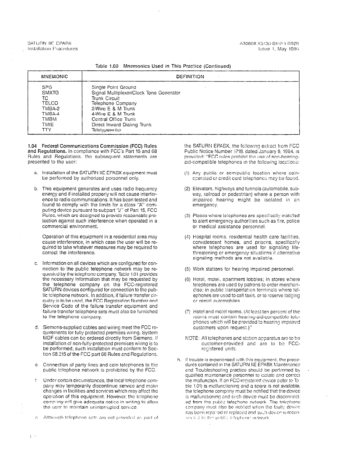
Tabic 1.00 Mnemonics Used in This Practice (Continued)
MNEMONIC DEFINITION
S?G
SMXTG
TC
TELCO
TMBA-2
TMBA-4
TMBM
TMIE
TTY
Single Point Ground
Stgnal Multiplexer/Clock Tone Generator
Trunk Circuit
Telephone Company
2-Wire E & M Trunk
4-Wire E & M Trunk
Central Office Trunk
Direct Inward Dialing Trunk
Teletypewriter
1.04 Federal Communications Commission (FCC) Rules
and Regulations. In compliance with FCC’s Part 15 and 68
Rules and Regulations, the subsequent statements are
presented to the user:
!he SATURN EPAGX, the fc!!ow:ng extract flcm FCC
Public Notice Number -i718. dated January 9. 1984, IS
provided: “FCC rules prohibit the use of non-hearing-
aId-compatible telephones In the fcllcwing locc!io:;;:
a. Installation of the SATURN IIE EPABX equipment must
il)
Any public cr semipublic locaiicn where coin-
be performed by authorized personnel only. cperaied cr credit card telephone; may be fourid.
5. This equipment generates and uses radio frequency
energy and if installed properly will not cause interfer-
ence to radio communications. It has boen tested and
found to comply with the limits for a class “‘A” com-
puting device pursuant to subpart ‘3” of Part 15, FCC
Rules, which are designed to provide reasonable pro-
tection against such interference when operated in a
commercial environment.
(2)
(3)
Elevators, highways and tunnels (autcmobile. sub-
way, railroad or pedestrian) where a person with
impaired hearing might be isolated in a!?
emergency.
Places where telephones are speci:iccliy instz!ied
to alert emergency authorities such as f:re, pclice
or medical assistance personnel.
Operation of this equipment in a residential area may
cause interference, in which case the user will be re-
quired to take whatever measures may be required to
correct the interference.
(4) Hospital rooms. residential health care facili?ies.
convalescent homes, and priscns, specifically
where te!ephones are used for signaling Ilfe-
threatening or emergency situaticns I: alternative
signaling meihods are not available.
c. lnfcrmation on all devices which are configured for con-
nection to the public telephone network may be re- (5)
quested by the telephone company. Table 1.01 provides
the necessary information that may be requested by
(6)
Work stations for hearing impaired personnel.
the telephone company en the FCC-registered
SATURN devices configured for connection to the pub-
lic telephone network. In addition, if failure transfer cir-
cuitry is to be used, the FCC Registration Number and
Serwce Code of the failure transfer equipment and
failure transfer telephone sets must also be furnished
to the telephcne company. (7)
Hotel, motel, apartment lobbies; in stores where
telephones are used by patrons to order merc!ian-
disc; in public :ransporia?ion terminals where !el-
ephones are used to call taxis, or to reserve lodging
or rental automoblles.
d. Siemcns-supplied cables and wiring meet the FCC rc-
quirements for fully protected premises wiring. System
MDF cab!es can be ordered directly from Slemens. If
installation of non-fully-protected premises wil-ing is to
be performed, such installation must ccnform to Scc-
tion 68.215 of the FCC part G8 Rules and Regulations.
Hotel and mo:el rooms. (At
le?.si
ten perc,znt of the
rooms mus? contain hearing-aid-compatible tcio-
phones which will be provided to hearing :mpaircd
custcmers upon reques:.)”
NDTE: All telephones and st,?!icn a;?;aratus are to be
customer-provided and are to bz FCC-
rcrjstered umts.
e. Connection of party lines and coin telephones to the
public telephone neiwork is prohIbited by the FCC.
‘ Undrr certain circumstances, the local telephone
coin-
pany may ternporarily discontinue service and make?
changes In facilittes and scrvires which may affect the
opelntion of this equipment. However, the :r:lcphoiic
corny !ny v~i!I give adequate notice in wrltmg to allow
the usor lo mnlntain unintcrruptcd serb:cc
h. If trouble 1s experienced tv:ith this equipmer-,I. the proze-
dures contained in the SATURN IIE EPABX h?aln!ennncc
and Troubleshooting practice should be performed b!i
qualified mJlntenance personnel to
ISOlaiC
snd correct
the malfunction. If an FCC-rccls:e:ed dr?v:ce (Icfcr to D
ble 101) is malfunclioning and a spare is not available,
the telephone company must be notified tha? the device
is malfunctioning 2nd s~!ch devfcc must be disconncct-
cd from t!x?
publ~.z
telephone nc!work The trlc$!oro
coxpany m~sl nlso be notl!;e:l v:hc,n tllc f~~ult,; drv#:-e
ka.5 been rcpz cd or rrplaci Y! avl su,!i dcv.cr rs rcco;i-
S”C‘!i’ ! 10 11!c3 p14bi:7 :!~!Ppll:,rlt~
nrtv:ork
i. Each sys!cm. ;IS stllppod. is accompanied by a Ivl&rinl dcfectwe equlpmpnt for repair. Spxili: warranty Infor-
Return Authorizatron (MRA) kit. This kit contnms In- m&on is provltied by Siemens to each +7&r null-0
stiuctions ,7nd rolatcd documen!ation fur returnlnc_l rizod to soli. install nnd maintain SATURN eqwpmcnt
Table 1.01 FCC Fkaistration Information
FCC ReGistration Number 61586K-14442~MF-E
Interfacing
Device
CENTRAL OFFICE
TRUNKS:
2VL:re Lc:p S::::
%\‘!ire Grc:nd Start
CIREC%IN.DIALING
TRWKS:
2J::i:e (lrmli~g Cnlyl
OFF-PREUISES
STATION:
X’:~e
Cl2Sj
C
AUXILIARY DEVICES:
F?.-l::e Trans’er C?!s.
lS?E kld::‘s FCG)
Sienens
Device f~lodel
or Part Number
T;.:SA4
js3calo-as3c.x- * .esc?)
T:.:EM
(S3lB;O-CGX- x -E5C3)
Sib%0
(53;510.@1:73.X. * .B9C3)
Private Line Rciliiy
Interface Code/
Scrvicc
Code
-
Ringer
Equivalence
No. (REN)
-
-
0.96
0.9
NO. usoc
Of
Jack
Leads
NO.
?J2:X
!
Comments

I -
SATURN IIE EPABX
Installation Procedures A30808-X5130-BllO-l-8928
Issue 1. May 1988
SECTION 2.00 EQUIPMENT LOCATION AND IDENTIFICATION
2.01 General. The SATURN IIE System is housed in a sin-
gle, lightweight equipment cabinet with expansion capabili-
ties. An LTU shelf can be added within the basic cabinet: in
addition an expansion cabinet which contains one or two LTU
shelves can be mounted on top of the basic cabinet. Figures
2.00 and 2.01 show the basic cabinet and expansion cabi-
net. The block diagram shown in Figure 2.02 identifies the
functional blocks of circuits into which the system is divided.
These functional blocks are related to the system hardware
groups.
for expansion. The expansion cabinet can contain one
or two LTU shelves.
b. Power and Distribution Equipment. The SATURN IIE
System makes use of distributed power in the cabinet.
Several power modules of various sizes are located
alongside and at the bottom of the system cabinet. For
further information, refer to Figure 2.03.
2.02 SATURN
IIE Cabinets.
Figures 2.03 through 2.07 show
the basic and expanded configurations for the SATURN HE
System, The identification, location, and functional descrip-
tion of the equipment contained in the system cabinet is
presented below.
c. Miscellaneous Equipment. Two Floppy Disk Drives
(FDD) provide random data storage, using floppy disks
as the data storage medium. The FDDs are located
at the bottom of the rack (see Figure 2.03).
a. Equipment Shelves. The basic cabinet can contain one
or two shelves, a reauired basic shelf and an LTU shelf
d. Printed Circuit Boards. Two types of Printed Circuit
Boards (PC&) are used, common equipment PCBs
and peripheral interfacing PCBs. Refer to Table 2.03
for further information on the common equipment
PCBs, and Table 2.04 for information on the peripher-
at interfacing PCBs.
Figure 2.00 SATUHN Ilt uaslc ~aumx (with Front Panel)
2-l
I -
SATURN IIE EPABX
tnstallation Procedures
A30808-X5130-8110-1-69~8
Issue 1, May 1986
-9
.
Figure 2.01 SATURN 1lE Basic and Expansion Cabinets (with Front Panel)
2-2

I -
SATURN IIE EPABX A30808-X5130-6110-1-8928
Installation Procedures Issue 1, May 1986
I
t t I , I
PREMIUM
INSTRUM. DTMF TRUNK
MODULE _ RECEIVER MODULE
t PIMD DTMF TMBA 214 SLMA-0
SUBSCRIBER TMBM SLMA-S
- LINE MODULE - TMIE SLA16
DIGITAL -1
SLMD r 1
LINE/TRUNK
I
LINE/
ANCILLARY
TRUNK UNIT
EQUIPMENT
CONTROL.
LTUC
LTU SHELF
BASIC SHELF
-v-----------7 ---------------- -I
LINE/TRUNK p..,.-P,-.m I..,_ . I
CONFERENCE
I!
I
I I
- _ -.- -. .-. - I
r-
I 3”“I lb”lN” ,
NETWORK , I
I
I
I -’
AXENUATOR
i I I
i
I
! -
MODEM INTERFACE TO SLMA 1
OR TRUNK FOR REMOTE
MAINTENANCE
il.
-h
1 I
1 I
-II-
r
1,
I
I!
LINE MODULE -
FDD
___-------
----- ------
-- ----
.-- -----
l-l
ATTENDANT
CONSOLE
SDT
I
I-
r
POWER, RING GEN.
PlhlC CVhlP
1 POWER SUPPLIES t-1
llll.Y “II..,,
AND MAINTENANCE
I I
ANCILLARY
EQUIPMENT I,
i
‘TWO LTU CONTROL PCBs PER LTV SHELF (MAXIMUM)
A&331-I-3/14/66
Figure 2.02 SATURN IIE System Block Diagram
2-3
I -
SATURN IIE EPAEX A30808-X5130-BllO-l-8928
Installation Procedures Issue 1. May 1986
e Q
LTU
PS2
@ 0
LTU Shelf 3
256 Ports
B 0 E
LTU LTU Shelf 2
PSl 256
Ports
LTU Shelf 1
256
Ports
---xJl
Basic Shelf
224
Ports
Cor--
Equi r”‘-“’
Expansion
Cabinet
26.5
Inches
(67.3
CM)
Basic
Cabinet
70.5
Inches 1
(179 CM)
Figure 2.03 SATURN HE Equipment Configuration
2-4
I -
,’
SATURN IIE EPABX A30808-X5130-BllO-l-B928
Installation Procedures Issue 1, May 1986
Figure 2.04 SATURN IIE Basic Cabinet (Rear View)
2-5

!
I i
----I
SATURN IIE EPABX A30808-X5130-BllO-l-8928
Installation Procedures Issue 1, May 1986
I’
I’
Figure 2.05 SATURN IIE Basic Cabinet (Front View)
2-6
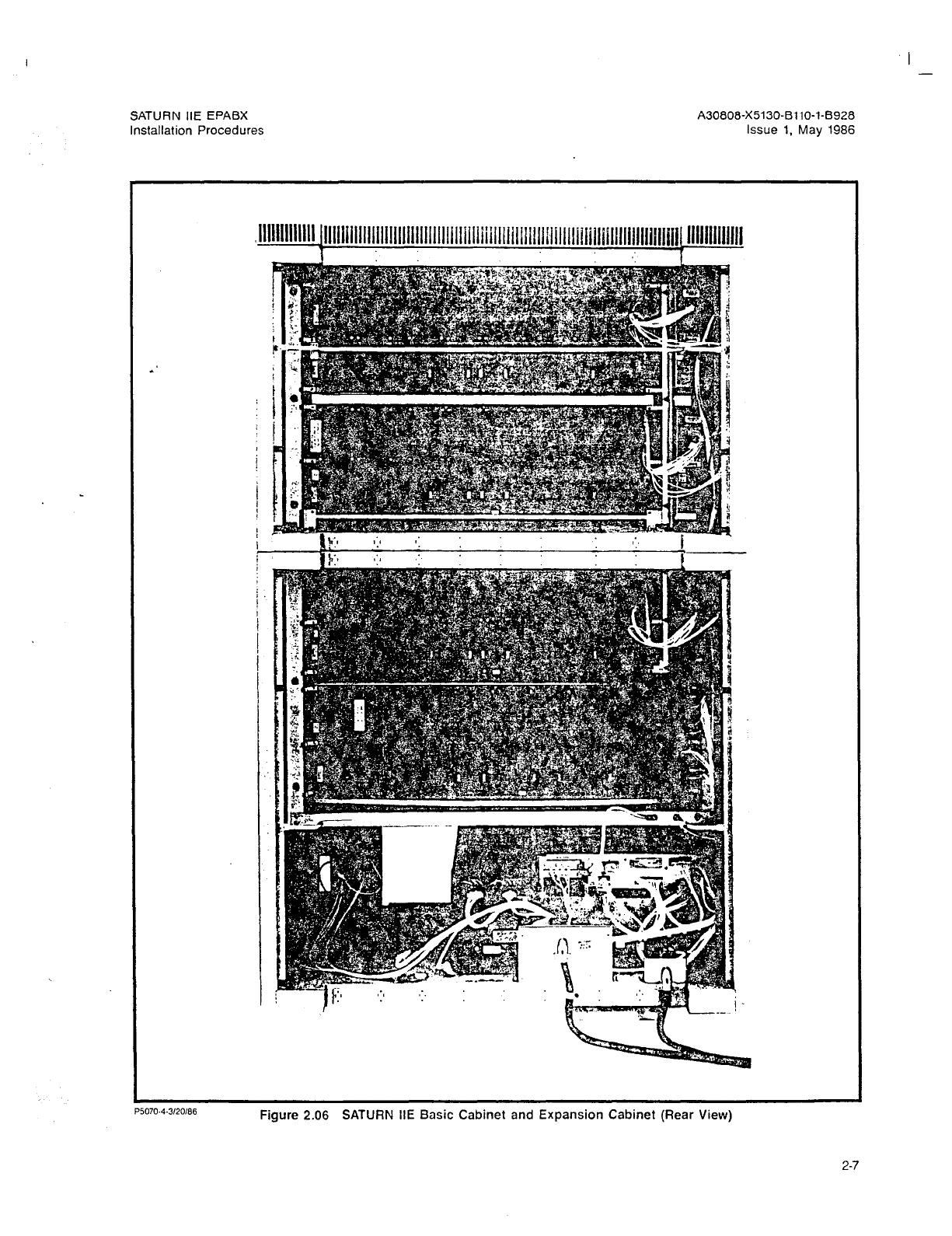
SATURN IIE EPABX
Installation Procedures
A30808-X5130-BllO-l-8928
Issue 1. May 1986
Figure 2.06 SATURN IIE Basic Cabinet and Expansion Cabinet (Rear View)
2-7

SATURN HE EPABX A30808-X5130-BllO-143928
Installation Procedures Issue 1, May 1986
Figure 2.07 SATURN IIE Basic Cabinet and Expansion Cabinet (Front View)
2-8

SATURN IIE EPABX A30808-X5130-BllO-l-6928
installation Procedures Issue 1, May 1986
BASIC
Table 2.00 Identification and Functional Description of Equipment Shelves
Basic Shelf. The basic shelf has both common equipment and peripheral PCBs which make up the com-
mon control and switching network circuitry of the system. In addition, the basic shelf also contains three
4-card Line/Trunk Unit (LTU) channel groups, .and four 2-card LTU channel groups.
LTU ~ Line/Trunk Unit Shelf. One LTU shelf can be installed in the basic cabinet and two can be installed in the
expansion cabinet. Each LTU shelf has peripheral interface PCBs. The peripheral PCBs provide the inter-
face circuitry between the system and external devices.
In addition, each LTU shelf is equipped with a Power Supply (LTUPS) for supplying the logic voltages
of +I- 5 Vdc and +I- 12 Vdc.
*’ NOTE: The guidelines shown in
Table 2.04
should be followed when assigning peripheral PCBs to the
basic and LTU shelves.
PSU
-48PS0
-48PSl
Table 2.01 Identification and Functional Description of Power and Distribution Equipment
The PSU front panel provides the access and control point to various system maintenance functions and
serves as the main AC and DC power distribution point to the following:
a. AC power, via circuit breakers, to the PSU, LTUPS units, and -48PS0, and -48PSl (see Table 4.06
for detailed information).
b. Fused -48Vdc outputs for talk battery, signaling battery, SLMD and PIMD applications to all chan-
nel groups in the basic and LTU Shelves and the input to the RGEN module ( see Table 4.06 for
detailed information).
c. Fused 9OVac. 20Hz for Ringing AC (RAC) and Ringing Message Waiting (RMW) to all channel
groups in the basic and LTU shelves (see Table 4.06 for detailed information).
The -48PS is an AC-to-DC converter which provides 48Vdc output voltage. This voltage is used for talk bat-
tery, signal battery, SLMD and PIMD applications for station instruments, SDTs, trunks, and attendant con-
soles, respectively. The -48PS also powers the RGEN modules.
A single -48PS (-48PSO) is adequate for the basic cabinet applications.
A second -48PS (-48PSl) is required when the expansion cabinet is included.
Memory Support Module. The MSM contained within the PSU is an optional battery backup package that
provides +SVdc to the RAM memory when the commercial AC power fails. In the event of such failure, the
battery maintains the data stored in memory for at least five minutes. When the AC source is restored within
this period , the memory does not have to be reloaded from floppy disk: system operation can begin im-
mediately. The MSM is capable of anther 5minute backup cycle after 30 minutes of recharging. The MSM
includes the battery charging circuitry and is under a “float” charge during normal operation. The MSM
is located within the PSU.
Table 2.02 Identification and Functional Description of Miscellaneous Equipment
FDDO
FDDl Floppy Disk Drive O/l. The floppy disk drive (FDD) provides the backup memory for the following: system
initialization, system reload, administration, and maintenance testing.
2-9

I
SATURN IIE EPABX A30808-X5130-B110-l-8928
Installation Procedures issue 1. May 1986
Table 2.03 Identification, Location and Functional Description
of Common Equipment PC&
MNEMONIC TITLE AND FUNCTION SLOT NUMBER
SMXTG Signal Multiplexer/ClocklTone Generator (SMXTG) PCB is divided into three func- 21
tional parts: the signal multiplexer, the clock generator, and the tone generator.
., The SMXTG is a hardware-controlled scanner/distributor, which provides an interface
between the lineftrunk units and CIOI? The SMXTG handles control and status sig-
nals for 32 highways.
The clock generator provides the 8.192MHz, 4.048MHz, and 250Hz clocking signals
required to operate the system.
*’ The tone generator provides various tqne outputs from which all the system DTMF
tones and supervisory tones are derived. The tone generator also provides a square
wave timing signal for system generated dial pulses.
MEM4 The MEM4 PCB provides 1 Megabyte of memory and its supporting logic to store
system data. The memory is organized as 512k words X 16 bits/word, with memory
divided into sixteen 64K byte pages, write protection provided in 1K word segments.
MEM4 is arranged for battery backup memory protection to safeguard stored data
during short term power outages. Also, an error-correction code is provided to cor-
rect any single-bit error and detect double-bit errors existing in a word.
27-29
MEM3
RAUP
The MEM3 PCB provides 256k bytes of memory and its supporting logic to store sys-
tern data. The memory is organized as 128k words X 16 bits/word, with memory write
protection provided in 1K word segments. MEM3 is arranged for battery backup
memory protection to safeguard stored data during short term power outages. Also,
an error-correction code is provided to correct any single-bit error and detect double-
bit errors existing in a word. .
Remote Access Unit/ Ports. The RAUP allows remote access to the system for main-
tenance and administrative functions. The RAUP is located in slot 25 of the basic
shelf and does not use up any time slots.
27-29
25
CIOP Controller/Input Output Processor. Contains the Signal Buffer and processor and per-
forms the input/output functions in the system. An RS-232-C connector is provided
for the service terminal.
26
PSC Parallel/Serial Converter.Converts serial PCM voice signals to parallel signals, and
then multiplexes them into parallel flow. The parallel data is sent lo the Memory Con-
trol and Attenuator (MCA) for further processing; the reverse function is performed
by the PSC to provide serial voice signals back to the LTUs.
20,22
PSC 0 - basic and LTU Shelf 1.
PSC 1 - LTU Shelves 2 & 3.
MCA Memory Control and Attenuator. The MCA is divided into two functional parts, a Time
Switch Unit and Memory Control. The time switch unit makes ail two party connec-
tions and provides attenuation (as required) for all system calls. The memory control
receives data from the processor and causes the time switch to make the required
connections.
23
CONF Conference (CONF). The CONF function provides the switching control for confer-
ences involving 3 to 7 parties plus attendant. 21
2-10
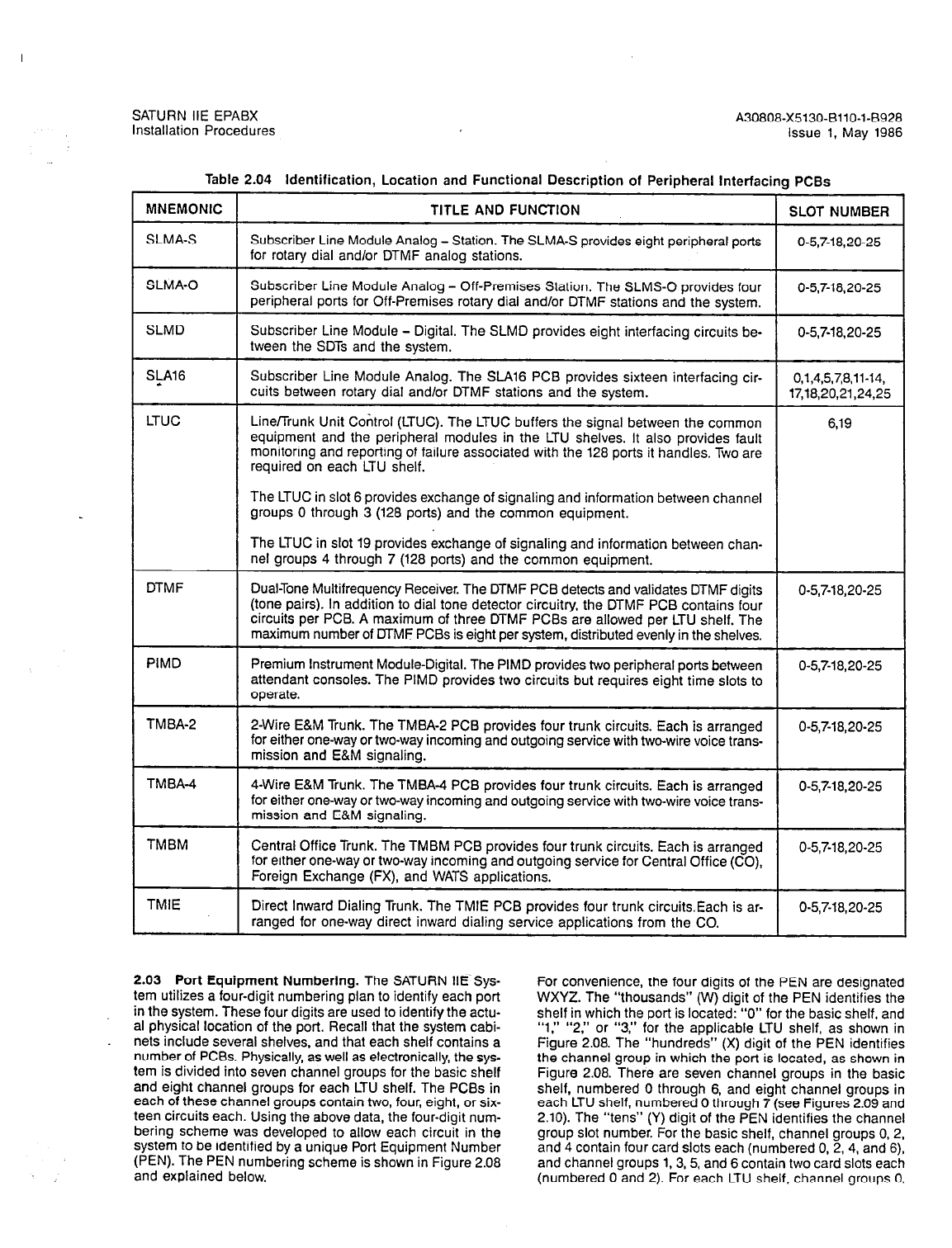
Table 2.04 Identification, Location and Functional Description of Peripheral Interfacing PCBs
MNEMONIC TITLE AND FUNCTION SLOT NUMBER
SLMA-S Subscriber Line Module Analog - Station. The SLMA-S provides eight peripheral ports O-5,7-18,20-25
for rotary dial and/or DTMF analog stations.
SLMA-0 Subscriber Line Module Analog - Off-Premises Station. The SLMS-0 provides four
peripheral ports for Off-Premises rotary dial and/or DTMF stations and the system. O-5,7-18,20-25
SLMD Subscriber Line Module - Digital. The SLMD provides eight interfacing circuits be-
tween the SDTs and the system.
O-5,7-18,20-25
S@6
LTUC
Subscriber Line Module Analog. The SLA16 PCB provides sixteen interfacing cir- 0,1,4,5,7,8,11-14,
cuits between rotary dial and/or DTMF stations and the system. 17,18,20,21,24,25
Line/Trunk Unit Control (LTUC). The LTUC buffers the signal between the common 6,19
equipment and the peripheral modules in the LTU shelves. It also provides fault
monitoring and reporting of failure associated with the 128 ports it handles. Two are
required on each LTU shelf.
The LTUC in slot 6 provides exchange of signaling and information between channel
groups 0 through 3 (128 ports) and the common equipment.
The LTUC in slot 19 provides exchange of signaling and information between chan-
nel groups 4 through 7 (128 ports) and the common equipment.
DTMF Dual-Tone Multifrequency Receiver. The DTMF PCB detects and validates DTMF digits
(tone pairs). In addition to dial tone detector circuitry, the DTMF PCB contains four
circuits per PCB. A maximum of three DTMF PCBs are allowed per LTU shelf. The
maximum number of MMF PCBs is eight per system, distributed evenly in the shelves.
O-5,7-18,20-25
PIMD Premium Instrument Module-Digital. The PIMD provides two peripheral ports between
attendant consoles. The PIMD provides two circuits but requires eight time slots to
operate.
O-5,7-18,20-25
TM BA-2 2-Wire E&M Trunk. The TMBA-2 PCB provides four trunk circuits. Each is arranged
for either one-way or two-way incoming and outgoing service with two-wire voice trans-
mission and E&M signaling.
O-5,7-18,20-25
TMBA-4 4-Wire E&M Trunk. The TMBA-4 PCB provides four trunk circuits. Each is arranged
for either one-way or two-way incoming and outgoing service with two-wire voice trans-
mission and E&M signaling.
O-5,7-18,20-25
TMBM Central Office Trunk. The TMBM PCB provides four trunk circuits. Each is arranged
for either one-way or two-way incoming and outgoing service for Central Office (CO),
Foreign Exchange (FX), and WATS applications.
O-5,7-18,20-25
TMIE Direct Inward Dialing Trunk. The TMIE PCB provides four trunk circuitsEach is ar-
ranged for one-way direct inward dialing service applications from the CO. O-5,7-18,20-25
SATURN IIE EPABX A30808-X5130-BllO-l-8928
Installation Procedures Issue 1, May 1986
2.03 Port Equipment Numbering.
The SATURN IIE Sys-
tem utilizes a four-digit numbering plan to identify each port
in the system. These four digits are used to identify the actu-
al physical location of the port. Recall that the system cabi-
nets include several shelves, and that each shelf contains a
number of PCBs. Physically, as well as electronically, the sys-
tem is divided into seven channel groups for the basic shelf
and eight channel groups for each LTU shelf. The PCBs in
each of these channel groups contain two, four, eight, or six-
teen circuits each. Using the above data, the four-digit num-
bering scheme was developed to allow each circuit in the
system to be identified by a unique Port Equipment Number
(PEN). The PEN numbering scheme is shown in Figure 2.08
and explained below.
For convenience, the four digits of the PEN are designated
WXYZ. The “thousands” (W) digit of the PEN identifies the
shelf in which the port is located: “0” for the basic shelf, and
“1,” “ 2,” or “3,” for the applicable LTU shelf, as shown in
Figure 2.08. The “hundreds” (X) digit of the PEN identifies
the channel group in which the port is located, as shown in
Figure 2.08. There are seven channel groups in the basic
shelf, numbered 0 through 6, and eight channel groups in
each LTU shelf, numbered 0 through 7 (see Figures 2.09 and
2.10). The “tens” (Y) digit of the PEN identifies the channel
group slot number. For the basic shelf, channel groups 0, 2,
and 4 contain four card slots each (numbered 0, 2,4, and 6),
and channel groups 1, 3, 5, and 6 contain two card slots each
(numbered 0 and 2). For each LTU shelf. channel groups 0.
2-11
I
SATURN IIE EPABX
Installation Procedures
2, 4, and 6 contain four card slots each (numbered 0, 2, 4,
and 6) and channel groups 1, 3, 5 and 7 contain two card slots
each (numbered 0 and 2). See Figure 2.10. (The LTU card
slots labeled “LTUC” contain no ports and therefore are not
included in the numbering plan).
The SATURN IIE System employs “virtual” slots in addition
to the physical slots in each channel group. Two virtual slots
are added to the four-card channel groups and two virtual slots
are added to the two-card channel groups. The virtual slots
are numbered 1 and 3 and are paired with slots 0 and 2,
respectively. This has the effect of depicting the channel groups
as six-slot and four-slot channel groups, respectively. The vir-
tual slots are used in the numbering scheme only when a
%-circuit card’is installed. For example, when an StA16 is in-
stalled in slot 0, its top eight circuits are assigned to slot 0 and
its bottom eight circuits are assigned to virtual slot 1. As each
channel group is allotted only 32 time slots, only two SLA16s
may be placed in any one channel group. In addition, the soft-
ware interface enforces compliance with the following rules:
a. A sixteen-circuit card (i.e., SLA16) cannot be used in slot
4 or slot 6, regardless of the type of cards used in slots
0 and 2.
b. If an SLA16 is used in slot 0, slot 4 must be left empty.
c. If an SLA16 is used in slot 2, slot 6 must be left empty.
Caution
Insertion of any card in slot 4 with an SLAl6 in slot
0 (or in slot 6 with an SLAl6 in slot 2) will result in
port contention and consequent system mal-
function.
The “units” (2) digit of the PEN identifies the circuit on the
PCB that is associated with the port. The circuit numbers for
PCBs are designated as follows:
Two-circuit PCBs (PIMDs): circuits 0 and 2.
Four-circuit PCBs (trunks, MMF receivers, and SLMA-
OS): circuits 0, 2, 4, and 6.
Eight-circuit PCBs (SLMA-Ss and SLMDs): circuits 0
through 7.
Sixteen-circuit PC& (SLAlGs): two sets of 0 through 7
(see explanation for “tens” above).
As an example of PEN numbering, assume that the circuit in
question is circuit 5 located on the PCB in card slot 4 of chan-
nel group 2 of shelf 3. The PEN number of the circuit would
be 3245. That is:
Shelf (W) 3
Channel Group (X) 2
Slot (Y) 4
Circuit (Z) 5
As a second example, assume that the circuit in question is
the second circuit on the bottom half of an SLA16 PCB locat-
ed in card slot 0 of channel group 1 of the basic shelf. In this
case, the PEN number would be 0111. That is:
Shelf (W) 0
Channel Group (X) 1
Slot (Y) 1
Circuit (Z) 1
A30608-X5130-BllO-l-8928
Issue 1, May 1986
Note, in this example, that the slot number is 1, even though
the physical slot is slot 0, and that the circuit is PEN numbered
1 even though it is the tenth circuit on the PCB. This is be-
cause the second eight circuits on the SLAl6 are assigned to
a virtual slot (in this case, slot 1) and numbered 0 to 7 as ex-
plained above.
2.04 Allocation of Printed Circuit Boards. The SATURN IIE
System line and trunk PCBs, as noted previously, contain either
two, four, eight or sixteen circuits each. (Each circuit uses one
port on the system.) The system is arranged in channel groups
of 32 channels each; a channel is used for each port. The basic
shelf contains seven channel groups and the LTU shelf con-
tains eight channel groups. Each channel group consists of
universal card slots. Some of the channel groups contain four
card slots each, and the others contain two card slots each.
Allocation of both initially-equipped PCBs and future PCBs
should be carefully planned during the configuration of the in-
itial system site so as assign the ports in the most efficient man-
ner. In a two-card channel-group, the use of anything other than
16-port cards will cause a loss of ports. For instance, the as-
signment of two four-port PCBs to a two-card channel group
would only use eight ports in that channel group, thus making
the remaining twenty-four portsunavailable for use. In four-card
channel groups, use of cards of less than eight channels each
will also result in the loss of availability of some of the channel
group’s ports.
The card slot position in each LTU shelf universally accepts
any SATURN IIE peripheral interface module; however, certain
limitations exist regarding the placement of these modules due
to the distribution of time slots within a shelf. There are also
guidelines that may be followed to achieve optimum time slot
usage. These limitations and guidelines are based on the num-
ber of time slots each peripheral interface module uses, as
follows:
Peripheral Interface Module Time Slots Used
Subscriber Line Module -Analog-l6 (SLA16) 16
Subscriber Line Module -Analog (SLMA-S) 8
Premium Instrument Module - Digital (PIMD) 8
Subscriber Line Module - Digital (SLMD) 8
Central Office Trunk (TMBM) 4
Direct Inward Dialing Trunk (TMIE) 4
a-Wire E/M Tie Trunk (TMBA-2) 4
4-Wire E/M Tie Trunk (TMBA-4) 4
Dual Tone Multifrequency Receiver (DTMF) 4
Subscriber Line Module - Analog -
Off-Premise (SLMA-0) 4
Except as noted above, 4 and 8 time slot peripheral interface
modules can be used in any slot of any LTU. Certain uses of
peripheral interface modules in SATURN IIE results in unusa-
ble time slots, as follows:
Unusable Time Slots
2 Card LTU 4 Card LTU
4 Time Slot Module 12 4
0 Time Slot Module 8 0
16 Time Slot Module 0 0
While not prohibited by the hardware/software design, it is
recommended that special consideration be given to the place-
ment of E&M trunk modules in the LTUs so that the E&M leads
do not share any MDF cables with audio pairs. If an E&M trunk
module is placed into any of slots 0, 2, or 4 of a four-slot LTU,
2-12
I -
SATURN IIE EPABX A30608-X5130-8110-l-8928
Installation Procedures Issue 1, May 1986
none of these slots should be filled with eight- or sixteen-port
modules. If an E&M trunk module is placed into slot 6 of a four-
slot LTU or either of slots 0 or 2 of the two-slot LTUs situated
to the immediate riqht of the four-slot LTU. none of these slots
should be filled with eight- or sixteen-port modules.
In addition, the total number per shelf of any one type of mod-
ule is limited
by
the power supply feeding that shelf. These
limitations are as follows:
SLMD Modules
DTQF Modules
Trunk Modules (2)
Basic Shelf (1) LTU Shelf (1)
is 16
4 2
20 16
Notes: 1.
2.
Each power supply (in the basic shelf) can drive
more than the number of modules shown above.
The number shown represents the maximum
guaranteed quantities that can be powered by
each supply, independent of how the rest of the
shelf is populated.
At least 50 per cent of the trunks are assumed
to be TMBMs. As the percentage of TMBMs is
increased, the trunk module drive capability in-
creases.
2-13
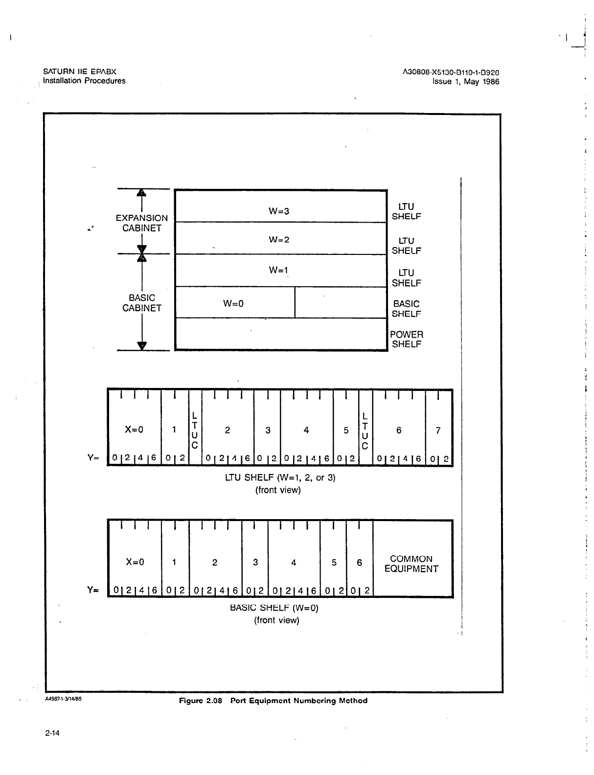
SATURN IIE EPABX A30808-X5130-BllO-143928
,, Installation Procedures Issue 1, May 1986
BL I I
I
w=3 LTU
EXPANSION SHELF
*’ CABINET
-+I- .
w=2 LTU
SHELF
W=l LTU
SHELF
I
[ SHELF + 1
I I I I I I I I I I I I I I I
I v
L L
x=0 1 T
U 2 3 4 = L 6 7
C C
Y= 0121416 012 O(21416 012 012(416 012 0121416 01 2
LTU SHELF (W=l, 2, or 3)
(front view)
I I I I I I I
I
I I I
I I
x=0
1 2 3 4 5 6 COMMON
EQUIPMENT
Y= 01214(6 012 0)21416 012 O(21416 012 012
BASIC SHELF (W=O)
(front view)
Figure 2.08 Port Equipment Numbering Method
2-14
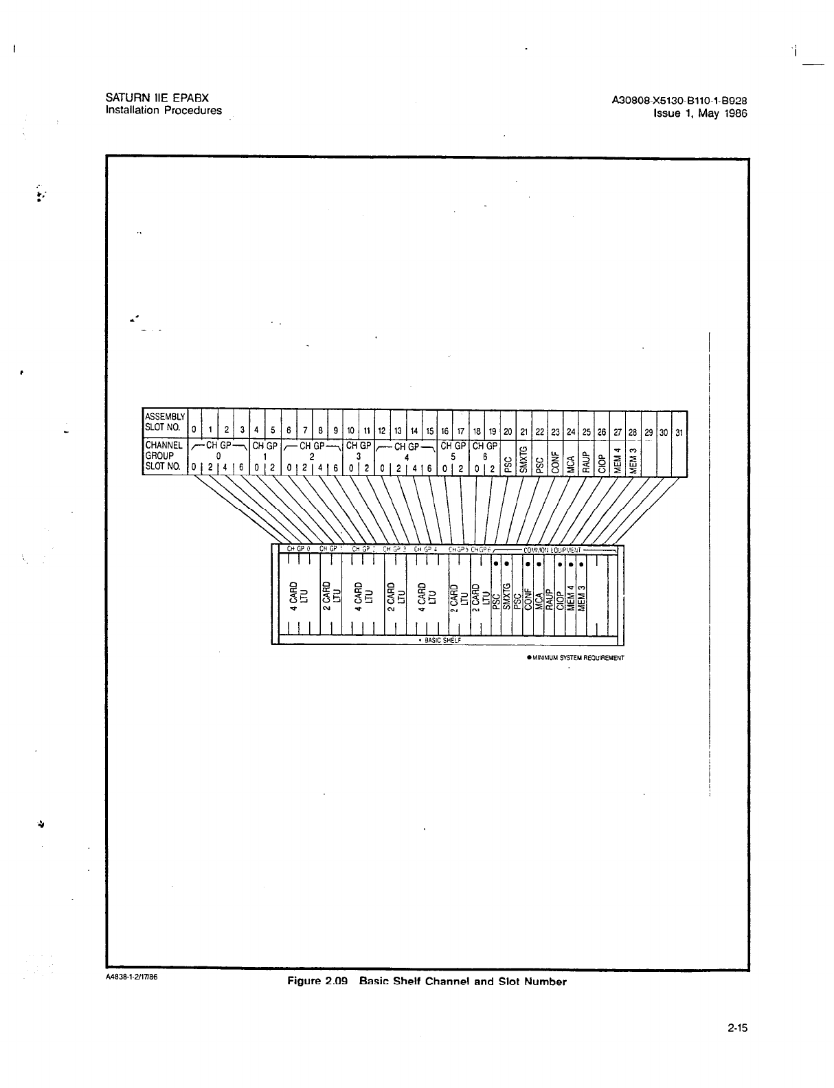
l .’
.
,
SATURN HE EPABX
Installation Procedures A30808-X5130-6110-1-8928
Issue 1, May 1986
6 7 6 9 10 11 12 13 14 15 16 17 16 19 20 21 22 23 24 25 26 27 26 29 30 31
Figure 2.09 Basic Shelf Channel and Slot Number
2-15
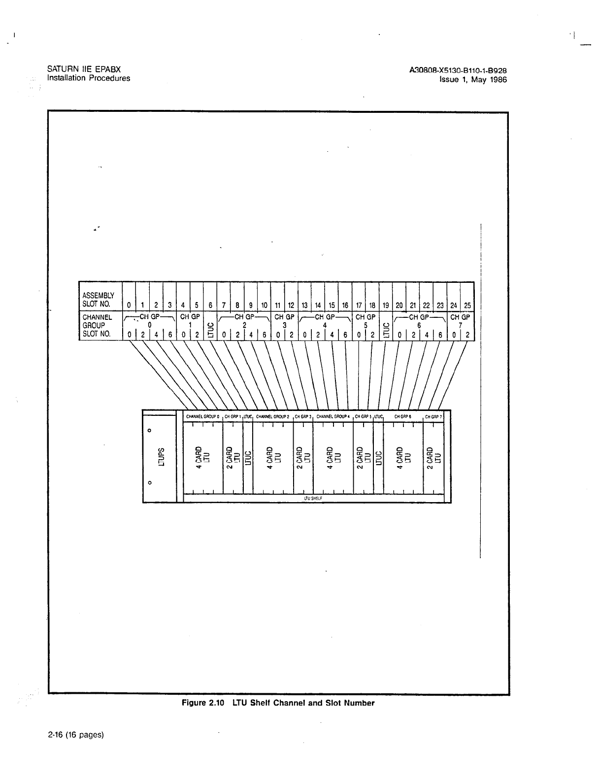
I -
SATURN IIE EPABX A30808-X5130-BllO-l-8928
Installation Procedures Issue 1, May 1986
ASSEMBLY
SLOTNO. 0 1 2 3 4 5 6 7 10 6 9 11 12 13 14 15 16 17 16 19 20 21 22 23 24 25
CHANNEL -CH GP--, CH GP
GROUP 0 l 2
-CH GP-, CH GP ,-CH GP-, CH GP 1
2 3 4 5 CJ
(
-cH6Gp- cH7Gp
SLOT NO. O(21416 012 5 0121416 012 012 4 6 012 g 01214[6 012
Figure 2.10 LTU Shelf Channel and Slot Number
2-16 (16 pages)
I
SATURN IIE EPABX A30808-X5130-8110-l-8928
Installation Procedures Issue 1, May 1986
SECTION 3.00 CUSTOMER SITE PREPARATION
3.01
General.
This section specifies the equipment room
preparation and house cabling procedures used to install a
SATURN IIE System. Included is a recommended MDF lay-
out for the system.
3.02 Equipment Room Preparation.
The SATURN IIE Sys-
tem may be located in a dedicated room. This room, desig-
nated “equipment room” in this practice, must meet the
environmental requirements set forth below. If on-site serv-
ice equipment and spares are to be provided, adequate
storage facilities should be available. Adequate lighting should
be provided for normal installation and maintenance activi-
ties. Walls should be painted or otherwise sealed.’
a. Environmental Requirements. The following environ-
mental requirements for the equipment room must be
observed to ensure a high grade of service perfor-
mance and reliability for the SATURN IIE System.
Failure to observe these environmental requirements
may seriously degrade the service, performance and
reliability of the system and may result in the voiding
of its warranty.
1. Lightning and Surge Arrestor Protection. The in-
terfacing circuits (e.g., trunk circuits) of the
SATURN IIE System are designed to withstand vol-
tage surges specified in the EIA proposed standard
for Physical Environment for Telephone Terminal
Equipment, and FCC’s Part 68 Rules and Regula-
tions. Lightning can cause high voltage surges on
leads connected to exposed outside plant facilities.
Protection of these outside plant interface leads
(i.e., CO-PBX trunk, tie trunk, and off-premises sta-
tion interface leads which connect to outside facil-
ities) from foreign potentials and currents must be
provided by installing commercially available pro-
tection equipment meeting the above specified
guidelines. The Siemens lightning and surge ar-
restor equipment can be purchased separately and
used when protection above and beyond the speci-
fied requirements is necessary for a given instal-
lation.
2. Temperature and Humidity. The SATURN IIE Sys-
tem is designed to operate in an indoor, controlled
environment. Extreme low or high temperatures
may degrade the service performance and relia-
bility of the system. Avoid installing the equipment
cabinet in unheated areas or areas which are sub-
ject to high temperatures. Table 3.00 lists the oper-
ating and storage temperatures for the system and
ancillary equipment. Maximum service perfor-
mance and reliability of the system is obtained
when the room temperature does not exceed the
normal office environment temperature range. Un-
der no circumstances should the room tempera-
ture exceed the maximum temperature range.
Storage temperatures apply only to non-operating
equipment. Extreme low or high humidity may also
degrade service performance and reliability of the
system. Low relative humidity increases the chance
of static electricity discharges; high relative humid-
ity increases the chance of moisture condensation.
Table 3.00 also lists the operating and storage hu-
midity ranges for the system and ancillary equip-
ment. Maximum service performance and reliability
of the system is obtained when the room relative
humidity does not exceed the normal office en-
vironment humidity range. Under no circumstances
should the room relative humidity exceed the max-
imum humidity range. Storage humidity range ap-
plies only to non-operating equipment.
3. Contaminants. The SATURN IIE System should be
protected from exposure to airborne contaminants
(e.g., corrosive gases, particulate materials, aer-
osols, etc.) which may affect service performance
and reliability of the system. Avoid exposure to
hydrogen sulfide, sulfur dioxide, nitrogen oxides,
or other gases which are corrosive. Smoky and
dusty environments should be avoided since the
contact resistance of the connectors may be affect-
ed. Aerosols such as oil, solvents and other indus-
trial chemicals should also be avoided as they also
affect contact resistance. Extremely dusty environ-
ments may destroy PCBs by damaging their con-
nectors. Such damage may not be repairable and
may cause system failures that are difficult to iso-
late and correct.
4. Air Conditioning. Air conditioning equipment
provided for the SATURN IIE equipment room must
be capable of maintaining the temperature and hu-
midity ranges specified in Table 3.00. Such equip-
ment should contain air filters to reduce
contaminants as noted above. The air condition-
ing equipment should be regularly maintained by
the customer to ensure proper performance, and
to maintain a positive room pressure. It is recom-
mended that the air conditioning equipment be
powered from an AC branch circuit separate from
that used for oowerina the SATURN IIE Svstem.
The cyclic, inductive-loads presented by such
equipment may affect service performance and
reliability of the system.
Table 3.00 Equipment Cabinet
Temperature/Humidity Ranges
CONDITION
Operating
RANGE
Q to 38.0% (40° to 100°F)
20% to 80% (noncondensing)
Storage -400 to 66.00 (-400 to 150.8OF)
0% to 950/o (noncondensing)
5. Floor Insulation. Carpeting is not normally recom-
mended because of its tendency to produce high-
voltage electrostatic charges, which can severely
damage electronic components. For installations
where carpeting is required,
a
specially treated car-
peting should be used. An acceptable carpeting
is a carpet that has a rubber backing and a net-
work of metal filaments between the backing and
the pile. The special carpeting should cover the
complete installation area and extend at least three
3-l

‘I
SATURN IIE EPABX A30808-X5130-8110-l-8928
Installation Procedures Issue 1, May 1986
feet on all sides of the SATURN IIE System cabinet.
A connection must be made between the metal fila-
ments and earth ground. This ground connection
must not be the SATURN HE System ground.
b. Cabinet Space and Floor Loading Specifications. The
following specifications are presented to aid craft per-
sonnel in selecting an adequate equipment room for
the SATURN IIE System:
1. Cabinet Space Specifications. The equipment
room should be sized for one cabinet assembly and
adequate space for normal installation and main-
**
tenance activities. Other peripheral equipment (i.e.,
service terminal) may be located near the cabinet
assembly or the MDF. Figure 3.00 illustrates the
recommended space required for the equipment
cabinet of the SATURN IIE System. Figure 3.01 il-
lustrates the physical dimensions of the basic cabi-
net and Figure 3.02 the expansion cabinet.
2. Cabinet Floor Loading Specifications. The basic
cabinet weighs 440 pounds and floor loading is 55
Ib./sq ft. The basic and expansion cabinets together
weighs 685 pounds and floor loading is 90 Ib./sq
ft (equally distributed)
r --- -----
11
Top View ,
36 Inches Minimum
(91.4 CM)
36 inches Minimum 36 Inches Minimum
36 Inches-Minimum
(91.4 CM)
Front
-------
I
Figure
3.00 SATURN IIE
System Space Requirements
3-2
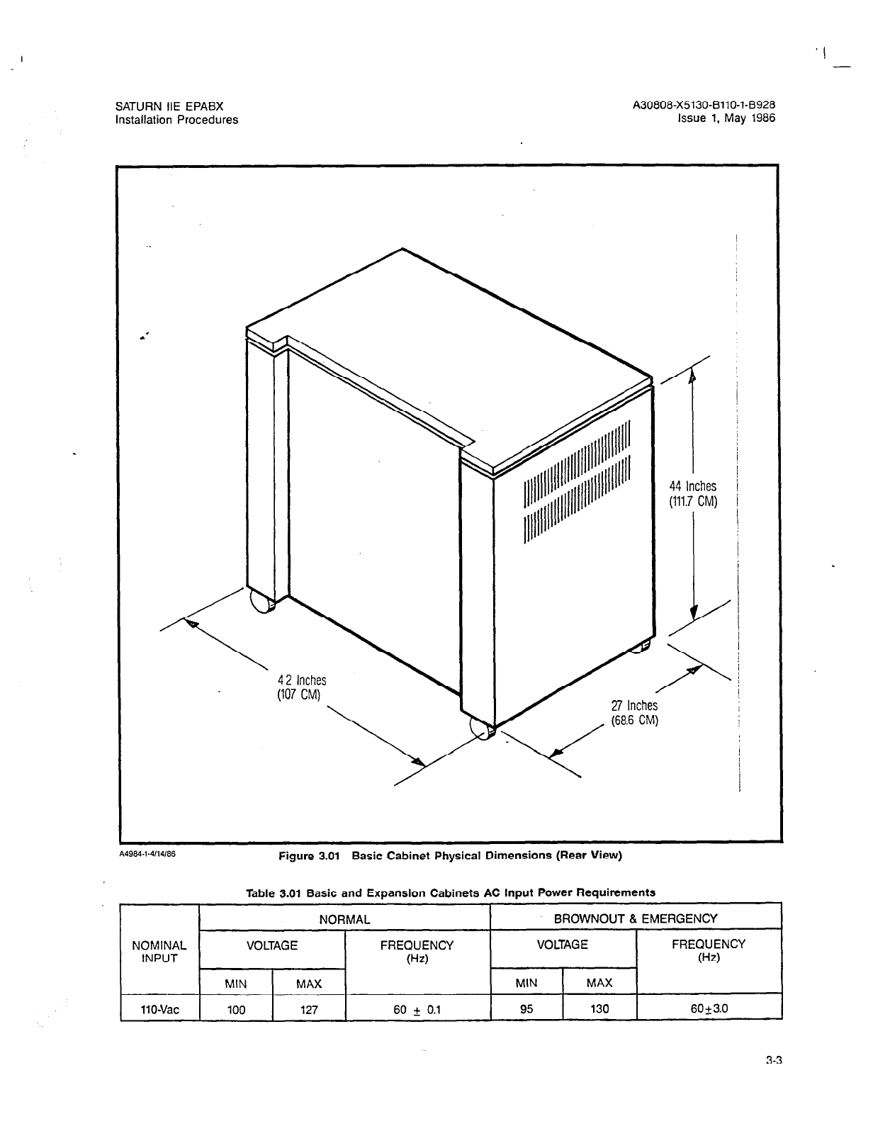
. I
SATURN IIE EPABX
Installation Procedures
A30808-X5130-8110-l-8928
Issue 1, May 1986
\
42 Inches
(I07 CM)
__r
44 Inches
(111.7 CM)
I
1-
Figure 3.01 Basic Cabinet Physical Dimensions (Rear View)
Table 3.01 Basic and Exoanslon Cabinets AC lnout Power Reouirements
I I
NORMAL I BROWNOUT 8 EMERGENCY
NOMINAL VOLTAGE FREQUENCY VOLTAGE FREQUENCY
INPUT 0-z) (Hz)
MIN MAX MIN MAX
IlO-Vat 100 127
60
f 0.1 95 130
6Ok3.0
3-3
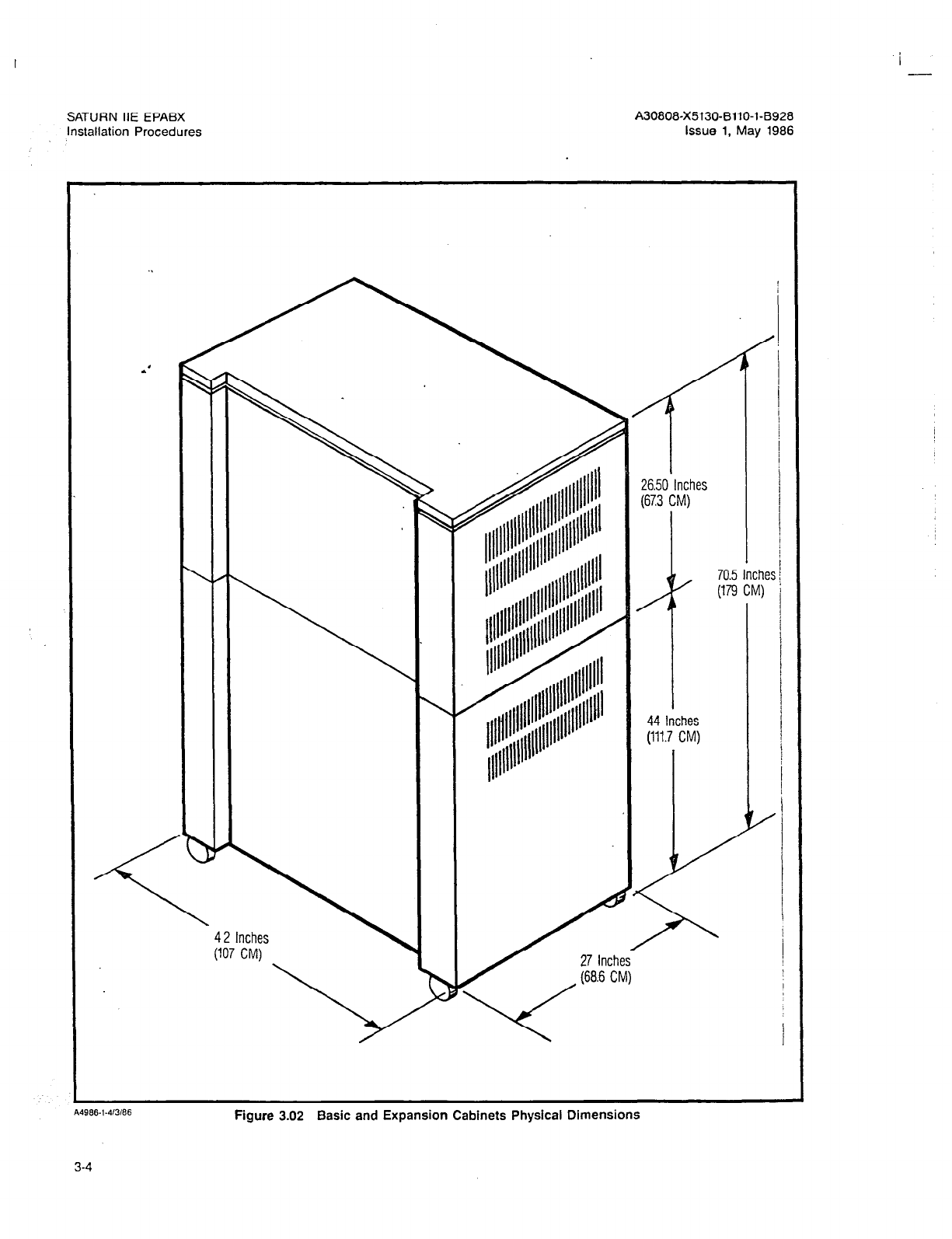
I -
SATURN IIE EPABX
Installation Procedures
A30808-X5130-6110-1-8928
Issue 1, May 1986
986.1.‘lWt)6
Figure 3.02 Basic and Expansion Cabinets Physical Dimensions

SATURN IIE EPABX
Installation Procedures A30808-X5130-BllO-1-8928
Issue 1, May 1986
c. Cabinet Input Power and Grounding Requirements.
The following information is presented to aid craft per-
sonnel in selecting an adequate AC power source, as
well as a ground source, for powering a SATURN IIE
System cabinet.
t. AC Input Power Requirements. One AC input source
is required for the basic cabinet. A second AC in-
put source is required when the expansion cabinet
is added, as shown in Figure 3.03. The AC input
power source must meet the parameters specified
in Table 3.01. A 1Bfoot long (3.6 meters) 3-conductor
power cord is supplied with the equipment cabinet.
A’ One end of this power cord is terminated on a ter-
minal box located at the bottom rear of the equip-
ment cabinet. The other end of the power cord is
terminated with a three-prong connector that plugs
into an AC power source outlet (i.e., commercial AC
wall outlet or receptacle). This AC power recepta-
cle should comply with the following recommen-
dations:
a) The AC power receptacle should be located
within the length of the supplied power cord (i.e.,
12 feet) and easily accessible for maintenance
activities.
b) The AC power receptacle must provide fused
11OVac (single-phase) power at 60Hz capable of
delivering 20 Amps.
c) The AC power receptacle should be fused in-
dependently from all other AC power receptacles.
d) The AC power receptacle must only be con-
trolled from the branch circuit breaker panel and
not by a local light switch.
e) The AC power cords for the basic and expan-
sion cabinet require separate mounting brackets
f) A warning tag should be attached to the circuit
breaker controlling the AC power receptacle to
prevent accidental removal of power.
g) The AC power cords for the basic and expan-
sion cabinets require separate mounting
brackets.
d.
3.03
h)
A warning tag should be attached to the power
cord connector to prevent accidental removal of
cord. If possible, the power cord should be
clamped near the AC power receptacle to
minimize movement.
Ground Requirements. The cabinet assembly is
grounded via its power cord. In addition to this
ground, an earth ground is required. This earth
ground can be a metallic cold water pipe, ground
field, copper ground rod, etc., and must not exceed
two ohms in resistance. The earth ground conduc-
tor is attached to the cabinet frame ground via a lug
which accepts a &gauge conductor, The wire gauge
size used for earth ground is determined by the
ground wire length from the cabinet assembly to the
selected earth ground (refer to Table 3.02). Earth
ground connections for the equipment cabinet are
shown in Figure 3.03.
Note: Change the ground lug if wire gauge is too
large (see Table 3.02).
MDF Preparation. In accordance with FCC’s Part 68
Rules and Regulations for “Fullv Protected Premises
Wiring”, the S.&URN IIE equipment registration, the fol-
lowing requirements must be observed:
1. System to MDF Cabling Requirements. Accom-
plished via double-ended 50conductor (24AWG
twisted 25pair) cable not exceeding 25 feet from
point to point connection.
2. MDF Cable Terminating Block Types. The terminat-
ing blocks to be mounted at the MDF for the sys-
tem cable are dual 50-prong-row prewired,
connector-ended blocks.
3. Suggested MDF Layout. Figure 3.05 illustrates the
suggested MDF layout for the cabinet assembly.
House Cabling Preparation. To aid craft personnel with
. .
house cabling, me rollowlng requirements are presented:
a. General House Cabling Requirements. All standard sta-
tion lines should meet the National Electric Code clear-
ance requirements (this is a standard telephone industry
practice).
3-5
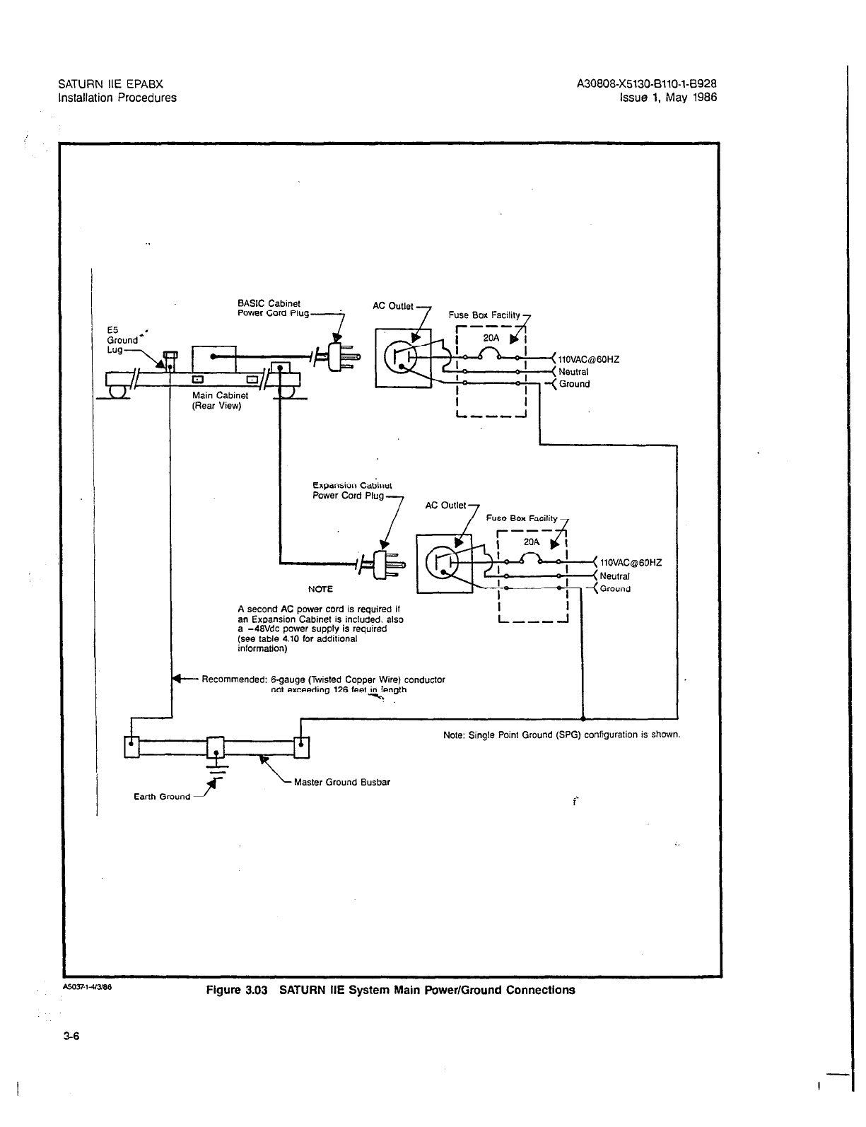
SATURN IIE EPABX A30808-X5130-BllO-l-6928
Installation Procedures Issue 1, May 1986
Fuse Box Faci
Fuse Box Facili
A second AC power cord is required if
an Expansion Cabinet is included. also
Figure 3.03 SATURN IIE System Main Power/Ground Connections
3-6
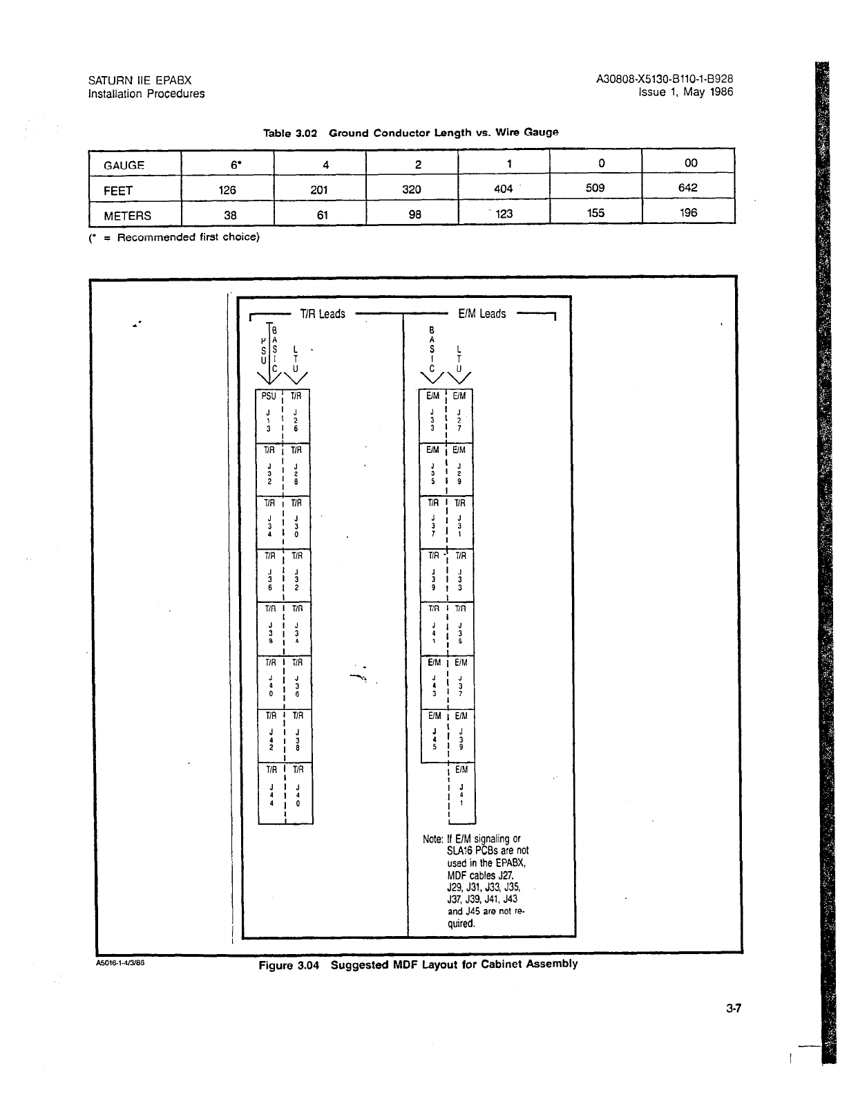
SATURN IIE EPABX A30808-X5130-BllO-l-6928
Installation Procedures Issue 1, May 1986
Table 3.02 Ground Conductor Length vs. Wire Gauge
GAUGE 6’ 4 2 1 0 00
FEET 126 201 320 404 509 642
METERS 38 61 98 123 155 196
(’ = Recommended first choice)
I- T/R Leads - - E/M
!i
s L
I T
Leads - 1
I
I
J
I 4
I ’
Note: If E/M signaling or
SLA16 PCBs are not
used in the EPA%
MDF cables J27,
J29, J31, J33, J35,
J37, J39, J41, J43
and J45 are not re-
quired.
Figure 3.04 Suggested MDF Layout for Cabinet AssemDly
3-7
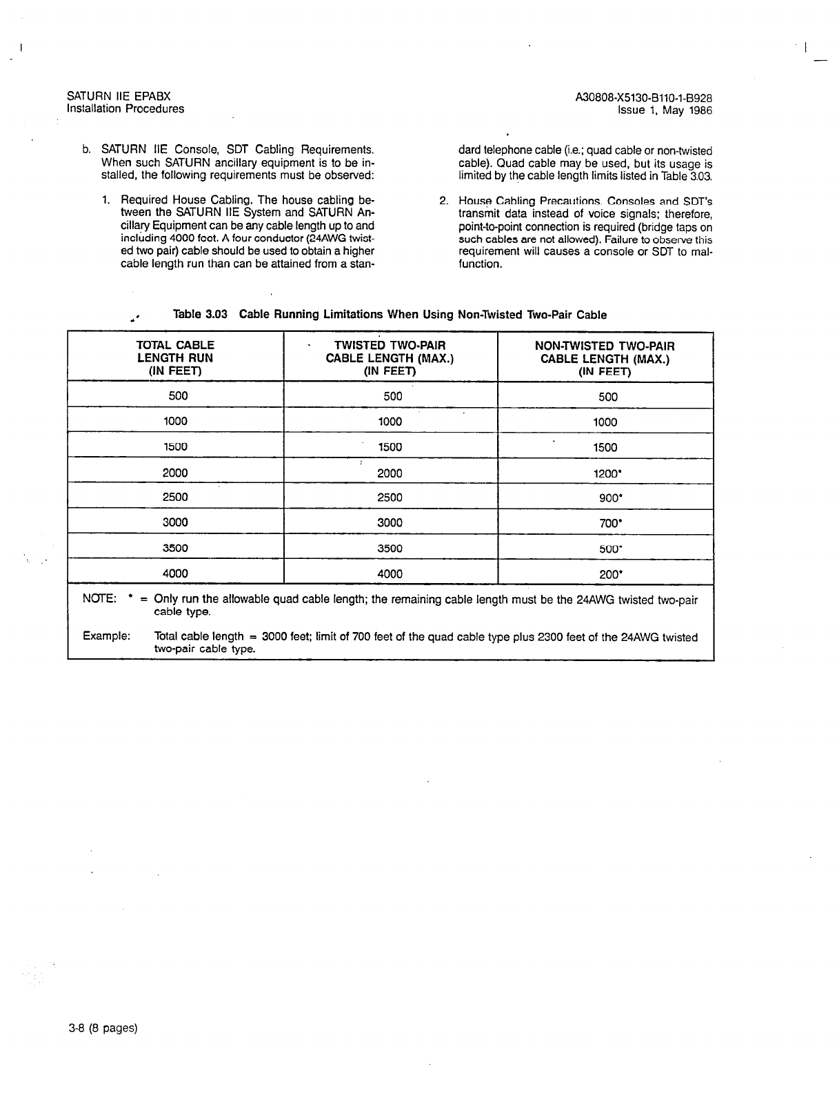
SATURN IIE EPABX
Installation Procedures
b. SATURN IIE Console, SDT Cabling Requirements. dard telephone cable (i.e.; quad cable or non-twisted
When such SATURN ancillary equipment is to be in- cable). Quad cable may be used, but its usage is
stalled, the following requirements must be observed: limited by the cable length limits listed in Table 3.03.
1. Required House Cabling. The house cabling be-
tween the SATURN IIE System and SATURN An-
cillary Equipment can be any cable length up to and
including 4000 feet. A four conductor (24AWG twist-
ed two pair) cable should be used to obtain a higher
cable length run than can be attained from a stan-
2.
House Cabling Precautions. Consoles and SDT’s
transmit data instead of voice signals; therefore,
point-to-point connection is required (bridge taps on
such cables are not allowed). Failure to observe this
requirement will causes a console or SDT to mal-
function.
A30808-X5130-BllO-l-8928
Issue 1, May 1986
.’ Table 3.03 Cable Running Limitations When Using Non-Twisted Two-Pair Cable
TOTAL CABLE _ TWlSTEil TWO-PAIR NON-TWISTED TWO-PAIR
LENGTH RUN CABLE LENGTH (MAX.) CABLE LENGTH (MAX.)
(IN FEET) (IN FEET) (IN FEET)
500 500 500
1000 1000 1000
I 1
1500 1500 1500
I 1
2000 2000 1200’
2500 2500 900’
3000 3000 700’
3500 3500 500’
4000 4000 200’
NOTE:
l
= Only run the allowable quad cable length; the remaining cable length must be the 24AWG twisted two-pair
cable type.
Example: Total cable length = 3000 feet: limit of 700 feet of the quad cable type plus 2300 feet of the 24AWG twisted
two-pair cable type.
3-8 (8
pages)
SATURN IIE EPABX A30808-X5130-8110-l-8928
installation Procedures Issue 1, May 1986
SECTION 4.00 EQUIPMENT INSTALLATldN PROCEDURES
4.01 General. The SATURN IIE System is shipped in kits
and as individual items according to customer requirements.
This section contains the necessary information to install the
various equipment kits and items listed in Table 4.00.
Table 4.00 SATURN IIE EPABX Orderable Items List
AVAILABLE EQUIPMENT, PART NO. COMMENTS
Basic-Cabinet (1lOVac 60Hz) L30808-X5130-Al- * -890 Refer to Table 4.01.
Basic Shelf Part of basic cabinet
Name Plate Logo C39324-A9679-B15- * -8900
Expansion Cabinet (Includes 2nd
AC Power Cord) L30808-X5130-A4- * -8900 Refer to Table 4.03
LTU expansion shelf L30808-X5130-A7- * -8900
Includes:
LTU Shelf S30804-85198-X- * -8900
LTUC S30810-Q0428-X- * -8900
LTUPS L30808-X5130-A39 * -8900
Cable Assembly Power(W21 & W22)
LTUPS-LTU C39195A9679-A5- * -B900
Cable Assembly Signal
(W14,W15,W16,& W17)basic and LTU )
shelves C39195-A9679-A3- * -8900 Refer to Table 4.03
POWER AND DISTRIBUTION
EQUIPMENT:
Memory Support Module (MSM)
Memory Battery Pack
~;~rt-tsion Shelf Power Supply
(+I-SVdc,+I-12Vdc) ’
PSU Fuse Kit (Includes following
Fuses)
Fuse% Amp. 125V
Fuse 5 Amp. 125V
Fuse 10 Amp. 125V
MISCELLANEOUS EQUIPMENT:
L30808-X5130-A34- * -6900
L30808-X5130-A51- * -8900
L30808X5130A39- * -8900
L30808X5050-Al2- * -8900
L30808-X5131-A5:r* -8900
Refer to Table 4.08
Refer to Table 4.09
Refer to Table 4.03
Floppy Disk Drive (FDD) Module
PERIPHERAL INTERFACE
PRINTED CIRCUIT BOARDS:
Dual-Tone Multifrequency (DTMF)
Receiver PCB
Premium Instrument Module Digital
(PIMD) PCB
Subscriber Line Module Analog
Station (SLMA-S) PCB
L30808-X5130&0- * -8900
S30810-Q431-X2- * -8900
S30810-Q432-X- * -8900
S30810-Q1674-X- * -8900
Refer to Table 4.12
Refer to Table 4.13
Refer to Table 4.14
Refer to Table 4.15
4-l
SATURN IIE EPABX
‘nstallation Procedures A30808X5130-BllO-l-8928
Issue 1, May 1988
Table 4.00 SATURN 11E EPABX
Orderable Item
List
(Continued)
AVAILABLE EQUIPMENT PART NO. COMMENTS
Subscriber Line Module Analog -
Off-Premises Station (SLMA-0) PCB S30810-Q1739-X- * -8900 Refer to Table 4.18
Subscriber Line Module Digital
(SLMD) PCB S30810-Q1724-X- + -8900 Refer to Table 4.17
Central Office Trunk (TMBM) PCB S30810-Q414-X- * -8900 Refer to Table 4.19
Direct Inward Dialing Trunk (TMIE)
PCB -.
Two-Wire E&M Trunk (TMBA-2) PCB
Four-Wire E&M Trunk (TMBA-4)
PCB
Linenrunk Unit Control (LTUC)
Subscriber Line Module Analog -
18 Line (SLAl8)
COMMON EQUIPMENT PRINTED
CIRCUIT BOARDS:
S30810-Q415-X- * -8900 Refer to Table 4.20
S30810-Q429-X- * -8900 Refer to Table 4.21
S30810-Q430-X- * -B900 Refer to Table 4.22
S30810-Q428-X- + -B900 Refer to Table 4.31
S30810-Q1790-X- i -8900 Refer to Table 4.18
Signal Multiplexerflone Generator
(SMXTG)
Remote Access Unit/Port (RAUP)
Memory Control and Attenuator
(MC4
Conference (CONF)
Parallel/Serial Converter (PSC)
System Memory
1
megabyte
(MEM 4)
System Memory 258 Kb (MEM 3)
S30810-Q1791-X- * -8900
S30810-01792-X- +-8900
S30810-Q0418-X- * -8900
S30810-Q0417-X- * -B900
S30810-Q0419-XlOO- * -8900
S30810-Ql775-X- * -8900
S30810-Q1740-X- * -8900
Refer to Table 4.24
Refer to Table 4.27
Refer to Table 4.28
Refer to Table 4.25
Refer to Table 4.23
Refer to Table 4.29
Refer to Table 4.30
Controller (CIOP)
Attendant Console
S30810-Q1789-X- * -6900
L30808-X5130A8- *
-8900
Refer to Table 4.28 . -;-;; .s;
Refer to Table 4.32
4.02 Basic Cabinet.
The SATURN IIE System consists of
an equipment cabinet with expansion capabilities; an expan-
sion shelf (See Paragraph 4.03) and expansion cabinet (See
Paragraph 4.04) can be added to the basic cabinet (See Para-
graph 4.03) for detailed information). The basic equipment
cabinet is mounted upright on a wooden pallet and enclosed
in a corrugated sleeve and cap as shown in Figure 4.00. To
uncrate an equipment cabinet, perform the following proce-
dures (refer to Figures 4.01 and 4.02 for details):
a. Cut the two vertical plastic straps securing the cor-
rugated cap and sleeve onto the wooden pallet.
b. Remove the corrugated cap and any packaging materi-
al from the top of the equipment cabinet. Remove the
corrugated sleeve by cutting open one of its corners
with a cutting knife, or by lifting it over the cabinet as-
sembly if overhead space is sufficient.
c. Cut the two vertical plastic straps securing the equip-
ment cabinet onto the wooden pallet. Remove any
packaging material and the vinyl-plastic shroud cover-
ing the equipment cabinet.
4-2
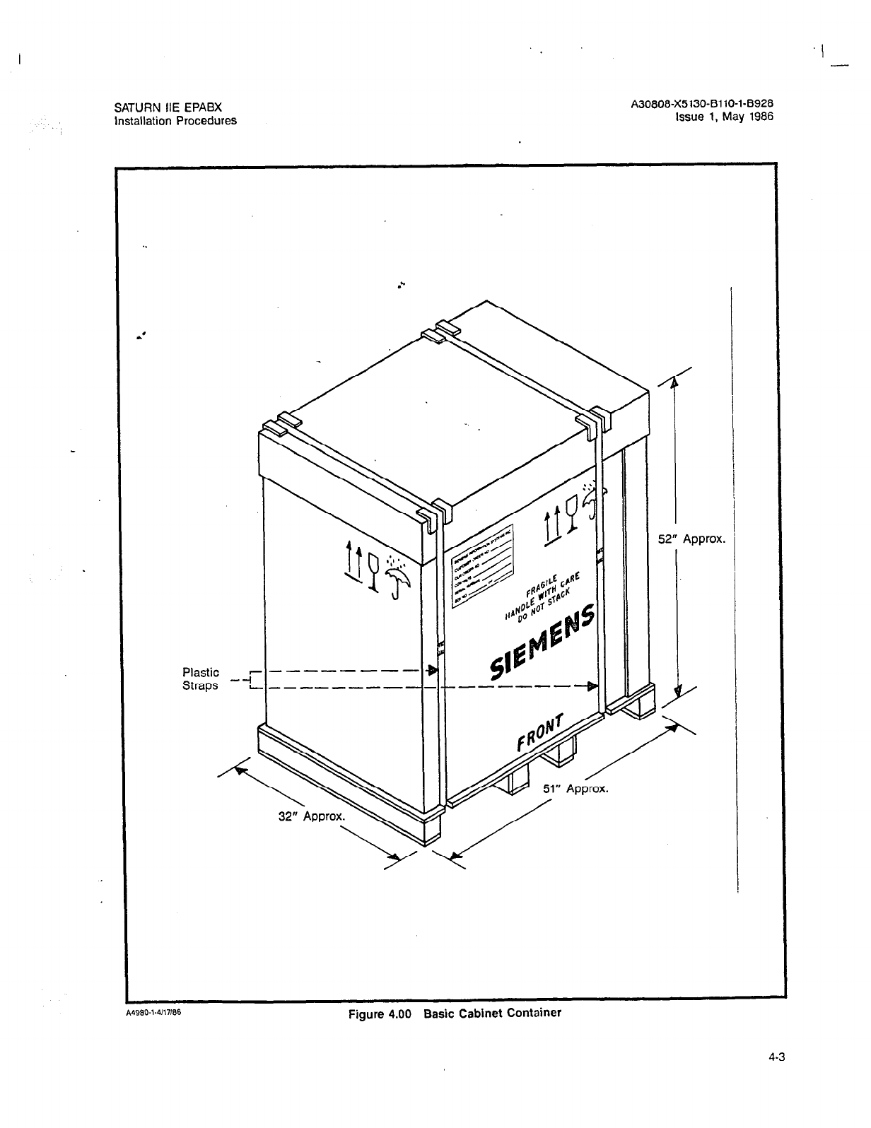
SATURN IIE EPABX
Installation Procedures
A30808-X5130-BllO-l-8928
Issue 1,
May 1986
.’
Plastic
Straps
A4960-1.4117166
Figure 4.00 Basic Cabinet Contalner
4-3
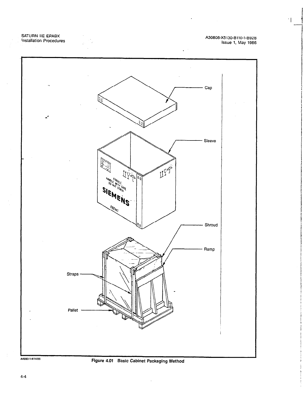
SATURN HE EPABX
hstallation Procedures A30808-X5130-BllO-l-B928
issue 1, May 1986
.,
Straps
Pallet
Sleeve
c
A49fwl-4/14/86
Figure 4.01 Basic Cabinet Packaging Method
Ramp
4-4
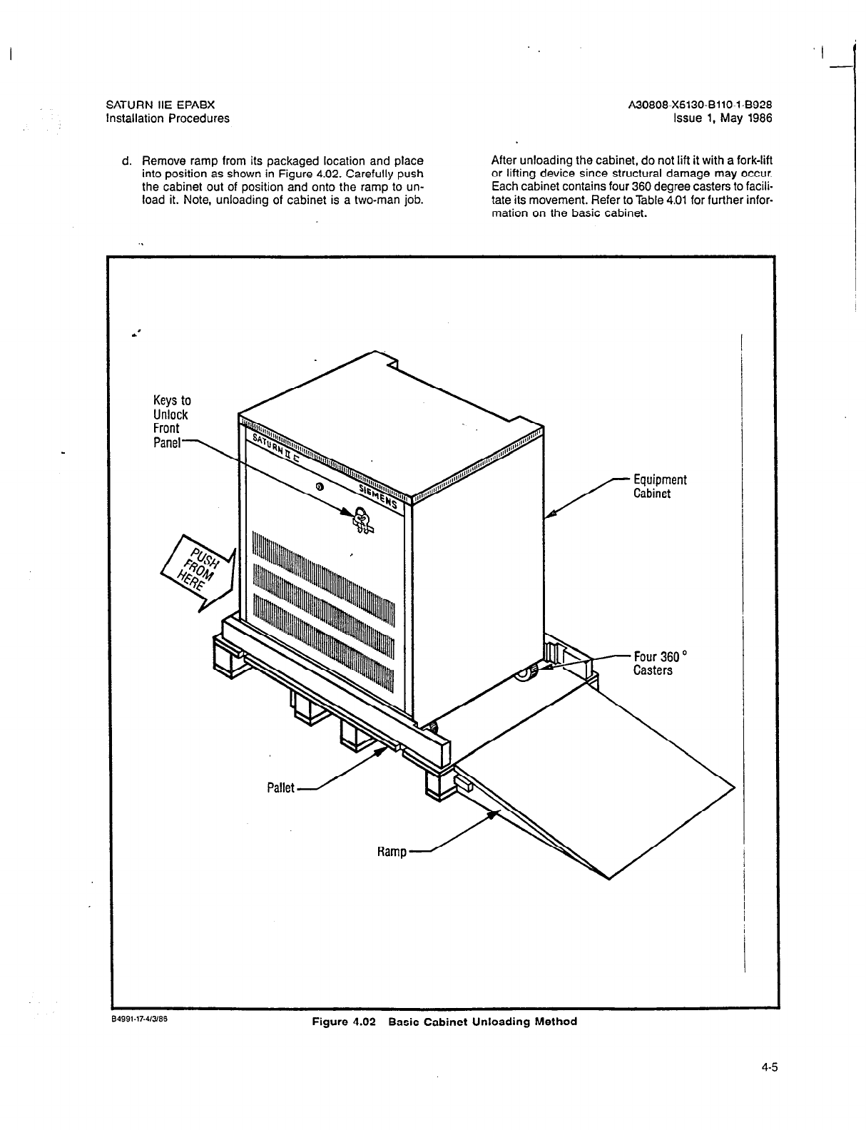
SATURN IIE EPABX A30808-X5130-BilO-l-8928
Installation Procedures Issue 1, May 1986
d. Remove ramp from its packaged location and place
into position as shown in Figure 4.02. Carefully push
the cabinet out of position and onto the ramp to un-
load it. Note, unloading of cabinet is a two-man job.
After unloading the cabinet, do not lift it with a fork-lift
or lifting device since structural damage may occur.
Each cabinet contains four 360 degree casters to facili-
tate its movement. Refer to Table 4.01 for further infor-
mation on the basic cabinet.
L
Figure 4.02 Basic Cabinet Unloading Method
4-5
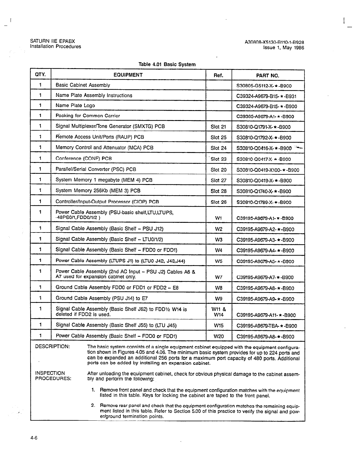
I -
SATURN IIE EPABX
Installation Procedures A30808-X5130-BllO-l-8928
Issue
1, May 1986
Table 4.01 Basic System
QTY. EQUIPMENT
Ref.
PART NO.
1 Basic Cabinet Assembly
1.
S30805-G5112-X- * -8900
1 Power
Cable Assembly (PSU-basic shelf,LTU,LTUPS,
-48PSO/l,FDD0/1/2 ) Wl C39195A9679Al- * -8900
1 Signal Cable Assembly (Basic Shelf - PSU J12) w2 C39195&679-A2- * -B900
1 Signal Cable Assembly (Basic Shelf - LTUO/1/2) w3 C39195-A9679-A3- * -8900
1 Signal Cable Assembly (Basic Shelf - FDDO or FDDl) w4 C39195-A9679-A4- * -8900
1
Power Cable Assembly (LTUPS Jl) to (LTUO 542, J43,J44) w5 C39195A9679&- * -8900
1 Power Cable Assembly (2nd AC lnput - PSU J2) Cables A6 &
A7 used for expansion cabinet only. w7 C39195-A9679-A7- + -8900
1 Ground Cable Assembly FDDO or FDDl or FDD2 - E8 W8 C39195-A9679-A8- * -8900
1 Ground Cable Assembly (PSU J14) to E7 w9 C39195-A9679-A9- * -B900
1 Signal Cable Assembly (Basic Shelf J62) to FDDV2 W14 is Wll &
deleted if FDD2 is used. w14 C39195-A9679All- * -8900
1 Signal Cable Assembly (Basic Shelf J55) to (LTU J45) W15 C39195-A967%TBA- * -8900
1 Power Cable Assembly (Basic Shelf - FDDO or FDDl) w20 C39195-A9679-A8- * -8900
DESCRIPTION: The basic system consists of a single equipment cabinet equipped with the equipment configura-
tion shown in Figures 4.05 and 4.06. The minimum basic system provides for up to 224 ports and
can be expanded an additional 256 ports for a maximum port capacity of 480 ports. Additional
ports can be added by installing an expansion cabinet.
INSPECTION
PROCEDURES: After unloading the equipment cabinet, check for obvious physical damage to the cabinet assem-
bly and perform the following:
1. Remove front panel and check that the equipment configuration matches with the equipment
listed in this table. Keys for locking the cabinet are taped to the front panel.
2. Remove rear panel and check that the equipment configuration matches the remaining equip-
ment listed in this table. Refer to Section 5.00 of this practice to verify the signal and pow-
er/ground termination points.
4-6

-
SATURN IIE EPABX A30808-X5130-BllO-l-8928
Installation Procedures Issue 1, May 1986
i
Table 4.01 Basic System (Continued)
3. Replace front and rear panels, if necessary, and move equipment cabinet to its approximate
final position.
ADDITIONAL
EQUIPMENT
REdUIRED: Per installation-site configuration to meet customer requirements.
OBSERVATIONS: None: the common equipment PCBs and modules equipped with the basic system are already
in their corresponding positions.
INSTALLATION
Pf$ICEDURES: 1. Place equipment cabinet in its final position and adjust the four levelers located underneath
the cabinet assembly, shown in Figure 4.06, to prevent movement while performing remain-
ing installation tasks.
2. After securing equipment cabinet in its final position, remove front and rear panels and any
remaining packaging material or loose objects.
3. At the bottom rear of the eouipment cabinet, locate Lug No. E5 and connect the conductor
from the selected earth ground. Refer to Section 3.00 for details on earth grounding and Sec-
tion 5.00 for details on power/ground cabling. Also, do not connect the AC power cord at this
time.
4. Refer to Table 4.02 if the LTU shelf and its power supply module are to be installed.
5. Refer to Tables 4.08 and 4.09 if the optional MSM is to be installed.
6. Refer to Table 4.10 if an additional 48Vdc power supply is to be installed as the 48PSl module.
7. Refer to Table 4.06 for insertion of the PSU grasshopper-type fuses into their corresponding
locations on the PSU fuse/circuit-breaker panel.
8. insert the peripheral interfacing PCBs into their site-allocated card slots in the basic shelf.
Trunk type PCBs (i.e., TMBA-2, TMBA4, TMBM, and TMIE PCBs) may require strapping
changes to meet the CO or PABX signaling termination. Refer to Tables 4.19 through 4.22
for further information on these peripheral interfacing PCBs.
9. Recheck that the common equipment PC&r are in their corresponding card slot locations.
The CIOP PCB requires switch settings changes to meet the operating characteristics of the
service terminal to be used, if any. Refer to Tables 4.23 through 4.30 for further information
on these common equipment PC&.
10. Refer to Section 6.00 in this practice to run and connect the required MDF cables. After run-
ning and connecting MDF cables, do not cross-connect at this time.
11. Refer to SATURN IIE EPABX Installation Test Procedures practice for further instructions.
4-7
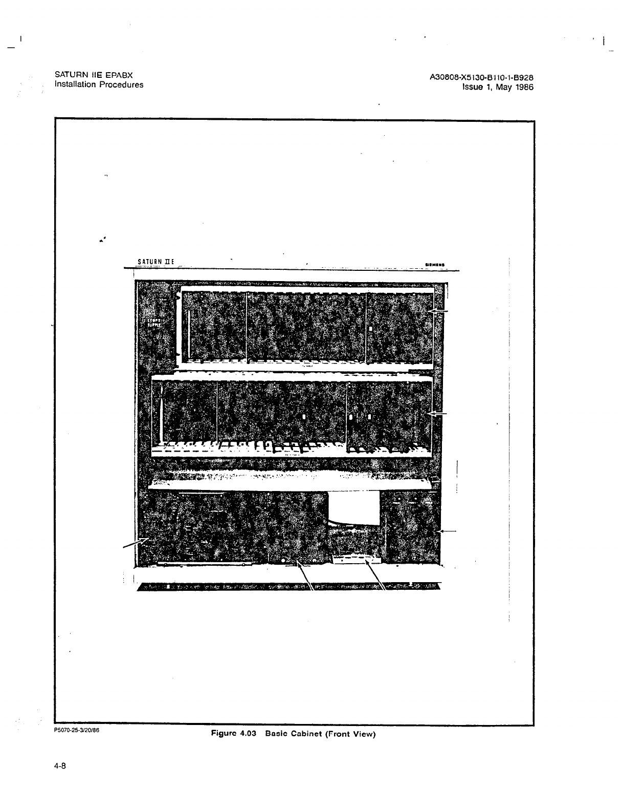
-
SATURN IIE EPABX
installation Procedures
’ I
A30808-X5130-BllO-l-8928
Issue 1, May 1986
SATURN Ilt
!
P5070.25-worn
Figure 4.03 Basic Cabinet (Front View)
4-8
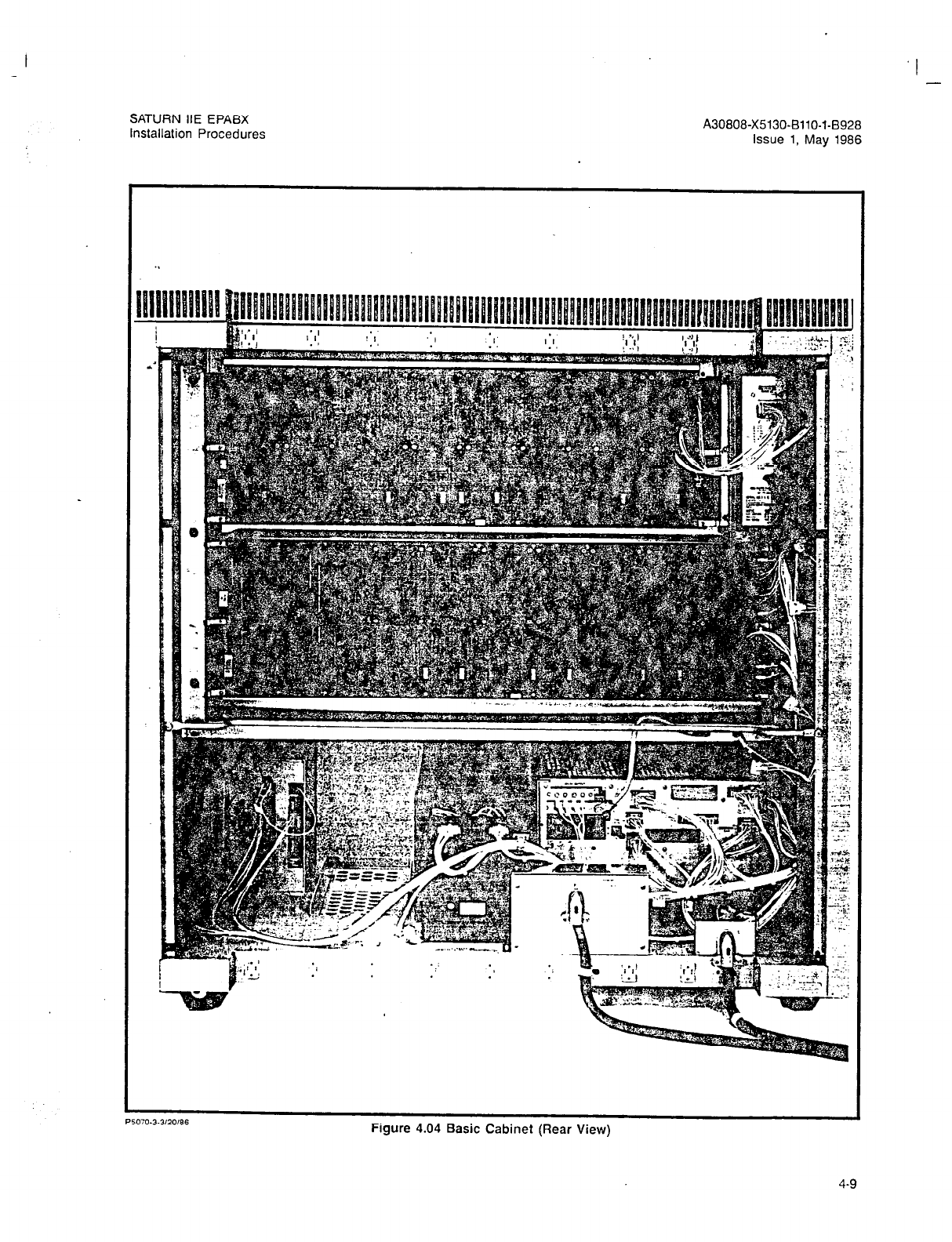
SATURN IIE EPABX
installation Procedures A30808-X5130-BllO-l-8928
Issue 1, May 1986
.I
P5030.3.3/20/86
Figure 4.04 Basic Cabinet (Rear View)
4-9

SATURN IlE EPABX
Installation Procedures
A30808-X5130-BllO-l-8928
Issue 1, May 1986
.’
i
I I
C4996-l-4114166
Figure 4.05 Basic Cabinet Connector Contiguration
4-10
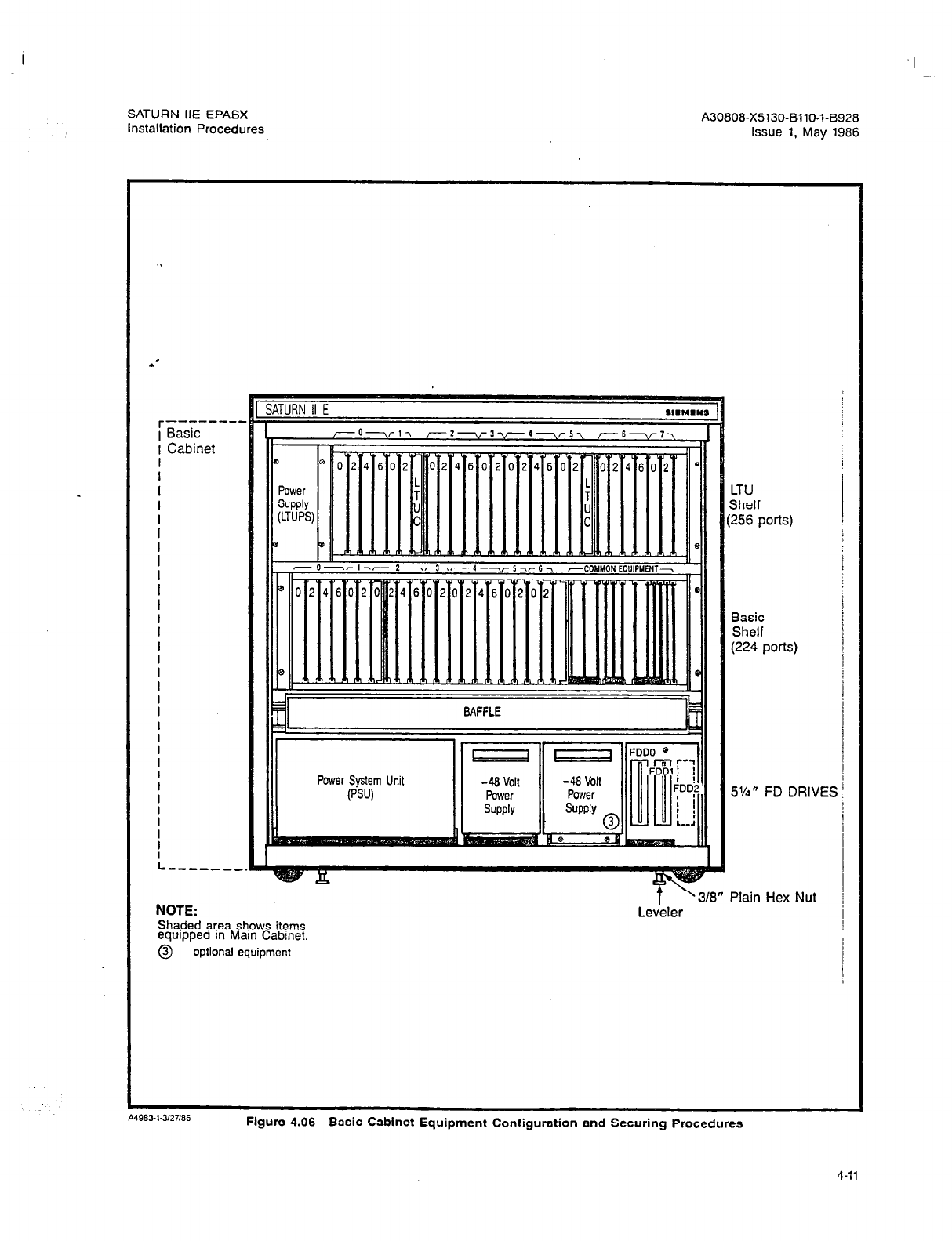
I
SATURN IIE EPABX A30808-X5130-BllO-l-8928
installation Procedures Issue 1, May 1986
r--------
Basic
Cabinet
LTU
Shelf
(256 ports)
I
I
I
I
I
I
I
I
I
I
I
I
L----,.
NOTE:
Shaded area shows items
equipped in Main Cabinet.
0 optional equipment
t ’ 318”
Leveler
Power System
Unit
Basic
Shelf
(224 ports)
5%” FD DRIVE
Plain Hex Nut
Si
A49631-3127166
Figure 4.06 Basic Cabinet Equipment Configuration and Securing Procedures
4-11
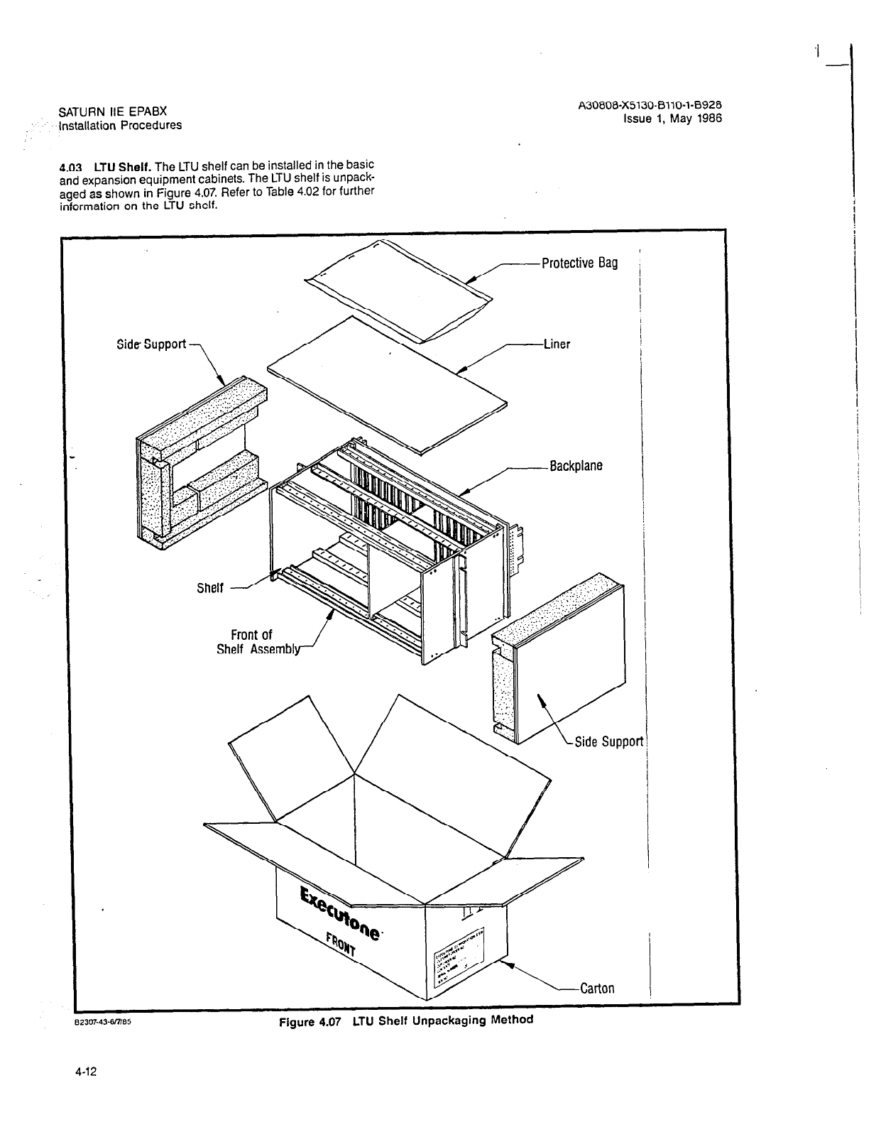
SATURN IIE EPABX
Installation Procedures
4.03 LTU Shelf. The LTU shelf can be installed in the basic
and expansion equipment cabinets. The LTU shelf is unpack-
aged as shown in Figure 4.07. Refer to Table 4.02 for further
information on the LTU shelf.
A30808-X5130-8110-l-8928
Issue 1, May 1986
8230743-185
4-12
Figure 4.07 LTU Shelf Unpackagmg Memoa

I --
SATURN IIE EPABX A30808-X5130-8110-l-8928
Installation Procedures Issue 1, May 1986
Table 4.02 Line/Trunk Unit Shelf
EQUIPMENT
Card SLOT PART NO.
LTU Shelf Assembly S30804-B5197-X7- * -8900
LTU Power Supply V30141-ZO113-Al.5 * -8900
Dual-Tone Multifrequency (DTMF) Receiver PCB O-517-18,20-25 S30810-Q431-X2- * -8900
Premium Instrument Module Digital (PIMD) PCB O-5,7-18,20-25 S30810-Q432-X- * -8900
Subscriber Line Module Analog - Station (SLMA-S) PCB
O-5,7-18,20-25 S30810-Q1674-X-
* -8900
Subscriber Line Module Analog - Off-Premises Station (SLMA-0)
PCB O-5,7-18,20-25 S30810-Q1739-X- * -8900
Subscriber Line Module Digital (SLMD) PCB O-5,7-18,20-25 S30810-Q1724-X- * -8900
Central Office Trunk (TMBM) PCB O-5,7-18,20-25 S30810-Q414-X- * -8900
Direct Inward Dialing Trunk (TMIE) PCB O-5,7-18,20-25 S30810-Q415-X- * -B900
Two-Wire E&M Trunk (TMBA-2) PCB O-5,7-18,20-25 S30810-Q429-X- * -8900
Four-Wire E&M Trunk (TMBA-4) PCB O-5,7-18,20-25 S30810-Q430-X- * -B900
Subscriber Line Module Analog - 16 Line (SLA16) PCB 014578
.Tl,,l
ll-14,17,18,20,
21,24,25 S30810-Q1790-X-
* -8900
Line/Trunk Unit Control (LTUC) PCB 6,19
S30810-Q428-X-
* -8900
NOTE: One LTU Shelf and one LTUPS are required for expansion of the basic cabinet. The expansion cabinet can
contain a maximum of two LTUs Shelfs and two LTUPS.
DESCRIF’TION:
INSPECTION
PROCEDURES:
Each LTU Shelf provides 256 ports. A total of three LTU shelves can be installed within a SATURN
IIE system: one in the basic cabinet and one or two in the expansion cabinet.
After unpacking carton, check for obvious physical damage to the shelf assembly. Also check that
the equipment configuration matches this table.
ADDITIONAL
EQUIPMENT
REQUIRED: Each LTU shelf requires an LTU Power Supply (LTUPS) module.
OBSERVATIONS:
INSTALLATION
PROCEDURES:
Mounting of the ribbon cable holder supplied with the LTU shelf is not required on the LTU backplane.
1. Mount the four U-type metal fasteners supplied in the Mounting Hardware Kit on the cor-
responding hole openings in the cabinet frame above the basic shelf assembly.
2. Remove the six backplane screws shown in Figure 4.10.
3. Insert the LTU shelf assembly into position in the cabinet frame. Once the shelf is in position,
insert the four screws from the Mounting Hardware Kit as shown in Figure 4.11 and secure.
4. Replace the six backplane screws previously removed in step 2 into their corresponding lo-
cations, making sure that the busbar flanges are interconnected with backplane.
Note: Prior to installation of power cables, check that the associated LTUPS circuit breaker
is turned off.
5. Refer to Table 4.11 to install the configured power supply module (i.e., LTUPS).
6. Connect the power cable assembly supplied in the protective bag as shown in Figure 4.10.
Refer to Section 5.00 in this practice for details on signal and power/ground cabling.
7. After installing the LTU shelf, do not power-up its associated power supply or cross-connect
any associated cables at the MDF. Refer to SATURN II EPABX Installation Test Procedures
practice for further instructions.
4-13
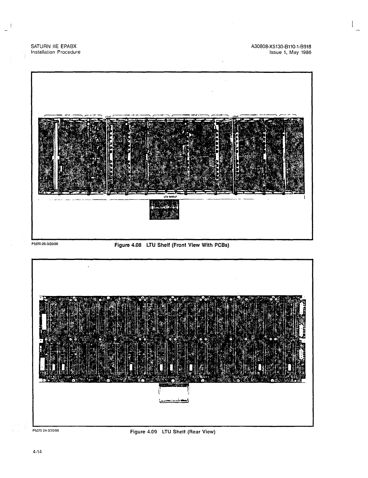
SATURN IIE EPABX A30808-X5130-BllO-l-8918
Installation Procedure Issue 1, May 1986
P5070-26-3/20/66
Figure 4.08 LTU Shelf (Front View With PCBs)
P5070.24.3/20/66
Figure 4.09 LTU Shell (Rear View)
4-14
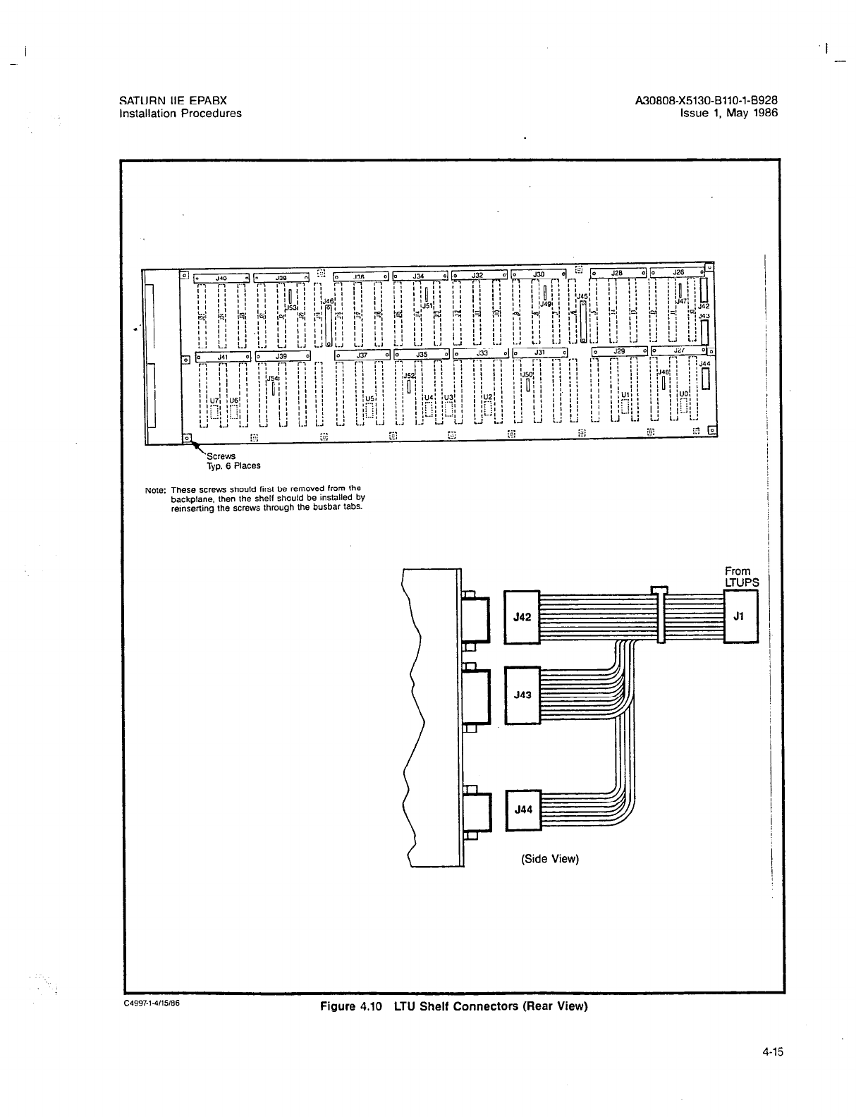
I -
SATURN IIE EPABX A30808-X5130-BllO-l-8928
installation Procedures Issue 1, May 1986
‘SCWS
Typ. 6 Places
Note: These screws should first be removed from the
backplane, then the shelf should be installed by
remserling the straws through the busbar tabs.
From
(Side View)
Figure 4.10 LTU Shelf Connectors (Rear View)
4-15
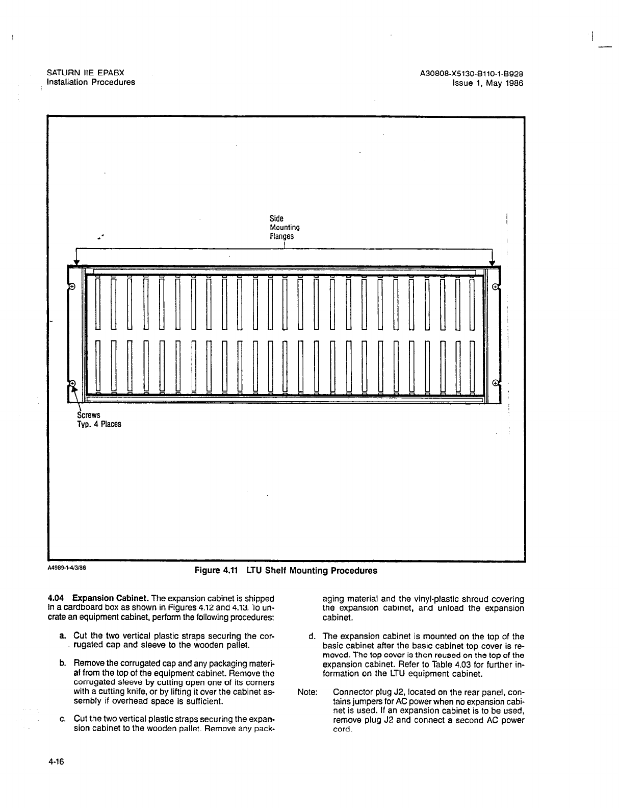
6
-
SATURN HE EPABX
installation Procedures A30808-X5130-8110-l-8928
Issue 1, May 1986
Side
Mounting
Flanges
I
Screws
Typ. 4 Places
-. _ _~ .-.. -. ._ __ . . - .
rlgure
4.11
LI u melt Mountmg Procedures
4.04 Expansion Cabinet. The expansion cabinet is shipped
in a cardboard box as shown in Figures 4.12 and 4.13. To un- aging material and the vinyl-plastic shroud covering
the expansion cabinet, and unload the expansion
crate an equipment cabinet, perform the following procedures: cabinet.
a. Cut the two vertical plastic straps securing the cor-
rugated cap and sleeve to the wooden pallet.
b. Remove the corrugated cap and any packaging materi-
al from the top of the equipment cabinet. Remove the
corrugated sleeve by cutting open one of its corners
with a cutting knife, or by lifting it over the cabinet as-
sembly if overhead space is sufficient.
d. The expansion cabinet is mounted on the top of the
basic cabinet after the basic cabinet top cover is re-
moved. The top cover is then reused on the top of the
expansion cabinet. Refer to Table 4.03 for further in-
formation on the LTU equipment cabinet.
c. Cut the two vertical plastic straps securing the expan-
sion cabinet to the wooden pallet. Remove any pack-
Note: Connector plug J2, located on the rear panel, con-
tains jumpers for AC power when no expansion cabi-
net is used. If an expansion cabinet is to be used,
remove plug J2 and connect a second AC power
cord.
4-16

I -
SATURN IIE EPABX
Installation Procedures
A30808-X5130-8110-l-8928
Issue 1, May 1986
A4YL)I.I.J,LO,tm
Figure 4.12 Expansion Cabinet Container
4-17
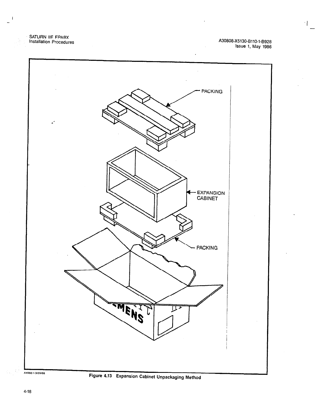
,I -
SATURN HE EPABX
installation Procedures A30808-X5130-BllO-l-B928
Issue 1, May 1986
.’
A4962.l-3/26/66
Figure 4.13 Expansion Cabinet Unpackaging Method
4-18

SATURN IIE EPABX
Installation Procedures A30808-X5130-6110-l-8928
Issue 1, May 1986
Expansion
j Cabinet
---a---.
Basic
Shelf 0
(224
port
LTU
Shelf 3
(256
ports)
LTU
Shelf 2
(256
ports)
Ir! - ,el L) I1
1
LTU
I
5%” FD DRIVES 1
C4866.l-2/11/66 c: -. . -- 1 . 1 I..--.- - ~~. L -...-. -
ryure 4.14 oaslc ana txpanslon Cabmets Equipment Configuration
4-19
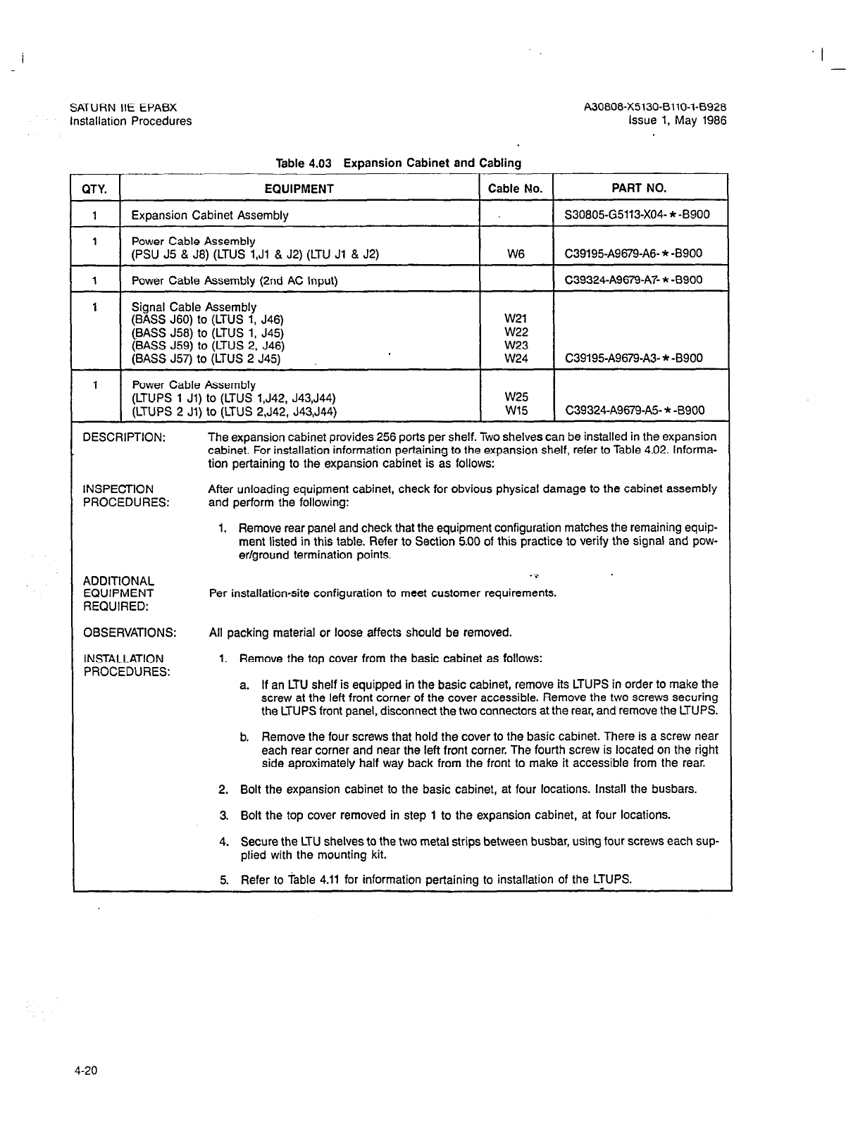
I -
SATURN IIE EPABX A30808-X5130-BilO-I-8928
Installation Procedures Issue 1, May 1986
Table 4.03 Expansion Cabinet and Cabling
‘Y. EQUIPMENT Cable No. PART NO.
I Expansion Cabinet Assembly S30805-G5113-X04- * -8900
I Power Cable Assembly
(PSU J5 & J8) (LTUS 1,Ji & J2) (LTU Jl & J2) W6 C39195A9679-A6- * -8900
I Power Cable Assembly (2nd AC Input) C39324-A9679-A7- * -8900
I Signal Cable Assembly
(BASS J60) to (LTUS 1, J46) w21
(BASS J58) to (LTUS 1, J45) w22
(BASS J59) to (LTUS 2, J46) W23
(BASS J57) to (LTUS 2 J45) W24 C39195-A9679-A3- * -8900
I Power Cable Assembly
(LTUPS 1 Jl) to (LTUS l,J42, J43,J44) w25
(LTUPS 2 Jl) to (LTUS 2,J42, J43,J44) w15 C39324-A9679-A5- * -8900
ZSCRIPTION: The expansion cabinet provides 256 ports per shelf. Two shelves can be installed in the expansion
cabinet. For installation information pertaining to the expansion shelf, refer to Table 4.02. Informa-
tion pertaining to the expansion cabinet is as follows:
SPECTION
3OCEDURES: After unloading equipment cabinet, check for obvious physical damage to the cabinet assembly
and perform the following:
1. Remove rear panel and check that the equipment configuration matches the remaining equip-
ment listed in this table. Refer to Section 5.00 of this practice to verify the signal and pow-
er/ground termination points.
IDITIONAL
lUlPMENT
:QUIRED:
. ‘0
Per installationsite configuration to meet customer requirements.
3SERVATIONS:
STALLATION
3OCEDURES:
All packing material or loose affects should be removed.
1. Remove the top cover from the basic cabinet as follows:
a. If an LTU shelf is equipped in the basic cabinet, remove its LTUPS in order to make the
screw at the left front corner of the cover accessible. Remove the two screws securing
the LTUPS front panel, disconnect the two connectors at the rear, and remove the LTUPS.
b. Remove the four screws that hold the cover to the basic cabinet. There is a screw near
each rear corner and near the left front corner. The fourth screw is located on the right
side aproximately half way back from the front to make it accessible from the rear.
2. Bolt the expansion cabinet to the basic cabinet, at four locations. Install the busbars.
3. Bolt the top cover removed in step 1 to the expansion cabinet, at four locations.
4. Secure the LTU shelves to the two metal strips between busbar, using four screws each sup-
plied with the mounting kit.
5. Refer to Table 4.11 for information pertaining to installation of the LTUPS.
4-20
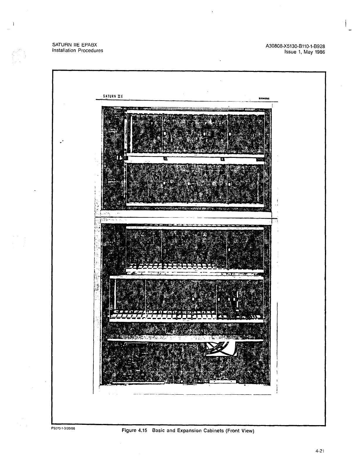
I
-
SATURN IIE EPABX
Installation Procedures A30808-X5130-BliO-l-8928
Issue 1, May 1986
SATURN IIIE
.
P5070-l-3120166
Figure 4.15 Basic and Expansion Cabinets (Front View)
4-21
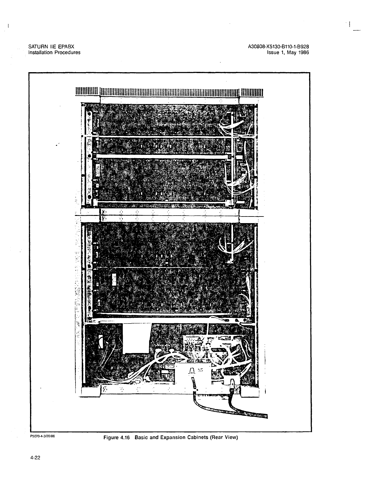
SATURN IIE EPABX
Installation Procedures
A30808-X5130-BllO-l-8928
Issue 1, May 1986
llllMllllll lllillllllllllllillllllllllllllllllllllllillllll~llllliillill~llllllllllllll~lllllflllllll
P5070-4.3120186
Figure 4.16 Basic and Expansion Cabinets (Rear View)
4-22

SATURN IiE EPABX
Installation Procedures A30808-X5130-BllO-l-8928
issue 1, May 1986
4.05 Power and Distribution Equipment. The SATURN IIE
System contains several power supply modules of various
sizes located within the system. Refer to Tables 4.06 through
4.11 for detailed information on these power modules.
The PSU has a connector plug (J2) on its rear panel, J2 con-
tains jumpers for AC power when no expansion cabinet is
used. If an expansion cabinet is to be used, remove plug J2
and connect a second AC power cord (see expansion cabi-
net installation for further information.
The PSU module contains the modules shown in Figure 4.19.
The Repairable Items of the PSU are listed in Table 4.04.
Table 4.04 Power System Unit (PSU) Repairable Items
QTY.
-1
EQUIPMENT REF. PART NO.
Memory Support Module Table 4.08 L30808-X5130-A34- * -8900
1 MSM Battery Pack Table 4.09 L30808-X5130-A51- * -8900
Table 4.05 Control Lo& Board
DESCRIPTION: The Control Logic Board, shown in Figure 4.19, is part of the PSU and is not a repairable item.
It provides access and control point to various system maintenance functions and serves as the
main AC and DC power distribution point to the following:
a. AC power, via circuit breakers, to the PSU, the LTUPS 0, 1, and 2, the 48Vdc Power Supplies
(48PS0 and 48PSl).
b. Fused -48Vdc outputs for talk battery PlMD,and SLMD applications to all channel groups in
the basic and LTU shelves, as well as the input to the RGEN module.
c. Fused 9OVac @ 20Hz for Ringing AC (RAC) and 97Vdc for Ringing Message Waiting (RMW)
to all channel groups in the basic and LTU shelves.
1. Indicators. The PSU panel has thirteen grasshopper-type fuses which provide visual
alarm indications when blown. These fuses and their designations are summarized
in Table 4.06. There are four LEDs on the control logic board: their functions are as
follows:
a. Alarm Indicators. One red LED, designated MAJ. when steadily lit, indicates a
major alarm condition exists in the system. One yellow LED, designated MIN,
when steadily lit, indicates a minor alarm condition exists in the system.
b. Failure Transfer Status Indicators. One red LED, designated ACTIVE, when steadily
lit, indicates the failure transfer relay subsystem is active. One yellow LED, desig-
nated INHIBIT, when steadily lit, indicates the failure transfer relay subsystem
is inactive. The failure transfer relay subsystem is customer-provided.
2. Switches. The PSU panel contains six switch/circuit breakers. These circuit breakers
and their PSU panel designations are summarized in Table 4.06. Also, a three-position
switch, designated FAILURE TRANSFER, is provided on the PSU panel. This switch
provides a selection of automatic, active, or inhibit operation of the failure transfer re-
lay subsystem.
3. Connectors. One modular jack, designated MTCE PHONE, is provided on the PSU
panel. This jack is used as a termination point for the maintenance test phone.
4. Strapping Options. If MSMlLCL in the Memory Support Module is equipped, insert con-
nector J5 on the back of the PSU in MSM receptacle. If MSM is not equipped, insert
connector 55 in LCL.
EXT FUSE ALM. If no External Fuse Alarm, insert jumper clip in J15 on the back of
the PSU. If there is an External Fuse alarm, remove jumper clip from J15.
OBSERVATIONS: None.
INSTALLATION None. The equipment cabinet comes equipped with a PSU containing a Control Logic Board when
PROCEDURES: shipped from the tactory.
4-23

SATURN IIE EPABX
Installation Procedures A30808-X5130-6110-l-8928
Issue 1, May 1986
Table 4.08 PSU Front Panel Circuit Breakers and Fuses
FlO RAC Basic
Fll RAC LTUO
F12 FtAC LTUl
F13 RAC LTUP
CB No. DESIGNATION
CBl Basic PS
(Ringing AC to Basic Shelf)
(Ringing AC to LTU Shelf)
(Ringing AC to LTU Shelf)
(Ringing AC to LTU Shelf)
Circuit Breakers
Functions
AC Power to Basic Power SUDDIV
1/2A
112A
112A
1/2A
Rating
1OA
CB2
CB3
LTUPSO
LTUPSl
AC Power to LTU Power Supply 5A
AC Power to LTU Power Sumlv 5A
CB4
CB5
LTUPS2
48PS0
AC Power to LTU Power Supply
AC Power to 48V Power Suoolv
5A
10A
CB6 48PSl AC Power to 48V Power Supply 10A
NOTE: Fuses Fl through F13 are “grasshopper” type fuses in which a spring wire indicates when a fuse has blown.
4-24
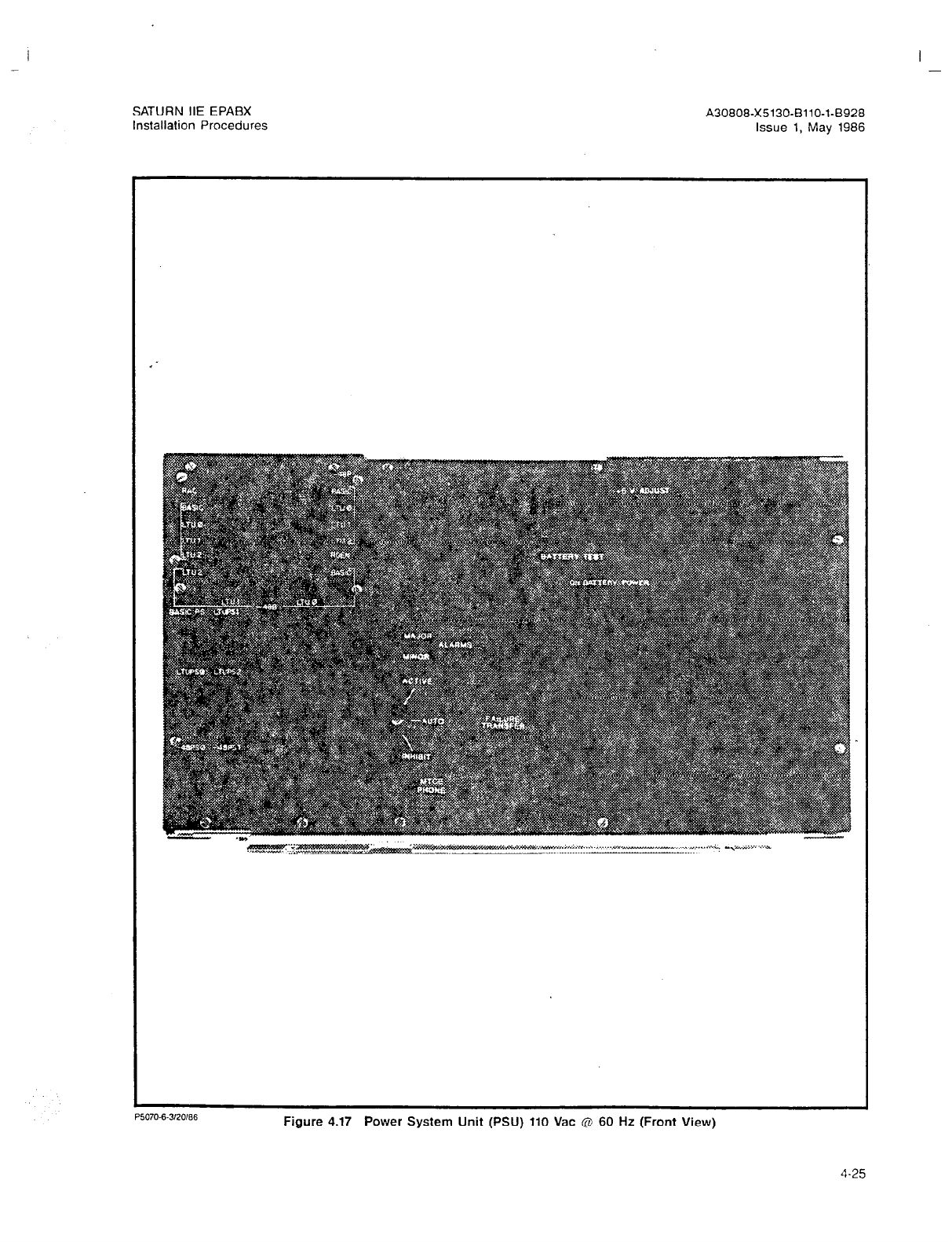
SATURN IIE EPABX A30808-X5130-BllO-l-8928
Installation Procedures Issue 1, May 1986
- I . . . . . . .*i: ..,~%,x~” . .
.^e.,aM :.
L
P5070-6-320186
Figure 4.17 Power System Unit (PSU) 110 Vat @ 60 Hz (Front View)
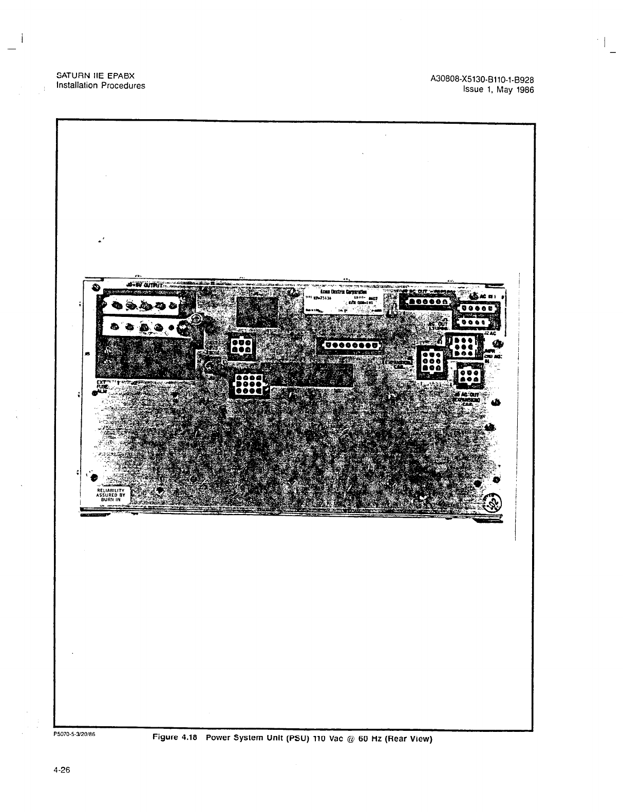
SATURN IIE EPABX
Installation Procedures A30808-X5130-8110-l-6928
Issue 1, May 1986
P5070.5.3!20!86
4-26
Figure 4.18 Power System Unit (PSU) 110 Vat Q 60 Hz (Rear View)
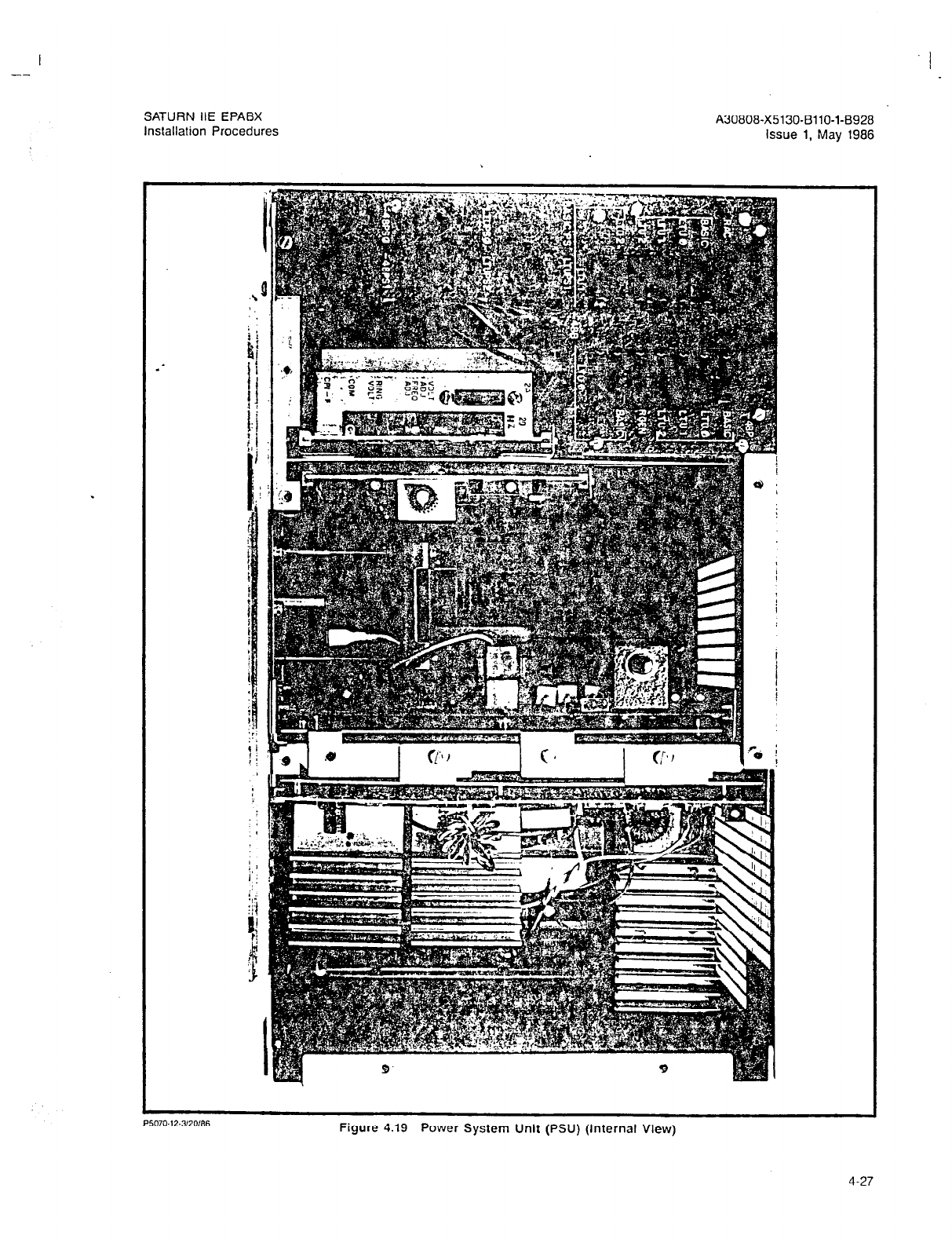
--
SATURN IIE EPABX A30806-X5130-BllO-l-8928
Installation Procedures Issue 1, May 1986
Figure 4.19 Power System Unit (PSU) (Internal View)
4-27
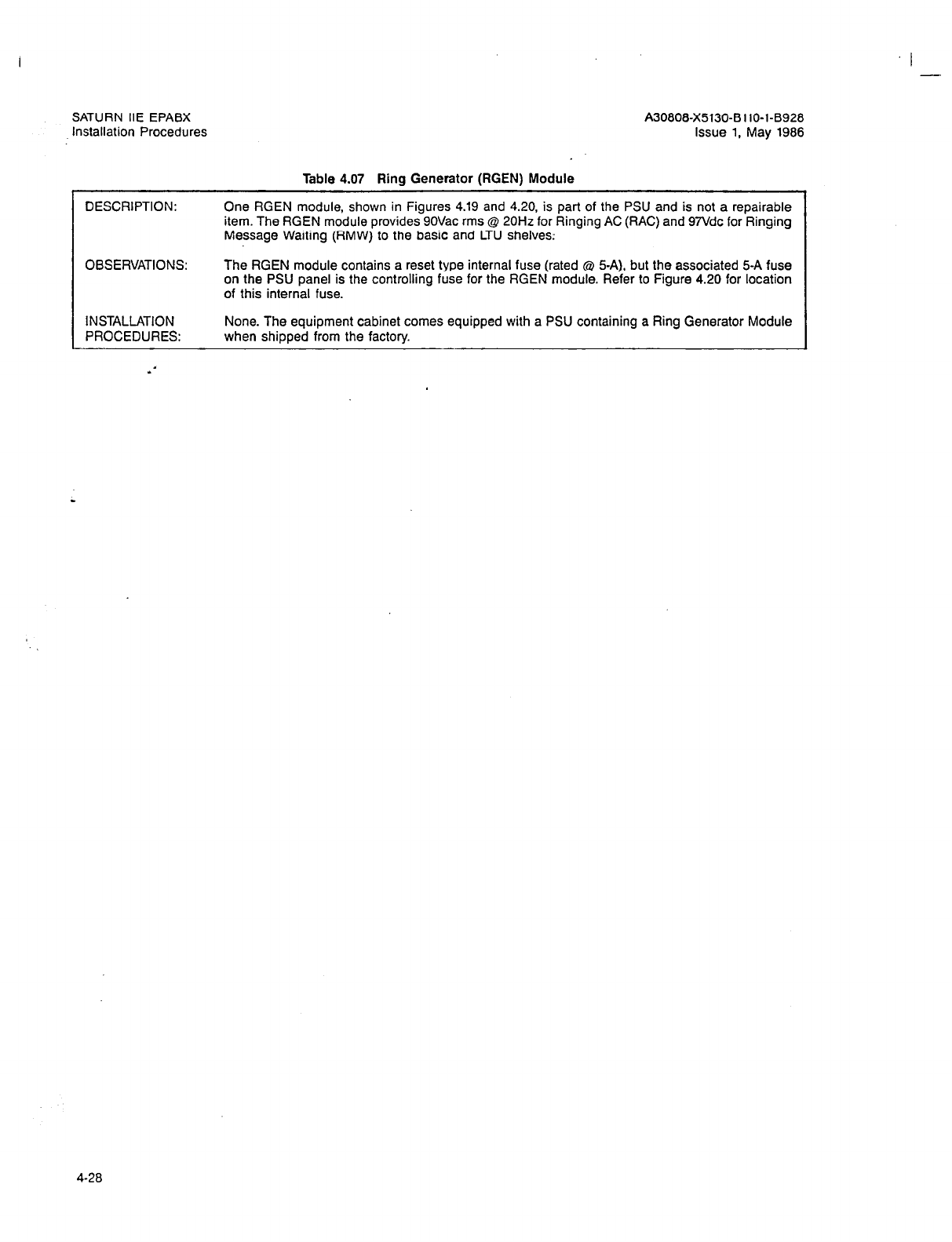
SATURN IIE EPABX
Installation Procedures
Table 4.07 Ring Generator (RGEN) Module
I -
A30809X5130-BllO-l-6925
Issue 1, May 1986
DESCRIPTION: One RGEN module, shown in Figures 4.19 and 4.20, is part of the PSU and is not a repairable
item. The RGEN module provides 9OVac rms @ 20Hz for Ringing AC (RAC) and 97Vdc for Ringing
Message Waiting (RMW) to the basic and LTU shelves;
OBSERVATIONS: The RGEN module contains a reset type internal fuse (rated @ 5-A), but the associated 5-A fuse
on the PSU panel is the controlling fuse for the RGEN module. Refer to Figure 4.20 for location
of this internal fuse.
INSTALLATION None. The equipment cabinet comes equipped with a PSU containing a Ring Generator Module
PROCEDURES: when shipped from the factory.
4-28
SATURN IIE EPABX
Installation Procedures A30808-X5130-BllO-l-8928
Issue 1, May 1986
-- .-.-_----
-.- I
z -,
Figure 4.20 RGEN Module (Front View)
4-29
I -
SATURN IIE EPABX A30808-X5130-BllO-l-8928
Installation Procedures Issue 1, May 1986
Table 4.08 Memory Support Module (MSM) PCB (L30808-X5130-A7- * -8900)
DESCRIPTION: The optional MSM, shown in Figure 4.19, is contained in a sealed package and is designed to pro-
vide +SVdc to the memory modules in the Basic Shelf if the local AC power fails. In the event
of a local power failure, the MSM battery maintains data-stored in memory for at least five minutes.
When the local power is restored, the battery is capable of another 5-minute cycle after 30 minutes
of charging. The charging provision is built into the MSM. Access for the battery test is through
the PSU front panel (labelled BATTERY TEST). See Figure 4.17.
Note: If optional MSM is installed, adjustment of the PSU 5 Vdc output voltage is required. Con-
nect voltmeter between J16 MSM connector pin and J9 (5V OUTPUT), located on the PSU
rear panel. Adjust the +5V ADJUST potentiometer located on the PSU front panel. The PSU
+5 Vdc output must be adjusted to 50 millivolts below +5MEM1+5B.
1. Indicators. The MSM has a green and a red LED:
a. The green LED is controlled by the MSM Battery Test Switch and is normally extin-
guished when the test switch is not being depressed. When the Battery Test Switch
is depressed, the LED is lit steadily if the battery is within acceptable voltage limits.
If the battery is below the acceptable voltage limits, the green LED remains extinguished.
b. The red LED is normally extinguished. In the event of an AC power failure and the bat-
tery is powering the memory, the LED is steadily lit. When the AC power source is re-
stored, the red LED is extinguished.
2. Switches. The MSM contains one switch called the Battery Test Switch, which is a momen-
tary switch. When depressed,it disconnects the battery from the charging circuit and con-
nects it to a test load and battery test indicator circuit.
3. Strapping Options. MSMILCL. If the Memory Support Module is equipped, remove connec-
tor J16 on the back of the PSU from the LCL receptacle, and insert it in the MSM receptacle.
OBSERVATIONS:
INSTALLATION
PROCEDURES:
None.
Note: PSU circuit breaker CBl must be in the off position before the MSM PCB is installed in the
PSU.
1. The MSM module is installed within the PSU module. No installation preparation is required.
If replacement is required, perform the following steps:
a. Remove the seven screws securing the PSU front panel (refer to Figure 4.17).
b. Remove two screws installed in the vertical partition and two screws installed in the
base of the PSU chassis.
2. For installation,locate the two plastic card guides in the PSU which support the MSM PCB.
Engage the MSM PCB (not the metal backing plate) into the card guides. The MSM PCB
should engage smoothly into the mating connector at the rear of the PSU. If the connector
does not engage, check the connector pins for alignment. After the MSM PCB is installed,
secure the MSM PCB with the two screws removed in step 1.
3. Install the battery connector wire from the Battery pack into the mating connector on the MSM
PCB.
4. Replace the PSU front panel.
Note: The LCUMSM option strap on the rear of the PSU must be changed before the PSU
circuit breaker is turned on.
5. Place PSU circuit breaker CBl in on position.
6. Refer to the SATURN IIE EPABX Installation Test Procedures practice for further instructions
to test the MSM operation.
4-30
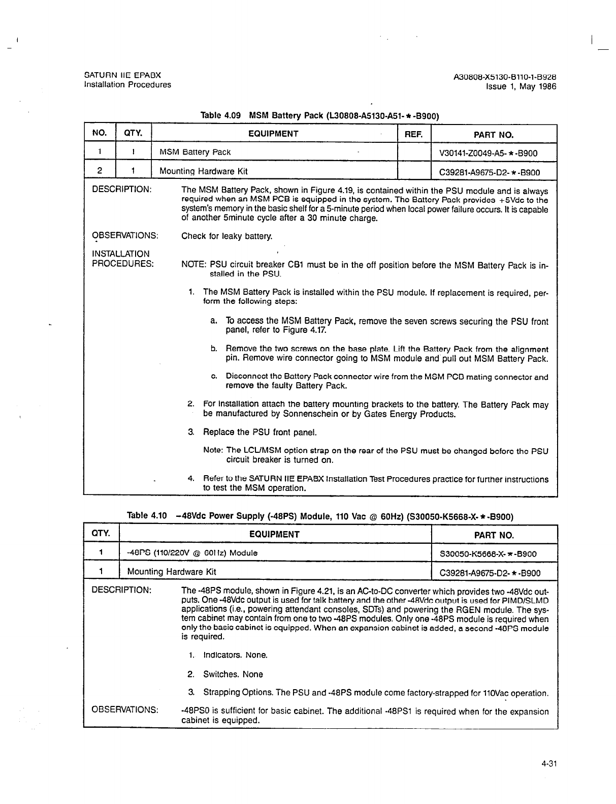
I -
SATURN IIE EPABX A30808-X5130-BllO-l-8928
Installation Procedures Issue 1, May 1986
Table 4.09 MSM Battery Pack (L30608-A5130A51- * -8900)
NO. QTY. EQUIPMENT REF. PART NO.
1 1 MSM Battery Pack V30141-20049~A5- * -8900
2
1 Mounting Hardware Kit C39281-A9675-D2- * -8900
DESCRIPTION:
OBSERVATIONS:
L
INSTALLATION
PROCEDURES:
The MSM Battery Pack, shown in Figure 4.19, is contained within the PSU module and is always
required when an MSM PCB is equipped in the system. The Battery Pack provides +SVdc to the
system’s memory in the basic shelf for a 5-minute period when local power failure occurs. It is capable
of another Sminute cycle after a 30 minute charge.
Check for leaky battery.
NOTE: PSU circuit breaker CBl must be in the off position before the MSM Battery Pack is in-
stalled in the PSU.
1. The MSM Battery Pack is installed within the PSU module. If replacement is required, per-
form
the following steps:
a. To access the MSM Battery Pack, remove the seven screws securing the PSU front
panel, refer to Figure 4.17.
b. Remove the two screws on the base plate. Lift the Battery Pack from the alignment
pin. Remove wire connector going to MSM module and pull out MSM Battery Pack.
c. Disconnect the Battery Pack connector wire from the MSM PCB mating connector and
remove the faulty Battery Pack.
2. For installation attach the battery mounting brackets to the battery. The Battery Pack may
be manufactured by Sonnenschein or by Gates Energy Products.
3. Replace the PSU front panel.
Note: The LCUMSM option strap on the rear of the PSU must be changed before the PSU
circuit breaker is turned on.
4. Refer to the SATURN IIE EPABX Installation Test Procedures practice for further instructions
to test the MSM operation.
L
Table 4.10 -48Vdc Power Supply (-48PS) Module, 110 Vat @ 60Hz) (S30050-K5668-X- * -B900)
QTY. EQUIPMENT PART NO.
1
-48PS (110/22OV @ 60Hz) Module S30050-K5668-X- * -8900
1 Mounting Hardware Kit C39281A9675-D2- * -8900
DESCRIPTION: The -48PS module, shown in Figure 4.21. is an AC-to-DC converter which provides two -48Vdc out-
puts. One -48Vdc output is used for talk battery and the other -48Vdc output is used for PlMDlSLMD
applications (i.e., powering attendant consoles, SDTs) and powering the RGEN module. The sys-
tem cabinet may contain from one to two -48PS modules. Only one -48PS module is required when
only the basic cabinet is equipped. When an expansion cabinet is added, a second -48PS module
is required.
1. Indicators. None.
2. Switches. None
OBSERVATIONS:
3. Strapping Options. The PSU and -48PS module come factory-strapped for 11OVac operation.
-48PS0 is sufficient for basic cabinet. The additional -48PSl is required when for the expansion
cabinet is equipped.
4-31
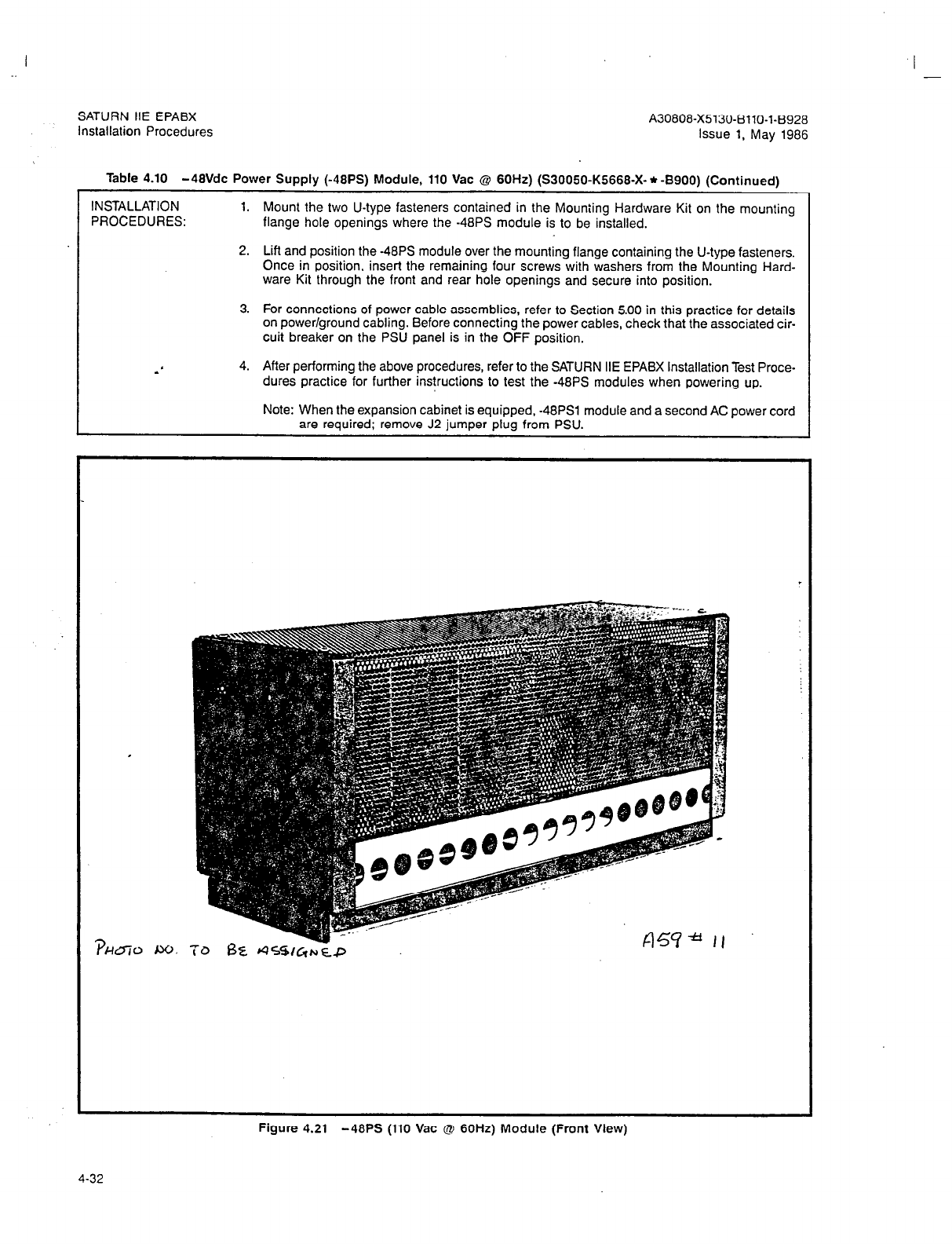
SATURN IIE EPABX A30808-X5130-BllO-l-8928
Installation Procedures Issue 1, May 1986
I -
Table 4.10 -48Vdc Power Supply (-48PS) Module, 110 Vat Q 60Hz) (S30050-K5668-X- * -8900) (Continued)
INSTALLATION 1.
PROCEDURES: Mount the two U-type fasteners contained in the Mounting Hardware Kit on the mounting
flange hole openings where the -48PS module is to be installed.
2. Lift and position the -48PS module over the mounting flange containing the U-type fasteners.
Once in position, insert the remaining four screws with washers from the Mounting Hard-
ware Kit through the front and rear hole openings and secure into position.
3. For connections of power cable assemblies, refer to Section 5.00 in this practice for details
on power/ground cabling. Before connecting the power cables, check that the associated cir-
cuit breaker on the PSU panel is in the OFF position.
4. After performing the above procedures, refer to the SATURN IIE EPABX Installation Test Proce-
dures practice for further instructions to test the -48PS modules when powering up.
Note: When the expansion cabinet is equipped, -48PSl module and a second AC power cord
are required; remove J2 jumper plug from PSU.
Figure 4.21 -48PS (110 Vat @ 60Hz) Module (Front View)
4-32

I -
SATUAN IIE EPABX
Installation Procedures A30606-X5130-BllO-1-8928
Issue 1. May 1986
(Factory-Strapped)
.’
Figure 4.22 -48PS (110 Vat @ 60HZ) Module (Rear View)
4-33

SATURN IIE EPABX
Installation Procedures A30808-X5130-BllO-l-8928
issue 1, May 1988
Table 4.11 LTU Power Supply (LTUPS) Module, 110 Vat Q 60Hz (L30808-X5130639-*-6901)
QTY. EQUIPMENT REF. PART NO.
1 LTUPS Module Assembly V301141-ZOll-A158900
DESCRIPTION The LTUPS module, shown in Figure 4.23, is used to power the LTU shelf. The LTUPS module is
a switching power supply which provides +SVdc, -SVdc, +12Vdc and -12Vdc output power to the
LTU shelf.
1. Indicators. None.
2. Switches. None.
3. Strapping Options. Verify that the LTUPS is internally strapped for 11OVac input voltage, be-
fore installing.
OBSERVATIONS: When the LTU shelf is equipped, an LTU Power Supply module is required for powering purposes.
INSTALLATION 1. Insert the LTUPS from the front of the cabinet. Slide into place and fasten with 2 screws sup-
PROCEDURES: plied with the mounting kit.
2. For connections of power cable assemblies, refer to Section 5.00 for details on power/ground
cabling. Before connecting power cables, check that the associated circuit breaker on the
PSU panel is in the OFF position.
3. After installing the LTUPS module, refer to SATURN IIE EPABX Installation Test Procedures
practice for further instructions to test the power supply when powering up.
4-34

I
-
SATURN IIE EPABX
Installation Procedures
I
A30808-X5130-8110-1-8928
Issue 1, May 1986
P5070-11.3120166
Figure 4.23 LTU Power Supply (LTUPS) Module, 110 Vat @ 60HZ
4-35
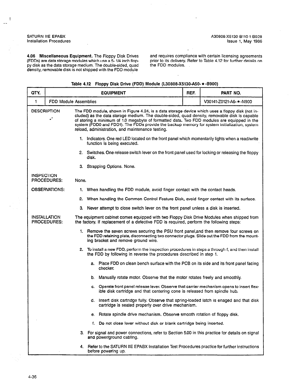
SATURN IIE EPABX A30808-X5130-BllO-l-6928
Installation Procedures issue 1. May 1986
4.06 Miscellaneous Equipment. The Floppy Disk Drives
(FDDs) are data storage modules which use a 5- l/4 inch flop-
py disk as the data storage medium. The double-sided, quad
density, removable disk is not shipped with the FDD module
and requires compliance with certain licensing agreements
prior to its delivery. Refer to Table 4.12 for further details on
the FDD modules.
Table 4.12 Floppy Disk Drive (FDD) Module (L30808-X5130-A50- * -8900)
QTY. EQUIPMENT REF. PART NO.
1 FDD Module Assemblies V30141-ZO121-A6- * -N900
DESCRIPTION The FDD module, shown in Figure 4.24, is a data storage device which uses a floppy disk (not in-
: cluded) as the data storage medium. The double-sided, quad density, removable disk is capable
of storing a minimum of 1.0 megabyte of formatted data. Two FDD modules are equipped in the
system (FDDO and FDDl). The FDDs provide the backup memory for system initialization, system
reload, administration, and maintenance testing.
1. Indicators. One red LED located on the front panel which momentarily lights when a read/write
function is being executed.
2. Switches. One release switch lever on the front panel used for locking or releasing the floppy
disk.
3. Strapping Options. None.
INSPECTION
PROCEDURES:
OBSERVATIONS:
INSTALLATION
PROCEDURES:
None.
1. When handling the FDD module, avoid finger contact with the contact heads.
2. When handling the Common Control Feature Disk, avoid finger contact with its surface.
3. Never attempt to close switch lever on the front panel unless a disk is inserted.
The equipment cabinet comes equipped with two Floppy Disk Drive Modules when shipped from
the factory. If replacement of a defective FDD is required, perform the following steps:
1. Remove the seven screws securing the PSU front paneLand then remove four screws on
the FDD retaining plate, disconnecting two connector plugs. Slide out the FDD from the mount-
ing bracket and remove ground wire.
2. To install a new FDD, perform the inspection procedures in steps a through f; and then install
the FDD by following in reverse the procedures described in step 1.
a. Place FDD on clean bench surface with the PCB on its side and its front panel facing
checker.
b. Manually rotate motor. Observe that the motor rotates freely and smoothly.
c. Operate front panel release lever. Observe that carrier mechanism opens to insert flex-
ible disk cartridge and that centering cone is released from spindle hub.
d. Insert disk cartridge fully. Observe that spring-loaded latch is enaged and that disk
cartridge is seated properly over drive mechanism.
e. Rotate spindle drive mechanism. Observe smooth rotation of floppy disk.
f. Do not close lever without disk or blank cartridge being inserted.
3. For signal and power connections, refer to Section 5.00 in this practice for details on signal
and power/ground cabling.
4. Refer to the SATURN IIE EPABX Installation Test Procedures practice for further instructions
before powering up.
4-36
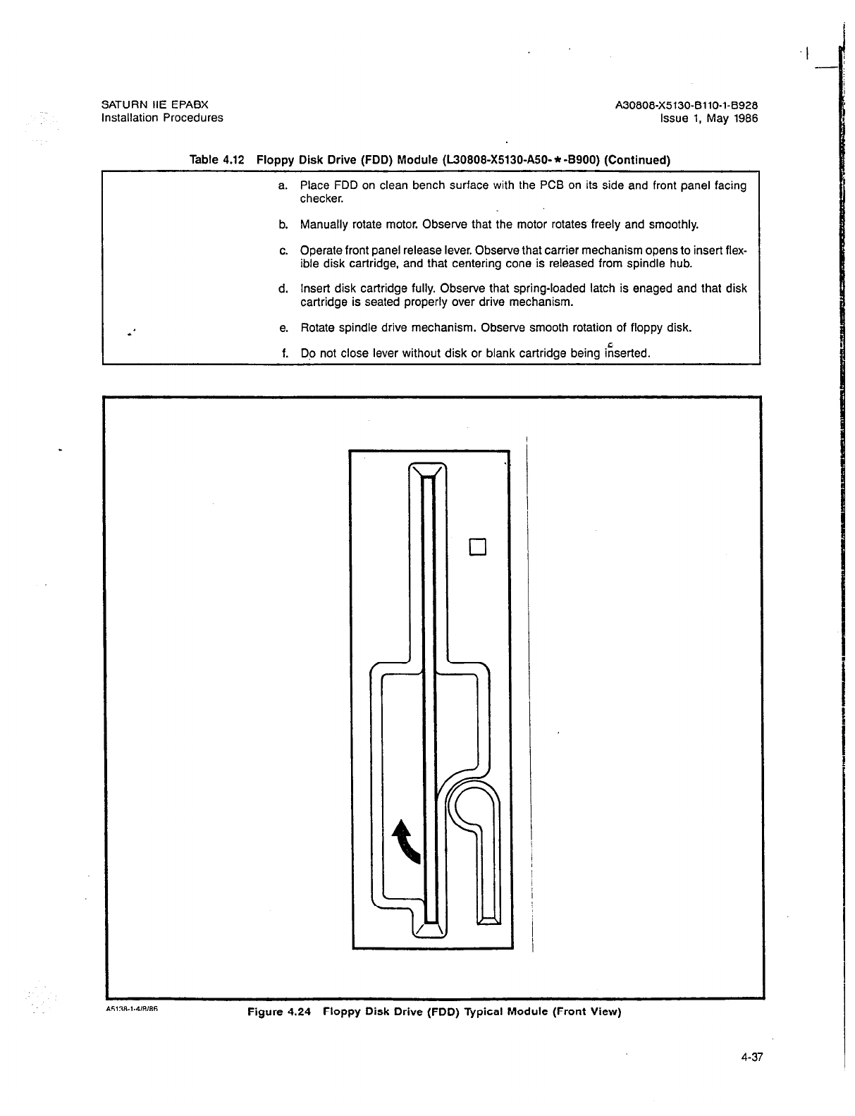
SATURN IIE EPABX A30808-X5130-BllO-l-B928
Installation Procedures Issue 1, May 1988
Table 4.12 Floppy Disk Drive (FDD) Module (L30808-X5130-A50-* -8900) (Continued)
a. Place FDD on clean bench surface with the PCB on its side and front panel facing
checker.
b. Manually rotate motor. Observe that the motor rotates freely and smoothly.
c. Operate front panel release lever. Observe that carrier mechanism opens to insert flex-
ible disk cartridge, and that centering cone is released from spindle hub.
d. Insert disk cartridge fully. Observe that spring-loaded latch is enaged and that disk
cartridge is seated properly over drive mechanism.
e. Rotate spindle drive mechanism. Observe smooth rotation of floppy disk.
f. Do not close lever without disk or blank cartridge being i;serted.
Figure 4.24 Floppy Disk Drive (FDD) Typical Module (Front View)
4-37
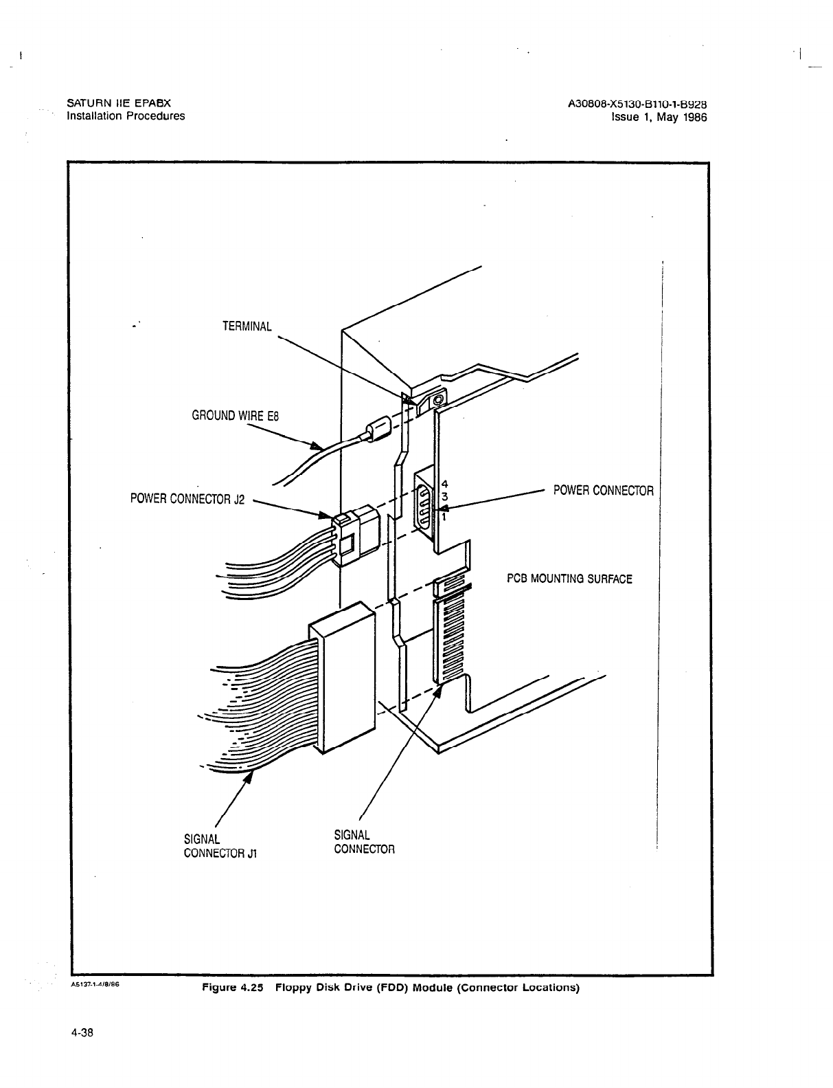
I
I -
SATURN HE EPABX
Installation Procedures A30808-X513043110-143928
Issue 1, May 1986
TERMINAL
GROUND WIRE E8
CONNECTOR J2 , I
PCB MOUNTING SURFACE
SIGNAL SIGNAL
CONNECTOR Jl CONNECTOR j
Figure 4.25 Floppy Disk Drive (FDD) Module (Connector Locations)
4-38

SATURN IIE EPABX
Installation Procedures
4.07 Printed Circuit Boards. The plug-in PCBs are 230mm
(9.02 in.) high by 280mm (11.02 in.) deep. Each PC6 has two
edge-connector tab areas with 60 terminals each. The PCBs
plug into mating 60-pin connectors mounted on the backplanes
of the basic and LTU shelves. Two extractor levers, mounted on
the faceplate of each PCB, allow for easy insertion or removal
from the shelf connectors. Each PCB comes factory-shipped in-
side an anti-static bag to protect the MOS integrated circuits.
Each bag is enclosed in foam material inside its carton as shown
in Figure 4.26.
CAUTION
Craft personnel handling PCBs with MOS integrated circuits
must first free themselves from electrostatic charge by
touching the frame of an already grounded system cabinet
or by wearing grounded wrist straps. Failure to observe this
practice may result in damage to the PCBs due to elec-
bvstafic discharge.
There are two types of PCBs: peripheral interfacing PCBs and
common equipment PCBs. The type of PCB may be readily
identified because the peripheral PCBs have a notch separat-
ing the two edge connectors and the common equipment PCBs
do not. Refer to the following tables for further information on
the peripheral interfacing PCBs and common equipment PCBs.
a. Peripheral Interfacing PCBs: 7. Table 4.29 - Memory 1.0 Megabyte (MEM4)
1. Table 4.13 - Dual-Tone Multifrequency (DTMF) 8. Table 4.30 - Memory 256K Kilobyte (MEMS)
Receiver 9. Table 4.31 -LineTTrunk Unit Control (LTUC)
Figure 4.26 PCB Packaging Method
I -
A30808-X5130-8110-l-8928
Issue 1, May 1986
2. Table 4.14 - Premium Instrument Module Digttal
(PIMD)
3. Table 4.15 - Subscriber Line Module Analog - Sta-
tion (SLMA-S)
3. Table 4.16 - Subscriber Line Module Analog - Off-
Premises (SLMA-0)
3. Table 4.17 - Subscriber Line Module Digital (SLMD)
3 Table 4.18 -Subscriber Line Module Analog - 16 Line
(SLA16)
4. Table 4.19 - Central Office Trunk (TMBM)
5. Table 4.20 - Direct Inward Dialing Trunk (TMIE)
6. Table 4.21 - Two-Wire E&M Trunk (TMBA-2)
7. Table 4.22 - Four-Wire E&M Trunk (TMsA-4)
b. Common Equipment PCBs:
1. Table 4.23 - Parallel/Serial Converter (PSC)
2. Table 4.24 - Signal Multiplexer/Clock/Tone Genera-
tor (SMXTG)
3 Table 4.25 - Conference (CONF)
4. Table 4.26 - Memory Control & Attenuation
(MCA)
5. Table 4.27 - Remote Access Unit/Ports (RAUP)
6. Table 4.28 - Controlledlnput-Output Processor (CIOP)
4-39
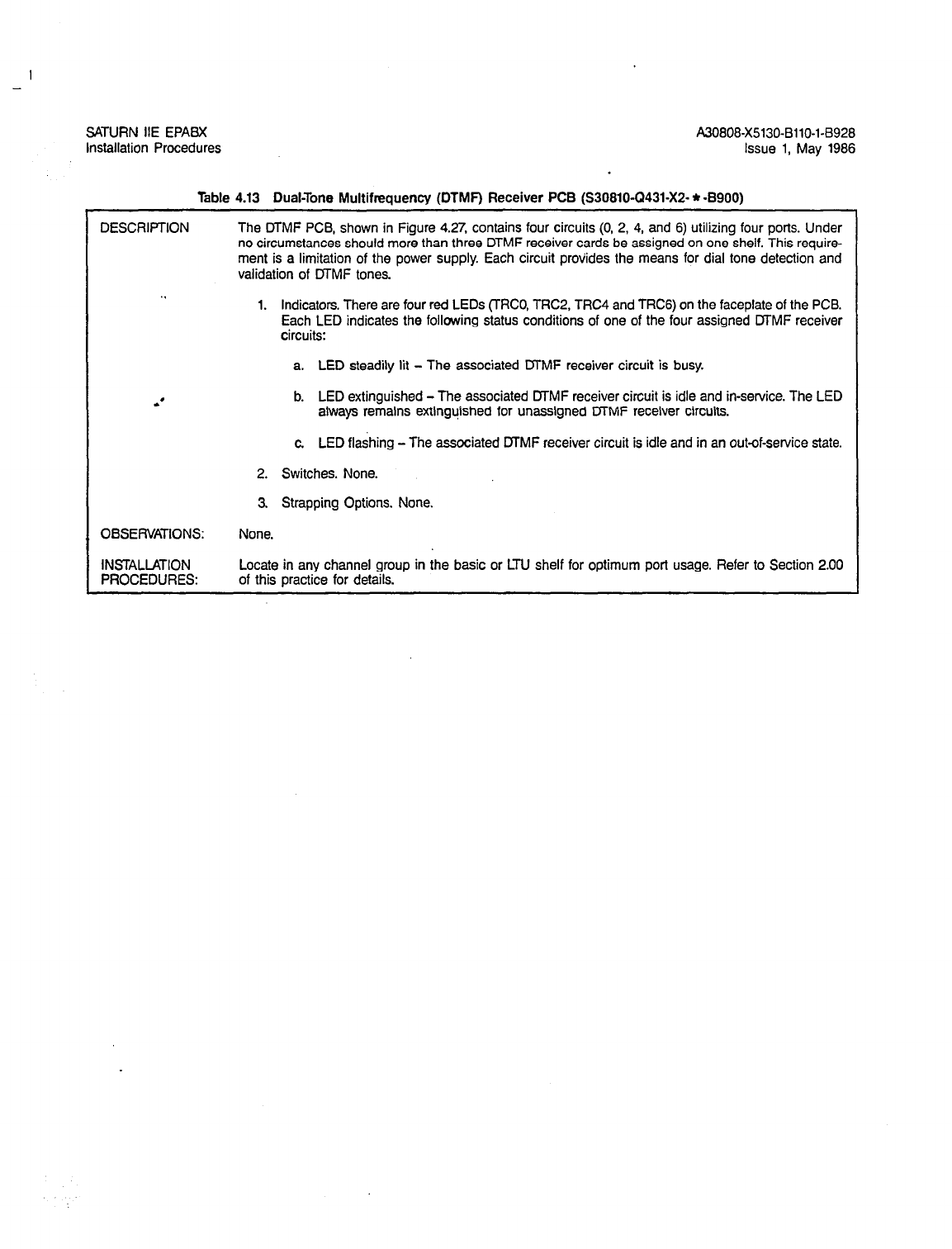
SATURN IIE EPABX A3O808-X5130-B110-1-8928
Installation Procedures Issue 1, May 1986
Table 4.13 Dual-Tone Multifrequency (DTMF) Receiver PCB (S30810-(2431-X2- * -B900)
DESCRIPTION The DTMF PCB, shown in Figure 4.27, contains four circuits (0, 2, 4, and 6) utilizing four ports. Under
no circumstances should more than three DTMF receiver cards be assigned on one shelf. This require-
ment is a limitation of the power supply. Each circuit provides the means for dial tone detection and
validation of DTMF tones.
1. Indicators. There are four red LEDs (TRCO, TRC2, TRC4 and TRCG) on the faceplate of the PCB.
Each LED indicates the following status conditions of one of the four assigned DTMF receiver
Circuits:
a. LED steadily lit - The associated DTMF receiver circuit is busy.
b. LED extinguished - The associated DTMF receiver circuit is idle and in-service. The LED
always remains extinguished for unassigned MMF receiver circuits.
OBSERVATIONS:
INSTALLATION
PROCEDURES:
c LED flashing - The associated MMF receiver circuit is idle and in an out-of-service state.
2. Switches. None.
3. Strapping Options. None.
None.
Locate in any channel group in the basic or LTU shelf for optimum port usage. Refer to Section 2.00
of this practice for details.

-
SATURN IIE EPABX A30808-X5130-8110-1-8928
Installation Procedures Issue 1, May 1986
4
.
Red LEDs-
Figure 4.27 DTMF PCB
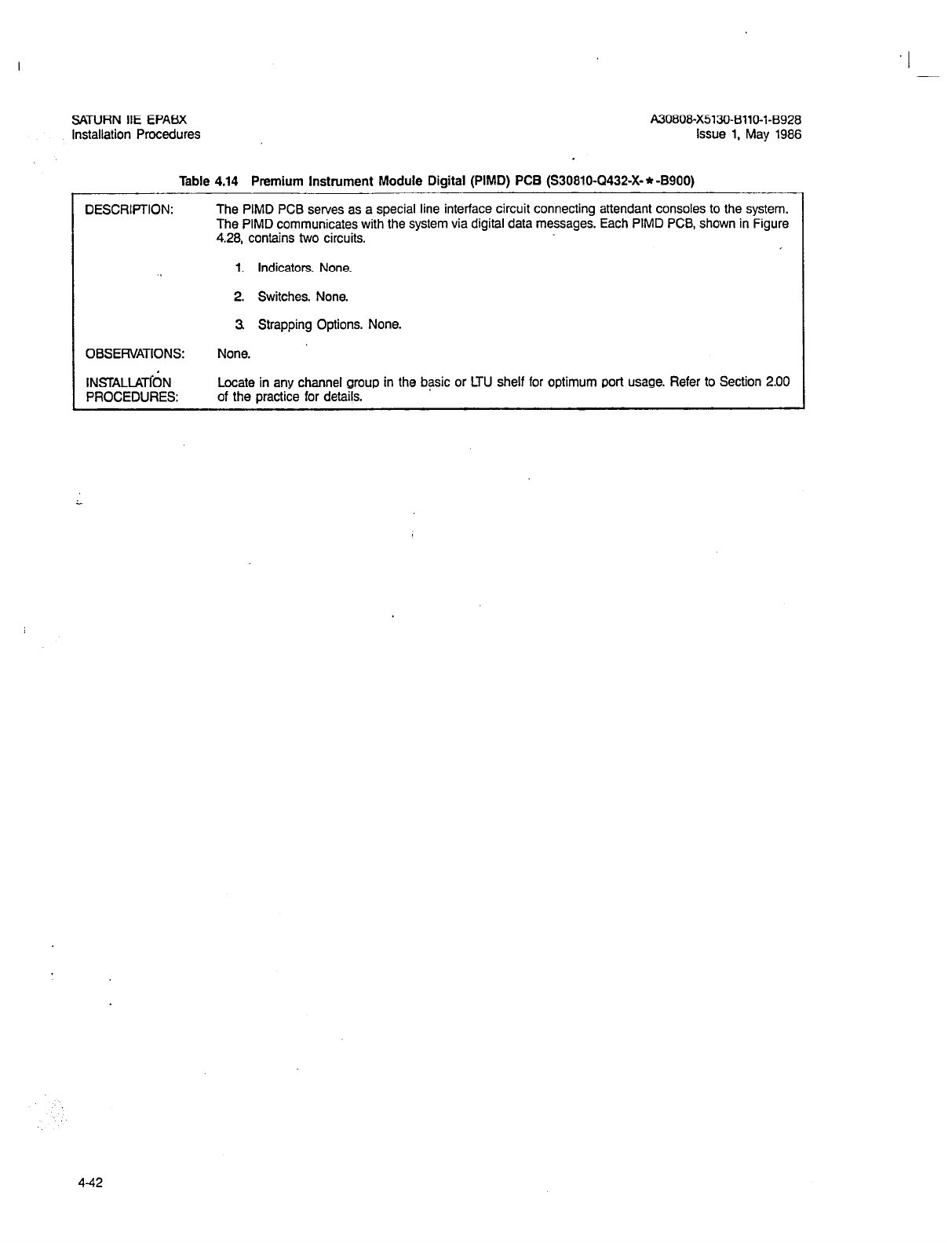
I -
A80808-X5180-8110-1-8928
issue 1, May 1986
Table 4.14 Premium Instrument Module Digital (PIMD) PCB (S30810-Q432-X- * -8900)
DESCRIPTION: The PIMD PCB serves as a special line interface circuit connecting attendant consoles to the system.
The PIMD communicates with the system via digital data messages. Each PIMD PCB, shown in Figure
4.28, contains two circuits.
1. Indicators. None.
2. Switches. None.
3 Strapping Options. None.
OBSERVATIONS: None.
INSTALiATdN
PROCEDURES: Locate in any channel group in the basic or LTU shelf for optimum port usage. Refer to Section 2.00
of the practice for details.
L
442
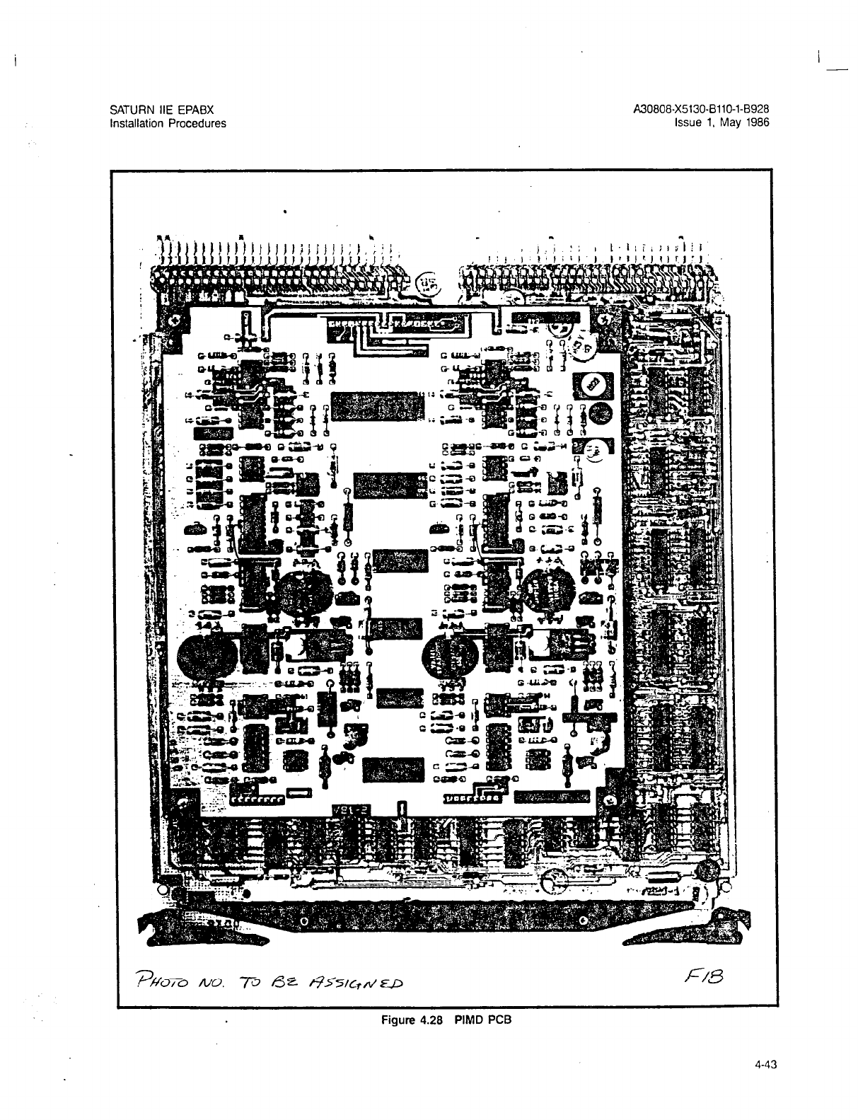
I -
SATURN IIE EPABX
Installation Procedures
A30808-X5130-BllO-l-8928
Issue 1. May 1986
.
Figure 4.28 PIMD PCB
4-43
SATURN HE EPABX A3O808-X5130-f3110-1-B928
Installation Procedures Issue 1, May 1986
I Table 4.15 Subscriber Line Module Analog - Station (SLMA-S) PCB (S30810-Q1674-X- * -B900) I
DESCRIPTION:
OBSERVATIONS:
INSTALLATION
PROCEDURES:
The SLMA-S PCB provides an interface between standard telephone sets (rotary dial and pushbutton)
and the system. The SLMA-S PCB, shown in Figure 4.29 , contains eight circuits (0 - 7) and utilizes
eight ports. Each circuit provides the required supervisory signaling plus the analog-toPCM and PCM-
to-analog transformation.
1. Indicators. One green LED which indicates the following status conditions:
a. LED lit steadily - One or more of the line circuits are busy.
b. LED extinguished - All assigned line circuits are idle and in-service.
c. LED flashing - All assigned line circuits are idle and one or more line circuits are in the
out-of-service state.
2. Switches. None:
3. Strapping Options. None.
The SLMA-S PCB can be used to terminate dial dictation circuits or ZUNA (Zoned Universal Night An-
swer) bells zoned for up to four zones, or other special equipment circuits.
Locate in any channel group per best port capacity
SATURN IIE EPABX
Installation Procedures A30808-X5130-BllO-l-8928
Issue 1, May 1986
,
Gieen LED
Figure 4.29 SLMA-S PCB
4-45
I -
A30808-X5130-8110-l-8928
Issue 1, May 1986
Table 4.16 Subscriber Line Module Analog - Off-Premises (SLMA-0) PCB (S30810-Ql7’39-X- * -B900)
DESCRIPTION:
. .
*’
The SLMA-C PCB provides an interface between standard telephone sets (rotary dial and pushbutton)
which are Off-Premises and the system. The SLMA-CI PCB, shown in Figure 4.30 , contains four circuits
(0, 2, 4, 6) and utilizes four ports. Each circuit provides the required supervisory signaling plus the analog
toPCM and PCM-to-analog transformation. The Off-Premises station can operate over a loop of 0 to
1800 Ohms, and is registered with the FCC for class “c” operation.
1. Indicators. One green LED which indicates the following status conditions:
a. LED lit steadily - One or more of the line circuits are busy.
b. LED extinguished - All assigned line circuits are idle and in-service.
c. LED flashing - All assigned line circuits are idle and one or more line circuits are in the
out-of-service state.
OBSERVATIONS:
INSTALLATION
PROCEDURES:
2. Switches. None.
3 Strapping Options. None.
None.
Locate in any channel group per best port capacity. Refer to Section 2.00 of this practice for details.
4-46

SATURN HE EPABX
installation Procedures A30808-X5130-8110-l-8928
Issue 1, May 1986
I
Figure 4.30 SLMA-0 PCB
4-47
I -
I
-
SATURN HE EPABX
installation Procedures A30808-X5130-Bllo-l-8928
Issue 1, May 1986
Table 4.17 Subscriber Line Module Digital (SLMD) PCB (S30810-Q1724-X-*-8900)
DESCRIPTION: The SLMD PCB provides an interface between standard Siemens digital telephone (SDT) sets and the
system. The SLMD PCB, shown in Figure 4.31 , contains eight circuits (O-7) and utilizes eight ports.
1. Indicators. One red LED which indicates the following status conditions:
a. LED lit steadily - One or more of the line circuits are busy
b. LED extinguished - All assigned line circuits are idle and in-service.
c LED flashing - All assigned line circuits are idle and one or more line circuits are in the
out-of-service state.
2. Switches. None.
3. Strapping Options. None.
I
OBSERVATIONS: None.
INSTALLATION Locate in any channel group in the basic or LTU shelf for optimum port usage. Refer to Section 2.00
PROCEDURES: of this practice for details.
-
4-48
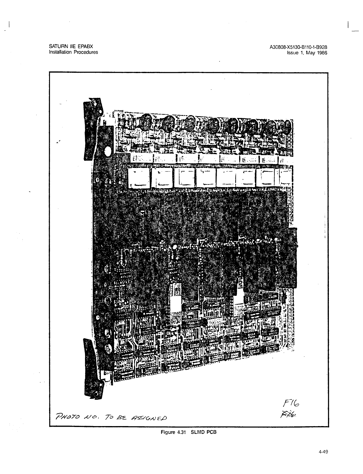
I -
SATURN IIE EPABX
Installation Procedures A30808-X5130-BllO-l-8928
issue 1, May 1986
Figure 4.31 SLMD PCB
4-49
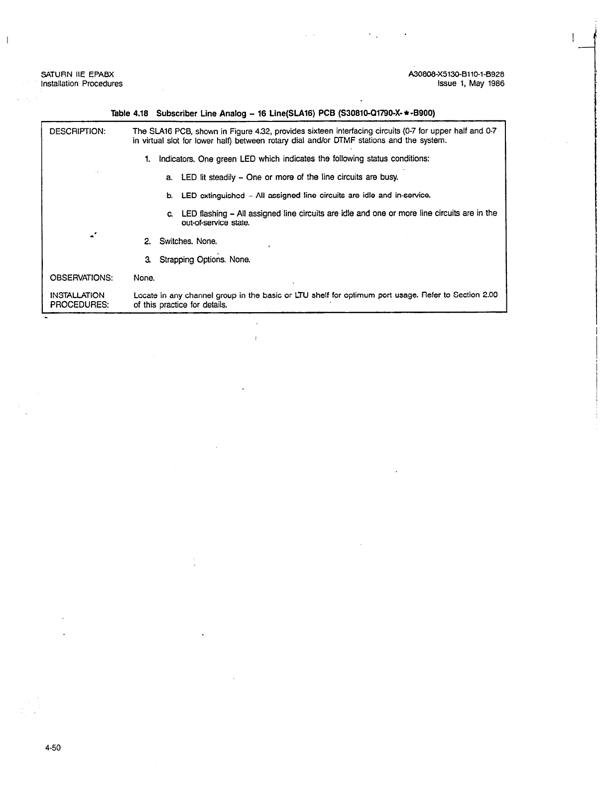
SATURN IIE EPABX
Installation Procedures
Issue
1, May 1986
Table 4.18 Subscriber Line Analog - 18 Line(SLA16) PCB (S30810-Q1790X * -8900)
DESCRIPTION: The SlAl6 PCB, shown in Figure 4.32, provides sixteen interfacing circuits (O-7 for upper half and O-7
in virtual slot for lower half) between rotary dial and/or DTMF stations and the system.
1. Indicators. One green LED which indicates the following status conditions:
a. LED lit steadily - One or more of the line circuits are busy.
b. LED extinguished - All assigned line circuits are idle and in-service.
c. LED flashing - All assigned line circuits are idle and one or more line circuits are in the
out-of-service state.
2. Switches. None.
OBSERVATIONS:
INSTALLATION
PROCEDURES:
3 Strapping Options. None.
None.
Locate in any channel group in the basic or LTU shelf for optimum port usage. Refer to Section 2.00
of this oractice for details.
4-50

-
SATURN HE EPABX
Installation Procedures A30808-X5130-BllO-l-8928
Issue 1, May 1986
.’
P557&22.920186
Figure 4.32 SLA16 PCB
4-51
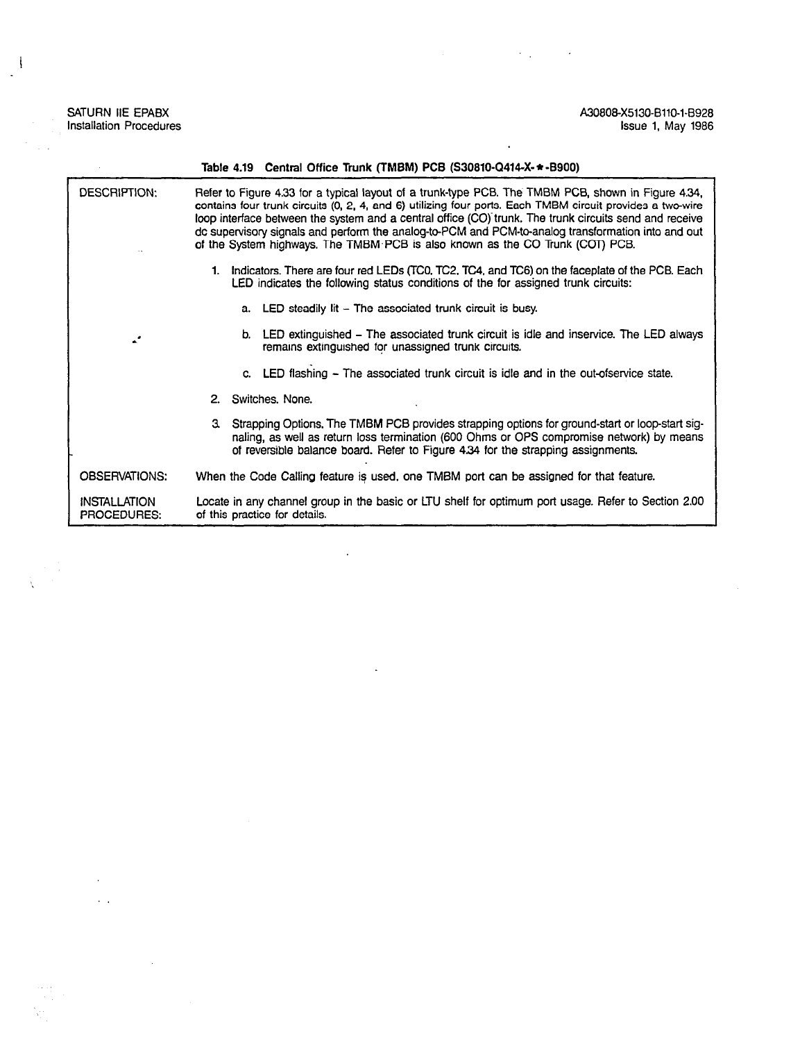
I
SATURN IlE EPABX
Installation Procedures A30808X5130-8110-1-8926
Issue 1, May 1986
DESCRIPTION:
Table 4.19 Central Office Trunk (TMEM) PC6 (S30810-Q414-X-*-8900)
Refer to Figure 4.33 for a typical layout of a trunk-type PCB. The TMBM PCB, shown in Figure 4.34,
contains four trunk circuits (0, 2, 4, and 6) utilizing four ports. Each TMBM circuit provides a two-wire
loop interface between the system and a central office (CO) trunk. The trunk circuits send and receive
dc supervisory signals and perform the analog-toPCM and PCM-to-analog transformation into and out
of the System highways. The TMBM’PCB is also known as the CO Trunk (Car) PCB.
1. Indicators. There are four red LEDs (TCO, TC2, TC4, and TCS) on the faceplate of the PCB. Each
LED indicates the following status conditions of the for assigned trunk circuits:
a. LED steadily lit - The associated trunk circuit is busy.
b. LED extinguished - The associated trunk circuit is idle and inservice. The LED always
remains extinguished for unassigned trunk circuits.
c. LED flashing - The associated trunk circuit is idle and in the out-ofservice state.
2. Switches. None.
3 Strapping Options, The TMBM PCB provides strapping options for ground-start or loop-start sig-
naling, as well as return loss termination (600 Ohms or OPS compromise network) by means
of reversible balance board. Refer to Figure 4.34 for the strapping assignments.
OBSERVATIONS: When the Code Calling feature is used, one TMBM port can be assigned for that feature.
INSTALLATION Locate in any channel group in the basic or LTU shelf for optimum port usage. Refer to Section 2.00
PROCEDURES: of this practice for details.
4-52
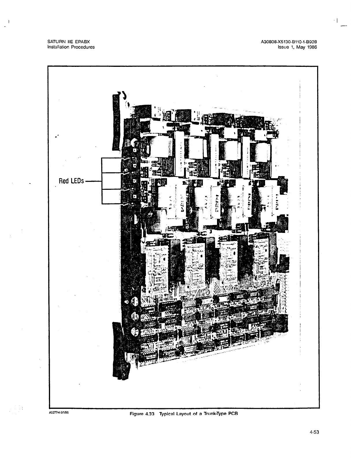
I
SATURN IIE EPABX A3o808-x5130-B110-1-8928
Installation Procedures Issue 1. May 1986
Red LEDs
Figure 4.33 Typical Layout of a Trunk-Type PCB
4-53
A30808-X513043110-143926
Issue 1, May 1986
Function Jumper Pins
GND Start VlOl-V401 1 to 2
Loop Start’ VlOl-v401 2 to 3
fat
identifie
of ealance
Balance
Balance Board Return Loss
A. With pin one of balance board in pin one
of balance board socket (as shown above)
the return ioss termination is:
600 Ohms t2.16pF.
8. With pin one of balance board in pin
twelve of balance board socket (reverse),
the return loss termination is:
B%G+5- 5//i% nominal 900 Ohms. F&Jo
85277-55/1/ffi
Figure 4.34 TMBM PCB
4-54
I -
A30808-X5130-BllO-l-6928
Issue 1, May 1986
DESCRIPTION:
.I
Table 4.20 Direct Inward Dialing Trunk
(TMIE)
PCB (S30810-Q415-X-*-B900)
The TMIE PCf3, shown in Figure 4.35, contains four trulik circuits (0. 2, 4, and 6) utilizing four ports.
Each TMIE trunk circuit provides direct inwarddialing service from a CO to the system . The trunk cir-
cuits send and receive dc supervisory signals, provide loop battery, and perform the analog lo PCM
and PCM to analog transformation. The TMIE PCB is also referred to as a DID trunk board.
1. Indicators. There are four red LEDs (TCO, TC2, TC4, and TC6) on the faceplate of the PCB. Each
LED indicates the following status conditions of one of the four assigned Trunk Circuits:
a. LED steadily lit - The associated trunk circuit is busy.
b. LED extinguished - The associated trunk circuit is idle and in-service. The LED always
remains extinguished for unassigned trunk circuits.
c. LED flashing L The associated trunk circuit is idle and in the out-of-service state.
2. Switches. None.
3. Strapping Options. Balance board options for return loss termination (600 ohms or OPS com-
promise network) are shown on Figure 4.35.
OBSERVATIONS: None.
INSTALLATION Locate in any channel group in the basic or LTU shelf for optimum port usage. Refer to Section 2.00
PROCEDURES: of this practice for details.
4-55
SATURN IIE EPABX
Installation Procedures A30808-X5130-BllO-l-8928
Issue 1, May
1986
DC4
04
! identifie.
Balance
Balance
s Pir
Boa
Balance Board Return Loss
A. With pin one of balance board in pin one
of balance board socket (as shown above)
the return loss termination is:
600 Ohms t2.16pF.
B. With pin one of balance board in pin
twelve of balance board socket (reverse),
the return loss termination is:
nominal 900 Ohms.
n5.a 7 7-h - C///&z
F/7
852778511186
Figure 4.35 TMIE PCB
4-56
I I --
SATURN IIE EPABX A30808-X5130-8110-l-8928
Installation Procedures Issue 1, May 1986
DESCRIPTION:
Table 4.21 Two-Wire E&M Trunk (TM&%2) PCB (S30810-Q429X * -8900)
The TMBA-2 (E&M signaling) PCB, shown in Figure 4.36, provides either one-way or two-way incoming
and outgoing trunk service. The TMBA-2 PCB contains four separate two-wire trunk circuits (0, 2, 4,
and 6) utilizing four ports Each trunk circuit provides a 2-wire voice pair and E&M signaling leads be-
tween the system and a distant PABX or signaling equipment. The trunk circuits send and receive dc
supervisory signals and perform the analog-to-PCM and PCM-to-analog transformation into and out of
the SATURN System highways.
1. Indicators. There are four red LEDs (TCO, TC2, TC4, and TC6) on the faceplate of the PCB. Each
LED indicates the following status conditions of one of the four assigned trunk circuits
a. LED steadily lit - The associated trunk circuit is busy.
b. LED extinguished - The associated trunk circuit is idle and in-service. The LED always
remains extinguished for unassigned trunk circuits.
c LED flashing - The associated trunk circuit is idle and in the out-of-service state.
2. Switches. None.
3. Strapping Options. The TMBA2 PCB provides strapping options for E&M signaling (type I, IA,
or II), as well as return loss termination (600 Ohms or OPS compromise network) via balance
boards. Refer to Flgure 4.36 for the strapping assignments.
OBSERVATIONS: When the Paging (with A&wetback) feature is used, from one to four TMBA-2 ports can be assigned
for each page zone.
INSTALLATION
PROCEDURES: Locate in any channel group in the basic or LTU shelf for optimum port usage. Refer to Section 2.00
of this practice for details.
4-57
I -
SATURN IIE EPABX A30808-X5130-8110-l-8928
Installation Procedures Issue
1,
May
1986
VlOl v201 v301 v401
v102 v103 V202 V203 V302 V303 V402 V403
.: _.
.__
. .
. . . . .
TMBA2 PCB E&M Signaling Table
&77-
Function Jumper Pins Jumper Pins Jumper] Pins 1
v101 v102
Comments
Provides two ELM MDF signaling
leads: E/M (or WMAL
v403
v103
to 3 v203 This private line type interface is
v303 1 to 2 similar to above but is onfy used in
v403 Europe; information upon request.
VlOl v102 v103
Type II g; 2 to 3 “v;;; 2 to 3 ;g Provides four E&M MDF signaling
Open leads: E/SG/M/SB
v401 v402 v403 (or EAIEBIMAIMB).
l
- Factory-Strapped NOTE: The latest Balance Board is a hybrid ceramic
DIP where pin 1 is identified by a dot.
? - s/J/a6
F7
St+
5
B527%Fy1186
Figure 4.36 TMBA-2 PCB
4-58
SATURN IIE EPABX A30808-X5130-BllO-l-8928
Installation Procedures Issue 1, May 1986
DESCRIF’TION:
.
Table 4.22 Four-Wire E&M Trunk (TMBA-4) PCB (S30810-Q430-X- * -BSOO)
The TMBA-4 (E&M type signaling) PCB. shown in Figure -427, provides either one-way or two-way in-
coming and outgoing service. The TMBA-4 PCB contains four separate four-wire trunk circuits (0, 2,
4, and 6) utilizing four ports. Each trunk circuit provides a voice transmit pair, a voice receive pair and
E&M signaling leads between the system and a remote PABX or signaling equipment . The trunk cir-
cuits send and receive dc supervisory signals and perform the analog-toPCM and PCM-to-analog trans-
formation into and out of the system highways.
1. Indicators. There are four red LEDs (TCO, TC2, TC4, and TC6) on the faceplate of the PCB. Each
LED indicates the following status conditions of one of the four assigned trunk circuits:
a. LED steadily lit - The associated trunk circuit is busy.
b. LED extinguished - The associated trunk circuit is idle and in-service. The LED always
remains extinguished for unassigned trunk circuits.
c. LED flashing - The associated trunk circuit is idle and in the out-of-service state.
2. Switches. None.
3. Strapping Options. None.
OBSERVATIONS: 1. When the Paging (without Answer back) feature is used, from one to four TMBA-4 ports can
be assigned for each page zone.
2. When the Intercept Announcement feature is used, only one TMBA4 port can be assigned for
that feature.
3 When the ACD Announcement feature is used, only one TMBA4 port can be assigned for that
feature.
INSTALLATION
PROCEDURES:
4. When the Music on Hold feature is used, only one TMBA-4 port can be assigned for that feature.
Locate in any channel group in the basic or LTU
shelf for
optimum port usage. Refer to Section 2.00
of this practice for details.
4-59
SATURN IIE EPABX A30606-x5130-B110-1-8928
Installation Procedures Issue 1, May 1966
VlOl v102 v301 v302
rT TT
1 T
TWA4 PCS ELM Signaling Strap Table
Function Jumper Pins Jumper Pins Jumper Pins Comments
I VlOl I I v102 I I v103 1 I
Tvml
v403
v103 This private iine type intertace
12 v203 ? *.. D is similar to above but is only used
V:
1 V402 1 103 L 'u J
1 v403 in Europe; iniormation upon-
request.
,,.A” I Prowdes lour E&M MOF signaling
en / g /2103 1 Ieey~~~,x~(or )
, ..I”,
1 V402 1 .-".a
I 1 I 1 1 I I
n I
ialPl* ( Vi
1 ( 11021 I Normal
1 Dial P2 Vl 1 2 to 3 I I pos!tion (do not alter strap).
I I 1 Future use (do not use).
("Factory-Strapped)
la
Pi
1 x
Vi
wQ77Bwe6
‘. Figure 4.37 TMBA-4 PCB
4-60

SATURN IIE EPABX
Installation Procedures
I -
A30808-X5130-BllO-l-8928
Issue 1, May 1986
Table
4.23 Parallel/Serial Converter (PSC) PCB (S30810-Q419-X10- *
-B900)
DESCRIPTION:
.
The
PSC
PCB, shown in Figure 4.38, converts the serial Pulse Code Modulation (PCM) voice signals
to parallel signals and multiplexes these signals onto an eight-bit parallel highway. These parallel sig-
nals are then transferred to the MCA board for further processing.
The
reverse
function is also performed by the PSC when the signals are returned from the MCA for
forwarding to the peripheral circuits.
1. Indicators. None.
2. Switches. None.
*’ 3 Strapping Options. None.
OBSERVATIONS: None. _
INSTALLATION
PROCEDURES: Locate in basic shelf slots 20 and 22.
4-61
I
I -
SATURN IIE EPABX
Installation Procedures A30808-X5130-BllO-l-8928
Issue 1, May 1986
P5Lliu15-320186
Figure 4.38 PSC PCB
4-62
I
-
SATURN IIE EPABX A30808-X5130-8110-l-8928
Installation Procedures Issue 1, May 1986
Table 4.24 Signal Multiplexer/Clock/Tone Generator (SMXTG) PCS (S30810-Ql791-X- * -8900)
1
DESCRIPTION: DESCRIPTION: The SMXTG PCB, shown in Figure 4.39, is divided into three functional parts: the signal multiplexer,
the clock generator, and the tone generator.
. . . .
OBSERVATIONS: OBSERVATIONS:
INSTALLATION INSTALLATION
PROCEDURES: PROCEDURES:
The SMXlG is a hardwarecontrolled scanner/distributor which provides an interface between the line/trunk
units and the ClOP and handles control and status signals.
The clock generator produces the 8192MHz, 4.096MHz, 2.048MHz, and 250Hz clocking signals required
to operate the system.
The tone generator provides various tone outputs from which all the system DTMF tones and supervisory
tones are derived. The tone generator also provides a square wave timing signal for system generated
dial pulses.
1. Indicators. None. ’
2. Switches. None.
3 Strapping Options. None..
None.
Locate in the basic shelf slot 21.
4-63
SATURN IIE EPABX
Installation Procedures A30808-X5130-BllO-l-8928
Issue 1, May 1986
“-. “L_cl~
Figure 4.39 SMXTG PCB
4-64

SATURN IIE EPABX A30608-X5130-6110.l-8928
Installation Procedures Issue 1, May 1986
DESCRIPTION:
Table 4.25 Conference (CONF) PCB (S30810.Q417-X- + -B900)
The CONF PCB, shown in Figure 4.40, makes all connections involving three to eight ports. The PCB
provides four, &port and twenty-four 24, Cport conference circuits. A maximum of two conference PCBs,
CONFO and CONFI, can be allocated in a LTU shelf. CONFO PCB is standard with the system, CONFl
is optional.
1. Indicators. None.
O@SERVATIONS:
INSTALLATION
PROCEDURES:
2. Switches. None.
3 Strapping Options. None.
None.
Locate in the basic shelf slot 23.
I -
4-65
I
I -
SATURN iIE EPABX
Installation Procedures
P5on-z-m6
Figure 4.40 CONF PCB
A30808-X5130-BllO-l-8928
Issue 1, May 1986
4-66

SATURN HE EPABX A30808-X5130-BllO-l-8928
Installation Procedures Issue 1, May 1986
, I
Table 4.26 Memory Control and Attenuation (MCA) PCB (S30810-Q416X*-8900)
DESCRIPTION: The MCA PCB, shown in Figure 4.41, is divided into two functional parts: a Time Switch Unit (TSU)
and a controller. The TSU makes all port connections and provides attenuation for all calls being processed
in the system. The controller receives control data from the main central processor and causes the TSU
and conference unit(s) to make the required connections.
1. Indicators. None.
O_BSERVATIONS:
INSTALtATlON
PROCEDURES:
2. Switches. None.
3 Strapping Options. None.
None.
Locate in the-basic shelf slot 24.
4-67
I
SATURN HE EPABX
Installation Procedures A30808-X5130-BllO-l-B928
Issue 1. May 1986
Figure 4.41 MCA PCB
4-68

I
-
I -
SATURN IIE EPABX A30808-X5130-BllO-l-6928
Installation Procedures Issue 1, May 1986
IESCRIPTION:
.
Table 4.27 Remote Access Unit/Ports (RAUP) PCB (S30810-Q1792X * -8900)
The RAUP PCB, shown in Figure 4.42, contains a built in modem and interfaces with the CIOP MCA
and MEM for the transfer of data to and from terminals and the modem port. It supports three serial
ports which can be connected to any device tha! supports serial communication. Two of the ports are
RS232 type for TTY0 and TTY1 interfaces, the third is a 212A modem port for communications from
a remote terminal.
Note: The RAUP Module is required in the system.
The 212A modem port is answer only; no call origination capabilities exist. The port is equipped with
a loop-start trunk circuit and can interface with an SLMA or directly to a TELCO trunk. Firmware causes
the modem to self-set to 300 or 1200 baud to match the incoming baud rate. The default baud rate
is 300. Programmable via CMU controlled options are:
Data Bits 7 or 8 (Default 7)
Stop Bits 1 or 2 (Default 1)
Parity or No Parity (Default Parity)
Parity Odd or Even (Default Even)
Both RS232 serial ports are configured as Data Communications Equipment (DCE). The baud rate is
programmable via CMU for both ports. Any of the following 6 baud rates are available. The default baud
rate is 9600.
116 300 1200
2400 4800 9600
Connections can be made to the FtAUP PCB after insertion in slot 25. Any desired RS-232-C type device(s)
with a DTE interface (25 pin D-type male) can be connected to the RAUP TTY0 or TTY1 ports. llY0
is the upper connector and TTY1 is the lower connector. The desired port configuration for TTY0 and
llY1 for baud rate, .number of data bits, and parity may have to be adjusted via the system service
terminal to successfully communicate with the connected device. The modem port is connected upon
card insertion to a tip and ring pair that terminate at the back Saturn IIE common control back plane
at interface plug J44 pins 24 and 49, respectively. From this point the pair can be connection to a patch
block for external connection to a trunk or station line.
1. Switches. None.
2. Strapping Options. None.
OBSERVATION: There is one green LED; when lit indicates that the modem port is in use.
WARNING
The RAUP PCS contains CMOS
circuitry,
which can be damaged by static electricity. Anti-
static bags should be used when the RAUP PC6 is shipped or stored . Whenever possi-
b/e, a grounding strap should be worn by personal handling the RAUP PCB.
INSTALLATION
PROCEDURES: Locate in the basic shelf slot number 25.
4-69
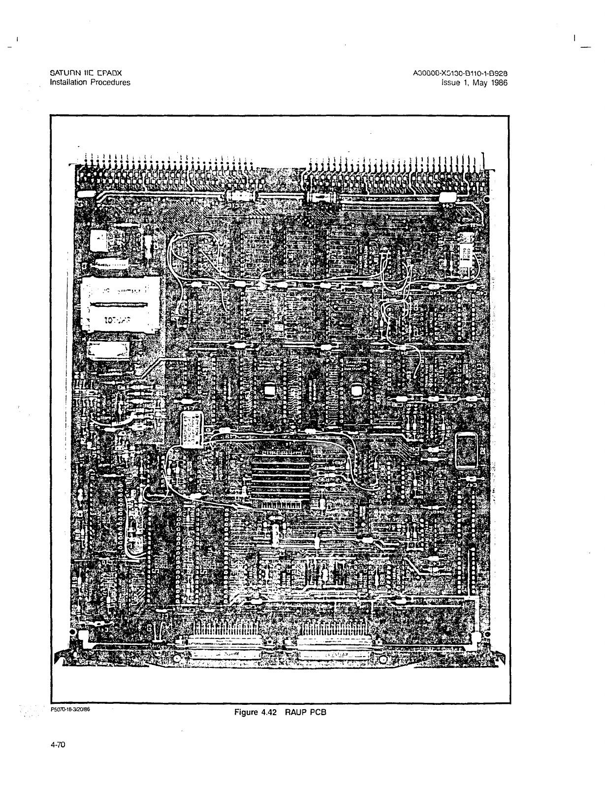
I -
SATURN IIE EPABX A30808-X5130-8110-1-8928
Installation Procedures Issue 1, May 1986
Figure 4.42 RAUP PCB
I
-
SATURN IIE EPABX A30808-X5130-BllO-l-8928
installation Procedures Issue 1, May 1986
Table 4.28 Controller/Input-Output Processor (CIOP) PCB (S30810-Q1789X
l
-8900)
DESCRIPTION: The CIOP PCB, shown in Figure 4.43, contains the main central processor, which processes incoming
data from the peripheral devices via the SMXTG, makes decisions based on the data received
using
instructions stored in memory and, as a result of these decisions, issues commands for call processing.
The Signal Input Buffer (SIB) contains a processor which controls the CIOP TTY port.
I
. Software controlled options for TTY port are as follows:
1.
Data Bits 7 or 8
Stop Bits 1 or 2
Parity or No Parity
Parity Odd or Even
(Default 7)
(Default 1)
(Default Parity)
(Default Even)
Indicator. There is one green LED. When lit it indicates that the TTY port is in use.
OBSERVATIONS:
INSTALLATION
PROCEDURES:
2. Switches. The TIY port is controlled by switch settings unless overridden by software.
3 Strapping Options. None.
None.
Locate in basic shelf slot number 26
4-71
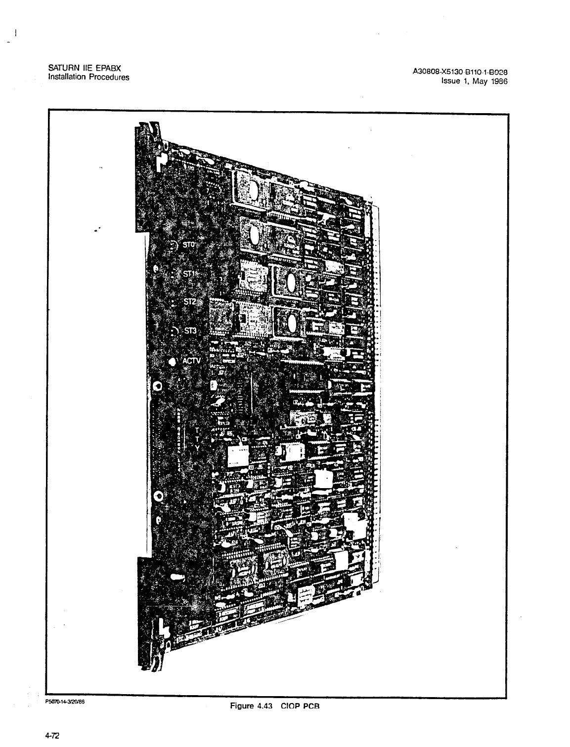
SATURN IIE EPABX
Installation Procedures A30808-X5130-8110-1-6928
issue 1. May 1986
PWiUW3ZTiE6
Figure 4.43 CIOP PCB
4-72
SATURN IIE EPABX
Installation Procedures A30808-X5130-6110-1-8928
Issue 1. May 1986
Table 4.29 Memory 1.0 Megabyte (MEM4) PCB (S30819-Ql775-X-*-8900)
DESCRIPTION: The MEM4 PCB, shown in Figure 4.44, provide 1.0 megabyte of dynamic Random Access Memory (RAM)
and its supporting logic to store system data. The memory is organized as 512K words X 16 bits/word,
and divided into 64K byte pages. Memory write protection is provided in 1K word segments. MEM4 is
arranged for battery backup memory protection to safeguard stored data during short term power out-
ages. Also, an Error-Correcting Code is provided to correct any single-bit errors and detect double-bit
errors existing in a word.
1. Switches. None,
2. Strapping Options. MEM4 PC8 Vl and V2 must be strapped as follows to provide for 1.0 mega-
byte of memory:
Vl strapped between 1 and 2
V2 strapped between’ 2 and 3
OBSERVATIONS: Check LEDs for normal indications (Refer to Maintenance and Troubleshooting Section)
OBSERVATIONS: None.
INSTALLATION
PROCEDURES: Locate in basic shelf slot number 27.
4-73
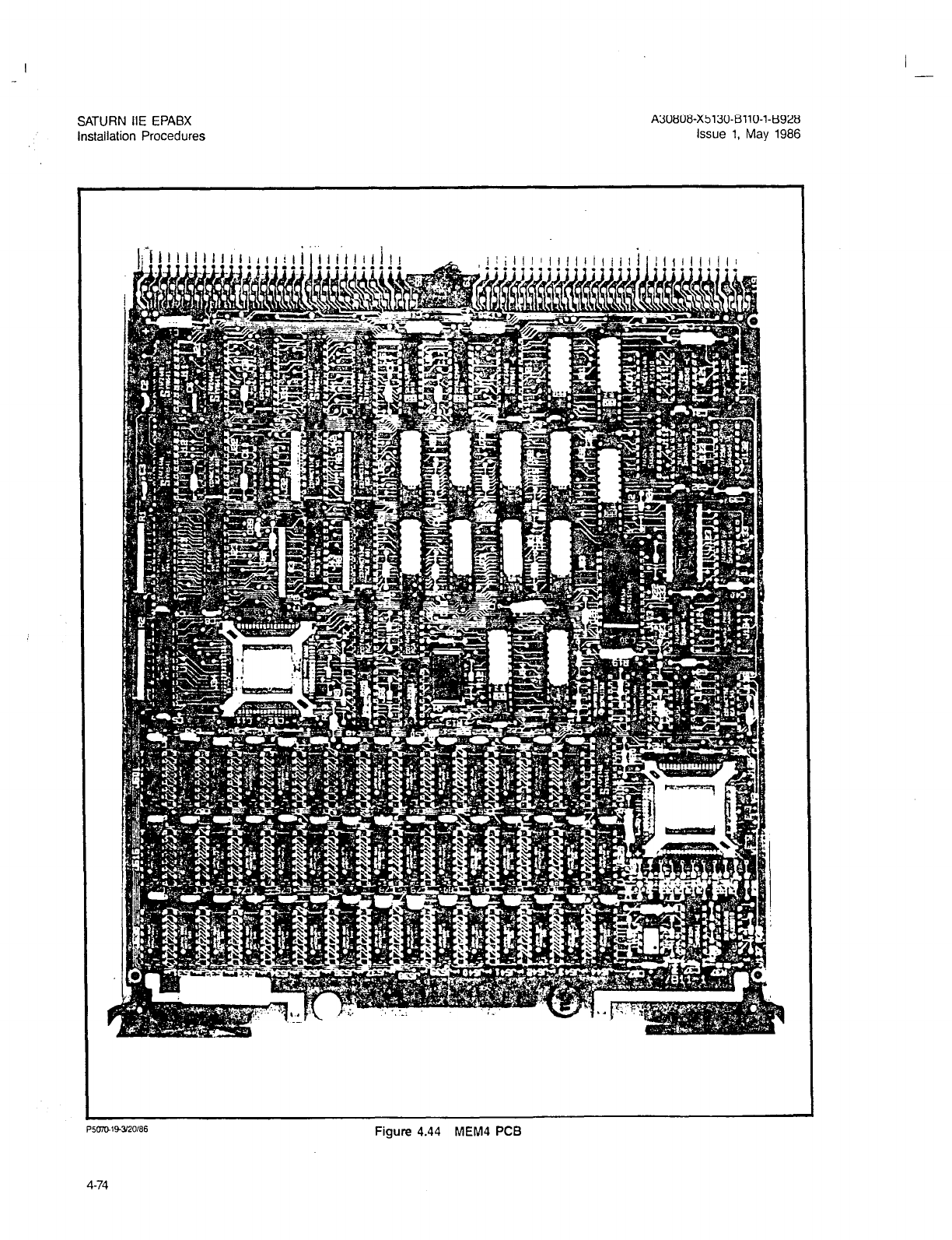
I -
SATURN IIE EPABX
installation Procedures
A30808-X5130-BllO-l-B928
Issue 1. May 1986
P5m143120186
Figure 4.44 MEM4 PCB
4-74

SATURN IIE EPABX A30808-X5130-BllO-l-8928
installation Procedures Issue 1, May 1986
Table 4.30 Memory 256 Kilobyte (MEM3) PCB (S30810-Q174O-X-e-8900)
DESCRIPTION:
. .
The MEM3 PCB, shown in Figure 4.45, provide 256 kilobytes of dynamic Random Access Memory (RAM)
and its supporting logic to store system data. The memory is organized as 128K words X 16 bits/ word,
with memory write protection provided in 1K word segments. MEMB is arranged for battery backup memory
protection to safeguard stored data durin short term power outages. Also, an Error-Correcting-Code
is provided to correct any single-bit erro 4 and detect double-bit errors existing in a word.
1. Indicator. None.
2. Switches. None.
OBSERVATIONS:
INSTALLATION
PROCEDURES:
3 Strapping Options. None.
None.
Locate in basic shelf slot number 28.
4-75
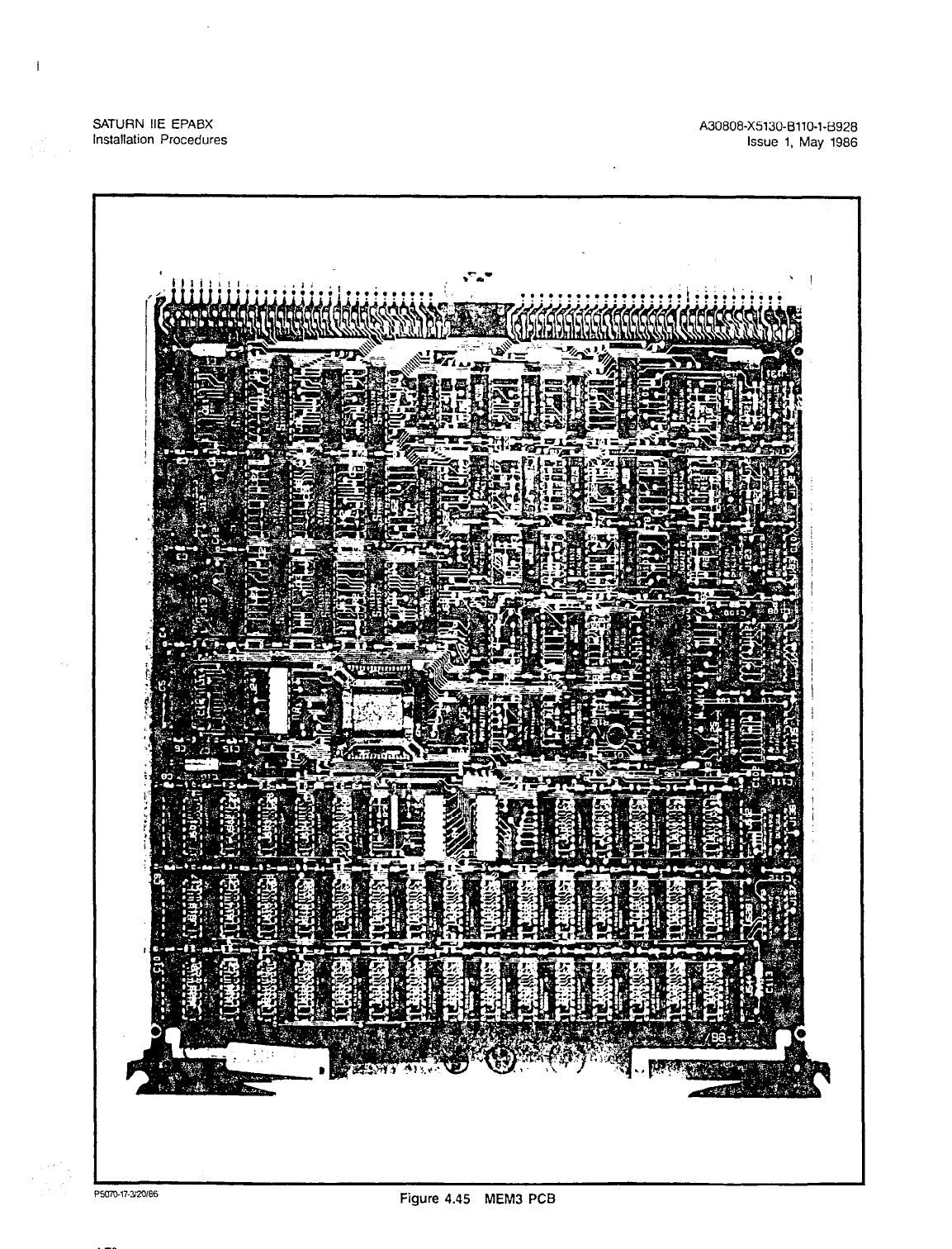
SATURN IIE EPABX A30808-X5130-BllO-l-8928
Installation Procedures Issue 1, May 1986
P5uiuW320166
Figure 4.45 MEM3 PCB
4-76
I -
SATURN IIE EPAEX A30808-X5130-8110-l-8928
Installation Procedures Issue 1, May 1986
Table 4.31 Line/lhmk Unit Control (LTUC) PCB (S30810-Q428-X- * -8900)
DESCRIPTION: The LTUC PCB. shown in Figure 4.46, provides the tim.ing signals necessary to address a line/trunk
unit. It multiplexes and demultiplexes both signal and voice highways. It also provides fault monitoring
and reporting of failures associated with the 128.ports it handles.
1. Indicators. Three red LEDs, designated PRS, ALMO, and ALMl, provide visual indications of ex-
isting malfunctions as follows:
a. Protection Restore Signal (PRS), when steadily lit, indicates that one of the following mal-
functions is present:
1. No common control on line.
2. +12Vdc under voltage.
3 -5Vdc under voltage.
4. -48Vdc under voltage.
Note: The PRS is delayed 40 ms (nominal) after the occurrence of any
one of the previous conditions:
b. Alarm 0 (A&IO), when steadily lit, indicates that one of the following malfunctions is present:
1. Loss’of CLK-A (2.048MHz clock) of common control 0
2. Loss of SYP (4ms time pulse) of common control 0
3 Loss of SYNR (ring sync) of common control 0
c. Alarm 1 (ALMl). ALMl is not used in the SATURN IIE
2. Switches. None.
OBSERVATIONS:
INSTALLATION
PROCEDURES:
3. Strapping Options. None.
None.
Locate in LTU shelf slots 6 and 19.
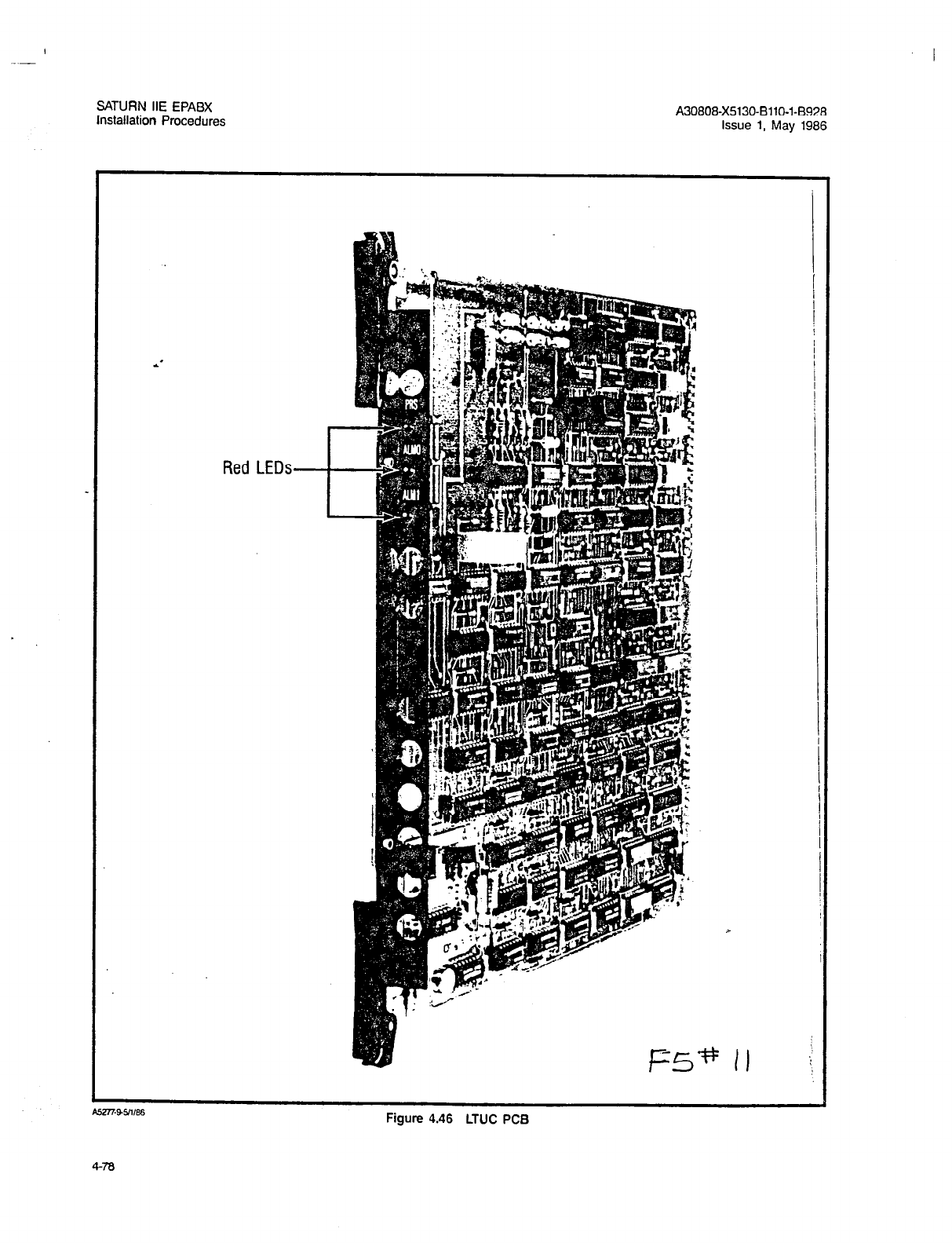
SATURN IIE EPABX
Installation Procedures A30808X5130-8110-1-8928
Issue 1, May 1986
Red LEDs
Figure 4.46 LTUC PCB
4-78
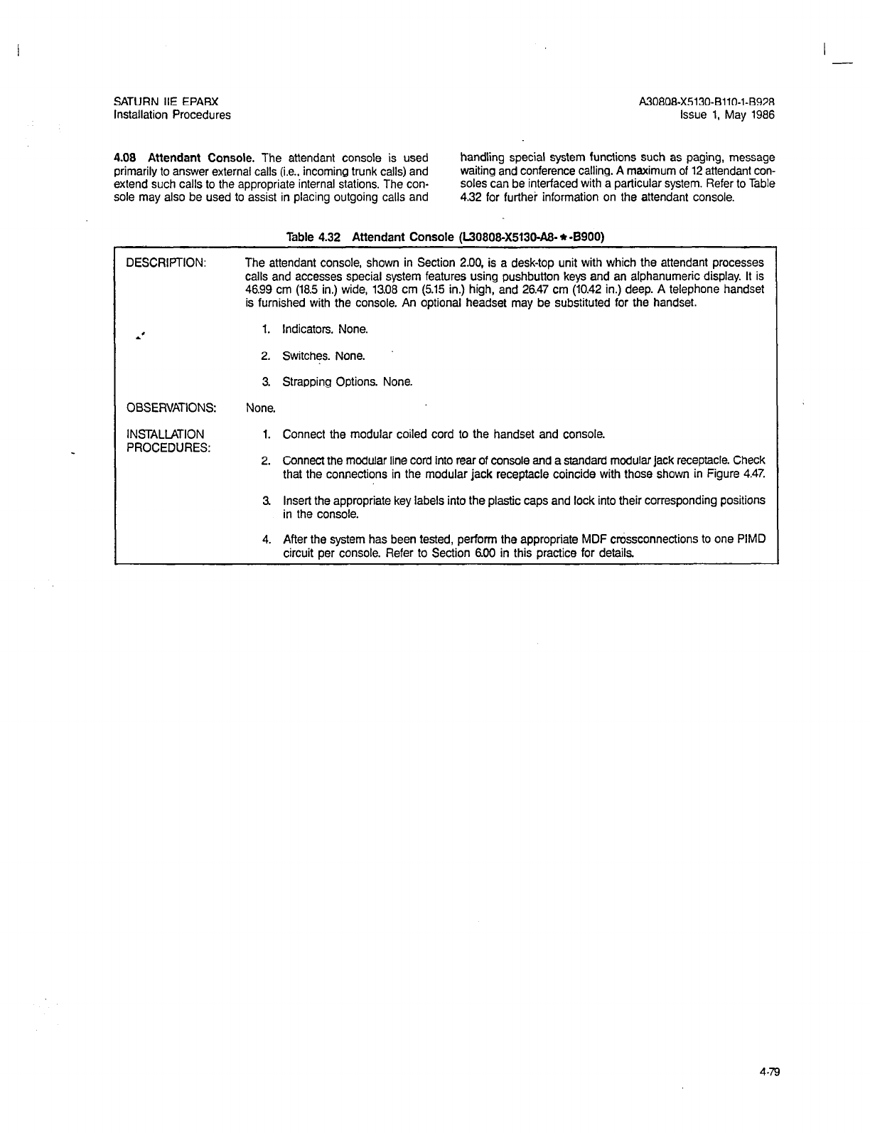
I -
SATURN IIE EPABX
Installation Procedures A30808-X5130-BllO-l-8928
Issue 1, May 1986
4.08 Attendant Console.
The attendant console is used handling special system functions such as paging, message
primarily to answer external calls (i.e., incoming trunk calls) and waiting and conference calling.
A
maximum of 12 attendant con-
extend such calls to the appropriate internal stations. The con- soles can be interfaced with a particular system. Refer to Table
sole may also be used to assist in placing outgoing calls and 4.32 for furthei information on the attendant console.
DESCRIPTION:
Table 4.32 Attendant Console (L30808X5130&% * -8900)
The attendant console, shown in Section 2.00, is a desk-top unit with which the attendant processes
calls and accesses special system features using pushbutton keys and an alphanumeric display. It is
46.99 cm (18.5 in.) wide, 13.08 cm (5.15 in.) high,
and 26.47
cm (10.42 in.) deep. A telephone handset
is furnished with the console. An optional headset may be substituted for the handset.
*’ 1. Indicators. None.
2. Switches. None.
3. Strapping Options. None.
OBSERVATIONS:
INSTALLATION
PROCEDURES:
None.
1. Connect the modular coiled cord to the handset and console.
2. Connect the modular line cord into rear of console and a standard modular jack receptacle. Check
that the connections in the modular jack receptacle coincide with those shown in Figure 4.47.
3 Insert the appropriate key labels into the plastic caps and lock into their corresponding positions
in the console.
4. After the system has been tested, perform the appropriate MDF crossconnections to one PIMD
circuit per console. Refer to Section 600 in this practice for details.
4-79
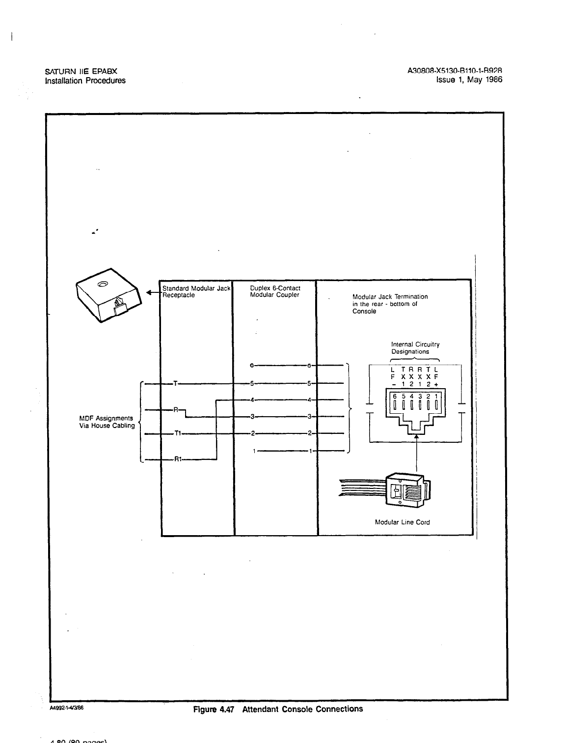
SATURN IIE EPABX
Installation Procedures A30808-X5130-BllO-l-8928
issue 1, May 1986
Standard Modular Jack Duolex B-Contact 1
1
Modular Jack Termmation
in the rear - bottom of
Console
internal Circuilry
Designaflons I
, \ /
L TRRTL
F XXXXF I
MDF Assignments
Via House Cabling
-2 2
1 1
-1212+
I
Modular Lme Cord
bms?-%a386
Figure 4.47 Attendant Console Connections
4-80 (80 pages)
-
I -
SATURN HE EPABX A30808-X5130-BllO-l-6928
Installation Procedures Issue 1, May 1988
SECTION 5.00 SYSTEM SIGNAL AND POWER/GROUND CABLING ARRANGEMENTS
5.01 General. This section provides the signal and pow-
er/ground-cabling arrangements for the SATURN IIE System.
Tables 5.00 and 5.01 list all the cable reference numbers used
throughout this practice. The tables provide point-to-point ca-
ble terminations and refer users to the appropriate cabling
illustration for quick reference. The following illustrations are
included in this section:
NOTE: When an LTU shelf is not equipped its correspond-
ing signal cable connector on the basic shelf must
: have a Berg jumper inserted across pins 29 and 30
in order to suppress LTU shelf failure alarm. The
connectors are designated as follows: ’
c. Basic shelf connectors J57 and J59 , jumpered if LTU3
shelf is missing.
Figure 5.00 Backplane Connectors
Figure 5.01 Power/Ground Distribution for the SATURN IIE
System (Basic Cabinet)
Figure 5.02 Power/Ground Distribution for the SATURN HE
System (Expansion Cabinet)
Figure 5.03 Signal Cable Distribution for the SATURN IIE
System (Basic Cabinet)
a. Basic shelf connectors J55 and J56, jumpered if LTUl Figure 5.04 Signal Cable Distribution for the SATURN IIE
shelf is missing. System (Expansion Cabinet)
b. Basic shelf connectors J58 and J60 , jumpered if LTUP
shelf is missing.
5-1
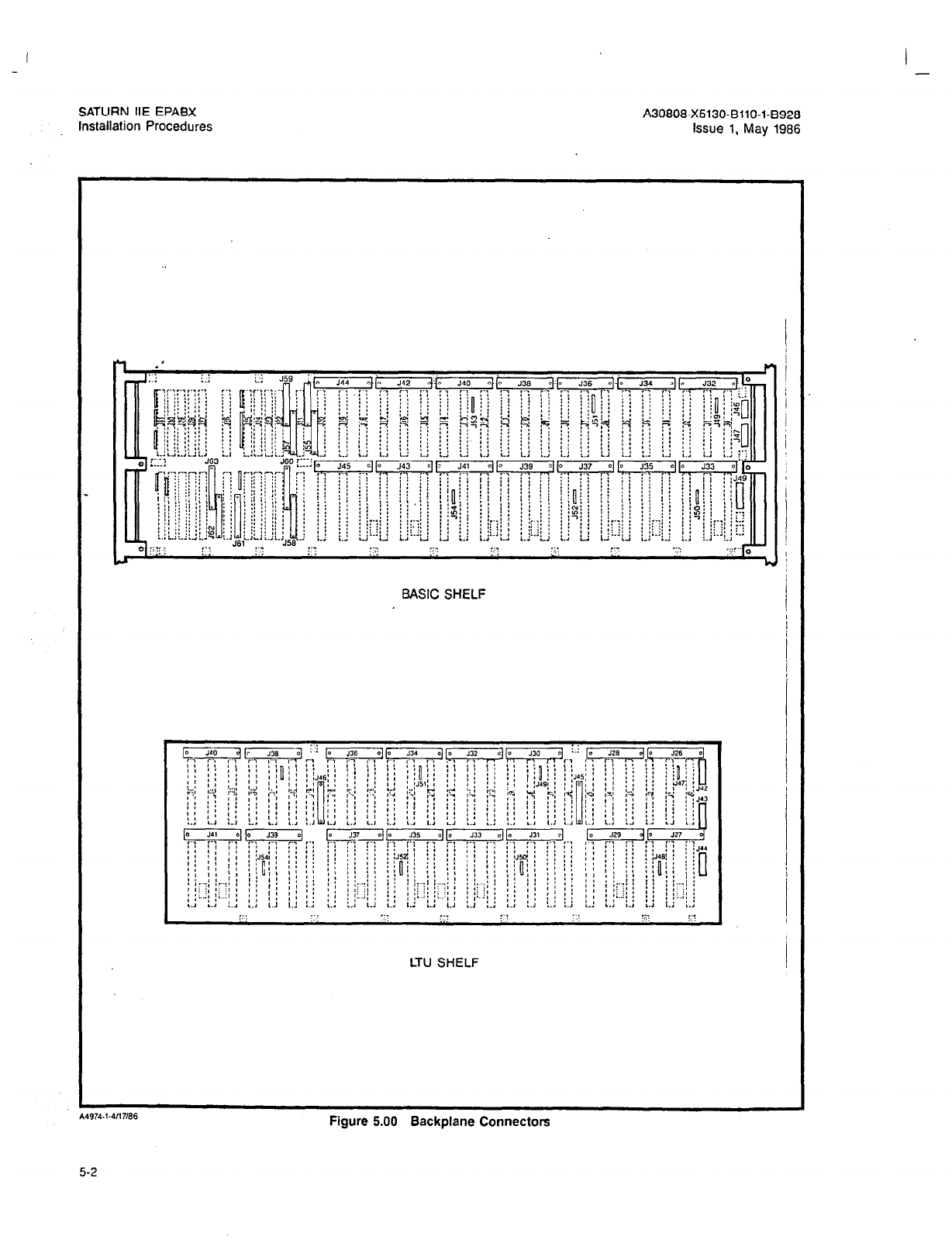
I -
SATURN IIE EPABX A30808-X5130-BllO-l-8928
Installation Procedures Issue 1, May 1986
BASIC SHELF
LTU SHELF
Figure 5.00 Backplane Connectors
5-2
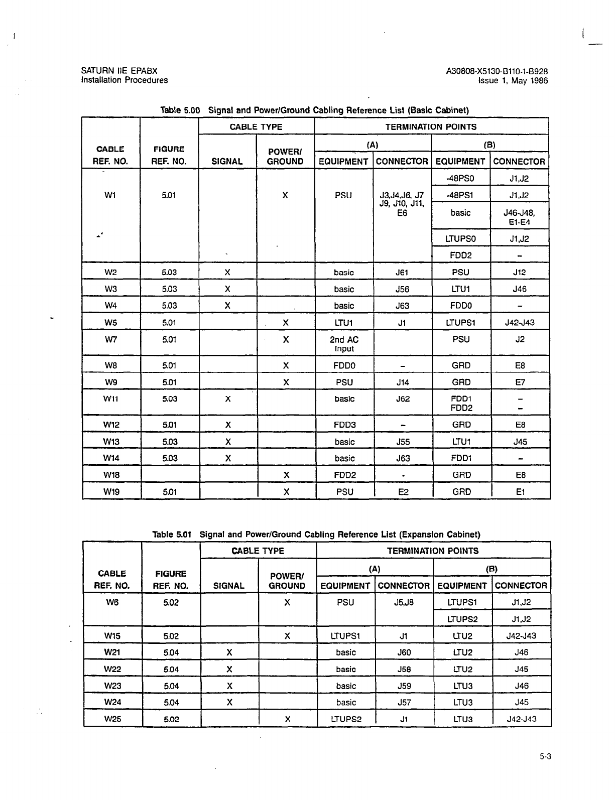
I -
SATURN HE EPABX
Installation Procedures
A30808-X5130-BllO-l-8928
Issue 1, May 1986
ci
f
Table 5.0 Signal and Power/Ground
CABLE TYPE
abling Reference List (Basic Cabinet) ,
TERMINATION POINTS
I I
(B)
ZONNECTOR EQUIPMENT CONNECTOR
(,
EQUIPMENT
CABLE
REF. NO.
FIGURE
REF. NO. POWER/
GROUND SIGNAL
Wl 5.01
X
PSU
basic J61 ! PSU ! J12
J56 LTUl J46
J63
FDDO
basic
LTUl
2nd AC
W8
GRD E8
J14 GRD E7
FDDO
PSU
basic
X FDD3
J55
LTUl J45
J63 FDDl
basic
basic w14
X
W18 X
FDD2
w19
.
GRD E8
E2 GRD El
5.01
X
PSU
Table 5.01 Signal and Power/Ground Cabling Reference List (Expansion Cabinet)
I CABLE TYPE I
TERMINATION POINTS I
POWER/
SIGNAL GROUND
--I--
X
(A) I (B) I
CABLE
FIGURE
REF. NO.
REF. NO.
W6
5.02
EQUIPMENT CONNECTOR EQUIPMENT CONNECTOR
PSU
J5,JB
LTUPSl Jl,J2
LTUPS2 Jl,J2
LTUPSl Jl LTUP J42-J43
basic J60
LTU2 J46
5.02 X
5.04 X
5.04 X
5.04 X
basic
basic
J58
LTU2 J45
J59 LTU3 J46
-2z-p-k
basic
LTUPS2
J57 LTUB J45
Jl LTUB J42-J43
5-3
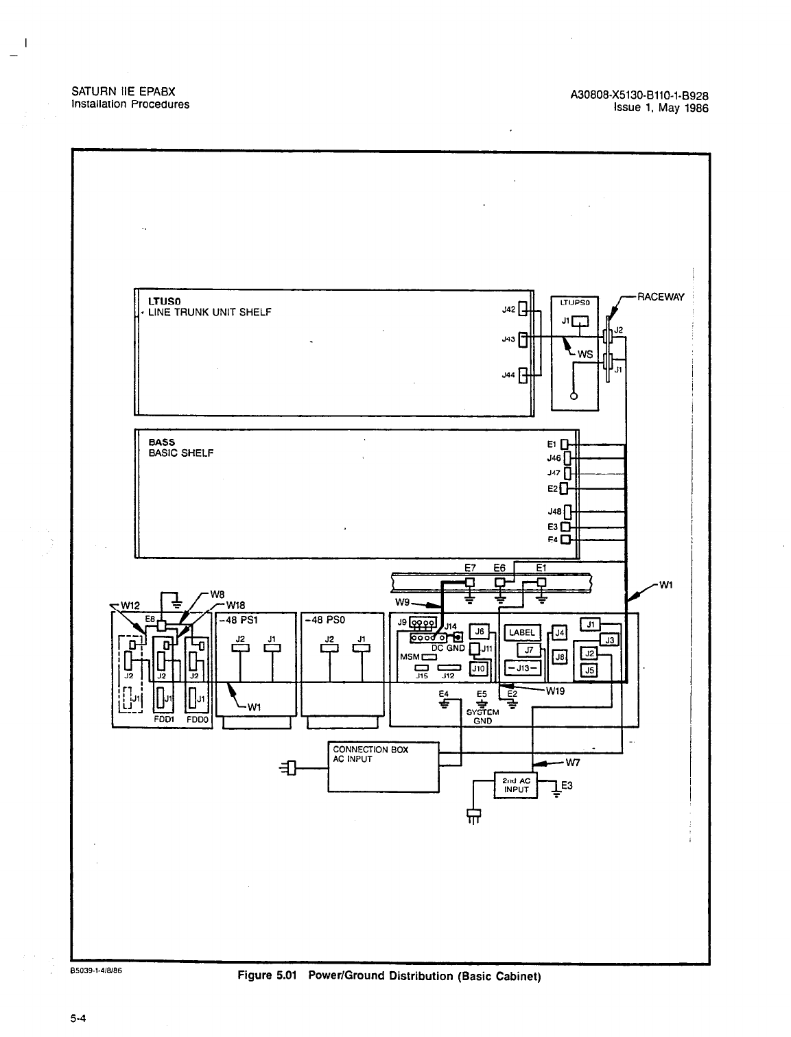
-
SATURN IIE EPABX
Installation Procedures A30808-X5130-BllO-l-8928
Issue 1, May 1986
BSK39.1.41186 -. --- - .^ . -. .- -
rlgure s.ul rowemurouna Dlstrlbution (Basic Cabinet)
5-4
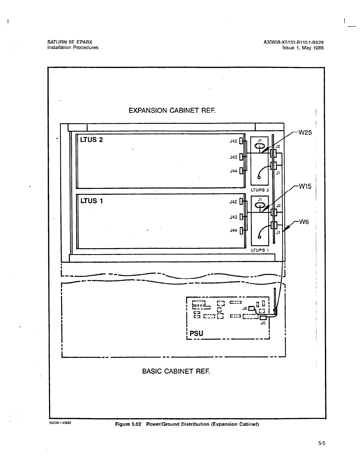
I
I -
SATURN IIE EPABX A30808-X5130-BllO-l-8928
Installation Procedures Issue 1, May 1986
EXPANSION CABINET REF.
L I
?
.'
LTUS 2
BASIC CABINET REF.
Figure 5.02 Power/Ground Distribution (Expansion Cabinet)
5-5
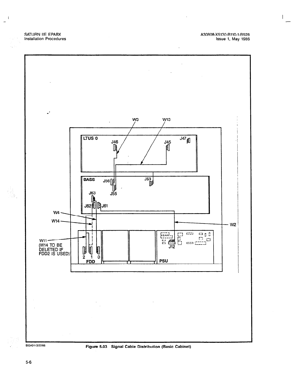
I -
SATURN IIE EPABX A30808-X5130-BllO-l-B928
installation Procedures issue 1, May 1986
w3 w13
/
1 / / I ,
/ /
LTUS 0
J47
J45
BASS J56
563 J55
J61
w4\
w14 3 d
I w2 !
Wll 4-f
NV14 TO BE
-1 ti LII
DELETED IF
FDD2 IS USED) l.MJ u.l
2
1 0
FDD ? I I , PSU
Figure 5.03 Signal Cable Distribution (Basic Cabinet)
5-6

I
-
SATURN IIE EPABX
Installation Procedures
A30808-X5130-BllO-l-8928
Issue 1, May 1986
.,
EXPANSION CABINET
L,rJp. - - -T-------- +
BASIC CA&NET
Figure 5.04 Signal Cable Distribution (Expansion Cabinet)
5-7 (5-8 blank)
-
SATURN IIE EPABX A30808-X5130-8110-l-8928
installation Procedures issue 1, May 1988
SECTION 6.00 MDF CABLING AND TERMINATING ARRANGEMENTS
8.01 General. This section provides the MDF cabling proce-
dures and termination arrangements for the SATURN IIE System.
6.02 MDF Cabling. MDF cabling for the SATURN IIE Sys-
tem can be accomplished through either the top or bottom
of the cabinet (refer to Figures 6.00
and
8.01). The tie-wrap
holders at the top and bottom of the cabinet provide the means
to easilv form and secure MDF cables into oosition. Each MDF
cable connector (system side) should contain a 180° hood
(refer to Figure 6.02) to connect into the backplane connec-
tor and secured via two captive-type screws. Figure 6.03 pro-
vides an overview of the backplane MDF cable connectors
and their corresponding card slot allocations on the basic and
LTU shelves. Figure 8.04 provides information pertaining to
connector/pin numbers for tip/ring and E&M leads.
6.03 MDF Terminating Arrangements. Tables 6.00 through
6.14 provide the necessary information on the terminating ar-
rangement at the MDF. Tables 6.00 through 6.06 provides the
MDF designations for the T&R leads for the basic shelf . Ta-
bles 6.07 through 6.14 provides the MDF designations for the
T&R leads for the expansion shelves. For information on MDF
cross-connections, refer to SATURN IIE EPABX Installation
Test Procedures Practice.
6-1

I -
SATURN IIE EPABX A30808-X5130-BllO-l-8928
Installation Procedures Issue 1, May 1986
Rear View
14993.1.4ll7166 Figure 6.00 MDF Cabling via Top of Cabinet Assembly (View of Typical Cabinet)
6-2
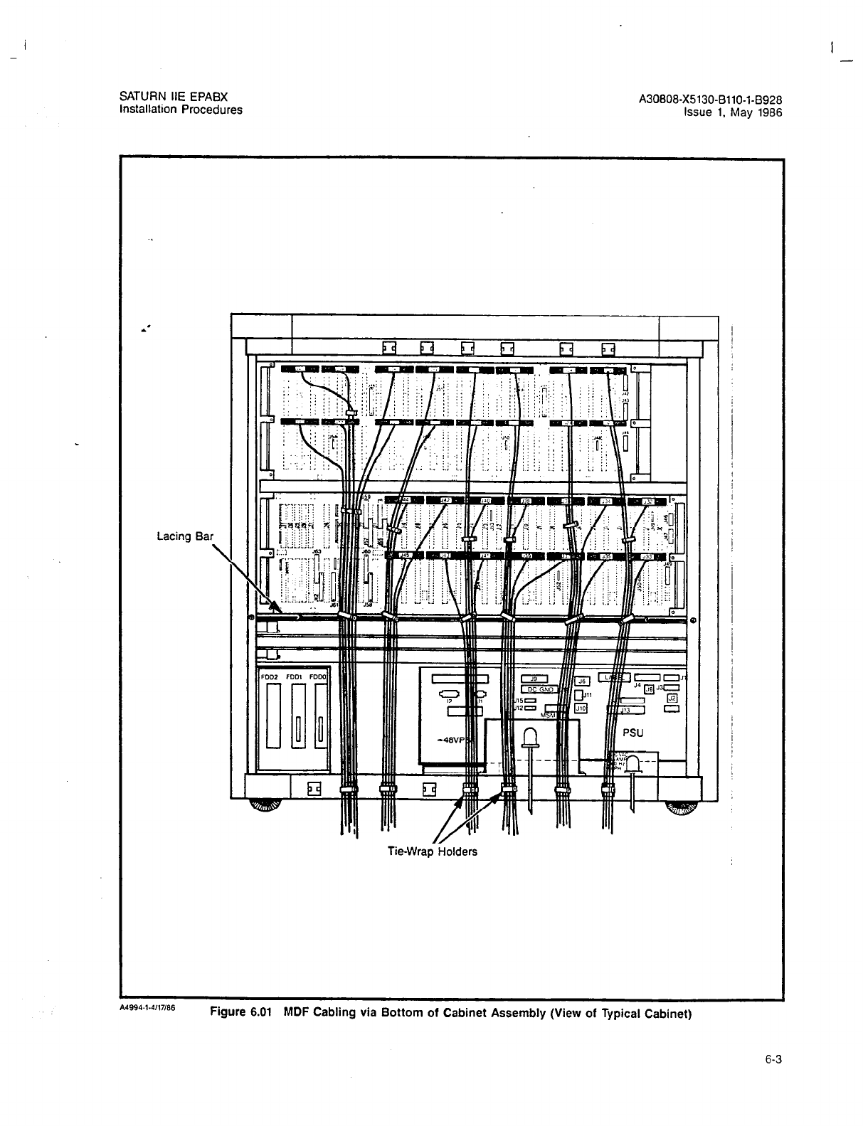
I
-
I -
SATURN IIE EPABX A30808-X5130-6110-1-8928
installation Procedures Issue 1, May 1986
Lacil ig Bar
\
I I II O’ II
II ‘.
II II II II I I
Tie-Wrap Holders
Figure 6.01 MDF Cabling via Bottom of Cabinet Assembly (View of Typical Cabinet)
6-3

- -
SATURN HE EPABX A30808-X5130-8110-l-8928
Installation Procedures Issue 1, May 1966
Caoth re SC
Plug AMP N-o. 229940-l
C.4976.1.Y26/66
Figure 6.02 Required MDF Cable Connector
6-4
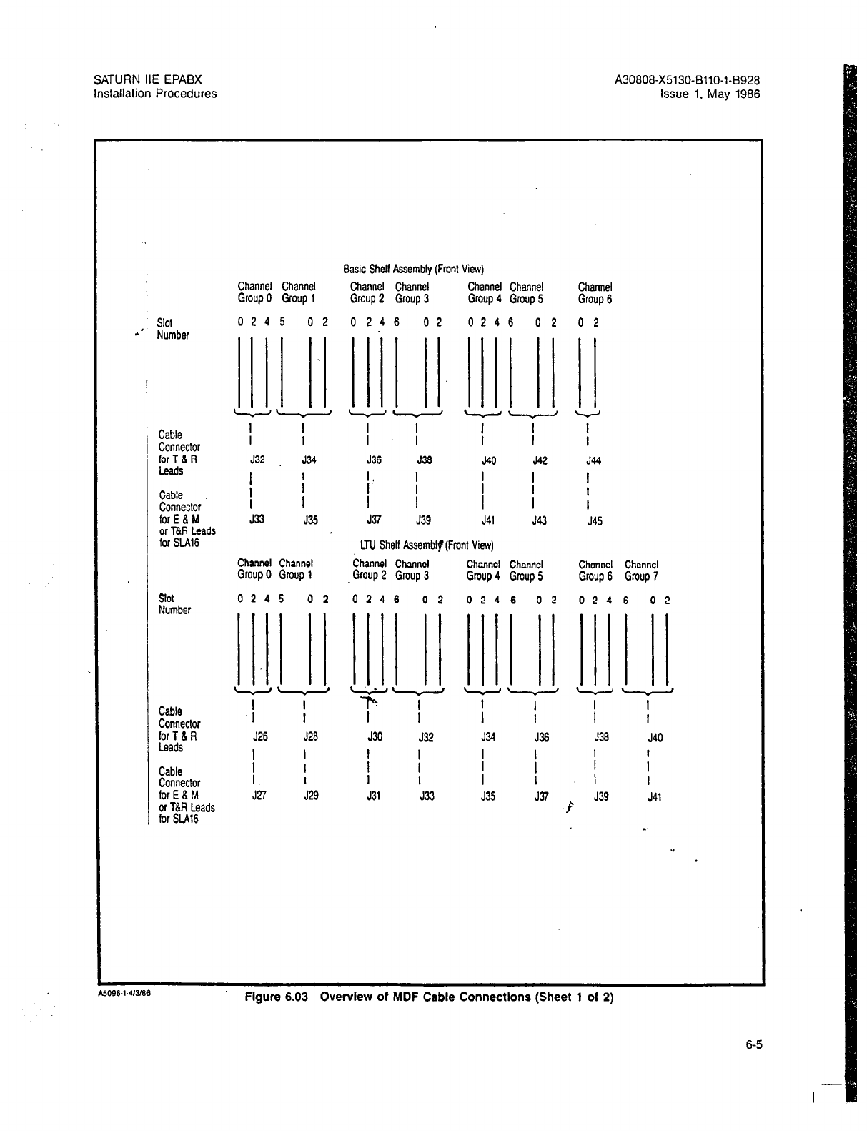
SATURN IIE EPABX A30808-X5130-BllO-l-8928
Installation Procedures Issue 1. May
1986
Slot
.’
Number
1 Cable
Connector
for T & R
Leads
Cable
pezt;
or T&R Leads
for SU16
slot
Number
Cable
Connector
for T 6 R
Leads
Cable
Connector
for
E a M
or T&R Leads
for SW3
Channel Channel
Group 0 Group
1
0245 02
Basic Shelf Assembly (Front View)
Channel Channel Channel Channel Channel
Group 2 Group 3 Group 4 Group 5 Group 6
0246 02 0246 02 02
I I
I I
J32 J34
/ ;
I
J33 J36
Channel Channel
Group 0 Group
1
0245 02
I
J26 J28
/
I
I
I
J27 529
I I I ! I
I
J36 J36 J40 J42 J44
/* / I I I
I I i
J37 J39 J41 J43 J45
LTU Shelf k.semblp(Fmnt View)
Channel Channel Channel Channel Channel Channel
. Gmup 2 Group 3 Group 4 Group 5 Group 6 Group 7
0246 02 0246 02 0246 02
I I I I I I
J30 532 J34 J36 J36 J40
!
1 I /
I
I I
I f I
J31 J33 J35 J37 J39
,s-‘ J41
Figure 6.03 Overview of MDF Cable Connections (Sheet 1 of 2)
6-5

A30808-X5130-BllO-1-0928
issue 1, May 1986
ASSIGNMENT OF PENS
Shelf (basic = 0, LTU = 1, 2, 3)
&. Channel Group (O-7; see above )
Card Slot (O-6: see below for SLA16)
Circuit (O-7; see below for StA16) I
For SLA16 Boards:
Circuits O-7: Use slot number (Y) as shown above.
Circuits 8-15: Use slot number +l r/+1)
EXAMPLE: SLA16 assigned to LTU Shelf 2, Channel Group 3, Slot 0
PENS of first 8 circuits: 2300 through 2307
T/R leads of circuits are located on connector J32
PENS of second 8 circuits: 2310 through 2317
T/R leads of circuits are located on connector J33
Figure 6.03 Overview of MDF Cable Connections (Sheet 2 of 2)
6-6
Siemens Practices
Installation Series
:
A30808-X5130-8120-1-8928 1
Issue 1, May 1986 ’ 1
!
Issued by Office Systems Group
5500 Broken Sound Boulevard N.W., Boca Raton, Florida 33431
--___________-
Siemcns Information Systems, Inc.
(305) 994-8100
l
Telex: 515052
----- - ..- -----
Printed in U.S.A.
SATURN IIE EPABX A30808X5130-8120-1-8328
Installation Test Procedures Issue 1, May 1906
SECTION
PAGE
l.CO INTRDCUCTlON ............
;
............. .1-l
Purpose .................................. l-l
scope .................................... 1-l
Siemens SATURN IIE Practices ................. l-l
Siemens Customer Support Services. ........... l-l
2.00 PREP/%KGXIY ACTIVITY ................... 2-1
Cener21. .................................
2-1
Test Equipment Required. ................... 2-l
Handling Precautions for PC& with
MOS Integrated Circuiis. .................... 2-l
PC6 Removal and Replacement Guidelines ....... 2-1
Initial Visual Inspection Procedures .............. 2-1
3.CO GROUND TESTS .......................... 3-l
General. .................................. 3-l
System Ground Test. ........................ 3-1
Shelf Ground Continuity Test. ................. 3-1
4.00 POWER-UP TESTS ........................ 4-l
Genera I. ................................. 4-1
Power-Up/Output Voltage Tests. ............... 4-l
5.00 OPERATING PROGRAM
LOAD!NG
............ 5-1
General. .................................. 5-1
Loading Operafing Dis!~. ..................... 5-l
Inputting CMU Data to Floppy Disk. ............ 5-l
&CO ON-FINE DlAGrGxTlC TESTS ............... 6-3
General. .................................. 6-l
Connection of Maintenance Phone
and Modem .............................. 6-l
MDF Cross-Connecting Prccedures. ............ 6-1
System Diagnostic Tests; .................... 6-12
7.CO INSTALLATION TEST PRCCEDURES CHEC#L!ST 7-l
General ................................... 7-l
l=lGURE
PAGE
2.00 Signal Cab!e Distribution for the SATURN IIE
System (Basic Cabinet). ................
2.01 Signal Cable Distribution for the SATURN IIE
System (Expansion Cabinet). ............
2.02 Power/Ground Distribution for the SATURN IIE
System (Basic Cabinet). ................
2.03 Power/Ground Distribution for the SATURN IIE
System (Expansion Cabinet) .............
3.00 System Ground Test Connections
..........
3.01 Shelf Ground Continuity Test Connections. ...
4.00 Location of Input Voltage Connectors on
Basic Backplane. .....................
4.01 Location of Input Voltage Connectors on
LTU Backplane .......................
5.00 Floppy Disk and Storage Envelope .........
5.01 Power System Unit (Front View). ...........
5.02 Floppy Disk Loading Procedures. ..........
5.03 CIOP Printed Circuit Board ...............
6.00 Maintenance Phone and Maintenance-Related
Cress-Connections ....................
6.01 Modem Cross-Connections ...............
.
2-4
2-5
2-6
2-7
3-2
3-3
. .
4-5
.
4-6
5-l
5-4
5-5
5-6
6-2
6-z
6.02 Single -Line Telephone Cross-Connections
Using SLMA PCB . . . 6-3
6.03 Single -Line Telephone Cross-Connections
Using SLAi6 PCB
6.04 Siemens Digital Teiephone Cross-Connections
Using SLMD PCB. .
6.05 SATURN Attendant Console Cross-Connections
6.06 CO and CID Trunk Cross-Conneciions .
6.07 Two-Wire (Type I) E&M Trunk Cross-Connec?ions
6.08 Four-Wire (T;lce I) E&M Trunk Cross-Connections
6-3
63
G-4
E-5
G-5
G-S
_.
6.09 Two-Wire (Type II) E&M Trunk Cross-Connections . 6-6
6.10 Four-Wire (?ype II) E&M Trunk Cross-Connections . 6-7
6.il Recorded Anncuncement (DID and Tie Trunk
Vacant Number Intercept, and ACD
Announcement Service) Cross-Connections 6-7
6.12 Code Ca!ling (With or Without Answerback)
Cross-Connections . . 6-8
6.13 Dial Ciciation (DTMF) Cross-Conneciions. 6-8
6.14 Music-en-Hold Cross-Connections Using
TMBA4 PCB . . . . 6-9
6.15 Music-on-Ho!d Cross-Connecticns Using
SLMAISLA16 PCB . . . . . . 6-9
6.16 Paging With Answerback Cross-Connections 6-10
6.17 Paging Without Answerback Cross-Connections. . 6-10
6.18 Universal Night Answer (UNA) Cross-Connections E-11
6.49 Attendant Conscie Keypad and Fcaturo
Button Depiassion Ssquonce G-:3
620 Siemens DYIiD Te!ephono Buttcn Ccpressicn
Sequence . . . . . . . . . . . . . . 6-21
6.21 Siemens JR-DYAD Te!ephone
Euitcn
Depression Sequence . . 6-23
1.00 Mnemonics Used in This Practice .............. l-l
2.CO PCB and Powar Supply Removal Guidelines ..... 2-2
2.01 Visual Inspeciion ........................... 2-3
3.00 System Ground Test. ........................ 3-l
3.01 Shelf Ground Continuity Test .................. 3-1
4.00 Power-Up/Output Voitnge Test ................. 4-l
5.00 Loading Procedures fcr Operating Disk. ......... 5-2
5.01 CIOP DIP Swiich Settings .................... 5-3
5.02 LED Display Values for Leading Errors .......... 5-4
6.00 Tone Generator Test ........................ 6-13
6.01 Tone Genera:or Test I\!umbers ................ G-i3
6.02 DTMF Receiver Test ........................ G-14
6.03 Station Line Test. .......................... 6-14
6.04 DTMF Pad Test ............................ 6-15
6.05 Console Test ............................... 6-16
6.06 Attendant Console Displayable Characters. ...... 6-19
6.07 Siemens Digital Telephone - DYAD Button Test 6-20
6.08 Siemens Digital Telephone - JR-DYAD
Button Test . . . . .
6.09 Siemens Digiial Telephone -DYAD Display Test
6.10 Siemens Digital Telephone Displayable
Characters . .
6.11 Outgoing Trunk Test .
6.12 Placing Circuit(s) In-Service
6.13 Taking Circuit(s) Out-of-Service
7.CO Insta!lation Test Procedures Checklist
G-22
6-24
6-25
6-26
6-27
6-27
7-l

SATURN IIE EPABX
installation Test Procedures
A30808-X5130-0120-l-0928
Issue 1, May 1986 .
1.01 Purpose. The equipment comprising the SATURN IiE
(SATURN Ii-Expanded) System is compleYely tested at the fac-
tory prior to shipment. The inspections and tests covered in
this practice verify that the EPABX equipment has been
properly installed; ensure that no damage wasIncurred dur-
ing transit; and confirm that the sysiem is completely opera-
tional. Table 1.00 defines the mnemonics usedthroughout ihis
practice.
CAUTION
lnstalbtion test procedures on the SATL’RN I/E EPABX
must be performed only by Siemer;s cetiified personnel.
1.02 Sccpe. This practice is divided into the following sec-
tions which are presented in the sequential order of per-for-
mance after initial installation of a SATURN IIE System. When
additional equipment is installed to an existing and active
SATURN IIE System, it is the responsibility of craft person-
nel to determine the sequential order of the test procedures
contained in tihese sections.
ACD Au;omaiic Cafl Disiribution
ALiVl Alarm
ASCII American Standard Code for Information lntarchange
CIOP Controller/Input-Ouiput Prccessor
CMU Customer Memory Update
co Central Office
CONF Conference Module
COT Central Office Trunk
DCI Data Communication Interface
DID Direct Inward Dialing
DIP Dual lnline Package
DP Dial Pulse
DTE Da?a Terminal Equipment
DTMF Dual Tone Multifrequency
EIA Electronics Industries Association
EPABX Electronic Private Automatic Branch Exchange
FDD Floppy Disk Drive
IRAM Input Random Access Memory
LTU Line/Trunk Unit
LTUPS Line/Trunk Unit Power Supply
LED Light-Emitting Diode
MCA Memory Control and Attenuation
MDF Main Distribution Frame
MEM3 25Gkb Memory
MEM4 1Mb Memory
MOS Metal Oxide Semiconductor
MRA Material Return Authorization.
MSM Memory Support Module
MTCE Maintenance
00s Out-of-Service
ORAM Output Random Access Memory
PABX Private Automatic Branch Exchange
PCB Printed Circuit Board
PEN Port Equipment Number
PIMD Premium Instrument Module Digital
PSC Parallel/Serial Converter
PSU Power Supply Unit
a. Section l.CO - Introduction
b. Section 2.00 - Preparatory Activiiy
c. Section 3.00 - Ground Tests
d. Section 4.00 - Power-Up Tests
e. Section 5.00 - Operating Program Loading
f. Section 6.80 - On-Lina Diagnostic Tesis
g. Section 7.00 - lnstallaticn Test Procedures
Checklist
7.03 Siemens SATURN IIE Prac:iccs. The practices, issue
numbers and dates for the SATURN IIE EPABX are lists3 in the
Practices Documentation Index A.30808~X5130-AlgO- * -E987 Al-
ways refer to the !aiest issue of the application indcx to ob-
tain the latest issue number of a practice.
724 Siemens Cus;oma: Sqpsrt Services. Sicrnons
maintains a nationwide network
cf
field service offices. Con-
tact the Siemens regional oifice for any engineering es-
sistance that may be requked.
TaS!e 1.00 Mnemonics Used in This Practice
DEFiN1TfON
i-i

SATURN IIE EPABX
Installation Test Procedures
.
Table 1.00 Mnemonics Used in This Practice (Continued)
[\fiNEMDNIC * DEFINITION
RAUP Remote Access Unit/Ports
RGEN Ring Generator
S-416 Subscriber Line Module Analog - 16 lines
SLMA Subscriber Line Module Analog
SLMA-S Subscriber Line Module Analog - Station
SLMD Subscriber Line Module Digital
SMXTG Signal Multiplexer/Tone Generator
SPC Stored-Program-Controlled
SPG Single Point Ground
TMBA-2 Two-Wire E&M Trunk
TMBA-4 Four-Wire E&M Trunk
TMBM Central Office Trunk
TMIE Direct Inward Dialing Trunk
TMS Transmission Measuring Set
TSTAPP Test - Apparatus
TSTDIAG Test - Maintenance Diagnostic
TTY Teletypewriter
UNA Universal Night Answer
ZUNA Zoned Universal Night Answer
-48PS -48Vdc Power Supply
l-2 (2 pages)
SATURN IIE EPABX A30808-X5130-B120-l-8928
Installation Test Procedures Issue 1, May 1986
2.01 General. This section describes the test equipment re-
quired to perform the installation test procedures, handling
precautions for Printed Circuit Boards (PCBs) with Metal Ox-
ide Semiconductor (MOS) integrated circuits, guidelines for
removal and replacement of PCBs and powei supplies, and
initial visual inspection procedures.
2.02 Test Equipment Required. The following test equip-
ment is required to perform the procedures contained in this
practice:
a. Digital Multimeter. A digital multimeter of gocd com-
mercial quality with an accuracy of + 1.0% or better.
The digital multimeter is used to perform the ground
tests and output voltage tests.
b. Maintenance Test Phone. For both Dial Pulse (DP) and
Dual Tone Multifrequency (DTMF) systems, a lineman’s
test set or a single line te!ephone. A modular jack
(MTCE PHONE) is provided on the front panal of the
PSU for conneciing the maintenance test phone when
equipped with a modular plug. When the maintenance
test phone is not equipped with a modular plug, a sta-
tion appearance can be used via the Main Distribu-
tion Frame (MDF). The mainienance test phone is used
to perform the on-line diagnostic tests.
c. Data Service Terminal. A Keyboard-Send-Receive
(KSR) daia terminal equipped with a standard ASCII
keyboard and an EIA RS-232C interface (Silent 700
Series - Model 743 KSR - Texas Instruments, or
equivalent). The data service terminal is used to input
installation dependent data (i.e., system data base) into
system memory when the standard data base format
is supplied with the SATURN IIE System.
d. -Transmission Measuring Set. A transmission measur-
ing set (TMS) used to measure the transmission qual-
ity of a trunk or station (Hewlett Packard HP-355iA or
equivalent). Refer to the manual On-Line DiagnostiC
Tests, Outgoing Trunk Test and Station Line Tosl.
2.03 handling Precautions for PCBs wifh MCS Integmt-
ed Circuiklt is important that craft personnel handling FCBs
with MOS integrated circuits free themselves from electrostatic
charge by touching a grounded cabinet frame before handling
such PCEs, or by wearing grounded wrist straps. Failur:, to
observe this practice may result in damage to MO3 PCBs
due to electrostatic discharge.
WARNING
lirazardous voltages exist r&h.% the eqo&ment cabins?.
Be extremely careful when perr”orming fcsa-
incjtroubleshooting procedures with the oquipmcr;t
panel(s) removed.
2.04 PCB Removal and P,ep!acemenZ Guide%% In many
instances during testing, the corrective action for a procedure
in which the proper verification was not obtained requires that
a PCB or a power supply be removed and replaced with a
spare. Tablo 2.00 provides the guidelines that shou!d be o!)-
served when removing and rep!acing PCBs and powor SI:;X-
plies in an active sysicm.
2.05 lnifial Visual kspactizn Procedurx. The visu’al in-
spection procedures contained in Tab!e 2.01 must be psrfcrmcd
to ensure that the equipment comprising the SATURN ItE Sys-
tem has been properly installed and configured to meet the
installation requirements. Before proceeding wiih the visual in-
spections, the front, rear and side panels of the cabinei should
be removed to allcw thorough inspection of the equipment.
2-1
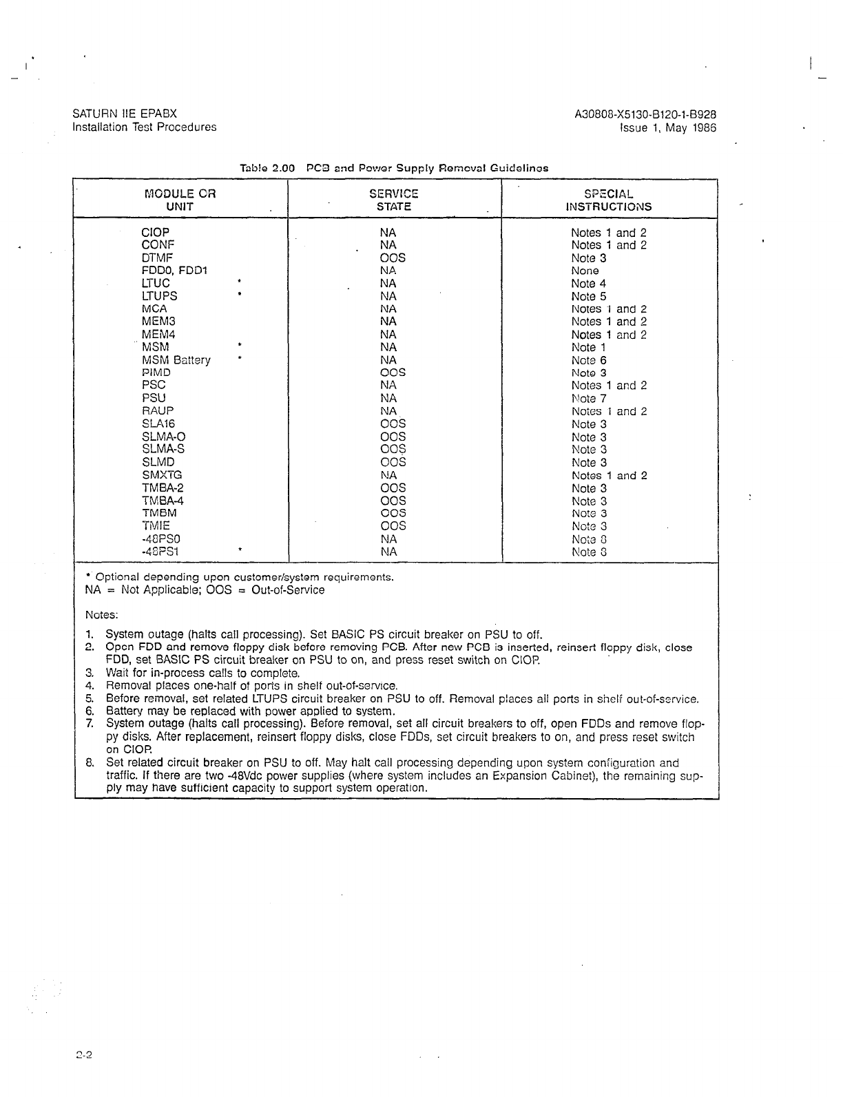
-
Table 2.00 PC3 and Power Supply Remcval Guidelines
I’AODIJLE OR SERVEC” SPECIAL
UNIT STATE INSTRUCTKWIS
CIOP NA
CONF . NA
DTMF 00s
FDDO, FDDl NA
LTUC f NA
LTUPS
l
NA
MCA
MEM3 kz
MEM4 NA
MSM
l
NA
MSM
Baitery
l
NA
PIMD 00s
PSC NA
PSU NA
RAUP NA
SLAl6 00s
SLMA-0 00s
SLMA-S 003
SLMD 00s
SMXTG
ES
TMBA-2
TMBA-4 00s
TMBM 00s
TMIE 00s
-48PS.l NA
-48PSt f NA
* Optional depending upon customer/system requirements.
NA = Not Applicable; 00s = Out-of-Service
Notes 1 and 2
Notes 1 and 2
Note 3
None
Note 4
Note 5
Notes 1 and 2
Notes 1 and 2
Notes 1 and 2
Note 1
Note 6
Note 3
Notes 1 and 2
Note 7
Notes 1 and 2
Note 3
Note 3
Note 3
Note 3
Notes 1 and 2
Note 3
Note 3
No?e 3
Note 3
Note 8
Noie 3
Notes:
1. System outage (halts call processing). Set BASIC PS circuit breaker on PSU to off.
2. Open FDD and remove floppy disk before removing PCB. After new PCB is inserted, reinsert floppy disk, close
FDD, set BASK PS circuit breaker on PSU to on, and press reset switch on CIOP
3. VVait for in-process ca!ls
i0
complete.
4. Removal places one-half of ports in shelf out-of-service.
5. Before removal, set related LTUPS circuit breaker on PSU to off. Removal places all ports in shelf out-of-service.
6. Battery may be replaced with power applied to system.
7. System outage (halts call processing). Before removal, set all circuit breakers to off, open FDDs and remove flop-
py disks. After replacement, reinsert floppy disks, close FDDs, set circuit breakers to on, and press reset switch
on CIOR
8. Set related circuit breaker on PSU to off. May halt call processing depending upon system configuration and
traffic. If there are two -48Vdc power supplies (where system includes an Expansion Cabinei), the remaining sup-
ply may have sufficient capacity to support system operation.
A30808-X5130-8120-l-8928
Issue 1, May 1986
2-2
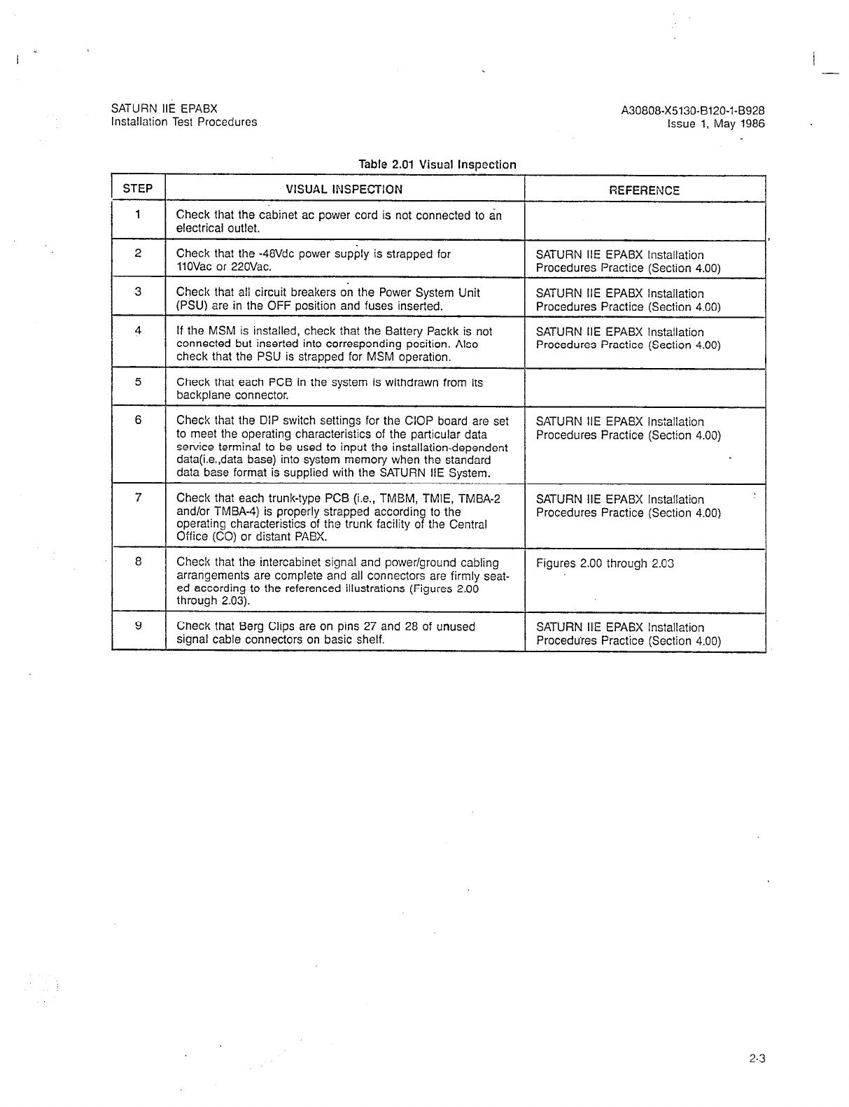
I .-
A30808-X5130-B120-l-8928
Issue 1, May 1986
SATURN IIE EPABX
Installation Test Procedures
Table 2.01 Visual Inspection
STEP VISUAL INSPECTION REFERENCE
1 Check that the cabinet ac power cord is not connected to an
electrical outlet.
2 Check that the -48Vdc power supply is strapped for SATURN IIE EPABX Installation
11OVac or 22OVac. Procedures Practice (Section 4.00)
3 Check that all circuit breakers on the Power System Unit SATURN IIE EPABX Installation
(PSU) are in the OFF position and fuses inserted. Procedures Practice (Section 4.00)
4 If the MSM is installed, check that the Battery Packk is not SATURN IIE EPABX Installation
connected but inserted into corresponding position. Also Procedures Practice (Section 4.00)
check that the PSU is strapped for MSM operation.
5 Check that each PCB in the system is withdrawn from its
backplane connector.
6 Check that the DIP switch settings for the CIOP board are set SATURN IIE EPABX Installation
to meet the operating characteristics of the particular data Procedures Practice (Section 4.00)
service terminal to be used to input the installation-dependent
data(i.e.,data base) into system memory when the standard
data base format is supplied with the SATURN IIE System.
7 Check that each trunk-type PCB (i.e., TMEM, TMIE, TMBA-2 SATURN IIE EPABX Installation
and/or TMBA-4) is properly strapped according to the Procedures Practice (Section 4.00)
operating characteristics of the trunk facility of the Central
Office (CO) or distant PABX.
8 Chec!c that the intercabinet signal and power/ground cabling Figures 2.00 through 2.03
arrangements are complete and all connectors are firmly seat-
ed according to the referenced illustrations (Figures 2.00
through 2.03).
9 Check that Berg Clips are on pins 27 and 28 of unused SATURN IIE EPABX Installation
signal cable connectors on basic shelf. Procedures Practice (Section 4.00)
2-3

w3 w13
-
I I
SATURN IIE EPABX
,xtallation Test Procedures A30808-X5130-B120-l-5928
Issue 1, May 1986
Figure 2.00 Signal Cable Distribution for the SATURN IIE System (Basic Cabinet)

SATURN IIE EPABX
Installation Test Procedures A30808-X5130-B120-l-8928
issue 1, May 1986
W23
EXPANSION CABINET
\
I --- ---
: ] 1
FDD :
, i;wi!
i-L--i-- - _-__
--
LiTJ-. - - -r----- *
W22
BASIC CA&NET
A5040-2.313186 Figure 2.01 Signal Cable Distribution for the SATURN IIE System (Expansion Cabinet)
2-5

SATURN IIE EPABX
tnstallation Test Procedures A30808-X5130-8120-1-8928
Issue 1, May 1986
LTUSO
LINE TRUNK UNIT SHELF
J42
J43
r JP
L
Jl
BASS
BASIC SHELF
El a----
J46
J47
E2
05039.1..wmG
Figure 2.02 Power/Ground Distribution for the SATURN IIE System (Basic Cabinet)
2-6
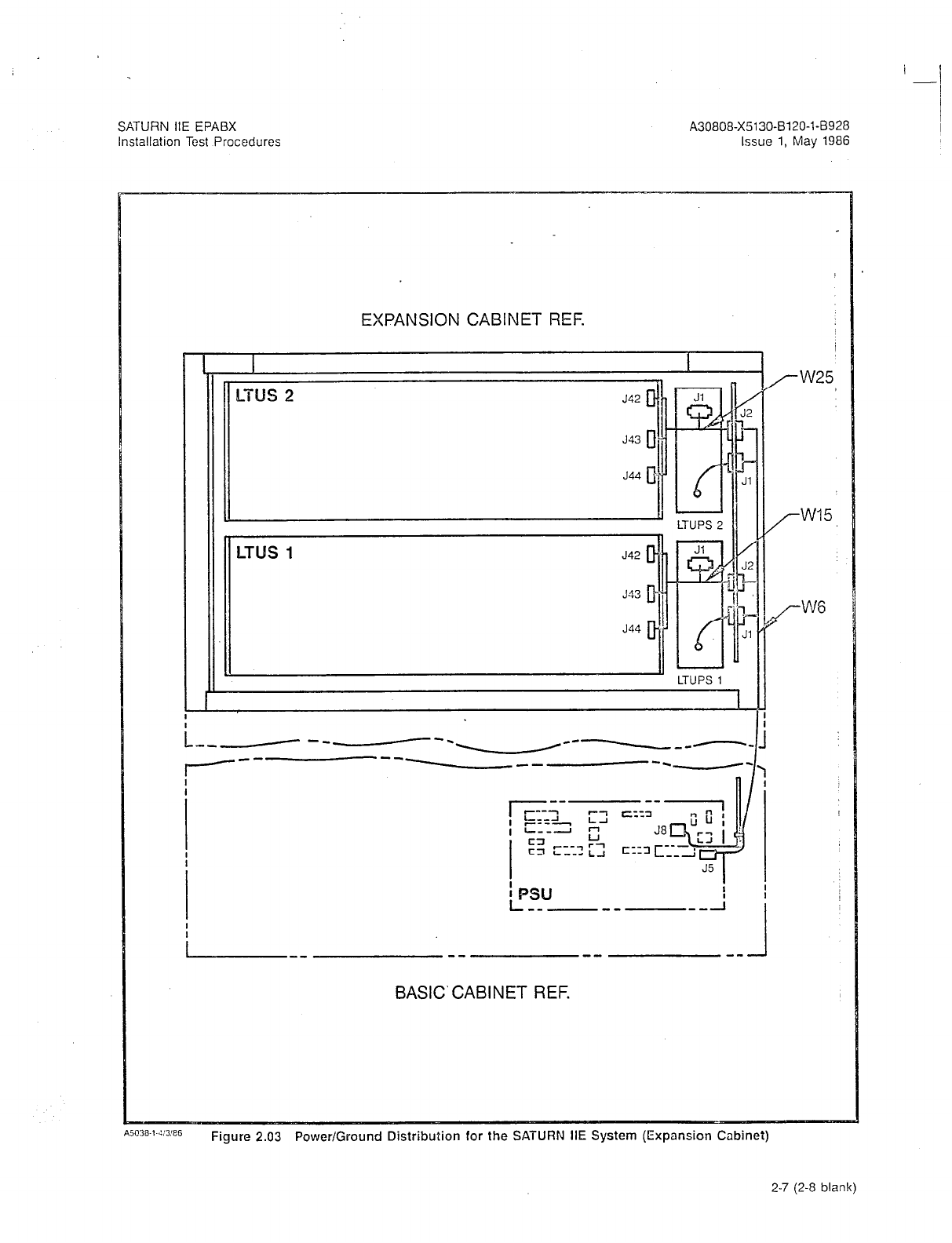
A30808-X5130-B120-l-8920
Issue 1, May 1986
EXPANSION CABINET REF.
L --M--e--\ ---- -,-,
------
-----
BASIC‘CABINET REF.
A5U38-1-4:3:86
Figure 2.03 Power/Ground Distribution for the SATURN IIE System (Expansion Cabinet)
2-7 (2-8 blank)
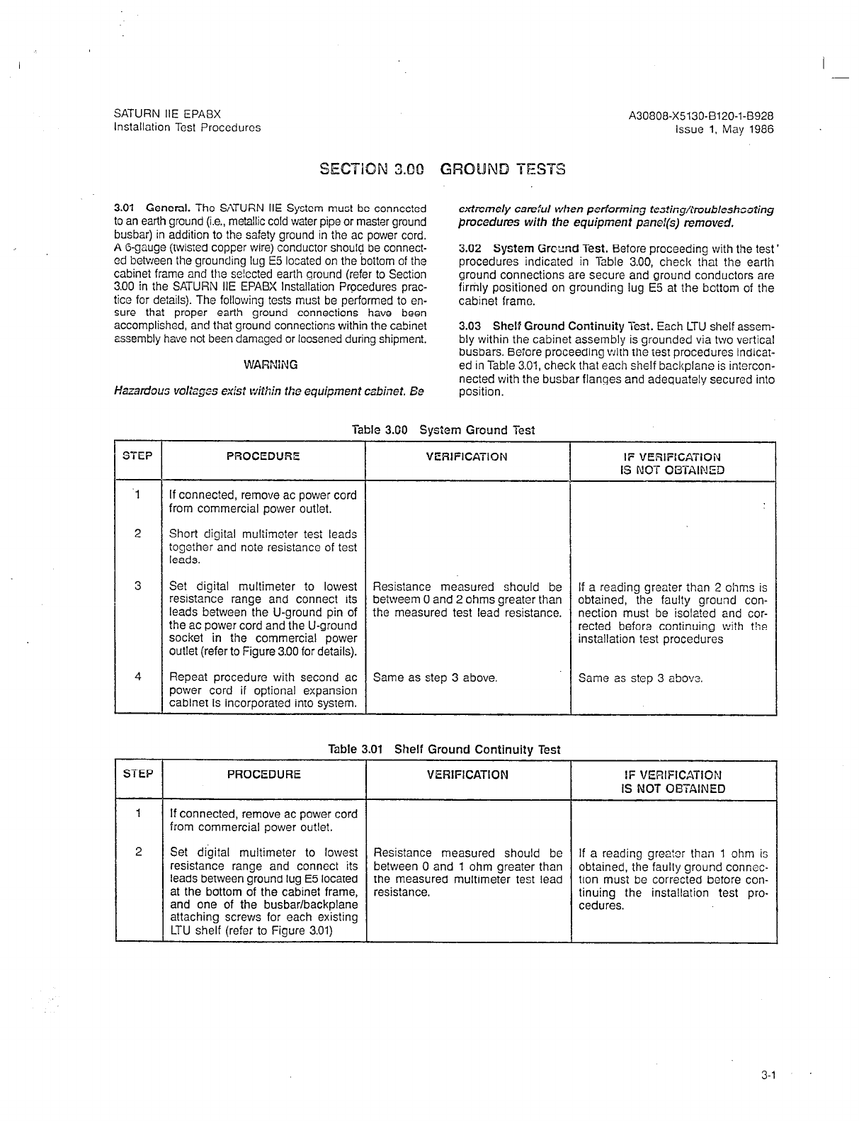
SATURN IIE EPABX A30808-X5130-B120-l-8928
Installation Test Procedures issue 1. May 1986
3.01 General. The SATURN HE System must be connected
to an earth ground (i.e., metallic cold water pipe or master ground
busbar) in addition to the safety ground in the ac power cord.
A G-gauge (twisted copper wire) conductor should be connect-
ed between the grounding lug E5 located on the bottom of the
cabinet frame and the snlccted earth ground (refer to Section
3.00 in the SATURN HE EPABX Installation Procedures prac-
tice for details). The following tests must be performed to en-
sure that proper earth ground connections have been
accomplished, and that ground connections within the cabinet
assembly have not been damaged or loosened during shipment.
WARNiNG
Hazardous voltsgos txkt within the equipment csbinef. Ee
extremely ca-ej’Ll when performing t~s%i~g/l’roubiesh~oting
procedures with the equipment panel(s) removed.
3.02 System Grcund Test. Before proceeding with the test’
procedures indicated in Table 3.00, check that the earth
ground connections are secure and ground conductors are
firmly positioned on grounding lug E5 at ihe bottom of the
cabinet frame.
3.03 Shelf Ground Continuity Test. Each LTU shelf assem-
bly within the cabinet assembly is grounded via two vertical
busbars. Beiore proceeding with the test procedures indicat-
ed in Table 3.01, check that each shelf backplane is iniercon-
netted with the busbar flanges and adequately secured into
position.
Table 3.00 System Ground Test
PROCEDURE VERlFlCATlON IF VERlFlCATION
IS NOT OBTAINED
.l If connected, remove ac power cord
from commercial power outlet.
2 Short digital multimeter
tesi
leads
together and noie resistance of test
leads.
3 Set digital multimeter to lowest Resistance measured should be If a reading greater ihan 2 ohms is
resistance range and connect its betweem 0 and 2 ohms greater than obtained, the faulty ground con-
leads between the U-ground pin of the measured test lead resistance. nection must be isolated and cor-
the ac power cord and the U-ground rected befora continuing wi?h the
socket in the commercial power installation test procedures
outlet (refer to Figure 3.00 for details).
4 Repeat procedure with second ac Same as step 3 above. Same as step 3 above.
power cord if optional expansion
cabinet is incorporated into system.
Table 3.01 Shelf Ground Continuity Test
STEP PROCEDURE VERIFICATION IF VERIFICATiON
IS NOT OBTAINED
1 If connected, remove ac power cord
from commercial power outlet.
2 Set digital multimeter to lowest Resistance measured should be If a reading greator than 1 ohm is
resistance range and connect its between 0 and 1 ohm greater than obtained, the faulty ground connec-
leads between ground lug E5 located the measured multimeter test lead tion must be corrected before con-
at the bottom of the cabinet frame, resistance. tinuing the installation test pro-
and one of the busbar/backplane cedures.
attaching screws for each existing
LTU shelf (refer to Figure 3.01)
3-l
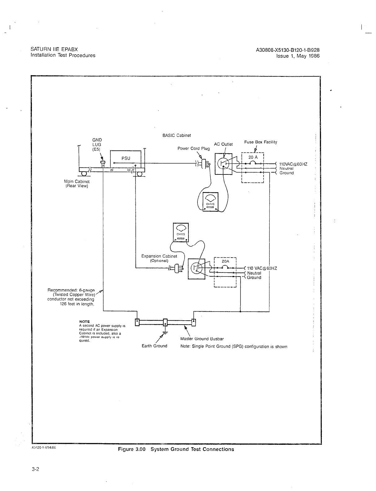
SATURN IIE EPABX A30808-X5130-B120-l-8928
Installation Test Procedures Issue 1, May 1986
BASIC Cabinet
GND
LUG Fuse Box Facility
(ES) ,
5, B D
Power co
PSU
f llOVAC~$GOi-fZ
El El Neulral
Ground
hlatn Cabmel
(Rear View)
Recommended: B-gauge
(iwtsted Copper Wire)
conductor not exceedmg
i26 feet m length.
I
(Ootlonall
I.1
f Master Ground Busbar
Earth Ground Note: Single Point Ground (SPG) configuration IS shown
Figure 3.00 System Ground Test Connections
3-2
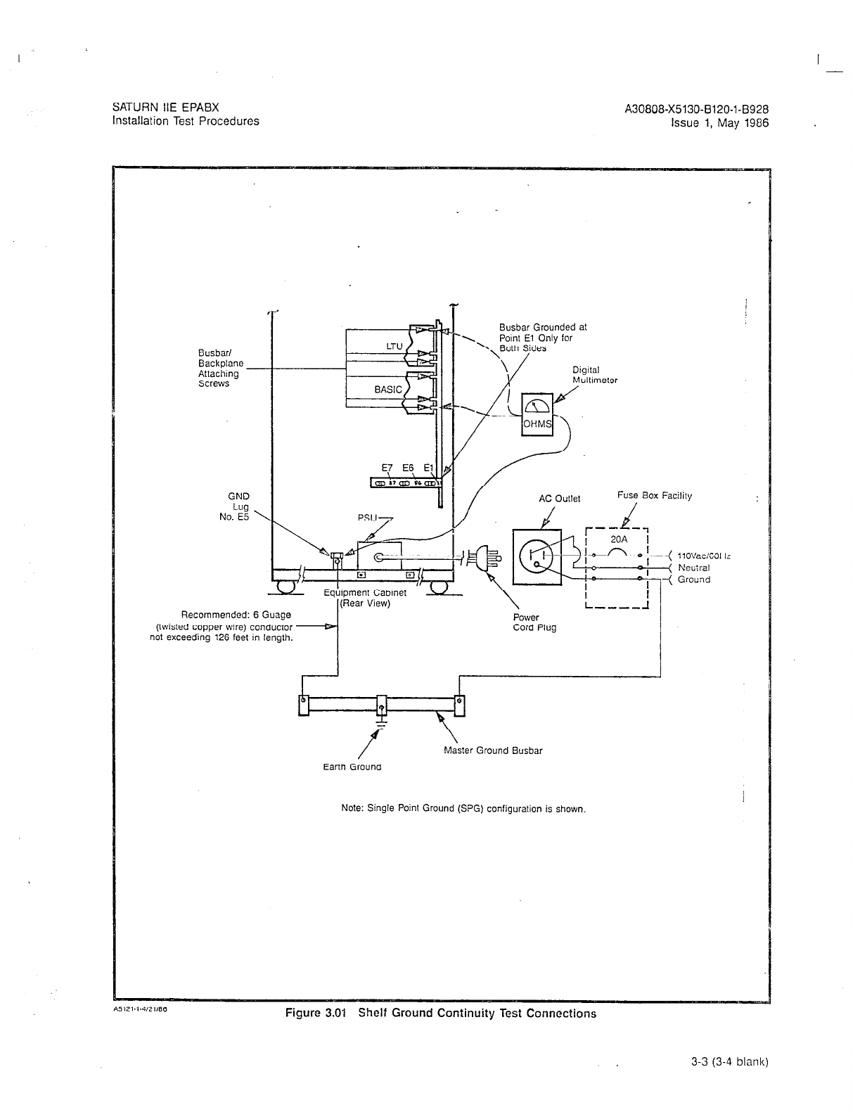
SATURN IIE EPABX
Installation Test Procedures A30808-X5130-8120-1-8928
Issue 1, May 1986
Busbar/
Backplane -
Attaching
Screws
GND
Lug
No. E5 ’
7
-
Recommended: 6 Guage
(twisted copper wire) conductor
not exceeding 126 feet in length.
I(Rear View)
Busbar Grounded at
Fuse Box Facility
\ I
L ---_ -I
Power
Cord Plug
7
Master Ground Busbar
Earth Ground
Note: Single Point Ground (SPG) configuration is shown
Figure 3.01 Shelf Ground Continuity Test Connections
3-3 (3-4
blank)
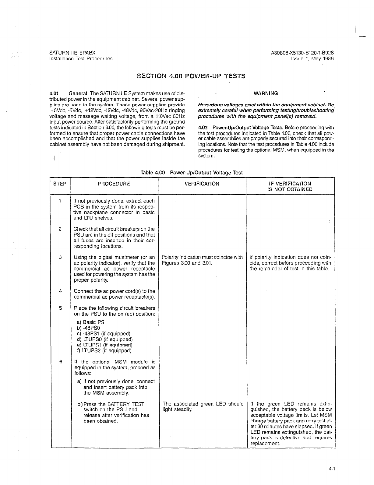
I -_
SATURN IIE EPABX
installation Test Procedures
A30808-X5130-BlZO-l-8928
Issue 1, May 1986
SECTION 4.00 POWER-UP TESTS
4.01 General. The SATURN IIE System makes use of dis-
tributed power in the equipment cabinet. Several power sup-
plies are used in the system. These power supplies provide
+5Vdc, -SVdc, +12Vdc, -12Vdc, -48Vdc, 90Vac-20Hz ringing
voltage and message waiting voltage, from a 11OVac 60Hz
input power source. After satisfactorily performing the ground
tests indicaied in Section 3.00, the following
tests
must be per-
formed to ensure that proper power cable connections have
been accomplished and that the power supplies inside the
cabinet assembly have not been damaged during shipment.
WARNING
Hazardous voltages exist within the equipment cabinet. Be
extremely careful when performing testin@roubkshootjng’
pmcedures with the equipment panel(s) removed.
4.02 Power-Up/Output Voltage Tests. Before proceeding with
the test procedures indicated in Table 4.00, check that all pow-
er cable assemblies are properly secured into their correspond-
ing locations. Note that the test procedures in Table 4.00 include
procedures for testing the optional MSM, when equipped in the
system.
Table 4.60 Power-Up/Output Voltage Test
YiEP PROCEDtJRE
f not previously done, extract each
‘CB in the system from its respec-
ive backplane connector in basic
md LTU shelves.
Check that
all
circuit breakers on the
‘SU are in the off positions and that
311 fuses are inserted in their cor-
,esponding locations.
Jsing the digital multimeter (or an
3c polarity indicator), verify that the
:ommercial ac power receptacle
Jsed for powering the systsm has the
Iroper polarity.
Connect the
ac
power cord(s) to the
zommercial
ac
power receptacle(s).
?lace the following circuit breakers
on the PSU to the on (up) position:
a) Basic PS
b) -48PSO
c) -48PSl (if equipped)
d) LTUPSO (if equipped)
e) LTUPSl (if equipped)
9
LTUPS2 (if equipped)
If the optional MSM module is
equipped in the system, proceed
2s
follows:
2)
If not previously done, connect
and insert battery pack into
the MSM assembly.
b)Press the BATTERY TEST
switch on the PSU and
release after verification has
been obtained.
VERIFICATION
‘olarity indication must coincide with
=igures 3.00 and 3.01.
The associated green LED should
light steadily.
IF VERIFICATION
IS NOT 08TAlNED
if polarity indication does not coin-
cide, correct before proceeding with
the remainder of test in this lable.
If the green LED remains cxtin-
guished, the battery pack is below
acceptable voltage limits. Let MSM
charge battery pack and retry test af-
ter 30 minutes have elapsed. If green
LED remains extinguished, the bat-
tery pack is defective and requires
replacement.
‘l-1
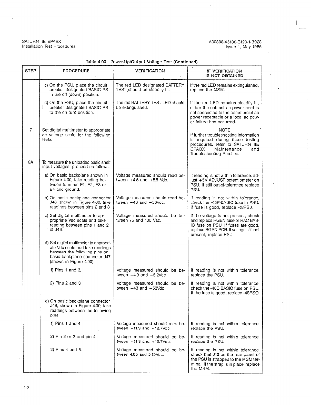
SATURN IlE EPABX
Installation Test Procedures A30808-X5130-8120-1-8928
issue 1, May 1986
Table 4.00 Power-Up/Output Voltage
Test (Continued)
SE?
PROCEDURE VEfiIFICATION IF VERIFICATION
IS NOT OBTAINED
c) On the PSU, place the circuit The red LED designated BATTERY If the red LED remains extinguished,
breaker designated BASIC PS TEST.should be steadily lit. replace the MSM.
in the off (down) position.
The red BATTERY TEST LED should
1 d) On the PSU, place the circuit If the red LED remains steadily lit,
breaker designated BASIC PS be extinguished. either the cabinet ac power cord is
to the on (up) position. not connected to the commercial ac
power receptacle or a local ac pow-
er failure has occurred.
7 Set digital multimeter to appropriate NOTE
dc voltage scale for the following If further troubleshooting information
tests. is required during these testing
procedures, refer to SATURN IIE
EPABX Maintenance and
Troubleshooting Practice.
8A To measure the unloaded basic shelf
input voltages, proceed as follows:
a) On basic backplane shown in Voltage measured should read be- If reading is not within tolerance, ad-
Figure 4.00, take reading be- tween +4.5 and +5.5 Vdc. just +5V ADJUST potentiometer on
tween terminal El, E2, E3 or PSU. If still out-of-tolerance replace
E4 and ground. PSU.
b) On basic backplane connector Voltage measured should read bo- If reading is not within to!erance,
J46, shown in Figure 4.00, take tween -43 and -53Vdc. check the -48P-BASIC fuse in PSU.
readings beiween pins 2 and 3. If fuse is good, replace -48PSO.
c) Set digital multimeter to ap- Voltage measured should be be- If the voltage is not present, check
propriate Vat scale and take tween 75 and 100 Vat. and replace RGEN fuse or RAC BAS-
reading between pins 1 and 2 IC fuse on PSU. If fuses are good,
of J46. replace RGEN PCB. If voltage still not
present, replace PSU.
d) Set digital multimeter to appropri-
ate Vdc scale and take readings
between the following pins on
basic backplane connector J47
(shown in Figure 4.00):
1) Pins 1 and 3.
2) Pins 2 and 3.
Voltage measured should be be- If reading is not within tolerance,
tween -4.9 and -5.2Vdc replace the PSU.
Voltage measured should be be- If reading is not within tolerance,
tween -43 and -53Vdc check the -488 BASIC fuse on PSU.
If the fuse is good, replace -48PS0.
e) On basic backplane connector
J48, shown in Figure 4.00, take
readings between the following
pins:
1) Pins 1 and 4.
2) Pin 2 or 3 and pin 4.
3) Pins 4 and 5.
Voltage measured should read be- If reading is not within tolerance,
tween -11.3 and -12.7Vdc. replace the PSU.
Voltage measured should be be- If reading is not within tolerance,
tween +11.3 and +12.7Vdc. replace the PSU.
Voltage measured should be be- If reading is not within tolerance,
tween 4.85 and 5.15Vdc. check that J16 on the rear panel of
the PSU is strapped to the MSM ter-
minal. If the strap is in place, replace
the MSM.
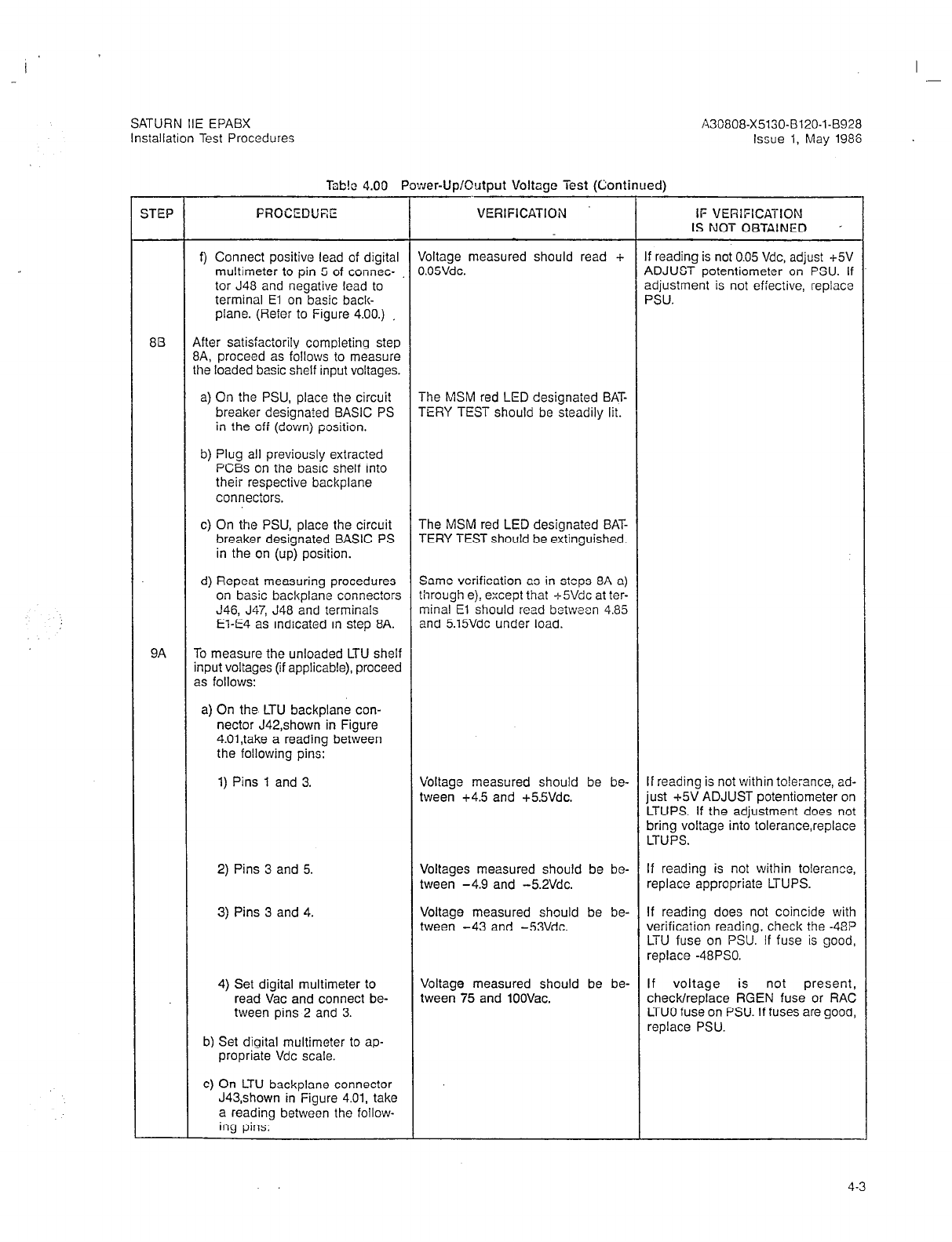
I -
SATURN IIE EPABX
Installation Test Procedures
A3G808-X5130-B120-1-B928
Issue 1, May 1986
lbb!c 4.00 Power-Up/Output Voltage Test (Continued)
STEP FROCEDUEE VERIFICATION IF VERIFICATION
IS NOT OBTAINED .
f) Connect positive lead of digital Voltage measured should read + If reading is not 0.05 Vdc, adjust +5V
multimeter to pin 5 of connec- 0.05Vdc. ADJUST potentiometer on PSU. If
tor J48 and negative lead to adjustment is not effective, replace
terminal El on basic back- PSU.
plane. (Refer to Figure 4.00.)
813 After satisfactorily completing step
8A, proceed as follows to measure
the loaded basic shelf input voltages.
a) On the PSU, place the circuit The MSM red LED designated BAT-
breaker designa?ed BASIC PS TERY TEST should be steadily lit.
in the off (down) position.
b) Plug all previously extracted
PCBs on the basic shelf into
their respective backplane
connectors.
c) On the PSU, place the circuit The MSM red LED designated BAT-
breaker designated BASIC PS TERY TEST should be extinguished.
in the on (up) position.
d) Repeat measuring procedures Same verification as in steps 8A a)
on basic backplane connectors through e), except that -t-S!/& at ter-
J46, J47, J48 and terminals minal El should read between 4.85
El-E4 as indicated in step 8A. and 5.15Vdc under load.
9A To measure the unloaded LTU shelf
input voltages (if applicable), proceed
as follows:
a) On the LTU backplane con-
nector J42,shown in Figure
4.01,take a reading between
the following pins:
1) Pins 1 and 3. Voltage measured should be be- If reading is not within to!e:ance, ad-
tween +4.5 and +5.5Vdc. just +5V ADJUST potentiometer on
LTUPS. If the adjustment does not
bring voltage into tolerance,replace
LTUPS.
2) Pins 3 and 5.
3) Pins 3 and 4.
Voltages measured should be be- If reading is not within tolerance,
tween -4.9 and -5.2Vdc. replace appropriate LTUPS.
Voltage measured should be be- If reading does not coincide with
tween -43 and -53Vdc. verification reading, check the -48P
LTU fuse on PSU. If fuse is good,
replace -48PS0.
4) Set digital multimeter to
read Vat and connect be-
tween pins 2 and 3.
Voltage measured should be be- If voltage is not present,
tween 75 and 1OOVac. check/replace RGEN fuse or RAC
LTUO fuse on PSU. If fuses are good,
replace PSU.
b) Set digital multimeter to ap-
propriate Vdc scale.
C)
On LTU backplane connector
J43,shown in Figure 4.01, take
a reading between the follow-
ing pins:
4-3

SATURN IIE EPABX
Installation Test Procedures A30808-X5130-B120-l-6928
Issue 1, May 1986
Table 4.00 Power-Up/Output Voliagc? Test (Continued)
STEP PROCEDURE VEFllFlCATlON IF VERIFICATION
IS NOT OBTAINED
1) Pins 1 and 3. Voltage measured should read be- If reading is not within tolerance, ad-
tween +4.5 and +5.5Vdc. just +5V ADJUST potentiometer on
LTUPSO. If adjustment does not bring
the voltage into tolerance, replace
LTUPSO.
2) Pins 1 and 2. Voltage measured should read be- If reading is not within tolerance,
tween -43 and -53Vdc. replace -48PS0. If voltage not
present, check -488 LTUO fuse on
PSU. If fuse is good, replace 48PS0.
3) Pins 1 and 4. Voltage measured should read be- If reading is not within tolerance,
tween +11.3 and +12,7Vdc. replace LTUPSO.
4) Pins 1 and 5. Voltage measured should read be- If reading is not within tolerance,
-. ttieen -11.3 and -12.7Vdc. replace LTUPSO.
d) On LTU backplane connector Voltage measured should read be- If reading is not within tolerance,
J44 shown in Figure 4.01, take tween +4.5 and +55Vdc. check +5V cabling between be-
a reading between pins 1 and tween basic shelf and LTU
2 or pins 1 and 3.
98 Repeat steps 9A a) through d) for ex-
pansion cabinet LTU shelf voltages
(if applicable) substituting -48PSl for
48Vdc power supply and appropriate
LTUPS.
9C After satisfactorily completing steps
9A and 96, proceed
2s
follows to
measure the loaded LTU shelf input
voltages:
a) On the PSU, place the circuit
breakers designated
LTUPSO,LTUPSl,and LTUPS2
in the off (down) positions.
b) Plug all previously extracted
PCBs on the LTU shelves into
their respective backplane
connectors.
c) On the PSU, place the circuit
breakers designated LTUPSO,
LTUPSl, and LTUPS2 in the
on (up) positions.
d) Repeat measurements on LTU Voltages measured should be within
backplane connectors J42, same tolerances except +5Vdc sup-
J43, and J44 per step 9A. ply should read between 4.85 and
5.15 Vdc.
4-4

I
SATURN IIE EPABX
lnstallatlon Test Proccdurcs A30808-X5130-8120-1-8928
Issue I, May 1986
J46/P46
J47/P47
Figure 4.00 Location of Input Voltage Connectors 011 Basic Bockplnnc
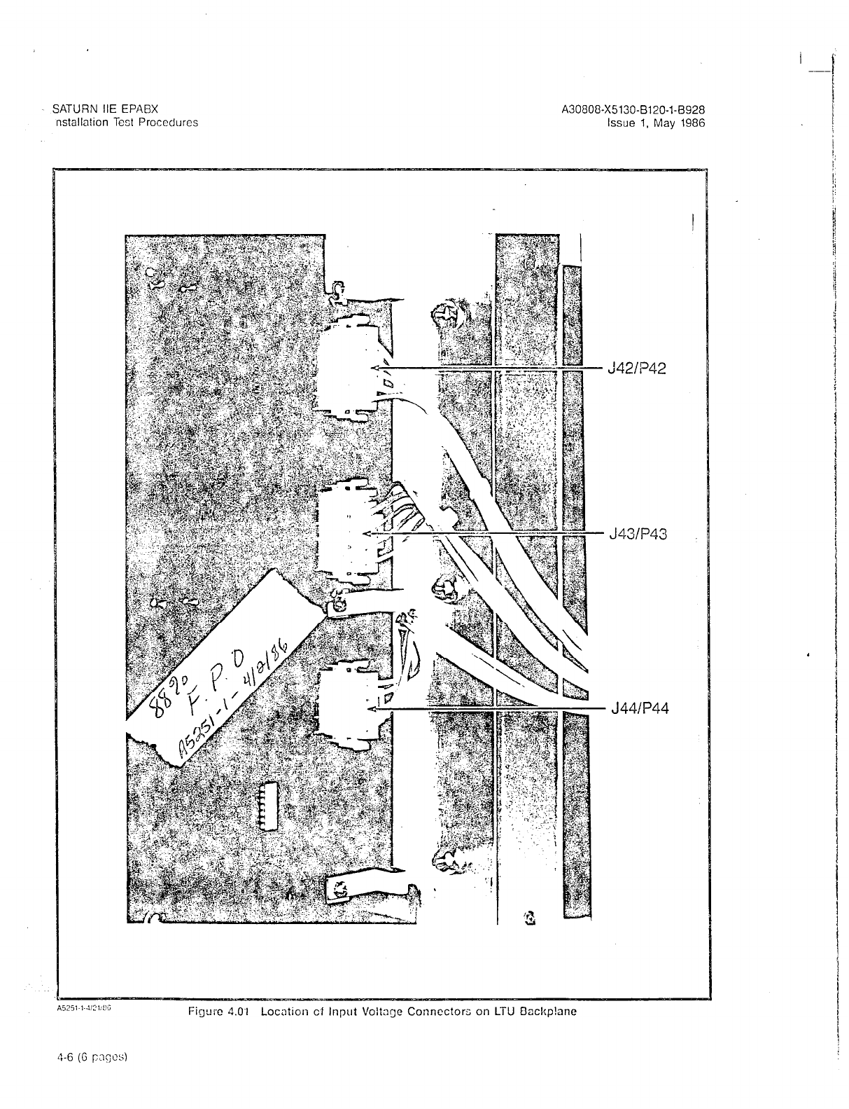
SATURN IIE EPABX A30808-X5130-8120-1-8928
nstallation Test Procedures Issue 1, May 1986
i ---I
I
:42/?42
J43/P43
J44lP44
Figure 4.0.1 Location cf Input Voltage Connectors on LTU Dackp!ane

SATURN IIE EPABX A30808-X5130-B120-l-8928
Installation Test Procedures Issue 1, May 1986
5.01 General. The SATURN IIE EPABX is a Stored-Program-
Controlled (SPC) system. The system is shipped with two iden-
tical floppy disks that contain the basic operating and the
installation-dependent data. The operating program uses the
installation-dependent data, commonly referred to as the sys-
tem data base, to complete and process calls as required by
the customer. This information includes such items as the
number of station lines and trunks in the system, as well as
their operating characteristics.
The exact equipment configuration of the SATURN IIE Sys-
tem must be defined in the data base in order for the system
to operate properly. Depending on how the system is ordered,
the data base is supplied in a standard format or, on request,
can be supplied completely defined and prepared by Siemens.
When the standard data base format is supplied, via the
SATURN EPABX Data Base Preparation practice, the equip-
ment configuration of the particular installation-site must be
evaluated to determine if additional information must be ad-
ded to the floppy disks. The floppy disks are updated via a
service terminal. The procedures for defining the data base
and inputting the data to memory are described in the
SATURN EPABX Data Base Preparation practice and
SATURN EPABX Customer Memory Update (CMU) Proce-
dures practice.
5.02 boadjng Operating D&a. After satisfactoriiy complet-
ing the Power-Up/Output Voltage Tests in Section 4.00, the
system’s operating program, contained on the floppy Uisks,
is loaded into the FDD modules for the initial processor in-
itialization. Both floppy disks are loaded, with either disk
placed in either drive (FDDO or FDDI). Before proceeding with
the loading procedures indicated in Table 5.00, the following
precautions must be observed when handling the floppy disks.
Figure 5.00 illustrates the floppy disk and storage envelope.
a. Prior to using a floppy disk, leave disk in the same en-
vironment as the FDD module for at least 5 minutes.
b. Do not place heavy objects on floppy disk.
c. Do not write on floppy disk.
d. Do not touch floppy disk suriace while hand!ing.
Damage to FDD head may occur due to skin oil pick-
ing up dirt.
e. Always return floppy dislc to storage envelope when it
is not in use.
5.03 Inputting CMU Data to F!oppy Disk. After satisfac-
torily loading the operating disks as indicated in Table 5.00,
refer to the SATURN EPABX Data Base Preparation practice
which defines the particular system’s data base, and SATURN
EPABX Customer Memory Update (CMU) Prccsdures prac-
tice to input the installation-dependent da?a to memory
Centering 1
Hole
Read/W
Window
Index
Hole
Protective
Envelope
I
I
Storage
Envelope
Figure 5.00 Floppy Disk and Storage Envelope
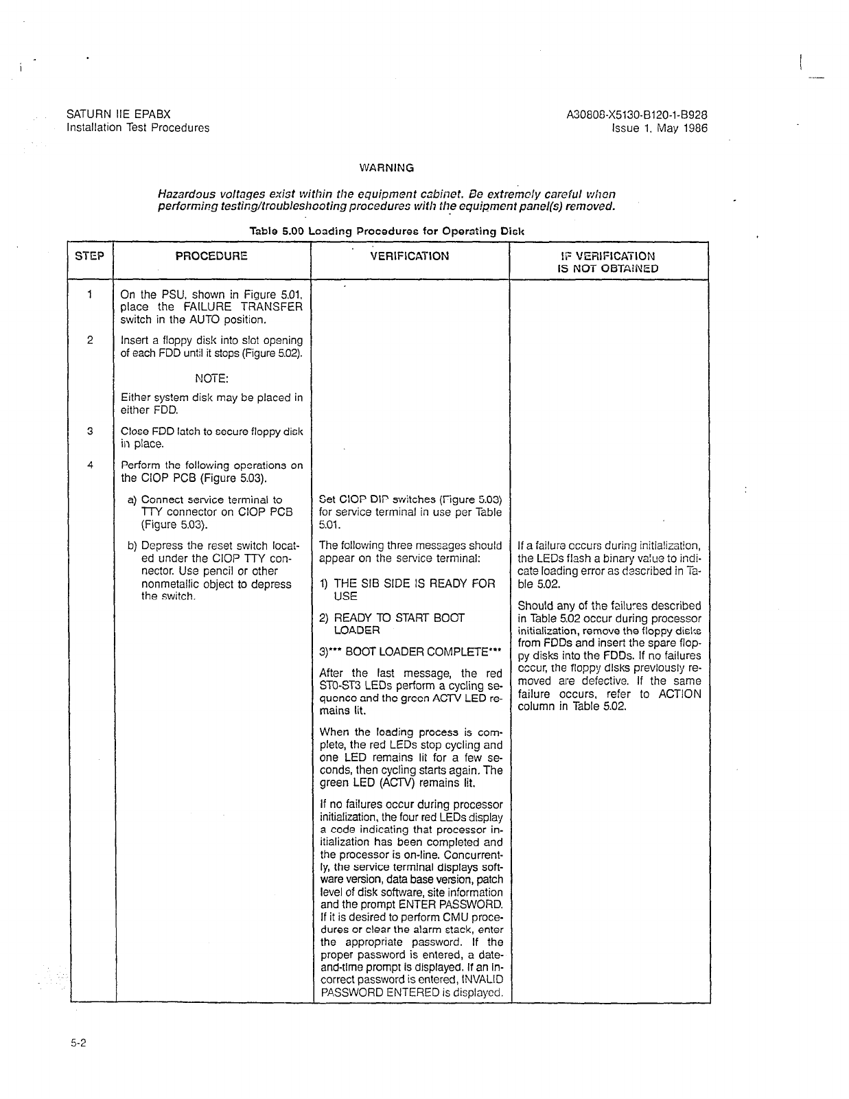
SATURN IIE EPABX A3080&X5130-B120-l-8928
Installation Test Procedures Issue 1, May 1986
WARNING
Hazardous voltages exist within the equipment cabinet. Be e&e&y careful when
performing testir;g/~roobleshooting procedur- LJ with the equ&ment panel(s) removed.
Table 5.00 Loading Procedures for Operaling Disk
;TEP PROCEDURE VERIFICATION !F VERIFICATION
IS NOT OBTA!NED
1 On the PSU, shown in Figure 5.01,
place the FAtLURE TRANSFER
switch in the AUTO position,
2 Insert a floppy disk into slot opening
of each FDD until it stops (Figure 5.02).
NOTE:
Either system disk may be placed in
either FDD.
3 Close FDD latch to secure floppy disk
in place.
4 Perform the following operations on
the CIOP PCB (Figure 5.03).
a) Connect service terminal to Set CIOP DlP switches (Figure 5.03)
TTY connector on CIOP PCB for service terminal in use per Table
(Figure 5.03). 5.01.
b) Depress the reset switch locat- The following ihree messages should If a failure occurs during initia!ization,
ed under the CIOP llY con- appear on the service terminal: the LEDs flash a binary value to indi-
nectar. Use pencil or other cate loading error as described in Ta-
nonmetallic object to depress 1) THE SIB SIDE IS READY FOR ble 5.02.
the switch. USE Should any of the failures described
2) READY TO START BOOT in Table 5.02 occur during processor
LOADER initialization, remove the floppy disks
3)“* BOOT LOADER COMPLETE”’ from FDDs and insert the spare flop-
py disks into the FDDs. If no failures
After the last message, the red cccur, the floppy disks previously re-
STO-ST3 LEDs perform a cycling se- moved are defective. If the same
quence and the green ACTV LED re- failure occurs, refer to ACTION
mains lit. cOlumn in Table 5,02
When the loading process is com-
plete, the red LEDs stop cycling and
one LED remains lit for a few se-
conds, then cycling starts again. The
green LED (ACTV) remains lit.
If no failures occur during processor
initialization, the four red LEDs display
a code indicating that processor in-
itialization has been completed and
the processor is on-line. Concurrent-
ly, the service terminal displays soft-
ware version, date base version, patch
level of disk software, site information
and the prompt ENTER PASSWORD.
If it is desired to perform CMU proce-
dures or clear the alarm stack, enter
the appropriate password. If the
proper password is entered, a date-
and-time prompt is displayed. If an in-
correct password is entered, INVALID
PASSWORD ENTERED is displayed.
5-2
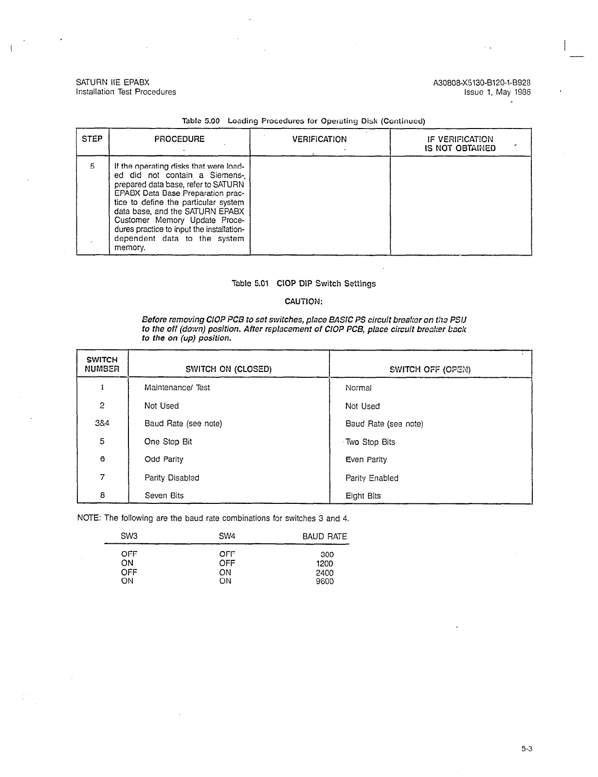
SATURN IIE EPABX A30808-X5130-0120-1-8928
Installation Test Procedures lssuc 1, May 1936
Table 5.00 Loading Procedures for Operating Disk (Continued)
STEP PROCEDURE VERlFlCATlON IF VERIFlCAT!ON
IS NOT OBTAINED ’
5 If the operating disks that were load-
ed did not contain a Siemens-.
prepared data base, refer to SATURN
EPABX Data Base Preparation prac-
tice to define the particular system
data base, and the SATURN EPABX
Customer Memory Update Proce-
dures practice to input the installation-
dependent data to the system
memory.
Table 5.01 CIOP DIP Switch Settings
CAUTION:
Before removing GOP PCB to set switches, place BASIC PS circuit brea!:er on lhe PSU
to the off (c?own) position. After replacement of ClOP PCB, place circuit breaker back
to the on (up) position.
SWITCH
NUMBER SWITCH ON (CLOSED) SWITCH OFF (OPZX)
1 Maintenance/ Test Normal
2 Not Used Not Used
3&4 Baud Rate (see note) Baud Rate (see no?e)
5 One Stop Bit Two Stop Bits
6 Odd Parity Even Parity
7 Parity Disabled Parity Enabled
8 Seven Bits Eight Bits
NOTE: The following are the baud rate combinations for switches 3 and 4.
SW3 SW4 BAUD RATE
OFF OFF 300
ON OFF 1200
OFF ON 2400
ON ON 9600
5-3
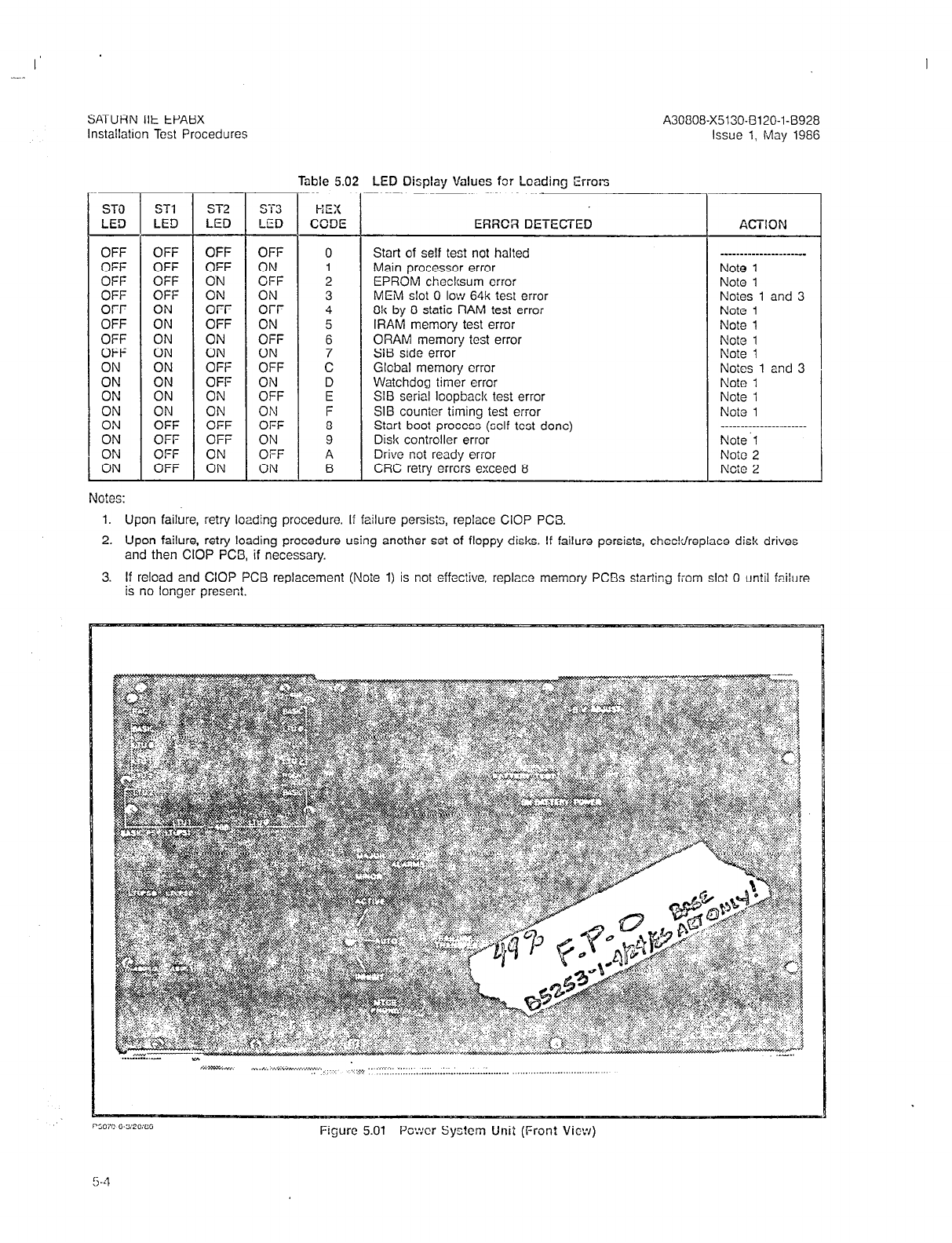
I’
A30808-X5130-(3120-l-8928
Issue 1, May 1986
Table 5.02 LED Display Values for Loading Errors
HEX
CCDE
ERRCR DETECTED
0
1
2
3
4
5
6
:
D
E
F
8
9
A
I3
Start of self test not halted
Main processor error
EPROM checksum error
MEM slot 0 low 64k test error
8k by 8 static RAM test error
IRAM memory test error
ORAM memory test error
SIB side error
Global memory error
Watchdog iimer error
SIB serial loopback test error
SIB counter timing test error
Start boot process (self test done)
Disk coniroller error
Drive not ready error
CRC retry errcrs exceed 8
ST0
LED
OFF
:z
OFF
OFF
OFF
OFF
OFF
ON
ON
ON
ON
ON
ON
ON
ON
Notes:
I
ST1
LED
OFF
OFF
OFF
OFF
ON
ON
%
ON
ON
ON
%F
OFF
OFF
OFF
ST2
LED
OFF
OFF
ON
ON
OFF
OFF
%
OFF
OFF
ON
%F
OFF
ON
ON
ST3
LED
OFF
ON
OFF
ON
OFF
ON
OFF
ON
OFF
ON
OFF
ON
OFF
ON
OFF
ON
ACTION
_._________-________
Note 1
Note 1
Notes 1 and 3
Noie 1
Note 1
Note 1
Note 1
NOieS
1 and 3
Note 1
Note 1
Note 1
______-___--___-____--
Note ‘1
Note 2
Note 2
1. Upon failure, retry loading procedure. If failure persists, replace CIOP PC3.
2. Upon failure, retry loading procedure using another set of floppy disks. If failure persists, chcc!i/replace disk drives
and then CIOP PCB, if necessary.
3. If reload and CIOP PCB replacement (Noie 1) is not effective, replace memory PCBs starting from sloi 0 until failure
is no longer present.
Figure 5.01 Po*wr Sys?em Unit (Front View)
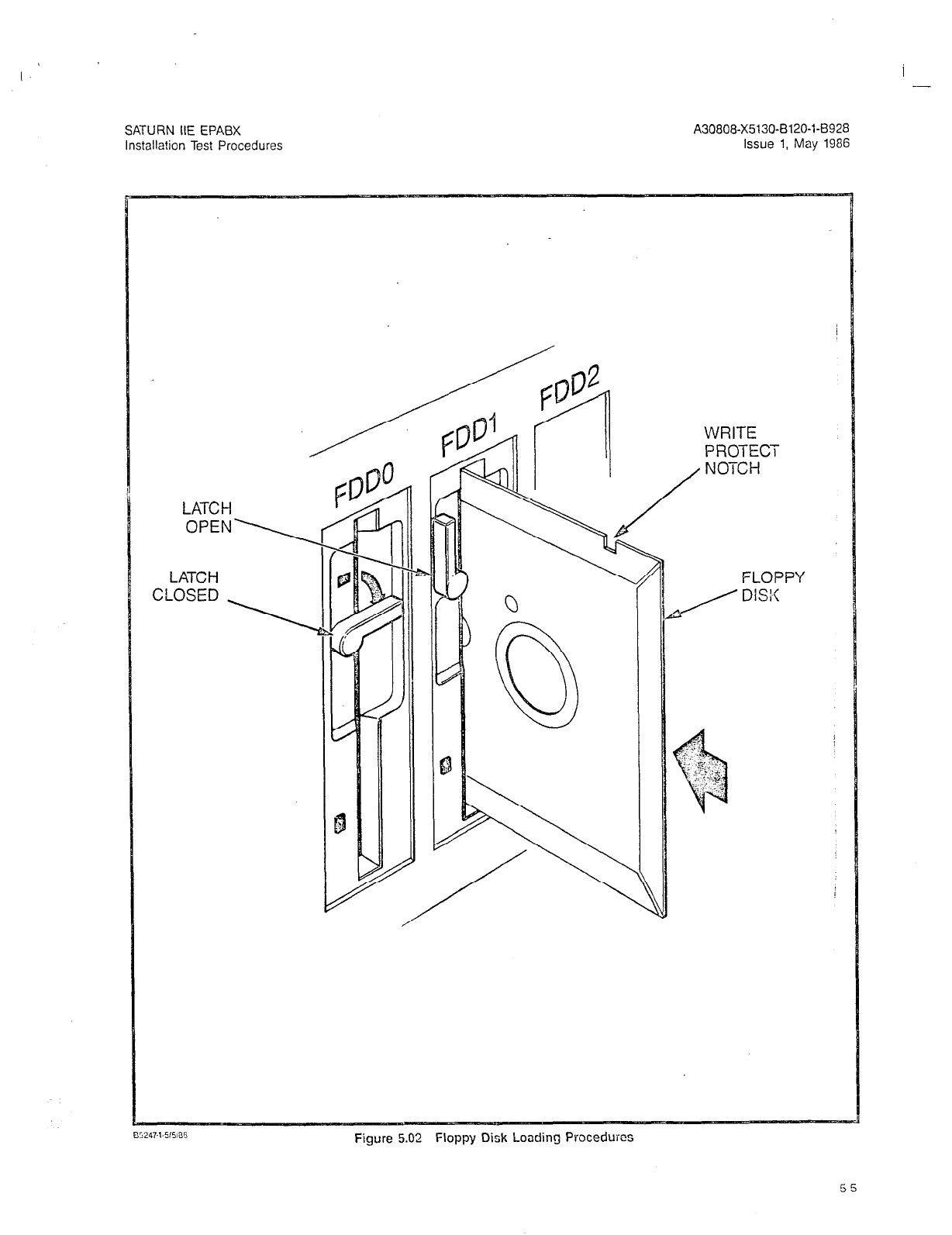
I --
SATURN IIE EPABX
Installation Test Procedures
A30808-X5130-6120-1-8928
Issue 1, May 1986
LATCH
OPEN\
LATCH
CLoSED \
/
/
?
25
0
WRITE
PROTECT
NOTCH
FLOPPY
/ DiSi’c
Figure 5.02 Floppy Dish Loading Proceduics
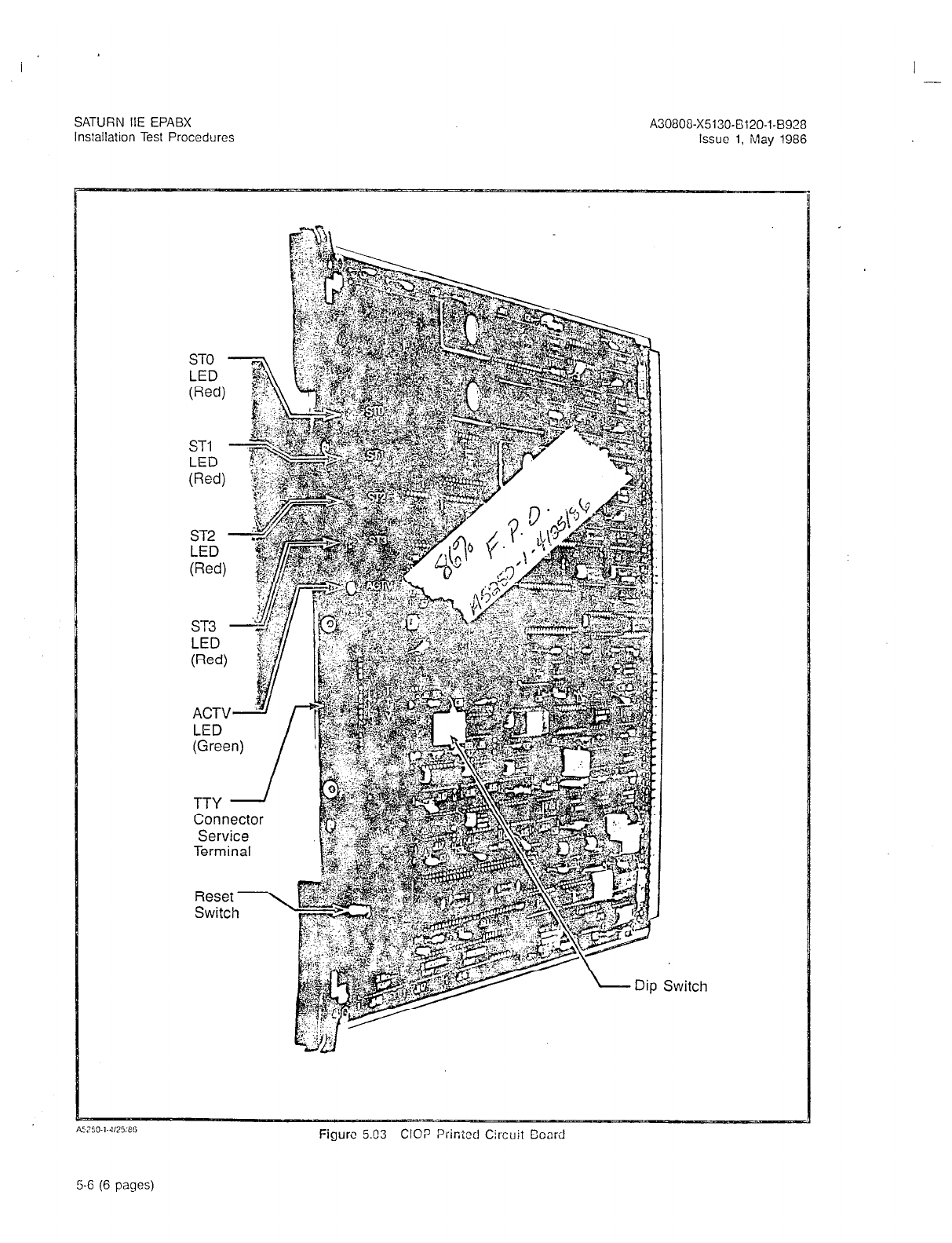
I -
SATURN IIE EPABX
Installation Test Procedures A30800-X5130-6120-l-8928
Issue 1, May 1986
LED
LED
(Red)
ST3
LED
ACTW r
LED
Connector
Service
Terminal
‘witch
Figure 5.03 CIOP Printed Circuit Coard
5-6 (6 pages)

SATURN IIE EPABX A30808-X5130-BlZO-l-8920
Installation Test Procedures Issue 1. May 1986
6.01 General. After satisfactorily loading the cperating disk
and inputting CMU data to system memory via a service ter-
minal, the operational capability of the system must be veri-
fied after the necessary MDF cross-connections are
performed. The SATURN IIE System software contains a
group of system and apparatus (ancillary equipment) diag-
nostic test routines which are accessed via the maintenance
phone. Resulting visual and/or audible responses from these
on-line diagnostic
tests
make it possible to verify correct oper-
ation or
detect
and isolate system and apparatus malfunc-
tions. If in doubt about a SATURN PCB or apparatus
maliunctioning, craft personnel should refer to the SATURN
IIE EPABX Mainionance and Troubleshooting praciice for fur-
ther details. If a SATURN PCB or apparatus is proven to be
defective,
craft personnel should proceed according to the
instructions contained in the MRA kit.
6.02 Connecticn of Maintenance Phcne and Modem.
Figures 6.00 and 6.01 provide the details for the maintenance
phone and modem initial MDF cross-connections. Figure 6.00
also identifies the leads used when interfacing other main-
tenance related equipment such as a power failure transfer
subsystem and dry contact closures for remote minor and
major alarm indications. Note that such equipment is
customer-provided and craft personnel should follow the
manufacturer’s instructions when installing them. To connect
ihe maintenance phone and modem, the initial MDF cross-
connections aie as follows:
a.
Maintenance Phone. At the MDF connecting block on
which PSU cable J13 is terminated, cross-connect the
T&R leads of pair number 1 (W/BL- BL/W) to the T&R
leads of the subscriber line circuit assigned for main-
tenance purposes (refer to Figure 6.00 for details). Note
that this subscriber line circuit must be classmarked
with the Maintenance Diagnostic Test (TESTDIAG) and
Apparatus Test (TSTAPP) features.
b. Modem. From the system T&R connecting block that
allocates system MDF cable J44 from the basic shelf,
cross-connect the T&R of pair number 24 (V/BR- BR/V)
to the T&R leads of the subscriber line circuit to be used
for modem application (refer to Figure 6.01 for details).
The subscriber line circuit to be used for modem ap-
plication must be assigned to a class of service in
which the Data Line Security (DATASEC) classmark has
been enabled.
After the above initial MDF cross-connections have been
performed, the DTMF telephone set to be used as the
maintenance phone can be connected to the modular
jack designated MTCE PHONE on the PSU if equipped
with a standard modular plug, or connected at the MDF
to the T&R leads of the associated subscriber line cir-
cuit. Note that if a permanent maintenance phone is
desrred in tho equipment, it may be installed neartho
front of the cabinet, and cross-connected per Figure 6.02.
6.03 MDF Cross-Connecting Procedures. After the main- ’
tenance phone and modem connections have been complet-
ed, perform the necessary MDF cross-connections according
to the equipment configuration plan. The following illusira-
tions are provided to assist craft personnel in the MDF cross
connections of peripheral interfacing devices:
a.
b.
C.
d.
e.
f.
9.
h.
i.
i
k.
I.
m
n.
0.
Figures 6.02 and 6.03 - Cross-Connections for rotary
or pushbutton Single Line Telephone Instruments in-
terfacing with SLMA-S and SLA16 PCBs, respectively.
Figure 6.04 - Cross-Connections for Siemens Digital
Telephone Interfacing with SLMD PCB.
Figure 6.05 - Cross-Connections for SATURN Atien-
dant Console.
Figure 6.06 - Cross-Connections for Central Office
(CO) and Direct Inward Dialing (DID) Trunks.
Figure 6.07 - Cross-Connections for Two-Wire (Type I)
E&M Tie Trunks.
Figure 6.03 - Cross-Connections for Four-l”dirc (T]pe
I) E&M Tie Trunks.
Figure 6.09 - Cross-Ccnnections for T;:jo-Wire (T]pe I!)
E&M Tie Trunks.
Figure 6.10 - Cross-Connections for Four Wire (Type
II) E&M Tie Trunks.
Figure 6.11 - Cross-Connections for Recorded An-
nouncement Equipment (DID and Tie Trunk Vacant
Number Intercept, and ACD Announcement Service).
Figure 6.12 - Cross-Connections for Coda Calling
Equipment with or without Answerbaclc Capability.
Figure 6.13 -Cross-Connections for DTMF Dial Dicta-
tion Equipment.
Figures 6.14 and 6.15 - Cross-Connections for Music-
on-Hold Feature via a Music Source, interfacing with
a TMBA4 and an SLMA/SLAlG PCB, respectively.
Figure 6.16 - Cross-Connections for Zoned Paging
Equipment With Answerback Capability.
Figure 6.17 - Cross-Connections for Zoned Paging
Equipment Without Answerback Capability.
Figure 6.18 - Cross-Connections for Zoned Universal
Night Answer (ZUNA or UNA) Signaling Equipment,
6-l
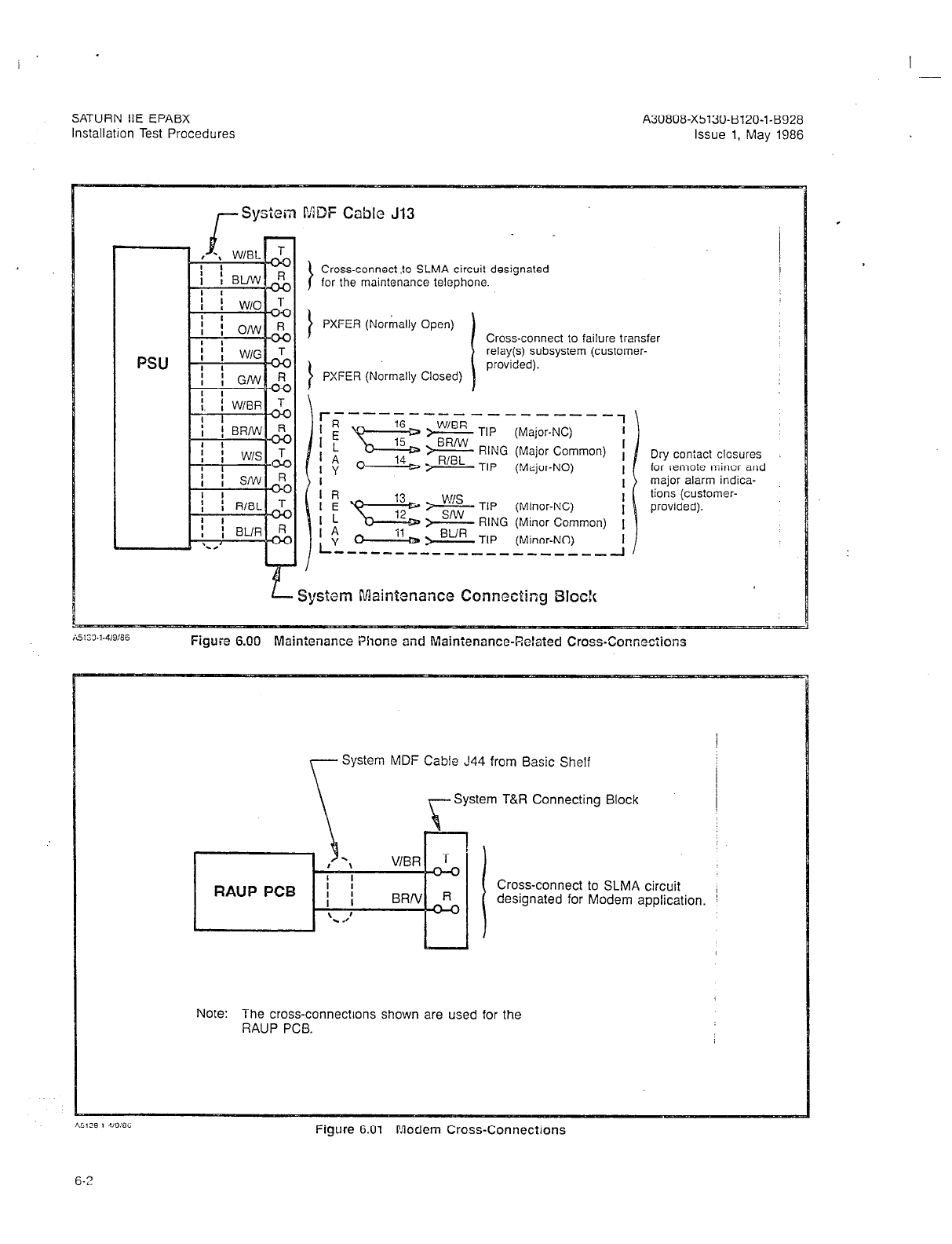
I .-
SATURN IIE EPABX A30808-X5130-B120-l-B928
lnstallatlon Test Procedures Issue 1, May 1986
,-Syslein MDF Cable J13
Cross-connect .to SLMA circuit designated
for the maintenance telephone.
1 PXFER (No&h Ooen1
J , I
PXFER (Normally Closed)
Cross-connect to failure transfer
relay(s) subsystem (customer-
provided).
\$$! > :tG TIP (Major-NC)
> RING (Major Common)
0 14 D > FUBL TIP (Major-NO) Dry contact closures
for remoie miner and
major alarm indica-
tions (customer-
provided).
Syslem Maiafcnancc Connecting Blsck
Figure 6.00 Mainienance Phone and Mainienance-Related Cross-Conneciions
System MDF Cable 144 from Basic Shelf
rSystem T&R Connecting Block
Cross-connect to SLMA circuit i
designated for Modem application. !
Note: The cross-connections shown are used for the
RAUP PCB.
Figure G.01 Modem Cross-Connections
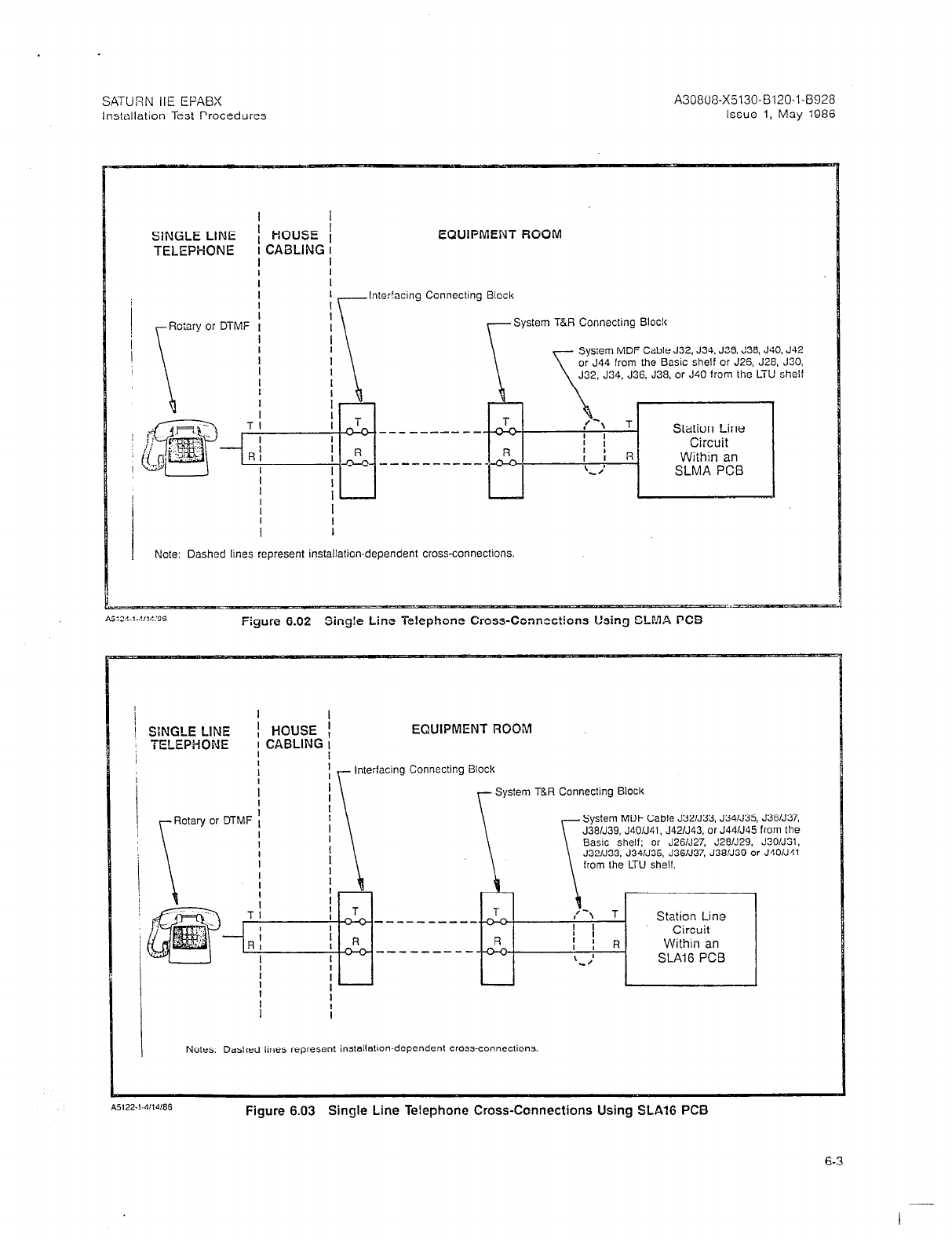
SATURN IIE EPABX A30808-X5130-B120-1-6928
Installation Test Procedures Issue 1, May 1986
I I
SlNGLE LINE ’ HOUSE /
TELEPHONE ! CABLING I
I
EQUIPMENT ROOM
I
Inlerfacing Connecting Block
System T&R Connecting Block
Sys:em MDF Cable J32, J34. J36. C38. JSO, J42
or
J44
from the EZISIC shelf or
J26, J28, J30,
J32. J34. J36. J38, or J40
from tile
LTU shelf
----------
f
-+(-Jo--- -________
[ ---I I I
I
Note: Dashed lilies represent installation-dependent cross-connections.
Figure 6.02 Sing!e Line Telephone Cross-Connections Using SLMA PC5
SINGLE LINE I HOUSE
TELEPHONE i CABLING
I
EWIPMENT ROOM
\I
Interfacing Connecting Block
r System T&R yecling Block
System MDF Cable J321J33, J34/J35, J3EN37,
J381J39, J401J41, J42/J43. or J441J45 from the
\ \ \
Basic shelf; or J26N27, J28N29, J3O/J31,
J32/J33, J34/J35, J36/J37, J38/J39 or J4O/J41
\ from Lhe LTU shelf.
Notes: Dashed lines represent installation-dependent cross-connections
Figure 6.03 Single Line Telephone Cross-Connections Using SLA16 PCB
6-3
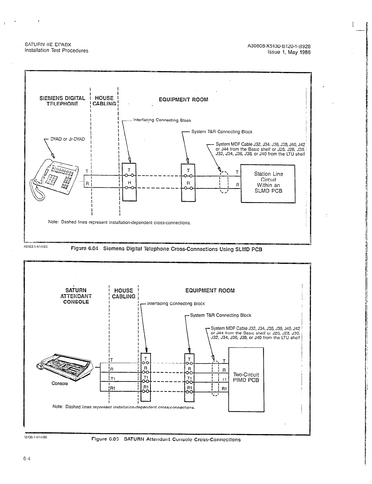
SATURN IIE EPABX
Installation Test Procedures A30808-X5130-B120-l-8928
Issue 1, May 1986
I I
I
SIEMENS DIGITAL : HOUSE ’ EQUlPMENT FiOOM
TELEPHONE ICABLING! .
I
I I
I I
1 Interfacing Connecting Block
I\ .
DYAD or Jr-DYAD
Figure 6.04 Siemens Digital Te!cphone Cross-Connections Using SLMD PC9
System T&R Connecting Block
1
System MDF Cable J32, J34, J36. J38, J40. J42 :
or J44 from the Basic shelf or J26, J28, J30, j
J32, J34, J36, J38, or J40 from the LTU shelf
Note: Dashed lines represent installation-dependent cross-connections
SAbRN
ATTENDANT
CONSOLE
HOUSE i EQUIPMENT ROOM
I
CABLING
Interfacing Connecting Block
System T&R Connecting Block
System MDF Cable J32, J34. J36. J38. J40. J42 i
or J44 from the Basic shelf or J25 J28, J30, ;
J32, J34, J36, J38. or J40 from the LTU shelf j
Note: Dashed lines represent installation-dependent cross-connections. I
Figure 6.05 SATURN Attendant Console Cross-Connections
6-4

SATURN IIE EPABX A30808-X5130-B120-1-6928
Installation Test Procedures Issue 1, May 1986
CENTRAL
OFFICE
co QP C3D
Trunk
Circuit
; TRUNK ; CUSTOMER PREMISES
I FAClLlTY :
I
i
Local Telephone
Company
I
I
Interfacing Connecting Bloc!c
System MDF Cable J32. J34, J35, J38, J40. J42
or J44 from the Basic shelf or J26, J28. J30, J32,
J34. J36, J38. or J40 from the LTU shelf
L
System T&R Connecting Dock
NO!% Dashed lines represcnl ins!allalion-dependenr cross-CCnnEcfions
Figure G.06 63 and DID Trunk Cross-Connections
DISTANT
OFFICE
OR SlGNALING
EQUIPMENT
TRUNK i CUSTOMER PREMlSES
FACILITV 1
Interfacing Connecting Block
System T&R Connecting Block
ystem
MDF Cable J32. J34. J36. J33. J40. J42 or
44 from the Dasic shelf or J26. J28. J30. J32, J34,
36. J38, or J40
from the LTU shelf
I
i
J39, J41. J43, or
‘3. J31, J33. 335.
if
System E&M Connecting Block
Figure 6.07 Two-Wire (Type I)
E&M
Trunk Cross-Connections
6-5
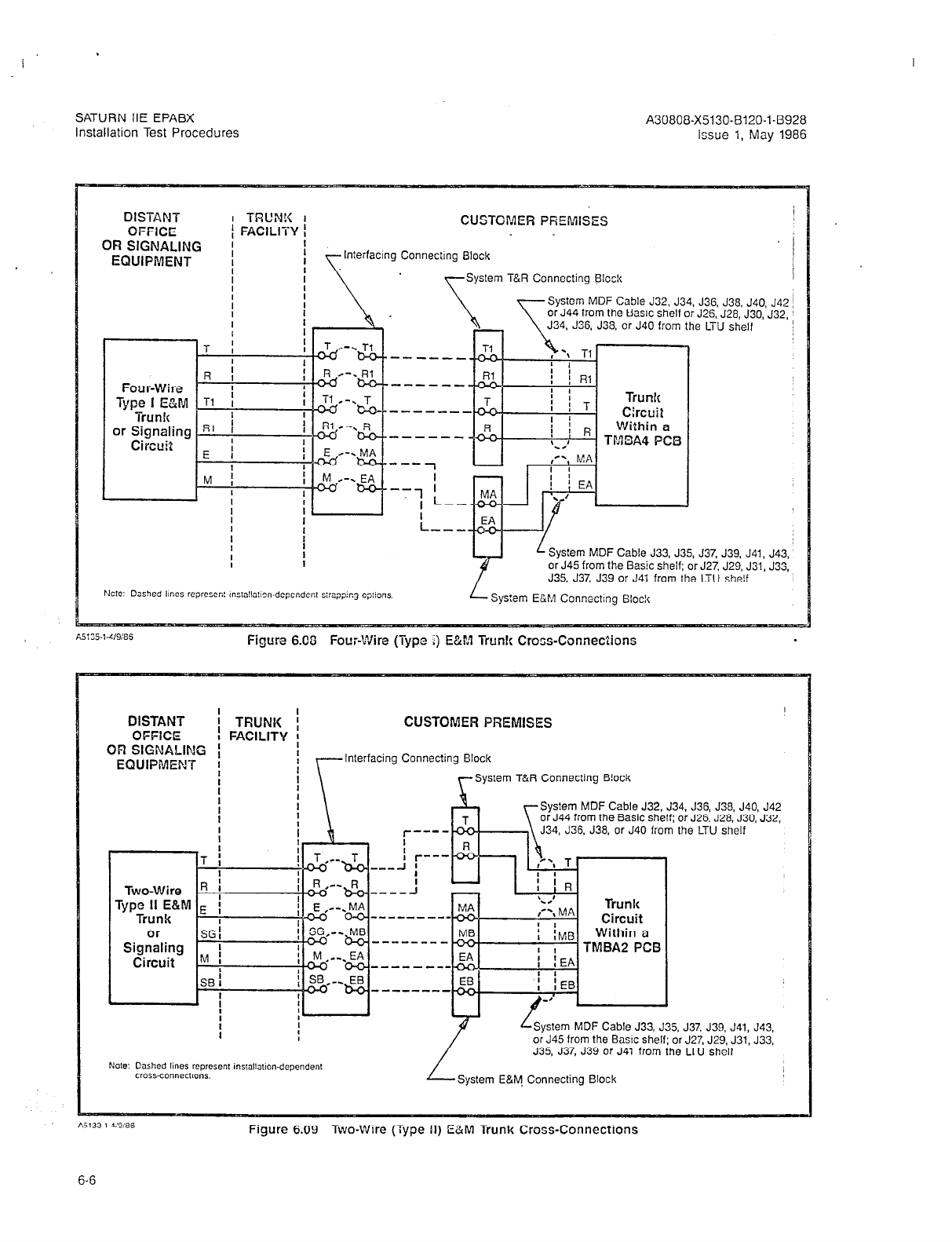
I -
SATURN IIE EPABX
Installation Test Procedures
A30808-X5130.B120-l-8928
Issue 1, May 1986
DISTANT I -l-RUN!< I
OFFICE ; FACILITY 1
OR SIGNALING ;
EQUIPMENT I
I
I
I
I
CUSTOMER PREMISES
Interfacing Connecilng Block
System T&R Connecting Bloc!c
System MDF Cable J32. J34. J36, J38. J40, J42
or J44 from the Basic shelf or J26. J28, J30, J32,
J34, J36, J38, or J40 from the LTU shelf
Y
L System MDF Cable J33, J35, J37, J39, J41, J43,
or J45 from the Basic sheif; or J27. J29, J31, J33,
J35. J37, J39 or J41 from the LTU she!f
L System E&M Connecting 6lock
A5135-1-4/W3!3
Figure 6.06 Four-Wire (Type ;) E&M Trunk Cross-Connections
DISTANT I TRUNK f
OFFICE t FACILITY :
OFI SIGNALING ( I
EQUIPIMENT
I i
I
t
CUSTOMER PREMISES
Interfacing Connecting Block
~System T&R Connecting B!ock
i
I
a
System MDF Cable J32, J34. J36, J38, J40, J42
or J44 from the Basic shelf: or J26. J28. J30, J32,
J34, J36. J38, or J40 from the LTU shelf
Lo
System MDF Cable J33, J35,
or J45 from the Baw shelf; or
J35, J37, J39 or J41 from the
J37.
J27,
LTU
J39. J41, J43,
J29, J31, J33,
shelf
I
L-.
System E&M. Connecting Elock
Figure 6.09 Two-Wire (Type II) E&M Trunk Cross-Connections
6-6
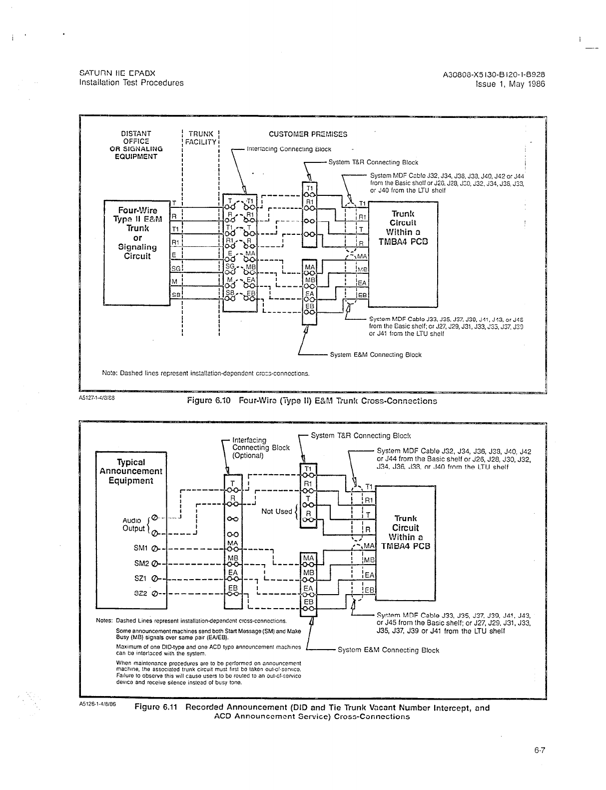
I
--
SATURN IIE EPABX A3080i3-X5130-B120-1-69.28
Installation Test Procedures Issue 1, May 1986
DISTANT
OFFICE
OR SIGNALING
EQUIPMENT
I
Four-Wire
I
Type II E&M
Trunk
or
Signaling
Circuit
-
R
-
I!
Rl
E
-
SC
-
M
-
SE
-
TRUNK ;
FACiLlTY f
CUSTOMER
PfiErvwzs
In:er:ach~g Conneclmg Block
System T&R Connecilng Block
r------
I
634. J3S. J30. J40. J42 or J44‘
J28.J~O.J32,~34.J3S.J33.
35, J37,
J39. J41. JS3. or J45
7.
J29, J31. J33,,‘35, J37, J29
System E&M Connecting Block
E!o!e: Dashed lines represent in s:al!ation-dependent crcc;-connections.
Figure 6.10 Four-Wiro (Type ii) E&M Tiunlc Cross-ConnecZions
Cable J32. J34, J36. J33. J40, J42
or J44
from
the Basic shelf or J26. J28, J30, J32,
J34. J36. J38.
or J40 from the LTU shelf
Audio G
output 8
1
SMl @
-------
SM2 @-
-------
SZl a-
___-----
sz2 a-
------
u
Typical
Announcement
Equipment
- System MDF Cable J33. J35, J37, J39, J4!, J43,
or J45 from the Basic shelf; or J27, J29. J31. J33.
Some ann~uncemenl machines send both Start Message (SM) and
Make J35, J37, J39 or J41 from the LTU shelf
Busy (MB)
signals
over same par (EAIEB).
P
System E&M Connecting
Block
A5126-l-4,8/86
Figure 6.11 Recorded Announcement (DID and Tie Trunk Vacant Number intercept, and
AC3 Announcement Service) Cross-Connections
6-7
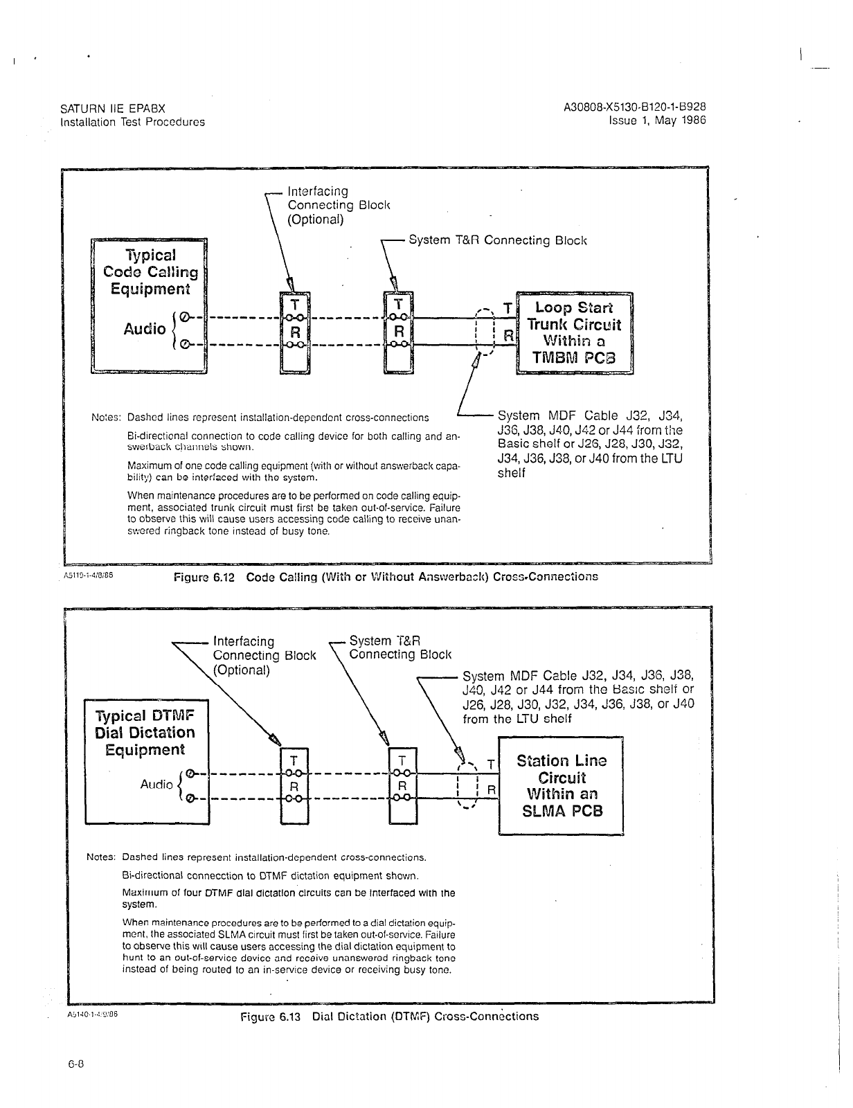
SATURN IIE EPABX
Installation Test Procedures
A30808-X5130-B120-l-8928
Issue
1, May 198G
Connecting Block
System T&R Connecting Block
No:es: Dashed lines represent installation-dependent cross-connectrons
Ei-drrecticnal connection to code calling device for both calling and an-
swerback channels shown.
Maximum of one code calling equipment (with or without answerbaclc capa-
bility) can be interfaced with the system.
When maintenance procedures are to be performed on code callrng equip-
ment, associated trunk circuit must first be taken out-of-service. Failure
to observe this will cause users accessing code calling to receive unan-
swered ringback tone instead of busy tone.
System MDF Cable J32, J34,
J36, J38, J4.0, J42 or J44 from the
Basic shelf or J25, J28, J30, J32,
J34, J36, J38, or J40 from the LTU
sheif
~Il”-i-4:oIES
Figure 6.12 Code Cailing (With or Without Answcrba~h) Cross-Comedons
stem MDF Cable J32, J34, J36, J38,
, J42 or J44 from the Basic shelf or
, J28, J30, J32, J34, J36, J38, or J40
m the LTU shelf
Notes: Dashed lines represent installation-dependent cross-connections,
Bi-directional connecction to DTMF dictation equipment shown.
Maximum of four DTMF dial dictation circuits can be interfaced with the
system.
When maintenance procedures are to be performed to a dial dictation equip-
ment, the associated SLMA crrcuit must first be taken out-of-servrce. Fatlure
to observe this will cause users accessing the dial dictation equipment to
hunt
to
an out-of-service device and receive unanswered ringback tone
instead of being routed to an in-service device or receiving busy tone.
Figure 6.13 Dial Dic?ation (DTMF) Cross-Connections

SATURN IIE EPABX
A30808-X5130-B120-l-8928
Installation Test Procedures Issue 1, May 1988
Interfacing
Connectmg Block System T&R Connecttng 61ocl( I
(Op!lonal) System MDF Cable J32. J34. J36. .Jm. J40. J42
or
J44
r
h
A---- from the Basic shelf or J26. J28, J33, J32, J34, J3G. J38. j
or J40 from the LTU shelf I
Figure 6.14
Music-cn-Wc!d
Cross-Connections Using TMBA4 PC0
System E&M Connecting Block
L
System MDF Cable J33: J35, J37, J33. J41, J43. or J45
from the @asic shelf; or J27, J29, J31, J33, J35, J37, J39
or J41 from the LTU shelf
Notes: Dashed lines represent installation-dependent cross-
connections. Broadcast type connection from music source
shown. Two kinds of music source can be cross-connected, con-
tinuous type and demand type. For continuous mustc, the E&M
leads are not used; and for demand music, the E&M leads are
EQUIPMENT ROOM
T
Interfacing Connecting Sloc!c
System T&R Connecting Block
Figure 6.15 Music-on-Hold Cross-Connections Using SLMAiSLAl6 PCB
Music Source
System MDF Cable J32, J34. J36, J36, JSO, J42
or J44 from the Basic shelf or J26, J26, J30, J32,
J34, J36, J38, or J40 from the LTU shelf
T \a
- - - - - ----- - ,--\ T
Station Line
I 1 Circuit
Within an
SLMAlSLAlG PCB
Notes: Dashed lines represent installation-dependent cross-
connecttons.
System MDF Cable connections are shown for an
SLMA PCB. For SLA16 connections, refer to Ftgure
6.03.
Only continuous type music sources may be cross-
connected.
6-9
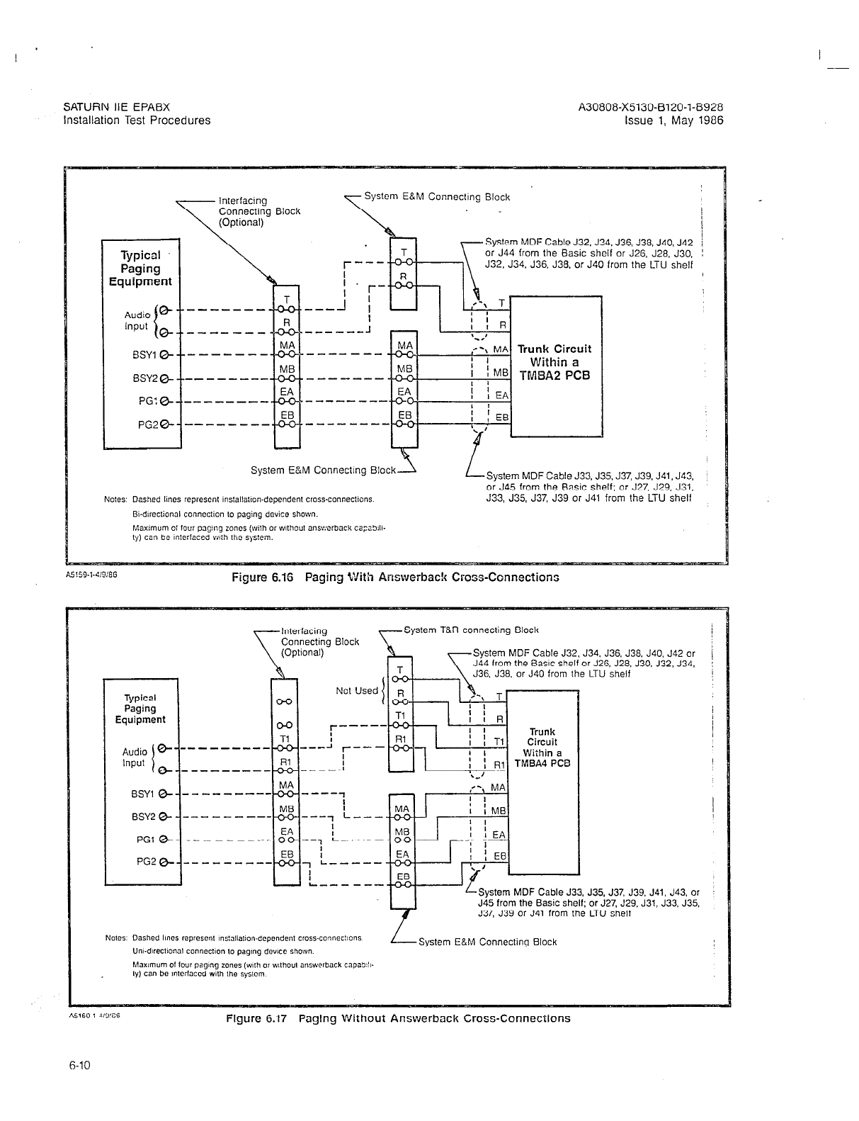
A30808-X5130-0120-1-8928
issue 1, May 1986
System E&M Connecting Block
System MDF Cable J3.2, J34. J36, J36. J40, J42
or J44 from the Basic shelf or J26, J26, J30.
J32, J34, J36. J36, or JSO from the LTU shelf
__----
-------
-----mm
--------
-------
Trunk Circuit
System E&M Connecting Block\
L
System MDF Cable J33. J35. J37, J39, J41, J43,
or J45 from the Basic shelf; or J27, J29, J31,
J33, J35, J37, J39 or J41 from the LTU shelf
A5!59-,-4,9:66
Figure 6.16 Paging With Answerback Cross-Connections
Typical
Paging
Equipment
Audio 8-
Input i
0
BSYl 0
BSY2 0
PGl 0
PG2 0
Interfacing
Connecting Block
(Optional)
[IO’ used’pJ k/--j
.,,-I
r---m7 -
i
-w---1
---------
System T&R connecting Block
System MDF Cable J32. J34. J36. J36. J40. J42 or
J44 from the Basic shelf or JZG. J28. J30. J32, J34, /
I
J36. J38. or J40 from the LTU shelf
--1 L----
I
I
7 L--w--
I
I
L---s--
J35, J37, J39. J41. J43, or
or J27, J29. J31. J33. J35.
LTU shelf
Figure 6.17 Paging Without Answerbock Cross-Connections
6-10
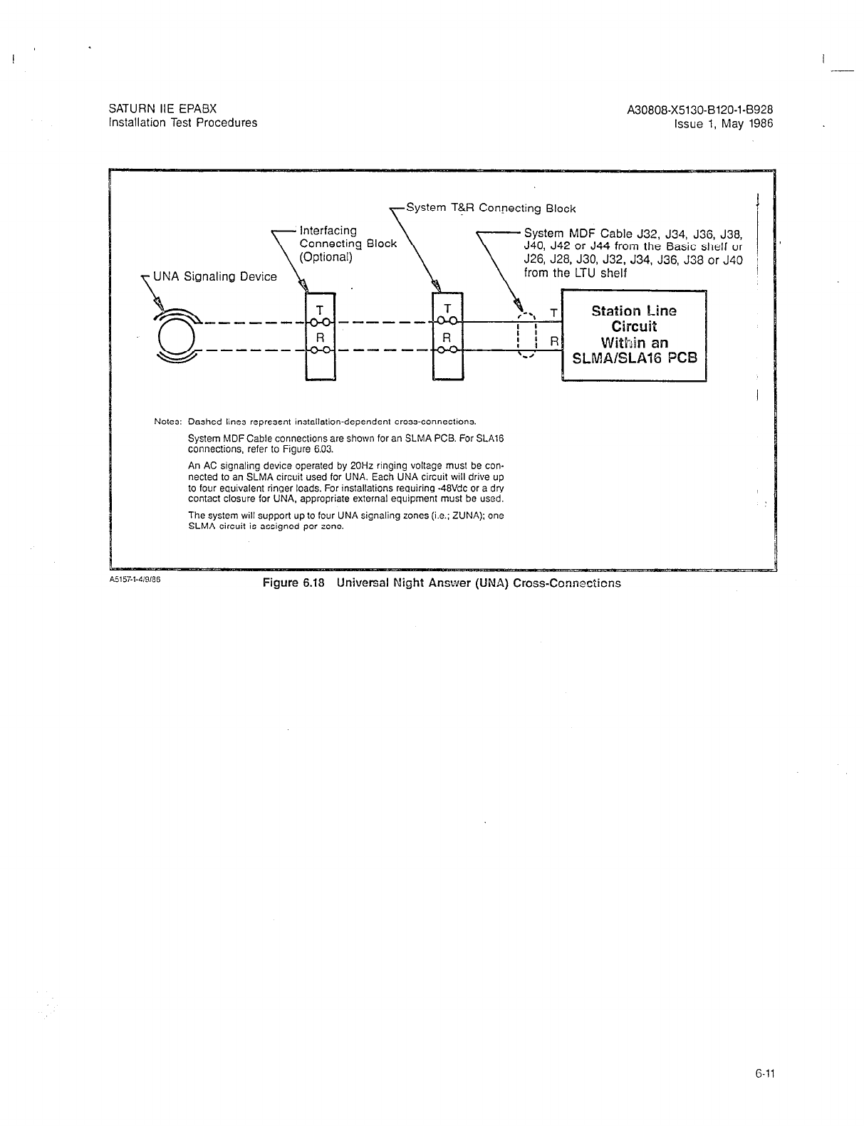
SATURN IIE EPABX A30808-X5130-6120-1-8928
Installation Test Procedures Issue 1, May 1986
System T+R Connecting Block I
Interfacing
\
Connecting Block System MDF Cable J32, J34, J36, J38,
J40, J42 or J44 from the Basic shelf or
(Optional) J26, J28. J30, J32, J34, J36, J38 or J40 i
UNA Signaling Device from the LTU shelf
-----a- ------
With an
------ SLMAISLAlG PC13
Notes: Dashed lines represent installation-dependent cross-connections.
System MDF Cable connections are shown for an SLMA PCS. For SLA16
connections, refer to Figure 6.03.
An AC signaling device operated by 20Hz ringing voltage must be con-
nected to an SLMA circuit used for UNA. Each UNA circuit will drive up
to four equivalent ringer loads. For installations requiring -48Vdc or a dry
contact closure for UNA. appropriate external equipment
must
be used.
The system will support up to four UNA signaling zones (i.e.; ZUNA); one
SLMA circuit is assigned per zone.
Figure 6.18 Universal Night Answer (UNA) Cross-Connections
6-11

SATURN IIE EPAEX
Installation Test Procedures
I -
6.04 System Diagnostic Tests. After the necessary MDF
cross-connections have been completed, the on-line diagnos-
tic
icsts
and procedures are performed to verify the opera-
tronal capability of the system. Note that the subsequent
on-line diagnostic tests and procedures are presented in the
sequence in which they should be performed under normal
insiallation conditions. It is the responsibility of craft pers,on-
nel to determine the sequence in which such tests and proce-
dures should be performed when unusual installation
conditions exist. Unless otherwise indicated, these tests can
be performed with SDTs and/or DTMF SLTs.
a. Tone Generator Test. This system diagnostic test rou-
tine verifies that each tone provided by the SMXTG
PCS is generated properly. In addition, the test also
checks the connection path(s) through the Memory
Time Switch (MTS). Refer to Table 6.00 for the neces-
sary procedures to perform the tone generator test.
b. DTMF Receiver Test. This system diagnostic test rou-
tine verifies that a DTMF receiver circuit in a aarticu-
lar DTMF PCB is operating properly. The test also
checks the connection path(s) through the MTS. Refer
to Table 6.02 for the necessary procedures to perform
the applicable DTMF receiver circuit test(s). This test
requires a Type 2500 DTMF Pushbutton Telephone Set.
c. Station Line Test. This apparatus diagnostic test rou-
tine verifies that the supervisory and transmission
capabilities between an SLMA, SLA16 or SLMD cir-
cuit and asscciated staiion or Siemens Digital Tele-
phone instrument are operating properly. This test is
performedfrom the station instrument under test and
applies to both single line telephones (rotary or push-
button) and Siemens Digital Telephones. Refer to Ta-
ble 6.03 for the necessary procedures to perform the
applicable station line test(s).
d. DTMF Pad Test. This apparatus diagnostic test routine
verifies that the DTMF keypad performance, including
the transmission capabilities, of any DTMF pushbutton-
type station instrument is operating properly. The test
is performed from the station instrument under test and
only applies to single line telephones equipped with
a DTMF keypad. Note that a Siemens Digital Telephone
cannot be used for this test since data, not tones, are
transmitted from the SDTs pushbutton keypad. Refer
to Table 6.04 for the necessary procedures to perform
the applicable DTMF pad test(s).
e. Console Test. This apparatus diagnostic test routine
verifies that the data and speech highways to and from
an attendant console are operating properly. The test
also verifies that the console LED indicators, alphanu-
meric display unit and audible alerting device are oper-
f.
9
h.
i.
j.
A30808-X5130-5120s1-8928
Issue 1. May 1986
ating properly. The test is performed from the console
under test. Refer to Table 6.05 for the necessary proce-
dures to perform the applicable console tes:s.
Siemens Digital Telephone Button Tests. These appara-
tus diagnostic test routines verify that the signaling
highways to and from Siemens DYAD and JR-DYAD tel-
ephones are operating properly. In addition, the tests
also verifv that the LEDs and the audible alertinn
devices of the telephones are operating properly. The
tests are performed using the DYAD and JR-DYAD tel-
ephones. Refer to Tables 6.07 and 6.08 for the neces-
sary procedures to perform the applicable Siemens
digital telephone button
tests.
Siemens Digital Telephone Display Test. This appara-
tus diagnostic test rouiine verifies that the signaling
highways to and from the Siemens DYAD telephones
are operating properly. In addition, the
tests
also veri-
fy that the alphanumeric display unit and the audible
alerting devices are operating prcperly. The tests are
performed using the DYAD telephones under test.
Refer to Table 6.09 for the necessary procsdurcs to per-
form the Siemens digital ie!ephone display
tests.
Trunk Test. This system diagnostic test verifies that the
supervisory and transmission capabilities of an outgo-
ing (or outgoing portion of a two-way) trunk are oper-
ating properly. In addiiion, the test also verifies the
connec?ion path(s) through the MTS. Refer to Tab!o 6.11
for the necessary procedures to perform the epplica-
ble trunk tests.
Placing Circuit(s) In-Service. This system procedure al-
lows craft personnel to place an assigned circuit in
service from an out-of-service state. This procedure
works in parallel with the CMU procedure that changes
a circuit’s state. Refer to Table 6.12 for the necessary
procedures to perform the applicable in-service place-
ment of circuits.
Placing Circuit(s) Out-of-Service. This system proce-
dure allows craft personnel to place an assigned cir-
cuit out-of service from an in-service state. This
procedure works in parallel with the CMU procedure
that changes a circuit’s state. Fiefer to Table 6.13 for
the necessary procedures to perform the applicable
out-of-service placement of circuits.
WARNING
Hazardous voltages exist Mhin the equipmcnr cebkc?.
Be extremely careful when performing test-
ing/troubleshooting procedures wiih Ehe equipment
panel(s) removed.
G-l?
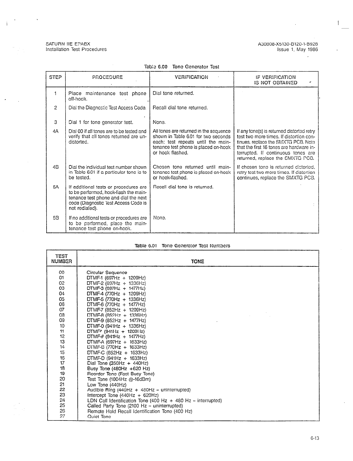
SATURN IIE E?ABX A30808-X5130-8120-l-8928
Installation Test Procedures issue 1, May 1986
TEP
1 Place maintenance test phone
off-hook.
Dial tone returned.
2 Dial the Diagncstic Test Access Code. Recall dial tone returned.
3
4A
Dial 1 for tone generator test. None.
Dial 00 if all tones are to be tested and
verify that all tones returned are un-
dis!orted.
All tones are returned in the sequence
shown in Table 6.01 for two seconds
each: test repeats until the main-
tenance test phone is placed on-hook
or hook flashed.
4B Dial the individual test number shown Chosen tone returned until main- If chcsen tono is returned dictoricd.
in Table 6.01 if a particular tone is to tenance test phone is placed on-hco!c retry test two moie times. If distortion
be tested. or hook-flashed. continues, replace the SMXTG PCB
5A If additional
tE?SiS
or procedures are
to be performed, hook-flash the main-
tenance test phone and dial the next
code (Diagnostic Test Access Code is
not redialed).
Recall dial tone is returned.
56 If no additional tests or procedures are
to be performed, placa the main-
tenance test phone on-hook.
Nono.
iab:a 6.00 Tone Generator Test
PCDCECURE VERIFICATION
TEST
NUMBER
00
01
02
03
04
05
06
07
08
09
10
11
12
13
14
15
16
17
18
19
20
21
22
23
24
25
26
27
IF VERIFICATION
IS NOT OBTAINED s
If any tone(s) is returned distortad retry
test two mere times. If distortion con-
tinues, replace the SMXTG PCB. Ncto
that the first 16 tones are hardware in-
terrupted. if continuous tones are
returned, replace the SMXTG PCB.
Table 6.01 Tone Generator Test Numbers
TONE
Circular Sequence
DTMF-1 (697Hz + 1209Hz)
DTMF-2 (6Q7Hz + 1336Hz)
DTMF-3 (697Hz + 1477Hz)
DTMF-4 (77OHz + 1209Hz)
DTMF-5 (77OHz + 1336Hz)
DTMF-6 (77OHz + 14i7Hz)
DTMF-7 (852Hz + 1209Hz)
DTMF-8 (852Hz + 1336Hz)
DTMF-9 (852Hz + 1477H.z)
DTMF-0 (941Hz + 133SHz)
DTMF-’ (941Hz + 1209Hz)
DTMF-# (941Hz + 14i7Hz)
DTMF-A (697Hz + 1633Hz)
DTMF-B (770Hz + 1633Hz)
DTMF-C (852Hz + 1633Hz)
DTMF-D (941Hz -I- 1633Hz)
Dial Tone (35OHz + 440Hz)
Busy Tone (480Hz +620 Hz)
Reorder Tone (Fast Busy Tone)
Test Tone (1004Hz @-16dEim)
Low Tone (440Hz)
Audible Ring (440Hz + 480Hz - uninterrupted)
Intercept Tone (440Hz + 620Hz)
LDN Call Identification Tone (400 Hz + 480 Hz - interrupted)
Called Party Tone (2100 Hz - uninterrupted)
Remote Hold Recall Identification Tone (400 Hz)
Quiet Tone --_
G-13

I
SATURN IIE EPABX A30808-X5130-B120-l-8928
Installation Test Procedures Issue 1, May 1986
STEP PROCECURE VEFHFICATION
1
5
6A
68
Table 6.02 DTMF Receiver Test
Place maintenance test phone
off-hook.
Dial the Diagnostic Test Access Code.
Dial # for DTMF receiver test.
Dial the four-digit PEN number of the
DTMF receiver circuit to be tested.
Depress the maintenance test phone
keypad’s buttons in the following se-
quence.
Test tone (1004Hz at -16dBm)
returned.
a) For 12-button phones: 1, 2, 3,
4, 5, 6, 7, 8, 9, 0, *and #.
b) For 16-button phones: A, B, C,
D, 1, 2, 3, 4, 5, 6, 7, 8, 9, 0, * ,
and #.
If additional tests or procedures are
to be performed, hook-flash main-
tenance tes? phone and dial the next
code (Diagnostic Test Access Code is
not redialed).
Recall dial tone is returned and the
associaied DTMF receiver circuit LED
in the DTMF PCB is extinguished.
If no additional tests or procedures are The associated DTMF receiver circuit
to be performed, place the main- LED in the DTMF PCB is extin-
tenance test phone on-hook. guished.
Dial tone is returned.
Recall dial tone is returned.
None.
Dial tone returned and the associat-
ed DTMF receiver circuit LED in the
DTMF PCB is lit steadily.
IF VERIFICATION
IS NOT OBTAINED
If busy tone is returned, the DTMF
receiver circuit is busy. Retry later. If
intercept tone is returned, the DTMF
receiver circuit is not assigned (check
data base assignment).
If intercept tone is returned at any
time, either the DTMF receiver or the
maintenance phone’s key-pad is nc?
operating properly, or the buttons
were depressed in the wrong se-
quence. Retry test with another DTMF
phone. If intercept tone is returned
again, replace the DTMF receiver
circuit.
Table 6.03 Station Line Test
NOTES: 1) If the system option flag TSTDIAG has been enabled in the data base or the station under test is c!assmarked
with the TSTAPP feature, the maintenance test phone is not required to enable or disable the Apparatus Diagnos-
tic Test routines; therefore, perform only steps 5 through 10.
2) If the system option flag TSTDIAG has been disabled in the data base or the station under test is not classmarked
with the TSTAPP feature, the maintenance test phone is required to enable or disable the Apparatus Diagnostic
Test routines; therefore, oerform the entire procedure (steps 1 throuqh 11).
STEP
.
PROCEDURE VERIFICATION
Place maintenance test phone
off-hook. Dial tone is returned.
Dial the Diagnostic Test Access Code.
Dial 3 to enable the Apparatus tests.
Place the maintenance test phone
on-hook.
Recall dial tone is returned.
Confirmation tone is returned.
None.
Place the station under test off-hook. Dial tone is returned
;:;ethe Test-Station Line Access Confirmation tone is returned.
IF VERIFKATION
IS NOT OBTAINED
1
6-14
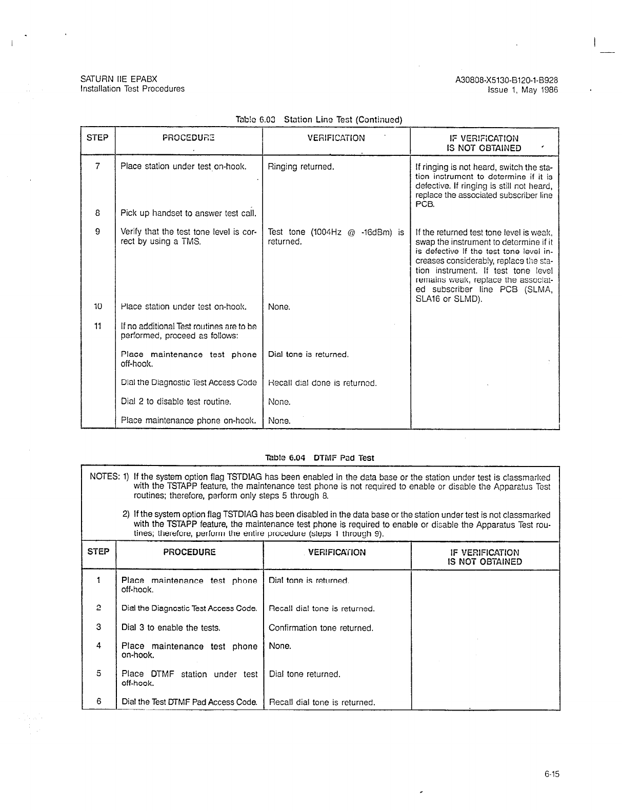
SATURN IIE EPABX
Installation Test Procedures
A30808-X5130-B120-l-8928
Issue 1, May 1986 .
Tab!c A.03 Station Line Test fCnntinc)edl
,
STEP PROCEDURE
\-----------I
STEP FROCEDUZZ VERIFICATTION IF VER!FiCATION
IS NOT OBTAINED ’
7 Place station under test on-hook. Ringing returned. If ringing is not heard, switch the sta-
tion instrument to determine if it is
defective. If ringing is still not heard,
replace the associated subscriber line
PCB.
8 Pick up handset to answer test tail.
9 Verify that the test tone level is cor- Test tone (1004Hz @ -lGdBm) is If the returned test tone level is weak,
rect by using a TMS. returned. swap the instrument to determine if it
is defective If the test tone level in-
creases considerably, replace the s:a-
tion instrument. If test tone level
remains weak, replace the associat-
ed subscriber line PCB (SLMA,
10 Place station under test on-hoo!(. SLA16 or SLMD).
None.
11 If no additional Test routines are to be
performed, proceed as follows:
Place maintenance test phone Dial tone is returned.
off-boo!<.
Dial the Diagnostic Test Access Code Recall dial done is returned,
Dial 2 to disable test routine. None.
Place maintenance phone on-hook. None.
Tab!e 6.04 DTMF Fad Test
NOTES: 1) If the system option flag TSTDIAG has been enabled in the data base or the station under test is classmaiked
with the TSTAPP feature, the maintenance test phone is not required to enable or disable the Apparatus Test
routines; therefore, perform only sieps 5 through 8.
2) If the system option flag TSTDIAG has been disabled in the data base or the station under test is not classmarked
with the TSTAPP feature, the maintenance test phone is required to enable or disable the Apparatus Test rou-
tines; therefore, perform the entire procedure (steps 1 through 9).
VERIFICATION IF VERIFICATION
IS NOT OBTAINED
1 Place maintenance test phone Dial tone is returned.
off-hook.
2 Dial the Diagnostic Test Access Code. Recall dial tone is returned.
3 Dial 3 to enable the tests. Confirmation tone returned.
4 Place maintenance test phone None.
on-hook.
5 Place DTMF station under test Dial tone returned.
off-hook.
6 Dial the Test DTMF Pad Access Code. Recall dial tone is returned.
6-15
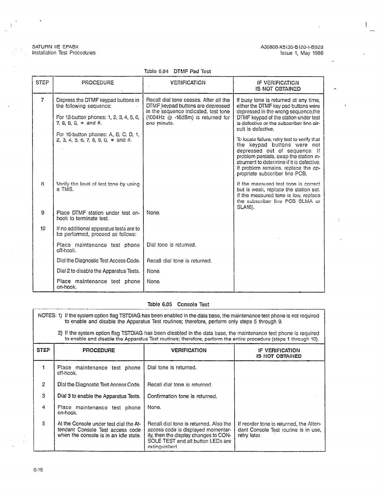
SATURN IIE EPABX A30808-X5130-B120-l-B928
instaliation Test Procedures Issue 1, May 1986
Wbtc 6.04 DTMF Pad Test
STEP PWO@EDWE VERIFICATION IF VERIFICATIGN
IS NOT OBTAINED
7 Depress the DTMF keypad buttons in Recall dial tone ceases. After all the If busy tone is returned at any time,
the following sequence: DTMFjteypad buttons are depressed either the DTMF key pad buttons were
in the sequence indicated, test tone depressed in the wrong sequencethe
For 12-button phones: 1, 2, 3, 4, 5, 6, (1004Hz @ -16dBm) is returned for DTMF keypad of the station under test
7, 8, 9, 0, 4 and #. one minute. is defective or the subscriber line cir-
cuit is defective.
For 16-button phones: A, B, C, D, 1,
2, 3, 4, 5, 6, 7, 8, 9, 0, * and #. To locate failure, retry test to verify that
the keypad buttons were not
depressed out of sequence. If
problem persists, swap the station in-
strument to determine ii it is defective.
If problem remains, replace the rp-
propriate subscriber line PCB.
8 F;Q;he level of test tone by using If the measured test tone is correct
but is weak, replace the station set.
If the measured tone is low, rep!ace
the subscriber line PCB SLMA or
SLA16).
9 Place DTMF station under test on- None.
hook to terminate test.
10 If no additional apparatus tests are to
be performed, proceed as foilows:
Place maintenance test phone Dial tone is returned.
off-hoo!(.
Dial the Diagnostic Test Access Code. Recall dial tone is returned.
Dial 2 to disable the Apparatus Tests. None.
Place maintenance test phone None.
on-hook.
Table 6.05 Console Test
NOTES: 1) If the system option flag TSTDIAG has been enabled in the data base, the maintenance test phone is not required
to enable and disable the Apparatus Test routines; therefore, perform only steps 5 through 9.
2) If the system option flag TSTDIAG has been disabted in the data base, the maintenance test phone is required
to enable and disable the Apparatus Test routines; therefore, perform the entire procedure (steps 1 through 10).
STEP PROCEDURE VERIFICATION IF VERIFICATION
IS NO-i- OBTAINED
1 Place maintenance test phone Dial tone is returned.
off-hook.
2 Dial the Diagnostic Test Access Code. Recall dial tone is returned.
3 Dial 3 to enable the Apparatus Tests. Confirmation tone is returned.
4 Place maintenance test phone None.
on-hook.
5 At the Console under test dial the At- Recall dial tone is returned. Also the If reorder tone is returned, the Atten-
tendant Console Test access code access code is displayed momentar- dant Console Test routine is in use,
when the console is in an idle state. ily, then the display changes to CON- retry later.
SOLE TEST and all button LEDs are
extinguished.
6-16
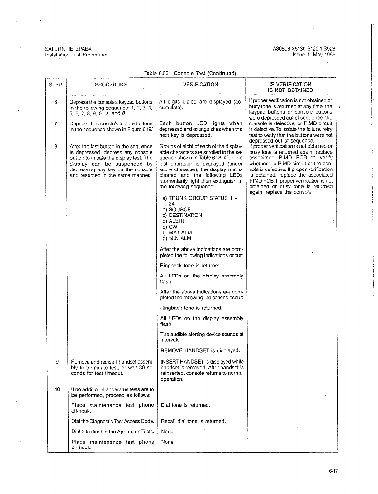
SATURN IIE EPABX A30808-X5130-B120-l-8928
Installation Test Procedures Issue 1, May 1986
Table 6.05 Console Test (Continued)
:TE? PRCCEDURE VERIFICATIDN lF VERlFlCATlON
IS NOT OBTAINED +
6 Depress the console’s keypad buttons All digits dialed are displayed (ac- If proper verification is not obtained or
in the following sequence: 1, 2, 3, 4, cumulate). busy tone is returned at any time, the
5, 6, 7, 8, 9, 0, * and #. keypad buttons or console buttons
were depressed out of sequence, the
7 Depress the console’s feature buttons Each button LED lights when console is defective, or PIMD circuit
in the sequence shown in Figure 6.19.’ depressed and extinguishes when the is defective. To isolate the failure, retry
next key is depressed. test to verify that the buttons were not
depressed out of sequence.
a
After the last button in the sequence Groups of eight of each of the display- If proper verificaiion is not obtained or
is depressed, depress any console able characters are scrolled in the se- busy tone is returned again, replace
button to initiate the display test. The quence shown in Table 6.06. Ai-ier the associated PIMD PCB to verify
display can be suspended by last character is displayed (under whether the PIMD circuit or the con-
depressing any key on the console score character), the display unit is sole is defective. If proper verificaiion
and resumed in the same manner. cleared and the following LEDs is obtained, replace the associa?ed
momentarily light then extinguish in PIMD PCB. If proper verification is not
the following sequence: obiained or busy tone is returned
again, replace the console.
a) TRUNK GROUP STATUS 1 -
b) %“RCE
c) DESTINATION
d) ALERT
e) CW
9
MAJ ALM
g) MIN ALM
After the above indications are com-
pleted the fo!lowing indications occur:
Ringbeck tone is returned.
All LEDs on the display assembly
flash..
.
After the above indications are com-
pleted the following indications occur:
Ringback tone is returned.
All LEDs on the display assembly
flash.
The audible alerting device sounds at
intervals.
REMOVE HANDSET is displayed.
9 Remove and reinsert handset assem- INSERT HANDSET is displayed while
bly to terminate test, or wait 30 se- handset is removed. After handset is
conds for test timeout. reinserted, console returns to normal
operation.
10 If no additional apparatus tests are to
be performed, proceed as follows:
Place maintenance test phone Dial tone is returned.
off-hook.
Dial the Diagnostic Test Access Code. Recall dial tone is returned.
Dial 2 to disable the Apparatus Tests. None.
Place maintenance test phone None.
on-hook.
6-17
I -
SATURN IIE EPABX A30808-X5130-8120-143928
installation Test Procedures Issue 1, May 1986
TRUNK GGOUPSTATUS
nnnnnnnn k
(ALPHANUMERIC DISPLAY L'NI;)
SOUlxi OESTIXATION
00000000
li 18 19 20 21 22 23 24 ALERT CL'1
Figure 6.19 Attendant Console Keypad and Feature Button Depression Sequence

SATURN IIE EPABX A30808-X5130-B120-l-6926
Installation Test Procedures Issue 1, May 1986
Table 6.06 Attendant Console Displayable Characters
ORDER
1.
2.
3.
4.
5.
6.
7.
8.
9.
10.
11.
12.
13.
14.
15.
16.
17.
18
19.
20.
2’:.
23:
24.
25.
26.
27.
28.
29.
30.
31.
32.
CHARACTER
I I I I I I ! !
;;;;,A!,;;;;
$$$$5$$$
o/o o/o 010 o/o o/o o/o o/o %
&&&&&&&&
I I I I I I I I
( ( ( ( ( ( ( (
) 1 1 1 1 1 1 1
* l * * * l * *
++++++++
I I > 9 I 1 3 I
- - - - - - - -
i i i i i i i i
00000000
1 1 1 1 1 1 1 1
22222222
33333333
44444444
55555555 66666666
77777777
88888888
99999999
: : : : : : : :
; ; ; ; ; ; ; ;
(((((((C
TPffSf=>S
????????
OQOQ@@@@
ORDER CHARACTER
33. AAAAAAAA
34. BBBBBBBB
cccccccc
ii: DDDDDDDD
37. EEEEEEEE
FFFFFFFF
:i GGGGGGGG
40: HHHHHHHH
41. I I I I I I I I
42. JJJJJJJJ
43. K K K K K K I< K
44. LLLLLLLL
45. MMMMMMMM
46. NNNNNNNN
47. 00000000
48. PPPPPPPP
49. QQQQQQQQ
50. RRRRRRRR
51. ssssssss
52. TTTTTTTT
54. 53. vvvvvvvv uuuuuuuu
55. wwwwwwww
56. xxxxxxxx
2; YYYYYYYY
zzzzzzzz
59: [ I [ 1 I 1 1 I
60.
61. \\\\)))\
1 1 I I
62. A A A A ,I> A A A
63. ----_---
6-19
I .
SATURN IIE EPABX A30808-X5130-B120-I-6928
Installation Test Procedures Issue 1, May 1986
Table 6.07 Siemcns Digital Telephone - DVAD Dutton Test
NOTES: 1) If the system option flag TSTDIAG has been enabled in the data base or the Siemcns Digital Telephone under
test is classmarked with TSTAPP feature, the maintenance test phone is nbt required to enable or disable the
Apparatus Diagnostic routines; therefore, perform only steps 5 through 9.
2) If the system option flag TSTDIAG has been disabled in the data base or the Siemens Digital Telephone under
test is not classmarked with the TSTAPP feature. the maintenance test phone is required to enable or disable
the Apparatus Diagnostic routine?
s; t
herefore, perform the entire procedure (steps 1’ through 10).
STEP
1
2
3
4
5
6
7
8
9
10
PROCEDURE . VERIFICATION
‘lace the maintenance test phone
,ff-hook.
3ial the Diagnostic Test Access Code.
Iial 3 to enable the Apparatus Diag-
lostic Tests.
‘lace maintenance test phone
x+hook.
‘lace Siemens DYAD Telephone
,ff-hook.
Dial the Siemens Digital Telephone
rest Access Code.
Ieoress the Siemens DYAD Telc-
&ne keypad buttons as, fo!lows: 1,
3, 3, 4, 5, 6, 7, 8, 9, 0, * , i?.
Depress the DYAD feature buttons in
the sequence shown in Figure 6.20
and according to the Siemens DYAD
Telephone model.
Place Siemens DYAD Telephone un- Siemens DYAD Telephone returns to
der test on-hook to terminate test. normal operation.
If no additional Apparatus Diagnostic
Test routines are to be performed, pro-
ceed as follows:
Place maintenance test phone
off-hook.
Dial tone is returned.
Dial the Diagnostic Test Access code. Recall dial tone is returned.
Dial 2 to disable the Apparatus Diag-
nostic Test. None.
Place maintenance test phone on-
hook.None. None.
Iial tone is returned.
qecall dial tone is returned.
>onfirmation tone is returned.
Uone.
Iial tone is returned.
secall dial tone is returned.
The access code is momentarily dis- f reorder tone is returned, the Sie-
3layed, then the display unit and but- nens DYAD Telephone
Button
Test is
ton LEDs are extinguished. n use, try later.
Button LEDs light when depressed
and extinguish when the next button
is depressed.
After the last button is depressed, the
following indications occur:
Ringback tone is returned.
All button LEDs flash.
The audible alerting device sounds at
intervals.
TEST COMPLETE is displayed.
IF VERiFICATlON
IS NOT OBTAINED
f proper verification is not obtained cr
xsy tone is returned at eny time,
either the keypad buttons cr featuie
buttons were depressed out of se-
quence, the DYAD Telephone is defac-
tive, or the SLMD circuit is defective.
To isolate the failure, retry test to veri-
fy that the buttons were not depressed
Dut of sequence.
If proper verification is not obtained or
busy tone is returned again, replace
the Siemens DYAD Telephone under
test with a known good DYAD Tele-
phone and retry test. If proper verifi-
cation is not obtained or busy tone is
returned again, replace the SLMD
PCB.
I -
6-20

I
-
SATURN HE EPABX
Installation Test Procedures A30808-X5130-8120-1-8928
Issue 1, May 1986
IS BUTTON
DYAD
26 BUTTON
DYAD
SEE NOTE
NOTE: These buttons do not
contain LEDs.
SEE NOTE y
/ ’
I
Figure 6.20 Siemens DYAD Telephone Button Depression Sequence
6-21
SATURN IIE EPABX
Installation Test Procedures
A30808-X5130-BlZO-l-8928
Issue 1, May 1986
Table 6.06 Siemcns Digital Telephone - JR-DYAD Button Test
NOTES: 1) If the system option flag TSTDIAG has been enabled in the data base or the Siemens Digital Telephone under
test is classmarked with TSTAPP feature, the maintenance test phone is ‘not required to enable or disable the
Apparatus Diagnostic routines; therefore, perform only steps‘5 through 9.
2) If the system option flag TSTDIAG has been disabled in the data base or the Siemens Digital Telephone under
test is not classmarked with the TSTAPP feature, the maintenance test phone is required to enab!e or disable
the Apparatus Diagnostic routines; therefore, perfcrm ihe entire procedure (steps 1 through i0).
STEP PROCEDURE VERIFICATION IF VERIFICATION
IS NOT OBTAINED
1 Place the maintenance test phone Dial tone is returned.
off-hook.
2 Dial the Diagncstic Test Access Code. Recall dial tone is returned.
3 Dial 3 to enable the Apparatus Diag- Confirmation tone is returned.
nostic Tests,
4 Place maintenance test phone None.
on-hook.
5 Place JR-DYAD Telephone off-hook. Dial tone is rereturned.
6 Dial the Siemens Digital Telephone Recall dial tone is returned. If reorder tone is returned, the Sie-
Test Access Code. mens JR-DYAD Telephcne Button Test
is in use, try later.
7 Depress the Siemens JR-DYAD Tele- Ii proper verification is net obtainsd or
phone keypad buttons as, follows: 1, busy tone is returned at any iime,
2, 3, 4, 5, 6, 7, 8, 9, 0, * , #. either the keypad buttons or feature
buttons were depressed out of se-
8 Depress the JR-DYAD feature buttons Button LEDs light when depressed quence, the JR-DYAD Telephone is
in the sequence shown in Figure 6.21. and extinguish when the next button defective, or the SLMD circuit is
is depressed. defective. To isolate the failure, retry
test to verify that the buttons were not
After the last button is depressed, the depressed out of sequence.
following indications occur: If proper verification is not obtained or
Ringbac!c tone is returned. busy tone is returned again, replace
All button LEDs flash. the Siemens JR-DYAD Telephone un-
der test with a known good JR-DYAD
The audible alerting device sounds at Telephone and retry test. If proper
intervals. verification is not obtained or busy
tone is returned again, the SLMD cir-
cuit is defective and the SLMD PC6
requires replacement.
9 Place Siemens JR-DYAD Telephone Siemens JR-DYAD Telephone returns
under test on-hook to terminate test. to normal operation.
10 If no additional Apparatus Diagnostic
Test routines are to be performed, pro-
ceed as follows:
P&tokmaintenance test phone Dial tone is returned.
Dial the Diagnostic Test Access code. Recall dial tone is reiurned.
Dial 2 to disable the Apparatus Diag- None.
nostic Test.
Place maintenance test phone None.
on-hook.
6-22
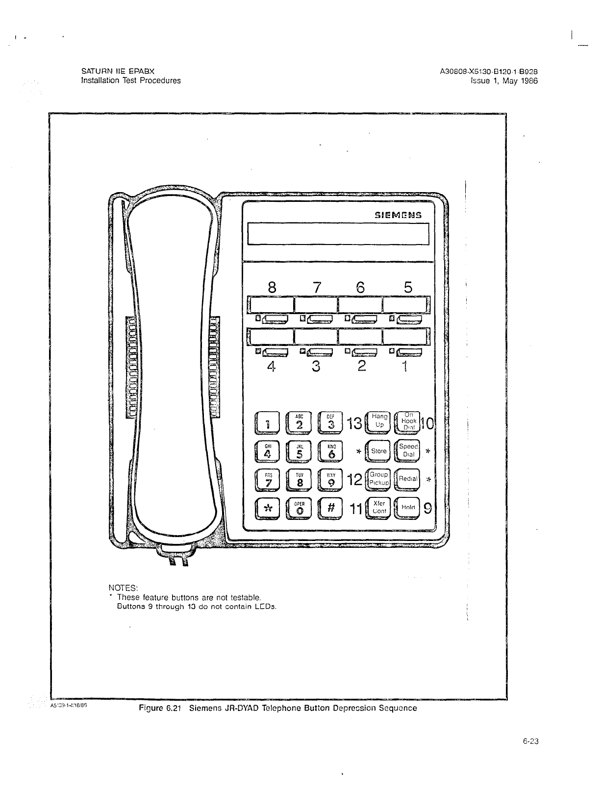
I -
SATURN IIE EPABX A30808-X5130-B120-l-8928
Installation Test Procedures Issue 1, May 1986
NOTES:
* These feature buttons are not testable.
Buttons 9 through 13 do not contain LEDs.
Figure 6.21 Siemeno JR-DYAD Telephone Button Depression Sequence
6-23
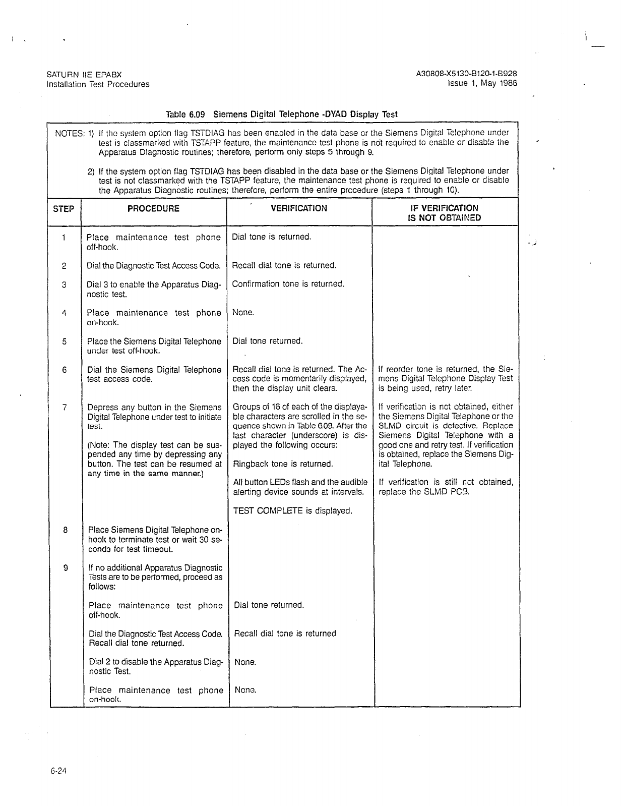
I . I -
SATURN IIE EPABX
Installation Test Procedures
A30808-X5130-B120-l-8928
Issue 1, May 1986
Table 6.09 Siemens Digital Telephone -DYAD Display Test
NOTES: 1) If the system
option
flag TSTDIAG has been enabled in the data base or the Siemens Digital Telephone under
test is classmarked with TSTAPP feature, the maintenance test phone is not required to enable or disabie the
Apparatus Diagnostic routines; therefore, perform only steps 5 through 9.
2) If the system option flag TSTDIAG has been disabled in the data base or the Siemens Digital Telephone under
test is not classmarked with the TSTAPP feature, the maintenance test phone is required to enable or disable
the Apparatus Diagnostic routines; therefore, perform the entire procedure (steps 1 through 10).
XEP PROCEDURE VERIFICATION IF VERIFICATION
IS NOT OBTAINED
1 Place maintenance test phone Dial tone is returned.
off-hook.
.
./ ;
2 Dial the Diagnostic Test Access Code. Recall dial tone is returned.
3 Dial 3 to enable the Apparatus Diag- Confirmation tone is returned.
nostic test.
4 Place maintenance test phone None.
on-hcok.
5 Place the Siemens Digital Telephone Dial tone returned.
under test off-hook.
G Dial the Siemens Digital Telephone Recall dial tone is returned. The Ac- If reorder tone is returned, the Sie-
test access code. cess code is momentarily displayed, mens Digital Telephone Display Test
then the display unit clears. is being used, retry later.
7 Depress any button in the Siemens Groups of 16 of each of the displaya- If verification is not obtained, either
Digital Telephone under test to initiate ble characters are scrolled in the se- the Siemens Digital Telephone or the
test. quence shown in Table 6.09. After the SLMD circuit is defective. Replace
last characier (underscore) is dis- Siemens Digital Telephone with a
(Note: The display test can be sus- played the following occurs: good one and retry test. If verification
pended any time by depressing any is obtained, replace the Siemens Dig-
button. The test can be resumed at Ringback tone is returned. ital Telephone.
any time in the same manner.) All button LEDs flash and the audible If verification is still not obtained,
alerting device sounds at intervals. replace the SLMD PCS.
TEST COMPLETE is displayed.
8 Place Siemens Digital Telephone on-
hook to terminate test or wait 30 se-
conds for test timeout.
9 If no additional Apparatus Diagnostic
Tests are to be performed, proceed as
follows:
Place maintenance test phone Dial tone returned.
off-hook.
Dial the Diagnostic Test Access Code. Recall dial tone is returned
Recall dial tone returned.
Dial 2 to disable the Apparatus Diag- None.
nostic Test.
Place maintenance test phone None.
on-hook.
G-24
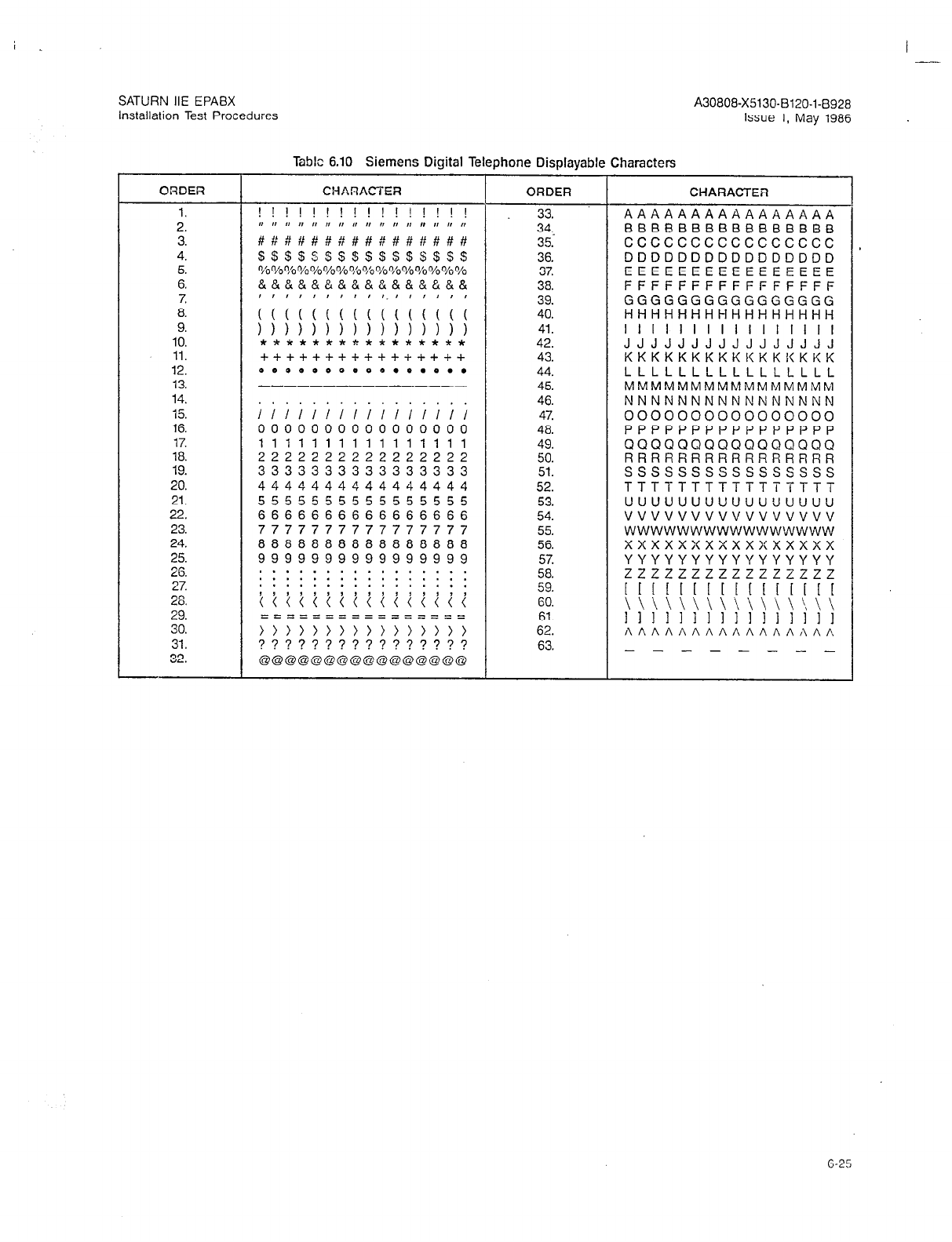
i . I
SATURN IIE EPABX A30808-X5130-B120-l-6928
Installation Test Procedures Issue 1, May 1986
Table 6.10 Siemens Digital Telephone Displayable Characters
ORDER CHARACTER ORDER CHARACTER
1. ! ! ! ! ! ! ! ! ! ! ! ! ! ! ! ! 33. AAAAAAAAAAAAAAAA
2. #P It It I, I, ,I 0 0 I, r, 0 I, 0 I, ,I I, 34, BBBBBBBBBBBBBBBB
3. #H#H#####,Y###### 35. cccccccccccccccc
4. $ssssss$s$s$s$s$ 36. DDDDDDDDDDDDDDDD
5. o/b 010 vo %%%% vo vo o/o %% o/o %% o/o 37. EEEEEEEEEEEEEEEE
6. &&&&&&&&&&.&&&&&& 38. FFFFFFFFFFFFFFFF
7. 39. GGGGGGGGGGGGGGGG
8. ;;;;;;;;;1;;;;;; 40. HHHHHHHHHHHHHHHH
9. ))))))))))))))I) 41. I I I I I I I I I I I I I I I I
10. **************** 42. JJJJJJJJJJJJJJJJ
11. -I-+++++++++++++++ 43. KKKKKKKKKKKKKKKK
12. 0000000e00.0.0.. 44. LLLLLLLLLLLLLLLL
13. --------------- 45. MMMMMMMMMMMMMMMM
14. 46. NNNNNNNNNNNNNNNN
15. GE;;;;;;;;;;; 47. 0000000000000000
16. 0000000000000000 48. PPPPPPPPPPPPPPPP
17. 1111111111111111 49. QQQQQQQQQQQQQQQQ
18. 2222222222222222 50. RRRRRRRRRRRRRRRR
19. 3333333333333333 51. ssssssssssssssss
20. 4444444444444444 52. TTTTTTTTTTTTTTTT
21. 5555555555555555 53. uuuuuuuuuuuuuuuu
22. 6666666666666666 54. vuvvvvuvvvvvuvvv
23. 7777777777777777 55. wwwwwwwwwwwwwwww
24. 8888888888888888 56. xxxxxxxxxxxxxxxx
25. 9999999999999999 57. YYYYYYYYYYYYYYYY
26. . . . * . . . . . . . . . . . .
. . . . . . . . . . . . . . . . 58. zzzzzzzzzzzzzzzz
27. . . . . . . . . . . . . . . . .
28. ~~~~t~~~~i~i~lii 59. 11 1 [ I [ [ [ 11 I[ [ [ [ [
GO.
29. \ \ \> \ \ \ \ \ \ \ \ \ \ :\ \ \
========zz==
30. ff~~~,,,,,,,,,,, 61.
11 1 I II 1111111111
62. AAAAAAAAAAAAAAAA
31. ???????????????? 63. - - - - - _ _ _
32. Q@Q@@@@@@@@Q@QOQ
6-25
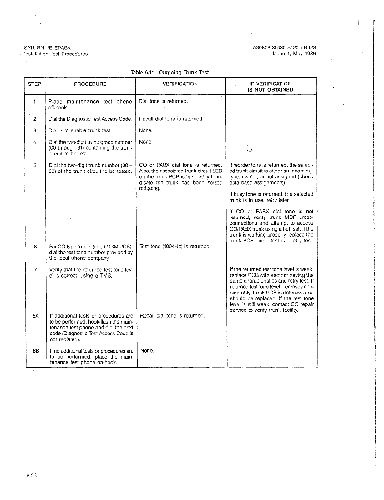
SATURN IIE EPABX
‘nstallation Test Procedures
Table 6.11 Outgoing Trunk Test
A30808-X5130-8120-l-8928
Issue 1, May 1986
STEP
1
5
6
7
8A
8B
PROCEDURE VERlFiCATlCN
?lace maintenance test phone
off-hook.
Dial the Diagnos?ic Test Access Code.
Dial 2 to enable trunk test.
Dial the two-digit trunk group number
(00 through 31) coniaining the trunk
circuit to be tested.
Dial the two-digit trunk number (00 -
99) of the trunk circuit to be tested.
For CO-type trunks (i.e., TMBM PCB),
dial the test tone number provided by
the local phone company.
Verify that the returned test tone lev-
el is correct, using a TMS.
If additional tests or procedures are
to be performed, hook-flash the main-
tenance test phone and dial the next
code (Diagnostic Test Access Code is
not redialed).
If no additional tests or procedures are
to be performed, place the main-
tenance test phone on-hook.
Iial tone is returned.
jecall dial tone is returned.
done.
done.
20 or PABX dial tone is returned.
41~0, the associated irunk circuit LED
In the trunk PCB is lit steadily to in-
licate the trunk has been seized
Iutgoing.
Test tone (1004Hz) is returned
Recall dial tone is returned.
None.
IF VERIFICATION
IS NOT OETAINED
I j
If reorder tone is returned, the select-
ed trunk circuit is either an incoming-
type, invalid, or not assigned (chec!c
data base assignments).
If busy tone is reiurned, the selected
trunk is in use, retry later.
If CO or PABX dial tone is not
returned, verify trunk MDF cross-
connections and attempt to access
CO/PABX trunk using a butt set. If the
trunlc is working properly replace the
trunk PCB under test and retry test.
If the reiurned test tone level is weak,
replace PCB with another having the
same characteristics and retry test. If
returned test tone level increases con-
siderably, trunk PCB is defective and
should be replaced. If the test tone
level is still weak, contact CO repair
service to verify trunk facility.
i
i
6-26

-
SATURN IIE EPABX A30i308-X5130-B120-1-B928
Installation Test Procedures Issue 1, May 1986 .
Table 6.12 Placing Circuit(s) In-Service
STEP PROCEDURE VERIF!CATION IF VERlFlCATIOfl
IS NOT OBTAiNED *
1 Place maintenance test phone Dial tone is returned.
off-hook.
2 Dial the Diagnostic Test Access Code. Recall dial tone is returned.
3 Dial 7 for placing a circuit in-service. None.
4A If a single circuit is to be placed in- Coniirmation tone is returned. If reorder tone is returned, the seleci-
service, dial the four digit PEN num- ed circuit is invalid or unassigned.
bar of the circuit. Check data base assignments.
45 If all the circuits in a PCB are to be Confirmation tone is returned. If reorder tone is returned the select-
placed in-service, dial the first three ed PCB is invalid or unassigned
digits of the PEN number for the PCB Check data base assignments,
followed by digit 8. For an SLA16, dial
the first three digits of the PEN num-
ber associated with the first eight cir-
cuits followed by an 8, then dial the
first three digits of the associated PEN
number for the second eight circuits
(W,X,Y+l) followed by an 8.
5A If additional t&s or procedures are Recall dial tcne is returned.
to be performed, hoolcilash the main-
tenance test phcne and dial the next
code (Diagnostic Test Access Code is
not redialed).
5B If no additional tests or procedures are None.
to be performed, place the main-
tenance test phone on-hook.
Table 6.73 Taking Ci:cuit(s) Out-et-Service
STEP PROCEDURE VERIFICATION IF VERlFtCATION
IS NOT OBTAINED
1 Place maintenance test phone Dial tone is returned.
off-hook.
2 Dial the Diagnostic Test Access Code. Recall dial tone is returned.
3 Dial 8 for placing a circuit out-of- None.
service.
4A
48
If a single circuit is to be placed out- Confirmation tone is returned. If reorder tone is returned, the select-
of-service, dial the four digit PEN ed circuit is invalid or unassigned.
number of the circuit. Check data base assignments.
If all the circuits in a PCB are to be Confirmation tone is returned. If reorder tone is returned the select-
placed out-of-service dial the first ed PCB is invalid or unassigned.
three digits of the PEN number for the Check data base assignments.
PCB followed by digit 8. For an SL416,
dial the first three digits of the PEN
number associated with the first eight
circuits followed by an 8, then dial the
first three digits of the associated PEN
number for the second eight circuits
(W,X,Y+l) followed by an 8.
6-27
I ’
SATURN IIE EPABX
installation Test Procedures
Table 6.13 Takinq Circuit(s) Out-of-Service IContinucdl
A30808-X5130-8120-1-8928
Issue 1, May 1986
. ,
STEP
PROCEDURE VERIFICATION IF VERIFICATION
IS NOT OBTAINED
5A
If additional tests or procedures are Recall dial tone is returned.
to be performed, hook-flash the main-
tenance test phone and dial the next
code (Diagnostic Test Access Code is
not redialed).
5B If no additional tests or procedures are None.
to be performed place the main-
tenance test phone on-hook. .: j
6-28 (28
pages)
I .--
SATURN IIE EPABX A30808-X5130-B120-143928
Installation Test Procedures Issue 1, May 1986
SECTKIN 7.00 INSTALLATION TEST PROCEDURES CHECKLlST
7.01 General. After performing the installation test proce-
dures contained in this practice, each installation test proce-
dure performed should be recorded to ensure that all tests
have been completed satisfactorily. Use Table 7.00, Installa-
iion Test. Procedures Checklist, for this purpose. This table
can be used as a sign-off sheet, if required.
Table 7.00 Installation Test Procedures Checklist
7-l (7-2 bl!nnL,)

Siemens Pracltces
Maintenance Series
A30808-X5130-DllO-18920
Issue 1, May 1986
SATURN” IIE EPABX
MAINTENANCE AND TWQU ESH~O=~I
Issued by Office Systems Group
5500 Broken Sound Boulevard N.W.. Boca Raton. Florida 33431
- - .-_ .~__- -
Stemens lnformatlon Systems, Inc.
(305) 994-8100 l Telex: 515052
Printed in U.S.A.
Siemens Practices
,.’ Maintenance Series
A30808-X5130-DIIO-l-8920
Issue 1, May 1986
0 Siemens Information Systems, inc., 1985
All rights reserved.
- i
I
-:
This material is proprietary to Siemens Information Systems, Inc. Any unauthorized
reproduction, use or disclosure of this material, or any part thereof, is strictly prohibited.
Siemens reserves the right to make changes in specifications at any time and without
notice. The information furnished by Siemens in this material is believed to be accurate
and reliable. However, no responsibility is assumed by Siemens for its use.
SATURN is a registered trademark of Siemens Information Systems, Inc.
/
‘I
SAUTRN IIE EPABX A30808-X5130-DllO-l-8920
Maintenance and Troubleshooting Issue 1, May 1986
CONTENTS
I --.
SECTION PAGE FIGURE PAGE
.................
.......
l-l
Purpose.. ....................... ...... 1-l
Scope ........................... ...... l-l
Siemens SATURN IIE Practices ...... ...... 1-l
Siemens Customer Support Services ...... l-l
What to Do in Case of Trouble with
FCC-Registered Equipment, .......
.
l-l
2.00 MAINTENANCE OVERVIEW ................ 2-l
Introduction ............................... 2-1
General .................................. 2-l
Design Considerations ...................... 2-2
Maintenance Facilities ...................... 2-2
Power System Unit ......................... 2-2
Maintenance Phone ........................ 2-4
Service Terminal ........................... 2-4
Manual On-Line Diagnostic Tests. ............. 2-7
System Diagnostic Tests. .................... 2-7
Apparatus Diagnostic Tests .................. 2-8
Automatic On-Line Diagnostic Testing
and Reporting ........................... 2-9
Self-Test Routines .......................... 2-9
Audit Routines ............................ 2-10
Alarm Indicators and Classification ........... 2-11
Power Distribution and Failures .............. 2-11
3.00 PREVENTIVE MAINTENANCE .............. 3-l
General .................................. 3-1
Floppy Disk Drives .......................... 3-1
4.00 TROUBLESHOOTING AND REPAIR
PROCEDURES ......................... 4-1
General .................................. 4-l
Test Equipment ............................ 4-1
PCB and Power Supply Removal and
Replacement ...................
System Fails to Reload. ............
Alarm Conditions and Reporting .........
Power Failures. .......................
4-l
4-1
4-l
: ‘4-18
Single-Line Telephone Related Failures ....... 4-27
Attendant Console Related Failures .......... 4-28
Siemens Digital Telephone (SDT)
Related Failures . . . . . . .
Manual On-Line Diagnostic Tests . .
Automatic On-Line Audit Tests, . . . .
Spare Parts . . . . . . . . . . . . . . . . .
4-28
4-30
4-30
4-30
FIGURE
LIST OF FlGlJRE!i
PAGE
1.00 SATURN IIE System Basic Cabinet . . . l-2
1.01 SATURN IIE System with Basic and
Expansion Cabinets . . . . . . . . 1-3
2.00 SATURN IIE System Block Diagram 2-l
2.01 Power System Unit (PSU), Front View 2-3
2.02 Controller/Input-Output Processor Printed
Circuit Board (CIOP) . . . 2-5
2.03 Remote Access Unit/Ports Printed Circuit
Board (RAUP) . . 2-6
2.04 SATURN IIE EPABX Basic Cabinet,
Front View 2-12
2.05 SATURN IIE EPABX-Basic Cabinet,
Rear-View ............................... 2-13
2.06 SATURN IIE EPABX Basic and Expansion
Cabinets, Front View ...................... 2-14
2.07 SATURN IIE EPABX Basic and Expansion
Cabinets, Rear View ...................... 2-15
2.08 Block Diagram of AC Input to Power Supply
Assemblies and Modules . .- ................ 2-17
2.09 Layout of Connectors and Terminals on
Power System Unit (PSU) Rear Panel ........ 2-18
2.10 Fusing of -48 Volt Outputs from -48PSO
and -48PSl .............................. 2-19
2.11 Power System Unit (PSU) Block Diagram ..... 2-21
2.12 RAC/RMW Signals ........................ 2-24
4.00 Power System Unit (PSU) Power Connections 4-21
4.01 -48PSO Module Power Connections .......... 4-22
4.02 Basic Shelf Backplane Power Connections .... 4-24
4.03 LTUPS Module Power Connections. .......... 4-25
4.04 LTU Shelf Backplane Power Connections. ..... 4-26
4.05 Attendant Console Keypad and Feature Button
Depression Sequence. ..................... 4-37
4.06 Siemens DYAD Telephone Button Depression
Sequence ............................... 4-42
4.07 Siemens JR-DYAD Telephone Button
Depression Sequence ...................... 4-45
LIST OF TABLES
TABLE PAGE
1.00 Mnemonics Used in This Practice ............ l-4
2.00 Functions of Connectors and Terminals on
PSU Rear Panel ......................... 2-20
2.01 Pin Functions at Connector J13
on the PSU ............................. 2-25
2.02 Alarm LEDs and Output Status at
Connector J13 on the PSU ................. 2-25
3.00 Floppy Disk Head Cleaning Procedure ........ 3-l
4.00 PCB and Power Supply Removal Guidelines ... 4-2
4.01 Failure Indications on Controller/input-Output
Processor Printed Circuit Board (CIOP) ........ 4-3
4.02 Alarm Reporting and Processing ............. 4-4
4.03 Failure Indications on LTUC Printed Circuit
Board .................................. 4-17
4.04 Memory Support Module (MSM) Battery
Test .................................... 4-17
4.05 Allowable Voltage Ranges .................. 4-19
4.06 Tone Generator Test ...................... 4-31
4.07 Tone Generator Test Numbers .............. 4-31
4.08 Outgoing Trunk Test ...................... 4-32
4.09 DTMF Receiver Test ...................... 4-33
4.10 Placing Circuit(s) In-Service ................ 4-33
4.11 Taking-Circuit(s) .Out-of-Service
4.12 DTMF Dial Pad Test
4.13 Station Line Test
4.14 Attendant Console Test . .
4.15 Attendant Console Displayable Characters
4.16 Siemens DYAD Telephone Button Test .
4.17 Siemens JR-DYAD Telephone Button Test
4.18 Siernens DYAD Telephone Display Test
4.19 Siemens DYAD Telephone Displayable
Characters
4-34
4-35
4-36
4-38
4-39
4-40
4-43
4-46
4-47
SATURN IlE EPABX
Maintenance and Troubleshooting
SEC?‘lON 1.00 INTRODUCTION
1.01 Purpose. This maintenance series practice provides
step-by-step instructions for troubleshooting and repairing a
malfunctioning SATURN IIE (SATURN II - Expanded) Elec-
tronic Private Automatic Branch Exchange (EPABX) System.
The information contained in this practice allows maintenance
personnel to locate and correct malfunctions during
precutover and postcutover of the system. Figures 1.00 and
1.01 illustrate the two cabinet configurations of the SATURN
HE System. CAUTION
Maintenance procedures on the SATURN IIE EPAEX must
be performed only by Siemens certified personnel.
Table 1.00 defines the mnemonics used in this practice.
1.02 Scope. The information contained in this practice is
divided into the following four sections:
a. Introduction
b. Maintenance Overview
c. Preventive Maintenance
d. Troubleshooting and Repair Procedures
A30808-X5130-DllO-l-8920
Issue 1, May 1986
1.03 Siemens SATURN HE Practices. The practices, issue
numbers, and dates for the SATURN HE EPABX are listed in
the Practices Documentation Index. A.30808X5130-AlgO- * -8987.
NOTE: Always refer to the latest issue of the applicable in-
dex to obtain the latest issue number of the practice.
1.04 Siemens Customer Support Services. Siemens
maintains a nationwide network of field service offices. Con-
tact the Siemens regional office for any engineering as-
sistance which may be required.
1.05 What to Do in Case of Trouble with FCC-Registered
Equipment. When trouble is experienced with FCC-registered
equipment of the SATURN IIE EPABX, the procedures con-
tained in this document should be followed, by qualified main-
tenance personnel, to isolate and correct the malfunction. If
spare equipment is not available, the telephone company
must be notified that the equipment is faulty and this equip-
ment must be disconnected from the public telephone net-
work. The telephone company must also be notified when the
faulty equipment has been repaired.or replaced and such
equipment is reconnected to the
public
telephone network.
l-l
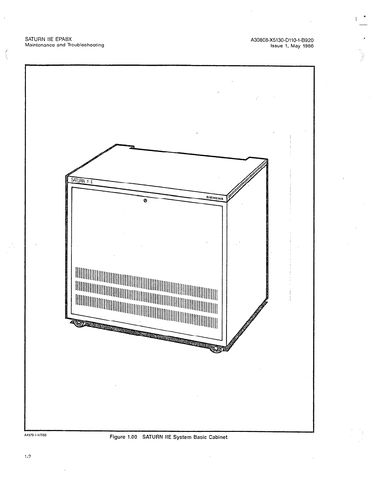
SATURN IIE EPABX A30808-X5130-DllO-l-8920
Maintenance and Troubleshooting issue 1, May 1986
Figure 1.00 SATURN IIE System Basic Cabinet
1-2
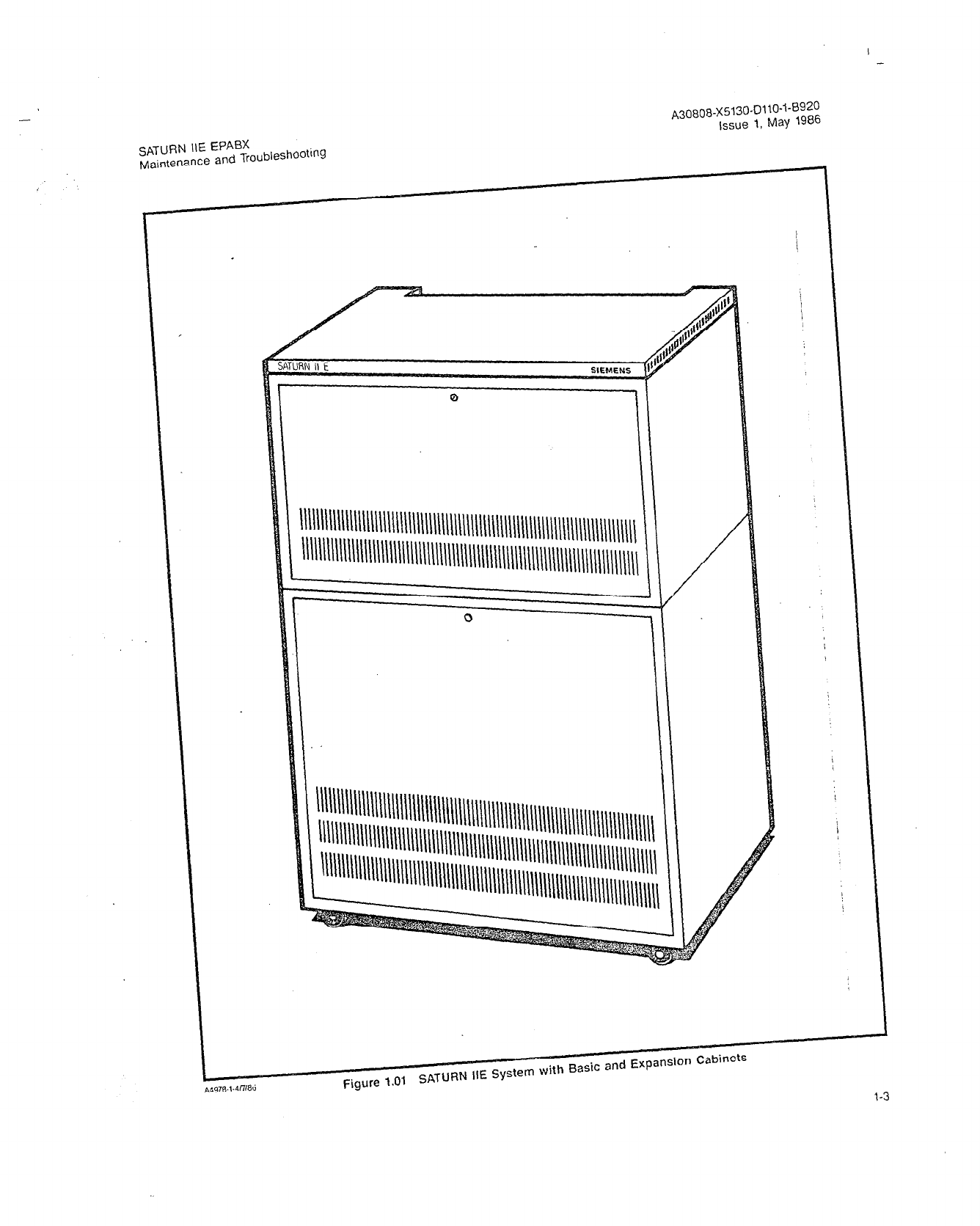
-
A3~~0~-~513O-~i~o-~-8~~~
issue I, May 19%
SATURN IIE EPABX
Maintenance and Troubleshooting
IN Ii E
SIEMENS
Q
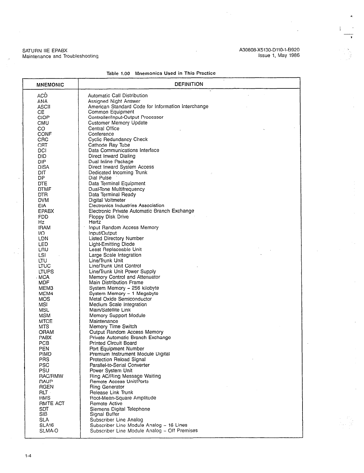
SATURN IiE EPABX
Maintenance and Troubleshooting
Table 1.00 Mnemonics Used in This Practice
MNEMONIC DEFINITION
AC6 Automatic Call Distribution
ANA Assigned Night Answer
ASCII American Standard Code for Information Interchange
CE Common Equipment
CIOP Controller/Input-Output Processor
CMU Customer Memory Update
co Central Office
CONF Conference
CRC Cyclic Redundancy Check
CRT Cathode Ray Tube
DCI Data Communications Interface
DID Direct Inward Dialing
DIP Dual lnline Package
DISA Direct Inward System Access
DIT Dedicated Incoming Trunk
DP Dial Pulse
DTE Data Terminal Equipment
DTMF Dual-Tone Multifrequency
DTR Data Terminal Ready
DVM Digital Voltmeter
EIA Electronics Industries Association
EPABX Electronic Private Automatic Branch Exchange
FDD Floppy Disk Drive
HZ Hertz
IRAM Input Random Access Memory
I/O Input/Output
LDN Listed Directory Number
LED Light-Emitting Diode
LRU Least Replaceable Unit
LSI Large Scale Integration
LTU Line/Trunk Unit
LTUC Line/Trunk Unit Control
LTUPS Line/Trunk Unit Power Supply
MCA Memory Control and Attenuator
MDF Main Distribution Frame
MEM3 System Memory - 256 kilobyte
MEM4 System Memory - 1 Megabyte
MOS Metal Oxide Semiconductor
MSI Medium Scale Integration
MSL Main/Satellite Link
MSM Memory Support Module
MTCE Maintenance
MTS Memory Time Switch
ORAM Output Random Access Memory
PABX Private Automatic Branch Exchange
PCB Printed Circuit Board
PEN Port Equipment Number
P!MD Premium Instrument Module Digital
PRS Protection Reload Signal
PSC Parallel-to-Serial Converter
PSU Power System Unit
RAClRMW Ring AC/Ring Message Waiting
RAUP Remote Access Unit/Ports
RGEN Ring Generator
RLT Release Link Trunk
RMS Root-Mean-Square Amplitude
RMTE ACT Remote Active
SDT Siemens Digital Telephone
SIB Signal Buffer
SLA Subscriber Line Analog
SLA16 Subscriber Line Module Analog - 16 Lines
SLMA-0 Subscriber Line Module Analog - Off Premises
1-4
I -
SATURN IIE EPABX
Maintenance and Troubleshooting
Table 1.00 Mnemonics Used in This Practice (Continued)
A30808-X5130-DllO-l-8920
Issue 1, May 1986
MNEMONIC I DEFINITION
SLMA-S
SLMD
SLT
SMDR
SMXTG
T&R
TM BA-2
TMBA-4
TMBM
TMIE
TMS
TTY
-48PS
Subscriber Line Module Analog - Station
Subscriber Line Module Digital
Single-Line Telephone
Station Message Detail Recording
Signal Multiplexer/Tone Generator
Tip and Ring
2-Wire E&M Trunk
4-Wire E&M Trunk
Central Office Trunk
Direct Inward Dialing Trunk
Transmission Measuring Set
Teletypewriter
-48Vdc Power Supply
l-5 (1-6 blank)
I -
SATURN IIE EPABX
Maintenance and Troubleshooting
SECTION 2.00 MAINTENANCE OVERVIEW
A30808-X5130-DllO-l-6920
Issue 1, May 1986
2.01 Introduction. This section describes the design con-
siderations and maintenance facilities incorporated in the
SATURN IIE EPABX. The maintenance concept for the EPABX
is based on detecting and isolating failures to the Least
Replaceable Unit (LRU), replacing the faulty LRU, and restor-
ing normal service as soon as possible. The maintenance con-
cept does not include the replacement of components on
Printed Circuit Boards (PCBs). When a PCB is found to be
defective, the PCB must be replaced and the original sent
to the repair facility.
configuration, the SATURN IIE System is housed in a Basic
Cabinet-plus an Expansion Cabinet, which is mounted on top
of the Basic Cabinet as shown in.Figure 1.01. The equipment
cabinet(s) contain all functional units of the system. The sys-
tem is divided into five functional blocks of circuits as shown
in the block diagram of Figure 2.00. These functional blocks
may be directly related to the system’s hardware groups. The
functional blocks are as follows:
a. Line/Trunk
b. Switching
c. Control
d. Power
e. Ancillary Equipment
2.02 General. In its basic configuration, the SATURN IIE
System is housed in a single light-weight equipment cabinet,
called the Basic Cabinet (shown in Figure 1.00). In its expanded
ATTENDANT
I
CONSOLE
pF-J
ANCILLARY
EQUIPMENT
I ‘-J-j& .
LTU SHELF I
r------ ------__ BASIC SHELF
1 LINE/TRUNK
_________ ~
I
SWITCHING 1
NETWORK
I I I
COW
OR TRUNK FOR REMOTE
MAINTENANCE
===-I I
ANCILLARY
EQUIPMENT
Figure 2.00 SATURN IIE System Block Diagram
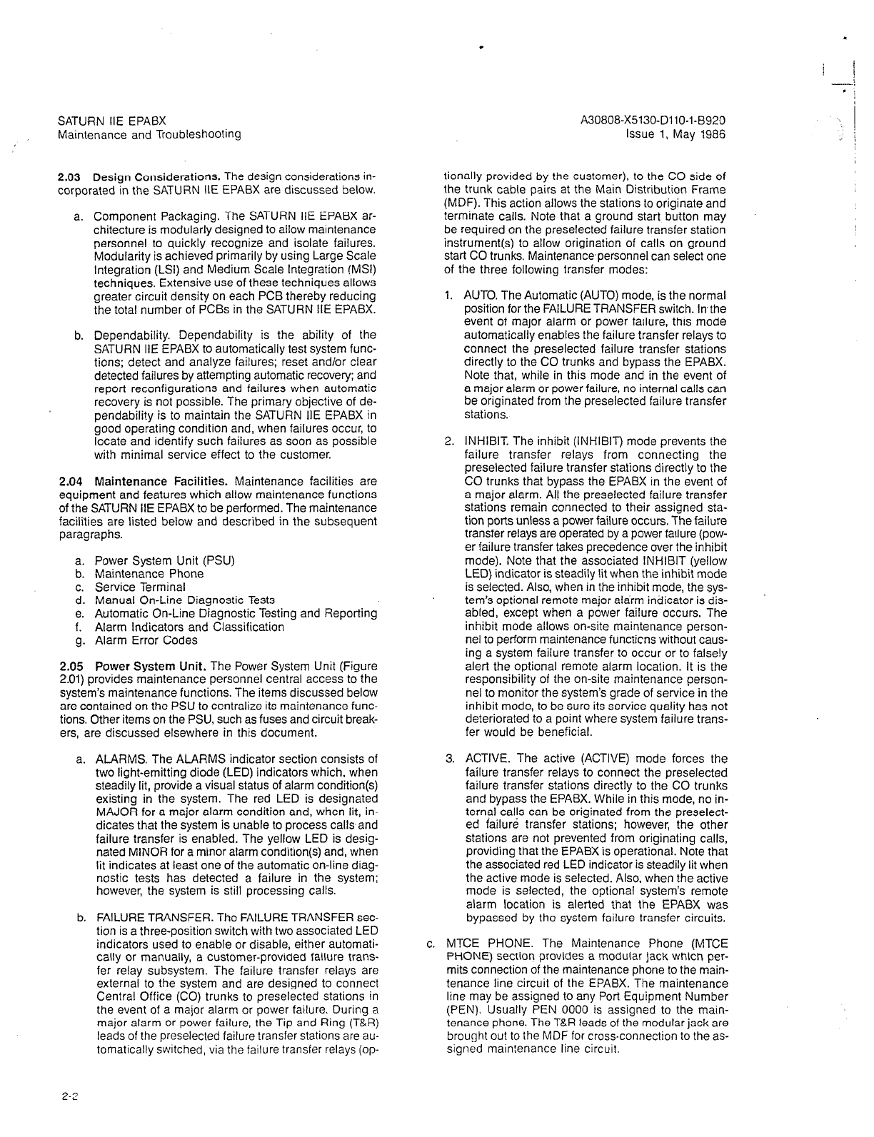
SATURN IIE EPABX
Maintenance and Troubleshooting
A30808-X5130-DllO-I-8920
Issue 1, May 1986
2.03 Design Considerations. The design considerations in-
corporated in the SATURN IIE EPABX are discussed below.
a. Component Packaging. The SATURN IIE EPABX ar-
chitecture is modularly designed to allow maintenance
personnel to quickly recognize and isolate failures.
Modularity is achieved primarily by using Large Scale
Integration (LSI) and Medium Scale Integration (MSI)
techniques. Extensive use of these technrques allows
greater circuit density on each PCB thereby reducing
the total number of PCBs in the SATURN IIE EPABX.
b. Dependability. Dependability is the ability of the
SATURN IIE EPABX to automatically test system func-
tions; detect and analyze failures; reset and/or clear
detected failures by attempting automatic recovery; and
report reconfigurations and failures when automatic
recovery is not possible. The primary objective of de-
pendabili?y is to maintain the SATURN IIE EPABX in
good operating condition and, when failures occur, to
locate and identify such failures as soon as possible
with minimal service effect to the customer.
2.04 Maintenance Facilities.
Maintenance facilities are
equipment and features which allow maintenance functions
of the
SATURN IIE EPABX
to be performed. The maintenance
facilities are listed below and described in the subsequent
paragraphs.
a. Power System Unit (PSU)
b. Maintenance Phone
c. Service Terminal
d. Manual On-Line Diagnostic Tests
e. Automatic On-Line Diagnostic Testing and Reporting
f. Alarm Indicators and Classification
g. Alarm Error Codes
2.05 Power System Unit.
The Power System Unit (Figure
2.01) provides maintenance personnel central access to the
system’s maintenance functions. The items discussed below
are contained on the PSU to centralize its maintenance func-
tions. Other items on the PSU, such as fuses and circuit break-
ers. are discussed elsewhere in this document.
a.
ALARMS. The ALARMS
indicator section consists of
two light-emitting diode (LED) indicators which, when
steadily lit, provide a visual status of alarm condition(s)
existing in the system. The red LED is designated
MAJOR for a major alarm condition and, when lit, in-
dicates that the system is unable to process calls and
failure transfer is enabled. The yellow LED is desig-
nated MINOR for a minor alarm condition(s) and, when
lit indicates at least one of the automatic on-line diag-
nostic tests has detected a failure in the system;
however, the system is still processing calls.
b. FAILURE TRANSFER. The FAILURE TRANSFER sec-
tion is a three-position switch with two associated LED
indicators used to enable or disable, either automati-
cally or manually, a customer-provided failure trans-
fer relay subsystem. The failure transfer relays are
external to the system and are designed to connect
Central Office (CO) trunks to preselected stations in
the event of a major alarm or power failure. During a
major alarm or power failure, the Tip and Ring (T&R)
leads of the preselected failure transfer stations are au-
tomattcally switched, via the failure transfer relays (op-
tionally provided by the customer), to the CO side of
the trunk cable pairs at the Main Distribution Frame
(MDF). This action allows the stations to originate and
terminate calls. Note that a ground start button may
be required on the preselected failure transfer station
instrument(s) to allow origination of calls on ground
start CO trunks. Maintenance-personnel can select one
of the three following transfer modes:
1.
AUTO.
The Automatic (AUTO) mode, is the normal
position for the FAILURE TRANSFER switch. Inthe
event of major alarm or power failure, this mode
automatically enables the failure transfer relays to
connect the preselected failure transfer stations
directly to the CO trunks and bypass the EPABX.
Note that, while in this mode and in the event of
a major alarm or power failure, no internal calls can
be originated from the preselected failure transfer
stations.
2. INHIBIT. The inhibit (INHIBIT) mode prevents the
failure transfer relays from connecting the
preselected failure transfer stations directly to the
CO trunks that bypass the EPABX in the event of
a major alarm. Al! the preselected failure transfer
stations remain connected to their assigned sta-
tion ports unless a power failure occurs, The failure
transfer relays are operated by a power failure (pow-
er failure transfer takes precedence over the inhibit
mode). Note that the associated INHIBIT (yellow
LED) indicator is steadily lit when the inhibit mode
is selected. Also, when in the inhibit mode, the sys-
tem’s optional remote major alarm indicator is dis-
abled, except when a power failure occurs. The
inhibit mode allows on-site maintenance person-
nel to perform maintenance functicns without caus-
ing a system failure transfer to occur or to falsely
alert the optional remote alarm location. It is the
responsibility of the on-site maintenance person-
nel to monitor the system’s grade of service in the
inhibit mode, to be sure its service quality has not
deteriorated to a point where system failure trans-
fer would be beneficial.
3. ACTIVE. The active (ACTIVE) mode forces the
failure transfer relays to connect the preselected
failure transfer stations directly to the CO trunks
and bypass the EPABX. While in this mode, no in-
ternal calls can be originated from the preselect-
ed failure transfer stations; however, the other
stations are not prevented from originating calls,
providing that the EPABX is operational. Note that
the associated red LED indicator is steadily lit when
the active mode is selected. Also, when the active
mode is selected, the optional system’s remote
alarm location is alerted that the EPABX was
bypassed by the system failure transfer circuits.
c. MTCE PHONE. The Maintenance Phone (MTCE
PHONE)
section provides a modular jack which per-
mits connection of the maintenance phone to the main-
tenance line circuit of the EPABX. The maintenance
line may be assigned to any Port Equipment Number
(PEN). Usually PEN 0000 is assigned to the main-
tenance phone. The T&R leads of the modular jack are
brought out to the MDF for cross-connection to the as-
signed main!enance line circuit.
2-Z
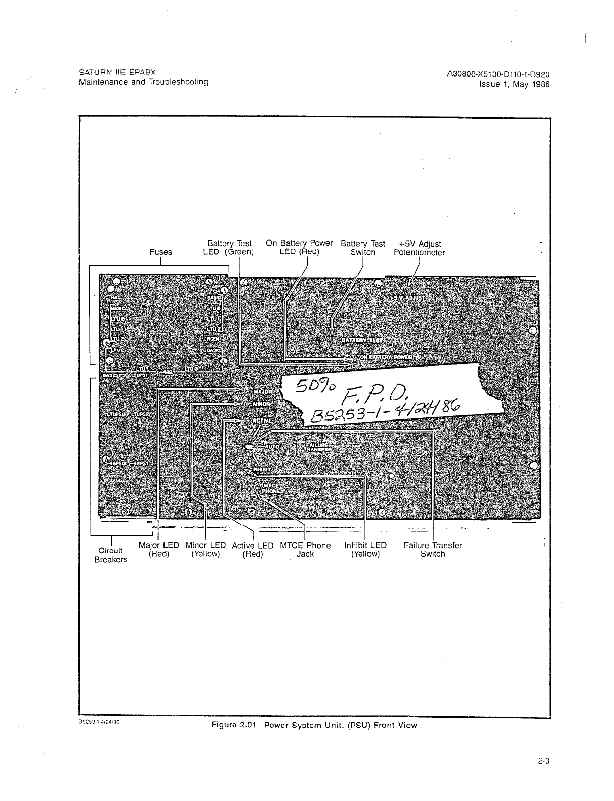
SATURN IIE EPABX A30808-X5130-DllO-l-8920
Maintenance and Troubleshooting Issue 1. May 1986
Fuses
I
Battery Test On Battery Power Battery Test
LED (Red) +5V Adjust
LED (Gr7en) Switch
I Potentl]ometer
Major LED Minor LED Active LED MTCE Phone
(Red) Jack (Yellow) Switch
Figure 2.01 Power System Unit, (PSU) Front View
2-3
A30808-X5130-DllO-l-8920
Issue 1, May 1986
SATURN IIE EPABX
Maintenance and Troubleshootrng
2.06 Maintenance Phone. The maintenance phone can be
either a portable test phone, test set, or a standard two-wire
station instrument used to access the maintenance functions
of the system, either locally or remotely.
a. Local Maintenance Functions. The maintenance line
is usually assigned as a Dual-Tone Multifrequency
(DTMF) station type; however, a Dial Pulse (DP) or
DTMF maintenance phone may be connected to it. Lo-
cal interfacing of the maintenance phone with the main-
tenance functions is achieved via the maintenance line
circuit by connecting its line cord to either the desig-
nated iack (i.e.. MTCE PHONE) on the PSU front oanel
or the’ T&R leads of the PEN assigned and dross-
connected at the MDF. Once interfaced, the main-
tenance phone can access a repertoire of system and
apparatus diagnostic test programs by dialing the
maintenance diagnostic test access code (customer
assignable via CMU procedures).
During local maintenance functions, a hookswitch flash
at any point in a test clears any diagnostic conditions,
releases any resources, and returns the maintenance
phone to the point where a test select code may be
dialed.
b. Remote Maintenance Functions. The maintenance
phone, when used for remote (off-site) maintenance
functions, must be assigned as a DTMF station type.
In DP systems, a DTMF receiver must be assigned so
that the maintenance phone can be used to commu-
nidate with the system. Maintenance personnel at a re-
mote area can gain access to the diagnostic test
programs by dialing the directory number associated
with the Direct Inward System Access (DISA) feature,
an appropriate two- to four-digit authorization code, and
the diagnostic test access code; or an attendant can
complete an incoming call to the test number.
During remote maintenance operations, the hookswitch
flash signal cannot be sent over the public telephone
network to the maintenance port; therefore, after each
test is completed, maintenance personnel must redial
the DISA trunk directory number in order to perform
further tests.
2.07 Service Terminal. The service terminal is a customer-
provided CRT or keyboard-printer data terminal. It provides
further troubleshooting capabilities in addition to the main-
tenance phone by interfacing, either locally or remotely, with
the maintenance functions of the system via a dedicated data
port. Once interfaced, the service terminal can be used to
gain access to a repertoire of auditing routines and the failure
history memory as well as performing CMU procedures.
a. Local Maintenance Functions. The service terminal,
when used for local (on-site) maintenance functions,
must be equipped with an EIA RS-232-C interface. Lo-
cal interfacing of the service terminal with the system’s
maintenance functions is achieved via a dedicated data
port by connecting its signal cable to the 25-pin
W-232-C TTY connector on the front of the CIOP PCB
(Figure 2.02). DIP switches on the CIOP PCB permit
the baud rate to be set at 300, 1200, 2400, or 9600
baud. One or both of the TTY connectors on the front
of the RAUP (Figure 2.03) may also be used for local
maintenance functions. These interfaces (also
RS-232-C compatible) are programmable to any of 15
baud rates between 50 and 9600 baud. The default
baud rate is 9600.
b. Remote Maintenance Functions.. The RAUP PCB
(Figure 2.03) of the SATURN IIE System has a
designed-in, serial modem port to facilitate communi-
cation, via standard telephone lines, between a remote
modem and terminal and the main system processor.
This modem, which is answer-only and does not dial
out, self-sets to either 300 baud or 1200 baud depend-
ing upon the incoming baud rate. (The modem port and
either or both of the two TTY ports of the RAUP may
all be used simultaneously if desired.) A green Remote
Active (RMTE ACT) LED on the RAUP lights steadily
to indicate when the carrier detect signal is active on
the modem accessed by the remote service terminal.
The service terminal at the remote site must be
equipped with an originating-type modem compatible
with modem type 103 or 212A. Maintenance person-
nel at a remote area can gain access to the system’s
maintenance functions by:
1. Dialing the listed directory number for the system
EPABX attendant and requesting the attendant (or
ANA station user, if the system is in the niqht’mode)
to extend to a station-number which-is cross:
connected to the SLA port dedicated to the RAUP
modem.
2. In systems equipped with Direct Inward Dialing
(DID), dialing the DID extension number of a sta-
tion which is cross-connected to the SLA port dedi-
cated to the RAUP modem.
3. Dialing the listed directory number associated with
the Direct Inward System Access (DISA) feature,
a three- or four-digit authorization code, and the
number assigned to a station cross-connected to
the SLA port dedicated to the RAUP modem.
4. Dialing the listed directory number of a dedicated
loop-start CO trunk circuit connected directly to the
RAUP modem.
Once the SLA circuit associated with the service terminal and
the RAUP modem port has been accessed, the answer tone
is heard when the handset assembly is to be placed in the
data mode (e.g., placed in an acoustic coupler). Refer to the
SATURN IIE EPABX Customer Memory Update (CMU) Proce-
dures practice and the service terminal’s operating manual
to coordinate proper operating procedures before any com-
mand inputs are entered.
2-4

SATURN IIE EPABX A30808-X5130-DllO-l-8920
Maintenance and Troubleshooting issue 1, May 1986
I
Figure 2.02 Controller/Input-Output Processor Printed Circuit Board (CIOP)
2-5
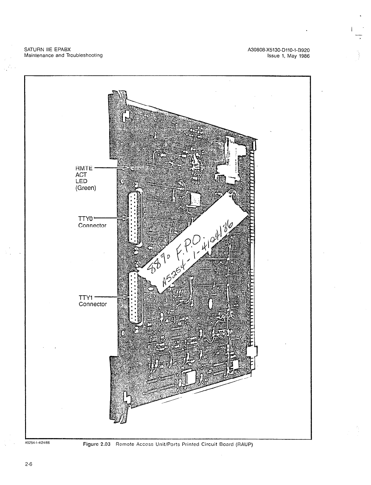
SATURN IIE EPABX
Maintenance and Troubleshooting
RMTE -
ACT
LED
(Green)
TTY0 -
Connector
TTY1 -
Connector
Figure 2.03 Remote Access Unit/Ports Printed Circuit Board (RAUP)
I -
SATURN IIE EPABX
Maintenance and Troubleshooting
2.08 Manual On-Line Diagnostic Tests. The SATURN IIE
EPABX software includes a group of system diagnostic and
apparatus diagnostic test programs which are used via the
maintenance phone. Resulting visual and/or audible
responses from these tests make it possible to verify correct
operation or detect and isolate system and apparatus mal-
functions.
2.09 System Diagnostic Tests. The system diagnostic pro-
grams permit calls and procedures to be initiated into and
through the system to verify the correct operation of the call
processing functions of the system equipment.
In order to access the system diagnostic tests, the main-
tenance diagnostic test access code (customer assignable
via a CMU procedure) must first be dialed by using the main-
tenance phone. Once the maintenance diagnostic test access
code has been entered into the system, the following listed
tests and procedures can be performed:
a.
l
Tone Generator Test (Refer to Table 4.06)
0 Outgoing Trunk Test (Refer to Table 4.08)
l
DTMF Receiver Test (Refer to Table 4.09)
l
Placing Circuits in Service (Refer to Table 4.10)
0 Taking Circuits Out of Service (Refer to Table 4.11)
Tone Generator Test. This test verifies each tone
produced by the tone generator, located in the SMXTG
PCB, either individually or in a circular sequence. This
test is performed, either locally or remotely, by dialing
test select code 1 from the maintenance phone. After
the digit 1 is dialed, two more digits are dialed to select
the individual tone to be tested or to initiate the auto-
matic circular sequencing of all tones. If an individual
tone is selected, the maintenance phone is connect-
ed to that tone (through the MTS) as long as it remains
off-hook. If the automatic circular sequence is initiat-
ed, each tone is connected to the maintenance phone
(through the MTS) for approximately 2 seconds with
an intertone silence period of 0.25 to 0.5 second. The
test automatically advances to the next tone in a cir-
cular sequence as long as the maintenance phone re-
mains off-hook.
Outgoing Trunk Test. This test verifies the supervisory
and transmission capabilities (in the outgoing direc-
tion) of any individually selected outgoing or two-way
trunk circuit on either a TMBM, TMBA-2, or TMBA-4
PCB. The test also checks the connection path through
the MTS. This test is performed either locally or remote-
ly, via the maintenance phone by dialing the test select
code 2. After the digit 2 is dialed, the trunk group num-
ber (00 to 31) followed by the trunk number within the
particular trunk group (00 to 99) is dialed. The main-
tenance phone is then cut-through to the specific trunk
circuit selected, seizing it in the outgoing direction. Sei-
zure is confirmed when dial tone is returned to the
maintenance phone. The transmiss’ion quality of the
trunk can be checked by dialing the CO milliwatt test
tone number or the test tone access code of the EPABX
(if provided). The milliwatt test tone frequency and level
(1004 Hz @ OdBm) may be measured by means of a
Transmission Measuring Set (TMS).
DTMF Receiver Test. This test verifies any individual-
ly selected DTMF receiver circuit on a DTMF PCB. The
test also checks the connection path through the
d.
e.
A30808-X5130-DllO-l-8920
Issue 1, May 1986
Memory Time Switch (MTS). This test is performed,
either locally or remotely, via the maintenance phone
by dialing test select code H. After the # is dialed, the
Port Equipment Number (PEN) of the particular DTMF
:eceiver circuit under test is dialed. The pushbuttons
on the DTMF keypad of the maintenance phone are
then depressed in a fixed sequence. If the telephone
has a 12-button keypad, the buttons are depressed in
the following sequence: 1, 2, 3, 4, 5, 6, 7, 8, 9, 0, *,
and #. If the telephone has a 16-button keypad, the
buttons are depressed in this sequence: A, B, C, D,
1, 2, 3, 4, 5, 6, 7, 0, 9, Oi *, and #. After depressing
the pushbuttons in the applicable fixed sequence, a
test tone (1004 Hz) is returned if the DTMF receiver cir-
cuit under test recognized all the tones associated with
the pushbuttons. If the pushbuttons are depressed in
the wrong sequence or the DTMF receiver circuit un-
der test failed to recognize a particular tone, intercept
tone is returned.
Placing Circuits In Service. This procedure allows
maintenance personnel to place an assigned circuit
in service from an out-of-service state. This procedure
is performed, either locally or remotely, via the main-
tenance phone by dialing test select code 7. After 7
is dialed, the PEN of the particular circuit to be placed
in service (in either an- SLMA-0, SLMA-S, SLA16,
SLMD. PIMD. DTMF. TMBM. TMBA-2. TMBA-4. or
TMIE PCB) is’dialed.‘Note that all circuiis on a pahic-
ular PCB (with exception of the SL416 PCB) are placed
in service by entering the digit 8 as the circuit location
of the PEN (e.g., 0028 places all circuits in the basic
shelf, designated as shelf 0, channel group 0, slot 2,
in service). If all 16 circuits of an SLAl6 PCB are to
be placed in service, they are placed in service eight
circuits at a time. The first sight circuits for an SLA16
(in the same shelf, channel group, and slot as above)
are placed in service as described, i.e., by entering
0028. The second eight circuits are placed in service
by dialing 0038 (a 1 is added to the basic slot number
to designate the second eight circuits on an SLAl6
PCB). If the procedure fails, either due to entry of an
invalid circuit number or because the slot number is
unassigned, reorder tone is returned. Successful com-
pletion of the procedure is indicated by the return of
confirmation tone.
Taking Circuits Out of Service. This procedure allows
maintenance personnel to take an assigned circuit out
of service from an in-service state. This procedure is
performed, either locally or remotely, via the main-
tenance phone by dialing test select code 8. After the
digit 8 is dialed, the PEN of the particular circuit (in
either an SLMA-0, SLMA-S, SLA16, SLMD, PIMD,
DTMF, TMBM, TMBA-2, TMBA-4, or TMIE PCB) to be
taken out of service is dialed. Note that all circuits on
a particular PCB (with exception of the SLA16 PCB)
are taken out of service by entering the digit 8 as the
circuit location of the PEN (e.g., 0208) places all cir-
cuits in the basic shelf (0), channel group 2, slot 0 out
of service). If all 16 circuits of an SLA16 PCB are to
be taken out of service, the procedure is performed
eight circuits at a time. The first eight circuits for an
.%A16 (in the same shelf, channel group, and slot num-
ber as above) are taken out of service as described,
i.e., by entering 0208 The second eight circuits are
taken out of service by dialing 0218 (a 1 is added to
2-7

SATURN IIE EPABX
Maintenance and Troubleshooting
I --.
A30808-X5130-DllO-l-8920
Issue 1, May 1986
the basic slot number to designate the second eight
circuits on an SLA16 PCB). When this procedure is
enabled, it allows existing calls on the circuits to be
completed before being taken out of service. If the
procedure fails, because the selected circuit is either
invalid or unassigned, reorder tone is returned. Suc-
cessful completion of the procedure is indicated by the
return of confirmation tone after the circuit is taken out
of service (i.e., after calls in progress are completed).
In addition, maintenance personnel are not required
to wait for confirmation tone before placing the main-
tenance phone on-hook to take the circuit out of serv-
ice. Once this procedure is enabled, it automatically
takes the pariicular circuit out of service as each call
is completed.
2.10 Apparatus Diagnostic Tests. The apparatus diagnos-
tic tests permit testing of the various types of telephones and
consoles that may be interfaced with the SATURN IIE EPABX.
These tests verify proper operation of Single Line Telephones,
Siemens Digital Telephones (DYADs and JR-DYADs), and At-
tendant Consoles connected to the EPABX.
In order to test a SATURN apparatus, the craftsperson must
enable the apparatus test program via the maintenance
phone, by dialing the maintenance diagnostic test access
code, followed by the test select code 3. Note that this proce-
dure is not required if the apparatus test program has been
permanently enabled as a SATURN System option. Once the
apparatus test program is enabled, the following listed ap-
paratus tests can be performed:
0 Station Line Tests (Refer to Tables 4.12 and 4.13)
l
Attendant Console Test (Refer to Table 4.14)
0 Siemens Digital Telephone - DYAD Button Test
(Refer to Table 4.16)
0 Siemens Digital Telephone - JR-DYAD Button Test
(Refer to Table 4.17)
l
Siemens Digital Tetepnone - DYAD Display Test
(Refer to Table 4.18)
a. Station Line Tests. The following tests can be per-
formed on a SATURN EPABX station instrument:
1. Dial Pad Test. This test checks the transmission
capabilities and DTMF keypad performance of any
DTMF instrument. This test can only be enabled
after dialing the apparatus diagnostic test select
code 3 from the maintenance phone, if required,
and the dial pad test access code (customer as-
signed via a CMU procedure) from the station in-
strument under test. After the dial pad test access
code is dialed, recall dial tone is returned and the
dial pad keys are depressed in a fixed sequence.
If the telephone has a 1Bbutton keypad, the but-
tons are depressed in the following sequence: 1,
2, 3, 4, 5, 6, 7, 8, 9, 0, *, and #. If the telephone
has a 16-button keypad, the buttons are depressed
in this sequence: A, B, C, D, 1, 2, 3, 4, 5, 6, 7, 8,
9, 0,. * and ft.
As each key is depressed, data are sent from the
instrument to the test program. If a data error or
an incorrect sequence is detected, busy tone is
returned. Successful completion of this test is in-
dicated by the return of a test tone (1004Hz @
-16dBm). The transmission quality of the station can
then be verified by measuring the test tone frequen-
cy and level by using a TMS.
2. Ringback Test. This test checks the supervisory
and transmission capabilities of any station instru-
ment (rotary dial, DTMF and Siemens Digital Tele-
phone). This test can only be enabled after dialing
the apparatus diagnostic test select code 3 from
the maintenance phone, if required, and the ring-
back test access code (customer assignable via a
CMU procedure) from the station instrument un-
der test. After the ringback tesi access code is di-
aled, confirmation tone is returned, and the user
places the station instrument on-hook. When the
station instrument rings, its supervisory capabili-
ties are verified. Upon answering the ringing (go-
ing off-hook), a test tone (1004 Hz @ -16dBm) is
applied to the station line. The transmission quali-
ty of the station can then be verified by measuring
the test tone frequency and level by using a TMS.
b. Attendant Console Test. This test checks the data and
speech highways to and from an attendant console,
its LED indicators, display module, and audible alert-
ing device. The test can only be enabled after dialing
the apparatus diagnostic test select code 3 via the
maintenance phone, if required, and the attendant con-
sole test access code (customer assignable via CMU
procedure) from the attendant console under test. Af-
ter the attendant console test access code is dialed,
the console keys are depressed in a fixed sequence.
As each is depressed, data are sent from the console
to the test program. If a data error occurs or an incor-
rect sequence is depressed, busy tone is returned to
the console. Display module and LED indications are
provided to verify correct operation of the transmit and
receive circuits of the console. Successful completion
of this test is indicated by the returning of ringback tone
to the console handset or headset and the sounding
of an audible alerting device in the instrument.
c. Siemens Digital Telephone - DYAD Button Test. This
test checks the signaling highways to and from a DYAD
Telephone, its LED indicators, and audible alerting
device. The test can only be enabled after dialing the
apparatus diagnostic test select code 3 via the main-
tenance phone, if required, and the Siemens Digital
Telephone button test access code (customer assiq-
nabte via a CMU procedure) from theDYAD Telephole
under test. After the Siemens Diaital Telephone but-
ton test access code is dialed, the DYAD’Telephone
keypad and feature buttons are depressed in a fixed
sequence. As each button is depressed, data are sent
from the DYAD Telephone to the test program. If a data
error or an incorrect sequence is detected, busy tone
is returned to the DYAD Telephone. LED indications are
provided to verify correct operation of the transmit and
receive circuits of the DYAD Telephone. Successful
completion of the test is indicated by the returning of
ringback tone to the DYAD Telephone handset and the
sounding of an audible alerting device in the telephone.
d. Siemens Digital Telephone - JR-DYAD Button Test.
This test checks the signaling highways to and from
a JR-DYAD Telephone, its LED indicators, and audible
alerting device. The test is very similar to that for the
DYAD Telephone described above with the exception
2-8

SATURN IIE EPABX
Maintenance and Troubleshooting
A30808-X5130-DllO-l-6920
Issue 1, May 1986
that the operation of certain buttons (and
SuCCeSSful
test completion) is indicated at the end of the test by
the return of ringback tone and actuation of the audi-
ble alerting device in the JR-DYAD Telephone.
e. Siemens Digital Telephone - DYAD Display Test. This
test checks the signalinghighways to and from a DYAD
Telephone, its display module, and audible alerting
device. The DYAD Telephone display test can only be
enabled after dialing the apparatus diagnostic test
select code 3 via the maintenance phone, if required,
and the Siemens Digital Telephone display test access
code (customer assignable via a CMU procedure) from
the DYAD Telephone under test. After the Siemens Dig-
ital Telephone display test access code is dialed, the
DYAD Telephone alphanumeric display and its address
signaling scheme are tested. These tests consist of
shifting the entire alphanumeric character set through
each character position on the display module. Suc-
cessful completion of the test is indicated by the return-
ing of ringback tone to the DYAD Telephone handset
and the sounding of an audible alerting device in the
DYAD Telephone. The pass/fail status of the test is
based on observation by maintenance personnel of the
characters displayed.
2.11 Automatic On-Line Diagnostic Testing and Report-
ing. The SATURN EPABX System is provided with software
self-test routines and audit test routines which check for
failures occurring in the system. When a failure is detected,
pertinent data regarding the failure is recorded in an area of
memory called “Failure History” and the appropriate major
or minor alarm is enabled. Recovery programs are automati-
cally executed as necessary on the failing equipment. The
failure history memory can record 32 system failures (error
messages) along with the identity of the failing equipment and
the date and time of occurrence for each failure. When the
failure history memory is full, new failures push-off the oldest
failure of the failure history memory. The MIN ALM key on
the attendant console is used to display the failures record-
ed in the failure history memory. The failure history memory
can also.be accessed from a local or remote service terminal.
2.12 Self-Test Routines. The SATURN EPABX is provided
with software self-test routines which verify that certain call
processing operations, initiated by the main controller have
been successfully completed by the peripheral circuits. If a
call processing error occurs, the error(s) is recorded in the
failure history memory and the appropriate major or. minor
alarm is enabled. Recovery programs are automatically ex-
ecuted as necessary on the faulty equipment.
a. Connect Test. When a trunk is seized outgoing, a
3-second (nominal) timer is set. If the CO or distant
equipment does not acknowledge the seizure (e.g.,
ground return on tip lead, loop current, dial tone de-
tection, or wink-start signal) before the timer expires,
a connect error message is recorded in the failure his-
tory memory and the minor alarm indicators are light-
ed. An attempt is made to reroute the call over another
trunk.
b. Disconnect Test. When a trunk is released by the
SATURN EPABX. a 20second (nominal) timer is set.
If the CO does not release the trunk (e.g., ground re-
moved from tip lead, open-loop condition on DID trunk
or E lead) before the timer expires, a disconnect error
message is recorded in the failure history memory and
the minor alarm indicators are lighted. The trunk is left
in the idle off-hook state (not disconnected, i.e., it is
usable).
c. Fuse Alarm Test. W’henever a fuse on the PSU front
panel fails, a fuse failure message is recorded in the
failure history memory and the minor alarm indicators
are lighted. The SATURN IIE System continues to
process calls normally for the circuits still reporting
events. If a fuse failure occurs affecting a major por-
tion of the system (e.g., common equipment), the major
alarm indicators are lighted by virtue of other failures
that will result from the blown fuse.
d. Input/Output Processor Tests. The CIOP and RAUP
provide return codes for each command to indicate
whether or not the requested operation was success-
ful. If the return code indicates an error or the CIOP
or RAUP detects an internal failure, an error message
is recorded in the failure history memory and the minor
alarm indicators are lighted. If the CIOP detects an er-
ror that prevents the initialization of the system when
an initialization is required, the major alarm indicators
are lighted.
e. LTU Clock Test. Hardware monitors built into the Sig-
nal Multiplexernone Generator (SMXTG) PCB are used
to detect loss of principal clock, clock synchronization,
or ring synchronization. If a failure is detected, an LTU
Clock error message is recorded in the failure history
memory and the minor alarm indicators are lighted.
The location of the failure is indicated’ in the error
message.
f. Mainbus Timeout Test. The system watchdog timer is
set each time the mainbus receives a command. If the
timer expires before an acknowledgement is returned,
a mainbus timeout error message is recorded in the
failure history memory and the minor alarm indicators
are lighted.
g. Memory Parity Test. If a word is addressed that has
incorrect parity, the parity detector on the addressed
memory module generates an interrupt. A memory par-
ity error message is recorded in the failure history
memory and the minor alarm indicators are lighted.
h. Memory Protect Test. If a write is attempted to a word
in write protected memory, the write protect detector
on the addressed memory module generates an inter-
rupt. A memory protect error message is recorded in
the failure history memory and the minor alarm indi-
cators are lighted.
i. Memory Support Test. A voltage level detector circuit
provides a software testable signal that indicates when
the memory support battery voltage is below an ac-
ceptable voltage level. This signal is sampled once per
hour by software. If the software testable signal indi-
cates that the battery is low or disconnected, a memory
support failure message is recorded in the failure his-
tory memory and the minor alarm indicators are lighted.
j. PIMD or SLMD Synchronization Test. When a PIMD
PC6 loses synchronization with an attendant console
or an SLMD PCB loses synchronization with an SDT
2-o
SATURN IIE EPABX
Maintenance and Troubleshooting
or DCI, a PIMD error message is recorded in the failure
history memory and the minor alarm indicators are
lighted.
k. Presence Alarm Test. The scan data returned for each
port circuit contains a presence bit. If the presence bit
goes inactive for 3 seconds or changes state (active/in-
active) six times in 3 seconds, a presence alarm mes-
sage is recorded in the failure history memory and the
minor alarm indicators are lighted. The presence alarm
is not generated for ports marked as out-of-service.
I. SMXTG Clock Test. When the SMXTG 1 kHz clock fails,
an SMXTG clock failure message is recorded in the
failure history memory and the major alarm indicators
are lighted.
m. Software Loop Test. When a software loop error exists,
a software loop error message is recorded in the failure
history memory and the minor alarm indicators are
lighted. If the number of errors is excessive, the major
alarm indicators are lighted.
n. Software Trap Test. When an event occurs for a given
circuit type, the state/event table for that circuit type
is accessed to determine what software action is to be
taken in response to the event. If the event is illogical
in regard to the state of the circuit, a software trap er-
ror message is recorded in the failure history memory
and the minor alarm indicators are lighted.
2.13 Audit Routines. The SATURN IIE EPABX software in-
cludes a repertoire of audit routines which are executed dur,
ing processor idle time. These routines provide automatic
testing of system equipment. Each audit routine is designed
to be individually enabled (activated) or disabled (inactivat-
ed) from the automatic routining sequence. This enable/dis-
able capability is only accessible by maintenance personnel
via a service terminal. When an auditing routine is enabled,
detected failures are recorded in the failure history memory
and the appropriate major or minor alarm is enabled. All
failures are identified by the AUDIT error message (refer to
Table 4.02). Recovery programs are automatically executed
as necessary on faulty equipment. Additionally, each audit
routine is designed to be executed on demand by main-
tenance personnel via a local or remote service terminal. Im-
mediate results (reasonable execution time considered) of
pass or fail conditions are provided upon completion of each
audit routine. The failure indication can be displayed by ac-
cessing the failure history memory. The following listed audit
programs are described in subsequent paragraphs.
l
Memory Parity Audit Test
l
Memory Content Audit Test
l
Input/Output Loop-Around Audit Test
0 Speech Highway Audit Test
* DTMF Receiver/Tone Generator Audit Test
l
MTS Memory Control Audit Test
l
Digital Apparatus Audit Test
l
Trunk Activity Audit Test
a. Memory Parity Audit Test. The memory parity audit test
checks each memory address for correct parity of its
contents. If a parity error is detected, the error is record-
ed in the failure history memory, the MINOR alarm in-
dicator on the PSU is lit, and recovery is automatically
attempted. This audit routine is intended to be used
b.
C.
d.
e.
A30808-X5130-DllO-l-8920
Issue 1, May 1986
by maintenance personnel as a demand-executed au-
dit routine only to be run when memory is first installed
or suspected faulty. This routine should normally be
disabled from automatically running on an in-service
system, since it may unnecessarily disrupt service if
it detects ah error in a normally unused portion of the
memory. The standard system data base has this au-
dit routine disabled.
Memory Content Audit Test. Verifies the check sum of
control memory areas. If a conflict of data is detected,
the error is recorded in the failure history memory, the
MINOR alarm indicator on the PSU is lit, and recov-
ery is automatically attempted.
Input/Output Loop-Around Audit Test. The input/output
loop-around audit test provides verification of the in-
put/output interface circuits for the equipped CIOP and
RAUP PCBs. This audit routine checks the comolete
l/O interface of each PCB. This audit routine is not in-
tended to provide a test of the peripheral equipment
accessing the interfaces. If the loop-around test fails,
the failure is recorded in the failure history memory and
the MINOR alarm indicator on the PSU is lit.
Speech Highway Audit Test. The speech highway au-
dit test checks the individual port’s codec operation,
speech highway, and MTS switching elements for cor-
rect data/voice transfer. This audit routine transmits a
DTMF tone to a selected idle line or trunk port in the
loopback mode. It then receives the results via a DTMF
receiver. If the DTMF tone is not properly received, the
failure is recorded in the failure history memory and
the MINOR alarm indicator on the PSU is lit.
DTMF Receivernone Generator Audit Test. The DTMF
generator/receiver audit test checks the tone genera-
tor’s DTMF outputs and each equipped DTMF receiver
in the system by connecting each DTMF tone output
from the tone generator to the input of the DTMF
receiver. The DTMF receiver is then scanned for proper
decodinq of the tones. Each idle DTMF receiver is cv-
,
cled through all DTMF tones. Detected failures are
recorded in the failure history memory. If an individual
DTMF receiver is faulty, it is placed in an out-of-service
state and the MINOR alarm indicator on the PSU is
lit. If the tone generator is faulty, the MAJOR alarm in-
dicator on the PSU is lit.
MTS Memory Control Audit Test. The MTS memory
control audit test provides verification of the MTS
memory on the MCA printed circuit board. A series of
values are written to and then read from each MTS
memory location. If a mismatch occurs between the
data written and the data read, the failure is recorded
in the failure history memory and the MINOR alarm
indicator on the PSU is lit.
Digital Apparatus Audit Test. The digital apparatus audit
test is used to verify the operation of data devices
(DCls) connected to the system and used either as ter-
minal controllers or for pooled modems. When the test
is initiated, the system maintenance channel is
checked first. If the maintenance channel is function-
al, then an idle data device is looped-back (at the
device) and a fixed data pattern is written to the main-
tenance channel. After a short delay, the data is read
2-10
I _-.
SATURN IIE EPABX
Maintenance and Troubleshooting
back and, if it matches the original data, the data
device is considered to be fully operational and other
idle data devices are located for testing. If the first loop-
back test fails, the associated SLMD is looped-back
and the data pattern test is repeated. If the second test
fails, an SLMD fault is suspected; if the second test
passes, a DCI failure or wiring fault is suspected. When
either or both tests fail, the PEN of the failed device
and the test(s) failed is recorded in the failure history
and the MINOR alarm indicator on the PSU is lit.
h. Trunk Activity Audit Test. The trunk activity audit test
checks each assigned trunk in any prerequested trunk
group for possible abnormal activity. Activity is moni-
tored by maintaining attempts event and occupancy
usage counts for each trunk in the trunk group. Sig-
naling problems will be indicated by seizures of either
excessively short or extremely long duration, as evi-
denced by the events and usage counts. One-way in-
coming trunks experiencing signaling problems may
remain idle for long periods when traffic density is high.
2.14 Alarm Indicators and Classification. Major alarm
(MAJOR) and Minor alarm (MINOR) indicators are provided
in the ALARMS indicator area of the PSU front panel and at-
tendant console. These alarm indicators provide an indica-
tion of one of three possible system alarm conditions:
a. No Alarm (MAJOR and MINOR alarm indicators dark)
- No detectable failures are present in the system.
b. Minor Alarm (MINOR.alarm indicator lighted) - At least
one of the automatic on-line diagnostic tests has de-
tected a failure in the system and maintenance per-
sonnel attention is required when possible.
c. Major Alarm (MAJOR alarm indicator lighted) - The
A30808-X5130-DllO-l-6920
Issue 1. May 1986
system is in a non-operative state and the system’s
failure transfer relays are active, if provided. Immedi-
ate maintenance personnel attention is required. Note
that certain major alarm conditions could prevent the
major alarm (MAJ ALM) indicator on the attendant con-
sole from being lighted. Examples are primary power
failure. console power failure, and -48PS failure.
2.15 Power Distribution and Failures. Each SATURN IIE
EPABX Basic Cabinet is provided with the following power-
related assemblies and modules (refer to Figures 2.04 and
2.05):
0
.
0
Power System Unit (PSU) containing:
Circuit Breaker (and Fuse) Panel Basic Power Sup-
DIV
Board Rina Generator IRGEN) Module Control
Logic Board Memory Support Module (MSM), op-
tional
-48 Vdc Power Supply (-48PSO).
Line/Trunk Unit Power Supply (LTUPS), optional.
When the Basic Cabinet is equipped with an LTU
shelf, an LTUPS is required in the LTU shelf.
If an Expansion Cabinet is added to the Basic Cabinet, the
following power supplies are added (refer to Figures 2.06 and
2.07):
. -48 Vdc Power.Supply (-48PSl). A -48 Vdc Power
Supply is added in the space adjacent to -48PS0
in the Basic Cabinet.
0 Line/Trunk Unit Power Supply(s) (LTUPS). An
LTUPS is required in each LTU shelf in the Expan-
sion Cabinet.
2-11
SATURN IIE EPABX A30808-X5130-DllO-1-5920
Maintenance and Troubleshooting Issue 1, May 1986
.
Q
: :
LTU
PS
0
It.
-00~1~-2-~3~-4---7r5~r6~ -COMMON EOUIPMENT-
LTU
Shelf
Basic
Shelf
Figure 2.04 SATURN IIE EPABX Basic Cabinet (Front View)
I
-
SATURN IIE EPABX
Maintenance and Troubleshooting
A30808-X5130-DllO-1-6920
Issue 1, May 1986
LTU
Shelf 1
Basic
Shelf
A5?56-I-4/21186
Figure 2.05 SATURN IIE EPABX Basic Cabinet (Rear View)
2-13

SATURN IIE EPABX
Maintenance and Troubleshooting
A30808-X5130-DllO-l-8920
Issue 1, May 1986
[df SATIIRN II F
P, c3
LTU LTU Shelf 3
PS2
0 0 B
c? Q
LTU
PSI
LTU Shelf 2
LTU Shelf 1
11 Basic Shelf 1
I 1
i Expansion
Cabinet
’
Basic
Cabinet
Figure 2.06 SATURN IIE EPABX Basic and Expansion Cabinets (Front View)
.
1 -
SATURN IIE EPABX A30808-X5130-DllO-l-8920
Maintenance and Troubleshooting Issue 1. May 1986
LTU
Shelf 3
LTU
Shelf 2
LTU
Shelf 1
Basic
Shelf
Figure 2.07 SATURN IIE EPABX Basic and Expansion Cabinets (Rear View)
2-15
SATURN IIE EPABX
Maintenance and Troubleshooting
Figure 2.08 is a block diagram which shows the ac power in-
put to the Power System Unit and ac power distribution to
the various system power supplies via the PSU circuit break-
er panel. All circuit breakers and fuses are mounted on the
PSU front panel. (Refer to Figure 2.01.) Figure 2.09 shows the
layout of input/output connectors and terminals on the rear
panel of the PSU. Table 2.00 lists the designations and func-
tions of these connectors and terminals.
Figure 2.10 is a block diagram showing the fusing of -48 volt
outputs from the -48PS module(s). As shown, these -48 volt
outputs are supplied to the Basic and LTU Shelves and the
Ring Generator (RGEN) module. Also shown is the fusing of
the RAClRMW (ringing signal) output of the Control Logic
Board which is distributed to the Basic and LTU Shelves.
The function and consequences of a failure of each of these
modules is described below:
a. Power System Unit (PSU). The PSU performs a num-
ber of major functions in the SATURN IIE System. It
A30808-X5130-DllO-l-8920
Issue 1, May 1986
provides (1) dc voltages necessary for operation of the
Lineflrunk and Common Equipment PCBs in the Basic
Shelf and Floppy Disk Drives FDDO and FDDl, (2) ac
distribution-to and circuit breaker protection on the ac
inputs of all system power supplies, (3) -48Vdc distri-
bution and fuse protection on the -48PS outputs to the
Basic Shelf and optional LTU Shelf(s), (4) it generates
and provides synchronization of the ringing
(RACIRMW) signal and provides fuse protection and
distribution of the ringing signal to the Basic Shelf and
optional LTU Shelf(s), (5) it provides-fuse, voltage, and
alarm detection and monitoring, and (6) failure trans-
fer control and major and minor alarm indications when
a failure or alarm condition is detected. In addition to
the above, the PSU provides mounting facilities and
power input to the optional Memory Support Module
(MSM) when it is provided in the system. The various
circuits and components that make up the PSU are list-
ed and described below. Refer to Figure 2.11 for a block
diagram of the PSU.
.
,
2-16
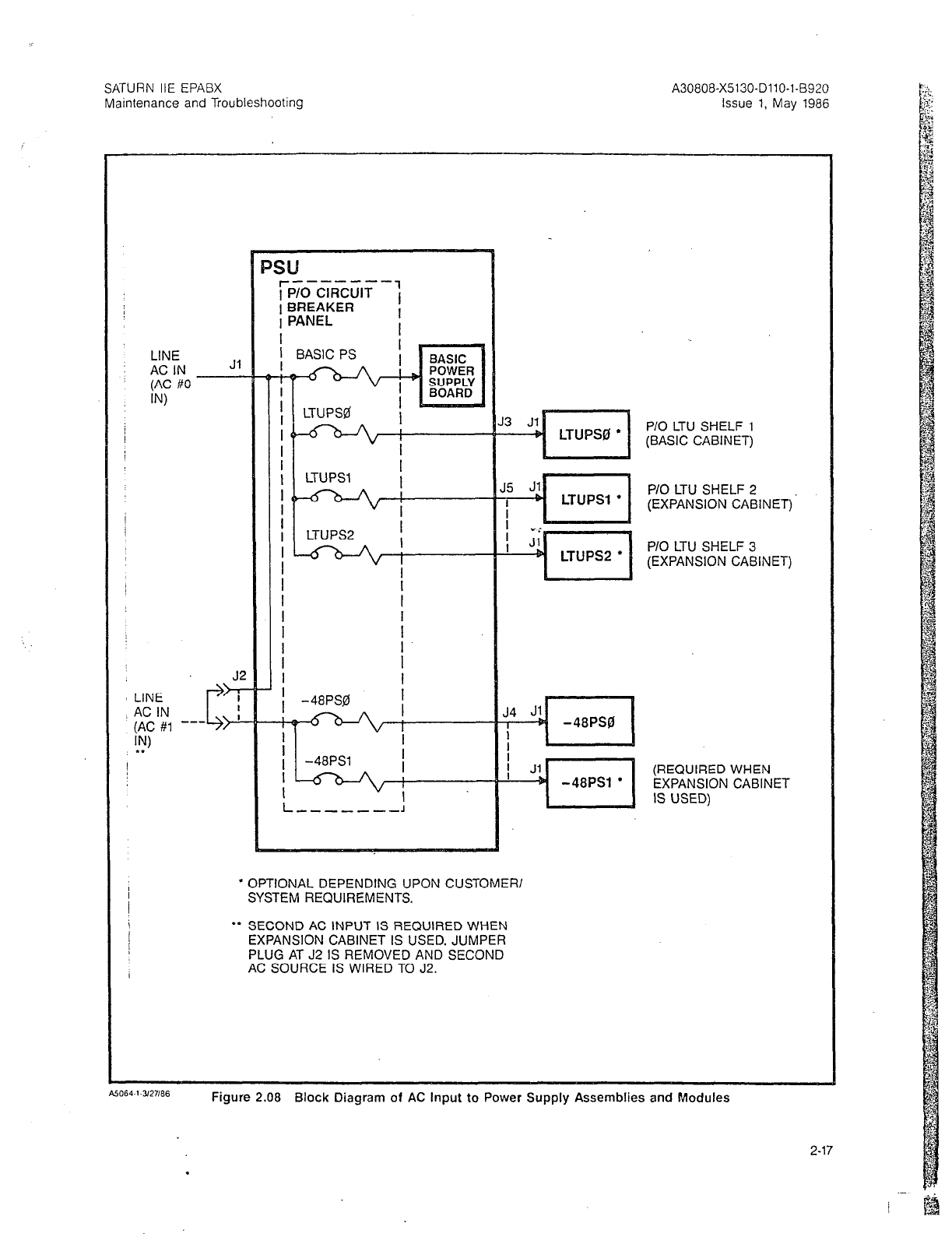
SATURN IIE EPABX
Maintenance and Troubleshooting
A30808-X5130-DllO-l-8920
Issue 1, May 1986
LINE
AC IN
(AC #O
IN
LINE
AC IN
(AC #1 --
W
l *
J5 s ,.I
LTUPSl
l
I
P/O LTU SHELF 2
(EXPANSION CABINET)
LTIlPS2
l I
P/O LTU SHELF 3
(EXPANSION CABINET)
P/O LTU SHELF 1
(BASIC CABINET)
/ Jl
+ -48PSl
l
l
OPTIONAL DEPENDING UPON CUSTOMER/
SYSTEM REQUIREMENTS.
l
* SECOND AC INPUT IS REQUIRED WHEN
EXPANSION CABINET IS USED. JUMPER
PLUG AT J2 IS REMOVED AND SECOND
AC SOURCE IS WIRED TO J2.
(REQUIRED WHEN
EXPANSION CABINET
IS USED)
Figure 2.08 Block Diagram of AC Input to Power Supply Assemblies and Modules
2-17
.
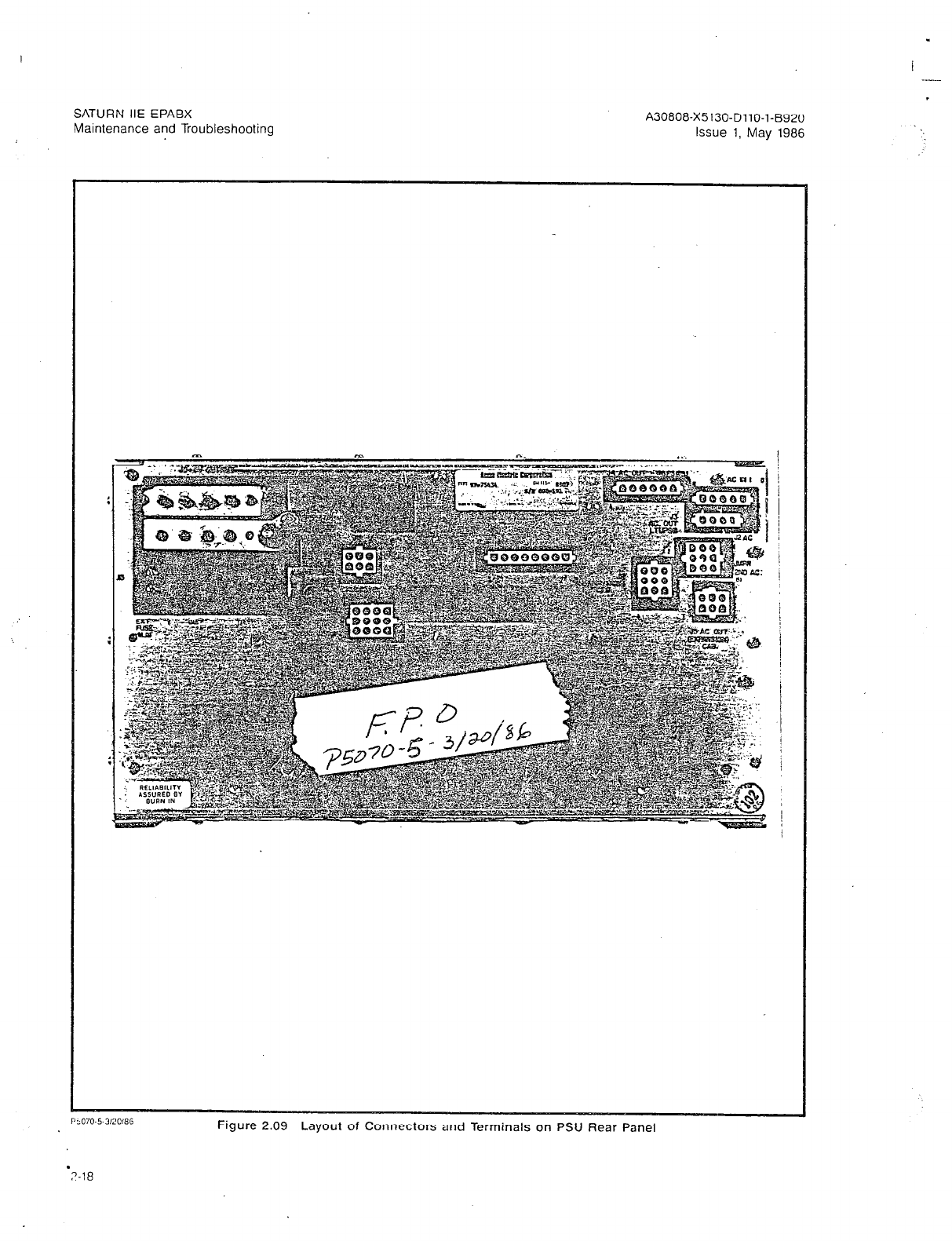
SATURN IIE EPABX
Maintenance and Troubleshooting A30808-X5130-DllO-l-8920
Issue 1, May 1986
Ftgure 2.09 Layout of Connectors and Terminals on PSU Rear Panel
.
7-18
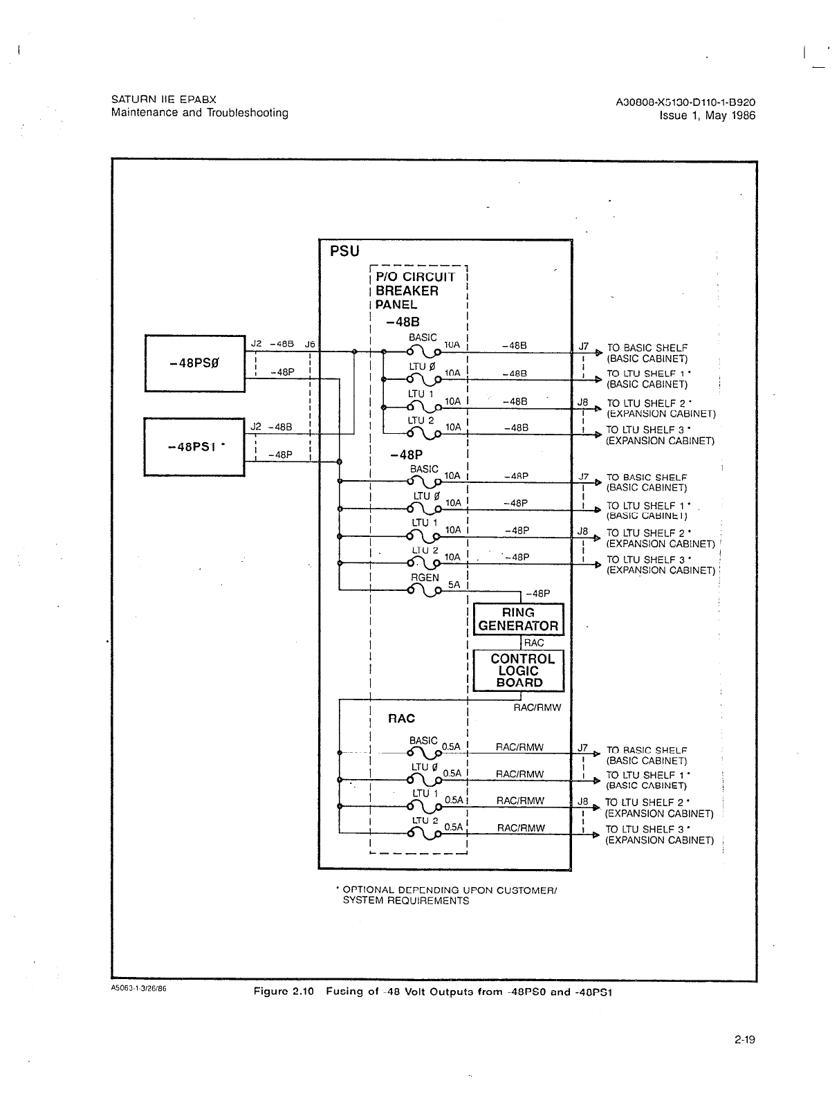
SATURN IIE EPABX
Maintenance and Troubleshooting A30808-X5130-DllO-l-8920
Issue 1, May 1986
PSU -mm----
rP/O CIRCUIT j
I BREAKER ,
* OPTIONAL DEPENDING UPON CUSTOMER/
SYSTEM RECIUIREMENTS
J& TO BASIC SHELF
I (BASIC CABINET)
b TO LTU SHELF
1 * :
(BASIC CABINET)
TO LTU SHELF 2 *
(EXPANSION CABINET)
& TO LTU SHELF 3 *
(EXPANSION CABINET)
J7 TO BASIC SHELF
I (BASIC CABINET)
&, TO LTU SHELF 1 *
(BASIC CABINET)
TO LTU SHELF 2 *
(EXPANSION CABINET)
& TO LTU SHELF 3 ’
;
(EXPANSION CABINET) !
!?+ TO BASIC SHELF
’ (BASIC CABINET)
& TO LTU SHELF 1 *
(BASIC CABINET) ;
J& TO LTU SHELF 2 *
I (EXPANSION CABINET)
& TO LTU SHELF 3 *
(EXPANSION CABINET)
Figure 2.10 Fusing of -48 Volt Outputs from -48PS0 and -48PSl
2-19
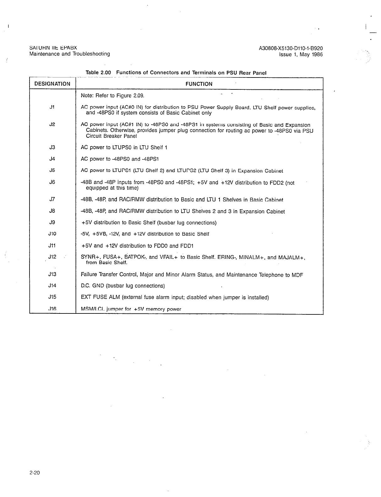
SATURN IIE EPABX
Maintenance and Troubleshooting
Table 2.00 Functions of Connectors and Terminals on PSU Rear Panel
DESIGNATION FUNCTION
Note: Refer to Figure 2.09. _ -
Jl AC power input (AC#O IN) for distribution to PSU Power Supply Board, LTU Shelf power supplies,
and -48PS0 if system consists of Basic Cabinet only
J2 AC power input (AC#l IN) to -48PS0 and -48PSl in systems consisting of Basic and Expansion
Cabinets. Otherwise, provides jumper plug connection for routing ac power to -48PS0 via PSU
Circuit Breaker Panel
J3
J4
J5
J6
AC power to LTUPSO in LTU Shelf 1
AC power to -48PS0 and -48PSl
AC power to LTUPSl (LTU Shelf 2) and LTUPS2 (LTU Shelf 3) in Expansion Cabinet
-488 and -48P inputs from -48PS0 and -48PSl; +5V and +12V distribution to FDDP (not
equipped at this time)
J7
J8
J9
JlO
Jll
J12
-488, -48R and RAClRMW distribution to Basic and LTU 1 Shelves in Basic Cabinet
-48B, -48P, and RAClRMW distribution to LTU Shelves 2 and 3 in Expansion Cabinet
+5V distribution to Basic Shelf (busbar lug connections)
-5V, +5VB, -12V, and +12V distribution to Basic Shelf
+5V and +12V distribution to FDDO and FDDl
SYNR+, FUSA+, BATPOK-, and VFAlLc to Basic Shelf. ERING-, MINALM+, and MAJALM+,
from Basic Shelf.
J13 Failure Transfer Control, Major and Minor Alarm Status, and Maintenance Telephone to MDF
J14 DC. GND (busbar lug connections)
J15 EXT FUSE ALM (external fuse alarm input; disabled when jumper is installed)
J16 MSMlLCL jumper for +5V memory power
I -
. .
2-20
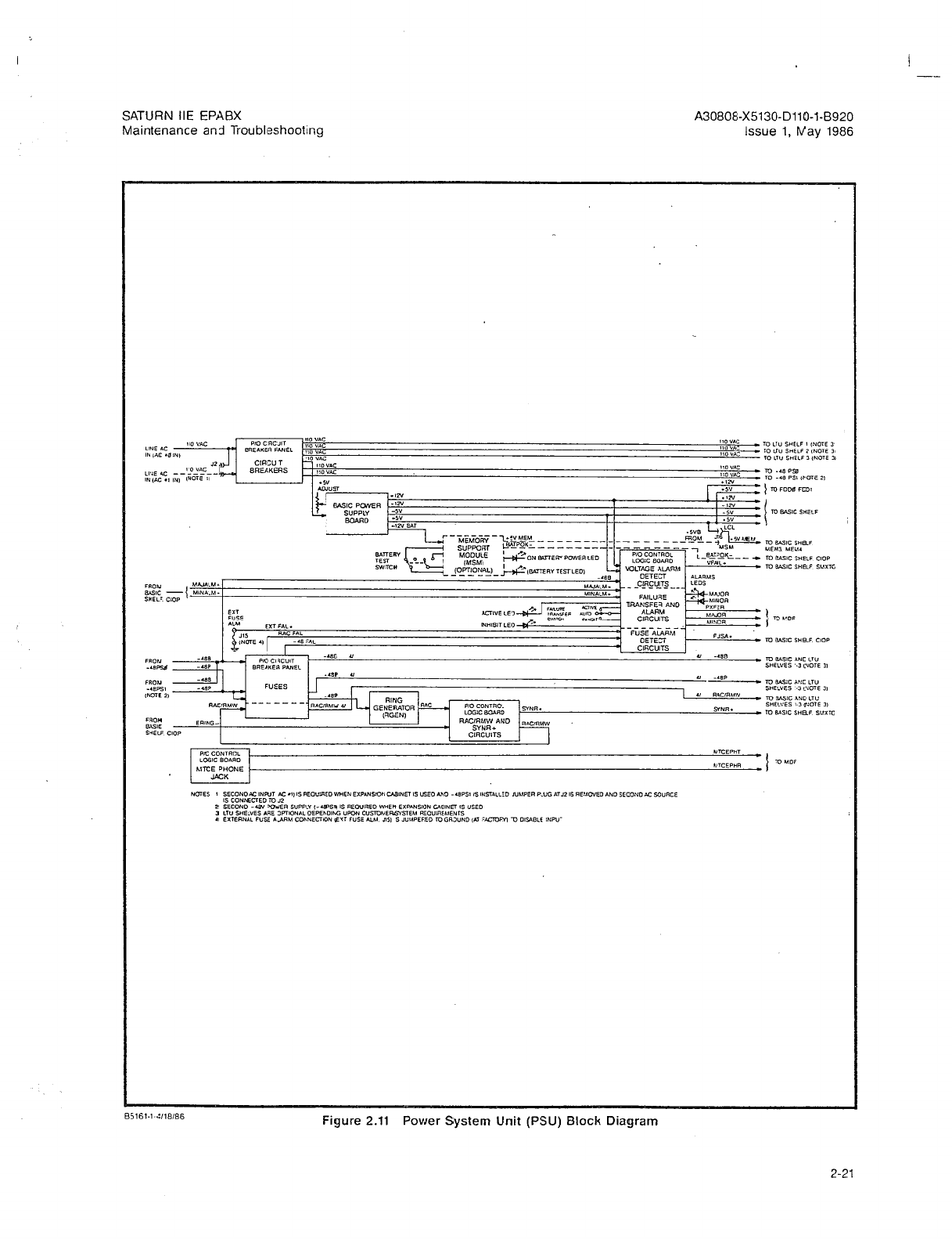
e
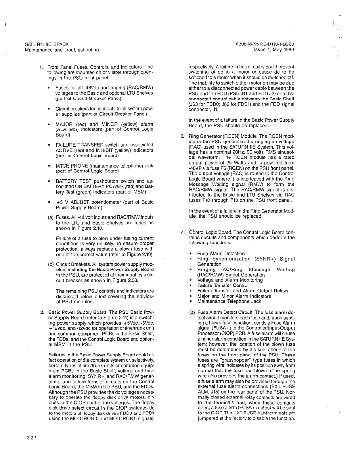
SATURN IIE EPABX
Maintenance and Troubleshooting
I -
A30808-X5130-DllO-l-6920
Issue 1, May 1986
1. Front Panel Fuses, Controls, and Indicators. The
following are mounted on or visible through open-
ings in the PSU front panel:
l
Fuses for all -48Vdc and ringing (RACIRMW)
voltages to the Basic and optional LTU Shelves
(part of Circuit Breaker Panel)
l
Circuit breakers for ac inputs to all system pow-
er supplies (part of Circuit Breaker Panel)
l
MAJOR (red) and MINOR (yellow) alarm
(ALARMS) indicators (part of Control Logic
Board)
l
FAILURE TRANSFER switch and associated
ACTIVE (red) and INHIBIT (yellow) indicators
(part of Control Logic Board)
l
MTCE PHONE (maintenance telephone) jack
(part of Control Logic Board)
0 BATTERY TEST pushbutton switch and as-
sociated ON BATTERY POWER (red) and Eat-
tery Test (green) indicators (part of MSM)
0 +5 V ADJUST potentiometer (part of Basic
Power Supply Board)
(a) Fuses. All -48 volt inputs and RAClRMW inputs
to the LTU and Basic Shelves are fused as
shown in Figure 2.10.
Failure of a fuse to blow under fusing current
conditions is very unlikely. To ensure proper
protection, always replace a blown fuse with
one of the correct value (refer to Figure 2.10).
(b) Circuit Breakers. All system power supply mod-
ules, including the Basic Power Supply Board
in the PSU, are protected at their input by a cir-
cuit breaker as shown in Figure 2.08.
The remaining PSU controls and indicators are
discussed below in text covering the individu-
al PSU modules.
2. Basic Power Supply Board. The PSU Basic Pow-
er Supply Board (refer to Figure 2.11) is a switch-
ing power supply which provides +SVdc, -5Vdc,
+12Vdc, and -12Vdc for operation of line/trunk unit
and common equipment PCBs in the Basic Shelf,
the FDDs, and the Control Logic Board and option-
al MSM in the PSU.
Failures in the Basic Power Supply Board could af-
fect operation of the complete system or, selectively,
certain types of line/trunk units or common equip-
ment PCBs in the Basic Shelf, voltage and fuse
alarm monitoring, SYNR+ and RAClRMW gener-
ating, and failure transfer circuits on the Control
Loaic Board. the MSM in the PSU. and the FDDs.
Altrhough the PSU provides the dc voltages neces-
sary to operate the floppy disk drive motors, cir-
cuits in the CIOP control the voltages. The floppy
disk drive select circuit in the CIOP switches dc
to the motors of floppy disk drives FDDO and FDDl
using the MOTORONO- and MOTORONI- signals,
respectively. A failure in this circuitry could prevent
switching of dc to a motor or cause dc to be
switched to a.motor when it should be switched off.
The inability to switch either motor on may be due
either to a disconnected power cable between the
PSU and the FDD (PSlJ.Jll and FDD J2) or a dis-
connected control cable-between the Basic Shelf
(J63 for FDDO; J62 for FDDl) and the FDD signal
connector, Jl.
In the event of a failure in the Basic Power Supply
Board, the PSU should be replaced.
3. Ring Generator (RGEN) Module. The RGEN mod-
ule in the PSU generates the ringing ac voltage
(RAC) used in the SATURN IIE System. This voi-
tage has a nominal 20H2, 90 volts RMS sinusoi-
dal waveform. The RGEN module has a rated
output power of 25 Watts and is powered from
-48VP via fuse F5 (RGEN) on the PSU front panel.
The output voltage (RAC) is routed to the Control
Logic Board where it is interleaved with the Ring
Message Waitinq signal (RMW) to form the
RAClRMW signal, The RA&RMW signal is dis-
tributed to the Basic and LTU Shelves via RAC
fuses FlO through F13 on the PSU front panel.
In the event of a failure in the Ring Generator Mod-
ule, the PSU should be replaced.
4. Cbntrol Logic Board. The Control Logic Board con-
tains circuits and components which perform the
following functions.
.
0
.
Fuse Alarm Detection
Ring Synchronization (SYNR+) Signal
Generation
Ringing AC/Ring Message Waiting
(RACIRMW) Signal Generation
Voltage and Alarm Monitoring
Failure Transfer Control
Failure Transfer and Alarm Output Relays
Major and Minor Alarm Indicators
Maintenance Telephone Jack
(a) Fuse Alarm Detect Circuit. The fuse alarm de-
tect circuit monitors each fuse and, upon sens-
ing a blown fuse condition, sends a Fuse Alarm
signal (FUSA+) to the Controller/Input-Output
Processor (CIOP) PCB. A fuse alarm will cause
a minor alarm condition in the SATURN IIE Sys-
tem; however, the location of the blown fuse
must be determined by a visual check of the
fuses on the front panel of the PSU. These
fuses are “grasshopper” type fuses in which
a spring wire indicates by its position away from
normal that the fuse has blown. (The spring
wire also provides the alarm contact.) If used,
a fuse alarm may also be provided through the
external fuse alarm connections (EXT FUSE
ALM, J15) on the rear panel of the PSU. Nor-
mally closed external relay contacts are wired
to the terminals and, when these contacts
open, a fuse alarm (FUSA+) output will be sent
to the CIOI? The EXT FUSE ALM terminals are
jumpered at the factory to disable the function.
2-22
SATURN IIE EPABX
Maintenance and Troubleshooting
A failure in the fuse alarm detect circuit may
cause spurious fuse alarm (FUSA+) signals or
prevent a fuse alarm signal, depending on the
nature of the fault. A spurious fuse alarm may
occur due to a disconnected cable from J12 of
the PSU module to the basic shelf as well as
a fault in the CIOP PCB.
If a fuse is blown but no fuse alarm is indicat-
ed, the fault could be in the fuse alarm detect
circuit in the PSU Control Logic Board or cir-
cuits in the CIOP PCB.
If the Fuse Alarm Detect Circuit on the Control
Logic Board fails, replace the PSU.
(b) Ring Synchronization Signal (SYNR+) Circuit.
The SYNR+ signal is used in the SLMA-0,
SLMA-S. and .%A16 PCBs to control the oper-
ation and release of the ring relays. The
SYNR+ sianal is routed from the PSU to the
SMXTG PCB in the Basic Shelf. It is buffered
in the SMXTG PCB and then distributed to
each line/trunk group on the Basic and
LTU
shelves. Loss of the SYNR+ signal will gener-
ate an alarm signal and light the ALMO LED
on the affected LTUC PCB. Refer to Table 4.03.
(c) Ringing AC/Ring Message Waiting
(RACIRMW) Signal Circuit. The RAC signal
from the PSU RGEN module and the ERING-
signal from the CIOP PCB are used in the
generation of the RAClRMW signal in the PSU
Control Logic Board.
The RAClRMW signal consists of 2-second in-
tervals of RAC signal interleaved with l-second
intervals of RMW signal. The transitions from
RAC to RMW and from RMW to RAC are con-
trolled by the ERING- signal.
The RAC signal is nominally 90 Vat RMS 20Hz
and the RMW signal is nominally 97 Vdc. The
RAClRMVV signal consists of two interleaved
phases as shown in Figure 2.12.
During the RAC signal intervals, telephones in
the ring mode will ring and the associated mes-
sage waiting lamps will flicker. During the RMW
signal intervals, telephones in the message
waiting mode will have their message waiting
lamps lighted steadily. The associated ringer
will not sound.
Thus telephones will ring with a 2 seconds on,
4 seconds off cadence and the message wait-
ing lamps will light with a 1 second on, 2 se-
conds off cadence.
Failure of the RAClRMW circuit on the Control
Logic Board may result in improper RAC or
RMW signals and/or improper timing of these
signals. Such faults may be detected audibty
and visually.
if the Ringing AC/Ring Message Waiting
(RAC/RMW) Circuit on the Control Logic Board
03
A30808-X5130-DllO-l-6920
lssue 1, May 1986
fails, replace the PSU.
Voltage and Alarm Monitoring Circuit. The vol-
tage and alarm monitoring circuit is provided
on the Control Logic Board in the PSU. The
+12Vdc and and -5Vdc outputs of the PSU Bas-
ic Power Supply Board and the -488 output vol-
tage from the -48PS module(s) are monitored
by the circuit. A loss of one or more of the three
voltages causes a voltage failure signal
(VFAIL+) to be sent to the SMXTG in the Bas-
ic Shelf and results in a minor alarm.
The +5Vdc, +5.2Vdc, and -12Vdc voltages are
not monitored. The reason for this is that a loss,
or low level, of the +5Vdc will affect operation
of all line/trunk unit PCBs on the Basic Shelf
and will cause generation of a PRESENCE ER-
ROR alarm from all of these PCBs to be record-
ed in the system’s failure history memory.
The toss, or low level, of +52Vdc on the Basic
Shelf will cause complete system failure.
(However, if an
MSM
module is installed, the
memory will be retained for at least 5 minutes.)
The -12Vdc is used on the DTMF and RAUP
modules. Therefore, a loss or low level of this
voltage on the LTU or Basic Shelves, will be
evidenced by misoperation of the RAUP PCB
on the Basic Shelf and the DTMF PCBs on
other shelves, as applicable.
If the Voltage and Alarm Monitoring Circuit on
the Control Logic Board fails, replace the PSU.
(e) Failure Transfer Control Circuit. With the
FAILURE TRANSFER mode select switch on
the front of the PSU set to the AUTO position,
an active MAJALM+ signal from the CIOP PCB
in the Basic shelf will initiate a failure transfer.
With the FAILURE TRANSFER mode select
switch in the ACTIVE position, failure transfer
is initiated regardless of the status of the moni-
tored voltages and MAJALM+ signal.
With the FAILURE TRANSFER mode select
switch in the INHIBIT position, failure transfer
is inhibited regardless of the status of the moni-
tored voltages and MAJALM+ signal.
If the Failure Transfer Control Circuit on the
Control Logic Board fails, replace the PSU.
(f) Failure Transfer and Alarm Output Relays.
Failure transfer/major alarm and minor alarm
relays in the PSU Control Logic Card have con-
tact sets connected to pins on connector J13
on the rear panel of the PSU.
Both relays are normally operated. Contact sets
of one of the relays are used to control remote
failure transfer (PXFER) and provide major
alarm (MAJOR) status. A contact set on the
other relay provides minor alarm (MINOR)
status.
I ,
-.
2-23
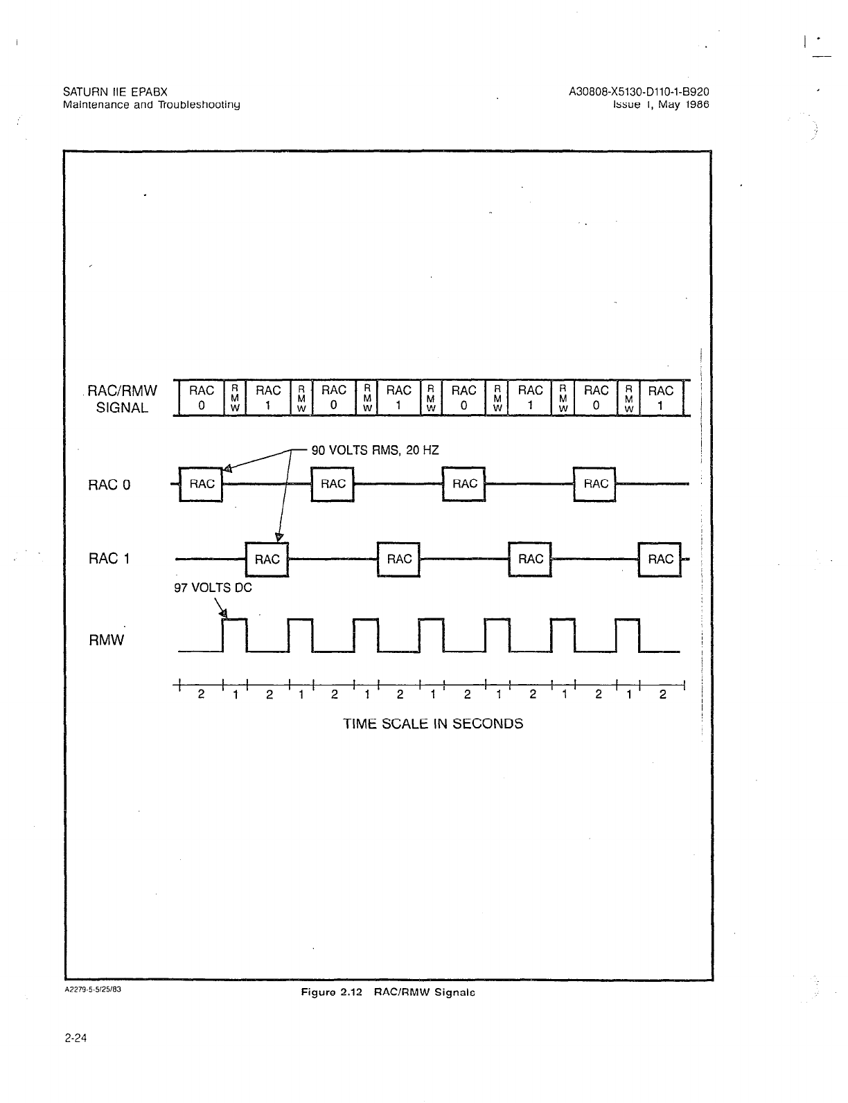
SATURN HE EPABX
Maintenance and Troubleshooting
RAC/RMW
SIGNAL
90 VOLTS RMS, 20 HZ
RAC 0
RAC 1
97 VOLTS DC
RMW.
TIME SCALE IN SECONDS
Figure 2.12 RAClRMW Signals
2-24

SATURN IIE EPABX A30808-X5130-DllO-l-8920
Maintenance and Troubleshooting issue 1, May 1986
Both normally closed and normally open con-
tact arrangements are provided for failure trans-
fer
and
.for major alarm and minor alarm
outputs to allow use of external equipment
responding to either arrangement. Connections
are normally made to the MDF for distribution
of the failure transfer, major alarm, and minor
alarm functions.
The relay contacts connected to J13 will give
an output status for the various combinations
of MAJALM+ and MINALM+ signals as shown
in Table 2.01.
If a fault is suspected in the Failure Transfer and
Alarm Output Relays on the Control Logic
Board, replace the PSU.
(g) Major and Minor Alarm Indicators. The MAJOR
and MINOR ALARMS indicators are visible
through openings in the PSU front panel and light
when MA.JALM+ and MlNALM+ signals are
received from the CIOP Table 2.02 shows alarm
indicator states for combinations of MAJALM+
and MINALM+ signals from the CIOP If an
alarm indicator is faulty, replace the PSU.
(h) Maintenance Telephone (MTCE PHONE) Jack.
A standard modular jack is accessible through
the front of the PSU for plug-in of a maintenance
telephone. The jack is connected to pins on con-
nector J13 on the PSU rear panel as indicated
in Table 2.01. Connector J13 is wired to the MDF
If the jack or interconnecting printed circuit or
PSU wiring is faulty, replace the PSU.
Table 2.01 Pin Functions at Connector 513 on the PSU
J13 PIN
1 Ring
26 Tip
2 Ring
27 Tip
3 Ring
28 Tip
31 Tip
4 Ring
29 Tip
PIN LEAD AND RELAY CONTACT STATUS
(Not Applicable)
(Not Applicable)
(Normally Open)
(Common)
(Normally Closed)
(Common)
(Normally Closed)
(Common)
(Normally Open)
FUNCTION
Maintenance Phone
Failure Transfer
Major Alarm
6 Tip (Normally Open)
5 Ring (Common) Minor Alarm
30 Tip (Normally Closed)
Note: The relay contact status shown in this table applies when both relays are not operated (in accordance with standard
convention). However, under normal system operating conditions, both relays are operated. Therefore, under normal
system operating conditions, the relay contacts are the reverse of those shown in this table.
Table 2.02 Alarm LEDs and Output Status at Connector J13 on the PSU
ALARM STATUS LED LIT OUTPUT STATUS (J13)
Neither MINALM+ nor None Normal
MAJALM + Active
MlNALM+ Only Active
MAJALM+ Only Active
Both MINALM+ and
MAJALM-t Active
MINOR only
MAJOR only
MAJOR only
Minor Alarm Only
Major Alarm, Failure Transfer
Major Alarm, Failure Transfer
2-25
SATURN IIE EPABX
Maintenance and TroubleshootIng
A30808-X5130-DllO-l-6920
Issue 1, May 1986
I -
5. Memory Support Module (MSM). The MSM is an
optional module which provides +SVdc (+5VB)
with internal battery back-up for the memory chips
in the memory (MEMS and MEM4) PCBs in the
common equipment section of the Basic Shelf. The
MSM contains a linear regulator and battery charg-
er, a battery, and sensing circuits to detect power
failure, battery overvoltage, and battery failure. Pro-
tection for output overvoltage, whether due to an
externally applied overvoltage or due to an inter-
nal fault, is provided by means of a crowbar and
output disconnect circuit. If the protection circuit
is activated, clear the fault condition and then
switch the BASIC PS circuit breaker on the PSU
off (down) and then on (up) again to restore the
+5VB output.
Upon removal of the fault condition causing exces-
sive output current, normal output capability is au-
tomatically restored.
The battery contained in the MSM is a standard
sealed plug-in assembly which may be removed
and replaced from the front of the Basic Cabinet
by removing the PSU front panel. A BATTERY
TEST switch and associated green LED are mount-
ed on the front of the MSM and are visible through
openings in the PSU front panel. A red LED (ON
BATTERY POWER) mounted on the front of the
MSM and also visible through the PSU front panel
indicates whether the memory integrated circuits
(ICs) in the memory PCBs are being powered from
the internal MSM battery.
b. -48Vdc Power Supply (-48PS0, -48PSl). The -48PS
module is a ferroresonant transformer power supply
which provides talking battery voltage (-48VB) and
oremium -48Vdc (-48VP) for the Basic and LTV Shelves.
ihe -48VP outpui is used for powering the RGEN mod-
ule (in the PSU) and the SDTs and attendant consoles
via SLMD and PIMD PCBs, respectively. The -48Vf3
output is derived from the -48VP voltage, after addi-
tional filtering, and is used for talk battery to the SLMA-
0, SLMA-S, and SLA16 modules.
Because of its ferroresonant transformer design, the
-48PS has inherent output voltage limiting and is capa-
ble of supplying a considerable output current over-
load without damage (although the output voltage will
decrease). It contains a thermal cut-off switch to pro-
tect against overheating due to excessive output cur-
rent overload or an internal fault. This thermal cut-off
switch will operate and remove power from the power
supply if the ferroresonant transformer overheats. Shut-
down due to an overvoltage condition causes the power
supply output to latch off. To unlatch the power supply
output and resume normal operation, clear the fault
condition and set the associated input circuit breaker
(-48PS0 or -48PS1, located on the PSU front panel) to
off (down) and then on (up) again. This unlatches the
protection mode and allows the power supply to re-
sume normal operation.
One or two -48PS modules may be installed, depend-
ing upon system size and cabinet configuration. A sys-
tem consisting of only a Basic Cabinet requires only
one -48PS module; a system using both a Basic and
an Expansion Cabinet requires two. When two -48PS
modules are installed, the -48VB and -48VP outputs
of the power supplies are paralleled in the PSU.
Whether one or two power supply modules are used,
the outpuis are distributed, via fuses on the PSU front
panel, to the Basic and LTU Shelves. The -48VP (-48P)
outputs are distributed to the shelves via fuses Fl
throuah F4. The RGEN module in the PSU is also ao-
werei by a -48VP output through fuse F5. The -48’VB
(-488) outputs are distributed to the shelves via fuses
F6 through F9.
If a fault condition in a -48Vdc Power Supply cannot
be cleared, replace the power supply.
c. Line/Trunk Unit Power Supply (LTUPS). The LTUPS is
the standard power supply used to power the LTU shelf.
It has four outputs: +SVdc, -5Vdc, +12Vdc, and -12Vdc.
All LTUPS outputs have overvoltage, overcurrent, and
short-circuit protection.
An overvoltage at any output, whether due to an inter-
nal failure or an external bridging of a high voltage to
a lower voltage output, will result in shut-down of the
power supply and cause all outputs to drop to approx-
imately zero volts. An overcurrent or short-circuit at any
output will cause that output to go into current limit-
ing. Shut-down due to an overvoltage condition causes
the power supply output to latch off. To unlatch the pow-
er supply output and restore normal operation, the as-
sociated input circuit breaker (LTUPSO, LTUPSl, or
LTUPS2, located on the PSU front panel) must be set
to off (down) and then on (up) again. This unlatches
the protection mode and allows the power supply to
resume normal operation.
The power supplies are designed to automatically restore
to normal operation when an output overcurrent or short-
circuit condition is cleared. Note that an output fault
should not normally trip an input circuit breaker.
The power supplies are further protected against in-
ternal faults by internal fuses and a thermal cut-off
switch. The internal fuses, located in the input circuitry,
will blow under certain internal fault conditions to pro-
tect against the propagation of further fault conditions.
The thermal cut-off switch will operate if the internal
fault conditions cause overheating in the power sup-
ply. Operation of this switch will cause the power sup-
ply to go into the same protective mode as an
overvoltage condition.
Internal fault conditions which cause an increase in
the input current to the trip point of the input circuit
breaker will normally trip the circuit breaker. However,
if the circuit breaker is faulty and does not trip, the in-
ternal fuses and thermal cut-off switch will provide a
degree of backup protection. If an internal fuse blows,
replacement of the power supply is required.
The -12Vdc output of the LTUPS is used only in DTMF
PCBs. A loss of this output or a deviation below the
normal operating limit will be evidenced only by im-
proper operation of the DTMF PCBs.
If a fault condition in an LTUPS cannot be cleared,
replace the power supply.
2-X (26 pages)

I -
SATURN IIE EPAEX
Maintenance and Troubleshooting
A30808-X5130-DllO-l-6920
Issue 1, May 1986
SECTION 3.00 PREVENTIVE MAINTENANCE
3.01 General. The following general-type service routines
are suggested for proper upkeep of the SATURN IIE EPASX.
The service routines should be performed on an annual ba-
sis unless otherwise specified.
a. Hardware and Cabling. Check for general mechani-
cal integrity, no loose or broken parts and connectors.
Tighten or repair as necessary.
b. Cabinet Exterior. Clean exterior of cabinet usina a soft
cloth dampened with a solution of water and-a mild
detergent.
c. Air Vents. Inspect air vents at top and bottom of cabi-
net for unrestricted air passage. Clear vents as
necessary.
3.02 Floppy Disk Drives. Some manufacturers of floppy
disk drives recommend periodic cleaning of the disk drive
heads. The schedule of cleaning depends on usage and the
surrounding environment but cleaning every 3 to 6 months
is normally suggested. Use the head cleaning kit recommend-
ed bv the manufacturer of the disk drives and follow the oroce-
dureoutlined in Table 3.00 to clean the heads. ’
Table 3.00 Floppy Disk Head Cleaning Procedure
STEP PROCEDURE VERIFICATION
1 Open the doors on both floppy disk drives.
2 Replace one program disk with the cleaning disk; close
that disk drive door (leave other door open).
3 Access any CMU procedure from the service terminal System attempts to locate a CMU overlay file; red LED
(e.g., DISPLAY STNASSN). on disk drive lights.
NOTE:
An 110 error message appears at service terminal. This
is normal. However, if the CMU procedure already resides
in system memory, repeat step 3 for different CMU
procedure.
4 Repeat the above procedure for the second floppy disk
drive.
3-1 (3-2 blank)
I -
SATURN IIE EPABX A30808-X5130-DllO-l-8920
Maintenance and Troubleshooting Issue 1, May 1986
SECTION 4.00 TROUBLESHOOTING AND REWUR PROCEDURES
4.01 General. This section of the practice provides step-by-
step instructions for the troubleshooting and repair of mal-
functions or failures during precutover or postcutover of the
SATURN IIE EPABX. WARNING
Hazardous voltages exist wirhin the equipment cabinet.
Be extremely careful when performing maintenance and
troubleshooting procedures wirh the equipment panel(s)
removed.
4.02 Test Equipment. The following test equipment is re-
quired to perform the procedures contained in this practice.
a. Digital Voltmeter. A digital voltmeter of good commer-
cial quality with an accuracy of + 0.1%. The digital volt-
meter is used to perform input and output voltage tests.
b. Maintenance Test Phone. A test set or a single-line tele-
phone may be used as a maintenance test phone for
both Dial Pulse (DP) and Dual Tone Multifrequency
fDTMF1 svstems. A modular iack (MTCE PHONE) is
brovided on the front panel ofthe $SU for connectjng
the maintenance test phone when it is equipped with
a modular plug. When the maintenance test phone is
not equipped with a modular plug, a station appear-
ance at the MDF can be used for test connections. The
maintenance test phone is used to perform the manu-
al on-line diagnostic tests.
c. Data Service Terminal. A Keyboard-Send-Receive
(KSR) data terminal equipped with a standard ASCII
keyboard and an EIA RS-232-C interface (Silent 700
Series - Model 743 KSR - Texas Instruments, or
equivalent). The data service terminal is used to ac-
cess CMU procedures, a repertoire of auditing routines
and the failure history memory.
d. Transmission Measuring Set. A Transmission Measur-
ing Set (TMS) is used to measure the transmission
quality of a trunk or station. Refer to the manual on-
line diagnostic tests, Outgoing Trunk Test and Station
Line Tests.
4.03 PCB and Power Supply Removal and Replacement.
In many instances during troubleshooting, corrective actions
may require that a suspected faulty PCB or power supply be
removed and replaced with a spare. The following guidelines
should be followed when removing and replacing these items.
CAUTION
Craft personnel handling PCBs with MOS integrated cir- *
cuirs must first free themselves from electrostatic dis-
charge by touching the cabinet chassis ground or wearing
grounded wrist straps. Failure to observe this practice will
result in damage to such PCBs due to electrostatic dis-
charge.
a. Refer to Table 4.00 before removing a PCB or power
supply.
b. Before inserting a PCB or installing a power supply,
verify (when applicable) that correct strapping options
are installed. (Refer to Siemens SATURN IIE Practice
covering Installation Procedures.)
4.04 System Fails to Reload. During normal system oper-
ation, the upper four red LEDs (STO, STl, ST2, and ST3) on
the CIOP PCB (Figure 2.02) provide a binary display that cons-
tantly decrements.
When processor initialization is requested, either manually
via depression of the Reset switch on the CIOP PCB or auto-
matically via self-test or audit test routines, all four indicators
momentarily light steadily. As various initialization events are
completed, the binary value of the four indicators are
decremented. If no failures occur during system initialization,
all four indicators momentarily extinguish then begin a con-
tinuous decrement sequence indicating normal system oper-
ation. If a failure is encountered during the initialization period:
the four LED indicators momentarily stop decrementing and
display a binary value that represents the point at which the
initialization failed. The corrective repair procedure for the in-
dicated binary value is provided in Table 4.01. Note that the
failure indication is displayed only for a short period of time
(approximately 1 second); after which the system attempts to
reinitialize. This cycle is ‘repeated until the failure is corrected.
4.05 Alarm Conditions and Reporting. The SATURN IIE
System is provided with software self-test routines and audit
test routines which constantly check for system failures. When
a failure or failures occur, the detected failure(s) are record-
ed as error messages in the failure history memory and the
appropriate major or minor alarm indicator is lighted. A
description of each alarm type is provided in Section 2.00,
Maintenance Overview. The corrective action required for a
given alarm type is provided in Table 4.02 (Alarm Reporting
and Processing).
4-l
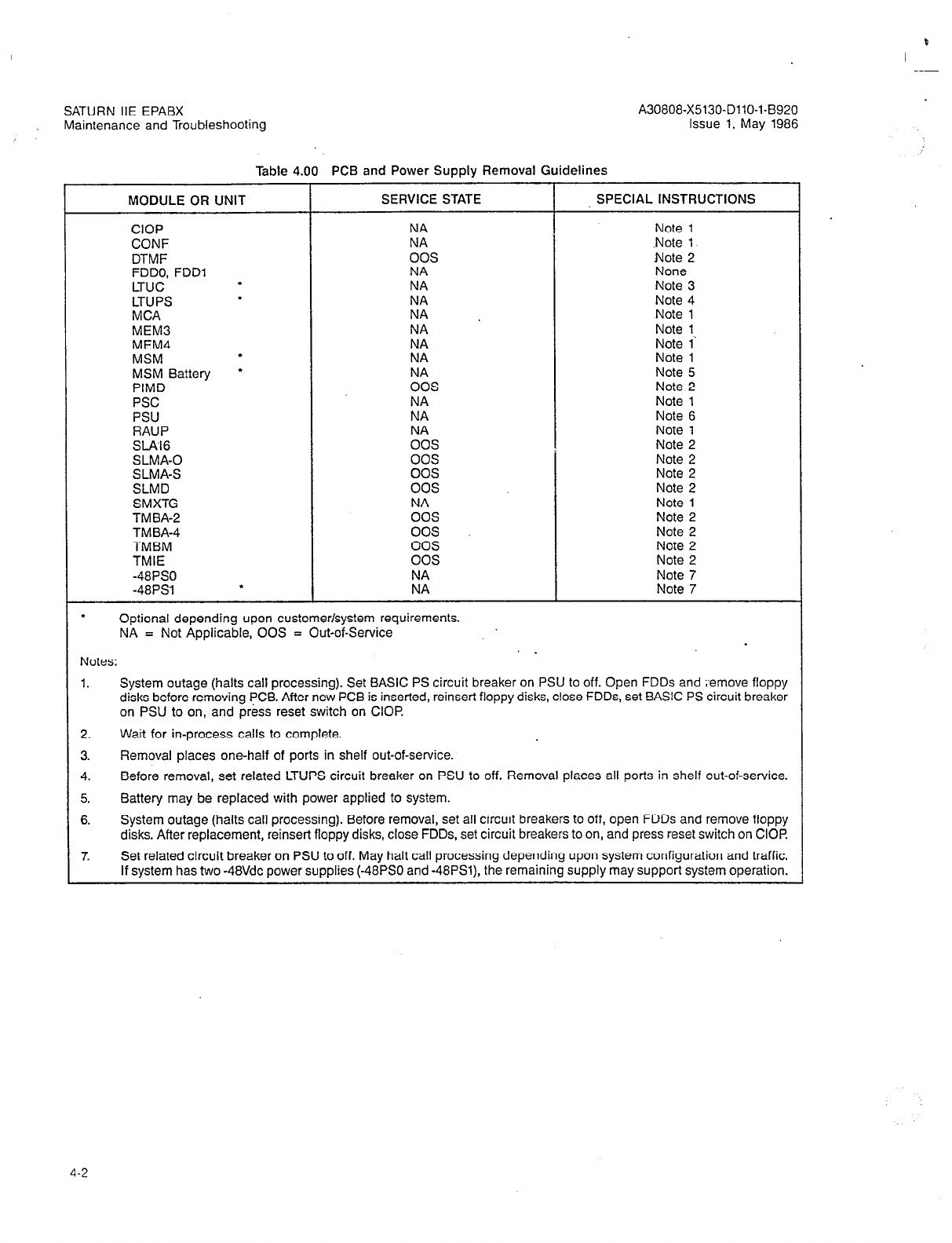
P
SATURN IIE EPABX A30808-X5130-DllO-l-8920
Maintenance and Troubleshooting Issue 1, May 1986
Table 4.00 PCB and Power Supply Removal Guidelines
MODULE OR UNIT SERVICE STATE SPECIAL INSTRUCTIONS
CIOP NA
CONF NA
DTMF 00s
FDDO, FDDl NA
LTUC . NA
LTUPS
l
NA
MCA NA
MEM3 NA
MEM4 NA
MSM . NA
MSM Battery
l
ES
PIMD
PSC
PSU K
RAUP NA
SlAl6 00s
SLMA-0 00s
SLMA-S 00s
SLMD 00s
SMXTG NA
TM BA-2 00s
TMBA-4 00s
TMBM 00s
TMIE 00s
-48PS0 NA
-48PSl . NA
. Optional depending upon customer/system requirements.
NA = Not Applicable, 00s = Out-of-Service
Notes: .
Note 1
.Note 1
Note 2
None
Note 3
Note 4
Note 1
Note 1
Note 1
Note 1
Note 5
Note 2
Note 1
Note 6
Note 1
Note 2
Note 2
Note 2
Note 2
Note 1
Note 2
Note 2
Note 2
Note 2
Note 7
Note 7
1.
2.
3.
4.
5.
6.
7.
System outage (halts call processing). Set BASIC PS circuit breaker on PSU to off. Open FDDs and ;‘emove floppy
disks before removing PCB. After new PCB is inserted, reinsert floppy disks, close FDDs, set BASIC PS circuit breaker
on PSU to on, and press reset switch on CIOP
Wait for in-process calls to complete.
Removal places one-half of ports in shelf out-of-service.
Before removal, set related LTUPS circuit breaker on PSU to off. Removal places all ports in shelf out-of-service.
Battery may be replaced with power applied to system.
System outage (halts call processing). Before removal, set all circuit breakers to off, open FDDs and remove floppy
disks. After replacement, reinsert floppy disks, close FDDs, set circuit breakers to on, and press reset switch on CIOF!
Set related circuit breaker on PSU to off. May halt call processing depending upon system configuration and traffic.
If system has two -48Vdc power supplies (-48PS0 and -48PSl), the remaining supply may support system operation.
4-2
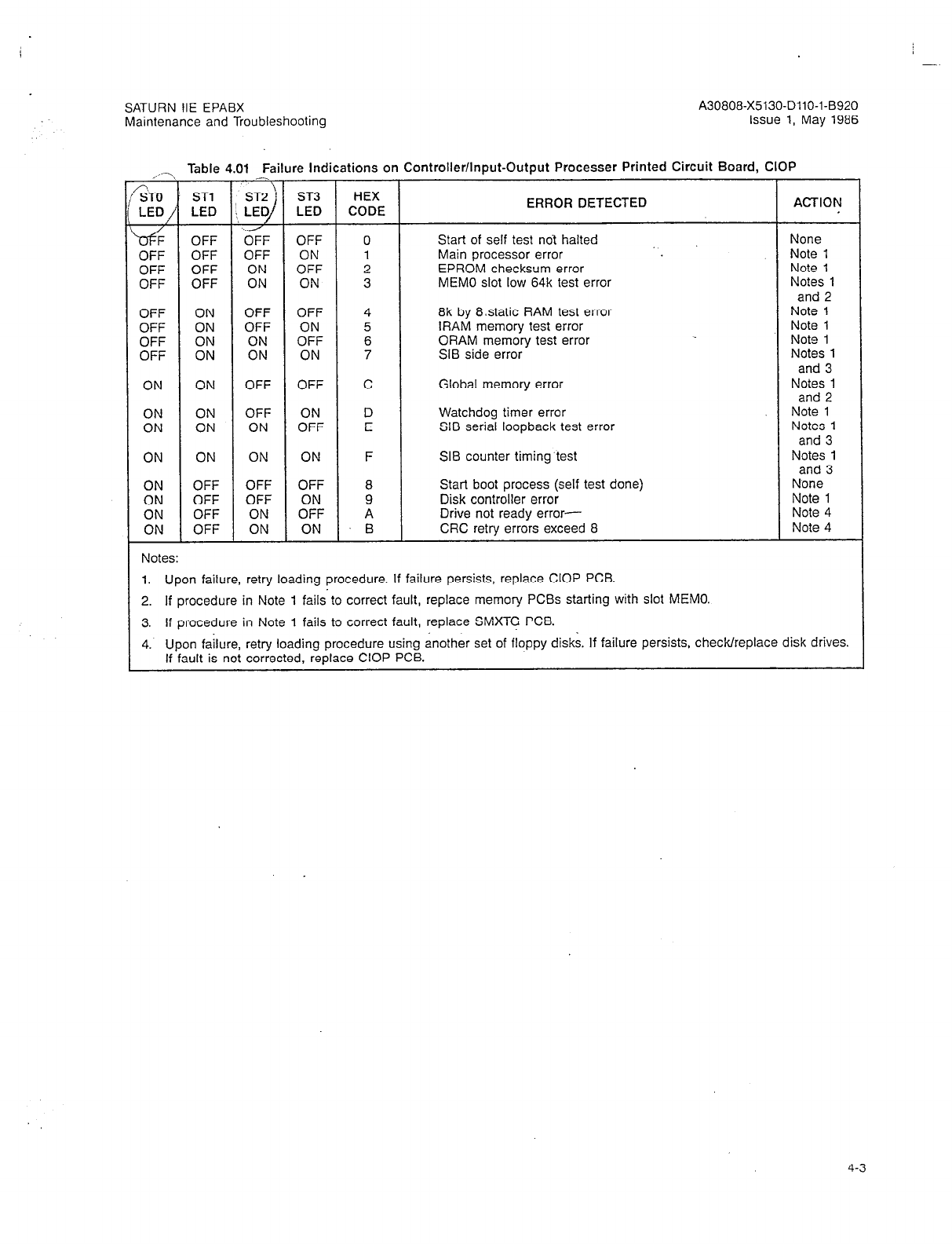
-
SATURN IIE EPABX
Maintenance and Troubleshooting
A30808-X5130-DllO-l-8920
Issue 1, May 1986
,,- Table 4.01 Failure Indications on Controller/Input-Output Processer Printed Circuit Board, CIOP
ZTO ’ ST1 \
ST2 ’ ST3 HEX
LED /’ LED 3, LED LED CODE ERROR DETECTED ACTION
/
OFF OFF OFF 0
Start of self test noi halted None
OFF OFF ON 1 Main processor error Note 1
OFF OFF OFF
:: ON 2 EPROM checksum error Note 1
OFF OFF 3 MEMO slot low 64k test error Notes 1
and 2
OFF ON OFF OFF 4 8k by 8static RAM test error Note 1
OFF ON OFF 5 lRAM memory test error Note 1
OFF ON ON 09°F 6 ORAM memory test error Note 1
OFF ON ON ON 7 SIB side error Notes 1
and 3
ON ON OFF OFF C Global memory error Notes 1
and 2
ON ON OFF D Watchdog timer error Note 1
ON ON ON 09°F E SIB serial loopback test error Notes 1
and 3
ON ON ON ON F SIB counter timing test Notes 1
and 3
ON OFF OFF OFF 8 Start boot process (self test done) None
ON OFF OFF ON 9 Disk controller error Note 1
ON OFF ON OFF A Drive not ready error- Note 4
ON OFF ON ON B CRC retry errors exceed 8 Note 4
Notes:
1. Upon failure, retry loading procedure. If failure persists, replace CIOP PCB.
2. If procedure in Note 1 failato correct fault, replace memory PCBs starting with slot MEMO.
3. If procedure in Note 1 fails to correct fault, replace SMXTG PCB
4. Upon failure, retry loading procedure using another set of floppy disks. If failure persists, check/replace disk drives.
If fault is not corrected, replace CIOP PCB.
4-3

SATURN IIE EPABX A30808-X5130-DllO-l-8920
Maintenance and Troubleshooting issue 1. May 1986
Table 4.02 Alarm Reporting and Processing
ALARM TYPE CORRECTIVE ACTION
a. AUDIT eeee(pp) aaaa bbbb
cccc dddd mm/dd hh:mm
eeee = error number
(PP)’ = ID of process
aaaa’ = error information
bbbb’ = error information
cccc* = error information
dddd’ = error information
mm/dd = date of error
hh:mm = time of error
(1) If eeee = 1428 The memory contents audit routine has detected a check-
sum error in protected memory.
A system reload is automatically initiated.
If the system appears to be performing correctly with the
exception of this error, craft personnel can disable the
memory contents audit routine until the cause can be iso-
lated by a systematic replacement of memory PCBs to iso-
late the failing PCB.
If the memory contents audit routine is disabled, craft per-
sonnel should avoid saving customer data to the disk, since
this operation could corrupt the disk as well.
(2) If eeee = 1433 DTMF receiver unusable.
The DTMF receiver audit routine has detected a failing DTMF
receiver. If no DTMF receivers are already out-of-service, the
suspected DTMF receiver is placed in the out-of-service craft
state. If one or more DTMF receivers are already out-of-
service, the suspected DTMF receiver is left in-service.
NOTE: Out-of-service craft state means that the system has
automatically placed the circuit in such a state and requires
craft personnel to manually return it to an in-service state.
If the problem is repetitive, replace the associated DTMF
PCB during a low-traffic period, taking care to place all cir-
cuits in the PCB out-of-service (craft) before removing it.
NOTE: The PEN of the suspected DTMF receiver is identi-
fied as indicated in the error message below.
“AUDIT 1433(18) wxyz 0000
0000 0000 hhldd hh:mm”
wxyz = PEN
(3) If eeee = 1438 l/O peripheral device or PCB failure.
The I/O loop around audit routine has detected a failed l/O
device or associated PCB. If the problem is repetitive, repair
or replace the failing device or replace the associated I/O
PCB (CIOP or RAUP).
* = For Siemens field service use only.
NOTE: The identity of the failing device or l/O PCB is indi-
cated in the error message below.
“AUDIT 1438(18) OOaa OObb
0000 0000 mm/dd hh:mm”
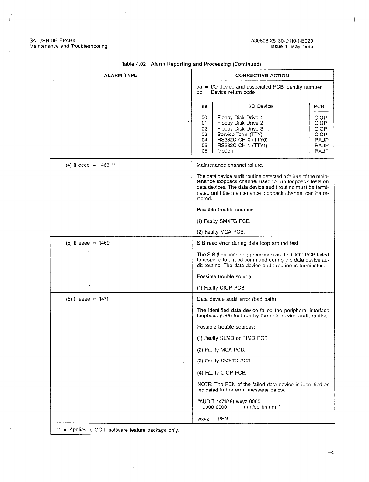
I -
SATURN IIE EPABX A30808-X5130-DllO-l-8920
Maintenance and Troubleshooting Issue 1, May 1986
Table 4.02 Alarm Reporting and Processing (Continued)
ALARM TYPE CORRECTIVE ACTION
aa = l/O device and associated PCB identity number
bb = Device return code
(4) If eeee = 1468
l
*
aa I/O Device PCB
00 Floppy Disk Drive 1 CIOP
01 Floppy Disk Drive 2 CIOP
02 Floppy Disk Drive 3 _ CIOP
03 Service Term’l(TTY) CIOP
04 RS232C CH 0 (TTYO) RAUP
05 RS232C CH 1 (TTYl) RAUP
06 Modem RAUP
Maintenance channel failure.
The data device audit routine detected a failure of the main-
tenance loopback channel used to run loopback tests on
data devices. The data device audit routine must be termi-
nated until the maintenance loopback channel can be re-
stored.
Possible trouble sources:
(5) ff eeee = 1469
_
(1) Faulty SMXTG PCB.
(2) Faulty MCA PCB.
SIB ;ead error during data loop around test.
The SIB (line scanning processor) on the CIOP PCB failed
to respond to a read command during the data device au-
dit routine. The data device audit routine is terminated.
Possible trouble source:
(1) Faulty CIOP PCB.
(6) If eeee = 1471 Data device audit error (bad path).
The identified data device failed the periphera! interface
loopback (LB5) test run by the data device audit routine.
Possible trouble sources:
(1) Faulty SLMD or PIMD PCB.
(2) Faulty MCA PCB.
(3) Faulty SMXTG PCB.
(4) Faulty CIOP PCB.
NOTE: The PEN of the failed data device is identified as
indicated in the error message below.
‘AUDIT 1471(18) wxyz 0000
0000 0000 mm/dd hh:mm”
wxyz = PEN
f. = Applies to OC II software feature package only.
4-5
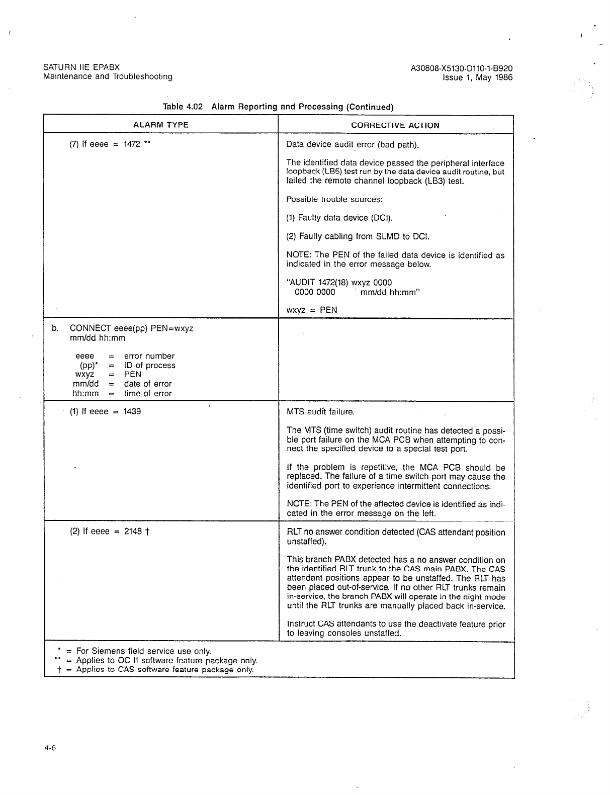
SATURN IIE EPABX A30808-X5130-DllO-l-8920
Maintenance and Troubleshooting Issue 1, May 1986
Table 4.02 Alarm Reporting and Processing (Continued)
ALARM TYPE
(7) If eeee = 1472 **
CORRECTIVE ACTION
Data device audit error (bad path).
The identified data device passed the peripheral interface
loopback (LB5) test run by the data device audit routine, but
failed the remote channel loopback (LB3) test.
Possible trouble sources:
(1) Faulty data device (DCI).
(2) Faulty cabling from SLMD to DCI.
NOTE: The PEN of the failed data device is identified as
indicated in the error message below.
“AUDIT 1472(18) wxyz 0000
0000 0000 mm/dd hh:mm”
wxyz = PEN
. CONNECT eeee(pp) PEN=wxyz
mm/dd hh:mm
eeee = error number
(PP)’ = ID of process
wxyz = PEN
mm/dd = date of error
hh:mm = time of error
(1) If eeee = 1439 MTS audit failure.
The MTS (time switch) audit routine has detected a possi-
ble port failure on the MCA PCB when attempting to con-
nect the specified device to a special test port.
If the problem is repetitive, the MCA PCB should be
replaced. The failure of a time switch port may cause the
identified port to experience intermittent connections.
NOTE: The PEN of the affected device is identified as indi-
cated in the error message on the left.
(2) If eeee = 2148 t RLT no answer condition detected (CAS attendant position
unstaffed).
This branch PABX detected has a no answer condition on
the identified RLT trunk to the CAS main PABX. The CAS
attendant positions appear to be unstaffed. The RLT has
been placed out-of-service. If no other RLT trunks remain
in-service, the branch PABX will operate in the night mode
until the RLT trunks are manually placed back in-service.
Instruct CAS attendants to use the deactivate feature prior
to leaving consoles unstaffed.
’ = For Siemens field service use only.
l *
= Applies to OC II software feature package only.
T = Applies to CAS software feature package only.
4-6
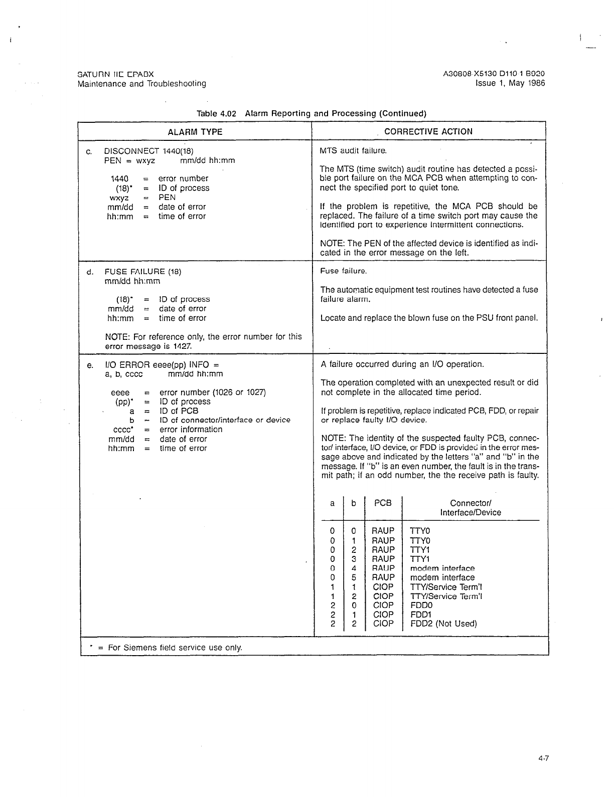
SATURN IIE EPABX
Maintenance and Troubleshooting
Table 4.02 Alarm Reporting and Processing (Continued)
ALARM TYPE
c. DISCONNECT 1440(18)
PEN = wxyz mm/dd hh:mm
1440 = error number
WY
= ID of process
wxyz = PEN
mm/dd = date of error
hh:mm = time of error
CORRECTIVE ACTION
MTS audit failure.
The MIS (time switch) audit routine has detected a possi-
ble port failure on the MCA PCB when attempting to con-
nect the specified port to quiet tone.
If the problem is repetitive, the MCA PCB should be
replaced. The failure of a time switch port may cause the
identified port to experience intermittent connections.
NOTE: The PEN of the affected device is identified as indi-
cated in the error message on the left.
d. FUSE FAILURE (18)
mm/dd hh:mm
Fuse failure.
(18)’
= ID of process
mm/dd = date of error
hh:mm = time of error
NOTE: For reference only, the error number for this
error message is 1427.
The automatic equipment test routines have detected a fuse
failure alarm.
Locate and replace the blown fuse on the PSU front panel.
e. l/O ERROR eeee(pp) INFO = A failure occurred during an l/O operation.
a, b, cccc mm/dd hh:mm The operation completed with an unexpected result or did
eeee = error number (1026 or 1027) not complete in the allocated time period.
(PP)’ = ID of process
a = ID of PCB If problem is repetitive, replace indicated PCB, FDD, or repair
b = ID of connector/interface or device or replace faulty 110 device.
cccc” = error information
mm/dd = date of error NOTE: The identity of the suspected faulty PCB, connec-
hh:mm = time of error tar/ interface, l/O device, or FDD is provided in the error mes-
sage above and indicated by the letters “a” and “b” in the
message. If “b” is an even number, the fault is in the trans-
mit path; if an odd number, the the receive path is faulty.
a b PCB Connector/
Interface/Device
0 0 RAUP TTY0
0 1 RAUP TTY0
0 2 RAUP n-Y1
0 3 RAUP TTY1
0 4 RAUP modem interface
0 5 RAUP modem interface
1 1 CIOP TTY/Service Term’1
1 2 CIOP TTY/Service Term?
2 0 CIOP FDDO
2 1 CIOP FDDl
2 2 CIOP FDD2 (Not Used)
* = For Siemens field service use only.
4-7
Table 4.02 Alarm Reporting and Processing (Continued)
ALARM TYPE CORRECTIVE ACTION
f. LTU FAILURE (18) PEN’S LTU (or Basic Shelf) clock failure error.
aaaa TO bbbb mm/dd hh:mm The identified shelf and LTUC (where applicable) has lost
(W’ = ID of process communication with the CE. The error may be a result of
aaaa = 1st number in range of PENS affected the following:
by failure
bbbb = last number in range of PENS affect- (1) Blown shelf fuse on the PSU front panel.
ed by failure
mm/dd = date of error (2) A faulty LTU shelf power supply, LTUPS.
hh:mm = time of error (3) A faulty LTUC PCB.
NOTE: For reference only, the error number of this
error message is 1424. (4) Loss of critical signals (CKA, SYP, or SYNR) from the CE
as a result of an SMXTG PCB or other failure.
NOTE: The PEN range in the error message identifies the
shelf and PCB experiencing faults. The following table corre-
lates each possible PEN range to a specific shelf and sus-
pected faulty PCB. The associated LTU clock is indicated
in the fourth column. (Refer also to Table 4.03 for LTUC PCB
alarm information.)
aaaa bbbb SHELF PCB LTU
(PEN Range) CLK
0000 0267 Basic SMXTG 0
0300 0637 Basic SMXTG 1
1000 1337 LTU 1 LTUC 0 2
1400 1737 LTU 1 LTUC 1 3
2000 2337 LTU 2 LTUC 0 4
2400 2737 LTU 2 LTUC 1. 5
3000 3337 LTU 3 LTUC 0 6
3400 3737 LTU 3 LTUC 1 7
NOTE: If replacement of the indicated LTUC fails to correct
the fault condition, replace the SMXTG PCB.
9 MBUS T/O (pp) Multibus timeout error.
LOC=aaaa:bbbb mm/dd hh:mm Memory failed to respond to a data request from the main
(PP)’ = ID of process processor. If problem is repetitive, consult Siemens field
aaaa: service representative.
bbbb = address of program which initiated
the unsuccessful memory request
mm/dd = date of error
hh:mm = time of error
NOTE: For reference only, the error number for this
error message is 1402.
h. MEM PAR eeee(pp) STAT=aaaa
ADDR=bbbb MEMc mm/dd hh:mm
eeee = error number
(PP)’ = ID of process
aaaa’ = error information
bbbb’ = error information
C
= memory PCB slot ID number in Basic
Shelf
mm/dd = date of error
hh:mm = time of error
* = For Siemens field service use only.
4-a

A30806X5130-DllO-l-8920
Issue 1, May 1986
Table 4.02 Alarm Reporting and Processing (Continued)
ALARM TYPE
(1) If eeee = 1405
CORRECTIVE ACTION
Correctable memory parity error on a MEM3 or MEM4 PCB.
A parity error was detected and corrected on the MEM3 or
MEM4 PCB as identified by the slot number in this error
message. If the problem occurs more than once in a single
week, the identified memory PCB should be replaced.
NOTE: The slot number identity of the faulty memory PCB
is provided in the following error message:
“MEM PAR 1405(pp) STAT=aaaa
ADDR=bbbb MEMc mm/dd hh:mm”
c = slot number identity of of faulty memory PCB.
(2) If eeee = 1410 Uncorrectable memory parity error in control memory on a
MEM3 or MEM4 PCB.
An uncorrectable parity error was signaled by the MEM3
or MEM4 PCB as identified by the slot number in this error
message. If the problem occurs more than once in a single
month, the identified memory PCB should be replaced. An
automatic system reload is triggered.
NOTE: The slot number identity of the faulty memory PCB
is provided in the following error message:
“MEM PAR 141O(pp) STAT=aaaa
ADDR=bbbb MEMc mm/dd hh:mm”
c = slot number identity of faulty memory PCB.
(3) If eeee = 1411 Uncorrectable memory parity error in dynamic memory on
a MEM3 or MEM4 PCB.
An uncorrectable parity error was signaled by the MEM3
or MEM4 PCB as identified by the slot number in this error
message. If the problem occurs more than once in a single
month, the identified memory PCB should be replaced. A
hard restart is triggered.
NOTE: The slot number identity of the faulty memory PCB
is provided in the following error message:
“MEM PAR 1411(pp) STAT=aaaa
ADDR=bbbb MEMc mm/dd hh:mm”
c = slot number identity of of faulty memory PCB.
(4) If eeee = 1414 Correctable memory parity error on a memory PCB.
The correctable error threshold for this memory PCB has
been reached, no further correctable error will be reported.
Immediately replace the identified memory PCB.
NOTE: The identity of the memory PCB is provided as indi-
cated in the error message shown for error number 1405.
* = For Siemens field service use only.
I -
SATURN IIE EPABX
Maintenance and Troubleshooting
4-9
SATURN IIE EPABX
Maintenance and Troubleshooting
Table 4.02 Alarm Reporting and Processing (Continued)
ALARM TYPE CORRECTIVE ACTION
i. MEM PROT (pp) LOC=aaaa:bbbb The main processor attempted to write into protected
ADDR=cccc:dddd mm/dd hh:mm memory.
(PP)’ = ID of process If problem is repetitive, consult Siemens field service
aaaa: representative.
bbbb’ = error information
cccc:
dddd’ = error information
mmldd = date of error
hh:mm = time of error
NOTE: For reference only, the error number for this
error message is 1406.
i. MEMORY SUPPORT FAILURE (18) The automatic equipment test routines have detected a
mm/dd hh:mm failure of the system memory support hardware.
(18)’
= ID of process The error indicates a missing, failed or discharged MSM
mm/dd = date of error memory support battery-in the PSU.
hh:mm = time of error
NOTE: For reference only, the error number for this
error message is 1426.
k. PIMD OVERCUR (pp) PEN=wxyz PIMD or SLMD overcurrent error.
mmldd hh:mm The identified digital device has drawn too much current
(PP)’ = ID of process from the associated PIMD or SLMD PCB causing a device
wxyz = PEN shutdown. The device has been taken out-of-service and
mm/dd = date of error must be manually placed back in-service. Possible trouble
hh:mm = time of error sources are:
NOTE: For reference only, the error number for this (1) Faulty console (if PIMD); faulty SDT or DCI (if SLMD).
error message is 143.5. (2) Faulty cabling between console and PIMD PCB; faulty
cabling between SDT or DCI and SLMD PCB.
(3) Faulty PIMD or SLMD PCB.
(4) Possible short on line.
NOTE: The affected digital device is identified by the PEN
provided in the error message shown above.
I. PIMD ERR eeee(07) PEN=wxyz
mm/dd hh:mm
eeee = error number
(07)’ = ID of process
wxyz = PEN
dd/mm = date of error
hh:mm = time of error
(1) If eeee = 1464 PIMD or SLMD failure.
An excessive number of PIMD or SLMD error events (PIMD
or SLMD failure or loss of synchronization) were detected
on the identified port. The device has been taken out-of-
service and must be manually placed back in-service.
* = For Siemens field service use only.
4-10
SATURN IIE EPABX A30808-X5130-DllO-l-8920
Maintenance and Troubleshooting Issue 1, May 1986
Table 4.02 Alarm Reportinq and Processinq (Continued)
- .
ALARM TYPE CORRECTIVE ACTION
NOTE: This error also occurs when a PIMD or SLMD PCB
is removed without first taking it out-of-service.
Possible trouble sources:
(1) Faulty console, SDT, or DCI.
(2) Faulty cabling
between
apparatus and PIMD or SLMD
PCB.
(3) Faulty PIMD or SLMD PCB.
(4) Faulty SMXTG PCB if PEN indicates Basic Shelf; faulty
LTUC PCB (first), then faulty SMXTG (second) if PEN in-
dicates LTU Shelf.
(2)
If eeee = 1465 PIMD or SLMD response error.
The identified port has repeatedly failed to respond to restart
commands issued by the common control. The digital device
has been taken out-of-service and must be manually placed
back in-service.
Possible trouble sources:
(1) Faulty console, SDT, or DCI.
(2) Faulty cabling between apparatus and PIMD or SLMD
PCB.
(3) Faulty PIMD or SLMD PCB.
(4) Faulty SMXTG PCB if PEN indicates Basic Shelf: faulty
LTUC PCB (first), then faulty SMXTG (second) if PEN in-
dicates LTU Shelf.
(5) Digital device not connected.
m. PRESENCE (pp) PEN=wxyz
mm/dd hh:mm
(PP)’ = ID of process
wxyz = PEN number
mmldd = date of error
hh:mm = time of error
NOTE: For reference only, the error number for this
error message is 1408.
The central processor has detected the removal of a sub-
scriber line module (SLMA-0, SLMA-S, or .%A16 PCB). Each
defined line circuit on the PCB should generate a presence
error when the PCB is removed.
A large number of unexplained presence errors may indj-
cate the following:
(1) A blown BASIC or LTU shelf fuse on the PSU front
panel.
(2) A faulty LTUPS or a fault in the PSU.
(3) A faulty LTUC PCB on the affected shelf.
(4) A faulty SMXTG PCB.
Intermittent unexplained presence errors may indicate any
of the previous mentioned problems, or a failure of the power
supply ring synchronization circuitry contained in the PSU.
* = For Siemens field service use only.
4-11
SATURN IIE EPABX
Maintenance and Troubleshooting A30808-X5130-DllO-l-B920
Issue 1, May 1986
Table 4.02 Alarm Reporting and Processing (Continued)
r
ALARM TYPE CORRECTIVE ACTION
1. RELOAD : MANUAL RESET (pp) A system reload,-initiated via the CIOP Reset pushbutton,
mm/dd hh:mm has been completed.
(PP)’ = ID of process
mm/dd = date of error This message is followed by a ‘S&V TRAP” message in-
hh:mm = time of error dicating the type of recovery (i.e., a reload).
NOTE: For reference only, the error number for this
error message is 1488.
C
1. RELOAD : MEM4 REFRESH A hardware fault on the MEM4 PCB caused a loss of
FAILURE (pp) mm/dd hh:mm memory refresh. An automatic system reload has been in-
itiated and completed as a result of the fault.
(PP)’ = ID of process
mm/dd = date of error
hh:mm = time of error This message is followed by a “S/W TRAP” message in-
dicating the type of recovery (i.e., a reload).
NOTE: For reference only, the error number for this
error message is 1485. If the problem is repetitive, replace the MEM4 PCB.
F
1. RELOAD : RECOVERY ACTION Software has initiated and completed a system reload either
(PP) mm/dd hh:mm automatically due to excessive restarts or manually through
(PP)’ = ID of process
a RECOVERY CMU Procedure (BEG RECOVERY).
mm/dd = date of error
hh:mm = time of error This message is followed by a “S/W TRAP” message in-
dicating the type of recovery (i.e., a reload).
C
NOTE: For reference only, the error number for this
error message is 1486. If system reload due to excessive restarts is repetitive, con-
sult Siemens field service representative.
1. RELOAD : POWER FAILURE (pp) A system reload has been initiated and completed due to
mm/dd hh:mm a primary power loss and loss of +SVdc power input to the
memory PCBs.
(PP)’ = ID of process
mm/dd = date of error
hh:mm = time of error (1) In systems equipped with an MSM, the capacity of the
MSM battery to provide power to the memory PCBs was ex-
NOTE: For reference only, the error number for this
error message is 1489.
ceeded or an MSM battery failure has occurred. The MSM
battery will be recharged to capacity during normal system
operation. If a battery failure is suspected, perform the MSM
Test provided in Table 4.04.
(2) In systems without an MSM, a primary power failure has
occurred and resulted in the loss of +5Vdc input to the
memory PCBs. Restoration of primary power returns the sys-
tem to operation.
The message shown above is followed by a “S/w TRAP”
message indicating the type of recovery (i.e., a reload).
If system reloads due to excessive power failures are repeti-
tive, consult Siemens field service representative.
r. RELOAD : WATCHDOG TIMING
FAILURE (pp) mm/dd hh:mm
CIOP watchdog timing logic has initiated and completed a SF-
tern reload due to excessive watchdog timeouts or because
(PP)’ = ID of process
mm/dd = date of error
hh:mm = time of error
software failed to acknowledge a watchdog timeout interrupt.
This message is followed by a “S/W TRAP” message in-
dicating the type of recovery (i.e., a reload).
NOTE: For reference only, the error number for this If problem is repetitive, replace the CIOP PCB. If problem
error message is 1487. persists, consult Siemens field service representative.
* = For Siemens field service use only.
4-12
.
SATURN IIE EPABX A30808-X5130-DllO-l-8920
Maintenance and Troubleshooting Issue 1, May 1986
Table 4.02 Alarm Reporting and Processing (Continued)
ALARM TYPE CORRECTIVE ACTION
s. RESTART : POWER FAILURE (pp) In an MSM equipped system, a hard restart has been in-
mm/dd hh:mm itiated and completed due to a momentary power loss. The
rn!ZZ = ID of process MSM maintained the +SVdc power input to the memory
= date of error PCBS.
hh:mm = time of error
This message is followed by a “S/W TRAP” message in-
NOTE: For reference only, the error number for this dicating the type of recovery (i.e., a hard restart).
error message is 1470. If problem is repetitive, check lbcal power source and con-
sult Siemens field service representative.
t. SMXTG CLOCK FAILURE (pp) The automatic equipment test routines have detected a pos-
mmldd hh:mm sible failure of the SMXTG master system clock.
(PP)’ = ID of process A system reload is automatically initiated.
mm/dd = date of error
hh:mm = time of error If the master clock has actually experienced a hard failure,
the failed common control equipment will be unable to
NOTE: For reference only, the error number for this process telephone calls until it is corrected.
error message is 1425. If problem is intermittent, the system reload may clear the
intermittent condition.
If a hard failure (or repetitive intermittent failures) occurs,
the following are the possible trouble sources:
(1) Faulty SMXTG PCB.
(2j Faulty clap Pm.
u. S/W LOOP ERROR x (pp) A system watchdog detected a possible software loop er-
LOC=aaaa:bbbb mm/dd hh:mm ror. If problem is repetitive, consult Siemens field service
representative.
X
= watchdog identity;
(PP)’ = ID of process NOTE: The watchdog identity (x) is provided in the follow-
aaaa: ing list:
bbbb” = error information
mmtdd = date of error 1 = foreground (interrupt) watchdog
hh:mm = time of error
NOTE: For reference only, the error number for this
error message is 1407.
2 = background (idle time) watchdog
V.
S/W TRAP eeee (pp) aaaa bbbb
cccc dddd mmldd hh:mm
eeee = error number
(PP)’ = ID of process
aaaa’ = error information
bbbb’ = error information
cccc* = error information
dddd’ = error information
mm/dd = date of error
hh:mm = time of error
(1) If eeee = 1039 Service terminal timeout error.
A service terminal operation did not complete in the allo-
cated time period.
If the problem is repetitive, replace the CIOP PCB.
* = For Siemens field service use only
SATURN IIE EPABX
Maintenance and Troubleshooting
Table 4.02 Alarm Reporting and Processing (Continued)
ALARM TYPE
(2) If eeee = 1300
CORRECTIVE ACTION
System restart marker.
This error entry logs the date and time whenkver the system
goes through a system restart (recovery). Analyze the errors
preceding this error to determine the cause of the restart.
NOTE: The type of restart is identified in the following error
message:
“SNV TRAP 1300 (05) aaaa bbbb
cccc dddd mmldd hh:mm”
aaaa = type of restart, as follows:
If aaaa = 0000; soft restart (calls preserved)
If aaaa = 0001; hard restart (calls dropped)
If aaaa = 0002; system reload from disk (calls dropped)
(3) If eeee = 1403 Spurious memory interrupt.
A memory error interrupt occurred, but the main processor
could not identify the memory PCB which signaled the er-
ror. If the error is repetitive, systematically replace each of
the memory (MEMS and MEM4) PCBs until the faulty PCB
is located.
(4) If eeee = 1404 Invalid memory interrupt.
A memory error interrupt occurred, but the memory PCB
which generated the error cannot correctly identify the er-
ror type. If the error is repetitive, replace the faulty memory
(MEMB or MEM4) PCB.
NOTE: Slot identification of the faulty memory PCB loca-
tion (in the COMMON EQUIPMENT section of the Basic
Shelf) is indicated in the error message below:
“SNV TRAP 1404 (pp) aaaa 0000
0000 0000 mm/dd hh:mm”
aaaa = Memory slot identification number
aaaa SLOT NAME
---I--
0000 MEMO
0001 MEMl
0002
l
MEM2
0003
l
MEM3
l
Not currently used.
(5) If eeee = 1409 System clock failure.
System software has detected a possible master clock
failure, resulting in a loss of clock interrupts.
A system reload is automatically initiated.
If the master clock has actually experienced a hard failure,
the failed common control equipment will be unable to
process telephone calls until it is corrected.
4-14
I -
SATURN IIE EPABX
Maintenance and Troubleshoohng
Table 4 rXJ Alarm Reoortino and Processino (Continued)
A30808-X5130-DllO-l-8920
Issue 1, May 1986
_____ ..__ _.._.... .._r _..... ~ -..- ----- . .._ ,-- ---,
ALARM TYPE CORRECTIVE ACTION
If the prpbtem is intermittent, the system reload may clear
the intermittent condition.
If a hard failure (or repet&e intermittent failures) occurs,
possible sources of the trouble are:
(1) Faulty SMXTG PCB.
. (2) Faulty CIOP PCB.
(6) If eeee = 1444 Disk write error during data base save operation.
A disk error was detected during a data base save opera-
tion (via CMU procedure SAVE CUSTDATA). The disk save
operation was aborted and the contents of the disk are now
questionable. This error stack entry is accompanied by an
immediate error message to craft personnel who attempt-
ed the save operation.
Craft personnel should reattempt the save operation until
successful. if the problem is repetitive, the disk, disk drive
(FDD) module, or the CIOP PCB may be faulty.
NOTE: The system should not be left unattended with a
questionable disk in the disk drive (FDD) module, since this
could result in a lengthy outage if a reload from disk should
become necessary for any reason.
(7) if eeee = 1445 Disk directory error during data base save operation.
A disk error was detected during a data base save opera-
tion (via CMU procedure SAVE CUSTDATA). The disk save
operation was aborted and the contents of the disk are now
questionable. This error stack entry is accompanied by an
immediate error message to craft personnel who attempt-
ed the save operation.
Craft personnel should reattempt the save operation until
successful. If the problem is repetitive, the disk, disk drive
(FDD) module, or the CIOP PCB may be faulty.
NOTE: The system should not be left unattended with a
questionable disk in the disk drive (FDD) module, since this
could result in a lengthy outage if a reload from disk should
become necessary for any reason.
(8) If eeee = 1446 Data table checksum error detected during system load.
The system data base load software detected a checksum
error during the system start-up operation. No recovery ac-
tion is initiated.
This error may indicate a memory problem, disk corruption,
or a faulty CIOP PCB. However, this error will occur on the
first reload after a software upgrade procedure, and on each
succeeding reload until the CMU procedure SAVE CUSTDA-
TA is performed. In this instance, no corrective action (other
than the CMU procedure SAVE CUSTDATA) is necessary.
(9) If eeee = 1490 A power failure has occurred with MSM present and appar-
ently operating, but software has detected that memory is
not valid. An automatic system reload has been initiated and
completed as a result.
.
4-15
SATURN IIE EPABX A30808-X5130-DllO-l-8920
Maintenance and Troubleshooting Issue 1, May 1986
Table 4.02 Alarm Reporting and Processing (Continued)
AI ARM TVPF
CORRECTIVE ACTION
. .-. . . . . . . . -
This message is followed by “RELOAD : POWER FAILURE”
and “S/W TRAP” messages (1489 and 1300) respectively,
indicating the type and time of the recovery.
If system reloads resulting in these error messages are
repetitive:
1. Replace MEM3 and MEM4 PCBs.
2. Verify MSM operation.
3. Consult Siemens field service representative.
(10) If eeee = 2133 tt MSL number mismatch in main satellite network.
The software detected that a serious data base inconsistency
exists within the main satellite network. For proper main
satellite network operations, both ends of each MSL trunk
must correctly know the identity of the trunk (MSL number).
The MSL number audit has determined that two ends of the
identified trunk do not agree regarding the trunk identity.
Lost calls will occur until the inconsistency is corrected.
NOTE: The trunk identity is provided as indicated in the er-
ror message below.
“S/W TRAP 2133 (pp) OOaa OObb
occc 0000 mm/dd hh:mm”
aa = trunk group number
bb = trunk member number
ccc = MSL number sent from the distant PABX
w. TONE GENERATOR FAILURE (18) The DTMF receiver audit routine has detected a failure of
mmldd hh:mm the tone generator. A soft restart is initiated ?o restart the
(18)’
= ID of process tone generator. If the problem is repetitive, the SMXTG PCB
should be replaced.
mm/dd = date of error
hh:mm = time of error
NOTE: For reference only, the error number for this
error message is 1432.
x. TRACE REQUEST BY EXT=aaaa
ON EXT=bbbb mmldd hh:mm
aaaa = station which requested the trace
bbbb = connected station .
The identified station dialed a call trace request access code.
This information is printed on the SMDR alarm channel if
equipped and simultaneously logged in the failure history
memory.
NOTE: For reference only, the error number for this
error message is 1609.
Contact the requesting party and determine the reason for
the request. The most common reasons are:
(1) A nuisance call was in progress.
(2) A bad connection was experienced.
Y. TRACE REQUEST BY EXT=aaaa The identified station dialed a call trace request access code.
ON TRUNK=bb/cc mm/dd hh:mm This information is printed on the SMDR alarm channel if
equipped and simultaneously logged in the failure history
aaaa = station which requested the trace
bb = trunk group number memory.
cc = trunk member number Contact requesting party and determine the reason for the
NOTE: For reference only, the error number for this request. The most common reasons are described above.
error message is 1609.
l
= For Siemens field service use only.
tt - Applies to MS software feature package only.
(
1
I
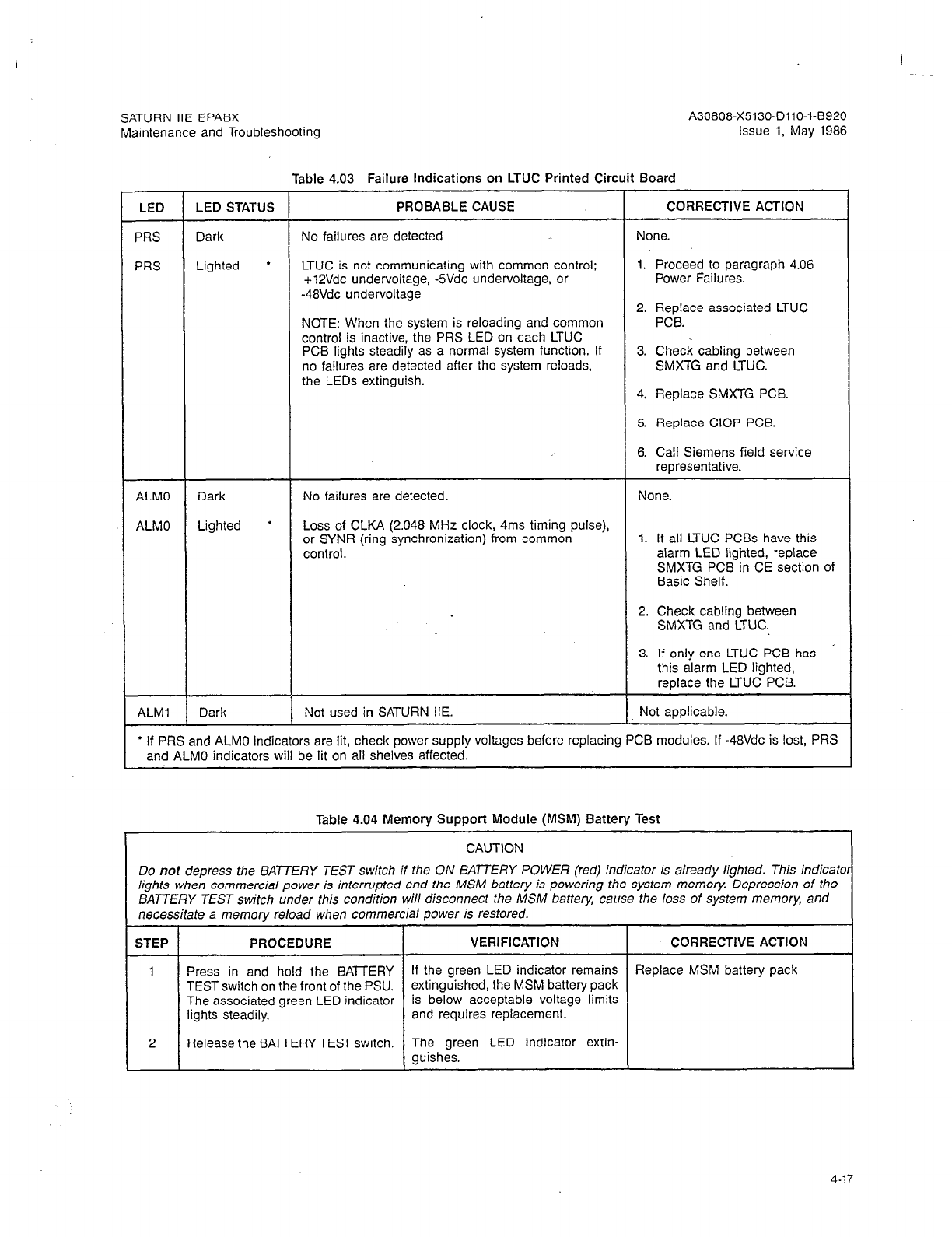
I -
SATURN IIE EPABX
Maintenance and Troubleshooting
A30808-X5130-DllO-l-8920
Issue 1, May 1986
Table 4.03 Failure Indications on LTUC Printed Circuit Board
LED
PUS
PRS
ALMO
ALMO
LED STATUS
Dark
Lighted
l
Dark
Lighted
l
ALMl Dark
PROBABLE CAUSE
No failures are detected
LTUC is not communicating with common control:
+12Vdc undervoltage, -5Vdc undervoltage, or
-48Vdc undervottage
NOTE: When the system is reloading and common
control is inactive, the PRS LED on each LTUC
PCB lights steadily as a normal system function. If
no failures are detected after the system reloads,
the LEDs extinguish.
No failures are detected.
Loss of CLKA (2.048 MHz clock, 4ms timing pulse),
or SYNR (ring synchronization) from common
control.
Not used in SATURN IIE.
CORRECTIVE ACTION
None.
1. Proceed to paragraph 4.06
Power Failures.
2. Replace associated LTUC
PCB.
3. Check cabling between
SMXTG and LTUC.
4. Replace SMXTG PCB.
5. Replace CIOP PCB.
6. Call Siemens field service
representative.
None.
1. If all LTUC PCBs have this
alarm LED lighted, replace
SMXTG PCB in CE section of
Basic Shelf.
2. Check cabling between
SMXTG and LTUC.
3. If only one LTUC PCB has
this alarm LED lighted,
replace the LTUC PCB.
Not applicable.
l
If PRS and ALMO indicators are lit, check power supply voltages before replacing PCB modules. If -48Vdc is lost, PRS
and ALMO indicators will be lit on all shelves affected.
Table 4.04 Memory Support Module (MSM) Battery Test
CAUTION
Do
not
depress the BAsTEFlY TEST switch if the ON BATTERY POWER (red) indicator is already lighted. This indicate
lights when commercial power is interrupted and the MSM battery is powering the system memory. Depression of the
BATTERY TEST switch under this condition will disconnect the MSM battery cause the loss of system memory, and
necessitate a memory reload when commercial Dower is restored.
STEP
1
2
PROCEDURE
Press in and hold the BATTERY
TEST switch on the front of the PSU.
The associated green LED indicator
lights steadily.
Release the BATTERY TEST switch.
VERIFICATION
If the green LED indicator remains
extinguished, the MSM battery pack
is below acceptable voltage limits
and requires replacement.
The green LED indicator extin-
guishes.
CORRECTIVE ACTION
Replace MSM battery pack
4-17
A30808-X5130-DllO-l-6920
Issue 1, May 1986
I --
SATURN IIE EPABX
Maintenance and Troubleshooting
4.06 Power Failures. When a loss of power is suspected
to be the cause of failures in the system, the craftsperson
should follow the guidelines described below. (Refer to para-
graph 2.15, Power Distribution and Failures, for descriptive
information on the power supplies.)
l
Visually check the PSU front panel (Figure 2.01) for
blown fuses and tripped circuit breakers. Refer to para-
graph 4.06a.
.
If PSU fuses and circuit breakers are normal but all
LEDs on the cabinet(s) are extinguished (i.e., the sys-
tem is not processing calls), check the ac input vol-
tage(s) to the Basic Cabinet, the PSU, and the -48PS
module(s) (-48PS0 and, -48PSl if applicable). (When
an Expansion Cabinet is included in the system, a se-
cond ac input is wired to the Basic Cabinet and feeds
the two -48 Vdc power supplies (-48PS0 and -48PSl)
via PSU connector, J2.) If ac is measured, check the
dc output voltages from the PSU in the Basic Cabi-
net. Refer to paragraph 4.06b.
0 If PSU fuses and circuit breakers are normal and the
system is processing some calls (i.e., status indicators
on the CIOP PCB are decrementing), check the dc in-
put voltages to the Basic Shelf or ac input voltage to
the LTUPS(s) on the LTU shelf or shelves, if applica-
ble, in which problems are being experienced. Refer
to paragraph 4.06~.
l
If the ac input voltages to the Basic Cabinet, PSU,
-48PS module(s). and LTU shelf or shelves‘are correct.
. ,.
check the dc output voltages of the PSU, -48PS mod:
ule(s), and the LTUPS module(s) on the LTU shelf or
shelves, if applicable. Refer to paragraph 4.06d.
When voltages are to be checked, the voltages must be with-
in the ranges specified in Table 4.05.
WARNING
Hazardous voltages exist within the equipment cabinet.
Be extremely careful when performing maintenance and
troubleshooting procedures with the equipment panel(s)
removed. CAUTION
Before disconnecting or connecting power cables lead-
ing to and from system power supplies, switch the as-
sociated circuit breaker on the PSU front panel to the off
(down) position.
a. Visually check the PSU front panel for blown fuses
(grasshopper-type) and tripped circuit breakers (refer
to Figure 2.01).
1. If a -488 fuse has blown,
NOTE: If it is known or believed that a previous
event or action by the craftsperson may
have caused a transient fault condition
which caused the fuse to blow, proceed to
step (a) below; otherwise proceed to step
(b) below.
(a) Replace the -488 fuse. If the fuse blows again,
proceed to step (b) below.
(b) Remove all subscriber line modules (SLMA-0,
SLMA-S, and SLAl6 PCBs) and E&M trunk
modules (TMBA-2 and TMBA-4 PCBs) from the
shelf protected by the blown fuse. Do not re-
move the DTMF, SLMD, and PIMD PCBs from
the shelf.
(c) Replace the fuse again.
(1) If the fuse does not blow, one of the mod-
ules removed in step (b) is probably at fault.
Reinsert the subscriber line and trunk mod-
ules one at a time and recheck the fuse af-
ter each module is inserted. If the fuse
blows after reinserting a module, the mod-
ule is defective. Replace the module.
(2) If the fuse blows again, the most probable
location of the fault is the PSU. Replace the
PSU. (If optional MSM is installed, adjust
PSU +SVdc output versus MSM output as
specified in Table 4.05.)
2. If a -48P fuse has blown,
NOTE: If it is known or believed that a previous
event or action by the craftsperson may
have
caused
a transient fault condition
which caused the fuse to blow, proceed to
step (a) below; otherwise proceed to step
(b) below.
(a) Replace the-48P fuse. If the fuse blows again,
proceed to step (b) below.
(b) Remove all SLMD and PIMD PCBs in the as-
sociated shelf. Do not remove the subscriber
line modules (SLMA-0, SLMA-S, or SLAl6
PCBs), DTMF modules, trunk modules
(TMBAQ, TMBA4, TMBM, or TMIE PCBs) or
common control modules (CE PCBs) in the
shelf.
(c) Replace the fuse again.
(1) If the fuse does not blow, an SLMD or PIMD
PCB is at fault. Reinsert the SLMD and/or
PIMD PCB(s) in the shelf, one at a time and
recheck the fuse after each module is in-
serted. If the fuse blows after reinserting a
module, the module is defective. Replace
the module.
(2) If the fuse blows again, the most probable
location of the fault is the PSU. Reolace the
PSU. (If optional MSM is installed, adjust
PSU +SVdc output versus MSM output as
specified in Table 4.05.)
3. If the RGEN fuse has blown,
NOTE: If it is known or believed that a previous event
or action by the craftsperson may have caused
a transient fault condition which caused the
fuse to blow, -proceed to step (a) below; other-
wise proceed to step (b) below.
4-18
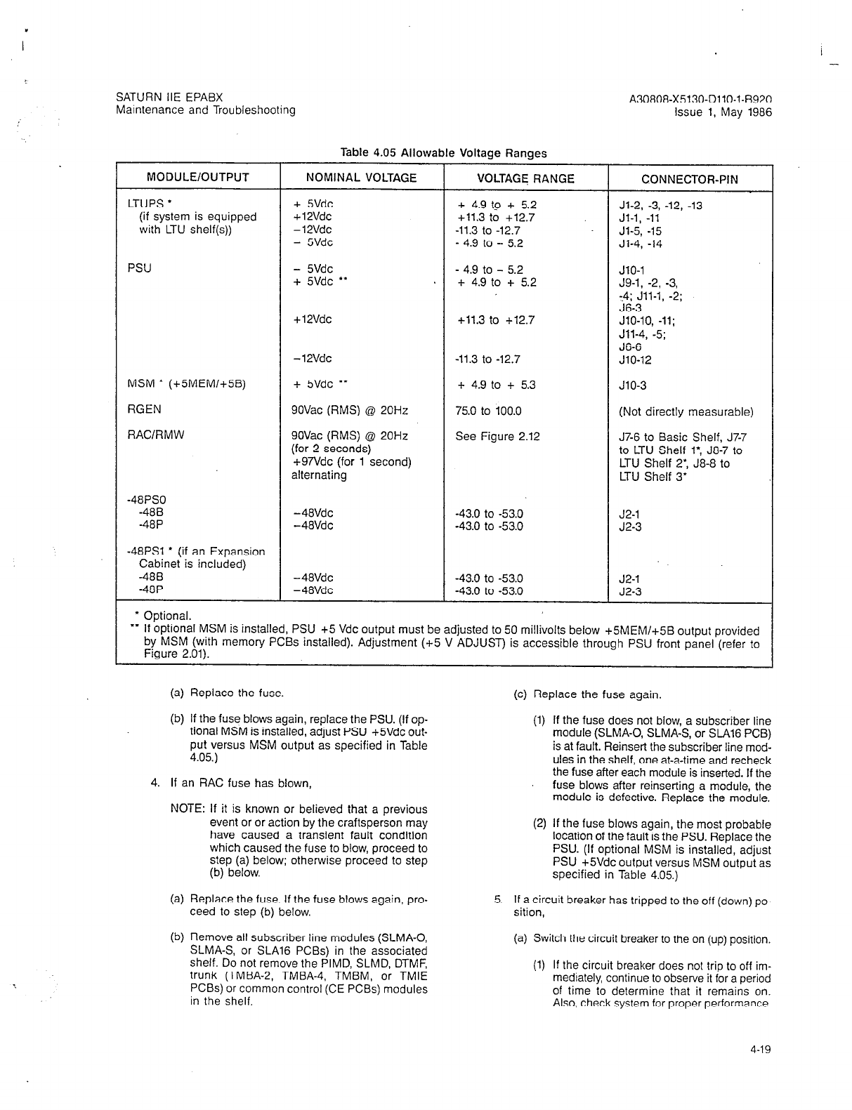
SATURN IIE EPABX
Maintenance and Troubleshooting
-
A30808-X5130-DllO-l-8920
Issue 1, May 1986
Table 4.05 Allowable Voltage Ranges
MODULE/OUTPUT NOMINAL VOLTAGE VOLTAGE RANGE CONNECTOR-PIN
LTUPS
l
+ 5Vdc + 4.9 tp + 5.2 Jl-2, -3, -12, -13
(if system is equipped + 12Vdc +11.3 to +12.7 Jl-1, -11
with LTU shelf(s)) -12Vdc -11.3 to -12.7 Jl-5, -15
- 5Vdc - 4.9 to - 5.2 Jl-4, -14
PSU - 5Vdc - 4.9 to - 5.2 JlO-1
+ 5Vdc
l
* * + 4.9 to f 5.2 J9-1, -2, -3,
:4; Jll-1, -2;
J6-3
+ 12Vdc +11.3 to -1-12.7 JlO-10, -11;
Jll-4, -5;
J6-6
-12Vdc -11.3 to -12.7 JlO-12
MSM
l
(+5MEM/+5B) + 5Vdc
l
* + 4.9 to + 5.3 JlO-3
RGEN 9OVac (RMS) @ 20Hz 75.0 to 100.0 (Not directly measurable)
RACIRMW 9OVac (RMS) @ 20Hz See Figure 2.12 J7-6 to Basic Shelf, J7-7
(for 2 seconds) to LTU Shelf 1: J8-7 to
+97Vdc (for 1 second) LTU Shelf 2: J8-8 to
alternating LTU Shelf 3’
-48PS0
-488 -48Vdc -43.0 to -53.0 J2-1
-48P -48Vdc -43.0 to -53.0 J2-3
-48PSl * (if an Expansion
Cabinet is included)
-488 -48Vdc -43.0 to -53.0 J2-1
-48P -48Vdc -43.0 to -53.0 J2-3
* Optional.
l
* If optional MSM is installed, PSU +5 Vdc output must
be adjusted to 50 millivolts
below +5MEM/+5B output provided
by MSM (with memory PCBs installed). Adjustment (+5 V ADJUST) is accessible through PSU front panel (refer to
Figure 2.01).
(a) Replace the fuse. (c) Replace the fuse again.
(b) If the fuse blows again, replace the PSU. (If op-
tional MSM is installed, adjust PSU +SVdc out-
put versus MSM output as specified in Table
4.05.)
4. If an RAC fuse has blown,
NOTE: If it is known or believed that a previous
event or or action by the craftsperson may
have caused a transient fault condition
which caused the fuse to blow, proceed to
step (a) below; otherwise proceed to step
(b) below.
(1) If the fuse does not blow, a subscriber line
module (SLMA-0, SLMA-S, or SLAl6 PCB)
is at fault. Reinsert the subscriber line mod-
ules in the shelf, one at-a-time and recheck
the fuse after each module is inserted. If the
fuse blows after reinserting a module, the
module is defective. Replace the module.
(2) If the fuse blows again, the most probable
location of the fault is the PSU. Replace the
PSU. (If optional MSM is installed, adjust
PSU +SVdc output versus MSM output as
specified in Table 4.05.)
(a) Replace the fuse. If the fuse blows again, pro- 5.
ceed to step (b) below. If a circuit breaker has tripped to the off (down) po-
sition,
(b) Remove all subscriber line modules (SLMA-0,
SLMA-S, or SLA16 PCBs) in the associated
shelf. Do not remove the PIMD, SLMD, DTMF,
trunk (TMBA-2, TMBA-4, TMBM, or TMIE
PCBs) or common control (CE PCBs) modules
in the shelf.
(a) Switch the circuit breaker to the on (up) position.
(1) If the circuit breaker does not trip to off im-
mediately, continue to observe it for a period
of time to determine that it remains on.
Also, check system for proper performance
4-19
A30808-X5130-DIIO-l-8920
Issue 1, May 1986
SATURN IIE EPABX
Maintenance and Troubleshootrng
(b) If the circuit breaker trips off (down) again,
switch it on again.
(1) If the circuit breaker does not trip to off im-
mediately, continue to observe it for a peri-
od of time to determine that it remains on.
Also, check system for proper performance.
(2) If the circuit breaker trips off again, replace
the associated power supply as indicated
below:
BASIC PS circuit breaker: replace the PSU.
(If optional MSM is installed, adjust PSU
+SVdc output versus MSM output as
specified in Table 4.05.)
LTUPSO circuit breaker: replace the LTUPS
on LTU Shelf 1.
LTUPSl circuit breaker: replace the LTUPS
on LTU Shelf 2 in the Expansion Cabinet.
LTUPS2 circuit breaker: replace the LTUPS
on LTU Shelf 3 in the Expansion Cabinet.
-48PSO circuit breaker: replace -48PSO.
-48PSl circuit breaker: replace -48PSl.
(3) If the circuit breaker trips off again, the most
probable location of the fault is the PSU.
Replace the PSU. (If optional MSM is in-
stalled, adjust PSU +SVdc output versus
MSM output as specified in Table 4.05.)
b. If the fuses and circuit breakers are normal but all LEDs
on the cabinet(s) are extinguished (i.e., no calls are be-
ing processed), perform the following voltage checks:
1. Check the ac input voltage to the Basic Cabinet:
(a) Connect one lead of the DVM to pin 1 and the
other lead to pin 3 of connector Pl (connected
to Jl) on the rear panel of the PSU (refer to Figure
4.00). Be careful not to damage the connector
housing or contacts.
(b) If ac voltage is measured, replace the PSU. (If
optional MSM is installed, adjust PSU +5Vdc
output versus MSM output as specified in Table
4.05.)
(c) If no ac voltage is measured, check the ac vol-
tage at the ac power source outlet.
(1) If no ac voltage is measured, commercial
power is not being supplied to the SATURN
System.
(2) If the ac voltage is correct at the ac power
source outlet, check power cable and con-
nections in cabinet junction box (refer to
Figure 4.01).
2. To check the ac input to a particular -48PS module,
(a) Connect one DVM lead to pin 1 and the other
lead to pin 2 of the plug mated to connector Jl
4-20
on the -48PS module (refer to Figure 4.01). Be
careful not to damage the plug housing or
contacts.
(b) If no ac voltage is measured, replace the PSU.
(If optional MSM is installed, adjust PSU +5Vdc
output versus MSM output as specified in Table
4.05.)
3. Check the dc output voltages from the PSU (+5V,
SV, +12V and -12V) appearing at connectors J47 and
J48 on the Basic Shelf backplane (refer to Figure
4.02). For each voltage shown in Figure 4.02, con-
nect the common (-) DVM lead to the ground bus-
bar and insert the positive (+) DVM lead into the
associated wire slot of the wiring harness plug. Be
careful not to damage the plug housing or contacts.
(a) If only one output voltage from the PSU to the
Basic Shelf backplane is low (refer to Table 4.05
for the acceptable voltage ranges), suspect that
excessive current load on that output is causing
current foldback protection to be in effect. This
may be due to a short circuit or partial short cir-
cuit in a PCB installed in the Basic Shelf or the
PSU may be defective. To isolate the fault, pro-
ceed as follows:
(1)
(2)
(3)
Remove all PCBs in the Basic Shelf and
recheck the incorrect voltage.
If the voltage remains low, replace the PSU.
(If optional MSM is installed, adjust PSU
+5Vdc output versus MSM output as speci-
fied in Table 4.05.)
If the voltage returns to normal after remov-
ing all PCBs in the Basic Shelf, a PCB is
probably at fault. Reinsert the PCBs in the
shelf, one at-a-time and recheck the voltage
after each PC8 is inserted. If the incorrect
voltage reading returns after inserting a PCB,
the PCB is defective. Replace the PCB.
(b) If all PSU output voltages are low as measured
at the Basic Shelf, the PSU may have ex-
perienced an overvoltage condition at its output
which caused the overvoltage protection circuitry
to latch the PSU into a shut down mode. This
may be due to a short,circuit or partial short cir-
cuit between two output voltages. When a short
circuit is cleared, it is necessary to switch the
BASIC PS circuit breaker on the PSU to off
(down), then on (up) again, to clear the latched
shut down condition. To isolate the faulty equip-
ment proceed as follows:
(1) Remove all PCBs from the Basic Shelf
(2) Switch the associated BASIC PS circuit
breaker on the PSU to off (down), then on
(up) again. Check the PSU output voltages
once again at the Basic Shelf. If the voltages
remain low, replace the PSU. flf ootional
MSM is installed, adjust PSU +5Vdcbutput
versus MSM output as specified in Table
4.05)

SATURN IIE EPABX A30808-X5130-DllO-l-8920
Maintenance and Troubleshooting Issue 1, May 1986
Jg,(I, j-J11w</
J”, J13!- : \ J7
7-l \ i J4 1 J31 +Jl
Ji5 Ji2 J14 J16 J8 J2 J5
,
Jl- J2- J3- J4-
1,2 AC line l-3 AC line 1 AC line 1,2 AC line
3,4. AC neutral 4-6 AC neutral 2 AC neutral 3,4 AC neutral
5 AC ground 7 AC ground 3 Not used 5,6 AC ground
8,9 Not used 4 AC ground
J6- J7- J8- J9-
12
-48Vdc” 1,2 -48Vdc’= 1,2 -48Vdc”’ l-4 +5Vdc
3 +5Vdc 3-4 -48Vdc”’ 3 -48Vdc”’
45 -48Vdc’*’ 5 Not used 4,5 Not used
6 +12Vdc 6,7 RACIRMW 6 -48Vdc”’
798
Ground 8 Not used 7,8 RAC/RMW
9 RAC return 9 Not used
lo-12 Ground
Jll- J12 J13 J14-
l-2 +5Vdc Signal leads PXFER, MAJOR, l-4 DC ground
3 Ground to/from MINOR alarm
4.5 + 1 PVdc Basic Shelf contacts; MTCE
6 Ground PHONE connec-
tions to MDF
J16
LCL +5Vdc
MSM +5Vdc (+5B)’
f Present if optional MSM is installed.
.* -48P
**.
-488
J5-
1,2 AC line
3 AC ground
4,5 AC neutral
6 AC ground
JlO-
1 -5Vdc
2 Not used
3 +5Vdc (+5B)
4
Not
used
5-8 Ground
9 Not used
IO,11 +-12Vdc
12 -72Vdc
J15
External
fuse alarm
connections
Figure 4.00 Power System Unit (PSU) Power Connections
4-21

SATURN IIE EPABX A30808-X5130-DllO-l-8920
Maintenance and Troubleshooting issue 1, May 1986
I
J2/P2
Pin
1 -48Vdc (-488)
2 Ground
3 -48Vdc (-48P)
4 Ground
Jl/Pl Junction LINE-AC IN LINE AC IN
Pin Box (AC%@ IN) (AC#l IN)
1 AC Line Note 2
2 AC Neutral
3 AC Ground
\
-48PSo
Note 1 PSU J2
Notes:
1. When -48PSl is installed, voltages on connectors Jl and J2 are the same as
those on -48PSfi. \
2. Second AC input is required only when expansion cabinet is used and -48$PSl
is installed. Jumper plug at PSU J2 is removed and second AC source is connected
to J2.
Figure 4.01 -48PSO Module Power Connections
4-22
SATURN IIE EPABX
Maintenance and Troubleshooting
A30808-X5130-DllO-l-6920
Issue 1, May 1986
(3) If the voltages return to normal after remov-
ing all the PCBs, a PCB has probably short-
ed. Reinsert the PCBs in the shelf, one at
a time, and recheck the the PSU output vol-
tages at the Basic Shelf after each PCB is
inserted. If the low voltage readings return
after inserting a PCB, the PCB is defective.
Replace the PCB.
(c) If all output voltages from the PSU are zero and
ac is applied to the input, switch off all PSU cir-
cuit breakers and replace the PSU. (If optional
MSM is installed, adjust PSU +SVdc output ver-
sus MSM output as specified in Table 4.05.)
c. If PSU circuit breakers and fuses are normal and the sys-
tem is processing some calls (i.e., status indicators on
the CIOP PCB are decrementing), check appropriate vol-
tages for the shelf or shelves experiencing problems. If
problems appear to be in the Basic Shelf, check dc in-
put voltages to the shelf. If problems appear to be in an
LTU shelf, check the ac input voltage to the shelf LTUPS
then check the dc output voltages provided by the
LTUPS.
To check the ac input to a particular LTUPS,
1. Connect one lead of the DVM to pin 1 and the other
lead to pin 2 of the LTUPS ac input connector on
the raceway (refer to Figure 4.03). Be careful not to
damage the connector housing or contacts.
2. If no ac voltage is measured, replace the PSU. (If
optional MSM is installed, adjust PSU +5Vdc out-
put versus MSM output as specified in Table 4.05.)
d. If the ac input voltage to the LTUPS is correct, check the
dc output voltages from the associated LTUPS module.
The LTUPS output voltages can be checked at connec-
tor Jl on the LTUPS and at connectors J42, J43, and
J44 on the LTU shelf backplane. To check the output vol-
tages, refer to Figure 4.03 for the location of the connec-
tor on the rear of the LTUPS and Figure 4.04 for the
locations of connectors J42, J43, and J44 on the LTU
shelf backplane. For each voltage indicated in Figures
4.03 and 4.04, connect the common (-) DVM lead to the
ground busbar and insert the positive (+) DVM lead in
the associated wire slot of the connector. Be careful not
to damage the connector housings or contacts.
1. If only one output voltage is low (refer to Table 4.05),
suspect that excessive current load on that output
is causing current foldback protection to be in effect.
This may be due to a short circuit or partial short
circuit within a PCB installed in the shelf, or the
LTUPS module may be at fault. To isolate the faulty
equipment proceed as follows:
NOTE: If the +5Vdc is low, the voltage can be in-
creased by turning the +5 V ADJUST
potentiometer on the front of the LTUPS
clockwise.
(4
(b)
w
2.
Remove all PCBs in the LTU shelf and check the
voltage again.
If the voltage is still low, replace the LTUPS
module.
If the voltage returns to normal after removing
all the PCBs, a PCB has probably shorted.
Reinsert the PCBs into the shelf, one at a time.
Check whether the low voltage returns after in-
serting each PCB. If the low voltage returns af-
ter inserting a PCB, the PCB is defective.
Replace the PCB.
If all output voltages from the LTUPS module are
low, suspect that the LTUPS module has ex-
perienced an overvoltage condition at its output
which has caused the overvoltage protection cir-
cuitry to latch the LTUPS into a shut down mode.
This may be due to a short circuit or partial short
circuit between two output voltages. When the
short circuit is cleared, it will be necessary to switch
the associated LTU shelf input circuit breaker OFF
and then ON to clear the “latched shut down con-
dition.”
(a) Remove all PCBs in the LTU shelf.
(b) Switch the LTU circuit breaker on the PSU mod-
ule off and then ON to determine if the shut
down condition is cleared.
(c) Check the LTUPS output voltages again.
(1) If the voltages are still low, replace the
LTUPS module.
(2) If the voltages return to normal after remov-
ing all the PCBs, the latched shut down
condition has cleared, indicating that a
PCB has probably shorted. To determine
which PCB(s) is defective, reinsert the
PCBs into the shelf, one at a time. After in-
serting each PCB, again check the output
voltages of the LTUPS module. If the low
voltages return after inserting a PCB, the
PCB is defective. Replace the PCB.
(3) If all output voltages from the LTUPS mod-
ule are zero and there is ac input to the
module, replace the LTUPS module.
4-23
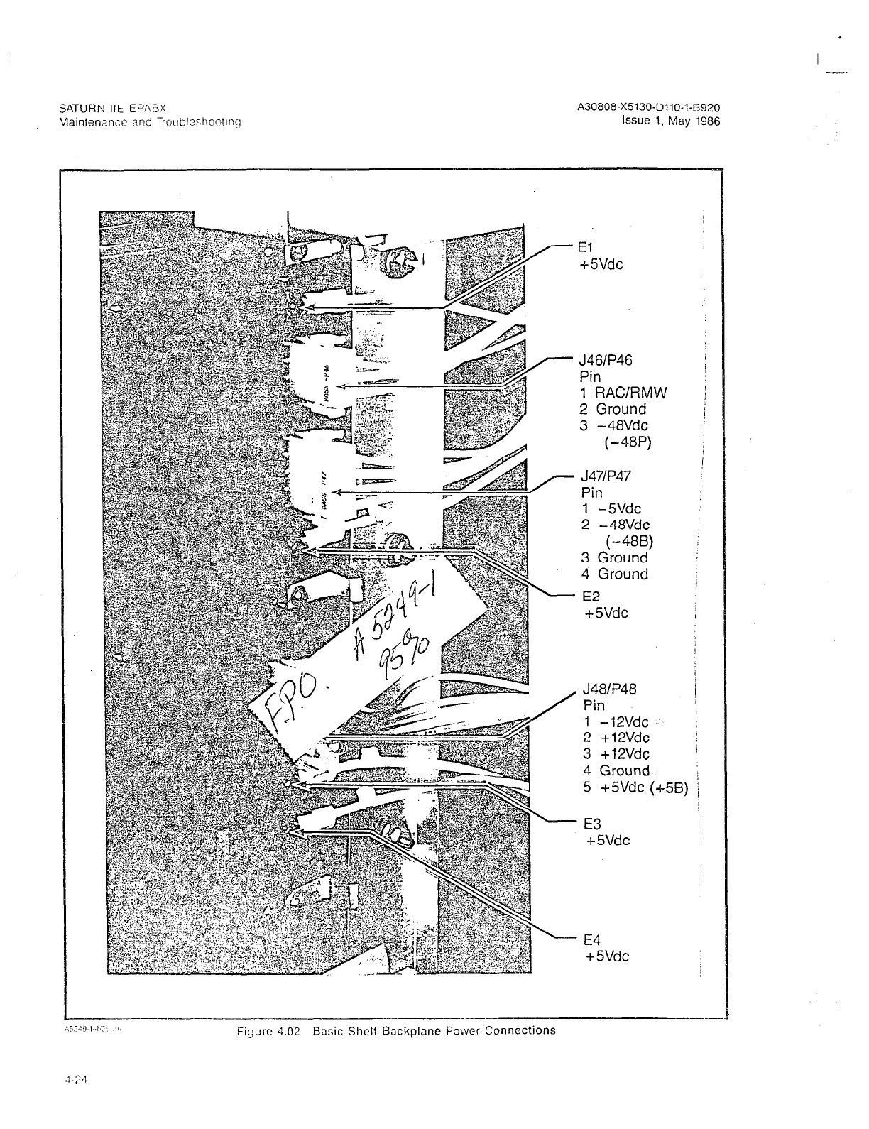
A30808-X5130-DllO-l-8920
Issue 1, May 1986
El
+5Vdc
J46IP46
Pin
1 RAC/RMW
2 Ground
3 -48Vdc
(-48P)
J47IP47
Pin
1 -5Vdc
2 -48Vdc
(-488)
3 Ground
4 Ground
E2
+ 5Vdc
J48lP48
Pin
1 -12Vdc -
2 +12Vdc
3 +12Vdc
4 Ground
5 +5Vdc (a5B)
’ E3
-i- 5Vdc
’ E4
+5Vdc
Figure 4.02 Basic Shelf Backplane Power Connections
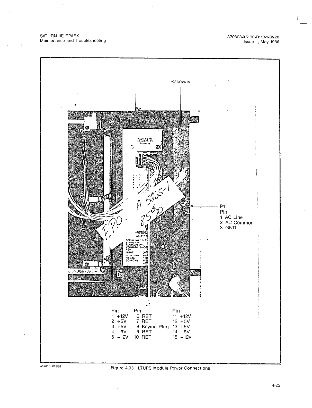
I
SATURN IIE EPABX
Maintenance and Troubleshooting A30808-X5130-DllO-l-8920
Issue 1, May 1986
Raceway
PI
Pin
1 AC Line
2 AC Corn1
3 GND nor
Jl
Pin Pin Pin
1 +12v 6 RET 11 +12v
2 +5v 7 RET 12 +5v
3 +5v 8 Keying Plug 13 +5V
4 -5v 9 RET 14 -5v
5 -12V 10 RET 15 -12v
Figure 4.03 LTUPS Module Power Connections
4-25
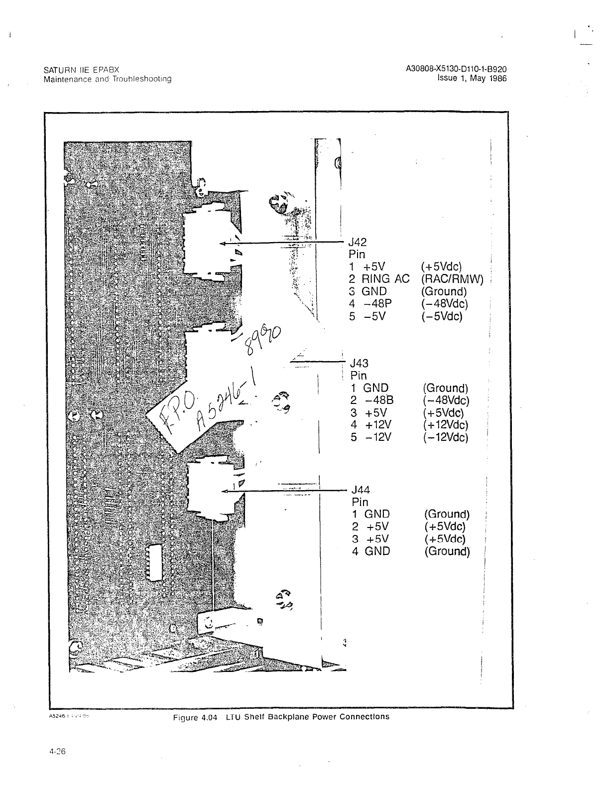
SATURN IIE EPABX
Maintenance and Trouhleshootlng
J42
Pin
1 -k5v
2 RING
S GND
4 -48P
5 -5v
J43
Pin
1 GND
2 -488
3 +5v
4 +12v
5 -12v
’ J44
Pin
1 GND
2 +5v
3 +5v
4 GND
AC (+-5Vdc)
(RAC/RMV
(Ground)
(Ground)
(-48Vdc)
(+SVdc)
(Ground)
V) !
Figure 4.04 LTU Shelf Backplane Power Connections
4-16
I _-.
SATURN IIE EPABX
Maintenance and Troubleshooting
4.07 Single-Line Telephone Related Failures. Step-by-step
instructions for troubleshooting the single-line telephone (SLT)
(i.e., 500-or 2500-type analog instrument) are provided below:
a. If the SLT is completely inoperative (i.e., no talk battery),
1. Using the SERVICE CMU Procedure, check serv-
ice state of the circuit serving this SLT
(a) If in-service, continue with step 2.
(b) If out-of-service-craft, return the circuit to the
in-service state (Table 4-10) and verify opera-
tion. Continue with step 2 if the SLT remains
inoperative.
(c) If out-of-service - automatic, attempt to return
the circuit to the in-service state (Table 4-10).
(1) If circuit returns to the in-service state and
the failure clears, the problem was tran-
sient. If transient problems recur on the
same circuit, continue with step 2.
(2) If the circuit remains in the out-of-service
- automatic state, continue with step 2.
2. Using the ALMDATA CMU Procedure, check the
Failure History Memory for system alarm mes-
sages. The corrective repair procedures for system
alarm messages are provided in Table 4.02.
3. If more than one SLT fails at the same time,
(a) If all affected SLTs are assigned to the same sub-
scriber line module (SLMA-C, SLMA-S, or %A16
PCB) replace the subscriber line module.
(b) Replace the SMXTG PCB
4. If only one SLT fails,
(4
Check the line with a test set or replace the SLT
with a known good SLT. If the problem disap-
pears, replace the faulty SLT.
UN
Replace the associated subscriber line mod-
ule (SLMA-0, SLMA-S, or %A16 PCB).
(4
Replace the SMXTG PCB.
b. If the SLT rings continuously,
1. Replace the associated subscriber line module
(SLMA-0, SLMA-S, or SLAl6 PCB).
c. If dial tone cannot be heard,
1. Using the SERVICE CMU Procedure, check serv-
ice state of the circuit serving this SLT.
(a) If in-service, continue with step 2.
(b) If out-of-service - craft, return the circuit to the
in-service state (Table 4-lo), and verify opera-
tion. Continue with step 2 if the SLT remains
inoperative.
A30808-X5130-DllO-l-8920
Issue 1. May 1986
(c) If out-of-service - automatic, attempt to return
the circuit to the in-service state (Table 4-10).
(1) If circuit returns to the in-service state and
the failure clears, the problem was tran-
sient. If transient problems recur on the
same circuit, continue with step 2.
(2) If the circuit remains in the out-of-service
- automatic state, continue with step 2.
2. Using the ALMDATA CMU Procedure, check the
Failure History Memory for system alarm mes-
sages. The corrective repair procedures for system
alarm messages are provided in Table 4.02.
3. If dial tone cannot be heard at more than one SLT,
(4
04
(cl
If all affected SLTs are assigned to the same
subscriber line module (SLMA-0, SLMA-S, or
SLA16 PCB), replace the associated subscriber
line module.
Perform the Tone Generator Test (Table 4.06).
If the Tone Generator Test passes but the failure
still persists, replace the associated SMXTG
PCB.
4. If dial tone cannot be heard on one SLT only,
(a) Check line.with a test set or replace the SLT
with a known g,ood SLT. If the problem disap-
pears, replace the faulty SLT.
(b) Replace the associated subscriber line mod-
ule (SLMA-0, SLMA-S, or SLAl6) PCB.
d. If dial tone is distorted or at a low level,
1.
2.
If dial tone is distorted or at a low level on only one
SLT, replace the SLT with a known good SLT.
If dial tone is distorted or at a low level on more
than one SLT.
(a)
(b)
(cl
Perform the Tone Generator Test (Table 4.06).
If the Tone Generator Test passes but the failure
still persists, replace the associated PSC PCB
and recheck dial tone. (PSCO for Basic Cabi-
net; PSCl for Expansion Cabinet, if applicable.)
If failure persists, reinsert original PSC PCB
and replace the MCA PCB.
e. If the SLT dial pad is suspected of being faulty, per-
form the DTMF Dial Pad Test (Table 4.12).
f. If the SLT fails to ring,
1. Using the SERVICE CMU Procedure, check serv-
ice state of the circuit serving this SLT,
(a) If in-service, continue with step 2.
(b) If out-of-service-craft, return the circuit to the
4-27
SATURN IIE EPABX
Maintenance and Troubleshooting
I ’
A30808-X5130-DllO-l-8920
Issue 1, May 1986
in-service state (Table 4-lo), and verify opera-
tion. Continue with step 2 if the SLT remains
inoperative.
(c) If out-of-service - automatic, attempt to return
the circuit to the in-service state (Table 4-10).
(1) If circuit returns to the in-service state and
the failure clears, the problem was tran-
sient. If transient problems recur on the
same circuit, continue with step 2.
(2) If the circuit remains in the out-of-service
- automatic state, continue with step 2.
2. Using the ALMDATA CMU Procedure, check the
Failure History Memory for system alarm mes-
sages. The corrective repair procedures for system
alarm messages are provided in Table 4.02.
3. Perform the Station Line Test (Table 4.13) to verify
ringing capability.
4. Verify that the problem is not due to the activation
of a SATURN feature (e.g., Do Not Disturb, Call For-
warding, etc.).
5. Replace the SLT with a known good SLT. If the
problem is corrected, replace the faulty SLT.
6. Replace the associated subscriber line module
(SLMA-0, SLMA-S, or SLA16) PCB.
4.08 Attendant Console Related Failures. Step-by-step in-
structions for troubleshooting the attendant console are
provided below:
a. If the console is completely inoperative (i.e., no dial
tone, no audible alerting, no functioning buttons and
LED indicators),
1. Using the SERVICE CMU Procedure, check serv-
ice state of the circuit serving this console.
(a) If in-service, continue with step 2.
(b) If out-of-service - craft, return the circuit to the
in-service state (Table 4-10) and verify opera-
tion. Continue with step 2 if the console re-
mains inoperative.
(c) If out-of-service - automatic, attempt to return
the circuit to the in-service state (Table 4-10).
(1) If circuit returns to the in-service state and
the failure clears, the problem was tran-
sient. If transient problems recur on the
same circuit, continue with step 2.
(2) If the circuit remains in the out-of-service
- automatic state, continue with step 2.
2. Using the ALMDATA CMU Procedure, check the
Failure History Memory for system alarm mes-
sages. The corrective repair procedures for system
alarm messages are provided in Table 4.02.
3. Verify that the line cord is properly seated in the
modular jacks. One end of the line cord plugs into
the rear base of the console and the other end con-
nects to the modular connecting block. Also insure
that the handset cord is properly seated in the
handset console jacks.
4. Replace the associated PIMD PCB.
5. Replace the console with a known good console.
If the problem is corrected, replace the faulty
console.
b. If static is heard in the handset,
1. Replace the handset.
2. Replace the handset coiled cord.
3. Replace the associated PIMD PCB.
4. Replace the console with a known good console.
If the problem is corrected, replace the faulty
console.
c. If the console is not operating properly (i.e., nonfunc-
tioning LED(s), button(s), alphanumeric display, audi-
ble alerting device, etc.):
1. Perform the Attendant Console Test (refer to Table
4.14).
2. If theAttendant Console Test passes but the failure
persists,
(a) Replace the associated PIMD PCB.
(b) Replace the console with a known good con-
sole. If the problem is corrected, replace the
faulty console.
(c) Replace the SMXTG PCB.
4.09 Siemens Digital Telephone (SDT) Related Failures.
Step-by-step instructions for troubleshooting SDTs are provid-
ed below:
a. If the SDT is completely dead (i.e., no dial tone, no au-
dible alerting, no functioning buttons and LED indi-
cators),
1. Using the SERVICE CMU Procedure, check serv-
ice state of the circuit serving this SDT.
(a) If in-service, continue with step 2.
(b) If out-of-service - craft, return the circuit to the
in-service state (Table 4-10) and verifv opera-
tion. Continue with step 2 ‘if the SDT iemains
inoperative.
(c) If out-of-service - automatic, attempt to return
the circuit to the in-service state (Table 4-10).
(1) If circuit returns to the in-service state and
the failure clears, the problem was tran-
sient. If transient problems recur on the
same circuit, continue with step 2.
4-28
A30808-X5130-DllO-l-8920
Issue 1, May 1986
I
SATURN ItE EPABX
Maintenance and Troubleshoohng
(2) If the circuit remains in the out-of-service
- automatic state, continue with step 2.
2. Using the ALMDATA CMU Procedure, check the
Failure History Memory for system alarm mes-
sages. The corrective repair procedures for system
alarm messages are provided in Table 4.02.
3. If more than one SDT fails at the same time,
(a) If all affected SDTs are assigned to the same
SLMD PCB, replace the PCB.
(b) Replace the SMXTG PCB.
4. If only one SDT fails,
(a) Verify that the line cord connectors are properly
seated in the modular jacks. One end of the
line cord plugs into the rear base of the SDT
and the other end connects to the modular con-
necting block. Also insure that the handset cord
connectors are properly seated in the handset
and SDT jacks.
(b) Replace the SDT with a known good SDT. If the
problem is corrected, replace the faulty SDT.
(c) Replace the associated SLMD PCB.
(d) Replace the SMXTG PCB.
b. If the trouble report indicates that one or more LED
indicators or buttons do not operate properly,
1. Verify that the problem is not due to the misunder-
standing of a feature by the SDT user.
2. Perform the Siemens Digital Telephone button test
(Table 4.16 for DYAD telephones or Table 4.17 for
JR-DYAD telephones).
3. If the Siemens Digital Telephone button test pass-
es but the problem persists:
(a) Replace the SDT with a known good SDT If the
problem is corrected, replace the faulty SDT.
(b) Replace the associated SLMD PCB.
c. If the trouble report indicates that the display unit on
the SDT is not operating properly,
1. Verify that the problem is not due to the misunder-
standing of a feature by the SDT user.
2. Perform the Siemens DYAD Telephone Display Test
(Table 4.18).
3. If the display test passes but the problem persists:
(a) Replace the SDT with a known good SDT. If the
problem is corrected, replace the faulty SDT.
(b) Replace the associated SLMD PCB
d. If the SDT dial pad is suspected of being faulty, per-
form the Siemens Digital Telephone button test (Table
4.16 for DYAD telephones or Table 4.17 for JR-DYAD
telephones).
e. If-the SDT fails to ring,
1.
2.
3.
4.
5.
6.
Usinq the SERVICE CMU Procedure, check serv-
ice siate of the circuit serving this SDT.
(a) If in-service, continue with step 2.
(b) If out-of-service-craft, return the circuit to the
in-service state (Table 4-10) and verify opera-
tion. Continue with step 2 if the SDT remains
inoperative.
(c) if out-of-service - automatic, attempt to return
the circuit to the in-service state (Table 4-10).
(1) If circuit returns to the in-service state and
the failure clears, the problem was tran-
sient. If transient problems recur on the
same circuit, continue with step 2.
(2) If the circuit remains in the out-of-service
- automatic state, continue with step 2.
Using the ALMDATA CMU Procedure, check the
Failure History Memory for system alarm mes-
sages. The corrective repair procedures for system
alarm messages are provided in Table 4.02.
Perform the Siemens Digital Telephone Button Test
(Table 4.16 for DYAD telephones or Table 4.17 for JR-
DYAD telephones), as applicable. This test checks
the audible alerting device in the SD% If the alerting
device does not sound as’descr~bed in the Siemens
Digital Telephone Button Test, try adjusting the
volume level of the tone ringer (DYAD Telephones)
or the audible alert tone level (JR-DYAD Telephones).
(The tone ringer or alert tone level control is the black
knob located on the underside of the telephone.)
If the Siemens Digital Telephone button test pass-
es but the problem persists, verify that the problem
is not due to the activation of a SATURN IIE fea-
ture (e.g., Do Not Disturb, Station Ringer Cutoff,
Call Forwarding, etc.).
Replace the SDT with a known good SDT If the
problem is corrected, replace the faulty SDT.
Replace the associated SLMD PCB.
f. If the SDT rings continuously,
1. Replace the SDT with a known good SDT. If the
problem is corrected, replace the faulty SDT.
2. Replace the associated SLMD PCB.
g. If dial tone cannot be heard,
1. Using the SERVICE CMU Procedure, check serv-
ice state of the circuit serving this SDT.
(a) If in-service, continue with step 2
4-29
,
SATURN IIE EPABX
Maintenance and Troubleshooting
(b)
03
If out-of-service - craft, return the circuit to the
in-service state (Table 4-lo), and verify opera-
tion. Continue with step 2 if the SDT remains
inoperative.
If out-of-service - automatic, attempt to return
the circuit to the in-service state (Table 4-10).
(1) If circuit returns to the in-service state and
the failure clears, the problem was tran-
sient. If transient problems recur on the
same circuit, continue with step 2.
(2) If the circuit remains in the out-of-service
- automatic state, continue with step 2.
Using the ALMDATA CMU Procedure, check the
Failure History Memory for system alarm mes-
sages. The corrective repair procedures for system
alarm messages are provided in Table 4.02.
If dial tone cannot be heard at more than one SDT,
(4
(b)
(cl
If all affected SDTs are assigned to the same
SLMD PCB, replace the PCB.
Perform the Tone Generator Test (Table 4.06).
If the Tone Generator Test passes but the
failures persist, replace the SMXTG PCB.
If dial tone cannot be heard at one SDT only,
(a) Replace the SDT with a known good SDT. If the
problem is corrected, replace the faulty SDT.
(b) Replace the associated SLMD PCB.
h. If dial tone is distorted or at a low level,
1. If dial tone is distorted or at a low level at only one
SDT, replace the SDT with a known good SDT.
2. If dial tone is distorted or at a low level on more
than one SDT,
(a) Perform the Tone Generator Test (Table 4.06).
(b) If the Tone Generator Test passes but the failure
still persists, replace the associated PSC PCB
and recheck dial tone (PSCO for Basic Cabi-
net; PSCl for Expansion Cabinet).
(c) If failure persists, reinsert original PSC PCB
and replace the MCA PCB.
i. If static is heard in the handset,
1. Replace the handset.
2. Replace the handset coiled cord.
A30808-X5130-DllO-l-8920
Issue 1, May 1986
3. Replace the SDT with a known good SDT. If the
problem is corrected, replace the faulty SDT.
4. Replace the associated SLMD PCB.
4.10 Manual On--Line Diagnostic Tests. Step-by-step proce-
dures for the system and apparatus diagnostic tests are
described in Tables 4.06 through 4.18.
a. System Diagnostic Tests. The following system diag-
nostic tests and procedures can be performed:
0 Tone Generator Test (Table 4.06)
0 Outgoing Trunk Test (Table 4.08)
0 DTMF Receiver Test (Table 4.09)
l
Placing Circuit(s) In-Service (Table 4.10)
l
Taking Circuit(s) Out-of-Service (Table 4.11)
b. Apparatus Diagnostic Tests. The following apparatus
diagnostic tests can be performed:
l
DTMF Dial Pad Test (Table 4.12)
l
Station Line Test (Table 4.13)
0 Attendant Console Test (Table 4.14)
* Siemens DYAD Telephone Button Test (Table 4.16)
0 Siemens JR-DYAD Telephone Button Test (Table
4.17)
l
Siemens DYAD Telephone Display Test (Table 4.18)
4.11 Automatic On-Line Audit Tests. The SATURN IIE
EPABX is provided with a repertory of audit test routines that
are used to test the EPABX equipment during processor idle
time. These audit test routines can be enabled and disabled
by using Customer Memory Update (CMU) Procedures at a
service terminal. When an audit test routine is enabled, de-
tected failures are recorded in the failure history memory and
the appropriate major and minor alarm indicators are light-
ed. Appropriate recovery routines are executed automatical-
ly on the failing equipment. .
The procedures for enabling and disabling the audit test rou-
tines are described in Siemens practice SATURN IIE EPABX
Customer Memory Update Procedures. The following audit
test routines can be enabled and disabled.
* Memory Parity Audit Test
0 Memory Content Audit Test
0 Input/Output Loop-Around Audit Test
0 Speech Highway Audit Test
l
DTMF Receiver/Tone Generator Audit Test
l
MTS Memory Control Audit Test
l
Digital Apparatus Audit Test
* Trunk Activity Audit Test
4.12 Spare Parts. The troubleshooting instructions are
based on the assumption that spare Printed Circuit Boards
(PCBs) and other replaceable assemblies are available on
the premises, centralized job site, or some location convenient
to the EPABX. A list of spare parts and associated Dart num-
bers is provided in Siem’ens practice SATURN IIE CPABX In-
stallation Procedures.
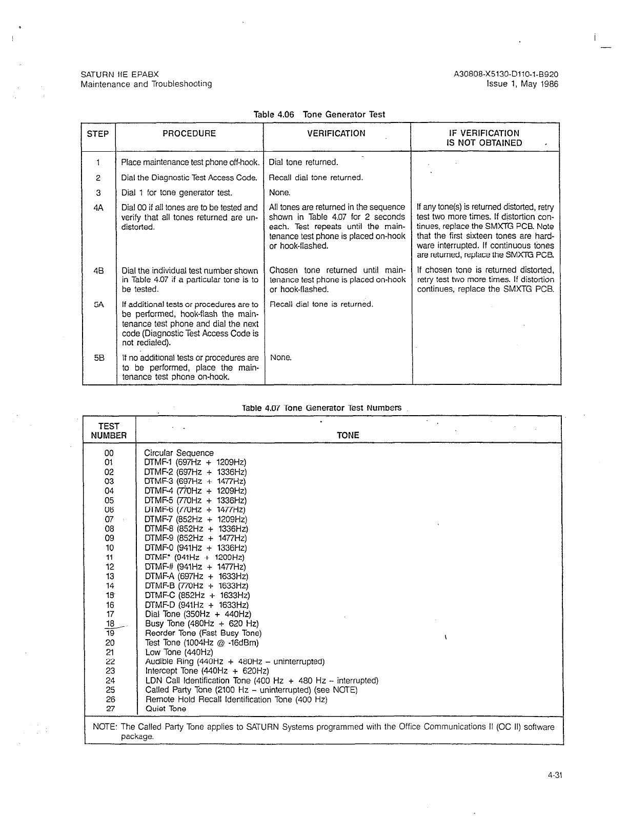
SATURN IIE EPABX
Maintenance and Troubleshooting
Table 4.06 Tone Generator Test
STEP PROCEDURE VERIFICATION IF VERIFICATION
IS NOT OBTAINED ,
-
1 Place maintenance test phone off-hook. Dial tone returned.
2 Dial the Diagnostic Test Access Code. Recall dial tone returned.
3 Dial 1 for tone generator test. None.
4A Dial 00 if all tones are to be tested and All tones are returned in the sequence If any tone(s) is returned distorted, retry
verify that all tones returned are un- shown in Table 4.07 for 2 seconds test two more times. If distortion con-
distorted. each. Test repeats until the main- tinues, replace the SMXTG PCB. Note
tenance test phone is placed on-hook that the first sixteen tones are hard-
or hook-flashed. ware interrupied. If continuous tones
are returned, replace the SMXTG PCB.
48
5A
Dial the individual test number shown Chosen tone returned until main- If chosen tone is returned distorted,
in Table 4.07 if a particular tone is to tenance test phone is placed on-hook retry test two more times. If distortion
be tested. or hook-flashed. continues, replace the SMXTG PCB.
If additional tests or procedures are to Recall dial tone is returned.
be performed, hook-flash the main-
tenance test phone and dial the next
code (Diagnostic Test Access Code is
not redialed).
5B If no additional tests or procedures are None.
to be performed, place the main-
tenance test phone on-hook.
Table 4.07 Tone Generator Test Numbers
TEST .
NUMBER TONE
00 Circular Sequence
01 DTMF-1 (697Hz + 1209Hz)
02 MMF-2 (697Hz + 1336Hz)
03 MMF-3 (697Hz + 1477Hz)
04 DTMF-4 (77OHz + 1209Hz)
05 DTMF-5 (77OHz + 1336Hz)
06 DTMF-6 (i7OHz + 1477Hz)
07 DTMF-7 (852Hz + 1209Hz)
08 DTMF-8 (852Hz + 1336Hz)
09 DTMF-9 (852Hz + 1477Hz)
10 DTMF-0 (941Hz + 1336Hz)
11 MMFT (941Hz + 1209Hz)
12 DTMF-# (941Hz + 1477Hz)
13 DTMF-A (697Hz + 1633Hz)
14 MMF-B (77OHz + 1633Hz)
1% DTMF-C (852Hz + 1633Hz)
16 DTMF-D (941Hz + 1633Hz)
17 Dial Tone (350Hz + 440Hz)
5 Busy Tone (480Hz + 620 Hz)
19 Reorder Tone (Fast Busy Tone)
20 Test Tone (1004Hz @ -16dBm)
21 Low Tone (440Hz)
22 Audible Ring (440Hz + 480Hz - uninterrupted)
23 Intercept Tone (440Hz + 62OHz)
24 LDN Call Identification Tone (400 Hz + 480 Hz - interrupted)
25 Called Party Tone (2100 Hz - uninterrupted) (see NOTE)
26 Remote Hold Recall Identification Tone (400 Hz)
27 Quiet Tone
NOTE: The Called Party Tone applies to SATURN Systems programmed with the Office Communications II (OC II) software
package. -
I -
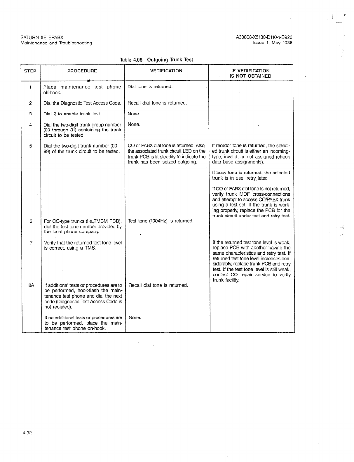
A30808-X5130-DllO-l-6920
Issue 1, May 1986
Table 4.08 Outgoing Trunk Test
STEP PROCEDURE VERIFICATION IF VERIFICATION
IS NOT OBTAINED
1 Place maintenance test phone Dial tone is returned.
off-hook.
2 Dial the Diagnostic Test Access Code. Recall dial tone is returned.
3 Dial 2 to enable trunk test. None.
4 Dial the two-digit trunk group number None.
(00 through 31) containing the trunk
circuit to be tested.
5 Dial the two-digit trunk number (00 - CO or PABX dial tone is returned. Also, If reordar tone is returned, the select-
99) of the trunk circuit to be tested. the associated trunk circuit LED on the ed trunk circuit is either an incoming-
trunk PCB is lit steadily to indicate the type, invalid, or not assigned (check
trunk has been seized outgoing. data base assignments).
If busy tone is returned, the selected
trunk is in use; retry later.
If CO or PABX dial tone is not returned,
verify trunk MDF cross-connections
and attempt to access CO/PABX trunk
using a test set. If the trunk is work-
ing properly, replace the PCB for the
trunk circuit under test and retry test.
6 For CO-type trunks (i.e.,TMBM PCB), Test tone (1004Hz) is returned.
dial the test tone number provided by
tlie local phone company.
.
7 Verify that the returned test tone level If the returned test tone level is weak,
is correct, using a TMS. replace PCB with another having the
same characteristics and retry test. If
returned test tone level increases con-
siderably, replace trunk PCB and retry
test. If the test tone level is still weak,
contact CO repair service to verify
trunk facility.
8A If additional tests or procedures are to Recall dial tone is returned.
be performed, hook-flash the main-
tenance test phone and dial ihe next
code (Diagnostic Test Access Code is
not redialed).
If no additional tests or procedures are None.
to be performed, place the main-
tenance test phone on-hook.
SATURN IIE EPABX
Maintenance and Troubleshooting
4-32
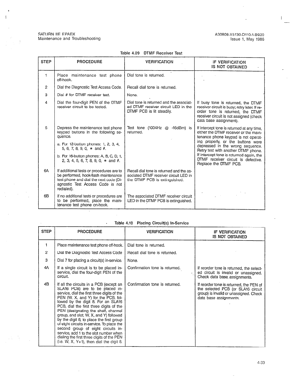
+
I -.
SATURN IIE EPABX
Maintenance and Troubleshooting
Table 4.09 DTMF Receiver Test
STEP PROCEDURE VERIFICATION
6A
6B
STEP PROCEDURE VERIFICATION
1
2
3
4A
4B
Place maintenance test phone
off-hook.
Dial the Diagnostic Test Access Code.
Dial #f for DTMF receiver test.
Dial the four-digit PEN of the DTMF
receiver circuit to be tested.
Depress the maintenance test phone
keypad buttons in the following se-
quence.
a. For 12-button phones: 1, 2, 3, 4,
5, 6, 7, 8, 9, 0, * and #.
b. For l&button phones: A, B, C, D, 1,
2, 3, 4, 5, 6, 7, 8, 9, 0, * and #.
If additional tests or procedures are to
be performed, hook-flash mainienance
test phone and dial the next code (Di-
agnostic Test Access Code is not
rediated).
If no additional tests or procedures are
to be performed, place the main-
tenance test phone on-hook.
Dial tone is returned.
Recall dial tone is returned.
None.
Dial tone is returned and the associat-
ed MMF receiver circuit LED in the
MMF PCB is lit steadily.
Test tone (1004Hz @ -16dBm) is
returned.
Recall dial tone is returned and the as-
sociated MMF receiver circuit LED in
the MMF PCB is extinguished.
The associated DTMF receiver circuit
LED in the MMF PCB is extinguished.
. Table 4.10 Placing Circuit(s) In-Service
Place maintenance test phone off-hook.
Dial the Diagnostic Test Access Code
Dial 7 for placing a circuit(s) in-service.
If a single circuit is to be placed in-
service, dial the four-digit PEN of the
circuit.
If all the circuits in a PCB (except an
%A16 PCB) are to be placed in-
service, dial the first three digits of the
PEN (W, X, and Y) for the PCB, fol-
lowed by the digit 8. For an SLAl6
PCB, dial the first three digits of the
PEN (designating the shelf, channel
group, and slot; W, X, and Y) followed
by the digit 8, to place the first group
of eight circuits in-service. To place the
second group of eight circuits in-
service, add 1 to the slot number when
dialing the first three digits of the PEN
(i.e. W, X, Y+l), then dial the digit 8.
Dial tone is returned.
Recall dial tone is returned.
None.
Confirmation tone is returned.
Confirmation tone is returned.
A30808-X5130-DllO-l-8920
Issue 1, May 1986
IF VERIFICATION
IS NOT OBTAINED
If busy tone is returned, the DTMF
receiver circuit is busy; retry later. If re-
order tone is returned, the DTMF
receiver circuit is not assigned (check
data base assignment).
If intercept tone is returned at any time,
either the MMF receiver or the main-
tenance phone keypad is not operat-
ing properly, or the buttons were
depressed in the wrong sequence.
Retry test with another DTMF phone.
If intercept tone is returned again, the
MMF receiver circuit is defective.
Replace the MMF PCB.
IF VERIFICATION
IS NOT OBTAINED
If reorder tone is returned, the select-
ed circuit is invalid or unassigned.
Check data base. assignments.
If reorder tone is returned, the PEN of
the selected PCB (or SlA16 circuit
group) is invalid or unassigned. Check
data base assignments.
4-33
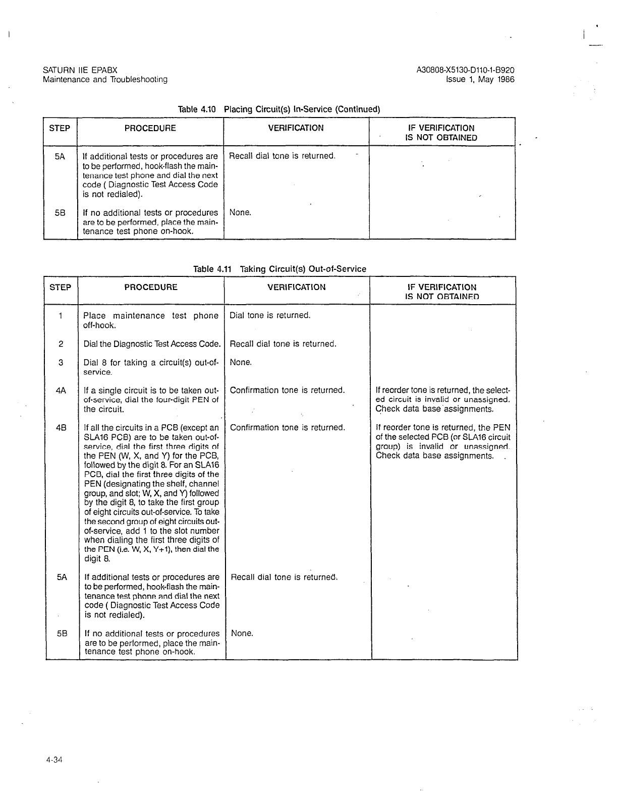
-.
Table 4.10 Placing Circuit(s) In-Service (Continued)
STEP
5A
STEP PROCEDURE VERIFICATION
1
2
3
4A
48
5A
58
PROCEDURE
If additional tests or procedures are
to be performed, hook-flash the main-
tenance test phone and dial the next
code ( Diagnostic Test Access Code
is not redialed).
If no additional tests or procedures
are to be performed, place the main-
tenance test phone on-hook.
I
VERlFlCATlON
Recall dial tone is returned
None.
Table 4.11 Taking Circuit(s) Out-of-Service
Place maintenance test phone
off-hook.
Dial tone is returned.
Dial the Diagnostic Test Access Code. Recall dial tone is returned.
Dial 8 for taking a circuit(s) out-of-
service.
None.
If a single circuit is to be taken out-
of-service, dial the four-digit PEN of
the circuit.
Confirmation tone is returned.
If all the circuits in a PCB (except an
SLA16 PCB) are to be taken out-of-
service, dial the first three digits of
the PEN (W, X, and Y) for the PCB,
followed by the digit 8. For an SLA16
PCB, dial the first three digits of the
PEN (designating the shelf, channel
group, and slot; W, X, and Y) followed
by the digit 8, to take the first group
of eight circuits out-of-service. To take
the second group of eight circuits out-
of-service, add 1 to the slot number
when dialing the first three digits of
the PEN (i.e. W, X, Y+l), then dial the
digit 8.
Confirmation tone is returned.
If additional tests or procedures are
to be performed, hook-flash the main-
tenance test phone and dial the next
code ( Diagnostic Test Access Code
is not redialed).
Recall dial tone is returned..
If no additional tests or procedures
are to be performed, place the main-
tenance test phone on-hook.
None.
IF VERIFICATION
IS NOT OBTAINED
IF VERIFICATION
IS NOT OBTAINED
If reorder tone is returned, the select-
ed circuit is invalid or unassigned.
Check data base.assignments.
If reorder tone is returned, the PEN
of the selected PCB (or .%A16 circuit
group) is invalid or unassigned.
Check data base assignments.
4-34
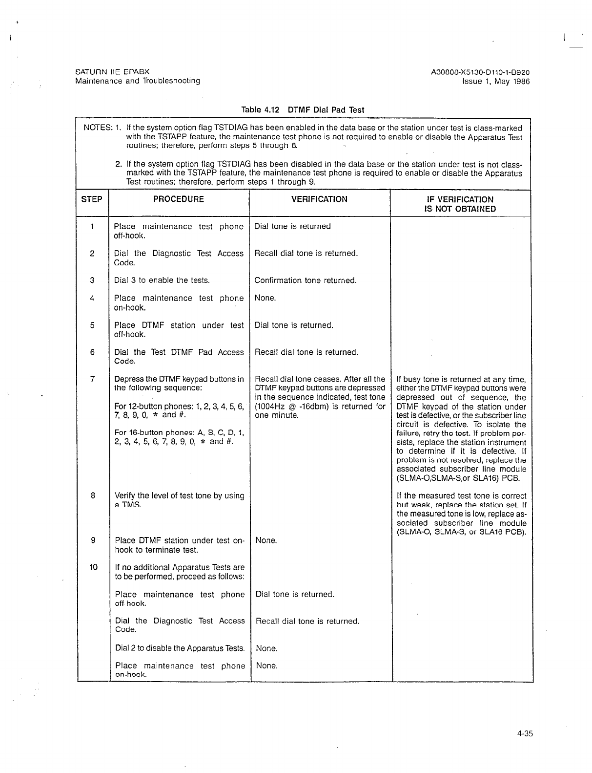
,
SATURN IIE EPABX
Maintenance and Troubleshooting
A30808-X5130-DllO-l-8920
Issue 1, May 1986
Table 4.12 DTMF Dial Pad Test
NOTES: 1. If the system option flag TSTDIAG has been enabled in the data base or the station under test is class-marked
with the TSTAPP feature, the maintenance test phone is not required to enable or disable the Apparatus Test
routines; therefore, perform steps 5 through 8.
2. If the system option flag TSTDIAG has been disabled in the data base or the station under test is not class-
marked with the TSTAPP feature, the maintenance test phone is required to enable or disable the Apparatus
Test routines; therefore, perform steps 1 through 9.
STEP PROCEDURE VERIFICATION IF VERIFICATION
IS- NOT OBTAINED
1 Place maintenance test phone Dial tone is returned
off-hook.
2 Dial the Diagnostic Test Access Recall dial tone is returned.
Code.
3 Dial 3 to enable the tests. Confirmation tone returned.
4 Place maintenance test phone None.
on-hook.
5 Place DTMF station under test Dial tone is returned.
off-hook.
Dial the Test DTMF Pad Access Recall dial tone is returned.
Code.
Depress the DTMF keypad buttons in Recall dial tone ceases. After all the If busy tone is returned at any time,
the following sequence: DTMF keypad buttons are depressed either the DTMF keypad buttons were
in the sequence indicated, test tone depressed out of sequence, the
For 12-button phones: 1,2,3,4, 5, 6, (1004Hz @ -16dbm) is returned for DTMF keypad of the station under
7, 8, 9, 0, * and #. one minute. test is defective, or the subscriber line
circuit is defective. To isolate the
For 16-button phones: A, 8, C, D, 1, failure, retry the test. If problem per-
2, 3, 4, 5, 6, 7, 8, 9, 0, * and #. sists, replace the station instrument
to determine if it is defective. If
problem is not resolved, replace the
associated subscriber line module
(SLMA-O,SLMA-S,or SLA16) PCB.
Verify the level of test tone by using If the measured test tone is correct
a TMS. but weak, replace the station set. If
the measured tone is low, replace as-
sociated subscriber line module
(SLMA-0, SLMA-S, or %A16 PCB).
Place DTMF station under test on- None.
hook to terminate test.
1 If no additional Apparatus Tests are
to be performed, proceed as follows:
Place maintenance test phone Dial tone is returned.
off-hook.
Dial the Diagnostic Test Access Recall dial tone is returned.
Code.
Dial 2 to disable the Apparatus Tests. None.
Place maintenance test phone None.
on-hook.
4-35
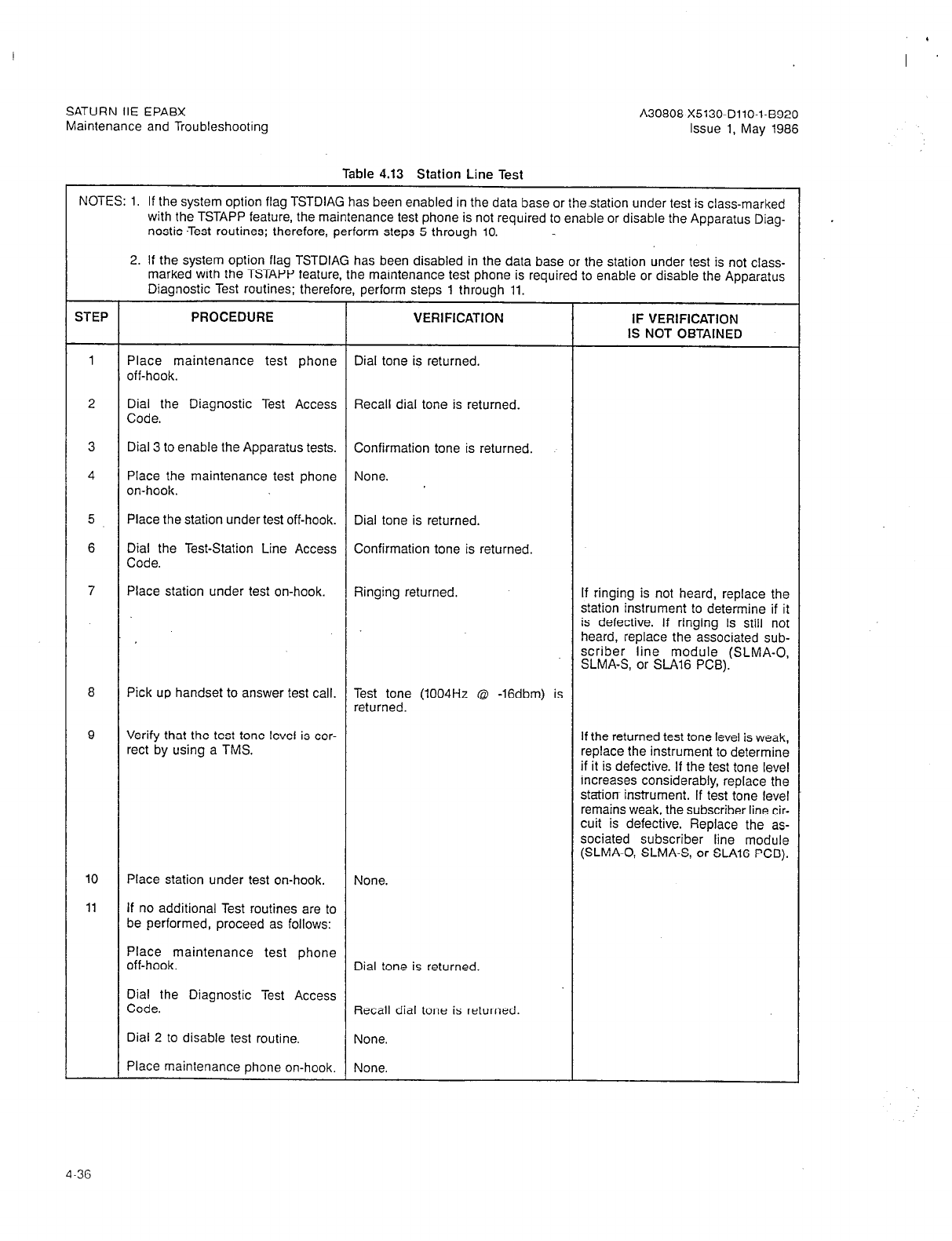
SATURN IIE EPABX
Maintenance and Troubleshooting A30808-X5130-DllO-l-8920
Issue 1, May 1986
Table 4.13 Station Line Test
NOTES: 1. If the system option flag TSTDIAG has been enabled in the data base or the.station under test is class-marked
with the TSTAPP feature, the maintenance test phone is not required to enable or disable the Apparatus Diag-
nostic -Test routines; therefore, perform steps 5 through 10.
2. If the system option flag TSTDIAG has been disabled in the data base or the station under test is not class-
marked with the TSTAPP feature, the maintenance test phone is required to enable or disable the Apparatus
Diagnostic Test routines; therefore, perform steps 1 through 11.
STEP PROCEDURE VERIFICATION IF VERIFICATION
IS NOT OBTAINED
1 Place maintenance test phone Dial tone is returned.
off-hook.
2 Dial the Diagnostic Test Access Recall dial tone is returned.
Code.
3 Dial 3 to enable the Apparatus tests. Confirmation tone is returned.
4 Place the maintenance test phone None.
on-hook.
5 Place the station under test off-hook. Dial tone is returned.
6 Dial the Test-Station Line Access Confirmation tone is returned.
Code.
7 Place station under test on-hook. Ringing returned. If ringing is not heard, replace the
station instrument to determine if it
is defective. If ringing is still not
heard, replace the associated sub-
scriber line module (SLMA-0,
SLMA-S, or S-416 PCB).
8 Pick up handset to answer test call. Test tone (1004Hz @ -16dbm) is
returned.
9 Verify that the test tone level is cor- If the returned test tone level is weak,
rect by using a TM.?. replace the instrument to determine
if it is defective. If the test tone level
increases considerably, replace the
station instrument. If test tone level
remains weak, the subscriber line cir-
cuit is defective. Replace the as-
sociated subscriber line module
(SLMA-0, SLMA-S, or SLA16 PCB).
10
11
Place station under test on-hook. None.
If no additional Test routines are to
be performed, proceed as follows:
Place maintenance test phone
off-hook. Dial tone is returned.
Dial the Diagnostic Test Access
Code. Recall dial tone is returned.
Dial 2 to disable test routine. None.
Place maintenance phone on-hook, None.
4-36

SATURN IIE EPABX
Maintenance and Troubleshooting A30808-X5130-DllO-l-6920
Issue 1, May 1986
pyyq
6
7 8 9 10
==m --
l I I I Flb.5”
=
31 T
E
32 ANS
IT
, 1 a I I ,
11 12 13 14 15
w
26 27 28 29 30
Figure 4.05 Attendant Console Keypad and Feature Button Depression Sequence
4-37
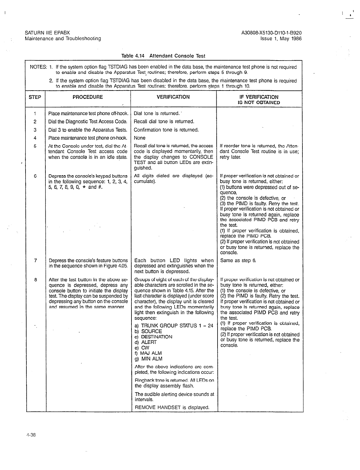
SATURN IIE EPABX A30808-X5130-DllO-l-8920
Maintenance and Troubleshooting Issue 1, May 1986
Table 4.14 Attendant Console Test
,
STEP PROCEDURE VERIFICATION IF tiERtFlcATi0~
IS NOT OBTAINED
1 Place maintenance test phone off-hook. Dial tone is returned.
2 Dial the Diagnostic Test Access Code. Recall dial tone is returned.
3 Dial 3 to enable the Apparatus Tests. Confirmation tone is returned.
4 Place maintenance test phone on-hook. None
5 At the Console under test, dial the At- Recall dial tone is returned, the access If reorder tone is returned, the Atten-
tendant Console Test access code code is displayed momentarily, then dant Console Test routine is in use;
when the console is in an idle state. the display changes to CONSOLE retry later.
TEST and all button LEDs are extin-
guished.
6 Depress the console’s keypad buttons All digits dialed are displayed (ac- If proper verification is not obtained or
in the following sequence: 1, 2, 3, 4, cumulate). busy tone is returned, either:
5, 6, 7, 8, 9, 0, * and #. (1) buttons were depressed out of se-
quence,
(2) the console is defective, or
(3) the PIMD is faulty. Retry the test.
If proper verification is not obtained or
busy tone is returned again, replace
the associated PIMD PCB and retry
the test.
(1) If proper verification is obtained,
replace the PIMD PCB.
(2) If proper verification is not obtained
or busy tone is returned, replace the
console.
7 Depress the console’s feature buttons Each button LED lights when Same as step 6.
in the sequence shown in Figure 4.05. depressed and extinguishes when the
next button is depressed.
8 After the last button in the above se- Groups of eight of each of the display- If proper verification is not obtained or
quence is depressed, depress any able characters are scrolled in the se- busy tone is returned, either:
console button to initiate the display quence shown in Table 4.15. After the (1) the console is defective, or
test. The display can be suspended by last character is displayed (under score (2) the PIMD is faulty. Retry the test.
depressing any button on the console character), the display unit is cleared If proper verification is not obtained or
and resumed in the same manner. and the following LEDs momentarily busy tone is returned again, replace
light then extinguish in the following the associated PIMD PCB and retry
sequence: the test.
. . a) TRUNK GROUP STATUS 1 - 24 (1) If proper verification is obtained,
b) SOURCE replace the PIMD PCB.
c) DESTINATION (2) If proper verification is not obtained
d) ALERT or busy tone is returned, replace the
e) CW console.
9
MAJ ALM
g) MIN ALM
After the above indications are com-
pleted, the following indications occur:
Ringback tone is returned. All LEDs on
the display assembly flash.
The audible alerting device sounds at
intervals.
REMOVE HANDSET is displayed.
4-38
NOTES: 1. If the system option flag TSTDIAG has been enabled in the data base, the maintenance test phone is not required
to enable and disable the Apparatus Test-routines; therefore, perform steps 5 through 9.
2. If the system option flag TSTDIAG has been disabled in the data base, the maintenance test phone is required
to enable and disable the Apparatus Test routines; therefore, perform steps 1 through 10.

SATURN IIE EPABX
Maintenance and Troubleshooting
Table 4.14 Attendant Console Test (Continued)
STEP PROCEDURE VERIFICATION IF VERIFICATION
IS NOT OBTAINED .
9 Remove and reinsert handset assem- INSERT HANDSET is displayed while
bly to terminate test, or wait 30 sec- handset is removed. After handset is
onds for test timeout. reinserted, console returns to normal
operation.
10 If no additional Apparatus Tests are to
be performed proceed as follows:
Place maintenance test phone Dial tone is returned.
off-hook.
Dial the Diagnostic Test Access Code. Recall dial tone is returned.
Dial 2 to disable the Apparatus Tests. None.
Place maintenance test phone None.
on-hook.
Table 4.15 Attendant Console Displayable Characters
ORDER
1.
2.
3.
4.
5.
6.
7.
8.
9.
10.
11.
12.
13.
14.
15.
16.
17.
18.
19.
20.
21.
22.
23.
24.
2
27.
28.
29. 30.
31.
32.
CHARACTER ORDER CHARACTER
I 1 I ! ! F ! !
-;,,,; 33. AAAAAAAA
34. BBBBBBBB
35. cccccccc
f§S$$S$$$ 36. DDDDDDDD
010 % o/o o/o o/o o/o o/o % 37. EEEEEEEE
&&&&&&&& 38. FFFFFFFF
I I I I I I I I
39. GGGGGGGG
( ( ( ( ( ( ( ( 40. HHHHHHHH
41. I I I I I I I I
))I)))))
t * * * * l l *
42. JJJJJJJJ
++++++++ 43. KKKKKKKK
9 I I , I I I I 44. LLLLLLLL
- - - - - - - - 45. MMMMMMMM
i i i i i i i i 46. NNNNNNNN
47. 00000000
00000000 48. PPPPPPPP
1 1 1 1 1 1 1 1 49. QQQQQQQQ
22222222 50. RRRRRRRR
33333333 51. sssssss.s
44444444 52. TTTTTTTT
55555555 53. uuuuuuuu
66666666 54. vvvvvvvv
77777777 55. wwwwwwww
88888888 56. xxxxxxxx
99999999 : : : : : : : : 58. 57. YYYYYYYY
zzzzzzzz
; ; ; ; ; ; : ;
(((((((( 2 1 I I [ 1 \\\\\\\\ I I [
======
KU)))) 61.
62. ~~~L~~
???????? 63. ------__
@?@@OQ@OQ
4-39
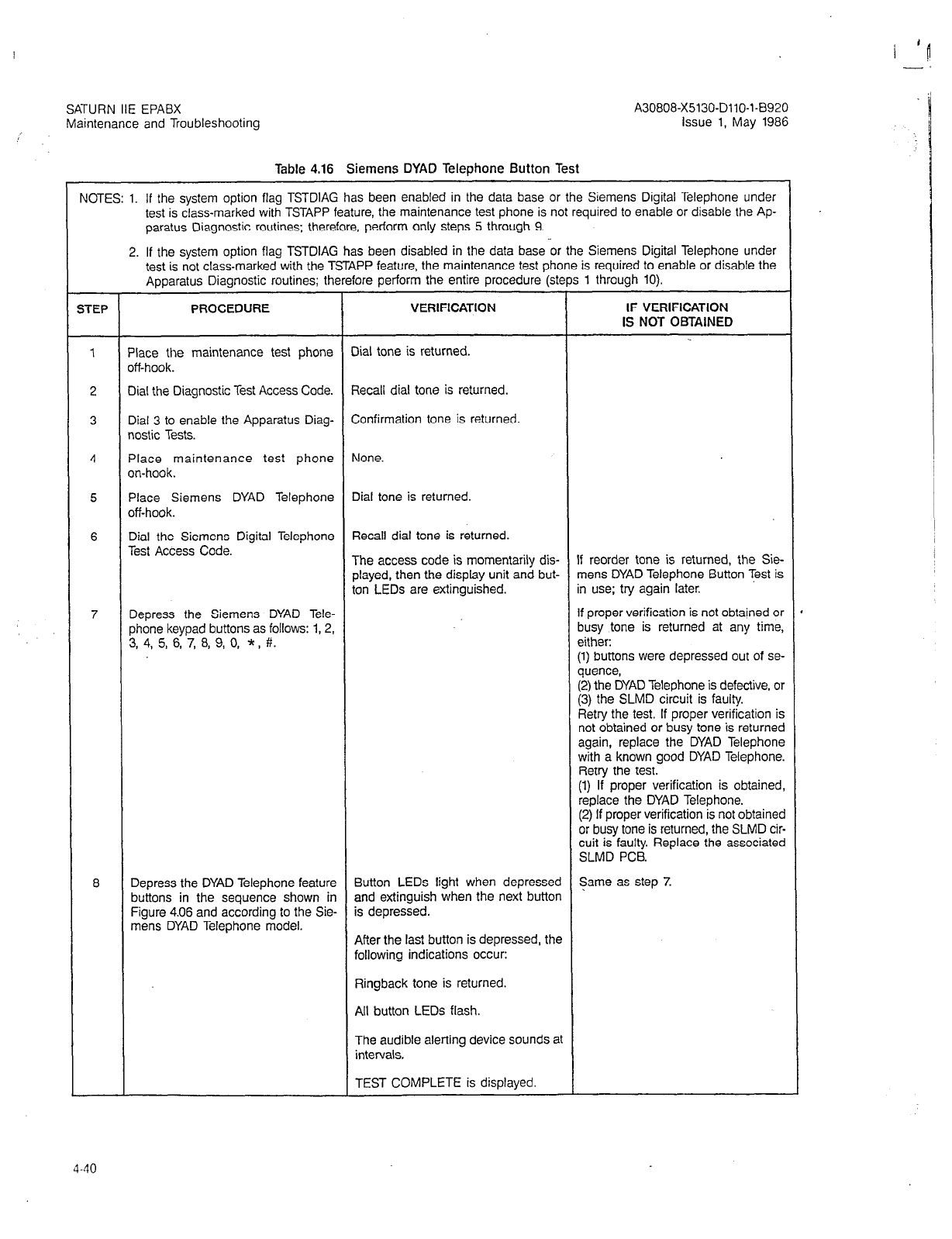
SATURN IIE EPABX
Maintenance and Troubleshooting
Table 4.16 Siemens DYAD Telephone Button Test
NOTES: 1. If the system option flag TSTDIAG has been enabled in the data base or the Siemens Digital Telephone under
test is class-marked with TSTAPP feature, the maintenance test phone is not required to enable or disable the Ap-
paratus Diagnostic routines; therefore, perform only steps 5 through 9.
2. If the system option flag TSTDIAG has been disabled in the data base or the Siemens Digital Telephone under
test is not class-marked with the TSTAPP feature, the maintenance test phone is required to enable or disable the
Apparatus Diagnostic routines; therefore perform the entire procedure (steps 1 through 10).
STEP PROCEDURE VERIFICATION IF VERIFICATION
IS NOT OBTaINED
1 Place the maintenance test phone Dial tone is returned.
off-hook.
2 Dial the Diagnostic Test Access Code. Recall dial tone is returned.
3 Dial 3 to enable the Apparatus Diag- Confirmation tone is returned.
nostic Tests.
4 Place maintenance test phone None.
on-hook.
5 Place Siemens DYAD Telephone Dial tone is returned.
off-hook.
6 Dial the Siemens Digital Telephone Recall dial tone is returned.
Test Access Code. The access code is momentarily dis- If reorder tone is returned, the Sie-
played, then the display unit and but- mens DYAD Telephone Button Test is
ton LEDs are extinguished. in use; try again later.
7 Depress the Siemens DYAD Tele- If proper verification is not obtained or
phone keypad buttons as follows: 1,2, busy tone is returned at any time,
3, 4, 5, 6, 7, 8, 9, 0, * , #. either:
(1) buttons were depressed out of se-
quence,
(2) the DYAD Telephone is defective, or
(3) the SLMD circuit is faulty.
Retry the test. If proper verification is
not obtained or busy tone is returned
again, replace the DYAD Telephone
with a known good DYAD Telephone.
Retry the test.
(1) If proper verification is obtained
replace the DYAD Telephone.
(2) If proper verification is not obtainec
or busy tone is returned, the SLMD cir,
cuit is faulty. Replace the associatec
SLMD PCB.
8 Depress the DYAD Telephone feature Button LEDs light when depressed Same as step 7.
buttons in the sequence shown in and extinguish when the next button
Figure 4.06 and according to the Sie- is depressed.
mens DYAD Telephone model. After the last button is depressed, the
following indications occur:
Ringback tone is returned.
All button LEDs flash.
The audible alerting device sounds at
intervals.
TEST COMPLETE is displayed.
4-40
SATURN IIE EPABX
Maintenance and Troubleshooting A30808-X5130-DllO-l-B920
Issue 1, May 1986
Table 4.16 Siemens DYAD Telephone Button Test (Continued)
STEP PROCEDURE VERIFICATION IF VERIFICATION
IS NOT OBTAINED
9 Place Siemens DYAD Telephone un- Siemens DYAD Telephone-returns to
der test on-hook to terminate test. normal operation.
10 If no additional Apparatus Diagnostic
Test routines are to be performed, pro-
ceed as follows:
Place maintenance test phone Dial tone is returned.
off-hook.
Dial the Diagnostic Test Access code. Recall dial tone is returned.
Dial 2 to disable the Apparatus Diag- None.
nostic Test.
Place maintenance test phone None.
on-hook.
4-41
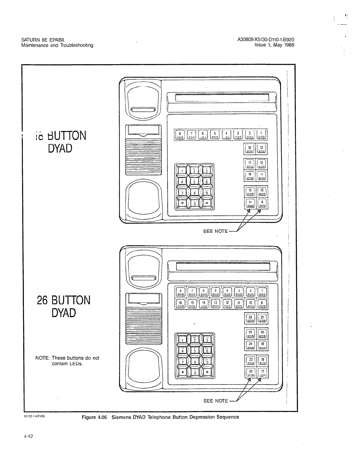
SATURN IIE EPABX A30808-X5130-DllO-l-8920
Maintenance and Troubleshooting Issue 1, May 1986
‘iit dUTTON
DYAD
26 BUTTON
DYAD
NOTE: These buttons do not
contain LEDs.
SEE NOTE2
SEE NOTE2
Figure 4.06 Siemens DYAD Telephone Button Depression Sequence
4-42
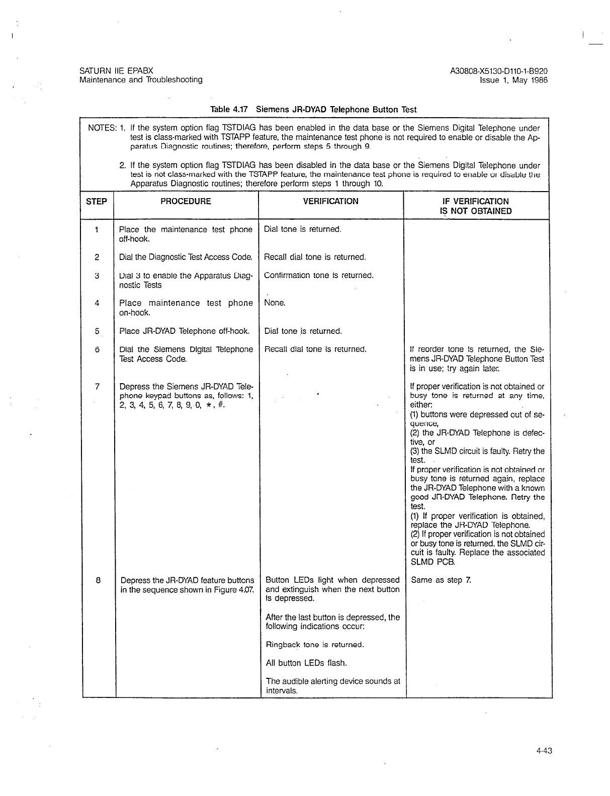
SATURN IIE EPABX
Maintenance and Troubleshooting A30808-X5130-DllO-l-6920
issue 1, May 1986
Table 4.17 Siemens JR-DYAD Telephone Button Test
NOTES: 1. If the svstem option flaa TSTDIAG has been enabled in the data base or the Siemens Diaital Teleohone under
test is class-marked with TSTAPP feature, the maintenance test phone is not required to enaTble or disable the Ap-
paratus Diagnostic routines; therefore, perform steps 5 through 9.
2. If the system option flag TSTDIAG has been disabled in the data base or the Siemens Digital Telephone under
test is not class-marked with the TSTAPP feature, the maintenance test ohone is required to enable or disable the
Apparatus Diagnostic routines; therefore perform steps 1 throuqh 10. ’
1
STEP PROCEDURE
Place the maintenance test phone
off-hook.
Dial the Diagnostic Test Access Code.
Dial 3 to enable the Apparatus Diag-
nostic Tests
Place maintenance test phone
on-hook.
Place JR-DYAD Telephone off-hook.
Dial the Siemens Digital Telephone
Test Access Code.
Depress the Siemens JR-DYAD Tele-
phone keypad buttons as, follows: 1,
2, 3, 4, 5, 6, 7, 8, 9, 0, * . #.
Depress the JR-DYAD feature buttons
in the sequence shown in Figure 4.0%
VERIFICATION
Dial tone is returned.
Recall dial tone is returned.
Confirmation tone is returned.
None.
Dial tone is returned.
Recall dial tone is returned.
Button LEDs light when depressed
and extinguish when the next button
is depressed.
After the last button is depressed, the
following indications occur:
Ringback tone is returned.
All button LEDs flash.
The audible alerting device sounds at
intervals.
IF VERIFICATION
I$ NOT OBTAINED
f reorder tone is returned, the Sie-
nens JR-DYAD Telephone Button Test
s in use; try again later.
!f proper verification is not obtained or
ousy tone is returned at any time,
aither:
:l) buttons were depressed out.of se-
quence,
:2) the JR-DYAD Telephone is defec-
tive, or
(3) the SLMD circuit is faulty. Retry the
test.
If proper verification is not obtained or
busy tone is returned again, replace
the JR-DYAD Telephone with a known
good JR-DYAD Telephone. Retry the
test.
(1) If proper verification is obtained,
replace the JR-DYAD Telephone.
(2) If proper verification is not obtained
or busy tone is returned, the SLMD cir-
cuit is faulty. Replace the associated
SLMD PCB.
Same as step 7.
4-43
SATURN IIE EPABX
Maintenance and Troubleshooting A30808-X5130-DllO-l-8920
Issue 1, May 1986
Table 4.17 Siemens JR-DYAD telephone Button Test (Continued)
STEP PROCEDURE VERIFICATION IF VERIFICATION
IS NOT OBTAINED
9 Place Siemens JR-DYAD Telephone Siemens JR-DYAD Telephone returns
under test on-hook to terminate test. to normal operation.
10 If no additional Apparatus Diagnostic
Test routines are to be performed, pro
teed as follows:
Place maintenance test phone Dial tone is returned.
off-hook.
Dial the Diagnostic Test Access code. Recall dial tone is returned.
Dial 2 to disable the Apparatus Diag- None.
nostic Test.
Place maintenance test phone None.
on-hook.
4-44
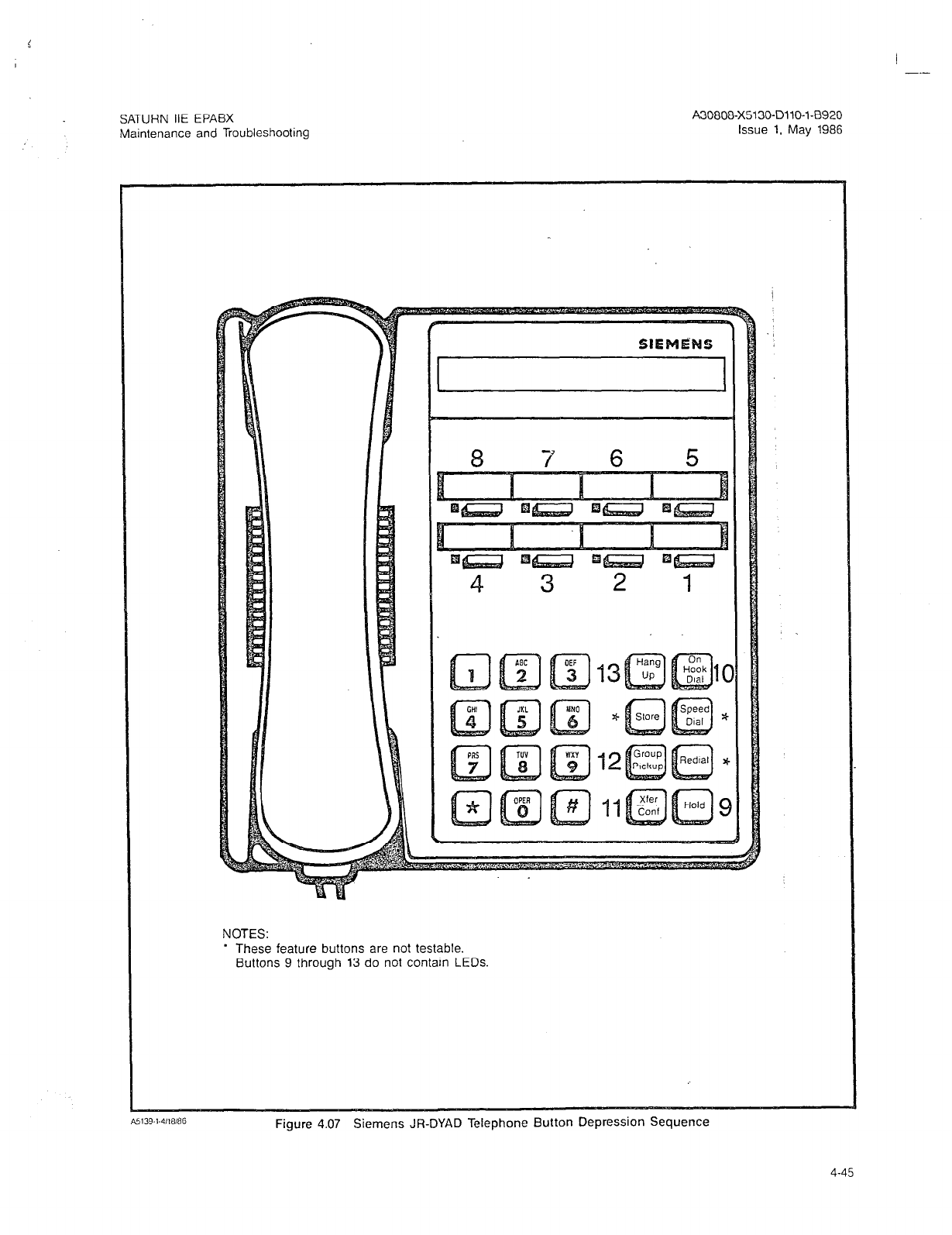
I --
SATURN IIE EPABX
Maintenance and Troubleshooting
A30808-X5130-DllO-l-8920
Issue 1. May 1986
NOTES:
* These feature buttons are not testable.
Buttons 9 through 13 do not contam LEDs.
Figure 4.07 Siemens JR-DYAD Telephone Button Depression Sequence
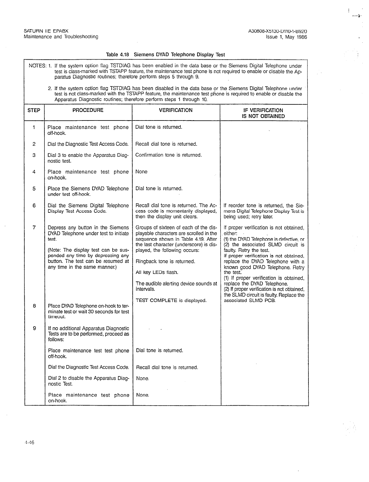
--).
SATURN IIE EPABX A30808-X5130-DllO-l-8920
Maintenance and Troubleshooting Issue 1, May 1986
Table 4.18 Siemens DYAD Telephone Display Test
NOTES: 1. If the system option flag TSTDIAG has been enabled in the data base or the Siemens Digital Telephone under
test is class-marked with TSTAPP feature, the maintenance test phone is not required to enable or disable the Ap
paratus Diagnostic routines: therefore perform steps 5 through 9.
2. If the system option flag TSTDIAG has been disabled in the data base or the Siemens Digital Telephone under
test is not class-marked with the TSTAPP feature, the maintenance test phone is required to enable or disable the
Apparatus Diagnostic routines; therefore perform steps 1 through 10.
STEP PROCEDURE VERIFICATION IF VERIFICATION
IS NOT OBTAINED
1 Place maintenance test phone Dial tone is returned.
off-hook.
2 Dial the Diagnostic Test Access Code. Recall dial tone is returned.
3 Dial 3 to enable the Apparatus Diag- Confirmation tone is returned.
nostic test.
4 Place maintenance test phone None
on-hook.
5 Place the Siemens DYAD Telephone Dial tone is returned.
under test off-hook.
6 Dial the Siemens Digital Telephone Recall dial tone is returned. The Ac- If reorder tone is returned, the Sie-
Display Test Access Code. cess code is momentarily displayed, mens Digital Telephone Display Test is
then the display unit clears. being used; retry later.
7 Depress any button in the Siemens Groups of sixteen of each of the dis- If proper verification is not obtained,
DYAD Telephone under test to initiate playable charactew are scrolled in the either:
test. sequence shown in Table 4.19. After (1) the DYAD Te!ephone is defective, or
the last character (underscore) is dis- (2) the associated SLMD circuit is
(Note: The display test can be sus- played, the following occurs: faulty. Retry the test.
pended any time by depressing any If proper verification is not obtained,
button. The test can be resumed at Ringback tone is returned. replace the DYAD Telephone with a
any time in the same manner.) known good DYAD Telephone. Retry
All key LEDs flash. the test.
(1) If proper verification is obtained,
The audible alerting device sounds at replace the DYAD Telephone.
intervals. (2) If proper verification is not obtained,
the SLMD circuit is faulty. Replace the
TEST COMPLETE is displayed. associated SLMD PCB.
8 Place DYAD Telephone on-hook to ter-
minate test or wait 30 seconds for test
timeout.
9 If no additional Apparatus Diagnostic .
Tests are to be performed, proceed as
follows:
Place maintenance test test phone Dial tone is returned.
off-hook.
Dial the Diagnostic Test Access Code. Recall dial tone is returned.
Dial 2 to disable the Apparatus Diag- None.
nostic Test.
Place maintenance test phone None.
on-hook.
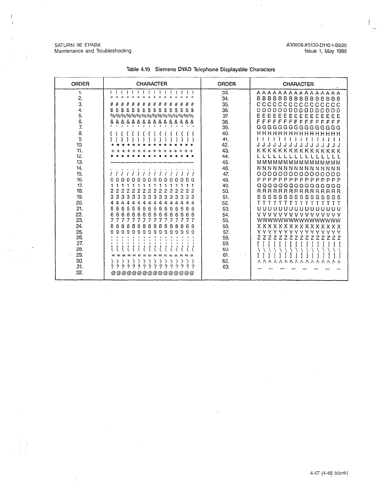
SATURN IIE EPABX A30808-X5130-DllO-l-8920
Maintenance and Troubleshooting Issue 1, May 1986
Table 4.19 Siemens DYAD Telephone Displayable Characters
ORDER CHARACTER ORDER, CHARACTER
1. ! ! ! ! ! ! ! ! ! ! ! ! ! ! ! ! 33. AAAAAAAAAAAAAAAA
2. ,, r, I, I, I, I, ,, I, II ,I I, ,I I, I, n I, -34. BBBBBBBBBBBBBBBB
3. ##########I###### 35. cccccccccccccccc
4. $$$5$S$$SSSS$SSS 36. DDDDDDDDDDDDDDDD
5. %%%%%%%%%%%%%%%% 37. EEEEEEEEEEEEEEEE
6. &&&&&&&&&&&&&&&& 38. FFFFFFFFFFFFFFFF
7.
39. GGGGGGGGGGGGGGGG
8. ;;;;;;;;;;;;;;;; 40. H-HHHHHHHHHHHHHHH
9. )))))))))))))))) 41. I I II‘1 I I I I I I I I1 I I
10. **************x* 42. JJJJJJJJJJJJJJJJ
11. ++++++++++++++++ 43. KKKKKKKKKKKKKKKK
12. .**.0...*.0**0.* 44. LLLLLLLLLLLLLLLL
13. --_---__-------- 45. MMMMMMMMMMMMMMMM
14. 46. NNNNNNNNNNNNNNNN
15. ;i;iii;iii;iiii; 4% 0000000000000000
16. 0000000000000000 48. PPPPPPPPPPPPPPPP
17.
18.
19.
20.
21.
22.
23.
24.
25.
26.
27.
28.
29.
30.
31.
32.
1111111111111111
2222222222222222
3333333333333333
4444444444444444
5555555555555555
6666666666666666
7777777777777777
8888888888888888
9999999999999999
. * . . . . . . . . . . . . . .
. . . . . . . . . * . . . . . .
. . . . . . . . . . . . . . . .
~~~~i~i~~~~iii~~
==========zz=====
49.
50.
51.
52.
53.
54.
55.
56.
57.
58.
59.
60.
61.
62.
63.
QQQQQ-QQQQQQQQQQQ
RRRRRARRRRRRRRRR
ssssssssssssssss
TTTTTTTTTTTTTTTT
uuuuuuuuuuuuuuuu
vvvvvvvvvvvvv~vvv
wwwwwwwwwwwwwwww
xxxxxxxxxxxxxxxx
YYYYYYYYYYYYYYYY
zzzzzzzzzzzzzzzz
I I [ 11 1 [ 1 [ I I [ I[ [ [
\\\\\\\\\\\\\\\\
111111’1111 I1 11 II
AAAAAAAAAAAAAAAA
- - - - - - - -
4-47 (4-48 blank)
