AC Servo Drives Sigma II Series SGMVH/SGDM/SGDH USER'S MANUAL SGMVH SGDM SGDH User
User Manual:
Open the PDF directly: View PDF ![]() .
.
Page Count: 339 [warning: Documents this large are best viewed by clicking the View PDF Link!]
- Front Cover
- About this Manual
- Safety Information
- Notes for Safe Operation
- CONTENTS
- 1 Outline
- 2 Selections
- 3 Servomotor Specifications and Dimensional Drawings
- 4 SERVOPACK Specifications and Dimensional Drawings
- 5 Specifications and Dimensional
Drawings of Cables and
Peripheral Devices
- 5.1 SERVOPACK Main Circuit Wire Size
- 5.2 Encoder Cables for CN2 Connector
- 5.3 Connectors and Cables for Encoder Signals
- 5.4 I/O Signal Cables for CN1 Connector
- 5.5 Peripheral Devices
- 5.5.1 Cables for Connecting Personal Computers
- 5.5.2 Digital Operator
- 5.5.3 Cables for Analog Monitor
- 5.5.4 Connector Terminal Block Converter Unit
- 5.5.5 Brake Power Supply Unit
- 5.5.6 Absolute Encoder Battery
- 5.5.7 Molded-case Circuit Breaker (MCCB)
- 5.5.8 Noise Filter
- 5.5.9 Surge Absorber
- 5.5.10 Regenerative Resistor Unit
- 5.5.11 Dynamic Brake (DB) Unit
- 5.5.12 Thermal Relays
- 5.5.13 Variable Resistor for Speed and Torque Setting
- 5.5.14 Encoder Signal Converter Unit
- 5.5.15 MECHATROLINK Application Module
- 5.5.16 DeviceNet Application Module
- 5.5.17 PROFIBUS-DP Application Module
- 5.5.18 Fully-closed Application Module
- 6 Wiring
- 7 Digital Operator/Panel Operator
- 7.1 Functions on Digital Operator/Panel Operator
- 7.2 Operation in Utility Function Mode (Fn***)
- 7.2.1 List of Utility Function Modes
- 7.2.2 Alarm Traceback Data Display (Fn000)
- 7.2.3 Zero-point Search Mode (Fn003)
- 7.2.4 Parameter Settings Initialization (Fn005)
- 7.2.5 Alarm Traceback Data Clear (Fn006)
- 7.2.6 Manual Zero Adjustment and Gain Adjustment of Analog Monitor Output (Fn00C, Fn00D)
- 7.2.7 Offset Adjustment of Motor Current Detection Signal (Fn00E, Fn00F)
- 7.2.8 Password Setting (Protects Parameters from Being Changed) (Fn010)
- 7.2.9 Motor Models Display (Fn011)
- 7.2.10 Software Version Display (Fn012)
- 7.2.11 Application Module Detection Results Clear (Fn014)
- 7.3 Operation in Parameter Setting Mode (Pn***)
- 7.4 Operation in Monitor Mode (Un***)
- 8 Operation
- 8.1 Trial Operation
- 8.2 Control Mode Selection
- 8.3 Setting Common Basic Functions
- 8.4 Absolute Encoders
- 8.5 Operating Using Speed Control with Analog Reference
- 8.6 Operating Using Position Control
- 8.7 Operating Using Torque Control
- 8.8 Operating Using Speed Control with an Internally Set Speed
- 8.9 Limiting Torque
- 8.9.1 Internal Torque Limit (Limiting Maximum Output Torque)
- 8.9.2 External Torque Limit (Output Torque Limiting by Input Signals)
- 8.9.3 Torque Limiting Using an Analog Voltage Reference
- 8.9.4 Torque Limiting Using an External Torque Limit and Analog Voltage Reference
- 8.9.5 Checking Output Torque Limiting during Operation
- 8.10 Control Mode Selection
- 8.11 Other Output Signals
- 9 Adjustments
- 9.1 Autotuning
- 9.2 Online Autotuning
- 9.3 Manual Tuning
- 9.4 Servo Gain Adjustment Functions
- 9.4.1 Feed-forward Reference
- 9.4.2 Torque Feed-forward
- 9.4.3 Speed Feed-forward
- 9.4.4 Proportional Control Operation (Proportional Operation Reference)
- 9.4.5 Using the Mode Switch (P/PI Switching)
- 9.4.6 Setting the Speed Bias
- 9.4.7 Speed Feedback Filter
- 9.4.8 Speed Feedback Compensation
- 9.4.9 Switching Gain Settings
- 9.4.10 Torque Reference Filter
- 9.5 Analog Monitor
- 10 Inspection, Maintenance, and Troubleshooting
- 11 Appendix
- 11.1 Servomotor Capacity Selection Examples
- 11.2 Connection to Host Controller
- 11.2.1 Example of Connection to MP2200/MP2300 Motion Module SVA-01
- 11.2.2 Example of Connection to MP920 4-axes Analog Module SVA-01
- 11.2.3 Example of Connection to OMRON’s Motion Control Unit
- 11.2.4 Example of Connection to OMRON’s Position Control Unit
- 11.2.5 Example of Connection to MITSUBISHI’s AD72 Positioning Unit (SERVOPACK in Speed Control Mode)
- 11.2.6 Example of Connection to MITSUBISHI’s AD75 Positioning Unit (SERVOPACK in Position Control Mode)
- 11.3 List of Parameters
- 11.4 Parameter Recording Table
- INDEX
- Revision History
- Back Cover
SGMVH Servomotor
SGDM/SGDH SERVOPACKs
Σ-II Series
AC Servo Drives
USER'S MANUAL
Outline
Selections
Servomotor Specifications and
Dimensional Drawings
SERVOPACK Specifications and
Dimensional Drawings
Specifications and Dimensional Drawings of
Cables and Peripheral Devices
Wiring
Digital Operator/Panel Operator
Operation
Adjustments
Inspection, Maintenance,
and Troubleshooting
Appendix
MANUAL NO. SIEP S800000 59A
1
2
3
4
5
6
7
8
9
10
11
モーションコントロール事業部(A4)(英文)
SGMVH/SGDM/SGDH
CN2
CN3
CN1
480
V 460
V
DU
400
V 0
V
440
V
DWDV B1
380
V
DC
24N
B2
DC
24P
CHARGE
S -HDG
****
T DATA/SEEMOD /
KSERVOPAC
AYASKAW
R
O
P
E
R
A
T
O
CN3
8CN
POWER
CN5

Copyright © 2008 YASKAWA ELECTRIC CORPORATION
All rights reserved. No part of this publication may be reproduced, stored in a retrieval system,
or transmitted, in any form, or by any means, mechanical, electronic, photocopying, recording,
or otherwise, without the prior written permission of Yaskawa. No patent liability is assumed
with respect to the use of the information contained herein. Moreover, because Yaskawa is con-
stantly striving to improve its high-quality products, the information contained in this manual is
subject to change without notice. Every precaution has been taken in the preparation of this
manual. Nevertheless, Yaskawa assumes no responsibility for errors or omissions. Neither is
any liability assumed for damages resulting from the use of the information contained in this
publication.

iii
About this Manual
Intended Audience
This manual is intended for the following users.
• Those selecting Σ-II Series servo drives or peripheral devices for Σ-II Series servo drives.
• Those wanting to know about the ratings and characteristics of Σ-II Series servo drives.
• Those designing Σ-II Series servo drive systems.
• Those installing or wiring Σ-II Series servo drives.
• Those performing trial operation or adjustments of Σ-II Series servo drives.
• Those maintaining or inspecting Σ-II Series servo drives.
Description of Technical Terms
The terms in this manual are defined as follows:
• Servomotor or motor = Σ-II Series SGMVH servomotor.
• SERVOPACK = Σ-II Series SGDM/SGDH amplifier.
• Servo drive = A set including a servomotor and servo amplifier.
• Servo system = A servo control system that includes the combination of a servo drive with a host
controller and peripheral devices.
• Parameter number = Numbers that the user inputs toward the SERVOPACK.

iv
Quick access to your required information
Read the chapters marked with 9 to get the information required for your purpose.
■Visual Aids
The following aids are used to indicate certain types of information for easier reference.
• Indicates important information that should be memorized, including precautions such as alarm dis-
plays to avoid damaging the devices.
• Indicates supplemental information.
• Indicates application examples.
• Indicates definitions of difficult terms or terms that have not been previously explained in this man-
ual.
Chapter
SERVOPACKs,
Servomotors,
and Peripheral
Devices
Ratings and
Character-
istics
System
Design
Panel
Configura-tion
and Wiring
Trial Operation
and Servo
Adjustment
Inspection and
Maintenance
Chapter 1
Outline
9
Chapter 2
Selections
9
Chapter 3
Servomotor Specifications
and Dimensional Drawings
9999
Chapter 4
SERVOPACK Specifications
and Dimensional Drawings
9999
Chapter 5
Specifications and
Dimensional Drawings of
Cables and Peripheral
Devices
9999
Chapter 6
Wiring
99 9
Chapter 7
Digital Operator/Panel
Operator
99
Chapter 8
Operation
9
Chapter 9
Adjustments
9
Chapter 10
Inspection, Maintenance,
and Troubleshooting
9
Chapter 11
Appendix
9999
IMPORTANT
INFO
EXAMPLE
TERMS

v
■Indication of Reverse Signals
In this manual, the names of reverse signals (ones that are valid when low) are written with a forward slash (/)
before the signal name, as shown in the following example:
• S-ON = /S-ON
• P-CON = /P-CON
■Related Manuals
Refer to the following manuals as required.
Manual Name Manual Number Contents
Σ-II Series SGMH/SGDH
Digital Operator Operation Manual
TOE-S800-34 Provides detailed information on the operating method
of JUSP-OP02A-2 type Digital Operator (option
device).
Σ-II Series SERVOPACKs
Personal Computer Monitoring Software
Operation Manual
SIE-S800-35 Describes the using and the operating methods on soft-
ware that changes the local personal computer into the
monitor equipment for the Σ-II Series servomotor.
Σ-II Series SGDH
Fully Closed Interface Unit
User’s Manual
Type: JUSP-FC100
SIE-C718-5 Provides detailed information on the fully closed con-
trol of the JUSP-FC100 interface unit.
Σ-II Series SGDH MECHATROLINK
Application Module User’s Manual
Type: JUSP-NS100
SIE-C718-4 Provides detailed information on MECHATROLINK
communications.
Σ-II Series SGDH MECHATROLINK-II
Application Module User’s Manual
Type: JUSP-NS115
SIEPC71080001 Provides detailed information on MECHATROLINK-II
communications.
Σ-II Series SGDH
DeviceNet Application Module
User’s Manual
Type: JUSP-NS300
SIE-C718-6 Provides detailed information on DeviceNet communi-
cations.
Σ-II Series SGDH PROFIBUS-DP
Application Module User’s Manual
Type: JUSP-NS500
SIE-C718-8 Provides detailed information on PROFIBUS-DP
communications.
vi
Safety Information
The following conventions are used to indicate precautions in this manual. Failure to heed precautions provided
in this manual can result in serious or possibly even fatal injury or damage to the products or to related equipment
and systems.
Indicates precautions that, if not heeded, could possibly result in loss of life or serious
injury.
Indicates precautions that, if not heeded, could result in relatively serious or minor
injury, damage to the product, or faulty operation.
In some situations, the precautions indicated could have serious consequences if not heeded.
Indicates prohibited actions that must not be performed. For example, this symbol
would be used as follows to indicate that fire is prohibited: .
Indicates compulsory actions that must be performed. For example, this symbol would
be used as follows to indicate that grounding is compulsory: .
WARNING
CAUTION
PROHIBITED
MANDATORY

vii
Notes for Safe Operation
Read this manual thoroughly before checking products on delivery, storage and transportation, installation,
wiring, operation and inspection, and disposal of the AC servo drive.
• Never touch any rotating motor parts while the motor is running.
Failure to observe this warning may result in injury.
• Before starting operation with a machine connected, make sure that an emergency stop can
be applied at any time.
Failure to observe this warning may result in injury.
• Never touch the inside of the SERVOPACKs.
Failure to observe this warning may result in electric shock.
• Do not touch terminals for five minutes after the power is turned OFF.
Residual voltage may cause electric shock.
• Do not touch terminals for five minutes after voltage resistance test.
Residual voltage may cause electric shock.
• Follow the procedures and instructions for trial operation precisely as described in this
manual.
Malfunctions that occur after the servomotor is connected to the equipment not only damage the
equipment, but may also cause an accident resulting in death or injury.
• The multiturn limit value must be changed only for special applications.
Changing it inappropriately or unintentionally can be dangerous.
• If the Multiturn Limit Disagreement alarm (A.CC) occurs, check the setting of parameter
Pn205 in the SERVOPACK to be sure that it is correct.
If Fn013 is executed when an incorrect value is set in Pn205, an incorrect value will be set in the
encoder. The alarm will disappear even if an incorrect value is set, but incorrect positions will be
detected, resulting in a dangerous situation where the machine will move to unexpected positions.
• Do not remove the front cover, cables, connectors, or optional items while the power is ON.
Failure to observe this warning may result in electric shock.
• Installation, disassembly, or repair must be performed only by authorized personnel.
Failure to observe this warning may result in electric shock or injury.
• Do not damage, press, exert excessive force or place heavy objects on the cables.
Failure to observe this warning may result in electric shock, stopping operation of the product, or
burning.
• Provide an appropriate stopping device on the machine side to ensure safety.
A holding brake for a servomotor with brake is not a stopping device for ensuring safety.
Failure to observe this warning may result in injury.
• Do not come close to the machine immediately after resetting momentary power loss to
avoid an unexpected restart.
Take appropriate measures to ensure safety against an unexpected restart.
Failure to observe this warning may result in injury.
• Do not modify products.
Failure to observe this warning may result in injury or damage to products.
• Connect the ground terminal to electrical codes (ground resistance: 100 Ω or less).
Improper grounding may result in electric shock or fire.
WARNING
viii
Checking on Delivery
Storage and Transportation
• Always use the servomotor and SERVOPACK in one of the specified combinations.
Failure to observe this caution may result in fire or malfunction.
• Do not store or install the product in the following places.
• Locations subject to direct sunlight.
• Locations subject to temperatures outside the range specified in the storage or installation temperature conditions.
• Locations subject to humidity outside the range specified in the storage or installation humidity conditions.
• Locations subject to condensation as the result of extreme changes in temperature.
• Locations subject to corrosive or flammable gases.
• Locations subject to dust, salts, or iron dust.
• Locations subject to exposure to water, oil, or chemicals.
• Locations subject to shock or vibration.
Failure to observe this caution may result in fire, electric shock, or damage to the product.
• Do not hold the product by the cables or motor shaft while transporting it.
Failure to observe this caution may result in injury or malfunction.
• Do not place any load exceeding the limit specified on the packing box.
Failure to observe this caution may result in injury or malfunction.
• If disinfectants or insecticides must be used to treat packing materials such as wooden frames, pallets, or
plywood, the packing materials must be treated before the product is packaged, and methods other than
fumigation must be used.
Example: Heat treatment, where materials are kiln-dried to a core temperature of 56°C for 30
minutes or more.
If the electronic products, which include stand-alone products and products installed in machines, are packed with
fumigated wooden materials, the electrical components may be greatly damaged by the gases or fumes resulting from
the fumigation process. In particular, disinfectants containing halogen, which includes chlorine, fluorine, bromine, or
iodine can contribute to the erosion of the capacitors.
Installation
• Never use the products in an environment subject to water, corrosive gases, inflammable gases, or
combustibles.
Failure to observe this caution may result in electric shock or fire.
• Do not step on or place a heavy object on the product.
Failure to observe this caution may result in injury.
• Do not cover the inlet or outlet parts and prevent any foreign objects from entering the product.
Failure to observe this caution may cause internal elements to deteriorate resulting in malfunction or fire.
• Be sure to install the product in the correct direction.
Failure to observe this caution may result in malfunction.
CAUTION
CAUTION
CAUTION
ix
Wiring
• Provide the specified clearances between the SERVOPACK and the control panel or with
other devices.
Failure to observe this caution may result in fire or malfunction.
• Do not apply any strong impact.
Failure to observe this caution may result in malfunction.
• Connect the ground terminal to electrical codes (ground resistance: 100 Ω or less).
Improper grounding may result in electric shock or fire.
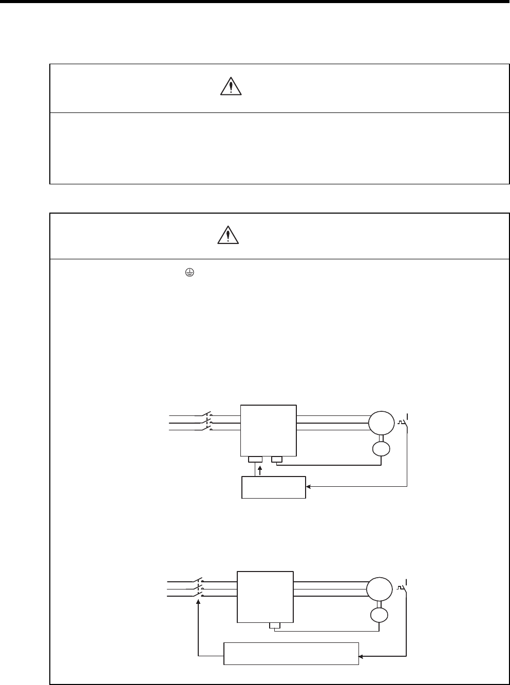
• Use the thermal protector built into the servomotor according to either of the two following methods.
SGMVH servomotors are cooled by a fan. If the fan is defective or power to the fan is disconnected, heat from the
motor may result in burns or fire.
Method 1:
• Wire the output from the thermal protector to the host controller and turn OFF the servo when the thermal
protector operates.
Method 2:
• Wire the thermal protector to the operating circuit of the main circuit magnetic contactors or the host
controller and turn OFF the main circuit magnetic contactor when the thermal protector operates.
Installation(cont’d)
CAUTION
WARNING
Host Controller
Servo OFF
PG
MThermal
protector
Main circuit
magnetic
contactors
Main circuit
power supply SERVOPACK
PG
MThermal
protector
Main circuit
magnetic
contactors
To main circuit
magnetic contactors
Host controller or operating circuit
of main circuit magnetic contactors
Main circuit
power supply SERVOPACK

x
• Do not connect a three-phase power supply to the U, V, or W output terminals.
Failure to observe this caution may result in injury or fire.
• Securely connect the power supply terminals and motor output terminals.
Failure to observe this caution may result in fire.
• Do not bundle or run power and signal lines together in the same duct. Keep power and signal lines
separated by at least 30 cm.
• Use twisted-pair shielded wires or multi-core twisted pair shielded wires for signal and encoder (PG)
feedback lines.
The maximum length is 3 m for reference input lines and is 20 m for PG feedback lines.
• Do not touch the power terminals for five minutes after turning power OFF because high voltage may still
remain in the SERVOPACK.
Make sure the charge indicator is turned OFF first before starting an inspection.
• Avoid frequently turning power ON and OFF.
Since the SERVOPACK has a capacitor in the power supply, a high charging current flows for 0.2 seconds when
power is turned ON. Frequently turning power ON and OFF causes main power devices such as capacitors and fuses
to deteriorate, resulting in unexpected problems.
• Install the battery at either the host controller or the SERVOPACK.
It is dangerous to install batteries at both simultaneously, because that sets up a loop circuit between the batteries.
• Be sure to wire correctly and securely.
Failure to observe this caution may result in motor overrun, injury, or malfunction.
• Always use the specified power supply voltage.
An incorrect voltage may result in burning.
• Take appropriate measures to ensure that the input power supply is supplied within the specified voltage
fluctuation range. Be particularly careful in places where the power supply is unstable.
An incorrect power supply may result in damage to the product.
• Install external breakers or other safety devices against short-circuiting in external wiring.
Failure to observe this caution may result in fire.
• Take appropriate and sufficient countermeasures for each when installing systems in the following
locations.
• Locations subject to static electricity or other forms of noise.
• Locations subject to strong electromagnetic fields and magnetic fields.
• Locations subject to possible exposure to radioactivity.
• Locations close to power supplies including power supply lines.
Failure to observe this caution may result in damage to the product.
• Do not reverse the polarity of the battery when connecting it.
Failure to observe this caution may damage the battery or cause it to explode.
CAUTION
xi
Operation
• Conduct trial operation on the servomotor alone with the motor shaft disconnected from machine to avoid
any unexpected accidents.
Failure to observe this caution may result in injury.
• Before starting operation with a machine connected, change the settings to match the parameters of the
machine.
Starting operation without matching the proper settings may cause the machine to run out of control or malfunction.
• Forward run prohibited (P-OT) and reverse run prohibited (N-OT) signals are not effective during zero point
search mode using parameter Fn003.
• When using the servomotor for a vertical axis, install the safety devices to prevent workpieces to fall off due
to occurrence of alarm or overtravel. Set the servomotor so that it will stop in the zero clamp state at
occurrence of overtravel.
Failure to observe this caution may cause workpieces to fall off due to overtravel.
• Do not touch the SERVOPACK heatsinks, regenerative resistor, or servomotor while power is ON or soon
after the power is turned OFF.
Failure to observe this caution may result in burns due to high temperatures.
• Do not make any extreme adjustments or setting changes of parameters.
Failure to observe this caution may result in injury due to unstable operation.
• When an alarm occurs, remove the cause, reset the alarm after confirming safety, and then resume
operation.
Failure to observe this caution may result in injury.
• Do not use the servo brake of the servomotor for ordinary braking.
Failure to observe this caution may result in malfunction.
• Do not turn the Servo ON or OFF unless necessary.
Failure to observe this caution may cause internal parts to deteriorate.
CAUTION

xii
Maintenance and Inspection
Disposal
General Precautions
• When replacing the SERVOPACK, transfer the previous SERVOPACK parameters to the new
SERVOPACK before resuming operation.
Failure to observe this caution may result in damage to the product.
• Do not attempt to change wiring while the power is ON.
Failure to observe this caution may result in electric shock or injury.
• Do not disassemble the servomotor.
Failure to observe this caution may result in electric shock or injury.
• When disposing of the products, treat them as ordinary industrial waste.
Note the following to ensure safe application.
• The drawings presented in this manual are sometimes shown without covers or protective guards. Always replace
the cover or protective guard as specified first, and then operate the products in accordance with the manual.
• The drawings presented in this manual are typical examples and may not match the product you received.
• This manual is subject to change due to product improvement, specification modification, and manual
improvement. When this manual is revised, the manual code is updated and the new manual is published as a next
edition.
• If the manual must be ordered due to loss or damage, inform your nearest Yaskawa representative or one of the
offices listed on the back of this manual.
• Yaskawa will not take responsibility for the results of unauthorized modifications of this product. Yaskawa shall
not be liable for any damages or troubles resulting from unauthorized modification.
CAUTION
CAUTION

xiii
CONTENTS
About this Manual - - - - - - - - - - - - - - - - - - - - - - - - - - - - - - - - - - - - - - - - - - - - - - - - - - - - - - - -iii
Safety Information - - - - - - - - - - - - - - - - - - - - - - - - - - - - - - - - - - - - - - - - - - - - - - - - - - - - - - - vi
Notes for Safe Operation - - - - - - - - - - - - - - - - - - - - - - - - - - - - - - - - - - - - - - - - - - - - - - - - - - vii
1 Outline
1.1 Checking Products - - - - - - - - - - - - - - - - - - - - - - - - - - - - - - - - - - - - - - - - - - - - 1-2
1.1.1 Check Items - - - - - - - - - - - - - - - - - - - - - - - - - - - - - - - - - - - - - - - - - - - - - - - - - - - - - - - - - - 1-2
1.1.2 Servomotors - - - - - - - - - - - - - - - - - - - - - - - - - - - - - - - - - - - - - - - - - - - - - - - - - - - - - - - - - - 1-2
1.1.3 SERVOPACKs - - - - - - - - - - - - - - - - - - - - - - - - - - - - - - - - - - - - - - - - - - - - - - - - - - - - - - - - 1-2
1.2 Examples of Servo System Configurations - - - - - - - - - - - - - - - - - - - - - - - - - - - 1-3
1.2.1 Three-phase, 200 V Series- - - - - - - - - - - - - - - - - - - - - - - - - - - - - - - - - - - - - - - - - - - - - - - - 1-3
1.2.2 Three-phase, 400 V Series- - - - - - - - - - - - - - - - - - - - - - - - - - - - - - - - - - - - - - - - - - - - - - - - 1-4
1.3 Applicable Standards - - - - - - - - - - - - - - - - - - - - - - - - - - - - - - - - - - - - - - - - - - 1-5
1.3.1 North American Safety Standards (UL) - - - - - - - - - - - - - - - - - - - - - - - - - - - - - - - - - - - - - - - 1-5
1.3.2 CE Marking- - - - - - - - - - - - - - - - - - - - - - - - - - - - - - - - - - - - - - - - - - - - - - - - - - - - - - - - - - - 1-5
2 Selections
2.1 Servomotor Model Designations - - - - - - - - - - - - - - - - - - - - - - - - - - - - - - - - - - 2-2
2.2 SERVOPACK Model Designations - - - - - - - - - - - - - - - - - - - - - - - - - - - - - - - - - 2-3
2.3 Σ-II Series SERVOPACKs and Applicable Servomotor - - - - - - - - - - - - - - - - - - - 2-4
2.4 Selecting Cables - - - - - - - - - - - - - - - - - - - - - - - - - - - - - - - - - - - - - - - - - - - - - 2-5
2.4.1 Cables for SGMVH Servomotor - - - - - - - - - - - - - - - - - - - - - - - - - - - - - - - - - - - - - - - - - - - - 2-5
2.5 Selecting Peripheral Devices - - - - - - - - - - - - - - - - - - - - - - - - - - - - - - - - - - - - - 2-6
2.5.1 Special Options - - - - - - - - - - - - - - - - - - - - - - - - - - - - - - - - - - - - - - - - - - - - - - - - - - - - - - - - 2-6
2.5.2 Molded-case Circuit Breaker and Fuse Capacity - - - - - - - - - - - - - - - - - - - - - - - - - - - - - - - - 2-8
2.5.3 Noise Filters, Magnetic Contactors, and Brake Power Supply Units - - - - - - - - - - - - - - - - - - - 2-9
2.5.4 Regenerative Resistor Units - - - - - - - - - - - - - - - - - - - - - - - - - - - - - - - - - - - - - - - - - - - - - - 2-9
2.5.5 Dynamic Brake (DB) Units - - - - - - - - - - - - - - - - - - - - - - - - - - - - - - - - - - - - - - - - - - - - - - - 2-10
2.5.6 Thermal Relays- - - - - - - - - - - - - - - - - - - - - - - - - - - - - - - - - - - - - - - - - - - - - - - - - - - - - - - 2-11
3 Servomotor Specifications and Dimensional Drawings
3.1 Ratings and Specifications of SGMVH (1500 min-1) - - - - - - - - - - - - - - - - - - - - - 3-2
3.2 Ratings and Specifications of SGMVH (800 min-1) - - - - - - - - - - - - - - - - - - - - - - 3-6
3.3 Mechanical Specifications of Servomotors - - - - - - - - - - - - - - - - - - - - - - - - - - - 3-9
3.3.1 Precautions on Servomotor Installation - - - - - - - - - - - - - - - - - - - - - - - - - - - - - - - - - - - - - - - 3-9
3.3.2 Allowable Radial and Thrust Loads - - - - - - - - - - - - - - - - - - - - - - - - - - - - - - - - - - - - - - - - - 3-13
3.3.3 Mechanical Tolerance - - - - - - - - - - - - - - - - - - - - - - - - - - - - - - - - - - - - - - - - - - - - - - - - - - 3-14
3.3.4 Direction of Servomotor Rotation - - - - - - - - - - - - - - - - - - - - - - - - - - - - - - - - - - - - - - - - - - 3-14
3.3.5 Impact Resistance - - - - - - - - - - - - - - - - - - - - - - - - - - - - - - - - - - - - - - - - - - - - - - - - - - - - - 3-14
3.3.6 Vibration Resistance - - - - - - - - - - - - - - - - - - - - - - - - - - - - - - - - - - - - - - - - - - - - - - - - - - - 3-14

xiv
3.3.7 Vibration Class - - - - - - - - - - - - - - - - - - - - - - - - - - - - - - - - - - - - - - - - - - - - - - - - - - - - - - - - 3-15
3.4 Dimensional Drawings of SGMVH Servomotors (1500 min-1) - - - - - - - - - - - - - 3-16
3.5 Dimensional Drawings of SGMVH Servomotors (800 min-1) - - - - - - - - - - - - - - 3-22
4 SERVOPACK Specifications and Dimensional Drawings
4.1 SERVOPACK Ratings and Specifications - - - - - - - - - - - - - - - - - - - - - - - - - - - - 4-2
4.1.1 Three-phase 200 V - - - - - - - - - - - - - - - - - - - - - - - - - - - - - - - - - - - - - - - - - - - - - - - - - - - - - -4-2
4.1.2 Three-phase 400 V - - - - - - - - - - - - - - - - - - - - - - - - - - - - - - - - - - - - - - - - - - - - - - - - - - - - - -4-2
4.1.3 SERVOPACK Ratings and Specifications - - - - - - - - - - - - - - - - - - - - - - - - - - - - - - - - - - - - - -4-3
4.2 SERVOPACK Installation - - - - - - - - - - - - - - - - - - - - - - - - - - - - - - - - - - - - - - - 4-5
4.3 SERVOPACK Internal Block Diagrams - - - - - - - - - - - - - - - - - - - - - - - - - - - - - - 4-7
4.3.1 Three-phase 200 V, 22 kW, 30 kW Models - - - - - - - - - - - - - - - - - - - - - - - - - - - - - - - - - - - - -4-7
4.3.2 Three-phase 200 V, 37 kW Model - - - - - - - - - - - - - - - - - - - - - - - - - - - - - - - - - - - - - - - - - - -4-8
4.3.3 Three-phase 400 V, 22 kW, 30 kW Models - - - - - - - - - - - - - - - - - - - - - - - - - - - - - - - - - - - - -4-9
4.3.4 Three-phase 400 V, 37 kW Model - - - - - - - - - - - - - - - - - - - - - - - - - - - - - - - - - - - - - - - - - - -4-9
4.3.5 Three-phase 400 V, 45 kW, 55 kW Models - - - - - - - - - - - - - - - - - - - - - - - - - - - - - - - - - - - - 4-10
4.3.6 Three-phase 400 V, 90 kW Model - - - - - - - - - - - - - - - - - - - - - - - - - - - - - - - - - - - - - - - - - - 4-10
4.4 SERVOPACK’s Power Supply Capacities and Power Losses - - - - - - - - - - - - - 4-11
4.5 SERVOPACK Overload Characteristics and Allowable Load Moment of Inertia 4-12
4.5.1 Overload Characteristics - - - - - - - - - - - - - - - - - - - - - - - - - - - - - - - - - - - - - - - - - - - - - - - - -4-12
4.5.2 Starting and Stopping Time - - - - - - - - - - - - - - - - - - - - - - - - - - - - - - - - - - - - - - - - - - - - - - - 4-13
4.5.3 Load Moment of Inertia - - - - - - - - - - - - - - - - - - - - - - - - - - - - - - - - - - - - - - - - - - - - - - - - - -4-14
4.6 SERVOPACK Dimensional Drawings - - - - - - - - - - - - - - - - - - - - - - - - - - - - - - 4-16
4.6.1 Three-phase 200 V, 22 kW, 30 kW Models - - - - - - - - - - - - - - - - - - - - - - - - - - - - - - - - - - - - 4-16
4.6.2 Three-phase 200 V, 37 kW Model - - - - - - - - - - - - - - - - - - - - - - - - - - - - - - - - - - - - - - - - - - 4-17
4.6.3 Three-phase 400 V, 22 kW Model - - - - - - - - - - - - - - - - - - - - - - - - - - - - - - - - - - - - - - - - - - 4-18
4.6.4 Three-phase 400 V, 30 kW Model - - - - - - - - - - - - - - - - - - - - - - - - - - - - - - - - - - - - - - - - - -4-19
4.6.5 Three-phase 400 V, 37 kW Model - - - - - - - - - - - - - - - - - - - - - - - - - - - - - - - - - - - - - - - - - - 4-20
4.6.6 Three-phase 400 V, 45 kW, 55 kW Models - - - - - - - - - - - - - - - - - - - - - - - - - - - - - - - - - - - - 4-20
4.6.7 Three-phase 400 V, 90 kW Model - - - - - - - - - - - - - - - - - - - - - - - - - - - - - - - - - - - - - - - - - - 4-21
5 Specifications and Dimensional Drawings of Cables and Peripheral Devices
5.1 SERVOPACK Main Circuit Wire Size - - - - - - - - - - - - - - - - - - - - - - - - - - - - - - - 5-2
5.1.1 Wiring Cables to Main Circuit Terminals - - - - - - - - - - - - - - - - - - - - - - - - - - - - - - - - - - - - - - -5-2
5.1.2 Three-phase 200 V - - - - - - - - - - - - - - - - - - - - - - - - - - - - - - - - - - - - - - - - - - - - - - - - - - - - - -5-3
5.1.3 Three-phase 400 V - - - - - - - - - - - - - - - - - - - - - - - - - - - - - - - - - - - - - - - - - - - - - - - - - - - - - -5-4
5.2 Encoder Cables for CN2 Connector - - - - - - - - - - - - - - - - - - - - - - - - - - - - - - - - 5-6
5.2.1 Encoder Cable with Connectors on Both Ends - - - - - - - - - - - - - - - - - - - - - - - - - - - - - - - - - -5-6
5.2.2 Cable with Loose Wire at Encoder End- - - - - - - - - - - - - - - - - - - - - - - - - - - - - - - - - - - - - - - -5-7
5.3 Connectors and Cables for Encoder Signals - - - - - - - - - - - - - - - - - - - - - - - - - - 5-8

xv
5.4 I/O Signal Cables for CN1 Connector - - - - - - - - - - - - - - - - - - - - - - - - - - - - - - 5-10
5.4.1 Standard Cables - - - - - - - - - - - - - - - - - - - - - - - - - - - - - - - - - - - - - - - - - - - - - - - - - - - - - - 5-10
5.4.2 Connector Type and Cable Size - - - - - - - - - - - - - - - - - - - - - - - - - - - - - - - - - - - - - - - - - - - 5-10
5.4.3 Connection Diagram - - - - - - - - - - - - - - - - - - - - - - - - - - - - - - - - - - - - - - - - - - - - - - - - - - - 5-12
5.5 Peripheral Devices - - - - - - - - - - - - - - - - - - - - - - - - - - - - - - - - - - - - - - - - - - - 5-13
5.5.1 Cables for Connecting Personal Computers- - - - - - - - - - - - - - - - - - - - - - - - - - - - - - - - - - - 5-13
5.5.2 Digital Operator - - - - - - - - - - - - - - - - - - - - - - - - - - - - - - - - - - - - - - - - - - - - - - - - - - - - - - - 5-14
5.5.3 Cables for Analog Monitor - - - - - - - - - - - - - - - - - - - - - - - - - - - - - - - - - - - - - - - - - - - - - - - 5-15
5.5.4 Connector Terminal Block Converter Unit - - - - - - - - - - - - - - - - - - - - - - - - - - - - - - - - - - - - 5-16
5.5.5 Brake Power Supply Unit - - - - - - - - - - - - - - - - - - - - - - - - - - - - - - - - - - - - - - - - - - - - - - - - 5-17
5.5.6 Absolute Encoder Battery- - - - - - - - - - - - - - - - - - - - - - - - - - - - - - - - - - - - - - - - - - - - - - - - 5-18
5.5.7 Molded-case Circuit Breaker (MCCB) - - - - - - - - - - - - - - - - - - - - - - - - - - - - - - - - - - - - - - - 5-19
5.5.8 Noise Filter - - - - - - - - - - - - - - - - - - - - - - - - - - - - - - - - - - - - - - - - - - - - - - - - - - - - - - - - - - 5-20
5.5.9 Surge Absorber- - - - - - - - - - - - - - - - - - - - - - - - - - - - - - - - - - - - - - - - - - - - - - - - - - - - - - - 5-22
5.5.10 Regenerative Resistor Unit- - - - - - - - - - - - - - - - - - - - - - - - - - - - - - - - - - - - - - - - - - - - - - 5-23
5.5.11 Dynamic Brake (DB) Unit - - - - - - - - - - - - - - - - - - - - - - - - - - - - - - - - - - - - - - - - - - - - - - - 5-29
5.5.12 Thermal Relays - - - - - - - - - - - - - - - - - - - - - - - - - - - - - - - - - - - - - - - - - - - - - - - - - - - - - - 5-36
5.5.13 Variable Resistor for Speed and Torque Setting - - - - - - - - - - - - - - - - - - - - - - - - - - - - - - - 5-39
5.5.14 Encoder Signal Converter Unit - - - - - - - - - - - - - - - - - - - - - - - - - - - - - - - - - - - - - - - - - - - 5-40
5.5.15 MECHATROLINK Application Module - - - - - - - - - - - - - - - - - - - - - - - - - - - - - - - - - - - - - - 5-41
5.5.16 DeviceNet Application Module - - - - - - - - - - - - - - - - - - - - - - - - - - - - - - - - - - - - - - - - - - - 5-42
5.5.17 PROFIBUS-DP Application Module - - - - - - - - - - - - - - - - - - - - - - - - - - - - - - - - - - - - - - - - 5-43
5.5.18 Fully-closed Application Module - - - - - - - - - - - - - - - - - - - - - - - - - - - - - - - - - - - - - - - - - - 5-44
6 Wiring
6.1 Wiring Main Circuit - - - - - - - - - - - - - - - - - - - - - - - - - - - - - - - - - - - - - - - - - - - - 6-2
6.1.1 Names and Functions of Main Circuit Terminals - - - - - - - - - - - - - - - - - - - - - - - - - - - - - - - - - 6-2
6.1.2 Typical Main Circuit Wiring Examples - - - - - - - - - - - - - - - - - - - - - - - - - - - - - - - - - - - - - - - - 6-4
6.2 Wiring Encoders - - - - - - - - - - - - - - - - - - - - - - - - - - - - - - - - - - - - - - - - - - - - - - 6-8
6.2.1 Connecting an Encoder (CN2) and Output Signals from the SERVOPACK (CN1) - - - - - - - - - 6-8
6.2.2 Encoder Connector (CN2) Terminal Layout - - - - - - - - - - - - - - - - - - - - - - - - - - - - - - - - - - - - 6-9
6.3 I/O Signal Connections - - - - - - - - - - - - - - - - - - - - - - - - - - - - - - - - - - - - - - - - 6-10
6.3.1 Example of I/O Signal Connection- - - - - - - - - - - - - - - - - - - - - - - - - - - - - - - - - - - - - - - - - - 6-10
6.3.2 I/O Signal Connector (CN1) Terminal Layout - - - - - - - - - - - - - - - - - - - - - - - - - - - - - - - - - - 6-11
6.3.3 I/O Signal (CN1) Names and Functions - - - - - - - - - - - - - - - - - - - - - - - - - - - - - - - - - - - - - - 6-12
6.3.4 Interface Circuit- - - - - - - - - - - - - - - - - - - - - - - - - - - - - - - - - - - - - - - - - - - - - - - - - - - - - - - 6-14
6.4 Others - - - - - - - - - - - - - - - - - - - - - - - - - - - - - - - - - - - - - - - - - - - - - - - - - - - - 6-17
6.4.1 Wiring Precautions - - - - - - - - - - - - - - - - - - - - - - - - - - - - - - - - - - - - - - - - - - - - - - - - - - - - 6-17
6.4.2 Wiring for Noise Control - - - - - - - - - - - - - - - - - - - - - - - - - - - - - - - - - - - - - - - - - - - - - - - - - 6-18
6.4.3 Using More Than One SERVOPACK- - - - - - - - - - - - - - - - - - - - - - - - - - - - - - - - - - - - - - - - 6-22
6.4.4 Extending Encoder Cables - - - - - - - - - - - - - - - - - - - - - - - - - - - - - - - - - - - - - - - - - - - - - - - 6-24

xvi
7 Digital Operator/Panel Operator
7.1 Functions on Digital Operator/Panel Operator - - - - - - - - - - - - - - - - - - - - - - - - - 7-2
7.1.1 Connecting the Digital Operator - - - - - - - - - - - - - - - - - - - - - - - - - - - - - - - - - - - - - - - - - - - - -7-2
7.1.2 Key Names and Functions - - - - - - - - - - - - - - - - - - - - - - - - - - - - - - - - - - - - - - - - - - - - - - - -7-3
7.1.3 Basic Mode Selection and Operation - - - - - - - - - - - - - - - - - - - - - - - - - - - - - - - - - - - - - - - - -7-4
7.1.4 Status Display - - - - - - - - - - - - - - - - - - - - - - - - - - - - - - - - - - - - - - - - - - - - - - - - - - - - - - - - -7-5
7.2 Operation in Utility Function Mode (Fn) - - - - - - - - - - - - - - - - - - - - - - - - - 7-7
7.2.1 List of Utility Function Modes - - - - - - - - - - - - - - - - - - - - - - - - - - - - - - - - - - - - - - - - - - - - - - -7-7
7.2.2 Alarm Traceback Data Display (Fn000)- - - - - - - - - - - - - - - - - - - - - - - - - - - - - - - - - - - - - - - -7-8
7.2.3 Zero-point Search Mode (Fn003) - - - - - - - - - - - - - - - - - - - - - - - - - - - - - - - - - - - - - - - - - - - -7-9
7.2.4 Parameter Settings Initialization (Fn005)- - - - - - - - - - - - - - - - - - - - - - - - - - - - - - - - - - - - - -7-10
7.2.5 Alarm Traceback Data Clear (Fn006) - - - - - - - - - - - - - - - - - - - - - - - - - - - - - - - - - - - - - - - - 7-11
7.2.6 Manual Zero Adjustment and Gain Adjustment of Analog Monitor Output (Fn00C, Fn00D) - - 7-12
7.2.7 Offset Adjustment of Motor Current Detection Signal (Fn00E, Fn00F) - - - - - - - - - - - - - - - - - 7-15
7.2.8 Password Setting (Protects Parameters from Being Changed) (Fn010) - - - - - - - - - - - - - - - - 7-17
7.2.9 Motor Models Display (Fn011) - - - - - - - - - - - - - - - - - - - - - - - - - - - - - - - - - - - - - - - - - - - - - 7-18
7.2.10 Software Version Display (Fn012) - - - - - - - - - - - - - - - - - - - - - - - - - - - - - - - - - - - - - - - - -7-19
7.2.11 Application Module Detection Results Clear (Fn014) - - - - - - - - - - - - - - - - - - - - - - - - - - - - 7-20
7.3 Operation in Parameter Setting Mode (Pn)- - - - - - - - - - - - - - - - - - - - - - 7-21
7.3.1 Setting Parameters - - - - - - - - - - - - - - - - - - - - - - - - - - - - - - - - - - - - - - - - - - - - - - - - - - - - -7-21
7.3.2 Input Circuit Signal Allocation - - - - - - - - - - - - - - - - - - - - - - - - - - - - - - - - - - - - - - - - - - - - -7-24
7.3.3 Output Circuit Signal Allocation - - - - - - - - - - - - - - - - - - - - - - - - - - - - - - - - - - - - - - - - - - - - 7-27
7.4 Operation in Monitor Mode (Un) - - - - - - - - - - - - - - - - - - - - - - - - - - - - - 7-29
7.4.1 List of Monitor Modes - - - - - - - - - - - - - - - - - - - - - - - - - - - - - - - - - - - - - - - - - - - - - - - - - - - 7-29
8 Operation
8.1 Trial Operation - - - - - - - - - - - - - - - - - - - - - - - - - - - - - - - - - - - - - - - - - - - - - - - 8-4
8.1.1 Trial Operation for Servomotor without Load - - - - - - - - - - - - - - - - - - - - - - - - - - - - - - - - - - - -8-6
8.1.2 Trial Operation for Servomotor without Load from Host Reference - - - - - - - - - - - - - - - - - - - -8-9
8.1.3 Trial Operation with the Servomotor Connected to the Machine - - - - - - - - - - - - - - - - - - - - - 8-15
8.1.4 Servomotor with Brakes - - - - - - - - - - - - - - - - - - - - - - - - - - - - - - - - - - - - - - - - - - - - - - - - - 8-16
8.1.5 Position Control by Host Controller- - - - - - - - - - - - - - - - - - - - - - - - - - - - - - - - - - - - - - - - - - 8-16
8.2 Control Mode Selection- - - - - - - - - - - - - - - - - - - - - - - - - - - - - - - - - - - - - - - - 8-17
8.3 Setting Common Basic Functions - - - - - - - - - - - - - - - - - - - - - - - - - - - - - - - - 8-18
8.3.1 Setting the Servo ON Signal - - - - - - - - - - - - - - - - - - - - - - - - - - - - - - - - - - - - - - - - - - - - - - 8-18
8.3.2 Switching the Servomotor Rotation Direction- - - - - - - - - - - - - - - - - - - - - - - - - - - - - - - - - - - 8-19
8.3.3 Setting the Overtravel Limit Function - - - - - - - - - - - - - - - - - - - - - - - - - - - - - - - - - - - - - - - - 8-20
8.3.4 Setting for Holding Brakes - - - - - - - - - - - - - - - - - - - - - - - - - - - - - - - - - - - - - - - - - - - - - - - -8-22
8.3.5 Selecting the Stopping Method After Servo OFF - - - - - - - - - - - - - - - - - - - - - - - - - - - - - - - - 8-26
8.3.6 Instantaneous Power Loss Settings - - - - - - - - - - - - - - - - - - - - - - - - - - - - - - - - - - - - - - - - - 8-27
8.4 Absolute Encoders - - - - - - - - - - - - - - - - - - - - - - - - - - - - - - - - - - - - - - - - - - - 8-28
8.4.1 Interface Circuits - - - - - - - - - - - - - - - - - - - - - - - - - - - - - - - - - - - - - - - - - - - - - - - - - - - - - - 8-29
8.4.2 Selecting an Absolute Encoder - - - - - - - - - - - - - - - - - - - - - - - - - - - - - - - - - - - - - - - - - - - -8-30
8.4.3 Handling Batteries - - - - - - - - - - - - - - - - - - - - - - - - - - - - - - - - - - - - - - - - - - - - - - - - - - - - - 8-30

xvii
8.4.4 Replacing Batteries - - - - - - - - - - - - - - - - - - - - - - - - - - - - - - - - - - - - - - - - - - - - - - - - - - - - 8-31
8.4.5 Absolute Encoder Setup (Fn008) - - - - - - - - - - - - - - - - - - - - - - - - - - - - - - - - - - - - - - - - - - 8-32
8.4.6 Absolute Encoder Reception Sequence- - - - - - - - - - - - - - - - - - - - - - - - - - - - - - - - - - - - - - 8-33
8.4.7 Multiturn Limit Setting - - - - - - - - - - - - - - - - - - - - - - - - - - - - - - - - - - - - - - - - - - - - - - - - - - 8-36
8.4.8 Multiturn Limit Setting When Multiturn Limit Disagreement (A.CC) Occurred - - - - - - - - - - - - 8-37
8.5 Operating Using Speed Control with Analog Reference - - - - - - - - - - - - - - - - - 8-38
8.5.1 Setting Parameters - - - - - - - - - - - - - - - - - - - - - - - - - - - - - - - - - - - - - - - - - - - - - - - - - - - - 8-38
8.5.2 Setting Input Signals - - - - - - - - - - - - - - - - - - - - - - - - - - - - - - - - - - - - - - - - - - - - - - - - - - - 8-39
8.5.3 Adjusting Offset- - - - - - - - - - - - - - - - - - - - - - - - - - - - - - - - - - - - - - - - - - - - - - - - - - - - - - - 8-40
8.5.4 Soft Start - - - - - - - - - - - - - - - - - - - - - - - - - - - - - - - - - - - - - - - - - - - - - - - - - - - - - - - - - - - 8-43
8.5.5 Speed Reference Filter - - - - - - - - - - - - - - - - - - - - - - - - - - - - - - - - - - - - - - - - - - - - - - - - - 8-43
8.5.6 Using the Zero Clamp Function - - - - - - - - - - - - - - - - - - - - - - - - - - - - - - - - - - - - - - - - - - - 8-43
8.5.7 Encoder Signal Output - - - - - - - - - - - - - - - - - - - - - - - - - - - - - - - - - - - - - - - - - - - - - - - - - - 8-45
8.5.8 Speed Coincidence Output- - - - - - - - - - - - - - - - - - - - - - - - - - - - - - - - - - - - - - - - - - - - - - - 8-48
8.6 Operating Using Position Control - - - - - - - - - - - - - - - - - - - - - - - - - - - - - - - - - 8-49
8.6.1 Setting Parameters - - - - - - - - - - - - - - - - - - - - - - - - - - - - - - - - - - - - - - - - - - - - - - - - - - - - 8-49
8.6.2 Setting the Electronic Gear- - - - - - - - - - - - - - - - - - - - - - - - - - - - - - - - - - - - - - - - - - - - - - - 8-51
8.6.3 Position Reference - - - - - - - - - - - - - - - - - - - - - - - - - - - - - - - - - - - - - - - - - - - - - - - - - - - - 8-54
8.6.4 Smoothing - - - - - - - - - - - - - - - - - - - - - - - - - - - - - - - - - - - - - - - - - - - - - - - - - - - - - - - - - - 8-57
8.6.5 Positioning Completed Output Signal - - - - - - - - - - - - - - - - - - - - - - - - - - - - - - - - - - - - - - - 8-58
8.6.6 Positioning Near Signal - - - - - - - - - - - - - - - - - - - - - - - - - - - - - - - - - - - - - - - - - - - - - - - - - 8-59
8.6.7 Reference Pulse Inhibit Function (INHIBIT) - - - - - - - - - - - - - - - - - - - - - - - - - - - - - - - - - - - 8-60
8.6.8 Reference Pulse Input Multiplication Switching Function - - - - - - - - - - - - - - - - - - - - - - - - - - 8-61
8.7 Operating Using Torque Control - - - - - - - - - - - - - - - - - - - - - - - - - - - - - - - - - - 8-63
8.7.1 Setting Parameters - - - - - - - - - - - - - - - - - - - - - - - - - - - - - - - - - - - - - - - - - - - - - - - - - - - - 8-63
8.7.2 Torque Reference Input - - - - - - - - - - - - - - - - - - - - - - - - - - - - - - - - - - - - - - - - - - - - - - - - - 8-63
8.7.3 Adjusting the Reference Offset - - - - - - - - - - - - - - - - - - - - - - - - - - - - - - - - - - - - - - - - - - - - 8-64
8.7.4 Limiting Servomotor Speed during Torque Control - - - - - - - - - - - - - - - - - - - - - - - - - - - - - - 8-66
8.8 Operating Using Speed Control with an Internally Set Speed - - - - - - - - - - - - - 8-68
8.8.1 Setting Parameters - - - - - - - - - - - - - - - - - - - - - - - - - - - - - - - - - - - - - - - - - - - - - - - - - - - - 8-68
8.8.2 Input Signal Settings - - - - - - - - - - - - - - - - - - - - - - - - - - - - - - - - - - - - - - - - - - - - - - - - - - - 8-69
8.8.3 Operating Using an Internally Set Speed - - - - - - - - - - - - - - - - - - - - - - - - - - - - - - - - - - - - - 8-69
8.9 Limiting Torque- - - - - - - - - - - - - - - - - - - - - - - - - - - - - - - - - - - - - - - - - - - - - - 8-71
8.9.1 Internal Torque Limit (Limiting Maximum Output Torque) - - - - - - - - - - - - - - - - - - - - - - - - - - 8-71
8.9.2 External Torque Limit (Output Torque Limiting by Input Signals)- - - - - - - - - - - - - - - - - - - - - 8-72
8.9.3 Torque Limiting Using an Analog Voltage Reference - - - - - - - - - - - - - - - - - - - - - - - - - - - - - 8-73
8.9.4 Torque Limiting Using an External Torque Limit and Analog Voltage Reference- - - - - - - - - - 8-74
8.9.5 Checking Output Torque Limiting during Operation - - - - - - - - - - - - - - - - - - - - - - - - - - - - - - 8-75
8.10 Control Mode Selection - - - - - - - - - - - - - - - - - - - - - - - - - - - - - - - - - - - - - - - 8-76
8.10.1 Setting Parameters - - - - - - - - - - - - - - - - - - - - - - - - - - - - - - - - - - - - - - - - - - - - - - - - - - - 8-76
8.10.2 Switching the Control Mode - - - - - - - - - - - - - - - - - - - - - - - - - - - - - - - - - - - - - - - - - - - - - 8-76

xviii
8.11 Other Output Signals- - - - - - - - - - - - - - - - - - - - - - - - - - - - - - - - - - - - - - - - - 8-77
8.11.1 Servo Alarm Output (ALM) and Alarm Code Output (ALO1, ALO2, ALO3) - - - - - - - - - - - - - 8-77
8.11.2 Warning Output (/WARN)- - - - - - - - - - - - - - - - - - - - - - - - - - - - - - - - - - - - - - - - - - - - - - - -8-78
8.11.3 Servomotor running Output Signal (/TGON) - - - - - - - - - - - - - - - - - - - - - - - - - - - - - - - - - - 8-78
8.11.4 Servo Ready (/S-RDY) Output - - - - - - - - - - - - - - - - - - - - - - - - - - - - - - - - - - - - - - - - - - - -8-79
9 Adjustments
9.1 Autotuning - - - - - - - - - - - - - - - - - - - - - - - - - - - - - - - - - - - - - - - - - - - - - - - - - - 9-2
9.1.1 Servo Gain Adjustment Methods - - - - - - - - - - - - - - - - - - - - - - - - - - - - - - - - - - - - - - - - - - - -9-2
9.1.2 List of Servo Adjustment Functions - - - - - - - - - - - - - - - - - - - - - - - - - - - - - - - - - - - - - - - - - -9-2
9.2 Online Autotuning- - - - - - - - - - - - - - - - - - - - - - - - - - - - - - - - - - - - - - - - - - - - - 9-4
9.3 Manual Tuning - - - - - - - - - - - - - - - - - - - - - - - - - - - - - - - - - - - - - - - - - - - - - - - 9-4
9.3.1 Explanation of Servo Gain - - - - - - - - - - - - - - - - - - - - - - - - - - - - - - - - - - - - - - - - - - - - - - - - -9-4
9.3.2 Servo Gain Manual Tuning - - - - - - - - - - - - - - - - - - - - - - - - - - - - - - - - - - - - - - - - - - - - - - - -9-5
9.3.3 Position Loop Gain - - - - - - - - - - - - - - - - - - - - - - - - - - - - - - - - - - - - - - - - - - - - - - - - - - - - - -9-5
9.3.4 Speed Loop Gain - - - - - - - - - - - - - - - - - - - - - - - - - - - - - - - - - - - - - - - - - - - - - - - - - - - - - - -9-6
9.3.5 Speed Loop Integral Time Constant - - - - - - - - - - - - - - - - - - - - - - - - - - - - - - - - - - - - - - - - - -9-6
9.4 Servo Gain Adjustment Functions - - - - - - - - - - - - - - - - - - - - - - - - - - - - - - - - - 9-7
9.4.1 Feed-forward Reference - - - - - - - - - - - - - - - - - - - - - - - - - - - - - - - - - - - - - - - - - - - - - - - - - -9-7
9.4.2 Torque Feed-forward- - - - - - - - - - - - - - - - - - - - - - - - - - - - - - - - - - - - - - - - - - - - - - - - - - - - -9-7
9.4.3 Speed Feed-forward - - - - - - - - - - - - - - - - - - - - - - - - - - - - - - - - - - - - - - - - - - - - - - - - - - - - -9-8
9.4.4 Proportional Control Operation (Proportional Operation Reference)- - - - - - - - - - - - - - - - - - - -9-9
9.4.5 Using the Mode Switch (P/PI Switching) - - - - - - - - - - - - - - - - - - - - - - - - - - - - - - - - - - - - - -9-10
9.4.6 Setting the Speed Bias - - - - - - - - - - - - - - - - - - - - - - - - - - - - - - - - - - - - - - - - - - - - - - - - - -9-13
9.4.7 Speed Feedback Filter - - - - - - - - - - - - - - - - - - - - - - - - - - - - - - - - - - - - - - - - - - - - - - - - - -9-13
9.4.8 Speed Feedback Compensation - - - - - - - - - - - - - - - - - - - - - - - - - - - - - - - - - - - - - - - - - - - 9-13
9.4.9 Switching Gain Settings - - - - - - - - - - - - - - - - - - - - - - - - - - - - - - - - - - - - - - - - - - - - - - - - -9-14
9.4.10 Torque Reference Filter - - - - - - - - - - - - - - - - - - - - - - - - - - - - - - - - - - - - - - - - - - - - - - - - -9-16
9.5 Analog Monitor- - - - - - - - - - - - - - - - - - - - - - - - - - - - - - - - - - - - - - - - - - - - - - 9-20
10 Inspection, Maintenance, and Troubleshooting
10.1 Troubleshooting - - - - - - - - - - - - - - - - - - - - - - - - - - - - - - - - - - - - - - - - - - - - 10-2
10.1.1 Alarm Display Table - - - - - - - - - - - - - - - - - - - - - - - - - - - - - - - - - - - - - - - - - - - - - - - - - - -10-2
10.1.2 Warning Display - - - - - - - - - - - - - - - - - - - - - - - - - - - - - - - - - - - - - - - - - - - - - - - - - - - - - -10-4
10.1.3 Alarm Display Table when the Application Module is Used - - - - - - - - - - - - - - - - - - - - - - - - 10-5
10.1.4 Warning Display Table when the Application Module is Used - - - - - - - - - - - - - - - - - - - - - - 10-6
10.1.5 Troubleshooting of Alarm and Warning - - - - - - - - - - - - - - - - - - - - - - - - - - - - - - - - - - - - - -10-7
10.1.6 Troubleshooting for Malfunction without Alarm Display - - - - - - - - - - - - - - - - - - - - - - - - - - 10-16
10.2 Inspection and Maintenance - - - - - - - - - - - - - - - - - - - - - - - - - - - - - - - - - - 10-20
10.2.1 Servomotor Inspection - - - - - - - - - - - - - - - - - - - - - - - - - - - - - - - - - - - - - - - - - - - - - - - - 10-20
10.2.2 SERVOPACK Inspection - - - - - - - - - - - - - - - - - - - - - - - - - - - - - - - - - - - - - - - - - - - - - - - 10-20
10.2.3 SERVOPACK’s Parts Replacement Schedule - - - - - - - - - - - - - - - - - - - - - - - - - - - - - - - - 10-21

xix
11 Appendix
11.1 Servomotor Capacity Selection Examples - - - - - - - - - - - - - - - - - - - - - - - - - - 11-2
11.1.1 Selection Example for Speed Control- - - - - - - - - - - - - - - - - - - - - - - - - - - - - - - - - - - - - - - 11-2
11.1.2 Selection Example for Position Control - - - - - - - - - - - - - - - - - - - - - - - - - - - - - - - - - - - - - 11-4
11.2 Connection to Host Controller - - - - - - - - - - - - - - - - - - - - - - - - - - - - - - - - - - 11-7
11.2.1 Example of Connection to MP2200/MP2300 Motion Module SVA-01 - - - - - - - - - - - - - - - - 11-7
11.2.2 Example of Connection to MP920 4-axes Analog Module SVA-01 - - - - - - - - - - - - - - - - - - 11-8
11.2.3 Example of Connection to OMRON’s Motion Control Unit - - - - - - - - - - - - - - - - - - - - - - - - 11-9
11.2.4 Example of Connection to OMRON’s Position Control Unit - - - - - - - - - - - - - - - - - - - - - - -11-10
11.2.5 Example of Connection to MITSUBISHI’s AD72 Positioning
Unit (SERVOPACK in Speed Control Mode) - - - - - - - - - - - - - - - - - - - - - - - - - - - - - - - - - -11-11
11.2.6 Example of Connection to MITSUBISHI’s AD75 Positioning Unit
(SERVOPACK in Position Control Mode)- - - - - - - - - - - - - - - - - - - - - - - - - - - - - - - - - - - - -11-12
11.3 List of Parameters- - - - - - - - - - - - - - - - - - - - - - - - - - - - - - - - - - - - - - - - - - 11-13
11.3.1 Utility Functions List - - - - - - - - - - - - - - - - - - - - - - - - - - - - - - - - - - - - - - - - - - - - - - - - - - -11-13
11.3.2 List of Parameters - - - - - - - - - - - - - - - - - - - - - - - - - - - - - - - - - - - - - - - - - - - - - - - - - - - -11-14
11.4 Parameter Recording Table - - - - - - - - - - - - - - - - - - - - - - - - - - - - - - - - - - - 11-29
INDEX
Revision History

1
Outline
1-1
1
Outline
1.1 Checking Products - - - - - - - - - - - - - - - - - - - - - - - - - - - - - - 1-2
1.1.1 Check Items - - - - - - - - - - - - - - - - - - - - - - - - - - - - - - - - - - - - - - - - - 1-2
1.1.2 Servomotors - - - - - - - - - - - - - - - - - - - - - - - - - - - - - - - - - - - - - - - - - 1-2
1.1.3 SERVOPACKs - - - - - - - - - - - - - - - - - - - - - - - - - - - - - - - - - - - - - - - 1-2
1.2 Examples of Servo System Configurations - - - - - - - - - - - - -1-3
1.2.1 Three-phase, 200 V Series - - - - - - - - - - - - - - - - - - - - - - - - - - - - - - - 1-3
1.2.2 Three-phase, 400 V Series - - - - - - - - - - - - - - - - - - - - - - - - - - - - - - - 1-4
1.3 Applicable Standards - - - - - - - - - - - - - - - - - - - - - - - - - - - - - 1-5
1.3.1 North American Safety Standards (UL) - - - - - - - - - - - - - - - - - - - - - - 1-5
1.3.2 CE Marking - - - - - - - - - - - - - - - - - - - - - - - - - - - - - - - - - - - - - - - - - - 1-5
1 Outline
1.1.1 Check Items
1-2
1.1 Checking Products
The following procedure is used to check the AC servo drives of Σ-ΙΙ Series products on delivery.
1.1.1 Check Items
Check the following items when Σ-ΙΙ Series products are delivered.
If any of the above items are faulty or incorrect, contact your Yaskawa representative or the dealer from whom
you purchased the products.
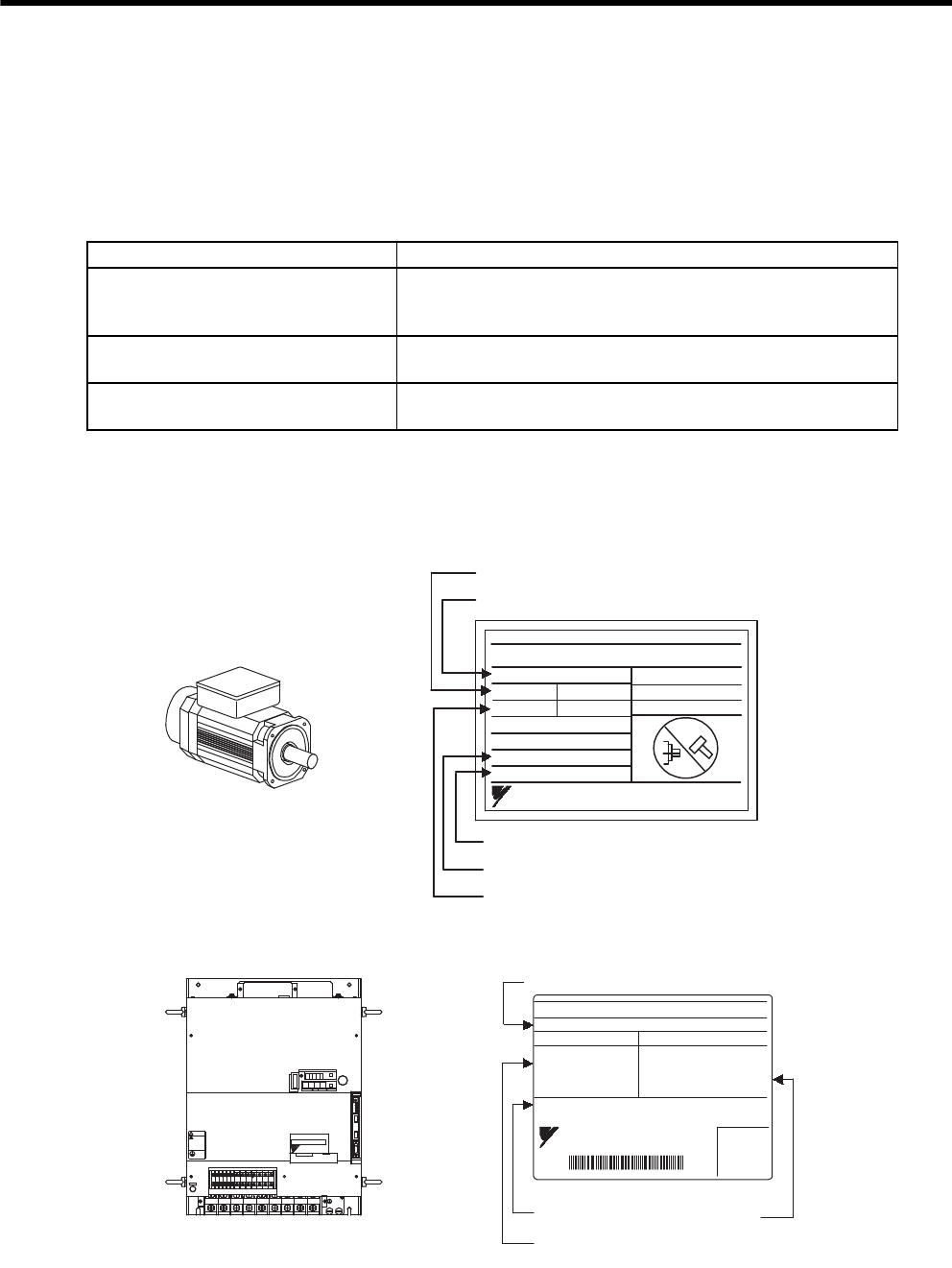
1.1.2 Servomotors
1.1.3 SERVOPACKs
Check Items Comments
Are the delivered products the ones
that were ordered?
Check the model numbers marked on the nameplates on the servomo-
tor and SERVOPACK. (Refer to the descriptions of model numbers in
the following section.)
Does the servomotor shaft rotate
smoothly?
The servomotor shaft is normal if it can be turned smoothly by hand.
Servomotors with brakes, however, cannot be turned manually.
Is there any damage? Check the overall appearance, and check for damage or scratches that
may have occurred during shipping.
Manufacturing date
Serial number
Servomotor model
Rated output
Rated rotation speed
SGMVH
servomotor
AC SERVO MOTOR
TYPE
SGMVH - 2BDCA
kw N
.
m
min
SER.NO.
A
RATING
DATE
22 140
1500 58
CONT.
K7A500 101 - 004
9708
ENCODER
UTMAH - B12BDYR11
17 bit
YASKAWA ELECTRIC CORPORATION
JAPAN
-1
Σ-II Series SGDM and SGDH
SERVOPACKs
SERVOPACK model
Serial number Output power
Applicable power supply
SERVOPACK
SGDH - 3ZDEB
AC- INPUT AC - OUTPUT
MODEL
VOLTS 380 - 480
Hz 50/60
PHASE 3
AMPS 145
VOLTS 0 - 480
PHASE 3
AMPS 175
30.0 (40.2)
S / N R7C303 - 221 - 4
YASKAWA ELECTRIC
MADE IN JAPAN
kW (HP)
+2-+1 L1/R L2/S L3/T UV W
480
V 460
V
DU
400
V 0
V
440
V
DWDV B1
380
V
DC
24N
B2
DC
24P
CHARGE
S-HDG
㧖㧖㧖㧖
T DATA/SEEMOD/
KSERVOPAC
AYASKAW
R
O
P
E
R
A
T
O
CN3
8CN
POWER
CN5
WARNING
ෂޓ㒾
ㅢ㔚ਛ߮㔚Ḯࠝࡈᓟ5
ಽ㑆ޔ┵ሶㇱߦ⸅ࠆߥ!
electric shock.
Disconnect all power
May cause
ᗵ㔚ߩᕟࠇࠅ
before servicing.
and wait 5 min.
grounding techniques.
ធ⛯ߖࠃ
Use proper
ᔅߕࠕ㧙ࠬ✢ࠍ
1.2 Examples of Servo System Configurations
1
Outline
1-3
1.2 Examples of Servo System Configurations
This section describes examples of basic servo system configuration.
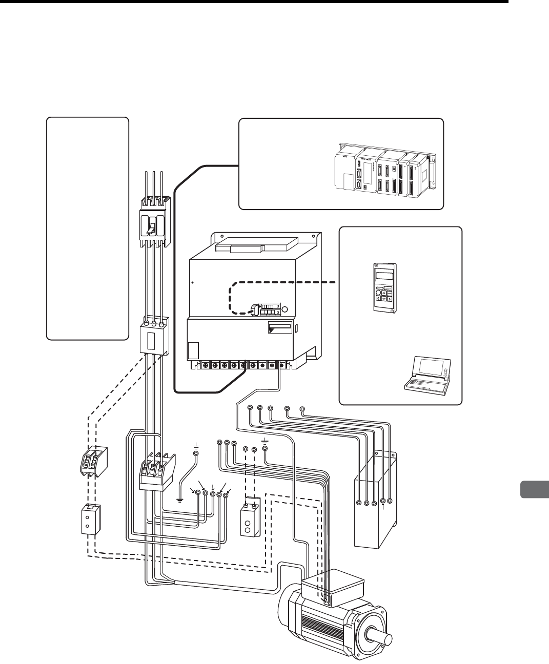
1.2.1 Three-phase, 200 V Series
UVWB1 B2
RST
CN3
CN1
DB24
DU DV DW DBON
DB24
DU DV DW DBON
Regenerative
Resistor Unit
Power supply for
cooling fan
Power supply
Three-phase 200 VAC
SGMVH
servomotor
SGDM/SGDH SERVOPACK
Host controller
Connect the SGDM/SGDH SERVOPACK
to a Yaskawa or an other manufacturer’s
host controller.
Digital Operator
Allows the user to set parameters or
operation reference and display
operation status or alarm status.
(JUSP-OP02A-2)
Cable model:
Personal computer
Hand-held type
1-meter cable included
Molded-case circuit
breaker (MCCB)
Used to protect power
supply line.
Noise filter
Used to eliminate exter-
nal noise from power
supply line.
Magnetic contactor *
Turns the servo ON or
OFF.
Brake power supply
Used for SGMVH
servomotor with brake.
LPSE-2H01
(For 200 V input)
Dynamic Brake (DB)
Unit
*Use a surge absorber
for the magnetic contactor.
Brake power supply Dynamic Brake Unit
Used if dynamic brake
function is required for the
SERVOPACK.
Note: The Dynamic Brake (DB) Unit DBON and
DB24 terminals can be used with SERVO-
PACKs of 37 kW or more only.
MP900/MP2000 Series
JZSP-CMS01 to 03
L1/R
L2/S L3/T L3C/t
L1C/r
-+1 +2 L1/R L2/S L3/T UVW
CN2
CN3
CN1
TDATA/SEEMOD/
SERVOPACK
YAS K AWA
R
O
P
E
R
A
T
O
CN3
8CN
POWER
CN5
SGDH-
㧖㧖㧖㧖
1 Outline
1.2.2 Three-phase, 400 V Series
1-4
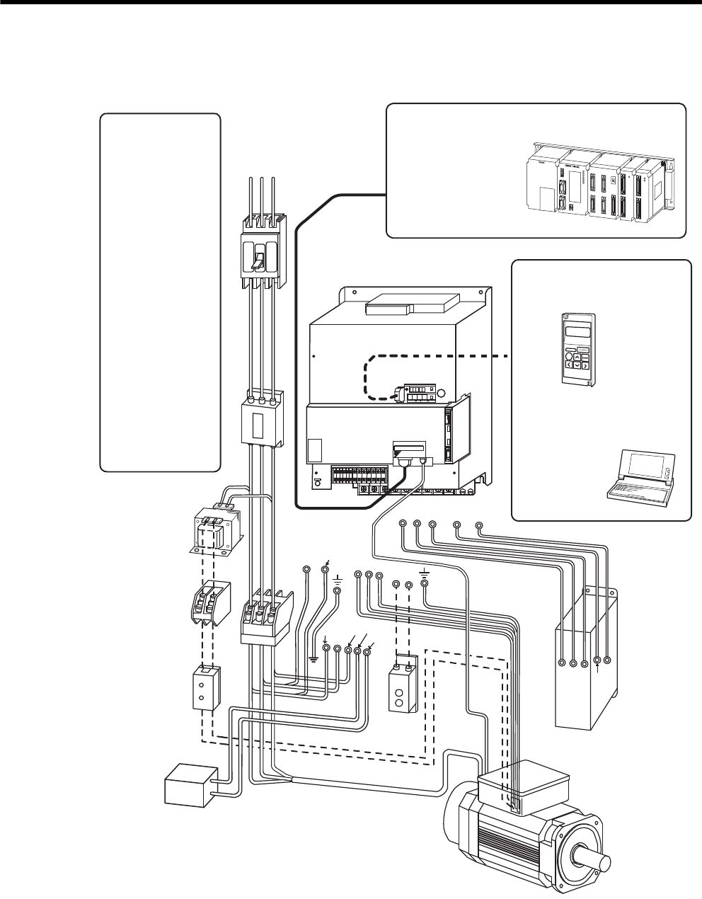
1.2.2 Three-phase, 400 V Series
Regenerative
Resistor Unit
UVWB1 B2
0V
Power supply for
cooling fan
Power supply
Three-phase 400 VAC
RST
SGMVH
servomotor
SGDH SERVOPACK
Host controller Connect the SGDH SERVOPACK to a
Yaskawa or an other manufacturer’s
host controller.
Digital Operator
Allows the user to set parameters or
operation reference and display
operation status or alarm status.
(JUSP-OP02A-2)
Cable model:
Personal computer
Hand-held type
1-meter cable included
Molded-case circuit
breaker (MCCB)
Used to protect power
supply line.
Noise filter
Used to eliminate exter-
nal noise from power
supply line.
Magnetic contactor *
Turns the servo ON or
OFF.
Brake power supply
Used for SGMVH
servomotor with brake.
LPSE-2H01
(For 200 V input)
Power transformer
Used to switch between
200 V to 400 V.
Dynamic Brake (DB)
Unit
*Use a surge absorber
for the magnetic contactor.
CN3
CN1
Brake power supply
DB24
DU DV DW DBON
Dynamic Brake Unit
DB24
DU DV DW DBON
Used if dynamic brake
function is required for the
SERVOPACK.
Note: The Dynamic Brake (DB) Unit DBON and
DB24 terminals can be used with SERVO-
PACKs of 37 kW or more only.
MP900/MP2000 Series
JZSP-CMS01 to 03
380 to 480V
L1/R
L2/S
L3/T DC24N
DC24P
DC power
supply
(24 VDC)
+
-
CN2
CN3
CN1
8
8
&7
8
8
8
&9&8 $
8
&%
0
$
&%
2
%*#4)'
5*&)
㧖㧖㧖㧖
6#5''/1&
-5'4812#%
#;#5-#9
4
1
2
'
4
#
6
1
%0
%0
219'4
%0

1.3 Applicable Standards
1
Outline
1-5
1.3 Applicable Standards
1.3.1 North American Safety Standards (UL)
* 1. 200 V SERVOPACKs and servomotors have not obtained certification showing compliance
with UL standards.
* 2. 75 kW SERVOPACKs and servomotors have not obtained certification showing compliance
with UL standards.
* 3. Underwriters Laboratories Inc.
1.3.2 CE Marking
The SGDH SERVOPACK and SGMVH servomotor have not obtained certification showing compliance with CE
marking, but, the following models comply with its standards.
* A low voltage directive-compliant model is in development.
Note: Because SERVOPACKs and servomotors are built-in type, reconfirmation is required after
being installed in the final product.
Model Voltage∗1 Capacity∗2 UL∗3 Standards
(UL File No.)
SERVOPACK SGDH 400 V 22 kW to 55 kW UL508C(E147823)
Servomotor SGMVH 400 V 22 kW to 55 kW UL1004(E165827)
Model Voltage∗Capacity∗
Low Voltage
Directive
(compliant)
EMC Directive (compliant)
EMI EMS
SERVOPACK SGDH 400 V 22 kW to 55 kW EN50178 EN55011
class A group 1
EN50082-2
or
EN61000-6-2
Servomotor SGMVH 400 V 22 kW to 55 kW –∗EN55011
class A group 1
EN50082-2
or
EN61000-6-2

2
Selections
2-1
2
Selections
2.1 Servomotor Model Designations - - - - - - - - - - - - - - - - - - - - - 2-2
2.2 SERVOPACK Model Designations - - - - - - - - - - - - - - - - - - -2-3
2.3 Σ-II Series SERVOPACKs and Applicable Servomotor - - - - - 2-4
2.4 Selecting Cables - - - - - - - - - - - - - - - - - - - - - - - - - - - - - - - - 2-5
2.4.1 Cables for SGMVH Servomotor - - - - - - - - - - - - - - - - - - - - - - - - - - - 2-5
2.5 Selecting Peripheral Devices - - - - - - - - - - - - - - - - - - - - - - - 2-6
2.5.1 Special Options - - - - - - - - - - - - - - - - - - - - - - - - - - - - - - - - - - - - - - - 2-6
2.5.2 Molded-case Circuit Breaker and Fuse Capacity - - - - - - - - - - - - - - - - 2-8
2.5.3 Noise Filters, Magnetic Contactors, and Brake Power
Supply Units - - - - - - - - - - - - - - - - - - - - - - - - - - - - - - - - - - - - - - - - - 2-9
2.5.4 Regenerative Resistor Units - - - - - - - - - - - - - - - - - - - - - - - - - - - - - - 2-9
2.5.5 Dynamic Brake (DB) Units - - - - - - - - - - - - - - - - - - - - - - - - - - - - - - 2-10
2.5.6 Thermal Relays - - - - - - - - - - - - - - - - - - - - - - - - - - - - - - - - - - - - - - 2-11
2 Selections
2-2
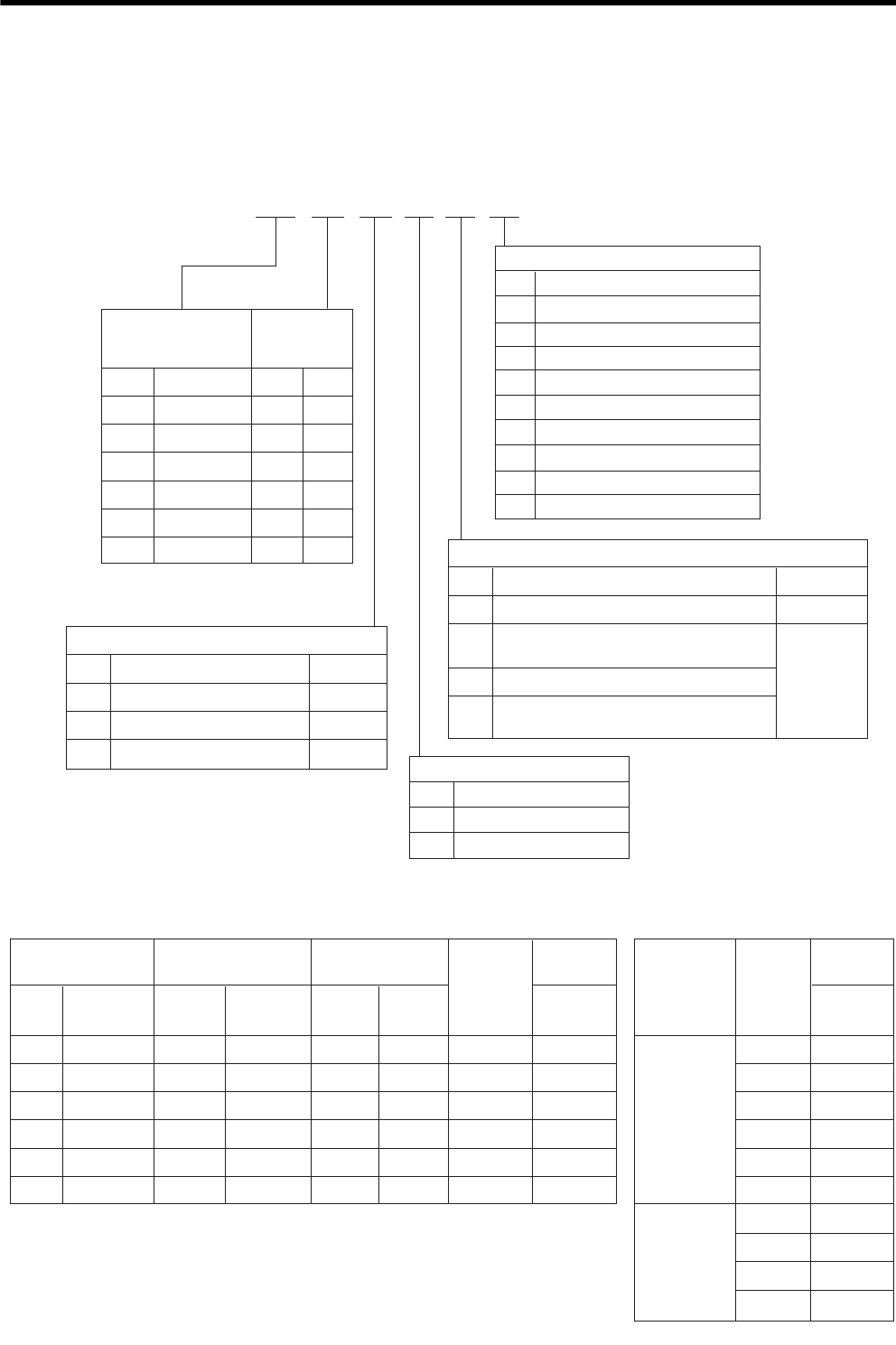
2.1 Servomotor Model Designations
(1) Available Models
SGMVH −2B A 2 B 2 N
4th digit: Serial Encoder
7th digit: Brake and Oil Seal
Code
N
1
S
B
C
D
E
F
G
Specifications
Standard (without options)
With dust seal
With oil seal
With 90-VDC brake
With 24-VDC brake
With oil seal and 90-VDC brake
With oil seal and 24-VDC brake
With dust seal and 90-VDC brake
With dust seal and 24-VDC brake
1st + 2nd digits:
Rated Output
(kW)
Code
2B
3Z
3G
4E
5E
7E
Rated Output A
−
−
−
D
3rd digit:
Voltage
A:200V,D:400V
Code
2
3
C
Remarks
Standard
ޓޓSpecifications
17-bit absolute encoder
20-bit absolute encoder
17-bit incremental encoder
: Available
Option
5th digit: Rated Speed
Code
B
D
Specifications
6th digit: Shaft End, Mounting Method
Code
6
RemarksޓޓSpecifications
Flange-mounted, straight without key
Flange-mounted, straight with key
and shaft end tap (×1)
1st +
2nd
digits
3rd
digit
4th
digit
5th
digit
6th
digit
7th
digit
: Not available
−
1500 min-1
800 min-1
Foot-mounted, straight with key
and shaft end tap (×1)
K
L
Foot-mounted, straight without key
2Standard
Option
22
30
37
45
55
75
Standard
1st + 2nd digits:
Rated Output (kW)
Code Rated
Output BD
5th digit: Rated Speed
B: 1500 min
-1,
D: 800 min
-1
Flange-
mounted
Mounting Method
: Available
With
Brake
With
Brake
Rated
Speed
(min
-1
)
Rated
Output
(kW)
With Oil
Seal and
Dust Seal
Foot-
mounted
1500
800
22
30
37
45
55
75
22
30
37
45
Flange-
mounted
22
30
37
45
55
75
2B
3Z
3G
4E
5E
7E
Foot-
mounted
: Not available
−
2.2 SERVOPACK Model Designations
2
Selections
2-3
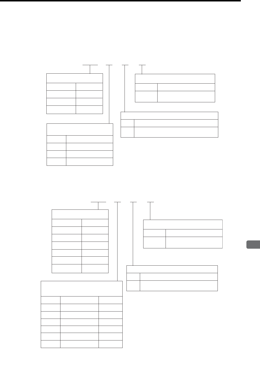
2.2 SERVOPACK Model Designations
Select the SERVOPACK according to the applied servomotor.
Code
2B
3Z
3G
Rated Output
22
30
37
Code
D
Specificatioins
Code
2B
3Z
3G
A
Code
B
Specificatioins
2BSGDM - A D B
5th digit: Applicable Servomotor Model
1st + 2nd digits (kW)
3rd digit: Power Supply
Voltage A: 200 V
4th digit: Model
SGMVH
Servomotor
For torque, speed and position control
1st +
2nd
digits
3rd
digit
4th
digit
5th
digit
: Available
Code
2B
3Z
3G
4E
5E
9Z
Rated Output
22
30
37
45
55
75
D
Δ
Δ
Δ
2BSGDH - A E B
Code
2B
3Z
3G
4E
5E
9Z
A
1st +
2nd
digits
3rd
digit
4th
digit
5th
digit
Code
E
Specificatioins
Code
B
Specificatioins
5th digit: Applicable Servomotor Model
1st + 2nd digits (kW)
3rd digit: Power Supply Voltage
A: 200 V, D: 400 V
4th digit: Model
SGMVH
Servomotor
For torque, speed and position control
: Available
: Option
: Not available
Δ

2 Selections
2-4
2.3 Σ-II Series SERVOPACKs and Applicable Servomotor
Note: =A: 200 V, D: 400 V
Be sure to match the voltage ratio on the servomotor and the SERVOPACK.
Servomotor
SGMVH-
SERVOPACK
SGDM- SGDH-
200 V 200 V 400 V
1500 min-1
2B2BADB 2BAEB 2BDEB
3Z3ZADB 3ZAEB 3ZDEB
3G3GADB 3GAEB 3GDEB
4ED – – 4EDEB
5ED – – 5EDEB
7ED – – 9ZDEB
800 min-1
2B2BADB 2BAEB 2BDEB
3Z3ZADB 3ZAEB 3ZDEB
3G3GADB 3GAEB 3GDEB
4ED – – 4EDEB
2.4 Selecting Cables
2
Selections
2-5
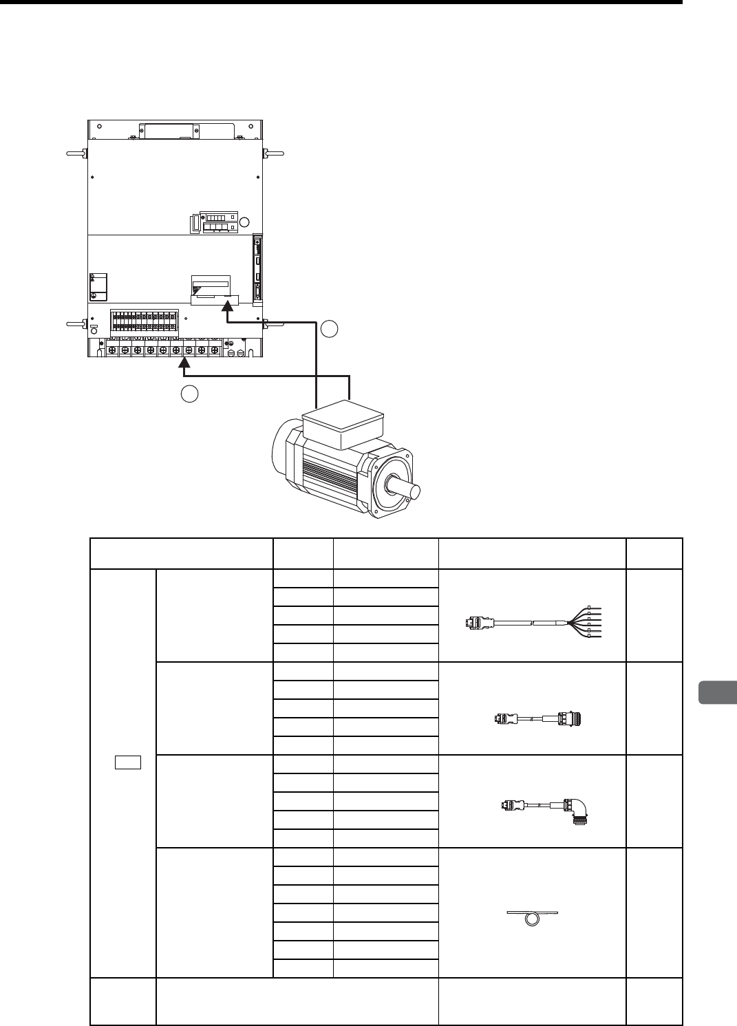
2.4 Selecting Cables
2.4.1 Cables for SGMVH Servomotor
Name Length Type Specifications Refer-
ence
c
Encoder
Cable
Cable with loose
wire at encoder
end
3 m JZSP-CMP23-03
5.2.2
5 m JZSP-CMP23-05
10 m JZSP-CMP23-10
15 m JZSP-CMP23-15
20 m JZSP-CMP23-20
Cable with a
straight plug
3 m JZSP-CMP21-03
5.2.1
5 m JZSP-CMP21-05
10 m JZSP-CMP21-10
15 m JZSP-CMP21-15
20 m JZSP-CMP21-20
Cable with an
L-shaped plug
3 m JZSP-CMP22-03
5.2.1
5 m JZSP-CMP22-05
10 m JZSP-CMP22-10
15 m JZSP-CMP22-15
20 m JZSP-CMP22-20
Cables
5 m JZSP-CMP29-05
5.3
10 m JZSP-CMP29-10
15 m JZSP-CMP29-15
20 m JZSP-CMP29-20
30 m JZSP-CMP29-30
40 m JZSP-CMP29-40
50 m JZSP-CMP29-50
dMain
Circuit
Cable
Cables Not available.
For details, refer to chapter 5. −
1
2
.4 .5 .6 789
8
8
&7
8
8
8
&9&8 $
8
&%
0
$
&%
2
%*#4)'
5*&)
㧖㧖㧖㧖
6 #5''/1&
-5'4812#%
#;#5-#9
4
1
2
'
4
#
6
1
%0
%0
219'4
%0
WARNING
ෂޓ㒾
ㅢ㔚ਛ߮㔚Ḯࠝࡈᓟ5
ಽ㑆ޔ┵ሶㇱߦ⸅ࠆߥ
electric shock.
Disconnect all power
May cause
ᗵ㔚ߩᕟࠇࠅ
before servicing.
and wait 5 min.
grounding techniques.
ធ⛯ߖࠃ
Use proper
ᔅߕࠕ㧙ࠬ✢ࠍ
CN2
Encoder
end
SERVOPACK
end
Encoder
end
SERVOPACK
end
Encoder
end
SERVOPACK
end
50 m max.
2 Selections
2.5.1 Special Options
2-6
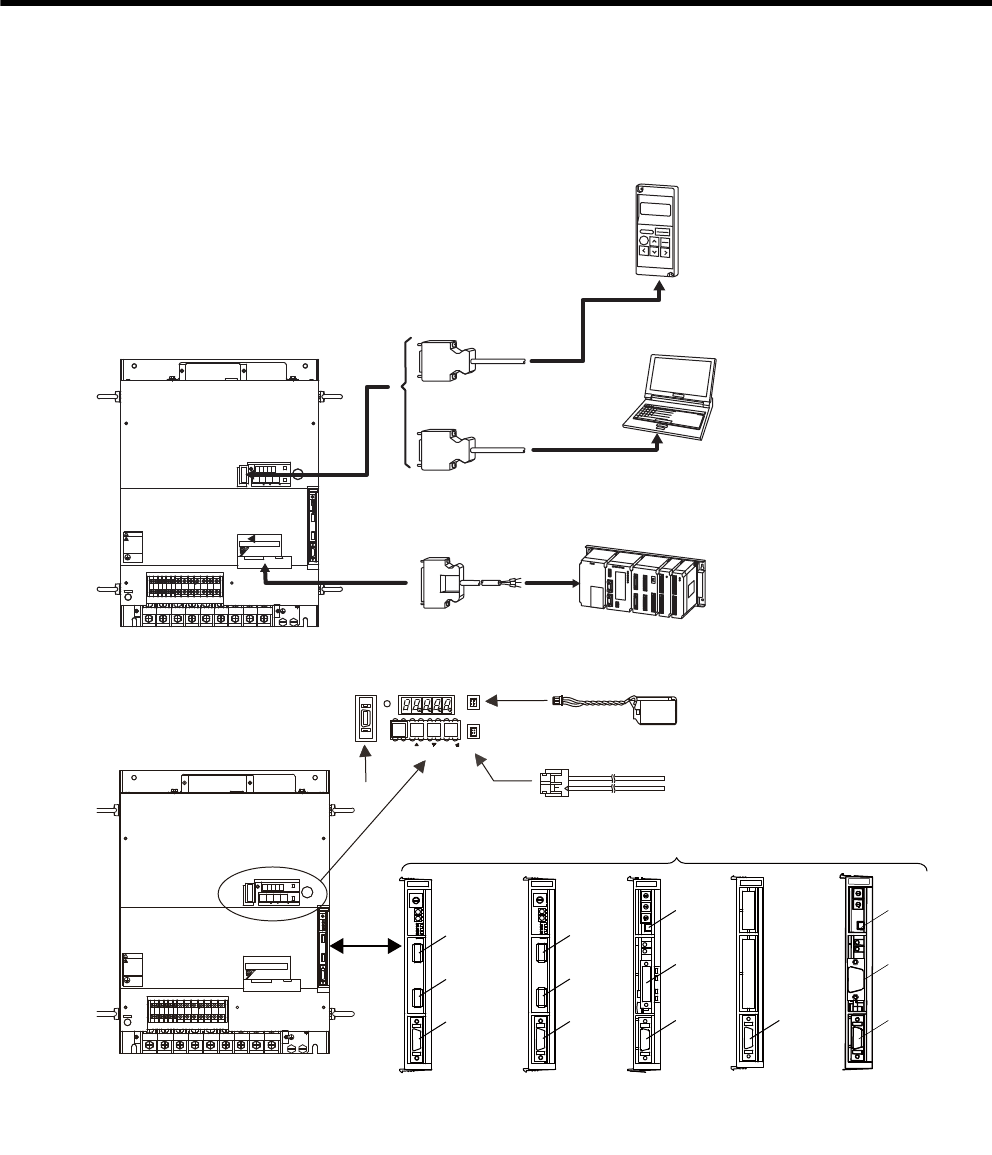
2.5 Selecting Peripheral Devices
2.5.1 Special Options
Personal
computer
Digital operator
Host controller
I/O signal cable
Connection cable
for digital operator
Connection cable
for personal computer
.4 .5 .6 789
8
8 &7
8
8
8 &9&8 $
8
&%
0
$
&%
2
%*#4)'
5*&)
㧖㧖㧖㧖
6#5''/1&
-5'4812#%
#;#5-#9
4
1
2
'
4
#
6
1
%0
%0
219'4
%0
WARNING
ෂޓ㒾
ㅢ㔚ਛ߮㔚Ḯࠝࡈᓟ5
ಽ㑆ޔ┵ሶㇱߦ⸅ࠆߥ
electric shock.
Disconnect all power
May cause
ᗵ㔚ߩᕟࠇࠅ
before servicing.
and wait 5 min.
grounding techniques.
ធ⛯ߖࠃ
Use proper
ᔅߕࠕ㧙ࠬ✢ࠍ
NS100
S
W
1
S
W
2
A
R
C
N
6
A
C
N
6
B
C
N
4
5
4
0
9
6
12
7
8
3
3
5
4
0
9
6
12
7
8
NS300
5
4
0
9
6
12
7
8
3
X
10
X
1
D
R
C
N
11
M
S
N
S
FC100
MECHATROLINK-I
application
module
(NS100)
DeviceNet
application
module
(NS300)
Fully-closed
application
module
(FC100)
PROFIBUS-DP
application
module
(NS500)
Connector CN6A
CN11
CN6
CN4
CN11
CN6
CN4CN4
CN6B
CN4
6
NS500
NS115
S
W
1
S
W
2
A
R
C
N
6
A
C
N
6
B
C
N
4
MECHATROLINK-II
application
module
(NS115)
CN6A
CN6B
CN4
CN3
CN8
MODE/SET DATA/
POWER
CN5
.4 .5 .6 789
8
8
&7
8
8
8
&9&8 $
8
&%
0
$
&%
2
%*#4)'
5*&)
㧖㧖㧖㧖
6#5''/1&
-5'4812#%
#;#5-#9
4
1
2
'
4
#
6
1
%0
%0
219'4
%0
WARNING
ෂޓ㒾
ㅢ㔚ਛ߮㔚Ḯࠝࡈᓟ5
ಽ㑆ޔ┵ሶㇱߦ⸅ࠆߥ
electric shock.
Disconnect all power
May cause
ᗵ㔚ߩᕟࠇࠅ
before servicing.
and wait 5 min.
grounding techniques.
ធ⛯ߖࠃ
Use proper
ᔅߕࠕ㧙ࠬ✢ࠍ
Analog monitor cable
Battery for absolute encoder
2.5 Selecting Peripheral Devices
2
Selections
2-7
* For details, refer to the manuals of each application module.
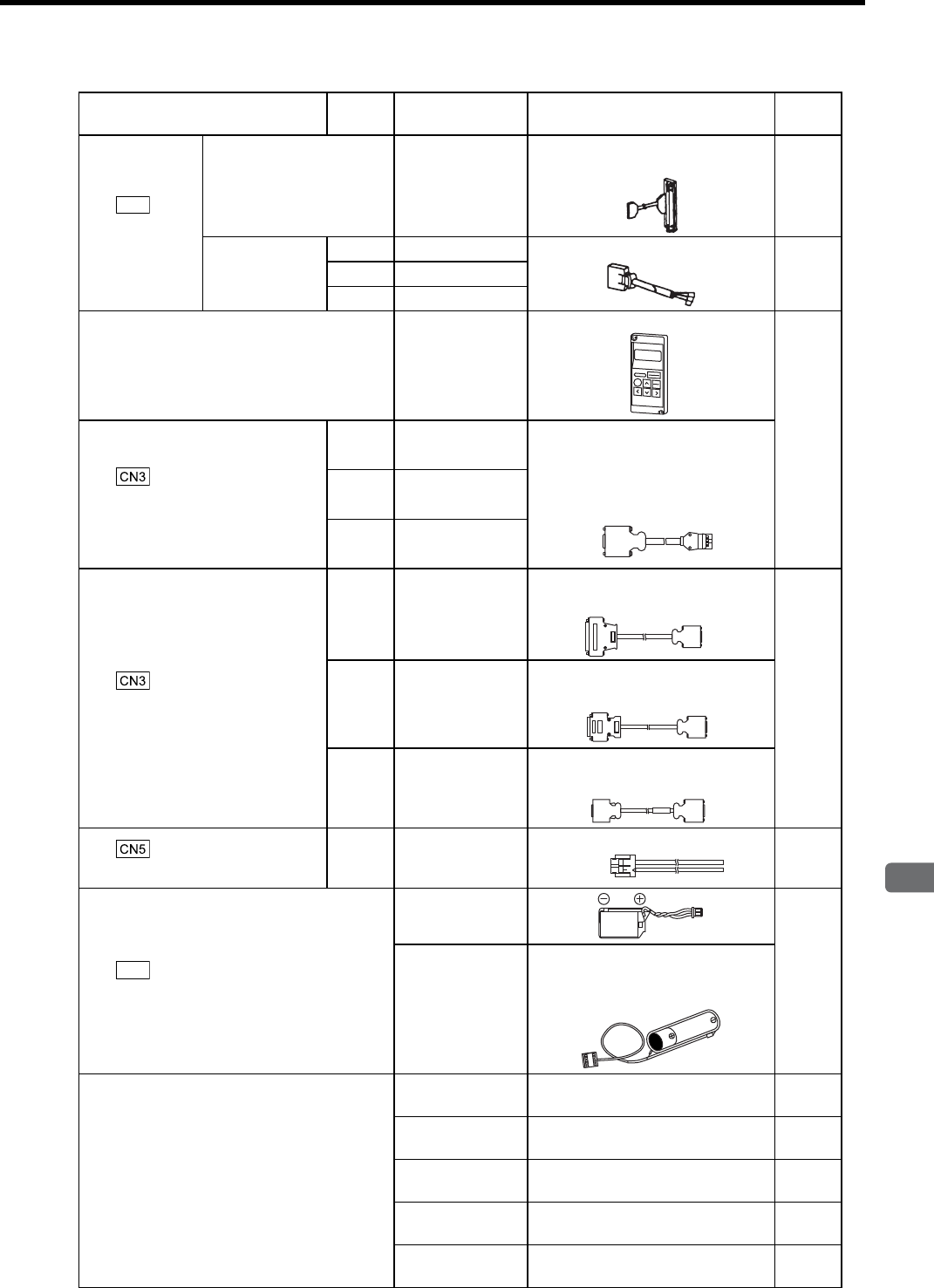
Name Length Type Specifications Refer-
ence
c
I/O Signal
Cables
Connector terminal block
converter unit JUSP-TA50PG
Terminal block and 0.5 m connection
cable
5.5.4
Cable with
loose wires at
one end
1 m JZSP-CKI01-1 Loose wires at host controller end
5.4.1
2 m JZSP-CKI01-2
3 m JZSP-CKI01-3
d Digital Operator JUSP-OP02A-2
With connection cable (1 m)
5.5.2
e
Connection Cable for Digital
Operator
1m JZSP-CMS00-1 Required only when the digital oper-
ator model: JUSP-OP02A-1 for Σ-I
series is used.
1.5m JZSP-CMS00-2
2 m JZSP-CMS00-3
f
Connection Cable for Personal
Computer
2 m JZSP-CMS01
D-Sub 25-pin (For PC98)
5.5.1
2 m JZSP-CMS02
D-Sub 9-pin (For DOS/V)
2 m JZSP-CMS03
Half-pitch 14-pin (For PC 98)
g
Analog Monitor Cable 1 m JZSP-CA01 or
DE9404559 5.5.3
h
Battery for Absolute Encoder
JZSP-BA01-1
5.5.6
ER6VC3
To connect to a host controller,
3.6 V, 2000 mAh, manufactured by
Toshiba Battery Co., Ltd.
⑦Application Module ∗
JUSP-NS100 MECHATROLINK-I application
module (NS100) 5.5.15
JUSP-NS115 MECHATROLINK-II application
module (NS115) 5.5.15
JUSP-NS300 DeviceNet application module
(NS300) 5.5.16
JUSP-FC100 Fully-closed application module
(FC100) 5.5.18
JUSP-NS500 PROFIBUS-DP
application module (NS500) 5.5.17
CN1
Operator
end
SERVOPACK
end
Personal
computer end
SERVOPACK
end
Personal
computer end
SERVOPACK
end
Personal
computer end
SERVOPACK
end
SERVOPACK end Monitor end
CN8

2 Selections
2.5.2 Molded-case Circuit Breaker and Fuse Capacity
2-8
2.5.2 Molded-case Circuit Breaker and Fuse Capacity
Select a input fuse or molded-case circuit breaker that comply with UL standard.
* 1. Nominal value at the rated load.
* 2. Cutoff characteristics (25°C): 200% for two seconds min. and 700% for 0.01 seconds min.
* 3. The values will vary, depending on the 24 VDC control power supply used.
Note: Do not use a fast-acting fuse. Because the SERVOPACK’s power supply is a capacitor
input type, a fast-acting fuse may blow when the power is turned ON.
SERVOPACK Model
Power Supply
Capacity per
SERVOPACK
(kVA)∗1
Current Capacity of the
Molded-case Circuit Breaker
and the Fuse (A)∗2
Inrush Current (A)
Main Circuit
Power Supply
Control Circuit
Power Supply
SGDM-2BADB
SGDH-2BAEB 36.7 150 300 30
SGDM-3ZADB
SGDH-3ZAEB 50.1 200 300 30
SGDM-3GADB
SGDH-3GAEB 61.8 225 600 30
SGDH-2BDEB 36.7 100 140
(10)*3
SGDH-3ZDEB 50.1 150 565
SGDH-3GDEB 61.8 150 565
SGDH-4EDEB 75.2 225 1130
SGDH-5EDEB 91.9 225 1130
SGDH-9ZDEB 125.3 300 170

2.5 Selecting Peripheral Devices
2
Selections
2-9
2.5.3 Noise Filters, Magnetic Contactors, and Brake Power Supply Units
Note: 1. If some SERVOPACKs are wired at the same time, select the proper magnetic contactors accord-
ing to the total capacity.
2. The following table shows the manufacturers of each device.
2.5.4 Regenerative Resistor Units
SERVOPACK Model Recommended Noise Filter Magnetic Contactor Brake Power Supply Unit
SGDM-2BADB
SGDH-2BAEB
FN258L-130-35 SC-N6 (125A)
c24 VDC brake (provided by a
customer)
d90 VDC brake
• LPDE-1H01 for 100 VAC input
• LPSE-2H01 for 200 VAC input
SGDM-3ZADB
SGDH-3ZAEB
FN258L-180-07 SC-N8 (180A)
SGDM-3GADB
SGDH-3GAEB
FN359P-250-99 SC-N10 (220A)
SGDH-2BDEB FN258L-180-07 SC-N6 (125A)
SGDH-3ZDEB FN258L-180-07 SC-N8 (180A)
SGDH-3GDEB FN258L-180-07 SC-N8 (180A)
SGDH-4EDEB FN359P-250-99 SC-N10 (220A)
SGDH-5EDEB FN359P-250-99 SC-N10 (220A)
SGDH-9ZDEB FN359P-300-99 SC-N11 (300A)
Peripheral Device Manufacturer
Noise Filter Schaffner Electronic
Magnetic Contactor Fuji Electric Co., Ltd.
Brake Power Supply
Unit Yaskawa Controls Co., Ltd.
SERVOPACK
Model
SGDM- 2BADB 3ZADB 3GADB −
SGDH-2BAEB 3ZAEB 3GAEB 2BDEB 3ZDEB 3GDEB 4EDEB 5EDEB 9ZDEB
Regenerative
Resistor Unit
Model
JUSP-RA08 RA09 RA11 RA12 RA13 RA14 RA15 RA16 RA25
Resistance (Ω)2.4 1.8 1.6 9 6.7 5 4 3.8 2.1
Resistance
Capacity (W)
2400 4800 4800 3600 3600 4800 6000 7200 16800
Allowable Load Moment of
Inertia (×10-4kg·m2)
1830 2490 2875 1830 2490 2875 5355 6450 9020
Allowable Duty 2% ED at maximum speed and torque deceleration.

2 Selections
2.5.5 Dynamic Brake (DB) Units
2-10
2.5.5 Dynamic Brake (DB) Units
Externally attach a dynamic brake resistor to the SERVOPACK to dissipate regenerative energy when using the
dynamic brake function. The dynamic brake resistor does not need to be installed if the dynamic brake function is
not required.
Use the dynamic brake unit under the following conditions. Contact your Yaskawa representative before using
the unit under conditions more severe than those specified below.
• Allowable load moment of inertia: 5 times the load moment of inertia
• Allowable duty: Less than one DB stop per hour at maximum rotation speed
Dynamic Brake
(DB) Unit Model
SERVOPACK Model Resistance
Specifications
(Star Wiring )
DB Contactor and
Surge Absorption Unit
SGDM- SGDH-
JUSP–DB01 2BADB, 3ZADB 2BAEB, 3ZAEB 180 W, 0.3 ΩBuilt into the
SERVOPACK
JUSP–DB02 3GADB 3GAEB 180 W, 0.3 ΩBuilt into Dynamic Brake
Unit
JUSP–DB03 −2BDEB, 3ZDEB 180 W, 0.8 ΩBuilt into the
SERVOPACK
JUSP–DB04 −3GDEB 180 W, 0.8 ΩBuilt into Dynamic Brake
Unit
JUSP–DB05 −4EDEB 180 W, 0.8 ΩBuilt into Dynamic Brake
Unit
JUSP–DB06 −5EDEB 300 W, 0.8 ΩBuilt into Dynamic Brake
Unit
JUSP–DB12 −9ZDEB 600 W, 0.9 ΩBuilt into Dynamic Brake
Unit

2.5 Selecting Peripheral Devices
2
Selections
2-11
2.5.6 Thermal Relays
Dynamic Brake
(DB) Unit and
Regenerative
Resistor
Unit Model
Thermal Relay
Model
Thermal Relay
Current Range
Thermal Relay
Current
Manufacturer
JUSP-DB01
JUSP-DB02 TR-N3H/3 9 A 9 to 13 A 10 A
Fuji Electric Co., Ltd.
JUSP-DB03
JUSP-DB04
JUSP-DB05
TR-N3H/3 7 A 7 to 11 A 7 A
JUSP-DB06 TR-N3H/3 7 A 7 to 11 A 9 A
JUSP-DB12 TR-N3H/3 9 A 9 to 13 A 12 A
JUSP-RA08 TR-N3H/3 12 A 12 to 18 A 14 A
JUSP-RA09 TR-N3H/3 18 A 18 to 26 A 23 A
JUSP-RA11 TR-N3H/3 18 A 18 to 26 A 24 A
JUSP-RA12 TR-N3H/3 7 A 7 to 11 A 9 A
JUSP-RA13 TR-N3H/3 9 A 9 to 13 A 10 A
JUSP-RA14 TR-N3H/3 12 A 12 to 18 A 14 A
JUSP-RA15 TR-N3H/3 12 A 12 to 18 A 17 A
JUSP-RA16 TR-N3H/3 18 A 18 to 26 A 19 A
JUSP-RA25 TR-N3H/3 34 A 34 to 50 A 40 A

3
Servomotor Specifications and Dimensional Drawings
3-1
3
Servomotor Specifications and
Dimensional Drawings
3.1 Ratings and Specifications of SGMVH (1500 min-1) - - - - - - - 3-2
3.2 Ratings and Specifications of SGMVH (800 min-1) - - - - - - - - 3-6
3.3 Mechanical Specifications of Servomotors - - - - - - - - - - - - - -3-9
3.3.1 Precautions on Servomotor Installation - - - - - - - - - - - - - - - - - - - - - - 3-9
3.3.2 Allowable Radial and Thrust Loads - - - - - - - - - - - - - - - - - - - - - - - - 3-13
3.3.3 Mechanical Tolerance - - - - - - - - - - - - - - - - - - - - - - - - - - - - - - - - - 3-14
3.3.4 Direction of Servomotor Rotation - - - - - - - - - - - - - - - - - - - - - - - - - - 3-14
3.3.5 Impact Resistance - - - - - - - - - - - - - - - - - - - - - - - - - - - - - - - - - - - - 3-14
3.3.6 Vibration Resistance - - - - - - - - - - - - - - - - - - - - - - - - - - - - - - - - - - 3-14
3.3.7 Vibration Class - - - - - - - - - - - - - - - - - - - - - - - - - - - - - - - - - - - - - - 3-15
3.4 Dimensional Drawings of SGMVH
Servomotors (1500 min-1) - - - - - - - - - - - - - - - - - - - - - - - - 3-16
3.5 Dimensional Drawings of SGMVH
Servomotors (800 min-1) - - - - - - - - - - - - - - - - - - - - - - - - - 3-22

3 Servomotor Specifications and Dimensional Drawings
3-2
3.1 Ratings and Specifications of SGMVH (1500 min-1)
(1) Ratings and Specifications
(a) 200 V Class
Note: Refer to the next page for the notes.
• Time Rating: Continuous
• Vibration Class: V15
• Insulation Resistance: 500 VDC,
10 MΩ min.
• Surrounding Air Temperature: 0 to 40°C
• Excitation: Permanent magnet
• Mounting: Flange-mounted (standard)
Foot-mounted (semi-standard)
• Thermal Class: F
• Withstand Voltage:
200 V Servomotors: 1500 VAC for one minute
400 V Servomotors: 1800 VAC for one minute
• Enclosure: Totally enclosed, cooled separately, IP44
• Ambient Humidity: 20% to 80% (no condensation)
• Drive Method: Timing belt or coupling
Voltage Class 200 V
Servomotor Model SGMVH- 2BAB3ZAB3GAB
Rated Output ∗kW 22 30 37
Rated Torque ∗N·m 140 191 236
Stall Torque ∗N·m 140 191 236
Instantaneous
Peak Torque ∗N·m 350 478 589
Rated Current ∗Arms 88 120 152
Instantaneous
Max. Current ∗Arms 240 350 460
Rated Speed ∗min-1 1500
Max. Speed ∗min-1 2000
Torque
Constant N·m/Arms 1.72 1.72 1.68
Rotor Moment
of Inertia J
×10-4
kg·m2 366 498 595
Rated Power
Rate ∗ kW/s 536 733 933
Rated Angular
Acceleration ∗rad/s23827 3536 3960

3.1 Ratings and Specifications of SGMVH (1500 min-1)
3
Servomotor Specifications and Dimensional Drawings
3-3
(b) 400 V Class
* These items and torque-motor speed characteristics quoted in combination with SGDM/SGDH
SERVOPACK are at an armature winding temperature of 20°C.
Note: These characteristics are values with the following iron plate (heat sink) attached for
cooling.
SGMVH-2B, 3Z and 3G: 650 × 650 × 35 mm
SGMVH-4E, 5E and 7E: 740 × 520 × 27 mm
Voltage Class 400 V
Servomotor Model SGMVH- 2BDB3ZDB3GDB4EDB5EDB7EDB
Rated
Output ∗kW 22 30 37 45 55 75
Rated
Torque ∗N·m 140 191 236 286 350 477
Stall
Torque ∗N·m 140 191 236 286 350 477
Instantaneous
Peak
Torque ∗
N·m 350 478 589 715 875 1193
Rated
Current ∗Arms 44 60 76 102 117 150
Instantaneous
Max.
Current ∗
Arms 120 170 230 280 340 450
Rated Speed ∗min-1 1500
Max. Speed ∗min-1 2000
Torque
Constant N·m/Arms 3.44 3.44 3.36 3.09 3.15 3.35
Rotor Moment
of Inertia J
×10-4
kg·m2
366 498 595 1071 1290 1804
Rated Power
Rate ∗kW/s 536 733 933 767 950 1265
Rated Angular
Acceleration ∗rad/s23827 3536 3960 2675 2715 2645
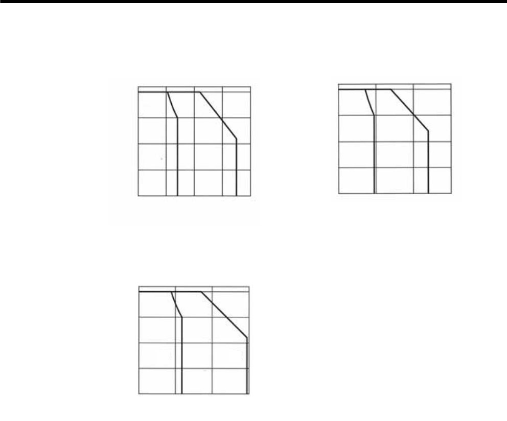
3 Servomotor Specifications and Dimensional Drawings
3-4
(2) Torque-Motor Speed Characteristics (200 V class)
2000
1500
1000
500
0
0 100 200 300 400
SGMVH-2BAB SGMVH-3ZAB
2000
1500
1000
500
0
0 200 400 600
SGMVH-3GAB
2000
1500
1000
500
0
0 200 400 600
ABAB
AB
Torque (Nm)
Motor
speed
(min-1)
Torque (Nm)
Motor
speed
(min-1)
Torque (Nm)
Motor
speed
(min-1)
A
: Continuous Duty Zone
B
: Intermittent Duty Zone
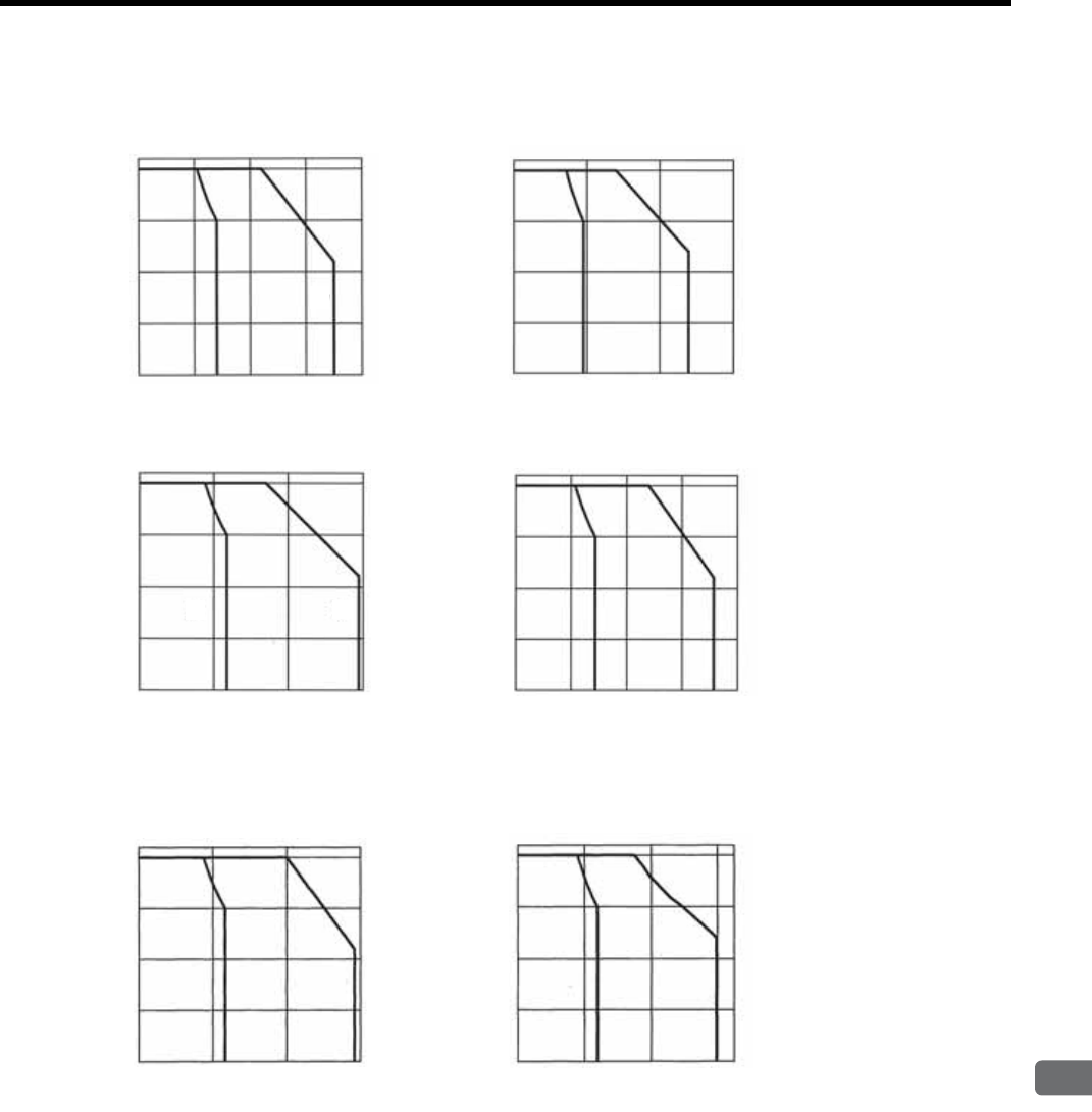
3.1 Ratings and Specifications of SGMVH (1500 min-1)
3
Servomotor Specifications and Dimensional Drawings
3-5
(3) Torque-Motor Speed Characteristics (400 V class)
2000
1500
1000
500
0
0 300 600 900
SGMVH-5EDB
AB
2000
1500
1000
500
0
0 200 400 600
SGMVH-3GDB
2000
1500
1000
500
0
0 100 200 300 400
SGMVH-2BDB
A
2000
1500
1000
500
0
0 200 400 600
SGMVH-3ZDB
A
2000
1500
1000
500
0
0 200 400 600 800
SGMVH-4EDB
AB
2000
1500
1000
500
0
0 400 800 1200
SGMVH-7EDB
AA
AB
AB
AB
B
A
BB
Torque (Nm)
Motor
speed
(min-1)
Torque (Nm)
Motor
speed
(min-1)
Torque (Nm)
Motor
speed
(min-1)
Torque (Nm)
Motor
speed
(min-1)
Torque (Nm)
Motor
speed
(min-1)
Torque (Nm)
Motor
speed
(min-1)
A
: Continuous Duty Zone
B
: Intermittent Duty Zone

3 Servomotor Specifications and Dimensional Drawings
3-6
3.2 Ratings and Specifications of SGMVH (800 min-1)
(1) Ratings and Specifications
(a) 200 V Class
Note: Refer to the next page for the notes.
• Time Rating: Continuous
• Vibration Class: V15
• Insulation Resistance: 500 VDC, 10 MΩ min.
• Surrounding Air Temperature: 0 to 40°C
• Excitation: Permanent magnet
• Mounting: Flange-mounted (standard)
Foot-mounted (semi-standard)
• Thermal Class: F
• Withstand Voltage:
200 V Servomotors: 1500 VAC for one minute
400 V Servomotors: 1800 VAC for one minute
• Enclosure: Totally enclosed, cooled separately, IP44
• Ambient Humidity: 20% to 80% (no condensation)
• Drive Method: Timing belt or coupling
Voltage Class 200 V
Servomotor Model
SGMVH- 2BAD3ZAD3GAD
Rated Output ∗kW 22 30 37
Rated Torque ∗N·m 262 358 442
Stall Torque ∗N·m 262 358 442
Instantaneous Peak Torque ∗N·m 526 752 930
Rated Current ∗Arms 104 150 195
Instantaneous Max. Current ∗Arms 240 340 460
Rated Speed ∗min-1 800
Max. Speed ∗min-1 1300
Torque Constant N·m/Arms 2.73 2.50 2.34
Rotor Moment of Inertia J x10-4 kg·m2705 1290 1564
Rated Power Rate ∗kW/s 979 994 1248
Rated Angular Acceleration ∗rad/s2372627772824
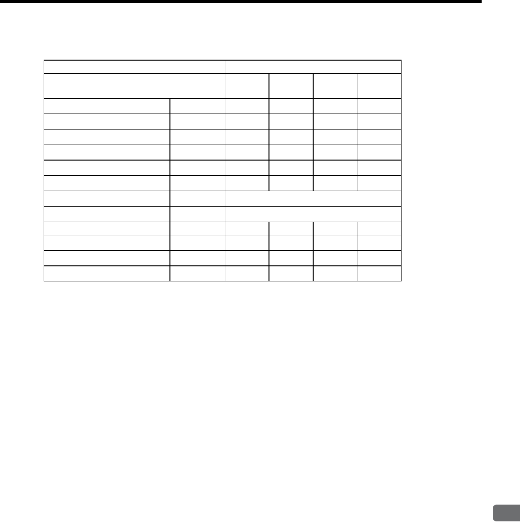
3.2 Ratings and Specifications of SGMVH (800 min-1)
3
Servomotor Specifications and Dimensional Drawings
3-7
(b) 400 V Class
* These items and torque-motor speed characteristics quoted in combination with SGDM/SGDH
SERVOPACK are at an armature winding temperature of 20°C.
Note: These characteristics are values with the following iron plates (heat sinks) attached for
cooling.
SGMVH-2B: 650 × 650 × 35 mm
SGMVH-3Z, 3G and 4E: 740 × 520 × 27 mm
Voltage Class 400 V
Servomotor Model
SGMVH- 2BDD3ZDD3GDD4EDD
Rated Output ∗kW 22 30 37 45
Rated Torque ∗N·m 262 358 442 537
Stall Torque ∗N·m 262 358 442 537
Instantaneous Peak Torque ∗N·m 526 752 930 1182
Rated Current ∗Arms 52 75 98 110
Instantaneous Max. Current ∗Arms 120 170 230 280
Rated Speed ∗min-1 800
Max. Speed ∗min-1 1300
Torque Constant N·m/Arms 5.46 5.00 4.68 5.21
Rotor Moment of Inertia J x10-4 kg·m2 705 1290 1564 1804
Rated Power Rate ∗kW/s 979 994 1248 1600
Rated Angular Acceleration ∗rad/s23726 2777 2824 2978
3 Servomotor Specifications and Dimensional Drawings
3-8
(2) Torque-Motor Speed Characteristics (200 V class)
(3) Torque-Motor Speed Characteristics (400 V class)
1500
1000
500
0
0 200 400 600
SGMVH-2BAD
1500
1000
500
0
0 400 800 1200
SGMVH-3GAD
1500
1000
500
0
0 200 400 600 800
SGMVH-3ZAD
ABAB
AB
Motor
speed
(min-1)
Torque (Nm)
Motor
speed
(min-1)
Torque (Nm)
Motor
speed
(min-1)
Torque (Nm)
A
: Continuous Duty Zone
B
: Intermittent Duty Zone
2000
1500
1000
500
0
0 400 800 1200
SGMVH-3GDD
AB
2000
1500
1000
500
0
0 200 400 600
SGMVH-2BDD
2000
1500
1000
500
0
0 200 400 600 800
SGMVH-3ZDD
AB
2000
1500
1000
500
0
0 400 800 1200
SGMVH-4EDD
AB
B
A
B
AB
A
B
A
Motor
speed
(min-1)
Torque (Nm)
Motor
speed
(min-1)
Torque (Nm)
Motor
speed
(min-1)
Torque (Nm)
Motor
speed
(min-1)
Torque (Nm)
A
: Continuous Duty Zone
B
: Intermittent Duty Zone
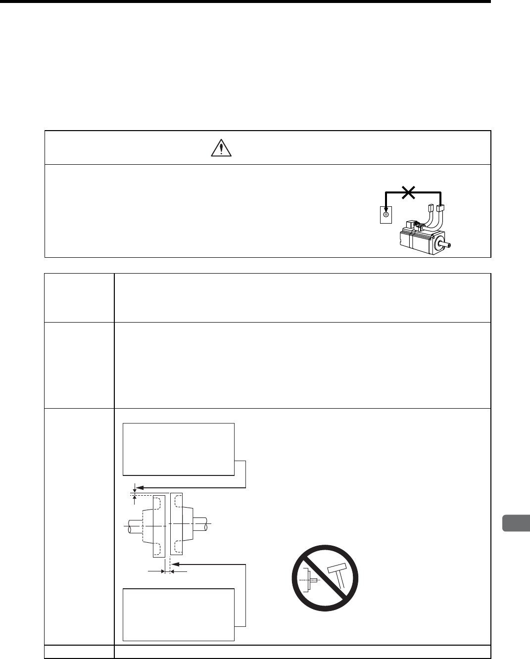
3.3 Mechanical Specifications of Servomotors
3
Servomotor Specifications and Dimensional Drawings
3-9
3.3 Mechanical Specifications of Servomotors
3.3.1 Precautions on Servomotor Installation
Servomotors can be installed either horizontally or vertically.
The service life of the servomotor will be shortened or unexpected problems will occur if the servomotor is
installed incorrectly or in an inappropriate location. Always observe the following installation instructions.
• Do not connect the servomotor directly to a commercial power line. This
will damage the servomotor.
The servomotor cannot operate without the proper SERVOPACK.
CAUTION
Do not connect
Storage
Temperature
and Humidity
Store the servomotor within the following temperature range if it is stored with the power cable discon-
nected.
Surrounding air temperature during storage: -20 to 60°C
Ambient humidity during storage: 80%RH or less (with no condensation)
Installation Site Servomotors are designed for indoor use. Install the servomotor in environments that satisfy the follow-
ing conditions.
• Free of corrosive or explosive gases.
• Well-ventilated and free of dust and moisture.
• Surrounding air temperature of 0 to 40°C
• Relative humidity of 20% to 80% with no condensation.
• Facilitates inspection and cleaning
Alignment Align the shaft of the servomotor with the shaft of the
equipment, and then couple the shafts. Install the servo-
motor so that alignment accuracy falls within the range
described on the left.
Vibration may occur and damage the bearings and the
encoder if the shafts are not correctly aligned.
Connect the servomotor to a machine in a way that pre-
vents the application of concentric loads or rotary unbal-
anced loads on the motor shaft.
When installing, do not hit
the shafts with a hammer
etc., as impacts may result
in malfunction.
Orientation Servomotors can be installed either horizontally or vertically.
Measure this distance at four
different positions on the
circumference. The difference
between the maximum and
minimum measurements must be
0.06 mm or less.
(Turn together with coupling.)
Alignment Accuracy
Measure this distance at four
different positions on the
circumference. The difference
between the maximum and
minimum measurements must be
0.05 mm or less.
(Turn together with coupling.)
Alignment Accuracy
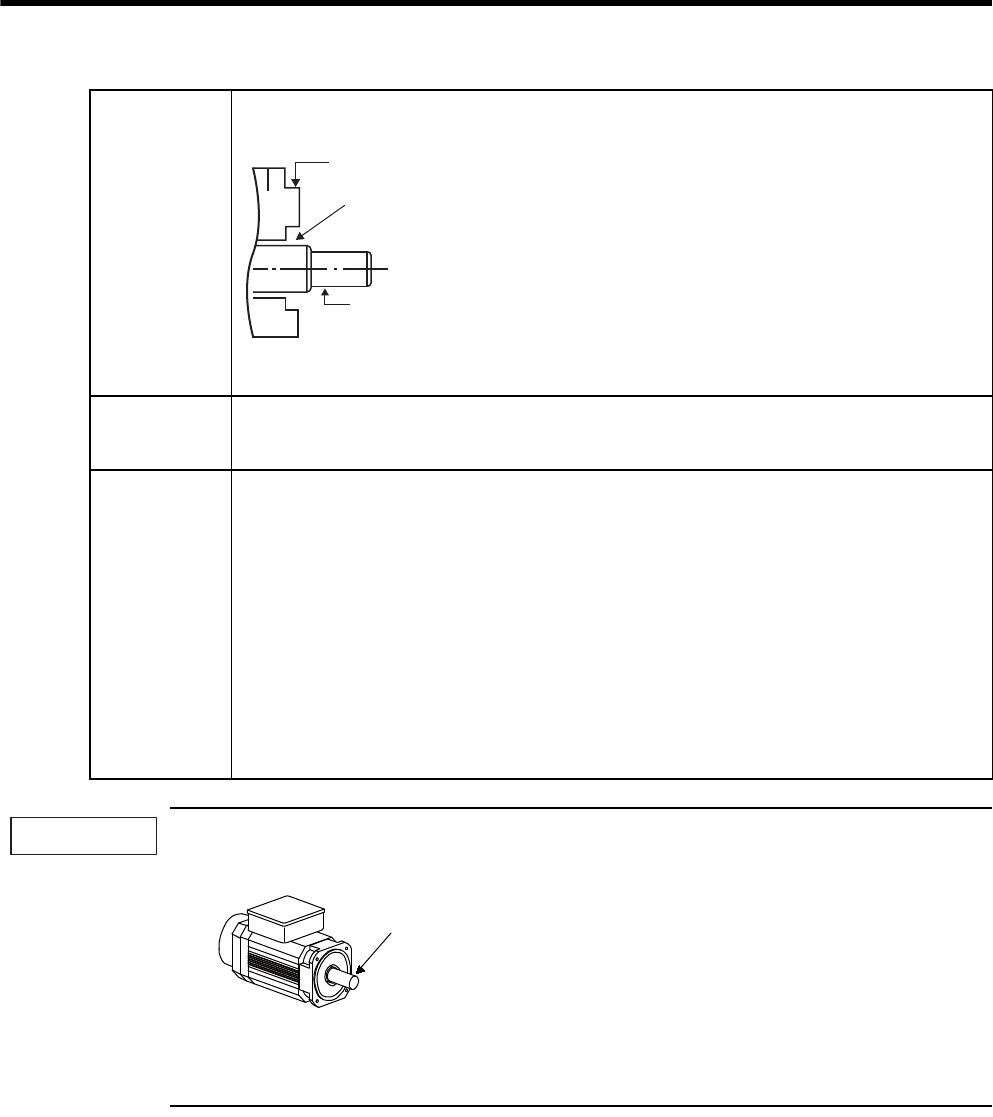
3 Servomotor Specifications and Dimensional Drawings
3.3.1 Precautions on Servomotor Installation
3-10
1. Before starting installation, thoroughly remove the anticorrosive paint that coats the end of the motor
shaft.
2. Vibration from improper alignment of shafts will damage the bearings.
3. Do not allow direct impact to be applied to the shafts when installing the coupling as the encoder
mounted on the opposite end of the shaft may be damaged.
Handling Oil
and Water
If the servomotor is used in a location that is subject to
water drops, make sure of the servomotor protective
specifications (except for through shaft section).
If the servomotor is used in a location that is subject to
water or oil mist, use a servomotor with an oil seal to
seal the through shaft section.
Precautions on Using Servomotor With Oil Seal
• The oil surface must be under the oil seal lip.
• Use an oil seal in favorably lubricated condition.
• When using a servomotor with its shaft pointed
upward, be sure that oil will not stay in the oil seal
lips.
Cable Stress Make sure there are no bends or tension on the power lines.
Especially be careful to wire signal line cables so that they are not subject to stress because the core
wires are very thin at only 0.2 to 0.3 mm.
Connectors Observe the following precautions:
• Make sure there is no foreign matters such as dust and metal chips in the connector before connect-
ing.
• When the connectors are connected to the motor, be sure to connect the end of servomotor main cir-
cuit cables before connecting the encoder cable’s end.
If the encoder cable’s end is connected first, the encoder may be damaged because of the voltage dif-
ferences between frame grounds.
• Make sure of the pin arrangement.
• Do not apply shock to resin connectors. Otherwise, they may be damaged.
• When handling a servomotor with its cables connected, hold the servomotor or the connectors.
Otherwise, the cables will be damaged.
• When bending cables are used, wiring must be performed so that excessive stress will not be applied
to the connector section. Failure to observe this caution may damage the connector.
Through shaft section:
Shaft
Flange
This refers to the gap where
the shaft protrudes from
the end of the motor.
IMPORTANT
Anticorrosive
paint is
coated here.
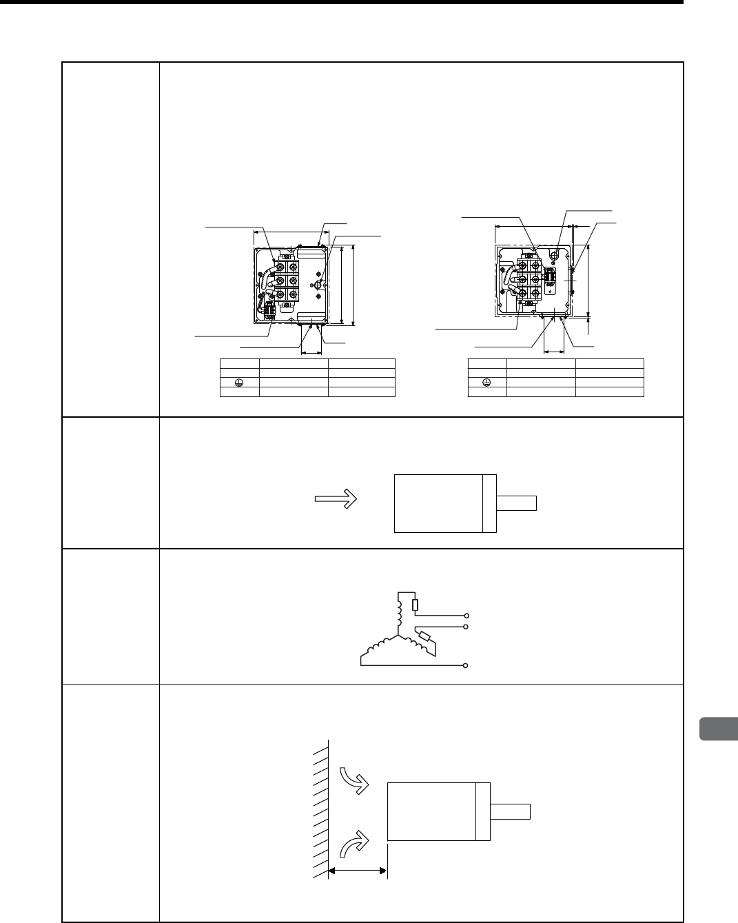
3.3 Mechanical Specifications of Servomotors
3
Servomotor Specifications and Dimensional Drawings
3-11
Wring the Motor
Terminal Box
• Connect the servomotor power lines (U, V, and W) to the servomotor terminal block (M10) in the ser-
vomotor terminal box. Connect the ground wire to the ground bolt (M10) in the terminal box.
• The servomotor has a built-in thermostat. Wire the thermostat leads (l, lb) to the terminal block (M4)
in the servomotor’s terminal box.
• Terminal Box
• 22 kW to 37 kW (1500 min-1)
• 22 kW (800 min-1)
• 45 kW to 75 kW (1500 min-1)
• 30 kW to 45 kW (800 min-1)
Wiring the
Servomotor
Fan
Wire the servomotor fan leads U(A), V(B), and W(C) so that the direction of air flows according to the
following diagram. If the air flows in the opposite direction, change the wiring of any of the two phases
U, V, and W
.
Protecting the
Servomotor
Fan
The servomotor fan has a built-in thermal protector, as shown in the following diagram, that operates at
140°C ±5%. To protect the servomotor fan from overcurrent, use with a 2-A no-fuse breaker.
Installing the
Servomotor
Fan
To maximize the cooling capacity of the servomotor fan, install the fan at least 200 mm from the inlet
side of the servomotor as shown in the following diagram.
U
VW
11b
Terminal Terminal Screw
M10
M10
1,1b M4Thermostat
Motor
Ground
Symbol Terminal Terminal Screw
Thermostat
Motor
Ground
Symbol
U,V,W
230
236
249
φ
61
Plate Plate
Ground bolt
Ground bolt
Terminal block
for motor leads
Terminal block
for motor leads
Plate Plate
Terminal block
for thermostat
Terminal block
for thermostat
Motor lead exit Motor lead exit
U,V,W M10
M10
1,1b M4
220
(5)
φ
61
236 (5)
Unitsmm
7
89
D
Servomotor
Direction of
cooling air
U
V
W
Servomotor
Cooling air
200 mm min.
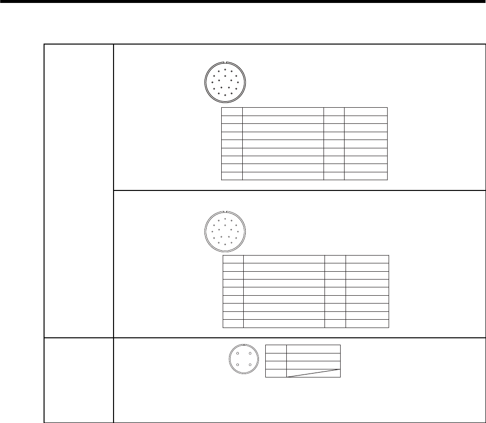
3 Servomotor Specifications and Dimensional Drawings
3.3.1 Precautions on Servomotor Installation
3-12
Encoder-end
Connector
Specifications
Absolute Encoder
Incremental Encoder
Fan Connector
Specifications
ABC
D
E
F
G
H
J
K
LM
TNP
R
S
0V
+5VDC
DATA-
DATA+
BATT-
BATT+
AK
B
C
D
E
F
G
H
J
L
M
N
P
R
S
T
FG㧔Frame ground㧕
Plug: JA06A-20-29S-J1-EB
Cable clamp: JL04-2022CKE㧔㧕
Receptacle: 97F3102E20-29P
Applicable plug㧔purchased by a customer.㧕
--
-
-
-
-
-
-
-
-
#$%
&
'
(
)
*
,
-
./
602
4
5
0V
+5VDC
DATA-
DATA+
AK
B
C
D
E
F
G
H
J
L
M
N
P
R
S
T
--
-
-
-
-
-
-
-
-
-
-
FG㧔Frame ground㧕
Plug: JA06A-20-29S-J1-EB
Cable clamp: JL04-2022CKE㧔㧕
Receptacle: 97F3102E20-29P
Applicable plug㧔purchased by a customer.㧕
A
B
C
D
Fan terminal㧔㨁㧕
Fan terminal㧔㨂㧕
Fan terminal㧔㨃㧕
A
B
C
D
Plug: CE05-6A18-10SD-B-BSS
Cable clamp: CE3057-10A-㧔D265㧕
Receptacle: CE05-2A18-10PD-B
Applicable plug㧔purchased by a customer.㧕
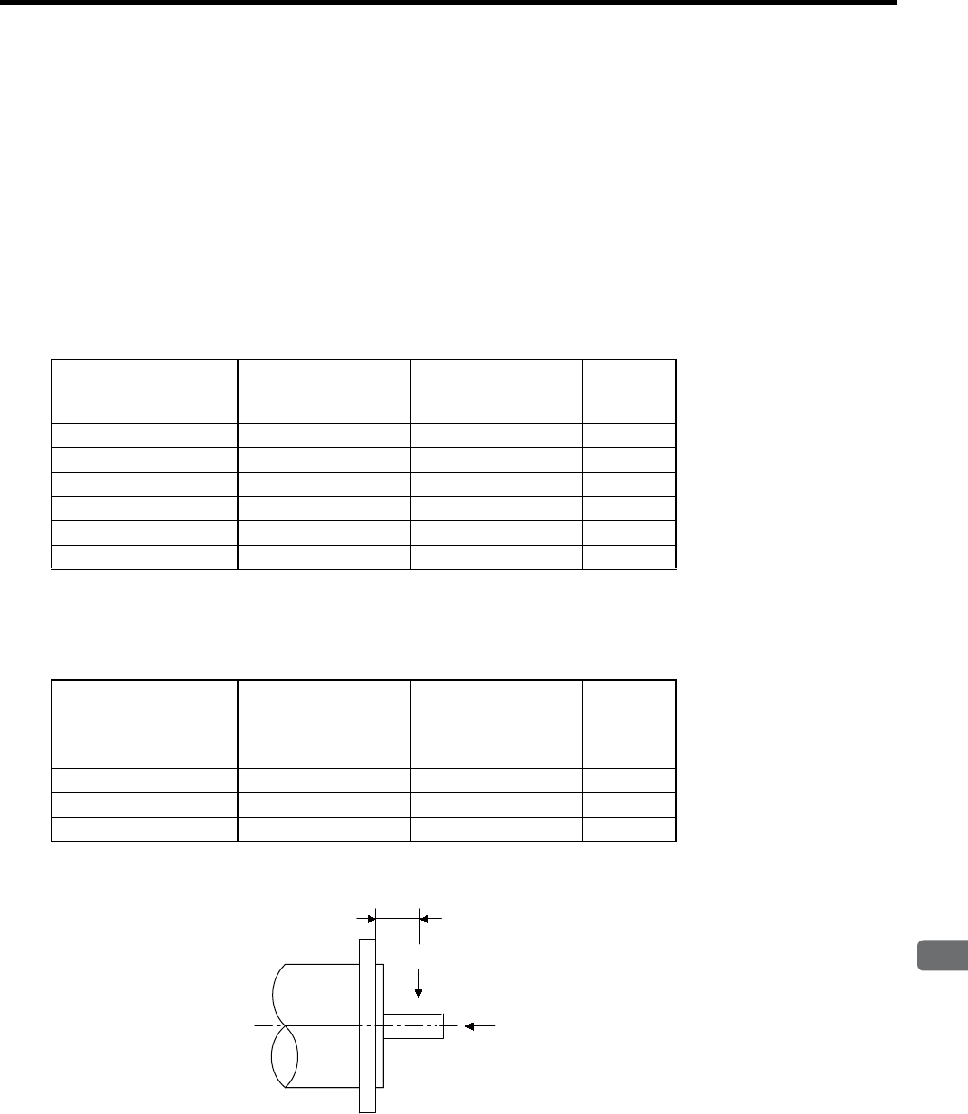
3.3 Mechanical Specifications of Servomotors
3
Servomotor Specifications and Dimensional Drawings
3-13
3.3.2 Allowable Radial and Thrust Loads
The following table shows the allowable loads applied to the SGMVH servomotor shaft end.
Design the mechanical system so radial and thrust loads applied to the servomotor shaft end during operation
falls within the ranges shown in the following table.
Note that even when using a servomotor below the allowable radial load, the following imbalance or the loads
may damage the bearings.
• The imbalance of parts that are connected to the shaft end
• Rotating loads generated by unmatched concentricity, when the bearing is attached to the extended shaft
end.
(1) 1500 min-1 Series
Note: Allowable radial and thrust loads shown above are the maximum values that could be
applied to the shaft end from motor torque or other loads.
(2) 800 min-1 Series
Note: Allowable radial and thrust loads shown above are the maximum values that could be
applied to the shaft end from motor torque or other loads.
Servomotor Model
SGMVH-
Allowable Radial Load
Fr [N]
Allowable Thrust
Load
Fs [N]
LR
[mm]
2BAB, 2BDB5880 2156 100
3ZAB, 3ZDB6272 2156 100
3GAB, 3GDB7448 2156 100
4EDB7840 2156 100
5EDB8428 2156 110
7EDB10100 2156 120
Servomotor Model
SGMVH-
Allowable Radial Load
Fr [N]
Allowable Thrust
Load
Fs [N]
LR
[mm]
2BAD, 2BDD7448 2156 100
3ZAD, 3ZDD8428 2156 110
3GAD, 3GDD8428 2156 110
4EDD10100 2156 120
LR
Fr
Fs
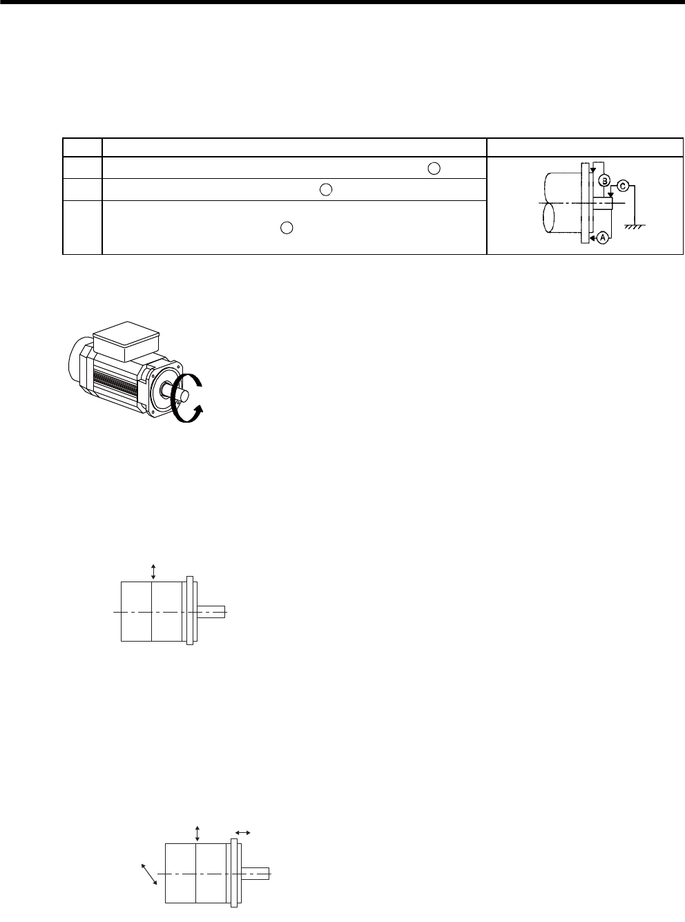
3 Servomotor Specifications and Dimensional Drawings
3.3.3 Mechanical Tolerance
3-14
3.3.3 Mechanical Tolerance
The following table shows tolerances for the servomotor’s output shaft and installation area. For more details on
tolerances, refer to the dimensional drawing of the individual servomotor.
3.3.4 Direction of Servomotor Rotation
Positive rotation of the servomotor is counterclockwise when viewed from the load.
3.3.5 Impact Resistance
Mount the servomotor with the axis horizontal. The servomotor will withstand the following vertical impacts:
• Impact acceleration: 490 m/s2
• Impact occurrences: 2
3.3.6 Vibration Resistance
Mount the servomotor with the axis horizontal. The servomotor will withstand the following vibration accelera-
tion in three directions: Vertical, side to side, and front to back. The amount of vibration the servomotor endures
will vary depending on the application. Check the vibration acceleration being applied to your servomotor for
each application.
• Vibration acceleration: 24.5 m/s2
Tolerance T. I. R. (Total Indicator Reading) Reference Diagram
APerpendicularity between the flange face and output shaft : 0.05
BMating concentricity of the flange O.D. : 0.025
CRun-out at the end of the shaft : 0.03
A
B
C
Positive direction
Vertical
Horizontal shaft
Impact applied to the servomotor
Impact applied to the servomotor
Vertical Front to back
Horizontal shaft
Side to side

3.3 Mechanical Specifications of Servomotors
3
Servomotor Specifications and Dimensional Drawings
3-15
3.3.7 Vibration Class
The vibration class 1for the servomotors at rated motor speed is as follows.
• Vibration class: V15
1 Vibration Class
A vibration class of V15 indicates a total vibration amplitude of 15 μm maximum on the servomotor during rated rotation.
TERMS
Position for measuring vibration
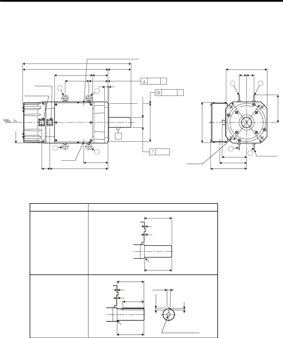
3 Servomotor Specifications and Dimensional Drawings
3-16
3.4 Dimensional Drawings of SGMVH Servomotors (1500 min-1)
(1) 22 kW (-2BAB, -2BDB)
• Shaft End Specifications
* Shaft end key is a JIS B 1301-1996 horizontal key (key slot tightening type).
Specifications Shaft End
Straight, without key
Straight, with key and
tap *
φ265
φ
300
غ250
250
48 220
167
116
149
(Encoder, fan)
20 5
φ
230
0
-0.046
140
230
163
(Motor lead exit)
غ250
(Flange)
45 45
353
658
518
φ
60
+0.030
+0.011
144
94
147
Cooling air
Fan connector
Encoder
connector
4-φ13.5
b
φ61
Motor lead exit
Opening for motor lead when
terminal box plate is replaced.
ab
Hanging bolt
available
Units: mm
Approx. mass: 95 kg
d
cd
c
aφ0.05 A
0.05 A
A
0.03
140
5
7
140
R1.6
140
5
7
140
110
18
11
7
R1.6
M20 screw depth 40
0
-0.110
0
-0.043
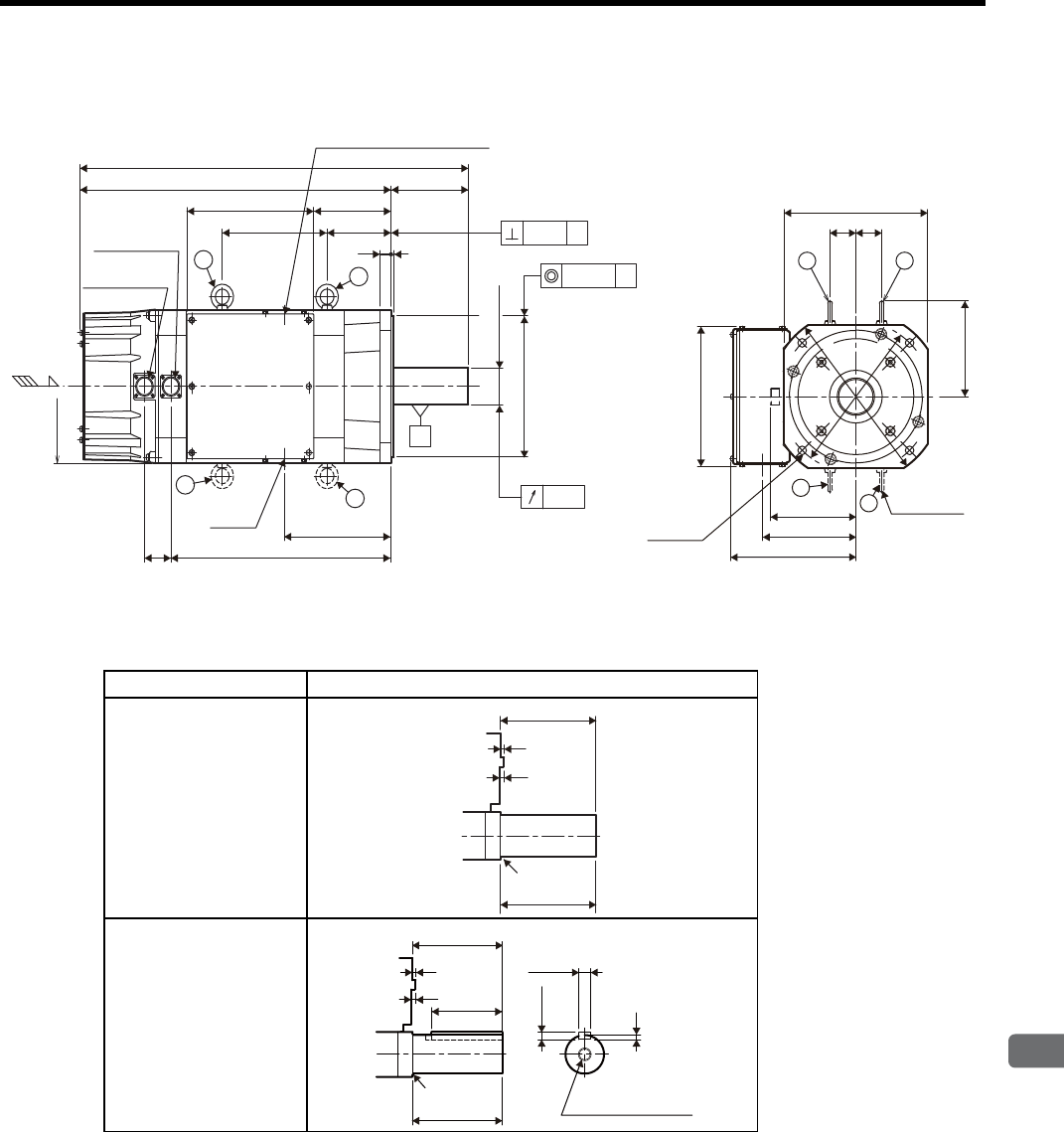
3.4 Dimensional Drawings of SGMVH Servomotors (1500 min-1)
3
Servomotor Specifications and Dimensional Drawings
3-17
(2) 30 kW (-3ZAB, -3ZDB)
• Shaft End Specifications
* Shaft end key is a JIS B 1301-1996 horizontal key (key slot tightening type).
Specifications Shaft End
Straight, without key
Straight, with key and
tap *
250
140564
704
116190
20
5
φ
60
+0.030
+0.011
φ
230
0
-0.046
193
399
48
140230
0.03
φ61
a
b
d
c
φ0.05 A
0.05 A
A
φ265
φ
300
250
220
167
149
(Encoder, fan)
163
(Motor lead exit)
250
(Flange)
45 45
4-φ13.5
ab
d
c
Opening for motor lead when
terminal box plate is replaced.
Encoder
connector
Fan connector
Motor lead exit
Hanging bolt
available
Cooling air
Units: mm
Approx. mass: 110 kg
140
5
7
140
R1.6
140
5
7
140
110
7
R1.6
M20 screw depth 40
18
11
0
-0.110
0
-0.043
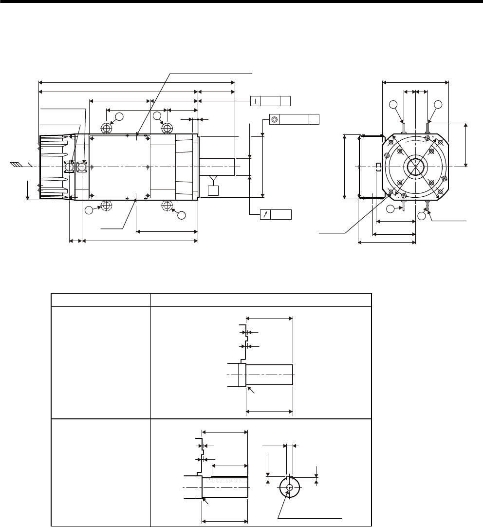
3 Servomotor Specifications and Dimensional Drawings
3-18
(3) 37 kW (-3GAB, -3GDB)
• Shaft End Specifications
* Shaft end key is a JIS B 1301-1996 horizontal key (key slot tightening type).
Specifications Shaft End
Straight, without key
Straight, with key and
tap *
φ265
φ
300
250
220
167
149
(Encoder, fan)
163
(Motor lead exit)
250
(Flange)
45 45
250
48
φ
65
+0.030
+0.011
φ
230
0
-0.046
233
439
140
744
604
520
230
230 116
180
4-φ13.5
ab
Hanging bolt
available
d
c
0.03
φ
61
dc
a
bφ0.05 A
0.05 A
A
Cooling air
Opening for motor lead when
terminal box plate is replaced.
Fan connector
Encoder
connector
Motor lead exit
Units: mm
Approx. mass: 120 kg
140
5
7
140
R1.2
140
5
7
140
110
7
R1.2
M20 screw depth 40
18
11
0
-0.110
0
-0.043
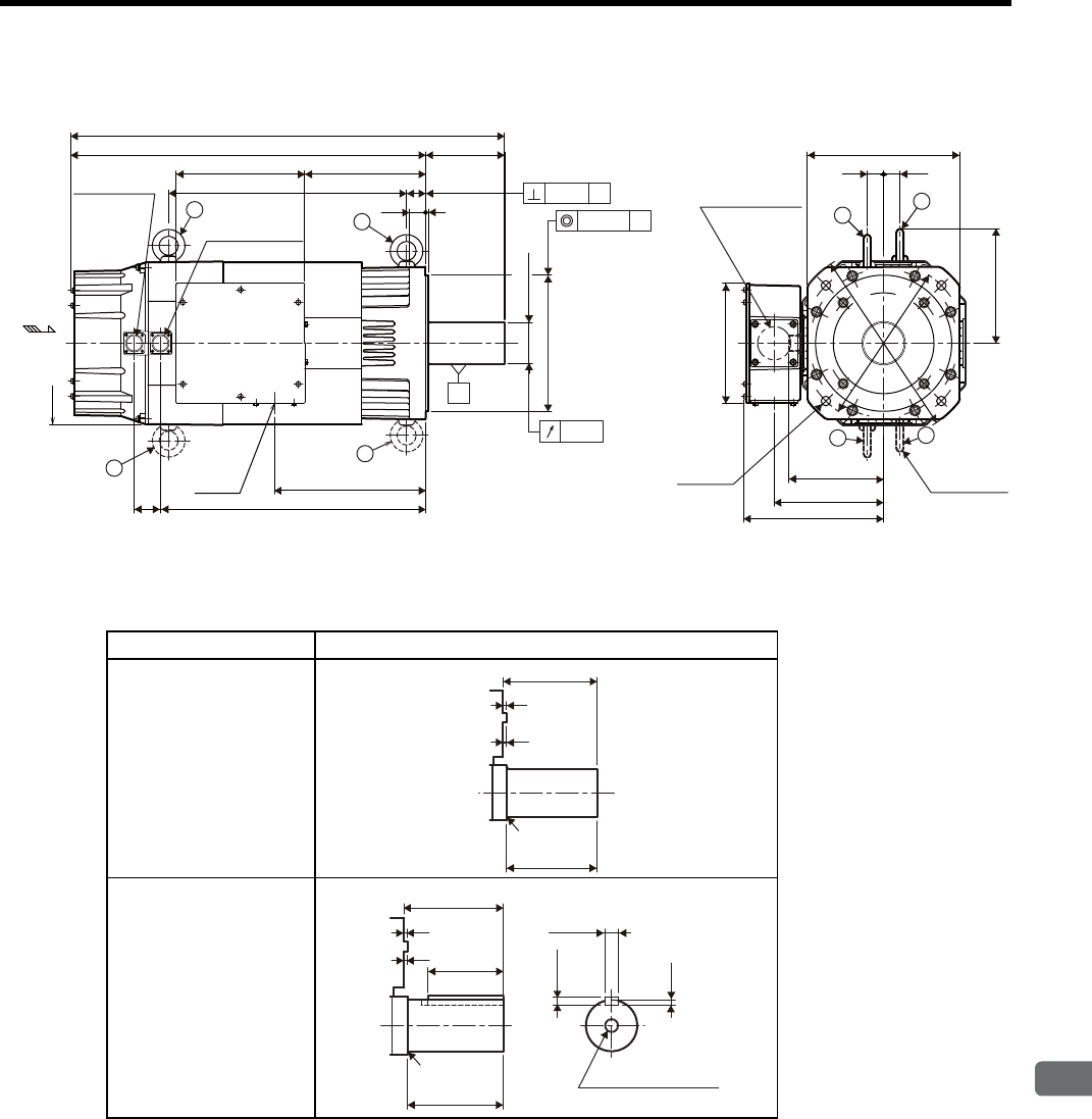
3.4 Dimensional Drawings of SGMVH Servomotors (1500 min-1)
3
Servomotor Specifications and Dimensional Drawings
3-19
(4) 45 kW (-4EDB)
• Shaft End Specifications
* Shaft end key is a JIS B 1301-1996 horizontal key (key slot tightening type).
Specifications Shaft End
Straight, without key
Straight, with key and
tap *
φ300
φ
350
300
220
530
φ75
+0.030
+0.011
φ250
0
-0.046
437 35
145652
797
222236
280
(Flange)
3030
174
(Encoder, fan)
487
277
48 201
(Motor lead exit)
210
258
Cooling air
Motor lead exit
a
b
a
b
0.03
Opening for motor lead
when terminal box plate
is replaced.
c
d
φ61
d
Hanging bolt
available
c
Fan connector
Encoder connector
4-φ17.5
0.05 A
A
φ0.05 A
Units: mm
Approx. mass: 165 kg
5
5
145
140
R2.5
5
145
140
5
7.5
110
R2.5 M20 screw depth 40
20
12
0
-0.110
0
-0.052
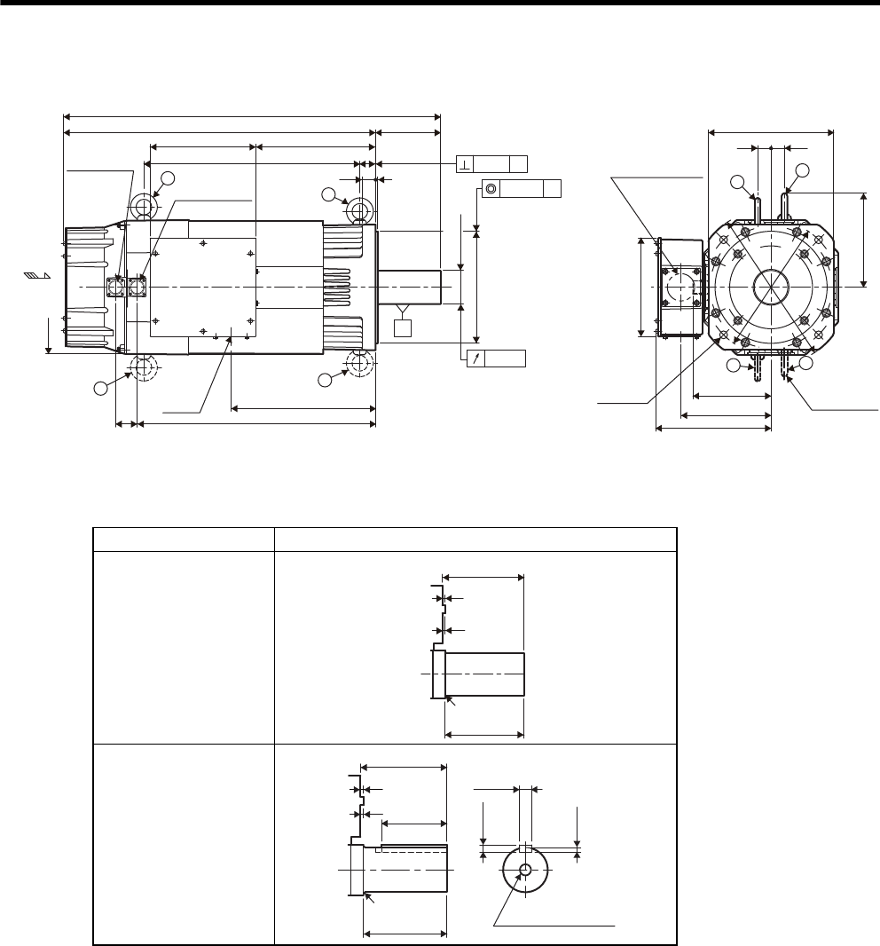
3 Servomotor Specifications and Dimensional Drawings
3-20
(5) 55 kW (-5EDB)
• Shaft End Specifications
* Shaft end key is a JIS B 1301-1996 horizontal key (key slot tightening type).
Specifications Shaft End
Straight, without key
Straight, with key and
tap *
φ300
φ
350
220
280
(Flange)
3030
174
(Encoder, fan)
258
201
(Motor lead exit)
210
300
5
145697
842
267236
482 35
30
φ
75
+0.030
+0.011
φ
250
0
-0.046
532
322
48
ab
Opening for motor lead
when terminal box plate
is replaced.
d
Hanging bolt
available
c
Cooling air
Motor lead exit
0.03
a
b
c
d
φ
61
4-
φ
17.5
Encoder connector
Fan connector
0.05
A
A
φ
0.05
A
Units: mm
Approx. mass: 185 kg
5
5
145
140
R2.5
5
140
5
145
110
7.5
R2.5 M20 screw depth 40
20
12
0
-0.110
0
-0.052
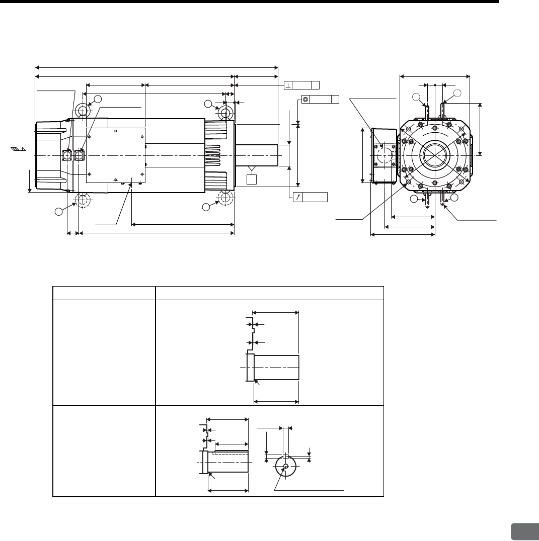
3.4 Dimensional Drawings of SGMVH Servomotors (1500 min-1)
3
Servomotor Specifications and Dimensional Drawings
3-21
(6) 75 kW (-7EDB)
• Shaft End Specifications
* Shaft end key is a JIS B 1301-1996 horizontal key (key slot tightening type).
Specifications Shaft End
Straight, without key
Straight, with key and
tap *
300
220
30 5
35
175
973
798
572
357
φ
85
+0.035
+0.013
φ
250
0
-0.046
236 30 30
280
(Flange)
210
258
201
(Motor lead exit)
174
(Encoder, fan)
622
48
412
φ
300
φ
350
a
Opening for motor lead
when terminal box plate
is replaced.
d
Hanging bolt
available
c
Cooling air
a
c
d
Motor lead exit
0.03
0.05
A
φ0.05 Ab
b
φ
61
Encoder
connector
Fan connector
4-
φ
17.5
A
Units: mm
Approx. mass: 225 kg
5
5
175
170
R2.5
5
170
5
175
140
9
R2.5
M20screw depth 40
22
14
0
-0.110
0
-0.052
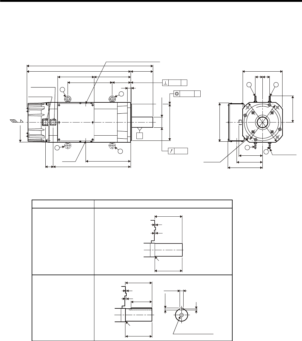
3 Servomotor Specifications and Dimensional Drawings
3-22
3.5 Dimensional Drawings of SGMVH Servomotors (800 min-1)
(1) 22 kW (-2BAD, -2BDD)
• Shaft End Specifications
* Shaft end key is a JIS B 1301-1996 horizontal key (key slot tightening type).
Specifications Shaft End
Straight, without key
Straight, with key and
tap *
250
φ
265
φ
300
250
220
167
149
(Encoder, fan)
163
(Motor lead exit)
250
(Flange)
45 45
140
116
20 5
φ
230
0
-0.046
48
230
φ
65
+0.030
+0.011
794
654
230
283
489
280
Fan connector
Encoder
connector
Motor lead exit
4-φ13.5
ab
Hanging bolt
available
d
c
0.03
φ
61
a
b
dc
φ0.05 A
0.05 A
A
Cooling air
Opening for motor lead when
terminal box plate is replaced.
Units: mm
Approx. mass: 135 kg
140
5
7
140
R1.2
5
7
7
140
140
110
M20 screw depth 40
R1.2
18
11
0
-0.110
0
-0.043
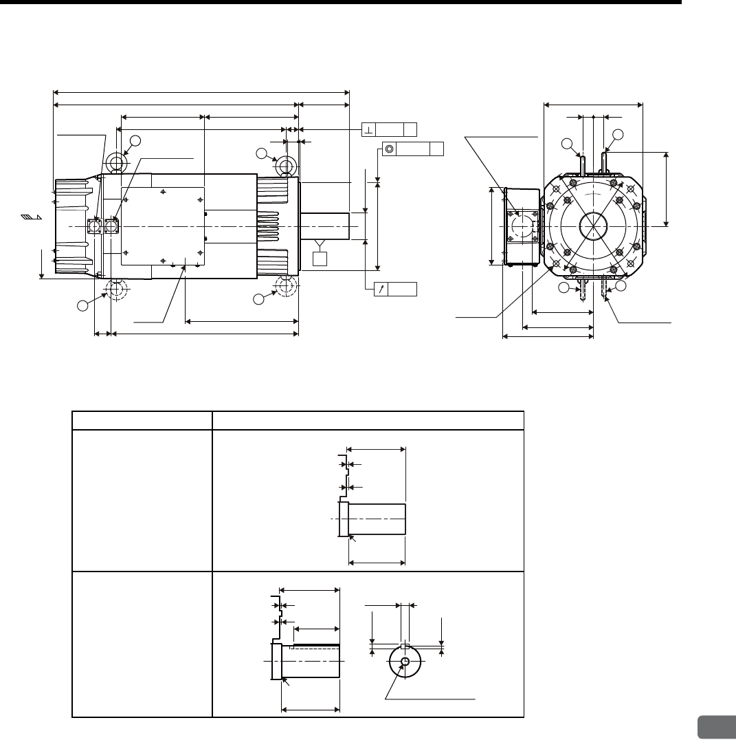
3.5 Dimensional Drawings of SGMVH Servomotors (800 min-1)
3
Servomotor Specifications and Dimensional Drawings
3-23
(2) 30 kW (-3ZAD, -3ZDD)
• Shaft End Specifications
* Shaft end key is a JIS B 1301-1996 horizontal key (key slot tightening type).
Specifications Shaft End
Straight, without key
Straight, with key and
tap *
φ
300
φ
350
220
280
(Flange)
3030
174
(Encoder, fan)
201
(Motor lead exit)
210
300
5
145697
842
267236
482 35
30
φ
75
+0.030
+0.011
φ
250
0
-0.046
532
322
48 258
ab
Opening for motor lead
when terminal box plate
is replaced.
d
Hanging bolt
available
c
Cooling air
Motor lead exit
0.03
a
b
c
d
φ61 4-φ17.5
Encoder
connector
Fan connector
0.05 A
A
φ0.05 A
Units: mm
Approx. mass: 185 kg
5
5
145
140
R2.5
5
145
140
5
7.5
110
R2.5 M20 screw depth 40
20
12
0
-0.110
0
-0.052
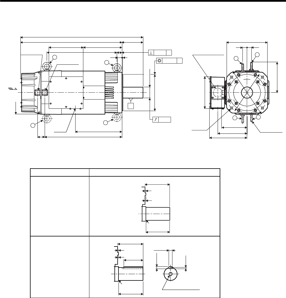
3 Servomotor Specifications and Dimensional Drawings
3-24
(3) 37 kW (-3GAD, -3GDD)
• Shaft End Specifications
* Shaft end key is a JIS B 1301-1996 horizontal key (key slot tightening type).
Specifications Shaft End
Straight, without key
Straight, with key and
tap *
φ
300
φ
350
220
280
(Flange)
3030
174
(Encoder, fan)
201
(Motor lead exit)
210
300
5
145
236
35
30
φ
75
+0.030
+0.011
φ
250
0
-0.046
48
372
582
317
532
747
892
258
ab
Opening for motor lead
when terminal box plate
is replaced.
d
Hanging bolt
available
c
Cooling air
Motor lead exit
0.03
a
b
c
d
φ61 4-φ17.5
Encoder
connector
Fan connector
0.05 A
A
φ0.05 A
Units: mm
Approx. mass: 205 kg
5
5
145
140
R2.5
5
145
140
5
7.5
110
R2.5 M20 screw depth 40
20
12
0
-0.110
0
-0.052
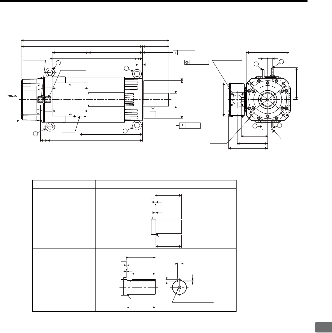
3.5 Dimensional Drawings of SGMVH Servomotors (800 min-1)
3
Servomotor Specifications and Dimensional Drawings
3-25
(4) 45 kW (-4EDD)
• Shaft End Specifications
* Shaft end key is a JIS B 1301-1996 horizontal key (key slot tightening type).
Specifications Shaft End
Straight, without key
Straight, with key and
tap *
300
220
35
572
48
30 5
175
φ
85
+0.035
+0.013
φ
250
0
-0.046
30 30
280
(Flange)
210
174
(Encoder, fan)
201
(Motor lead exit)
236 357
798
973
412
622
φ
300
φ
350
258
a
Opening for motor lead
when terminal box plate
is replaced.
d
Hanging bolt
available
c
Cooling air
a
b
c
d
φ61
Motor lead exit
0.03
0.05
A
φ
0.05
Ab
Encoder
connector
Fan connector
4-φ17.5
A
Units: mm
Approx. mass: 225 kg
5
5
175
170
R2.5
5
170
5140
175
9
R2.5 M20 screw depth 40
22
14
0
-0.110
0
-0.052

4
SERVOPACK Specifications and Dimensional Drawings
4-1
4
SERVOPACK Specifications and
Dimensional Drawings
4.1 SERVOPACK Ratings and Specifications - - - - - - - - - - - - - - 4-2
4.1.1 Three-phase 200 V - - - - - - - - - - - - - - - - - - - - - - - - - - - - - - - - - - - - 4-2
4.1.2 Three-phase 400 V - - - - - - - - - - - - - - - - - - - - - - - - - - - - - - - - - - - - 4-2
4.1.3 SERVOPACK Ratings and Specifications - - - - - - - - - - - - - - - - - - - - - 4-3
4.2 SERVOPACK Installation - - - - - - - - - - - - - - - - - - - - - - - - - - 4-5
4.3 SERVOPACK Internal Block Diagrams - - - - - - - - - - - - - - - - 4-7
4.3.1 Three-phase 200 V, 22 kW, 30 kW Models - - - - - - - - - - - - - - - - - - - - 4-7
4.3.2 Three-phase 200 V, 37 kW Model - - - - - - - - - - - - - - - - - - - - - - - - - - 4-8
4.3.3 Three-phase 400 V, 22 kW, 30 kW Models - - - - - - - - - - - - - - - - - - - - 4-9
4.3.4 Three-phase 400 V, 37 kW Model - - - - - - - - - - - - - - - - - - - - - - - - - - 4-9
4.3.5 Three-phase 400 V, 45 kW, 55 kW Models - - - - - - - - - - - - - - - - - - - 4-10
4.3.6 Three-phase 400 V, 90 kW Model - - - - - - - - - - - - - - - - - - - - - - - - - 4-10
4.4 SERVOPACK’s Power Supply Capacities and Power Losses 4-11
4.5 SERVOPACK Overload Characteristics and Allowable Load
Moment of Inertia - - - - - - - - - - - - - - - - - - - - - - - - - - - - - - 4-12
4.5.1 Overload Characteristics - - - - - - - - - - - - - - - - - - - - - - - - - - - - - - - 4-12
4.5.2 Starting and Stopping Time - - - - - - - - - - - - - - - - - - - - - - - - - - - - - - 4-13
4.5.3 Load Moment of Inertia - - - - - - - - - - - - - - - - - - - - - - - - - - - - - - - - 4-14
4.6 SERVOPACK Dimensional Drawings - - - - - - - - - - - - - - - - 4-16
4.6.1 Three-phase 200 V, 22 kW, 30 kW Models - - - - - - - - - - - - - - - - - - - 4-16
4.6.2 Three-phase 200 V, 37 kW Model - - - - - - - - - - - - - - - - - - - - - - - - - 4-17
4.6.3 Three-phase 400 V, 22 kW Model - - - - - - - - - - - - - - - - - - - - - - - - - 4-18
4.6.4 Three-phase 400 V, 30 kW Model - - - - - - - - - - - - - - - - - - - - - - - - - 4-19
4.6.5 Three-phase 400 V, 37 kW Model - - - - - - - - - - - - - - - - - - - - - - - - - 4-20
4.6.6 Three-phase 400 V, 45 kW, 55 kW Models - - - - - - - - - - - - - - - - - - - 4-20
4.6.7 Three-phase 400 V, 90 kW Model - - - - - - - - - - - - - - - - - - - - - - - - - 4-21
4 SERVOPACK Specifications and Dimensional Drawings
4.1.1 Three-phase 200 V
4-2
4.1 SERVOPACK Ratings and Specifications
4.1.1 Three-phase 200 V
The value of the input power supply voltage is maximum 253 Vrms.
4.1.2 Three-phase 400 V
The value of the input power supply voltage is maximum 528 Vrms.
• Take appropriate measures to ensure that the input power supply is supplied within the specified voltage
range.
An incorrect input power supply may result in damage to the SERVOPACK. If the voltage exceeds these values, use
a step-down transformer so that the voltage will be within the specified range.
CAUTION
SERVOPACK
Model
SGDM- 2BADB 3ZADB 3GADB
SGDH- 2BAEB 3ZAEB 3GAEB
Max. Applicable Servomotor Capacity (kW) 22 30 37
Continuous Output Current (Arms) 110 148 195
Max. Output Current (Arms) 240 340 460
Input Power Supply Main Circuit Three-phase 200 to 230 VAC +10% to -15%, 50/60 Hz
Control Circuit Single-phase 200 to 220 VAC +10% to -15%, 50 Hz
Single-phase 200 to 230 VAC +10% to -15%, 60 Hz
Configuration Base-mounted
SERVOPACK Model SGDH- 2BDEB 3ZDEB 3GDEB 4EDEB 5EDEB 9ZDEB
Max. Applicable Servomotor Capacity (kW) 22 30 37 45 55 75
Continuous Output Current (Arms) 52.2 75 98 127 150 210
Max. Output Current (Arms) 120 170 230 280 340 580
Input Power Supply Main Circuit Three-phase 380 to 480 VAC +10% to -15%, 50/60 Hz
Control Circuit 24 VDC ±15%
For Control Actuator Single-phase 380 to 480 VAC, 50/60 Hz, 150 VA
Configuration Base-mounted

4.1 SERVOPACK Ratings and Specifications
4
SERVOPACK Specifications and Dimensional Drawings
4-3
4.1.3 SERVOPACK Ratings and Specifications
Basic
Specifi-
cations
Control Method Three-phase full-wave rectification IGBT-PWM (sine-wave driven)
Feedback Serial encoder: 17-bit (incremental/absolute)
Condi-
tions
Ambient/Storage Temperature ∗10 to +55°C/-20 to +85°C
Ambient/Storage Humidity 90% RH or less (with no condensation)
Vibration/Shock Resistance 4.9 m/s2/19.6 m/s2
Speed
and
Torque
Control
Modes
Perfor-
mance
Speed Control Range 1:5000 (The lowest speed of the speed control range is the speed at which
the servomotor will not stop with a rated torque load.)
Speed
Regula-
tion ∗2
Load Regulation 0 to 100% load: ±0.01% or less (at rated speed)
Voltage Regulation Rated voltage ±10%: 0% (at rated speed)
Temperature Regula-
tion
25 ± 25°C: ±0.1% or less (at rated speed)
Frequency Characteristics 100 Hz (at JL = JM)
Torque Control Tolerance
(Repeatability)
±2%
Soft Start Time Setting 0 to 10 s (Can be set individually for acceleration and deceleration.)
Input
Signals
Speed
Reference
Input
Reference Voltage ∗3±6 VDC (Variable setting range: ±2 to ±10 VDC) at rated speed, input
voltage: maximum ±12 V (servomotor forward rotation with positive
reference)
Input Impedance About 14 kΩ
Circuit Time Constant About 47 μs
Torqu e
Reference
Input
Reference Voltage ∗3±3 VDC (Variable setting range: ±1 to ±10 VDC) at rated torque, input
voltage: maximum ±12 V (positive torque reference with positive
reference)
Input Impedance About 14 kΩ
Circuit Time Constant About 47 μs
Contact
Speed
Reference
Rotation Direction
Selection
With P control signal
Speed Selection With forward/reverse external torque limit signal (speed 1 to 3 selection),
servomotor stops or another control method is used when both are OFF.
Position
Control
Modes
Perfor-
mance
Bias Setting 0 to 450 min-1 (setting resolution: 1 min-1)
Feed Forward Compensation 0 to 100% (setting resolution: 1%)
Positioning Completed Width
Setting
0 to 250 reference units (setting resolution: 1 reference unit)
Input
Signals
Reference
Pulse
Type Sign + pulse train, 90° phase difference 2-phase pulse train (phase A +
phase B), or CCW + CW pulse train
Form Line driver (+5 V level), open collector (+5 V or +12 V level)
Frequency Maximum 500/200 kpps (line driver/open collector)
Control Signal Clear signal (input pulse form identical to reference pulse)
Built-in Open Collector Power
Supply ∗4
+12 V (1kΩ resistor built in)
I/O
Signals
Position Output Form Phase-A, -B, -C line driver
Phase-S line driver (only with an absolute encoder)
Frequency Dividing
Ratio
Any
Sequence Input Signal allocation can
be modified.
Servo ON, P control (or Control mode switching, forward/reverse motor
rotation by internal speed setting, zero clamping, reference pulse prohib-
ited), forward run prohibited (P-OT), reverse run prohibited (N-OT),
alarm reset, forward external torque limit, and reverse external torque
limit (or internal speed selection)
Sequence Output Fixed Output Servo alarm, 3-bit alarm codes
Signal allocation can
be modified.
Select three signals from the following: Positioning completed (speed
coincidence), servomotor rotation detection, servo ready, torque limit,
speed limit, brake interlock, warning, NEAR signal.

4 SERVOPACK Specifications and Dimensional Drawings
4.1.3 SERVOPACK Ratings and Specifications
4-4
* 1. Use the SERVOPACK within the surrounding air temperature range. When enclosed in a control
panel, internal temperatures must not exceed the ambient temperature range.
* 2. Speed regulation is defined as follows:
The motor speed may change due to voltage variations or amplifier drift and changes in processing
resistance due to temperature variation. The ratio of speed changes to the rated speed represent speed
regulation due to voltage and temperature variations.
* 3. Forward is clockwise viewed from the non-load side of the servomotor. (Counterclockwise viewed
from the load and shaft end)
* 4. The built-in open collector power supply is not electrically insulated from the control circuit in the
SERVOPACK.
Internal
Func-
tions
Dynamic Brake Operated at main power OFF, servo alarm, servo OFF or overtravel.
Overtravel Stop Dynamic brake stop at P-OT or N-OT, deceleration to a stop, or coast to a
stop
Electronic Gear 0.01 ≤ B/A ≤ 100
Protection Overcurrent, overvoltage, low voltage, overload, regeneration error, main
circuit detection section error, heat sink overheated, no power supply,
overflow, overspeed, encoder error, overrun, CPU error, parameter error
LED Display Charge, Power, five 7-segment LEDs × 5 digits (built-in Digital Operator
functions)
CN5Analog Monitoring Analog monitor connector built in for monitoring speed, torque and other
reference signals.
Speed: 1 V/1000 min-1
Torque: 1 V/ rated torque
Position error pulses: 0.05 V/1 reference units or 0.05 V/100 reference
units
Communications Connected Devices Digital Operator (hand-held model), RS-422A port such as for a personal
computer (RS-232C ports under certain conditions)
1:N Communications Up to N = 14 for RS-422A ports
Axis Address Setting Set with parameters.
Functions Status display, parameter setting, monitor display, alarm trace-back dis-
play, JOG operations, speed/torque reference signal and other drawing
functions
Others Reverse rotation connection, zero-point search, automatic servomotor ID,
DC reactor connection terminal for harmonic suppressions
Speed reguration
=
No-load motor speed – Total load motor speed
Rated motor speed ×100%
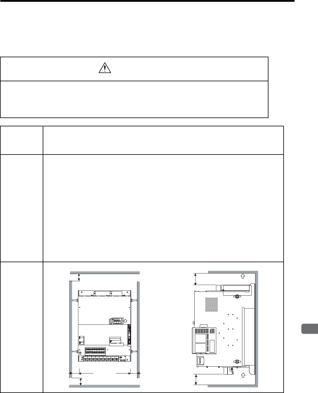
4.2 SERVOPACK Installation
4
SERVOPACK Specifications and Dimensional Drawings
4-5
4.2 SERVOPACK Installation
The SGDM/SGDH SERVOPACKs can be mounted on a base. Incorrect installation will cause problems. Always
observe the following installation instructions.
• After voltage resistance test, wait at least five minutes before servicing the product. (Refer to “Voltage Resis-
tance Test” on the following page.)
Failure to observe this warning may result in electric shock.
• Connect the main circuit wires, control wires, and main circuit cables of the motor correctly.
Incorrect wiring will result in failure of the SERVOPACK.
WARNING
Storage Store the SERVOPACK within the following temperature range if it is stored with the power cable discon-
nected.
Temperature: -20 to 85°C
Humidity: 90% RH or less (with no condensation)
Installation Site Installation in a Control Panel
Design the control panel size, unit layout, and cooling method so the temperature around the SERVOPACK
does not exceed 55°C.
Installation Near a Heating Unit
Minimize the heat radiating from the heating unit as well as any temperature rise caused by natural convec-
tion so the temperature around the SERVOPACK does not exceed 55 °C.
Installation Near a Source of Vibration
Install a vibration isolator on the SERVOPACK to avoid subjecting it to vibration.
Installation at a Site Exposed to Corrosive Gas
Corrosive gas does not have an immediate effect on the SERVOPACK but will eventually cause the elec-
tronic components and contactor-related devices to malfunction. Take appropriate action to avoid corrosive
gas.
Other Situations
Do not install the SERVOPACK in hot, humid locations or locations subject to water, cutting oil, excessive
dust, iron powder, and radioactivity in the air.
Orientation Install the SERVOPACK perpendicular to the wall as shown in the figure.
Air flow
120 mm min. 120 mm min.
Air flow
50 mm min.
(ventilation exhaust)
50 mm min. (ventilation intake)
50 mm min.
50 mm min.
+2-+1 L1/R L2/S L3/T UVW
480
V 460
V
DU
400
V 0
V
440
V
DWDV B1
380
V
DC
24N
B2
DC
24P
CHARGE
S-HDG
㧖㧖㧖㧖
T DATA/SEEMOD/
KSERVOPAC
AYASKAW
R
O
P
E
R
A
T
O
CN3
8CN
POWER
CN5
WARNING
ෂޓ㒾
ㅢ㔚ਛ߮㔚Ḯࠝࡈᓟ5
ಽ㑆ޔ┵ሶㇱߦ⸅ࠆߥ!
electric shock.
Disconnect all power
May cause
ᗵ㔚ߩᕟࠇࠅ
before servicing.
and wait 5 min.
grounding techniques.
ធ⛯ߖࠃ
Use proper
ᔅߕࠕ㧙ࠬ✢ࠍ
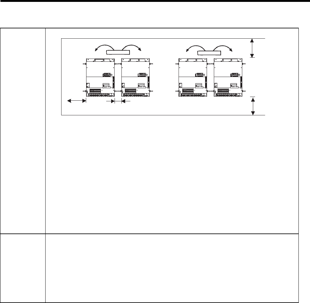
4 SERVOPACK Specifications and Dimensional Drawings
4-6
Installation Follow the procedure below to install multiple SERVOPACKs side by side in a control panel.
SERVOPACK Orientation
Install the SERVOPACK perpendicular to the wall so the front panel containing connectors faces outward.
Cooling
As shown in the figure above, allow sufficient space around each SERVOPACK for cooling by cooling fans
or natural convection.
Side-by-side Installation
When installing SERVOPACKs side by side as shown in the figure above, allow at least 100 mm between
and at least 120 mm above and below each SERVOPACK. Allow the space for eyebolts on both sides of the
SERVOPACK.
Environmental Conditions in the Control Panel
Surrounding Air Temperature:0 to 55°C
Humidity: 90% RH or less
Vibration: 4.9 m/s2
Condensation and Freezing: None
Surrounding Air Temperature for Long-term Reliability: 45°C or less
Voltage
Resistance Test
Conduct voltage resistance tests under the following conditions.
• Voltage: 1500 Vrms AC for one minute
• Braking current: 100 mA
• Frequency: 50 or 60 Hz
• Voltage applied points
200 V series: Between the ground terminals and the point where terminals L1C/r, L3C/t, L1/R, L2/S, L3/T
are connected.
400 V series: Between the ground terminals and the point where terminals 480 V, 460 V, 440 V, 400 V, 380 V,
0 V, L1/R, L2/S, L3/T are connected.
Fan
50 mm min. 100 mm min.
120 mm
min.
120 mm
min.
Fan
.4 .5 .6 789
8
8
&7
8
8
8
&9&8 $
8
&%
0
$ &%
2
%*#4)'
5*&)
㧖㧖㧖㧖
6#5''/1&
-5'4812#%
#;#5-#9
4
1
2
'
4
#
6
1
%0
%0
219'4
%0
WARNING
ෂޓ㒾
ㅢ㔚ਛ߮㔚Ḯࠝࡈᓟ5
ಽ㑆ޔ┵ሶㇱߦ⸅ࠆߥ
electric shock.
Disconnect all power
May cause
ᗵ㔚ߩᕟࠇࠅ
before servicing.
and wait 5 min.
grounding techniques.
ធ⛯ߖࠃ
Use proper
ᔅߕࠕ㧙ࠬ✢ࠍ
.4 .5 .6 789
8
8
&7
8
8
8
&9&8 $
8
&%
0
$ &%
2
%*#4)'
5*&)
㧖㧖㧖㧖
6#5''/1&
-5'4812#%
#;#5-#9
4
1
2
'
4
#
6
1
%0
%0
219'4
%0
WARNING
ෂޓ㒾
ㅢ㔚ਛ߮㔚Ḯࠝࡈᓟ5
ಽ㑆ޔ┵ሶㇱߦ⸅ࠆߥ
electric shock.
Disconnect all power
May cause
ᗵ㔚ߩᕟࠇࠅ
before servicing.
and wait 5 min.
grounding techniques.
ធ⛯ߖࠃ
Use proper
ᔅߕࠕ㧙ࠬ✢ࠍ
.4 .5 .6 789
8
8
&7
8
8
8
&9&8 $
8
&%
0
$ &%
2
%*#4)'
5*&)
㧖㧖㧖㧖
6#5''/1&
-5'4812#%
#;#5-#9
4
1
2
'
4
#
6
1
%0
%0
219'4
%0
WARNING
ෂޓ㒾
ㅢ㔚ਛ߮㔚Ḯࠝࡈᓟ5
ಽ㑆ޔ┵ሶㇱߦ⸅ࠆߥ
electric shock.
Disconnect all power
May cause
ᗵ㔚ߩᕟࠇࠅ
before servicing.
and wait 5 min.
grounding techniques.
ធ⛯ߖࠃ
Use proper
ᔅߕࠕ㧙ࠬ✢ࠍ
.4 .5 .6 789
8
8
&7
8
8
8
&9&8 $
8
&%
0
$ &%
2
%*#4)'
5*&)
㧖㧖㧖㧖
6#5''/1&
-5'4812#%
#;#5-#9
4
1
2
'
4
#
6
1
%0
%0
219'4
%0
WARNING
ෂޓ㒾
ㅢ㔚ਛ߮㔚Ḯࠝࡈᓟ5
ಽ㑆ޔ┵ሶㇱߦ⸅ࠆߥ
electric shock.
Disconnect all power
May cause
ᗵ㔚ߩᕟࠇࠅ
before servicing.
and wait 5 min.
grounding techniques.
ធ⛯ߖࠃ
Use proper
ᔅߕࠕ㧙ࠬ✢ࠍ
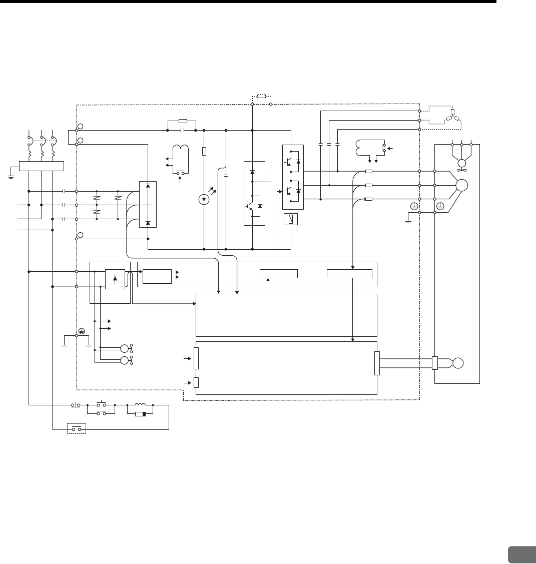
4.3 SERVOPACK Internal Block Diagrams
4
SERVOPACK Specifications and Dimensional Drawings
4-7
4.3 SERVOPACK Internal Block Diagrams
4.3.1 Three-phase 200 V, 22 kW, 30 kW Models
FIL
R
S
T
1KM L1/R
+ 1
+ 2
R1
B1
TRM7
TRM1 to
TRM6
FU1 to 3
C1 to
C4
B2
+
-
CHARGE
SA1 to SA3
3PWB
200 VAC
1KM
1KM
(5Ry) Open during servo alarm
1CN
3CN
L1C/r
L3C/t
+5V 2PWB
2CN
PG
L2/S
L3/T
-
200 VAC
DCCT1
DCCT2
DCCT3
MC2
DU
DV
DW
U
V
W
U
RST
UVW
V
W
M
200
VAC MC1
MC1
FAN
㨪ޓ
㨪ޓ
FAN1 to FAN2
1QF
Servomotor
Three-phase
200 to 230 VAC
(50/60 Hz)
Regenerative resistor (option) DB resistor (option)
From
detection
circuit
From detection
circuit
DC/DC
converter Power for
drive
Drive circuit Current sensor
Sensor circuit
Position/speed calculation circuit
Control input
Digital operator
(personal computer)
Power OFF Power ON
Surge absorber
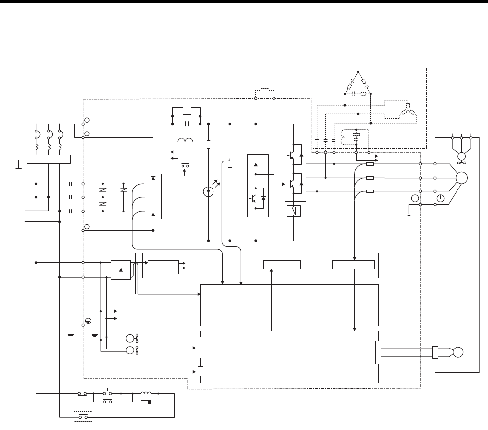
4 SERVOPACK Specifications and Dimensional Drawings
4.3.2 Three-phase 200 V, 37 kW Model
4-8
4.3.2 Three-phase 200 V, 37 kW Model
FIL
R
S
T
1KM L1/R
+ 1
+ 2
R1
B1
TRM7
TRM1
to
TRM6
FU1 to 3
C1 to
C4
B2
+
-
CHARGE
SA1 to SA3
3PWB
200 VAC
1KM
1KM
(5Ry) Open during servo alarm
1CN
3CN
L1C/r
L3C/t
+5V 2PWB
2CN
PG
L2/S
L3/T
-
R2
DCCT1
DCCT2
DCCT3
DU DV DW
U
V
W
U
RST
UVW
V
W
M
MC1
MC1
200
VAC
FAN
㨪ޓ
㨪ޓ
FAN1 to FAN2
1QF
Servomotor
Three-phase
200 to 230 VAC
(50/60 Hz)
Regenerative resistor (option) DB resistor
(option)
DB unit
(option)
From detection
circuit
From detection
circuit
DC/DC
converter Power for
drive
Drive circuit Current sensor
Sensor circuit
Position/speed calculation circuit
Control input
Digital operator
(personal computer)
Power OFF Power ON
Surge absorber
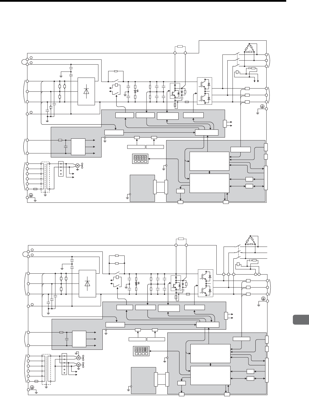
4.3 SERVOPACK Internal Block Diagrams
4
SERVOPACK Specifications and Dimensional Drawings
4-9
4.3.3 Three-phase 400 V, 22 kW, 30 kW Models
4.3.4 Three-phase 400 V, 37 kW Model
D/A
A/D
I/O
CN5 CN3
CN10
CN2
CN8
CN1
1PCB
2PCB
+
-
+5V
+24V
+15V
43CN
3PCB
200 VAC
FAN1
215V 1
2
3
4
480V
460V
440V
400V
380V
0V
600V 4A 0
E
DC24P
DC24N
DU
DV
DW
MC2
DCCT1
DB24DBON
W
V
U
W
V
U
DCCT2
DCCT3
DB24
DBON
R
T
S
+
-
+
-
+
-
+
-
TRM1 to TRM6
C1 to C4
TRM7
+
-
+
-
CHARGE
MC1
MC1
R1
200 VAC
C64
C65
C61 to C63
L1/R
DM1 to DM3
PG
1
2
-
L2/S
L3/T
B1 B2
+
+
FU1
FU4
MC2
SA1 to SA3
Digital operator
DC reactor
connection
terminals
Main circuit power
input terminals
(380 to 480 VAC)
Main circuit
minus terminal
Control power
input terminals
(24 VDC)
Control power
input terminals
(380 to 480 VAC)
Ground terminal
Ground terminal
VaristorVaristor
Varistor
DC/DC
converter
Voltage sensor
Relay drive Voltage sensor Voltage sensor
gate drive
Gate drive
Interface
Regenerative resistor
Regenerative resistor
unit connection terminals
Motor
connection
terminals
Thermostat 1 Thermostat 2
Panel operator
(Option unit)
ASIC (PWM control, etc.)
CPU
(Position/speed calculation, etc.)
Current sensor
Battery
PG output
Reference pulse
input
Speed/torque
reference input
Sequence input
Analog monitor
Dynamic
brake
unit
connection
terminals
D/A
A/D
I/O
CN5 CN3
CN10
CN2
CN8
CN1
1PCB
2PCB
+
-
+5V
+24V
+15V
43CN
3PCB
DC24P
DC24N
DU
DV
DW
KM
DCCT1
DB24
DBON
W
V
U
W
V
U
DCCT2
DCCT3
DB24
DBON
R
T
S
+
-
+
-
+
-
+
-
TRM1 to TRM6
C1 to C4
TRM7
+
-
+
-
CHARGE
MC1
MC1
R1
200 VAC
DM1 to DM3
C64
C65
C61 to C63
L1/R
1
2
-
L2/S
L3/T
B1 B2
+
+
FU1
FU4
FAN1
215V 1
2
3
4
480V
460V
440V
400V
380V
0V
600V 4A 0
E
FAN2
5
6200 VAC
SA1 to SA3
DU DV DW
KM
R2
Panel operator
PG
Digital operator
DC reactor
connection
terminals
Main circuit power
input terminals
(380 to 480 VAC)
Main circuit
minus terminal
Control power
input terminals
(24 VDC)
Control power
input terminals
(380 to 480 VAC)
Ground terminal
Ground terminal
Varistor
VaristorVaristor
DC/DC
converter
Voltage sensor
Relay drive Voltage sensor Voltage sensor
gate drive
Gate drive
Interface
Regenerative resistor
Regenerative resistor
unit connection terminals
Motor
connection
terminals
Thermostat 1 Thermostat 2
(Option unit)
ASIC (PWM control, etc.)
CPU
(Position/speed calculation, etc.)
Battery
PG output
Reference pulse
input
Speed/torque
reference input
Sequence input
Analog monitor
Current sensor
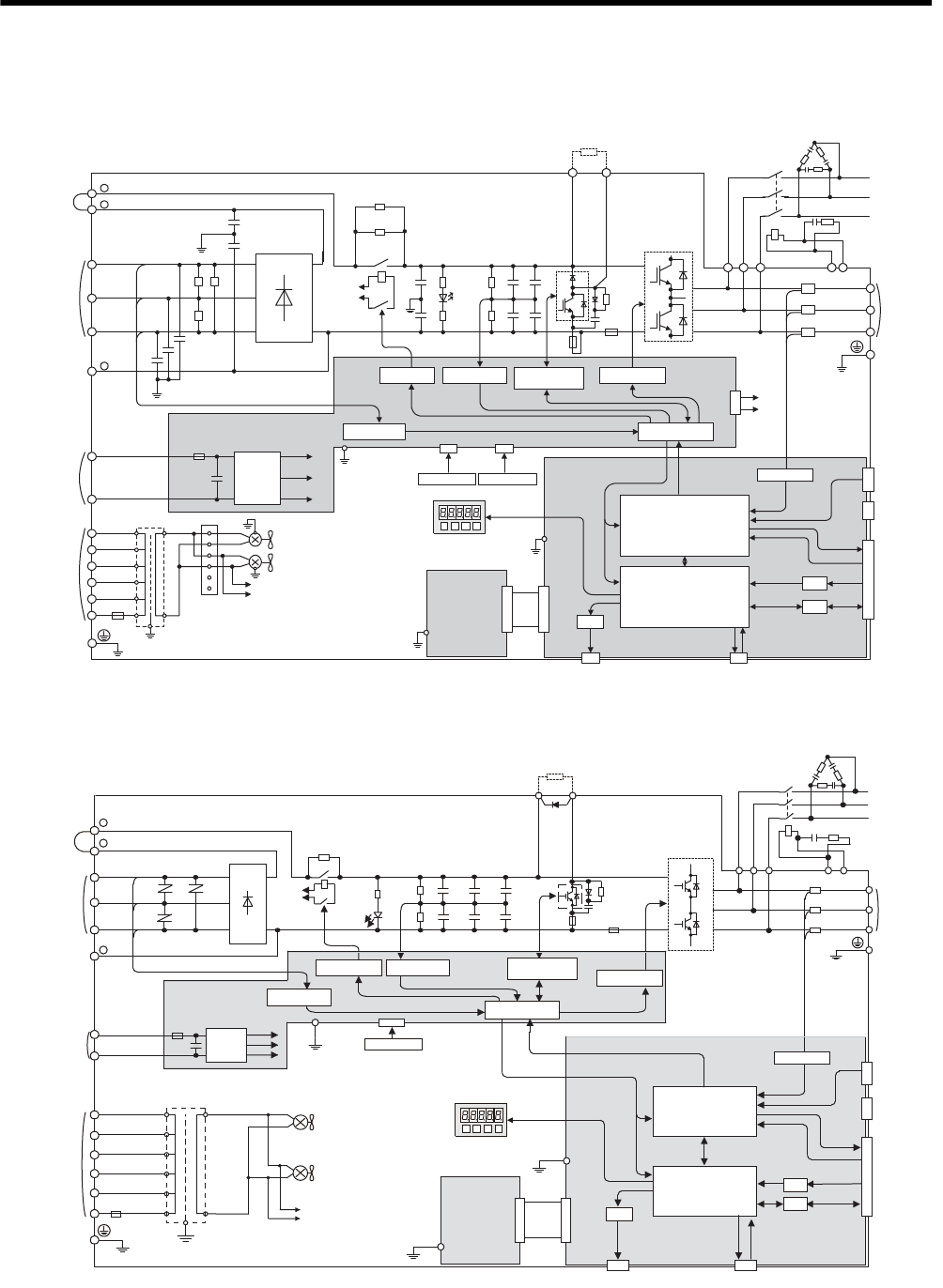
4 SERVOPACK Specifications and Dimensional Drawings
4.3.5 Three-phase 400 V, 45 kW, 55 kW Models
4-10
4.3.5 Three-phase 400 V, 45 kW, 55 kW Models
4.3.6 Three-phase 400 V, 90 kW Model
D/A
A/D
I/O
CN5 CN3
CN10
CN2
CN8
CN1
1PCB
2PCB
+
-
+5V
+24V
+15V
43CN
3PCB
DC24P
DC24N
DU
DV
DW
KM
DCCT1
DB24
DBON
W
V
U
W
V
U
DCCT2
DCCT3
DB24
DBON
R
T
S
+
-
+
-
+
-
+
-
TRM1 to TRM6
C1 to C4
TRM7
+
-
+
-
CHARGE
MC1
MC1
R1
200 VAC
DM1 to DM3
C64
C65
C61 to C63
L1/R
1
2
-
L2/S
L3/T
B1 B2
+
+
FU1
FU4
FAN1
215V 1
2
3
4
480V
460V
440V
400V
380V
0V
600V 4A 0
E
FAN2
5
6200 VAC
SA1 to SA3
DU DV DW
KM
R2
Panel operator
PG
DC reactor
connection
terminals
Main circuit power
input terminals
(380 to 480 VAC)
Main circuit
minus terminal
Control power
input terminals
(24 VDC)
Control power
input terminals
(380 to 480 VAC)
Ground terminal
Ground terminal
DC/DC
converter
Voltage sensor
Relay drive Voltage sensor Voltage sensor
gate drive
Gate drive
Interface
Regenerative resistor
Regenerative resistor
unit connection terminals
Motor
connection
terminals
Thermostat 1 Thermostat 2
(Option unit)
ASIC (PWM control, etc.)
CPU
(Position/speed calculation, etc.)
Battery
PG output
Reference pulse
input
Speed/torque
reference input
Sequence input
Analog monitor Digital operator
Varistor
VaristorVaristor
Current sensor
+
+
-
1
2
L1/R SA1 to SA3
DM1 to DM6
C1 to C6
L2/S
L3/T
DC24P
2PCB
3PCB
1PCB
DC24N
480 V
460 V
440 V
400 V
380 V
FU5
0 V
R
R1
MC1
MC1
S
T
200 VAC
CHARGE
B1 B2
TRM13
TRM1 to TRM12
FU2 FU1
U
V
W
U
V
W
KM
DU
DV
DW
DU DV DW
DCCT1
DCCT2
DCCT3
DBON DB24
+5 V
+24 V
+15 V
200 VAC
FAN1
FAN2
CN10
CN5 CN3
CN2
CN8
CN1
D/A
A/D
I/O
Thermostat
+
-
+
-
+
-
+
-
+
-
+
-
+
-
Panel operator
PG
DC reactor
connection
terminals
Main circuit power
input terminals
(380 to 480 VAC)
Main circuit
minus terminal
Control power
input terminals
(24 VDC)
Control power
input terminals
(380 to 480 VAC)
Ground terminal
Ground terminal
DC/DC
converter
Voltage sensor
Relay drive Voltage sensor Voltage sensor
gate drive Gate drive
Interface
Regenerative resistor
Regenerative resistor
unit connection terminals
Motor
connection
terminals
(Option unit)
ASIC (PWM control, etc.)
CPU
(Position/speed
calculation, etc.)
Battery
PG output
Reference pulse
input
Speed/torque
reference input
Sequence input
Analog monitor Digital operator
Current sensor

4.4 SERVOPACK’s Power Supply Capacities and Power Losses
4
SERVOPACK Specifications and Dimensional Drawings
4-11
4.4 SERVOPACK’s Power Supply Capacities and Power Losses
The following table shows SERVOPACK’s power supply capacities and power losses at the rated output.
Main Circuit Power
Supply
SERVOPACK
Model
Output
Current
(Effective
Value)
A
Main Circuit
Power Loss
W
Control
Circuit
Power
Loss
W
To tal
Power
Loss
W
Three-phase 200 VAC SGDM-2BADB 110 670 72 742
SGDM-3ZADB 148 980 1052
SGDM-3GADB 195 1700 120 1820
SGDH-2BAEB 110 670 72 742
SGDH-3ZAEB 148 980 1052
SGDH-3GAEB 195 1700 120 1820
Three-phase 400 VAC SGDH-2BDEB 52.2 650
120
770
SGDH-3ZDEB 72 970 1090
SGDH-3GDEB 90 1140 1260
SGDH-4EDEB 127 1440 1560
SGDH-5EDEB 150 1720 1840
SGDH-9ZDEB 210 2500 2620
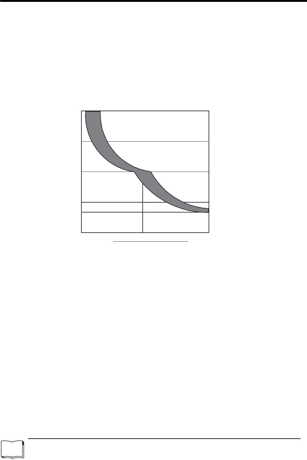
4 SERVOPACK Specifications and Dimensional Drawings
4.5.1 Overload Characteristics
4-12
4.5 SERVOPACK Overload Characteristics and Allowable Load
Moment of Inertia
4.5.1 Overload Characteristics
SERVOPACKs have a built-in overload protective function that protects the SERVOPACKs and servomotors
from overload. Allowable power for the SERVOPACKs is limited by the overload protective function as shown
in the figure below.
The overload detection level is set under hot start1 conditions at a servomotor surrounding air temperature of
40°C.
1 Hot Start
A hot start indicates that both the SERVOPACK and the servomotor have run long enough at the rated load to be thermally
saturated.
TERMS
Operating time (s)
Rated current Maximum current
Motor current
Approx. Rated current + Maximum current
2
10000
1000
100
5
1
10000
1000
100
5
1
10000
1000
100
10
5
1
10000
1000
100
10
5
1
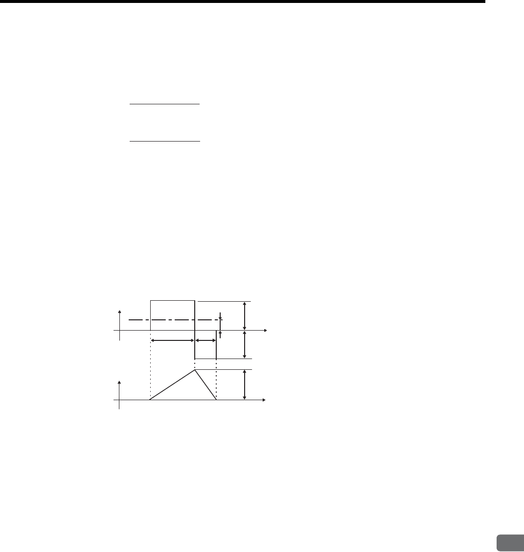
4.5 SERVOPACK Overload Characteristics and Allowable Load Moment of Inertia
4
SERVOPACK Specifications and Dimensional Drawings
4-13
4.5.2 Starting and Stopping Time
The motor starting time (tr) and stopping time (tf) under a constant load are calculated using the following for-
mulas. Motor viscous torque and friction torque are ignored.
Calculate the torque from the motor current using servomotor torque constant × motor current (effective value).
The following figure shows the motor torque and motor speed timing chart.
nM:Motor speed (min-1)
JM:Motor rotor moment of inertia (kgxm2)
JL:Load converted to shaft moment of inertia (kgxm2)
TPM: Instantaneous peak motor torque when combined with a SERVOPACK (Nxm)
TL: Load torque (Nxm)
tr =
tf =
Starting time:
Stopping time:
2
π
nM (JM + JL)
(TPM - TL)
60 [s]
[s]
2
π
nM (JM + JL)
(TPM + TL)
60
Motor torque
(current amplitude)
Motor speed
tr tf
nMTPM
TL
Time
Time
TPM

4 SERVOPACK Specifications and Dimensional Drawings
4.5.3 Load Moment of Inertia
4-14
4.5.3 Load Moment of Inertia
The larger the load moment of inertia, the worse the movement response of the load.
The size of the load moment of inertia (JL) allowable when using a servomotor is limited to within 5 times the
moment of inertia of each servomotor (JM).
An overvoltage alarm is likely to occur during deceleration if the load moment of inertia exceeds the 5 times of
load moment of inertia. Take one of the following steps if this occurs.
• Reduce the torque limit.
• Reduce the deceleration rate.
• Reduce the maximum motor speed.
If the alarm cannot be cleared, contact your Yaskawa Application Engineering Department.
(1) Allowable Load Moment of Inertia at the Motor Shaft
The rotor moment of inertia ratio is the value for a servomotor without a gear and a brake.
Servomotor Model Allowable Load Moment of Inertia
(×10-4 kg·m2 )
1500 min-1 Series
SGMVH-2BAB1830
SGMVH-3ZAB2490
SGMVH-3GAB2975
SGMVH-2BDB1830
SGMVH-3ZDB2490
SGMVH-3GDB2975
SGMVH-4EDB5355
SGMVH-5EDB6450
SGMVH-7EDB9020
800 min-1 Series
SGMVH-2BAD3525
SGMVH-3ZAD6450
SGMVH-3GAD7820
SGMVH-2BDD3525
SGMVH-3ZDD6450
SGMVH-3GDD7820
SGMVH-4EDD9020
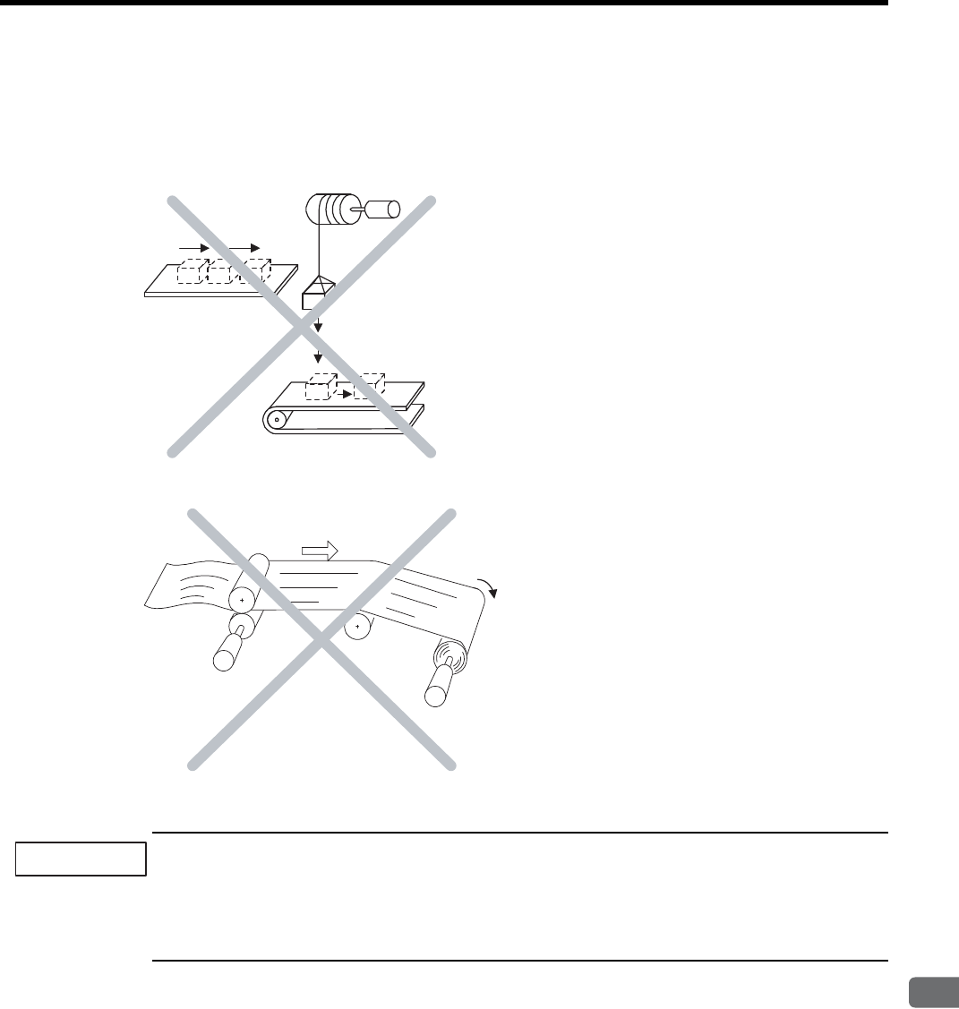
4.5 SERVOPACK Overload Characteristics and Allowable Load Moment of Inertia
4
SERVOPACK Specifications and Dimensional Drawings
4-15
(2) Overhanging Loads
A servomotor may not be operated with an overhanging load, which tends to continuously rotate the motor. Fig.
4.1 shows a typical example of such a load.
• DO NOT use the servomotor with the Vertical Axis Motor Drive without Counterweight
• DO NOT use the servomotor with the Feeding Motor Drive
Fig. 4.1 Examples of Overhanging Loads
• Never operate servomotors with an overhanging load. Doing so will cause the SERVOPACKs’ regenerative
brake to be applied continuously and the regenerative energy of the load may exceed the allowable range
causing damage to the SERVOPACK.
• The regenerative brake capacity of the SGDH SERVOPACKs is rated for short-term operation approxi-
mately equivalent to the time it takes to decelerate to a stop.
Servomotor
Tension
Servomotor
Servomotor
Servomotor rotated repeatedly at a
constant speed to maintain the tension.
IMPORTANT
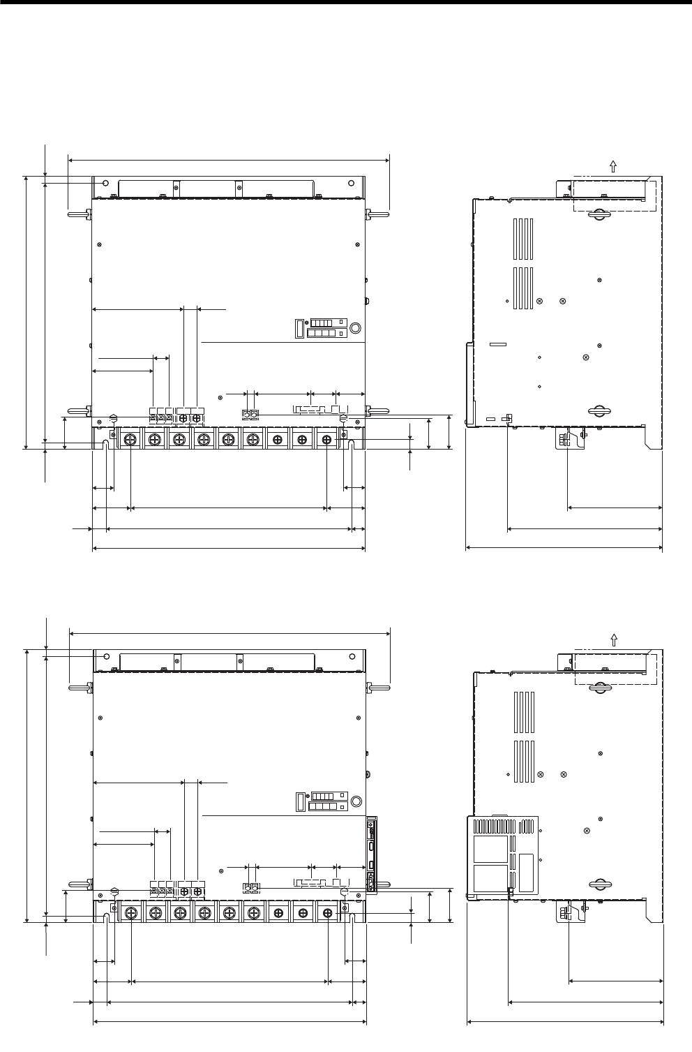
4 SERVOPACK Specifications and Dimensional Drawings
4.6.1 Three-phase 200 V, 22 kW, 30 kW Models
4-16
4.6 SERVOPACK Dimensional Drawings
4.6.1 Three-phase 200 V, 22 kW, 30 kW Models
(1) SGDM-2BADB, -3ZADB
(2) SGDH-2BAEB, -3ZAEB
Ventilation
CN1 CN2
L1C/r L3C/t
CN3
-+1
+2 L1/R L2/S L3/T
UVW
B2
DU
DW
B1
DV
589
167 24.5
14.5×2=29
112
54
47
103
13
45×8=360
450
500
70
40
25
174
285
359
18
57
63
59
475
500
12.5
12.5
Units: mm
Approx.mass: 55 kg
40
70
25
CN1 CN2
L1C/r L3C/t
CN3
-+1 +2 L1/R L2/S L3/T UVW
B2
DU
DW
B1
DV
589
167 24.5
14.5×2=29
112
54
47
103
13
45×8=360
450
500
70
40
25
174
285
18
57
63
59
475
500
12.5
12.5
05050505
CN6A
CN6B
CN4
359
40
70
25
Ventilation
Units: mm
Approx.mass: 55 kg
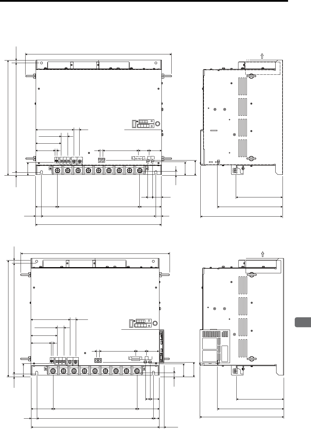
4.6 SERVOPACK Dimensional Drawings
4
SERVOPACK Specifications and Dimensional Drawings
4-17
4.6.2 Three-phase 200 V, 37 kW Model
(1) SGDM-3GADB
(2) SGDH-3GAEB
L1C/r L3C/t
.4 .5 .6 7 8 9
&$
10 &$
DU DV DW B2B1
CN3
CN2
CN1
639
167 24.5
14.5×2=29
112
86 813 155 47 54
20 40
95
25
45×8=360
500
550
95
25
285
203
63
57
18
57
12.5 475 12.5
500
359
Ventilation
Units: mm
Approx.mass: 60 kg
-+1+2
L1/R L2/S L3/T U VW
0505
203
285
639
12.5
500
475
12.5
57
95
25
458=360
500
550
20
40
95
25
㧔20㧕
18
57
63
54
47
CN2CN1
155
13
.%V
.%T
CN6A
CN6B
CN4
CN3
167 24.5
14.5×2=29
112
86 8
B2B1
DW
DVDU
DB
24
DB
ON
359
Ventilation
Units: mm
Approx.mass: 60 kg
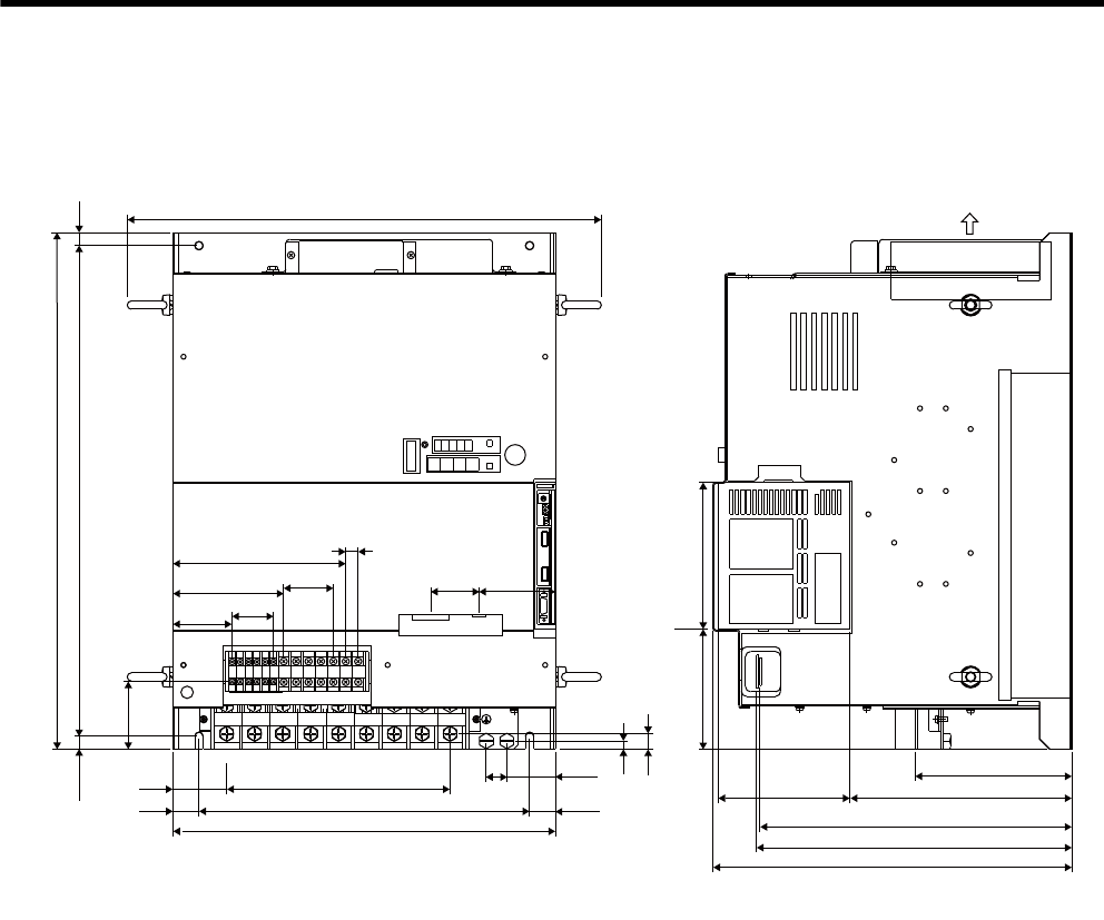
4 SERVOPACK Specifications and Dimensional Drawings
4.6.3 Three-phase 400 V, 22 kW Model
4-18
4.6.3 Three-phase 400 V, 22 kW Model
(1) SGDH-2BDEB
+2
-+1 L1/R L2/S L3/T UV
W
CN1 CN2
NS100
480
V 460
V DU
400
V 0
V
440
V DWDV B1
380
V DC
24N
B2 DC
24P
CN3
459
12.5
500
475
65
12.5
64
25
24.5×8=196
320
370
㧔25㧕
20
47
8
15
116 142
167
107 12×4=48
12
5×8=40
57
46.5 74
CN6A
CN6B
CN4
128
348
306
302
215
152
Ventilation
Units: mm
Approx.mass: 40 kg
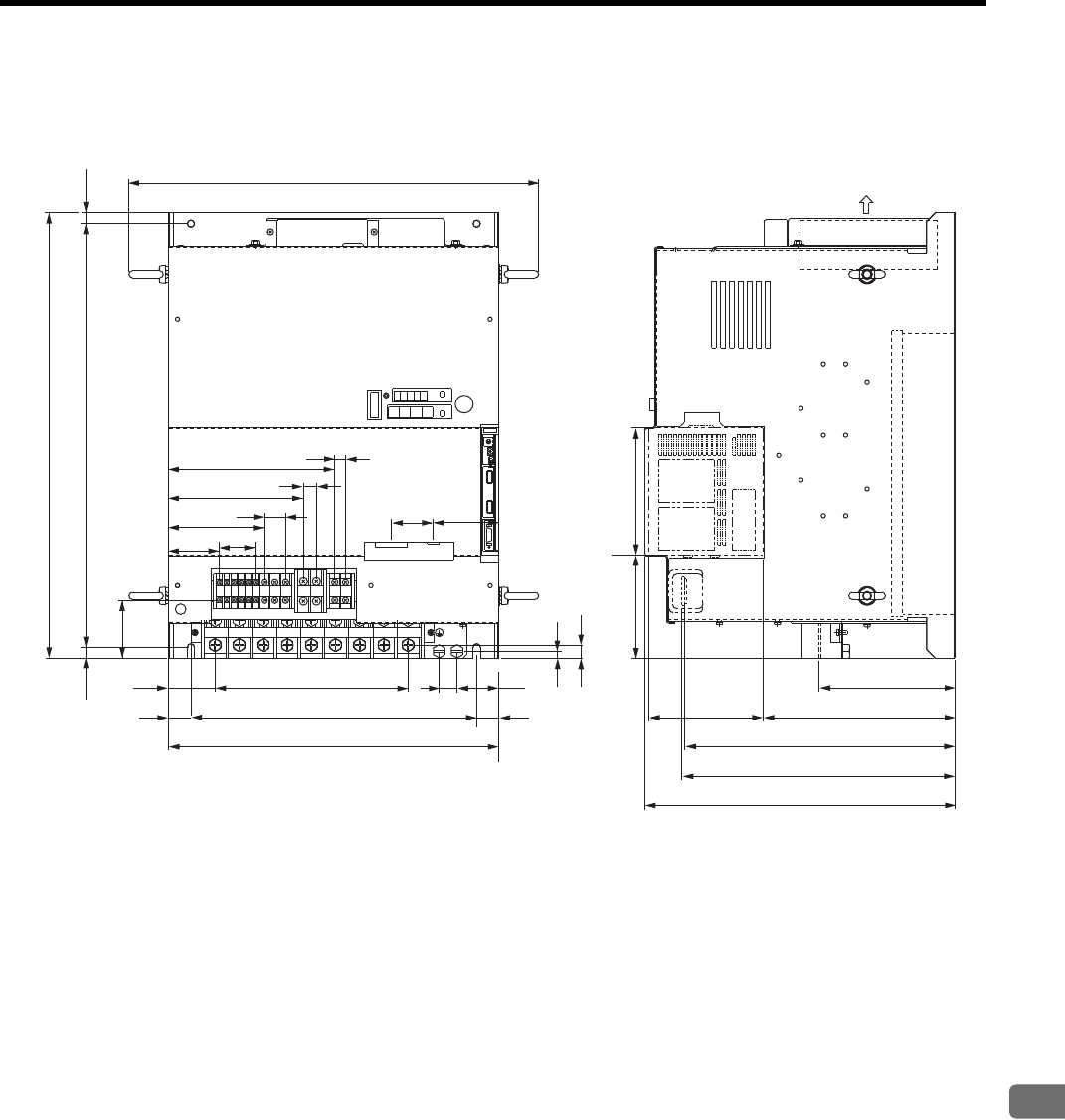
4.6 SERVOPACK Dimensional Drawings
4
SERVOPACK Specifications and Dimensional Drawings
4-19
4.6.4 Three-phase 400 V, 30 kW Model
(1) SGDH-3ZDEB
CN3
459
151
12
107
57
8×5=40
52
25 320
370
20
47
(25)
500
475
12.5
65
8
15
186
14.5
12×2=24
46.5 74
12.5
27×8=216
CN6A
CN6B
CN4
116 142
128
152
215
302
306
348
+2
+1
−L1/R L2/S L3/T U V W
CN2CN1
DU DWDV B1
DC
24N
480
V
460
V
440
V
400
V
380
V
0
V
DC
24P
B2
NS100
Ventilation
Units: mm
Approx.mass: 40 kg
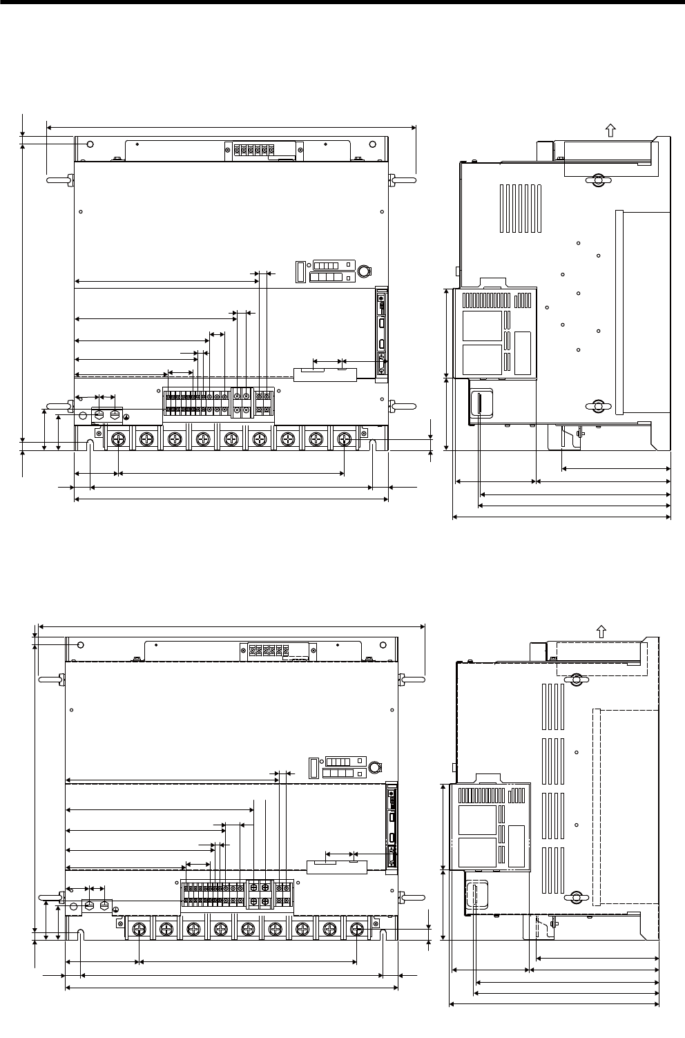
4 SERVOPACK Specifications and Dimensional Drawings
4.6.5 Three-phase 400 V, 37 kW Model
4-20
4.6.5 Three-phase 400 V, 37 kW Model
(1) SGDH-3GDEB
4.6.6 Three-phase 400 V, 45 kW, 55 kW Models
(1) SGDH-4EDEB, -5EDEB
- +1 +2 L1/R L2/S L3/T U V W
1234
CN1 CN2
CN3
DVDU
380
V
DB
24 DW
DB
ON B1 B2
480
V 460
V 400
V
440
V
DC
24P
0
V
DC
24N
NS100
589
12.5
475
12.5
65
56.5
25
70 45×8=360
450
500
㧔25㧕
17.5
116 142
CN6A
CN6B
CN4
46.5 74
12
294
14.5
12×2=24
8×5=40
259
215
197
149
40 25
174
215
302
306
348
128
8
Ventilation
Units: mm
Approx.mass: 60 kg
- +1 +2 L1/R L2/S L3/T U V W
1234
CN1 CN2
CN3
DB
24 DW DC
24N
DV
400
V
460
V
DC
24P
480
V 440
V 380
V B2B1
DB
ON
0
V DU
NS100
639
12.5
475
65
12.5
56.5
25
122
550
500
45×8=360
㧔25㧕
17.5
116 142
CN6A
CN4
CN6B
46.5 74
40 25
199
247
265
8×5=40
8
12×2=24
311
353
19
12
348
306
302
215
204
128
Ventilation
Units: mm
Approx.mass: 65 kg
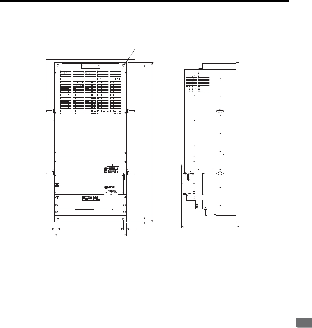
4.6 SERVOPACK Dimensional Drawings
4
SERVOPACK Specifications and Dimensional Drawings
4-21
4.6.7 Three-phase 400 V, 90 kW Model
(1) SGDH-9ZDEB
24 450 24
498
20 1060
1100
611
395
4×M12 mounting holes
Units: mm
Approx.mass: 130 kg

5
Specifications and Dimensional Drawings of Cables and Peripheral Devices
5-1
5
Specifications and Dimensional
Drawings of Cables and
Peripheral Devices
5.1 SERVOPACK Main Circuit Wire Size - - - - - - - - - - - - - - - - - 5-2
5.1.1 Wiring Cables to Main Circuit Terminals - - - - - - - - - - - - - - - - - - - - - - 5-2
5.1.2 Three-phase 200 V - - - - - - - - - - - - - - - - - - - - - - - - - - - - - - - - - - - - 5-3
5.1.3 Three-phase 400 V - - - - - - - - - - - - - - - - - - - - - - - - - - - - - - - - - - - - 5-4
5.2 Encoder Cables for CN2 Connector - - - - - - - - - - - - - - - - - - 5-6
5.2.1 Encoder Cable with Connectors on Both Ends - - - - - - - - - - - - - - - - - 5-6
5.2.2 Cable with Loose Wire at Encoder End - - - - - - - - - - - - - - - - - - - - - - 5-7
5.3 Connectors and Cables for Encoder Signals - - - - - - - - - - - - 5-8
5.4 I/O Signal Cables for CN1 Connector - - - - - - - - - - - - - - - - 5-10
5.4.1 Standard Cables - - - - - - - - - - - - - - - - - - - - - - - - - - - - - - - - - - - - - 5-10
5.4.2 Connector Type and Cable Size - - - - - - - - - - - - - - - - - - - - - - - - - - 5-10
5.4.3 Connection Diagram - - - - - - - - - - - - - - - - - - - - - - - - - - - - - - - - - - 5-12
5.5 Peripheral Devices - - - - - - - - - - - - - - - - - - - - - - - - - - - - - 5-13
5.5.1 Cables for Connecting Personal Computers - - - - - - - - - - - - - - - - - - 5-13
5.5.2 Digital Operator - - - - - - - - - - - - - - - - - - - - - - - - - - - - - - - - - - - - - - 5-14
5.5.3 Cables for Analog Monitor - - - - - - - - - - - - - - - - - - - - - - - - - - - - - - 5-15
5.5.4 Connector Terminal Block Converter Unit - - - - - - - - - - - - - - - - - - - - 5-16
5.5.5 Brake Power Supply Unit - - - - - - - - - - - - - - - - - - - - - - - - - - - - - - - 5-17
5.5.6 Absolute Encoder Battery - - - - - - - - - - - - - - - - - - - - - - - - - - - - - - - 5-18
5.5.7 Molded-case Circuit Breaker (MCCB) - - - - - - - - - - - - - - - - - - - - - - 5-19
5.5.8 Noise Filter - - - - - - - - - - - - - - - - - - - - - - - - - - - - - - - - - - - - - - - - - 5-20
5.5.9 Surge Absorber - - - - - - - - - - - - - - - - - - - - - - - - - - - - - - - - - - - - - - 5-22
5.5.10 Regenerative Resistor Unit - - - - - - - - - - - - - - - - - - - - - - - - - - - - - 5-23
5.5.11 Dynamic Brake (DB) Unit - - - - - - - - - - - - - - - - - - - - - - - - - - - - - - 5-29
5.5.12 Thermal Relays - - - - - - - - - - - - - - - - - - - - - - - - - - - - - - - - - - - - - 5-36
5.5.13 Variable Resistor for Speed and Torque Setting - - - - - - - - - - - - - - 5-39
5.5.14 Encoder Signal Converter Unit - - - - - - - - - - - - - - - - - - - - - - - - - - 5-40
5.5.15 MECHATROLINK Application Module - - - - - - - - - - - - - - - - - - - - - 5-41
5.5.16 DeviceNet Application Module - - - - - - - - - - - - - - - - - - - - - - - - - - - 5-42
5.5.17 PROFIBUS-DP Application Module - - - - - - - - - - - - - - - - - - - - - - - 5-43
5.5.18 Fully-closed Application Module - - - - - - - - - - - - - - - - - - - - - - - - - 5-44

5 Specifications and Dimensional Drawings of Cables and Peripheral Devices
5.1.1 Wiring Cables to Main Circuit Terminals
5-2
5.1 SERVOPACK Main Circuit Wire Size
1. Wire sizes were selected for three cables per bundle at 40°C surrounding air temperature with the rated
current.
2. Use cable with a minimum withstand voltage of 600 V for main circuits.
3. If cables are bundled in PVC or metal ducts, consider the reduction ratio of the allowable current.
4. Use heat-resistant cables under high surrounding air or panel temperatures where normal vinyl cables
will rapidly deteriorate.
5. Use cables within the allowable moment of inertia.
6. Do not use cables under continuous regenerative state.
5.1.1 Wiring Cables to Main Circuit Terminals
Use the following UL-certified copper cables (rated 75°C, 600 V) and round crimped terminals (UL standard
compliant) when connecting cables to main circuit terminals. Crimp the terminal with the recommended crimp-
ing tool. Yaskawa recommends the crimped terminals manufactured by J.S.T. Mfg. Co., Ltd.
IMPORTANT
Cable Size
mm2
(AWG)
Terminal Screw
Size
Crimped Terminal
Type
Tightening Torque
Nxm
1.25
(16)
M3.5 R1.25-3.5 0.8 to 0.88
M4 R1.25-4 1.2 to 1.5
2
(14)
M4 R2-4 1.2 to 1.5
M5 R2-5 2.0 to 2.5
3.5/5.5
(12/10)
M4 R5.5-4 1.2 to 1.5
M5 R5.5-5 2.0 to 2.5
M6 R5.5-6 4.0 to 4.6
8
(8)
M4 8-4 1.2 to 1.5
M5 R8-5 2.0 to 2.5
14
(6)
M5 R14-5 2.0 to 2.5
M8 R14-8 9.0 to 11.0
22
(4)
M6 R22-6 4.0 to 4.6
M8 R22-8 9.0 to 11.0
M10 R22-10 17.5 to 20.5
30/38
(3/2)
M6 38-6 4.0 to 4.6
M8 R38-8 9.0 to 11.0
M10 R38-10 17.5 to 20.5
50/60
(1/0/2/0)
M8 R60-8 9.0 to 11.0
M10 R60-10 17.5 to 20.5
80
(3/0) M10 R80-10 17.5 to 20.5

5.1 SERVOPACK Main Circuit Wire Size
5
Specifications and Dimensional Drawings of Cables and Peripheral Devices
5-3
5.1.2 Three-phase 200 V
SERVOPACK
Model
SGDM-ADB
SGDH-AEB
Terminal Symbol Terminal
Screw Size
Tightening Torque
Nxm
Applicable Cable
Range
mm2
(AWG)
Recommended
Cable Size
mm2
(AWG)
2B
L1/R, L2/S, L3/T
-, +1, +2 M10 17.5 to 20.5 30 to 80
(3 to 3/0)
30
(3)
U, V, W M8 9.0 to 11.0 30 to 60
(3 to 2/0)
38
(2)
L1C/r, L3C/t M4 1.2 to 1.5 0.75 to 2
(18 to 14)
1.25
(16)
B1, B2 M8 9.0 to 11.0 14 to 38
(6 to 2)
14
(6)
DU, DV, DW M5 2.0 to 2.5 3.5 to 8
(12 to 8)
3.5
(12)
M8 9.0 to 11.0 30 to 60
(3 to 2/0)
38
(2)
3Z
L1/R, L2/S, L3/T
-, +1, +2 M10 17.5 to 20.5 30 to 80
(3 to 3/0)
50
(1/0)
U, V, W M8 9.0 to 11.0 30 to 60
(3 to 2/0)
60
(2/0)
L1C/r, L3C/t M4 1.2 to 1.5 0.75 to 2
(18 to 14)
1.25
(16)
B1, B2 M8 9.0 to 11.0 14 to 38
(6 to 2)
14
(6)
DU, DV, DW M5 2.0 to 2.5 3.5 to 8
(12 to 8)
3.5
(12)
M8 9.0 to 11.0 30 to 60
(3 to 2/0)
60
(2/0)
3G
L1/R, L2/S, L3/T
-, +1, +2 M10 17.5 to 20.5 30 to 80
(3 to 3/0)
60
(2/0)
U, V, W M10 17.5 to 20.5 30 to 80
(3 to 3/0)
80
(3/0)
L1C/r, L3C/t M4 1.2 to 1.5 0.75 to 2
(18 to 14)
1.25
(16)
B1, B2 M8 9.0 to 11.0 14 to 38
(6 to 2)
22
(4)
DU, DV, DW M5 2.0 to 2.5 3.5 to 8
(12 to 8)
5.5
(10)
DBON, DB24 M3.5 0.8 to 0.88 0.75 to 2
(18 to 14)
1.25
(16)
M8 9.0 to 11.0 30 to 60
(3 to 2/0)
60
(2/0)

5 Specifications and Dimensional Drawings of Cables and Peripheral Devices
5.1.3 Three-phase 400 V
5-4
5.1.3 Three-phase 400 V
SERVOPACK
Model
SGDH-DEB
Terminal Symbol Terminal
Screw Size
Tightening Torque
Nxm
Applicable Cable
Range
mm2
(AWG)
Recommended
Cable Size
mm2
(AWG)
2B
L1/R, L2/S, L3/T
-, +1, +2 M8 9.0 to 11.0 14 to 38
(6 to 2)
14
(6)
U, V, W M8 9.0 to 11.0 14 to 38
(6 to 2)
14
(6)
DC24P, DC24N M4 1.2 to 1.5 0.75 to 2
(18 to 14)
1.25
(16)
B1, B2 M4 1.2 to 1.5 2 to 5.5
(14 to 10)
5.5
(10)
0 V, 380 V, 400 V
440 V, 460 V, 480 V M3.5 0.8 to 0.88 0.75 to 2
(18 to 14)
1.25
(16)
DU, DV, DW M4 1.2 to 1.5 2 to 5.5
(14 to 10)
2
(14)
M8 9.0 to 11.0 14 to 38
(6 to 2)
14
(6)
3Z
L1/R, L2/S, L3/T
-, +1, +2 M8 9.0 to 11.0 14 to 38
(6 to 2)
14
(6)
U, V, W M8 9.0 to 11.0 14 to 38
(6 to 2)
22
(4)
DC24P, DC24N M4 1.2 to 1.5 0.75 to 2
(18 to 14)
1.25
(16)
B1, B2 M5 2.0 to 2.5 8 to 14
(8 to 6)
8
(8)
0 V, 380 V, 400 V
440 V, 460 V, 480 V M3.5 0.8 to 0.88 0.75 to 2
(18 to 14)
1.25
(16)
DU, DV, DW M4 1.2 to 1.5 2 to 5.5
(14 to 10)
2
(14)
M8 9.0 to 11.0 22 to 38
(4 to 2)
22
(4)
3G
L1/R, L2/S, L3/T
-, +1, +2 M10 17.5 to 20.5 22 to 80
(4 to 3/0)
22
(4)
U, V, W M10 17.5 to 20.5 30 to 80
(3 to 3/0)
30
(3)
DC24P, DC24N M4 1.2 to 1.5 0.75 to 2
(18 to 14)
1.25
(16)
B1, B2 M5 2.0 to 2.5 8 to 14
(8 to 6)
8
(8)
0 V, 380 V, 400 V
440 V, 460 V, 480 V M3.5 0.8 to 0.88 0.75 to 2
(18 to 14)
1.25
(16)
DU, DV, DW M5 1.2 to 1.5 0.75 to 5.5
(18 to 10)
3.5
(12)
DBON, DB24 M3.5 0.8 to 0.88 0.75 to 2
(18 to 14)
1.25
(16)
M8 9.0 to 11.0 30 to 38
(3 to 2)
30
(3)

5.1 SERVOPACK Main Circuit Wire Size
5
Specifications and Dimensional Drawings of Cables and Peripheral Devices
5-5
4E
L1/R, L2/S, L3/T
-, +1, +2 M10 17.5 to 20.5 30 to 80
(3 to 3/0)
30
(3)
U, V, W M10 17.5 to 20.5 30 to 80
(3 to 3/0)
38
(2)
DC24P, DC24N M4 1.2 to 1.5 0.75 to 2
(18 to 14)
1.25
(16)
B1, B2 M6 4.0 to 4.6 14 to 22
(6 to 4)
14
(6)
0 V, 380 V, 400 V
440 V, 460 V, 480 V M3.5 0.8 to 0.88 0.75 to 2
(18 to 14)
1.25
(16)
DU, DV, DW M4 1.2 to 1.5 2 to 5.5
(14 to 10)
3.5
(12)
DBON, DV24 M3.5 0.8 to 0.88 0.75 to 2
(18 to 14)
1.25
(16)
M8 9.0 to 11.0 38 to 50
(2 to 1/0)
38
(2)
5E
L1/R, L2/S, L3/T
-, +1, +2 M10 17.5 to 20.5 30 to 80
(3 to 3/0)
38
(2)
U, V, W M10 17.5 to 20.5 30 to 80
(3 to 3/0)
50
(1/0)
DC24P, DC24N M4 1.2 to 1.5 0.75 to 2
(18 to 14)
1.25
(16)
B1, B2 M6 4.0 to 4.6 14 to 22
(6 to 4)
14
(6)
0 V, 380 V, 400 V
440 V, 460 V, 480 V M3.5 0.8 to 0.88 0.75 to 2
(18 to 14)
1.25
(16)
DU, DV, DW M4 1.2 to 1.5 2 to 5.5
(14 to 10)
3.5
(12)
DBON, DB24 M3.5 0.8 to 0.88 0.75 to 2
(18 to 14)
1.25
(16)
M8 9.0 to 11.0 50 to 60
(1/0 to 2/0)
50
(1/0)
9Z
L1/R, L2/S, L3/T
-, +1, +2 M10 17.5 to 20.5 30 to 80
(6 to 3/0)
80
(3/0)
U, V, W M10 17.5 to 20.5 30 to 80
(6 to 3/0)
50
(1/0)
DC24P, DC24N M4 1.2 to 1.5 0.75 to 2
(18 to 14)
1.25
(16)
B1, B2 M8 9.0 to 11.0 30 to 50
(3 to 1/0)
30
(3)
0 V, 380 V, 400 V
440 V, 460 V, 480 V M3.5 0.8 to 0.88 0.75 to 2
(18 to 14)
1.25
(16)
DU, DV, DW M6 4.0 to 4.6 5.5 to 14
(10 to 6)
5.5
(10)
DBON, DB24 M3.5 0.8 to 0.88 0.75 to 2
(18 to 14)
1.25
(16)
M8 9.0 to 11.0 50 to 60
(1/0 to 2/0)
50
(1/0)
SERVOPACK
Model
SGDH-DEB
Terminal Symbol Terminal
Screw Size
Tightening Torque
Nxm
Applicable Cable
Range
mm2
(AWG)
Recommended
Cable Size
mm2
(AWG)
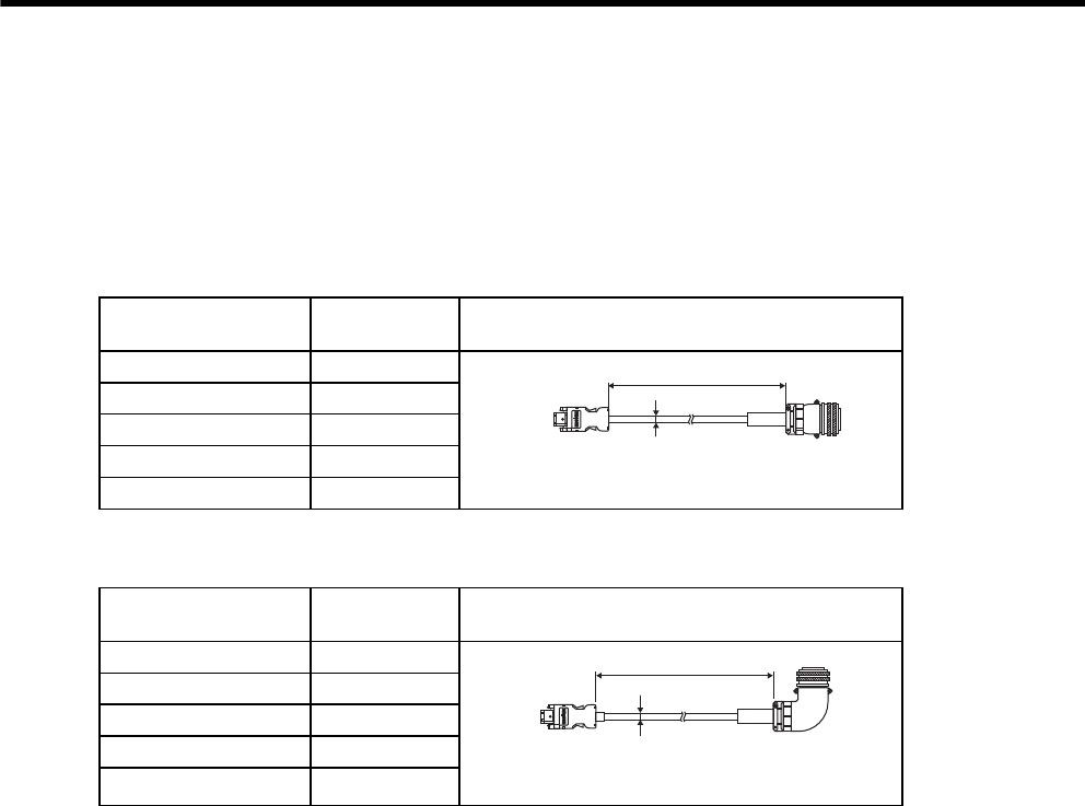
5 Specifications and Dimensional Drawings of Cables and Peripheral Devices
5.2.1 Encoder Cable with Connectors on Both Ends
5-6
5.2 Encoder Cables for CN2 Connector
When assembling the encoder cable, refer to 5.3 Connectors and Cables for Encoder Signals.
5.2.1 Encoder Cable with Connectors on Both Ends
(1) Cable With a SERVOPACK Connector and Encoder Straight Plug
(2) Cable With a SERVOPACK Connector and Encoder L-shaped Plug
Cable Type Cable Length
(L) Dimensional Drawing
JZSP-CMP21-03 3 m
JZSP-CMP21-05 5 m
JZSP-CMP21-10 10 m
JZSP-CMP21-15 15 m
JZSP-CMP21-20 20 m
MS3106B20́29S
(DDK Ltd.)
MS3057́12A
Cable clamp
㧸
SERVOPACK end Encoder end
Crimped connector
(Molex Japan Co., Ltd.)
Finished dimension
φ6.5 mm
Cable Type Cable Length
(L) Dimensional Drawing
JZSP-CMP22-03 3 m
JZSP-CMP22-05 5 m
JZSP-CMP22-10 10 m
JZSP-CMP22-15 15 m
JZSP-CMP22-20 20 m
L
Crimped connector
(Molex Japan Co., Ltd.)
MS3108B20́29S
(DDK Ltd.)
MS3057́12A
Cable clamp
SERVOPACK end Encoder end
Finished dimension
φ6.5 mm
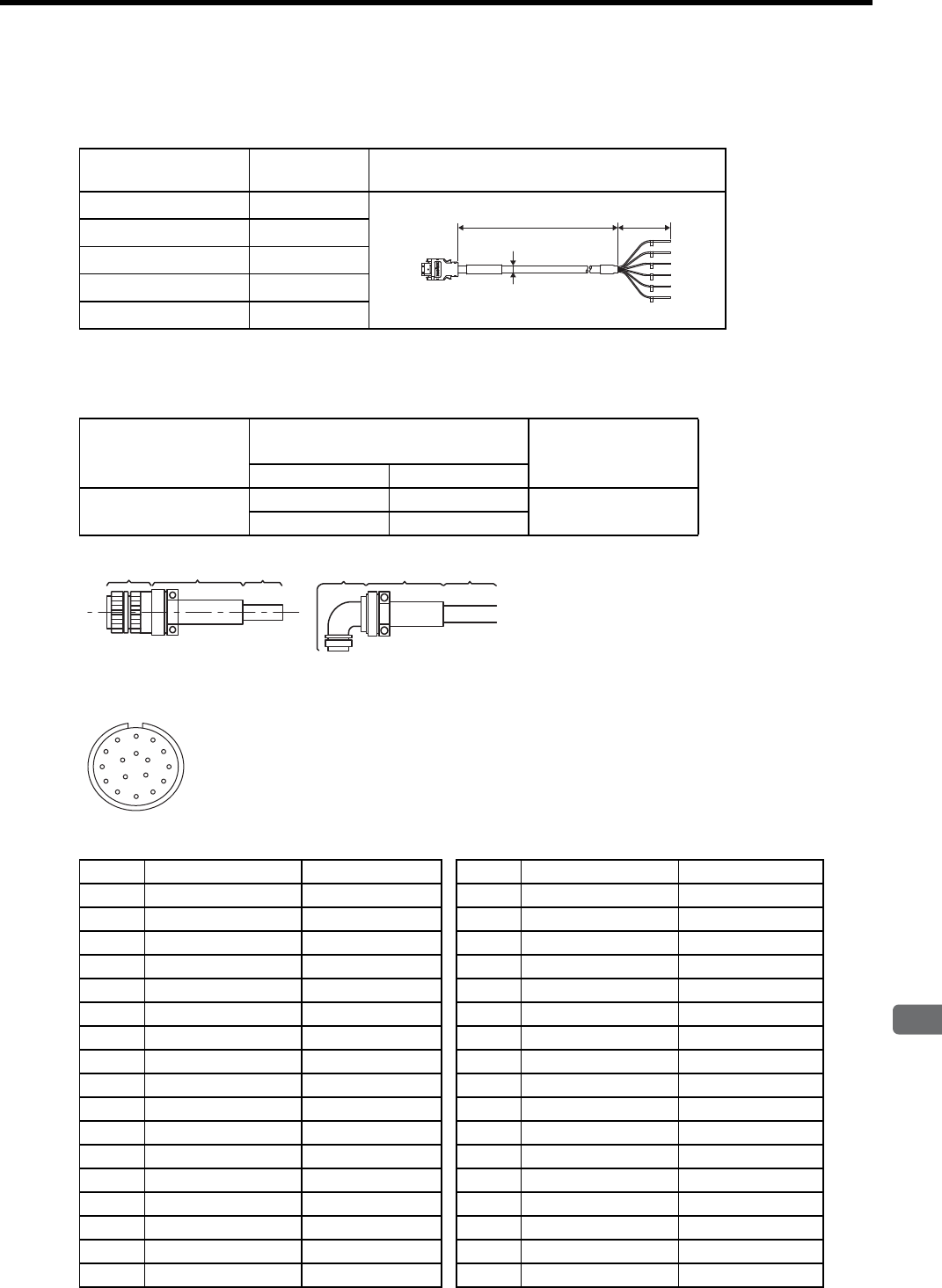
5.2 Encoder Cables for CN2 Connector
5
Specifications and Dimensional Drawings of Cables and Peripheral Devices
5-7
5.2.2 Cable with Loose Wire at Encoder End
(1) Cable Type
(2) Encoder-end Connector
Contact Yaskawa Controls Co., Ltd.
(3) Encoder Plug Connector Pin Arrangement
Cable Type Cable Length
(L) Dimensional Drawing
JZSP-CMP23-03 3 m
JZSP-CMP23-05 5 m
JZSP-CMP23-10 10 m
JZSP-CMP23-15 15 m
JZSP-CMP23-20 20 m
Encoder endSERVOPACK end
Crimped connector
(Molex Japan Co., Ltd.)
L60 mm
1
2
3
4
5
6
Wire markers
Finished dimension
φ6.5 mm
Connector on
Servomotor
Plug
(Manufactured by DDK Ltd.)
Cable Clamp
(Manufactured by
DDK Ltd.)
Type Model
MS3102A20-29P Straight MS3106B20-29S MS3057-12A
L-shaped MS3108B20-29S
Plug
Cable
clamp Cable Plug
Cable
clamp Cable
Absolute Encoder Connection Specifications Incremental Encoder Connection Specifications
Pin No. Signal Lead Color Pin No. Signal Lead Color
A−−
A−−
B−−
B−−
CPS Blue CPS Blue
D/PS White/blue D/PS White/blue
E−−
E−−
F−−
F−−
GPG0V Inner shield GPG0V Inner shield
HPG5V Red HPG5V Red
JFG (Frame ground) Outer shield JFG (Frame ground) Outer shield
K−−
K−−
L−−
L−−
M−−
M−−
N−−
N−−
P−−
P−−
R−−
R−−
SBAT(−) White/orange S−−
TBAT(+) Orange T−−
A
N
T
SR
P
M
K
J
HGF
LB
C
E
D
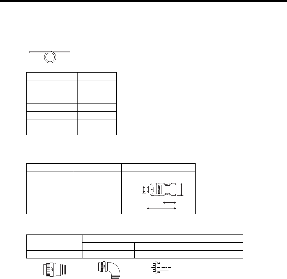
5 Specifications and Dimensional Drawings of Cables and Peripheral Devices
5-8
5.3 Connectors and Cables for Encoder Signals
(1) Cable Type
(2) SERVOPACK-end Connector for CN2
(3) Encoder-end Connector
* Manufactured by DDK Ltd.
Cable Type Cable Length
JZSP-CMP29-05 5 m
JZSP-CMP29-10 10 m
JZSP-CMP29-15 15 m
JZSP-CMP29-20 20 m
JZSP-CMP29-30 30 m
JZSP-CMP29-40 40 m
JZSP-CMP29-50 50 m
Units: mm
Model Manufacturer Dimensional Drawing
JZSP-CMP9-1 Molex Japan Co.,
Ltd.
Plug connector (Soldered)
18.4
11
33
37.4
Connector on
Servomotor
Encoder-end Connector Type
Straight Plug * L-shaped Plug * Cable Clamp *
MS3102A20-29P MS3106B20-29S MS3108B20-29S MS3057-12A
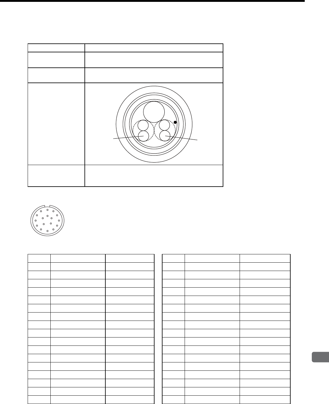
5.3 Connectors and Cables for Encoder Signals
5
Specifications and Dimensional Drawings of Cables and Peripheral Devices
5-9
(4) Encoder Cable Specifications
(5) Encoder Plug Connector Pin Arrangement
Cable Type JZSP-CMP29-
Basic
Specifications
T/20276-SP (SP)
AWG26 × 2P
, AWG16 × 1P
Finished
Dimension φ7.0 mm
Internal Configuration
and Lead Colors
Yaskawa Standard
Specifications
(Standard Length)
5 m, 10 m, 15 m, 20 m, 30 m, 40 m, 50 m
Blue
Orange
Orange/
white Blue/
white
Red
Absolute Encoder Connection Specifications Incremental Encoder Connection Specifications
Pin No. Signal Lead Color Pin No. Signal Lead Color
A−−
A−−
B−−
B−−
CPS Blue CPS Blue
D/PS White/blue D/PS White/blue
E−−
E−−
F−−
F−−
GPG0V Inner shield GPG0V Inner shield
HPG5V Red HPG5V Red
JFG (Frame ground) Outer shield JFG (Frame ground) Outer shield
K−−
K−−
L−−
L−−
M−−
M−−
N−−
N−−
P−−
P−−
R−−
R−−
SBAT(−) White/orange S−−
TBAT(+) Orange T−−
A
N
T
SR
P
M
K
J
HGF
LB
C
E
D
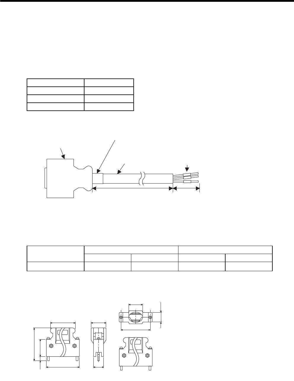
5 Specifications and Dimensional Drawings of Cables and Peripheral Devices
5.4.1 Standard Cables
5-10
5.4 I/O Signal Cables for CN1 Connector
5.4.1 Standard Cables
For the connection diagram, refer to 5.4.3 Connection Diagram.
(1) Cable Types
(2) Dimensional Drawing
* Manufactured by Sumitomo 3M Ltd.
5.4.2 Connector Type and Cable Size
Use the following connector and wire when assembling the cable. The CN1 connector includes a set of case and
a connector.
* Manufactured by Sumitomo 3M Ltd.
(1) Dimensional Drawing of Case
Cable Type Cable Length (L)
JZSP-CKI01-1 1 m
JZSP-CKI01-2 2 m
JZSP-CKI01-3 3 m
100 mm
+10
0
φ2.8 mm
wire markers
L
Cable (black)
SSRFPVV-SB AWG#28 × 25P
UL20276 VW-1SC
Sleeve F2 (black)
SERVOPACK end
Connector: 10150-6000EL(50P)∗
Shell: 10350-52A0-008∗
Connector Type Case Connector
Type Qty Type Qty
JZSP-CKI9 10350-52A0-008∗1 set 10150-3000VE* 1
41.1
Units: mm
52.4
12.7
46.5
17.0
18.0
39.0
23.8
5.7
14.0
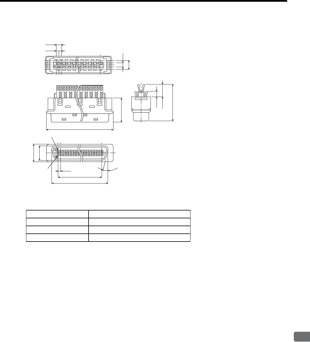
5.4 I/O Signal Cables for CN1 Connector
5
Specifications and Dimensional Drawings of Cables and Peripheral Devices
5-11
(2) Dimensional Drawing of Connector
(3) Cable Size
2.54
Units: mm
1.27
Pin No. 26
Pin No. 1
15q
2.3
㧟㧹
5.1
36.7
30.48
1.27
41.1
(6.6)
19.3
(2.9)
12.7
9.1
7.5
Item Specifications
Cable Use twisted-pair or twisted-pair shielded wire.
Applicable Wires AWG24, 26, 28, 30
Finished Dimension φ16 mm or less
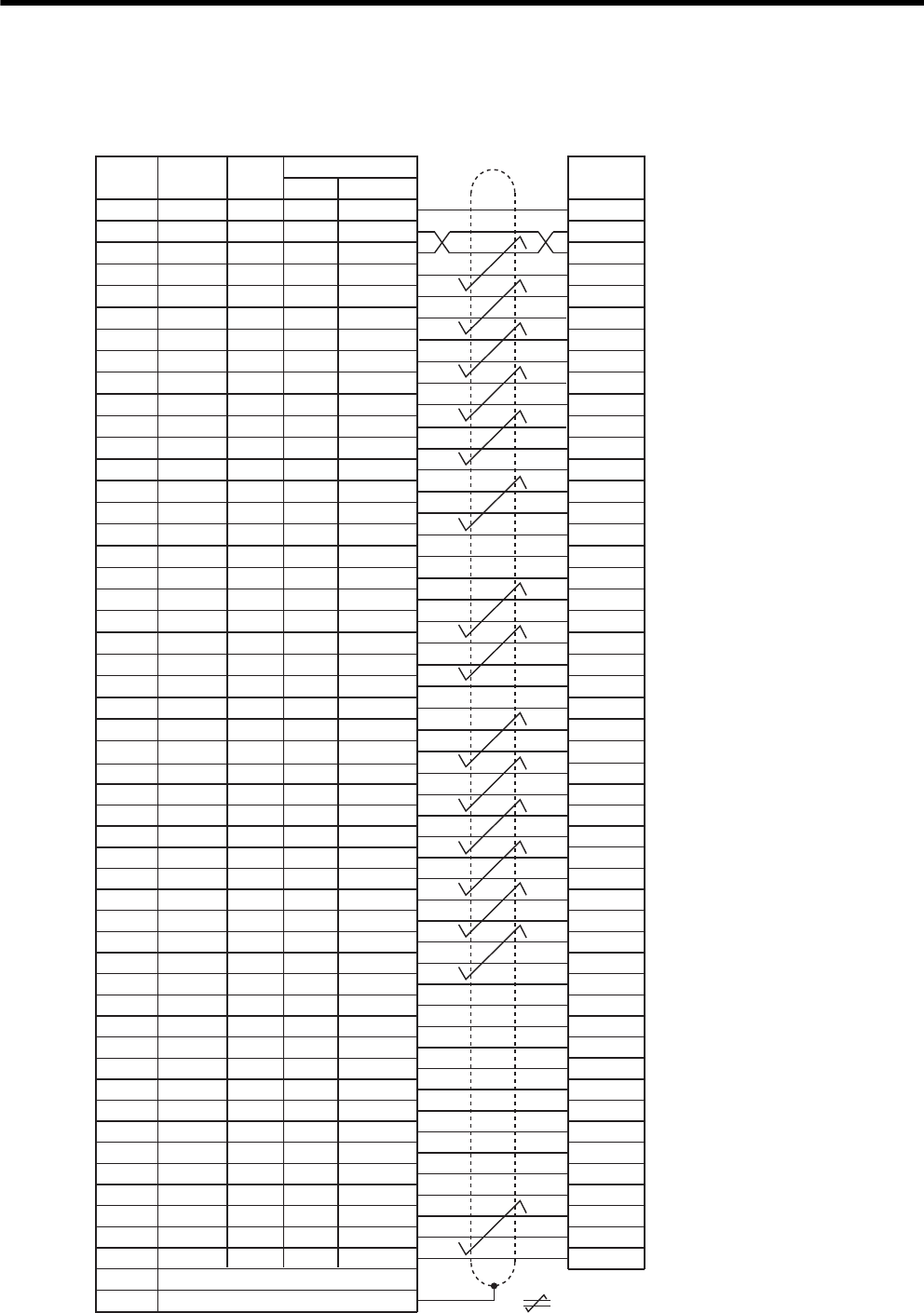
5 Specifications and Dimensional Drawings of Cables and Peripheral Devices
5.4.3 Connection Diagram
5-12
5.4.3 Connection Diagram
SG
SG
PL1
SEN
V-REF
SG
PULS
/PULS
T-REF
SG
SIGN
/SIGN
PL2
/CLR
CLR
−
−
PL3
PCO
/PCO
BAT(+)
BAT(-)
−
−
/V-CMP+
/V-CMP-
/TGON+
/TGON-
/S-RDY+
/S-RDY-
ALM+
ALM-
PAO
/PAO
PBO
/PBO
ALO1
ALO2
ALO3
/S-ON
/P-CON
P-OT
N-OT
/ALM-RST
/P-CL
/N-CL
+24VIN
PSO
/PSO
−
Host controller end
Pin No. Lead
Color
Signal
Marking
Color
1
2
3
4
5
6
7
8
9
10
11
12
13
14
15
16
17
18
19
20
21
22
23
24
25
26
Lead
Marker No.
1
2
3
4
5
6
7
8
9
10
11
12
13
14
15
16
17
18
19
20
21
22
23
24
25
26
Orange
Gray
Orange
Gray
White
White
Yellow
Yellow
Pink
Pink
Orange
Orange
Gray
White
White
Gray
Yellow
Yellow
Pink
Pink
Orange
Orange
Gray
Gray
White
White
Red
Red
Black
Black
Red
Black
Red
Black
Red
Black
Red
Black
Red
Red
Black
Black
Red
Black
Red
Black
Red
Black
Red
Black
Red
Black
1
1
1
1
1
1
1
1
1
1
2
2
2
2
2
2
2
2
2
2
3
3
3
3
3
3
SERVOPACK end
27
28
29
30
31
32
33
34
35
36
37
38
39
40
41
42
43
44
45
46
47
48
49
50
Case
27
28
29
30
31
32
33
34
35
36
37
38
39
40
41
42
43
44
45
46
47
48
49
50
Yellow
Yellow
Pink
Pink
Orange
Orange
Gray
Gray
White
White
Yellow
Yellow
Pink
Pink
Orange
Orange
Gray
Gray
White
White
Yellow
Pink
Pink
Yellow
Red
Black
Red
Black
Red
Black
Red
Black
Red
Black
Red
Black
Red
Black
Red
Black
Red
Black
Red
Black
Red
Red
Black
Black
3
3
3
3
4
4
4
4
4
4
4
4
4
4
5
5
5
5
5
5
5
5
5
5
Shield
represents twisted-pair wires.
Dots
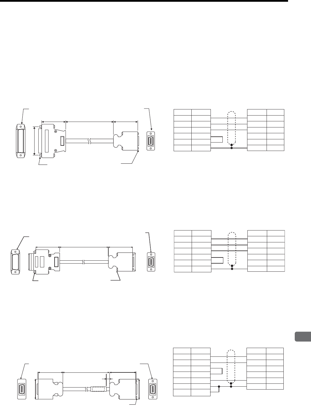
5.5 Peripheral Devices
5
Specifications and Dimensional Drawings of Cables and Peripheral Devices
5-13
5.5 Peripheral Devices
5.5.1 Cables for Connecting Personal Computers
(1) For 25-pin Connector Cable for NEC PC-98 Series PC
(a) Cable Type: JZSP-CMS01
(b) Dimensional Drawing
(2) D-sub, 9-pin Connector Cable for IBM PC Compatible
(a) Cable Type: JZSP-CMS02
(b) Dimensional Drawing
(3) 14-pin Half-pitch Connector Cable for NEC PC-98 Series PC
(a) Cable Type: JZSP-CMS03
(b) Dimensional Drawing
2
M2.6 screws 2
M2.6 screws
2000±50
38 39
Half-pitch connector
Plug: 10114-3000VE
Shell: 10314-52A0-008
(Sumitomo 3M Ltd.)
D-sub connector (25-pin)
17JE-23250-02㧔D8A㧕
(DDK Ltd.)
1
7
8
14
Personal computer end
Units: mm
SERVOPACK end
Cable type:
AWG263C UL2464
114
25 13
47
Personal computer end
Signal Pin No.
Case
SERVOPACK end
SignalPin No.
14
−
0 V
−
−−
RXD
TXD
0 V
RTS
CTS
FG
3
2
7
4
5
1
/TXD
/RXD
FG
2
4
Shield wire
38 39
61
95
81
14 7
2 × M2.6 screws 2 × M2.6 screws
2000±50
Half-pitch connector
Plug: 10114-3000VE
Shell: 10314-52A0-008
(Sumitomo 3M Ltd.)
D-sub connector (9-pin)
17JÉ13090́02㧔D8A㧕
(DDK Ltd.)
32
29.5
Personal computer end SERVOPACK end
Cable type:
AWG26
×
3C UL2464
Units: mm
Personal computer end
Signal Pin No.
Case
SERVOPACK end
SignalPin No.
14
−
0 V
−
−−
RXD
TXD
0 V
RTS
CTS
FG
2
3
5
7
8
Case
/TXD
/RXD
FG
2
4
Shield wire
Label
81
14
7
81
14 7
2 × M2.6 screws
5
39
Half-pitch connector
Plug: 101143000VE
Shell: 1031452A0008
(Sumitomo 3M Ltd.)
Half-pitch connector
Plug: 101143000VE
Shell: 1031452F0008
(Sumitomo 3M Ltd.)
39
29.5
Personal computer end SERVOPACK end
Cable:
AWG26
×
3C UL2464
2000±50
29.5
Units: mm
Personal computer end
Signal Pin No.
Case
SERVOPACK end
SignalPin No.
14
−
0 V
−
−−
RXD
TXD
RTS
CTS
GND
FG
FG
1
9
10
4
14
12
Case
/TXD
/RXD
FG
2
4
Shield wire
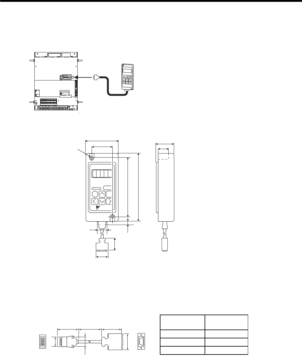
5 Specifications and Dimensional Drawings of Cables and Peripheral Devices
5.5.2 Digital Operator
5-14
5.5.2 Digital Operator
(1) Model JUSP-OP02A-2 with a 1m-connection Cable
(2) Dimensional Drawing
(3) Other Types of the Applicable Connection Cables: JZSP-CMS00-
* Order your cable from Yaskawa Controls Co., Ltd. in the following cases.
• When you need a longer cable than the cable supplied with the digital operator.
• When you need additional cables.
Digital Operator
.4 .5 .6 789
8
8
&7
8
8
8
&9&8 $
8
&%
0
$
&%
2
%*#4)'
5*&)
㧖㧖㧖㧖
6 #5''/1&
-5'4812#%
#;#5-#9
4
1
2
'
4
#
6
1
%0
%0
219'4
%0
WARNING
ෂޓ㒾
ㅢ㔚ਛ߮㔚Ḯࠝࡈᓟ5
ಽ㑆ޔ┵ሶㇱߦ⸅ࠆߥ
electric shock.
Disconnect all power
May cause
ᗵ㔚ߩᕟࠇࠅ
before servicing.
and wait 5 min.
grounding techniques.
ធ⛯ߖࠃ
Use proper
ᔅߕࠕ㧙ࠬ✢ࠍ
2 × φ4.5 mounting holes
125
135
63
Units: mm
18.5
7
50
YASKAWA
26
(8)
39
29.5
Cable Type Cable Length
(L)
JZSP-CMS00-1 1 m
JZSP-CMS00-2 1.5 m
JZSP-CMS00-3 2 m
L
2
10
1
9
8
11
1
7
Digital Operator end
Units: mm
SERVOPACK end
17.3
29.5
20.2
30 39
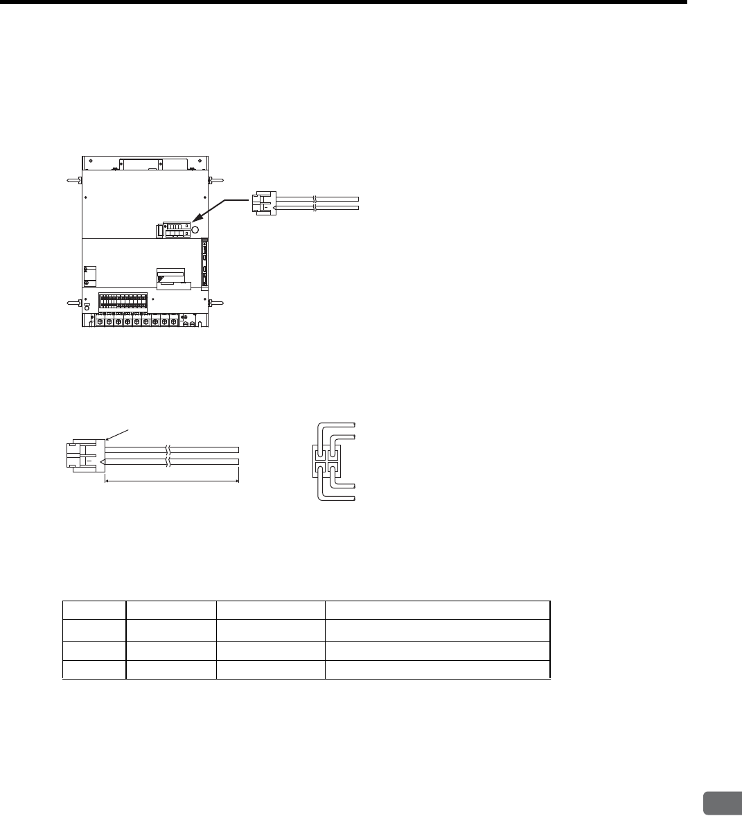
5.5 Peripheral Devices
5
Specifications and Dimensional Drawings of Cables and Peripheral Devices
5-15
5.5.3 Cables for Analog Monitor
(1) Cable Type: JZSP-CA01 (DE9404559)
Connect the specified cables to CN5 connector for monitoring the analog monitor signals. For details, refer to
9.5 Analog Monitor.
Note: Specify the cable type either JZSP-CA01 or DE9404559 when ordering the cable for analog moni-
tor.
(2) Dimensional Drawing
* Manufactured by Hirose Electric Corporation.
(3) Specifications
Note: The above monitoring items are the factory settings. The monitoring items can be changed by set-
ting the parameter Pn003. Refer to 9.5 Analog Monitor.
Cable for Analog Monitor
.4 .5 .6 789
8
8
&7
8
8
8
&9&8 $
8
&%
0
$
&%
2
%*#4)'
5*&)
㧖㧖㧖㧖
6 #5''/1 &
-5'4812#%
#;#5-#9
4
1
2
'
4
#
6
1
%0
%0
219'4
%0
WARNING
ෂޓ㒾
ㅢ㔚ਛ߮㔚Ḯࠝࡈᓟ5
ಽ㑆ޔ┵ሶㇱߦ⸅ࠆߥ
electric shock.
Disconnect all power
May cause
ᗵ㔚ߩᕟࠇࠅ
before servicing.
and wait 5 min.
grounding techniques.
ធ⛯ߖࠃ
Use proper
ᔅߕࠕ㧙ࠬ✢ࠍ
34
12
Socket: DF11-4DS-2C∗
Connector: DF11-2428SCF∗
1000 ޓmm
-0
+20
White
Red
Black
Black
Viewed from the cable
Pin No. Cable Color Signal Monitoring Item
1Red Analog Monitor 2 Motor speed: 1V/1000 min-1
2White Analog Monitor 1 Torque reference: 1V/100% rated torque
3 and 4 Black (2 cables) GND (0 V) −
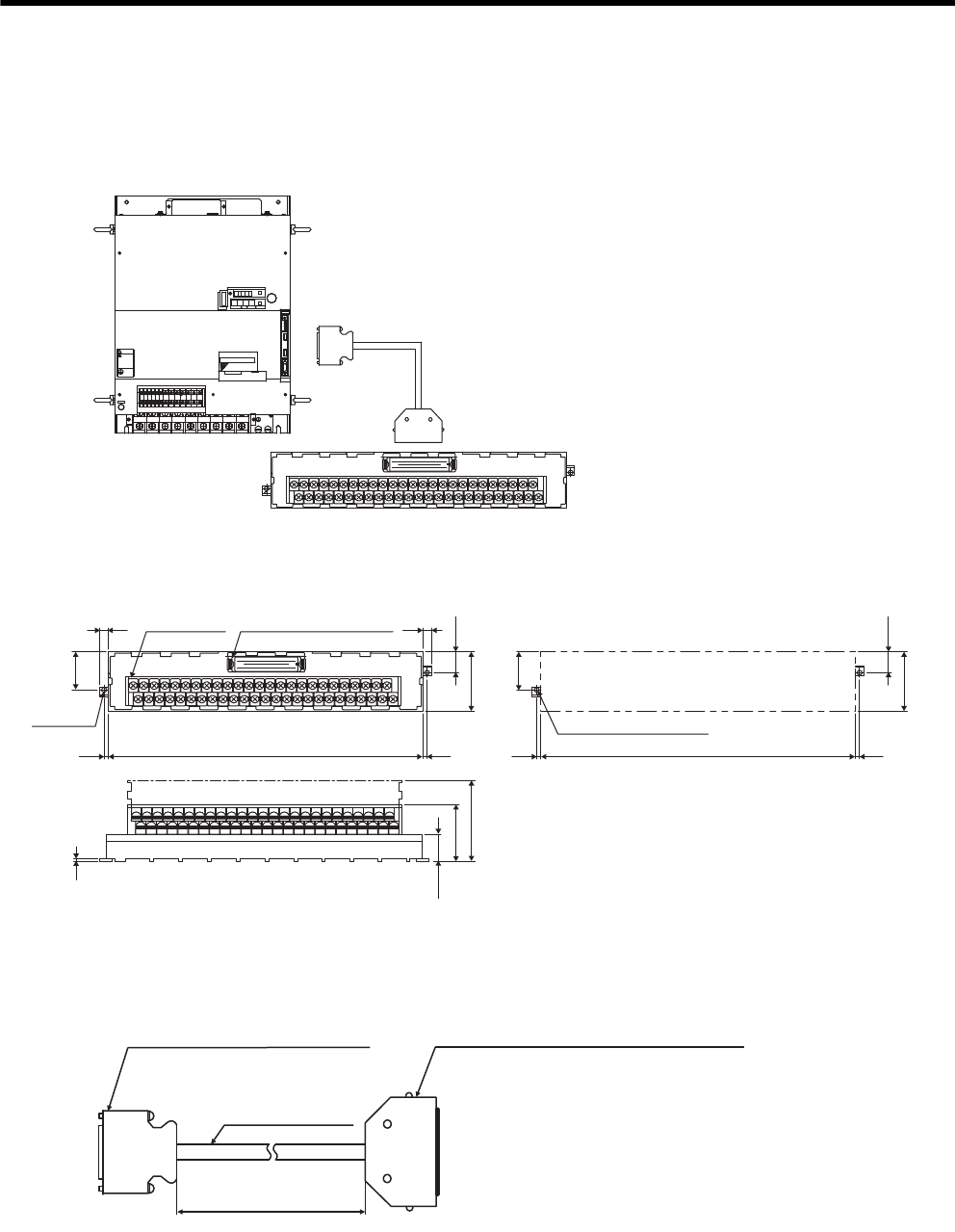
5 Specifications and Dimensional Drawings of Cables and Peripheral Devices
5.5.4 Connector Terminal Block Converter Unit
5-16
5.5.4 Connector Terminal Block Converter Unit
(1) Model: JUSP-TA50PG
The connection between the connector terminal block converter and the SERVOPACK is shown below.
(2) Dimensional Drawings of Terminal Block
(3) Dimensional Drawing of Cable
1
19
33
16
32
50
1
1
2
49
50
SERVOPACK
Connector terminal block converter unit
model: JUSP-TA50PG
CN1 Attached cable length: 500 mm
+50
-0
.4 .5 .6 789
8
8
&7
8
8
8
&9&8 $
8
&%
0
$
&%
2
%*#4)'
5*&)
㧖㧖㧖㧖
6 #5''/1 &
-5'4812#%
#;#5-#9
4
1
2
'
4
#
6
1
%0
%0
219'4
%0
WARNING
ෂޓ㒾
ㅢ㔚ਛ߮㔚Ḯࠝࡈᓟ5
ಽ㑆ޔ┵ሶㇱߦ⸅ࠆߥ
electric shock.
Disconnect all power
May cause
ᗵ㔚ߩᕟࠇࠅ
before servicing.
and wait 5 min.
grounding techniques.
ធ⛯ߖࠃ
Use proper
ᔅߕࠕ㧙ࠬ✢ࠍ
1
19
33
16
32
50
1
1
2
49
50
Terminal
block (50P)
M3.5 screw Connector plug (50P)
MR-50RMD2
77
15.5
45
15.5
45
3.53.5
29.5
29.5
2×φ3.5
247.5 3.5
3.5
2×M3 screw holes
247.5
2
20.5
43.5
Can be fixed on DIN rail
(62)
Units: mm
With terminal block
cover removed
500
SERVOPACK end connector (50P)
10150-6000EL (Sumitomo 3M Ltd.)
Shell
10350-52AO-008 (Sumitomo 3M Ltd.)
Cable (black)
AWG#2825P
UL20276 VW-1SC
Connector terminal block converter unit
end connector (50P)
MRP-50F01 (Honda Tsushin Kogyo Co., Ltd.)
Case
MR-50L
(Honda Tsushin Kogyo Co., Ltd.)
+50
0
Units: mm
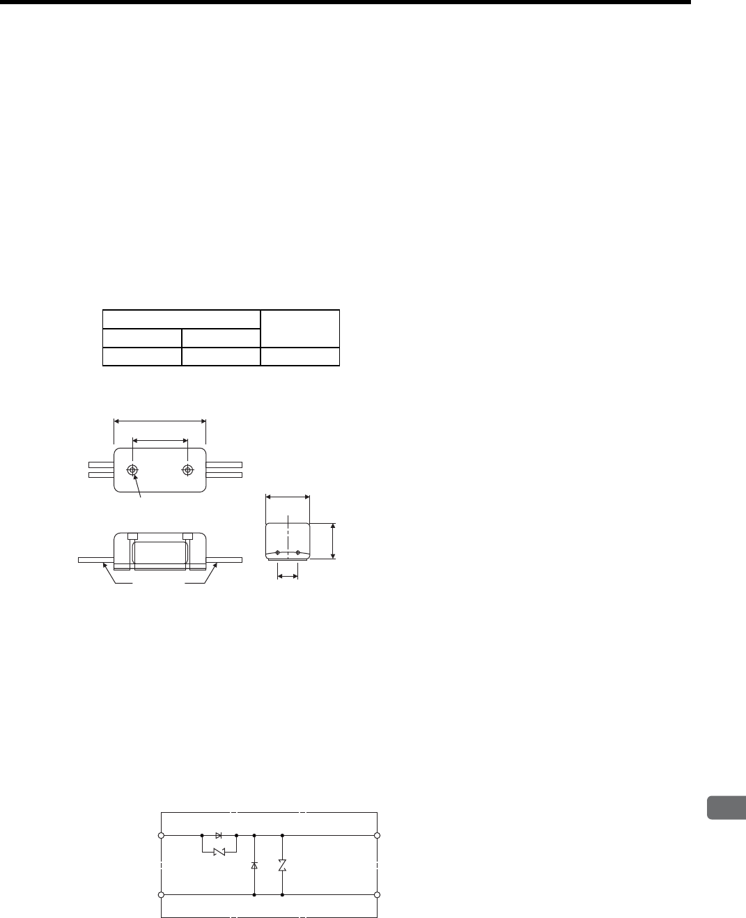
5.5 Peripheral Devices
5
Specifications and Dimensional Drawings of Cables and Peripheral Devices
5-17
5.5.5 Brake Power Supply Unit
(1) Model: LPSE-2H01, LPDE-1H01
Contact Yaskawa Controls Co., Ltd.
• 200 V input: LPSE-2H01
• 100 V input: LPDE-1H01
(2) Specifications
• Rated output voltage: 90 VDC
• Maximum output current: 1.0 ADC
• Lead wire length: 500 mm each
• Maximum surrounding air temperature: 60°C
• Lead wires: Color coded. Refer to the table below.
(3) Dimensional Drawing
(4) Internal Circuits
The brake power supply circuit can be opened and closed either on AC or DC side. However, if the wiring dis-
tance on DC side is too long, the brake circuit may not operate normally due to the influence of switching noises.
When switching the circuit on AC side, install a surge absorber model CR50500BL (sold as spark quencher) for
the brake power supply near the brake coil to reduce the influence of switching noises.
When switching the circuit on DC side, the influence of the switching noise is minimal, even without installing a
surge absorber. However, the surge voltage at switching may damage the brake coil. Install a surge absorber
near the brake coil to prevent the damage to the brake coil in addition to the built-in surge absorber.
(a) Internal Circuit for 200 VAC
Brake Power Supply Model: LPSE-2H01
AC Input End Brake End
100 V 200 V
Blue/White Yellow/White Red/Blue
2 Mounting holes φ3
(Spot facing φ5.5
and 4 long㧕
30
25
Units: mm
Nameplate
50
11
20
Lead wire
Yellow
White
Red
Black
AC side
180 to 230 V Diode Surge absorber DC (Brake) side
No polarity
Surge absorber
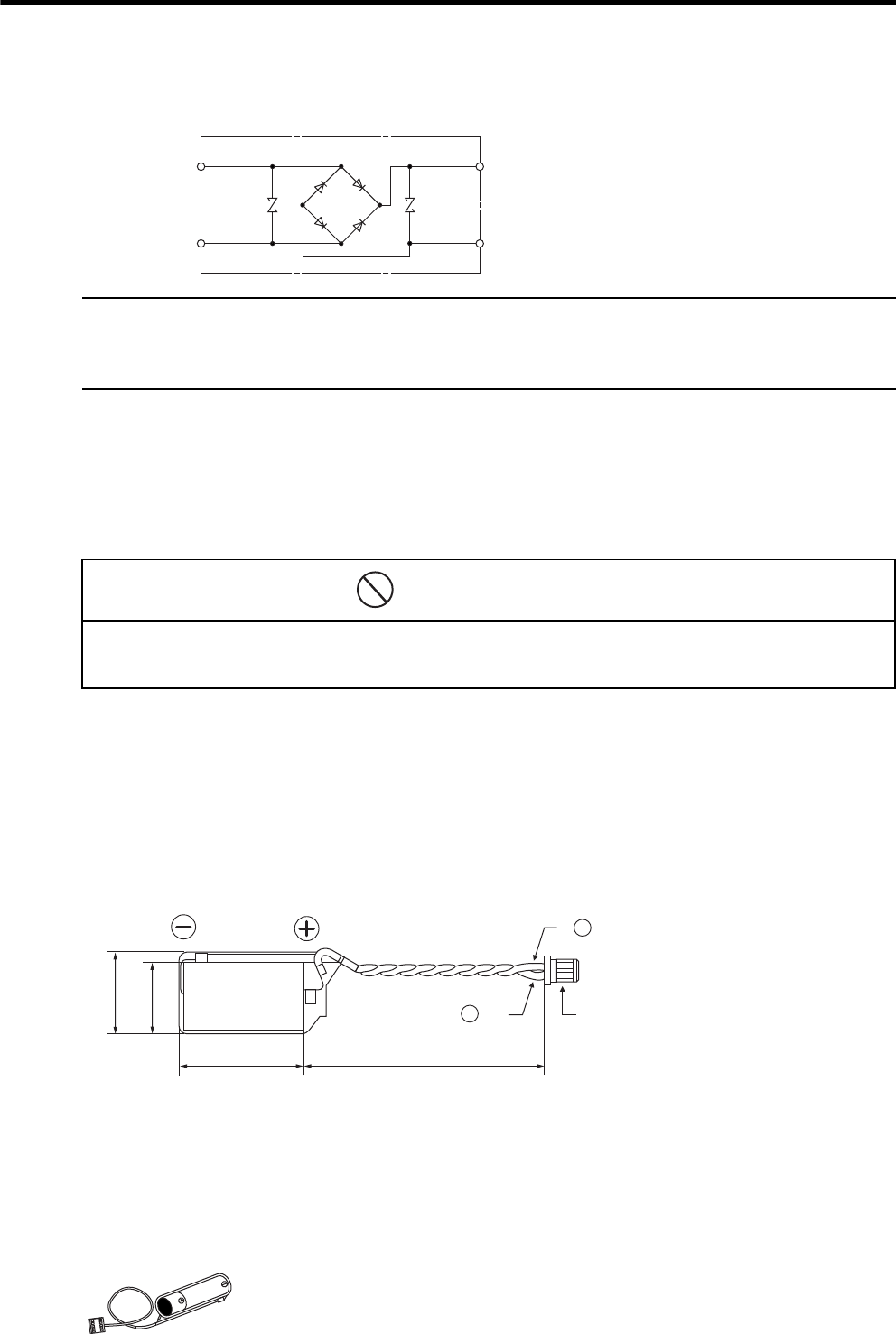
5 Specifications and Dimensional Drawings of Cables and Peripheral Devices
5.5.6 Absolute Encoder Battery
5-18
(b) Internal Circuit for 100 VAC
Brake Power Supply Model: LPDE-1H01
Brake Power Supply Unit for the 24 VDC
The brake power supply unit for the 24 VDC is not provided by Yaskawa. When using the servomotor with a 24-VDC
brake, the brake power supply unit is to be provided by the customer.
5.5.6 Absolute Encoder Battery
When using an absolute encoder, a backup battery is required to prevent the position data from being lost at
power OFF. Install one of the following absolute encoder batteries.
There are two types of battery: Battery to be mounted on the SERVOPACK and battery to be connected to the
host controller.
(1) Battery Mounted on SERVOPACK
(a) Model
JZSP-BA01-1
(b) Dimensional Drawing
(2) Battery Connected to the Host Controller
When connecting the battery to the host controller, select the battery in accordance with the specifications of the
host controller.
Use the battery ER6 VC3 or the equivalent:
3.6 V, 2000 mAh manufactured by Toshiba Battery Co., Ltd.
Blue
White
Red
Black
AC side
90 to 120 V
Diode bridge
Surge
absorber
Surge
absorber DC (Brake) side
No polarity
• Install the absolute encoder battery on either the SERVOPACK or the host controller.
Installing the batteries both on the SERVOPACK and host controller configures a loop in the circuit between two bat-
teries, which damages the circuit.
PROHIBITED
ޓRed Connector
2ޓBlack
㧗
̆
26
17
14.5
50±5
Lithium battery ER3V
3.6 V 1000 mAh
Manufactured by Toshiba Battery Co., Ltd.
Units: mm

5.5 Peripheral Devices
5
Specifications and Dimensional Drawings of Cables and Peripheral Devices
5-19
5.5.7 Molded-case Circuit Breaker (MCCB)
If selecting a molded-case circuit breaker, observe the following precautions.
Circuit Breakers
• Select a breaker for inverters.
• High-frequency current leaks from the servomotor armature because of switching operations inside the
SERVOPACK.
(1) Maximum Input Current
• The instantaneous maximum output of SERVOPACK is 3 times of the rated output for maximum 3 sec-
onds. Accordingly, select a circuit breaker whose operating time is 5 seconds or more at 300% of SER-
VOPACK rated current.
The general-purpose and low-speed acting molded-case circuit breakers are applicable.
• The power supply capacity per SERVOPACK when using a servomotor is described in 2.6.2 Molded-case
Circuit Breaker and Fuse Capacity. Select a circuit breaker with the capacity larger than the effective
load current (when using multiple SERVOPACKs) calculated from the total power supply capacity.
• The power consumption of other controllers must be considered when selecting a circuit breaker.
(2) Inrush Current
• Refer to 2.6.2 Molded-case Circuit Breaker and Fuse Capacity for SERVOPACK inrush current.
• The allowable inrush current for a low-speed acting circuit breaker is approximately 10 times of the rated
current for 0.02 seconds.
• When turning ON multiple SERVOPACKs simultaneously, select a molded-case circuit breaker with the
allowable current for 20 ms larger than the total inrush current shown in 2.6.2 Molded-case Circuit
Breaker and Fuse Capacity.
IMPORTANT
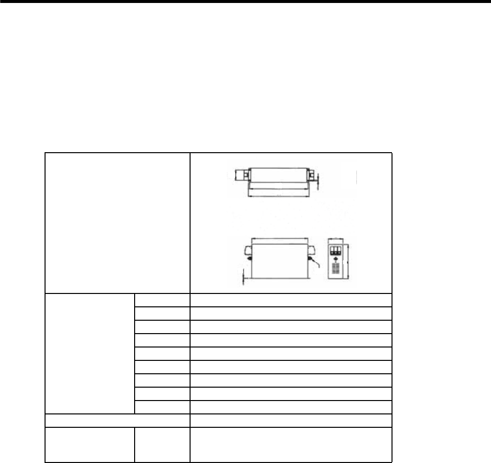
5 Specifications and Dimensional Drawings of Cables and Peripheral Devices
5.5.8 Noise Filter
5-20
5.5.8 Noise Filter
The noise filters model FN manufactured by Schaffner Electronic are recommended. Contact Yaskawa Controls
Co., Ltd.
Select one of the following noise filters according to SERVOPACK capacity. For more details, refer to 2.5.3
Noise Filters, Magnetic Contactors, and Brake Power Supply Units.
Refer to 6.1.2 Typical Main Circuit Wiring Examples for the connection method.
(1) Model: FN258L-130-35
Dimensional Drawings
External Dimensions
(mm)
A439 ± 1.5
B240
C110 ± 0.8
D400 ± 1.2
E414
F80
G6.5
J3
OM10
Specifications 480 VAC, 130 A
Applicable
SERVOPACK
Three-
phase
200 V
SGDM-2BADB
SGDH-2BAEB
CD
B
O
J
G
F
E
A
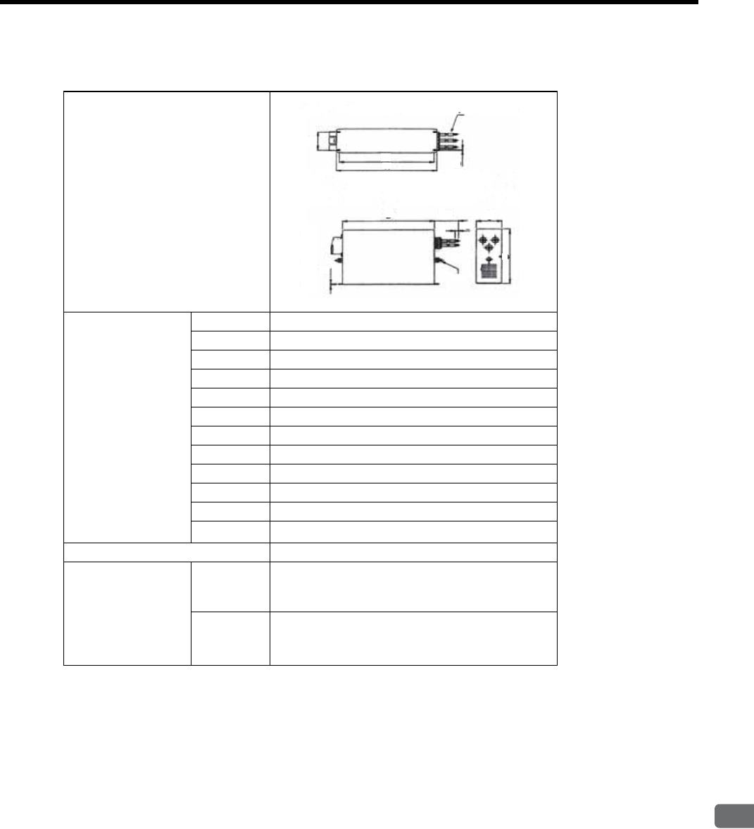
5.5 Peripheral Devices
5
Specifications and Dimensional Drawings of Cables and Peripheral Devices
5-21
(2) Model: FN258L-180-07
Dimensional Drawings
External Dimensions
(mm)
A438±1.5
B240
C110±0.8
D400±1.2
E413
F80
G6.5
H500
J4
L15
OM10
P50 (mm2)
Specifications 480 VAC, 180 A
Applicable
SERVOPACK
Three-
phase
200 V
SGDM-3ZADB
SGDH-3ZAEB
Three-
phase
400 V
SGDH-2BDEB
SGDH-3ZDEB
SGDH-3GDEB
C
L
H
D
E
P
B
B
OG
F
J
A
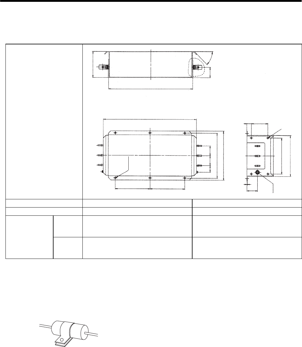
5 Specifications and Dimensional Drawings of Cables and Peripheral Devices
5.5.9 Surge Absorber
5-22
(3) Model: FN359P-250-99, FN359P-300-99
5.5.9 Surge Absorber
When using a servomotor with holding brake, install a surge absorber near the brake coil to prevent the power
supply noises. The surge absorber handled by Okaya Electric Industries Co., Ltd. is recommended.
(a) Model: CR50500BL (sold as Spark Quencher)
(b) Specifications
External Dimensions
(mm)
Model FN359P-250-99 FN359P-300-99
Specifications AC480 V, 250 A AC480 V, 300 A
Applicable
SERVOPACK
Three-
phase
200 V
SGDM-3GADB
SGDH-3GAEB −
Three-
phase
400 V
SGDH-4EDEB
SGDH-5EDEB SGDH-9ZDEB
8 × M5
mounting holes
100 ± 0.5
27 ± 0.2
160 ±
±
±
±
±
±
±
±
1
516 1.5
64 2
564 1.5
210 0.5 210 0.5
40 ± 0.3
60 ± 0.5 60 ± 0.5
275 0.5
300 1
±
±
220 0.5
250 1
3 ± 0.2
64 ± 1
M12
±
45q5q
φ9 ± 0.2
Power supply: 250 VAC
Capacitance: 0.5 μF ± 20%
Resistance: 50 Ω(1/2 W) ± 30%
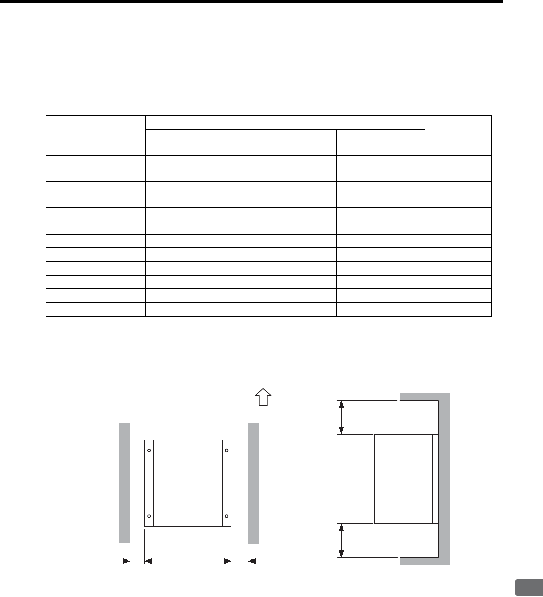
5.5 Peripheral Devices
5
Specifications and Dimensional Drawings of Cables and Peripheral Devices
5-23
5.5.10 Regenerative Resistor Unit
(1) Model
Refer to the following table to install the regenerative resistor unit according to the SERVOPACK model require-
ments.
(2) Mounting
To cool the regenerative resistor by fan or natural convection, provide at least 70 mm of space on each side and at
least 200 mm of space both above and below.
SERVOPACK Model Regenerative Resistor Unit Allowable
Power Loss
(W)
Model Resistance
(Ω)
Resistance
Capacity(W)
SGDM-2BADB
SGDH-2BAEB JUSP-RA08 2.4 2400 480
SGDM-3ZADB
SGDH-3ZAEB JUSP-RA09 1.8 4800 960
SGDM-3GADB
SGDH-3GAEB JUSP-RA11 1.6 4800 960
SGDH-2BDEB JUSP-RA12 9 3600 720
SGDH-3ZDEB JUSP-RA13 6.7 3600 720
SGDH-3GDEB JUSP-RA14 5 4800 960
SGDH-4EDEB JUSP-RA15 4 6000 1200
SGDH-5EDEB JUSP-RA16 3.8 7200 1440
SGDH-9ZDEB JUSP-RA25 2.1 16800 3360
70 min.70 min.
200 min.200 min.
Mounting
direction
Up
Units: mm
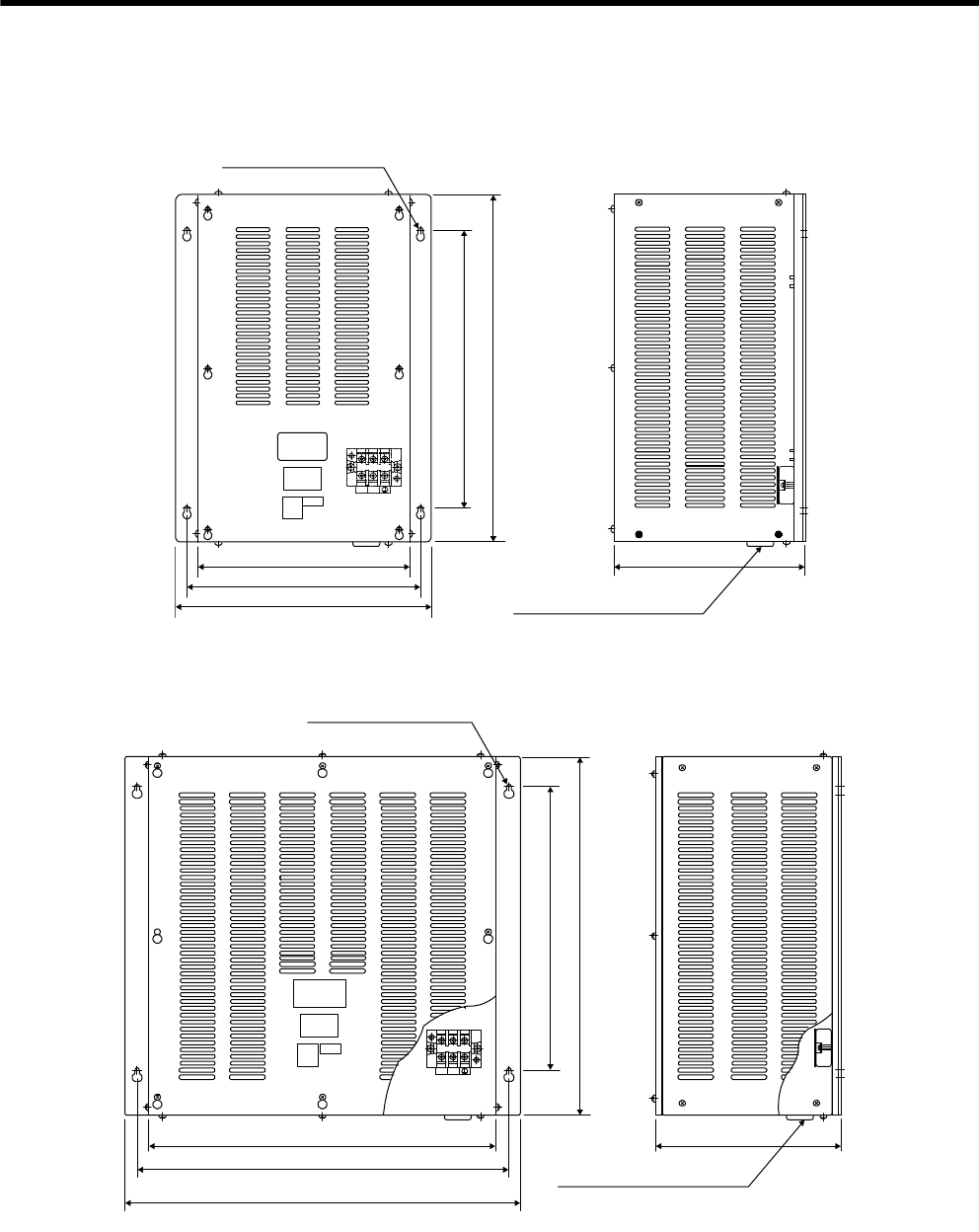
5 Specifications and Dimensional Drawings of Cables and Peripheral Devices
5.5.10 Regenerative Resistor Unit
5-24
(3) Dimensional Drawings
(a) JUSP-RA08 Regenerative Resistor Unit
(b) JUSP-RA09 Regenerative Resistor Unit
298
400
328
358
500
260
B2B1
Power line insertion hole
(φ17, with rubber bushing)
4 × φ7 mounting holes
Units: mm
Approx. mass: 14.0 kg
400
500
260
488
518
548
B2B1
Power line insertion hole
(φ17, with rubber bushing)
4 × φ7 mounting holes
Units: mm
Approx. mass: 21.0 kg
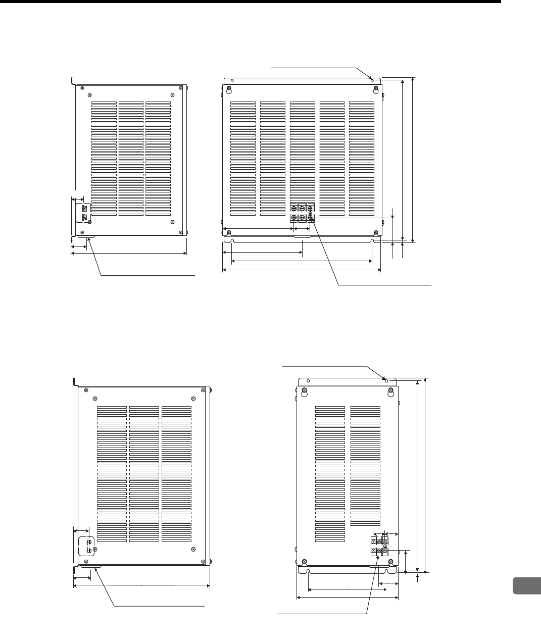
5.5 Peripheral Devices
5
Specifications and Dimensional Drawings of Cables and Peripheral Devices
5-25
(c) JUSP-RA11 Regenerative Resistor Unit
(d) JUSP-RA12 Regenerative Resistor Unit
216
45 348
M8 main circuit terminals
4 × M5 mounting holes
77
49
B1 B2
Power line insertion hole
(φ33, with rubber bushing)
Units: mm
Approx. mass: 20.5 kg
484
425
242
7.5 485
500
37
Power line insertion hole
(φ33, with rubber bushing)
M4 main circuit terminals
4 × M5 mounting holes
348
34
45
7.5
60
485
500
200
259
49
24 38
Units: mm
Approx. mass: 14 kg
B1B2
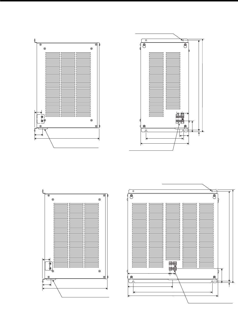
5 Specifications and Dimensional Drawings of Cables and Peripheral Devices
5.5.10 Regenerative Resistor Unit
5-26
(e) JUSP-RA13 Regenerative Resistor Unit
(f) JUSP-RA14 Regenerative Resistor Unit
348
45
259
200 49
7.5
59
485
500
29 34
B1 B2
Units: mm
Approx. mass: 14 kg
Power line insertion hole
(φ33, with rubber bushing) M5 main circuit terminals
4 × M5 mounting holes
37
348
37
45
29
231
242
425
484
7.5
79
485
500
B1B2
Units: mm
Approx. mass: 20 kg
Power line insertion hole
(φ33, with rubber bushing)
M5 main circuit terminals
4 × M5 mounting holes
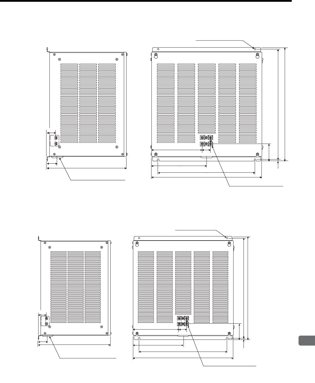
5.5 Peripheral Devices
5
Specifications and Dimensional Drawings of Cables and Peripheral Devices
5-27
(g) JUSP-RA15 Regenerative Resistor Unit
(h) JUSP-RA16 Regenerative Resistor Unit
348
45
484
425
242
224
38
7.5 485
500
78.5
B1 B2
Units: mm
Approx. mass: 21.5 kg
Power line insertion hole
(φ33, with rubber bushing)
M6 main circuit terminals
4 × M5 mounting holes
35.5
B1 B2
348
45
224
242
425
484
7.5 485
500
78.5
38
Units: mm
Approx. mass: 23.5 kg
Power line insertion hole
(φ33, with rubber bushing)
M6 main circuit terminals
4 × M5 mounting holes
35.5
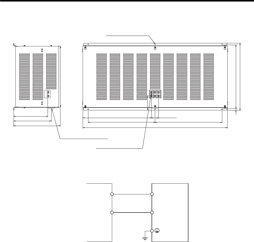
5 Specifications and Dimensional Drawings of Cables and Peripheral Devices
5.5.10 Regenerative Resistor Unit
5-28
(i) JUSP-RA25 Regenerative Resistor Unit
(4) Connections
Connect the Regenerative Resister Unit to the SGDM/SGDH SERVOPACKs as shown in the following diagram.
27x2=54
255
281
348
512
500
1081
500
485
7.5 500
106
Units: mm
Approx. mass: 45 kg
Power line insertion hole
(φ33, with rubber bushing)
M8 main circuit terminals
6 × M5 mounting holes
B1
B2
SGDM/SGDH
SERVOPACK
B1
B2
Regenerative Resistor Unit
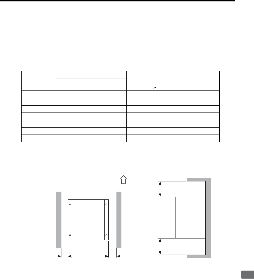
5.5 Peripheral Devices
5
Specifications and Dimensional Drawings of Cables and Peripheral Devices
5-29
5.5.11 Dynamic Brake (DB) Unit
Externally attach a dynamic brake resistor to the SERVOPACK to dissipate regenerative energy when using the
dynamic brake function. The dynamic brake resistor does not need to be installed if the dynamic brake function is
not required.
(1) Specifications
The following Dynamic Brake Units are required according to the SERVOPACK model.
(2) Mounting
To cool the regenerative resistor by fan or natural convection, provide at least 70 mm of space on each side and at
least 200 mm of space both above and below.
Dynamic Brake
(DB) Unit Model
SERVOPACK Model Resistance
Specifications
(Star Wiring )
DB Contactor and
Surge Absorption Unit
SGDM- SGDH-
JUSP-DB01 2BADB, 3ZADB 2BAEB, 3ZAEB 180 W, 0.3 ΩBuilt into the SERVOPACK
JUSP-DB02 3GADB 3GAEB 180 W, 0.3 ΩBuilt into Dynamic Brake Unit
JUSP-DB03 −2BDEB, 3ZDEB 180 W, 0.8 ΩBuilt into the SERVOPACK
JUSP-DB04 −3GDEB 180 W, 0.8 ΩBuilt into Dynamic Brake Unit
JUSP-DB05 −4EDEB 180 W, 0.8 ΩBuilt into Dynamic Brake Unit
JUSP-DB06 −5EDEB 300 W, 0.8 ΩBuilt into Dynamic Brake Unit
JUSP-DB12 −9ZDEB 600 W, 0.9 ΩBuilt into Dynamic Brake Unit
Units: mm
70 min.
70 min.
200 min.200 min.
Mounting
direction
Up
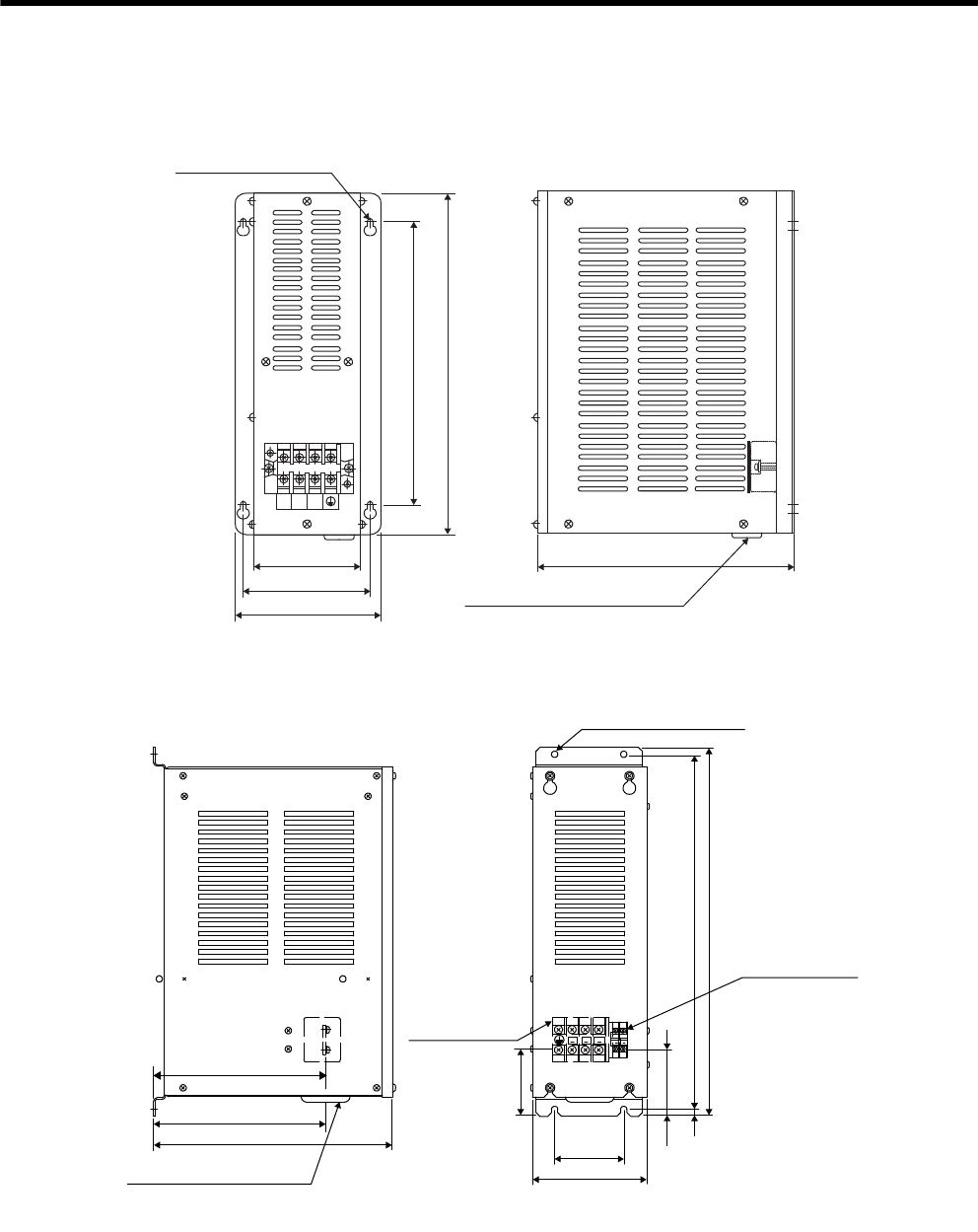
5 Specifications and Dimensional Drawings of Cables and Peripheral Devices
5.5.11 Dynamic Brake (DB) Unit
5-30
(3) Dimensional Drawings
(a) JUSP-DB01 Dynamic Brake Unit
(b) JUSP-DB02 Dynamic Brake Unit
110
350
130
150
290
255
DVDU DW
Units: mm
Approx. mass: 5.0 kg
Power line insertion hole
(φ17, with rubber bushing)
4 × φ7 mounting holes
DW
DVDU
71.5
M3.5 control
circuit terminals
DB
24
DB
ON
187
187
259 75
124
73
7.5 385
400
Units: mm
Approx. mass: 6.0 kg
Power line insertion hole
(φ33, with rubber bushing)
M5 main
circuit terminals
4 × M5 mounting holes
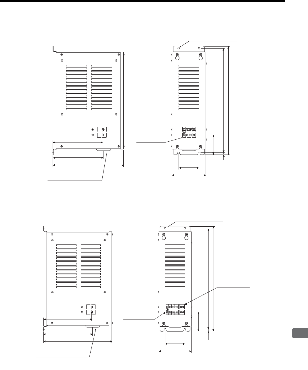
5.5 Peripheral Devices
5
Specifications and Dimensional Drawings of Cables and Peripheral Devices
5-31
(c) JUSP-DB03 Dynamic Brake Unit
(d) JUSP-DB04 Dynamic Brake Unit
DW
DUDV
184
187
259 75
124
73
7.5 385
400
Units: mm
Approx. mass: 5.0 kg
Power line insertion hole
(φ33, with rubber bushing)
M4 main
circuit terminals
4 × M5 mounting holes
DU DVDW DB
24
DB
ON
184
187
259 75
124
73
7.5 385
400
Units: mm
Approx. mass: 6.0 kg
Power line insertion hole
(φ33, with rubber bushing)
M4 main
circuit terminals
M3.5 control
circuit terminals
4 × M5 mounting holes
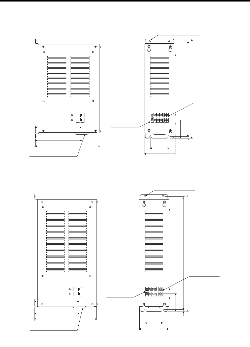
5 Specifications and Dimensional Drawings of Cables and Peripheral Devices
5.5.11 Dynamic Brake (DB) Unit
5-32
(e) JUSP-DB05 Dynamic Brake Unit
(f) JUSP-DB06 Dynamic Brake Unit
DU DV DW DB
24
DB
ON
184
187
259 75
124
73
7.5 385
400
Units: mm
Approx. mass: 6.0 kg
Power line insertion hole
(φ33, with rubber bushing)
M3.5 control
circuit terminals
M4 main
circuit terminals
4 × M5 mounting holes
DU DV DW DB
24
DB
ON
184
187
259 75
124
73
7.5 475
490
Units: mm
Approx. mass: 7.0 kg
Power line insertion hole
(φ33, with rubber bushing)
M4 main
circuit terminals
M3.5 control
circuit terminals
4 × M5 mounting holes
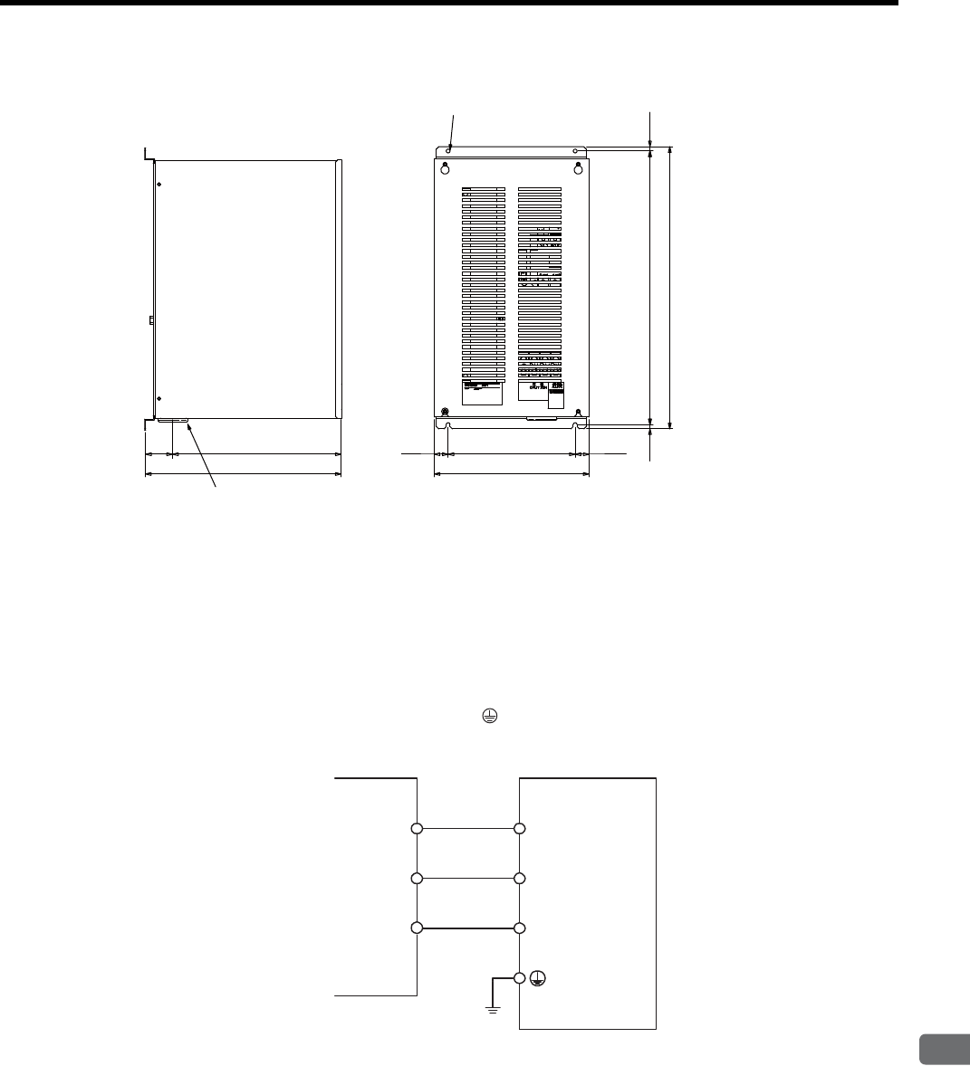
5.5 Peripheral Devices
5
Specifications and Dimensional Drawings of Cables and Peripheral Devices
5-33
(g) JUSP-DB12 Dynamic Brake Unit
(4) Connections
(a) Using a Yaskawa Dynamic Brake Unit
• SGDM-2BADB, -3ZADB SERVOPACKs
SGDH-2BAEB, -3ZAEB SERVOPACKs
SGDH-2BDEB, -3ZDEB SERVOPACKs
The dynamic brake contactor and surge absorption unit are built into the SERVOPACK. Connect the DU,
DV, and DW terminals and the Frame Ground ( ) on the dynamic brake unit, as sown in the following
diagram.
7.5
24.524.5 225
274
50 298
348
7.5 485
500
Units: mm
Approx. mass: 16 kg
Power line insertion hole
(φ33, with rubber bushing)
4 × M5 mounting holes
DU
DV
DW
DU
DV
DW
SERVOPACK Dynamic Brake Unit
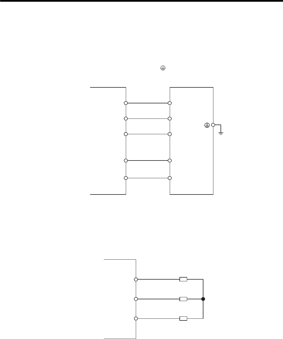
5 Specifications and Dimensional Drawings of Cables and Peripheral Devices
5.5.11 Dynamic Brake (DB) Unit
5-34
• SGDM-3GADB SERVOPACK
SGDH-3GAEB, SERVOPACK
SGDH-3GDEB, -4EDEB , -5EDEB , -9ZDEB SERVOPACKs
The dynamic brake contactor and surge absorption unit are not built into the SERVOPACK.
The dynamic brake contactor and surge absorption unit are built into the dynamic brake unit. Connect the
DU, DV, and DW terminals and the frame ground ( ) on the dynamic brake unit, and also connect the
terminals DBON and DB24 for dynamic brake contactor control, as shown in the following diagram.
(b) Using Dynamic Brake Resistors Prepared by the Customer
• SGDM-2BADB, -3ZADB SERVOPACKs
SGDH-2BAEB, 3ZAEB, SERVOPACKs
SGDH-2BDEB, -3ZDEB, SERVOPACKs
The dynamic brake contactor and surge absorption unit are built into the SERVOPACK. Connect the
dynamic brake resistors only, as shown in the following diagram.
Note: Connect dynamic brake resistors with the following resistance specifications.
200-V SERVOPACKs: Higher than 0.3 Ω
400-V SERVOPACKs: Higher than 0.8 Ω
DU
DV
DW
SERVOPACK
DU
DV
DBON
DW
DB24
DBON
DB24
Dynamic Brake Unit
DU
DV
DW
Dynamic Brake
resistors
SERVOPACK
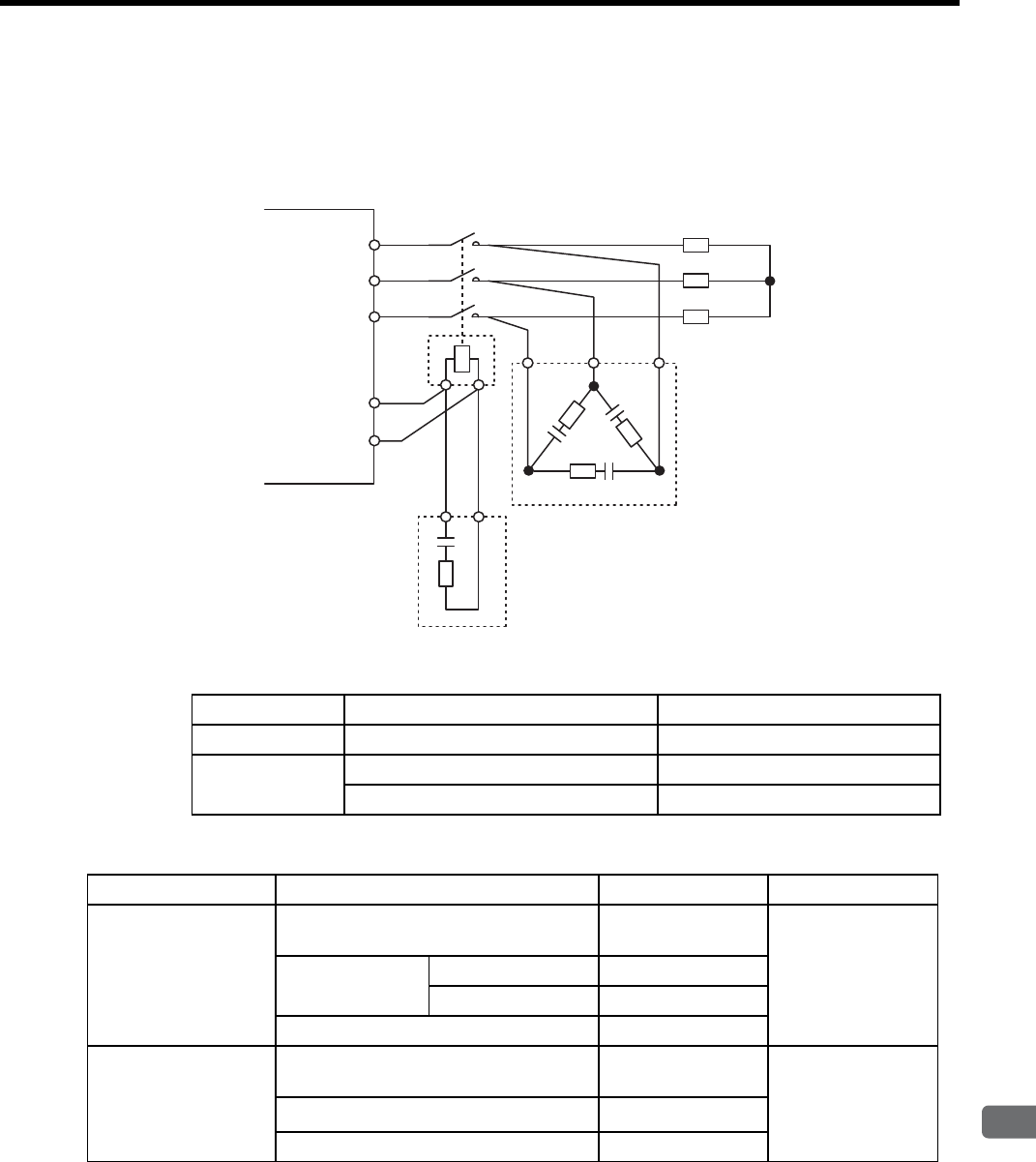
5.5 Peripheral Devices
5
Specifications and Dimensional Drawings of Cables and Peripheral Devices
5-35
• SGDM-3GADB SERVOPACK
SGDH-3GAEB SERVOPACK
SGDH-3GDEB, -4EDEB, -5EDEB, -9ZDEB SERVOPACKs
Connect a dynamic brake contactor and surge absorption unit, as shown in the following diagram.
Note: Connect dynamic brake resistors with the following resistance specifications.
Use the following dynamic brake contactor and surge absorption unit.
* The main circuit surge absorption unit is available as a front-connection type or a side-connection type.
Voltage SERVOPACK Model Dynamic Brake Resistors
200 V SGDM-3GADB, SGDH-3GAEB Higher than 0.3 Ω
400 V SGDH-3GDEB, 4EDEB, 5EDEB Higher than 0.8 Ω
SGDH-9ZDEB Higher than 0.9 Ω
SERVOPACK Model Name Model Manufacturer
SGDM-3GADB
SGDH-3GAEB
SGDH-3GDEB
SGDH-4EDEB
SGDH-5EDEB
Contactor SC-4-1/G
24-VDC coil
Fuji Electric Co., Ltd.
Main Circuit Surge
Absorption Unit*
Front Connection SZ-ZM1
Side Connection SZ-ZM2
Coil Surge Absorption Unit SZ-Z4
SGDH-9ZDEB
Contactor SD-N50
24-VDC coil Mitsubishi Electric
Co., Ltd.
Main Circuit Surge Absorption Unit*UN-SA33
Coil Surge Absorption Unit UN-SA721
DV
DU
DW
SERVOPACK Dynamic brake
resistors
DBON
DB24
Dynamic brake
contactor
Main circuit
surge absorption unit
Coil surge
absorption unit
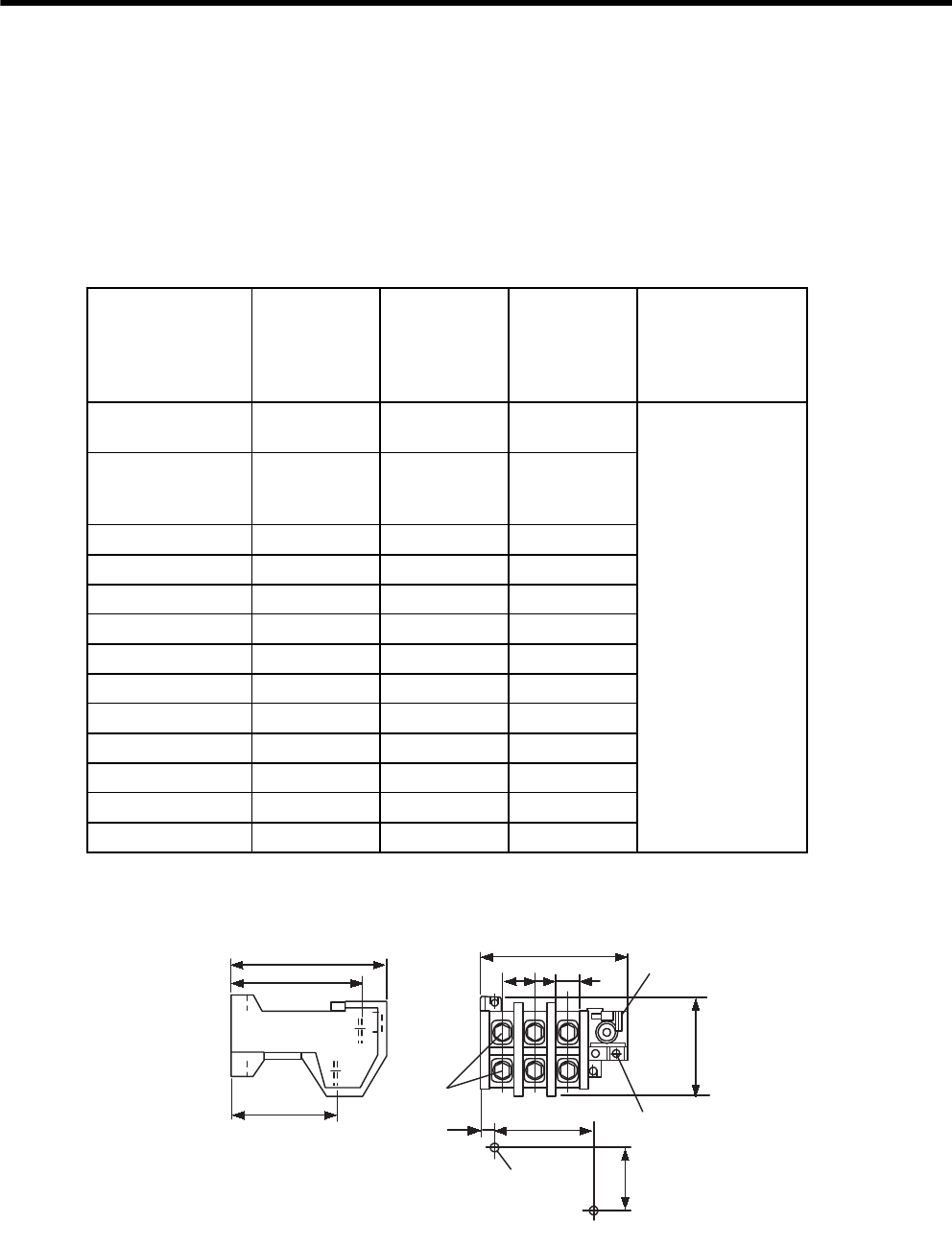
5 Specifications and Dimensional Drawings of Cables and Peripheral Devices
5.5.12 Thermal Relays
5-36
5.5.12 Thermal Relays
Connect a thermal relay to the SERVOPACK to protect the regenerative resistor and dynamic brake resistor from
heat damage when operating under extreme conditions.
(1) Models
Select the appropriate thermal relay from the following list according to regenerative resistor unit and dynamic
brake unit model.
(2) Dimensional Drawings
The following dimensional drawings are for a TR-3N thermal relay.
Dynamic Brake
(DB) Unit and
Regenerative
Resistor
Unit Model
Thermal Relay
Model
Thermal Relay
Current Range
Thermal Relay
Current
Manufacturer
JUSP-DB01
JUSP-DB02 TR-3N/3 9 A 9 to 13 A 10 A
Fuji Electric Co., Ltd.
JUSP-DB03
JUSP-DB04
JUSP-DB05
TR-3N/3 7 A 7 to 11 A 7 A
JUSP-DB06 TR-3N/3 7 A 7 to 11 A 9 A
JUSP-DB12 TR-3N/3 9 A 9 to 13 A 12 A
JUSP-RA08 TR-3N/3 12 A 12 to 18 A 14 A
JUSP-RA09 TR-3N/3 18 A 18 to 26 A 23 A
JUSP-RA11 TR-3N/3 18 A 18 to 26 A 24 A
JUSP-RA12 TR-3N/3 7 A 7 to 11 A 9 A
JUSP-RA13 TR-3N/3 9 A 9 to 13 A 10 A
JUSP-RA14 TR-3N/3 12 A 12 to 18 A 14 A
JUSP-RA15 TR-3N/3 12 A 12 to 18 A 17 A
JUSP-RA16 TR-3N/3 18 A 18 to 26 A 19 A
JUSP-RA25 TR-3N/3 34A 34 to 50 A 40 A
93
79.5
64.5
Reset switch
7
Units: mm
Approx. mass: 0.3 kg
88
15.3
20
M3.5 Auxiliary terminal
M6
Main
terminals
60
61.5
40
2
×
M4
mounting holes
Mounting Hole Dimensions
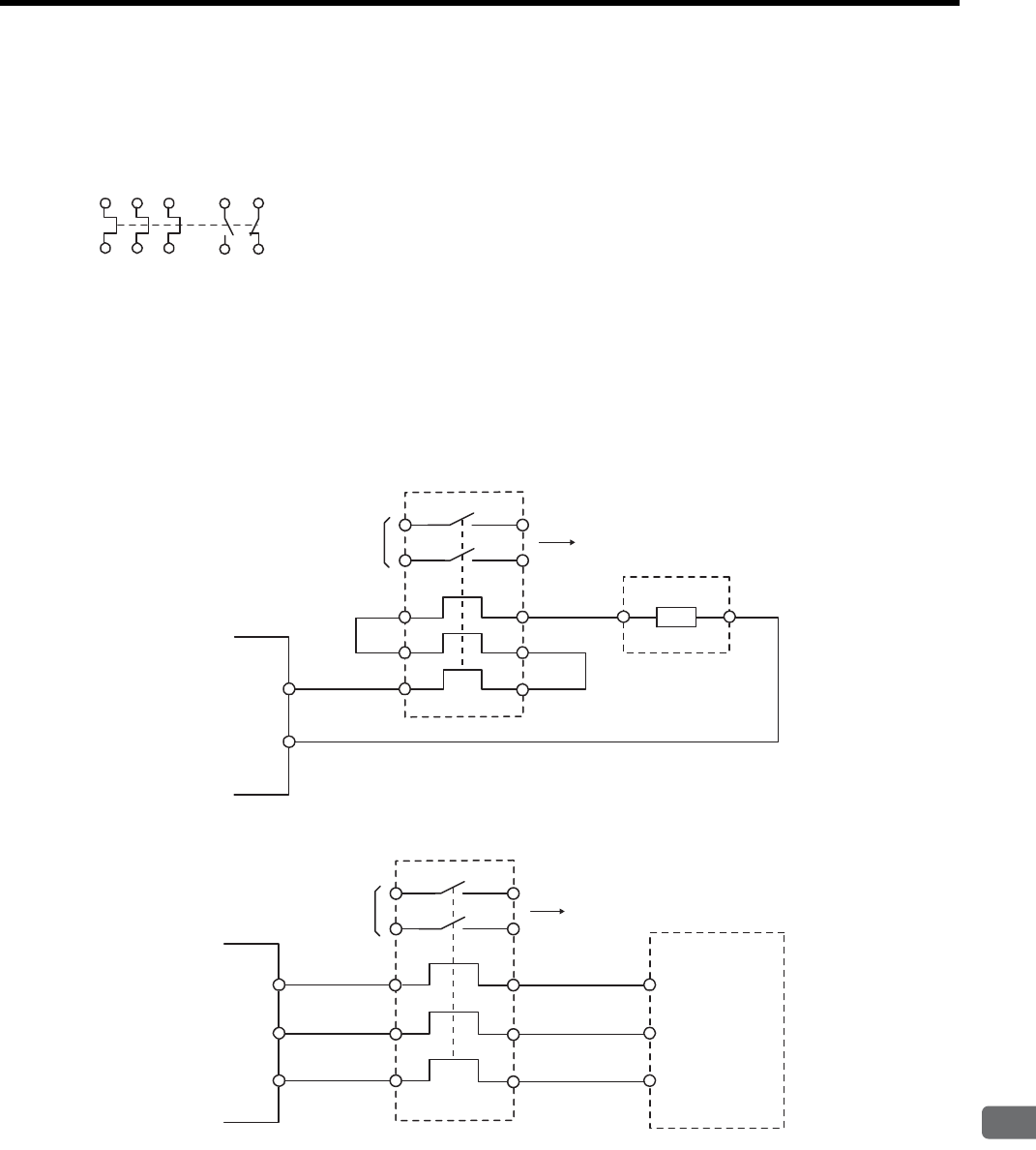
5.5 Peripheral Devices
5
Specifications and Dimensional Drawings of Cables and Peripheral Devices
5-37
(3) Internal Connection Diagram
The following connection diagram is for a TR-3N thermal relay.
(4) Connections
Connect the thermal relay as shown in the following diagram.
When the thermal relay operates, the auxiliary contact turns OFF or ON. Therefore, configure a sequence so that
the main power supply or the servomotor turns OFF when the auxiliary contact turns OFF or ON.
(a) Connecting to a Regenerative Resistor Unit
(b) Connecting to a Dynamic Brake Unit
1
2
3
4
5
6
97 95
98 96
(NO) (NC)
(NO) (NC)
SGDM/SGDH
SERVOPACK
Thermal relay
Regenerative
Resistor Unit
Auxiliary contact To host controller
B1
B2
B1 B2
Thermal relay Dynamic Brake Unit
Auxiliary contact
To host controller
DV
DW
DU
DW
DU
DV
SGDM/SGDH
SERVOPACK
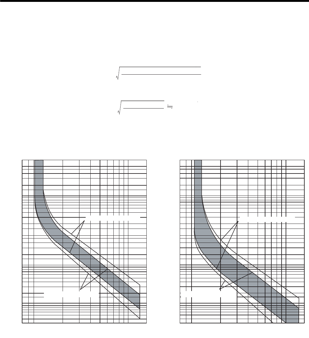
5 Specifications and Dimensional Drawings of Cables and Peripheral Devices
5.5.12 Thermal Relays
5-38
(5) Selecting a Thermal Relay
When preparing the dynamic brake resistor and regenerative resistor separately, select a thermal relay by calcu-
lating the setting current of the thermal relay according to the value and capacity of the resistor being used, as
shown in the following equation.
Example for a JUSP-RA08
Select a thermal relay that has operating characteristics equivalent to those of the recommended product.
Refer to the following diagrams for the operating characteristics of the recommended thermal relays.
Setting current = Resistance capacity (W) × 0.2
Resistance value (Ω)
Setting current =
2000 (W) × 0.2
2.4 (Ω)14 A
Cold Start Characteristics (Ambient Temperature of 20
°
C) Hot Start Characteristics (Ambient Temperature of 20
°
C)
60
50
40
30
10
8
6
5
4
3
2
60
50
40
30
20
10
8
6
5
4
3
2
1
0.8
0.6
0.5
0.4
0.3
20
Multiplier of setting current Multiplier of setting current
xln [A] xln [A]
60
50
40
30
10
8
6
5
4
3
2
60
50
40
30
20
10
8
6
5
4
3
2
1
0.8
0.6
0.5
0.4
0.3
20
Operating time
Operating time
21 3 4 5 6 7 8 9 10 1521 3 4 5 6 7 8 9 10 15
Minutes
Seconds
Minutes
Seconds
Rated at 18 to 26 A min.
Rated at 12 to 18 A max.
Rated at 18 to 26 A min.
Rated at 12 to 18 A max.
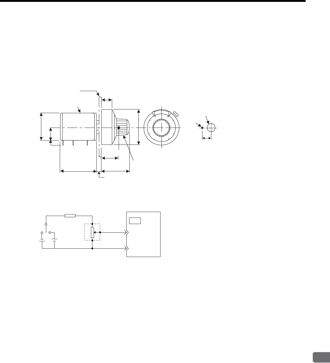
5.5 Peripheral Devices
5
Specifications and Dimensional Drawings of Cables and Peripheral Devices
5-39
5.5.13 Variable Resistor for Speed and Torque Setting
(1) Model: 25HP-10B
The multiturn type winding variable resistors with dial MD10-30B4 are manufactured by Sakae Tsushin Kogyo
Co., Ltd. Contact Yaskawa Controls Co., Ltd.
(2) Dimensional Drawings
(3) Example of Connection to an External Power Supply
MD multi-dial
25 HP Helicolumn Panel driling diagram
Panel
11.5±1
37.5±1
24±1
14.5±1
φ25±1
φ31±1
21 max.
23 1
4.5
φ2.5 hole
φ7.5 hole
10
Units: mm
12V
1.8 kΩ (1/2 W) min.
25HP-10B
2 kΩ
3
1
2
SERVOPACK
5
6
(9)
(10)
CN1
V-REF
(T-REF)
SG
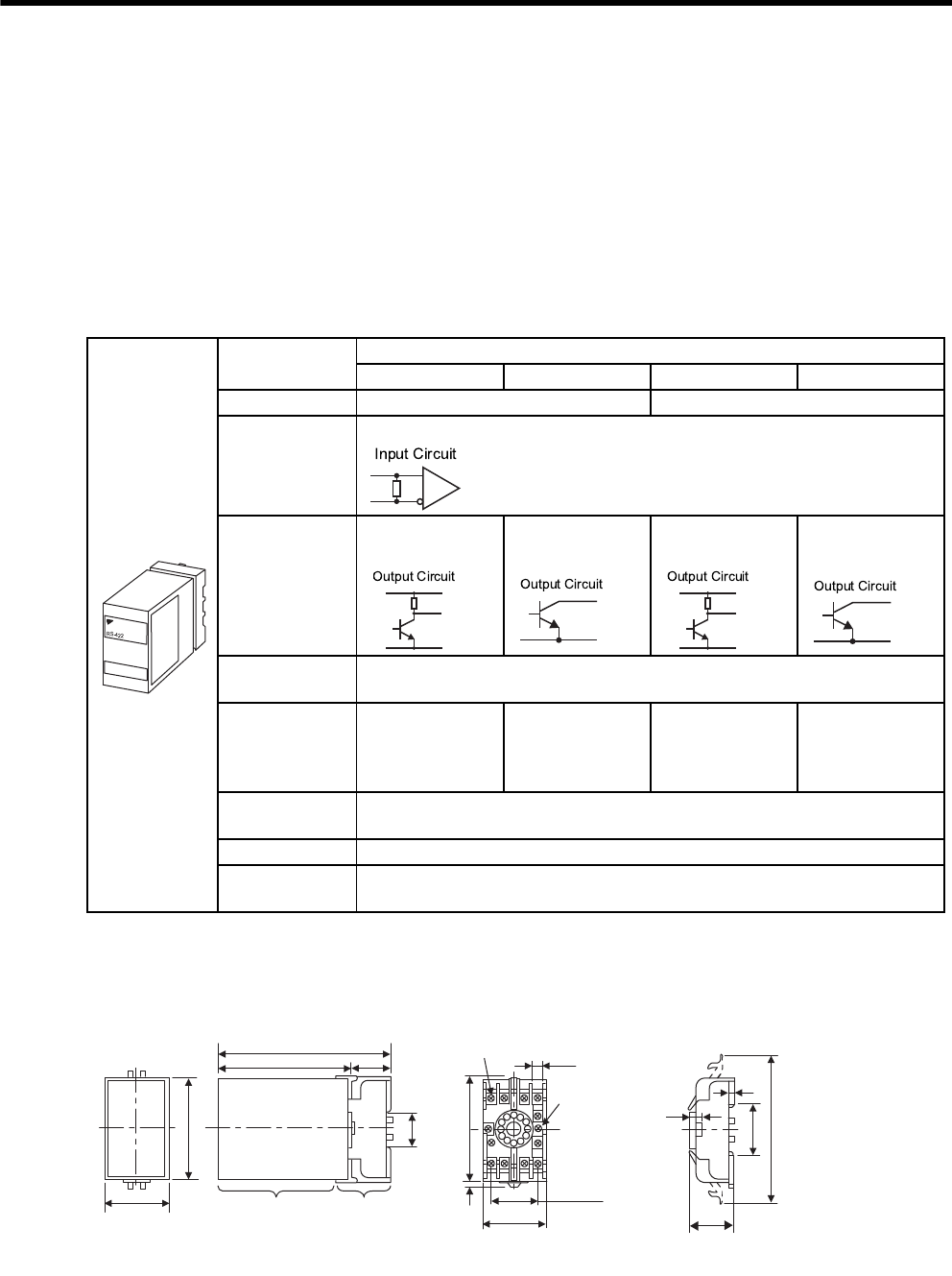
5 Specifications and Dimensional Drawings of Cables and Peripheral Devices
5.5.14 Encoder Signal Converter Unit
5-40
5.5.14 Encoder Signal Converter Unit
The encoder signal converter unit (the trade name “Receiver Unit”) converts encoder signal output from the line
driver to open-collector or voltage-pulse output.
A socket model 11PFA is required to use a Receiver Unit.
(1) Model: LRX-01 / A
Contact Yaskawa Controls Co., Ltd.
(2) Specifications
(3) Dimensional Drawings
The socket is optional.
Specifications Receiver Unit
LRX-01/A1 LRX-01/A2 LRX-01/A3 LRX-01/A4
Power Supply 12 VDC ±10 %, 100 mA 5 VDC ±5 %, 100 mA
Input Signals
Balanced line driver input (RS-422)
Output Signals
Voltage pulse
output
Open collector
output
Voltage pulse
output
Open collector
output
Input Signal
Level Differential voltage ≥ 0.3 V, built-in terminator 100 Ω
Output Signal
Level
H: 10 V min.
(1 mA)
L: 0.5 V max.
(30 mA)
L: 0.5 V min.
(30 mA)
Withstand
voltage: 50 V
H: 3 V min.
(1 mA)
L: 0.5 V max.
(30 mA)
L: 0.5 V min.
(30 mA)
Withstand
voltage: 50 V
Surrounding Air
Temperature 0 to + 60°C
IC Used Receiver IC: AM26LS32C or the equivalent
Response
Frequency 100 kHz
YASKAWA
5
33.5 max.
18 max.
35.4
4
4
7.8
11-M3.57
SEMS screws
51 max.
40r0.2
81 max.
2Ǿ4.5 hole
50
80
35.4
129
100
Socket
Receiver unit
29
Receiver unit and socket Socket Type 11PFA
Units: mm
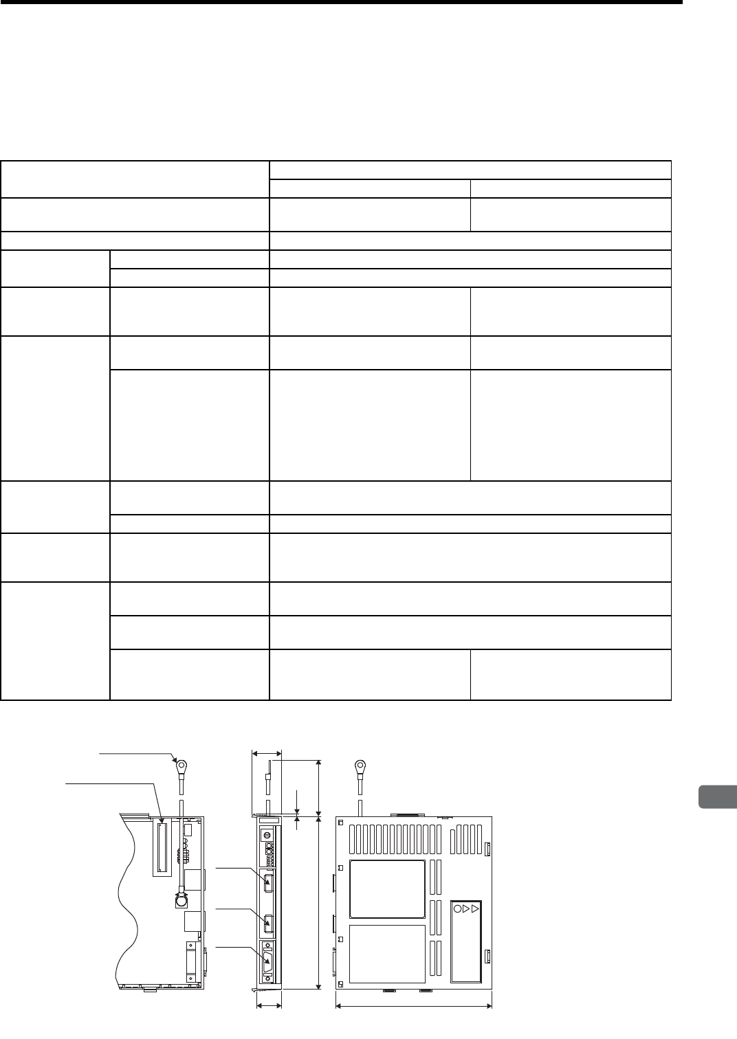
5.5 Peripheral Devices
5
Specifications and Dimensional Drawings of Cables and Peripheral Devices
5-41
5.5.15 MECHATROLINK Application Module
(1) Model : JUSP-NS100 (for MECHATROLINK-I communications)
: JUSP-NS115 (for MECHATROLINK-I/II communications)
(2) Specifications
(3) Dimensional Drawings (JUSP-NS100/NS115)
Item Details
JUSP-NS100 JUSP-NS115
Applicable SERVOPACK All SGDH-EB models SGDH-EB models
(except for 90 kW model)
Installation Method Mounted on the SGDH SERVOPACK side: CN10.
Basic
Specifications
Power Supply Method Supplied from the SERVOPACK control power supply.
Power Consumption 2 W
MECHA-
TROLINK Com-
munications
Baud Rate/
Transmission Cycle 4 Mbps / 2 ms 10Mbps/500μs or more (4Mbps/2ms
when using MECHATROLINK-I)
Command Format
Operation Specification Positioning using MECHA-
TROLINK-I communications.
Positioning using MECHA-
TROLINK-I/II communications.
Reference Input
MECHATROLINK-I
communications
Commands: Motion commands (posi-
tion, speed), Interpola-
tion commands,
Parameter read/write,
Monitor output
MECHATROLINK-I/II
communications
Commands: Motion commands (posi-
tion, speed), Interpolation
commands, Parameter
read/write, Monitor out-
put
Position Control
Functions
Acceleration/
Deceleration Method Linear first/second-step, asymmetric, exponential, S-curve
Fully-closed Control Impossible
Input Signals Signal Allocation Changes
Possible
Forward/reverse run prohibited, Zero point return deceleration LS
External latch signals 1, 2, 3
Forward/reverse external torque limit
Internal Functions
Position Data Latch
Function Position data latching is possible using phase C, and external signals 1, 2, 3
Protection Parameters damage, Parameter setting errors, Communications errors,
WDT errors
LED Indicators
A: Alarm
R: MECHATROLINK-I
Communicating
A: Alarm
R: MECHATROLINK-I/II
Communicating
(24)
CN6A
Units: mm
Approx. mass: 0.2 kg
NS100
S
W
1
20
142 (100)
(2)
S
W
2
A
R
C
N
6
A
C
N
6
B
C
N
4
Nameplate
CN6B
CN4
FG terminal
Connector
to SERVOPACK
M4
128
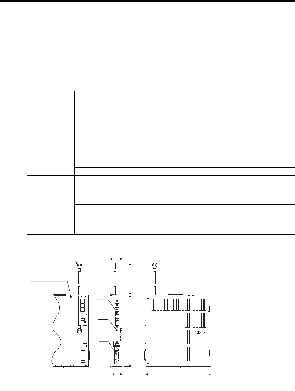
5 Specifications and Dimensional Drawings of Cables and Peripheral Devices
5.5.16 DeviceNet Application Module
5-42
5.5.16 DeviceNet Application Module
(1) Model: JUSP-NS300
(2) Specifications
(3) Dimensional Drawings
Item Details
Applicable SERVOPACK All SGDH-EB models
Installation Method Mounted on the SGDH SERVOPACK side: CN10.
Basic
Specifications
Power Supply Method Supplied from the SERVOPACK control power supply.
Power Consumption 1.3 W
DeviceNet
Communications
Baud Rate Setting Select from 125 kbps, 250 kbps, or 500 kbps using a rotary switch.
Node Address Setting Select the address from 0 to 63 using the rotary switches.
Command Format
Operation Specifications Positioning using DeviceNet communications.
Reference Input
DeviceNet communications
Commands: Motion commands (position, speed), and Parameter
read/write
Position Control
Functions
Acceleration/
Deceleration Method Linear first/second-step, asymmetric, exponential, S-curve
Fully Closed Control Possible
Input Signals Fixed Allocation to SER-
VOPACK CN1 Connector
Forward/reverse run prohibited, Zero point signal, External position-
ing signal, Zero point return deceleration limit switch
Internal Functions
Position Data Latch
Function
Position data latching is possible using phase C, zero point signals,
and external signals.
Protection Parameters damage, Parameter setting errors, Communications error,
etc.
LED Indicators MS: Module Status
NS: Network Status
(24)
CN11
CN6
20
(100)
5
4
0
9
6
12
7
8
3
5
4
0
9
6
12
7
8
NS300
5
4
0
9
6
12
7
8
3
X
10
X
1
D
R
C
N
11
M
S
N
S
CN4
142
M4
133
Nameplate
Units: mm
Approx. mass: 0.2 kg
FG terminal
Connector
to SERVOPACK
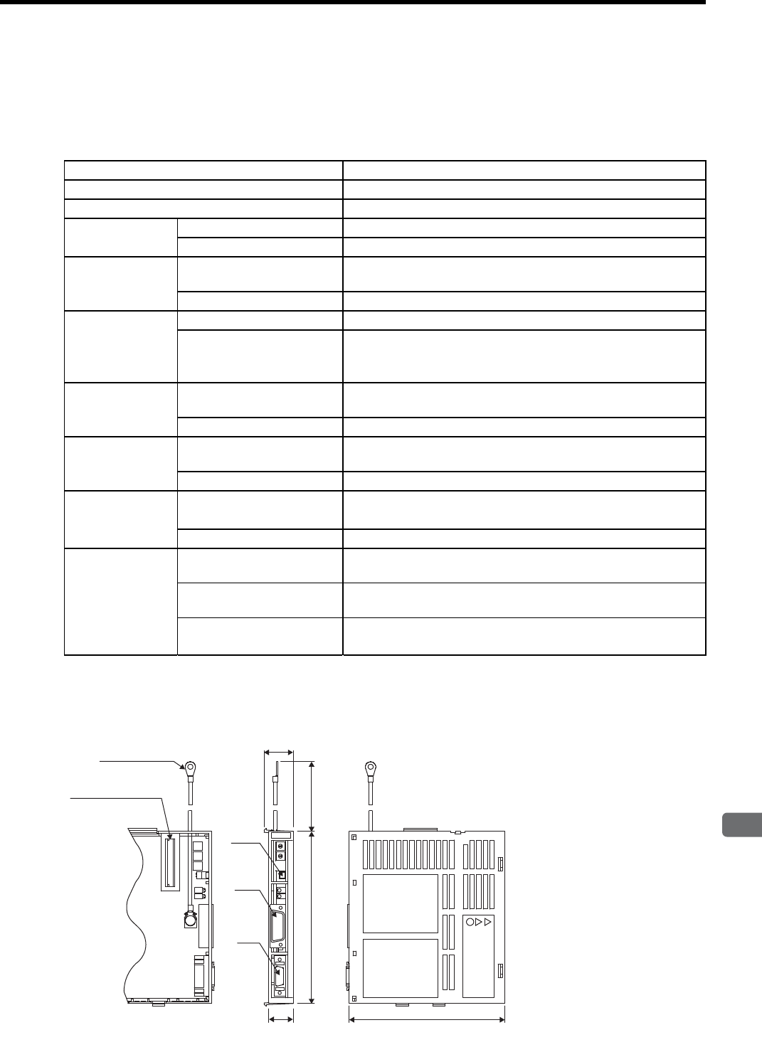
5.5 Peripheral Devices
5
Specifications and Dimensional Drawings of Cables and Peripheral Devices
5-43
5.5.17 PROFIBUS-DP Application Module
(1) Model: JUSP-NS500
(2) Specifications
* The allocation of the output signals for brake interlock, servo ready, or positioning completion
can be changed using parameter settings.
(3) Dimensional Drawings
Item Details
Applicable SERVOPACk All SGDH-EB models
Installation Method Mounted on the SGDH SERVOPACK side: CN10.
Basic
Specifications
Power Supply Method Supplied from the SERVOPACK control power supply.
Power Consumption 1.3 W
PROFIBUS-DP
Communications
Baud Rate Setting The baud rate is automatically set by the Master between 9.6 kbps
and 12 Mbps.
Station Address Setting Select the address from 0 to 7D (0 to 125) using the rotary switches.
Command Format
Operation Specifications Positioning using PROFIBUS-DP communications
Reference Input
PROFIBUS-DP communications
Commands: Motion commands (position, speed), Parameter read/
write
Position Control
Functions
Acceleration/
Deceleration Method Linear first/second-step, asymmetric, exponential, S-curve
Fully Closed Control Possible
Input Signals
Fixed Allocation to SER-
VOPACK CN1 Connector
Forward/reverse run prohibited, Zero point return deceleration LS,
Zero point signal, External positioning signal
NS500 Module Emergency stop signal
Output Signals
SERVOPACK CN1
Connector∗Servo alarm, Brake interlock, Servo ready, Positioning completion
NS500 Module Notch 1, notch 2
Internal Functions
Position Data Latch
Function
Position data latching is possible using phase C, zero point signals,
and external signals.
Protection Parameters damage, Parameter setting errors, Communications
errors, etc.
LED Indicators ERR: Module Error
COMM: Communications Status
(24)
CN11
CN6
20
(100)
5
4
0
9
6
12
7
8
3
NS500
5
4
0
9
6
12
7
8
3
X
10
X
1
D
R
C
N
11
CN4
142
M4
133
Nameplate
Units: mm
Approx. mass: 0.2 kg
FG terminal
Connector
to SERVOPACK
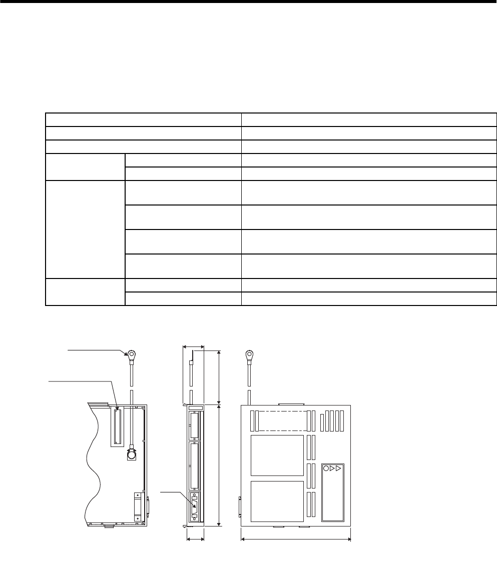
5 Specifications and Dimensional Drawings of Cables and Peripheral Devices
5.5.18 Fully-closed Application Module
5-44
5.5.18 Fully-closed Application Module
(1) Model: JUSP-FC100
(2) Specifications
(3) Dimensional Drawings
Item Details
Applicable SERVOPACK All SGDH-EB models
Installation Method Mounted on the SGDH SERVOPACK side: CN10.
Basic
Specifications
Power Supply Method Supplied from the SERVOPACK control power supply.
Power Consumption 0.5 W or less
Fully Closed
System
Specifications
Fully-closed Encoder Pulse
Output Form
5 V differential line-driver output (complies with EIA Standard
RS-422A)
Fully-closed Encoder Pulse
Signal Form 90° Phase difference 2-phase differential pulse (phase A, phase B)
Maximum Receivable Fre-
quency for SERVOPACK 1 Mbps
Power Supply for Fully-
closed Encoder To be prepared by customer.
Internal Functions Protection Detecting fully-closed encoder disconnection
LED Indicators Setting with the parameters
128
(24)
CN4
142 (100)
20
FC100
Nameplate
M4
Units: mm
Approx. mass: 0.2 kg
FG terminal
Connector
To SERVOPACK

6
Wiring
6-1
6
Wiring
6.1 Wiring Main Circuit - - - - - - - - - - - - - - - - - - - - - - - - - - - - - -6-2
6.1.1 Names and Functions of Main Circuit Terminals - - - - - - - - - - - - - - - - 6-2
6.1.2 Typical Main Circuit Wiring Examples - - - - - - - - - - - - - - - - - - - - - - - 6-4
6.2 Wiring Encoders - - - - - - - - - - - - - - - - - - - - - - - - - - - - - - - -6-8
6.2.1 Connecting an Encoder (CN2) and
Output Signals from the SERVOPACK (CN1) - - - - - - - - - - - - - - - - - 6-8
6.2.2 Encoder Connector (CN2) Terminal Layout - - - - - - - - - - - - - - - - - - - 6-9
6.3 I/O Signal Connections - - - - - - - - - - - - - - - - - - - - - - - - - - 6-10
6.3.1 Example of I/O Signal Connection - - - - - - - - - - - - - - - - - - - - - - - - - 6-10
6.3.2 I/O Signal Connector (CN1) Terminal Layout - - - - - - - - - - - - - - - - - 6-11
6.3.3 I/O Signal (CN1) Names and Functions - - - - - - - - - - - - - - - - - - - - - 6-12
6.3.4 Interface Circuit - - - - - - - - - - - - - - - - - - - - - - - - - - - - - - - - - - - - - - 6-14
6.4 Others - - - - - - - - - - - - - - - - - - - - - - - - - - - - - - - - - - - - - - 6-17
6.4.1 Wiring Precautions - - - - - - - - - - - - - - - - - - - - - - - - - - - - - - - - - - - - 6-17
6.4.2 Wiring for Noise Control - - - - - - - - - - - - - - - - - - - - - - - - - - - - - - - - 6-18
6.4.3 Using More Than One SERVOPACK - - - - - - - - - - - - - - - - - - - - - - - 6-22
6.4.4 Extending Encoder Cables - - - - - - - - - - - - - - - - - - - - - - - - - - - - - - 6-24
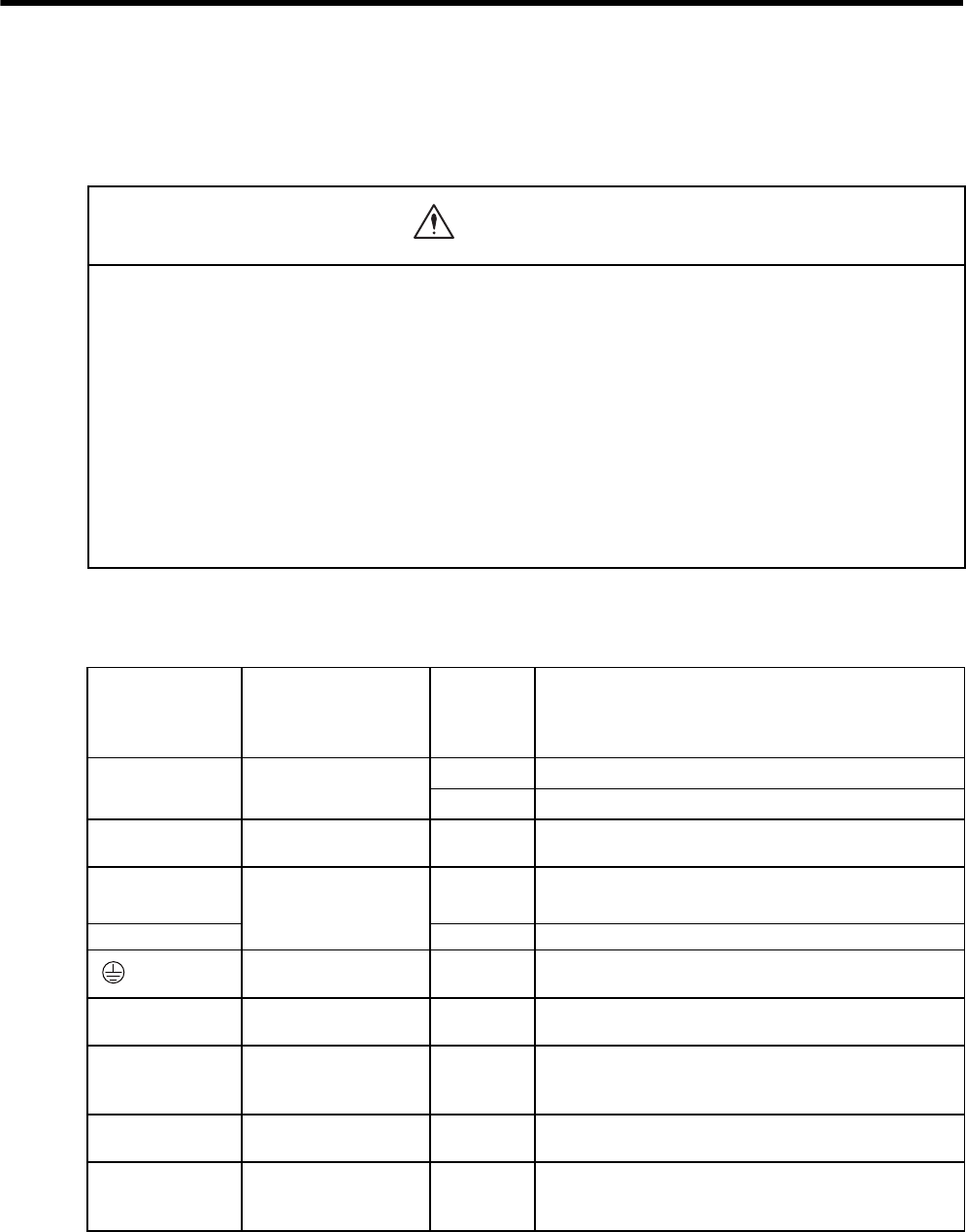
6 Wiring
6.1.1 Names and Functions of Main Circuit Terminals
6-2
6.1 Wiring Main Circuit
This section describes typical examples of main circuit wiring, functions of main circuit terminals, and the power
ON sequence.
6.1.1 Names and Functions of Main Circuit Terminals
(1) SERVOPACK main circuit terminal functions and descriptions
• Do not bundle or run power and signal lines together in the same duct. Keep power and signal lines sepa-
rated by at least 300 mm.
Failure to observe this caution may result in malfunction.
• Use twisted-pair shielded wires or multi-core twisted pair shielded wires for signal and encoder (PG) feed-
back lines.
The maximum length is 3 m for reference input lines.
• Do not touch the power terminals for five minutes after turning power OFF because high voltage may still
remain in the SERVOPACK.
Make sure the charge indicator is turned OFF first before starting an inspection.
• Avoid frequently turning power ON and OFF.
Since the SERVOPACK has a capacitor in the power supply, a high charging current flows for 0.2 seconds when the
power is turned ON. Frequently turning the power ON and OFF causes main power devices such as capacitors and
fuses to deteriorate, resulting in unexpected problems.
Terminal Symbol External Terminal
Name
Main
Circuit
Voltage
(V)
Functions
L1/R, L2/S,
L3/T
Main circuit power
supply input terminal
200 Three-phase 200 to 230 VAC+10%, -15% (50/60 Hz)
400 Three-phase 380 to 480 VAC+10%,-15% (50/60 Hz)
U, V, W Servomotor
connection terminals
−Connects to the servomotor.
L1C/r, L3C/t Control circuit power
supply input terminal
200 Single-phase 200 to 220 VAC+10%, -15% (50 Hz)
Single-phase 200 to 230 VAC+10%, -15% (60 Hz)
DC24P, DC24N 400 24 VDC (±15%)
Ground terminals −Connects to the power supply ground terminals and servo-
motor ground terminal.
B1, B2 Regenerative resistor
connection terminal
−Connects to the regenerative resistor.
0 V, 380 V,
400 V, 440 V,
460 V, 480 V
Input terminal for
actuator control
400 Single-phase 380 to 480 VAC (50/60 Hz)
Power input terminals for the fan or contactor.
DU, DV, DW Dynamic brake unit
connection terminal
−Connects the dynamic brake unit.
DBON, DB24 Dynamic brake unit
connection terminal
−Connects to the DBON and DB24 terminals of the dynamic
brake unit (only when using 37 kW or more SERVO-
PACK).
CAUTION

6.1 Wiring Main Circuit
6
Wiring
6-3
(2) Servomotor terminal names and description
Terminal Symbol External Terminal
Name
Main
Circuit
Voltage
(V)
Functions
U, V, WSERVOPACK
connection terminal
−Connects to the U, V and W terminals of the
SERVOPACK.
U (A),
V (B),
W (C)
Fan terminal
200 Three-phase 200 to 230 VAC+10%, -15% (50/60 Hz)
400 Three-phase 380 to 480 VAC+10%,-15% (50/60 Hz)
A, BBrake power supply
connection terminal
(only when using
servomotors with
brakes)
−
Connects the brake power supply.
1, 1b
Thermal protector
terminal
−Used to detect overheating of the servomotor and to open
the thermal protector circuit. Use a sequence that turns the
SERVOPACK’s main circuit power supply OFF or the
servo OFF when the thermal protector circuit opens.
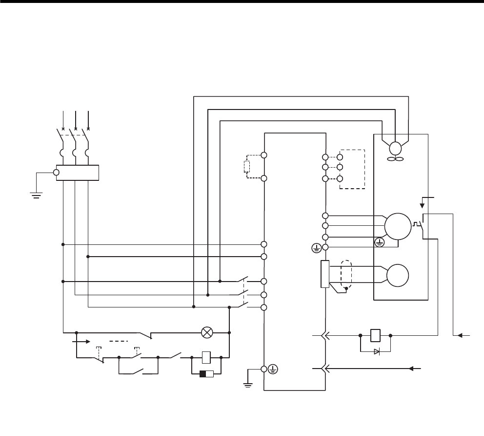
6 Wiring
6.1.2 Typical Main Circuit Wiring Examples
6-4
6.1.2 Typical Main Circuit Wiring Examples
(1) Three-phase 200 V, 22 kW and 30 kW SERVOPACKs
L1/R
L1C/r
PG
SGDM-ADB
U
V
W
M
ALM-
+24V
0 V
24
1Ry
ALM+ 31
32 1D
OFF
1MC
1Ry
ON
1SA
1Ry
L2/S
L3/T
L3C/t
B1
B2
DU
DV
DW
U(A)
V(B)
W(C)
1
1b
U
V
W
FG
FG
CN1
CN2
RST
1PL
SGDH-AEB
SERVOPACK
(Alarm lamp)
Regen-
erative
Resistor DB Unit
Fan
Main circuit
power
Thermal
protector
Three-phase
200 to 230 VAC (50/60 Hz)
+10
-15 %
: Lamp for display
: Surge absorber
: Flywheel diode
1PL
1SA
1D
1QF
FIL
1KM
1Ry
: Circuit breaker (for inverters)
: Noise filter
: Contactor
: Relay
1KM
1KM
1QF
FIL
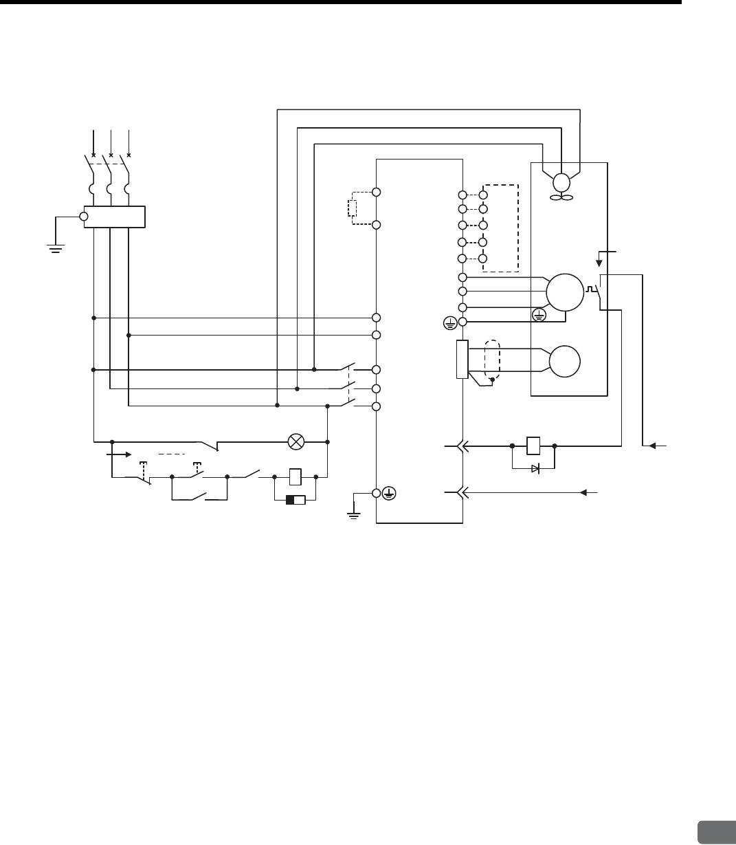
6.1 Wiring Main Circuit
6
Wiring
6-5
(2) Three-phase 200 V, 37 kW SERVOPACK
L1/R
L1C/r
PG
U
V
W
M
+24V
0 V
24
1Ry
31
32 1D
OFF 1Ry
ON
1Ry
L2/S
L3/T
L3C/t
B1
B2
DU
DV
DW
U(A)
V(B)
W(C)
1
1b
U
V
W
FG
FG
CN1
CN2
DB24
DBON
RST
1PL
1KM
ALM-
ALM+
SGDM-ADB
SGDH-AEB
SERVOPACK
(Alarm lamp)
Regen-
erative
Resistor DB Unit
Main circuit
power
Thermal
protector
Fan
Three-phase
200 to 230 VAC (50/60 Hz)
+10
-15 %
: Lamp for display
: Surge absorber
: Flywheel diode
1PL
1SA
1D
1QF
FIL
1KM
1Ry
: Circuit breaker (for inverters)
: Noise filter
: Contactor
: Relay
1KM
1SA
1KM
1QF
FIL
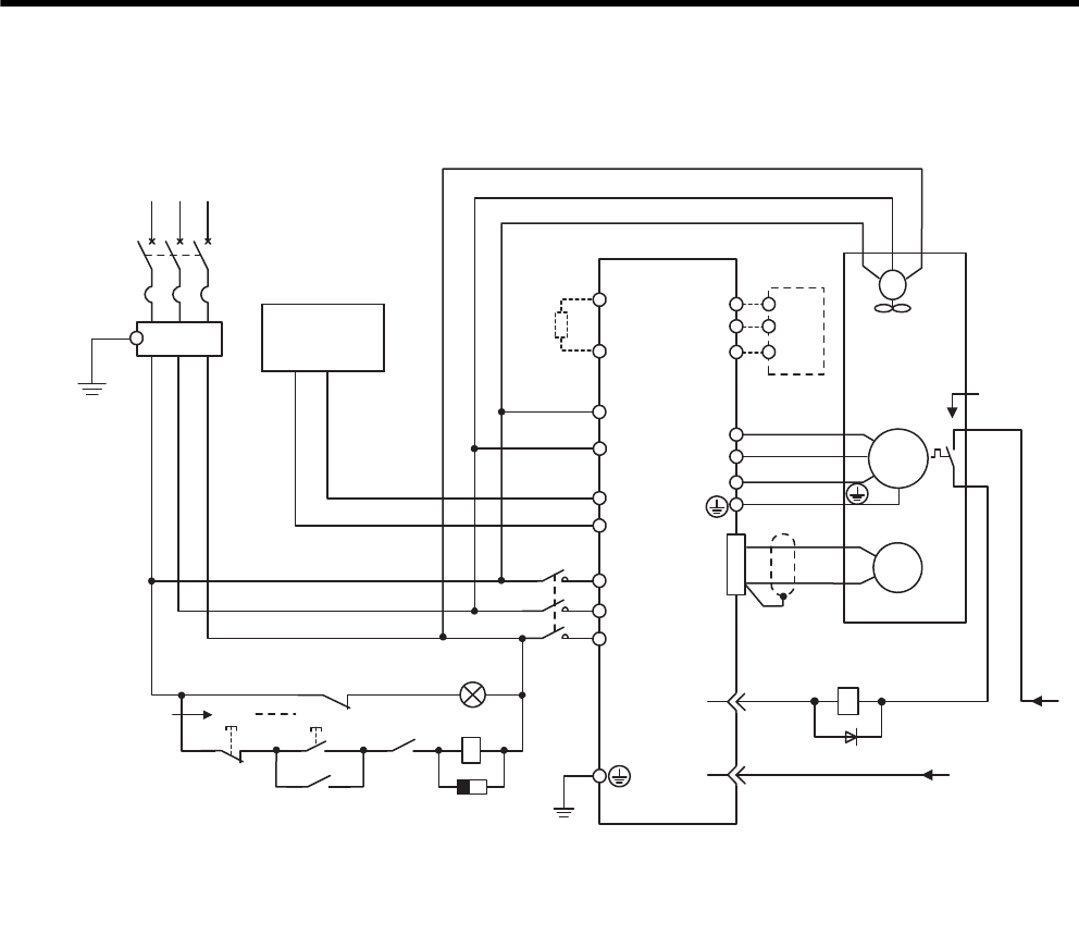
6 Wiring
6.1.2 Typical Main Circuit Wiring Examples
6-6
(3) Three-phase 400 V, 22 kW and 30 kW SERVOPACKs
L1/R
DC24P
PG
SERVOPACK
SGDH- DEB
U
V
W
M
ALM -
+24V
0 V
24
1Ry
ALM+ 31
32 1D
OFF 1Ry
ON
(Alarm lamp)
1SA
1Ry
L2/S
L3/T
DC24N
B1
B2
Regen-
erative
Resistor DU
DV
DW
DB Unit
U(A)
V(B)
W(C)
Fan
1
1b
U
V
W
Main circuit
power
Thermal
protector
FG
FG
CN1
CN2
Three-phase
380 to 480 VAC (50/60 Hz)
+10
-15 %
RST
FIL
1PL
: Lamp for display
: Surge absorber
: Flywheel diode
1PL
1SA
1D
1QF
FIL
1KM
1Ry
: Circuit breaker (for inverters)
: Noise filter
: Contactor
: Relay
0V
380 to 480 V
Prepared by customer
Control power
supply
24 VDC
+−
1KM
1KM
1KM
1QF
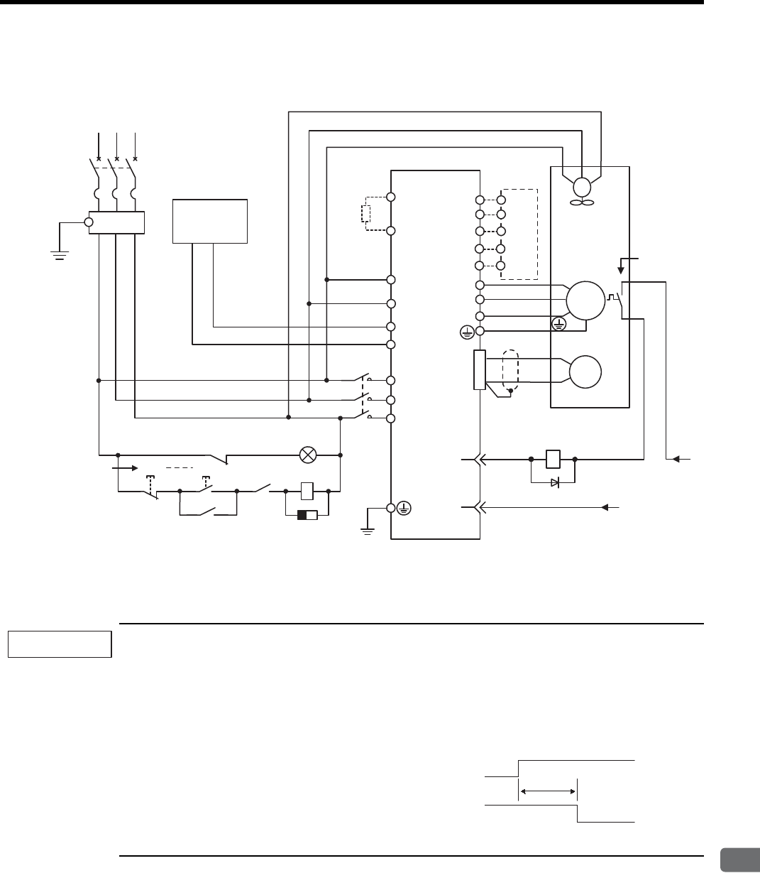
6.1 Wiring Main Circuit
6
Wiring
6-7
(4) Three-phase 400 V, 37 kW to 90 kW SERVOPACKs
Designing a Power ON Sequence
Note the following points when designing the power ON sequence.
• Design the power ON sequence so that main circuit power supply is turned OFF when a servo alarm signal
is output. See the previous circuit figure.
• Hold the power ON button for at least two seconds. The SERVOPACK will output (1Ry is OFF) a servo
alarm signal for two seconds or less when power is turned ON. This is required in order to initialize the
SERVOPACK.
• Select the power supply specifications for the parts in accordance with the input power supply.
L1/R
DC24P
PG
U
V
W
M
+24V
0 V
24
1Ry
31
32 1D
OFF 1Ry
ON
1Ry
L2/S
L3/T
DC24N
B1
B2
DU
DV
DW
U(A)
V(B)
W(C)
1
1b
U
V
W
FG
FG
CN1
CN2
DB24
DBON
RST
1PL
ALM -
ALM+
+10
-15 %
24 VDC
0V
380 to 480 V
SERVOPACK
SGDH- DEB
(Alarm lamp)
DB Unit Fan
Main circuit
power
Thermal
protector
Three-phase
380 to 480 VAC
FIL
: Lamp for display
: Surge absorber
: Flywheel diode
1PL
1SA
1D
1QF
FIL
1KM
1Ry
: Circuit breaker (for inverters)
: Noise filter
: Contactor
: Relay
Prepared by customer
Control power
supply
+−
1SA
1KM
1KM
1KM
1QF
IMPORTANT
Power supply
Servo alarm (ALM)
output signal
2.0 s max.
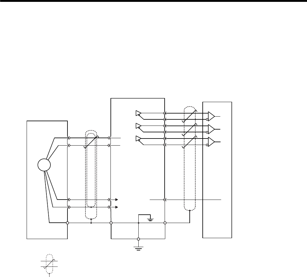
6 Wiring
6.2.1 Connecting an Encoder (CN2) and Output Signals from the SERVOPACK (CN1)
6-8
6.2 Wiring Encoders
The connection cables between encoder and SERVOPACK and wiring pin numbers differ depending on servo-
motor model. Refer to 5 Specifications and Dimensional Drawings of Cables and Peripheral Devices for details.
6.2.1 Connecting an Encoder (CN2) and Output Signals from the SERVOPACK
(CN1)
(1) Incremental Encoders
* 1. : represents twisted-pair wires.
* 2. Applicable line receiver: SN75175 manufactured by Texas Instruments or the equivalent.
C
D
H
G
J
PG5 V
PG0 V
0 V
CN2
2-5
2-6
2-1
2-2
CN1
0 V
1-33
1-34
1-35
1-36
1-19
1-20
PAO
/PAO
PBO
/PBO
PCO
/PCO
1-1 SG
∗1
∗2
Customer end
PG
Connector
shell
Inner
shield
Outer
shield
Connector
shell
Blue
White/blue
Incremental
encoder
Red
SERVOPACK
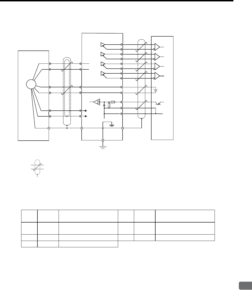
6.2 Wiring Encoders
6
Wiring
6-9
(2) Absolute Encoders
* 1. : represents twisted-pair wires.
* 2. Applicable line receiver: SN75175 manufactured by Texas Instruments or the equivalent.
6.2.2 Encoder Connector (CN2) Terminal Layout
+
–
C
D
T
S
H
G
J
PG5 V
PG0 V 0 V
CN2
2-5
2-6
2-3
2-4
2-1
2-2
CN1
+5 V
0 V
1-33 PAO
1-34 /PAO
1-35 PBO
1-36 /PBO
1-19 PCO
1-20 /PCO
1-48 PSO
1-49 /PSO
1-21 BAT(+)
1-22 BAT(–)
1-4 SEN
1-2 SG
1-1 SG
∗1
∗2
PG
Absolute encoder
SERVOPACK
Orange
White/orange
Connector
shell
Connector
shell
Battery
Red
Inner
shield
Outer
shield
Blue
White/blue
Customer end
1PG5V PG power supply
+5 V 2PG 0 V PG power supply
0 V
3BAT (+) Battery (+)
(For an absolute encoder) 4BAT (-) Battery (-)
(For an absolute encoder)
5PS PG serial signal input 6/PS PG serial signal input
SHELL Shield −
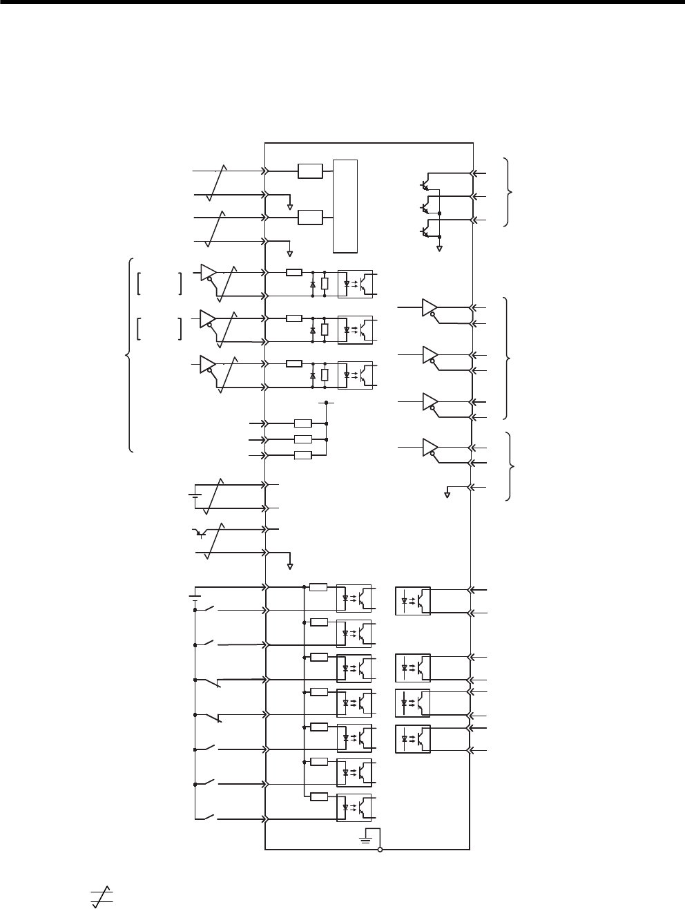
6 Wiring
6.3.1 Example of I/O Signal Connection
6-10
6.3 I/O Signal Connections
6.3.1 Example of I/O Signal Connection
* 1. represents twisted-pair wires.
* 2. The time constant for the primary filter is 47 μs.
* 3. Connect a backup battery when using an absolute encoder.
* 4. Enabled when using the absolute encoder.
ALO2
A/D
PULS
CW
Phase A
CCW
Phase B
SIGN
CLR
V -REF
T -REF
∗2
∗1
∗2
5
10
PULS
/PULS
SIGN
CLR
11
15
12
14
+
-
+5 V
0 V
BAT (+)
BAT (- )
+24VIN
+24 V
+
-/S-ON
/P-CON
N-OT
P-OT
/ALM-RST
/N-CL
/P-CL
21
22
4
2
47
40
41
43
42
44
45
46
ALO1
ALO3
PA O
PBO
PCO
AO
/PBO
/PCO
/PSO
PSO
SG
/V-CMP+
(/COIN+)
/V-CMP-
(/COIN-)
/TGON+
/TGON-
/S-RDY+
/S-RDY-
ALM+
ALM -
38
39
33
34
35
36
19
20
48
49
1
∗4
25
26
27
28
31
29
30
32
FG
PL1
PL2
PL3
+12 V
Photocoupler
Photocoupler
3
13
18
Reverse external torque
limit (Limit when ON)
Forward external torque
limit (Limit when ON)
SG
SG
6
9
/SIGN
/CLR
7
8
SEN
SG
/P
-
-
-
-
-
37
150 Ω
150 Ω
150 Ω
1 kΩ
LPF
LPF
SGDM/SGDH SERVOPACK
Amount of phase-S rotation
Serial data output
Applicable line receiver
SN75175 or MC3486
manufactured by Texas
Instruments
Backup battery
2.8 to 4.5 V
∗3
Servo ON
(Servo ON when ON)
Reverse run prohibited
(Prohibited when OFF)
Forward run prohibited
(Prohibited when OFF)
Alarm reset
(Reset when ON)
P control
(P control when ON)
Speed reference
±2V to ±10V
/rated motor
speed
Torque reference
±1V to ±10V
/rated torque
Power supply for
Open collector
reference
SEN signal input
∗3
Connect shield to
connector shell.
Connector
shell
PG dividing ratio output
Applicable line receiver
SN75175 or MC3486
manufactured by Texas
Instruments
Running output
(ON when the motor speed
exceeds the settings.)
Servo ready output
(ON when ready)
Servo alarm output
(OFF for an alarm)
Photocoupler output
Max. operating voltage:
30 VDC
Max. operating current:
50 mA DC
Speed coincidence detection:
ON when speed coincides.
(Positioning completed:
ON when positioning completes.)
Alarm code output
Max. operating voltage:
30 VDC
Max. operating current:
20 mA DC

6.3 I/O Signal Connections
6
Wiring
6-11
6.3.2 I/O Signal Connector (CN1) Terminal Layout
The following diagram shows the terminal layout and the signals that are preset before shipping.
Notes: 1. Do not use unused terminals for relays.
2. Connect the shield of the I/O signal cable to the connector shell.
Connect to the FG (frame ground) at the SERVOPACK-end connector.
3. The functions allocated to the following input and output signals can be changed by using the
parameters.
• Input signals: /S-ON, /P-CON, P-OT, N-OT, /ALM-RST, /P-CL, and /N-CL
• Output signals: /TGON, /S-RDY, and /V-CMP (/COIN)
• The above output signals can be changed to /CLT, /VLT, /BK, /WARN, and /NEAR.
Pin
Num-
ber
Signal
Name Function
1SG GND 26 /V-CMP-
(/COIN-)
Speed coinci-
dence detec-
tion output
2SG GND 27 /TGON+ Running sig-
nal output
3PL1
Open-collec-
tor reference
power supply
28 /TGON- Running
signal output
4
SEN SEN signal
input 29 /S-RDY+ Servo ready
output
5V-REF Speed refer-
ence input 30 /S-RDY- Servo ready
output
6
SG GND 31 ALM+ Servo alarm
output
7PULS Reference
pulse input 32 ALM- Servo alarm
output
8
/PULS Reference
pulse input 33 PAO
PG dividing
pulse output
Phase A
9T-REF Torque refer-
ence input 34 /PAO
PG dividing
pulse output
Phase A
10
SG GND 35 PBO
PG dividing
pulse output
Phase B
11 SIGN Reference
sign input 36 /PBO
PG dividing
pulse output
Phase B
12
/SIGN Reference
sign input 37 ALO1 Alarm code
output
13 PL2
Open-collec-
tor reference
power supply
38 ALO2 Alarm code
output
14
/CLR Clear input 39 ALO3 Alarm code
output
15 CLR Clear input 40 /S-ON Servo ON
input
16 −− 41 /P-CON P control
input
17 −− 42 P-OT Forward run
prohibit input
18 PL3
Open-collec-
tor reference
power supply
43 N-OT Reverse run
prohibit input
19 PCO
PG dividing
pulse output
Phase C
44 /ALM-
RST
Alarm reset
input
20
/PCO
PG dividing
pulse output
Phase C
45 /P-CL
Forward
external
torque limit
input
21 BAT (+) Battery (+) 46 /N-CL
Reverse
external
torque limit
input
22
BAT (-) Battery (-) 47 +24V
IN
External input
power supply
23 −− 48 PSO Phase-S
signal output
24 −− 49 /PSO Phase-S
signal output
25 /V-CMP+
(/COIN+)
Speed coinci-
dence detec-
tion output
50 −−

6 Wiring
6.3.3 I/O Signal (CN1) Names and Functions
6-12
6.3.3 I/O Signal (CN1) Names and Functions
(1) Input Signals
Note: 1. Pin numbers in parentheses () indicate signal grounds.
2. The functions allocated to /S-ON, /P-CON. P-OT, N-OT, /ALM-RST, /P-CL, and /N-CL input
signals can be changed by using the parameters. Refer to 7.3.2 Input Circuit Signal Allocation.
3. The voltage input range for speed and torque references is a maximum of ±12 V.
Signal Name Pin No. Function Refer-
ence
Common
/S-ON 40 Servo ON: Turns ON the servomotor when the gate block in the inverter is released. 8.3.1
/P-CON 41
Function selected by parameter. −
Proportional control
reference
Switches the speed control loop from PI (proportional/
integral) to P (proportional) control when ON.
8.5.2
9.4.4
Direction reference With the internally set speed selection: Switch the rotation
direction. 8.8.2
Control mode
switching 8.10.2
Zero-clamp reference Speed control with zero-clamp function: Reference
speed is zero when ON. 8.5.6
Reference pulse block Position control with reference pulse stop: Stops reference
pulse input when ON. 8.6.7
P-OT
N-OT
42
43
Forward run
prohibited
Reverse run
prohibited
Overtravel prohibited: Stops servomotor when movable part
travels beyond the allowable range of motion. 8.3.3
/P-CL
/N-CL
45
46
Function selected by parameter. −
Forward external
torque limit ON
Reverse external
torque limit ON
External torque limit function enabled when ON. 8.9.2
Internal speed
switching
With the internally set speed selection: Switches the
internal speed settings.
8.8.2
8.10.2
/ALM-RST 44 Alarm reset: Releases the servo alarm state. 8.11.1
+24VIN 47
Control power supply input for sequence signals: Users must provide the +24 V
power supply.
Allowable voltage fluctuation range: 11 to 25 V
6.3.4
SEN 4 (2) Initial data request signal when using an absolute encoder. 8.4.1
BAT (+)
BAT (-)
21
22
Connecting pin for the absolute encoder backup battery.
Do not connect when a battery is connected to the host controller.
6.2.1
8.4.3
Speed V-REF 5 (6) Speed reference speed input: ±2 to ±10 V/rated motor speed (Input gain can be
modified using a parameter.) 8.5.2
Torque T-REF 9 (10) Torque reference input: ±1 to ±10 V/rated motor torque (Input gain can be modified
using a parameter.) 8.7.2
Position
PULS
/PULS
SIGN
/SIGN
7
8
11
12
Reference pulse input
for line driver and open
collector
Input mode is set from the following pulses.
• Sign + pulse string
• CCW/CW pulse
• Two-phase pulse (90° phase differential)
8.6.1
CLR
/CLR
15
14
Positional error pulse clear input: Clears the positional error pulse during position
control. 8.6.1
PL1
PL2
PL3
3
13
18
+12 V pull-up power is supplied when PULS, SIGN, and CLR reference signals are
open-collector outputs (+12 V power supply is built into the SERVOPACK).
6.3.4
8.6.3
Position speed
Position torque
Torque speed
Enables control mode switching.
↔
↔
↔

6.3 I/O Signal Connections
6
Wiring
6-13
(2) Output Signals
Notes: 1. Pin numbers in parentheses () indicate signal grounds.
2. The functions allocated to /TGON, /S-RDY, and /V-CMP (/COIN) can be changed by using the
parameters. /CLT, /VLT, /BK, /WARN, and /NEAR signals can also be changed.
Signal Name Pin No. Function Reference
Common
ALM+
ALM-
31
32 Servo alarm: Turns OFF when an error is detected. 8.11.1
/TGON+
/TGON-
27
28
Detection during servomotor rotation: Detects when the servomotor is rotating
at a speed higher than the motor speed setting. Detection speed can be set by using
the parameters.
8.11.3
/S-RDY+
/S-RDY-
29
30
Servo ready: ON if there is no servo alarm when the control/main circuit power
supply is turned ON. 8.11.4
PAO
/PAO
33 (1)
34 Phase-A signal Converted two-phase pulse (phases A and B) encoder output
signal and zero-point pulse (phase C) signal: RS-422 or the
equivalent
(Proper line receiver is SN75175 manufactured by Texas
Instruments or the equivalent corresponding to MC3486.)
8.4.6
8.5.7
PBO
/PBO
35
36 Phase-B signal
PCO
/PCO
19
20 Phase-C signal
PSO
/PSO
48
49 Phase-S signal With an absolute encoder: Outputs serial data corresponding
to the number of revolutions (RS-422 or the equivalent)
ALO1
ALO2
ALO3
37
38
39 (1)
Alarm code output: Outputs 3-bit alarm codes.
Open-collector: 30 V and 20 mA rating maximum 8.11.1
FG Shell Connected to frame ground if the shield wire of the I/O signal cable is connected
to the connector shell. −
Speed /V-CMP+
/V-CMP-
25
26
Speed coincidence (output in Speed Control Mode): Detects whether the motor
speed is within the setting range and if it matches the reference speed value. 8.5.8
Position /COIN+
/COIN-
25
26
Positioning completed (output in Position Control Mode): Turns ON when the
number of positional error pulses reaches the value set. The setting is the number of
positional error pulses set in reference units (input pulse units defined by the elec-
tronic gear).
8.6.5
Reserved
/CLT
/VLT
/BK
/WARN
/NEAR
−
Reserved terminals
The functions allocated to /TGON, /S-RDY, and /V-CMP (/COIN) can be changed by
using the parameters. /CLT, /VLT, /BK, /WARN, and /NEAR signals can also be
changed.
8.3.4
8.6.6
8.7.4
8.9.5
8.11.2
−
16
17
23
24
50
Terminals not used
Do not connect relays to these terminals. −
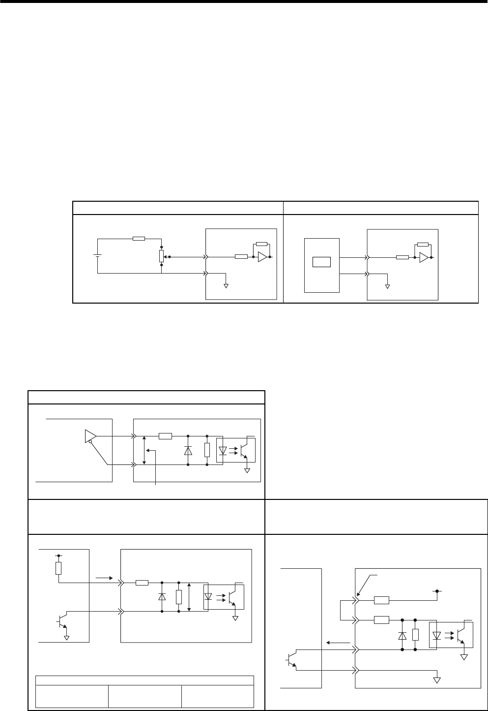
6 Wiring
6.3.4 Interface Circuit
6-14
6.3.4 Interface Circuit
This section shows examples of SERVOPACK I/O signal connection to the host controller.
(1) Interface for Reference Input Circuits
(a) Analog Input Circuit
CN1 connector terminals, 5-6: Speed reference input and 9-10: Torque reference input are explained below.
Analog signals are either speed or torque reference signals at the impedance below.
• Reference speed input: About 14 kΩ
• Reference torque input: About 14 kΩ
The maximum allowable voltages for input signals is ±12 V.
(b) Position Reference Input Circuit
CN1 connector terminals, 7-8: Reference pulse input, 11-12: Reference code input and 15-14: Clear input are
explained below.
An output circuit for the reference pulse and position error pulse clear signal at the host controller can be either
line-driver or open-collector outputs. The following shows by type.
Analog Voltage Input Circuit Analog Voltage Input Circuit (D/A)
1.8 k
Ω (1/2 W)min.
25HP-10B
2 k
Ω
32
12 V
1
0 V
SG
About 14 kΩ
SERVOPACK
V-REF or
T-REF
0 V
SG
Host controller
About 14 kΩ
SERVOPACK
V-REF or
T-REF
D/A
Line-driver Output Circuit
Open-collector Output, Example 1:
Power Supply Provided by User
Open-collector Output, Example 2:
Using 12-V Power Supply Built into SERVOPACK,
Non-insulated Input
150 Ω4.7 kΩ
2.8 V
≤
(H level) - (L level)
≤
3.7 V
A
pplicable line driver
SN75174 manufactured
by Texas Instruments
or the equivalent
Host controller SERVOPACK
V
F
= 1.5 to 1.8 V
Vcc
Tr1
V
F
R1 i150 Ω4.7 kΩ
Use the examples below to set pull-up resistor R1 so the input
current, i, falls between 7 mA and 15 mA.
Application Examples
R1 = 2.2 kΩ with a
Vcc of 24 V ±5% R1 = 1 kΩ with a
Vcc of 12 V ±5%
R1 = 180 Ω with a
Vcc of 5 V ±5%
Host controller SERVOPACK
PL1, PL2, PL3 terminals
0 V
+12 V
1.0 kΩ
150 Ω
1.5 V max.
when ON
About
9 mA
Host controller SERVOPACK
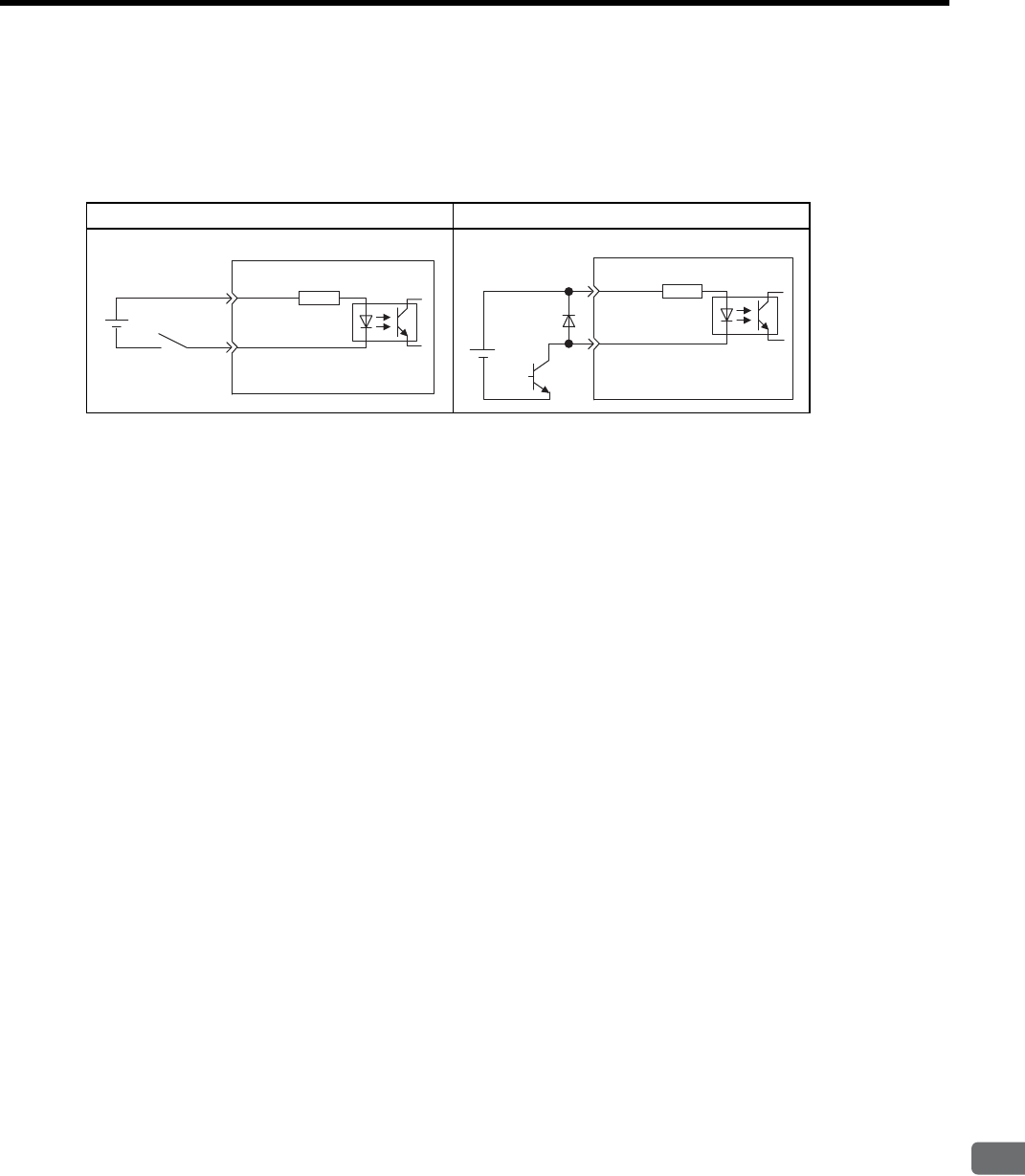
6.3 I/O Signal Connections
6
Wiring
6-15
(2) Sequence Input Circuit Interface
CN1 connector terminals 40 to 47 is explained below.
The sequence input circuit interface connects through a relay or open-collector transistor circuit. Select a low-
current relay otherwise a faulty contact will result.
Note: The 24 VDC external power supply capacity must be 50 mA minimum.
(3) Output Circuit Interface
There are three types of SERVOPACK output circuits:
(a) Line Driver Output Circuit
CN1 connector terminals, 33-34: phase-A signal, 35-36: phase-B signal and 19-20: phase-C signal are
explained below.
Encoder serial data converted to two-phase (phases A and B) pulse output signals (PAO, /PAO, PBO, /PBO),
zero-point pulse signals (PCO, /PCO), and the amount of phase-S rotation signal are output via line-driver
output circuits. Normally, the SERVOPACK uses this output circuit in speed control to comprise the position
control system at the host controller. Connect the line-driver output circuit through a line receiver circuit at
the host controller.
Relay Circuit Example Open-collector Circuit Example
3.3 kΩ
/S-ON, etc.
SERVOPACK
24 VDC +24VIN
+24VIN 3.3 kΩ
/S-ON, etc.
SERVOPACK
24 VDC
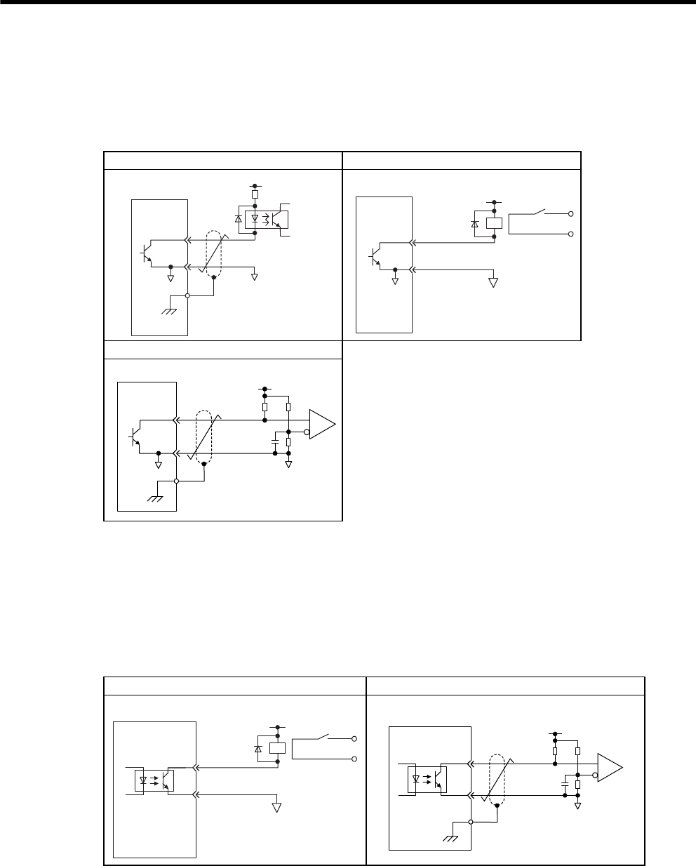
6 Wiring
6.3.4 Interface Circuit
6-16
(b) Open-collector Output Circuit
CN1 connector terminals 37 to 39: Alarm code output are explained below.
Alarm code signals (ALO1, ALO2, ALO3) are output from open-collector transistor output circuits. Con-
nect an open-collector output circuit through a photocoupler, relay circuit, or line receiver circuit.
Note: The maximum allowable voltage and current capacities for open-collector output circuits
are as follows:
• Voltage: 30 VDC
• Current: 20 mA DC
(c) Photocoupler Output Circuit
Photocoupler output circuits are used for servo alarm (ALM), servo ready (/S-RDY), and other sequence out-
put signal circuits. Connect a photocoupler output circuit through a relay circuit or line receiver circuit.
Note: The maximum allowable voltage and current capacities for photocoupler output circuits
are as follows:
• Voltage: 30 VDC
• Current: 50 mA DC
Photocoupler Circuit Example Relay Circuit Example
Line Receiver Circuit Example
0V 0V
SERVOPACK
5 to 12 VDC
Photocoupler
0V
Relay
5 to 24 VDC
SERVOPACK
SERVOPACK 5 to 12 VDC
0V
0V
Relay Circuit Example Line Receiver Circuit Example
0V
Relay
5 to 24 VDC
SERVOPACK
5 to 12 VDC
SERVOPACK
0V

6.4 Others
6
Wiring
6-17
6.4 Others
6.4.1 Wiring Precautions
To ensure safe and stable operation, always observe the following wiring precautions.
1. For wiring for reference inputs and encoders, use the specified cables. Refer to 5 Specifications and
Dimensional Drawings of Cables and Peripheral Devices for details.
Use cables as short as possible.
2. For a ground wire, use as thick a cable as possible (2.0 mm2 or thicker).
• At least class-3 ground (100 Ω max.) is recommended.
• Ground to one point only.
• If the servomotor is insulated from the machine, ground the servomotor directly.
3. Do not bend or apply tension to cables.
The conductor of a signal cable is very thin (0.2 to 0.3 mm), so handle the cables carefully.
4. Use a noise filter to prevent noise interference.
(For details, refer to 6.4.2 Wiring for Noise Control.)
• If the equipment is to be used near private houses or may receive noise interference, install a noise filter on
the input side of the power supply line.
• Because the SERVOPACK is designed as an industrial device, it provides no mechanism to prevent noise
interference.
5. To prevent malfunction due to noise, take the following actions:
• Position the input reference device and noise filter as close to the SERVOPACK as possible.
• Always install a surge absorber in the relay, solenoid and magnetic contactor coils.
• The distance between a power line (such as a power supply line or servomotor cable) and a signal line must
be at least 300 mm. Do not put the power and signal lines in the same duct or bundle them together.
• Do not share the power supply with an electric welder or electrical discharge machine. When the SERVO-
PACK is placed near a high-frequency generator, install a noise filter on the input side of the power supply
line.
6. Use a molded-case circuit breaker (QF) or fuse to protect the power supply line from high voltage.
• The SERVOPACK connects directly to a commercial power supply without a transformer, so always use a
QF or fuse to protect the SERVOPACK from accidental high voltage.
7. The SERVOPACKs do not have built-in ground protection circuits. To configure a safer system, install
an earth leakage breaker for protection against overloads and short-circuiting, or install an earth leakage
breaker combined with a wiring circuit breaker for ground protection.
IMPORTANT
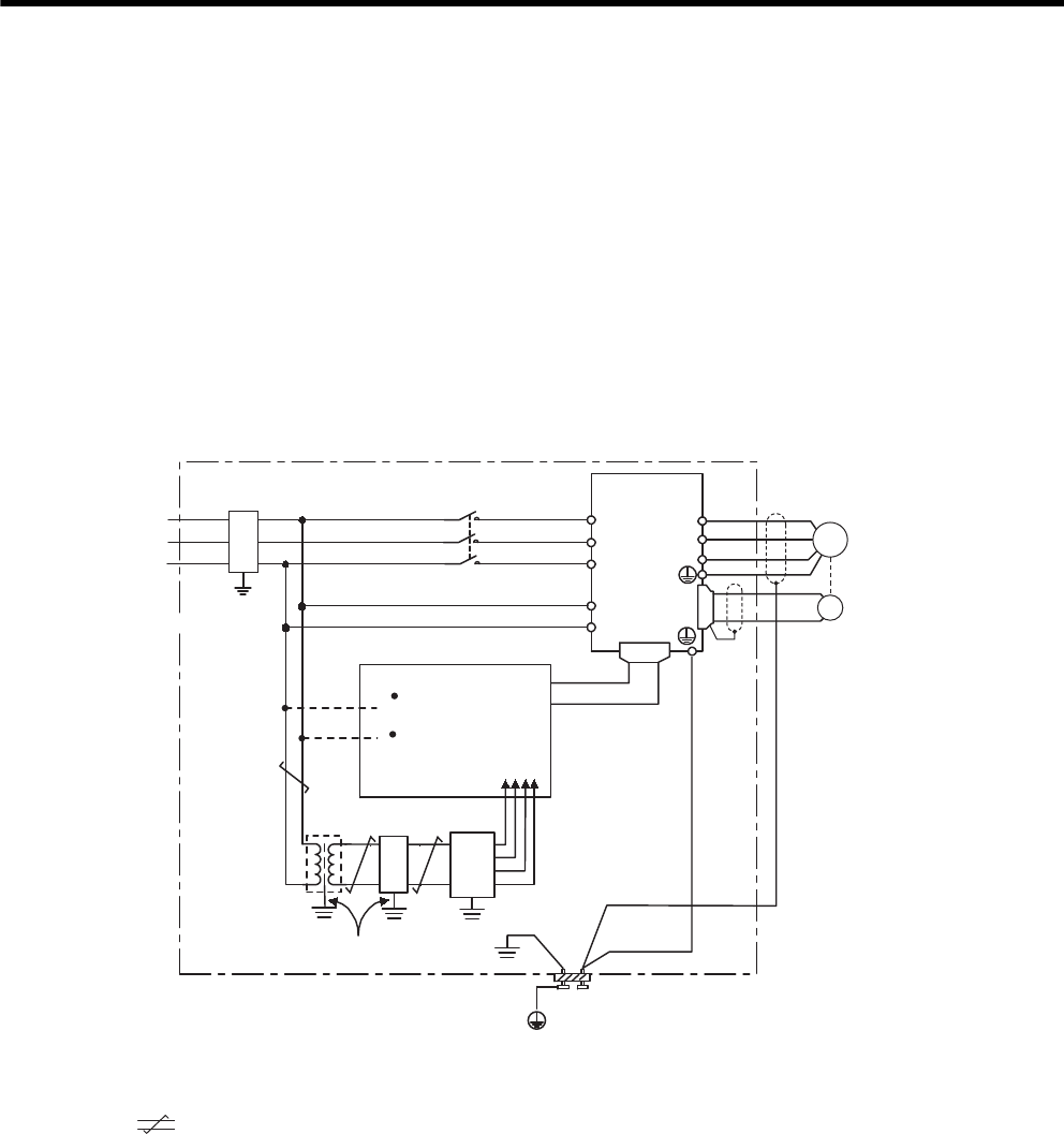
6 Wiring
6.4.2 Wiring for Noise Control
6-18
6.4.2 Wiring for Noise Control
(1) Wiring Example
The SERVOPACK uses high-speed switching elements in the main circuit. It may receive “switching noise”
from these high-speed switching elements if the processing of wiring or grounding around the SERVOPACK is
not appropriate. To prevent this, always wire and ground the SERVOPACK correctly.
The SGDH SERVOPACK has a built-in microprocessor (CPU), so protect it from external noise as much as pos-
sible by installing a noise filter in the appropriate place.
The following is an example of wiring for noise control.
When using a noise filter, follow the precautions in (3) Using Noise Filters.
* 1. For ground wires connected to the casing, use a thick wire with a thickness of
at least 3.5 mm (preferably, plain stitch copper wire).
* 2. : represents twisted-pair wires.
U
W
V
L2/S
L1/R
L3/T
L3C/t
L1C/r CN2
SGDM/SGDH
SERVOPACK Servomotor
Operation relay
sequence
Signal generation
circuit (provided by
customer)
1LF AVR
(Ground)
(Casing)
(Casing)
(Casing)
(Casing)
(Casing)
(Ground plate)
2LF
3.5 mm
min.
2
200 to 230
VAC
Noise filter
∗1
∗1
∗2
2mm
2
min.
3.5 mmޓmin.
2∗1
2.0 mm
2
min.
3.5 mm
min.
2
PG
(FG)
M
Wires of 3.5 mm
or more
2
Ground: Ground to an independent ground
(at least class-3 grounding (100 Ω max).)
2LF
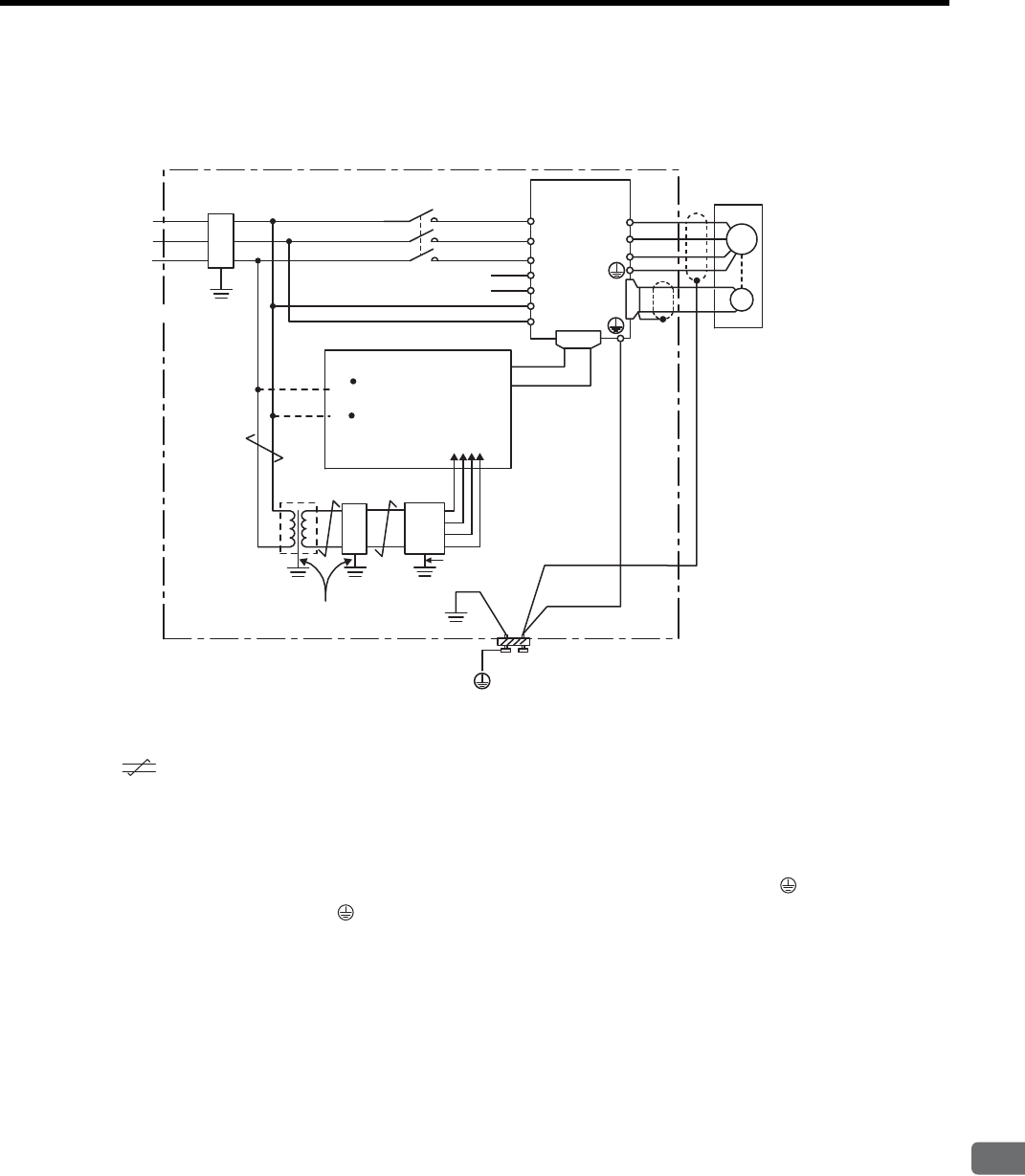
6.4 Others
6
Wiring
6-19
* 1. For ground wires connected to the casing, use a thick wire with a thickness of
at least 3.5 mm (preferably, plain stitch copper wire).
* 2. : represents twisted-pair wires.
(2) Correct Grounding
(a) Grounding the Motor Frame
Always connect servomotor frame terminal FG to the SERVOPACK ground terminal . Also be sure to
ground the ground terminal .
If the servomotor is grounded via the machine, a switching noise current will flow from the SERVOPACK
power unit through servomotor stray capacitance. The above grounding is required to prevent the adverse
effects of switching noise.
(b) Noise on the Reference Input Line
If the reference input line receives noise, ground the 0 V line (SG) of the reference input line. If the main cir-
cuit wiring for the motor is accommodated in a metal conduit, ground the conduit and its junction box.
For all grounding, ground at one point only.
M
(FG)
U
W
V
L2/S
L1/R
L3/T
CN2
1LF
∗2
2LF
PG
0 V
+
-
24 VDC DC24P
DC24N
380 to 480 V
SGDH
SERVOPACK Servomotor
Operation relay
sequence
Signal generation
circuit (provided by
customer)
(Casing)
(Casing)
(Casing)
(Casing)
(Casing)
(Ground plate)
3.5 mm
min.
2
380 to 480
VAC
Noise filter
∗1
∗1
2 mm2min.
3.5 mmmin.
∗1
2.0 mm
min.
3.5 mm
min.
2
Wires of 3.5 mm
or more
Ground: Ground to an independent ground
(at least class-3 grounding (100 Ω max).)
AVR
(Ground)
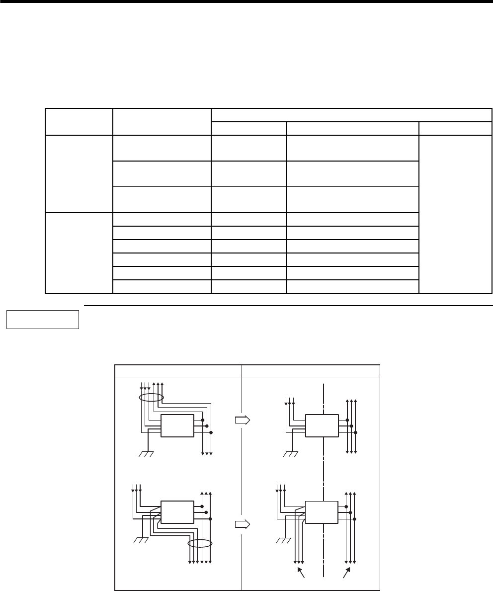
6 Wiring
6.4.2 Wiring for Noise Control
6-20
(3) Using Noise Filters
Use an inhibit type noise filter to prevent noise from the power supply line. The following table lists recom-
mended noise filters for each SERVOPACK model.
Install a noise filter on the power supply line for peripheral equipment as necessary.
Precautions when using noise filter
Always observe the following installation and wiring instructions. Incorrect use of a noise filter halves its
benefits.
1. Do not put the input and output lines in the same duct or bundle them together.
Voltage SERVOPACK Model Recommended Noise Filters
Model Specifications Manufacturer
Three-phase
200 V
SGDM-2BADB
SGDH-2BAEB FN258L-130-35 480 VAC, 130 A
Schaffner
SGDM-3ZADB
SGDH-3ZAEB FN258L-180-07 480 VAC, 180 A
SGDM-3GADB
SGDH-3GAEB FN359P-250-99 480 VAC, 250 A
Three-phase
400 V
SGDH-2BDEB FN258L-180-07 480 VAC, 180 A
SGDH-3ZDEB FN258L-180-07 480 VAC, 180 A
SGDH-3GDEB FN258L-180-07 480 VAC, 180 A
SGDH-4EDEB FN359P-250-99 480 VAC, 250 A
SGDH-5EDEB FN359P-250-99 480 VAC, 250 A
SGDH-9ZDEB FN359P-300-99 A480 VAC, 300 A
IMPORTANT
Noise
filter
Incorrect Correct
Separate these circuits
Box
Box Box
Box
Noise
filter
Noise
filter
Noise
filter
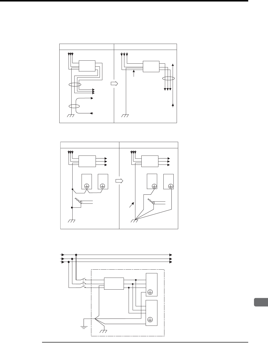
6.4 Others
6
Wiring
6-21
2. Separate the noise filter ground wire from the output lines.
Do not accommodate the noise filter ground wire, output lines, and other signal lines in the same duct or
bundle them together.
3. Connect the noise filter ground wire directly to the ground plate.
Do not connect the noise filter ground wire to other ground wires.
4. When grounding a noise filter inside a unit:
If a noise filter is located inside a unit, connect the noise filter ground wire and the ground wires from other
devices inside the unit to the ground plate for the unit first, then ground these wires.
The ground wire
can be close to
input lines.
Noise
filter
Box
Box
Incorrect Correct
Noise
filter
Shielded
ground wire Thick and
short
Box
Box
SERVOPACK
Incorrect Correct
Noise
filter
Noise
filter
SERVOPACK SERVOPACK SERVOPACK
Noise
filter
Unit
Ground
Box
SERVOPACK
SERVOPACK
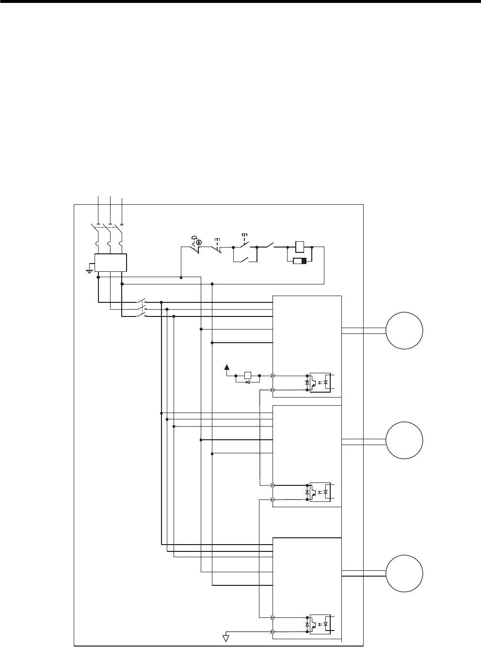
6 Wiring
6.4.3 Using More Than One SERVOPACK
6-22
6.4.3 Using More Than One SERVOPACK
The following diagram is an example of the wiring when more than one SERVOPACK is used.
Connect the alarm output (ALM) terminals for the three SERVOPACKs in series to enable alarm detection relay
1Ry to operate.
When the alarm occurs, the ALM output signal transistor is turned OFF.
Multiple servos can share a single molded-case circuit breaker (QF) or noise filter. Always select a QF or noise
filter that has enough capacity for the total power capacity (load conditions) of those servos. For details, refer to
2.5.2 Molded-case Circuit Breaker and Fuse Capacity.
(1) Three-phase 200 VAC: SGDM-ADB/SGDH-AEB
Note: Wire the system, so that the phase-S power supply will be the ground phase.
RS T
QF
1KM
1KM
1RY
1SA
1KM
1RY
+24V
L1/R
L2/S
L3/T
L1C/r
CN1
31 ALM+
32 ALM-
0V
M
L3C/t
L1/R
L2/S
L3/T
L1C/r
L3C/t
L1/R
L2/S
L3/T
L1C/r
L3C/t
M
M
Power supply
Three-phase 200 to 230 VAC
Noise
filter
Power
ON
Power
OFF
SERVOPACK
Servomotor
Servomotor
Servomotor
CN1
31 ALM+
32 ALM -
SERVOPACK
CN1
31 ALM+
32 ALM -
SERVOPACK
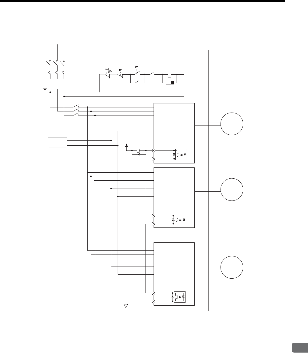
6.4 Others
6
Wiring
6-23
(2) Three-phase 400 VAC: SGDH-DEB
Note: Wire the system, so that the phase-S power supply will be the ground phase.
RS T
QF 1KM
1SA
1KM
1Ry
+24 V
L1/R
L2/S
L3/T
DC24P
CN1
31 ALM+
32 ALM -
0 V
M
DC24N
L1/R
L2/S
L3/T
DC24P
CN1
31 ALM+
32 ALM -
DC24N
L1/R
L2/S
L3/T
DC24P
CN1
31 ALM+
32 ALM -
DC24N
M
M
1KM
1Ry
DC24 V
+
-
FIL
Power supply
Three-phase 380 to 480 VAC
Power
ON
Power
OFF
SERVOPACK
Servomotor
Servomotor
Servomotor
SERVOPACK
SERVOPACK
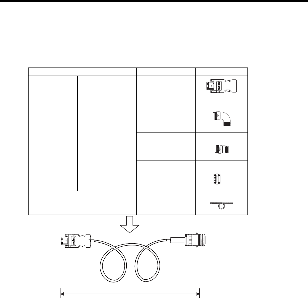
6 Wiring
6.4.4 Extending Encoder Cables
6-24
6.4.4 Extending Encoder Cables
Standard encoder cables have a maximum length of 20 m. If a longer cable is required, prepare an extension
cable as described below. The maximum allowable cable length is 50 m.
For the encoder cable specifications, refer to 5.3 Connectors and Cables for Encoder Signals.
Name Type Specifications
SERVOPACK-
end connector kit
Plug for encoder
connector (CN2) JZSP-CMP9-1
Servomotor-end
connector kit Encoder connector
MS3108B20-29S
L-shaped plug
MS3106B20-29S
Straight plug
MS3057-12A
Cable clamp
Cables
JZSP-CMP29-30
JZSP-CMP29-40
JZSP-CMP29-50
50 m max.
Maximum length: 50 m

7
Digital Operator/Panel Operator
7-1
7
Digital Operator/Panel Operator
7.1 Functions on Digital Operator/Panel Operator - - - - - - - - - - - 7-2
7.1.1 Connecting the Digital Operator - - - - - - - - - - - - - - - - - - - - - - - - - - - 7-2
7.1.2 Key Names and Functions - - - - - - - - - - - - - - - - - - - - - - - - - - - - - - - 7-3
7.1.3 Basic Mode Selection and Operation - - - - - - - - - - - - - - - - - - - - - - - - 7-4
7.1.4 Status Display - - - - - - - - - - - - - - - - - - - - - - - - - - - - - - - - - - - - - - - - 7-5
7.2 Operation in Utility Function Mode (Fn) - - - - - - - - - - - - 7-7
7.2.1 List of Utility Function Modes - - - - - - - - - - - - - - - - - - - - - - - - - - - - - 7-7
7.2.2 Alarm Traceback Data Display (Fn000) - - - - - - - - - - - - - - - - - - - - - - 7-8
7.2.3 Zero-point Search Mode (Fn003) - - - - - - - - - - - - - - - - - - - - - - - - - - 7-9
7.2.4 Parameter Settings Initialization (Fn005) - - - - - - - - - - - - - - - - - - - - 7-10
7.2.5 Alarm Traceback Data Clear (Fn006) - - - - - - - - - - - - - - - - - - - - - - - 7-11
7.2.6 Manual Zero Adjustment and Gain Adjustment of Analog Monitor
Output (Fn00C, Fn00D) - - - - - - - - - - - - - - - - - - - - - - - - - - - - - - - - 7-12
7.2.7 Offset Adjustment of Motor Current Detection Signal (Fn00E,
Fn00F) - - - - - - - - - - - - - - - - - - - - - - - - - - - - - - - - - - - - - - - - - - - - 7-15
7.2.8 Password Setting (Protects Parameters from Being Changed)
(Fn010) - - - - - - - - - - - - - - - - - - - - - - - - - - - - - - - - - - - - - - - - - - - - 7-17
7.2.9 Motor Models Display (Fn011) - - - - - - - - - - - - - - - - - - - - - - - - - - - 7-18
7.2.10 Software Version Display (Fn012) - - - - - - - - - - - - - - - - - - - - - - - - 7-19
7.2.11 Application Module Detection Results Clear (Fn014) - - - - - - - - - - - 7-20
7.3 Operation in Parameter Setting Mode (Pn) - - - - - - - - 7-21
7.3.1 Setting Parameters - - - - - - - - - - - - - - - - - - - - - - - - - - - - - - - - - - - 7-21
7.3.2 Input Circuit Signal Allocation - - - - - - - - - - - - - - - - - - - - - - - - - - - - 7-24
7.3.3 Output Circuit Signal Allocation - - - - - - - - - - - - - - - - - - - - - - - - - - - 7-27
7.4 Operation in Monitor Mode (Un) - - - - - - - - - - - - - - - - 7-29
7.4.1 List of Monitor Modes - - - - - - - - - - - - - - - - - - - - - - - - - - - - - - - - - - 7-29
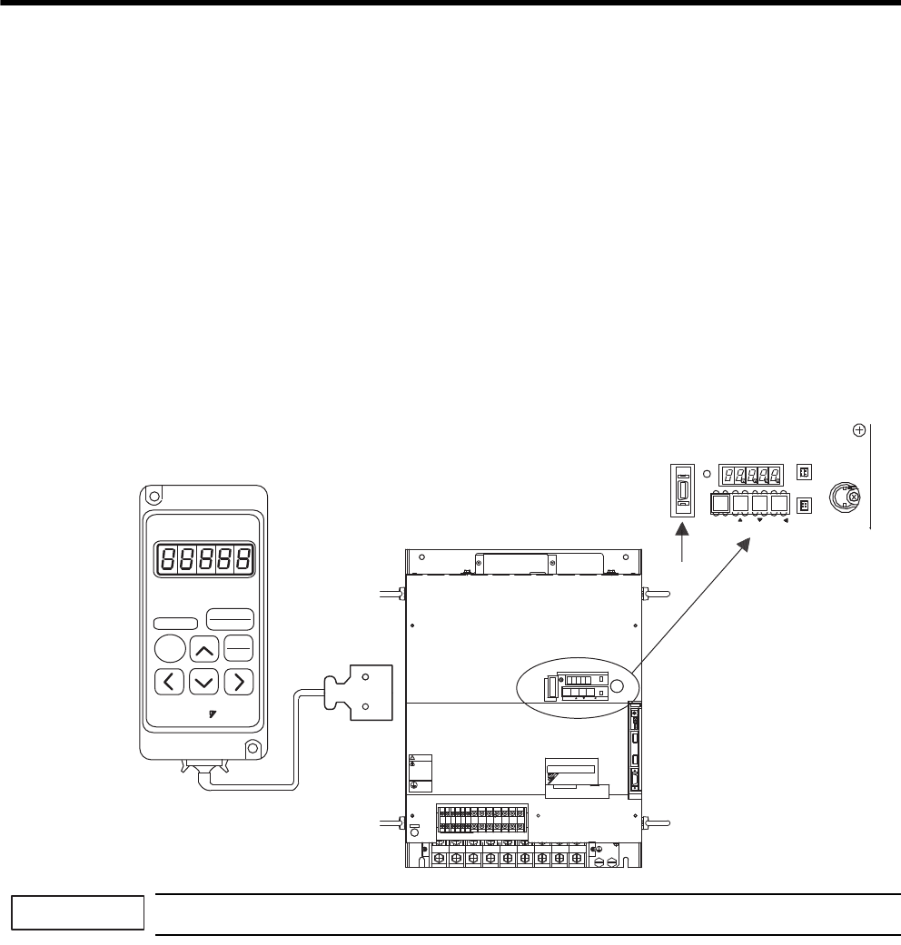
7 Digital Operator/Panel Operator
7.1.1 Connecting the Digital Operator
7-2
7.1 Functions on Digital Operator/Panel Operator
This section describes the basic operations of the digital operator (hereinafter called the digital operator) and the
panel operator (hereinafter called the panel operator) for setting the operating conditions. Set parameters and
JOG operation, and display status using these operators. For the operation of the digital operator (model: JUSP-
OP02A-2), refer to Σ-II Series SGMH/SGDH Digital Operator Operation Manual (TOE-S800-34).
7.1.1 Connecting the Digital Operator
Two types of digital operators are available. One is a built-in operator that has a panel indicator and switches
located on the front panel of the SERVOPACK. This type of digital operator is also called a panel operator. The
other one is a hand-held operator (JUSP-OP02A-2 digital operator), which can be connected to the SERVO-
PACK with connector CN3 of the SERVOPACK.
There is no need to turn OFF the SERVOPACK to connect this hand-held operator to the SERVOPACK. Refer to
the following illustrations to connect the digital operator to the SERVOPACK.
If the digital operator is connected to the SERVOPACK, the panel operator does not display anything.
Digital Operator
Panel Operator
JUSP-OP02A-2
A dedicated cable is used to
connect the digital operator
to the SERVOPACK. SERVOPACK
RESET
ALARM
SERVOPACK
.....
DIGITAL
OPERATOR
JUSP-OP02A
YASKAWA
DSPL
SET
DATA
ENTER
JOG
SVON
CN3
CN8
BATTERY
MODE/SET DATA/
POWER
CN5
.4 .5 .6 789
8
8
&7
8
8
8
&9&8 $
8
&%
0
$
&%
2
%*#4)'
5*&)
㧖㧖㧖㧖
6#5''/1&
-5'4812#%
#;#5-#9
4
1
2
'
4
#
6
1
%0
%0
219'4
%0
WARNING
ෂޓ㒾
ㅢ㔚ਛ߮㔚Ḯࠝࡈᓟ5
ಽ㑆ޔ┵ሶㇱߦ⸅ࠆߥ
electric shock.
Disconnect all power
May cause
ᗵ㔚ߩᕟࠇࠅ
before servicing.
and wait 5 min.
grounding techniques.
ធ⛯ߖࠃ
Use proper
ᔅߕࠕ㧙ࠬ✢ࠍ
IMPORTANT
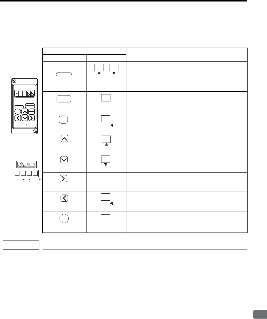
7.1 Functions on Digital Operator/Panel Operator
7
Digital Operator/Panel Operator
7-3
7.1.2 Key Names and Functions
Key names and functions for the digital operator and the panel operator are explained below.
Set parameters and JOG operation, and display status using the panel operator.
When an alarm occurs, remove the cause, and then reset the alarm. Refer to 10.1 Troubleshooting.
Key Function
Digital Operator Panel Operator
To reset the servo alarm.
Note 1. The servo alarm can be reset by /ALM-RST (CN1-44)
input signal.
2. The servo alarm need not be reset if the control power
supply is turned OFF.
To select a basic mode, such as the status display mode, utility
function mode, parameter setting mode, or monitor mode.
Can be also used to set the data.
To display parameter setting and set value.
Press the UP Key to increase the set value.
For JOG operation, this key is used as Forward Run Start Key.
Press the DOWN Key to decrease the set value.
For JOG operation, this key is used as Reverse Run Start Key.
−Press the RIGHT Key to shift to the next digit on the right.
Press the LEFT or DATA/SHIFT Key to shift to the next digit on
the left.
Press the SVON or MODE/SET Key to perform servo ON/OFF
in the JOG operation with the operator.
Digital Operator
ALARM
SERVOPACK DIGITAL
OPERATOR
JUSP-OP02A
RESET
DSPL
SET
JOG
SVON
DATA
ENTER
YASKAWA
ALARM
RESET
(RESET Key)
Press simultaneously
+
DSPL
SET
(DSPL/SET Key)
MODE/SET
(MODE/SET Key)
DATA
ENTER
(DATA/ENTER
K
ey)
DATA/
(DATA/SHIFT Key)
(UP Key)
(UP Key)
Panel Operator
MODE/SET DATA/
(DOWN Key)
(DOWN Key)
(RIGHT Key)
(LEFT Key)
DATA/
(DATA/SHIFT Key)
JOG
SVON
(SVON Key)
MODE/SET
(MODE/SET Key)
IMPORTANT
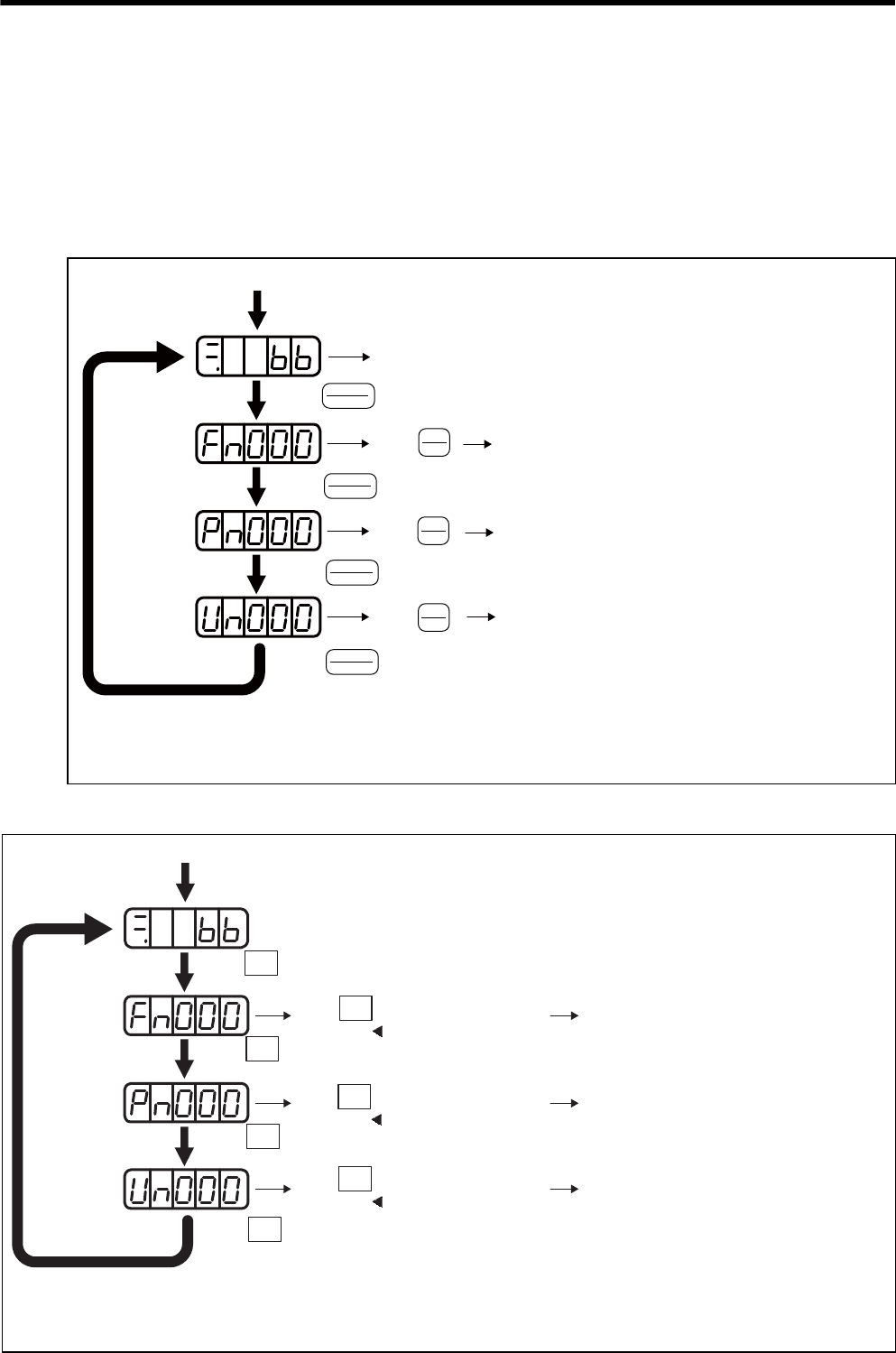
7 Digital Operator/Panel Operator
7.1.3 Basic Mode Selection and Operation
7-4
7.1.3 Basic Mode Selection and Operation
The basic modes include: Status display mode, Utility Function Mode, Parameter Setting Mode, and Monitor
Mode.
Select a basic mode to display the operation status, set parameters and operation references.
The basic mode is selected in the following order.
(1) Using the Digital Operator
(2) Using the Panel Operator
Turn ON the power
Fn: Utility Function Mode
(Refer to 7.2)
Pn: Monitor Mode
(Refer to 7.4)
Press DSPL/SET Key.
A basic mode is selected in the following order.
Repeat
DATA
ENTER
DSPL
SET
Press DATA/ENTER Key and UP or DOWN Key to select the desired parameter number.
Then, press DATA/ENTER Key to display the contents of selected parameter number
in the selected mode. (Refer to each operation instruction described later.)
Status Display Mode (Refer to 7.1.4)
Press .
Press .
DSPL
SET
Press .
DATA
ENTER
Press . Pn: Parameter Setting Mode
(Refer to 7.3)
DSPL
SET
Press .
DSPL
SET
Press .
DATA
ENTER
Press .
Turn ON the power Press MODE/SET Key.
A basic mode is selected in the following order.
Repeat
Press DATA/SHIFT Key and UP or DOWN Key to select the desired parameter number.
Then, press DATA/SHIFT Key for more than one second to display the contents of selected
parameter number in the selected mode. (Refer to each operation instruction described later.)
Status Display Mode (Refer to 7.1.4)
Press .
Fn: Utility Function Mode (Refer to 7.2)
Pn: Parameter Setting Mode (Refer to 7.3)
Un: Monitor Mode (Refer to 7.4)
Press for more than one second.
Press for more than one second.
Press for more than one second.
DATA/
(DATA/SHIFT)
DATA/
(DATA/SHIFT)
DATA/
(DATA/SHIFT)
MODE/SET
Press .
MODE/SET
Press .
MODE/SET
Press .
MODE/SET
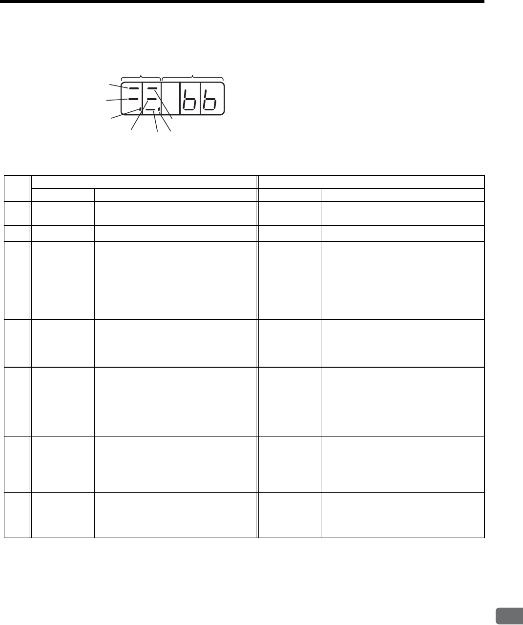
7.1 Functions on Digital Operator/Panel Operator
7
Digital Operator/Panel Operator
7-5
7.1.4 Status Display
(1) Bit Data and Meanings
Bit data Code
Item Speed or Torque Control Mode Position Control Mode
Bit Data Meaning Bit Data Meaning
cControl
Power ON
Lit when SERVOPACK control power is
ON.
Control
Power ON
Lit when SERVOPACK control power sup-
ply is ON.
dBaseblock Lit for baseblock. Not lit when servo is ON. Baseblock Lit for baseblock. Not lit when servo is ON.
eSpeed
Coincidence
(/V-CMP)
Lit when the difference between the motor
speed and reference speed is the same as or
less than the value set in Pn503. (Factory
setting is 10 min-1.)
∗ Always lit in torque control mode.
Positioning
Completion
(/COIN)
Lit if error between position reference and
actual motor position is below preset value.
Not lit if error between position reference
and actual motor position exceeds preset
value.
Preset value: Set in Pn500 (Factory setting
is 7 reference units.)
fServomotor
Rotation
Detection
(/TGON)
Lit if motor speed exceeds preset value.
Not lit if motor speed is below preset value.
Preset value: Set in Pn502 (Factory setting
is 20 min-1.)
Servomotor
Rotation
Detection
(/TGON)
Lit if motor speed exceeds preset value.
Not lit if motor speed is below preset value.
Preset value: Set in Pn502 (Factory setting
is 20 min-1.)
gSpeed
Reference
Input
Lit if input speed reference exceeds preset
value.
Not lit if input speed reference is below pre-
set value.
Preset value: Set in Pn502 (Factory setting
is 20 min-1.)
Reference
Pulse Input
Lit if reference pulse is input.
Not lit if no reference pulse is input.
hTorque
Reference
Input
Lit if input torque reference exceeds preset
value.
Not lit if input torque reference is below
preset value.
Preset value: 10% of rated torque
Error Counter
Clear Signal
Input
Lit when error counter clear signal is input.
Not lit when error counter clear signal is not
input.
iPower Ready Lit when main circuit power supply is ON
and normal.
Not lit when main circuit power supply
power is OFF.
Power Ready Lit when main circuit power supply is ON
and normal.
Not lit when main circuit power supply
power is OFF.
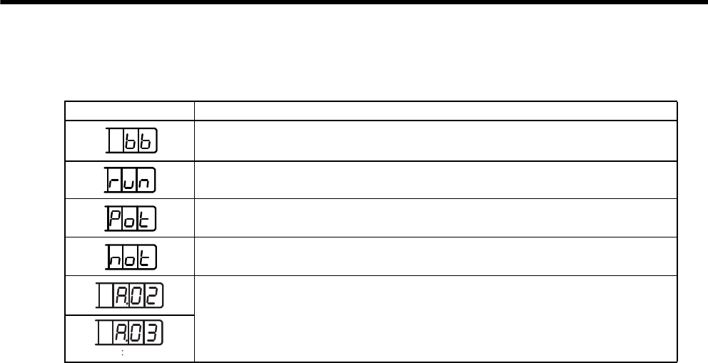
7 Digital Operator/Panel Operator
7.1.4 Status Display
7-6
(2) Codes and Meanings
Code Meaning
Baseblock
Servo OFF (motor power OFF)
Run
Servo ON (motor power ON)
Forward Run Prohibited
CN1-42 (P-OT) is OFF.
Reverse Run Prohibited
CN1-43 (N-OT) is OFF.
Alarm Status
Displays the alarm number.

7.2 Operation in Utility Function Mode (Fn)
7
Digital Operator/Panel Operator
7-7
7.2 Operation in Utility Function Mode (Fn)
7.2.1 List of Utility Function Modes
This section describes how to apply the basic operations using the panel operator to run and adjust the motor.
The following table shows the parameters in the utility function mode.
Note: When the parameters marked with “√” in remarks column or in Pn are set for Password Set-
ting (Fn010), the indication shown below appears and such parameters cannot be changed.
Parameter
No. Function Remarks
Fn000 Alarm traceback data display −
Fn001 Not used for the SERVOPACKs of 22 kW or more. √
Fn002 JOG mode operation −
Fn003 Zero-point search mode −
Fn004 Reserved −
Fn005 Parameter setting initialization √
Fn006 Alarm traceback data clear √
Fn007 Not used for the SERVOPACKs of 22 kW or more. −
Fn008 Absolute encoder multiturn reset and encoder alarm reset √
Fn009 Automatic tuning of speed and torque reference offset √
Fn00A Manual adjustment of speed reference offset √
Fn00B Manual adjustment of torque reference offset √
Fn00C Manual zero-adjustment of analog monitor output √
Fn00D Manual gain-adjustment of analog monitor output √
Fn00E Automatic offset-adjustment of motor current detection signal √
Fn00F Manual offset-adjustment of motor current detection signal √
Fn010 Password setting (protects parameters from being changed) −
Fn011 Motor models display −
Fn012 Software version display −
Fn013 Multiturn limit setting change when a Multiturn Limit Disagreement Alarm
(A.CC) occurs
√
Fn014 Application module detection results clear −
Blinks for
one second
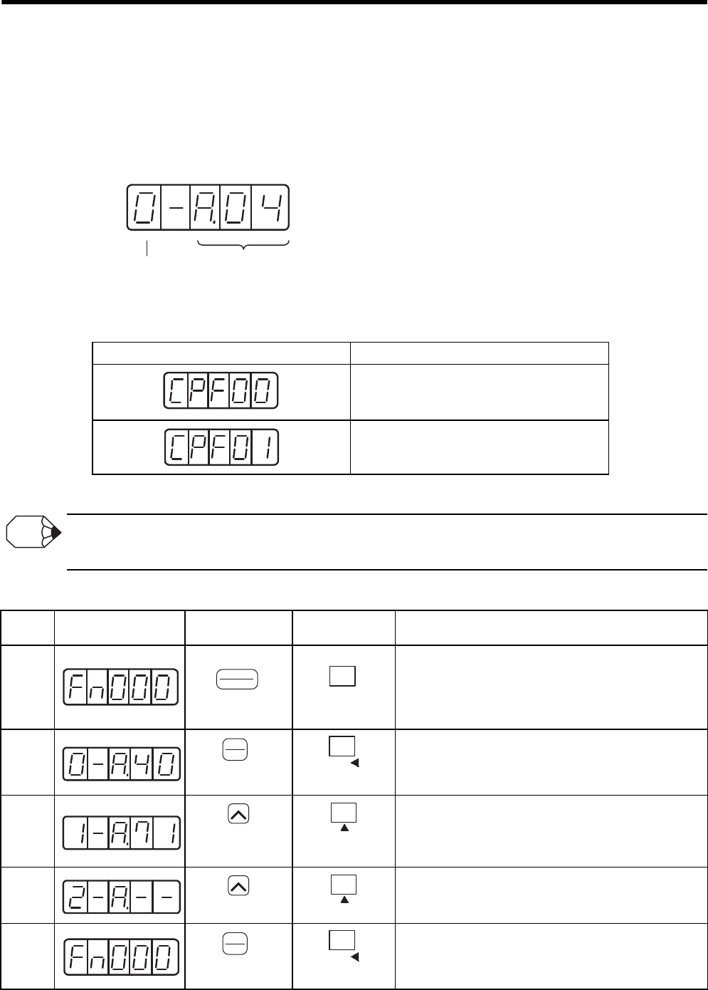
7 Digital Operator/Panel Operator
7.2.2 Alarm Traceback Data Display (Fn000)
7-8
7.2.2 Alarm Traceback Data Display (Fn000)
The alarm traceback display can display up to 10 previously occurred alarms. The alarm data is displayed on
Fn000, which is stocked in the alarm traceback data. The data can be cleared using an utility function mode
“Alarm Traceback Data Clear.” For details, refer to 7.2.5 Alarm Traceback Data Clear (Fn006).
The alarm traceback data is not cleared on alarm reset or when the SERVOPACK power is turned OFF. This does
not adversely affect operation.
The following alarm are operator-related alarms which are not recorded in the traceback data.
Refer to 10.1 Troubleshooting for alarm number and contents.
1. Alarm traceback data will not be updated when the same alarm occurs repetitively.
2. The display “A.--” means no alarm occurs.
Follow the procedure below to confirm alarms which have been generated.
Display Description
Digital operator transmission error 1
Digital operator transmission error 2
Alarm Code
See the alarm
table.
Alarm Sequence Number
The higher the number,
the older the alarm data is.
INFO
Step Display after
Operation Digital Operator Panel Operator Description
1Press the DSPL/SET or MODE/SET Key to select “Alarm
Traceback Data Display (Fn000).” If a number other than
Fn000 is displayed, press UP Key or DOWN Key to set
Fn000.
Note: The enabled digit blinks.
2Press the DATA/ENTER Key once, or DATA/SHIFT Key
for more than one second.
The latest alarm data is displayed.
3Press the UP Key to display the data for a previous alarm.
(To display one newer alarm data, press DOWN Key.)
Note: The higher the digit on the far left, the older the
alarm data is.
4Press the UP Key to display value in order.
Note: “A.--” means no alarm occurs.
5Press the DATA/ENTER Key once, or DATA/SHIFT Key
for more than one second. The display will return to
Fn000.
DSPL
SET
(DSPL/SET Key)
MODE/SET
(MODE/SET Key)
DATA
ENTER
(DATA/ENTER
K
ey)
DATA
(DATA/SHIFT Key)
(Press at least 1 s.)
(UP Key)
(UP Key)
(UP Key)
(UP Key)
DATA
ENTER
(DATA/ENTER
K
ey)
DATA
(DATA/SHIFT Key)
(Press at least 1 s.)
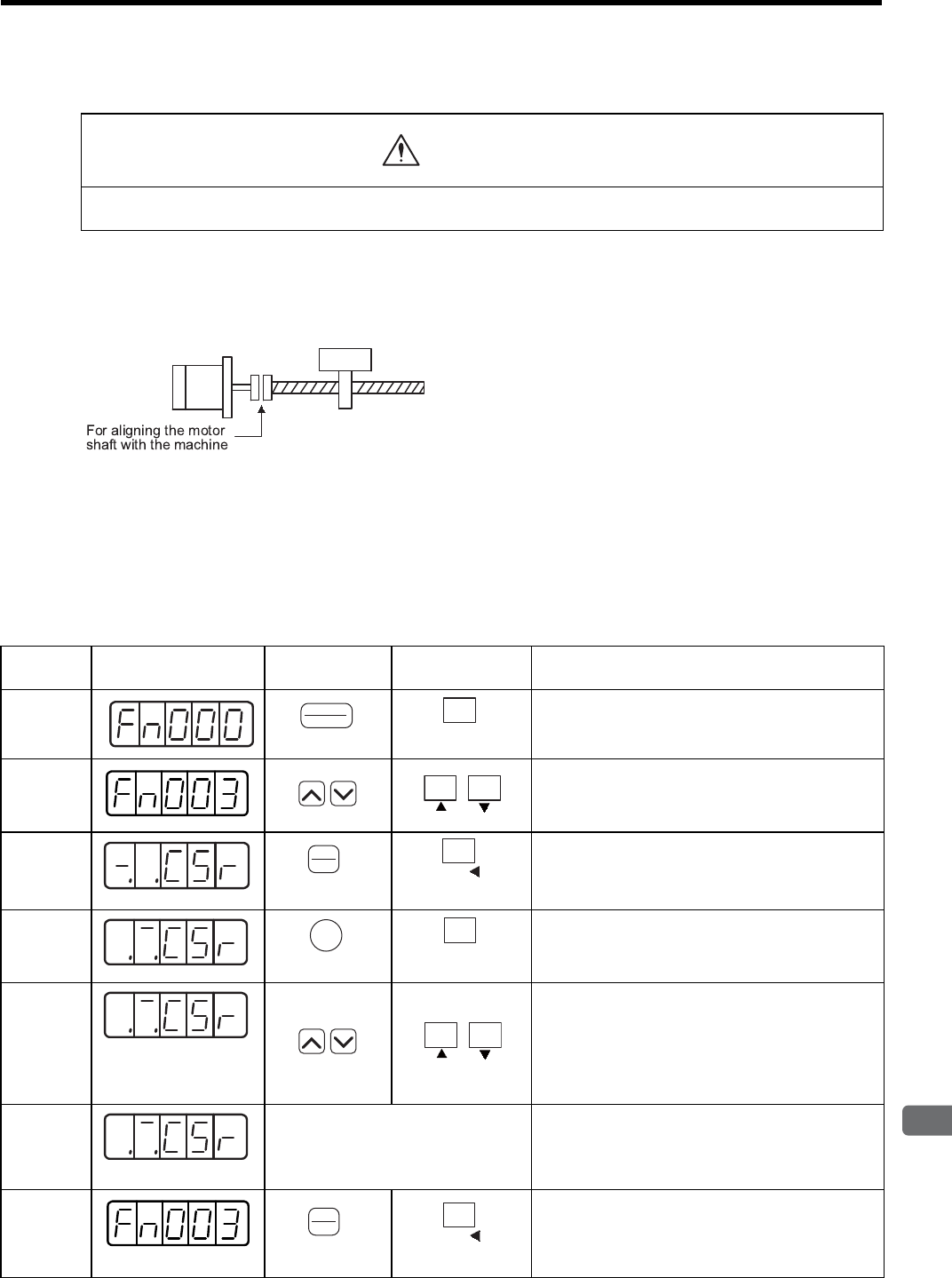
7.2 Operation in Utility Function Mode (Fn)
7
Digital Operator/Panel Operator
7-9
7.2.3 Zero-point Search Mode (Fn003)
The zero-point search mode is designed to perform positioning to the zero-point pulse (phase-C) position of the
encoder and to clamp at the position.
This mode is used when the motor shaft needs to be aligned to the machine.
Execute the zero-point search without connecting the motor shaft with the machine.
The speed for executing the zero-point search is 60 min-1.
The following conditions must be met to perform the zero-point search operation.
• If the Servo-ON input signal (/S-ON) is ON, turn it OFF.
• Release the Servo-ON signal mask if the parameter Pn 50A.1 is set to 7, and the servo has been set to
always be ON.
Follow the procedure below to execute the zero-point search.
• Forward run prohibited (P-OT) and reverse run prohibited (N-OT) signals are disabled during zero-point
search mode operations using Fn003.
CAUTION
Step Display after
Operation Digital Operator Panel Operator Description
1Press the DSPL/SET or MODE/SET Key to select
the utility function mode.
2Press the UP or DOWN Key to select the Fn003.
Note: The enabled digit blinks.
3Press the DATA/ENTER Key once, or DATA/SHIFT
Key for more than one second, and the display will
be as shown on the left.
4Press the SVON or MODE/SET Key.
The servo turns ON.
5When the parameter is set to Pn000.0 = 0 (default),
pressing the UP Key will rotate the motor in the for-
ward direction. Pressing the DOWN Key will rotate
the motor in the reverse direction. When the parame-
ter is set to Pn000.0 = 1, the rotation direction of the
motor is reversed.
6
Display blinks.
When the motor zero-point search is completed, the
display blinks.
At this moment, the motor is servo-locked at the
zero-point pulse position.
7Press the DATA/ENTER Key once, or DATA/SHIFT
Key for more than one second.
Fn003 display appears again.
The motor will be servo OFF status.
DSPL
SET
(DSPL/SET Key)
MODE/SET
(MODE/SET Key)
DATA
ENTER
(DATA/ENTER
K
ey)
DATA
(DATA/SHIFT Key)
(Press at least 1 s.)
JOG
SVON
(SVON Key)
MODE/SET
(MODE/SET Key)
DATA
ENTER
(DATA/ENTER
K
ey)
DATA
(DATA/SHIFT Key)
(Press at least 1 s.)
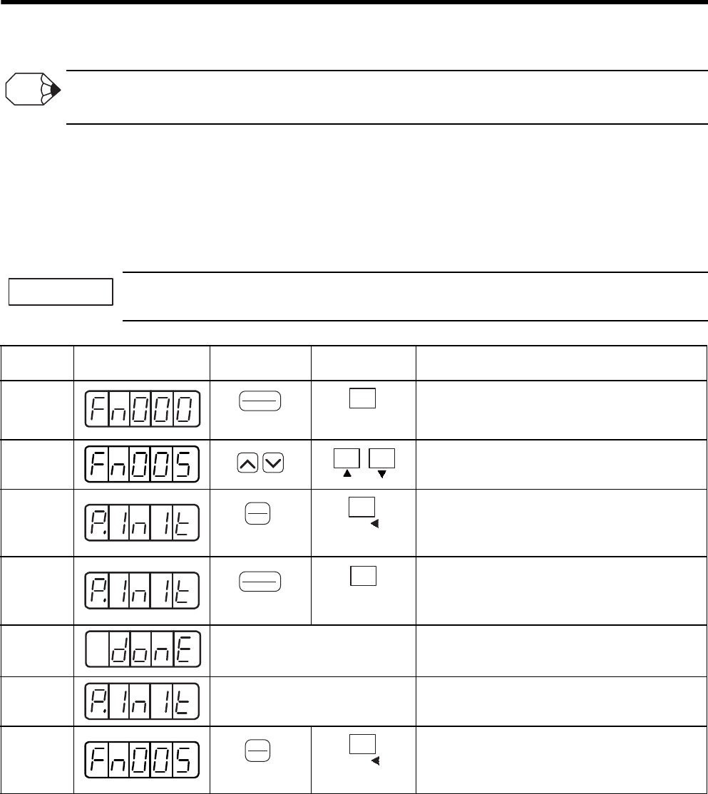
7 Digital Operator/Panel Operator
7.2.4 Parameter Settings Initialization (Fn005)
7-10
Forward run prohibited (P-OT) and reverse run prohibited (N-OT) signals cannot be input during the zero-point search
operation.
7.2.4 Parameter Settings Initialization (Fn005)
This function is used when returning to the factory settings after changing parameter settings.
Pressing the DSPL/SET or MODE/SET Key during servo ON does not initialize the parameter settings.
After initialization, turn OFF the power supply and then turn ON again.
Initialize the parameter settings with the servo OFF.
INFO
IMPORTANT
Step Display after
Operation Digital Operator Panel Operator Description
1Press the DSPL/SET or MODE/SET Key to select the
utility function mode.
2Press the UP or DOWN Key to select Fn005.
Note: The enabled digit blinks.
3Press the DATA/ENTER Key once, or DATA/SHIFT
Key for more than one second, and the display will be
as shown on the left.
4Press the DSPL/SET or MODE/SET Key. Then, the
parameters will be initialized.
During initialization, the display shown on the left
blinks.
5End of initialization When the initialization of parameter setting com-
pletes, the display shown on the left blinks for about
one second.
6After about one
second
The display changes from “donE” to the display
shown on the left.
7Press the DATA/ENTER Key once, or DATA/SHIFT
Key for more than one second to return to the utility
function mode display Fn005.
DSPL
SET
(DSPL/SET Key)
MODE/SET
(MODE/SET Key)
DATA
ENTER
(DATA/ENTER
K
ey)
DATA
(DATA/SHIFT Key)
(Press at least 1 s.)
DSPL
SET
(DSPL/SET Key)
MODE/SET
(MODE/SET Key)
DATA
ENTER
(DATA/ENTER
K
ey)
DATA
(DATA/SHIFT Key)
(Press at least 1 s.)
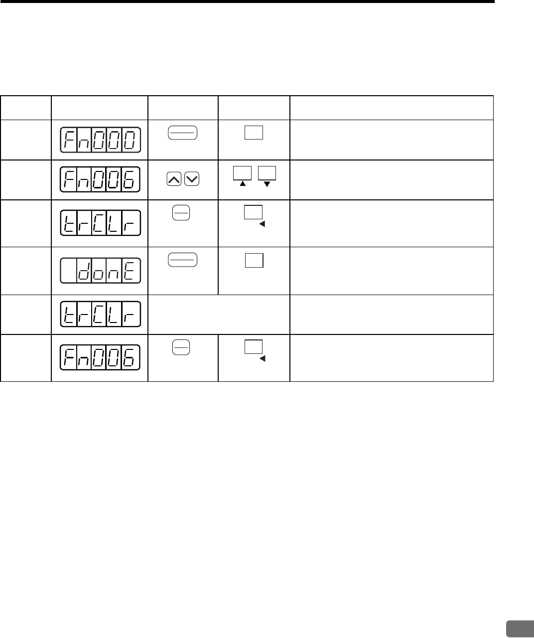
7.2 Operation in Utility Function Mode (Fn)
7
Digital Operator/Panel Operator
7-11
7.2.5 Alarm Traceback Data Clear (Fn006)
This function clears the alarm traceback data, which stores the alarms generated in the SERVOPACK.
After having cleared data, “A.--” (No alarm) is set to all the alarm traceback data.
Step Display after
Operation Digital Operator Panel Operator Description
1Press the DSPL/SET or MODE/SET Key to select the
utility function mode.
2Press the UP or DOWN Key to select Fn006.
Note: The enabled digit blinks.
3Press the DATA/ENTER Key once, or DATA/SHIFT
Key for more than one second, and the display will be
as shown on the left.
4Press the DSPL/SET or MODE/SET Key to clear the
alarm traceback data.
The display shown on the left blinks for about one sec-
ond when the data is cleared.
5After about one second The display changes from “donE” to the display
shown on the left.
6Press the DATA/ENTER Key once, or DATA/SHIFT
Key for more than one second to return to the utility
function mode display Fn006.
DSPL
SET
(DSPL/SET Key)
MODE/SET
(MODE/SET Key)
DATA
ENTER
(DATA/ENTER
K
ey)
DATA
(DATA/SHIFT Key)
(Press at least 1 s.)
DSPL
SET
(DSPL/SET Key)
MODE/SET
(MODE/SET Key)
DATA
ENTER
(DATA/ENTER
K
ey)
DATA
(DATA/SHIFT Key)
(Press at least 1 s.)
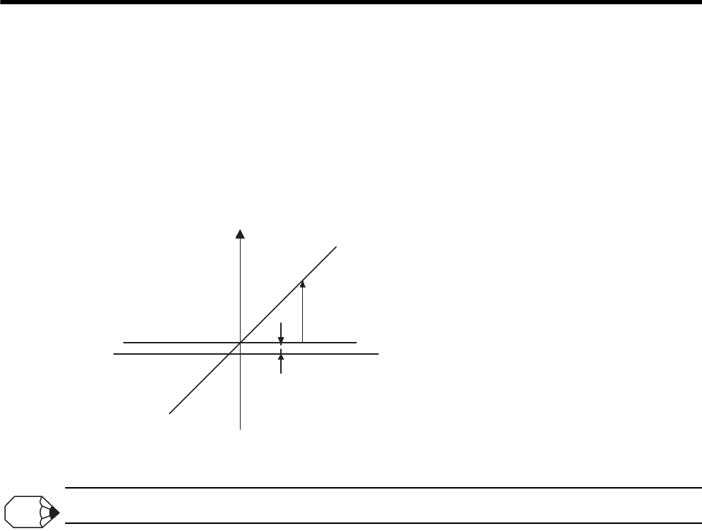
7 Digital Operator/Panel Operator
7.2.6 Manual Zero Adjustment and Gain Adjustment of Analog Monitor Output (Fn00C, Fn00D)
7-12
7.2.6 Manual Zero Adjustment and Gain Adjustment of Analog Monitor Output
(Fn00C, Fn00D)
Motor speed, torque reference, and position error can be monitored through the analog monitor output. Refer to
9.5 Analog Monitor.
Use the manual zero adjustment function to compensate for the output voltage drift or the zero point drift caused
by noise entering the monitor system. The gain adjustment function can be changed to match the sensitivity of
the measuring system.
The output voltage of the analog monitor is ±8 V max. The output voltage will be limited to ±8 V if ±8 V is exceeded.
Monitor output voltage
Zero adjustment
Gain adjustment
Zero Setting Range: ±2V →17 mV/LSB
Gain Setting Range: 50% to 150% →0.4 %/LSB
Setting Unit
INFO
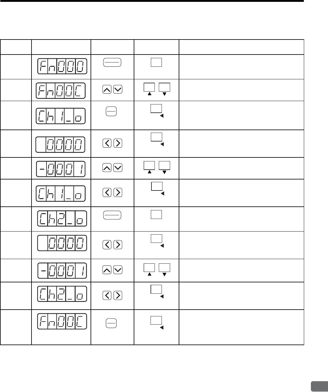
7.2 Operation in Utility Function Mode (Fn)
7
Digital Operator/Panel Operator
7-13
(1) Manual Zero adjustment of Analog Monitor Output (Fn00C)
Step Display after
Operation Digital Operator Panel Operator Description
1Press the DSPL/SET or MODE/SET Key to select the
utility function mode.
2Press the UP or DOWN Key to select Fn00C.
Note: The enabled digit blinks.
3Press the DATA/ENTER Key once, or DATA/SHIFT
Key for more than one second, and the display shown
on the left appears.
4Press the LEFT or RIGHT or DATA/SHIFT Key for
less than one second to display the output data of
analog monitor.
5Press the UP or DOWN Key to perform the zero
adjustment of analog monitor.
6Press the LEFT or RIGHT or DATA/SHIFT Key for
less than one second.
The display shown on the left appears.
7Press the DSPL/SET or MODE/SET Key.
The display shown on the left appears.
8Press the LEFT or RIGHT or DATA/SHIFT Key for
less than one second to display the output data of
analog monitor.
9Press the UP or DOWN Key to perform the zero
adjustment of analog monitor.
10 Press the LEFT or RIGHT Key or DATA/SHIFT Key
for less than one second.
The display shown on the left appears.
11 When the zero adjustment of analog monitor output
completes, press the DATA/ENTER Key once, or
DATA/SHIFT Key for more than one second. The
display returns to the utility function mode display
Fn00C.
DSPL
SET
(DSPL/SET Key)
MODE/SET
(MODE/SET Key)
DATA
ENTER
(DATA/ENTER
K
ey)
DATA
(DATA/SHIFT Key)
(Press at least 1 s.)
DATA
(DATA/SHIFT Key)
(Press less than 1 s.)
DATA
(DATA/SHIFT Key)
(Press less than 1 s.)
DSPL
SET
(DSPL/SET Key)
MODE/SET
(MODE/SET Key)
DATA
(DATA/SHIFT Key)
(Press less than 1 s.)
DATA
(DATA/SHIFT Key)
(Press less than 1 s.)
DATA
ENTER
(DATA/ENTER
K
ey)
DATA
(DATA/SHIFT Key)
(Press at least 1 s.)
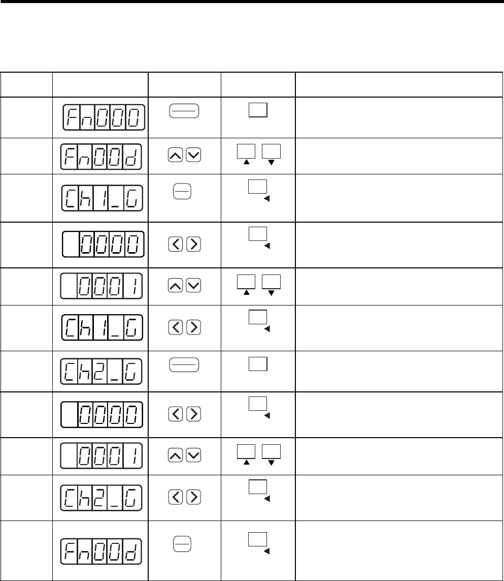
7 Digital Operator/Panel Operator
7.2.6 Manual Zero Adjustment and Gain Adjustment of Analog Monitor Output (Fn00C, Fn00D)
7-14
(2) Manual Gain adjustment of Analog Monitor Output (Fn00D)
Step Display after
Operation Digital Operator Panel Operator Description
1Press the DSPL/SET or MODE/SET Key to select the
utility function mode.
2Press the UP or DOWN Key to select Fn00D.
Note: The enabled digit blinks.
3
Press the DATA/ENTER Key once, or DATA/SHIFT
Key for more than one second, and the display shown
on the left appears.
4
Press the LEFT or RIGHT or DATA/SHIFT Key for
less than one second to display the gain coefficient of
analog monitor.
5Press the UP or DOWN Key to adjust the gain coeffi-
cient of analog monitor.
6
Press the LEFT or RIGHT or DATA/SHIFT Key for
less than one second.
The display shown on the left appears.
7Press the DSPL/SET or MODE/SET Key.
The display shown on the left appears.
8
Press the LEFT or RIGHT or DATA/SHIFT Key for
less than one second to display the gain coefficient of
analog monitor.
9Press the UP or DOWN Key to adjust the gain coeffi-
cient of analog monitor.
10
Press the LEFT or RIGHT Key or DATA/SHIFT Key
for less than one second.
The display shown on the left appears.
11
When the gain coefficient of analog monitor adjust-
ment completes, press the DATA/ENTER Key once,
or DATA/SHIFT Key for more than one second.
The display returns to the utility function mode dis-
play Fn00D.
DSPL
SET
(DSPL/SET Key)
MODE/SET
(MODE/SET Key)
DATA
ENTER
(DATA/ENTER
K
ey)
DATA
(DATA/SHIFT Key)
(Press at least 1 s.)
DATA
(DATA/SHIFT Key)
(Press less than 1 s.)
DATA
(DATA/SHIFT Key)
(Press less than 1 s.)
DSPL
SET
(DSPL/SET Key)
MODE/SET
(MODE/SET Key)
DATA
(DATA/SHIFT Key)
(Press less than 1 s.)
DATA
(DATA/SHIFT Key)
(Press less than 1 s.)
DATA
ENTER
(DATA/ENTER
K
ey)
DATA
(DATA/SHIFT Key)
(Press at least 1 s.)
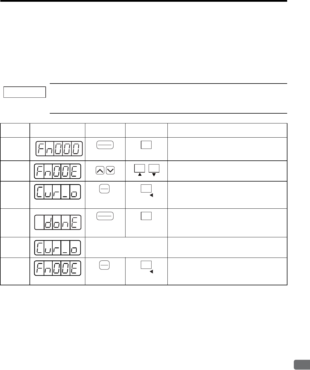
7.2 Operation in Utility Function Mode (Fn)
7
Digital Operator/Panel Operator
7-15
7.2.7 Offset Adjustment of Motor Current Detection Signal (Fn00E, Fn00F)
Motor current detection offset adjustment has performed at Yaskawa before shipping. Basically, the user need not
perform this adjustment.
Perform this adjustment only if highly accurate adjustment is required for reducing torque ripple caused by cur-
rent offset. This section explains automatic offset-adjustment and manual offset adjustment.
(1) Automatic Offset Adjustment of Motor Current Detection Signal (Fn00E)
1. Execute the automatic offset adjustment if the torque ripple is too big when compared with that of other
SERVOPACKs.
2. Automatic adjustment is possible only while power is supplied to the main circuit and the servo is OFF.
IMPORTANT
Step Display after
Operation Digital Operator Panel Operator Description
1Press the DSPL/SET or MODE/SET Key to select the
utility function mode.
2Press the UP or DOWN Key to select Fn00E.
Note: The enabled digit blinks.
3Press the DATA/ENTER Key once, or DATA/SHIFT
Key for more than one second, and the display will be
as shown on the left.
4Press the DSPL/SET or MODE/SET Key.
The offset will be automatically adjusted.
When the adjustment completes, the display shown on
the left blinks for about one second.
5After about one second The display changes from “donE” to the display shown
on the left.
6Press the DATA/ENTER Key once, or DATA/SHIFT
Key for more than one second to return to the utility
function mode display Fn00E.
DSPL
SET
(DSPL/SET Key)
MODE/SET
(MODE/SET Key)
DATA
ENTER
(DATA/ENTER
K
ey)
DATA
(DATA/SHIFT Key)
(Press at least 1 s.)
DSPL
SET
(DSPL/SET Key)
MODE/SET
(MODE/SET Key)
DATA
ENTER
(DATA/ENTER
K
ey)
DATA
(DATA/SHIFT Key)
(Press at least 1 s.)
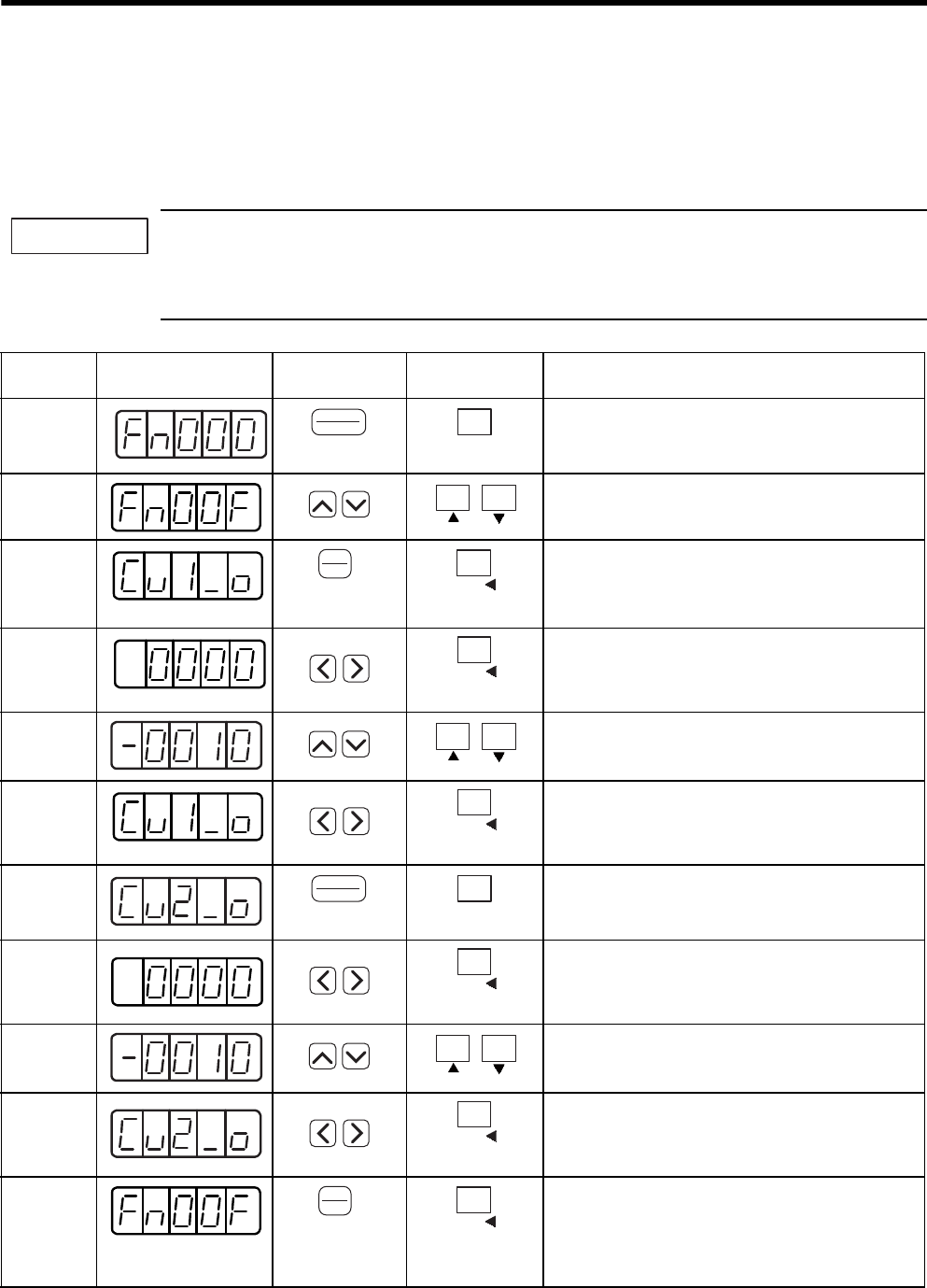
7 Digital Operator/Panel Operator
7.2.7 Offset Adjustment of Motor Current Detection Signal (Fn00E, Fn00F)
7-16
(2) Manual Offset Adjustment of Motor Current Detection Signal (Fn00F)
The adjusting range of the motor current detection offset is -512 to +511.
To adjust the offset, perform the automatic adjustment (Fn00E) first.
And if the torque ripple is still big after the automatic adjustment, perform the manual adjustment.
If this function, particularly manual adjustment, is executed carelessly, it may worsen the characteristics.
When performing manual adjustments, run the motor at a speed of approximately 100 min-1, and adjust the
operator until the torque monitor ripple is minimized. (Refer to 9.5 Analog Monitor.) Adjust the phase-U
and phase-V offsets alternately several times until these offsets are well balanced.
IMPORTANT
Step Display after
Operation Digital Operator Panel Operator Description
1Press the DSPL/SET or MODE/SET Key to select the
utility function mode.
2Press the UP or DOWN Key to select Fn00F.
Note: The enabled digit blinks.
3Press the DATA/ENTER Key once, or DATA/SHIFT
Key for more than one second, and the display will be
as shown on the left (phase U).
4Press the LEFT or RIGHT or DATA/SHIFT Key for
less than one second to display the phase-U offset
amount.
5Press the UP or DOWN Key to adjust the offset. Care-
fully adjust the offset while monitoring the torque ref-
erence monitor signal.
6Press the LEFT or RIGHT or DATA/SHIFT Key for
less than one second.
The display shown on the left appears.
7Press the DSPL/SET or MODE/SET Key.
The display shown on the left appears (phase V).
8Press the LEFT or RIGHT or DATA/SHIFT Key for
less than one second to display the phase-V offset
amount.
9Press the UP or DOWN Key to adjust the offset. Care-
fully adjust the offset while monitoring the torque ref-
erence monitor signal.
10 Press the LEFT or RIGHT Key or DATA/SHIFT Key
for less than one second.
The display shown on the left appears.
11 When the offset adjustment completes, press the
DATA/ENTER Key once, or DATA/SHIFT Key for
more than one second.
The display returns to the utility function mode dis-
play Fn00F.
DSPL
SET
(DSPL/SET Key)
MODE/SET
(MODE/SET Key)
DATA
ENTER
(DATA/ENTER
K
ey)
DATA
(DATA/SHIFT Key)
(Press at least 1 s.)
DATA
(DATA/SHIFT Key)
(Press less than 1 s.)
DATA
(DATA/SHIFT Key)
(Press less than 1 s.)
DSPL
SET
(DSPL/SET Key)
MODE/SET
(MODE/SET Key)
DATA
(DATA/SHIFT Key)
(Press less than 1 s.)
DATA
(DATA/SHIFT Key)
(Press less than 1 s.)
DATA
ENTER
(DATA/ENTER
K
ey)
DATA
(DATA/SHIFT Key)
(Press at least 1 s.)
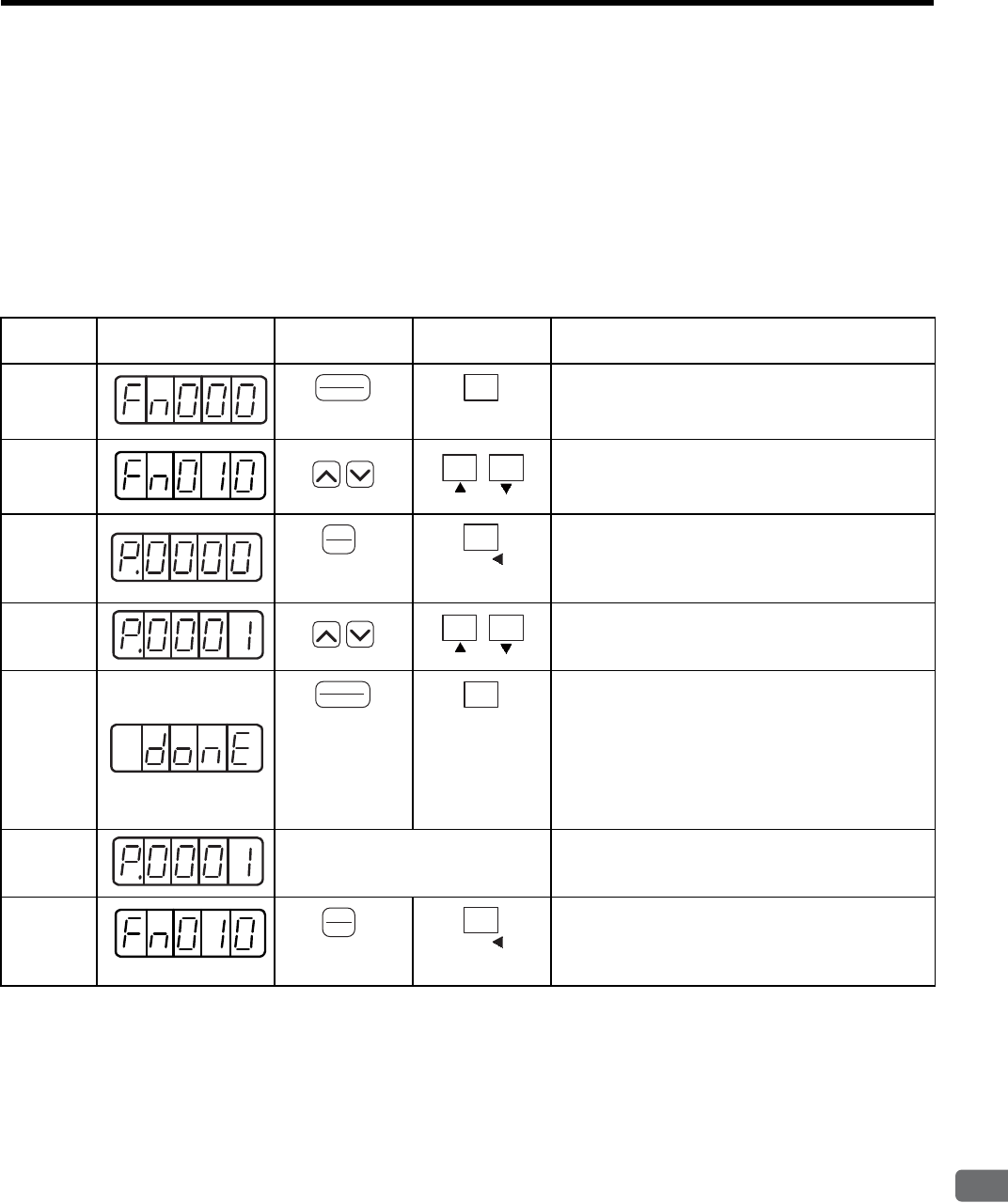
7.2 Operation in Utility Function Mode (Fn)
7
Digital Operator/Panel Operator
7-17
7.2.8 Password Setting (Protects Parameters from Being Changed) (Fn010)
The write prohibited setting is used for preventing accidental changes of the parameter. All the parameters
Pn and some of Fn become write prohibited by setting values. Refer to 7.2.1 List of Utility Function
Modes for details.
Setting values are as follows:
• “0000”: Write permitted (Releases write prohibited mode.)
• “0001”: Write prohibited (Parameters become write prohibited from the next power ON.)
Step Display after
Operation Digital Operator Panel Operator Description
1Press the DSPL/SET or MODE/SET Key to select the
utility function mode.
2Press the UP or DOWN Key to select Fn010.
Note: The enabled digit blinks.
3Press the DATA/ENTER Key once, or DATA/SHIFT
Key for more than one second, and the display will be
as shown on the left.
4Press the UP or DOWN Key to set a value:
“0000”: Write permitted, “0001”: Write prohibited
5Press the DSPL/SET or MODE/SET Key to register
the value.
When the value is registered, the display shown on the
left blinks for about one second.
Note: If a value other than “0000” and “0001” is
set, “Error” blinks for about one second,
and the previous setting is displayed.
6After about one second The display changes from “donE” to “P.000.”
7Press the DATA/ENTER Key once, or DATA/SHIFT
Key for more than one second to return to the utility
function mode display Fn010.
DSPL
SET
(DSPL/SET Key)
MODE/SET
(MODE/SET Key)
DATA
ENTER
(DATA/ENTER
K
ey)
DATA
(DATA/SHIFT Key)
(Press at least 1 s.)
DSPL
SET
(DSPL/SET Key)
MODE/SET
(MODE/SET Key)
DATA
ENTER
(DATA/ENTER
K
ey)
DATA
(DATA/SHIFT Key)
(Press at least 1 s.)
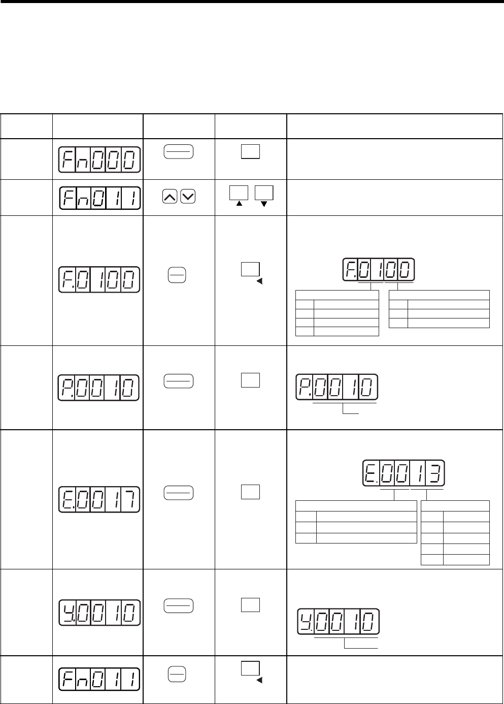
7 Digital Operator/Panel Operator
7.2.9 Motor Models Display (Fn011)
7-18
7.2.9 Motor Models Display (Fn011)
This mode is used for motor maintenance such as checking the connected servomotor model, voltage, capacity,
encoder type, or encoder resolution. Set the parameter Fn011 to select the motor model check mode. If the SER-
VOPACK has been custom-made, you can also check the specification codes of SERVOPACKs.
Step Display after
Operation Digital Operator Panel Operator Description
1Press the DSPL/SET or MODE/SET Key to select the
utility function mode.
2Press the UP or DOWN Key to select Fn011.
Note: The enabled digit blinks.
3Press the DATA/ENTER Key once, or DATA/SHIFT
Key for more than one second to display the servomotor
model and voltage code.
4Press the DSPL/SET or MODE/SET Key to display the
servomotor capacity.
5Press the DSPL/SET or MODE/SET Key, and the
encoder type and resolution code will be displayed.
6Press the DSPL/SET or MODE/SET Key to display the
SERVOPACK’s code for custom orders.
Note: The display “y.0000” means standard model.
7Press the DATA/ENTER Key once, or DATA/SHIFT
Key for more than one second to return to the utility
function mode display Fn011.
DSPL
SET
(DSPL/SET Key)
MODE/SET
(MODE/SET Key)
DATA
ENTER
(DATA/ENTER
K
ey)
DATA
(DATA/SHIFT Key)
(Press at least 1 s.)
Motor Voltage
Data Model
00
01
02
100VAC, 140VDC
200VAC, 280VDC
400VAC, 560VDC
SGMVH (1500 min-1)
17
19 SGMVH (800 min-1)
Motor Type
Model Data
DSPL
SET
(DSPL/SET Key)
MODE/SET
(MODE/SET Key)
Motor capacity in units of 10 W
The above example indicates 100 W.
DSPL
SET
(DSPL/SET Key)
MODE/SET
(MODE/SET Key)
Encoder Resolution
Data Resolution
13-bit
16-bit
17-bit
Reserved
13
16
17
20
Encoder Type
Data Type
Incremental
Absolute encoder
00
01
DSPL
SET
(DSPL/SET Key)
MODE/SET
(MODE/SET Key)
Code for custom orders
DATA
ENTER
(DATA/ENTER
K
ey)
DATA
(DATA/SHIFT Key)
(Press at least 1 s.)
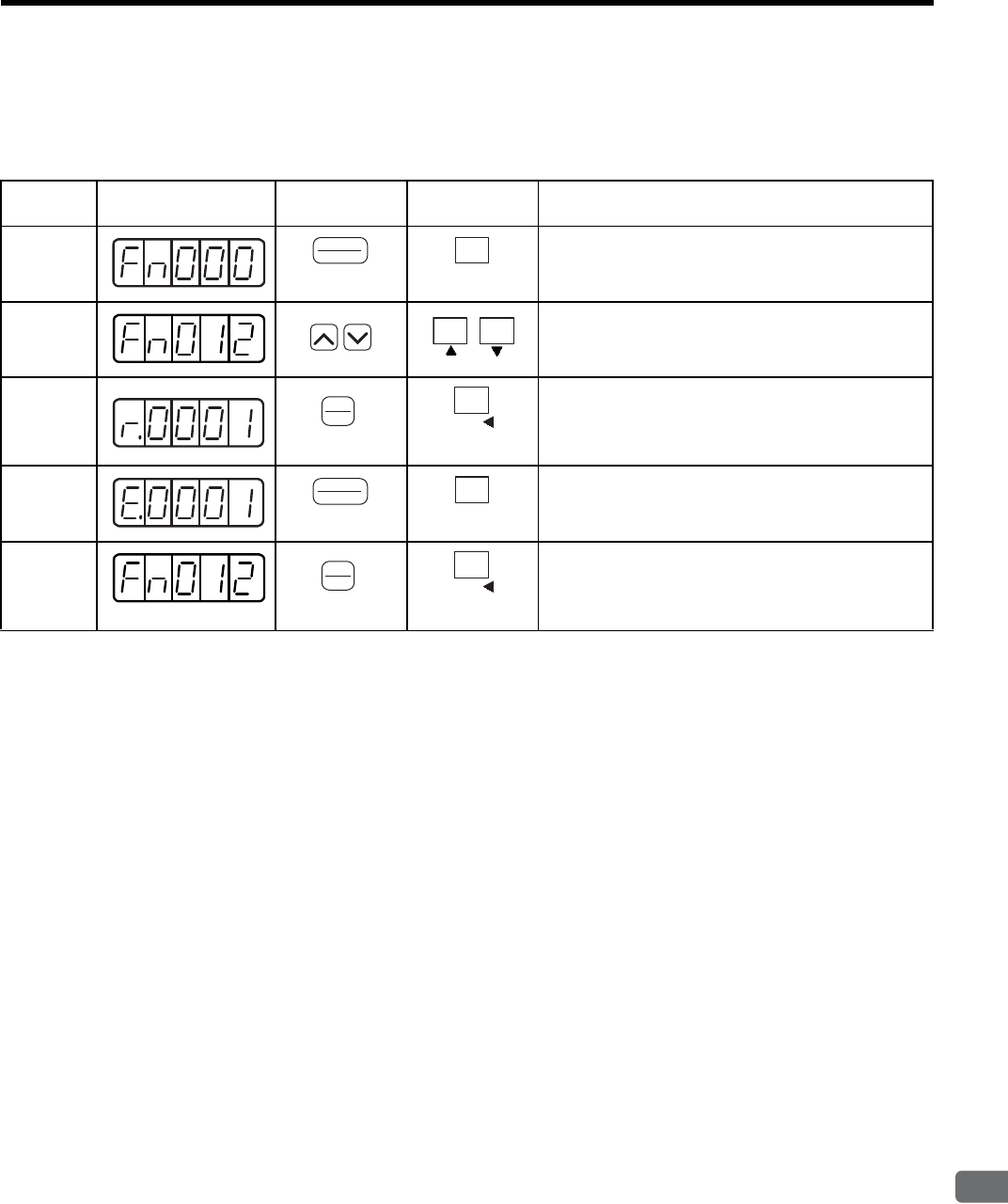
7.2 Operation in Utility Function Mode (Fn)
7
Digital Operator/Panel Operator
7-19
7.2.10 Software Version Display (Fn012)
Set the Fn012 to select the software-version check mode to check the SERVOPACK and encoder software ver-
sion.
Step Display after
Operation Digital Operator Panel Operator Description
1Press the DSPL/SET or MODE/SET Key to select the
utility function mode.
2Press the UP or DOWN Key to select Fn012.
Note: The enabled digit blinks.
3Press the DATA/ENTER Key once, or DATA/SHIFT
Key for more than one second to display the SERVO-
PACK software version.
4Press the DSPL/SET or MODE/SET Key to display the
encoder software version.
5Press the DATA/ENTER Key once, or DATA/SHIFT
Key for more than one second to return to the utility
function mode Fn012.
DSPL
SET
(DSPL/SET Key)
MODE/SET
(MODE/SET Key)
DATA
ENTER
(DATA/ENTER
K
ey)
DATA
(DATA/SHIFT Key)
(Press at least 1 s.)
DSPL
SET
(DSPL/SET Key)
MODE/SET
(MODE/SET Key)
DATA
ENTER
(DATA/ENTER
K
ey)
DATA
(DATA/SHIFT Key)
(Press at least 1 s.)
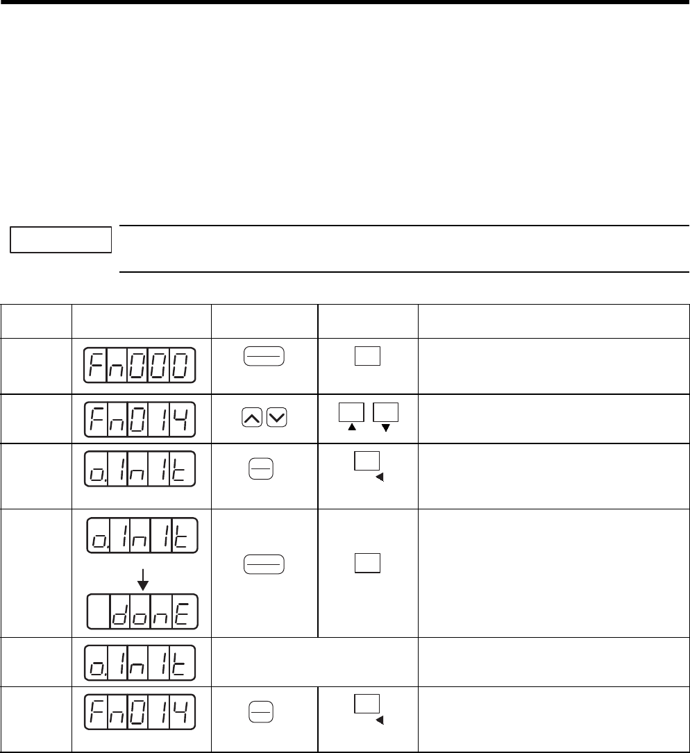
7 Digital Operator/Panel Operator
7.2.11 Application Module Detection Results Clear (Fn014)
7-20
7.2.11 Application Module Detection Results Clear (Fn014)
The alarm A.E7 (application module detection error) occurs when turning ON the power for the first time when
the SERVOPACK is used without application module after the SERVOPACK has been used with application
module.
Clearing application module detection results is performed as using the SERVOPACK individually without
operating the application module detection.
Restarting again after performing the following operation will clear and reset the alarm A.E7. Then, the opera-
tion of SERVOPACK without application module is enabled.
Because the parameter is set for the SERVOPACK with an application module, change the setting or initial-
ize the parameter value (Fn005 of utility function mode) as required.
IMPORTANT
Step Display after
Operation Digital Operator Panel Operator Description
1Press the DSPL/SET or MODE/SET Key to select
the utility function mode.
2Press the UP or DOWN Key to select the Fn014.
Note: The enabled digit blinks.
3Press the DATA/ENTER Key once, or DATA/
SHIFT Key for more than one second, and the dis-
play will be as shown on the left.
4Press the DSPL/SET or MODE/SET Key, and the
display will be as shown on the left to clear the
application module detection.
5
After about one second
The display changes from “donE” to the display
shown on the left.
6Press the DATA/ENTER Key once, or DATA/
SHIFT Key for more than one second to return to
the utility function mode.
DSPL
SET
(DSPL/SET Key)
MODE/SET
(MODE/SET Key)
DATA
ENTER
(DATA/ENTER
K
ey)
DATA
(DATA/SHIFT Key)
(Press at least 1 s.)
Blinks
DSPL
SET
(DSPL/SET Key)
MODE/SET
(MODE/SET Key)
DATA
ENTER
(DATA/ENTER
K
ey)
DATA
(DATA/SHIFT Key)
(Press at least 1 s.)
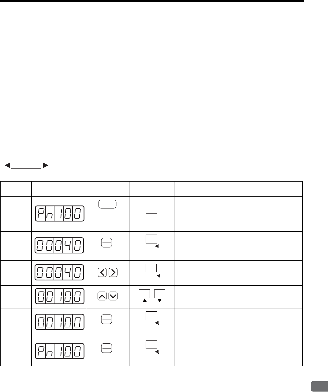
7.3 Operation in Parameter Setting Mode (Pn)
7
Digital Operator/Panel Operator
7-21
7.3 Operation in Parameter Setting Mode (Pn)
Functions can be selected or adjusted by setting parameters. There are two types of parameters. One type requires
value setting and the other requires function selection. These two types use different setting methods.
With value setting, a parameter is set to a value within the specified range of the parameter. With function selec-
tion, the functions allocated to each digit of the seven-segment LED panel indicator (five digits) can be selected.
7.3.1 Setting Parameters
(1) Value Setting Parameters
(a) Types of Value Setting Parameters
Refer to 11.3.2 List of Parameters.
(b) Example of Changing Value Setting Parameter
The parameter settings can be used for changing parameter data. Before changing the data, check the permit-
ted range of the parameter.
The example below shows how to change parameter Pn100 (speed loop gain) from “40” to “100.”
EXAMPLE
Step Display after
Operation Digital Operator Panel Operator Description
1Press the DSPL/SET or MODE/SET Key to select the
parameter setting mode. If a parameter other than
Pn100 is displayed, press the UP or DOWN Key to
select Pn100.
Note: The enabled digit blinks.
2Press the DATA/ENTER Key once, or DATA/SHIFT
Key for more than one second. The current data of
Pn100 is displayed.
3Press the LEFT or RIGHT Key or DATA/SHIFT Key to
select the digit to be set.
4Press the UP or DOWN Key to change the data.
Keep pressing UP or DOWN Key until “00100” is dis-
played.
5Press the DATA/ENTER Key once, or DATA/SHIFT
Key for more than one second. The value blinks and is
saved.
6Press the DATA/ENTER Key once, or DATA/SHIFT
Key for more than one second to return to the display of
Pn100. The data for the speed loop gain (Pn100) is
changed from “40” to “100.”
DSPL
SET
(DSPL/SET Key)
MODE/SET
(MODE/SET Key)
DATA
ENTER
(DATA/ENTER
K
ey)
DATA
(DATA/SHIFT Key)
(Press at least 1 s.)
DATA/
(DATA/SHIFT Key)
DATA
ENTER
(DATA/ENTER
K
ey)
DATA
(DATA/SHIFT Key)
(Press at least 1 s.)
DATA
ENTER
(DATA/ENTER
K
ey)
DATA
(DATA/SHIFT Key)
(Press at least 1 s.)
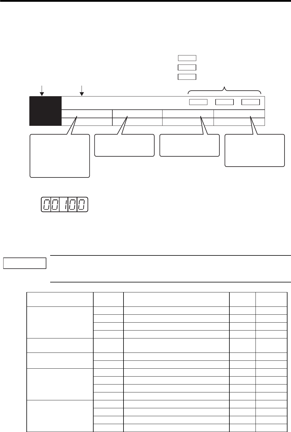
7 Digital Operator/Panel Operator
7.3.1 Setting Parameters
7-22
(c) Parameter Indications
In this manual, the parameter is explained with using the following format.
The following alarm shows the setting value of the parameter.
(2) Function Selection Parameters
(a) Types of Function Selection Parameters
Refer to 11.3.2 List of Parameters.
If the parameters with “After restart” in “Setting Validation” column in the table are changed, turn OFF the
main circuit and control power supply and ON again to validate new setting.
• Pn10B.1 requires the power to be reset as mentioned above.
Decimal display in five digits
Pn406 Emergency Stop Torque
Setting Range
0 to 800 1% 800 Immediately
Setting Unit Factory Setting Setting Validation
The number of the
parameter
The name of the
parameter
Position
Positoin
Speed Torque
Torque
Applicable control mode for the parameter
Speed : Speed control, internally set speed control
: Position control
: Torque control
This section shows the
range of the parameter
settings. The maximum
value can be set even if
the parameter is combined
with the other sepecified
motor.
This section shows the
minimum setting unit
(the setting value).
This section shows the
SERVOPACK's parameter
with factory setting.
This section shows if
the setting is validated
"immediately" or "after
restart" when changing
the parameter.
Category Parameter
No. Name Factory
Setting
Setting
Validation
Function Selection
Parameter
Pn000 Function Selection Basic Switches 0000 After restart
Pn001 Function Selection Application Switches 0000 After restart
Pn002 Function Selection Application Switches 0000 After restart
Pn003 Function Selection Application Switches 0002 Immediately
Servo Gain Related
Parameter
Pn10B Gain Application Switches 0000 After restart/
Immediately
Position Control Related
Parameter
Pn200 Position Control References Selection Switches 0000 After restart
Pn207 Position Control Function Switches 0000 After restart
Sequence Related
Parameter
(Input Signal Selection)
Pn50A Input Signal Selections 2100 After restart
Pn50B Input Signal Selections 6543 After restart
Pn50C Input Signal Selections 8888 After restart
Pn50D Input Signal Selections 8888 After restart
Sequence Related
Parameter
(Output Signal Selection)
Pn50E Output Signal Selections 3211 After restart
Pn50F Output Signal Selections 0000 After restart
Pn510 Output Signal Selections 0000 After restart
Pn512 Output Signal Reversal Setting 0000 After restart
IMPORTANT
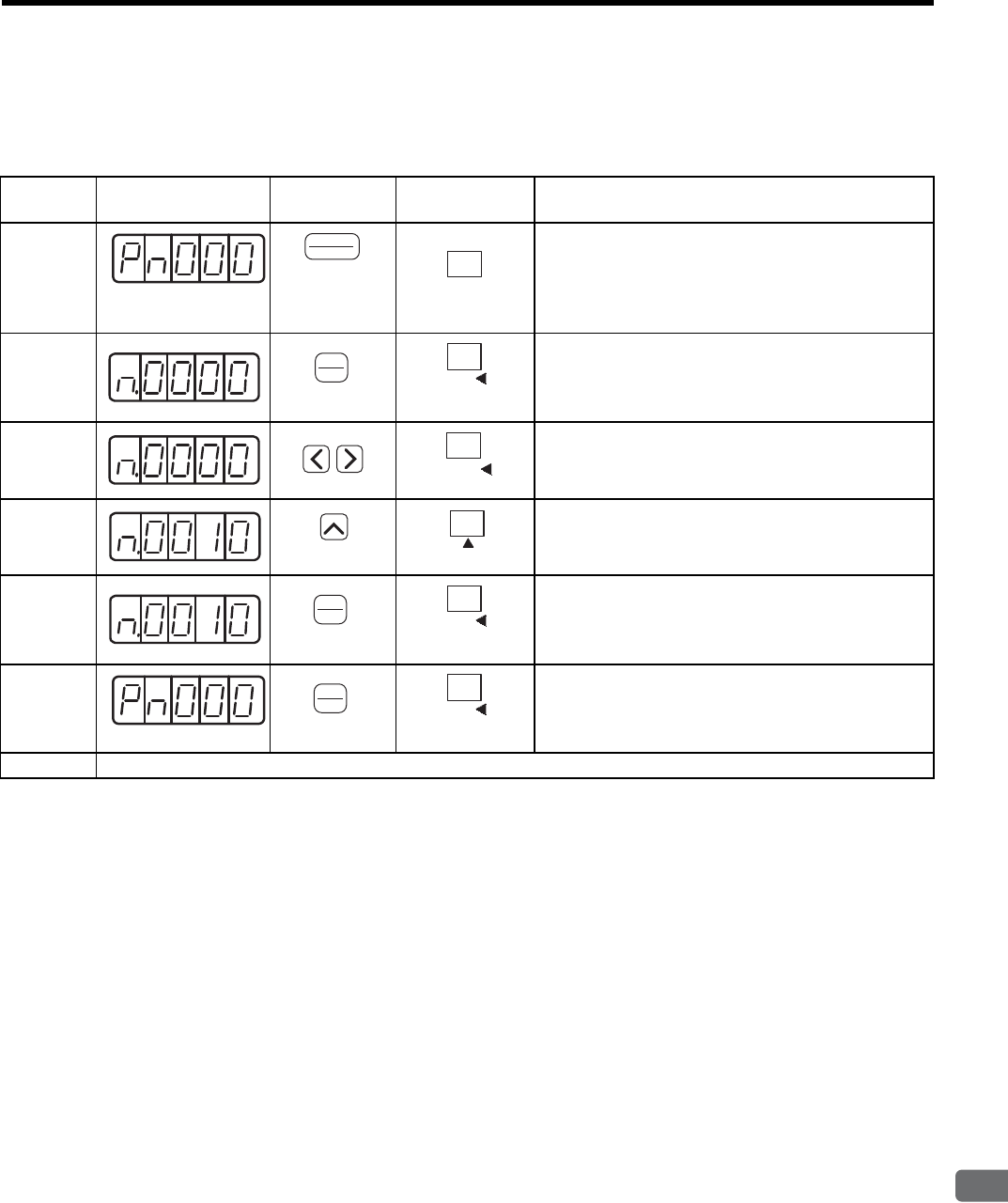
7.3 Operation in Parameter Setting Mode (Pn)
7
Digital Operator/Panel Operator
7-23
(b) Example of Changing Function Selection
The procedure to change the setting of control method selection (Pn000.1) of the function selection basic
switches (Pn000) from speed control to position control is shown below.
Step Display after
Operation
Digital
Operator Panel Operator Description
1Press the DSPL/SET or MODE/SET Key to select the
parameter setting mode. If a parameter other than Pn000
is displayed, press the UP or DOWN Key to select the
Pn100.
Note: The enable digit blinks.
2Press the DATA/ENTER Key once, or DATA/SHIFT
Key for more than one second. The current data of
Pn000 is displayed.
3Press the LEFT or RIGHT or DATA/SHIFT Key to
select the first digit of current data.
4Press the UP Key once to change to “n.0010.”
(Set the control method to position control.)
5Press the DATA/ENTER Key once, or DATA/SHIFT
Key for more than one second. The value blinks and is
saved.
6Press the DATA/ENTER Key once, or DATA/SHIFT
Key for more than one second to return to the display
Pn000. The control method is changed to position con-
trol.
7To enable the change in the setting of function selection basic switches (Pn000), turn OFF the power and ON again.
DSPL
SET
(DSPL/SET Key)
MODE/SET
(MODE/SET Key)
DATA
ENTER
(DATA/ENTER
K
ey)
DATA
(DATA/SHIFT Key)
(Press at least 1 s.)
DATA/
(DATA/SHIFT Key)
(UP Key)
(UP Key)
DATA
ENTER
(DATA/ENTER
K
ey)
DATA
(DATA/SHIFT Key)
(Press at least 1 s.)
DATA
ENTER
(DATA/ENTER
K
ey)
DATA
(DATA/SHIFT Key)
(Press at least 1 s.)
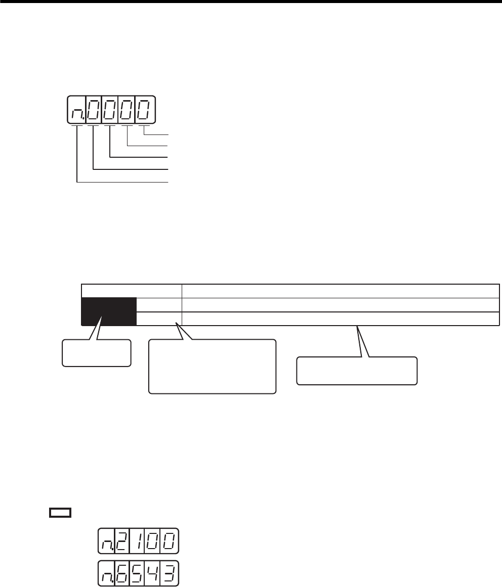
7 Digital Operator/Panel Operator
7.3.2 Input Circuit Signal Allocation
7-24
(c) Parameter Indications
Each digit of the function selection parameters is defined as the hexadecimal display. The parameter display
example shows how parameters are displayed in digits for set values.
For details on each digit of the parameter, see 11.3.2 List of Parameters.
7.3.2 Input Circuit Signal Allocation
Each input signal is allocated to a pin of the input connector CN1 by setting the parameter.
The following table shows detailed allocation.
(1) Factory Setting (Pn50A.0 = 0)
The factory setting for the input signal allocation is as follows.
means factory setting.
• Pn000.0 or n.xxx: Indicates the value for the 1st digit of parameter Pn000.
• Pn000.1 or n.xxx: Indicates the value for the 2nd digit of parameter Pn000.
• Pn000.2 or n.xxx: Indicates the value for the 3rd digit of parameter Pn000.
• Pn000.3 or n.xxx: Indicates the value for the 4th digit of parameter Pn000.
For the hexadecimal display only
1st digit
2nd digit
3rd digit
4th digit
Pn50A
n.2
n.8
The number of the
parameter
Parameter Meaning
This section explains the
details of the function selection.
This blank shows the setting
value of the function selection,
as well as the state condition
on the panel operator and the
digital operator (JUSP-OP02A-2).
Input the forward run prohibited signal (P-OT) from CN1-42 (Factory setting).
Forward run prohibited signal (P-OT) is disabled (Forward rotation allowed).
Pn50A:
Pn50B:
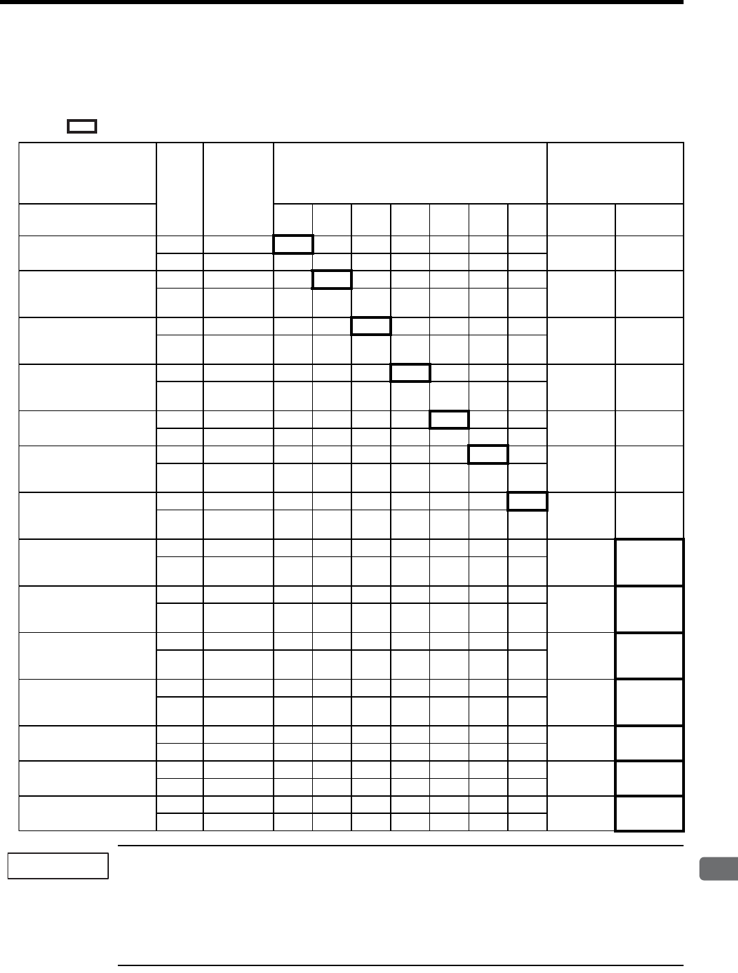
7.3 Operation in Parameter Setting Mode (Pn)
7
Digital Operator/Panel Operator
7-25
(2) Changing the Allocation (Pn50A.0 = 1)
Set the parameter in accordance with the relation between the signal to be used and the input connector pin.
After having changed the parameter, turn OFF the power and ON again to enable the parameters.
means factory setting.
1. When using Servo ON, Forward Run Prohibited, and Reverse Run Prohibited signals with the setting
“Polarity Reversal,” the machine may not move to the specified safe direction at occurrence of failure
such as signal line disconnection. If such setting is absolutely necessary, confirm the operation and
observe safety precautions.
2. When two or more signals are allocated to the same input circuit, the input signal level will be applied to
all the allocated signal.
Signal Name Valid-
ity
Level
Input
Signal
CN1 Input Pin Allocation
Connection Not
Required
(SERVOPACK judges
the connection)
Parameter Setting
Allocation 40 41 42 43 44 45 46 Always
ON
Always
OFF
Servo ON
Pn50A.1 = n.xxx
L /S-ON 0123456 78
HS-ON9ABCDEF
Proportional Operation
Reference
Pn50A.2 = n.xxx
L /P-CON0123456
78
HP-CON9ABCDEF
Forward Run
Prohibited
Pn50A.3 = n.xxx
H P-OT 0123456
78
L/P-OT9ABCDEF
Reverse Run
Prohibited
Pn50B.0 = n.xxx
H N-OT 0123456
78
L /N-OT 9 A B C D E F
Alarm Reset
Pn50B.1 = n.xxx
L/ALM-RST0123456 −8
HALM-RST9 A B C D E F
Forward External
Torque Limit
Pn50B.2 = n.xxx
L /P-CL 0123456
78
HP-CL9ABCDEF
Reserve External
Torque Limit
Pn50B.3 = n.xxx
L /N-CL 0123456
78
HN-CL9ABCDEF
Internally Set Speed
Selection
Pn50C.0 = n.xxx
L /SPD-D0123456
78
H SPD-D 9 A B C D E F
Internally Set Speed
Selection
Pn50C.1 = n.xxx
L /SPD-A0123456
78
H SPD-A 9 A B C D E F
Internally Set Speed
Selection
Pn50C.2 = n.xxx
L /SPD-B0123456
78
H SPD-B 9 A B C D E F
Control Method
Selection
Pn50C.3 = n.xxx
L /C-SEL0123456
78
HC
-S
EL9ABCDEF
Zero Clamp
Pn50D.0 = n.xxx
L/ZCLAMP0123456 78
HZCLAMP9 A B C D E F
Reference Pulse Inhibit
Pn50D.1 = n.xxx
L/INHIBIT0123456 78
H INHIBIT 9 A B C D E F
Gain Changeover
Pn50D.2 = n.xxx
L /G-SEL0123456 78
HG-SEL9ABCDEF
IMPORTANT
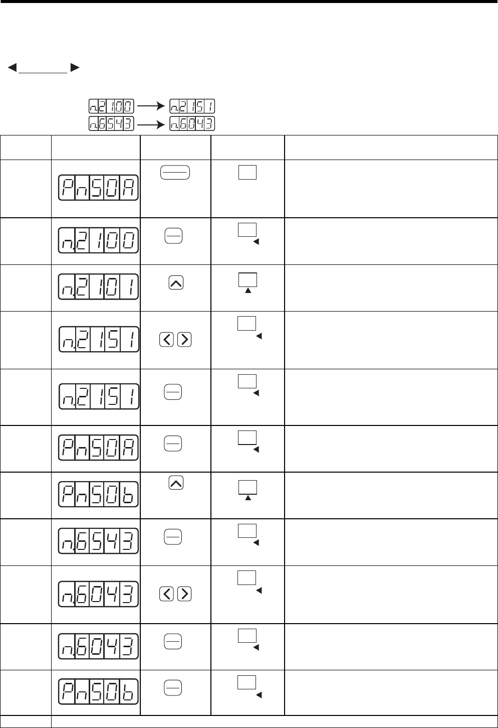
7 Digital Operator/Panel Operator
7.3.2 Input Circuit Signal Allocation
7-26
(3) Allocating Input Signals
The procedure to replace Servo ON (/S-ON) signal allocated to CN1-40 and Forward External Torque Limit
(/P-CL) allocated to CN1-45 is shown below.
EXAMPLE
Pn50B:
Pn50A:
Before After
Step Display after
Operation
Digital
Operator Panel Operator Description
1Press the DSPL/SET or MODE/SET Key to select the
“value setting parameter” mode. If a parameter other
than Pn50A is displayed, press the UP or DOWN Key to
set Pn50A.
Note: The enabled digit blinks.
2Press the DATA/ENTER Key once, or DATA/SHIFT
Key for more than one second to display the current data
of Pn50A.
(/S-ON is allocated to CN1-40.)
3Press the UP Key to set to “1.”
(Sequence input signals can be freely set.)
4Press the LEFT or RIGHT Key or DATA/SHIFT Key to
select the second digit from the right. Press the UP key
to set to “5.”
(Changes the allocation of /S-ON from CN1-40 to CN1-
45.)
5Press the DATA/ENTER Key once, or DATA/SHIFT
Key for more than one second. The value blinks and is
saved.
At the moment, the CN1-45 operates with OR logic for
/S-ON and /P-CL.
6Press the DATA/ENTER Key once, or DATA/SHIFT
Key for more than one second to return to the display
Pn50A.
7Press the UP Key to set Pn50B.
Note: The enabled digit blinks.
8Press the DATA/ENTER Key once, or DATA/SHIFT
Key for more than one second to display the current data
of Pn50B.
(/P-CL is allocated to CN1-45.)
9Press the LEFT or RIGHT Key or DATA/SHIFT Key to
select the third digit from the right. Press the DOWN
Key to set to “0.”
(Changes the allocation of /P-CL from CN1-45 to CN1-
40.)
10 Press the DATA/ENTER Key once, or DATA/SHIFT
Key for more than one second. The value blinks and is
saved.
11 Press the DATA/ENTER Key once, or DATA/SHIFT
Key for more than one second to return to the display
Pn50B. /S-ON is allocation to CN1-45, and /P-CL is
allocated to CN1-40.
12 Turn the power OFF and ON again to enable the change of input signal selections (Pn50A and Pn50B).
DSPL
SET
(DSPL/SET Key)
MODE/SET
(MODE/SET Key)
DATA
ENTER
(DATA/ENTER
K
ey)
DATA
(DATA/SHIFT Key)
(Press at least 1 s.)
(UP Key)
(UP Key)
DATA/
(DATA/SHIFT Key)
DATA
ENTER
(DATA/ENTER
K
ey)
DATA
(DATA/SHIFT Key)
(Press at least 1 s.)
DATA
ENTER
(DATA/ENTER
K
ey)
DATA
(DATA/SHIFT Key)
(Press at least 1 s.)
(UP Key)
(UP Key)
DATA
ENTER
(DATA/ENTER
K
ey)
DATA
(DATA/SHIFT Key)
(Press at least 1 s.)
DATA/
(DATA/SHIFT Key)
DATA
ENTER
(DATA/ENTER
K
ey)
DATA
(DATA/SHIFT Key)
(Press at least 1 s.)
DATA
ENTER
(DATA/ENTER
K
ey)
DATA/
(DATA/SHIFT Key)
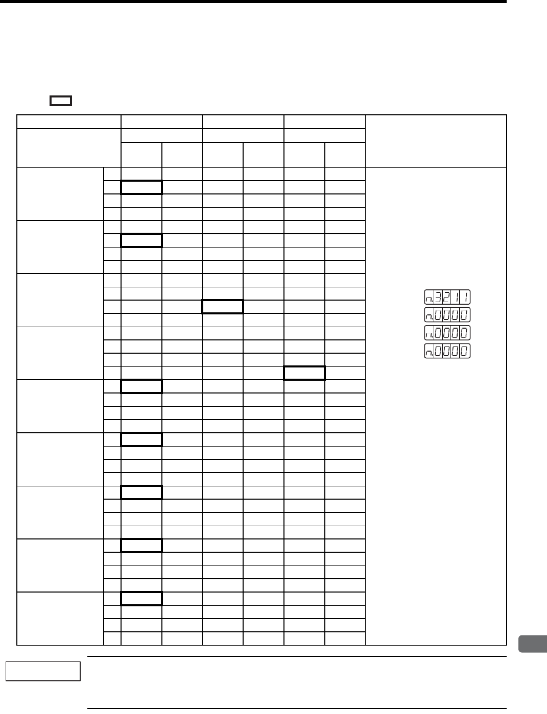
7.3 Operation in Parameter Setting Mode (Pn)
7
Digital Operator/Panel Operator
7-27
7.3.3 Output Circuit Signal Allocation
Functions can be allocated to the following sequence output signals. After having changed the parameter, turn
OFF the power and ON again to enable the parameters.
means factory setting.
1. When two or more signals are allocated to the same output circuit, a signal is output with OR logic.
2. The signals not detected are considered as “Invalid.” For example, Positioning Completion (/COIN) Sig-
nal in speed control mode is “Invalid.”
CN1 Pin No. 25/(26) 27/(28) 29/(30)
Remark
Parameter Setting
Allocation
Pn512=n.xxxPn512=n.xxx Pn512=n.xxx
01
(reverse) 01
(reverse) 01
(reverse)
Positioning
Completion
(/COIN)
Pn50E.0 = n.xxx
0Invalid L:
Valid output signal: Low level
H:
Valid output signal: High level
Invalid:
Do not use the output signal.
Factory Setting
Note:
The output signals for Positioning
Completion Signal and Speed Coin-
cidence Detection Signal differ
depending on the control method.
1L H
2LH
3LH
Speed Coinci-
dence Detection
(/V-CMP)
Pn50E.1 = n.xxx
0Invalid
1L H
2LH
3LH
Servomotor
Rotation Detection
(/TGON)
Pn50E.2 = n.xxx
0Invalid
1L H
2LH
3LH
Servo Ready
(/S-RDY)
Pn50E.3 = n.xxx
0Invalid
1L H
2LH
3LH
Torque Limit
Detection
(/CLT)
Pn50F.0 = n.xxx
0Invalid
1L H
2LH
3LH
Speed Limit
Detection
(/VLT)
Pn50F.1 = n.xxx
0Invalid
1L H
2LH
3LH
Brake Interlock
(/BK)
Pn50F.2 = n.xxx
0Invalid
1L H
2LH
3LH
Warning
(/WARN)
Pn50F.3 = n.xxx
0Invalid
1L H
2LH
3LH
Near
(/NEAR)
Pn510.0 = n.xxx
0I
nv
alid
1L H
2LH
3LH
Pn512:
Pn510:
Pn50F:
Pn50E:
IMPORTANT
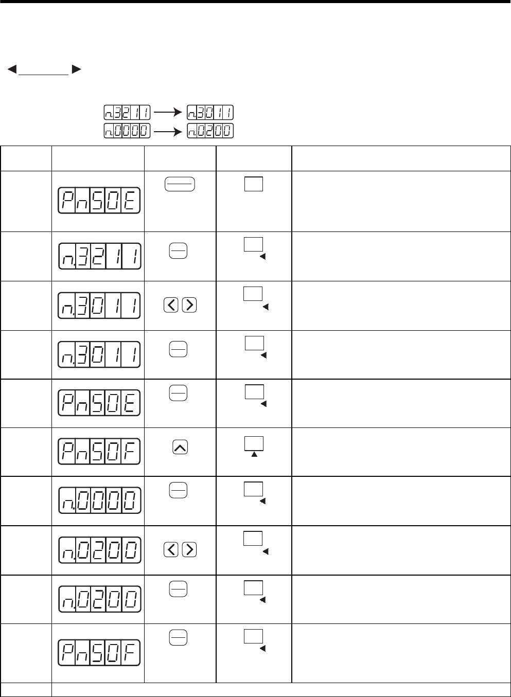
7 Digital Operator/Panel Operator
7.3.3 Output Circuit Signal Allocation
7-28
• Allocating Output Signals
The procedure to replace Servomotor Rotation Detection (/TGON) signal allocated to CN1-27 (28) with
factory setting to “Invalid” and allocate Brake Interlock (/BK) signal to CN1-27 (28) is shown below.
EXAMPLE
Step Display after
Operation
Digital
Operator
Panel
Operator Description
1Press the DSPL/SET or MODE/SET Key to select the
“value setting parameter” mode. If a parameter other
than Pn50E is displayed, press the UP or DOWN Key to
select Pn50E.
Note: The enabled digit blinks.
2Press the DATA/ENTER Key once, or DATA/SHIFT
Key for more than one second to display the current data
of Pn50E.
(/TGON is allocated to CN1-27 (28).)
3Press the LEFT Key or RIGHT or DATA/SHIFT Key to
select the third digit from the right. Press the DOWN
Key to set “0.”
(Sets /TGON “Invalid.”)
4Press the DATA/ENTER Key once, or DATA/SHIFT
Key for more than one second.
The value blinks and is saved.
5Press the DATA/ENTER Key once, or DATA/SHIFT
Key for more than one second to return to the display
Pn50E.
6Press the UP Key to set Pn50F.
Note: The enabled digit blinks.
7Press the DATA/ENTER Key once, or DATA/SHIFT
Key for more than one second to display the current data
of Pn50F.
(/BK is set to “Invalid.”)
8Press the LEFT or RIHGT Key or DATA/SHIFT Key to
select the third digit from the right. Press the UP Key to
set “2.”
(Allocates /BK to CN1-27 (28).)
9Press the DATA/ENTER Key once, or DATA/SHIFT
Key for more than one second. The value blinks and is
saved.
10 Press the DATA/ENTER Key once, or DATA/SHIFT
Key for more than one second to return to the display
Pn50F.
/TGON is set as “Invalid” and /BK is allocated to CN1-
27 (28).
11 Turn OFF the power and ON again to enable the changes of output signal selection (Pn50E and Pn50F).
Pn50E:
Before After
Pn50F:
DSPL
SET
(DSPL/SET Key)
MODE/SET
(MODE/SET Key)
DATA
ENTER
(DATA/ENTER
K
ey)
DATA
(DATA/SHIFT Key)
(Press at least 1 s.)
DATA/
(DATA/SHIFT Key)
DATA
ENTER
(DATA/ENTER
K
ey)
DATA
(DATA/SHIFT Key)
(Press at least 1 s.)
DATA
ENTER
(DATA/ENTER
K
ey)
DATA
(DATA/SHIFT Key)
(Press at least 1 s.)
(UP Key)
(UP Key)
DATA
ENTER
(DATA/ENTER
K
ey)
DATA
(DATA/SHIFT Key)
(Press at least 1 s.)
DATA/
(DATA/SHIFT Key)
DATA
ENTER
(DATA/ENTER
K
ey)
DATA
(DATA/SHIFT Key)
(Press at least 1 s.)
DATA
ENTER
(DATA/ENTER
K
ey)
DATA
(DATA/SHIFT Key)
(Press at least 1 s.)

7.4 Operation in Monitor Mode (Un)
7
Digital Operator/Panel Operator
7-29
7.4 Operation in Monitor Mode (Un)
The monitor mode can be used for monitoring the reference values, I/O signal status, and SERVOPACK internal
status.
The monitor mode can be selected during motor operation.
7.4.1 List of Monitor Modes
(1) Contents of Monitor Mode Display
* 1. Refer to (2) Sequence I/O Signal Monitor Display.
* 2. Refer to (4) Monitor Display of Reference Pulse Counter and Feedback Pulse Counter.
Parameter
No. Content of Display Unit
Un000 Actual motor speed min-1
Un001 Input speed reference (Valid only in speed control mode) min-1
Un002 Internal torque reference ( in percentage to the rated torque) %
Un003 Rotation angle 1 (16-bit decimal code) Number of pulses
from the zero-point
Un004 Rotation angle 2 (Angle from the zero-point (electrical angle)) deg
Un005 Input signal monitor *1 −
Un006 Output signal monitor *1 −
Un007 Input reference pulse speed (valid only in position control mode) min-1
Un008 Error counter value (amount of position error) (valid only in position control mode) reference unit
Un009 Accumulated load rate (value for the rated torque as 100 %. Displays effective torque in 10-s
cycle.)
%
Un00A Regenerative load rate (value for the processable regenerative power as 100 %. Displays regen-
erative power consumption in 10-s cycle.)
%
Un00B Power consumed by DB resistance
(Value for the processable power when dynamic brake is applied as 100 %. Displays power
consumed by DB resistance in 10-s cycle.)
%
Un00C Input reference pulse counter (32-bit hexadecimal code)
(valid only in position control mode) *2
−
Un00D Feedback pulse counter (Data as four times of the encoder pulse number: 32-bit hexadecimal
code) *2
−
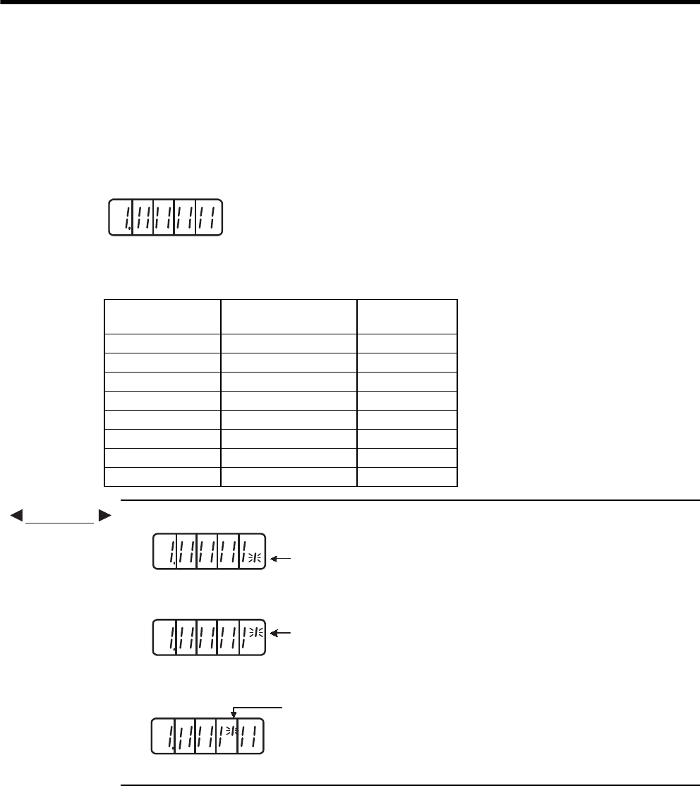
7 Digital Operator/Panel Operator
7.4.1 List of Monitor Modes
7-30
(2) Sequence I/O Signal Monitor Display
The following section describes the monitor display for sequence I/O signals.
(a) Input Signal Monitor Display
The status of input signal allocated to each input terminal is displayed:
When the input is in OFF (open) status, the top segment (LED) is lit.
when the input is in ON (short-circuited) status, the bottom segment (LED) is lit.
Refer to 7.3.2 Input Circuit Signal Allocation for the relation between input terminals and signals.
• When /S-ON signal is ON (Servo ON at L level)
• When /S-ON signal is OFF
• When P-OT signal operates (Operates at H level)
7654 321
Top: OFF (H level)
Bottom: ON (L level)
Number
8
Display LED
Number Input Terminal Name Factory Setting
1CN1-40 /S-ON
2CN1-41 /P-CON
3CN1-42 P-OT
4CN1-43 N-OT
5CN1-44 /ALM-RST
6CN1-45 /P-CL
7CN1-46 /N-CL
8CN1-4 SEN
EXAMPLE
The bottom segment
of number 1 is lit.
7654321
8
76543218
The top segment of
number 1 is lit.
The top segment of
number 3 is lit.
76543218
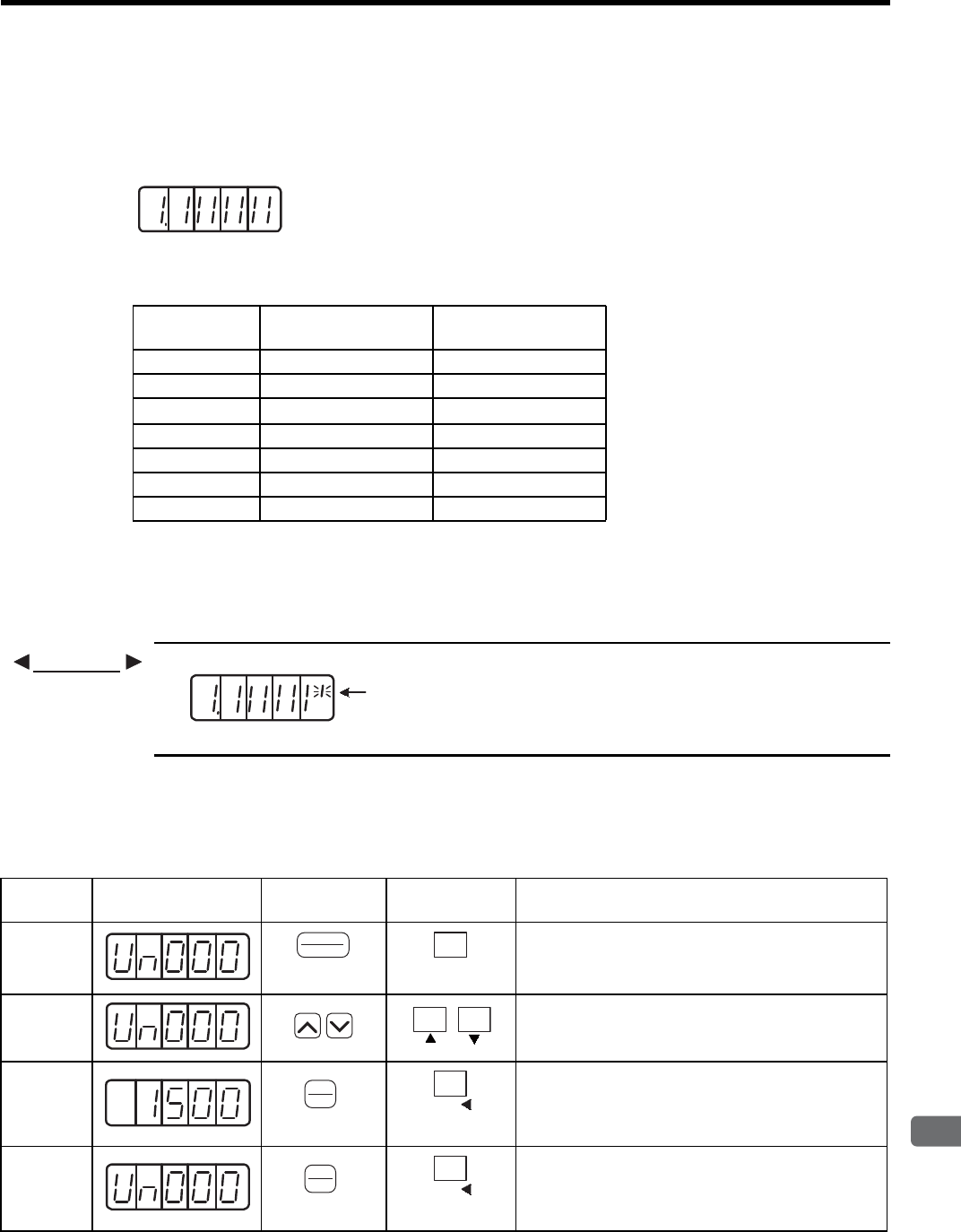
7.4 Operation in Monitor Mode (Un)
7
Digital Operator/Panel Operator
7-31
(b) Output Signal Monitor Display
The status of output signal allocated to each output terminal is displayed:
When the output is in OFF (open) status, the top segment (LED) is lit.
When the output is in ON (short-circuited) status, the bottom segment is lit.
Refer to 7.3.3 Output Circuit Signal Allocation for the relation between output terminals and signals.
Note: For the detail of output terminals, refer to 7.3.3 Output Circuit Signal Allocation.
Seven segments in the top and bottom rows of an LED turn ON and OFF in different combinations to indi-
cate various output signals.
These segments ON for L level and OFF for H level.
• When ALM signal operates (alarm at H level.)
(3) Operation in Monitor Mode
The example below shows how to display the contents of monitor number Un000 when the servomotor rotates at
1500 min-1.
4321
Top: OFF (H level)
Bottom: ON (L level)
Number
765
Display LED
Number
Output Terminal
Name Factory Setting
1CN1-31, -32 ALM
2CN1-25, -26 /COIN or /V-CMP
3CN1-27, -28 /TGON
4CN1-29, -30 /S-RDY
5CN1-37 ALO1
6CN1-38 ALO2
7CN1-39 ALO3
EXAMPLE
The top segment of
number 1 is lit.
43
21
765
Step Display after
Operation
Digital
Operator
Panel
Operator Description
1Press the DSPL/SET or MODE/SET Key to select the
monitor mode.
2Press the UP or DOWN Key to select the monitor num-
ber to be displayed. The display shows the example of
the data of Un000.
3Press the DATA/ENTER Key once, or DATA/SHIFT
Key for more than one second to display the data of
Un000.
4Press the DATA/ENTER Key once, or DATA/SHIFT
Key for more than one second to return to the display
of monitor number.
DSPL
SET
(DSPL/SET Key)
MODE/SET
(MODE/SET Key)
DATA
ENTER
(DATA/ENTER
K
ey)
DATA
(DATA/SHIFT Key)
(Press at least 1 s.)
DATA
ENTER
(DATA/ENTER
K
ey)
DATA
(DATA/SHIFT Key)
(Press at least 1 s.)
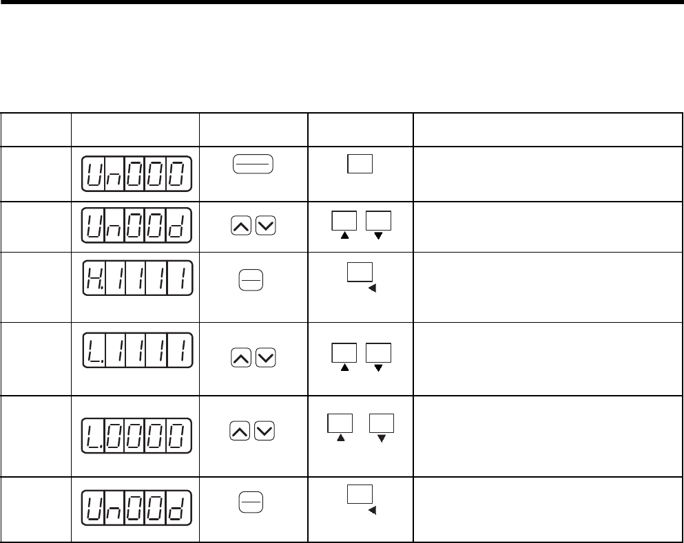
7 Digital Operator/Panel Operator
7.4.1 List of Monitor Modes
7-32
(4) Monitor Display of Reference Pulse Counter and Feedback Pulse Counter
The monitor display of reference pulse counter and feedback pulse counter is expressed in 32-bit hexadecimal.
When the control power supply is turned ON, reference pulse and feedback pulse will be “0.” The counter
value increases by forward references, and decreases by reverse references.
Displays the pulse number from 0 to 4294967295 in sequence. If one pulse is decreased from 0, the digital
operator and the panel operator display 4294967295 and then decrease from this pulse number. Also, if one
pulse in increased from 4294967295, the digital operator and the panel operator display 0 and increase from
this pulse number.
The feedback pulse will be 65536 pulse/rev, when using the 16-bit encoder. The feedback pulse will be
131071 pulse/rev, when using the 17-bit encoder.
Step Display after
Operation
Digital
Operator
Panel
Operator Description
1Press the DSPL/SET or MODE/SET Key to select
the monitor mode.
2Press the UP or DOWN Key to select “Un00C” or
“Un00D.”
3Press the DATA/ENTER Key once, or DATA/
SHIFT Key for more than one second to display the
data of the selected monitor number.
4Press the UP or DOWN Key to display the lower
16-bit data.
5Press both UP and DOWN Keys simultaneously
while the display on the left appears to clear the 32-
bit counter data.
(The display shown on the left is of the lower 16-bit
data.)
6Press the DATA/ENTER Key once, or DATA/
SHIFT Key for more than one second to return to
the display of monitor number.
DSPL
SET
(DSPL/SET Key)
MODE/SET
(MODE/SET Key)
The upper 16-bit data
DATA
ENTER
(DATA/ENTER
K
ey)
DATA
(DATA/SHIFT Key)
(Press at least 1 s.)
The lower 16-bit data
(Press simultaneouly)
Press simultaneously
+
DATA
ENTER
(DATA/ENTER
K
ey)
DATA
(DATA/SHIFT Key)
(Press at least 1 s.)

8
Operation
8-1
8
Operation
8.1 Trial Operation - - - - - - - - - - - - - - - - - - - - - - - - - - - - - - - - - 8-4
8.1.1 Trial Operation for Servomotor without Load - - - - - - - - - - - - - - - - - - 8-6
8.1.2 Trial Operation for Servomotor without Load from Host Reference - - - 8-9
8.1.3 Trial Operation with the Servomotor Connected to the Machine - - - - 8-15
8.1.4 Servomotor with Brakes - - - - - - - - - - - - - - - - - - - - - - - - - - - - - - - - 8-16
8.1.5 Position Control by Host Controller - - - - - - - - - - - - - - - - - - - - - - - - 8-16
8.2 Control Mode Selection - - - - - - - - - - - - - - - - - - - - - - - - - - 8-17
8.3 Setting Common Basic Functions - - - - - - - - - - - - - - - - - - - 8-18
8.3.1 Setting the Servo ON Signal - - - - - - - - - - - - - - - - - - - - - - - - - - - - - 8-18
8.3.2 Switching the Servomotor Rotation Direction - - - - - - - - - - - - - - - - - 8-19
8.3.3 Setting the Overtravel Limit Function - - - - - - - - - - - - - - - - - - - - - - - 8-20
8.3.4 Setting for Holding Brakes - - - - - - - - - - - - - - - - - - - - - - - - - - - - - - 8-22
8.3.5 Selecting the Stopping Method After Servo OFF - - - - - - - - - - - - - - - 8-26
8.3.6 Instantaneous Power Loss Settings - - - - - - - - - - - - - - - - - - - - - - - - 8-27
8.4 Absolute Encoders - - - - - - - - - - - - - - - - - - - - - - - - - - - - - 8-28
8.4.1 Interface Circuits - - - - - - - - - - - - - - - - - - - - - - - - - - - - - - - - - - - - - 8-29
8.4.2 Selecting an Absolute Encoder - - - - - - - - - - - - - - - - - - - - - - - - - - - 8-30
8.4.3 Handling Batteries - - - - - - - - - - - - - - - - - - - - - - - - - - - - - - - - - - - - 8-30
8.4.4 Replacing Batteries - - - - - - - - - - - - - - - - - - - - - - - - - - - - - - - - - - - 8-31
8.4.5 Absolute Encoder Setup (Fn008) - - - - - - - - - - - - - - - - - - - - - - - - - 8-32
8.4.6 Absolute Encoder Reception Sequence - - - - - - - - - - - - - - - - - - - - - 8-33
8.4.7 Multiturn Limit Setting - - - - - - - - - - - - - - - - - - - - - - - - - - - - - - - - - - 8-36
8.4.8 Multiturn Limit Setting When Multiturn Limit Disagreement
(A.CC) Occurred - - - - - - - - - - - - - - - - - - - - - - - - - - - - - - - - - - - - - 8-37
8.5 Operating Using Speed Control with Analog Reference - - - 8-38
8.5.1 Setting Parameters - - - - - - - - - - - - - - - - - - - - - - - - - - - - - - - - - - - 8-38
8.5.2 Setting Input Signals - - - - - - - - - - - - - - - - - - - - - - - - - - - - - - - - - - 8-39
8.5.3 Adjusting Offset - - - - - - - - - - - - - - - - - - - - - - - - - - - - - - - - - - - - - - 8-40
8.5.4 Soft Start - - - - - - - - - - - - - - - - - - - - - - - - - - - - - - - - - - - - - - - - - - - 8-43
8.5.5 Speed Reference Filter - - - - - - - - - - - - - - - - - - - - - - - - - - - - - - - - - 8-43
8.5.6 Using the Zero Clamp Function - - - - - - - - - - - - - - - - - - - - - - - - - - - 8-43
8.5.7 Encoder Signal Output - - - - - - - - - - - - - - - - - - - - - - - - - - - - - - - - - 8-45
8.5.8 Speed Coincidence Output - - - - - - - - - - - - - - - - - - - - - - - - - - - - - - 8-48

8 Operation
8-2
8.6 Operating Using Position Control - - - - - - - - - - - - - - - - - - - 8-49
8.6.1 Setting Parameters - - - - - - - - - - - - - - - - - - - - - - - - - - - - - - - - - - - - 8-49
8.6.2 Setting the Electronic Gear - - - - - - - - - - - - - - - - - - - - - - - - - - - - - -8-51
8.6.3 Position Reference - - - - - - - - - - - - - - - - - - - - - - - - - - - - - - - - - - - -8-54
8.6.4 Smoothing - - - - - - - - - - - - - - - - - - - - - - - - - - - - - - - - - - - - - - - - - -8-57
8.6.5 Positioning Completed Output Signal - - - - - - - - - - - - - - - - - - - - - - -8-58
8.6.6 Positioning Near Signal - - - - - - - - - - - - - - - - - - - - - - - - - - - - - - - - - 8-59
8.6.7 Reference Pulse Inhibit Function (INHIBIT) - - - - - - - - - - - - - - - - - - -8-60
8.6.8 Reference Pulse Input Multiplication Switching Function - - - - - - - - - 8-61
8.7 Operating Using Torque Control - - - - - - - - - - - - - - - - - - - - 8-63
8.7.1 Setting Parameters - - - - - - - - - - - - - - - - - - - - - - - - - - - - - - - - - - - - 8-63
8.7.2 Torque Reference Input - - - - - - - - - - - - - - - - - - - - - - - - - - - - - - - - - 8-63
8.7.3 Adjusting the Reference Offset - - - - - - - - - - - - - - - - - - - - - - - - - - -8-64
8.7.4 Limiting Servomotor Speed during Torque Control - - - - - - - - - - - - - - 8-66
8.8 Operating Using Speed Control with an Internally Set Speed 8-68
8.8.1 Setting Parameters - - - - - - - - - - - - - - - - - - - - - - - - - - - - - - - - - - - - 8-68
8.8.2 Input Signal Settings - - - - - - - - - - - - - - - - - - - - - - - - - - - - - - - - - - -8-69
8.8.3 Operating Using an Internally Set Speed - - - - - - - - - - - - - - - - - - - - - 8-69
8.9 Limiting Torque - - - - - - - - - - - - - - - - - - - - - - - - - - - - - - - - 8-71
8.9.1 Internal Torque Limit (Limiting Maximum Output Torque) - - - - - - - - -8-71
8.9.2 External Torque Limit (Output Torque Limiting by Input Signals) - - - - 8-72
8.9.3 Torque Limiting Using an Analog Voltage Reference - - - - - - - - - - - -8-73
8.9.4 Torque Limiting Using an External Torque Limit and Analog Voltage
Reference - - - - - - - - - - - - - - - - - - - - - - - - - - - - - - - - - - - - - - - - - - 8-74
8.9.5 Checking Output Torque Limiting during Operation - - - - - - - - - - - - -8-75
8.10 Control Mode Selection - - - - - - - - - - - - - - - - - - - - - - - - - 8-76
8.10.1 Setting Parameters - - - - - - - - - - - - - - - - - - - - - - - - - - - - - - - - - - -8-76
8.10.2 Switching the Control Mode - - - - - - - - - - - - - - - - - - - - - - - - - - - - -8-76
8.11 Other Output Signals - - - - - - - - - - - - - - - - - - - - - - - - - - - 8-77
8.11.1 Servo Alarm Output (ALM) and Alarm Code Output
(ALO1, ALO2, ALO3) - - - - - - - - - - - - - - - - - - - - - - - - - - - - - - - - - 8-77
8.11.2 Warning Output (/WARN) - - - - - - - - - - - - - - - - - - - - - - - - - - - - - - -8-78
8.11.3 Servomotor running Output Signal (/TGON) - - - - - - - - - - - - - - - - -8-78
8.11.4 Servo Ready (/S-RDY) Output - - - - - - - - - - - - - - - - - - - - - - - - - - - 8-79

8
Operation
8-3
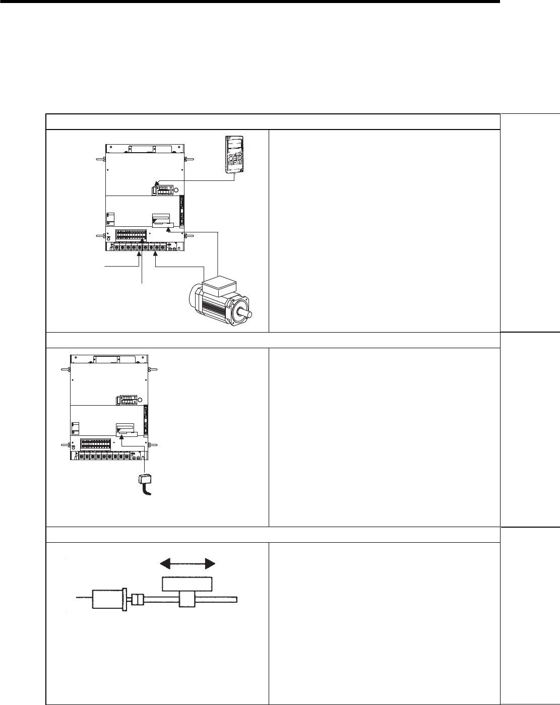
8 Operation
8-4
8.1 Trial Operation
Make sure that all wiring has been completed prior to trial operation.
Perform the following three types of trial operation in order. Instructions are given for speed control mode (stan-
dard setting) and position control mode. Unless otherwise specified, the standard parameters for speed control
mode (factory setting) are used.
(1)Trial Operation for Servomotor without Load (Refer to 8.1.1.)
Purpose
The servomotor is operated without connecting the shaft to
the machine in order to confirm that the following wiring is
correct.
• Power supply circuit wiring
• Servomotor wiring
• Encoder wiring
• Servomotor’s rotation direction and motor speed
(2)Trial Operation for Servomotor with Host Reference (Refer to 8.1.2.)
Purpose
The servomotor is operated without connecting the shaft to
the machine in order to confirm that the following wiring is
correct.
• I/O signal wiring between the SERVOPACK and the host
controller.
• Servomotor’s rotation direction, motor speed, and number
of rotations
• Operation of the brake, overtravel, and other protective
functions.
(3)Trial Operation for the Servomotor and Machine Combined (Refer to 8.1.3.)
Purpose
The servomotor is connected to the machine and trial opera-
tion is performed. The SERVOPACK is adjusted to match the
machine characteristics.
• The servomotor’s rotation direction, motor speed, and
machine travel distance.
• Set the necessary parameters.
Check the wiring
.4 .5 .6 789
8
8
&7
8
8
8
&9&8 $
8
&%
0
$
&%
2
%*#4)'
5*&)
㧖㧖㧖㧖
6#5''/1&
-5'4812#%
#;#5-#9
4
1
2
'
4
#
6
1
%0
%0
219'4
%0
WARNING
ෂޓ㒾
ㅢ㔚ਛ߮㔚Ḯࠝࡈᓟ5
ಽ㑆ޔ┵ሶㇱߦ⸅ࠆߥ
electric shock.
Disconnect all power
May cause
ᗵ㔚ߩᕟࠇࠅ
before servicing.
and wait 5 min.
grounding techniques.
ធ⛯ߖࠃ
Use proper
ᔅߕࠕ㧙ࠬ✢ࠍ
From power
supply
.4 .5 .6 789
8
8 &7
8
8
8 &9&8 $
8
&%
0
$
&%
2
%*#4)'
5*&)
㧖㧖㧖㧖
6#5''/1&
-5'4812#%
#;#5-#9
4
1
2
'
4
#
6
1
%0
%0
219'4
%0
WARNING
ෂޓ㒾
ㅢ㔚ਛ߮㔚Ḯࠝࡈᓟ5
ಽ㑆ޔ┵ሶㇱߦ⸅ࠆߥ
electric shock.
Disconnect all power
May cause
ᗵ㔚ߩᕟࠇࠅ
before servicing.
and wait 5 min.
grounding techniques.
ធ⛯ߖࠃ
Use proper
ᔅߕࠕ㧙ࠬ✢ࠍ
Connect the CN1 connector
Connect to the machine
Servomotor
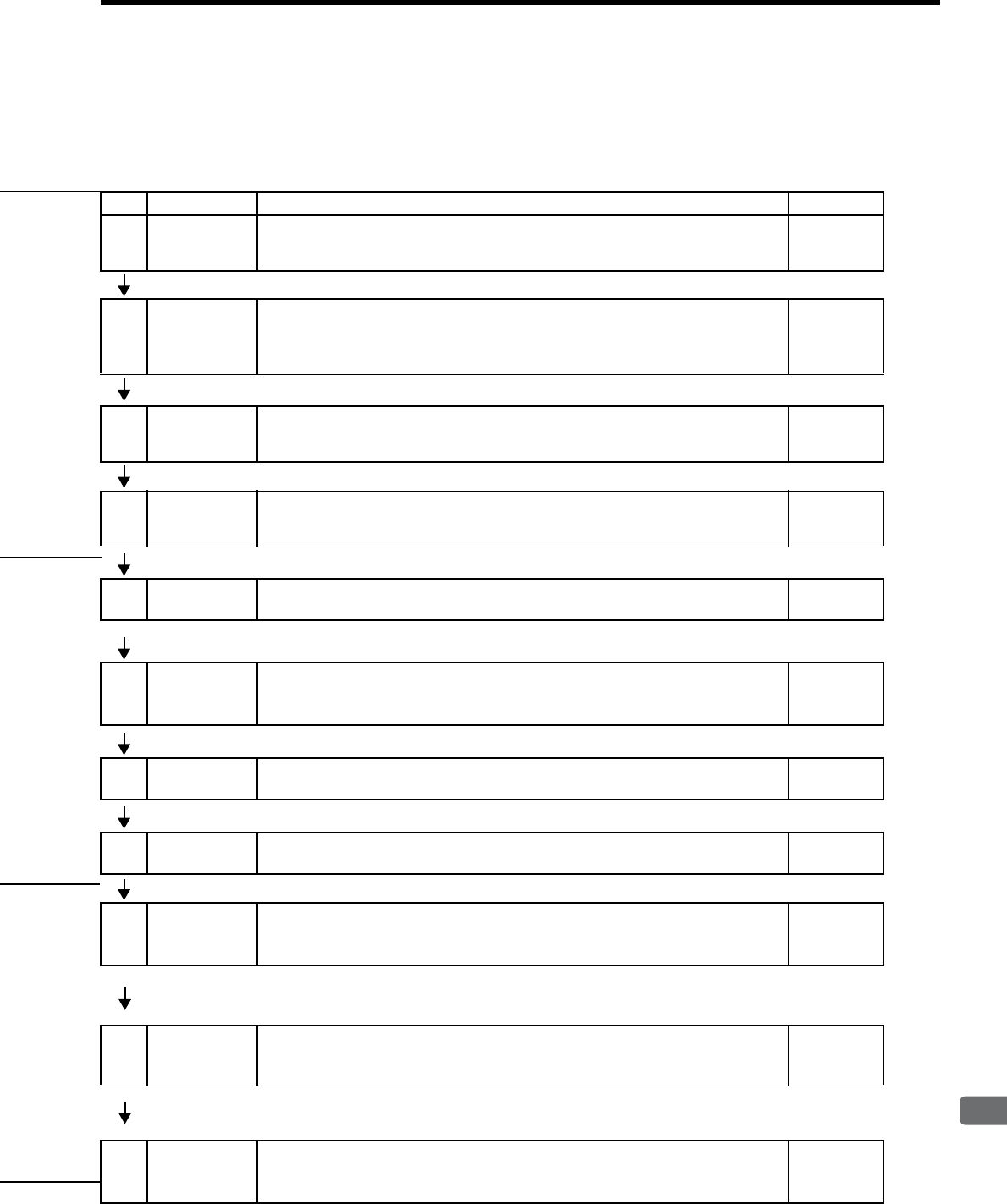
8.1 Trial Operation
8
Operation
8-5
Step Item Description Reference
1Installation
and mounting
Install the servomotor and SERVOPACK according to the installation conditions.
(Do not connect the servomotor to the machine because the servomotor will be oper-
ated first under a no-load condition for checking.)
−
2Wiring and
connections
Connect the power supply circuit (refer to 6.1.2), servomotor wiring (U, V, W), I/O
signal wiring (CN1), and encoder wiring (CN2). During (1) Trial Operation for Ser-
vomotor without Load, however, disconnect the CN1 connector (refer to 8.1.1). −
3Turn ON the
power.
Turn ON the power. Check the panel operator to make sure that the SERVOPACK is
running normally. If using a servomotor equipped with an absolute encoder, perform
the setup for the absolute encoder (refer to 8.4.5.).
−
4
Execute jog
mode
operation.
Execute jog mode operation with the servomotor alone under a no-load condition. Jog Operation
5Connect input
signals. Connect the input signals (CN1) necessary for trial operation. −
6Check input
signals.
Use the internal monitor function to check the input signals.
Turn ON the power, and check the emergency stop, brake, overtravel, and other pro-
tective functions for correct operation.
−
7Input the ser-
vo ON signal. Input the servo ON signal, and turn ON the servomotor. Host
Reference
8Input
reference.
Input the reference for the control mode being used, and check the servomotor for
correct operation.
Host
Reference
9Check protec-
tive operation.
Turn OFF the power, and then connect the servomotor to the machine.
If using a servomotor with an absolute encoder, set up the absolute encoder and make
the initial settings for the host controller to match the machine’s zero position.
−
10
Set
necessary
parameters.
Using the same procedure as you did to input a reference in step 8, operate the servo-
motor from the host controller and set the parameter so that the machine’s travel
direction, travel distance, and travel speed all correspond to the reference.
Host
Reference
11 Operation
The servomotor can now be operated. Adjust the servo gain if necessary. Refer to
9.1 Autotuning.
If a problem occurs, refer to 10 Inspection, Maintenance, and Troubleshooting.
Host
Reference
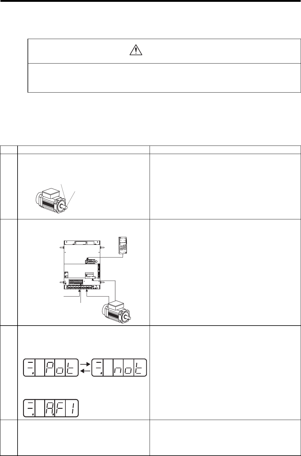
8 Operation
8.1.1 Trial Operation for Servomotor without Load
8-6
8.1.1 Trial Operation for Servomotor without Load
In this section, confirm the cable connections of the main circuit power supply, motor and encoder except the
connection to host controller. Incorrect wiring is generally the reason why servomotors fail to operate properly
during the trial operation.
Confirm the wiring, and then conduct the trial operation for servomotor without load.
The operation and the display are the same both for the panel operator and optional digital operator (JUSP-
OP02A-2).
• Release the coupling between the servomotor and the machine, and secure only the servomotor without a
load.
To prevent accidents, initially perform the trial operation for servomotor under no-load conditions (with all couplings
and belts disconnected).
CAUTION
Step Description Check Method and Remarks
1
Secure the servomotor.
Follow 3.3.1 Precautions on Servomotor Installation and secure
the servomotor mounting plate to the machine in order to prevent
the servomotor from moving during operation.
Do not connect the servomotor shaft to the machine. The servomo-
tor may tip over during rotation.
2
Check the power supply circuit, servomotor, and encoder
wiring.
With the CN1 connector not connected, check the power supply
circuit and servomotor wiring.
Refer to 6.1 Wiring Main Circuit for wiring example of main cir-
cuit. Refer to 2.4 Selecting Cables for motor and encoder cables.
3
Turn ON the control power supply and main circuit power
supply.
Normal Display
Example of Alarm Display
If the power is correctly supplied, the panel operator display on the
front panel of the SERVOPACK will appear as shown on the left.
The display on the left indicates that Forward Run Prohibited (P-
OT) and Reverse Run Prohibited (N-OT). For details, refer to
7.1.4 Status Display.
If an alarm display appears, the power supply circuit, servomotor
wiring, or encoder wiring is incorrect. If an alarm is displayed, turn
OFF the power, find the problem, and correct it.
Refer to 10.1 Troubleshooting.
4
Release the brake before driving the servomotor when a
servomotor with brake is used.
When using an absolute encoder, encoder setup is required
before running the servomotor.
Refer to 8.3.4 Setting for Holding Brakes and 8.4.5 Absolute
Encoder Setup (Fn008).
Absolute Encoder Setup (Fn008) operation can be omitted when
setting the Pn002 to n.1 (uses absolute encoder as an incre-
mental encoder) only during trial operation.
Secure the mounting plate
of the servomotor to the
equipment.
Do not connect anything
to the shaft
(no-load conditions).
Check the wiring
.4 .5 .6 789
8
8
&7
8
8
8
&9&8 $
8
&%
0
$
&%
2
%*#4)'
5*&)
㧖㧖㧖㧖
6#5''/1&
-5'4812#%
#;#5-#9
4
1
2
'
4
#
6
1
%0
%0
219'4
%0
WARNING
ෂޓ㒾
ㅢ㔚ਛ߮㔚Ḯࠝࡈᓟ5
ಽ㑆ޔ┵ሶㇱߦ⸅ࠆߥ
electric shock.
Disconnect all power
May cause
ᗵ㔚ߩᕟࠇࠅ
before servicing.
and wait 5 min.
grounding techniques.
ធ⛯ߖࠃ
Use proper
ᔅߕࠕ㧙ࠬ✢ࠍ
From power
supply
Alternate display
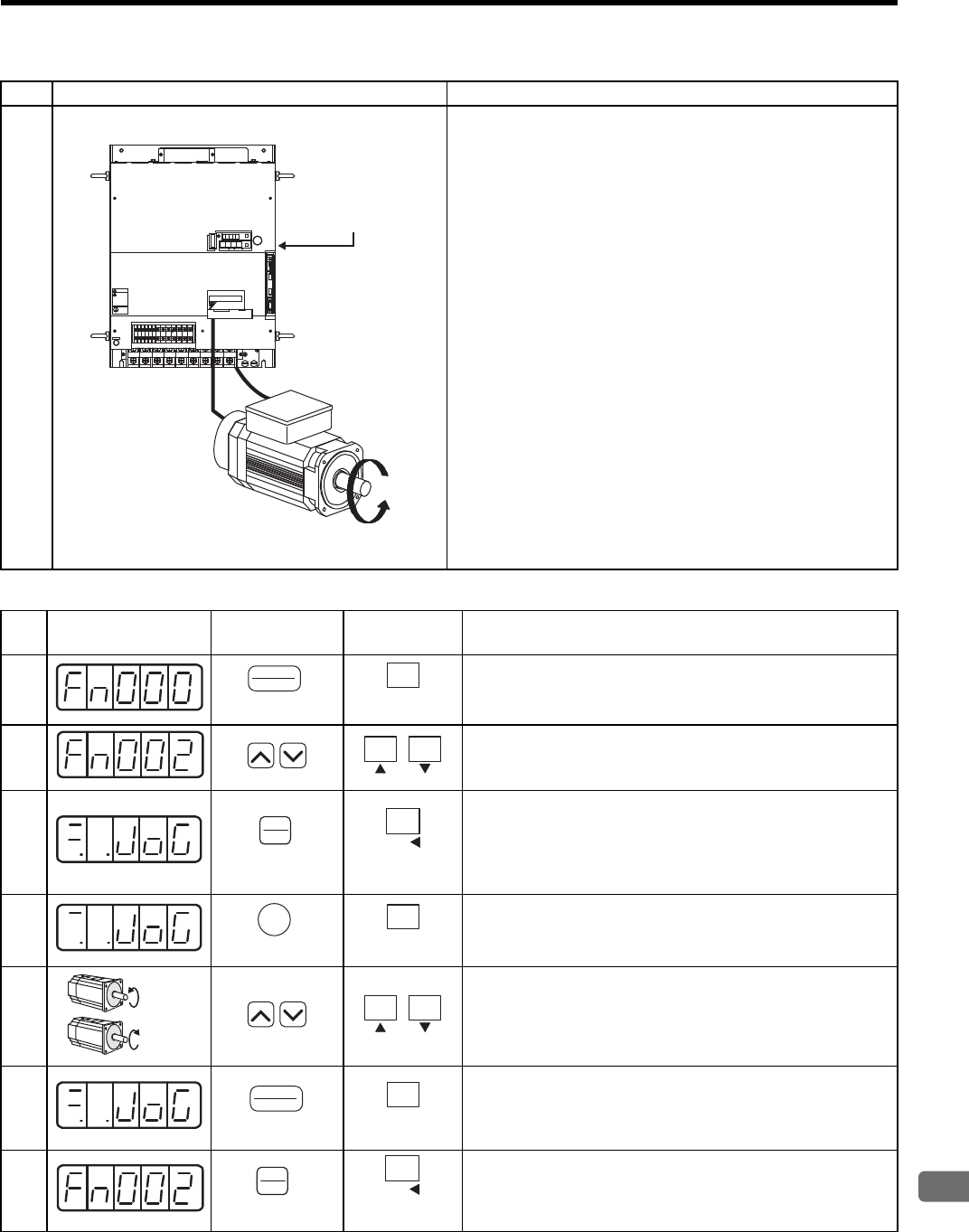
8.1 Trial Operation
8
Operation
8-7
• JOG Mode Operation (Fn002)
5
Operate with the panel operator.
Use the panel operator to operate the servomotor with utility func-
tion Fn002 (Jog Mode Operation).
Check that the servomotor rotates in the forward direction by UP
key, and reverse direction by DOWN key.
The operation is completed when the operation is performed as
described below and the alarm display does not appear. Complete
the Fn002 (Jog Mode Operation) and turn OFF the power.
For operation method of the digital operator and the panel operator,
refer to 7.1 Functions on Digital Operator/Panel Operator.
The servomotor speed can be changed using the Pn304 (JOG
Speed). The factory setting for jog speed is 500 min-1.
Step Display after
Operation Digital Operator Panel
Operator Description
1Press the DSPL/SET or MODE/SET Key to select the utility
function mode.
2Press the UP or DOWN Key to select Fn002.
Note: The digit that can be set will blink.
3Press the DATA/ENTER Key once, or DATA/SHIFT Key for
more than one second.
The display shown at the left will appear, and the servomotor
will enter JOG operation mode. The servomotor can be operated
with the panel operator in this condition.
4Press the SVON or MODE/SET Key. This will turn ON the
power to the servomotor.
5
Press the UP Key (forward) or DOWN Key (reverse). The servo-
motor will operate as long as the key is pressed.
6Press the DSPL/SET or MODE/SET Key. This will turn OFF the
power to the servomotor. The power will remain OFF even if the
SVON or DATA/SHIFT Key is pressed for more than one sec-
ond.
7Press the DATA/ENTER Key once, or DATA/SHIFT Key for
more than one second to return to the Fn002 display of the utility
function mode.
Step Description Check Method and Remarks
.4 .5 .6 789
8
8
&7
8
8
8
&9&8 $
8
&%
0
$
&%
2
%*#4)'
5*&)
㧖㧖㧖㧖
6 #5''/1 &
-5'4812#%
#;#5-#9
4
1
2
'
4
#
6
1
%0
%0
219'4
%0
WARNING
ෂޓ㒾
ㅢ㔚ਛ߮㔚Ḯࠝࡈᓟ5
ಽ㑆ޔ┵ሶㇱߦ⸅ࠆߥ
electric shock.
Disconnect all power
May cause
ᗵ㔚ߩᕟࠇࠅ
before servicing.
and wait 5 min.
grounding techniques.
ធ⛯ߖࠃ
Use proper
ᔅߕࠕ㧙ࠬ✢ࠍ
SERVOPACK
Panel Operator
(DSPL/SET Key)
DSPL
SET
MODE/SET
(MODE/SET Key)
(DATA/ENTER Key)
DATA
ENTER
DATA/
(DATA/SHIFT Key)
(Press at least 1 s.)
JOG
SVON
(SVON Key)
MODE/SET
(MODE/SET Key)
Forward
running
Reverse
running
(DSPL/SET Key)
DSPL
SET
MODE/SET
(MODE/SET Key)
(DATA/ENTER Key)
DATA
ENTER
DATA/
(DATA/SHIFT Key)
(Press at least 1 s.)
8 Operation
8.1.1 Trial Operation for Servomotor without Load
8-8
The servomotor’s rotation direction depends on the setting of parameter Pn000.0 (Direction Selection). The example on
the previous page describes operation with Pn000.0 in the factory setting.
The motor can be operated using only the digital operator without reference from the host controller. The follow-
ing conditions are required to perform jog mode operation.
1. The servo on (/S-ON) input signal is OFF (H level). Refer to 8.3.1 Setting the Servo ON Signal.
2. Pn50A is not set to n.7 (Sets signal ON) with the external input signal allocation. Refer to 7.3.2
Input Circuit Signal Allocation.
Pay attention that the Forward Run Prohibited (P-OT) and Reverse Run Prohibited (N-OT) signals are invalid
during jog mode operation. For the jog mode operation procedures, refer to pages 8-6 and 8-7.
INFO
Pn304 JOG Speed
Setting Range Setting Unit Factory Setting Setting Validation
0 to 10000 1 min-1 500 Immediately
Sets the utility function Fn002 (Jog Mode Operation) to the reference value of motor speed.
Speed
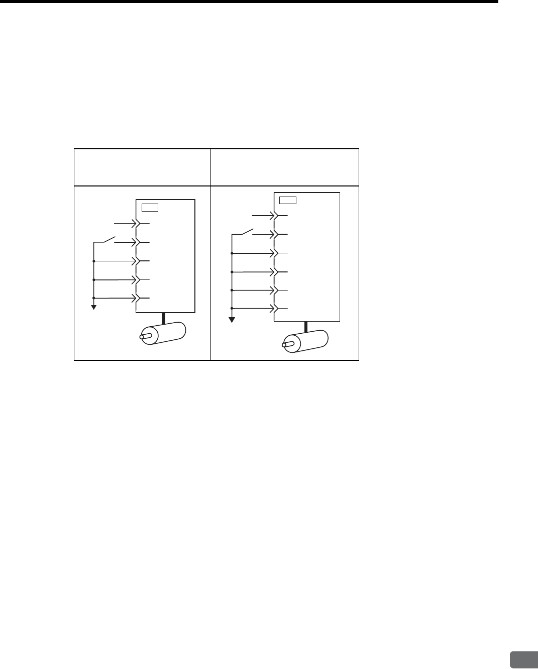
8.1 Trial Operation
8
Operation
8-9
8.1.2 Trial Operation for Servomotor without Load from Host Reference
Check that the servomotor move reference or I/O signals are correctly set from the host controller to the SERVO-
PACK. Also check that the wiring and polarity between the host controller and SERVOPACK, and the SERVO-
PACK operation settings are correct. This is final check before connecting the servomotor to the machine.
(1) Servo ON Command from the Host
The following circuits are required: External input signal circuit or equivalent.
Change the SEN signal (CN1-4) to the H level when an absolute encoder is used.
Speed Control
(Standard Setting)
[Pn000=n.0]
Position Control
[Pn000=n.1]
47
CN1
+24V
/S-ON
P-OT
N-OT
V-REF
40
42
43
5
0V
47
CN1
+24V
/S-ON
P-OT
N-OT
PULS
40
42
43
7
SIGN 11
0V
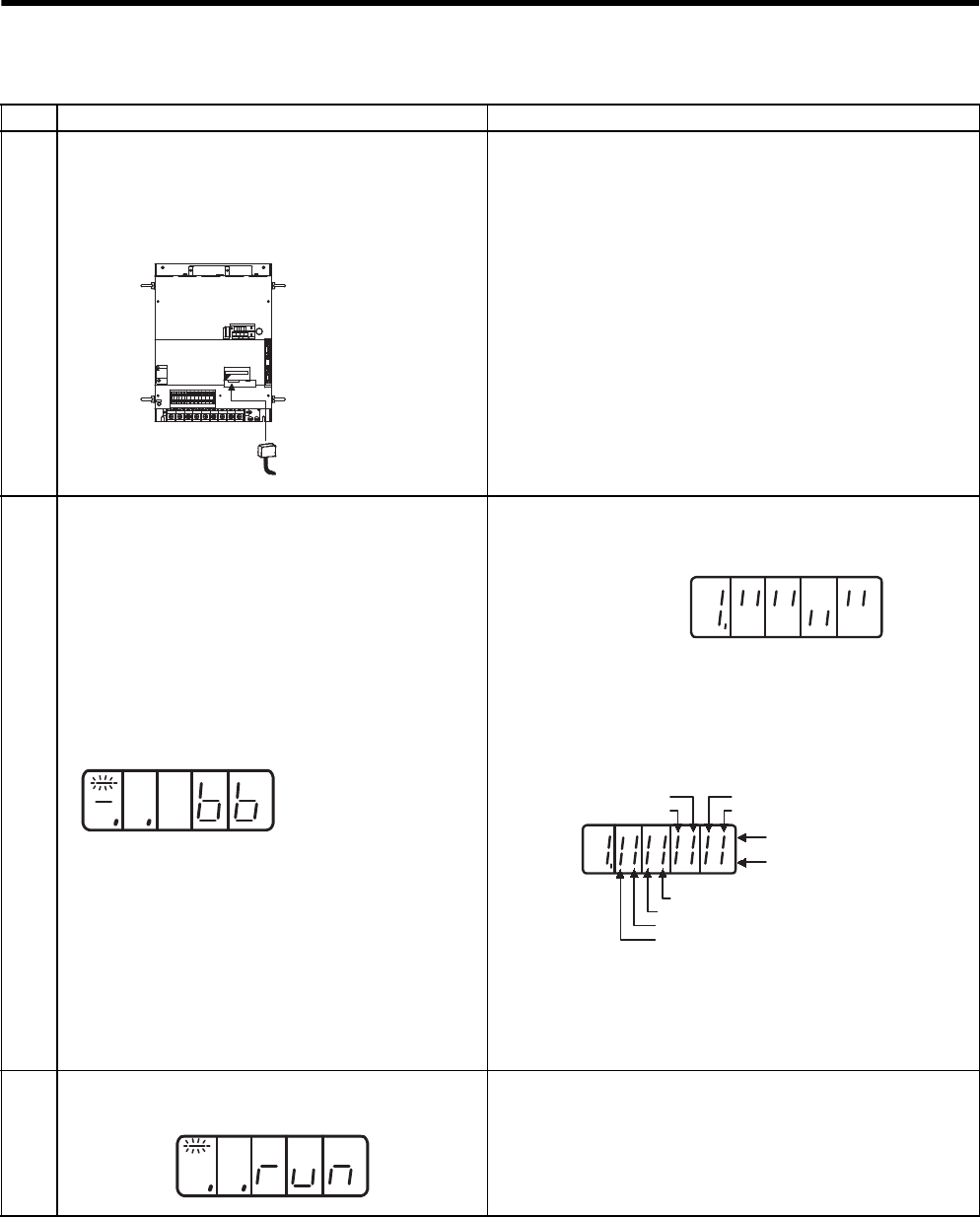
8 Operation
8.1.2 Trial Operation for Servomotor without Load from Host Reference
8-10
Step Description Check Method and Remarks
1
Configure an input signal circuit necessary for servo ON.
Connect the I/O signal connectors (CN1) in the circuit on
the previous page or equivalent to input the signal neces-
sary for servo ON. Then turn OFF the power and connect
the CN1 to the SERVOPACK.
Satisfy the following conditions:
1. Servo ON (/S-ON) input signal can be input.
2. Forward Run Prohibited (P-OT) and Reverse Run Prohibited
(N-OT) input signals are turned ON (L level). (Forward run
and reverse run are prohibited.)
3. Reference input (0V reference or 0 pulse) is not input.
To omit the external wiring, the input terminal function can be set
to “Always ON” or “Always OFF” using the input signal allocation
function of parameter. Refer to 7.3.2 Input Circuit Signal Alloca-
tion.
When the absolute encoder is used, Fn008 (Absolute Encoder
Setup) operation and the SEN signal wiring can be omitted when
setting the Pn002 to n.1 (uses absolute encoder as an incre-
mental encoder) only during trial operation.
2
Turn ON the power and make sure that the panel operator
display is as shown below.
The input signal setting is not correct if the display is not the same
as on the left. Check the input signal using the Un005 (input signal
monitor) from the panel operator.
Check input signal wiring in monitor mode using the digital opera-
tor. Refer to 7.4.1 List of Monitor Modes.
Turn ON and OFF each signal line to see if the LED monitor bit
display on the digital operator changes as shown below.
If an absolute encoder is being used, the servo will not turn ON
when the servo ON signal (/S-ON) is input unless the SEN signal is
also ON.
When the SEN signal is checked in monitor mode, the top of the
LED will light because the SEN signal is high when ON.
3
Input the /S-ON signal, then make sure that the display of
the panel operator is as shown below. If an alarm display appears, correct it according to 10.1 Trouble-
shooting. If there is noise in the reference voltage during speed
control, the horizontal line (−) at the far left edge of the panel oper-
ator display may blink. Also the servomotor may turn very slowly.
Refer to 6.4 Others and take a preventive measure.
Connect the CN1
connector
.4 .5 .6 789
8
8
&7
8
8
8
&9&8 $
8
&%
0
$
&%
2
%*#4)'
5*&)
㧖㧖㧖㧖
6#5''/1&
-5'4812#%
#;#5-#9
4
1
2
'
4
#
6
1
%0
%0
219'4
%0
WARNING
ෂޓ㒾
ㅢ㔚ਛ߮㔚Ḯࠝࡈᓟ5
ಽ㑆ޔ┵ሶㇱߦ⸅ࠆߥ
electric shock.
Disconnect all power
May cause
ᗵ㔚ߩᕟࠇࠅ
before servicing.
and wait 5 min.
grounding techniques.
ធ⛯ߖࠃ
Use proper
ᔅߕࠕ㧙ࠬ✢ࠍ
Un005 =
Input signal LED display
/P-CL
/N-CL
Top lights when input
signal is OFF (high level).
Bottom lights when input
signal is ON (low level).
/ALM-RST
/P-CON
/S-ON
P-OT
N-OT
SEN
Un005 =
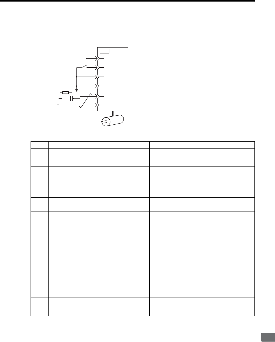
8.1 Trial Operation
8
Operation
8-11
(2) Operating Procedure in Speed Control Mode (Pn000 = n.0)
The following circuit is required: External input signal circuit or equivalent.
Step Description Check Method and Remarks
1Check the power and input signal circuits again, and
check that the speed reference input (voltage
between the V-REF and SG) is 0 V.
Refer to the above figure for input signal circuit.
2
Turn ON the servo ON (/S-ON) input signal.
If the servomotor rotates at extremely slow speed,
refer to 8.5.3 Adjusting Offset, and use the reference
voltage offset to keep the servomotor from moving.
3Generally increase the speed reference input voltage
between V-REF and SG from 0 V. The factory setting is 6 V/rated rotation speed.
4Check the speed reference input to the SERVO-
PACK (Un000 [min-1]).
Refer to 7.1.3 Basic Mode Selection and Operation for
how it is displayed.
5Check the servomotor speed value (Un000 [min-1]). Refer to 7.1.3 Basic Mode Selection and Operation for
how it is displayed.
6Check that the Un001 and Un000 values in steps 4
and 5 are equal.
Change the speed reference input voltage and check
that Un001 and Un000 values are equal for multiple
speed references.
7
Check the speed reference input gain and motor
rotation direction.
Refer to the following equation to change the Pn300
(speed reference input gain).
Un001=(voltage between V-REF) [V] × Pn300 [3000
min-1/6V]
To change the motor rotation direction without chang-
ing polarity for speed reference input voltage, refer to
8.3.2 Switching the Servomotor Rotation Direction.
Perform the operation from step 2 again after the
motor rotation direction is changed.
8When the speed reference input is set to 0 V and
servo OFF status enters, the trial operation for ser-
vomotor without load is completed.
−
47
CN1
+24V
/S-ON
P-OT
N-OT
V-REF
40
42
43
5
6
SERVOPACK
0V
+
VE
VE: Max. voltage (12 V)
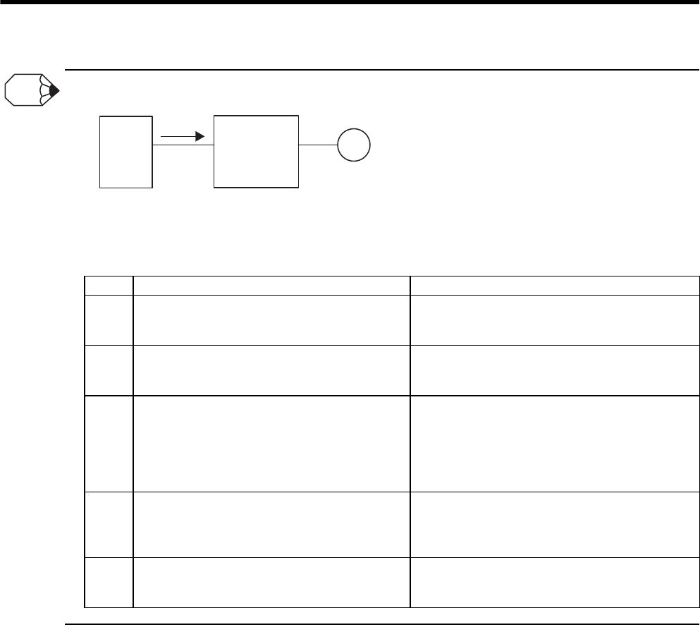
8 Operation
8.1.2 Trial Operation for Servomotor without Load from Host Reference
8-12
When Position Control is configured at the Host
When the SERVOPACK conducts speed control and position control is conducted at the host controller, perform the oper-
ations below, following the operations in (2) Operating Procedure in Speed Control Mode (Pn000 = n.
0
) on the pre-
vious page.
Step Description Check Method and Remarks
9Check the input signal circuit again, and check that
the speed reference input (voltage between the V-
REF and SG) is 0 V.
Refer to the above figure for input signal circuit.
10
Turn ON the servo ON (/S-ON) input signal.
If the servomotor rotates at extremely slow speed,
refer to 8.5.3 Adjusting Offset, and use the reference
voltage offset to keep the servomotor from moving.
11 Send the command for the number of motor rotation
easy to check (for example, one motor revolution)
from the host controller in advance, and check the
sent number of rotation and actual number of rota-
tion by visual inspection and the Un003 (rotation
a n g l e 1 ) [ p u l s e ] .
Refer to 7.1.3 Basic Mode Selection and Operation for
how it is displayed.
Un003 (rotation angle 1)[pulse]: The number of pulses
from the zero point.
12 If the sent number of rotation and actual number of
rotation in step 11 are not equal, correctly set the
Pn201 (PG divided ratio) outputting the encoder
pulse from the SERVOPACK.
Refer to 8.5.7 Encoder Signal Output for how to set.
Pn201 (PG divider) [P/Rev]: The number of encoder
pulses per revolution
13 When the speed reference input is set to 0 V and
servo OFF status enters, the trial operation for posi-
tion control with the host controller is completed.
−
INFO
Trial operation for
servomotor without load
M
Host
Position control Speed control
SERVOPACK
Analog speed
reference
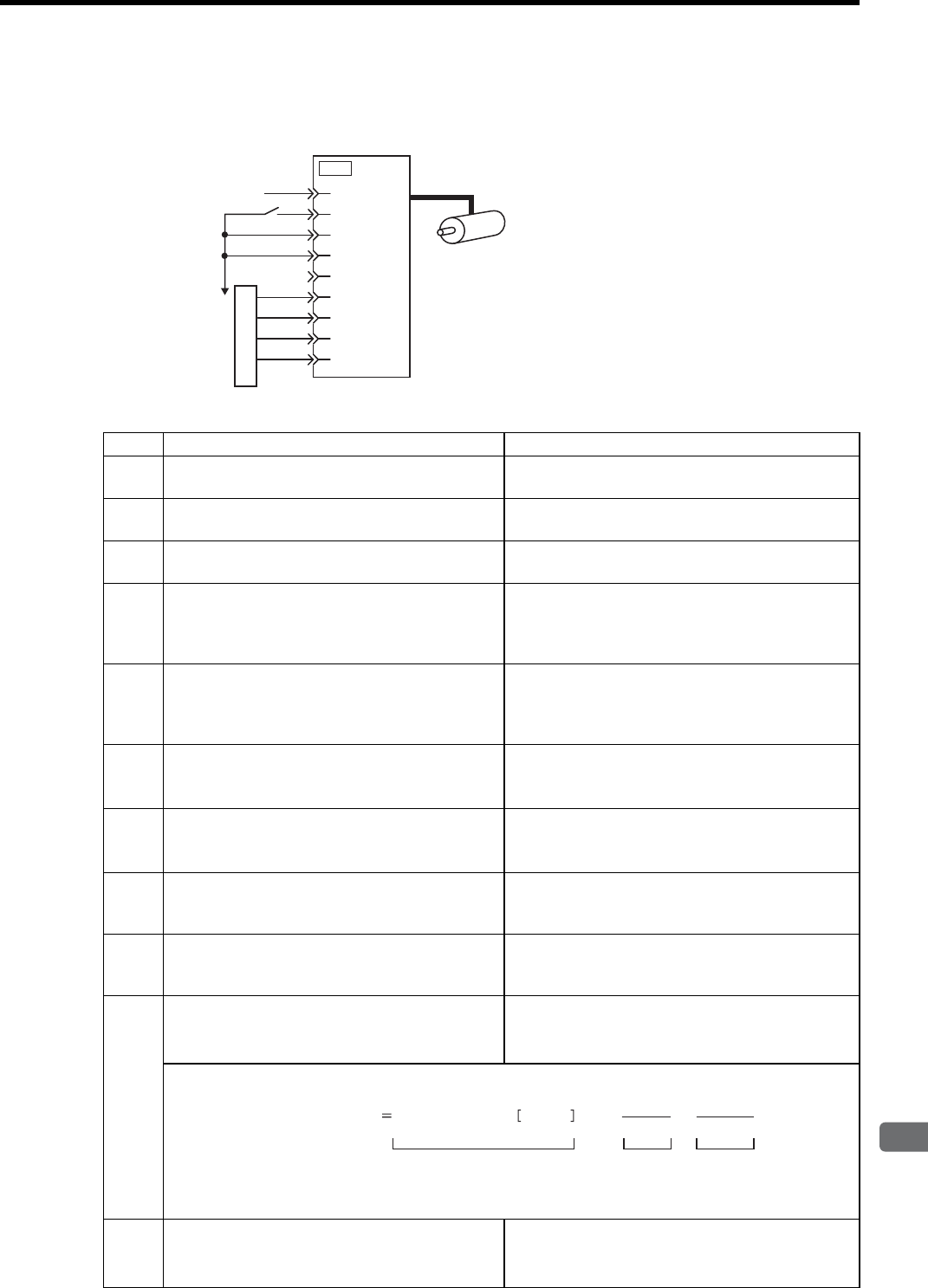
8.1 Trial Operation
8
Operation
8-13
(3) Operating Procedure in Position Control Mode (Pn000 = n.1)
The following circuit is required: External input signal circuit or equivalent.
Step Description Check Method and Remarks
1Match the reference pulse form with the pulse out-
put form from the host controller.
Set the reference pulse with Pn200=n.×. Refer
to 8.6.1 (2) Setting a Reference Pulse Form.
2Set the reference unit and electronic gear ration so
that it coincides with the host controller setting.
Set the electronic gear ratio with Pn202/Pn203. Refer
to 8.6.2 Setting the Electronic Gear.
3Turn ON the power and the servo ON (/S-ON) input
signal. −
4Send the pulse reference for the number of motor
rotation easy to check (for example, one motor revo-
lution) and with slow speed from the host controller
in advance.
Set the motor speed of several 100 min-1 for the refer-
ence pulse speed because such speed is safe.
5Check the number of reference pulses input to the
SERVOPACK by the changed amount before and
after the Un00C (input reference pulse counter)
[pulse] was executed.
Refer to 7.1.3 Basic Mode Selection and Operation for
how it is displayed.
Un00C (input reference pulse counter) [pulse]
6Check the actual number of motor rotation [pulse]
by the changed amount before and after the Un003
(rotation angle 1) [pulse] was executed.
Refer to 7.1.3 Basic Mode Selection and Operation for
how it is displayed.
Un003 (rotation angle 1) [pulse]
7Check that steps 5 and 6 satisfy the following equa-
tion:
Un003=Un00C × (Pn202/Pn203)
−
8Check that the motor rotation direction is the same
as the reference.
Check the input pulse polarity and input reference
pulse form. Refer to 8.6.1 (2) Setting a Reference
Pulse Form.
9Input the pulse reference with the large number of
motor rotation from the host controller to obtain the
constant speed.
Set the motor speed of several 100 min-1 for the refer-
ence pulse speed because such speed is safe.
10 Check the reference pulse speed input to the SER-
VOPACK using the Un007 (input reference pulse
speed) [min-1].
Refer to 7.1.3 Basic Mode Selection and Operation for
how it is displayed.
Un007 (input reference pulse speed) [min-1]
The number of Un007 (input reference pulses) can be obtained from the following equation.
* The encoder pulse differs depending on the model of the servomotor used.
11 Check the motor speed using the Un000 (motor
speed) [min-1].
Refer to 7.1.3 Basic Mode Selection and Operation for
how it is displayed.
Un000 (motor speed) [min-1]
Pulse reference
SERVOPACK
Reference pulse
according to
parameter
Pn200.0 setting ∗ CLR signal is not connected.
+24V
/S-ON
P-OT
N-OT
CLR∗
PULS
/PULS
40
47
42
43
7
8
SIGN
/SIGN
11
12
15
CN1
Un007(input reference pulse speed) input reference pulse pulses/S × 60 × Pn203
Pn202 1
2 (8192)
13
×
Reference input ppm Electronic
gear ratio
Encoder
pulse ∗

8 Operation
8.1.2 Trial Operation for Servomotor without Load from Host Reference
8-14
12 Check that the Un007 and Un000 values in steps 9
and 10 are equal. −
13
Check the motor rotation direction.
To change the motor rotation direction without chang-
ing input reference pulse form, refer to 8.3.2 Switching
the Servomotor Rotation Direction.
Perform the operation from step 9 again after the
motor rotation direction is changed.
14 When the pulse reference input is stopped and servo
OFF status enters, the trial operation for servomotor
without load and using position control with the host
controller is completed.
−
Step Description Check Method and Remarks

8.1 Trial Operation
8
Operation
8-15
8.1.3 Trial Operation with the Servomotor Connected to the Machine
Follow the procedures below to perform the trial operation.
• Follow the procedure below for trial operation precisely as given.
Malfunctions that occur after the servomotor is connected to the machine not only damage the machine, but may also
cause an accident resulting death or injury.
WARNING
Step Description Check Method and Remarks
1
Turn ON the power and make the settings for
mechanical configuration related to protective
functions such as overtravel and brake.
Refer to 8.3 Setting Common Basic Functions.
When a servomotor with brake is used, take advance
measures to prevent vibration due to gravity acting on
the machine or external forces before checking the
brake operation. Check that both servomotor and
brake operations are correct. For details, refer to 8.3.4
Setting for Holding Brakes.
2Set the necessary parameters for control mode used.
Refer to 8.5 Operating Using Speed Control with Ana-
log Reference, 8.6 Operating Using Position Control,
and 8.7 Operating Using Torque Control for control
mode used.
3Connect the servomotor to the machine with cou-
pling, etc., while the power is turned OFF. Refer to 3.3.1 Precautions on Servomotor Installation.
4
Check that the SERVOPACK is servo OFF status
and then turn ON the power to the machine (host
controller). Check again that the protective function
in step 1 operates normally.
Refer to 8.3 Setting Common Basic Functions.
For steps 4 to 8, take advance measures for emergency
stop so that the servomotor can stop safely when an
error occurs during operation.
5
Perform trial operation with the servomotor con-
nected to the machine, following each section in
8.1.2 Trial Operation for Servomotor without Load
from Host Reference.
Check that the trial operation is completed with as the
trial operation for servomotor without load. Also
check the settings for machine such as reference unit.
6Check the settings of parameters for control mode
used set in step 2 again.
Check that the servomotor rotates matching the
machine operating specifications.
7Adjust the servo gain and improve the servomotor
response characteristics, if necessary.
Refer to 9.1 Autotuning.
The servomotor will not be broken in completely dur-
ing the trial operation. Therefore, let the system run
for a sufficient amount of additional time to ensure that
it is properly broken in.
8
Write the parameters set for maintenance in 11.4
Parameter Recording Table.
Then the trial operation with the servomotor con-
nected to the machine is completed.
−
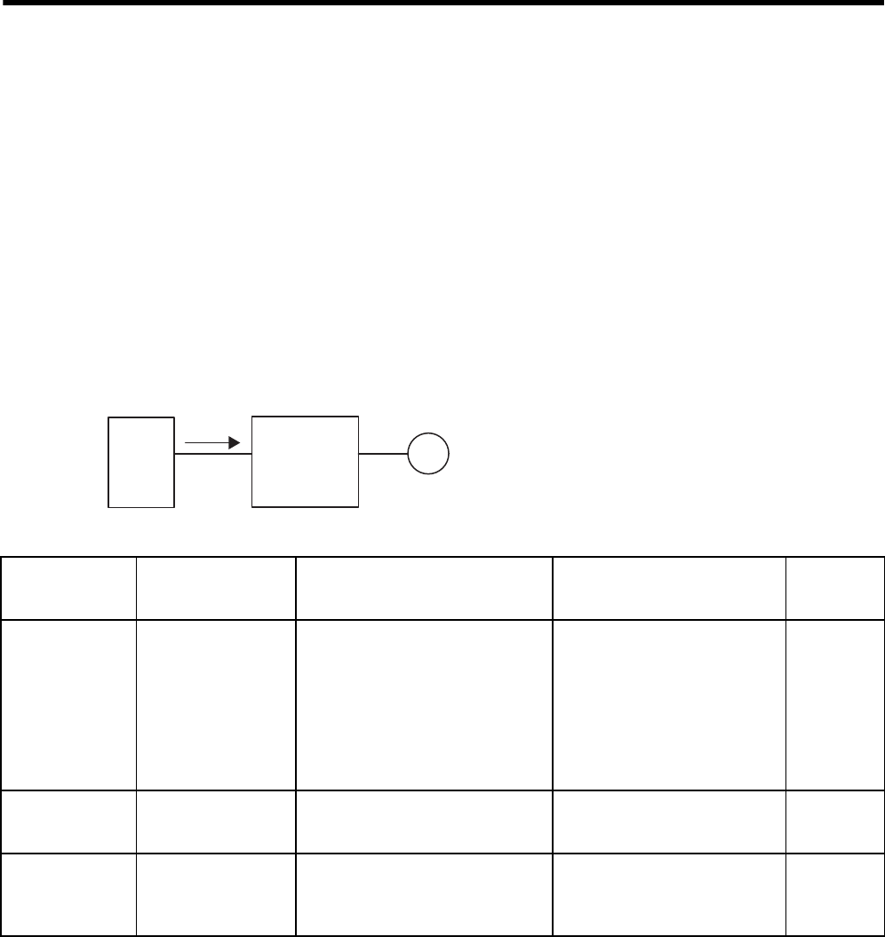
8 Operation
8.1.4 Servomotor with Brakes
8-16
8.1.4 Servomotor with Brakes
Holding brake operation of the servomotor with brake can be controlled with the brake interlock output (/BK)
signal of the SERVOPACK.
When checking the brake operation, take advance measures to prevent vibration due to gravity acting on the
machine or external forces. Check the servomotor operation and holding brake operation with the servomotor
separated from the machine. If both operations are correct, connect the servomotor and perform trial operation.
For wiring on a servomotor with brakes and parameter settings, refer to 8.3.4 Setting for Holding Brakes.
8.1.5 Position Control by Host Controller
As described above, be sure to separate the servomotor and machine before performing trial operation of the ser-
vomotor without a load. Refer to the following table, and check the servomotor operation and specifications in
advance.
Trial operation for
servomotor without load.
M
Host
controller
Position control Speed control
SERVOPACK
Analog
speed
reference
Reference from
the Host
Controller
Check Item Check Method Review Items Reference
Section
JOG Operation
(Constant
Reference Speed
Input from
Host Controller)
Motor Speed
Check motor speed as follows:
• Use the motor speed monitor
(Un000) on the panel operator.
• Run the servomotor at low speed.
Input a reference speed of 60 min-1
for example to check to see if the
servomotor makes one revolution
per second.
Check the parameter setting at
Pn300 to see if reference speed
gain is correct.
8.5.1
Simple
Positioning No. of motor rotation
Input a reference equivalent to one
motor rotation and visually check to
see if the shaft makes one revolution.
Check the parameter setting at
Pn201 to see if the number of PG
dividing pulses is correct.
8.5.7
Overtravel
(P-OT and
N-OT Used)
Whether the servomo-
tor stops rotating
when P-OT and N-OT
signals are input
Check to see if the servomotor stops
when P-OT and N-OT signals are
input during continuous servomotor
operation.
Review P-OT and N-OT wiring if
the servomotor does not stop. 8.3.3

8.2 Control Mode Selection
8
Operation
8-17
8.2 Control Mode Selection
The control modes supported by the SGDM/SGDH SERVOPACKs are described below.
Parameter Control Mode Reference
Section
Pn000 n.0
(Factory
setting)
Speed Control (Analog voltage speed reference)
Controls servomotor speed by means of an analog voltage speed reference. Use
in the following instances.
• To control speed
• For position control using the encoder feedback division output from the
SERVOPACK to form a position loop in the host controller.
8.5
n.1Position Control (Pulse train reference)
Controls the position of the servomotor by means of a pulse train position ref-
erence.
Controls the position with the number of input pulses, and controls the speed
with the input pulse frequency. Use when positioning is required.
8.6
n.2Torque Control (Analog voltage reference)
Controls the servomotor’s output torque by means of an analog voltage torque
reference. Use to output the required amount of torque for operations such as
pressing.
8.7
n.3Speed Control (Internally set speed selection)
Uses the three input signals /P-CON (/SPD-D), /P-CL (/SPD-A), and /N-CL (/
SPD-B) to control the speed as set in advance in the SERVOPACK. Three
operating speeds can be set in the SERVOPACK. (In this case, an analog ref-
erence is not necessary.)
8.8
n.4
x
x
x
n.B
These are switching modes for using the four control methods described above
in combination. Select the control method switching mode that best suits the
application.
8.10

8 Operation
8.3.1 Setting the Servo ON Signal
8-18
8.3 Setting Common Basic Functions
8.3.1 Setting the Servo ON Signal
This sets the servo ON signal (/S-ON) that determines whether the servomotor power is ON or OFF.
(1) Servo ON signal (/S-ON)
(2) Enabling/Disabling the Servo ON Signal
A parameter can be always used to set a parameter servo ON condition. This eliminates the need to wire /S-ON,
but care must be taken because the SERVOPACK can operate as soon as the power is turned ON.
Type Name Connector Pin
Number Setting Meaning
Input /S-ON CN1-40
(Factory setting)
ON (low level) Servomotor power ON. Servomotor can be operated.
OFF (high
level) Servomotor power OFF. Servomotor cannot be operated.
IMPORTANT
Always input the servo ON signal before inputting the input reference to start or stop the servomotor. Do not input the input
reference first and then use the /S-ON signal to start or stop. Doing so will degrade internal elements and lead to malfunc-
tion.
A parameter can be used to re-allocate the input connector number for the /S-ON signal. Refer to 7.3.2 Input Circuit Signal
Allocation.
Parameter Meaning
Pn50A n.0Inputs the /S-ON signal from the input terminal CN1-40. (Factory setting)
n.7Constantly enables the /S-ON signal.
• After changing these parameters, turn OFF the main circuit and control power supplies and then turn them ON again to
enable the new settings.
• When the parameter is set to constantly “enable” the signal, resetting an alarm can only be done by turning the power
OFF and ON. (Alarm reset is disabled.)
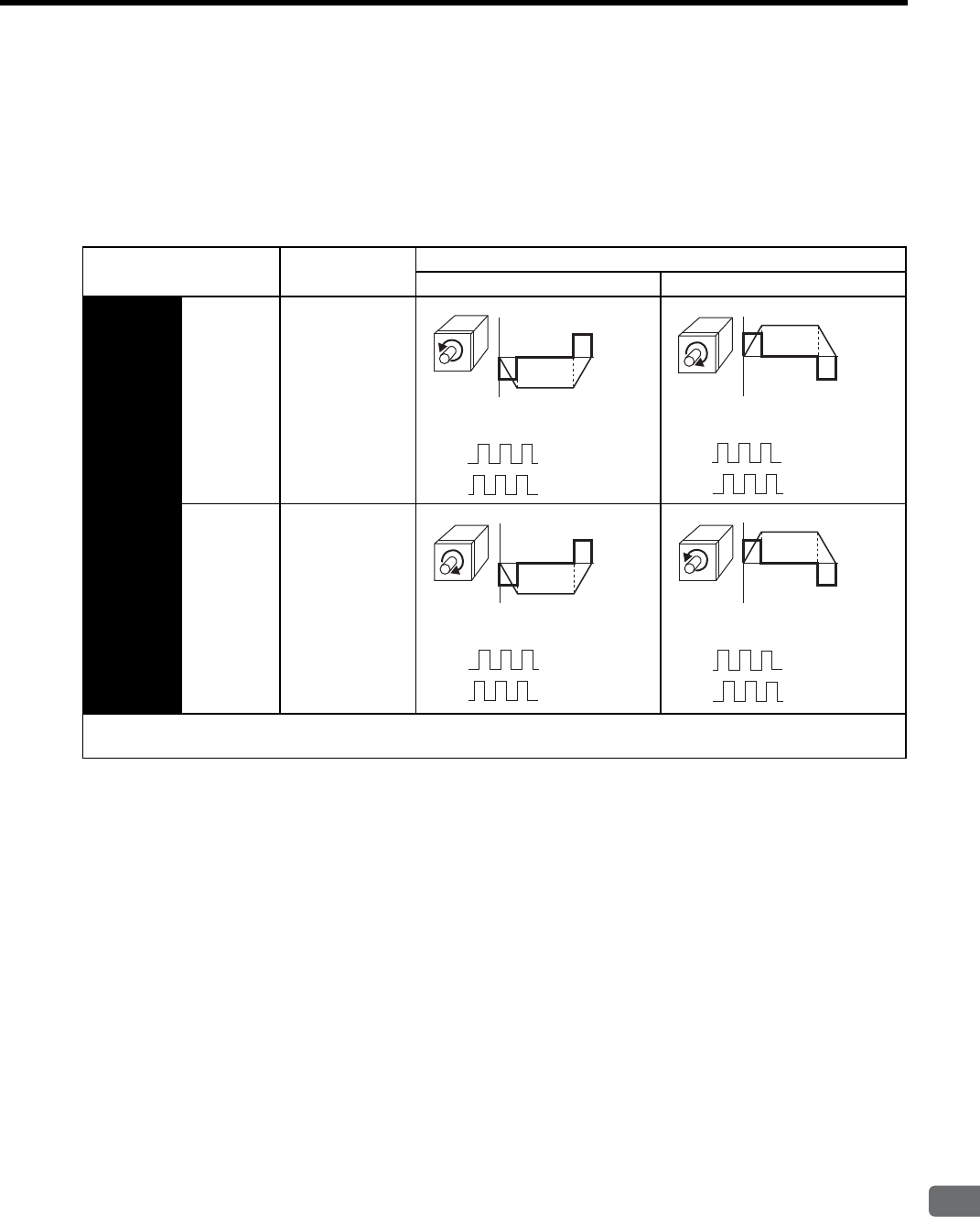
8.3 Setting Common Basic Functions
8
Operation
8-19
8.3.2 Switching the Servomotor Rotation Direction
The rotation direction of the servomotor can be switched without changing the reference pulse to the SERVO-
PACK or the reference voltage polarity.
This causes the travel direction (+, -) of the shaft reverse. The output signal polarity such as encoder pulse output
and analog monitor signal from the SERVOPACK does not change.
The standard setting for “forward rotation” is counterclockwise as viewed from the drive end.
Parameter Name Reference
Forward Reference Reverse Reference
Pn000 n.0
Standard setting
(CCW = For-
ward)
(Factory setting)
n.1
Reverse Rotation
Mode
(CW = Forward)
The direction of P-OT and N-OT change. For Pn000 = n.0 (standard setting), counterclockwise is P-OT. For Pn000
= n.1 (Reverse Rotation Mode), clockwise is P-OT.
Analog monitor
Forward
(CCW) Rotation speed
torque reference
Phase B advanced
Encoder pulse division output
PAO
PBO
Analog monitor
Phase A advanced
Encoder pulse division output
PAO
PBO
Reverse
(CW)
Analog monitor
Phase B advanced
Encoder pulse division output
PAO
PBO
Reverse
(CW)
Phase A advanced
Analog monitor
Encoder pulse division output
PAO
PBO
Forward
(CCW)
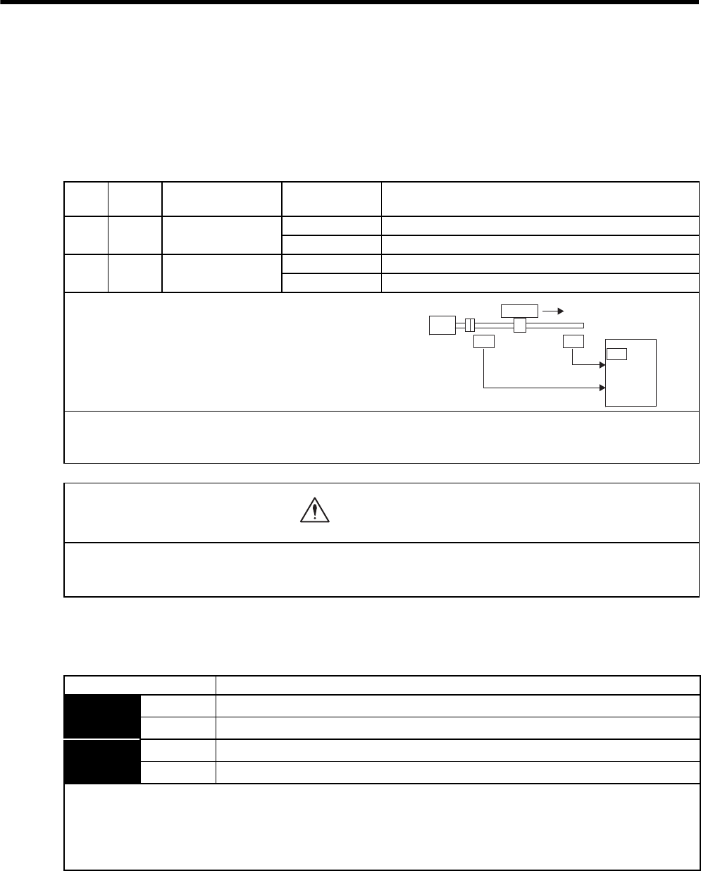
8 Operation
8.3.3 Setting the Overtravel Limit Function
8-20
8.3.3 Setting the Overtravel Limit Function
The overtravel limit function forces movable machine parts to stop if they exceed the allowable range of motion
and turn ON a limit switch.
(1) Connecting the Overtravel Signal
To use the overtravel function, connect the following overtravel limit switch input signal terminals.
(2) Enabling/Disabling the Overtravel Signal
A parameter can be set to disable the overtravel signal. If the parameter is set, there is no need to wire the over-
travel input signal.
Type Name Connector Pin
Number Setting Meaning
Input P-OT CN1-42
(Factory setting)
ON (low level) Forward rotation allowed. Normal operation status.
OFF (high level) Forward rotation prohibited. Forward overtravel.
Input N-OT CN1-43
(Factory setting)
ON (low level) Reverse rotation allowed. Normal operation status.
OFF (high level) Reverse rotation prohibited. Reverse overtravel.
Connect limit switches as shown below to prevent damage to
the devices during linear motion.
Rotation in the opposite direction is possible during overtravel.
For example, reverse rotation is possible during forward over-
travel.
IMPORTANT
When the servomotor stops due to overtravel during position control, the position error pulses are held. A clear signal
(CLR) input is required to clear the error pulses.
Limit
switch
Servomotor
SERVOPACK
42
CN1
43
N-OT
P-OT
Limit
switch
Motor forward rotation direction
When using the servomotor on a vertical axis, the workpiece may fall in the overtravel condition.
To prevent this, always set the zero clamp after stopping with Pn001 = n.1.
Refer to (3) Selecting the Motor Stop Method When Overtravel is Used in this section.
CAUTION
Parameter Meaning
Pn50A n.2 Inputs the Forward Run Prohibited (P-OT) signal from CN1-42. (Factory setting)
n.8 Disables the Forward Run Prohibited (P-OT) signal. (Allows constant forward rotation.)
Pn50B n.3Inputs the Reverse Run Prohibited (N-OT) signal from CN1-43. (Factory setting)
n.8Disables the Reverse Run Prohibited (N-OT) signal. (Allows constant reverse rotation.)
• Applicable control methods: Speed control, position control, and torque control
• After changing these parameters, turn OFF the main circuit and control power supplies and then turn them ON again to
enable the new settings.
* A parameter can be used to re-allocate input connector number for the P-OT and N-OT signals. Refer to 7.3.2 Input Cir-
cuit Signal Allocation.
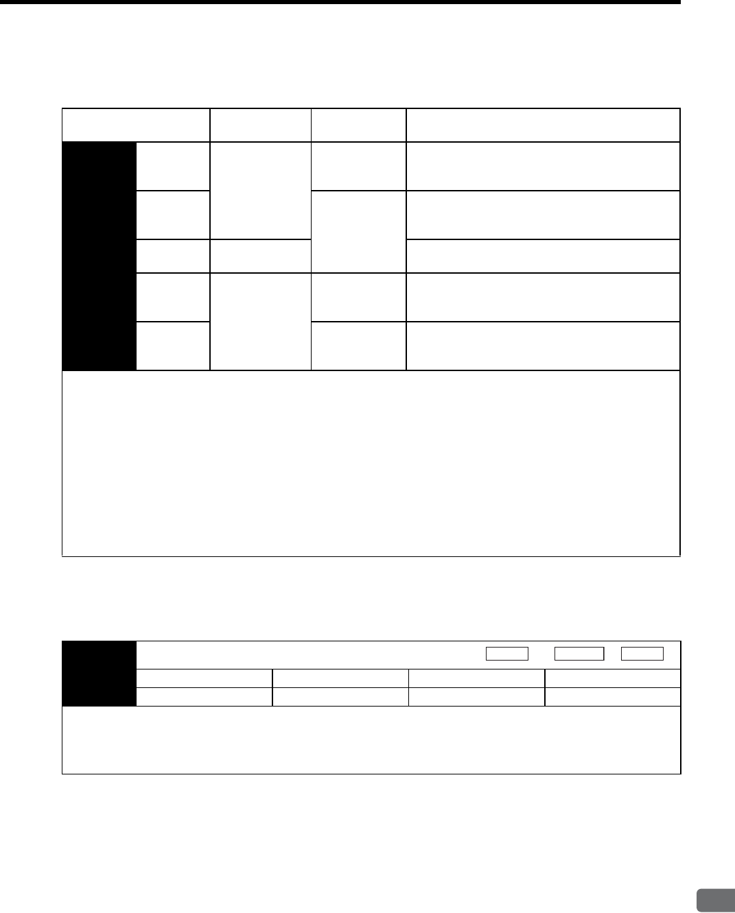
8.3 Setting Common Basic Functions
8
Operation
8-21
(3) Selecting the Motor Stop Method When Overtravel is Used
This is used to set the stop method when an overtravel (P-OT, N-OT) signal is input while the motor is operating.
* For details on stopping methods when the servo turns OFF or when an alarm occurs, refer to 8.3.5 Selecting the Stopping
Method After Servo OFF.
(4) Setting the Stop Torque for Overtravel
Parameter Stop Mode Mode After
Stopping Meaning
Pn001 n.00
Stop by dynamic
brake
Holding
Dynamic Brake
Mode
Rapidly stops the servomotor by using dynamic
braking (DB), then keeps it in Dynamic Brake Mode
after the servomotor stops.
n.01
Coast
Rapidly stops the servomotor by using dynamic
braking (DB), then puts it into Coast (power OFF)
Mode.
n.02 Coast to a stop Coasts to a stop, then places it into Coast (power
OFF) Mode.
n.1
Decelerate to stop
Zero Clamp
Decelerates the servomotor with emergency stop
torque (Pn406), then places it into Zero Clamp (Ser-
volock) Mode.
n.2
Coast
Decelerates the servomotor with emergency stop
torque (Pn406), then places it into Coast (power
OFF) Mode.
• In each setting, only the servomotor stopping method can be selected during torque control. After the servomotor stops, it
maintains the coasting to a stop status regardless of the setting.
• After changing these parameters, turn OFF the main circuit and control power supplies and then turn them ON again to
enable the new settings.
• During n.02 Coast Mode, SERVOPACK can be resumed using the servo ON signal.
TERMS
• Stop by dynamic brake: Stops by using the dynamic brake.
• Coast to a stop: Stops naturally, with no brake, by using the friction resistance of the motor in operation.
• Decelerate to stop: Stops by using deceleration (braking) torque.
• Zero Clamp Mode: A mode forms a position loop by using the position reference zero.
Pn406 Emergency Stop Torque
Setting Range Setting Unit Factory Setting Setting Validation
0 to 800 % 800 Immediately
• This sets the stop torque for when the overtravel signal (P-OT, N-OT) is input.
• The setting unit is a percentage of the rated torque (the rated torque is 100%).
• The value large enough to be the motor maximum torque, 800% is set as the factory setting for emergency stop torque.
However, the actual output emergency stop torque is determined by motor ratings.
Speed
Position
Torque
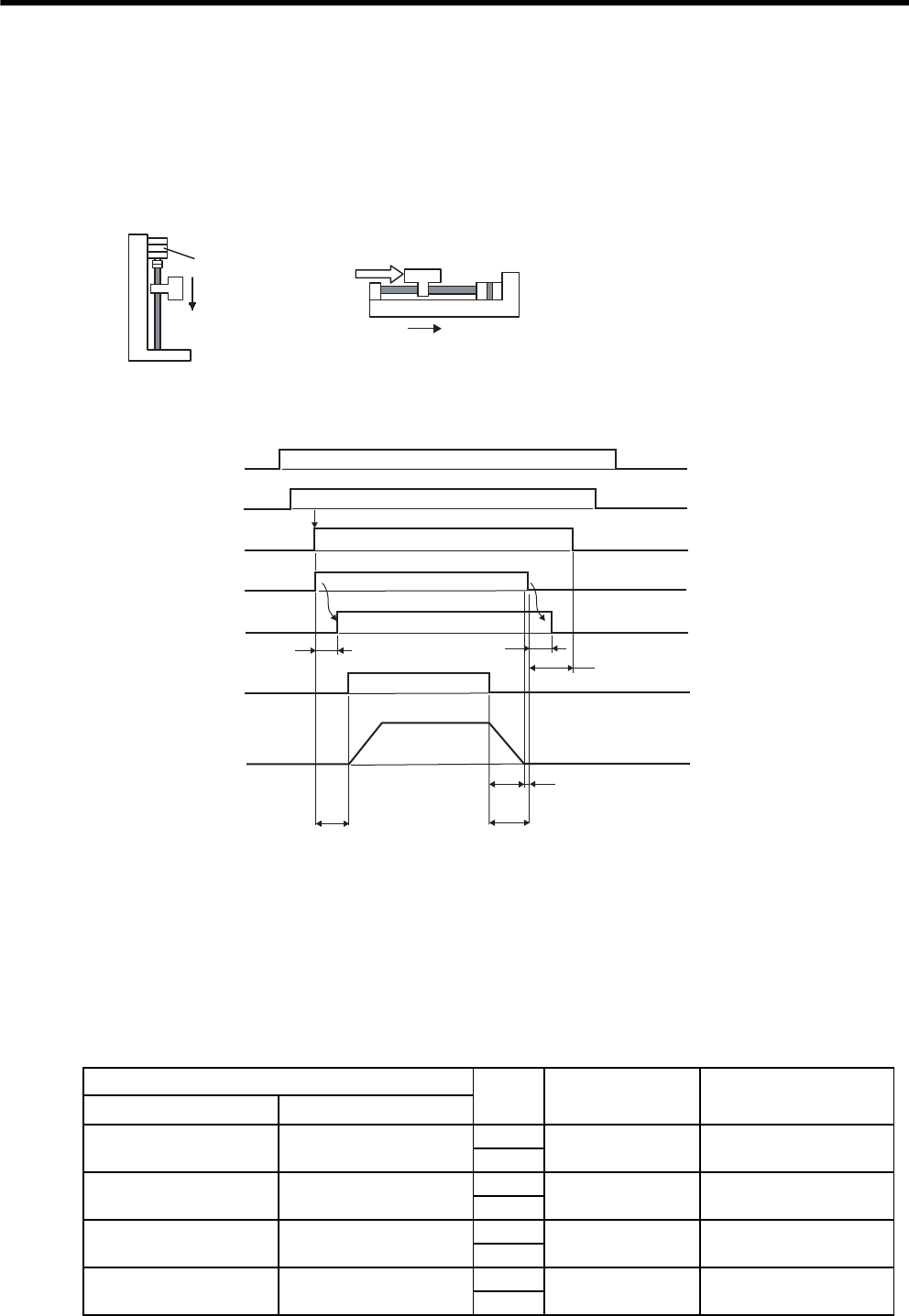
8 Operation
8.3.4 Setting for Holding Brakes
8-22
8.3.4 Setting for Holding Brakes
The holding brake is used when a SERVOPACK controls a vertical axis. In other words, a servomotor with
brake prevents the movable part from shifting due to gravity when the SERVOPACK power goes OFF. (Refer to
8.1.4 Servomotor with Brakes.)
There is a delay in the braking operation. Set the following ON/OFF timing. The timing can be easily set using
the brake interlock output signal.
* 1. The servo ON signal and holding brake power supply may be turned ON simultaneously.
* 2. The operation delay time of the brake depends on the model. For details, refer to Table 8.1 Brake Operation Delay Time.
* 3. Allow a period of 200 ms before the speed reference is input after the brake power supply is turned ON.
* 4. The servomotor stop time is shown by t0. Refer to Table 8.2 Calculation Method for Servomotor Stop Time for the
calculation of t0.
* 5. Always turn OFF the brake power supply after the servomotor comes to a stop. Usually, set t0+t1 to 1 or 2 seconds.
* 6. Turn OFF the servo ON signal 0.2 to 1.0 second after the brake power supply is turned OFF.
Note: The above operation delay time is an example when the power supply is turned ON
and OFF on the DC side.
Be sure to evaluate the above times on the actual equipment before using the application.
Table 8.1 Brake Operation Delay Time
Model Voltage Brake Open Time
(ms)
Brake Operation Time
(ms)
1500 min-1 800 min-1
SGMVH-2B, 3Z – 90V 500 max. 150 max.
24V
SGMVH-3G SGMVH-2B 90V 500 max. 150 max.
24V
SGMVH-4E, 5E SGMVH-3Z 90V 550 max. 320 max.
24V
SGMVH-7E SGMVH-3G 90V 700 max. 320 max.
24V
Servomotor
Vertical Shaft
Holding brake
Prevents the servomotor
from shifting when
the power is OFF.
Shaft with External Force Applied
Servomotor
External
force
Prevents the servomotor from
shifting due to external force.
OFF
OFF
OFF
OFF
Brake release
ON
ON
ON
ON
*1
*2
*4
*5
*6
*3
200 ms or more
200 ms to 1.0 second
0V
*2
SERVOPACK main
power
SERVOPACK control
power
Servo ON
Holding brake power
Brake contact part
(lining)
Speed reference
Motor speed
t0
t0+t1
t1
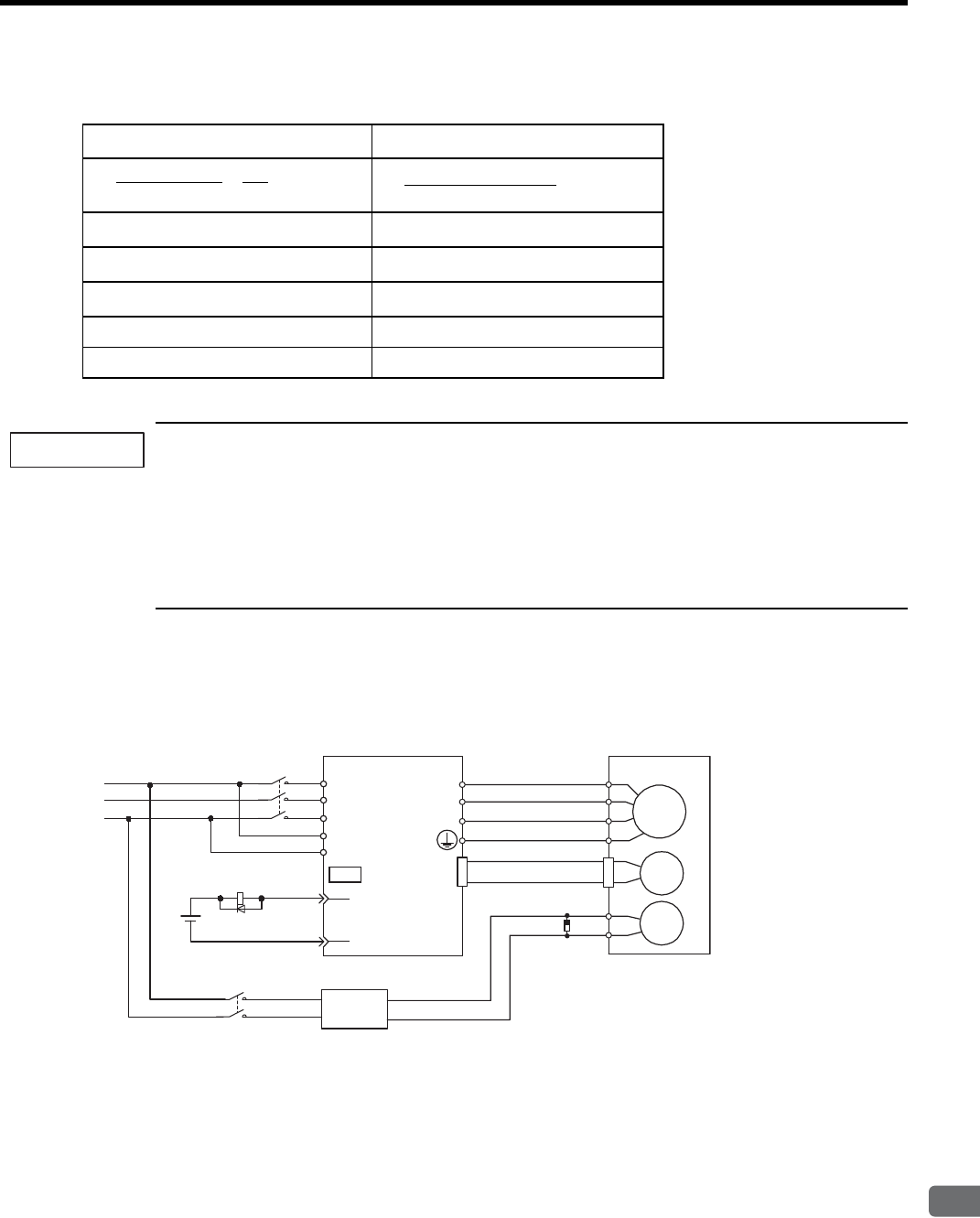
8.3 Setting Common Basic Functions
8
Operation
8-23
1. The brake built into the servomotor with brakes is a deenergization brake, which is used only to hold and
cannot be used for braking. Use the holding brake only to hold a stopped motor. Brake torque is at least
120% of the rated motor torque.
2. When operating using only a speed loop, turn OFF the servo and set the input reference to 0 V when the
brake is applied.
3. When forming a position loop, do not use a mechanical brake while the servomotor is stopped because
the servomotor enters servolock status.
(1) Wiring Example
Use the SERVOPACK contact output signal /BK and the brake power supply to form a brake ON/OFF circuit.
The following diagram shows a standard wiring example.
Table 8.2 Calculation Method for Servomotor Stop Time
Using SI Units Conventional Method
JM : Rotor moment of inertia (kgxm2)GD2M : Motor GD2 (kgfxm2)
JL : Load moment of inertia (kgxm2)GD2L : Load inertia GD2 (kgfxm2)
NM : Motor rotational speed (min-1)NM : Motor rotational speed (r/min)
TP : Motor deceleration torque (Nxm) TP : Motor deceleration torque (kgfxm)
TL : Load torque (Nxm) TL : Load torque (kgfxm)
t0 = × (sec)
(TP + TL)
(JM + JL) × NM2π
60
t0 = (sec)
(GD2M + GD2L) × NM
375 × (TP + TL)
IMPORTANT
Servomotor
with brake
SERVOPACK
Power supply
Red
Black
Blue or
yellow
White
BK-R Y
: Brake control relay
∗ are the output terminals allocated with Pn50F.2.
M
BK
PG
U
V
W
CN2
AC DC
BK-RY
BK-RY
+24V
L1/R
L2/S
L3/T
L1C/r
L2C/t
(/BK+)
(/BK-)
CN1
∗
∗
Brake power supply
Brake power supply Input voltage 200-V models: LPSE-2H01
Surge absorber model: CR50500BL (sold as Spark Quencher
manufactured by Okaya Electric Industries
Co., Ltd.)
Input voltage 100-V models: LPDE-1H01
R
S
T
Surge absorber
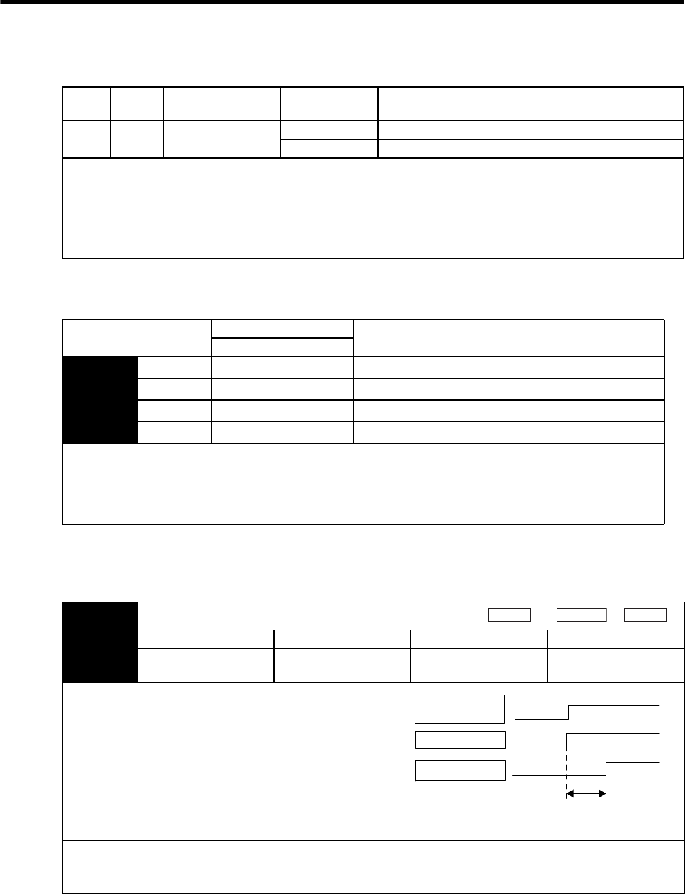
8 Operation
8.3.4 Setting for Holding Brakes
8-24
(2) Brake Interlock Output (/BK)
(3) Allocating Brake Interlock Output Signals (/BK)
The brake interlock output signal (/BK) is not used with the factory settings. The output signal must be allocated.
(4) Setting the Brake ON Timing after the Servomotor Stops
With the standard setting, the /BK signal is output at the same time as the servo is turned OFF. The servo OFF
timing can be changed with a parameter.
Type Name Connector Pin
Number Setting Meaning
Output /BK Must be allocated ON (low level) Releases the brake.
OFF (high level) Applies the brake.
This output signal controls the brake and is used only for a servomotor with a brake. This output signal is not used with the
factory settings. The output signal must be allocated (with Pn50F). It does not need to be connected for servomotors with-
out a brake.
IMPORTANT
The /BK signal is not output during overtravel, or when there is no power to the servomotor.
Parameter Connector Pin Number Meaning
+ Terminal - Terminal
Pn50F n.0 −−The /BK signal is not used. (Factory setting)
n.1 CN1-25 CN1-26 The /BK signal is output from output terminal CN1-25, 26.
n.2 CN1-27 CN1-28 The /BK signal is output from output terminal CN1-27, 28.
n.3 CN1-29 CN1-30 The /BK signal is output from output terminal CN1-29, 30.
IMPORTANT
When set to the factory setting, the brake interlock output signal (/BK) is invalid. When multiple signals are allocated to
the same output terminal, the signals are output with OR logic. To output the /BK output signal alone, disable the other
output signals or set them to output terminals other than the one allocated to the /BK output signal. For the allocation of
SERVOPACK output signals other than /BK output signal, refer to 7.3.3 Output Circuit Signal Allocation.
Pn506 Delay Time from Brake Reference Until Servo OFF
Setting Range Setting Unit Factory Setting Setting Validation
0 to 50
(0 to 500 ms) 10 ms 0 Immediately
• When using the servomotor to control a vertical axis, the
machine movable part may shift slightly depending on the brake
ON timing due to gravity or an external force. By using this
parameter to delay turning the servo OFF, this slight shift can be
eliminated.
• This parameter changes the brake ON timing while the servomo-
tor is stopped.
For details on brake operation while the servomotor is operating,
refer to (5) Setting the Brake ON Timing When Servomotor Run-
ning in this section.
IMPORTANT
The servomotor will turn OFF immediately when an alarm occurs, regardless of the setting of this parameter.
The machine movable part may shift due to gravity or external force during the time until the brake operates.
Speed Position Torque
/S-ON
(CN1-40)
/BK output
Power to motor
Brake released
Servo ON
Power to motor
Brake held
Servo OFF
No power to motor
Pn506
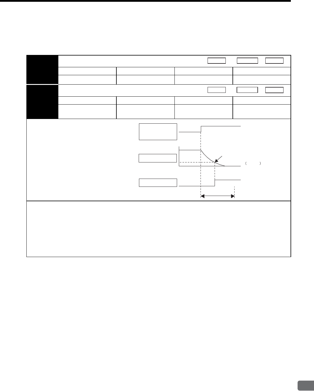
8.3 Setting Common Basic Functions
8
Operation
8-25
(5) Setting the Brake ON Timing When Servomotor Running
The following parameters can be used to change the /BK signal output conditions when a stop reference is output
during servomotor operation due to the servo OFF or an alarm occurring.
Pn507 Brake Reference Output Speed Level
Setting Range Setting Unit Factory Setting Setting Validation
0 to 10000 1 min-1 100 Immediately
Pn508 Timing for Brake Reference Output during Motor Operation
Setting Range Setting Unit Factory Setting Setting Validation
10 to 100
(100 to 1000 ms) 10 ms 50
(500 ms) Immediately
/BK Signal Output Conditions When Servo-
motor Running
The /BK output signal goes to high level (brake
ON) when either of the following conditions is
satisfied:
• When the motor speed falls below the level set
in Pn507 after the servo OFF.
• When the time set in Pn508 is exceeded after
the servo OFF.
IMPORTANT
• The servomotor will be limited to its maximum speed even if the value set in Pn507 is higher than the maximum speed.
• Allocate the running output signal (/TGON) and the brake interlock output signal (/BK) to different terminals.
• If the brake interlock output signal (/BK) and running output signal (/TGON) are allocated to the same output terminal,
the /TGON signal will go to low level at the speed at which the movable part drops on the vertical axis, which means that
the /BK output signal will not go to high level even if the conditions of this parameter are met. (This is because signals are
output with OR logic when multiple signals are allocated to the same output terminal.) For output signal allocations, refer
to 7.3.3 Output Circuit Signal Allocation.
Speed
Position
Torque
Speed Position
Torque
/S-ON input
Or alarm or
power OFF
Motor speed Pn507
/BK output
Brake released
(Motor stopped by applying
DB or by coasting.)
Pn001.0
Pn508
Brake held
Servo ON Servo OFF

8 Operation
8.3.5 Selecting the Stopping Method After Servo OFF
8-26
8.3.5 Selecting the Stopping Method After Servo OFF
The stopping method when the power to the SERVOPACK turns OFF can be selected.
The dynamic brake (DB)1 is an emergency stop function.
If the servomotor is frequently started and stopped by turning the power ON/OFF or using the servo ON sig-
nal (/S-ON), the DB circuit will also be repeatedly operated, degrading the SERVOPACK’s internal ele-
ments. Use the speed input reference and position reference to control the starting and stopping of the
servomotor.
Parameter Stop Mode Mode After
Stopping Meaning
Pn001 n.0
Stop by dynamic
brake
Dynamic Brake
Stops the servomotor by dynamic braking (DB),
then holds it in Dynamic Brake Mode. (Factory set-
ting)
n.1Coast Stops the servomotor by dynamic braking (DB),
then places it into Coast (power OFF) Mode.
n.2Coast to a stop Coast Stops the servomotor by coasting, then places it
into Coast (power OFF) Mode.
These parameters are valid under the following conditions:
• When the /S-ON input signal is OFF (Servo OFF).
• When an alarm occurs.
• When main circuit power supply is OFF.
Similar to the Coast Mode, the n.0 setting (which stops the servomotor by dynamic braking and then holds it in
Dynamic Brake Mode) does not generate any braking force when the servomotor stops or when it rotates at very low speed.
TERMS
• Stop by dynamic brake: Stops by using the dynamic brake.
• Coast to a stop: Stops naturally, with no brake, by using the friction resistance of the motor in operation.
IMPORTANT
The SERVOPACK is forced to stop by dynamic braking, regardless of the settings of this parameter, when the main cir-
cuit power supply or control power supply turns OFF.
If the servomotor must be stopped by coasting rather than by dynamic braking when the main circuit power supply or the
control power supply turns OFF, arrange the sequence externally so the servomotor wiring will be interrupted.
1 Dynamic brake (DB)
A common method for quickly stopping a servomotor. The servomotor is stopped
by short-circuiting the servomotor circuit. This function is built into the SERVO-
PACK.
IMPORTANT
SERVOPACK Servomotor
TERMS
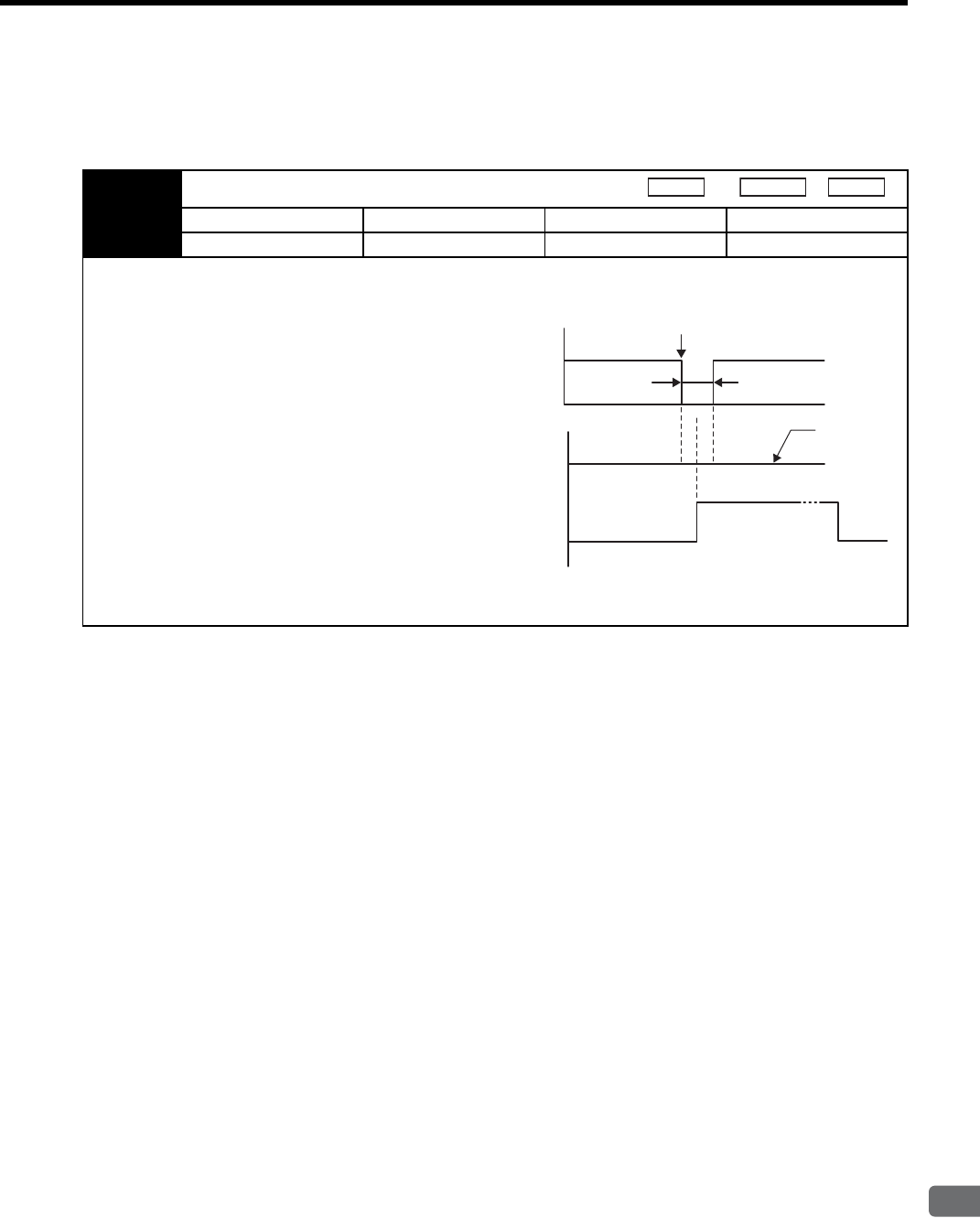
8.3 Setting Common Basic Functions
8
Operation
8-27
8.3.6 Instantaneous Power Loss Settings
Determines whether to continue operation or turn the servo OFF when the power supply voltage to the SERVO-
PACK main circuit is instantaneously interrupted.
Pn509 Instantaneous Power Cut Hold Time
Setting Range Setting Unit Factory Setting Setting Validation
20 to 1000 1 ms 20 Immediately
In power loss detection, the status of the main circuit power supply is detected and OFF status is ignored so servomotor
operation will continue if the servomotor turns back ON within the time set in parameter Pn509.
In the following instances, however, the parameter setting
will be invalid.
• If an insufficient voltage alarm (A.41) occurs during a
power loss with a large servomotor load.
• When control is lost (equivalent to normal power OFF
operation) with loss of the control power supply.
IMPORTANT
The maximum setting for the hold time during a power
loss is 1,000 ms, but the hold time for the SERVOPACK
control power supply is about 100 ms. The hold time for
the main circuit power supply depends on the SERVO-
PACK output.
To continue SERVOPACK operation for a power loss that is longer than this, provide an uninterruptible power supply.
Speed
Position
Torque
Power
supply
voltage
Instantaneous power interruption
OFF time t
Servo ON
Servo ON Servo OFF
Pn509 > t
Pn509 < t
Operation
continued
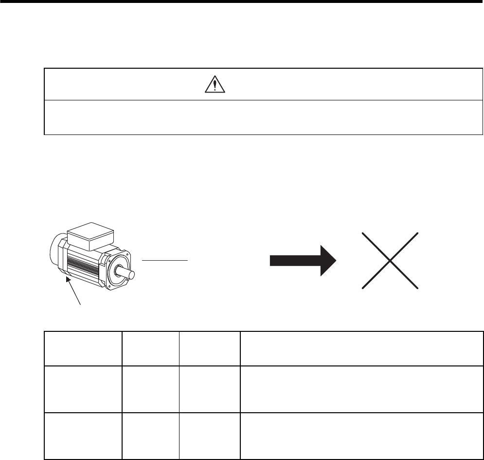
8 Operation
8-28
8.4 Absolute Encoders
If a motor with an absolute encoder is used, a system to detect the absolute position can be made in the host con-
troller. Consequently, operation can be performed without zero point return operation immediately after the
power is turned ON.
SGMVH-2 servomotor: With 17-bit absolute encoder
SGMVH-3 servomotor: With 20-bit absolute encoder (optional)
* The action differs when the Multiturn Limit Setting (Pn205) is changed. Refer to 8.4.7 Multiturn Limit
Setting.
• The output range of multiturn data for the Σ-II series absolute detection system differs from that for conven-
tional systems (15-bit encoder and 12-bit encoder). When an infinite length positioning system of the con-
ventional type is to be configured with the Σ-II series, be sure to make the following system modification.
WARNING
Absolute position
detected continuously zero point return operation
Absolute encoder
Absolute Encoder
Type Resolution
Output Range
of Multiturn
Data
Action when Limit Is Exceeded
Σ-I Series 12-bit
15-bit
-99999 to
+ 99999
• When the upper limit (+99999) is exceeded in the forward direc-
tion, the multiturn data is 0.
• When the lower limit (-99999) is exceeded in the reverse direc-
tion, the multiturn data is 0.
Σ-II Series
16-bit
17-bit
20-bit
-32768 to
+ 32767
• When the upper limit (+32767) is exceeded in the forward direc-
tion, the multiturn data is -32768.*
• When the lower limit (-32768) is exceeded in the reverse direc-
tion, the multiturn data is +32767.*
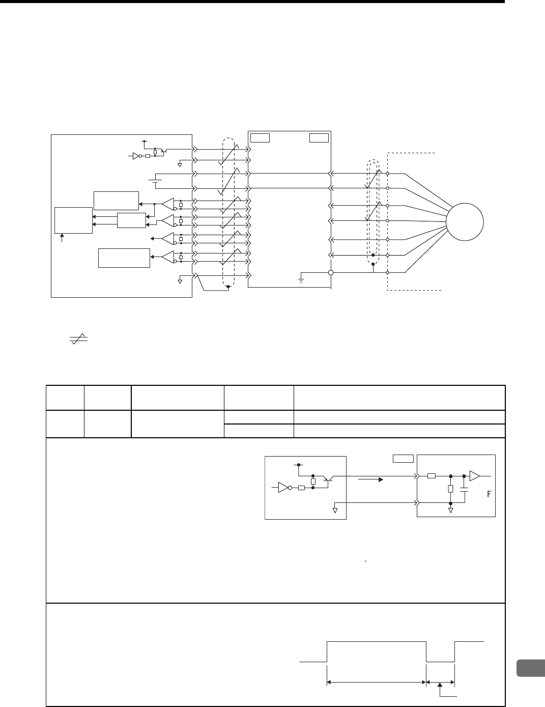
8.4 Absolute Encoders
8
Operation
8-29
8.4.1 Interface Circuits
The following diagram shows the standard connections for a an absolute encoder mounted to a servomotor. The
connection cables and wiring pin numbers depend on the servomotor. For details, refer to chapter 5 Specifica-
tions and Dimensional Drawings of Cables and Peripheral Devices.
* 1. : Represents twisted-pair wires.
* 2. For wiring pin numbers, refer to 5 Specifications and Dimensional Drawings of Cables and Peripheral Devices.
• SEN Signal Connection
Applicable line receiver: Texas Instruments’s SN75175 or the equivalent
Terminating resistance R: 220 to 470 Ω
R
BAT (+)
BAT (-)
PG5 V
PG0 V
PS
/PS
BAT(-)
PCO
/PCO
PBO
/PBO
PAO
/PAO
BAT(+)
SEN
SG
R
R
PA
PB
PC
PS
+5 V
7406
0 V
+
-
4
2
21
22
33
34
35
36
19
1
20
CN1
3
4
5
6
2
1
CN2
UP
DOWN
SG
0 V
Host controller
Battery
SERVOPACK
Encoder
Serial interface
circuit
Serial interface
circuit
Line receiver
Edge
detection
Up/down
counter
Clear
Shield (shell)
Connector
shell
R
PSO
/PSO 48
49
PG
∗1
∗1
∗2
Type Name Connector
Pin Number Setting Meaning
Input SEN CN1-4 OFF (low level) Input when power is turned ON
ON (high level) Input at absolute data request
• This input signal is required to output absolute data
from the SERVOPACK.
• When the SERVOPACK main circuit power supply
turns OFF, input the SEN signal at a low level.
• Let at least three seconds elapse after turning ON the
power before changing the SEN signal to high level.
• When the SEN signal changes from low level to high
level, the multiturn data and initial incremental
pulses are output.
Until these operations have been completed, the ser-
vomotor cannot be turned ON regardless of the status
of the servo ON signal (/S-ON).
• The panel operator display will also remain “b.b”.
Refer to 8.4.6 Absolute Encoder Reception Sequence.
IMPORTANT
Maintain the high level for at least 1.3 seconds when the SEN
signal is turned OFF and then ON, as shown in the figure on the
right.
4.7 k
SEN 4
CN1
SG
2
+5V
0V
100 Ω
Ω
0V
0.1 μ
Host controller SERVOPACK
High level:
About 1 mA
7406 or equivalent
We recommend a PNP transistor.
Signal levels
High: 4.0 V min. Low: 0.8 V max.
OFF ON (high level)
1.3 s min.
OFF ON
15 ms min.
SEN signal
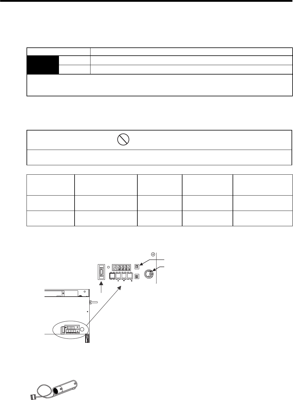
8 Operation
8.4.2 Selecting an Absolute Encoder
8-30
8.4.2 Selecting an Absolute Encoder
An absolute encoder can also be used as an incremental encoder.
8.4.3 Handling Batteries
In order for the absolute encoder to retain position data when the power is turned OFF, the data must be backed
up by a battery.
* For Yaskawa model, a connector is included with a battery.
(1) Battery Provided for SERVOPACK
(2) Installing the Battery at the Host Controller
Prepare the battery according to the specifications of the host controller. Use the battery with the model number
ER6VC3 (3.6 V, 2000 mAh made by Toshiba Battery Co., Ltd.) or the equivalent.
Parameter Meaning
Pn002 n.0 Use the absolute encoder as an absolute encoder. (Factory setting)
n.1 Use the absolute encoder as an incremental encoder.
• The SEN signal and back-up battery are not required when using the absolute encoder as an incremental encoder.
• After changing these parameters, turn OFF the main circuit and control power supplies and then turn them ON again to
enable the new settings.
• Install the battery at either the host controller or the SERVOPACK.
It is dangerous to install batteries at both simultaneously, because that sets up a loop circuit between the batteries.
PROHIBITED
Battery
Installation
Location
Yaskawa Model* Manufacturer
Model Specifications Manufacturer
Host controller −ER6VC3 Lithium battery
3.6 V, 2000 mAh Toshiba Battery Co., Ltd.
SERVOPACK JZSP-BA01-1 ER3V Lithium battery
3.6 V, 1000 mAh Toshiba Battery Co., Ltd.
For mounting battery
Connector for battery (CN8)
CN3
CN8
BATTERY
MODE/SET DATA/
POWER
CN5
6#5''/1&
4
1
2
'
4
#
6
1
%0
%0
219'4
%0

8.4 Absolute Encoders
8
Operation
8-31
8.4.4 Replacing Batteries
The SERVOPACK will generate an absolute encoder battery alarm (A.83) when the battery voltage drops below
about 2.7 V. This alarm is output, however, only when the SERVOPACK power is turned ON. If the voltage
drops while the SERVOPACK power is ON, the SERVOPACK will not generate the alarm.
• Battery Replacement Procedure
1. Replace the battery with only the SERVOPACK control power supply turned ON.
2. After replacing the battery, turn OFF the SERVOPACK power to cancel the absolute encoder battery
alarm (A.83).
3. Turn ON the SERVOPACK power back again. If it operates without any problems, the battery replace-
ment has been completed.
If the SERVOPACK control power supply is turned OFF and the battery is disconnected (which includes
disconnecting the encoder cable), the absolute encoder data will be deleted. The absolute encoder must
be setup again. Refer to 8.4.5 Absolute Encoder Setup (Fn008).
IMPORTANT
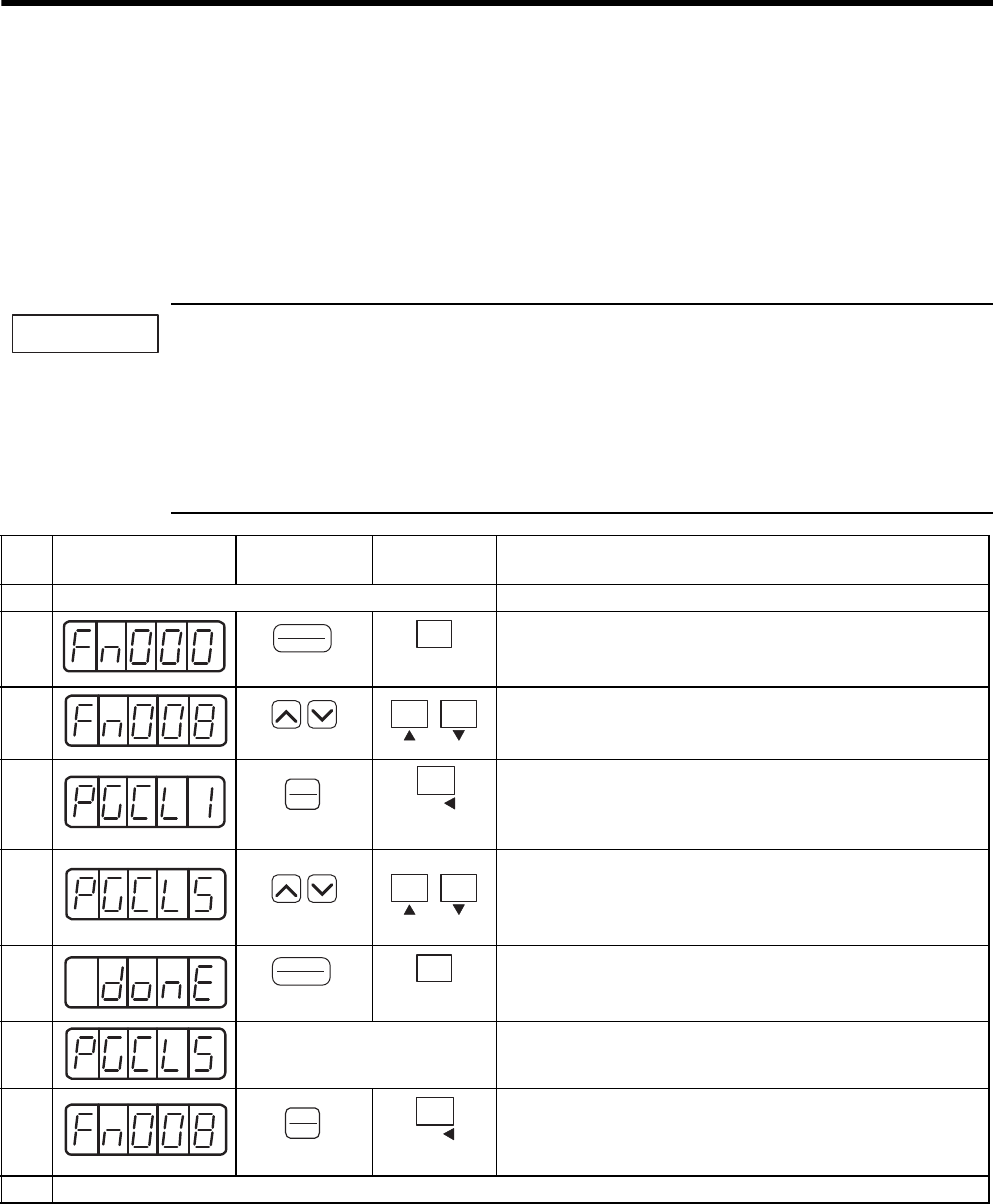
8 Operation
8.4.5 Absolute Encoder Setup (Fn008)
8-32
8.4.5 Absolute Encoder Setup (Fn008)
Setting up (initializing) the absolute encoder is necessary in the following cases.
• When starting the machine for the first time
• When an encoder backup error alarm (A.81) is generated
• When an encoder checksum error alarm (A.82) is generated
• When the multiturn data of the absolute encoder is to be 0.
Use a built-in type digital operator in the SERVOPACK or a digital operator for setup.
1. Encoder setup operation is only possible when the servo is OFF.
2. If the following absolute encoder alarms are displayed, cancel the alarm by using the same method as the
setup (initializing). They cannot be canceled with the SERVOPACK alarm reset input signal (/ALM-
RST).
• Encoder backup error alarm (A.81)
• Encoder checksum error alarm (A.82)
Any other alarms that monitor the inside of the encoder should be canceled by turning OFF the power.
IMPORTANT
Step Display after
Operation
Digital
Operator
Panel
Operator Description
1Alarm generated
2Press the DSPL/SET or MODE/SET Key to select the utility func-
tion mode.
3Press the UP or DOWN Key to select parameter Fn008.
Note: The digit that can be set will blink.
4Press the DATA/ENTER Key once, or DATA/SHIFT Key for
more than one second.
The display will be as shown at the left.
5Continue pressing the UP Key until PGCL5 is displayed.
Note: If there is a mistake in the key operation, “nO_OP” will
blink for about one second. The panel operator or digital
operator will return to the utility function mode.
6Press the DSPL/SET or MODE/SET Key. This will clear the mul-
titurn data of the absolute encoder.
When completed, “donE” will blink for about one second.
7
About one second later After “donE” is displayed, “PGCL5” will be displayed again.
8Press the DATA/ENTER Key once, or DATA/SHIFT Key for
more than one second to return to the Fn008 display of the utility
function mode.
9Turn OFF the power, and then turn it ON again to make the setting valid.
(DSPL/SET Key)
DSPL
SET
MODE/SET
(MODE/SET Key)
(DATA/ENTER Key)
DATA
ENTER
DATA/
(DATA/SHIFT Key)
(Press at least 1 s.)
(DSPL/SET Key)
DSPL
SET
MODE/SET
(MODE/SET Key)
(DATA/ENTER Key)
DATA
ENTER
DATA/
(DATA/SHIFT Key)
(Press at least 1 s.)
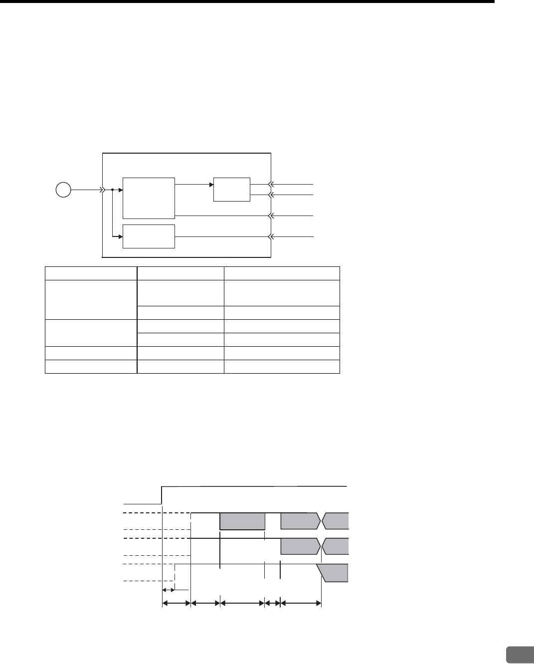
8.4 Absolute Encoders
8
Operation
8-33
8.4.6 Absolute Encoder Reception Sequence
The sequence in which the SERVOPACK receives outputs from the absolute encoder and transmits them to host
controller is shown below.
(1) Outline of Absolute Signals
The serial data, pulses, etc., of the absolute encoder that are output from the SERVOPACK are output from the
PAO, PBO, PCO, and PSO signals as shown below.
(2) Absolute Encoder Transmission Sequence and Contents
1. Set the SEN signal at high level.
2. After 100 ms, set the system to serial data reception-waiting-state. Clear the incremental pulse up/down
counter to zero.
3. Receive eight bytes of serial data.
4. The system enters a normal incremental operation state about 25 ms after the last serial data is received.
• Serial data: Indicates how many turns the motor shaft has made from the reference position (position spec-
ified at setup).
• Initial incremental pulse: Outputs pulses at the same pulse rate as when the motor shaft rotates from the
origin to the current position at about 1250 min-1 (for 17 bits when the dividing pulse is at the factory set-
ting).
Signal Name Status Meaning
PAO At initial status Serial data
Initial incremental pulse
At normal status Incremental pulse
PBO At initial status Initial incremental pulse
At normal status Incremental pulse
PCO Always Zero point pulse
PSO Always Rotation count serial data
SERVOPACK
Conversion
from serial data
into pulse
PG PS PAO
PBO
PCO
PSO
Dividing
circuit
(Pn201)
Data
conversion
Incremental pulse
SEN signal
PAO
PBO
PSO Rotation count serial data
(Phase A)
50 ms
60 ms min.
90 ms typ.
260 ms max.
10 ms
max.
Approx.15 ms
1 to 3 ms
25 ms max.
Rotation count serial data
Initial incre-
mental pulse
Initial incre-
mental pulse
Initial incre-
mental pulse
Incremental pulse
Undefined
Undefined
Undefined
(Phase A)
(Phase B) (Phase B)
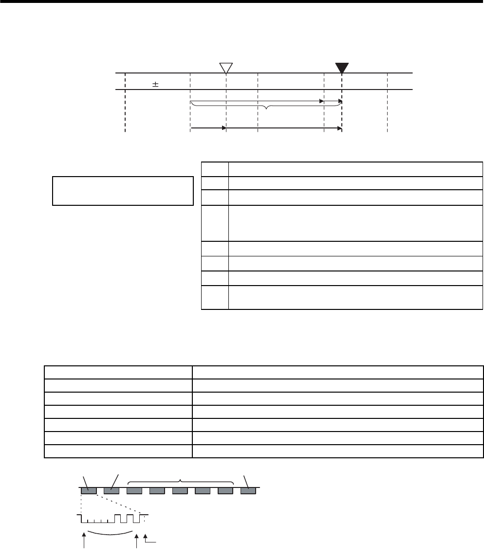
8 Operation
8.4.6 Absolute Encoder Reception Sequence
8-34
Final absolute data PM is calculated by following formula.
(3) Detailed Signal Specifications
(a) PAO Serial Data Specifications
The number of revolutions is output in five digits.
Notes: 1. Data is “P+00000” (CR) or “P-00000” (CR) when the number of revolutions is zero.
2. The revolution range is “+32767” to “-32768.” When this range is exceeded, the data changes
from “+32767” to “-32678” or from “-32678” to “+32767.” When changing multiturn limit, the
range changes. For details, refer to 8.4.7 Multiturn Limit Setting.
PECurrent value read by encoder
PE = M × R + PO
PM = PE - PS
MMultiturn data (rotation count data)
PONumber of initial incremental pulses
Use the following for reverse rotation
mode (Pn000.0 = 1).
PE = -M × R + PO
PM = PE - PS
PS
Absolute data read at setup (This is saved and controlled by the host
controller.)
PS = MS × R + PS'
MsMultiturn data read at setup
PS'Number of initial incremental pulses read at setup
PMCurrent value required for the user’s system.
RNumber of pulses per encoder revolution (pulse count after dividing,
value of Pn201)
Coordinate
value
Value M
Reference position (setup)
-1 0 +1 +2 +3
+3
Current position
+2+1
0
PE
PM
PS
PO
M×R
Data Transfer Method Start-stop Synchronization (ASYNC)
Baud rate 9600 bps
Start bits 1 bit
Stop bits 1 bit
Parity Even
Character code ASCII 7-bit code
Data format 8 characters, as shown below.
Data
Start bit Even parity
"+" or "- " "0" to "9" "CR"
"P"
Stop bit
00000 1010 1
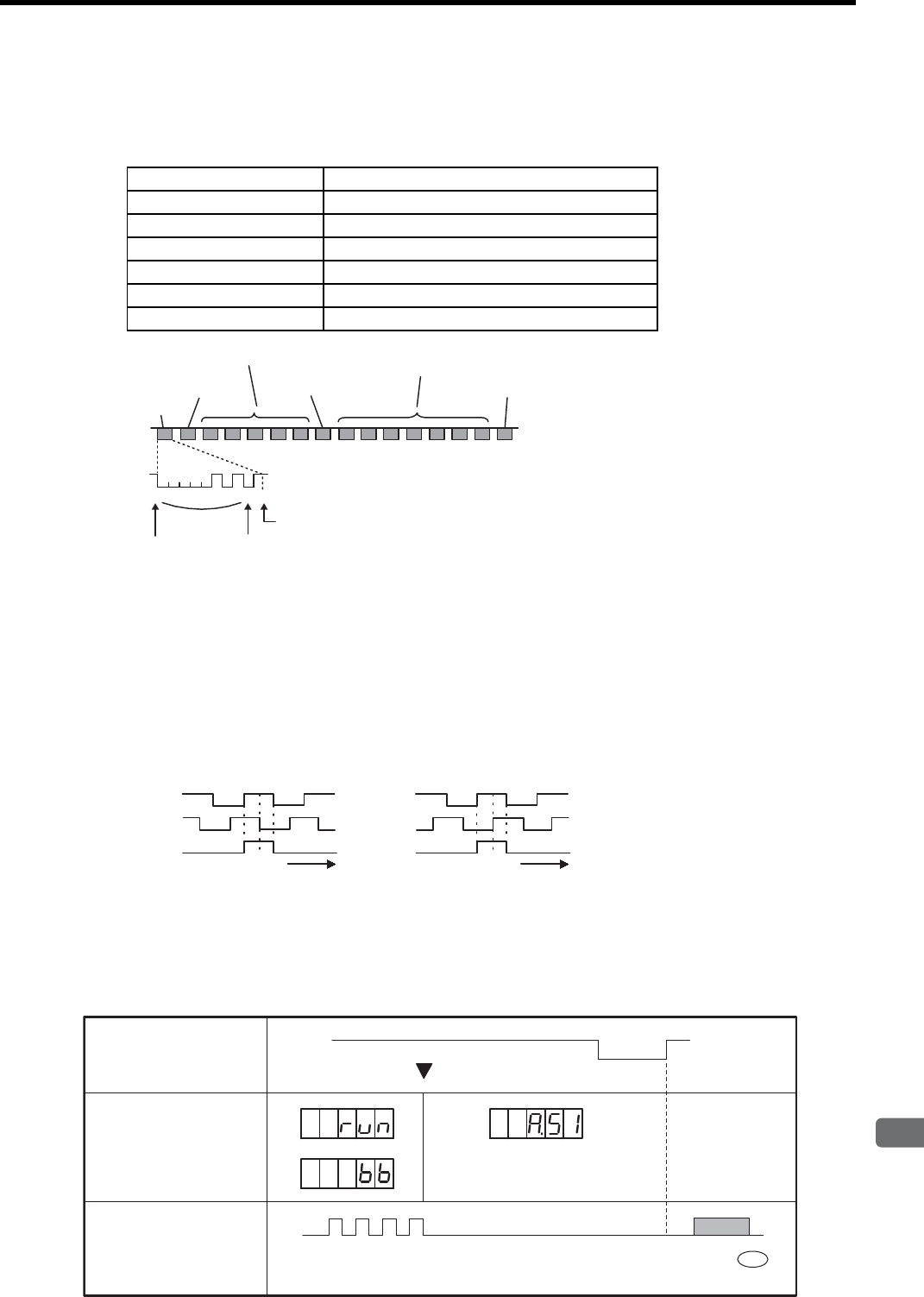
8.4 Absolute Encoders
8
Operation
8-35
(b) PSO Serial Data Specifications
The number of revolutions is always output in five digits and seven digits (absolute position within one revo-
lution).
Note: 1. The absolute position data within one revolution is the value before divided.
2. The absolute position data increases during forward rotation. (The reverse rotation mode is
invalid.)
(c) Incremental Pulses and Zero-Point Pulses
Just as with normal incremental pulses, initial incremental pulses which provide absolute data are first
divided by the frequency divider inside the SERVOPACK and then output.
For details, refer to 8.5.7 Encoder Signal Output.
(4) Transferring Alarm Contents
When an absolute encoder is used, SEN signals can be utilized to transfer the alarm detection contents from PAO
outputs to the host controller as serial data.
For alarm list, refer to 10.1.1 Alarm Display Table.
Data Transfer Method Start-stop Synchronization (ASYNC)
Baud rate 9600 bps
Start bits 1 bit
Stop bits 1 bit
Parity Even
Character code ASCII 7-bit code
Data format 13 characters, as shown below.
CR
P
000001010
Data
Even parity
1
Stop bit
No. of revolutions: 0 to 9 Absolute position within
one revolution: 0 to 9
+ or -
Start bit
̉
Forward rotation
Phase A
Phase B
Phase C
Reverse rotation
Phase A
Phase B
Phase C
tt
Low
level
High level Error detection
Overspeed
or
Incremental pulse ALM51 CR
Serial Data
SEN Signal
Panel Operator
(Digital Operator)
Display
PAO
Serial Data
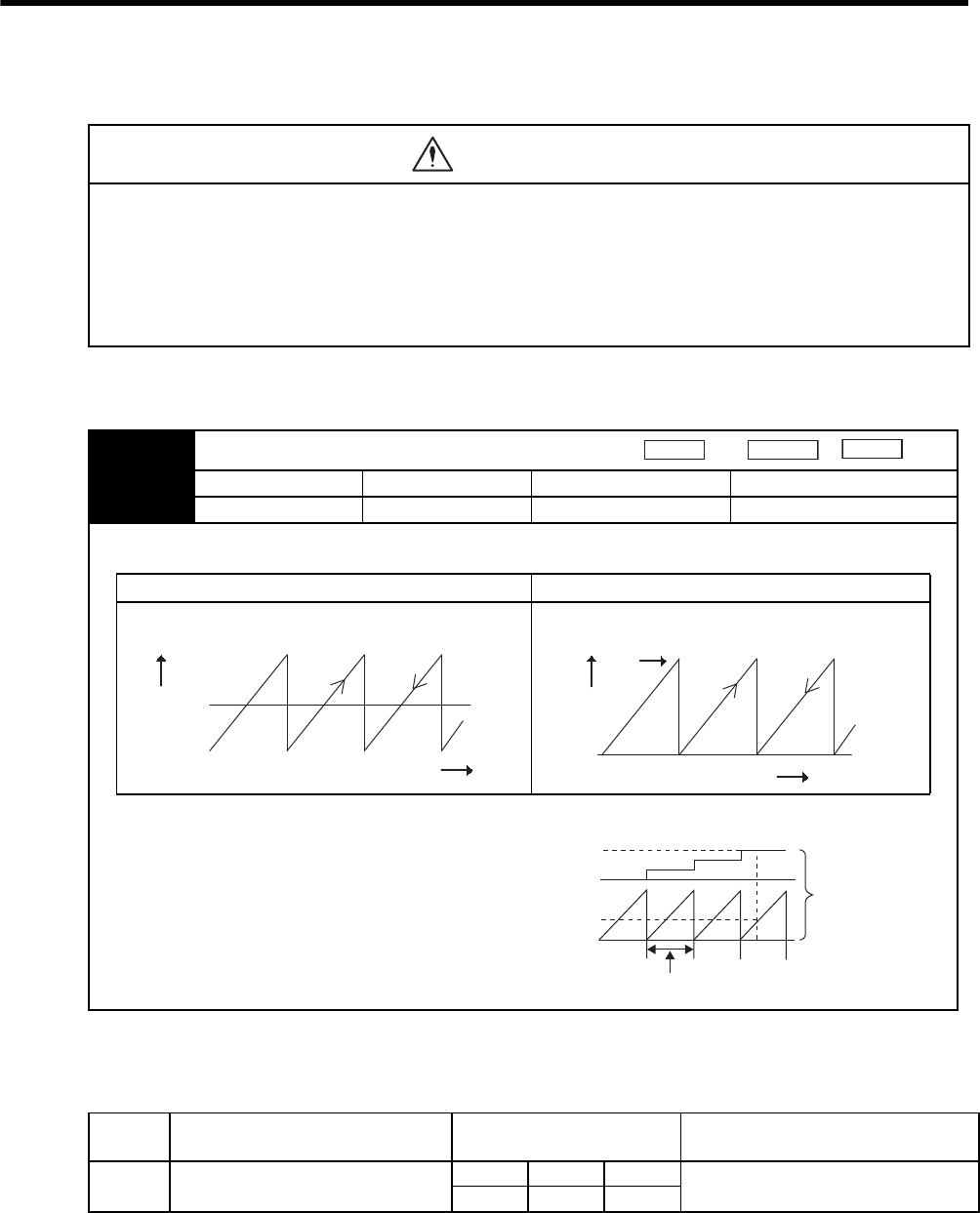
8 Operation
8.4.7 Multiturn Limit Setting
8-36
8.4.7 Multiturn Limit Setting
The parameter for the multiturn limit setting sets the upper limit for the multiturn data from the encoder into
Pn002 = n0 when using an absolute encoder. When the rotation amount exceeds this setting, the encoder
rotation amount returns to 0.
• Encoder Multiturn Limit Disagreement
If the Pn205 value is changed from the factory setting and the power is turned OFF then ON, an alarm will be dis-
played.
When the alarm is displayed, be sure to change the multiturn limit value within the encoder.
• The multiturn limit value must be changed only for special applications. Changing it inappropriately or unin-
tentionally can be dangerous.
• If the Multiturn Limit Disagreement alarm (A.CC) occurs, check the setting of parameter Pn205 to be sure
that it is correct.
If Fn013 is executed when an incorrect value is set in Pn205, an incorrect value will be set in the encoder. The alarm
will disappear even if an incorrect value is set, but incorrect positions will be detected, resulting a dangerous situation
where the machine will move to unexpected positions and machine break and personal accident will occur.
WARNING
Pn205 Multiturn Limit Setting
Setting Range Setting Unit Factory Setting Setting Validation
0 to 65535 1 Rev 65535 After restart
This parameter is valid when Pn002 = n0 (when the absolute encoder is used).
The range of the multiturn data will vary when this parameter is set to anything other than the factory setting.
Factory Setting (=65535) Without Factory Setting (≠65535)
When Set to Anything Other than the Factory Setting
(≠65535)
When the motor rotates in the reverse direction with the multiturn
data at 0, the multiturn data will change to the setting of Pn205.
When the motor rotates in the forward direction with the multiturn
data at the Pn205 setting, the multiturn data will change to 0.
Set the Pn205 to (the desired multiturn data -1).
Speed
Position
Torque
+32767
-32768 No. of revolutions
Multiturn
data 0
Reverse
direction
Forward
direction
0
Pn205 setting value Reverse
direction
No. of revolutions
Forward
direction
Multiturn
data
Position (Absolute encoder)
Travel distance/motor = 1 revolution
(Revolution counter)
Position detection
Detection amount
Alarm
Display Alarm Name Alarm Code Outputs Meaning
A.CC Multiturn Limit Disagreement ALO1 ALO2 ALO3 Different multiturn limits have been set
in the encoder and SERVOPACK.
ON (L) OFF (H) ON (L)
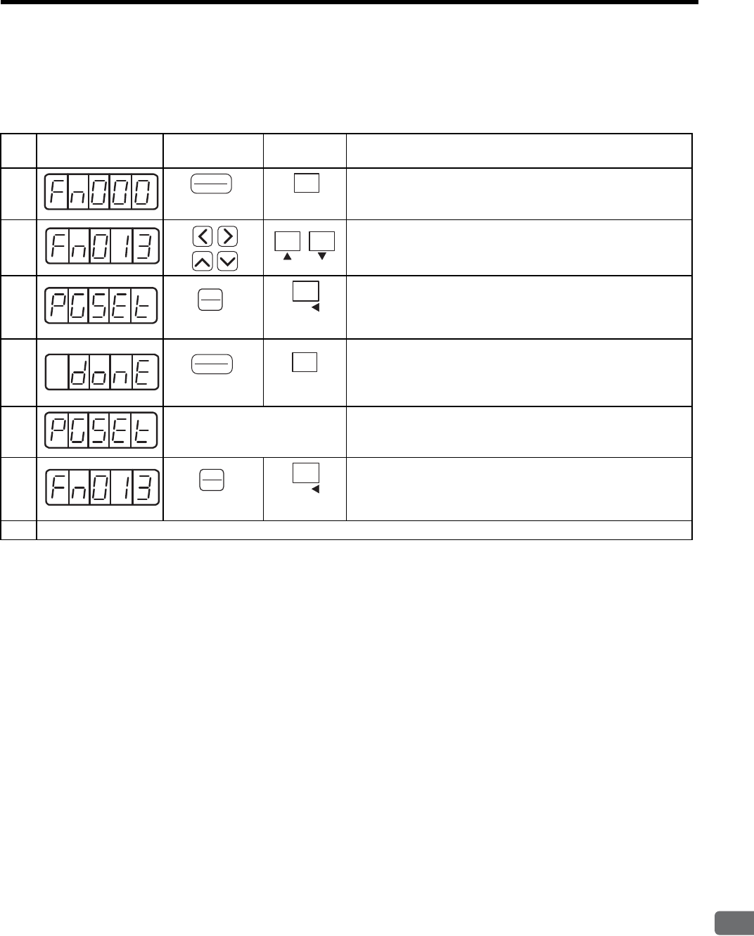
8.4 Absolute Encoders
8
Operation
8-37
8.4.8 Multiturn Limit Setting When Multiturn Limit Disagreement (A.CC) Occurred
Perform the following operation using the digital operator or panel operator.
This operation can only be done when the A.CC alarm is generated.
Step Display after
Operation
Digital
Operator
Panel
Operator Description
1Press the DSPL/SET or MODE/SET Key to select the utility func-
tion mode.
2Press the LEFT/RIGHT or UP/DOWN Key or the UP or DOWN
Key to set the parameter Fn013.
*The digit that can be set will blink.
3
Press the DATA/ENTER Key once, or DATA/SHIFT Key for
more than one second. The display on the left will appear.
4Press the DSPL/SET or MODE/SET Key. The multiturn limit set-
ting in the absolute encoder will be changed.
When the setting is completed, “donE” will blink for about one
second.
5
About one second later After “donE” is displayed, “PGSEt” will be displayed again.
6Press the DATA/ENTER Key once, or DATA/SHIFT Key for
more than one second to return to the Fn013 display of the utility
function mode.
7Turn OFF the power, and then turn it ON again to make the setting valid.
(DSPL/SET Key)
DSPL
SET
MODE/SET
(MODE/SET Key)
(DATA/ENTER Key)
DATA
ENTER
DATA/
(DATA/SHIFT Key)
(Press at least 1 s.)
(DSPL/SET Key)
DSPL
SET
MODE/SET
(MODE/SET Key)
(DATA/ENTER Key)
DATA
ENTER
DATA/
(DATA/SHIFT Key)
(Press at least 1 s.)
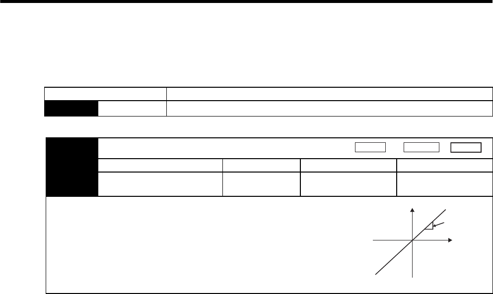
8 Operation
8.5.1 Setting Parameters
8-38
8.5 Operating Using Speed Control with Analog Reference
8.5.1 Setting Parameters
Parameter Description
Pn000 n.0Control mode selection: Speed control (analog reference) (factory setting)
Pn300 Speed Reference Input Gain
Setting Range Setting Unit Factory Setting Setting Validation
1.50 to 3000
(150 to 30.00 V/rated speed)
0.01 V/Rated
speed
600
(6 V/rated speed) Immediately
Sets the analog voltage level for the speed reference (V-REF) necessary to operate the
servomotor at the rated speed.
EXAMPLE
Pn300=600: 6-V input is equivalent to the rated speed of the servomotor
(factory setting).
Pn300=1000: 10-V input is equivalent to the rated speed of the servomotor.
Pn300=200: 2-V input is equivalent to the rated speed of the servomotor.
Speed Position Torque
Reference
Reference
Voltage (V)
Speed
(min )
-1 Set this
slope.
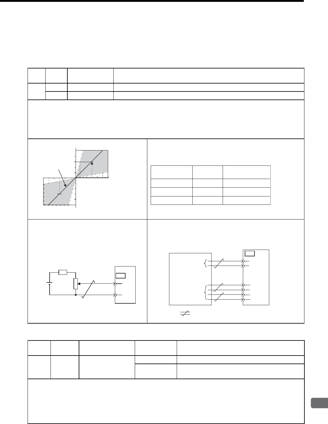
8.5 Operating Using Speed Control with Analog Reference
8
Operation
8-39
8.5.2 Setting Input Signals
(1) Speed Reference Input
Input the speed reference to the SERVOPACK using the analog voltage reference to control the servomotor speed
in proportion to the input voltage.
(2) Proportional Control Reference (/P-CON)
Type Signal
Name
Connector Pin
Number Name
Input V-REF CN1-5 Speed Reference Input
SG CN1-6 Signal Ground for Speed Reference Input
The above inputs are used for speed control (analog voltage reference). (Pn000.1 = 0, 4, 7, 9, or A)
Pn300 is used to set the speed reference input gain. Refer to 8.5.1 Setting Parameters.
Input Specifications
• Input range: ±2 VDC to ±10 VDC/rated speed
• Maximum allowable input voltage: ±12 VDC
• Setting Example
Pn300 = 600: Rated speed at ±6 V
Actual examples are shown below.
Parameter Pn300 can be used to change the voltage input range.
Input Circuit Example
• Always use twisted-pair wire to control noise.
• Recommended variable resistor: Model 25HP-
10B manufactured by Sakae Tsushin Kogyo Co.,
Ltd.
Connect V-REF and SG to the speed reference output terminals on
the host controller when using a host controller, such as a program-
mable controller, for position control.
Type Signal
Name
Connector
Pin Number Setting Description
Input /P-CON CN1-41
ON (low level) Operates the SERVOPACK with proportional control.
OFF (high level) Operates the SERVOPACK with proportional integral
control.
/P-CON signal selects either the PI (proportional integral) or P (proportional) Speed Control Mode.
Switching to P control reduces servomotor rotation and minute vibrations due to speed reference input drift.
Input reference: At 0 V, the servomotor rotation due to drift will be reduced, but servomotor rigidity (holding force) drops
when the servomotor is stopped.
Note: A parameter can be used to reallocate the input connector number for the /P-CON signal. Refer to 7.3.2 Input Circuit
Signal Allocation.
Input voltage (V)
Factory setting
Rated motor speed
Rated motor speed
The slope is set in Pn300.
-4-8-12
4812
Speed Reference
Input
Rotation
Direction Motor Speed
+6 V Forward Rated motor speed
Forward 1/6 rated motor speed
1/2 rated motor speed
Reverse
+1 V
-3 V
CN1
5
6
SG
V-REF
2 kΩ
+12 V
SERVOPACK
1.8 kΩ1/2 W min.
SG
V-REF
CN1
6
33
34
35
36
5
/PBO
PBO
/PAO
PAO
Feedback
pulse input
terminals
Speed reference
Host controller
output terminals
SERVOPACK
: represents twisted-pair wires.
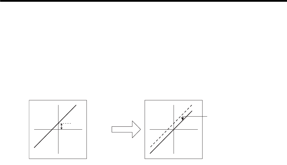
8 Operation
8.5.3 Adjusting Offset
8-40
8.5.3 Adjusting Offset
When using the speed control, the servomotor may rotate slowly even if 0 V is specified as the analog voltage
reference. This happens if the host controller or external circuit has a slight offset (in the units of mV) in the ref-
erence voltage. Adjustments can be done manually or automatically by using the panel operator or digital opera-
tor. Refer to 7.2 Operation in Utility Function Mode (Fn
).
The automatic adjustment of the analog (speed, torque) reference offset (Fn009) automatically measures the
amount of the offset and adjusts the reference voltage.
The SERVOPACK automatically adjusts the offset when the host controller or external circuit has the offset in
the reference voltage.
After completion of the automatic adjustment, the amount of offset is stored in the SERVOPACK. The amount of
offset can be checked in the speed reference offset manual adjustment mode (Fn00A). Refer to 8.5.3 (2) Manual
Adjustment of the Speed Reference Offset.
Offset
Reference
voltage
Reference
voltage Offset automatically
adjusted in SERVOPACK.
Speed
reference
Speed
reference
Automatic
offset
adjustment
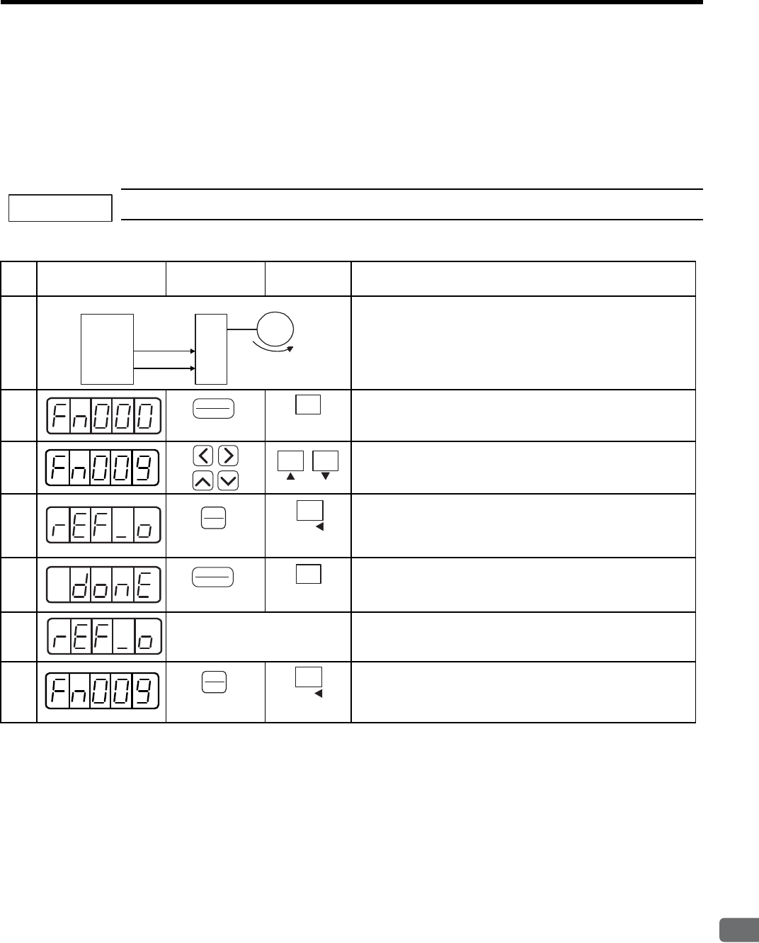
8.5 Operating Using Speed Control with Analog Reference
8
Operation
8-41
(1) Automatic Adjustment of the Speed Reference Offset
The automatic adjustment of reference offset (Fn009) cannot be used when a position loop has been formed with
a host controller and the error pulse is changed to zero at the servomotor stop due to servolock. Use the speed ref-
erence offset manual adjustment (Fn00A) described in the next section for a position loop.
The zero-clamp speed control function can be used to force the motor to stop while the zero speed reference is
given. Refer to 8.5.6 Using the Zero Clamp Function.
The speed reference offset must be automatically adjusted with the servo OFF.
Adjust the speed reference offset automatically in the following procedure.
IMPORTANT
Step Display after
Operation
Digital
Operator
Panel
Operator Description
1
Turn OFF the SERVOPACK, and input the 0-V reference voltage
from the host controller or external circuit.
2Press the DSPL/SET or MODE/SET Key to select the utility
function mode.
3Press the LEFT/RIGHT or UP/DOWN Key, or UP or DOWN
Key to select parameter Fn009.
*The digit that can be set will blink.
4
Press the DATA/ENTER Key once, or DATA/SHIFT Key for
more than one second. “rEF_o” will be displayed.
5Press the DSPL/SET or MODE/SET Key.
The reference offset will be automatically adjusted.
When completed, “donE” will blink for about one second.
6
About one second later After “donE” is displayed, “rEF_o” will be displayed again.
7Press the DATA/ENTER Key once, or DATA/SHIFT Key for
more than one second to return to the Fn009 display of the utility
function mode.
Servomotor
Slow rotation
(Servo ON)
SERVOPACK
Servo OFF
0-V speed
reference
Host
controller
(DSPL/SET Key)
DSPL
SET
MODE/SET
(MODE/SET Key)
(DATA/ENTER Key)
DATA
ENTER
DATA/
(DATA/SHIFT Key)
(Press at least 1 s.)
(DSPL/SET Key)
DSPL
SET
MODE/SET
(MODE/SET Key)
(DATA/ENTER Key)
DATA
ENTER
DATA/
(DATA/SHIFT Key)
(Press at least 1 s.)
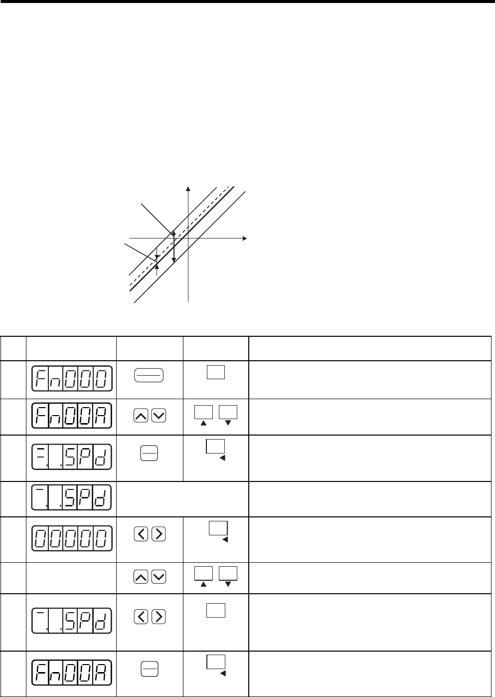
8 Operation
8.5.3 Adjusting Offset
8-42
(2) Manual Adjustment of the Speed Reference Offset
Use the speed reference offset manual adjustment (Fn00A) in the following situations:
• If a loop is formed with the host controller and the position error pulse is to be zero when servolock is
stopped.
• To deliberately set the offset to some value.
• To check the offset data set in the speed reference offset automatic adjustment mode.
This function operates in the same way as the reference offset automatic adjustment mode (Fn009), except that
the amount of offset is directly input during the adjustment.
The offset setting range and setting units are as follows:
Adjust the speed reference offset manually in the following procedure.
Offset Adjustment Range: ±15000
(Speed Reference: ±750 mV)
Speed Reference
Offset adjustment
range
Offset setting unit Analog
Input
Voltage
Offset Setting Unit
Speed Reference:1 = 0.05 mV
Step Display after
Operation
Digital
Operator
Panel
Operator Description
1Press the DSPL/SET or MODE/SET Key to select the utility
function mode.
2Press the UP or DOWN Key to select parameter Fn00A.
*The digit that can be set will blink.
3Press the DATA/ENTER Key once, or DATA/SHIFT Key for
more than one second. The display will be as shown at the left.
The manual adjustment mode for the speed reference offset will
be entered.
4
Servo ON Turn ON the servo ON (/S-ON) signal. The display will be as
shown at the left.
5
Press the LEFT or RIGHT Key or DATA/SHIFT Key for less
than one second to display the speed reference offset amount.
6
Press the UP or DOWN Key to adjust the amount of offset.
7Press the LEFT or RIGHT Key or MODE/SET Key for less than
one second. The display will appear momentarily as shown at the
left, and “donE” will blink and the offset will be set. After the
setting is completed, the display will return to the display as
shown at the left.
8Press the DATA/ENTER Key once, or DATA/SHIFT Key for
more than one second to return to the Fn00A display of the utility
function mode.
(DSPL/SET Key)
DSPL
SET
MODE/SET
(MODE/SET Key)
(DATA/ENTER Key)
DATA
ENTER
DATA/
(DATA/SHIFT Key)
(Press at least 1 s.)
DATA/
(DATA/SHIFT Key)
(Press less than 1 s.)
MODE/SET
(MODE/SET Key)
(Press less than 1 s.)
(DATA/ENTER Key)
DATA
ENTER
DATA/
(DATA/SHIFT Key)
(Press at least 1 s.)
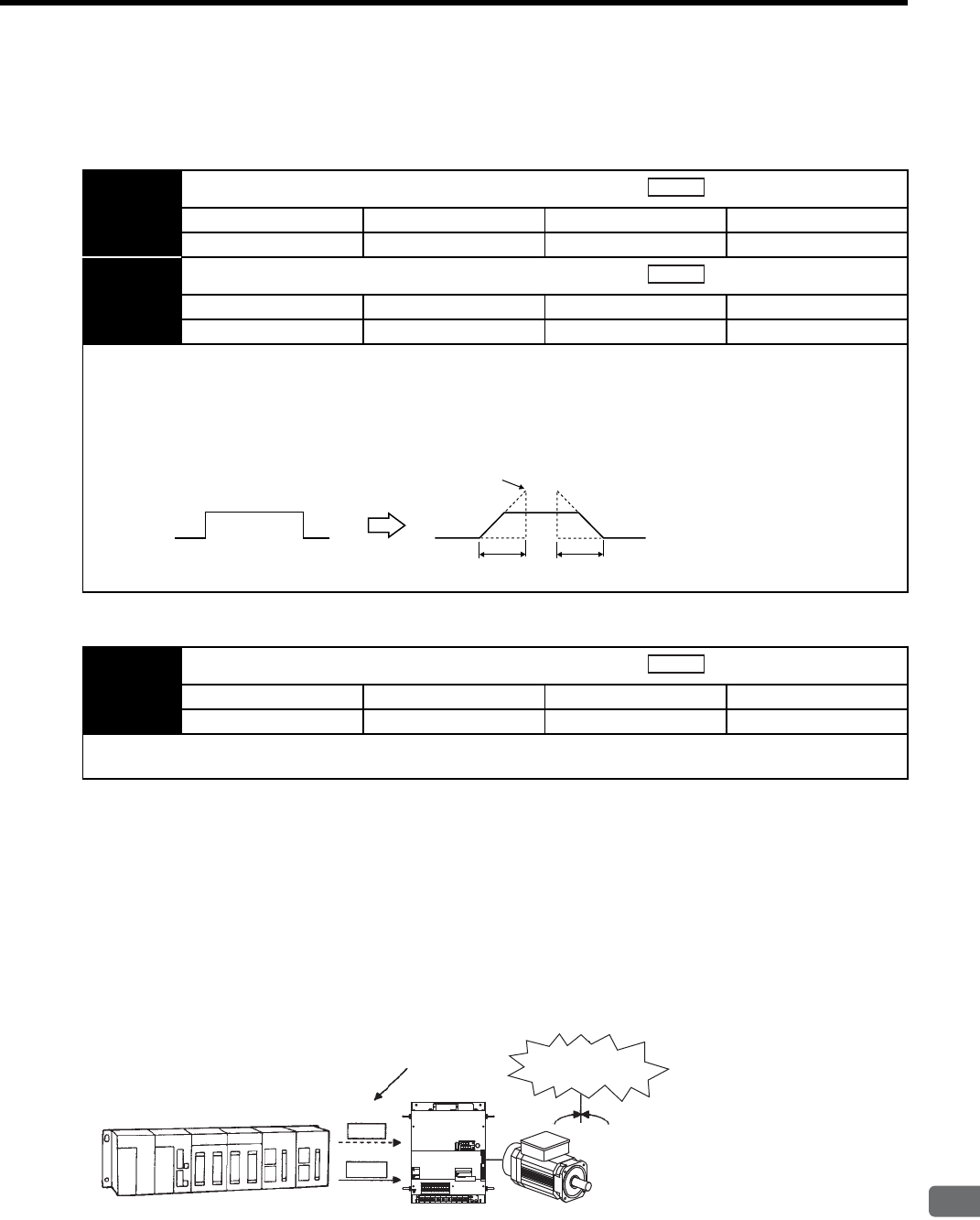
8.5 Operating Using Speed Control with Analog Reference
8
Operation
8-43
8.5.4 Soft Start
The soft start function converts the stepwise speed reference inside the SERVOPACK to a consistent rate of
acceleration and deceleration.
8.5.5 Speed Reference Filter
8.5.6 Using the Zero Clamp Function
(1) Zero Clamp Function
The zero clamp function is used for systems where the host controller does not form a position loop for the speed
reference input. When the zero clamp signal (/ZCLAMP) is ON, a position loop is formed inside the SERVO-
PACK as soon as the input voltage of the speed reference (V-REF) drops below the motor speed level in the zero
clamp level (Pn501). The servomotor ignores the speed reference and then quickly stops and locks the servomo-
tor.
The servomotor is clamped within ±1 pulse of when the zero clamp function is turned ON, and will still return to
the zero clamp position even if it is forcibly rotated by external force.
Pn305 Soft Start Acceleration Time
Setting Range Setting Unit Factory Setting Setting Validation
0 to 10000 1 ms 0 Immediately
Pn306 Soft Start Deceleration Time
Setting Range Setting Unit Factory Setting Setting Validation
0 to 10000 1 ms 0 Immediately
The soft start function enables smooth speed control when inputting a stepwise speed reference or when selecting internally
set speeds. Set both Pn305 and Pn306 to “0” for normal speed control.
Set these parameters as follows:
• Pn305: The time interval from the time the motor starts until the motor maximum speed is reached.
• Pn306: The time interval from the time the motor is operating at the motor maximum speed until it stops.
Speed
Speed
Pn305 Pn306
After soft start
Maximum speed of Servomotor
Before soft start
Pn307 Speed Reference Filter Time Constant
Setting Range Setting Unit Factory Setting Setting Validation
0 to 65535 0.01 ms 40 Immediately
This smoothens the speed reference by applying a 1st-order delay filter to the analog speed reference (V-REF) input. A
value that is too large, however, will slow down response.
Speed
Host controller Speed
reference
A speed reference below
the Pn501 setting is ignored. ࡇ࠲࠶!
/P-CON
(/ZCLAMP)
V-REF
.4 .5 .6 789
8
8
&7
8
8
8
&9&8 $
8
&%
0
$
&%
2
%*#4)'
5*&)
㧖㧖㧖㧖
6 #5''/1&
-5'4812#%
#;#5-#9
4
1
2
'
4
#
6
1
%0
%0
219'4
%0
WARNING
ෂޓ㒾
ㅢ㔚ਛ߮㔚Ḯࠝࡈᓟ5
ಽ㑆ޔ┵ሶㇱߦ⸅ࠆߥ
electric shock.
Disconnect all power
May cause
ᗵ㔚ߩᕟࠇࠅ
before servicing.
and wait 5 min.
grounding techniques.
ធ⛯ߖࠃ
Use proper
ᔅߕࠕ㧙ࠬ✢ࠍ
Stops precisely!
Zero clamp
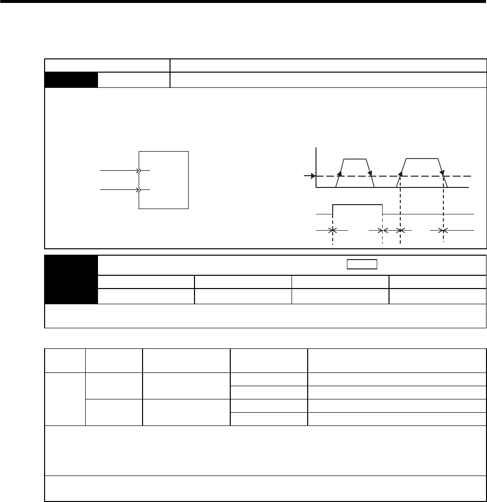
8 Operation
8.5.6 Using the Zero Clamp Function
8-44
(2) Parameter Setting
(3) Input Signal Setting
Parameter Meaning
Pn000 n.AControl mode selection: Speed control (analog voltage reference) ⇔ Zero clamp
Zero Clamp Conditions
Zero clamp is performed with Pn000 = n.A when the following two conditions are satisfied:
• /P-CON (/ZCLAMP) is ON (low level).
• Speed reference (V-REF) drops below the setting of Pn501.
Speed reference
Zero clamp
V-REF
CN1
41
5
/P-CON
SERVOPACK
(/ZCLAMP)
V-REF speed reference
Speed
Pn501
Preset value
for zero clamping
/P-CON (/ZCLAMP) input
Zero clamp is performed.
Open (OFF)
Closed (ON)
Time
ON ON ON
OFFOFF
Pn501 Zero Clamp Level
Setting Range Setting Unit Factory Setting Setting Validation
0 to 10000 1 min-1 10 Immediately
Sets the motor speed at which the zero clamp is performed if zero clamp speed control (Pn000 = n.A) is selected.
Even if this value is set higher than the maximum speed of the servomotor, the maximum speed will be used.
Speed
Type Signal Name Connector Pin
Number Setting Meaning
Input
/P-CON CN1-41 ON (low level) Zero clamp function ON (enabled)
OFF (high level) Zero clamp function OFF (disabled)
/ZCLAMP Must be allocated ON (low level) Zero clamp function ON (enabled)
OFF (high level) Zero clamp function OFF (disabled)
This is the input signal for the zero clamp operation.
Either /P-CON or /ZCLAMP can be used to switch the zero clamp.
To use the /ZCLAMP signal, allocation of the input signal is required.
Refer to 7.3.2 Input Circuit Signal Allocation for more details.
IMPORTANT
When the /ZCLAMP signal is allocated, the zero clamp operation will be used even for speed control Pn000 = n.0.
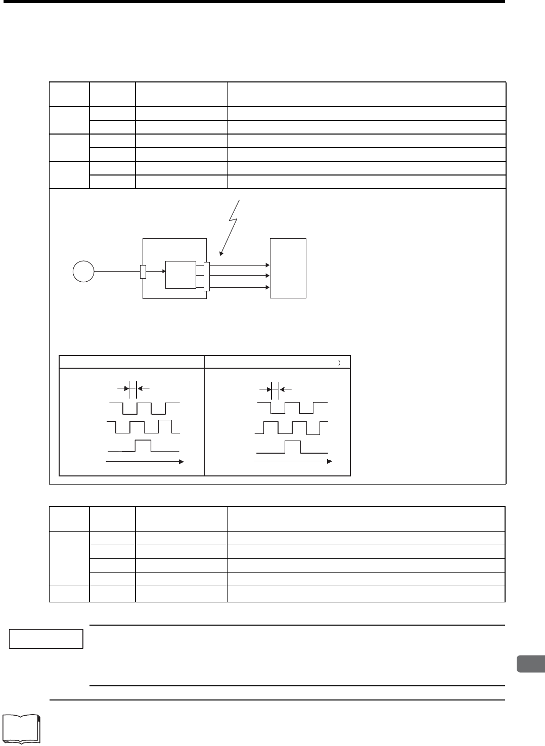
8.5 Operating Using Speed Control with Analog Reference
8
Operation
8-45
8.5.7 Encoder Signal Output
Encoder feedback pulses processed inside the SERVOPACK can be output externally.
The following signals are added when using an absolute encoder.
* SG (CN1-1, 2): Connect to 0 V on the host controller.
If using the SERVOPACK’s phase-C pulse output for a zero point return, rotate the servomotor twice or
more before starting a zero point return. If the configuration prevents the servomotor from rotating the ser-
vomotor or more, perform a zero point return at a motor speed of 600 min-1 or below. If the motor speed is
faster than 600 min-1, the phase-C pulse output may not be output correctly.
1 Dividing
The dividing means that the divider converts data into the number of pulses based on the pulses of the encoder installed on
the servomotor, and outputs it. The setting unit is the number of pulses/revolution.
Type Signal
Name
Connector
Pin Number Name
Output PAO CN1-33 Encoder output phase A
/PAO CN1-34 Encoder output phase /A
Output PBO CN1-35 Encoder output phase B
/PBO CN1-36 Encoder output phase /B
Output PCO CN1-19 Encoder output phase C (zero-point pulse)
/PCO CN1-20 Encoder output phase /C (zero-point pulse)
* Even in reverse rotation mode (Pn000.0 = 1), the dividing 1 output phase form is the same as that for the standard setting
(Pn000.0 = 0).
Output Phase Form
PG
SERVOPACK
CN2 CN1
Encoder
Host controller
These outputs explained here.
Phase A (PAO)
Phase B (PBO)
Phase C (PCO)
Serial data Frequency
dividing
circuit
*Note: The width of the zero-point pulse varies
depending on the setting of the dividing ratio
(Pn201). The width of zero-point pulse and
phase A are identical.
Phase A
Phase B
Phase C
90˚
t
Phase A
Phase B
Phase C
90˚
t
Forward rotation (phase B leads by 90˚) Reverse rotation (phase A leads by 90˚
Type Signal
Name
Connector
Pin Number Name
Input
SEN CN1-4 SEN Signal Input
SG CN1-2 Signal Ground
BAT (+) CN1-21 Battery (+)
BAT (-) CN1-22 Battery (-)
Output SG∗CN1-1 Signal Ground
IMPORTANT
TERMS
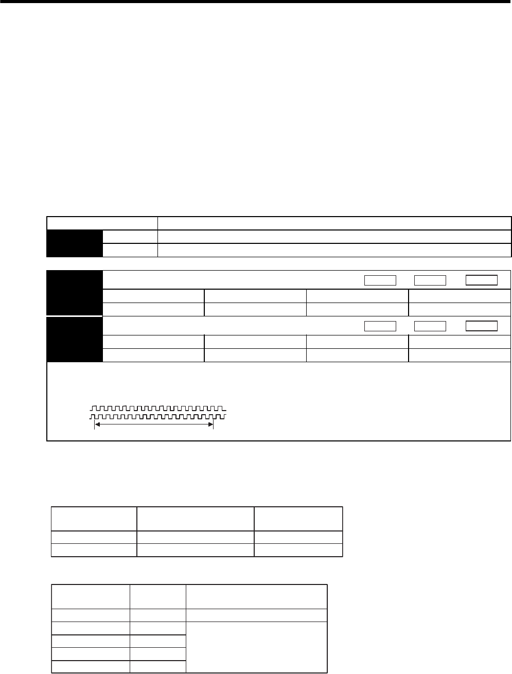
8 Operation
8.5.7 Encoder Signal Output
8-46
• Pulse Dividing Ratio Setting
The upper limit of PG dividing ratio (Pn201) is 16384 [P/R] that is decided for 16-bit encoder. However,
SGMVH servomotors are equipped with 17-bit encoder as standard and 20-bit encoder as an option. There-
fore, the parameter Pn212 is added to adapt the dividing pulse setting for 20-bit encoder.
For the PG dividing ratio setting, either the existing Pn210 or the newly added Pn212 can be used.
Select Pn201 or Pn212 by the switch for parameters. The factory setting is Pn201.
• Dividing pulse is set in the resolution 16-bit or less, use Pn201.
• Dividing pulse is set in the resolution 17-bit or more, use Pn212.
For the setting method of dividing ratio for 17-bit or more resolution, refer to (2) Setting PG dividing ratio of
5-digit or more.
(1) Related Parameters
The setting range of Pn212 differs depending on the encoder used.
The upper limit of dividing output frequency is 1.4 Mpps because of the restrictions on the hardware. Therefore,
setting a high number of pulses limits the motor speed.
The following table shows the setting conditions when Pn212 is used.
For settings higher than 16384 P/R, pulses must be set in the following increments.
The setting error alarm A.09 (dividing ratio setting error) will occur if the setting is outside the allowable range
or does not satisfy the setting conditions. The overspeed alarm A.51 will occur if the motor speed exceeds the
upper limit.
When setting the pulse dividing ratio using a digital operator or panel operator, the display of the number of
pulses is skipped to not increment by 2 to 16 pulses and the upper limit will not increment above the resolution of
mounted encoder.
Parameter Description
Pn207 n.0 Uses the parameter Pn201 (For 16-bit or less) as the dividing ratio (Factory setting).
n.1 Uses the parameter Pn212 (For 17-bit or more) as the dividing ratio.
Pn201 PG Dividing Ratio (For 16-bit or less)
Setting Range Setting Unit Factory Setting Setting Validation
16 to 16384 1 P/rev 16384 After restart
Pn212 PG Dividing Ratio (For 17-bit or more)
Setting Range Setting Unit Factory Setting Setting Validation
16 to 1073741824 1 P/rev 2048 After restart
Output Example
Pn201=16 (when 16 pulses are output per revolution)
Speed
Position
Torque
Speed
Position
Torque
Preset value: 16
1 revolution
PAO
PBO
Encoder Resolution
(Bits)
Number of Encoder Pulses
per Revolution (P/R) Setting Range (P/R)
17
20
32768
262144
16 to 32768
16 to 262144
PG Dividing Ratio
Setting (P/R)
Increments
(P/R) Motor Speed Upper Limit (min-1)
16 to 16384
16386 to 32768
32772 to 65536
65544 to 131072
131088 to 262144
1-pulse
2-pulse
4-pulse
8-pulse
16-pulse
No limit
82 × 106/set value
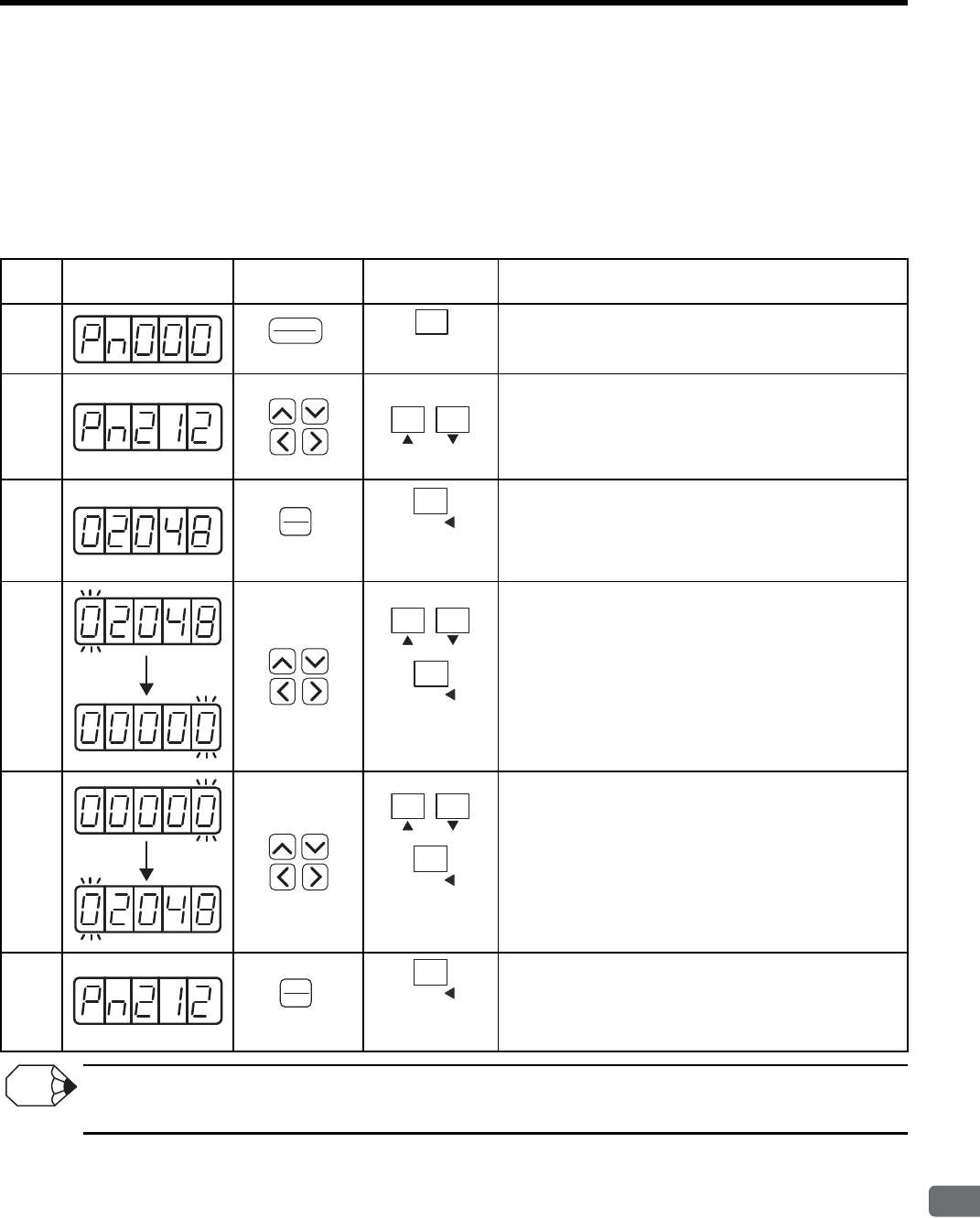
8.5 Operating Using Speed Control with Analog Reference
8
Operation
8-47
When Pn212 is set without connecting a servomotor to the SERVOPACK, the upper limit is automatically set to
230 (=1073741824: the maximum output value of the SERVOPACK) since the encoder resolution of the servo-
motor is unknown.
Therefore, it is recommended to set Pn212 after connecting a servomotor.
(2) Setting PG dividing ratio of 5-digit or more
The following table shows a procedure to set Pn212 by a digital operator or a panel operator.
When the password setting (write prohibited setting) is enabled, the setting can be read only by pressing Left or Right
Cursor Key or DATA/SHIFT Key.
Proce-
dure
Display After
Operation
Hand-held
digital operator Panel Operator Description
1
Press DSPL/SET or MODE/SET Key to select the utility
function mode.
2
Press Up or Down Cursor Key to select the parameter
Pn212.
Press Left or Right Cursor Key to select the digit. The
enabled digit blinks.
Press Up or Down Cursor Key to change the value.
3
Press DATA/ENTER Key or DATA/SHIFT key for more
than one second to display the lower 5 digits of the current
PG dividing ratio setting value.
4
Press Left or Right Cursor Key once, or DATA/SHIFT Key
for more than one second to select the digit. The enable
digit blinks.
Press Up or Down Cursor Key to change the value.
Pressing Left or Right Cursor Key or DATA SHIFT Key
when the left-end or right-end digit is blinking displays
another 5 digits.
5
Press Left or Right Cursor Key or DATA/SHIFT Key for
more then one second to select the digit. The enabled digit
blinks.
Press Up or Down Cursor Key to change the value.
Pressing Left or Right Cursor Key or DATA/SHIFT Key
when the left-end or right-end digit is blinking displays
another 5 digits.
Repeat the steps 4 and 5 to change the data.
6
DATA/ENTER Key once, or DATA/SHIFT Key for more
than one second.
The display returns to Pn212.
(DSPL/SET Key)
DSPL
SET
MODE/SET
(MODE/SET Key)
(DATA/ENTER Key)
DATA
ENTER
(DATA/SHIFT Key)
(Press at least
1 s.)
DATA/
(DATA/SHIFT Key)
(Press at least
1 s.)
DATA/
(DATA/SHIFT Key)
(Press at least
1 s.)
DATA/
(DATA/ENTER Key)
DATA
ENTER
(DATA/SHIFT Key)
(Press at least
1 s.)
DATA/
INFO
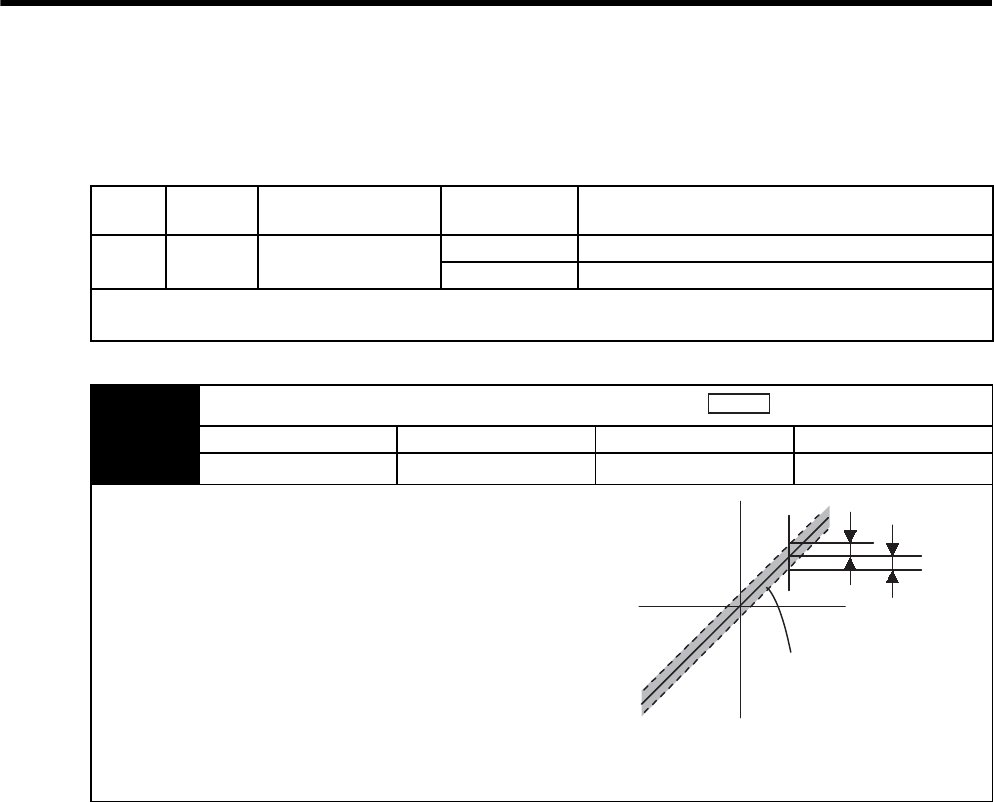
8 Operation
8.5.8 Speed Coincidence Output
8-48
8.5.8 Speed Coincidence Output
The speed coincidence (/V-CMP) output signal is output when the actual motor speed during speed control is the
same as the speed reference input. The host controller uses the signal as an interlock.
Type Signal
Name
Connector
Pin Number Setting Meaning
Output /V-CMP CN1-25, 26
(Factory setting)
ON (low level) Speed coincides.
OFF (high level) Speed does not coincide.
This output signal can be allocated to another output terminal with parameter Pn50E.
Refer to 7.3.3 Output Circuit Signal Allocation for details.
Pn503 Speed Coincidence Signal Output Width
Setting Range Setting Unit Factory Setting Setting Validation
0 to 100 1 min-1 10 Immediately
The /V-CMP signal is output when the difference between the speed
reference and actual motor speed is the same as the pn503 setting or
less.
EXAMPLE
The /V-CMP signal turns ON at 1900 to 2100 min-1 if the Pn503 param-
eter is set to 100 and the reference speed is 2000 min-1.
/V-CMP is a speed control output signal. When the factory setting is used and the output terminal allocation is not per-
formed with the Pn50E, this signal is automatically used as the positioning completed signal /COIN for position control,
and it is always OFF (high level) for torque control.
Speed
Motor speed
Reference speed
/V-CMP is output in
this range.
Pn503
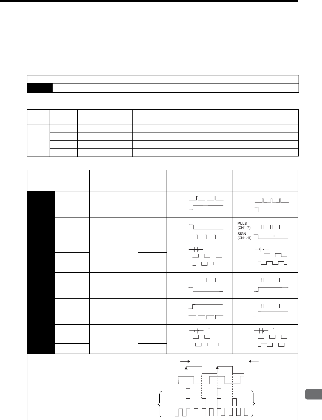
8.6 Operating Using Position Control
8
Operation
8-49
8.6 Operating Using Position Control
8.6.1 Setting Parameters
Set the following parameters for position control using pulse trains.
(1) Control Mode Selection
(2) Setting a Reference Pulse Form
Set the input form for the SERVOPACK using parameter Pn200.0 according to the host controller specifications.
Parameter Meaning
Pn000 n.1Control mode selection: Position control (pulse train reference)
Type Signal
Name
Connector
Pin Number Name
Input
PULS CN1-7 Reference Pulse Input
/PULS CN1-8 Reference Pulse Input
SIGN CN1-11 Reference Code Input
/SIGN CN1-12 Reference Code Input
Parameter Reference Pulse
Form
Input
Pulse
Multiplier
Forward Rotation
Reference
Reverse Rotation
Reference
Pn200 n.0Sign + pulse train
(Positive logic)
(Factory setting)
−
n.1CW pulse + CCW
pulse
(Positive logic)
−
n.2Two-phase pulse
train with 90° phase
differential
(Positive logic)
×1
n.3×2
n.4×4
n.5
Sign + pulse train
(Negative logic) −
n.6CW pulse + CCW
pulse
(Negative logic)
−
n.7Two-phase pulse
train with 90° phase
differential
(Negative logic)
×1
n.8×2
n.9×4
The input pulse multiplier can be set for the
2-phase pulse train with 90° phase differen-
tial reference pulse form.
H
PULS
(CN1-7)
SIGN
(CN1-11)
L
PULS
(CN1-7)
SIGN
(CN1-11)
L
PULS
(CN1-7)
SIGN
(CN1-11)
90°
PULS
PULS
(CN1-7)
SIGN
1)(CN1-1
90°
PULS
PULS
(CN1-7)
SIGN
1)
(CN1-1
L
PULS
(CN1-7)
SIGN
(CN1-11)
H
PULS
(CN1-7)
SIGN
(CN1-11)
H
PULS
(CN1-7)
SIGN
(CN1-11)
H
PULS
(CN1-7)
SIGN
(CN1-11)
90
PULS
PULS
(CN1-7)
SIGN
1)
(CN1-1
90
PULS
PULS
(CN1-7)
SIGN
1)(CN1-1
(CN1-7)
(CN1-11)
PULS
SIGN
Internal
processing
×1
×2
×4
Motor movement
reference pulses
Forward rotation Reverse rotation
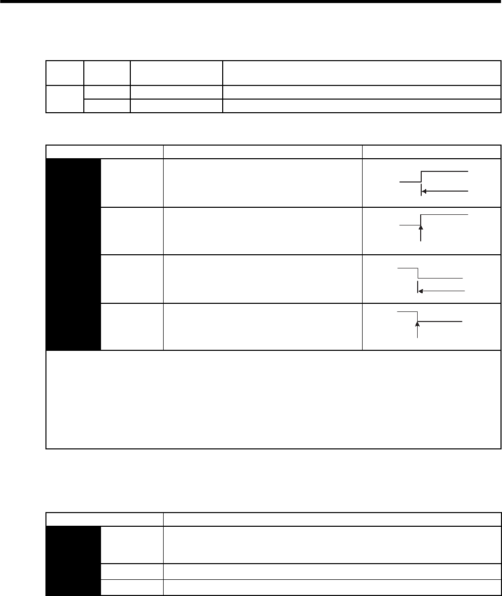
8 Operation
8.6.1 Setting Parameters
8-50
(3) Clear Signal Form Selection
The internal processing of the SERVOPACK for the clear signal can be set to either of four types by parameter
Pn200.1. Select according to the specifications of the machine or host controller.
(4) Clear Operation Selection
This parameter determines when the error pulse should be cleared according to the condition of the SERVO-
PACK, in addition to the clearing operation of the clear signal (CLR). Either of three clearing modes can be
selected with Pn200.2
Type Signal
Name
Connector
Pin Number Name
Input CLR CN1-15 Clear Input
/CLR CN1-14 Clear Input
Parameter Description Timing
Pn200 n.0Clears at high level.
Position error pulses do not accumulate while the
signal is at high level.
(Factory setting)
n.1
Clears at the rising edge.
n.2Clears at low level.
Position error pulses do not accumulate while the
signal is at low level.
n.3
Clears at the falling edge.
The following are executed when the clear operation is enabled.
• The SERVOPACK error counter is set to 0.
• Position loop operation is disabled.
→ Holding the clear status may cause the servo clamp to stop functioning and the servomotor to rotate slowly due to drift
in the speed loop.
If the clear signal (CLR) is not wired and Pn200 is set to n.2, the position-error pulse is always cleared.
So, if a pulse-train reference is input, the servomotor will not operate.
Clears at
high level
CLR
(CN1-15)
High
Clears here just once.
CLR
(CN1-15)
CLR
(CN1-15) Clears at low level
Low
Clears here just once.
CLR
(CN1-15)
Parameter Description
Pn200 n.0 Clear the error pulse at the CLR signal input during the baseblock. (Factory setting)
“During the baseblock” means when the /S-ON signal or the main circuit power supply is
OFF, or an alarm occurs.
n.1 Do not clear the error pulse. Clear only with the CLR signal.
n.2 Clear the error pulse when an alarm occurs or the CLR signal is input.
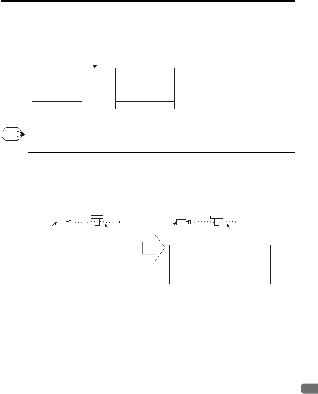
8.6 Operating Using Position Control
8
Operation
8-51
8.6.2 Setting the Electronic Gear
(1) Number of Encoder Pulses
Note: For details on reading servomotor model numbers, refer to 2.1 Servomotor Model Designations.
The number of bits representing the resolution of the applicable encoder is not the same as the number of encoder signal
pulses (phases A and B). The number of bits representing the resolution is equal to the number of encoder pulses × 4 (mul-
tiplier).
(2) Electronic Gear
The electronic gear enables the workpiece travel distance per input reference pulse from the host controller to be
set to any value. One reference pulse from the host controller, i.e., the minimum position data unit, is called a ref-
erence unit.
SGMVH- (Servomotor model)
Encoder Type
Incremental
encoder
C
2
3
17 bits
17 bits
20 bits
32768
32768
262144
Absolute
encoder
No. of Encoder Pulses
(P/Rev)
Motor Model
Encoder Specifications
INFO
When the Electronic Gear
Is Not Used
When the Electronic Gear Is Used
Ball screw pitch: 6 mm
Workpiece
No. of encoder pulses: 2048 P/Rev
Reference unit: 1 μm:
To move a workpiece 10 mm:
10 ÷ 6 =1.6666 revolutions
2048 × 4 pulses is 1 revolution. Therefore,
1.6666 × 2048 × 4 = 13653 pulses
13653 pulses are input as reference pulses.
The equation must be calculated at the
host controller.
To move a workpiece 10 mm using reference units:
The reference unit is 1 μm. Therefore,
To move the workpiece 10 mm (10000 μm),
1 pulse = 1 μm, so
10000/1=10000 pulses.
Input 10000 pulses per 10 mm of workpiece
movement.
Ball screw pitch: 6 mm
No. of encoder pulses: 2048 P/Rev
Workpiece
1 revolution is 6 mm. Therefore,
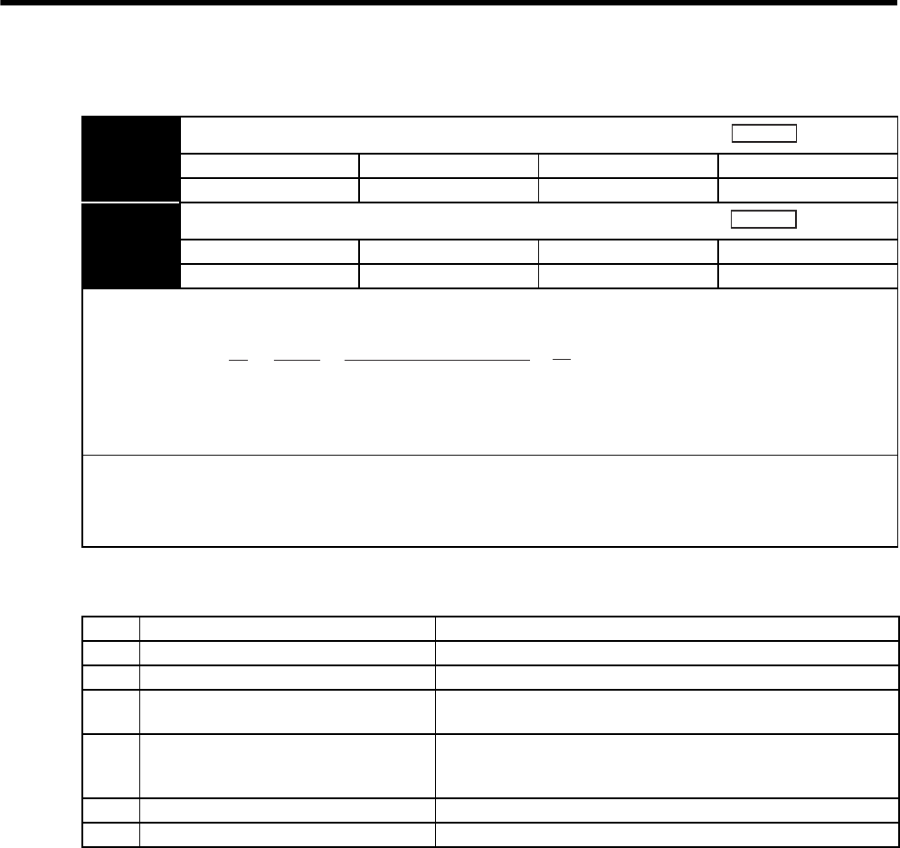
8 Operation
8.6.2 Setting the Electronic Gear
8-52
(3) Related Parameters
(4) Procedure for Setting the Electronic Gear Ratio
Use the following procedure to set the electronic gear ratio.
Pn202 Electronic Gear Ratio (Numerator)
Setting Range Setting Unit Factory Setting Setting Validation
1 to 65535 −4 After restart
Pn203 Electronic Gear Ratio (Denominator)
Setting Range Setting Unit Factory Setting Setting Validation
1 to 65535 −1 After restart
If the deceleration ratio of the servomotor and the load shaft is given as n/m where m is the rotation of the servomotor and
n is the rotation of the load shaft,
* If the ratio is outside the setting range, reduce the fraction (both numerator and denominator) until you obtain integers
within the range. Be careful not to change the electronic gear ratio (B/A).
IMPORTANT
Electronic gear ratio setting range: 0.01 ≤ Electronic gear ratio (B/A) ≤ 100
If the electronic gear ratio is outside this range, the SERVOPACK will not operate properly. In this case, modify the load
configuration or reference unit.
Position
Position
Electronic gear ratio: =
A
B
Pn203
Pn202 =n
m
No. of encoder pulses × 4
Travel distance per load
shaft revolution (reference units)
×
Step Operation Description
1Check machine specifications. Check the deceleration ratio, ball screw pitch, and pulley diameter.
2Check the number of encoder pulses. Check the number of encoder pulses for the servomotor used.
3Determine the reference unit used. Determine the reference unit from the host controller, considering the
machine specifications and positioning accuracy.
4Calculate the travel distance per load shaft
revolution.
Calculate the number of reference units necessary to turn the load
shaft one revolution based on the previously determined reference
units.
5Calculate the electronic gear ratio. Use the electronic gear ratio equation to calculate the ratio (B/A).
6Set parameters. Set parameters using the calculated values.
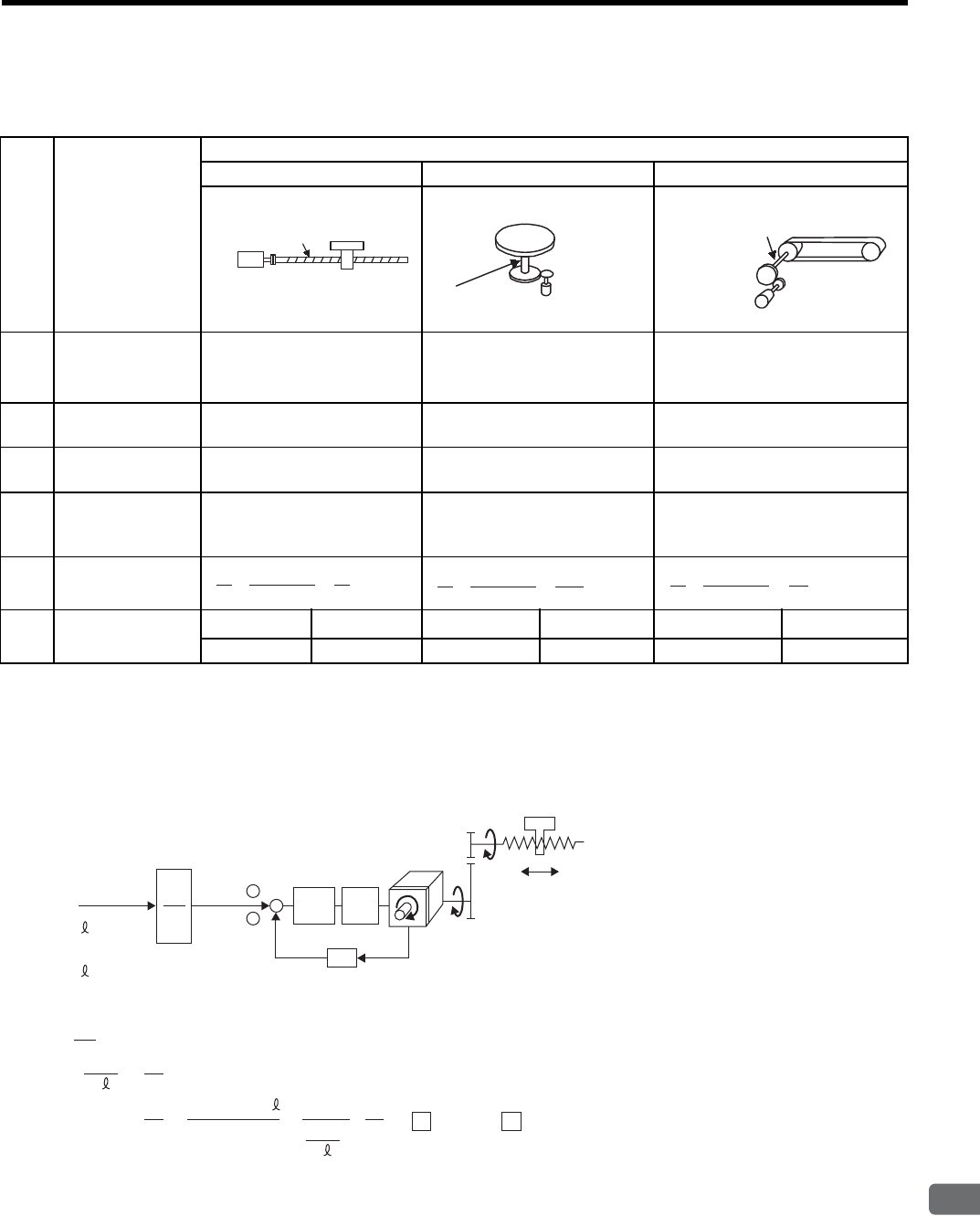
8.6 Operating Using Position Control
8
Operation
8-53
(5) Electronic Gear Ratio Setting Examples
The following examples show electronic gear ratio settings for different load configurations.
Reduce the fraction (both numerator and denominator) since the calculated result will not be within the setting
range. For example, reduce the numerator and denominator by four to obtain Pn201=32768, Pn203=3925 and
complete the settings.
(6) Electronic Gear Ratio Equation
Step Operation
Load Configuration
Ball Screw Disc Table Belt and Pulley
1Check machine
specifications.
x Ball screw pitch: 6 mm
x Deceleration ratio: 1/1
Rotation angle per revolution:
360°
Deceleration ratio: 3/1
Pulley diameter: 100 mm
(pulley circumference: 314 mm)
x Deceleration ratio: 2/1
2Check the number
of encoder pulses. 13-bit: 2048 P/Rev 13-bit: 2048 P/Rev 16-bit: 16384 P/Rev
3Determine the ref-
erence unit used.
1 Reference unit: 0.001 mm
(1 μm) 1 Reference unit: 0.1°1 Reference unit: 0.02 mm
4
Calculate the travel
distance per load
shaft revolution.
6 mm/0.001 mm=6000 360°/0.1°=3600 314 mm/0.02 mm=15700
5Calculate the elec-
tronic gear ratio.
6Set parameters. Pn202 8192 Pn202 24576 Pn202 131072∗
Pn203 6000 Pn203 3600 Pn203 15700
Ball screw
pitch: 6 mm
13-bit encoder
Load shaft
Reference unit: 0.001 mm
13-bit encoder
Load shaft
Reference unit: 0.1°
Deceleration
ratio:
3 : 1
Load shaft
Deceleration
ratio
2 : 1
Reference Unit: 0.02 mm
Pully diameter:
100 mm
16-bit encoder
A 6000
B 2048 × 4
1
1
=×
A 3600
B 2048 × 4
1
3
=×
A 15700
B 16384 × 4
1
2
=×
A
B
n
m
+
-
×4
Pitch = P (mm/rev)
m
n
Servomotor
P
G
(P/rev)
P
G
(P/Rev): Encoder pulses
Position
loop
Speed
loop
Reference pulse
Δ (mm/P)
n × P
n × P
B
ΔAG
Δ (mm/P): Reference unit
P
Δ
Δ
×
×
()
m
n
= 4 × P × m
B
A
()
==
GG
4 × P × m ×4 × P Set A and B with the following parameters.
A㧦Pn203 B㧦Pn202
P (mm/Rev): Ball screw pitch
: Deceleration ratio
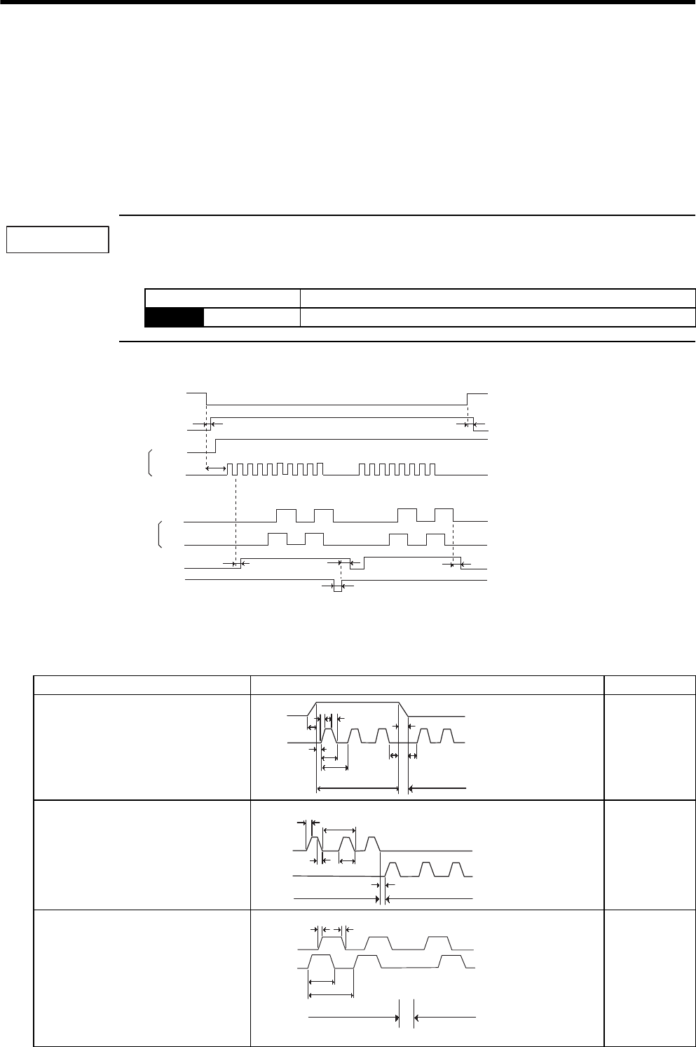
8 Operation
8.6.3 Position Reference
8-54
8.6.3 Position Reference
The servomotor positioning is controlled by inputting a pulse train reference.
The pulse train output form from the host controller corresponds to the following:
• Line-driver Output
• +24V Open-collector output
• +12V Open-collector output
• +5V Open-collector output
Precautions for Open-collector Output
When the open-collector output is used, input signal noise margin lowers. When a position error caused by
the noise occurs, change the parameter as follows:
(1) Input/Output Signal Timing Example
Note: 1. The interval from the time the servo ON signal is turned ON until a reference pulse is input must
be at least 40 ms, otherwise the reference pulse may not be received by the SERVOPACK.
2. The error counter clear signal must be ON for at least 20 μs.
Parameter Description
Pn200 n.1 Reference input filter for open-collector signal
IMPORTANT
Servo ON
Baseblock
Sign + pulse train
Release t1 ≤ 30 ms
t2 ≤ 6 ms
(When parameter Pn506 is set to 0.)
t3 ≥ 40 ms
Encoder pulses
t4, t5, t6 ≤ 2 ms
t7 ≥ 20 μs
t6
CN1-11
CN1-7
PAO L
L
L
H
H
H
H
ONON
ON
CLR
PBO
t7
t5
t4
t3
t2
t1
/COIN
Table 8.3 Reference Pulse Input Signal Timing
Reference Pulse Signal Form Electrical Specifications Remarks
Sign and pulse train input
(SIGN and PULS signal)
Maximum reference frequency:
500 kpps
(For open-collector output: 200 kpps)
t1,t2 ≤ 0.1 μs
t3,t7 ≤ 0.1 μs
t4,t5,t6 > 3 μs
τ ≥ 1.0 μs
(τ/T) × 100 ≤ 50%
Sign (SIGN)
H = Forward
reference
L = Reverse
reference
CW pulse and CCW pulse
Maximum reference frequency:
500 kpps
(For open-collector output: 200 kpps)
t1,t2 ≤ 0.1 μs
t3 > 3 μs
τ ≥ 1.0 μs
(τ/T) × 100 ≤ 50%
−
Two-phase pulse train with 90°
phase differential (phase A and
phase B)
Maximum reference frequency
×1 input pulse multiplier: 500 kpps
×2 input pulse multiplier: 400 kpps
×4 input pulse multiplier: 200 kpps
t1,t2 ≤ 0.1 μs
τ ≥ 1.0 μs
(τ/T) × 100 = 50%
Switching of
the input pulse
multiplier
mode is done
with parameter
Pn200.0 set-
ting.
Forward
reference
Reverse
reference
t1 t2
t3
t4 t5 t6
t7
T
τ
SIGN
PULS
Forward
reference
Reverse
reference
t2
t3
T
τ
CW
CCW
t1
Phase B leads
phase A by 90
°
Phase B lags
phase A by 90 °
Forward reference Reverse reference
Phase B
Phase A
t2
τ
T
t1
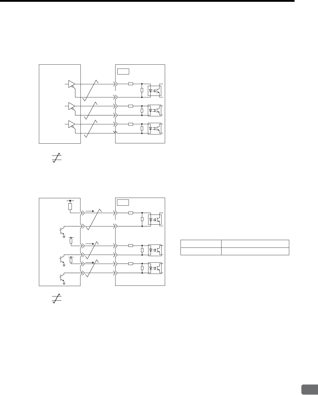
8.6 Operating Using Position Control
8
Operation
8-55
(2) Connection Example
(a) Connection Example for Line-driver Output
Applicable line driver: SN75174 manufactured by Texas Instruments Inc., or MC3487 or the equivalent
* : Represents twisted-pair wires.
(b) Connection Example for Open-collector Output
Select the limit resistance R1 value so that the input current i will be within 7 to 15 mA.
* : Represents twisted-pair wires.
Line
driver
SERVOPACK
Photocoupler
Host controller
CN1
7
8
14
15
12
11
/PULS
SIGN
/SIGN
CLR
/CLR
PULS
∗150 Ω
150 Ω
150 Ω
عExample
When Vcc is +12V: R1=1 kΩ
When Vcc is +24V: R1=2.2 kΩ
When Vcc is +5V: R1=180 Ω
Note: When the open-collector output is used,
the signal logic is as follows:
When Tr1 is ON High level input or the equivalent
Low level input or the equivalentWhen Tr1 is OFF
SERVOPACK
Photocoupler
Host controller
CN1
7
8
14
15
12
11
/PULS
SIGN
/SIGN
CLR
/CLR
PULS
∗
Vcc
R1 i
R1
R1
i
i
150 Ω
150 Ω
150 Ω
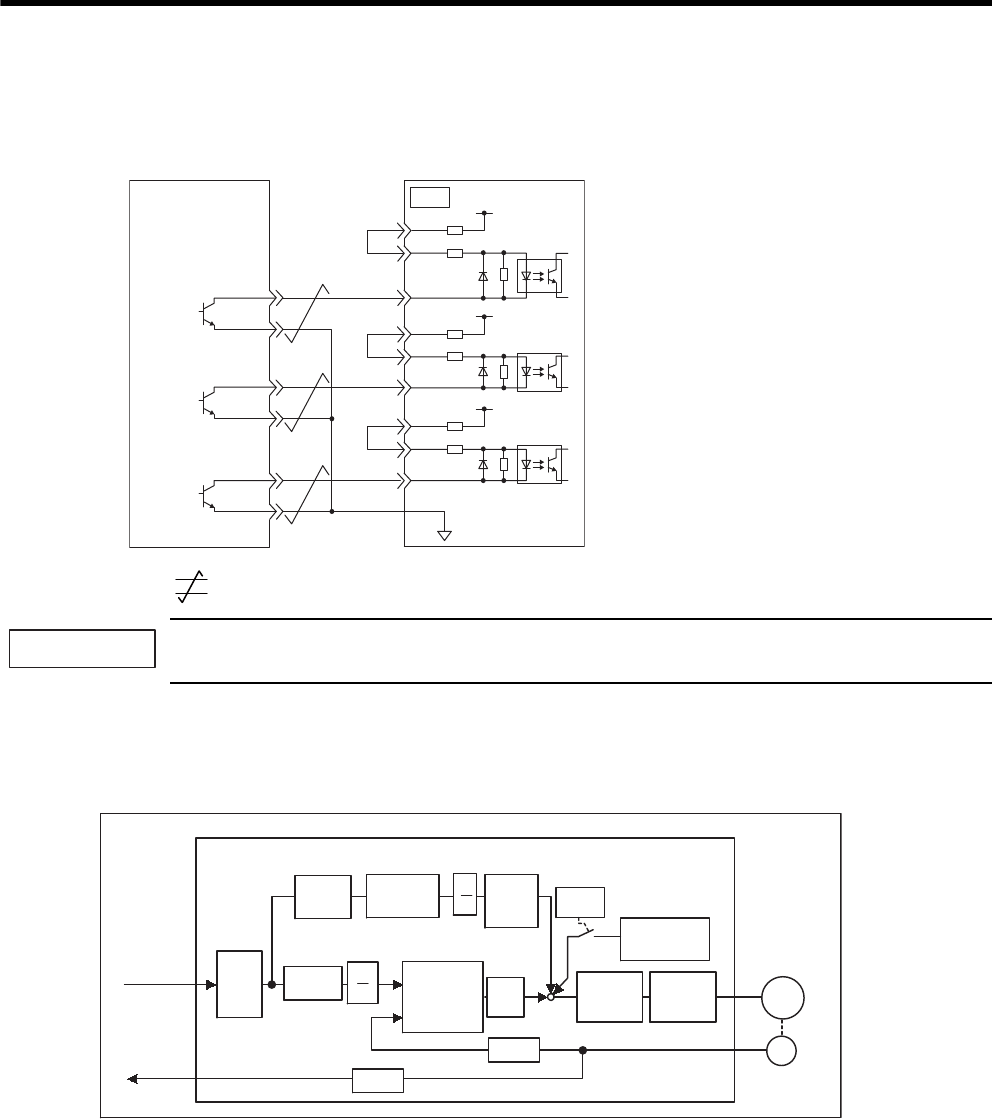
8 Operation
8.6.3 Position Reference
8-56
The SERVOPACK internal power supply can be used.
In this case, the circuit will not be isolated.
* : Represents twisted-pair wires.
When the open-collector output is used, input signal noise margin lowers. When a position error caused by
the noise occurs, set the parameter Pn200.3 to 1.
(3) Position Control Block Diagram
A block diagram for position control is shown below.
SERVOPACK
Photocoupler
Host controller
CN1
7
3
8
1
14
15
12
11
13
18
/PULS
SIGN
/SIGN
CLR
/CLR
PULS
PL1
PL2
PL3
150 Ω
1 kΩ+12 V
∗
Tr1
1.5 V max.
at ON
IMPORTANT
Kp M
Pn201
Pn204 Pn202
Pn203
+
-
Pn102
Pn203
Pn202 Pn10A Pn107
Pn109
PG
Pn200.0
Pn108
B
A
B
A
+
++
Differ-
ential
Smoothing Error
counter
Feed-
forward
Feed-for-
ward fil-
ter time
constant
Bias
Speed
loop
Current
loop
Dividing
Servomotor
Reference
pulse
PG signal
output
SERVOPACK (in position control)
Encoder
Bias adding
width
× 4
× 4
× 2
× 1
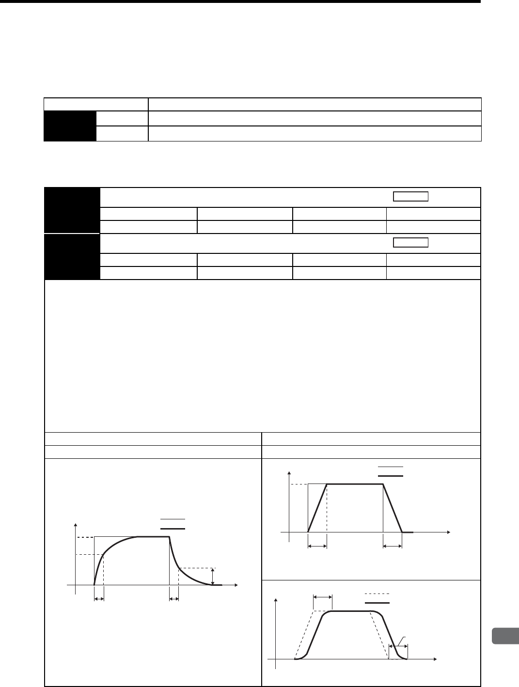
8.6 Operating Using Position Control
8
Operation
8-57
8.6.4 Smoothing
A filter can be applied in the SERVOPACK to a constant-frequency reference pulse.
(1) Selecting a Position Reference Filter
* After resetting the parameter, turn OFF the power once and turn it ON again.
(2) Filter-related Parameters
Parameter Description
Pn207 n.0Acceleration/deceleration filter
n.1Average movement filter
Pn204 Position Reference Acceleration/Deceleration Time Constant
Setting Range Setting Unit Factory Setting Setting Validation
0 to 6400 0.01 ms 0 Immediately
Pn208 Average Movement Time of Position Reference
Setting Range Setting Unit Factory Setting Setting Validation
0 to 6400 0.01 ms 0 Immediately
IMPORTANT
When the position reference acceleration/deceleration time constant (Pn204) is changed, a value with no reference pulse
input and a position error of 0 will be enabled. To ensure that the setting value is correctly reflected, stop the reference pulse
from the host controller and input the clear signal (CLR), or turn the servo OFF to clear the error.
This function provides smooth motor operating in the following cases. The function does not affect the travel distance (i.e.,
the number of pulses).
• When the host controller that outputs a reference cannot perform acceleration/deceleration processing.
• When the reference pulse frequency is too low.
• When the reference electronic gear ratio is too high (i.e., 10× or more).
The difference between the position reference acceleration/deceleration time constant (Pn204) and the position reference
movement averaging time (Pn208) is shown below.
Acceleration/Deceleration Filter Average Movement Time Filter
Pn207=n.0 Pn207=n.1
Position
Position
100%
63.2%
36.8%
Pn204 Pn204
Before filter applied
After filter applied
Response waveform for stepwise input
t
100%
Pn208 Pn208
Before filter applied
After filter applied
Response waveform for stepwise input
t
Pn208 Before filter applied
After filter applied
Response waveform for ramp reference input
t
Pn208
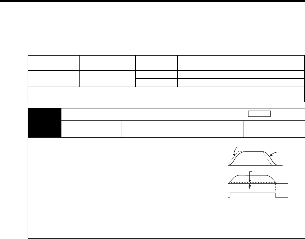
8 Operation
8.6.5 Positioning Completed Output Signal
8-58
8.6.5 Positioning Completed Output Signal
This signal indicates that servomotor movement has been completed during position control. Use the signal as an
interlock to confirm at the host controller that positioning has been completed.
Type Signal
Name
Connector
Pin Number Setting Meaning
Output /COIN CN1-25, 26
(Factory setting)
ON (low level) Positioning has been completed.
OFF (high level) Positioning is not completed.
This output signal can be allocated to an output terminal with parameter Pn50E. Refer to 7.3.3 Output Circuit Signal Allo-
cation. The factory setting is allocated to CN1-25, 26.
Pn500 Positioning Completed Width
Setting Range Setting Unit Factory Setting Setting Validation
0 to 250 1 reference unit 7 Immediately
The positioning completed (/COIN) signal is output when the difference
(position error pulse) between the number of reference pulses output by
the host controller and the travel distance of the servomotor is less than
the value set in this parameter.
Set the number of error pulses in reference units (the number of input
pulses defined using the electronic gear.)
Too large a value at this parameter may output only a small error during
low-speed operation that will cause the /COIN signal to be output con-
tinuously.
The positioning completed width setting has no effect on final position-
ing accuracy.
/COIN is a position control signal.
When the factory setting is used and the output terminal allocation is not performed with the Pn50E, this signal is used for
the speed coincidence output /V-CMP for speed control, and it is always OFF (high level) for torque control.
Position
Speed
Reference Motor speed
/COIN
(CN1-25)
Error pulse
(Un008)
Pn500
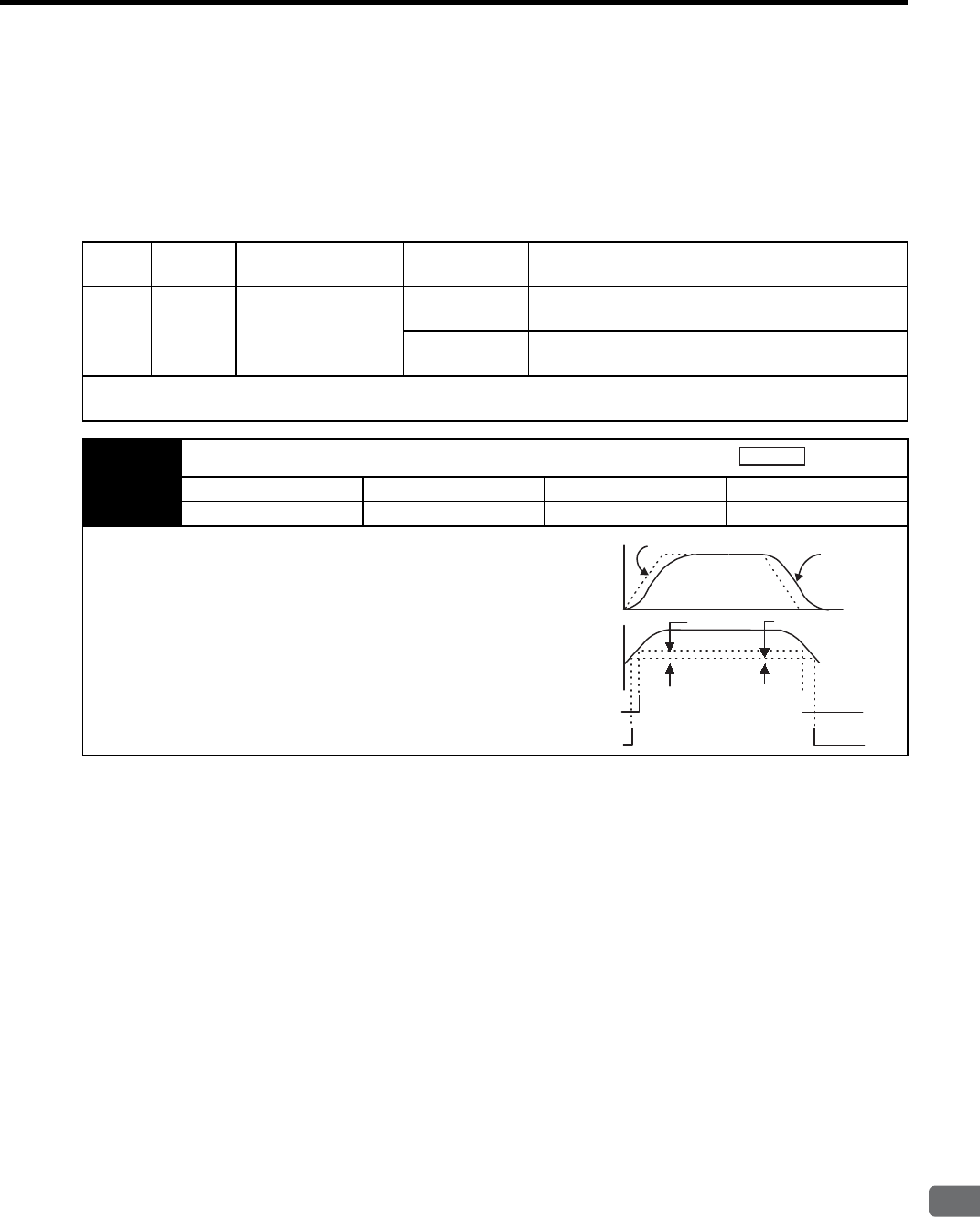
8.6 Operating Using Position Control
8
Operation
8-59
8.6.6 Positioning Near Signal
This signal indicates that the positioning of the servomotor is near to completion, and is generally used in combi-
nation with the positioning completed (/COIN) output signal.
The host controller receives the positioning near signal prior to confirming the positioning-completed signal, and
performs the following operating sequence after positioning has been completed to shorten the time required for
operation.
Type Signal
Name
Connector
Pin Number Setting Meaning
Output /NEAR Must be allocated
ON (low level) The servomotor has reached a point near to positioning
completed.
OFF (high level) The servomotor has not reached a point near to posi-
tioning completed.
The output terminal must be allocated with parameter Pn510 in order to use positioning near signal. Refer to 7.3.3 Output
Circuit Signal Allocation for details.
Pn504 NEAR Signal Width
Setting Range Setting Unit Factory Setting Setting Validation
1 to 250 1 reference unit 7 Immediately
The positioning near (/NEAR) signal is output when the differ-
ence (error) between the number of reference pulses output by
the host controller and the travel distance of the servomotor is
less than the value set in Pn504.
Set the number of error pulses in reference units (the number of
input pulses defined using the electronic gear.)
Normally, the setting should be larger than that for the position-
ing completed width (Pn500).
Position
Speed
Reference Motor speed
Error pulse
/NEAR
/COIN
Pn504 Pn500
0
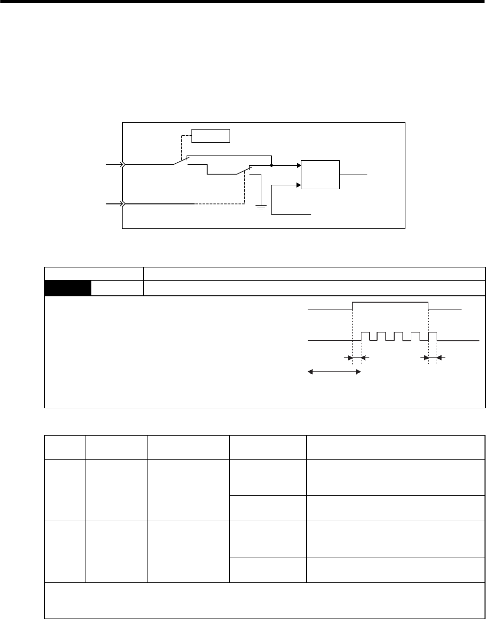
8 Operation
8.6.7 Reference Pulse Inhibit Function (INHIBIT)
8-60
8.6.7 Reference Pulse Inhibit Function (INHIBIT)
(1) Description
This function inhibits the SERVOPACK from counting input pulses during position control. The servomotor
remains locked (clamped) while pulse are inhibited.
(2) Setting Parameters
(3) Setting Input Signals
Pn000.1
Pn000=n.1
Pn000=n.B
OFF
ON
+
-
/P-CON (/INHIBIT)
/P-CON
(/INHIBIT)
Error
counter
Reference pulse
Feedback pulse
SERVOPACK
Parameter Meaning
Pn000 n.BControl mode selection: Position control (pulse train reference) ⇔ Inhibit
Inhibit (INHIBIT) switching condition
x /P-CON (/INHIBIT) signal ON (low level)
Type Signal Name Connector Pin
Number Setting Meaning
Input /P-CON CN1-41
(Factory setting)
ON (low level)
Turns the INHIBIT function ON.
(Inhibits the SERVOPACK from counting refer-
ence pulses.)
OFF (high level) Turns the INHIBIT function OFF.
(Counts reference pulses.)
(Input) (/INHIBIT) Must be allocated
CN1-
ON (low level)
Turns the INHIBIT function ON.
(Inhibits the SERVOPACK from counting refer-
ence pulses.)
OFF (high level) Turns the INHIBIT function OFF.
(Counts reference pulses.)
These input signals enable the inhibit function.
Either the /P-CON or the /INHIBIT signal can be used to switch the inhibit signal. The input signal must be allocated in
order to use the /INHIBIT signal. Refer to 7.3.2 Input Circuit Signal Allocation.
ON
Reference pulse
OFF
t1
ON
t2
t1, t2 ≤ 0.5 ms
Input reference pulses
are not counted
during this period.
/INHIBIT signal
(/P-CON)
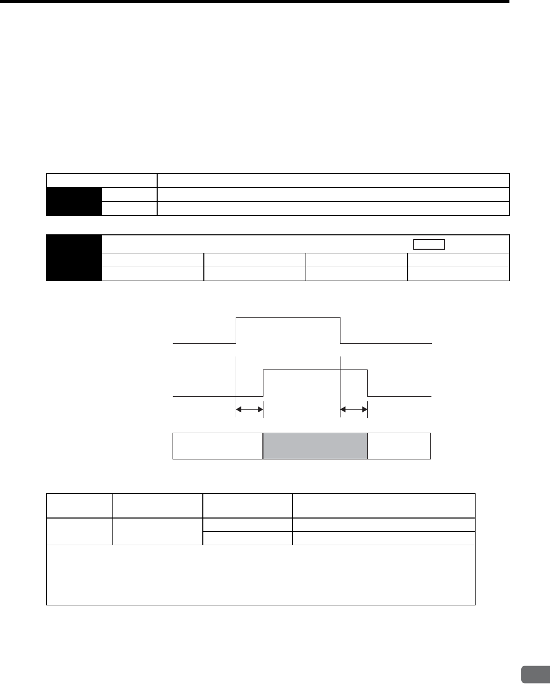
8.6 Operating Using Position Control
8
Operation
8-61
8.6.8 Reference Pulse Input Multiplication Switching Function
If the /PSEL signal for switching the multiplication of the position reference pulse input turns ON or OFF, the
multiplication factor can be switched from 1 to n (n = 1 to 99). And the status of this signal indicates whether the
position multiplication is switched to 1 or n.
Set Pn218.0 = 1 to enable this function, and set the multiplication in Pn217.
To change the reference pulse multiplication, the position reference pulse must be set to 0. Otherwise, the opera-
tion cannot be guaranteed.
(1) Related Parameters
Note: After changing the setting, turn OFF the power and ON again to enable the new setting.
(2) Timing Chart for Reference Pulse Input Multiplication Switching
(3) Input Signal Selection
Parameters Description
Pn218 n.0Reference pulse input multiplication switching function: Disabled (Factory setting)
n.1Reference pulse input multiplication switching function: Enabled
Pn217 Reference Pulse Input Multiplication
Setting Range Setting Unit Factory Setting Setting Validation
1 to 99 ×1 1 Immediately
Position
×1×n
(n=Pn217)
×1
Reference pulse
input switching
(/PSEL)
Enable
Disable
Reference pulse
input switcing
(/PSELA)
Enable
Disable
Internal processing
4ms or less 4ms or less
Signal Name Connector Pin
Number Setting Meaning
/PSEL Signal allocation not
required
ON (low level) Enabled when the /PSEL signal turns ON.
OFF (high level) Disabled when the /PSEL signal turns OFF.
The /PSEL signal is the input signal that switches the multiplication factor of the reference pulse input to the value
set in Pn217.
This signal must be allocated in parameter Pn513.0 as shown in the following table. Refer to 7.3.2 Input Circuit
Signal Allocation for more information on how to allocate input signals. After setting Pn217, turn OFF the power
supplies for the main circuit and the control and then turn ON again.

8 Operation
8.6.8 Reference Pulse Input Multiplication Switching Function
8-62
Note: After changing the setting, turn OFF the power and ON again to enable the new setting.
(4) Output Signal Selection
The /PSELA signal is the output signal that indicates if switching for reference pulse input multiplication is
enabled by /PSEL signal or not.
The /PSELA signal can’t be used with the factory setting. Allocate the /PSELA output signal.
Note: After changing the setting, turn OFF the power and ON again to enable the new setting.
Parameter Description
Pn513 n.0Input signal from CN1-40 is ON (high level): Enabled
n.1Input signal from CN1-41 is ON (high level): Enabled
n.2Input signal from CN1-42 is ON (high level): Enabled
n.3Input signal from CN1-43 is ON (high level): Enabled
n.4Input signal from CN1-44 is ON (high level): Enabled
n.5Input signal from CN1-45 is ON (high level): Enabled
n.6Input signal from CN1-46 is ON (high level): Enabled
n.7Sets the signal ON.
n.8Sets the signal OFF. (Factory setting)
n.9Input signal from CN1-40 is OFF (low level): Enabled
n.AInput signal from CN1-41 is OFF (low level): Enabled
n.BInput signal from CN1-42 is OFF (low level): Enabled
n.CInput signal from CN1-43 is OFF (low level): Enabled
n.DInput signal from CN1-44 is OFF (low level): Enabled
n.EInput signal from CN1-45 is OFF (low level): Enabled
n.FInput signal from CN1-46 is OFF (low level): Enabled
Signal Name Connector Pin
Number Setting Meaning
/PSELA Signal allocation not
required
ON (low level) Enabled when the /PSEL signal turns ON.
OFF (high level) Disabled when the /PSEL signal turns OFF.
Parameter Meaning
Pn510 n.0 Disabled (/PSELA output signal is not used.)
n.1 Outputs the /PSELA signal from the CN1-25, 26 output terminal.
n.2 Outputs the /PSELA signal from the CN1-27, 28 output terminal
n.3 Outputs the /PSELA signal from the CN1-29, 30 output terminal.
For the factory settings, the pins CN1-25 to CN1-30 are allocated for other output signals. If multiple signals are allocated
to the same output terminal, signals are output with OR logic. To enable only the /PSELA output signal, allocate the other
signals to other output terminals or disable the other signals.
Refer to 7.3.3 Output Circuit Signal Allocation for the allocation of output signals.

8.7 Operating Using Torque Control
8
Operation
8-63
8.7 Operating Using Torque Control
8.7.1 Setting Parameters
The following parameters must be set for torque control operation with analog voltage reference.
8.7.2 Torque Reference Input
By applying a torque reference determined by the analog voltage reference to the SERVOPACK, the servomotor
torque can be controlled in proportion with the input voltage.
Checking the Internal Torque Reference
1. Checking the internal torque reference with the panel operator:
Use the Monitor Mode (Un002). Refer to 7.4 Operation in Monitor Mode (Un
).
2. Checking the internal torque reference with an analog monitor:
The internal torque reference can also be checked with an analog monitor. Refer to 9.5 Analog Monitor.
Parameter Meaning
Pn000 n.2Control mode selection: Torque control (analog voltage reference)
Pn400 Torque Reference Input Gain
Setting Range Setting Unit Factory Setting Setting Validation
10 to 100
(1.0 to 10.0 V/rated torque) 0.1V/rated torque 30 Immediately
This sets the analog voltage level for the torque reference (T-REF) that is
necessary to operate the servomotor at the rated torque.
EXAMPLE
Pn400 = 30: The servomotor operates at the rated torque with 3-V input
(factory setting).
Pn400 = 100: The servomotor operates at the rated torque with 10-V input.
Pn400 = 20: The servomotor operates at the rated torque with 2-V input.
Speed
Position
Torque
Reference voltage (V)
Reference torque
This reference voltage is set.
Rated torque
Type Signal
Name
Connector
Pin Number Name
Input T-REF CN1-9 Torque Reference Input
SG CN1-10 Signal Ground for Torque Reference Input
Used during torque control (analog voltage reference). (Pn000.1 = 2, 6, 8, 9)
The torque reference gain is set in Pn400. For setting details, refer to 8.7.1 Setting Parameters.
Input Specifications
• Input range: ±1 to ±10VDC/rated torque
• Max. allowable input voltage: ±12 VDC
• Factory setting
Pn400 = 30: Rated torque at 3 V
+3-V input: Rated torque in forward direction
+9-V input: 300% rated torque in forward direction
-0.3-V input: 10% rated torque in reverse direction
The voltage input range can be changed with parameter Pn400.
Input Circuit Example
Use twisted-pair wires as a countermeasure against noise.
Variable resistor example: Model 25HP-10B manufactured by Sakae
Tsushin Kogyo Co., Ltd.
Reference torque (%)
Input voltage (V)
Set the slope
with Pn400.
Factory setting
300
200
100
- 300
- 200
- 100
034 8 12
-4-8-12
SG
T-REF
+12 V 9
10
470 Ω
2 kΩ
SERVOPACK
1/2 W min.
CN1
INFO
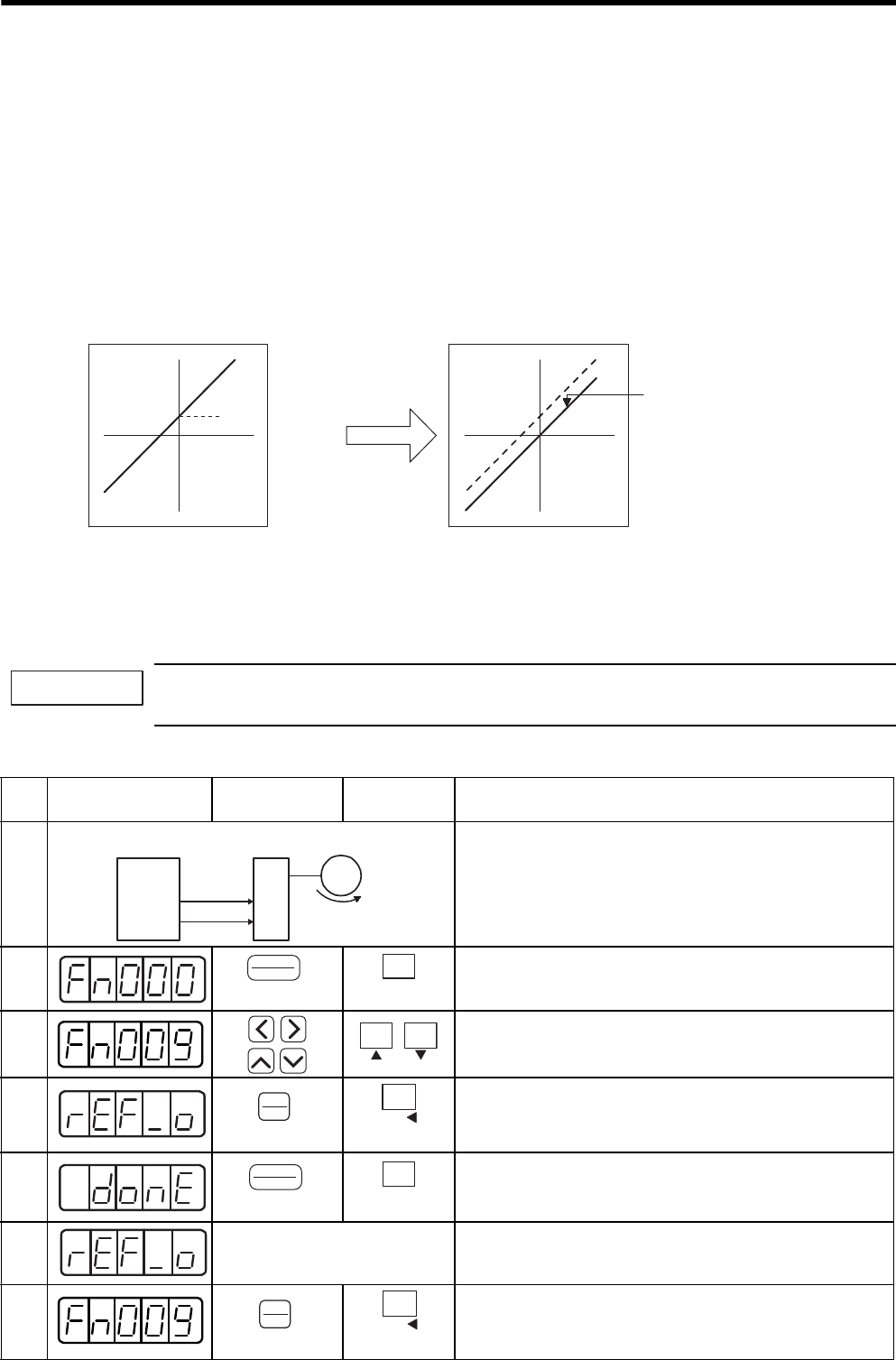
8 Operation
8.7.3 Adjusting the Reference Offset
8-64
8.7.3 Adjusting the Reference Offset
(1) Automatic Adjustment of the Torque Reference Offset
When using torque control, the servomotor may rotate slowly even when 0 V is specified as the analog reference
voltage. This occurs when the host controller or external circuit has a slight offset (measured in mV) in the refer-
ence voltage. In this case, the reference offset can be adjusted automatically and manually using the panel oper-
ator or digital operator.
The automatic adjustment of analog (speed, torque) reference offset (Fn009) automatically measures the offset
and adjusts the reference voltage.
The SERVOPACK performs the following automatic adjustment when the host controller or external circuit has
an offset in the reference voltage.
After completion of the automatic adjustment, the amount of offset is stored in the SERVOPACK. The amount of
offset can be checked in the manual adjustment of torque reference offset (Fn00B).
The automatic adjustment of analog reference offset (Fn009) cannot be used when a position loop has been
formed with the host controller and the error pulse is changed to zero at the servomotor stop due to servolock.
Use the torque reference offset manual adjustment (Fn00B).
The analog reference offset must be automatically adjusted with the servo OFF.
Use the following procedure for automatic adjustment of the torque reference offset.
Offset
Torque
reference
Reference voltage Reference voltage
Offset automatically
adjusted in SERVOPACK.
Automatic
offset
adjustment
Torque
reference
IMPORTANT
Step Display after
Operation
Digital
Operator
Panel
Operator Description
1
Turn OFF the SERVOPACK, and input the 0-V reference voltage
from the host controller or external circuit.
2Press the DSPL/SET or MODE/SET Key to select the utility
function mode.
3Press the LEFT/RIGHT or UP/DOWN Key, or UP or DOWN
Key to select parameter Fn009.
*The digit that can be set will blink.
4
Press the DATA/ENTER Key once, or DATA/SHIFT Key for
more than one second. “rEF_o” will be displayed.
5Press the DSPL/SET or MODE/SET Key.
The reference offset will be automatically adjusted.
When completed, “donE” will blink for about one second.
6
About one second later After “donE” is displayed, “rEF_o” will be displayed again.
7Press the DATA/ENTER Key once, or DATA/SHIFT Key for
more than one second to return to the Fn009 display of the utility
function mode.
Servo-
motor
Slow rotation
(Servo ON)
SERVO-
PACK
Servo OFF
0-V speed
reference or
torque
reference
Host
controller
(DSPL/SET Key)
DSPL
SET
MODE/SET
(MODE/SET Key)
(DATA/ENTER Key)
DATA
ENTER
DATA/
(DATA/SHIFT Key)
(Press at least 1 s.)
(DSPL/SET Key)
DSPL
SET
MODE/SET
(MODE/SET Key)
(DATA/ENTER Key)
DATA
ENTER
DATA/
(DATA/SHIFT Key)
(Press at least 1 s.)
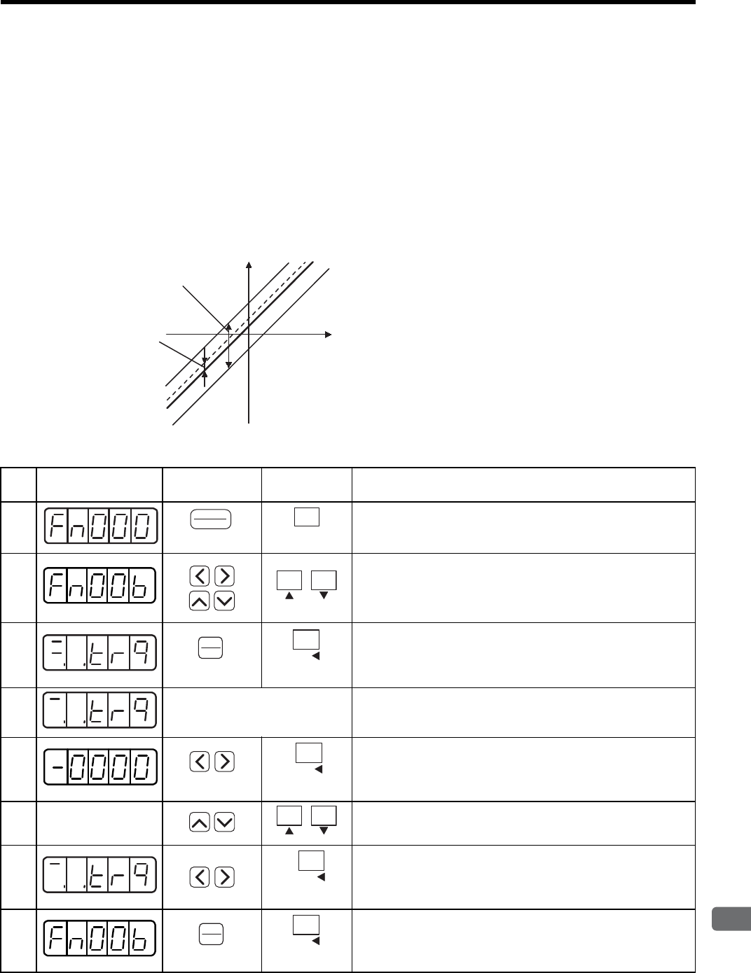
8.7 Operating Using Torque Control
8
Operation
8-65
(2) Manual Adjustment of the Torque Reference Offset
Manual adjustment of the torque reference offset (Fn00B) is used in the following cases.
• If a position loop is formed with the host controller and the error is zeroed when servolock is stopped.
• To deliberately set the offset to some value.
• Use this mode to check the offset data that was set in the automatic adjustment mode of the torque refer-
ence offset.
This mode operates in the same way as the automatic adjustment mode (Fn009), except that the amount of offset
is directly input during the adjustment.
The offset adjustment range and setting units are as follows:
Use the following procedure to manually adjust the torque reference offset.
Offset Adjustment Range: -128 to +127
(Torque reference: -1881.6 mV to +1866.9 mV)
Torque Reference
Offset Adjustment
Range
Offset Setting Unit Analog
Input
Voltage
Offset Setting Unit
Torque reference: 1 = 14.7 mV
Step Display after
Operation
Digital
Operator
Panel
Operator Description
1Press the DSPL/SET or MODE/SET Key to select the utility
function mode.
2Press the LEFT/RIGHT or UP/DOWN Key or UP or DOWN Key
to select parameter Fn00B.
*The digit that can be set will blink.
3Press the DATA/ENTER Key once, or DATA/SHIFT Key for
more than one second. The display will be as shown at the left.
The manual adjustment mode for the torque reference offset will
be entered.
4
Servo ON Turn ON the servo ON (/S-ON) signal. The display will be as
shown at the left.
5
Press the LEFT or RIGHT Key or DATA/SHIFT Key for less than
one second to display the torque reference offset amount.
6
Press the UP or DOWN Key to adjust the amount of offset.
7
Press the LEFT or RIGHT Key or DATA/SHIFT Key for less than
one second to return to the display shown on the left.
8Press the DATA/ENTER Key once, or DATA/SHIFT Key for
more than one second to return to the Fn00B display of the utility
function mode.
(DSPL/SET Key)
DSPL
SET
MODE/SET
(MODE/SET Key)
(DATA/ENTER Key)
DATA
ENTER
DATA/
(DATA/SHIFT Key)
(Press at least 1 s.)
DATA/
(DATA/SHIFT Key)
(Less than 1 s.)
DATA/
(DATA/SHIFT Key)
(Less than 1 s.)
(DATA/ENTER Key)
DATA
ENTER
DATA/
(DATA/SHIFT Key)
(Press at least 1 s.)
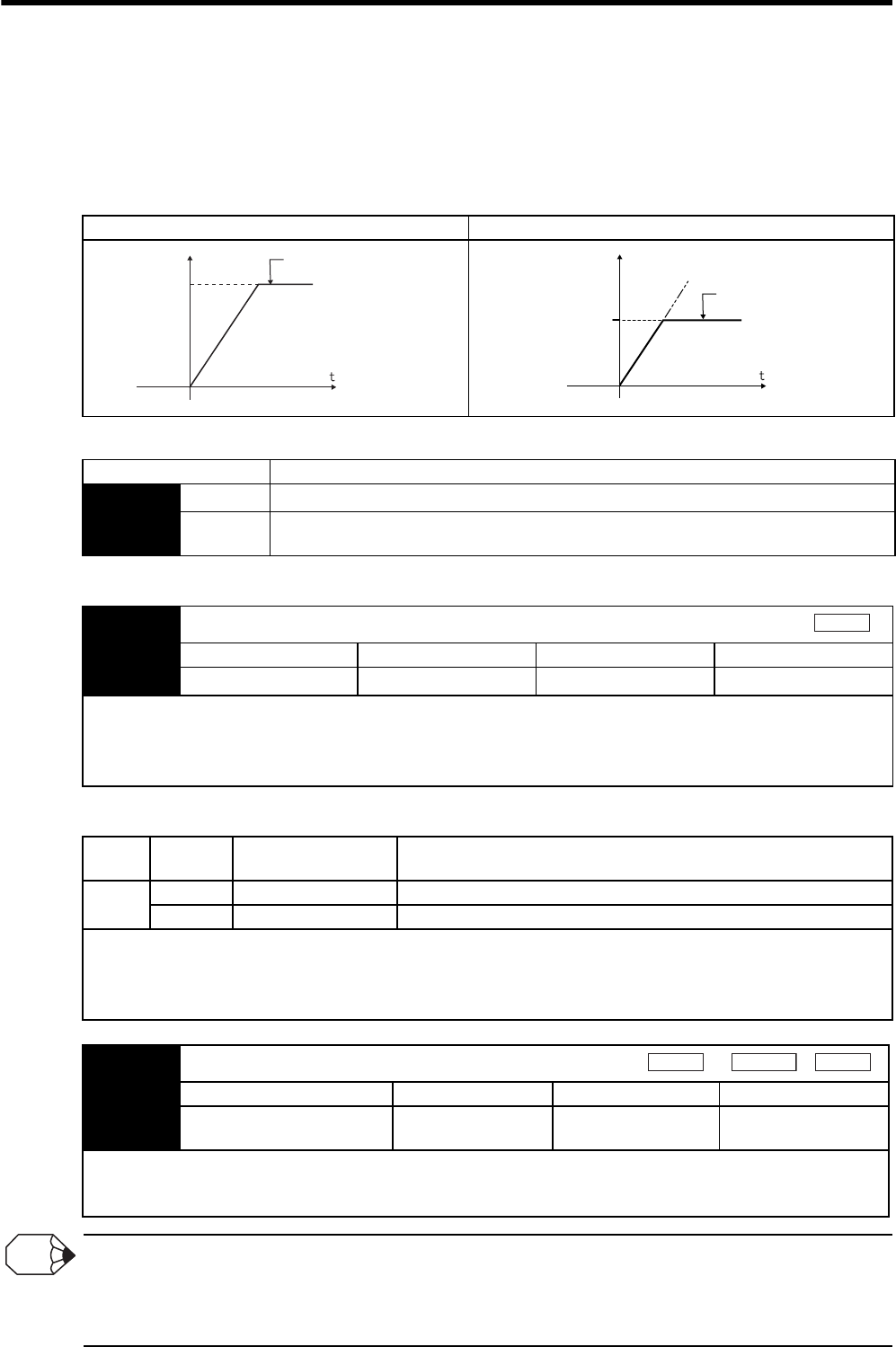
8 Operation
8.7.4 Limiting Servomotor Speed during Torque Control
8-66
8.7.4 Limiting Servomotor Speed during Torque Control
During torque control, the servomotor is controlled to output the specified torque, which means that the servomo-
tor speed is not controlled. Accordingly, when an excessive reference torque is set for the mechanical load
torque, it will prevail over the mechanical load torque and the servomotor speed will greatly increase.
This function serves to limit the servomotor speed during torque control to protect the machine.
(1) Speed Limit Mode Selection (Torque Limit Option)
(2) Internal Speed Limit Function
(3) External Speed Limit Function
The Principle of Speed Limiting
When the speed is outside of the allowable range, a torque that is proportional to the difference between the actual speed
and the speed limit is used as negative feedback to bring the speed back within the speed limit range. Accordingly, there is
a margin generated by the load conditions in the actual motor speed limit value.
With No Speed Limit With Speed Limit
Parameter Description
Pn002 n.0Uses the value set in Pn407 as the speed limit (internal speed limit function).
n.1Uses V-REF (CN1-5, 6) as an external speed limit input. Applies a speed limit using the input
voltage of V-REF and the setting in Pn300 (external speed limit function).
Pn407 Speed Limit During Torque Control
Setting Range Setting Unit Factory Setting Setting Validation
0 to 10000 1 min-1 10000 Immediately
Sets the servomotor speed limit value during torque control.
The setting in this parameter is enabled when Pn002 = n.0.
The servomotor’s maximum speed will be used when the setting in this parameter exceeds the maximum speed of the ser-
vomotor used.
Type Signal
Name
Connector
Pin Number Name
Input V-REF CN1-5 External Speed Limit Input
SG CN1-6 Signal Ground
Inputs an analog voltage reference as the servomotor speed limit value during torque control.
The smaller value is enabled, the speed limit input from V-REF or the Pn407 (Speed Limit during Torque Control) when
Pn002 = n.1.
The setting in Pn300 determines the voltage level to be input as the limit value. Polarity has no effect.
Motor speed
Maximum speed
Danger of damage due to
excessive machine speed.
Motor speed
Speed limit
Safe operation with
speed limit.
Torque
Pn300 Speed Reference Input Gain
Setting Range Setting Unit Factory Setting Setting Validation
150 to 3000
(1.50 to 30.0 V/rated speed) 0.01 V/rated speed 600 Immediately
Sets the voltage level for the speed that is to be externally limited during torque control.
With Pn300 = 600 (factory setting) and 6 V input from V-REF (CN1-5, 6), the actual motor speed is limited to the rated
speed of the servomotor used.
Speed
Position
Torque
INFO

8.7 Operating Using Torque Control
8
Operation
8-67
(4) Signals Output during Servomotor Speed Limit
Type Signal
Name
Connector
Pin Number Setting Meaning
Output /VLT Must be allocated
CN1-
ON (low level) Servomotor speed limit being applied.
OFF (high level) Servomotor speed limit not being applied.
This signal is output when the servomotor speed reaches the speed limit value set in Pn407 or set by the analog voltage ref-
erence.
For use, this output signal must be allocated with parameter Pn50F. For details, refer to 7.3.3 Output Circuit Signal Alloca-
tion.
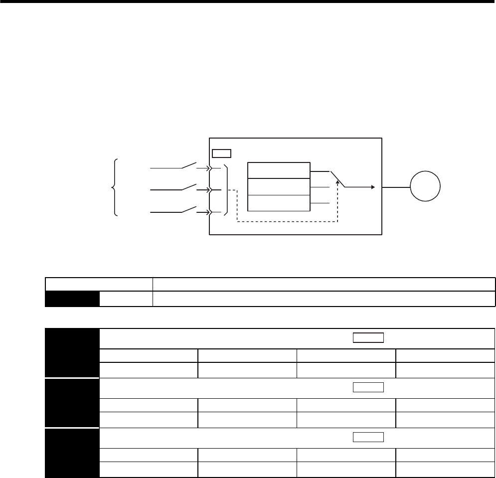
8 Operation
8.8.1 Setting Parameters
8-68
8.8 Operating Using Speed Control with an Internally Set Speed
• Internally Set Speed Selection
This function allows speed control operation by externally selecting an input signal from among three servo-
motor speed settings made in advance with parameters in the SERVOPACK. The speed control operations
within the three settings are valid. There is no need for an external speed or pulse generator.
8.8.1 Setting Parameters
Note: The maximum speed of servomotor is used whenever a speed settings for the Pn301 to Pn303
exceed the maximum speed.
SERVOPACK
41
45
46
Pn301SPEED1
Pn302SPEED2
Pn303SPEED3
Internally set speed
Parameter
Speed
reference
Servomotor
M
Contact input
/P-CON (/SPD-D)
/P-CL (/SPD-A)
/N-CL (/SPD-B)
CN1
Parameter Meaning
Pn000 n.3Control mode selection: Internally set speed control (contact reference)
Pn301 Internally Set Speed 1
Setting Range Setting Unit Factory Setting Setting Validation
0 to 10000 1 min-1 100 Immediately
Pn302 Internally Set Speed 2
Setting Range Setting Unit Factory Setting Setting Validation
0 to 10000 1 min-1 200 Immediately
Pn303 Internally Set Speed 3
Setting Range Setting Unit Factory Setting Setting Validation
0 to 10000 1 min-1 300 Immediately
Speed
Speed
Speed

8.8 Operating Using Speed Control with an Internally Set Speed
8
Operation
8-69
8.8.2 Input Signal Settings
The following input signals are used to switch the operating speed.
8.8.3 Operating Using an Internally Set Speed
Use ON/OFF combinations of the following input signals to operate with the internally set speeds.
Note: Signal OFF = High level; Signal ON = Low level
Control Mode Switching
When Pn000.1 = 4, 5, or 6, and either /P-CL (/SPD-A) or /N-CL (SPD-B) is OFF (high level), the control
mode will switch.
Example:
When Pn000.1=5: Internally set speed selection ⇔ Position control (pulse train)
Type Signal
Name
Connector Pin
Number Meaning
Input /P-CON CN1-41 Switches the servomotor rotation direction.
(/SPD-D) Must be allocated
Input /P-CL CN1-45 Selects the internally set speed.
(/SPD-A) Must be allocated
Input /N-CL CN1-46 Selects the internally set speed.
(/SPD-B) Must be allocated
Input Signal Selection
The following two types of operation can be performed using the internally set speeds:
• Operation with the /P-CON, /P-CL, and /N-CL input signals (pins allocated in factory setting)
• Operation with the /SPD-D, /SPD-A, and /SPD-B input signals
/SPD-D, /SPD-A, and /SPD-B input signals must be allocated with parameter Pn50C. Refer to 7.3.2 Input Circuit Signal
Allocation.
Input Signal Motor Rotation
Direction Speed
/P-CON
(/SPD-D)
/P-CL
(/SPD-A)
/N-CL
(/SPD-B)
OFF (high)
OFF (high) OFF (high)
Forward
Stop at 0 of the internally set speed
OFF (high) ON (low) Pn301: Internally Set Speed 1 (SPEED1)
ON (low) ON (low) Pn302: Internally Set Speed 2 (SPEED2)
ON (low) OFF (high) Pn303: Internally Set Speed 3 (SPEED3)
ON (low)
OFF (high) OFF (high)
Reverse
Stop at 0 of the internally set speed
OFF (high) ON (low) Pn301: Internally Set Speed 1 (SPEED1)
ON (low) ON (low) Pn302: Internally Set Speed 2 (SPEED2)
ON (low) OFF (high) Pn303: Internally Set Speed 3 (SPEED3)
Input Signal Speed
/P-CL (/SPD-A) /N-CL (/SPD-B)
OFF (high) OFF (high) Pulse train reference input (position control)
OFF (high) ON (low) Pn301: Internally Set Speed 1 (SPEED1)
ON (low) ON (low) Pn302: Internally Set Speed 2 (SPEED2)
ON (low) OFF (high) Pn303: Internally Set Speed 3 (SPEED3)
IMPORTANT
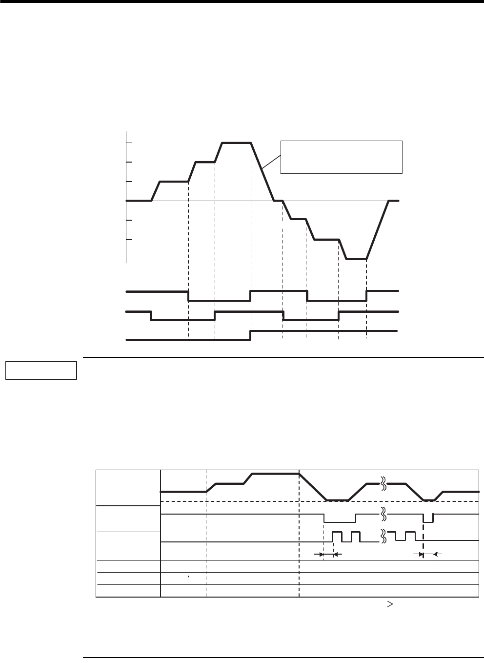
8 Operation
8.8.3 Operating Using an Internally Set Speed
8-70
• Example of Operating with Internally Set Speed Selection
The shock that results when the speed is changed can be reduced by using the soft start function.
For details on the soft start function, refer to 8.5.4 Soft Start.
Example: Operation with an Internally Set Speed and Soft Start
When Pn000.1 = 5 (Internally set speed control ⇔ Position control), the soft start function will operate only
when selecting the internally set speed. The soft start function cannot be used with pulse reference input.
When switching to pulse reference input during operation at either of the three speeds (1st speed to 3rd
speed), the pulse reference will not be received by the SERVOPACK until after the positioning completed (/
COIN) signal is output. Always begin the output of the pulse reference from the host controller after the
positioning completed (/COIN) signal is output from the SERVOPACK.
Example: Operation with an Internally Set Speed and Soft Start ⇔ Position Control (Pulse Train Reference)
Note: 1. The soft start function is used in the above figure.
2. The t1 value is not affected by whether the soft start function is used.
A maximum delay of 2 ms occurs in loading /P-CL (/SPD-A) and /N-CL (/SPD-B).
-SPEED1
Servomotor speed
+SPEED3
+SPEED2
+SPEED1
-SPEED2
-SPEED3
0
OFF ON
Stop
/P-CL (/SPD-A)
/N-CL (/SPD-B)
/P-CON( /SPD-D)
Stop
Stop
OFF OFF OFF OFF
OFF OFF OFF OFF OFF
OFF OFF OFF OFF OFF
ON ON ON
ON ON ON ON
ONON ON ON
Acceleration/deceleration are
done for the soft start times set in
Pn305 and Pn306.
1st speed
1st speed
2nd speed
2nd speed
3rd speed
3rd speed
IMPORTANT
/N-CL (/SPD-B)
/P-CL (/SPD-A)
ON
Selected speed
ON
OFF ON OFF
OFF OFF
Pulse reference
ON OFF
ON
/COIN
Pulse reference
0 min-1
Motor speed
t1
t1 2 ms
Signal Timing in Position Control
t1
1st speed 2nd speed 3rd speed 1st speed
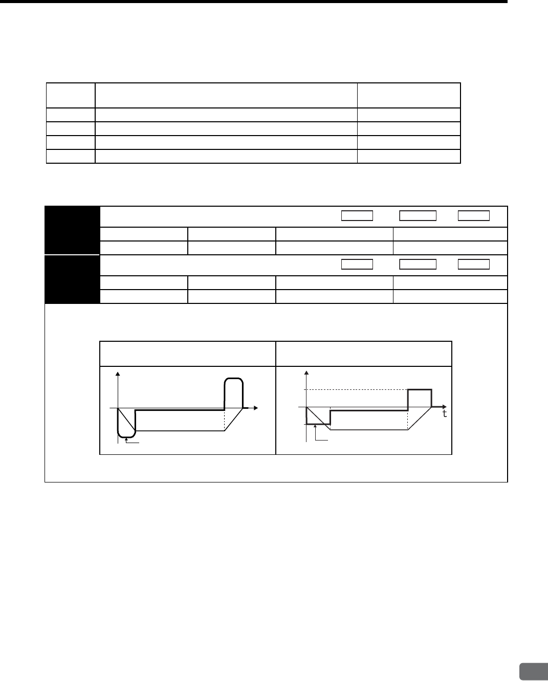
8.9 Limiting Torque
8
Operation
8-71
8.9 Limiting Torque
The SERVOPACK provides the following four methods for limiting output torque to protect the machine.
8.9.1 Internal Torque Limit (Limiting Maximum Output Torque)
Maximum torque is always limited to the values set in the following parameters.
Setting
Level Limiting Method Reference Section
1Internal torque limit 8.9.1
2External torque limit 8.9.2
3Torque limiting by analog voltage reference 8.9.3
4External torque limit + Torque limiting by analog voltage reference 8.9.4
Pn402 Forward Torque Limit
Setting Range Setting Unit Factory Setting Setting Validation
0 to 800 1% 800 Immediately
Pn403 Reverse Torque Limit
Setting Range Setting Unit Factory Setting Setting Validation
0 to 800 1% 800 Immediately
The settings in these parameters are constantly enabled. The setting unit is a percentage of rated torque.
If the torque limit is set higher than the maximum torque of the servomotor, the maximum torque of the servomotor is used
(as is the case with the 800% factory setting).
No Internal Torque Limit
(Maximum Torque Can Be Output) Internal Torque Limit
Too small a torque limit setting will result in insufficient torque during acceleration and deceleration.
Speed
Position
Torque
Speed
Position
Torque
Speed
Maximum torque
t
Speed
Limiting torque
Pn403
Pn402
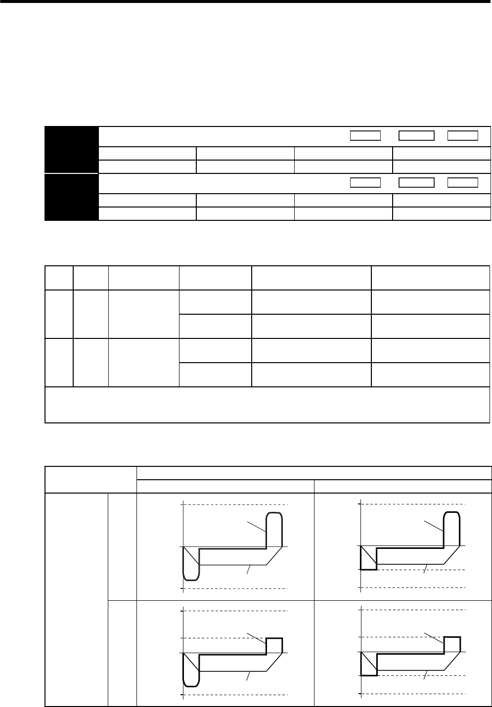
8 Operation
8.9.2 External Torque Limit (Output Torque Limiting by Input Signals)
8-72
8.9.2 External Torque Limit (Output Torque Limiting by Input Signals)
This function allows the torque to be limited at specific times during machine operation, for example, during
press stops and hold operations for robot workpieces.
An input signal is used to enable the torque limits previously set in parameters.
(1) Related Parameters
Note: The setting unit is a percentage of rated torque (i.e., the rated torque is 100%).
(2) Input Signals
(3) Changes in Output Torque during External Torque Limiting
Example: External torque limit (Pn402, Pn403) set to 800%
Note: In this example, the servomotor rotation direction is Pn000 = n.0 (standard setting, CCW =
forward).
Pn404 Forward External Torque Limit
Setting Range Setting Unit Factory Setting Setting Validation
0 to 800 1% 100 Immediately
Pn405 Reverse External Torque Limit
Setting Range Setting Unit Factory Setting Setting Validation
0 to 800 1% 100 Immediately
Speed Position Torque
Speed Position Torque
Type Signal
Name
Connector Pin
Number Setting Meaning Limit Value
Input /P-CL CN1-45
(Factory Setting)
ON (low level) Forward external torque limit
ON
The value set in Pn402 or
Pn404 (whichever is smaller)
OFF (high level) Forward external torque limit
OFF Pn402
Input /N-CL CN1-46
(Factory Setting)
ON (low level) Reverse external torque limit
ON
The value set in Pn403 or
Pn405 (whichever is smaller)
OFF (high level) Reverse external torque limit
OFF Pn403
When using this function, make sure that there are no other signals allocated to the same terminals as /P-CL and /N-CL.
When multiple signals are allocated to the same terminal, the signals are handled with OR logic, which affects the ON/OFF
state of the other signals. Refer to 7.3.2 Input Circuit Signal Allocation.
/P-CL (Forward External Torque Limit Input)
High level Low level
/N-CL
(Reverse
External
Torque Limit
Input)
High
level
Low
level
Pn403
Pn402
0
Torque
Speed
Pn403
0
Pn404
Pn402
Torque
Speed
0
Pn403
Pn405
Pn402
Torque
Speed
0
Pn403
Pn405
Pn404
Pn402
Torque
Speed
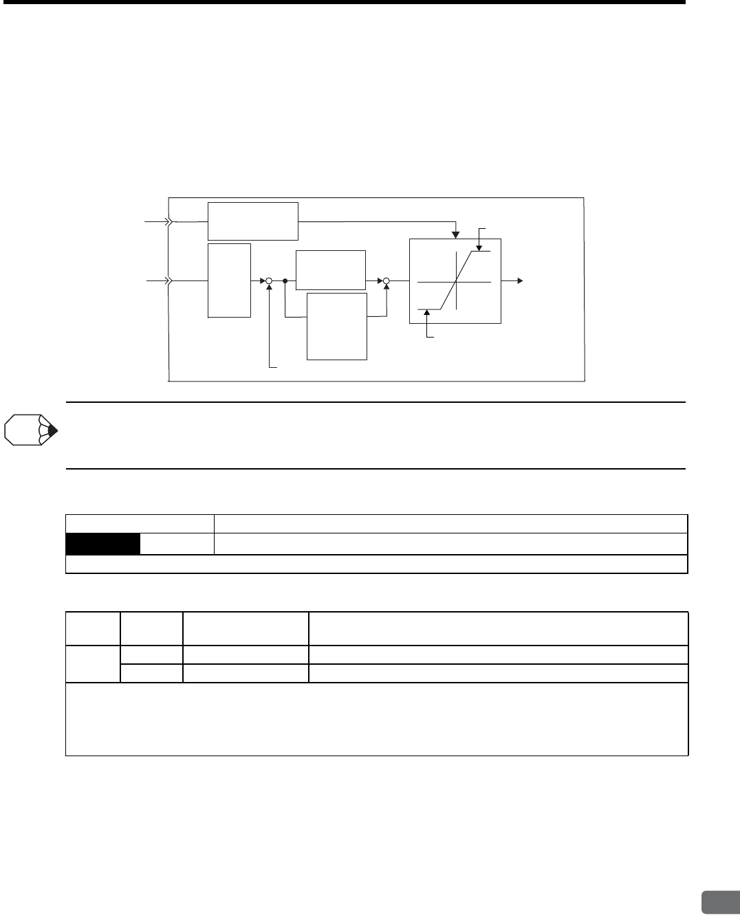
8.9 Limiting Torque
8
Operation
8-73
8.9.3 Torque Limiting Using an Analog Voltage Reference
Torque limiting by analog voltage reference limits torque by assigning a torque limit in an analog voltage to the
T-REF terminals (CN1-9 and 10). This function can be used only during speed or position control, not during
torque control.
Refer to the following block diagram when the torque limit with an analog voltage reference is used for speed
control.
There is no polarity in the input voltage of the analog voltage reference for torque limiting. The absolute values of both +
and - voltages are input, and a torque limit value corresponding to that absolute value is applied in the forward or reverse
direction.
(1) Related Parameters
(2) Input Signals
Speed
refer-
ence
input
gain
(Pn300)
+
+
+
-
Torque reference
input gain
(Pn400)
T-REF
V-REF
Forward torque
value (Pn402)
Speed loop
gain
(Pn100)
Speed feedback
Torque limit
value
Speed
reference
Torque
reference
Reverse torque
value (Pn403)
Speed loop
integral
time
constant
(Pn101)
SERVOPACK
INFO
Parameter Meaning
Pn002 n.1Speed control option: Uses the T-REF terminal to be used as an external torque limit input.
When n.2 is set, the T-REF terminal is used for torque feed-forward input, but the functions cannot be used together.
Type Signal
Name
Connector
Pin Number Name
Input T-REF CN1-9 Torque reference input
SG CN1-10 Signal ground for torque reference input
The torque limit input gain is set at parameter Pn400. Refer to 8.7.1 Setting Parameters.
Input Specifications
• Input range: ±1 VDC to ±10 VDC/rated torque
• Maximum allowable input voltage: ±12 VDC
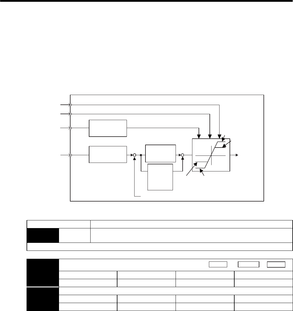
8 Operation
8.9.4 Torque Limiting Using an External Torque Limit and Analog Voltage Reference
8-74
8.9.4 Torque Limiting Using an External Torque Limit and Analog Voltage Reference
This function can be used to combine torque limiting by an external input signal and by analog voltage reference.
Because the torque limit by analog voltage reference is input from T-REF (CN1-9, 10), this function cannot be
used during torque control. Use /P-CL (CN1-45) or /N-CL (CN1-46) for torque limiting by external input signal.
When /P-CL (or /N-CL) is ON, either the torque limit by analog voltage reference or the setting in Pn404 (or
Pn405) will be applied as the torque limit, whichever is smaller.
(1) Related Parameters
* The setting unit is a percentage of rated torque (i.e., the rated torque is 100%).
Torque limit
value
Speed
reference
Speed reference
input gain
Pn300
+
+
+
-
Torque reference
input gain
Pn400
T-REF
V-REF
Pn404
(/P-CL:ON)
Forward torque
limit value (Pn402)
Pn405
(/N-CL:ON)
Speed loop
integral
time
constant
(Pn101)
Speed loop
gain
(Pn100)
Speed feedback
Torque
reference
Reverse torque
limit value (Pn403)
/N-CL
/P-CL
SERVOPACK
Parameter Meaning
Pn002 n.3Speed control option: When /P-CL or /N-CL is enabled, the T-REF terminal is used as the
external torque limit input.
When n.2 is set, T-REF is used for torque feed-forward input, but the functions cannot be used together.
Pn404 Forward External Torque Limit
Setting Range Setting Unit Factory Setting Setting Validation
0 to 800 1% 100 Immediately
Pn405 Reverse External Torque Limit
Setting Range Setting Unit Factory Setting Setting Validation
0 to 800 1% 100 Immediately
Speed
Position Torque

8.9 Limiting Torque
8
Operation
8-75
(2) Input Signals
8.9.5 Checking Output Torque Limiting during Operation
The following signal can be output to indicate that the servomotor output torque is being limited.
Type Signal
Name
Connector Pin
Number Name
Input T-REF CN1-9 Torque reference input
SG CN1-10 Signal ground for torque reference input
The torque limit input gain is set in parameter Pn400. Refer to 8.7.1 Setting Parameters.
Input Specifications
• Input range: ±1 VDC to ±10 VDC/rated torque
• Maximum allowable input voltage: ±12 VDC
Type Signal
Name
Connector Pin
Number Setting Meaning Limit Value
Input /P-CL CN1-45
(Factory setting)
ON (low level) Forward external torque limit
ON
The analog voltage reference
limit or the value set in Pn402 or
Pn404 (whichever is smaller)
OFF (high level) Forward external torque limit
OFF Pn402
Input /N-CL CN1-46
(Factory setting)
ON (low level) Reverse external torque limit
ON
The analog voltage reference
limit or the value set in Pn403 or
Pn405 (whichever is smaller)
OFF (high level) Reverse external torque limit
OFF Pn403
When using the torque limiting with the external torque limit and analog voltage reference, make sure that there are no
other signals allocated to the same terminals as /P-CL and /N-CL. When multiple signals are allocated to the same terminal,
the signals are handled with OR logic, which affects the ON/OFF state of the other signals. Refer to 7.3.2 Input Circuit Sig-
nal Allocation.
Type Signal
Name
Connector Pin
Number Setting Meaning
Output /CLT Must be allocated ON (low level) Servomotor output torque is being limited.
OFF (high level) Torque is not being limited.
The output terminal must be allocated with parameter Pn50F to use this output signal. Refer to 7.3.3 Output Circuit Signal
Allocation for details.
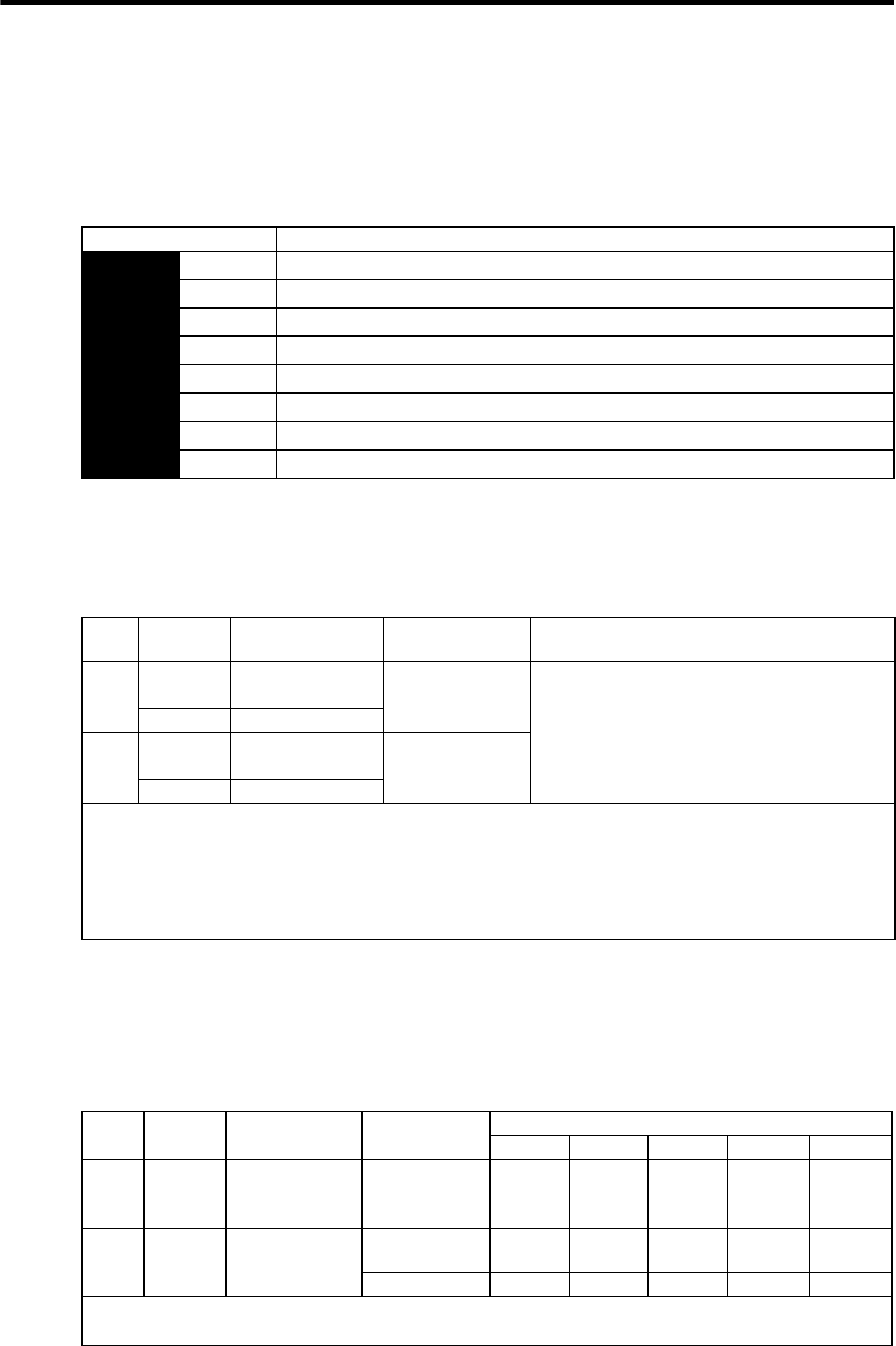
8 Operation
8.10.1 Setting Parameters
8-76
8.10 Control Mode Selection
The methods and conditions for switching SERVOPACK control modes are described below.
8.10.1 Setting Parameters
The following combinations of control modes can be selected according to the application at hand.
8.10.2 Switching the Control Mode
(1) Switching Internally Set Speed Control (Pn000.1 = 4, 5, or 6)
With the sequence input signals in the factory setting (Pn50A = n.0), the control mode will switch when
both /P-CL (/SPD-A) and /N-CL (/SPD-B) signals are OFF (high level).
(2) Switching Other Than Internally Set Speed Control (Pn000.1 = 7, 8, 9, A, or B)
Use the following signals to switch control modes. The control modes switch as shown below for each of the sig-
nal states indicated.
When changing the sequence input signal from the factory setting (Pn50A = n.1), allocate the /C-SEL to
an input terminal and change modes with the /C-SEL signal. In this case, input a speed reference (analog voltage
reference) for speed control, and a position reference (pulse train reference) for position control.
Parameter Control Method
Pn000 n.4Internally set speed control (contact reference) ⇔ Speed control (analog voltage reference)
n.5Internally set speed control (contact reference) ⇔ Position control (pulse train reference)
n.6Internally set speed control (contact reference) ⇔ Torque control (analog voltage reference)
n.7Position control (pulse train reference) ⇔ Speed control (analog voltage reference)
n.8Position control (pulse train reference) ⇔ Torque control (analog voltage reference)
n.9Torque control (analog voltage reference) ⇔ Speed control (analog voltage reference)
n.ASpeed control (analog voltage reference) ⇔ Zero clamp
n.BPosition control (pulse train reference) ⇔ Position control (inhibit)
Type Signal
Name
Connector
Pin Number Setting Meaning
Input /P-CL CN1-45
(Factory setting) OFF (high level)
Switches control mode.
(/SPD-A) Must be allocated
Input /N-CL CN1-46
(Factory setting) OFF (high level)
(/SPD-B) Must be allocated
Input Signal Selection
The following two types of control mode selection are available for switching from internally set speed control:
• Switching with the /P-CL and /N-CL input signals (pins allocated in factory setting)
• Switching with the /SPD-A and /SPD-B input signals
When using /SPD-A and /SPD-B, they must be allocated with parameter Pn50C. Refer to 7.3.2 Input Circuit Signal Alloca-
tion.
Type Signal
Name
Connector
Pin Number Setting Pn000 Setting
n.7n.8n.9n.An.B
Input /P-CON CN1-41
(Factory setting)
ON (low level) Speed Torque Speed Zero
clamp Inhibit
OFF (high level) Position Position Torque Speed Position
Input /C-SEL Must be allocated ON (low level) Speed Torque Speed Zero
clamp Inhibit
OFF (high level) Position Position Torque Speed Position
The control mode can be switched with either /P-CON or /C-SEL.
When using the /C-SEL signal, the input signal must be allocated. Refer to 7.3.2 Input Circuit Signal Allocation.

8.11 Other Output Signals
8
Operation
8-77
8.11 Other Output Signals
The following output signals, which have no direct connection with the control modes, are used for machine pro-
tection.
8.11.1 Servo Alarm Output (ALM) and Alarm Code Output (ALO1, ALO2, ALO3)
(1) Servo Alarm Output (ALM)
This signal is output when an error is detected in the SERVOPACK.
(2) Alarm Reset
1. Some encoder-related alarms cannot be reset with the /ALM-RST signal input. To reset these alarms,
turn OFF the control power supply.
2. When an alarm occurs, always eliminate the cause before resetting the alarm. The methods for trouble-
shooting alarms are described in 10.1.5 Troubleshooting of Alarm and Warning.
(3) Alarm Code Output
Type Signal
Name
Connector
Pin Number Setting Meaning
Output ALM CN1-31, 32
(Factory setting)
ON (low level) Normal SERVOPACK condition
OFF (high level) SERVOPACK alarm condition
IMPORTANT
Always form an external circuit so this alarm output turns OFF the main circuit power supply to the SERVOPACK.
Type Signal
Name
Connector
Pin Number Name
Input /ALM-
RST CN1-44 Alarm Reset
When a servo alarm (ALM) has occurred and the cause of the alarm has been eliminated, the alarm can be reset by turning
this signal (/ALM-RST) from OFF (high level) to ON (low level).
This signal can be allocated to other pin numbers with Pn50B.
For details on the procedure, refer to 7.3.2 Input Circuit Signal Allocation.
The /ALM-RST signal cannot be constantly enabled by the allocation of an external input signal. Reset the alarm by chang-
ing the signal from high level to low level. The alarm can also be reset from the panel operator or digital operator. Refer to
7.1.2 Key Names and Functions for details.
IMPORTANT
Type Signal
Name
Connector
Pin Number Meaning
Output ALO1 CN1-37 Alarm code output
Output ALO2 CN1-38 Alarm code output
Output ALO3 CN1-39 Alarm code output
Output SG CN1-1 Signal ground for alarm code output
These open-collector signals output alarm codes. The ON/OFF combination of these output signals indicates the type of
alarm detected by the servomotor.
Use these signals to display alarm codes at the host controller. Refer to 10.1.1 Alarm Display Table for details on alarm
code output.
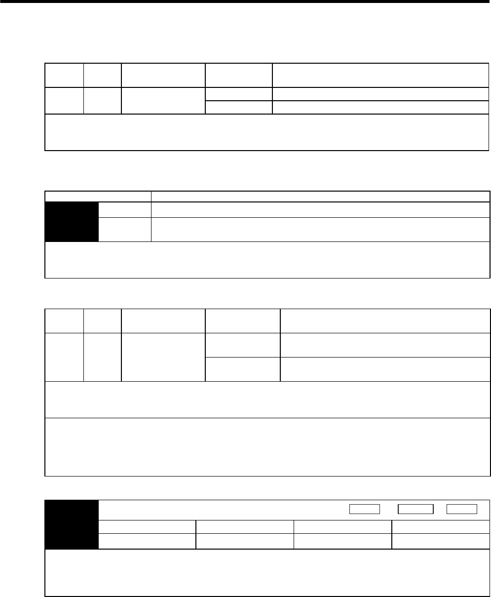
8 Operation
8.11.2 Warning Output (/WARN)
8-78
8.11.2 Warning Output (/WARN)
• Related Parameters
The following parameter is used to select the alarm code output.
8.11.3 Servomotor running Output Signal (/TGON)
• Related Parameter
Type Signal
Name
Connector
Pin Number Setting Meaning
Output /WARN Must be allocated ON (high level) Normal state
OFF (low level) Warning state
This output signal displays warnings before an overload (A.71) or regenerative overload (A.32) alarm is output.
For use, the /WARN signal must be allocated with parameter Pn50F. For details, refer to 7.3.3 Output Circuit Signal Allo-
cation.
Parameter Description
Pn001 n.0 Outputs alarm codes alone for alarm codes ALO1, ALO2, and ALO3.
n.1 Outputs both alarm and warning codes for alarm codes ALO1, ALO2, and ALO3, and out-
puts an alarm code when an alarm occurs.
• Refer to 8.11.1 Servo Alarm Output (ALM) and Alarm Code Output (ALO1, ALO2, ALO3) for alarm code descriptions.
• Refer to 10.1.2 Warning Display for the ON/OFF combinations of ALO1, ALO2, and ALO3 when a warning code is out-
put.
Type Signal
Name
Connector
Pin Number Setting Meaning
Output /TGON CN1-27, 28
(Factory setting)
ON (low level) Servomotor is operating (Motor speed is above the set-
ting in Pn502).
OFF (high level) Servomotor is not operating (Motor speed is below the
setting in Pn502).
This signal is output to indicate that the servomotor is currently operating above the setting in parameter Pn502.
The /TGON signal can be allocated to another output terminal with parameter Pn50E. For details, refer to 7.3.3 Output Cir-
cuit Signal Allocation.
IMPORTANT
• If the brake interlock signal (/BK) and servomotor running output signal (/TGON) are allocated to the same output termi-
nal, the /TGON signal will go to low level at the speed at which the movable part drops on the vertical axis, which means
that the /BK signal will not go to high level. (This is because signals are output with OR logic when multiple signals are
allocated to the same output terminal.). Always allocate /TGON and /BK signals to different terminals.
Pn502 Servomotor Rotation Detection Level
Setting Range Setting Unit Factory Setting Setting Validation
1 to 10000 1 min-1 20 Immediately
Set the range in which the servomotor running output signal (/TGON) is output in this parameter.
When the servomotor rotation speed is above the value set in the Pn502, it is judged to be servomotor rotating and the ser-
vomotor running output signal (/TGON) is output. The servomotor running detection signal (/TGON) can also be checked
on the digital operator. For details, refer to 7.1.4 Status Display and 7.4.1 List of Monitor Modes.
Speed
Position Torque

8.11 Other Output Signals
8
Operation
8-79
8.11.4 Servo Ready (/S-RDY) Output
Type Signal
Name
Connector Pin
Number Setting Meaning
Output /S-RDY CN1-29, 30
(Factory setting)
ON (low level) Servo is ready.
OFF (high level) Servo is not ready.
This signal indicates that the SERVOPACK received the servo ON signal and completed all preparations.
It is output when there are no servo alarms and the main circuit power supply is turned ON.
An added condition with absolute encoder specifications is that when the SEN signal is at high level, absolute data was out-
put to the host controller.
The servo ready signal condition can also be checked on the digital operator. For details, refer to 7.1.4 Status Display and
7.4.1 List of Monitor Modes.
The /S-RDY signal can be allocated to another output terminal with parameter Pn50E. For details, refer to 7.3.3 Output Cir-
cuit Signal Allocation.

9
Adjustments
9-1
9
Adjustments
9.1 Autotuning - - - - - - - - - - - - - - - - - - - - - - - - - - - - - - - - - - - - 9-2
9.1.1 Servo Gain Adjustment Methods - - - - - - - - - - - - - - - - - - - - - - - - - - - 9-2
9.1.2 List of Servo Adjustment Functions - - - - - - - - - - - - - - - - - - - - - - - - - 9-2
9.2 Online Autotuning - - - - - - - - - - - - - - - - - - - - - - - - - - - - - - -9-4
9.3 Manual Tuning - - - - - - - - - - - - - - - - - - - - - - - - - - - - - - - - -9-4
9.3.1 Explanation of Servo Gain - - - - - - - - - - - - - - - - - - - - - - - - - - - - - - - 9-4
9.3.2 Servo Gain Manual Tuning - - - - - - - - - - - - - - - - - - - - - - - - - - - - - - - 9-5
9.3.3 Position Loop Gain - - - - - - - - - - - - - - - - - - - - - - - - - - - - - - - - - - - - 9-5
9.3.4 Speed Loop Gain - - - - - - - - - - - - - - - - - - - - - - - - - - - - - - - - - - - - - - 9-6
9.3.5 Speed Loop Integral Time Constant - - - - - - - - - - - - - - - - - - - - - - - - - 9-6
9.4 Servo Gain Adjustment Functions - - - - - - - - - - - - - - - - - - - - 9-7
9.4.1 Feed-forward Reference - - - - - - - - - - - - - - - - - - - - - - - - - - - - - - - - - 9-7
9.4.2 Torque Feed-forward - - - - - - - - - - - - - - - - - - - - - - - - - - - - - - - - - - - 9-7
9.4.3 Speed Feed-forward - - - - - - - - - - - - - - - - - - - - - - - - - - - - - - - - - - - 9-8
9.4.4 Proportional Control Operation (Proportional Operation
Reference) - - - - - - - - - - - - - - - - - - - - - - - - - - - - - - - - - - - - - - - - - - 9-9
9.4.5 Using the Mode Switch (P/PI Switching) - - - - - - - - - - - - - - - - - - - - 9-10
9.4.6 Setting the Speed Bias - - - - - - - - - - - - - - - - - - - - - - - - - - - - - - - - - 9-13
9.4.7 Speed Feedback Filter - - - - - - - - - - - - - - - - - - - - - - - - - - - - - - - - - 9-13
9.4.8 Speed Feedback Compensation - - - - - - - - - - - - - - - - - - - - - - - - - - 9-13
9.4.9 Switching Gain Settings - - - - - - - - - - - - - - - - - - - - - - - - - - - - - - - - 9-14
9.4.10 Torque Reference Filter - - - - - - - - - - - - - - - - - - - - - - - - - - - - - - - 9-16
9.5 Analog Monitor - - - - - - - - - - - - - - - - - - - - - - - - - - - - - - - - 9-20

9 Adjustments
9.1.1 Servo Gain Adjustment Methods
9-2
9.1 Autotuning
9.1.1 Servo Gain Adjustment Methods
The SERVOPACK has the servo gains to determine the servo response characteristics. The servo gains are set in
the parameters. The parameters are designated for each function as shown in 9.1.2 List of Servo Adjustment
Functions.
The servo gains are factory-set to stable values, and responsiveness can be increased depending on the actual
machine conditions. Select the adjustment method according to the client’s intent using 9.1.2 List of Servo
Adjustment Functions.
9.1.2 List of Servo Adjustment Functions
(1) Online Autotuning Functions
Online autotuning functions cannot be used for SERVOPACKs of 22 kW or more.
(2) Positioning Time Reduction Functions
Function Name and
Related Parameters
Description Features Valid
Control
Modes
Refer-
ence
Section
Feed-forward
Pn109
Pn10A
Feed-forward compensation for the position refer-
ence is added to the speed reference.
Adjustment is easy.
The system will be unstable if a
large value is set, possibly result-
ing in overshooting or vibration.
Position 9.4.1
Torque feed-forward
Pn002
Pn400
Inputs torque feed-forward to the torque reference
input terminal and adds to the internal torque ref-
erence at the speed control.
Speed 9.4.2
Speed feed-forward
Pn207
Pn300
Inputs speed feed-forward to the speed reference
input terminal and adds to the internal speed refer-
ence at the position control.
Position 9.4.3
Mode Switch
(P/PI Switching)
Pn10B
Pn10C
Pn10D
Pn10E
Pn10F
Switches from PI control to P control using the
value of an internal servo variable in a parameter
(torque, speed, acceleration, or position error) as a
threshold value.
The setting for automatic switch-
ing between PI and P control is
easy.
Position
Speed
9.4.5
Speed Feedback
Compensation
Pn110
Pn111
This function cannot be used for SERVOPACKs
of 22 kW or more.
−−
9.4.8
Gain Switching
Pn100
Pn101
Pn102
Pn104
Pn105
Pn106
Automatically switches each parameter for speed
loop gain (Kv), speed loop integral time constant
(Ti), and position loop gain (Kp) by external signal
or according to condition:
Whether position reference is specified or not, or
Position error level, or
AND logic of the above two determined condi-
tions.
−Position
Speed
9.4.9

9.1 Autotuning
9
Adjustments
9-3
(3) Vibration Reduction Functions
Function Name and
Related Parameters
Description Features Valid
Control
Modes
Refer-
ence
Section
Soft Start
Pn305
Pn306
Converts a stepwise speed reference to a
constant acceleration or deceleration for
the specified time interval.
A constant acceleration/deceleration is
achieved for smoother operation. The
operation time is increased for the speci-
fied time.
Speed 8.5.4
Acceleration/
Deceleration Filters
Pn204
Pn207
A 1st-order delay filter for the position
reference input.
Enables smooth operation.
The reference time increases by the filter
delay time even after the reference input
has been completed.
Position 8.6.4
Movement Average
Filter
Pn207
Pn208
A movement averaging filter for the posi-
tion reference input.
Enables smooth operation.
The reference time increases by the filter
delay time even after the reference input
has been completed.
Position 8.6.4
Speed Feedback
Filter
Pn308
A standard 1st-order delay filter for the
speed feedback.
The feedback speed is smoother.
The response is delayed if a large value is
set.
Position
Speed
9.4.7
Speed Reference
Filter
Pn307
A 1st-order delay filter for the speed refer-
ence.
The speed reference is smoother.
The response is delayed if a large value is
set.
Speed 8.5.5
Torque Reference
Filter
Pn401
A 1st-order filter time constant can be set
for the torque reference.
The lower the value, the better the speed
control response will be, but there is a
lower limit that depends on the machine
conditions.
Position
Speed
Torque
9.4.10
Notch Filter
Pn408
Pn409
Pn40A
Pn40B
Pn40C
Notch filters can be set for the torque ref-
erence. The performances of first stage
notch filter and second stage notch filter
are identical.
Mainly effective for vibration between
500 and 2,000 Hz.
Instability will result if the setting is not
correct.
Position
Speed
Torque
9.4.10
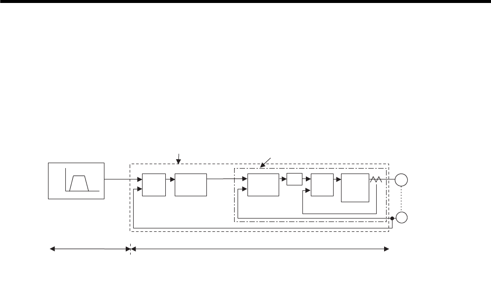
9 Adjustments
9.3.1 Explanation of Servo Gain
9-4
9.2 Online Autotuning
Online autotuning functions cannot be used for SERVOPACKs of 22 kW or more.
9.3 Manual Tuning
9.3.1 Explanation of Servo Gain
The block diagram for position control is as follows:
To adjust the servo gain manually, understand the configuration and characteristics of the SERVOPACK and
adjust the servo gain parameters one by one. If one parameter is changed, it is almost always necessary to adjust
the other parameters. It will also be necessary to make preparations such as setting up a measuring instrument to
monitor the output waveform from the analog monitor.
The SERVOPACK has three feedback loops (i.e., position loop, speed loop, and current loop). The innermost
loop must have the highest response and the middle loop must have higher response than the outermost. If this
principle is not followed, it will result in vibration or responsiveness decreases.
The SERVOPACK is designed to ensure that the current loop has good response performance. The user need to
adjust only position loop gain and speed loop gain.
Encoder
Position control loop Speed control loop
Speed
Speed pattern
Time
Move
reference
Error
counter
Position
loop
gain Kp
Speed
control
section
Kv
Ti
+
-
Current
control
section
Electric
power
converting
Section
Servomotor
M
PG
Position loop
SERVOPACK
Host controller
(provided by user)
KpPosition Loop Gain (Pn102㧕
KvSpeed Loop Gain㧔Pn100㧕
TiSpeed Loop Integral Time
TfTorque Reference Filter Time
+
-
+
-
Speed
reference
Speed loop Current loop
Tf
Constant (Pn101)
Constant (Pn401)
9.3 Manual Tuning
9
Adjustments
9-5
9.3.2 Servo Gain Manual Tuning
The SERVOPACK has the following parameters for the servo gains. Setting the servo gains in the parameters
can adjust the servo responsiveness.
• Pn100: Speed loop gain (Kv)
• Pn101: Speed loop integral time constant (Ti)
• Pn102: Position loop gain (Kp)
• Pn401: Torque reference filter time constant (Tf)
For the position and speed control, the adjustment in the following procedure can increase the responsiveness.
The positioning time in position control can be reduced.
Start the manual tuning from the factory setting. Prepare measuring instruments such as memory recorder so that
the signals can be observed from the analog monitor (CN5) such as “Torque Reference” and “Motor Speed,” and
“Position Error Monitor” for the position control. (Refer to 9.5 Analog Monitor.) The servo drive supporting tool
“SigmaWin+” allows you to observe such signals. Prepare either of them.
9.3.3 Position Loop Gain
If the position loop gain (Pn102) cannot be set high in the mechanical system, an overflow alarm may occur during high
speed operation. In this case, increase the values in the following parameter to suppress detection of the overflow alarm.
Step Explanation
1Set correctly the moment of inertia ratio (Pn103).
2Increase the speed loop gain (Pn100) to within the range so that the machine does not vibrate. At the
same time, decrease the speed loop integral time constant (Pn101).
3Adjust the torque reference filter time constant (Pn401) so that no vibration occurs.
4Repeat the steps 1 and 2. Then reduce the value for 10 to 20%.
5For the position control, increase the position loop gain (Pn102) to within the range so that the machine
does not vibrate.
Pn102 Position Loop Gain (Kp)
Setting Range Setting Unit Factory Setting Setting Validation
1 to 2,000 1/s 40 Immediately
The responsiveness of the position loop is determined by the position loop gain. The responsiveness increases and the posi-
tioning time decreases when the position loop gain is set to a higher value. In general, the position loop gain cannot be set
higher than natural vibrating frequency of the mechanical system, so the mechanical system must be made more rigid to
increase its natural vibrating frequency and allow the position loop gain to be set to a high value.
Position
INFO
Pn505 Overflow Level
Setting Range Setting Unit Factory Setting Setting Validation
1 to 32,767 256 reference units 1,024 Immediately
This parameter’s new setting must satisfy the following condition.
Position
Pn505 Pn102 2.0
≥Max. feed speed (reference units/s) ×
9 Adjustments
9.3.4 Speed Loop Gain
9-6
9.3.4 Speed Loop Gain
9.3.5 Speed Loop Integral Time Constant
Selecting the Speed Loop Control Method (PI Control or I-P Control)
Generally, I-P control is more effective in high-speed positioning or high-speed/precision manufacturing applications. The
position loop gain is lower than it would be in PI control, so shorter positioning times and smaller arc radii can be
achieved. On the other hand, PI control is generally used when switching to P control fairly often with a mode switch or
other method.
Pn100 Speed Loop Gain (Kv)
Setting Range Setting Unit Factory Setting Setting Validation
1 to 2,000 1 Hz 40 Immediately
This parameter determines the responsiveness of the speed loop. If the speed loop’s responsiveness is too low, it will delay
the outer position loop and cause overshooting and vibration of the speed reference. The SERVOPACK will be most stable
and responsive when the speed loop gain is set as high as possible within the range that does not cause vibration in the
mechanical system. The value of speed loop gain is the same as the set value of Pn100 if the moment of inertia ratio in
Pn103 has been set correctly.
Speed
Position
Pn103 Moment of Inertia Ratio
Setting Range Setting Unit Factory Setting Setting Validation
0 to 20,000 1 % 0 Immediately
The factory setting is Pn103=0. Before adjusting the servo, determine the moment of inertia ratio with the equation above
and set parameter Pn103.
Pn101 Speed Loop Integral Time Constant (Ti)
Setting Range Setting Unit Factory Setting Setting Validation
15 to 51,200
(0.15 to 512.00 ms)
0.01 ms 2,000
(20.00 ms)
Immediately
The speed loop has an integral element so that the speed loop can respond to minute inputs. This integral element causes a
delay in the SERVOPACK. If the time constant is set too long, overshooting will occur, which results in a longer position-
ing settling time or responsiveness decreases.
The estimated set value for Pn101 depends on the speed loop control method with Pn10B.1, as shown below.
Speed
Position
Torque
Pn103 set value = Motor axis conversion load moment of inertia (JL)
Servomotor rotor moment of inertia (JM)
×100(%)
Speed
Position
INFO
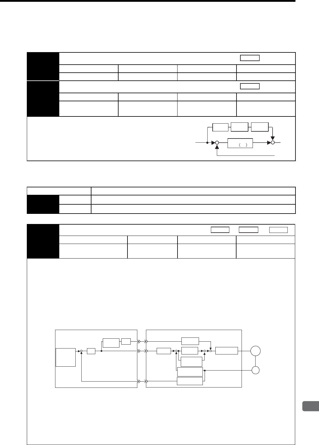
9.4 Servo Gain Adjustment Functions
9
Adjustments
9-7
9.4 Servo Gain Adjustment Functions
9.4.1 Feed-forward Reference
9.4.2 Torque Feed-forward
Pn109 Feed-forward
Setting Range Setting Unit Factory Setting Setting Validation
0 to 100 1 % 0 Immediately
Pn10A Feed-forward Filter Time Constant
Setting Range Setting Unit Factory Setting Setting Validation
0 to 6,400
(0.00 to 64.00 ms)
0.01ms 0 Immediately
Applies feed-forward compensation in position control inside
the SERVOPACK. Use this parameter to shorten positioning
time. Too high value may cause the machine to vibrate. For
ordinary machines, set 80% or less in this parameter.
Position
Position
Position
reference pulse
Encoder feedback pulse
+++
-
Position loop
gain Kp
Pn109 Pn10A
Differ-
ential
Parameter Meaning
Pn002 n.0Disabled
n.2Uses T-REF terminal for torque feed-forward input.
Pn400 Torque Reference Input Gain
Setting Range Setting Unit Factory Setting Setting Validation
10 to 100
(1.0 to 10.0 V/rated torque)
0.1 V/rated torque 30 Immediately
The torque feed-forward function is valid only in speed control (analog reference).
The torque feed-forward function shortens positioning time, differentiates a speed reference at the host controller to gener-
ate a torque feed-forward reference, and inputs the torque feed-forward reference together with the speed reference to the
SERVOPACK.
Too high a torque feed-forward value will result in overshooting or undershooting. To prevent such troubles, set the opti-
mum value while observing the system responsiveness.
Connect a speed reference signal line to V-REF (CN1-5 and -6) and a torque forward-feed reference to T-REF (CN1-9 and
-10) from the host controller.
Torque feed-forward is set using the parameter Pn400.
The factory setting is Pn400 = 30. If, for example, the torque feed-forward value is ±3V, then, the torque is limited to
±100% of the rated torque.
The torque feed-forward function cannot be used with torque limiting by analog voltage reference described in 8.9.3
Torque Limiting Using an Analog Voltage Reference.
Speed
Position
Torque
-
V-REF (CN1-5)
Position
reference
Kp Pn100 Current loop M
PG
Differ-
ential
KFF
Speed
calculation
Integration
(Pn101)
++
+
+
+
T-REF (CN1-9)
Servomotor
Encoder
Host controller SERVOPACK
Kp: Position loop gain
KFF: Feed-forward gain
++
Pn400
Pn300
-
Divider
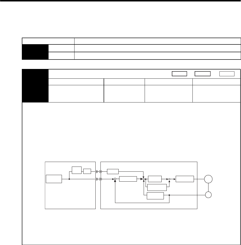
9 Adjustments
9.4.3 Speed Feed-forward
9-8
9.4.3 Speed Feed-forward
Parameter Meaning
Pn207 n.0Disabled
n.1Uses V-REF terminal for speed feed-forward input.
Pn300 Speed Reference Input Gain
Setting Range Setting Unit Factory Setting Setting Validation
150 to 3,000
(1.50 to 30.00 V/rated
speed)
0.01 V/rated speed 600 Immediately
The speed feed-forward function uses analog voltages and is valid only in position control.
The speed feed-forward function is used to shorten positioning time. The host controller differentiates the position refer-
ence to generate the feed-forward reference, and inputs the feed-forward reference together with the position reference to
the SERVOPACK.
Too high a speed feed-forward value will result in overshooting or undershooting. To prevent such troubles, set the opti-
mum value while observing the system responsiveness.
Connect a position reference signal line to PULS and SIGN (CN1-7, -8, -11, and -12) and a speed feed-forward reference
signal line to V-REF (CN1-5 and -6) from the host controller.
Speed feed-forward value is set using the parameter Pn300.
The factory setting is Pn300 = 600. If, for example, the speed feed-forward value is ±6V, then the speed is limited to the
rated speed.
Speed
Position
Torque
Pn100 M
PG
KFF
+
-+
+
V-REF (CN1-5 and -6)
+
Kp (Pn102)
+
-
Position
reference Current loop
Speed
calculation
Integration
(Pn101)
Servomotor
Encoder
Host controller SERVOPACK
Kp: Position loop gain
KFF: Feed-forward gain
Differ-
ential Pn300
PULS
SIGN
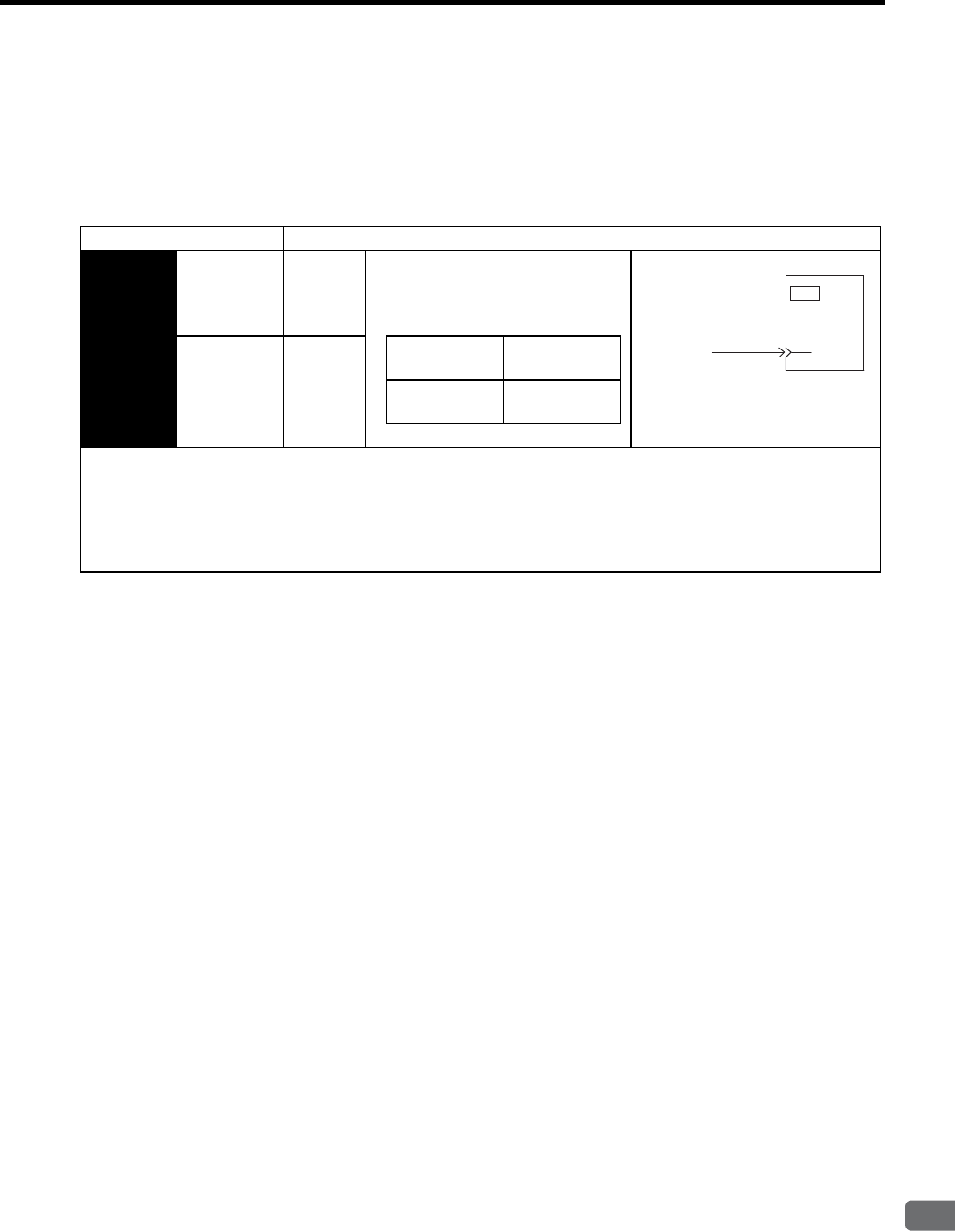
9.4 Servo Gain Adjustment Functions
9
Adjustments
9-9
9.4.4 Proportional Control Operation (Proportional Operation Reference)
If parameter Pn000.1 is set to 0 or 1 as shown below, the /P-CON input signal serves as switch to change between
PI control and P control.
• PI control: Proportional/Integral control
• P control: Proportional control
Parameter Control Mode
Pn000 n.0Speed
Control
Effective in speed control or position
control.
Input signal /P-CON (CN1-41) is used
to select PI control or P control.
n.1Position
Control
CN1-41 is OFF
(H level).
PI control
CN1-41 is ON
(L level).
P control
• When sending references from the host controller to the SERVOPACK, P control mode can be selected from the host
controller for particular operating conditions. This mode switching method can be used to suppress overshooting and
shorten the settling time. Refer to 9.4.5 Using the Mode Switch (P/PI Switching) for more details on inputting the /P-
CON signal and switching the control mode for particular operating conditions.
• If PI control mode is being used and the speed reference has a reference offset, the servomotor may rotate very slowly
and fail to stop even if 0 is specified as the speed reference. In this case, use P control mode to stop the servomotor.
SERVOPACK
/P-CON
P control 41
CN1
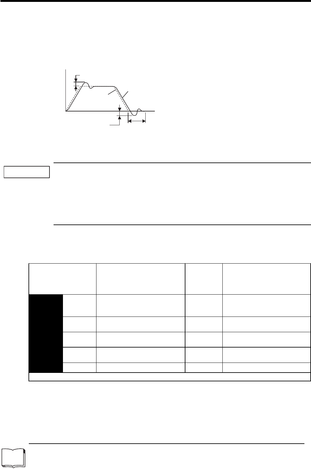
9 Adjustments
9.4.5 Using the Mode Switch (P/PI Switching)
9-10
9.4.5 Using the Mode Switch (P/PI Switching)
Use the mode switch (P/PI switching) function in the following cases:
• To suppress overshooting during acceleration or deceleration (for speed control)
• To suppress undershooting during positioning and reduce the settling time (for position control)
The mode switch function automatically switches the speed control mode from PI control mode to P control1
mode based on a comparison between the servo’s internal value and a user-set detection level.
1. The mode switch function is used in very high-speed positioning when it is necessary to use the servo-
drive near the limits of its capabilities. The speed response waveform must be observed to adjust the
mode switch.
2. For normal use, the speed loop gain and position loop gain set by autotuning provide sufficient speed/
position control. Even if overshooting or undershooting occur, they can be suppressed by setting the host
controller’s acceleration/deceleration time constant, the SERVOPACK’s Soft Start Acceleration/Deceler-
ation Time (Pn305, Pn306), or Position Reference Acceleration/Deceleration Time Constant (Pn204).
(1) Selecting the Mode Switch Setting
The SERVOPACK provides the following four mode switch settings (0 to 3). Select the appropriate mode switch
setting with parameter Pn10B.0.
1 From PI control to P control
PI control means proportional/integral control and P control means proportional control. In short, switching “from PI
control to P control” reduces effective servo gain, making the SERVOPACK more stable.
Actual motor operation
Overshoot
Speed
Reference
Settling time
Time
Undershoot
TERMS
IMPORTANT
Parameter Mode Switch Selection
Parameter
Containing
Detection
Point Setting
Setting Unit
Pn10B n.0Use a torque reference level for
detection point.
(Factory Setting)
Pn10C
Percentage to the rated torque
n.1Use a speed reference level for
detection point. Pn10D Servomotor speed: min-1
n.2Use an acceleration level for detec-
tion point. Pn10E Servomotor acceleration: 10 min-1/s
n.3Use a position error pulse for detec-
tion point. Pn10F Reference unit
n.4Do not use the mode switch function. −−
Select a condition to execute the mode switch (P/PI switching). (Setting is validated immediately.)
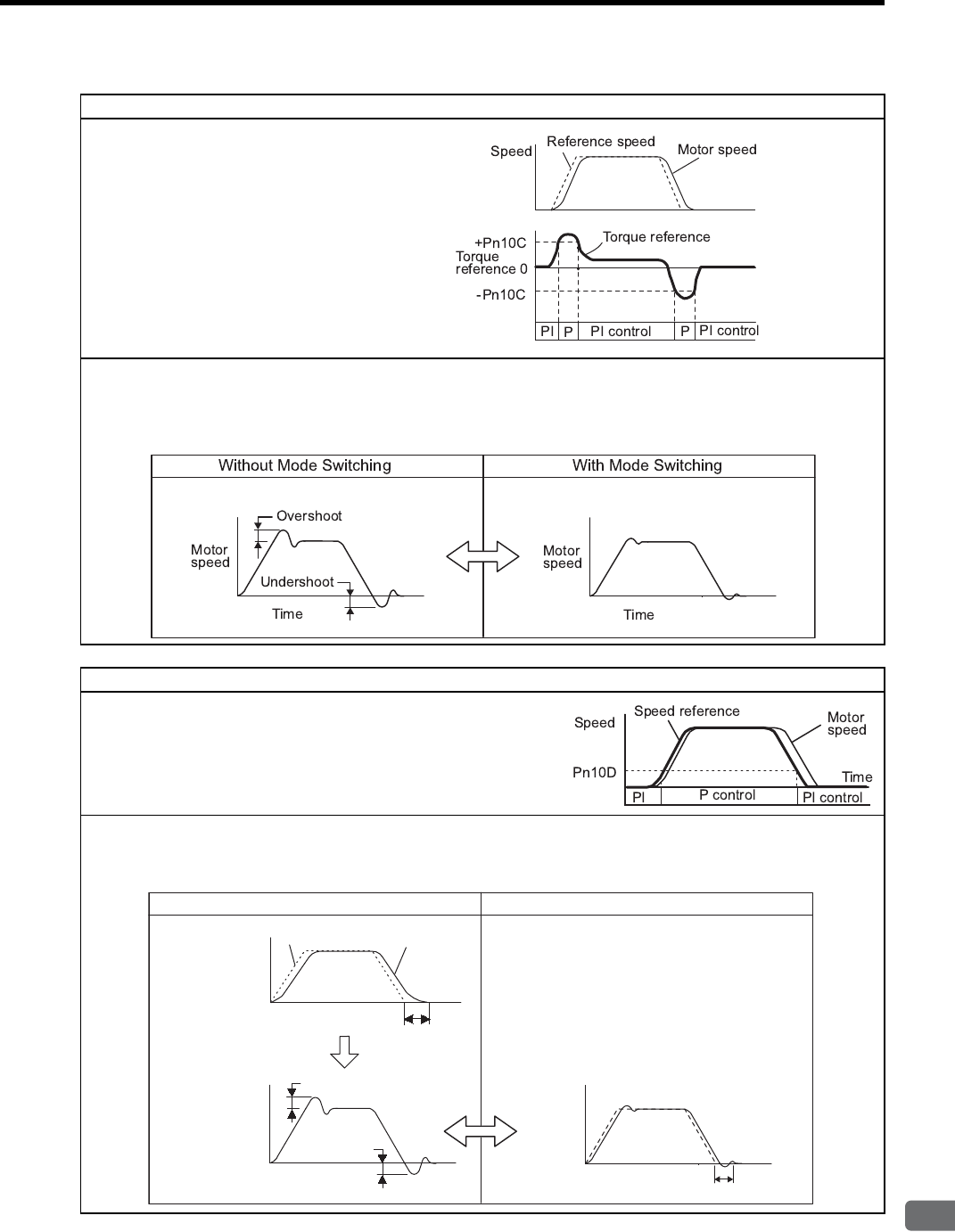
9.4 Servo Gain Adjustment Functions
9
Adjustments
9-11
Using the Torque Reference Level to Switch Modes (Factory Setting)
With this setting, the speed loop is switched to P
control when the value of torque reference input
exceeds the torque set in parameter Pn10C. The fac-
tory default setting for the torque reference detection
point is 200% of the rated torque (Pn10C = 200).
Operating Example
If the mode switch function is not being used and the SERVOPACK is always operated with PI control, the speed of the
motor may overshoot or undershoot due to torque saturation during acceleration or deceleration. The mode switch function
suppresses torque saturation and eliminates the overshooting or undershooting of the motor speed.
Using the Speed Reference Level to Switch Modes
With this setting, the speed loop is switched to P control when the value
of speed reference input exceeds the speed set in parameter Pn10D.
Operating Example
In this example, the mode switch is used to reduce the settling time. It is necessary to increase the speed loop gain to reduce
the settling time. Using the mode switch suppresses overshooting and undershooting when speed loop gain is increased.
Motor speed
Speed
reference
Long settling time
Increase speed loop gain.
Settling time
Motor
speed
Overshoot
Undershoot
Motor
speed
Time
Motor
speed
Without Mode Switching With Mode Switching
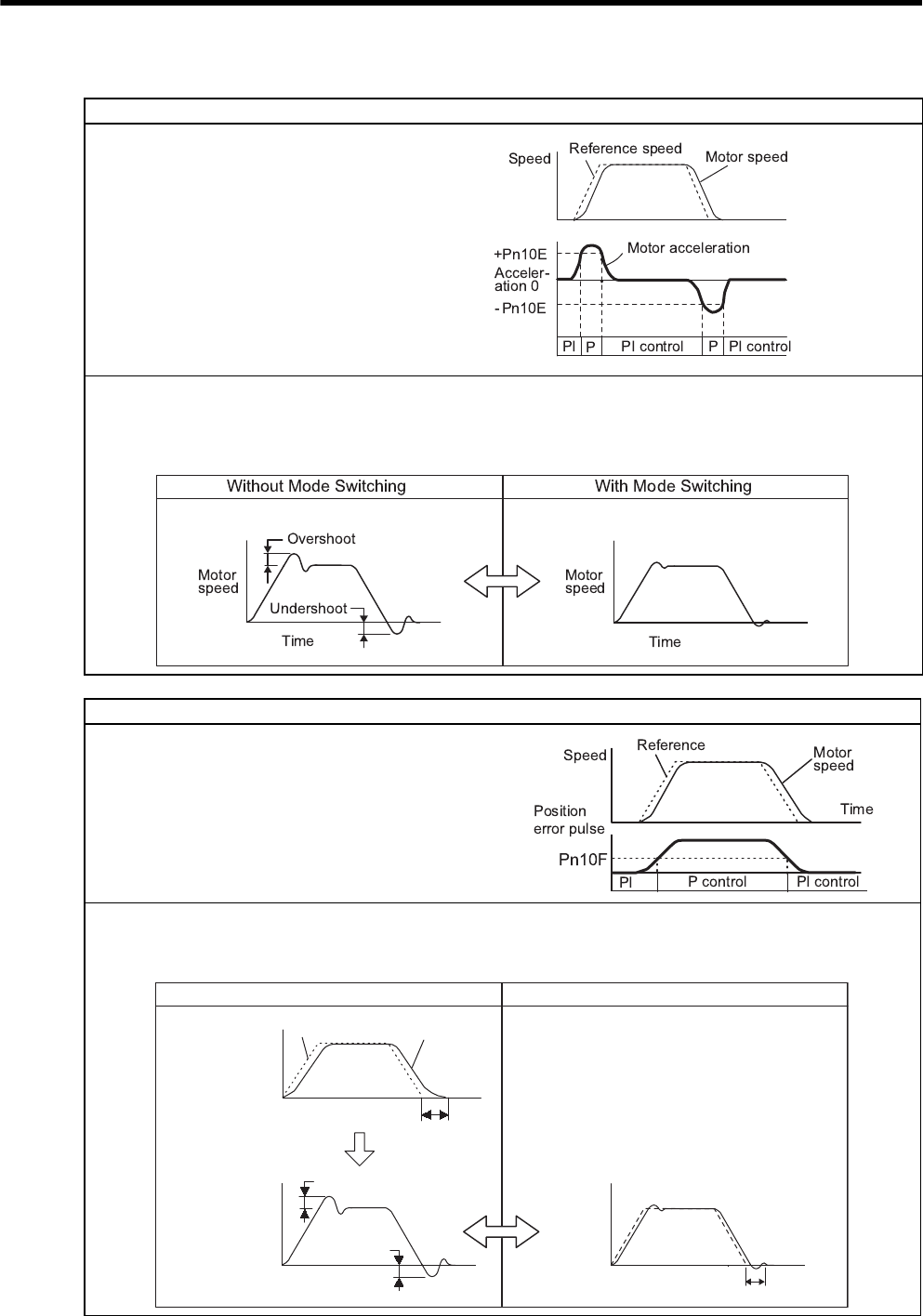
9 Adjustments
9.4.5 Using the Mode Switch (P/PI Switching)
9-12
Using the Acceleration Level to Switch Modes
With this setting, the speed loop is switched to P
control when the motor’s acceleration rate exceeds
the acceleration rate set in parameter Pn10E.
Operating Example
If the mode switch function is not being used and the SERVOPACK is always operated with PI control, the speed of the
motor may overshoot or undershoot due to torque saturation during acceleration or deceleration. The mode switch function
suppresses torque saturation and eliminates the overshooting or undershooting of the motor speed.
Using the Error Pulse Level to Switch Modes
This setting is effective with position control only.
With this setting, the speed loop is switched to P control when
the error pulse exceeds the value set in parameter Pn10F.
Operating Example
In this example, the mode switch is used to reduce the settling time. It is necessary to increase the speed loop gain to reduce
the settling time. Using the mode switch suppresses overshooting and undershooting when speed loop gain is increased.
Motor speed
Speed
reference
Long settling time
Increase speed loop gain.
Settling time
Motor
speed
Overshoot
Undershoot
Motor
speed
Time
Motor
speed
Without Mode Switching With Mode Switching
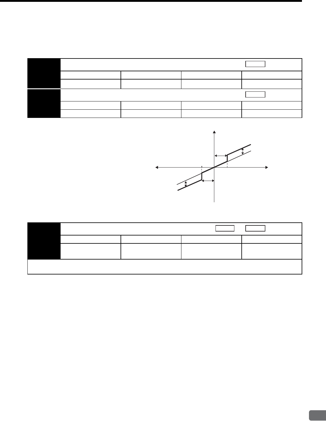
9.4 Servo Gain Adjustment Functions
9
Adjustments
9-13
9.4.6 Setting the Speed Bias
The settling time for positioning can be reduced by setting the following parameters to add bias in the speed ref-
erence block in the SERVOPACK.
9.4.7 Speed Feedback Filter
9.4.8 Speed Feedback Compensation
Speed feedback compensation cannot be used for SERVOPACKs of 22 kW or more.
Pn107 Bias
Setting Range Setting Unit Factory Setting Setting Validation
0 to 450 1 min-1 0 Immediately
Pn108 Bias Width Addition
Setting Range Setting Unit Factory Setting Setting Validation
0 to 250 1 Reference unit 7 Immediately
Position
Position
To reduce the positioning time, set these parameters
based on the machine’s characteristics.
The Bias Width Addition (Pn108) specifies when the
Bias (Pn107) is added and the width is expressed in
error pulse units. The bias input will be added when
the error pulse value exceeds the width set in Pn108.
Bias width addition
Bias set
Bias (Pn107)
Bias (Pn107)
No bias
(Pn108)
Bias width addition
Pn108
(Pn108)
Error pulse
Speed reference
Pn308 Speed Feedback Filter Time Constant
Setting Range Setting Unit Factory Setting Setting Validation
0 to 65,535
(0.00 to 655.35 ms)
0.01 ms 0 Immediately
Sets the 1st-order filter for the speed loop’s speed feedback. Makes the motor speed smoother and reduces vibration. If the
set value is too high, it will introduce a delay in the loop and cause poor responsiveness.
Speed
Position
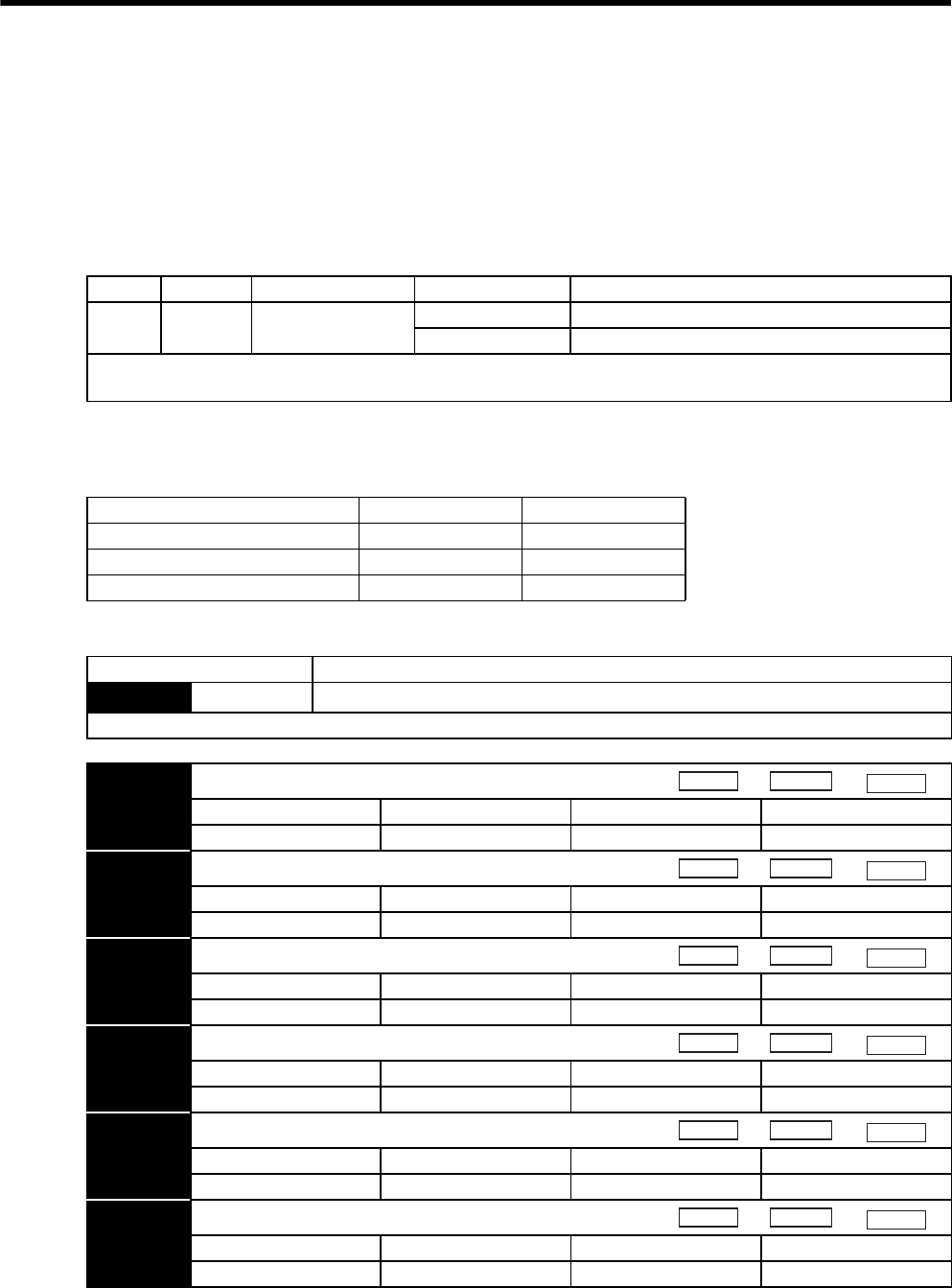
9 Adjustments
9.4.9 Switching Gain Settings
9-14
9.4.9 Switching Gain Settings
Gain switching functions by the external signal, or by using automatic gain switching that is enabled only at posi-
tion control, are built into the SGDM/SGDH SERVOPACK. For example, to use different gains while the servo-
motor is running or stopped, set two values in the gain settings 1 and 2 and switch the gains.
(1) Gain Switching Function Using an External Input Signal
(a) Gain Switching Input Signal
(b) Switchable Gain Combinations
Turning ON and OFF the gain switching signal /G-SEL switches the gains as follows.
(c) Related Parameters
Type Signal Connector Pin No. Setting Meaning
Input /G-SEL Signal allocation
required
OFF: H (high) level Gain settings 1
ON: L (low) level Gain settings 2
To use the input signal, the input signal must be allocated in the parameter Pn50D. Refer to 7.3.2 Input Circuit Signal Allo-
cation.
Gain Switching Signal (/G-SEL) OFF (H Level) ON (L Level)
Speed loop gain Pn100 Pn104
Speed loop integral time constant Pn101 Pn105
Position loop gain Pn102 Pn106
Parameter Function
Pn50A n.1Enables the input signal allocation for the sequence.
Set to allocate the gain switching signal (/G-SEL) to an input terminal.
Pn100 Speed Loop Gain
Setting Range Setting Unit Factory Setting Setting Validation
1 to 2,000 Hz 40 Immediately
Pn101 Speed Loop Integral Time Constant
Setting Range Setting Unit Factory Setting Setting Validation
15 to 51,200 0.01 ms 2,000 Immediately
Pn102 Position Loop Gain
Setting Range Setting Unit Factory Setting Setting Validation
1 to 2,000 1/s 40 Immediately
Pn104 2nd Speed Loop Gain
Setting Range Setting Unit Factory Setting Setting Validation
1 to 2,000 Hz 40 Immediately
Pn105 2nd Speed Loop Integral Time Constant
Setting Range Setting Unit Factory Setting Setting Validation
15 to 51,200 0.01 ms 2,000 Immediately
Pn106 2nd Position Loop Gain
Setting Range Setting Unit Factory Setting Setting Validation
1 to 2,000 1/s 40 Immediately
Speed
Position
Torque
Speed
Position
Torque
Speed
Position
Torque
Speed
Position
Torque
Speed
Position
Torque
Speed
Position
Torque
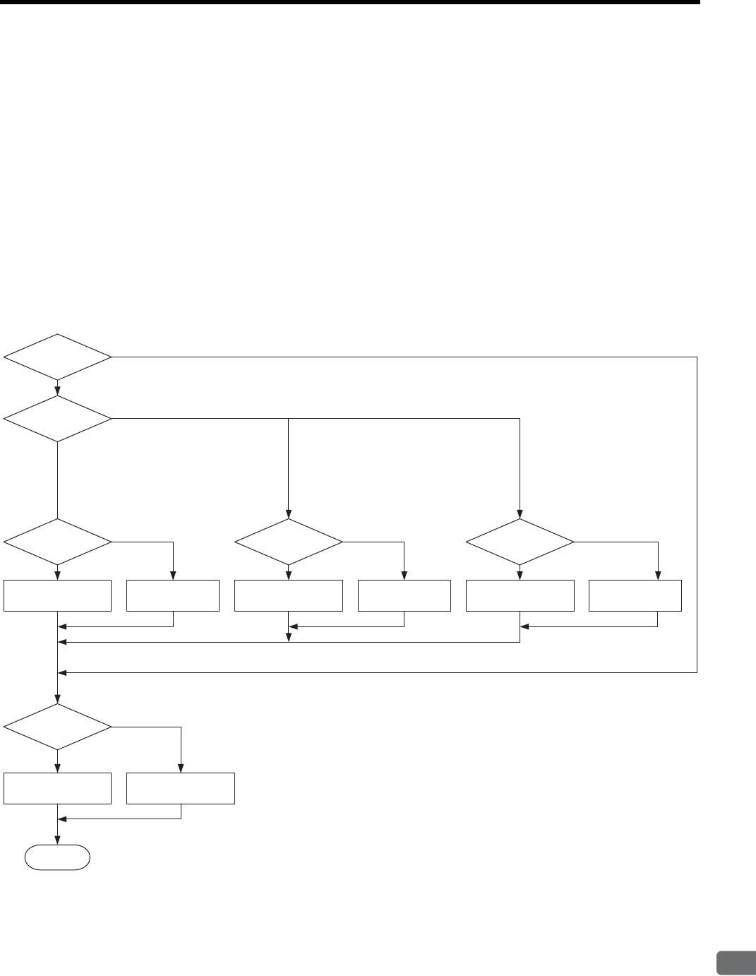
9.4 Servo Gain Adjustment Functions
9
Adjustments
9-15
(2) Automatic Gain Switching Function
The automatic gain switching function switches the gain setting between the gain setting 1 and 2 according to the
condition:
Whether position reference is specified or not, or
Position error level, or
AND logic of the above two determined conditions
The position reference of the automatic gain switching condition indicates the reference pulses from CN1.
Note that the automatic gain switching function is disabled for the control modes other than position control.
The existing gain switching function by /G-SEL signal is also available. However, it cannot be used with the
gain switching function.
When the automatic gain switching is enabled by setting 1 to 3 of Pn10B.2, the gain switching function by /G-
SEL signal is disabled.
The following flowchart shows the automatic gain switching.
With or without
position reference
Automatic gain
switching enabled?
Gain switching timer
count-up
Gain switching timer
0 clear
Without
With Position error
Gain switching timer
count-up
Gain switching timer
0 clear
Position error < Pn125
Automatic gain
switching condition
Position
reference and
Position error
Gain switching timer
count-up
Gain switching timer
0 clear
Without position reference
and
Position error < Pn125
With position reference
or
Position error ≥ Pn125
Position reference only
(Pn10B.2 = 1) Position error only
(Pn10B.2 = 2)
Position reference
and position error
(Pn10.B = 3)
Disabled (Pn10B.2 = 0)
Timer > Pn124
Gain Setting 2 Gain Setting 1
YES
NO
Enabled (Pn10B.2 = 1 to 3)
Position error ≥ Pn125
End
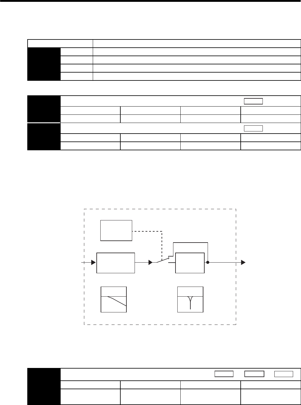
9 Adjustments
9.4.10 Torque Reference Filter
9-16
(1) Related Parameters
Note: After changing the setting, turn OFF the power and ON again to enable the new setting.
9.4.10 Torque Reference Filter
As shown in the following diagram, the torque reference filter contains torque reference filter time constant
(Pn401) and notch filter (two stages) arrayed in series. The notch filter can be enabled and disabled using the
parameters.
(1) Torque Reference Filter
If you suspect that machine vibration is being caused by the servodrive, try adjusting the filter time constant. This
may stop the vibration. The lower the value, the better the speed control response will be, but there is a lower
limit that depends on the machine conditions.
Parameter Meaning
Pn10B n.0 Automatic gain switching disabled (Factory setting)
n.1 Switches the gain according to the position reference condition only.
n.2 Switches the gain according to the position error condition only.
n.3 Switches the gain according to the position reference and position error condition only.
Pn124 Automatic Gain Switching Timer
Setting Range Setting Unit Factory Setting Setting Validation
1 to 10000 1 ms 100 immediately
Pn125 Automatic Gain Switching Width
Setting Range Setting Unit Factory Setting Setting Validation
1 to 250 1 Reference units 7 immediately
Position
Position
Torque reference
after filtering
Torque reference
before filtering
Notch
filter
(two stages)
Torque reference
filter time
constant
Pn401
Torque
function
switches
Pn408
Notch filter
1st-order delay filter
Pn401 Torque Reference Filter Time Constant
Setting Range Setting Unit Factory Setting Setting Validation
0 to 65,535
(0.00 to 655.35 ms)
0.01 ms 100 Immediately
Speed
Position
Torque
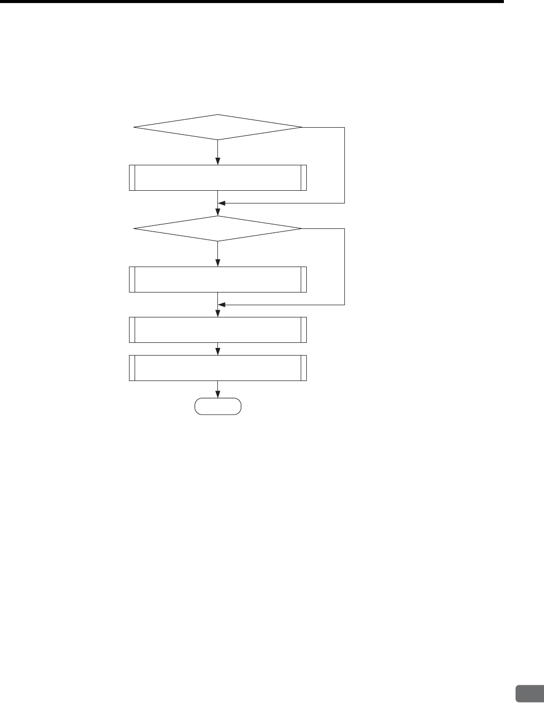
9.4 Servo Gain Adjustment Functions
9
Adjustments
9-17
(2) Notch Filter
Using the notch filter in accordance with the components of specific vibration frequency such as resonances of
ball screw can eliminate the frequency components to stop the vibration.
The performances of first stage notch filter and second stage notch filter are identical.
First Stage Notch Filter
Second Stage Notch Filter
Torque Reference Filter
(Low-pass filter)
Torque Limit
Use First Stage Notch Filter.
Use Second Stage Notch Filter
NO
NO
YES
YES
End
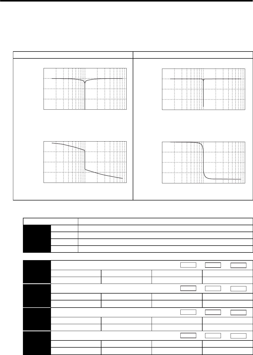
9 Adjustments
9.4.10 Torque Reference Filter
9-18
(a) Notch Filter
The notch filter can decrease the set frequency responsiveness. The notch filter puts a notch in the gain curve at
the specific vibration frequency. The frequency components near the notch frequency can be eliminated with this
characteristic. A higher notch filter Q value produces a sharper notch and phase delay.
(b) Related Parameters
Q value = 0.7 Q value = 1.0
Notch filter
Notch filter
Gain
(db)
Frequency (Hz)
-300
-200
-100
0
100
2
10
10
3
10
4
2
10
10
3
10
4
Phase
Frequency (Hz)
-400
-300
-200
-100
0
(deg)
-300
-200
-100
0
100
2
1010
3
10
4
2
1010
3
10
4
-400
-300
-200
-100
0
Notch filter
Gain
(db)
Frequency (Hz)
Notch filter
Phase
(deg)
Frequency (Hz)
Parameter Meaning
Pn408 n.0First notch filter disabled (Factory setting)
n.1Use first notch filter.
n.0 Second notch filter disabled (Factory setting)
n.1 Use second notch filter.
Pn409 First Stage Notch Filter Frequency
Setting Range Setting Unit Factory Setting Setting Validation
50 to 2000 1 Hz 2000 Immediately
Pn40A First Stage Notch Filter Q Value
Setting Range Setting Unit Factory Setting Setting Validation
50 to 400 × 0.01 70 Immediately
Pn40B Second Stage Notch Filter Frequency
Setting Range Setting Unit Factory Setting Setting Validation
50 to 2000 1 Hz 2000 Immediately
Pn40C Second Stage Notch Filter Q Value
Setting Range Setting Unit Factory Setting Setting Validation
50 to 400 × 0.01 70 Immediately
Speed
Position
Torque
Speed
Position
Torque
Speed
Position
Torque
Speed
Position
Torque

9.4 Servo Gain Adjustment Functions
9
Adjustments
9-19
1. Sufficient precautions must be taken when setting the notch frequency. Do not set the notch filter fre-
quency (Pn409, Pn40B) that is close to the speed loop’s response frequency. Set the frequency at least
four times higher than the speed loop’s response frequency. Setting the notch filter frequency too close to
the response frequency may cause vibration and damage the machine. The speed loop response fre-
quency is the value of the Speed Loop Gain (Pn100) when the Moment of Inertia Ratio (Pn103) is set to
the correct value.
2. Change the Notch Filter Frequency (Pn409, Pn40B) only when the servomotor is stopped. Vibration may
occur if the notch filter frequency is changed when the servomotor is rotating.
IMPORTANT
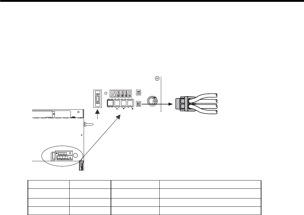
9 Adjustments
9-20
9.5 Analog Monitor
Signals for analog voltage references can be monitored.
To monitor analog signals, connect the analog monitor cable (JZSP-CA01 or DE9404559) to the connector CN5.
The analog monitor signals can be selected by setting parameters Pn003.0 and Pn003.1.
Pin Number Line Color Signal Name Monitoring Item with Factory Setting
1Red Analog monitor 2 Motor speed: 1 V/1000 min-1
2White Analog monitor 1 Torque reference: 1 V/100% rated torque
3, 4 Black (2 lines) GND (0 V) −
Analog monitor cable model:
JZSP-CA01 or DE9404559
Black
Black
Red
White
CN3
CN8
BATTERY
MODE/SET DATA/
POWER
CN5
6#5''/1&
4
1
2
'
4
#
6
1
%0
%0
219'4
%0
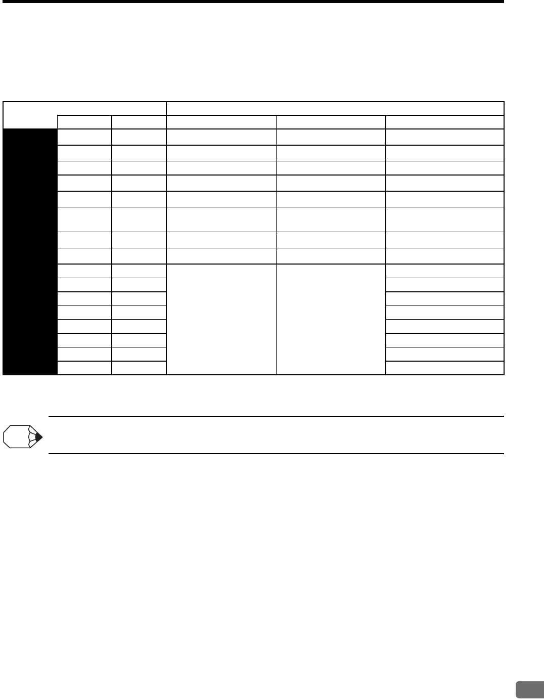
9.5 Analog Monitor
9
Adjustments
9-21
(1) Related Parameters
The following signals can be monitored.
(a) Pn003: Function Selections
* When using speed control or torque control, the position error monitor signal is not specified.
The analog monitor output voltage is ±8 V (maximum). The output will be limited to ±8 V even if this value is exceeded
in the above calculations.
Parameter Function
Monitor 1 Monitor 2 Monitor Signal Observation Gain Remarks
Pn003 n.0n.0Motor speed 1 V / 1000 min-1 Factory setting for Monitor 1
n.1n.1Speed reference 1 V / 1000 min-1 −
n.2n.2Internal torque reference 1 V / 100% rated torque Factory setting for Monitor 2
n.3n.3Position error ∗0.05 V / 1 reference unit −
n.4n.4Position error ∗0.05 V / 100 reference units −
n.5n.5Position reference speed
(converted to motor speed)
1 V / 1000 min-1 −
n.6n.6Motor speed 1 V / 250 min-1 −
n.7n.7Motor speed 1 V / 125 min-1 −
n.8n.8
Reserved. Do not set. −
−
n.9n.9−
n.An.A−
n.Bn.B−
n.Cn.C−
n.Dn.D−
n.En.E−
n.Fn.F−
INFO

10-1
10
Inspection, Maintenance, and Troubleshooting
10
Inspection, Maintenance, and
Troubleshooting
10.1 Troubleshooting - - - - - - - - - - - - - - - - - - - - - - - - - - - - - - 10-2
10.1.1 Alarm Display Table - - - - - - - - - - - - - - - - - - - - - - - - - - - - - - - - - - 10-2
10.1.2 Warning Display - - - - - - - - - - - - - - - - - - - - - - - - - - - - - - - - - - - - - 10-4
10.1.3 Alarm Display Table when the Application Module is Used - - - - - - - 10-5
10.1.4 Warning Display Table when the Application Module is Used - - - - - 10-6
10.1.5 Troubleshooting of Alarm and Warning - - - - - - - - - - - - - - - - - - - - 10-7
10.1.6 Troubleshooting for Malfunction without Alarm Display - - - - - - - - 10-16
10.2 Inspection and Maintenance - - - - - - - - - - - - - - - - - - - - - 10-20
10.2.1 Servomotor Inspection - - - - - - - - - - - - - - - - - - - - - - - - - - - - - - - 10-20
10.2.2 SERVOPACK Inspection - - - - - - - - - - - - - - - - - - - - - - - - - - - - - 10-20
10.2.3 SERVOPACK’s Parts Replacement Schedule - - - - - - - - - - - - - - - 10-21

10 Inspection, Maintenance, and Troubleshooting
10.1.1 Alarm Display Table
10-2
10.1 Troubleshooting
10.1.1 Alarm Display Table
The relation between alarm displays and alarm code outputs is shown in Table 10.1.
If an alarm occurs, the servomotor can be stopped by doing either of the following operations.
• DB STOP: Stops the servomotor immediately using the dynamic brake.
• COAST TO A STOP: Stops naturally, with no brake, by using the friction resistance of the motor in oper-
ation.
Table 10.1 Alarm Displays and Outputs
Alarm
Display Alarm Name Meaning
Alarm
Reset
Alarm Code Output Servo
Alarm
(ALM)
Output
ALO1 ALO2 ALO3
A.02 Parameter Breakdown EEPROM data of SERVOPACK is
abnormal.
N/A
HHHH
A.03 Main Circuit Encoder Error Detection data for power circuit is
abnormal.
Available
A.04 Parameter Setting Error The parameter setting is outside the
allowable setting range.
N/A
A.05 Combination Error SERVOPACK and servomotor capaci-
ties do not match each other.
Available
A.09 Dividing Ratio Setting Error The setting of dividing ratio (Pn212) is
not acceptable (out of fixed incre-
ments), or exceeds the value for the
connected, encoder resolution.
N/A
A.0A Encoder Model Unmatched The mounted serial encoder is not sup-
ported by Σ-II series SERVOPACK.
N/A
A.10 Overcurrent or Heat Sink Over-
heated
An overcurrent flowed through the
IGBT.
Heat sink of SERVOPACK was over-
heated.
N/A
LHHH
A.30 Regeneration Error Detected Regenerative transistor or regenerative
resistor is faulty.
Available
LLHH
A.32 Regenerative Overload Regenerative energy exceeds regener-
ative resistor capacity.
Available
A.33 Main Circuit Power
Supply Wiring Error
The power supply to the main circuit
does not match the parameter Pn001
setting.
Available
A.40 Overvoltage *Main circuit DC voltage is excessively
high.
Available
HHL H
Undervoltage* Main circuit DC voltage is excessively
low.
Available
A.51 Overspeed The motor speed is excessively high. Available LHLH
A.71 Overload: High Load The motor was operating for several
seconds to several tens of seconds
under a torque largely exceeding rat-
ings.
Available
LLLH
A.72 Overload: Low Load The motor was operating continuously
under a torque largely exceeding rat-
ings.
Available
A.73 Dynamic Brake Overload When the dynamic brake was applied,
rotational energy exceeded the capac-
ity of dynamic brake resistor.
Available
A.74 Overload of Surge
Current Limit Resistor
The main circuit power was frequently
turned ON and OFF.
Available
A.7A Heat Sink Overheated The heat sink of SERVOPACK over-
heated.
Available

10.1 Troubleshooting
10-3
10
Inspection, Maintenance, and Troubleshooting
* For the SERVOPACK with a capacity of 22 kW or more, alarm A.40 indicates detecting excessively
high/low voltage in the main circuit.
A.81 Encoder Backup Error All the power supplies for the absolute
encoder have failed and position data
was cleared.
N/A
HHHH
A.82 Encoder Checksum Error The checksum results of encoder
memory is abnormal.
N/A
A.83 Absolute Encoder Battery Error Backup battery voltage for the abso-
lute encoder has dropped.
Available
A.84 Encoder Data Error Data in the encoder is abnormal. N/A
A.85 Encoder Overspeed The encoder was rotating at high
speed when the power was turned ON.
N/A
A.86 Encoder Overheated The internal temperature of encoder is
too high.
N/A
A.b1 Reference Speed Input Read Error The A/D converter for reference speed
input is faulty.
Available
A.b2 Reference Torque Input Read
Error
The A/D converter for reference
torque input is faulty.
Available
A.b3 Current Detection Error The current sensor is faulty, or the ser-
vomotor is disconnected.
Available
A.bF System Alarm A system error occurred in the SER-
VOPACK.
N/A
A.C1 Servo Overrun Detected The servomotor ran out of control. Available
LHLH
A.C8 Absolute Encoder Clear Error and
Multiturn Limit Setting Error
The multiturn for the absolute encoder
was not properly cleared or set.
N/A
A.C9 Encoder Communications Error Communications between SERVO-
PACK and encoder is not possible.
N/A
A.CA Encoder Parameter Error Encoder parameters are faulty. N/A
A.Cb Encoder Echoback Error Contents of communications with
encoder is incorrect.
N/A
A.CC Multiturn Limit Disagreement Different multiturn limits have been
set in the encoder and SERVOPACK.
N/A
A.d0 Position Error Pulse Overflow Position error pulse exceeded parame-
ter (Pn505).
Available LLHH
A.F1 Power Line Open Phase One phase is not connected in the
main power supply.
Available
HLHH
A.F4 Main circuit MC Error The magnetic contactor of main circuit
is faulty.
Available
A.F5 Servomotor Disconnection Alarm The servomotor will not operate, or
the power is not being supplied to the
servomotor, though the Servo ON
command was input and the command
to the SERVOPACK was valid.
Available
A.F6
CPF00 Digital Operator
Transmission Error
Digital operator (JUSP-OP02A-2)
fails to communicate with SERVO-
PACK (e.g., CPU error).
N/A
Not decided
CPF01 N/A
A.− − Not an error Normal operation status -HHH L
Table 10.1 Alarm Displays and Outputs (cont’d)
Alarm
Display Alarm Name Meaning
Alarm
Reset
Alarm Code Output Servo
Alarm
(ALM)
Output
ALO1 ALO2 ALO3

10 Inspection, Maintenance, and Troubleshooting
10.1.2 Warning Display
10-4
10.1.2 Warning Display
The relation between warning displays and warning code outputs is shown in table 10.2.
Note: Warning code is not output without setting Pn001 = n.1 (Outputs both Alarm Codes and
Warning Codes.)
Table 10.2 Warning Displays and Outputs
Warning
Display Warning Name Meaning Warning Code Output
ALO1 ALO2 ALO3
A.90 Excessive Position Error
Warning
The position errors exceed the setting in Pn51E. HHH
A.91 Overload This warning occurs before the overload alarms (A.71 or
A.72) occur. If the warning is ignored and operation con-
tinues, an overload alarm may occur.
LHH
A.92 Regenerative Overload This warning occurs before the regenerative overload
alarm (A.32) occurs. If the warning is ignored and opera-
tion continues, a regenerative overload alarm may occur.
HLH
A.93 Absolute Encoder Battery
Voltage Lowered
This warning occurs when the absolute encoder battery
voltage is lowered. If the warning is ignored and operation
continues, an overload alarm may occur.
LLH
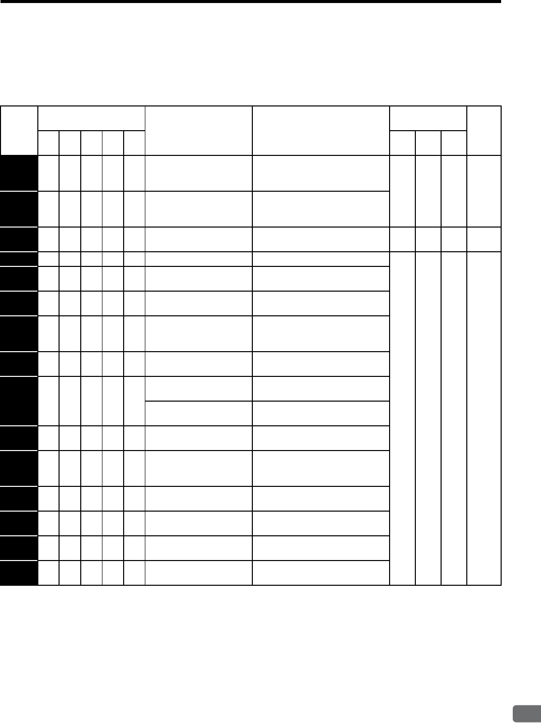
10.1 Troubleshooting
10-5
10
Inspection, Maintenance, and Troubleshooting
10.1.3 Alarm Display Table when the Application Module is Used
The following special alarms will occur when the SGDH SERVOPACK and an application module are used
together. The relation between alarm displays and alarm code outputs is shown in Table 10.3.
Note: 1. The following types of application modules are available:
NS100 (JUSP-NS100): MECHATROLINK-I application module
NS115 (JUSP-NS115): MECHATROLINK-II I/F application module
NS300 (JUSP-NS300): DeviceNet application module
NS500 (JUSP-NS500): PROFIBUS-DP application module
FC100 (JUSP-FC100): Fully-closed application module
2. For troubleshooting application module alarms, refer to relevant application module manual.
Manual numbers are described in About this Manual.
3. When mounting the NS115 module, observe the following restrictions on use. If the NS115 mod-
ule is connected to the hand-held digital operator or communications are being sent to or from
SigmaWin+ and another device (a personal computer) during execution of the following
MECHATROLINK-II commands, an A.ED alarm (Command execution incomplete) occurs and
the commands are not successfully sent.
PRM_RD, PRM_WR, PPRM_WR, CONFIG, ALM_RD, ALM_CLR,
SENS_ON, ADJ, ID_RD
Table 10.3 Alarm Displays and Outputs when the SERVOPACK and an Application Module Are Used Together
Alarm
Display
Application Module
which Detects Alarms
Alarm Name Meaning Alarm Code
Output
Servo
Alarm
(ALM)
Output
NS
100
NS
115
NS
300
NS
500
FC
100
ALO
1
ALO
2
ALO
3
A.C6 {{{{{
Fully Closed Encoder
Phase A/B Disconnection
Alarm
The phase A/B of the fully closed
encoder was disconnected.
LHL H
A.C7 {{{{{
Fully Closed Encoder
Phase C Disconnection
Alarm
The phase C of the fully closed
encoder was disconnected.
A.d1 {{{{{
Motor-Load Position Error
Over
The motor-load position error over
level (Pn51A) was exceeded. LLH H
A.E0 {{{{ −No Application Module No application module installed.
HLL H
A.E1 {{{{ −Application Module Time-
out
No response from the application
module.
A.E2 {{{{ −Watchdog Counter Error of
Application Module
WDC error in the application mod-
ule
A.E4 −{−−−
MECHATROLINK-II
Transmission Cycle
Setting Error
Transmission cycle setting of
MECHATROLINK-II is incorrect.
A.E5 {{ −−−
Watchdog Timer Error MECHATROLINK-I/II synchroni-
zation error
A.E6 {{{ −−
NS100/NS115 Communi-
cations Error
MECHATROLINK-I/II communi-
cations error
NS300 Duplicate MAC ID
Error
Same node address already exists
on the DeviceNet network.
A.E7 {{{{ −Application Module
Detection Error
No application module was
detected.
A.E9 −−{−−
BUS-OFF Error Fatal communications error has
occurred in DeviceNet communi-
cations.
A.EA {{{{ −SERVOPACK Malfunc-
tion
SERVOPACK is defective.
A.EB {{{{ −SERVOPACK Initial
Access Error
Initial processing failed.
A.EC {{{{ −SERVOPACK WDC Error SERVOPACK watchdog counter
error
A.ED {{{{ −Command Execution
Incomplete
Command was interrupted.

10 Inspection, Maintenance, and Troubleshooting
10.1.4 Warning Display Table when the Application Module is Used
10-6
10.1.4 Warning Display Table when the Application Module is Used
The following special warnings will occur when the SGDH SERVOPACK and an application module are used
together. The relation between warning displays and warning code outputs is shown in Table 10.4.
Note: 1. The following types of application modules are available:
NS100 (JUSP-NS100): MECHATROLINK-I application module
NS115 (JUSP-NS115): MECHATROLINK-II application module
NS300 (JUSP-NS300): DeviceNet application module
NS500 (JUSP-NS500): PROFIBUS-DP application module
FC100 (JUSP-FC100): Fully closed application module
2. For troubleshooting application module alarms, refer to relevant application module manual.
Manual numbers are described in About this Manual on page v.
3. When mounting the NS115 module, observe the following restrictions on use. If the hand-held
digital operator is connected or the communications are being sent or from SigmaWin+ and
another device (a personal computer), the following MECHATROLINK-II commands can not
be carried out unconditionally (command warning: A.95) and the commands are not successfully
sent.
PRM_RD, PRM_WR, PPRM_WR, CONFIG, ALM_RD, ALM_CLR,
SENS_ON, ADJ, ID_RD
Table 10.4 Warning Displays and Outputs when the SERVOPACK and an Application Module Are Used Together
Warning
Display
Application Module
which Detects
Warnings
Warning Name Meaning Warning Code
Output
Servo
Alarm
(ALM)
Output
NS
100
NS
115
NS
300
NS
500
FC
100
ALO
1
ALO
2
ALO
3
A.94 {{{{ −Data Setting Warning A value outside the setting range
was set using communications. LLH L
A.95 {{{{ −Command Warning A command not supported in the
product specifications was issued.
The command reception condi-
tions were not met.
HLH L
A.96 {{{ −−
Communications
Warning
A communications error occurred
(once). LHH L
A.98 −−{{ −Main Power OFF The main power supply is not
being supplied. LLL L
A.9A −−{{ −Not Completed within
the Set Time
Positioning was not completed
within the set time. LHL L

10.1 Troubleshooting
10-7
10
Inspection, Maintenance, and Troubleshooting
10.1.5 Troubleshooting of Alarm and Warning
When an error occurs in servodrive, an alarm display such as A. and CPF or warning display such as
A.9 appears on the panel operator. However, the display “A.--” is not an alarm. Refer to the following sec-
tions to identify the cause of an alarm and the action to be taken.
Contact your Yaskawa representative if the problem cannot be solved by the described corrective action.
(1) Alarm Display and Troubleshooting
Table 10.5 Alarm Display and Troubleshooting
Alarm
Display Alarm Name Situation at Alarm
Occurrence Cause Corrective Actions
A.02 Parameter
Breakdown
(The EEPROM
data storing the
parameter is
incorrect.)
Occurred when the
control power sup-
ply was turned ON.
The power supply was turned OFF while changing
the parameter setting.
The power supply was turned OFF while an alarm
was being written.
Set Fn005 to initialize the parameter and input the
parameter again.
The number of times that parameters were written
exceeded the limit. For example, the parameter was
changed every scan through the host controller.
Replace the SERVOPACK.
(Recheck the parameter writing method.)
The SERVOPACK EEPROM and the related circuit
are faulty.
Replace the SERVOPACK.
A.03 Main Circuit
Encoder Error
Occurred when the
control power sup-
ply was turned ON
or during operation
A SERVOPACK fault occurred. Replace the SERVOPACK.
A.04 Parameter
Setting Error
(The parameter
setting was out
of the allowable
setting range.)
Occurred when the
control power sup-
ply was turned ON.
The incorrect parameter was being loaded. (The
incorrect value was rejected as an error at the digital
operator.)
Set Fn005 to initialize the parameter.
The SERVOPACK EEPROM and the related circuit
are faulty.
Replace the SERVOPACK.
A.05 Combination
Error
(The SERVO-
PACK and ser-
vomotor
capacities do not
correspond.)
Occurred when the
control power sup-
ply was turned ON.
The SERVOPACK and servomotor capacities do not
correspond to each other.
Servomotor capacity / SERVOPACK capacity ≤ 1/4
or servomotor capacity / SERVOPACK capacity ≥ 4
Select the proper combination of SERVOPACK
and servomotor capacities.
The parameter that is written in the encoder is incor-
rect.
Replace the servomotor.
A SERVOPACK fault occurred. Replace the SERVOPACK.
A.09 Dividing Ratio
Setting Error
Occurred when the
control power sup-
ply was turned ON.
At Pn207.2 = 1, the setting of dividing ratio (Pn212)
is not acceptable (out of fixed increments), or
exceeds the value for the connected encoder resolu-
tion.
Correct the setting of Pn212, and turn OFF the
control power and turn it ON again.
The SERVOPACK EEPROM and the related circuit
are faulty.
Replace the SERVOPACK.
A.0A Encoder Model
Unmatched
Occurred when the
control power sup-
ply was turned ON.
The connected serial encoder is not supported by Σ-
II series servo drives.
Replace the servomotor with Σ-II series SERVO-
PACK supported model.
A SERVOPACK fault occurred. Replace the SERVOPACK.
A.10 Overcurrent
(An overcurrent
flowed through
the IGBT) or
Heat Sink
Overheated
Occurred when the
control power sup-
ply was turned ON.
The overload alarm has been reset by turning OFF
the power too many times.
Change the method to reset the alarm.
The connection is faulty between the SERVOPACK
board and the thermostat switch.
Replace the SERVOPACK.
The SERVOPACK fault occurred.
Occurred when the
main circuit power
supply was turned
ON or while the ser-
vomotor was run-
ning.
The connection between grounding and U, V, or W
is incorrect.
Check and then correct the wiring.
The grounding line has contact with other terminals.
A short circuit occurred between the grounding and
U, V, or W of the servomotor cable.
Repair or replace the servomotor main circuit
cable.
A short circuit occurred between phases U, V, and W
of the servomotor.
A short circuit occurred between the grounding and
U, V, or W of the SERVOPACK.
Replace the SERVOPACK.
A SERVOPACK fault occurred (current feedback
circuit, power transistor or board fault).

10 Inspection, Maintenance, and Troubleshooting
10.1.5 Troubleshooting of Alarm and Warning
10-8
A.10 Overcurrent
(An overcurrent
flowed through
the IGBT) or
Heat Sink
Overheated
(cont’d)
Occurred when the
main circuit power
supply was turned
ON or while the ser-
vomotor was run-
ning.
A short circuit occurred between the grounding and
U, V, W of the servomotor.
Replace the servomotor.
A short circuit occurred between phases U, V, and W
of the servomotor.
Load moment of inertia was large and DB circuit
fault occurred when a dynamic brake is applied dur-
ing high-speed motor running.
Reduce the load.
Reduce the motor speed at dynamic brake or
replace the SERVOPACK.
The dynamic brake was activated too frequently, so
a DB overload alarm occurred.
Reduce the DB operation frequency or replace the
SERVOPACK.
The overload alarm has been reset by turning OFF
the power too many times.
Change the method to reset the alarm.
The overload or regenerative power exceeds the
regenerative resistor’s capacity.
Reconsider the load and operation conditions.
The direction or the distance of the SERVOPACK to
other devices is incorrect.
The surrounding air temperature for the
SERVOPACK must be 55°C or less.
A SERVOPACK fan fault occurred. Replace the SERVOPACK.
A SERVOPACK fault occurred.
A.30 Regeneration
Error Detected
Occurred when the
control power sup-
ply was turned ON.
A SERVOPACK fault occurred. Replace the SERVOPACK.
Occurred when the
main circuit power
supply was turned
ON.
A regenerative resistor is not connected. Check the wiring of the regenerative resistor.
A regenerative resistor is disconnected. Replace the regenerative resistor.
A SERVOPACK fault occurred, such as regenerative
transistor fault.
Replace the SERVOPACK.
Occurred during
normal operation.
Check for incorrect wiring and disconnection of the
regenerative resistor.
Correct the wiring for the regenerative resistor.
The regenerative resistor is disconnected. Reconsider the load and operation conditions and
check if the regenerative energy become exces-
sive, or replace the regenerative resistor.
A SERVOPACK fault, such as regenerative transis-
tor fault, occurred.
Replace the SERVOPACK.
A.32 Regenerative
Overload
Occurred when the
control power sup-
ply was turned ON.
A SERVOPACK fault occurred. Replace the SERVOPACK.
Occurred during
normal operation
(large increase of
regenerative resistor
temperature).
The regenerative energy exceeds the allowable
value.
Select a proper regenerative resistance capacity, or
reconsider the load and operation conditions.
The regenerating state continued.
Occurred during
normal operation
(small increase of
regenerative resistor
temperature).
The setting of parameter Pn600 is smaller than the
regenerative resistor’s capacity.
Correct the set value of parameter Pn600.
A SERVOPACK fault occurred. Replace the SERVOPACK.
Occurred at servo-
motor deceleration.
The regenerative energy is excessive. Select a proper regenerative resistance capacity, or
reconsider the load and operation conditions.
A.33 Main Circuit
Wiring Error
Occurred when the
control power sup-
ply was turned ON.
A SERVOPACK fault occurred. Replace the SERVOPACK.
Residual voltage exists in the main circuit. Reconsider the resistance value of the regenera-
tive resistor.
Occurred when the
main circuit power
supply was turned
ON.
In the DC power input mode, AC power is supplied
through L1, L2, and L3.
For AC power input, Pn001.2=0.
For DC power input, Pn001.2=1.
In the AC power input mode, DC power is supplied
through 1 and terminals.
Table 10.5 Alarm Display and Troubleshooting (cont’d)
Alarm
Display Alarm Name Situation at Alarm
Occurrence Cause Corrective Actions

10.1 Troubleshooting
10-9
10
Inspection, Maintenance, and Troubleshooting
A.40 Overvoltage Occurred when the
control power sup-
ply was turned ON.
A SERVOPACK fault occurred. Replace the SERVOPACK.
Occurred when the
main circuit power
supply was turned
ON.
The AC power voltage is too high. Check the AC power voltage.
A SERVOPACK fault occurred. Replace the SERVOPACK.
Occurred during
normal operation.
Check the AC power voltage (check if there is no
excessive voltage change.)
Check the AC power voltage.
The motor speed is high and load moment of inertia
is excessive, resulting in insufficient regenerative
capacity.
Reconsider the load and operation conditions.
Check the load moment of inertia and minus load
specifications.
A SERVOPACK fault occurred. Replace the SERVOPACK.
Occurred at servo-
motor deceleration.
The motor speed is high, and the load moment of
inertia is excessive.
Reconsider the load and operation conditions.
A.40 Undervoltage Occurred when the
control power sup-
ply was turned ON.
A SERVOPACK fault occurred. Replace the SERVOPACK.
Occurred when the
main circuit power
supply was turned
ON.
The AC power supply voltage is low. Check the AC power supply voltage.
The fuse of the SERVOPACK is blown out. Replace the SERVOPACK.
The inrush current limit resistor is disconnected,
resulting in an overload of the inrush current limit
resistor.
Reduce the number of times that the main circuit
is turned ON or OFF, or replace the SERVO-
PACK.
A SERVOPACK fault occurred. Replace the SERVOPACK.
Occurred during
normal operation.
The AC power supply voltage was lowered, and
large voltage drop occurred.
Check the AC power supply voltage.
A temporary power failure occurred. Check the AC power supply voltage.
A SERVOPACK fault occurred. Replace the SERVOPACK.
A.51 Overspeed Occurred when the
control power sup-
ply was turned ON.
A SERVOPACK fault occurred. Replace the SERVOPACK.
Occurred when
servo was ON.
The order of phases U, V, and W in the servomotor
wiring is incorrect.
Correct the servomotor wiring.
The encoder wiring is incorrect. Correct the encoder wiring.
Malfunction occurred due to noise interference in
the encoder wiring.
Take measures against noise for the encoder wir-
ing.
A SERVOPACK fault occurred. Replace the SERVOPACK.
Occurred when the
servomotor started
running or in a
high-speed rotation.
The order of phases U, V, and W in the servomotor
wiring is incorrect.
Correct the servomotor wiring.
The encoder wiring is incorrect. Correct the encoder wiring.
Malfunction occurred due to noise interference in
the encoder wiring.
Take measures against noise for the encoder wir-
ing.
The position or speed reference input is too large. Reduce the reference value.
The setting of the reference input gain is incorrect. Check the setting of the parameter.
A SERVOPACK fault occurred. Replace the SERVOPACK.
Table 10.5 Alarm Display and Troubleshooting (cont’d)
Alarm
Display Alarm Name Situation at Alarm
Occurrence Cause Corrective Actions

10 Inspection, Maintenance, and Troubleshooting
10.1.5 Troubleshooting of Alarm and Warning
10-10
A.71
A.72
Overload
A.71:
Instantaneous
Peak Load
A.72:
Continuous Peak
Load
Occurred when the
control power sup-
ply was turned ON.
A SERVOPACK fault occurred. Replace the SERVOPACK.
Occurred when the
servo was ON.
The servomotor wiring is incorrect or the connection
is faulty.
Correct the servomotor wiring.
The encoder wiring is incorrect or the connection is
faulty.
Correct the encoder wiring, or check if the con-
nector is inserted securely.
A SERVOPACK fault occurred. Replace the SERVOPACK.
Occurred when the
servomotor did not
run by the refer-
ence input.
The servomotor wiring is incorrect or the connection
is faulty.
Correct the servomotor wiring.
The encoder wiring is incorrect or the connection is
faulty.
Correct the encoder wiring, or check if the con-
nector is inserted securely.
The starting torque exceeds the maximum torque. Reconsider the load and operation conditions, or
reconsider the servomotor capacity.
A SERVOPACK fault occurred. Replace the SERVOPACK.
Occurred during
normal operation.
The actual torque exceeds the rated torque. Reconsider the load and operation conditions, or
reconsider the servomotor capacity.
A SERVOPACK fault occurred. Replace the SERVOPACK.
A.73 Dynamic Brake
Overload
Occurred when the
control power sup-
ply was turned ON.
A SERVOPACK fault occurred. Replace the SERVOPACK.
Occurred when the
servomotor was
running and in a sta-
tus other than servo
OFF.
A SERVOPACK fault occurred. Replace the SERVOPACK.
Occurred when the
servomotor was
running in servo
OFF status.
The rotating energy at a DB stop exceeds the DB
resistance capacity.
cReduce the motor speed,
dReduce the load moment of inertia, or
eReduce the number of times of the DB stop
operation.
A SERVOPACK fault occurred. Replace the SERVOPACK.
A.74 Overload of
Inrush Current
Limit Resistor
Occurred when the
control power sup-
ply was turned ON.
A SERVOPACK fault occurred. Replace the SERVOPACK.
Occurred during
operations other
than the turning
ON/OFF of the
main circuit.
A SERVOPACK fault occurred. Replace the SERVOPACK.
Occurred at the
main circuit power
supply ON/OFF
operation.
The main circuit power supply ON/OFF operation is
repeated frequently.
Reduce the number of times that main circuit’s
power supply ON/OFF operation .
A SERVOPACK fault occurred. Replace the SERVOPACK.
A.7A Heat Sink
Overheated
Occurred when the
control power sup-
ply was turned ON.
A SERVOPACK fault occurred. Replace the SERVOPACK.
Occurred during
normal operation.
The load exceeds the rated load. Reconsider the load and operation conditions, or
reconsider the servomotor capacity.
The SERVOPACK surrounding air temperature
exceeds 55°C.
The surrounding air temperature must be 55°C or
less.
A SERVOPACK fault occurred. Replace the SERVOPACK.
Cooling is not sufficient by natural convection or
fun.
Reconsider the installation according to the SER-
VOPACK mounting instructions.
Table 10.5 Alarm Display and Troubleshooting (cont’d)
Alarm
Display Alarm Name Situation at Alarm
Occurrence Cause Corrective Actions

10.1 Troubleshooting
10-11
10
Inspection, Maintenance, and Troubleshooting
A.81 Encoder
Backup Error
Occurred when the
control power sup-
ply was turned ON.
(Setting:
Pn002.2=1)
A SERVOPACK fault occurred. Replace the SERVOPACK.
Occurred when the
control power sup-
ply was turned ON.
(Setting:
Pn002.2=0)
Alarm occurred when the power to the absolute
encoder was initially turned ON.
Set up the encoder.
The encoder cable had been disconnected once. First confirm the connection and set up the
encoder.
The power from both the PG power supply (+5 V)
and the battery power supply from the SERVO-
PACK is not being supplied.
Replace the battery or take similar measures to
supply power to the encoder, and set up the
encoder.
An absolute encoder fault occurred. If the alarm cannot be reset by setting up the
encoder again, replace the servomotor.
A SERVOPACK fault occurred. Replace the SERVOPACK.
A.82 Encoder
Checksum
Error
Occurred when the
control power sup-
ply was turned ON
or during an opera-
tion.
A fault occurred in the encoder and was detected by
encoder self-diagnosis.
Set up the encoder. If this alarm occurs fre-
quently, replace the servomotor.
A SERVOPACK fault occurred. Replace the SERVOPACK.
Occurred when the
SEN signal turned
ON.
A fault occurred in the encoder and was detected by
encoder self-diagnosis.
Set up the encoder. If this alarm occurs fre-
quently, replace the servomotor.
A.83 Absolute
Encoder
Battery Error
When the control
power supply was
turned ON.
(Setting:
Pn002.2=1)
A SERVOPACK fault occurred. Replace the SERVOPACK.
When the control
power supply was
turned ON. (Setting:
Pn002.2=0)
The battery connection is incorrect. Reconnect the battery.
The battery voltage is lower than the specified value
2.7 V.
Replace the battery, and then turn ON the power
to the encoder.
A SERVOPACK fault occurred. Replace the SERVOPACK.
A.84 Encoder Data
Error
Occurred when the
control power sup-
ply was turned ON.
A malfunction occurred in the encoder. Turn the encoder power supply OFF and then ON
again. If this alarm occurs frequently, replace the
servomotor.
A SERVOPACK fault occurred. Replace the SERVOPACK.
Occurred during
normal operation.
A malfunction occurred in the encoder due to exter-
nal noise.
Correct the wiring around the encoder by separat-
ing the encoder cable from the power line, or by
checking the grounding and other wiring.)
An encoder fault occurred. If this alarm occurs frequently, replace the
servomotor.
A SERVOPACK fault occurred. Replace the SERVOPACK.
A.85 Encoder
Overspeed
Occurred when the
control power sup-
ply was turned ON.
When the encoder power supply turns ON, the ser-
vomotor runs at 200 min-1 or more.
Turn ON the encoder power supply when the
servomotor stops.
An encoder fault occurred. Replace the servomotor.
A SERVOPACK fault occurred. Replace the SERVOPACK.
Occurred during
normal operation.
An encoder fault occurred. Replace the servomotor.
A SERVOPACK fault occurred. Replace the SERVOPACK.
A.86 Encoder
Overheated
Occurred when the
control power sup-
ply was turned ON.
An encoder fault occurred. Replace the servomotor.
A SERVOPACK board fault occurred. Replace the SERVOPACK.
Occurred during
normal operation.
The surrounding air temperature around the servo-
motor is too high.
The surrounding air temperature must be 40°C or
less.
The servomotor load is greater than the rated load. The servomotor load must be within the specified
range.
An encoder fault occurred. Replace the servomotor.
A SERVOPACK board fault occurred. Replace the SERVOPACK.
A.b1 Reference
Speed Input
Read Error
Occurred when the
control power sup-
ply was turned ON.
A SERVOPACK fault occurred. Replace the SERVOPACK.
Occurred during
normal operation.
A malfunction occurred in reading section of the
speed reference input.
Clear and reset the alarm and restart the operation.
A SERVOPACK fault occurred. Replace the SERVOPACK.
Table 10.5 Alarm Display and Troubleshooting (cont’d)
Alarm
Display Alarm Name Situation at Alarm
Occurrence Cause Corrective Actions

10 Inspection, Maintenance, and Troubleshooting
10.1.5 Troubleshooting of Alarm and Warning
10-12
A.b2 Reference
Torque Input
Read Error
Occurred when the
control power sup-
ply was turned ON.
A SERVOPACK fault occurred. Replace the SERVOPACK.
A malfunction occurred in the reading section of the
torque reference input.
Clear and reset the alarm and restart the operation.
Occurred during
normal operation.
A SERVOPACK fault occurred. Replace the SERVOPACK.
A.b3 Current Detec-
tion Error
Occurred when the
control power sup-
ply was turned ON.
A SERVOPACK fault occurred. Replace the SERVOPACK.
Occurred when the
servo was ON.
A SERVOPACK fault occurred. Replace the SERVOPACK.
The Servo ON command was input while the servo-
motor was operating.
Check to be sure the servomotor has stopped, and
then input the Servo ON command.
The servomotor is disconnected. Correct the servomotor wiring.
Occurred during
normal operation.
A SERVOPACK fault occurred. Replace the SERVOPACK.
The servomotor was disconnected. Correct the servomotor wiring.
A.bF System Alarm
(Program error)
Occurred when the
control power sup-
ply was turned ON.
A SERVOPACK fault occurred. Replace the SERVOPACK.
Occurred during
normal operation.
A program is incorrect. Replace the SERVOPACK.
A SERVOPACK fault occurred. Replace the SERVOPACK.
A.C1 Servo Overrun
Detected
Occurred when the
control power sup-
ply was turned ON.
A SERVOPACK fault occurred. Replace the SERVOPACK.
Occurred when the
servo was ON or
during normal oper-
ation.
The order of phase U, V, and W in the servomotor
wiring is incorrect.
Correct the servomotor wiring.
An encoder fault occurred. Replace the servomotor.
A SERVOPACK fault occurred. Replace the SERVOPACK.
A.C8 Absolute
Encoder Clear
Error and Multi-
turn Limit Set-
ting Error
Occurred when the
control power sup-
ply was turned ON.
An encoder fault occurred. Replace the servomotor.
A SERVOPACK fault occurred. Replace the SERVOPACK.
Occurred when an
encoder alarm was
cleared and reset.
An encoder fault occurred. Replace the servomotor.
A SERVOPACK fault occurred. Replace the SERVOPACK.
A.C9 Encoder
Communica-
tions Error
Occurred when the
control power sup-
ply was turned ON
or during operation.
The encoder wiring and the contact are incorrect. Correct the encoder wiring.
Encoder cable specification is incorrect. Use the recommended cable for the encoder cable.
The wiring distance for the encoder cable is too
long.
The wiring distance must be 20m max.
The noise interference occurred on the signal line
because the encoder cable is bent and the sheath is
damaged.
Correct the encoder cable layout.
The encoder cable is bundled with a power line. Separate the encoder cable from the power line.
The FG electrical potential varies because of the
influence from such machines on the servomotor
side as welders.
Ground the machine separately from PG side FG.
Noise interference occurred on the signal line from
the encoder.
Take a measure against noise for the encoder wir-
ing.
An encoder fault occurred. Replace the servomotor.
A SERVOPACK fault occurred. Replace the SERVOPACK.
A.CA Encoder
Parameter
Error
Occurred when the
control power sup-
ply was turned ON.
An encoder fault occurred. Replace the servomotor.
A SERVOPACK fault occurred. Replace the SERVOPACK.
Table 10.5 Alarm Display and Troubleshooting (cont’d)
Alarm
Display Alarm Name Situation at Alarm
Occurrence Cause Corrective Actions

10.1 Troubleshooting
10-13
10
Inspection, Maintenance, and Troubleshooting
A.Cb Encoder Echo-
back Error
Occurred when the
control power sup-
ply was turned ON
or during normal
operation.
The encoder wiring and contact are incorrect. Correct the encoder wiring.
Encoder cable specifications is incorrect. Use the recommended cable for the encoder cable.
The wiring distance for the encoder cable is too
long.
The wiring distance must be 20m max.
Noise interference occurred on the signal line,
because the encoder cable is bent and the sheath is
damaged.
Correct the encoder cable layout.
The encoder cable is bundled with a power line or
near a high-current line.
Separate the encoder cable from the power line.
The FG electrical potential varies because of the
influence from such machines on the servomotor
side as welders.
Ground the machine separately from PG side FG.
Noise interference occurred on the signal line from
the encoder.
Take measures against noise for the encoder wir-
ing.
An encoder fault occurred. Replace the servomotor.
A SERVOPACK fault occurred. Replace the SERVOPACK.
A.CC Multiturn Limit
Disagreement
Occurred when the
control power sup-
ply was turned ON.
The parameter settings for the SERVOPACK are
incorrect.
Correct the setting of Pn205 (0 to 65535).
The multiturn limit value for the encoder is not set or
was changed.
Execute Fn013 at the occurrence of alarm.
Occurred during
normal operation.
A SERVOPACK fault occurred. Replace the SERVOPACK.
A.d0 Position Error
Pulse Overflow
Occurred when the
control power sup-
ply was turned ON.
The overflow level (Pn505) is incorrect. Make the value set in the Pn505 to other than 0.
A SERVOPACK fault occurred. Replace the SERVOPACK.
Occurred at the ser-
vomotor high-speed
rotation.
The contact in the servomotor U, V, and W wirings
is faulty.
Correct the servomotor wiring.
A SERVOPACK fault occurred. Replace the SERVOPACK.
The servomotor did
not run with posi-
tion reference input.
Wirings of the servomotor U, V, and W are incorrect. Correct the servomotor wiring.
A SERVOPACK fault occurred. Replace the SERVOPACK.
Normal movement,
but occurred with a
long distance refer-
ence input.
The SERVOPACK gain adjustment is improper. Increase the speed loop gain (Pn100) and position
loop gain (Pn102).
The position reference pulse frequency is too high. Adjust slowly the position reference pulse fre-
quency.
Apply the smoothing function.
Correct the electronic gear ratio.
Setting of the position error pulse overflow alarm
level (Pn505) is incorrect.
Set the parameter Pn505 to proper value.
The load exceeds the rated load. Reconsider and correct the load/operation condi-
tions and servomotor capacity.
A.F1 Power Line
Open Phase
Occurred when the
control power sup-
ply was turned ON.
A SERVOPACK fault occurred. Replace the SERVOPACK.
Occurred when the
main circuit power
supply was turned
ON.
The three-phase power supply wiring is incorrect. Correct the power supply wiring.
The three-phase power supply is unbalanced. Check the power supply voltage.
A SERVOPACK fault occurred. Replace the SERVOPACK.
Occurred during
normal operation.
The contact in three-phase power supply wiring is
faulty.
Correct the power supply wiring.
Three-phase power supply is unbalanced. Check the power supply voltage.
A SERVOPACK fault occurred. Replace the SERVOPACK.
A.F4 Main Circuit MC
Error
Occurred when the
control/main circuit
power supply was
turned ON.
A SERVOPACK fault occurred. Replace the SERVOPACK.
Occurred when
servo was ON.
Incorrect wiring of control power supply input ter-
minals 380 to 480 VAC (only for 400V models)
Correct the power supply wiring.
A SERVOPACK fault occurred. Replace the SERVOPACK.
Occurred during
normal operation
A SERVOPACK fault occurred. Replace the SERVOPACK.
Table 10.5 Alarm Display and Troubleshooting (cont’d)
Alarm
Display Alarm Name Situation at Alarm
Occurrence Cause Corrective Actions

10 Inspection, Maintenance, and Troubleshooting
10.1.5 Troubleshooting of Alarm and Warning
10-14
A.F5 Servomotor
Disconnection
Alarm
Occurred when the
control power sup-
ply was turned ON.
A SERVOPACK fault occurred. Replace the SERVOPACK.
A.F6 Occurred when the
servo was ON.
The servomotor power cable (U, V, W) was discon-
nect.
Correct the servomotor wiring.
A SERVOPACK fault occurred. Replace the SERVOPACK.
CPF00 Digital Opera-
tor Transmis-
sion Error 1
Occurred when the
power supply was
turned ON with dig-
ital operator con-
nected or
when connecting
digital operator with
the power supply
was turned ON.
The contact between the digital operator and the
SERVOPACK is faulty.
Insert securely the connector, or replace the cable.
The external noise interference occurred to the digi-
tal operator or cable.
(The digital operator cable is near noise source.)
Do not lay the cable near noise source.
Install digital operator far from noise source.
CPF01 Digital Opera-
tor Transmis-
sion Error 2
A digital operator fault occurred. Replace the digital operator.
A SERVOPACK fault occurred. Replace the SERVOPACK.
Table 10.5 Alarm Display and Troubleshooting (cont’d)
Alarm
Display Alarm Name Situation at Alarm
Occurrence Cause Corrective Actions

10.1 Troubleshooting
10-15
10
Inspection, Maintenance, and Troubleshooting
(2) Warning Display and Troubleshooting
Table 10.6 Warning Display and Troubleshooting
Warning
Display
Warning Name Situation at Warning
Occurrence
Cause Corrective Actions
A.90 Excessive Posi-
tion Error Warn-
ing:
Warning for the
alarm A.d0
Occurred at the servo-
motor high-speed rota-
tion.
The contact in the servomotor U, V, and W wir-
ings is faulty.
Correct the servomotor wiring.
A SERVOPACK fault occurred. Replace the SERVOPACK.
The servomotor did not
run with position refer-
ence input.
The contact in the servomotor U, V, and W wir-
ings is faulty.
Correct the servomotor wiring.
A SERVOPACK fault occurred. Replace the SERVOPACK.
Normal movement, but
occurred with a long
distance reference
input.
The SERVOPACK gain adjustment is improper. Increase the speed loop gain (Pn100) and
position loop gain (Pn102).
The position reference pulse frequency is too
high.
Adjust slowly the position reference
pulse frequency.
Apply the smoothing function.
Correct the electronic gear ratio.
Setting of the position error pulse over flow
warning level (Pn51E) is incorrect.
Set the parameter Pn51E to proper value.
The servomotor specifications do not meet the
load conditions.
Reconsider and correct the load/operation
conditions and servomotor capacity.
A.91 Overload:
Warning for the
alarms A71 and
A72
Occurs when the servo
was ON.
Wiring is incorrect and the contact in servomotor
wiring is faulty.
Correct the servomotor wiring.
Wiring is incorrect and the contact in encoder
wiring is faulty.
Correct the encoder wiring.
A SERVOPACK fault occurred. Replace the SERVOPACK.
The servomotor did not
run with a reference
input.
Servomotor wiring is incorrect and the contact is
faulty.
Correct the servomotor wiring.
Encoder wiring is incorrect and the contact is
faulty.
Correct the encoder wiring or confirm
that the connector is inserted securely.
The starting torque exceeds the maximum torque. Reconsider the load and operation condi-
tions. Or, check the servomotor capacity.
A SERVOPACK fault occurred. Replace the SERVOPACK.
Occurred during nor-
mal operation.
The effective torque exceeds the rated torque. Reconsider the load and operation condi-
tions. Or, check the servomotor capacity.
A SERVOPACK fault occurred. Replace the SERVOPACK.
A.92 Regenerative
Overload:
Warning for the
alarm A320
Occurred when the con-
trol power supply was
turned ON.
A SERVOPACK fault occurred. Replace the SERVOPACK.
Occurred during nor-
mal operation
(Large increase of
regenerative resistor
temperature.)
Regenerative energy exceeds the allowable value. Check the regenerative resistor capacity,
or reconsider the load and operation con-
ditions.
Regenerative status continues.
Occurred during nor-
mal operation
(Small increase of
regenerative resistor
temperature).
The setting of parameter Pn600 is smaller than
the external regenerative resistor capacity.
Correct the setting of parameter Pn600.
A SERVOPACK fault occurred. Replace the SERVOPACK.
Occurred at servomo-
tor deceleration.
Regenerative energy is excessive. Check the regenerative resistor capacity,
or reconsider the load and operation con-
ditions.
A.93 Absolute Encoder
Battery Warning
Occurred when the con-
trol power supply was
turned ON
(Setting: Pn002.2=1).
A SERVOPACK fault occurred. Replace the SERVOPACK.
Occurred 4 seconds or
more after the control
power supply was
turned ON
(Setting: Pn002.2=0).
When an absolute
encoder was used.
The battery connection is incorrect or faulty. Connect correctly the battery.
The battery voltage is lower than the specified
value 2.7 V.
Replace the battery, and turn OFF the
encoder power supply and ON again.
A SERVOPACK fault occurred. Replace the SERVOPACK.

10 Inspection, Maintenance, and Troubleshooting
10.1.6 Troubleshooting for Malfunction without Alarm Display
10-16
10.1.6 Troubleshooting for Malfunction without Alarm Display
The troubleshooting for the malfunctions that causes no alarm display is listed below.
Contact your Yaskawa representative if the problem cannot be solved by the described corrective actions.
Table 10.7 Troubleshooting for Malfunction without Alarm Display
Symptom Cause
Inspection Corrective Actions
: Turn OFF the servo system before executing operations.
Servomotor
Does Not
Start
The power supply is not ON. Check voltage between power supply termi-
nals.
Correct the power circuit.
Wrong wiring or disconnection of
I/O signal connector CN1
Check if the connector CN1 is properly
inserted and connected.
Correct the connector CN1 connection.
Servomotor or encoder wiring dis-
connected.
Check the wiring. Connect the wiring.
Overloaded Run under no load. Reduce load or replace with larger capacity servomotor.
Speed/position references not input Check reference input pins. Input speed/position references correctly.
Setting for Pn50A to Pn50D “Input
Signal Selection” is incorrect.
Check settings of parameters Pn50A to
Pn50D.
Correct the settings for Pn50A to Pn50D “Input Signal
Selection.”
Encoder type differs from parameter
setting.
Check incremental or absolute encoder. Set parameter Pn002.2 to the encoder type being used.
/S-ON input signal stays OFF. Check settings of parameters Pn50A.0 and
Pn50A.1.
Correct the parameter setting and turn ON /S-ON input
signal.
/P-CON input function setting is
incorrect.
Check parameter Pn000.1. Set parameters to match the application.
SEN input is turned OFF. Check the SEN signal input (when absolute
encoder is used).
Turn SEN input signal ON.
Reference pulse mode selection is
incorrect.
Check the parameter setting for the refer-
ence pulse mode.
Correct setting of parameter Pn200.0.
The error clear counter (CLR) input
is turned ON.
Check CLR input pins. Turn CLR input signal OFF.
The forward run prohibited (P-OT)
or reverse run prohibited (N-OT)
input signal is turned OFF.
Check P-OT or N-OT input signal. Turn P-OT or N-OT input signal ON.
A SERVOPACK fault occurred. −Replace the SERVOPACK.
Servomotor
Moves In-
stantaneous-
ly, and then
Stops
Servomotor wiring is incorrect. Check the servomotor wiring. Correct the servomotor wiring.
Encoder wiring is incorrect. Check the encoder wiring. Correct the encoder wiring.
Servomotor
Suddenly
Stops during
Operation
and will Not
Restart
An alarm occurred while alarm reset
signal (/ALM-RST) was turned ON.
Check /ALM-RST signal. Remove the cause of alarm. Turn alarm reset signal
(/ALM-RST) from ON to OFF.
Servomotor
Speed Unsta-
ble
Wiring connection to servomotor is
defective.
Check connection of power lead (phases U,
V, and W) and encoder connectors.
Tighten any loose terminals or connectors.
Servomotor
Rotates With-
out Refer-
ence Input
Speed control: Speed reference input
is incorrect.
Check V-REF and SG to confirm if the con-
trol method and the input are agreed.
Correct the control mode selection parameter, or the
input correctly.
Torque control: Torque reference
input is incorrect.
Check T-REF and SG to confirm if the con-
trol method and the input are agreed.
Correct the control mode selection parameter, or the
input correctly.
Speed reference offset is error. −Adjust the SERVOPACK offset correctly.
Position control: Reference pulse
input is incorrect.
Set the parameter and cheek the reference
pulse form.
Correct the control mode selection parameter, or the
input correctly.
A SERVOPACK fault occurred. −Replace the SERVOPACK.
DB (dynamic
brake) Does
Not Operate
Improper parameter setting Check the setting of parameter Pn001.0. Correct the parameter setting.
DB resistor disconnected Check if excessive moment of inertia,
motor overspeed, or DB frequently acti-
vated occurred.
Replace the SERVOPACK, and reconsider the load.
DB drive circuit fault −Replace the SERVOPACK.

10.1 Troubleshooting
10-17
10
Inspection, Maintenance, and Troubleshooting
Abnormal
Noise from
Servomotor
Mounting not secured Check if there are any loosen mounting
screws.
Tighten the mounting screws.
Check if there are misalignment of cou-
plings.
Align the couplings.
Check if there are unbalanced couplings. Balance the couplings.
Defective bearings Check for noise and vibration around the
bearings.
If any problems, contact your Yaskawa representative.
Vibration source on the driven
machine
Any foreign matter, damages, or deforma-
tion on the machine movable section.
Contact the machine manufacturer.
Noise interference due to incorrect
input signal wire specifications
Check if the cable meets the recommended
specification.
Use the specified input signal wires.
Noise interference due to long dis-
tance of input signal line
The wiring distance must be 3 m max. and
the impedance a few hundreds ohm max.
Shorten the wiring distance for input signal line to the
specified value.
Noise interference due to incorrect
encoder cable specifications
Check if the cable meets the recommended
specification.
Use the specified encoder cable.
Noise interference due to long
encoder cable wiring distance
The wiring distance must be 20 m max. Shorten the encoder cable wiring distance to the speci-
fied value.
Noise due to damaged encoder cable Check if the encoder cable is not damaged
or bent.
Modify the encoder cable layout.
Excessive noise to the encoder cable Check if the encoder cable is bundled with
high-current line.
Install a surge suppressor to the encoder cable.
FG electrical potential varies by
influence of such machines on the
servomotor side as welders.
Check if the machine is correctly grounded. Ground the machine separately from PG side FG.
SERVOPACK pulse counting error
due to noise
Check if there is noise interference on the
signal line from encoder.
Take measure against noise for the encoder wiring.
Encoder fault −Replace the servomotor.
Servomotor
Vibrates at
about 200 to
400 Hz
Speed loop gain value (Pn100) too
high.
Factory setting: Kv=40.0 Hz*Reduce speed loop gain (Pn100) preset value.
Position loop gain value (Pn102) too
high
Factory setting: Kp=40.0/s*Reduce position loop gain (Pn102) preset value.
Incorrect speed loop integral time
constant (Pn101) setting
Factory setting: Ti=20.00 ms*Correct the speed loop integral time constant (Pn101)
setting.
When the autotuning is not used:
Incorrect rotational moment of iner-
tia ratio data
−Correct the rotational moment of inertia ratio data
(Pn103).
High
Rotation
Speed
Overshoot on
Starting and
Stopping.
Speed loop gain value (Pn100) too
high
Factory setting: Kv=40.0 Hz*Reduce the speed loop gain (Pn100) preset value.
Position loop gain value (Pn102) too
high
Factory setting: Kp=40.0/s*Reduce the position loop gain (Pn102) preset value.
Incorrect speed loop integral time
constant (Pn101) setting
Factory setting: Ti=20.00 ms*Correct the speed loop integral time constant (Pn101)
setting.
Incorrect moment of inertia ratio
(Pn103) setting
−Correct the rotational moment of inertia ratio data
(Pn103).
* Refer to 9.3.2 Servo Gain Manual Tuning.
Table 10.7 Troubleshooting for Malfunction without Alarm Display (cont’d)
Symptom Cause
Inspection Corrective Actions
: Turn OFF the servo system before executing operations.

10 Inspection, Maintenance, and Troubleshooting
10.1.6 Troubleshooting for Malfunction without Alarm Display
10-18
Absolute
Encoder
Position
Difference
Error
(The position
saved in host
controller
when the
power turned
OFF is dif-
ferent from
the position
when the
power turned
ON.)
Noise interference due to improper
encoder cable specifications
Check if the cable meets recommended
specification.
Use encoder cable with the specified specifications.
Noise interference because the
encoder cable distance is too long.
The wiring distance must be 20 m max. The encoder cable distance must be within the specified
range.
Noise interference due to damaged
encoder cable
Noise interference occurred to the signal
line because the encoder cable is bent or its
sheath damaged.
Correct the encoder cable layout.
Excessive noise to the encoder cable Check if the encoder cable is bundled with a
high-current line.
Change the encoder cable layout so that no surge is
applied.
FG electrical potential varies by
influence of such machines on the
servomotor side as welder.
Check if the machine is correctly grounded. Ground the machine separately from PG side FG.
SERVOPACK pulse counting error
due to noise interference
Check if the signal line from the encoder
receives influence from noise interference.
Take measures against noise for encoder wiring.
Excessive vibration and shock to the
encoder
Vibration from machine occurred or servo-
motor mounting such as mounting surface
precision, fixing, and alignment is incor-
rect.
Reduce vibration from machine or mount securely the
servomotor.
Encoder fault −Replace the servomotor.
SERVOPACK fault Check the multiturn data from SERVO-
PACK.
Replace the SERVOPACK.
Host controller multiturn data read-
ing error
Check the error detection at the host con-
troller.
Correct the error detection section of host controller.
Check if the host controller executes data
parity check.
Execute the multiturn data parity check.
Check noise on the signal line between
SERVOPACK and the host controller.
Overtravel
(OT)
(Movement
over the zone
specified by
the host con-
troller)
An overtravel signal is output (P-OT
(CN1-42) or N-OT (CN1-43)) is at
H.
Check if the voltage of input signal external
power supply (+24 V) is correct.
Connect to the external +24 V power supply.
Check if the overtravel limit switch (SW)
operates properly.
Correct the overtravel limit SW.
Check if the overtravel limit switch (SW) is
connected correctly.
Correct the overtravel limit SW wiring.
The overtravel signal does not oper-
ate normally (P-OT or N-OT signal
sometimes changes).
Check the fluctuation of the input signal
external power supply (+24 V) voltage.
Stabilize the external +24 V power supply voltage.
Check if the overtravel limit switch (SW)
activate correctly.
Adjust the overtravel limit SW so that it operates cor-
rectly.
Check if the overtravel limit switch wiring
is correct. (check for damaged cables, etc.)
Correct the overtravel limit SW wiring.
Incorrect P-OT/N-OT signal selec-
tion
Check the P-OT signal selection (Pn50A.3). Correct the setting of P-OT signal selection (Pn50A.3).
Check the N-OT signal selection
(Pn50B.0).
Correct the setting of N-OT signal selection (Pn50B.0).
Incorrect servomotor stop method
selection
Check if “coast to stop” in servo OFF status
is selected.
Check Pn001.0 and Pn001.1.
Check if “coast to stop” in torque control
mode is selected.
Check Pn001.0 and Pn001.1.
Improper overtravel position setting The distance to the position of OT (over-
travel) is too short considering the coasting
distance.
Correct the OT position.
Improper encoder cable specifica-
tions
Check if the cable meets the recommended
specifications.
Use encoder cable with the specified specifications.
Noise interference because the
encoder cable distance is too long.
The wiring distance must be 20 m max. The encoder cable distance must be within the specified
range.
Noise influence due to damaged
encoder cable
Check if the encoder cable is bent or its
sheath is damaged.
Correct the encoder cable layout.
Excessive noise interference to
encoder cable
Check if the encoder cable is bundled with a
high-current line.
Change the encoder cable layout so that no surge is
applied.
FG electrical potential varies by
influence of such machines on the
servomotor side as welders.
Check if the machine is correctly grounded. Ground the machine separately from PG side FG.
SERVOPACK pulse count error due
to noise
Check if the signal line from the encoder is
influenced by noise.
Take a measure against noise for the encoder wiring.
Table 10.7 Troubleshooting for Malfunction without Alarm Display (cont’d)
Symptom Cause
Inspection Corrective Actions
: Turn OFF the servo system before executing operations.
10.1 Troubleshooting
10-19
10
Inspection, Maintenance, and Troubleshooting
Overtravel
(OT)
(Movement
over the zone
specified by
the host con-
troller)
(cont’d)
Excessive vibration and shock to the
encoder
Machine vibration occurred or servomotor
mounting such as mounting surface preci-
sion, fixing, alignment is incorrect.
Reduce the machine vibration or mount the servomotor
securely.
Encoder fault −Replace the servomotor.
SERVOPACK fault A SERVOPACK fault occurred. Replace the SERVOPACK.
Position error
(without
alarm)
Unsecured coupling between
machine and servomotor
Check if a position error occurs at the cou-
pling between machine and servomotor.
Secure the coupling between the machine and servomo-
tor.
Noise interference due to improper
input signal cable specifications
Check if the cable meets the recommended
specifications.
Use input signal cable with the specified specifications.
Noise interference because the input
signal cable distance is too long.
The wiring distance must be 3 m max. and
the impedance several hundreds ohm max.
The input signal cable distance must be within the speci-
fied range.
Encoder fault (pulse count does not
change)
−Replace the servomotor.
Servomotor
Overheated
Surrounding air temperature too high Measure servomotor surrounding air tem-
perature.
Reduce surrounding air temperature to 40°C max.
Servomotor surface dirty Check visually. Clean dust and oil from servomotor surface.
Overloaded Run under no load. Reconsider load and operation conditions or replace with
larger capacity servomotor.
Table 10.7 Troubleshooting for Malfunction without Alarm Display (cont’d)
Symptom Cause
Inspection Corrective Actions
: Turn OFF the servo system before executing operations.

10 Inspection, Maintenance, and Troubleshooting
10.2.1 Servomotor Inspection
10-20
10.2 Inspection and Maintenance
10.2.1 Servomotor Inspection
The AC servomotors are brushless. Simple, daily inspection is sufficient. The inspection and maintenance fre-
quencies in Table 10.8 are only guidelines. Increase or decrease the frequency to suit the operating conditions and
environment.
During inspection and maintenance, do not disassemble the servomotor. If disassembly of the servomotor is
required, contact your Yaskawa representative.
* Measure across the servomotor FG and the phase-U, phase-V, or phase-W power line.
10.2.2 SERVOPACK Inspection
For inspection and maintenance of the SERVOPACK, follow the inspection procedures in Table 10.9 at least
once every year. Other routine inspections are not required.
Table 10.8 Servomotor Inspections
Item Frequency Procedure Comments
Vibration and Noise Daily Touch and listen. Levels higher than normal?
Exterior According to degree
of contamination
Clean with cloth or compressed
air.
−
Insulation Resistance
Measurement
At least once a year Disconnect SERVOPACK and
test insulation resistance at 500 V.
Must exceed 10 MΩ .∗
Contact your Yaskawa repre-
sentative if the insulation
resistance is below 10 MΩ .
Replacing Oil Seal At least once every
5,000 hours
Contact your Yaskawa represen-
tative.
Applies only to servomotors
with oil seals.
Overhaul At least once every
20,000 hours or 5
years
Contact your Yaskawa represen-
tative.
−
IMPORTANT
Table 10.9 SERVOPACK Inspections
Item Frequency Procedure Comments
Check the
Appearance
At least once a year Check for dust, dirt, and oil
on the surfaces.
Clean with cloth or compressed air.
Loose Screws Check for loose terminal
block and connector
screws.
Tighten any loose screws.

10.2 Inspection and Maintenance
10-21
10
Inspection, Maintenance, and Troubleshooting
10.2.3 SERVOPACK’s Parts Replacement Schedule
The following electric or electronic parts are subject to mechanical wear or deterioration over time. To avoid
failure, replace these parts at the frequency indicated.
Refer to the standard replacement period in the following table, contact your Yaskawa representative. After
an examination of the part in question, we will determine whether the parts should be replaced or not.
The parameters of any SERVOPACKs overhauled by Yaskawa are reset to the factory settings before ship-
ping. Be sure to confirm that the parameters are properly set before starting operation.
Table 10.10 Periodical Part Replacement
Part Standard
Replacement
Period
Operating Conditions
Cooling Fan 4 to 5 years • Surrounding Air Temperature:
Annual average of 30°C
• Load Factor: 80% max.
• Operation Rate: 20 hours/day
max.
Smoothing Capacitor 7 to 8 years
Relays −
Fuses 10 years
Aluminum
Electrolytic
Capacitor on Circuit
Board
5 years

11-1
11
Appendix
11
Appendix
11.1 Servomotor Capacity Selection Examples - - - - - - - - - - - - 11-2
11.1.1 Selection Example for Speed Control - - - - - - - - - - - - - - - - - - - - - - 11-2
11.1.2 Selection Example for Position Control - - - - - - - - - - - - - - - - - - - - - 11-4
11.2 Connection to Host Controller - - - - - - - - - - - - - - - - - - - - - 11-7
11.2.1 Example of Connection to MP2200/MP2300 Motion Module SVA-01 11-7
11.2.2 Example of Connection to MP920 4-axes Analog Module SVA-01 - 11-8
11.2.3 Example of Connection to OMRON’s Motion Control Unit - - - - - - - 11-9
11.2.4 Example of Connection to OMRON’s Position Control Unit - - - - - 11-10
11.2.5 Example of Connection to MITSUBISHI’s AD72 Positioning Unit
(SERVOPACK in Speed Control Mode) - - - - - - - - - - - - - - - - - - - -11-11
11.2.6 Example of Connection to MITSUBISHI’s AD75
Positioning Unit (SERVOPACK in Position Control Mode) - - - - - - 11-12
11.3 List of Parameters - - - - - - - - - - - - - - - - - - - - - - - - - - - - 11-13
11.3.1 Utility Functions List - - - - - - - - - - - - - - - - - - - - - - - - - - - - - - - - - 11-13
11.3.2 List of Parameters - - - - - - - - - - - - - - - - - - - - - - - - - - - - - - - - - - 11-14
11.4 Parameter Recording Table - - - - - - - - - - - - - - - - - - - - - 11-29
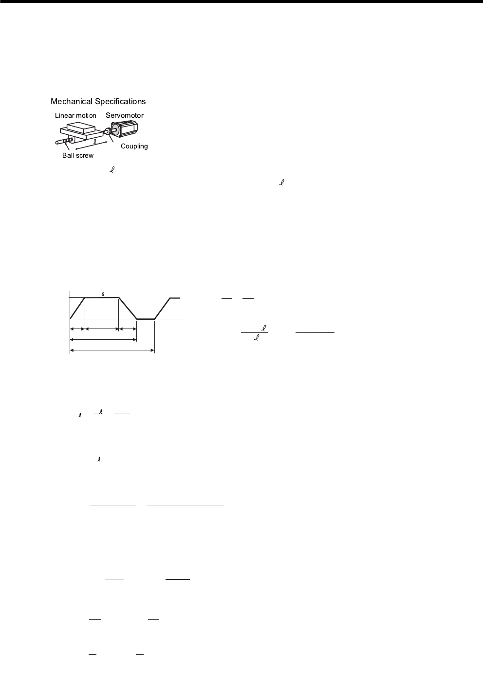
11 Appendix
11.1.1 Selection Example for Speed Control
11-2
11.1 Servomotor Capacity Selection Examples
11.1.1 Selection Example for Speed Control
l
(1) Speed Diagram
(2) Rotation Speed
• Load axis rotation speed
• Motor shaft rotation speed with the direct coupling: Gear ratio 1/R = 1/1
Therefore,
(3) Load torque
(4) Load Moment of Inertia
• Linear motion section
• Ball screw
• Coupling
• Load moment of inertia at motor shaft
• Load speed: V = 15 m/min • Feeding times: n = 40 times/min
• Linear motion section mass: M = 500 kg • Feeding distance: = 0.275 m
• Ball screw length: LB = 1.4 m • Feeding time: tm = 1.2 s max.
• Ball screw diameter: DB = 0.04 m • Friction coefficient: μ = 0.2
• Ball screw lead: PB = 0.01 m • Mechanical efficiency: η = 0.9 (90%)
• Coupling mass: MC = 1 kg
• Coupling outer diameter: DC = 0.06 m
1
c
ttad
t
(m/min)
Speed
Time (s)
tm
t
V
15 60
n
t = = = 1.5 (s)
tc = 1.2 − 0.1 × 2 = 1.0 (s)
where ta = td
60
40
60 ×
ta = tm − = 1.2 − = 0.1 (s)
60 × 0.275
15
V
N = = = 1500 (min )
V15
PB
-1
0.01
N = N R = 1500 × 1 = 1500 (min )
M-1
TL = = = 1.73 (Nm)
9.8μ M PB
2πR η
9.8 × 0.2 × 500 × 0.01
2π × 1 × 0.9
JL1 = M
(
)
2
= 500 ×
(
)
2
= 12.7 × 10⁻⁴ (kg m2)
PB
2πR
0.01
2π × 1
J = ρ L D = × 7.87 × 10 × 1.4 × (0.04) = 27.7 × 10 (kg m )
π
32
π
32
BBB
-4-344
2
J = M
C
D
C2
= × 1 × (0.06)
2
= 4.5 × 10
-4
(kg
m
2
)
8
11
8
C
J = J +
J +
J = 44.9 × 10 (kg
m )
LL1 C
B
-4 2

11.1 Servomotor Capacity Selection Examples
11-3
11
Appendix
(5) Load Moving Power
(6) Load Acceleration Power
(7) Servomotor Provisional Selection
(a) Selecting Conditions
• TL ≤ Motor rated torque
• Pa + Po = (1 to 2) × Motor rated output
• NM ≤ Motor rated speed
• JL ≤ SERVOPACK allowable load moment of inertia
The followings satisfy the conditions.
• SGMGH-09A2A21 servomotor
• SGDH-10AE SERVOPACK
(b) Specifications of the Provisionally Selected Servomotor and SERVOPACK
• Rated output: 850 (W)
• Rated motor speed: 1500 (min-1)
• Rated torque: 5.39 (N⋅m)
• Instantaneous peak torque: 13.8 (N⋅m)
• Servomotor moment of inertia: 13.9 × 10⁻⁴ (kg⋅m2)
• SERVOPACK allowable load moment of inertia: 69.58 × 10⁻⁴ (kg⋅m2)
(8) Verification on the Provisionally Selected Servomotor
• Required starting torque
• Required braking torque
• Torque efficiency
P
O
= = = 272 (W)
2πN
M
T
L
60
2π × 1500 × 1.73
60
P
a =
(
NM
)
2
=
(
× 1500
)
2
= 1108 (W)
2π
60
2π
60
JL
ta
44.9 × 10⁻⁴
0.1
T = + T = + 1.73
60ta 60 × 0.1
2πN (J + J ) 2π × 1500 × (13.9 + 44.9) × 10
P
−4
MM L
L
11 (Nm) < Instantaneous peak torqueSatisfactory
T = − T = − 1.73
60td 60 × 0.1
2πN (J + J ) 2π × 1500 × (13.9 + 44.9) × 10
S
−4
MM L
L
7.5 (Nm) < Instantaneous peak torqueSatisfactory
T = =
t
Τ ta + T tc + T td
r m s
PLS
3.72 (Nm) < Rated torqueSatisfactory
222
1.5
(11) × 0.1 + (1.73) × 1.0 + (7.5) × 0.1
222
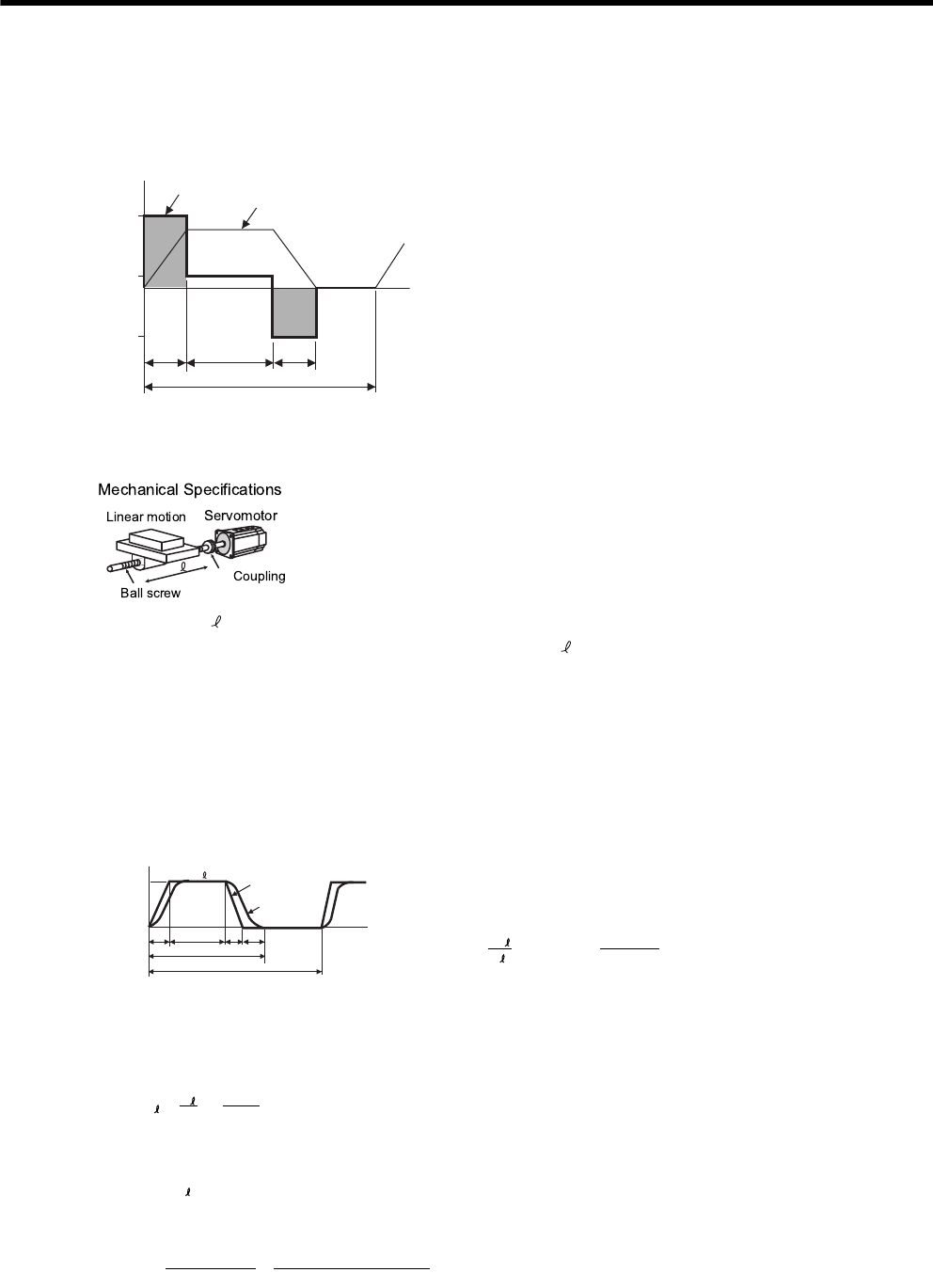
11 Appendix
11.1.2 Selection Example for Position Control
11-4
(9) Result
The provisionally selected servomotor and SERVOPACK are confirmed to be applicable.
The torque diagram is shown below.
11.1.2 Selection Example for Position Control
(1) Speed Diagram
(2) Rotation Speed
• Load axis rotation speed
• Motor shaft rotation speed with direct coupling: Gear ratio 1/R = 1/1
Therefore,
(3) Load Torque
(Nm)
0.1
1.5
1.0
0.1
-7.5
0
1.73
11
Torque Speed
• Load speed: V = 15 m/min • Positioning times: n = 40 times/min
• Linear motion section mass: M = 80 kg • Positioning distance: = 0.25 m
• Ball screw length: LB = 0.8 m • Positioning time: tm = Less than 1.2 s
• Ball screw diameter: DB = 0.016 m • Electrical stop accuracy: δ = ± 0.01 mm
• Ball screw lead: PB = 0.005 m • Friction coefficient: μ = 0.2
• Coupling mass: MC = 0.3 kg • Mechanical efficiency: η = 0.9 (90%)
• Coupling outer diameter: DC =0 .03 m
Where ta = td, ts = 0.1 (s)
1
Load
speed
Reference
pulse
s
t
d
ttac
t
(m/min)
Speed
Time (s)
tm
t
V
15
t60
n
------60
40
------1.5s()===
ta = tm − ts − = 1.2 − 0.1 − = 0.1 (s)
60 60 × 0.25
V15
tc 1.2 0.1–0.12×–0.9s()==
N = = = 3000 (min )
V15
P
B
-1
0.005
N = N R = 3000 × 1 = 3000 (min )
M-1
TL = = = 0.139 (Nm)
9.8μ M PB
2πR η
9.8 × 0.2 × 80 × 0.005
2π × 1 × 0.9

11.1 Servomotor Capacity Selection Examples
11-5
11
Appendix
(4) Load Moment of Inertia
• Liner motion section
• Ball screw
• Coupling
• Load moment of inertia at the motor shaft
(5) Load Moving Power
(6) Load Acceleration Power
(7) Provisionally Servomotor Selection
(a) Selecting Conditions
• TL ≤ Motor rated torque
• Pa + Po = (1 to 2) × Motor rated output
• NM ≤ Motor rated speed
• JL ≤ SERVOPACK allowable load moment of inertia
The followings satisfy the conditions.
• SGMPH-02AAA21 servomotor
• SGDH-02AE SERVOPACK
(b) Specifications of Servomotor and SERVOPACK
• Rated output: 200 (W)
• Rated motor speed: 3000 (min-1)
• Rated torque: 0.637 (N⋅m)
• Instantaneous peak torque: 1.91 (N⋅m)
• Servomotor rotor moment of inertia: 0.209 × 10⁻⁴ (kg⋅m2)
• SERVOPACK allowable load moment of inertia: 3.69 × 10⁻⁴ (kg⋅m2)
• Number of encoder pulses: 2048 (P/R)
J
L1
= M
(
)
2
= 80 ×
(
)
2
= 0.507 × 10
-4
(kg
m )
P
B
2πR
0.005
2π × 1
2
J
B
= ρ
L
B
D
B4
= × 7.87 × 10
3
× 0.8 × (0.016)
4
= 0.405 × 10
-4
(kg
m
2
)
π
32
π
32
J
C = MC DC4 = × 0.3 × (0.03)2 = 0.338 × 10⁻⁴ (kg m2)
8
11
8
JL = JL1 JB JC = 1.25 × 10⁻⁴ (kg m2)
PO = = = 43.7 (W)
2πNM TL
60
2π × 3000 × 0.139
60
Pa =
(
NM
)
2
=
(
× 3000
)
2
-4
= 123.4 (W)
2π
60
2π
60
JL
ta
1.25 × 10
0.1

11 Appendix
11.1.2 Selection Example for Position Control
11-6
(8) Verification on Provisionally Selected Servomotor
• Required starting torque
• Required braking torque
• Effective torque
The above confirms that the provisionally selected servomotor and SERVOPACK capacities are sufficient. In the
next step, their performance in position control are checked.
(9) PG Feedback Pulse Dividing Ratio: Setting of Electronic Gear Ratio
As the electrical stop accuracy δ = ±0.01 mm, take the position detection unit Δ= 0.01 mm/pulse.
(10) Reference Pulse Frequency
(11) Error Counter Pulses
Position loop gain Kp = 30 (1/S)
(12) Electrical Stop Accuracy
The above results confirm that the selected SERVOPACK and servomotor are applicable for the position control.
T = + T = + 0.139
60ta 60 × 0.1
2πN (J + J ) 2π × 3000 × (0.209 + 1.25) × 10
P
−4
MM L
L
0.597 (Nm) < Instantaneous peak torqueSatisfactory
T = − T = − 0.139
60ta 60 × 0.1
2πN (J + J ) 2π × 3000 × (0.209 + 1.25) × 10
S
−4
MM L
L
0.319 (Nm) < Instantaneous peak torqueSatisfactory
T = =
t
Τ ta + T tc + T td
r m s
PLS
0.205 (Nm) < Rated torqueSatisfactory
222
1.5
(0.597) × 0.1 + (0.139) × 0.9 + (0.319) × 0.1
222
B
A
( )
× = × = 2048 × 4
k = =
P
Δ B
A
5
0.01
B
A
B( )
B
A2048 × 4
500
( )
vs = = = 25,000 (pps)
1000 × 15
60 × 0.01
1000V
60 × Δ
ε = = = 833 (pulse)
25,000
30
vs
Kp
±Δε = ± = ± ± 0.17 < ± 1 (pulse) = ± 0.01 (pulse)
NR
M
N
ε
(SERVOPACK
3000
3000
833
5000 ×
control range) ×
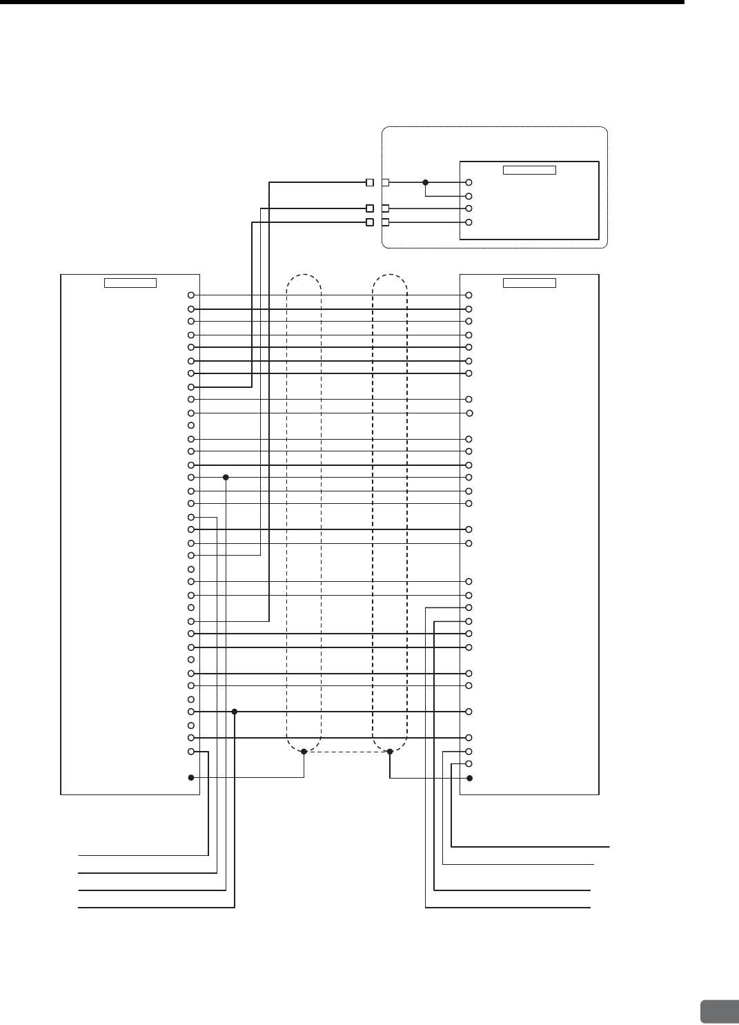
11.2 Connection to Host Controller
11-7
11
Appendix
11.2 Connection to Host Controller
11.2.1 Example of Connection to MP2200/MP2300 Motion Module SVA-01
SGDM/SGDH SERVOPACK
AO_0 (NREF)
PAL
PCL
AI_0 (VTG)
0 V (For 24V)
DO_2 (PCON)
DO_3
+24 V
DI_2 (ZERO/HOME LS)
SG
PA
PC
SG
AO_1 (TREF)
0 V (For 24V)
DO_4
DI_3 (P-OT)
DI_0 (SVALM)
SEN (5V)
DO_5 (SEN for VS866)
㧙
PBL
AI-GND
0 V (For 24V)
DO_1 (ALMRST)
+24 V
DI_5 (EXT/DEC)
SG
AI_1 (TMON)
PB
SG
AO-GND
0 V (For 24V)
DO_0
DI_4 (N-OT)
DI_1 (SRDY)
1
2
3
4
5
6
7
8
9
10
11
12
13
14
15
16
17
18
19
20
21
22
23
24
25
26
27
28
29
30
31
32
33
34
35
36
SG2
V-REF5
PA33
/PA34
PC19
/PC20
SG6
T-REF9
ALM-32
CN1/CN2
/C-SEL
(Control mode switch)
41
CN1
SVA-01
P-OT42
+24V IN47
ALM+31
ZERO/HOME LS input
P-OT input
N-OT input
EXT/DEC input
TGON- (/BRK-)28
SG10
SEN4
BAT-22
BAT+21
PB35
/PB36
SG1
TGON+ (/BRK+)27
/ALM-RST44
/S-ON40
N-OT43
Brake interlock output (+)
Battery for absolute encoder (0V)
Battery for absolute encoder (3.6V)
Hood FG
Brake interlock output (-)
/S-RDY+29
/P-CL
(Depending on the user setting)
45
/N-CL
(Depending on the user setting)
46
Standard analog input
Standard analog input
Analog input ground GND4
GND3
Analog monitor 1
(torque reference monitor)
2
1
CN5
SGDM / SGDH
MP2200 / MP2300
Analog monitor 2
(speed reference monitor)
Cable for analog monitor
(JZSP-CA01)
Black
Black
White
Red
/S-RDY-30
FG ޓ Shell
(SV ON)
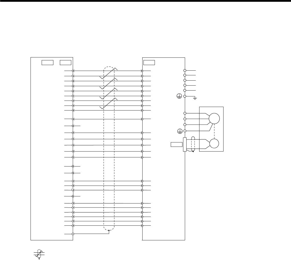
11 Appendix
11.2.2 Example of Connection to MP920 4-axes Analog Module SVA-01
11-8
11.2.2 Example of Connection to MP920 4-axes Analog Module SVA-01
* represents twisted-pair wires.
CN1 CN1CN4
SGDM/SGDH SERVOPACK
MP920 Series SVA-01
manufactured by
Yaskawa
3
4
5
16
7
6
13
12
30
34
29
11
19
14
1
20
28
32
FG
21
22
18
35
10
17
31
2
23
24
20
6
43
42
41
47
4
27
32
30
10
29
31
5
2
33
34
35
36
19
44
21
22
40
NREF
SG
PA
PAL
PB
PBL
PC
PCL
SG
+24V OUT
SVON
ALMRST
PCON
OTR
OTF
DOSEN
0V
SEN
SG
0V
0V
SVALM
0V
SVRDY
BRK
BAT
0BAT
V-REF
SG
∗
SG
PAO
/PAO
PBO
/PBO
PCO
/PCO
+24V-IN
/S-ON
/ALM-RST
/P-CON
N-OT
P-OT
SEN
SG
/S-RDY+
ALM+
ALM-
/S-RDY+
/TGON+
BAT(+)
BAT(-)
to
CN2
L1C/r
L3/T
L2/S
L1/R
L2C/t
W
V
A(1)
B(2)
C(3)
D(4)
U
Servomotor
M
Control power supply
Main circuit power supply
PG
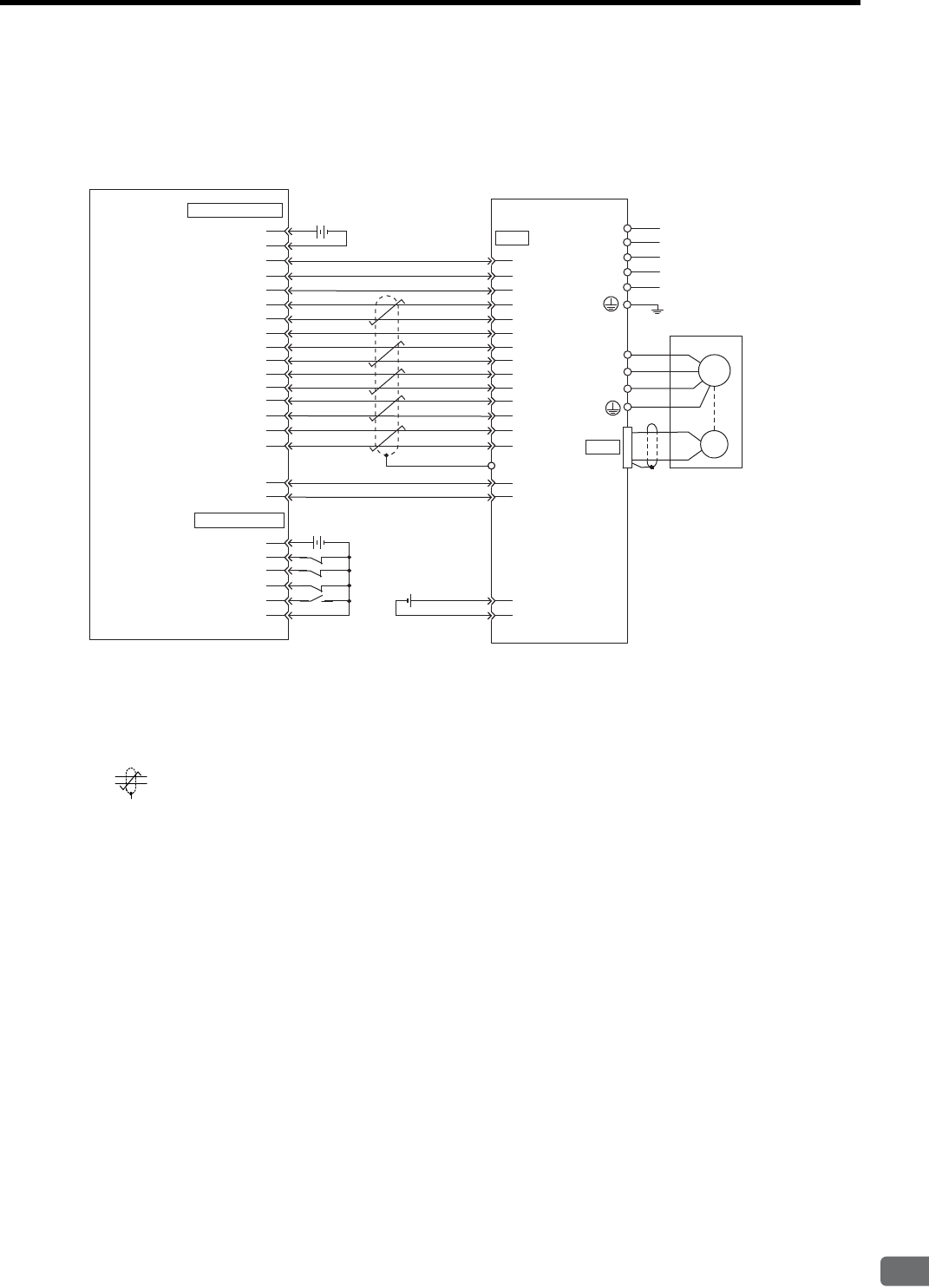
11.2 Connection to Host Controller
11-9
11
Appendix
11.2.3 Example of Connection to OMRON’s Motion Control Unit
* 1. Connect when an absolute encoder is used.
When a battery is installed in the SERVOPACK, no battery is required for CN1 (between 21 and 22).
x Battery for CN1: ER6VC3 (3.6 V, 2000 mAh)
x Battery installed in the SERVOPACK: JZSP-BA01-1 (3.6 V, 1000 mAh)
* 2. represents twisted-pair wires.
Note: 1. Only signals applicable to OMRON’s MC unit and Yaskawa’s SGDM/SGDH SERVOPACK are
shown in the diagram.
2. The main circuit power supply is a three-phase 200 VAC SERVOPACK input in the example.
The power supply and wiring must be in accordance with the power supply specifications of the
SERVOPACK to be used.
3. Note that incorrect signal connection will cause damage to the MC unit and SERVOPACK.
4. Open the signal lines not to be used.
5. The above connection diagram shows only X-axis connection. When using another axes, make
connection to the SERVOPACK in the same way.
6. The normally closed (N.C.) input terminals not to be used at the motion control unit I/O connec-
tor section must be short-circuited at the connector.
7. Make the setting so that the servo can be turned ON/OFF by the /S-ON signal.
CN2
CN1
3
4
5
16
8
9
13
12
11
19
15
14
18
1
5
6
1
19
20
35
34
20
4
BAT(-)
36
47
32
W
V
A(1)
B(2)
C(3)
D(4)
U
MC unit manufactured
by OMRON
DRV connector
Servomotor
SGDM/SGDH SERVOPACK
Battery
(CV500-MC221/MC421)
(CS1W-MC221/MC421)
C200H-MC221
10
10
17
2
4
6
14
1
2
2
31
33
44
21
22
40
ALM+
/S-ON
/ALM-RST
SG
SEN
SG
SG
ALM-
FG
PAO
/PAO
/PBO
PBO
PCO
/PCO
V-REF
+24-IN
24V 24 VDC
24 VDC
input
24V input ground
X-axis alarm input
X-axis run reference output
X-axis alarm reset output
X-axis SEN signal ground
X-axis SEN signal output
X-axis feedback ground
X-axis phase-A input
X-axis phase-/A input
X-axis phase-B input
X-axis phase-/B input
X-axis phase-Z input
X-axis phase-/Z input
X-axis speed reference
Axis speed reference ground
24 V output
24 V output ground
I/O connector
24 V input
X-axis CW limit input
X-axis CCW limit input
X-axis immediate stop input
X-axis origin proximity input
24 V input ground
Shell
㧖2㧖1
㧖1
㧖1
㧖1
㧖1
BAT(+)
M
Control
power supply
Main circuit
power supply
2.8 to 4.5 VDC
PG
L1C/r
L3/T
L2/S
L1/R
L2C/t
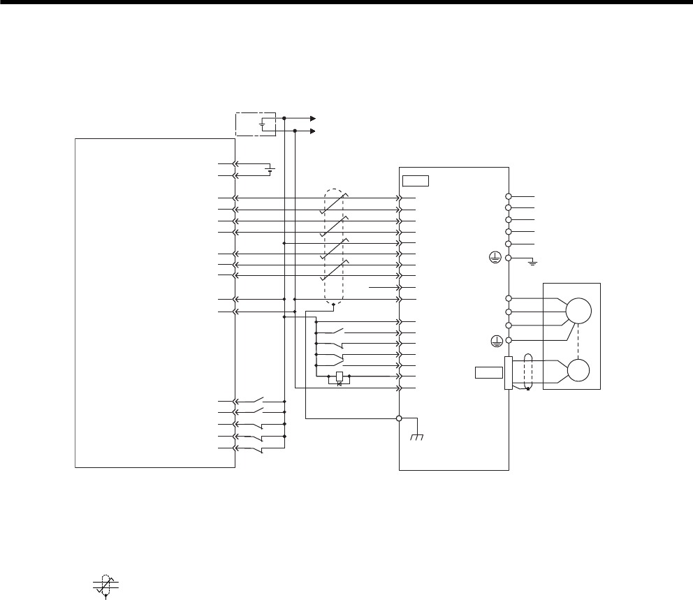
11 Appendix
11.2.4 Example of Connection to OMRON’s Position Control Unit
11-10
11.2.4 Example of Connection to OMRON’s Position Control Unit
* 1. The ALM signal is output for about two seconds after the power is turned ON. Take this into consid-
eration when designing the power ON sequence. The ALM signal actuates the alarm detection relay
1Ry to stop the main circuit power supply to the SERVOPACK.
* 2. Set parameter Pn200.0 to 1.
* 3. Connect the shield wire to the connector shell.
* 4. represents twisted-pair wires.
Note: Only signals applicable to OMRON’s MC unit (positioning unit) and Yaskawa’s SGDM/SGDH
SERVOPACK are shown in the diagram.
CN2
CN1
A3
A5
A6
A7
A4
8
20
25
19
12
7
14
15
W
V
A(1)
B(2)
C(3)
D(4)
U
Position control unit
Servomotor
SGDM/SGDH SERVOPACK
CS1W-NC133 / 233 / 433
manufactured by OMRON
A16
A11
A14
A1
A2
A8
A20
A22
A23
A21
A19
11
/SIGN
CLR
/CLR
PCO
PULS
/PULS
SIGN
/PCO
COIN+
/COIN- 26
31
32
44
42
43
47
40
+24V-IN
/S-ON
P-OT
N-OT
/ALM-RST
ALM-
ALM+
1Ry 1
2
3
4
5 VDC
5V power supply for pulse output
5V GND for pulse output
24 V power supply for output
24 V GND for output
CCW(+) output
CCW(-) output
CW(+) output
CW(-) output
Origin input signal
Origin input common
Error counter reset output
X-axis CW limit input
X-axis CCW limit input
X-axis immediate stop input
X-axis origin proximity input
X-axis external interrupt input
Connector
shell
M
Control
power supply
Main circuit
power supply
PG
+
-
+24V
0
24
+24
V
I/O power supply
L1C/r
L3/T
L2/S
L1/R
L2C/t
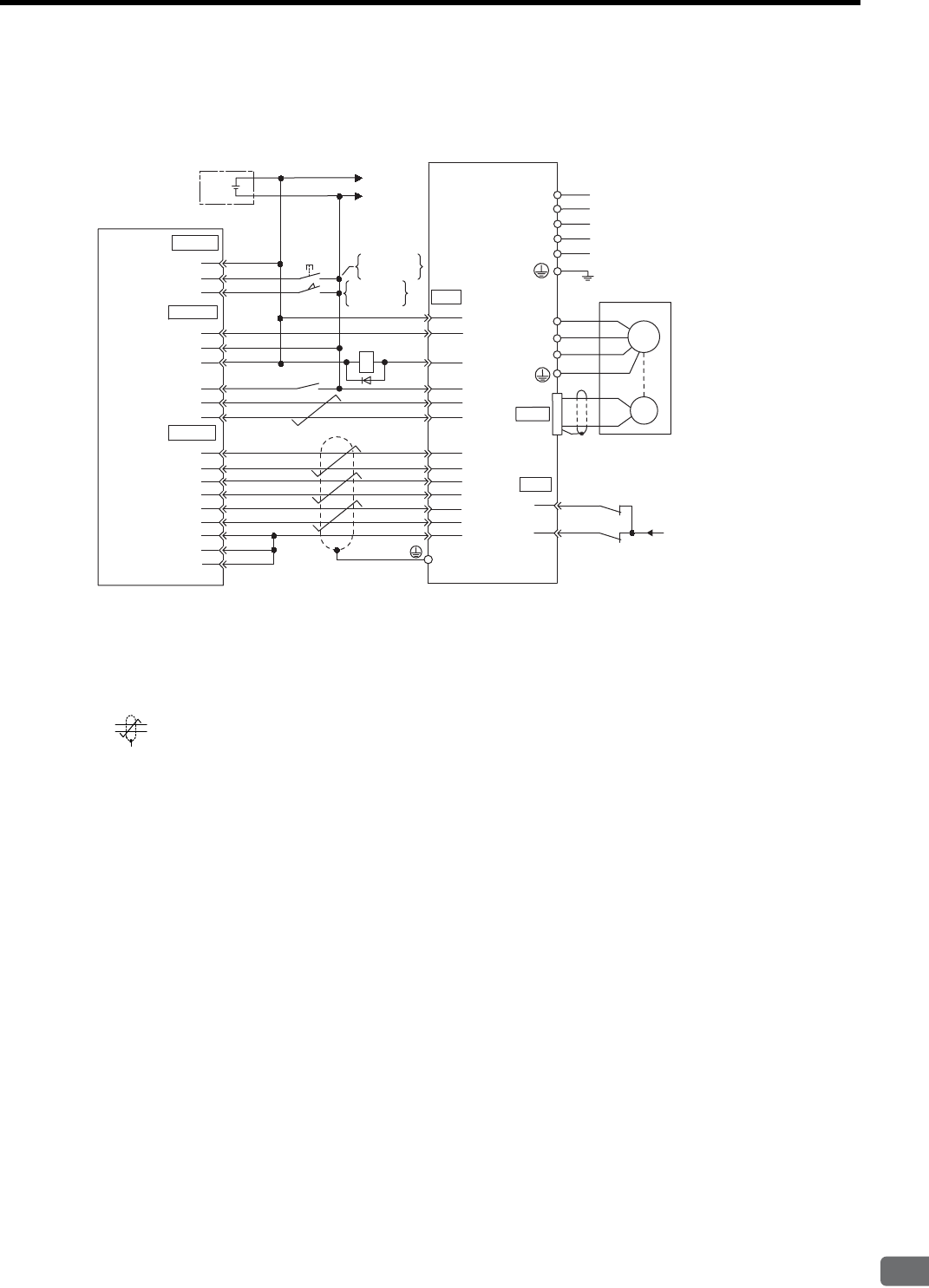
11.2 Connection to Host Controller
11-11
11
Appendix
11.2.5 Example of Connection to MITSUBISHI’s AD72 Positioning
Unit (SERVOPACK in Speed Control Mode)
* 1. The ALM signal is output for about two seconds after the power is turned ON. Take this into consid-
eration when designing the power ON sequence. The ALM signal actuates the alarm detection relay
1Ry to stop the main circuit power supply to the SERVOPACK.
* 2. Pin numbers are the same both for X-axis and Y-axis.
* 3. Connect the connector wire to the connector shell.
* 4. represents twisted-pair wires.
Note: Only signals applicable to Mitsubishi’s AD72 Positioning Unit and Yaskawa’s SGDM/SGDH
SERVOPACK are shown in the diagram.
43
42
1Ry
+
-
+24V
I/O power supply
0
24
V
+24 V
CONT
SERVO
CN1
ENCO
CN1
STOP
DOG
SV-ON
READY
PULSE A
PULSE C
PULSE B
0V
0V
0V
∗2
1
3
2
1
3
2
4
6
5
4
7
5
8
11
10
3
9
6
1
+24V-IN
P-OT
N-OT
ALM+
ALM-
V-REF (T-REF)
SG
PAO
SG
/PCO
PCO
/PBO
PBO
/PAO
47
32
31
40
1
20
19
34
33
36
35
5(9)
6(10)
/S-ON
1Ry
∗4
0
24
V
Positioning unit AD72
manufactured
by Mitsubishi
SGDM/SGDH SERVOPACK
Speed reference
ON when
positioning is
canceled.
ON when
proximity is
detected.
∗3
Connector
shell
CN2
W
V
A(1)
B(2)
C(3)
D(4)
U
Servomotor
M
Control
power supply
PG
Main circuit
power supply
L1C/r
L3/T
L2/S
L1/R
L2C/t
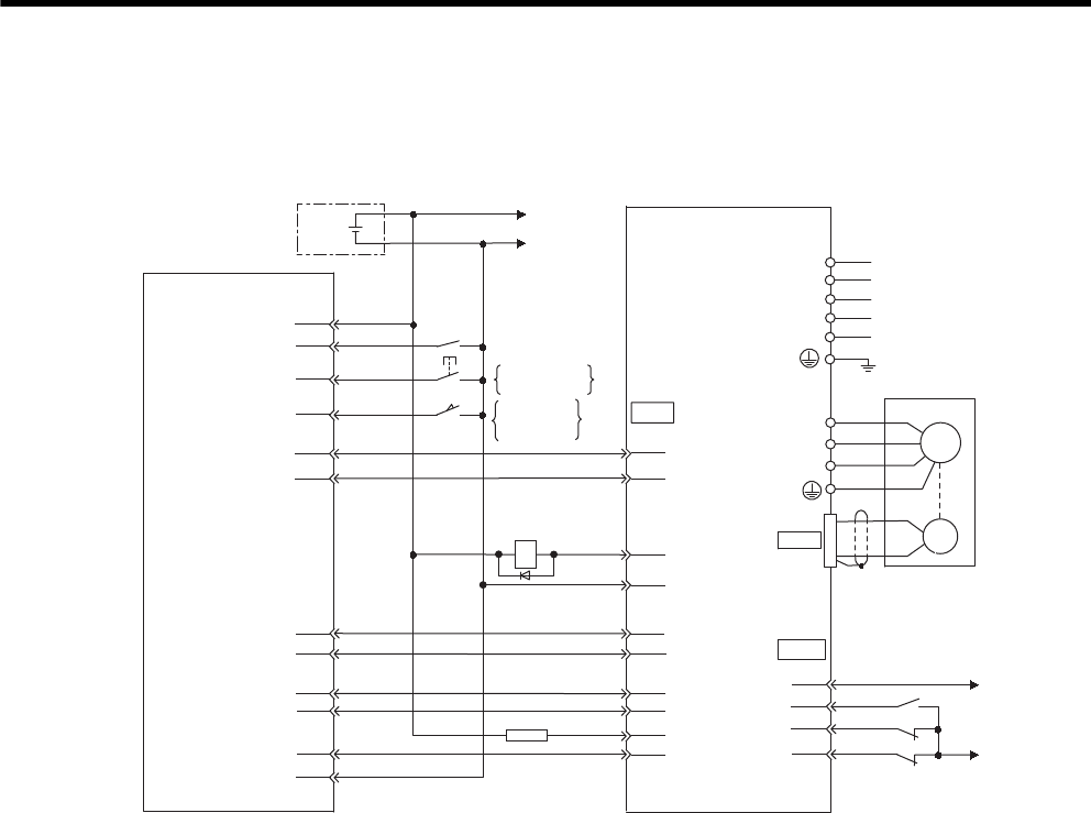
11 Appendix
11.2.6 Example of Connection to MITSUBISHI’s AD75 Positioning Unit (SERVOPACK in Position Control Mode)
11-12
11.2.6 Example of Connection to MITSUBISHI’s AD75 Positioning Unit
(SERVOPACK in Position Control Mode)
* The ALM signal is output for about two seconds when the power is turned ON. Take this into consider-
ation when designing the power ON sequence. The ALM signal actuates the alarm detection relay 1Ry
to stop the main circuit power supply to the SERVOPACK.
Note: Only signals applicable to Mitsubishi’s AD75 Positioning Unit and Yaskawa’s SGDM/SGDH
SERVOPACK are shown in the diagram.
+
-
+24V
024
V
1Ry
CN1
CN1
STOP
DOG
READY
PGO
PULSE
SIGN
CLEAR
1Ry
2.2Kǡ
19
14
15
12
8
7
32
31
20
42
43
40
47
/S-ON
P-OT
N-OT
25
24
14
7
26
23
5
22
4
21
3
+24 V
024V
+24V
PULS
CLR
SIGN
/PULS
/CLR
/SIGN
ALM+
ALM -
PCO
/PCO
Positioning unit AD75
manufactured by
Mitsubishi
I/O power supply
X-axis (Y-axis)
SGDM/SGDH
SERVOPACK
ON when
proximity is
detected.
ON when
positioning is
canceled.
11
11
CN2
W
V
A(1)
B(2)
C(3)
D(4)
U
Servomotor
M
Control
power supply
Main circuit
power supply
PG
L1C/r
L3/T
L2/S
L1/R
L2C/t

11.3 List of Parameters
11-13
11
Appendix
11.3 List of Parameters
11.3.1 Utility Functions List
The following list shows the available utility functions.
Parameter
No.
Function
Fn000 Alarm traceback data display
Fn001 Not used for the SERVOPACKs of 22 kW or more.
Fn002 JOG mode operation
Fn003 Zero-point search mode
Fn004 Reserved (Do not change.)
Fn005 Parameter setting initialization
Fn006 Alarm traceback data clear
Fn007 Not used for the SERVOPACKs of 22 kW or more.
Fn008 Absolute encoder multiturn reset and encoder alarm reset
Fn009 Automatic tuning of analog (speed, torque) reference offset
Fn00A Manual adjustment of speed reference offset
Fn00B Manual adjustment of torque reference offset
Fn00C Manual zero-adjustment of analog monitor output
Fn00D Manual gain-adjustment of analog monitor output
Fn00E Automatic offset-adjustment of motor current detection signal
Fn00F Manual offset-adjustment of motor current detection signal
Fn010 Password setting (protects parameters from being changed.)
Fn011 Motor models display
Fn012 Software version display
Fn013 Multiturn limit value setting change when a Multiturn Limit Disagreement alarm (A.CC) occurs
Fn014 Application module detection results clear
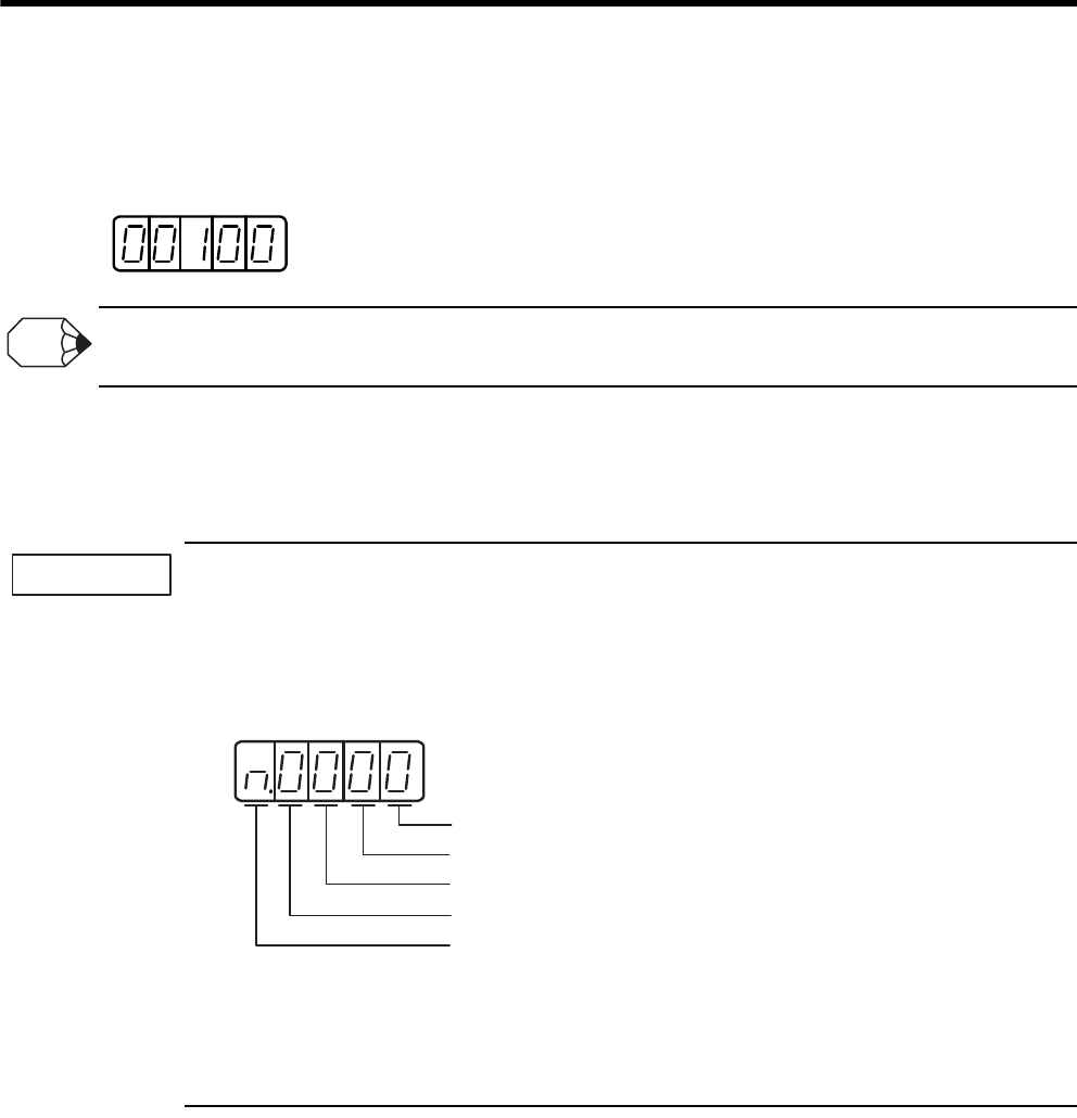
11 Appendix
11.3.2 List of Parameters
11-14
11.3.2 List of Parameters
(1) Parameter Display
Parameter settings are displayed as shown below.
Since each digit in the function selection parameters has a significant meaning, the value can only be changed for each
individual digit. Each digit displays a value within its own setting range.
(2) Definition of Display for Function Selection Parameters
Each digit of the function selection parameters has a meaning.
For example, the rightmost digit of parameter Pn000 is expressed as “Pn000.0.”
1. Each digit of the function selection parameters is defined as shown below. The following explains the
purpose of each digit of a parameter.
• Pn000.0 or n.×××: Indicates the value for the 1st digit of parameter Pn000.
• Pn000.1 or n.×××: Indicates the value for the 2nd digit of parameter Pn000.
• Pn000.2 or n.×××: Indicates the value for the 3rd digit of parameter Pn000.
• Pn000.3 or n.×××: Indicates the value for the 4th digit of parameter Pn000.
How to Display Parameters
2. After changing the parameters with “After restart” mentioned in “Setting Validation” column in the table
on the following pages, turn OFF the main circuit and control power supplies and then turn them ON
again to enable the new settings.
Decimal display
in five digit
INFO
IMPORTANT
1st digit
2nd digit
3rd digit
4th digit
Hexadecimal display
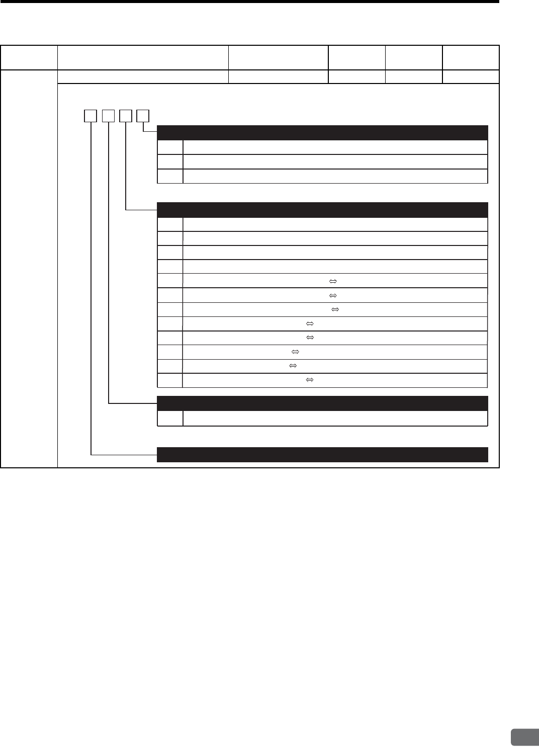
11.3 List of Parameters
11-15
11
Appendix
Parameter
No. Name Setting Range Units Factory
Setting
Setting
Validation
Pn000 Function Selection Basic Switches −−0000 After restart
0
1
0
1
2
3
4
5
6
7
8
9
A
B
Sets CCW as forward direction.
Sets CW as forward direction (Reverse Rotation Mode).
Reserved (Do not change.)
Speed control (analog reference)
Position control (pulse train reference)
Torque control (analog reference)
Internally set speed control (contact reference)
Internally set speed control (contact reference) Speed control (analog reference)
Internally set speed control (contact reference) Position control (pulse train reference)
Internally set speed control (contact reference) Torque control (analog reference)
Position control (pulse train reference) Speed control (analog reference)
Position control (pulse train reference) Torque control (analog reference)
Torque control (analog reference) Speed control (analog reference)
Speed control (analog reference) Zero clamp
Position control (pulse train reference) Position control (Inhibit)
Direction Selection
Control Method Selection
0 to F Sets SERVOPACK axis address.
Axis Address
Reserved (Do not change)
4th
digit
3rd
digit
2nd
digit 1st
digit
n.
2 and 3
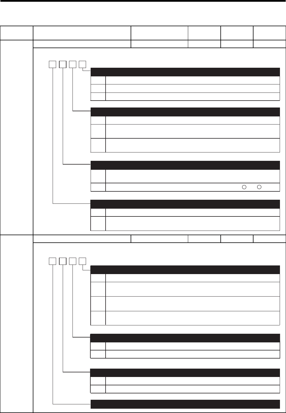
11 Appendix
11.3.2 List of Parameters
11-16
Pn001 Function Selection Application Switches 1 −−0000 After restart
Pn002 Function Selection Application Switches 2 −−0000 After restart
Parameter
No. Name Setting Range Units Factory
Setting
Setting
Validation
0
1
2
0
1
2
Stops the motor by applying dynamic brake (DB).
Stops the motor by applying dynamic brake (DB) and then releases DB.
Makes the motor coast to a stop state without using the dynamic brake (DB).
Same setting as Pn001.0 (Stops the motor by applying DB or by coasting).
Sets the torque of Pn406 to the maximum value, decelerate the motor to a stop, and then sets it
to servolock state.
Sets the torque of Pn406 to the maximum value, decelerates the motor to a stop, and then sets it
to coasting state.
Servo OFF or Alarm Stop Mode
Overtravel (OT) Stop Mode
0
1
Not applicable to main circuit DC power input: Input AC power supply through L1, L2, and L3
terminals.
AC/DC Power Input Selection
0
1
ALO1, ALO2, and ALO3 output only alarm codes.
Warning Code Output Selection
4th
digit
3rd
digit
2nd
digit 1st
digit
n.
Applicable to main circuit DC power input: Input DC power supply between + 1 and 㧙
ALO1, ALO2, and ALO3 output both alarm codes and warning codes. While warning
codes are output, ALM signal output remains ON (normal state).
0
0
1
N/A
Uses V-REF as an external speed limit input.
Speed Control Option (T-REF Terminal Allocation)
Torque Control Option (V-REF Terminal Allocation)
0
1
Uses absolute encoder as an absolute encoder.
Uses absolute encoder as an incremental encoder.
Absolute Encoder Usage
Reserved (Do not change)
n.
4th
digit
3rd
digit
2nd
digit 1st
digit
N/A
Uses T-REF as an external torque limit input.
(Refer to "8.9.3 Torque Limiting Using an Analog Voltage Reference.")
Uses T-REF as a torque feed forward input.
(Refer to "9.4.2 Torque Feed-forward.")
Uses T-REF as an external torque limit input when P-CL and N-CL are ON.
(Refer to "8.9.4 Torque Limiting Using an External Torque Limit and Analog Voltage Reference.")
1
2
3
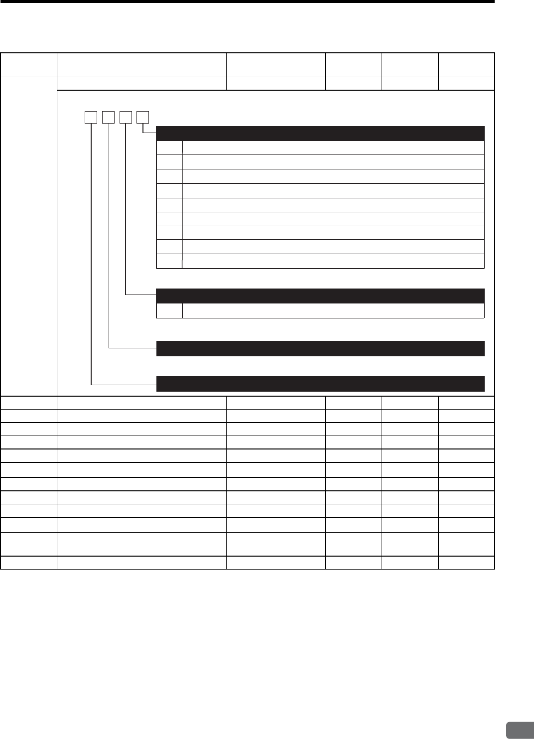
11.3 List of Parameters
11-17
11
Appendix
Parameter
No. Name Setting Range Units Factory
Setting
Setting
Validation
Pn003 Function Selection Application Switches 3 −−0002 After restart
Pn004 Reserved (Do not change) −−0000 −
Pn005 Reserved (Do not change) −−0000 −
Pn100 Speed Loop Gain 1 to 2000 1 Hz 40 Immediately
Pn101 Speed Loop Integral Time Constant 15 to 51200 0.01 ms 2000 Immediately
Pn102 Position Loop Gain 1 to 2000 1/s 40 Immediately
Pn103 Moment of Inertia Ratio 0 to 20000 1% 0 Immediately
Pn104 2nd Speed Loop Gain 1 to 2000 1 Hz 40 Immediately
Pn105 2nd Speed Loop Integral Time Constant 15 to 51200 0.01 ms 2000 Immediately
Pn106 2nd Position Loop Gain 1 to 2000 1/s 40 Immediately
Pn107 Bias 0 to 450 1 min-1 0 Immediately
Pn108 Bias Width Addition 0 to 250 1 reference
unit
7 Immediately
Pn109 Feed-forward 0 to 100 1% 0 Immediately
0
1
2
3
4
5
6
7
Motor speed: 1 V/1000 min-1
Speed reference: 1 V/1000 min-1
Internal torque reference: 1 V/100%
Position error: 0.05 V/1 reference unit
Position error: 0.05 V/100 reference units
Reference pulse frequency (converted to min-1): 1 V/1000 min-1
Motor speed × 4: 1 V/250 min-1
Motor speed × 8: 1 V/125 min-1
Reserved (Do not change)
Analog Monitor 1 Torque Reference Monitor
0 to F Same as Analog Monitor 1 Torque Reference Monitor
Analog Monitor 2 Speed Reference Monitor
4th
digit
3rd
digit
2nd
digit 1st
digit
n.
8 to F
Reserved (Do not change)
Reserved (Do not change)
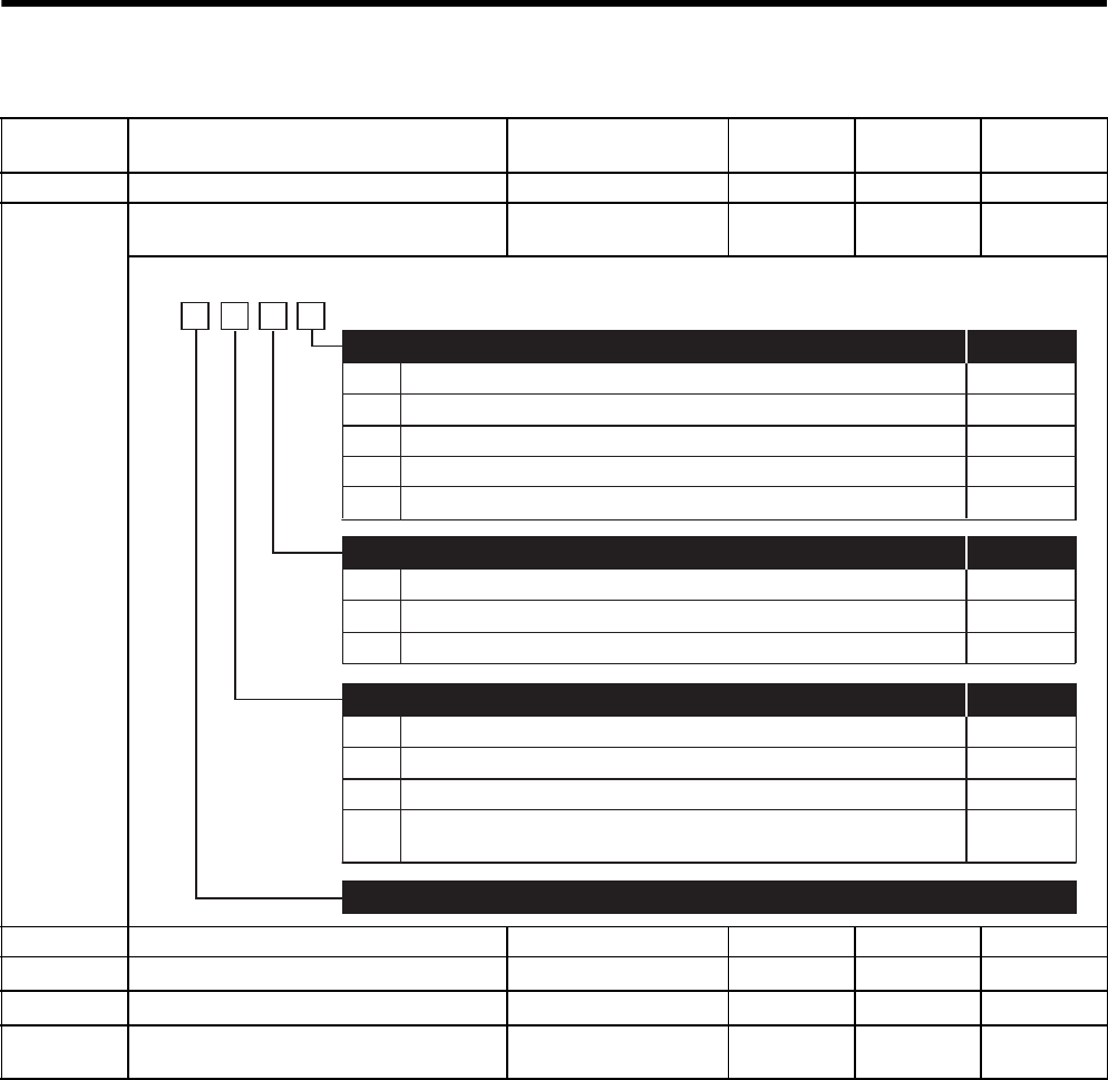
11 Appendix
11.3.2 List of Parameters
11-18
Parameter
No. Name Setting Range Units Factory
Setting
Setting
Validation
Pn10A Feed-forward Filter Time Constant 0 to 6400 0.01 ms 0 Immediately
Pn10B Gain-related Application Switches 0000 to 2314 −0000 After restart/
Immediately
Pn10C Mode Switch Torque Reference 0 to 800 1% 200 Immediately
Pn10D Mode Switch Speed Reference 0 to 10000 1 min-1 0 Immediately
Pn10E Mode Switch Acceleration 0 to 3000 1 min-1/ s 0 Immediately
Pn10F Mode Switch Error Pulse 0 to 10000 1 reference
unit
0 Immediately
0
1
2
3
4
0
1
Uses internal torque reference as the condition (Level setting: Pn10C)
Uses speed reference as the condition (Level setting: Pn10D)
Uses acceleration as the condition (Level setting: Pn10E)
Uses position error pulse as the condition (Level setting: Pn10F)
No mode switch function available
PI control
IP control
Reserved (Do not change)
Immediately
Immediately
Immediately
Immediately
Immediately
After restart
After restart
After restart
Mode Switch Selection
Speed Loop Control Method
Reserved (Do not change)
4th
digit
3rd
digit
2nd
digit 1st
digit
n.
2 and 3
Setting
Validation
Setting
Validation
0
1
2
3
Automatic gain switching disabled (Factory setting)
Switches the gain according to the position reference condition only.
Switches the gain according to the position error condition only.
Switches the gain according to the position reference and
position error condition only.
After restart
After restart
After restart
After restart
Automatic Gain Switching Condition Selection Setting
Validation

11.3 List of Parameters
11-19
11
Appendix
* 1. The parameters Pn110 and Pn111 settings are disabled.
* 2. Not used for the SERVOPACKs of 22 kW or more.
Parameter
No. Name Setting Range Units Factory
Setting
Setting
Validation
Pn110 Online Autotuning Switches *1*2 −−0012 −
Pn111 Speed Feedback Compensation ∗1*2 1 to 500 1% 100 Immediately
Pn112 Reserved (Do not change) −−100 −
Pn113 1000
Pn114 200
Pn115 32
Pn116 16
Pn117 100
Pn118 100
Pn119 50
Pn11A 1000
Pn11B 50
Pn11C 70
Pn11D 100
Pn11E 100
Pn11F 0
Pn120 0
Pn121 50
Pn122 0
Pn123 0
Pn124 Automatic Gain Switching Timer 1 to 10000 1 ms 100 Immediately
Pn125 Automatic Gain Switching Width 1 to 250 1 reference
unit
7 Immediately
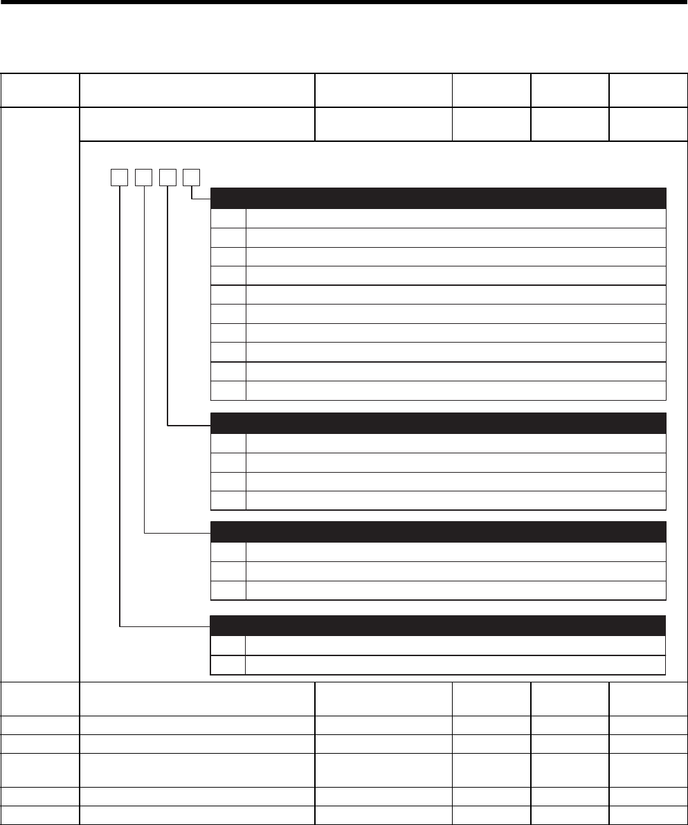
11 Appendix
11.3.2 List of Parameters
11-20
* This setting must be changed only for special applications. Do not change this limit inappropriately or
unintentionally.
Parameter
No. Name Setting Range Unit Factory
Setting
Setting
Validation
Pn200 Position Control References Selection
Switches
−−0000 After restart
Pn201 PG Dividing Ratio
(For 16-bit or less)
16 to 16384 1 P/rev 16384 After restart
Pn202 Electronic Gear Ratio (Numerator) 1 to 65535 −4 After restart
Pn203 Electronic Gear Ratio (Denominator) 1 to 65535 −1 After restart
Pn204 Position Reference Accel/Decel Time Con-
stant
0 to 6400 0.01 ms 0 Immediately
Pn205 Multiturn Limit Setting * 0 to 65535 1 rev 65535 After restart
Pn206 Reserved (Do not change) −−16384 −
0
1
2
3
4
5
6
7
8
9
Sign + Pulse, positive logic
CW + CCW, positive logic
Phase A + Phase B ( ×1), positive logic
Phase A + Phase B ( ×2), positive logic
Phase A + Phase B ( ×4), positive logic
Sign + Pulse, negative logic
CW + CCW, negative logic
Phase A + Phase B ( ×1), negative logic
Phase A + Phase B ( ×2), negative logic
Phase A + Phase B ( ×4), negative logic
Reference Pulse Form
0
1
2
3
Clears error counter when the signal is at H level.
Clears error counter at the rising edge of the signal.
Clears error counter when the signal is at L level.
Clears error counter at the falling edge of the signal.
Error Counter Clear Signal From
4th
digit
3rd
digit
2nd
digit 1st
digit
n.
0
1
2
Clears error counter at the baseblock.
Does not clear error counter (Possible to clear error counter only with CLR signal).
Clears error counter when an alarm occurs.
Clear Operation
0
1
Reference input filter for line driver signals
Reference input filter for open collector signals
Filter Selection
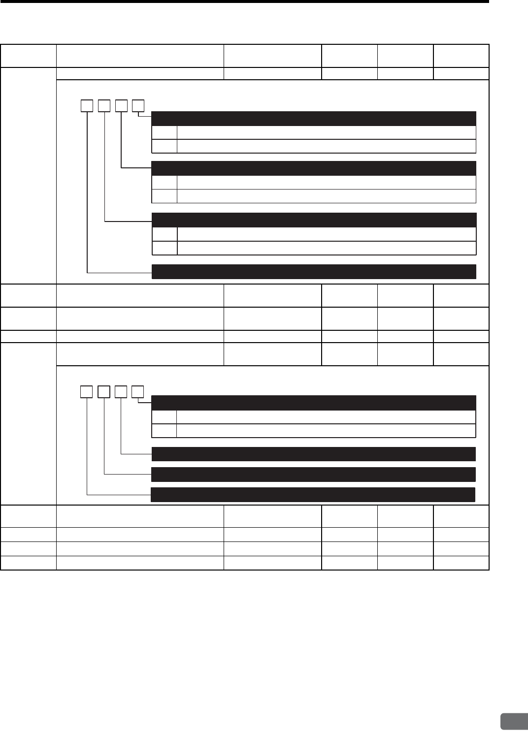
11.3 List of Parameters
11-21
11
Appendix
Parameter
No. Name Setting Range Unit Factory
Setting
Setting
Validation
Pn207 Position Control Function Switches 0000 to 1111 −0000 After restart
Pn208 Position Reference Movement Averaging
Time
0 to 6400 0.01 ms 0 After restart
Pn212 PG Dividing Ratio
(For 17-bit or more)
16 to 1073741824 1 P/rev 2048 After restart
Pn217 Reference Pulse Input Multiplication 1 to 99 ×1 1 Immediately
Pn218 Reference Pulse Multiplication Range
Switching Function
0000 to 0001 −0000 After restart
Pn300 Speed Reference Input Gain 150 to 3000 0.01V
/ rated speed
600 Immediately
Pn301 Internal Set Speed 1 0 to 10000 1 min-1 100 Immediately
Pn302 Internal Set Speed 2 0 to 10000 1 min-1 200 Immediately
Pn303 Internal Set Speed 3 0 to 10000 1 min-1 300 Immediately
0
1
Acceleration/deceleration filter
Average movement filter
Reserved (Do not change)
Position Reference Filter Selection
0
1
N/A
Uses V-REF as a speed feed-forward input.
Position Control Option
4th
digit
3rd
digit
2nd
digit
1st
digit
n.
0
1
Uses the parameter Pn201 (For 16-bit or less) as the dividing ratio (Factory setting).
Uses the parameter Pn212 (For 17-bit or more) as the dividing ratio.
Dividing Output Range Selection
Reserved (Do not change)
4th
digit
3rd
digit
2nd
digit
1st
digit
n.
0
1
Disabled (Factory setting)
Enabled
Reference Pulse Input Multiplication Range Switching Function
Reserved (Do not change)
Reserved (Do not change)
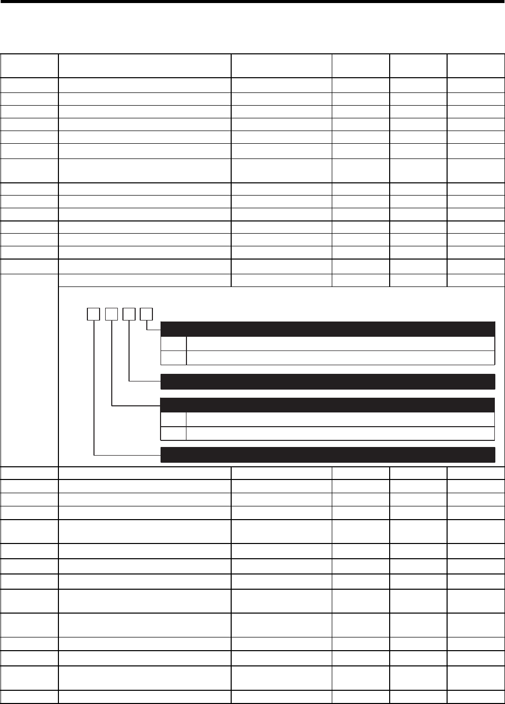
11 Appendix
11.3.2 List of Parameters
11-22
Parameter
No. Name Setting Range Unit Factory
Setting
Setting
Validation
Pn304 JOG Speed 0 to 10000 1 min-1 500 Immediately
Pn305 Soft Start Acceleration Time 0 to 10000 1 ms 0 Immediately
Pn306 Soft Start Deceleration Time 0 to 10000 1 ms 0 Immediately
Pn307 Speed Reference Filter Time Constant 0 to 65535 0.01 ms 40 Immediately
Pn308 Speed Feedback Filter Time Constant 0 to 65535 0.01 ms 0 Immediately
Pn309 Reserved (Do not change) −−60 −
Pn400 Torque Reference Input Gain 10 to 100 0.1 V/rated
torque
30 Immediately
Pn401 Torque Reference Filter Time Constant 0 to 65535 0.01 ms 100 Immediately
Pn402 Forward Torque Limit 0 to 800 1% 800 Immediately
Pn403 Reverse Torque Limit 0 to 800 1% 800 Immediately
Pn404 Forward External Torque Limit 0 to 800 1% 100 Immediately
Pn405 Reverse External Torque Limit 0 to 800 1% 100 Immediately
Pn406 Emergency Stop Torque 0 to 800 1% 800 Immediately
Pn407 Speed Limit during Torque Control 0 to 10000 1 min-1 10000 Immediately
Pn408 Torque Function Switches 0000 to 0101 −0000 Immediately
Pn409 First Stage Notch Filter Frequency 50 to 2000 1 Hz 2000 Immediately
Pn40A First Stage Notch Filter Q Value 50 to 400 ×0.01 70 Immediately
Pn40B Second Stage Notch Filter Frequency 50 to 2000 1 Hz 2000 Immediately
Pn40C Second Stage Notch Filter Q Value 50 to 400 ×0.01 70 Immediately
Pn500 Positioning Completed Width 0 to 250 1 reference
unit
7 Immediately
Pn501 Zero Clamp Level 0 to 10000 1 min-1 10 Immediately
Pn502 Rotation Detection Level 1 to 10000 1 min-1 20 Immediately
Pn503 Speed Coincidence Signal Output Width 0 to 100 1 min-1 10 Immediately
Pn504 NEAR Signal Width 1 to 250 1 reference
unit
7 Immediately
Pn505 Overflow Level 1 to 32767 256 refer-
ence units
1024 Immediately
Pn506 Brake Reference - Servo OFF Delay Time 0 to 50 10 ms 0 Immediately
Pn507 Brake Reference Output Speed Level 0 to 10000 1 min-1 100 Immediately
Pn508 Timing for Brake Reference Output during
Motor Operation
0 to 100 10 ms 50 Immediately
Pn509 Momentary Hold time 20 to 1000 1 ms 20 Immediately
0
1
First notch filter disabled.
Uses first notch filter.
Notch Filter Selection
4th
digit 3rd
digit
2nd
digit 1st
digit
n.
Reserved (Do not change)
Reserved (Do not change)
0
1
Second notch filter disabled.
Uses second notch filter.
Notch Filter Function 2

11.3 List of Parameters
11-23
11
Appendix
* When Pn50A.0 is set to 0 for the input signal standard allocation mode, the following modes are compatible:
Pn50A.1 = 7, Pn50A.3 = 8, and Pn50B.0 = 8.
Parameter
No. Name Setting Range Unit Factory
Setting
Setting
Validation
Pn50A Input Signal Selections 1 −−2100 After restart
0
1
2
3
4
5
6
7
8
9
A
B
0
1
ON when CN1-40 input signal is ON (L-level).
ON when CN1-41 input signal is ON (L-level).
ON when CN1-42 input signal is ON (L-level).
ON when CN1-43 input signal is ON (L-level).
ON when CN1-44 input signal is ON (L-level).
ON when CN1-45 input signal is ON (L-level).
ON when CN1-46 input signal is ON (L-level).
Sets signal ON.
Sets signal OFF.
OFF when CN1-40 input signal is OFF (H-level).
OFF when CN1-41 input signal is OFF (H-level).
OFF when CN1-42 input signal is OFF (H-level).
OFF when CN1-43 input signal is OFF (H-level).
OFF when CN1-44 input signal is OFF (H-level).
OFF when CN1-45 input signal is OFF (H-level).
OFF when CN1-46 input signal is OFF (H-level).
/S-ON Signal Mapping
Signal Polarity: Normal; Servo ON when ON (L-level)
Signal Polarity: Reverse; Servo ON when OFF (H-level)
0 to F Same as /S-ON
/P-CON Signal Mapping (P control when ON (L-level))
4th
digit
3rd
digit
2nd
digit
1st
digit
n.
C
D
E
F
Uses the sequence input signal terminals with standard allocation.∗
Changes the sequence input signal allocation for each signal.
Input Signal Allocation Mode
P-OT Signal Mapping (Overtravel when OFF (H-level))
0
1
2
3
4
5
6
7
8
9
A
B
Forward run allowed when CN1-40 input signal is ON (L-level).
Forward run allowed when CN1-41 input signal is ON (L-level).
Forward run allowed when CN1-42 input signal is ON (L-level).
Forward run allowed when CN1-43 input signal is ON (L-level).
Forward run allowed when CN1-44 input signal is ON (L-level).
Forward run allowed when CN1-45 input signal is ON (L-level).
Forward run allowed when CN1-46 input signal is ON (L-level).
Forward run prohibited.
Forward run allowed.
Forward run allowed when CN1-40 input signal is OFF (H-level).
Forward run allowed when CN1-41 input signal is OFF (H-level).
Forward run allowed when CN1-42 input signal is OFF (H-level).
Forward run allowed when CN1-43 input signal is OFF (H-level).
Forward run allowed when CN1-44 input signal is OFF (H-level).
Forward run allowed when CN1-45 input signal is OFF (H-level).
Forward run allowed when CN1-46 input signal is OFF (H-level).
C
D
E
F
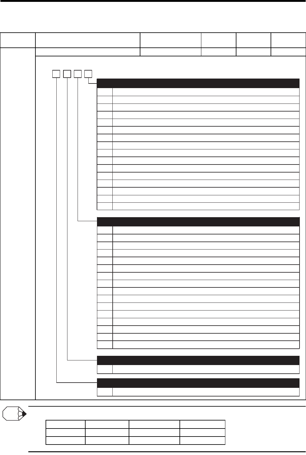
11 Appendix
11.3.2 List of Parameters
11-24
Input signal polarities
Parameter
No. Name Setting Range Unit Factory
Setting
Setting
Validation
Pn50B Input Signal Selections 2 −−6543 After restart
0
1
2
3
4
5
6
7
8
9
A
B
Reverse run allowed when CN1-40 input signal is ON (L-level).
Reverse run allowed when CN1-41 input signal is ON (L-level).
Reverse run allowed when CN1-42 input signal is ON (L-level).
Reverse run allowed when CN1-43 input signal is ON (L-level).
Reverse run allowed when CN1-44 input signal is ON (L-level).
Reverse run allowed when CN1-45 input signal is ON (L-level).
Reverse run allowed when CN1-46 input signal is ON (L-level).
Reverse run prohibited.
Reverse run allowed.
Reverse run allowed when CN1-40 input signal is OFF (H-level).
Reverse run allowed when CN1-41 input signal is OFF (H-level).
Reverse run allowed when CN1-42 input signal is OFF (H-level).
0 to F Same as above
4th
digit
3rd
digit
2nd
digit 1st
digit
n.
Reverse run allowed when CN1-43 input signal is OFF (H-level).
Reverse run allowed when CN1-44 input signal is OFF (H-level).
Reverse run allowed when CN1-45 input signal is OFF (H-level).
Reverse run allowed when CN1-46 input signal is OFF (H-level).
C
D
E
F
/P-CL Signal Mapping (Forward Torque Limit when ON (L-level))
0 to F Same as above
/N-CL Signal Mapping (Reverse Torque Limit when ON (L-level))
N-OT Signal Mapping (Overtravel when OFF (H-level))
/ALM-RST Signal Mapping (Alarm Reset when ON (L-level))
0
1
2
3
4
5
6
7
8
9
A
B
C
D
E
F
ON when CN1-40 input signal is ON (L-level).
ON when CN1-41 input signal is ON (L-level).
ON when CN1-42 input signal is ON (L-level).
ON when CN1-43 input signal is ON (L-level).
ON when CN1-44 input signal is ON (L-level).
ON when CN1-45 input signal is ON (L-level).
ON when CN1-46 input signal is ON (L-level).
Sets signal ON.
Sets signal OFF.
ON when CN1-40 input signal is OFF (H-level).
ON when CN1-41 input signal is OFF (H-level).
ON when CN1-42 input signal is OFF (H-level).
ON when CN1-43 input signal is OFF (H-level).
ON when CN1-44 input signal is OFF (H-level).
ON when CN1-45 input signal is OFF (H-level).
ON when CN1-46 input signal is OFF (H-level).
Signal Effective Level Voltage level Contact
ON Low (L) level 0 V Close
OFF High (H) level 24 V Open
INFO
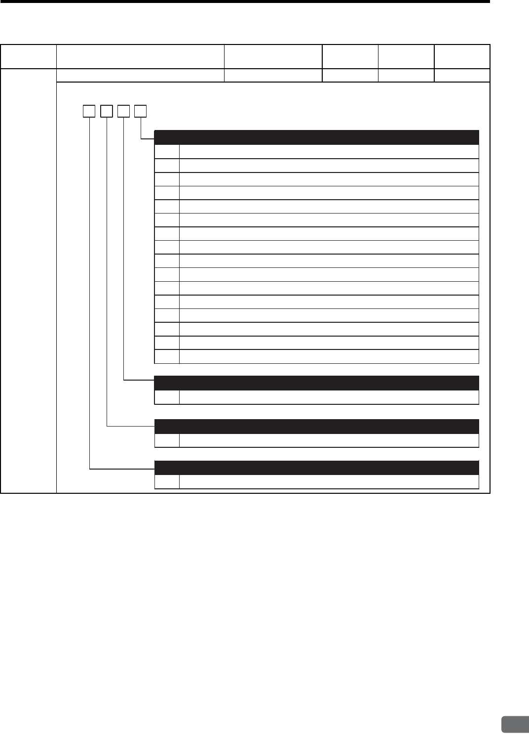
11.3 List of Parameters
11-25
11
Appendix
Parameter
No. Name Setting Range Unit Factory
Setting
Setting
Validation
Pn50C Input Signal Selections 3 −−8888 After restart
0
1
2
3
4
5
6
7
8
9
A
B
ON when CN1-40 input signal is ON (L-level).
ON when CN1-41 input signal is ON (L-level).
ON when CN1-42 input signal is ON (L-level).
ON when CN1-43 input signal is ON (L-level).
ON when CN1-44 input signal is ON (L-level).
ON when CN1-45 input signal is ON (L-level).
ON when CN1-46 input signal is ON (L-level).
Sets signal ON.
Sets signal OFF.
ON when CN1-40 input signal is OFF (H-level).
ON when CN1-41 input signal is OFF (H-level).
ON when CN1-42 input signal is OFF (H-level).
ON when CN1-43 input signal is OFF (H-level).
0 to F Same as /SPD-D
0 to F Same as /SPD-D
4th
digit
3rd
digit
2nd
digit 1st
digit
n.
ON when CN1-44 input signal is OFF (H-level).
ON when CN1-45 input signal is OFF (H-level).
ON when CN1-46 input signal is OFF (H-level).
C
D
E
F
0 to F Same as /SPD-D
/SPD-D Signal Mapping
/SPD-A Signal Mapping
/SPD-B Signal Mapping
/C-SEL Signal Mapping (Control mode change when ON (L-level))
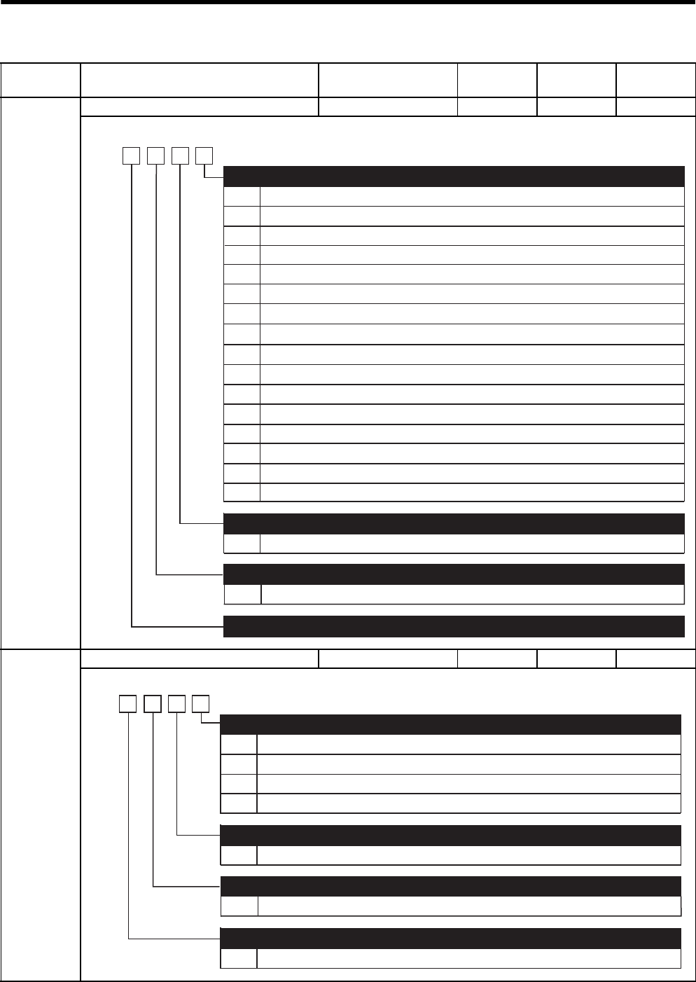
11 Appendix
11.3.2 List of Parameters
11-26
Pn50D Input Signal Selections 4 −−8888 After restart
Pn50E Output Signal Selections 1 −−3211 After restart
Parameter
No. Name Setting Range Unit Factory
Setting
Setting
Validation
0
1
2
3
0 to F Same as /ZCLAMP
Same as /ZCLAMP
ON when CN1-40 input signal is ON (L-level).
ON when CN1-41 input signal is ON (L-level).
ON when CN1-42 input signal is ON (L-level).
ON when CN1-43 input signal is ON (L-level).
ON when CN1-44 input signal is ON (L-level).
ON when CN1-45 input signal is ON (L-level).
ON when CN1-40 input signal is OFF (H-level).
ON when CN1-41 input signal is OFF (H-level).
ON when CN1-42 input signal is OFF (H-level).
ON when CN1-43 input signal is OFF (H-level).
ON when CN1-44 input signal is OFF (H-level).
ON when CN1-45 input signal is OFF (H-level).
ON when CN1-46 input signal is OFF (H-level).
ON when CN1-46 input signal is ON (L-level).
/ZCLAMP Signal Mapping (Zero clamp when ON (L-level))
/INHIBIT Signal Mapping (Reference pulse inhibit when ON (L-level))
/G-SEL Signal Mapping (Gain change when ON (L-level))
Reserved (Do not change)
4th
digit
3rd
digit
2nd
digit
1st
digit
n.
0 to F
4
5
6
7
8
9
A
B
C
D
E
F
Sets signal OFF.
Sets signal ON.
0
1
2
3
0 to 3
Disabled (the above signal is not used.)
Outputs the signal from CN1-25, 26 output terminal.
Outputs the signal from CN1-27, 28 output terminal.
Outputs the signal from CN1-29, 30 output terminal.
Same as /COIN
Same as /COIN
Same as /COIN
Positioning Completion Signal Mapping (/COIN)
Speed Coincidence Detection Signal Mapping (/V-CMP)
Rotation Detection Signal Mapping (/TGON)
Servo Ready Signal Mapping (/S-RDY)
4th
digit
3rd
digit
2nd
digit
1st
digit
n.
0 to 3
0 to 3
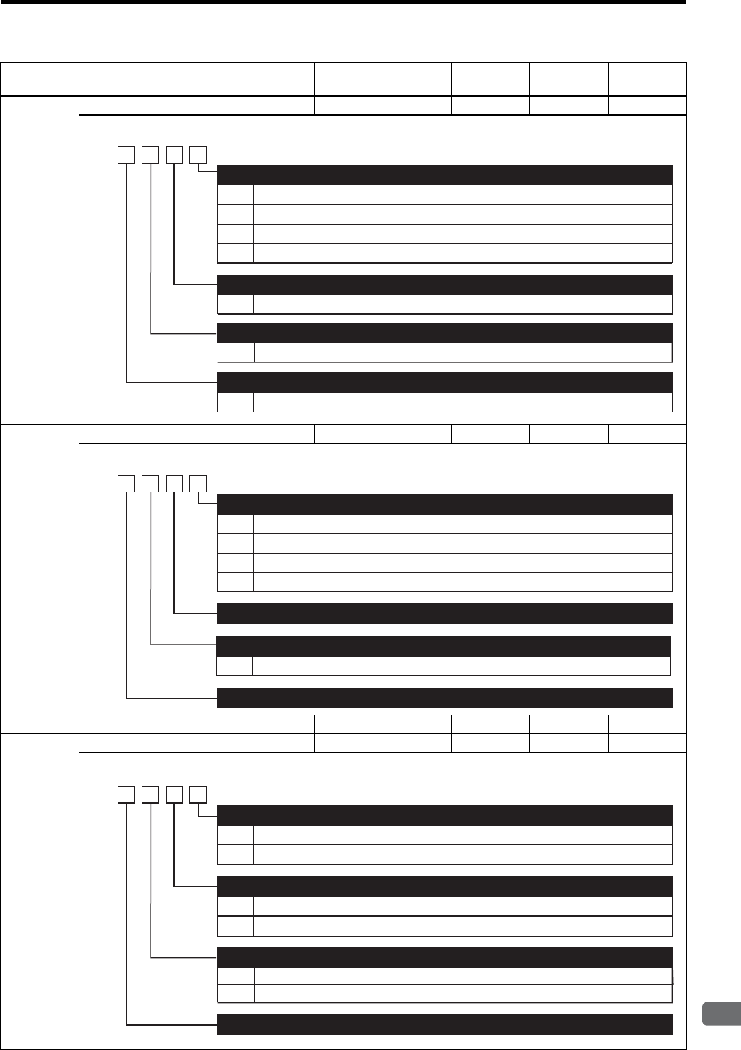
11.3 List of Parameters
11-27
11
Appendix
Pn50F Output Signal Selections 2 −−0000 After restart
Pn510 Output Signal Selections 3 −−0000 After restart
Pn511 Reserved (Do not change) −−8888 Immediately
Pn512 Output Signal Reversal Settings −−0000 After restart
Parameter
No. Name Setting Range Unit Factory
Setting
Setting
Validation
0
1
2
3
0 to 3
Disabled (the above signal is not used.)
Outputs the signal from CN1-25, -26 output terminal.
Outputs the signal from CN1-27, -28 output terminal.
Outputs the signal from CN1-29, -30 output terminal.
Same as /CLT
Same as /CLT
Same as /CLT
Torque Limit Detection Signal Mapping (/CLT)
Speed Limit Detection Signal Mapping (/VLT)
Brake Interlock Signal Mapping (/BK)
4th
digit
3rd
digit
2nd
digit
1st
digit
n.
0 to 3
0 to 3
Warning Signal Mapping (/WARN)
0
1
2
3
Disabled (the above signal is not used.)
Outputs the signal from CN1-25 or -26 terminals.
Outputs the signal from CN1-27 or -28 terminals.
Outputs the signal from CN1-29 or -30 terminals.
Near Signal Mapping (/NEAR)
4th
digit
3rd
digit
2nd
digit 1st
digit
n.
Reserved (Do not change)
Reserved (Do not change)
Same as /NEAR
0 to 3
Reference Pulse Input Multiplication Change Output Signal Mapping (/PSELA)
0
1
0
1
0
1
Output signal is not reversed.
Output signal is reversed.
Output signal is not reversed.
Output signal is reversed.
Output signal is not reversed.
Output signal is reversed.
Output Signal Reversal for CN1-25 or -26 Terminals
4th
digit
3rd
digit
2nd
digit
1st
digit
n.
Output Signal Reversal for CN1-27 or -28 Terminals
Output Signal Reversal for CN1-29 or -30 Terminals
Reserved (Do not change)
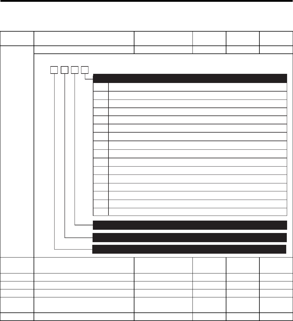
11 Appendix
11.3.2 List of Parameters
11-28
* 1. Normally set to “0.” When using an external regenerative resistor, set the allowable power loss (W)
of the regenerative resistor.
* 2. The upper limit is the maximum output capacity (W) of the SERVOPACK.
Parameter
No. Name Setting Range Unit Factory
Setting
Setting
Validation
Pn513 Input Signal Selections 5 −−0088 After restart
Pn51A Position Error Level Between Motor and
Load
0 to 32767 1 reference
unit
0 Immediately
Pn51B Reserved (Do not change) −−100 −
Pn51C Reserved (Do not change) −−450 −
Pn51E Excessive Position Error Warning Level 0 to 100 1 % 0 Immediately
Pn600 Regenerative Resistor Capacity ∗1Depends on SERVO-
PACK Capacity ∗2
10 W 0 After restart
Pn601 Reserved (Do not change) −−0−
0
1
2
3
ON when CN1-40 input signal is ON (L-level).
ON when CN1-41 input signal is ON (L-level).
ON when CN1-42 input signal is ON (L-level).
ON when CN1-43 input signal is ON (L-level).
ON when CN1-44 input signal is ON (L-level).
ON when CN1-45 input signal is ON (L-level).
ON when CN1-40 input signal is OFF (H-level).
ON when CN1-41 input signal is OFF (H-level).
ON when CN1-42 input signal is OFF (H-level).
ON when CN1-43 input signal is OFF (H-level).
ON when CN1-44 input signal is OFF (H-level).
ON when CN1-45 input signal is OFF (H-level).
ON when CN1-46 input signal is OFF (H-level).
ON when CN1-46 input signal is ON (L-level).
Reference Pulse Input Mulitiplication Change
Reserved (Do not change)
4th
digit
3rd
digit
2nd
digit
1st
digit
n.
4
5
6
7
8
9
A
B
C
D
E
F
Sets signal OFF. (Factory setting)
Sets signal ON.
Reserved (Do not change)
Reserved (Do not change)

11.4 Parameter Recording Table
11-29
11
Appendix
11.4 Parameter Recording Table
Use the following table for recording parameters.
Note: Setting validation (“immediately” or “after restart”) for Pn10B differs depending on the digit. The digits vali-
dated after restart are underlined in “Factory Setting” column.
Parameter
No.
Factory
Setting Name Setting
Validation
Pn000 0000 Function Selection Basic Switches After restart
Pn001 0000 Function Selection Application
Switches 1
After restart
Pn002 0000 Function Selection Application
Switches 2
After restart
Pn003 0002 Function Selection Application
Switches 3
After restart
Pn004 0000 Reserved (Do not change) Immediately
Pn005 0000 Reserved (Do not change) Immediately
Pn100 40 Hz Speed Loop Gain Immediately
Pn101 20.00 ms Speed Loop Integral Time Constant Immediately
Pn102 40 /s Position Loop Gain Immediately
Pn103 0% Moment of Inertia Ratio Immediately
Pn104 40 Hz 2nd Speed Loop Gain Immediately
Pn105 20.00 ms 2nd Loop Integral Time Constant Immediately
Pn106 40 /s 2nd Position Loop Gain Immediately
Pn107 0 min-1 Bias Immediately
Pn108 7 reference
units
Bias Width Addition Immediately
Pn109 0% Feed-forward Immediately
Pn10A 0.00 ms Feed-forward Filter Time Constant Immediately
Pn10B 0000Gain-related Application Switches After restart
/Immediately
Pn10C 200% Mode Switch Torque Reference Immediately
Pn10D 0 min-1 Mode Switch Speed Reference Immediately
Pn10E 0 min-1/s Mode Switch Acceleration Immediately
Pn10F 0 reference
units
Mode Switch Error Pulse Immediately
Pn110 0012 Online Autotuning Switches After restart
Pn111 100 Speed Feedback Compensation Immediately
Pn112 100% Reserved (Do not change) Immediately
Pn113 1000 Reserved (Do not change) Immediately
Pn114 200 Reserved (Do not change) Immediately
Pn115 32 Reserved (Do not change) Immediately
Pn116 16 Reserved (Do not change) Immediately
Pn117 100% Reserved (Do not change) Immediately
Pn118 100% Reserved (Do not change) Immediately
Pn119 50 /s Reserved (Do not change) Immediately
Pn11A 1000% Reserved (Do not change) Immediately
Pn11B 50 Hz Reserved (Do not change) Immediately
Pn11C 70 Hz Reserved (Do not change) Immediately
Pn11D 100% Reserved (Do not change) Immediately
Pn11E 100% Reserved (Do not change) Immediately
Pn11F 0 ms Reserved (Do not change) Immediately
Pn120 0 ms Reserved (Do not change) Immediately
Pn121 50 Hz Reserved (Do not change) Immediately

11 Appendix
11-30
Pn122 0 Hz Reserved (Do not change) Immediately
Pn123 0% Reserved (Do not change) Immediately
Pn124 100 ms Automatic Gain Switching Timer Immediately
Pn125 7 reference
units
Automatic Gain Switching Width Immediately
Pn200 0000 Position Control References Selection
Switches
After restart
Pn201 16384 P/rev PG Dividing Ratio
(For 16-bit or less)
After restart
Pn202 4 Electronic Gear Ratio (Numerator) After restart
Pn203 1 Electronic Gear Ratio (Denominator) After restart
Pn204 0.00 ms Position Reference Accel/Decel Time
Constant
Immediately
Pn205 65535 rev Multiturn Limit Setting After restart
Pn206 16384 P/rev Reserved (Do not change) −
Pn207 0000 Position Control Function Switches After restart
Pn208 0.00 ms Position Reference Movement
Averaging Time
After restart
Pn212 2048 P/rev PG Dividing Ratio
(For 17-bit or more)
After restart
Pn217 ×1Reference Pulse Input Multiplication Immediately
Pn218 0000 Reference Pulse Multiplication Range
Switching Function
After restart
Pn300 6.00 V/
rated speed
Speed Reference Input Gain Immediately
Pn301 100 min-1 Internal Set Speed 1 Immediately
Pn302 200 min-1 Internal Set Speed 2 Immediately
Pn303 300 min-1 Internal Set Speed 3 Immediately
Pn304 500 min-1 JOG Speed Immediately
Pn305 0 ms Soft Start Acceleration Time Immediately
Pn306 0 ms Soft Start Deceleration Time Immediately
Pn307 0.40 ms Speed Reference Filter Time Constant Immediately
Pn308 0.00 ms Speed Feedback Filter Time Constant Immediately
Pn309 60 min-1 Reserved (Do not change) Immediately
Pn400 3.0 V/
rated speed
Torque Reference Input Gain Immediately
Pn401 1.00 ms Torque Reference Filter Time Constant Immediately
Pn402 800% Forward Torque Limit Immediately
Pn403 800% Reverse Torque Limit Immediately
Pn404 100% Forward External Torque Limit Immediately
Pn405 100% Reverse External Torque Limit Immediately
Pn406 800% Emergency Stop Torque Immediately
Pn407 10000 min-1 Speed Limit during Torque Control Immediately
Pn408 0000 Torque Function Switches Immediately
Pn409 2000 Hz First Stage Notch Filter Frequency Immediately
Pn40A 0.70 First Stage Notch Filter Q Value Immediately
Pn40B 2000 Hz Second Stage Notch Filter Frequency Immediately
Pn40C 0.70 Second Stage Notch Filter Q Value Immediately
Pn500 7 reference
units
Positioning Completed Width Immediately
Pn501 10 min-1 Zero Clamp Level Immediately
Parameter
No.
Factory
Setting Name Setting
Validation

11.4 Parameter Recording Table
11-31
11
Appendix
Pn502 20 min-1 Rotation Detection Level Immediately
Pn503 10 min-1 Speed Coincidence Signal Output
Width
Immediately
Pn504 7 reference
units
NEAR Signal Width Immediately
Pn505 1024
reference
units
Overflow Level Immediately
Pn506 0 ms Brake Reference-Servo OFF Delay
Time
Immediately
Pn507 100 min-1 Brake Reference Output Speed Level Immediately
Pn508 500 ms Timing for Brake Reference Output
during Motor Operation
Immediately
Pn509 20 ms Momentary Hold Time Immediately
Pn50A 2100 Input Signal Selections 1 After restart
Pn50B 6543 Input Signal Selections 2 After restart
Pn50C 8888 Input Signal Selections 3 After restart
Pn50D 8888 Input Signal Selections 4 After restart
Pn50E 3211 Output Signal Selections 1 After restart
Pn50F 0000 Output Signal Selections 2 After restart
Pn510 0000 Output Signal Selections 3 After restart
Pn511 8888 Reserved (Do not change) Immediately
Pn512 0000 Output Signal Reversal Settings After restart
Pn513 0088 Input Signal Selections After restart
Pn51A 0
reference
units
Position Error Level Between Motor
and Load
Immediately
Pn51B 100
reference
units
Reserved (Do not change) Immediately
Pn51C 450 min-1 Reserved (Do not change) Immediately
Pn51D 0% Excessive Position Error Warning
Level
Immediately
Pn600 0 W Regenerative Resistor Capacity After restart
Pn601 0 W Reserved (Do not change) After restart
Parameter
No.
Factory
Setting Name Setting
Validation

Index
Index-1
INDEX
A
absolute encoder battery - - - - - - - - - - - - - - - - - - - - - - - - -2-7, 5-18
absolute encoder reception sequence - - - - - - - - - - - - - - - - - - - - 8-33
absolute encoders
handling - - - - - - - - - - - - - - - - - - - - - - - - - - - - - - - - - - - - 8-28
selection - - - - - - - - - - - - - - - - - - - - - - - - - - - - - - - - - - - - 8-30
setup (initialization) - - - - - - - - - - - - - - - - - - - - - - - - - - - - 8-32
wiring - - - - - - - - - - - - - - - - - - - - - - - - - - - - - - - - - - - - - - 6-9
accumulated load rate - - - - - - - - - - - - - - - - - - - - - - - - - - - - - - 7-29
adjusting offset - - - - - - - - - - - - - - - - - - - - - - - - - - - - - - - - - - 8-40
alarm code output- - - - - - - - - - - - - - - - - - - - - - - - - - - - - - - - - 8-77
alarm display and troubleshooting- - - - - - - - - - - - - - - - - - - - - - 10-7
alarm display table - - - - - - - - - - - - - - - - - - - - - - - - - - - - - - - - 10-2
alarm reset - - - - - - - - - - - - - - - - - - - - - - - - - - - - - - - - - - - - - 8-77
alarm reset availability - - - - - - - - - - - - - - - - - - - - - - - - - - - - - 10-2
alarm traceback data
clear (Fn006)- - - - - - - - - - - - - - - - - - - - - - - - - - - - - - - - - 7-11
display (Fn000) - - - - - - - - - - - - - - - - - - - - - - - - - - - - - - - - 7-8
alignment - - - - - - - - - - - - - - - - - - - - - - - - - - - - - - - - - - - - - - - 3-9
allocating input signals - - - - - - - - - - - - - - - - - - - - - - - - - - - - - 7-26
allocating output signals - - - - - - - - - - - - - - - - - - - - - - - - - - - - 7-28
allowable radial loads - - - - - - - - - - - - - - - - - - - - - - - - - - - - - - 3-13
allowable thrust loads - - - - - - - - - - - - - - - - - - - - - - - - - - - - - - 3-13
ALM - - - - - - - - - - - - - - - - - - - - - - - - - - - - - - - - - - - - - 6-13, 8-77
ALM-RST - - - - - - - - - - - - - - - - - - - - - - - - - - - - - - - - - - - - - 6-12
ALO 1 to 3 - - - - - - - - - - - - - - - - - - - - - - - - - - - - - - - - - - - - - 6-13
analog monitor- - - - - - - - - - - - - - - - - - - - - - - - - - - - - - - - - - - 9-20
analog monitor cable- - - - - - - - - - - - - - - - - - - - - - - - - - - -2-7, 5-15
analog monitor output
manual gain adjustment (Fn00D) - - - - - - - - - - - - - - - - - - - 7-12
manual zero adjustment (Fn00C) - - - - - - - - - - - - - - - - - - - 7-12
applicable standards - - - - - - - - - - - - - - - - - - - - - - - - - - - - - - - - 1-5
application module - - - - - - - - - - - - - - - - - - - - - - - - - - - - - - - - - 2-7
alarm display table when the application module is used - - - 10-5
detection results clear (Fn014) - - - - - - - - - - - - - - - - - - - - - 7-20
warning display table when the application module is used - - 10-6
automatic gain switching function- - - - - - - - - - - - - - - - - - - - - - 9-15
automatic gain switching timer - - - - - - - - - - - - - - - - - - - - - - - - 9-16
automatic gain switching width - - - - - - - - - - - - - - - - - - - - - - - 9-16
B
ball screw - - - - - - - - - - - - - - - - - - - - - - - - - - - - - - - - - - - - - - 8-53
BAT - - - - - - - - - - - - - - - - - - - - - - - - - - - - - - - - - - - - - - - - - - 6-12
batteries - - - - - - - - - - - - - - - - - - - - - - - - - - - - - - - - - - - -2-7, 5-18
handling - - - - - - - - - - - - - - - - - - - - - - - - - - - - - - - - - - - - 8-30
replacing- - - - - - - - - - - - - - - - - - - - - - - - - - - - - - - - - - - - 8-31
belt and pulley - - - - - - - - - - - - - - - - - - - - - - - - - - - - - - - - - - - 8-53
bias setting - - - - - - - - - - - - - - - - - - - - - - - - - - - - - - - - - - - - - - 4-3
BK- - - - - - - - - - - - - - - - - - - - - - - - - - - - - - - - - - - - - - - - - - - 6-13
brake power supply unit - - - - - - - - - - - - - - - - - - - - - - - - - - - - 5-17
selection - - - - - - - - - - - - - - - - - - - - - - - - - - - - - - - - - - - - - 2-9
built-in open collector power supply - - - - - - - - - - - - - - - - - - - - - 4-3
built-in panel operator- - - - - - - - - - - - - - - - - - - - - - - - - - - - - - - 7-2
C
cable selection - - - - - - - - - - - - - - - - - - - - - - - - - - - - - - - - - - - - 2-5
cables for connecting personal computers- - - - - - - - - - - - - -2-7, 5-13
checking products - - - - - - - - - - - - - - - - - - - - - - - - - - - - - - - - - 1-2
circuit time constant - - - - - - - - - - - - - - - - - - - - - - - - - - - - - - - - 4-3
clear signal form selection - - - - - - - - - - - - - - - - - - - - - - - - - - - 8-50
CLR - - - - - - - - - - - - - - - - - - - - - - - - - - - - - - - - - - - - - - - - - 6-12
CLT- - - - - - - - - - - - - - - - - - - - - - - - - - - - - - - - - - - - - - - - - - 6-13
CN1terminal layout - - - - - - - - - - - - - - - - - - - - - - - - - - - - - - - 6-11
CN2 terminal layout- - - - - - - - - - - - - - - - - - - - - - - - - - - - - - - - 6-9
COIN- - - - - - - - - - - - - - - - - - - - - - - - - - - - - - - - - - - - - - - - - 6-13
connecting the servomotor power lines - - - - - - - - - - - - - - - - - - 3-11
connection cable for digital operator - - - - - - - - - - - - - - - - - - - - - 2-7
connection to host controller - - - - - - - - - - - - - - - - - - - - - - - - - 11-7
connector terminal block converter unit- - - - - - - - - - - - - - - - - - 5-16
connectors and cables for encoder signals - - - - - - - - - - - - - - - - - 5-8
control method - - - - - - - - - - - - - - - - - - - - - - - - - - - - - - - - - - - 4-3
control mode selection - - - - - - - - - - - - - - - - - - - - - - - - - - - - - 8-17
control mode switching- - - - - - - - - - - - - - - - - - - - - - - - - - - - - 8-76
crimped terminals (UL standard compliant) - - - - - - - - - - - - - - - - 5-2
D
DATA/ENTER key - - - - - - - - - - - - - - - - - - - - - - - - - - - - - - - - 7-3
DATA/SHIFT key - - - - - - - - - - - - - - - - - - - - - - - - - - - - - - - - - 7-3
deceleration ratio - - - - - - - - - - - - - - - - - - - - - - - - - - - - - - - - - 8-52
designing a power ON sequence- - - - - - - - - - - - - - - - - - - - - - - - 6-7
DeviceNet application module - - - - - - - - - - - - - - - - - - - - - - - - 5-42
digital operator - - - - - - - - - - - - - - - - - - - - - - - - - - - - - - - 2-7, 5-14
connection - - - - - - - - - - - - - - - - - - - - - - - - - - - - - - - - - - - 7-2
key names and functions - - - - - - - - - - - - - - - - - - - - - - - - - - 7-3
status display - - - - - - - - - - - - - - - - - - - - - - - - - - - - - - - - - 7-5
disc table - - - - - - - - - - - - - - - - - - - - - - - - - - - - - - - - - - - - - - 8-53
dividing ratio setting error - - - - - - - - - - - - - - - - - - - - - - - - - - - 8-46
DOWN key - - - - - - - - - - - - - - - - - - - - - - - - - - - - - - - - - - - - - 7-3
DSPL/SET key - - - - - - - - - - - - - - - - - - - - - - - - - - - - - - - - - - - 7-3
dynamic brake (DB) function - - - - - - - - - - - - - - - - - - - - - - - - - 4-4
dynamic brake unit - - - - - - - - - - - - - - - - - - - - - - - - - - - - - - - 5-29
E
electronic gear- - - - - - - - - - - - - - - - - - - - - - - - - - - - - - - - - - - - 4-4
electronic gear ratio equation - - - - - - - - - - - - - - - - - - - - - - - - - 8-53
emergency stop torque - - - - - - - - - - - - - - - - - - - - - - - - - - - - - 8-21
enabling reference pulse input multiplication switching function - 8-61
encoder cables- - - - - - - - - - - - - - - - - - - - - - - - - - - - - - - - - - - - 5-6
encoder connector (CN2) terminal layout - - - - - - - - - - - - - - - - - 6-9
encoder pulse dividing ratio setting- - - - - - - - - - - - - - - - - - - - - 8-46
encoder signal converter unit - - - - - - - - - - - - - - - - - - - - - - - - - 5-40
encoder signal output - - - - - - - - - - - - - - - - - - - - - - - - - - - - - - 8-45
encoder-end connector specifications - - - - - - - - - - - - - - - - - - - 3-12
extending encoder cables - - - - - - - - - - - - - - - - - - - - - - - - - - - 6-24
external torque limit - - - - - - - - - - - - - - - - - - - - - - - - - - - - - - - 8-72
F
feed forward compensation - - - - - - - - - - - - - - - - - - - - - - - - - - - 4-3
feed-forward reference - - - - - - - - - - - - - - - - - - - - - - - - - - - - - - 9-7
forward rotation prohibited - - - - - - - - - - - - - - - - - - - - - - - - - - 8-20
forward torque limit - - - - - - - - - - - - - - - - - - - - - - - - - - - - - - - 8-71
frequency characteristics- - - - - - - - - - - - - - - - - - - - - - - - - - - - - 4-3
fully-closed application module - - - - - - - - - - - - - - - - - - - - - - - 5-44
fuse capacity - - - - - - - - - - - - - - - - - - - - - - - - - - - - - - - - - - - - - 2-8
G
grounding - - - - - - - - - - - - - - - - - - - - - - - - - - - - - - - - - - - - - - 6-19
H
handling oil and water - - - - - - - - - - - - - - - - - - - - - - - - - - - - - 3-10
hot start - - - - - - - - - - - - - - - - - - - - - - - - - - - - - - - - - - - - - - - 4-12
I
I/O signal (CN1)
connection example - - - - - - - - - - - - - - - - - - - - - - - - - - - - 6-10
names and functions- - - - - - - - - - - - - - - - - - - - - - - - - - - - 6-12

Index
Index-2
I/O signal cables - - - - - - - - - - - - - - - - - - - - - - - - - - - - - - 2-7, 5-10
I/O signal connections - - - - - - - - - - - - - - - - - - - - - - - - - - - - - 6-10
impact acceleration - - - - - - - - - - - - - - - - - - - - - - - - - - - - - - - 3-14
impact occurrences - - - - - - - - - - - - - - - - - - - - - - - - - - - - - - - 3-14
impact resistance - - - - - - - - - - - - - - - - - - - - - - - - - - - - - - - - - 3-14
input circuit signal allocation- - - - - - - - - - - - - - - - - - - - - - - - - 7-24
input impedance - - - - - - - - - - - - - - - - - - - - - - - - - - - - - - - - - - 4-3
input pulse form - - - - - - - - - - - - - - - - - - - - - - - - - - - - - - - - - - 4-3
input pulse frequency - - - - - - - - - - - - - - - - - - - - - - - - - - - - - - - 4-3
input pulse type - - - - - - - - - - - - - - - - - - - - - - - - - - - - - - - - - - - 4-3
input signal monitor display - - - - - - - - - - - - - - - - - - - - - - - - - 7-30
inspection and maintenance - - - - - - - - - - - - - - - - - - - - - - - - - 10-20
instantaneous power loss settings - - - - - - - - - - - - - - - - - - - - - - 8-27
interface for reference input circuits
analog input circuit - - - - - - - - - - - - - - - - - - - - - - - - - - - - 6-14
position reference input circuit- - - - - - - - - - - - - - - - - - - - - 6-14
internal torque limit - - - - - - - - - - - - - - - - - - - - - - - - - - - - - - - 8-71
J
JOG mode operation (Fn002) - - - - - - - - - - - - - - - - - - - - - - - - - 8-7
JOG speed - - - - - - - - - - - - - - - - - - - - - - - - - - - - - - - - - - - - - - 8-8
L
LEFT key - - - - - - - - - - - - - - - - - - - - - - - - - - - - - - - - - - - - - - - 7-3
limiting torque - - - - - - - - - - - - - - - - - - - - - - - - - - - - - - - - - - 8-71
using an external torque limit and analog voltage reference - 8-74
list of utility function modes - - - - - - - - - - - - - - - - - - - - - - - - - - 7-7
load moment of inertia - - - - - - - - - - - - - - - - - - - - - - - - - - - - - 4-14
load regulation - - - - - - - - - - - - - - - - - - - - - - - - - - - - - - - - - - - 4-3
M
magnetic contactor selection - - - - - - - - - - - - - - - - - - - - - - - - - - 2-9
main circuit wiring examples - - - - - - - - - - - - - - - - - - - - - - - - - - 6-4
manual adjustment of the torque reference offset - - - - - - - - - - - 8-65
manual tuning - - - - - - - - - - - - - - - - - - - - - - - - - - - - - - - - - - - - 9-4
mating concentricity of the flange - - - - - - - - - - - - - - - - - - - - - 3-14
mechanical tolerance - - - - - - - - - - - - - - - - - - - - - - - - - - - - - - 3-14
MECHATROLINK application module- - - - - - - - - - - - - - - - - - 5-41
mode switch (P/PI switching) - - - - - - - - - - - - - - - - - - - - - - - - 9-10
MODE/SET key - - - - - - - - - - - - - - - - - - - - - - - - - - - - - - - - - - 7-3
molded-case circuit breaker- - - - - - - - - - - - - - - - - - - - - - - - - - 5-19
selection- - - - - - - - - - - - - - - - - - - - - - - - - - - - - - - - - - - - - 2-8
moment of inertia ratio - - - - - - - - - - - - - - - - - - - - - - - - - - - - - - 9-5
monitor display of feedback pulse counter - - - - - - - - - - - - - - - - 7-32
monitor display of reference pulse counter- - - - - - - - - - - - - - - - 7-32
monitor mode - - - - - - - - - - - - - - - - - - - - - - - - - - - - - - - - - - - 7-29
motor current detection signal
automatic offset adjustment (Fn00E)- - - - - - - - - - - - - - - - - 7-15
manual offset adjustment (Fn00F) - - - - - - - - - - - - - - - - - - 7-16
motor models display (Fn011) - - - - - - - - - - - - - - - - - - - - - - - - 7-18
multiturn limit setting - - - - - - - - - - - - - - - - - - - - - - - - - - - - - - 8-36
N
N-CL - - - - - - - - - - - - - - - - - - - - - - - - - - - - - - - - - - - - - - - - - 6-12
NEAR - - - - - - - - - - - - - - - - - - - - - - - - - - - - - - - - - - - - - - - - 6-13
noise control - - - - - - - - - - - - - - - - - - - - - - - - - - - - - - - - - - - - 6-18
noise filters- - - - - - - - - - - - - - - - - - - - - - - - - - - - - - - - - - - - - 5-20
selection- - - - - - - - - - - - - - - - - - - - - - - - - - - - - - - - - - - - - 2-9
using noise filters - - - - - - - - - - - - - - - - - - - - - - - - - - - - - 6-20
noise interference - - - - - - - - - - - - - - - - - - - - - - - - - - - - - - - - 6-17
N-OT- - - - - - - - - - - - - - - - - - - - - - - - - - - - - - - - - - - - - - - - - 6-12
notch filter - - - - - - - - - - - - - - - - - - - - - - - - - - - - - - - - - - - - - - 9-3
first stage notch filter frequency - - - - - - - - - - - - - - - - - - - - 9-18
first stage notch filter Q value - - - - - - - - - - - - - - - - - - - - - 9-18
notch filter function - - - - - - - - - - - - - - - - - - - - - - - - - - - - 9-18
second stage notch filter frequency - - - - - - - - - - - - - - - - - 9-18
second stage notch filter Q value - - - - - - - - - - - - - - - - - - - 9-18
O
online autotuning functions- - - - - - - - - - - - - - - - - - - - - - - - - - - 9-2
operating using position control- - - - - - - - - - - - - - - - - - - - - - - 8-49
operating using speed control with an internally set speed - - - - - 8-68
operating using speed control with analog reference - - - - - - - - - 8-38
operating using torque control - - - - - - - - - - - - - - - - - - - - - - - - 8-63
operation in monitor mode - - - - - - - - - - - - - - - - - - - - - - - - - - 7-31
output circuit interface
line driver output circuit - - - - - - - - - - - - - - - - - - - - - - - - - 6-15
open-collector output circuit - - - - - - - - - - - - - - - - - - - - - - 6-16
photocoupler output circuit - - - - - - - - - - - - - - - - - - - - - - - 6-16
output circuit signal allocation- - - - - - - - - - - - - - - - - - - - - - - - 7-27
overhanging loads - - - - - - - - - - - - - - - - - - - - - - - - - - - - - - - - 4-15
overload detection level - - - - - - - - - - - - - - - - - - - - - - - - - - - - 4-12
overload protective function - - - - - - - - - - - - - - - - - - - - - - - - - 4-12
overshooting- - - - - - - - - - - - - - - - - - - - - - - - - - - - - - - - - - - - 9-10
overtravel stop - - - - - - - - - - - - - - - - - - - - - - - - - - - - - - - - - - - 4-4
P
panel operator
key names and functions - - - - - - - - - - - - - - - - - - - - - - - - - 7-3
status display - - - - - - - - - - - - - - - - - - - - - - - - - - - - - - - - - 7-5
PAO - - - - - - - - - - - - - - - - - - - - - - - - - - - - - - - - - - - - - - - - - 6-13
PAO serial data specifications - - - - - - - - - - - - - - - - - - - - - - - - 8-34
parameter setting mode - - - - - - - - - - - - - - - - - - - - - - - - - - - - 7-21
parameter settings initialization (Fn005) - - - - - - - - - - - - - - - - - 7-10
parameters - - - - - - - - - - - - - - - - - - - - - - - - - - - - - - - - - - - - - 7-24
example of changing function selection - - - - - - - - - - - - - - 7-23
list - - - - - - - - - - - - - - - - - - - - - - - - - - - - - - - - - - - - - - -11-13
parameter indications- - - - - - - - - - - - - - - - - - - - - - - - - - - 7-22
password setting (protects parameters from being changed)
(Fn010) - - - - - - - - - - - - - - - - - - - - - - - - - - - - - - - - - - - - - - - 7-17
PBO - - - - - - - - - - - - - - - - - - - - - - - - - - - - - - - - - - - - - - - - - 6-13
P-CL - - - - - - - - - - - - - - - - - - - - - - - - - - - - - - - - - - - - - - - - - 6-12
PCO - - - - - - - - - - - - - - - - - - - - - - - - - - - - - - - - - - - - - - - - - 6-13
P-CON - - - - - - - - - - - - - - - - - - - - - - - - - - - - - - - - - - - - - - - 6-12
peripheral device selection - - - - - - - - - - - - - - - - - - - - - - - - - - - 2-6
perpendicularity between the flange face and output shaft - - - - - 3-14
PG dividing ratio (for 16-bit or less)- - - - - - - - - - - - - - - - - - - - 8-46
PG dividing ratio (for 17-bit or more)- - - - - - - - - - - - - - - - - - - 8-46
PL1 to 3- - - - - - - - - - - - - - - - - - - - - - - - - - - - - - - - - - - - - - - 6-12
position control block diagram - - - - - - - - - - - - - - - - - - - - - - - 8-56
position control by host controller - - - - - - - - - - - - - - - - - - - - - 8-16
position loop gain - - - - - - - - - - - - - - - - - - - - - - - - - - - - - - - - - 9-5
position reference
input pulse multiplier- - - - - - - - - - - - - - - - - - - - - - - - - - - 8-49
selecting a position reference filter- - - - - - - - - - - - - - - - - - 8-57
setting a reference pulse form - - - - - - - - - - - - - - - - - - - - - 8-49
positioning completed output signal - - - - - - - - - - - - - - - - - - - - 8-58
positioning completed width setting - - - - - - - - - - - - - - - - - - - - - 4-3
positioning near signal - - - - - - - - - - - - - - - - - - - - - - - - - - - - - 8-59
positioning time reduction functions- - - - - - - - - - - - - - - - - - - - - 9-2
P-OT- - - - - - - - - - - - - - - - - - - - - - - - - - - - - - - - - - - - - - - - - 6-12
power consumed by dynamic brake resistance - - - - - - - - - - - - - 7-29
PROFIBUS-DP application module - - - - - - - - - - - - - - - - - - - - 5-43
proportional control operation (proportional operation reference) - 9-9
protection- - - - - - - - - - - - - - - - - - - - - - - - - - - - - - - - - - - - - - - 4-4
PSEL - - - - - - - - - - - - - - - - - - - - - - - - - - - - - - - - - - - - - - - - 8-61
PSELA - - - - - - - - - - - - - - - - - - - - - - - - - - - - - - - - - - - - - - - 8-62
PSO - - - - - - - - - - - - - - - - - - - - - - - - - - - - - - - - - - - - - - - - - 6-13
PULS - - - - - - - - - - - - - - - - - - - - - - - - - - - - - - - - - - - - - - - - 6-12

Index
Index-3
Q
Q value- - - - - - - - - - - - - - - - - - - - - - - - - - - - - - - - - - - - - - - - 9-18
R
reference pulse form
CW pulse + CCW pulse - - - - - - - - - - - - - - - - - - - - - - - - - 8-49
sign + pulse train - - - - - - - - - - - - - - - - - - - - - - - - - - - - - - 8-49
two-phase pulse train with 90° phase differential- - - - - - - - - 8-49
reference pulse inhibit function (INHIBIT)- - - - - - - - - - - - - - - - 8-60
reference pulse input multiplication- - - - - - - - - - - - - - - - - - - - - 8-61
reference pulse input multiplication switching function - - - - - - - 8-61
reference unit- - - - - - - - - - - - - - - - - - - - - - - - - - - - - - - - - - - - 8-51
reference voltage - - - - - - - - - - - - - - - - - - - - - - - - - - - - - - - - - - 4-3
regenerative load rate - - - - - - - - - - - - - - - - - - - - - - - - - - - - - - 7-29
regenerative resistor unit - - - - - - - - - - - - - - - - - - - - - - - - -2-9, 5-23
replacing oil seal - - - - - - - - - - - - - - - - - - - - - - - - - - - - - - - - 10-20
RESET key - - - - - - - - - - - - - - - - - - - - - - - - - - - - - - - - - - - - - - 7-3
reverse rotation prohibited - - - - - - - - - - - - - - - - - - - - - - - - - - - 8-20
reverse torque limit- - - - - - - - - - - - - - - - - - - - - - - - - - - - - - - - 8-71
RIGHT key - - - - - - - - - - - - - - - - - - - - - - - - - - - - - - - - - - - - - - 7-3
rotation direction selection- - - - - - - - - - - - - - - - - - - - - - - - - - - - 4-3
S
selecting a dynamic brake unit - - - - - - - - - - - - - - - - - - - - - - - - 2-10
selecting the speed loop control method (PI Control or IP Control) 9-6
selecting the stopping method after servo OFF - - - - - - - - - - - - - 8-26
SEN - - - - - - - - - - - - - - - - - - - - - - - - - - - - - - - - - - - - - - - - - - 6-12
SEN signal connection - - - - - - - - - - - - - - - - - - - - - - - - - - - - - 8-29
sequence I/O signal monitor display - - - - - - - - - - - - - - - - - - - - 7-30
sequence input circuit interface- - - - - - - - - - - - - - - - - - - - - - - - 6-15
sequence input signal - - - - - - - - - - - - - - - - - - - - - - - - - - - - - - - 4-3
sequence output signal - - - - - - - - - - - - - - - - - - - - - - - - - - - - - - 4-3
servo alarm output - - - - - - - - - - - - - - - - - - - - - - - - - - - - - - - - 8-77
servo gain
adjustment methods - - - - - - - - - - - - - - - - - - - - - - - - - - - - - 9-2
explanation - - - - - - - - - - - - - - - - - - - - - - - - - - - - - - - - - - - 9-4
servo ready output - - - - - - - - - - - - - - - - - - - - - - - - - - - - - - - - 8-79
servo system configurations - - - - - - - - - - - - - - - - - - - - - - - - - - - 1-3
servomotor
capacity selection examples - - - - - - - - - - - - - - - - - - - - - - - 11-2
direction of servomotor rotation - - - - - - - - - - - - - - - - - - - - 3-14
mechanical specifications - - - - - - - - - - - - - - - - - - - - - - - - - 3-9
model designations- - - - - - - - - - - - - - - - - - - - - - - - - - - - - - 2-2
nameplate - - - - - - - - - - - - - - - - - - - - - - - - - - - - - - - - - - - - 1-2
precautions on servomotor installation- - - - - - - - - - - - - - - - - 3-9
running output signal - - - - - - - - - - - - - - - - - - - - - - - - - - - 8-78
wire size - - - - - - - - - - - - - - - - - - - - - - - - - - - - - - - - - - - - - 5-2
servomotor fan
connectors- - - - - - - - - - - - - - - - - - - - - - - - - - - - - - - - - - - 3-10
installation - - - - - - - - - - - - - - - - - - - - - - - - - - - - - - - - - - 3-11
protection - - - - - - - - - - - - - - - - - - - - - - - - - - - - - - - - - - - 3-11
wiring - - - - - - - - - - - - - - - - - - - - - - - - - - - - - - - - - - - - - 3-11
servomotor inspection- - - - - - - - - - - - - - - - - - - - - - - - - - - - - 10-20
SERVOPACK
allowable load moment of inertia - - - - - - - - - - - - - - - - - - - 4-12
ambient/storage temperature - - - - - - - - - - - - - - - - - - - - - - - 4-3
applicable servomotors - - - - - - - - - - - - - - - - - - - - - - - - - - - 2-4
cable types - - - - - - - - - - - - - - - - - - - - - - - - - - - - - - - - - - - 5-6
dimensional drawings - - - - - - - - - - - - - - - - - - - - - - - - - - - 4-16
installation - - - - - - - - - - - - - - - - - - - - - - - - - - - - - - - - - - - 4-5
internal block diagrams - - - - - - - - - - - - - - - - - - - - - - - - - - - 4-7
model designations- - - - - - - - - - - - - - - - - - - - - - - - - - - - - - 2-3
nameplate - - - - - - - - - - - - - - - - - - - - - - - - - - - - - - - - - - - - 1-2
overload characteristics - - - - - - - - - - - - - - - - - - - - - - - - - - 4-12
power losses - - - - - - - - - - - - - - - - - - - - - - - - - - - - - - - - - 4-11
power supply capacities - - - - - - - - - - - - - - - - - - - - - - - - - 4-11
precautions on installation- - - - - - - - - - - - - - - - - - - - - - - - - 4-5
ratings and specifications - - - - - - - - - - - - - - - - - - - - - - - - - 4-2
wire size- - - - - - - - - - - - - - - - - - - - - - - - - - - - - - - - - - - - - 5-2
SERVOPACK inspection - - - - - - - - - - - - - - - - - - - - - - - - - - 10-20
SERVOPACK’s parts replacement schedule- - - - - - - - - - - - - - 10-21
setting a reference pulse form - - - - - - - - - - - - - - - - - - - - - - - - 8-49
setting for holding brakes - - - - - - - - - - - - - - - - - - - - - - - - - - - 8-22
setting PG dividing ratio of 5-digit or more - - - - - - - - - - - - - - - 8-47
setting the electronic gear - - - - - - - - - - - - - - - - - - - - - - - - - - - 8-51
setting the overtravel limit function - - - - - - - - - - - - - - - - - - - - 8-20
setting the servo ON signal - - - - - - - - - - - - - - - - - - - - - - - - - - 8-18
setting the speed bias - - - - - - - - - - - - - - - - - - - - - - - - - - - - - - 9-13
SGMVH servomotors (1500 min-1)
dimensional drawings- - - - - - - - - - - - - - - - - - - - - - - - - - - 3-16
ratings and specifications - - - - - - - - - - - - - - - - - - - - - - - - - 3-2
torque-motor speed characteristics - - - - - - - - - - - - - - - - - - - 3-4
SGMVH servomotors (800 min-1)
dimensional drawings- - - - - - - - - - - - - - - - - - - - - - - - - - - 3-22
ratings and specifications - - - - - - - - - - - - - - - - - - - - - - - - - 3-6
torque-motor speed characteristics - - - - - - - - - - - - - - - - - - - 3-7
SIGN - - - - - - - - - - - - - - - - - - - - - - - - - - - - - - - - - - - - - - - - - 6-12
smoothing - - - - - - - - - - - - - - - - - - - - - - - - - - - - - - - - - - - - - 8-57
soft start - - - - - - - - - - - - - - - - - - - - - - - - - - - - - - - - - - - - - - - 8-43
soft start time setting - - - - - - - - - - - - - - - - - - - - - - - - - - - - - - - 4-3
software version display (Fn012) - - - - - - - - - - - - - - - - - - - - - - 7-19
S-ON - - - - - - - - - - - - - - - - - - - - - - - - - - - - - - - - - - - - - - - - - 6-12
speed coincidence output - - - - - - - - - - - - - - - - - - - - - - - - - - - 8-48
speed control range - - - - - - - - - - - - - - - - - - - - - - - - - - - - - - - - 4-3
speed feedback compensation - - - - - - - - - - - - - - - - - - - - - - - - 9-13
speed feed-forward - - - - - - - - - - - - - - - - - - - - - - - - - - - - - - - - 9-2
speed limit during torque control - - - - - - - - - - - - - - - - - - - - - - 8-66
speed loop gain - - - - - - - - - - - - - - - - - - - - - - - - - - - - - - - - - - - 9-6
speed loop integral time constant - - - - - - - - - - - - - - - - - - - - - - - 9-6
speed reference input - - - - - - - - - - - - - - - - - - - - - - - - - - - - - - - 4-3
speed regulation - - - - - - - - - - - - - - - - - - - - - - - - - - - - - - - - - - 4-4
S-RDY- - - - - - - - - - - - - - - - - - - - - - - - - - - - - - - - - - - - 6-13, 8-79
standard replacement period - - - - - - - - - - - - - - - - - - - - - - - - 10-21
starting and stopping time - - - - - - - - - - - - - - - - - - - - - - - - - - - 4-13
surge absorber - - - - - - - - - - - - - - - - - - - - - - - - - - - - - - - - - - - 5-22
SVON key - - - - - - - - - - - - - - - - - - - - - - - - - - - - - - - - - - - - - - 7-3
switching gain settings - - - - - - - - - - - - - - - - - - - - - - - - - - 9-2, 9-14
switching the servomotor rotation direction - - - - - - - - - - - - - - - 8-19
T
temperature regulation - - - - - - - - - - - - - - - - - - - - - - - - - - - - - - 4-3
TGON - - - - - - - - - - - - - - - - - - - - - - - - - - - - - - - - - - - - 6-13, 8-78
thermal relay selection - - - - - - - - - - - - - - - - - - - - - - - - - - - - - 2-11
thermal relays - - - - - - - - - - - - - - - - - - - - - - - - - - - - - - - - - - - 5-36
through shaft section - - - - - - - - - - - - - - - - - - - - - - - - - - - - - - 3-10
torque control tolerance - - - - - - - - - - - - - - - - - - - - - - - - - - - - - 4-3
torque feed-forward - - - - - - - - - - - - - - - - - - - - - - - - - - - - - - - - 9-2
torque limiting using an analog voltage reference - - - - - - - - - - - 8-73
torque reference filter - - - - - - - - - - - - - - - - - - - - - - - - - - - - - - 9-16
torque reference input- - - - - - - - - - - - - - - - - - - - - - - - - - - - - - 8-63
T-REF - - - - - - - - - - - - - - - - - - - - - - - - - - - - - - - - - - - - - - - - 6-12
trial operation - - - - - - - - - - - - - - - - - - - - - - - - - - - - - - - - - - - - 8-4
trial operation for servomotor with brakes - - - - - - - - - - - - - - - - 8-16
trial operation for servomotor without load - - - - - - - - - - - - - - - - 8-6
troubleshooting - - - - - - - - - - - - - - - - - - - - - - - - - - - - - - - - - - 10-2
troubleshooting for malfunction without alarm display - - - - - - 10-16
U
undershooting - - - - - - - - - - - - - - - - - - - - - - - - - - - - - - - - - - - 9-10
UP key- - - - - - - - - - - - - - - - - - - - - - - - - - - - - - - - - - - - - - - - - 7-3

Index
Index-4
using more than one SERVOPACK - - - - - - - - - - - - - - - - - - - - 6-22
using noise filters- - - - - - - - - - - - - - - - - - - - - - - - - - - - - - - - - 6-20
V
variable resistor for speed and torque setting - - - - - - - - - - - - - - 5-39
V-CMP - - - - - - - - - - - - - - - - - - - - - - - - - - - - - - - - - - - - - - - 6-13
vibration class - - - - - - - - - - - - - - - - - - - - - - - - - - - - - - - - - - - 3-15
vibration reduction functions - - - - - - - - - - - - - - - - - - - - - - - - - - 9-3
vibration resistance - - - - - - - - - - - - - - - - - - - - - - - - - - - - - - - 3-14
vibration/shock resistance - - - - - - - - - - - - - - - - - - - - - - - - - - - - 4-3
VLT- - - - - - - - - - - - - - - - - - - - - - - - - - - - - - - - - - - - - - - - - - 6-13
voltage regulation - - - - - - - - - - - - - - - - - - - - - - - - - - - - - - - - - 4-3
voltage resistance test - - - - - - - - - - - - - - - - - - - - - - - - - - - - - - - 4-6
V-REF - - - - - - - - - - - - - - - - - - - - - - - - - - - - - - - - - - - - - - - - 6-12
W
WARN - - - - - - - - - - - - - - - - - - - - - - - - - - - - - - - - - - - - 6-13, 8-78
warning code output- - - - - - - - - - - - - - - - - - - - - - - - - - - - - - - 10-4
warning display - - - - - - - - - - - - - - - - - - - - - - - - - - - - - - - - - - 10-4
warning display and troubleshooting- - - - - - - - - - - - - - - - - - - 10-15
warning output (/WARN) - - - - - - - - - - - - - - - - - - - - - - - - - - - 8-78
wiring encoders - - - - - - - - - - - - - - - - - - - - - - - - - - - - - - - - - - - 6-8
wiring example for noise control - - - - - - - - - - - - - - - - - - - - - - 6-18
wiring incremental encoders - - - - - - - - - - - - - - - - - - - - - - - - - - 6-8
wiring precautions - - - - - - - - - - - - - - - - - - - - - - - - - - - - - - - - 6-17
wiring the thermostat - - - - - - - - - - - - - - - - - - - - - - - - - - - - - - 3-11
Z
zero clamp function - - - - - - - - - - - - - - - - - - - - - - - - - - - - - - - 8-43
zero-point search mode (Fn003)- - - - - - - - - - - - - - - - - - - - - - - - 7-9

Revision History
The revision dates and numbers of the revised manuals are given on the bottom of the back cover.
Date of
Publication
Rev.
No. Section Revised Content
August 2008 −First edition
Published in Japan August 200808-8
MANUAL NO.ޓSIEP S800000 59A
Date of
publication Date of original
publication

08-5-3
MANUAL NO. SIEP S800000 59A
Published in Japan August 2008 08-8
英文No.4-5(A4) メカトロ製品用
YASKAWA ELECTRIC CORPORATION
In the event that the end user of this product is to be the military and said product is to be employed in any weapons systems or the manufacture
thereof, the export will fall under the relevant regulations as stipulated in the Foreign Exchange and Foreign Trade Regulations. Therefore, be sure
to follow all procedures and submit all relevant documentation according to any and all rules, regulations and laws that may apply.
Specifications are subject to change without notice for ongoing product modifications and improvements.
© 2008 YASKAWA ELECTRIC CORPORATION. All rights reserved.
YASKAWA
Σ-II Series
AC Servo Drives
USER'S MANUAL
SGMVH/SGDM/SGDH
IRUMA BUSINESS CENTER (SOLUTION CENTER)
480, Kamifujisawa, Iruma, Saitama 358-8555, Japan
Phone 81-4-2962-5696 Fax 81-4-2962-6138
YASKAWA ELECTRIC AMERICA, INC.
2121 Norman Drive South, Waukegan, IL 60085, U.S.A.
Phone 1-847-887-7000 Fax 1-847-887-7370
YASKAWA ELETRICO DO BRASIL LTDA.
Avenida Fagundes Filho, 620 Sao Paulo-SP CEP 04304-000, Brazil
Phone 55-11-3585-1100 Fax 55-11-5581-8795
YASKAWA ELECTRIC EUROPE GmbH
Hauptstraβe 185, 65760 Eschborn, Germany
Phone 49-6196-569-300 Fax 49-6196-569-398
YASKAWA ELECTRIC UK LTD.
1 Hunt Hill Orchardton Woods Cumbernauld, G68 9LF, United Kingdom
Phone 44-1236-735000 Fax 44-1236-458182
YASKAWA ELECTRIC KOREA CORPORATION
7F, Doore Bldg. 24, Yeoido-dong, Youngdungpo-Ku, Seoul 150-877, Korea
Phone 82-2-784-7844 Fax 82-2-784-8495
YASKAWA ELECTRIC (SINGAPORE) PTE. LTD.
151 Lorong Chuan, #04-01, New Tech Park 556741, Singapore
Phone 65-6282-3003 Fax 65-6289-3003
YASKAWA ELECTRIC (SHANGHAI) CO., LTD.
No.18 Xizang Zhong Road. Room 1702-1707, Harbour Ring Plaza Shanghai 200001, China
Phone 86-21-5385-2200 Fax 86-21-5385-3299
YASKAWA ELECTRIC (SHANGHAI) CO., LTD. BEIJING OFFICE
Room 1011A, Tower W3 Oriental Plaza, No.1 East Chang An Ave.,
Dong Cheng District, Beijing 100738, China
Phone 86-10-8518-4086 Fax 86-10-8518-4082
YASKAWA ELECTRIC TAIWAN CORPORATION
9F, 16, Nanking E. Rd., Sec. 3, Taipei, Taiwan
Phone 886-2-2502-5003 Fax 886-2-2505-1280
