Silhouette Portrait Manual En
User Manual:
Open the PDF directly: View PDF ![]() .
.
Page Count: 118 [warning: Documents this large are best viewed by clicking the View PDF Link!]

silhouettestudio
V3
V4
Table of Contents
Soware Usage Agreement ...........................1
Registered Trademarks ..................................2
Disclaimer .....................................................2
About this Manual .........................................2
1 - General Informaon .................................3
1.1 System Requirements .................................3
1.2 Features Overview ......................................4
1.3 Soware File Formats .................................5
1.4 Available Digital Content ............................6
2 - Installing Silhouee Studio® .....................7
2.1 Download ...................................................7
3 - Basic Soware Overview ..........................8
3.1 Opening the Soware.................................8
3.2 Soware Secons .......................................9
3.3 Cung/Drawing Area ...............................11
3.4 Opening Documents .................................12
3.5 Document Tabs .........................................13
3.6 Document Sizes ........................................14
3.7 Cung Orientaon ...................................15
3.8 Viewing and Zooming ...............................17
3.9 Preferences ............................................... 18
4 - Drawing/Eding Images .......................... 21
4.1 Basic Drawing Tools ..................................21
4.2 Eding Images ..........................................23
4.3 Line Tools ..................................................27
4.4 Fill Tools ....................................................29
5 - Text ........................................................33
5.1 Creang Text .............................................33
5.2 Manipulang Text .....................................34
5.3 Text to Path ...............................................37
6 - Manipulang Images ..............................38
6.1 Basics ........................................................38
6.2 Grouping/Ungrouping ..............................41
6.3 Compound Paths ......................................43
6.4 Moving Images .........................................45
6.5 Rotang ....................................................46
6.6 Sizing ........................................................47
6.7 Mirroring ..................................................50
6.8 Arranging ..................................................51
6.9 Aligning ..................................................... 53
6.10 Replicang ..............................................55
6.11 Nesng (Designer Edion only) ..............57
6.12 Modify ....................................................58
6.13 Oset Opons ........................................61
6.14 Tracing Opons .......................................62
7 - Library and Design Store .........................63
7.1 Library .......................................................64
7.2 Silhouee Design Store ............................66
8 - Saving .....................................................73
9 - Cung/Sketching ..................................74
9.1 Send .......................................................... 74
9.2 Performing a Test Cut ...............................79
9.3 Cung / Sketching ...................................80
10 - Print & Cut ............................................81
10.1 Registraon Marks ..................................81
10.2 Cung Printed Images ...........................82
11 - PixScan™ ..............................................84
11.1 Import from Scanner ..............................84
11.2 Import from Camera ...............................85
11.3 Using PixScan™ images ...........................87
12 - Curio Features ......................................88
12.1 Embossing ..............................................88
12.2 Sppling .................................................. 92
12.3 Mulple tool use ....................................95
13 - Designer Edion Plus Features ..............96
13.1 Appliqué Embroidery ..............................96
13.2 Advanced Rhinestones ...........................98
14 - Business Edion Features ....................102
14.1 Mul-Cuer Support ............................102
14.2 Ai/EPS/CDR le compability ..............103
14.3 Design View vs. Media Layout View ....103
14.4 Tiling Feature ........................................104
14.5 Automac Nesng Preview ..................106
14.6 Matrix Copy Feature .............................108
14.7 Automated Weed Line Feature ............109
15 - Troubleshoong ................................. 110
15.1 Common Troubleshoong Tips .............110
15.2 Calibraon ............................................113
15.3 Further Support Contact Informaon ...115
Silhouee Studio® Shortcuts .....................116

Silhouee Studio® V4 | Soware Usage Agreement 1
Soware Usage Agreement
Silhouee America Corporaon ("Silhouee America") hereby grants the purchaser and authorized User (the "User") the right to use the soware
(the “Soware”) in accordance with the terms and condions specied. By its purchase and/or use of the Soware, the User hereby accepts and
agrees to abide by the terms and condions set forth herein.
1. Copyrights
All copyrights relang to the Soware and accompanying printed materials such as manuals shall be retained by the individuals or organizaons
indicated in the Soware or printed material.
2. License
The User may use the Soware on one computer at a me.
3. Copying and modicaon
(1) The User may copy the Soware for backup purposes.
(2) The User may not modify, combine, amend, or otherwise adapt the Soware by any means, including disassembly and decompiling.
4. Third-party use
The User may not transfer, assign, or otherwise dispose of the rights relang to the Soware or its use to third pares.
5. Warranty
(1) Should the Soware not operate correctly due to physical defects in the Soware installaon CD, contact Silhouee America. The Soware
CD will be exchanged in the case of a physical manufacturing defect, or a link to download the soware will alternately be provided at Silhouee
America’s discreon.
(2) Silhouee America only guarantees the CD under the above situaon.
(3) Silhouee America provides the Soware on an “as is” basis. Neither Silhouee America nor the supplier guarantees the performance or
results that may be achieved using the Soware and accompanying documentaon. Neither Silhouee America nor the supplier gives any explicit
or implicit guarantees regarding the infringement of a third party's rights arising from the use of the Soware or accompanying manuals, their
commercial performance, or their suitability for specic purposes. Neither Silhouee America nor the supplier assumes any responsibility for
incidental, secondary, or special damages resulng from the use of the Soware or accompanying manuals under any circumstances, including
cases in which the possibility of that parcular damage arising is indicated to the User by the retailer. Moreover, neither Silhouee America nor the
supplier assumes any responsibility for claims from third pares.

2Silhouee Studio® V4 | Registered Trademarks
Registered Trademarks
The company names and product names described in this manual are registered trademarks of their respecve owners.
Disclaimer
Some of the soware images used in this manual are those that were used when the soware was under development, and they may be slightly
dierent from those actually displayed. There are no dierences between the funcons and seng layouts shown here and those of the actual
version.
About this Manual
This manual is intended to provide an overview on how to use the Silhouee Studio® soware. While other cung devices may be compable, this
manual assumes the use of Silhouee electronic cung tools. Instrucons on using the Silhouee cung tool may be found in subsequent manuals
regarding the Silhouee hardware itself, including instrucons on seng up the Silhouee for cung or sketching, loading materials, and using the
SD card feature (SD and Cameo models only) to cut directly from the Silhouee hardware device.
(1) The contents of this manual may not be copied in part or in whole without permission.
(2) The details and product specicaons in this manual are subject to change without noce.
(3) The greatest eort has been taken to ensure the clarity and accuracy of the informaon in this manual. Please contact Silhouee or your retailer
with any quesons you may have.
(4) Please note that Silhouee America assumes no responsibility for any liabilies arising out of the use of this manual and product.

Silhouee Studio® V4 | Chapter 1 - General Informaon 3
1 - General Informaon
Silhouee Studio® is drawing/eding/output soware that enables the creaon of outline and print data consisng of objects and text, and the
output of the created data to the Silhouee electronic cung tool for a variety of applicaons including cung and perforang media materials for
2-dimensional projects, fabricang 3-dimensional fold-together models from cut-out templates, and sketching line art. The soware is compable
with all Silhouee models. The soware also interfaces with other Graphtec ploer models CC100 – CC300 series models. Features and cung
results cannot be guaranteed for compable ploer units or electronic cung tools not oered by Silhouee America. Some features, such as
Print & Cut applicaons, may not be available for other compable cung tools not oered by Silhouee America. Silhouee Studio® also supports
convenient funcons that enable the capturing of image data into the soware and the automac creaon of registraon marks for Print & Cut
applicaons.
1.1 System Requirements
The following system environment is required to use Silhouee Studio®.
Operang System:
Windows – Windows 7 & higher
Mac – OSX 10.7 & higher
CPU: Penum III 800 MHz or higher
Memory: 1GB RAM recommended
Monitor: 1024 x 768 True-color recommended (compact buon mode available for notebook computers)
Mouse and/or Graphic Tablet
Supported cung tool: Silhouee (original), Silhouee SD, Silhouee CAMEO®, Silhouee Portrait®, Silhouee Curio™, Cra ROBO, and Graphtec
models (CC100, CC200, CC300/CC330, CC300L/CC330L)
Supported printers: Windows-compable or Mac-compable printers (inkjet printers strongly recommended for Print & Cut applicaons)

4Silhouee Studio® V4 | Chapter Registered Trademarks
1.2 Features Overview
The Silhouee Studio® soware includes, but is not limited to, the following soware features and benets:
• Imports a variety of le formats
• Print & Cut technology (requires printer)
• Download exclusive digital content
• Organize and opmize the library collecon of images
• Cut font les already installed on your computer
• Manipulate Text with:
o Word and leer wrapping
o Alignment juscaon
o Leer spacing control
o Fit text to path
• Draw your own images in prinng and cung formats, including
o Lines
o Circles, Squares, and Rounded Rectangles
o Polygons & Curved lines
o Free-hand drawing tool
• Resize images to exact specicaons
• Ungroup/Group sets of lines for manipulaon
• Edit and manipulate points of text and images
• Erase image parts with freehand eraser tool
• Weld images together
• Create shadowed mat eects
• Arrange images with following abilies:
o Transform
o Rotate
o Align
o Replicate
o Modify
• Manipulate line types for diering cung acons
• Create your own Print & Cut images by lling images with custom colors, gradients, paern lls
• Unlimited “Undo” and “Redo” acons

Silhouee Studio® V4 | Chapter Registered Trademarks 5
1.3 Soware File Formats
The Silhouee Studio® soware uses a proprietary .STUDIO le format, which consist of vector art for line and color/gradient ll type data intended
for prinng and/or cung. The Silhouee also is able to open* the following vector le formats in a Ready to Cut format:
• GSD/GST (ROBO Master program les)
• DXF
• SVG (Designer Edion only)
The Silhouee Studio® soware can also import some other vector and raster le formats for the purpose of being able to trace these images to
create cut lines for Print & Cut images. The following addional le types can be imported:
• JPG
• BMP
• PNG
• GIF
• WMF
• PDF (Designer Edion only)
In addion to les that may be opened or imported, Silhouee Studio® can also access font. Please note that Silhouee cannot guarantee the
quality or success of fonts not oered by our company as not all fonts are designed with cung or sketching in mind.
You are also able to create your own images to cut with the Silhouee soware. There are simple line drawing funcons built into the Silhouee
soware that will allow you to do so from within the Silhouee program.
*Not all features of these le types may be able to be imported into the Silhouee Studio® soware
6Silhouee Studio® V4 | Chapter Registered Trademarks
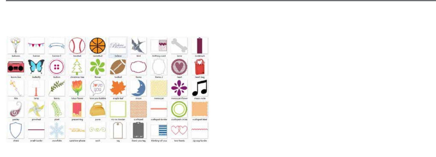
1.4 Available Digital Content
The Silhouee Studio® soware comes preloaded with designs. These become available as you connect and power on your electronic cung tool.
SAMPLE
Preloaded shapes will vary between Silhouee electronic cung tools.
Addional content is available through the Silhouee Design Store (accessed through the Silhouee Studio® soware). The store will allow you to
access and purchase addional digital content for the soware, available both from Silhouee arsts as well as independent arsts and various
companies, thus ensuring a variety in look and feel of available premade content. Further informaon on the store and downloading content will be
provided later in this manual.

Silhouee Studio® V4 | Chapter 2 - Installing Silhouee Studio® 7
2 - Installing Silhouee Studio®
2.1 Download
Silhouee Studio® is a free soware download from silhoueeamerica.com. Follow the prompts to download the soware to your computer. Make
sure to choose the corresponding operang system (PC or MAC) to the computer you are using.
NOTE FOR WINDOWS USERS ONLY: Upon hooking up the USB cord from the Silhouee electronic cung tool to your computer and powering on the Silhouee unit, you may
be prompted with a “New Hardware Wizard” to install a driver. You may proceed to automacally nd and install the driver as located on the installaon CD. The driver is not
required for proper operaon of the Silhouee Studio® soware, but may be installed to resolve the Windows automac “Plug and Play” feature of prompng to install a driver
for the hardware whenever the Silhouee is powered on.
8Silhouee Studio® V4 | Chapter 3 - Basic Soware Overview
3 - Basic Soware Overview
3.1 Opening the Soware
To open the soware on PC, locate the desktop icon and double-click. If a desktop icon was not created during installaon, go to the Windows
Start menu and select to run Silhouee Studio®.
To open the soware on Mac, open the Applicaons folder and launch Silhouee Studio®.
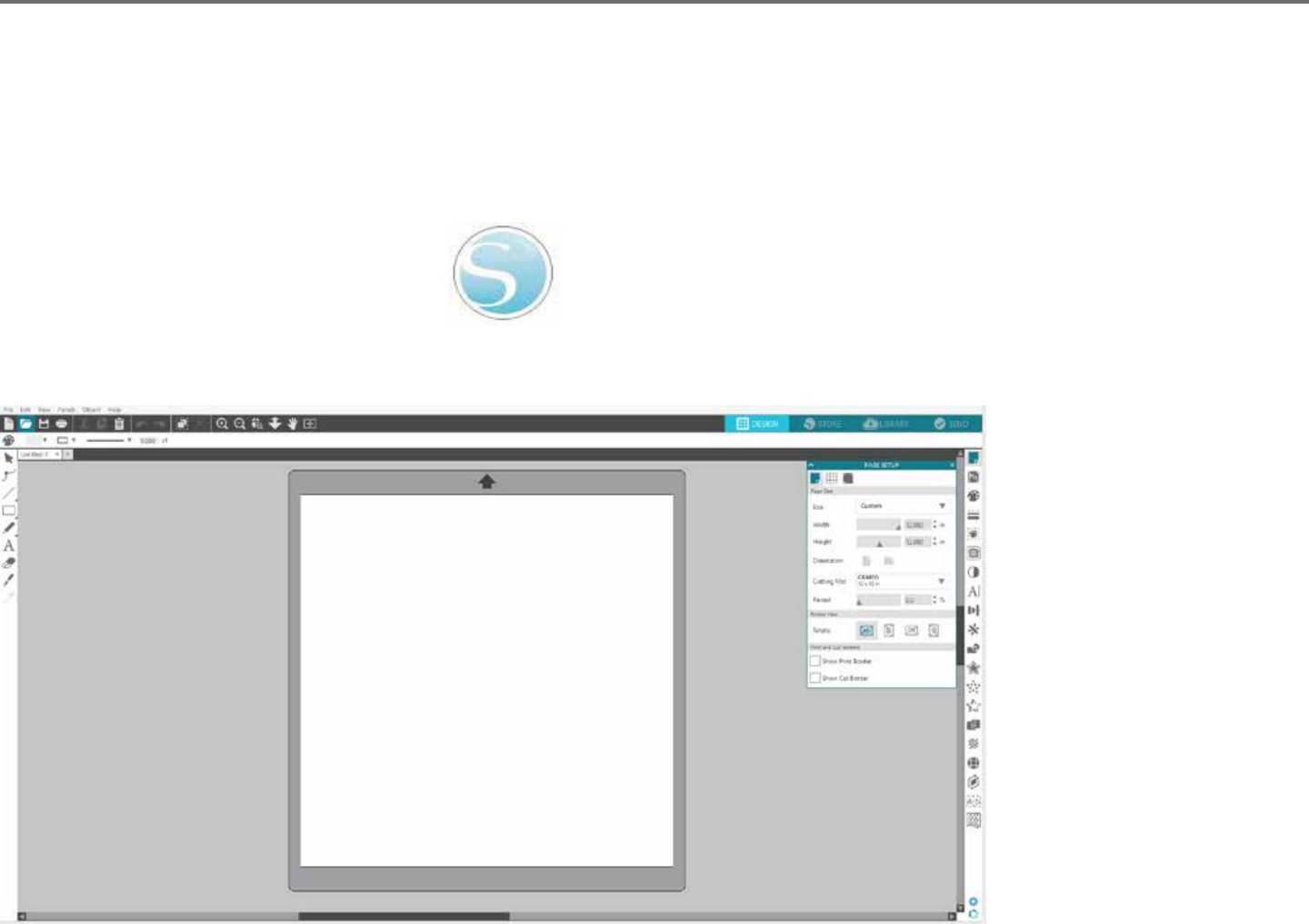
The Silhouee Studio® icon will appear as follows:
Once opened, the soware should show an available starng document and workspace as shown below:
Silhouee Studio® V4 | Chapter 3 - Basic Soware Overview 9
3.2 Soware Secons
The soware oers several seconed areas. Details as to each buon’s specic funcon are discussed in later secons. However, so that you may be
familiarized with where everything is located, a brief overview is provided for each of the secons.
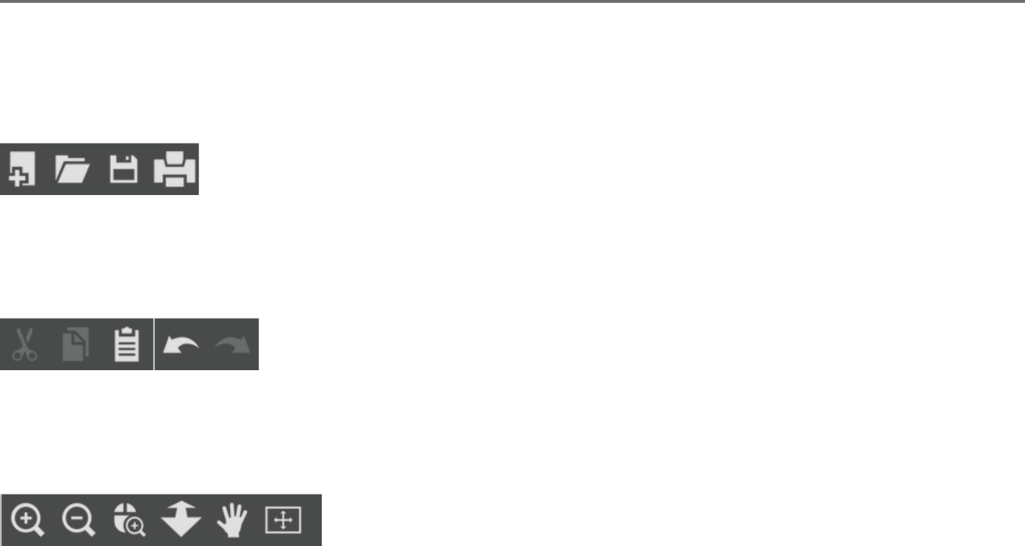
General Document Management
This secon along the top le-hand side of the screen is for general document management funcons, such as opening, saving, and sending
documents to a printer or your Silhouee electronic cung tool.
Standard Eding Tools
This secon along the top le-hand side of the screen is for basic copy/paste/cut and undo/redo acons commonly found in many programs.
Zooming Tools
This secon along the top le-hand side of the screen is for basic zoom-in or zoom-out funcons to view parts of the document from a closer
perspecve or at a more distant range.
10Silhouee Studio® V4 | Chapter 3 - Basic Soware Overview
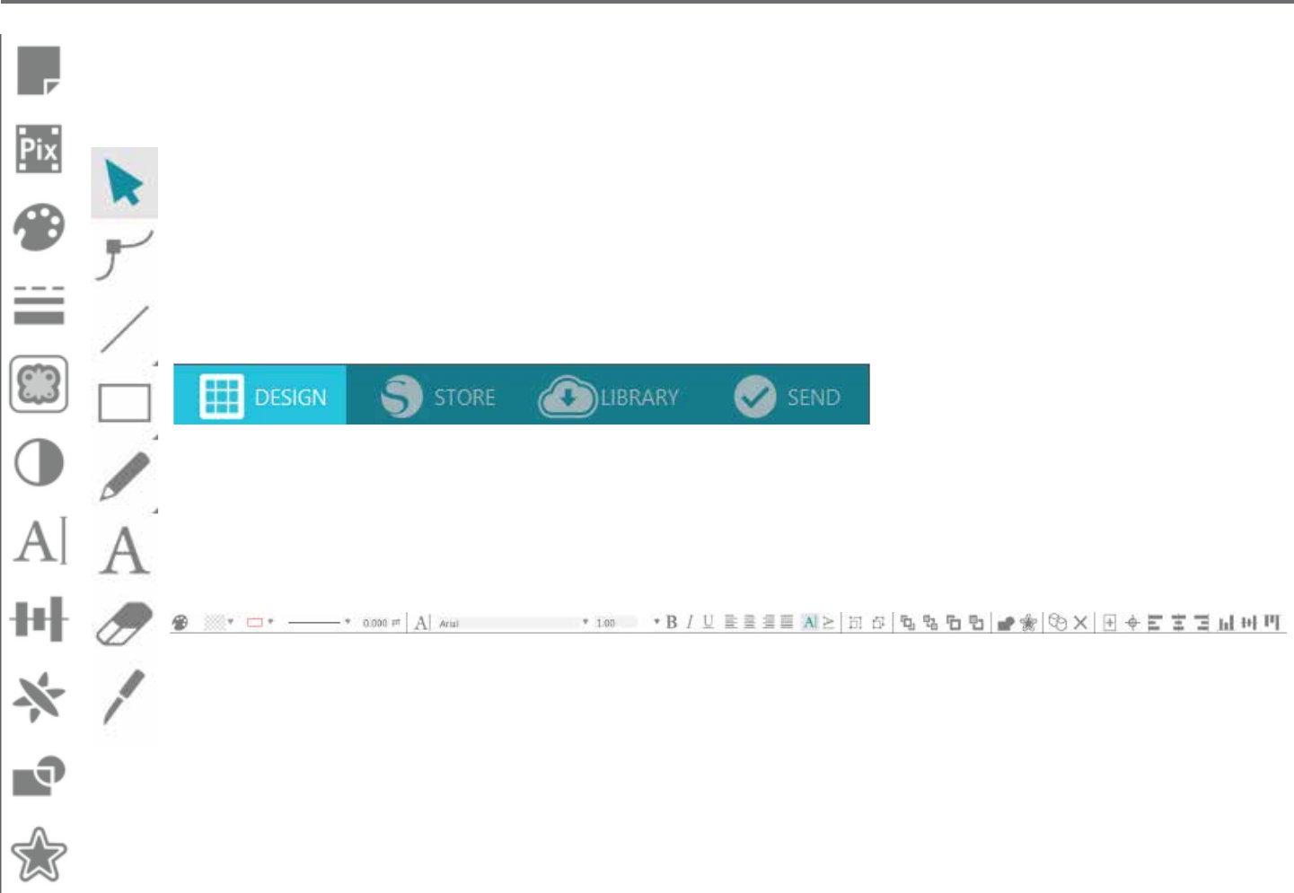
Silhouee Studio® Tools
This secon along the top right-hand side of the screen provides a range of tools for lling images, altering lines, adjusng text aributes,
adjusng and replicang images, and adjusng page and cung condions.
Drawing Tools
This secon along the le-hand side of the screen provides tools used for selecng, and drawing images as well as the ability to
drop text directly into your workspace area.
Tabs
The tabs along the top right-hand side of the screen provide navigaon to the Design page, Store, Library, and Send panel.
Quick Access Tool Bar
This secon along the top of the screen provides a range of tools for grouping and selecng images, duplicang and deleng
items, image placement priority (such as bringing images to the forefront or sending them to the back behind other images),
welding, and oseng.

Silhouee Studio® V4 | Chapter 3 - Basic Soware Overview 11
3.3 Cung/Drawing Area
You will note there are two dierent secons in your workspace:
• White workspace
• Grey holding area
The white workspace notes the acve document area. Images may be placed or drawn onto this area, or they may be placed or drawn in the grey
holding area. Any images in this grey area are invisible to your cung tool or printer. You may wish to place images o to the side to be set aside as
you do not wish to include them in your job to be printed and/or cut.
You will note a red border inside this white workspace. The red line represents the acve cung area. The cung tool will only be able to see and
be able to cut what is inside this red line. All images being sent to the Silhouee to cut should be within this red line area.

12Silhouee Studio® V4 | Chapter 3 - Basic Soware Overview
3.4 Opening Documents
Though opening the soware will always provide you with a new document, you may select a new workspace to start a new project at any
me. To start a new document you may either use the New opon from the File menu, or select the New icon:
To open exisng les you may either use the Open opon from the File menu, or select the Open icon:
You will then be prompted to navigate to the locaon where your desired le is located. Through the Open feature, the Silhouee Studio® soware
has the ability to open the following cung-type les:
• STUDIO (Silhouee Studio® les)
• GSD/GST (Graphtec “ROBO Master” program les)
• DXF *
• SVG (Designer Edion only)
* Silhouee Studio® supports the following DXF features only: Arc, Circle, Ellipse, Line, DWPolyline, Spline, and Text
The Open feature can also access simple image le types that are not in cung format, but may be imported for prinng or tracing purposes. When
using a PC, you will need to select “All Files” under the type of le as you seek to open another type of le format.
A list of recently used documents may also be accessed from the File menu under Open Recent.
You may also use the Merge opon from the File menu to open any le into the same workspace you are using rather than opening a new
document workspace.
Finally, compable le types may also be accessed by dragging the saved le from your computer directly onto your workspace in the soware.
Silhouee Studio® V4 | Chapter 3 - Basic Soware Overview 13
3.5 Document Tabs
Each new document or opened document will provide you with a new document tab at the top le-hand corner of your screen.
The tab will be labeled as “Untled” unl you save your le with a name, or if you have opened a le that already had a name, in which case the
le’s name will be displayed. The white tab will always be the acve document while all other opened inacve documents will be grey. You may click
on any inacve tabs to make it the acve workspace and toggle between open documents. Clicking on the “X” will close any open workspace.

14Silhouee Studio® V4 | Chapter 3 - Basic Soware Overview
3.6 Document Sizes
When a new document is opened, the default document size will always start at a standard Leer size (8.5” x 11”) for the original
Silhouee, Silhouee SD, and Silhouee Portrait® models or a 12” x 12” size for the Silhouee CAMEO® model.
To adjust your document size to another seng, you may either use the Page Tools opon from the View menu, or select the Page icon:
The Page panel will allow you to alter the width or length of your document. There are pre-set common sizes you may select, or you may set
measurements manually for any custom page sizes of material you may wish to use.
With custom page sizes the width may be adjusted up to a maximum 8.5 inch material width (original Silhouee, Silhouee SD, and
Silhouee Portrait®) or a 12 inch width (Silhouee CAMEO®) depending on the cung model used. The minimum recommended width for a
custom size is 3 inches. The height may be adjusted up to any desired measurement. However, the maximum recommended height is 40 inches.
While longer materials ranges may be selected, lengths exceeding 40 inches may have the possibility of becoming misaligned on the Silhouee
machine’s rollers as the cung process connues beyond this maximum recommendaon. The minimum recommended height for a custom size is
3 inches.
While viewing the Page Sengs menu, if your material is sized to t onto the cung mat, the cung mat will be displayed to help you see how
your material may be placed onto the cung mat to feed into the Silhouee when it is me to cut. Later, as you go to cut, this will also be displayed
to help ensure you are feeding your material into the Silhouee correctly. This cung mat animaon may be selected to always be displayed under
the Preferences sengs (discussed in secon 3.9).
When the cung mat is shown, you may select the
Reveal Cung mat
opon in the Page Sengs menu in order to show exactly on your mat
where images will be cut in reference to the grid that is printed on the actual cung mat.
As you slide the bar to the right or increase the percentage number, the white page workspace will become more
transparent and show the cung mat beneath. A seng of 100%, or having this bar slid all the way to the right,
will allow you to see the cung mat completely and your white workspace will be enrely transparent.
When viewing in this manner, the red line will sll represent your cung area. Images falling outside of this red
cung area will not be cut. The darker area on the cung mat represents your printer’s print margin area and is
only for reference.
Silhouee Studio® V4 | Chapter 3 - Basic Soware Overview 15
3.7 Cung Orientaon
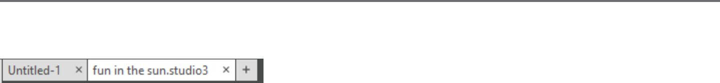
Documents may be viewed in Landscape or Portrait orientaon. Depending on how you may wish to view your workspace, images being sent to the
Silhouee will vary based on your orientaon.
Landscape is the default orientaon whenever a new document is opened.
When a document is in landscape orientaon, it will be sent to the Silhouee with the upper le-hand corner of the screen coinciding with the
upper right-hand side of your material, as seen below:
16Silhouee Studio® V4 | Chapter 3 - Basic Soware Overview
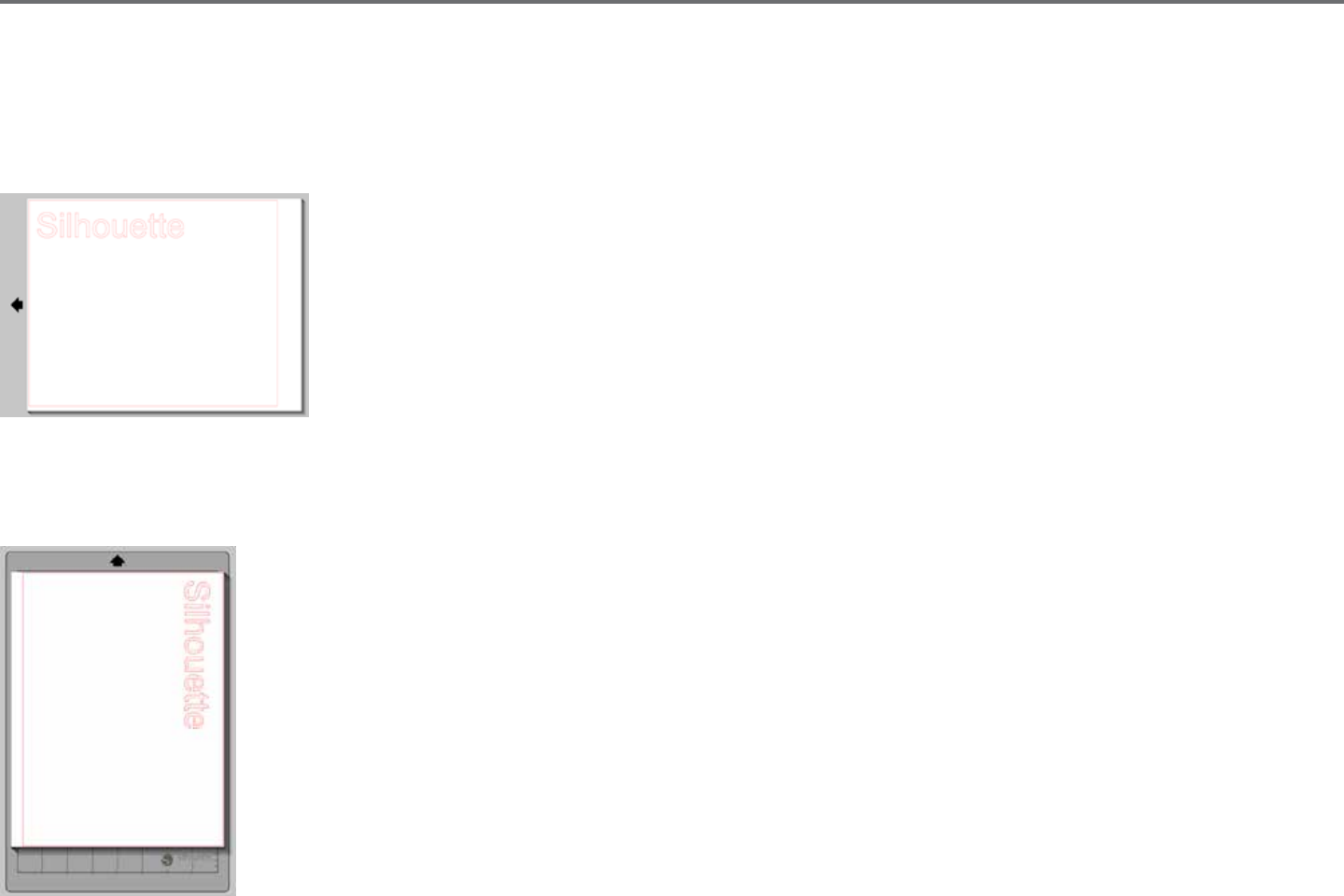
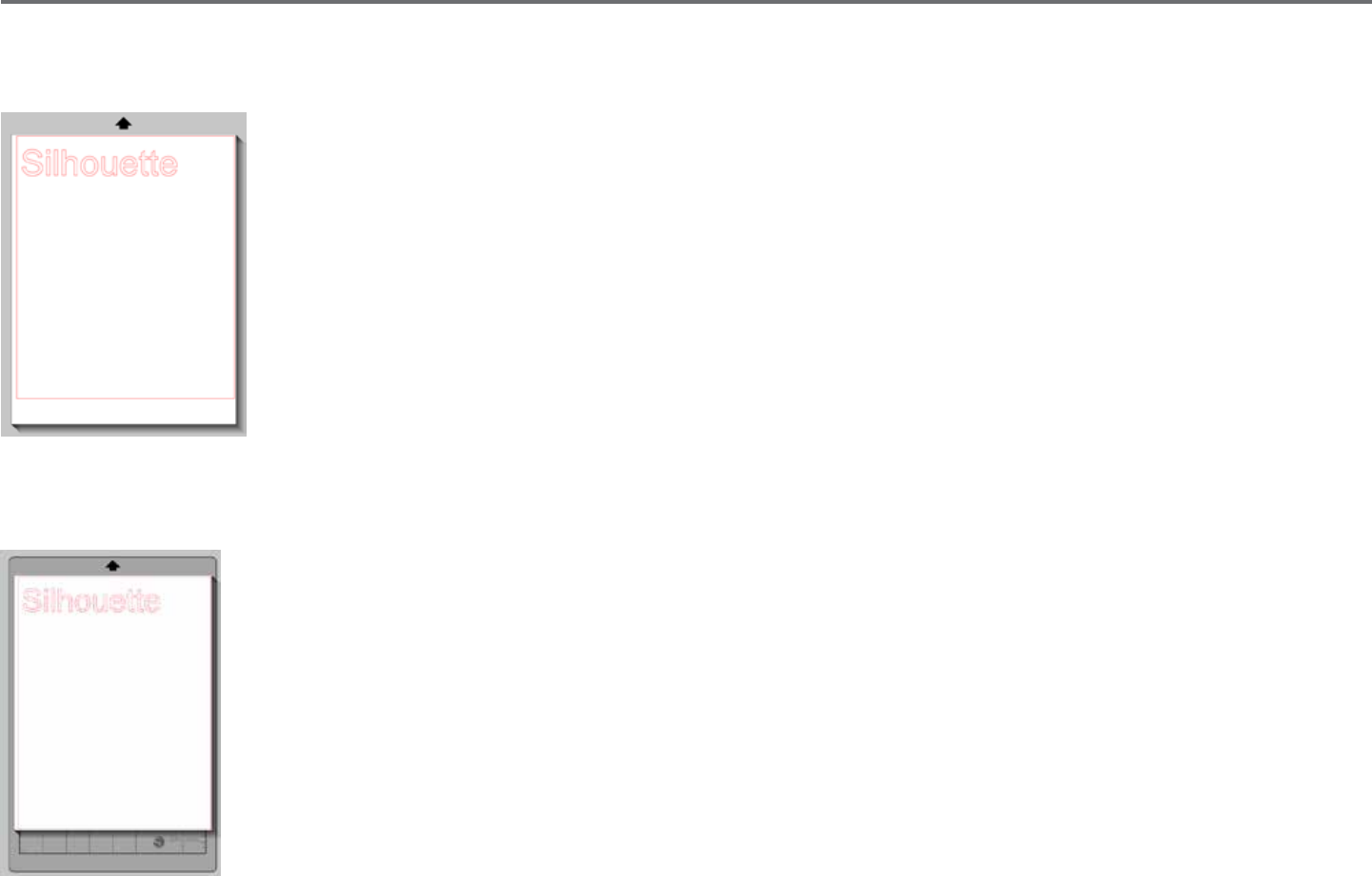
Portrait orientaon is an oponal orientaon that may be switched to through the Page Tools. Using this orientaon will provide you with a screen
that appears as the following:
When a document is in portrait orientaon, it will be sent to the Silhouee with the upper right-hand corner of the screen matching the upper
right-hand side of your material, as seen below:
The Page Tools also provides the ability to rotate how you are viewing your page. While the Page Orientaon will dictate
the way your cung job is being sent to the Silhouee to cut, the Rotate View opon will simply rotate your workspace on
the screen for a dierent perspecve.

Silhouee Studio® V4 | Chapter 3 - Basic Soware Overview 17
3.8 Viewing and Zooming
Oen as you view your workspace, you may either wish to zoom in to get a closer look at smaller images or parts of an image that may be more
dicult to work with.
Zoom In
This tool will zoom into the center of your workspace for a closer view.
Zoom Out
This tool will zoom out from your view for a more broad perspecve.
Selecon Zoom
This tool will allow you to zoom to specic areas of your workspace by drawing a box around the area you wish to zoom into.
Drag Zoom
Aer clicking on this tool, your icon will appear as the Drag Zoom icon above. You may then click and hold down your mouse to zoom in or
out manually to any selected scale.
Pan
This allows you to move your enre workspace around.
Fit to Page
Clicking the Fit to Page icon will immediately t the full dened workspace to the center of your screen.

18Silhouee Studio® V4 | Chapter 3 - Basic Soware Overview
3.9 Preferences
There are a number of user-controlled opons that may be found in the Edit menu (PC) or Silhouee Studio® menu (Mac) under Preferences.
General
This secon allows you to manually select the program language and how oen you may wish the program to check for available soware updates
automacally. This secon also provides preferences regarding units of measurement displayed in the program. You may adjust the following:
• Unit of Measurement – Adjust all displayed measurements to desired unit.
• Dimensions – Turn on or o image’s measurement properes as images are selected.
Defaults
This secon will allow you to adjust the default sengs when Silhouee Studio® soware is opened. You may adjust the following sengs:
•Default Fill Style – Provides the ability to select how new user-drawn images are created as to whether they are displayed as an outline only
(as red line images or grey line image), or as solid ll images (which may be preferable for the creaon of Print & Cut images that are made by the
user).
•Registraon Marks Preference – Adjusts the program to default to have registraon marks turned on or o.
•Page Orientaon – Dene whether Landscape or Portrait orientaon is desired whenever a new document is started.
•Page Border – Gives the opon to cut to the edge of your page.

Silhouee Studio® V4 | Chapter 3 - Basic Soware Overview 19
Display
This secon provides display opons including:
•Analiasing – Helps smooth jagged lines as they are created and viewed. Higher sample rates will increase the smoothness of lines. The “o”
seng will produce rougher edges, but increases drawing speed.
•Buon sizing – Allows for larger or smaller buons to be displayed.
•Animaon – Controls speed of animang acons, such as images being moved on undo or redo acons, or during zooming in and out. Can be
adjusted to “Instant” to turn animaons o.
•Background Color Preference – Allows you to determine the color of the inacve workspace area.
•Curve Quality – Enhances the visual appearance of lines on screen. Does not aect actual cut quality.
Import Opons
Allows you to determine the behavior of various le types when opened.
Tools
This secon provides preferences for how you may wish to view bezier control handles and how you would like images to behave when certain
modicaons are applied. It also provides preferences for adjusng how the program selects images or how various drawing tools either connue
to draw or nish upon compleon of using the drawing tools.

20Silhouee Studio® V4 | Chapter 3 - Basic Soware Overview
Advanced
This secon provides addional advanced opons. In this secon, you may adjust the following:
•Restore Factory Defaults – Resets all preferences.
•Reindex My Library –Performing this acon will re-index the library to ensure corrupon or errors may be resolved should you experience any concerns
with your library loading properly or being able to use the library’s Search funcon properly.
•Set Library Permissions – Allows library to be properly accessed according to computer account permissions.
•Restore Pre-loaded Designs –Restores pre-loaded designs according to the Silhouee model detected.
•Reset Library – This acon will remove all images and folders from your library and reset the library back to its original soware installaon
sengs.
•OpenGL Sengs – Aends to select display issues.
•HTTP Sockets – Depending on your internet connecon speed, this opon may be adjusted to a higher number of sockets to increase the
download speed when purchasing images from the Design Store.
•IME Seng – Allows for typing of non-western characters.
•Proxy Sengs – Used for proxy connecon setups.
•Packet Size – Rate at which informaon is sent to the Silhouee.
Another program opon not in the Preferences menu is the Soware Color Theme buon located in the boom right-hand corner of the
soware screen.
Clicking on this buon will cycle through a preselected list of color themes for the soware’s overall appearance, should you prefer some color
other than the default dark grey interface.
Silhouee Studio® V4 | Chapter 4 - Drawing/Eding Images 21
4 - Drawing/Eding Images
4.1 Basic Drawing Tools
Silhouee Studio® allows users to draw and create images very easily through a set of basic drawing tools. All drawing tools are located on the le
side of the soware screen.
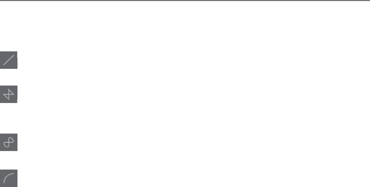
Line Tool
The Line Tool allows for the creaon of single straight lines. Holding down the Shi key on your keyboard while drawing will force a straight
vercal, horizontal, or 45� increment line from the start point.
Polygon Tool
The Polygon Tool allows for the creaon of mulple straight lines. A point will be created upon each mouse click. Lines will connue to be
drawn unl the image is closed by aligning the end point with the starng point, or by double-clicking the mouse to stop drawing. Holding
down the Shi key on your keyboard while drawing will force a straight vercal, horizontal, or 45� increment line from the start point or last
point dropped.
Curved Shape Tool
The Curved Shape Tool allows for the creaon of mulple curved lines. A point will be created upon each mouse click. Lines will connue to
be drawn unl the image is closed by aligning the end point with the starng point, or by double-clicking the mouse to stop drawing.
Arc Tool
The Arc tool allows you to draw any size arc on your page.

22Silhouee Studio® V4 | Chapter 4 - Drawing/Eding Images
Rectangle Tool
The Rectangle Tool allows for the creaon of a square or rectangle. Holding down the Shi key on your keyboard while drawing will create
a square, while holding down the Alt key on your keyboard will make the inial cursor point where your image is started as the exact center
of your object.
Rounded Rectangle Tool
The Rounded Rectangle Tool allows for the creaon of a square or rectangle with rounded corners. Holding down the Shi key on your
keyboard while drawing will create a rounded square, while holding down the Alt key on your keyboard will make the inial cursor point
where your image is started as the exact center of your object. As a rounded rectangle is selected, you will nd two red control points on
the rectangle’s upper le-hand corner. These may be dragged to adjust the curves of the rectangle’s top and boom or sides, or you may
select both simultaneously by holding down the Shi key on your keyboard and dragging one of the control points.
Ellipse
The Ellipse Tool allows for the creaon of an oval or circle. Holding down the Shi key on your keyboard while drawing will create a circle,
while holding down the Alt key on your keyboard will make the inial cursor point where your image is started as the exact center of your
object.
Regular Polygon
The Polygon Tools allows for creaon of shapes of dierent number of sides. The default number of sides is ve, but the slider bar in the
middle provides a method of raising or lowering the number to produce dierent shapes, such as a triangle.
Freehand Tool
The Freehand Drawing Tool allows for the creaon of a connuous free-form line. Lines drawn with this tool will connue unl the mouse
buon is released, or the image is closed by aligning the end point with the start point.
Smooth Freehand Tool
The Smooth Freehand Drawing Tool allows for the creaon of a smooth, connuous free-form line. Lines drawn with this tool will have
smooth transions and no sharp angles. Lines drawn with this tool will connue unl the mouse buon is released, or the image is closed
by aligning the end point with the start point.
Silhouee Studio® V4 | Chapter 4 - Drawing/Eding Images 23
4.2 Eding Images
All line points on images may be edited, if changes to the exisng image are desired.
Select Tool
The Select Tool determines which image is selected as the acve image and allows you to move images around on your screen. This is your
default tool to click on images to show they are selected.
Edit Points
To enter the Point Eding Mode, you may either double-click on a selected image, or use the Edit Points tool. This tool will allow you to edit
any points of your image to move them around or remove them. Only single ungrouped line selecons may be edited. Ungrouping will be
discussed in later secons.
To exit the Point Eding Mode, you may double-click on your image again, or return to the regular select mode by clicking on the Select tool.
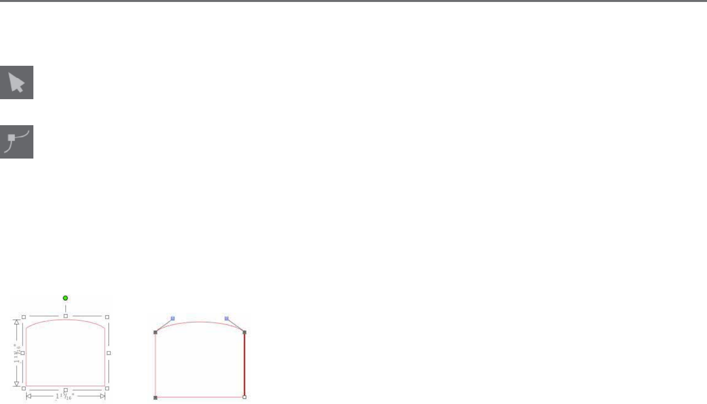
Point Eding Mode
When you enter the Point Eding Mode, selected images will change from displaying the resizing and rotang control handles around the image
to showing the points, or nodes, of the image. Points on lines are where the line may take a new direcon or change from being at (or straight) to
being curved.
Regular Selecon Mode Point Eding Mode
In Point Eding Mode, the selected point will be displayed in white while all other points will be dark grey. The selected line associated with the
selected point will be emphasized as a bolded red line. Addional lines that have blue points are handles to adjust curved lines.
In Point Eding Mode, you will also be shown the Point Eding toolbar on the right-hand side of the screen. You may do the following acons in
Point Eding Mode:

24Silhouee Studio® V4 | Chapter 4 - Drawing/Eding Images
Move/Adjust Points
Move a point by hovering with your mouse over any point on the line. Once over a point that may be edited, the cursor will adjust to show you
may click and grab the point to move it to any desired locaon. With curved lines, you may similarly grab the blue points and drag them around the
screen to adjust the curve of the associated line segment.
Add Points
Add a point by hovering over the line where no points currently exist where you may wish to drop a new point to edit your image. Once over a line
where a point may be dropped, the cursor will be adjusted to show you may click to drop a point onto the desired line locaon.
Aside from the tools found in Point Edit Mode, there are two addional eding tools found on the le-hand side of the screen.
Delete Point
Any selected point will be deleted by using the Delete Point tool, or by right clicking on the selected point and choosing the Delete Point
opon. Deleng a point will cause the closest points on either side of the deleted point to join and create a new connecng line. Note that
this tool is dierent from deleng an image and is only intended to delete individual points. It will only be available while in Point Eding
Mode.
Break Path
You may break the path of any line point by using the Break Path tool, or by right clicking on the selected point and choosing the Break Path
opon. Breaking a path will create two new points from the originally selected point where the path was broken.
You will note that a broken path, or two unconnected end points of opposite ends of the same line, may be re-joined by dragging one end
point onto the opposite end point of the image.
Silhouee Studio® V4 | Chapter 4 - Drawing/Eding Images 25
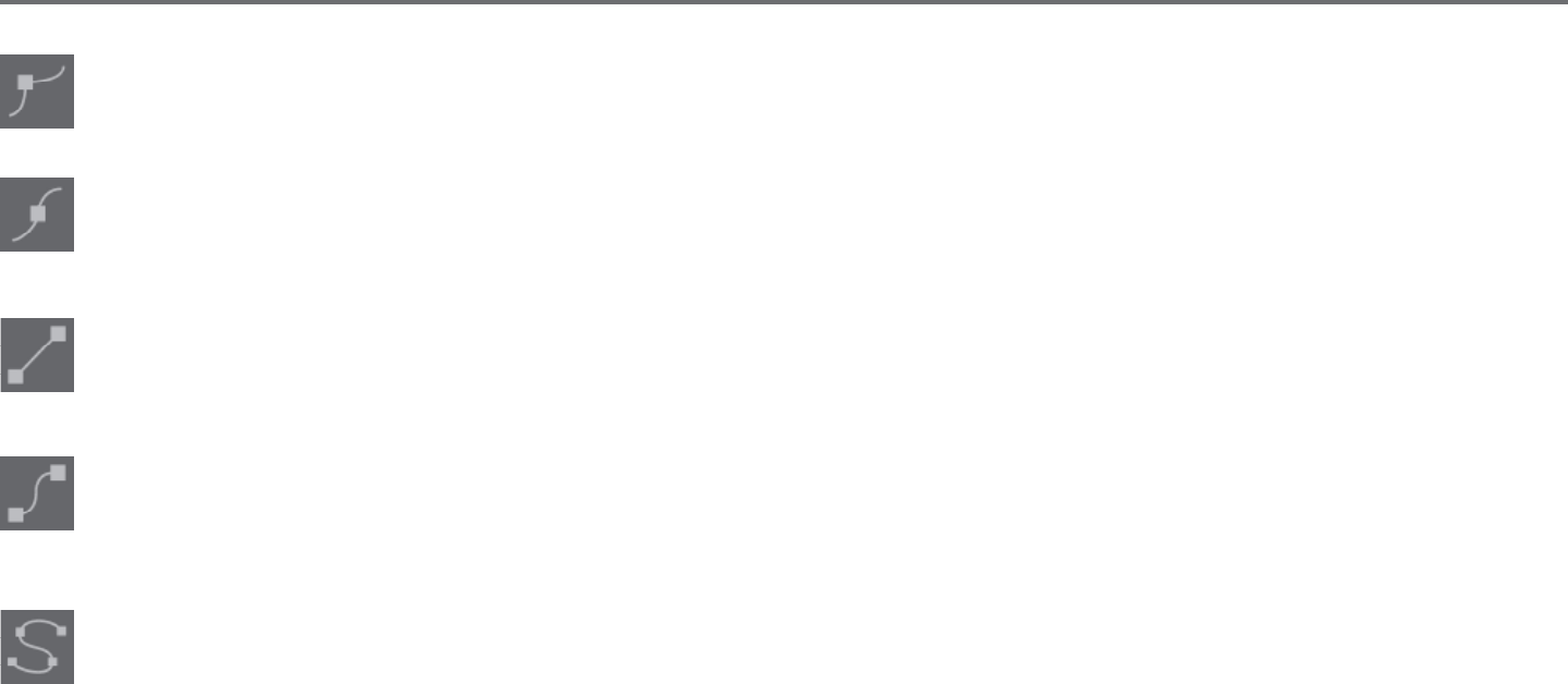
Corner
The Corner tool will allow a selected point to be so that the control handles at the selected intersecng point can be adjusted each
individually to create a sharp corner.
Smooth
The Smooth tool will allow a selected point to be adjusted to make a smooth transion point at the selected intersecng point.
Make Flat
The Make Flat opon will adjust the selected line (the line emphasized in bold red that is associated with whichever currently selected
point) to a at, straight line.
Make Curve
The Make Curve opon will adjust the selected line (the line emphasized in bold red that is associated with whichever currently selected
point) to a curved line.
Simplify
Some library images or other imported images from other sources may contain a very large number of points. The Simplify tool will
automacally re-adjust the image’s points and simplify the image to its simplest possible point form while maintaining the image’s original
overall line form.
26Silhouee Studio® V4 | Chapter 4 - Drawing/Eding Images
Aside from the tools found in Point Edit Mode, there are two addional eding tools found on the le-hand side of the screen.
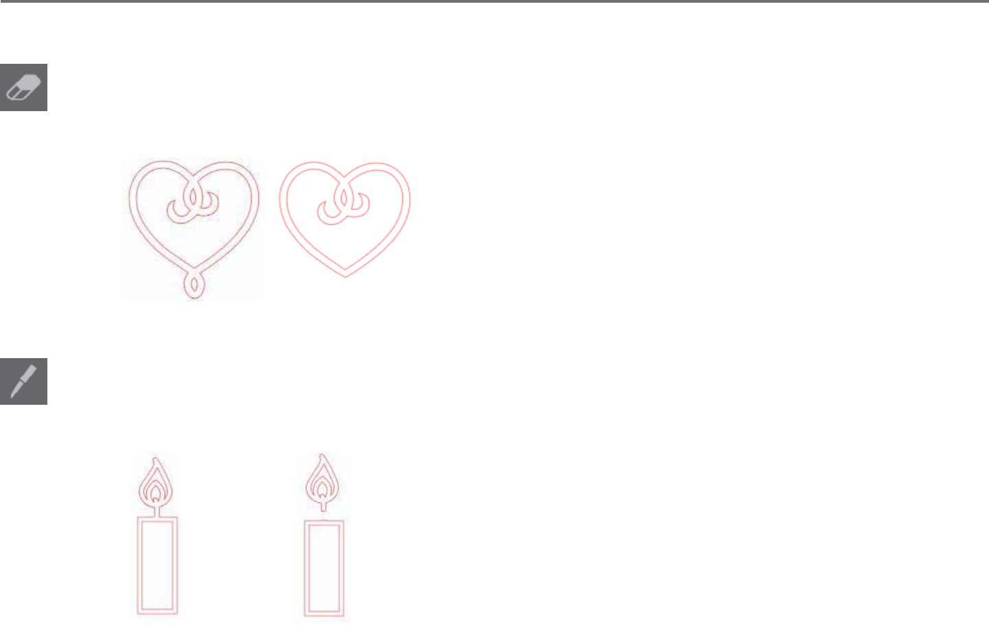
Eraser Tool
You may erase any part of any image using the Eraser tool to easily and immediately remove inner parts or edges of the line image. The
Designer Edion of the soware features several opons for eraser shapes and allows you to choose between creang an open or closed
eraser path.
Original Image New Image Using Eraser Tool
Knife Tool
You may segment images using the Knife tool. This tool delivers a straight-line cut to separate parts of images to create a new separate
independent shape. The Designer Edion of the soware features several opons for knife path shapes and allows you to choose between
creang an open or closed knife path.
Original Image New Image Using Knife Tool
Silhouee Studio® V4 | Chapter 4 - Drawing/Eding Images 27
4.3 Line Tools
Lines in the program, including text, images created using the drawing tools, and library images, may be altered to have dierent properes.
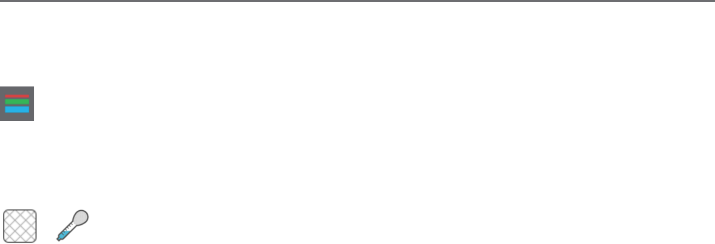
Line Color Opons
While lines will default to be displayed in red, you may alter lines to any desired color. Altering line colors will not aect their properes
in how they may cut. Altering line colors may be helpful to allow you to more easily view dierent images or image parts, see lines in
whichever color you may prefer to view them, or adjust image parts specically with prinng in mind for Print & Cut jobs where it may be
important that line colors are selected to be printed.
To adjust line colors, select your image and access the Line Color menu by clicking on the icon shown above. You may then select any of the Basic
Menu color opons. The hash line selecon will always represent “clear”. The color picker tool will allow you to select any color from another object
in the drawing area to duplicate the desired color.
Clear Color Picker
The Advanced Opons menu will allow you to create lines in any desired custom color. You may either drag the target on the color spectrum to
visually match the color you are looking for, or type in the RGB (Red Green Blue) or HSL (Hue Saturaon Lightness) value of your desired color. You
will also have the ability to adjust the Transparency of the line.

28Silhouee Studio® V4 | Chapter 4 - Drawing/Eding Images
Line Style Opons
Within the Line Style menu, you may adjust the style of your line to be a solid (default) or dashed style line. Lines will accordingly be cut or
printed in the selected style.
Lines are viewed in point sizes regarding their width. The point size may be adjusted to any desired specicaon. While line width may be adjusted,
the line will always be cut or sketched in a xed width; that is, according to how thick the blade or pen is that you are using.
Line thickness may be adjusted by either manually dragging the Thickness opon bar or by typing in the desired point thickness.
The Corner Style opon will adjust how lines appear at any of the image’s corner points where Corner is a sharp edge whereas Rounded will be a
smoother edge.
The End Cap Style opon will only adjust lines that have open ends. Flat or Square provide varying sharper at edges at the line p whereas
Rounded provides a smoother rounded edge to the line p.
The Posion opon will adjust if the line is In Front of a lled image, or Behind the lled image.
Silhouee Studio® V4 | Chapter 4 - Drawing/Eding Images 29
4.4 Fill Tools
Closed images (where the starng point of the line connects with the ending point of the line) including Text, images created using the drawing
tools, and library images, may be altered to have dierent lled properes. Only closed images may have lled aributes. If the path is broken on
any closed images, any applied ll aributes will immediately disappear.
Fill Color Opons
While closed images will default to be displayed as empty, you may ll any closed image with any desired color. Altering ll colors may be
helpful to allow you to more easily view dierent images or image parts, see shapes and text in whichever color you may prefer to view
them, or adjust images specically with prinng in mind for Print & Cut jobs.
To apply ll colors, select your closed line image and access the Fill Color menu by clicking on the icon shown above. You may then select
any of the Basic Menu color opons. The hash line selecon will always represent “clear”. The color picker tool will allow you to select any
color from another object in the drawing area to duplicate the desired color.
Clear Color Picker
The Advanced Opons menu will allow you to create ll colors in any desired custom color. You may either drag the target on the color spectrum to
visually match the color you are looking for, or type in the RGB (Red Green Blue) or HSL (Hue Saturaon Lightness) value of your desired color, if you
are seeking a specic known color. You will also have the ability to adjust the transparency of the lled color by manually dragging the Transparency
opon bar or by typing in the desired percentage of how transparent you wish the lled color to be, where 0% is solid and 100% is completely clear.
30Silhouee Studio® V4 | Chapter 4 - Drawing/Eding Images
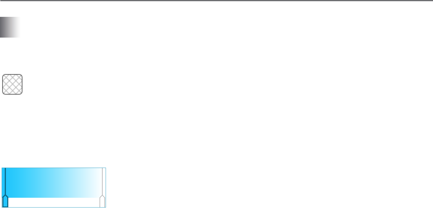
Fill Gradient Opons
Similar to lling images with solid colors, you may also select to ll any closed line images with a gradient ll.
To apply gradient ll opons, select your closed line image and access the Fill Gradient menu by clicking on the icon shown above. You may then
select any of the Basic Menu precreated gradient opons. The hash line selecon will always represent “clear”.
Clear
You may also alter the basic direcon of the gradient by clicking on any of the Direcon opons at the boom of the Basic Opons panel.
The Advanced Opons menu will allow you to create your own custom gradient lls based o of the last gradient ll selected. Gradient lls will
always have a minimum of two colors, with one color at the top and one color at the boom. The gradient will then create a range between the two
selected colors.
You may change either of these colors in the range by clicking on the color arrow bars on the le-hand side of this gradient creator tool. Once the
color is selected, you may then select any new color from the Select Color tools directly below. You may also add new bars at any interval between
the top and boom colors, or slide any color bars in between the top and boom gradient color bars up and down to create new gradient eects.
Also in the Advanced Opons is the ability to rotate the angle of the gradient eect to any customized degree by either manually dragging the Angle
tool or by typing in a specied degree. You will also have the ability to adjust the transparency of the line by manually dragging the Transparency
opon bar or by typing in the desired percentage of how transparent you wish the lled gradient eect to be, where 0% is solid and 100% is
completely clear.

Silhouee Studio® V4 | Chapter 4 - Drawing/Eding Images 31
Fill Paern Opons
The nal ll opon is used to ll any closed line images with a paern ll. To apply paern lls, select your closed line image and access the
Fill Paern menu by clicking on the icon shown above. You may then select any of the paern opons.
Once your desired paern ll is selected, the Advanced Opons menu will allow you to adjust the paern’s direcon Horizontally or Vercally, or
adjust to either a Fixed or Stretch aspect rao. Opons are provided in this menu to rotate the paern by either simple preset degrees, or to any
customized degree by either manually dragging the Angle tool or by typing in a specied degree.
In addion, you have the ability to scale the paern’s size to alter the paern itself as it lls the selected shape. You may do this by either manually
dragging the Scale Paern bar or entering a new percentage value of how much larger or smaller you may wish to make the lled paern.
You will also have the ability to adjust the transparency of the line by manually dragging the Transparency opon bar or by typing in the desired
percentage of how transparent you wish the lled gradient eect to be, where 0% is solid and 100% is completely clear.
Addional paerns may be downloaded from the Silhouee Design Store.
You can create paerns from your own images by going to File > Import > Import Opons. Navigate to the image you would like to use and select it.
A new dialogue box appears where you can add informaon about the image. Press OK to add the image to the User Designs folder in your library.
From there, you can drag your image onto any llable shape on your workspace.
32Silhouee Studio® V4 | Chapter 4 - Drawing/Eding Images
Shadow Opons (Designer Edion only)
You can add and adjust a shadow by clicking the Shadow icon in the toolbar above the workspace. In the Shadow menu, you can adjust the
shadow oset, color and transparency.
Sketch Opons (Designer Edion only)
Create a sketch design by clicking the Sketch icon in the toolbar above the workspace. In the Sketch menu, you can adjust the sketch edge,
ll type, and ll eect.
Rhinestone Opons (Designer Edion only)
Create a rhinestone design by clicking the Rhinestone icon in the toolbar above the workspace. In the Rhinestone menu, you can choose
a rhinestone eect, rhinestone size and spacing, and placement opons. For advanced rhinestone opons, see the ‘Designer Edion Plus
Features’ secon.
Silhouee Studio® V4 | Chapter 5 - Text 33
5 - Text
Silhouee Studio® has the ability to ulize any font that is installed on your computer. You do not need to install these fonts into the
program. Silhouee Studio® will simply access all installed font les and display them for you as you go to create your desired text.
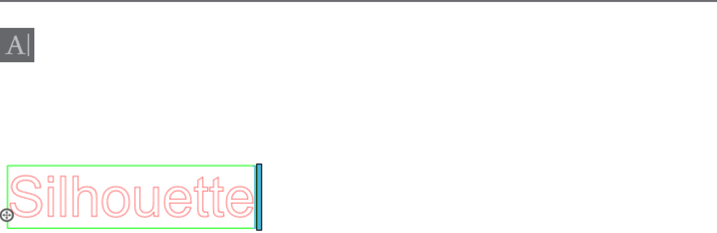
5.1 Creang Text
To use your fonts, click on the text tool located on the le-hand side of the soware screen.
Clicking this will allow you to place a text cursor onto your workspace and begin typing directly onto the screen.
The red blinking line is your cursor to show where you are typing. You may back up or move forward by either clicking your mouse or using your
computer’s right and le arrow keys.
The surrounding green box is your text box. This box may be adjusted by clicking and holding the black bar on the right edge of the text box.
Dragging this bar to the le will allow you to wrap your text. Dragging this bar to the right will allow you to bring text back toward being on a single
linear path.
You may double-click or click outside of the text to exit the Text Eding Mode. You may return at any me to re-edit any words or leers by double-
clicking again on your created text.
34Silhouee Studio® V4 | Chapter 5 - Text
5.2 Manipulang Text
During the creaon of your text, the Text Style menu will be opened on the right-hand side of your screen providing mulple adjustment opons.
Available Fonts
The rst secon of this menu will display the current selected font with addional font opons that are installed on your computer you may scroll
through. The top of this secon may be used to search for any specic font by typing in a font name if it is known.
You may change fonts during the Text Eding Mode and use a new font within the same text box with other fonts. Dierent fonts may also be
applied to exisng text or leers during Text Eding Mode by highlighng the desired string and selecng the newly desired font. If you are not in
Text Eding Mode, new fonts may sll be applied to selected text, but such adjustments will change the font for the enre selected text box.
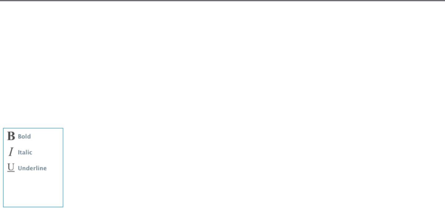
Font Characteriscs
Some fonts are programmed to enable the use of certain style characteriscs allowing you to bold, italicize, or underline text
or leers. These characteriscs will only be highlighted to be available for selecng if the font in queson is programmed
with that characterisc and such characteriscs can be applied. To apply one of these characterisc, you may highlight the
intended leers or words and then click on the available characterisc.
While Bold, Italic, and Underline opons are displayed, if there are any addional available opons programmed for the
selected font, a scroll bar will appear on the right-hand side of this opon box allowing you to scroll down and view whatever
other opons may be programmed.
Silhouee Studio® V4 | Chapter 5 - Text 35
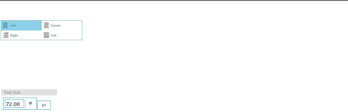
Text Juscaon
While text will be automacally be jused to the le, if your text is wrapped on mulple lines, you may alter
your text juscaon as desired.
Text Size
Text size will always default to 72 point size. This refers to the font’s printed font size. Though fonts vary as they are programmed by a wide variety
of sources, this will generally equate to roughly a one (1) inch height (or 25 mm). The most common point sizes for print-format fonts are included
in the available drop-down list, though any custom number may be manually typed into this size preference.
Other common equivalent measurements in the list include:
18 pt = 0.25 inch (6 mm)
24 pt = 0.33 inch (8 mm)
36 pt = 0.5 inch (13 mm)
48 pt = 0.66 inch (17 mm)
144 pt = 2 inches (50 mm)
288 pt = 4 inches (100 mm)
Again, these measurements are approximaons and will vary from font to font, so if you are seeking to obtain a specic measurement, you may
wish to alternately re-size your text to your desired specicaon aer creaon.
36Silhouee Studio® V4 | Chapter 5 - Text
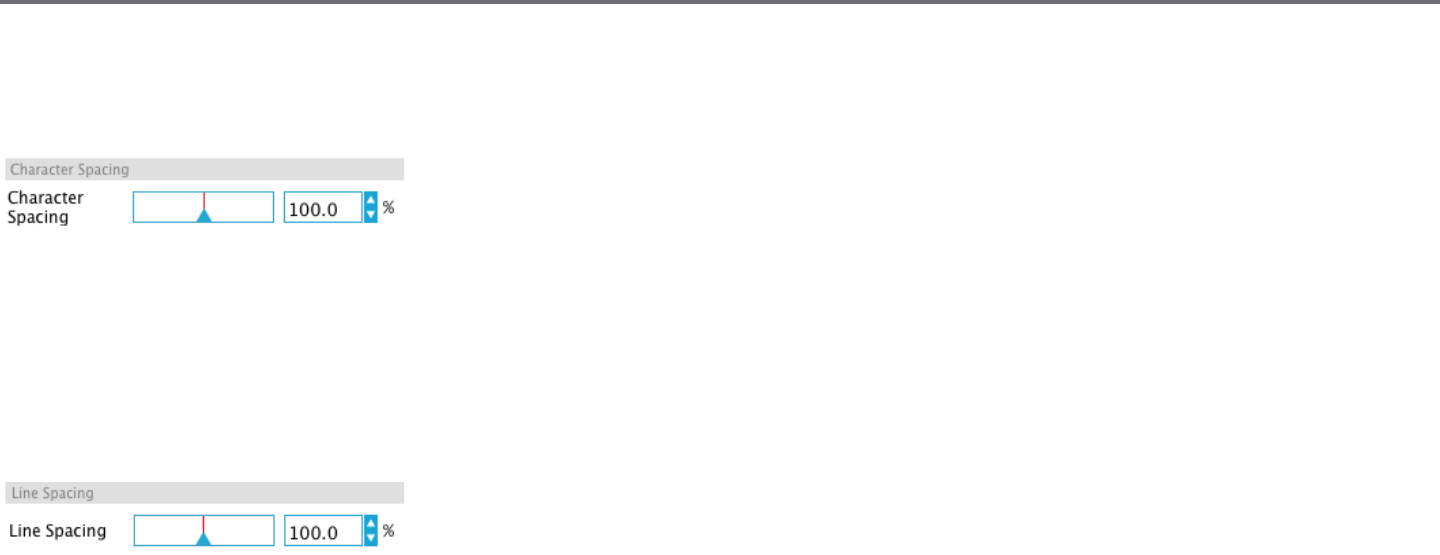
Character Spacing
Leers may be adjusted from their normally programmed spacing to either bring them closer together or push farther apart with the Character
Spacing opon.
Spacing will always start at 100% indicang spacing between characters are normally distanced. As the number is lowered or the bar is slid to the
le, leers will come closer together. As the number is raised or the bar is slid to the right, leers will become spaced farther apart.
Line Spacing
If your created text is wrapped to mulple lines, you may similarly increase or decrease the Line Spacing opon to adjust the distance between lines
of text.
Spacing will always start at 100% indicang spacing of lines are normally distanced. As the number is lowered or the bar is slid to the le, text lines
will come closer together. As the number is raised or the bar is slid to the right, text lines will become spaced farther apart.
Silhouee Studio® V4 | Chapter 5 - Text 37
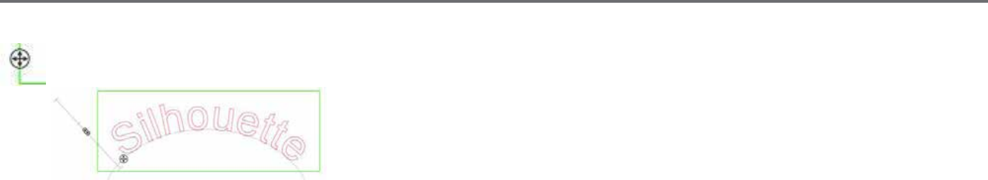
5.3 Text to Path
As text is created, or while in Text Eding Mode, you will nd a control point located on the le-hand side of the text being created:
This control point may be dragged to rest directly on any line path within your workspace. For
example, you may create an oval with the Ellipse tool and then drag your text onto this line to
achieve an arced eect:
As text is applied to a path in this manner, you will note a vercal bar to the le of the text. This allows for a new control bar which can be used to
adjust the placement of your text relave to the line onto which the text has been applied so that it may be placed on, above, in line with, or below
the path.
Note also that the object used as a path will turn grey. This indicates that this image is now turned o for cung purposes. If you wish to re-enable
the object being used as a path to cut, you may visit the Cut Style Opons as previously discussed and select Enable Cut Style as the grey path
object is selected.
38Silhouee Studio® V4 | Chapter 6 - Manipulang Images
6 - Manipulang Images
There are many tools in Silhouee Studio® allowing for basic and advanced manipulaon of images and text. The following secon provides an
overview for all of these included tools and how they may be used.
6.1 Basics
Like most any soware program, Silhouee Studio® has a set of common basic eding tools as follows:
Selecng
Images may of course be selected by clicking on them. Mulple images may be selected by holding down the Shi key on your computer keyboard
and clicking on another image. You may repeat this acon to select as many images as desired. Holding down the Shi key and clicking on an image
that is already selected will deselect that image.
Mulple images may be also be selected by clicking above an image and dragging your mouse to enclose all
desired shapes to be selected at the same me. As you hold your mouse buon down and drag your mouse, you
will see a dashed line creang a selecon box showing what you are selecng. Upon leng go of your mouse, all
enclosed images in this box will be selected together in the same bounding box.
If you wish to select all available images on the screen together, you may click on the Select All buon located in the Quick Access Tool bar.
If you wish to select only those images that are the same color, you may click on the Select by Color buon located on the right-hand side.
If you wish to deselect all currently selected images, you may click on the Deselect All buon located in the Quick Access Tool bar..
Silhouee Studio® V4 | Chapter 6 - Manipulang Images 39
Cut, Copy, and Paste Tools
These tools perform the basic expected acons of copying selected images, pasng them, or cung them from view. Images copied or
cut will reside in your computer’s memory on a virtual clipboard. You may only have one object on this clipboard at a me. This means if
you copy one image and then copy another, only the most recent image will be waing on the clipboard to be pasted. These acons may
be accessed from the top tool bar, in the Edit menu, or by right-clicking on an image, as well as by using standard shortcut keys for these
acons.
Pasng copied images will place the copy directly to the right of your original image so you may easily see and nd your copy. An addional Paste in
Front opon is also provided to be able to paste a copy of an image directly on top of itself and is found in the Edit menu, in the right-click menu for
the selected image, or by using standard shortcuts for this acon.
Duplicate
The Duplicate opon performs the same acon as copying and pasng the selected image to the side, but does so without the need of
ulizing your clipboard and is a one-click operaon. This toolbar buon is located at the top of the soware screen and can alternately be
located in the Edit menu or by right-clicking on a selected image.
Delete
Selected images may be deleted from your workspace by clicking on the Delete buon located at the top of the soware screen, by
accessing the Edit menu and selecng Delete, right-clicking a selected image and choosing the Delete opon, or by simply pressing the
Delete key on your computer keyboard.
Undo/Redo
Any acon taken, including simply moving an image, may be undone. To back up to the previous acon taken, click the Undo buon. There
are an unlimited number of acons you may go back to with the Undo buon, including going back to when you rst opened your new
workspace.
Similarly, you may click the Redo buon to repeat any acons you may have undone. You may connue to use this buon unl you return to the last
acon taken.

40Silhouee Studio® V4 | Chapter 6 - Manipulang Images
Transfer Properes (Designer Edion only)
Properes such as line color and cut style can be transferred from one shape to another by selecng the shape you want to transfer
properes to, selecng the Eye Dropper icon in the le-hand tool bar, and then clicking on the shape you want to imitate.
Layers (Designer Edion only)
When you import a project with layers created in another program, you can access those layers in the Layers panel. You can also the +/-
keys to add or remove layers in Studio.
Silhouee Studio® V4 | Chapter 6 - Manipulang Images 41
6.2 Grouping/Ungrouping
These two acons are commonly used and are invaluable tools for helping to manipulate and adjust images. To understand these concepts we must
rst understand what grouped and ungrouped images are.
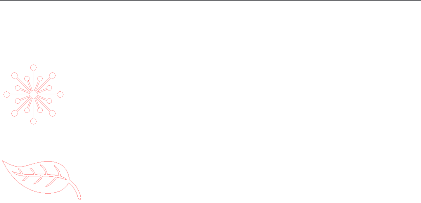
The following is an example of a single line:
While the image may have many parts, it is sll just one line with a single starng point and end point.
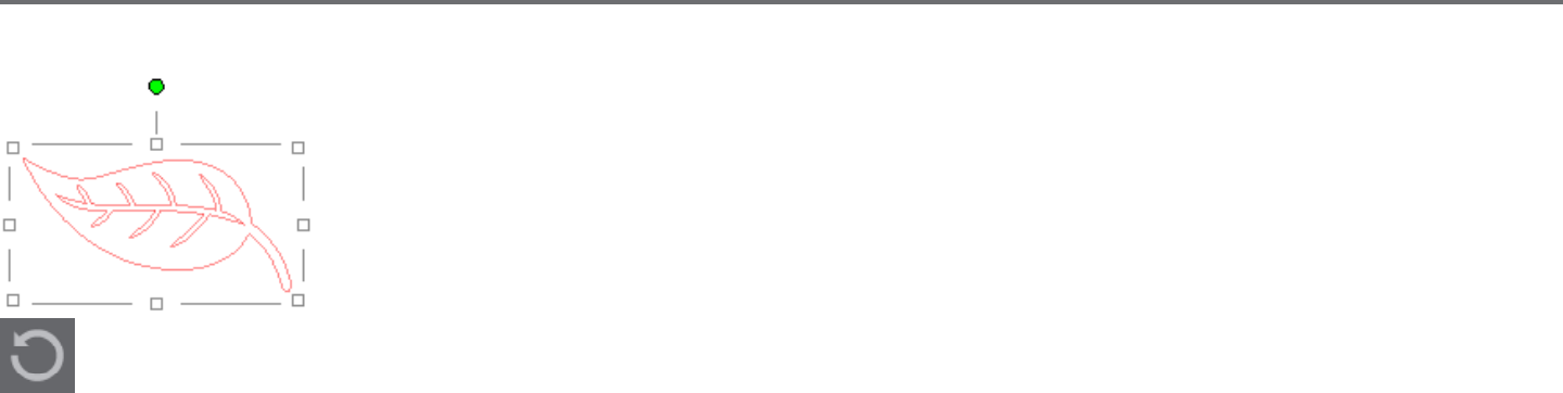
The following is an example of a mulple line image:
This image has two line sets with the body of the leaf and stem being one part and the inner details of the leaf being
another. This image is grouped together so that if moved around on your screen, you do not have to move the outer
line of the leaf and then move the center part independently and try to align it inside.
While it is not necessarily important to know exactly how many line parts an image has, it is important to understand
that single line images are not grouped together with anything, while anything that has mulple parts is or can be
grouped.
42Silhouee Studio® V4 | Chapter 6 - Manipulang Images
Grouping
Any two sets of lines can be grouped together so they are xed in their relave posions, even if moved, by using the Group opon.
To use the Group opon, select two or more images at the same me and click on the Group icon located in the Quick Access Tool bar. This can
alternately be located in the Object menu or by right-clicking on the mulple selected images and selecng Group.
Ungrouping
Any image that contains more than one line set can be ungrouped so that parts of the image may be treated independently, removed,
rotated, resized, or otherwise manipulated rather than having to manipulate the image as a whole.
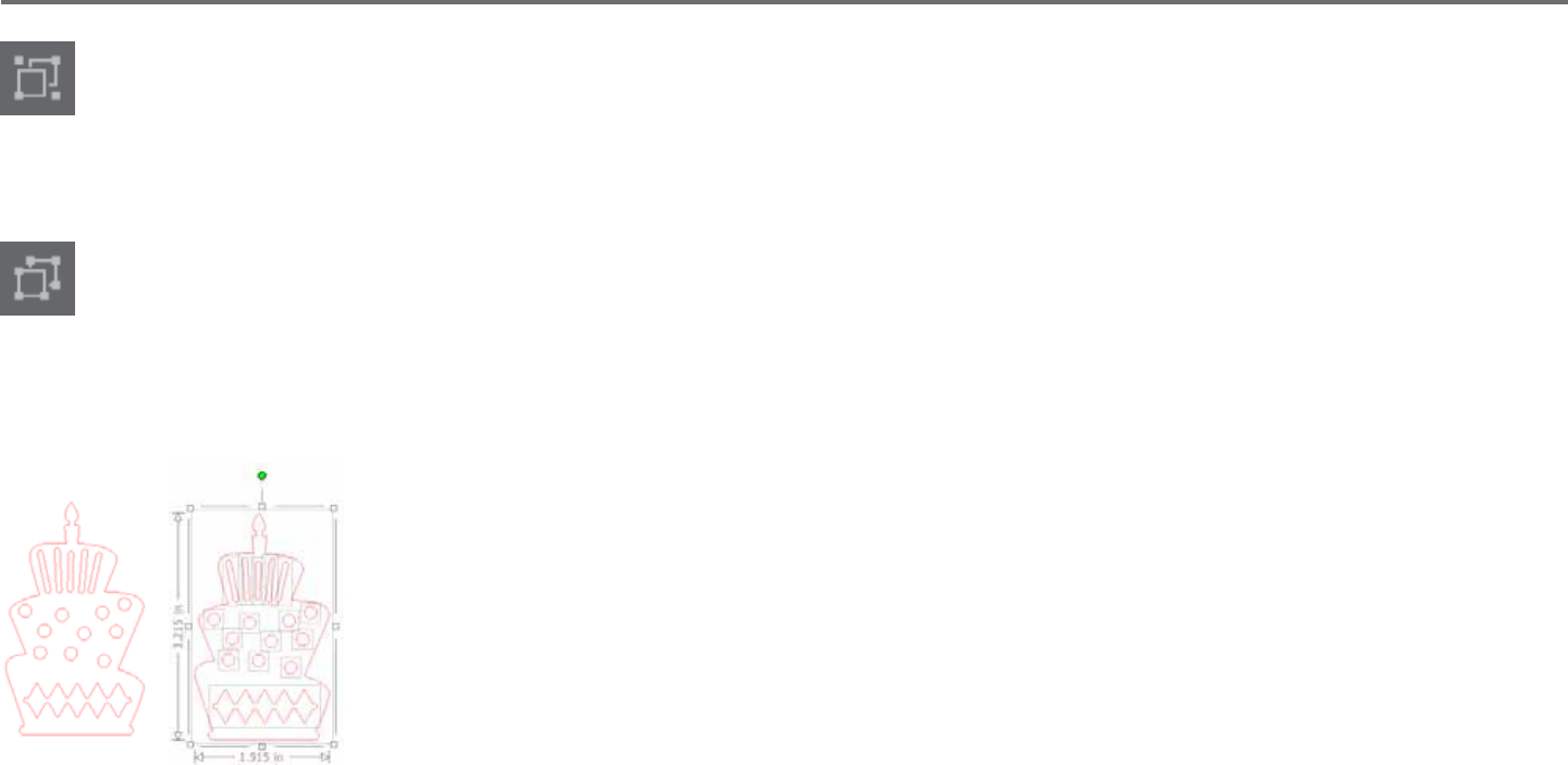
For example, you may wish to cut out this cake image, but want to ungroup the image in order to remove some of the inner decoraons of the
image:
Once ungrouped, the image will be displayed showing individual selecon boxes around each new ungrouped
image part that can now be manipulated:
To access the individual ungrouped parts, you may unselect your image.
Silhouee Studio® V4 | Chapter 6 - Manipulang Images 43
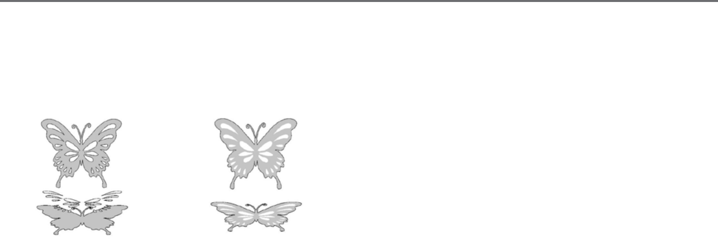
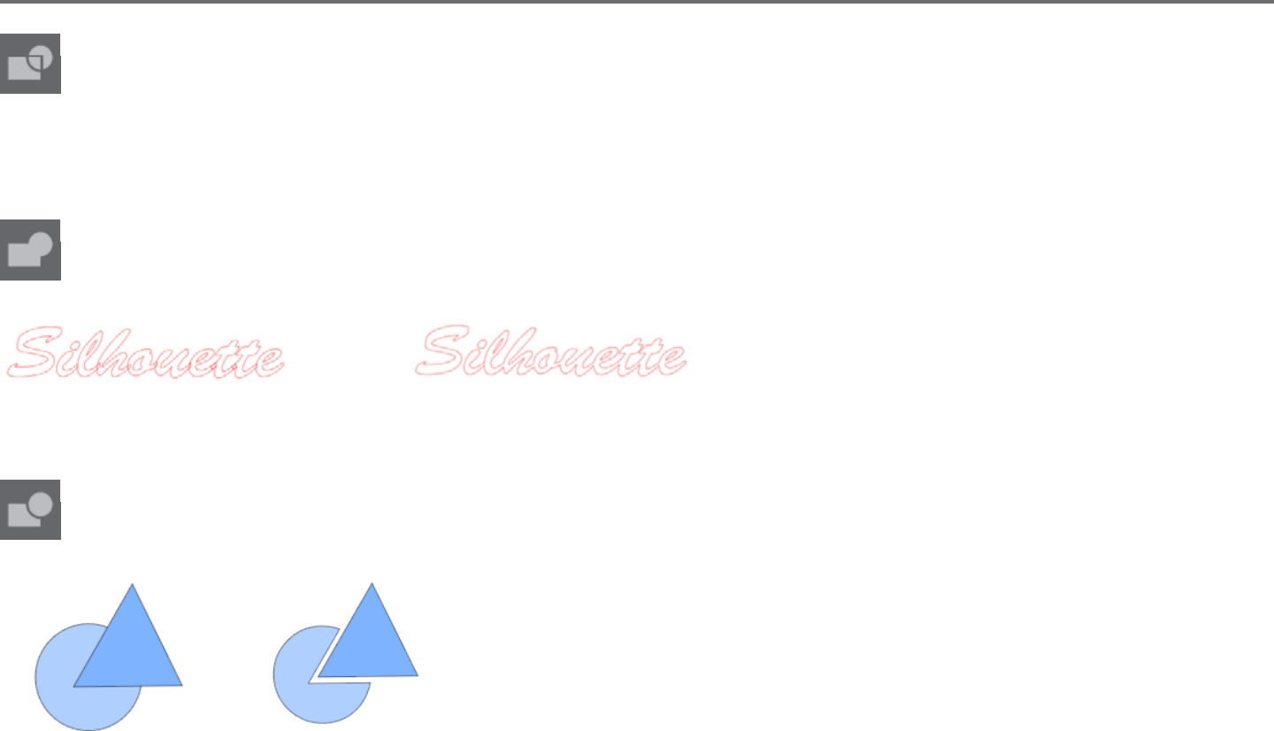
6.3 Compound Paths
The concept of compound paths is important in order to understand why certain aributes may be applied dierently to seemingly idencal
situaons. Compound paths are a collecon of two or more line sets where inner lines are embedded into the image. A compound path may appear
the same as a grouped set of lines, but is quite dierent in the way it will react to being lled with color, for example.
Compound paths are only really a concern when you are creang Print & Cut images.
Non-compound Image Compound Path Image
In the previous examples, the top two images are seen straight on and appear to be idencal. However, when looking at the boom set of images
the dierences become apparent. With the image on the le, from a side view we are actually looking at a grey buery with white spots resng on
top. This is an image that is not a compound path. With the image on the right, from a side view we see that we are looking at a grey buery with
white spots embedded into the image.
Of course, as we go to cut or sketch both images with the Silhouee, they will cut out in the exact same manner, but it is important to understand
that there is a dierence between these images as you may wish to achieve certain eects with lling images for Print & Cut applicaons.
44Silhouee Studio® V4 | Chapter 6 - Manipulang Images
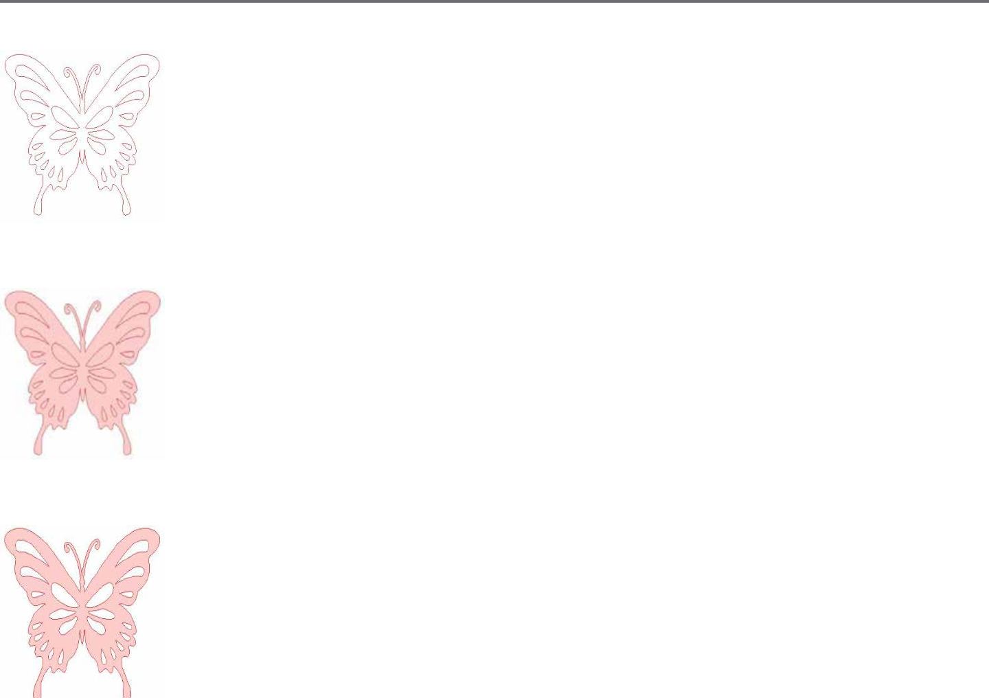
For example:
This is the same image unlled. All parts are grouped together.
If this is a non-compound image and it is lled with a color feature, this will be the result:
Even though grouped together, all line sets are sll just individual pieces lying on top of each other, so they are all lled
with the selected ll eect.
If this image has a compound path and it is lled with a color feature, this will be the result:
The unlled parts of the image cannot be lled with compound path images because these embedded areas are negave
space.
Compound paths can sll be ungrouped to move mulple image parts around, but the acon of ungrouping will
immediately release the compound path and make it a non-compound path image
To make a series of mulple selected images a compound path, you may right-click unl the mulple parts are all selected
and select Make Compound Path. Similarly, you may right-click on a compound image and select Release Compound Path
to perform the opposite acon. These opons may also be found in the Object menu.

Silhouee Studio® V4 | Chapter 6 - Manipulang Images 45
6.4 Moving Images
Images may obviously be moved by selecng them and then dragging them around the screen with your mouse to any desired locaon. Selected
images may also be moved by using the arrow keys on your computer keyboard.
You may also move images through the Move menu panel.
Selected images may be moved by using any of the Move opons. The direconal arrows in this screen will move images subtly in whichever
direcon you select. This acon may be repeated unl your image is located on your workspace as desired.
The Move By opon will move selected images from the current locaon by whatever measurement is entered, while the Move To opon will move
images regardless of present locaon to a specic ploed course on your workspace, where a measurement of 0, 0 (zero, zero) represents the
upper le-hand corner of your workspace and moves out from that point either to the right or downward as the values increase.
46Silhouee Studio® V4 | Chapter 6 - Manipulang Images
6.5 Rotang
Objects may be rotated to any desired angle. Selected images will always appear with a green rotaon handle-bar
that may be manually grabbed and rotated using your mouse.
The Rotate menu opons will also provide addional rotaon opons for more exact or specic rotaon opons.
Within the Rotate menu you may select any of the following opons.
Rotate By
These opons will rotate the selected image by the selected common angle from the image’s current angle.
Rotate To
These opons will rotate the selected image to the selected angle based on the image’s original xed 0° point.
Custom Rotate By
This opon will allow you to either manually slide a degree measurement bar or enter a specic degree measurement and apply to rotate the
selected image from the image’s current angle.
Custom Rotate To
This opon will allow you to either manually slide a degree measurement bar or enter a specic degree measurement and apply to rotate the
selected image based on the image’s original xed 0° point.
Center of Rotaon (Designer Edion only)
To adjust the point around which your shape rotates, you can adjust the center of rotaon. To do so, select the shape you want to rotate, press the
leer ‘O’ on your keyboard to display a small cross-hair icon in the center of the shape. You can then move the cross-hair icon to the desired new
point of rotaon.
Silhouee Studio® V4 | Chapter 6 - Manipulang Images 47
6.6 Sizing
Objects may be sized to any desired measurement. It is important to note, however, that while you may customize images to any desired size, the
quality of cuts made may vary, especially when cung thicker materials such as cardstock. Reducing the size of an image with intricate parts and
cung it in a thicker material is an example where the cut quality could suer.
You will be able to view the measurement alongside your image as you draw or select images.
There are also control points on the selecon box for resizing images manually. To resize manually, simply click on
any of these boxes and drag your mouse in the desired direcon to make your shape larger or smaller. The corner
control points will proporonately resize the image and maintain the relave height and width, while the side control
points will stretch your image in the direcon your mouse is dragged.
The Scale menu opons will also provide addional sizing opons for more exact or specic rotaon
resizing opons.
48Silhouee Studio® V4 | Chapter 6 - Manipulang Images
Within the Scale menu you may select any of the following abilies.
Scale
These opons will resize any selected images by a percentage of its current size. Any number under 100% will make your image smaller and any
number over 100% will make your image larger. For example, selecng to resize your image to 50% of the current size will make your image half as
large while selecng to resize your image to 200% of the current size will make your image twice as large. Any custom percentage may be applied as
desired.
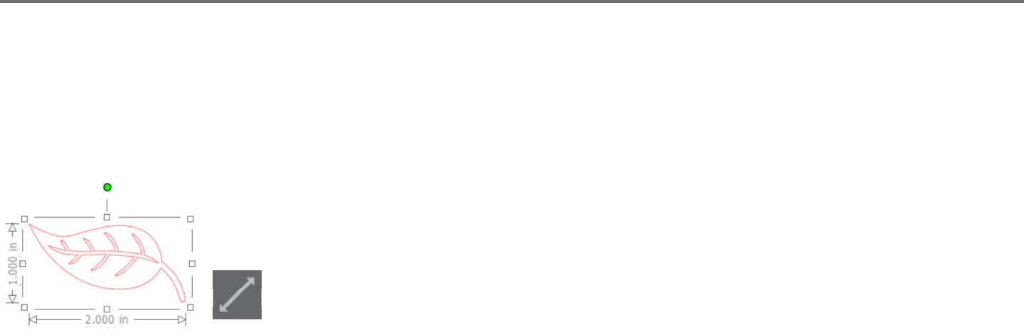
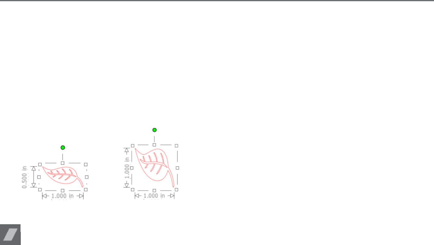
Specify Dimensions
This opon will allow you to resize a selected image to any specic measurement. The Lock Aspect Rao opon when checked will ensure your
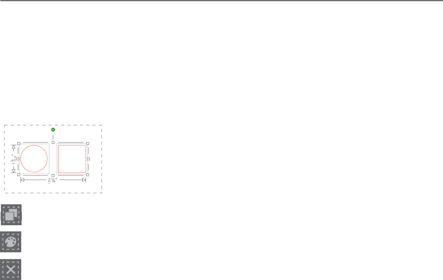
image is resized proporonately when only one measurement is being altered but you wish to maintain the image’s proporons. For example, if we
take our original leaf example that started at 1 inch height by 2 inches width and adjust the width to 1 inch, you can see the following results:
With Lock Aspect Ratio
Without Lock Aspect Ratio
Shear (Designer Edion only)
Use Shear to skew your design vercally or horizontally. You can select from preset amounts or specify a custom shear.
Silhouee Studio® V4 | Chapter 6 - Manipulang Images 49
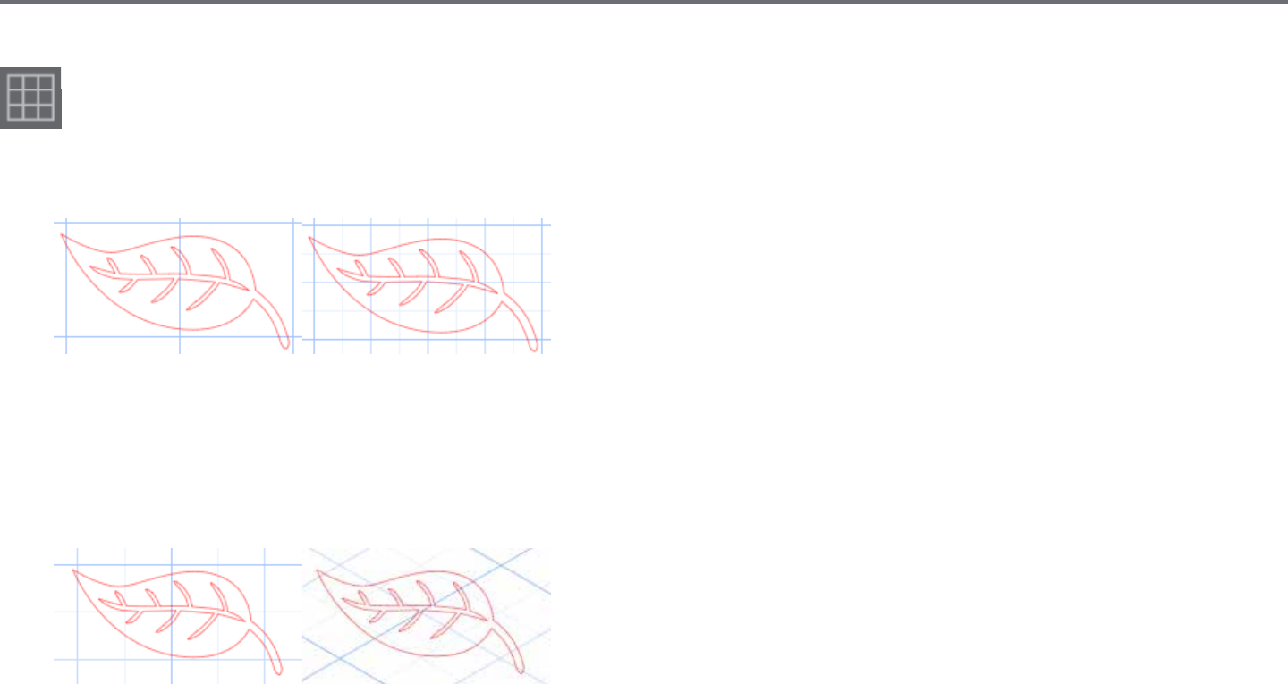
Grid
To assist with viewing measurements, you may also opt to turn on the grid by either right-clicking on your workspace while there are no
images selected and clicking on Show Grid, or by going to the Grid menu.
In the Grid menu you may turn the grid on and o, adjust the grid spacing to any desired measurement, and dene the number of divisions in the
grid.
Single Division Mulple Sub-Division
The Snap to Grid opon when enabled will force the image to conform to grid’s measurement and divisions. This may be especially helpful when
drawing images to force them to conform to specic desired measurements.
The grid’s Style may be selected to be either a tradional Square grid or an Isometric grid. Again, the dierent styles may be helpful while drawing
images within the soware to provide a reference for measurement as you draw.
Square Grid Isometric
The grid’s Color can also be adjusted as desired and oers a preselected set of color suggesons which may provide a non-intrusive appearance for
your grid, though any custom color may, of course, be selected.
In Designer Edion, you also have the ability to acvate Rulers and Crosshairs to help make layout easier.
50Silhouee Studio® V4 | Chapter 6 - Manipulang Images
6.7 Mirroring
Some materials or situaons require images to be cut in a mirror image format, or you may simply want to ip objects around to achieve your
desired image appearance.
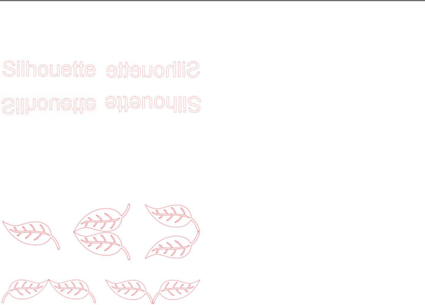
To mirror an image, you may right-click any selected image to select the Mirror Horizontally or Mirror Vercally opon.
No Mirror Eect Mirrored Horizontally
Mirrored Vercally Mirrored Horizontally and Vercally
Further mirroring opons may be accessed in the Object menu under the Transform sub-menu listed as Mirror Opons.
In this menu, you may likewise ip your images around (as displayed above) under the listed Flip menu opons.
You may addionally create mirror copies of selected images with the Mirror menu opons, where you may create a mirrored copy to the le, to
the right, mirrored above, or mirrored below.
To mirror an image, you may right-click any selected image to select the Mirror Horizontally or Mirror Vercally opon.
Original Image Mirror Copy Above Mirror Copy Below
Mirror Copy Le Mirror Copy Right
Silhouee Studio® V4 | Chapter 6 - Manipulang Images 51
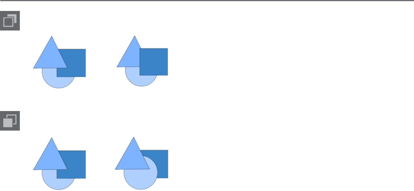
6.8 Arranging
Mulple images may overlap each other. The order of which image is in front and which is in back can be arranged. This is mostly used with lled
images for Print & Cut applicaons so you can determine which image should be in front of the other.
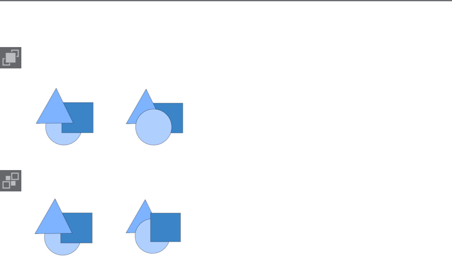
Bring to Front
This opon will take your selected image and move it in front of all other overlapping images.
Original Image Order Circle Selected and Brought to Front
Send to Back
This opon will take your selected image and move it behind all other overlapping images.
Original Image Order Triangle Selected and Sent to Back
52Silhouee Studio® V4 | Chapter 6 - Manipulang Images
In addion to these opons, you may also right-click on an image and select Send Backward to send the selected image one level back
rather than all the way to the back.
Original Image Order Triangle Selected and Sent Backward
Similarly, you may right-click on an image and select Bring Forward to bring the selected image one level forward rather than all the way to
the front.
Original Image Order Circle Selected and Brought Forward

Silhouee Studio® V4 | Chapter 6 - Manipulang Images 53
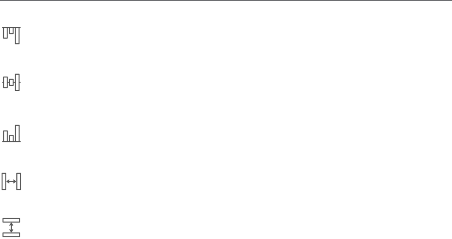
6.9 Aligning
Mulple images may be aligned in relaon to each other. The following Align opons are available:
Centralize (Align Center-Middle)
This opon will center two or more selected objects so that they are lined up with each other in the middle of each other.
Align Le
This opon will align two or more selected objects so that they are aligned together to the le edge of the shared bounding box while
maintaining their respecve distances in regard to being above or below each other.
Align Center
This opon will align two or more selected objects so that their center points are aligned together while maintaining their respecve
distances in regard to being above or below each other.
Align Right
This opon will align two or more selected objects so that they are aligned together to the right edge of the shared bounding box while
maintaining their respecve distances in regard to being above or below each other.
54Silhouee Studio® V4 | Chapter 6 - Manipulang Images
Align Top
This opon will align two or more selected objects so that they are aligned together on the top edge of the shared bounding box while
maintaining their respecve distances in regard to being next to each other.
Align Middle
This opon will align two or more selected objects so that their center points are aligned together while maintaining their respecve
distances in regard to being next to each other.
Align Boom
This opon will align two or more selected objects so that they are aligned together on the boom edge of the shared bounding box while
maintaining their respecve distances in regard to being next to each other.
Space Horizontally
When a minimum of three objects are selected, this opon will take all images and space them horizontally so that all objects are
equidistant from each other horizontally.
Space Vercally
When a minimum of three objects are selected, this opon will take all images and space them vercally so that all objects are equidistant
from each other vercally.

Silhouee Studio® V4 | Chapter 6 - Manipulang Images 55
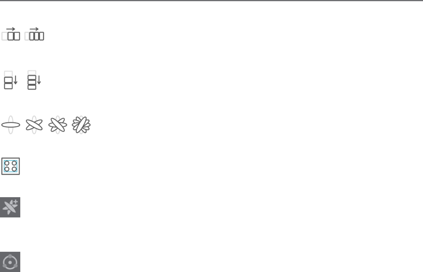
6.10 Replicang
Replicang while similar to copying and pasng an image or duplicang it allows for the ability to create any number of copies and place
them at once without the need to copy and paste the images mulple mes and then have to place them manually around the screen as
desired. These opons will also create copies next to each other as closely as possible to maximize your cung area.
You will nd the following opons in the Replicate opons basic menu.
Duplicate Le
This opon will duplicate the selected object and place a copy directly to the le with the most minimal amount of space between the
objects as possible.
Duplicate Right
This opon will duplicate the selected object and place a copy directly to the right with the most minimal amount of space between the
objects as possible.
Duplicate Above
This opon will duplicate the selected object and place a copy directly above with the most minimal amount of space between the objects
as possible.
Duplicate Below
This opon will duplicate the selected object and place a copy directly below with the most minimal amount of space between the objects
as possible.
56Silhouee Studio® V4 | Chapter 6 - Manipulang Images
Row of Three / Row of Four
These opons will copy the selected object and replicate two or three addional copies next to each other in a row, stacked
horizontally next to each other, with the most minimal amount of space between the objects as possible.
Column of Three / Column of Four
These opons will copy the selected object and replicate two or three addional copies next to each other in a column, stacked
vercally on top of each other, with the most minimal amount of space between the objects as possible.
Rotate One Copy / Two Copies / Three Copies / Five Copies
These opons will copy the selected object and replicate one through ve rotated copies on top of the original
image.
Fill Page
This opon will copy and replicate the selected object and ll the cung area with as many copies possible.
In the Replicate menu, you may also access an Advanced Opons menu. Here you will have the opon to select any desired number of
copies to replicate your selected image and the distance between these replicated images, including the ability to select any custom
direcon. Once the desired number of copies and direcon has been selected, you may click on the Replicate buon at the boom of the
Advanced Opons menu to apply the selected aributes.
Object to Path
This opon allows you to take one object and place it on the path of another object. Once it is on the path, you may make copies and
duplicate the object by simply pulling on the control handles.

Silhouee Studio® V4 | Chapter 6 - Manipulang Images 57
6.11 Nesng (Designer Edion only)
To minimize the space required to cut a certain design, the Nesng feature can be used. You can choose to use your enre media surface to
nest you shapes or create a specic area for them to nest in.
Use Cut Area
If you choose to Use Cut Area, your enre media surface can be used to nest shapes.
Use Selected
If you would like to nest your shapes within a certain area, rst draw that area on your workspace. Next, click on Use Selected in the Nesng menu.
Nesng will occur within this dened area.
Select all the shapes you would like to nest. In the Nesng menu, you can adjust the rotaons and padding of the shapes to be nested. Increasing
rotaons and/or decreasing padding will yield a ghter nest.
Aer making any necessary adjustments, click Nest and the shapes will nest together to maximize space. If you have selected more shapes than will
t in the nesng area, the soware will determine which shapes t best in the dened area.
58Silhouee Studio® V4 | Chapter 6 - Manipulang Images
6.12 Modify
Overlapping images may be altered in a variety of ways. The Modify menu opons provide welding and other advanced opons to allow
overlapping images to be adjusted.
Within the Modify menu you may select any of the following abilies.
Weld
While the Weld opon may be found in the Modify menu, there is also a quick access buon located along the boom tool panel of the
soware screen. Welding will take two or more selected overlapping images and join them together into one single connuous image.
Welding can be parcularly useful when cung so that the cut lines don’t overlap during the cung process.
Subtract All
This opon will remove any poron of an image that is in back behind another image.
Original Image With Subtract All Applied
Non-welded image with overlapping lines Welded image with overlapping lines removed
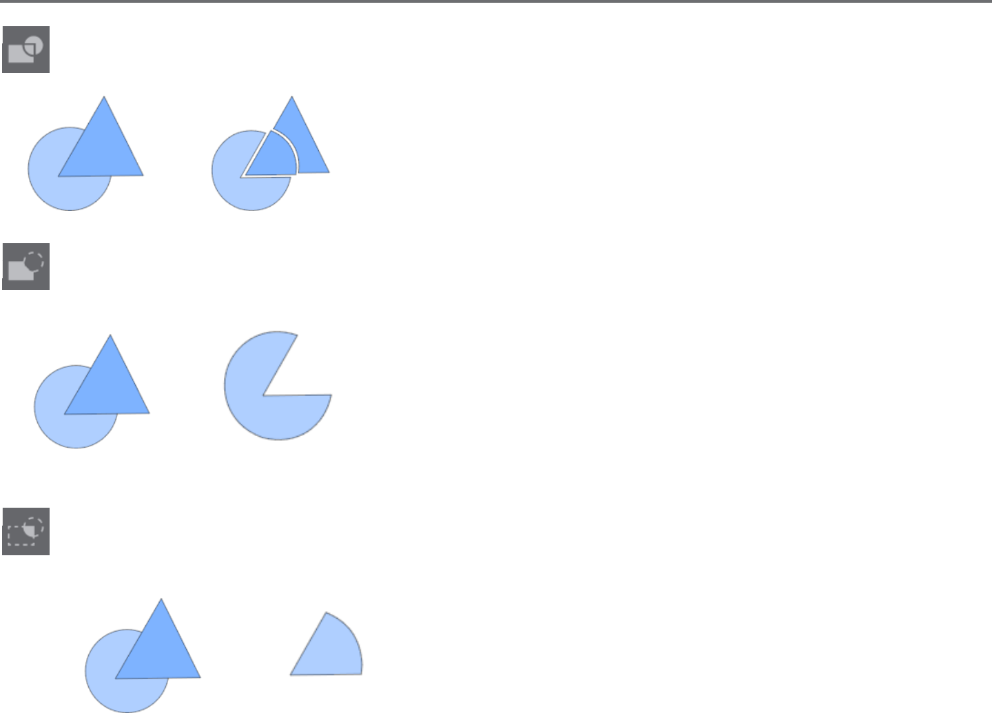
Silhouee Studio® V4 | Chapter 6 - Manipulang Images 59
Divide
This opon will create individual images from the intersecons of up to eight selected images.
Original Image With Divide Applied
Subtract
This opon will remove all overlapping parts of images that are in front of other images, so that only the image located in back will remain
with the overlapping parts removed.
Original Image With Subtract Applied
Intersect
This opon will leave only the overlapping part, or intersecng part, of the selected images when applied.
Original Image With Intersect Applied
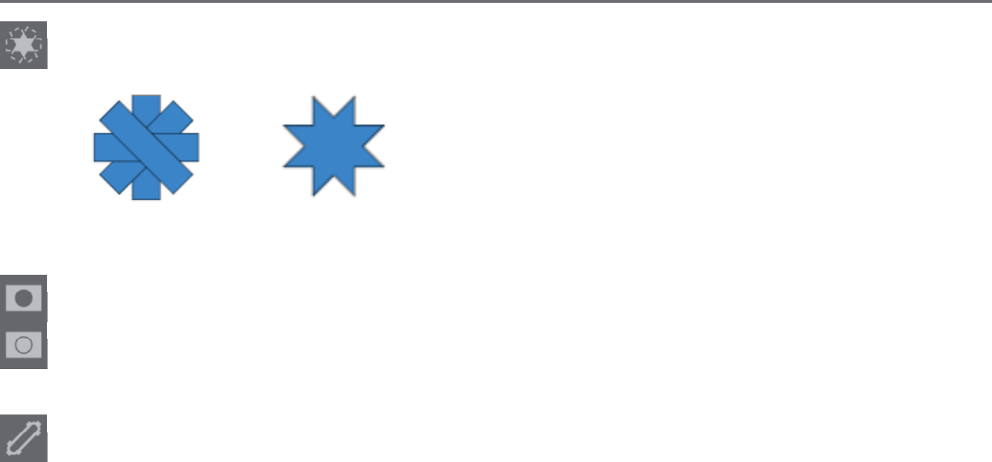
60Silhouee Studio® V4 | Chapter 6 - Manipulang Images
Crop
This opon will remove all areas that are not shared by at least two shapes when overlapping.
Original Image With Crop Applied
Compound Paths (Make / Release)
These opons are the same opons previously discussed in the secon 6.3 regarding Compound Paths. This tool will take overlapping
embedded images and either Make them into a compound path or Release the compound path.
Detach Lines
When images are lled or have thick lines dened, this opon may be used to detach and move the outline to create two separate images;
one with just the lines and one with just the lled eects le behind.
Silhouee Studio® V4 | Chapter 6 - Manipulang Images 61
6.13 Oset Opons
The Oset opon may be used to outline cut-line images giving the image a shadowed mat eect underneath it. It may also be used to
create contoured inner lines for images.
To apply oset condions, you will rst need to select an image.
Original Starng Image
Within the Oset menu you may start by selecng the oset acon.
You may select to either have your oset image have a sharper Corner appearance, or have a soer more bubbly Round appearance.
Though clicking the oset acon buon provides a starng point, you may ne tune the oset eect to any specied Oset Distance with the slider
bar, or by typing in a specic measurement.
At any point your desired eect is achieved you may set the properes of the newly created image into place by clicking Apply.
Oset Image
You may conversely create an internal oset condion.
This feature is generally beer suited for the creaon of internal lines for use with sketch pens.
Internal Oset Image

62Silhouee Studio® V4 | Chapter 6 - Manipulang Images
6.14 Tracing Opons
Tracing opons can be used to automacally trace imported external images for the purpose of creang cut lines. Silhouee
cannot guarantee the quality of images not created by our company nor support any third-party images not oered through the
Silhouee Design Store. Silhouee Studio® should not be used to trace licensed or copyrighted images which you do not specically own.
Once you have opened an external image you own (as discussed in Secon 3.4), you may open the Tracing opons and then click on Select Trace
Area. This will allow you to draw a box around the intended area of your imported image you may wish to trace. This selecon area once drawn may
be adjusted or moved like any other object in the program as you may need to expand or rene the trace area. The trace area selecon will provide
a preview of the original image with a yellow area overlay where the trace area would be applied according to the Trace Sengs lters. These lters
will provide a more rened or more liberal applicaon of the intended traced eect depending on the sengs selected.
Once the desired tracing eect preview is achieved, you may then opt to apply the trace method by selecng one of the following:
Trace
This opon will provide a traced line contour around all parts of the yellow preview area displayed.
Trace Outer Edge
This opon will create a traced line around the outer edge of the yellow preview area displayed only and ignore any inner parts that may otherwise
be displayed in yellow showing a potenal tracing path.
Trace and Detach
This opon will trace the outer edge of the yellow preview areas of the image and detach them from the rest of the background of the raster image.
Trace by Color (Designer Edion)
This will trace a single area lled with a solid color. Check ‘Trace all areas with same color’ to trace all instances that color appears.
Magnet Trace (Designer Edion)
This will give a magnet tool that will cling to an image while it is being traced. Each mouse click will result in a magnet trace point added to
the image. Once the image has been traced, the remaining background will be cropped out.
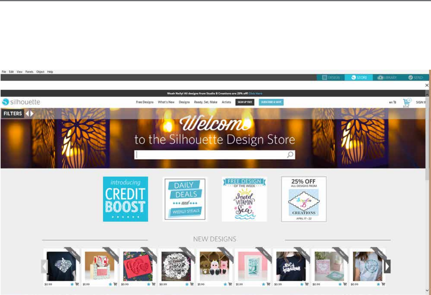
Silhouee Studio® V4 | Chapter 7 - Library and Design Store 63
7 - Library and Design Store
Silhouee Studio® oers a library feature to keep and categorize all of your downloaded and user-created image for easy reference, as well as an
Design Store to provide new content for users to download.
The library and store views may be found in the top tabs of the soware screen and show which panel of Design, Store, Library, or Send is the
current selected acve tab.
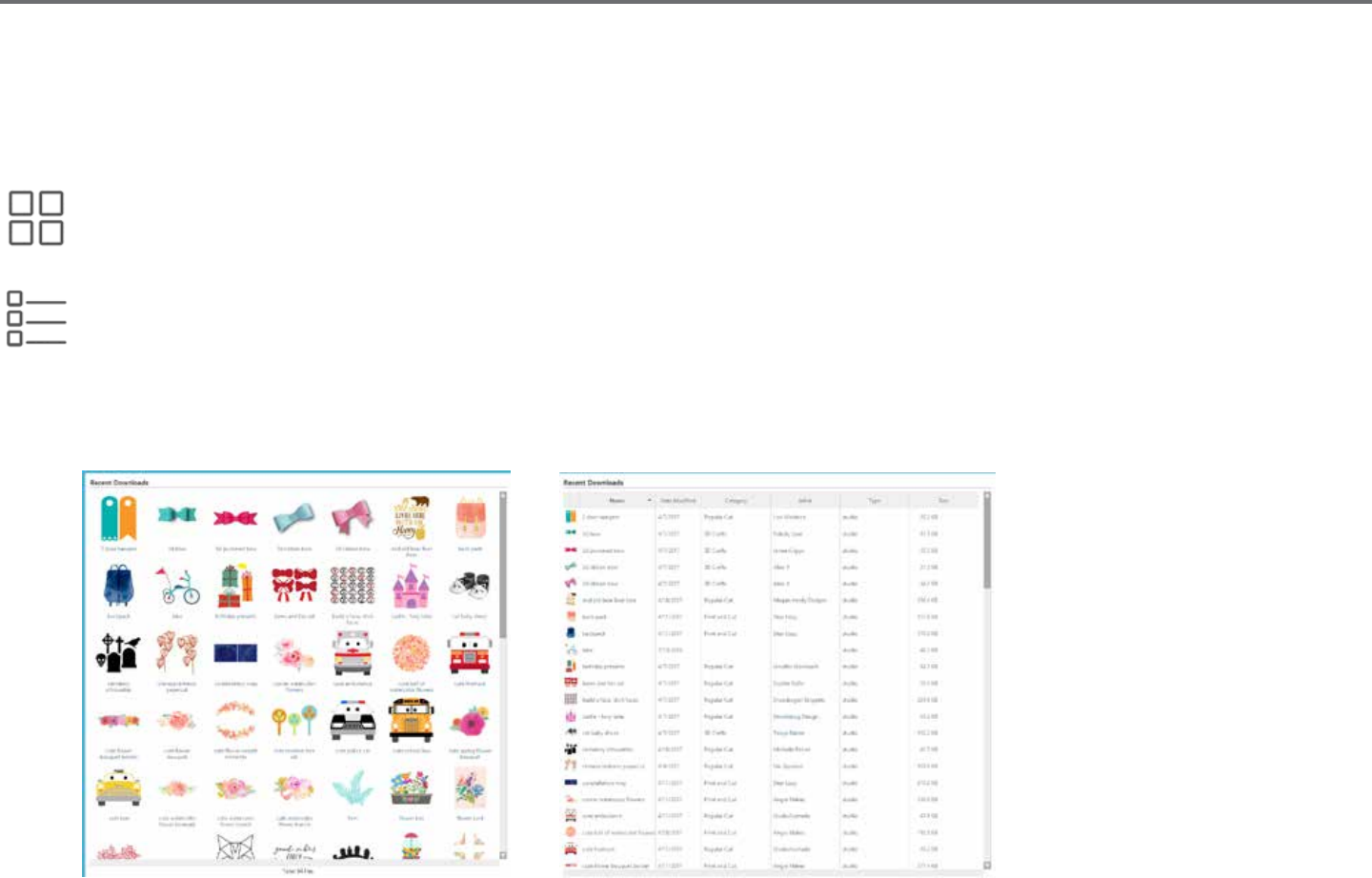
64Silhouee Studio® V4 | Chapter 7 - Library and Design Store
7.1 Library
The Library is where all of your preloaded and purchased content is contained and may be categorized, sorted, and accessed.
Viewing
You are able to view your images as icons by clicking on the Icon View opon:
You may alternately view your library images in a list view to see more detail by clicking on the List View opon:
In List View mode you may sort your images by Name, Category, Arst, Date Downloaded, or Size by clicking on these column header tles.
Library in List View mod
e
Library in Icon View mode

Silhouee Studio® V4 | Chapter 7 - Library and Design Store 65
Accessing Library Content
To access library images, you may:
• Double-click on your image to open it onto your workspace
• Drag images from your library onto your workspace (only if your workspace is being displayed)
Categorizing & Library Management
As your library connues to grow with addional content, you may nd it convenient to customize your library with new folders and sort images
according to your liking.
You may add new custom folders by right-clicking and selecng “New Folder”.
As new Untled Folders are created, you may immediately name your folder to the desired name. Once your new folder has been created, you may
drag and drop images into the folder. Right-clicking on a folder will allow you to create a new sub-folder for that selected folder, delete the folder
(along with all contained content), or rename the folder.
In addion to customizing folders, you may also adjust any of your images within the library. Right-clicking on an image will allow you to delete the
image, re-name the image, sort the images in the current folder, or show/hide the images properes. Image properes will provide you with the
image’s descripon (as downloaded from the Design Store) and display any associated keywords.
As images or folders are deleted, they will be moved into the library’s Recycle Bin. You may sll restore any of these images or folders by dragging
them back into your library. However, once you have deleted any content from your Recycle Bin, this content will be permanently deleted from your
computer.

66Silhouee Studio® V4 | Chapter 7 - Library and Design Store
7.2 Silhouee Design Store
The Silhouee Design Store provides addional downloadable content from not only Silhouee, but also a variety of independent arsts and
contribung companies. The Silhouee Design Store can only be accessed from within the Silhouee Studio® soware and requires an internet
connecon.
The Store is accessible at any me, 24 hours a day, 7 days a week.
While images may be purchased individually to customize your library experience, subscripon opons are also available for a monthly fee. Further
informaon on subscripons may be found in the Silhouee Design Store.
All images are provided with the following benets:
• You may download images using any major credit card, through download cards, or by using subscripon credits
• Indenite usage (you do not have to be connected to the Internet to access once purchased)
• Recoverable (in case of computer crash or replacement)
• Resizable and customizable to your specicaons (using Silhouee Studio® tools discussed in previous secons)
Download Cards
Silhouee oers download cards which provide download credit valid toward any of the store’s download content you may wish to purchase and
add to your library. You will nd two codes on the back of each card. In the lower right-hand corner is the card’s idencaon number. Behind the
silver security strip is the actual download code. It is a 16-digit code.
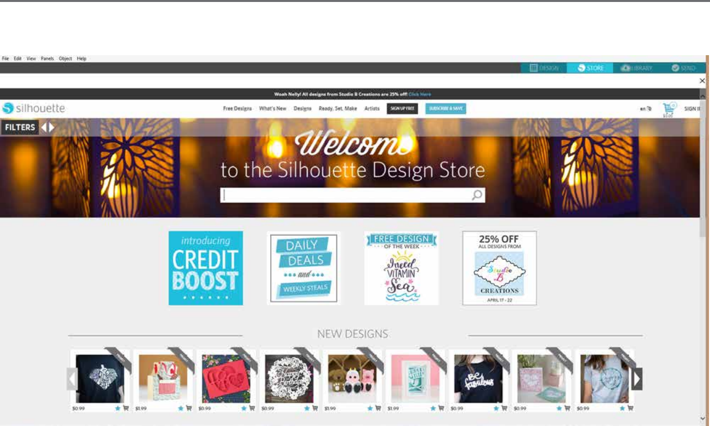
Silhouee Studio® V4 | Chapter 7 - Library and Design Store 67
Logging into the Store
Upon accessing the Silhouee Design store by clicking on the Store tab, you will be brought to the store’s homepage.
You may sign in, or sign up for an account if you do not already have one created, by clicking on the link in the upper right-hand corner nong that
“You are not signed in”.
To create an account, you will need to provide your name, your email address (which will be your login name), and any desired password.

68Silhouee Studio® V4 | Chapter 7 - Library and Design Store
My Account Opons
Once logged into your account, you will nd a link in the upper right-hand corner called My Account which will provide you with tools to manage
your account. You will have the following opons:
Change My Account Informaon – This will allow you to alter your email and password.
My Download History – This will allow you to view a copy of all orders placed. When viewing specic orders, you may also opt to recover a specic
order if there was any break in connecon during the download process.
Recover All Downloaded Designs – This will allow you to recover any and all previously downloaded content if you are seeking to load the soware
onto a new computer in the case your computer has crashed or you are simply replacing your computer.
Add a Download Card to My Balance – This is where you may enter any download card codes to apply the available balance onto your account.
Manage My Credit Cards – Allows you to manage any credit card informaon on le used to pay for subscripons or individual purchases.
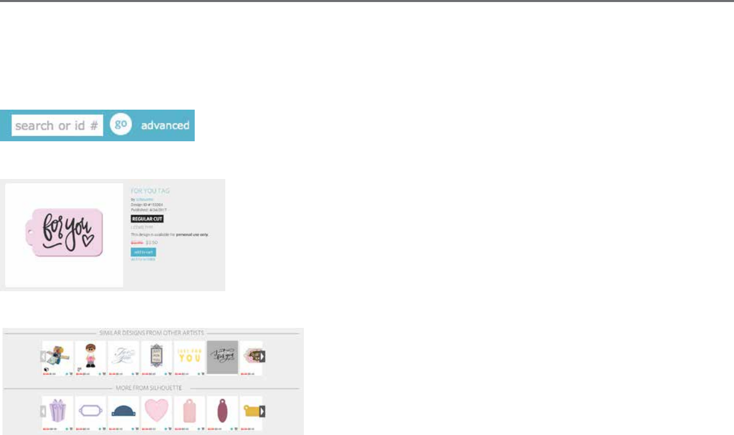
Silhouee Studio® V4 | Chapter 7 - Library and Design Store 69
Shopping
You are free to browse all available Silhouee images without any obligaon to purchase. You will nd a navigaon aide on the le-hand side of
your shopping window. As categories are selected or as you search for images, you will also nd related suggesons listed.
For specic images you are looking for, you may search for specic image names or terms in the upper right-hand corner:
As you browse through the dierent themes and releases or make specic searches, once you nd an image you would like to download, you may
either add it to your cart by clicking on the add to cart opon:
Below the design is a lisng of similar or related shapes you may be interested in, as well.
Note that images that have already been purchased cannot be added to your cart and will show that you already own it.

70Silhouee Studio® V4 | Chapter 7 - Library and Design Store
Downloading
You may connue to browse and add addional images unl you are ready to check out. Once you are ready, you may either click on the my
cart link in your mini cart preview, or click on the cart icon in the upper right-hand corner of the shopping window.
When you are ready to download, simply click the Checkout buon. If you have a balance on your account from a download card or subscripon
credit, the total charges will be taken from your balance automacally. If you do not have a balance or your account balance does not cover the
total of the images you are seeking to purchase, you will be prompted to either provide credit card informaon or add a download card code to
your account.
Once ready, you will be prompted for your password to authorize your purchase. Upon entering your password to conrm the purchase, the library
will appear in a panel above the store and you will be able to view your images as they are downloaded into your library.
You may then connue to navigate through the Design Store, or close it as desired. Once your images are all downloaded, you may then drag
them from the recent download secon and sort them as desired into any of your library folders. Downloaded images will remain in this
Recent Downloads folder unl sorted.
You will note that while all purchased images are stored in your library, purchased fonts will also be referenced in the library in a special “My Fonts”
secon. You many then either access these fonts purchased through the Design Store by double-clicking on these from the library, which will bring
you to your workspace with a text cursor ready to place to type, or by access your fonts as previously discussed in secon 5.

Silhouee Studio® V4 | Chapter 7 - Library and Design Store 71
Recovering Images
Silhouee America maintains a database of all Silhouee users and their download histories. In the event of a computer crash or computer
replacement, aer re-loading the soware onto your new computer, you may log into your Silhouee user account with your email address and
password. Once logged into your account, you may go to the my account opons to select Recover All Download Designs.
If you have mulple computers you own (such as a desktop and a laptop) and are simply seeking to recover your most recently purchased images
to a secondary computer, rather than using the Recover All opon, you may visit your My Download History in your account opons to access a
list of your previous purchases. In this secon, you may click on any previous order number and recover your order. Again, you may only perform
individual order recoveries to a limited number of computers which you expressly own.
Using the recovery features will not, of course, recover any user-created designs you may have created. Only downloaded images purchased
through the shopping secon may be recovered. You may back-up your user-created designs by simply locang where you have saved your user-
created les and saving them onto a disc or other storage device.
Silhouee America does regulate the number of unique computers you log into and reserves the right to suspend or remove accounts of registered
Silhouee users whose account acvity may be suspicious or indicave of public le sharing.
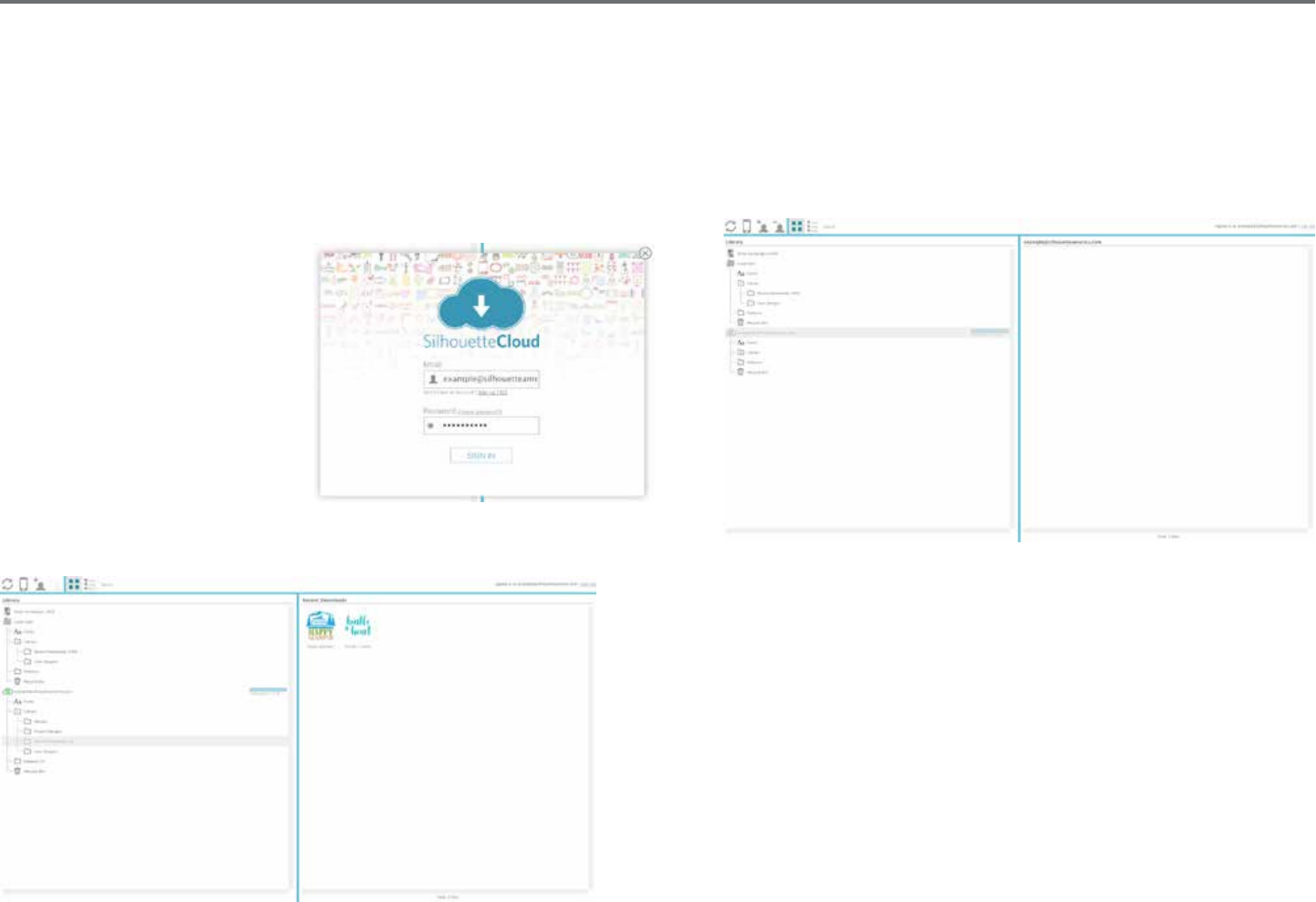
72Silhouee Studio® V4 | Chapter 7 - Library and Design Store
Silhouee Cloud
Silhouee Cloud works hand in hand with Silhouee Studio® Mobile to keep all of your designs synced on mulple devices. You can sync up to ve
devices with your Cloud account. If you aren’t using mulple devices, Silhouee Cloud is useful in backing up your designs and prevenng the need
for recoveries.
In Silhouee Cloud, there is unlimited storage available for Silhouee Design Store downloads. There is 1GB available for custom content.
Club Silhouee Members receive 5GB of storage for custom content.
To sync your les, drag them into
the cloud icon in your Library
folder. The soware will prompt
you to sign into the Cloud with
your Silhouee account. Once
you sign in, your Cloud will start
syncing your designs.
Your Cloud Library will remain its own folder in your Library. You have the opon
to save things under you Local User folder or into your Cloud Library, which is
tled with your Silhouee Account email. Files saved in your Local User folder
will only be available from that device.
To manage your Cloud Devices, go to your Account Opons in the Silhouee
Design store.

Silhouee Studio® V4 | Chapter 8 - Saving 73
8 - Saving
Aer you have created an image or document layout, you will have a variety of opons to save your images.
Save
The Save opon is the basic saving funcon to allow you to create a STUDIO le and save to any locaon on your computer. These les may be
backed up on any removable memory device.
Save As
This opon found in the File menu will allow you to name your image as it is saved. It is saved to any specied locaon on your computer and can
be backed up to a removable or external memory device as desired.
Save Selecon
This opon found in the File menu will save a STUDIO le of only the acvely selected images from your document. It is saved to any specied
locaon on your computer and can be backed up to a removable or external memory device as desired.
Save to Library
This opon found in the File menu will save your le into the Library in Silhouee Studio®. Upon saving images to your Library, they will be added to
a secon labeled User Designs in the Library. These images cannot be navigated to on your computer for manually backing them up, so it is highly
recommended to also save a copy of any images using the regular Save opon.
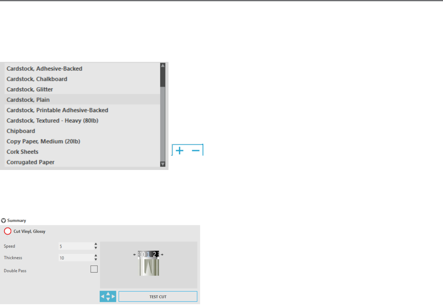
74Silhouee Studio® V4 | Chapter 9 - Cung/Sketching
9 - Cung/Sketching
9.1 Send
Once you have all desired images and/or text on your workspace ready to cut or sketch, you may select the Send tab.
Material
In the Material menu, you will be provided with a list of common materials that can be
cut with the Silhouee as well as all specialty materials oered from Silhouee. Click on a
material from the list to select it.
You may add User Dened media types into this list by clicking on the plus sign
in the media list, and likewise remove any unwanted material types by clicking
on the minus sign.
When you select a material type from the list (or create your own), recommended cut sengs will appear in the Acon panel. If you need to adjust
these sengs for your specic material, you may do so. Your changes will be saved for future projects, so it is generally preferable to create custom
sengs rather than altering exisng sengs.
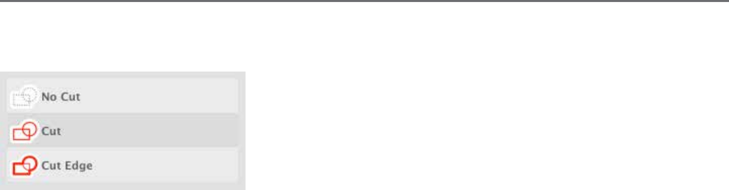
Silhouee Studio® V4 | Chapter 9 - Cung/Sketching 75
Acon By: Simple
In Simple Cut Mode, all lines are scheduled to cut at the same me. Cut lines can be turned on or o individually, but cannot be sorted to cut in a
specic order.
In Simple Cut Mode, you can adjust the Cut Style of individual lines in your project. When
clicking on this opon, your workspace will immediately emphasize all lines and their selected
aributes for easy reference. To change a line’s cut style, simply click on the desired image and
then select the new desired line style from the list. The following line styles are available:
No Cut – This opon will turn o the line from being sent to the Silhouee. While you will sll
be able to see it on your screen, it will be suppressed from being cut.
Cut – This opon ensures the selected line will be cut regardless of where it is placed, whether overlapping or inside a larger image. Lines with this
aribute will cut even if they are contained within other lines that are dened as “Cut Edge” or “Perforate Edge” line types.
Cut Edge – This opon will cut the outer edge of any overlapping lines and will suppress any lines with the same aribute if they are contained
inside a larger image. This opon may be preferable for the creaon of Print & Cut images.
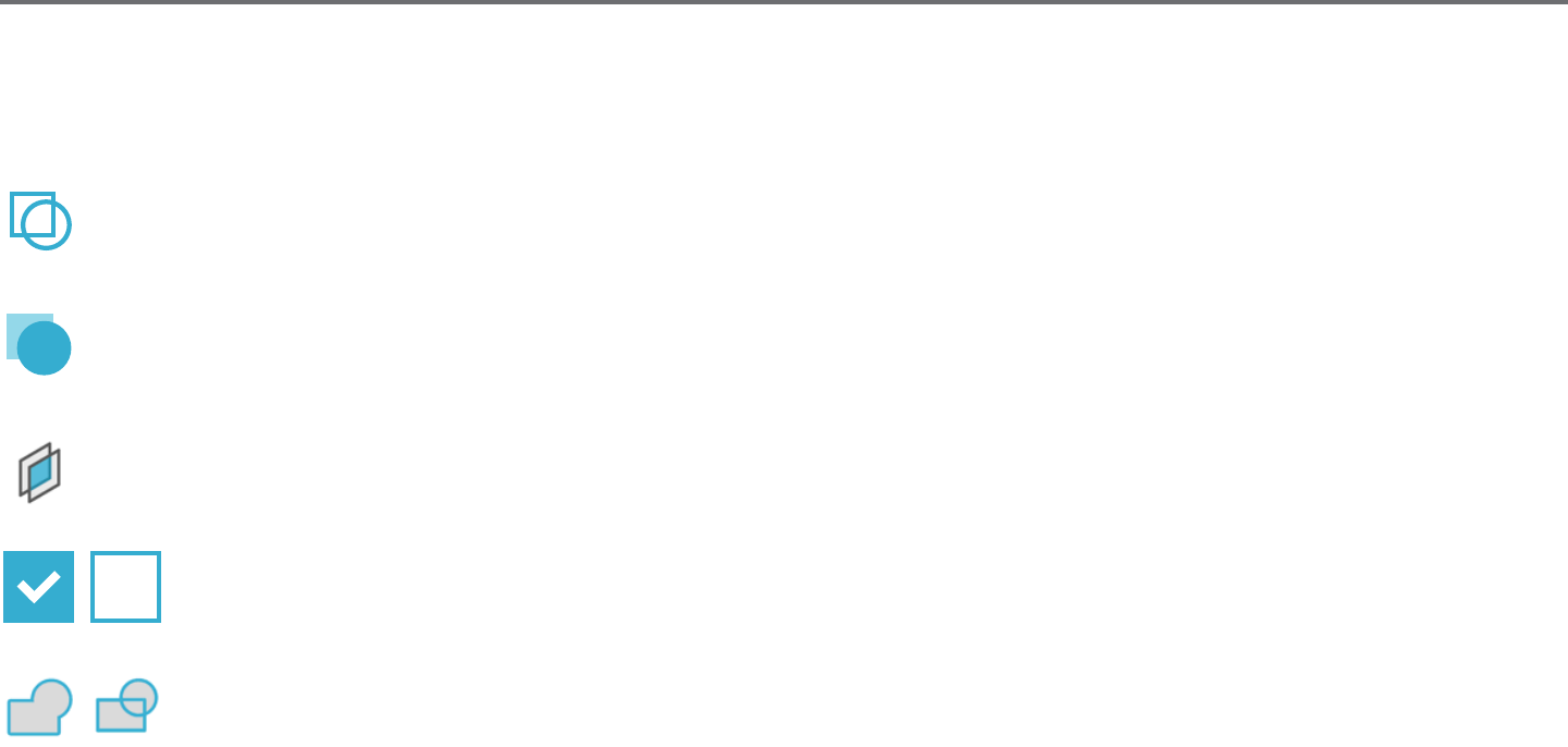
76Silhouee Studio® V4 | Chapter 9 - Cung/Sketching
Acon By: Line Color, Fill Color, or Layer
You have the opon to break up your project into mulple stages. This is especially handy if your project is designed to be cut in several colors or
with projects that are to be sketched and then cut out. You can schedule cuts by line color, ll color, or by layer (Designer Edion only).
By Line Color - All of the line colors present in your project will be visible in the cut menu. Based on line color, you can turn cut lines on or
o, acvate or deacvate auto-weld, and arrange a cung order.
By Fill Color - All of the ll colors present in your project will be visible in the cut menu. Based on ll color, you can turn cut lines on or o,
acvate or deacvate auto-weld, and arrange a cung order.
By Layer (Designer Edion Only) - All of the layers present in your project will be visible in the cut menu. Based on the layers you’ve
created, you can turn cut lines on or o, acvate or deacvate auto-weld, and arrange a cung order.
Turning cut lines on or o - You can turn cut lines on or o by checking (or unchecking) the box next to the cut color or layer.
Turning auto-weld on or o - You can turn auto-weld on or o by clicking the auto-weld box next to the cut color or layer. With
auto-weld acvated, overlapping shapes of the same color or layer will be welded together.
Arranging cung order - To arrange the order that dierent colors or layers are cut, simply click and drag the desired color or layer to a higher or
lower in posion in the cut order.
Adding pauses - Pauses are especially helpful in sketch projects where it is necessary to change pens or blades between colors. To schedule a pause
aer a color or layer is nished, right-click (control-click on a Mac) the color or layer and select “add pause”.

Silhouee Studio® V4 | Chapter 9 - Cung/Sketching 77
Blade Seng Recommendaon – Though the soware and actual Silhouee unit will not know what blade level you are actually using, the
recommendaon will provide you with a visual cue on what blade seng should be used for the intended media based on the blade type for your
cung tool model. The Sketch Pen selecon refers to Silhouee sketch pens that t directly into the Silhouee unit where the blade would usually
be loaded and is intended to be used when sketching rather than cung.
Speed – The Speed is measured in cenmeters per second x 10. In other words, the Silhouee can cut from 10 cenmeters per second up to
100 cenmeters per second. To achieve the best results, slower speeds may be recommended for thicker materials or designs that are more
intricate.
Thickness – The Thickness is measured in approximately 7 grams force per seng and has 33 levels. In other words, the Silhouee can cut from
7 grams up to 230 grams force. Thicker materials will likely require higher Thickness levels.
Double Pass – This check box will have the Silhouee cut through all lines present in your cung area twice. It may be necessary when cung
thicker materials in order to obtain a cleaner cut.
Cung Mat – This check box noes the program as to whether or not you are using the Silhouee’s cung mat (scky cung mat). This opon
may only be selected for material sizes that do not exceed the ability to load materials onto the cung mat. Many specialty material types oered
by Silhouee America will have their own backing and so do not require the use of the cung mat. However, if your material is either too narrow to
be gripped by the rollers or does not have its own adhesive backing, you must check this opon.
Track Enhancing – This check box noes the program that you wish to enable the Track Enhancing feature, which will roll your material into the
Silhouee and back out several mes prior to cung in order to create a track where the rollers are gripping the material in order to ensure the
material stays on track during the cung process. This opon should only be used if it is already pre-selected for your material type or if you are
having issues with a specic material type slipping during cung and causing the resulng cuts to be misaligned.
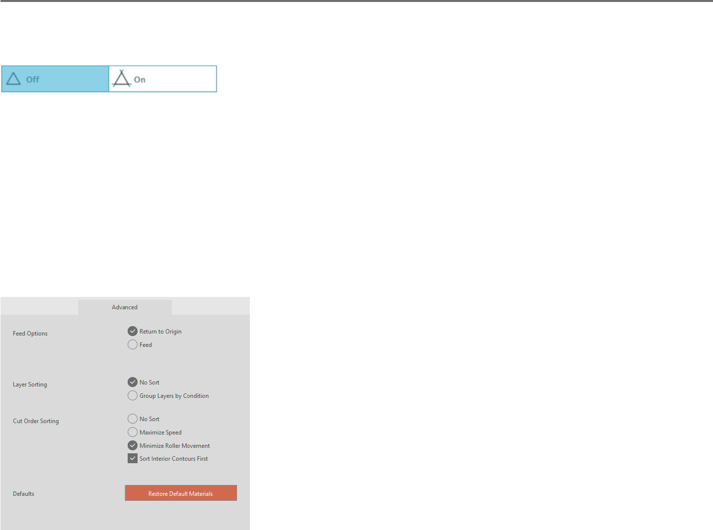
78Silhouee Studio® V4 | Chapter 9 - Cung/Sketching
Line Segment Overcut
Once a material type is selected, you will nd a Line Segment Overcut opon that can be turned on or o by clicking on the desired opon:
Selecng the “O” opon will have all lines cut normally. Selecng the “On” opon will have all straight corners cut with a slight overcut. This
opon is benecial for providing cleaner cung results in the following condions:
• Cung thicker/denser material types (such as chipboard)
• Cung smaller block fonts or sharp-edged images on various material types
The opon will have no eect on rounded edges. It is only eecve for images containing sharp edges in order to achieve the best cung results
possible under the condions listed above.
Advanced Cut Seng
The Advanced Send menu oers several opons for specialized cung with your Silhouee.
Feed Opons - The Return to Origin opon will simply return the material back to the original
starng point aer the job is completed. The Feed opon will connue to feed the material
forward beyond the original point of origin.
Layer Sorng - The No Sort opon will retain your images as originally laid out while the Group
Layers by Condion will sort your images according to any layers that exist in the document.
Cut Order Sorng - This series of opons allows you to control the cung order of your job.
The No Sort opon will not take any special order acon and will simply cut your images
according to their layout. The Maximize Speed opon will set the cung order to cut the job
as quickly as possible. The Minimize Roller Movement opon will cut the job according the
least amount of back and forth roller movement possible to aid in the cung more delicate
materials where decreased roller movement may be benecial. The checkbox opon for Sort
Interior Contours First allows you to control whether the interiors of images will be cut rst
(checked), or if the interior is simply cut in line with all other porons of the image during the
cung process (un-checked).

Silhouee Studio® V4 | Chapter 9 - Cung/Sketching 79
9.2 Performing a Test Cut
When going to cut a new material type you have not previously cut, whether it be a pre-dened media-type seng or a new User Dened media
type you are trying to nd the correct sengs for, it is advisable to perform a Test Cut in order to ensure your sengs are correct and you will be
able to obtain a clean quality cut for your intended job. You can access the Test Cut opons in the Send menu.
To perform a Test Cut, click on the Blade Posion Arrows to move your blade so that it is resng over your loaded material in the
Silhouee unit.
Once your blade is in posion where you wish to make a small cut, you may click on the Test Cut buon. The Silhouee will then cut a small square
with an embedded triangle so that you may gauge your results and determine if any sengs need to be adjusted. You may connue to make further
test cuts unl results are to your sasfacon.

80Silhouee Studio® V4 | Chapter 9 - Cung/Sketching
9.3 Cung / Sketching
Once you have selected the correct sengs and are ready to send the acve workspace to the Silhouee, you will want to ensure your material has
been loaded properly and that you have selected the correct blade seng for cung, or that you have loaded a pen in the case you are sketching.
Please refer to the “Silhouee Quick Start Guide” received with your Silhouee for further instrucon on proper blade and cung mat preparaon
with your Silhouee electronic cung tool.
When using the Cameo model you will also want to make sure you have adjusted the rollers to the proper distance seng according to whether
you are using a cung mat or according to the media size being used. The Send panel will instruct you which roller seng to use if you are unsure.
Again, please refer to the “Silhouee Quick Start Guide” for further informaon on how to adjust the Cameo rollers, if necessary.
Performing the Cut
When your material is loaded into the Silhouee and the proper cut sengs are selected, you’re ready to send your project to the Silhouee.
Simply press the Send buon to begin.
Upon compleon, you may unload your cung mat and/or material by pressing the Unload buon.
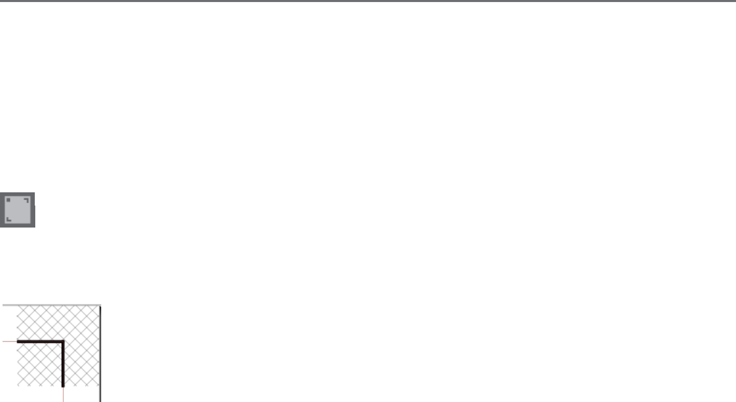
Silhouee Studio® V4 | Chapter 10 - Print & Cut 81
10 - Print & Cut
Silhouee electronic cung tools have the special ability to read printed jobs sent from Silhouee Studio® in order to cut the contour lines dened
in your workspace as they outline print informaon. In other words, you are able to print an image with lled color or eects to your regular home
printer and then feed the printed sheet into the Silhouee to cut out around the printed image.
10.1 Registraon Marks
The original Silhouee, Silhouee SD, Cameo, Portrait, and Curio models have an opc scanner for reading marks that can be printed by
Silhouee Studio®. These marks are called registraon marks. These marks will print around the border of your workspace and will be read by
the Silhouee’s opc scanner prior to cung so that the Silhouee can triangulate according to where these marks are located and know exactly
where the cut lines are dened around your printed images. Registraon marks are only used when prinng images for the purpose of performing
Print & Cut jobs.
To access these marks, click on the Registraon Marks icon in the Page panel.
You may enable the registraon marks by selecng Type 1 or Type 2 under the Registraon Mark icon. If desired according to the job being
performed, these marks can be adjusted. Please note that while you may make the marks smaller, if the Silhouee fails to locate these marks, you
may need to adjust the registraon mark size to ensure the opc scanner is able to successfully locate these marks.
You will note that the marks have a hash mark ll around them.
This hash mark ll indicates that print informaon cannot be contained in this area in order for the opc scanner to operate
properly.
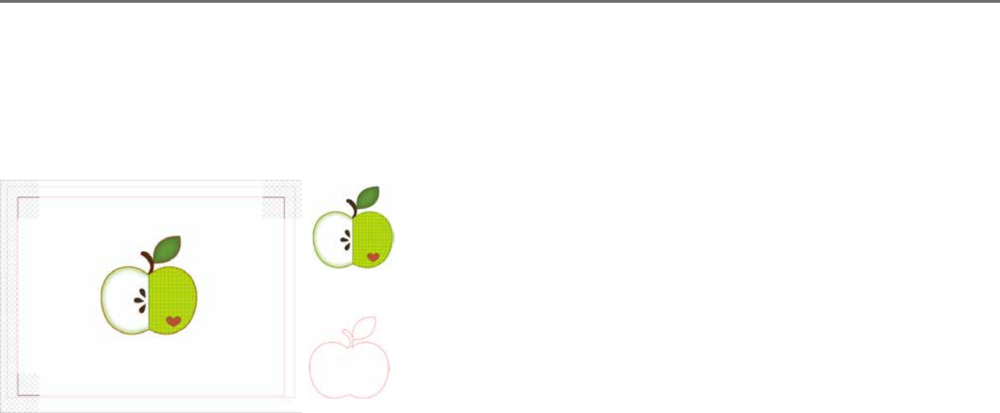
82Silhouee Studio® V4 | Chapter 10 - Print & Cut
10.2 Cung Printed Images
With the registraon marks displayed, you are ready to perform Print & Cut jobs. Again, this does not mean that the Silhouee will scan and cut
around any print informaon. Rather the Silhouee is using the registraon marks to know where your cut lines are dened around your printed
image. Your image must have lines around your printed image which are dened to be cut (see the Line Styles secon).
The following is an example of a Print & Cut job.
In this case, your printer will see the following to print out:
While the Silhouee will see the following to cut:

Silhouee Studio® V4 | Chapter 10 - Print & Cut 83
When your job is ready, you may print it by accessing the Print opon.
Once printed, it is important to remember not to make any further adjustments to the document as it appears on your screen. If any objects are
moved and the locaon of printed or cut informaon is altered, you will need to re-print your document.
To use the Silhouee’s Automac Registraon Mark Reading feature, set up your job as directed in the previous secon. If you have registraon
marks on your page in the design screen, your machine will know to detect them when you send your job to cut. The Silhouee’s opc scanner will
then locate the marks for you. Once all marks are successfully detected, the Silhouee will cut the dened lines around your printed image.
As previously noted, Silhouee Studio® allows you to ll any image with ll colors, gradients, and paerns. Though Silhouee does oer premade
special Print & Cut images that are designed to only have print informaon inside and a cut edge around the outside of the image, literally any
image can be turned into a Print & Cut image by using the tools provided in Silhouee Studio®.
84Silhouee Studio® V4 | Chapter 11 - PixScan™
11 - PixScan™
The PixScan™ feature requires the use of a PixScan™ mat (PixScan™ mat sold separately).
This feature allows for the use of images that are already printed which have not originated from the Silhouee Studio® soware. The PixScan™ mat
provides the ability to cut according to an image’s actual size whether it be to provide a contour cut around the image, or to nest images into an
oddly shaped material precisely, or to replicate a paern at its original size.
11.1 Import from Scanner
When imporng directly from a scanner, you may perform the following steps:
1. Place the intended printed image onto the PixScan™ mat which you wish to cut.
IMPORTANT: Ensure the image is within the mat’s cung area as shown by the black line border on the mat.
2. Click on the PixScan™ Icon in the Silhouee Studio® soware.
3. Select the Import from Scanner secon.
4. Place the image on the PixScan™ mat face down onto the scanner.
5. Select your scanner from the Source drop-down list and click on the Import PixScan™ Image from Scanner opon.
IMPORTANT: If the PixScan™ mat is larger than the scanner, you may scan in two passes. You will need to ensure that all markings on the mat are
captured along with the actual image. If scanning in mulple passes, you do not need to worry if the scanned images overlap. The soware will knit
the images together properly.
Silhouee Studio® V4 | Chapter 11 - PixScan™ 85
11.2 Import from Camera
When imporng an image from a camera or camera phone, you may perform the following steps:
1. Place the intended printed image onto the PixScan™ mat which you wish to cut.
2. Take a picture of the image on the mat with your camera.
NOTE: For opmal results when photographing the PixScan™ mat, please ensure that:
· No zoom is used
· Lighng is even
· The enre mat is clearly visible in the image
· The PixScan mat is at
· The cut media is contained within the black cut border
3. Transfer the image to your computer.
4. Click on the PixScan™ Icon in the Silhouee Studio soware.
5. Select the Import from File secon.
6. A window will pop up for you to navigate to and select your image.
7. Click on Open once your image is selected.
NOTE: If a calibraon prole does not already exist for your model of camera, you will need to calibrate the PixScan™ feature. PixScan™ calibraon
is only necessary to perform once per camera.
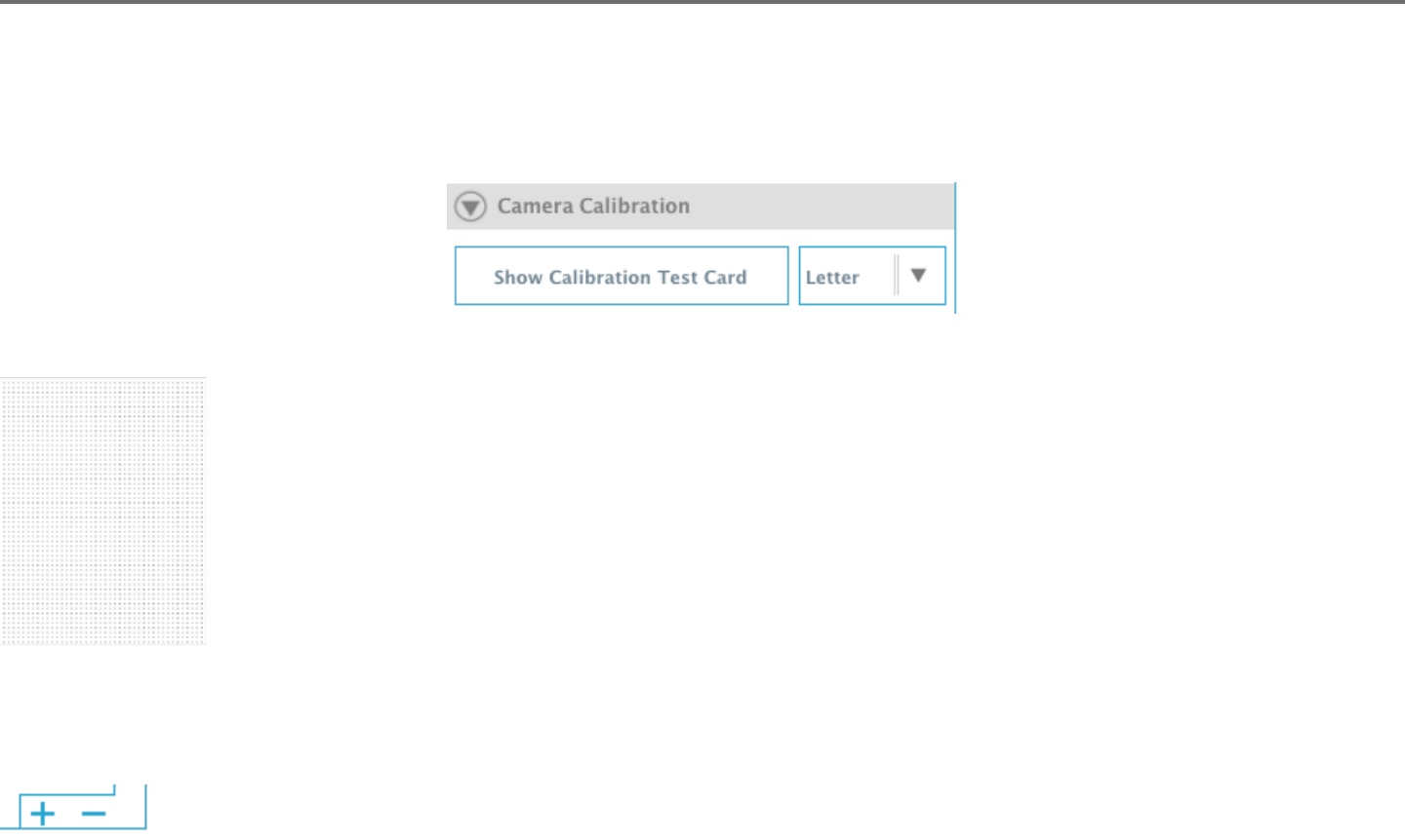
86Silhouee Studio® V4 | Chapter 11 - PixScan™ 86
Calibrang your Camera
The following steps may be performed to create a PixScan™ Camera Calibraon prole:
1. Click on the PixScan™ Icon
2. Select the Camera Calibraon secon
3. Click on the Show Calibraon Test Card opon
4. Go to File > Print and print out the page
NOTE: It is okay if the enre page is not displayed or some of the dots are cut o
5. Take a picture of the printed calibraon page from a bird’s-eye view, ensuring that the calibraon dots ll the enre image
NOTE: For opmal results when photographing the calibraon image, please ensure that:
· No zoom is used
· Lighng is even
· The photo is clear and crisp
· The calibraon image is resng on a at surface
· The camera is parallel and in line with the calibraon image
· Only the calibraon dots are showing in the photo
6. Once you have your image saved on your computer, click on the plus (+) icon under the Camera Calibraon secon of the
PixScan™ panel.
7. A window will pop up for you to navigate to and select your calibraon image
8. Click on Open once your image is selected
Your PixScan™ calibraon is now set up for the camera in use. Again, this process is only necessary any me a new camera is in use. You may select
a PixScan™ Camera Calibraon prole for any previously calibrated camera at any me depending on which camera is used to capture your image.

Silhouee Studio® V4 | Chapter 11 - PixScan™ 87
11.3 Using PixScan™ images
Once you have your PixScan™ image loaded, you are ready to create or place your cut lines.
Contour Cung
Please see Tracing (Secon 6.14) for further informaon on creang cut lines to associate around your image. You may nd it preferable to add a
small Internal Oset (e.g. 0.2mm) aer tracing in order to avoid white borders on traced PixScan™ images.
Material Nesng
If using a uniquely shaped material that has been scanned or photographed on the PixScan™ mat, you may use the Tracing feature (Secon 6.14) to
nd the contour of the material. You may then use the Nesng feature (Secon 6.11) to Set Selected Shape as Boundary and nest any images into
the material’s border. This will allow for precise placement of images you are seeking to cut into the uniquely shaped material.
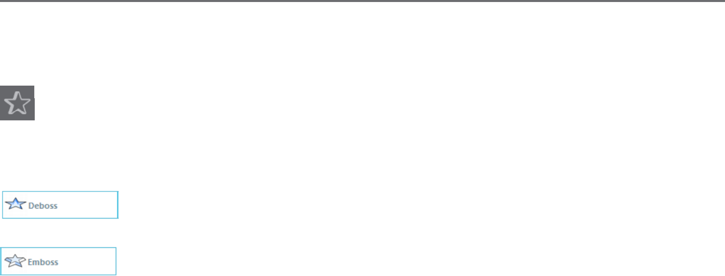
88Silhouee Studio® V4 | Chapter 12 - Curio Features
12 - Curio Features
Some features found in Silhouee Studio® can only be used when the Curio is connected. The Curio provides select opons that cannot be
performed by other Silhouee tools.
12.1 Embossing
The Silhouee Curio™ is capable of embossing when using the Curio’s embossing mat. Once the embossing mat has been set up for use,
you may go to the Embossing icon.
At the top of the Embossing menu, you will nd an opon to select either Deboss or Emboss. This opon will apply to the enre document and is
not object-specic.
When Deboss is selected, your job will be processed as it is viewed on screen. The acon of the embossing tool pressing
down onto your material will create a recessed relief of the image, or Deboss eect.
When Emboss is selected, while you will connue to see your job as it has been designed on screen, your job will be ipped
horizontally when processed so that the enre page is mirrored. The acon of the embossing tool pressing down in a
mirror image will allow the material to be ipped over aer the job is completed to display a raised image, or Emboss
eect.
IMPORTANT: When selecng to Emboss, make sure you place your material onto the embossing mat face down.
Select one of the following embossing opons in the soware to set up your image to be debossed or embossed as desired.

Silhouee Studio® V4 | Chapter 12 - Curio Features 89
Emboss/Deboss
Embossing/debossing is made possible when using the Silhouee Curio™ embossing mat with an embossing tool. If no special eects from
this panel are applied, the Silhouee Curio™ will simply emboss/deboss the outline of your image. The eects and opons found in the
Emboss/Deboss secon provide addional opons that may be desirable when using an embossing tool.
An Eect can be selected to ll in any image with an embossing paern. To apply an embossing Eect, select your image and then click on the
desired Eect.
Spacing will control how compact or spread out the applied Eect will appear.
The Angle opon will control the applied angle of the selected Eect.
The Spacing and Angle opons are dynamic and will automacally adjust when images are resized or adjusted. However, if you wish to set these
opons to be stac aer they are created to your liking, you may click on the Release Emboss opon.
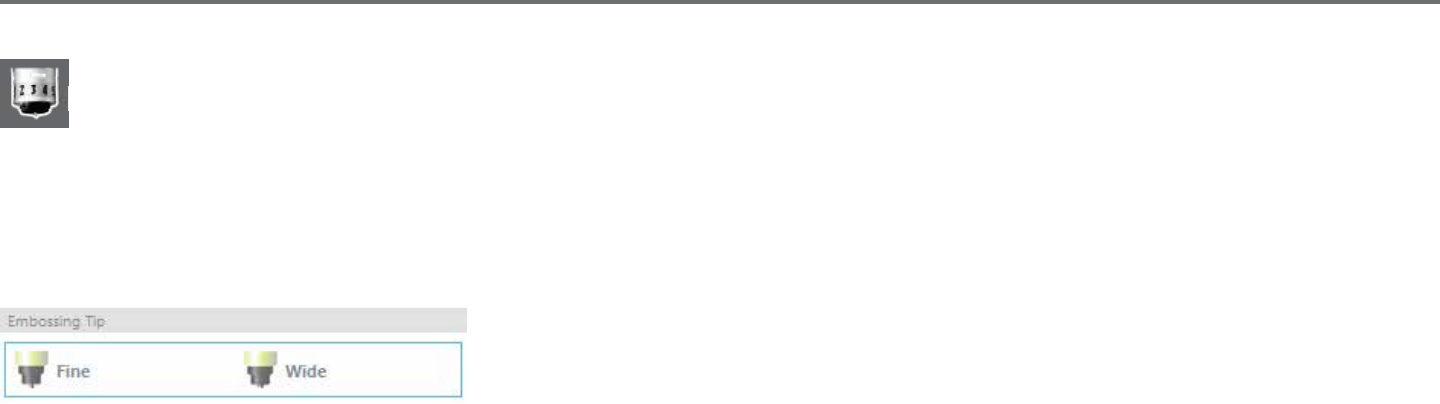
90Silhouee Studio® V4 | Chapter 12 - Curio Features
Score & Emboss
The Score & Emboss opon is a special acon that will rst score around the edges of your image (with a blade), and then will press inside
of the score line (with an embossing tool). The resulng eect provides a more dramac deboss relief or raised emboss eect.
IMPORTANT: This feature is intended for use with Silhouee brand “Score & Emboss Paper”. Silhouee cannot guarantee eecve results when
using other material types. All further instrucons assume the use of Silhouee brand “Score & Emboss Paper”.
When going to Score & Emboss an image, begin by selecng the Embossing Tip type.
Selecng the Fine embossing tool will provide a more pronounced emboss/deboss eect and have
the emboss line closer to the score line. Selecng the Wide embossing tool will provide a soer
emboss/deboss eect and have the emboss line farther from the score line.
IMPORTANT: Make sure the Embossing Tip selected in the soware matches the actual Embossing Tool that has been placed into the
Silhouee Curio™
You may adjust addional sengs found under the Score & Emboss opons if desired. The opons found here will allow you to control how many
embossing passes are performed aer the image has been scored.
By default, the image will only be embossed a single me close to the score line.
Raising the Passes opon will allow you to perform an addional number of impressions made inside of the score line.
Fill will have the selected image lled enrely by a series of emboss lines.
Once you have all sengs to your liking, you may then select the image and click on Apply Score & Emboss Lines.
When ready, you may go to adjust your sengs if needed by clicking on the Adjust Cut Sengs buon. The acon to Apply Score & Emboss Lines
will have automacally set up your job to be scored and then embossed according to the opons selected.
IMPORTANT: Ensure that your blade is placed into the Curio’s le-hand tool holder (idened by the red circle) at a blade seng of “1”, and that
your desired embossing tool is placed into the right-hand tool holder (idened by the blue circle).
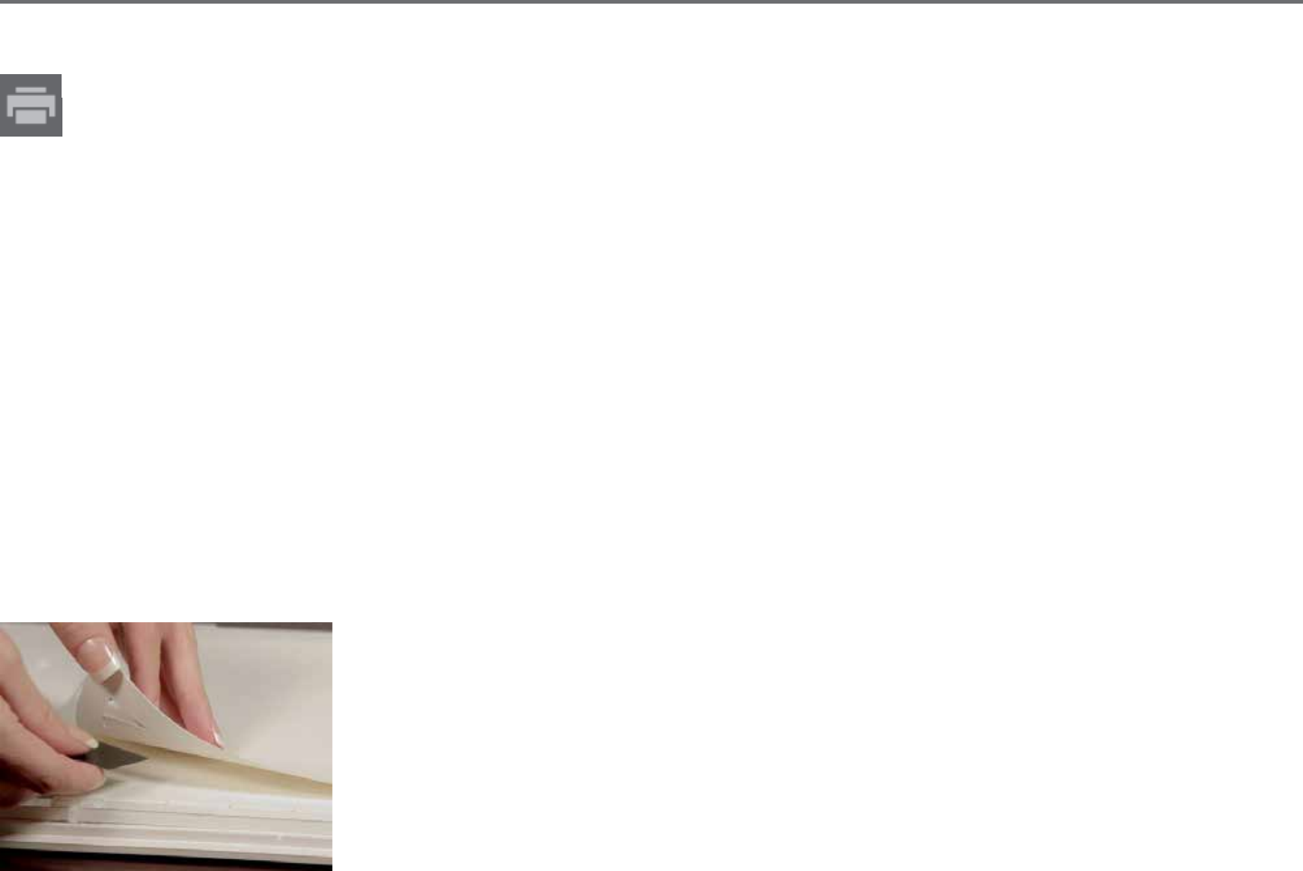
Silhouee Studio® V4 | Chapter 12 - Curio Features 91
Print & Emboss
The Print & Emboss opon is very similar to the Print & Cut opon, which uses registraon marks to provide proper alignment around a
print image. Print & Emboss jobs allow you to print an image onto a material’s surface and then press down onto the opposite side of the
printed surface with an embossing tool. The resulng eect produces a printed image that is embossed. The emboss eect can either be
around the edge or lled in according the Emboss/Deboss opons previously selected.
Begin by placing your print design on screen and create the desired embossing lines around or within the printed image.
TIP: If using a Print & Cut image that already has a cut line created around the image and which also has surrounding white space, you can select
the image and go to the Modify opons to select Intersect. This will have all white space outside of the cut line contour trimmed. If you desire to
assign an emboss ll type, you may then right-click Copy, and then right-click Paste In Front. The design can then be selected to apply any emboss ll
type for use with the Print & Emboss feature.
You may then go to the Print & Emboss secon in the Emboss tool panel and click on the “Print” buon under Step 1. This will have your image sent
to your printer with printed registraon marks.
IMPORTANT: Please allow ample me for ink to dry prior to placing it onto the embossing mat. Ink that has not fully dried may transfer an imprint of
the image onto the embossing mat surface. While this will not degrade or harm the mat, it may be undesirable.
Remove the printed page with the cut-out registraon marks from your Curio cung mat. Flip the printed page over to the back (non-printed side)
and place it face down onto your embossing mat. You may then slide the three small black squares received with your Curio under the cut-out
registraon marks so that the marks appear to be black.
IMPORTANT: It is recommended to allow ample me for ink to dry prior to placing it face down onto the
embossing mat. Some ink may transfer onto the embossing mat. Such is normal and will not negavely aect
further usage of the embossing mat.
Replace the blade with an embossing tool into the Curio’s le-hand tool holder (idened by the red circle)
and click on the “Emboss” buon under Step 3. The back of the page will be indented along the emboss lines
so that a raised emboss eect will be visible when the page is viewed from the front.

92Silhouee Studio® V4 | Chapter 12 - Curio Features
12.2 Sppling
Sppling is the process of marking a material’s surface with numerous small dots to make a paern. The Silhouee Curio™ provides the
ability to create spple points by either converng lines into spple points, or by converng imported print images into spple paerns.
The Spple opon assumes you are either using a Spple Tool (item sold separately) or a felt p pen.
Spple
The Spple secon will allow you to convert lines into spple paerns or to ll images with various spple paerns.
To convert lines to spple points, check the box for Spple Edge under the Spple menu. Aer doing so, you may control the spple point distance
by adjusng the Spacing opon.
Selecng one of the Spple Fill types (Paerns or Shapes) will have the selected line image lled with your desired paern or shape. Only one
Paern or Shape opon can be selected at a me. The following sengs can be adjusted according to your Paern or Shape selected:
Grid Spacing: Zooms the selected spple Shape in or out
Spple Spacing: Controls spple point spacing to either be closer together or spaced farther apart
Angle: Controls the angle of the spple ll
Oset: Controls how close to or far from the edge of the lled shape the Spple Fill will appear
The Spple Size opon will adjust the display size of the spple points on your screen. This does not control the actual resulng size of the created
spple point. This is for display purposes only.
When the Print Spple opon is checked, your image can be sent to a printer in order to print out an image of the selected spple sengs.

Silhouee Studio® V4 | Chapter 12 - Curio Features 93
Spple Trace
The Spple Trace secon will allow you to convert imported raster images (such as JPG, PNG, and other supported bitmaps) into spple
paerns.
Once you have opened an external image you own (as discussed in Secon 3.4) you may click on the Select Spple Area buon. This will allow you
to draw a box around the intended area of your imported image in order to create a spple paern. This selected area once drawn may be adjusted
or moved like any other object in the soware as you may need to expand or rene the Spple Trace area. The Spple Trace area selecon will
provide a preview of the original image with a black-doed image showing how the intended spple points will be created.
Aer selecng all desired Spple Opons (as noted below) and your spple paern appears as you would like, you may click on the Create Spple
buon to have the paern created.
Spple Style: Various spple styles and sengs can be adjusted to provide altering spple eects.
Invert: The invert checkbox will have the contra-posive image traced.
Density: Generally, lighter regions of the drawing will be populated with fewer spple points and darker regions are more densely populated. The
darkness of any region is magnied by the Density seng which aects the populaon, or density of spples rendered in that region.
Renement: Spples are rendered at the points of a small invisible square grid, the spacing of which is dened by “Grid Spacing”. Some Spple
Style opons allow this to be adjusted so that the spple points appear at half, third, or quarter grid squares, thus higher values provide a more
randomized display of spple points which may have a more natural or less blocky appearance.
Grid Spacing: Species the distance between rows and columns of the square grid upon which the spple points are posioned. Lower values
provide a ner grid upon which the spple points may be posioned.
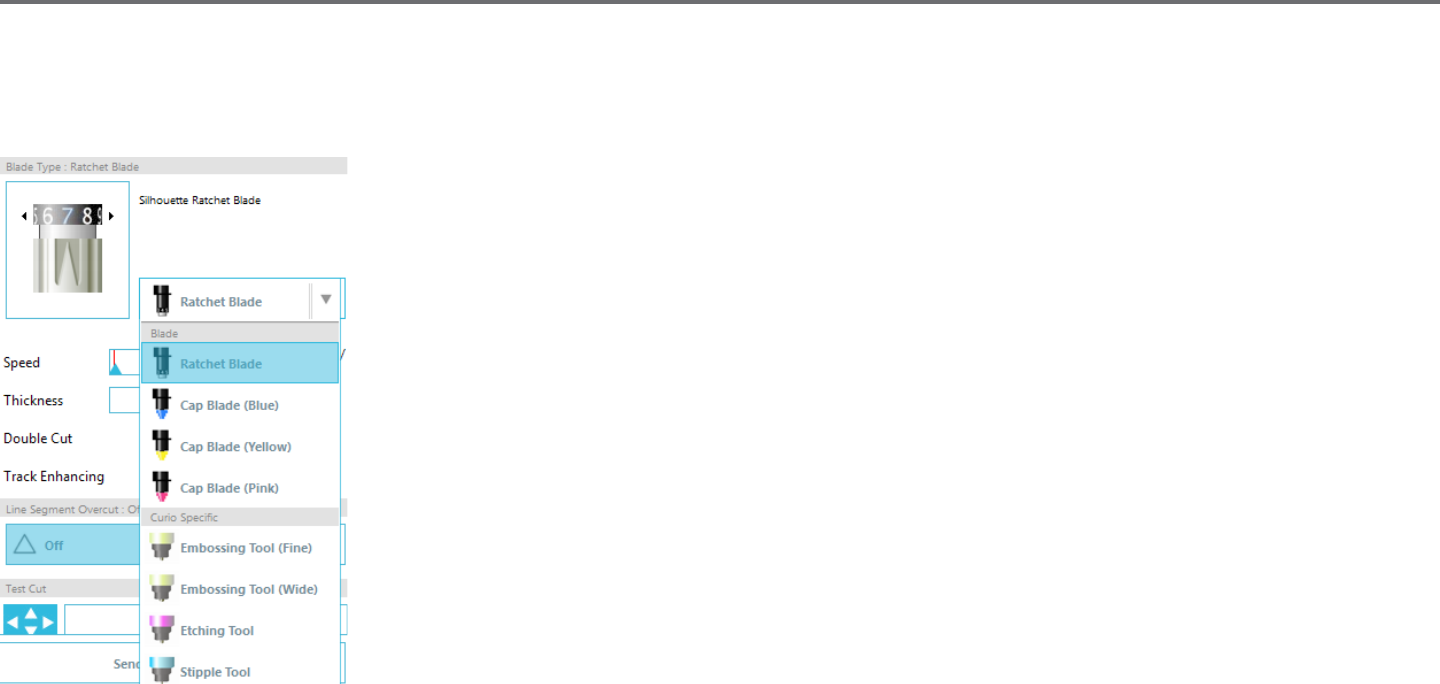
94Silhouee Studio® V4 | Chapter 12 - Curio Features
Selecng the Spple Tool
When opng to spple, you may either use a felt-p type pen or a Silhouee Sppling & Embossing Tool. Whenever performing a sppling job, you
will want to select the Spple Tool for your material type under the Cut Sengs panel.
To select the Spple Tool, select your material type in the Cut Sengs panel and then click on the tool type
drop-down opon.
You can then scroll down to select the Spple Tool. Once selected you will have two new tool seng opons
available.
While the acon of Sppling is generally an up\down acon, the Spple Size opon here will allow you to
create a larger spple point by dropping the tool and having the spple point created in a circular moon, thus
making the spple point larger. The default seng of 0.00 mm will simply have the spple point created at the
tool’s actual point diameter.
When using the Spple Tool to spple metal surface, such as the Silhouee brand Metal Sppling Sheets, you
may check the Increased Spple Force box in order to create a harder punched spple point.
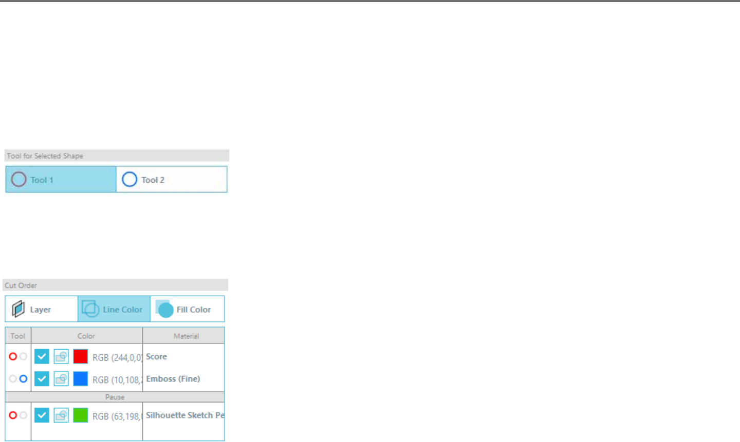
Silhouee Studio® V4 | Chapter 12 - Curio Features 95
12.3 Mulple tool use
The Silhouee Curio™ and Silhouee CAMEO® 3 have two tool holders so that mulple tools can be used simultaneously. This means that you are
able to perform two dierent acons during the same job, such as cut, emboss, etch, spple, and sketch.
When Silhouee Curio™ is detected, Silhouee Studio® will provide an opon in the Send panel to allow various line sets to be assigned to the
dierent tool holders.
When in the Send Panel, you may select your desired object in your workspace and then click on the associated Tool holder opon you want to use.
This will assign the selected line to be performed by the desired tool you have placed into the
associated tool holder.
When in the Advanced Cut Mode, you can assign your lines to be performed by the desired tool holder by clicking onto the associated circle found
under the Tool column. This can be performed according to Line Color or Fill Color, or if using the Designer Edion version you may also set up your
job to various tools according to Layer.
Clicking on the le-hand red circle will have the selected row performed by the Curio’s le-hand tool,
whereas clicking on the right-hand blue circle will have the selected row performed by the Curios’
right-hand tool.
If you have more than two tool types you wish to use within the same job, you can right-click to add a
pause in order to stop the Curio between acons and change out your tool as needed.
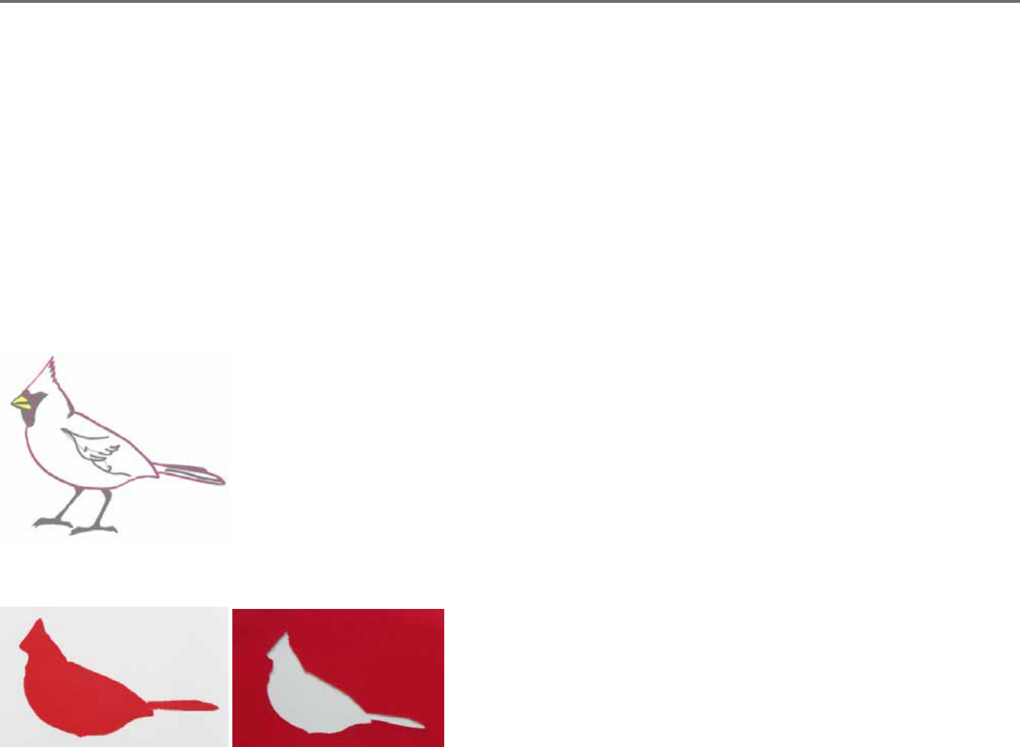
96Silhouee Studio® V4 | Chapter 13 - Designer Edion Plus Features
13 - Designer Edion Plus Features
Silhouee Studio® Designer Edion Plus has a two extra features: appliqué embroidery and advanced rhinestones.
13.1 Appliqué Embroidery
Silhouee Studio® Designer Edion Plus enables you to import appliqué embroidery les. If your embroidery le has a placement stch layer, you
can use it to cut out the appliqué shapes using your Silhouee cung machine.
To do so, upload your embroidery le to Silhouee Studio®. You can import the following embroidery formats with Designer Edion Plus:
PES (Brother, Babylock, Deco, Singer)
DST (Tajima, Barudan, Toyota)
EXP (Stellar, Melco)
JEF (Janome)
XXX (Singer)
Open your le in the design screen. Delete the extra embroidery shapes so only the placement stch line remains.
Send your shape to your Silhouee and cut your shape out of your fabric. Now you have a perfectly cut appliqué.

Silhouee Studio® V4 | Chapter 13 - Designer Edion Plus Features 97
Sketching with Embroidery Files
You can convert embroidery designs to sketch artwork using Silhouee sketch pens.
Upload your le to Silhouee Studio®. Assign each layer a color. Send the image to your Silhouee with each colored layer corresponding to a
colored sketch pen.
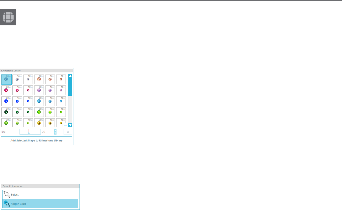
98Silhouee Studio® V4 | Chapter 13 - Designer Edion Plus Features
13.2 Advanced Rhinestones
The advanced rhinestone tools in Silhouee Studio® Designer Edion Plus provide addional customizaon opons and enable you to view
your designs with photo-realisc renderings.
Custom Rhinestones
You can draw your own custom rhinestone shapes in Silhouee Studio®, or you can import images of your custom rhinestones using a PixScan™ mat
(see the PixScan™ secon for more informaon).
Once you have your shape drawn or have placed the image of your custom rhinestone on the page, select the
image. Then, click the ‘Add Selected Shape to Rhinestone Library’ buon. This will add your shape to a secon
called ‘User Rhinestones’ underneath the preloaded stock rhinestones. The rhinestone shape will remain in your
library so you can use it for future projects.
Resize Rhinestones to Non-Standard Sizes
The size of circular rhinestones can be dened in ‘ss’ or in the dimensional units (‘mm’ or ‘inches’) set in your
preferences sengs. The width / height of non-circular rhinestones is dened in the dimensional units (‘mm’ or
‘inches’) set in your preferences sengs. You can resize your custom rhinestones by clicking on the slider bars
under your rhinestone library.
Placing Individual Rhinestones
To place individual rhinestones in your design, you can select the rhinestone you want and drag and drop it in place. Or you can select ‘Single Click’
from the advanced rhinestone menu. Otherwise, there are two opons to place rhinestones in your design: single and mulple.
Single Click mode provides a rhinestone cursor in the draw area which places the currently selected rhinestone
from the Rhinestone Library on the page, allowing you to quickly place a repeated rhinestone.
When you are in ‘Mulple Rhinestones’ mode, the Rhinestone Cursor rotates through the sequence of
Rhinestones dened in your ‘User Rhinestones’ list, allowing sequences of dierent rhinestone types to be quickly placed.
Clicking the Rhinestone Cursor above a rhinestone which has already been placed in the draw area causes that rhinestone to be replaced by the
new one, posioning the new rhinestone at the same center.
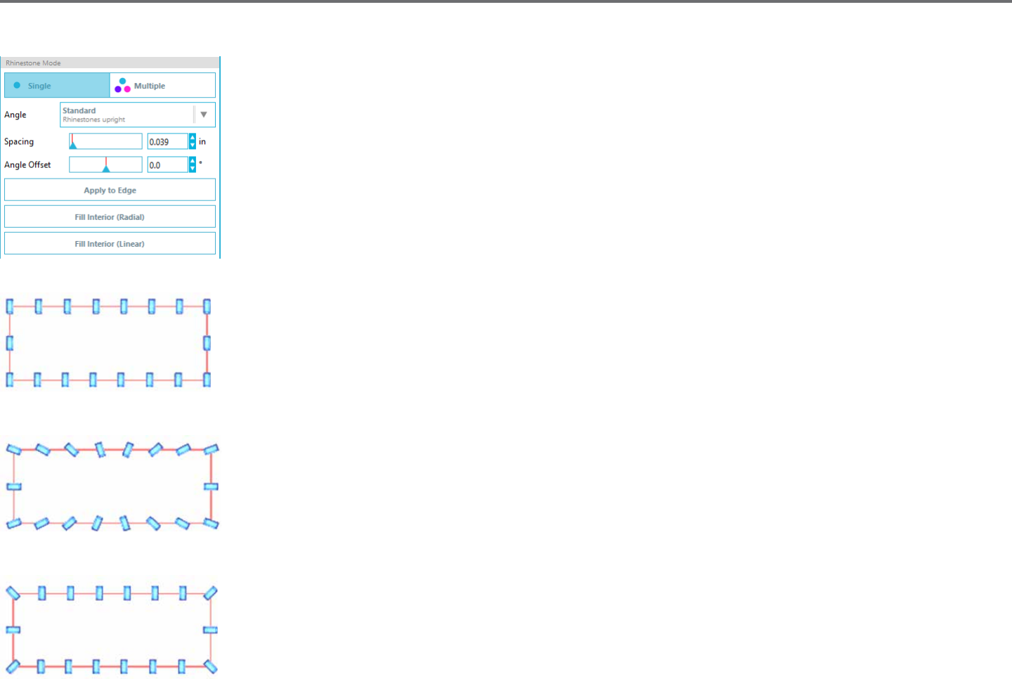
Silhouee Studio® V4 | Chapter 13 - Designer Edion Plus Features 99
Placing Rhinestones as Outlines or Fills
You can create outlines or lls using either a single rhinestone style or a mulple rhinestone paern.
To use a single rhinestone style, you can select a single rhinestone and outline or ll your design with it. First,
select your image. Next, under ‘Rhinestone Mode’ select ‘Single’. Then, select which rhinestone you are using for
your design.
There are three adjustment opons: Angle, Spacing, and Angle Oset.
The following opons are available in the drop down ‘Angle menu.
Standard: Rhinestones are oriented in a uniform direcon.
Center: Rhinestones are oriented to point toward the center of the boundary shape.
Perpendicular: Rhinestones are oriented perpendicular to the contour upon which they sit.
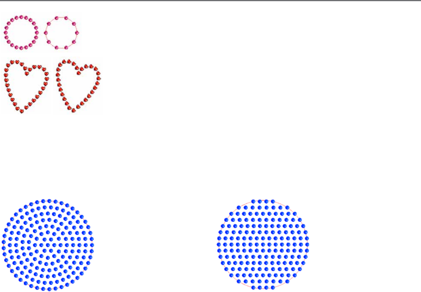
100Silhouee Studio® V4 | Chapter 13 - Designer Edion Plus Features
’Spacing’ adjusts how much space there is between each individual rhinestone.
’Angle Oset’ allows you to adjust the angle at which rhinestones are placed.
Hearts with no angle oset and hearts with 450 angle oset.
Aer you have selected your Angle, Spacing, and Angle Oset, click ‘Apply to Edge’.
Fill Opons
There are two opons to ll your design.
‘Fill Interior Radial’ posions rhinestones on edge of the
path and on concentric contours in the interior.
‘Fill Interior Linear’ posions rhinestones in a grid-like formaon
in the interior.
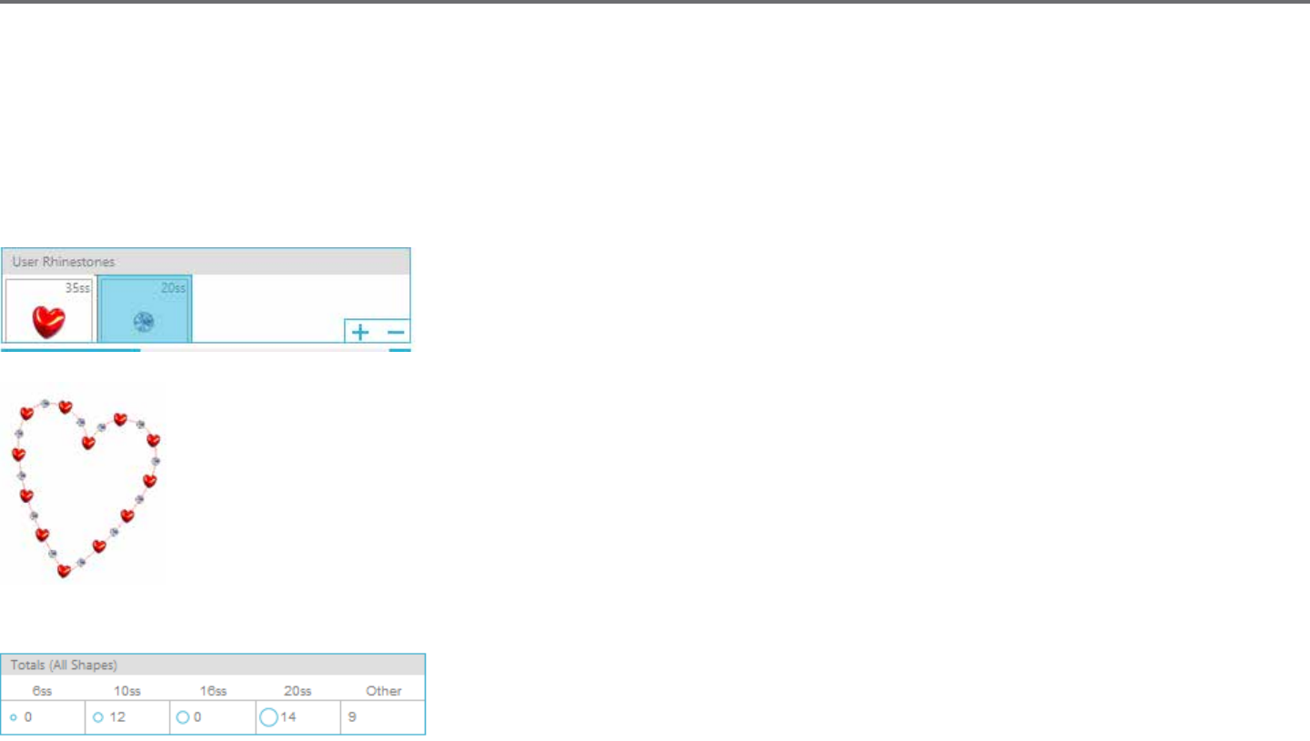
Silhouee Studio® V4 | Chapter 13 - Designer Edion Plus Features 101
Mulple Rhinestones
Mulple Rhinestone Mode funcons similarly to Single Rhinestone Mode except the outline or ll uses a mulple rhinestone paern.
When in ‘Mulple Rhinestones’ mode, you can make a paern of rhinestones for your design. To make a paern, click on the rhinestone you want
and drag it down to ‘User Rhinestones’. Go back to your rhinestone library and click the next rhinestone you want and drag it down next to the rst
one. You can drag down as many rhinestones as you want to create your paern. Each rhinestone will automacally be placed at the end of the
paern, but by clicking and dragging, you can rearrange them to create your desired look.
Total (All Shapes)
At the boom of the Advanced Rhinestone menu is a total rhinestone count. It tracks how many
rhinestones of each size you use in your design.
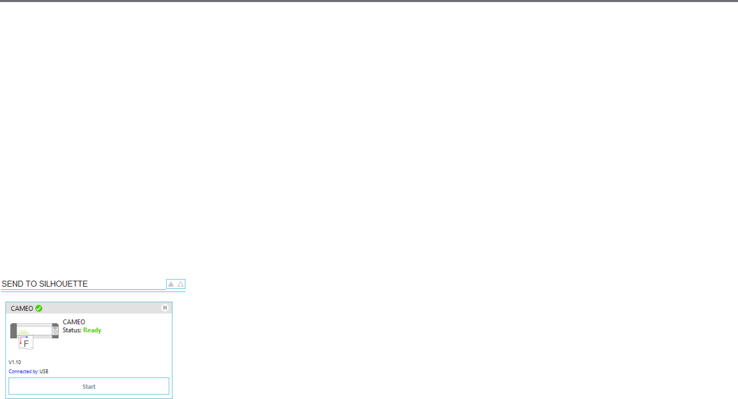
102Silhouee Studio® V4 | Chapter 14 - Business Edion Features
14 - Business Edion Features
Silhouee Studio® Business Edion has a few helpful tools to aid in the producon of large, intricate, or batched projects.
14.1 Mul-Cuer Support
The Silhouee Studio® Business Edion provides mul-cuer support. This means that when using the Business Edion, you are provided the ability
to send cut jobs to mulple Silhouee cung units at the same me as they are hooked up to your computer.
To ulize the ability to send jobs to mulple Silhouee units hooked up to the same computer, you may simply go to the Send panel and select
which Silhouee unit you would like to send the job to and then press the Start buon.
You can use this feature to cut the same job or dierent jobs for whichever document tab is selected and acvely displayed as you opt to start the
job.
The opon to use mulple Silhouee units also provides the capability in the Business Edion to name your Silhouee units within the program.
This is so you are able to determine which job is being sent to which unit. To rename a connected Silhouee, simply click on the Silhouee model
name (shown in grey below) in the Send to Silhouee Screen:
Once you click on the model name, you can type in any new desired name for the specic Silhouee unit.
The name will be retained whenever using the computer that was used to create the name, even if the unit is
unplugged and then later plugged back in. However, please note that the naming is specic to the computer
in queson.

Silhouee Studio® V4 | Chapter 14 - Business Edion Features 103
14.2 Ai/EPS/CDR le compability
The Silhouee Studio® Business Edion provides the ability to open Ai, EPS, and CDR les directly which have been created from other major vector
imaging soware programs (such as Adobe Illustrator® or CorelDraw®).
To access this feature in the Business Edion, go to the File menu and select Open. If on a PC, you will need to select the le type you are seeking to
open and select the Ai, EPS, or CDR opon.
You may either select to cut by layer and simply enable the desired layers, or opt to cut by line color and either enable the “no color” line to be cut
or re-color your lines as desired using the Line Color tool.
You may alternately opt to use the Silhouee Connect™ program to cut these les from their nave soware programs.
14.3 Design View vs. Media Layout View
Silhouee Studio® Business Edion provides a dierent view opon to enable users to view both the original Design View of how images
are laid out from a design aspect and a Media Layout View of how lines are processed to actually appear in the resulng cut job. While the
tradional “what you see is what you get” Design View can be ulized and jobs processed in this manner when using the Business Edion, there
is an addional opon to change to the Media Layout View in order to maximize eciency of laying out designs to be cut on specialty materials
commonly used in business sengs.
This side-by-side view capability provides access to further Business Edion features, such as Matrix Copy opons, Media Layout Nesng, and Tiling.
Design View
Selecng this opon will put the soware into the tradional single pane view and have objects cut out as they have been placed in their original
design.
Media Layout View
Selecng this opon will provide a side-by-side view of your original layout (Design View on the le-hand side of the screen), and a view of the way
your job will be processed to cut to your media, or material that is being cut (Media Layout View on the right-hand side of the screen).
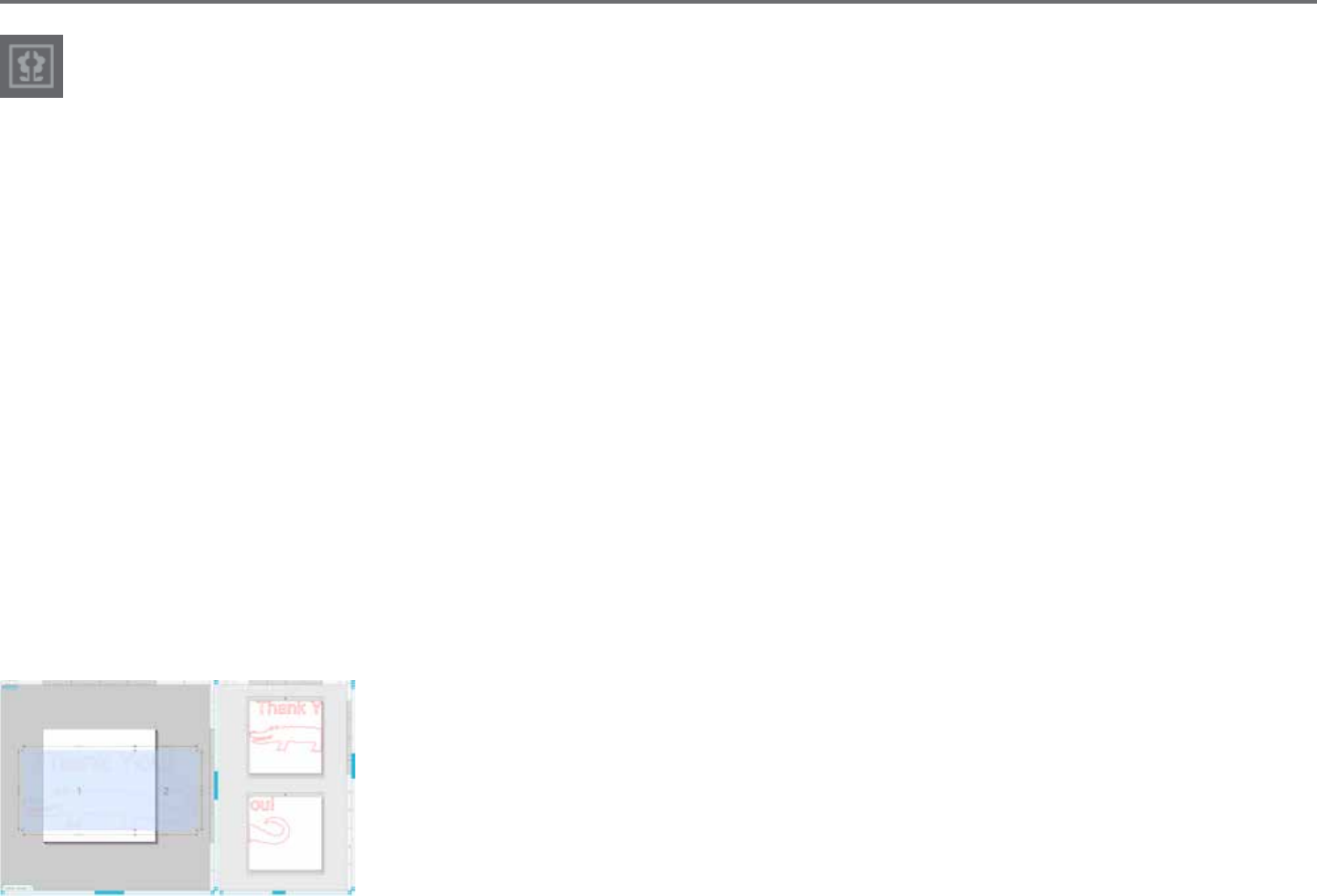
104Silhouee Studio® V4 | Chapter 14 - Business Edion Features
14.4 Tiling Feature
The Silhouee Studio® Business Edion provides an automated Tiling feature.
The Tiling feature provides a method by which a larger job can be cut from a series of smaller les which are then assembled aer the cung
process is completed in order to create the larger scale job.
By example, the Tiling feature will allow the user to design a large scale image of 24 inches height by 24 inches width and cut it out in several
passes. Even though such a material size cannot be cut in a single pass due to the Silhouee’s maximum cung width limitaon of 12 inches, the
Tiling feature will automacally segment the job into a series of smaller jobs that can be cut out and then assembled to achieve the nal 24 inch by
24 inch project.
The Tiling feature is available only when running the Business Edion version in the Media Layout mode.
While the original design can retain its original design layout, the Tiling opon will provide a method to re-arrange the design to be cut in a series of
mulple panels, thus allowing the target project which is larger than the media being used to be successfully created in a series of mulple smaller
jobs.
The following opons are available in the Tiling panel:
Tiling Acve
This opon turns the feature on or o as desired. The opon can be combined with other Business Edion features, such as Media Layout Nesng
and Matrix Copy. (NOTE: This the processed design shown in the Media Layout View will only change to mulple panels if the image exceeds the
available cung area.)
When Tiling is acve, the Design View will display a series of numbered les to display how the project will
be split up into the resulng cut jobs.
These les can be controlled by the following further available tools found in the Tiling panel:

Silhouee Studio® V4 | Chapter 14 - Business Edion Features 105
Congure Posion and Size - The opons found in this secon will allow for the adjustment of the le sizes and posioning for how the les will
process the resulng cut job.
Maintain Aspect - This opon will maintain the aspect rao of the master le.
Automac - This opon will resize the les to the size of the project being cut. The ling division lines will be posioned automacally according to
the dened media size.
Custom - This opon will allow you to edit the les by dragging the division lines and nodes.
Regular Grid - This opon will resize the les to maintain width and height dimensions for the individual les, rather than sizing them according to
the media size specically.
Margin - This opon will create an overlap of the resulng cut, which may be useful as overlap in the nal resulng job may be required.
Show Dimensions - This opon toggles the le sizes on and o.
All Tiles - This opon will have all les selected to be cut.
Selected Tiles Only - This opon allows for selected les only to be cut. Alternately, you may click in the Design View on the les to toggle them on
or o.
Separaon- This opon toggles the le sizes on and o.

106Silhouee Studio® V4 | Chapter 14 - Business Edion Features
14.5 Automac Nesng Preview
The Silhouee Studio® Business Edion provides an Automated Nesng preview mode where shapes are automacally nested within the
Media Layout View to provide ecient usage of the material being cut, while maintaining the image’s original posioning in the Design
View thus allowing the user to connue eding and rening the design.
The Media Layout Nesng opon is available only when running the Business Edion version in the Media Layout mode.
While the original design can retain its original design layout, the Media Layout Nesng opon will provide a method to re-arrange the objects to be
cut in a manner that makes the most eecve use of your media.
The following opons are available in the Media Layout Nesng panel:
Nesng Acve - This opon turns the feature on or o as desired. The opon can be combined with other Business Edion features, such as Tiling
and Matrix Copy.
Interlock Shapes - This opon will nest concave shapes together in more ecient ways and aempt to interlock them to save more space on your
media.

Silhouee Studio® V4 | Chapter 14 - Business Edion Features 107
Maintain Grain - When enabled, the nesng feature is constrained to leave images unrotated, or to rotang only by 180 degrees. This may be useful
when using specialty media that has a grain in order to ensure the grain runs in the desired direcon for the resulng cut out images.
Align - When enabled and images are rotated to an irregular angle in the Design View, the Align opon will make the image upright to compensate
prior to determining the best angle to nest the shape into.
Whole Words - This opon will keep leers from words together which have been created with the Text tool, instead of nesng each individual
leer.
Maintain Groups - This opon will keep any grouped images in their original grouping rather than nesng each individual object.
Rotaons - The Rotaons opon will allow or restrict the level of angles you may allow the images to be rotated. For example, a Rotaons seng
of “0” will hold the images exactly in their original angle of rotaon whereas a Rotaons seng of “2” will allow rotaons of 0º and 180º turns for
the images. A Rotaons seng of “4” will allow images to be rotated at angles of 0º, 90º, 180º, and 270º. As the Rotaons seng is raised, the
number of possible rotaon angles for each image increases. The seng is present because while the highest seng may aempt to make the most
eecve use of space, there may be instances where the angle of images is important and it is more desirable to hold images in a certain angle.
Padding - This opon controls the minimum distance between two adjacent shapes aer they have been nested.
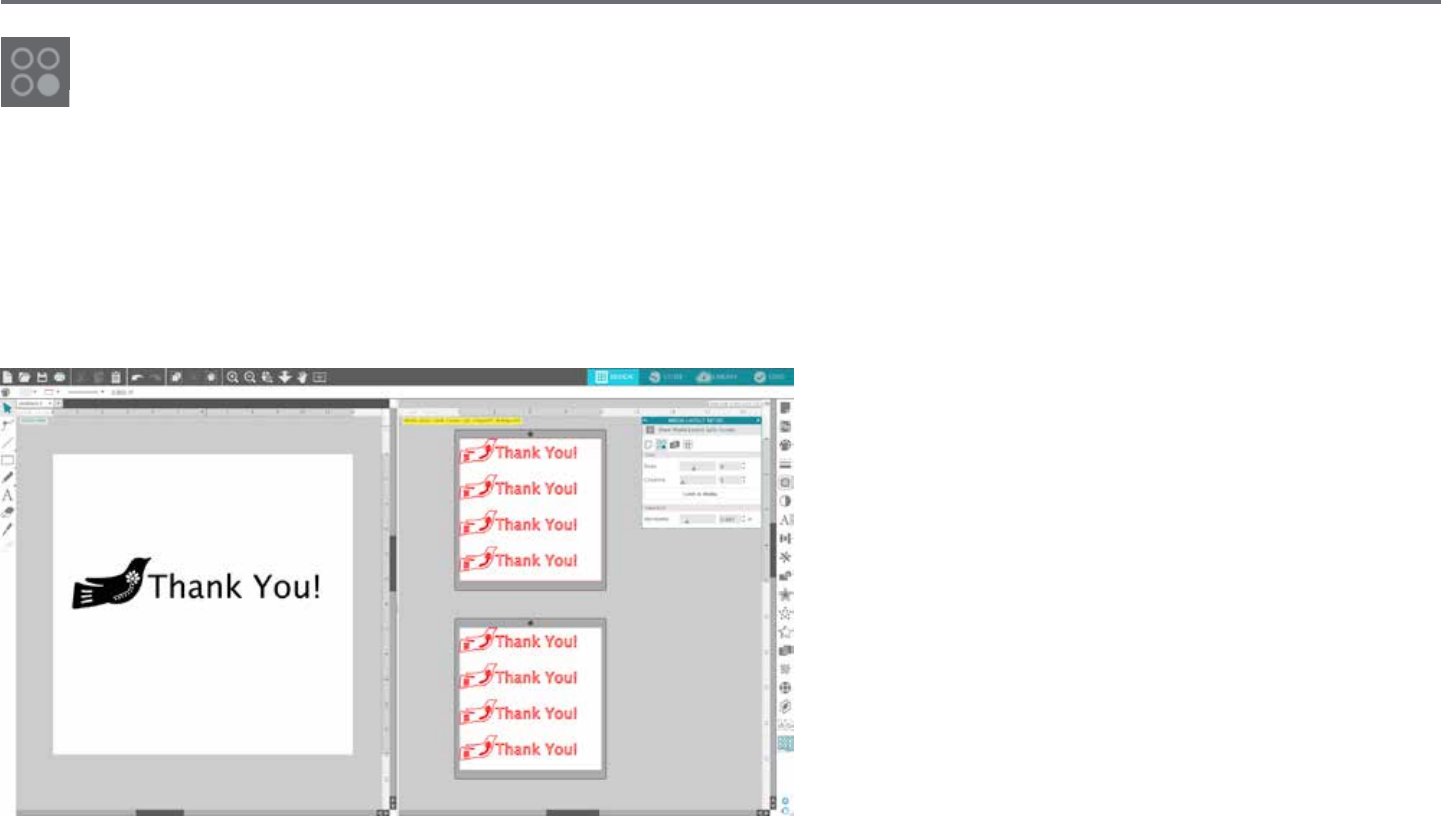
108Silhouee Studio® V4 | Chapter 14 - Business Edion Features
14.6 Matrix Copy Feature
The Silhouee Studio® Business Edion provides a Matrix Copy feature. This feature will provide the ability to create matrix of mulple
copies of the same project that are replicated during the processing of the cut job but which do not actually alter or eect your original
design.
The Copy feature is available only when running the Business Edion version in the Media Layout mode.
While the original design can retain its original design layout, the Copy panel opons will provide a method to replicate the design to cut mulple
copies as desired.
The following opons are available in the Copy panel:
Rows - This opon will provide mulple rows of the job as
dened.
Columns - This opon will provide mulple columns of the job
as dened.
Limit to Media - Pressing this buon will take the specied
numbers for the rows and columns entered and remove any
which exceed the allowed size of your media size.
Separaon - The Horizontal opon determines the horizontal
spacing between copies while the Vercal opon determines
the vercal spacing between copies.

Silhouee Studio® V4 | Chapter 14 - Business Edion Features 109
14.7 Automated Weed Line Feature
The Silhouee Studio® Business Edion provides a Weed Sengs tool. This feature provides the opon to create weed lines within open
line paths for easier weeding of materials such as vinyl and heat transfer. Opons include a surrounding weed line border as well as
internal weed lines inside the design’s open spaces (such as within leers) to provide an easy method of removing excess material aer the
compleon of the cut job.
The Weed Sengs panel can be found when running the Business Edion in the upper right-hand side of the screen.
The following opons are available in the Weed Sengs panel:
Show Weed Border - This opon enables an automated weed border to be created around the enre cut job.
Padding - The opon will adjust the padding dimension to add or remove spacing between the border and the included weed border.
Weed Lines - The Weed Lines opon provides an opon to include internal weed lines, as they may be possible to include for the image.
All weed borders and internal weed lines are automated and adjusted on the y as adjustments are made to the placement or sizing of objects
placed on your workspace.
All weed borders and lines are displayed in blue:

110Silhouee Studio® V4 | Chapter 15 - Troubleshoong
15 - Troubleshoong
If you experience problems, a list of common trouble-shoong ps and further support informaon may be found below.
15.1 Common Troubleshoong Tips
Blade won’t cut through material
If using the original Silhouee, make sure the notch on the blade (the black “n” on the base of your blade) is turned to the right, facing the blue
power light in the 3 o’clock posion. When the notch is faced in this direcon and locked into place, the blade will be lowered slightly and thus
deliver more cung force. Again, this would be for the original Silhouee only.
Regardless of which Silhouee model you have, blade posioning could sll be an issue if the blade had been removed recently to change the cap
or make an adjustment to the blade level (depending on the blade type being used). The blade may not be fully seated in the holder and thus not
delivering clean results when cung. To check this, unlock the blade and while holding the lock lever in place, twist and push the blade down to
make sure it is seated all the way down in the holder.
You may also check the cut sengs. If you are cung with a depth that is too shallow, you may need to adjust your cung sengs or blade cap/
seng according to the type of paper or media you are trying to cut. Use the Test Cut buon to ensure your sengs are set up correctly for the
media type you are using prior to going through the enre cung process. If the test cut does not work, you most likely need to re-adjust the
sengs. If the test cut works, the actual cut job should work.
If you nd for any reason that there are areas not giving a clean cut, you may also wish to select to use the Double Pass opon in the Send Panel to
ensure any problem areas are given an extra pass during the cut job.
Images are not aligned when cut
When cung regular paper or cardstock that does not have its own adhesive-backing, please ensure you have loaded your paper onto your cung
mat. This issue may be experienced if you are not using the cung mat properly or are not using it with materials that would require the use of a
cung mat.
If you are using the cung mat, you will want to ensure the mat’s liner has been removed to expose the scky surface so that your material is being
held down in place rmly during the cung process. If the mat has lost its adhesive quality for any reason and is not holding the paper rmly in
place, this may cause your paper to dri as it is being cut.
If you are using the cung mat and your paper is being loaded onto the cung mat correctly and held rmly in place, you may be experiencing this
issue if you have loaded your cung mat or material into the Silhouee lined up with the far le-hand side of the machine, as opposed to lining up
the cung mat or material with the raised guide. If the cung mat or material being cut is not lined up correctly with this guide and is not being
inially grabbed between the two white rollers, you would experience the issue of your cung mat or material driing as it is being cut and your
image would not be aligned properly.

Silhouee Studio® V4 | Chapter 15 - Troubleshoong 111
New Hardware Wizard appears each me Silhouee is powered on
If your computer is asking you to install the soware (even though it is already installed), this is likely when you are turning on the Silhouee or if
you have unplugged the USB and are plugging it back in. Your computer is simply thinking there is a new hardware device it has not yet recognized.
You may safely navigate through the automac recommended installaon as it simply is referring to the driver. The driver is contained on your
installaon CD, or in the case of downloading the soware may be obtained from www.silhoueeamerica.com in the Support secon. The driver
is actually not necessary for proper use of the soware, but may be used to quiet the Windows Plug & Play feature which tries to nd hardware
drivers when new devices are connected. Aer re-installing the driver, you should no longer receive this prompt to install.
NOTE: You may see a threatening message from Microso during driver installaon that menons the driver is a potenal risk or has not passed
Windows logo tesng. Please note that the driver has been tested extensively and will safely work with Windows XP, Windows Vista, and
Windows 7. Click on the “Connue Anyway” buon and proceed with the driver installaon process.
Unload Media is displayed immediately aer loading (SD and Cameo models only)
This is not an error. Once you have selected one of the loading opons, whether or not you have actually loaded anything into the machine, the
Silhouee will think that material has been loaded and await further acon to cut either through your computer or through a SD card. As it is
waing to cut, the inial opon displayed will show Unload Media. This is displayed in case you had loaded your material incorrectly or if it was not
loaded into the machine straight. Aer the cung process has ended, you will likewise be shown this opon displayed to unload your material.
If there is no material actually loaded yet and the Enter key was accidentally pressed, you may simply press the Unload Media buon and then scroll
over to again nd the loading opons on the Silhouee SD’s LCD screen to properly load your material to cut.
Cung mat stuck in Silhouee (SD model only)
Turn on the Silhouee SD and press the arrow keys on the LCD screen of your Silhouee unl the Unload Media opon is displayed. Once displayed,
press the Enter key. If the mat is not fully ejected, please perform these acons again unl the mat is fully ejected. You may alternately power o
the Silhouee SD and manually pull the mat from the machine.

112Silhouee Studio® V4 | Chapter 15 - Troubleshoong
Silhouee is loud during operaon
Please li the Silhouee’s lid to ensure any tape that is connecng the motor to the side of the unit has been removed. If this was not previously
removed, this would be the cause of the noises experienced when your machine was powered on. If the tape had been le on, no damage should
have been experienced, but the noises heard would be atypical. Please remove the tape and again power the Silhouee unit back on.
Otherwise, please note that the Silhouee is unfortunately not a whisper quiet unit. The sounds you are hearing are likely normal.
ERROR: Could not connect to the Silhouee
If this message is displayed while Send panel, you will need to check your USB connecon to ensure it is rmly connected from the computer into
the Silhouee. You may wish to power o the Silhouee and then unplug both ends of the USB cord. You may then power the Silhouee back on
and plug the USB cord back in to your computer and the Silhouee. If problems persist, close Silhouee Studio® and restart your computer.
ERROR: Detecon of registraon marks failed
When using registraon marks for Print & Cut jobs, if this message is displayed, remove your media or cung mat from the Silhouee and re-load.
Most commonly, this error is encountered if the media or cung mat was loaded so that it was not aligned properly with the loading guide marks,
or the incorrect loading method was selected (“Load Media” versus “Load w/Carrier”).
Download progress stops or download me connues to increase
If during the download process the progress stops and/or the esmated me connues to increase while the progress of how many remaining
images to download stays the same, you may go to the Preferences screen and select Advanced. In this screen raise the HTTP Sockets seng unl
the remaining number of downloads begins to decrease showing further progress.

Silhouee Studio® V4 | Chapter 15 - Troubleshoong 113
15.2 Calibraon
Calibraon of the tool is only required for adjustment of the cung alignment as it relates to Print & Cut jobs and the alignment of cuts as they
relate to printed informaon. This should only be performed if you specically experience concerns with your cut lines not aligning with the contour
of printed images during Print & Cut jobs that use registraon marks. These opons may be found by right-clicking anywhere in the Send tab and
selecng Calibraon.
For this operaon, it is recommended to use a sketch pen in order to more clearly view the results and make adjustments accordingly.
To start, you will rst need to select to Print the Calibraon Test Page in order to print the test page to your home printer. Do not make any
adjustments to the Calibraon Test Page on your computer screen. Once printed, you will need to place the printed sheet onto your cung mat
as displayed on the screen. You will need to select the Load w/ Carrier opon on the unit when using the Silhouee SD model or Load Cung Mat
opon when using the Cameo or Portrait model.
Once loaded, use the arrow buons on the screen to align your blade so it is poinng to the rst cross mark in the area that is
represented in green on your computer screen, or in other words, the upper le corner of the rst mark.
Once the blade is in posion, click on the Calibrate opon. This will engage the Silhouee to aempt to read the mark and sketch/cut along the
cross lines accordingly.
If either line is o, you will want to make adjustments according to the measurement of exactly how far above or below/how far to the le or right
the resulng sketch or cut line was performed. To do this, measure the distance between the original printed mark and the actual performed mark.
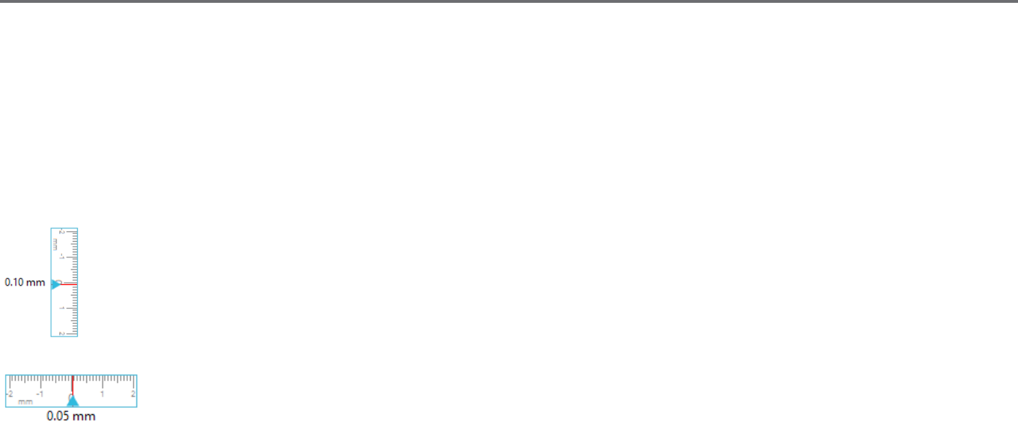
114Silhouee Studio® V4 | Chapter 15 - Troubleshoong
If the performed horizontal mark is above or below the printed mark, you will need to adjust the vercal slider bar on screen according to the
precise measurement observed between the printed and actual marks.
If the performed vercal mark is above or below the printed mark, you will need to adjust the horizontal slider bar on screen according to the
precise measurement observed between the printed and actual marks.
You may then repeat this acon as needed by again using the arrow buons on screen to align with the green area as noted on screen with the next
cross mark, click the Calibrate buon, then observe results and connue to make correcons as needed unl the actual marks performed align with
the printed marks.
A Distance Adjustment tool can be found by right-clicking anywhere in the Send panel and selecng Distance Adjustment. This should
only be used if noted that the measurement of your image noted on screen diers from the actual exact measured size. Necessary
adjustments should be exceponally rare.
To use this tool, select to Print the Calibraon Test Page to your home printer and place the printed sheet onto your cung
mat as displayed on the screen. You will need to select the Load w/ Carrier opon on the unit when using the Silhouee SD
model or Load Cung Mat opon when using the Cameo model. Once loaded, click on the opon to Cut the Distance
Adjustment Test Lines.
There will be two lines cut at posions 1 and 2 as labeled on your page. You will then need to measure the exact distance between the two lines and
adjust the horizontal slider bar for under the Distance Adjustment secon to match the exact measurement made. Once the measurement has been
adjusted, the distance correcon will be in eect. You may close the Calibraon screen and connue to cut as desired. Addional test results are not
necessary as further resulng test cuts will yield the same results on the test page and fall in line with the new adjusted number. You should only
perform this test once.

Silhouee Studio® V4 | Chapter 15 - Troubleshoong 115
15.3 Further Support Contact Informaon
Further support informaon may be obtained through the following sources:
Web: www.silhoueeamerica.com
Email: support@silhoueeamerica.com
Phone: 800.859.8243 (Toll-free U.S. & Canada only)
Silhouee America, Inc. is based out of Lehi, Utah and is open M-F
8 a.m. to 5 p.m. (Mountain me).
The specicaons, etc., in this manual are
subject to change without noce.
________________________________________
July 2017, 11th edion
Silhouee America, Inc.

Silhouee Studio® Shortcuts
Edit PC MAC
Paste in Front ctrl + f cmd + f
Duplicate ctrl + d cmd + d
Select All ctrl + a cmd + a
Deselect All ctrl + shift + a cmd + shift + a
Spelling F7 fn + F7
Preferences ctrl + k cmd + k
File PC MAC
Save as ctrl + shift + s cmd + shift + s
Save to Library ctrl + alt + r ctrl + cmd + r
Close Document ctrl + w cmd + w
Quit ctrl + q cmd + q
Object PC MAC
Group ctrl + g cmd + g
Ungroup ctrl + shift + g cmd + shift + g
Make
Compound Path ctrl + e cmd + e
Release
Compound Path ctrl + shift + e cmd + shift + e
Tools PC MAC
Select v v
Edit Points a a
Line \ \
Rectangle r r
Rounded Rectangle shift + r shift + r
Ellipse e e
Polygon p p
Curve c c
Freehand f f
Smooth Freehand shift + f shift + f
Arc shift + a shift + a
Regular Polygon shift + p shift + p
Text t t
Eraser shift + e shift + e
Knife k k
Eyedropper i i
Eyedropper ctrl + click cmd + click
Document PC MAC
New Document ctrl + n cmd + n
Open Document ctrl + o cmd + o
Save Document ctrl + s cmd + s
Print ctrl + p cmd + p
Copy ctrl + c cmd + c
Paste ctrl + v cmd + v
Cut ctrl + x cmd + x
Undo ctrl + z cmd + z
Redo ctrl + shift + z cmd + shift + z
Pan Tool spacebar spacebar
Drag-zoom Tool z z
Fit to window ctrl + 1 cmd + 1
Replicate PC MAC
Duplicate Left ctrl + !cmd + !
Duplicate Right ctrl + "cmd + "
Duplicate Above ctrl + #cmd + #
Duplicate Below ctrl + $cmd + $
Mirror Left alt + shift + !alt + shift + !
Mirror Right alt + shift + "alt + shift + "
Mirror Above alt + shift + #alt + shift + #
Mirror Below alt + shift + $alt + shift + $
Rotate 1 Copy ctrl + shift + F1 cmd +
shift + fn + F1
Rotate 2 Copies ctrl +
shift + F2
cmd +
shift + fn + F2
Rotate 3 Copies ctrl +
shift + F3
cmd +
shift + fn + F3
Rotate 5 Copies ctrl +
shift + F5
cmd +
shift + fn + F5
Row of 3 ctrl + shift + "cmd
+ shift + "
Row of 4 ctrl + alt + "cmd + alt + "
Column of 3 ctrl + shift + $cmd + shift + $
Column of 4 ctrl + alt + $cmd + alt + $
Fill Page ctrl + shift + f cmd + shift + f
View PC MAC
Show D es ig n Pag e ctrl + shift + d cmd + shift + d
Show Store ctrl + alt + s cmd + alt + s
Show Library ctrl + alt + l cmd + alt + l
Show Send Page ctrl + F2 cmd + fn + F2
Show Grid g g
Grid Panel ctrl + F4 cmd + fn + F4
Page Panel ctrl + F1 cmd + fn + F1
Print Border ctrl + shift + p cmd + shift + p
Cut Border ctrl + shift + l cmd + shift + l
Center of Rotation o o
Registration
Marks Window ctrl + F3 cmd + fn + F3
Me d ia Layou t View ctrl + shift + v cmd + shift + v
Other PC MAC
Registration Marks m m
Cut Style = Cut ctrl + t cmd + t
Cut Sty le = No Cut ctrl + shift + t cmd + shift + t
Ruler ctrl + r cmd + r
Crosshairs ctrl + h cmd + h
Edit Object Double Click Double Click
Scroll Left/Right ctrl +
scroll wheel
cmd +
scroll wheel
Zoom In/Out alt +
scroll wheel
alt +
scroll wheel
Arrange PC MAC
Bring to Front ctrl + shift + ] cmd + shift + ]
Send to Back ctrl + shift + [ cmd + shift + [
Bring Forward ctrl + ] cmd + ]
Send Backward ctrl + [ cmd + [
Modify PC MAC
Weld ctrl + shift + w cmd
+ shift + w
