Simp BMS Setup Manual V0.8
User Manual:
Open the PDF directly: View PDF ![]() .
.
Page Count: 27
SIMP BMS V2.1 SimpEco Engineering
10-03-19 simpecoeng@gmail.com 1
SIMP BMS
Manual V0.8
SIMP BMS V2.1 SimpEco Engineering
10-03-19 simpecoeng@gmail.com 2
Contents
Basics of the SIMP BMS ........................................................................................................................... 3
Currently supported slaves: ................................................................................................................ 3
Features: ............................................................................................................................................. 3
Current working features: ................................................................................................................... 3
Working Modes ................................................................................................................................... 3
Wiring Basics ........................................................................................................................................... 4
................................................................................................................................................................ 4
Outputs and Inputs ................................................................................................................................. 8
Contactors ........................................................................................................................................... 8
Inputs .................................................................................................................................................. 8
Wiring up BMS Slaves ......................................................................................................................... 9
Serial Interface ...................................................................................................................................... 10
Diagnostic Info Screen ...................................................................................................................... 13
Simp BMS Setup Menu ..................................................................................................................... 14
‘q’ Quit .............................................................................................................................................. 14
‘d’ Debug Settings ............................................................................................................................. 15
‘b’ Battery Settings Menu ................................................................................................................. 16
‘e’ Charging Settings ......................................................................................................................... 18
‘c’ Current Sensor .............................................................................................................................. 20
‘k’ Contactor Control ......................................................................................................................... 21
‘a’ Alarms and Warnings Settings Menu ........................................................................................... 22
CANBUS ................................................................................................................................................. 23
Termination Resistor ......................................................................................................................... 23
Outlanders BMS SLAVES ................................................................................................................... 24
CAN Current Sensor .......................................................................................................................... 24
CAB 300 ......................................................................................................................................... 24
Panasonic BMS Slaves ....................................................................................................................... 24
Victron VE-CAN ................................................................................................................................. 24
Other CAN Devices ............................................................................................................................ 25
CAN Messages ............................................................................................................................... 25
Firmware Updating ............................................................................................................................... 27
Links .................................................................................................................................................. 27
Flashing the HEX................................................................................................................................ 27

SIMP BMS V2.1 SimpEco Engineering
10-03-19 simpecoeng@gmail.com 3
Basics of the SIMP BMS
The starting point for this BMS is to keep it simple, the BMS will not prevent you from harming your
battery if you do not set it up properly or ignore the limits it sends out.
Currently supported slaves:
-Tesla Model S/X
-Tesla battery modules used in other OEM cars
-VW E-Golf and GTE (no balancing currently)
-Mitsubishi Outlander
-BMW I3 (no temperature or balancing currently)
Features:
Teensy 3.2 based
4 - 5-16V isolated inputs
4 - 12V outputs
4 - Low side switching outputs
2 - analogue current inputs (for dual range sensor)
1 - Serial bus for Tesla modules
1 - Canbus for communication with other modules, current senors or vehicle
1- Spare serial bus for expansion
Current working features:
- Canbus communication formatted for Victron Systems
- Full Control of Slaves, reading temperatures and voltages plus controlling balancing
- Precharge control, timer and current based
- Can based current sensor (CAB300)
- AH Counter Based SOC calculation
- Voltage based SOC correction
- Watchdog timer to reset BMS in event of software error
- Canbus Chargers (Brusa NLG5xx, Chevy Volt, Elcon)
-Display support (Nextion)
Working Modes
Normal Operation
This mode will function as you would expect from a ‘key’ operated pack, such as found in vehicles.
Precharge will happen with key on ect.
ESS Mode
Specifically developed to cater to the needs of stationary or large packs
(dual purpose packs on boats for example)
When powered up Precharge occurs (no key in used) then contactors/relays used to control charge
and discharge allowed.
All features beyond output and input control are identical.
SIMP BMS V2.1 SimpEco Engineering
10-03-19 simpecoeng@gmail.com 4
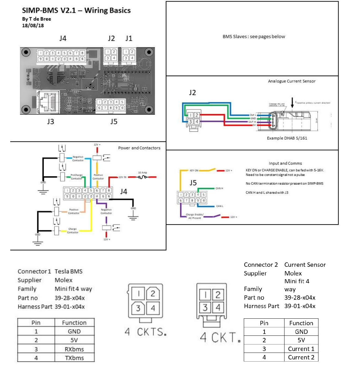
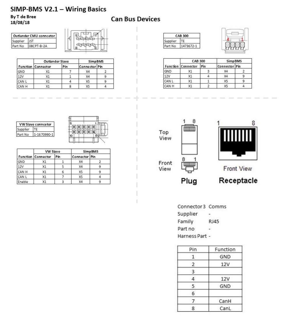
Wiring Basics

SIMP BMS V2.1 SimpEco Engineering
10-03-19 simpecoeng@gmail.com 5
SIMP BMS V2.1 SimpEco Engineering
10-03-19 simpecoeng@gmail.com 6
Connector 3 is compatible with Victron CAN RJ45
SIMP BMS V2.1 SimpEco Engineering
10-03-19 simpecoeng@gmail.com 7
SIMP BMS V2.1 SimpEco Engineering
10-03-19 simpecoeng@gmail.com 8
Outputs and Inputs
Contactors
It is possible to use both contactors with built in economizers or without.
Contactors with built in economizers MUST be used on the 12V switched outputs
Contactors without built in economizers MUST be used on the ground switched PWM outputs
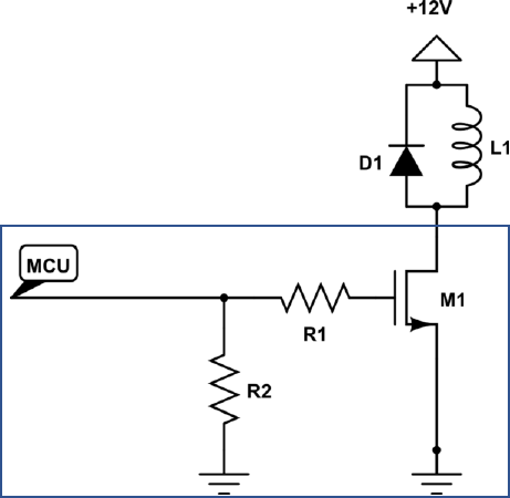
See for the circuit below, a diode must be used in parallel with the contactor.
Inputs
Inputs are triggered by giving them anywhere from 5-16V, the inputs are isolated from the micro
controller but must share the same ground as 12V in.
SIMP BMS
SIMP BMS V2.1 SimpEco Engineering
10-03-19 simpecoeng@gmail.com 9
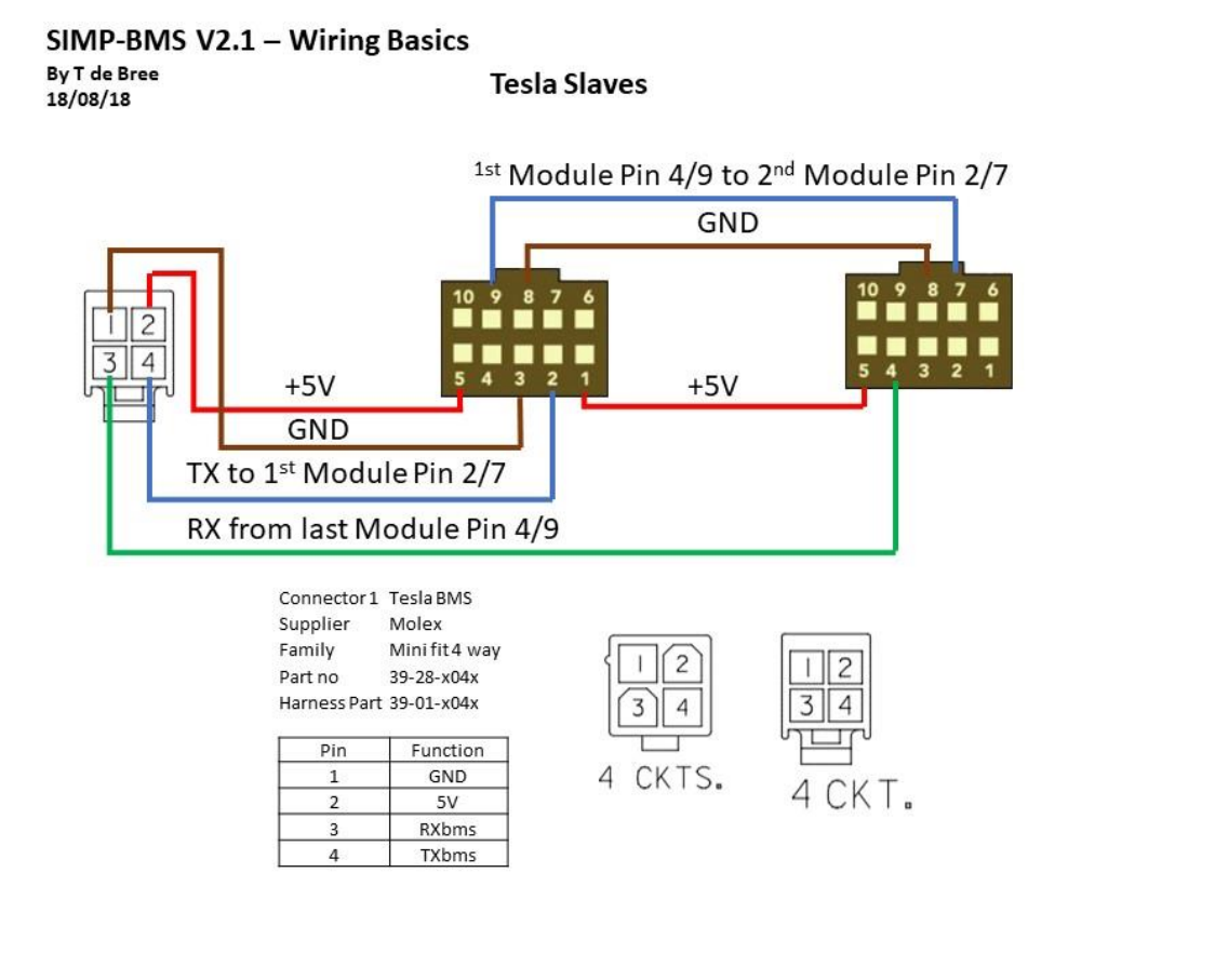
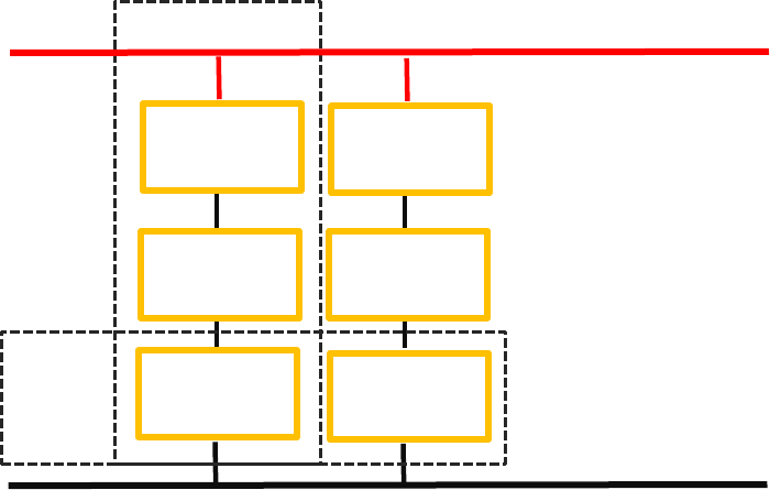
Wiring up BMS Slaves
When reusing existing vehicle battery modules might not be possible to parallel them at cell level.
The approach that thus can be taken is to wire all the modules in series and then parallel the strings
to create the complete pack.
Values to determine for your setup:
Battery Capacity – Capacity of parallel cells monitored by BMS Slave
slaves in parallel – How many battery strings are connected in parallel
Cells in Series – total amount of cells that are in series in a string
String
Module
with Slave
Module
with Slave
Module
with Slave
Module
with Slave
Module
with Slave
Module
with Slave
Parallel
SIMP BMS V2.1 SimpEco Engineering
10-03-19 simpecoeng@gmail.com 10
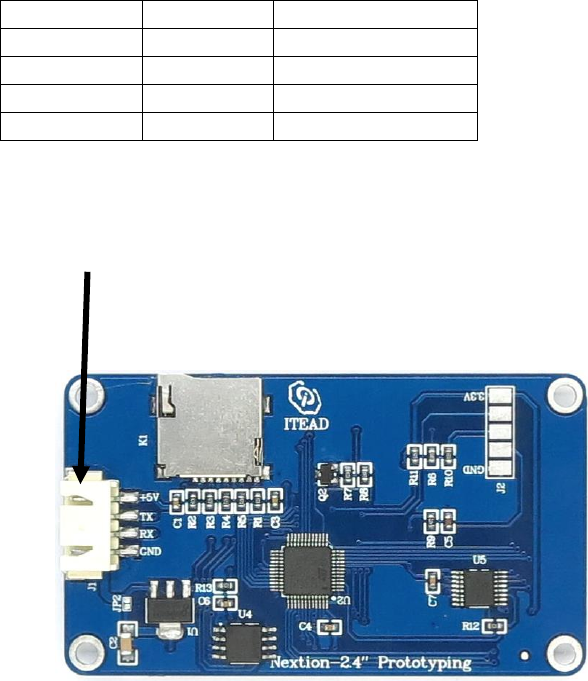
Wiring up Nextion Display
A Nextion Display programmed with the appropriate software will allow the displaying of
information provide by the SimpBMS.
The required connections are on connector 5.
Connector 5
Signal BMS
Connection Display
5
5V supply
5V
10
Ground
Ground
8
RXspare
TX
3
TXspare
RX
Nextion Display Connection
SIMP BMS V2.1 SimpEco Engineering
10-03-19 simpecoeng@gmail.com 11
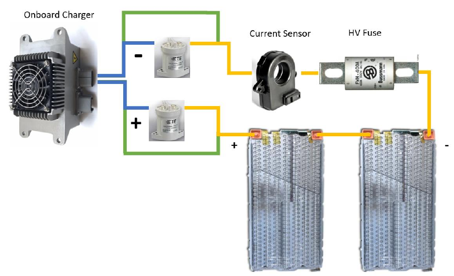
Wiring up Chargers
SimpBMS can control chargers in various ways:
• Simple on/off control with a relay
• Can bus controlled with a relay as back up
Depending on how your charger is connected to your pack you can enable the HV contactors closing
if required.
Below is an simplified diagram, this is for illustration only.
If the charger is directly connected to the battery, like the green lines show, the contactors do not
need to close in order to charge.
The variable ;
Charger HV Connection
would be set to Direct To Battery HV
If the charger is connected to the HV bus after the contactors, the blue lines;
The variable ;
Charger HV Connection
would be set to Behind Contactors

SIMP BMS V2.1 SimpEco Engineering
10-03-19 simpecoeng@gmail.com 12
Serial Interface
How to connect to SIMP BMS.
1. Connect the Micro-B USB port on the teensy to your computer with appropriate cable
2. Computer should identify new usb/serial device
3. Open your preferred Serial Terminal Program. Example :
https://www.compuphase.com/software_termite.htm
4. Connected to the Simp BMS via the serial port (115200 BAUD)
5. Now you should see the ‘Debug’ screen info scrolling
Any issues with connecting please check the Teensy Microcontroller troubleshooting guide:
https://www.pjrc.com/teensy/troubleshoot.html
SIMP BMS V2.1 SimpEco Engineering
10-03-19 simpecoeng@gmail.com 13
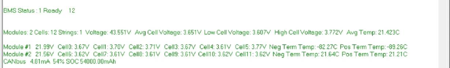
Diagnostic Info Screen
BMS Status : this is what state the bms is in.
Ready : BMS is good and communicating normally, waiting for a drive or charge digital input
Mode that is suggested for a fixed storage solution
Error : A fault is present in the read out from the modules. Possible issues:
Overvoltage
Under voltage
Overtemperature
Under temperature
Precharge : when Key on is high this is initiated, drives the negative contactor and then the
precharge contactor. Once Precharge Timer (5000mS) has ran out AND the current
drops below 1000mA it will close the contactor.* This initiates transition into drive.
Drive : Monitors voltages and temperatures with negative and positive contactor closed.
If key on signal goes low both contactors turn off immediately and BMS goes into
Ready state.
Transition to error state if : under voltage is detected
Temperature currently only derates the transmitted current limits
Charge: When AC present in is high the charger enable output gets turned on until end of
charge is reached or error occurs.
When one cell hits the overvoltage it will stop charging and go to ready.
Rest of displayed information is shown per module, both voltage and temperatures reported
Plus a summary of totals and averages based on pack settings
To open setup send the command: s
SIMP BMS V2.1 SimpEco Engineering
10-03-19 simpecoeng@gmail.com 14
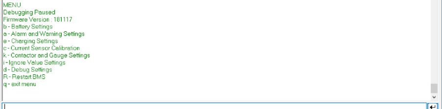
Simp BMS Setup Menu
This stops the scrolling of the diagnostics info.
This shows the Firmware Version Number, please indicate this when ever requesting support.
And displays the following options:
b - Battery Settings
a - Alarm and Warning Settings
e - Charging Settings
c - Current Sensor Calibration
k – Contactor settings and Gauge Settings
i – Ignore Value Settings
d - Debug Settings
R – Restart BMS
q - exit menu
‘q’ Quit
Exit the setup menu and resume diagnostics display info
SIMP BMS V2.1 SimpEco Engineering
10-03-19 simpecoeng@gmail.com 15
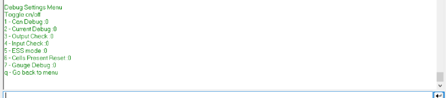
‘d’ Debug Settings
Inputting a number of the shown options toggles the modes, to stop send the same number.
1 – Can Debug = show can messages
2 – Current Debug = show all the current calculation information
3 – Output Check = cycle outputs !!! DO NOT TURN ON WITH HV CONNECTED TO CONTACTORS
4 – Input Check = show level of all inputs
5 – ESS Mode = turn on and off ESS Mode, ON is 1
6 – Cells Present Reset = recalibrate the cells to check if they are present
7 – Gauge Debug = cycle the gauge output up and down for testing pwm settings for gauge
q – go back a menu
SIMP BMS V2.1 SimpEco Engineering
10-03-19 simpecoeng@gmail.com 16
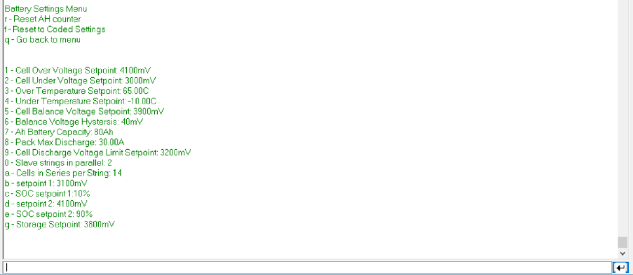
‘b’ Battery Settings Menu
Settings modified by sending “ ‘ID’ ‘New Value’ ” via the serial terminal, will refresh values in terminal
r – Reset AH Counter = Use voltage to determine SOC, best used with open circuit voltage
f – Reset to coded settings, the settings that were written when the code was compiled
1 – Over Voltage Setpoint = Over voltage limit per cell in mV
2 – Under Voltage Setpoint = Under voltage limit per cell in mV
3 – Over Temperature Setpoint = Setpoint at which allowed discharge and charge current is reduced
to zero
4 - Under Temperature Setpoint = Setpoint at which allowed discharge and charge current is reduced
to zero
5 – Balance Voltage Setpoint = Setpoint of cell voltage in mV at which during charging cells will start
balancing.
6 – Balance Voltage Hysteresis = Voltage required to be above the lowest cell to allow balancing of
cell in mV
7 – Battery Capacity = each group of parallel cells monitored per slave capacity in Ah
8 – Max Discharge = maximum discharge current in A, transmitted current limit will taper from max
current starting at discharge temp to zero at over temperature.
9 – discharge voltage limit = used to calculate max discharge setpoint, voltage per cell will get
converted to pack level by BMS
0 – slaves in parallel = amount of slave strings in pack (will multiply total pack capacity)
a – cells in series = amount of cells in series (per string if wired in parallel)

SIMP BMS V2.1 SimpEco Engineering
10-03-19 simpecoeng@gmail.com 17
b - mV setpoint 1 = cell voltage setpoint 1 for voltage based SOC calc
c - SOC setpoint 1 = SOC for corresponding cell voltage
c- mV setpoint 2 = cell voltage setpoint 2 for voltage based SOC calc
e- SOC setpoint 2 = SOC for corresponding cell voltage
g – Storage Charge Voltage setpoint = when in Storage mode in ESS this is used instead of Charge
Voltage Limit
0
10
20
30
40
50
60
70
80
90
100
3000 3200 3400 3600 3800 4000 4200
SOC vs Voltage
SIMP BMS V2.1 SimpEco Engineering
10-03-19 simpecoeng@gmail.com 18
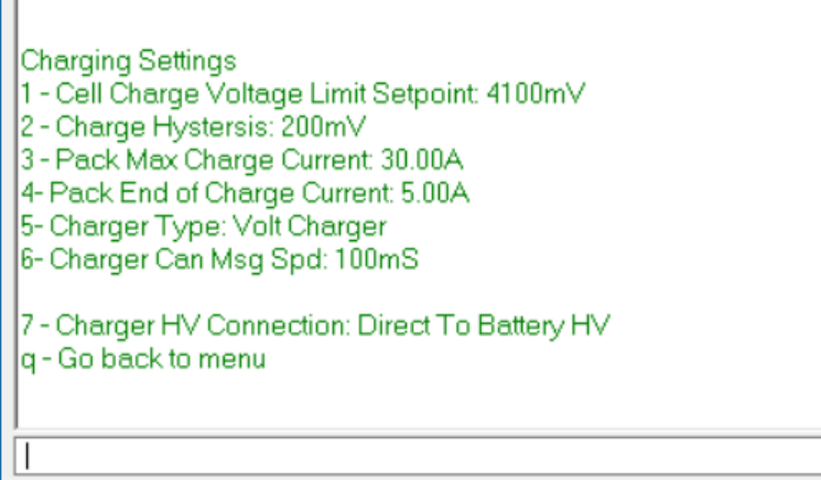
‘e’ Charging Settings
Settings modified by sending “ ‘ID’ ‘New Value’ ” via the serial terminal, will refresh values in terminal
1 – Cell Charge Voltage Limit = End of charge voltage target for cells
2 – Charge Hysteresis = Drop in cell voltage required to restart charging
3 – Pack Max Charge Current = Max allowed charge current into pack
4 – Pack End of Charge Current = Current when reaching target voltage, tapers based on hysteresis
5- Charger Type = Switch can bus controlled charge output messages (Cyclic)
Relay Control – Turn output on and off
Brusa NLG533 – On standard Control Ids
Volt Charger
Eltek Charger – Volvo versions also supported
Victron Charger
6- Charger Can Msg Spd = Interval target between sent can messages
7 – Charger HV Connection = How does the charger connect to the pack
Direct To Battery HV – connected directly to the battery pack (through a fuse ofcourse)
Behind Contactors – connected onto the main HV bus after the contactors, so during
charging contactors need to be closed.
SIMP BMS V2.1 SimpEco Engineering
10-03-19 simpecoeng@gmail.com 19
SIMP BMS V2.1 SimpEco Engineering
10-03-19 simpecoeng@gmail.com 20
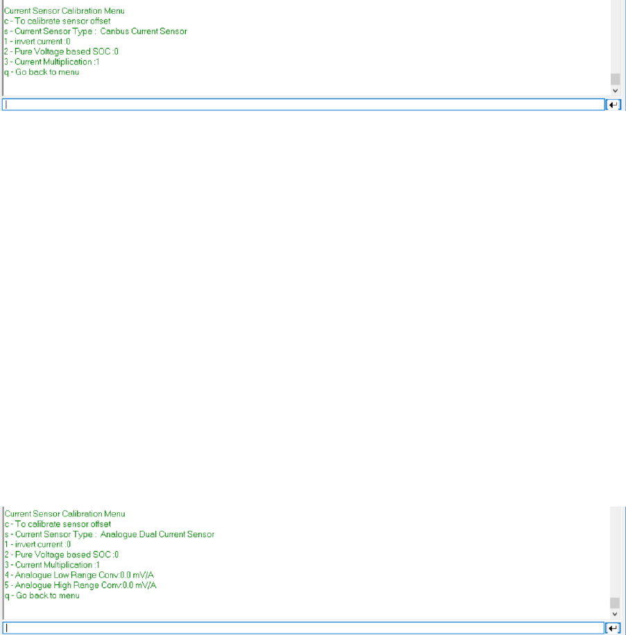
‘c’ Current Sensor
Settings modified by sending “ ‘ID’ ‘New Value’ ” via the serial terminal, will refresh values in terminal
c - To calibrate sensor offset = for calibrating analogue sensor offsets*
s - To switch between Current Sensors = switches between sensors types
Undefined = OFF
Analogue Dual Sensor = dual range 5V output sensors
CanBus Sensor = CAB300 supported over CAN
Analogue Single Sensor = single range 5V output sensors
1- Invert current = if current sensor is reading the wrong direction toggle value
2- Pure Voltage SOC = do not use coulomb counting and rely on using cell voltage to do SOC
Recommend for large packs with low discharge and charge currents
3 – Current Multiplication = 1 if all current goes through the sensor , 2 if only one cable (identical
required) passes through the sensor and two are used on one pole.
q - Go back to menu
4 – Analogue Low Range Conv = value for conversion mV/A, enter 10x.
5 – Analogue High Range Conv = value for conversion mV/A, enter 10x.
SIMP BMS V2.1 SimpEco Engineering
10-03-19 simpecoeng@gmail.com 21
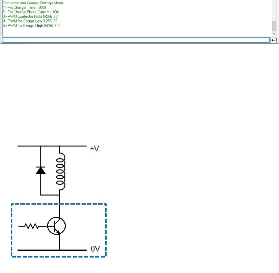
‘k’ Contactor Control
Settings modified by sending “ ‘ID’ ‘New Value’ ” via the serial terminal, will refresh values in terminal
1 – Precharge Timer = mS of minimum precharge time
2 – Precharge Finish Current = mA of allowed current before switching in the main contactor
3 – Pwm contactor Hold = PWM duty cycle (values 0-255), lower the value the lower the ‘voltage’ at
the contactor. This only works on the PWM pull low outputs.
Contactors without an internal coil require an diode placed across their ground and 12V feed, as
depicted below, the coil is the contactor.
4 – PWM for Gauge Low = PWM duty cycle of Gauge Output to reflect 0% SOC
5 – PWM for Gauge High = PWM duty cycle of Gauge Output to reflect 100% SOC
SIMP BMS
SIMP BMS V2.1 SimpEco Engineering
10-03-19 simpecoeng@gmail.com 22
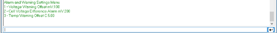
‘a’ Alarms and Warnings Settings Menu
Settings modified by sending “ ‘ID’ ‘New Value’ ” via the serial terminal, will refresh values in terminal
1 – Voltage Warning Offset = Offset from Under and Over Voltage limits when an Alarm Flag gets set
2 – Cell Voltage Difference Alarm = Difference below low and high cell to trigger Alarm Flag
3 – Temp Warning Offset = Offset from Over Temperature limit when an Alarm Flag gets set
SIMP BMS V2.1 SimpEco Engineering
10-03-19 simpecoeng@gmail.com 23
CANBUS
SIMP BMS will communicate on the canbus at 500kbp/s
This is used to communicate with the following devices:
• Outlander BMS slaves
• Panasonic BMS slaves
• Can Current sensor
• Victron VE-CAN
• Other devices
Under development : Canbus controlled charges
Termination Resistor
SIMP BMS does not come with a termination resistor as standard does come with a location for a
0805 resistor to add one.
If you measure the resistance across CanH and CanL if it is not 60 Ohm add a 120 Ohm resistor at the
SIMP BMS connector. If the resistance is still too high add a 120 Ohm resistor at the other end of the
can bus.
SIMP BMS V2.1 SimpEco Engineering
10-03-19 simpecoeng@gmail.com 24
Outlanders BMS SLAVES
It is only possible to use slaves with unique IDS, so maximum of 10 slaves before a trick is required.
Each slave can monitor 8 (10 possibly) parallel cell groups
CAN Current Sensor
Only one current sensor per SIMP BMS
CAB 300
Bi-directional 350A max
Panasonic BMS Slaves
It is only possible to use slaves with unique IDS, so maximum of 8 slaves before a trick is required.
Each slave can monitor 12 parallel cell groups
Victron VE-CAN
Communicate using the simple protocol as REC BMS, will share all required information from the
batteries.

SIMP BMS V2.1 SimpEco Engineering
10-03-19 simpecoeng@gmail.com 25
Other CAN Devices
Other devices can be connected, these can be setup to display and react to messages from the SIMP
BMS.
CAN Messages
Message
Limits
Message ID
0X351
Byte
Bit
Signal
Scale
unit
0
Discharge Current LSB
0.1
A
1
Discharge Current MSB
0.1
A
2
Discharge Voltage LSB
0.1
V
3
Discharge Voltage MSB
0.1
V
4
Charge Current LSB
0.1
A
5
Charge Current MSB
0.1
A
6
Charge Voltage LSB
0.1
V
7
Charge Voltage MSB
0.1
V
Message
SOC
Message ID
0X355
Byte
Bit
Signal
Scale
unit
0
SOC LSB
1
%
1
SOC MSB
1
%
2
SOH LSB
1
%
3
SOH MSB
1
%
4
SOC LSB
0.01
%
5
SOC MSB
0.01
%
6
-
7
-
Message
Status
Message ID
0X356
Byte
Bit
Signal
Scale
unit
0
Voltage LSB
0.01
V
1
Voltage MSB
0.01
V
2
Current LSB
0.1
A
3
Current MSB
0.1
A
4
Temperature LSB
0.1
C
5
Temperature MSB
0.1
C
6
-
7
-

SIMP BMS V2.1 SimpEco Engineering
10-03-19 simpecoeng@gmail.com 26
Message
Warnings
Message ID
0X35A
Byte
Bit
Signal
0
3
Undervoltage
4
Overvoltage
1
7
Overtemp
2
12
Undertemp
3
-
4
-
5
-
6
-
7
-

SIMP BMS V2.1 SimpEco Engineering
10-03-19 simpecoeng@gmail.com 27
Firmware Updating
Updating firmware can be done with the simple process explained below, CHECK SETTINGS once you
flash the new firmware. The process can alter memory locations and thus corrupt settings.
Links
Latest files available on Github, including uncompiled code.
Tesla Github :
https://github.com/tomdebree/TeslaBMSV2
Outlander Github :
https://github.com/tomdebree/OutlanderPHEVBMS/tree/master/OutlanderBMSV2
VW Github:
https://github.com/tomdebree/VW-bms/tree/master/VWBMSV2
Flashing the HEX
The easiest way to get new firmware onto the SIMP BMS is by uploading the latest ‘ino.hex’ file
Example file name: TeslaBMSV2.ino.TEENSY31.hex
In order to get the hex onto the Teensy (microcontroller of the SIMP BMS) it is required to have
Teensy Loader installed.
Please follow instructions on the PJRC website : https://www.pjrc.com/teensy/loader.html
Once installed and having downloaded the latest hex onto your computer follow the following steps
to update the firmware:
6. Power down the system SIMP BMS is part of
a. This means turning off all chargers and loads attached if these are controlled by the
SIMP BMS
7. Connect the Micro-B USB port on the teensy to your computer with appropriate cable
8. Open Teensy Loader “teensy.exe’
9. Go ‘file’ , ‘Open HEX File’ and select the just obtained firmware HEX
10. Program your SIMP BMS by clicking the arrow curved down (‘Program’ button)
a. If buttons not available hit press the reset on button on the Teensy on the SIMP BMS
11. Use the Teensy loader to reboot the SIMP BMS once Programmed, arrow pointing right
12. Using a Terminal program check all settings on the SIMP BMS, and correct as required
