Print Preview C:\TEMP\Apdf_2541_3068\home\AppData\Local\PTC\Arbortext\Editor\.aptcache\ae1qwjtr/tf1qwcnj Simulink Coder User's Guide
User Manual:
Open the PDF directly: View PDF ![]() .
.
Page Count: 1365 [warning: Documents this large are best viewed by clicking the View PDF Link!]
- toc
- Check Bug Reports for Issues and Fixes
- Model Architecture and Design
- Modeling
- Configure a Model for Code Generation
- Scheduling
- About Scheduling
- Single-Tasking and Multitasking Execution Modes
- About Tasking Modes
- Execute Multitasking Models
- Multitasking and Pseudomultitasking Modes
- Build a Program for Multitasking Execution
- Single-Tasking Mode
- Build a Program for Single-Tasking Execution
- Model Execution and Rate Transitions
- Simulate Models with the Simulink Product
- Execute Models in Real Time
- Single-Tasking Versus Multitasking Operation
- Handle Rate Transitions
- Single-Tasking and Multitasking Model Execution
- Handle Asynchronous Events
- About Asynchronous Events
- Handling Interrupts
- Connecting the Async Interrupt Block
- Requirements and Restrictions
- Performance Considerations
- Using the Async Interrupt Block in Simulation and Code Generatio
- Dual-Model Approach: Simulation
- Dual-Model Approach: Code Generation
- Initialization Code
- Generated ISR Code
- Model Termination Code
- Initialization Code
- Task and Task Synchronization Code
- Task Termination Code
- Rate Transitions and Asynchronous Blocks
- Use Timers in Asynchronous Tasks
- Create a Customized Asynchronous Library
- C MEX Block Implementation
- ssSetAsyncTimerAttributes
- ssSetAsyncTaskPriorities
- SS_OPTION Settings
- TLC Implementation
- Generate #include Directives
- BlockInstanceSetup Function
- Outputs Function
- Start Function
- Terminate Function
- C MEX Block Implementation
- TLC Implementation
- Generate #include Directives
- BlockInstanceSetup Function
- Start Function
- Outputs Function
- Terminate Function
- Import Asynchronous Event Data for Simulation
- Asynchronous Support Limitations
- Timers
- Configure Scheduling
- Supported Products and Block Usage
- Modeling Semantic Considerations
- Subsystems
- Code Generation of Subsystems
- Generate Code and Executables for Individual Subsystem
- Inline Subsystem Code
- Generate Subsystem Code as Separate Function and Files
- Generate Reusable Function for Identical Subsystems Within a Mod
- Optimize Code for Identical Nested Subsystems
- Generate Reusable Code for Subsystems Containing S-Function Bloc
- Generate Reusable Code from Stateflow Charts
- Code Reuse Limitations for Subsystems
- Code Reuse For Subsystems Shared Across Referenced Models
- Reusable Library Subsystem
- Code Generation of Constant Parameters
- Shared Constant Parameters for Code Reuse
- Generate Reusable Code for Subsystems Shared Across Models
- Create a reusable library subsystem.
- Create the example model.
- Set configuration parameters of the top model.
- Create and propagate a configuration reference.
- Generate and view the code.
- Determine Why Subsystem Code Is Not Reused
- Referenced Models
- Code Generation for Referenced Models
- Generate Code for Referenced Models
- Project Folder Structure for Model Reference Targets
- Configure Referenced Models
- Build Model Reference Targets
- Simulink Coder Model Referencing Requirements
- Storage Classes for Signals Used with Model Blocks
- Inherited Sample Time for Referenced Models
- Customize Library File Suffix and File Type
- Reusable Code and Referenced Models
- Simulink Coder Model Referencing Limitations
- Combined Models
- Configure Model Parameters
- Platform Options for Development and Deployment
- Configure Emulation and Embedded Target Hardware
- Configure Embedded Hardware Characteristics
- Configure Emulation Hardware Characteristics
- Control the Location for Generated Files
- Control Generated Files Location Used for Simulation
- Control the Location for Code Generation Files
- Override Build Folder Settings for Current Session
- Model Protection
- Modeling
- Data, Function, and File Definition
- Data Representation
- Enumerations
- Structure Parameters and Generated Code
- Parameters
- About Parameters
- Nontunable Parameter Storage
- Tunable Parameter Storage
- Tunable Parameter Storage Classes
- Declare Tunable Parameters
- Tunable Expressions
- Linear Block Parameter Tunability
- Configuration Parameter Quick Reference Diagram
- Generated Code for Parameter Data Types
- Tunable Workspace Parameter Data Type Considerations
- Tune Parameters
- Parameter Objects
- About Parameter Objects for Code Generation
- Use Parameter Objects for Code Generation
- Configure Parameter Objects for Code Generation
- Storage Classes and Code Generation for Parameter Objects
- Generate Code for Parameter Objects from Command Line
- Generate Code for Parameter Objects Using Model Explorer
- Parameter Object Configuration Quick Reference Diagram
- Resolve Conflicts in Parameter Object Configurations
- Structure Parameters and Generated Code
- Signals
- About Signals
- Signal Storage Concepts
- Signals with Auto Storage Class
- Signals with Test Points
- Interface Signals to External Code
- Symbolic Naming Conventions for Signals
- Summary of Signal Storage Class Options
- Interfaces for Monitoring Signals
- Signal Objects
- About Signal Objects for Code Generation
- Use Signal Objects for Code Generation
- Configure Signal Objects for Code Generation
- Storage Classes and Code Generation for Signal Objects
- Generate Code for Signal Objects from Command Line
- Generate Code for Signal Objects Using Model Explorer
- Resolve Conflicts in Configuration of Signals Objects
- Initialize Signals and States Using Signal Objects
- States
- Data Stores
- Entry Point Functions and Scheduling
- Entry Point Functions and Scheduling
- About Model Execution
- Non-Real-Time Single-Tasking Systems
- Non-Real-Time Multitasking Systems
- Real-Time Single-Tasking Systems
- Real-Time Multitasking Systems
- Multitasking Systems Using Real-Time Tasking Primitives
- Program Timing
- Program Execution
- External Mode Communication
- Data Logging in Single-Tasking and Multitasking Model Execution
- Rapid Prototyping and Embedded Model Execution Differences
- Rapid Prototyping Model Functions
- Embedded Model Functions
- Data Representation
- Code Generation
- Configuration
- Configuring a Model for Code Generation
- Code Generation Configuration
- Open the Model Configuration for Code Generation
- Configure a Model Programmatically
- Step 1. Open a model.
- Step 2. Get the active configuration set.
- Step 3. Select the Generic Real-Time (GRT) target.
- Step 4. Modify parameters to optimize execution speed.
- Step 5. Save the model configuration to a file.
- Application Objectives
- Target
- Hardware Targets
- Available Targets
- About Targets and Code Formats
- Types of Target Code Formats
- Targets and Code Formats
- Targets and Code Styles
- Backwards Compatibility of Code Formats
- Selecting a Target
- Template Makefiles and Make Options
- Custom Targets
- Describing the Emulation and Embedded Targets
- Describing Embedded Hardware Characteristics
- Describing Emulation Hardware Characteristics
- Specifying Target Interfaces
- Selecting and Viewing Code Replacement Libraries
- Select the Target Language
- Code Appearance
- Debug
- Configuring a Model for Code Generation
- Source Code Generation
- Initiate Code Generation
- Reload Generated Code
- Generated Source Files and File Dependencies
- Files and Folders Created by Build Process
- How Code Is Generated From a Model
- Code Generation of Matrices and Arrays
- Shared Utility Code
- Generating Code Using Simulink Coder™
- Report Generation
- Reports for Code Generation
- HTML Code Generation Report Location
- HTML Code Generation Report for Referenced Models
- Generate a Code Generation Report
- Generate Code Generation Report After Build Process
- Open Code Generation Report
- Generate Code Generation Report Programmatically
- Search in the Code Generation Report
- View Code Generation Report in Model Explorer
- Package and Share the Code Generation Report
- Document Generated Code with Simulink Report Generator
- Configuration
- Deployment
- Desktops
- Rapid Simulations
- About Rapid Simulation
- Rapid Simulation Performance
- General Rapid Simulation Workflow
- Identify Rapid Simulation Requirements
- Configure Inports to Provide Simulation Source Data
- Configure and Build Model for Rapid Simulation
- Set Up Rapid Simulation Input Data
- Scripts for Batch and Monte Carlo Simulations
- Run Rapid Simulations
- Using the RSim target, you can build a model once and run multip
- Requirements for Running Rapid Simulations
- Set a Clock Time Limit for a Rapid Simulation
- Override a Model Simulation Stop Time
- Read the Parameter Vector into a Rapid Simulation
- Specify New Signal Data File for a From File Block
- Specify Signal Data File for an Inport Block
- Change Block Parameters for an RSim Simulation
- Specify a New Output File Name for a Simulation
- Specify New Output File Names for To File Blocks
- Rapid Simulation Target Limitations
- Generated S-Function Block
- About Object Libraries
- Create S-Function Blocks from a Subsystem
- Tunable Parameters in Generated S-Functions
- System Target File and Template Makefiles
- Checksums and the S-Function Target
- S-Function Target Limitations
- Limitations on Using Tunable Variables in Expressions
- Run-Time Parameters and S-Function Compatibility Diagnostics
- Limitations on Using Goto and From Block
- Limitations on Building and Updating S-Functions
- Unsupported Blocks
- SimState Not Supported for Code Generation
- Profiling Code Performance Not Supported
- Limitations on Nesting S-Functions
- Limitations on User-Defined Data Types
- Limitation on Right-Click Generation of an S-Function Target
- Limitation on S-Functions with Bus I/O Signals
- Limitation on Subsystems with Function-Call I/O Signals
- Rapid Simulations
- Real-Time Systems
- External Code Integration
- Integration Options
- Reuse Algorithmic Components in Generated Code
- Deploy Algorithm Code Within a Target Environment
- Export Generated Algorithm Code for Embedded Applications
- Export Algorithm Executables for System Simulation
- Modify External Code for Language Compatibility
- Automate S-Function Generation
- Integrate External Code Using Legacy Code Tool
- Configure Model for External Code Integration
- Insert Custom Code Blocks
- Insert S-Function Code
- About S-Functions and Code Generation
- Write Noninlined S-Functions
- Write Wrapper S-Functions
- Write Fully Inlined S-Functions
- Write Fully Inlined S-Functions with mdlRTW Routine
- Guidelines for Writing Inlined S-Functions
- Write S-Functions That Support Expression Folding
- S-Functions That Specify Port Scope and Reusability
- S-Functions That Specify Sample Time Inheritance Rules
- S-Functions That Support Code Reuse
- S-Functions for Multirate Multitasking Environments
- Build Support for S-Functions
- Program Building, Interaction, and Debugging
- Compiler or IDE Selection and Configuration
- Choose and Configure a Compiler
- Compilers and the Build Process
- Simulink Coder and ANSI C/C++ Compliance
- Support for C and C++ Code Generation
- Support for International (Non-US-ASCII) Characters
- C++ Target Language Considerations
- Choose and Configure Compiler on Microsoft Windows
- Choose and Configure Compiler on UNIX
- Include S-Function Source Code
- Troubleshoot Compiler Configurations
- Choose and Configure a Compiler
- Program Builds
- Build and Run a Program
- Profile Code Performance
- Data Exchange
- Host/Target Communication
- Logging
- Parameter Tuning
- Data Interchange Using the C API
- ASAP2 Data Measurement and Calibration
- Direct Memory Access to Generated Code
- Compiler or IDE Selection and Configuration
- Desktops
- Performance
- Optimizations for Generated Code
- Defensive Programming
- Data Copy Reduction
- Execution Speed
- Memory Usage
- Verification
- Customization
- Build Process Integration
- Control Build Process Compiling and Linking
- Cross-Compile Code Generated on Microsoft Windows
- Control Library Location and Naming During Build
- Recompile Precompiled Libraries
- Customize Post-Code-Generation Build Processing
- Configure Generated Code with TLC
- Customize Build Process with STF_make_rtw_hook File
- Customize Build Process with sl_customization.m
- About sl_customization.m
- Register Build Process Hook Functions Using sl_customization.m
- Variables Available for sl_customization.m Hook Functions
- Example Build Process Customization Using sl_customization.m
- Example 1: sl_customization.m for Simulink Coder Build Process C
- Example 2: CustomRTWEntryHook.m
- Example 3: CustomRTWPostProcessHook.m
- Replace the STF_rtw_info_hook Mechanism
- Customize Build to Use Shared Utility Code
- Run-Time Data Interface Extensions
- Customize an ASAP2 File
- Create a Transport Layer for External Communication
- Custom Target Development
- About Embedded Target Development
- Sample Custom Targets
- Target Development Mechanics
- Folder and File Naming Conventions
- Components of a Custom Target
- Key Folders Under Target Root (mytarget)
- Key Files in Target Folder (mytarget/mytarget)
- Additional Files for Externally Developed Targets
- Target Development and the Build Process
- Customize System Target Files
- Customize Template Makefiles
- Template Makefiles and Tokens
- Invoke the make Utility
- Structure of the Template Makefile
- Customize and Create Template Makefiles
- Support Optional Features
- Interface to Development Tools
- Device Drivers and Target Preferences
- Build Process Integration
- Desktop IDEs and Desktop Targets
- Project and Build Configurations for Desktop Targets
- Model Setup
- Block Selection
- Target Preferences
- Configuration Parameters
- What are Configuration Parameters?
- Setting Model Configuration Parameters
- Build format
- Build action
- Overrun notification
- Function name
- Configuration
- Compiler options string
- Linker options string
- System stack size (MAUs)
- Link Automation
- Maximum time allowed to build project (s)
- Maximum time allowed to complete IDE operation (s)
- Export IDE link handle to base workspace
- IDE link handle name
- Source file replacement
- Model Reference
- IDE Projects
- Makefiles for Software Build Tool Chains
- Model Setup
- Verification Code Generated for Desktop Targets
- Working with Eclipse IDE
- Working with Linux Target
- Working with Microsoft Windows Target
- Project and Build Configurations for Desktop Targets
- Examples
- Index
- tables
- Execution Order and Sample Times (Single-Tasking)
- Task Allocation of Blocks in Multitasking Execution
- Supported Sample Time and Priority for Function Call Subsystem w
- Summary of asynclib.tlc Library Functions
- Additional Math and Discrete: Additional Discrete
- Additional Math and Discrete: Increment/Decrement
- Continuous
- Discontinuities
- Discrete
- Logic and Bit Operations
- Lookup Tables
- Math Operations
- Model Verification
- Model-Wide Utilities
- Ports & Subsystems
- Signal Attributes
- Signal Routing
- Sinks
- Sources
- User-Defined
- Configuration Requirements for Model Referencing with All System
- Configuration Requirements for Model Referencing with ERT System
- Relationships of Signals and Storage Classes Between Parent and
- Targets Available from the System Target File Browser
- Features Supported by Simulink Coder Targets and Code Formats
- Macros for Accessing the Real-Time Model Data Structure
- Code Styles Listed by Target
- Comparison of Features Licensed with the Simulink Coder Product
- System Header Files
- Simulink Coder Header Files
- Types of Output Expressions
- External Mode Command-Line Parameters
- Differences Between ASAP2 and Simulink Parameter and Signal Obje
- Target Language Compiler Optional Variables
- Built-In Transport Layer Implementations
- MATLAB Commands to Rebuild ext_comm and ext_serial_win32 MEX-Fil
- Execution Support Files
- rtwoptions Structure Fields Summary
- Template Makefile Tokens Expanded by make_rtw

Simulink®Coder™
User’s Guide
R2012b

How to Contact MathWorks
www.mathworks.com Web
comp.soft-sys.matlab Newsgroup
www.mathworks.com/contact_TS.html Technical Support
suggest@mathworks.com Product enhancement suggestions
bugs@mathworks.com Bug reports
doc@mathworks.com Documentation error reports
service@mathworks.com Order status, license renewals, passcodes
info@mathworks.com Sales, pricing, and general information
508-647-7000 (Phone)
508-647-7001 (Fax)
The MathWorks, Inc.
3 Apple Hill Drive
Natick, MA 01760-2098
For contact information about worldwide offices, see the MathWorks Web site.
Simulink®Coder™ User’s Guide
© COPYRIGHT 2011–2012 by The MathWorks, Inc.
The software described in this document is furnished under a license agreement. The software may be used
or copied only under the terms of the license agreement. No part of this manual may be photocopied or
reproduced in any form without prior written consent from The MathWorks, Inc.
FEDERAL ACQUISITION: This provision applies to all acquisitions of the Program and Documentation
by, for, or through the federal government of the United States. By accepting delivery of the Program
or Documentation, the government hereby agrees that this software or documentation qualifies as
commercial computer software or commercial computer software documentation as such terms are used
or defined in FAR 12.212, DFARS Part 227.72, and DFARS 252.227-7014. Accordingly, the terms and
conditions of this Agreement and only those rights specified in this Agreement, shall pertain to and govern
theuse,modification,reproduction,release,performance,display,anddisclosureoftheProgramand
Documentation by the federal government (or other entity acquiring for or through the federal government)
and shall supersede any conflicting contractual terms or conditions. If this License fails to meet the
government’s needs or is inconsistent in any respect with federal procurement law, the government agrees
to return the Program and Documentation, unused, to The MathWorks, Inc.
Trademarks
MATLAB and Simulink are registered trademarks of The MathWorks, Inc. See
www.mathworks.com/trademarks for a list of additional trademarks. Other product or brand
names may be trademarks or registered trademarks of their respective holders.
Patents
MathWorks products are protected by one or more U.S. patents. Please see
www.mathworks.com/patents for more information.
Revision History
April 2011 Online only New for Version 8.0 (Release 2011a)
September 2011 Online only Revised for Version 8.1 (Release 2011b)
March 2012 Online only Revised for Version 8.2 (Release 2012a)
September 2012 Online only Revised for Version 8.3 (Release 2012b)
Check Bug Reports for Issues and Fixes
Software is inherently complex and is not free of errors. The output of a code generator
might contain bugs, some of which are not detected by a compiler. MathWorks
reports critical known bugs brought to its attention on its Bug Report system at
www.mathworks.com/support/bugreports/. Use the Saved Searches and Watched Bugs tool
with the search phrase ‘‘Incorrect Code Generation’’ to obtain a report of known bugs that
produce code that might compile and execute, but still produce wrong answers.
The bug reports are an integral part of the documentation for each release. Examine
periodically all bug reports for a release, as such reports may identify inconsistencies between
the actual behavior of a release you are using and the behavior described in this documentation.
In addition to reviewing bug reports, you should implement a verification and validation
strategy to identify potential bugs in your design, code, and tools.

Contents
Model Architecture and Design
Modeling
1
Configure a Model for Code Generation ............. 1-2
Scheduling ........................................ 1-4
About Scheduling ................................. 1-4
Single-Tasking and Multitasking Execution Modes ...... 1-5
Handle Rate Transitions ............................ 1-13
Single-Tasking and Multitasking Model Execution ...... 1-27
Handle Asynchronous Events ........................ 1-34
Timers .......................................... 1-79
Configure Scheduling .............................. 1-90
Supported Products and Block Usage ............... 1-92
Related Products .................................. 1-92
Simulink Built-In Blocks That Support Code Generation .. 1-94
Block Set Support for Code Generation ................ 1-116
Fixed-Point Tool Data Type Override ................. 1-116
Data Type Overrides Unavailable for Most Blocks in
Embedded Targets and Desktop Targets ............ 1-116
Modeling Semantic Considerations .................. 1-117
Data Propagation ................................. 1-117
Sample Time Propagation .......................... 1-119
Latches for Subsystem Blocks ....................... 1-120
Block Execution Order ............................. 1-120
Algebraic Loops ................................... 1-122
v

Subsystems
2
Code Generation of Subsystems ..................... 2-2
Subsystem Code Dependence ........................ 2-3
Generate Code and Executables for Individual
Subsystem ...................................... 2-4
Subsystem Build Limitations ........................ 2-6
Inline Subsystem Code ............................. 2-7
Configure Subsystem to Inline Code .................. 2-7
Exceptions to Inlining .............................. 2-8
Generate Subsystem Code as Separate Function and
Files ............................................ 2-10
Generate Reusable Function for Identical Subsystems
Within a Model .................................. 2-11
Considerations for Function Packaging Options Auto and
Reusable function ............................. 2-13
Optimize Code for Identical Nested Subsystems ...... 2-14
Generate Reusable Code for Subsystems Containing
S-Function Blocks ............................... 2-15
Generate Reusable Code from Stateflow Charts ...... 2-16
Code Reuse Limitations for Subsystems ............. 2-17
Blocks That Prevent Code Reuse ..................... 2-17
Code Reuse Limitations for Subsystems Shared Across
Referenced Models .............................. 2-18
Code Reuse For Subsystems Shared Across Referenced
Models ......................................... 2-19
Reusable Library Subsystem ....................... 2-20
vi Contents

Code Generation of a Reusable Library Subsystem ...... 2-20
Reusable Library Subsystem Code Placement and
Naming ....................................... 2-21
Reusable Library Subsystem in the Top Model .......... 2-21
Reusable Library Subsystem Connected to Root Outport .. 2-21
Code Generation of Constant Parameters ............ 2-22
Shared Constant Parameters for Code Reuse ........ 2-23
Shared Constant Parameters Limitations .............. 2-24
Generate Reusable Code for Subsystems Shared Across
Models ......................................... 2-25
Determine Why Subsystem Code Is Not Reused ...... 2-32
Review the Subsystems Section of the HTML Code
Generation Report .............................. 2-32
Compare Subsystem Checksum Data ................. 2-32
Referenced Models
3
Code Generation for Referenced Models ............. 3-2
Generate Code for Referenced Models ............... 3-4
About Generating Code for Referenced Models .......... 3-4
Create and Configure the Subsystem ................. 3-4
Convert Model to Use Model Referencing .............. 3-7
Generate Model Reference Code for a GRT Target ....... 3-11
Work with Project Folders .......................... 3-14
Project Folder Structure for Model Reference
Targets ......................................... 3-16
Configure Referenced Models ....................... 3-17
Build Model Reference Targets ..................... 3-18
vii

Reduce Change Checking Time ...................... 3-18
Simulink Coder Model Referencing Requirements .... 3-19
Configuration Parameter Requirements ............... 3-19
Naming Requirements ............................. 3-23
Custom Target Requirements ....................... 3-24
Storage Classes for Signals Used with Model Blocks .. 3-25
Storage Classes for Parameters Used with Model Blocks .. 3-26
Effects of Signal Name Mismatches ................... 3-27
InheritedSampleTimeforReferencedModels ....... 3-29
Customize Library File Suffix and File Type ......... 3-31
Reusable Code and Referenced Models .............. 3-32
General Considerations ............................ 3-32
Code Reuse and Model Blocks with Root Inport or Outport
Blocks ........................................ 3-33
Simulink Coder Model Referencing Limitations ...... 3-36
Customization Limitations .......................... 3-36
Data Logging Limitations ........................... 3-36
State Initialization Limitation ....................... 3-37
Reusability Limitations ............................ 3-38
S-Function Limitations ............................. 3-39
Simulink Tool Limitations .......................... 3-39
Subsystem Limitations ............................. 3-39
Target Limitations ................................ 3-39
Other Limitations ................................. 3-40
Combined Models
4
Combined Models .................................. 4-2
Use GRT Malloc to Combine Models ................. 4-4
viii Contents

Share Data Across Models .......................... 4-4
Timing Issues .................................... 4-4
Data Logging and External Mode Support ............. 4-5
Configure Model Parameters
5
Platform Options for Development and Deployment .. 5-2
Configure Emulation and Embedded Target
Hardware ....................................... 5-3
Identify the Device Vendor .......................... 5-4
Identify the Device Type ............................ 5-5
Register Additional Device Vendor and Device Type
Values ........................................ 5-5
SetNativeWordSizefortheDevice .................. 5-9
SetByteOrderingUsedByDevice ................... 5-10
Set Quotient Rounding Technique for Signed Integer
Division ....................................... 5-11
Set Arithmetic Right Shift Behavior for Signed Integers .. 5-12
Configure Embedded Hardware Characteristics ...... 5-13
Configure Emulation Hardware Characteristics ...... 5-15
Update Release 14 Hardware Configuration ............ 5-17
Control the Location for Generated Files ............ 5-18
Control Generated Files Location Used for
Simulation ...................................... 5-20
Control the Location for Code Generation Files ...... 5-22
Override Build Folder Settings for Current Session ... 5-24
ix

Model Protection
6
Protect a Referenced Model ........................ 6-2
Requirements for Protecting a Model ................. 6-3
Harness Model .................................... 6-4
Protected Model Report ............................ 6-5
Code Generation Support in a Protected Model ...... 6-6
Protected Model Requirements to Support Code
Generation ..................................... 6-6
Protected Model File ............................... 6-8
Create a Protected Model .......................... 6-9
Test the Protected Model ........................... 6-13
Save Base Workspace Definitions ................... 6-15
Package a Protected Model ......................... 6-16
Data, Function, and File Definition
Data Representation
7
Enumerations ..................................... 7-2
About Enumerated Data Types ...................... 7-2
Default Code for an Enumerated Data Type ............ 7-2
Type Casting for Enumerations ...................... 7-3
Override Default Methods (Optional) ................. 7-4
Enumerated Type Limitations ....................... 7-7
xContents
Structure Parameters and Generated Code .......... 7-8
About Structure Parameters and Generated Code ....... 7-8
Configure Structure Parameters for Generated Code .... 7-8
Control Name of Structure Parameter Type ............ 7-9
Parameters ....................................... 7-10
About Parameters ................................. 7-10
Nontunable Parameter Storage ...................... 7-11
Tunable Parameter Storage ......................... 7-13
Tunable Parameter Storage Classes .................. 7-14
Declare Tunable Parameters ........................ 7-17
Tunable Expressions ............................... 7-22
Linear Block Parameter Tunability ................... 7-26
Configuration Parameter Quick Reference Diagram ..... 7-27
Generated Code for Parameter Data Types ............. 7-28
Tunable Workspace Parameter Data Type
Considerations ................................. 7-34
Tune Parameters .................................. 7-36
Parameter Objects ................................. 7-38
Structure Parameters and Generated Code ............ 7-49
Signals ........................................... 7-52
About Signals .................................... 7-52
Signal Storage Concepts ............................ 7-53
Signals with Auto Storage Class ..................... 7-55
Signals with Test Points ............................ 7-59
Interface Signals to External Code ................... 7-60
Symbolic Naming Conventions for Signals ............. 7-62
Summary of Signal Storage Class Options ............. 7-63
Interfaces for Monitoring Signals ..................... 7-64
Signal Objects .................................... 7-65
Initialize Signals and States Using Signal Objects ....... 7-74
States ............................................. 7-83
About States ..................................... 7-83
State Storage ..................................... 7-83
State Storage Classes .............................. 7-84
Interface States to External Code .................... 7-85
Symbolic Names for States .......................... 7-87
Control Code Generation for Block States .............. 7-90
Summary of State Storage Class Options .............. 7-91
xi

Data Stores ....................................... 7-93
About Data Stores ................................. 7-93
Storage Classes for Data Store Memory Blocks ......... 7-93
Generate Code for Data Store Memory Blocks .......... 7-96
Nonscalar Data Stores in Generated Code ............. 7-97
Data Store Buffering in Generated Code ............... 7-99
Entry Point Functions and Scheduling
8
Entry Point Functions and Scheduling .............. 8-2
About Model Execution ............................ 8-4
Non-Real-Time Single-Tasking Systems .............. 8-6
Non-Real-Time Multitasking Systems ................ 8-7
Real-Time Single-Tasking Systems .................. 8-9
Real-Time Multitasking Systems .................... 8-11
Multitasking Systems Using Real-Time Tasking
Primitives ...................................... 8-14
Program Timing ................................... 8-16
Program Execution ................................ 8-18
External Mode Communication ..................... 8-19
Data Logging in Single-Tasking and Multitasking
Model Execution ................................ 8-20
xii Contents

Rapid Prototyping and Embedded Model Execution
Differences ..................................... 8-22
Rapid Prototyping Model Functions ................. 8-23
Embedded Model Functions ........................ 8-30
Code Generation
Configuration
9
Configuring a Model for Code Generation ........... 9-2
Code Generation Configuration ...................... 9-2
Open the Model Configuration for Code Generation ...... 9-3
Configure a Model Programmatically ................. 9-3
Application Objectives ............................. 9-6
About Code Generation Objectives .................... 9-6
Configure Code Generation Objectives Using Code
Generation Advisor .............................. 9-7
Target ............................................ 9-9
Hardware Targets ................................. 9-9
Available Targets ................................. 9-10
About Targets and Code Formats .................... 9-15
Types of Target Code Formats ....................... 9-16
Targets and Code Formats .......................... 9-29
Targets and Code Styles ............................ 9-29
Backwards Compatibility of Code Formats ............. 9-31
Selecting a Target ................................. 9-34
Template Makefiles and Make Options ................ 9-38
Custom Targets ................................... 9-44
Describing the EmulationandEmbeddedTargets ....... 9-45
Describing Embedded Hardware Characteristics ........ 9-54
Describing Emulation Hardware Characteristics ........ 9-55
Specifying Target Interfaces ......................... 9-58
Selecting and Viewing Code Replacement Libraries ..... 9-61
xiii

Select the Target Language ......................... 9-71
Code Appearance .................................. 9-72
Configure Code Comments .......................... 9-72
Configure Generated Identifiers ..................... 9-73
Debug ............................................ 9-80
Source Code Generation
10
Initiate Code Generation ........................... 10-2
Reload Generated Code ............................ 10-3
Generated Source Files and File Dependencies ....... 10-4
About Generated Files and File Dependencies .......... 10-4
Header Dependencies When Interfacing Legacy/Custom
Code with Generated Code ........................ 10-6
Dependencies of the Generated Code .................. 10-16
Specify Include Paths in Simulink Coder Generated Source
Files .......................................... 10-21
Files and Folders Created by Build Process .......... 10-24
Files Created During the Build Process ............... 10-24
Folders Used During the Build Process ................ 10-28
How Code Is Generated From a Model ............... 10-31
Model Compilation ................................ 10-31
Code Generation .................................. 10-31
Code Generation of Matrices and Arrays ............. 10-33
Simulink Coder Matrix Parameters ................... 10-34
Internal Data Storage for Complex Number Arrays ...... 10-36
Shared Utility Code ................................ 10-37
About Shared Utility Code .......................... 10-37
xiv Contents

Controlling Shared Utility Code Placement ............ 10-38
rtwtypes.h and Shared Utility Code .................. 10-38
Incremental Shared Utility Code Generation and
Compilation .................................... 10-39
Shared Utility Checksum ........................... 10-39
Shared Fixed-Point Utility Functions ................. 10-41
Share User-Defined Data Types Across Models ......... 10-43
Generating Code Using Simulink Coder™ ........... 10-49
Report Generation
11
Reports for Code Generation ....................... 11-2
HTML Code Generation Report Location ............ 11-3
HTML Code Generation Report for Referenced
Models ......................................... 11-4
Generate a Code Generation Report ................. 11-5
Generate Code Generation Report After Build
Process ......................................... 11-6
Open Code Generation Report ...................... 11-8
Limitation ....................................... 11-8
Generate Code Generation Report
Programmatically ............................... 11-10
Search in the Code Generation Report .............. 11-11
View Code Generation Report in Model Explorer ..... 11-12
PackageandSharetheCodeGenerationReport ..... 11-14
xv

Package the Code Generation Report ................. 11-14
View the Code Generation Report .................... 11-15
Document Generated Code with Simulink Report
Generator ...................................... 11-16
Generate Code for the Model ........................ 11-17
Open the Report Generator ......................... 11-18
Set Report Name, Location, and Format ............... 11-20
Include Models and Subsystems in a Report ............ 11-21
Customize the Report .............................. 11-22
Generate the Report ............................... 11-23
Deployment
Desktops
12
Rapid Simulations ................................. 12-2
About Rapid Simulation ............................ 12-2
Rapid Simulation Performance ...................... 12-3
General Rapid Simulation Workflow .................. 12-3
Identify Rapid Simulation Requirements .............. 12-4
Configure Inports to Provide Simulation Source Data .... 12-6
Configure and Build Model for Rapid Simulation ........ 12-6
Set Up Rapid Simulation Input Data ................. 12-9
Scripts for Batch and Monte Carlo Simulations ......... 12-19
Run Rapid Simulations ............................. 12-20
Rapid Simulation Target Limitations ................. 12-33
Generated S-Function Block ........................ 12-34
About Object Libraries ............................. 12-34
Create S-Function Blocks from a Subsystem ........... 12-37
Tunable Parameters in Generated S-Functions ......... 12-42
System Target File and Template Makefiles ............ 12-44
Checksums and the S-Function Target ................ 12-45
S-Function Target Limitations ....................... 12-45
xvi Contents

Real-Time Systems
13
Real-Time System Rapid Prototyping ............... 13-2
About Real-Time Rapid Prototyping .................. 13-2
Goals of Real-Time Rapid Prototyping ................. 13-3
Refine Code With Real-Time Rapid Prototyping ......... 13-3
Hardware-In-the-Loop (HIL) Simulation ............. 13-5
About Hardware-In-the-Loop Simulation .............. 13-5
Set Up and Run HIL Simulations .................... 13-6
External Code Integration
14
Integration Options ................................ 14-2
About Integration Options .......................... 14-2
Types of External Code Integration ................... 14-2
Reuse Algorithmic Components in Generated Code ... 14-5
Reusable Algorithmic Components ................... 14-5
Integrate External MATLAB Code ................... 14-5
Integrate External C or C++ Code .................... 14-8
Integrate Fortran Code ............................. 14-11
Integration ConsiderationsforReusableAlgorithmic
Components .................................... 14-11
Deploy Algorithm Code Within a Target
Environment .................................... 14-14
Export Generated Algorithm Code for Embedded
Applications .................................... 14-18
Export Algorithm Executables for System
Simulation ...................................... 14-21
Modify External Code for Language Compatibility ... 14-22
xvii

Automate S-Function Generation ................... 14-23
Integrate External Code Using Legacy Code Tool ..... 14-28
Legacy Code Tool and Code Generation ............... 14-28
Generate Inlined S-Function Files for Code Generation .. 14-29
Apply Code Style Settings to Legacy Functions ......... 14-30
Address Dependencies on Files in Different Locations .... 14-31
Deploy S-Functions for Simulation and Code Generation .. 14-32
Configure Model for External Code Integration ...... 14-33
Insert Custom Code Blocks ......................... 14-36
Custom Code Library .............................. 14-36
Embed Custom Code Directly Into MdlStart Function .... 14-40
Custom Code in Subsystems ........................ 14-43
Preserve User Files in Build Folder ................... 14-44
Insert S-Function Code ............................. 14-46
About S-Functions and Code Generation .............. 14-46
Write Noninlined S-Functions ....................... 14-52
Write Wrapper S-Functions ......................... 14-54
Write Fully Inlined S-Functions ..................... 14-64
Write Fully Inlined S-Functions with mdlRTW Routine .. 14-65
Guidelines for Writing Inlined S-Functions ............ 14-91
Write S-Functions That Support Expression Folding ..... 14-91
S-Functions That Specify Port Scope and Reusability .... 14-105
S-Functions That Specify Sample Time Inheritance
Rules ......................................... 14-111
S-Functions That Support Code Reuse ................ 14-113
S-Functions for Multirate Multitasking Environments ... 14-113
Build Support for S-Functions ....................... 14-120
Program Building, Interaction, and Debugging
15
Compiler or IDE Selection and Configuration ........ 15-2
Choose and Configure a Compiler .................... 15-2
Troubleshoot Compiler Configurations ................ 15-9
xviii Contents

Program Builds ................................... 15-12
Configure the Build Process ......................... 15-12
Initiate the Build Process ........................... 15-14
Build a Generic Real-Time Program .................. 15-14
Rebuild a Model ................................... 15-27
Control Regeneration of Top Model Code .............. 15-27
Reduce Build Time for Referenced Models ............. 15-28
Relocate Code to Another Development Environment .... 15-33
How Executable Programs Are Built From Models ...... 15-38
Build and Run a Program .......................... 15-43
Profile Code Performance .......................... 15-45
About Profiling Code Performance .................... 15-45
How to Profile Code Performance .................... 15-45
Run Profiling Hooks for Generated Code ............... 15-48
Profiling Limitation ............................... 15-49
Data Exchange .................................... 15-50
Host/Target Communication ........................ 15-50
Logging ......................................... 15-105
Parameter Tuning ................................. 15-119
Data Interchange Using the C API ................... 15-137
ASAP2DataMeasurementandCalibration ............ 15-174
Direct Memory Access to Generated Code .............. 15-189
Performance
Optimizations for Generated Code
16
Optimization Parameters ........................... 16-2
Advice About Optimizing Models for Code
Generation ...................................... 16-5
Control Compiler Optimizations .................... 16-6
xix

Optimization Tools and Techniques ................. 16-7
Control Memory Allocation for Time Counters ....... 16-9
Optimization Dependencies ........................ 16-10
Defensive Programming
17
Optimize Code for Floating-Point to Integer
Conversions ..................................... 17-2
Remove Code That Wraps Out-of-Range Values ......... 17-2
Remove Code That Maps NaN to Integer Zero .......... 17-3
Disable Nonfinite Checks or Inlining for Math
Functions ....................................... 17-4
Data Copy Reduction
18
Optimizing Generated Code ........................ 18-2
About Optimizing Generated Code ................... 18-2
Setting Up the Model .............................. 18-2
Generate Code Without Buffer Optimization ......... 18-4
Generate Code With Buffer Optimization ............ 18-9
Minimize Computations and Storage for Intermediate
Results ......................................... 18-11
About Expression Folding ........................... 18-11
Expression Folding Example ........................ 18-12
Enable Expression Folding .......................... 18-15
xx Contents

Declare Signals as Local Function Data .............. 18-17
Inline Invariant Signals ............................ 18-18
Execution Speed
19
Inline Parameters ................................. 19-2
Referenced Models ................................ 19-3
Configure Loop Unrolling Threshold ................ 19-4
Optimize Code Generated for Vector Assignments .... 19-6
Configure Model to Optimize Code Generated for Vector
Assignments ................................... 19-6
Optimize Code Generated for Vector Assignments Using
memcpy ....................................... 19-7
Generate Target Optimizations Within Algorithm
Code ........................................... 19-10
Memory Usage
20
Minimize Memory Requirements During Code
Generation ...................................... 20-2
Implement Logic Signals as Boolean Data ........... 20-3
Reduce Memory Requirements for Signals ........... 20-4
Reuse Memory Allocated for Signals ................ 20-5
xxi

Use Stack Space Allocation ......................... 20-6
Verification
Simulation and Code Comparison
21
Comparing Output Data ............................ 21-2
Configure Signal Data for Logging .................. 21-3
Log Simulation Data ............................... 21-5
Log Data from the Generated Program .............. 21-7
Compare Numerical Results ........................ 21-9
Customization
Build Process Integration
22
Control Build Process Compiling and Linking ........ 22-2
Cross-Compile Code Generated on Microsoft
Windows ........................................ 22-4
Control Library Location and Naming During Build .. 22-7
Specify the Location of Precompiled Libraries .......... 22-8
Control the Location of Model Reference Libraries ....... 22-9
Control the Suffix Applied to Library File Names ....... 22-10
Recompile Precompiled Libraries ................... 22-12
xxii Contents
Customize Post-Code-Generation Build Processing ... 22-13
Build Information Object ........................... 22-14
Program a Post Code Generation Command ............ 22-14
Define a Post Code Generation Command .............. 22-16
Suppress Makefile Generation ....................... 22-17
Configure Generated Code with TLC ................ 22-18
About Configuring Generated Code with TLC .......... 22-18
Assigning Target Language Compiler Variables ........ 22-18
SetTargetLanguageCompilerOptions ............... 22-20
Customize Build Process with STF_make_rtw_hook
File ............................................ 22-21
About the STF_make_rtw_hook File .................. 22-21
Conventions for Using the STF_make_rtw_hook File .... 22-21
STF_make_rtw_hook.m Function Prototype and
Arguments ..................................... 22-22
Applications for STF_make_rtw_hook.m ............... 22-25
Control Code Regeneration Using
STF_make_rtw_hook.m .......................... 22-26
Use STF_make_rtw_hook.m for Your Build Procedure ... 22-27
Customize Build Process with sl_customization.m .... 22-28
About sl_customization.m ........................... 22-28
Register Build Process Hook Functions Using
sl_customization.m .............................. 22-30
Variables Available for sl_customization.m Hook
Functions ...................................... 22-31
Example Build Process Customization Using
sl_customization.m .............................. 22-31
Replace the STF_rtw_info_hook Mechanism ......... 22-33
Customize Build to Use Shared Utility Code ......... 22-34
Modify Template Makefiles to Support Shared Utilities .. 22-35
xxiii

Run-Time Data Interface Extensions
23
Customize an ASAP2 File ........................... 23-2
About ASAP2 File Customization .................... 23-2
ASAP2 File Structure on the MATLAB Path ........... 23-2
Customize the Contents of the ASAP2 File ............. 23-3
ASAP2 Templates ................................. 23-4
Use GROUP and SUBGROUP Hierarchies to Organize
Signals and Parameters .......................... 23-6
Customize Computation Method Names ............... 23-12
Suppress Computation Methods for FIX_AXIS .......... 23-13
Create a Transport Layer for External
Communication ................................. 23-14
About Creating a Transport Layer for External
Communication ................................. 23-14
Design of External Mode ........................... 23-14
External Mode Communications Overview ............. 23-17
External Mode Source Files ......................... 23-19
Implement a Custom Transport Layer ................ 23-23
Custom Target Development
24
About Embedded Target Development ............... 24-2
Custom Targets ................................... 24-2
Types of Targets .................................. 24-2
Recommended Features for Embedded Targets ......... 24-5
Sample Custom Targets ............................ 24-9
Target Development Mechanics ..................... 24-11
Folder and File Naming Conventions ................. 24-11
Components of a Custom Target ..................... 24-12
Key Folders Under Target Root (mytarget) ............. 24-17
Key Files in Target Folder (mytarget/mytarget) ......... 24-20
Additional Files for Externally Developed Targets ....... 24-28
xxiv Contents
Target Development and the Build Process ............ 24-29
Customize System Target Files ..................... 24-36
Control Code Generation With the System Target File ... 24-36
System Target File Naming and Location Conventions ... 24-37
System Target File Structure ........................ 24-37
Define and Display Custom Target Options ............ 24-46
Tips and Techniques for Customizing Your STF ........ 24-54
Create a Custom Target Configuration ................ 24-61
Customize Template Makefiles ...................... 24-75
Template Makefiles and Tokens ..................... 24-75
Invoke the make Utility ............................ 24-82
Structure of the Template Makefile ................... 24-83
Customize and Create Template Makefiles ............. 24-87
Support Optional Features ......................... 24-100
Overview ........................................ 24-100
Support Model Referencing ......................... 24-101
Support Compiler Optimization Level Control .......... 24-115
Support firstTime Argument Control ................. 24-117
Support C Function Prototype Control ................ 24-119
Support C++ Encapsulation Interface Control .......... 24-121
Interface to Development Tools ..................... 24-123
About Interfacing to Development Tools ............... 24-123
Makefile Approach ................................ 24-124
Interface to an Integrated Development Environment .... 24-124
Device Drivers and Target Preferences .............. 24-135
IntegrateDeviceDrivers ............................ 24-135
Use Target Preferences ............................. 24-135
xxv

Desktop IDEs and Desktop Targets
Project and Build Configurations for Desktop
Targets
25
Model Setup ....................................... 25-2
Block Selection ................................... 25-2
Target Preferences ................................ 25-3
Configuration Parameters .......................... 25-7
Model Reference .................................. 25-14
IDE Projects ...................................... 25-16
Support for Third Party Products .................... 25-16
Third Party Product Setup .......................... 25-16
Code Generation and Build ......................... 25-16
Automation of IDE Tasks and Processes ............... 25-17
Makefiles for Software Build Tool Chains ............ 25-19
What is the XMakefile Feature ...................... 25-19
Using Makefiles to Generate and Build Software ........ 25-21
Making an XMakefile Configuration Operational ........ 25-24
Working with Microsoft Visual Studio ................. 25-24
Creating a New XMakefile Configuration .............. 25-25
XMakefile User Configuration Dialog Box ............. 25-31
Verification Code Generated for Desktop
Targets
26
Processor-in-the-Loop (PIL) Simulation ............. 26-2
Overview ........................................ 26-2
PIL Approaches ................................... 26-3
Communications .................................. 26-8
Running Your PIL Application to Perform Simulation and
Verification .................................... 26-11
Definitions ....................................... 26-11
xxvi Contents

PIL Issues and Limitations ......................... 26-12
Working with Eclipse IDE
27
Installing Third-Party Software for Eclipse .......... 27-2
Tested Software Versions ........................... 27-2
Installing Sun Java Runtime Environment (JRE) ....... 27-3
Installing Eclipse IDE for C/C++ Developers ........... 27-5
Verifying the GNU Tool Chain on Linux Host .......... 27-6
Installing the GNU Tool Chain on Windows ............ 27-7
Configuring Your MathWorks Software to Work with
Eclipse ......................................... 27-10
Troubleshooting with Eclipse IDE ................... 27-14
SIGSEGV Segmentation Fault for GDB ............... 27-14
GDBStopsonEachSemaphorePost .................. 27-14
Build Errors ...................................... 27-15
Profiling Not Available for Intel x86/Pentium and AMD
K5/K6/Athlon Processors Running Windows or Linux
Operating Systems .............................. 27-15
Eclipse Message: “Can’t find a source file” ............. 27-15
Eclipse Message: “Cannot access memory at address” .... 27-16
Some Versions of Eclipse CDT Do Not Catch GCC
Errors ......................................... 27-16
Working with Linux Target
28
Disambiguation ................................... 28-2
Preparing Models to Run on Linux Target ........... 28-3
Scheduler ......................................... 28-4
xxvii

Base Rate ........................................ 28-4
Running Target Applications on Multicore Processors .... 28-4
Running Multirate, Multitasking Executables on the Linux
Desktop ....................................... 28-11
Avoiding Lock-Up in Free-Running, Multirate, Multitasking
Models ........................................ 28-12
Working with Microsoft Windows Target
29
Preparing Models to Run on Windows ............... 29-2
Scheduler ......................................... 29-3
Selecting the Operating System and Scheduling Mode ... 29-3
Base Rate ........................................ 29-4
Running Target Applications on Multicore Processors .... 29-4
Limitations ...................................... 29-10
Examples
A
Models ............................................ A-2
Timing Services ................................... A-3
Model Reference ................................... A-4
Data Management ................................. A-5
Custom Code ...................................... A-6
S-Functions ....................................... A-7
xxviii Contents

Optimizations ..................................... A-8
External Mode ..................................... A-9
Verification ....................................... A-10
Interfaces ......................................... A-11
Advanced Code Generation ......................... A-12
Code Generation Using Makefiles ................... A-13
Index
xxix
xxx Contents


1Modeling
Configure a Model for Code Generation
Model configuration parameters determine the method for generating the
code and the resulting format.
1Open rtwdemo_throttlecntrl and save a copy as throttlecntrl in a
writable location on your MATLAB path.
Note This model uses Stateflow®software.
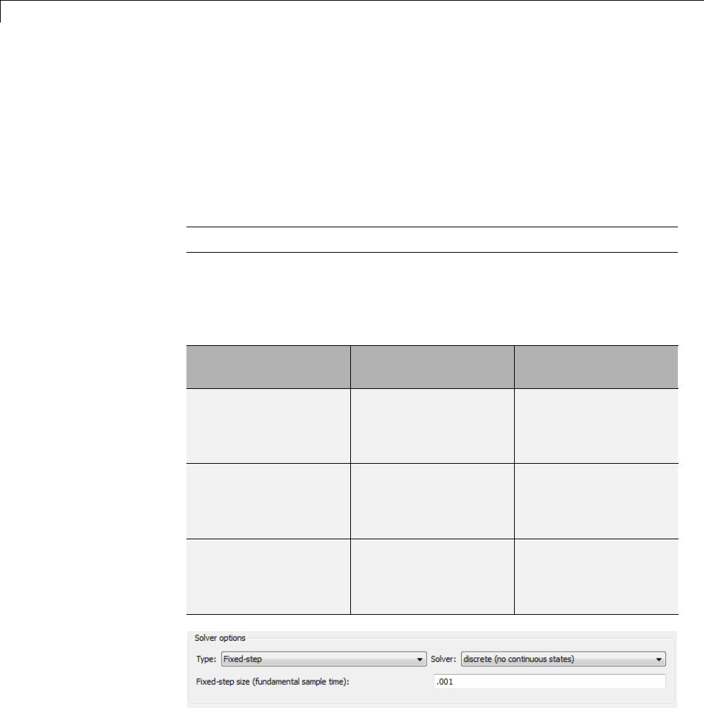
2Open the Configuration Parameters dialog box Solver pane. To generate
code for a model, you must configure the model to use a fixed-step solver.
For this example, set the parameters as noted in the following table.
Parameter Setting Effect on Generated
Code
Type Fixed-step Maintains a constant
(fixed) step size, which
is required for code
generation
Solver discrete (no
continuous states)
Applies a fixed-step
integration technique
for computing the state
derivative of the model
Fixed-step size .001 Sets the base rate;
must be the lowest
common multiple of all
rates in the system
1-2

Configure a Model for Code Generation
3Open the Code Generation pane and make sure that System target
file is set to grt.tlc.
Note The GRT (Generic Real-Time Target) configuration requires a
fixed-step solver. However, the rsim.tlc system target file supports
variable step code generation.
The system target file (STF) defines a target, which is an environment
for generating and building code for execution on a certain hardware or
operating system platform. For example, one property of a target is code
format. The grt configuration requires a fixed step solver and the rsim.tlc
supports variable step code generation.
4Open the Code Generation > Custom Code pane, and under Include
list of additional,selectInclude directories.IntheInclude
directories text field, enter:
"$matlabroot$\toolbox\rtw\rtwdemos\EmbeddedCoderOverview\"
This directory includes files that are required to build an executable for
the model.
5Apply your changes and close the dialog box.
1-3

1Modeling
Scheduling
The following sections explain and illustrate how the Simulink®and
Simulink Coder™ products handle multirate (mixed-rate) models, depending
on whether code is being generated for single-tasking or multitasking
environments.
In this section...
“About Scheduling” on page 1-4
“Single-Tasking and Multitasking Execution Modes” on page 1-5
“Handle Rate Transitions” on page 1-13
“Single-Tasking and Multitasking Model Execution” on page 1-27
“Handle Asynchronous Events” on page 1-34
“Timers” on page 1-79
“Configure Scheduling” on page 1-90
About Scheduling
Simulink models run at one or more sample times. The Simulink product
provides considerable flexibility in building multirate systems, that is,
systems with more than one sample time. However, this same flexibility
also allows you to construct models for which the code generator cannot
generate real-time code for executioninamultitaskingenvironment. To
make multirate models operate as expected in real time (that is, to give
the right answers), you sometimes must modify your model or instruct the
Simulink engine to modify the model for you. In general, the modifications
involve placing Rate Transition blocks between blocks that have unequal
sample times. The following sections discuss issues you must address to use
a multirate model in a multitasking environment. For a comprehensive
discussion of sample times, including rate transitions, see “What Is Sample
Time?”, “Sample Times in Subsystems”, “Sample Times in Systems”, “Resolve
Rate Transitions”, and associated topics.
1-4

Scheduling
Single-Tasking and Multitasking Execution Modes
•“About Tasking Modes” on page 1-5
•“Execute Multitasking Models” on page 1-6
•“Multitasking and Pseudomultitasking Modes” on page 1-8
•“Build a Program for Multitasking Execution” on page 1-10
•“Single-Tasking Mode” on page 1-10
•“Build a Program for Single-Tasking Execution” on page 1-11
•“Model Execution and Rate Transitions” on page 1-11
•“Simulate Models with the Simulink Product” on page 1-12
•“Execute Models in Real Time” on page 1-12
•“Single-Tasking Versus Multitasking Operation” on page 1-13
About Tasking Modes
There are two execution modes for a fixed-step Simulink model: single-tasking
and multitasking. These modes are available only for fixed-step solvers. To
select an execution mode, use the Tasking mode for periodic sample
times menu on the Solver pane of the Configuration Parameters dialog
box. Automode (the default) applies multitasking execution for a multirate
model, and otherwise selects single-tasking execution. You can also select
SingleTasking or MultiTasking execution explicitly.
Execution of models in a real-time system can be done with the aid of a
real-time operating system, or it can be done on a bare-board target, where
the model runs in the context of an interrupt service routine (ISR).
The fact that a system (such as The Open Group UNIX®or Microsoft®
Windows®systems) is multitasking does not imply that your program can
execute in real time. This is because the program might not preempt other
processes when required.
In operating systems (such as PC-DOS) where only one process can exist at
any given time, an interrupt service routine (ISR) must perform the steps of
saving the processor context, executing the model code, collecting data, and
restoring the processor context.
1-5
1Modeling
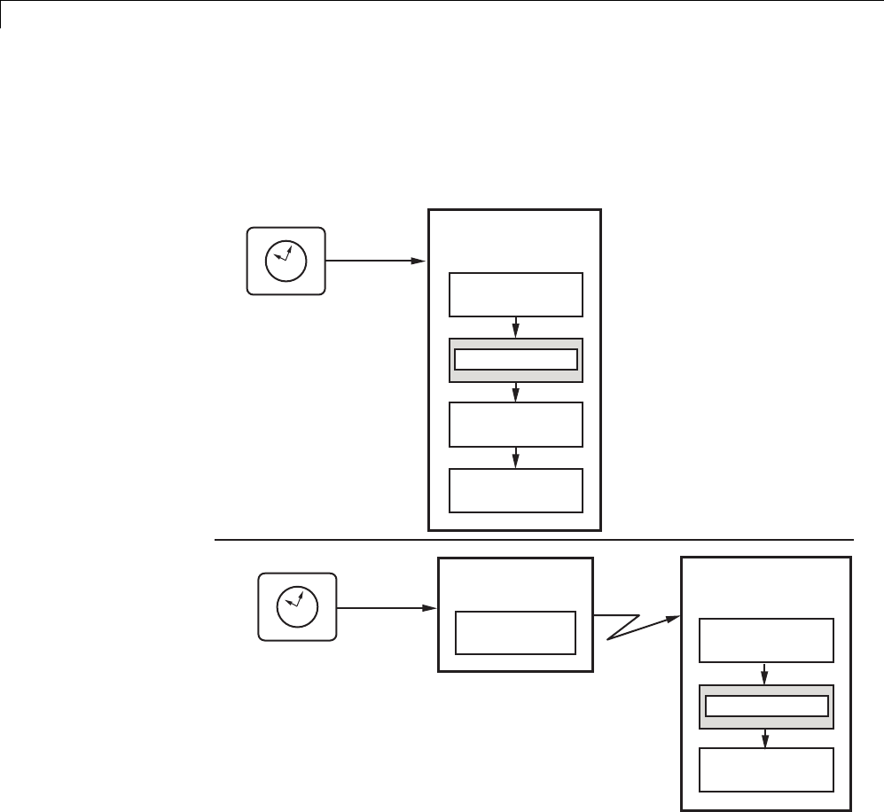
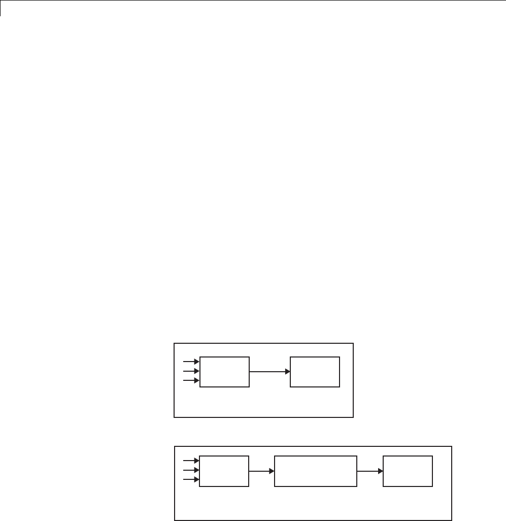
Other operating systems, such as POSIX-compliant ones, provide automatic
context switching and task scheduling. This simplifies the operations
performed by the ISR. In this case, the ISR simply enables the model execution
task, which is normally blocked. The next figure illustrates this difference.
Real-Time Clock
Hardware
Interrupt
Hardware
Interrupt
Real-Time Clock
Program execution using a real-time
operating system primitive. See the
Tornado raget for an example.
Program execution using an
interrupt service routine
(bareboard, with no real-time
operating system). See the
grt target for an example.
Interrupt Service
Routine
Execute Model
Restore Context
Save Context
Collect Data
Interrupt Service
Routine
semGive
Context
Switch
Model Execution
Task
Execute Model
Collect Data
semTake
Execute Multitasking Models
In cases where the continuous part of a model executes at a rate that is
different from the discrete part, or a model has blocks with different sample
1-6
Scheduling
rates, the Simulink engine assigns each block a task identifier (tid)to
associate the block with the task that executes at the block’s sample rate.
You set sample rates and their constraints on the Solver pane of the
Configuration Parameters dialog box. To generate code with the Simulink
Coder software, you must select Fixed-step for the solver type. Certain
restrictions apply to the sample rates that you can use:
•Thesamplerateofanyblockmustbeanintegermultipleofthebase(that
is, the fastest) sample period.
•When Periodic sample time constraint is unconstrained, the base
sample period is determined by the Fixed step size specified on the
Solvers pane of the Configuration parameters dialog box.
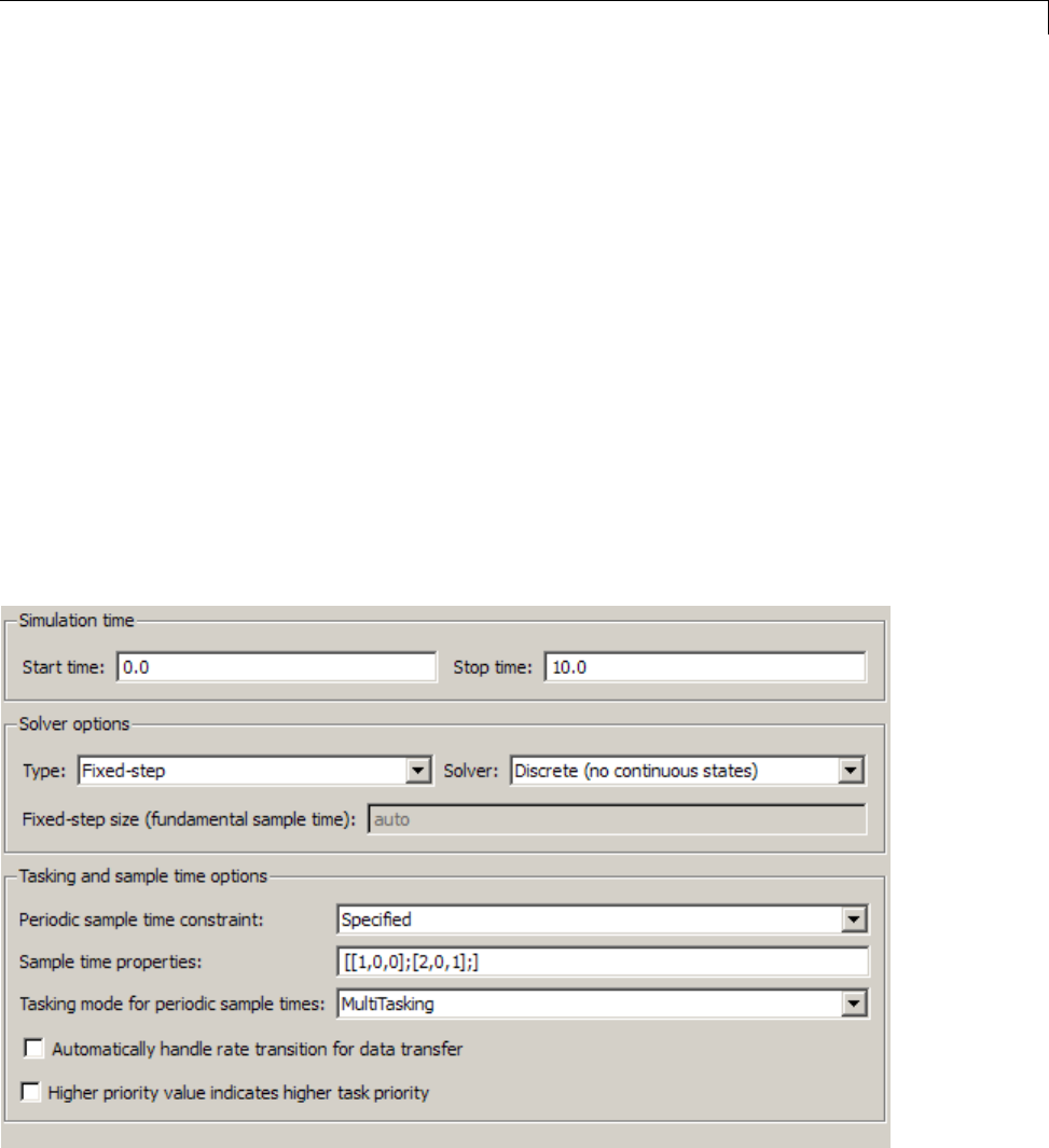
•When Periodic sample time constraint is Specified,thebaserate
fixed-step size is the first element of the sample time matrix that you
specify in the companion option Sample time properties.TheSolver
pane from the example model rtwdemo_mrmtbb shows an example.
1-7

1Modeling
•Continuous blocks always execute by using an integration algorithm that
runsatthebasesamplerate. Thebasesampleperiodisthegreatest
common denominator of all rates in the model only when Periodic sample
time constraint is set to Unconstrained and Fixed step size is Auto.
•The continuous and discrete parts of the model can execute at different
rates only if the discrete part is executed at the same or a slower rate than
the continuous part and is an integer multiple of the base sample rate.
Multitasking and Pseudomultitasking Modes
When periodic tasks execute in a multitasking mode, by default the blocks
with the fastest sample rates are executed by the task with the highest
priority, the next fastest blocks are executed by a task with the next higher
priority, and so on. Time available in between the processing of high-priority
tasks is used for processing lower priority tasks. This results in efficient
program execution.
Where tasks are asynchronous rather than periodic, there may not necessarily
be a relationship between sample rates and task priorities; the task with
the highest priority need not have the fastest sample rate. You specify
asynchronous task priorities using Async Interrupt and Task Sync blocks.
You can switch the sense of what priority numbers mean by selecting or
deselecting the Solver option Higher priority value indicates higher
task priority.
In multitasking environments (that is, under a real-time operating system),
you can define separate tasks and assign them priorities. In a bare-board
target (that is, no real-time operating system present), you cannot create
separate tasks. However, Simulink Coder application modules implement
what is effectively a multitasking execution scheme using overlapped
interrupts, accompanied by programmatic context switching.
This means an interrupt can occur while another interrupt is currently
in progress. When this happens, the current interrupt is preempted, the
floating-point unit (FPU) context is saved, and the higher priority interrupt
executes its higher priority (that is, faster sample rate) code. Once complete,
control is returned to the preempted ISR.
1-8
Scheduling
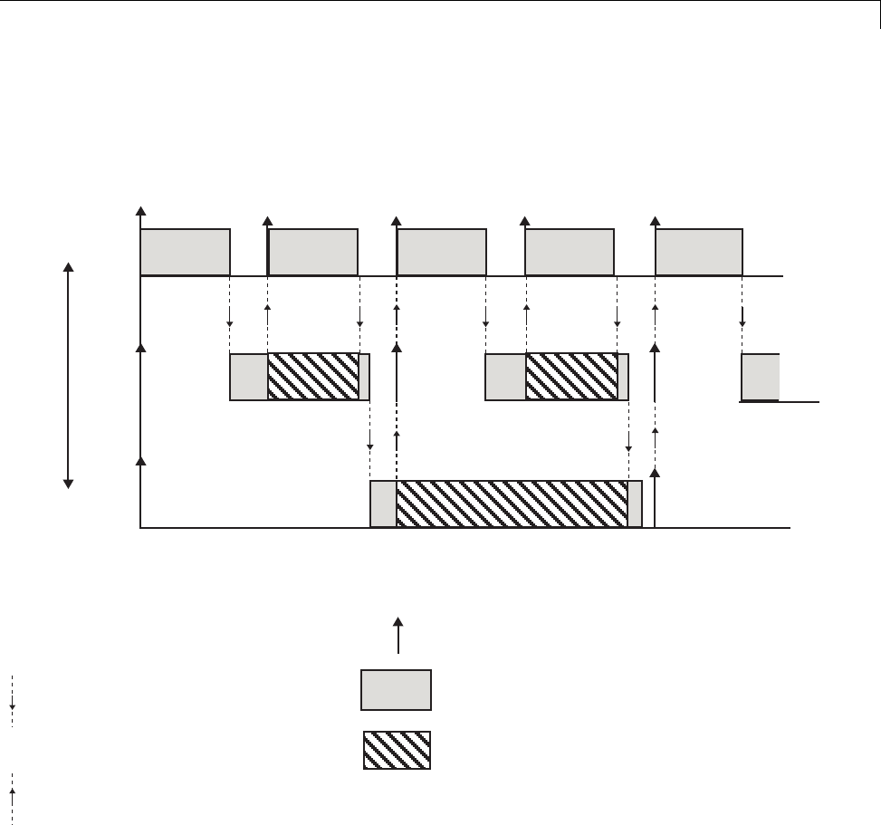
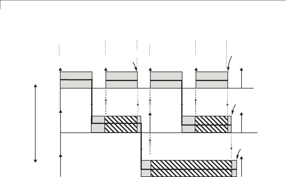
The next figures illustrate how timing of tasks in multirate systems are
handled by the Simulink Coder software in multitasking, pseudomultitasking,
and single-tasking environments.
Highest Priority
Lowest Priority
Dotted lines with downward pointing
arrows indicate the release of control
to a lower priority task.
Dotted lines with upward pointing
arrows indicate preemption by a
higher priority task.
Vertical arrows indicate sample time hits.
Dark gray areas indicate task execution.
Hashed areas indicate task preemption
by a higher priority task.
Light gray areas indicate task execution
is pending.
rate 3
rate 2
rate 1
t0 t1 t2 t3 t4
The next figure shows how overlapped interrupts are used to implement
pseudomultitasking. In this case, Interrupt 0 does not return until after
Interrupts 1, 2, and 3.
1-9
1Modeling
Highest Priority
Lowest Priority
t0 t1 t2 t3 t4
Interrupt 0
Begins Interrupt 1 Interrupt 2
Begins Interrupt 3
Interrupt 3
Ends
Interrupt 2
Ends
Interrupt 0
Ends
Interrupt 1
Ends
Build a Program for Multitasking Execution
To use multitasking execution, select Auto (the default) or MultiTasking from
the Tasking mode for periodic sample times menu on the Solver pane
of the Configuration Parameters dialog box. This menu is active only if you
select Fixed-step as the solver type. Auto mode results in a multitasking
environment if your model has two or more different sample times. A model
with a continuous and a discrete sample time runs in single-tasking mode if
the fixed-step size is equal to the discrete sample time.
Single-Tasking Mode
You can execute model code in a strictly single-tasking manner. While this
mode is less efficient with regard to execution speed, in certain situations,
it can simplify your model.
In single-tasking mode, the base sample rate must define a time interval that
is long enough to allow the execution of all blocks within that interval.
1-10
Scheduling
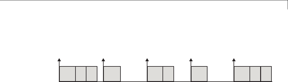
The next figure illustrates the inefficiency inherent in single-tasking
execution.
t0 t1 t2 t3 t4
Single-tasking system execution requires a base sample rate that is long
enough to execute one step through the entire model.
Build a Program for Single-Tasking Execution
To use single-tasking execution, select SingleTasking from the Tasking
mode for periodic sample times menu on the Solver pane of the
Configuration Parameters dialog box. If you select Auto,single-taskingis
used in the following cases:
•If your model contains one sample time
•If your model contains a continuous and a discrete sample time and the
fixed step size is equal to the discrete sample time
Model Execution and Rate Transitions
To generate code that executes as expected in real time, you (or the Simulink
engine) might need to identify and handle sample rate transitions within
the model. In multitasking mode, by default the Simulink engine flags
errors during simulation if the model contains invalid rate transitions,
although you can use the Multitask rate transition diagnostic to alter this
behavior. A similar diagnostic, called Single task rate transition,existsfor
single-tasking mode.
To avoid raising rate transition errors, insert Rate Transition blocks between
tasks. You can request that the Simulink engine handle rate transitions
automatically by inserting hidden Rate Transition blocks. See “Automatic
Rate Transition” on page 1-20 for an explanation of this option.
To understand such problems, first consider how Simulink simulations differ
from real-time programs.
1-11

1Modeling
Simulate Models with the Simulink Product
Before the Simulink engine simulates a model, it orders the blocks based upon
their topological dependencies. This includes expanding virtual subsystems
into the individual blocks they contain and flattening the entire model into a
single list. Once this step is complete, each block is executed in order.
The key to this process is the ordering of blocks. Any block whose output is
directly dependent on its input (that is, any block with direct feedthrough)
cannot execute until the block driving its input executes.
Some blocks set their outputs based on values acquired in a previous time
step or from initial conditions specified as a block parameter. The output of
such a block is determined by a value stored in memory, which can be updated
independently of its input. During simulation, computations are performed
prior to advancing the variable corresponding to time. In essence, this results
in computations occurring instantaneously (that is, no computational delay).
Execute Models in Real Time
A real-time program differs from a Simulink simulation in that the program
must execute the model code synchronously with real time. Every calculation
results in some computational delay. This means the sample intervals cannot
be shortened or lengthened (as they can be in a Simulink simulation), which
leads to less efficient execution.
Consider the following timing figure.
t0 t1 t2
Time
Note the processing inefficiency in the sample interval t1. That interval
cannot be compressed to increase execution speed because, by definition,
sample times are clocked in real time.
1-12

Scheduling
You can circumvent this potential inefficiency by using the multitasking
mode. The multitasking mode defines tasks with different priorities to
execute parts of the model code that have different sample rates.
See “Multitasking and Pseudomultitasking Modes” on page 1-8 for a
description of how this works. It is important to understand that section
before proceeding here.
Single-Tasking Versus Multitasking Operation
Single-tasking programs require longer sample intervals, because all
computations must be executed within each clock period. This can result in
inefficient use of available CPU time,asshowninthepreviousfigure.
Multitasking mode can improve the efficiency of your program if the model is
large and has many blocks executing at each rate.
However, if your model is dominated by a single rate, and only a few blocks
execute at a slower rate, multitasking can actually degrade performance. In
such a model, the overhead incurred in task switching can be greater than the
time required to execute the slower blocks. In this case, it is more efficient to
execute all blocks at the dominant rate.
If you have a model that can benefit from multitasking execution, you might
need to modify your model by adding Rate Transition blocks (or instruct the
Simulink engine to do so) to generate expected results. The next section,
“Handle Rate Transitions” on page 1-13, discusses issues related to rate
transition blocks.
Handle Rate Transitions
•“About Rate Transitions” on page 1-14
•“Data Transfer Problems” on page 1-15
•“Data Transfer Assumptions” on page 1-16
•“Rate Transition Block Options” on page 1-17
•“Faster to Slower Transitions in a Simulink Model” on page 1-22
•“Faster to Slower Transitions in Real Time” on page 1-23
1-13
1Modeling
•“Slower to Faster Transitions in a Simulink Model” on page 1-24
•“Slower to Faster Transitions in Real Time” on page 1-25
About Rate Transitions
Two periodic sample rate transitions can exist within a model:
•A faster block driving a slower block
•A slower block driving a faster block
The following sections concern models with periodic sample times with zero
offset only. Other considerations apply to multirate models that involve
asynchronous tasks. For details on how to generate code for asynchronous
multitasking, see “Handle Asynchronous Events” on page 1-34.
In single-tasking systems, there are no issues involving multiple sample
rates. In multitasking and pseudomultitasking systems, however, differing
sample rates can cause problems by causing blocks to be executed in the
wrong order. To prevent possible errors in calculated data, you must control
model execution at these transitions. When connecting faster and slower
blocks, you or the Simulink engine must add Rate Transition blocks between
them. Fast-to-slow transitions are illustrated in the next figure.
T = 1s T = 2s
T = 1s Port-based:
Tin = 1s; Tout = 2s T = 2s
Faster
Block
Slower
Block
Rate TransitionFaster
Block
Slower
Block
becomes
1-14
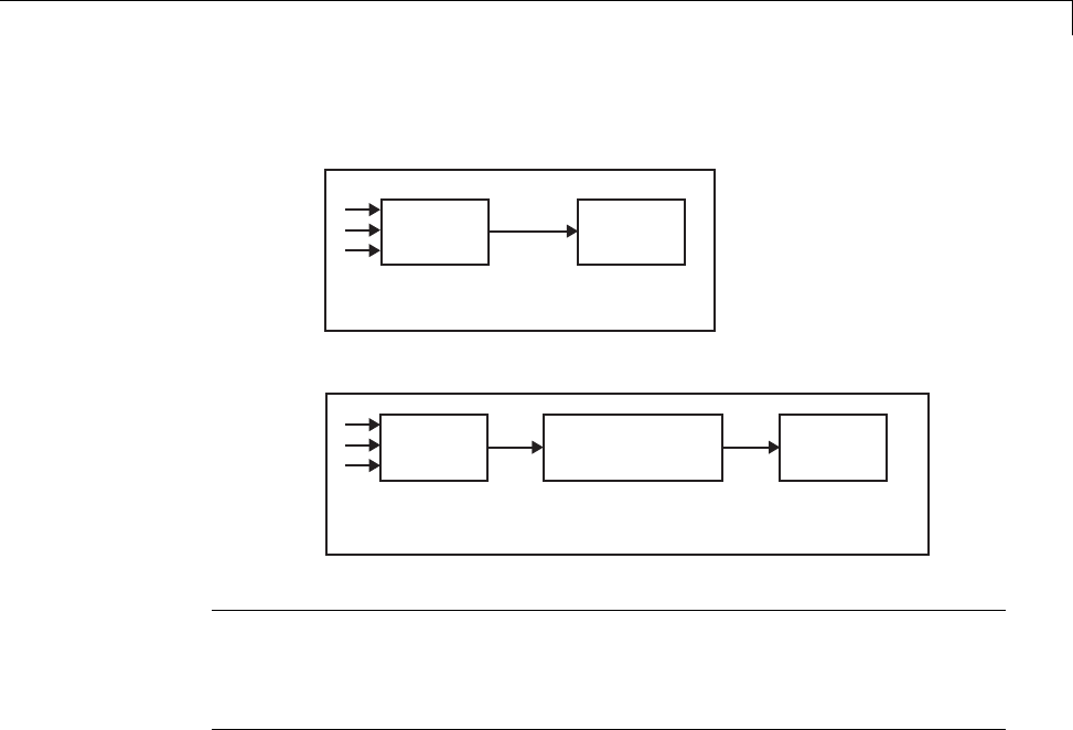
Scheduling
Slow-to-fast transitions are illustrated in the next figure.
T = 1sT = 2s
T = 1s
Port-based:
Tin = 2s; Tout = 1s
T = 2s
Faster
Block
Slower
Block
Rate Transition Faster
Block
Slower
Block
becomes
Note Although the Rate Transition block offers a superset of the capabilities
of the Unit Delay block (for slow-to-fast transitions) and the Zero-Order Hold
block (for fast-to-slow transitions), you should use the Rate Transition block
instead of these blocks.
Data Transfer Problems
Rate Transition blocks deal with issues of data integrity and determinism
associated with data transfer between blocks running at different rates.
•Data integrity: A problem of data integrity exists when the input to a block
changes during the execution of that block. Data integrity problems can be
caused by preemption.
Consider the following scenario:
-A faster block supplies the input to a slower block.
-The slower block reads an input value V1from the faster block and
begins computations using that value.
1-15

1Modeling
-The computations are preempted by another execution of the faster
block, which computes a new output value V2.
-A data integrity problem now arises: when the slower block resumes
execution, it continues its computations, now using the “new” input
value V2.
Suchadatatransferiscalledunprotected. “Faster to Slower Transitions in
Real Time” on page 1-23 shows an unprotected data transfer.
In a protected data transfer, the output V1of the faster block is held until
the slower block finishes executing.
•Deterministic versus nondeterministic data transfer: In a deterministic
data transfer, the timing of the data transfer is completely predictable, as
determined by the sample rates of the blocks.
The timing of a nondeterministic data transfer depends on the availability
of data, the sample rates of the blocks, and the time at which the receiving
block begins to execute relative to the driving block.
You can use the Rate Transition block to protect data transfers in your
application and make them deterministic. These characteristics are
considered desirable in most applications. However,theRateTransition
block supports flexible options that allow you to compromise data integrity
and determinism in favor of lower latency. The next section summarizes
these options.
Data Transfer Assumptions
When processing data transfers between tasks, the Simulink Coder software
assumes the following:
•Data transitions occur between a single reading task and a single writing
task.
•A read or write of a byte-sized variable is atomic.
•When two tasks interact through a data transition, only one of them can
preempt the other.
•For periodic tasks, the faster rate task has higher priority than the slower
rate task; the faster rate task always preempts the slower rate task.
1-16

Scheduling
•All tasks run on a single processor. Time slicing is not allowed.
•Processes do not crash or restart (especially while data is transferred
between tasks).
Rate Transition Block Options
Several parameters of the Rate Transition block are relevant to its use in code
generation for real-time execution, as discussed below. For a complete block
description, see Rate Transition in the Simulink documentation.
The Rate Transition block handles periodic (fast to slow and slow to fast) and
asynchronous transitions. When inserted between two blocks of differing
sample rates, the Rate Transition block automatically configures its input
and output sample rates for the type of transition; you do not need to specify
whether a transition is slow-to-fast or fast-to-slow (low-to-high or high-to-low
priorities for asynchronous tasks).
The critical decision you must make in configuring a Rate Transition block is
the choice of data transfer mechanism to be used between the two rates. Your
choice is dictated by considerations of safety, memory usage, and performance.
As the Rate Transition block parameter dialog box in the next figure shows,
the data transfer mechanism is controlled by two options.
1-17
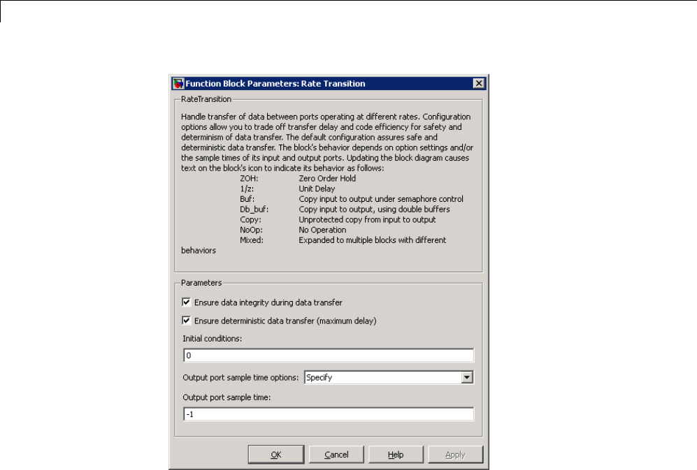
1Modeling
•Ensure data integrity during data transfer: When this option is on,
data transferred between rates maintains its integrity (the data transfer
is protected). When this option is off, the data might not maintain its
integrity (the data transfer is unprotected). By default, Ensure data
integrity during data transfer is on.
•Ensure deterministic data transfer (maximum delay):Thisoptionis
supported for periodic tasks with an offset of zero and fast and slow rates
that are multiples of each other. Enable this option for protected data
transfers (when Ensure data integrity during data transfer is on).
When this option is on, the Rate Transition block behaves like a Zero-Order
Hold block (for fast to slow transitions) or a Unit Delay block (for slow to
fast transitions). The Rate Transition block controls the timing of data
transfer in a completely predictable way. When this option is off, the data
transfer is nondeterministic. By default, Ensure deterministic data
1-18

Scheduling
transfer (maximum delay) is on for transitions between periodic rates
with an offset of zero; for asynchronous transitions, it cannot be selected.
Thus the Rate Transition block offers three modes of operation with respect to
data transfer. In order of level of safety:
•Protected/Deterministic (default): This is the safest mode. The
drawback of this mode is that it introduces deterministic latency into the
system for the case of slow-to-fast periodic rate transitions. For that case,
thelatencyintroducedbytheRateTransitionblockisonesampleperiodof
theslowertask. Forthecaseoffast-to-slow periodic rate transitions, the
Rate Transition block introduces no additional latency.
•Protected/NonDeterministic: In this mode, for slow-to-fast periodic rate
transitions, data integrity is protected by double-buffering data transferred
between rates. For fast-to-slow periodic rate transitions, a semaphore flag
is used. The blocks downstream from the Rate Transition block always use
the latest available data from the block that drives the Rate Transition
block. Maximum latency is less than or equal to one sample period of the
faster task.
The drawbacks of this mode are its nondeterministic timing. The advantage
of this mode is its low latency.
•Unprotected/NonDeterministic: This mode is not recommended for
mission-critical applications. The latency of this mode is the same as for
Protected/NonDeterministic mode, but memory requirements are reduced
since neither double-buffering nor semaphores are required. That is, the
Rate Transition block does nothing in this mode other than to pass signals
through; it simply exists to notify you that a rate transition exists (and can
cause generated code to compute incorrect answers). Selecting this mode,
however, generates the least amount of code.
Note In unprotected mode (Ensure data integrity during data
transfer option off), the Rate Transition block does nothing other than
allow the rate transition to exist in the model.
1-19

1Modeling
Automatic Rate Transition. The Simulink engine can detect mismatched
rate transitions in a multitasking model and automatically insert Rate
Transition blocks to handle them. To instruct the engine to do this, select
Automatically handle rate transition for data transfer on the Solver
pane of the Configuration Parameters dialog box.
The Automatically handle rate transition for data transfer option is off
by default. When you select it,
•The Simulink engine handles transitions between periodic sample times
and asynchronous tasks.
•The Simulink engine inserts “hidden” Rate Transition blocks that are not
visible on the block diagram.
•The Simulink Coder software generates code for the automatically inserted
Rate Transition blocks that is identical to that generated for manually
inserted Rate Transition blocks.
•Automatically inserted Rate Transition blocks operate in protected mode
for periodic tasks and asynchronous tasks, which you cannot alter. For
periodic tasks, automatically inserted Rate Transition blocks operate
with the level of determinism specified by the Solver pane parameter
Deterministic data transfer. (The default setting is Whenever
possible, which enables determinism for data transfers between periodic
sample-times that are related by an integer multiple; for more information,
see “Deterministic data transfer” in the Simulink reference documentation.)
To use other modes, you must insert Rate Transition blocks and set their
modes manually.
For example, in the following model SineWave2 has a Sample time of 2, and
SineWave3 has a Sample time of 3.
1-20
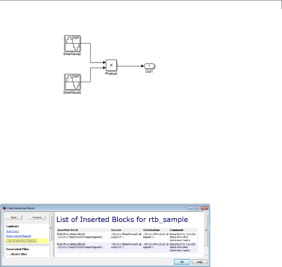
Scheduling
If Automatically handle rate transition for data transfer is on, the
Simulink engine inserts an invisible Rate Transition block between each Sine
Wave block and the Product block. The inserted blocks have the parameter
values required to reconcile the Sine Wave block sample times.
Inserted Rate Transition Block HTML Report
When the Simulink engine has automatically inserted Rate Transition blocks
into a model, after code generation the optional HTML code generation report
includesaList of inserted blocks that describes the blocks. For example,
the following report describes the two Rate Transition blocks that the engine
automatically inserts into the previous model.
Only automatically inserted Rate Transition blocks appear in a List of
inserted blocks. If no such blocks exist in a model, the HTML code
generation report does not include a List of inserted blocks.
1-21
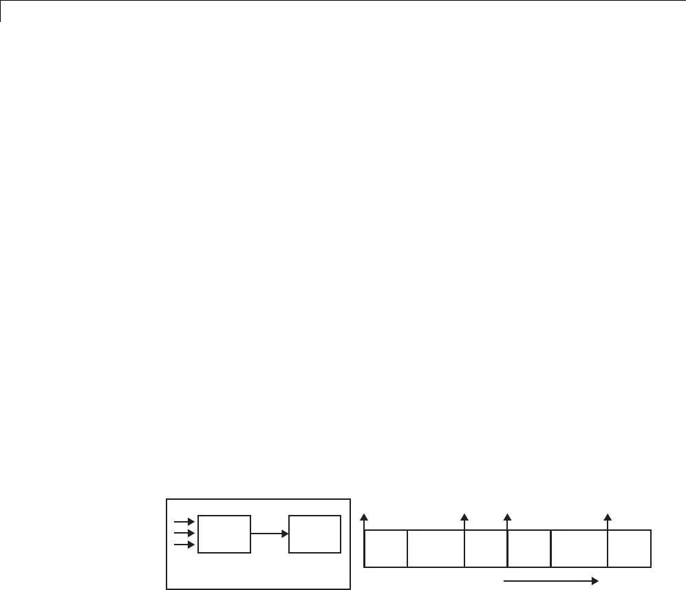
1Modeling
Rate Transition Blocks and Continuous Time. Thesampletimeatthe
output port of a Rate Transition block can only be discrete or fixed in minor
time step. This means that when a Rate Transition block inherits continuous
sample time from its destination block, it treats theinheritedsampletime
as Fixed in Minor Time Step. Therefore, the output function of the Rate
Transition block runs only at major time steps. If the destination block
sample time is continuous, Rate Transition block output sample time is the
baseratesampletime(ifsolverisfixed-step),orzero-order-hold-continuous
sample time (if solver is variable-step).
The next four sections describe cases in which Rate Transition blocks are
required for periodic sample rate transitions. The discussion and timing
diagrams in these sections are based on the assumption that the Rate
Transition block is used in its default (protected/deterministic) mode;
that is, the Ensuredataintegrityduringdatatransferand Ensure
deterministic data transfer (maximum delay) options are both on. These
are the settings used for automatically inserted Rate Transition blocks.
Faster to Slower Transitions in a Simulink Model
In a model where a faster block drives a slower block having direct
feedthrough, the outputs of the faster block are always computed first. In
simulation intervals where the slower block does not execute, the simulation
progresses more rapidly because there are fewer blocks to execute. The next
figure illustrates this situation.
T = 2s
T = 1s
Faster
Block
Slower
Block Time
t0
T = 1s
t1 t2 t3
T = 2s T = 1s T = 1s T = 2s T = 1s
A Simulink simulation does not execute in real time, which means that it is
not bound by real-time constraints. The simulation waits for, or moves ahead
to,whatevertasksarerequiredtocompletesimulationflow. Theactualtime
interval between sample time steps can vary.
1-22
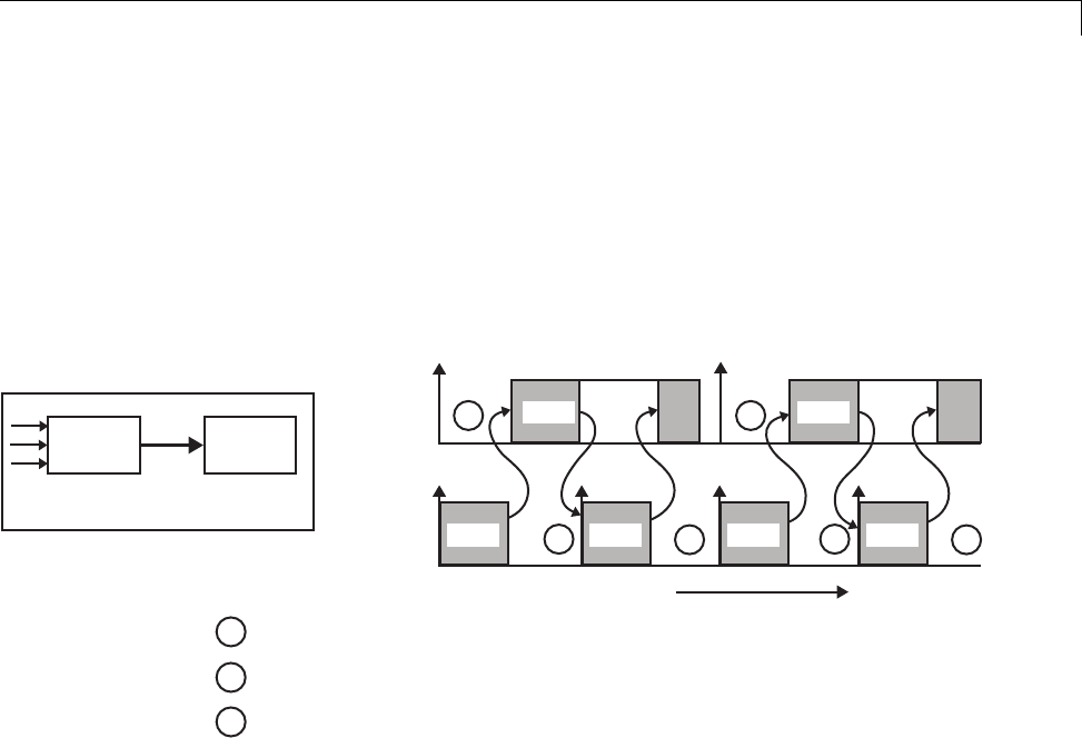
Scheduling
Faster to Slower Transitions in Real Time
In models where a faster block drives a slower block, you must compensate
for the fact that execution of the slower block might span more than one
execution period of the faster block. This means that the outputs of the faster
block can change before the slower block has finished computing its outputs.
The next figure shows a situation in which this problem arises (T = sample
time). Note that lower priority tasks are preempted by higher priority tasks
before completion.
T = 1s
Faster
Block
T = 2s
Slower
Block
2 Sec
Task
1 Sec
Task
Time
1
2
3
The faster task (T=1s) completes.
Higher priority preemption occurs.
The slower task (T=2s) resumes and its inputs
have changed. This leads to unpredictable results.
11
2 2
3 3
T=2s T=2s
T=1s T=1s T=1s T=1s
In the above figure, the faster block executes a second time before the slower
block has completed execution. This can cause unpredictable results because
the input data to the slow task is changing. Data might not maintain its
integrity in this situation.
To avoid this situation, the Simulink engine must hold the outputs of the 1
second (faster) block until the 2 second (slower) block finishes executing. The
way to accomplish this is by inserting a Rate Transition block between the 1
second and 2 second blocks. The input to the slower block does not change
during its execution, maintaining data integrity.
1-23

1Modeling
Tin = 1Tout = 2
T = 1 s T = 2 s
Faster Block Rate Transition Slower Block
It is assumed that the Rate Transition block is used in its default
(protected/deterministic) mode.
The Rate Transition block executes at the sample rate of the slower block, but
with the priority of the faster block.
2 Sec
Task
1 Sec
Task
Time
T=2s T=2s
T=1s RT T=1s T=1s RT T=1s
t0 t2
t0 t1 t2 t3
When you add a Rate Transition block, the block executes before the 2 second
block (its priority is higher) and its output value is held constant while the 2
second block executes (it executes at the slower sample rate).
Slower to Faster Transitions in a Simulink Model
In a model where a slower block drives a faster block, the Simulink engine
again computes the output of the driving block first. During sample intervals
where only the faster block executes, the simulation progresses more rapidly.
Thenextfigureshowstheexecutionsequence.
1-24
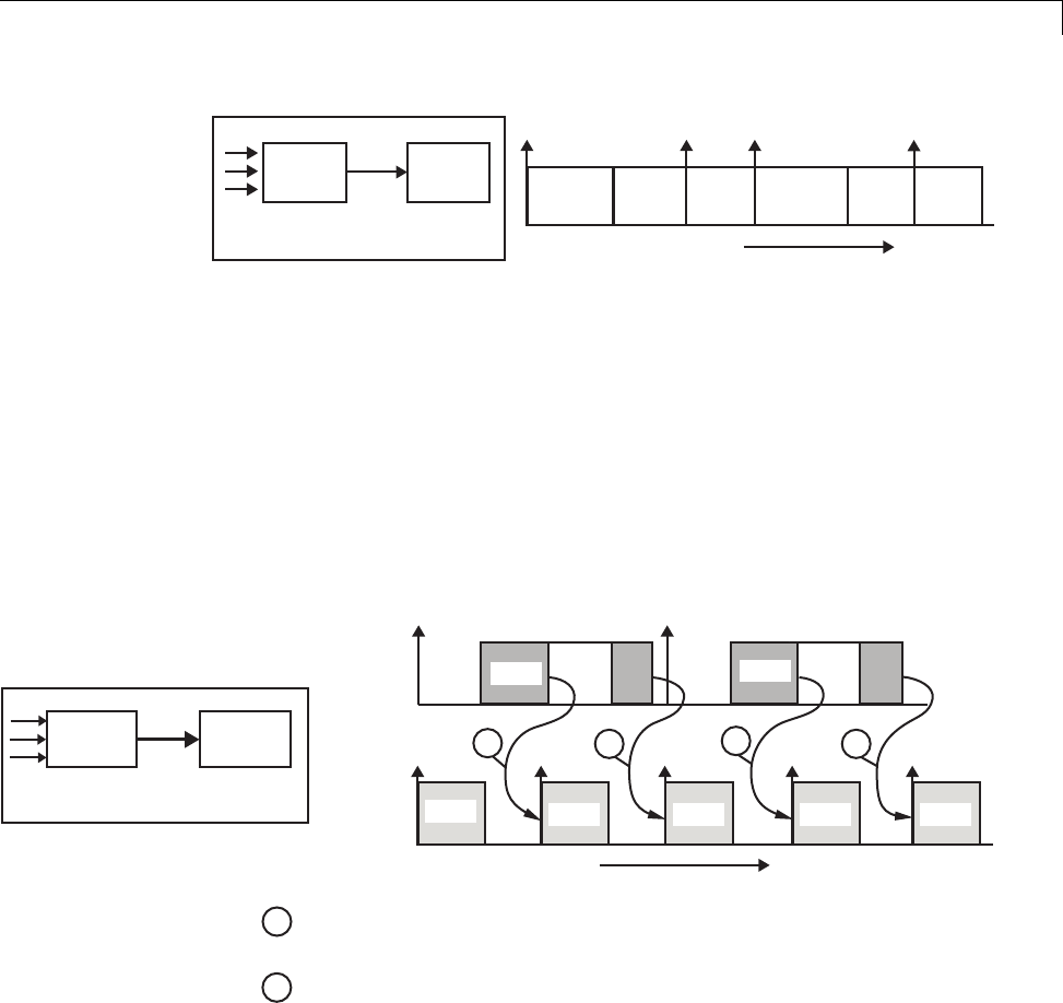
Scheduling
T = 2s T = 1s
Faster
Block
Slower
Block Time
t0
T = 1s
t1 t2 t3
T = 2s T = 1s T = 2s T = 1s T = 1s
As you can see from the preceding figures, the Simulink engine can simulate
models with multiple sample rates in an efficient manner. However, a
Simulink simulation does not operate in real time.
Slower to Faster Transitions in Real Time
In models where a slower block drives a faster block, the generated code
assigns the faster block a higher priority than the slower block. This means
the faster block is executed before the slower block, which requires special
care to avoid incorrect results.
T = 1s
Faster
Block
T = 2s
Block
2 Sec
Task
1 Sec
Task
Time
1
2
The faster block executes a second time prior
to the completion of the slower block.
The faster block executes before the slower block.
1122
T=2s T=2s
T=1s T=1s T=1s T=1s T=1s
t0 t2
t0 t1 t2 t3 t4
This timing diagram illustrates two problems:
•Execution of the slower block is split over more than one faster block
interval. In this case the faster task executes a second time before the
1-25
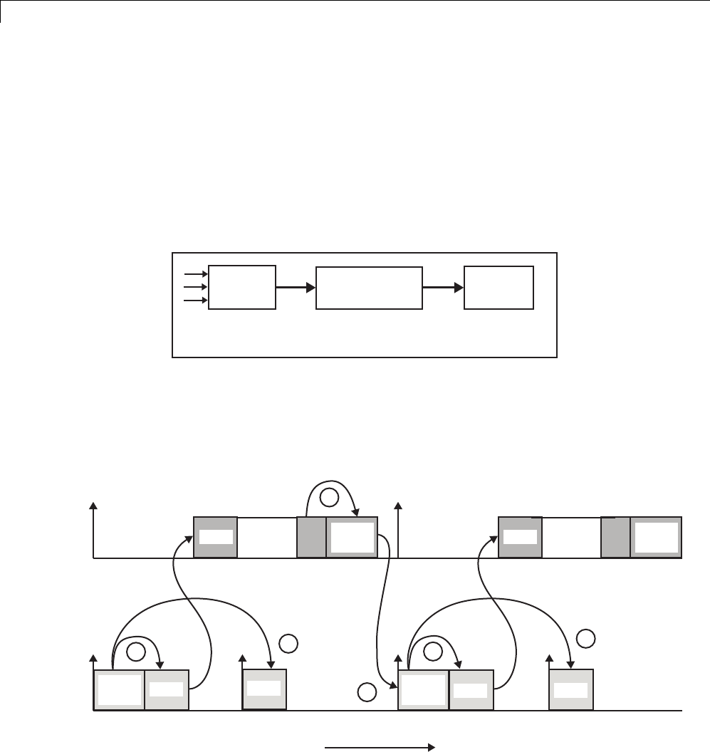
1Modeling
slower task has completed execution. This means the inputs to the faster
task can have incorrect values some of the time.
•The faster block executes before the slower block (which is backward from
the way a Simulink simulation operates). In this case, the 1 second block
executes first; but the inputs to the faster task have not been computed.
This can cause unpredictable results.
To eliminate these problems, you must insert a Rate Transition block between
the slower and faster blocks.
T = 1s
Faster
Block
T = 2s
Slower
Block
Rate Transition
Tin = 2 Tout = 1
It is assumed that the Rate Transition block is used in its default
(protected/deterministic) mode.
The next figure shows the timing sequence that results with the added Rate
Transition block.
2 Sec
Task
1 Sec
Task
Time
1
3
2
T=2s
T=1s T=1s T=1s
t0 t1 t2 t3
RT
update T=2s RT
update
1
1
1
RT
output T=1s RT
output
1-26

Scheduling
Three key points about transitions in this diagram (refer to circled numbers):
1The Rate Transition block output runs in the 1 second task, but at a slower
rate (2 seconds). The output of the Rate Transition block feeds the 1 second
task blocks.
2The Rate Transition update uses the output of the 2 second task to update
its internal state.
3The Rate Transition output in the 1 second task uses the state of the Rate
Transition that was updated in the 2 second task.
The first problem is alleviated because the Rate Transition block is updating
at a slower rate and at the priority of the slower block. The input to the Rate
Transition block (which is the output of the slower block) is read after the
slower block completes executing.
The second problem is alleviated because the Rate Transition block executes
at a slower rate and its output does not change during the computation of the
faster block it is driving. The output portion of a Rate Transition block is
executed at the sample rate of the slower block, but with the priority of the
faster block. Since the Rate Transition block drives the faster block and has
effectively the same priority, it is executed before the faster block.
Note This use of the Rate Transition block changes the model. The output
of the slower block is now delayed by onetimestepcomparedtotheoutput
without a Rate Transition block.
Single-Tasking and Multitasking Model Execution
•“Introduction” on page 1-28
•“Single-Tasking Execution” on page 1-28
•“Multitasking Execution” on page 1-31
1-27
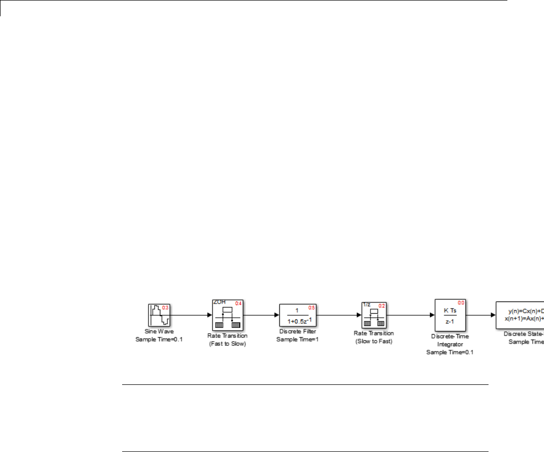
1Modeling
Introduction
This section examines how a simple multirate model executes in both real
time and simulation, using a fixed-step solver. It considers the operation of
both SingleTasking and MultiTasking Solver pane tasking modes.
The example model is shown in the next figure. The discussion refers to the
six blocks of the model as A through F, as labeled in the block diagram.
The execution order of the blocks (indicated in the upper right of each block)
has been forced into the order shown by assigning higher priorities to blocks F,
E, and D. The ordering shown is one possible valid execution ordering for this
model. (See “Simulating Dynamic Systems” in the Simulink documentation.)
The execution order is determined by data dependencies between blocks.
In a real-time system, the execution order determines the order in which
blocks execute within a given time interval or task. This discussion treats the
model’s execution order as a given, because it is concerned with the allocation
of block computations to tasks, and the scheduling of task execution.
Note The discussion and timing diagrams in this section are based on
the assumption that the Rate Transition blocks are used in the default
(protected/deterministic) mode, with the Ensure data integrity during
data transfer and Ensure deterministic data transfer (maximum
delay) options on.
Single-Tasking Execution
This section considers the execution of the above model when the solver
Tasking mode is SingleTasking.
1-28

Scheduling
In a single-tasking system, if the Block reduction option on the
Optimization pane is on, fast-to-slow Rate Transition blocks are optimized
out of the model. The default case is shown (Block reduction on), so block B
does not appear in the timing diagrams in this section. For more information,
see “Block reduction”.
The following table shows, for each block in the model, the execution order,
sample time, and whether the block has an output or update computation.
Block A does not have discrete states, and accordingly does not have an
update computation.
Execution Order and Sample Times (Single-Tasking)
Blocks
(in Execution
Order)
Sample Time
(in Seconds) Output Update
F0.1 YY
E0.1 YY
D1YY
A0.1 YN
C1YY
Real-Time Single-Tasking Execution. The next figure shows the
scheduling of computations when the generated code is deployed in a real-time
system. The generated program is shown running in real time, under control
of interrupts from a 10 Hz timer.
1-29
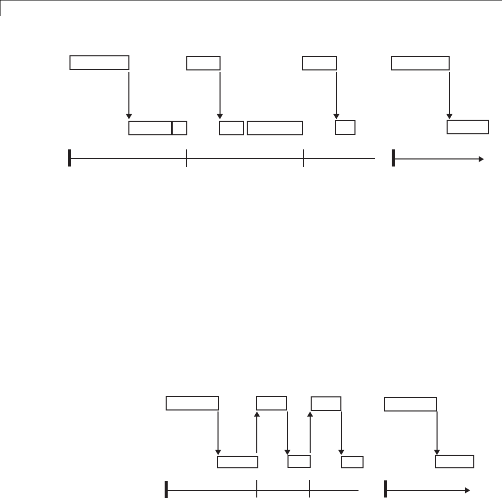
1Modeling
... ...
Output:
Update:
Time: 0.0 0.1 0.2 1.0
F E A F E A
F E D C
F E D A C
F E D C
FE
FE
(wait) (wait)
F E D A C
..
...
At time 0.0, 1.0, and every second thereafter, both the slow and fast blocks
execute their output computations; this is followed by update computations
for blocks that have states. Within a given time interval, output and update
computations are sequenced in block execution order.
The fast blocks execute on every tick, at intervals of 0.1 second. Output
computations are followed by update computations.
The system spends some portion of each time interval (labeled “wait”) idling.
During the intervals when only the fast blocks execute, a larger portion
of the interval is spent idling. This illustrates an inherent inefficiency of
single-tasking mode.
Simulated Single-Tasking Execution. Thenextfigureshowstheexecution
of the model during the Simulink simulation loop.
...
Output:
Update:
Time: 0.0 0.1 0.2 1.0
F E A F E A
F E D C
F E D A C
F E D C
FE
FE
F E D A C
...
...
...
1-30

Scheduling
Because time is simulated, the placement of ticks represents the iterations
of the simulation loop. Blocks execute in exactly the same order as in the
previous figure, but without the constraint of a real-time clock. Therefore
thereisnoidletimebetweensimulatedsampleperiods.
Multitasking Execution
This section considers the execution of the above model when the solver
Tasking mode is MultiTasking. Block computations are executed under
two tasks, prioritized by rate:
•The slower task, which gets the lower priority, is scheduled to run every
second. Thisiscalledthe1 second task.
•The faster task, which gets higher priority, is scheduled to run 10 times
per second. This is called the 0.1 second task. The 0.1 second task can
preempt the 1 second task.
The following table shows, for each block in the model, the execution order,
the task under which the block runs, and whether the block has an output
or update computation. Blocks A and B do not have discrete states, and
accordingly do not have an update computation.
Task Allocation of Blocks in Multitasking Execution
Blocks
(in Execution
Order) Task Output Update
F0.1 second task YY
E0.1 second task YY
1-31

1Modeling
Task Allocation of Blocks in Multitasking Execution (Continued)
Blocks
(in Execution
Order) Task Output Update
DTheRateTransitionblockuses
port-based sample times.
Output runs at the output port
sample time under 0.1 second
task.
Update runs at input port sample
time under 1 second task.
For more information on
port-based sample times, see
“Inherit Sample Times” in the
Simulink documentation.
YY
A0.1 second task YN
BTheRateTransitionblockuses
port-based sample times.
Output runs at the output port
sample time under 0.1 second
task.
For more information on
port-based sample times, see
“Inherit Sample Times” in the
Simulink documentation.
YN
C1 second task YY
Real-Time Multitasking Execution. Thenextfigureshowsthescheduling
of computations in MultiTasking solver mode when the generated code is
deployed in a real-time system. The generated program is shown running in
real time, as two tasks under control of interrupts from a 10 Hz timer.
1-32
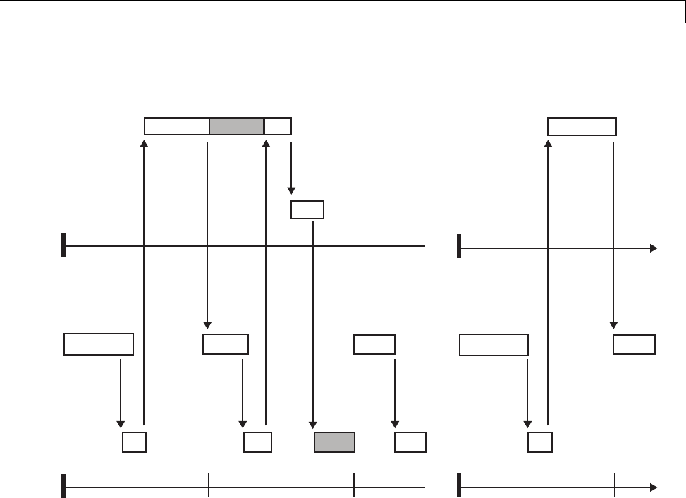
Scheduling
Output:
Update:
Time: 0.0 0.1 0.2 1.0
F E A F E A F E D A B
F E D A B
FE
...
Output:
Update:
Time:
1 SECOND
0.1 SECOND
1.1
0.0 1.0
...
...
...
preemption
preemption
FE FE FE
(wait)
F E A
C
C C
DC
Simulated Multitasking Execution. The next figure shows the Simulink
execution of the same model, in MultiTasking solver mode. In this case,
the Simulink engine runs the blocks in one thread of execution, simulating
multitasking. No preemption occurs.
1-33
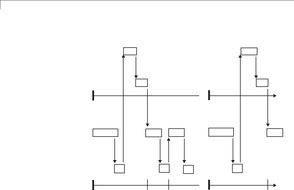
1Modeling
Output:
Update:
Time: 0.0 0.1 0.2 1.0
F E A F E D A
F E D A B
FE
F E A
Output:
Update:
Time:
1 SECOND
BLOCKS
1.1
0.1 SECOND
BLOCKS
...
0.0 1.0
...
FE F... FE
F E A
DCDC
CC
Handle Asynchronous Events
•“About Asynchronous Events” on page 1-35
•“Handling Interrupts” on page 1-37
•“Rate Transitions and Asynchronous Blocks” on page 1-53
•“Use Timers in Asynchronous Tasks” on page 1-58
•“Create a Customized Asynchronous Library” on page 1-60
•“Import Asynchronous Event Data for Simulation” on page 1-69
•“Asynchronous Support Limitations” on page 1-74
1-34

Scheduling
About Asynchronous Events
•“Asynchronous Support” on page 1-35
•“Block Library for Wind River Systems VxWorks Real-Time Operating
System” on page 1-35
•“Access the VxWorks Block Library” on page 1-36
•“Generate Code with the VxWorks Library Blocks” on page 1-37
•“Examples and Additional Information” on page 1-37
Asynchronous Support. Simulink Coder models are normally timed from
aperiodic interrupt source (for example, a hardware timer). Blocks in a
periodically clocked single-rate model run at a timer interrupt rate (the base
rate of the model). Blocks in a periodically clocked multirate model run at the
baserateoratsubmultiplesofthatrate.
Many systems must also support executionofblocksinresponsetoeventsthat
are asynchronous with respect to the periodic timing source of the system. For
example, a peripheral device might signal completion of an input operation
by generating an interrupt. The system must service such interrupts, for
example, by acquiring data from the interrupting device.
This chapter explains how to use blocks to model and generate code for
asynchronous event handling, including servicing of hardware-generated
interrupts, maintenance of timers, asynchronous read and write operations,
and spawning of asynchronous tasks under a real-time operating system
(RTOS). Although the blocks target the Wind River®Systems VxWorks®
Tornado®RTOS, this chapter provides source code analysis and other
information you can use to develop blocks that support asynchronous event
handling for an alternative target RTOS.
Block Library for Wind River Systems VxWorks Real-Time Operating
System. The next figure shows the blocks in the VxWorks block library
(vxlib1).
1-35
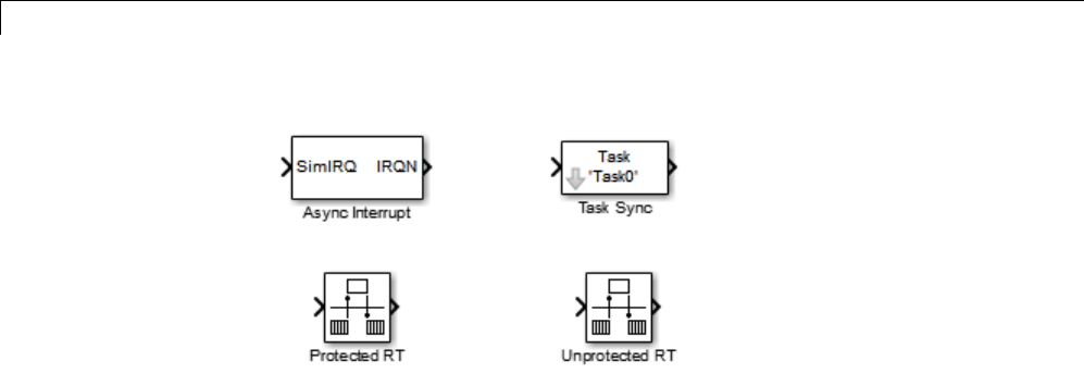
1Modeling
The key blocks in the library are the Async Interrupt and Task Sync blocks.
These blocks are targeted for the VxWorks Tornado operating system. You
can use them, without modification, to support VxWorks applications.
If you want to implement asynchronous support for an RTOS other than
VxWorks RTOS, guidelines and example code are provided that will help
you to adapt the VxWorks library blocks to target your RTOS. This topic is
discussed in “Create a Customized Asynchronous Library” on page 1-60.
The VxWorks library includes blocks you can use to
•Generate interrupt-level code — Async Interrupt block
•Spawn a VxWorks task that calls a function call subsystem — Task Sync
block
•Enable data integrity when transferring data between blocks running as
different tasks — Protected RT block
•Use an unprotected/nondeterministic mode when transferring data
between blocks running as different tasks — Unprotected RT block
The use of protected and unprotected Rate Transition blocks in asynchronous
contexts is discussed in “Rate Transitions and Asynchronous Blocks” on page
1-53. For general information on rate transitions, see “Scheduling” on page
1-4.
AccesstheVxWorksBlockLibrary.To access the VxWorks library, enter
the MATLAB®command vxlib1.
1-36

Scheduling
Generate Code with the VxWorks Library Blocks. To generate a
VxWorks compatible application from a model containing VxWorks library
blocks, select one of the following targets from the System Target File Browser
associated with the model:
•ert.tlc Embedded Coder. This target is provided with the Embedded
Coder™ product.
When using the ERT target with VxWorks library blocks, you must
select the Generate an example main program option, and select
VxWorksExample from the Target operating system menu.
•tornado.tlc Tornado (VxWorks) Real-Time Target.
Examples and Additional Information. Additional information relevant
to the topics in this chapter can be found in
•The rtwdemo_async model. To open this example, type rtwdemo_async
at the MATLAB command prompt.
•The rtwdemo_async_mdlreftop model. To open this example, type
rtwdemo_async_mdlreftop at the MATLAB command prompt.
•“Scheduling” on page 1-4, discusses general multitasking and rate
transition issues for periodic models.
•The Embedded Coder documentation discusses the Embedded Real-Time
(ERT) target, including task execution and scheduling.
•See your VxWorks system documentation for detailed information about
the VxWorks system calls mentioned in this chapter.
Handling Interrupts
•“Generate Interrupt Service Routines” on page 1-37
•“Spawn a Wind River Systems VxWorks Task” on page 1-46
Generate Interrupt Service Routines. To generate an interrupt service
routine (ISR) associated with a specific Wind River Systems VxWorks VME
interrupt level, use the Async Interrupt block. The Async Interrupt block
enables the specified interrupt level and installs an ISR that calls a connected
function call subsystem.
1-37
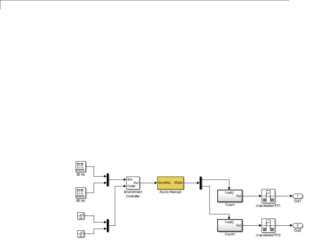
1Modeling
You can also use the Async Interrupt block in a simulation. It provides an
inputportthatcanbeenabledandconnected to a simulated interrupt source.
Connecting the Async Interrupt Block
To generate an ISR, connect an output of the Async Interrupt block to the
control input of
•A function call subsystem
•The input of a Task Sync block
•The input to a Stateflow chart configured for a function call input event
ThenextfigureshowsanAsyncInterrupt block configured to service two
interrupt sources. The outputs (signal width 2) are connected to two function
call subsystems.
Requirements and Restrictions
Note the following requirements and restrictions:
•The Async Interrupt block supports VME interrupts 1 through 7.
1-38

Scheduling
•The Async Interrupt block requires a VxWorks Board Support Package
(BSP) that supports the following VxWorks system calls:
-sysIntEnable
-sysIntDisable
-intConnect
-intLock
-intUnlock
-tickGet
Performance Considerations
Execution of large subsystems at interrupt level can have a significant impact
on interrupt response time for interrupts of equal and lower priority in the
system. As a general rule, it is best to keep ISRs as short as possible. Connect
only function call subsystems that contain a small number of blocks to an
Async Interrupt block.
A better solution for large subsystems is to use the Task Sync block to
synchronize the execution of the function call subsystem to a VxWorks
task. The Task Sync block is placed between the Async Interrupt block and
the function call subsystem. The Async Interrupt block then installs the
Task Sync block as the ISR. The ISR releases a synchronization semaphore
(performs a semGive) to the task, and returns immediately from interrupt
level. The task is then scheduled and run by the VxWorks RTOS. See “Spawn
a Wind River Systems VxWorks Task” on page 1-46 for more information.
Using the Async Interrupt Block in Simulation and Code Generation
This section describes a dual-model approach to the development and
implementation of real-time systems that include ISRs. In this approach, you
develop one model that includes a plant and a controller for simulation, and
another model that only includes the controller for code generation. Using a
Simulink library, you can implement changes to both models simultaneously.
The next figure shows how changes made to the plant or controller, both of
which are in a library, are propagated to the models.
1-39
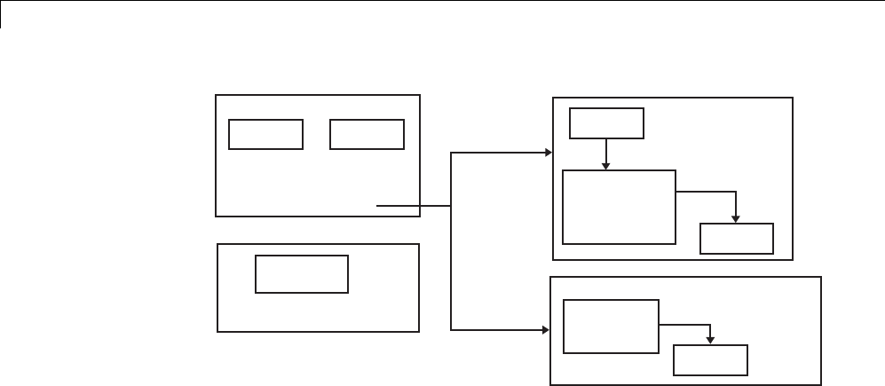
1Modeling
Library: Changes made here
affect both models.
Simulink Coder library
Plant Controller
Interrupt
Block
Plant Model
(for simulation)
Interrupt
Block
(Simulation
input enabled) Controller
Interrupt
Block
Model
(for code generation)
Controller
Dual-Model Use of Async Interrupt Block for Simulation and Code Generation
Asingle-model approach is also possible. In this approach, the Plant
component of the model is active only in simulation. During code generation,
the Plant components are effectively switched out of the system and code is
generated only for the interrupt block and controller partsofthemodel. For
an example of this approach, see the rtwdemo_async model.
Dual-Model Approach: Simulation
The following block diagram shows a simple model that illustrates the
dual-model approach to modeling. During simulation, the Pulse Generator
blocks provide simulated interrupt signals.
1-40
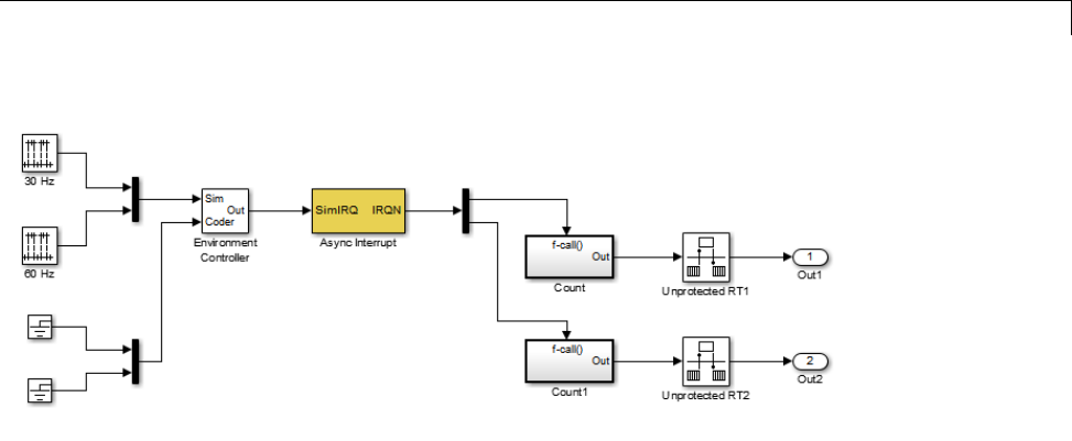
Scheduling
The simulated interrupt signals are routed through the Async Interrupt
block’s input port. Upon receiving a simulated interrupt, the block calls the
connected subsystem.
During simulation, subsystems connected to Async Interrupt block outputs
are executed in order of their VxWorks priority. In the event that two or more
interrupt signals occur simultaneously, the Async Interrupt block executes
the downstream systems in the order specified by their interrupt levels (level
7getsth
e highest priority). The first input element maps to the first output
element.
You can also use the Async Interrupt block in a simulation without enabling
the simulation input. In such a case, the Async Interrupt block inherits the
base rate of the model and calls the connected subsystems in order of their
VxWorks priorities. (In effect, in this case the Async Interrupt block behaves
as if all inputs received a 1simultaneously.)
Dual-Model Approach: Code Generation
In the generated code for the sample model,
•Ground blocks provide input signals to the Environment Controller block
•The Async Interrupt block does not use its simulation input
1-41
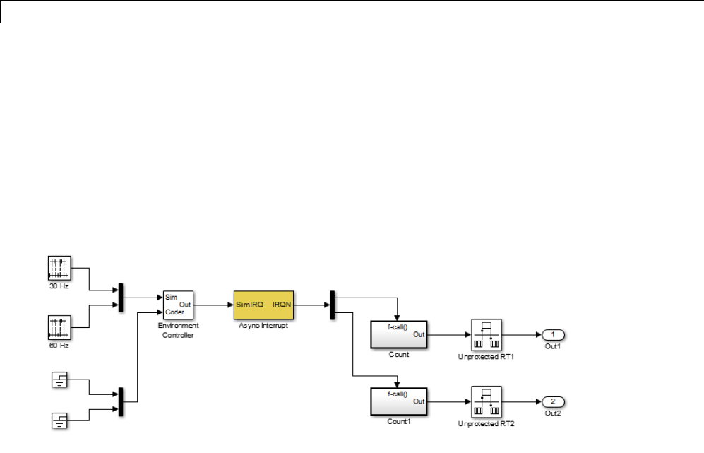
1Modeling
The Ground blocks drive control input of the Environment Controller block so
no code is generated for that signal path. The Simulink Coder code generator
does not generate code for blocks that drive the simulation control input to the
Environment Controller block because that path is not selected during code
generation. However, the sample times of driving blocks for the simulation
input to the Environment Controller block contribute to the sample times
supported in the generated code. To avoid including unnecessary sample
times in the generated code, use the sample times of the blocks driving the
simulation input in the model where generated code is intended.
Standalone functions are installed as ISRs and the interrupt vector table
is as follows:
Offset
192 &isr_num1_vec192()
193 &isr_num2_vec193()
Consider the code generated from this model, assuming that the Async
Interrupt block parameters are configuredasshowninthenextfigure.
1-42
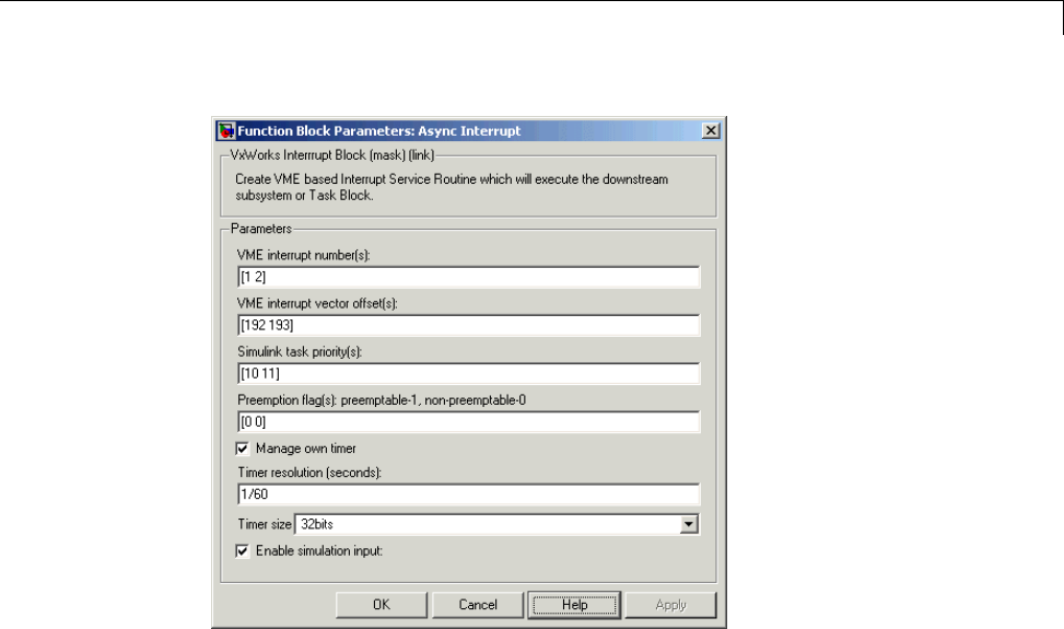
Scheduling
Initialization Code
In the generated code, the Async Interrupt block installs the code in the
Subsystem blocks as interrupt service routines. The interrupt vectors for
IRQ1 andIRQ2 are stored at locations 192 and 193 relative to the base of the
interrupt vector table, as specified by the VME interrupt vector offset(s)
parameter.
Installing an ISR requires two VxWorks calls, int_connect and
sysInt_Enable. The Async Interrupt block inserts these calls in the
model_initialize function, as shown in the following code excerpt.
/* VxWorks Interrupt Block: '<Root>/Async Interrupt' */
/* Connect and enable ISR function: isr_num1_vec192 */
if( intConnect(INUM_TO_IVEC(192), isr_num1_vec192, 0) != OK) {
printf("intConnect failed for ISR 1.\n");
}
sysIntEnable(1);
1-43

1Modeling
/* VxWorks Interrupt Block: '<Root>/Async Interrupt' */
/* Connect and enable ISR function: isr_num2_vec193 */
if( intConnect(INUM_TO_IVEC(193), isr_num2_vec193, 0) != OK)
{
printf("intConnect failed for ISR 2.\n");
}
sysIntEnable(2);
The hardware that generates the interrupt is not configured by the Async
Interrupt block. Typically, the interrupt source is a VME I/O board, which
generates interrupts for specific events (for example, end of A/D conversion).
The VME interrupt level and vector are set up in registers or by using jumpers
on the board. You can use the mdlStart routine of a user-written device
driver (S-function) to set up the registers and enable interrupt generation on
the board. You must match the interrupt level and vector specified in the
Async Interrupt block dialog to the level and vector set up on the I/O board.
Generated ISR Code
The actual ISR generated for IRQ1 is listed below.
/* VxWorks Interrupt Block: '<Root>/Async Interrupt' */
void isr_num1_vec192(void)
{
int_T lock;
FP_CONTEXT context;
/* Use tickGet() as a portable tick counter example.
A much higher resolution can be achieved with a
hardware counter */
Async_Code_M->Timing.clockTick2 = tickGet();
/* disable interrupts (system is configured as non-ive) */
lock = intLock();
/* save floating point context */
fppSave(&context);
1-44

Scheduling
/* Call the system: <Root>/Subsystem A */
Count(0, 0);
/* restore floating point context */
fppRestore(&context);
/* re-enable interrupts */
intUnlock(lock);
}
There are several features of the ISR that should be noted:
•BecauseofthesettingofthePreemption Flag(s) parameter, this ISR is
locked; that is, it cannot be preempted by a higher priority interrupt. The
ISR is locked and unlocked by the VxWorks int_lock and int_unlock
functions.
•The connected subsystem, Count, is called from within the ISR.
•The Count function executes algorithmic (model) code. Therefore, the
floating-point context is saved and restored across the call to Count.
•The ISR maintains its own absolute time counter, which is distinct from
other periodic base rate or subrate counters in the system. Timing data is
maintained for the use of any blocks executed within the ISR that require
absolute or elapsed time.
See“UseTimersinAsynchronousTasks”onpage1-58fordetails.
Model Termination Code
The model’s termination function disables the interrupts:
/* Model terminate function */
void Async_Code_terminate(void)
{
/* VxWorks Interrupt Block: '<Root>/Async Interrupt' */
/* Disable interrupt for ISR system: isr_num1_vec192 */
sysIntDisable(1);
1-45

1Modeling
/* VxWorks Interrupt Block: '<Root>/Async Interrupt' */
/* Disable interrupt for ISR system: isr_num2_vec193 */
sysIntDisable(2);
}
Spawn a Wind River Systems VxWorks Task. Tospawnanindependent
VxWorks task, use the Task Sync block. The Task Sync block is a function
call subsystem that spawns an independent VxWorks task. The task calls the
function call subsystem connected to the output of the Task Sync block.
Typically, the Task Sync block is placed between an Async Interrupt block
and a function call subsystem block or a Stateflow chart. Another example
wouldbetoplacetheTaskSyncblockattheoutputofaStateflowchartthat
has an event, Output to Simulink, configured as a function call.
The Task Sync block performs the following functions:
•An independent task is spawned, using the VxWorks system call
taskSpawn. When the task is activated, it calls the downstream function
call subsystem code. The task is deleted using taskDelete during model
termination.
•A semaphore is created to synchronize the connected subsystem to the
execution of the Task Sync block.
•The spawned task is wrapped in an infinite for loop. In the loop, the
spawned task listens for the semaphore, using semTake.WhensemTake is
first called, NO_WAIT is specified. This allows the task to determine whether
a second semGive has occurred prior to the completion of the function call
subsystem. This would indicate that the interrupt rate is too fast or the
task priority is too low.
•The Task Sync block generates synchronization code (for example,
semGive()). This code allows the spawned task to run; the task in turn
calls the connected function call subsystem code. The synchronization
code can run at interrupt level. This is accomplished by connecting the
Task Sync block to the output of an Async Interrupt block, which triggers
execution of the Task Sync block within an ISR.
•If blocks in the downstream algorithmic code require absolute time, it can
be supplied either by the timer maintained by the Async Interrupt block,
1-46
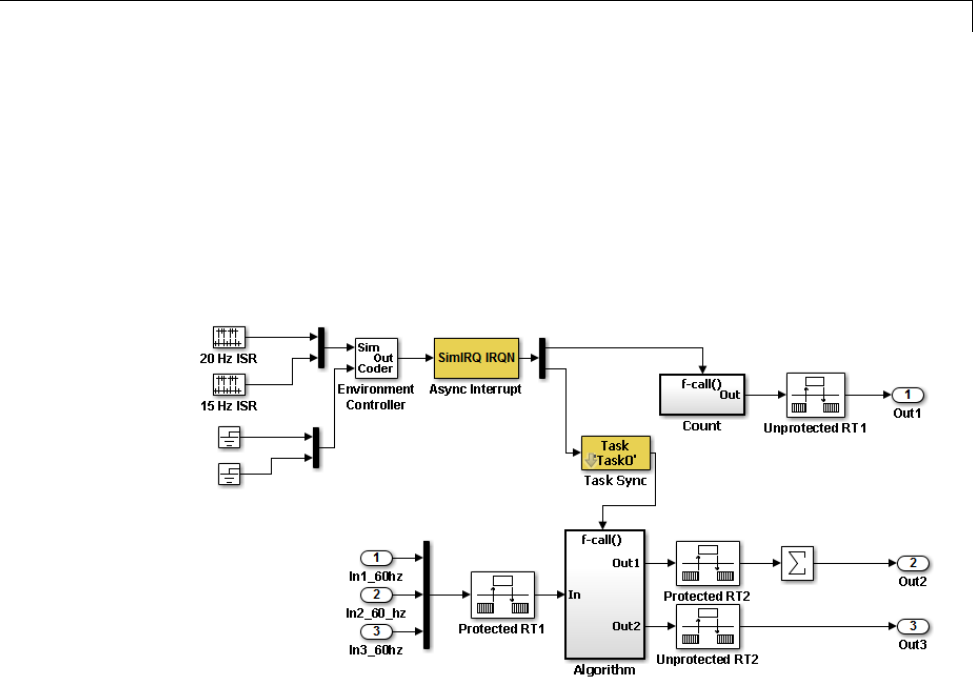
Scheduling
or by an independent timer maintained by the task associated with the
Task Sync block.
ForanexampleofhowtousetheTaskSyncblock,seethertwdemo_async
example. The block diagram for the model appears in the next figure. Before
reading the following discussion, open the example model and double-click
the Generate Code button. You can then examine the generated code in the
HTML code generation report produced by the example.
In this model, the Async Interrupt block is configured for VME interrupts 1
and 2, using interrupt vector offsets 192 and 193. Interrupt 2 is connected to
the Task Sync block, which in turn drives the Algorithm subsystem. Consider
the code generated from this model, assuming that the Task Sync block
parameters are configured as shown in the next figure.
1-47
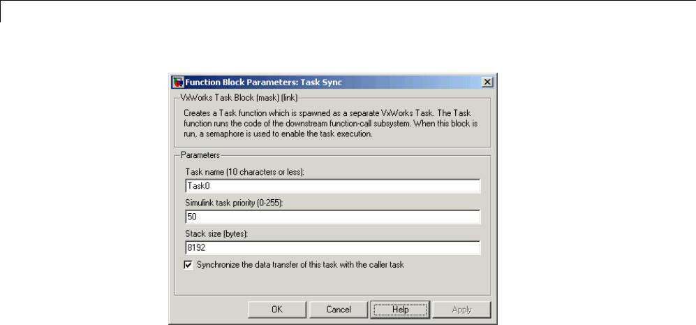
1Modeling
Initialization Code
The Task Sync block generates initialization code for initialization by
MdlStart, which itself creates and initializes the synchronization semaphore.
It also spawns an independent task (task0).
/* VxWorks Task Block: <S5>/S-Function (vxtask1) */
/* Spawn task: Task0 with priority 50 */
if ((*(SEM_ID *)rtwdemo_async_DWork.SFunction_PWORK.SemID =
semBCreate(SEM_Q_PRIORITY, SEM_EMPTY)) == NULL) {
printf("semBCreate call failed for block Task0.\n");
}
if ((rtwdemo_async_DWork.SFunction_IWORK.TaskID = taskSpawn("Task0",
50.0, VX_FP_TASK, 8192.0, (FUNCPTR)Task0, 0, 0, 0, 0, 0, 0, 0,
0, 0, 0)) == ERROR) {
printf("taskSpawn call failed for block Task0.\n");
}
After spawning Task0,MdlStart connects and enables the ISR
(isr_num2_vec193) for interrupt 2:
/* VxWorks Interrupt Block: '<Root>/Async Interrupt' */
/* Connect and enable ISR function: isr_num1_vec192 */
1-48

Scheduling
if( intConnect(INUM_TO_IVEC(192), isr_num1_vec192, 0) != OK) {
printf("intConnect failed for ISR 1.\n");
}
sysIntEnable(1);
The ordering of these operations is significant. The task must be spawned
before the interrupt that activates it can be enabled.
Task and Task Synchronization Code
The function Task0, generated by the Task Sync block, runs as a VxWorks
task. The task waits for a synchronization semaphore in an infinite for loop.
If it obtains the semaphore, it updates its task timer and calls the Algorithm
subsystem.
For this example, the Synchronize the data transfer of this task with
the caller task option of the Task Sync block is selected. Therefore, the
timer associated with the Task Sync block (rtM->Timing.clockTick2)is
updated with the value of the timer that is maintained by the Async Interrupt
block (rtM->Timing.clockTick3). Therefore, blocks within the Algorithm
subsystem use timer values based on the time of the most recent interrupt
(not the most recent activation of Task0).
/* VxWorks Task Block: <S5>/S-Function (vxtask1) */
/* Spawned with priority: 50 */
void Task0(void)
{
/* Wait for semaphore to be released by system:
rtwdemo_async/Task Sync */
for(;;) {
if (semTake(*(SEM_ID
*)rtwdemo_async_DWork.SFunction_PWORK.SemID,NO_WAIT) !=
ERROR) {
logMsg("Rate for Task Task0() too fast.\n",0,0,0,0,0,0);
#if STOPONOVERRUN
logMsg("Aborting real-time simulation.\n",0,0,0,0,0,0);
semGive(stopSem);
return(ERROR);
#endif
1-49

1Modeling
} else {
semTake(*(SEM_ID
*)rtwdemo_async_DWork.SFunction_PWORK.SemID,
WAIT_FOREVER);
}
/* Use the upstream clock tick counter for this Task. */
rtwdemo_async_M->Timing.clockTick2 =
rtwdemo_async_M->Timing.clockTick3;
/* Call the system: <Root>/Algorithm */
{
/* Output and update for function-call system: '<Root>/Algorithm' */
{
uint32_T rt_currentTime = ((uint32_T)rtwdemo_async_M->Timing.clockTick2);
uint32_T rt_elapseTime = rt_currentTime -
rtwdemo_async_DWork.Algorithm_PREV_T;
rtwdemo_async_DWork.Algorithm_PREV_T = rt_currentTime;
{
int32_T i;
/* DiscreteIntegrator: '<S1>/Integrator' */
rtwdemo_async_B.Integrator = rtwdemo_async_DWork.Integrator_DSTATE;
for(i = 0; i < 60; i++) {
/* Sum: '<S1>/Sum' */
rtwdemo_async_B.Sum[i] = rtwdemo_async_B.ProtectedRT1[i] + 1.25;
}
}
/* Sum: '<S1>/Sum1' */
rtwdemo_async_B.Sum1 = rtwdemo_async_B.Sum[0];
{
int_T i1;
const real_T *u0 = &rtwdemo_async_B.Sum[1];
1-50

Scheduling
for (i1=0; i1 < 59; i1++) {
rtwdemo_async_B.Sum1 += u0[i1];
}
}
{
int32_T i;
if(rtwdemo_async_DWork.ProtectedRT2_ActiveBufIdx) {
for(i = 0; i < 60; i++) {
rtwdemo_async_DWork.ProtectedRT2_Buffer0[i] =
rtwdemo_async_B.Sum[i];
}
rtwdemo_async_DWork.ProtectedRT2_ActiveBufIdx = (boolean_T)0U;
} else {
for(i = 0; i < 60; i++) {
rtwdemo_async_DWork.ProtectedRT2_Buffer1[i] =
rtwdemo_async_B.Sum[i];
}
rtwdemo_async_DWork.ProtectedRT2_ActiveBufIdx = (boolean_T)1U;
}
}
/* Update for DiscreteIntegrator: '<S1>/Integrator' */
rtwdemo_async_DWork.Integrator_DSTATE = (real_T)rt_elapseTime *
1.6666666666666666E-002 * rtwdemo_async_B.Sum1 +
rtwdemo_async_DWork.Integrator_DSTATE;
}
The semaphore is granted by the function isr_num2_vec193, which is called
from interrupt level:
/* VxWorks Interrupt Block: '<Root>/Async Interrupt' */
void isr_num2_vec193(void)
{
/* Use tickGet() as a portable tick counter example. A much
higher resolution can be achieved with a hardware counter */
rtwdemo_async_M->Timing.clockTick3 = tickGet();
/* Call the system: <S4>/Subsystem */
1-51

1Modeling
/* Output and update for function-call system:
'<S4>/Subsystem' */
{
{
int32_T i;
for(i = 0; i < 60; i++) {
if(rtwdemo_async_DWork.ProtectedRT1_ActiveBufIdx) {
rtwdemo_async_B.ProtectedRT1[i] =
rtwdemo_async_DWork.ProtectedRT1_Buffer1[i];
} else {
rtwdemo_async_B.ProtectedRT1[i] =
rtwdemo_async_DWork.ProtectedRT1_Buffer0[i];
}
}
}
/* VxWorks Task Block: <S5>/S-Function (vxtask1) */
/* Release semaphore for system task: Task0 */
semGive(*(SEM_ID *)rtwdemo_async_DWork.SFunction_PWORK.SemID);
}
}
The ISR maintains a timer that stores the tick count at the time of interrupt.
This timer is updated before releasing the semaphore that activates Task0.
As this example shows, the Task Sync block generates only a small amount of
interrupt-level code.
Task Termination Code
The Task Sync block also generates the following termination code.
/* Model terminate function */
void rtwdemo_async_terminate(void)
{
1-52

Scheduling
/* VxWorks Interrupt Block: '<Root>/Async Interrupt' */
/* Disable interrupt for ISR system: isr_num1_vec192 */
sysIntDisable(1);
/* VxWorks Interrupt Block: '<Root>/Async Interrupt' */
/* Disable interrupt for ISR system: isr_num2_vec193 */
sysIntDisable(2);
/* Terminate for function-call system: '<S4>/Subsystem' */
/* VxWorks Task Block: <S5>/S-Function (vxtask1) */
/* Destroy task: Task0 */
taskDelete(rtwdemo_async_DWork.SFunction_IWORK.TaskID);
}
Rate Transitions and Asynchronous Blocks
•“About Rate Transitions and Asynchronous Blocks” on page 1-53
•“Handle Rate Transitions for Asynchronous Tasks” on page 1-55
•“Handle Multiple Asynchronous Interrupts” on page 1-56
About Rate Transitions and Asynchronous Blocks. Because an
asynchronous function call subsystem can preempt or be preempted by other
model code, an inconsistency arises when more than one signal element is
connected to an asynchronous block. The issue is that signals passed to and
from the function call subsystem can be in the process of being written to or
read from when the preemption occurs. Thus, some old and some new data
is used. This situation can also occur with scalar signals in some cases. For
example, if a signal is a double (8 bytes), the read or write operation might
require two machine instructions.
The Simulink Rate Transition block is designed to deal with preemption
problems that occur in data transfer between blocks running at different
rates. These issues are discussed in “Scheduling” on page 1-4.
You can handle rate transition issues automatically by selecting the
Automatically handle data transfers between tasks option on the Solver
pane of the Configuration Parameters dialog box. This saves you from having
to manually insert Rate Transition blocks to avoid invalid rate transitions,
1-53

1Modeling
including invalid asynchronous-to-periodic and asynchronous-to-asynchronous
rate transitions, in multirate models. For asynchronous tasks, the Simulink
engine configures inserted blocks for data integrity but not determinism
during data transfers.
For asynchronous rate transitions, the Rate Transition block provides data
integrity, but cannot provide determinism. Therefore, when you insert Rate
Transition blocks explicitly, you must clear the Ensure data determinism
check box in the Block Parameters dialog box.
When you insert a Rate Transition block between two blocks to maintain
data integrity and priorities are assigned to the tasks associated with the
blocks, the Simulink Coder software assumes that the higher priority task can
preempt the lower priority task and the lower priority task cannot preempt
the higher priority task. If the priority associated with task for either block is
not assigned or the priorities of the tasks for both blocks are the same, the
Simulink Coder software assumes that either task can preempt the other task.
Priorities of periodic tasks are assigned by the Simulink engine, in accordance
with the options specified in the Solver options section of the Solver pane
of the Configuration Parameters dialog box. When the Periodic sample
time constraint option field of Solver options is set to Unconstrained,the
model base rate priority is set to 40. Priorities for subrates then increment or
decrement by 1from the base rate priority, depending on the setting of the
Higher priority value indicates higher task priority option.
You can assign priorities manually by using the Periodic sample time
properties field. The Simulink engine does not assign a priority to
asynchronous blocks. For example, the priority of a function call subsystem
that connects back to an Async Interrupt block is assigned by the Async
Interrupt block.
The Simulink task priority field of the Async Interrupt block specifies
a priority level (required) for every interrupt number entered in the VME
interrupt number(s) field. The priority array sets the priorities of the
subsystems connected to each interrupt.
For the Task Sync block, if the Wind River Systems VxWorks RTOS is the
target, the Higher priority value indicates higher task priority option
should be deselected. The Simulink task priority field specifies the block
1-54
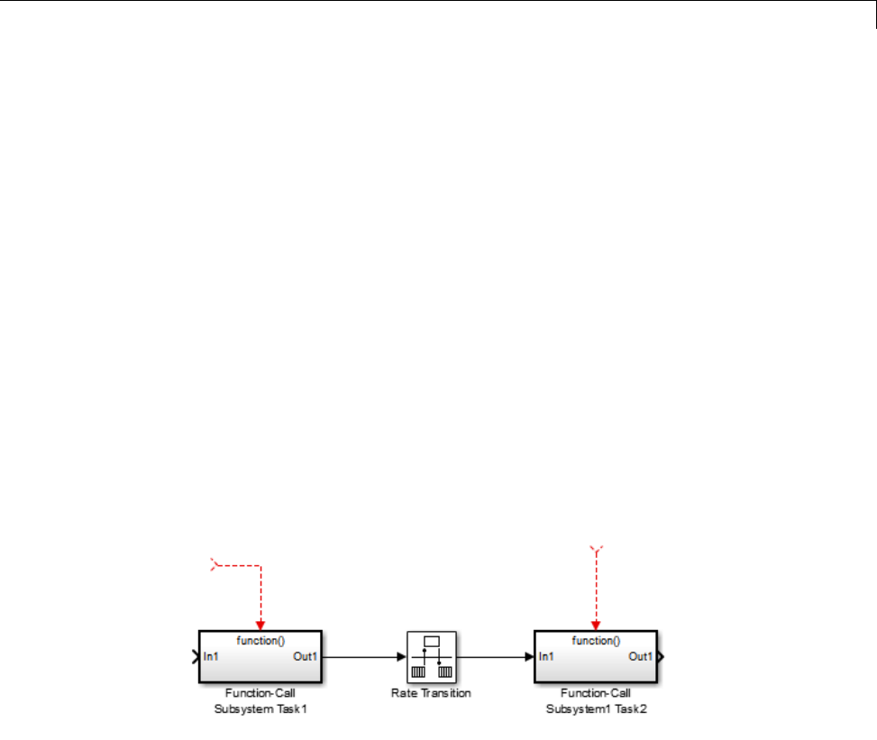
Scheduling
priority relative to connected blocks (in addition to assigning a VxWorks
priority to the generated task code).
The VxWorks library provides two types of rate transition blocks as a
convenience. These are simply preconfigured instances of the built-in
Simulink Rate Transition block:
•Protected Rate Transition block: Rate Transition block that is configured
with the Ensure data integrity during data transfers on and Ensure
deterministic data transfer off.
•Unprotected Rate Transition block: Rate Transition block that is configured
with the Ensure data integrity during data transfers option off.
Handle Rate Transitions for Asynchronous Tasks. For rate transitions
that involve asynchronous tasks, you can maintain data integrity. However,
you cannot achieve determinism. You have the option of using the Rate
Transition block or target-specific rate transition blocks.
Consider the following model, which includes a Rate Transition block.
You can use the Rate Transition block in either of the following modes:
•Maintain data integrity, no determinism
•Unprotected
Alternatively, you can use target-specific rate transition blocks. The following
blocks are available for the VxWorks RTOS:
1-55
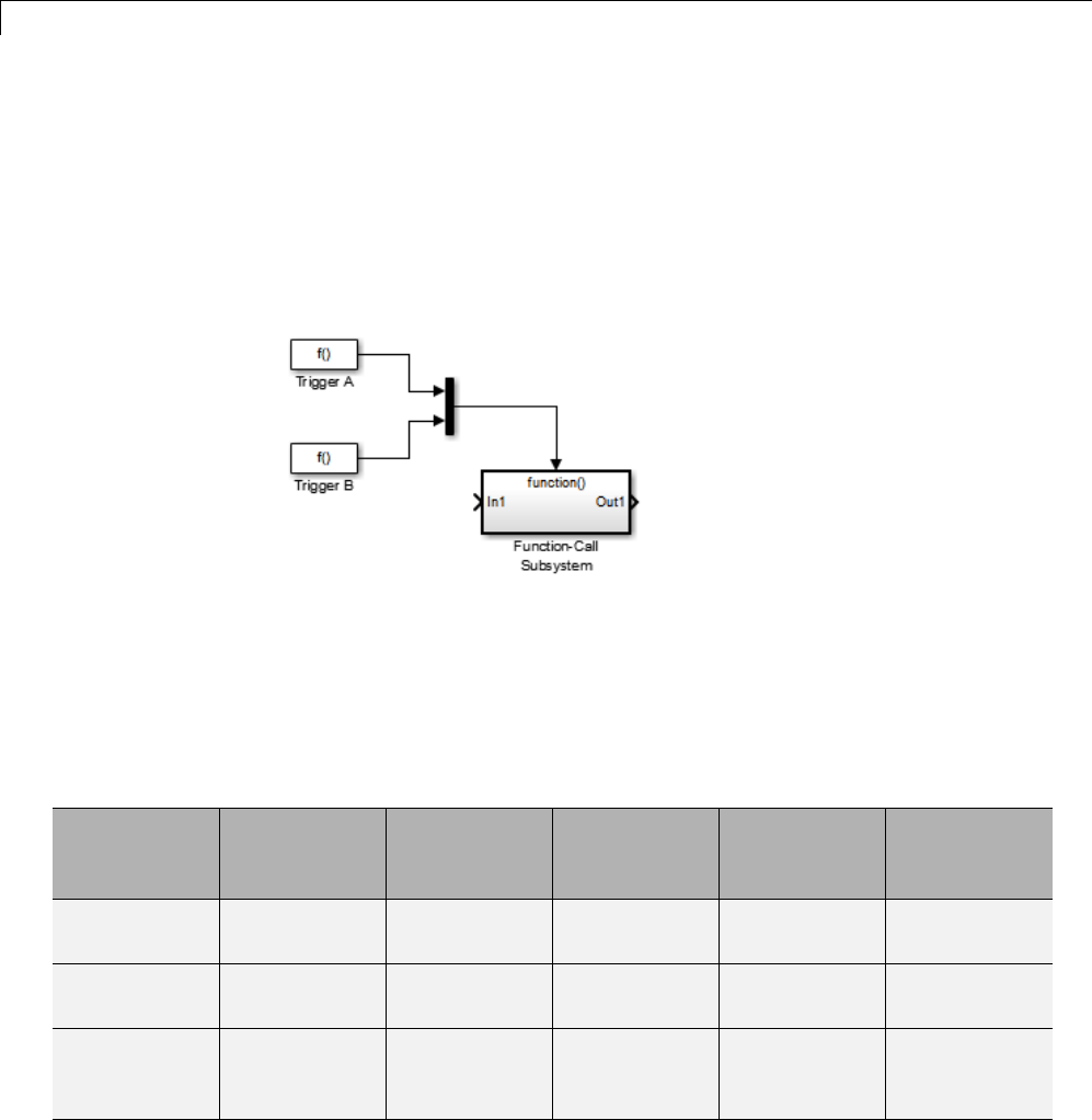
1Modeling
•Protected Rate Transition block (reader)
•Protected Rate Transition block (writer)
•Unprotected Rate Transition block
Handle Multiple Asynchronous Interrupts. Consider the following model,
in which two functions trigger the same subsystem.
The two tasks must have equal priorities. When priorities are the same, the
outcome depends on whether they are firing periodically or asynchronously,
and also on a diagnostic setting. The following table and notes describe
these outcomes:
Supported Sample Time and Priority for Function Call Subsystem with Multiple Triggers
Async
Priority = 1
Async
Priority = 2
Async
Priority
Unspecified
Periodic
Priority = 1
Periodic
Priority = 2
Async
Priority = 1
Supported (1)
Async
Priority = 2
Supported (1)
Async
Priority
Unspecified
Supported (2)
1-56

Scheduling
Supported Sample Time and Priority for Function Call Subsystem with Multiple Triggers
(Continued)
Async
Priority = 1
Async
Priority = 2
Async
Priority
Unspecified
Periodic
Priority = 1
Periodic
Priority = 2
Periodic
Priority = 1
Supported
Periodic
Priority = 2
Supported
1Control these outcomes using the Tasks with equal priority option in
the Diagnostics pane of the Configuration Parameters dialog box; set this
diagnostic to none if tasks of equal priority cannot preempt each other
in the target system.
2For this case, the following warning message is issued unconditionally:
The function call subsystem <name> has multiple asynchronous
triggers that do not specify priority. Data integrity will
not be maintained if these triggers can preempt one another.
Empty cells in the above table represent multiple triggers with differing
priorities, which are unsupported.
The Simulink Coder product provides absolute time management for a
function call subsystem connected to multiple interrupts in the case where
timer settings for TriggerA and TriggerB (time source, resolution) are the
same.
Assume that all of the following conditions are true for the model shown above:
•A function call subsystem is triggered by two asynchronous triggers
(TriggerA and TriggerB) having identical priority settings.
•Each trigger sets the source of time and timer attributes by calling the
functions ssSetTimeSource and ssSetAsyncTimerAttributes.
1-57

1Modeling
•The triggered subsystem contains a block that needs elapsed or absolute
time (for example, a Discrete Time Integrator).
The asynchronous function call subsystem has one global variable,
clockTick# (where #is the task ID associated with the subsystem). This
variable stores absolute time for the asynchronous task. There are two ways
timing can be handled:
•IfthetimesourceissettoSS_TIMESOURCE_BASERATE, the Simulink Coder
code generator generates timer code in the function call subsystem,
updating the clock tick variable from the base rate clock tick. Data integrity
is maintained if the same priority is assigned to TriggerA and TriggerB.
•IfthetimesourceisSS_TIMESOURCE_SELF, generated code for both TriggerA
and TriggerB updates the same clock tick variable from the hardware clock.
The word size of the clock tick variable can be set directly or be established
according to the Application lifespan (days) setting and the timer
resolution set by the TriggerA and TriggerB S-functions (which must be the
same). See “Use Timers in Asynchronous Tasks” on page 1-58 and “Control
Memory Allocation for Time Counters” on page 16-9 for more information.
Use Timers in Asynchronous Tasks
An ISR can set a source for absolute time. This is done with the function
ssSetTimeSource, which has the following three options:
•SS_TIMESOURCE_SELF: Each generated ISR maintains its own absolute time
counter, which is distinct from any periodic base rate or subrate counters
inthesystem. Thecountervalueandthetimerresolutionvalue(specified
in the Timer resolution (seconds) parameter of the Async Interrupt
block) are used by downstream blocks to determine absolute time values
required by block computations.
•SS_TIMESOURCE_CALLER: The ISR reads time from a counter maintained by
its caller. Time resolution is thus the same as its caller’s resolution.
•SS_TIMESOURCE_BASERATE: The ISR can read absolute time from the
model’s periodic base rate. Time resolution is thus the same as its base
rate resolution.
1-58

Scheduling
Note The function ssSetTimeSource cannot be called before
ssSetOutputPortWidth is called. If this occurs, the program will come to a
halt and generate an error message.
By default, the counter is implemented as a 32-bit unsigned integer member
of the Timing substructure of the real-time model structure. For any target
that supports the rtModel data structure, when the time data type is not set
by using ssSetAsyncTimeDataType, the counter word size is determined by
the Application lifespan (days) model parameter. As an example (from
ERT target code),
/* Real-time Model Data Structure */
struct _RT_MODEL_elapseTime_exp_Tag {
const char *errorStatus;
/*
* Timing:
* The following substructure contains information regarding
* the timing information for the model.
*/
struct {
uint32_T clockTick1;
uint32_T clockTick2;
} Timing;
};
The example omits unused fields in the Timing data structure (a feature of
ERT target code not found in GRT). For any target that supports the rtModel
data structure, the counter word size is determined by the Application
lifespan (days) model parameter.
By default, the library blocks for the Wind River Systems VxWorks RTOS
set the timer source to SS_TIMESOURCE_SELF and update their counters by
using the system call tickGet.tickGet returns a timer value maintained by
theVxWorkskernel. ThemaximumwordsizeforthetimerisUINT32.The
following VxWorks example for the shows a generated call to tickGet.
/* VxWorks Interrupt Block: '<Root>/Async Interrupt' */
void isr_num2_vec193(void)
1-59

1Modeling
{
/* Use tickGet() as a portable tick counter example. A much
higher resolution can be achieved with a hardware counter */
rtM->Timing.clockTick2 = tickGet();
...
The tickGet call is supplied only as an example. It can (and in many
instances should) be replaced by a timing source that has better resolution. If
you are targeting the VxWorks RTOS, you can obtain better timer resolution
by replacing the tickGet call and accessing a hardware timer by using your
BSP instead.
If you are implementing a custom asynchronous block for an RTOS other than
the VxWorks RTOS, you should either generate an equivalent call to the
target RTOS, or generate code to read a timer register on the target hardware.
The default Timer resolution (seconds) parameter of your Async Interrupt
block implementation should be changed to match the resolution of your
target’s timing source.
The counter is updated at interrupt level. Its value represents the tick value
of the timing source at the most recent execution of the ISR. The rate of this
timing source is unrelated to sample rates in the model. In fact, typically it
is faster than the model’s base rate. Select the timer source and set its rate
and resolution based on the expected rate of interrupts to be serviced by the
Async Interrupt block.
For an example of timer code generation, see “Async Interrupt Block
Implementation” on page 1-61.
Create a Customized Asynchronous Library
•“About Implementing Asynchronous Blocks” on page 1-61
•“Async Interrupt Block Implementation” on page 1-61
•“Task Sync Block Implementation” on page 1-66
•“asynclib.tlc Support Library” on page 1-68
1-60

Scheduling
About Implementing Asynchronous Blocks. This section describes how
to implement asynchronous blocks for use with your target RTOS, using the
Async Interrupt and Task Sync blocks as a starting point. (Rate Transition
blocks are target-independent, so you do not need to develop customized rate
transition blocks.)
You can customize the asynchronous libraryblocksbymodifyingtheblock
implementation. These files are
•The block’s underlying S-function MEX-file
•The TLC files that control code generation of the block
In addition, you need to modify the block masks to remove references specific
to the Wind River Systems VxWorks RTOS and to incorporate parameters
required by your target RTOS.
Custom block implementation is an advanced topic, requiring familiarity with
the Simulink MEX S-function format and API, and with the Target Language
Compiler (TLC). These topics are covered in the following documents:
•Simulink topics “What Is an S-Function?”, “Use S-Functions in Models”,
“How S-Functions Work”, and “Implementing S-Functions” describe MEX
S-functions and the S-function API in general.
•The “Inlining S-Functions”, “Inlining C MEX S-Functions”, and “Insert
S-Function Code” on page 14-46 describe how to create a TLC block
implementation for use in code generation.
The following sections discuss the C/C++ and TLC implementations of the
asynchronous library blocks, including required SimStruct macros and
functions in the TLC asynchronous support library (asynclib.tlc).
Async Interrupt Block Implementation. The source files for the Async
Interrupt block are located in matlabroot/rtw/c/tornado/devices:
•vxinterrupt1.c: C MEX-file source code, for use in configuration and
simulation
•vxinterrupt1.tlc: TLC implementation, for use in code generation
1-61

1Modeling
•asynclib.tlc: library of TLC support functions, called by the TLC
implementation of the block. The library calls are summarized in
“asynclib.tlc Support Library” on page 1-68.
C MEX Block Implementation
Most of the code in vxinterrupt1.c performs ordinary functions that are
not related to asynchronous support (for example, obtaining and validating
parameters from the block mask, marking parameters nontunable, and
passing parameter data to the model.rtw file).
The mdlInitializeSizes function uses special SimStruct macros and
SS_OPTIONS settings that are required for asynchronous blocks, as described
below.
Note that the following macros cannot be called before ssSetOutputPortWidth
is called:
•ssSetTimeSource
•ssSetAsyncTimerAttributes
•ssSetAsyncTimerResolutionEl
•ssSetAsyncTimerDataType
•ssSetAsyncTimerDataTypeEl
•ssSetAsyncTaskPriorities
•ssSetAsyncTaskPrioritiesEl
If any one of the above macros is called before ssSetOutputPortWidth,the
following error message will appear:
SL_SfcnMustSpecifyPortWidthBfCallSomeMacro {
S-function '%s' in '%<BLOCKFULLPATH>'
must set output port %d width using
ssSetOutputPortWidth before calling macro %s
}
1-62

Scheduling
ssSetAsyncTimerAttributes
ssSetAsyncTimerAttributes declares that the block requires a timer,
and sets the resolution of the timer as specified in the Timer resolution
(seconds) parameter.
The function prototype is
ssSetAsyncTimerAttributes(SimStruct *S, double res)
where
•SisaSimstructpointer.
•res is the Timer resolution (seconds) parameter value.
The following code excerpt shows the call to ssSetAsyncTimerAttributes.
/* Setup Async Timer attributes */
ssSetAsyncTimerAttributes(S,mxGetPr(TICK_RES)[0]);
ssSetAsyncTaskPriorities
ssSetAsyncTaskPriorities sets the Simulink task priority for blocks
executing at each interrupt level, as specified in the block’s Simulink task
priority field.
The function prototype is
ssSetAsyncTaskPriorities(SimStruct *S, int numISRs,
int *priorityArray)
where
•Sis a SimStruct pointer.
•numISRs is the number of interrupts specified in the VME interrupt
number(s) parameter.
•priorityarray is an integer array containing the interrupt numbers
specified in the VME interrupt number(s) parameter.
The following code excerpt shows the call to ssSetAsyncTaskPriorities:
1-63

1Modeling
/* Setup Async Task Priorities */
priorityArray = malloc(numISRs*sizeof(int_T));
for (i=0; i<numISRs; i++) {
priorityArray[i] = (int_T)(mxGetPr(ISR_PRIORITIES)[i]);
}
ssSetAsyncTaskPriorities(S, numISRs, priorityArray);
free(priorityArray);
priorityArray = NULL;
}
SS_OPTION Settings
ThecodeexcerptbelowshowstheSS_OPTION settings for vxinterrupt1.c.
SS_OPTION_ASYNCHRONOUS_INTERRUPT should be used when a function
call subsystem is attached to an interrupt. For more information, see
the documentation for SS_OPTION and SS_OPTION_ASYNCHRONOUS in
matlabroot/simulink/include/simstruc.h.
ssSetOptions( S, (SS_OPTION_EXCEPTION_FREE_CODE |
SS_OPTION_DISALLOW_CONSTANT_SAMPLE_TIME |
SS_OPTION_ASYNCHRONOUS_INTERRUPT |
TLC Implementation
This section discusses each function of vxinterrupt1.tlc,withanemphasis
on target-specific features that you will need to change to generate code for
your target RTOS.
Generate #include Directives
vxinterrupt1.tlc begins with the statement
%include "vxlib.tlc"
vxlib.tlc is a target-specific file that generates directives to include
VxWorks header files. You should replace this with a file that generates
includes for your target RTOS.
1-64

Scheduling
BlockInstanceSetup Function
For each connected output of the Async Interrupt block, BlockInstanceSetup
defines a function name for the corresponding ISR in the generated code.
The functions names are of the form
isr_num_vec_offset
where num is the ISR number defined in the VME interrupt number(s)
block parameter, and offset is an interrupt table offset defined in the VME
interrupt vector offset(s) block parameter.
In a custom implementation, there is no requirement to use this naming
convention.
The function names are cached for use by the Outputs function, which
generates the actual ISR code.
Outputs Function
Outputs iterates over the connected outputs of the Async Interrupt block. An
ISR is generated for each such output.
The ISR code is cached in the "Functions" section of the generated code.
Before generating the ISR, Outputs does the following:
•Generates a call to the downstream block (cached in a temporary buffer).
•Determines whether the ISR should be locked or not (as specified in the
Preemption Flag(s) block parameter).
•Determines whether the block connected to the Async Interrupt block is a
Task Sync block. (This information is obtained by using the asynclib calls
LibGetFcnCallBlock and LibGetBlockAttribute.) If so,
-The preemption flag for the ISR must be set to 1. An error results
otherwise.
-VxWorks calls to save and restore floating-point context are generated,
unless the user has configured the model for integer-only code
generation.
1-65

1Modeling
When generating the ISR code, Outputs calls the asynclib function
LibNeedAsyncCounter to determine whether a timer is required by
the connected subsystem. If so, and if the time source is set to be
SS_TIMESOURCE_SELF by ssSetTimeSource,LibSetAsyncCounter is called to
generate a VxWorks tickGet function call and update the counter. In your
implementation, you should generate either an equivalent call to the target
RTOS, or generate code to read the a timer register on the target hardware.
If you are targeting the VxWorks RTOS, you can obtain better timer resolution
by replacing the tickGet call and accessing a hardware timer by using your
BSP instead. tickGet supports only a 1/60 second resolution.
Start Function
The Start function generates the required VxWorks calls (int_connect and
sysInt_Enable)toconnectandenableeachISR.Youshouldreplacethis
with calls to your target RTOS.
Terminate Function
The Terminate function generates the call sysIntDisable to disable each
ISR. You should replace this with calls to your target RTOS.
Task Sync Block Implementation. The source files for the Task Sync block
are located in matlabroot/rtw/c/tornado/devices.Theyare
•vxtask1.c: MEX-file source code, for use in configuration and simulation.
•vxtask1.tlc: TLC implementation, for use in code generation.
•asynclib.tlc: library of TLC support functions, called by the TLC
implementation of the block. The library calls are summarized in
“asynclib.tlc Support Library” on page 1-68.
C MEX Block Implementation
Like the Async Interrupt block, the TaskSyncblocksetsupatimer,inthis
case with a fixed resolution. The priority of the task associated with the block
1-66

Scheduling
is obtained from the Simulink task priority parameter. The SS_OPTION
settings are the same as those used for the Async Interrupt block.
ssSetAsyncTimerAttributes(S, 0.01);
priority = (int_T) (*(mxGetPr(PRIORITY)));
ssSetAsyncTaskPriorities(S,1,&priority);
ssSetOptions(S, (SS_OPTION_EXCEPTION_FREE_CODE |
SS_OPTION_ASYNCHRONOUS |
SS_OPTION_DISALLOW_CONSTANT_SAMPLE_TIME |
}
TLC Implementation
Generate #include Directives
vxtask1.tlc begins with the statement
%include "vxlib.tlc"
vxlib.tlc is a target-specific file that generates directives to include
VxWorks header files. You should replace this with a file that generates
includes for your target RTOS.
BlockInstanceSetup Function
The BlockInstanceSetup function derives the task name, block name, and
other identifier strings used later in code generation. It also checks for
and warns about unconnected block conditions, and generates a storage
declaration for a semaphore (stopSem)thatisusedincaseofinterrupt
overflow conditions.
Start Function
The Start function generates the required VxWorks calls to define storage
for the semaphore that is used in management of the task spawned by the
1-67

1Modeling
Task Sync block. Depending on the code format of the target, either a static
storage declaration or a dynamic memory allocation call is generated. This
function also creates a semaphore (semBCreate) and spawns a VxWorks task
(taskSpawn). You should replace these with calls to your target RTOS.
Outputs Function
The Outputs function generates a VxWorks task that waits for a semaphore.
When it obtains the semaphore, it updates the block’s tick timer and calls the
downstream subsystem code, as described in “Spawn a Wind River Systems
VxWorks Task” on page 1-46. Outputs also generates code (called from
interrupt level) that grants the semaphore.
Terminate Function
The Terminate function generatestheVxWorkscalltaskDelete to end
execution of the task spawned by the block. You should replace this with calls
to your target RTOS.
Note also that if the target RTOS has dynamically allocated any memory
associated with the task , the Terminate function should deallocate the
memory.
asynclib.tlc Support Library. asynclib.tlc is a library of TLC functions
that support the implementation of asynchronous blocks. Some functions
are specifically designed for use in asynchronous blocks. For example,
LibSetAsyncCounter generates a call to update a timer for an asynchronous
block. Other functions are utilities that return information required by
asynchronous blocks (for example, information about connected function call
subsystems).
The following table summarizes the public calls in the library. For details,
see the library source code and the vxinterrupt1.tlc and vxtask1.tlc
files, which call the library functions.
1-68

Scheduling
Summary of asynclib.tlc Library Functions
Function Description
LibBlockExecuteFcnCall For use by inlined S-functions with function call outputs.
Generatescodetoexecutea function call subsystem.
LibGetBlockAttribute Returns a field value from a block record.
LibGetFcnCallBlock Given an S-Function block and call index, returns the block
record for the downstream function call subsystem block.
LibGetCallerClockTickCounter Provides access to the time counter of an upstream
asynchronous task.
LibGetCallerClockTickCounterHighWord
Provides access to the high word of the time counter of an
upstream asynchronous task.
LibManageAsyncCounter Determines whether an asynchronous task needs a counter
and manages its own timer.
LibNeedAsyncCounter If the calling block requires an asynchronous counter,
returns TLC_TRUE, otherwise returns TLC_FALSE.
LibSetAsyncClockTicks Returns code that sets clockTick counters that are to be
maintained by the asynchronous task.
LibSetAsyncCounter Generatescodetosetthetickvalueoftheblock’s
asynchronous counter.
LibSetAsyncCounterHighWord Generatescodetosetthetickvalueofthehighwordofthe
block’s asynchronous counter
Import Asynchronous Event Data for Simulation
Capabilities. You can inport asynchronous event data into a function-call
subsystem via an Inport block. For standalone fixed-step simulations, you
can specify:
•The time points at which each asynchronous event occurs
•The number of asynchronous events at each time point
1-69

1Modeling
Input Data Format. You can enter your asynchronous data at the MATLAB
command line or on the Data Import/Export pane of the Configuration
Parameters dialog box. In either case, a number of restrictions apply to the
data format.
•The expression for the parameter Data Import/Export > Input must be a
comma-separated list of tables, as described in “Enable Data Import”.
•The table corresponding to the input port outputting asynchronous events
must be a column vector containing time values for the asynchronous
events.
-The time vector of the asynchronous events must be of double data type
and monotonically increasing.
-All time data must be integer multiples of the model step size.
-To specify multiple function calls at a given time step, you must repeat
the time value accordingly. In other words, if you wish to specify three
asynchronous events at t= 1 and two events at t= 9, then you must list 1
three times and 9 twice in your time vector. ( t=[11199])
•The table corresponding to normal data input port can be of any other
supported format as described in “Enable Data Import”.
Example. In this model, a function-call subsystem is used to track the total
number of asynchronous events and to multiply a set of inputs by 2.
1-70
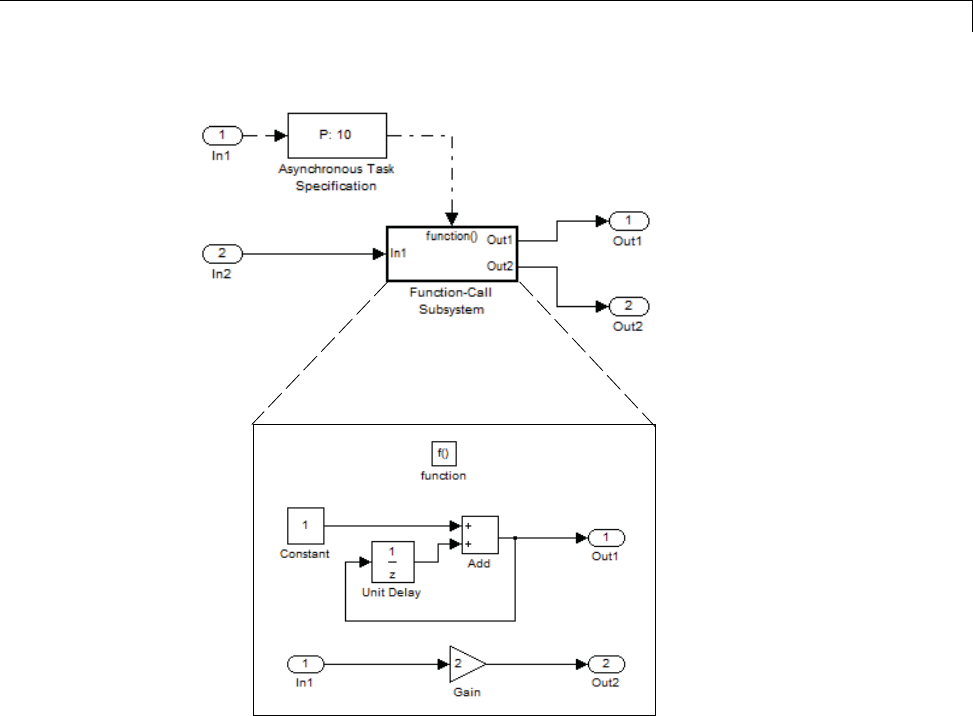
Scheduling
1-71

1Modeling
1To input data via the Configuration Parameters dialog box,
aSelect Simulation > Configuration Parameters > Data
Import/Export.
bSelect the Input parameter.
cFor this example, enter the following command in the MATLAB window:
>> t = [1 1 5 9 9 9]', u = [[0:10]' [0:10]']
Alternatively, you can enter the data as t, tu in the Data Import/Export
pane:
1-72
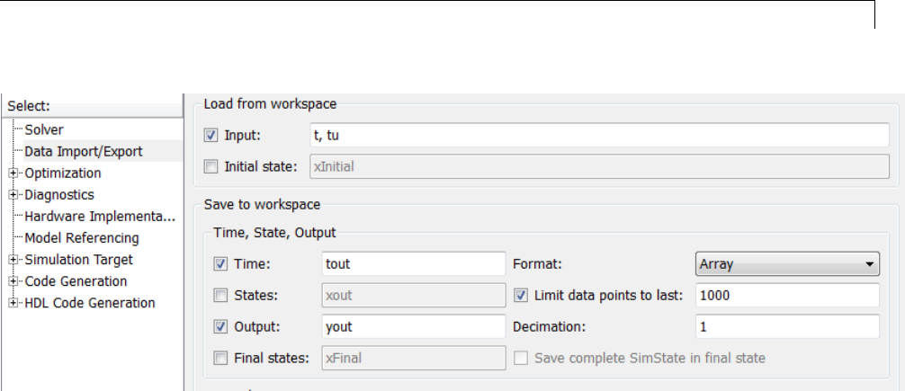
Scheduling
Here, tis a column vector containing the times of asynchronous events
for Inport block In1 while tu is a table of input values versus time for
Inport block In2.
2By default, the Time and Output options are selected and the output
variables are named tout and yout.
3Simulate the model.
4Display the output by entering [tout yout] at the MATLAB command
line and obtain:
ans =
00-1
122
222
322
422
5310
6310
7310
8310
9618
10 6 18
Here the first column contains the simulation times.
1-73
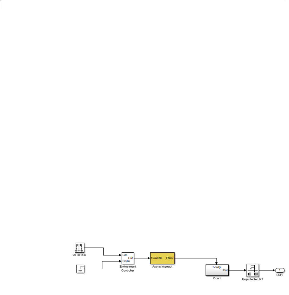
1Modeling
The second column represents the output of Out1 — the total number of
asynchronous events. Since the function-call subsystem is triggered twice
at t= 1, the output is 2. It is not called again until t=5,andsodoesnot
increase to 3 until then. Finally, it is called three times at 9, so it increases
to 6.
The third column contains the output of Out2 obtained by multiplying the
input value at each asynchronous event time by 2. At any other time, the
output is held at its previous value
Asynchronous Support Limitations
•“Asynchronous Task Priority” on page 1-74
•“Convert an Asynchronous Subsystem into a Model Reference” on page 1-74
Asynchronous Task Priority. The Simulink product does not simulate
asynchronous task behavior. Although you can specify a task priority for an
asynchronous task represented in a model with the Task Sync block, the
priority setting is for code generation purposes only and is not honored during
simulation.
Convert an Asynchronous Subsystem into a Model Reference. You
can use the Asynchronous Task Specification block to specify an asynchronous
function-call input to a model reference. However, you must convert the
Async Interrupt and Function-Call blocks into a subsystem and then convert
the subsystem into a model reference.
Following is an example with step-by-step instructions for conversion.
1-74
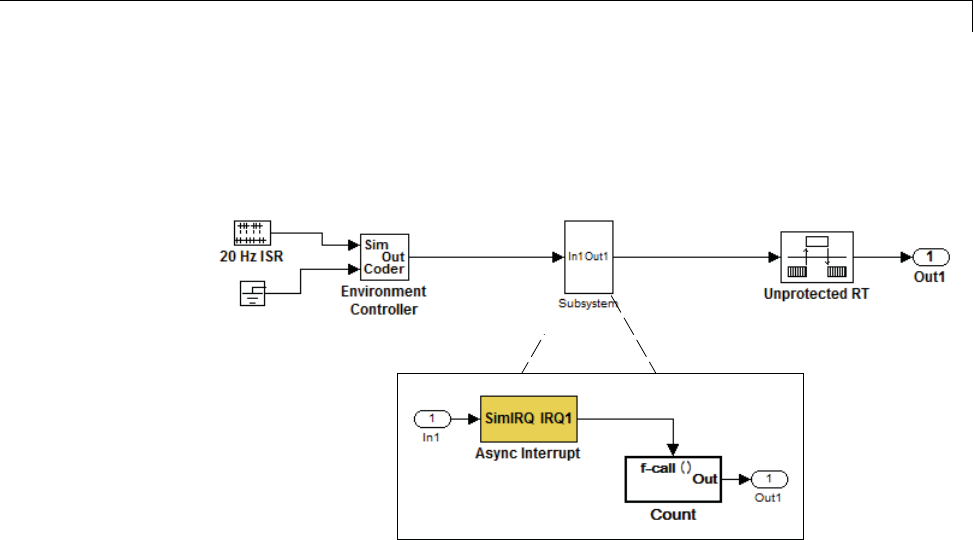
Scheduling
1Convert the Async Interrupt and Count blocks into a subsystem. Select
both blocks and right-click Count. From the menu, select Subsystem &
Model Reference > Create Subsystem from Selection.
2To prepare for converting the new subsystem to a Model block, set
the following configuration parameters in the top model. Open the
Configuration Parameters dialog box.
•If you are simulating in Normal mode, then you must make the following
change. From the Optimization node, navigate to the Signals and
Parameters pane. Under Simulation and code generation, select the
Inline parameters option.
•From the Diagnostics node, navigate to the Sample Time pane. Then set
Multitask rate transition to error and Multitask conditionally
executed subsystem to error.
•Under Diagnostics, navigate to the Data Validity pane and set the
Multitask data store option to error and set the Underspecified
initialization detection to Simplified. If your model is large
or complex, in the Model Advisor, run the Check consistency of
initialization parameters for Outport and Merge blocks check and
make suggested changes.
•Under Diagnostics, navigate to the Connectivity pane. Set Mux
blocks used to create bus signals,Bus signal treated as
1-75

1Modeling
vector,andInvalid function-call connection to error.Alsoset
Context-dependent inputs to Enable All.
3Convert the subsystem to an atomic subsystem. Select Edit > Subsystem
Parameters > Treat as atomic unit.
4Convert the subsystem to a Model block. Right-click the subsystem
and select Subsystem & Model Reference > Convert Subsystem
to > Referenced Model. A window opens with a model reference block
inside of it.
5Replace the subsystem in the top model with the new model reference block.
6Move the Async Interrupt block from the model reference to the top model,
before the model reference block.
1-76
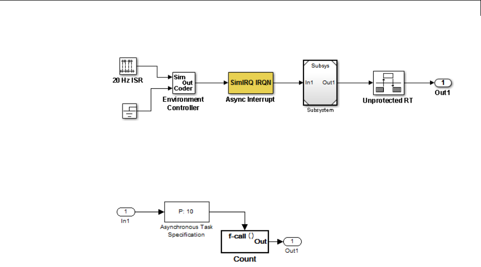
Scheduling
7Insert an Asynchronous Task Specification block in the model reference.
Set the priority of the Asynchronous Task Specification block. (For more
information on setting the priority, see Asynchronous Task Specification.)
8In the model reference, double-click the input port to open its Source Block
Parameters dialog box. Click theSignal Attributes tab and select the
Output function call option. Click OK.
1-77
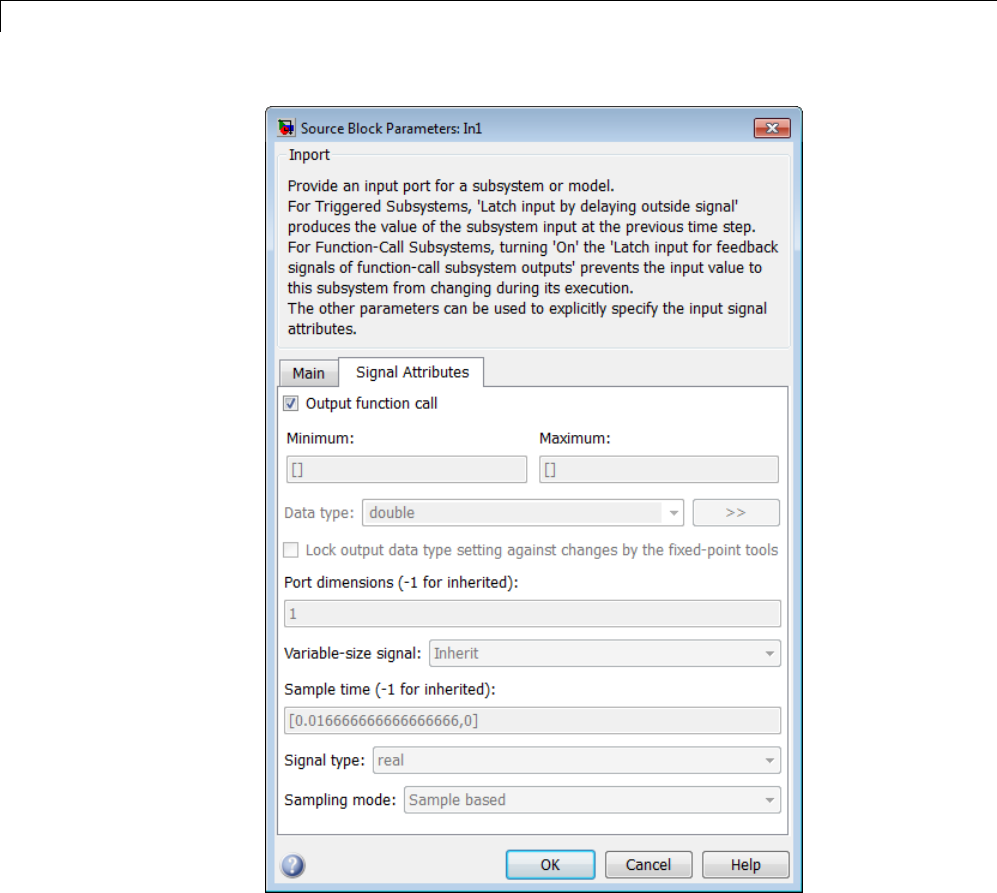
1Modeling
9Save your model and then perform Simulation > Update Diagram to
verify your settings.
1-78
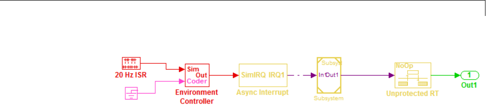
Scheduling
Timers
•“Absolute and Elapsed Time Computation” on page 1-79
•“APIs for Accessing Timers” on page 1-81
•“Elapsed Timer Code Generation Example” on page 1-85
•“Limitations on the Use of Absolute Time” on page 1-88
Absolute and Elapsed Time Computation
•“About Timers” on page 1-79
•“Timers for Periodic and Asynchronous Tasks” on page 1-80
•“Allocation of Timers” on page 1-80
•“Integer Timers in Generated Code” on page 1-81
•“Elapsed Time Counters in Triggered Subsystems” on page 1-81
About Timers. Certain blocks require the value of either absolute time
(that is, the time from the start of program execution to the present time) or
elapsed time (for example, the time elapsed between two trigger events).
Targets that support the real-time model (rtModel) data structure provide
efficient time computation services to blocks that request absolute or elapsed
time. Absolute and elapsed timer features include
•Timers are implemented as unsigned integers in generated code.
•In multirate models, at most one timer is allocated per rate. If no blocks
executing at a given rate require a timer, no timer is allocated to that rate.
This minimizes memory allocated for timers and significantly reduces
overhead involved in maintaining timers.
1-79

1Modeling
•Allocation of elapsed time counters for use of blocks within triggered
subsystems is minimized, further reducing memory usage and overhead.
•The Simulink Coder product provides S-function and TLC APIs that let
your S-functions access timers, in both simulation and code generation.
•The word size of the timers is determined by a user-specified maximum
counter value, Application lifespan (days). If you specify this value,
timers will not overflow. For more information, see “Control Memory
Allocation for Time Counters” on page 16-9.
See “Limitations on the Use of Absolute Time” on page 1-88 and “Blocks that
Depend on Absolute Time” on page 1-89 for more information about absolute
time and the restrictions that it imposes.
Timers for Periodic and Asynchronous Tasks. This chapter discusses
timing services provided for blocks executing within periodic tasks (that is,
tasks running at the model’s base rate or subrates).
The Simulink Coder product also provides timer support for blocks whose
execution is asynchronous with respect to the periodic timing source of the
model. See the following sections of the Asynchronous Support chapter:
•“Use Timers in Asynchronous Tasks” on page 1-58
•“Create a Customized Asynchronous Library” on page 1-60
Allocation of Timers. If you create or maintain an S-Function block that
requires absolute or elapsed time data, it must register the requirement (see
“APIs for Accessing Timers” on page 1-81). In multirate models, timers are
allocated on a per-rate basis. For example, consider a model structured as
follows:
•Therearethreerates,A,B,andC,inthemodel.
•No blocks running at rate B require absolute or elapsed time.
•Two blocks running at rate C register a requirement for absolute time.
•One block running at rate A registers a requirement for absolute time.
In this case, two timers are generated, running at rates A and C respectively.
The timing engine updates the timers as the tasks associated with rates A
1-80

Scheduling
and C execute. Blocks executing at rates A and C obtain time data from the
timers associated with rates A and C.
Integer Timers in Generated Code. In the generated code, timers for
absolute and elapsed time are implemented as unsigned integers. The default
size is 64 bits. This is the amount of memory allocated for a timer if you
specify a value of inf for the Application lifespan (days) parameter. For
an application with a sample rate of 1000 MHz, a 64-bit counter will not
overflow for more than 500 years. See “Use Timers in Asynchronous Tasks”
on page 1-58 and “Control Memory Allocation for Time Counters” on page
16-9 for more information.
Elapsed Time Counters in Triggered Subsystems. Some blocks, such
as the Discrete-Time Integrator block, perform computations requiring the
elapsed time (delta T) since the previous block execution. Blocks requiring
elapsed time data must register the requirement (see “APIs for Accessing
Timers” on page 1-81). A triggered subsystem then allocates and maintains a
single elapsed time counter if required. This timer functions at the subsystem
level, not at the individual block level. The timer is generated if the triggered
subsystem (or any unconditionally executed subsystem within the triggered
subsystem) contains one or more blocks requiring elapsed time data.
Note If you are using simplified initialization mode, elapsed time is always
reset on first execution after becoming enabled, whether or not the subsystem
is configured to reset on enable. For more information, see “Underspecified
initialization detection” in the Simulink documentation.
APIs for Accessing Timers
•“About Timer APIs” on page 1-82
•“C API for S-Functions” on page 1-82
•“TLC API for Code Generation” on page 1-84
1-81

1Modeling
About Timer APIs. This section describes APIs that let your S-functions
take advantage of the efficiencies offered by the absolute and elapsed timers.
SimStruct macros are provided for use in simulation, and TLC functions are
provided for inlined code generation. Note that
•To generate and use the new timers as described above, your
S-functions must register the need to use an absolute or elapsed
timer by calling ssSetNeedAbsoluteTime or ssSetNeedElapseTime in
mdlInitializeSampleTime.
•Existing S-functions that read absolute time but do not register by using
thesemacroswillcontinuetooperate as expected, but will generate
old-style, less efficient code.
C API for S-Functions. The SimStruct macros described in this section
provide access to absolute and elapsed timers for S-functions during
simulation.
In the functions below, the SimStruct *S argument is a pointer to the
simstruct of the calling S-function.
•void ssSetNeedAbsoluteTime(SimStruct *S, boolean b):ifbis TRUE,
registers that the calling S-function requires absolute time data, and
allocates an absolute time counter for the rate at which the S-function
executes (if such a counter has not already been allocated).
•int ssGetNeedAbsoluteTime(SimStruct *S): returns 1 if the S-function
has registered that it requires absolute time.
•double ssGetTaskTime(SimStruct *S, tid): read absolute time
for a given task with task identifier tid.ssGetTaskTime operates
transparently, regardless of whether or not you use the new timer features.
ssGetTaskTime is documented in the SimStruct Functions chapter of the
Simulink documentation.
•void ssSetNeedElapseTime(SimStruct *S, boolean b):ifbis TRUE,
registers that the calling S-function requires elapsed time data, and
allocates an elapsed time counter for the triggered subsystem in which the
S-function executes (if such a counter has not already been allocated). See
also “Elapsed Time Counters in Triggered Subsystems” on page 1-81.
1-82

Scheduling
•int ssGetNeedElapseTime(SimStruct *S): returns 1 if the S-function
has registered that it requires elapsed time.
•void ssGetElapseTime(SimStruct *S, (double *)elapseTime):
returns, to the location pointed to by elapseTime,thevalue(asadouble)
of the elapsed time counter associated with the S-function.
•void ssGetElapseTimeCounterDtype(SimStruct *S, (int *)dtype):
returns the data type of the elapsed time counter associated with the
S-function to the location pointed to by dtype. This function is intended for
use with the ssGetElapseTimeCounter function (see below).
•void ssGetElapseResolution(SimStruct *S, (double *)resolution):
returns the resolution (that is, the sample time) of the elapsed time counter
associated with the S-function to the location pointed to by resolution.
This function is intended for use with the ssGetElapseTimeCounter
function (see below).
•void ssGetElapseTimeCounter(SimStruct *S, (void *)elapseTime):
This function is provided for the use of blocks that require the elapsed time
values for fixed-point computations. ssGetElapseTimeCounter returns,
to the location pointed to by elapseTime, the integer value of the elapsed
time counter associated with the S-function. If the counter size is 64 bits,
the value is returned as an array of two 32-bit words, with the low-order
word stored at the lower address.
To determine how to access the returned counter value, obtain the data
type of the counter by calling ssGetElapseTimeCounterDtype,asinthe
following code:
int *y_dtype;
ssGetElapseTimeCounterDtype(S, y_dtype);
switch(*y_dtype) {
case SS_DOUBLE_UINT32:
{
uint32_T dataPtr[2];
ssGetElapseTimeCounter(S, dataPtr);
}
break;
case SS_UINT32:
{
uint32_T dataPtr[1];
1-83

1Modeling
ssGetElapseTimeCounter(S, dataPtr);
}
break;
case SS_UINT16:
{
uint16_T dataPtr[1];
ssGetElapseTimeCounter(S, dataPtr);
}
break;
case SS_UINT8:
{
uint8_T dataPtr[1];
ssGetElapseTimeCounter(S, dataPtr);
}
break;
case SS_DOUBLE:
{
real_T dataPtr[1];
ssGetElapseTimeCounter(S, dataPtr);
}
break;
default:
ssSetErrorStatus(S, "Invalid data type for elaspe time
counter");
break;
}
If you want to use the actual elapsed time, issue a call to the
ssGetElapseTime function to access the elapsed time directly. You do not
need to get the counter value and then calculate the elapsed time.
double *y_elapseTime;
.
.
.
ssGetElapseTime(S, elapseTime)
TLC API for Code Generation. The following TLC functions support
elapsed time counters in generated code when you inline S-functions by
writing TLC scripts for them.
1-84

Scheduling
•LibGetTaskTimeFromTID(block): Generates code to read the absolute
time for the task in which block executes.
LibGetTaskTimeFromTID is documented with other sample time functions
in the TLC Function Library Reference pages of the Target Language
Compiler documentation.
Note Do not use LibGetT for this purpose. LibGetT always reads the base
rate (tid 0)timer. IfLibGetT is called for a block executing at a subrate,
the wrong timer is read, causing serious errors.
•LibGetElapseTime(system): Generates code to read the elapsed time
counter for system.(system is the parent system of the calling block.) See
“Elapsed Timer Code Generation Example” on page 1-85 for an example
of code generated by this function.
•LibGetElapseTimeCounter(system): Generates code to read the integer
value of the elapsed time counter for system.(system is the parent system
of the calling block.) This function should be used in conjunction with
LibGetElapseTimeCounterDtypeId and LibGetElapseTimeResolution.
(See the discussion of ssGetElapseTimeCounter above.)
•LibGetElapseTimeCounterDtypeId(system): Generates code that returns
thedatatypeoftheelapsedtimecounterforsystem.(system is the parent
system of the calling block.)
•LibGetElapseTimeResolution(system): Generates code that returns the
resolution of the elapsed time counter for system.(system is the parent
system of the calling block.)
Elapsed Timer Code Generation Example
This section shows a simple model illustrating how an elapsed time counter is
generated and used by a Discrete-Time Integrator block within a triggered
subsystem. The following block diagrams show the model elapseTime_exp,
which contains subsystem Amplifier, which includes a Discrete-Time
Integrator block.
1-85
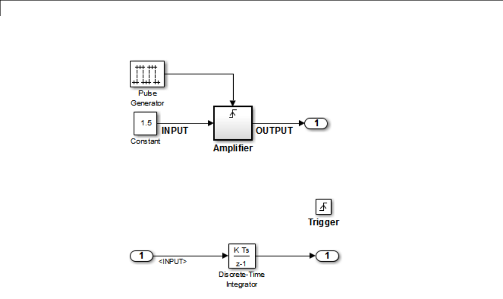
1Modeling
elapseTime_exp Model
Amplifier Subsystem
A 32-bit timer for the base rate (the only rate in this model) is defined within
the rtModel structure, as follows, in model.h.
-/*
* Timing:
* The following substructure contains information regarding
* the timing information for the model.
*/
struct {
time_T stepSize;
uint32_T clockTick0;
uint32_T clockTickH0;
time_T stepSize0;
time_T tStart;
time_T tFinal;
time_T timeOfLastOutput;
void *timingData;
real_T *varNextHitTimesList;
1-86

Scheduling
SimTimeStep simTimeStep;
boolean_T stopRequestedFlag;
time_T *sampleTimes;
time_T *offsetTimes;
int_T *sampleTimeTaskIDPtr;
int_T *sampleHits;
int_T *perTaskSampleHits;
time_T *t;
time_T sampleTimesArray[1];
time_T offsetTimesArray[1];
int_T sampleTimeTaskIDArray[1];
int_T sampleHitArray[1];
int_T perTaskSampleHitsArray[1];
time_T tArray[1];
} Timing;
Had the target been ERT instead of GRT, the Timing structure would have
been pruned to contain only the data required by the model, as follows:
/* Real-time Model Data Structure */ (for ERT!)
struct _RT_MODEL_elapseTime_exp_Tag {
/*
* Timing:
* The following substructure contains information regarding
* the timing information for the model.
*/
struct {
uint32_T clockTick0;
} Timing;
};
Storage for the previous-time value of the Amplifier subsystem
(Amplifier_PREV_T) is allocated in the D_Work(states) structure in model.h.
typedef struct D_Work_elapseTime_exp_tag {
real_T DiscreteTimeIntegrator_DSTATE; /* '<S1>/Discrete-Time
Integrator' */
int32_T clockTickCounter; /* '<Root>/Pulse Generator' */
uint32_T Amplifier_PREV_T; /* '<Root>/Amplifier' */
} D_Work_elapseTime_exp;
1-87

1Modeling
These structures are declared in model.c:
/* Block states (auto storage) */
D_Work_elapseTime_exp elapseTime_exp_DWork;
.
.
.
/* Real-time model */
rtModel_elapseTime_exp elapseTime_exp_M_;
rtModel_elapseTime_exp *elapseTime_exp_M = &elapseTime_exp_M_;
The elapsed time computation is performed as follows within the model_step
function:
/* Output and update for trigger system: '<Root>/Amplifier' */
uint32_T rt_currentTime =
((uint32_T)elapseTime_exp_M->Timing.clockTick0);
uint32_T rt_elapseTime = rt_currentTime -
elapseTime_exp_DWork.Amplifier_PREV_T;
elapseTime_exp_DWork.Amplifier_PREV_T = rt_currentTime;
As shown above, the elapsed time is maintained as a state of the triggered
subsystem. The Discrete-Time Integrator block finally performs its output
and update computations using the elapsed time.
/* DiscreteIntegrator: '<S1>/Discrete-Time Integrator' */
OUTPUT = elapseTime_exp_DWork.DiscreteTimeIntegrator_DSTATE;
/* Update for DiscreteIntegrator: '<S1>/Discrete-Time Integrator'*/
elapseTime_exp_DWork.DiscreteTimeIntegrator_DSTATE += 0.3 *
(real_T)rt_elapseTime * 1.5 ;
Because the triggered subsystem maintains the elapsed time, the TLC
implementation of the Discrete-Time Integrator block needs only a single call
to LibGetElapseTime to access the elapsed time value.
Limitations on the Use of Absolute Time
•“About Absolute Time Limitations” on page 1-89
•“Logging Absolute Time” on page 1-89
1-88

Scheduling
•“Absolute Time in Stateflow Charts” on page 1-89
•“Blocks that Depend on Absolute Time” on page 1-89
About Absolute Time Limitations. Absolute time isthetimethathas
elapsed from the beginning of program execution to the present time, as
distinct from elapsed time, the interval between two events. See “Absolute
and Elapsed Time Computation” on page 1-79 for more information.
Whenyoudesignanapplicationthatisintendedtorunindefinitely,youmust
take care when logging time values, or using charts or blocks that depend
onabsolutetime. Ifthevalueoftimereachesthelargestvaluethatcan
be represented by the data type used by the timer to store time, the timer
overflows and the logged time or block output is incorrect.
If your target uses rtModel, you can avoid timer overflow by specifying a
value for the Application life span parameter. See “Integer Timers in
Generated Code” on page 1-81 for more information.
Logging Absolute Time. If you log time values by opening the Configuration
Parameters dialog box and enabling Data Import/Export > Save to
workspace > Time, your model uses absolute time.
Absolute Time in Stateflow Charts. Every Stateflow chart that uses time
is dependent on absolute time. The only way to eliminate the dependency is to
changetheStateflowcharttonotusetime.
Blocks that Depend on Absolute Time. The following Simulink blocks
depend on absolute time:
•Backlash
•Chirp Signal
•Clock
•Derivative
•Digital Clock
•Discrete-Time Integrator (only when used in triggered subsystems)
•From File
1-89

1Modeling
•From Workspace
•Pulse Generator
•Ramp
•Rate Limiter
•Repeating Sequence
•Signal Generator
•Sine Wave (only when the Sine type parameter is set to Time-based)
•Step
•To File
•To Workspace (only when logging to StructureWithTime format)
•Transport Delay
•Variable Time Delay
•Variable Transport Delay
In addition to the Simulink blocks above, blocks in other blocksets may depend
on absolute time. See the documentation for the blocksets that you use.
Configure Scheduling
•“Configure Start and Stop Times” on page 1-90
•“Configure the Solver Type” on page 1-91
•“Configure the Tasking Mode” on page 1-91
For details about solver options, see “Solver Pane” in the Simulink reference
documentation.
Configure Start and Stop Times
The Stop time must be greater than or equal to the Start time.Ifthestop
time is zero, or if the total simulation time (Stop minus Start)islessthan
zero, the generated program runs for one step. If the stop time is set to inf,
the generated program runs indefinitely.
1-90

Scheduling
When using the GRT or Wind River Systems Tornado targets, you can
override the stop time when running a generated program from the Microsoft
Windows command prompt or UNIX1command line. To override the stop
time that was set during code generation, use the -tf switch.
model -tf n
The program runs for nseconds. If n=inf, the program runs indefinitely.
Certain blocks have a dependency on absolute time. If you are designing a
program that is intended to run indefinitely (Stop time =inf), and your
generated code does not use the rtModel data structure (that is, it uses
simstructs instead), you must not use these blocks. See “Limitations on the
Use of Absolute Time” on page 1-88 for a list of blocks that can potentially
overflow timers.
If you know how long an application that depends on absolute time needs to
run, you can prevent the timers from overflowing and force the use of optimal
word sizes by specifying the Application lifespan (days) parameter on the
Optimization pane. See “Control Memory Allocation for Time Counters” on
page 16-9 for details.
Configure the Solver Type
For code generation, you must configure a model to use a fixed-step solver for
all targets except the S-function and RSim targets. You can configure the
S-function and RSim targets with a fixed-step or variable-step solver.
Configure the Tasking Mode
The Simulink Coder product supports both single-tasking and multitasking
modes for periodic sample times. See “Scheduling” on page 1-4 for details.
1.UNIX®is a registered trademark of The Open Group in the United States and other
countries.
1-91

1Modeling
Supported Products and Block Usage
In this section...
“Related Products” on page 1-92
“Simulink Built-In Blocks That Support Code Generation” on page 1-94
“Block Set Support for Code Generation” on page 1-116
“Fixed-Point Tool Data Type Override” on page 1-116
“Data Type Overrides Unavailable for Most Blocks in Embedded Targets
and Desktop Targets” on page 1-116
Related Products
The following table summarizes MathWorks® products that extend and
complement Simulink Coder software. For information about these and other
MathWorks products, see www.mathworks.com.
Product Extends Code Generation Capabilities for
...
Aerospace Blockset™ Aircraft, spacecraft, rocket, propulsion
systems,andunmannedairbornevehicles
Communications System Toolbox™ Physical layer of communication systems
Computer Vision System Toolbox™ Video processing, image processing, and
computer vision systems
Control System Toolbox™ Linear control systems
DSP System Toolbox™ Signal processing systems
Embedded Coder Embedded systems, on-target rapid prototyping
boards, microprocessors in mass production,
and real-time simulators
Fuzzy Logic Toolbox™ System designs based on fuzzy logic
Gauges Blockset™ Linking generated code executing on a target
system with graphical instrumentation in a
Simulink model
1-92

Supported Products and Block Usage
Product Extends Code Generation Capabilities for
...
Model-Based Calibration Toolbox™ Developing processes for systematically
identifying optimal balance of engine
performance, emissions, and fuel economy, and
reusing statistical models for control design,
hardware-in-the-loop testing, or powertrain
simulation
Model Predictive Control Toolbox™ Controllers that optimize performance of
multi-input and multi-output systems that are
subject to input and output constraints
Real-Time Windows Target™ Rapid prototyping or hardware-in-the-loop
simulation of control system and signal
processing algorithms
SimDriveline™ Driveline (drivetrain) systems
SimElectronics®Electronic and electromechanical systems
SimHydraulics®Hydraulic power and control systems
SimMechanics™ Three-dimensional mechanical systems
SimPowerSystems™ Systems that generate, transmit, distribute,
and consume electrical power
Simscape™ Systems spanning mechanical, electrical,
hydraulic, and other physical domains as
physical networks
Simulink Fixed Point™ Control and signal processing systems
implemented with fixed-point arithmetic
Simulink 3D Animation™ Systems with 3D visualizations
Simulink Design Optimization™ Systems requiring maximum overall system
performance
Simulink Report Generator™ Automatically generating project
documentation in a standard format
1-93

1Modeling
Product Extends Code Generation Capabilities for
...
Simulink Verification and Validation™ Applications requiring automated
requirements tracing, model standards
compliance checking, and test harness
generation
System Identification Toolbox™ Systems constructed from measured
input-output data
Support exceptions:
•Nonlinear IDNLGREY Model, IDDATA
Source, IDDATA Sink, and estimator blocks
•Nonlinear ARX models that contain custom
regressors
•neuralnet nonlinearities
•customnet nonlinearities
Vehicle Network Toolbox™ Support exception: CAN Configuration, CAN
Receive, and CAN Transmit blocks in the CAN
Communication library
xPC Target™ Rapid control prototyping,
hardware-in-the-loop (HIL) simulation, and
other real-time testing applications
xPC Target Embedded Option™ Deploying real-time embedded systems on a PC
for production, data acquisition, calibration,
and testing applications
Simulink Built-In Blocks That Support Code
Generation
The following tables summarize Simulink Coder and Embedded Coder
support for Simulink blocks. There is a table for each block library. For
each block, the second column indicates any support notes, which give
information about the block for code generation. For more detail, including
1-94

Supported Products and Block Usage
data types each block supports, in the MATLAB Command Window, type
showblockdatatypetable, or consult the block reference pages.
•Additional Math and Discrete: Additional Discrete on page 1-96
•Additional Math and Discrete: Increment/Decrement on page 1-97
•Continuous on page 1-97
•Discontinuities on page 1-98
•Discrete on page 1-99
•Logic and Bit Operations on page 1-101
•Lookup Tables on page 1-102
•Math Operations on page 1-103
•Model Verification on page 1-106
•Model-Wide Utilities on page 1-107
•Ports & Subsystems on page 1-107
•Signal Attributes on page 1-108
•Signal Routing on page 1-109
•Sinks on page 1-110
•Sources on page 1-112
•User-Defined on page 1-115
1-95

1Modeling
Additional Math and Discrete: Additional Discrete
Block Support Notes
Fixed-Point State-Space The Simulink Coder software does not explicitly
group primitive blocks that constitute a
nonatomic masked subsystem block in the
generated code. This flexibility allows for more
efficient code generation. In certain cases, you
can achieve grouping by configuring the masked
subsystem block to execute as an atomic unit by
selecting the Treat as atomic unit option.
Transfer Fcn Direct Form II
Transfer Fcn Direct Form II Time Varying
Unit Delay Enabled
Unit Delay Enabled External IC
Unit Delay Enabled Resettable
Unit Delay Enabled Resettable External IC
Unit Delay External IC
Unit Delay Resettable
Unit Delay Resettable External IC
Unit Delay With Preview Enabled
Unit Delay With Preview Enabled Resettable
Unit Delay With Preview Enabled Resettable
External RV
Unit Delay With Preview Resettable
Unit Delay With Preview Resettable
External RV
•The Simulink Coder software does not
explicitly group primitive blocks that
constitute a nonatomic masked subsystem
block in the generated code. This flexibility
allows for more efficient code generation. In
certain cases, you can achieve grouping by
configuring the masked subsystem block to
execute as an atomic unit by selecting the
Treat as atomic unit option.
•Generated code might rely on memcpy or
memset (string.h).
1-96

Supported Products and Block Usage
Additional Math and Discrete: Increment/Decrement
Block Support Notes
Decrement Real World
Decrement Stored Integer
The Simulink Coder software does not explicitly group primitive
blocks that constitute a nonatomic masked subsystem block in
the generated code. This flexibility allows for more efficient
code generation. In certain cases, you can achieve grouping by
configuring the masked subsystem block to execute as an atomic
unit by selecting the Treat as atomic unit option.
Decrement Time To Zero Supports code generation.
Decrement To Zero
Increment Real World
Increment Stored Integer
The Simulink Coder software does not explicitly group primitive
blocks that constitute a nonatomic masked subsystem block in
the generated code. This flexibility allows for more efficient
code generation. In certain cases, you can achieve grouping by
configuring the masked subsystem block to execute as an atomic
unit by selecting the Treat as atomic unit option.
Continuous
Block Support Notes
Derivative
Integrator
Integrator Limited
PID Controller
PID Controller (2DOF)
Second-Order Integrator
Second-Order Integrator
Limited
State-Space
Transfer Fcn
Transport Delay
Variable Time Delay
Not recommended for production-quality code. Relates to resource
limits and restrictions on speed and memory often found in
embedded systems. The code generated can contain dynamic
allocation and freeing of memory, recursion, additional memory
overhead, and widely-varying execution times. While the code
is functionally valid and generally acceptable in resource-rich
environments, smaller embedded targets often cannot support
such code.
In general, consider using the Simulink Model Discretizer to
map continuous blocks into discrete equivalents that support
production code generation. To start the Model Discretizer,
select Analysis > Control Design > Model Discretizer.One
exception is the Second-Order Integrator block because, for
this block, the Model Discretizer produces an approximate
discretization.
1-97

1Modeling
Continuous (Continued)
Block Support Notes
Variable Transport Delay
Zero-Pole
Discontinuities
Block Support Notes
Backlash Supports code generation.
Coulomb and Viscous
Friction
The Simulink Coder software does not explicitly group primitive
blocks that constitute a nonatomic masked subsystem block in
the generated code. This flexibility allows for more efficient
code generation. In certain cases, you can achieve grouping by
configuring the masked subsystem block to execute as an atomic
unit by selecting the Treat as atomic unit option.
Dead Zone Supports code generation.
Dead Zone Dynamic The Simulink Coder software does not explicitly group primitive
blocks that constitute a nonatomic masked subsystem block in
the generated code. This flexibility allows for more efficient
code generation. In certain cases, you can achieve grouping by
configuring the masked subsystem block to execute as an atomic
unit by selecting the Treat as atomic unit option.
Hit Crossing Not recommended for production code. Relates to resource limits
and restrictions on speed and memory often found in embedded
systems. Generated code can contain dynamic allocation and
freeing of memory, recursion, additional memory overhead, and
widely-varying execution times. While the code is functionally
valid and generally acceptable in resource-rich environments,
smaller embedded targets often cannot support such code. Usually,
blocks evolve toward being suitable for production code. Thus,
blocks suitable for production code remain suitable.
Quantizer Supports code generation.
Rate Limiter Cannot use inside a triggered subsystem hierarchy.
1-98

Supported Products and Block Usage
Discontinuities (Continued)
Block Support Notes
Rate Limiter Dynamic The Simulink Coder software does not explicitly group primitive
blocks that constitute a nonatomic masked subsystem block in
the generated code. This flexibility allows for more efficient
code generation. In certain cases, you can achieve grouping by
configuring the masked subsystem block to execute as an atomic
unit by selecting the Treat as atomic unit option.
Relay
Saturation
Support code generation.
Saturation Dynamic
Wrap To Zero
The Simulink Coder software does not explicitly group primitive
blocks that constitute a nonatomic masked subsystem block in
the generated code. This flexibility allows for more efficient
code generation. In certain cases, you can achieve grouping by
configuring the masked subsystem block to execute as an atomic
unit by selecting the Treat as atomic unit option.
Discrete
Block Support Notes
Delay Supports code generation.
Difference •The Simulink Coder software does not explicitly group primitive
blocks that constitute a nonatomic masked subsystem block in
the generated code. This flexibility allows for more efficient
code generation. In certain cases, you can achieve grouping by
configuring the masked subsystem block to execute as an atomic
unit by selecting the Treat as atomic unit option.
•Not recommended for production code. Relates to resource limits
and restrictions on speed and memory often found in embedded
systems. Generated code can contain dynamic allocation and
freeing of memory, recursion, additional memory overhead, and
widely-varying execution times. While the code is functionally
valid and generally acceptable in resource-rich environments,
smaller embedded targets often cannot support such code.
1-99

1Modeling
Discrete (Continued)
Block Support Notes
Usually, blocks evolve toward being suitable for production
code. Thus, blocks suitable for production code remain suitable.
Discrete Derivative •Generated code might rely on memcpy or memset (string.h).
•Depends on absolute time when used inside a triggered
subsystem hierarchy.
Discrete Filter
Discrete FIR Filter
Support code generation.
PID Controller
PID Controller (2DOF)
•Generated code might rely on memcpy or memset (string.h).
•Depends on absolute time when used inside a triggered
subsystem hierarchy.
Discrete State-Space
Discrete Transfer Fcn
Discrete Zero-Pole
Generated code might rely on memcpy or memset (string.h).
Discrete-Time Integrator Depends on absolute time when used inside a triggered subsystem
hierarchy.
First-Order Hold Not recommended for production code. Relates to resource limits
and restrictions on speed and memory often found in embedded
systems. Generated code can contain dynamic allocation and
freeing of memory, recursion, additional memory overhead, and
widely-varying execution times. While the code is functionally
valid and generally acceptable in resource-rich environments,
smaller embedded targets often cannot support such code. Usually,
blocks evolve toward being suitable for production code. Thus,
blocks suitable for production code remain suitable.
Memory
Tapped Delay
Support code generation.
1-100

Supported Products and Block Usage
Discrete (Continued)
Block Support Notes
Transfer Fcn First Order
Transfer Fcn Lead or Lag
Transfer Fcn Real Zero
The Simulink Coder software does not explicitly group primitive
blocks that constitute a nonatomic masked subsystem block in
the generated code. This flexibility allows for more efficient
code generation. In certain cases, you can achieve grouping by
configuring the masked subsystem block to execute as an atomic
unit by selecting the Treat as atomic unit option.
Unit Delay Generated code might rely on memcpy or memset (string.h).
Zero-Order Hold Supports code generation.
Logic and Bit Operations
Block Support Notes
Bit Clear
Bit Set
Bitwise Operator
Combinatorial Logic
ComparetoConstant
Compare to Zero
Support code generation.
Detect Change
Detect Decrease
Detect Fall Negative
Detect Fall Nonpositive
Detect Increase
Detect Rise Nonnegative
Detect Rise Positive
Generated code might rely on memcpy or memset (string.h).
1-101

1Modeling
Logic and Bit Operations (Continued)
Block Support Notes
Extract Bits
Interval Test
Interval Test Dynamic
Logical Operator
Relational Operator
Shift Arithmetic
Support code generation.
Lookup Tables
Block Support Notes
Cosine The Simulink Coder software does not explicitly group primitive
blocks that constitute a nonatomic masked subsystem block in
the generated code. This flexibility allows for more efficient
code generation. In certain cases, you can achieve grouping by
configuring the masked subsystem block to execute as an atomic
unit by selecting the Treat as atomic unit check box.
Direct Lookup Table (n-D)
Interpolation Using
Prelookup
1-D Lookup Table
2-D Lookup Table
n-D Lookup Table
Lookup Table Dynamic
Prelookup
Support code generation.
Sine The Simulink Coder software does not explicitly group primitive
blocks that constitute a nonatomic masked subsystem block in
the generated code. This flexibility allows for more efficient
code generation. In certain cases, you can achieve grouping by
1-102

Supported Products and Block Usage
Lookup Tables (Continued)
Block Support Notes
configuring the masked subsystem block to execute as an atomic
unit by selecting the Treat as atomic unit option.
Math Operations
Block Support Notes
Abs
Add
Support code generation.
Algebraic Constraint Ignored during code generation.
Assignment
Bias
Complex to
Magnitude-Angle
Complex to Real-Imag
Divide
Dot Product
Find Nonzero Elements
Gain
Magnitude-Angle to
Complex
Math Function (10^u)
Math Function (conj)
Math Function (exp)
Math Function (hermitian)
Math Function (hypot)
Math Function (log)
Math Function (log10)
Support code generation.
1-103

1Modeling
Math Operations (Continued)
Block Support Notes
Math Function
(magnitude^2)
Math Function (mod)
Math Function (pow)
Math Function (reciprocal)
Math Function (rem)
Math Function (square)
Math Function (transpose)
Matrix Concatenate
MinMax
MinMax Running
Resettable
Permute Dimensions
Polynomial
Product
Product of Elements
Real-Imag to Complex
Reciprocal Sqrt
Reshape
Rounding Function
Sign
Signed Sqrt
1-104

Supported Products and Block Usage
Math Operations (Continued)
Block Support Notes
Sine Wave Function •Does not refer to absolute time when configured for
sample-based operation. Depends on absolute time when in
time-based operation.
•Depends on absolute time when used inside a triggered
subsystem hierarchy.
Slider Gain
Sqrt
Squeeze
Subtract
Sum
Sum of Elements
Support code generation.
Trigonometric Function Functions asinh,acosh,andatanh are not supported by all
compilers. If you use a compiler that does not support those
functions, the software issues a warning for the block and the
generated code fails to link.
Unary Minus
Vector Concatenate
Weighted Sample Time
Math
Support code generation.
1-105

1Modeling
Model Verification
Block Support Notes
Assertion Supports code generation.
Check Discrete Gradient Not recommended for production code. Relates to resource limits
and restrictions on speed and memory often found in embedded
systems. Generated code can contain dynamic allocation and
freeing of memory, recursion, additional memory overhead, and
widely-varying execution times. While the code is functionally
valid and generally acceptable in resource-rich environments,
smaller embedded targets often cannot support such code. Usually,
blocks evolve toward being suitable for production code. Thus,
blocks suitable for production code remain suitable.
Check Dynamic Gap
Check Dynamic Lower
Bound
Check Dynamic Range
Check Dynamic Upper
Bound
Support code generation.
Check Input Resolution
Check Static Gap
Check Static Lower Bound
Check Static Range
Check Static Upper Bound
Not recommended for production code. Relates to resource limits
and restrictions on speed and memory often found in embedded
systems. Generated code can contain dynamic allocation and
freeing of memory, recursion, additional memory overhead, and
widely-varying execution times. While the code is functionally
valid and generally acceptable in resource-rich environments,
smaller embedded targets often cannot support such code. Usually,
blocks evolve toward being suitable for production code. Thus,
blocks suitable for production code remain suitable.
1-106

Supported Products and Block Usage
Model-Wide Utilities
Block Support Notes
Block Support Table Ignored during code generation.
DocBlock Uses the template symbol you specify for the Embedded Coder
Flag block parameter to add comments to generated code.
Requires an Embedded Coder license. For more information, see
“Use a Simulink DocBlock to Add a Comment”.
Model Info
Timed-Based Linearization
Trigger-Based
Linearization
Ignored during code generation.
Ports & Subsystems
Block Support Notes
Atomic Subsystem
CodeReuse Subsystem
Configurable Subsystem
Enable
Enabled Subsystem
Enabled and Triggered
Subsystem
For Each
For Each Subsystem
For Iterator Subsystem
Function-Call Generator
Function-Call Split
Function-Call Subsystem
If
Support code generation.
1-107

1Modeling
Ports & Subsystems (Continued)
Block Support Notes
If Action Subsystem
Model
Subsystem
Switch Case
Switch Case Action
Subsystem
Triggered Subsystem
While Iterator Subsystem
Signal Attributes
Block Support Notes
Bus to Vector
Data Type Conversion
Data Type Conversion
Inherited
Data Type Duplicate
Data Type Propagation
Data Type Scaling Strip
Support code generation.
IC Not recommended for production code. Relates to resource limits
and restrictions on speed and memory often found in embedded
systems. Generated code can contain dynamic allocation and
freeing of memory, recursion, additional memory overhead, and
widely-varying execution times. While the code is functionally
valid and generally acceptable in resource-rich environments,
smaller embedded targets often cannot support such code. Usually,
blocks evolve toward being suitable for production code. Thus,
blocks suitable for production code remain suitable.
Probe Supports code generation.
1-108

Supported Products and Block Usage
Signal Attributes (Continued)
Block Support Notes
Rate Transition •Generated code might rely on memcpy or memset (string.h).
•Cannot use inside a triggered subsystem hierarchy.
Signal Conversion
Signal Specification
Weighted Sample Time
Width
Support code generation.
Signal Routing
Block Support Notes
Bus Assignment
Bus Creator
Bus Selector
Data Store Memory
Data Store Read
Data Store Write
Demux
Support code generation.
Environment Controller Not recommended for production code. Relates to resource limits
and restrictions on speed and memory often found in embedded
systems. Generated code can contain dynamic allocation and
freeing of memory, recursion, additional memory overhead, and
widely-varying execution times. While the code is functionally
valid and generally acceptable in resource-rich environments,
smaller embedded targets often cannot support such code. Usually,
blocks evolve toward being suitable for production code. Thus,
blocks suitable for production code remain suitable.
1-109

1Modeling
Signal Routing (Continued)
Block Support Notes
From
Goto
Goto Tag Visibility
Index Vector
Support code generation.
Manual Switch Not recommended for production code. Relates to resource limits
and restrictions on speed and memory often found in embedded
systems. Generated code can contain dynamic allocation and
freeing of memory, recursion, additional memory overhead, and
widely-varying execution times. While the code is functionally
valid and generally acceptable in resource-rich environments,
smaller embedded targets often cannot support such code. Usually,
blocks evolve toward being suitable for production code. Thus,
blocks suitable for production code remain suitable.
Merge When multiple signals connected to a Merge block have a non-Auto
storage class, all non-Auto signals connected to that block must be
identically labeled and have the same storage class.WhenMerge
blocks connect directly to one another, these rules apply to all
signals connected to Merge blocks in the group.
Multiport Switch
Mux
Selector
Support code generation.
Switch Generated code might rely on memcpy or memset (string.h).
Sinks
Block Support Notes
Display
Floating Scope
Ignored for code generation.
Outport (Out1) Supports code generation.
1-110

Supported Products and Block Usage
Sinks (Continued)
Block Support Notes
Scope Ignored for code generation.
Stop Simulation •Not recommended for production code. Relates to resource limits
and restrictions on speed and memory often found in embedded
systems. Generated code can contain dynamic allocation and
freeing of memory, recursion, additional memory overhead, and
widely-varying execution times. While the code is functionally
valid and generally acceptable in resource-rich environments,
smaller embedded targets often cannot support such code.
Usually, blocks evolve toward being suitable for production
code. Thus, blocks suitable for production code remain suitable.
•Generated code stops executing when the stop condition is true.
Terminator Supports code generation.
To File Not recommended for production code. Relates to resource limits
and restrictions on speed and memory often found in embedded
systems. Generated code can contain dynamic allocation and
freeing of memory, recursion, additional memory overhead, and
widely-varying execution times. While the code is functionally
valid and generally acceptable in resource-rich environments,
smaller embedded targets often cannot support such code. Usually,
blocks evolve toward being suitable for production code. Thus,
blocks suitable for production code remain suitable.
To Workspace
XY Graph
Ignored for code generation.
1-111

1Modeling
Sources
Block Support Notes
Band-Limited White Noise Cannot use inside a triggered subsystem hierarchy.
Chirp Signal
Clock
Not recommended for production code. Relates to resource limits
and restrictions on speed and memory often found in embedded
systems. Generated code can contain dynamic allocation and
freeing of memory, recursion, additional memory overhead, and
widely-varying execution times. While the code is functionally
valid and generally acceptable in resource-rich environments,
smaller embedded targets often cannot support such code. Usually,
blocks evolve toward being suitable for production code. Thus,
blocks suitable for production code remain suitable.
Constant Supports code generation.
Counter Free-Running Not recommended for production code. Relates to resource limits
and restrictions on speed and memory often found in embedded
systems. Generated code can contain dynamic allocation and
freeing of memory, recursion, additional memory overhead, and
widely-varying execution times. While the code is functionally
valid and generally acceptable in resource-rich environments,
smaller embedded targets often cannot support such code. Usually,
blocks evolve toward being suitable for production code. Thus,
blocks suitable for production code remain suitable.
Counter Limited •The Simulink Coder software does not explicitly group primitive
blocks that constitute a nonatomic masked subsystem block in
the generated code. This flexibility allows for more efficient
code generation. In certain cases, you can achieve grouping by
configuring the masked subsystem block to execute as an atomic
unit by selecting the Treat as atomic unit option.
•Not recommended for production code. Relates to resource limits
and restrictions on speed and memory often found in embedded
systems. Generated code can contain dynamic allocation and
freeing of memory, recursion, additional memory overhead, and
widely-varying execution times. While the code is functionally
valid and generally acceptable in resource-rich environments,
smaller embedded targets often cannot support such code.
1-112

Supported Products and Block Usage
Sources (Continued)
Block Support Notes
Usually, blocks evolve toward being suitable for production
code. Thus, blocks suitable for production code remain suitable.
Digital Clock Not recommended for production code. Relates to resource limits
and restrictions on speed and memory often found in embedded
systems. Generated code can contain dynamic allocation and
freeing of memory, recursion, additional memory overhead, and
widely-varying execution times. While the code is functionally
valid and generally acceptable in resource-rich environments,
smaller embedded targets often cannot support such code. Usually,
blocks evolve toward being suitable for production code. Thus,
blocks suitable for production code remain suitable.
Enumerated Constant Supports code generation.
From File
From Workspace
Ignored for code generation.
Ground
Inport (In1)
Support code generation.
Pulse Generator Cannot use inside a triggered subsystem hierarchy. Does not refer
to absolute time when configured for sample-based operation.
Depends on absolute time when in time-based operation.
Ramp Not recommended for production code. Relates to resource limits
and restrictions on speed and memory often found in embedded
systems. Generated code can contain dynamic allocation and
freeing of memory, recursion, additional memory overhead, and
widely-varying execution times. While the code is functionally
valid and generally acceptable in resource-rich environments,
smaller embedded targets often cannot support such code. Usually,
blocks evolve toward being suitable for production code. Thus,
blocks suitable for production code remain suitable.
Random Number Supports code generation.
1-113

1Modeling
Sources (Continued)
Block Support Notes
Repeating Sequence •Not recommended for production code. Relates to resource limits
and restrictions on speed and memory often found in embedded
systems. Generated code can contain dynamic allocation and
freeing of memory, recursion, additional memory overhead, and
widely-varying execution times. While the code is functionally
valid and generally acceptable in resource-rich environments,
smaller embedded targets often cannot support such code.
Usually, blocks evolve toward being suitable for production
code. Thus, blocks suitable for production code remain suitable.
•Consider using the Repeating Sequence Stair or Repeating
Sequence Interpolated block instead.
Repeating Sequence
Interpolated
•The Simulink Coder software does not explicitly group primitive
blocks that constitute a nonatomic masked subsystem block in
the generated code. This flexibility allows for more efficient
code generation. In certain cases, you can achieve grouping by
configuring the masked subsystem block to execute as an atomic
unit by selecting the Treat as atomic unit option.
•Cannot use inside a triggered subsystem hierarchy.
Repeating Sequence Stair The Simulink Coder software does not explicitly group primitive
blocks that constitute a nonatomic masked subsystem block in
the generated code. This flexibility allows for more efficient
code generation. In certain cases, you can achieve grouping by
configuring the masked subsystem block to execute as an atomic
unit by selecting the Treat as atomic unit option.
Signal Builder
Signal Generator
Not recommended for production code. Relates to resource limits
and restrictions on speed and memory often found in embedded
systems. Generated code can contain dynamic allocation and
freeing of memory, recursion, additional memory overhead, and
widely-varying execution times. While the code is functionally
valid and generally acceptable in resource-rich environments,
smaller embedded targets often cannot support such code. Usually,
blocks evolve toward being suitable for production code. Thus,
blocks suitable for production code remain suitable.
1-114

Supported Products and Block Usage
Sources (Continued)
Block Support Notes
Sine Wave •Depends on absolute time when used inside a triggered
subsystem hierarchy.
•Does not refer to absolute time when configured for
sample-based operation. Depends on absolute time when in
time-based operation.
Step Not recommended for production code. Relates to resource limits
and restrictions on speed and memory often found in embedded
systems. Generated code can contain dynamic allocation and
freeing of memory, recursion, additional memory overhead, and
widely-varying execution times. While the code is functionally
valid and generally acceptable in resource-rich environments,
smaller embedded targets often cannot support such code. Usually,
blocks evolve toward being suitable for production code. Thus,
blocks suitable for production code remain suitable.
Uniform Random Number Supports code generation.
User-Defined
Block Support Notes
Fcn Supports code generation.
Interpreted MATLAB
Function
Consider using the MATLAB Function block instead.
Level-2 MATLAB
S-Function
Ignored during code generation.
MATLAB Function Supports code generation.
S-Function
S-Function Builder
S-functions that call into MATLAB are not supported for code
generation.
1-115

1Modeling
Block Set Support for Code Generation
Several products that include blocks are available for you to consider for
code generation. However, before using the blocks for one of these products,
consult the documentation for that product to confirm whether any, all, or a
subset of blocks support code generation.
Fixed-Point Tool Data Type Override
SIL/PIL does not support signals with data types overridden by the
Fixed-Point Tool Data type override parameter at the SIL/PIL component
boundary.
Youmayseeanexceptionmessagelikethefollowing:
Simulink.DataType object 'real_T' is not in scope
from 'mpil_mtrig_no_ic_preread/TmpSFcnForModelReference_unitInTopMdl'.
This error message is related to a hidden S-Function block.
There is no resolution for this issue.
Data Type Overrides Unavailable for Most Blocks in
Embedded Targets and Desktop Targets
When you attempt to perform a datatype override on a block, you may get an
error message similar to the following example:
Error reported by S-function 'sfun_can_frame_splitter' in
'c2000_host_CAN_monitor/CAN Message Unpacking/CAN Message
Unpacking': Incompatible DataType or Size specified.
Data type overrides using the Fixed point tool are not available for blocks
in Simulink Coder > Desktop Targets and Embedded Coder > Embedded
Targets libraries that support fixed-point.
There is no resolution for this issue.
1-116

Modeling Semantic Considerations
Modeling Semantic Considerations
In this section...
“Data Propagation” on page 1-117
“SampleTimePropagation”onpage1-119
“Latches for Subsystem Blocks” on page 1-120
“Block Execution Order” on page 1-120
“Algebraic Loops” on page 1-122
Data Propagation
Thefirststageofcodegenerationiscompilationoftheblockdiagram. This
stage is analogous to that of a C or C++ program. The compiler carries out
type checking and preprocessing. Similarly, the Simulink engine verifies that
input/output data types of block ports are consistent, line widths between
blocks are of expected thickness, and thesampletimesofconnectingblocks
are consistent.
The Simulink engine propagates data from one block to the next along signal
lines. The data propagated consists of
•Data type
•Line widths
•Sample times
You can verify what data types any given Simulink block supports by typing
showblockdatatypetable
at the MATLAB prompt, or (from the Help browser) clicking the command
above.
The Simulink engine typically derives signal attributes from a source block.
For example, the Inport block’s parameters dialog box specifies the signal
attributes for the block.
1-117
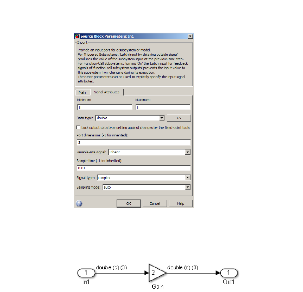
1Modeling
In this example, the Inport block has a port width of 3, a sample time of .01
seconds, the data type is double, and the signal is complex.
This figure shows the propagation of the signal attributes associated with the
Inport block through a simple block diagram.
In this example, the Gain and Outport blocks inherit the attributes specified
for the Inport block.
1-118

Modeling Semantic Considerations
Sample Time Propagation
Inherited sample times in source blocks (for example, a root inport) can
sometimes lead to unexpected and unintended sample time assignments.
Since a block may specify an inherited sample time, information available at
the outset is often insufficient to compile a block diagram completely.
In such cases, the Simulink engine propagates the known or assigned sample
times to those blocks that have inherited sample times but that have not
yet been assigned a sample time. Thus, the engine continues to fill in the
blanks (the unknown sample times) until sample times have been assigned
to as many blocks as possible. Blocks that still do not have a sample time
are assignedadefaultsampletime.
For a completely deterministic model (one wherenosampletimesareset
using the above rules), you should explicitly specify the sample times of all
your source blocks. Source blocks include root inport blocks and any blocks
without input ports. You do not have to set subsystem input port sample
times. You might want to do so, however, when creating modular systems.
An unconnected input implicitly connects to ground. For ground blocks and
ground connections, the sample time is always constant (inf).
All blockshaveaninheritedsampletime(T
s= -1). They are assigned a
sample time of (Tf-T
i)/50.
Constant Block Sample Times
You can specify a sample time for Constant blocks. This has certain
implications for code generation.
When a sample time of inf is selected for a Constant block,
•If Inline parameters is on, the block takes on a constant sample time,
and propagates a constant sample time downstream.
•If Inline parameters is off, the Constant block inherits its sample time –
which is nonconstant – and propagates that sample time downstream.
Generated code for any block differs when it has a constant sample time; its
outputs are represented in the constant block outputs structure instead of in
1-119

1Modeling
the general block outputs structure. The generated code thus reflects that the
Constant block propagates a constant sample time downstream if a sample
time of inf is specified and Inline parameters is on.
Latches for Subsystem Blocks
When an Inport block is the signal source for a triggered or function-call
subsystem,youcanuselatchoptionstopreserveinputvalueswhilethe
subsystem executes. The Inport block latch options include:
For... You Can Use...
Triggered
subsystems
Latch input by delaying outside signal
Function-call
subsystems
Latch input for feedback signals of function-call
subsystem outputs
When you use Latch input for feedback signals of function-call
subsystem outputs for a function-call subsystem, the Simulink Coder code
generator
•Preserves latches in generated code regardless of any optimizations that
might be set
•Places the code for latches at the start of a subsystem’s output/update
function
For more information on these options, see the description of the Inport block
in the Simulink documentation.
Block Execution Order
Once the Simulink engine compiles the block diagram, it creates a model.rtw
file (analogous to an object file generated from a C or C++ file). The model.rtw
file contains the connection information of the model, as well as the signal
attributes. Thus, the timing engine in can determine when blocks with
different rates should be executed.
You cannot override this execution order by directly calling a block
(inhandwrittencode)inamodel. Forexample,inthenextfigurethe
1-120
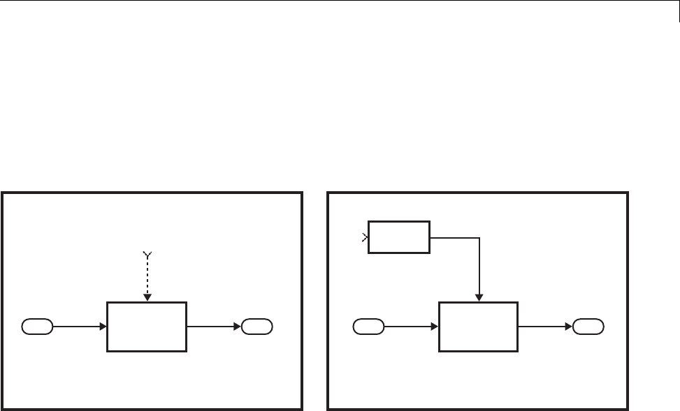
Modeling Semantic Considerations
disconnected_trigger model on the left has its trigger port connected to
ground, which can lead to all blocks inheriting a constant sample time. Calling
the trigger function, f(), directly from user code does not work and should
never be done. Instead, you should use a function-call generator to specify the
rate at which f() should be executed, as shown in the connected_trigger
model on the right.
Disconnected
Trigger
Triggered
Subsystem
In1
1In1 Out1
f0
Out1
1
Triggered
Subsystem
In1
1In1 Out1
f0
Out1
1
f0
Function-call
Generator
Connected
Trigger
Instead of the function-call generator, you could use any other block that can
drive the trigger port. Then, you should call the model’s main entry point to
execute the trigger function.
For multirate models, a common use of the Simulink Coder product is to build
individual models separately and then manually code the I/O between the
models. This approach places the burden of data consistency between models
on the developer of the models. Another approach is to let the Simulink
and Simulink Coder products maintain data consistency between rates and
generate multirate code for use in a multitasking environment. The Simulink
Rate Transition block is able to interface both periodic and asynchronous
signals. For a description of the Simulink Coder libraries, see “Handle
Asynchronous Events” on page 1-34. For more information on multirate code
generation, see “Scheduling” on page 1-4.
1-121
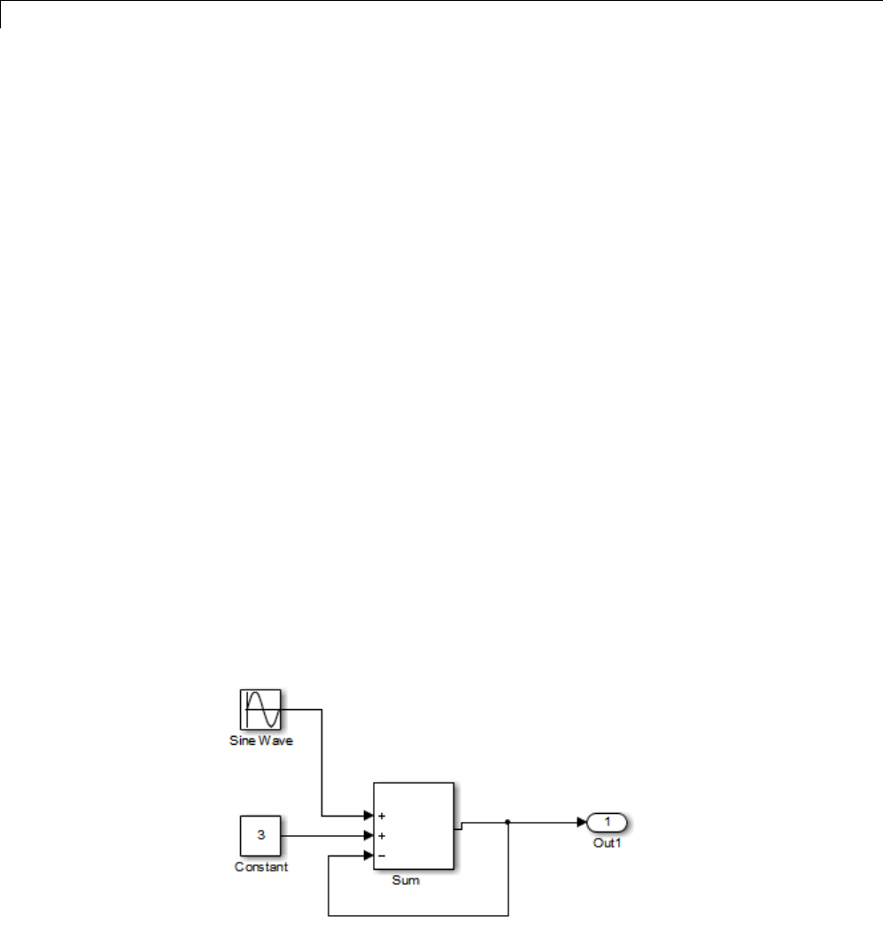
1Modeling
Algebraic Loops
Algebraic loops are circular dependencies between variables. This prevents
the straightforward direct computation of their values. For example, in the
case of a system of equations
•x=y+2
•y=-x
the values of xand ycannot be directly computed.
To solve this, either repeatedly try potential solutions for xand y(in an
intelligent manner, for example, using gradient based search) or “solve” the
system of equations. In the previous example, solving the system into an
explicit form leads to
•2x = 2
•y=-x
•x=1
•y=-1
An algebraic loop exists whenever the output of a block having direct
feedthrough (such as Gain, Sum, Product, and Transfer Fcn) is fed back as an
input to the same block. The Simulink engine is often able to solve models
that contain algebraic loops, such as the next diagram.
1-122
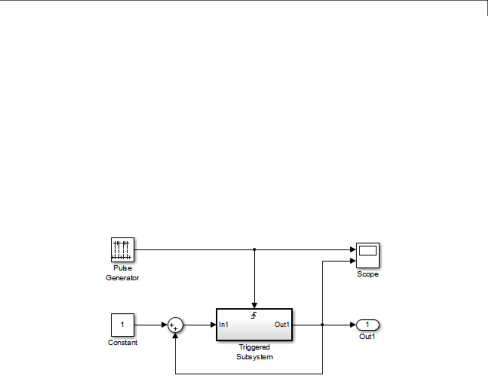
Modeling Semantic Considerations
The Simulink Coder software does not produce code that solves algebraic
loops. This restriction includes models that use Algebraic Constraint blocks
in feedback paths. However, the Simulink engine can often eliminate all
or some algebraic loops that arise, by grouping equations in certain ways
in models that contain them. It does this by separating the update and
output functions to avoid circular dependencies. See “Algebraic Loops” in the
Simulink documentation for details.
Algebraic Loops in Triggered Subsystems
While the Simulink engine can minimize algebraic loops involving atomic
and enabled subsystems, a special consideration applies to some triggered
subsystems. Anexampleforwhichcodecanbegeneratedisshowninthe
following model and triggered subsystem.
The default Simulink behavior is to combine output and update methods for
the subsystem, which creates an apparent algebraic loop, even though the
Unit Delay block in the subsystem has no direct feedthrough.
You can allow the Simulink engine to solve the problem by splitting the output
and update methods of triggered and enabled-triggered subsystems when
feasible. If you want the Simulink Coder code generator to take advantage of
this feature, select the Minimize algebraic loop occurrences check box in
the Subsystem Parameters dialog box. Select this option to avoid algebraic
loop warnings in triggered subsystems involved in loops.
1-123

1Modeling
Note If you always check this box, the generated code for the subsystem
might contain split output and update methods, even if the subsystem is
not actually involved in a loop. Also, if a direct feedthrough block (such as a
Gain block) is connected to the inport in the above triggered subsystem, the
Simulink engine cannot solve the problem, and the Simulink Coder software
isunabletogeneratecode.
A similar Minimize algebraic loop occurrences option appears on the
Model Referencing pane of the Configuration Parameters dialog box.
Selecting it enables the Simulink Coder software to generate code for models
containing Model blocks that are involved in algebraic loops.
1-124

2
Subsystems
•“Code Generation of Subsystems” on page 2-2
•“Generate Code and Executables for Individual Subsystem” on page 2-4
•“Inline Subsystem Code” on page 2-7
•“Generate Subsystem Code as Separate Function and Files” on page 2-10
•“Generate Reusable Function for Identical Subsystems Within a Model”
on page 2-11
•“Optimize Code for Identical Nested Subsystems” on page 2-14
•“Generate Reusable Code for Subsystems Containing S-Function Blocks”
on page 2-15
•“Generate Reusable Code from Stateflow Charts” on page 2-16
•“Code Reuse Limitations for Subsystems” on page 2-17
•“Code Reuse For Subsystems Shared Across Referenced Models” on page
2-19
•“Reusable Library Subsystem” on page 2-20
•“Code Generation of Constant Parameters” on page 2-22
•“Shared Constant Parameters for Code Reuse” on page 2-23
•“Generate Reusable Code for Subsystems Shared Across Models” on page
2-25
•“Determine Why Subsystem Code Is Not Reused” on page 2-32

2Subsystems
Code Generation of Subsystems
For you to control how code is generated for any nonvirtual subsystem, the
Simulink Coder software provides subsystem parameters that you can use.
The categories of nonvirtual subsystems are:
•Conditionally executed subsystems. Execution depends upon a control
signal or control block. These subsystems include:
-Triggered
-Enabled
-Action
-Iterator
-Function-call
For more information, see “About Conditional Subsystems”.
•Atomic subsystems: Any virtual subsystem can be declared atomic (and
therefore nonvirtual) by using the “Treat as atomic unit” parameter in the
Subsystem Parameters dialog box.
For more information on nonvirtual subsystems and atomic subsystems, see
“Systems and Subsystems” and run the sl_subsys_semantics model.
You can design and configure your model to control the code generated from
nonvirtual subsystems.
To... See...
Generate inlined code from a selected
nonvirtual subsystem.
“Inline Subsystem Code” on page 2-7
Generate code for only a subsystem. “Generate Code and Executables for
Individual Subsystem” on page 2-4
Generate separate functions with no
arguments, and optionally place the
subsystem code in a separate file.
“Generate Subsystem Code as
Separate Function and Files” on
page 2-10
2-2

Code Generation of Subsystems
To... See...
Generate a single reentrant function
for a subsystem that is included in
multiple places within a model.
“Generate Reusable Function for
Identical Subsystems Within a
Model” on page 2-11
Generate a single reentrant function
for a subsystem that is included in
multiple places in a model reference
hierarchy.
“Generate Reusable Code for
Subsystems Shared Across Models”
on page 2-25 and “Code Reuse
For Subsystems Shared Across
Referenced Models” on page 2-19
Note If you generate code for a virtual subsystem, code generator treats the
subsystem as atomic and generates the code accordingly. The resulting code
can change the execution behavior of your model, for example, by applying
algebraic loops, and therefore introduce inconsistencies with the simulation
behavior. Declare virtual subsystems as atomic subsystems, which makes
simulation and execution behavior consistent for your model consistent.
Subsystem Code Dependence
Code generated from nonvirtual subsystems may or may not be completely
independent of the generating model. When generating code for a subsystem,
the code may reference global data structures of the model, even if the
subsystem code is in a separate file. Each subsystem code file contains
include directives and comments describing the dependencies. The Simulink
Coder software checks for cyclic file dependencies and warns about them
at build time. For descriptions of how generated code is packaged, see
“Generated Source Files and File Dependencies” on page 10-4.
To generate subsystem code that is independent of the generating model,
place the subsystem in a library and configure it as a reusable subsystem. For
more information, see “Code Reuse For Subsystems Shared Across Referenced
Models” on page 2-19.
2-3

2Subsystems
Generate Code and Executables for Individual Subsystem
You can generate code and build an executable for a subsystem within a
model. The code generation and build process uses the code generation and
build parameters of the root model.
1In the Configuration Parameters dialog box, set up the code generation and
build parameters, similar to setting up the code generation for a model.
2Right-click the Subsystem block. From the context menu, select C/C++
Code > Build This Subsystem from the context menu.
Alternatively, in the current model, click a subsystem and then from the
Code menu, select C/C++ Code > Build Selected Subsystem.
Note When you select Build This Subsystem,ifthemodelisoperatingin
external mode, the Simulink Coder build process automatically turns off
external mode for the duration of the build. Simulink Coder then restores
external mode upon completion of the build process.
2-4
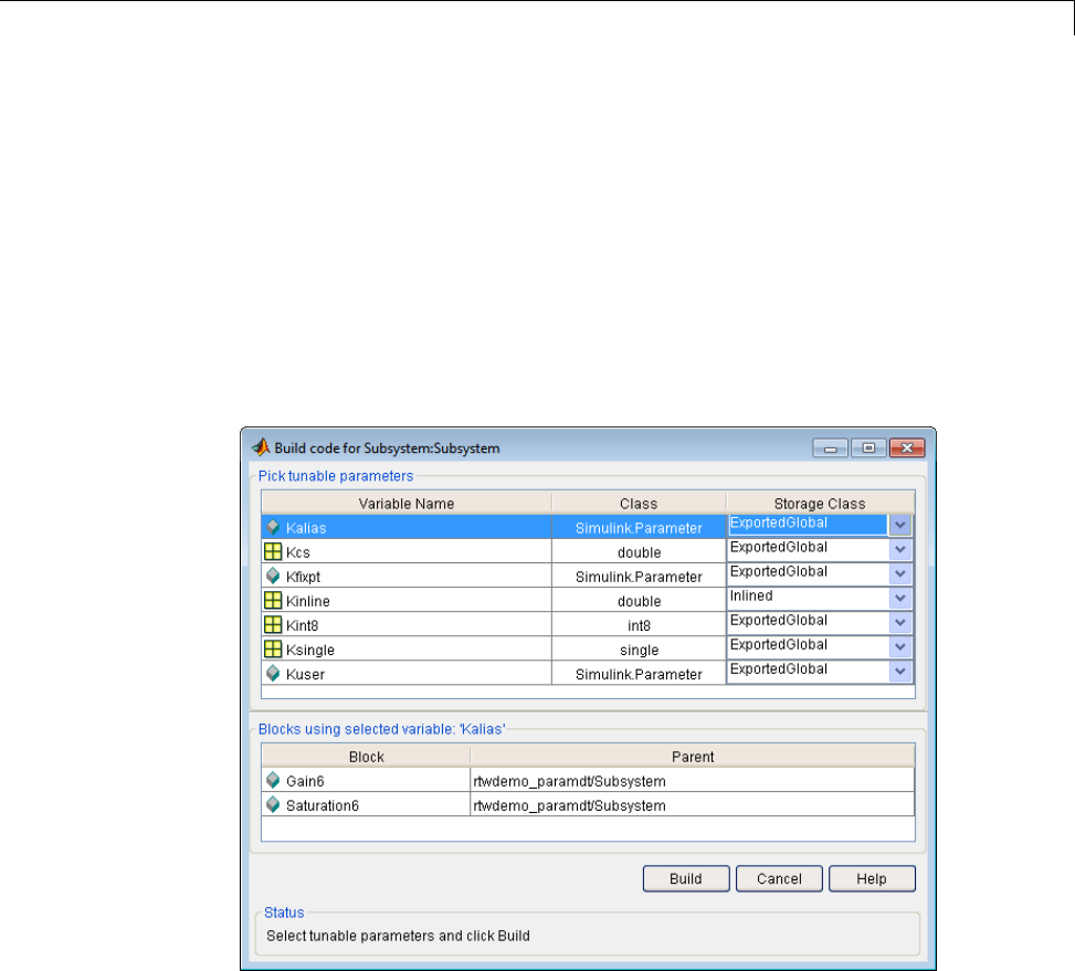
Generate Code and Executables for Individual Subsystem
3The Build code for Subsystem window displays a list of the subsystem
parameters. The upper pane displays the name, class, and storage class
of each variable (or data object) that is referenced as a block parameter in
the subsystem. When you select a parameter in the upper pane, the lower
pane shows all the blocks that reference the parameter and the parent
system of each block.
The Storage Class column contains a menu for each row. The menu
options set the storage class or inline the parameter. To declare a
parameter to be tunable, set the Storage Class to any value other than
Inlined.
For more information on tunable and inlined parameters and storage
classes, see “Parameters” on page 7-10.
4After selecting tunable parameters, Build to initiate the code generation
and build process.
2-5

2Subsystems
5ThebuildprocessdisplaysstatusmessagesintheMATLABCommand
Window. When the build is complete, the generated executable is in your
working folder. The name of the generated executable is subsystem.exe
(on PC platforms) or subsystem (on The Open Group UNIX platforms).
subsystem is the name of the source subsystem block.
The generated code is in a build subfolder, named subsystem_target_rtw.
subsystem is the name of the source subsystem block and target is the
name of the target configuration.
When you generate code for a subsystem, you can generate an S-function
by selecting Code > C/C++ Code> Generate S-Function,oryoucanuse
the right-click subsystem build. For more information on S-functions, see
“Automate S-Function Generation” on page 14-23 and in Embedded Coder,
“Generate S-Function Wrappers”.
Subsystem Build Limitations
The following limitations apply to building subsystems:
•When you right-click build a subsystem that includes an Outport block for
which the Data type parameter specifies a bus object, you must address
errors that result from setting signal labels. To configure the software to
display these errors, in the Configuration Parameters dialog box for the
parent model, on the Diagnostics > Connectivity pane, set the Signal
label mismatch parameter to error.
•When a subsystem is in a triggered or function-call subsystem, the
right-click build process might fail if the subsystem code is not sample-time
independent. To find out whether a subsystem is sample-time independent:
1Copyallblocksinthesubsystemtoanemptymodel.
2In the Configuration Parameters dialog box, on the Solver pane, set:
a. Type to Fixed-step.
b. Periodic sample time constraint to Ensure sample time
independent.
c. Click Apply.
3Update the model. If the model is sample-time dependent, Simulink
generates an error in the process of updating the diagram.
2-6

Inline Subsystem Code
Inline Subsystem Code
You can configure a nonvirtual subsystemtoinlinethesubsystemcode
with the model code. In the Subsystem Parameters dialog box, setting the
Function packaging parameter to Auto or Inline inlines the generated
code of the subsystem.
The Auto option is the default. When there is only one instance of a subsystem
in the model, the Auto option inlines the subsystem code. When multiple
instances of a subsystem exist, the Auto option results in a single copy of the
function (as a reusable function). For function-call subsystems with multiple
callers, the subsystem code is generated as if you specified Function.
To always inline subsystem code, select Inline.TheInline option explicitly
directs the code generator to inline the subsystem unconditionally.
Configure Subsystem to Inline Code
To configure your subsystem for inlining:
1Right-click the Subsystem block. From the context menu, select Block
Parameters (Subsystem).
2In the Subsystem Parameters dialog box, if the subsystem is virtual, select
Treat as atomic unit. This option makes the subsystem nonvirtual.
On the Code Generation tab, the Function packaging option is now
available.
If the system is already nonvirtual, the Function packaging option is
already selected.
3Click the Code Generation tab and select Auto or Inline from the
Function packaging parameter.
2-7
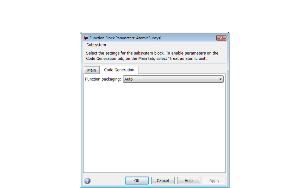
2Subsystems
4Click Apply and close the dialog box.
The border of the subsystem thickens, indicating that it is nonvirtual.
When you generate code from your model, the code generator inlines
subsystem code within model.c or model.cpp (or in its parent system’s source
file). You can identify this code by system/block identification tags, such as:
/* Atomic SubSystem Block: <Root>/AtomicSubsys1 */
Exceptions to Inlining
There are certain cases in which the code generator does not inline a
nonvirtual subsystem, even though the Inline option is selected.
•If the subsystem is a function-call subsystem that is called by a noninlined
S-function, the Inline option is ignored. Noninlined S-functions make calls
2-8

Inline Subsystem Code
by using function pointers. Therefore, the function-call subsystem must
generate a function with all arguments present.
•In a feedback loop involving function-call subsystems, the code generator
forces one of the subsystems to be generated as a function instead of
inlining it. Based on the order in which the subsystems are sorted
internally, the software selects the subsystem to be generated as a function.
•If a subsystem is called from an S-function block that sets the option
SS_OPTION_FORCE_NONINLINED_FCNCALL to TRUE,itisnotinlined.
When user-defined Async Interrupt blocks or Task Sync blocks are
present, this result might occur. Such blocks must be generated as
functions. These blocks are located in the VxWorks block library
(vxlib1) shipped with the Simulink Coder product and use the
SS_OPTION_FORCE_NONINLINED_FCNCALL option.2
2. VxWorks®is a registered trademark of Wind River®Systems, Inc.
2-9

2Subsystems
Generate Subsystem Code as Separate Function and Files
To generate both a separate subsystem function and a separate file for a
subsystem in a model:
1Right-click a Subsystem block. From the context menu, select Block
Parameters (Subsystem).
2In the Subsystem Parameters dialog box, if the subsystem is virtual, select
Treat as atomic unit.OntheCode Generation tab, the Function
packaging parameter is now available.
3Click the Code Generation tab and select Function from the Function
packaging parameter. The Function option enables two parameters:
•The “Function name options” parameter controls the naming of the
generated function.
•The “File name options” parameter controls the naming of the generated
file.
4Set the Function name options parameter.
5Set the File name options parameter to a value other than Auto.Ifyou
are generating a reusable function for your subsystem, see “Generate
Reusable Function for Identical Subsystems Within a Model” on page
2-11 or “Generate Reusable Code for Subsystems Shared Across Models”
on page 2-25.
6Click Apply and close the dialog box.
2-10

Generate Reusable Function for Identical Subsystems Within a Model
Generate Reusable Function for Identical Subsystems
Within a Model
In the Subsystem Parameters dialog box, the Function packaging
parameter option Function generates functions that use global data. The
Reusable function option generates reusable functions that have data
passed as arguments (enabling them to be reentrant). Selecting Reusable
function generates a function with arguments that allows the subsystem
code to be shared by other instances of it in the model. This action supports
less code instead of replicating the code for each instance of a subsystem or
each time it is called.
To determine reusability of the subsystem code, the code generator performs a
checksum to determine if subsystems are identical. The generated function
has arguments, for example, for block inputs and outputs (rtB_*), continuous
states (rtDW_*), parameters (rtP_*).
Note In the generated code, the call interface is subject to change from
release to release. Therefore, do not directly call reusable functions from
external code.
To generate one reusable function for identical subsystems within a model:
1Right-click the Subsystem block. From the context menu, select Block
Parameters (Subsystem).
2In the Subsystem Parameters dialog box, if the subsystem is virtual, select
Treat as atomic unit.OntheCode Generation tab, the Function
packaging menu is now available.
If the subsystem is already nonvirtual, the Function packaging menu is
already selected.
3Click the Code Generation tab and select Reusable function for the
Function packaging parameter.
2-11
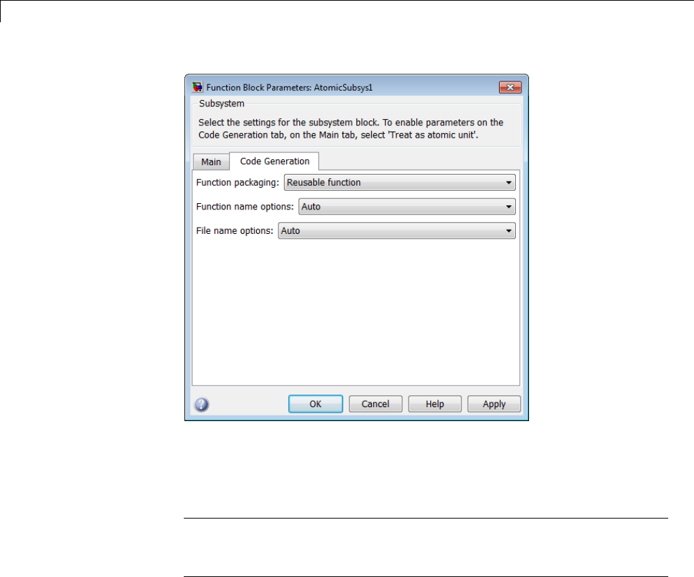
2Subsystems
For more information about this setting, see “Considerations for Function
Packaging Options Auto and Reusable function” on page 2-13.
4Set the function name using the “Function name options” parameter.
Note If you do not choose Auto, for all other Subsystem blocks that
you want to share this code, specify thesamefunctionnameforthose
Subsystem blocks.
5Set the file name using the “File name options” parameter to a value other
than Auto. If your generated code is under source control, a value other
than Auto prevents the generated file name from changing due to unrelated
model modifications.
2-12

Generate Reusable Function for Identical Subsystems Within a Model
Note ForallotherSubsystemblocksthatyouwanttosharethiscode,
specify the same file name for those Subsystem blocks.
6Click Apply and close the dialog box.
For a summary of code reuse limitations, see “Code Reuse Limitations for
Subsystems” on page 2-17.
Considerations for Function Packaging Options Auto
and Reusable function
When you want multiple instances of a subsystem to be represented as one
reusable function, you can designate each one of them as Auto or as Reusable
function. Use one or the other, because using both creates two reusable
functions, one for each specification. The outcomes of these choices differ
only when reuse is not possible. Selecting Auto does not allow control of the
function or file name for the subsystem code.
The Reusable function and Auto options both try to determine if multiple
instances of a subsystem exist and if the code can be reused. When reuse is
not possible, there are differences in the options behavior:
•Auto yields inlined code. If circumstances prohibit inline, then the
generated code is separate functions without arguments for each subsystem
instance.
•Reusable function yields a separate function with arguments for each
subsystem instance in the model.
2-13
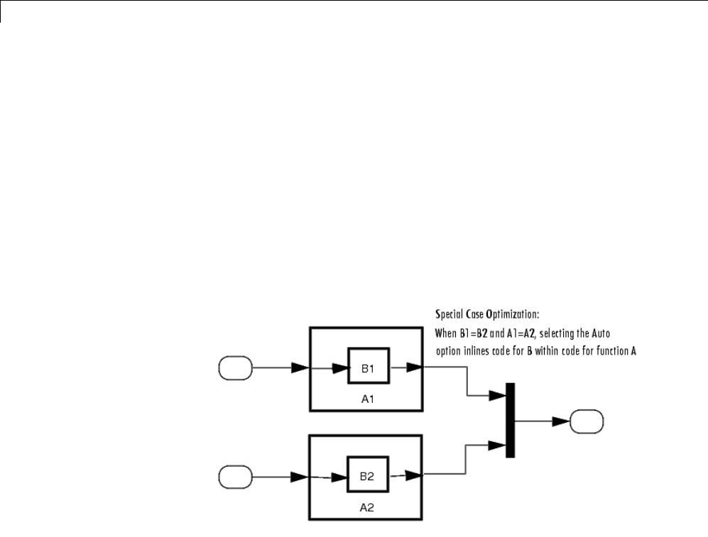
2Subsystems
Optimize Code for Identical Nested Subsystems
The Function packaging parameter Auto option can optimize code in
situations in which identical subsystems contain other identical subsystems,
by both reusing and inlining generated code. Suppose a model, such as the
one shown in Reuse of Identical Nested Subsystems on page 2-14, contains
identical subsystems A1 and A2.A1 contains subsystem B1,andA2 contains
subsystem B2, which are identical. In such cases, the Auto option causes one
function to be generated which is called for both A1 and A2. This function
contains one piece of inlined code to execute B1 and B2. This optimization
generates less code which improves execution speed.
Reuse of Identical Nested Subsystems
2-14

Generate Reusable Code for Subsystems Containing S-Function Blocks
Generate Reusable Code for Subsystems Containing
S-Function Blocks
There are several requirements that need to be met in order for subsystems
containing S-function blocks to be reused. For the list of requirements, see
“S-Functions That Support Code Reuse” on page 14-113.
When you select the Reusable function option, two additional options are
enabled, Function name options and File name options.Ifyouuse
these fields to enter a function name and/or a file name, you must specify
exactly the same function name and file name for each instance of identical
subsystems for the code generator toreusethesubsystemcode. Foran
example, follow the procedure in “Generate Reusable Function for Identical
Subsystems Within a Model” on page 2-11.
2-15

2Subsystems
Generate Reusable Code from Stateflow Charts
You can generate reusable code from a Stateflow chart, or from a subsystem
containing a chart, except in the following cases:
•The Stateflow chart contains exported graphical functions.
•The Stateflow model contains machine parented events.
2-16

Code Reuse Limitations for Subsystems
Code Reuse Limitations for Subsystems
The code generator uses a checksum to determine whether subsystems are
identical and reusable. Subsystem code is not reused, if:
•Multiple ports of a subsystem share the same source.
•A port used by multiple instances of a subsystem has different sample
times, data types, complexity, frame status, or dimensions across the
instances.
•The output of a subsystem is marked as a global signal.
•Subsystems contain identical blocks with different names or parameter
settings.
•The output of a subsystem is connected to a Merge block, and the output of
the Merge block is a custom storage class that is implemented in the C code
as memory that is nonaddressable (for example, BitField).
•The input of a subsystem is nonscalar and has a custom storage class that
is implemented in the C code as memory that is nonaddressable.
•A masked subsystem has a parameter that is nonscalar and has a custom
storage class that is implemented in the C code as memory that is
nonaddressable.
If you select Reusable function, and the code generator determines that
code for a subsystem cannot be reused, it generates a separate function that
is not reused. The code generation report might show that the separate
function is reusable, even if it is usedbyonlyonesubsystem. Ifyouprefer
that subsystem code be inlined in such circumstances rather than deployed as
functions, then choose Auto for the Function packaging option.
Blocks That Prevent Code Reuse
Use of the following blocks in a subsystem can also prevent the subsystem
code from being reused:
•Scope blocks (with data logging enabled)
•S-Function blocks that fail to meet certain criteria (see “S-Functions That
Support Code Reuse” on page 14-113)
2-17

2Subsystems
•To File blocks (with data logging enabled)
•To Workspace blocks (with data logging enabled)
Code Reuse Limitations for Subsystems Shared
Across Referenced Models
The code generator uses a checksum to determine whether reusable library
subsystems are identical. The reusable library subsystem code is placed in
the shared utilities folder and is independent of the generated code of the top
model or the referenced model. For example, the reusable library subsystem
code does not include model.h or model_types.h.
Reusable code that is generated to the shared utilities folder and is dependent
on the model code does not compile. If the code generator determines that the
reusable library subsystem code is dependent on the model code, the reusable
subsystem code is not generated to the shared utilities folder. The following
cases might generate code that is dependent on the model code, when the
reusable library subsystem:
•Contains a block that uses time-related functionality, such as a Step block,
or continuous time or multirate blocks.
•Contains one or more Model blocks.
•Contains subsystems that are not inlined or a reusable library subsystem.
•Contains a For Each subsystem and the model configuration parameter,
Inline parameters,iscleared. Inthiscase,typesaredefinedin
model_types.h.
•Contains a signal that is not an Auto storage class. Variables of non-Auto
storage classes are generated to model.h.
•Contains a parameter that is not an Auto storage class.
•Contains a user-defined type where Data Scope is not set to Exported.
The code generator might place the type definition in model_types.h.
•Is a variant subsystem that generates preprocessor conditionals.
Preprocessor directives defining the variant objects are included in
model_types.h.
2-18

Code Reuse For Subsystems Shared Across Referenced Models
Code Reuse For Subsystems Shared Across Referenced
Models
To reuse common functionality, you can include multiple instances of a
subsystem within a model and across referenced models. To generate a
reusable function for a subsystem which is included in multiple referenced
models:
•If the subsystem is in a model reference hierarchy, set the configuration
parameter, Shared code placement to Auto. Otherwise, for each
model that uses the subsystem, set Shared code placement to Shared
location.TheShared code placement parameter is in the Configuration
Parameters dialog box, on the Code Generation > Interface pane.
•The subsystem must be defined in a library and configured for reuse.
Thissubsystemisreferredtoasareusable library subsystem.Formore
information, see “Reusable Library Subsystem” on page 2-20.
For an example, see “Generate ReusableCodeforSubsystemsSharedAcross
Models” on page 2-25.
The code generator performs a checksum to determine reusability. There
are cases when the code generator cannot reuse subsystem code. For more
information, see “Code Reuse Limitations for Subsystems” on page 2-17.
2-19

2Subsystems
Reusable Library Subsystem
A reusable library subsystem is a subsystem included in a library that is
configured for reuse. The Subsystem parameters must be set as follows:
•Treat as an atomic unit is selected.
•On the Code Generation tab:
-Function packaging is set to Reusable function.
-Function name options
and File name options are set to Auto or Use subsystem name.
For more information on creating a library, see “Libraries”. For an example
of creating a reusable library subsystem, see “Generate Reusable Code for
Subsystems Shared Across Models” on page 2-25.
Code Generation of a Reusable Library Subsystem
For incremental code generation, if the reusable library subsystem changes,
a rebuild of itself and its parents occurs. During the build, if a matching
function is not found, a new instance of the reusable function is generated
into the shared utilities folder. If a different matching function is found
from previous builds, that function is used, and a new reusable function is
not emitted.
For subsequent builds, unused files are not replaced or deleted from your
folder. During development of a model, when many obsolete shared functions
exist in the shared utilities folder, you can delete the folder and regenerate
the code. If all instances of a reusable library subsystem are removed from a
model reference hierarchy and you regenerate the code, the obsolete shared
functions remain in the shared utilities folder until you delete them.
If a model changes such that the change might cause different generated code
for the subsystem, a new reusable function is generated. For example, model
configuration parameters that modify code comments might cause different
generated code for the subsystem even if the reusable library subsystem did
not change.
2-20

Reusable Library Subsystem
Reusable Library Subsystem Code Placement and
Naming
The code generator uses checksums to determine reusability. The generated
code of a reusable library subsystem is independent of the generated code of
the model. Code for the reusable library subsystem is generated to the shared
utility folder, slprj/target/_sharedutils, instead of the model reference
hierarchy folders. The generated code for the supporting types, which are
generated to the .h file, are also in the shared utilities folder.
In the Subsystem Parameters dialog box, the Function name options
and File name options must be set to Auto or Use subsystem name.For
unique naming, reusable function names have a checksum string appended to
the reusable library subsystem name. For example, the code and files for a
subsystem, SS1, which links to a reusable library subsystem, RLS,mightbe:
•Function name: RLS_mgdjlngd
•File name: RLS_mgdjlnd.c and RLS_mgdjlnd.h
Reusable Library Subsystem in the Top Model
In a model reference hierarchy, if an instance of the reusable library
subsystem is in the top model, then on the Model Referencing pane of the
Configuration Parameters dialog box, you must select the Pass fixed-size
scalar root input by value for code generation parameter. If you do
not select the parameter, a separate shared function is generated for the
reusable library subsystem instance in the top model, and a reusable function
is generated for instances in the referenced models.
Reusable Library Subsystem Connected to Root
Outport
If a reusable library subsystem is connected to the root outport, reuse does not
happen with identical subsystems that are not connected to the root outport.
However, you can set Pass reusable system outputs as to Individual
arguments on the Optimizations > Signals and Parameters pane to make
sure that reuse occurs between these subsystems. This parameter requires
an Embedded Coder license.
2-21

2Subsystems
Code Generation of Constant Parameters
The code generator attempts to generate constant parameters to the shared
utilities folder first. If constant parameters are not generated to the shared
utilities folder, they are defined in the top model in a global constant
parameter structure. The declaration of the structure, ConstParam_model,is
in model.h:
/* Constant parameters (auto storage) */
typedef struct {
/* Expression: [1 2 3 4 5 6 7]
* Referenced by: '<Root>/Constant'
*/
real_T Constant_Value[7];
/* Expression: [7 6 5 4 3 2 1]
* Referenced by: '<Root>/Gain'
*/
real_T Gain_Gain[7];
} ConstParam_model;
The definition of the constant parameters, model_constP,isin:
/* Constant parameters (auto storage) */
const ConstParam_model model_ConstP = {
/* Expression: [1 2 3 4 5 6 7]
* Referenced by: '<Root>/Constant'
*/
{ 1.0, 2.0, 3.0, 4.0, 5.0, 6.0, 7.0 },
/* Expression: [7 6 5 4 3 2 1]
* Referenced by: '<Root>/Gain'
*/
{ 7.0, 6.0, 5.0, 4.0, 3.0, 2.0, 1.0 }
};
The model_constP is passed as an argument to referenced models. For more
information on how shared constants are generated, see “Shared Constant
Parameters for Code Reuse” on page 2-23.
2-22

Shared Constant Parameters for Code Reuse
Shared Constant Parameters for Code Reuse
You can share the generated code for constant parameters across models if:
•Constant parameters are shared in a model reference hierarchy, or
•On the Code Generation > Interface pane, the model configuration
parameter Shared code placement is set to Shared location.
The shared constant parameters are generated individually to the
const_params.c file, which is placed in the shared utilities folder
slprj/target/_sharedutils.
For example, if a constant has multiple uses within a model reference
hierarchy where the top model is named topmod,thecodefortheshared
constant is as follows:
•In the shared utility folder, slprj/grt/_sharedutils, the constant
parameters are defined in const_params.c and named rtCP_pooled_
appended to a unique checksum string:
extern const real_T rtCP_pooled_lfcjjmohiecj[7];
const real_T rtCP_pooled_lfcjjmohiecj[7] = { 1.0, 2.0, 3.0, 4.0, 5.0, 6.0, 7.0 };
extern const real_T rtCP_pooled_ppphohdbfcba[7];
const real_T rtCP_pooled_ppphohdbfcba[7] = { 7.0, 6.0, 5.0, 4.0, 3.0, 2.0, 1.0 };
•In top_model_private.h or in any referenced model,
ref_model_private.h, for better readability, the constants are
renamed as follows:
extern const real_T rtCP_pooled_lfcjjmohiecj[7];
extern const real_T rtCP_pooled_ppphohdbfcba[7];
#define rtCP_Constant_Value rtCP_pooled_lfcjjmohiecj /* Expression: [1234567]
* Referenced by: '<Root>/Constant'*/
#define rtCP_Gain_Gain rtCP_pooled_ppphohdbfcba /* Expression: [7 6 5 4 3 2 1]
* Referenced by: '<Root>/Gain' */
•In topmod.c or refmod.c,thecallsitemightbe:
2-23

2Subsystems
for (i = 0; i < 7; i++) {
topmod_Y.Out1[i] = (topmod_U.In1 + rtCP_Constant_Value[i]) * rtCP_Gain_Gain[i];
}
The code generator attempts to generate all constants as individual constants
to the const_params.c file in the shared utilities folder. Otherwise, constants
are generated as described in “Code Generation of Constant Parameters”
on page 2-22.
Shared Constant Parameters Limitations
No shared constants or shared functions are generated for a model when:
•The model has a Code Replacement Library (CRL) that is specified for
data alignment.
•The model is specified to replace data type names in the generated code.
•The Memory Section for constants is MemVolatile or MemConstVolatile.
Individual constants are not shared, if:
•A constant is referenced by a non-inlined S-function.
•A constant has a user-defined type where Data Scope is not set to
Exported.
2-24
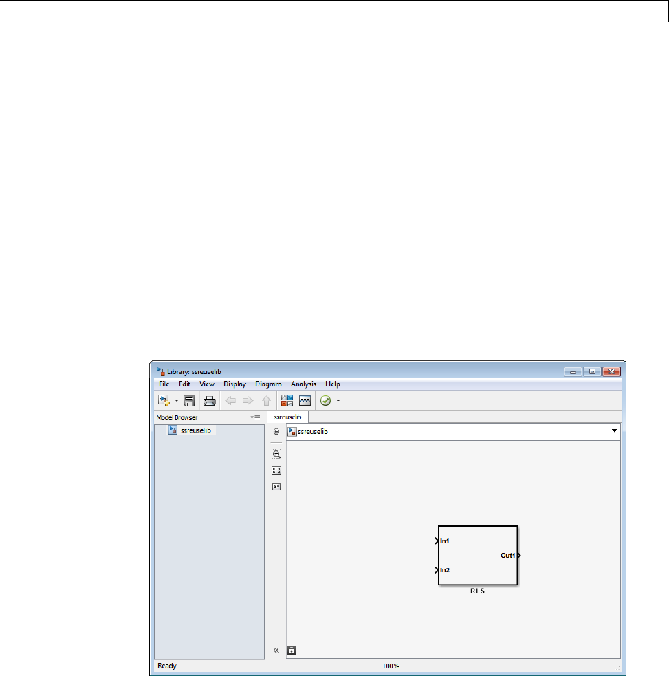
Generate Reusable Code for Subsystems Shared Across Models
Generate Reusable Code for Subsystems Shared Across
Models
This example shows you how to configure a reusable library subsystem and
generate a reusable function for a subsystem shared across referenced models.
The result is reusable code for the subsystem, which is generated to the
shared utility folder (slprj/target/_sharedutils). For more information
about a reusable library subsystem, see “Code Reuse For Subsystems Shared
Across Referenced Models” on page 2-19.
Create a reusable library subsystem.
1In the Simulink Editor, select File>New>Library.Open
rtwdemo_ssreuse to copy and paste subsystem SS1 into the Library Editor.
This action loads the variables for SS1 into the base workspace. Rename
the subsystem block to RLS.
2Click the Subsystem block and press Ctrl+U to view the contents of
subsystem RLS.
2-25
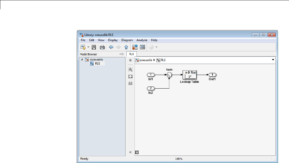
2Subsystems
3To configure the subsystem, in the Library editor, right-click RLS.Inthe
context menu, select Block Parameters(Subsystem).IntheSubsystem
Parameters dialog box, choose the following options:
•Select Treat as an atomic unit.
•On the Code Generation tab:
–Set Function packaging to Reusable function.
–Set Function name options and File name options to Auto.
4Click Apply and OK.
5Savethereusablelibrarysubsystemasssreuselib, which creates a file,
ssreuselib.slx.
Create the example model.
1Create a model which includes one instance of RLS from ssreuselib.Name
this subsystem SS1. Add another subsystem and name it SS2.Namethe
model ex_model1.
2-26
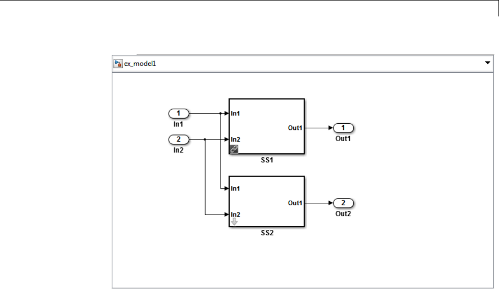
Generate Reusable Code for Subsystems Shared Across Models
2Create another model which includes one instance of RLS from ssreuselib.
Name this subsystem SS1. Add another subsystem and name it SS3.Name
the model ex_model2.
2-27
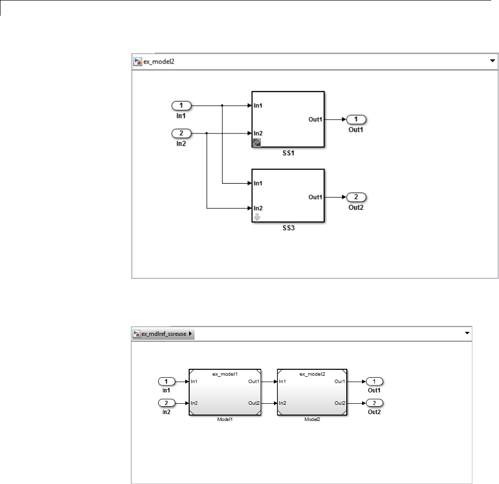
2Subsystems
3Create a top model with two model blocks that reference ex_model1 and
ex_model2. Save the top model as ex_mdlref_ssreuse.
Set configuration parameters of the top model.
2-28

Generate Reusable Code for Subsystems Shared Across Models
1With model ex_mdlref_ssreuse open in the Simulink Editor, select
Simulation > Model Configuration Parameters to open the
Configuration Parameters dialog box.
2On the Optimization > Signals and Parameters pane, select Inline
parameters.
3On the Solver pane, specify the Type as Fixed-step.
4On the Code Generation > Report pane, select Create code generation
report and Open report automatically.
5On the Code Generation > Interface pane, set the Shared code
placement to Shared location.
6On the Code Generation > Symbols pane, set the Maximum identifier
length to 256. This step is optional.
7Click Apply and OK.
Create and propagate a configuration reference.
1In the Simulink Editor, select View > Model Explorer to open the Model
Explorer. In the left navigation column of the Model Explorer, expand the
ex_mdlref_ssreuse node.
2Right-click Configuration and select Convert to Configuration
Reference.
3In the Convert Active Configuration to Reference dialog box, click OK.This
action converts the model configuration set to a configuration reference,
Simulink.ConfigSetRef, and creates the configuration reference object,
configSetObj, in the base workspace.
4In the left navigation column, right-click Reference (Active) and select
Propagate to Referenced Models.
5In the Configuration Reference Propagation to Referenced Models dialog
box, select the referenced models in the list. Click Propagate.
Now, the top model and reference models all use the same configuration
reference, Reference (Active), which points to a model configuration
2-29

2Subsystems
reference object, configSetObj, in the base workspace. When you save your
model, you also need to export the configSetObj to a MAT-file. For more
information, see “Save a Referenced Configuration Set”.
Generate and view the code.
1To generate code, in the Simulink Editor, press Ctrl-B. After the code is
generated, the code generation report opens.
2To view the code generation report for a referenced model, in the left
navigation pane, in the Referenced Models section, select ex_model1.
The code generation report displays the generated files for ex_model1.
3In the left navigation pane, expand the Shared Utility files.The
code generator uses the reusable library subsystem name and a unique
string to name the reused function. The code for subsystem SS1 is in
RLS_aaaippph.c and RLS_aaaippph.h.
2-30

Generate Reusable Code for Subsystems Shared Across Models
4Click Back and navigate to the ex_model2 code generation report.
ex_model2 uses the same source code, RLS_aaaippph.c and
RLS_aaaippph.h,asthecodeforex_model1. Your subsystem function and
file names will be different.
Related
Examples
•“Determine Why Subsystem Code Is Not Reused” on page 2-32
•“Share a Configuration Across Referenced Models”
•“Generate Reusable Function for Identical Subsystems Within a Model”
on page 2-11
Concepts •“Code Generation of Subsystems” on page 2-2
•“Code Reuse For Subsystems Shared Across Referenced Models” on page
2-19
•“Code Reuse Limitations for Subsystems” on page 2-17
•“Libraries”
2-31

2Subsystems
Determine Why Subsystem Code Is Not Reused
Due to the limitations described in “Code Reuse Limitations for Subsystems”
on page 2-17, the code generator might not reuse generated code as you
expect. To determine why code generated for a subsystem is not reused, see
“Review the Subsystems Section of the HTML Code Generation Report” on
page 2-32. If you cannot determine why based on the report, see “Compare
Subsystem Checksum Data” on page 2-32.
Review the Subsystems Section of the HTML Code
Generation Report
If you determine that the code generator does not generate code for a
subsystem as reusable code, and you specified the subsystem as reusable,
examine the Subsystems section of the HTML code generation report (see
“Generate a Code Generation Report” on page 11-5). The Subsystems section
contains:
•A table that summarizes how nonvirtual subsystems were converted to
generated code.
•Diagnostic information that describes why the contents of some subsystems
were not generated as reusable code.
The Subsystems section also indicates the mapping of each noninlined
subsystem in the model to functions or reused functions in the generated code.
For an example, open and build the rtwdemo_atomic model.
Compare Subsystem Checksum Data
You can determine why subsystem code is not reused by accessing and
comparing subsystem checksum data. The code generator determines whether
subsystems are identical by comparing subsystem checksums, as noted in
“Code Reuse Limitations for Subsystems” on page 2-17. For subsystem reuse
across referenced models, this procedure might not catch every difference.
Consider the model, rtwdemo_ssreuse.SS1 and SS2 are instances of the
same subsystem. In both instances the subsystem parameter Function
packaging is set to Reusable function.
2-32

Determine Why Subsystem Code Is Not Reused
Use the method, Simulink.SubSystem.getChecksum,togetthechecksumfor
a subsystem. Compare the results to determine why code is not reused.
1Open the model rtwdemo_ssreuse. Save a copy of the model in a folder
where you have write access.
2In the model window, select subsystem SS1. In the command window, enter
SS1 = gcb;
3In the model window, select subsystem SS2. In the command window, enter
SS2 = gcb;
4Use the method, Simulink.SubSystem.getChecksum,togetthechecksum
for each subsystem. This method returns two output values: the checksum
value and details on the input used to compute the checksum.
[chksum1, chksum1_details] = ...
Simulink.SubSystem.getChecksum(SS1);
[chksum2, chksum2_details] = ...
Simulink.SubSystem.getChecksum(SS2);
5Compare the two checksum values. They should be equal based on the
subsystem configurations.
isequal(chksum1, chksum2)
ans =
1
6To see how you can use Simulink.SubSystem.getChecksum to determine
why the checksums of two subsystems differ, change the data type mode of
the output port of SS1 so that it differs from that of SS2.
aLook under the mask of SS1. Right-click the subsystem. In the context
menu, select Mask > Look Under Mask.
bIn the block diagram of the subsystem, double-click the Lookup Table
block to open the Subsystem Parameters dialog box.
cClick Data Types.
2-33

2Subsystems
dSelect Saturate on integer overflow and click OK.
7Get the checksum for SS1. Compare the checksums for the two subsystems.
This time, the checksums are not equal.
[chksum1, chksum1_details] = ...
Simulink.SubSystem.getChecksum(SS1);
isequal(chksum1, chksum2)
ans =
0
8After you determine that the checksums are different, find out why. The
Simulink engine uses information, such as signal data types, some block
parameter values, and block connectivity information, to compute the
checksums. To determine why checksums are different, you compare the
data used to compute the checksum values. You can get this information
from the second value returned by Simulink.SubSystem.getChecksum,
which is a structure array with four fields.
Look at the structure chksum1_details.
chksum1_details
chksum1_details =
ContentsChecksum: [1x1 struct]
InterfaceChecksum: [1x1 struct]
ContentsChecksumItems: [287x1 struct]
InterfaceChecksumItems: [53x1 struct]
ContentsChecksum and InterfaceChecksum are component
checksums of the subsystem checksum. The remaining two fields,
ContentsChecksumItems and InterfaceChecksumItems, contain the
checksum details.
9Determine whether a difference exists in the subsystem contents, interface,
or both. For example:
isequal(chksum1_details.ContentsChecksum.Value,...
chksum2_details.ContentsChecksum.Value)
ans =
0
2-34

Determine Why Subsystem Code Is Not Reused
isequal(chksum1_details.InterfaceChecksum.Value,...
chksum2_details.InterfaceChecksum.Value)
ans =
1
In this case, differences exist in the contents.
10 Write a script like the following to find the differences.
idxForCDiffs=[];
for idx = 1:length(chksum1_details.ContentsChecksumItems)
if (~strcmp(chksum1_details.ContentsChecksumItems(idx).Identifier, ...
chksum2_details.ContentsChecksumItems(idx).Identifier))
disp(['Identifiers different for contents item ', num2str(idx)]);
idxForCDiffs=[idxForCDiffs, idx];
end
if (ischar(chksum1_details.ContentsChecksumItems(idx).Value))
if (~strcmp(chksum1_details.ContentsChecksumItems(idx).Value, ...
chksum2_details.ContentsChecksumItems(idx).Value))
disp(['String values different for contents item ', num2str(idx)]);
idxForCDiffs=[idxForCDiffs, idx];
end
end
if (isnumeric(chksum1_details.ContentsChecksumItems(idx).Value))
if (chksum1_details.ContentsChecksumItems(idx).Value ~= ...
chksum2_details.ContentsChecksumItems(idx).Value)
disp(['Numeric values different for contents item ', num2str(idx)]);
idxForCDiffs=[idxForCDiffs, idx];
end
end
end
11 Run the script. The following example assumes that you named the script
check_details.
check_details
String values different for contents item 202
The results indicate that differences exist for index item 202 in the
subsystem contents.
2-35

2Subsystems
12 Usethereturnedindexvaluestogetthehandle,identifier,andvalue
details for each difference found.
chksum1_details.ContentsChecksumItems(202)
ans =
Handle: 'rtwdemo_ssreuse/SS1/Lookup Table'
Identifier: 'SaturateOnIntegerOverflow'
Value: 'on'
The details identify the Lookup Table block parameter Saturate on
integer overflow as the focus for debugging a subsystem reuse issue.
2-36

3
Referenced Models

3Referenced Models
Code Generation for Referenced Models
This section describes model referencing considerations that apply specifically
to code generation by the Simulink Coder. This section assumes that you
understand referenced models and related terminology and requirements, as
described in “Overview of Model Referencing” and associated topics.
When generating code for a referenced model hierarchy, the code generator
produces a stand-alone executable for the top model, and a library module
called a model reference target for each referenced model. When the code
executes, the top executable invokes the model reference targets to compute
the referenced model outputs. Model reference targets are sometimes called
Simulink Coder targets.
Be careful not to confuse a model reference target (Simulink Coder target)
with any of these other types of targets:
•Hardware target — A platform for which the Simulink Coder software
generates code
•System target — A file that tells the Simulink Coder software how to
generate code for particular purpose
•Rapid Simulation target (RSim) — A system target file supplied with the
Simulink Coder product
•Simulation target — A MEX-file that implements a referenced model that
executes with Simulink Accelerator™ software
The code generator places the code for the top model of a hierarchy in the
current working folder, and the code for submodels in a folder named slprj
within the current working folder. Subfolders in slprj provide separate
places for different types of files. See “Project Folder Structure for Model
Reference Targets” on page 3-16 for details.
By default, the product uses incremental code generation.Whengenerating
code, it compares structural checksums of referenced model files with the
generated code files to determine whether to regenerate model reference
targets. To control when rebuilds occur, use the configuration parameter
Model Referencing > Rebuild. For details, see “Rebuild”.
3-2

Code Generation for Referenced Models
In addition to incremental code generation, the Simulink Coder software
uses incremental loading. The code for a referenced model is not loaded into
memory until the code for its parent model executes and needs the outputs of
the referenced model. The product then loads the referenced model target and
executes. Once loaded, the target remains in memory until it is no longer used.
Most code generation considerations are the same whether or not a model
includes any referenced models: the code generator handles the details
automatically insofar as possible. This chapter describes topics that you may
need to consider when generating code for a model reference hierarchy.
If you have a Embedded Coder license, custom targets must declare
themselves to be model reference compliant if they need to support Model
blocks. For more information, see “Support Model Referencing” on page
24-101.
3-3

3Referenced Models
Generate Code for Referenced Models
In this section...
“About Generating Code for Referenced Models” on page 3-4
“Create and Configure the Subsystem” on page 3-4
“Convert Model to Use Model Referencing” on page 3-7
“Generate Model Reference Code for a GRT Target” on page 3-11
“Work with Project Folders” on page 3-14
About Generating Code for Referenced Models
To generated code for referenced models, you
1Create a subsystem in an existing model.
2Convert the subsystem to a referencedmodel(Modelblock).
3Call the referenced model from the top model.
4Generate code for the top model and referenced model.
5Explorethegeneratedcodeandtheprojectfolder.
You can accomplish some of these tasks automatically with a function called
Simulink.Subsystem.convertToModelReference.
Create and Configure the Subsystem
In the first part of this example, you define a subsystem for the vdp
example model, set configuration parameters for the model, and use the
Simulink.Subsystem.convertToModelReference function to convert it into
two new models — the top model (vdptop) and a referenced model vdpmultRM
containing a subsystem you created (vdpmult).
3-4
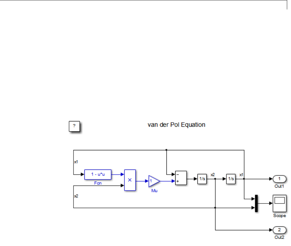
Generate Code for Referenced Models
1In the MATLAB Command Window, create a new working folder wherever
you want to work and cd into it:
mkdir mrexample
cd mrexample
2Open the vdp example model by typing:
vdp
3Drag a box around the three blocks outlined in blue below:
4ChooseCreate Subsystem from Selected from the model’s Diagram >
Subsystem & Model Reference menu.
Asub
system block replaces the selected blocks.
5If the new subsystem block is not where you want it, move it to a preferred
location.
6Rename the block vdpmult.
3-5
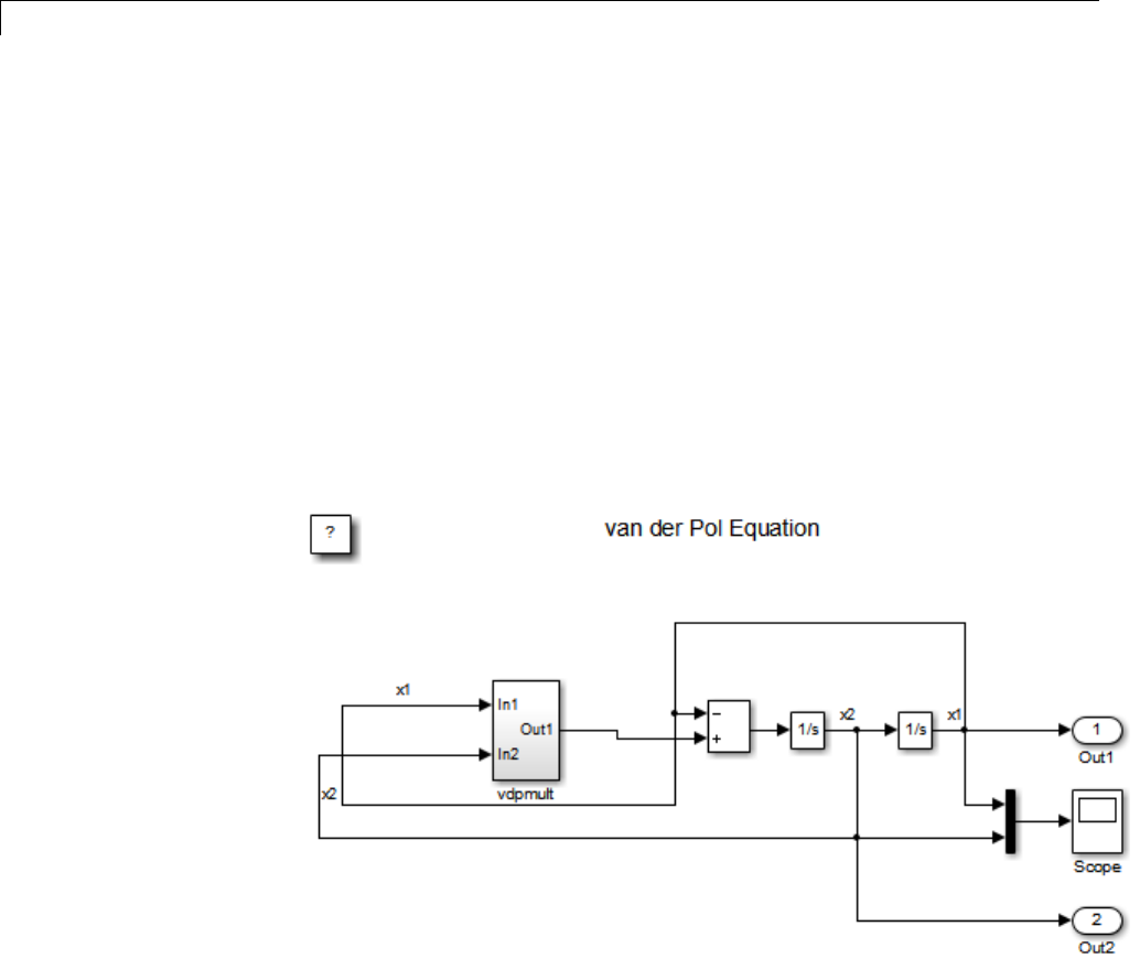
3Referenced Models
7Right-click the vdpmult block and select Subsystem Parameters.
The Function Block Parameters dialog box appears.
8In the Function Block Parameters dialog box, select Treat as atomic
unit,thenclickOK.
The border of the vdpmult subsystem thickens to indicate that it is now
atomic. An atomic subsystem executes as a unit relative to the parent
model: subsystem block execution does not interleave with parent block
execution. This property makes it possible to extract subsystems for use as
stand-alone models and as functions in generated code.
The block diagram should now appear as follows:
You must set several properties before you can extract a subsystem for use as
a referenced model. To set the properties,
1Open Model Explorer by selecting Model Explorer from the model’s
View menu.
3-6

Generate Code for Referenced Models
2In the Model Hierarchy pane, click the symbol preceding the model name
to reveal its components.
3Click Configuration (Active) in the left pane.
4In the center pane, select Solver.
5In the right pane, under Solver Options change the Type to Fixed-step,
then click Apply. You must use fixed-step solvers when generating code,
although referenced models can use different solvers than top models.
6In the center pane, select Optimization. In the right pane, select
the Signals and Parameters tab, and under Simulation and code
generation,selectInline parameters.ClickApply.
7In the center pane, select Diagnostics.Intherightpane:
aSelect the Data Validity tab. In the Signals area, set Signal
resolution to Explicit only.
bSelect the Connectivity tab. In the Buses area, set Mux blocks used
to create bus signals to error.
8Click Apply.
The model now has the properties that model referencing requires.
9In the center pane, click Model Referencing.Intherightpane,set
Rebuild to If any changes in known dependencies detected.Click
Apply. This setting prevents code regeneration when it is not required.
10 In the vdp model window, choose File > Save as.Savethemodelas
vdptop in your working folder. Leave the model open.
Convert Model to Use Model Referencing
Inthisportionoftheexample,youusetheconversionfunction
Simulink.SubSystem.convertToModelReference to extract the subsystem
vdpmult from vdptop and convert vdpmult into a referenced model named
vdpmultRM. To see the complete syntax of the conversion function, type at
the MATLAB prompt:
help Simulink.SubSystem.convertToModelReference
3-7

3Referenced Models
For additional information, type:
doc Simulink.SubSystem.convertToModelReference
If you want to see an example of
Simulink.SubSystem.convertToModelReference before using it
yourself, type:
sldemo_mdlref_conversion
Simulink also provides a menu command, Subsystem & Model
Reference > Convert Subsystem to > Referenced Model,thatyou
can use to convert a subsystem to a referenced model. The command calls
Simulink.SubSystem.convertToModelReference with default arguments.
For more information, see “Convert a Subsystem to a Referenced Model”.
Extract the Subsystem to a Referenced Model
To use Simulink.SubSystem.convertToModelReference to extract vdpmult
and convert it to a referenced model, type:
Simulink.SubSystem.convertToModelReference...
('vdptop/vdpmult', 'vdpmultRM',...
'ReplaceSubsystem', true, 'BuildTarget', 'Sim')
This command:
1Extracts the subsystem vdpmult from vdptop.
2Converts the extracted subsystem to a separate model named vdpmultRM
and saves the model to the working folder.
3In vdptop, replaces the extracted subsystem with a Model block that
references vdpmultRM.
4Creates a simulation target for vdptop and vdpmultRM.
The converter prints progress messages and terminates with
ans =
1
3-8
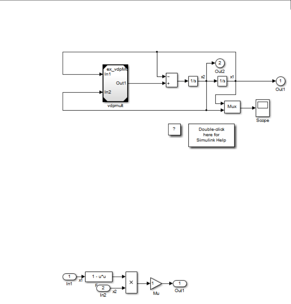
Generate Code for Referenced Models
The parent model vdptop now looks like this:
Note the changes in the appearance of the block vdpmult.Thesechanges
indicate that it is now a Model block rather than a subsystem. As a Model
block, it has no contents of its own: the previous contents now exist in the
referenced model vdpmultRM, whose name appears at the top of the Model
block. Widen the Model block to expose the complete name of the referenced
model.
If the parent model vdptop had been closed at the time of conversion, the
converter would have opened it. Extracting a subsystem to a referenced model
does not automatically create or change a saved copy of the parent model. To
preserve the changes to the parent model, save vdptop.
Right-click the Model block vdpmultRM and choose Open Model
’vdpmultRM’ to open the referenced model. The model looks like this:
3-9

3Referenced Models
Files Created and Changed by the Converter
The files in your working folder now consist of the following (not in this order).
File Description
vdptop model file Top model that contains a Model block
where the vdpmult subsystem was
vdpmultRM model file Referenced model created for the vdpmult
subsystem
vdpmultRM_msf.mexw32 Static library file (Microsoft Windows
platforms only). The last three characters
of the suffix are system-dependent and may
differ. This file executes when the vdptop
model calls the Model block vdpmult.When
called, vdpmult in turn calls the referenced
model vdpmultRM.
/slprj Project folder for generated model reference
code
Code for model reference simulation targets is placed in the slprj/sim
subfolder. Generated code for GRT, ERT, and other Simulink Coder targets is
placed in slprj subfolders named for those targets. You will inspect some
model reference code later in this example. For more information on project
folders, see “Work with Project Folders” on page 3-14.
3-10
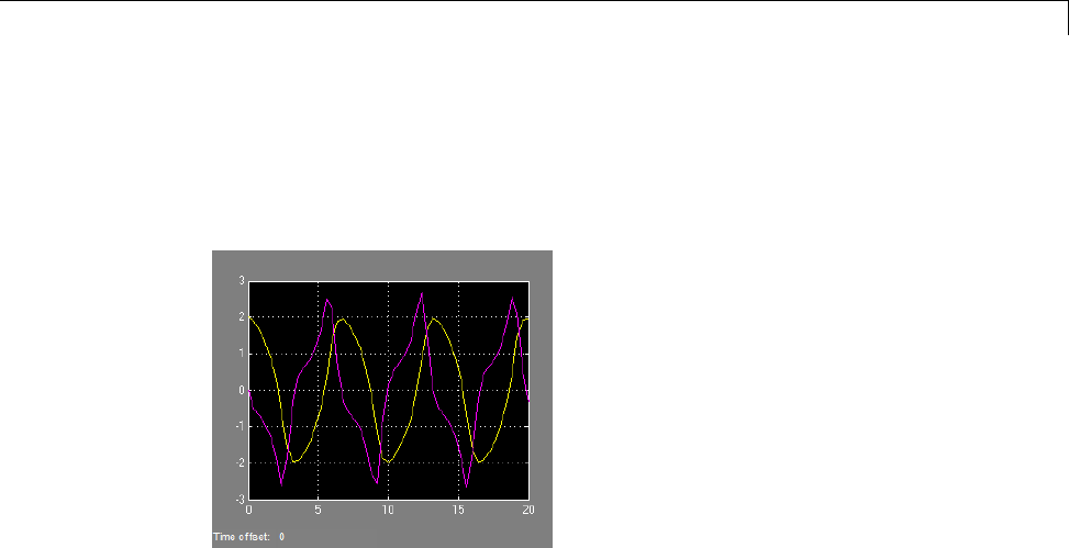
Generate Code for Referenced Models
Run the Converted Model
Open the Scope block in vdptop if it is not visible. In the vdptop window, click
the Run tool or choose Run from the Simulation menu. The model calls the
vdpmultRM_msf simulation target to simulate. The output looks like this:
Generate Model Reference Code for a GRT Target
The function Simulink.SubSystem.convertToModelReference created the
model and the simulation target files for the referenced model vdpmultRM.In
this part of the example, you generate code for that model and the vdptop
model, and run the executable you create:
1Verify that you are still working in the mrexample folder.
2If the model vdptop is not open, open it. Make sure it is the active window.
3Open Model Explorer by selecting Model Explorer from the model’s
View menu.
4In the Model Hierarchy pane, click the symbol preceding the vdptop
model to reveal its components.
5Click Configuration (Active) in the left pane.
6In the center pane, select Data Import/Export.
3-11
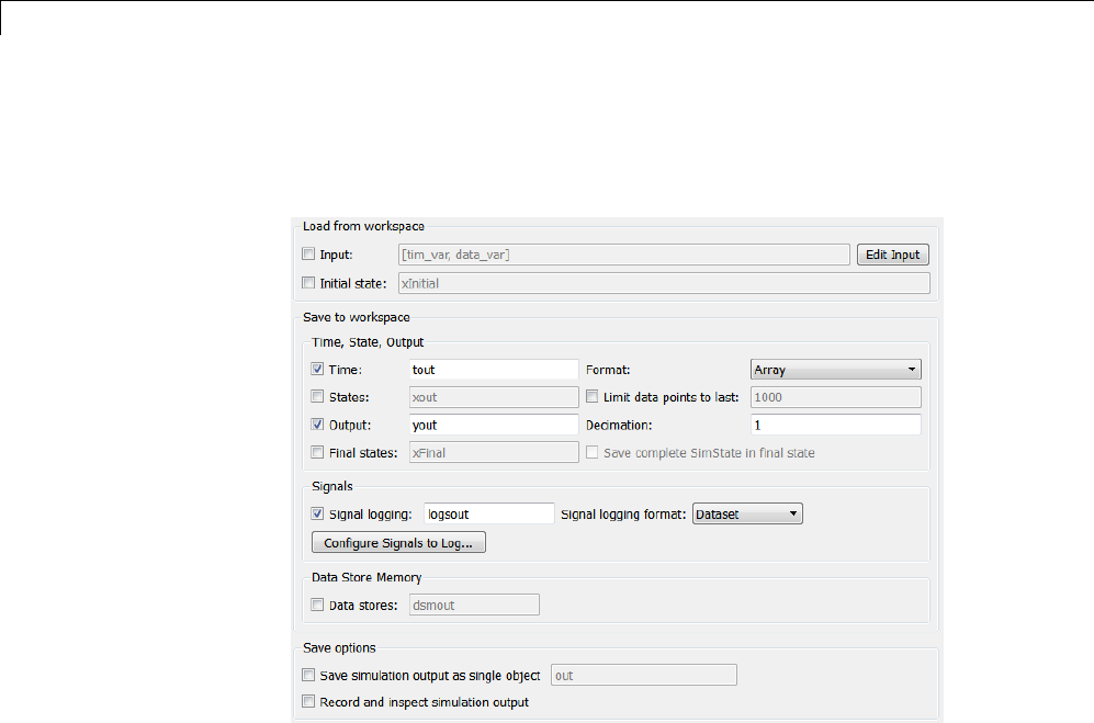
3Referenced Models
7In the Save to workspace section of the right pane, check Time and
Output and clear Data stores.ClickApply. The pane shows the following
information:
These settings instruct the model vdptop (and later its executable) to log
time and output data to MAT-files for each time step.
8GenerateGRTcode(thedefault)andanexecutableforthetopmodeland
the referenced model by selecting Code Generation in the center pane
and then clicking the Build button.
3-12

Generate Code for Referenced Models
The Simulink Coder build process generates and compiles code. The current
folder now contains a new file and a new folder:
File Description
vdptop.exe The executable created by the build
process
vdptop_grt_rtw/ The build folder, containing
generated code for the top model
The build process also generated GRT code for the referenced model, and
placed it in the slprj folder.
To view a model’s generated code in Model Explorer, the model must be
open. To use the Model Explorer to inspect the newly created build folder,
vdptop_grt_rtw:
1Open Model Explorer by selecting Model Explorer from the model’s
View menu.
2In the Model Hierarchy pane, click the symbol preceding the model name
to reveal its components.
3Click the symbol preceding Code for vdptop to reveal its components.
4Directly under Code for vdptop,clickThis Model.
A list of generated code files for vdptop appears in the Contents pane:
rtmodel.h
vdptop.c
vdptop.h
vdptop.mk
vdptop_private.h
vdptop_types.h
3-13
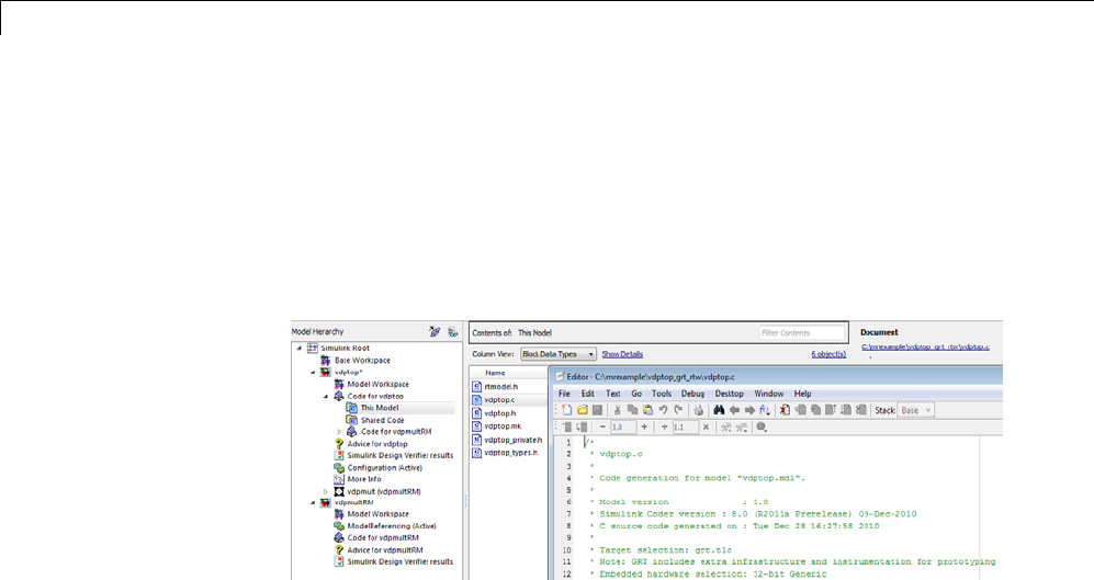
3Referenced Models
You can browse code in any of these files by selecting a file of interest in
the Contents pane.
To open a file in a text editor, click a filename, and then click the hyperlink
that appears in the gray area at the top of the Document pane. The
figure below illustrates viewing code for vdptop.c, in a text editor. Your
code may differ.
To view the generated code in the HTML code generation report, see
“Generate a Code Generation Report” on page 11-5.
Work with Project Folders
When you view generated code in Model Explorer, the files listed in the
Contents pane can exist either in a build folder or a project folder. Model
reference project folders (always rooted under slprj), like build folders, are
created in your current working folder, and this implies certain constraints on
when and where model reference targets are built, and how they are accessed.
The models referenced by Model blocks can be stored anywhere. A given
top model can include models stored on different file systems or in different
folders. The same is not true for the simulation targets derived from these
models; under most circumstances, all models referenced by a given top model
must be set up to simulate and generate model reference target code in a
single project folder. The top and referenced models can exist anywhere on
your path, but the project folder is assumed to exist in your current folder.
This means that, if you reference the same model from several top models,
each stored in a different folder, you must either
3-14

Generate Code for Referenced Models
•Always work in the same folder and be sure that the models are on your
path
•Allow separate project folders, simulation targets, and Simulink Coder
targets to be generated in each folder in which you work
The files in such multiple project folders are generally quite redundant.
Therefore, to minimize code regeneration for referenced models, choose a
specific working folder and remain in it for all sessions.
As model reference code generated for Simulink Coder targets as well as
for simulation targets is placed in project folders, the same considerations
as above apply even if you are generating target applications only. That is,
code for all models referenced from a given model ends up being generated
inthesameprojectfolder,evenifitisgenerated for different targets and at
different times.
3-15

3Referenced Models
Project Folder Structure for Model Reference Targets
Code for models referenced by using Model blocks is generated in project
folders within the current working folder. The top-level project folder is
always named /slprj. The next level within slprj contains parallel build
area subfolders.
The following table lists principal project folders and files. In the paths listed,
model is the name of the model being used as a referenced model, and target
is the system target file acronym (for example, grt,ert,rsim,andsoon).
Folders and Files Description
slprj/sim/model/Simulation target files for referenced
models
slprj/sim/model/tmwinternal MAT-files used during code generation
slprj/target/model/referenced_model_includes Header files from models referenced by
this model
slprj/target/model Model reference target files
slprj/target/model/tmwinternal MAT-files used during code generation
slprj/sl_proj.tmw Marker file
slprj/target/_sharedutils Utility functions for model reference
targets, shared across models
slprj/sim/_sharedutils Utility functions for simulation targets,
shared across models
If you are building code for more than one referenced model within the same
working folder, model reference files for all such models are added to the
existing slprj folder.
3-16

Configure Referenced Models
Configure Referenced Models
Minimize occurrences of algebraic loops by selecting the Minimize algebraic
loop occurrences parameter on the Model Reference pane. The setting
of this option affects only generation of code from the model. See “Hardware
Targets” on page 9-9 in the Simulink Coder documentation for information
on how this option affects code generation. For more information, see “Model
Blocks and Direct Feedthrough”.
Use the Integer rounding mode parameter on your model’s blocks to
simulate the rounding behavior of the C compiler that you intend to use to
compile code generated from the model. This setting appears on the Signal
Attributes pane of the parameter dialog boxes of blocks that can perform
signed integer arithmetic, such as the Product and n-D Lookup Table blocks.
For most blocks, the value of Integer rounding mode completely defines
rounding behavior. For blocks that support fixed-point data and the Simplest
rounding mode, the value of Signed integer division rounds to also affects
rounding. For details, see “Rounding”.
When models contain Model blocks, all models that they reference must be
configured to use identical hardware settings. For information on the Model
Referencing pane options, see “Model Referencing Pane” and “Configuration
Parameter Requirements”.
3-17

3Referenced Models
Build Model Reference Targets
By default, the Simulink engine rebuilds simulation targets before the
Simulink Coder software generates model reference targets. You can change
the rebuild criteria or specify that the engine always or never rebuilds targets.
See “Rebuild” for details.
The Simulink Coder software generates a model reference target directly from
the Simulink model. The product automatically generates or regenerates
model reference targets, for example, when they require an update.
You can command the Simulink and Simulink Coder products to generate a
simulation target for an Accelerator mode referenced model, and a model
reference target for any referenced model, by executing the slbuild command
with arguments in the MATLAB Command Window.
The Simulink Coder software generates only one model reference target for
all instances of a referenced model. See “Reusable Code and Referenced
Models” on page 3-32 for details.
Reduce Change Checking Time
You can reduce the time that the Simulink and Simulink Coder products
spend checking whether any or all simulation targets and model reference
targets need to be rebuilt by setting configuration parameter values as follows:
•In the top model, consider setting the model configuration parameter Model
Referencing > Rebuild to If any changes in known dependencies
detected.(See“Rebuild”.)
•In all referenced models throughout the hierarchy, set the configuration
parameter Diagnostics > Data Validity > Signal resolution to
Explicit only. (See “Signal resolution”.)
These parameter values exist in a referenced model’s configuration set, not
in the individual Model block, so setting either value for any instance of a
referenced model sets it for all instances of that model.
3-18

Simulink®Coder™ Model Referencing Requirements
Simulink Coder Model Referencing Requirements
A model reference hierarchy must satisfy various Simulink Coder
requirements, as described in this section. In addition to these requirements,
a model referencing hierarchy to be processed by the Simulink Coder software
must satisfy:
•The Simulink requirements listed in:
-“Configuration Requirements for All Referenced Model Simulation”
-“Model Structure Requirements”
•The Simulink limitations listed in “Limitations on All Model Referencing”
•The Simulink Coder limitations listed in “Simulink®Coder™ Model
Referencing Limitations” on page 3-36
Configuration Parameter Requirements
A referenced model uses a configuration set in the same way that any other
model does, as described in “Manage a Configuration Set”. By default, every
model in a hierarchy has its own configuration set, which it uses in the same
waythatitwouldifthemodelexecuted independently.
Because each model can have its own configuration set, configuration
parameter values can be different in different models. Furthermore, some
parameter values are intrinsically incompatible with model referencing. The
response of the Simulink Coder software to an inconsistent or unusable
configuration parameter depends on the parameter:
•Where an inconsistency has no significance, or a trivial resolution exists
that carries no risk, the product ignores or resolves the inconsistency
without posting a warning.
•Where a nontrivial and possibly acceptable solution exists, the product
resolves the conflict silently; resolves it with a warning; or generates an
error. See “Model configuration mismatch” for details.
•Where no acceptable resolution is possible, the product generates an
error. You must then change some or all parameter values to eliminate
the problem.
3-19

3Referenced Models
When a model reference hierarchy contains many submodels that have
incompatible parameter values, or a changed parameter value must propagate
to many submodels, manually eliminating all configuration parameter
incompatibilities can be tedious. You can control or eliminate such overhead
by using configuration references to assign an externally-stored configuration
set to multiple models. See “Manage a Configuration Reference” for details.
The following tables list configuration parameters that can cause problems if
set in certain ways, or if set differently in a referenced model than in a parent
model. Where possible, the Simulink Coder software resolves violations of
these requirements automatically, but most cases require changes to the
parameters in some or all models.
Configuration Requirements for Model Referencing with All System
Targets
Dialog Box
Pane
Option Requirement
Solver Start time Some system
targets require
the start time of
all models to be
zero.
Hardware
Implementation
Emulation hardware options All values
must be the
same for top
and referenced
models.
3-20

Simulink®Coder™ Model Referencing Requirements
Configuration Requirements for Model Referencing with All System
Targets (Continued)
Dialog Box
Pane
Option Requirement
System target file Must be the
same for top
and referenced
models.
Language Must be the
same for top
and referenced
models.
Code
Generation
Generate code only Must be the
same for top
and referenced
models.
Symbols Maximum identifier length Cannot be longer
for a referenced
model than for
its parent model.
Code replacement library Must be the
same for top
and referenced
models.
CAPI The C API check
boxes for signals,
parameters, and
states must be
thesamefortop
and referenced
models.
Interface
Data
exchange > Interface
ASAP2 Can be on or off
in a top model,
but must be off
in a referenced
3-21

3Referenced Models
Configuration Requirements for Model Referencing with All System
Targets (Continued)
Dialog Box
Pane
Option Requirement
model. If it is
not, the Simulink
Coder software
temporarily sets
it to off during
code generation.
Configuration Requirements for Model Referencing with ERT System
Targets (Requires Embedded Coder License)
Dialog
Box Pane
Option Requirement
Code
Generation
Ignore custom storage
classes
Mustbethesamefortopand
referenced models.
Global variables
Global types
Subsystem methods
Local temporary variables
Constant macros
$R token must appear.
Signal naming Mustbethesamefortopand
referenced models.
M-function If specified, must be the same
for top and referenced models.
Parameter naming Mustbethesamefortopand
referenced models.
Symbols
#define naming Mustbethesamefortopand
referenced models.
3-22

Simulink®Coder™ Model Referencing Requirements
Configuration Requirements for Model Referencing with ERT System
Targets (Requires Embedded Coder License) (Continued)
Dialog
Box Pane
Option Requirement
Support floating-point
numbers
Must be the same for both top
and referenced models
Support non-finite
numbers
If off for top model, must be
off for referenced models.
Support complex numbers If off for top model, must be
off for referenced models.
Interface
Suppress error status in
real-time model
If on for top model, must be
on for referenced models.
Templates Target operating system Mustbethesamefortopand
referenced models.
Module Naming Mustbethesamefortopand
referenced models.
Module Name (if specified) If set, must be the same for
top and referenced models.
Signal display level Mustbethesamefortopand
referenced models.
Data
Placement
Parameter tune level Mustbethesamefortopand
referenced models.
Naming Requirements
Within a model that uses model referencing, there can be no collisions
between the names of the constituent models. When you generate code from
a model that uses model referencing, the Maximum identifier length
parameter must be large enough to accommodate the root model name and
the name mangling string. A code generation error occurs if Maximum
identifier length is not large enough.
When a name conflict occurs between a symbol within the scope of a
higher-level model and a symbol within the scope of a referenced model, the
3-23

3Referenced Models
symbol from the referenced model is preserved. Name mangling is performed
on the symbol from the higher-level model.
Embedded Coder Naming Requirements
The Embedded Coder product provides a Symbol format field that lets you
control the formatting of generated symbols in much greater detail. When
generating code with an ERT target from a model that uses model referencing:
•The $R token must be included in the Identifier format control
parameter specifications (in addition to the $M token).
•The Maximum identifier length must be large enough to accommodate
full expansions of the $R and $M tokens.
See “Code Generation Pane: Symbols” for more information.
Custom Target Requirements
If you have an Embedded Coder license, a custom target must meet various
requirements to support model referencing. For details, see “Support Model
Referencing” on page 24-101.
3-24

Storage Classes for Signals Used with Model Blocks
Storage Classes for Signals Used with Model Blocks
Models containing Model blocks can use signals of storage class Auto without
restriction. However, when you declare signals to be global, you must be
awareofhowthesignaldatawillbehandled.
A global signal is a signal with a storage class other than Auto:
•ExportedGlobal
•ImportedExtern
•ImportedExternPointer
•Custom
The above are distinct from SimulinkGlobal signals, which are treated as
test points with Auto storage class.
Global signals are declared, defined, and used as follows:
•An extern declaration is generated by all models that use any given global
signal.
As a result, if a signal crosses a Model block boundary, the top model and
the referenced model both generate extern declarations for the signal.
•For any exported signal, the top mode is responsible for defining (allocating
memory for) the signal, whether or not the top model itself uses the signal.
•All global signals used by a referenced model are accessed directly (as
global memory). They are not passed as arguments to the functions that
are generated for the referenced models.
Custom storage classes also follow the above rules. However, certain custom
storage classes are not currently supported for use with model reference. See
“Custom Storage Class Limitations” for details.
3-25

3Referenced Models
Storage Classes for Parameters Used with Model
Blocks
All storage classes are supported for both simulation and code generation, and
all except Auto are tunable. The supported storage classes thus include
•SimulinkGlobal
•ExportedGlobal
•ImportedExtern
•ImportedExternPointer
•Custom
Note the following restrictions on parameters in referenced models:
•Tunable parameters are not supported for noninlined S-functions.
•Tunable parameters set using the Model Parameter Configuration dialog
box are ignored.
Note the following considerations concerning how global tunable parameters
are declared, defined, and used in code generated for targets:
•A global tunable parameter is a parameter in the base workspace with a
storage class other than Auto.
•An extern declaration is generated by all models that use any given
parameter.
•If a parameter is exported, the top model is responsible for defining
(allocating memory for) the parameter(whetheritusestheparameter
or not).
•All global parameters are accessed directly (as global memory). They are
not passed as arguments to any of the functions that are generated for
any of the referenced models.
•Symbols for SimulinkGlobal parameters in referenced models are
generated using unstructured variables (rtP_xxx) instead of being written
into the model_P structure. This is so that each referenced model can be
compiled independently.
3-26

Storage Classes for Signals Used with Model Blocks
Certain custom storage classes for parameters are not currently supported for
model reference. See “Custom Storage Class Limitations” for details.
Parameters used as Model block arguments must be defined in the referenced
model’s workspace. See “Parameterize Model References” in the Simulink
documentation for specific details.
EffectsofSignalNameMismatches
Within a parent model, the name and storage class for a signal entering or
leaving a Model block might not match those of the signal attached to the root
inport or outport within that referenced model. Because referenced models
are compiled independently without regard to any parent model, they cannot
adapt to all possible variations in how parent models label and store signals.
The Simulink Coder software accepts all cases where input and output signals
in a referenced model have Auto storage class. When such signals are test
pointed or are global, as described above, certain restrictions apply. The
following table describes how mismatches in signal labels and storage classes
between parent and referenced models are handled:
Relationships of Signals and Storage Classes Between Parent and
Referenced Models
Referenced
Model Parent Model
Signal Passing
Method
Signal
Mismatch
Checking
Auto Any Function
argument
None
SimulinkGlobal
or resolved to
Signal Object
Any Function
argument
Label Mismatch
Diagnostic (none
/ warning / error)
3-27

3Referenced Models
Relationships of Signals and Storage Classes Between Parent and
Referenced Models (Continued)
Referenced
Model Parent Model
Signal Passing
Method
Signal
Mismatch
Checking
Global Auto or
SimulinkGlobal
Global variable Label Mismatch
Diagnostic (none
/ warning / error)
Global Global Global variable Labels and
storage classes
must be identical
(else error)
To summarize, the following signal resolution rules apply to code generation:
•If the storage class of a root input or output signal in a referenced model is
Auto (or is SimulinkGlobal), the signal is passed as a function argument.
-When such a signal is SimulinkGlobal or resolves to a Simulink.Signal
object, the Signal Mismatch diagnostic is applied.
•If a root input or output signal in a referenced model is global, it is
communicated by using direct memory access (global variable). In addition,
-If the corresponding signal in the parent model is also global, the names
and storage classes must match exactly.
-If the corresponding signal in the parent model is not global, the Signal
Mismatch diagnostic is applied.
You can set the Signal Mismatch diagnostic to error,warning,ornone in
the Diagnostics > Connectivity pane of the Configuration Parameters
dialog box.
3-28

Inherited Sample Time for Referenced Models
Inherited Sample Time for Referenced Models
See “Inherit Sample Times” in the Simulink documentation for
information about Model block sample time inheritance. In
generated code, you can control inheriting sample time by using
ssSetModelReferenceSampleTimeInheritanceRule in different ways:
•An S-function that precludes inheritance: If the sample time is used
in the S-function’s run-time algorithm, then the S-function precludes a
model from inheriting a sample time. For example, consider the following
mdlOutputs code:
static void mdlOutputs(SimStruct *S, int_T tid)
{
const real_T *u = (const real_T*)
ssGetInputPortSignal(S,0);
real_T *y = ssGetOutputPortSignal(S,0);
y[0] = ssGetSampleTime(S,tid) * u[0];
}
This mdlOutputs codeusesthesampletimeinitsalgorithm,andthe
S-function therefore should specify
ssSetModelReferenceSampleTimeInheritanceRule
(S, DISALLOW_SAMPLE_TIME_INHERITANCE);
•An S-function that does not preclude Inheritance: If the sample time
is only used for determining whether the S-function has a sample hit,
then it does not preclude the model from inheriting a sample time. For
example, consider the mdlOutputs code from the S-function example
sfun_multirate.c:
static void mdlOutputs(SimStruct *S, int_T tid)
{
InputRealPtrsType enablePtrs;
int *enabled = ssGetIWork(S);
if (ssGetInputPortSampleTime
(S,ENABLE_IPORT)==CONTINUOUS_SAMPLE_TIME &&
ssGetInputPortOffsetTime(S,ENABLE_IPORT)==0.0) {
3-29

3Referenced Models
if (ssIsMajorTimeStep(S) &&
ssIsContinuousTask(S,tid)) {
enablePtrs =
ssGetInputPortRealSignalPtrs(S,ENABLE_IPORT);
*enabled = (*enablePtrs[0] > 0.0);
}
} else {
int enableTid =
ssGetInputPortSampleTimeIndex(S,ENABLE_IPORT);
if (ssIsSampleHit(S, enableTid, tid)) {
enablePtrs =
ssGetInputPortRealSignalPtrs(S,ENABLE_IPORT);
*enabled = (*enablePtrs[0] > 0.0);
}
}
if (*enabled) {
InputRealPtrsType uPtrs =
ssGetInputPortRealSignalPtrs(S,SIGNAL_IPORT);
real_T signal = *uPtrs[0];
int i;
for (i = 0; i < NOUTPUTS; i++) {
if (ssIsSampleHit(S,
ssGetOutputPortSampleTimeIndex(S,i), tid)) {
real_T *y = ssGetOutputPortRealSignal(S,i);
*y = signal;
}
}
}
} /* end mdlOutputs */
The above code uses the sample times of the block, but only for determining
whether there is a hit. Therefore, this S-function should set
ssSetModelReferenceSampleTimeInheritanceRule
(S, USE_DEFAULT_FOR_DISCRETE_INHERITANCE);
3-30

Customize Library File Suffix and File Type
Customize Library File Suffix and File Type
You can control the library file suffix and file type extension that the Simulink
Coder code generator uses to name generated model reference libraries. Use
the model configuration parameter TargetLibSuffix to specify the string for
the suffix and extension. The string must include a period (.). If you do not set
this parameter, the Simulink Coder software names the libraries as follows:
•On Windows systems, model_rtwlib.lib
•On UNIX or Linux®systems, model_rtwlib.a
3-31

3Referenced Models
Reusable Code and Referenced Models
Models that employ model referencing might require special treatment when
generating and using reusable code. The following sections identify general
restrictions and discuss how reusable functions with inputs or outputs
connected to a referenced model’s rootInportorOutportblockscanaffect
code reuse.
General Considerations
You can generate code for subsystems that contain referenced models
using the same procedures and options described in “Code Generation of
Subsystems” on page 2-2. However, the following restrictions apply to such
builds:
•A top model that uses single-tasking mode and that has a submodel that
uses multi-tasking mode executes for blocks with the different rates that
are not connected. However, you get an error if the blocks with different
rates are connected by Rate Transition block (inserted either manually
or by Simulink).
•ERT S-functions do not support subsystems that contain a continuous
sample time.
•The Simulink Coder S-function target is not supported.
•The Tunable parameters table (set by using the Model Parameter
Configuration dialog box) is ignored; to make parameters tunable, you
must define them as Simulink parameter objects in the base workspace.
•All other parameters are inlined into the generated code and S-function.
Note You can generate subsystem code using any target configuration
available in the System Target File Browser. However, if the S-function
target is selected, Build This Subsystem and Build Selected
Subsystem behaves identically to Generate S-Function. (See “Automate
S-Function Generation” on page 14-23.)
3-32
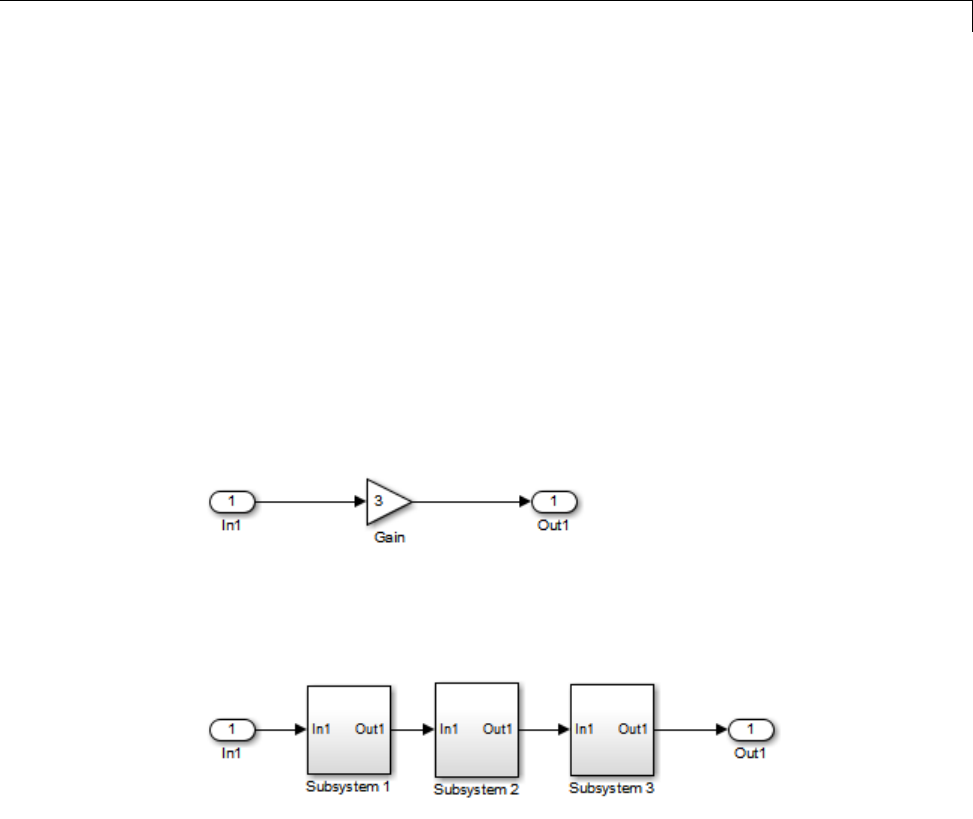
Reusable Code and Referenced Models
Code Reuse and ModelBlockswithRootInportor
Outport Blocks
Reusable functions with inputs or outputs connected to a referenced model’s
root Inport or Outport block can affect code reuse. This means that code for
certain atomic subsystems cannot be reused in a model reference context the
same way it is reused in a standalone model.
For example, suppose you create the following subsystem and make the
following changes to the subsystem’s block parameters:
•Select Treat as an atomic unit
•Go to the CodeGenerationtab and set Function packaging to
Reusable function
Suppose you then create the following model, which includes three instances
of the preceding subsystem.
With the Inline parameters option enabled in this stand-alone model, the
Simulink Coder code generator can optimize the code by generating a single
copy of the function for the reused subsystem, as shown below.
void reuse_subsys1_Subsystem1(
real_T rtu_0,
rtB_reuse_subsys1_Subsystem1 *localB)
{
3-33

3Referenced Models
/* Gain: '<S1>/Gain' */
localB->Gain_k = rtu_0 * 3.0;
}
When generated as code for a Model block (into an slprj project folder), the
subsystems have three different function signatures:
/* Output and update for atomic system: '<Root>/Subsystem1' */
void reuse_subsys1_Subsystem1(const real_T *rtu_0,
rtB_reuse_subsys1_Subsystem1
*localB)
{
/* Gain: '<S1>/Gain' */
localB->Gain_w = (*rtu_0) * 3.0;
}
/* Output and update for atomic system: '<Root>/Subsystem2' */
void reuse_subsys1_Subsystem2(real_T rtu_In1,
rtB_reuse_subsys1_Subsystem2
*localB)
{
/* Gain: '<S2>/Gain' */
localB->Gain_y = rtu_In1 * 3.0;
}
/* Output and update for atomic system: '<Root>/Subsystem3' */
void reuse_subsys1_Subsystem3(real_T rtu_In1, real_T *rty_0)
{
/* Gain: '<S3>/Gain' */
(*rty_0) = rtu_In1 * 3.0;
}
One way to make all the function signatures the same for code reuse, is
to insert Signal Conversion blocks. Place one between the Inport and
Subsystem1 and another between Subsystem3 and the Outport of the
referenced model.
3-34
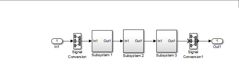
Reusable Code and Referenced Models
The result is a single reusable function:
void reuse_subsys2_Subsystem1(real_T rtu_In1,
rtB_reuse_subsys2_Subsystem1 *localB)
{
/* Gain: '<S1>/Gain' */
localB->Gain_g = rtu_In1 * 3.0;
}
You can achieve the same result (reusable code) with only one Signal
Conversion block. You can omit the Signal Conversion block connected to the
Inport block if you select the Pass fixed-size scalar root inputs by value
check box at the bottom of the Model Referencing pane of the Configuration
Parameters dialog box. When you do this, you still need to insert a Signal
Conversion block before the Outport block.
3-35

3Referenced Models
Simulink Coder Model Referencing Limitations
The following Simulink Coder limitations apply to model referencing. In
addition to these limitations, a model reference hierarchy used for code
generation must satisfy:
•The Simulink requirements listed in:
-“Configuration Requirements for All Referenced Model Simulation”
-“Model Structure Requirements”
•The Simulink limitations listed in “Model Referencing Limitations”.
•The Simulink Coder requirements applicable to the code generation target,
as listed in “Configuration Parameter Requirements” on page 3-19.
Customization Limitations
•The code generator ignores custom code settings in the Configuration
Parameter dialog box and custom code blocks when generating code for
a referenced model.
•Referenced models do not support custom storage classes if the parent
model has inline parameters off.
•This release does not include Stateflow target custom code in simulation
targets generated for referenced models.
•Data type replacement is not supported for simulation target code
generation for referenced models.
•Simulation targets do not include Stateflow target custom code.
•If you have an Embedded Coder license, some restrictions exist on grouped
custom storage classes in referenced models. For details, see “Custom
Storage Class Limitations”.
Data Logging Limitations
•To Workspace blocks, Scope blocks, and all types of runtime display,
such as the display of port values and signal values, are ignored when
the Simulink Coder software generates code for a referenced model. The
resulting code is the same as if the constructs did not exist.
3-36

Simulink®Coder™ Model Referencing Limitations
•Code generated for referenced models cannot log data to MAT-files. If data
logging is enabled for a referenced model, the Simulink Coder software
disables the option before code generation and re-enables it afterwards.
•If you log states for a model that contains referenced models, the ordering
of the states in the output is determined by block sorted order, and might
not match between simulation output and generated code MAT-file logging
output.
State Initialization Limitation
When a top model uses the Load from workspace > Initial state option
to specify initial conditions, the Simulink Coder software does not initialize
the states of any referenced models.
3-37

3Referenced Models
Reusability Limitations
If a referenced model used for code generation has any of the following
properties, the model must specify the configuration parameter Model
Referencing > Total number of instances allowed per top model as
One, and no other instances of the model can exist in the hierarchy. If you do
not set the parameter to One, or more than one instance of the model exists in
the hierarchy, an error occurs. The properties are:
•The model references another model which has been set to single instance
•The model contains a state or signal with non-auto storage class
•The model uses any of the following Stateflow constructs:
-Machine-parented data
-Machine-parented events
-Stateflow graphical functions
•The model contains a subsystem that is marked as function
•The model contains an S-function that is:
-Inlined buthasnotsettheoptionSS_OPTION_WORKS_WITH_CODE_REUSE
-Not inlined
•The model contains a function-call subsystem that:
-Has been forced by the Simulink engine to be a function
-Is called by a wide signal
3-38

Simulink®Coder™ Model Referencing Limitations
S-Function Limitations
•If a referenced model contains an S-function that should be inlined using a
Target Language Compiler file, the S-function must use the ssSetOptions
macro to set the SS_OPTION_USE_TLC_WITH_ACCELERATOR option in its
mdlInitializeSizes method. The simulation target will not inline the
S-function unless this flag is set.
•A referenced model cannot use noninlined S-functions generated by the
Simulink Coder software.
•The Simulink Coder S-function target does not support model referencing.
For additional information, in the Simulink documentation, see “S-Functions
with Model Referencing”.
Simulink Tool Limitations
•Simulink tools that require access to a model’s internal data or
configuration (including the Model Coverage tool, the Simulink Report
Generator product, the Simulink debugger, and the Simulink profiler) have
no effect on code generated by the Simulink Coder software for a referenced
model, or on the execution of that code. Specifications made and actions
takenbysuchtoolsareignoredandeffectivelydonotexist.
Subsystem Limitations
•If a subsystem contains Model blocks, you cannot build a subsystem module
by right-clicking the subsystem (or by using Code>C/C++Code>Build
Selected Subsystem) unless the model is configured to use an ERT target.
•If you generate code for an atomic subsystem as a reusable function, inputs
or outputs that connect the subsystem to a referenced model can affect code
reuse, as described in “Reusable Code and Referenced Models” on page 3-32.
Target Limitations
•Simulink Coder grt_malloc targets do not support model reference.
•The Simulink Coder S-function target does not support model referencing.
3-39

3Referenced Models
Other Limitations
•Errors or unexpected behavior can occur if a Model block is part of a cycle,
the Model block is a direct feedthrough block, and an algebraic loop results.
For details, see “Model Blocks and Direct Feedthrough”.
•The External mode optionisnotsupported. Ifitisenabled,itisignored
during code generation.
3-40

4
Combined Models

4Combined Models
Combined Models
If you want to combine several models (or several instances of the same model)
into a single executable, the Simulink Coder product offers several options.
The most powerful solution is to use Model blocks. Each instance of a
Model block represents another model, called a referenced model.Forcode
generation, the referenced model effectively replaces the Model block that
references it. For details, see “Overview of Model Referencing” and “Generate
Code for Referenced Models” on page 3-4.
When developing embedded systems using the Embedded Coder product, you
can interface the code for several models to a common harness program by
directly calling the entry points to each model. However, the Embedded Coder
target has certain restrictions, relating to embedded processing, that might
notbecompatiblewith your application.
The GRT malloc target is a another possiblesolution. Useitinsituations
where you want to:
•Selectively control calls to more than one model
•Use dynamic memory allocation
•Include models that employ continuous states
•Log data to multiple files
•Run one of the models in external mode
For more information, see “Use GRT Malloc to Combine Models” on page 4-4.
To summarize by target, your options are as follows:
TargetSupport for Combining Multiple
Models?
Generic Real-Time Target (grt.tlc)Yes (using Model blocks)
Generic Real-Time Target with
dynamic memory allocation
(grt_malloc.tlc)
Yes
4-2
Combined Models
Target Support for Combining Multiple
Models?
Embedded Coder (ert.tlc)Yes
S-function Target (rtwsfcn.tlc)No
4-3

4Combined Models
Use GRT Malloc to Combine Models
This section discusses how to use the GRT malloc target to combine models
into a single program.
Building a multiple-model executable is fairly straightforward:
1Generate and compile code from each of the models that are to be combined.
2Combine the makefiles for each of the models into one makefile for creating
the final multimodel executable.
3Create a combined simulation engine by modifying grt_malloc_main.c to
initialize and call the models.
4Runthecombinationmakefiletolinkthe object files fromthemodelsand
the main program into an executable.
Share Data Across Models
Use unidirectional signal connections between models. This affects the order
in which models are called. For example, if an output signal from modelA is
used as input to modelB,modelA's output computation should be called first.
Timing Issues
You must generate all the models you are combining with the same solver
mode (either all single-tasking or all multitasking.) In addition, if the models
employ continuous states, the same solver should be used for all models.
Because each model has its own model-specific definition of the rtModel
data structure, you must use an alternative mechanism to control model
execution, as follows:
•The file rtw/c/src/rtmcmacros.h provides an rtModel API clue that can
be used to call the rt_OneStep procedure.
•The rtmcmacros.h header file defines the rtModelCommon data structure,
which has the minimum common elements in the rtModel structure
required to step a model forward one time step.
4-4

Use GRT Malloc to Combine Models
•The rtmcsetCommon macro populates an object of type rtModelCommon by
copying the respective similar elements in the model’s rtModel object. Your
main routine must create one rtModelCommon structure for each model
being called by the main routine.
•The main routine will subsequently invoke rt_OneStep with a pointer to
the rtModelCommon structure instead of a pointer to the rtModel structure.
Ifthebaseratesforthemodelsarenotthesame,themainprogram(suchas
grt_malloc_main) must set up the timer interrupt to occur at the greatest
common divisor rate of the models. The main program calls each model at
a time interval.
Data Logging and External Mode Support
Amultiple-modelprogramcan log data to separate MAT-files for each model.
Only one of the models in a multiple-model program can use external mode.
4-5

4Combined Models
4-6

5
Configure Model
Parameters
•“Hardware Targets” on page 9-9
•“Describing the Emulation and Embedded Targets” on page 9-45
•“Describing Embedded Hardware Characteristics” on page 9-54
•“Describing Emulation Hardware Characteristics” on page 9-55
•“Control the Location for Generated Files” on page 5-18
•“Control Generated Files Location Used for Simulation” on page 5-20
•“Control the Location for Code Generation Files” on page 5-22
•“Override Build Folder Settings for Current Session” on page 5-24

5Configure Model Parameters
Platform Options for Development and Deployment
When you use Simulink software to create and execute a model, and Simulink
Coder software to generate code, you may need to consider up to three
platforms, often called hardware targets:
•MATLAB Host — The platform that runs MathWorks®software during
application development
•Embedded Target — The platform on which an application will be deployed
when it is put into production
•Emulation Target — The platform on which an application under
development is tested before deployment
The same platform might serve in two or possibly all three capacities, but they
remain conceptually distinct. Often the MATLAB host and the emulation
target are the same. The embedded target is usually different from, and less
powerful than, the MATLAB host or the emulation target; often it can do little
more than run a downloaded executable file.
When you use Simulink software to execute a model for which you will
later generate code, or use Simulink Coder software to generate code for
deployment on an embedded target, you must provide information about the
embedded target hardware and the compiler that you will use with it. The
Simulink software uses this information to get bit-true agreement for the
results of integer and fixed-point operations performed in simulation and in
code generated for the embedded target. The Simulink Coder code generator
usestheinformationtocreatecodethat executes with maximum efficiency.
When you generate code for testing on an emulation target, you must
additionally provide information about the emulation target hardware and the
compiler that you will use with it. The code generator uses this information
to create code that provides bit-true agreement for the results of integer and
fixed-point operations performed in simulation, in code generated for the
embedded target, and in code generated for the emulation target. Agreement
can result even though the embedded target and emulation target may use
very different hardware, and the compilers for the two targets may use
different defaults where the C standard does not completely define behavior.
5-2
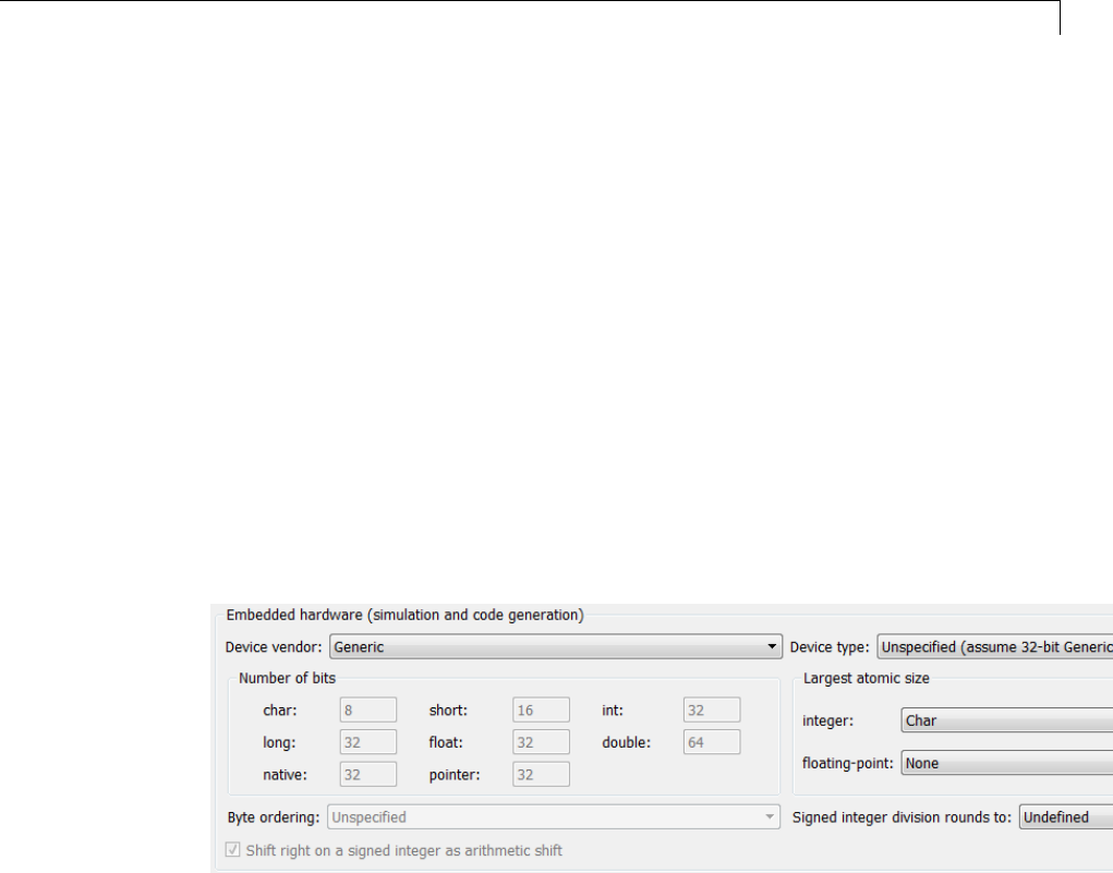
Configure Emulation and Embedded Target Hardware
Configure Emulation and Embedded Target Hardware
The Configuration Parameters dialog Hardware Implementation pane
provides options that you can use to describe hardware properties, such as
data size and byte ordering, and compiler behavior details that may vary with
the compiler, such as integer rounding. The Hardware Implementation
pane contains two subpanes:
•Embedded Hardware — Describes the embedded target hardware
and the compiler that you will use with it. This information affects both
simulation and code generation.
•Emulation Hardware — Describes the emulation target hardware and
the compiler that you will use with it. This information affects only code
generation.
The two subpanes provide identical options and value choices. By default, the
Embedded Hardware subpane initially looks like this:
The default assumption is that the embedded target and emulation target are
the same, so the Emulation Hardware subpane by default does not need
to specify anything and contains only a checked option labeled None.Code
generated under this configuration will be suitable for production use, or for
testing in an environment identical to the production environment.
If you clear the check box, the Emulation Hardware subpane appears,
initially showing the same values as the Embedded Hardware subpane. If
you change any of these values, then generate code, the code will be able to
execute in the environment specified by the Emulation Hardware subpane,
5-3

5Configure Model Parameters
but will behave as if it were executing in the environment specified by the
Embedded Hardware subpane. See “Describing Emulation Hardware
Characteristics” on page 9-55 for details.
If you have used the Code Generation pane to specify a System target
file, and the target file specifies a default microprocessor and its hardware
properties, the default and properties appear as initial values in the
Hardware Implementation pane.
Options with only one possible value cannot be changed. Any option that has
more than one possible value provides a list of legal values. If you specify
any hardware properties manually, check carefully that their values are
consistent with the system target file. Otherwise, the generated code may fail
to compile or execute, or may execute but give incorrect results.
Note Hardware Implementation pane options do not control hardware
or compiler behavior. They describe hardware and compiler properties to
MATLAB software, which uses the information to generate code for the
platform thatruns as efficiently as possible, and gives bit-true agreement for
the results of integer and fixed-point operations in simulation, production
code, and test code.
The rest of this section describes the options in the Embedded Hardware
and Emulation Hardware subpanes. Subsequent sections describe
considerations that apply only to one or the other subpane. For more about
Hardware Implementation options, see “Hardware Implementation Pane”.
To see an example of Hardware Implementation pane capabilities, run the
rtwdemo_targetsettings example.
Identify the Device Vendor
The Device vendor option gives the name of the device vendor. To set the
option, select a vendor name from the Device vendor menu. Your selection
ofvendorwilldeterminetheavailabledevicevaluesintheDevice type list.
If the desired vendor name does not appear in the menu, select Generic and
then use the Device type option to further specify the device.
5-4

Configure Emulation and Embedded Target Hardware
Note
•For complete lists of Device vendor and Device type values, see “Device
vendor” and “Device type” in the Simulink reference documentation.
•To add Device vendor and Device type values to the default set that
is displayed on the Hardware Implementation pane, see “Registering
Additional Device Vendor and Device Type Values” on page 9-47.
Identify the Device Type
The Device type option selects a hardware device among the supported
devices listed for your Device vendor selection. To set the option, select
a microprocessor name from the Device type menu. If the desired
microprocessor does not appear in the menu, change the Device vendor
to Generic.
If you specified the Device vendor as Generic, examine the listed device
descriptions and select the device type that matches your hardware. If no
available device type matches, select Custom.
If you select a device type for which the target file specifies default hardware
properties, the properties appear as initial values in the subpane. Options
with only one possible value cannot be changed. An option that has more
than one possible value provides a list of legal values. Select values for your
hardware. If the device type is Custom, more options can be set, and each
option has a list of possible values.
Register Additional Device Vendor and Device Type
Values
To add Device vendor and Device type values to the default set that is
displayed on the Hardware Implementation pane, you can use a hardware
device registration API provided by the Simulink Coder software.
TousethisAPI,youcreateansl_customization.m file, located in your
MATLAB path, that invokes the registerTargetInfo function and fills
in a hardware device registry entry with device information. The device
5-5
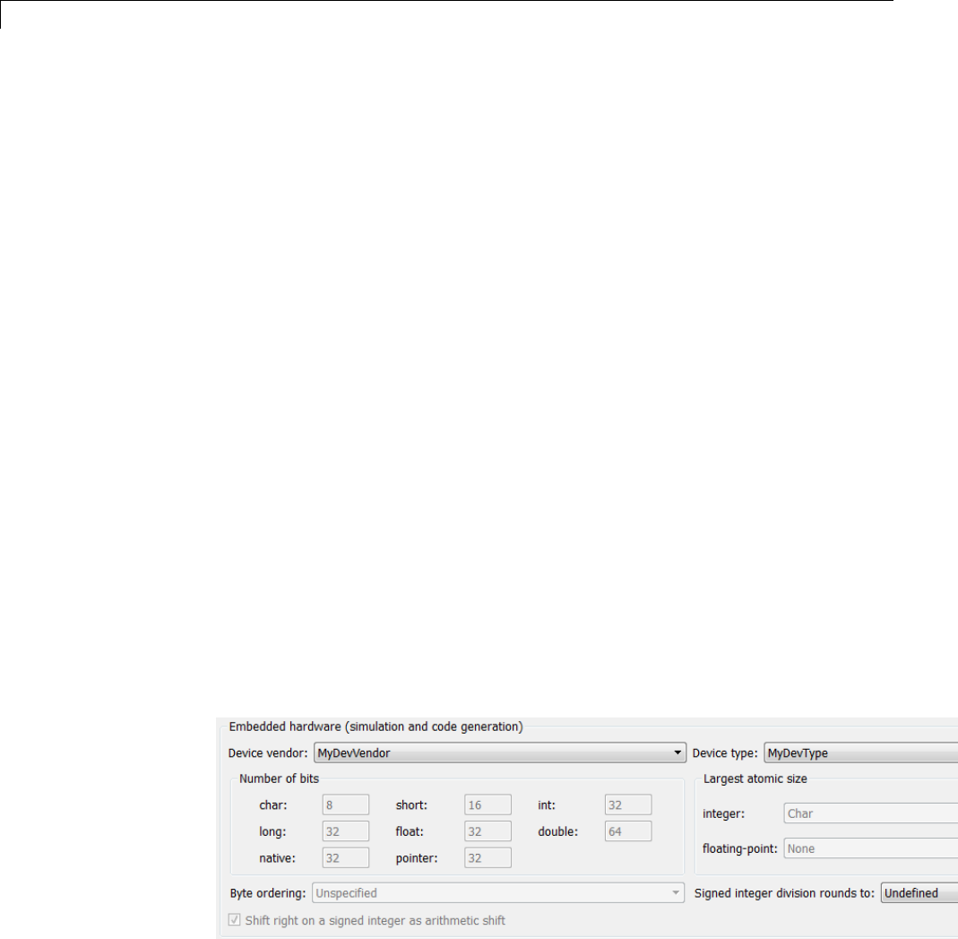
5Configure Model Parameters
information will be registered with Simulink software for each subsequent
Simulink session. (To register your device information without restarting
MATLAB, issue the MATLAB command sl_refresh_customizations.)
For example, the following sl_customization.m file adds device vendor
MyDevVendor and device type MyDevType to the Simulink device lists.
function sl_customization(cm)
cm.registerTargetInfo(@loc_register_device);
end
function thisDev = loc_register_device
thisDev = RTW.HWDeviceRegistry;
thisDev.Vendor = 'MyDevVendor';
thisDev.Type = 'MyDevType';
thisDev.Alias = {};
thisDev.Platform = {'Prod', 'Target'};
thisDev.setWordSizes([8 16 32 32 32]);
thisDev.LargestAtomicInteger = 'Char';
thisDev.LargestAtomicFloat = 'None';
thisDev.Endianess = 'Unspecified';
thisDev.IntDivRoundTo = 'Undefined';
thisDev.ShiftRightIntArith = true;
thisDev.setEnabled({'IntDivRoundTo'});
end
If you subsequently select the device in the Hardware Implementation
pane, it is displayed as follows:
5-6

Configure Emulation and Embedded Target Hardware
To register multiple devices, you can specify an array of
RTW.HWDeviceRegistry objects in your sl_customization.m file. For
example,
function sl_customization(cm)
cm.registerTargetInfo(@loc_register_device);
end
function thisDev = loc_register_device
thisDev(1) = RTW.HWDeviceRegistry;
thisDev(1).Vendor = 'MyDevVendor';
thisDev(1).Type = 'MyDevType1';
...
thisDev(4) = RTW.HWDeviceRegistry;
thisDev(4).Vendor = 'MyDevVendor';
thisDev(4).Type = 'MyDevType4';
...
end
ThefollowingtableliststheRTW.HWDeviceRegistry properties that you can
specify in the registerTargetInfo function call in your sl_customization.m
file.
Property Description
Vendor String specifying the Device vendor value for your
hardware device.
Type String specifying the Device type value for your
hardware device.
5-7

5Configure Model Parameters
Property Description
Alias Cell array of strings specifying any aliases or
legacy names that users might specify that
should resolve to this device. Specify each alias
or legacy name in the format 'Vendor->Type'.
(Embedded Coder software provides the
utility functions RTW.isHWDeviceTypeEq and
RTW.resolveHWDeviceType for detecting and
resolving alias values or legacy values when testing
user-specified values for the target device type.)
Platform Cell array of enumerated string values specifying
whether this device should be listed in the
Embedded hardware subpane ({'Prod'}), the
Emulation hardware subpane ({'Target'}), or
both ({'Prod', 'Target'}).
setWordSizes Array of integer sizes to associate with the Number
of bits parameters char,short,int,long,and
native word size,respectively.
LargestAtomicInteger
String specifying an enumerated value for the
Largest atomic size: integer parameter: 'Char',
'Short','Int',or'Long'.
LargestAtomicFloat String specifying an enumerated value for the
Largest atomic size: floating-point parameter:
'Float','Double',or'None'.
Endianess String specifying an enumerated value for the Byte
ordering parameter: 'Unspecified','Little' for
little Endian, or 'Big' for big Endian.
IntDivRoundTo String specifying an enumerated value for the
Signed integer division rounds to parameter:
'Zero','Floor',or'Undefined'.
5-8

Configure Emulation and Embedded Target Hardware
Property Description
ShiftRightIntArith Boolean value specifying whether your compiler
implements a signed integer right shift as an
arithmetic right shift (true)ornot(false).
setEnabled Cell array of strings specifying which device
properties should be enabled (modifiable) in
the Hardware Implementation pane when
this device type is selected. In addition to
the 'Endianess','IntDivRoundTo',and
'ShiftRightIntArith' properties listed above, you
can enable individual Number of bits parameters
using the property names 'BitPerChar',
'BitPerShort','BitPerInt','BitPerLong',and
'NativeWordSize'.
SetNativeWordSizefortheDevice
The Number of bits options describe the native word size of the
microprocessor, and the bit lengths of char,short,int,andlong data. For
code generation to succeed:
•The bit lengths must be such that char <= short <= int <= long.
•Bit lengths must be multiples of 8, with a maximum of 32.
•The bit length for long data must not be less than 32.
Simulink Coder integer type names are defined in the file rtwtypes.h.The
values that you provide must be consistent with the word sizes as defined in
the compiler’s limits.h header file. The following table lists the standard
Simulink Coder integer type names and maps them to the corresponding
Simulink names.
Simulink Coder Integer
Type
Simulink Integer Type
boolean_T boolean
int8_T int8
uint8_T uint8
5-9

5Configure Model Parameters
Simulink Coder Integer
Type
Simulink Integer Type
int16_T int16
uint16_T uint16
int32_T int32
uint32_T uint32
If no ANSI®C type with a matching word size is available, but a larger ANSI
C type is available, the Simulink Coder code generator uses the larger type
for int8_T,uint8_T,int16_T,uint16_T,int32_T, and uint32_T.
An application can use integer data of any length from 1 (unsigned) or 2
(signed) bits up 32 bits. If the integer length matches the length of an
available type, the Simulink Coder code generator uses that type. If no
matching type is available, the code generator uses the smallest available
type that can hold the data, generating code that never uses unnecessary
higher-order bits. For example, on a target that provided 8-bit, 16-bit, and
32-bit integers, a signal specified as 24 bits would be implemented as an
int32_T or uint32_T.
Code that uses emulated integer data is not maximally efficient, but can be
useful during application development for emulating integer lengths that are
available only on production hardware. The use of emulation does not affect
the results of execution.
SetByteOrderingUsedByDevice
The Byte ordering option specifies whether the target hardware uses Big
Endian (most significant byte first) or Little Endian (least significant byte
first) byte ordering. If left as Unspecified, the Simulink Coder software
generates code that determines the endianness of the target; this is the least
efficient option.
5-10

Configure Emulation and Embedded Target Hardware
Set Quotient Rounding Technique for Signed Integer
Division
ANSI C does not completely define the quotient rounding technique to
be used when dividing one signed integer by another, so the behavior is
implementation-dependent. If both integers are positive, or both are negative,
the quotient must round down. If either integer is positive and the other is
negative, the quotient can round up or down.
The Signed integer division rounds to parameter tells the Simulink
Coder code generator how the compiler rounds the result of signed integer
division. Providing this information does not affect the operation of the
compiler, it only describes that behavior to the code generator, which uses
the information to optimize code generated for signed integer division. The
parameter options are:
•Zero — If the quotient is between two integers, the compiler chooses the
integer that is closer to zero as the result.
•Floor — If the quotient is between two integers, the compiler chooses the
integer that is closer to negative infinity.
•Undefined — Choose this option if neither Zero nor Floor describes the
compiler’s behavior, or if that behavior is unknown.
The following table illustrates the compiler behavior that corresponds to each
of these three options:
ND
Ideal
N/D Zero Floor Undefined
33 48.25 8 8 8
-33 4 -8.25 -8 -9 -8 or -9
33 -4 -8.25 -8 -9 -8 or -9
-33 -4 8.25 8 8 8 or 9
5-11

5Configure Model Parameters
Note Select Undefined only as a last resort. When the code generator does
not know the signed integer division rounding behavior of the compiler, it
generates extra code.
The compiler’s implementation for signed integer division rounding can
be obtained from the compiler documentation, or by experiment if no
documentation is available.
Set Arithmetic Right Shift Behavior for Signed
Integers
ANSI C does not define the behavior of right shifts on negative integers, so the
behavior is implementation-dependent. The Shift right on a signed integer
as arithmetic shift parameter tells the code generator how the compiler
implements right shifts on negative integers. Providing this information does
not affect the operation of the compiler, it only describes that behavior to the
code generator, which uses the information to optimize the code generated for
arithmetic right shifts.
Select the option if the C compiler implements a signed integer right shift as
an arithmetic right shift, and clear the option otherwise. An arithmetic right
shift fills bits vacated by the right shift with the value of the most significant
bit, which indicates the sign of the number in twos complement notation.
The option is selected by default. If your compiler handles right shifts as
arithmetic shifts, this is the preferred setting.
•When the option is selected, the Simulink Coder software generates simple
efficient code whenever the Simulink model performs arithmetic shifts on
signed integers.
•When the option is cleared, the Simulink Coder software generates fully
portable but less efficient code to implement right arithmetic shifts.
The compiler’s implementation for arithmetic right shifts can be obtained
from the compiler documentation, or by experiment if no documentation is
available.
5-12

Configure Embedded Hardware Characteristics
Configure Embedded Hardware Characteristics
“Describing the Emulation and Embedded Targets” on page 9-45 documents
the options available on the Hardware Implementation subpanes. This
section describes considerations that apply only to the Embedded Hardware
subpane. When you use this subpane, keep the following in mind:
•Code generation targets can have word sizes and other hardware
characteristics that differ from the MATLAB host. Furthermore, code can
be prototyped on hardware that is different from either the deployment
target or the MATLAB host. The Simulink Coder code generator takes
these differences into account when generating code.
•The Simulink product uses some of the information in the Embedded
Hardware subpane so that simulation without code generation gives
the same results as executing generated code, including detecting error
conditions that could arise on the target hardware, such as hardware
overflow.
•The Simulink Coder software generates code that has bit-true agreement
with Simulink results for integer and fixed-point operations. Generated
code that emulates unavailable data lengths runs less efficiently than
it would without emulation, but the emulation does not affect bit-true
agreement with Simulink for integer and fixed-point results.
•If you change targets during application development, you must reconfigure
the hardware implementation parameters for the new target before
generating or regenerating code. Bit-true agreement might not be achieved
for results of integer and fixed-point operations in simulation, production
code, and test code when code executes on hardware for which it was not
generated.
•Use the Integer rounding mode parameter on your model’s blocks to
simulate the rounding behavior of the C compiler that you intend to use
to compile code generated from the model. This setting appears on the
Signal Attributes pane of the parameter dialog boxes of blocks that can
perform signed integer arithmetic, such as the Product and n-D Lookup
Table blocks.
•For most blocks, the value of Integer rounding mode completely defines
rounding behavior. For blocks that support fixed-point data and the
5-13

5Configure Model Parameters
Simplest rounding mode, the value of Signed integer division rounds to
also affects rounding. For details, see “Rounding”.
•When models contain Model blocks, models that they reference must be
configured to use identical hardware settings.
5-14

Configure Emulation Hardware Characteristics
Configure Emulation Hardware Characteristics
“Describing the Emulation and Embedded Targets” on page 9-45 documents
the options available on the Hardware Implementation subpanes. This
section describes considerations that apply only to the Emulation Hardware
subpane.
Note (If the Emulation Hardware subpane contains a button labeled
Configure current execution hardware device, see “Updating from
Earlier Versions” on page 9-57, then continue from this point.)
The default assumption is that the embedded target and emulation target are
the same, so the Emulation Hardware subpane by default does not need to
specify anything and contains only a selected check box labeled None.Code
generated under this configuration will be suitable for production use, or for
testing in an environment identical to the production environment.
To generate code that runs on an emulation target for test purposes, but
behaves as if it were running on an embedded target in a production
application, you must specify the properties of both targets in the Hardware
Implementation pane. The Embedded Hardware subpane specifies
embedded target hardware properties, as described previously. To specify
emulation target properties:
1Clear the None option in the Emulation Hardware subpane.
By default, the Hardware Implementation pane now looks like this:
5-15
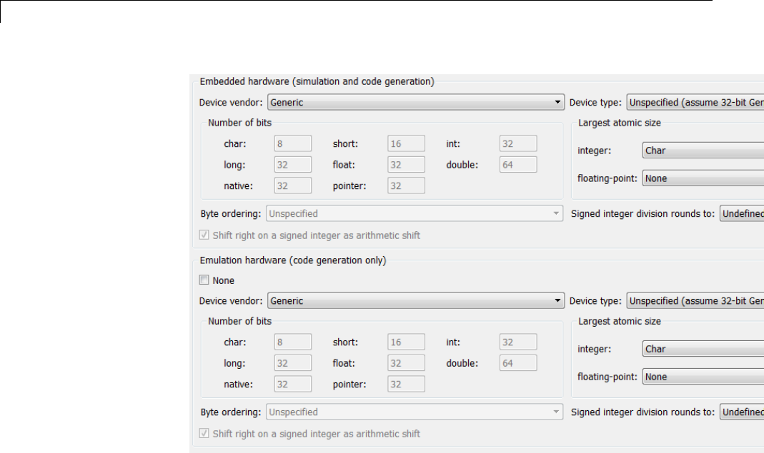
5Configure Model Parameters
2In the Emulation Hardware subpane, specify the properties of the
emulation target, using the instructions in “Describing the Emulation and
Embedded Targets” on page 9-45
If you have used the Code Generation pane to specify a System target
file, and the target file specifies a default microprocessor and its hardware
properties, the default and properties appear as initial values in both
subpanes of the Hardware Implementation pane.
Options with only one possible value cannot be changed. Any option that has
more than one possible value provides a list of legal values. If you specify
any hardware properties manually, check carefully that their values are
consistent with the system target file. Otherwise, the generated code may fail
to compile or execute, or may execute but give incorrect results.
If you do not display the Emulation Hardware subpane, the Simulink and
Simulink Coder software defaults every Emulation Hardware option to
5-16
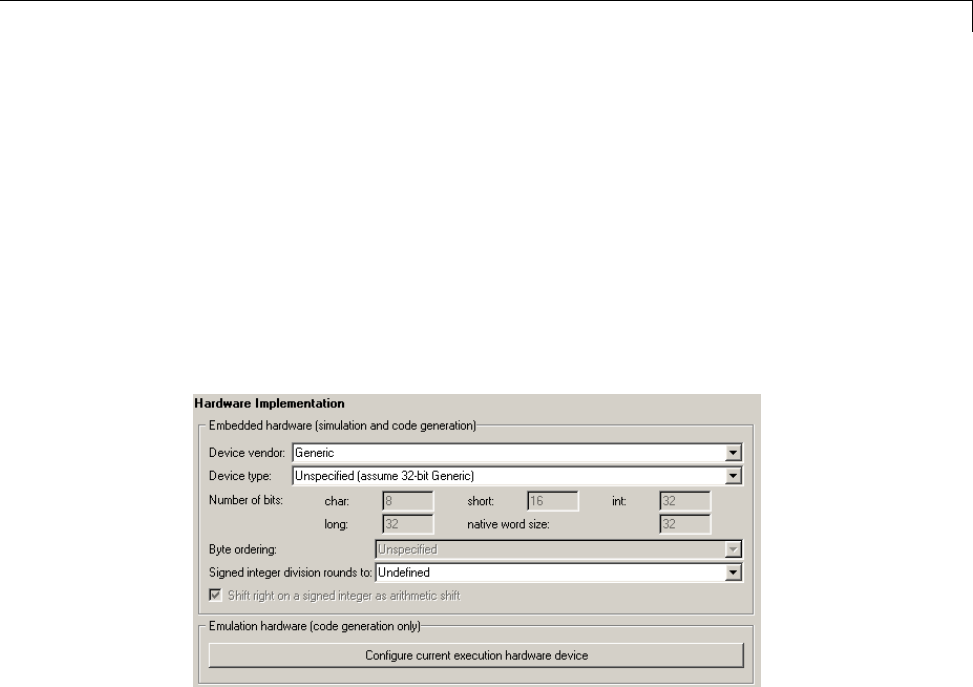
Configure Emulation Hardware Characteristics
have the same value as the corresponding Embedded Hardware option.
If you hide the Emulation Hardware subpane after setting its values,
the values that you specified will be lost. The underlying configuration
parameters immediately revert to the values that they had when you exposed
the subpane, and these values, rather than the values that you specified, will
appear if you re-expose the subpane.
Update Release 14 Hardware Configuration
If your model was created before Release 14 and has not been updated, by
default the Hardware Implementation pane initially looks like this:
Click Configure current execution hardware device.TheConfigure
current execution hardware device button disappears. The subpane then
appears as shown in the first figure in this section. Save your model at this
point to avoid redoing Configure current execution hardware device
next time you access the Hardware Implementation pane.
5-17

5Configure Model Parameters
Control the Location for Generated Files
By default, the files generated by Simulink diagram updates and model
builds are placed in a build folder, the root of which is the current working
folder (pwd). If you are doing model builds, which potentially generate files
for simulation targets as well as code generation targets, artifacts used for
simulation and Simulink Coder code generation files coexist in subfolders
within that build folder. However, in some situations, you might want the
generated files to go to a root folder outside the current working folder. For
example,
•You need to keep generated files separate from the models and other source
materials used to generate them.
•You want to reuse or share previously-built simulation targets without
having to set the current working folder back to a previous working folder.
You might also want to separate generated simulation artifacts from
generated production code.
To allow you to control the output locations for the files generated by diagram
updates and model builds, the software allows you to separately specify the
following build folders:
•Simulation cache folder — root folder in which to place build artifacts
used for simulation
•Code generation folder — root folder in which to place Simulink Coder
code generation files
For specifying the folder locations, the software provides
•MATLAB session parameters CacheFolder and CodeGenFolder
•Simulink preferences Simulation cache folder and Code generation
folder, which, if specified, provide the initial defaults for the MATLAB
session parameters
•Function Simulink.fileGenControl for directly manipulating the
MATLAB session parameters, for example, overriding or restoring the
initial default values for the current session
5-18

Control the Location for Generated Files
For more information about setting up a simulation cache folder, see “Control
Generated Files Location Used for Simulation” on page 5-20.
For more information about setting up a code generation folder, see “Control
the Location for Code Generation Files” on page 5-22.
For more information about directly manipulating the MATLAB session
parameters CacheFolder and CodeGenFolder, see “Override Build Folder
Settings for Current Session” on page 5-24.
5-19
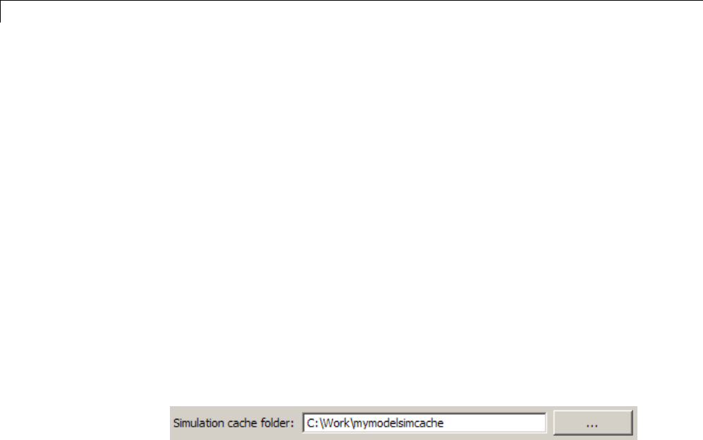
5Configure Model Parameters
Control Generated Files Location Used for Simulation
By default, the files generated by Simulink diagram updates are placed in a
build folder, the root of which is the current working folder (pwd). However,
in some situations, you might want the generated files to go to a root folder
outside the current workingfolder. Forexample,
•You need to keep generated files separate from the models and other source
materials used to generate them.
•You want to reuse or share previously-built simulation targets without
having to set the current working folder back to a previous working folder.
The Simulink preference Simulation cache folder provides control over
the output location for files generated by Simulink diagram updates. The
preference appears in the Simulink Preferences Window, Main Pane, in the
File generation control group. To specify the root folder location for files
generated by Simulink diagram updates, set the preference value by entering
or browsing to a folder path, for example:
The folder path that you specify provides the initial default for the MATLAB
session parameter CacheFolder. When you initiate a Simulink diagram
update, any files generated are placed in a build folder at the root location
specified by CacheFolder (if any), rather than in the current working folder
(pwd).
For example, using a 32-bit Windows host platform, if you set the Simulation
cache folder to 'C:\Work\mymodelsimcache' and then simulate the example
model rtwdemo_capi, files are generated into the specified folder as follows:
5-20
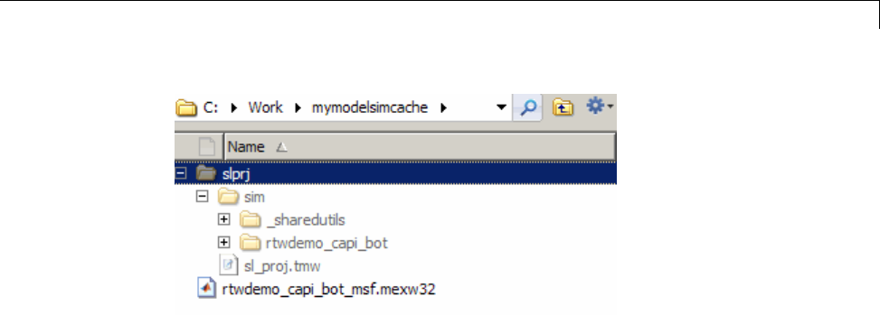
Control Generated Files Location Used for Simulation
As an alternative to using the Simulink preferences GUI to set Simulation
cache folder, you also can get and set the preference value from the
command line using get_param and set_param. For example,
>> get_param(0, 'CacheFolder')
ans =
''
>> set_param(0, 'CacheFolder', fullfile('C:','Work','mymodelsimcache'))
>> get_param(0, 'CacheFolder')
ans =
C:\Work\mymodelsimcache
Also, you can choose to override the Simulation cache folder preference
value for the current MATLAB session.
5-21
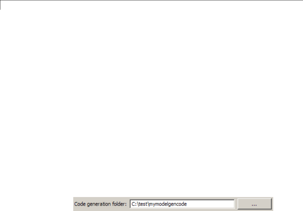
5Configure Model Parameters
Control the Location for Code Generation Files
By default, the files generated by Simulink model builds are placed in a
build folder, the root of which is the current working folder (pwd). Model
builds potentially generate files for simulation targets as well as code
generation targets, and the resulting build folder contains both artifacts used
for simulation and Simulink Coder code generation files. However, in some
situations, you might want the generated files to go to one or more root folders
outside the current workingfolder. Forexample,
•You need to keep generated files separate from the models and other source
materials used to generate them.
•You want to separate generated production code from generated simulation
artifacts.
The Simulink preference Code generation folder provides control over the
output location for files generated by model builds for code generation targets.
The preference appears in the Simulink Preferences Window, Main Pane, in
the File generation control group. To specify the root folder location for
code generation files generated by model builds, set the preference value by
entering or browsing to a folder path, for example:
The folder path that you specify provides the initial default for the MATLAB
session parameter CodeGenFolder. When you initiate a Simulink model
build, any code generation files generated are placed in a build folder at the
root location specified by CodeGenFolder (if any), rather than in the current
working folder (pwd).
For example, using a 32-bit Windows host platform, if you set the Code
generation folder to 'C:\test\mymodelgencode' and then build the
example model rtwdemo_capi, files are generated into the specified folder as
follows:
5-22
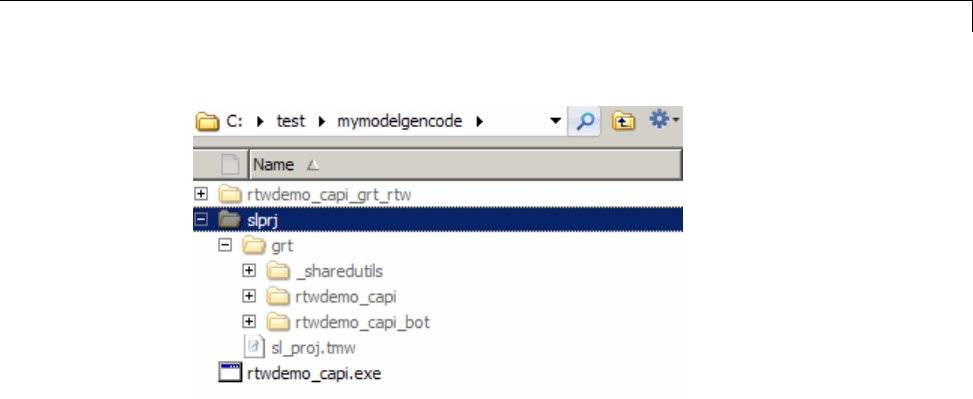
Control the Location for Code Generation Files
As an alternative to using the Simulink preferences GUI to set Code
generation folder, you also can get and set the preference value from the
command line using get_param and set_param. For example,
>> get_param(0, 'CodeGenFolder')
ans =
''
>> set_param(0, 'CodeGenFolder', fullfile('C:','test','mymodelgencode'))
>> get_param(0, 'CodeGenFolder')
ans =
C:\test\mymodelgencode
Also, you can choose to override the Code generation folder preference
value for the current MATLAB session. For more information, see “Override
Build Folder Settings for Current Session” on page 5-24.
5-23

5Configure Model Parameters
Override Build Folder Settings for Current Session
The Simulink preferences Simulation cache folder and Code generation
folder provide the initial defaults for the MATLAB session parameters
CacheFolder and CodeGenFolder, which determine where files generated
by Simulink diagram updates and model builds are placed. However,
you can override these build folder settings during the current MATLAB
session, using the Simulink.fileGenControl function. This function
allows you to directly manipulate the MATLAB session parameters, for
example, overriding or restoring the initial default values. The values
you set using Simulink.fileGenControl expire at the end of the current
MATLAB session. For more information and detailed examples, see the
Simulink.fileGenControl function reference page.
5-24

6
Model Protection
•“Protect a Referenced Model” on page 6-2
•“Harness Model” on page 6-4
•“Protected Model Report” on page 6-5
•“Code Generation Support in a Protected Model” on page 6-6
•“Protected Model File” on page 6-8
•“Create a Protected Model” on page 6-9
•“Test the Protected Model” on page 6-13
•“Save Base Workspace Definitions” on page 6-15
•“Package a Protected Model” on page 6-16

6Model Protection
Protect a Referenced Model
Protect a model when you want to share a model with a third party without
revealing the intellectual property. Protecting a model does not use encryption
technology.
When you create a protected model:
•By default, Simulink creates and stores a protected version of the
referenced model in the current working folder. The protected model has
thesamenameasthesourcemodel,witha.slxp extension.
•The original Model block does not change. However, if the Model block
parameter Model name does not specify an extension, a protected model,
.slxp, takes precedence over a model file, .slx.
•The Simulation mode parameter of the protected model is automatically
set to Accelerator. You cannot change this value.
•You can optionally create a harness model which includes the protected
model. A shield icon appears in the lower-left corner of the protected model
block in the harness model. For more information, see “Harness Model”
on page 6-4.
•You can optionally include generated code with the protected model so that
a third party can generate code for a model that contains the protected
model. Including code generation support with a protected model also
allows the third party to simulate a model that references the protected
model in Accelerator mode. For more information, see “Code Generation
Support in a Protected Model” on page 6-6.
•If the Model block uses variants, only the active variant is protected. For
more information, see “Set Up Model Variants”.
•If you rename a protected model, or change its suffix, the model is unusable
until you restore its original name and suffix. You cannot change a
protected model internally because any internal change destroys the
usability of the file.
You can create a protected model using either:
•A Model block context menu. For more information, see “Create a Protected
Model” on page 6-9 and
6-2

Protect a Referenced Model
•ASimulink.ModelReference.protect function.
Requirements for Protecting a Model
When you create a protected model from a referenced model, the referenced
model must meet all requirements listed in “Model Referencing Limitations”,
as well as these requirements:
•You must have a Simulink Coder license to create a protected model.
•A model that you protect must be available on the MATLAB path and not
have any unsaved changes.
•A model that you protect cannot reference a protected model directly or
indirectly.
•A model that you protect cannot use a non-inlined S-function directly or
indirectly.
Model protection has certain limitations, as listed in “Limitations on All Model
Referencing” and “Limitations on Accelerator Mode Referenced Models”.
6-3

6Model Protection
Harness Model
You can create a harness model for the generated protected model. The
harness model opens as a new, untitled model that contains only a Model
block which references the protected model. This Model block:
•Specifies the Model block parameter, Model name, as the name of the
protected model.
•Has a shield icon in the lower-left corner.
•Has the same number of input and output ports as the protected model.
•Defines any model reference arguments that the protected model uses, but
does not provide any values.
To create a harness model, see “Create a Protected Model” on page 6-9. You
can use a harness model to test your protected model. For more information,
see “Test the Protected Model” on page 6-13. You can also copy the Model
block in your harness model to another model, where it is an interface to
the protected model.
6-4

Protected Model Report
Protected Model Report
You can generate a report for a protected model to include with the protected
model. The report provides information to the receiver to determine if the
protected model can be used. The report has:
•ASummary, including the Simulink version and platform used to create
the protected model.
•An Interface Report, including model interface information, such as,
input and output specifications, exported function information, and
whether code generation support is included.
A protected model report is generated while the protected model is created. In
the Create Protected Model dialog box, select the Create protected model
report parameter. For an example, see “Create a Protected Model” on page
6-9.
After you create the protected model, to view the protected model report,
double-click the protected model block.
6-5

6Model Protection
Code Generation Support in a Protected Model
You can create a protected model that supports code generation. When a
protected model includes generated code, a third party can generate code for a
model that includes the protected model. If you choose to obfuscate the code,
all code is obfuscated before compilation. The protected model file contains
only obfuscated headers and binaries. No source, such as, .c and .cpp,is
present in the protected model file, although the headers are documented in
the protected model report. For more information, see “Protected Model File”
on page 6-8 and “Protected Model Report” on page 6-5.
In the Create Protected Model dialog box, select the Include generated code
parameter, which enables the Obfuscate code parameter. For an example on
including code generation support, see “Create a Protected Model” on page 6-9.
Protected Model Requirements to Support Code
Generation
Contents and configuration of a model might prevent code generation support
of the protected model. Interaction between the parent model and the
protected model might also prevent code generation.
•Code generation for the protected model is only supported for Accelerator
mode and a single target. Both GRT and ERT targets cannot be supported
by the same protected model.
•A protected model cannot include a model reference hierarchy.
•Source code comments in the Code Generation > Comments pane are
ignored. Obfuscation of the generated code removes comments because
comments might reveal intellectual property.
•Custom code in the Code Generation > Custom Code pane should not be
included. Custom code is obfuscated, but identifiers are not.
•Code generation of a model that includes a protected model produces an
error, if:
-Their interfaces do not match.
-There are incompatible parameters.
6-6

Code Generation Support in a Protected Model
-A protected model and another model share the same name in the same
model reference hierarchy.
6-7

6Model Protection
Protected Model File
A protected model file (.slxp)consistsofthemodelitselfandsupportingfiles,
depending on the options that you selected when you created the protected
model.
If you created a protected model for simulation only, after simulation, the
model.mexext file is placed in the build folder.
For simulation with a report, these additional files are unpacked:
•slprj/sim/model/html/*
•slprj/sim/model/buildinfo.mat
If you opted to include code generation support when you created the
protected model, after building your model the following files are unpacked
(in addition to the preceding files):
•slprj/sim/model/*.h
•slprj/sim/model/modellib.a (or modellib.lib)
•slprj/sim/model/tmwinternal/*
•slprj/sim/_sharedutils/*
•slprj/target/model/*.h
•slprj/target/model/model_rtwlib.a (or model_rtwlib.lib)
•slprj/target/model/buildinfo.mat
•slprj/target/_sharedutils/*
•slprj/target/model/tmwinternal/*
For code generation with a report, after building your model these files are
unpacked (in addition to the preceding files):
•slprj/target/model/html/*
•slprj/target/model/buildinfo.mat
•slprj/target/_sharedutils/html/*
6-8

Create a Protected Model
Create a Protected Model
This example shows how to create a protected model to be used for simulation
and code generation.
1Open the model rtwdemo_roll.
2In the Simulink Editor, right-click the Model block that references the model
for which you want to generate protected model code. In this example,
right-click HeadingMode.
3From the context menu, select Block Parameters (ModelReference).
4In the Block Parameters dialog box, in the Model name field, specify the
extension for the model, .slx. Whenboththemodelandtheprotectedmodel
exist in the same folder, .slxp takes precedence over .slx.IntheModel
name field, if you do not specify an extension, when you create the protected
model, the original Model block in the model becomes protected.
5Click Apply and OK.
6Right-click the Model block. From the context menu, select Subsystem &
Model Reference > Create Protected Model for Selected Model Block.
7In the Create Protected Model dialog box, select Include generated code
to include generated code with the protected model. This parameter enables
and selects the Obfuscate code parameter. For more information about
the generated code, see “Code Generation Support in a Protected Model” on
page 6-6.
8In the Package path field, specify the folder path for the protected model.
The default value is the current working folder.
9To create a harness model for the protected model, select Create harness
model for protected model.
6-9
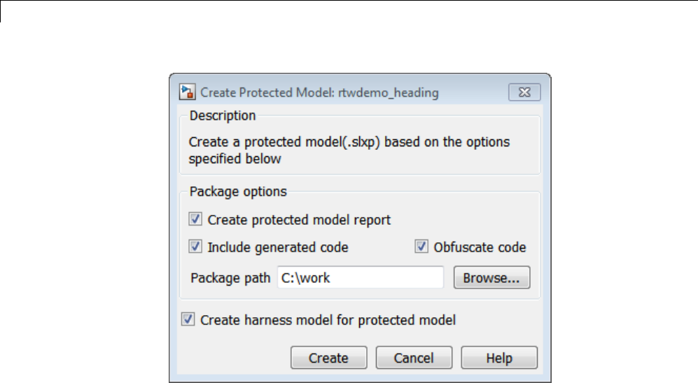
6Model Protection
10 Click Create. An untitled harness model opens and contains a Model block,
which refers to the protected model rtwdemo_heading.slxp.TheSimulation
mode for the Model block is set to Accelerator. You cannot change the mode.
6-10
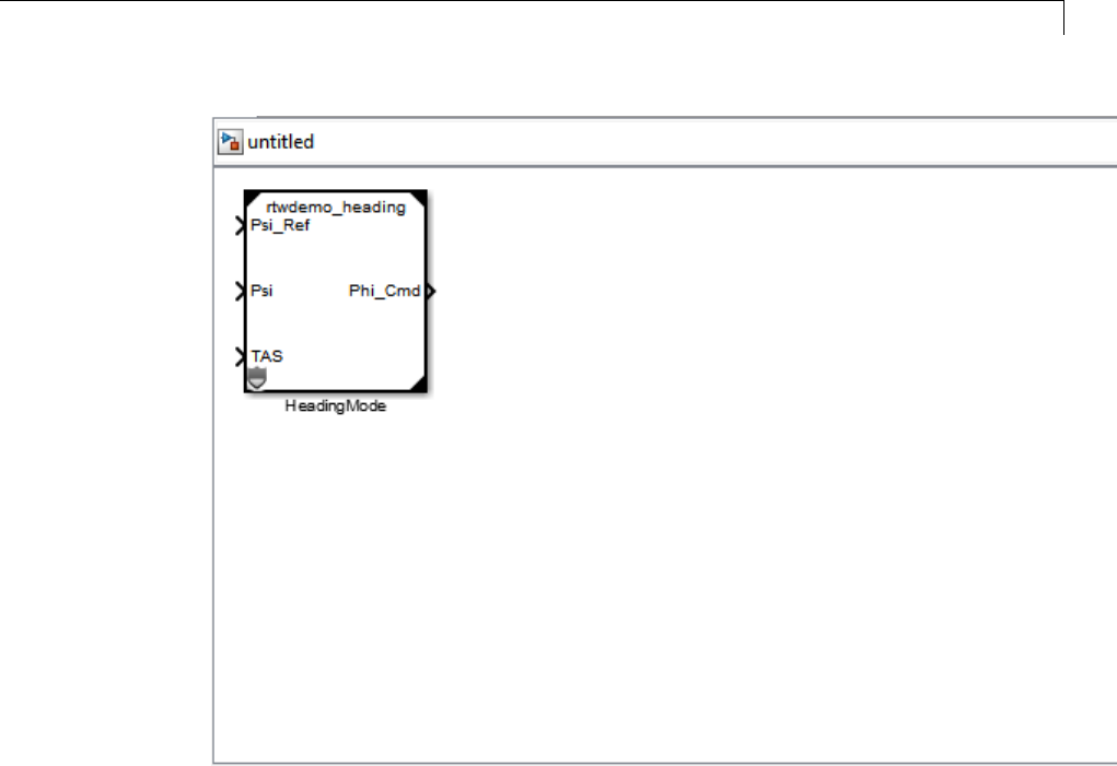
Create a Protected Model
11 To view the protected model report, double-click the HeadingMode block.
6-11
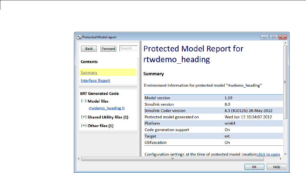

Test the Protected Model
Test the Protected Model
To test a protected model that you created, you use the generated harness
model and the procedure described in “Use Protected Model in Simulation”.
You can also compare the output of the protected model to the output of
the original model. Because you are the supplier, both the original and the
protected model might exist on the MATLAB path. In the original model, if
the Model block Model name parameter names the model without providing
a suffix, the protected model takes precedence over the unprotected model.
If you need to override this default when testing the output, in the Model
block Model name parameter, specify the file name with the extension of
the unprotected model, .slx.
To compare the unprotected and protected versions of a Model block, use
the Simulation Data Inspector. This example uses rtwdemo_roll and the
protected model, rtwdemo_heading.slxp, which is created in “Create a
Protected Model” on page 6-9.
1If it is not already open, open rtwdemo_roll.
2Enable logging for the output signal of the Model block, HeadingMode.In
the Configuration Parameters dialog box, on the Data Import/Export
pane, select the Signal logging parameter and set Signal logging
format to Dataset.ClickApply and OK.
3Right-click the output signal. From the context menu, select Properties.
In the Signal Properties dialog box, select Log signal data.ClickApply
and OK. For more information, see “Export Signal Data Using Signal
Logging”.
4Right-click the HeadingMode block. From the context menu, select Block
Parameters (ModelReference). In the Block Parameters dialog box,
specify the Model name parameter with the name of the unprotected
model and the extension, rtwdemo_heading.slx.ClickApply and OK.
5In the Simulink Editor, click the Record button on. Simulate the model.
When the simulation is complete, the Simulation Data Inspector opens.
6-13

6Model Protection
6In the Simulation Data Inspector, rename the run to indicate that it is
for the unprotected model.
7In the Simulink Editor, right-click the HeadingMode block. From the
context menu, select Block Parameters (ModelReference).IntheBlock
Parameters dialog box, specify the Model name parameter with the name
of the protected model, rtwdemo_heading.slxp. A shield icon appears
on the Model block.
8In the Simulink Editor, the Record button is still on. Simulate the model,
which now refers to the protected model. When the simulation is complete,
the Simulation Data Inspector opens.
9In the Simulation Data Inspector, rename the new run to indicate that it
is for the protected model.
10 In the Simulation Data Inspector, select the Compare Runs tab to
compare the runs for the unprotected and the protected model. For more
information about comparing runs, see “Compare All Logged Signal Data
From Multiple Simulations”.
6-14

Save Base Workspace Definitions
Save Base Workspace Definitions
Referenced models might use object definitions or tunable parameters that
are defined in the MATLAB base workspace. These variables are not saved
with the model. When you protect a model, you must obtain the definitions of
required base workspace entities and ship them with the model.
The following base workspace variables must be saved to a MAT-file:
•Global tunable parameter
•Global data store
•Any of the following objects used by a signal that connects to a root-level
model Inport or Outport:
-Simulink.Signal
-Simulink.Bus
-Simulink.Alias
-Simulink.NumericType that is an alias
For more information, see “Workspace Variables in Model Explorer”.
Before executing the protected model as a part of a third-party model, the
receiver of the protected model must load the MAT-file.
6-15

6Model Protection
Package a Protected Model
In addition to the protected model file (.slxp), you might need to include
additional files in the protected model package:
•Harness model file.
•Any required definitions saved in a MAT-file. For more information, see
“Save Base Workspace Definitions” on page 6-15.
•Instructions on how to retrieve the files.
Some ways to deliver the protected model package are:
•Provide the .slxp file and other supporting files as separate files.
•Combine the files into a ZIP or other container file.
•Combine the files using a manifest. For more information, see “Export
Files in a Manifest”.
•Provide the files in some other standard or proprietary format specified
by the receiver.
Whichever approach you use to deliver a protected model, include information
onhowtoretrievetheoriginalfiles. Oneapproachtoconsideristousethe
Simulink Manifest Tools, as described in “Analyze Model Dependencies”.
6-16


7Data Representation
Enumerations
In this section...
“About Enumerated Data Types” on page 7-2
“Default Code for an Enumerated Data Type” on page 7-2
“Type Casting for Enumerations” on page 7-3
“Override Default Methods (Optional)” on page 7-4
“Enumerated Type Limitations” on page 7-7
About Enumerated Data Types
Enumerated data is data that is restricted to a finite set of values. An
enumerated data type is a MATLAB class that defines a set of enumerated
values. Each enumerated value consists of an enumerated name and an
underlying integer which the software uses internally and in generated code.
The following is a MATLAB class definition for an enumerated data type
named BasicColors, which is used in the examples in this section.
classdef(Enumeration) BasicColors < Simulink.IntEnumType
enumeration
Red(0)
Yellow(1)
Blue(2)
end
end
For information about enumerated data types and their use in Simulink
models, see “Use Enumerated Data in Simulink Models”. For information
about enumerated data types in Stateflow charts, see “How to Define
Enumerated Data in a Chart”.
Default Code for an Enumerated Data Type
By default, enumerated data types in generated code are defined in the
generated header file model_types.h forthemodel.Forexample,thedefault
code for BasicColors, which is defined in the previous section, appears as
follows:
7-2

Enumerations
#ifndef _DEFINED_TYPEDEF_FOR_BasicColors_
#define _DEFINED_TYPEDEF_FOR_BasicColors_
typedef enum {
Red = 0, /* Default value */
Yellow = 1,
Blue = 2,
} BasicColors;
#endif
Type Casting for Enumerations
How Safe Casting Works
A Simulink Data Type Conversion block can accept a signal of integer type
and convert the input to one of the underlying values of an enumerated type.
If the input value does not match any of the underlying values of the
enumerated type’s values, Simulink can insert a safe cast to replace the input
value with the enumerated type’s default value.
Enable and Disable Safe Casting
You can enable or disable safe casting for enumerations during code
generation for a Simulink Data Type Conversion block or a Stateflow block.
To control safe casting, enable or disable the block’s Saturate on integer
overflow parameter. The parameter works as follows:
•Enabled: Simulink replaces a non-matching input value with the default
value of the enumerated values during simulation and generates a safe
cast function during code generation.
•Disabled: For a non-matching input value, Simulink generates an error
during simulation and omits the safe cast function during code generation.
While the code is more efficient in this case, it may be more vulnerable to
runtime errors.
7-3

7Data Representation
Safe Cast Function in Generated Code
This example shows how the safe cast function int32_T
ET08_safe_cast_to_BasicColors for the enumeration BasicColors appears
in generated code.
static int32_T ET08_safe_cast_to_BasicColors(int32_T input)
{
int32_T output;
/* Initialize output value to default value for BasicColors (Red) */
output = 0;
if ((input >= 0) && (input <= 2)) {
/* Set output value to input value if it is a member of BasicColors */
output = input;
}
return output;
}
Through this function, the enumerated type’s default value is used if the
input value does not match one of underlying values of the enumerated type’s
values.
If the block’s Saturate on integer overflow parameter is disabled, this
function does not appear in generated code.
Override Default Methods (Optional)
Every enumerated class has four associated static methods, which it inherits
from Simulink.IntEnumType. You can optionally override any or all of
these static methods to customize the behavior of an enumerated type. The
methods are:
•getDefaultValue — Returns the default value of the enumerated data
type.
•getDescription — Returns a description of the enumerated data type.
•getHeaderFile — Specifies a file where the type is defined for generated
code.
•addClassNameToEnumNames — Specifies whether the class name becomes
a prefix in code.
7-4

Enumerations
The first of these methods, getDefaultValue, is relevant to both simulation
and code generation, and is described in “Specifying a Default Enumerated
Value” in the Simulink documentation. The other three methods are relevant
only to code generation, and are described in this section. To override any of
the methods, include a customized version of the method in the enumerated
class definition’s methods section. If you do not want to override any default
methods, omit the methods section entirely. The following table summarizes
the four methods and the data to supply for each one:
Method Purpose Default Return Custom Return
getDefaultValue Returns the default
valuefortheclass,
which must be an
instance of the class.
The lexically
first value in the
enumeration.
Any enumerated
value in the class.
See “Instantiate
Enumerations”.
getDescription Returns a string
containing a
description of the
enumerated class.
'' Anystringthat
MATLAB accepts.
getHeaderFile Returns a string
containing the name
of the header file
'' Thenameofthefile
that contains the
enumerated type
definition.
addClassNameToEnumNames Returns a boolean
value indicating
whether to prefix
the class name in
generated code
false true or false
Specifying a Description
To specify a description for an enumerated data type, include the following
method in the enumerated class’s methods section:
function retVal = getDescription()
% GETDESCRIPTION Optional string to describe the data type.
retVal = 'description';
end
7-5

7Data Representation
Substitute any legal MATLAB string for description. The generated code
that defines the enumerated type will include the specified description.
Specify a Header File
To prevent the declaration of an enumerated type from being embedded in the
generated code, allowing you to provide the declaration in an external file,
include the following method in the enumerated class’s methods section:
function retVal = getHeaderFile()
% GETHEADERFILE File where type is defined for generated code.
% If specified, this file is #included in the code.
% Otherwise, the type is written out in the generated code.
retVal = 'filename';
end
Substitute any legal filename for filename. Besuretoprovideafilename
suffix, typically .h. Providing the method replaces the declaration that would
otherwisehaveappearedinmodel_types.h with a #include statement like:
#include "imported_enum_type.h"
The getHeaderFile method does not create the declaration file itself. You
must provide a file of the specified name that declares the enumerated data
type.
Add Prefixes To Class Names
By default, enumerated values in generated code have the same names that
they have in the enumerated class definition. Alternatively, the code can
prefix every enumerated value in an enumerated class with the name of
the class. This technique can be useful for preventing identifier conflicts or
improving the clarity of the code. To specify class name prefixing, include the
following method in an enumerated class’s methods section:
function retVal = addClassNameToEnumNames()
% ADDCLASSNAMETOENUMNAMES Control whether class name is added as
% a prefix to enumerated names in the generated code.
% By default the code does not use the class name as a prefix.
retVal = boolean;
end
7-6

Enumerations
Replace boolean with true to enable class name prefixing, or false to
suppress prefixing without having to delete the method itself. If boolean
is true, each enumerated value in the class appears in generated code as
EnumTypeName_EnumName.ForBasicColors, which was defined in “About
Enumerated Data Types” on page 7-2, the data type definition with class
name prefixing looks like this:
#ifndef _DEFINED_TYPEDEF_FOR_BasicColors_
#define _DEFINED_TYPEDEF_FOR_BasicColors_
typedef enum {
BasicColors_Red = 0, /* Default value */
BasicColors_Yellow = 1,
BasicColors_Blue = 2,
} BasicColors;
#endif
In this example, the enumerated class name BasicColors appears as a prefix
for each of the enumerated names. The definition is otherwise the same as
it would be without name prefixing.
Enumerated Type Limitations
•Generated code does not support logging enumerated data.
7-7

7Data Representation
Structure Parameters and Generated Code
In this section...
“About Structure Parameters and Generated Code” on page 7-49
“Include Structure Parameters in Generated Code” on page 7-50
“Control Naming of Structure Parameter Types” on page 7-50
About Structure Parameters and Generated Code
Structure parameters provide a way to improve generated code to use
structures rather multiple separate variables. You also have the option of
configuring the appearance of a structure parameter in generated code.
For more information about structure parameters, see“Structure Parameters”
in the Simulink documentation. For an example of how to convert a model
that uses unstructured workspace variables to a model that uses structure
parameters, see sldemo_applyVarStruct.
Configure Structure Parameters for Generated Code
By default, structure parameters do not appear in generated code. Structure
parameters include numeric variables and the code generator inlines numeric
values.
To make structure type definition appear in generated code for a structure
parameter,
1Create a Simulink.Parameter object.
2Define the object value to be the parameter structure.
3Define the object storage class to be a value other than Auto.
The code generator places a structure type definition or the tunable parameter
structure in model_types.h. By default, the code generator identifies
the type with a nondescriptive, automatically generated name, such as
struct_z98c0D2qc4btL.
7-8

Structure Parameters and Generated Code
For information on how to control the naming of the type, see “Control
Naming of Structure Parameter Types” on page 7-50. For an example, see
sldemo_applyVarStruct
Control Name of Structure Parameter Type
To control the naming of a structure parameter type, use a Simulink.Bus
object to specify the data type of the Simulink.Parameter object.
1Use Simulink.Bus.createObject to create a bus object with the same shape
as the parameter structure. For example:
busInfo=Simulink.Bus.createObject(ControlParam.Value);
2Assign the bus object name to the data type property of the parameter
object.
ParamType=eval(busInfo.busName);
ControlParam.DataType='Bus: ParamType';
Only Simulink.Parameter can accept the bus object name as a data type.
For an example, see sldemo_applyVarStruct
7-9

7Data Representation
Parameters
In this section...
“About Parameters” on page 7-10
“Nontunable Parameter Storage” on page 7-11
“Tunable Parameter Storage” on page 15-119
“Tunable Parameter Storage Classes” on page 15-121
“Declare Tunable Parameters” on page 15-124
“Tunable Expressions” on page 15-128
“Linear Block Parameter Tunability” on page 15-132
“Configuration Parameter Quick Reference Diagram” on page 7-27
“Generated Code for Parameter Data Types” on page 7-28
“Tunable Workspace Parameter Data Type Considerations” on page 15-133
“Tune Parameters” on page 7-36
“Parameter Objects” on page 7-38
“Structure Parameters and Generated Code” on page 7-49
About Parameters
This section discusses how the Simulink Coder product generates parameter
storage declarations, and how you can generate the storage declarations
you need to interface block parameters to your code. For information about
defining block parameters in Simulink models, see “Set Block Parameters”.
If you are using S-functions in your model and intend to tune their run-time
parameters in the generated code, see “Tuning Run-Time Parameters” in the
Simulink documentation. Note that
•Parameters must be numeric, logical, or character arrays.
•Parameters may not be sparse.
•Parameter arrays must not be greater than 2 dimensions.
7-10
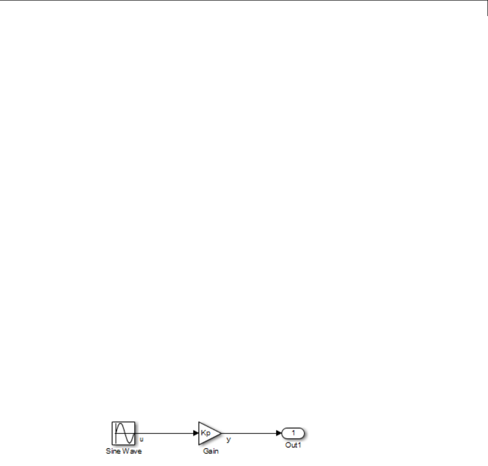
Parameters
For guidance on implementing a parameter tuning interface using a C API,
see “Data Interchange Using the C API” on page 15-137.
Simulink external mode offers a way to monitor signals and modify parameter
values while generated model code executes. However, external mode might
not be the optimal solution for your application. For example, the S-function
target does not support external mode. For other targets, you might want
your existing code to access parameters and signals of a model directly, rather
than using the external mode communications mechanism. For information
on external mode, see “Host/Target Communication” on page 15-50.
Nontunable Parameter Storage
By default, block parameters are not tunable in the generated code. When
Inline Parameters is off (the default), the Simulink Coder product has
control of parameter storage declarations and the symbolic naming of
parameters in the generated code.
Nontunable parameters are stored as fields within model_P (formerly rtP), a
model-specific global parameter data structure. The Simulink Coder product
initializes each field of model_P to the value of the corresponding block
parameter at code generation time.
When the Inline parameters option is on, block parameters are evaluated at
code generation time, and their values appear as constants in the generated
code, if possible (in certain circumstances, parameters cannot be inlined, and
are then included in a constant parameter or model parameter structure.)
As an example of nontunable parameter storage, consider the following model.
The workspace variable Kp sets the gain of the Gain block.
7-11
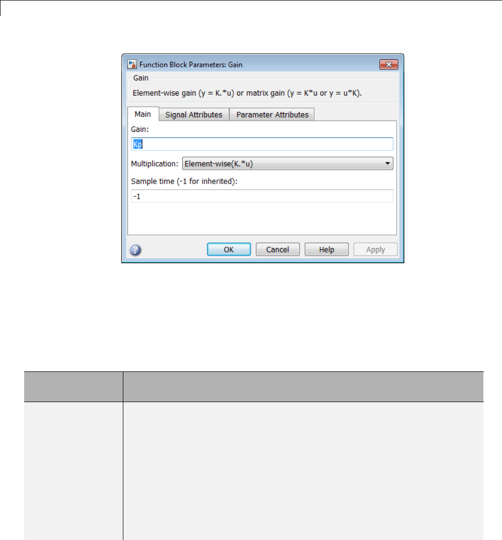
7Data Representation
Assume that Kp is nontunable and has a value of 5.0. The next table shows
the variable declarations and the code generated for Kp in the noninlined
and inlined cases.
The generated code does not preserve the symbolic name Kp. The noninlined
code represents the gain of the Gain block as model_P.Gain_Gain.WhenKp is
noninlined, the parameter is tunable.
Inline
Parameters
Generated Variable Declaration and Code
Off
struct Parameters_non_tunable_sin { real_T SineWave_Amp;
real_T SineWave_Bias;
real_T SineWave_Freq;
real_T SineWave_Phase;
real_T Gain_Gain;
};
.
.
.
Parameters_non_tunable_sin non_tunable_sin_P = {
7-12

Parameters
Inline
Parameters
Generated Variable Declaration and Code
1.0 , /* SineWave_Amp : '<Root>/Sine Wave' */
0.0 , /* SineWave_Bias : '<Root>/Sine Wave' */
1.0 , /* SineWave_Freq : '<Root>/Sine Wave' */
0.0 , /* SineWave_Phase : '<Root>/Sine Wave' */
5.0 /* Gain_Gain : '<Root>/Gain' */
};
.
.
.
non_tunable_sin_Y.Out1 = rtb_u *
non_tunable_sin_P.Gain_Gain;
On
non_tunable_sin_Y.Out1 = rtb_u * 5.0;
Tunable Parameter Storage
Atunable parameter is a block parameter whose value can be changed at
run-time. A tunable parameter is inherently noninlined. Consequently, when
Inlined parameters is off, all parameters are members of model_P, and thus
are tunable. A tunable expression is an expression that contains one or more
tunable parameters.
When you declare a parameter tunable, you control whether or not the
parameter is stored within model_P. You also control the symbolic name of
the parameter in the generated code.
When you declare a parameter tunable, you specify
•The storage class of the parameter.
The storage class property of a parameter specifies how the Simulink Coder
product declares the parameter in generated code.
The term “storage class,” as used in the Simulink Coder product, is not
synonymous with the term storage class specifier, as used in the C language.
7-13

7Data Representation
•Astorage type qualifier,suchasconst or volatile.Thisissimplyastring
that is included in the variable declaration.
•(Implicitly) the symbolic name of the variable or field in which the
parameter is stored. The Simulink Coder product derives variable and field
names from the names of tunable parameters.
The Simulink Coder product generates a variable or struct storage
declaration for each tunable parameter. Your choice of storage class controls
whether the parameter is declared as a member of model_P or as a separate
global variable.
You can use the generated storage declaration to make the variable visible
to external legacy code. You can also make variables declared in your code
visible to the generated code. You are responsible for linking your code to
generated code modules.
You can use tunable parameters or expressions in your root model and
in masked or unmasked subsystems, subject to certain restrictions. (See
“Tunable Expressions” on page 15-128.)
Override Inlined Parameters for Tuning
When the Inline parameters option is selected, you can use the Model
Parameter Configuration dialog box toremoveindividualparametersfrom
inlining and declare them to be tunable. This allows you to improve overall
efficiency by inlining most parameters, while at the same time retaining the
flexibility of run-time tuning for selected parameters. Another way you can
achieve the same result is by using Simulink data objects; see “Parameters”
on page 7-10 for specific details.
The mechanics of declaring tunable parameters are discussed in “Declare
Tunable Parameters” on page 15-124.
Tunable Parameter Storage Classes
The Simulink Coder product defines four storage classes for tunable
parameters. You must declare a tunable parameter to have one of the
following storage classes:
7-14
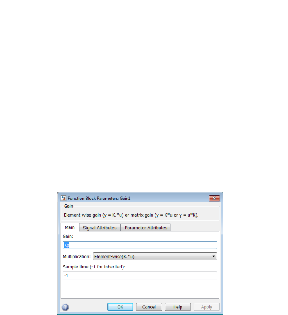
Parameters
•SimulinkGlobal (Auto): This is the default storage class. The Simulink
Coder product stores the parameter as a member of model_P. Each member
of model_P is initialized to the value of the corresponding workspace
variable at code generation time.
•ExportedGlobal: The generated code instantiates and initializes the
parameter and model.h exports it as a global variable. An exported global
variable is independent of the model_P data structure. Each exported
global variable is initialized to the value of the corresponding workspace
variable at code generation time.
•ImportedExtern:model_private.h declares the parameter as an extern
variable. Your code must supply the variable definition and initializer.
•ImportedExternPointer:model_private.h declares the variable as an
extern pointer. Your code must supply the pointer variable definition
and initializer, if any.
The generated code for model.h includes model_private.h to make the
extern declarations available to subsystem files.
As an example of how the storage class declaration affects the code generated
for a parameter, consider the next figure.
7-15

7Data Representation
The workspace variable Kp sets the gain of the Gain block. Assume that
the value of Kp is 3.14. The following table shows the variable declarations
and the code generated for the gain block when Kp is declared as a tunable
parameter. An example is shown for each storage class.
Note The Simulink Coder product uses column-major ordering for
two-dimensional signal and parameter data. When interfacing your
hand-written code to such signals or parameters by using ExportedGlobal,
ImportedExtern,orImportedExternPointer declarations, make sure that
your code observes this ordering convention.
The symbolic name Kp is preserved in the variable and field names in the
generated code.
Storage Class Generated Variable Declaration and Code
SimulinkGlobal
(Auto) typedef struct _Parameters_tunable_sin
Parameters_tunable_sin;
struct _Parameters_tunable_sin {
real_T Kp;
};
Parameters_tunable_sin tunable_sin_P = {
3.14
};
.
.
tunable_sin_Y.Out1 = rtb_u *
tunable_sin_P.Kp;
ExportedGlobal
real_T Kp = 3.14;
.
.
tunable_sin_Y.Out1 = rtb_u * Kp;
7-16

Parameters
Storage Class Generated Variable Declaration and Code
ImportedExtern
extern real_T Kp;
.
.
tunable_sin_Y.Out1 = rtb_u * Kp;
ImportedExtern
Pointer extern real_T *Kp;
.
.
tunable_sin_Y.Out1 = rtb_u * (*Kp);
Declare Tunable Parameters
•“Declare Workspace Variables as Tunable Parameters” on page 15-124
•“Declare New Tunable Parameters” on page 15-124
•“Declare Tunable Parameters Using Configuration Parameter Dialog” on
page 15-125
•“Select Workspace Variables” on page 15-126
•“Create New Tunable Parameters” on page 15-127
•“Set Tunable Parameter Properties” on page 15-128
•“Remove Unused Tunable Parameters” on page 15-128
Declare Workspace Variables as Tunable Parameters
To declare tunable parameters,
1Open the Model Parameter Configuration dialog box.
2In the Source list pane, select one or more variables.
3Click Add to table . The variables then appear as tunable parameters in
the Global (tunable) parameters pane.
7-17

7Data Representation
4Select a parameter in the Global (tunable) parameters pane.
5Select a storage class from the Storage class menu.
6Optionally, select (or enter) a storage type qualifier, such as const or
volatile for the parameter.
7Click Apply,orclickOK to apply changes and close the dialog box.
Declare New Tunable Parameters
To declare tunable parameters,
1Open the Model Parameter Configuration dialog box.
2In the Global (tunable) parameters pane, click New.
3Specify a name for the parameter.
4Select a storage class from the Storage class menu.
5Optionally, select (or enter) a storage type qualifier, such as const or
volatile for the parameter.
6Click Apply,orclickOK to apply changes and close the dialog box.
Declare Tunable Parameters Using Configuration Parameters
The Model Configuration Parameters dialog box lets you select base
workspace variables and declare them to be tunable parameters in the current
model. Using controls in the dialog box, you move variables from a source list
to a global (tunable) parameter list for a model.
To open the dialog box,
1Select the Inline parameters check box on the Optimization > Signals
and Parameters pane of the Configuration Parameters dialog box. This
activates a Configure button, as shown below.
7-18
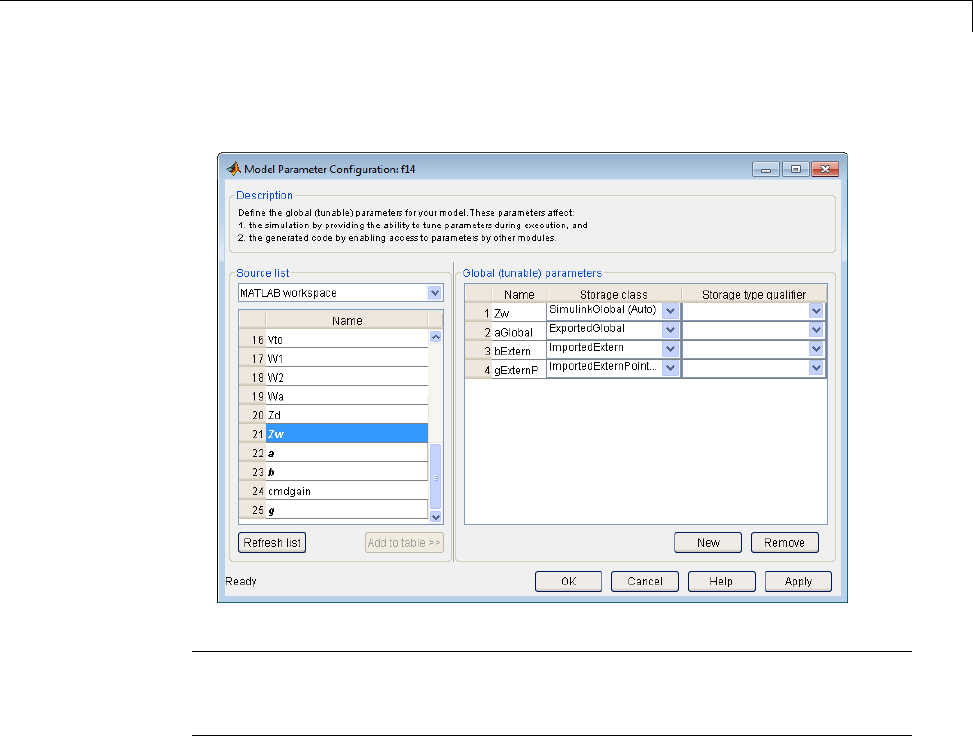
Parameters
2Click Configure to open the Model Configuration Parameters dialog box.
Note The Model Configuration Parameters dialog box cannot tune
parameters within referenced models. See “Parameterize Model References”
for tuning techniques that work with referenced models.
Select Workspace Variables
The Source list pane displays a menu and a scrolling table of numerical
workspace variables. To select workspace variables,
1From the menu, select the source of variables you want listed.
7-19

7Data Representation
To List... Choose...
All variables in the MATLAB
workspace that have numeric
values
MATLAB workspace
Only variables in the MATLAB
workspace that have numeric
values and are referenced by the
model
Referenced workspace
variables
A list of workspace variables appear in the Source List pane.
2Select one or more variables from the source list. This enables the Add
to table button.
3Click Add to table to add the selected variables to the tunable parameters
list in the Global (tunable) parameters pane. In the Source list,the
names of variables added to the tunable parameters list are displayed in
bold type (see the preceding figure).
Note If you selected a variable with a name that matches a block
parameter that is not tunable and you click Add to table ,awarning
appears during simulation and code generation.
To update the list of variables to reflect the current state of the workspace,
at any time, click Refresh list . For example, you might use Refresh list if
you define or remove variables in the workspace while the Model Parameter
Configuration dialog box is open.
Create New Tunable Parameters
To create a new tunable parameter,
1In the Global (tunable) parameters pane, click New.
2In the Name field, enter a name for the parameter.
7-20

Parameters
Ifyouenteranamethatmatchesthenameofaworkspacevariablein
the Source list pane, that variable is declared tunable and appears in
italics in the Source list.
3Click Apply.
Themodeldoesnotneedtobeusingaparameterbeforeyoucreateit. Youcan
add references to the parameter later.
Note If you edit the name of an existing variable in the list, you actually
create a new tunable variable with the new name. The previous variable is
removed from the list and loses its tunability (that is, it is inlined).
Set Tunable Parameter Properties
To set the properties of tunable parameters listed in the Global (tunable)
parameters pane, select a parameter and then specify a storage class and,
optionally, a storage type qualifier.
Property Description
Storage class Selectoneofthefollowingtobeusedforcode
generation:
•SimulinkGlobal (Auto)
•ExportedGlobal
•ImportedExtern
•ImportedExternPointer
See “Tunable Parameter Storage Classes” on
page 15-121 for definitions.
Storage type qualifier For variables with any storage class except
SimulinkGlobal (Auto),youcanadda
qualifier (such as const or volatile)tothe
generated storage declaration. To do so, you
can select a predefined qualifier from the list
or add qualifiers not in the list. The code
7-21
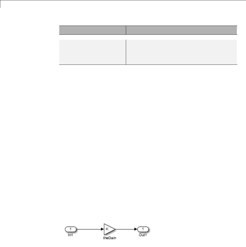
7Data Representation
Property Description
generator does not check the storage type
qualifier for validity, and includes the qualifier
string in the generated code without checking
syntax .
Remove Unused Tunable Parameters
To remove unused tunable parameters from the table in the Global (tunable)
parameters pane, click Remove. Removed variables are inlined if the
Inlined parameters option is enabled.
Tunable Expressions
•“Tunable Expressions in Masked Subsystems” on page 15-129
•“Tunable Expression Limitations” on page 15-131
The Simulink Coder product supports the use of tunable variables in
expressions. An expression that contains one or more tunable parameters is
called a tunable expression.
Tunable Expressions in Masked Subsystems
Tunable expressions are allowed in masked subsystems. You can use tunable
parameter names or tunable expressions in a masked subsystem dialog box.
When referenced in lower-level subsystems, such parameters remain tunable.
As an example, consider the masked subsystem in the next figure. The
masked variable ksets the gain parameter of theGain.
7-22
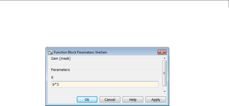
Parameters
Suppose that the base workspace variable bis declared tunable with
SimulinkGlobal (Auto) storage class. The next figure shows the tunable
expression b*3 in the subsystem’s mask dialog box.
Tunable Expression in Subsystem Mask Dialog Box
The Simulink Coder product produces the following output computation for
theGain.Thevariablebis represented as a member of the global parameters
structure, model_P. (For clarity in showing the individual Gain block
computation, expression folding is off in this example.)
/* Gain: '<S1>/theGain' */
rtb_theGain_C = rtb_SineWave_n * ((subsys_mask_P.b * 3.0));
/* Outport: '<Root>/Out1' */
subsys_mask_Y.Out1 = rtb_theGain_C;
As this example shows, for GRT targets, the parameter structure is mangled
to create the structure identifier model_P (subject to the identifier length
constraint). This is done to avoid namespace clashes in combining code from
multiple models using model reference. ERT-based targets provide ways to
customize identifier names.
When expression folding is on, the above code condenses to
/* Outport: '<Root>/Out1' incorporates:
* Gain: '<S1>/theGain'
*/
subsys_mask_Y.Out1 = rtb_SineWave_n * ((subsys_mask_P.b * 3.0));
7-23

7Data Representation
Expressions that include variables that were declared or modified in mask
initialization code are not tunable.
As an example, consider the subsystem above, modified as follows:
•The mask initialization code is
t=3*k;
•The parameter kof the myGain block is 4+t.
•Workspace variable b=2. The expression b*3is plugged into the mask
dialog box as in the preceding figure.
Since the mask initialization code can run only once, kis evaluated at code
generation time as
4+(3*(2*3))
The Simulink Coder product inlines the result. Therefore, despite the fact
that bwas declared tunable, the code generator produces the following output
computation for theGain. (For clarity in showing the individual Gain block
computation, expression folding is off in this example.)
/* Gain Block: <S1>/theGain */
rtb_temp0 *= (22.0);
Tunable Expression Limitations
Currently, there are certain limitations on the use of tunable variables in
expressions. When an unsupported expression is encountered during code
generation a warning is issued and the equivalent numeric value is generated
in the code. The limitations on tunable expressions are
•Complex expressions are not supported, except where the expression is
simply the name of a complex variable.
•The use of certain operators or functionsinexpressionscontainingtunable
operands is restricted. Restrictions are applied to four categories of
operators or functions, classified in the following table:
7-24

Parameters
Category Operators or Functions
1+ - .* ./ < > <= >= == ~= & |
2*/
3abs,acos,asin,atan,atan2,boolean,ceil,cos,cosh,
exp,floor,log,log10,sign,sin,sinh,sqrt,tan,tanh,
4single,int8,int16,int32,uint8,uint16,uint32
5: .^ ^ [] {} . \ .\ ' .' ; ,
The rules applying to each category are as follows:
-Category 1 is unrestricted. These operators can be used in tunable
expressions with any combination of scalar or vector operands.
-Category 2 operators can be used in tunable expressions where at least
one operand is a scalar. That is, scalar/scalar and scalar/matrix operand
combinations are supported, but not matrix/matrix.
-Category 3 lists functions that support tunable arguments. Tunable
arguments passed to these functions retain their tunability. Tunable
arguments passed to any other functions lose their tunability.
-Category 4 lists the casting functions that do not support tunable
arguments. Tunable arguments passed to these functions lose their
tunability.
Note The Simulink Coder product casts values using MATLAB
typecasting rules. The MATLAB typecasting rules are different from C
code typecasting rules. For example, using the MATLAB typecasting
rules, int8(3.7) returns the result 4, while in C code int8(3.7) returns
the result 3.
-Category 5 operators are not supported.
•Expressions that include variables that were declared or modified in mask
initialization code are not tunable.
•The Fcn block does not support tunable expressions in code generation.
7-25

7Data Representation
•Model workspace parameters can take on only the Auto storage class, and
thus are not tunable. See “Parameterize Model References” for tuning
techniques that work with referenced models.
•Non-double expressions are not supported.
•Blocks that access parameters only by address support the use of tunable
parameters, if the parameter expression is a simple variable reference.
When an operation such as a data type conversion or a math operation
is applied, the Simulink Coder product creates a nontrivial expression
that cannot be accessed by address, resulting in an error during the build
process.
Linear Block Parameter Tunability
The following blocks have a Realization parameter that affects the
tunability of their parameters:
•Transfer Fcn
•State-Space
•Discrete State-Space
The Realization parameter must be set by using the MATLAB set_param
function, as in the following example.
set_param(gcb,'Realization','auto')
The following values are defined for the Realization parameter:
•general: The block’s parameters are preserved in the generated code,
permitting parameters to be tuned.
•sparse: The block’s parameters are represented in the code by transformed
values that increase the computational efficiency. Because of the
transformation, the block’s parameters are no longer tunable.
•auto: This setting is the default. A general realization is used if one or
more of the block’s parameters are tunable. Otherwise sparse is used.
7-26

Parameters
Note To tune the parameter values of a block of one of the above types
without restriction during an external mode simulation, you must set
Realization to general.
Code Reuse for Subsystems with Mask Parameters
The Simulink Coder product can generate reusable (reentrant) code for
a model containing identical atomic subsystems. Selecting the Reusable
function option for Function packaging enables such code reuse, and
causes a single function with arguments to be generated that is called when
any of the identical atomic subsystem executes. See “Subsystems” for details
and restrictions on the use of this option.
Mask parameters become arguments toreusablefunctions. However,for
reuse to occur, each instance of a reusable subsystem must declare the same
set of mask parameters. If, for example subsystem A has mask parameters b
and K, and subsystem B has mask parameters cand K, then code reuse is not
possible, and the Simulink Coder product will generate separate functions
for A and B.
Configuration Parameter Quick Reference Diagram
Thenextfigureshowsthecodegenerationandstorageclassoptionsthat
control the representation of parameters in generated code.
7-27
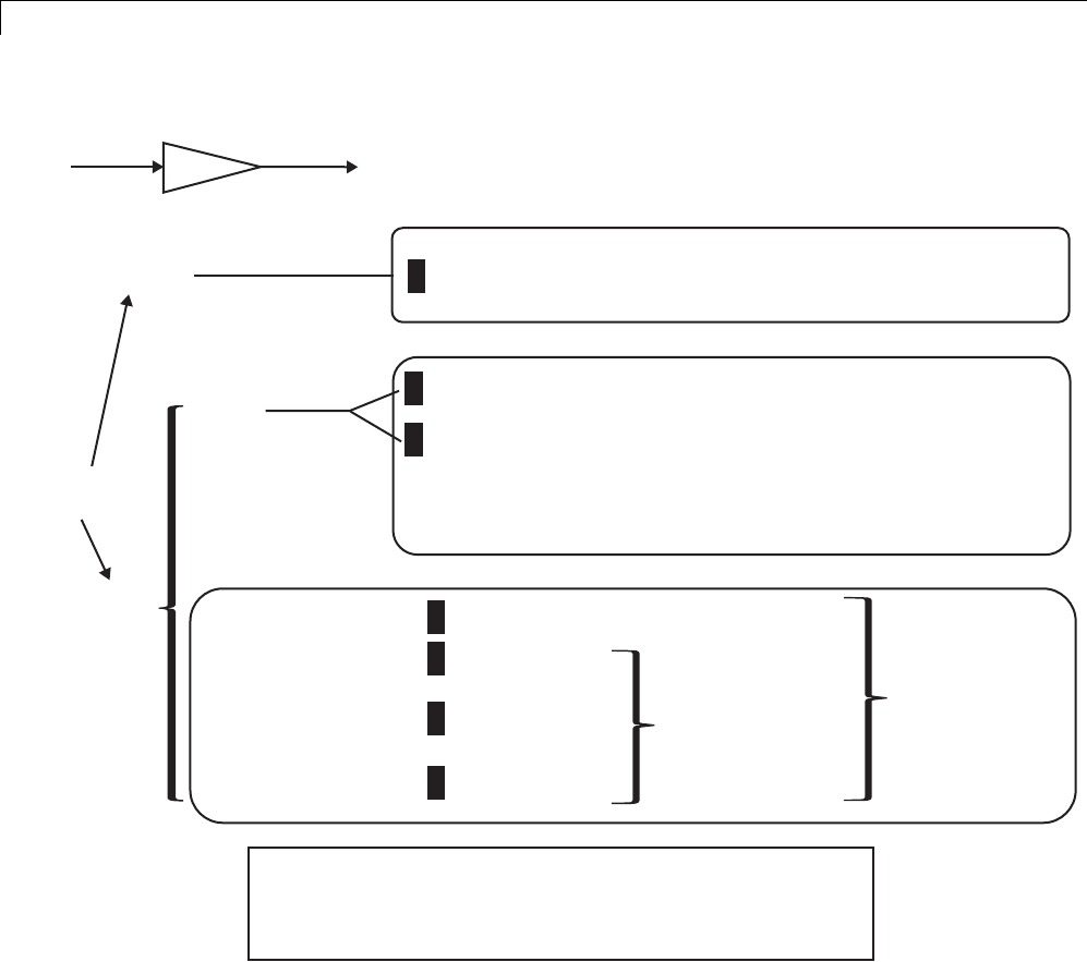
7Data Representation
KEY:
[option] : default for code generation option
<???> : Generated symbol for parameter storage field
Kp = 5.0;
Kp
uy
[OFF]
Inline
Parameters
ON
[Auto]
(implicit)
SIMULINK CODER CONTROLS SYMBOL USED IN CODE
1
2
3
4
5
6
7
SIMULINK CODER CONTROLS SYMBOL USED IN CODE
INCLUDED IN LIST OF GLOBAL (TUNABLE) PARAMETERS
y = u* (rtP.<???>);
Include parameters as fields
in a global structure
(field names based on block names)
y = u* (5.0);
const *p_<???> = &rtP.<???>[0];
for (i=0; i<N; i++){
y[i] = u * (p_<???>[i]);
}
Use numeric value of
parameter (if possible)
Otherwise, include in a
constant global structure
[SimulinkGlobal(Auto)]
ImportedExtern
ExportedGlobal
ImportedExternPointer
Symbol preserved
(must be unique)
y = u* (rtP.Kp);
y = u* (Kp);
y = u* (Kp);
y = u* (*Kp);
Include in a
global structure
Unstructured
storage
Generated Code for Parameter Data Types
For an example of the code generated from Simulink parameters with
different data types, run the model rtwdemo_paramdt. This model shows
options that are available for controlling the data type of tunable parameters
in the generated code. The model’s subsystem includes several instances of
7-28

Parameters
Gain blocks feeding Saturation blocks. Each pair of blocks uses a workspace
variable of a particular data type, as shown in the next figure.
7-29
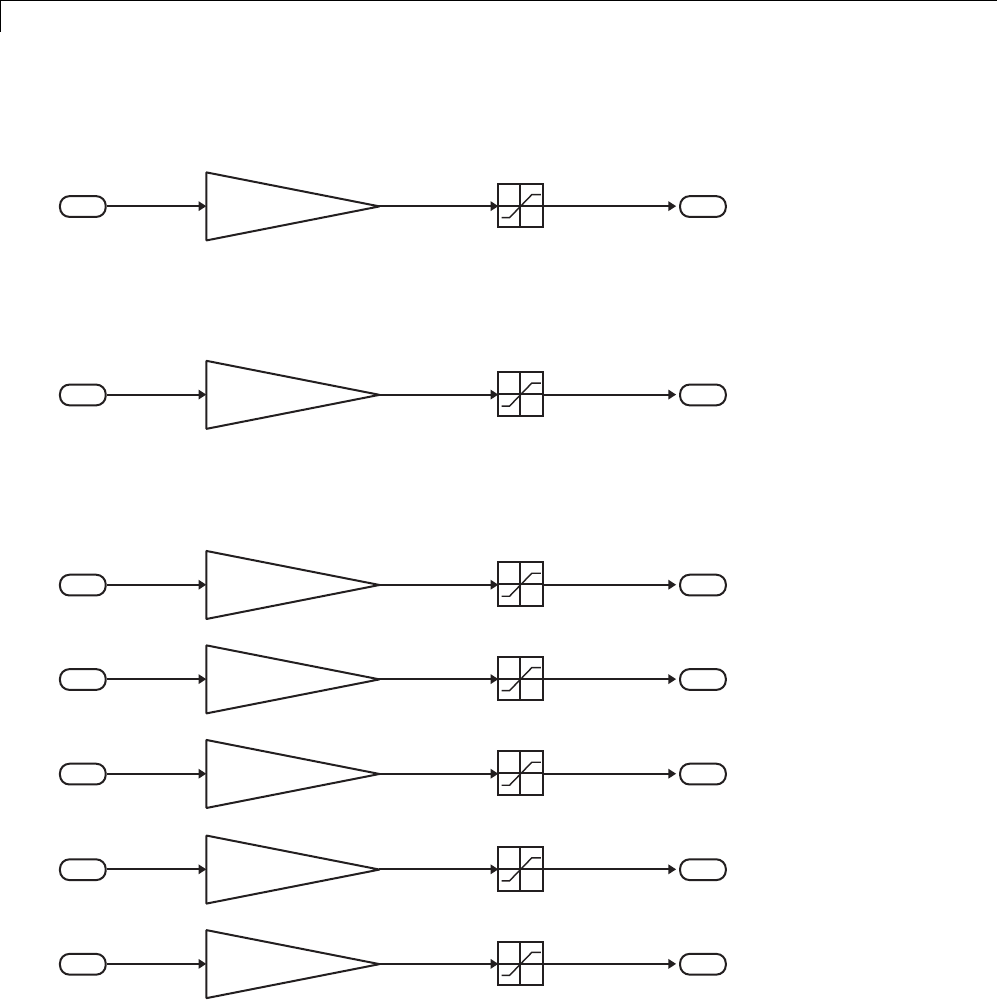
7Data Representation
Inlined parameters (InLineParameters ON + Auto storage class)
==> numeric value inlined
single Kinline single single
11
Upper: Kinline
Lower: 0
Double-precision (context-sensitive) parameters
==> tunable parameter inherits data type from run-time parameter
single Kcs single single
22
Upper: Kcs
Lower: 0
Tunable parameters with explicit data type specification
==> parameter is cast to run-time parameter data type in generated code
single Ksingle single single
33
Upper: Ksingle
Lower: 0
single Kint8 single single
44
Upper: Kint8
Lower: 0
single Kfixpt single single
55
Upper: Kfixpt
Lower: 0
single Kalias single single
66
Upper: Kalias
Lower: 0
single Kuser single single
77
Upper: Kuser
Lower: 0
7-30

Parameters
The Simulink engine initializes the parameters in the model by executing
the script rtwdemo_paramdt_data.m. You can view the initialization script
and inspect the workspace variables in Model Explorer by double-clicking
the yellow boxes in the model.
In the model, note that the Inline parameters option on the
Optimization > Signals and Parameters pane of the Configuration
Parameters dialog box is selected. The Model Parameter Configuration
dialog box reveals that all base workspace variables (with the exception
of Kinline)havetheirStorage class property set to ExportedGlobal.
Consequently, Kinline is a nontunable parameter while the remaining
variables are tunable parameters.
To generate code for the model, double-click the blue boxes. The following
tableshowsboththeMATLABcodeusedtoinitializeparametersandthecode
generated for each parameter in the rtwdemo_paramdt model.
Parameter & MATLAB Code Generated Variable Declaration and Code
Kinline
Kinline = 2;
rtb_Gain1 = rtwdemo_paramdt_U.In1 * 2.0F;
.
.
rtwdemo_paramdt_Y.Out1 = rt_SATURATE(rtb_Gain1, 0.0F, 2.0F);
Kcs
Kcs=3;
real32_T Kcs = 3.0F;
.
.
rtb_Gain1 = rtwdemo_paramdt_U.In2 * Kcs;
.
.
rtwdemo_paramdt_Y.Out2 = rt_SATURATE(rtb_Gain1, 0.0F, Kcs);
7-31

7Data Representation
Parameter & MATLAB Code Generated Variable Declaration and Code
Ksingle
Ksingle = single(4);
real32_T Ksingle = 4.0F;
.
.
rtb_Gain1 = rtwdemo_paramdt_U.In3 * Ksingle;
.
.
rtwdemo_paramdt_Y.Out3 = rt_SATURATE(rtb_Gain1, 0.0F, Ksingle);
Kint8
Kint8 = int8(5);
int8_T Kint8 = 5;
.
.
rtb_Gain1 = rtwdemo_paramdt_U.In4 * ((real32_T)( Kint8 ));
.
.
rtwdemo_paramdt_Y.Out4 = rt_SATURATE(rtb_Gain1, 0.0F,
((real32_T)( Kint8 )));
Kfixpt
Kfixpt = Simulink.Parameter;
Kfixpt.Value = 6;
Kfixpt.DataType = ...
'fixdt(true, 16, 2^-5, 0)';
Kfixpt.CoderInfo.StorageClass = ...
'ExportedGlobal';
int16_T Kfixpt = 192;
.
.
rtb_Gain1 = rtwdemo_paramdt_U.In5 *
(((real32_T)ldexp((real_T)Kfixpt, -5)));
.
.
rtwdemo_paramdt_Y.Out5 = rt_SATURATE(rtb_Gain1, 0.0F,
(((real32_T)ldexp((real_T)Kfixpt, -5))));
7-32

Parameters
Parameter & MATLAB Code Generated Variable Declaration and Code
Kalias
aliasType = ...
Simulink.AliasType('single');
Kalias = Simulink.Parameter;
Kalias.Value = 7;
Kalias.DataType = 'aliasType';
Kalias.CoderInfo.StorageClass = ...
'ExportedGlobal';
typedef real32_T aliasType;
.
.
aliasType Kalias = 7.0F;
.
.
rtb_Gain1 = rtwdemo_paramdt_U.In6 * Kalias;
.
.
rtwdemo_paramdt_Y.Out6 = rt_SATURATE(rtb_Gain1, 0.0F, Kalias);
Kuser
userType = Simulink.NumericType;
userType.DataTypeMode = ...
'Fixed-point: slope and bias scaling';
userType.Slope = 2^-3;
userType.isAlias = true;
Kuser = Simulink.Parameter;
Kuser.Value = 8;
Kuser.DataType = 'userType';
Kuser.CoderInfo.StorageClass = ...
'ExportedGlobal';
typedef int16_T userType;
.
.
userType Kuser = 64;
.
.
rtb_Gain1 = rtwdemo_paramdt_U.In7 *
(((real32_T)ldexp((real_T)Kuser, -3)));
.
.
rtwdemo_paramdt_Y.Out7 = rt_SATURATE(rtb_Gain1, 0.0F,
(((real32_T)ldexp((real_T)Kuser, -3))));
The salient features of the code generated for this model are as follows:
•The Simulink Coder product inlines nontunable parameters, for example,
Kinline. However, the product does not inline tunable parameters, such
as Kcs,Ksingle,andKint8.
•The Simulink engine treats tunable parameters of data type double in a
context-sensitive manner, such that the parameter inherits its data type
from the context in which the block uses it. For example, Kcs inherits a
single data type from the Gain block’s input signal.
7-33

7Data Representation
•If a parameter’s data type matches that of the block’s run-time parameter,
the block can use the tunable parameter without any transformation.
Consequently, the Simulink Coder product need not cast the parameter
fromonedatatypetoanother,asillustratedbyKsingle and Kalias.
However, if a parameter’s data type does not match that of the block’s
run-time parameter, the block cannot readily compute its output. In
this case, the product casts parameters to the relevant data type. For
example, Kint8,Kfixpt,andKuser require casts to a single data type for
compatibility with the input signals to the Gain and Saturation blocks.
•If you are using an ERT target and a parameterspecifiesadatatypealias,
for example, created by an instance of the Simulink.AliasType class, its
variable definition in the generated code uses the alias data type. For
example, the Simulink Coder product declares Kalias and Kuser to be of
data types aliasType and userType,respectively.
•If a parameter specifies a fixed-point data type, the Simulink Coder product
initializes its value in the generatedcodetothevalueofQcomputedfrom
the expression V = SQ + B (see the Simulink Fixed Point documentation for
more information about fixed-point semantics and notation), where
-Visareal-worldvalue
-Q is an integer that encodes V
-Sistheslope
-B is the bias
For example, Kfixpt has a real-world value of 6, slope of 2-5, and bias of 0.
Consequently, the product declares the value of Kfixpt to be 192.
Tunable Workspace Parameter Data Type
Considerations
If you are using tunable workspace parameters, you need to be aware of
potential issues regarding data types. A workspace parameter is tunable
when the following conditions exist:
•You select the Inline parameters option on the Optimization > Signals
and Parameters pane of the Configuration Parameters dialog box
•The parameter has a storage class other than Auto
7-34

Parameters
When generating code for tunable workspace parameters, the Simulink Coder
product checks and compares the data types used for a particular parameter
in the workspace and in Block Parameter dialog boxes.
If... The Simulink Coder Product...
The data types match Uses that data type for the parameter in the
generated code.
You do not explicitly
specify a data type
other than double in
the workspace
Usesthedatatypespecifiedbytheblockin
the generated code. If multiple blocks share a
parameter, they must all specify the same data
type. If the data type varies between blocks,
the product generates an error similar to the
following:
Variable 'K' is used in incompatible ways
in the dialog fields of the following:
cs_params/Gain, cs_params/Gain1. The
variable'value is being used both directly
and after a transformation. Only one of
these usages is permitted for any given
variable.
You explicitly specify
adatatypeother
than double in the
workspace
Usesthedatatypefromtheworkspaceforthe
parameter. The block typecasts the parameter to
the block specific data type before using it.
Guidelines for Specifying Data Types
The following table provides guidelines on specifying data types for tunable
workspace parameters.
If You Want to... Then Specify Data Types in...
Minimize memory usage (int8
instead of single)
The workspace explicitly
Avoid typecasting Blocks only
7-35

7Data Representation
If You Want to... Then Specify Data Types in...
Interfacetolegacyorcustomcode The workspace explicitly
Use the same parameter for
multiple blocks that specify
different data types
The workspace explicitly
The Simulink Coder product enforces limitations on the use of data types
other than double in the workspace, as explained in “Limitations on
Specifying Workspace Data Types Explicitly” on page 15-135.
Limitations on Data Type Specifications in Workspace
When you explicitly specify a data type other than double in the workspace,
blocks typecast the parameter to a corresponding data type. This is an
issue for blocks that use pointer access for their parameters. Blocks cannot
use pointer access if they need to typecast the parameter before using it
(because of a data type mismatch). Another case in which this occurs is for
workspace variables with bias or fractional slope. Two possible solutions
to these problems are
•Remove the explicit data type specification in the workspace for parameters
used in such blocks.
•Modify the block so that it uses the parameter with the same data type
as specified in the workspace. For example, the Lookup Table block uses
the data types of its input signal to determine the data type that it uses
to access the X-breakpoint parameter. You can prevent the block from
typecasting the run-time parameter by converting the input signal to the
data type used for X-breakpoints in the workspace. (Similarly, the output
signal is used to determine the data types used to access the lookup table
Ydata.)
Tune Parameters
Tune Parameters from the Command Line
When parameters are MATLAB workspace variables, the Model Parameter
Configuration dialog box is the recommended way to see or set the properties
7-36

Parameters
of tunable parameters. In addition to that dialog box, you can also use
MATLAB get_param and set_param commands.
Note You can also use Simulink.Parameter objects for tunable parameters.
See“ConfigureParameterObjectsfor Code Generation” on page 7-39 for
details.
The following commands return the tunable parameters and corresponding
properties:
•get_param(gcs, 'TunableVars')
•get_param(gcs, 'TunableVarsStorageClass')
•get_param(gcs, 'TunableVarsTypeQualifier')
The following commands declare tunable parameters or set corresponding
properties:
•set_param(gcs, 'TunableVars', str)
The argument str (string) is a comma-separated list of variable names.
•set_param(gcs, 'TunableVarsStorageClass', str)
The argument str (string) is a comma-separated list of storage class
settings.
The valid storage class settings are
-Auto
-ExportedGlobal
-ImportedExtern
-ImportedExternPointer
•set_param(gcs, 'TunableVarsTypeQualifier', str)
The argument str (string) is a comma-separated list of storage type
qualifiers.
7-37

7Data Representation
The following example declares the variable k1 to be tunable, with storage
class ExportedGlobal and type qualifier const. The number of variables and
number of specified storage class settings must match. If you specify multiple
variables and storage class settings, separate them with a comma.
set_param(gcs, 'TunableVars', 'k1')
set_param(gcs, 'TunableVarsStorageClass','ExportedGlobal')
set_param(gcs, 'TunableVarsTypeQualifier','const')
Interfaces for Tuning Parameters
The Simulink Coder product includes
•Support for developing a Target Language Compiler API for tuning
parameters independent of external mode. See “Parameter Functions” in
the Target Language Compiler documentation for information.
•A C application program interface (API) for tuning parameters independent
of external mode. See “Data Interchange Using the C API” on page 15-137
for information.
•An interface for exporting ASAP2 files, which you customize to use
parameter objects. For details, see “ASAP2 Data Measurement and
Calibration” on page 15-174.
Parameter Objects
•“About Parameter Objects for Code Generation” on page 7-39
•“Use Parameter Objects for Code Generation” on page 7-39
•“Configure Parameter Objects for Code Generation” on page 7-39
•“Storage Classes and Code Generation for Parameter Objects” on page 7-40
•“Generate Code for Parameter Objects from Command Line” on page 7-41
•“Generate Code for Parameter Objects Using Model Explorer” on page 7-42
•“Parameter Object Configuration Quick Reference Diagram” on page 7-46
•“Resolve Conflicts in Parameter Object Configurations” on page 7-47
7-38

Parameters
About Parameter Objects for Code Generation
Within the class hierarchy of Simulink data objects, the Simulink product
provides a class that is designed as base class for parameter storage. This
topic explains how to use parameter objects in code generation.
The CoderInfo properties of parameter objects are used by the Simulink
Coder product during code generation. These properties let you assign storage
classes to the objects, thereby controlling how the generated code stores and
represents parameters.
The Simulink Coder build process also writes information about the properties
of parameter objects to the model.rtw file. This information, formatted as
Object records, is accessible to Target Language Compiler programs. For
general information on Object records, see “Data Object Information in
model.rtw”.
Before using Simulink parameter objects with the Simulink Coder product,
read the discussion of Simulink data objects in the Simulink documentation.
Use Parameter Objects for Code Generation
The general procedure for using parameter objects in code generation is as
follows:
1Define a subclass of Simulink.Parameter.
2Instantiate parameter objects from your subclass and set their properties
from the command line or by using Model Explorer.
3Use the objects as parameters within your model.
4Generate code and build your target executable.
Configure Parameter Objects for Code Generation
In configuring parameter objects for code generation, you use the following
code generation and parameter object properties:
•The Inline parameters option (see “Parameters” on page 7-10).
•Parameter object properties:
7-39

7Data Representation
-Value. The numeric value of the object, used as an initial (or inlined)
parameter value in generated code.
-DataType. The data type of the object. This can be any Simulink numeric
data type, including a fixed-point, user-defined, or alias data type.
-CoderInfo.StorageClass. Controls the generated storage declaration
and code for the parameter object.
Other parameter object properties (such as user-defined properties of
classes derived from Simulink.Parameter) do not affect code generation.
Note If Inline parameters is off (the default), the
CoderInfo.StorageClass parameter object property is ignored
in code generation.
Storage Classes and Code Generation for Parameter Objects
The Simulink Coder product generates code and storage declarations based
on the CoderInfo.StorageClass property of the parameter object. The logic
is as follows:
•If the storage class is 'Auto' (the default), the parameter object is inlined
(if possible), using the Value property.
•For storage classes other than 'Auto', the parameter object is handled as a
tunable parameter.
-A global storage declaration is generated. You can use the generated
storage declaration to make the variable visible to your hand-written
code. You can also make variables declared in your hand-written code
visibletothegeneratedcode.
-The symbolic name of the parameter object is generally preserved in
the generated code.
See the table in “Generate Code for Parameter Objects Using Model
Explorer” on page 7-42 for examples of code generated for possible settings of
CoderInfo.StorageClass.
7-40

Parameters
Generate Code for Parameter Objects from Command Line
In this section, the Gain block computations of the model shown in the next
figure are used as an example of how the Simulink Coder build process
generates code for a parameter object.
Model Using Parameter Object Kp As Block Parameter
In this model, Kp sets the gain of the Gain block.
To configure a parameter object such as Kp for code generation:
1Instantiate a Simulink.Parameter object called Kp.Inthis
example, the parameter object is an instance of the example class
SimulinkDemos.Parameter, which is provided with the Simulink product.
Kp = Simulink.Parameter
Kp =
Simulink.Parameter
Value: 5
CoderInfo: [1x1 Simulink.ParamCoderInfo]
Description: ''
DataType: 'auto'
7-41

7Data Representation
Min: []
Max: []
DocUnits: ''
Complexity: 'real'
Dimensions: '[1x1]'
Make sure that the name of the parameter object matches the desired block
parameter in your model. This enables the Simulink engine to associate
the parameter name with the corresponding object. In the preceding model,
the Gain block parameter Kp resolves to the parameter object Kp.
2Set the object properties you need. You can do this by using the Model
Explorer, or you can assign properties by using MATLAB commands, as
follows:
•To specify the Value property, type
Kp.Value = 5.0;
•To specify the storage class of for the parameter, set the
CoderInfo.StorageClass property, for example:
Kp.CoderInfo.StorageClass = 'ExportedGlobal';
The CoderInfo parameters are now
Kp.CoderInfo
Simulink.ParamCoderInfo
StorageClass: 'ExportedGlobal'
Alias: ''
CustomStorageClass: 'Default'
CustomAttributes: [1x1
SimulinkCSC.AttribClass_Simulink_Default]
Generate Code for Parameter Objects Using Model Explorer
If you prefer, you can create and modify attributes of parameter objects using
the Model Explorer. This lets you see the attributes of a parameter in a
dialog box, and alleviates the need to remember and type field names. Do the
following to instantiate Kp and set its attributes from Model Explorer:
7-42
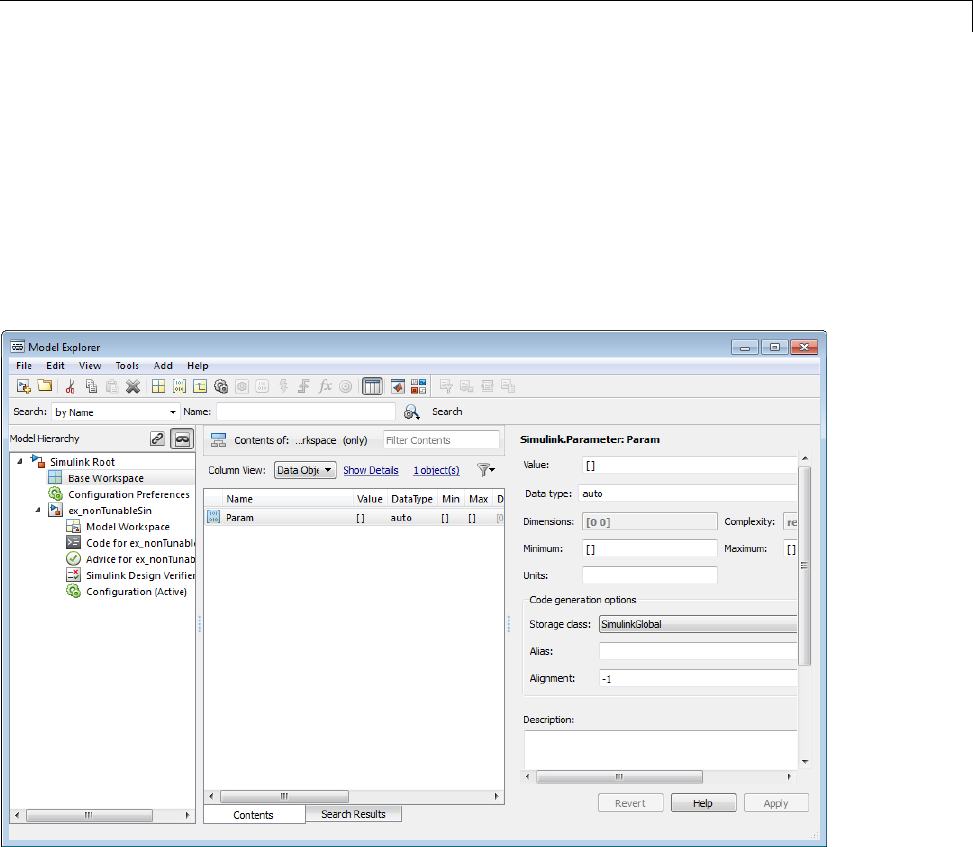
Parameters
1Choose Model Explorer from the View menu.
Model Explorer opens or activates if it already was open.
2Select Base Workspace in the Model Hierarchy pane.
3Select Simulink Parameter from the Add menu.
A new parameter named Param appears in the Contents pane.
4To setKp.Name in the Model Explorer:
aClickthewordParam in the Name column to select it.
bRename it by typing Kp in place of Param.
cPress Enter or Return.
5To set Kp.Value in Model Explorer:
7-43
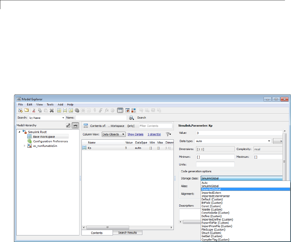
7Data Representation
aSelect the Value field at the top of the Dialog pane.
bType 5.0.
cClick the Apply button.
6To set the Kp.CoderInfo.StorageClass in Model Explorer:
aClick the Storage class menu and select ExportedGlobal,asshownin
the next figure.
bClick Apply.
ThefollowingtableshowsthevariabledeclarationsforKp and the code
generated for the Gain block in the model shown in the preceding model,
with the Inline parameters and Eliminate superfluous local variables
(Expression folding) check boxes selected (which includes the gain
computation in the output computation). An example is shown for each
7-44

Parameters
possible setting of CoderInfo.StorageClass. Global structures include the
model name (symbolized as model_ or _model).
StorageClass
Property
Generated Variable Declaration
and Code
Auto
model_Y.Out1 = rtb_u * 5.0;
SimulinkGlobal
struct _Parameters_model {
real_T Kp;
}
.
.
Parameters_model model_P = {
5.0
};
.
.
model_Y.Out1 = rtb_u * model_P.Kp;
ExportedGlobal
extern real_T Kp;
.
.
real_T Kp = 5.0;
.
.
model_Y.Out1 = rtb_u * Kp;
7-45

7Data Representation
StorageClass
Property
Generated Variable Declaration
and Code
ImportedExtern
extern real_T Kp;
.
.
model_Y.Out1 = rtb_u * Kp;
ImportedExternPointer
extern real_T *Kp;
.
.
model_Y.Out1 = rtb_u * (*Kp);
Parameter Object Configuration Quick Reference Diagram
Thenextfigureshowsthecodegenerationandstorageclassoptionsthat
control the representation of parameter objects in generated code.
7-46
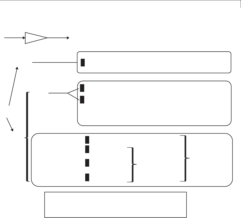
Parameters
KEY:
[option] : default for code generation option
<???> : Generated symbol for parameter storage field
Kp = Simulink.Parameter; Kp.Value = 5.0;
Kp
uy
[OFF]
Inline
Parameters
ON
[Auto]
SIMULINK CODER CONTROLS SYMBOL USED IN CODE
1
2
3
4
5
6
7
SIMULINK CODER CONTROLS SYMBOL USED IN CODE
INCLUDED IN LIST OF GLOBAL (TUNABLE) PARAMETERS
y = u* (rtP.<???>);
Include parameters as fields
in a global structure
(field names based on block names)
y = u* (5.0);
const *p_<???> = &rtP.<???>[0];
for (i=0; i<N; i++){
y[i] = u * (p_<???>[i]);
}
Use numeric value of
parameter (if possible)
Otherwise, include in a
constant global structure
SimulinkGlobal
ImportedExtern
ExportedGlobal
ImportedExternPointer
Symbol preserved
(must be unique)
y = u* (rtP.Kp);
y = u* (Kp);
y = u* (Kp);
y = u* (*Kp);
Include in a
global structure
Unstructured
storage
Resolve Conflicts in Parameter Object Configurations
Twomethodsareavailableforcontrolling the tunability of parameters. You
can
•Define them as Simulink.Parameter objects in the MATLAB workspace
7-47
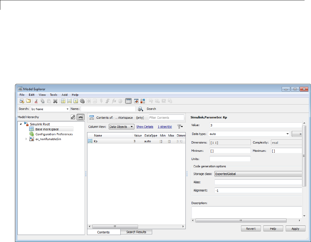
7Data Representation
•Use the Model Parameter Configuration dialog box
The next figures show how you can use each of these methods to control
the tunability of parameter Kp. The first figure shows Kp defined as
Simulink.Parameter in the Model Explorer. You control the tunability of Kp
by specifying the parameter’s storage class.
Parameter Object Kp with Auto Storage Class in Model Explorer
The next figure shows how you can use the Model Parameter Configuration
dialog box to specify a storage class for numeric variables in the MATLAB
workspace.
7-48
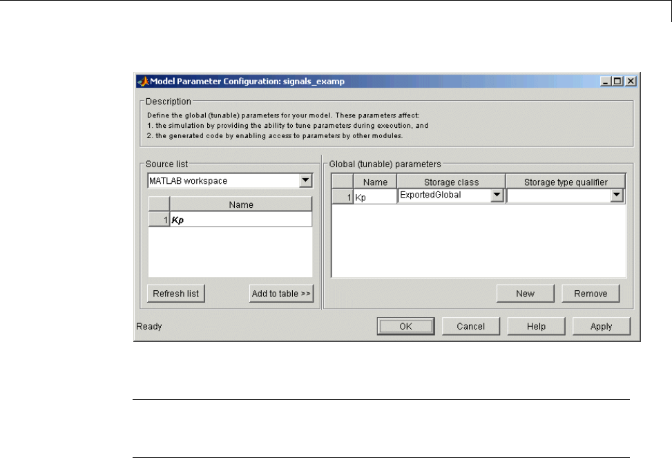
Parameters
Parameter Kp Defined with SimulinkGlobal Storage Class
Note Do not use both methods for controlling the tunability of a given
parameter. If you use both methods and the storage class settings for the
parameter do not match, an error results.
Structure Parameters and Generated Code
•“About Structure Parameters and Generated Code” on page 7-49
•“Include Structure Parameters in Generated Code” on page 7-50
•“Control Naming of Structure Parameter Types” on page 7-50
About Structure Parameters and Generated Code
Structure parameters provide a way to improve generated code to use
structures rather multiple separate variables. You also have the option of
configuring the appearance of a structure parameter in generated code.
For more information about structure parameters, see“Structure Parameters”
in the Simulink documentation. For an example of how to convert a model
7-49

7Data Representation
that uses unstructured workspace variables to a model that uses structure
parameters, see sldemo_applyVarStruct.
Include Structure Parameters in Generated Code
By default, structure parameters do not appear in generated code. Structure
parameters include numeric variables and the code generator inlines numeric
values.
To make structure type definition appear in generated code for a structure
parameter,
1Create a Simulink.Parameter object.
2Define the object value to be the parameter structure.
3Define the object storage class to be a value other than Auto.
The code generator places a structure type definition or the tunable parameter
structure in model_types.h. By default, the code generator identifies
the type with a nondescriptive, automatically generated name, such as
struct_z98c0D2qc4btL.
For information on how to control the naming of the type, see “Control
Naming of Structure Parameter Types” on page 7-50. For an example, see
sldemo_applyVarStruct
Control Naming of Structure Parameter Types
To control the naming of a structure parameter type, by using a Simulink.Bus
object to specify the data type of the Simulink.Parameter object.
1Use Simulink.Bus.createObject to create a bus object with the same shape
as the parameter structure. For example:
busInfo=Simulink.Bus.createObject(ControlParam.Value);
2Assign the bus object name to the data type property of the parameter
object.
ParamType=eval(busInfo.busName);
7-50

Parameters
ControlParam.DataType='Bus: ParamType';
Only Simulink.Parameter can accept the bus object name as a data type.
For an example, see sldemo_applyVarStruct
7-51

7Data Representation
Signals
In this section...
“About Signals” on page 7-52
“Signal Storage Concepts” on page 7-53
“Signals with Auto Storage Class” on page 7-55
“Signals with Test Points” on page 7-59
“Interface Signals to External Code” on page 7-60
“Symbolic Naming Conventions for Signals” on page 7-62
“Summary of Signal Storage Class Options” on page 7-63
“Interfaces for Monitoring Signals” on page 7-64
“Signal Objects” on page 7-65
“Initialize Signals and States Using Signal Objects” on page 7-74
About Signals
The Simulink Coder product offers a number of options that let you control
how signals in your model are stored and represented in the generated code.
This section discusses how you can use these options to
•Control whether signal storage is declared in global memory space or
locally in functions (that is, in stack variables).
•Control the allocation of stack space when using local storage.
•Delcare signals as test points to store them in unique memory locations
•Reduce memory usage by instructing the Simulink Coder product to store
signals in reusable buffers.
•Control whether or not signals declared in generated code are interfaceable
(visible) to externally written code. You can also specify that signals are to
be stored in locations declared by externally written code.
•Preserve the symbolic names of signals in generated code by using signal
labels.
7-52
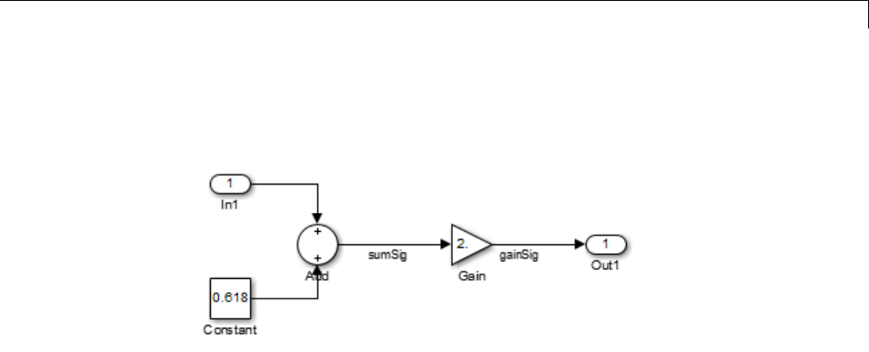
Signals
The discussion in the following sections refers to code generated from
signal_examp, the model shown in the next figure.
Signal_examp Model
Signal Storage Concepts
This section discusses structures and concepts you must understand to choose
the best signal storage options for your application:
•The global block I/O data structure model_B
•The concept of signal storage classes as used in the Simulink Coder product
Global Block I/O Structure
By default, the Simulink Coder product attempts to optimize memory usage
by sharing signal memory and using local variables.
However, under a number of circumstances you should place signals in global
memory. For example,
•You might want a signal to be stored in a structure that is visible to
externally written code.
•The number and/or size of signals in your model might exceed the stack
space available for local variables.
In such cases, it is possible to override the default behavior and store selected
(or all) signals in a model-specific global block I/O data structure.Theglobal
block I/O structure is called model_B (in earlier versions this was called rtB).
7-53

7Data Representation
The following code shows how model_B is defined and declared in code
generated (with signal storage optimizations off) from the signal_examp
model shown in the Signal_examp Model on page 7-53 figure.
(in signal_examp.h)
/* Block signals (auto storage) */
extern BlockIO_signal_examp signal_examp_B;
(in signal_examp.c)
/* Block signals (auto storage) */
BlockIO_signal_examp signal_examp_B;
Field names for signals stored in model_B are generated according to the rules
described in “Symbolic Naming Conventions for Signals” on page 7-62.
Signals Storage Classes
In the Simulink Coder product, the storage class property of a signal
specifies how the product declares and stores the signal. In some cases this
specification is qualified by more options.
In the context of the Simulink Coder product, the term “storage class” is not
synonymous with the term storage class specifier,asusedintheClanguage.
Default Storage Class. Auto is the default storage class and is the storage
class you should use for signals that you do not need to interface to external
code. Signals with Auto storage class can be stored in local and/or shared
variables or in a global data structure. The form of storage depends on
the Signal storage reuse,Reuse block outputs,Enable local block
outputs,andMinimize data copies between local and global variables
options, and on available stack space. See “Signals with Auto Storage Class”
on page 7-55 for a full description of code generation options for signals with
Auto storage class.
Explicitly Assigned Storage Classes. Signals with storage classes other
than Auto are stored either as members of model_B,orinunstructuredglobal
variables, independent of model_B. These storage classes are for signals that
you want to monitor and/or interface to external code.
7-54

Signals
The Signal storage reuse,Enable local block outputs,Reuse block
outputs,Eliminate superfluous local variables (expression folding),
and Minimize data copies between local and global variables
optimizations do not apply to signals with storage classes other than Auto.
Use the Signal Properties dialog box to assign these storage classes to signals:
•SimulinkGlobal(Test Point): Test points are stored as fields of the
model_B structure that are not shared or reused by any other signal. See
“Signals with Test Points” on page 7-59 for more information.
•ExportedGlobal: The signal is stored in a global variable, independent
of the model_B data structure. model.h exports the variable. Signals
with ExportedGlobal storage class must have unique signal names. See
“Interface Signals to External Code” on page 7-60 for more information.
•ImportedExtern:model_private.h declares the signal as an extern
variable. Your code must supply the variable definition. Signals with
ImportedExtern storage class must have unique signal names. See
“Interface Signals to External Code” on page 7-60 for more information.
•ImportedExternPointer:model_private.h declares the signal as an
extern pointer. Your code must define a valid pointer variable. Signals
with ImportedExtern storage class must have unique signal names. See
“Interface Signals to External Code” on page 7-60 for more information.
Signals with Auto Storage Class
Options are available for signals with Auto storage class:
•Signal storage reuse
•Enable local block outputs
•Reuse block outputs
•Eliminate superfluous local variables (expression folding)
•Minimize data copies between local and global variables
Use these options to control signal memory reuse and choose local or global
(model_B) storage for signals. The Signal storage reuse option is on
the Optimization > Signals and Parameters pane of the Configuration
Parameters dialog box, as shown in the next figure.
7-55

7Data Representation
These options interact. When the Signal storage reuse option is selected,
•The Reuse block outputs option is enabled and selected, and signal
memory is reused.
•The Enable local block outputs option is enabled and selected. This
lets you choose whether reusable signal variables are declared as local
variablesinfunctionsorasmembersofmodel_B.
•The Eliminate superfluous local variables (expression folding)
is enabled and selected, and block computations collapse into single
expressions.
•The Minimize data copies between local and global variables is
enabled and cleared, and global memory is not reused.
The following code examples illustrate the effects of the Signal storage
reuse,Enable local block outputs,Reuse block outputs,Eliminate
superfluous local variables (expression folding) and Minimize data
copies between local and global variables options. The examples were
generated from the signal_examp model (see figure Signal_examp Model
on page7-53).
The first example illustrates signal storage optimization, with Signal
storage reuse,Enable local block outputs,Reuse block outputs,and
Minimize data copies between local and global variables selected. (For
clarity in showing the individual Gain and Sum block computation, expression
folding is off in this example.) The output signal from the Sum block reuses
signal_examp_Y.Out1, a variable local to the model output function.
7-56

Signals
/* Model output function */
static void signal_examp_output(int_T tid)
{
/* Sum: '<Root>Sum' incorporates:
* Constant: '<Root>/Constant'
* Inport: '<Root>>/In1'
*/
signal_examp_Y.Out1 = signal_examp_U.In1 + signal_examp_P.Constant_Value;
/* Gain: '<Root>/Gain' */
signal_examp_Y.Out1 = signal_examp_P.Gain_Gain * signal_examp_Y.Out1;
/* tid is required for a uniform function interface.
* Argument tid is not used in the function. */
UNUSED_PARAMETER(tid);
}
If you are constrained by limited stack space, you can turn Enable local
block outputs off and still benefit from memory reuse. The following
example was generated with Enable local block outputs cleared and
Signal storage reuse,Reuse block outputs,andMinimize data copies
between local and global variables selected. The output signals from
the Sum and Gain blocks use global structure signal_examp_B rather than
declaring local variables and in both cases the signal name is gainSig.
/* Model output function */
static void signal_examp_output(int_T tid)
{
/* Sum: '<Root>/Add' incorporates:
* Constant: '<Root>/Constant'
* Inport: '<Root>/In1'
*/
signal_examp_B.gainSig = signal_examp_U.In1 +
signal_examp_P.Constant_Value;
/* Gain: '<Root>/Gain' */
signal_examp_B.gainSig = signal_examp_P.Gain_Gain *
signal_examp_B.gainSig;
/* Outport: '<Root>/Out1' */
7-57

7Data Representation
signal_examp_Y.Out1 = signal_examp_B.gainSig;
/* tid is required for a uniform function interface.
* Argument tid is not used in the function. */
UNUSED_PARAMETER(tid);
}
When the Signal storage reuse option is cleared, Reuse block outputs,
Enable local block outputs,andMinimize data copies between local
and global variables are disabled. This makes the block output signals
global and unique, signal_examp_B.sumSig and signal_examp_B.gainSig,
as shown in the following code.
/* Model output function */
static void signal_examp_output(int_T tid)
{
/* Sum: '<Root>/Add' incorporates:
* Constant: '<Root>/Constant'
* Inport: '<Root>/In1'
*/
signal_examp_B.sumSig = signal_examp_U.In1 +
signal_examp_P.Constant_Value;
/* Gain: '<Root>/Gain' */
signal_examp_B.gainSig = signal_examp_P.Gain_Gain *
signal_examp_B.sumSig;
/* Outport: '<Root>/Out1' */
signal_examp_Y.Out1 = signal_examp_B.gainSig;
/* tid is required for a uniform function interface.
* Argument tid is not used in the function. */
UNUSED_PARAMETER(tid);
}
In large models, disabling Signal storage reuse can significantly increase
RAM and ROM usage. Therefore, this approach is not recommended for code
deployment; however it can be useful in rapid prototyping environments.
7-58

Signals
The following table summarizes the possible combinations of the Signal
storage reuse /Reuse block outputs and Enable local block outputs
options.
Signal storage reuse
and Reuse block
outputs ON
Signal storage reuse
OFF
(Reuse block outputs
disabled)
Enable local block
outputs ON
Reuse signals in
local memory (fully
optimized)
N/A
Enable local block
outputs OFF
Reuse signals in
model_B structure
Individual signal
storage in model_B
structure
Control Stack Space Allocation
The value of the “Maximum stack size (bytes)” parameter, on the
Optimization > Signals and Parameters pane of the Configuration
Parameters dialog box constrains the use of stack space used by local
block output variables. The command-line equivalent for this parameter
is MaxStackSize. If the accumulated size of variables in local memory
exceeds MaxStackSize, the product places subsequent local variables in
global memory space.
If it is important that you maximize potential for signal storage optimization,
then set MaxStackSize to accommodate the size and number of signals in your
model. This minimizes overflow into global memory space and maximizes use
of local memory. Local variables offer more optimization potential through
mechanisms such as expression folding and buffer reuse. See “Use Stack
Space Allocation” on page 20-6 for more information.
Signals with Test Points
Atest point is a signal that is stored in a unique location no other signals share
or reuse. See “Test Points” in the Simulink documentation for information
about including test points in your model.
7-59

7Data Representation
When you generate code for models that include test points, the Simulink
Coder build process allocates a separate memory buffer for each test point.
Test points are stored as members of the model_B structure.
Declaring a signal as a test point disables the following options for that signal.
This can lead to increased code and data size. You do not lose the benefits of
optimized storage for any other signals in your model.
•Signal storage reuse
•Enable local block outputs
•Reuse block outputs
•Eliminate superfluous local variables (expression folding)
•Minimize data copies between local and global variables
For an example of storage declarations and code generated for a test point,
see “Summary of Signal Storage Class Options” on page 7-63.
If you have an Embedded Coder license, you can specify that the Simulink
Coder build process ignore test points in the model, allowing optimal buffer
allocation, using the “Ignore test point signals” parameter. Ignoring test
points facilitates transitioning from prototyping to deployment and avoids
accidental degradation of generated code due to workflow artifacts. For more
information, see “Ignore test point signals”.
Interface Signals to External Code
The Simulink Signal Properties dialog box lets you interface selected signals
to externally written code. In this way, your hand-written code has access
to such signals for monitoring or other purposes. To interface a signal to
external code, use the Code Generation tab of the Signal Properties dialog
boxtoassignoneofthefollowingstorage classes to the signal:
•ExportedGlobal
•ImportedExtern
•ImportedExternPointer
Set the storage class as follows:
7-60
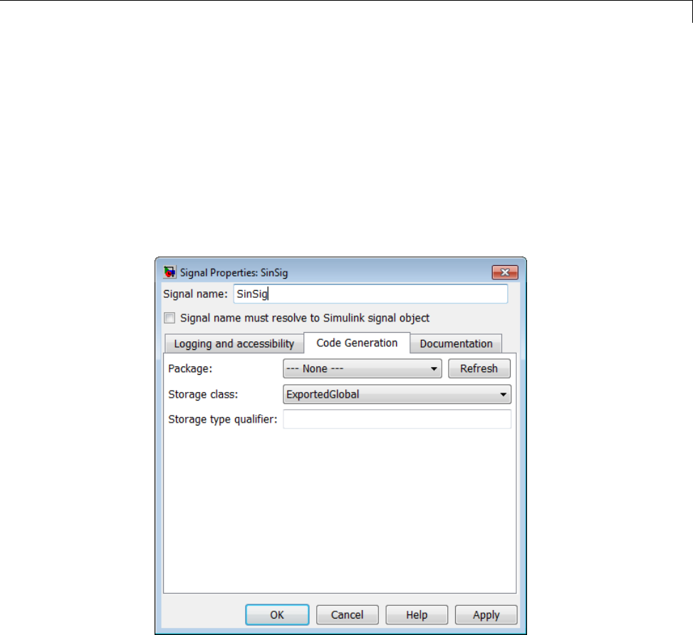
Signals
1In your Simulink block diagram, select the line that carries the signal.
Then select Signal Properties from the Edit menu of your model. This
opens the Signal Properties dialog box. Alternatively, right-click the line
that carries the signal, and select Signal properties from the menu.
2Select the Code Generation tab of the Signal Properties dialog box.
3Select the desired storage class (Auto,ExportedGlobal,ImportedExtern,
or ImportedExternPointer)fromtheStorage class menu. The next
figure shows ExportedGlobal selected.
4Optional: For storage classes other than Auto, you can enter a storage type
qualifier such as const or volatile in the Storage type qualifier field.
The Simulink Coder product does not check this string for errors; whatever
you enter is included in the variable declaration.
5Click Apply.
7-61

7Data Representation
Note You can also interface test points and other signals that are stored
as members of model_B to your code. To do this, your code must know
the address of the model_B structure where the data is stored, and other
information. This information is not automatically exported. The Simulink
Coder product provides C/C++ and Target Language Compiler APIs that
give your code access to model_B and other data structures. See “Interfaces
for Monitoring Signals” on page 7-64 for more information.
Symbolic Naming Conventions for Signals
When signals have a storage class other than Auto, the Simulink Coder
product preserves symbolic information about the signals or their originating
blocks in the generated code.
For labeled signals, field names in model_B derive from the signal names. In
the following example, the field names model_B.sumSig and model_B.gainSig
are derived from the corresponding labeled signals in the signal_examp
model (shown in figure Signal_examp Model on page 7-53).
/* Block signals (auto storage) */
typedef struct _BlockIO_signal_examp {
real_T sumSig; /* '<Root>/Add' */
real_T gainSig; /* '<Root>/Gain' */
} BlockIO_signal_examp;
When you clear the Signal storage reuse optimization, sumSig is not
part of model_B, and a local variable is used for it instead. For unlabeled
signals, model_B field names are derived from the name of the source block
or subsystem.
The components of a generated signal label are
•The root model name, followed by
•The name of the generating signal object, followed by
•A unique name mangling string (if required)
The number of characters that a signal label can have is limited by the
Maximum identifier length parameter specified on the Symbols pane
7-62

Signals
of the Configuration Parameters dialog box. See “Configure Generated
Identifiers” on page 9-73 for more detail.
When a signal has Auto storage class, the Simulink Coder build process
controls generation of variable or field names without regard to signal labels.
Summary of Signal Storage Class Options
The next table shows, for each signal storage class option, the variable
declaration and the code generated for Sum (sumSig)andGain(gainSig)
block outputs of the model shown in figure Signal_examp Model on page 7-53.
Storage Class Declaration Code
Auto
(with Signal
storage reuse
optimizations on)
In model.c or model.cpp
real_T rtb_sumSig;
rtb_sumSig = signal_examp_U.In1 +
signal_examp_P.Constant_Value;
rtb_sumSig *=
signal_examp_P.Gain_Gain;
signal_examp_Y.Out1 = rtb_sumSig;
Test point (for
sumSig only)
In model.h
typedef struct
_BlockIO_signal_examp
{
real_T sumSig;
}
BlockIO_signal_examp;
In model.c or model.cpp
BlockIO_signal_examp
signal_examp_B;
real_T rtb_gainSig;
signal_examp_B.sumSig =
signal_examp_U.In1 +
signal_examp_P.Constant_Value;
rtb_gainSig =
signal_examp_B.sumSig *
signal_examp_P.Gain_Gain;
signal_examp_Y.Out1 = rtb_gainSig;
7-63

7Data Representation
Storage Class Declaration Code
ExportedGlobal
(for sumSig only)
In model.h
extern real_T sumSig;
In model.c or model.cpp
real_T sumSig;
real_T rtb_gainSig;
sumSig = signal_examp_U.In1 +
signal_examp_P.Constant_Value;
rtb_gainSig = sumSig *
signal_examp_P.Gain_Gain;
signal_examp_Y.Out1 = rtb_gainSig;
ImportedExtern In model_private.h
extern real_T sumSig;
In model.c or model.cpp
real_T rtb_gainSig;
sumSig = signal_examp_U.In1 +
signal_examp_P.Constant_Value;
rtb_gainSig = sumSig *
signal_examp_P.Gain_Gain;
signal_examp_Y.Out1 = rtb_gainSig;
ImportedExternPointer
In model_private.h
extern real_T *sumSig;
In model.c or model.cpp
real_T rtb_gainSig;
(*sumSig) = signal_examp_U.In1 +
signal_examp_P.Constant_Value;
rtb_gainSig = (*sumSig) *
signal_examp_P.Gain_Gain;
signal_examp_Y.Out1 = rtb_gainSig;
Interfaces for Monitoring Signals
The Simulink Coder product includes
•Support for developing a Target Language Compiler API for monitoring
signals and states independent of external mode. See “Input Signal
Functions” and “Output Signal Functions” in the Target Language
Compiler documentation for information.
•A C application program interface (API) for monitoring signals and states
independent of external mode. See “Data Interchange Using the C API” on
page 15-137 for information.
7-64

Signals
•An interface for exporting ASAP2 files, which you customize to use signal
objects. For details, see “ASAP2 Data Measurement and Calibration” on
page 15-174.
Signal Objects
•“About Signal Objects for Code Generation” on page 7-65
•“Use Signal Objects for Code Generation” on page 7-66
•“Configure Signal Objects for Code Generation” on page 7-66
•“Storage Classes and Code Generation for Signal Objects” on page 7-66
•“Generate Code for Signal Objects from Command Line” on page 7-67
•“Generate Code for Signal Objects Using Model Explorer” on page 7-69
•“Resolve Conflicts in Configuration of Signals Objects” on page 7-72
This section discusses how to use signal objects in code generation. Signal
objects can be used to represent both signal and state data, and behave
similarly to parameter objects, described in “Parameter Objects” on page 7-38.
About Signal Objects for Code Generation
Within the class hierarchy of Simulink data objects, the Simulink product
provides a class that is designed as base class for signal storage. This topic
explains how to use signal objects in code generation.
The CoderInfo properties of signal objects are used by the Simulink Coder
product during code generation. These properties let you assign storage
classes to the objects, thereby controlling how the generated code stores and
represents signals.
The Simulink Coder build process also writes information about the properties
of signal objects to the model.rtw file. This information, formatted as Object
records, is accessible to Target Language Compiler programs. For general
information on Object records, see “Data Object Information in model.rtw”.
Before using Simulink signal objects with the Simulink Coder product, read
the discussion of Simulink data objects in the Simulink documentation.
7-65

7Data Representation
Use Signal Objects for Code Generation
The general procedure for using signal objects in code generation is as follows:
1Define a subclass of Simulink.Signal.
2Instantiate signal objects from your subclass and set their properties from
the command line or by using Model Explorer.
3Use the objects as signals within your model.
4Generate code and build your target executable.
Configure Signal Objects for Code Generation
In configuring signal objects for code generation, you use the following code
generation options and signal object properties:
•The Signal storage reuse code generation option (see “Signals” on page
7-52).
•The Enable local block outputs code generation option (see “Signals” on
page 7-52).
•The Minimize data copies between local and global variables code
generation option (see “Signals” on page 7-52).
•The CoderInfo.StorageClass signal object property: The storage classes
defined for signal objects, and their effect on code generation, are the same
for model signals and signal objects (see “Signals Storage Classes” on
page 7-54).
Other signal object properties (such as user-defined properties of classes
derived from Simulink.Signal) do not affect code generation.
Storage Classes and Code Generation for Signal Objects
The way in which the Simulink Coder product uses storage classes to
determinehowsignalsarestoredisthesamewithandwithoutsignal
objects. However, if a signal’s label resolves to a signal object, the object’s
CoderInfo.StorageClass property is used in place of the port configuration
of the signal.
7-66
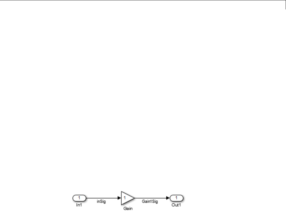
Signals
The default storage class is Auto. IfthestoragetypeisAuto, the Simulink
Coder product follows the Signal storage reuse,Reuse block outputs,
Enable local block outputs,Eliminate superfluous local variables
(expression folding),andMinimize data copies between local and
global variables code generation options to determine whether signal objects
are stored in reusable and/or local variables. Make sure that these options
are set for your application.
To generate a test point or signal storage declaration that can interface
externally, use an explicit CoderInfo.StorageClass assignment. For
example, setting the storage class to SimulinkGlobal, as in the following
command, is equivalent to declaring a signal as a test point.
SinSig.CoderInfo.StorageClass = 'SimulinkGlobal';
Generate Code for Signal Objects from Command Line
Thediscussionandcodeexamplesinthissectionrefertothemodelshownin
the next figure.
To configure a signal object, you must first create it and associate it with a
labeled signal in your model. To do this,
1Define a subclass of Simulink.Signal. In this example, the signal object
is an instance of the class Simulink.Signal, which is provided with the
Simulink product.
2Instantiate a signal object from your subclass. The following example
instantiates inSig, a signal object of class Simulink.Signal.
inSig = Simulink.Signal
inSig =
7-67

7Data Representation
Simulink.Signal
CoderInfo: [1x1 Simulink.SignalCoderInfo]
Description: ''
DataType: 'auto'
Min: []
Max: []
DocUnits: ''
Dimensions: -1
Complexity: 'auto'
SampleTime: -1
SamplingMode: 'auto'
InitialValue: ''
Make sure that the name of the signal object matches the label of the
desired signal in your model. This enables the Simulink engine to resolve
the signal label to the corresponding object. For example, in the model
shown in the above figure, the signal label inSig would resolve to the
signal object inSig.
3You can require signals in a model to resolve to Simulink.Signal objects.
To do this for the signal inSig, in the model window right-click the signal
line labeled inSig and choose Signal Properties from the context menu.
A Signal Properties dialog appears.
7-68
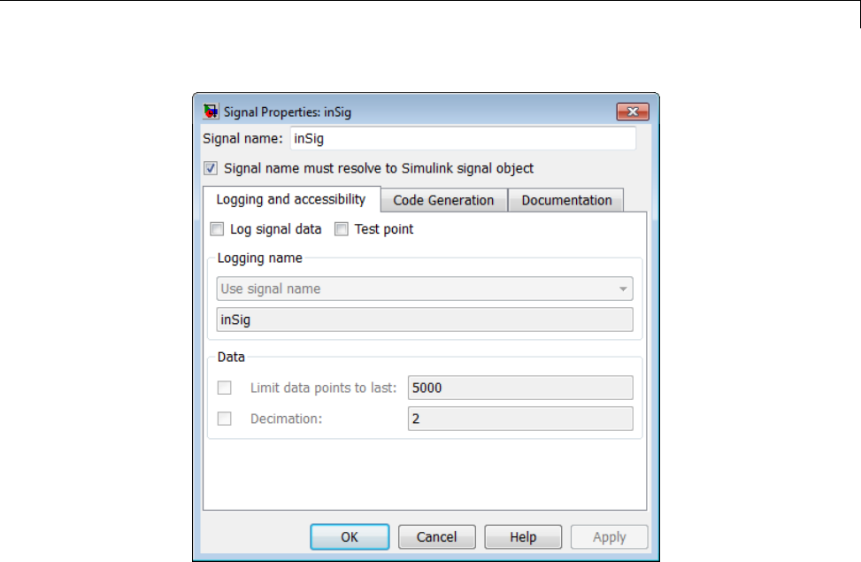
Signals
4In the Signal Properties dialog box that appears, select the check box
labelled Signal name must resolve to Simulink signal object,and
click OK or Apply.
5Set the object properties as required. You can do this by using the
Simulink Model Explorer. Alternatively, you can assign properties by using
MATLAB commands. For example, assign the signal object’s storage class
by setting the CoderInfo.StorageClass property as follows.
inSig.CoderInfo.StorageClass = 'ExportedGlobal';
Generate Code for Signal Objects Using Model Explorer
If you prefer, you can create signal objects and modify their attributes using
Model Explorer. This lets you see and set attributes of a signal in a dialog
7-69
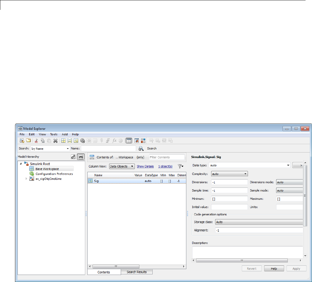
7Data Representation
box pane, and alleviates the need to remember and type field names. Do the
following to instantiate inSig and set its attributes from Model Explorer:
1Choose Model Explorer from the View menu.
Model Explorer opens or activates if it already was open.
2Select Base Workspace in the Model Hierarchy pane.
3Select Simulink Signal from the Add menu.
AnewsignalnamedSig appears in the Contents pane.
4To set the signal name in Model Explorer, click the word Sig in the Name
column to select it, and rename it by typing inSig followed by Return
in place of Sig.
7-70
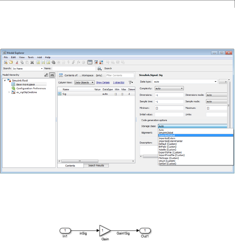
Signals
5To set the inSig.CoderInfo.StorageClass in Model Explorer, click the
Storage class menu and select ExportedGlobal,asshowninthenext
figure.
6Click Apply.
The following table shows, for each setting of CoderInfo.StorageClass,the
variable declaration and the code generated for the inport signal (inSig)
of the current model:
7-71

7Data Representation
Storage Class Declaration Code
Auto (with
storage
optimizations
on)
In model.h
typedef struct
_ExternalInputs_signal_ objs_examp_tag
{
real_T inSig;
}
ExternalInputs_signal_ objs_examp;
rtb_Gain1Sig =
signal_objs_examp_U.inSig *
signal_objs_examp_P.Gain_Gain;
SimulinkGlobal In model.h
typedef struct
_ExternalInputs_signal_objs_examp_tag
{
real_T inSig;
}
ExternalInputs_signal_objs_examp;
rtb_Gain1Sig =
signal_objs_examp_U.inSig *
signal_objs_examp_P.Gain_Gain;
ExportedGlobal In model.c or model.cpp
real_T inSig;
In model.h
extern real_T inSig;
rtb_Gain1Sig = inSig *
signal_objs_examp_P.Gain_Gain;
ImportedExtern In model_private.h
extern real_T inSig;
rtb_Gain1Sig = inSig *
signal_objs_examp_P.Gain_Gain;
ImportedExternPointer
In model_private.h
extern real_T *inSig;
rtb_Gain1Sig = (*inSig) *
signal_objs_examp_P.Gain_Gain;
Resolve Conflicts in Configuration of Signals Objects
If a signal is defined in the Signal Properties dialog box and a signal object of
thesamenameisdefinedbyusingthecommand line or in the Model Explorer,
the potential exists for ambiguity when the Simulink engine attempts to
resolvethesymbolrepresentingthesignalname. Onewaytoresolvethe
7-72
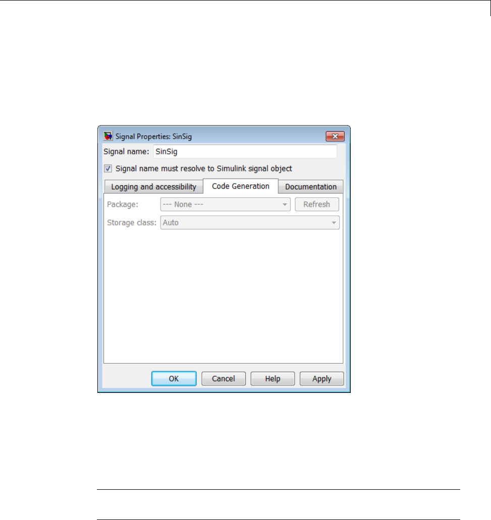
Signals
ambiguity is to specify that a signal must resolve to a Simulink data object. To
do this, select the Signal name must resolve to Simulink signal object
option in the Signal Properties dialog box. When you do this, you no longer
can specify the Storage class property in the Code Generation tab of the
Signal Properties dialog box, as the next figure shows.
As the preceding figure shows, the Storage class menu is disabled because it
is up to the SinSig Simulink.Signal object to specify its own storage class.
The signal and signal objects SinSig both have SimulinkGlobal storage class.
Therefore, no conflict arises, and SinSig resolves to the signal object SinSig.
NoteThe rules for compatibility between block states/signal objects are
identical to those given for signals/signal objects.
7-73

7Data Representation
Initialize Signals and States Using Signal Objects
You can use Simulink signal objects to initialize signals and discrete
states with user-defined values for simulation and code generation. Data
initialization increases application reliability and is a requirement of safety
critical applications. Initializing signals for both simulation and code
generation can expedite transitions between phases of Model-Based Design.
For details on simulation behavior, see “Initialization Behavior Summary for
Signal Objects” in the Simulink documentation.
Specify Initial Value for Signal Object
You can use signal objects that have a storage class other than 'auto’or
'SimulinkGlobal' to initialize
•Discrete states with an initial condition parameter
•Any signals in a model except bus signals and signals with constant sample
time
The initial value is the signal or state value before a simulation takes its
first time step.
7-74

Signals
Note Some initial value settings may depend on the initialization mode. For
more information, see “Underspecified initialization detection”.
Classic initialization mode: In this mode, initial value settings for
signal objects that represent the following signals and states override the
corresponding block parameter initial values if undefined (specified as []):
•Output signals of conditionally executed subsystems and Merge blocks
•Block states
Simplified initialization mode: In this mode, initial values of signal
objects associated with the output of the following blocks are ignored. The
initial values of the corresponding blocks (which cannot be specified as [])
are used instead.
•Output signals of conditionally executed subsystems
•Merge blocks
To specify an initial value, use the Model Explorer or MATLAB commands to
do the following:
1Create the signal object.
Model Explorer
7-75
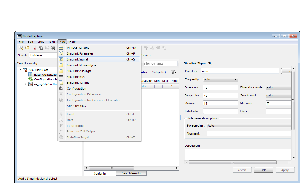
7Data Representation
MATLAB Command
S1=Simulink.Signal;
The nameofthesignalobjectmustbethesameasthenameofthesignal
that the object is initializing. Although not required, consider setting the
Signal name must resolve to Simulink signal object option in the
Signal Properties dialog box. This setting makes signal objects in the
MATLAB workspace consistent with signals that appear in your model.
Consider using the Data Object Wizard to create signal objects. The Data
Object Wizard searches a model for signals for which signal objects do not
exist. You can then selectively create signal objects for multiple signals
listed in the search results with a single operation. For more information
about the Data Object Wizard, see “Data Object Wizard” in the Simulink
documentation.
7-76
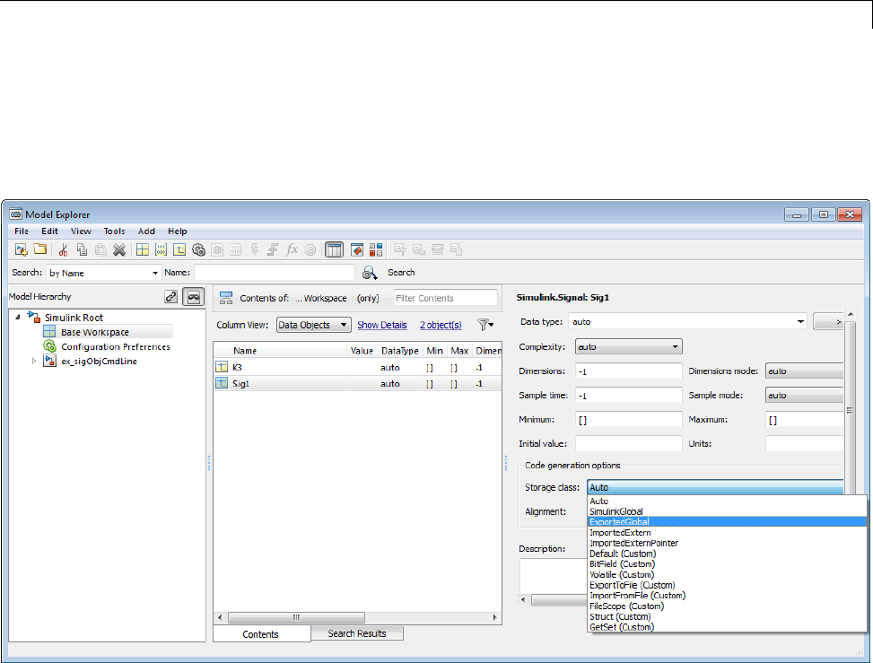
Signals
2Set the signal object’s storage class to a value other than 'auto’or
'SimulinkGlobal'.
Model Explorer
MATLAB Command
S1.CoderInfo.StorageClass='ExportedGlobal';
3Set the initial value. You can specify anyMATLABstringexpressionthat
evaluates to a double numeric scalar value or array.
7-77
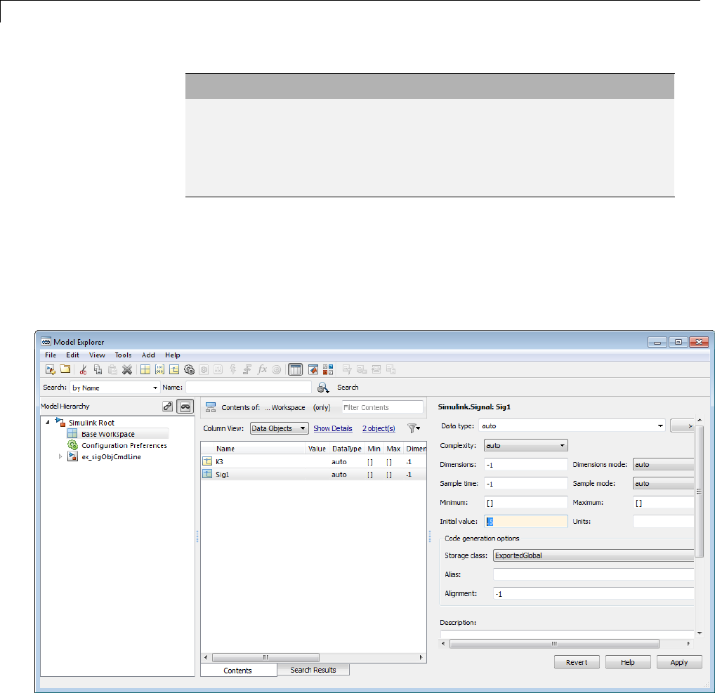
7Data Representation
Model Explorer MATLAB Command
Valid 1.5
[1 2 3]
1+0.5
foo = 1.5;
s1.InitialValue = 'foo';
Invalid uint(1) foo = '1.5';
s1.InitialValue = 'foo';
The Simulink engine converts the initial value so the type, complexity, and
dimension are consistent with the corresponding block parameter value.
If you specify an invalid value or expression, an error message appears
when you update the model.
Model Explorer
MATLAB Command
7-78
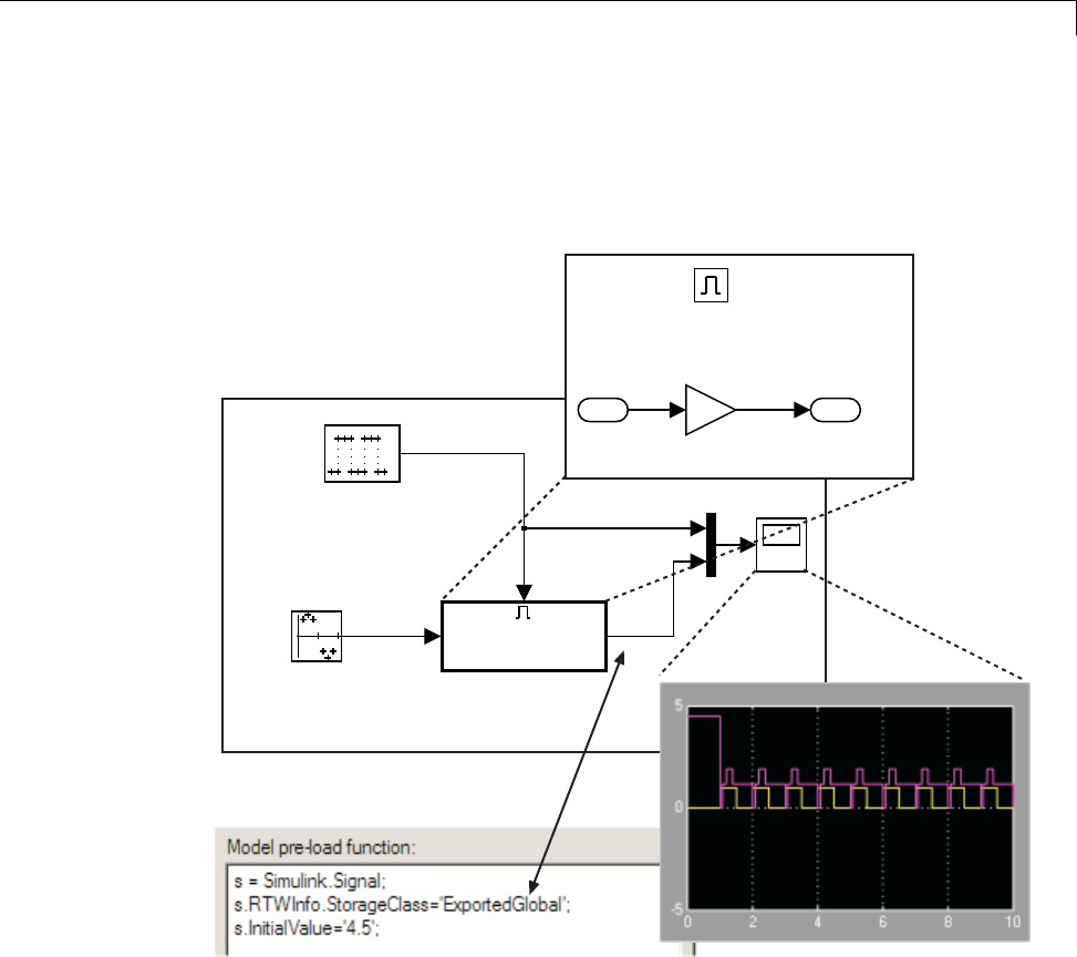
Signals
S1.InitialValue='0.5'
Thefollowingexampleshowsasignalobject specifying the initial output of
an enabled subsystem.
Sine Wave
Amplitude = 1
Period = 10 samples
Ts = 0.1
Scope
In1 Out1
Enabled
Subsystem
Enable
Ts = 0.1
Phase Delay = 10 samples
e
s
1
Out1
Initial Output = []
2
Gain
Enable
1
In1
Signal sisinitializedto4.5.Notethattoavoidaconsistencyerror,theinitial
value of the enabled subsystem’s Outport block must be [ ] or 4.5.
Signal Object Initialization in Generated Code
The initialization behavior for code generation is the same as that for model
simulation with the following exceptions:
7-79
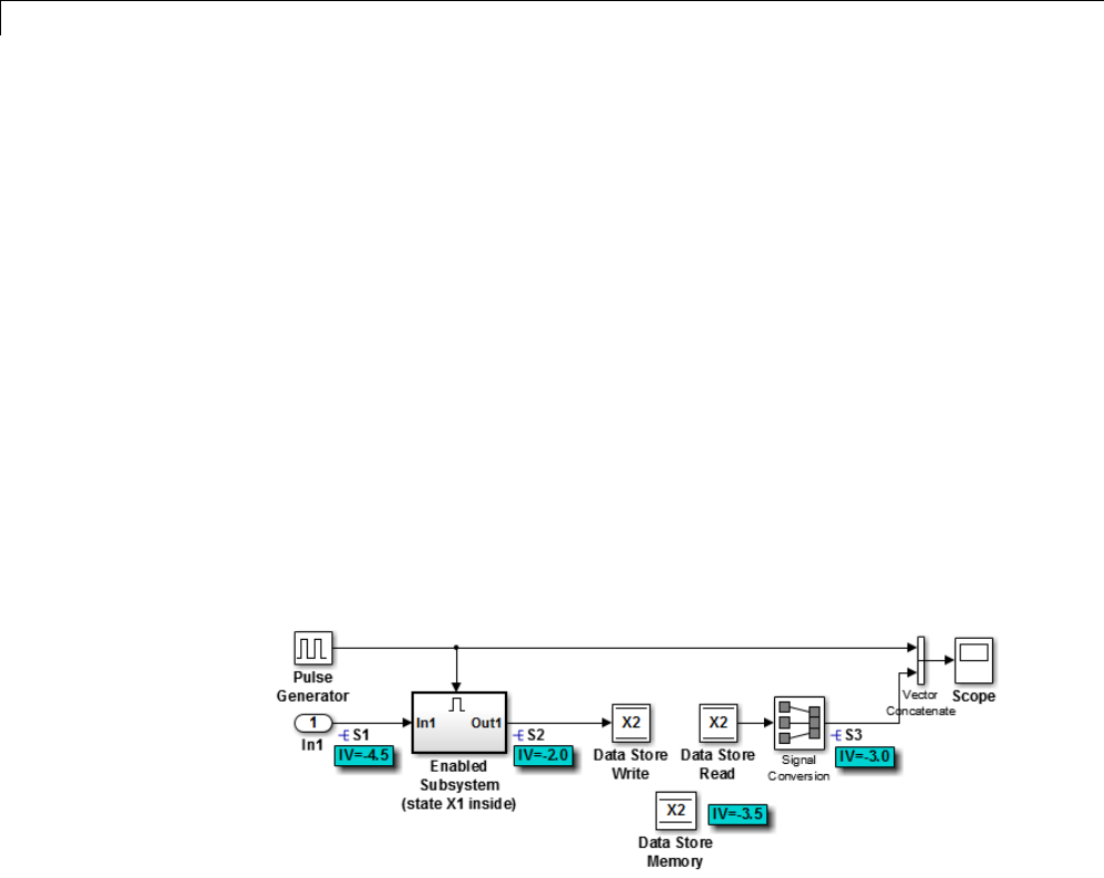
7Data Representation
•RSim executables can use the Data Import/Export pane of the
Configuration Parameters dialog box to load input values from MAT-files.
GRTandERTexecutablescannotload input values from MAT-files.
•Theinitialvalueforablockoutputsignal or root level input or output
signal can be overwritten by an external (calling) program.
•Setting the initial value for persistent signals is relevant if the value is
used or viewed by an external application.
For details on initialization behavior fordifferenttypesofsignals and discrete
states, see “Initialization Behavior Summary for Signal Objects” in the
Simulink documentation.
When you initialize Simulink signal objects in a model during code generation,
the corresponding initialization statements are placed in model.c or
model.cpp in the model’s initialize code.
Forexample,considerthemodelrtwdemo_sigobj_iv.
If you create and initialize signal objects in the base workspace, the
Simulink Coder product places initialization code for the signals in the file
rtwdemo_sigobj_iv.c under the rtwdemo_sigobj_iv_initialize function,
as shown below.
/* Model initialize function */
void rtwdemo_sigobj_iv_initialize(boolean_T firstTime)
{
7-80

Signals
.
.
.
/* exported global signals */
S3 = -3.0;
S2 = -2.0;
.
.
.
/* exported global states */
X1 = 0.0;
X2 = 0.0;
/* external inputs */
S1 = -4.5;
.
.
.
The following code shows the initialization code for the enabled subsystem’s
Unit Delay block state X1 and output signal S2.
void MdlStart(void) {
.
.
.
/* InitializeConditions for UnitDelay: '<S2>/Unit Delay' */
X1 = aa1;
/* Start for enable system: '<Root>/Enabled Subsystem (state X1 inside)' */
/* virtual outports code */
/* (Virtual) Outport Block: '<S2>/Out1' */
S2 = aa2;
}
7-81

7Data Representation
Also note that for an enabled subsystem, such as the one shown in the
preceding model, the initial value is also used as a reset value if the
subsystem’s Outport block parameter Output when disabled is set
to reset. The following code from rtwdemo_sigobj_iv.c shows the
assignment statement for S3 as it appears in the model output function
rtwdeni_sigobj_iv_output.
/* Model output function */
static void rtwdemo_sigobj_iv_output(void)
{
.
.
.
/* Disable for enable system: '<Root>/Enabled Subsystem (state X1 inside)' */
/* (Virtual) Outport Block: '<S2>/Out1' */
S2 = aa2;
Tunable Initial Values
If you specify a tunable parameter in the initial value for a signal object, the
parameter expression is preserved in the initialization code in model.c.
For example, if you configure parameter df to be tunable for model signal_iv
and you initialize the signal object for discrete state X1 with the expression
df*2, the following initialization code appears for signal object X1 in
signal_iv.c.
void MdlInitialize(void) {
/* InitializeConditions for UnitDelay: '<Root>/Unit Delay X1=2' */
X1 = (tunable_param_P.df * 2.0);
}
For more information about the treatment of tunable parameters in generated
code, see “Parameters” on page 7-10.
7-82

States
States
In this section...
“About States” on page 7-83
“State Storage” on page 7-83
“State Storage Classes” on page 7-84
“Interface States to External Code” on page 7-85
“Symbolic Names for States” on page 7-87
“Control Code Generation for Block States” on page 7-90
“Summary of State Storage Class Options” on page 7-91
About States
For certain block types, the Simulink Coder product lets you control how block
states in your model are stored and represented in the generated code. Using
the State Attributes tab of a block dialog box, you can:
•Control whether or not states declared in generated code are interfaceable
(visible) to externally written code. You can also specify that states be
stored in locations declared by externally written code.
•Assign symbolic names to block states in generated code.
State Storage
The discussion of block state storage in this section applies to the following
blocks:
•Discrete Filter
•Discrete PID Controller
•Discrete PID Controller (2DOF)
•Discrete State-Space
•Discrete-Time Integrator
•Discrete Transfer Function
7-83

7Data Representation
•Discrete Zero-Pole
•Memory
•Unit Delay
These blocks require persistent memory to store values representing the
state of the block between consecutive time intervals. By default, such values
are stored in a data type work vector. This vector is usually referred to as
the DWork vector. It is represented in generated code as model_DWork,a
global data structure.
If you want to interface a block state to your hand-written code, you can
specify that the state is to be stored in a location other than the DWork vector.
You do this by assigning a storage class to the block state.
You can also define a symbolic name, to be used in code generation, for a
block state.
State Storage Classes
The storage class property of a block state specifies how the Simulink Coder
product declares and stores the state in a variable. Storage class options for
block states are similar to those for signals. The available storage classes are
•Auto
•ExportedGlobal
•ImportedExtern
•ImportedExternPointer
Default Storage Class
Auto isthedefaultstorageclassandisthestorageclassyoushouldusefor
states that you do not need to interface to external code. States with Auto
storageclassarestoredasmembersoftheDwork vector.
You can assign a symbolic name to states with Auto storage class. If you do
not supply a name, the Simulink Coder product generates one, as described in
“Symbolic Names for States” on page 7-87.
7-84

States
Explicitly Assigned Storage Classes
Block states with storage classes other than Auto are stored in unstructured
global variables, independent of the Dwork vector. These storage classes are
for states that you want to interface to external code. The following storage
classes are available for states:
•ExportedGlobal: The state is stored in a global variable. model.h exports
the variable. States with ExportedGlobal storage class must have unique
names.
•ImportedExtern:model_private.h declares the state as an extern
variable. Your code must supply the variable definition. States with
ImportedExtern storage class must have unique names.
•ImportedExternPointer:model_private.h declares the state as an
extern pointer. Your code must supply the pointer variable definition.
States with ImportedExternPointer storage class must have unique
names.
The table in “Summary of Signal Storage Class Options” on page 7-63 gives
examples of variable declarations and the code generated for block states
with each type of storage class.
Note Assign a symbolic name to states to specify a storage class other than
auto. If you do not supply a name for auto states, the Simulink Coder product
generates one, as described in “Symbolic Names for States” on page 7-87.
The next section explains how to use the State Attributes tab of the block
dialog box to assign storage classes to block states.
Interface States to External Code
In the State Attributes tab of a block parameter dialog box, you can
interface a block’s state to external code by assigning the state a storage
class other than Auto (that is, ExportedGlobal,ImportedExtern,or
ImportedExternPointer).
Set the storage class as follows:
7-85
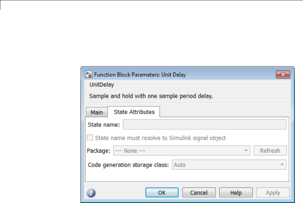
7Data Representation
1In your block diagram, double-click the desired block. This action opens the
block dialog box with two or more tabs, which includes State Attributes.
2Click the State Attributes tab.
3EnteranameforthevariabletobeusedtostoreblockstateintheState
name field.
The State name field turns yellow to indicate that you changed it.
4Click Apply to register the variable name.
ThefirsttwofieldsbeneaththeState name,State name must resolve
to Simulink signal object and Code generation storage class,become
enabled.
5If the state is to be stored in a Simulink signal object in the base or model
workspace, select State name must resolve to Simulink signal object.
If you choose this option, you cannot declare a storage class for the state in
the block, and the fields below become disabled.
7-86

States
6Select the desired storage class (ExportedGlobal,ImportedExtern,or
ImportedExternPointer)fromtheCode generation storage class
menu.
7Optional: For storage classes other than Auto, you can enter a storage type
qualifier such as const or volatile in the Code generation storage
type qualifier field. The Simulink Coder product does not check this
string for errors; what you enter is included in the variable declaration.
8Click OK or Apply and close the dialog box.
Symbolic Names for States
To determine the variable or field name generated for a block’s state, you can:
•UseadefaultnamegeneratedbytheSimulinkCoderproduct
•Define a symbolic name by using the State name field of the State
Attributes tab in a block dialog box
Default Block State Naming Convention
If you do not define a symbolic name for a block state, the Simulink Coder
product uses the following default naming convention:
BlockType#_DSTATE
where
•BlockType isthenameoftheblocktype(for example, Discrete_Filter).
•#is a unique ID number (#) assigned by the Simulink Coder product if
multiple instances of the same block type appear in the model. The ID
number is appended to BlockType.
•_DSTATE is a string that is always appended to the block type and ID
number.
For example, consider the model shown in the next figure.
7-87
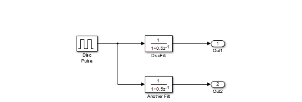
7Data Representation
Model with Two Discrete Filter Block States
Examine the code generated for the states of the two Discrete Filter blocks.
Assume that:
•Neither block’s state has a user-defined name.
•The upper Discrete Filter block has Auto storage class (and is therefore
stored in the DWork vector).
•The lower Discrete Filter block has ExportedGlobal storage class.
The states of the two Discrete Filter blocks are stored in DWork vectors,
initialized as shown in the code below:
/* data type work */
disc_filt_states_M->Work.dwork = ((void *)
&disc_filt_states_DWork);
(void)memset((char_T *) &disc_filt_states_DWork, 0,
sizeof(D_Work_disc_filt_states));
{
int_T i;
real_T *dwork_ptr = (real_T *)
&disc_filt_states_DWork.DiscFilt_DSTATE;
for (i = 0; i < 2; i++) {
dwork_ptr[i] = 0.0;
}
}
7-88
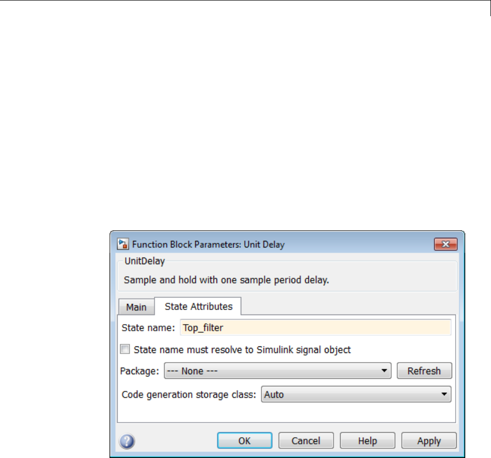
States
Define User Block State Names
Using the State Attributes tab of a block dialog box, you can define your
own symbolic name for a block state:
1In your block diagram, double-click the desired block. This action opens
the block dialog box, containing two or more tabs, which includes State
Attributes.
2Click the State Attributes tab.
3Enter the symbolic name in the State name field. For example, enter
the state name Top_filter.
4Click Apply. The dialog box now looks like this:
5Click OK.
The following state initialization code was generated from the example model
shown in “Generate Code for Signal Objects from Command Line” on page
7-67, under the following conditions:
7-89

7Data Representation
•The upper Discrete Filter block has the state name Top_filter,andAuto
storage class (and is therefore stored in the DWork vector).
•The lower Discrete Filter block has the state name Lower_filter,and
storage class ExportedGlobal.
Top_filter is placed in the Dwork vector.
/* data type work */
disc_filt_states_M->Work.dwork = ((void *)
&disc_filt_states_DWork);
(void)memset((char_T *) &disc_filt_states_DWork, 0,
sizeof(D_Work_disc_filt_states));
disc_filt_states_DWork.Top_filter = 0.0;
/* exported global states */
Lower_filter = 0.0;
Control Code Generation for Block States
If you are not familiar with Simulink data objects and signal objects, you
should read “Signals” on page 7-52 before reading this section.
You can associate a block state with a signal object and control code
generation for the block state through the signal object:
1Instantiate the desired signal object, and set its CoderInfo.StorageClass
property.
2Open the dialog box for the block whose state you want to associate with
the signal object.
3Click the State Attributes tab.
4Enter the name of the signal object in the State name field.
5Select State name must resolve to Simulink signal object.
This step disables the Code generation storage class and Code
generation storage type qualifier options in the State Attributes tab,
because the signal object specifies these settings.
7-90
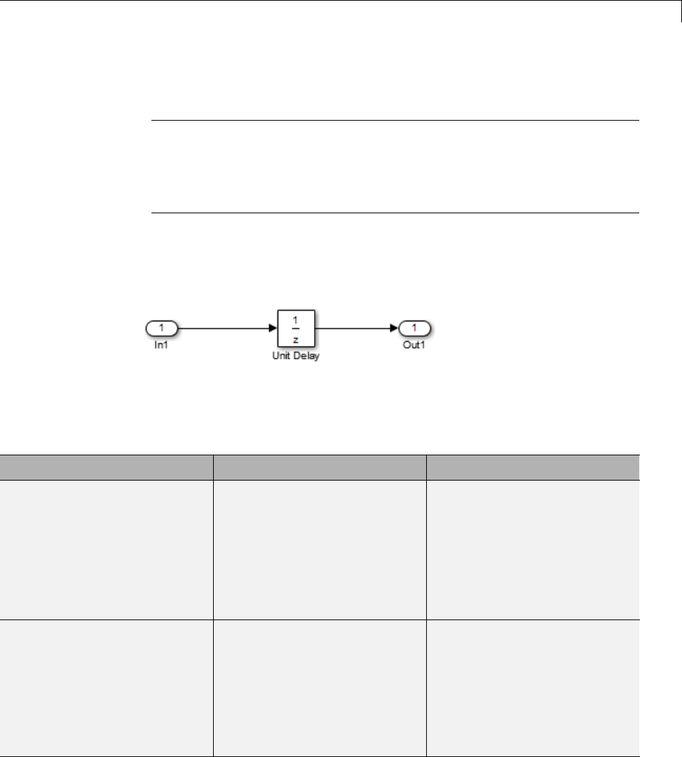
States
6Click Apply and close the dialog box.
Note When a block state is associated with a signal object, the mapping
between the block state and the signal object must be one-to-one. If two or
more identically named entities, such as a block state and a signal, map
to the same signal object, the name conflict is flagged as an error at code
generation time.
Summary of State Storage Class Options
Here is a simple model, unit_delay, which contains a Unit Delay block:
The following table shows, for each state storage class option, the variable
declaration and initialization code generated for a Unit Delay block state. The
block state has the user-defined state name udx.
Storage Class Declaration Initialization Code
Auto In model.h
typedef struct
D_Work_unit_delay_tag
{
real_T udx;
}
D_Work_unit_delay;
unit_delay_DWork.udx = 0.0;
Exported Global In model.c or model.cpp
real_T udx;
In model.h
extern real_T udx;
In model.c or model.cpp
udx = 0.0;
7-91

7Data Representation
Storage Class Declaration Initialization Code
ImportedExtern In model_private.h
extern real_T udx;
In model.c or model.cpp
udx =
unit_delay_P.UnitDelay_X0;
ImportedExternPointer In model_private.h
extern real_T *udx;
In model.c or model.cpp
(*udx) =
unit_delay_P.UnitDelay_X0;
7-92

Data Stores
Data Stores
In this section...
“About Data Stores” on page 7-93
“Storage Classes for Data Store Memory Blocks” on page 7-93
“Generate Code for Data Store Memory Blocks” on page 7-96
“Nonscalar Data Stores in Generated Code” on page 7-97
“Data Store Buffering in Generated Code” on page 7-99
About Data Stores
A data store contains data that is accessible at any point in a model hierarchy
at or below the level in which the data store is defined. Data stores can allow
subsystems and referenced models to share data without having to use I/O
ports to pass the data from level to level. See “Data Stores with Data Store
Memory Blocks” for information about data stores in Simulink. This section
provides additional information about data store code generation.
Storage Classes for Data Store Memory Blocks
You can control how Data Store Memory blocks in your model are stored
and represented in the generated code by assigning storage classes and type
qualifiers. You do this in almost exactly the same way you assign storage
classes and type qualifiers for block states.
Data Store Memory blocks, like block states, have Auto storage class by
default, and their memory is stored within the DWork vector. The symbolic
name of the storage location is based on the data store name.
You can generate code from multiple Data Store Memory blocks that have the
same data store name, subject to the following restriction: at most one of the
identically named blocks can have a storage class other than Auto. An error is
reported if this condition is not met.
For blocks with Auto storage class, the Simulink Coder product generates a
unique symbolic name for each block to avoid name clashes. For Data Store
7-93

7Data Representation
Memory blocks with storage classes other than Auto, the generated code uses
the data store name as the symbol.
In the following model, a Data Store Write block writes to memory declared
by the Data Store Memory block myData:
To control the storage declaration for a Data Store Memory block, use the
Code Generation > Storage class and Code Generation > Storage type
qualifier fields of the Data Store Memory block dialog box. The next figure
shows the Data Store Memory block dialog box for the preceding model.
7-94
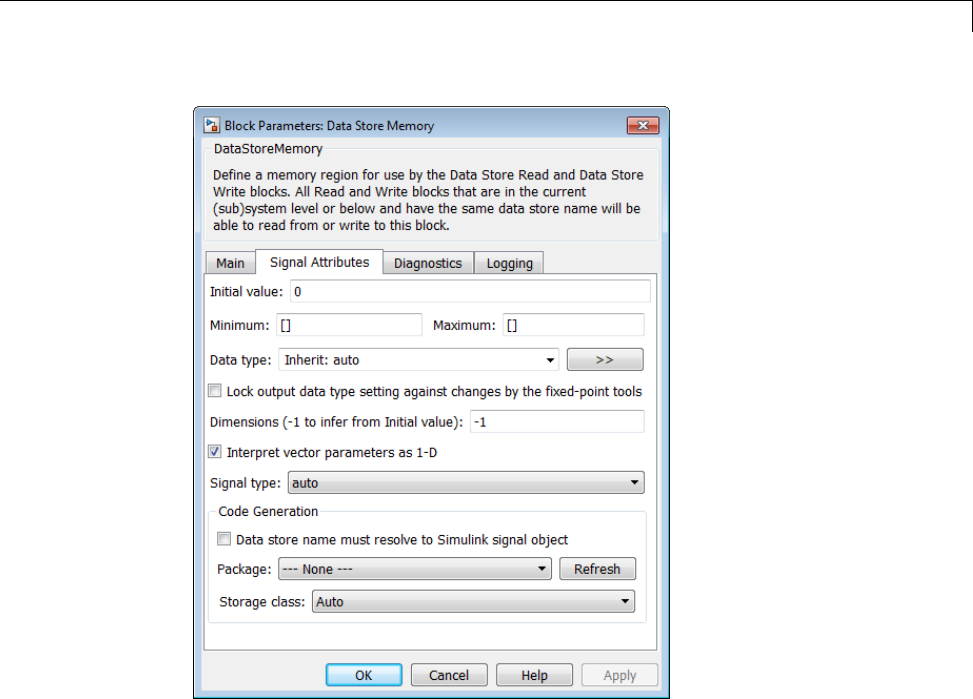
Data Stores
Data Store Memory blocks are nonvirtual because code is generated for
their initialization in .c and .cpp files and their declarations in header
files. The following table shows how the code generated for the Data Store
Memory block in the preceding model differs for different settings of Code
Generation > Storage class.Thetablegivesthevariabledeclarationsand
MdlOutputs code generated for the myData block.
7-95

7Data Representation
Storage Class Declaration Code
Auto In model.h
typedef struct
D_Work_tag
{
real_T myData;
}
D_Work;
In model.c or model.cpp
/* Block states (auto storage) */
D_Work model_DWork;
model_DWork.myData =
rtb_SineWave;
ExportedGlobal In model.c or model.cpp
/* Exported block states */
real_T myData;
In model.h
extern real_T myData;
myData = rtb_SineWave;
ImportedExtern In model_private.h
extern real_T myData;
myData = rtb_SineWave;
ImportedExternPointer In model_private.h
extern real_T *myData;
(*myData) = rtb_SineWave;
Generate Code for Data Store Memory Blocks
If you are not familiar with Simulink data objects and signal objects, you
should read “Signals” on page 7-52 before reading this section.
7-96

Data Stores
You can associate a Data Store Memory block with a signal object, and control
code generation for the block through the signal object. To do this:
1Instantiate the desired signal object.
2Set the object’s CoderInfo.StorageClass property to indicate the desired
storage class.
3Open the block dialog box for the Data Store Memory block that you want
to associate with the signal object.
4Enter the name of the signal object in the Data store name field.
5Select Data store name must resolve to Simulink signal object.
6Do not set the storage class field to a value other than Auto (the default).
7Click OK or Apply.
Note When a Data Store Memory block is associated with a signal object,
the mapping between the Data store name and the signal object name
must be one-to-one. If two or more identically named entities map to
thesamesignalobject,thenameconflictisflaggedasanerroratcode
generation time. See “Resolve Conflicts in Configuration of Signals Objects”
on page 7-72 for more information.
Nonscalar Data Stores in Generated Code
Stateflow generates efficient code for accessing individual elements of
nonscalar data stores. For example, the next figure shows a data store
named Athat has seven elements. The Stateflow chart assigns the fourth
element of the data store from a value computed from the third element.
The generated code is efficient and involves no unnecessary access of any of
the other elements of A.
7-97
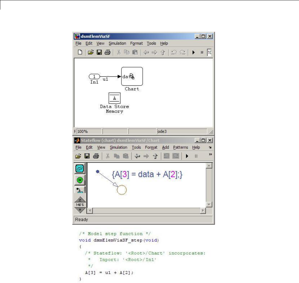
7Data Representation
In contrast, modeling and code generation for data store element selection
and assignment in Simulink is more explicit. The next figure shows the same
algorithm modeled without using a Stateflow chart. The assignment block
7-98
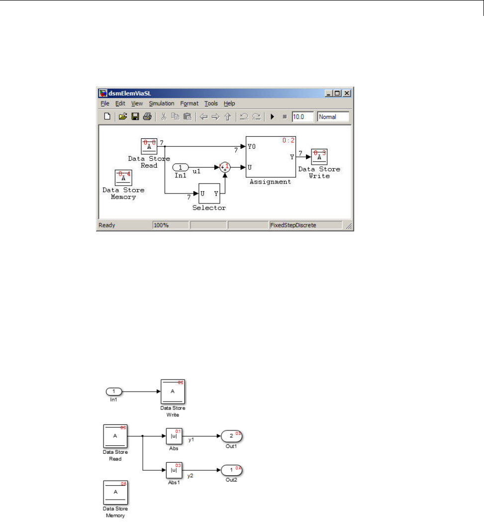
Data Stores
copies each element of the data store back to itself, in addition to updating
the element.
Data Store Buffering in Generated Code
A Data Store Read block is a nonvirtual block that copies the value of the
data store to its output buffer when it executes. Since the value is buffered,
all downstream blocks connected to the output of the data store read utilize
the same value, even if a Data Store Write block updates the data store in
between execution of two of the downstream blocks.
The next figure shows a model that uses blocks whose priorities have been
modified to achieve a particular order of execution:
7-99
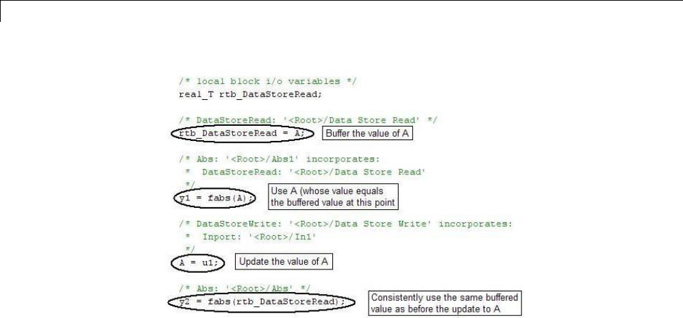
7Data Representation
The following execution order applies:
1TheblockDataStoreReadbuffersthecurrentvalueofthedatastore
Aat its output.
2The block Abs1 uses the buffered output of Data Store Read.
3The block Data Store Write updates the data store.
4The block Abs uses the buffered output of Data Store Read.
Because the output of Data Store Read is a buffer, both Abs and Abs1 use the
same value: the value of the data store at the time that Data Store Read
executes.
The next figure shows another example:
7-100
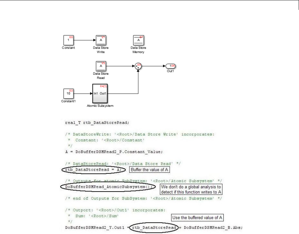
Data Stores
In this example, the following execution order applies:
1TheblockDataStoreReadbuffersthecurrentvalueofthedatastore
Aat its output.
2Atomic Subsystem executes.
3The Sum block adds the output of Atomic Subsystem to the output of Data
Store Read.
Simulink assumes that Atomic Subsystem might update the data store, so
Simulink buffers the data store. Atomic Subsystem executes after Data Store
7-101
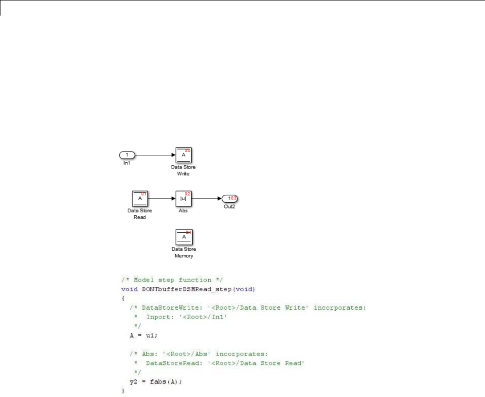
7Data Representation
Read buffers its output, and the bufferprovidesawayfortheSumblockto
usethevalueofthedatastoreasitwaswhenDataStoreReadexecuted.
In some cases, theSimulink Coder code generator determines that it can
optimize away the output buffer for a Data Store Read block, and the
generated code will refer to the data store directly, rather than a buffered
valueofit. Thenextfigureshowsanexample:
In the generated code, the argument of the fabs() function is the data store A
rather than a buffered value.
7-102

8
Entry Point Functions and
Scheduling
•“Entry Point Functions and Scheduling” on page 8-2
•“About Model Execution” on page 8-4
•“Non-Real-Time Single-Tasking Systems” on page 8-6
•“Non-Real-Time Multitasking Systems” on page 8-7
•“Real-Time Single-Tasking Systems” on page 8-9
•“Real-Time Multitasking Systems” on page 8-11
•“Multitasking Systems Using Real-Time Tasking Primitives” on page 8-14
•“Program Timing” on page 8-16
•“Program Execution” on page 8-18
•“External Mode Communication” on page 8-19
•“Data Logging in Single-Tasking and Multitasking Model Execution” on
page 8-20
•“Rapid Prototyping and Embedded Model Execution Differences” on page
8-22
•“Rapid Prototyping Model Functions” on page 8-23
•“Embedded Model Functions” on page 8-30

8Entry Point Functions and Scheduling
Entry Point Functions and Scheduling
The following functions represent entry points in the generated code for a
Simulink model.
Function Description
model_initialize Initialization entry point in
generated code for Simulink model
model_SetEventsForThisBaseStep Set event flags for multirate,
multitasking operation before calling
model_step for Simulink model
— not generated as of Version 5.1
(R2008a)
model_step Step routine entry point in generated
code for Simulink model
model_terminate Termination entry point in generated
code for Simulink model
For ERT-based models, the calling interface generated for each of these
functions differs significantly depending on how you set the Generate
reusable code parameter. By default, Generate reusable code is off, and
the model entry point functions access model data with statically allocated
global data structures. When Generate reusable code is on, model data
structures are passed in (by reference) as arguments to the model entry point
functions. For efficiency, only those data structures that are actually used in
the model are passed in. Therefore when Generate reusable code is on, the
argument lists generated for the entry point functions vary according to the
requirements of the model.
The entry points are exported with model.h. To call the entry-point functions
from your hand-written code, add an #include model.h directive to your
code. For ERT-based models, if Generate reusable code is on, you must
examine the generated code to determine the calling interface required for
these functions.
8-2

Entry Point Functions and Scheduling
For more information, see the reference pages for the listed functions.
Note The function reference pages document the default (GRT or ERT with
Generate reusable code off) calling interface generated for these functions.
8-3

8Entry Point Functions and Scheduling
About Model Execution
Before looking at the two styles of generated code, you need to have a
high-level understanding of how the generated model code is executed. The
Simulink Coder software generates algorithmic code as defined by your
model. You can include your own code in your model by using S-functions.
S-functions can range from high-level signal manipulation algorithms to
low-level device drivers.
The Simulink Coder product also provides a run-time interface that executes
the generated model code. The run-time interface and model code are
compiled together to create the model executable. The next figure shows a
high-level object-oriented view of the executable.
Model code
and S-functions
Run-Time Interface
Execution driver for model code,
operating system interface routines,
I/O dependent routines,
solver and data logging routines.
The Object-Oriented View of a Real-Time Program
In general, the conceptual design of the model execution driver does not
change between the rapid prototypingandembeddedstyleofgenerated
code. The following sections describe model execution for single-tasking and
multitasking environments both for simulation (non-real-time) and for real
time. For most models, the multitasking environment will provide the most
efficient model execution (that is, fastest sample rate).
The following concepts are useful in describing how models execute.
•Initialization:model_initialize initializes the run-time interface code
and the model code.
•ModelOutputs: Calling all blocks in your model that have a sample hit at
the current time and having them produce their output. model_output can
8-4

About Model Execution
bedoneinmajororminortimesteps. Inmajortimesteps,theoutputis
a given simulation time step. In minor time steps, the run-time interface
integrates the derivatives to update the continuous states.
•ModelUpdate:model_update calls all blocks in your model that have a
sample hit at the current point in time and has them update their discrete
states or similar type objects.
•ModelDerivatives: Calling all blocks in your model that have continuous
states and having them update their derivatives. model_derivatives
is only called in minor time steps.
•ModelTerminate:model_terminate terminates the program if it is
designed to run for a finite time. It destroys the real-time model data
structure, deallocates memory, and can write data to a file.
The identifying names in the preceding list (ModelOutputs, and so on) identify
functions in pseudocode examples shown in the following sections.
•“Non-Real-Time Single-Tasking Systems” on page 8-6
•“Non-Real-Time Multitasking Systems” on page 8-7
•“Real-Time Single-Tasking Systems” on page 8-9
•“Real-Time Multitasking Systems” on page 8-11
•“Multitasking Systems Using Real-Time Tasking Primitives” on page 8-14
8-5

8Entry Point Functions and Scheduling
Non-Real-Time Single-Tasking Systems
The pseudocode below shows the execution of a model for a non-real-time
single-tasking system.
main()
{
Initialization
While (time < final time)
ModelOutputs -- Major time step.
LogTXY -- Log time, states and root outports.
ModelUpdate -- Major time step.
Integrate -- Integration in minor time step for
-- models with continuous states.
ModelDerivatives
Do 0 or more
ModelOutputs
ModelDerivatives
EndDo -- Number of iterations depends upon the solver
Integrate derivatives to update continuous states.
EndIntegrate
EndWhile
Termination
}
The initialization phase begins first. This consists of initializing model states
and setting up the execution engine. The model then executes, one step at a
time. First ModelOutputs executes at time t, then the workspace I/O data is
logged, and then ModelUpdate updates the discrete states. Next, if your model
has any continuous states, ModelDerivatives integrates the continuous
states’ derivatives to generate the states for time tth
new =+ ,wherehis the
step size. Time then moves forward to tnew and the process repeats.
During the ModelOutputs and ModelUpdate phases of model execution, only
blocks that reach the current point in time execute.
8-6

Non-Real-Time Multitasking Systems
Non-Real-Time Multitasking Systems
The pseudocode below shows the execution of a model for a non-real-time
multitasking system.
main()
{
Initialization
While (time < final time)
ModelOutputs(tid=0) -- Major time step.
LogTXY -- Log time, states, and root
-- outports.
ModelUpdate(tid=0) -- Major time step.
Integrate -- Integration in minor time step for
-- models with continuous states.
ModelDerivatives
Do 0 or more
ModelOutputs(tid=0)
ModelDerivatives
EndDo (Number of iterations depends upon the solver.)
Integrate derivatives to update continuous states.
EndIntegrate
For i=1:NumTids
ModelOutputs(tid=i) -- Major time step.
ModelUpdate(tid=i) -- Major time step.
EndFor
EndWhile
Termination
}
Multitasking operation is more complex than single-tasking execution because
the output and update functions are subdivided by the task identifier (tid)
that is passed into these functions. This allows for multiple invocations of
these functions with different task identifiers using overlapped interrupts, or
for multiple tasks when using a real-time operating system. In simulation,
multiple tasks are emulated by executing the code in the order that would
occur if no preemption existed in a real-time system.
Multitasking execution assumes that all task rates are multiples of the
baserate. TheSimulinkproductenforces this when you create a fixed-step
8-7

8Entry Point Functions and Scheduling
multitasking model. The multitasking execution loop is very similar to that
of single-tasking, except for the use of the task identifier (tid)argument
to ModelOutputs and ModelUpdate.
8-8

Real-Time Single-Tasking Systems
Real-Time Single-Tasking Systems
The pseudocode below shows the execution of a model in a real-time
single-tasking system where the model is run at interrupt level.
rtOneStep()
{
Check for interrupt overflow
Enable "rtOneStep" interrupt
ModelOutputs -- Major time step.
LogTXY -- Log time, states and root outports.
ModelUpdate -- Major time step.
Integrate -- Integration in minor time step for models
-- with continuous states.
ModelDerivatives
Do0ormore
ModelOutputs
ModelDerivatives
EndDo (Number of iterations depends upon the solver.)
Integrate derivatives to update continuous states.
EndIntegrate
}
main()
{
Initialization (including installation of rtOneStep as an
interrupt service routine, ISR, for a real-time clock).
While(time < final time)
Background task.
EndWhile
Mask interrupts (Disable rtOneStep from executing.)
Complete any background tasks.
Shutdown
}
Real-time single-tasking execution is very similar to non-real-time
single-tasking execution, except that instead of free-running the code, the
rt_OneStep function is driven by a periodic timer interrupt.
8-9

8Entry Point Functions and Scheduling
At the interval specified by the program’s base sample rate, the interrupt
service routine (ISR) preempts the background task to execute the model code.
The base sample rate is the fastest in the model. If the model has continuous
blocks, then the integration step size determines the base sample rate.
For example, if the model code is a controller operating at 100 Hz, then
every 0.01 seconds the background task is interrupted. During this
interrupt, the controller reads its inputs from the analog-to-digital converter
(ADC), calculates its outputs, writes these outputs to the digital-to-analog
converter (DAC), and updates its states. Program control then returns to the
background task. All these steps must occur before the next interrupt.
8-10

Real-Time Multitasking Systems
Real-Time Multitasking Systems
The following pseudocode shows how a model executes in a real-time
multitasking system where the model is run at interrupt level.
rtOneStep()
{
Check for interrupt overflow
Enable "rtOneStep" interrupt
ModelOutputs(tid=0) -- Major time step.
LogTXY -- Log time, states and root outports.
ModelUpdate(tid=0) -- Major time step.
Integrate -- Integration in minor time step for
-- models with continuous states.
ModelDerivatives
Do0ormore
ModelOutputs(tid=0)
ModelDerivatives
EndDo (Number of iterations depends upon the solver.)
Integrate derivatives and update continuous states.
EndIntegrate
For i=1:NumTasks
If (hit in task i)
ModelOutputs(tid=i)
ModelUpdate(tid=i)
EndIf
EndFor
}
main()
{
Initialization (including installation of rtOneStep as an
interrupt service routine, ISR, for a real-time clock).
While(time < final time)
Background task.
EndWhile
Mask interrupts (Disable rtOneStep from executing.)
Complete any background tasks.
Shutdown
}
8-11

8Entry Point Functions and Scheduling
Running models at interrupt level in a real-time multitasking environment
is very similar to the previous single-tasking environment, except that
overlapped interrupts are employed for concurrent execution of the tasks.
The execution of a model in a single-tasking or multitasking environment
when using real-time operating system tasking primitives is very similar to
the interrupt-level examples discussed above. The pseudocode below is for a
single-tasking model using real-time tasking primitives.
tSingleRate()
{
MainLoop:
If clockSem already "given", then error out due to overflow.
Wait on clockSem
ModelOutputs -- Major time step.
LogTXY -- Log time, states and root
-- outports
ModelUpdate -- Major time step
Integrate -- Integration in minor time step
-- for models with continuous
-- states.
ModelDeriviatives
Do 0 or more
ModelOutputs
ModelDerivatives
EndDo (Number of iterations depends upon the solver.)
Integrate derivatives to update continuous states.
EndIntegrate
EndMainLoop
}
main()
{
Initialization
Start/spawn task "tSingleRate".
Start clock that does a "semGive" on a clockSem semaphore.
Wait on "model-running" semaphore.
Shutdown
}
8-12

Real-Time Multitasking Systems
In this single-tasking environment, the model executes as real-time operating
system tasking primitives. In this environment, create a single task
(tSingleRate) to run the model code. This task is invoked when a clock tick
occurs. The clock tick gives a clockSem (clock semaphore) to the model task
(tSingleRate). The model task waits for the semaphore before executing.
The clock ticks occur at the fundamental step size (base rate) for your model.
8-13

8Entry Point Functions and Scheduling
Multitasking Systems Using Real-Time Tasking Primitives
The pseudocode below is for a multitasking model using real-time tasking
primitives.
tSubRate(subTaskSem,i)
{
Loop:
Wait on semaphore subTaskSem.
ModelOutputs(tid=i)
ModelUpdate(tid=i)
EndLoop
}
tBaseRate()
{
MainLoop:
If clockSem already "given", then error out due to overflow.
Wait on clockSem
For i=1:NumTasks
If (hit in task i)
If task i is currently executing, then error out due to
overflow.
Do a "semGive" on subTaskSem for task i.
EndIf
EndFor
ModelOutputs(tid=0) -- major time step.
LogTXY -- Log time, states and root outports.
ModelUpdate(tid=0) -- major time step.
Loop: -- Integration in minor time step for
-- models with continuous states.
ModelDeriviatives
Do 0 or more
ModelOutputs(tid=0)
ModelDerivatives
EndDo (number of iterations depends upon the solver).
Integrate derivatives to update continuous states.
EndLoop
EndMainLoop
}
main()
8-14

Multitasking Systems Using Real-Time Tasking Primitives
{
Initialization
Start/spawn task "tSubRate".
Start/spawn task "tBaseRate".
Start clock that does a "semGive" on a clockSem semaphore.
Wait on "model-running" semaphore.
Shutdown
}
In this multitasking environment, the model is executed using real-time
operating system tasking primitives. Such environments require several
model tasks (tBaseRate and several tSubRate tasks) to run the model code.
The base rate task (tBaseRate) has a higher priority than the subrate tasks.
The subrate task for tid=1 has a higher priority than the subrate task for
tid=2, and so on. The base rate task is invoked when a clock tick occurs. The
clock tick gives a clockSem to tBaseRate. The first thing tBaseRate does is
give semaphores to the subtasks that have a hit at the current point in time.
Because the base rate task has a higher priority, it continues to execute. Next
it executes the fastest task (tid=0), consisting of blocks in your model that
have the fastest sample time. After this execution, it resumes waiting for the
clock semaphore. The clock ticks are configured to occur at the fundamental
step size for your model.
8-15
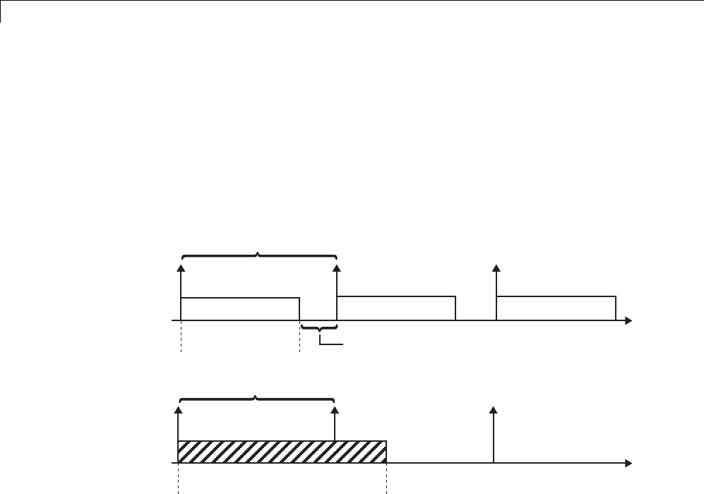
8Entry Point Functions and Scheduling
Program Timing
Real-time programs require careful timing of the task invocations (either by
using an interrupt or a real-time operating system tasking primitive) so that
the model code executes to completion before another task invocation occurs.
This includes time to read and write data to and from external hardware.
The next figure illustrates interrupt timing.
Time to execute the model code
Sample interval is too short for this model code execution.
Sample interval is appropriate for this model code execution.
Time available to process background tasks
Time to execute
the model code
time
time
Task Timing
The sample interval must be long enough to allow model code execution
between task invocations.
In the figure above, the time between two adjacent vertical arrows is the
sample interval. The empty boxes in the upper diagram show an example of a
program that can complete one step within the interval and still allow time
for the background task. The gray box in the lower diagram indicates what
happens if the sample interval is too short. Another task invocation occurs
before the task is complete. Such timing results in an execution error.
Note also that, if the real-time program is designed to run forever (that is, the
final time is 0 or infinite so the while loop never exits), then the shutdown
code never executes.
8-16


8Entry Point Functions and Scheduling
Program Execution
As the previous section indicates, a real-time program cannot require 100%
of the CPU’s time. This provides an opportunity to run background tasks
during the free time.
Background tasks include operations such as writing data to a buffer or file,
allowing access to program data by third-party data monitoring tools, or using
Simulink external mode to update program parameters.
It is important, however, that the program be able to preempt the background
task so the model code can execute in real time.
The way the program manages tasks depends on capabilities of the
environment in which it operates.
8-18

External Mode Communication
External Mode Communication
External mode allows communication between the Simulink block diagram
and the standalone program that is built from the generated code. In this
mode, the real-time program functions as an interprocess communication
server, responding to requests from the Simulink engine.
8-19

8Entry Point Functions and Scheduling
Data Logging in Single-Tasking and Multitasking Model
Execution
The Simulink Coder data-logging features, described in “Debug” on page
9-80, enable you to save system states, outputs, and time to a MAT-file at the
completion of the model execution. The LogTXY function, which performs data
logging, operates differently in single-tasking and multitasking environments.
If you examinehowLogTXY is called in the single-tasking and multitasking
environments, you will notice that for single-tasking LogTXY is called
after ModelOutputs. During this ModelOutputs call, all blocks that have
ahitattimetexecute, whereas in multitasking, LogTXY is called after
ModelOutputs(tid=0), which executes only the blocks that have a hit at
time tand that have a task identifier of 0. This results in differences in the
logged values between single-tasking and multitasking logging. Specifically,
consider a model with two sample times, the faster sample time having a
period of 1.0 second and the slower sample time having a period of 10.0
seconds. At time t = k*10, k=0,1,2... both the fast (tid=0)andslow(tid=1)
blocks execute. When executing in multitasking mode, when LogTXY is
called, the slow blocks execute, but the previous value is logged, whereas in
single-tasking the current value is logged.
Another difference occurs when loggingdatainanenabledsubsystem.
Consider an enabled subsystem that has a slow signal driving the enable port
and fast blocks within the enabled subsystem. In this case, the evaluation of
the enable signal occurs in a slow task, and the fast blocks see a delay of one
sample period; thus the logged values will show these differences.
To summarize differences in logged data between single-tasking and
multitasking, differences will be seen when
•Any root outport block has a sample time that is slower than the fastest
sample time
•Any block with states has a sample time that is slower than the fastest
sample time
•Any block in an enabled subsystem where the signal driving the enable
port is slower than the rate of the blocks in the enabled subsystem
8-20

Data Logging in Single-Tasking and Multitasking Model Execution
For the first two cases, even though the logged values are different between
single-tasking and multitasking, the model results are not different. The only
real difference is where (at what point in time) the logging is done. The third
(enabled subsystem) case results in a delay that can be seen in a real-time
environment.
8-21

8Entry Point Functions and Scheduling
Rapid Prototyping and Embedded Model Execution
Differences
The rapid prototyping program framework provides a common application
programming interface (API) that does not change between model definitions.
The Embedded Coder product provides a different framework called the
embedded program framework. The embedded program framework provides
an optimized API that is tailored to your model. When you use the embedded
style of generated code, you are modeling how you would like your code to
execute in your embedded system. Therefore, the definitions defined in your
model shouldbespecifictoyourembeddedtargets. Itemssuchasthemodel
name, parameter, and signal storage class are included as part of the API for
the embeddedstyleofcode.
One major difference between the rapid prototyping and embedded style of
generated code is that the latter contains fewer entry-point functions. The
embedded style of code can be configured to have only one run-time function,
model_step.
Thus, when you look again at the model execution pseudocode presented
earlier in this chapter, you can eliminate the Loop...EndLoop statements,
and groupModelOutputs,LogTXY,andModelUpdate into a single statement,
model_step.
For more information about how generated embedded code executes, see
“Embedded Model Functions” on page 8-30.
8-22

Rapid Prototyping Model Functions
Rapid Prototyping Model Functions
The rapid prototyping code defines the following functions that interface with
the run-time interface:
•Model(): The model registration function. This function initializes the
work areas (for example, allocating and setting pointers to various data
structures) used by the model. The model registration function calls the
MdlInitializeSizes and MdlInitializeSampleTimes functions. These
two functions are very similar to the S-function mdlInitializeSizes and
mdlInitializeSampleTimes methods.
•MdlStart(void): After the model registration functions
MdlInitializeSizes and MdlInitializeSampleTimes execute, the
run-time interface starts execution by calling MdlStart.Thisroutineis
called once at startup.
The function MdlStart has four basic sections:
-Code to initialize the states for each block in the root model that has
states. A subroutine call is made to the “initialize states” routines of
conditionally executed subsystems.
-Code generated by the one-time initialization (start) function for each
block in the model.
-Code to enable the blocks in the root model that have enable methods,
and the blocks inside triggered or function-call subsystems residing in
the root model. Simulink blocks can have enable and disable methods.
An enable method is called just before a block starts executing, and the
disable method is called just after the block stops executing.
-Code for each block in the model that has a constant sample time.
•MdlOutputs(int_T tid):MdlOutputs updates the output of blocks. The
tid (task identifier) parameter identifies the task that in turn maps when
to execute blocks based upon their sample time. This routine is invoked by
the run-time interface during major and minor time steps. The major time
steps are when the run-time interface is taking an actual time step (that
is, it is time to execute a specific task). If your model contains continuous
states, the minor time steps will be taken. The minor time steps are when
the solver is generating integration stages, which are points between major
8-23

8Entry Point Functions and Scheduling
outputs. These integration stages are used to compute the derivatives used
in advancing the continuous states. The solver is called to updates
•MdlUpdate(int_T tid):MdlUpdate updates the states and work vector
state information (that is, states that are neither continuous nor discrete)
saved in work vectors. The tid (task identifier) parameter identifies the
task that in turn indicates which sample times are active, allowing you to
conditionally update only states of active blocks. This routine is invoked
by the run-time interface after the major MdlOutputs has been executed.
The solver is also called, and model_Derivatives is called in minor steps
by the solver during its integration stages. All blocks that have continuous
states have an identical number of derivatives. These blocks are required
to compute the derivatives so that the solvers can integrate the states.
•MdlTerminate(void):MdlTerminate contains any block shutdown code.
MdlTerminate is called by the run-time interface, as part of the termination
of the real-time program.
The contents of the above functions are directly related to the blocks in your
model. A Simulink block can be generalized to the following set of equations.
yftxxu
cd
=0(, , , )
Output yis a function of continuous state xc, discrete state xd,andinputu.
Each block writes its specific equation in a section of MdlOutputs.
xftxu
dud+=
1(, , )
The discrete states xdare a function of the current state and input. Each block
that has a discrete state updates its state in MdlUpdate.
xftxu
dc
=(, , )
The derivatives xare a function of the current input. Each block that has
continuous states provides its derivatives to the solver (for example, ode5)in
model_Derivatives. The derivatives are used by the solver to integrate the
continuous state to produce the next value.
The output, y, is generally written to the block I/O structure. Root-level
Outport blocks write to the external outputs structure. The continuous and
8-24

Rapid Prototyping Model Functions
discrete states are stored in the states structure. The input, u, can originate
from another block’s output, which is located in the block I/O structure, an
external input (located in the external inputs structure), or a state. These
structures are defined in the model.h file that the Simulink Coder software
generates.
The next example shows the general contents of the rapid prototyping style of
Ccodewrittentothemodel.c file.
8-25
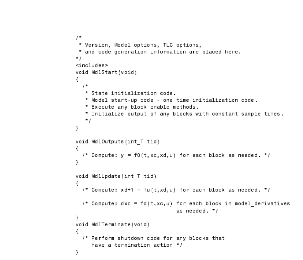
8Entry Point Functions and Scheduling
The next figure shows a flow chart describing the execution of the rapid
prototyping generated code.
8-26
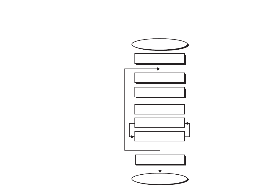
Rapid Prototyping Model Functions
Execution Loop
Integration in Minor Time Steps
End
model_Derivatives
Start Execution
MdlStart
MdlOutputs
MdlUpdate
MdlOutputs
model_Derivatives
MdlTerminate
Rapid Prototyping Execution Flow Chart
Each block places code in specific Mdl routines according to the algorithm that
it is implementing. Blocks have input, output, parameters, and states, as well
as other general items. For example, in general, block inputs and outputs are
written to a block I/O structure (model_B). Block inputs can also come from
the external input structure (model_U) or the state structure when connected
to a state port of an integrator (model_X), or ground (rtGround) if unconnected
or grounded. Block outputs can also go to the external output structure
(model_Y). The next figure shows the general mapping between these items.
8-27
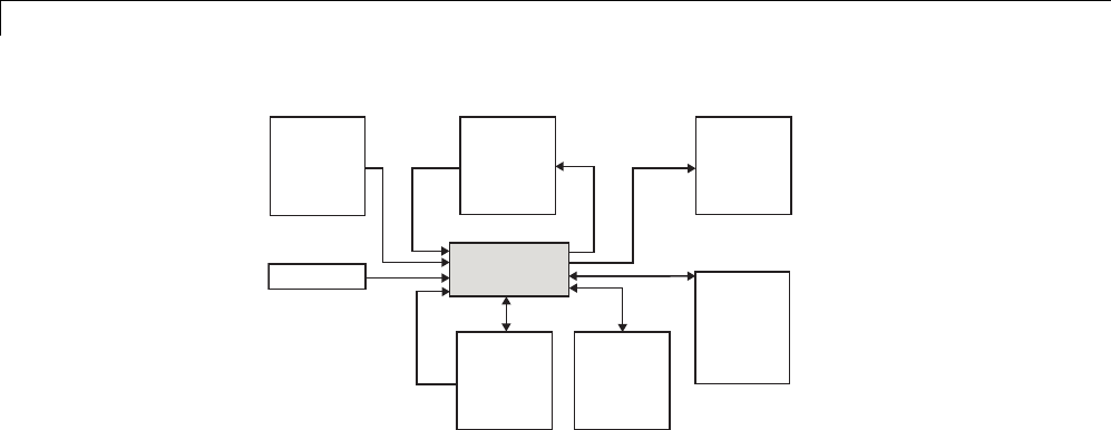
8Entry Point Functions and Scheduling
Block
External
inputs
struct
model_U
rtGround
Block I/O
struct
model_B
External
outputs
struct
model_Y
States
struct
model_X
Parameter
struct
model_P
Work
structs
rtRWork,
rtIWork,
rtPWork,
....
Data View of the Generated Code
The following list defines the structures shown in the preceding figure:
•Block I/O structure (model_B): This structure consists of persistent block
output signals. The number of block output signals is the sum of the
widths of the data output ports of all nonvirtual blocks in your model. If
you activate block I/O optimizations, the Simulink and Simulink Coder
products reduce the size of the model_B structure by
-Reusing the entries in the model_B structure
-Making other entries local variables
See “Signals” on page 7-52 for more information on these optimizations.
Structure field names are determined either by the block’s output signal
name (when present) or by the block name and port number when the
output signal is left unlabeled.
•Block states structures: The continuous states structure (model_X)contains
the continuous state information for any blocks in your model that have
continuous states. Discrete states are stored in a data structure called
the DWork vector (model_DWork).
•Block parameters structure (model_P): The parameters structure contains
block parameters that can be changed during execution (for example, the
parameter of a Gain block).
•External inputs structure (model_U): The external inputs structure consists
of all root-level Inport block signals. Field names are determined by either
8-28

Rapid Prototyping Model Functions
the block’s output signal name, when present, or by the Inport block’s name
when the output signal is left unlabeled.
•External outputs structure (model_Y): The external outputs structure
consists of all root-level Outport blocks. Field names are determined by the
root-level Outport block names in your model.
•Real work, integer work, and pointer work structures (model_RWork,
model_IWork,model_PWork): Blocks might have a need for real, integer,
or pointer work areas. For example, the Memory block uses a real work
element for each signal. These areas are used to save internal states or
similar information.
8-29

8Entry Point Functions and Scheduling
Embedded Model Functions
The Embedded Coder target generates the following functions:
•model_initialize: Performs model initialization and should be called once
before you start executing your model.
•If the Single output/update function code generation option is selected,
then you see
-model_step: Contains the output and update code for all blocks in your
model.
Otherwise, you see
-model_output: Contains the output code for all blocks in your model.
-model_update: Contains the update code for all blocks in your model.
•If the Terminate function required code generation option is selected,
then you see
-model_terminate: This contains model shutdown code and should be
called as part of system shutdown.
See “Entry Point Functions and Scheduling” in the Embedded Coder
documentation for complete descriptions of these functions.
8-30


9Configuration
Configuring a Model for Code Generation
In this section...
“Code Generation Configuration” on page 9-2
“Open the Model Configuration for Code Generation” on page 9-3
“Configure a Model Programmatically” on page 9-3
Code Generation Configuration
When you are ready to generate code for a model, you can modify the model
configuration parameters specific to code generation. The code generation
parameters affect how the Simulink Coder software generates code and builds
an executable from your model.
Your application objectives might include a combination of the following code
generation objectives: debugging, traceability, execution efficiency, and safety
precaution. There are tradeoffs associated with these configuration choices,
such as execution speed and memory usage. You can use the Model Advisor
and the Code Generation Advisor to help configure any model to achieve your
application objectives. For more information, see “Advice About Optimizing
Models for Code Generation” on page 16-5 and “Configure Code Generation
Objectives Using Code Generation Advisor” on page 9-7.
You modify the model configuration parameters for code generation in the
Code Generation and Optimization panes of the Configuration Parameters
dialog box. The content of the Code Generation pane and its subpanes
can change depending on the target that you specify. To open the Code
Generation pane, see “Open the Model Configuration for Code Generation”
on page 9-3. Some configuration options are available only with the Embedded
Coder product. The Optimization pane includes code generation parameters
that help to improve the performance of the generated code.
To automate the configuration of models, you can use the set_param
function from the MATLAB command line to adjust the model configuration
parameters. For more information, see “Parameter Command-Line
Information Summary” in the Simulink Coder documentation. For an
example of automating the configuration of a model, see “Configure a Model
Programmatically” on page 9-3.
9-2

Configuring a Model for Code Generation
Open the Model Configuration for Code Generation
To modify the model configuration parameters for code generation, open the
Code Generation pane. There are four ways to open the Code Generation
pane from the Simulink editor:
•To open the Configuration Parameters dialog box, click the model
configuration parameters icon:
and select Code Generation.
•From the Simulation menu, select Model Configuration Parameters.
When the Configuration Parameters dialog box opens, click Code
Generation in the Select (left) pane.
•From the Code menu, select C/C++ Code > Code Generation Options.
•From the View menu in the model window, select Model Explorer,or
from the MATLAB command line, type daexplr and press Enter.Inthe
Model Explorer, expand the node for the current model in the left pane and
click Configuration (active). The configuration elements are listed in
themiddlepane.Clickinganyoftheseelements displays the corresponding
parameters in the right pane. Alternatively, right-clicking the Code
Generation element in the middle pane and choosing Properties from
the context menu opens the Code Generation pane in a separate window.
Note In a Configuration Parameters dialog box, when you change a check
box, menu selection, or edit field, the white background of the element turns
to light yellow to indicate that you made an unsaved change. When you click
OK,Cancel,orApply, the background resets to white.
For more information on model configurations, see “Configuration Sets”.
Configure a Model Programmatically
This example shows you how to modify code generation parameters for the
active configuration set from the MATLAB command line. Use this approach
for creating a script that automates setting parameters for an established
9-3

9Configuration
model configuration. The configuration parameters that you can get and
set are listed in “Parameter Command-Line Information Summary” in the
Simulink Coder reference.
In this example, you modify the configuration parameters to support the Code
Generation Advisor application objective, Execution efficiency.
Step 1. Open a model.
sldemo_f14
Step 2. Get the active configuration set.
cs = getActiveConfigSet(model);
Step 3. Select the Generic Real-Time (GRT) target.
switchTarget(cs,'grt.tlc',[]);
Step 4. Modify parameters to optimize execution speed.
If your application objective is Execution efficiency,useset_param to
modify the following parameters:
set_param(cs,'MatFileLogging','off');
set_param(cs,'SupportNonFinite','off');
set_param(cs,'RTWCompilerOptimization','on');
set_param(cs,'OptimizeBlockIOStorage','on');
set_param(cs,'EnhancedBackFolding','on');
set_param(cs,'ConditionallyExecuteInputs','on')
set_param(cs,'InlineParams','on');
set_param(cs,'BooleanDataType','on');
set_param(cs,'BlockReduction','on');
set_param(cs,'ExpressionFolding','on');
set_param(cs,'LocalBlockOutputs','on');
set_param(cs,'EfficientFloat2IntCast','on');
set_param(cs,'BufferReuse','on');
Step 5. Save the model configuration to a file.
9-4

Configuring a Model for Code Generation
Save the model configuration to a file, `Exec_efficiency_cs.m',andview
the parameter settings.
saveAs(cs,'Exec_Efficiency_cs');
dbtype Exec_Efficiency_cs 1:50
Using this technique, you can create a script to configure multiple models.
An alternative method for configuring multiple models is to save the
configuration set to the base workspace. Then, create a configuration
reference to point to that configuration set. For more information, see “About
Configuration References”.
9-5

9Configuration
Application Objectives
In this section...
“About Code Generation Objectives” on page 9-6
“Configure Code Generation Objectives Using Code Generation Advisor”
on page 9-7
About Code Generation Objectives
Depending on the type of application that your model represents, you are
likely to have specific code generation objectives in mind. For example, safety
and traceability might be more critical than efficient use of memory. If you
have specific objectives in mind, you can quickly configure your model to
meet those objectives by selecting and prioritizing from the following list of
code generation objectives:
•Execution efficiency (all targets)
•ROM efficiency (ERT-based targets)
•RAM efficiency (ERT-based targets)
•Safety precaution (ERT-based targets)
•Traceability (ERT-based targets)
•Debugging (all targets)
•MISRA-C:2004 guidelines(ERT-basedtargets)
Based on your objective selections and prioritization, the Code Generation
Advisor checks your model and suggests changes that you can make to
achieve your code generation objectives.
9-6

Application Objectives
Note If you select the MISRA-C:2004 guidelines code generation objective,
the Code Generation Advisor checks:
•The model configuration settings for compliance with the MISRA-C:2004
configuration setting recommendations.
•For blocks that are not supported or recommended for MISRA-C:2004
compliant code generation.
Setting code generation objectives and running the Code Generation Advisor
provides information on how to meet code generation objectives for your
model. The Code Generation Advisor does not alter the generated code.
You can use the Code Generation Advisor to make the suggested changes
to your model. The generated code is changed only after you modify your
model and regenerate code. If you use the Code Generation Advisor to set
code generation objectives and check your model, the generated code includes
comments identifying which objectives you specified, the checks the Code
Generation Advisor ran on the model, and the results of running the checks.
For detailed information, see “Application Objectives” in the Embedded Coder
documentation.
ConfigureCodeGenerationObjectivesUsingCode
Generation Advisor
To configure the code generation objectives and use the Code Generation
Advisor:
1Open the Configuration Parameters dialog box and select Code
Generation.
2Select or confirm selection of a System target file.
3Specify the objectives using the Select objectives drop down list
(GRT-based targets) or clicking Set objectives button (ERT-based targets).
Clicking Set objectives opens the Set Objectives - Code Generation
Advisor dialog box.
9-7

9Configuration
4Click Check model to run the model checks. The Code Generation Advisor
dialog box opens. The Code Generation Advisor uses the code generation
objectives to determine which model checks to run.
5Ontheleftpane,theCodeGeneration Advisor lists the checks run on
the model and the results. Click each warning to see the suggestions for
changes that you can make to your model to pass the check.
6Determine which changes to make to your model. On the right pane of
the Code Generation Advisor, follow the instructions listed for each check
to modify the model.
To run the Code Generation Advisor during code generation, on the
Code Generation pane, set the Check model before generating code
parameter to either:
•On (stop for warnings) - Code generation stops with a check warning.
The Code Generation Advisor dialog box opens as described in step 5.
•On (proceed with warnings) - Code generation proceeds with check
warnings. The Code Generation Advisor interface opens with a list of the
checks it ran on the model, along with the results.
For more information, see “Set Objectives — Code Generation Advisor Dialog
Box”
9-8

Target
Target
In this section...
“Hardware Targets” on page 9-9
“Available Targets” on page 9-10
“About Targets and Code Formats” on page 9-15
“Types of Target Code Formats” on page 9-16
“Targets and Code Formats” on page 9-29
“Targets and Code Styles” on page 9-29
“Backwards Compatibility of Code Formats” on page 9-31
“Selecting a Target” on page 9-34
“Template Makefiles and Make Options” on page 9-38
“Custom Targets” on page 9-44
“Describing the Emulation and Embedded Targets” on page 9-45
“Describing Embedded Hardware Characteristics” on page 9-54
“Describing Emulation Hardware Characteristics” on page 9-55
“Specifying Target Interfaces” on page 9-58
“Selecting and Viewing Code Replacement Libraries” on page 9-61
Hardware Targets
When you use Simulink software to create and execute a model, and Simulink
Coder software to generate code, you may need to consider up to three
platforms, often called hardware targets:
•MATLAB Host — The platform that runs MathWorks software during
application development
•Embedded Target — The platform on which an application will be deployed
when it is put into production
•Emulation Target — The platform on which an application under
development is tested before deployment
9-9

9Configuration
The same platform might serve in two or possibly all three capacities, but they
remain conceptually distinct. Often the MATLAB host and the emulation
target are the same. The embedded target is usually different from, and less
powerful than, the MATLAB host or the emulation target; often it can do little
more than run a downloaded executable file.
When you use Simulink software to execute a model for which you will
later generate code, or use Simulink Coder software to generate code for
deployment on an embedded target, you must provide information about the
embedded target hardware and the compiler that you will use with it. The
Simulink software uses this information to produce bit-true agreement for the
results of integer and fixed-point operations performed in simulation and in
code generated for the embedded target. The Simulink Coder code generator
usestheinformationtocreatecodethat executes with maximum efficiency.
When you generate code for testing on an emulation target, you must
additionally provide information about the emulation target hardware
and the compiler that you will use with it. The code generator uses this
information to create code that provides bit-true agreement for the results of
integer and fixed-point operations performed in simulation, in code generated
for the embedded target, and in code generated for the emulation target.
The agreement is possible even though the embedded target and emulation
target may use very different hardware, and the compilers for the two targets
may use different defaults where the C standard does not completely define
behavior.
Available Targets
The following table lists supported system target files and their associated
code formats. The table also gives references to relevant manuals or chapters
in this book. All of these targets are built using the make_rtw make command.
Note You can select any target of interest using the System Target File
Browser. This allows you to experiment with configuration options and save
your model with different configurations. However, you cannot build or
generate code for non-GRT targets unless you have the required license on
your system (Embedded Coder license for ERT, Real-Time Windows Target
licenseforRTWIN,andsoon).
9-10

Target
Each system target file invokes one or more template makefiles. The template
makefile that is invoked activates a particular compiler (for example, Lcc,
gcc, or Watcom compilers). This is specified for you by MEXOPTS,whichis
determined when you run mex -setup to select a compiler for mex.One
exception is the Microsoft Visual C++®project target, which has separate
System Target File Browser entries.
9-11

9Configuration
Targets Available from the System Target File Browser
Target/Code
Format
System Target
File
Template Makefile
and Comments Reference
Embedded Coder
(for PC or UNIX3
platforms)
ert.tlc
ert_shrlib.tlc
ert_default_tmf
Use mex -setup to
configure for Lcc,
Watcom, vc, gcc, and
other compilers
“Target” (Embedded
Coder topic)
Embedded Coder
for Visual C++4
Solution File
ert.tlc RTW.MSVCBuild
Creates and builds
Visual C++ Solution
(.sln)file
“Target” (Embedded
Coder topic)
Embedded Coder for
AUTOSAR
autosar.tlc ert_default_tmf “Target” (Embedded
Coder topic)
Generic Real-Time
forPCorUNIX
platforms
grt.tlc grt_default_tmf
Use mex -setup to
configure for Lcc,
Watcom, vc, gcc, and
other compilers
“Targets and Code
Formats” on page 9-29
Generic Real-Time
for Visual C++
Solution File
grt.tlc RTW.MSVCBuild
Creates and builds
Visual C++ Solution
(.sln)file
“Targets and Code
Formats” on page 9-29
3. UNIX®is a registered trademark of The Open Group in the United States and other
countries.
4. Visual C++®is a registered trademark of Microsoft®Corporation.
9-12

Target
Targets Available from the System Target File Browser (Continued)
Target/Code
Format
System Target
File
Template Makefile
and Comments Reference
Generic Real-Time
(dynamic) for PC or
UNIX platforms
grt_malloc.tlc grt_malloc_default_
tmf
Use mex -setup to
configure for Lcc,
Watcom, vc, gcc, and
other compilers
Does not support
SimStruct.
“Targets and Code
Formats” on page 9-29
Generic Real-Time
(dynamic) for Visual
C++ Solution File
grt_malloc.tlc RTW.MSVCBuild
Creates and builds
Visual C++ Solution
(.sln)file
“Targets and Code
Formats” on page 9-29
Rapid Simulation
Target (default
forPCorUNIX
platforms)
rsim.tlc rsim_default_tmf
Use mex -setup to
configure
“Rapid Simulations” on
page 12-2
Rapid Simulation
Target for LCC
compiler
rsim.tlc rsim_lcc.tmf “Rapid Simulations” on
page 12-2
Rapid Simulation
Target for UNIX
platforms
rsim.tlc rsim_unix.tmf “Rapid Simulations” on
page 12-2
Rapid Simulation
Target for Visual
C++ compiler
rsim.tlc rsim_vc.tmf “Rapid Simulations” on
page 12-2
Rapid Simulation
Target for Watcom
compiler
rsim.tlc rsim_watc.tmf “Rapid Simulations” on
page 12-2
9-13

9Configuration
Targets Available from the System Target File Browser (Continued)
Target/Code
Format
System Target
File
Template Makefile
and Comments Reference
S-Function Target
forPCorUNIX
platforms
rtwsfcn.tlc rtwsfcn_default_tmf
Use mex -setup to
configure
“Generated S-Function
Block” on page 12-34
S-Function Target
for LCC
rtwsfcn.tlc rtwsfcn_lcc.tmf “Generated S-Function
Block” on page 12-34
S-Function Target
for UNIX platforms
rtwsfcn.tlc rtwsfcn_unix.tmf “Generated S-Function
Block” on page 12-34
S-Function Target
for Visual C++
compiler
rtwsfcn.tlc rtwsfcn_vc.tmf “Generated S-Function
Block” on page 12-34
S-Function Target
for Watcom
rtwsfcn.tlc rtwsfcn_watc.tmf “Generated S-Function
Block” on page 12-34
Tornado (VxWorks)
Real-Time Target
tornado.tlc tornado.tmf “Asynchronous Support”
on page 1-35
ASAM-ASAP2 Data
Definition Target
asap2.tlc asap2_default_tmf “ASAP2 Data
Measurement and
Calibration” on page
15-174
Real-Time Windows
Target for Open
Watcom
rtwin.tlc
rtwinert.tlc
rtwin.tmf
rtwinert.tmf
“Use Simulink Models”
(Real-Time Windows
Target topic)
xPC Target for
Visual C++ or
Watcom C/C++
compilers
xpctarget.tlc
xpctargetert.tlc
xpc_default_tmf
xpc_ert_tmf
xpc_vc.tmf
xpc_watc.tmf
“xPC Target Options
Configuration
Parameter” (xPC Target
topic)
IDE Link capability idelink_grt.tlc
idelink_ert.tlc
N/A Desktop IDE/target topics
such as “Model Setup”
on page 25-2; Embedded
IDE/target topics such as
“Model Setup” (Embedded
Coder topic)
9-14

Target
Targets Supporting Nonzero Start Time
When you try to build models with a nonzero start time, if the selected target
does not support a nonzero start time, the Simulink Coder software does not
generate code and displays an error message. The Rapid Simulation (RSim)
target supports a nonzero start time when the RSim Target > Solver
selection parameter in the Configuration Parameters dialog box is set to
Use Simulink solver module. The other listed targets do not support a
nonzero start time.
About Targets and Code Formats
Atarget (such as the GRT target) is an environment for generating and
building code intended for execution on a certain hardware or operating
system platform. A target is defined at the top level by a system target file,
which in turn invokes other target-specific files.
Acode format (such as embedded or real-time) is one property of a target.
The code format controls decisions made at several points in the code
generation process. These include whether and how certain data structures
are generated (for example, SimStruct or rtModel),whetherornotstatic
or dynamic memory allocation code is generated, and the calling interface
used for generated model functions. In general, the Embedded-C code format
is more efficient than the RealTime code format. Embedded-C code format
provides more compact data structures, a simpler calling interface, and static
memory allocation. These characteristics make the Embedded-C code format
the preferred choice for production code generation.
In prior releases, only the ERT target and targets derived from the ERT
target used the Embedded-C code format. Non-ERT targets used other code
formats (for example, RealTime or RealTimeMalloc).
In Release 14, the GRT target uses the Embedded-C code format for back end
code generation. This includes generation of both algorithmic model code
and supervisory timing and task scheduling code. The GRT target (and
derived targets) generates a RealTime code format wrapper around the
Embedded-C code. This wrapper provides a calling interface that is backward
compatible with existing GRT-based custom targets. The wrapper calls are
compatible with the main program module of the GRT target (grt_main.c
or grt_main.cpp). This use of wrapper calls incurs some calling overhead;
9-15

9Configuration
thepureEmbedded-CcallinginterfacegeneratedbytheERTtargetismore
highly optimized.
For a description of the calling interface generated by the ERT target, see
“Entry Point Functions and Scheduling”.
Code format unification simplifies the conversion of GRT-based custom targets
to ERT-based targets. See “Making Pre-R2012a Custom GRT-Based Targets
ERT-Compatible” on page 9-26 for a discussion of target conversion issues.
Types of Target Code Formats
•“Real-Time Code Format” on page 9-20
•“Real-Time malloc Code Format” on page 9-21
•“S-Function Code Format” on page 9-23
•“Embedded Code Format” on page 9-23
Your choice of code format is the most important code generation option.
The code format specifies the overall framework of the generated code and
determines its style.
When you choose a target, you implicitly choose a code format. Typically, the
system target file will specify the code format by assigning the TLC variable
CodeFormat. The following example is from ert.tlc.
%assign CodeFormat = "Embedded-C"
IfthesystemtargetfiledoesnotassignCodeFormat, the default is RealTime
(as in grt.tlc).
If you are developing a custom target, you must consider which code format is
best for your application and assign CodeFormat accordingly.
Choose the RealTime or RealTime malloc code format for rapid prototyping.
If your application does not have significant restrictions in code size, memory
usage, or stack usage, you might want to continue using the generic real-time
(GRT) target throughout development.
9-16

Target
For production deployment, and when your application demands that you
limit source code size, memory usage, or maintain a simple call structure, you
should use the Embedded-C code format. Consider using the Embedded Coder
product, if you need added flexibility to configure and optimize code.
Finally, you should choose the Model Reference or the S-function formats if
you are not concerned about RAM and ROM usage and want to
•Use a model as a component, for scalability
•Create a proprietary S-function MEX-file object
•Interface the generated code using the S-function C API
•Speedupyoursimulation
The following table summarizes how different targets support applications:
Application Targets
Fixed- or variable-step
acceleration
RSIM, S-Function, Model Reference
Fixed-step real-time
deployment
GRT, GRT-Malloc, ERT, xPC Target,
Wind River Systems Tornado, Real-Time
Windows Target, Texas Instruments™
DSP, ...
The following table summarizes the various options available for each
Simulink Coder code format/target, with the exceptions noted.
9-17

9Configuration
Features Supported by Simulink Coder Targets and Code Formats
Feature GRT
Real-
time
malloc ERT
ERT
Shared
Library
Wind
River
Systems
VxWorks
/Tornado
S-
Func RSIM
RT
Win xPC
Other
Supported
Targets1
Static
memory
allocation
XX X XXX
Dynamic
memory
allocation
XXXXX
Continuous
time
XX X X X X X X
C/C++ MEX
S-functions
(noninlined)
XX X X X X X X
S-function
(inlined)
XX X X X X X X X
Minimize
RAM/ROM
usage
XX
2X2X
Supports
external
mode
XX X X X X X
Rapid
prototyping
XX X X X X
Production
code
XX
2X2X3
9-18

Target
Features Supported by Simulink Coder Targets and Code Formats (Continued)
Feature GRT
Real-
time
malloc ERT
ERT
Shared
Library
Wind
River
Systems
VxWorks
/Tornado
S-
Func RSIM
RT
Win xPC
Other
Supported
Targets1
Batch
parameter
tuning
and Monte
Carlo
methods
XX
System-level
Simulator
X
Executes in
hard real
time
X4X4X4XXXX
5
Non-real-time
executable
included
XX X X
Multiple
instances
of model
X6X6,
7
X6X2, 6,
7
X2, 6, 7
Supports
variable-step
solvers
XX
Supports
SIL/PIL
XX
1The Embedded Targets capabilities in Simulink Coder support other targets.
2Does not apply to GRT based targets. Applies only to an ERT based target.
9-19

9Configuration
4The default GRT, GRT malloc, and ERT rt_main files emulate execution of
hard real time, and when explicitly connected to a real-time clock execute
in hard real time.
6You can generate code for multiple instances of a Stateflow chart or
subsystem containing a chart, except when the chart contains exported
graphical functions or the Stateflow model contains machine parented events.
7You must enable Generate reusable code in the Code
Generation > Interface pane of the Configuration Parameters dialog box.
Real-TimeCodeFormat
•“About Real-Time Code Format” on page 9-20
•“Unsupported Blocks” on page 9-20
•“System Target Files” on page 9-21
•“Template Makefiles” on page 9-21
About Real-Time Code Format. The real-time code format (corresponding
to the generic real-time target) is useful for rapid prototyping applications. If
you want to generate real-time code while iterating model parameters rapidly,
you should begin the design process withthegenericreal-timetarget. The
real-timecodeformatsupports:
•Continuous time
•Continuous states
•C/C++ MEX S-functions (inlined and noninlined)
For more information on inlining S-functions, see “Insert S-Function Code” on
page 14-46 and “Inlining S-Functions”.
The real-time code format declares memory statically, that is, at compile time.
Unsupported Blocks. The real-time format does not support the following
built-in user-defined blocks:
•Interpreted MATLAB Function block (note that Fcn blocks are supported)
9-20

Target
•S-Function block — MATLAB language S-functions, Fortran S-functions,
or C/C++ MEX S-functions that call into the MATLAB environment (Fcn
block calls are supported)
System Target Files.
•grt.tlc - Generic Real-Time Target
•rsim.tlc - Rapid Simulation Target
•tornado.tlc - Tornado (VxWorks) Real-Time Target
Template Makefiles.
•grt
-grt_lcc.tmf — Lcc compiler
-grt_unix.tmf — The Open Group UNIX host
-grt_vc.tmf — Microsoft Visual C++
-grt_watc.tmf —WatcomC
•rsim
-rsim_lcc.tmf — Lcc compiler
-rsim_unix.tmf — UNIX host
-rsim_vc.tmf —VisualC++
-rsim_watc.tmf —WatcomC
•tornado.tmf
•win_watc.tmf
Real-Time malloc Code Format
•“About Real-Time malloc Code Format” on page 9-22
•“Unsupported Blocks” on page 9-22
•“System Target Files” on page 9-22
•“Template Makefiles” on page 9-23
9-21

9Configuration
About Real-Time malloc Code Format. The real-time malloc code format
(corresponding to the generic real-time malloc target) is very similar to the
real-time code format. The differences are
•Real-time malloc declares memory dynamically.
For MathWorks blocks, malloc calls are limited to the model initialization
code. Generated code is designed to be free from memory leaks, provided
that the model termination function is called.
•Real-time malloc allowsyoutodeploymultipleinstancesofthesame
model with each instance maintaining its own unique data.
•Real-time malloc allows you to combine multiple models together in
one executable. For example, to integrate two models into one larger
executable, real-time malloc maintains a unique instance of each of the
two models. If you do not use the real-time malloc format, the Simulink
Coder code generator will not necessarily create uniquely named data
structures for each model, potentially resulting in name clashes.
grt_malloc_main.c (or .cpp), the main routine for the generic real-time
malloc (grt_malloc) target, supports one model by default. See
“Use GRT Malloc to Combine Models” on page 4-4 for information on
modifying grt_malloc_main.c (or .cpp) to support multiple models.
grt_malloc_main.c and grt_malloc_main.cpp arelocatedinthefolder
matlabroot/rtw/c/grt_malloc.
Unsupported Blocks. The real-time malloc format does not support the
following built-in blocks, as shown:
•Functions & Tables
-Interpreted MATLAB Function block (note that Fcn blocks are
supported)
-S-Function block — MATLAB language S-functions, Fortran S-functions,
or C/C++ MEX S-functions that call into the MATLAB environment (Fcn
block calls are supported)
System Target Files.
•grt_malloc.tlc - Generic Real-Time Target with dynamic memory
allocation
9-22

Target
•tornado.tlc - Tornado (VxWorks) Real-Time Target
Template Makefiles.
•grt_malloc
-grt_malloc_lcc.tmf — Lcc compiler
-grt_malloc_unix.tmf — The Open Group UNIX host
-grt_malloc_vc.tmf — Microsoft Visual C++
-grt_malloc_watc.tmf —WatcomC
•tornado.tmf
S-Function Code Format
The S-function code format (corresponding to the S-function target) generates
code that conforms to the Simulink MEX S-function API. Using the S-function
target, you can build an S-function component and use it as an S-Function
block in another model.
The S-function code format is also used by the accelerated simulation target
to create the Accelerator MEX-file.
In general, you should not use the S-function code format in a system target
file. However, you might need to do special handling in your inlined TLC
files to account for this format. You can check the TLC variable CodeFormat
to see if the current target is a MEX-file. If CodeFormat = "S-Function"
and the TLC variable Accelerator is set to 1, the target is an accelerated
simulation MEX-file.
See “Generated S-Function Block” on page 12-34, for more information.
Embedded Code Format
•“About Embedded Code Format” on page 9-24
•“Using the Real-Time Model Data Structure” on page 9-24
•“Making Pre-R2012a Custom GRT-Based Targets ERT-Compatible” on
page 9-26
9-23

9Configuration
•“Converting Your Target to Use rtModel” on page 9-27
•“Generating Pre-R2012a GRT Wrapper Code” on page 9-29
About Embedded Code Format. The Embedded-C code format corresponds
to the Embedded Coder target (ERT), andtargetsderivedfromERT.Thiscode
format includes a number of memory-saving and performance optimizations.
See the Embedded Coder “Product Description” and configuration topics such
as “Application Objectives”, “Target”, and “Code Appearance” for details.
Using the Real-Time Model Data Structure. The Embedded-C format
uses the real-time model (RT_MODEL) data structure. This structure is also
referred to as the rtModel data structure. You can access rtModel data by
using a set of macros analogous to the ssSetxxx and ssGetxxx macros that
S-functions use to access SimStruct data, including noninlined S-functions
compiled by the Simulink Coder code generator.
You need to use the set of macros rtmGetxxx and rtmSetxxx to access the
real-time model data structure, which is specific to the Simulink Coder
product. The rtModel is an optimized data structure that replaces SimStruct
as the top level data structure for a model. The rtmGetxxx and rtmSetxxx
macros are used in the generated code as well as from the main.c or main.cpp
module. If you are customizing main.c or main.cpp (either a static file or a
generated file), you need to use rtmGetxxx and rtmSetxxx instead of the
ssSetxxx and ssGetxxx macros.
Usage of rtmGetxxx and rtmSetxxx macrosisthesameasforthessSetxxx
and ssGetxxx versions, except that you replace SimStruct S by real-time
model data structure rtM. The following table lists rtmGetxxx and rtmSetxxx
macros that are used in grt_main.c,grt_main.cpp,grt_malloc_main.c,
and grt_malloc_main.cpp.
Macros for Accessing the Real-Time Model Data Structure
rtm Macro Syntax Description
rtmGetdX(rtm) Getthederivativesofablock’scontinuous
states
rtmGetOffsetTimePtr(RT_MDL rtM) Return the pointer of vector that stores sample
time offsets of the model associated with rtM
9-24

Target
Macros for Accessing the Real-Time Model Data Structure (Continued)
rtm Macro Syntax Description
rtmGetNumSampleTimes(RT_MDL rtM) Get the number of sample times that a block
has
rtmGetPerTaskSampleHitsPtr(RT_MDL) Return a pointer of NumSampleTime ×
NumSampleTime matrix
rtmGetRTWExtModeInfo(RT_MDL rtM) Return an external mode information data
structure of the model. This data structure is
used internally for external mode.
rtmGetRTWLogInfo(RT_MDL) Return a data structure used by Simulink
Coder logging. Internal use.
rtmGetRTWRTModelMethodsInfo(RT_MDL) Return a data structure of Simulink Coder
real-time model methods information. Internal
use.
rtmGetRTWSolverInfo(RT_MDL) Return data structure containing solver
information of the model. Internal use.
rtmGetSampleHitPtr(RT_MDL) Return a pointer of Sample Hit flag vector
rtmGetSampleTime(RT_MDL rtM, int TID) Get a task’s sample time
rtmGetSampleTimePtr(RT_MDL rtM) Get pointer to a task’s sample time
rtmGetSampleTimeTaskIDPtr(RT_MDL rtM) Get pointer to a task’s ID
rtmGetSimTimeStep(RT_MDL) Return simulation step type ID
(MINOR_TIME_STEP,MAJOR_TIME_STEP)
rtmGetStepSize(RT_MDL) Return the fundamental step size of the model
rtmGetT(RT_MDL,t) Get the current simulation time
rtmSetT(RT_MDL,t) Set the time of the next sample hit
rtmGetTaskTime(RT_MDL,tid) Get the current time for the current task
rtmGetTFinal(RT_MDL) Get the simulation stop time
rtmSetTFinal(RT_MDL,finalT) Set the simulation stop time
rtmGetTimingData(RT_MDL) Return a data structure used by timing engine
of the model. Internal use.
9-25

9Configuration
Macros for Accessing the Real-Time Model Data Structure (Continued)
rtm Macro Syntax Description
rtmGetTPtr(RT_MDL) Return a pointer of the current time
rtmGetTStart(RT_MDL) Get the simulation start time
rtmIsContinuousTask(rtm) Determine whether a task is continuous
rtmIsMajorTimeStep(rtm) Determine whether the simulation is in a
major step
rtmIsSampleHit(RT_MDL,tid) Determinewhetherthesampletimeishit
For additional details on usage, see “SimStruct Macros and Functions Listed
by Usage”.
Making Pre-R2012a Custom GRT-Based Targets ERT-Compatible. If
you developed a GRT-based custom target in a release before R2012a, it
is simpletomakeyourtargetERTcompatible. Bydoingso,youcantake
advantage of many efficiencies.
There are several approaches to ERT compatibility:
•If your installation does not include an Embedded Coder license, you can
convert a GRT-based target as described in “Converting Your Target to Use
rtModel” on page 9-27. This enables your custom target to support current
GRT features, including back end Embedded-C code generation.
•If your installation includes an Embedded Coder license, you can do either
of thefollowing:
-Create an ERT-based target, but continue to use your customized version
of grt_main.c or grt_main.cpp module. To do this, you can configure
the ERT target to generate a pre-R2012a GRT calling interface, as
described in “Generating Pre-R2012a GRT Wrapper Code” on page 9-29.
This lets your target support the full ERT feature set, without changing
your GRT-based run-time interface.
-Reimplement your custom target as a completely ERT-based target,
including use of an ERT generated main program. This approach lets
9-26

Target
your target support the full ERT feature set, without the overhead
caused by wrapper calls.
Note If you intend to use custom storage classes (CSCs) with a custom
target, you must use an ERT-based target. See “Custom Storage Classes”
in the Embedded Coder documentation for detailed information on CSCs.
For details on how GRT targets are made call-compatible with previous
Simulink Coder product versions, see “Using the Real-Time Model Data
Structure” on page 9-24.
Converting Your Target to Use rtModel. The real-time model data
structure (rtModel) encapsulates model-specific information in a much more
compact form than the SimStruct. Many ERT-related efficiencies depend on
generation of rtModel rather than SimStruct, including
•Integer absolute and elapsed timing services
•Independent timers for asynchronous tasks
•Generation of improved C API code for signal, state, and parameter
monitoring
•Pruning the data structure to minimize its size (ERT-derived targets only)
To take advantage of such efficiencies, you must update your GRT-based
target to use the rtModel (unless you already did so for Release 13). The
conversion requires changes to your system target file, template makefile,
and main program module.
The following changes to the system target file and template makefile are
required to use rtModel instead of SimStruct:
•In the system target file, add the following global variable assignment:
%assign GenRTModel = TLC_TRUE
•In the template makefile, define the symbol USE_RTMODEL. See one of the
GRT template makefiles for an example.
9-27

9Configuration
The following changes to your main program module (that is, your customized
version of grt_main.c or grt_main.cpp) are required to use rtModel instead
of SimStruct:
•Include rtmodel.h instead of simstruc.h.
•Since the rtModel data structure has a type that includes the model name,
define the following macros at the top of the main program file:
#define EXPAND_CONCAT(name1,name2) name1 ## name2
#define CONCAT(name1,name2) EXPAND_CONCAT(name1,name2)
#define RT_MODEL CONCAT(MODEL,_rtModel)
•Change the extern declaration for the function that creates and initializes
the SimStruct to
extern RT_MODEL *MODEL(void);
•Change the definitions of rt_CreateIntegrationData and
rt_UpdateContinuousStates tobeasshownintheRelease14version
of grt_main.c.
•Change function prototypes to have the argument 'RT_MODEL' instead of
the argument 'SimStruct'.
•The prototypes for the functions rt_GetNextSampleHit,
rt_UpdateDiscreteTaskSampleHits,rt_UpdateContinuousStates,
rt_UpdateDiscreteEvents,rt_UpdateDiscreteTaskTime,and
rt_InitTimingEngine have changed. Change their names to use the prefix
rt_Sim instead of rt_ and then change the arguments you pass in to them.
See the Release 14 version of grt_main.c for the list of arguments passed
in to each function.
•Modify all macros that refer to the SimStruct to now refer to the rtModel.
SimStruct macros begin with the prefix ss,whereasrtModel macros
begin with the prefix rtm. For example, change ssGetErrorStatus to
rtmGetErrorStatus.
9-28

Target
Generating Pre-R2012a GRT Wrapper Code. The Simulink Coder
product supports the “Classic call interface” model option. When this
option is selected, the Simulink Coder product generates model function calls
that are compatible with the main program module of the pre-R2012a GRT
target (grt_main.c or grt_main.cpp). These calls act as wrappers that
interface to code generated with R2012a or higher.
This option provides a quick way to use code generated with R2012a or
higher with a main program module based on pre-R2012a grt_main.c or
grt_main.cpp.
Targets and Code Formats
The Simulink Coder product provides five different code formats.Each
code format specifies a framework for code generation suited for specific
applications. The five code formats and corresponding application areas are
•Real-time —Rapidprototyping
•Real-time malloc —Rapidprototyping
•S-function — Creating proprietary S-function MEX-file objects, code
reuse,andspeedingupyoursimulation
•Model reference — Creating MEX-file objects from entire models that
other models can use, sometimes in place of S-functions
•Embedded C — Deeply embedded systems
This chapter discusses the relationship of code formats to the available target
configurations, and factors you should consider when choosing a code format
and target. This chapter also summarizes the real-time, real-time malloc,
S-function, model referencing, and embedded C/C++ code formats.
Targets and Code Styles
The Simulink Coder software generates two styles of code. One code style is
suitable for rapid prototyping (and simulation by using code generation). The
other style is suitable for embedded applications. This chapter discusses the
program architecture, that is, the structure of code generated by the Simulink
Coder code generator, associated with these two styles of code. The next table
classifies the targets shipped with the product. For related details about
9-29

9Configuration
code style and target characteristics, see “Types of Target Code Formats”
on page 9-16.
Code Styles Listed by Target
Target Code Style (Using C or C++ Unless Noted)
Embedded Coder
embedded real-time
(ERT) target
Embedded — Useful as a starting point when
using generated C/C++ code in an embedded
application (often referred to as a production code
target).
Simulink Coder
Generic real-time
(GRT) target
Rapid prototyping — Use as a starting point for
creating a rapid prototyping target that does not
use real-time operating system tasking primitives,
and for verifying the generated code on your
workstation. Uses components of ERT, with a
different calling interface.
Real-time malloc
target
Rapid prototyping — Similar to the generic
real-time (GRT) target except that this target
allocates model working memory dynamically
rather than statically declaring it in advance.
Rapid simulation
target (RSim)
Rapid prototyping — Non-real-time simulation
of your model on your workstation. Useful as a
high-speed or batch simulation tool.
S-function target Rapid prototyping — Creates a C MEX S-function
for simulation of your model within another
Simulink model.
Tornado (VxWorks)
real-time target5
Rapid prototyping — Runs model in real time
using the VxWorks real-time operating system
tasking primitives. Also useful as a starting point
for targeting a real-time operating system.
5. Tornado®and VxWorks®are registered trademarks of Wind River®Systems, Inc.
9-30

Target
Code Styles Listed by Target (Continued)
Target Code Style (Using C or C++ Unless Noted)
Real-Time Windows
Target
Rapid prototyping — Runs model in real time
at interrupt level while your PC is running
a Microsoft Windows environment in the
background.
xPC Target Rapid prototyping — Runs model in real time on
target PC running the xPC Target kernel.
Third-party vendors supply additional targets for the Simulink Coder product.
Generally, these can be classified as rapid prototyping targets. For more
information about third-party products, see the MathWorks Connections
Program Web page: http://www.mathworks.com/products/connections.
This chapter is divided into three sections. The first section discusses model
execution, the second section discusses the rapid prototyping style of code,
and the third section discusses the embedded style of code.
Backwards Compatibility of Code Formats
Because GRT targets now use Embedded-C code format, existing applications
thatdependontheRealTimecodeformat’scallinginterfacecouldhave
compatibility issues. To address this, a set of macros is generated (in model.h)
that maps Embedded-C data structures to the identifiers that RealTime code
format used. The following, which can be found in any model.h file created
for a GRT target, describes these identifier mappings:
/* Backward compatible GRT Identifiers */
#define rtB model_B
#define BlockIO BlockIO_model
#define rtXdot model_Xdot
#define StateDerivatives StateDerivatives_model
#define tXdis model_Xdis
#define StateDisabled StateDisabled_model
#define rtY model_Y
#define ExternalOutputs ExternalOutputs_model
#define rtP model_P
#define Parameters Parameters_model
9-31

9Configuration
Since the GRT target now uses the Embedded-C code format for back end code
generation, many Embedded-C optimizations are available to all Simulink
Coder users. In general, the GRT and ERT targets now have many more
common features, but the ERT target offers additional controls for common
features. The availability of features is now determined by licensing, rather
than being tied to code format. The following table compares features
available with a Simulink Coder license with those available under an
Embedded Coder license:
Comparison of Features Licensed with the Simulink Coder Product Versus the Embedded
Coder Product
Feature Simulink Coder License Embedded Coder License
rtModel data
structure
•Full rtModel structure
generated
•GRT variable declaration:
rtModel_model model_M_;
•rtModel is optimized for the
model
•Optional suppression of error
status field and data logging
fields
•ERT variable declaration:
RT_MODEL_model model_M_;
Custom storage
classes (CSCs)
Code generation ignores CSCs;
objects are assigned a CSC default
to Auto storage class
Code generation with CSCs is
supported
HTML code
generation report
Basic HTML code generation
report
Enhanced report with additional
detail and hyperlinks to the model
Symbol formatting Symbols (for signals, parameters
and so on) are generated in
accordance with hard-coded
default
Detailed control over generated
symbols.
User-defined
maximum identifier
length for generated
symbols
Supported Supported
Generation of
terminate function
Always generated Option to suppress terminate
function
9-32

Target
Comparison of Features Licensed with the Simulink Coder Product Versus the Embedded
Coder Product (Continued)
Feature Simulink Coder License Embedded Coder License
Combined
output/update
function
Separate output/update functions
are generated
Option to generate combined
output/update function
Optimized data
initialization
Not available Options to suppress generation of
unnecessary initialization code for
zero-valued memory, I/O ports, and
so on
Comments generation Basic options to include or suppress
comment generation
Options to include Simulink block
descriptions, Stateflow object
descriptions, and Simulink data
object descriptions in comments
Module Packaging
Features (MPF)
Not supported Extensivecodecustomization
features (see Embedded Coder
topics such as “Data Types”,
“User-Defined Data Types”, and
“Custom Storage Classes”.)
Target-optimized
data types header file
Requires full tmwtypes.h header
file
Generates optimized rtwtypes.h
header file, including definitions
required by the target
User-defined types User-defined types default to base
types in code generation
User defined data type aliases are
supported in code generation
Rate grouping Not supported Supported
Auto-generation of
main program module
Not supported; static main
program module is provided.
Automated and customizable
generation of main program
module is supported (static main
program also available)
Reusable
(multi-instance) code
generation with static
memory allocation
Not supported Option to generate reusable code
9-33

9Configuration
Comparison of Features Licensed with the Simulink Coder Product Versus the Embedded
Coder Product (Continued)
Feature Simulink Coder License Embedded Coder License
Software constraint
options
Support for floating point, complex,
and nonfinite numbers is always
enabled
Options to enable or disable
support for floating-point, complex,
and nonfinite numbers
Application life span Defaults to inf User-specified; determines most
efficient word size for integer
timers
Software-in-the-loop
(SIL) testing
Model reference simulation target
can be used for SIL testing
Additional SIL testing support by
using auto-generation of SIL block
ANSI6-C/C++ code
generation
Supported Supported
ISO®7-C/C++ code
generation
Supported Supported
GNU®8-C/C++ code
generation
Supported Supported
Generate scalar
inlined parameters as
#DEFINE statements
Not supported Supported
MAT-file variable
name modifier
Supported Supported
Data exchange: C
API, external mode,
ASAP2
Supported Supported
Selecting a Target
The first step to configuring a model for Simulink Coder code generation is
to choose and configure a code generation target. When you select a target,
6. ANSI®is a registered trademark of the American National Standards Institute, Inc.
7. ISO®is a registered trademark of the International Organization for Standardization.
8. GNU®is a registered trademark of theFreeSoftwareFoundation.
9-34

Target
other model configuration parameters change automatically to best serve
requirements of the target. For example:
•Code interface parameters
•Build process parameters, such as the template make file
•Target hardware parameters, such as word size and byte ordering
Use the Browse button on the Code Generation pane to open the System
Target File Browser. The browser lets you select a preset target configuration
consisting of a system target file, template makefile, and make command. For
a complete list of available target configurations, see “Available Targets”
on page 9-10.
If you select a target configuration by using the System Target File Browser,
your selection appears in the System target file field (target.tlc).
If you are using a target configuration that does not appear in the System
Target File Browser, enter the name of your system target file in the System
target file field. Click Apply or OK to configure for that target.
You also can select a target programmatically from MATLAB code, as
described in “Selecting a System Target File Programmatically” on page 9-37.
After selecting a target, you can modify model configuration parameter
settings.
If you want to switch between different targets in a single workflow for
different code generation purposes (for example, rapid prototyping versus
product code deployment), set up different configuration sets for the same
model and switch the active configuration set for the current operation.
For more information on how to set up configuration sets and change the
active configuration set, see “Manage a Configuration Set” in the Simulink
documentation.
To select a target configuration using the System Target File Browser,
1Open the Code Generation pane of the Configuration Parameters dialog
box.
9-35
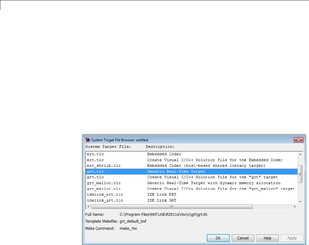
9Configuration
2Click the Browse button next to the System target file field. This opens
the System Target File Browser. The browser displays a list of currently
available target configurations, including customizations. When you
select a target configuration, the Simulink Coder software automatically
chooses the system target file, template makefile, and make command for
that configuration.
The next step shows the System Target File Browser with the generic
real-time target selected.
3Click the desired entry in the list of available configurations. The
background of the list box turns yellow to indicate an unapplied choice has
been made. To apply it, click Apply or OK.
System Target File Browser
When you choose a target configuration, the Simulink Coder software
automatically chooses the system target file, template makefile, and make
command for that configuration, and displays them in the System target
file field. The description of the target file from the browser is placed below
its name in the Code Generation pane.
9-36

Target
Selecting a System Target File Programmatically
Simulink models store model-wide parameters and target-specific data in
configuration sets. Every configuration set contains a component that defines
the structure of a particular target and the current values of target options.
Some of this information is loaded from a system target file when you select a
target using the System Target File Browser. You can configure models to
generate alternative target code by copying and modifying old or adding new
configuration sets and browsing to select a new target. Subsequently, you can
interactively select an active configuration from among these sets (only one
configuration set can be active at a given time).
Scripts that automate target selection need to emulate this process.
To program target selection
1Obtain a handle to the active configuration set with a call to the
getActiveConfigSet function.
2Define string variables that correspond to the required Simulink Coder
system target file, template makefile, and make command settings. For
example, for the ERT target, you would define variables for the strings
'ert.tlc','ert_default_tmf',and'make_rtw'.
3Select the system target file with a call to the switchTarget function. In
the function call, specify the handle for the active configuration set and
the system target file.
4Set the TemplateMakefile and MakeCommand configuration parameters to
the corresponding variables created in step 2.
For example:
cs = getActiveConfigSet(model);
stf = 'ert.tlc';
tmf = 'ert_default_tmf';
mc = 'make_rtw';
switchTarget(cs,stf,[]);
set_param(cs,'TemplateMakefile',tmf);
set_param(cs,'MakeCommand',mc);
9-37

9Configuration
Template Makefiles and Make Options
The Simulink Coder product includes a set of built-in template makefiles that
aredesignedtobuildprogramsforspecifictargets.
There are two types of template makefiles:
•Compiler-specific template makefiles are designed for use with a particular
compiler or development system.
By convention, compiler-specific template makefiles are named according to
the target and compiler (or development system). For example, grt_vc.tmf
isthetemplatemakefileforbuildinga generic real-time program under the
Visual C++ compiler; ert_lcc.tmf is the template makefile for building an
Embedded Coder program under the Lcc compiler.
•Default template makefiles make your model designs more portable, by
choosing the compiler-specific makefile and compiler for your installation.
“Choose and Configure a Compiler” on page 15-2 describes the operation of
default template makefiles in detail.
Default template makefiles are named target_default_tmf.They
are MATLAB language files that, when run, select the TMF for the
specified target configuration. For example, grt_default_tmf is the
default template makefile for building a generic real-time program;
ert_default_tmf is the default template makefile for building an
Embedded Coder program.
You can supply options to makefiles by using arguments to the Make
command field in the Code Generation pane of the Configuration
Parameters dialog box. Append the arguments after make_rtw (or make_xpc
or other make command), as in the following example:
make_rtw OPTS="-DMYDEFINE=1"
The syntax for make command options differs slightly for different compilers.
Complete details on the structure of template makefiles are provided in the
Embedded Coder documentation. This information is provided for those who
want to customize template makefiles. This section describes compiler-specific
template makefiles and common options you can use with each.
9-38

Target
Note To control compiler optimizations for your Simulink Coder makefile
build at the Simulink GUI level, use the Compiler optimization level
option on the Code Generation pane of the Configuration Parameters dialog
box. The Compiler optimization level option provides
•Target-independent values Optimizations on (faster runs) and
Optimizations off (faster builds), which allow you to easily toggle
compiler optimizations on and off during code development
•The value Custom for entering custom compiler optimization flags at
Simulink GUI level (rather than at other levels of the build process)
If you specify compiler options for your Simulink Coder makefile build using
OPT_OPTS,MEX_OPTS (except MEX_OPTS="-v"), or MEX_OPT_FILE,thevalueof
Compiler optimization level is ignored and a warning is issued about
the ignored parameter.
Template Makefiles for UNIX Platforms
ThetemplatemakefilesforUNIXplatformsaredesignedtobeusedwiththe
Free Software Foundation’s GNU Make. These makefile are set up to conform
to the guidelines specified in the IEEE®9Std 1003.2-1992 (POSIX) standard.
•ert_unix.tmf
•grt_malloc_unix.tmf
•grt_unix.tmf
•rsim_unix.tmf
•rtwsfcn_unix.tmf
You can supply options by using arguments to the make command.
•OPTS — User-specific options, for example,
make_rtw OPTS="-DMYDEFINE=1"
9.IEEE®is a registered trademark of The Institute of Electrical and Electronics Engineers,
Inc.
9-39

9Configuration
•OPT_OPTS— Optimization options. Default is -O. To enable debugging
specify as OPT_OPTS=-g. Because of optimization problems in IBM_RS, the
default is no optimization.
•CPP_OPTS — C++ compiler options.
•USER_SRCS — Additional user sources, such as files used by S-functions.
•USER_INCLUDES — Additional include paths, for example,
USER_INCLUDES="-Iwhere-ever -Iwhere-ever2"
Theseoptionsarealsodocumented in the comments at the head of the
respective template makefiles.
Template Makefiles for the Microsoft Visual C++ Compiler
The Simulink Coder product offers two sets of template makefiles designed
for use with the Visual C++ compiler.
To build an executable within the Simulink Coder build process, use one of
the target_vc.tmf template makefiles:
•ert_vc.tmf
•grt_malloc_vc.tmf
•grt_vc.tmf
•rsim_vc.tmf
•rtwsfcn_vc.tmf
You can supply options by using arguments to the make command.
•OPT_OPTS — Optimization option. Default is -O2. To enable debugging
specify as OPT_OPTS=-Zi.
•OPTS — User-specific options.
•CPP_OPTS — C++ compiler options.
•USER_SRCS — Additional user sources, such as files used by S-functions.
•USER_INCLUDES — Additional include paths, for example,
9-40

Target
USER_INCLUDES="-Iwhere-ever -Iwhere-ever2"
Theseoptionsarealsodocumented in the comments at the head of the
respective template makefiles.
Visual C++ Code Generation Only. To create a Visual C++ project
makefile (model.mak) without building an executable, use one of the
target_msvc.tmf template makefiles:
•ert_msvc.tmf
•grt_malloc_msvc.tmf
•grt_msvc.tmf
These template makefiles are designed to be used with nmake,whichis
bundled with the Visual C++ compiler.
You can supply the following options by using arguments to the nmake
command:
•OPTS — User-specific options, for example,
make_rtw OPTS="/D MYDEFINE=1"
•USER_SRCS — Additional user sources, such as files used by S-functions.
•USER_INCLUDES — Additional include paths, for example,
USER_INCLUDES="-Iwhere-ever -Iwhere-ever2"
Theseoptionsarealsodocumented in the comments at the head of the
respective template makefiles.
Template Makefiles for the Watcom C/C++ Compiler
The Simulink Coder product provides template makefiles to create an
executable for the Microsoft Windows platform using Watcom C/C++. These
template makefiles are designed to be used with wmake, which is bundled
with Watcom C/C++.
9-41

9Configuration
Note The Watcom C compiler is no longer available from the manufacturer.
However, the Simulink Coder product continues to ship with Watcom-related
template makefiles.
•ert_watc.tmf
•grt_malloc_watc.tmf
•grt_watc.tmf
•rsim_watc.tmf
•rtwsfcn_watc.tmf
You can supply options by using arguments to the make command. Note that
the location of the quotes is different from the other compilers and make
utilities discussed in this chapter.
•OPTS — User-specific options, for example,
make_rtw "OPTS=-DMYDEFINE=1"
•OPT_OPTS — Optimization options. The default optimization option is
-oxat. To turn off optimization and add debugging symbols, specify the
-d2 compiler switch in the make command, for example,
make_rtw "OPT_OPTS=-d2"
•CPP_OPTS — C++ compiler options.
•USER_OBJS — Additional user objects, such as files used by S-functions.
•USER_PATH — The folder path to the source (.c or .cpp) files that are used
to create any .obj files specified in USER_OBJS. Multiple paths must be
separated with a semicolon. For example,
USER_PATH="path1;path2"
•USER_INCLUDES — Additional include paths, for example,
USER_INCLUDES="-Iinclude-path1 -Iinclude-path2"
9-42

Target
Theseoptionsarealsodocumented in the comments at the head of the
respective template makefiles.
Template Makefiles for the LCC Compiler
The Simulink Coder product provides template makefiles to create an
executable for the Windows platform using Lcc compiler Version 2.4 and
GNU Make (gmake).
•ert_lcc.tmf
•grt_lcc.tmf
•grt_malloc_lcc.tmf
•rsim_lcc.tmf
•rtwsfcn_lcc.tmf
You can supply options by using arguments to the make command:
•OPTS — User-specific options, for example,
make_rtw OPTS="-DMYDEFINE=1"
•OPT_OPTS — Optimization options. Default is none. To enable debugging,
specify -g4 in the make command:
make_rtw OPT_OPTS="-g4"
•CPP_OPTS — C++ compiler options.
•USER_SRCS — Additional user sources, such as files used by S-functions.
•USER_INCLUDES — Additional include paths, for example,
USER_INCLUDES="-Iwhere-ever -Iwhere-ever2"
For Lcc, have a /as file separator before the filename instead of a \,for
example, d:\work\proj1/myfile.c.
Theseoptionsarealsodocumented in the comments at the head of the
respective template makefiles.
9-43

9Configuration
Enabling the Simulink Coder Software to Build When Path
Names Contain Spaces
The Simulink Coder software is able to handle path names that include
spaces. Spaces might appear in the path from several sources:
•Your MATLAB installation folder
•The current MATLAB folder in which you initiate a build
•AcompileryouareusingforaSimulinkCoderbuild
If your work environment includes one or more of the preceding scenarios, use
the following support mechanisms as they apply::
•Add the following code to your template makefile (.tmf):
ALT_MATLAB_ROOT = |>ALT_MATLAB_ROOT<|
ALT_MATLAB_BIN = |>ALT_MATLAB_BIN<|
!if "$(MATLAB_ROOT)" != "$(ALT_MATLAB_ROOT)"
MATLAB_ROOT = $(ALT_MATLAB_ROOT)
!endif
!if "$(MATLAB_BIN)" != "$(ALT_MATLAB_BIN)"
MATLAB_BIN = $(ALT_MATLAB_BIN)
!endif
This code replaces MATLAB_ROOT with ALT_MATLAB_ROOT when the values
of the two tokens are not equal, indicating the path for your MATLAB
installation folder includes spaces. Likewise, ALT_MATLAB_BIN replaces
MATLAB_BIN.
Note the preceding code is specific to nmake. See the supplied Simulink
Coder template make files for platform-specific examples.
•When using operating system commands, such as system or dos,enclose
path that specify executables or command parameters in double quotes
(""). For example,
system('dir "D:\Applications\Common Files"')
Custom Targets
You can create your own system target files to build custom targets that
interface with external code or operating environments.
9-44

Target
See “About Embedded Target Development” on page 24-2 and the topics it
references for details and examples showing how to make your custom targets
appear in the System Target File Browser and display relevant controls in
panes of the Configuration Parameters dialog box.
Describing the Emulation and Embedded Targets
The Configuration Parameters dialog Hardware Implementation pane
provides options that you can use to describe hardware properties, such as
data size and byte ordering, and compiler behavior details that may vary with
the compiler, such as integer rounding. The Hardware Implementation
pane contains two subpanes:
•Embedded Hardware — Describes the embedded target hardware
and the compiler that you will use with it. This information affects both
simulation and code generation.
•Emulation Hardware — Describes the emulation target hardware and
the compiler that you will use with it. This information affects only code
generation.
The two subpanes provide identical options and value choices. By default, the
Embedded Hardware subpane initially looks like this:
The default assumption is that the embedded target and emulation target are
the same, so the Emulation Hardware subpane by default does not need
to specify anything and contains only a checked option labeled None.Code
generated under this configuration will be suitable for production use, or for
testing in an environment identical to the production environment.
9-45

9Configuration
If you clear the check box, the Emulation Hardware subpane appears,
initially showing the same values as the Embedded Hardware subpane. If
you change any of these values, then generate code, the code will be able to
execute in the environment specified by the Emulation Hardware subpane,
but will behave as if it were executing in the environment specified by the
Embedded Hardware subpane. See “Describing Emulation Hardware
Characteristics” on page 9-55 for details.
If you have used the Code Generation pane to specify a System target
file, and the target file specifies a default microprocessor and its hardware
properties, the default and properties appear as initial values in the
Hardware Implementation pane.
Options with only one possible value cannot be changed. Any option that has
more than one possible value provides a list of legal values. If you specify
any hardware properties manually, check carefully that their values are
consistent with the system target file. Otherwise, the generated code may fail
to compile or execute, or may execute but give incorrect results.
Note Hardware Implementation pane options do not control hardware or
compiler behavior in any way. Their purpose is solely to describe hardware
and compiler properties to MATLAB software, which uses the information to
generate code for the platform thatruns as efficiently as possible, and gives
bit-true agreement for the results of integer and fixed-point operations in
simulation, production code, and test code.
The rest of this section describes the options in the Embedded Hardware
and Emulation Hardware subpanes. Subsequent sections describe
considerations that apply only to one or the other subpane. For more about
Hardware Implementation options, see “Hardware Implementation Pane”.
To see an example of Hardware Implementation pane capabilities, run the
rtwdemo_targetsettings example.
Describing the Device Vendor
The Device vendor option gives the name of the device vendor. To set the
option, select a vendor name from the Device vendor menu. Your selection
ofvendorwilldeterminetheavailabledevicevaluesintheDevice type list.
9-46

Target
If the desired vendor name does not appear in the menu, select Generic and
then use the Device type option to further specify the device.
Note
•For complete lists of Device vendor and Device type values, see “Device
vendor” and “Device type” in the Simulink reference documentation.
•To add Device vendor and Device type values to the default set that
is displayed on the Hardware Implementation pane, see “Registering
Additional Device Vendor and Device Type Values” on page 9-47.
Describing the Device Type
The Device type option selects a hardware device among the supported
devices listed for your Device vendor selection. To set the option, select
a microprocessor name from the Device type menu. If the desired
microprocessor does not appear in the menu, change the Device vendor
to Generic.
If you specified Device vendor as Generic,examinethelisteddevice
descriptions and select the device type that matches your hardware. If no
available device type matches, select Custom.
If you select a device type for which the target file specifies default hardware
properties, the properties appear as initial values in the subpane. Options
with only one possible value cannot be changed. Any option that has more
than one possible value provides a list of legal values. Select values for your
hardware. If the device type is Custom, more options can be set, and each
option has a list of possible values.
Registering Additional Device VendorandDeviceTypeValues
To add Device vendor and Device type values to the default set that is
displayed on the Hardware Implementation pane, you can use a hardware
device registration API provided by the Simulink Coder software.
9-47

9Configuration
TousethisAPI,youcreateansl_customization.m file, located in your
MATLAB path, that invokes the registerTargetInfo function and fills
in a hardware device registry entry with device information. The device
information will be registered with Simulink software for each subsequent
Simulink session. (To register your device information without restarting
MATLAB, issue the MATLAB command sl_refresh_customizations.)
For example, the following sl_customization.m file adds device vendor
MyDevVendor and device type MyDevType to the Simulink device lists.
function sl_customization(cm)
cm.registerTargetInfo(@loc_register_device);
end
function thisDev = loc_register_device
thisDev = RTW.HWDeviceRegistry;
thisDev.Vendor = 'MyDevVendor';
thisDev.Type = 'MyDevType';
thisDev.Alias = {};
thisDev.Platform = {'Prod', 'Target'};
thisDev.setWordSizes([8 16 32 32 32]);
thisDev.LargestAtomicInteger = 'Char';
thisDev.LargestAtomicFloat = 'None';
thisDev.Endianess = 'Unspecified';
thisDev.IntDivRoundTo = 'Undefined';
thisDev.ShiftRightIntArith = true;
thisDev.setEnabled({'IntDivRoundTo'});
end
If you subsequently select the device in the Hardware Implementation
pane, it is displayed as follows:
9-48
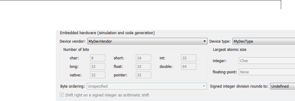
Target
To register multiple devices, you can specify an array of
RTW.HWDeviceRegistry objects in your sl_customization.m file. For
example,
function sl_customization(cm)
cm.registerTargetInfo(@loc_register_device);
end
function thisDev = loc_register_device
thisDev(1) = RTW.HWDeviceRegistry;
thisDev(1).Vendor = 'MyDevVendor';
thisDev(1).Type = 'MyDevType1';
...
thisDev(4) = RTW.HWDeviceRegistry;
thisDev(4).Vendor = 'MyDevVendor';
thisDev(4).Type = 'MyDevType4';
...
end
ThefollowingtableliststheRTW.HWDeviceRegistry properties that you can
specify in the registerTargetInfo function call in your sl_customization.m
file.
9-49

9Configuration
Property Description
Vendor String specifying the Device vendor value for your
hardware device.
Type String specifying the Device type value for your
hardware device.
Alias Cell array of strings specifying any aliases or
legacy names that users might specify that
should resolve to this device. Specify each alias
or legacy name in the format 'Vendor->Type'.
(Embedded Coder software provides the
utility functions RTW.isHWDeviceTypeEq and
RTW.resolveHWDeviceType for detecting and
resolving alias values or legacy values when testing
user-specified values for the target device type.)
Platform Cell array of enumerated string values specifying
whether this device should be listed in the
Embedded hardware subpane ({'Prod'}), the
Emulation hardware subpane ({'Target'}), or
both ({'Prod', 'Target'}).
setWordSizes Array of integer sizes to associate with the Number
of bits parameters char,short,int,long,and
native word size,respectively.
LargestAtomicInteger
String specifying an enumerated value for the
Largest atomic size: integer parameter: 'Char',
'Short','Int',or'Long'.
LargestAtomicFloat String specifying an enumerated value for the
Largest atomic size: floating-point parameter:
'Float','Double',or'None'.
Endianess String specifying an enumerated value for the Byte
ordering parameter: 'Unspecified','Little' for
little Endian, or 'Big' for big Endian.
IntDivRoundTo String specifying an enumerated value for the
Signed integer division rounds to parameter:
'Zero','Floor',or'Undefined'.
9-50

Target
Property Description
ShiftRightIntArith Boolean value specifying whether your compiler
implements a signed integer right shift as an
arithmetic right shift (true)ornot(false).
setEnabled Cell array of strings specifying which device
properties should be enabled (modifiable) in
the Hardware Implementation pane when
this device type is selected. In addition to
the 'Endianess','IntDivRoundTo',and
'ShiftRightIntArith' properties listed above, you
can enable individual Number of bits parameters
using the property names 'BitPerChar',
'BitPerShort','BitPerInt','BitPerLong',and
'NativeWordSize'.
Describing the Number of Bits
The Number of bits options describe the native word size of the
microprocessor, and the bit lengths of char,short,int,andlong data. For
code generation to succeed:
•The bit lengths must be such that char <= short <= int <= long.
•Bit lengths must be multiples of 8, with a maximum of 32.
•The bit length for long data must not be less than 32.
Simulink Coder integer type names are defined in the file rtwtypes.h.The
values that you provide must be consistent with the word sizes as defined in
the compiler’s limits.h header file. The following table lists the standard
Simulink Coder integer type names and maps them to the corresponding
Simulink names.
Simulink Coder Integer
Type
Simulink Integer Type
boolean_T boolean
int8_T int8
uint8_T uint8
9-51

9Configuration
Simulink Coder Integer
Type
Simulink Integer Type
int16_T int16
uint16_T uint16
int32_T int32
uint32_T uint32
If no ANSI C type with a matching word size is available, but a larger ANSI C
type is available, the Simulink Coder code generator uses the larger type for
int8_T,uint8_T,int16_T,uint16_T,int32_T, and uint32_T.
An application can use integer data of any length from 1 (unsigned) or 2
(signed) bits up 32 bits. If the integer length matches the length of an
available type, the Simulink Coder code generator uses that type. If no
matching type is available, the code generator uses the smallest available
type that can hold the data, generating code that never uses unnecessary
higher-order bits. For example, on a target that provided 8-bit, 16-bit, and
32-bit integers, a signal specified as 24 bits would be implemented as an
int32_T or uint32_T.
Code that uses emulated integer data is not maximally efficient, but can be
useful during application development for emulating integer lengths that are
available only on production hardware. The use of emulation does not affect
the results of execution.
Describing the Byte Ordering
The Byte ordering option specifies whether the target hardware uses Big
Endian (most significant byte first) or Little Endian (least significant byte
first) byte ordering. If left as Unspecified, the Simulink Coder software
generates code that determines the endianness of the target; this is the least
efficient option.
Describing Quotient Rounding for Signed Integer Division
ANSI C does not completely define the rounding technique to be
used when dividing one signed integer by another, so the behavior is
implementation-dependent. If both integers are positive, or both are negative,
9-52

Target
the quotient must round down. If either integer is positive and the other is
negative, the quotient can round up or down.
The Signed integer division rounds to parameter tells the Simulink
Coder code generator how the compiler rounds the result of signed integer
division. Providing this information does not affect the operation of the
compiler, it only describes that behavior to the code generator, which uses
the information to optimize code generated for signed integer division. The
parameter options are:
•Zero — If the quotient is between two integers, the compiler chooses the
integer that is closer to zero as the result.
•Floor — If the quotient is between two integers, the compiler chooses the
integer that is closer to negative infinity.
•Undefined — Choose this option if neither Zero nor Floor describes the
compiler’s behavior, or if that behavior is unknown.
The following table illustrates the compiler behavior that corresponds to each
of these three options:
ND
Ideal
N/D Zero Floor Undefined
33 48.25 8 8 8
-33 4 -8.25 -8 -9 -8 or -9
33 -4 -8.25 -8 -9 -8 or -9
-33 -4 8.25 8 8 8 or 9
Note Select Undefined only as a last resort. When the code generator does
not know the signed integer division rounding behavior of the compiler, it
generates extra code.
The compiler’s implementation for signed integer division rounding can
be obtained from the compiler documentation, or by experiment if no
documentation is available.
9-53

9Configuration
Describing Arithmetic Right Shifts on Signed Integers
ANSI C does not define the behavior of right shifts on negative integers, so
the behavior is implementation-dependent. The Shift right on a signed
integer as arithmetic shift parameter tells the Simulink Coder code
generator how the compiler implements right shifts on negative integers.
Providing this information does not affect the operation of the compiler, it
only describes that behavior to the code generator, which uses the information
to optimize the code generated for arithmetic right shifts.
Select the option if the C compiler implements a signed integer right shift as
an arithmetic right shift, and clear the option otherwise. An arithmetic right
shift fills bits vacated by the right shift with the value of the most significant
bit, which indicates the sign of the number in twos complement notation.
The option is selected by default. If your compiler handles right shifts as
arithmetic shifts, this is the preferred setting.
•When the option is selected, the Simulink Coder software generates simple
efficient code whenever the Simulink model performs arithmetic shifts on
signed integers.
•When the option is cleared, the Simulink Coder software generates fully
portable but less efficient code to implement right arithmetic shifts.
The compiler’s implementation for arithmetic right shifts can be obtained
from the compiler documentation, or by experiment if no documentation is
available.
Describing Embedded Hardware Characteristics
“Describing the Emulation and Embedded Targets” on page 9-45 documents
the options available on the Hardware Implementation subpanes. This
section describes considerations that apply only to the Embedded Hardware
subpane. When you use this subpane, keep the following in mind:
•Code generation targets can have word sizes and other hardware
characteristics that differ from the MATLAB host. Furthermore, code can
be prototyped on hardware that is different from either the deployment
target or the MATLAB host. The Simulink Coder code generator takes
these differences into account when generating code.
9-54

Target
•The Simulink product uses some of the information in the Embedded
Hardware subpanetogetthesameresultsfromsimulationwithout
code generation as executing generated code, including detecting error
conditions that could arise on the target hardware, such as hardware
overflow.
•The Simulink Coder software generates code that produces bit-true
agreement with Simulink results for integer and fixed-point operations.
Generated code that emulates unavailable data lengths runs less efficiently
than it would without emulation, but the emulation does not affect bit-true
agreement with Simulink for integer and fixed-point results.
•If you change targets at any point during application development,
reconfigure the hardware implementation parameters for the new target
before generating or regenerating code. Bit-true agreement for the results
of integer and fixed-point operations in simulation, production code, and
test code might not occur when code executes on hardware for which it
was not generated.
•Use the Integer rounding mode parameter on your model’s blocks to
simulate the rounding behavior of the C compiler that you intend to use
to compile code generated from the model. This setting appears on the
Signal Attributes pane of the parameter dialog boxes of blocks that can
perform signed integer arithmetic, such as the Product and n-D Lookup
Table blocks.
•For most blocks, the value of Integer rounding mode completely defines
rounding behavior. For blocks that support fixed-point data and the
Simplest rounding mode, the value of Signed integer division rounds to
also affects rounding. For details, see “Rounding”.
•When models contain Model blocks, all models that they reference must
be configured to use identical hardware settings.
Describing Emulation Hardware Characteristics
“Describing the Emulation and Embedded Targets” on page 9-45 documents
the options available on the Hardware Implementation subpanes. This
section describes considerations that apply only to the Emulation Hardware
subpane.
9-55
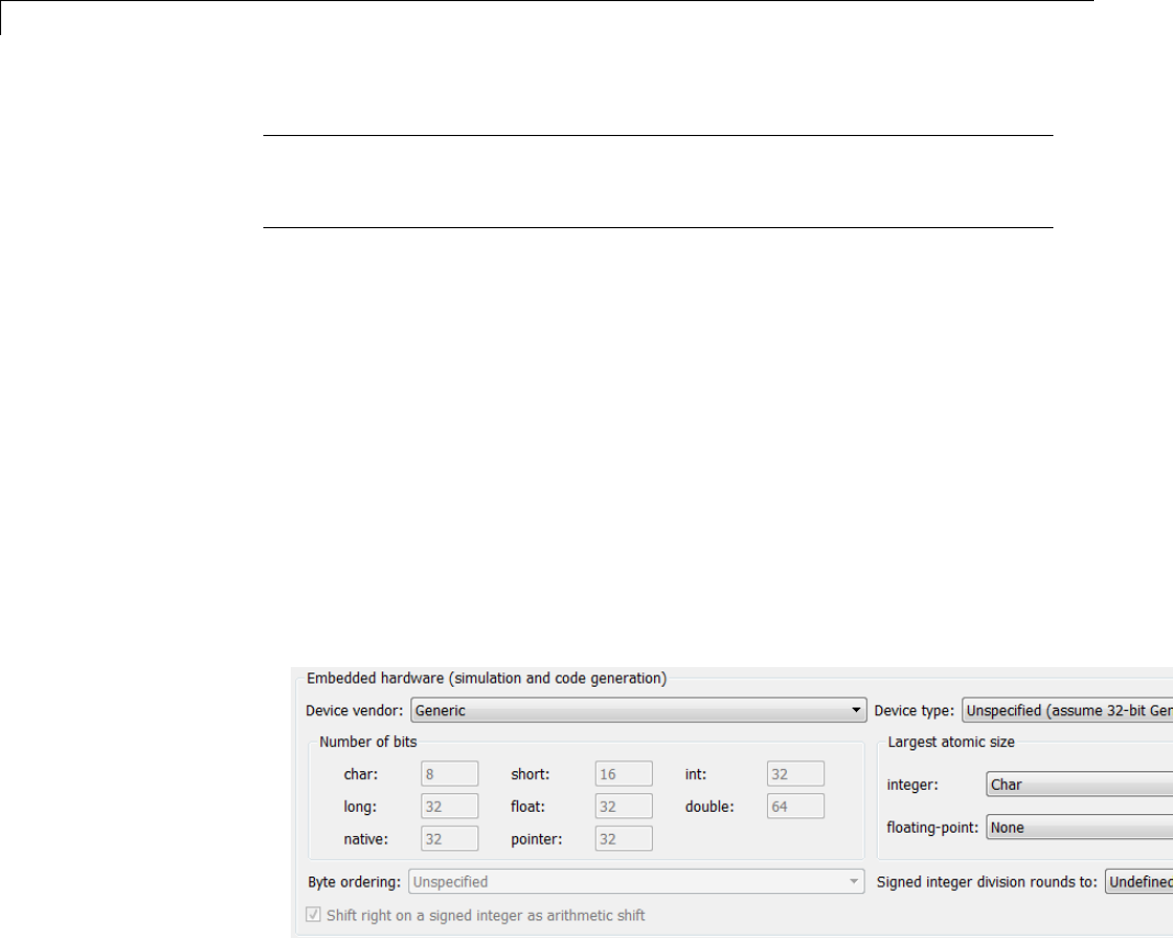
9Configuration
Note (If the Emulation Hardware subpane contains a button labeled
Configure current execution hardware device, see “Updating from
Earlier Versions” on page 9-57, then continue from this point.)
The default assumption is that the embedded target and emulation target are
the same, so the Emulation Hardware subpane by default does not need to
specify anything and contains only a selected check box labeled None.Code
generated under this configuration will be suitable for production use, or for
testing in an environment identical to the production environment.
To generate code that runs on an emulation target for test purposes, but
behaves as if it were running on an embedded target in a production
application, you must specify the properties of both targets in the Hardware
Implementation pane. The Embedded Hardware subpane specifies
embedded target hardware properties, as described previously. To specify
emulation target properties:
1Clear the None option in the Emulation Hardware subpane.
2In the Emulation Hardware subpane, specify the properties of the
emulation target, using the instructions in “Describing the Emulation and
Embedded Targets” on page 9-45
If you have used the Code Generation pane to specify a System target
file, and the target file specifies a default microprocessor and its hardware
properties, the default and properties appear as initial values in both
subpanes of the Hardware Implementation pane.
9-56
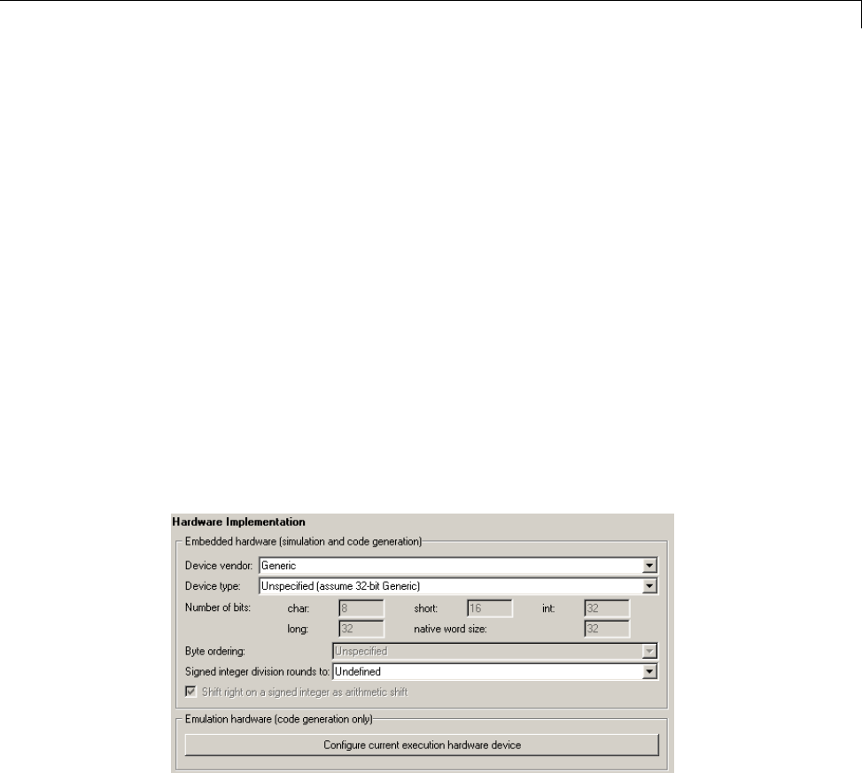
Target
Options with only one possible value cannot be changed. Any option that has
more than one possible value provides a list of legal values. If you specify
any hardware properties manually, check carefully that their values are
consistent with the system target file. Otherwise, the generated code may fail
to compile or execute, or may execute but give incorrect results.
If you do not display the Emulation Hardware subpane, the Simulink and
Simulink Coder software defaults every Emulation Hardware option to
have the same value as the corresponding Embedded Hardware option.
If you hide the Emulation Hardware subpane after setting its values,
the values that you specified will be lost. The underlying configuration
parameters immediately revert to the values that they had when you exposed
the subpane, and these values, rather than the values that you specified, will
appear if you re-expose the subpane.
Updating from Earlier Versions
If your model was created before Release 14 and has not been updated, by
default the Hardware Implementation pane initially looks like this:
Click Configure current execution hardware device.TheConfigure
current execution hardware device button disappears. The subpane then
appears as shown in the first figure in this section. Save your model at this
point to avoid redoing Configure current execution hardware device
next time you access the Hardware Implementation pane.
9-57

9Configuration
Specifying Target Interfaces
Use the Interface pane to control which math library is used at run time,
whether to include one of three APIs in generated code, and certain other
interface options.
To... Select or Enter...
Specify the target-specific
math library to use when
generating code
Select C89/C90 (ANSI),C99 (ISO),GNU99 (GNU),orC++ (ISO)
for Code replacement library. (Additional values may be listed
forlicensedtargetproducts,forEmbeddedTargetsandDesktop
Targets, or if you have created and registered code replacement
libraries with the Embedded Coder product.)
Selecting C89/C90 (ANSI) provides the ANSI10 C set of library
functions. For example, selecting C89/C90 (ANSI) would result in
generated code that calls sin() whether the input argument is
double precision or single precision. However, if you select C99
(ISO), the call instead is to the function sinf(), which is single
precision. If your compiler supports the ISO11 C math extensions,
selecting the ISO C library can result in more efficient code.
For more information about code replacement libraries, see
“Selecting and Viewing Code Replacement Libraries” on page 9-61.
Direct where the Simulink
Coder code generator
should place fixed-point
and other utility code
Select Auto or Shared location for Shared code placement.
The shared location directs code for utilities to be placed within
the slprj folder in your working folder, which is used for building
model reference targets. If you select Auto,
•When the model contains Model blocks, places utility code within
the slprj/target/_sharedutils folder.
•When the model does not contain Model blocks, places utility
code in the build folder (generally, in model.c or model.cpp).
10. ANSI®is a registered trademark of the American National Standards Institute, Inc.
11. ISO®is a registered trademark of the International Organization for Standardization.
9-58

Target
To... Select or Enter...
Specify a string to be
added to the variable
names used when logging
data to MAT-files, to
distinguish logging data
from Simulink Coder and
Simulink applications
Enter a prefix or suffix, such as rt_ or _rt,forMAT-file variable
name modifier. The Simulink Coder code generator prefixes
or appends the string to the variable names for system outputs,
states, and simulation time specified in the Data Import/Export
pane. See “Logging” on page 15-105 for information on MAT-file
data logging.
Specify an API to be
included in generated code
Select C API,External mode,orASAP2 for Interface.Whenyou
select CAPIor External mode, other options appear. C API and
External mode are mutually exclusive. However, this is not the
case for CAPIand ASAP2. For more information on working with
these interfaces, see “Data Interchange Using the C API” on page
15-137, “Host/Target Communication” on page 15-50, and “ASAP2
Data Measurement and Calibration” on page 15-174.
Note Before setting Code replacement library, verify that your compiler
supports the library you want to use. If you select a parameter value that
your compiler does not support, compiler errors can occur. For example, if
you select C99 (ISO) and your compiler does not support the ISO C math
extensions, compile-time errors likely will occur.
When the Embedded Coder product is installed on your system, the Code
Generation > Interface pane expands to include several additional options.
For descriptions of Code Generation > Interface pane parameters, see
“Code Generation Pane: Interface”. For a summary of option dependencies,
see “Interface Dependencies” on page 9-59.
Interface Dependencies
Several parameters available on the Interface pane have dependencies
on settings of other parameters. The following table summarizes the
dependencies.
9-59

9Configuration
Parameter Dependencies? Dependency Details
Code replacement library No
Shared code placement No
Support: floating-point
numbers (ERT targets only)
No
Support: non-finite numbers Yes (ERT targets)
No (GRT targets)
For ERT targets, enabled by Support
floating-point numbers
Support: complex numbers
(ERT targets only)
No
Support: absolute time (ERT
targets only)
No
Support: continuous time
(ERT targets only)
No
Support: non-inlined
S-functions (ERT targets
only)
Yes Requires that you enable Support
floating-point numbers and
Support non-finite numbers
Classiccallinterface Yes (ERTtargets)
No (GRTtargets)
For ERT targets, requires that you
enable Support floating-point
numbers and disable Single
output/update function
Single output/update function
(ERT targets only)
Yes Disable for Classic call interface
Terminate function required
(ERT targets only)
Yes
Generate reusable code (ERT
targets only)
Yes
Reusable code error
diagnostic (ERT targets only)
Yes Enabled by Generate reusable code
9-60

Target
Parameter Dependencies? Dependency Details
Pass root-level I/O as (ERT
targets only)
Yes Enabled by Generate reusable code
MAT-file logging Yes For GRT targets, requires that you
enable Support non-finite numbers;
for ERT targets, requires that you
enable Support floating-point
numbers,Support non-finite
numbers,andTerminate function
required
MAT-file file variable name
modifier
Yes Enabled by MAT-file logging
Suppress error status in
real-time model data structure
(ERT targets only)
No
Interface No
Generate C API for: signals Yes Set Interface to C API
Generate C API for:
parameters
Yes Set Interface to C API
Generate C API for: states Yes Set Interface to C API
Transport layer Yes Set Interface to External mode
MEX-file arguments Yes Set Interface to External mode
Static memory allocation Yes Set Interface to External mode
Static memory buffer size Yes Enable Static memory allocation
Selecting and Viewing Code Replacement Libraries
•“Selecting a Target-Specific Math Library for Your Model” on page 9-62
•“Code Replacement Table Overview” on page 9-63
•“Using the Code Replacement Viewer” on page 9-65
9-61

9Configuration
Selecting a Target-Specific Math Library for Your Model
Acode replacement library (CRL) is a set of one or more code replacement
tables that define the target-specific implementations of math functions
and operators to be used in generatingcodeforyourSimulinkmodel.
The Simulink Coder product provides default CRLs, which you can
select from the Code replacement library drop-down list on the Code
Generation > Interface pane of the Configuration Parameters dialog box.
CRL Description Contains tables...
C89/C90
(ANSI)
Generates calls to the ISO/IEC 9899:1990
C standard math library for floating-point
functions.
ansi_tfl_table_tmw.mat
C99 (ISO) Generates calls to the ISO/IEC 9899:1999 C
standard math library.
iso_tfl_table_tmw.mat
ansi_tfl_table_tmw.mat
GNU99 (GNU) Generates calls to the Free Software
Foundation’s GNU gcc math library, which
provides C99 extensions as defined by compiler
option -std=gnu99.
gnu_tfl_table_tmw.mat
iso_tfl_table_tmw.mat
ansi_tfl_table_tmw.mat
C++ (ISO) Generates calls to the ISO/IEC 14882:2003
C++ standard math library.
iso_cpp_tfl_table_tmw.mat
private_iso_cpp_tfl_table_tmw.mat
iso_tfl_table_tmw.mat
ansi_tfl_table_tmw.mat
CRL tables provide the basis for replacing default math functions and
operators in your model code with target-specific code. If you select a library
and then hover over the selected library with the cursor, a tool tip is displayed
that describes the CRL and lists the code replacement tables it contains.
Tables are listed in the order in which they are searched for a function or
operator match.
9-62

Target
The Simulink Coder product allows you to view the content of CRL code
replacement tables using the Code Replacement Viewer, as described in
“Using the Code Replacement Viewer” on page 9-65. If you are licensed to
use the Embedded Coder product, you additionally can create and register
the code replacement tables that make up a CRL.
Code Replacement Table Overview
Each CRL code replacement table contains one or more table entries, with
each table entry representing a potential replacement for a single math
function or an operator. Each table entry provides a mapping between a
conceptual view of the function or operator (similar to the Simulink block
view of the function or operator) and a target-specific implementation of that
function or operator.
The conceptual view of a function or operator is represented in a CRL table
entry by the following elements, which identify the function or operator entry
to the code generation process:
9-63

9Configuration
•A function or operator key (a function name such as 'cos' or an operator
ID string such as 'RTW_OP_ADD')
•A set of conceptual arguments that observe Simulink naming ('y1','u1',
'u2', ...), along with their I/O types (output or input) and data types
•Other attributes, such as fixed-point saturation and rounding
characteristics for operators, to identify the function or operator to the code
generation process as exactly as required for matching purposes
The target-specific implementation of a function or operator is represented in
a CRL table entry by the following elements:
•Thenameofanimplementationfunction(suchas'cos_dbl' or
'u8_add_u8_u8')
•A set of implementation arguments, along with their I/O types (output or
input) and data types
•Parameters providing the build information for the implementation
function, including header file and source file names and paths
Additionally, a CRL table entry includes a priority value (0-100, with 0 as the
highest priority), which defines the entry’s priority relative to other entries
in the table.
During code generation for your model, when the code generation process
encounters a call site for a math function or operator, it creates and partially
populates a CRL entry object, for the purpose of querying the CRL for a
replacement function. The information provided for the CRL query includes
the function or operator key and the conceptual argument list. The CRL
entry object is then passed to the CRL. If the CRL contains a matching table
entry, a fully-populated CRL entry, including the implementation function
name, argument list, and build information, is returned to the call site and
used to generate code.
Within the CRL that is selected for your model, the tables that comprise the
CRL are searched in the order in which they are listed (in the left or right
pane of the Code Replacement Viewer or in the CRL’s Code replacement
library tool tip). Within each table, if multiple matches are found for a
CRL entry object, priority level determines the match that is returned. A
9-64
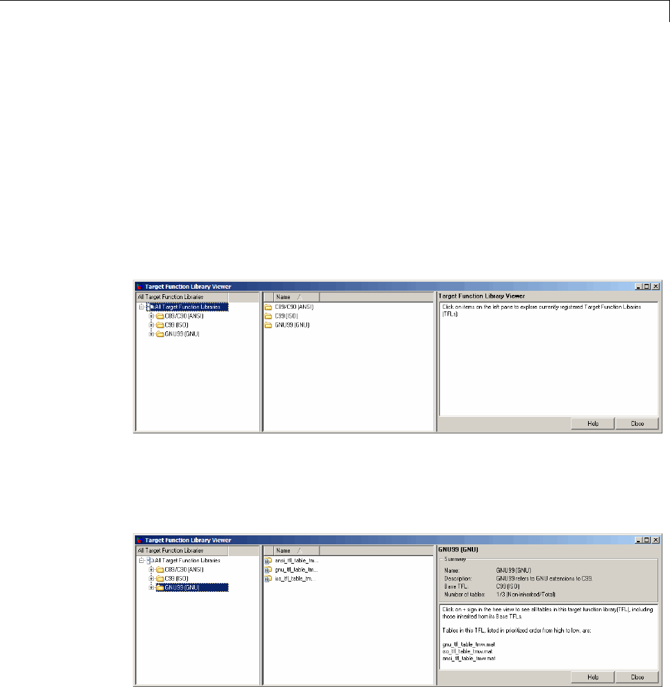
Target
higher-priority (lower-numbered) entry will be used over a similar entry with
a lower priority (higher number).
Using the Code Replacement Viewer
The Code Replacement Viewer allows you to examine the content of CRL code
replacement tables. (For an overview of code replacement tables and the
information they contain, see the preceding section.) To launch the viewer
with all currently registered CRLs displayed, issue the following MATLAB
command:
>> RTW.viewTfl
SelectthenameofaCRLintheleftpane,and the viewer displays information
about the CRL in the right pane. For example, the tables that make up the
CRL are listed in priority order. In the following display, the GNU CRL has
been selected.
Click the plus sign (+) next to a CRL name in the left pane to expand its list
of tables, and select a table from the list. The viewer displays the function
9-65
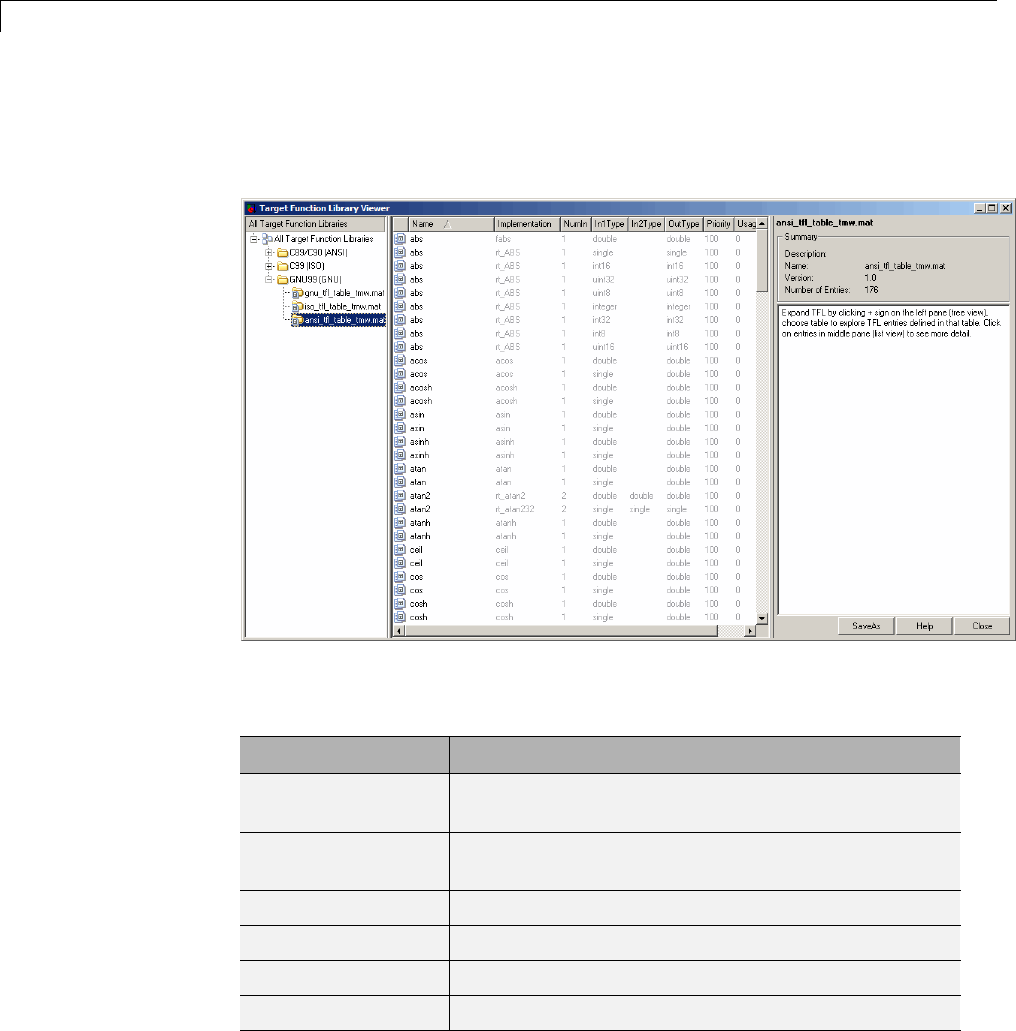
9Configuration
and operator entries in the selected table in the middle pane, along with
abbreviated table entry information for each entry. In the following display,
the ANSI table has been selected.
The following fields appear in the abbreviated table entry information
provided in the middle pane:
Field Description
Name Name of the function or ID of the operator to be
replaced (for example, cos or RTW_OP_ADD).
Implementation Name of the implementation function, which can
matchordifferfromName.
NumIn Number of input arguments.
In1Type Data type of the first conceptual input argument.
In2Type Data type of the second conceptual input argument.
OutType Data type of the conceptual output argument.
9-66
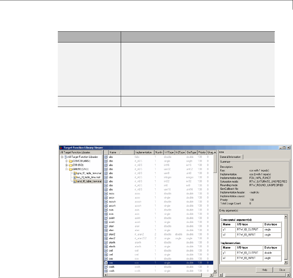
Target
Field Description
Priority The entry’s search priority, 0-100, relative to other
entries of the same name and conceptual argument
list within this table. Highest priority is 0, and
lowest priority is 100. The default is 100. If the
table provides two implementations for a function
or operator, the implementation with the higher
priority will shadow the one with the lower priority.
UsageCount Not used.
Select a function or operator entry in the middle pane. The viewer displays
detailed information from the table entry in the right pane. In the following
display, the second entry for the cos function has been selected.
The following fields appear in the detailed table entry information provided
in the right pane.
9-67

9Configuration
Field Description
Description Text description of the table entry (can be empty).
Key Name of the function or ID of the operator to be replaced
(for example, cos or RTW_OP_ADD), and the number of
conceptual input arguments.
Implementation Name of the implementation function, and the number
of implementation input arguments.
Implementation
type
Type of implementation: FCN_IMPL_FUNCT for
function or FCN_IMPL_MACRO for macro.
Saturation
mode
Saturation mode supported by the implementation
function for an operator replacement:
RTW_SATURATE_ON_OVERFLOW,
RTW_WRAP_ON_OVERFLOW, or
RTW_SATURATE_UNSPECIFIED.
Rounding mode Rounding mode supported by the implementation
function for an operator replacement:
RTW_ROUND_FLOOR, RTW_ROUND_CEILING,
RTW_ROUND_ZERO, RTW_ROUND_NEAREST,
RTW_ROUND_NEAREST_ML,
RTW_ROUND_SIMPLEST, RTW_ROUND_CONV, or
RTW_ROUND_UNSPECIFIED.
GenCallback
file
Not used.
Implementation
header
Nameoftheheaderfilethatdeclares the implementation
function.
Implementation
source
Name of the implementation source file.
Priority The entry’s search priority,0-100,relativetoother
entries of the same name and conceptual argument
list within this table. Highest priority is 0, and lowest
priority is 100. The default is 100. If the table provides
two implementations for a function or operator, the
implementation with the higher priority will shadow the
one with the lower priority.
9-68

Target
Field Description
Total Usage
Count
Not used.
Conceptual
argument(s)
Name, I/O type (RTW_IO_OUTPUT or
RTW_IO_INPUT), and data type for each conceptual
argument.
Implementation Name, I/O type (RTW_IO_OUTPUT or
RTW_IO_INPUT), and data type for each
implementation argument.
Ifyouselectanoperatorentry,anadditional tab containing fixed-point
setting information is displayed in the right pane. For example:
The following fields appear in the fixed-point setting information provided
in the right pane:
9-69

9Configuration
Field Description
Slopes must be
the same
Indicates whether CRL replacement request processing
must check that the slopes on all arguments (input and
output) are equal. Used with fixed-point addition and
subtraction replacement to disregard specific slope and
bias values and map relative slope and bias values to a
replacement function.
Must have zero
net bias
Indicates whether CRL replacement request processing
must check that the net bias on all arguments is
zero. Used with fixed-point addition and subtraction
replacement to disregard specific slope and bias values
and map relative slope and bias values to a replacement
function.
Relative
scaling factor
F
Slope adjustment factor (F) part of the relative scaling
factor, F2E, for relative scaling CRL entries. Used with
fixed-point multiplication and division replacement to
map a range of slope and bias values to a replacement
function.
Relative
scaling factor
E
Fixed exponent (E) part of the relative scaling factor,
F2E, for relative scaling CRL entries. Used with
fixed-point multiplication and division replacement to
map a range of slope and bias values to a replacement
function.
9-70

Select the Target Language
Select the Target Language
Use the Language menu in the Target selection section of the Code
Generation pane to select the target language for the code generated by
the Simulink Coder code generator. You can select C or C++. The Simulink
Coder software generates .c or .cpp files, depending on your selection, and
places the files in your build folder.
Note If you select C++, you might need to configure the Simulink Coder
software to use a compiler before you build a system. For details, see “Choose
and Configure a Compiler” on page 15-2.
9-71

9Configuration
Code Appearance
In this section...
“Configure Code Comments” on page 9-72
“Configure Generated Identifiers” on page 9-73
Configure Code Comments
Configure how the code generator inserts comments into generated code, by
modifying parameters on the Comments pane.
Note Comments can include international (non-US-ASCII) characters
encountered during code generation when found in Simulink block names and
block descriptions, user comments on Stateflow diagrams, Stateflow object
descriptions, custom TLC files, and code generation template files.
To... Select...
Include comments in
generated code
Include comments. Selecting this parameter allows you to select one
or more comment types to be placed in the code.
Include comments
for blocks that
were eliminated
as the result
of optimizations
(such as parameter
inlining)
Show eliminated blocks.
9-72

Code Appearance
To... Select...
Automatically insert
comments that
describe a block’s
code before the code
in the generated file
Simulink block / Stateflow object comments.
Include comments for
parameter variable
names and names
of source blocks in
the model parameter
structure declaration
in model_prm.h
Verbose comments for SimulinkGlobal storage class.Ifyoudonot
select this parameter, parameter comments are generated if less than
1000 parameters are declared. This reduces the size of the generated file
for models with a large number of parameters. When you select the
parameter, parameter comments are generated regardless of the number
of parameters.
For descriptions of Comments pane parameters, see “Code Generation Pane:
Comments” in the Simulink Coder reference documentation.
Configure Generated Identifiers
•“Reserved Keywords” on page 9-74
•“Construction of Symbols” on page 9-78
Configure how the code generator uses symbols to name identifiers and
objects by setting parameters on the Symbols pane.
Two options are available for GRT targets: Maximum identifier length and
Reserved names. These are the only symbols options for GRT targets.
The Maximum identifier length field allows you to limit the number of
characters in function, type definition, and variable names. The default is 31
characters. This is also the minimum lengthyoucanspecify;themaximum
is 256 characters. Consider increasing identifier length for models having
a deep hierarchical structure, and when exercising some of the mnemonic
identifier options described below.
Within a model containing Model blocks, no collisions of constituent model
names can exist. When generating code from a model that uses model
9-73

9Configuration
referencing, the Maximum identifier length must be large enough to
accommodate the root model name and the name mangling string (if any). A
code generation error occurs if Maximum identifier length is too small.
When a name conflict occurs between a symbol within the scope of a higher
level model and a symbol within the scope of a referenced model, the symbol
from the referenced model is preserved. Name mangling is performed on the
symbol from the higher level model.
The Reserved names field allows you to specify the set of keywords that
the Simulink Coder code generation process should not use, facilitating code
integration where functions and variables from external environments are
unknown in the Simulink model. For a list of rules for specifying reserved
names, see “Reserved names” in the Simulink Coder reference documentation.
If your model contains MATLAB Function or Stateflow blocks, the code
generation process can use the reserved names specified for those blocks if
you select Use the same reserved names as Simulation Target.
If the Embedded Coder product is installed on your system, the Symbols
pane expands to include options for controlling identifier formats, mangle
length, scalar inlined parameters, and Simulink data object naming rules.
For details, see “Customize Generated Identifiers” in the Embedded Coder
documentation.
For descriptions of Symbols pane parameters, see “Code Generation Pane:
Symbols”.
Reserved Keywords
•“C Reserved Keywords” on page 9-75
•“C++ Reserved Keywords” on page 9-75
•“Reserved Keywords for Code Generation” on page 9-76
•“Simulink®Coder™ Code Replacement Library Keywords” on page 9-76
SimulinkCodersoftwarereservescertainwordsforitsownuseaskeywords
of the generated code language. Simulink Coder keywords are reserved for
use internal to Simulink Coder software and should not be used in Simulink
9-74

Code Appearance
models as identifiers or function names. C reserved keywords should also not
be used in Simulink models as identifiers or function names. If your model
contains any reserved keywords, the code generation build does not complete
and an error message is displayed. To address this error, modify your model
to use identifiers or names that are not reserved.
If you are generating C++ code using the Simulink Coder software, your
model must not contain both the “Reserved Keywords for Code Generation” on
page 9-76 and the “C++ Reserved Keywords” on page 9-75.
Note You can register additional reserved identifiers in the Simulink
environment. For more information, see “Reserved names” in the Simulink
Coder reference documentation.
C Reserved Keywords.
auto double int struct
break else long switch
case enum register typedef
char extern return union
const float short unsigned
continue for signed void
default goto sizeof volatile
do if static while
C++ Reserved Keywords.
catch friend protected try
class inline public typeid
const_cast mutable reinterpret_cast typename
delete namespace static_cast using
dynamic_cast new template virtual
9-75

9Configuration
explicit operator this wchar_t
export private throw
Reserved Keywords for Code Generation.
abs fortran localZCE rtNaN
asm HAVESTDIO localZCSV SeedFileBuffer
bool id_t matrix SeedFileBufferLen
boolean_T int_T MODEL single
byte_T int8_T MT TID01EQ
char_T int16_T NCSTATES time_T
cint8_T int32_T NULL true
cint16_T int64_T NUMST TRUE
cint32_T INTEGER_CODE pointer_T uint_T
creal_T LINK_DATA_BUFFER_SIZEPROFILING_ENABLED uint8_T
creal32_T LINK_DATA_STREAM PROFILING_NUM_SAMPLESuint16_T
creal64_T localB real_T uint32_T
cuint8_T localC real32_T uint64_T
cuint16_T localDWork real64_T UNUSED_PARAMETER
cuint32_T localP RT USE_RTMODEL
ERT localX RT_MALLOC VCAST_FLUSH_DATA
false localXdis rtInf vector
FALSE localXdot rtMinusInf
Simulink Coder Code Replacement Library Keywords. The list of
code replacement library (CRL) reserved keywords for your development
environment varies depending on which CRLs currently are registered.
Beyond the default ANSI, ISO, and GNU CRLs provided with Simulink
Coder software, additional CRLs might be registered and available for use if
you have installed other products that provide CRLs (for example, a target
product), or if you have used Embedded Coder APIs to create and register
custom CRLs.
9-76

Code Appearance
To generate a list of reserved keywords for CRLs currently registered in your
environment, use the following MATLAB function:
crl_ids = RTW.TargetRegistry.getInstance.getTflReservedIdentifiers()
This function returns an array of CRL keyword strings. Specifying the return
argument is optional.
Note To list the CRLs currently registered in your environment, use the
MATLAB command RTW.viewTfl.
To generate a list of reserved keywords for the CRL that you are using to
generate code, call the function passing the name of the CRL as displayed in
the Code replacement library menu on the Code Generation > Interface
pane of the Configuration Parameters dialog box. For example,
crl_ids = RTW.TargetRegistry.getInstance.getTflReservedIdentifiers('GNU99 (GNU)')
Here is a partial example of the function output:
>> crl_ids = RTW.TargetRegistry.getInstance.getTflReservedIdentifiers('GNU99 (GNU)')
crl_ids =
'exp10'
'exp10f'
'acosf'
'acoshf'
'asinf'
'asinhf'
'atanf'
'atanhf'
...
'rt_lu_cplx'
'rt_lu_cplx_sgl'
'rt_lu_real'
'rt_lu_real_sgl'
'rt_mod_boolean'
'rt_rem_boolean'
9-77

9Configuration
'strcpy'
'utAssert'
Note Some of the returned keyword strings appear with the suffix
$N, for example, 'rt_atan2$N'.$N expands into the suffix _snf only if
nonfinite numbers are supported. For example, 'rt_atan2$N' represents
'rt_atan2_snf' if nonfinite numbers are supported and 'rt_atan2' if
nonfinite numbers are not supported. As a precaution, you should treat both
forms of the keyword as reserved.
Construction of Symbols
For GRT, GRT-malloc and RSim targets, the Simulink Coder code generator
automatically constructs identifiers for variables and functions in the
generated code. These symbols identify
•Signals and parameters that have Auto storage class
•Subsystem function names that are not user defined
•Stateflow names
The components of a generated symbol include
•The root model name, followed by
•Thenameofthegeneratingobject(signal, parameter, state, and so on),
followed by
•A unique name mangling string
The name mangling string is conditionally generated to resolve potential
conflicts with other generated symbols.
The length of generated symbols is limited by the Maximum identifier
length parameter specified on the Symbols pane of the Configuration
Parameters dialog box. When there is a potential name collision between two
symbols, a name mangling string is generated. The string has the minimum
number of characters required to avoid the collision. The other symbol
components are then inserted. If Maximum identifier length is not large
9-78

Code Appearance
enough to accommodate full expansions of the other components, they are
truncated. To avoid this outcome, it is good practice to:
•Avoid name collisions. For example, avoid using default block names (for
example, Gain1,Gain2...) when the model includes multiple blocks of the
same type. Also, make subsystems atomic and reusable.
•Where possible, increase the Maximum identifier length parameter to
accommodate the length of the symbols you expect to generate.
Model referencing might involve additional naming constraints. Within a
model that uses referenced models, there can be no collisions between the
names of the models. When you generate code from a model that includes
referenced models, the Maximum identifier length parameter must be
large enough to accommodate the root model name and the name mangling
string (if needed). When a name conflict occurs between a symbol within the
scope of a higher-level model and a symbol within the scope of a referenced
model, the symbol from the referenced model is preserved. Name mangling is
performed on the symbol from the higher-level model. For information, see
“Configure Generated Identifiers” on page 9-73 and “Parameterize Model
References”.
The Embedded Coder product provides additional flexibility over how symbols
are constructed, by using a Symbol format field that controls the symbol
formatting in much greater detail. See “Configure Symbols” in the Embedded
Coder documentation for more information.
9-79

9Configuration
Debug
Use parameters on the Diagnostics and Code Generation > Debug panes
of the Configuration Parameter dialog box to configure a model such that
generated code and the build process are optimized for debugging. You can set
parameters that apply to the model compilation phase, the target language
code generation phase, or both.
Parameters in the following table will be helpful if you are writing TLC code
for customizing targets, integrating legacy code, or developing new blocks.
To... Select...
Display progress
information during
code generation
in the MATLAB
Command Window
Verbose build.Compiler output also displays.
Prevent the
build process
from deleting the
model.rtw file from
the build folder at
the end of the build
Retain .rtw file. This parameter is useful if you are
modifying the target files, in which case you need to
look at the model.rtw file.
Instruct the TLC
profiler to analyze
the performance
of TLCcode
executed during
code generation
and generate a
report
Profile TLC. The report is in HTML format and can
be read in your Web browser.
Start the TLC
debugger during
code generation
Start TLC debugger when generating code.
Alternatively, enter the argument -dc for the System
target file parameter on the Code Generation
pane. To start the debugger and run a debugger
script, enter -df filename for System target file.
9-80

Debug
To... Select...
Generate a
report containing
statistics indicating
how many times
the Simulink Coder
code generator
reads each line of
TLC code during
code generation
Start TLC coverage when generating code.
Alternatively, enter the argument -dg for the System
Target File parameter on the Code Generation
pane.
Halt a build if any
user-supplied TLC
file contains an
%assert directive
that evaluates to
FALSE
Enable TLC assertion. Alternatively, you can
use MATLAB commands to control TLC assertion
handling. To set the flag on or off, use the set_param
command. The default is off.
set_param(model, 'TLCAssertion', 'on|off')
To check the current setting, use get_param.
get_param(model, 'TLCAssertion')
Detect loss of
tunability
Diagnostics > Data Validity > Detect loss of
tunability. You can use this parameter to report
loss of tunability when an expression is reduced to
a numeric expression. This can occur if a tunable
workspace variable is modified by Mask Initialization
code, or is used in an arithmetic expression with
unsupported operators or functions. Possible values
are:
•none — Loss of tunability can occur without
notification.
•warning — Loss of tunability generates a warning
(default).
•error — Loss of tunability generates an error.
9-81

9Configuration
To... Select...
For a list of supported operators and functions, see
“Tunable Expression Limitations” on page 15-131
Enable model
verification
(assertion) blocks
Diagnostics > Data Validity > Model
Verification block enabling . Use this parameter
to enable or disable model verification blocks such
as Assert, Check Static Gap, and related range
check blocks. The diagnostic has the same affect on
generated code as it does on simulation behavior. For
example, simulation and code generation ignore this
parameter when model verification blocks are inside
an S-function. Possible values are:
•User local settings
•Enable All
•Disable All
For Assertion blocks not disabled, generated code for
a model includes one of the following statements,
depending on the blocks input signal type (Boolean,
real,orinteger,respectively).
utAssert(input_signal);
utAssert(input_signal != 0.0);
utAssert(input_signal != 0);
By default, utAssert has no effect in generated code.
For assertions to abort execution, you must enable
them by specifying the following make_rtw command
for Code Generation > Make command:
make_rtw OPTS="-DDOASSERTS"
Use the following variant if you want triggered
assertions to print the assertion statement instead of
aborting execution:
9-82

Debug
To... Select...
make_rtw OPTS="-DDOASSERTS -DPRINT_ASSERTS"
utAssert is defined as #define utAssert(exp)
assert(exp).
To customize assertion behavior, provide your own
definition of utAssert in a handwritten header
file that overrides the default utAssert.h.For
details on how to include a customized header file in
generated code, see “Configure Model for External
Code Integration” on page 14-33.
When running a model in accelerator mode, the
Simulink engine calls back to itself to execute
assertion blocks instead of using generated code.
Thus, user-defined callbacks are still called when
assertions fail.
For more information about the TLC debugging options, see “Debugging”.
Also, consider using the Model Advisor as a tool for troubleshooting model
builds.
For descriptions of Debug pane parameters, see “Code Generation Pane:
Debug” in the Simulink Coder reference documentation.
9-83

9Configuration
9-84

10
Source Code Generation
•“Initiate Code Generation” on page 10-2
•“Reload Generated Code” on page 10-3
•“Generated Source Files and File Dependencies” on page 10-4
•“Files and Folders Created by Build Process” on page 10-24
•“How Code Is Generated From a Model” on page 10-31
•“Code Generation of Matrices and Arrays” on page 10-33
•“Shared Utility Code” on page 10-37
•“Generating Code Using Simulink Coder™” on page 10-49

10 Source Code Generation
Initiate Code Generation
You can generate code for your model with or without the compilation,
linking, and other processing that occurs as part of a full model build. To
generate code without initiating a full model build, select the Generate code
only option on the Code Generation pane of the Configuration Parameters
dialog box and click Generate Code.Toinitiateafullmodelbuild,clearthe
Generate code only option and click the Build button, or use any of the
methods described in “Initiate the Build Process” on page 15-14.
10-2
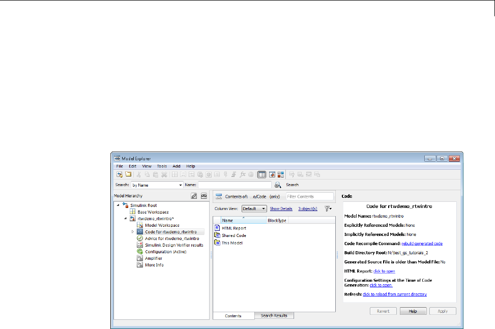
Reload Generated Code
Reload Generated Code
You can reload the code generated for a model from the Model Explorer.
1Click the Code for model node in the Model Hierarchy pane.
2In the Code pane, click the Refresh link.
The Simulink Coder software reloads the code for the model from the
build folder.
10-3

10 Source Code Generation
Generated Source Files and File Dependencies
In this section...
“About Generated Files and File Dependencies” on page 10-4
“Header Dependencies When Interfacing Legacy/Custom Code with
Generated Code” on page 10-6
“Dependencies of the Generated Code” on page 10-16
“Specify Include Paths in Simulink®Coder™ Generated Source Files” on
page 10-21
About Generated Files and File Dependencies
The Simulink Coder software generates codeintoasetofsourcefilesthatvary
little among different targets. Not all possible files are generated for every
model. Some files are created only when the model includes subsystems, calls
external interfaces, or uses particular types of data. The Simulink Coder code
generator handles most of the code formatting decisions (such as identifier
construction and code packaging) in consistent ways.
The source and make files created during the Simulink Coder build process
are generated into your build folder, which is created or reused in your
current folder. Some files are unconditionally generated, while the existence
of others depend on target settings and options(forexample,supportfilesfor
C API or external mode). See “Files and Folders Created by Build Process” on
page 10-24 for descriptions of the generated files.
Note ThefilepackagingofEmbeddedCoder targets differs slightly from
the file packaging described below. See “Generate Code Modules” in the
Embedded Coder documentation for more information.
Generated source file dependencies are depicted in the next figure. Arrows
coming from a file point to files it includes. Other dependencies exist, for
example on Simulink header files tmwtypes.h and simstruc_types.h,plusC
or C++ library files. The figure maps inclusion relations between only those
files that are generated in the build folder. Utility and model reference code
10-4
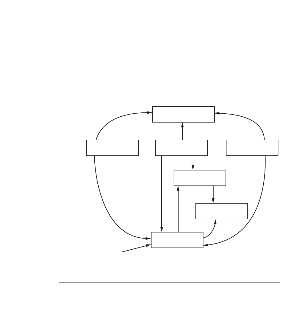
Generated Source Files and File Dependencies
located in a project folder might also be referenced by these files. See “Project
Folder Structure for Model Reference Targets” on page 3-16 for details.
Thefigureshowsthatparentsystemheaderfiles(
model.h) include all child
subsystem header files (subsystem.h). In more layered models, subsystems
similarly include their children’s header files, on down the model hierarchy.
As a consequence, subsystems are able to recursively “see” into their
descendants’ subsystems, as well as to see into the root system (because every
subsystem.c or subsystem.cpp includes model.h and model_private.h).
rtmodel.h is a
dummy include
file used only
for grt and
grt_malloc targets.
model_private.h
subsystem.cmodel.c model_data.c
subsystem.h
model_types.h
model.h
rtmodel.h
Simulink®Coder™ Generated File Dependencies
Note In the preceding figure, files model.h,model_private.h,and
subsystem.h also depend on the Simulink Coder header file rtwtypes.h.
Targets that are not based on the ERT target can have additional
dependencies on tmwtypes.h and simstruct_types.h.
10-5

10 Source Code Generation
Header Dependencies When Interfacing
Legacy/Custom Code with Generated Code
You can incorporate legacy or custom code into a Simulink Coder build in any
of several ways. One common approach is by creating S-functions. For details
on this approach, see “Insert S-Function Code” on page 14-46.
Another approach is to interface code using global variables created
by declaring storage classes for signals and parameters. This requires
customizing an outer code harness, typically referred to as a main.c or
main.cpp file, to properly execute to the generated code. In addition, the
harness can contain custom code.
These scenarios require you to include header files specific to the Simulink
Coder product to make available function declarations, type definitions, and
defines to the legacy or custom code.
rtwtypes.h
The header file rtwtypes.h defines data types, structures, and macros
required by the generated code. Normally, you should include rtwtypes.h
for both GRT and ERT targets instead of including tmwtypes.h or
simstruc_types.h. However, the contents of the header file varies depending
on your target selection.
For... rtwtypes.h
GRT target Provides a complete set of definitions by including
tmwtypes.h and simstruct_types.h,bothofwhich
depend on
•System headers limits.h and float.h
•Simulink Coder headers: rtw_matlogging.h,
rtw_extmode.h,rtw_continuous.h,and
rtw_solver.h
ERT target and
targets based on
the ERT target
Is optimized, when possible, to include a minimum set
of #define statements, enumerations, and so on; does
not include tmwtypes.h and simstruct_types.h
10-6

Generated Source Files and File Dependencies
The Simulink Coder build process generates the optimized version of
rtwtypes.h for the ERT target when both of the following conditions exist:
•The Classic call interface option on the Code Generation > Interface
pane of the Configuration Parameters dialog box is cleared.
•The model contains no noninlined S-functions
You should always include rtwtypes.h. If you include it for GRT targets, for
example, it is easier to use your code with ERT-based targets.
rtwtypes.h for GRT targets:
#ifndef __RTWTYPES_H__
#define __RTWTYPES_H__
#include "tmwtypes.h"
/* This ID is used to detect inclusion of an incompatible
* rtwtypes.h
*/
#define RTWTYPES_ID_C08S16I32L32N32F1
#include "simstruc_types.h"
#ifndef POINTER_T
# define POINTER_T
typedef void * pointer_T;
#endif
#ifndef TRUE
# define TRUE (1)
#endif
#ifndef FALSE
# define FALSE (0)
#endif
#endif
Top of rtwtypes.h for ERT targets:
#ifndef __RTWTYPES_H__
#define __RTWTYPES_H__
#ifndef __TMWTYPES__
#define __TMWTYPES__
10-7

10 Source Code Generation
#include <limits.h>
/*=======================================================================*
* Target hardware information
* Device type: 32-bit Generic
* Number of bits: char: 8 short: 16 int: 32
* long: 32 native word size: 32
* Byte ordering: Unspecified
* Signed integer division rounds to: Undefined
* Shift right on a signed integer as arithmetic shift: on
*=======================================================================*/
/* This ID is used to detect inclusion of an incompatible rtwtypes.h */
#define RTWTYPES_ID_C08S16I32L32N32F1
/*=======================================================================*
* Fixed width word size data types: *
* int8_T, int16_T, int32_T - signed 8, 16, or 32 bit integers *
* uint8_T, uint16_T, uint32_T - unsigned 8, 16, or 32 bit integers *
* real32_T, real64_T - 32 and 64 bit floating point numbers *
*=======================================================================*/
typedef signed char int8_T;
typedef unsigned char uint8_T;
typedef short int16_T;
typedef unsigned short uint16_T;
typedef int int32_T;
typedef unsigned int uint32_T;
typedef float real32_T;
typedef double real64_T;
...
For GRT and ERT targets, the location of rtwtypes.h depends on
whether the build uses the shared utilities location. If you use a
shared location, the Simulink Coder build process places rtwtypes.h in
slprj/target/_sharedutils;otherwise,itplacesrtwtypes.h in the
standard build folder (model_target_rtw). See “Logging” on page 15-105 for
moreinformationonwhenandhowtouse the shared utilities location.
10-8

Generated Source Files and File Dependencies
The header file rtwtypes.h should be included by source files that use
Simulink Coder type names or other Simulink Coder definitions. A typical
example is for files that declare variables using a Simulink Coder data type,
for example, uint32_T myvar;.
A source file that is intended to be used by the Simulink Coder product and by
a Simulink S-function can leverage the preprocessor macro MATLAB_MEX_FILE,
which is defined by the mex function:
#ifdef MATLAB_MEX_FILE
#include "tmwtypes.h"
#else
#include "rtwtypes.h"
#endif
AsourcefilemeanttobeusedastheSimulinkCodermain.c (or .cpp)file
would also include rtwtypes.h without any preprocessor checks.
#include "rtwtypes.h"
Custom source files that are generated using the Target Language Compiler
can also emit these include statements into their generated file.
model.h
The header file model.h declares model data structures and a public interface
to the model entry points and data structures. This header file also provides
an interface to the real-time model data structure (model_M) by using access
macros. If your code interfaces to model functions or model data structures,
as illustrated below, you should include model.h:
•Exported global signals
extern int32_T INPUT; /* '<Root>/In' */
•Global structure definitions
/* Block parameters (auto storage) */
extern Parameters_mymodel mymodel_P;
•RTM macro definitions
10-9

10 Source Code Generation
#ifndef rtmGetSampleTime
# define rtmGetSampleTime(rtm, idx)
((rtm)->Timing.sampleTimes[idx])
#endif
•Model entry point functions (ERT example)
extern void mymodel_initialize(void);
extern void mymodel_step(void);
extern void mymodel_terminate(void);
A Simulink Coder target’s main.c (or .cpp) file should include model.h.If
the main.c (or .cpp) file is generated from a TLC script, the TLC source
can include model.h using:
#include "%<CompiledModel.Name>.h"
If main.c or main.cpp is a static source file, a fixed header filename can be
used, rtmodel.h for GRT or autobuild.h for ERT. These files include the
model.h header file:
#include "model.h" /* If main.c is generated */
or
#include "rtmodel.h" /* If static main.c is used with GRT */
or
#include "autobuild.h" /* If static main.c is used with ERT */
Other custom source files might need to include model.h to interface to model
data, for example exported global parameters or signals. The model.h file
itself can have additional header dependencies, as listed in the tables System
Header Files on page 10-11 and Simulink®Coder™ Header Files on page
10-13, due to requirements of generated code.
10-10

Generated Source Files and File Dependencies
System Header Files
Header File Purpose GRT Targets ERT Targets
<float.h> Defines math
constants
Not included Included when generated code
honors the Stop time solver
configuration parameter due to
one of the following Simulink
Coder interface option settings:
•MAT-file logging selected
•Interface set to External
mode
<math.h> Provides
floating-point math
functions
Included when the
model contains
a floating-point
math function
Included when the model
contains a floating-point math
function that is not overridden by
an entry in the code replacement
library (CRL) selected for the
model
For more information about
CRLs, see “Selecting and
Viewing Code Replacement
Libraries” on page 9-61 in this
chapter, and the CRL chapter
in the Embedded Coder User’s
Guide.
<stddef.h> Defines NULL Included when the
model contains a
utility function
that needs it
Included when the model
contains a utility function that
needs it
<stdio.h> Provides file I/O
functions
Included when the
model includes a
To File block
Included when the
model includes a To File
block,oryouopenthe
Configuration Parameters
dialog box and select Code
Generation > Interface > MAT-file
logging.See“MAT-file
logging”.
10-11

10 Source Code Generation
System Header Files (Continued)
Header File Purpose GRT Targets ERT Targets
<stdlib.h> Provides utility
functions such as
div() and abs()
Included when the
model includes
•A Stateflow
chart
•AMath
Function block
configured for
mod() or rem(),
which generate
calls to div()
Included when the model
includes
•A Stateflow chart and
you select the Support
floating-point numbers
Simulink Coder interface
configuration parameter
•A Math Function block
configured for mod() or rem(),
which generate calls to div()
<string.h> Provides memory
functions such
as memset() and
memcpy()
Always included
due to use of
memset() in model
initialization code
Included when block or model
initialization code calls memcpy()
or memset()
For a list of relevant blocks,
enter showblockdatatypetable
in the MATLAB Command
Window and look for blocks with
the N2 note.
To omit calls to memset()
from model initialization code,
select the Remove root level
I/O zero initialization and
Remove internal data zero
initialization optimization
configuration parameters.
10-12

Generated Source Files and File Dependencies
Simulink Coder Header Files
Header File Purpose GRT Targets ERT Targets
dt_info.h Defines data
structures for
external mode
Included when you
configure a model
for external mode
Included when you configure a
model for external mode
ext_work.h Defines external
mode functions
Included when you
configure a model
for external mode
Included when you configure a
model for external mode
fixedpoint.h Provides
fixed-point support
for noninlined
S-functions
Always included Included when either of the
following conditions exists:
•The model uses noninlined
S-functions
•You select the Simulink
Coder interface configuration
parameter Classic call
interface
model_types.h Defines
model-specific data
types
Always included Always included
rt_logging.h Supports MAT-file
logging
Always included Includedwhenyouopenthe
Configuration Parameters
dialog box and select Code
Generation>Interface>MAT-file
logging. See “MAT-file logging”.
rt_nonfinite.h Provides support
for nonfinite
numbers in the
generated code
Always included Included when you select one
of the following Simulink
Coder interface configuration
parameters:
•MAT-file logging
•Support non-finite
numbers (and the generated
code requires nonfinite
numbers)
10-13

10 Source Code Generation
Simulink Coder Header Files (Continued)
Header File Purpose GRT Targets ERT Targets
rtw_continuous.h Supports
continuous time
Always
included by
simstruc_types.h
Included when you select
the Simulink Coder interface
configuration parameter
Support continuous time
and simstruc.h is not already
included
rtw_extmode.h Supports external
mode
Always
included by
simstruc_types.h
Included when you configure
the model for external mode
and simstruc.h is not already
included
rtw_matlogging.h Supports MAT-file
logging
Included by
simstruc_types.h
and
rtw_logging.h
Included by rtw_logging.h
rtw_solver.h Supports
continuous states
Always
included by
simstruc_types.h
Included when you select
the Simulink Coder interface
configuration parameter
Support floating-point
numbers and simstruc.h is not
already included
rtwtypes.h Defines Simulink
Coder data types;
generated file
Always included;
use the complete
version of the file,
which includes
tmwtypes.h and
simstruc_types.h
(see
simstruc_types.h
for dependencies)
Always included; use the
complete or optimized version
of the file as explained in
“rtwtypes.h” on page 10-6
10-14

Generated Source Files and File Dependencies
Simulink Coder Header Files (Continued)
Header File Purpose GRT Targets ERT Targets
simstruc.h Provides support
for calling
noninlined
S-functions that
use the Simstruct
definition; also
includes limits.h,
string.h,
tmwtypes.h,and
simstruc_types.h
Always included Included when either of the
following conditions exists:
•The model uses noninlined
S-functions
•You select the Simulink
Coder interface configuration
parameter Classic call
interface
simstruc_types.h Provides
definitions used by
generated code
and includes
the header files
rtw_matlogging.h,
rtw_extmode.h,
rtw_continuous.h,
rtw_solver.h,and
sysran_types.h
Always included
with rtwtypes.h
Not included; rtwtypes.h
contains definitions and model.h
contains header files
sysran_types.h Supports external
mode
Always
included by
simstruc_types.h
Included when you configure
the model for external mode
and simstruc.h is not already
included
Note Header file dependencies noted in the preceding table apply to the
system target files grt.tlc and ert.tlc. Targets derived from these base
targets may have additional header dependencies. Also, code generation
for blocks from blocksets, embedded targets, and custom S-functions may
introduce additional header dependencies.
10-15

10 Source Code Generation
Dependencies of the Generated Code
The Simulink Coder software can directly build standalone executables for
the host system such as when using the GRT target. Several processor- and
operating system-specific targets also provide automated builds using a
cross-compiler. All of these targets are typically makefile-based interfaces for
whichtheSimulinkCodersoftwareprovidesa“TemplateMakeFile(TMF)to
makefile” conversion capability. Part of this conversion process is to include,
in the generated makefile, source file, header file, and library file information
(the dependencies) for a compilation.
In other instances, the generated model code needs to be integrated into a
specific application. Or, it may be desired to enter the generated files and
any file dependencies into a configuration management system. This section
discusses the various aspects of the generated code dependencies and how to
determine them.
Typically, the generated code for a model consists of a small set of files:
•model.c or model.cpp
•model.h
•model_data.c or model_data.cpp
•model_private.h
•rtwtypes.h
These are generated in the build folder for a standalone model or a subfolder
under the slprj folder for a model reference target. There is also a top-level
main.c (or .cpp)filethatcallsthetopmodelfunctionstoexecutethemodel.
main.c (or .cpp) is a static (not generated) file (such as grt_main.c or
grt_main.cpp for GRT-based targets), and is either a static file (ert_main.c
or ert_main.cpp) or is dynamically generated for ERT-based targets.
The preceding files also have dependencies on other files, which occur due to:
•Including other header files
•Using macros declared in other header files
•Calling functions declared in other source files
10-16

Generated Source Files and File Dependencies
•Accessing variables declared in other source files
These dependencies are introduced for a number of reasons such as:
•Blocks in a model generate code that makes function calls. This can occur
in several forms:
-The called functions are declared in other source files. In some cases
such as a blockset, these source file dependencies are typically managed
by compiling them into a library file.
-In other cases, the called functions are provided by the compilers own
run-time library, such as for functions in the ANSI12 Cheader,math.h.
-Some function dependencies are themselves generated files. Some
examples are for fixed-point utilities and nonfinite support. These
dependencies are referred to as shared utilities. The generated functions
can appear in files in the build folder for standalone models or in the
_sharedutils folder under the slprj folder for builds that involve
model reference.
•Models with continuous time require solver source code files.
•Simulink Coder options such as external mode, C API, and MAT-file
logging are examples that trigger additional dependencies.
•Specifying custom code can introduce dependencies.
Providing the Dependencies
The Simulink Coder product provides several mechanisms for feeding
file dependency information into the Simulink Coder build process. The
mechanisms available to you depend on whether your dependencies are block
based or are model or target based.
For block dependencies, consider using
•S-functions and blocksets
-folders that contain S-function MEX-files used by a model are added
to the header include path.
12. ANSI®is a registered trademark of the American National Standards Institute, Inc.
10-17

10 Source Code Generation
-Makefile rules are created for these folders to allow source code to be
found.
-For S-functions that are not inlined with a TLC file, the S-function
source filename is added to the list of sources to compile.
-The S-Function block parameter SFunctionModules provides the ability
to specify additional source filenames.
-The rtwmakecfg.m mechanism provides further capability in specifying
dependencies. See “Use rtwmakecfg.m API to Customize Generated
Makefiles” on page 14-124 for more information.
For more information on applying these approaches to legacy or custom
codeintegration,see“IntegrateExternalCodeUsingLegacyCodeTool”on
page 14-28.
•S-Function Builder block, which provides its own GUI for specifying
dependency information
For model- or target-based dependencies, such as custom header files,
consider using
•The Code Generation > Custom Code pane of the Configuration
Parameters dialog box, which provides the ability to specify additional
libraries, source files, and include folders.
•TLC functions LibAddToCommonIncludes() and LibAddToModelSources(),
which allow you to specify dependencies during the TLC
phase. See “LibAddToCommonIncludes(incFileName)” and
“LibAddSourceFileCustomSection
(file, builtInSection, newSection)” in the Target Language Compiler
documentation for details. The Embedded Coder product also provides a
TLC-based customization template capability for generating additional
source files.
Makefile Considerations
As previously mentioned, Simulink Coder targets are typically makefile
based and the Simulink Coder product provides a “Template MakeFile (TMF)
to makefile” conversion capability. Thetemplatemakefilecontainsatoken
expansion mechanism in which the build process expands different tokens in
the makefile to include the additional dependency information. The resulting
10-18

Generated Source Files and File Dependencies
makefile contains the complete dependency information. See “Customize
Template Makefiles” on page 24-75 for more information on working with
template makefiles.
The generated makefile contains the following information:
•Names of the source file dependencies (by using various SRC variables)
•folders where source files are located (by using unique rules)
•Location of the header files (by using the INCLUDE variables)
•Precompiled library dependencies (by using the LIB variables)
•Libraries which need to be compiled and created (by using rules and the
LIB variables)
A property of make utilities is that the specific location for a given source C or
C++filedoesnotneedtobespecified. If a rule exists for that folder and the
source filename is a prerequisite in the makefile, the make utility can find
the source file and compile it. Similarly, the C or C++ compiler (preprocessor)
does not require absolute paths to the headers. Given the name of header
file by using an #include directive and an include path, it is able to find
the header. The generated C or C++ source code depends on this standard
compiler capability.
Also, libraries are typically created and linked against, but occlude the
specific functions that are being used.
Although the build process succeeds and can create a minimum-size
executable, these properties can make it difficult to manually determine the
minimum list of file dependencies along with their fully qualified paths. The
makefile can be used as a starting point to determining the dependencies
that the generated model code has.
An additional approach to determining the dependencies is by using linker
information, such as a linker map file, to determine the symbol dependencies.
The location of Simulink Coder and blockset source and header files is
provided below to assist in locating the dependencies.
10-19

10 Source Code Generation
Simulink Coder Static File Dependencies
Several locations in the MATLAB folder tree contain static file dependencies
specific to the Simulink Coder product:
•matlabroot/rtw/c/src/
This folder has subfolders and contains additional files that may need to be
compiled. Examples include solver functions (for continuous time support),
external mode support files, C API support files, and S-function support
files. Source files in this folder are included into the build process using in
the SRC variables of the makefile.
•matlabroot/rtw/extern/include/*.h
•matlabroot/simulink/include/*.h
These folders contain additional header file dependencies such as
tmwtypes.h,simstruc_types.h,andsimstruc.h.
Note For ERT-based targets, several header dependencies from the above
locations can be avoided. ERT-based targets generate the minimum set of
type definitions, macros, and so on, in the file rtwtypes.h.
Blockset Static File Dependencies
Blockset products leverage the rtwmakecfg.m mechanism to provide the
Simulink Coder software with dependency information. As such, the
rtwmakecfg.m file provided by the blockset contains the listing of include path
and source path dependencies for the blockset. Typically, blocksets create a
library from the source files, which the generated model code can then link
against. The libraries are created and identified using the rtwmakecfg.m
mechanism.
To locate the rtwmakecfg.m files for blocksets in your MATLAB installed tree,
use the following command:
>> which -all rtwmakecfg.m
For example, for the DSP System Toolbox product, the which command
displays a path similar to the following:
10-20

Generated Source Files and File Dependencies
C:\Program Files\MATLAB\toolbox\dspblks\dspmex\rtwmakecfg.m
If the model being compiled uses one or more of the blocksets listed by the
which command, you can determine folder and file dependency information
from the respective rtwmakecfg.m file. For example, here is an excerpt of the
rtwmakecfg.m file for the DSP System Toolbox product.
function makeInfo=rtwmakecfg()
%RTWMAKECFG adds include and source directories to RTW make files.
% makeInfo=RTWMAKECFG returns a structured array containing build info.
% Please refer to the rtwmakecfg API section in the Simulink Coder
% documentation for details on the format of this structure.
.
.
.
makeInfo.includePath={...
fullfile(matlabroot,'toolbox','dspblks','include') };
makeInfo.sourcePath = {};
Specify Include Paths in Simulink Coder Generated
Source Files
You can add #include statements to generated code. Such references can
come from several sources, including TLC scripts for inlining S-functions,
custom storage classes, bus objects, and data type objects. The included
files typically consist of header files for legacy code or other customizations.
Additionally, you can specify compiler include paths with the -I compiler
option. The Simulink Coder build process uses the specified paths to search
for included header files.
Usage scenarios for the generated code include, but are not limited to, the
following:
•Simulink Coder generated code is compiled with a custom build process
that requires an environment-specific set of #include statements.
In this scenario, the code generator is likely invoked with the Generate
code only check box selected. Consider using fully qualified paths, relative
10-21

10 Source Code Generation
paths, or just the header filenames in the #include statements, and
additionally leverage include paths.
•The generated code is compiled using the Simulink Coder build process.
In this case, compiler include paths (-I) can be provided to the Simulink
Coder build process in several ways:
-The Code Generation > Custom Code pane of the Configuration
Parameters dialog box allows you to specify additional include paths.
The include paths are propagated into the generated makefile when the
template makefile (TMF) is converted to the actual makefile.
-The rtwmakecfg.m mechanism allows S-functions to introduce additional
include paths into the Simulink Coder build process. The include paths
are propagated when the template makefile (TMF) is converted to the
actual makefile.
-When building a custom Simulink Coder target that is makefile-based,
thedesiredincludepathscanbedirectlyaddedintothetargetstemplate
makefile.
-AUSER_INCLUDES make variable that specifies a folder in which the
Simulink Coder build process should search for included files can be
specified on the Simulink Coder make command. For example,
make_rtw USER_INCLUDES=-Id:\work\feature1
The user includes are passed to the command-line invocation of the make
utility, which will add them to the overall flags passed to the compiler.
Recommended Approaches
The following are recommended approaches for using #include statements
and include paths in conjunction with the Simulink Coder build process to
generate code that remains portable and minimizes compatibility problems
with future versions.
Assume that additional header files are located at
c:\work\feature1\foo.h
c:\work\feature2\bar.h
10-22

Generated Source Files and File Dependencies
•A simple approach is to include in the #include statements only the
filename, such as
#include "foo.h"
#include "bar.h"
Then, the include path passed to the compiler should contain all folders in
which the headers files exist:
cc -Ic:\work\feature1 -Ic:\work\feature2 ...
•A second recommended approach is to use relative paths in #include
statements and provide an anchor folder for these relative paths using an
include path, for example,
#include "feature1\foo.h"
#include "feature2\bar.h"
Then specify the anchor folder (for example \work)tothecompiler:
cc -Ic:\work ...
Folder Dependencies to Avoid
When using the Simulink Coder build process, avoid dependencies on its
build and project folder structure, such as the model_ert_rtw build folder
or the slprj project folder. Thus, the #include statements should not just
be relative to where the generated source file exists. For example, if your
MATLAB current working folder is c:\work,ageneratedmodel.c source file
would be generated into a subfolder such as
c:\work\model_ert_rtw\model.c
The model.c file would have #include statements of the form
#include "..\feature1\foo.h"
#include "..\feature2\bar.h"
However, as this creates a dependency on the Simulink Coder folder structure,
you should instead use one of the approaches described above.
10-23

10 Source Code Generation
Files and Folders Created by Build Process
The following sections discuss
•“Files Created During the Build Process” on page 10-24
•“Folders Used During the Build Process” on page 10-28
Files Created During the Build Process
This section lists model.* files created during the code generation and build
process for the GRT and GRT malloc targets when used with stand-alone
models. Additional folders and files are created to support shared utilities
and model references.
The build process derives many of the files from the model file you create with
Simulink. You can think of the model file as a very high-level programming
language source file.
Note Files generated by the Embedded Coder build process are packaged
slightly differently. Depending on model architectures and code generation
options, the Simulink Coder build process might generate other files.
Descriptions of the principal generated files follow. Note that these
descriptions use the generic term model for the model name:
•model.rtw
An ASCII file, representing the compiled model, generated by the Simulink
Coder build process. This file is analogous to the object file created from a
high-level language source program. By default, the Simulink Coder build
process deletes this file when the build process is complete. However, you
can choose to retain the file for inspection.
•model.c
C source code that corresponds to the model file and is generated by the
Target Language Compiler. This file contains
-Include files model.h and model_private.h
10-24

Files and Folders Created by Build Process
-All data except data placed in model_data.c
-Model-specific scheduler code
-Model-specific solver code
-Model registration code
-Algorithm code
-Optional GRT wrapper functions
•model.h
Defines model data structures and a public interface to the model entry
points and data structures. Also provides an interface to the real-time
model data structure (model_rtM) via access macros. model.h is included
by subsystem .c files in the model. It includes
-Exported Simulink data symbols
-Exported Stateflow machine parented data
-Model data structures, including rtM
-Model entry point functions
•model_private.h
Contains local define constants and local data required by the model
and subsystems. This file is included by the generated source files in the
model. You might need to include model_private.h when interfacing
legacy hand-written code to a model. See “Header Dependencies When
Interfacing Legacy/Custom Code with Generated Code” on page 10-6 for
more information. This header file contains
-Imported Simulink data symbols
-Imported Stateflow machine parented data
-Stateflow entry points
-Simulink Coder details (various macros, enums, and so forth that are
privatetothecode)
•model_types.h
Provides forward declarations for the real-time model data structure and
the parameters data structure. These structure might be used by function
10-25

10 Source Code Generation
declarations of reusable functions. model_types.h is included by all the
generated header files in the model.
•model_data.c
A conditionally generated C source code file containing declarations for
the parameters data structure and the constant block I/O data structure,
and any zero representations for structure data types that are used in the
model. If these data structures are not used in the model, model_data.c is
not generated. Note that these structures are declared extern in model.h.
When present, this file contains
-Constant block I/O parameters
-Include files model.h and model_private.h
-Definitions for the zero representations for any user-defined structure
data types used by the model
-Constant parameters
•model.exe (Microsoft Windows platforms) or model (UNIX platforms),
generated in the current folder, not in the build folder
Executable program file created under control of the make utility by your
development system (unless you have explicitly specified that Simulink
Coder generate code only and skip the rest of the build process)
•model.mk
Customized makefile generated by the Simulink Coder build process. This
file builds an executable program file.
•rtmodel.h
Contains #include directives required by static main program modules
such as grt_main.c and grt_malloc_main.c. Since these modules are
not created at code generation time, they include rt_model.h to access
model-specific data structures and entry points. If you create your own
main program module, take care to include rtmodel.h.
•rtwtypes.h
For GRT targets, a header file that includes simstruc_types.h,which,
in turn, includes tmwtypes.h. For Embedded Coder ERT targets,
rtwtypes.h provides the defines, enums, and so on, instead of including
tmwtypes.h and simstruc_types.h.Thertwtypes.h file generated for
10-26

Files and Folders Created by Build Process
ERT is an optimized (reduced) file based on the settings provided with the
model that is being built. See “Header Dependencies When Interfacing
Legacy/Custom Code with Generated Code” on page 10-6 in the Simulink
Coder documentation for more information.
•rt_nonfinite.c
C source file that declares and initializes global nonfinite values for inf,
minus inf,andnan. Nonfinite comparison functions are also provided.
This file is always generated for GRT-based targets and optionally
generated for other targets.
•rt_nonfinite.h
C header file that defines extern references to nonfinite variables and
functions. This file is always generated for GRT-based targets and
optionally generated for other targets.
•rtw_proj.tmw
Simulink Coder file generated for the make utility to use to determine
when to rebuild objects when the name of the current Simulink Coder
project changes
•model.bat
Windows batch file used to set up the compiler environment and invoke
themakecommand
•modelsources.txt
List of additional sources that should be included in the compilation.
Optional files:
•model_targ_data_map.m
MATLABlanguagefileusedbyexternalmodetoinitializetheexternal
mode connection
•model_dt.h
C header file used for supporting external mode. Declares structures that
contain data type and data type transition information for generated model
data structures.
•subsystem.c
10-27

10 Source Code Generation
C source code for each noninlined nonvirtual subsystem or copy thereof
when the subsystem is configured to place code in a separate file
•subsystem.h
C header file containing exported symbols for noninlined nonvirtual
subsystems. Analogous to model.h.
•model_capi.h,model_capi.c
Header and sources file that contain data structures that describe the
model’s signals, states, and parameters without using external mode. See
“Data Interchange Using the C API” on page 15-137 in Simulink Coder
User’s Guide for more information.
•rt_sfcn_helper.h,rt_sfcn_helper.c
Header and source files providing functions usec by noninlined S-functions
in a model. The functions rt_CallSys,rt_enableSys,andrt_DisableSys
are used when noninlined S-functions call downstream function-call
subsystems.
In addition, when you select the Create code generation report check box,
the Simulink Coder software generates a set of HTML files (one for each
source file plus a model_contents.html index file) in the html subfolder
within your build folder.
The above source files have dependency relationships, and there are
additional file dependencies that you might need to take into account. These
are described in “Generated Source Files and File Dependencies” on page 10-4
in the Simulink Coder documentation.
Folders Used During the Build Process
The Simulink Coder build process places output files in three folders:
•The working folder
Ifyouchoosetogenerateanexecutableprogramfile,theSimulinkCoder
build process writes the file model.exe (Windows) or model (UNIX) to your
working folder.
•The build folder — model_target_rtw
10-28

Files and Folders Created by Build Process
A subfolder within your working folder. The build folder name is
model_target_rtw,wheremodel is the name of the source model and
target is the selected target type (for example, grt for the generic real-time
target). The build folder stores generated source code and all other files
created during the build process (except the executable program file).
•Project folder — slprj
A subfolder within your working folder. When models referenced via Model
blocks are built for simulation or Simulink Coder code generation, files are
placed in slprj. The Embedded Coder configuration has an option that
places generated shared code in slprj without the use of model reference.
Subfolders in slprj provide separate places for simulation code, some
Simulink Coder code, utility code shared between models, and other files.
Of particular importance to Simulink Coder users are:
-Header files from models referenced by this model
slprj/target/model/referenced_model_includes
-Model reference Simulink Coder target files
slprj/target/model
-MAT-files used during code generation of model reference
Simulink Coder target and stand-alone code generation
slprj/target/model/tmwinternal
-Shared (fixed-point) utilities
slprj/target/_sharedutils
See “Work with Project Folders” on page 3-14 for more information on
organizing your files with respect to project folders.
The build folder always contains the generated code modules model.c,
model.h, and the generated makefile model.mk.
Depending on the target, code generation, and build options you select, the
build folder might also include
•model.rtw
•Object files (.obj or .o)
10-29

10 Source Code Generation
•Code modules generated from subsystems
•HTML summary reports of files generated (in the html subfolder)
•TLC profiler report files
•Block I/O, state, and parameter tuning information file (model_capi.c)
•Simulink Coder project (model.tmw) files
For additional information about using project folders, see “Project Folder
Structure for Model Reference Targets” on page 3-16 and “Customize Build to
Use Shared Utility Code” on page 22-34 in the Simulink Coder documentation.
10-30

How Code Is Generated From a Model
How Code Is Generated From a Model
In this section...
“Model Compilation” on page 10-31
“Code Generation” on page 10-31
Model Compilation
The build process begins with the Simulink software compiling the block
diagram. During this stage, Simulink
•Evaluates simulation and block parameters
•Propagates signal widths and sample times
•Determines the execution order of blocks within the model
•Computes work vector sizes, such as those used by S-functions. (For more
information about work vectors, see “DWork Vector Basics”).
When Simulink completes this processing, it compiles an intermediate
representation of the model. This intermediate description is stored in a
language-independent format in the ASCII file model.rtw.Themodel.rtw file
is the input to the next stage of the build process. For a general description
of the model.rtw file format, see “model.rtw file”.
Code Generation
The Simulink Coder code generator uses the Target Language Compiler (TLC)
and a supporting TLC function library to transform the intermediate model
description stored in model.rtw into target-specific code.
The target language compiled by the TLC is an interpreted programming
language designed to convert a model description to code. The TLC executes a
TLC program comprising several target files (.tlc scripts). The TLC scripts
specify how to generate code from the model, using the model.rtw file as input.
The TLC
1Reads the model.rtw file
10-31

10 Source Code Generation
2Compiles and executes commands in a system target file
The system target file is the entry point or main file. You select it from
those available on the MATLAB path with the system target file browser or
youcantypethenameofanysuchfileonyoursystempriortobuilding.
3Compiles and executes commands in block-level target files
For blocks in the Simulink model, there is a corresponding target file that
is either dynamically generated or statically provided.
Note The Simulink Coder software executes all user-written S-function
target files, but optionally executes block target files for Simulink blocks.
4Writes a source code version of the Simulink block diagram
10-32

Code Generation of Matrices and Arrays
Code Generation of Matrices and Arrays
In this section...
“Simulink®Coder™ Matrix Parameters” on page 10-34
“Internal Data Storage for Complex Number Arrays” on page 10-36
MATLAB, Simulink, and Simulink Coder software store matrix data and
arrays(1–D, 2–D, ...) in column-major format as a vector. Column-major
format orders elements in a matrix starting from the first column, top to
bottom, and then moving on to the next column. For example, the following
3x3 matrix:
A=
123
456
789
translates to an array of length 9 in the following order:
A(1) = A(1,1) = 1;
A(2) = A(2,1) = 4;
A(3) = A(3,1) = 7;
A(4) = A(1,2) = 2;
A(5) = A(2,2) = 5;
and so on.
In column-major format, the next element of an array in memory is always
accessed by incrementing the first index of the array. For example, these
element pairs are stored sequentially in memory: A(i) and A(i+1),B(i,j)
and B(i+1,j),C(i,j,k) and C(i+1,j,k). For more information on the
internal representation of MATLAB data, see “MATLAB Data” in the
MATLAB External Interfaces document.
Code generation software uses column-major format for several reasons:
•The world of signal and array processing is largely column major:
MATLAB, LAPack, Fortran90, DSP libraries.
10-33

10 Source Code Generation
•A column is equivalent to a channel in frame-based processing. In this
case, column-major storage is more efficient.
•A column major array is self-consistent with its component submatrices:
-A column major 2–D array is a simple concatenation of 1–D arrays.
-A column major 3–D array is a simple concatenation of 2–D arrays.
-The stride of the first dimension is always 1 element, where the stride
is the number of memory locations to index to the next element in the
same dimension. The stride of the n’th dimension element is always the
product of sizes of the lower dimensions.
-Row-majorn-Darrayshavetheirstrideof1forthehighestdimension.
Any submatrix manipulations are typically accessing a scattered data
set in memory, which does not allow for efficient indexing.
Simulink Coder Matrix Parameters
The compiled model file, model.rtw, represents matrices as strings in
MATLAB syntax, with no implied storage format. This format allows you to
copy the string out of an .rtw file and paste it into a MATLAB file and have
it recognized by MATLAB.
Simulink Coder software declares Simulink block matrix parameters as
scalar or 1-D array variables
real_T scalar;
real_T mat[ nRows * nCols ];
where real_T can be any of the data types supported by Simulink, and
matches the variable type given in the model file.
For example, the 3-by-3 matrix in the 2–D Look-Up Table block
123
456
789
is stored in model.rtw as
Parameter {
10-34

Code Generation of Matrices and Arrays
Name "OutputValues"
Value Matrix(3,3)
[[1.0, 2.0, 3.0]; [4.0, 5.0, 6.0]; [7.0, 8.0, 9.0];]
String "t"
StringType "Variable"
ASTNode {
IsNonTerminal 0
Op SL_NOT_INLINED
ModelParameterIdx 3
}
}
and results in this definition in model.h
typedef struct Parameters_tag {
real_T s1_Look_Up_Table_2_D_Table[9];
/* Variable:s1_Look_Up_Table_2_D_Table
* External Mode Tunable:yes
* Referenced by block:
* <S1>/Look-Up Table (2-D
*/
[ ... other parameter definitions ... ]
} Parameters;
The model.h file declares the actual storage for the matrix parameter and you
can see that the format is column-major.
123
456
789
Parameters model_P = {
10-35

10 Source Code Generation
/* 3 x 3 matrix s1_Look_Up_Table_2_D_Table */
{ 1.0, 4.0, 7.0, 2.0, 5.0, 8.0, 3.0, 6.0, 9.0 },
[ ... other parameter declarations ...]
};
Note C typically uses row-major format, while MATLAB and Simulink use
column-major format. The code generation software cannot be configured
to generate code with row-major ordering. If you are integrating other C
code with the generated code, you might need to transpose the data into
column-major format as a 1–D array.
Internal Data Storage for Complex Number Arrays
Simulink and Simulink Coder internal data storage formatting differs from
MATLAB internal data storage formatting only in the storage of complex
number arrays. In MATLAB, the real and imaginary parts are stored in
separate arrays. In the Simulink and Simulink Coder products they are
stored in an "interleaved" format, where the numbers in memory alternate
real, imaginary, real, imaginary, and so forth. This convention allows efficient
implementations of small signals on Simulink lines and for Mux blocks and
other "virtual" signal manipulation blocks (i.e., they don’t actively copy their
inputs, merely the references to them).
10-36

Shared Utility Code
Shared Utility Code
In this section...
“About Shared Utility Code” on page 10-37
“Controlling Shared Utility Code Placement” on page 10-38
“rtwtypes.h and Shared Utility Code” on page 10-38
“Incremental Shared Utility Code Generation and Compilation” on page
10-39
“Shared Utility Checksum” on page 10-39
“Shared Fixed-Point Utility Functions” on page 10-41
“Share User-Defined Data Types Across Models” on page 10-43
About Shared Utility Code
Blocks in a model can require common functionality to implement their
algorithm. In many cases, it is most efficient to modularize this functionality
into standalone support or helper functions, rather than inlining the code for
the functionally for each block instance.
Typically, functions that can have multiple callers are packaged into a library.
Traditionally, such functions are defined statically, that is, the function
source code exists in a file before you use the Simulink Coder software to
generate code for your model.
In other cases, several model- and block-specific properties can affect which
functions are used and their behavior. Additionally, these properties can
affect type definitions (for example, typedef) in shared utility header files.
Since there are many possible combinations of properties that determine
unique behavior, it is not practical to statically define all possible function
files before code generation. Instead, you can use the Simulink Coder shared
utility mechanism, which generates support functions during code generation
process.
10-37

10 Source Code Generation
Controlling Shared Utility Code Placement
You control the shared utility code placement mechanism with the Shared
code placement optionontheCode Generation > Interface pane of the
Configuration Parameters dialog box. By default, the option is set to Auto.
For this setting, if the model being built does not include any Model blocks,
the Simulink Coder build process places any code required for fixed-point and
other utilities in one of the following:
•The model.c ormodel.cpp file
•In a separate file in the Simulink Coder build folder (for example,
vdp_grt_rtw)
Thus, the code is specific to the model.
If a model does contain Model blocks, the Simulink Coder build process
creates and uses a shared utilities folder within slprj. Model reference builds
require the use of shared utilities. The naming convention for shared utility
folders isslprj/target/_sharedutils,wheretarget is sim for simulations
with Model blocks or the name of the system target file for Simulink Coder
target builds. Some examples follow:
slprj/sim/_sharedutils % folder used with simulation
slprj/grt/_sharedutils % folder used with grt.tlc STF
slprj/ert/_sharedutils % folder used with ert.tlc STF
slprj/mytarget/_sharedutils % folder used with mytarget.tlc STF
To force a model build to use the slprj folder for shared utility generation,
even when the current model contains no Model blocks, set the Shared
code placements option to Shared location. This forces the Simulink
Coder build process to place utilities under the slprj folder rather than in
the normal Simulink Coder build folder. This setting is useful when you
are manually combining code from several models, as it prevents symbol
collisions between the models.
rtwtypes.h and Shared Utility Code
The generated header file rtwtypes.h provides defines, enumerations, and
so on. The location of this file is controlled by whether the build process
is using the shared utilities folder. Typically, the Simulink Coder build
10-38

Shared Utility Code
process places rtwtypes.h in the standard build folder, model_target_rtw.
However, if a shared folder is required, the product places rtwtypes.h in
slprj/target/_sharedutils.
Incremental Shared Utility Code Generation and
Compilation
As explained in “Controlling Shared Utility Code Placement” on page 10-38,
you can specify that C source files, which contain function definitions, and
header files, which contain macro definitions, be generated in a shared
utilities folder. For the purpose of this discussion, the term functions means
functions and macros.
A shared function can be used by blocks within the same model and by blocks
in different models when using model reference or when building multiple
standalone models from the same start build folder. However, the Simulink
Coder software generates the code for a given function only once for the block
that first triggers code generation. As the product determines the need to
generate function code for subsequent blocks, it performs a file existence
check. Ifthefileexists,thefunctionis not regenerated. Thus, the shared
utility code mechanism requires that a given function and file name represent
the same functional behavior regardless of which block or model generates
the function. To satisfy this requirement:
•Model properties that affect function behavior are included in a shared
utility checksum or affect the function and file name.
•Block properties that affect the function behavior also affect the function
and file name.
During compilation, makefile rules for the shared utilities folder are
configured to compile only new C files, and incrementally archive the object
file into the shared utility library, rtwshared.lib or rtwshared.a. Thus,
incremental compilation is also done.
Shared Utility Checksum
As explained in “Incremental Shared Utility Code Generation and
Compilation” on page 10-39, the Simulink Coder software uses the
shared utilities folder when you explicitly configure a model to use the
10-39
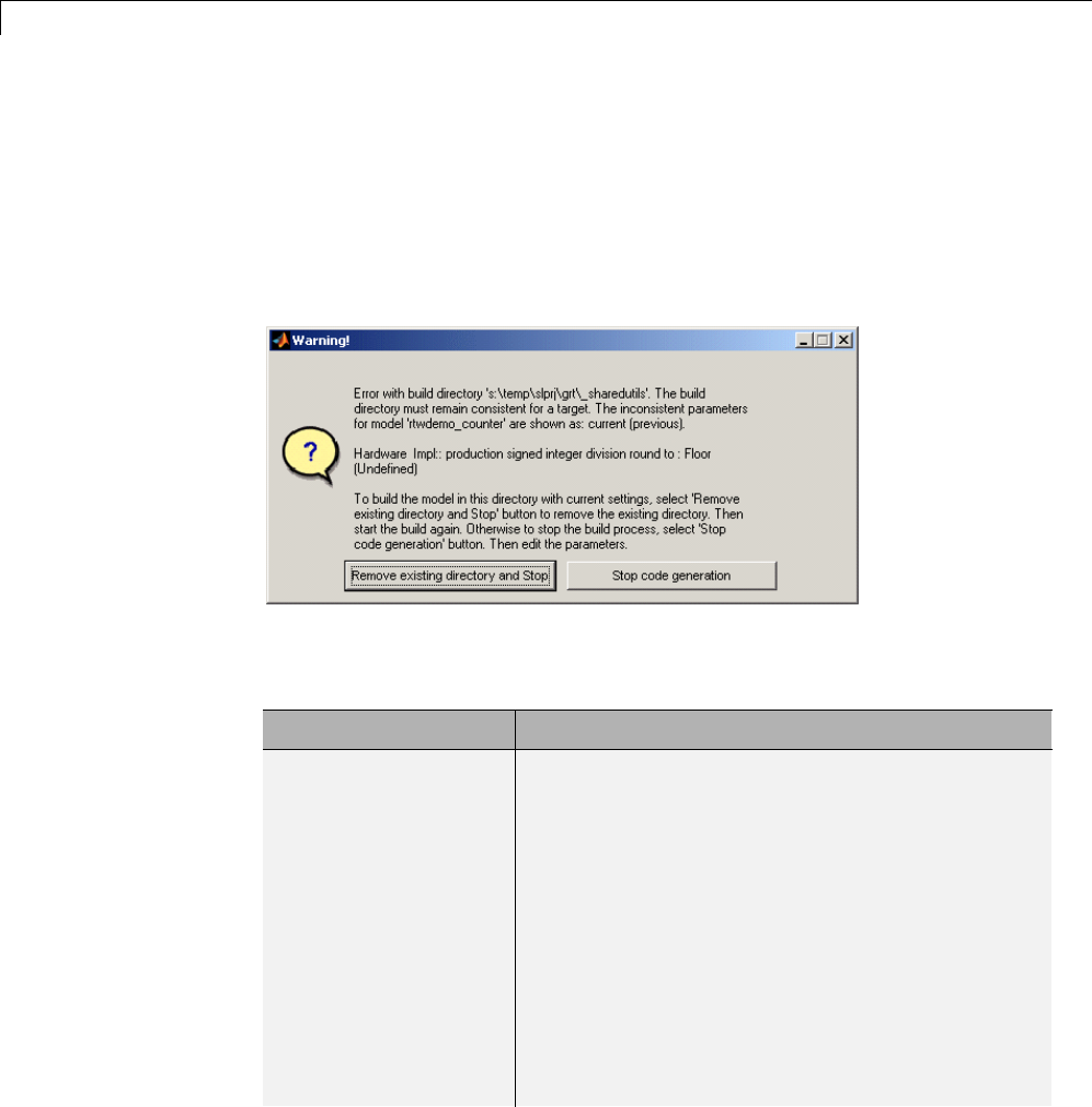
10 Source Code Generation
shared location or the model contains Model blocks. During the code
generation process, if relative to the current folder, the configuration file
slprj/target/_sharedutils/checksummap.mat exists, the product reads
that file and makes sure that the current model being built has identical
settings for the required model properties. If mismatches occur between the
properties defined in checksummap.mat and the current model properties,
a Warning dialog appears.
The following table lists properties that must match for the shared utility
checksum.
Category Properties
Hardware
Implementation
configuration
properties
get_param(bdroot,
'TargetShiftRightIntArith')
get_param(bdroot, 'TargetEndianess')
get_param(bdroot, 'ProdEndianess')
get_param(bdroot, 'TargetBitPerChar')
get_param(bdroot, 'TargetBitPerShort')
get_param(bdroot, 'TargetBitPerInt')
get_param(bdroot, 'TargetBitPerLong')
get_param(bdroot, 'ProdHWWordLengths')
get_param(bdroot, 'TargetWordSize')
get_param(bdroot, 'ProdWordSize')
get_param(bdroot, 'TargetHWDeviceType')
get_param(bdroot, 'ProdHWDeviceType')
10-40

Shared Utility Code
Category Properties
get_param(bdroot, 'TargetIntDivRoundTo')
get_param(bdroot, 'ProdIntDivRoundTo'
Additional
configuration
properties
get_param(bdroot, 'TargetLibSuffix')
get_param(bdroot, 'TargetLang')
get_param(bdroot, 'TemplateMakefile')
ERT target properties get_param(bdroot, 'PurelyIntegerCode')
get_param(bdroot, 'SupportNonInlinedSFcns'
Platform property Return value of the computer command
Shared Fixed-Point Utility Functions
An important set of generated functions that are placed in the shared utility
folder are the fixed-point support functions. Based on model and block
properties, there are many possible versions of fixed-point utilities functions
that make it impractical to provide a complete set as static files. Generating
only the required fixed-point utility functions during the code generation
processisanefficientalternative.
The shared utility checksum mechanism makes sure that several critical
properties are identical for all models that use the shared utilities. For the
fixed-point functions, there are additional properties that affect function
behavior. These properties are coded into the functions and file names to
maintain requirements. The additional properties include
Category Function/Property
Block
properties
•Fixed-point operation being performed by the block
•Fixed-point data type and scaling (Slope,Bias)of
function inputs and outputs
•Overflow handling mode (Saturation,Wrap)
•Rounding Mode (Floor,Ceil,Zero)
Model
properties
get_param(bdroot, 'NoFixptDivByZeroProtection')
10-41

10 Source Code Generation
The naming convention for the fixed-point utilities is based on the properties
as follows:
operation + [zero protection] + output data type + output bits +
[input1 data] + input1 bits + [input2 data type + input2 bits] +
[shift direction] + [saturate mode] + [round mode]
Below are examples of generated fixed-point utility files, the function or
macro names in the file are identical to the file name without the extension.
FIX2FIX_U12_U16.c
FIX2FIX_S9_S9_SR99.c
ACCUM_POS_S30_S30.h
MUL_S30_S30_S16.h
div_nzp_s16s32_floor.c
div_s32_sat_floor.c
For these examples, the respective fields correspond as follows:
Operation FIX2FIX FIX2FIX ACCUM_POS MUL div div
Zero protection NULL NULL NULL NULL _nzp NULL
Output data type _U _S _S _S _s _s
Output bits 12 9 30 30 16 32
Input data type _U _S _S _S [and _S] s NULL
Input bits 16 9 30 30 [and 16] 32 NULL
Shift direction NULL SR99 NULL NULL NULL NULL
Saturate mode NULL NULL NULL NULL NULL _sat
Round mode NULL NULL NULL NULL _floor _floor
Note For the ACCUM_POS example,theoutputvariableisalsousedasoneof
the input variables. Therefore, only the output and second input is contained
in the file and macro name. For the second div example, both inputs and
the output have identical data type and bits. Therefore, only the output is
included in the file and function name.
10-42

Shared Utility Code
Share User-Defined Data Types Across Models
•“About Sharing Data Types” on page 10-43
•“Example: Sharing Simulink Data Type Objects” on page 10-44
•“Example: Sharing Enumerated Data Types” on page 10-45
About Sharing Data Types
By default, user-defined data types that are shared among multiple models
generate duplicate type definitions in the model_types.h file for each
model. However, Simulink Coder software provides the ability to generate
user-defined data type definitions into a header file in the _sharedutils
folder that can be shared across multiple models, removing the need for
duplicate copies of the data type definitions. User-defined data types that you
can set up in a shared header file include:
•Simulink data type objects that you instantiate from the classes
Simulink.AliasType,Simulink.Bus,andSimulink.NumericType.
•Enumeration types that you define in MATLAB code
The general procedure for setting up user-defined data types to be shared
amongmultiplemodelsisasfollows:
1Define the data type.
2Setdatascopeandheaderfilepropertiesthatallowthedatatypetobe
shared.
3Use the data type as a signal type in your models.
4Before generating code for each model, set the Shared code placement
parameter on the Code Generation > Interface pane of the Configuration
Parameters dialog box to the value Shared location.
5Generate code.
10-43

10 Source Code Generation
Note You can configure the definition of the user-defined data type
to occur in a header file that is located in the _sharedutils folder,
however user-defined data type names are not used by the shared utility
functions that are generated into the _sharedutils folder. Currently,
theuser-defineddatatypenamesareusedonlybymodelcodelocatedin
code folders for each model.
For more information, see “Example: Sharing Simulink Data Type Objects” on
page 10-44 and “Example: Sharing Enumerated Data Types” on page 10-45.
Example: Sharing Simulink Data Type Objects
To export a user-defined Simulink data type object for sharing among
multiple models.
1In the base workspace, create a data type object of one of the following
classes:
•Simulink.AliasType
•Simulink.Bus
•Simulink.NumericType
For example:
a = Simulink.AliasType
2To specify that the data type should be exported to a specified header file,
use the data type object property DataScope.Specifythevalue'Exported'
for the DataScope property. For example:
a.DataScope = 'Exported'
3Tospecifythenameoftheheaderfiletowhichthedatatypeshouldbe
exported, use the data type object property HeaderFile. For example:
a.HeaderFile = 'a.h'
Alternatively, if you leave the HeaderFile value empty, the name of the
generated header file defaults to the name of the data type, in this case, a.h.
10-44

Shared Utility Code
4Use the data type object as a signal type in a model.
5Before generating code, if you want to generate the header file into
the shared utilities folder for sharing definitions between multiple
models, set the Shared code placement parameter on the Code
Generation > Interface pane of the Configuration Parameters dialog
box to the value Shared location.
6Generate code. Here is an example of the definition code that is generated
to a.h in the shared utilities folder:
#ifndef RTW_HEADER_a_h_
#define RTW_HEADER_a_h_
#include "rtwtypes.h"
typedef double a;
#endif /* RTW_HEADER_a_h_ */
To share the data type definition from other models, the alternatives include:
•Simplyusethesameworkspacevariableinmultiplemodels.Ifthecontents
of the data type object are the same, generating code will not regenerate
the header file. For example, model A and model B can export the same
data type to the same header file in the shared utilities folder.
•Definethesamedatatypeobjectinothermodels,butsetituptoimport
theshareddatatypedefinitionfrom the header file. Specify the value
'Imported' for the data type object property DataScope. For example:
a = Simulink.AliasType
a.DataScope = 'Imported'
a.HeaderFile = 'a.h'
Example: Sharing Enumerated Data Types
To export a user-defined enumerated data type for sharing among multiple
models:
1Define an enumerated data type in MATLAB code. For example, the
following MATLAB file defines BasicColors:
10-45

10 Source Code Generation
% BasicColors.m
classdef(Enumeration) BasicColors < Simulink.IntEnumType
enumeration
Red(0)
Yellow(1)
Blue(2)
end
methods (Static = true)
function retVal = getDefaultValue()
retVal = BasicColors.Blue;
end
end
end
2To specify that the data type should be exported to a specified header file,
you must override the default getDataScope method of the enumerated
class. Specify the value 'Exported' as the getDataScope return value.
For example:
methods (Static = true)
...
function retVal = getDataScope()
retVal = 'Exported';
end
...
end
3Tospecifythenameoftheheaderfiletowhichthedatatypeshouldbe
exported, you must override the default getHeaderFile method of the
enumerated class. Specify a file name as the getHeaderFile return value.
For example:
methods (Static = true)
...
function retVal = getHeaderFile()
retVal = 'BasicColors.h';
end
...
end
10-46

Shared Utility Code
Alternatively, if you leave the return value of the getHeaderFile method
unspecified, the name of the generated header file defaults to the name of
the data type, in this case, BasicColors.h.
4Here is BasicColors.m after the data scope and header file changes.
% BasicColors.m
classdef(Enumeration) BasicColors < Simulink.IntEnumType
enumeration
Red(0)
Yellow(1)
Blue(2)
end
methods (Static = true)
function retVal = getDefaultValue()
retVal = BasicColors.Blue;
end
function retVal = getDataScope()
retVal = 'Exported';
end
function retVal = getHeaderFile()
retVal = 'BasicColors.h';
end
end
end
Make sure BasicColors.m is present in the MATLAB path.
5Use the type enum:BasicColors as a signal type in a model.
6Before generating code, if you want to generate the header file into
the shared utilities folder for sharing definitions between multiple
models, set the Shared code placement parameter on the Code
Generation > Interface pane of the Configuration Parameters dialog
box to the value Shared location.
7Generate code. Here is an example of the definition code that is generated
to BasicColors.h in the shared utilities folder:
#ifndef RTW_HEADER_BasicColors_h
#define RTW_HEADER_BasicColors_h
10-47

10 Source Code Generation
/* Type definition for enum:BasicColors type */
typedef enum {
Red = 0,
Yellow,
Blue
} BasicColors;
#endif
To share the data type definition from other models, the alternatives include:
•Simply use the same enumerated type as a signal type in multiple models.
If the contents of the enumerated type are the same, generating code will
not regenerate the header file. For example, model A and model B can
exportthesamedatatypetothesameheaderfileinthesharedutilities
folder.
•Definethesameenumeratedtypeinothermodels,butsetituptoimport
the shared data type definition from the header file. In the enumerated
type definition file, specify the value 'Imported' as the getDataScope
return value. For example:
methods (Static = true)
...
function retVal = getDataScope()
retVal = 'Imported';
end
...
end
10-48
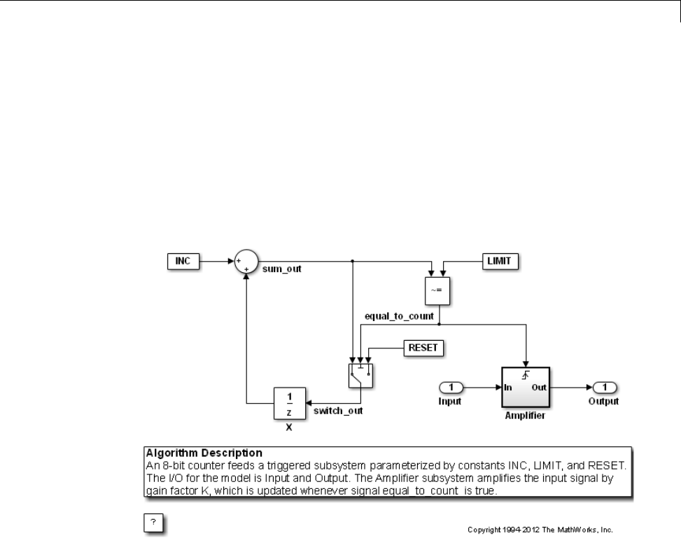
Generating Code Using Simulink Coder™
Generating Code Using Simulink Coder™
This example shows how to select a target for a Simulink model, generate C
code for real-time simulation, and view generated files.
1. Open the model.
model='rtwdemo_rtwintro';
open_system(model)
2. Open the Configuration Parameters dialog box from the model editor by
clicking Simulation > Configuration Parameters.
Alternately, type the following commands at the MATLAB command prompt
cs = getActiveConfigSet(model);
openDialog(cs);
3. Select the Code Generation node.
10-49
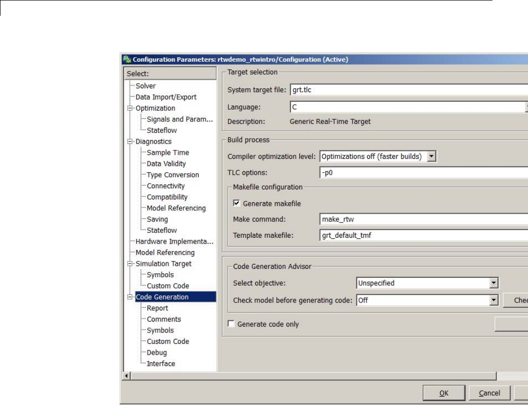
10 Source Code Generation
4. In the Target Selection pane, click Browse to select a target.
You can generate code for a particular target environment or purpose. Some
built-in targeting options are provided using system target files, which control
the code generation process for a target.
10-50
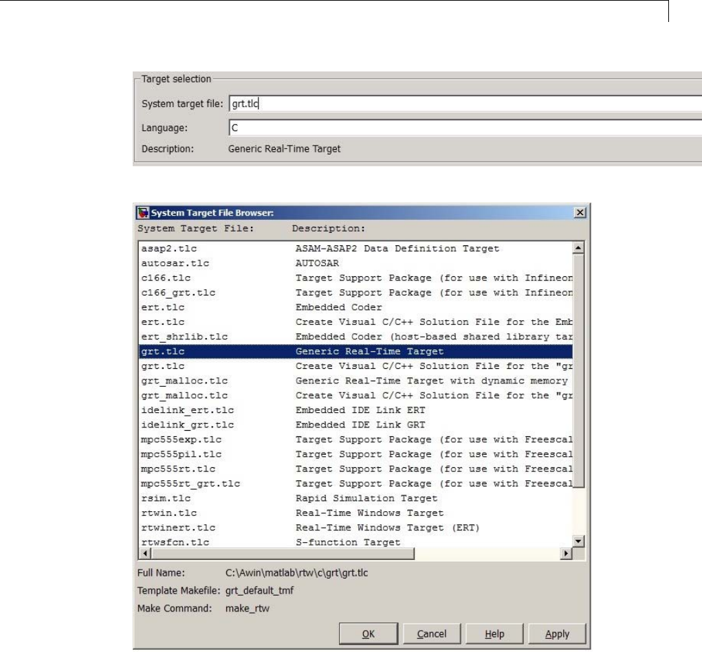
Generating Code Using Simulink Coder™
5. Select the Generic Real-Time (GRT) target and click Apply.
10-51
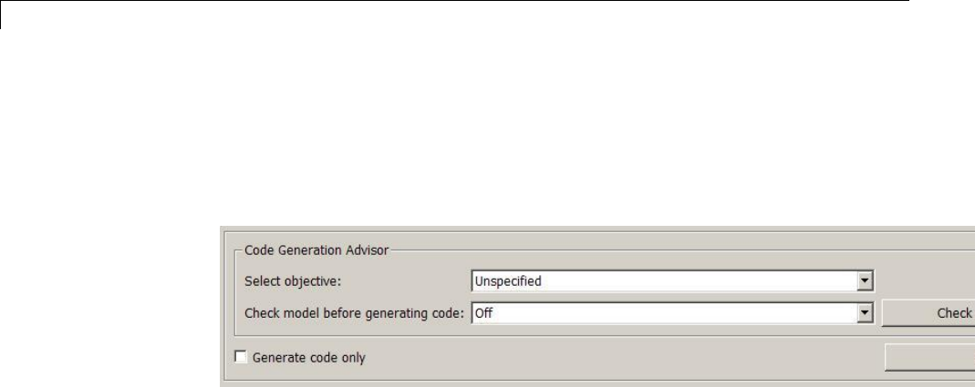
10 Source Code Generation
Optionally, in the Code Generation Advisor pane set the Select objective
field to Execution efficiency or Debugging.ThenclickCheck model... to
identify and systematically change parameters to meet your objectives.
6. In the Code Generation pane, click Build to generate code.
7. View the code generation report that appears.
The report includes links to model files such as rtwdemo_rtwintro.c and
associated utility and header files.
10-52
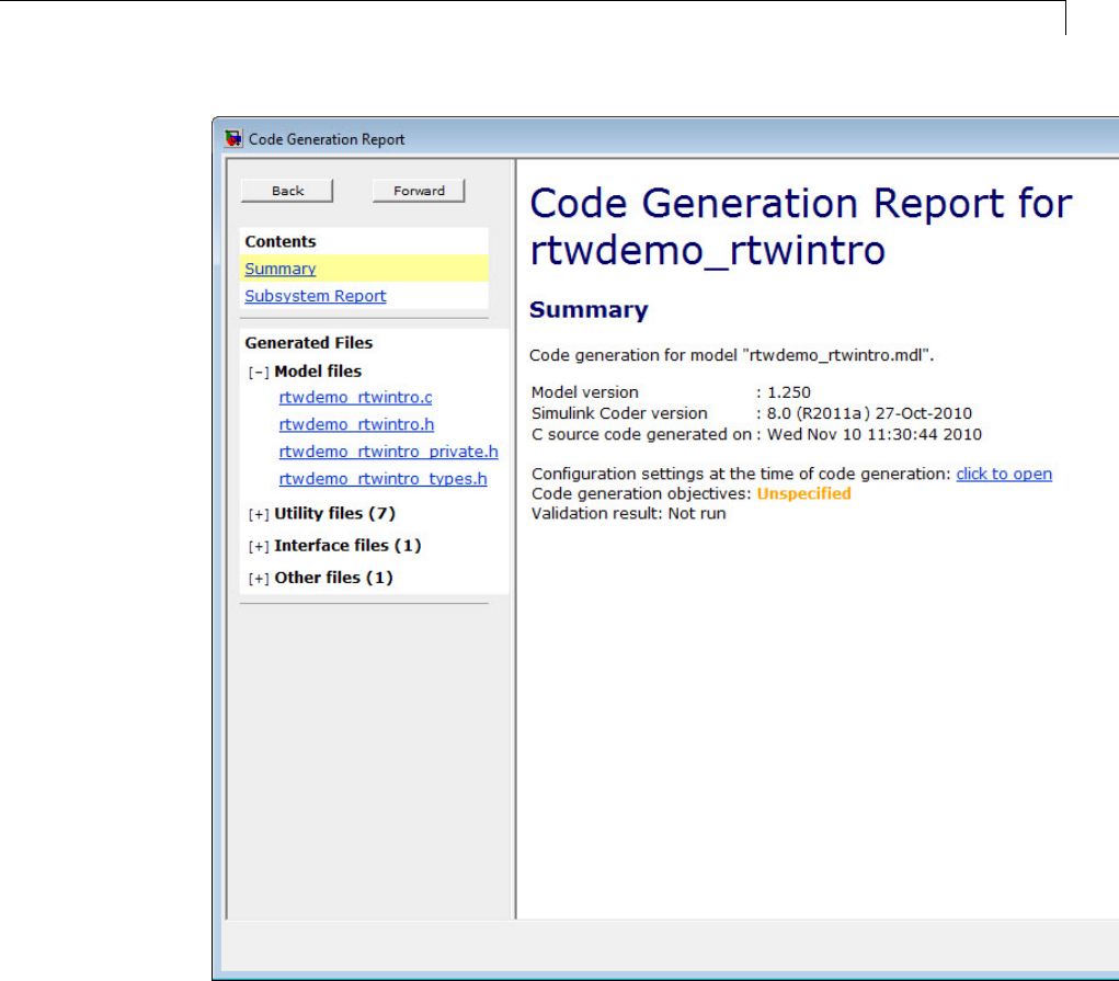
Generating Code Using Simulink Coder™
The figure below contains a portion of rtwdemo_rtwintro.c
10-53

10 Source Code Generation
10-54

Generating Code Using Simulink Coder™
8. Close the model.
bdclose(model)
rtwdemoclean;
10-55

10 Source Code Generation
10-56

11
Report Generation
•“Reports for Code Generation” on page 11-2
•“HTML Code Generation Report Location” on page 11-3
•“HTML Code Generation Report for Referenced Models” on page 11-4
•“Generate a Code Generation Report” on page 11-5
•“Generate Code Generation Report After Build Process” on page 11-6
•“Open Code Generation Report” on page 11-8
•“Generate Code Generation Report Programmatically” on page 11-10
•“Search in the Code Generation Report” on page 11-11
•“View Code Generation Report in Model Explorer” on page 11-12
•“Package and Share the Code Generation Report” on page 11-14
•“Document Generated Code with Simulink®Report Generator™” on page
11-16

11 Report Generation
Reports for Code Generation
Simulink Coder software provides an HTML code generation report so that
you can view and analyze the generated code. When your model is built, the
code generation process produces an HTML file that is displayed in an HTML
browser or in the Model Explorer. The code generation report includes:
•The Summary section lists version, date, and code generation objectives
information. The Configuration settings at the time of code
generation link opens a noneditable view of the Configuration Parameters
dialog box. The dialog box shows the Simulink model settings at the time of
code generation, including TLC options.
•The Subsystem Report section contains information on nonvirtual
subsystems in the model.
•In the Generated Files sectionontheContents pane, you can click the
names of source code files generated from your model to view their contents
in a MATLAB Web browser window. In the displayed source code, global
variables are hypertext that links to their definitions.
•ASearch box in the left navigation pane. For more information, see
“Search in the Code Generation Report” on page 11-11.
For an example, see “Generate a Code Generation Report” on page 11-5 and
“View Code Generation Report in Model Explorer” on page 11-12.
The contents of HTML reports varies depending on different target types. You
can generate individual HTML reports for a subsystem or referenced model.
For more information, see “HTML Code Generation Report for Referenced
Models” on page 11-4 and “Generate Code for Referenced Models” on page 3-4.
If you have a Simulink Report Generator license, you can document your
code generation project in multiple formats, including HTML, PDF, RTF,
Microsoft Word, and XML. For an example of how to create a Microsoft Word
report, see “Document Generated Code with Simulink®Report Generator™”
on page 11-16.
11-2

HTML Code Generation Report Location
HTML Code Generation Report Location
The default location for the code generation report files is in the html
subfolder of the build folder, model_target_rtw/html/.target is the name
of the System target file specified on the Code Generation pane. The
defaultnameforthetop-levelHTMLreportfileismodel_codegen_rpt.html
or subsystem_codegen_rpt.html. For more information on the location of
the build folder, see “Control the Location for Generated Files” on page 5-18.
11-3

11 Report Generation
HTML Code Generation Report for Referenced Models
To generate a code generation report for a top model and code generation
reports for each referenced model, you need to specify the Create code
generation report on the Code Generation > Report pane for the top
model and each referenced model. You can open the code generation report of
a referenced model in one of two ways:
•From the top-model code generation report, you can access the referenced
model code generation report by clicking a link under Referenced Models
in the left navigation pane. Clicking a link opens the code generation
report for the referenced model in the browser. To navigate back to the top
model code generation report, use the Back button at the top of the left
navigation pane.
•From the referenced model diagram window, select Code > C/C++
Code > Code Generation Report > Open Model Report.
To generate a code generation report for a referenced model individually,
follow the instructions in “Generate a Code Generation Report” on page 11-5
and “Open Code Generation Report” on page 11-8 for the referenced model.
11-4

Generate a Code Generation Report
Generate a Code Generation Report
To generate a code generation report when the model is built:
1In the model diagram window, select Code > C/C++ Code > Code
Generation Report > Options. The Configuration Parameters dialog box
opens with the Code Generation > Report pane visible.
2Select the Create code generation report parameter.
3If you want the code generation report to automatically open after
generating code, select the Open report automatically parameter (which
is enabled byselectingCreate code generation report).
4Generate code.
The build process writes the code generation report files to the html subfolder
of the build folder (see “HTML Code Generation Report Location” on page
11-3). Next, the build process automatically opens a MATLAB Web browser
window and displays the code generation report.
To open an HTML code generation report at any time after a build, see “Open
Code Generation Report” on page 11-8 and “Generate Code Generation Report
After Build Process” on page 11-6.
11-5
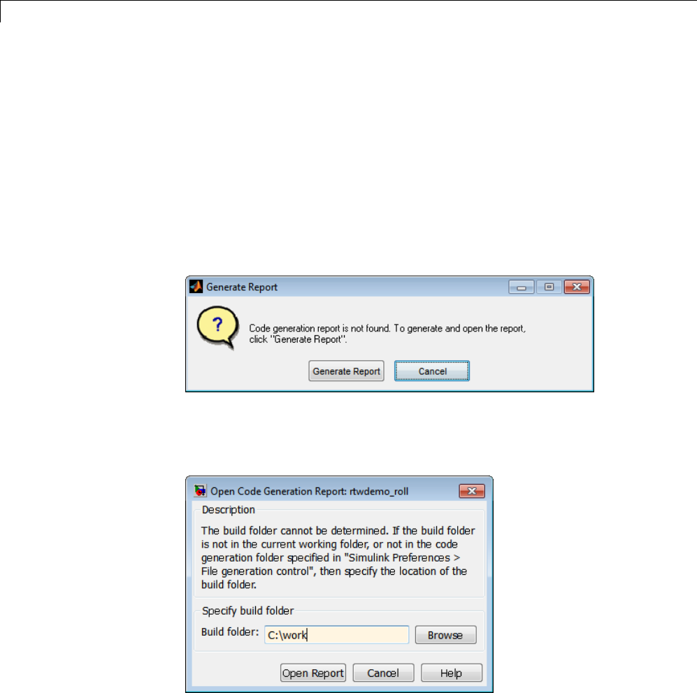
11 Report Generation
Generate Code Generation Report After Build Process
After generating code, if you did not configure your model to create a code
generation report, you can generate a code generation report without
rebuilding your model.
1In the model diagram window, select Code > C/C++ Code > Code
Generation Report > Open Model Report.
2If your current working folder contains the code generation files the
following dialog opens.
Click Generate Report.
3If the code generation files are not in your current working directory, the
following dialog opens.
Enter the full path of the build folder for your model, ../model_target_rtw
and click Open Report.
11-6

Generate Code Generation Report After Build Process
The software generates a report from the code generation files in the build
folder you specified.
Note An alternative method for generating the report after the build
process is complete is to configure your model to generate a report and build
your model. In this case, Embedded Coder generates the report without
regenerating the code.
11-7
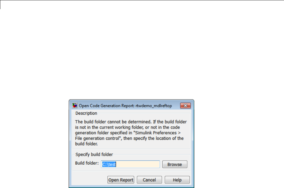
11 Report Generation
Open Code Generation Report
You can refer to existing code generation reports at any time. If you generated
a code generation report, you can open the report by selecting Code > C/C++
Code > Code Generation Report > Open Model Report.Ifyouare
opening a report for a subsystem, select Open Subsystem Report.
If your current working folder does not contain the code generation files and
the code generation report, the following dialog opens:
Enter the full path of the build folder for your model, ../model_target_rtw
and click Open Report.
Alternatively, you can open the code generation report
(model_codegen_rpt.html or subsystem_codegen_rpt.html)
manually into a MATLAB Web browser window, or into another Web browser.
For the location of the generated report files, see “HTML Code Generation
Report Location” on page 11-3.
Limitation
If you modify legacy or custom code after building your model or generating
the code generation report, you must rebuild your model or regenerate the
report for the code generation report to include the updated legacy source files.
For example, if you modify your legacy code and then use the Code > C/C++
Code > Code Generation Report > Open Model Report menu to open
an existing report, the software does not check if the legacy source file is
11-8

Open Code Generation Report
out of date compared to the generated code. Therefore, the code generation
report is not regenerated and the report includes the out-of-date legacy
code. This issue also occurs if you open a code generation report using the
coder.report.open function.
To regenerate the code generation report, do one of the following:
•Rebuild your model.
•Generate the report using the coder.report.generate function.
11-9

11 Report Generation
Generate Code Generation Report Programmatically
At the MATLAB command line, you can generate, open, and close an HTML
Code Generation Report with the following functions:
•coder.report.generate generates the code generation report for the
specified model.
•coder.report.open opens an existing code generation report.
•coder.report.close closes the code generation report.
11-10

Search in the Code Generation Report
Search in the Code Generation Report
When the code generation report is displayed in the MATLAB Web browser
window, you can search the report using the Search box in the left navigation
pane. The search is not case sensitive.
Pressing Ctrl-F sets focus to the Search box. Type text into the Search
box and hit Enter to start the search. The search highlights any found
terms in the displayed page and scrolls to the first instance found. Press
Enter to scroll through the subsequent search hits. If no terms are found, the
background of the search box is highlighted red.
11-11
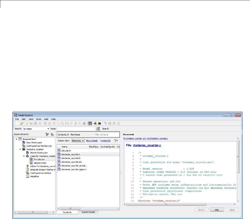
11 Report Generation
View Code Generation Report in Model Explorer
After generating an HTML code generation report, you can view the report
in the right pane of the Model Explorer. You can also browse the generated
files directly in the Model Explorer.
When you generate code, or open a model that has generated code for its
current target configurationinyourworkingfolder,theHierarchy (left)
pane of Model Explorer contains a node named Code for model.Underthat
node are other nodes, typically called This Model and Shared Code. Clicking
This Model displays in the Contents (middle) pane a list of generated source
code files in the build folder of that model. The next figure shows code for
the rtwdemo_counter model.
In this example, the file S:/rtwdemo_counter_grt_rtw/rtwdemo_counter.c
is being displayed. To view any file in the Contents pane, click it once.
The views in the Document (right) pane are read only. The code listings
there contain hyperlinks to functions and macros in the generated code.
Clicking the file hyperlink opens that source file in a text editing window
where you can modify its contents.
11-12

View Code Generation Report in Model Explorer
If an open model contains Model blocks, and if generated code for any of these
models exists in the current slprj folder, nodes for the referenced models
appear in the Hierarchy pane one level below the node for the top model.
Such referenced models do not need tobeopenforyoutobrowseandread
their generated source files.
If the Simulink Coder software generates shared utility code for a model, a
node named Shared Code appears directly under the This Model node. It
collects any source files that exist in the ./slprj/target/_sharedutils
subfolder.
Note You cannot use the Search tool built into Model Explorer toolbar to
search generated code displayed intheCodeViewer. OnPCs,typingCtrl+F
when focused on the Document pane opens a Find dialog box that you can
usetosearchforstringsinthecurrently displayed file. You can also search
for text in the HTML report window, and you can open any of the files in
the editor.
11-13

11 Report Generation
Package and Share the Code Generation Report
In this section...
“Package the Code Generation Report” on page 11-14
“View the Code Generation Report” on page 11-15
Package the Code Generation Report
To share the code generation report, you can package the code generation
report files and supporting files into a zip file for transfer. The default location
for the code generation report files is in two folders:
•/slprj
•html subfolder of the build folder, model_target_rtw,forexample
rtwdemo_counter_grt_rtw/html
To create a zip file from the MATLAB command window:
1In the Current Folder browser, select the two folders:
•/slprj
•Build folder: model_target_rtw
2Right-click to open the context menu.
3In the context menu, select Create Zip File. A file appears in the Current
Folderbrowser.
4Name the zip file.
Alternatively, you can use the MATLAB zip commandtozipthecode
generation report files:
zip('myzip',{'slprj','rtwdemo_counter_grt_rtw'})
11-14

Package and Share the Code Generation Report
Note If you need to relocate the static and generated code files for a model
to another development environment, such as a system or an integrated
development environment (IDE) that does not include MATLAB and Simulink
products, use the Simulink Coder pack-and-go utility. For more information,
see “Relocate Code to Another Development Environment” on page 15-33.
View the Code Generation Report
To view the code generation report after transfer, unzip the file and save
the two folders at the same folder level in the hierarchy. Navigate to the
model_target_rtw/html/ folder and open the top-level HTML report file
named model_codgen_rpt.html or subsystem_codegen_rpt.html in a Web
browser.
11-15

11 Report Generation
Document Generated Code with Simulink Report
Generator
In this section...
“Generate Code for the Model” on page 11-17
“Open the Report Generator” on page 11-18
“Set Report Name, Location, and Format” on page 11-20
“Include Models and Subsystems in a Report” on page 11-21
“Customize the Report” on page 11-22
“Generate the Report” on page 11-23
The Simulink Report Generator software creates documentation from your
model in multipleformats,includingHTML,PDF,RTF,MicrosoftWord,and
XML. This example shows one way to document a code generation project in
Microsoft Word. The generated report includes:
•System snapshots (model and subsystem diagrams)
•Block execution order list
•Simulink Coder and model version information for generated code
•List of generated files
•Optimization configuration parameter settings
•Simulink Coder target selection and build process configuration parameter
settings
•Subsystem map
•File name, path, and generated code listings for the source code
To adjust Simulink Report Generator settings to include custom code and
then generate a report for a model, complete the following tasks:
1“Generate Code for the Model” on page 11-17
2“Open the Report Generator” on page 11-18
11-16

Document Generated Code with Simulink®Report Generator™
3“Set Report Name, Location, and Format” on page 11-20
4“Include Models and Subsystems in a Report” on page 11-21
5“Customize the Report” on page 11-22
6“Generate the Report” on page 11-23
For more information on generating other reports, see the Simulink Report
GeneratorUserGuide.
Generate Code for the Model
Before you use the Report Generator to document your project, generate code
for the model.
1In the MATLAB Current Folder browser, navigate to a folder where you
have write access.
2Create a working folder from the MATLAB command line by typing:
mkdir report_ex
3Make report_ex your working folder:
cd report_ex
4Open the sldemo_f14 model by clicking the following model name below or
by entering the model name on the MATLAB command line.
5In the model window, choose File > Save As, navigate to the working
folder, report_ex, and save a copy of the sldemo_f14 model as myf14.
6Open the Model Explorer by selecting Model Explorer from the model
View menu.
7In the Model Hierarchy pane, click the expander for the model name to
reveal its components.
8In the left pane, click Configuration (Active).
11-17

11 Report Generation
9Select the Solver tab. In the Solver options section, specify the Type
parameter as Fixed-step.
10 Select the General tab. Select Generate code only. Scroll down if the
configuration parameter is not visible.
11 Click Apply.
12 Click Generate code. The Simulink Coder build process generates code
for the model.
Open the Report Generator
After you generate the code, open the Report Generator.
1In the model diagram window, select Tools > Report Generator.
11-18
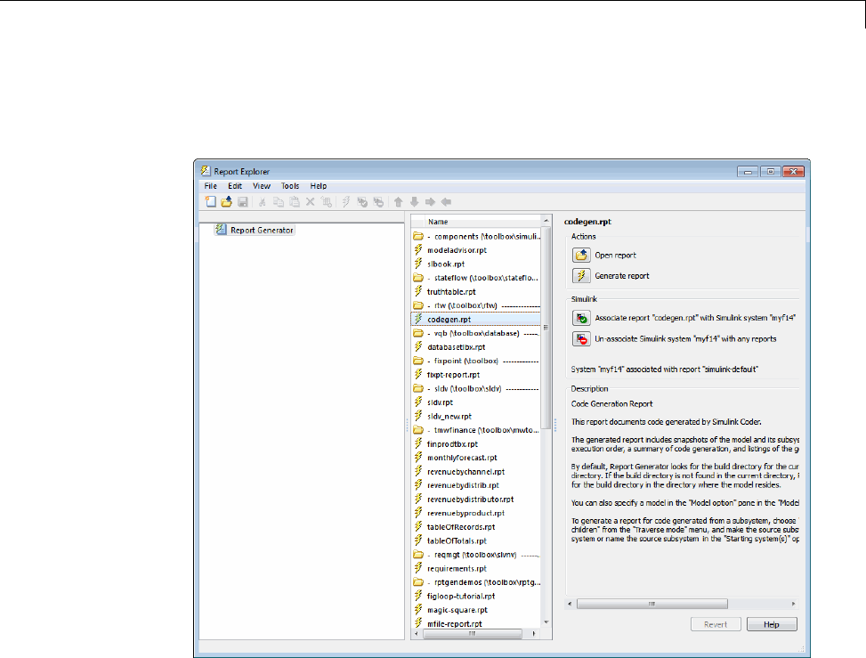
Document Generated Code with Simulink®Report Generator™
2In the Report Explorer window, in the options pane (center), click the folder
rtw (\toolbox\rtw). Click the setup file that it contains, codegen.rpt.
11-19
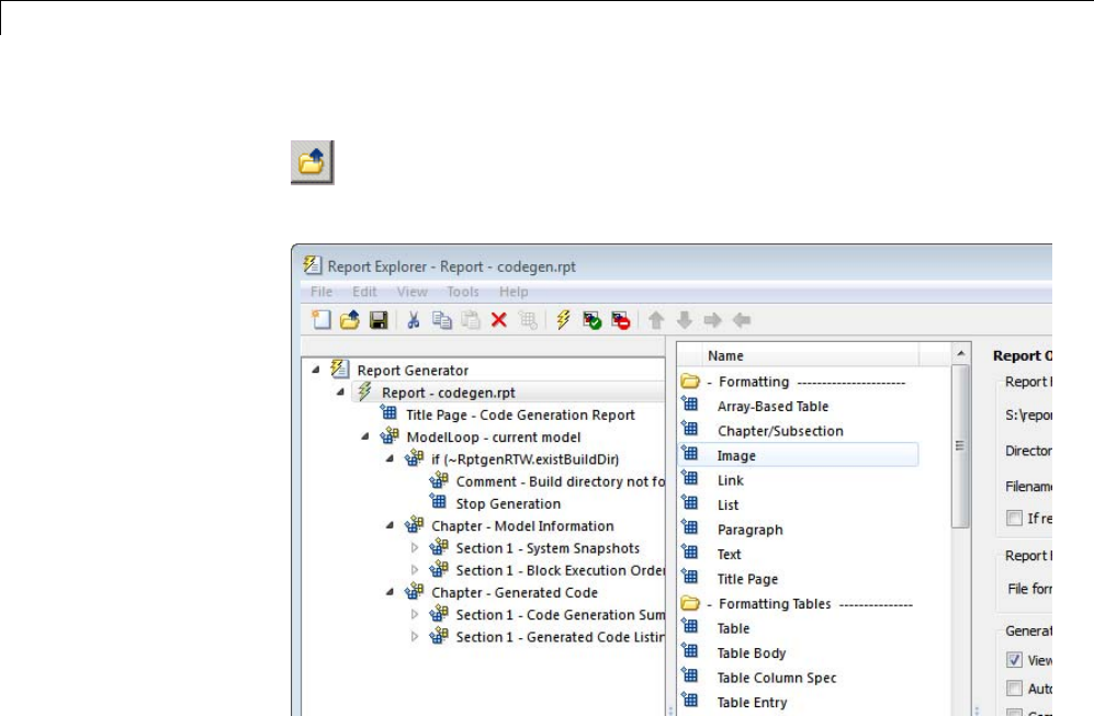
11 Report Generation
3Double-click codegen.rpt or select it and click the Open report button
. The Report Explorer displays the structure of the setup file in the
outline pane (left).
Set Report Name, Location, and Format
Before generating a report, you can specify report output options, such as the
folder, file name, and format. For example, to generate a Microsoft Word
report named MyCGModelReport.rtf:
11-20
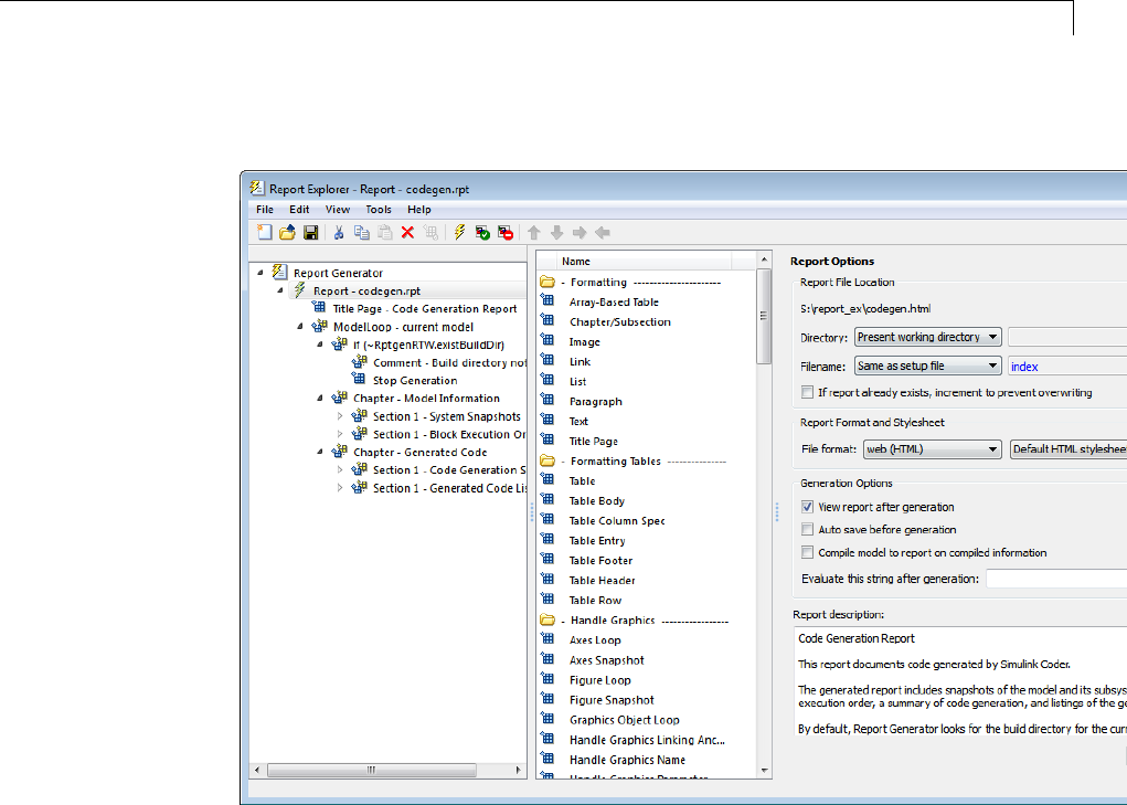
Document Generated Code with Simulink®Report Generator™
1In the properties pane, under Report Options, review the options listed.
2Leave the Directory field set to Present working directory.
3For Filename,selectCustom: and replace index with the name
MyModelCGReport.
4For File format,specifyRich Text Format and replace Standard Print
with Numbered Chapters & Sections.
Include Models and Subsystems in a Report
Specify the models and subsystems that you want to include in the generated
report by setting options in the Model Loop component.
11-21
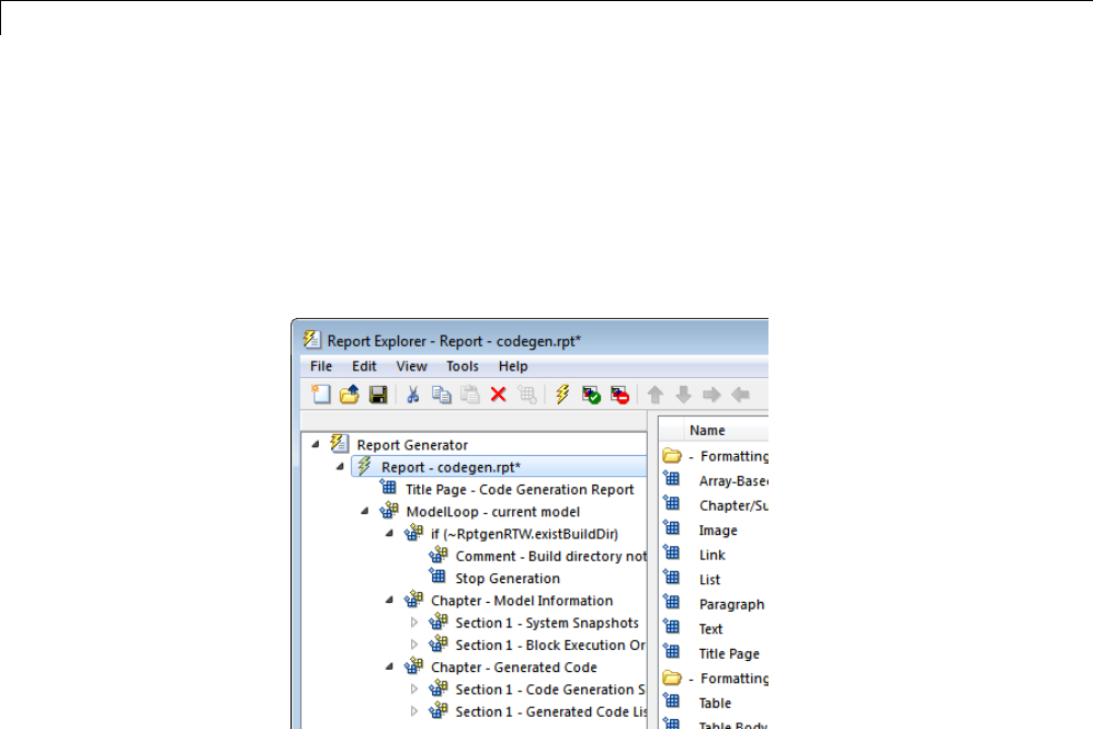
11 Report Generation
1In the outline pane (left), select Model Loop. Report Generator displays
Model Loop component options in the properties pane.
2If not already selected, select Current block diagram for the Model
name option.
3In the outline pane, click Report - codegen.rpt*.
Customize the Report
After specifying the models and subsystems to include in the report, you can
customize the sections included in the report.
1In the outline pane (left), expand the node Chapter - Generated Code.
By default, the report includes two sections, each containing one of two
report components.
2Expand the node Section 1 — Code Generation Summary.
3Select Code Generation Summary. Options for the component are
displayed in the properties pane.
11-22
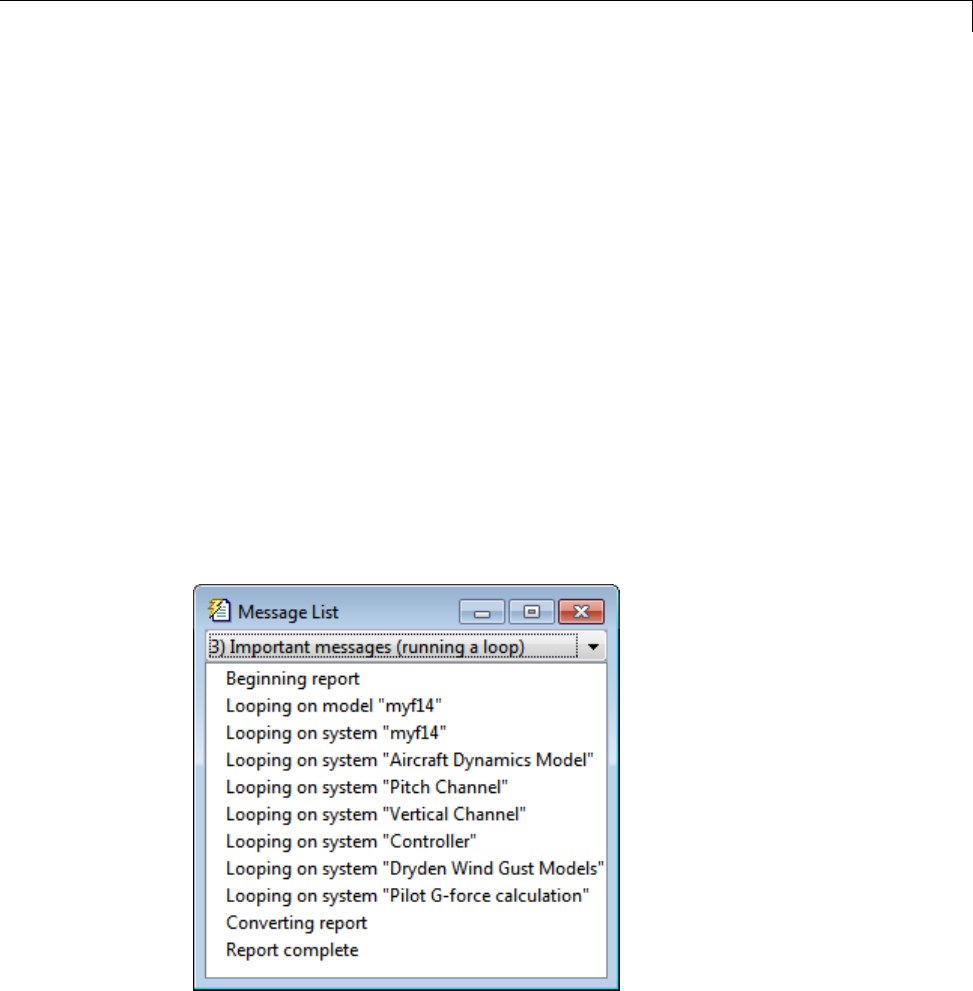
Document Generated Code with Simulink®Report Generator™
4Click Help to review the report customizations that you can make with the
Code Generation Summary component. For this example, do not customize
the component.
5In the Report Explorer window, expand the node Section 1 — Generated
Code Listing.
6Select Import Generated Code. Options for the component are displayed
in the properties pane.
7Click Help to review the report customizations that you can make with the
Import Generated Code component.
Generate the Report
After you adjust the report options, from the Report Explorer window,
generate the report by clicking File > Report.AMessage List dialog
box opens, which displays messages that you can monitor as the report is
generated. Model snapshots also appear during report generation. The
Message List dialog box might be hidden behind other dialog boxes.
When the report is complete, open the report, MyModelCGReport.rtf in the
folder report_ex (in this example).
11-23

11 Report Generation
For alternative ways of generating reports with the Simulink Report
Generator, see “Report Generation”.
11-24


12 Desktops
Rapid Simulations
In this section...
“About Rapid Simulation” on page 12-2
“Rapid Simulation Performance” on page 12-3
“General Rapid Simulation Workflow” on page 12-3
“Identify Rapid Simulation Requirements” on page 12-4
“Configure Inports to Provide Simulation Source Data” on page 12-6
“Configure and Build Model for Rapid Simulation” on page 12-6
“Set Up Rapid Simulation Input Data” on page 12-9
“Scripts for Batch and Monte Carlo Simulations” on page 12-19
“Run Rapid Simulations” on page 12-20
“Rapid Simulation Target Limitations” on page 12-33
About Rapid Simulation
After you create a model, you can use the Simulink Coder rapid simulation
(RSim) target to characterize the model behavior. The RSim target executable
that results from the build process is for non-real-time execution on your
host computer. The executable is highly optimized for simulating models of
hybrid dynamic systems, including models that use variable-step solvers and
zero-crossing detection. The speed of the generated code makes the RSim
target ideal for batch or Monte Carlo simulations.
Use the RSim target to generate an executable that runs fast, standalone
simulations. You can repeat simulations with varying data sets, interactively
or programmatically with scripts, without rebuilding the model. This can
accelerate the characterization and tuning of model behavior and code
generation testing.
Using command-line options:
•Define parameter values and input signals in one or more MAT-files that
you can load and reload at the start of simulations without rebuilding
your model.
12-2

Rapid Simulations
•Redirect logging data to one or more MAT-files that you can then analyze
and compare.
•Control simulation time.
•Specify External mode options.
Note To run an RSim executable, configure your computer to run MATLAB
and have the MATLAB and Simulink installation folders accessible. To deploy
a standalone host executable ( i.e., without MATLAB and Simulink installed),
consider using the Host-Based Shared Library target (ert_shrlib)."
Rapid Simulation Performance
The performance advantage that you gain from rapid simulation varies.
Larger simulations achieve speed improvements of up to 10 times faster than
standard Simulink simulations. Some models might not show any noticeable
improvement in simulation speed. To determine the speed difference for your
model, time your standard Simulink simulation and compare the results
with a rapid simulation. In addition, test the model performance in Rapid
Accelerator simulation mode.
General Rapid Simulation Workflow
Like other stages of Model-Based Design, characterization and tuning of
model behavior is an iterative process, as shown in the general workflow
diagram in the figure. Tasks in the workflow are:
1Identify your rapid simulation requirements.
2Configure Inport blocks that provide input source data for rapid
simulations.
3Configure the model for rapid simulation.
4Set up simulation input data.
5Run the rapid simulations.
12-3
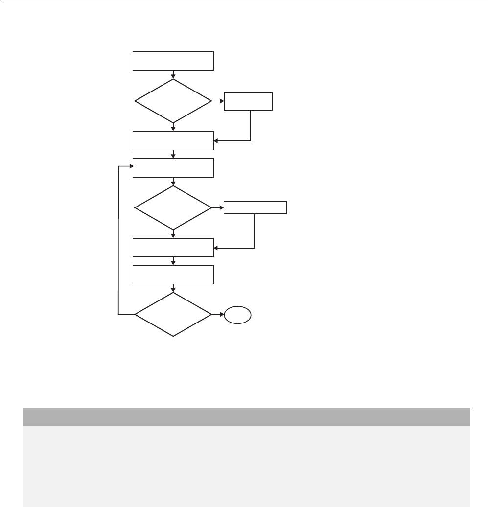
12 Desktops
Configure
Inport blocks
Program script
Yes
No
Configure and
build model
Set up input data
Run simulation
Model includes
Inport blocks?
Identify rapid simulation
requirements
Yes
No
Analyze simulation
results
Change input
data?
Yes Done
Batch
or Monte Carlo
simulations?
Identify Rapid Simulation Requirements
The first step to setting up a rapid simulation is to identify your simulation
requirements.
Question... For More Information, See...
How long do you want simulations to
run?
“Configure and Build Model for Rapid Simulation”
on page 12-6
Are there any solver requirements? Do
you expect to use the same solver for
which the model is configured for your
rapid simulations?
“Configure and Build Model for Rapid Simulation”
on page 12-6
12-4

Rapid Simulations
Question... For More Information, See...
Do your rapid simulations need to
accommodate flexible custom code
interfacing? Or, do your simulations
need to retain storage class settings?
“Configure and Build Model for Rapid Simulation”
on page 12-6
Will you be running simulations with
multiple data sets?
“Set Up Rapid Simulation Input Data” on page 12-9
Will the input data consist of global
parameters, signals, or both?
“Set Up Rapid Simulation Input Data” on page 12-9
What type of source blocks provide input
data to the model — From File, Inport,
From Workspace?
“Set Up Rapid Simulation Input Data” on page 12-9
Will the model’s parameter vector
(model_P)beusedasinputdata?
“Create a MAT-File That Includes a Model Parameter
Structure” on page 12-10
Whatisthedatatypeoftheinput
parameters and signals?
“Set Up Rapid Simulation Input Data” on page 12-9
Will the source data consist of one
variable or multiple variables?
“Set Up Rapid Simulation Input Data” on page 12-9
Does the input data include tunable
parameters?
“Create a MAT-File That Includes a Model Parameter
Structure” on page 12-10
Do you need to gain access to tunable
parameter information — model
checksum and parameter data types,
identifiers, and complexity?
“Create a MAT-File That Includes a Model Parameter
Structure” on page 12-10
Will you have a need to vary the
simulation stop time for simulation
runs?
“Configure and Build Model for Rapid Simulation”
on page 12-6 and“Override a Model Simulation Stop
Time” on page 12-23
Doyouwanttosetatimelimitforthe
simulation? Consider setting a time
limit if your model experiences frequent
zero crossings and has a small minor
step size.
“Set a Clock Time Limit for a Rapid Simulation” on
page 12-23
12-5

12 Desktops
Question... For More Information, See...
Do you need to preserve the output of
each simulation run?
“Specify a New Output File Name for a Simulation”
on page 12-32 and “Specify New Output File Names
for To File Blocks” on page 12-33
Do you expect to run the simulations
interactively or in batch mode?
“Scripts for Batch and Monte Carlo Simulations” on
page 12-19
Configure Inports to Provide Simulation Source Data
You can use Inport blocks as a source of input data for rapid simulations.
To do so, configure the blocks so that they can import data from external
MAT-files. By default, the Inport block inherits parameter settings from
downstream blocks. In most cases, to import data from an external MAT-file,
you must explicitly set the following parameters to match the source data
in the MAT-file.
•Main > Interpolate data
•Signal Attributes > Port dimensions
•Signal Attributes > Data type
•Signal Attributes > Signal type
If you do not have control over the model content, you might need to modify
the data in the MAT-file to conform to what the model expects for input.
Input data characteristics and specifications of the Inport block that receives
the data must match.
For details on adjusting these parameters and on creating a MAT-file for use
with an Inport block, see “Create a MAT-File for an Inport Block” on page
12-15. For descriptions of the preceding block parameters, see the description
of the Inport block in the Simulink documentation.
Configure and Build Model for Rapid Simulation
After you identify your rapid simulation requirements, configure the model
for rapid simulation.
1Open the Configuration Parameters dialog box.
12-6
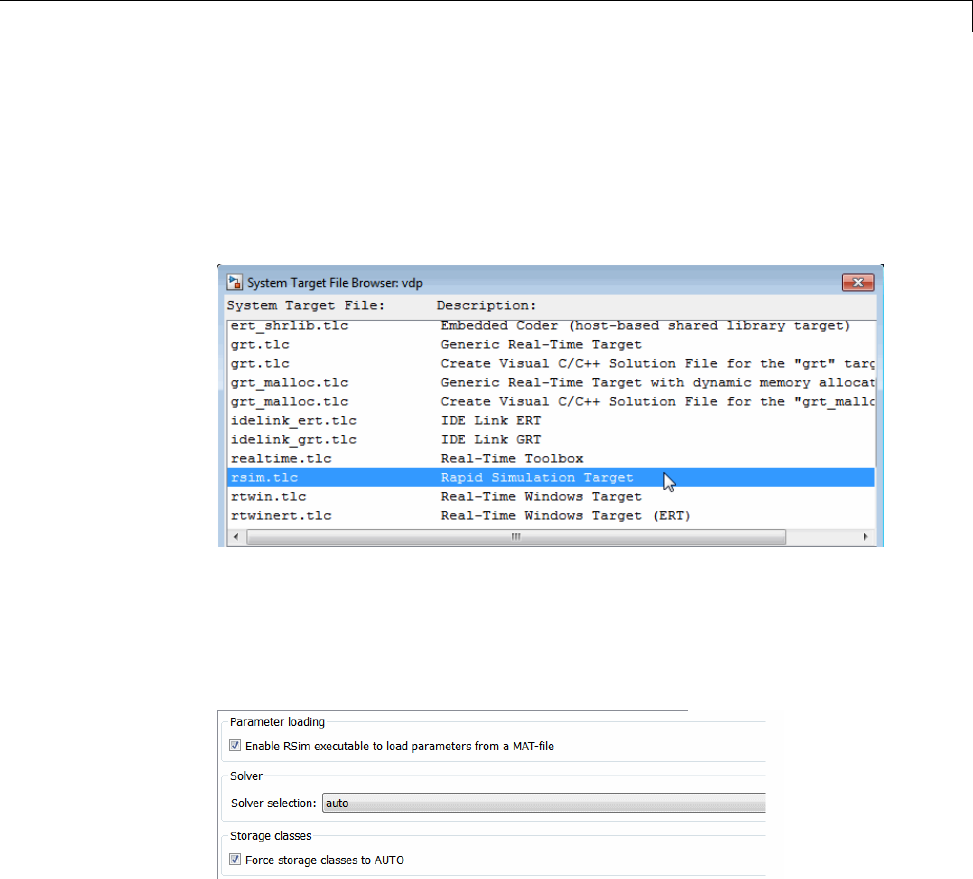
Rapid Simulations
2Go to the Code Generation pane.
3On the Code Generation pane, click Browse. The System Target File
Browser opens.
4Select rsim.tlc (Rapid Simulation Target) and click OK.
On the Code Generation pane, the Simulink Coder software populates
the Make command and Template makefile fields with default settings
and adds the RSim Target pane under Code Generation.
5Click RSim Target to view the RSim Target pane.
6Set the RSim target configuration parameters to your rapid simulation
requirements.
12-7

12 Desktops
If You Want to... Then...
Generate code that allows the RSim
executable to load parameters from a
MAT-file
Select Enable RSim executable to load
parameters from a MAT-file (default).
Let the target choose a solver based on the
solver already configured for the model.
Set Solver selection to auto (default). The
Simulink Coder software uses a built-in solver if a
fixed-step solver is specified on the Solver pane
or calls the Simulink solver module (a shared
library) if a variable-step solver is specified.
Explicitly instruct the target to use a
fixed-step solver
Set Solver selection to Use fixed-step
solvers. In the Configuration Parameters dialog
box, on the Solver pane, specify a fixed-step
solver.
Explicitly instruct the target to use a
variable-step solver
Set Solver selection to Use Simulink solver
module. In the Configuration Parameters dialog
box, on the Solver pane, specify a variable-step
solver.
Force all storage classes to Auto for flexible
custom code interfacing
Select Force storage classes to AUTO (default).
Retain storage class settings, such as
ExportedGlobal or ImportedExtern,dueto
application requirements
Clear Force storage classes to AUTO.
7Set up data import and export options. On the Data Import/Export pane,
in the Save to Workspace section, select the Time,States,Outputs,
and Final States options, as they apply. By default, the Simulink Coder
software saves simulation logging results to a file named model.mat.For
more information, see “Export Simulation Data”.
8If you are using External mode communications, set up the interface,
using the Code Generation > Interface pane. See “Host/Target
Communication” on page 15-50 for details.
9Return to the Code Generation pane and click Build. The Simulink
Coder code generator builds a highly optimized executable that you can run
on your host computer with varying data, without rebuilding.
12-8

Rapid Simulations
For more information on compilers that are compatible with the Simulink
Coder product, see “Choose and Configure a Compiler” on page 15-2 and
“Template Makefiles and Make Options” on page 9-38 .
Set Up Rapid Simulation Input Data
•“About Rapid Simulation Data Setup” on page 12-9
•“Create a MAT-File That Includes a Model Parameter Structure” on page
12-10
•“Create a MAT-File for a From File Block” on page 12-14
•“Create a MAT-File for an Inport Block” on page 12-15
About Rapid Simulation Data Setup
The format and setup of input data for a rapid simulation depends on your
requirements.
If the Input Data Source Is... Then...
The model’s global parameter
vector (model_P)
Use the rsimgetrtp function to get
the vector content and then save it to a
MAT-file.
The model’s global parameter
vector and you want a mapping
between the vector and tunable
parameters
In the Configuration Parameters dialog
box, on the Optimization > Signals
and Parameters pane, enable the
Inline Parameters option. Call the
rsimgetrtp function to get the global
parameter structure and then save it to
aMAT-file.
Provided by a From File block Create a MAT-file that a From File block
can read.
Provided by an Inport block Create a MAT-file that adheres to one of
the three data file formats that the Inport
block can read.
Provided by a From Workspace
block
Create structure variables in the
MATLAB workspace.
12-9

12 Desktops
The RSim target requires that MAT-files used as input for From File and
Inport blocks contain data. The grt target inserts MAT-file data directly into
the generated code, which is then compiled and linked as an executable. In
contrast, RSim allows you to replace data sets for each successive simulation.
A MAT-file containing From File or Inport block data must be present if a
From File block or Inport block exists in your model.
Create a MAT-File That Includes a Model Parameter Structure
To create a MAT-file that includes a model global parameter structure
(model_P),
1Get the structure by calling the function rsimgetrtp.
2Save the parameter structure to a MAT-file.
If you want to run simulations over varying data sets, consider converting
the parameter structure to a cell array and saving the parameter variations
to a single MAT-file.
Get the Parameter Structure for a Model. Get the global parameter
structure (model_P) for a model by calling the function rsimgetrtp.
param_struct = rsimgetrtp('model')
Argument Description
model The model for which you are running the rapid
simulations.
The rsimgetrtp function forces an update diagram action for the specified
model and returns a structure that contains the following fields.
12-10

Rapid Simulations
Field Description
modelChecksum A four-element vector that encodes the structure of the
model. The Simulink Coder software uses the checksum
to check whether the structure of the model has changed
since the RSim executable was generated. If you delete or
add a block, and then generate a new model_P vector, the
new checksum no longer matches the original checksum.
The RSim executable detects this incompatibility in
parameter vectors and exits to avoid returning incorrect
simulation results. If the model structure changes, you
must regenerate the code for the model.
parameters A structure that contains the model’s global parameters.
The parameter structure contains the following information.
Field Description
dataTypeName Thenameoftheparameterdatatype,forexample,
double
dataTypeID Internal data type identifier used by the Simulink Coder
software
complex The value 0 if real; 1 if complex
dtTransIdx Internal data index used by Simulink Coder software
values A vector of the parameter values associated with this
structure
map If you select the Inline parameters option, this field
contains the mapping information that correlates
the ’values’ to the tunable parameters of the model.
This mapping information, in conjunction with
rsimsetrtpparam, is useful for creating subsequent rtP
structures without compiling the block diagram.
If you select the Inline parameters option for the model, then tunable
parameter information is also available in the parameters field.
12-11

12 Desktops
The Simulink Coder software reports a tunable fixed-point parameter
according to its stored value. For example, an sfix(16) parameter value of
1.4 with a scaling of 2^-8 has a value of 358 as an int16.
In the following example, rsimgetrtp returns the parameter structure for the
example model rtwdemo_rsimtf to param_struct.
param_struct = rsimgetrtp('rtwdemo_rsimtf')
param_struct =
modelChecksum: [1.7165e+009 3.0726e+009 2.6061e+009 2.3064e+009]
parameters: [1x1 struct]
Save the Parameter Structure to a MAT-File. After you issue a call to
rsimgetrtp, save the return value of the function call to a MAT-file. Using a
command-line option, you can then specify that MAT-file as input for rapid
simulations.
The following example saves the parameter structure returned for
rtwdemo_rsimtf to the MAT-file myrsimdemo.mat.
save myrsimdemo.mat param_struct;
For information on using command-line options to specify required files, see
“Run Rapid Simulations” on page 12-20.
Convert the Parameter Structure for Running Simulations on Varying
Data Sets. Ifyouneedtouserapidsimulations to test changes to specific
parameters, you can convert the model parameter structure to a cell array.
You can then access a specific parameter by using the @ operator to specify
the index for a specific parameter in the file.
To convert the structure to a cell array:
1Save the parameters vector of the structure returned by rsimgetrtp to a
temporary variable. The following example saves the parameter vector to
temporary variable p.
param_struct = rsimgetrtp('rtwdemo_rsimtf');
p = param_struct.parameters;
12-12

Rapid Simulations
2Convert the structure to a cell array.
param_struct.parameters = [];
3Assign the saved contents of the temporary variable to the original
structure name as an element of the cell array.
param_struct.parameters{1} = p;
param_struct.parameters{1}
ans =
dataTypeName: 'double'
dataTypeId: 0
complex: 0
dtTransIdx: 0
values: [-140 -4900 0 4900]
map: []
4Make a copy of the cell array to preserve the original parameter values.
param_struct.parameters{2} = param_struct.parameters{1};
param_struct.parameters{2}
ans =
dataTypeName: 'double'
dataTypeId: 0
complex: 0
dtTransIdx: 0
values: [-140 -4900 0 4900]
map: []
For a subsequent data set, increment the array index.
5Modify any combination of the parameter values.
param_struct.parameters{2}.values=[-150 -5000 0 4950];
6Repeat steps 4 and 5 for each parameter data set that you want to use as
input to a rapid simulation of the model.
12-13

12 Desktops
7Save the cell array representing the parameter structure to a MAT-file.
save rtwdemo_rsimtf.mat param_struct;
For more information on how to specify each data set when you run the
simulations, see“Change Block Parameters for an RSim Simulation” on page
12-30.
CreateaMAT-FileforaFromFileBlock
You can use a MAT-file as the input data source for a From File block. The
format of the data in the MAT-file must match the data format expected
by that block.
To create a MAT-file for a From File block:
1For array format data, in the workspace create a matrix that consists of two
or more rows. The first row must contain monotonically increasing time
points. Other rows contain data points that correspond to the time point in
that column. The time and data points must be data of type double.
For example:
t=[0:0.1:2*pi]';
Ina1=[2*sin(t) 2*cos(t)];
Ina2=sin(2*t);
Ina3=[0.5*sin(3*t) 0.5*cos(3*t)];
var_matrix=[t Ina1 Ina2 Ina3]';
For other supported data types, such as int16 or fixed-point, the time data
points must be of type double, just as for array format data. However, the
sample data can be of any dimension.
For more information on setting up the input data, see the description of
theFromFileblockintheSimulink documentation.
2Save the matrix to a MAT-file.
The following example saves the matrix var_matrix to the MAT-file
myrsimdemo.mat in Version 7.3 format.
save '-v7.3' myrsimdemo.mat var_matrix;
12-14

Rapid Simulations
Using a command-line option, you can then specify that MAT-file as input
for rapid simulations.
Create a MAT-File for an Inport Block
You can use a MAT-file as the input data source for an Inport block.
TheformatofthedataintheMAT-filemustadheretooneofthethree
column-based formats listed in the following table. The table lists the formats
in order from least flexible to most flexible.
Format Description
Single time/data
matrix
•Least flexible.
•One variable.
•Two or more columns. Number of columns must equal the sum of the
dimensions of all root Inport blocks plus 1. First column must contain
monotonically increasing time points. Other columns contain data
points that correspond to the time point in a given row.
•Data of type double.
For an example, see Single time/data matrix in the following procedure,
step 4. For more information, see “ImportDataArrays”intheSimulink
documentation.
Format Description
Signal-and-time
structure
•More flexible than the single time/data matrix format.
•One variable.
•Must contain two top-level fields: time and signals.Thetime field
contains a column vector of the simulation times. The signals field
contains an array of substructures, each of which corresponds to an
Inport block. The substructure index corresponds to the Inport block
number. Each signals substructure must contain a field named
values.Thevalues field must contain an array of inputs for the
corresponding Inport block, where each input corresponds to a time
point specified by the time field.
12-15

12 Desktops
Format Description
•If the time field is set to an empty value, clear the check box for the
Inport block Interpolate data parameter.
•No data type limitations, but must match Inport block settings.
For an example, see Signal-and-time structure in the following procedure,
step 4. For more information on this format, see “Import Data Structures”
in the Simulink documentation.
Format Description
Per-port structure •Most flexible
•Multiple variables. Number of variables must equal the number of
Inport blocks.
•Consists of a separate structure-with-time or structure-without-time
for each Inport block. Each Inport block data structure has only one
signals field. To use this format, in the Input text field, enter the
names of the structures as a comma-separated list, in1,in2,..., inN,
where in1 is the data for your model’s first port, in2 for the second
port, and so on.
•Each variable can have a different time vector.
•If the time field is set to an empty value, clear the check box for the
Inport block Interpolate data parameter.
•No data type limitations, but must match Inport block settings.
•To save multiple variables to the same data file, you must save them in
the order expected by the model, using the -append option.
For an example, see Per-port structure in the following procedure, step
4. For more information, see “Import Data Structures” in the Simulink
documentation.
The supported formats and the following procedure are illustrated in
rtwdemo_rsim_i.
To create a MAT-file for an Inport block:
12-16

Rapid Simulations
1Choose one of the preceding data file formats.
2Update Inport block parameter settings and specifications to match
specifications of the data to be supplied by the MAT-file.
By default, the Inport block inherits parameter settings from downstream
blocks. To import data from an external MAT-file, explicitly set the
following parameters to match the source data in the MAT-file.
•Main > Interpolate data
•Signal Attributes > Port dimensions
•Signal Attributes > Data type
•Signal Attributes > Signal type
Ifyouchoosetouseastructureformat for workspace variables and the
time field is empty, you must clear Interpolate data or modify the field so
that it is set to a nonempty value. Interpolation requires time data.
For descriptions of the preceding block parameters, see the description of
the Inport block in the Simulink documentation.
3Build an RSim executable for the model. The Simulink Coder build process
creates and calculates a structural checksum for the model and embeds
it in the generated executable. The RSim target uses the checksum to
verify that data being passed into the model is consistent with what the
model executable expects.
4Create the MAT-file that provides the source data for the rapid simulations.
You can create the MAT-file from a workspace variable. Using the
specifications in the preceding format comparison table, create the
workspace variables for your simulations.
An example of each format follows:
Single time/data matrix
t=[0:0.1:2*pi]';
Ina1=[2*sin(t) 2*cos(t)];
Ina2=sin(2*t);
Ina3=[0.5*sin(3*t) 0.5*cos(3*t)];
12-17

12 Desktops
var_matrix=[t Ina1 Ina2 Ina3];
Signal-and-time structure
t=[0:0.1:2*pi]';
var_single_struct.time=t;
var_single_struct.signals(1).values(:,1)=2*sin(t);
var_single_struct.signals(1).values(:,2)=2*cos(t);
var_single_struct.signals(2).values=sin(2*t);
var_single_struct.signals(3).values(:,1)=0.5*sin(3*t);
var_single_struct.signals(3).values(:,2)=0.5*cos(3*t);
v=[var_single_struct.signals(1).values...
var_single_struct.signals(2).values...
var_single_struct.signals(3).values];
Per-port structure
t=[0:0.1:2*pi]';
Inb1.time=t;
Inb1.signals.values(:,1)=2*sin(t);
Inb1.signals.values(:,2)=2*cos(t);
t=[0:0.2:2*pi]';
Inb2.time=t;
Inb2.signals.values(:,1)=sin(2*t);
t=[0:0.1:2*pi]';
Inb3.time=t;
Inb3.signals.values(:,1)=0.5*sin(3*t);
Inb3.signals.values(:,2)=0.5*cos(3*t);
5Save the workspace variables to a MAT-file.
Single time/data matrix
The following example saves the workspace variable var_matrix to the
MAT-file rsim_i_matrix.mat.
save rsim_i_matrix.mat var_matrix;
Signal-and-time structure
The following example saves the workspace structure variable
var_single_struct to the MAT-file rsim_i_single_struct.mat.
12-18

Rapid Simulations
save rsim_i_single_struct.mat var_single_struct;
Per-port structure
To order data when saving per-port structure variables to a single MAT-file,
use the save command’s -append option. Besuretoappendthedatain
the order that the model expects it.
The following example saves the workspace variables Inb1,Inb2,andInb3
to MAT-file rsim_i_multi_struct.mat.
save rsim_i_multi_struct.mat Inb1;
save rsim_i_multi_struct.mat Inb2 -append;
save rsim_i_multi_struct.mat Inb3 -append;
The save command does not preserve the orderinwhichyouspecifyyour
workspace variables in the command line when saving data to a MAT-file.
For example, if you specify the variables v1,v2,andv3,inthatorder,the
order of the variables in the MAT-file could be v2 v1 v3.
Using a command-line option, you can then specify the MAT-files as input
for rapid simulations.
Scripts for Batch and Monte Carlo Simulations
The RSim target is for batch simulations in which parameters and input
signals vary for multiple simulations. New output file names allow you to run
new simulations without overwriting prior simulation results. You can set up
a series of simulations to run by creating a .bat file for use on a Microsoft
Windows platform.
Create a file for the Windows platform with any text editor and execute it by
typing the file name, for example, mybatch,wherethenameofthetextfile
is mybatch.bat.
rtwdemo_rsimtf -f rtwdemo_rsimtf.mat=run1.mat -o results1.mat -tf 10.0
rtwdemo_rsimtf -f rtwdemo_rsimtf.mat=run2.mat -o results2.mat -tf 10.0
rtwdemo_rsimtf -f rtwdemo_rsimtf.mat=run3.mat -o results3.mat -tf 10.0
rtwdemo_rsimtf -f rtwdemo_rsimtf.mat=run4.mat -o results4.mat -tf 10.0
12-19

12 Desktops
In this case, batch simulations run using four sets of input data in files
run1.mat,run2.mat, and so on. The RSim executable saves the data to the
files specified with the -o option.
The variable names containing simulation results in each of the files are
identical. Therefore, loading consecutive sets of data without renaming the
data once it is in the MATLAB workspace results in overwriting the prior
workspace variable with new data. To avoid overwriting, you can copy the
result to a new MATLAB variable before loading the next set of data.
You can also write MATLAB scripts to create new signals and new parameter
structures, as well as to save data and perform batch runs using the bang
command (!).
For details on running simulations and available command-line options, see
“Run Rapid Simulations” on page 12-20. For an example of a rapid simulation
batch script, see the example rtwdemo_rsim_batch_script.
Run Rapid Simulations
•“” on page 12-20
•“Requirements for Running Rapid Simulations” on page 12-22
•“Set a Clock Time Limit for a Rapid Simulation” on page 12-23
•“Override a Model Simulation Stop Time” on page 12-23
•“Read the Parameter Vector into a Rapid Simulation” on page 12-24
•“Specify New Signal Data File for a From File Block” on page 12-24
•“Specify Signal Data File for an Inport Block” on page 12-27
•“Change Block Parameters for an RSim Simulation” on page 12-30
•“Specify a New Output File Name for a Simulation” on page 12-32
•“SpecifyNewOutputFileNamesforToFileBlocks”onpage12-33
Using the RSim target, you can build a model once and run multiple
simulations to study effects of varying parameter settings and input signals.
You can run a simulation directly from your operating system command line,
12-20

Rapid Simulations
redirect the command from the MATLAB command line by using the bang
(!) character, or execute commands from a script.
Operating System Command Line
rtwdemo_rsimtf
MATLAB Command Line
!rtwdemo_rsimtf
The following table lists ways you can use RSim target command-line options
to control a simulation.
To... Use...
ReadinputdataforaFromFileblockfroma
MAT-file other than the MAT-file used for the
previous simulation
model -f oldfilename.mat=newfilename.mat
Print a summary of the options for RSim
executable targets
executable filename -h
Read input data for an Inport block from a
MAT-file
model -i filename.mat
Time out after nclock time seconds, where nis
a positive integer value
model -L n
Write MAT-file logging data to file
filename.mat
model -o filename.mat
Read a parameter vector from file
filename.mat
model -p filename.mat
Override the default TCP port (17725) for
External mode
model -port TCPport
WriteMAT-fileloggingdatatoaMAT-file
other than the MAT-file used for the previous
simulation
model -t
oldfilename.mat=newfilename.mat
Run the simulation until the time value
stoptime is reached
model -tf stoptime
12-21

12 Desktops
To... Use...
Runinverbosemode model -v
Wait for the Simulink engine to start the model
in External mode
model -w
The following sections use the rtwdemo_rsimtf example model in examples
to illustrate some of these command-lineoptions. Ineachcase,theexample
assumes you have already done the following:
•Created or changed to a working folder.
•Opened the example model.
•Copied the data file
matlabroot/toolbox/rtw/rtwdemos/rsimdemos/rsim_tfdata.mat to
your working folder. You can perform this operation using the command:
copyfile(fullfile(matlabroot,'toolbox','rtw','rtwdemos',...
'rsimdemos','rsim_tfdata.mat'),pwd);
Requirements for Running Rapid Simulations
•You can run the RSim executable on any computer configured to run
MATLAB and for which the MATLAB and Simulink installation folder is
accessible to the RSim.exe. To obtain that access, your PATH environment
variable must include /bin and /bin/($ARCH), where ($ARCH) represents
your operating system architecture. For example, for a personal computer
running on a Windows platform, ($ARCH) is “win32”, whereas for a Linux
machine, ($ARCH) is “glnx86”.
•On GNU Linux platforms, to run an RSim executable, define the
LD_LIBRARY_PATH environment variable to provide the path to the
MATLAB installation folder, as follows:
% setenv LD_LIBRARY_PATH /matlab/sys/os/glnx86:$LD_LIBRARY_PATH
•On the Apple Macintosh OS X platform, to run RSim target executables,
you must define the environment variable DYLD_LIBRARY_PATH to include
the folders bin/mac and sys/os/mac under the MATLAB installation
12-22

Rapid Simulations
folder. For example, if your MATLAB installation is under /MATLAB,
add /MATLAB/bin/mac and /MATLAB/sys/os/mac to the definition for
DYLD_LIBRARY_PATH.
Set a Clock Time Limit for a Rapid Simulation
If a model experiences frequent zero crossings and the model’s minor step size
is small, consider setting a time limit for a rapid simulation. To set a time
limit, specify the -L option with a positive integer value. The simulation
aborts after running for the specified amount of clock time (not simulation
time). For example,
!rtwdemo_rsimtf -L 20
Based on your clock, after the executable runs for 20 seconds, the program is
terminate. You see one of the following messages:
On a Microsoft Windows Platform
Exiting program, time limit exceeded
Logging available data ...
On The Open Group UNIX Platform
** Received SIGALRM (Alarm) signal @ Fri Jul 25 15:43:23 2003
** Exiting model 'vdp' @ Fri Jul 25 15:43:23 2003
You do not need to do anything to your model or to its Simulink Coder
configuration to use this option.
Override a Model Simulation Stop Time
By default, a rapid simulation runs until the simulation time reaches the time
specified the Configuration Parameters dialog box, on the Solver pane. You
can override the model simulation stop time by using the -tf option. For
example, the following simulation runs until the time reaches 6.0 seconds.
!rtwdemo_rsimtf -tf 6.0
TheRSimtargetstopsandlogsoutputdatausingMAT-filedataloggingrules.
12-23

12 Desktops
If the model includes a From File block, the end of the simulation is regulated
by the stop time setting specified in the Configuration Parameters dialog
box, on the Solver pane, or with the RSim target option -tf.Thevaluesin
the block’s time vector are ignored. However, if the simulation time exceeds
the endpoints of the time and signal matrix (if the final time is greater than
the final time value of the data matrix), the signal data is extrapolated to
the final time value.
Read the Parameter Vector into a Rapid Simulation
To read the model parameter vector into a rapid simulation, you must first
create a MAT-file that includes the parameter structure as described in
“Create a MAT-File That Includes a Model Parameter Structure” on page
12-10. You can then specify the MAT-file in the command line with the -p
option.
For example:
1Build an RSim executablefortheexamplemodelrtwdemo_rsimtf.
2Modify parameters in your model and save the parameter structure.
param_struct = rsimgetrtp('rtwdemo_rsimtf');
save myrsimdata.mat param_struct
3Run the executable with the new parameter set.
!rtwdemo_rsimtf -p myrsimdata.mat
** Starting model 'rtwdemo_rsimtf' @ Tue Dec 27 12:30:16 2005
** created rtwdemo_rsimtf.mat **
4Load workspace variables and plot the simulation results by entering the
following commands:
load myrsimdata.mat
plot(rt_yout)
Specify New Signal Data File for a From File Block
If your model’s input data source is a From File block, you can feed the block
with input data during simulation from a single MAT-file or you can change
12-24

Rapid Simulations
theMAT-filefromonesimulationtothe next. Each MAT-file must adhere
to the format described in “Create a MAT-File for a From File Block” on
page 12-14.
To change the MAT-file after an initial simulation, you specify the executable
with the -f option and an oldfile.mat=newfile.mat parameter, as shown in
the following example.
1Set some parameters in the MATLAB workspace. For example:
w = 100;
theta = 0.5;
2Build an RSim executablefortheexamplemodelrtwdemo_rsimtf.
3Run the executable.
!rtwdemo_rsimtf
The RSim executable runs a set of simulations and creates output
MAT-files containing the specific simulation result.
4Load the workspace variables and plot the simulation results by entering
the following commands:
load rtwdemo_rsimtf.mat
plot(rt_yout)
The resulting plot shows simulation results based on default input data.
12-25
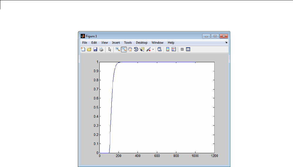
12 Desktops
5Create a new data file, newfrom.mat, that includes the following data:
t=[0:.001:1];
u=sin(100*t.*t);
tu=[t;u];
save newfrom.mat tu;
6Runarapidsimulationwiththenewdatabyusingthe-f option to replace
the original file, rsim_tfdata.mat,withnewfrom.mat.
!rtwdemo_rsimtf -f rsim_tfdata.mat=newfrom.mat
7Load the data and plot the new results by entering the following commands:
load rtwdemo_rsimtf.mat
plot(rt_yout)
The next figure shows the resulting plot.
12-26
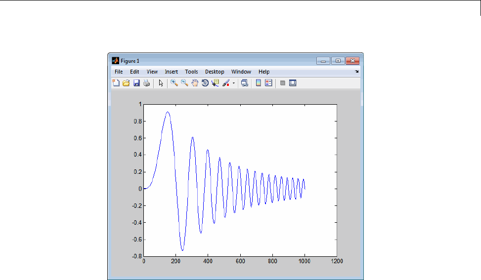
Rapid Simulations
From File blocks require input data of type double.Ifyouneedtoimport
signaldataofadatatypeotherthandouble, use an Inport block (see “Create
a MAT-File for an Inport Block” on page 12-15) or a From Workspace block
with the data specified as a structure.
Workspace data must be in the format:
variable.time
variable.signals.values
Ifyouhavemorethanonesignal,usethefollowingformat:
variable.time
variable.signals(1).values
variable.signals(2).values
Specify Signal Data File for an Inport Block
If your model’s input data source is an Inport block, you can feed the block
with input data during simulation from a single MAT-file or you can change
12-27

12 Desktops
theMAT-filefromonesimulationtothe next. Each MAT-file must adhere
to one of the three formats described in “Create a MAT-File for an Inport
Block” on page 12-15.
To specify the MAT-file after a simulation, you specify the executable with
the -i option and the name of the MAT-filethatcontainstheinputdata.
For example:
1Open the model rtwdemo_rsim_i.
2Check the Inport block parameter settings. The following Inport block data
parameter settings and specifications that you specify for the workspace
variables must match settings in the MAT-file, as indicated in “Configure
Inports to Provide Simulation Source Data” on page 12-6:
•Main > Interpolate data
•Signal Attributes > Port dimensions
•Signal Attributes > Data type
•Signal Attributes > Signal type
3Build the model.
4Setuptheinputsignals. Forexample:
t=[0:0.01:2*pi]';
s1=[2*sin(t) 2*cos(t)];
s2=sin(2*t);
s3=[0.5*sin(3*t) 0.5*cos(3*t)];
plot(t, [s1 s2 s3])
12-28
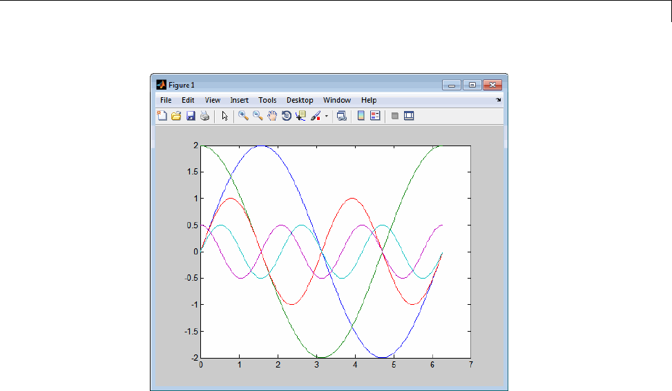
Rapid Simulations
5Prepare the MAT-file by using one of the three available file formats
described in “Create a MAT-File for an Inport Block” on page 12-15. The
following example defines a signal-and-time structure in the workspace
and names it var_single_struct.
t=[0:0.1:2*pi]';
var_single_struct.time=t;
var_single_struct.signals(1).values(:,1)=2*sin(t);
var_single_struct.signals(1).values(:,2)=2*cos(t);
var_single_struct.signals(2).values=sin(2*t);
var_single_struct.signals(3).values(:,1)=0.5*sin(3*t);
var_single_struct.signals(3).values(:,2)=0.5*cos(3*t);
v=[var_single_struct.signals(1).values...
var_single_struct.signals(2).values...
var_single_struct.signals(3).values];
6Save the workspace variable var_single_struct to MAT-file
rsim_i_single_struct.
save rsim_i_single_struct.mat var_single_struct;
12-29
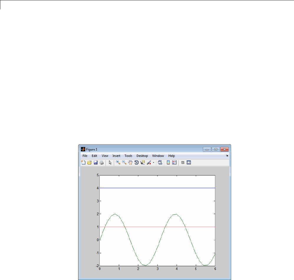
12 Desktops
7Run a rapid simulation with the input data by using the -i option. Load
and plot the results.
!rtwdemo_rsim_i -i rsim_i_single_struct.mat
** Starting model 'rtwdemo_rsim_i' @ Tue Dec 27 14:01:20 2005
*** rsim_i_single_struct.mat is loaded! ***
** created rtwdemo_rsim_i.mat **
** Execution time = 0.2683734753333333sload rsim_i_single_struct.mat;
8Load and plot the results.
load rtwdemo_rsim_i.mat
plot(rt_tout, rt_yout);
Change Block Parameters for an RSim Simulation
As described in “Create a MAT-File That Includes a Model Parameter
Structure” on page 12-10, after you alter one or more parameters in a
12-30

Rapid Simulations
Simulink block diagram, you can extract the parameter vector, model_P,for
theentiremodel.Youcanthensavetheparametervector,alongwithamodel
checksum, to a MAT-file. This MAT-file can be read directly by the standalone
RSim executable, allowing you to replace the entire parameter vector or
individual parameter values, for running studies of variations of parameter
values representing coefficients, new data for input signals, and so on.
The RSim target allows you to alter any model parameter, including
parameters that include side-effects functions. An example of a side-effects
function is a simple Gain block that includes the following parameter entry
in a dialog box:
gain value: 2 * a
The Simulink Coder code generator evaluates side-effects functions before
generating code. The generated code for this example retains only one
memory location entry, and the dependence on parameter ais no longer
visible in the generated code. The RSim target overcomes the problem of
handling side-effects functions by replacing the entire parameter structure,
model_P. You must create this new structure by using the rsimgetrtp
function and then saving it in a MAT-file, as described in “Create a MAT-File
That Includes a Model Parameter Structure” on page 12-10.
RSim can read the MAT-file and replace the entire model_P structure
whenever you change one or more parameters, without recompiling the entire
model.
For example, assume that you changed one or more parameters in your model,
generated the new model_P vector, and saved model_P to a new MAT-file
called mymatfile.mat.Torunthesamertwdemo_rsimtf model and use these
new parameter values, use the -p option, as shown in the following example:
!rtwdemo_rsimtf -p mymatfile.mat
load rtwdemo_rsimtf
plot(rt_yout)
If you have converted the parameter structure to a cell array for running
simulations on varying data sets, as described in “Convert the Parameter
Structure for Running Simulations on Varying Data Sets” on page 12-12, you
must add an @nsuffixtotheMAT-filespecification.nis the element of the cell
array that contains the specific input that you want to use for the simulation.
12-31

12 Desktops
The following example converts param_struct to a cell array, changes
parameter values, saves the changes to MAT-file mymatfile.mat,andthen
runs the executable using the parameter values in the second element of
the cell array as input.
param_struct = rsimgetrtp('rtwdemo_rsimtf');
p = param_struct.parameters;
param_struct.parameters = [];
param_struct.parameters{1} = p;
param_struct.parameters{1}
ans =
dataTypeName: 'double'
dataTypeId: 0
complex: 0
dtTransIdx: 0
values: [-140 -4900 0 4900]
param_struct.parameters{2} = param_struct.parameters{1};
param_struct.parameters{2}.values=[-150 -5000 0 4950];
save mymatfile.mat param_struct;
!rtwdemo_rsimtf -p mymatfile.mat@2 -o rsim2.mat
Specify a New Output File Name for a Simulation
If you have specified any of the Save to Workspace options — Time,
States,Outputs,orFinal States — in the Configuration Parameters dialog
box, on the Data Import/Export pane, the default is to save simulation
logging results to the file model.mat. For example, the example model
rtwdemo_rsimtf normally saves data to rtwdemo_rsimtf.mat,asfollows:
!rtwdemo_rsimtf
created rtwdemo_rsimtf.mat
You can specify a new output file name for data logging by using the -o option
when you run an executable.
!rtwdemo_rsimtf -o rsim1.mat
In this case, the set of parameters provided at the time of code generation,
including any From File block data, is run.
12-32

Rapid Simulations
Specify New Output File Names for To File Blocks
In much the same way as you can specify a new system output file name,
you can also provide new output file names for data saved from one or more
To File blocks. To do this, specify the original file name at the time of code
generation with a new name, as shown in the following example:
!rtwdemo_rsimtf -t rtwdemo_rsimtf_data.mat=mynewrsimdata.mat
In this case, assume that the original model wrote data to the output file
rtwdemo_rsimtf_data.mat. Specifying a new file name forces RSim to
writetothefilemynewrsimdata.mat. With this technique, you can avoid
overwriting an existing simulation run.
Rapid Simulation Target Limitations
TheRSimtargethasthefollowinglimitations:
•Does not support algebraic loops.
•Does not support Interpreted MATLAB Function blocks.
•Does not support noninlined MATLAB language or Fortran S-functions.
•If an RSim build includes referenced models (by using Model blocks), set
up these models to use fixed-step solvers to generate code for them. The
top model, however, can use a variable-step solver as long as all blocks in
the referenced models are discrete.
•In certain cases, changing block parameters can result in structural
changes to your model that change the model checksum. An example of
such a change is changing the number of delays in a DSP simulation. In
such cases, you must regenerate the code for the model.
•Variable-step solver support for RSim is not available on Microsoft
Windows platforms when you use the Watcom C/C++ compiler.
12-33

12 Desktops
Generated S-Function Block
S-functions are an important class of target for which the Simulink Coder
product can generate code. The ability to encapsulate a subsystem into an
S-function allows you to increase its execution efficiency and facilitate code
reuse.
The following sections describe the properties of S-function targets and
illustrate how to generate them. For more details on the structure of
S-functions, see “Host-Specific Code”.
In this section...
“About Object Libraries” on page 12-34
“Create S-Function Blocks from a Subsystem” on page 12-37
“Tunable Parameters in Generated S-Functions” on page 12-42
“System Target File and Template Makefiles” on page 12-44
“Checksums and the S-Function Target” on page 12-45
“S-Function Target Limitations” on page 12-45
AboutObjectLibraries
•“About the S-Function Target” on page 12-34
•“Required Files for S-Function Deployment” on page 12-36
•“Sample Time Propagation in Generated S-Functions” on page 12-37
•“Choose a Solver Type” on page 12-37
About the S-Function Target
Using the S-function target, you can build an S-function component and use
it as an S-Function block in another model. The S-function code format
used by the S-function target generates code that conforms to the Simulink
C MEX S-function application programming interface (API). Applications
of this format include
12-34

Generated S-Function Block
•Conversion of a model to a component. You can generate an S-Function
block for a model, m1. Then, you can place the generated S-Function
block in another model, m2. Regenerating code for m2 does not require
regenerating code for m1.
•Conversion of a subsystem to a component. By extracting a subsystem to
a separate model and generating an S-Function block from that model,
you can create a reusable component from the subsystem. See “Create
S-Function Blocks from a Subsystem” on page 12-37 for an example of
this procedure.
•Speeding up simulation. In many cases, an S-function generated from a
model performs more efficiently than the original model.
•Code reuse. You can incorporate multiple instances of one model inside
another without replicating the code for each instance. Each instance will
continue to maintain its own unique data.
The S-function target generates noninlined S-functions. Within the same
release, you can generate an executable from a model that contains generated
S-functions by using the generic real-time or real-time malloc targets. This is
not supported when incorporating a generated S-function from one release
into a model that you build with a different release.
You can place a generated S-Function block into another model from which
you can generate another S-function. This allows any level of nested
S-functions. For limitations related to nesting, see “Limitations on Nesting
S-Functions” on page 12-50.
12-35

12 Desktops
Note While the S-function target provides a means to deploy an application
component for reuse while shielding its internal logic from inspection and
modification, the preferred solutions for protecting intellectual property in
distributed components are:
•The protected model, a referenced model from which all block and line
information has been eliminated using the Model Protection facility. For
more information, see “Protected Model” in the Simulink documentation.
•The Embedded Coder shared library system target file, used to generate
a shared library for a model or subsystem for use in a system simulation
external to Simulink. For more information see “Shared Object Libraries”
in the Embedded Coder documentation.
Required Files for S-Function Deployment
To deploy your generated S-Function block for inclusion in other models
for simulation, you need only provide the binary MEX-file object that was
generated in the current working folder when the S-Function block was
created:
subsys_sf.mexext
where subsys is the subsystem name and mexext is a platform-dependent
MEX-file extension (see mexext). For example, SourceSubsys_sf.mexw32.
To deploy your generated S-Function block for inclusion in other models for
code generation, you must provide all of the files that were generated in the
current working folder when the S-Function block was created:
•subsys_sf.c or .cpp,wheresubsys is the subsystem name (for example,
SourceSubsys_sf.c)
•subsys_sf.h
•subsys_sf.mexext,wheremexext is a platform-dependent MEX-file
extension (see mexext)
•Subfolder subsys_sfcn_rtw and its contents
12-36

Generated S-Function Block
Sample Time Propagation in Generated S-Functions
A generated S-Function block can inherit its sample time from the model in
which it is placed if certain criteria are met. Conditions that govern sample
time propagation for both Model blocks and generated S-Function blocks are
described in “Inherit Sample Times” in the Simulink documentation and
“Inherited Sample Time for Referenced Models”onpage3-29intheSimulink
Coder documentation.
To generate an S-Function block that meets the criteria for inheriting sample
time, you must constrain the solver for the model from which the S-Function
block is generated. On the Solver configuration parameters dialog pane,
set Type to Fixed-step and Periodic sample time constraint to Ensure
sample time independent. If the model is unable to inherit sample times,
this setting causes the Simulink softwaretodisplayanerrormessagewhen
building the model. See “Periodic sample time constraint” in the Simulink
documentation for more information about this option.
Choose a Solver Type
If the model containing the subsystem from which you generate an S-function
uses a variable-step solver, the generated S-function contains zero-crossing
functions and will work properly only in models that use variable-step solvers.
If the model containing the subsystem from which you generate an S-function
uses a fixed-step solver, the generated S-function contains no zero-crossing
functions and the generated S-function will work properly in models that use
variable-step or fixed-step solvers.
Create S-Function Blocks from a Subsystem
This section illustrates how to extract a subsystem from a model and generate
a reusable S-function component from it.
ThenextfigureshowsSourceModel, a simple model that inputs signals to a
subsystem. The subsequent figure shows the subsystem, SourceSubsys.The
signals, which have different widths and sample times, are
•A Step block with sample time 1
•ASineWaveblockwithsampletime0.5
12-37
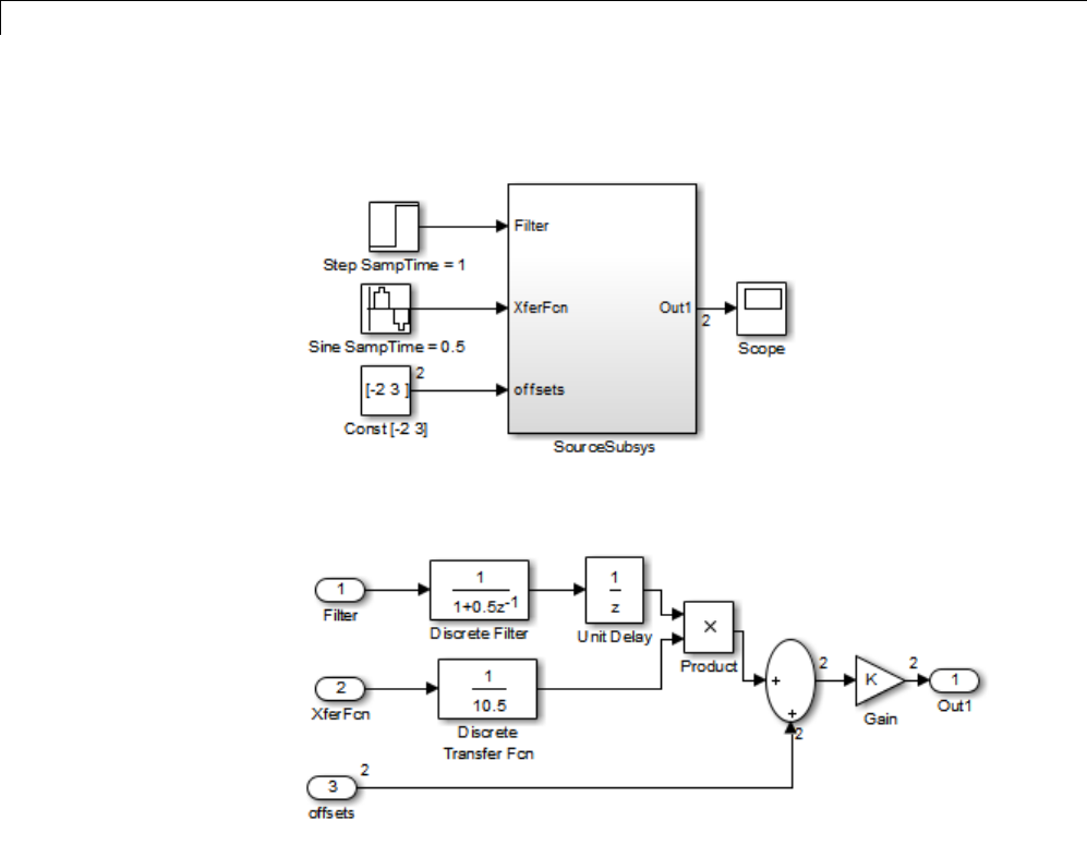
12 Desktops
•AConstantblockwhosevalueisthevector[-23]
SourceModel
SourceSubsys
The objective is to extract SourceSubsys from the model and build an
S-Function block from it, using the S-function target. The S-Function block
must perform identically to the subsystem from which it was generated.
In this model, SourceSubsys inherits sample times and signal widths from its
input signals. However, S-Function blocks created from a model using the
S-function target will have all signal attributes (such as signal widths or
sample times) hard-wired. (The sole exception to this rule concerns sample
times, as described in “Sample Time Propagation in Generated S-Functions”
on page 12-37.)
12-38
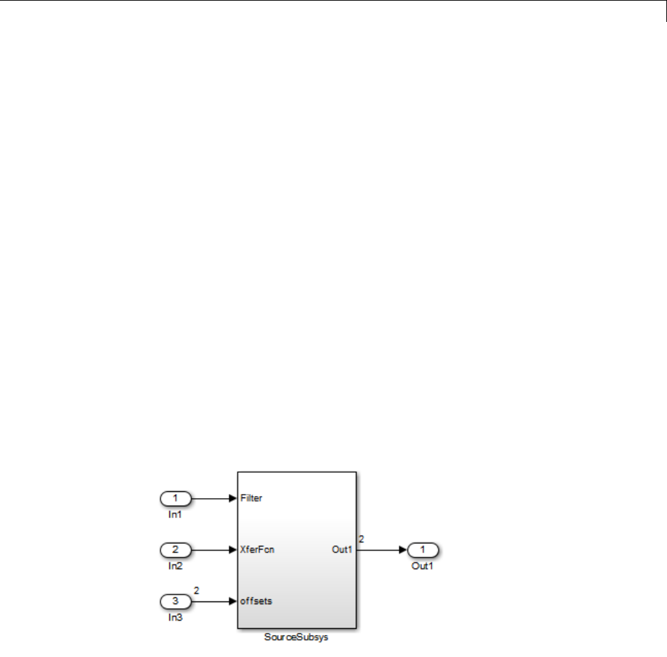
Generated S-Function Block
In this example, you want the S-Function block to retain the properties of
SourceSubsys as it exists in SourceModel. Therefore, before you build the
subsystem as a separate S-function component, you must set the inport
sample times and widths explicitly. In addition, the solver parameters of
the S-function component must be the same as those of the original model.
The generated S-function component will operate identically to the original
subsystem (see “Choose a Solver Type” on page 12-37 for an exception to
this rule).
To build SourceSubsys as an S-function component,
1Create a new model and copy/paste the SourceSubsys block into the empty
window.
2Set the signal widths and sample times of inports inside SourceSubsys
such that they match those of the signals in the original model. Inport 1,
Filter,hasawidthof1andasampletimeof1. Inport2,Xferfcn,has
awidthof1andasampletimeof0.5. Inport3,offsets,hasawidthof
2andasampletimeof0.5.
3The generated S-Function block should have three inports and one outport.
Connect inports and an outport to SourceSubsys,asshowninthenext
figure.
The signal widths and sample times are propagated to these ports.
12-39
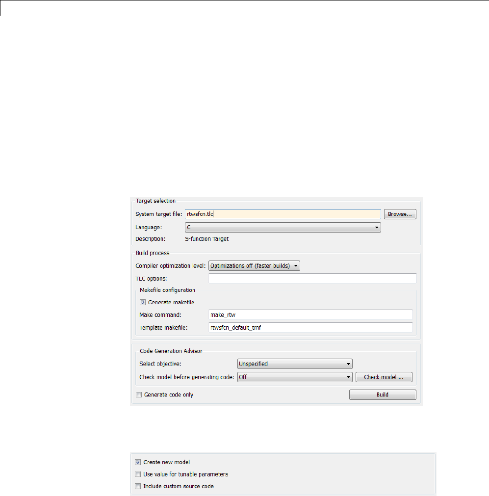
12 Desktops
4Set the solver type, mode, and other solver parameters such that they
areidenticaltothoseofthesourcemodel. Thisiseasiesttodoifyouuse
Model Explorer.
5In the Configuration Parameters dialog box, go to the Code Generation
pane.
6Click Browse to open the System Target File Browser.
7In the System Target File Browser, select the S-function target,
rtwsfcn.tlc,andclickOK.TheCode Generation pane appears as
follows.
8Select the S-Function Target pane. Make sure that Create new model
is selected, as shown in the next figure:
12-40

Generated S-Function Block
When this option is selected, the build process creates a new model after it
builds the S-function component. The new model contains an S-Function
block, linked to the S-function component.
Click Apply.
9Save the new model containing your subsystem, for example as
SourceSubsys.
10 Build the model.
11 The Simulink Coder build process builds the S-function component in the
working folder. After the build, a new model window is displayed.
Optionally you can save the generated model, for example as
SourceSubsys_Sfunction.
12 You can now copy the Simulink Coder S-Function block from the new model
and use it in other models or in a library.
Note For a list of files required to deploy your S-Function block for
simulation or code generation, see “Required Files for S-Function
Deployment” on page 12-36.
The next figure shows the S-Function block plugged into the original model.
Given identical input signals, the S-Function block will perform identically
to the original subsystem.
12-41
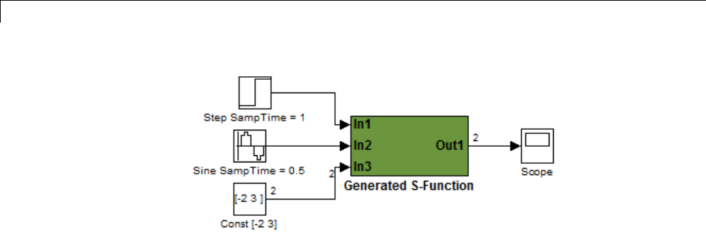
12 Desktops
Generated S-Function Configured Like SourceModel
The speed at which the S-Function block executes is typically faster than the
original model. This difference in speed is more pronounced for larger and
more complicated models. By using generated S-functions, you can increase
the efficiency of your modeling process.
Tunable Parameters in Generated S-Functions
You can use tunable parameters in generated S-functions in two ways:
•Use the Generate S-function feature (see “Automate S-Function
Generation” on page 14-23).
or
•Use the Model Parameter Configuration dialog box (see “Parameters” on
page 7-10) to declare desired block parameters tunable.
Block parameters that are declared tunable with the auto storage class in
the source model become tunable parameters of the generated S-function.
These parameters do not become part of a generated model_P (formerly
rtP) parameter data structure, as they would in code generated from other
targets. Instead, the generated code accesses these parameters by using MEX
API calls such as mxGetPr or mxGetData. Your code should access these
parameters in the same way.
For more information on MEX API calls, see “About Writing C S-Functions”
and “Application Programming Interfaces to MATLAB”.
12-42
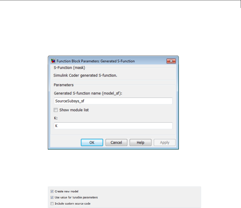
Generated S-Function Block
S-Function blocks created by using the S-function target are automatically
masked. The mask displays each tunable parameter in an edit field. By
default, the edit field displays the parameter by variable name, as in the
following example.
You can choose to display the value of the parameter rather than its variable
name by selecting Use value for tunable parameters on the Code
Generation > S-Function Target pane of the Configuration Parameters
dialog box.
When this option is chosen, the value of the variable (at code generation time)
is displayed in the edit field, as in the following example.
12-43
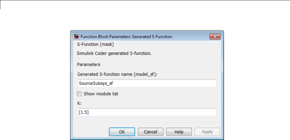
12 Desktops
System Target File and Template Makefiles
•“About System Target File and Template Makefiles” on page 12-44
•“System Target File” on page 12-44
•“Template Makefiles” on page 12-44
About System Target File and Template Makefiles
This section lists the target file and template makefiles that are provided
for use with the S-function target.
System Target File
•rtwsfcn.tlc
Template Makefiles
•rtwsfcn_lcc.tmf — Lcc compiler
•rtwsfcn_unix.tmf — The Open Group UNIX host
12-44

Generated S-Function Block
•rtwsfcn_vc.tmf — Microsoft Visual C++ compiler
•rtwsfcn_watc.tmf — Watcom C compiler
Checksums and the S-Function Target
The Simulink Coder software creates a checksum for a Simulink model and
uses the checksum during the build process for code reuse, model reference,
and External mode features.
The Simulink Coder software calculates a model’s checksum by
1Calculating a checksum for each subsystem in the model. A subsystem’s
checksum is the combination of properties (data type, complexity, sample
time, port dimensions, and so forth) of the subsystem’s blocks.
2Combining the subsystem checksums and other model-level information.
An S-function can add additional information, not captured during the block
property analysis, to a checksum by calling the function ssSetChecksumVal.
For the S-Function target, the value that gets added to the checksum is the
checksum of the model or subsystem from which the S-function is generated.
The Simulink Coder software applies the subsystem and model checksums as
follows:
•Code reuse — If two subsystems in a model have the same checksum, the
Simulink Coder build process generates code for one function only.
•Model reference — If the current model checksum matches the checksum
when the model was built, the Simulink Coder build process does not
rebuild submodels.
•External mode — If the current model checksum does not match the
checksum of the code that is running on the target, the Simulink Coder
build process generates an error.
S-Function Target Limitations
•“Limitations on Using Tunable Variables in Expressions” on page 12-46
12-45

12 Desktops
•“Run-Time Parameters and S-Function Compatibility Diagnostics” on
page 12-46
•“Limitations on Using Goto and From Block” on page 12-47
•“Limitations on Building and Updating S-Functions” on page 12-48
•“Unsupported Blocks” on page 12-49
•“SimState Not Supported for Code Generation” on page 12-49
•“Profiling Code Performance Not Supported” on page 12-50
•“Limitations on Nesting S-Functions” on page 12-50
•“Limitations on User-Defined Data Types” on page 12-50
•“Limitation on Right-Click Generation of an S-Function Target” on page
12-50
•“Limitation on S-Functions with Bus I/O Signals” on page 12-51
•“Limitation on Subsystems with Function-Call I/O Signals” on page 12-51
Limitations on Using Tunable Variables in Expressions
Certain limitations apply to the use of tunable variables in expressions. When
Simulink Coder software encounters an unsupported expression during code
generation, a warning appears and the equivalent numeric value is generated
in the code. For a list of the limitations, see “Tunable Expression Limitations”
on page 15-131.
Run-Time Parameters and S-Function Compatibility Diagnostics
If you set the S-function upgrades needed option on the
Diagnostics > Compatibility pane of the Configuration Parameters dialog
box to warning or error, the Simulink Coder software instructs you to
upgrade S-functions that you create with the Generate S-function feature.
This is because the S-function target does not register run-time parameters.
Run-time parameters are only supported for inlined S-Functions and the
generated S-Function supports features that prevent it from being inlined (for
example, it can call or contain other noninlined S-functions).
You can work around this limitation by setting the S-function upgrades
needed option to none. Alternatively, if you have an Embedded Coder
12-46
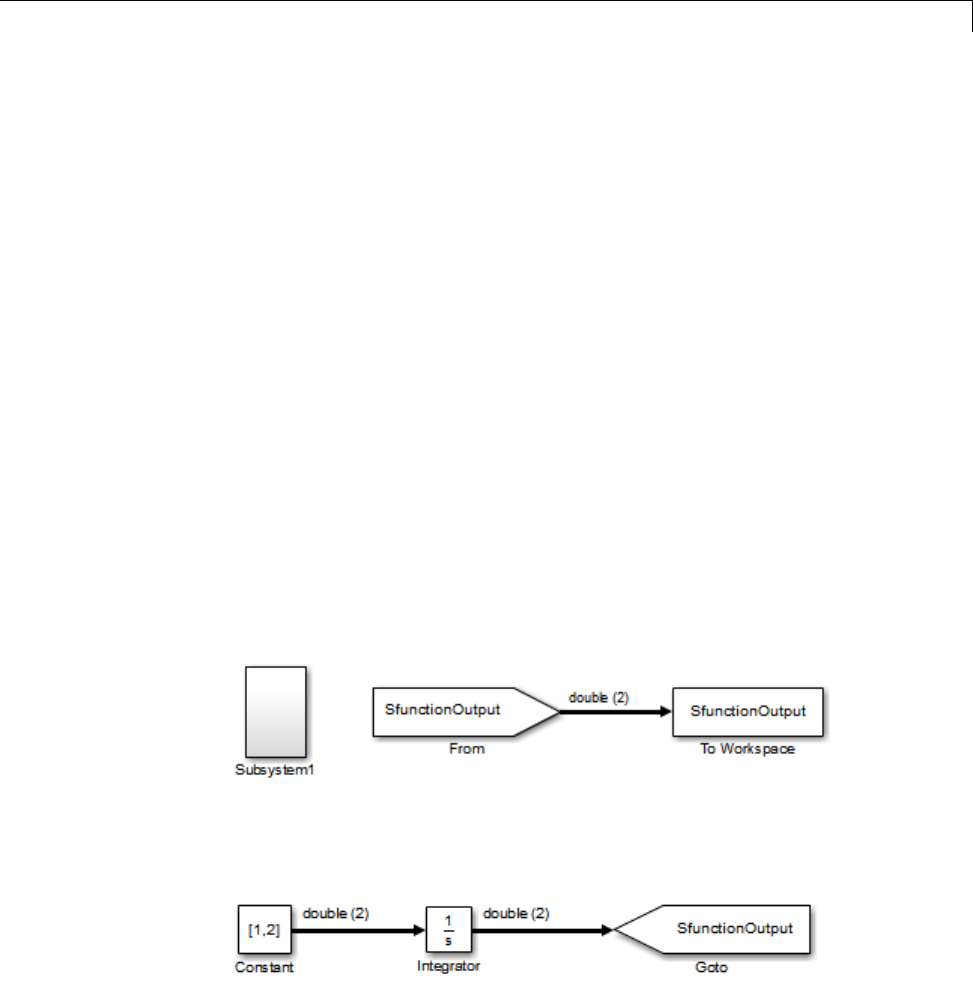
Generated S-Function Block
license, select the Create Embedded Coder SIL block check box on the
Generate S-function for Subsystem dialog box and create a SIL block
(containing the ERT S-function). In this case, you do not receive the upgrade
messages. However, you cannot include SIL blocks inside other generated
S-functions recursively.
Limitations on Using Goto and From Block
When using the S-function target, the Simulink Coder code generator restricts
I/O to correspond to the root model’s Inport and Outport blocks (or the Inport
and Outport blocks of the Subsystem block from which the S-function target
was generated). No code is generated for Goto or From blocks.
To work around this restriction, create your model and subsystem with the
required Inport and Outport blocks, instead of using Goto and From blocks
to pass data between the root model and subsystem. In the model that
incorporates the generated S-function, you would then add Goto and From
blocks.
Example Before Work Around
•Root model with a From block and subsystem, Subsystem1
•Subsystem1 with a Goto block, which has global visibility and passes its
input to the From block in the root model
12-47
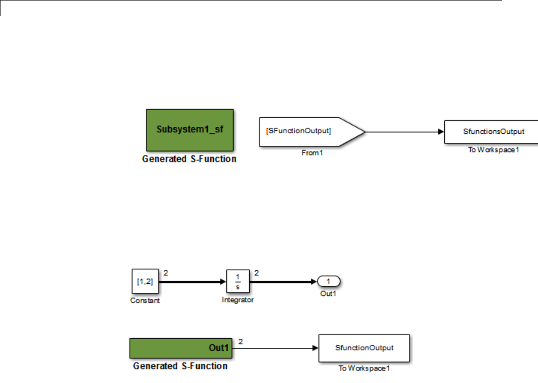
12 Desktops
•Subsystem1 replaced with an S-function generated with the S-Function
target — a warning results when you run the model because the generated
S-function does not implement the Goto block
Example After Work Around
An Outport block replaces the GoTo block in Subsystem1. When you plug the
generated S-function into the root model, its output connects directly to the
To Workspace block.
Limitations on Building and Updating S-Functions
The following limitations apply to building and updating S-functions using
the Simulink Coder S-function target:
•You cannot build models that contain Model blocks using the Simulink
Coder S-function target. This also means that you cannot build a subsystem
module by right-clicking (or by using Code > C/C++ Code > Build
Selected Subsystem) if the subsystem contains Model blocks. This
restriction applies only to S-functions generated using the S-function
target, not to ERT S-functions.
12-48

Generated S-Function Block
•If you modify the model that generated an S-Function block, the Simulink
Coder build process does not automatically rebuild models containing
the generated S-Function block. This is in contrast to the practice of
automatically rebuilding models referenced by Model blocks when they
are modified (depending on the Model Reference Rebuild configuration
setting).
•Handwritten S-functions without corresponding TLC files must contain
exception-free code. For more information on exception-free code, see
“Exception Free Code” in the Simulink documentation.
Unsupported Blocks
The S-function format does not support the following built-in blocks:
•Interpreted MATLAB Function block
•S-Function blocks containing any of the following:
-MATLAB language S-functions (unless you supply a TLC file for C code
generation)
-Fortran S-functions (unless you supply a TLC file for C code generation)
-C/C++ MEX S-functions that call into the MATLAB environment
•Scope block
•To Workspace block
The S-function format does not support blocks from the embeddedtargetslib
block library in the Embedded Coder product.
SimState Not Supported for Code Generation
You can use SimState within C-MEX and Level-2 MATLAB language
S-functions to save and restore the simulation state (see “S-Function
Compliance with the SimState” in the Simulink documentation). However,
SimState is not supported for code generation, including with the Simulink
Coder S-function target.
12-49

12 Desktops
Profiling Code Performance Not Supported
Profiling the performance of generated code using the Target Language
Compiler (TLC) hook function interface described by the example model
rtwdemo_profile is not supported for the S-function target.
Limitations on Nesting S-Functions
The following limitations apply to nesting a generated S-Function block in a
model or subsystem from which you generate another S-function:
•The software does not support nonvirtual bus input and output signals for
a nested S-function.
•You should avoid nesting an S-function in a model or subsystem having
the same name as the S-function (possibly several levels apart). In such
situations, the S-function can be called recursively. The software currently
does not detect such loops in S-function dependency, which can result
in aborting or hanging your MATLAB session. To prevent this from
happening, be sure to name the subsystem or model to be generated as
an S-function target uniquely, to avoid duplicating any existing MEX
filenames on the MATLAB path.
Limitations on User-Defined Data Types
The Simulink Coder S-function target does not support the HeaderFile
property that can be specified on user-defined data types, including those
based on Simulink.AliasType,Simulink.Bus,andSimulink.NumericType
objects. If a user-defined data type in your model uses the HeaderFile
property to specify an associated header file, Simulink Coder S-function target
code generation disregards the value and does not generate a corresponding
include statement.
Limitation on Right-Click Generation of an S-Function Target
If you generate an S-function target by right-clicking a Function-Call
Subsystem block, the original subsystem and the generated S-function might
not be consistent. An inconsistency occurs when the States when enabling
parameter of the Trigger Port block inside the Function-Call Subsystem block
is set to inherit.YoumustsettheStates when enabling parameter to
reset or held, otherwise Simulink reports an error.
12-50

Generated S-Function Block
Limitation on S-Functions with Bus I/O Signals
If an S-function generated using the S-function target has bus input or output
signals, the generated bus data structures might include padding to align
fields of the bus elements with the Simulink representation used during
simulation. However, if you insert the S-function in a model and generate code
using a model target such as grt.tlc, the bus structure alignment generated
for the model build might be incompatible with the padding generated for the
S-function and might affect the numerical results of code execution. To make
the structure alignment consistent between model simulation and execution of
the model code, for each Simulink.Bus object, you can modify the HeaderFile
property to remove the unpadded bus structure header file. This will cause
the bus typedefs generatedfortheS-functiontobereusedinthemodelcode.
Limitation on Subsystems with Function-Call I/O Signals
The S-function target does not support creating an S-Function block from a
subsystem that has a function-call trigger input or a function-call output.
12-51

12 Desktops
12-52

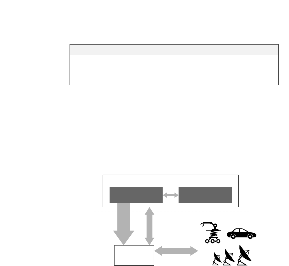
13 Real-Time Systems
Real-Time System Rapid Prototyping
In this section...
“About Real-Time Rapid Prototyping” on page 13-2
“Goals of Real-Time Rapid Prototyping” on page 13-3
“Refine Code With Real-Time Rapid Prototyping” on page 13-3
About Real-Time Rapid Prototyping
Real-time rapid prototyping requires the use of a real-time simulator,
potentially connected to system hardware (for example, physical plant or
vehicle) being controlled. You generate, deploy, and tune code as it runs on
the real-time simulator or embedded microprocessor. This design step is
crucial for verifying whether a component can adequately control the system,
and allows you to assess, interact with, and optimize code.
The following figure shows a typical approach for real-time rapid prototyping.
Actual environment (plants)
Algorithm model
Tuning and
logging
System model
Environment model
Code
generation
Host
Harness
Real-time
simulator
13-2

Real-Time System Rapid Prototyping
Goals of Real-Time Rapid Prototyping
Assuming that you have documented functional requirements, refined concept
models, system hardware for the physical plant or vehicle being controlled,
and access to target products you intend to use (for example, for example, the
xPC Target or Real-Time Windows Target product), you can use real-time
prototyping to:
•Refine component and environment model designs by rapidly iterating
between algorithm design and prototyping
•Validate whether a component can adequately control the physical system
in real time
•Evaluate system performance before laying out hardware, coding
production software, or committing to a fixed design
•Test hardware
Refine Code With Real-Time Rapid Prototyping
To perform real-time rapid prototyping:
1Create or acquire a real-time systemthatrunsinrealtimeonrapid
prototyping hardware. The xPC Target product facilitates real-time rapid
prototyping. This product provides a real-time operating system that
makes PCs run in real time. It also provides device driver blocks for
numerous hardware I/O cards. You can then create a rapid prototyping
system using inexpensive commercial-off-the-shelf (COTS) hardware. In
addition, third-party vendors offer products based on the xPC Target
product or other code generation technology that you can integrate into a
development environment.
2Use Simulink Coder system target files to generate code that you can
deploy onto a real-time simulator. See the following information.
13-3

13 Real-Time Systems
Engineering Tasks Related Product
Information
Examples
Generate code for real-time
rapid prototyping
“Targets and Code Formats”
on page 9-29 in the Simulink
Coder documentation
Embedded Coder
“What Are the Standards and
Guidelines?” in the Embedded
Coder documentation
rtwdemo_counter
rtwdemo_async
Generate code for rapid
prototyping in hard real time,
using PCs
xPC Target
“Setting Configuration
Parameters” in the xPC
Target documentation
help xpcdemos
Generate code for rapid
prototyping in soft real time,
using PCs
Real-Time Windows Target
“Code Generation Pane:
Real-Time Windows Target” in
the Real-Time Windows Target
documentation
rtvdp (and others)
3Monitor signals, tune parameters, and log data.
13-4

Hardware-In-the-Loop (HIL) Simulation
Hardware-In-the-Loop (HIL) Simulation
In this section...
“About Hardware-In-the-Loop Simulation” on page 13-5
“Set Up and Run HIL Simulations” on page 13-6
About Hardware-In-the-Loop Simulation
Hardware-in-the-loop (HIL) simulation tests and verifies an embedded
system or control unit in the context of a software test platform. Examples
of test platforms include real-time target systems and instruction set
simulators (IISs). You use Simulink software to develop and verify a model
that represents the test environment. Using the Simulink Coder product,
you then generate, build, and download an executable for the model to the
HIL simulation platform. After you set up the environment, you can run the
executable to validate the embedded system or control unit in real time.
During HIL simulation, you gradually replace parts of a system environment
with hardware components as you refine and fabricate the components. HIL
simulation offers an efficient design process that eliminates costly iterations
of part fabrication.
The code that you build for the system simulator provides real-time system
capabilities. For example, the code can include VxWorks from Wind River or
another real-time operating system (RTOS).
The following figure shows a typical HIL setup.
13-5
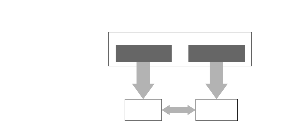
13 Real-Time Systems
Embedded
system
Algorithm model
Simulink
Environment model
Code
generation
Code
generation
Harness Real-time
simulator
The HIL platform available from MathWorks is the xPC Target product.
Several third-party products are also available for use as HIL platforms.
The xPC Target product offers hard real-time performance for any PC with
Intel®or AMD®32-bit processors functioning as your real-time target. The
xPC Target product enables you to add I/O interface blocks to your models
and automatically generate code with code generation technology. The xPC
Target product can download the code to a second PC running the xPC Target
real-time kernel. System integrator solutions that are based on xPC Target
are also available.
Set Up and Run HIL Simulations
To set up and run HIL simulations iterate through the following steps:
1Develop a model that represents the environment or system under
development. For more information, see:
•“Targets and Code Formats” on page 9-29
2Generate an executable for the environment model.
3DownloadtheexecutablefortheenvironmentmodeltotheHILsimulation
platform.
4Replace software representing a system component with corresponding
hardware.
5Test the hardware in the context of the HIL system.
13-6

Hardware-In-the-Loop (HIL) Simulation
6Repeat steps 4 and 5 until you can simulate the system after including
all components that require testing.
13-7

13 Real-Time Systems
13-8

14
External Code Integration
•“Integration Options” on page 14-2
•“Reuse Algorithmic Components in Generated Code” on page 14-5
•“Deploy Algorithm Code Within a Target Environment” on page 14-14
•“Export Generated Algorithm Code for Embedded Applications” on page
14-18
•“Export Algorithm Executables for System Simulation” on page 14-21
•“Modify External Code for Language Compatibility” on page 14-22
•“Automate S-Function Generation” on page 14-23
•“Integrate External Code Using Legacy Code Tool” on page 14-28
•“Configure Model for External Code Integration” on page 14-33
•“Insert Custom Code Blocks” on page 14-36
•“Insert S-Function Code” on page 14-46

14 External Code Integration
Integration Options
In this section...
“About Integration Options” on page 14-2
“Types of External Code Integration” on page 14-2
About Integration Options
The Simulink Coder product includes a variety of approaches for integrating
legacy or custom code with generated code. Legacy code is existing
handwritten code or code for environments that must be integrated with code
generated by the Simulink Coder software. Custom code is legacy code or any
other user-specified lines of code that must be included in the Simulink Coder
build process. Collectively, legacy and custom code are called external code.
There are two ways that you can achieve external code integration. You
can import existing external code into code generated by code generation
technology or you can export generated code into an existing external code
base. For example, you might want to use generated code as a plug-in function.
Types of External Code Integration
Based on application goals, external code integration can be characterized as
follows:
•Import external code into generated code
-Reuse of an algorithmic component in generated code
-Deploy an application with algorithm code within the target environment
-Generate target optimizations within algorithm code
•Export generated code into external code
-Export generated algorithm code for an embedded application
-Export an algorithm executable for system simulation
Use the following flow diagram to prepare for integration and choose
integration paths that best map to your application components. As the
14-2

Integration Options
diagram shows, before you make integration decisions, assess your application
architecture and partition it as much as possible. Working with smaller units
makes it easier to map algorithms to modeling components and decide how to
integrate the components. For each component, use the highlighted area of
the flow diagram to identify the most applicable type of integration. Then, see
the information provided for the corresponding type.
14-3
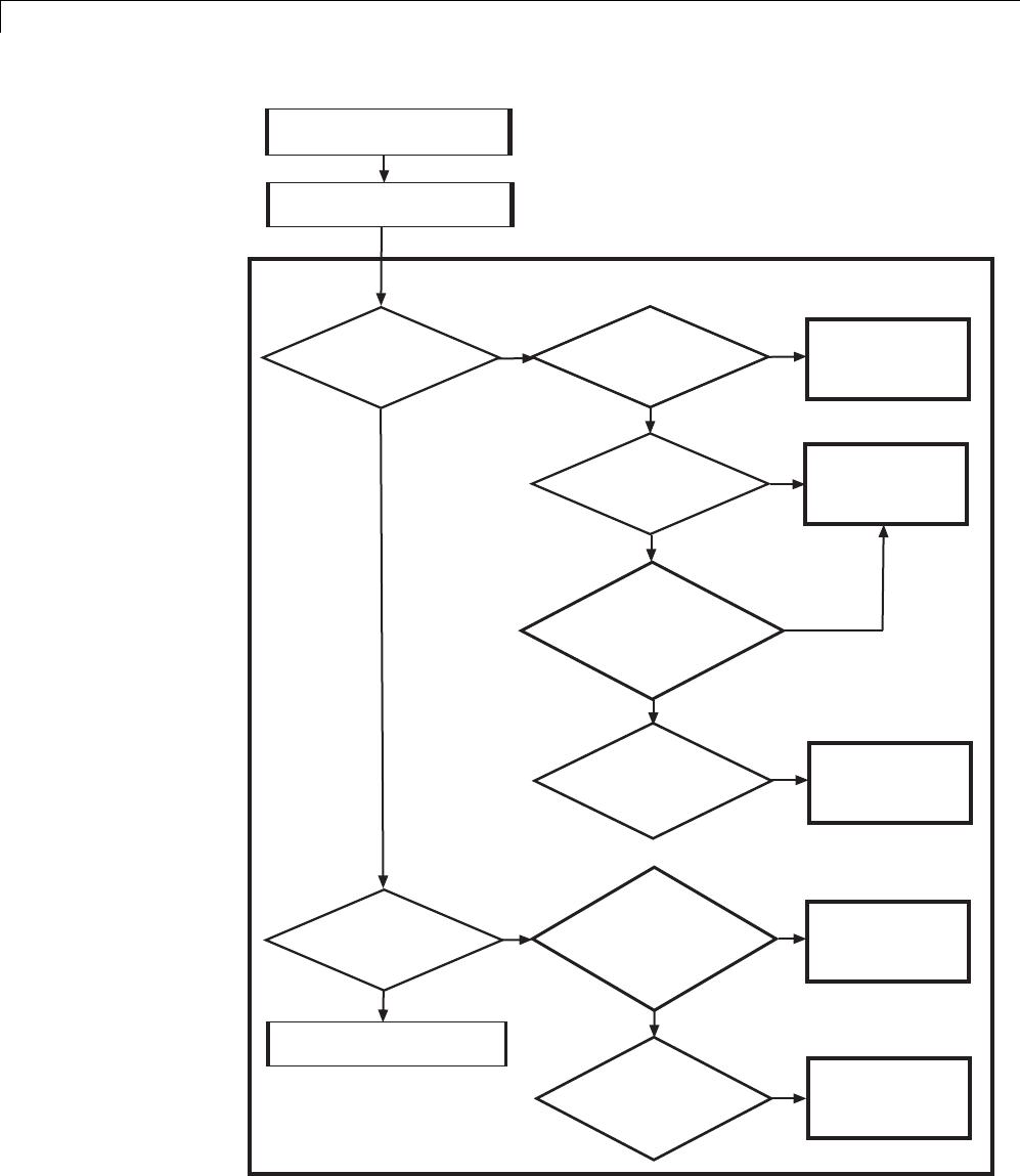
14 External Code Integration
Assess application partitioning
Map algorithms to modeling components
Integrate
existing external code with
generated code
?
Use component as is
Reuse algorithmic
component in
generated code
Deploy with algorithm
code within target
environment
Generate target
optimizations
within algorithm code
Export algorithm
executable for
system simulation
Export generated
algorithm code for
embedded application
Yes
Yes
No
No
Integrate
generated code with existing
external code
?
Hardware
independent, all C or C++
Example: lookup table
?
Hardware
specific, external to algorithm
Example: device driver
?
Yes
No
Yes
No
Plug
subsystem code
into existing code base
Example: specialized algorithm
inserted into larger
application
?
Yes
No
Hardware
specific, inside algorithm
Example: optimized
instructions
?
Yes
Plug object
code into larger model
Example: intellectual
property protection
?
For each component, decide...
Yes
Hardware
specific, generated model
code set up to run in real time
Example: connection to timer
interrupt or RTOS
?
No
Yes
14-4

Reuse Algorithmic Components in Generated Code
Reuse Algorithmic Components in Generated Code
In this section...
“Reusable Algorithmic Components” on page 14-5
“Integrate External MATLAB Code” on page 14-5
“Integrate External C or C++ Code” on page 14-8
“Integrate Fortran Code” on page 14-11
“Integration Considerations for Reusable Algorithmic Components” on
page 14-11
Reusable Algorithmic Components
You have several options for integrating reusable algorithmic components
with the generated code. Such components are hardware-independent and can
be verified with Simulink simulation. Examples of such components include:
•Lookup tables
•Math utilities
•Digital filters
•Special integrators
•Proportional–integral–derivative (PID) control modules
Some integration options allow you to integrate external code for a reusable
component directly, while other options convert external code to modeling
elements. To take full advantage of Model-Based Design, convert code to
modeling elements which you can then use in the Simulink or Stateflow
simulation environment. Doing so enables you to simulate and generate code
for an integrated component and, for example, use software-in-the-loop (SIL)
or processor-in-the-loop (PIL) testing to verify whether algorithm behavior
isthesameinbothenvironments.
Integrate External MATLAB Code
The following diagram identifies common characteristics or requirements for
reusable algorithmic components written in MATLAB code and recommends
14-5
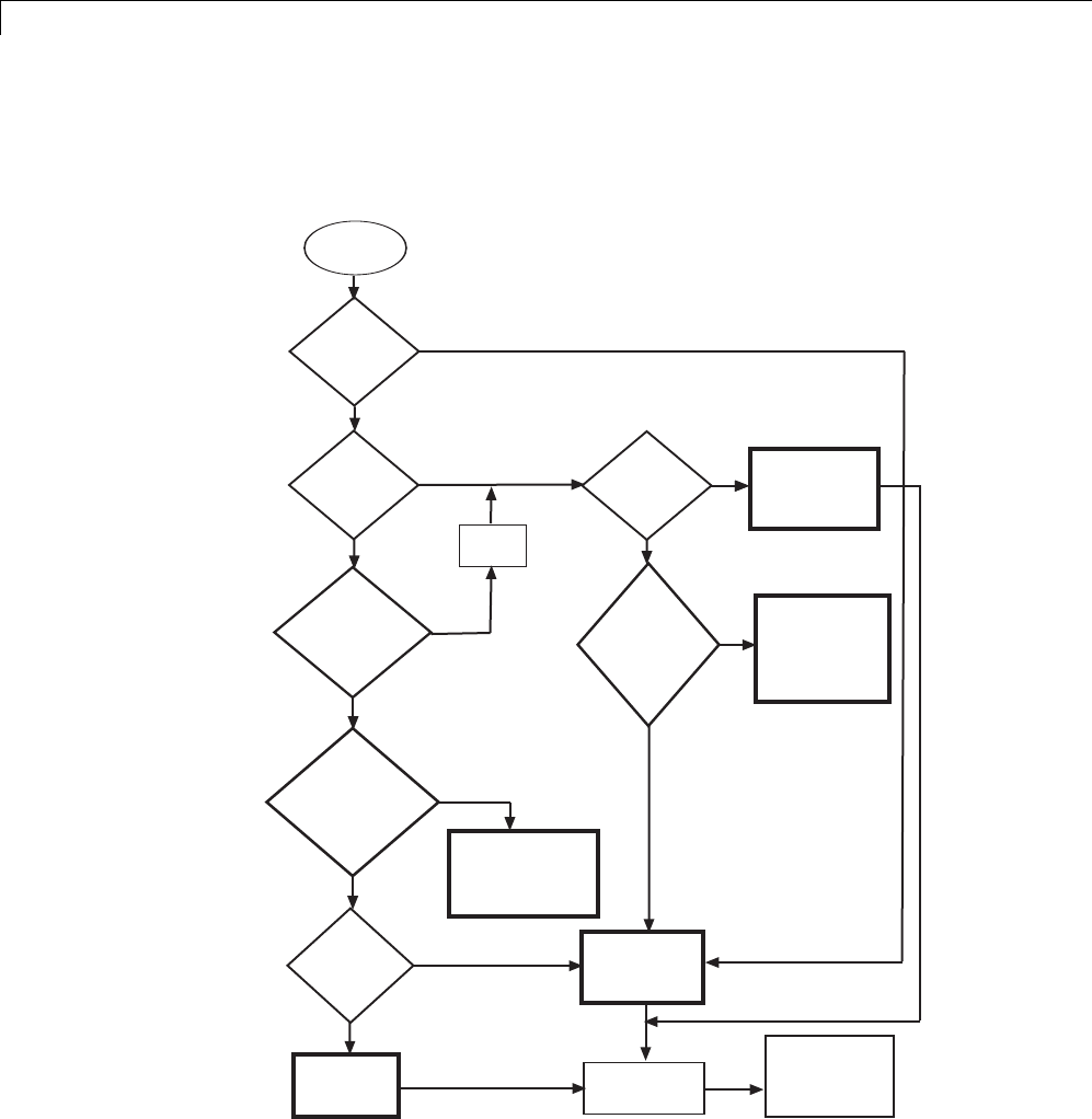
14 External Code Integration
solutions in each case. The table that follows the diagram provides more
detail. Collectively, the diagram and table help you choose the best solution
for your application and find more related information.
MATLAB
external code
Complies
with MATLAB for
code gen subset
?
Embed code in
MATLAB
Function block
Add S-function or
blocks to model
Generate C source
code, executable, or
library file with
MATLAB Coder
Yes
No
No
Yes
No
Yes
Embed
MATLAB code in
model
?
Can
refactor code to
comply with MATLAB
for code gen
subset
?
If necessary, add
support files to and
control model code
generation andl builds
Must
model continuous
state dynamics
?
No
Yes
Write MATLAB
S-function and TLC
file by hand
Yes
No
Refactor
code
C/C++
programming
experience and MATLAB
code includes C or
C++ constructs
?
No
Sections
of MATLAB code
map to built-in
blocks
?
Convert code to C or
C++ by hand and
use a C/C++ external
code option
Identify
applicable
built-in blocks
Yes
Yes
No
Optimize
for runtime
performance or
prepare to deploy
in embedded
system
?
j
k
m
l
n
14-6

Reuse Algorithmic Components in Generated Code
If... Then... For More Information, See...
1The algorithm
must model
continuous state
dynamics
Write a MATLAB
S-function and, for
generating code, a
corresponding TLC file
for the algorithm and add
theS-functiontoyour
model
•“MATLAB S-Functions”
•“Inline MATLAB File S-Functions”
2You want to
embed MATLAB
code directly in
the model
Add a MATLAB Function
block to the model and
embed the MATLAB code
in that block
MATLAB Function
3You need to
optimize runtime
performance or
preparetodeploy
thecodeinan
embedded system
Use MATLAB Coder
software to generate a C
source code, executable, or
library file
“Getting Started with MATLAB Coder”
4You have C or
C++ programming
experience and the
external MATLAB
code is compact
and primarily
uses C or C++
constructs
Convert the MATLAB code
to C or C++ code manually
and choose an option for
integrating the C or C++
code
“Integrate External C or C++ Code” on
page 14-8
5Sections of the
external MATLAB
code map to
built-in blocks
Develop the algorithm in
the context of a model,
using the applicable built
in blocks
•“Modeling Basics” and
“Component-Based Modeling”
•“Supported Products and Block Usage”
on page 1-92
To embed external MATLAB code in a MATLAB Function block or generate
C or C++ code from MATLAB code with the MATLAB Coder software, the
MATLAB code must use functions suitable for code generation.
14-7
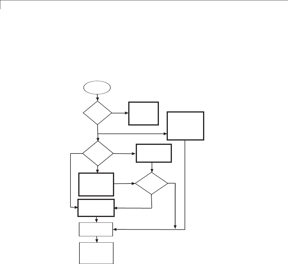
14 External Code Integration
Integrate External C or C++ Code
The following diagram identifies common characteristics or requirements for
reusable algorithmic components written in C or C++ code and recommends
solutions in each case. The table that follows the diagram provides more
detail. Collectively, the diagram and table will help you choose the best
solution for your application and find more related information.
C or C++
external code
Write or modify
S-function and TLC
files by hand
Add S-function or
blocks to model
Generate S-function
and TLC files with
S-Function Builder
(C only)
Generate S-function
and TLC files with
Legacy Code Tool
Fine tune
generated files
?
Full
Yes
No
Simulation
environment
?
Stateflow
Simulink
Level of
flexibility and
control
?Basic
Moderate
If necessary, add
support files to and
control model code
generation andl builds
Use Stateflow
Custom Code
Interface Call C code with
coder.ceval function
embedded in
MATLAB
Function block
MATLAB for code gen
j
k
m
l
n
14-8

Reuse Algorithmic Components in Generated Code
If... Then... For More Information, See...
1The external code will
simulate in a Stateflow
environment
Use the Stateflow
custom code interface
•sf_custom
•“Calling Custom C Code Functions”
in the Stateflow documentation
2Performance is not an
issue and you want to
quickly embed a call to
external C or C++ code
in a model
Call the C or C++ code
with the coder.ceval
function from a
MATLAB Function
block
•coder.ceval function description
•MATLAB Function block
3You want maximum
flexibility and the
ability to control what
code is generated; the
application requires
function overloading or
you need to format data
definitions such that
they are compatible
with a function
Write an S-function and
TLC file manually
•“C S-Function Examples” and “C++
S-Function Examples”
•“S-Function Basics”
•“Insert S-Function Code” on page
14-46
4You want ease of
use with moderate
flexibility to control
what code gets
generated,typically for
discrete applications;
you have C or
C++ programming
experience, but prefer
to generate the files
that add the code to
a model; optimizing
generated code is
essential
Use the Legacy Code
Tool to generate the
S-function and TLC
files; optionally, you can
fine-tune the generated
files manually to better
meet application needs
•rtwdemo_lct_lut_script
•“Integrate C Functions Using
Legacy Code Tool” in the Simulink
documentation
•“Integrate External Code Using
Legacy Code Tool” on page 14-28
5You want ease of use
with basic flexibility to
control what code gets
generated, typically
Use the S-Function
Builder to generate the
S-function and TLC
files; optionally, you can
“Build S-Functions Automatically” in
the Simulink documentation
14-9
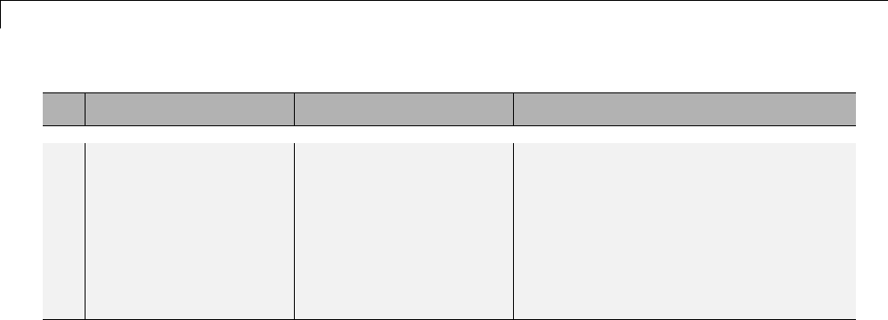
14 External Code Integration
If... Then... For More Information, See...
for mixed discrete
and continuous-time
applications;
programming
experience is limited
or the external code
requires a Fixed-Point
block interface
fine tune the generated
files manually to better
meet application needs
If you must control how code generation technology declares, stores, and
represents data in generated code, you can do so by designing (creating) and
applying custom storage classes (CSCs) if you have an Embedded Coder
license. For information on CSCs see the examples rtwdemo_cscpredef,
rtwdemo_importstruct,andrtwdemo_advsc and “Custom Storage Classes”
in the Embedded Coder documentation.
14-10
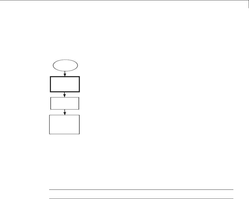
Reuse Algorithmic Components in Generated Code
Integrate Fortran Code
The following diagram shows that to integrateexternalFortrancodeas
reusable algorithmic components you must integrate the code by writing an
S-function and corresponding TLC file.
Fortran
external code
Write or modify
S-function and TLC
files by hand
Add S-function
to model
If necessary, add
support files to and
control model code
generation andl builds
For information, see “Fortran S-Function Examples” and “Fortran
S-Functions”
Integration Considerations for Reusable Algorithmic
Components
Note Solutions marked with EC only require an Embedded Coder license.
14-11

14 External Code Integration
If... Consider... For More Information,
See...
Generated code must use math
functions and operators that
are consistent with imported
external code
EC only—Using the code
replacement library (CRL)
API, Code Replacement Tool,
and Code Replacement Viewer
to create, examine, validate,
and register function and
operator replacement tables
•rtwdemo_crl_script
•“Introduction to Code
Replacement Libraries”
in the Embedded Coder
documentation
Generated code must share
data with imported external
code
Using data creation and
management technologies,
such as Simulink data objects,
alias and numeric data types,
and data type replacement to
match data type, formatting,
and storage that is consistent
with that used by the imported
external code
•“Data Types”
•“Data Representation”
Style and format of identifiers
in generated code must be
consistent with style and
format applied in imported
external code
In the Configuration
Parameters dialog box, on
the Symbols pane, configure
identifier naming for the
generated code
•rtwdemo_symbols
•rtwdemo_namerules
•“Configure Generated
Identifiers” on page
9-73 and “Configure
Generated Identifiers in
Embedded System Code”
in the Embedded Coder
documentation
14-12

Reuse Algorithmic Components in Generated Code
If... Consider... For More Information,
See...
Use of comments in generated
code must match the use
of comments in imported
external code
In the Configuration
Parameters dialog box, on the
Comments pane, configure
comments for the generated
code
•rtwdemo_comments
•“Configure Code Comments”
on page 9-72 and “Configure
Code Comments in
Embedded System Code”
in the Embedded Coder
documentation
Style of code, such as style and
usage of parentheses, must
be match the style used in
imported external code
EC only—In the Configuration
Parameters dialog box, on the
Code Style pane, configure
the style for the generated
code
•rtwdemo_parentheses
•“Control Code Style” in
the Embedded Coder
documentation
14-13

14 External Code Integration
Deploy Algorithm Code Within a Target Environment
Code generation technology can generate a single set of application source
files from an algorithm model and integrated external C or C++ code that
supports the target environment hardware. For example, you might have a
working device driver that you want to integrate with algorithmic code that
has to read data from and write data to the I/O device the driver supports.
Typically, a deployed model algorithm calls out to the external code.
The following diagram identifies common characteristics or requirements for
a target environment in which generated algorithm code might be deployed
and recommends solutions. The table that follows the diagram provides more
detail. Collectively, the diagram and table help you choose the best solution
for your application and find more related information.
14-14
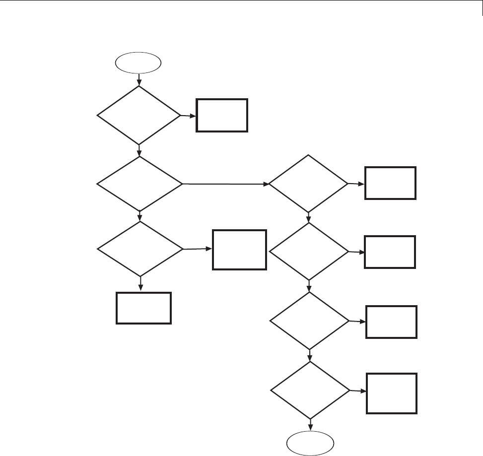
Deploy Algorithm Code Within a Target Environment
External code
High
Use custom file
processing
Yes
Yes
No
Control
organization
and format of
generated code
files
?
Insert
external code into
entry-point functions
generated for
model
?
Level of
control over placement
of generated
code
?
Use Custom Code
blocks to insert
code
Use Custom Code
Configuration
Parameter dialog
boxto insert code
Moderate
No
Control
data declaration,
storage, and
representation
?
Use custom
storage classes
Yes
No
Insert
comments or
pragmas to identify
sections of
memory
?
Use memory
sections
Yes
No
Set up
generated algorithmic
code to run in
real time
?
Generate and
customize ERT
target main
program module
Yes
Embed call
to hardware-specific code
within generated
algorithm code
?
Yes Use Legacy
Code Tool
No
Done - no
more choices
p
o
j
km
ln
14-15

14 External Code Integration
Note Solutions marked with EC only require an Embedded Coder license.
If You Need To... Then... For More Information, See...
1Embed a call to
hardware-specific
code, such as a device
driver, within generated
algorithm code
Use the Legacy Code Tool •“Integrate Device Drivers” on
page 24-135
•“Integrate C Functions Using
Legacy Code Tool” in the
Simulink documentation
•“Integrate External Code Using
Legacy Code Tool” on page 14-28
2Insert target-specific
CorC++codeinto
entry-point functions
that Simulink Coder
generates for a model with
a high level of control
over code placement;
for example, inserting
startup, initialization, or
termination code
UseCustomCodeblocks •rtwdemo_slcustcode
•“Insert Custom Code Blocks” on
page 14-36
3Insert application-specific
CorC++code—nearthe
top of the generated source
code or header file or inside
the model initialization or
termination function—or
files for the build
process—source, header,
library—for the external
code
Configure files and
data for the external
code environment by
entering code and
file specifications for
parameters on the Code
Generation > Interface
pane of the Configuration
Parameters dialog box
•Integrating the Generated Code
into the External Environment
•“Configure Model for External
Code Integration” on page 14-33
14-16

Deploy Algorithm Code Within a Target Environment
If You Need To... Then... For More Information, See...
4Control the organization
and format of code files
generated for a model—for
example, placement of code
in sections, inclusion of
banners, calls to generated
entry-point functions,
generation of a main
program module
EC only—Use the
custom file processing
components—code
generation template
(CGT) files, code template
API, and custom
file processing (CFP)
templates (the API and
CFP templates require
TLC programming
knowledge
•rtwdemo_codetemplate
•“Customize Code Organization
and Format” in the Embedded
Coder documentation
5Control how the
Simulink Coder product
declares, stores, and
represents signals,
tunable parameters, block
states, and data objects in
generated code
EC only— Design (create)
and apply custom storage
classes
•rtwdemo_cscpredef
•rtwdemo_importstruct
•rtwdemo_advsc
•“Custom Storage Classes”
in the Embedded Coder
documentation
6Insert comments or
pragmas in generated code
to identify memory for
custom storage classes or
model- or subsystem-level
functions and internal
data
EC only—Usethe
memory section capability
•rtwdemo_memsec
•“About Memory Sections”
7Set up generated
algorithmiccodetorun
in real time—within the
context of a real-time
operating system (RTOS)
or on hardware that is
not running an operating
system (bare board)
EC only—Generate and
customize an ERT target
main (harness) program
module (ert_main.c or
ert_main.cpp)forthe
model
•“Deployment”
•“Standalone Programs (No
Operating System)”
14-17

14 External Code Integration
Export Generated Algorithm Code for Embedded
Applications
You have multiple options for configuring and preparing a model or subsystem
so that you can plug its generated source code into an existing external code
base.
Scanthefirstcolumnofthefollowingtabletoidentifytasksthatapply
to the algorithm code you want to export. For each task that applies, the
information in the corresponding row describes how to achieve the goal, using
code generation technology.
Note Solutions marked with EC only require an Embedded Coder license.
If You Need To... Then... For More Information, See...
Insert C or C++ code
into specific entry-point
functions that Simulink
Coder generates for
interfacing with the
external code
UseCustomCodeblocks •rtwdemo_slcustcode
•“Insert Custom Code Blocks” on page
14-36
Pass composite data Represent the data in the
model as a vector or bus
•rtwdemo_scalarrep
•rtwdemo_slbus
•“Composite Signals”
•“Optimize Code Generated for Vector
Assignments” on page 19-6 and“Buses”
Readfromorwritetoa
specific region or area of
memory
EC only—SetupaData
Store Memory block in
the model to represent
the area of memory and
define the area with
the built-in advanced
custom storage class
(CSC) GetSet
•“IncreaseCodeEfficiencyWithGetSet
CSC”
•“GetSet Custom Storage Classes” in
the Embedded Coder documentation
14-18

Export Generated Algorithm Code for Embedded Applications
If You Need To... Then... For More Information, See...
Generate a C++ class
interface—encapsulated
model data (properties)
and model entry-point
functions (methods)—to
the model code
EC only—Configure
and generate the C++
encapsulation interface
in the Configuration
Parameters dialog box
or programmatically in
the MATLAB command
window or with a script
•“Simple Use of C++ Encapsulation
Control”
•“C++ Encapsulation Interface Control”
in the Embedded Coder documentation
Control how Embedded
Coder generates
function prototypes
— arguments, argument
order, and data
types—for a model
(for example, so the
prototypes match the
external code)
EC only—Configure
function prototypes
for the model by
clicking the Configure
Model Functions
button on the Code
Generation > Interface
pane of the Configuration
Parameters dialog
box and entering
data in the Model
Interface dialog box;
alternatively, configure
the function prototypes
programmatically in
the MATLAB command
window or with a script
•“Sample Procedure for Configuring
Function Prototypes”
•“Function Prototype Control” in the
Embedded Coder documentation
Insert
application-specific C
or C++ code—near the
top of the generated
source code or header
file or inside the
model initialization or
termination function—or
files for the build
process—source, header,
Configure files and
data for the external
code environment by
entering code and
file specifications for
parameters on the Code
Generation > Interface
pane of the Configuration
Parameters dialog box
•Integrating the Generated Code into
the External Environment
•“Configure Model for External Code
Integration” on page 14-33
14-19

14 External Code Integration
If You Need To... Then... For More Information, See...
library—for the external
code
Generate code, which is
to be integrated with an
existing C code base, for
a function-call or virtual
subsystem
EC only—Reviewand
adjust for exported
subsystem requirements,
configure the parent
model to use an ERT
target, and right-click
build the subsystem
block using the
C/C++ Code > Export
Functions menu item
•“Techniques for Exporting
Function-Call Subsystems”
•rtwdemo_export_functions
•“Export Function-Call Subsystems” in
the Embedded Coder documentation
14-20

Export Algorithm Executables for System Simulation
Export Algorithm Executables for System Simulation
If you have an Embedded Coder license, you can use an ERT shared library
target (shrlib.tlc) to build a Windows dynamic link library (.dll)ora
UNIX shared object (.so) file from a model. An application, which runs on a
Windows or a UNIX system, can then load the shared library file. You can
upgrade a shared library without having to recompile applications that use it.
Uses of shared library files include:
•Adding a software component to an application for system simulation
•Reusing off-the-shelf software modules among applications on a host system
•Hiding source code (intellectual property) for software shared with a vendor
For an example, see rtwdemo_shrlib. For more information, see “Shared
Object Libraries” in the Embedded Coder documentation.
14-21

14 External Code Integration
Modify External Code for Language Compatibility
If you need to integrate external C code with generated C++ code or vice
versa,youmustmodifyyourexternalcodetobelanguagecompatiblewiththe
generated code. Options for making thecodelanguagecompatibleinclude:
•Writing or rewriting the legacy or custom code in the same language as
the generated code.
•If the generated code is in C++ and your legacy or custom code is in C, for
each C function, create a header file that prototypes the function, using
the following format:
#ifdef __cplusplus
extern "C" {
#endif
int my_c_function_wrapper();
#ifdef __cplusplus
}
#endif
The prototype serves as a function wrapper. If your compiler supports C++
code, the value __cplusplus is defined. The linkage specification extern
"C" specifiesClinkagewithnonamemangling.
•If the generated code is in C and your legacy or custom code is in C++,
include an extern "C" linkage specification in each .cpp file. For example,
the following shows a portion of C++ code in the file my_func.cpp:
extern "C" {
int my_cpp_function()
{
...
}
}
14-22
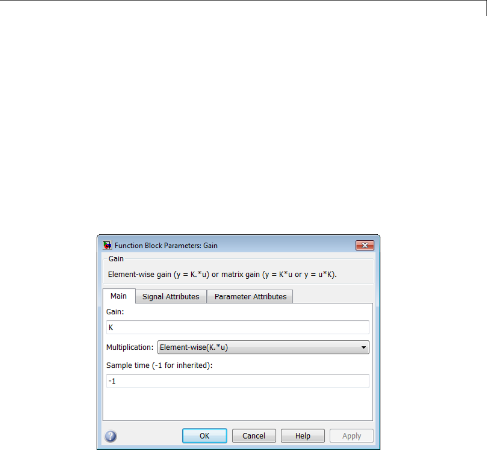
Automate S-Function Generation
Automate S-Function Generation
The Generate S-function feature automates the process of generating an
S-function from a subsystem. In addition, the Generate S-function feature
presents a display of parameters used within the subsystem, and lets you
declare selected parameters tunable.
As an example, consider SourceSubsys, the same subsystem illustrated in
the example “Create S-Function Blocks from a Subsystem” on page 12-37.
The objective is to automatically extract SourceSubsys from the model and
build an S-Function block from it, as in the previous example. In addition,
the workspace variable K, which is the gain factor of the Gain block within
SourceSubsys (as shown in the Gain block parameter dialog box below), is
declared and generated as a tunable variable.
To auto-generate an S-function from SourceSubsys with tunable parameter K,
1With the SourceSubsys model open, click the subsystem to select it.
2From the Code menu, select C/C++ Code > Generate S-Function.This
menu item is enabled when a subsystem is selected in the current model.
14-23
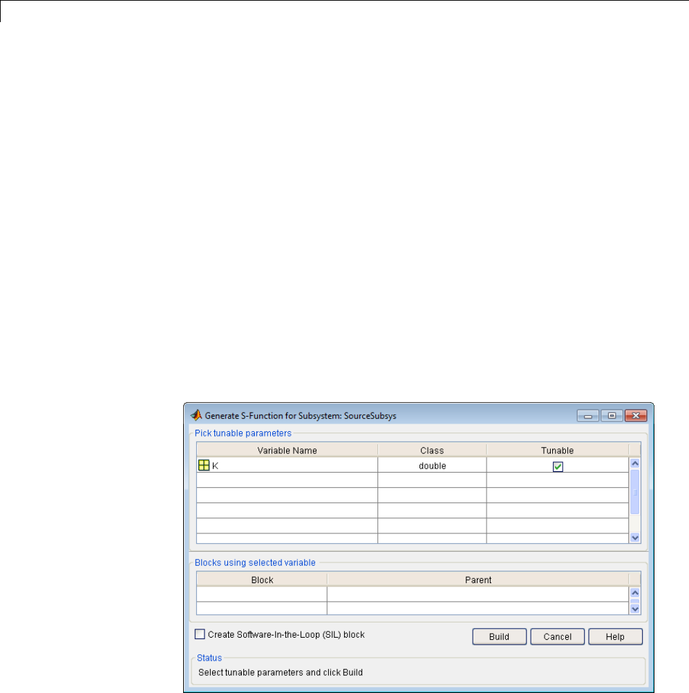
14 External Code Integration
Alternatively, you can right-click the subsystem and select C/C++
Code > Generate S-Function from the subsystem block’s context menu.
3The Generate S-Function window is displayed (see the next figure). This
window shows all variables (or data objects) that are referenced as block
parameters in the subsystem, and lets you declare them as tunable.
The upper pane of the window displays three columns:
•Variable Name: name of the parameter.
•Class: If the parameter is a workspace variable, its data type is shown.
If the parameter is a data object, its name and class is shown
•Tunable: Lets you select tunable parameters. To declare a parameter
tunable, select the check box. In the next figure, the parameter Kis
declared tunable.
When you select a parameter in the upper pane, the lower pane shows all
the blocks that reference the parameter, and the parent system of each
such block.
Generate S-Function Window
14-24
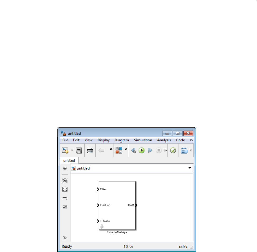
Automate S-Function Generation
4If you have installed the Embedded Coder product, and if the subsystem
does not have a continuous sample time, the Create Software In the
Loop (SIL) block check box is available, as shown above. Otherwise, it
is appears dimmed. When Create Software In the Loop (SIL) block
is selected, the build process generates a wrapper S-function by using the
Embedded Coder product. See “Generate S-Function Wrappers” in the
Embedded Coder documentation for more information.
5After selecting tunable parameters, click the Build button. This initiates
code generation and compilation of the S-function, using the S-function
target. The Create New Model option is automatically enabled.
6ThebuildprocessdisplaysstatusmessagesintheMATLABCommand
Window. When the build completes, the tunable parameters window closes,
and a new untitled model window opens.
7The model window contains an S-Function block with the same name
as the subsystem from which the block was generated (in this example,
SourceSubsys). Optionally, you can save the generated model containing
the generated block.
14-25

14 External Code Integration
8The generated code for the S-Function block is stored in the current
working folder. The following files are written to the top level folder:
•subsys_sf.c or .cpp,wheresubsys is the subsystem name (for example,
SourceSubsys_sf.c)
•subsys_sf.h
•subsys_sf.mexext,wheremexext is a platform-dependent MEX-file
extension (for example, SourceSubsys_sf.mexw32)
The source code for the S-function is written to the subfolder
subsys_sfcn_rtw.Thetop-level.c or .cpp file is a stub file that simply
contains an include directive that you can use to interface other C/C++
code to the generated code.
Note For a list of files required to deploy your S-Function block for
simulation or code generation, see “Required Files for S-Function
Deployment” on page 12-36.
9The generated S-Function block has inports and outports whose widths and
sample times correspond to those of the original model.
The following code, from the mdlOutputs routine of the generated S-function
code (in SourceSubsys_sf.c), shows how the tunable variable Kis referenced
by using calls to the MEX API.
static void mdlOutputs(SimStruct *S, int_T tid)
...
/* Gain: '<S1>/Gain' incorporates:
* Sum: '<S1>/Sum'
*/
rtb_Gain_n[0] = (rtb_Product_p + (*(((const
real_T**)ssGetInputPortSignalPtrs(S, 2))[0]))) * (*(real_T
*)(mxGetData(K(S))));
rtb_Gain_n[1] = (rtb_Product_p + (*(((const
real_T**)ssGetInputPortSignalPtrs(S, 2))[1]))) * (*(real_T
*)(mxGetData(K(S))));
14-26

Automate S-Function Generation
Notes
•In automatic S-function generation, the Use Value for Tunable
Parameters option is always set to its default value (off).
•A MEX S-function wrapper must only be used in the MATLAB version in
which the wrapper is created.
14-27

14 External Code Integration
Integrate External Code Using Legacy Code Tool
In this section...
“Legacy Code Tool and Code Generation” on page 14-28
“Generate Inlined S-Function Files for Code Generation” on page 14-29
“Apply Code Style Settings to Legacy Functions” on page 14-30
“Address Dependencies on Files in Different Locations” on page 14-31
“Deploy S-Functions for Simulation and Code Generation” on page 14-32
Legacy Code Tool and Code Generation
You can use the Simulink Legacy Code Tool to automatically generate fully
inlined C MEX S-functions for legacy or custom code that is optimized for
embedded components, such as device drivers and lookup tables, that call
existing C or C++ functions.
Note TheLegacyCodeToolcaninterfacewithC++functions,butnotC++
objects. For a work around so that the tool can interface with C++ objects, see
“Legacy Code Tool Limitations” in the Simulink documentation.
You can use the tool to:
•Compile and build the generated S-function for simulation.
•Generate a masked S-Function block that is configured to call the existing
external code.
If you want to include these types of S-functions in models for which you
intend to generate code, you must use the tool to generate a TLC block file.
The TLC block file specifies how the generated code for a model calls the
existing C or C++ function.
If the S-function depends on files in folders other than the folder containing
the S-function dynamically loadable executable file, and you want to maintain
those dependencies for building a model that includes the S-function, use the
14-28

Integrate External Code Using Legacy Code Tool
tool to also generate an rtwmakecfg.m file for the S-function. For example,
for some applications, such as custom targets, you might want to locate
files in a target-specific location. The Simulink Coder build process looks
for the generated rtwmakecfg.m file in the same folder as the S-function’s
dynamically loadable executable and calls the rtwmakecfg function if the
software finds the file.
For more information, see “Integrate C Functions Using Legacy Code Tool” in
the Simulink documentation.
Generate Inlined S-Function Files for Code Generation
Depending on your application’s code generation requirements, to generate
code for a model that uses the S-function, you can choose to do either of the
following:
•Generate one .cpp file for the inlined S-function. In the Legacy Code
Tool data structure, set the value of the Options.singleCPPMexFile field
to true before generating the S-function source file from your existing C
function. For example:
def.Options.singleCPPMexFile = true;
legacy_code('sfcn_cmex_generate', def);
•Generate a source file and a TLC block file for the inlined S-function. For
example:
def.Options.singleCPPMexFile = false;
legacy_code('sfcn_cmex_generate', def);
legacy_code('sfcn_tlc_generate', def);
singleCPPMexFile Limitations
You cannot set the singleCPPMexFile field to true if
•Options.language='C++'
•You use one of the following Simulink objects with the IsAlias property
set to true:
-Simulink.Bus
14-29

14 External Code Integration
-Simulink.AliasType
-Simulink.NumericType
•The Legacy Code Tool function specification includes a void* or void** to
represent scalar work data for a state argument
•HeaderFiles field of the Legacy Code Tool structure specifies multiple
header files
Apply Code Style Settings to Legacy Functions
To apply the model configuration parameters for code style to a legacy
function:
1Initialize the Legacy Code Tool data structure. For example:
def = legacy_code('initialize');
2In the data structure, set the value of the Options.singleCPPMexFile
field to true. For example:
def.Options.singleCPPMexFile = true;
To verify the setting, enter:
def.Options.singleCPPMexFile
singleCPPMexFile Limitations
You cannot set the singleCPPMexFile field to true if
•Options.language='C++'
•You use one of the following Simulink objects with the IsAlias property
set to true:
-Simulink.Bus
-Simulink.AliasType
-Simulink.NumericType
14-30

Integrate External Code Using Legacy Code Tool
•The Legacy Code Tool function specification includes a void* or void** to
represent scalar work data for a state argument
•HeaderFiles field of the Legacy Code Tool structure specifies multiple
header files
Address Dependencies on Files in Different Locations
By default, the Legacy Code Tool assumes that all files on which an S-function
depends reside in the same folder as the dynamically loadable executable file
for the S-function. If your S-function depends on files that reside elsewhere
and you are using the Simulink Coder template makefile build process, you
must generate an rtwmakecfg.m file for the S-function. For example, it is
likely that you need to generate this file if your Legacy Code Tool data
structure defines compilation resources as path names.
To generate the rtwmakecfg.m file, call the legacy_code function with
'rtwmakecfg_generate' as the first argument, and the name of the Legacy
Code Tool data structure as the second argument.
legacy_code('rtwmakecfg_generate', lct_spec);
If you use multiple registration files in the same folder and generate
an S-function for each file with a single call to legacy_code,thecallto
legacy_code that specifies 'rtwmakecfg_generate' must be common to all
registration files. For more information, see “Handling Multiple Registration
Files” in the Simulink documentation
For example, if you define defs as an array of Legacy Code Tool structures,
you call legacy_code with 'rtwmakecfg_generate' once.
defs = [defs1(:);defs2(:);defs3(:)];
legacy_code('rtwmakecfg_generate', defs);
For more information, see “Build Support for S-Functions” on page 14-120.
14-31

14 External Code Integration
Deploy S-Functions for Simulation and Code
Generation
You can deploy the S-functions that you generate with the Legacy Code Tool
so that other people can use them. To deploy an S-function for simulation and
code generation, share the following files:
•Registration file
•Compiled dynamically loadable executable
•TLC block file
•rtwmakecfg.m file
•All header, source, and include files on which the generated S-function
depends
Users of the deployed files must be aware that:
•Before using the deployed files in a Simulink model, they must add the
folder that contains the S-function files to the MATLAB path.
•If the Legacy Code Tool data structure registers any required files as
absolute paths and the location of the files changes, they must regenerate
the rtwmakecfg.m file.
14-32

Configure Model for External Code Integration
Configure Model for External Code Integration
Configure a model using the Custom Code pane such that the code generator
includes external code such as headers, files, and functions. You can also
include additional files and paths in the build process.
To... Select...
Insert custom
code near the top
of the generated
model.c or
model.cpp file,
outside of any
function
Source file andenterthecustomcodetoinsert.
Insert custom
code near the top
of the generated
model.h file
Header file andenterthecustomcodetoinsert.
Insert custom
code inside the
model’s initialize
function in the
model.c or
model.cpp file
Initialize function
Insert custom
code inside the
model’s terminate
function in the
model.c or
model.cpp file.
Terminate function and enter the custom code to
insert. Also select the Terminate function required
parameter on the Interface pane.
Add include
folders, which
contain header
files, to the build
process
Include directories and enter the absolute or relative
paths to the folders. If you specify relative paths, the
paths must be relative to the folder containing your
model files, not relative to the build folder. The order in
which you specify the folders is the order in which they
are searched for header, source, and library files.
14-33

14 External Code Integration
To... Select...
Add source files to
be compiled and
linked
Source files and enter the full paths or just the file
names for the files. Enter just the file name if the file is
in the current MATLAB folder or in one of the include
folders. For each additional source that you specify, the
build process expands a generic rule in the template
makefile for the folder in which the source file is found.
For example, if a source file is found in folder inc,the
build process adds a rule similar to the following:
%.obj: buildir\inc\%.c
$(CC) -c -Fo$(@F) $(CFLAGS) $<
The build process adds the rules in the order you list
the source files.
Add libraries to
be linked
Libraries and enter the full paths or just the file
namesforthelibraries. Enterjustthefilenameifthe
library is located in the current MATLAB folder or in
oneoftheincludefolders.
Use the same
custom code
settings as
those specified
for simulation
of MATLAB
Function blocks,
Stateflow charts,
and Truth Table
blocks
Use the same custom code settings as Simulation
Target
Note This option refers to the Simulation Target
pane in the Configuration Parameters dialog box.
Enable a library
model to use
custom code
settings unique
from the parent
model to which
the library is
linked
Use local custom code settings (do not inherit
from main model)
Note This option is available only for library models
that contain MATLAB Function blocks, Stateflow
charts, or Truth Table blocks.
14-34

Configure Model for External Code Integration
If you are including a header file, in your custom header file add #ifndef
code. This avoids multiple inclusions. For example, in rtwtypes.h the
following #include guards are added:
#ifndef RTW_HEADER_rtwtypes_h_
#define RTW_HEADER_rtwtypes_h_
...
#endif /* RTW_HEADER_rtwtypes_h_ */
Note Custom code that you include in a configuration set is ignored when
building S-function targets, accelerated simulation targets, and model
reference simulation targets.
For more information about Custom Code pane parameters, see “Code
Generation Pane: Custom Code”.
14-35

14 External Code Integration
Insert Custom Code Blocks
The following sections explain how to use blocks in the Custom Code block
library to insert custom code into the code generated for a model. This chapter
includes the following topics:
In this section...
“Custom Code Library” on page 14-36
“Embed Custom Code Directly Into MdlStart Function” on page 14-40
“Custom Code in Subsystems” on page 14-43
“Preserve User Files in Build Folder” on page 14-44
Custom Code Library
The Custom Code library contains blocks that enable you to insert your own
C or C++ code into specific functions within code generated by the Simulink
Coder product for root models and subsystems. These blocks are a superset of
code customization capabilities built into the Custom Code Configuration
Parameters dialog box, and provide greater flexibility in terms of code
placement than the controls on the dialog box.
The Custom Code library is part of the Simulink Coder library. You can access
the Simulink Coder library by using the Simulink Library Browser. You can
access Custom Code blocks by using the Simulink Coder library or by entering
the MATLAB command rtwlib and then double-clicking the Custom Code
Library block within it. Alternatively, you can enter the command custcode.
14-36
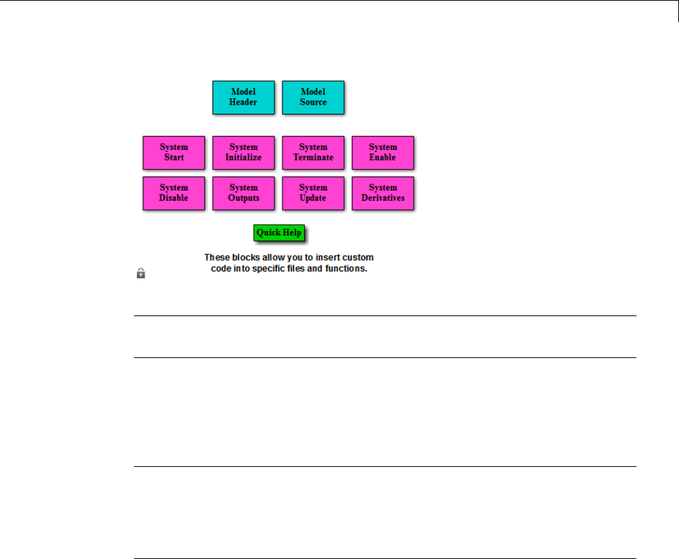
Insert Custom Code Blocks
Note If you need to integrate custom C++ code with generated C code or vice
versa, see “Modify External Code for Language Compatibility” on page 14-22.
All Custom Code blocks except for Model Header and Model Source can be
dragged into either root models or atomic subsystems. Model Header and
Model Source blocks can only be placed in root models.
Note You can use models containing Custom Code blocks as submodels
(models referenced by Model blocks). However, when simulation targets for
submodels are generated, all Custom Code blocks within them are ignored.
On the other hand, when submodel code is generated to create Simulink
Coder targets, custom code is included and is compiled in the generated code.
The Custom Code library contains ten blocks that insert custom code into the
generated model files and functions. You can view the blocks either by
•Expanding the Custom Code node (under Simulink Coder library) in the
Simulink Library Browser
•Right-clicking the Custom Code sublibrary icon in the right pane of the
Simulink Library Browser
The latter method opens the window shown in the previous section.
14-37
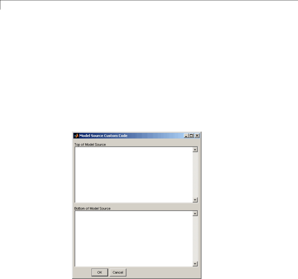
14 External Code Integration
The two blocks on the top row contain text fields for inserting custom code at
the top and bottom of
•model.h — Model Header File block
•model.c or model.cpp — Model Source File block
Each block contains two fields, in which you type or paste code and comments:
•Top of Model Source/Header
•Bottom of Model Source/Header
The next figure shows the Model Source block dialog box.
The eight function blocks in the second and third rows contain text fields to
insert custom code sections at the top and bottom of these designated model
functions:
14-38

Insert Custom Code Blocks
•SystemStart — System Start function block
•SystemInitialize — System Initialize function block
•SystemTerminate — System Terminate function block
•SystemEnable — System Enable function block
•SystemDisable — System Disable function block
•SystemOutputs — System Outputs function block
•SystemUpdate — System Update function block
•SystemDerivatives — System Derivatives function block
Each of these blocks provides a System Outputs Function Custom Code dialog
box that contains three fields:
•Declaration code
•Execution code
•Exit code
14-39
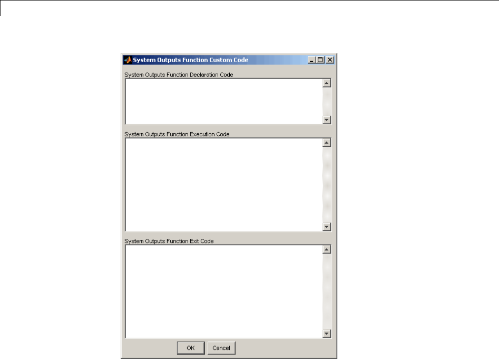
14 External Code Integration
Embed Custom Code Directly Into MdlStart Function
The following example uses a System Start Function block to introduce code
into the MdlStart function. The next figure shows a simple model with the
System Start Function block inserted.
14-40

Insert Custom Code Blocks
Double-clicking the System Start Function block opens the System Start
Function Custom Code dialog box.
14-41
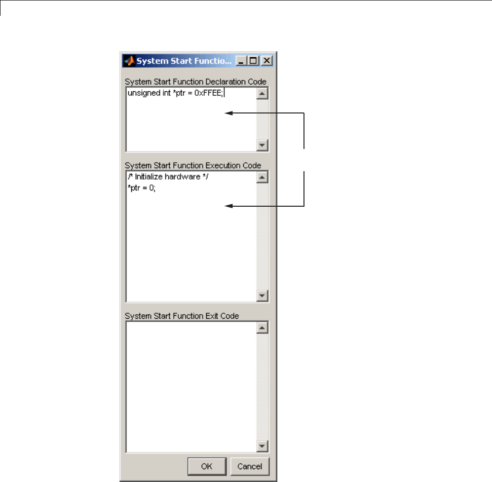
14 External Code Integration
The code generator inserts the code
entered here into the MdlStart function.
You can insert custom code into any or all of the available text fields.
14-42

Insert Custom Code Blocks
ThecodebelowistheMdlStart function for this example (mymodel).
void MdlStart(void)
{
{
{
/* user code (Start function Header) */
/* System '<Root>' */
unsigned int *ptr = 0xFFEE;
/* user code (Start function Body) */
/* System '<Root>' */
/* Initialize hardware */
*ptr = 0;
}
}
MdlInitialize();
}
ThecustomcodeenteredintheSystem Start Function Custom Code dialog
box is embedded directly in the generated code. Each block of custom code is
tagged with a comment such as
/* user code (Start function Header) */
Custom Code in Subsystems
The location of a Custom Code block in your model determines the location of
the code it contains. You can use SystemCustomCodeblockseitheratroot
level or within atomic subsystems; the code is local to the subsystem in which
you place the blocks. For example, the System Outputs block places code in
mdlOutputs when the code block resides in the root model. If the System
Outputs block resides in a triggered or enabled subsystem, however, the code
is placed in the subsystem’s Outputs function.
The ordering for a triggered or enabled system is
1Output entry
2Output exit
14-43

14 External Code Integration
3Update entry
4Update exit
Note If a root model or atomic subsystem does not need to generate a
function for which a Custom Code block has been supplied, either the code
in the block is not used or an error is generated. There is no diagnostic
setting to control this. To eliminate the error, remove the Custom Code
block.
Preserve User Files in Build Folder
Prior to Release 13 (Version 5.0), the Simulink Coder product did not delete
any .c or .h files that you might have placed in the build folder when
rebuilding targets. From Release 13 onward, all foreign source files are by
default deleted during builds, but can be preserved by following the guidelines
given below.
If you put a .c/.cpp or .h source file in a build folder, and you want to
prevent the Simulink Coder product from deleting it during the TLC code
generation process, insert the string target specific file in the first line
of the .c/.cpp or .h file. For example,
/* COMPANY-NAME target specific file
*
* This file is created for use with the
* COMPANY-NAME target.
* It is used for ...
*/
...
Make sure you spell the string “target specific file” as shown in the preceding
example, and that the string is in the first line of the source file. Other text
can appear before or after this string.
In addition to preserving them, flagging user files in this manner prevents
postprocessing them to indent them along with generated source files.
Auto-indenting occurred in previous releases to build folder files with names
having the pattern model_*.c/.cpp (where *could be any string). The
14-44

Insert Custom Code Blocks
indenting is harmless, but can cause differences to be detected by source
control software that might trigger unnecessary updates.
14-45

14 External Code Integration
Insert S-Function Code
In this section...
“About S-Functions and Code Generation” on page 14-46
“Write Noninlined S-Functions” on page 14-52
“Write Wrapper S-Functions” on page 14-54
“Write Fully Inlined S-Functions” on page 14-64
“Write Fully Inlined S-Functions with mdlRTW Routine” on page 14-65
“Guidelines for Writing Inlined S-Functions” on page 14-91
“Write S-Functions That Support Expression Folding” on page 14-91
“S-Functions That Specify Port Scope and Reusability” on page 14-105
“S-Functions That Specify Sample Time Inheritance Rules” on page 14-111
“S-Functions That Support Code Reuse” on page 14-113
“S-Functions for Multirate Multitasking Environments” on page 14-113
“Build Support for S-Functions” on page 14-120
About S-Functions and Code Generation
This chapter describes how to create S-functions that work seamlessly with
Simulink Coder code generation. It begins with basic concepts and concludes
with an example of how to create a highly optimized direct-index lookup table
S-Function block.
This chapter assumes that you understand the following concepts:
•Level 2 S-functions
•Target Language Compiler (TLC) scripting
•How the Simulink Coder software generates and builds C/C++ code
14-46

Insert S-Function Code
Note When this chapter refers to actions performed by the Target Language
Compiler, including parsing, caching, creating buffers, and so on, the name
Target Language Compiler is spelled out fully. When referring to code written
in the Target Language Compiler syntax, this chapter uses the abbreviation
TLC.
Note The guidelines presented in this chapter are for Simulink Coder
users. Even if you do not currently use the Simulink Coder code generator,
you should follow the practices presented in this chapter when writing
S-functions, especially if you are creating general-purpose S-functions.
Classes of Problems Solved by S-Functions
S-functions help solve various kinds of problems you might face when working
with the Simulink and Simulink Coder products. These problems include
•Extending the set of algorithms (blocks) provided by the Simulink and
Simulink Coder products
•Interfacing legacy (hand-written) code with the Simulink and Simulink
Coder products
•Interfacing to hardware through device driver S-functions
•Generating highly optimized code for embedded systems
•Verifying code generated for a subsystem as part of a Simulink simulation
S-functions are written using an application program interface (API) that
allows you to implement generic algorithms in the Simulink environment with
a great deal of flexibility. This flexibility cannot always be maintained when
you use S-functions with the Simulink Coder code generator. For example, it
isnotpossibletoaccesstheMATLABworkspacefromanS-functionthatis
used with the code generator. However, using the techniques presented in
this chapter, you can create S-functions for most applications that work with
the Simulink Coder generated code.
14-47

14 External Code Integration
Although S-functions provide a generic and flexible solution for implementing
complex algorithms in a Simulink model, the underlying API incurs overhead
in terms of memory and computation resources. Most often the additional
resources are acceptable for real-time rapid prototyping systems. In many
cases, though, additional resources are unavailable in real-time embedded
applications. You can minimize memory and computational requirements by
using the Target Language Compiler technology provided with the Simulink
Coder product to inline your S-functions. If you are producing an S-function
for existing code, consider using the Simulink Legacy Code Tool.
Types of S-Functions
The implementation of S-functions changes based on your requirements. This
chapter discusses the typical problems that you may face and how to create
S-functions for applications that need to work with the Simulink and Simulink
Coder products. These are some (informally defined) common situations:
1“I’m not concerned with efficiency. I just want to write one version of my
algorithm and have it work in the Simulink and Simulink Coder products
automatically.”
2“I have a lot of hand-written code that I need to interface. I want to call my
function from the Simulink and Simulink Coder products in an efficient
manner.”
or said another way:
“I want to create a block for my blockset that will be distributed throughout
my organization. I’d like it to be very maintainable with efficient code. I’d
like my algorithm to exist in one place but work with both the Simulink
and Simulink Coder products.”
3“I want to implement a highly optimized algorithm in the Simulink and
Simulink Coder products that looks like a built-in block and generates
very efficient code.”
MathWorks products have adopted terminology for these different
requirements. Respectively, the situations described above map to this
terminology:
1Noninlined S-function
14-48

Insert S-Function Code
2Wrapper S-function
3Fully inlined S-function
Noninlined S-Functions. A noninlined S-function is a C or C++ MEX
S-function that is treated identically by the Simulink engine and Simulink
Coder generated code. In general, you implement your algorithm once
according to the S-function API. The Simulink engine and Simulink Coder
generated code call the S-function routines (for example, mdlOutputs)during
model execution.
Additional memory and computation resources are required for each instance
of a noninlined S-Function block. However, this routine of incorporating
algorithms into Simulink models and Simulink Coder applications is typical
during the prototyping phase of a project where efficiency is not important.
The advantage gained by forgoing efficiency is the ability to change model
parameters and structures rapidly.
Writing a noninlined S-function does not involve any TLC coding. Noninlined
S-functions are the default case for the Simulink Coder build process in
the sense that once you build a MEX S-function in your model, there is no
additional preparation prior to clicking Build in the Code Generation pane
of the Configuration Parameters dialog box for your model.
Some restrictions exist concerning the names and locations of noninlined
S-function files when generating makefiles. See “Write Noninlined
S-Functions” on page 14-52.
Wrapper S-Functions. A wrapper S-function is ideal for interfacing
hand-written code or a large algorithm that is encapsulated within a few
procedures. In this situation, usually the procedures reside in modules that
are separate from the MEX S-function. The S-function module typically
contains a few calls to your procedures. Because the S-function module does
not contain any parts of your algorithm, but only calls your code, it is referred
to as a wrapper S-function.
In addition to the MEX S-function wrapper, you need to create a TLC wrapper
that complements your S-function. The TLC wrapper is similar to the
S-function wrapper in that it contains calls to your algorithm.
14-49

14 External Code Integration
Fully Inlined S-Functions. For S-functions to work in the Simulink
environment, some overhead code is generated. When the Simulink Coder
software generates code from models that contain S-functions (without
sfunction.tlc files), it embeds some of this overhead code in the generated
code. If you want to optimize your real-time code and eliminate some of the
overhead code, you must inline (or embed) your S-functions. This involves
writing a TLC (sfunction.tlc) file that eliminates all overhead code from
the generated code. The Target Language Compiler processes sfunction.tlc
files to define how to inline your S-function algorithm in the generated code.
Note The term inline should not be confused with the C++ inline keyword. In
Simulink Coder terminology, inline means to specify a text string in place of
the call to the general S-function API routines (for example, mdlOutputs). For
example, when a TLC file is used to inline an S-function, the generated code
contains the C/ C++ code that would normally appear within the S-function
routines and the S-function itself has been removed from the build process.
A fully inlined S-function builds your algorithm (block) into Simulink Coder
generated code in a manner that is indistinguishable from a built-in block.
Typically, a fully inlined S-function requires you to implement your algorithm
twice: once for the Simulink model (C/C++ MEX S-function) and once for
Simulink Coder code generation (TLC file). The complexity of the TLC file
depends on the complexity of your algorithm and the level of efficiency you’re
trying to achieve in the generated code. TLC files vary from simple to complex
in structure.
The Simulink Legacy Code Tool can automate the generation of a fully
inlined S-function and a corresponding TLC file based on information that
you register in a Legacy Code Tool data structure. For more information, see
“Integrate C Functions Using Legacy Code Tool” in the Simulink Writing
S-Functions documentation and “Integrate External Code Using Legacy Code
Tool” on page 14-28.
Basic Files Required for Implementation
This section briefly describes what files and functions you need to create
noninlined, wrapper, and fully inlined S-functions.
14-50

Insert S-Function Code
•Noninlined S-functions require the C or C++ MEX S-function source code
(sfunction.c or sfunction.cpp).
•Wrapper S-functions that inline a call to your algorithm (your C/C++
function) require an sfunction.tlc file.
•Fully inlined S-functions also require an sfunction.tlc file. Fully inlined
S-functions produce the optimal code for a parameterized S-function. This
is an S-function that operates in a specific mode dependent upon fixed
S-function parameters that do not change during model execution. For a
given operating mode, the sfunction.tlc file specifies the exact code that
is generated to implement the algorithm for that mode. For example, the
direct-index lookup table S-function at the end of this chapter contains two
operating modes — one for evenly spaced x-data and one for unevenly
spaced x-data.
Fully inlined S-functions might require the placement of the mdlRTW routine in
your S-function MEX-file sfunction.c or sfunction.cpp.ThemdlRTW routine
lets you place information in model.rtw, the record file that specifies a model,
and which the Simulink Coder code generator invokes the Target Language
Compiler to process prior to executing sfunction.tlc when generating code.
Including a mdlRTW routine is useful when you want to introduce nontunable
parameters into your TLC file. Such parameters are generally used to
determine which operating mode is active in a given instance of the S-function.
Based on this information, the TLC file for the S-function can generate highly
efficient, optimal code for that operating mode.
Guidelines for Writing S-Functions
•Use only C MEX S-functions with the Simulink Coder code generator. You
cannot use Level-1 MATLAB language S-functions with Simulink Coder
software.
•To inline an S-function, use the Legacy Code Tool. The Legacy Code Tool
automatically generates fully inlined C MEX S-functions for legacy or
custom code. In addition, the tool generates other files for compiling and
building the S-function for simulation and generate a masked S-function
block configured to call existing external code. For more information,
see “Integrate C Functions Using Legacy Code Tool” in the Simulink
14-51

14 External Code Integration
documentation and “Integrate ExternalCodeUsingLegacyCodeTool”on
page 14-28.
•If you are rapid prototyping, you might not have to inline an S-function.. If
you choose not to inline the C MEX S-function, write the S-function, include
it directly in the model, and let the Simulink Coder software generate the
code. For more information, see “Write Noninlined S-Functions” on page
14-52.
Write Noninlined S-Functions
•“About Noninlined S-Functions” on page 14-52
•“Guidelines for Writing Noninlined S-Functions” on page 14-52
•“Noninlined S-Function Parameter Type Limitations” on page 14-54
About Noninlined S-Functions
Noninlined S-functions are identified by the absence of an sfunction.tlc
file for your S-function. The filename varies depending on your platform.
For example, on a 32–bit Microsoft Windows system, the file name would be
sfunction.mexw32.Typemexext in the MATLAB Command Window to see
which extension your system uses.
Guidelines for Writing Noninlined S-Functions
•The MEX-file cannot call MATLAB functions.
•If the MEX-file uses functions in the MATLAB External Interface libraries,
include the header file cg_sfun.h instead of mex.h or simulink.c.To
handle this case, include the following lines at the end of your S-function:
#ifdef MATLAB_MEX_FILE /* Is this file being compiled as a MEX-file? */
#include "simulink.c" /* MEX-file interface mechanism */
#else
#include "cg_sfun.h" /* Code generation registration function */
#endif
•Use only MATLAB API function that the code generator supports, which
include:
14-52

Insert S-Function Code
mxGetEps
mxGetInf
mxGetM
mxGetN
mxGetNaN
mxGetPr
mxGetScalar
mxGetString
mxIsEmpty
mxIsFinite
mxIsInf
•MEX library calls are not supported in generated code. To use such calls in
MEX-file and not in the generated code, conditionalize the code as follows:
#ifdef MATLAB_MEX_FILE
#endif
•Use only full matrices that contain only real data.
•Do not specify a return value for calls to mxGetString .Ifyoudospecify
a return value, the MEX-file will not compile. Instead, use the function’s
second input argument, which returns a pointer to a string.
•Make sure that the #define s-function_name statement is correct. The
S-function name that you specify must match the S-function’s filename.
•Use the data types real_T and int_T instead of double and int, if possible.
The data types real_T and int_T are more generic and can be used in
multiple environments.
•Provide the Simulink Coder build process with the names of all modules
used to build the S-function. You can do this by using the Simulink Coder
template make file or the set_param function. For example, suppose you
build your S-function with the following command:
mex sfun_main.c sfun_module1.c sfun_module2.c
You can then use the following call to set_param to include all the required
modules:
set_param(sfun_block, "SFunctionModules","sfun_module1 sfun_module2')
14-53

14 External Code Integration
Noninlined S-Function Parameter Type Limitations
Parameters to noninlined S-functions can be of the following types only:
•Double precision
•Characters in scalars, vectors, or 2-D matrices
FormoreflexibilityinthetypeofparametersyoucansupplytoS-functionsor
the operations in the S-function, inline your S-function and consider using an
mdlRTW S-function routine.
Use of other functions from the MATLAB matrix.h API or other MATLAB
APIs, such as mex.h and mat.h, is not supported. If you call unsupported
APIs from an S-function source file, compiler errors occur. See the file
matlabroot/rtw/c/src/rt_matrx.h(.c) for details on supported MATLAB
API functions.
If you use mxGetPr on an empty matrix, the function does not return NULL;
rather, it returns a random value. Therefore, you should protect calls to
mxGetPr with mxIsEmpty.
Write Wrapper S-Functions
•“About Wrapper S-Functions” on page 14-54
•“MEX S-Function Wrapper” on page 14-55
•“TLC S-Function Wrapper” on page 14-59
•“The Inlined Code” on page 14-64
About Wrapper S-Functions
This section describes how to create S-functions that work seamlessly with
the Simulink and Simulink Coder products using the wrapper concept.
This section begins by describing how to interface your algorithms in
Simulink models by writing MEX S-function wrappers (sfunction.mex). It
finishes with a description of how to direct the code generator to insert your
algorithm into the generated code by creating a TLC S-function wrapper
(sfunction.tlc).
14-54

Insert S-Function Code
MEX S-Function Wrapper
Creating S-functions using an S-function wrapper allows you to insert C/C++
code algorithms in Simulink models and Simulink Coder generated code
with little or no change to your original C/C++ function. A MEX S-function
wrapper is an S-function that calls code that resides in another module. A
TLC S-function wrapper is a TLC file that specifies how the code generator
should call your code (the same code that was called from the C MEX
S-function wrapper).
Note A MEX S-function wrapper must only be used in the MATLAB version
in which the wrapper is created.
Suppose you have an algorithm (that is, a C function) called my_alg that
resides in the file my_alg.c. You can integrate my_alg into a Simulink model
by creating a MEX S-function wrapper (for example, wrapsfcn.c). Once
this is done, a Simulink model can call my_alg from an S-Function block.
However, the Simulink S-function contains a set of empty functions that the
Simulink engine requires for various API-related purposes. For example,
although only mdlOutputs calls my_alg,theenginecallsmdlTerminate as
well, even though this S-function routine performs no action.
You can integrate my_alg into generated code (that is, embed the call to
my_alg in the generated code) by creating a TLC S-function wrapper (for
example, wrapsfcn.tlc). The advantage of creating a TLC S-function
wrapper is that the empty function calls can be eliminated and the overhead
of executing the mdlOutputs function and then the my_alg function can be
eliminated.
Wrapper S-functions are useful when you are creating new algorithms that
are procedural in nature or when you are integrating legacy code into a
Simulink model. However, if youwanttocreatecodethatis
•Interpretive in nature (that is, highly parameterized by operating modes)
•Heavily optimized (that is, no extra tests to decide what mode the code
is operating in)
then you must create a fully inlined TLC file foryourS-function.
14-55
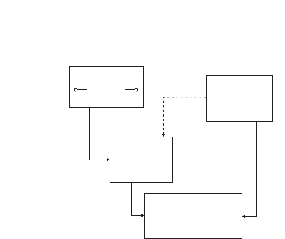
14 External Code Integration
The next figure shows the wrapper S-function concept.
Simulink
Place the name of your S-function
in the S-Function block dialog box.
wrapsfcn
S-function
wrapper.mdl
Simulink Coder
wrapper.c, the generated code,
calls mdlOutputs,
which then calls my_alg.
wrapper.c
...
MdlOutputs(...)
{
...
my_alg();
}
*See note below
In Simulink, the S-function
calls mdlOutputs, which
in turn calls my_alg.
wrapsfcn.c
...
mdlOutputs(...)
{
...
my_alg();
}
In the TLC wrapper
version of the S-function,
mdlOutputs in
wrapper.exe calls my_alg.
mdlOutputs in
wrapsfcn.mex
calls external
function my_alg.
my_alg.c
...
real_T my_alg(real_T u)
{
...
y=f(u);
}
*The dotted line is the path taken if the S-function does not have a TLC wrapper
file. If there is no TLC wrapper file, the generated code calls mdlOutputs.
Using an S-function wrapper to import algorithms in your Simulink model
means that the S-function serves as an interface that calls your C/C++
algorithms from mdlOutputs. S-function wrappers have the advantage that
you can quickly integrate large standalone C /C++ programs into your model
withouthavingtomakechangestothecode.
14-56

Insert S-Function Code
The following sample model includes an S-function wrapper.
There are two files associated with the wrapsfcn block, the S-function wrapper
and the C/C++ code that contains the algorithm. The S-function wrapper code
for wrapsfcn.c appears below. The first three statements do the following:
1Defines the name of the S-function (what you enter in the Simulink
S-Function block dialog).
2Specifies that the S-function is using the level 2 format.
3Provides access to the SimStruct data structure, which contains pointers to
data used during simulation and code generation and defines macros that
store data in and retrieve data from the SimStruct.
For more information, see “Templates for C S-Functions” in the Simulink
documentation.
#define S_FUNCTION_NAME wrapsfcn
#define S_FUNCTION_LEVEL 2
#include "simstruc.h"
extern real_T my_alg(real_T u); /* Declare my_alg as extern */
/*
* mdlInitializeSizes - initialize the sizes array
*/
static void mdlInitializeSizes(SimStruct *S)
{
ssSetNumSFcnParams( S, 0); /*number of input arguments*/
if (!ssSetNumInputPorts(S, 1)) return;
14-57

14 External Code Integration
ssSetInputPortWidth(S, 0, 1);
ssSetInputPortDirectFeedThrough(S, 0, 1);
if (!ssSetNumOutputPorts(S,1)) return;
ssSetOutputPortWidth(S, 0, 1);
ssSetNumSampleTimes( S, 1);
}
/*
* mdlInitializeSampleTimes - indicate that this S-function runs
* at the rate of the source (driving block)
*/
static void mdlInitializeSampleTimes(SimStruct *S)
{
ssSetSampleTime(S, 0, INHERITED_SAMPLE_TIME);
ssSetOffsetTime(S, 0, 0.0);
}
/*
* mdlOutputs - compute the outputs by calling my_alg, which
* resides in another module, my_alg.c
*/
static void mdlOutputs(SimStruct *S, int_T tid)
{
InputRealPtrsType uPtrs = ssGetInputPortRealSignalPtrs(S,0);
real_T *y = ssGetOutputPortRealSignal(S,0);
*y = my_alg(*uPtrs[0]); /* Call my_alg in mdlOutputs */
}
/*
* mdlTerminate - called when the simulation is terminated.
*/
static void mdlTerminate(SimStruct *S)
{
}
#ifdef MATLAB_MEX_FILE /* Is this file being compiled as a MEX-file? */
#include "simulink.c" /* MEX-file interface mechanism */
#else
14-58

Insert S-Function Code
#include "cg_sfun.h" /* Code generation registration function */
#endif
The S-function routine mdlOutputs contains a function call to my_alg,which
is the C function containing the algorithm that the S-function performs. This
is the code for my_alg.c:
#ifdef MATLAB_MEX_FILE
#include "tmwtypes.h"
#else
#include "rtwtypes.h"
#endif
real_T my_alg(real_T u)
{
return(u * 2.0);
}
See the section “Header Dependencies When Interfacing Legacy/Custom Code
with Generated Code” on page 10-6 in the Simulink Coder documentation
for more information.
The wrapper S-function wrapsfcn calls my_alg, which computes u*2.0.To
build wrapsfcn.mex, use the following command:
mex wrapsfcn.c my_alg.c
TLC S-Function Wrapper
This section describes how to inline the call to my_alg in the mdlOutputs
section of the generated code. In the above example, the call to my_alg is
embedded in the mdlOutputs section as
*y = my_alg(*uPtrs[0]);
When you are creating a TLC S-function wrapper,thegoalistoembedthe
same type of call in the generated code.
It is instructive to look at how the code generator executes S-functions that
are not inlined. A noninlined S-function is identified by the absence of the
file sfunction.tlc and the existence of sfunction.mex. When generating
14-59

14 External Code Integration
code for a noninlined S-function, the Simulink Coder software generates a
call to mdlOutputs through a function pointer that, in this example, then
calls my_alg.
The wrapper example contains one S-function, wrapsfcn.mex.Youmust
compile and link an additional module, my_alg, with the generated code.
To do this, specify
set_param('wrapper/S-Function','SFunctionModules','my_alg')
Code Overhead for Noninlined S-Functions. The code generated when
using grt.tlc as the system target file without wrapsfcn.tlc is
<Generated code comments for wrapper model with noninlined wrapsfcn S-function>
#include <math.h>
#include <string.h>
#include "wrapper.h"
#include "wrapper.prm"
/* Start the model */
void mdlStart(void)
{
/* (no start code required) */
}
/* Compute block outputs */
void mdlOutputs(int_T tid)
{
/* Sin Block: <Root>/Sin */
rtB.Sin = rtP.Sin.Amplitude *
sin(rtP.Sin.Frequency * ssGetT(rtS) + rtP.Sin.Phase);
/* Level2 S-Function Block: <Root>/S-Function (wrapsfcn) */
{
/* Noninlined S-functions create a SimStruct object and
* generate a call to S-function routine mdlOutputs
*/
SimStruct *rts = ssGetSFunction(rtS, 0);
sfcnOutputs(rts, tid);
}
14-60

Insert S-Function Code
/* Outport Block: <Root>/Out */
rtY.Out = rtB.S_Function;
}
/* Perform model update */
void mdlUpdate(int_T tid)
{
/* (no update code required) */
}
/* Terminate function */
void mdlTerminate(void)
{
/* Level2 S-Function Block: <Root>/S-Function (wrapsfcn) */
{
/* Noninlined S-functions require a SimStruct object and
* the call to S-function routine mdlTerminate
*/
SimStruct *rts = ssGetSFunction(rtS, 0);
sfcnTerminate(rts);
}
}
#include "wrapper.reg"
/* [EOF] wrapper.c */
In addition to the overhead outlined above, the wrapper.reg generated file
contains the initialization of the SimStruct for the wrapper S-Function block.
There is one child SimStruct for each S-Function block in your model. You
can significantly reduce this overhead by creating a TLC wrapper for the
S-function.
How to Inline. The generated code makes the call to your S-function,
wrapsfcn.c,inmdlOutputs by using this code:
SimStruct *rts = ssGetSFunction(rtS, 0);
sfcnOutputs(rts, tid);
14-61
14 External Code Integration
This call has computational overhead associated with it. First, the Simulink
engine creates a SimStruct data structure for the S-Function block. Second,
the code generator constructs a call through a function pointer to execute
mdlOutputs,thenmdlOutputs calls my_alg. By inlining the call to your
C/C++ algorithm, my_alg, you can eliminate both the SimStruct and the
extra function call, thereby improving the efficiency and reducing the size
of the generated code.
Inlining a wrapper S-function requires an sfunction.tlc file for the
S-function (see the “Target Language Compiler” for details). The TLC
file must contain the function call to my_alg. The following figure shows
the relationships between the algorithm, the wrapper S-function, and the
sfunction.tlc file.
my_alg.c
myalg()
{
<C code here>
}
wrapper.c
...
mdlOutputs
{
...
y = my_alg();
...
}
...
wrapsfcn.tlc
...
%<y> = my_alg(%<u>);
...
The wrapsfcn.tlc file tells
Simulink Coder how to
inline the call to my_alg
using this statement.
To inline this call, you have to place your function call in an sfunction.tlc
filewiththesamenameastheS-function(inthisexample,wrapsfcn.tlc).
This causes the Target Language Compiler to override the default method of
placing calls to your S-function in the generated code.
This is the wrapsfcn.tlc file that inlines wrapsfcn.c.
%% File : wrapsfcn.tlc
%% Abstract:
%% Example inlined tlc file for S-function wrapsfcn.c
%%
%implements "wrapsfcn" "C"
14-62

Insert S-Function Code
%% Function: BlockTypeSetup ====================================================
%% Abstract:
%% Create function prototype in model.h as:
%% "extern real_T my_alg(real_T u);"
%%
%function BlockTypeSetup(block, system) void
%openfile buffer
extern real_T my_alg(real_T u); /* This line is placed in wrapper.h */
%closefile buffer
%<LibCacheFunctionPrototype(buffer)>
%endfunction %% BlockTypeSetup
%% Function: Outputs ===========================================================
%% Abstract:
%% y = my_alg( u );
%%
%function Outputs(block, system) Output
/* %<Type> Block: %<Name> */
%assign u = LibBlockInputSignal(0, "", "", 0)
%assign y = LibBlockOutputSignal(0, "", "", 0)
%% PROVIDE THE CALLING STATEMENT FOR "algorithm"
%% The following line is expanded and placed in mdlOutputs within wrapper.c
%<y> = my_alg(%<u>);
%endfunction %% Outputs
The first section of this code inlines the wrapsfcn S-Function block and
generates the code in C:
%implements "wrapsfcn" "C"
The next task is to tell the code generator that the routine my_alg needs
to be declared external in the generated wrapper.h file for any wrapsfcn
S-Function blocks in the model. You only need to do this once for all wrapsfcn
S-Function blocks, so use the BlockTypeSetup function. In this function, you
tell the Target Language Compiler to create a buffer and cache the my_alg
as extern in the wrapper.h generated header file.
14-63

14 External Code Integration
The final step is the inlining of the call to the function my_alg. Thisisdone
by the Outputs function. In this function, you access the block’s input and
output and place a direct call to my_alg. The call is embedded in wrapper.c.
The Inlined Code
The code generated when you inline your wrapper S-function is similar to the
default generated code. The mdlTerminate function no longer contains a call
to an empty function and the mdlOutputs function now directly calls my_alg.
void mdlOutputs(int_T tid)
{
/* Sin Block: <Root>/Sin */
rtB.Sin = rtP.Sin.Amplitude *
sin(rtP.Sin.Frequency * ssGetT(rtS) + rtP.Sin.Phase);
/* S-Function Block: <Root>/S-Function */
rtB.S_Function = my_alg(rtB.Sin); /* Inlined call to my_alg */
/* Outport Block: <Root>/Out */
rtY.Out = rtB.S_Function;
}
In addition, wrapper.reg no longer creates a child SimStruct for the
S-function because the generated code is calling my_alg directly. This
eliminates over 1 KB of memory usage.
Write Fully Inlined S-Functions
Continuing the example of the previous section, you could eliminate the
call to my_alg entirely by specifying theexplicitcode(thatis,2.0 * u)in
wrapsfcn.tlc. Thisisreferredtoasafully inlined S-function.Whilethis
can improve performance, if you are working with a large amount of C/C++
code, this can be a lengthy task. In addition, you now have to maintain your
algorithm in two places, the C/C++ S-function itself and the corresponding
TLC file. However, the performance gains might outweigh the disadvantages.
To inline the algorithm used in this example, in the Outputs section of your
wrapsfcn.tlc file, instead of writing
%<y> = my_alg(%<u>);
14-64

Insert S-Function Code
use
%<y> = 2.0 * %<u>;
This is the code produced in mdlOutputs:
void mdlOutputs(int_T tid)
{
/* Sin Block: <Root>/Sin */
rtB.Sin = rtP.Sin.Amplitude *
sin(rtP.Sin.Frequency * ssGetT(rtS) + rtP.Sin.Phase);
/* S-Function Block: <Root>/S-Function */
rtB.S_Function = 2.0 * rtB.Sin; /* Explicit embedding of algorithm */
/* Outport Block: <Root>/Out */
rtY.Out = rtB.S_Function;
}
The Target Language Compiler has replaced the call to my_alg with the
algorithm itself.
Multiport S-Function
A more advanced multiport inlined S-function example is sfun_multiport.c
and sfun_multiport.tlc. This S-function illustrates how to create a fully
inlined TLC file for an S-function that contains multiple ports. You might find
that looking at this example helps you to understand fully inlined TLC files.
Write Fully Inlined S-Functions with mdlRTW Routine
•“About S-Functions and mdlRTW” on page 14-66
•“S-Function RTWdata” on page 14-67
•“Direct-Index Lookup Table Algorithm” on page 14-67
•“Direct-Index Lookup Table Example” on page 14-69
14-65

14 External Code Integration
About S-Functions and mdlRTW
You can inline more complex S-functions that use the S-function mdlRTW
routine. The purpose of the mdlRTW routineistoprovidethecodegeneration
process with more information about how the S-function is to be inlined,
by creating a parameter record of a nontunable parameter for use with
a TLC file. The mdlRTW routine does this by placing information in
the model.rtw file. The mdlRTW function is described in the text file
matlabroot/simulink/src/sfuntmpl_doc.c.
As an example of how to use the mdlRTW function, this section discusses
the steps you must take to create a direct-index lookup S-function. Lookup
tables are collections of ordered data points of a function. Typically, these
tables use some interpolation scheme to approximate values of the associated
function between known data points. To incorporate the example lookup table
algorithm into a Simulink model, the first step is to write an S-function that
executes the algorithm in mdlOutputs. To produce the most efficient code,
the next step is to create a corresponding TLC file to eliminate computational
overhead and improve the performance of the lookup computations.
For your convenience, the Simulink product provides support for two
general-purpose lookup 1-D and 2-D algorithms. You can use these
algorithms as they are or create a custom lookup table S-function to fit your
requirements. This section illustrates how to create a 1-D lookup S-function,
sfun_directlook.c, and its corresponding inlined sfun_directlook.tlc file
(see “Target Language Compiler” for more details). This 1-D direct-index
lookup table example illustrates the following concepts that you need to know
to create your own custom lookup tables:
•Error checking of S-function parameters
•Caching of information for the S-function that doesn’t change during model
execution
•How to use the mdlRTW function to customize Simulink Coder generated
code to produce the optimal code for a given set of block parameters
•How to generate an inlined TLC file for an S-function in a combination of
the fully inlined form and/or the wrapper form
14-66

Insert S-Function Code
S-Function RTWdata
There is a property of blocks called RTWdata, which can be used by the Target
Language Compiler when inlining an S-function. RTWdata is a structure of
strings that you can attach to a block. It is saved with the model and placed in
the model.rtw file when generating code. For example, this set of MATLAB
commands,
mydata.field1 = 'information for field1';
mydata.field2 = 'information for field2';
set_param(gcb,'RTWdata',mydata)
get_param(gcb,'RTWdata')
produces this result:
ans =
field1: 'information for field1'
field2: 'information for field2'
Inside the model.rtw file for the associated S-Function block is this
information.
Block {
Type "S-Function"
RTWdata {
field1 "information for field1"
field2 "information for field2"
}
Note RTWdata is saved in the model file for S-functions that are not linked
to a library. However, RTWdata is not persistent for S-Function blocks that
are linked to a library.
Direct-Index Lookup Table Algorithm
The 1-D lookup table block provided in the Simulink library uses interpolation
or extrapolation when computing outputs. This extra accuracy might not be
required. In this example, you create a lookup table that directly indexes the
output vector (y-data vector) based on the current input (x-data) point.
14-67

14 External Code Integration
This direct 1-D lookup example computes an approximate solution p(x) to a
partially known function f(x) at x=x0, given data point pairs (x,y) in the form
of an x-data vector and a y-data vector. For a given data pair (for example, the
i’th pair), y_i = f(x_i). It is assumed that the x-data values are monotonically
increasing. If x0 isoutsidetherangeofthex-data vector, the first or last
point is returned.
The parameters to the S-function are
XData, YData, XEvenlySpaced
XData and YData are double vectors of equal length representing the values
of the unknown function. XDataEvenlySpaced is a scalar, 0.0 for false and
1.0 for true. If the XData vector is evenly spaced, XDataEvenlySpaced is 1.0
and more efficient code is generated.
The following graph shows how the parameters XData=[1:6]and
YData=[1,2,7,4,5,9] are handled. For example, if the input (x-value) to the
S-Function block is 3, the output (y-value) is 7.
14-68
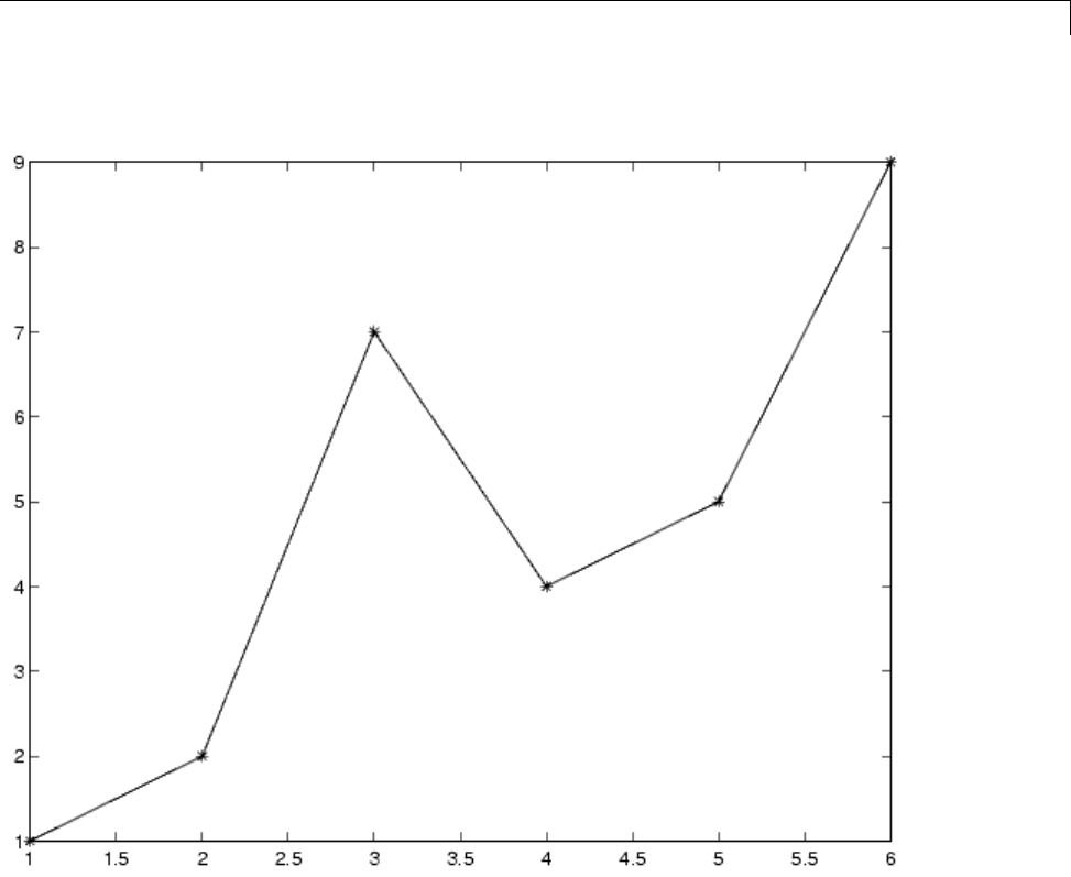
Insert S-Function Code
Direct-Index Lookup Table Example
This section shows how to improve the lookuptablebyinliningadirect-index
S-function with a TLC file. This direct-index lookup table S-function does not
requireaTLCfile. HeretheexampleusesaTLCfileforthedirect-index
lookuptableS-functiontoreducethecodesizeandincreaseefficiencyofthe
generated code.
Implementation of the direct-index algorithm with inlined TLC file requires
the S-function main module, sfun_directlook.c, and a corresponding
14-69

14 External Code Integration
lookup_index.c module. The lookup_index.c module contains the
GetDirectLookupIndex function that is used to locate the index in the
XData for the current xinput value when the XData is unevenly spaced.
The GetDirectLookupIndex routine is called from both the S-function and
the generated code. Here the example uses the wrapper concept for sharing
C/C++ code between Simulink MEX-files and the generated code.
If the XData is evenly spaced, then both the S-function main module and the
generated code contain the lookup algorithm (not a call to the algorithm) to
compute the y-value of a given x-value, because the algorithm is short. This
illustrates the use of a fully inlined S-function for generating optimal code.
The inlined TLC file, which either performs a wrapper call or embeds the
optimal C/C++ code, is sfun_directlook.tlc (see the example in “mdlRTW
Usage” on page 14-71).
Error Handling. In this example, the mdlCheckParameters routine verifies
that
•The new parameter settings valid..
•XData and YData are vectors of the same length containing real finite
numbers.
•XDataEvenlySpaced is a scalar.
•The XData vector is a monotonically increasing vector and evenly spaced.
The mdlInitializeSizes function explicitly calls mdlCheckParameters
after it verifies the number of parameters passed to the S-function.
After the Simulink engine calls mdlInitializeSizes,itthencalls
mdlCheckParameters whenever you change the parameters or there is a need
to reevaluate them.
User Data Caching. The mdlStart routine shows how to cache information
that does not change during the simulation (or while the generated code
is executing). The example caches the value of the XDataEvenlySpaced
parameter in UserData,afieldoftheSimStruct. The following line in
mdlInitializeSizes tells the Simulink engine to disallow changes to
XDataEvenlySpaced.
ssSetSFcnParamTunable(S, iParam, SS_PRM_NOT_TUNABLE);
14-70
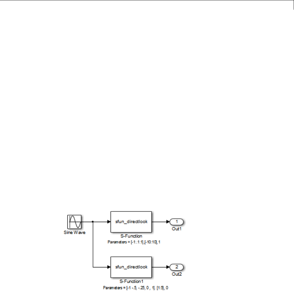
Insert S-Function Code
During execution, mdlOutputs accesses the value of XDataEvenlySpaced
from UserData rather than calling the mxGetPr MATLAB API function. This
increases performance.
mdlRTW Usage. The Simulink Coder code generator calls the mdlRTW
routine while generating the model.rtw file. To produce optimal code for your
Simulink model, you can add information to the model.rtw file about the
mode in which your S-Function block is operating.
The following example adds parameter settings to the model.rtw file.
The parameter settings do not change during execution. In this case,
the XDataEvenlySpaced S-function parameter cannot change during
execution (ssSetSFcnParamTunable was specified as false (0)foritin
mdlInitializeSizes). The example writes it out as a parameter setting
(XSpacing) using the function ssWriteRTWParamSettings.
Because xData and yData are registered as run-time parameters in
mdlSetWorkWidths, the code generator handles writing to the model.rtw
file automatically.
Before examining the S-function and the inlined TLC file, consider the
generated code for the following model.
14-71

14 External Code Integration
The model uses evenly spaced XData in the top S-Function block and unevenly
spaced XData in the bottom S-Function block. When creating this model, you
need to specify the following for each S-Function block.
set_param(`sfun_directlook_ex/S-Function','SFunctionModules','lookup_index')
set_param(`sfun_directlook_ex/S-Function1','SFunctionModules','lookup_index')
This informs the Simulink Coder build process to use the module
lookup_index.c when creating the executable.
When generating code for this model, the Simulink Coder software uses the
S-function’s mdlRTW method to generate a model.rtw file with the value
EvenlySpaced for the XSpacing parameter for the top S-Function block,
and the value UnEvenlySpaced for the XSpacing parameter for the bottom
S-Function block. The TLC-file uses the value of XSpacing to determine
what algorithm to include in the generated code. The generated code
contains the lookup algorithm when the XData is evenly spaced, but calls the
GetDirectLookupIndex routine when the XData is unevenly spaced. The
generated model.c or model.cpp code for the lookup table example model is
similar to the following:
/*
* sfun_directlook_ex.c
*
* Code generation for Simulink model
* "sfun_directlook_ex.slx".
*
...
*/
#include "sfun_directlook_ex.h"
#include "sfun_directlook_ex_private.h"
/* External output (root outports fed by signals with auto storage) */
ExternalOutputs_sfun_directlook_ex sfun_directlook_ex_Y;
/* Real-time model */
rtModel_sfun_directlook_ex sfun_directlook_ex_M_;
rtModel_sfun_directlook_ex *sfun_directlook_ex_M = &sfun_directlook_ex_M_;
14-72

Insert S-Function Code
/* Model output function */
static void sfun_directlook_ex_output(int_T tid)
{
/* local block i/o variables */
real_T rtb_SFunction_h;
real_T rtb_temp1;
/* Sin: '<Root>/Sine Wave' */
rtb_temp1 = sfun_directlook_ex_P.SineWave_Amp *
sin(sfun_directlook_ex_P.SineWave_Freq * sfun_directlook_ex_M->Timing.t[0] +
sfun_directlook_ex_P.SineWave_Phase) + sfun_directlook_ex_P.SineWave_Bias;
/* Code that is inlined for the top S-function block in the
* sfun_directlook_ex model
*/
/* S-Function Block: <Root>/S-Function */
{
const real_T *xData = &sfun_directlook_ex_P.SFunction_XData[0];
const real_T *yData = &sfun_directlook_ex_P.SFunction_YData[0];
real_T spacing = xData[1] - xData[0];
if ( rtb_temp1 <= xData[0] ) {
rtb_SFunction_h = yData[0];
} else if ( rtb_temp1 >= yData[20] ) {
rtb_SFunction_h = yData[20];
}else{
int_T idx = (int_T)( ( rtb_temp1 - xData[0] ) / spacing );
rtb_SFunction_h = yData[idx];
}
}
/* Outport: '<Root>/Out1' */
sfun_directlook_ex_Y.Out1 = rtb_SFunction_h;
/* Code that is inlined for the bottom S-function block in the
* sfun_directlook_ex model
*/
/* S-Function Block: <Root>/S-Function1 */
14-73

14 External Code Integration
{
const real_T *xData = &sfun_directlook_ex_P.SFunction1_XData[0];
const real_T *yData = &sfun_directlook_ex_P.SFunction1_YData[0];
int_T idx;
idx = GetDirectLookupIndex(xData, 5, rtb_temp1);
rtb_temp1 = yData[idx];
}
/* Outport: '<Root>/Out2' */
sfun_directlook_ex_Y.Out2 = rtb_temp1;
}
/* Model update function */
static void sfun_directlook_ex_update(int_T tid)
{
/* Update absolute time for base rate */
if(!(++sfun_directlook_ex_M->Timing.clockTick0))
++sfun_directlook_ex_M->Timing.clockTickH0;
sfun_directlook_ex_M->Timing.t[0] = sfun_directlook_ex_M->Timing.clockTick0 *
sfun_directlook_ex_M->Timing.stepSize0 +
sfun_directlook_ex_M->Timing.clockTickH0 *
sfun_directlook_ex_M->Timing.stepSize0 * 0x10000;
{
/* Update absolute timer for sample time: [0.1s, 0.0s] */
if(!(++sfun_directlook_ex_M->Timing.clockTick1))
++sfun_directlook_ex_M->Timing.clockTickH1;
sfun_directlook_ex_M->Timing.t[1] = sfun_directlook_ex_M->Timing.clockTick1
* sfun_directlook_ex_M->Timing.stepSize1 +
sfun_directlook_ex_M->Timing.clockTickH1 *
sfun_directlook_ex_M->Timing.stepSize1 * 0x10000;
}
}
...
14-74

Insert S-Function Code
matlabroot/toolbox/simulink/simdemos/simfeatures/src/sfun_directlook.c.
/*
* File : sfun_directlook.c
* Abstract:
*
* Direct 1-D lookup. Here we are trying to compute an approximate
* solution, p(x) to an unknown function f(x) at x=x0, given data point
* pairs (x,y) in the form ofaxdatavector and a y data vector. For a
* given data pair (say the i'th pair), we have y_i = f(x_i). It is
* assumed that the x data values are monotonically increasing. If the
* x0 is outside of the range of the x data vector, then the first or
* last point will be returned.
*
* This function returns the "nearest" y0 point for a given x0. No
* interpolation is performed.
*
* The S-function parameters are:
* XData - double vector
* YData - double vector
* XDataEvenlySpacing - double scalar 0 (false) or 1 (true)
* The third parameter cannot be changed during simulation.
*
* To build:
* mex sfun_directlook.c lookup_index.c
*
* Copyright 1990-2004 The MathWorks, Inc.
* $Revision: 1.1.8.11.2.4 $
*/
#define S_FUNCTION_NAME sfun_directlook
#define S_FUNCTION_LEVEL 2
#include <math.h>
#include "simstruc.h"
#include <float.h>
/* use utility function IsRealVect() */
#if defined(MATLAB_MEX_FILE)
14-75

14 External Code Integration
#include "sfun_slutils.h"
#endif
/*================*
* Build checking *
*================*/
#if !defined(MATLAB_MEX_FILE)
/*
* This file cannot be used directly with Simulink Coder. However,
* this S-function does work with Simulink Coder via
* the Target Language Compiler technology. See matlabroot/
* toolbox/simulink/simdemos/simfeatures/tlc_c/sfun_directlook.tlc
* for the C version
*/
# error This_file_can_be_used_only_during_simulation_inside_Simulink
#endif
/*=========*
* Defines *
*=========*/
#define XVECT_PIDX 0
#define YVECT_PIDX 1
#define XDATAEVENLYSPACED_PIDX 2
#define NUM_PARAMS 3
#define XVECT(S) ssGetSFcnParam(S,XVECT_PIDX)
#define YVECT(S) ssGetSFcnParam(S,YVECT_PIDX)
#define XDATAEVENLYSPACED(S) ssGetSFcnParam(S,XDATAEVENLYSPACED_PIDX)
/*==============*
* misc defines *
*==============*/
#if !defined(TRUE)
#define TRUE 1
#endif
#if !defined(FALSE)
#define FALSE 0
14-76

Insert S-Function Code
#endif
/*===========*
* typedef's *
*===========*/
typedef struct SFcnCache_tag {
boolean_T evenlySpaced;
} SFcnCache;
/*===================================================================*
* Prototype define for the function in separate file lookup_index.c *
*===================================================================*/
extern int_T GetDirectLookupIndex(const real_T *x, int_T xlen, real_T u);
/*====================*
* S-function methods *
*====================*/
#define MDL_CHECK_PARAMETERS /* Change to #undef to remove function */
#if defined(MDL_CHECK_PARAMETERS) && defined(MATLAB_MEX_FILE)
/* Function: mdlCheckParameters ================================================
* Abstract:
* This routine will be called after mdlInitializeSizes, whenever
* parameters change or get re-evaluated. The purpose of this routine is
* to verify the new parameter settings.
*
* You should add a call to this routine from mdlInitalizeSizes
* to check the parameters. After setting your sizes elements, you should:
* if (ssGetSFcnParamsCount(S) == ssGetNumSFcnParams(S)) {
* mdlCheckParameters(S);
*}
*/
static void mdlCheckParameters(SimStruct *S)
{
if (!IsRealVect(XVECT(S))) {
ssSetErrorStatus(S,"1st, X-vector parameter must be a real finite "
14-77

14 External Code Integration
" vector");
return;
}
if (!IsRealVect(YVECT(S))) {
ssSetErrorStatus(S,"2nd, Y-vector parameter must be a real finite "
"vector");
return;
}
/*
* Verify that the dimensions of X and Y are the same.
*/
if (mxGetNumberOfElements(XVECT(S)) != mxGetNumberOfElements(YVECT(S)) ||
mxGetNumberOfElements(XVECT(S)) == 1) {
ssSetErrorStatus(S,"X and Y-vectors must be of the same dimension "
"and have at least two elements");
return;
}
/*
* Verify we have a valid XDataEvenlySpaced parameter.
*/
if ((!mxIsNumeric(XDATAEVENLYSPACED(S)) &&
!mxIsLogical(XDATAEVENLYSPACED(S))) ||
mxIsComplex(XDATAEVENLYSPACED(S)) ||
mxGetNumberOfElements(XDATAEVENLYSPACED(S)) != 1) {
ssSetErrorStatus(S,"3rd, X-evenly-spaced parameter must be logical
scalar");
return;
}
/*
* Verify x-data is correctly spaced.
*/
{
int_T i;
boolean_T spacingEqual;
real_T *xData = mxGetPr(XVECT(S));
int_T numEl = mxGetNumberOfElements(XVECT(S));
14-78

Insert S-Function Code
/*
* spacingEqual is TRUE if user XDataEvenlySpaced
*/
spacingEqual = (mxGetScalar(XDATAEVENLYSPACED(S)) != 0.0);
if (spacingEqual) { /* XData is 'evenly-spaced' */
boolean_T badSpacing = FALSE;
real_T spacing = xData[1] - xData[0];
real_T space;
if (spacing <= 0.0) {
badSpacing = TRUE;
} else {
real_T eps = DBL_EPSILON;
for (i = 2; i < numEl; i++) {
space = xData[i] - xData[i-1];
if (space <= 0.0 ||
fabs(space-spacing) >= 128.0*eps*spacing ){
badSpacing = TRUE;
break;
}
}
}
if (badSpacing) {
ssSetErrorStatus(S,"X-vector must be an evenly spaced "
"strictly monotonically increasing vector");
return;
}
} else { /* XData is 'unevenly-spaced' */
for (i = 1; i < numEl; i++) {
if (xData[i] <= xData[i-1]) {
ssSetErrorStatus(S,"X-vector must be a strictly "
"monotonically increasing vector");
return;
}
}
}
14-79

14 External Code Integration
}
}
#endif /* MDL_CHECK_PARAMETERS */
/* Function: mdlInitializeSizes ================================================
* Abstract:
* The sizes information is used by Simulink to determine the S-function
* block's characteristics (number of inputs, outputs, states, and so on).
*/
static void mdlInitializeSizes(SimStruct *S)
{
ssSetNumSFcnParams(S, NUM_PARAMS); /* Number of expected parameters */
/*
* Check parameters passed in, providing the correct number was specified
* in the S-function dialog box. If an incorrect number of parameters
* was specified, Simulink will detect the error since ssGetNumSFcnParams
* and ssGetSFcnParamsCount will differ.
* ssGetNumSFcnParams - This sets the number of parameters your
* S-function expects.
* ssGetSFcnParamsCount - This is the number of parameters entered by
* the user in the Simulink S-function dialog box.
*/
#if defined(MATLAB_MEX_FILE)
if (ssGetNumSFcnParams(S) == ssGetSFcnParamsCount(S)) {
mdlCheckParameters(S);
if (ssGetErrorStatus(S) != NULL) {
return;
}
}else{
return; /* Parameter mismatch will be reported by Simulink */
}
#endif
{
int iParam = 0;
int nParam = ssGetNumSFcnParams(S);
14-80

Insert S-Function Code
for ( iParam = 0; iParam < nParam; iParam++ )
{
switch ( iParam )
{
case XDATAEVENLYSPACED_PIDX:
ssSetSFcnParamTunable( S, iParam, SS_PRM_NOT_TUNABLE );
break;
default:
ssSetSFcnParamTunable( S, iParam, SS_PRM_TUNABLE );
break;
}
}
}
ssSetNumContStates(S, 0);
ssSetNumDiscStates(S, 0);
if (!ssSetNumInputPorts(S, 1)) return;
ssSetInputPortWidth(S, 0, DYNAMICALLY_SIZED);
ssSetInputPortDirectFeedThrough(S, 0, 1);
ssSetInputPortOptimOpts(S, 0, SS_REUSABLE_AND_LOCAL);
ssSetInputPortOverWritable(S, 0, TRUE);
if (!ssSetNumOutputPorts(S, 1)) return;
ssSetOutputPortWidth(S, 0, DYNAMICALLY_SIZED);
ssSetOutputPortOptimOpts(S, 0, SS_REUSABLE_AND_LOCAL);
ssSetNumSampleTimes(S, 1);
ssSetOptions(S,
SS_OPTION_WORKS_WITH_CODE_REUSE |
SS_OPTION_EXCEPTION_FREE_CODE |
SS_OPTION_USE_TLC_WITH_ACCELERATOR);
} /* mdlInitializeSizes */
14-81

14 External Code Integration
/* Function: mdlInitializeSampleTimes ==========================================
* Abstract:
* The lookup inherits its sample time from the driving block.
*/
static void mdlInitializeSampleTimes(SimStruct *S)
{
ssSetSampleTime(S, 0, INHERITED_SAMPLE_TIME);
ssSetOffsetTime(S, 0, 0.0);
ssSetModelReferenceSampleTimeDefaultInheritance(S);
} /* end mdlInitializeSampleTimes */
/* Function: mdlSetWorkWidths ===============================================
* Abstract:
* Set up the [X,Y] data as run-time parameters
* that is, these values can be changed during execution.
*/
#define MDL_SET_WORK_WIDTHS
static void mdlSetWorkWidths(SimStruct *S)
{
const char_T *rtParamNames[] = {"XData","YData"};
ssRegAllTunableParamsAsRunTimeParams(S, rtParamNames);
}
#define MDL_START /* Change to #undef to remove function */
#if defined(MDL_START)
/* Function: mdlStart ==========================================================
* Abstract:
* Here we cache the state (true/false) of the XDATAEVENLYSPACED parameter.
* We do this primarily to illustrate how to "cache" parameter values (or
* information which is computed from parameter values) which do not change
* for the duration of the simulation (or in the generated code). In this
* case, rather than repeated calls to mxGetPr, we save the state once.
* This results in a slight increase in performance.
*/
static void mdlStart(SimStruct *S)
{
SFcnCache *cache = malloc(sizeof(SFcnCache));
14-82

Insert S-Function Code
if (cache == NULL) {
ssSetErrorStatus(S,"memory allocation error");
return;
}
ssSetUserData(S, cache);
if (mxGetScalar(XDATAEVENLYSPACED(S)) != 0.0){
cache->evenlySpaced = TRUE;
}else{
cache->evenlySpaced = FALSE;
}
}
#endif /* MDL_START */
/* Function: mdlOutputs ========================================================
* Abstract:
* In this function, you compute the outputs of your S-function
* block. Generally outputs are placed in the output vector, ssGetY(S).
*/
static void mdlOutputs(SimStruct *S, int_T tid)
{
SFcnCache *cache = ssGetUserData(S);
real_T *xData = mxGetPr(XVECT(S));
real_T *yData = mxGetPr(YVECT(S));
InputRealPtrsType uPtrs = ssGetInputPortRealSignalPtrs(S,0);
real_T *y = ssGetOutputPortRealSignal(S,0);
int_T ny = ssGetOutputPortWidth(S,0);
int_T xLen = mxGetNumberOfElements(XVECT(S));
int_T i;
/*
* When the XData is evenly spaced, we use the direct lookup algorithm
* to calculate the lookup
*/
if (cache->evenlySpaced) {
real_T spacing = xData[1] - xData[0];
14-83

14 External Code Integration
for (i = 0; i < ny; i++) {
real_Tu=*uPtrs[i];
if (u <= xData[0]) {
y[i] = yData[0];
} else if (u >= xData[xLen-1]) {
y[i] = yData[xLen-1];
} else {
int_T idx = (int_T)((u - xData[0])/spacing);
y[i] = yData[idx];
}
}
}else{
/*
* When the XData is unevenly spaced, we use a bisection search to
* locate the lookup index.
*/
for (i = 0; i < ny; i++) {
int_T idx = GetDirectLookupIndex(xData,xLen,*uPtrs[i]);
y[i] = yData[idx];
}
}
} /* end mdlOutputs */
/* Function: mdlTerminate ======================================================
* Abstract:
* Free the cache which was allocated in mdlStart.
*/
static void mdlTerminate(SimStruct *S)
{
SFcnCache *cache = ssGetUserData(S);
if (cache != NULL) {
free(cache);
}
} /* end mdlTerminate */
14-84

Insert S-Function Code
#define MDL_RTW /* Change to #undef to remove function */
#if defined(MDL_RTW) && (defined(MATLAB_MEX_FILE) || defined(NRT))
/* Function: mdlRTW ============================================================
* Abstract:
* This function is called when Simulink Coder is generating the
* model.rtw file. In this routine, you can call the following functions
* which add fields to the model.rtw file.
*
* Important! Since this S-function has this mdlRTW method, it is required
* to have a corresponding .tlc file so as to work with Simulink Coder. See the
* sfun_directlook.tlc in matlabroot/toolbox/simulink/simdemos/simfeatures/tlc_c/.
*/
static void mdlRTW(SimStruct *S)
{
/*
* Write out the spacing setting as a param setting, that is, this cannot be
* changed during execution.
*/
{
boolean_T even = (mxGetScalar(XDATAEVENLYSPACED(S)) != 0.0);
if (!ssWriteRTWParamSettings(S, 1,
SSWRITE_VALUE_QSTR,
"XSpacing",
even ? "EvenlySpaced" : "UnEvenlySpaced")){
return;/* An error occurred which will be reported by Simulink */
}
}
}
#endif /* MDL_RTW */
/*=============================*
* Required S-function trailer *
*=============================*/
#ifdef MATLAB_MEX_FILE /* Is this file being compiled as a MEX-file? */
#include "simulink.c" /* MEX-file interface mechanism */
#else
14-85

14 External Code Integration
#include "cg_sfun.h" /* Code generation registration function */
#endif
/* [EOF] sfun_directlook.c */
matlabroot/toolbox/simulink/simdemos/simfeatures/src/lookup_index.c.
/* File : lookup_index.c
* Abstract:
*
* Contains a routine used by the S-function sfun_directlookup.c to
* compute the index in a vector for a given data value.
*
* Copyright 1990-2004 The MathWorks, Inc.
* $Revision: 1.1.8.11.2.4 $
*/
#include "tmwtypes.h"
/*
* Function: GetDirectLookupIndex ==============================================
* Abstract:
* Using a bisection search to locate the lookup index when the x-vector
* isn't evenly spaced.
*
* Inputs:
* *x : Pointer to table, x[0] ....x[xlen-1]
* xlen : Number of values in xtable
* u : input value to look up
*
* Output:
* idx : the index into the table such that:
* if u is negative
* x[idx] <= u < x[idx+1]
* else
* x[idx]<u<=x[idx+1]
*/
int_T GetDirectLookupIndex(const real_T *x, int_T xlen, real_T u)
{
int_T idx = 0;
14-86

Insert S-Function Code
int_T bottom = 0;
int_T top = xlen-1;
/*
* Deal with the extreme cases first:
*
* i] u <= x[bottom] then idx = bottom
* ii] u >= x[top] then idx = top-1
*
*/
if (u <= x[bottom]) {
return(bottom);
} else if (u >= x[top]) {
return(top);
}
/*
* We have: x[bottom] <u<x[top], onward
* with search for the index ...
*/
for (;;) {
idx = (bottom + top)/2;
if (u < x[idx]) {
top = idx;
} else if (u > x[idx+1]) {
bottom = idx + 1;
} else {
/*
* We have: x[idx] <= u <= x[idx+1], only need
* to do two more checks and we have the answer
*/
if (u < 0) {
/*
* We want right continuity, that is,
* if u == x[idx+1]
* then x[idx+1] <= u < x[idx+2]
* else x[idx ] <= u < x[idx+1]
*/
return( (u == x[idx+1]) ? (idx+1) : idx);
} else {
14-87

14 External Code Integration
/*
* We want left continuity, that is,
* if u == x[idx]
* then x[idx-1] < u <= x[idx ]
* else x[idx ] < u <= x[idx+1]
*/
return( (u == x[idx]) ? (idx-1) : idx);
}
}
}
} /* end GetDirectLookupIndex */
/* [EOF] lookup_index.c */
matlabroot/toolbox/simulink/simdemos/simfeatures/tlc_c/sfun_directlook.tlc.
%% File : sfun_directlook.tlc
%% Abstract:
%% Level-2 S-function sfun_directlook block target file.
%% It is using direct lookup algorithm without interpolation
%%
%% Copyright 1990-2004 The MathWorks, Inc.
%% $Revision: 1.1.8.11.2.4 $
%implements "sfun_directlook" "C"
%% Function: BlockTypeSetup ====================================================
%% Abstract:
%% Place include and function prototype in the model's header file.
%%
%function BlockTypeSetup(block, system) void
%% To add this external function's prototype in the header of the generated
%% file.
%%
%openfile buffer
extern int_T GetDirectLookupIndex(const real_T *x, int_T xlen, real_T u);
%closefile buffer
14-88

Insert S-Function Code
%<LibCacheFunctionPrototype(buffer)>
%endfunction
%% Function: mdlOutputs ========================================================
%% Abstract:
%% Direct 1-D lookup table S-function example.
%% Here we are trying to compute an approximate solution, p(x) to an
%% unknown function f(x) at x=x0, given data point pairs (x,y) in the
%% form of a x data vector andaydatavector. For a given data pair
%% (say the i'th pair), we have y_i = f(x_i). It is assumed that the x
%% data values are monotonically increasing. If the first or last x is
%% outside of the range of the x data vector, then the first or last
%% point will be returned.
%%
%% This function returns the "nearest" y0 point for a given x0.
%% No interpolation is performed.
%%
%% The S-function parameters are:
%% XData
%% YData
%% XEvenlySpaced: 0 or 1
%% The third parameter cannot be changed during execution and is
%% written to the model.rtw file in XSpacing filed of the SFcnParamSettings
%% record as "EvenlySpaced" or "UnEvenlySpaced". The first two parameters
%% can change during execution and show up in the parameter vector.
%%
%function Outputs(block, system) Output
/* %<Type> Block: %<Name> */
{
%assign rollVars = ["U", "Y"]
%%
%% Load XData and YData as local variables
%%
const real_T *xData = %<LibBlockParameterAddr(XData, "", "", 0)>;
const real_T *yData = %<LibBlockParameterAddr(YData, "", "", 0)>;
%assign xDataLen = SIZE(XData.Value, 1)
%%
%% When the XData is evenly spaced, we use the direct lookup algorithm
%% to locate the lookup index.
14-89

14 External Code Integration
%%
%if SFcnParamSettings.XSpacing == "EvenlySpaced"
real_T spacing = xData[1] - xData[0];
%roll idx = RollRegions, lcv = RollThreshold, block, "Roller", rollVars
%assign u = LibBlockInputSignal(0, "", lcv, idx)
%assign y = LibBlockOutputSignal(0, "", lcv, idx)
if ( %<u> <= xData[0] ) {
%<y> = yData[0];
} else if ( %<u> >= yData[%<xDataLen-1>] ) {
%<y> = yData[%<xDataLen-1>];
} else {
int_T idx = (int_T)( ( %<u> - xData[0] ) / spacing );
%<y> = yData[idx];
}
%%
%% Generate an empty line if we are not rolling,
%% so that it looks nice in the generated code.
%%
%if lcv == ""
%endif
%endroll
%else
%% When the XData is unevenly spaced, we use a bisection search to
%% locate the lookup index.
int_T idx;
%assign xDataAddr = LibBlockParameterAddr(XData, "", "", 0)
%roll idx = RollRegions, lcv = RollThreshold, block, "Roller", rollVars
%assign u = LibBlockInputSignal(0, "", lcv, idx)
idx = GetDirectLookupIndex(xData, %<xDataLen>, %<u>);
%assign y = LibBlockOutputSignal(0, "", lcv, idx)
%<y> = yData[idx];
%%
%% Generate an empty line if we are not rolling,
%% so that it looks nice in the generated code.
%%
%if lcv == ""
14-90

Insert S-Function Code
%endif
%endroll
%endif
}
%endfunction
%% EOF: sfun_directlook.tlc
Guidelines for Writing Inlined S-Functions
•Consider using the block property RTWdata (see “S-Function RTWdata” on
page 14-67). This property is a structure of strings that you can associate
with a block. The code generator saves the structure with the model in
the model.rtw file and makes the .rtw file more readable. For example,
suppose you enter the following commands in the MATLAB Command
Window:
mydata.field1 = 'information for field1';
mydata.field2 = 'information for field2';
set_param(sfun_block, 'RTWdata', mydata);
The .rtw file that Simulink Coder generates for the block, will include the
comments specified in the structure mydata.
•Consider using the mdlRTW function to inline your C MEX S-function in the
generated code. This is useful when you want to
-Rename tunable parameters in the generated code
-IntroducenontunableparametersintoaTLCfile
WriteS-FunctionsThatSupportExpressionFolding
•“About S-Functions that Support Expression Folding” on page 14-92
•“Categories of Output Expressions” on page 14-93
•“Acceptance or Denial of Requests for Input Expressions” on page 14-98
•“Expression Folding in a TLC Block Implementation” on page 14-100
14-91

14 External Code Integration
About S-Functions that Support Expression Folding
This section describes how you can take advantage of expression folding to
increase the efficiency of code generated by your own inlined S-Function
blocks, by calling macros provided in the S-Function API. This section
assumes that you are familiar with:
•Writing inlined S-functions (see “S-Function Basics”).
•“Target Language Compiler”
The S-Function API lets you specify whether a given S-Function block should
nominally accept expressions at a given input port. A block should not always
accept expressions. For example, if the address of the signal at the input
is used, expressions should not be accepted at that input, because it is not
possible to take the address of an expression.
TheS-FunctionAPIalsoletsyouspecify whether an expression can represent
the computations associated with a given output port. When you request an
expression at a block’s input or output port, the Simulink engine determines
whether or not it can honor that request, given the block’s context. For
example, the engine might deny a block’s request to output an expression if the
destination block does not accept expressions at its input, if the destination
block has an update function, or if multiple output destinations exist.
The decision to honor or deny a request to output an expression can also
depend on the category of output expression the block uses (see “Categories of
Output Expressions” on page 14-93).
The sections that follow explain
•When and how you can request that a block accept expressions at an input
port
•When and how you can request that a block generate expressions at an
outport
•The conditions under which the Simulink engine will honor or deny such
requests
To take advantage of expression folding in your S-functions, you should
understand when to request acceptance and generation of expressions for
14-92

Insert S-Function Code
specific blocks. You do not have to understand the algorithm by which the
Simulink engine chooses to accept or deny these requests. However, if you
want to trace between the model and the generated code, it is helpful to
understand some of the more common situations that lead to denial of a
request.
Categories of Output Expressions
When you implement a C MEX S-function, you can specify whether the code
corresponding to a block’s output is to be generated as an expression. If
the block generates an expression, you must specify that the expression is
constant,trivial,orgeneric.
Aconstant output expression is a direct access to one of the block’s
parameters. For example, the output of a Constant block is defined as a
constant expression because the output expression is simply a direct access to
the block’s Value parameter.
Atrivial output expression is an expression that can be repeated, without any
performance penalty, when the output port has multiple output destinations.
For example, the output of a Unit Delay block is defined as a trivial expression
because the output expression is simply a direct access to the block’s state.
Because the output expression involves no computations, it can be repeated
more than once without degrading the performance of the generated code.
Ageneric output expression is an expression that should be assumed to have a
performance penalty if repeated. As such, a generic output expression is not
suitable for repeating when the output port has multiple output destinations.
For instance, the output of a Sum block is a generic rather than a trivial
expression because it is costly to recompute a Sum block output expression as
an input to multiple blocks.
Examples of Trivial and Generic Output Expressions. Consider the
following block diagram. The Delay block has multiple destinations, yet its
output is designated as a trivial output expression, so that it can be used more
than once without degrading the efficiency of the code.
14-93

14 External Code Integration
The following code excerpt shows code generated from the Unit Delay block
in this block diagram. The three root outputs are directly assigned from the
state of the Unit Delay block, which is stored in a field of the global data
structure rtDWork. Since the assignment is direct, involving no expressions,
there is no performance penalty associated with using the trivial expression
for multiple destinations.
void MdlOutputs(int_T tid)
{
...
/* Outport: <Root>/Out1 incorporates:
* UnitDelay: <Root>/Unit Delay */
rtY.Out1 = rtDWork.Unit_Delay_DSTATE;
/* Outport: <Root>/Out2 incorporates:
* UnitDelay: <Root>/Unit Delay */
rtY.Out2 = rtDWork.Unit_Delay_DSTATE;
/* Outport: <Root>/Out3 incorporates:
* UnitDelay: <Root>/Unit Delay */
rtY.Out3 = rtDWork.Unit_Delay_DSTATE;
...
}
On the other hand, consider the Sum blocks in the following model:
14-94
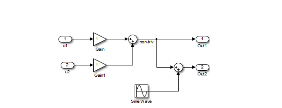
Insert S-Function Code
The upper Sum block in the preceding model generates the signal labeled
non_triv. Computation of this output signal involves two multiplications
and an addition. If the Sum block’s output were permitted to generate
an expression even when the block had multiple destinations, the block’s
operations would be duplicated in the generated code. In the case illustrated,
the generated expressions would proliferatetofourmultiplicationsandtwo
additions. This would degrade the efficiency of the program. Accordingly the
output of the Sum block is not allowed to be an expression because it has
multiple destinations
The code generated for the previous block diagram shows how code is
generated for Sum blocks with single and multiple destinations.
The Simulink engine does not permit the output of the upper Sum block
to be an expression because the signal non_triv is routed to two output
destinations. Instead, the result of the multiplication and addition operations
is stored in a temporary variable (rtb_non_triv) that is referenced twice in
the statements that follow, as seen in the code excerpt below.
In contrast, the lower Sum block, which has only a single output destination
(Out2), does generate an expression.
void MdlOutputs(int_T tid)
{
/* local block i/o variables */
real_T rtb_non_triv;
real_T rtb_Sine_Wave;
14-95

14 External Code Integration
/* Sum: <Root>/Sum incorporates:
* Gain: <Root>/Gain
* Inport: <Root>/u1
* Gain: <Root>/Gain1
* Inport: <Root>/u2
*
* Regarding <Root>/Gain:
* Gain value: rtP.Gain_Gain
*
* Regarding <Root>/Gain1:
* Gain value: rtP.Gain1_Gain
*/
rtb_non_triv = (rtP.Gain_Gain * rtU.u1) + (rtP.Gain1_Gain *
rtU.u2);
/* Outport: <Root>/Out1 */
rtY.Out1 = rtb_non_triv;
/* Sin Block: <Root>/Sine Wave */
rtb_Sine_Wave = rtP.Sine_Wave_Amp *
sin(rtP.Sine_Wave_Freq * rtmGetT(rtM_model) +
rtP.Sine_Wave_Phase) + rtP.Sine_Wave_Bias;
/* Outport: <Root>/Out2 incorporates:
* Sum: <Root>/Sum1
*/
rtY.Out2 = (rtb_non_triv + rtb_Sine_Wave);
}
Specify the Category of an Output Expression. The S-Function API
provides macros that let you declare whether an output of a block should
be an expression, and if so, to specify the category of the expression. The
following table specifies when to declare a block output to be a constant,
trivial, or generic output expression.
14-96

Insert S-Function Code
Types of Output Expressions
Category of
Expression When to Use
Constant Use only if block output is a direct memory access to a
block parameter.
Trivial Use only if block output is an expression that can appear
multiple times in the code without reducing efficiency
(for example, a direct memory access to a field of the
DWork vector, or a literal).
Generic Use if output is an expression, but not constant or
trivial.
You must declare outputs as expressions in the mdlSetWorkWidths function
using macros defined in the S-Function API. The macros have the following
arguments:
•SimStruct *S: pointer to the block’s SimStruct.
•int idx: zero-based index of the output port.
•bool value: pass in TRUE if the port generates output expressions.
The following macros are available for setting an output to be a constant,
trivial, or generic expression:
•void ssSetOutputPortConstOutputExprInRTW(SimStruct *S, int
idx, bool value)
•void ssSetOutputPortTrivialOutputExprInRTW(SimStruct *S, int
idx, bool value)
•void ssSetOutputPortOutputExprInRTW(SimStruct *S, int idx,
bool value)
The following macros are available for querying the status set by any prior
calls to the macros above:
14-97

14 External Code Integration
•bool ssGetOutputPortConstOutputExprInRTW(SimStruct *S, int
idx)
•bool ssGetOutputPortTrivialOutputExprInRTW(SimStruct *S, int
idx)
•bool ssGetOutputPortOutputExprInRTW(SimStruct *S, int idx)
The set of generic expressions is a superset of the set of trivial expressions, and
the set of trivial expressions is a superset of the set of constant expressions.
Therefore, when you query an output that has been set to be a constant
expression with ssGetOutputPortTrivialOutputExprInRTW,itreturnsTrue.
A constant expression is considered a trivial expression, because it is a direct
memory access that can be repeated without degrading the efficiency of the
generated code.
Similarly, an output that has been configured to be a constant or trivial
expression returns True when queried for its status as a generic expression.
Acceptance or Denial of Requests for Input Expressions
A block can request that its output be represented in code as an expression.
Such a request can be denied if the destination block cannot accept expressions
at its input port. Furthermore, conditions independent of the requesting block
and its destination blocks can prevent acceptance of expressions.
This section discusses block-specific conditions under which requests for
input expressions are denied. For informationonotherconditionsthat
prevent acceptance of expressions, see “Denial of Block Requests to Output
Expressions” on page 14-99.
Ablockshouldnotbeconfiguredtoacceptexpressionsatitsinputportunder
the following conditions:
•The block must take the address of its input data. It is not possible to take
the address of most types of input expressions.
•The code generated for the block references the input more than once
(for example, the Abs or Max blocks). This would lead to duplication of
a potentially complex expression and a subsequent degradation of code
efficiency.
14-98

Insert S-Function Code
If a block refuses to accept expressions at an input port, then any block that
is connected to that input port is not permitted to output a generic or trivial
expression.
A request to output a constant expression is never denied, because there is no
performance penalty for a constant expression, and it is always possible to
take the parameter’s address.
S-Function API to Specify Input Expression Acceptance. The S-Function
API provides macros that let you:
•Specify whether a block input should accept nonconstant expressions (that
is, trivial or generic expressions)
•Query whether a block input accepts nonconstant expressions
By default, block inputs do not accept nonconstant expressions.
You should call the macros in your mdlSetWorkWidths function. The macros
have the following arguments:
•SimStruct *S: pointer to the block’s SimStruct.
•int idx: zero-based index of the input port.
•bool value: pass in TRUE if the port accepts input expressions; otherwise
pass in FALSE.
The macro available for specifying whether or not a block input should accept
a nonconstant expression is as follows:
void ssSetInputPortAcceptExprInRTW(SimStruct *S, int portIdx, bool value)
The corresponding macro available for querying the status set by any prior
calls to ssSetInputPortAcceptExprInRTW is as follows:
bool ssGetInputPortAcceptExprInRTW(SimStruct *S, int portIdx)
Denial of Block Requests to Output Expressions. Even after a specific
block requests that it be allowed to generate an output expression, that
request can be denied for generic reasons. These reasons include, but are
not limited to
14-99

14 External Code Integration
•The output expression is nontrivial, and the output has multiple
destinations.
•The output expression is nonconstant, and the output is connected to at
leastonedestinationthatdoesnotacceptexpressionsatitsinputport.
•The output is a test point.
•The output has been assigned an external storage class.
•The output must be stored using global data (for example is an input to a
merge block or a block with states).
•The output signal is complex.
You do not need to consider these generic factors when deciding whether or
not to utilize expression folding for a particular block. However, these rules
canbehelpfulwhenyouareexamininggenerated code and analyzing cases
where the expression folding optimization is suppressed.
Expression Folding in a TLC Block Implementation
To take advantage of expression folding, you must modify the TLC block
implementation of an inlined S-Function such that it informs the Simulink
engine whether it generates or accepts expressions at its
•Input ports, as explained in “S-Function API to Specify Input Expression
Acceptance” on page 14-99.
•Output ports, as explained in “Categories of Output Expressions” on page
14-93.
This section discusses required modifications to the TLC implementation.
Expression Folding Compliance. In the BlockInstanceSetup function of
your S-function, register your block to be compliant with expression folding.
Otherwise, any expression folding requested or allowed at the block’s outputs
or inputs will be disabled, and temporary variables will be used.
To register expression folding compliance, call the TLC library function
LibBlockSetIsExpressionCompliant(block), which is defined in
matlabroot/rtw/c/tlc/lib/utillib.tlc. For example:
14-100

Insert S-Function Code
%% Function: BlockInstanceSetup ===========================================
%%
%function BlockInstanceSetup(block, system) void
%%
%<LibBlockSetIsExpressionCompliant(block)>
%%
%endfunction
You can conditionally disable expression folding at the inputs and outputs of a
block by making the call to this function conditionally.
If you have overridden one of the TLC block implementations provided by the
Simulink Coder product with your own implementation, you should not make
the preceding call until you have updated your implementation, as described
by the guidelines for expression folding in the following sections.
Output Expressions. The BlockOutputSignal function is used to
generate code for a scalar output expression or one element of a nonscalar
output expression. If your block outputs an expression, you should add a
BlockOutputSignal function. The prototype of the BlockOutputSignal is
%function BlockOutputSignal(block,system,portIdx,ucv,lcv,idx,retType) void
The arguments to BlockOutputSignal are as follows:
•block: the record for the block for whichanoutputexpressionisbeing
generated
•system: the record for the system containing the block
•portIdx: zero-based index of the output port for which an expression is
being generated
•ucv: user control variable defining the output element for which code is
being generated
•lcv: loop control variable defining the output element for which code is
being generated
•idx: signal index defining the output element for which code is being
generated
•retType: string defining the type of signal access desired:
14-101

14 External Code Integration
"Signal" specifies the contents or address of the output signal.
"SignalAddr" specifies the address of the output signal
The BlockOutputSignal function returns a text string for the output signal
or address. The string should enforce the precedence of the expression by
using opening and terminating parentheses, unless the expression consists
of a function call. The address of an expression can only be returned for a
constant expression; it is the address of the parameter whose memory is being
accessed. The code implementing the BlockOutputSignal function for the
Constant block is shown below.
%% Function: BlockOutputSignal =================================================
%% Abstract:
%% Return the reference to the parameter. This function *may*
%% be used by Simulink when optimizing the Block IO data structure.
%%
%function BlockOutputSignal(block,system,portIdx,ucv,lcv,idx,retType) void
%switch retType
%case "Signal"
%return LibBlockParameter(Value,ucv,lcv,idx)
%case "SignalAddr"
%return LibBlockParameterAddr(Value,ucv,lcv,idx)
%default
%assign errTxt = "Unsupported return type: %<retType>"
%<LibBlockReportError(block,errTxt)>
%endswitch
%endfunction
ThecodeimplementingtheBlockOutputSignal function for the Relational
Operator block is shown below.
%% Function: BlockOutputSignal =================================================
%% Abstract:
%% Return an output expression. This function *may*
%% be used by Simulink when optimizing the Block IO data structure.
%%
%function BlockOutputSignal(block,system,portIdx,ucv,lcv,idx,retType) void
%switch retType
%case "Signal"
%assign logicOperator = ParamSettings.Operator
14-102

Insert S-Function Code
%if ISEQUAL(logicOperator, "~=")
%assign op = "!="
elseif ISEQUAL(logicOperator, "==") %assign op = "=="
%else
%assign op = logicOperator
%endif
%assign u0 = LibBlockInputSignal(0, ucv, lcv, idx)
%assign u1 = LibBlockInputSignal(1, ucv, lcv, idx)
%return "(%<u0> %<op> %<u1>)"
%default
%assign errTxt = "Unsupported return type: %<retType>"
%<LibBlockReportError(block,errTxt)>
%endswitch
%endfunction
Expression Folding for Blocks with Multiple Outputs. When a block has
asingleoutput,theOutputs function in the block’s TLC file is called only if
the output port is not an expression. Otherwise, the BlockOutputSignal
function is called.
If a block has multiple outputs, the Outputs function is called if any output
port is not an expression. The Outputs function should guard against
generating code for output ports that areexpressions. Thisisachievedby
guarding sections of code corresponding to individual output ports with calls
to LibBlockOutputSignalIsExpr().
For example, consider an S-Function with two inputs and two outputs, where
•The first output, y0, is equal to two times the first input.
•The second output, y1, is equal to four times the second input.
The Outputs and BlockOutputSignal functions for the S-function are shown
in the following code excerpt.
%% Function: BlockOutputSignal =================================================
%% Abstract:
%% Return an output expression. This function *may*
%% be used by Simulink when optimizing the Block IO data structure.
%%
%function BlockOutputSignal(block,system,portIdx,ucv,lcv,idx,retType) void
14-103

14 External Code Integration
%switch retType
%case "Signal"
%assignu=LibBlockInputSignal(portIdx, ucv, lcv, idx)
%case "Signal"
%if portIdx == 0
%return "(2 * %<u>)"
%elseif portIdx == 1
%return "(4 * %<u>)"
%endif
%default
%assign errTxt = "Unsupported return type: %<retType>"
%<LibBlockReportError(block,errTxt)>
%endswitch
%endfunction
%%
%% Function: Outputs =================================================
%% Abstract:
%% Compute output signals of block
%%
%function Outputs(block,system) Output
%assign rollVars = ["U", "Y"]
%roll sigIdx = RollRegions, lcv = RollThreshold, block, "Roller", rollVars
%assign u0 = LibBlockInputSignal(0, "", lcv, sigIdx)
%assign u1 = LibBlockInputSignal(1, "", lcv, sigIdx)
%assign y0 = LibBlockOutputSignal(0, "", lcv, sigIdx)
%assign y1 = LibBlockOutputSignal(1, "", lcv, sigIdx)
%if !LibBlockOutputSignalIsExpr(0)
%<y0> = 2 * %<u0>;
%endif
%if !LibBlockOutputSignalIsExpr(1)
%<y1> = 4 * %<u1>;
%endif
%endroll
%endfunction
Comments for Blocks That Are Expression-Folding-Compliant. In the
past, all blocks preceded their outputs code with comments of the form
/* %<Type> Block: %<Name> */
14-104

Insert S-Function Code
When a block is expression-folding-compliant, the initial line shown above
is generated automatically. You should not include the comment as part of
the block’s TLC implementation. Additional information should be registered
using the LibCacheBlockComment function.
The LibCacheBlockComment function takes a string as an input, defining the
body of the comment, except for the opening header, the final newline of a
single or multiline comment, and the closing trailer.
The following TLC code illustrates registering a block comment. Note the
use of the function LibBlockParameterForComment, which returns a string,
suitable for a block comment, specifying the value of the block parameter.
%openfile commentBuf
$c(*) Gain value: %<LibBlockParameterForComment(Gain)>
%closefile commentBuf
%<LibCacheBlockComment(block, commentBuf)>
S-Functions That Specify Port Scope and Reusability
You can use the following SimStruct macros in the mdlInitializeSizes
method to specify the scope and reusability of the memory used for your
S-function’s input and output ports:
•ssSetInputPortOptimOpts: Specify the scope and reusability of the
memory allocated to an S-function input port
•ssSetOutputPortOptimOpts: Specify the scope and reusability of the
memory allocated to an S-function output port
•ssSetInputPortOverWritable: Specify whether one of your S-function’s
input ports can be overwritten by one of its output ports
•ssSetOutputPortOverwritesInputPort: Specify whether an output port
canshareitsmemorybufferwithaninputport
You declare an input or output as local or global, and indicate its reusability,
by passing one of the following four options to the ssSetInputPortOptimOpts
and ssSetOutputPortOptimOpts macros:
14-105

14 External Code Integration
•SS_NOT_REUSABLE_AND_GLOBAL: Indicates that the input and output ports
are stored in separate memory locations in the global block input and
output structure
•SS_NOT_REUSABLE_AND_LOCAL: Indicates that the Simulink Coder software
can declare individual local variables for the input and output ports
•SS_REUSABLE_AND_LOCAL: Indicates that the Simulink Coder software can
reuse a single local variable for these input and output ports
•SS_REUSABLE_AND_GLOBAL: Indicates that these input and output ports are
stored in a single element in the global block input and output structure
Note Marking an input or output port as a local variable does not imply
that the code generator uses a local variable in the generated code. If your
S-function accesses the inputs and outputs only in its mdlOutputs routine, the
code generator declares the inputs and outputs as local variables. However,
if the inputs and outputs are used elsewhere in the S-function, the code
generator includes them in the global block input and output structure.
The reusability setting indicates if the memory associated with an input or
output port can be overwritten. To reuse input and output port memory:
1Indicate the ports are reusable using either the SS_REUSABLE_AND_LOCAL
or SS_REUSABLE_AND_GLOBAL option in the ssSetInputPortOptimOpts and
ssSetOutputPortOptimOpts macros
2Indicate the input port memory is overwritable using
ssSetInputPortOverWritable
3If your S-function has multiple input and output ports, use
ssSetOutputPortOverwritesInputPort to indicate which output and
input ports share memory
The following example shows how different scope and reusability
settings effect the generated code. The following model contains
an S-function block pointing to the C MEX S-function
matlabroot/toolbox/simulink/simdemos/simfeatures/src/sfun_directlook.c,
which models a direct 1-D lookup table.
14-106

Insert S-Function Code
The S-function’s mdlInitializeSizes method declares the input port as
reusable, local, and overwritable and the output port as reusable and local, as
follows:
static void mdlInitializeSizes(SimStruct *S)
{
/* snip */
ssSetInputPortOptimOpts(S, 0, SS_REUSABLE_AND_LOCAL);
ssSetInputPortOverWritable(S, 0, TRUE);
/* snip */
ssSetOutputPortOptimOpts(S, 0, SS_REUSABLE_AND_LOCAL);
/* snip */
}
The generated code for this model stores the input and output signals in
a single local variable rtb_SFunction, as shown in the following output
function:
static void sl_directlook_output(int_T tid)
{
/* local block i/o variables */
real_T rtb_SFunction[2];
/* Sin: '<Root>/Sine Wave' */
rtb_SFunction[0] = sin(((real_T)sl_directlook_DWork.counter[0] +
sl_directlook_P.SineWave_Offset) * 2.0 * 3.1415926535897931E+000 /
sl_directlook_P.SineWave_NumSamp) * sl_directlook_P.SineWave_Amp[0] +
sl_directlook_P.SineWave_Bias;
rtb_SFunction[1] = sin(((real_T)sl_directlook_DWork.counter[1] +
sl_directlook_P.SineWave_Offset) * 2.0 * 3.1415926535897931E+000 /
sl_directlook_P.SineWave_NumSamp) * sl_directlook_P.SineWave_Amp[1] +
sl_directlook_P.SineWave_Bias;
14-107

14 External Code Integration
/* S-Function Block: <Root>/S-Function */
{
const real_T *xData = &sl_directlook_P.SFunction_XData[0];
const real_T *yData = &sl_directlook_P.SFunction_YData [0];
real_T spacing = xData[1] - xData[0];
if (rtb_SFunction[0] <= xData[0] ) {
rtb_SFunction[0] = yData[0];
} else if (rtb_SFunction[0] >= yData[20] ) {
rtb_SFunction[0] = yData[20];
}else{
int_T idx = (int_T)( ( rtb_SFunction[0] - xData[0] ) / spacing );
rtb_SFunction[0] = yData[idx];
}
if (rtb_SFunction[1] <= xData[0] ) {
rtb_SFunction[1] = yData[0];
} else if (rtb_SFunction[1] >= yData[20] ) {
rtb_SFunction[1] = yData[20];
}else{
int_T idx = (int_T)( ( rtb_SFunction[1] - xData[0] ) / spacing );
rtb_SFunction[1] = yData[idx];
}
}
/* Outport: '<Root>/Out1' */
sl_directlook_Y.Out1[0] = rtb_SFunction[0];
sl_directlook_Y.Out1[1] = rtb_SFunction[1];
UNUSED_PARAMETER(tid);
}
The following table shows variations of the code generated for this model
when using the generic real-time target (GRT). Each row explains a different
setting for the scope and reusability of the S-function’s input and output ports.
14-108

Insert S-Function Code
Scope and
reusability
S-function mdlInitializeSizes
code
Generated code
Inputs: Local,
reusable,
overwritable
Outputs: Local,
reusable
ssSetInputPortOptimOpts(S, 0,
SS_REUSABLE_AND_LOCAL);
ssSetInputPortOverWritable(S, 0,
TRUE);
ssSetOutputPortOptimOpts(S, 0,
SS_REUSABLE_AND_LOCAL);
The model.c file declares a local
variable in the output function.
/* local block i/o variables */
real_T rtb_SFunction[2];
Inputs: Global,
reusable,
overwritable
Outputs:
Global, reusable
ssSetInputPortOptimOpts(S, 0,
SS_REUSABLE_AND_GLOBAL);
ssSetInputPortOverWritable(S, 0,
TRUE);
ssSetOutputPortOptimOpts(S, 0,
SS_REUSABLE_AND_GLOBAL);
The model.h file defines a block
signals structure with a single
element to store the S-function’s
input and output.
/* Block signals (auto storage) */
typedef struct {
real_T SFunction[2];
} BlockIO_sl_directlook;
The model.c file uses this element
of the structure in calculations of the
S-function’s input and output signals.
/* Sin: '<Root>/Sine Wave' */
sl_directlook_B.SFunction[0] = sin ...
/* snip */
/*S-Function Block:<Root>/S-Function*/
{
const real_T *xData =
&sl_directlook_P.SFunction_XData[0]
14-109

14 External Code Integration
Scope and
reusability
S-function mdlInitializeSizes
code
Generated code
Inputs: Local,
not reusable
Outputs: Local,
not reusable
ssSetInputPortOptimOpts(S, 0,
SS_NOT_REUSABLE_AND_LOCAL);
ssSetInputPortOverWritable(S, 0,
FALSE);
ssSetOutputPortOptimOpts(S, 0,
SS_NOT_REUSABLE_AND_LOCAL);
The model.c file declares local
variables for the S-function’s input
and output in the output function
/* local block i/o variables */
real_T rtb_SineWave[2];
real_T rtb_SFunction[2];
Inputs: Global,
not reusable
Outputs:
Global, not
reusable
ssSetInputPortOptimOpts(S, 0,
SS_NOT_REUSABLE_AND_GLOBAL);
ssSetInputPortOverWritable(S, 0,
FALSE);
ssSetOutputPortOptimOpts(S, 0,
SS_NOT_REUSABLE_AND_GLOBAL);
The model.h file defines a block
signal structure with individual
elements to store the S-function’s
input and output.
/* Block signals (auto storage) */
typedef struct {
real_T SineWave[2];
real_T SFunction[2];
} BlockIO_sl_directlook;
The model.c file uses the different
elements in this structure when
calculating the S-function’s input
and output.
/* Sin: '<Root>/Sine Wave' */
sl_directlook_B.SineWave[0] = sin ...
/* snip */
/*S-Function Block:<Root>/S-Function*/
{
const real_T *xData =
&sl_directlook_P.SFunction_XData[0]
14-110

Insert S-Function Code
S-Functions That Specify Sample Time Inheritance
Rules
For the Simulink engine to determine whether a model can inherit
a sample time, the S-functions in the model need to specify how
they use sample times. You can specify this information by calling
the macro ssSetModelReferenceSampleTimeInheritanceRule from
mdlInitializeSizes or mdlSetWorkWidths. To use this macro:
1Check whether the S-function calls any of the following macros:
•ssGetSampleTime
•ssGetInputPortSampleTime
•ssGetOutputPortSampleTime
•ssGetInputPortOffsetTime
•ssGetOutputPortOffsetTime
•ssGetSampleTimePtr
•ssGetInputPortSampleTimeIndex
•ssGetOutputPortSampleTimeIndex
•ssGetSampleTimeTaskID
•ssGetSampleTimeTaskIDPtr
2Check for the following in your S-function TLC code:
•LibBlockSampleTime
•CompiledModel.SampleTime
•LibBlockInputSignalSampleTime
•LibBlockInputSignalOffsetTime
•LibBlockOutputSignalSampleTime
•LibBlockOutputSignalOffsetTime
3Depending on your search results, use
ssSetModelReferenceSampleTimeInheritanceRule as indicated in the
following table.
14-111

14 External Code Integration
If... Use...
None of the macros or functions
are present, the S-function does
not preclude the model from
inheriting a sample time.
ssSetModelReferenceSampleTimeInheritanceRule
(S, USE_DEFAULT_FOR_DISCRETE_INHERITANCE)
Any of the macros or functions
are used for
•Throwing errors if sample time
is inherited, continuous, or
constant
•Checking ssIsSampleHit
•Checking whether sample
time is inherited in either
mdlSetInputPortSampleTime
or
mdlSetOutputPortSampleTime
before setting
ssSetModelReferenceSampleTimeInheritanceRule...
(S,USE_DEFAULT_FOR_DISCRETE_INHERITANCE)
The S-function uses its sample
time for computing parameters,
outputs, and so on
ssSetModelReferenceSampleTimeInheritanceRule
(S, DISALLOW_SAMPLE_TIME_INHERITANCE)
Note If an S-function does not set the
ssSetModelReferenceSampleTimeInheritanceRule macro, by default the
Simulink engine assumes that the S-function does not preclude the model
containing that S-function from inheriting a sample time. However, the
engine issues a warning indicating that the model includes S-functions
for which this macro is not set.
You can use settings on the Diagnostics/Solver pane of the Configuration
Parameters dialog box or Model Explorer to control how the Simulink engine
responds when it encounters S-functions that have unspecified sample time
inheritance rules. Toggle the Unspecified inheritability of sample time
diagnostic to none,warning,orerror.Thedefaultiswarning.
14-112

Insert S-Function Code
S-Functions That Support Code Reuse
You can reuse the generated code for identical subsystems that occur in
multiple instances within a model and across referenced models. For more
information about code generation of subsystems for code reuse, see “Code
Generation of Subsystems” on page 2-2. If you want your S-function to
support code reuse for a subsystem, the S-function must meet the following
requirements:
•The S-function must be inlined.
•Code generated from the S-function must not use static variables.
•The S-function must initialize its pointer work vector in mdlStart and
not before.
•The S-function must not be a sink that logs data to the workspace.
•The S-function must register its parameters as run-time parameters in
mdlSetWorkWidths. (It must not use ssWriteRTWParameters in its mdlRTW
function for this purpose.)
•The S-function must not be a device driver.
In addition to meeting the preceding requirements, your S-function must
set the SS_OPTION_WORKS_WITH_CODE_REUSE flag (see the description of
ssSetOptions in the Simulink Writing S-Function documentation). This
flag indicates that your S-function meets the requirements for subsystem
code reuse.
S-Functions for Multirate Multitasking Environments
•“About S-Functions for Multirate Multitasking Environments” on page
14-113
•“Rate Grouping Support in S-Functions” on page 14-114
•“Create Multitasking, Multirate, Port-Based Sample Time S-Functions”
on page 14-115
About S-Functions for Multirate Multitasking Environments
S-functions can be used in models with multiple sample rates and deployed in
multitasking target environments. Likewise, S-functions themselves can have
14-113

14 External Code Integration
multiple rates at which they operate. The Embedded Coder product generates
code for multirate multitasking models using an approach called rate
grouping. In code generated for ERT-based targets, rate grouping generates
separate model_step functions for the base rate task and each subrate task
in the model. Although rate grouping is a code generation feature found in
ERT targets only, your S-functions can use it in other contexts when you
code them as explained below.
Rate Grouping Support in S-Functions
To take advantage of rate grouping, you must inline your multirate
S-functions if you have not done so. You need to follow certain Target
Language Compiler protocols to exploit rate grouping. Coding TLC to exploit
rate grouping does not prevent your inlined S-functions from functioning
properly in GRT. Likewise, your inlined S-functions will still generate valid
ERT code even if you do not make them rate-grouping-compliant. If you do so,
however, they will generate more efficient code for multirate models.
For instructions and examples of Target Language Compiler code illustrating
how to create and upgrade S-functions to generate rate-grouping-compliant
code, see “Rate Grouping Compliance and Compatibility Issues” in the
Embedded Coder documentation.
For each multirate S-function that is not rate grouping-compliant, the
Simulink Coder software issues the following warning when you build:
Warning: Simulink Coder: Code of output function for multirate block
'<Root>/S-Function' is guarded by sample hit checks rather than being rate
grouped. This will generate the same code for all rates used by the block,
possibly generating dead code. To avoid dead code, you must update the TLC
file for the block.
You will also find a comment such as the following in code generated for each
noncompliant S-function:
/* Because the output function of multirate block
<Root>/S-Function is not rate grouped,
the following code might contain unreachable blocks of code.
To avoid this, you must update your block TLC file. */
14-114

Insert S-Function Code
The words “update function” are substituted for “output function” in these
warnings.
Create Multitasking, Multirate, Port-Based Sample Time
S-Functions
The following instructions show how to support both data determinism and
data integrity in multirate S-functions. They do not cover cases where there
is no determinism nor integrity. Support for frame-based processing does
not affect the requirements.
Note The slow rates must be multiples of the fastest rate. The instructions
do not apply when two rates being interfaced are not multiples or when the
rates are not periodic.
Rules for Properly Handling Fast-to-Slow Transitions. The rules that
multirate S-functions should observe for inputs are
•The input should only be read at the rate that is associated with the input
port sample time.
•Generally, the input data is written to DWork,andtheDWork canthenbe
accessed at the slower (downstream) rate.
The input can be read at every sample hit of the input rate and written into
DWork memory, but this DWork memory cannot then be directly accessed
by the slower rate. Any DWork memory that will be read by the slow rate
must only be written by the fast rate when there is a special sample hit.A
special sample hit occurs when both this input port rate and rate to which
it is interfacing have a hit. Depending on their requirements and design,
algorithms can process the data in several locations.
The rules that multirate S-functions should observe for outputs are
•The output should not be written by any rate other than the rate assigned
to the output port, except in the optimized case described below.
•Theoutputshouldalwaysbewrittenwhenthesamplerateoftheoutput
port has a hit.
14-115

14 External Code Integration
If these conditions are met, the S-Function block can specify that the input
port and output port can both be made local and reusable.
Youcanincludeanoptimizationwhenlittleornoprocessingneedstobedone
on the data. In such cases, the input rate code can directly write to the output
(instead of by using DWork) when there is a special sample hit. If you do this,
however, you must declare the outport port to be global and not reusable.
This optimization results in one less memcpy but does introduce nonuniform
processing requirements on the faster rate.
Whether you use this optimization or not, the most recent input data, as
seen by the slower rate, is always the value when both the faster and slower
rate had their hits (and possible earlier input data as well, depending on
the algorithm). Any subsequent steps by the faster rate and the associated
input data updates are not seen by the slower rate until the next hit for the
slow rate occurs.
Pseudocode Examples of Fast-to-Slow Rate Transition. The pseudocode
belowabstractshowyoushouldwriteyourCMEXcodetohandlefast-to-slow
transitions, illustrating with an input rate of 0.1 second driving an output
rate of one second. A similar approach can be taken when inlining the code.
The block has following characteristics:
•File: sfun_multirate_zoh.c, Equation: y = u(tslow)
•Input: local and reusable
•Output: local and reusable
•DirectFeedthrough: yes
OutputFcn
if (ssIsSampleHit(".1")) {
if (ssIsSepcialSampleHit("1")) {
DWork = u;
}
}
if (ssIsSampleHit("1")) {
y = DWork;
}
An alternative, slightly optimized approach for simple algorithms:
14-116

Insert S-Function Code
•Input: local and reusable
•Output: global and not reusable because it needs to persist between special
sample hits
•DirectFeedthrough: yes
OutputFcn
if (ssIsSampleHit(".1")) {
if (ssIsSpecialSampleHit("1")) {
y=u;
}
}
Example adding a simple algorithm:
•File: sfun_multirate_avg.c;Equation:y = average(u)
•Input: local and reusable
•Output: local and reusable
•DirectFeedthrough: yes
(Assume DWork[0:10] and DWork[mycounter] are initialized to zero)
OutputFcn
if (ssIsSampleHit(".1")) {
/* In general, processing on 'u' could be done here,
it runs on every hit of the fast rate. */
DWork[DWork[mycounter]++] = u;
if (ssIsSpecialSampleHit("1")) {
/* In general, processing on DWork[0:10] can be done
here, but it does cause the faster rate to have
nonuniform processing requirements (every 10th hit,
more code needs to be run).*/
DWork[10] = sum(DWork[0:9])/10;
DWork[mycounter] = 0;
}
}
if (ssIsSampleHit("1")) {
/* Processing on DWork[10] can be done here before
outputing. This code runs on every hit of the
14-117

14 External Code Integration
slower task. */
y = DWork[10];
}
Rules for Properly Handling Slow-to-Fast Transitions. When output
rates are faster than input rates, input should only be read at the rate that is
associated with the input port sample time, observing the following rules:
•Always read input from the update function.
•Use no special sample hit checks when reading input.
•WritetheinputtoaDWork.
•When there is a special sample hit between the rates, copy the DWork into
a second DWork in the output function.
•Write the second DWork to the output at every hit of the output sample
rate.
The block can request that the input port be made local but it cannot be set to
reusable. The output port can be set to local and reusable.
As in the fast-to-slow transition case, the input should not be read by any rate
other than the one assigned to the input port. Similarly, the output should
not be written to at any rate other than the rate assigned to the output port.
An optimization can be made when the algorithm being implemented is only
required to run at the slow rate. In such cases, you use only one DWork.
The input still writes to the DWork in the update function. When there is a
special sample hit between the rates, the output function copies the same
DWork directly to the output. You must set the output port to be global
and not reusable in this case. This optimization results in one less memcpy
operation per special sample hit.
In either case, the data that the fast rate computations operate on is always
delayed, that is, the data is from the previous step of the slow rate code.
Pseudocode Examples of Slow-to-Fast Rate Transition. The pseudocode
below abstracts what your S-function needs to do to handle slow-to-fast
transitions, illustrating with an input rate of one second driving an output
rate of 0.1 second. The block has following characteristics:
14-118

Insert S-Function Code
•File: sfun_multirate_delay.c, Equation: y = u(tslow-1)
•Input: Set to local, will be local if output/update are combined (ERT)
otherwisewillbeglobal. Settonotreusablebecauseinputneedstobe
preserved until the update function runs.
•Output: local and reusable
•DirectFeedthrough: no
OutputFcn
if (ssIsSampleHit(".1") {
if (ssIsSpecialSampleHit("1") {
DWork[1] = DWork[0];
}
y = DWork[1];
}
UpdateFcn
if (ssIsSampleHit("1")) {
DWork[0] = u;
}
An alternative, optimized approach can be used by some algorithms:
•Input: Set to local, will be local if output/update are combined (ERT)
otherwisewillbeglobal. Settonotreusablebecauseinputneedstobe
preserved until the update function runs.
•Output: global and not reusable because it needs to persist between special
sample hits.
•DirectFeedthrough: no
OutputFcn
if (ssIsSampleHit(".1") {
if (ssIsSpecialSampleHit("1") {
y = DWork;
}
}
UpdateFcn
if (ssIsSampleHit("1")) {
DWork = u;
}
14-119

14 External Code Integration
Example adding a simple algorithm:
•File: sfun_multirate_modulate.c, Equation: y = sin(tfast) +
u(tslow-1)
•Input: Settolocal,willbelocalifoutput/updatearecombined(anERT
feature) otherwise will be global. Set to not reusable because input needs
to be preserved until the update function runs.
•Output: local and reusable
•DirectFeedthrough: no
OutputFcn
if (ssIsSampleHit(".1") {
if (ssIsSpecialSampleHit("1") {
/* Processing not likely to be done here. It causes
* the faster rate to have nonuniform processing
* requirements (every 10th hit, more code needs to
* be run).*/
DWork[1] = DWork[0];
}
/* Processing done at fast rate */
y = sin(ssGetTaskTime(".1")) + DWork[1];
}
UpdateFcn
if (ssIsSampleHit("1")) {
/* Processing on 'u' can be done here. There is a delay of
one slow rate period before the fast rate sees it.*/
DWork[0] = u;}
Build Support for S-Functions
•“About Build Support for S-Functions” on page 14-121
•“Implicit Build Support” on page 14-121
•“Specify Additional Source Files for an S-Function” on page 14-122
•“Use TLC Library Functions” on page 14-123
•“Use rtwmakecfg.m API to Customize Generated Makefiles” on page 14-124
14-120

Insert S-Function Code
•“Precompile S-Function Libraries” on page 14-129
About Build Support for S-Functions
User-written S-Function blocks provide a powerful way to incorporate
legacy and custom code into the Simulink and Simulink Coder development
environment. In most cases, you should use S-functions to integrate existing
code with Simulink Coder generated code. Several approaches to writing
S-functions are available as discussed in
•“Write Noninlined S-Functions” on page 14-52
•“Write Wrapper S-Functions” on page 14-54
•“Write Fully Inlined S-Functions” on page 14-64
•“Write Fully Inlined S-Functions with mdlRTW Routine” on page 14-65
•“S-Functions That Support Code Reuse” on page 14-113
•“S-Functions for Multirate Multitasking Environments” on page 14-113
S-functions also provide the most flexible and capable way of including build
information for legacy and custom code files in the Simulink Coder build
process.
This section discusses the different ways of adding S-functions to the Simulink
Coder build process.
Implicit Build Support
When building models with S-functions, the code generator automatically
adds rules, include paths, and source filenames to the generated makefile.
For this to occur, the source files (.h,.c,and.cpp) for the S-function must be
in the same folder as the S-function MEX-file. The code generator propagates
this information through the token expansion mechanism of converting a
template makefile (TMF) to a makefile. The propagation requires the TMF
to support the tokens.
Details of the implicit build support follow:
•If the file sfcnname.h exists in the same folder as the S-function MEX-file
(for example, sfcnname.mexext), the folder is added to the include path.
14-121

14 External Code Integration
•If the file sfcnname.c or sfcnname.cpp exists in the same folder as the
S-function MEX-file, the Simulink Coder code generator adds a makefile
rule for compiling files from that folder.
•When an S-function is not inlined with a TLC file, the Simulink Coder
code generator must compile the S-function’s source file. To determine
thenameofthesourcefiletoaddtothelistoffilestocompile,thecode
generator searches for sfcnname.cpp on the MATLAB path. If the source
file is found, the code generator adds the source filename to the makefile.
If sfcnname.cpp is not found on the path, the code generator adds the
filename sfcnname.c to the makefile, whether or not it is on the MATLAB
path.
Note For the Simulink engine to find the MEX-file for simulation and
code generation, it must exist on the MATLAB path or be in your current
MATLAB working folder.
Specify Additional Source Files for an S-Function
If your S-function has additional source file dependencies, you must add the
names of the additional modules to the build process. You can do this by
specifying the filenames
•In the S-function modules field of the S-Function block parameter dialog
box
•With the SFunctionModules parameter in a call to the set_param function
For example, suppose you build your S-function with multiple modules, as in
mex sfun_main.c sfun_module1.c sfun_module2.c
You can then add the modules to the build process by doing one of the
following:
•Specifying sfun_main,sfun_module1,andsfun_module2 in the
S-function modules field in the S-Function block dialog box
•Entering the following command at the MATLAB command prompt:
14-122

Insert S-Function Code
set_param(sfun_block,'SFunctionModules','sfun_module1 sfun_module2')
Alternatively,youcandefineavariabletorepresenttheparametervalue.
modules = 'sfun_module1 sfun_module2'
set_param(sfun_block,'SFunctionModules', modules)
Note The S-function modules field and SFunctionsModules parameter do
not support complete source file path specifications. To use the parameter,
the Simulink Coder software must be abletofindtheadditionalsourcefiles
when executing the makefile. For the Simulink Coder software to locate the
additional files, place them in the same folder as the S-function MEX-file.
This will enable you to leverage the implicit build support discussed in
“Implicit Build Support” on page 14-121.
For more complicated S-function file dependencies, such as specifying
source files in other locations or specifying libraries or object files, use the
rtwmakecfg.m API, as explained in “Use rtwmakecfg.m API to Customize
Generated Makefiles” on page 14-124.
Use TLC Library Functions
IfyouinlineyourS-functionbywriting a TLC file, you can add source
filenames to the build process by using the TLC library function
LibAddToModelSources. For details, see “LibAddSourceFileCustomSection
(file, builtInSection, newSection)” in the Target Language Compiler
documentation.
Note This function does not support complete source file path specifications
and assumes the Simulink Coder software can find the additional source
files when executing the makefile.
Another useful TLC library function is LibAddToCommonIncludes.
Use this function in a #include statement to include S-function
header files in the generated model.h header file. For details, see
14-123

14 External Code Integration
“LibAddToCommonIncludes(incFileName)” in the Target Language Compiler
documentation.
For more complicated S-function file dependencies, such as specifying
source files in other locations or specifying libraries or object files, use the
rtwmakecfg.m API, as explained in “Use rtwmakecfg.m API to Customize
Generated Makefiles” on page 14-124.
Use rtwmakecfg.m API to Customize Generated Makefiles
•“Overview” on page 14-124
•“Create the rtwmakecfg Function” on page 14-125
•“Modify the Template Makefile” on page 14-127
Overview. Simulink Coder TMFs provide tokens that let you add the
following items to generated makefiles:
•Source folders
•Include folders
•Run-time library names
•Run-time module objects
S-functions can add this information to the makefile by using an rtwmakecfg
function. This function is particularly useful when building a model that
contains one or more of your S-Function blocks, such as device driver blocks.
To add information pertaining to an S-function to the makefile,
1CreatetheMATLABlanguagefunctionrtwmakecfg in a file rtwmakecfg.m.
The Simulink Coder software associates this file with your S-function
based on its folder location. “Create the rtwmakecfg Function” on page
14-125 discusses the requirements for the rtwmakecfg function and the
data it should return.
2Modify your target’s TMF such that it supports macro expansion for the
information returned by rtwmakecfg functions. “Modify the Template
Makefile” on page 14-127 discusses the required modifications.
14-124

Insert S-Function Code
After the TLC phase of the build process, when generating a makefile from
the TMF, the Simulink Coder code generator searches for an rtwmakecfg.m
file in the folder that contains the S-function component. If it finds the file,
the code generator calls the rtwmakecfg function.
Create the rtwmakecfg Function. Create the rtwmakecfg.m file containing
the rtwmakecfg function in the same folder as your S-function component
(sfcname.mexext on a Microsoft Windows system and sfcname and a
platform-specific extension on The Open Group UNIX system). The function
must return a structured array that contains the following fields:
Field Description
makeInfo.includePath A cell array that specifies additional include folder
names, organized as a row vector. The Simulink Coder
code generator expands the folder names into include
instructions in the generated makefile.
makeInfo.sourcePath A cell array that specifies additional source folder names,
organized as a row vector. You must include the folder
names of files entered into the S-function modules field
on the S-Function Block Parameters dialog box or into the
block’s SFunctionModules parameter if they are not in the
same folder as the S-function. The Simulink Coder code
generator expands the foldernamesintomakerulesinthe
generated makefile.
makeInfo.sources A cell array that specifies additional source filenames (C or
C++), organized as a row vector. Do not include the name
of the S-function or any files entered into the S-function
modules field on the S-Function Block Parameters dialog
box or into the block’s SFunctionModules parameter. The
Simulink Coder code generator expands the filenames into
make variables that contain the source files. You should
specifyonlyfilenames(with extension). Specify path
information with the sourcePath field.
14-125

14 External Code Integration
Field Description
makeInfo.linkLibsObjs A cell array that specifies additional, fully qualified paths
to object or library files against which the Simulink
Coder generated code should link. The Simulink Coder
code generator does not compile the specified objects and
libraries. However, it includes them when linking the final
executable. This can be useful for incorporating libraries
that you do not want the Simulink Coder code generator to
recompile or for which the source files are not available.
You might also use this element to incorporate source files
from languages other than C and C++. This is possible if
you first create a C compatible object file or library outside
of the Simulink Coder build process.
makeInfo.precompile A Boolean flag that indicates whether the libraries specified
in the rtwmakecfg.m file exist in a specified location
(precompile==1) or if the libraries need to be created in
the build folder during the Simulink Coder build process
(precompile==0).
makeInfo.library A structure array that specifies additional run-time
libraries and module objects, organized as a row vector. The
Simulink Coder code generator expands the information
into make rules in the generated makefile. See the next
table for a list of the library fields.
The makeInfo.library field consists of the following elements:
Element Description
makeInfo.library(n).Name A character array that specifies the name of the library
(without an extension).
makeInfo.library(n).Location A character array that specifies the folder in which
the library is located when precompiled. See the
description of makeInfo.precompile in the preceding
table for more information. A target can use the
TargetPreCompLibLocation parameter to override
14-126

Insert S-Function Code
Element Description
this value. See “Specify the Location of Precompiled
Libraries” on page 22-8 for details.
makeInfo.library(n).Modules A cell array that specifies the C or C++ source file base
names (without an extension) that comprise the library.
Do not include the file extension. The makefile appends
the object extension.
Note The makeInfo.library field must fully specify each library and
how to build it. The modules list in the makeInfo.library(n).Modules
element cannot be empty. If you need to specify a link-only library, use the
makeInfo.linkLibsObjs field instead.
Example:
disp(['Running rtwmakecfg from folder: ',pwd]);
makeInfo.includePath = { fullfile(pwd, 'somedir2') };
makeInfo.sourcePath = {fullfile(pwd, 'somedir2'), fullfile(pwd, 'somedir3')};
makeInfo.sources = { 'src1.c', 'src2.cpp'};
makeInfo.linkLibsObjs = { fullfile(pwd, 'somedir3', 'src3.object'),...
fullfile(pwd, 'somedir4', 'mylib.library')};
makeInfo.precompile = 1;
makeInfo.library(1).Name = 'myprecompiledlib';
makeInfo.library(1).Location = fullfile(pwd,'somdir2','lib');
makeInfo.library(1).Modules = {'srcfile1' 'srcfile2' 'srcfile3' };
Note If a path that you specify in the rtwmakecfg.m API contains spaces,
the code generator does not automatically convert the path to its non-space
equivalent. If the build environments you intend to support do not support
spaces in paths, refer to “Enabling the Simulink®Coder™ Software to Build
When Path Names Contain Spaces” on page 9-44.
Modify the Template Makefile. To expand the information generated
by an rtwmakecfg function, you can modify the following sections of your
target’s TMF:
14-127

14 External Code Integration
•Include Path
•C Flags and/or Additional Libraries
•Rules
The TMF code examples below may not apply to your make utility.
For additional examples, see the GRT or ERT TMFs located in
matlabroot/rtw/c/grt/*.tmf or matlabroot/rtw/c/ert/*.tmf.
Add Folder Names to the Makefile Include Path
ThefollowingTMFcodeexampleaddsfoldernamestotheincludepathin
the generated makefile:
ADD_INCLUDES = \
|>START_EXPAND_INCLUDES<| -I|>EXPAND_DIR_NAME<| \
|>END_EXPAND_INCLUDES<|
Additionally, the ADD_INCLUDES macro must be added to the INCLUDES line,
as shown below.
INCLUDES = -I. -I.. $(MATLAB_INCLUDES) $(ADD_INCLUDES) $(USER_INCLUDES)
Add Library Names to the Makefile
The following TMF code example adds library names to the generated
makefile.
LIBS =
|>START_PRECOMP_LIBRARIES<|
LIBS += |>EXPAND_LIBRARY_NAME<|.a |>END_PRECOMP_LIBRARIES<|
|>START_EXPAND_LIBRARIES<|
LIBS += |>EXPAND_LIBRARY_NAME<|.a |>END_EXPAND_LIBRARIES<|
For more information on how to use configuration parameters to control
library names and location during the build process, see “Control Library
Location and Naming During Build” on page 22-7.
14-128

Insert S-Function Code
Add Rules to the Makefile
ThefollowingTMFcodeexampleaddsrulestothegeneratedmakefile.
|>START_EXPAND_RULES<|
$(BLD)/%.o: |>EXPAND_DIR_NAME<|/%.c $(SRC)/$(MAKEFILE) rtw_proj.tmw
@$(BLANK)
@echo ### "|>EXPAND_DIR_NAME<|\$*.c"
$(CC) $(CFLAGS) $(APP_CFLAGS) -o $(BLD)$(DIRCHAR)$*.o \
|>EXPAND_DIR_NAME<|$(DIRCHAR)$*.c > $(BLD)$(DIRCHAR)$*.lst
|>END_EXPAND_RULES<|
|>START_EXPAND_LIBRARIES<|MODULES_|>EXPAND_LIBRARY_NAME<| = \
|>START_EXPAND_MODULES<| |>EXPAND_MODULE_NAME<|.o \
|>END_EXPAND_MODULES<|
|>EXPAND_LIBRARY_NAME<|.a : $(MAKEFILE) rtw_proj.tmw
$(MODULES_|>EXPAND_LIBRARY_NAME<|:%.o=$(BLD)/%.o)
@$(BLANK)
@echo ### Creating $@
$(AR) -r $@ $(MODULES_|>EXPAND_LIBRARY_NAME<|:%.o=$(BLD)/%.o)
|>END_EXPAND_LIBRARIES<|
|>START_PRECOMP_LIBRARIES<|MODULES_|>EXPAND_LIBRARY_NAME<| = \
|>START_EXPAND_MODULES<| |>EXPAND_MODULE_NAME<|.o \
|>END_EXPAND_MODULES<|
|>EXPAND_LIBRARY_NAME<|.a : $(MAKEFILE) rtw_proj.tmw
$(MODULES_|>EXPAND_LIBRARY_NAME<|:%.o=$(BLD)/%.o)
@$(BLANK)
@echo ### Creating $@
$(AR) -r $@ $(MODULES_|>EXPAND_LIBRARY_NAME<|:%.o=$(BLD)/%.o)
|>END_PRECOMP_LIBRARIES<|
Precompile S-Function Libraries
You can precompile new or updated S-function libraries (MEX-files) for a
model by using the MATLAB language function rtw_precompile_libs.
Using a specified model and a library build specification, this function builds
and places the libraries in a precompiled library folder.
14-129

14 External Code Integration
By precompiling S-function libraries, you can optimize system builds. Once
your precompiled libraries exist, the Simulink Coder code generator can omit
library compilation from subsequent builds. For models that use numerous
libraries, the time savings for build processing can be significant.
To use rtw_precompile_libs,
1Set the library file suffix, including the file type extension, based on the
platform in use.
2Set the precompiled library folder.
3Define a build specification.
4Issue a call to rtw_precompile_libs.
The following procedure explains these steps in more detail.
1Set the library file suffix, including the file type extension, based on the
platform in use.
Consider checking for the type of platform in use and then using the
TargetLibSuffix parameter to set the library suffix accordingly. For
example, you might set the suffix to .a for a UNIX platform and _vc.lib
otherwise.
if isunix
suffix = '.a';
else
suffix = '_vc.lib';
end
set_param(my_model,'TargetLibSuffix', suffix);
2Set the precompiled library folder.
Use one of the following methods to set the precompiled library folder.
•Set the TargetPreCompLibLocation parameter, as explained in “Specify
the Location of Precompiled Libraries” on page 22-8.
•Set the makeInfo.precompile field in an rtwmakecfg.m function file.
14-130

Insert S-Function Code
If you set both TargetPreCompLibLocation and makeInfo.precompile,
the setting for TargetPreCompLibLocation takes precedence.
The following command sets the precompiled library folder for model
my_model to folder lib under the current working folder.
set_param(my_model,'TargetPreCompLibLocation', fullfile(pwd,'lib'));
Note If you set both the target folder for the precompiled library files and
a target library file suffix, the Simulink Coder code generator automatically
detects whether any precompiled library files are missing while processing
builds.
3Define a build specification.
Set up a structure that defines a build specification. The following
table describes fields you can define in the structure. All fields except
rtwmakecfgDirs are optional.
Field Description
rtwmakecfgDirs A cell array of strings that name the folders containing rtwmakecfg
files for libraries to be precompiled. The function uses the Name and
Location elements of makeInfo.library, as returned by rtwmakecfg,
to specify the name and location of the precompiled libraries. If you
set the TargetPreCompLibLocation parameter to specify the library
folder, that setting overrides the makeInfo.library.Location setting.
Note: The specified model must contain blocks that use precompiled
libraries specified by the rtwmakecfg files because the TMF-to-makefile
conversion generates the library rules only if the libraries are used.
libSuffix A string that specifies the suffix, including the file type extension, to
be appended to the name of each library (for example, .a or _vc.lib).
The string must include a period (.). You must set the suffix with either
this field or the TargetLibSuffix parameter. If you specify a suffix
with both mechanisms, the TargetLibSuffix setting overrides the
setting of this field.
14-131
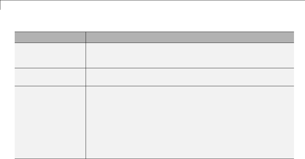
14 External Code Integration
Field Description
intOnlyBuild A Boolean flag. When set to true, the flag indicates the libraries are to
be optimized such that they are compiled from integer code only. This
field applies to ERT targets only.
makeOpts A string that specifies an option to be included in the rtwMake command
line.
addLibs A cell array of structures that specify libraries to be built that are not
specified by an rtwmakecfg function. Each structure must be defined
with two fields that are character arrays:
•libName — the name of the library without a suffix
•libLoc — the location for the precompiled library
The TMF can specify other libraries and how those libraries are to be
built. Use this field if you need to precompile those libraries.
The following commands set up build specification build_spec,which
indicates that the files to be compiled are in folder src under the current
working folder.
build_spec = [];
build_spec.rtwmakecfgDirs = {fullfile(pwd,'src')};
4Issue a call to rtw_precompile_libs.
Issue a call to rtw_precompile_libs that specifies the model for which
you want to build the precompiled libraries and the build specification.
For example:
rtw_precompile_libs(my_model,build_spec);
14-132


15 Program Building, Interaction, and Debugging
Compiler or IDE Selection and Configuration
In this section...
“ChooseandConfigureaCompiler”onpage15-2
“Troubleshoot Compiler Configurations” on page 15-9
Choose and Configure a Compiler
•“Compilers and the Build Process” on page 15-2
•“Simulink®Coder™ and ANSI C/C++ Compliance” on page 15-3
•“Support for C and C++ Code Generation” on page 15-4
•“Support for International (Non-US-ASCII) Characters” on page 15-5
•“C++ Target Language Considerations” on page 15-7
•“Choose and Configure Compiler on Microsoft Windows” on page 15-8
•“Choose and Configure Compiler on UNIX” on page 15-9
•“Include S-Function Source Code” on page 15-9
Compilers and the Build Process
The Simulink Coder build process depends upon the installation of one or
more supported compilers. Compiler,inthiscontext,referstoadevelopment
environment containing a linker and make utility, in addition to a high-level
language compiler. For details on supported compiler versions, see
http://www.mathworks.com/support/compilers/current_release
Most Simulink Coder targets create an executable that runs on your
workstation. When creating the executable, the Simulink Coder build
processmustbeabletoaccessasupported compiler. The build process can
automatically find a compiler to use based on your default MEX compiler.
The build process also requires the selection of a template makefile. The
template makefile determines which compiler runs, during the make phase of
the build, to compile the generated code.
15-2

Compiler or IDE Selection and Configuration
To determine which template makefiles are for your compiler and target, see
Targets Available from the System Target File Browser on page 9-12.
For both Simulink Coder generated files and user-supplied files, the file
extension, .c or .cpp, determines whether a C or a C++ compiler will be used
in the Simulink Coder build process. If the file extension is .c,aCcompiler
will be used to compile the file, and the symbols will use the C linkage
convention. If the file extension is .cpp,aC++compilerwillbeusedtocompile
the file, and the symbols by default will use the C++ linkage specification.
Simulink Coder and ANSI C/C++ Compliance
The Simulink Coder software generates code that is compliant with the
following standards:
Language Supported Standard
C ISO/IEC 9899:1990, also known as C89/C90
C++ ISO/IEC 14882:2003
Code generated by the Simulink Coder software from the following sources is
ANSI C/C++ compliant:
•Simulink built-in block algorithmic code
•Simulink Coder and Embedded Coder system level code (task ID [TID]
checks, management, functions, and so on)
•Code from other blocksets, including the Simulink Fixed Point product, the
Communications System Toolbox product, and so on
•Code from other code generators, such as MATLAB functions
Additionally, the Simulink Coder software can incorporate code from
•Embedded targets (for example, startup code, device driver blocks)
•User-written S-functions or TLC files
15-3

15 Program Building, Interaction, and Debugging
Note Coding standards for these two sources are beyond the control of the
Simulink Coder software, and can be a source for compliance problems, such
as code that uses C99 features not supported in the ANSI C, C89/C90 subset.
Support for C and C++ Code Generation
Simulink Coder supports C and C++ code generation. Consider the following
as you choose a language for your generated code:
•Whether you need to configure Simulink Coder to use a specific compiler.
This is required to generate C++ code on Windows. See “Choose and
Configure a Compiler” on page 15-2.
•The language configuration setting for the model. See “Select the Target
Language” on page 9-71.
•Whether you need to integrate legacy or custom code with generated code.
For a summary of integration options, see “Integration Options” on page
14-2.
•Whether you need to integrate C and C++ code. If so, see “Integration
Options” on page 14-2.
Note You can mix C and C++ code when integrating Simulink Coder
generated code with custom code. However, you must be aware of the
differences between C and default C++ linkage conventions, and add
the extern "C"’ linkage specifier where required. For the details of the
differing linkage conventions and how to apply extern "C",refertoaC++
programming language reference book.
•“C++ Target Language Limitations” on page 15-4.
For an example, enter sfcndemo_cppcount in the MATLAB Command
Window. For a Stateflow example, enter sf_cpp.
C++ Target Language Limitations.
•Simulink Coder does not support C++ code generation for the following:
15-4

Compiler or IDE Selection and Configuration
SimDriveline
SimMechanics
SimPowerSystems
Embedded Targets in Embedded Coder
Desktop Targets in Simulink Coder
xPC Target
•The following Embedded Coder dialog box fields currently do not accept
the .cpp extension. However, a .cpp file will be generated if you specify
a filename without an extension in these fields, with C++ selected as the
target language for your generated code.
-Data definition filename field on the Data Placement pane of the
Configuration Parameters dialog box
-Definition file field for an mpt data object in the Model Explorer
These restrictions on specifying .cpp will be removed in a future release.
Support for International (Non-US-ASCII) Characters
Simulink Coder does not include non-US-ASCII characters in compilable
portions of source code. However, Simulink, Stateflow, Simulink Coder, and
Embedded Coder do support non-US-ASCII characters in certain ways. When
non-US-ASCII characters are encountered during code generation, they either
become comments in the generated code ordonotpropagateintothegenerated
source files. Sources of non-US-ASCII characters are described below:
•Simulink Block Names: The name of Simulink blocks are permitted to use
non-US-ASCII character sets. The block name can be output in a comment
above the generated code for that block when the Simulink block /
Stateflow object comments check box is selected. If Simulink Coder also
uses the block name in the generated code as an identifier, the identifier’s
name changes so only US-ASCII characters are present.
One exception to using non-US-ASCII characters in block names is for
nonvirtual subsystems configured to use the subsystem name as either the
function name or the filename. In this case, only US-ASCII characters
canbeusedtonamethesubsystem.
•User comments on Stateflow diagrams: These comments can contain
non-US-ASCII characters. They are written to the generated code when
the Include comments check box is selected.
15-5

15 Program Building, Interaction, and Debugging
•Custom TLC files (.tlc): User-created Target Language Compiler files
can have non-US-ASCII characters inside both TLC comments and in any
code comments which are output. The Target Language Compiler does not
support non-US-ASCII characters in TLC variable or function names.
Additional Support with Embedded Coder. Users of Embedded Coder
have additional international character support:
•Simulink Block Description: Embedded Coder propagates block
descriptions entered from Simulink Block Parameter dialog boxes
into the generated code as comments when the Simulink block
descriptions check box on the Code Generation > Comments pane
of the Configuration Parameters dialog box is selected. Non-US-ASCII
characters are supported for these descriptions.
•Embedded Coder code template file: Code Generation Template (.cgt)files
provide customization capability for the generated code. Any output lines
in the .cgt file which are C or C++ comments can contain non-US-ASCII
characters, for example the file banner and file trailer sections; these
comments are propagated to the generated code. However, although TLC
comments in .cgt files can contain non-US-ASCII characters, these TLC
comments are not propagated to the generated code.
•Stateflow object descriptions: Stateflow object descriptions can contain
non-US-ASCII characters. The description will appear as a comment
above the generated code for that chart when the Stateflow object
descriptions check box is selected.
•Simulink Parameter Object Description: Simulink Parameter Object
descriptions can contain non-US-ASCII characters. The description will
appear as a comment above the generated code when the Simulink data
object descriptions check box is selected.
•MPT Signal Object Description: MPT object descriptions can contain
non-US-ASCII characters. The description will appear as a comment above
the generated code when the Simulink data object descriptions check box
is selected.
Character Set Limitation. You can encounter problems with models
containing characters of a specific character set, such as Shift JIS, on a host
system for which that character set is not configured as the default.
15-6

Compiler or IDE Selection and Configuration
When models containing characters of a given character set are used on a host
system that is not configured with that character set as the default, Simulink
can incorrectly interpret characters during model loading and saving. This
can lead to corrupted characters being displayed in the model and possibly
the model failing to load. It can also lead to corrupted characters in the model
file if you save it.
This limitation does not exist when the characters used in the model are in
the default character set for the host system. For example, you can use Shift
JIS characters with no issues if the host system is configured to use Japanese
Windows.
Additionally, during code generation, the Target Language Compiler can
have similar problems reading characters from either the model.rtw or user
written .tlc files. This can result in corrupt characters in generated source
file comments or a Target Language Compiler error.
For an example of international character set support for code generation, run
the example model rtwdemo_international. This example model is set up
to work around the character limitations described above. If you run this
example from a non-Japanese MATLAB host machine, you must set up an
international character set for Simulink. For example, type
bdclose all; set_param(0, 'CharacterEncoding', 'Shift_JIS')
rtwdemo_international
Other uses of non-US-ASCII characters in models or in files used during the
build process are not supported; you should not depend on any incidental
functionality that may exist.
For additional information, see the slCharacterEncoding function.
C++ Target Language Considerations
To use the C++ target language support, you might need to configure the
SimulinkCodersoftwaretouseaspecificcompiler. Forexample,ona
Microsoft Windows platform the default compiler is the Lcc Ccompiler
shipped with the MATLAB product, which does not support C++. If you do
not configure the Simulink Coder software to use a C++ compiler before you
specify C++ for code generation, the following build error message appears:
15-7

15 Program Building, Interaction, and Debugging
The specified target is configured to generate
C++, but the C-only compiler, LCC, is the default compiler. To
specify a C++ compiler, enter 'mex -setup' at the command prompt.
To generate C code, click (Open) to open the Configuration
Parameters dialog and set the target language to C.
Choose and Configure Compiler on Microsoft Windows
On Windows platforms, you can use the Lcc C compiler shipped with the
MATLAB product, or you can install and use one of the supported Windows
compilers.
The Simulink Coder code generator will choose a compiler based on the
template makefile (TMF) name specified on the Code Generation pane of
the Configuration Parameters dialog box. The simplest approach is to let
the code generator pick a compiler based on your default compiler, as set up
using the mex -setup function. When you use this approach, you do not need
to define compiler-specific environment variables, and the Simulink Coder
code generator determines the location of the compiler using information
from the mexopts.bat file located in the preferences folder (use the prefdir
command to verify this location).
To use this approach, the TMF filename specified must be a MATLAB
language file that returns default compiler information by using the
mexopts.bat file. Most targets provided by the Simulink Coder product use
this approach, as when grt_default_tmf or ert_default_tmf is specified as
the TMF name.
Alternatively, the name provided for the TMF can be a compiler-specific
template makefile, for example grt_vc.tmf, which designates the Microsoft
Visual C++ compiler. When you provide a compiler-specific TMF filename,
the Simulink Coder code generator uses the default mexopts.bat information
to locate the compiler if mex has been set up for the same compiler as the
specified TMF. If mex is not set up with a default compiler, or if it does not
match the compiler specified by the TMF, then an environment variable
must exist for the compiler specified by the TMF. The environment variable
required depends on the compiler.
15-8

Compiler or IDE Selection and Configuration
Choose and Configure Compiler on UNIX
On a UNIX platform, the Simulink Coder build process uses the default
compiler. The default compiler is cc.
You should choose the UNIX template makefileforyourtarget. Forexample,
grt_unix.tmf isthetemplatemakefileforbuilding a generic real-time
program on a UNIX platform.
Include S-Function Source Code
When the Simulink Coder code generator builds models with S-functions,
source code for the S-functions can be either in the current folder or in the
same folder as their MEX-file. The code generator adds an include path to
the generated makefiles whenever it finds a file named sfncname.h in the
same folder that the S-function MEX-file is in. This folder must be on the
MATLAB path.
Similarly, the Simulink Coder code generator adds a rule for the folder when
it finds a file sfncname.c (or .cpp) in the same folder as the S-function
MEX-file is in.
Troubleshoot Compiler Configurations
•“Compiler Version Mismatch Errors” on page 15-9
•“Generated Executable Image Produces Incorrect Results” on page 15-10
•“Compile-Time Errors” on page 15-10
Compiler Version Mismatch Errors
Explanation. You received a version mismatch error when you compiled
code generated by the Simulink Coder software.
User Action.
1Check the list of currently supported and compatible compilers available at
http://www.mathworks.com/support/compilers/current_release/.
15-9

15 Program Building, Interaction, and Debugging
2If necessary, upgrade or change your compiler. For more information, see
“Choose and Configure a Compiler” on page 15-2.
3Rebuild the model.
Generated Executable Image Produces Incorrect Results
Explanation. You applied compiler optimizations when you used Simulink
Coder to generate an executable image. However, the optimizations caused
the executable image to produce incorrect results, even though expected
code was generated.
User Action. Do one of the following:
•Lower the compiler optimization level.
1Select Custom for the Model Configuration parameter Code
Generation > Compiler optimization level.TheCustom compiler
optimization flags field appears.
2Specify a lower optimization level in the Custom compiler
optimization flags field.
3Rebuild the model.
•Disable compiler optimizations.
1Select Optimizations off (faster builds) for the Model
Configuration parameter Code Generation > Compiler optimization
level.
2Rebuild the model.
For more information, see “Control Compiler Optimizations” on page 16-6
and your compiler documentation.
Compile-Time Errors
Explanations.
•You received a compiler configuration error.
15-10

Compiler or IDE Selection and Configuration
•Environment variables for your make utility, compiler, or linker are set
up incorrectly. For example, installation of Cygwin tools on a Windows
platform might affect environment variables used by other compilers.
•Custom code specified as an S-function block or in the Code
Generation > Custom Code pane of the Configuration Parameters dialog
includes errors. For example, the codemightrefertoaheaderfilethatthe
compiler cannot find.
•The model includes a block, such as a device driver block, that is not
intended for use with the currently selected target.
User Actions.
•Make sure that MATLAB supports the compiler and version that you want
to use. For a list of currently supported and compatible compilers, see
http://www.mathworks.com/support/compilers/current_release/.If
necessary, upgrade or change your compiler (see “Choose and Configure
a Compiler” on page 15-2).
•Review the environment variable settings for your system by using the set
command on a Windows platform or setenv on a UNIX platform. Make
sure the settings match what is required for the tools you are using.
•Remove the custom code from the model, to help isolate the source of the
problem, debug, and rebuild.
•Remove the target-specific block or configure the model for use with the
another target.
15-11

15 Program Building, Interaction, and Debugging
Program Builds
In this section...
“Configure the Build Process” on page 15-12
“Initiate the Build Process” on page 15-14
“Build a Generic Real-Time Program” on page 15-14
“Rebuild a Model” on page 15-27
“Control Regeneration of Top Model Code” on page 15-27
“Reduce Build Time for Referenced Models” on page 15-28
“Relocate Code to Another Development Environment” on page 15-33
“How Executable Programs Are Built From Models” on page 15-38
Configure the Build Process
•“Specify TLC Options” on page 15-12
•“Specify Whether To Generate a Makefile” on page 15-13
•“Specify a Make Command” on page 15-13
•“Specify the Template Makefile” on page 15-13
Specify TLC Options
You can enter Target Language Compiler (TLC) command line options in the
TLC options edit field, for example
•-aVarName=1 to declare a TLC variable and/or assign a value to it
•-IC:\Work to specify an include path
•-v to obtain verbose output from TLC processing (for example, when
debugging)
Specifying TLC options does not add any flags to the Make command field,
as do some of the targets available in the System Target File Browser.
For additional information, see “Target Language Compiler Overview”.
15-12

Program Builds
Specify Whether To Generate a Makefile
The Generate makefile option specifies whether the Simulink Coder build
process is to generate a makefile for a model. By default, the Simulink Coder
build process generates a makefile. You can suppress the generation of a
makefile, for example in support of custom build processing that is not based
on makefiles, by clearing Generate makefile . When you clear this option,
•The Make command and Template makefile options are unavailable.
•You must set up any post code generation build processing, using a
user-defined command, as explained in “Customize Post-Code-Generation
Build Processing” on page 22-13.
Specify a Make Command
A high-level MATLAB command, invoked when a build is initiated, controls
the Simulink Coder build process. Each target has an associated make
command. The Make command fielddisplaysthiscommand.
Almost all targets use the default command, make_rtw. Third-party targets
might supply another make command. See the vendor’s documentation.
In addition to the name of the make command, you can supply arguments
in the Make command field. These arguments include compiler-specific
options, include paths, and other parameters. When the build process invokes
the make utility, these arguments are passed along in the make command line.
“Template Makefiles and Make Options” on page 9-38 lists the Make
command arguments you can use with each supported compiler.
Specify the Template Makefile
The Template makefile field has these functions:
•If you have selected a target configuration using the System Target File
Browser, this field displays the name of a MATLAB language file that
selects a template makefile for your development environment. For
example, in “Code Generation Pane: General”, the Template makefile
field displays grt_default_tmf, indicating that the build process invokes
grt_default_tmf.m.
15-13

15 Program Building, Interaction, and Debugging
“Template Makefiles and Make Options” on page 9-38 gives a detailed
description of the logic by which the Simulink Coder build process selects
a template makefile.
•Alternatively, you can explicitly enter the name of a specific template
makefile (including the extension) or a MATLAB language file that returns
a template make file in this field. You must do this if you are using a target
configuration that does not appear in the System Target File Browser.
For example, do this if you have written your own template makefile for a
custom target environment or you.
If you specify your own template makefile, be sure to include the filename
extension. If you omit the extension, the Simulink Coder build process
attempts to find and execute a file with the extension .m (that is, a MATLAB
language file). The template make file (or a MATLAB language file that
returns a template make file) must be on the MATLAB path. To determine
whether the file is on the MATLAB path, enter the following command in the
MATLAB Command Window:
which tmf_filename
Initiate the Build Process
You can initiate code generation and the build process by using the following
options:
•Clear the Generate code only option on the Code Generation pane of
the Configuration Parameters dialog box and click Build.
•Press Ctrl+B.
•Select Code > C/C++ Code > Build Model.
•Invoke the rtwbuild command from the MATLAB command line.
•Invoke the slbuild command from the MATLAB command line.
BuildaGenericReal-TimeProgram
•“About Building a Program” on page 15-15
•“Working and Build Folders” on page 15-15
•“Set Program Parameters” on page 15-16
15-14

Program Builds
•“Select a Target Configuration” on page 15-18
•“Build and Run a Program” on page 15-23
•“Contents of the Build Folder” on page 15-25
AboutBuildingaProgram
This section walks through the process of generating C code and building
an executable program from an example model. The resulting stand-alone
program runs on your workstation, independent of external timing and events.
Working and Build Folders
It is convenient to work with a local copy of the sldemo_f14 model, stored in
its own folder, f14example. Set up your working folder as follows:
1In the MATLAB Current Folder browser, navigate to a folder where you
have write access.
2Create the working folder from the MATLAB command line by typing:
mkdir f14example
3Make f14example your working folder:
cd f14example
4Open the sldemo_f14 model:
sldemo_f14
The model appears in the Simulink window.
5In the model window, choose File > Save As. Navigatetoyourworking
folder, f14example.Saveacopyofthesldemo_f14 model.
During code generation, the Simulink Coder software creates a build folder
within your working folder. The build folder name is model_target_rtw,
derived from the name of the source model and the chosen target. The build
folder stores generated source code and other files created during the build
process. You examine the build folder contents at the end of this example.
15-15

15 Program Building, Interaction, and Debugging
Note When a model contains Model blocks (which enable one Simulink
model to include others), special project folders are created in your working
folder to organize code for referenced models. Project folders exist alongside
of Simulink Coder build folders, and are always named slprj.“Generate
Code for Referenced Models” on page 3-4 describes navigating project folder
structures in Model Explorer.
Set Program Parameters
To generate code from your sldemo_f14 model, you must change some of the
simulation parameters. In particular, note that generic real-time (GRT) and
most other targets require that the model specify a fixed-step solver.
Note The Simulink Coder software can generate code for models using
variable-step solvers for rapid simulation (rsim) and S-function targets only.
To set parameters, use the Model Explorer as follows:
1Open Model Explorer by selecting Model Explorer from the model’s
View menu.
2In the Model Hierarchy pane, expand the model name node to reveal
its components.
3Click Configuration (Active) in the left pane.
4Click Solver in the center pane. The Solver pane appears at the right.
5Enter the following parameter values on the Solver pane (some may
already be set):
•Start time:0.0
•Stop time:60
•Type:Fixed-step
•Solver:ode5 (Dormand-Prince)
15-16
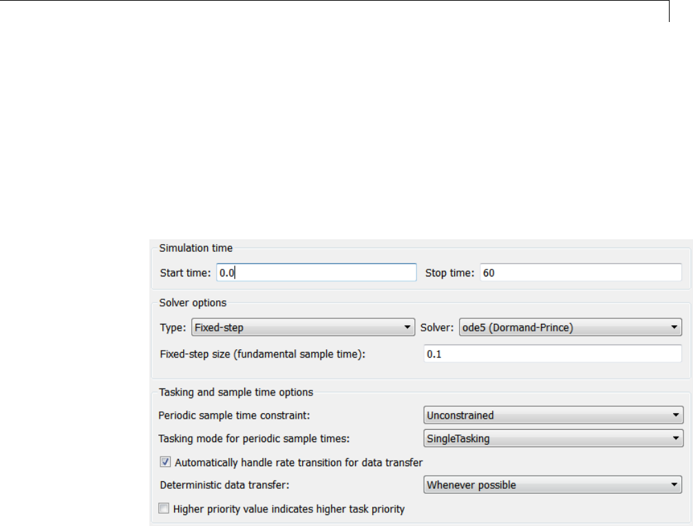
Program Builds
•Fixedstepsize(fundamentalsampletime):0.1
•Tasking mode for periodic sample times:SingleTasking
The Solver pane with the modified parameter settings is shown below.
Note the tan background color of the controls you just changed. The color
also appears on fields that were set automatically by your choices in other
fields. Use this visual feedback to verify that what you set is what you
intended. When you apply your changes, the background color reverts
to white.
6Click Apply to register your changes.
7Save the model. Simulation parameters persist with the model, for use in
future sessions.
15-17

15 Program Building, Interaction, and Debugging
Select a Target Configuration
Note Some of the steps in this section do not require you to make changes.
They are included to help you familiarize yourself with the Simulink Coder
user interface. As you step through the dialog boxes, place the mouse pointer
on any item of interest to see a tooltip describing its function.
To specify the desired target configuration, you choose a system target file, a
template makefile, and a make command.
In these examples (and in most applications), you do not need to specify these
parameters individually. Here, you use the ready-to-run generic real-time
target (GRT) configuration. The GRT target is designed to build a stand-alone
executable program that runs on your workstation.
To select the GRT target via the Model Explorer:
1With the sldemo_f14 model open, select View > Model Explorer to open
the Model Explorer.
2In the Model Hierarchy pane, expand the model node to reveal its
components.
3Click Configuration (Active) in the left pane.
4Click Code Generation in the center pane. The Code Generation pane
appears at the right. This pane has several tabs.
5Click the General tab to activate the pane that controls target selection.
15-18
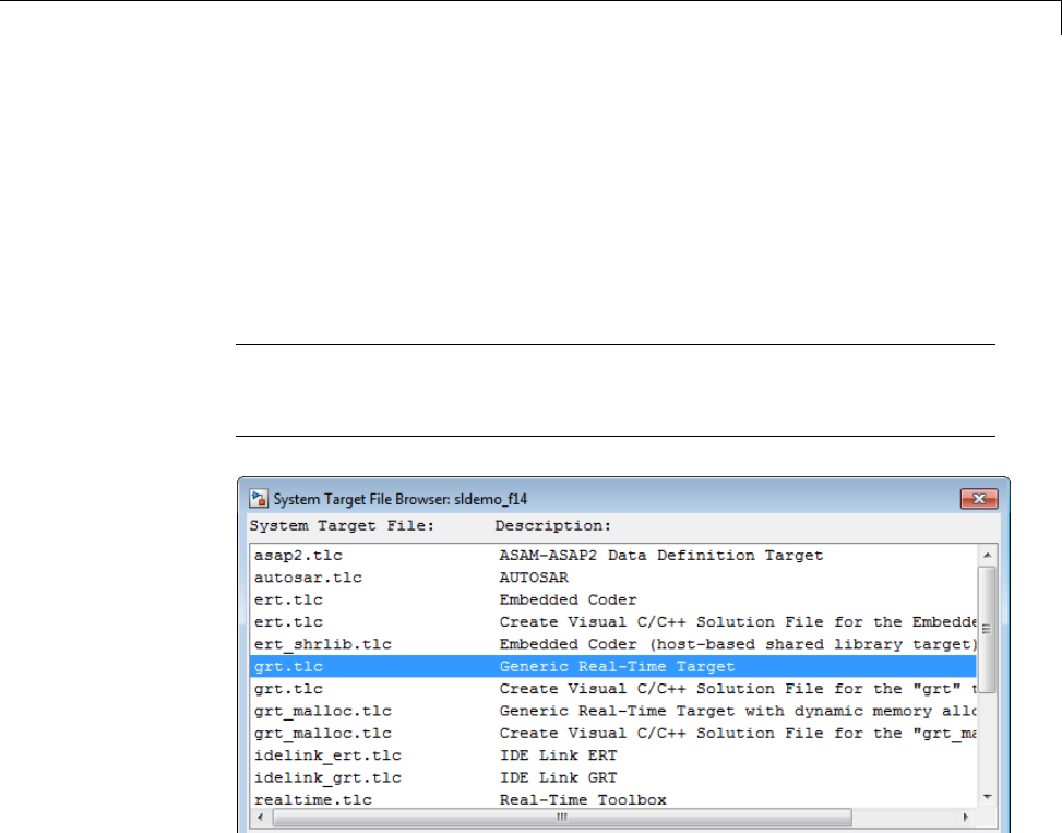
Program Builds
6Click the Browse button next to the System target file field. This opens
the System Target File Browser, illustrated below. The browser displays
a list of all currently available target configurations. Your available
configurations may differ. When you select a target configuration, the
Simulink Coder software automatically chooses the system target file,
template makefile, and make command for that configuration. Their names
appear at the bottom left of the window.
Note The system target file browser lists all system target files found on
the MATLAB path. Using some of these might require additional licensed
products, such as the Embedded Coder product.
15-19
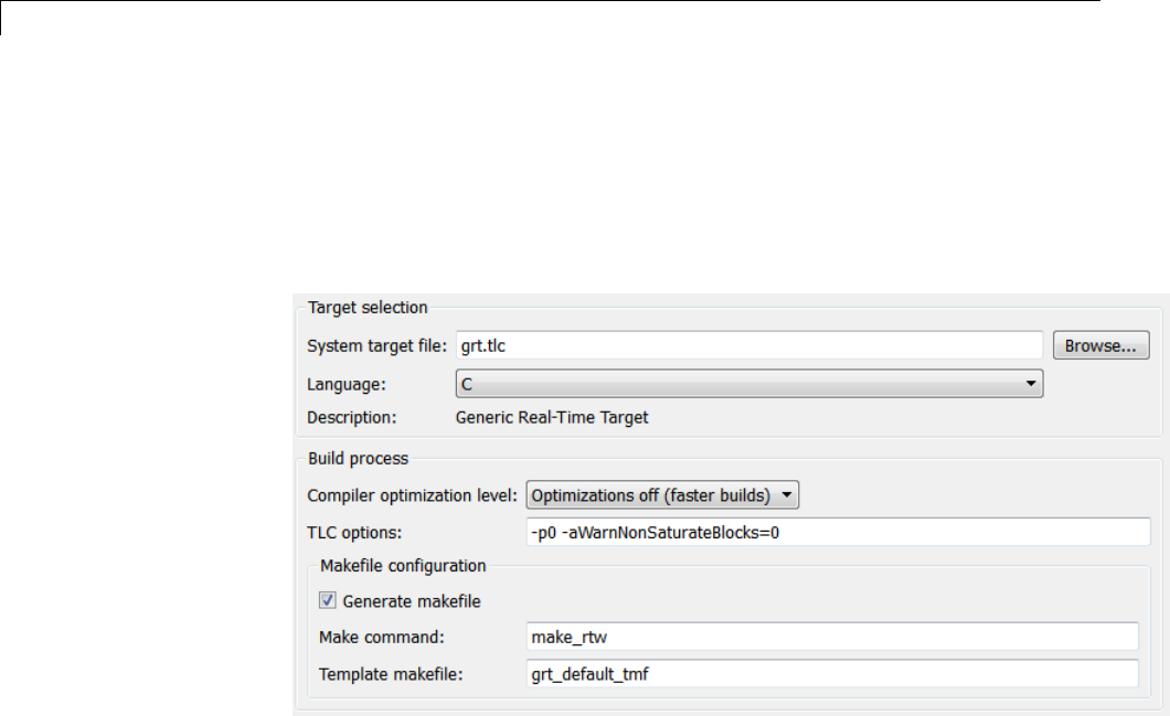
15 Program Building, Interaction, and Debugging
7From the list of available configurations, select Generic Real-Time
Target (as shown above) and then click OK.
The Code Generation pane displays the system target file (grt.tlc),
make command (make_rtw), and template makefile (grt_default_tmf),
as shown below:
15-20
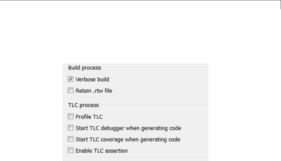
Program Builds
8Select the Code Generation > Debug pane. The options displayed here
control build verbosityanddebuggingsupport,andarecommontoall
target configurations. Make sure that all options are set to their defaults,
as shown below.
15-21
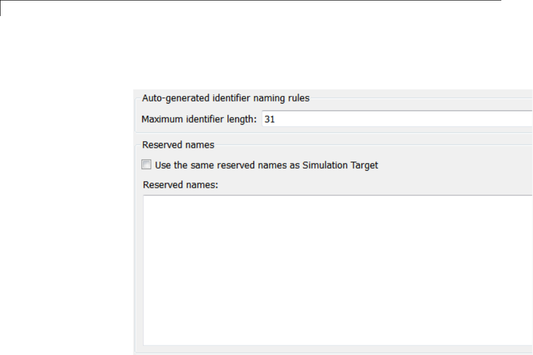
15 Program Building, Interaction, and Debugging
9Select the Code Generation > Symbols pane. The options on this pane
control the look and feel of generated code.
15-22
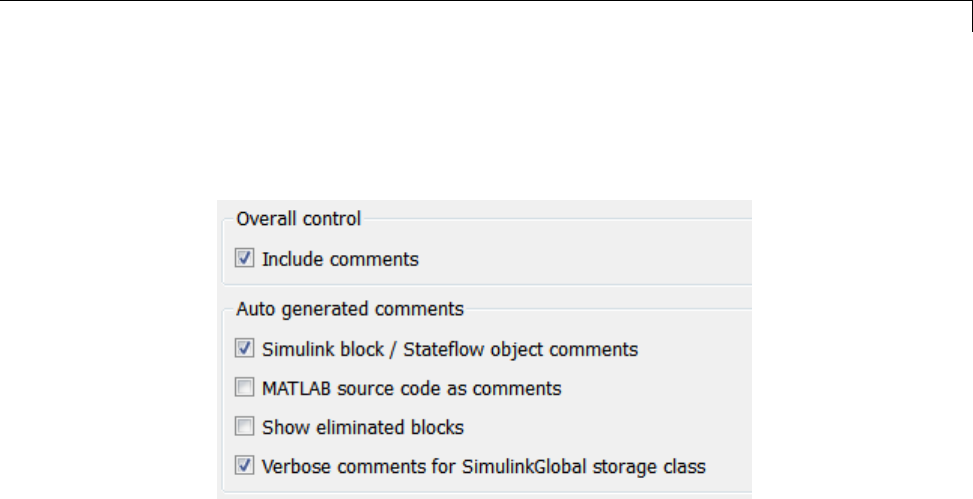
Program Builds
10 Select the Code Generation > Comments pane. The options displayed
here control the types of comments included in generated code. Make sure
that all options are set to their defaults, as shown below.
11 Make sure that the Generate code only check box at the bottom of the
pane is cleared.
12 Save the model.
Build and Run a Program
The Simulink Coder build process generates C code from the model, and then
compiles and links the generated program to create an executable image. To
build and run the program,
1With the sldemo_f14 model open, go to the Model Explorer window. In the
Code Generation pane, click the Build button to start the build process.
A number of messages concerning code generation and compilation appear
in the MATLAB Command Window. The initial message is
### Starting build procedure for model: sldemo_f14
The contents of many of the succeeding messages depends on your compiler
and operating system. The final message is
### Successful completion of build procedure
for model: sldemo_f14
15-23

15 Program Building, Interaction, and Debugging
The working folder now contains an executable, sldemo_f14.exe (Microsoft
Windows platforms) or sldemo_f14 (UNIX platforms). In addition, the
Simulink Coder build process has created a project folder, slprj,anda
build folder, sldemo_f14_grt_rtw, in your working folder.
Note The Simulink Coder build process displays a code generation
report after generating the code for the sldemo_f14 model. The example
“Optimizing Generated Code” on page 18-2 provides more information
about how to create and use a code generation report.
2To observe the contents of the working folder after the build, type the dir
command from the MATLAB Command Window.
dir
. sldemo_f14.exe sldemo_f14_grt_rtw
.. sldemo_f14.slx slprj
3To run the executable from the Command Window, type
!sldemo_f14
The ! character passes the command that follows it to the operating system,
which runs the stand-alone sldemo_f14 program.
The program produces one line of output in the Command Window:
**starting the model**
No data is output.
4Finally, to see the files created in the build folder, type
dir sldemo_f14_grt_rtw
The exact list of files produced varies among MATLAB platforms and
versions. Here is a sample list from a Windows platform.
. grt_main.obj rt_nonfinite.h
.. html rt_nonfinite.obj
15-24

Program Builds
buildInfo.mat modelsources.txt rt_rand.c
defines.txt ode5.obj rt_rand.h
sldemo_f14.bat rtGetInf.c rt_rand.obj
sldemo_f14.c rtGetInf.h rt_sim.obj
sldemo_f14.h rtGetInf.obj rtmodel.h
sldemo_f14.mk rtGetNaN.c rtw_proj.tmw
sldemo_f14.obj rtGetNaN.h rtwtypes.h
sldemo_f14_private.h rtGetNaN.obj rtwtypeschksum.mat
sldemo_f14_ref.rsp rt_logging.obj
sldemo_f14_types.h rt_nonfinite.c
Contents of the Build Folder
The build process creates a build folder and names it model_target_rtw,
where model is the name of the source model and target is the target
selected for the model. In this example, the build folder is named
sldemo_f14_grt_rtw.
The build folder includes the following generated files.
Note The code generation report you created for the sldemo_f14 model in
the previous section displays a link for each file listed below, which you can
click to explore the file contents.
File Description
sldemo_f14.c Standalone C code that implements the model
rt_nonfinite.c
rtGetInf.c
rtGetNaN.c
Functions to initialize nonfinite types (Inf,
NaN,and-Inf)
rt_rand.c Random functions, included only if used by the
application
sldemo_f14.h An include header file containing definitions of
parameters and state variables
sldemo_f14_private.h Header file containing common include
definitions
15-25

15 Program Building, Interaction, and Debugging
File Description
sldemo_f14_types.h Forward declarations of data types used in the
code
rt_nonfinite.h
rtGetInf.h
rtGetNaN.h
Provides support for nonfinite numbers in the
generated code, dynamically generates Inf,
NaN,and-Inf
rt_rand.h Imported declarations for random functions,
included only if used by the application
rtmodel.h Master header file for including generated code
in the static main program (its name never
changes, and it simply includes sldemo_f14.h)
rtwtypes.h Static include file for Simulink simstruct data
types; some embedded targets tailor this file to
reduce overhead, but GRT does not
The build folder contains other files used in the build process, most of which
you can disregard for the present:
•sldemo_f14.mk — Makefile generated from a template for the GRT target
•Object (.obj)files
•sldemo_f14.bat — Batch control file
•rtw_proj.tmw —Markerfile
•buildInfo.mat — Build information for relocating generated code to
another development environment
•defines.txt — Preprocessor defines required for compiling the generated
code
•sldemo_f14_ref.rsp — Data to include as command-line arguments to
mex (Windows systems only)
The build folder also contains a subfolder, html, which contains the files that
make up the code generation report. For more information about the code
generation report, see “Reports for Code Generation” on page 11-2.
15-26

Program Builds
Rebuild a Model
If you update generated source code or makefiles manually to add
customizations, you can rebuild the files with the rtwrebuild command. This
command recompiles the modified files by invoking the generated makefile.
Alternatively, you can use this command from the Model Explorer,
1In the Model Hierarchy pane, expand the node for the model of interest.
2Click the Code for model node.
3In the Code pane, click run rtwrebuild, listed to the right of the label
Code Recompile Command.
Control Regeneration of Top Model Code
When you rebuild a model, by default, the build process performs checks
to determine whether changes to the model or relevant settings require
regeneration of the top model code. Top model code is regenerated if any
of the following conditions is true:
•The structural checksum of the model has changed.
•The top-model-only checksum has changed. The top-model-only checksum
provides information about top model parameters, such as application
lifespan, maximum stack size, make command, verbose and .rtw file debug
settings, and the TLC options parameter.
•Any of the following TLC debugging model options, located on the Code
Generation > Debug pane of the Configuration Parameters dialog box,
is on:
-Start TLC debugger when generating code (TLCDebug)
-Start TLC coverage when generating code (TLCCoverage)
-Enable TLC assertion (TLCAssert)
-Profile TLC (ProfileTLC)
If the checks determine that top model code generation is required, the build
process fully regenerates and compiles the model code.
15-27

15 Program Building, Interaction, and Debugging
If the checks indicate that the top model generated code is current with
respect to the model, and no model settings require full regeneration, the
build process omits regeneration of the top model code. This can significantly
reduce model build times.
Regardless of whether the top model code is regenerated, the build process
subsequently calls all build process hooks, including STF_make_rtw_hook
functions and the post code generation command, and reruns the makefile so
that any external dependencies are recompiled and relinked.
Note Target authors can perform actions related to code regeneration,
including forcing or reacting to code regeneration, in the STF_make_rtw_hook
functions that are called by the build process. For more information, see
“Control Code Regeneration Using STF_make_rtw_hook.m” on page 22-26.
If you want to control or override the default top model build behavior, use
one of the following command-line options:
•To ignore the checksum and force regeneration of the top model code:
-rtwbuild(model,'ForceTopModelbuild',true)
-slbuild(model,'StandaloneRTWTarget','ForceTopModelBuild',true)
•To clean the model build area enough to trigger regeneration of the top
model code at the next build (slbuild only):
slbuild(model,'CleanTopModel')
Note You can also force regeneration of the top model code by deleting code
generation folders, for example, slprj or the generated model code folder.
Reduce Build Time for Referenced Models
•“Parallel Building For Large Model Reference Hierarchies” on page 15-29
•“Parallel Building Configuration Requirements” on page 15-30
•“Build Models In a Parallel Computing Environment” on page 15-30
15-28

Program Builds
•“Locate Parallel Build Logs” on page 15-31
Parallel Building For Large Model Reference Hierarchies
In a parallel computing environment, you can increase the speed of code
generation and compilation for models containing large model reference
hierarchies by building referenced models in parallel whenever conditions
allow. For example, if you have Parallel Computing Toolbox™ software, code
generation and compilation for each referenced model can be distributed
across the cores of a multicore host computer. If you additionally have
MATLAB Distributed Computing Server™ (MDCS) software, code generation
and compilation for each referenced model can be distributed across remote
workers in your MATLAB Distributed Computing Server configuration.
The performance gain realized by using parallel builds for referenced models
depends on several factors, including how many models can be built in
parallel for a given model referencing hierarchy, the size of the referenced
models, and parallel computing resources such as number of local and/or
remote workers available and the hardware attributes of the local and remote
machines (amount of RAM, number of cores, and so on).
For configuration requirements that might apply to your parallel computing
environment, see “Parallel Building Configuration Requirements” on page
15-30.
For a description of the general workflow for building referenced models
in parallel whenever conditions allow, see “Build Models In a Parallel
Computing Environment” on page 15-30.
For information on how to configure a custom embedded target to support
parallel builds, see “Support Model Referencing” on page 24-101.
Note In an MDCS parallel computing configuration, parallel building is
designed to work interactively with the MATLAB Distributed Computing
Server software. You can initiate builds from the Simulink user interface or
from the MATLAB Command Window using commands such as slbuild.You
cannot initiate builds using batch or other batch mode workflows.
15-29

15 Program Building, Interaction, and Debugging
Parallel Building Configuration Requirements
The following requirements apply to configuring your parallel computing
environment for building model reference hierarchies in parallel whenever
conditions allow:
•For local pools, the host machine must have enough RAM to support the
number of local workers (MATLAB sessions) that you plan to use. For
example, setting matlabpool to 4 results in five MATLAB sessions on your
machine, each using approximately 120 MB of memory at startup.
•Remote MDCS workers participating in a parallel build must use a common
platform and compiler.
•A consistent MATLAB environment must be set up in each MATLAB
worker session as in the MATLAB client session — for example, all
shared base workspace variables, MATLAB path settings, and so forth.
OneapproachistousethePreLoadFcn callback of the top model. If you
configure your model to load the topmodelwitheachMATLABworker
session, its preload function can be used for any MATLAB worker session
setup.
Build Models In a Parallel Computing Environment
To take advantage of parallel building for a model reference hierarchy:
1Set up a pool of local and/or remote MATLAB workers in your parallel
computing environment.
aMake sure that Parallel Computing Toolbox software is licensed and
installed.
bTouseremoteworkers,makesurethat MATLAB Distributed Computing
Server software is licensed and installed.
cIssue MATLAB commands to set up the worker pool, for example,
matlabpool 4.
2In the Configuration Parameters dialog box, go to the Model Referencing
pane and select the Enable parallel model reference builds option.
This selection enables the parameter MATLAB worker initialization
for builds.
15-30

Program Builds
For MATLAB worker initialization for builds, select one of the
following values:
•None if the software should perform no special worker initialization.
Specify this value if the child models in the model reference hierarchy do
not rely on anything in the base workspace beyond what they explicitly
setup(forexample,withamodelloadfunction).
•Copy base workspace if the software should attempt to copy the base
workspace to each worker. Specify this value if you use a setup script to
prepare the base workspace for all models to use.
•Load top model if the software should load the top model on each
worker. Specify this value if the top model in the model reference
hierarchy handles all of the base workspace setup (for example, with a
model load function).
3Optionally, inspect the model reference hierarchy to determine, based
on model dependencies, which models will be built in parallel. For
example, you can use the Model Dependency Viewer from the Simulink
Analysis > Model Dependencies menu.
4Build your model. Messages in the MATLAB Command Window record
when each parallel or serial build starts and finishes. The order in which
referenced models build is nondeterministic. They might build in a
different order each time the model is built.
If you need more information about a parallel build, for example, if a build
fails, see “Locate Parallel Build Logs” on page 15-31.
Locate Parallel Build Logs
When you build a model for which referenced models are built in parallel,
messages in the MATLAB Command Window record when each parallel or
serial build starts and finishes. Any referenced models that build in parallel
have only summary log entries in the command window, even if verbose
builds are turned on. For example,
### Initializing parallel workers for parallel model reference build.
15-31

15 Program Building, Interaction, and Debugging
### Parallel worker initialization complete.
### Starting parallel model reference SIM build for 'bot_model001'
### Starting parallel model reference SIM build for 'bot_model002'
### Starting parallel model reference SIM build for 'bot_model003'
### Starting parallel model reference SIM build for 'bot_model004'
### Finished parallel model reference SIM build for 'bot_model001'
### Finished parallel model reference SIM build for 'bot_model002'
### Finished parallel model reference SIM build for 'bot_model003'
### Finished parallel model reference SIM build for 'bot_model004'
### Starting parallel model reference RTW build for 'bot_model001'
### Starting parallel model reference RTW build for 'bot_model002'
### Starting parallel model reference RTW build for 'bot_model003'
### Starting parallel model reference RTW build for 'bot_model004'
### Finished parallel model reference RTW build for 'bot_model001'
### Finished parallel model reference RTW build for 'bot_model002'
### Finished parallel model reference RTW build for 'bot_model003'
### Finished parallel model reference RTW build for 'bot_model004'
If a parallel builds fails, you might see output similar to the following:
### Initializing parallel workers for parallel model reference build.
### Parallel worker initialization complete.
...
### Starting parallel model reference RTW build for 'bot_model002'
### Starting parallel model reference RTW build for 'bot_model003'
### Finished parallel model reference RTW build for 'bot_model002'
### Finished parallel model reference RTW build for 'bot_model003'
### Starting parallel model reference RTW build for 'bot_model001'
### Starting parallel model reference RTW build for 'bot_model004'
### Finished parallel model reference RTW build for 'bot_model004'
### The following error occurred during the parallel model reference RTW build for
'bot_model001':
Error(s) encountered while building model "bot_model001"
### Cleaning up parallel workers.
To obtain more detailed information about the failed build, you can examine
the parallel build log. For each referenced model built in parallel, the build
process generates a file named model_buildlog.txt,wheremodel is the
15-32

Program Builds
name of the referenced model. This file contains the full build log for that
model.
If a parallel build completes, the build log file is placed in the build
subfolder corresponding to the referenced model. For example,
for a build of referenced model bot_model004, you would look for
the build log file bot_model004_buildlog.txt in a referenced
model subfolder such as build_folder/slprj/grt/bot_model004,
build_folder/slprj/ert/bot_model004,or
build_folder/slprj/sim/bot_model004.
If a parallel build fails, the build log can be found in a referenced model
subfolder under the build subfolder /par_mdl_ref/model. For example,
for a failed parallel build of model bot_model001, you would look for
the build log file bot_model001_buildlog.txt in a subfolder such as
build_folder/par_mdl_ref/bot_model001/slprj/grt/bot_model001,
build_folder/par_mdl_ref/bot_model001/slprj/ert/bot_model001,or
build_folder/par_mdl_ref/bot_model001/slprj/sim/bot_model001.
Relocate Code to Another Development Environment
•“About Code Relocation” on page 15-33
•“Package Code Using the Graphical User Interface” on page 15-34
•“Package Code Using the Command-Line Interface” on page 15-34
•“packNGo Function Limitations” on page 15-38
About Code Relocation
If you need to relocate the static and generated code files for a model to
another development environment, such as a system or an integrated
development environment (IDE) that does not include MATLAB and Simulink
products, use the Simulink Coder pack-and-go utility. This utility uses the
tools for customizing the build process after code generation and a packNGo
function to find and package files for building an executable image. The files
are packaged in a compressed file that you can relocate and unpack using a
standard zip utility.
To package model code files, you can do either of the following:
15-33
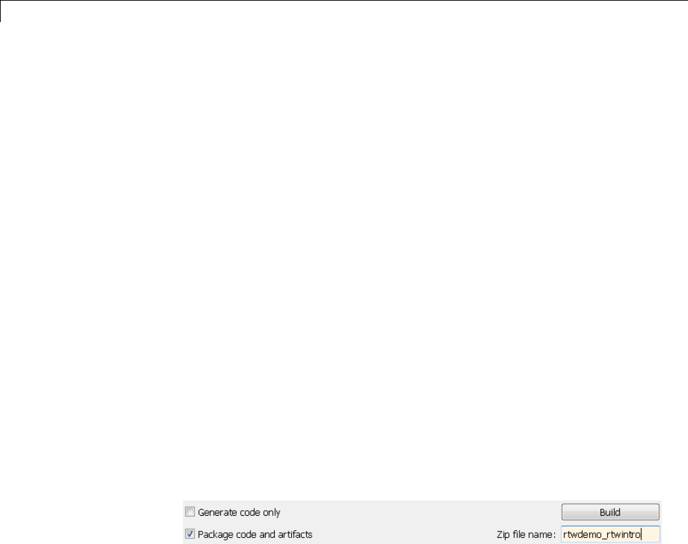
15 Program Building, Interaction, and Debugging
•Use the model option Package code and artifacts on the Code
Generation pane of the Configuration Parameters dialog box. See
“Package Code Using the Graphical User Interface” on page 15-34.
•Use MATLAB commands to configure a PostCodeGenCommand parameter
with a call to the packNGo function. See “Package Code Using the
Command-Line Interface” on page 15-34. The command-line interface
provides more control over the details of code packaging.
Package Code Using the Graphical User Interface
To package and relocate code for your model using the graphical user interface:
1Open the Configuration Parameters dialog box and select the Code
Generation pane.
2Select the option Package code and artifacts.Thisoptionconfiguresthe
build process to run the packNGo function after code generation to package
generated code and artifacts for relocation.
3In the Zip file name field, enter the name of the zip file in which to
package generated code and artifacts for relocation. The file name can be
specified with or without the .zip extension. If you specify no extension or
an extension other than .zip,thezip utility adds the.zip extension. If no
value is specified, the build process uses the name model.zip,wheremodel
is the name of the top model for which code is being generated.
4Apply changes and generate code for your model. Inspect the resulting zip
file to verify that it is ready for relocation. Depending on the zip tool you
use you might be able to open and inspect the file without unpacking it.
5Relocate the zip file to the destination development environment and
unpack the file.
PackageCodeUsingtheCommand-LineInterface
To package and relocate code for your model using the command-line interface:
15-34

Program Builds
1Select a structure for the zip file.
2Select a name for the zip file.
3Packagethemodelcodefilesinthezip file.
4Inspect the generated zip file.
5Relocate and unpack the zip file.
Select a Structure for the Zip File. Before you generate and package the
files for a model build, decide whether you want the files to be packaged
in a flat or hierarchical folder structure. By default, the packNGo function
packages the files in a single, flat folder structure. This is the simplest
approach and might be the optimal choice.
If... Then Use a...
You are relocating files to an IDE
that does not use the generated
makefile or the code is not dependent
ontherelativelocationofrequired
static files
Single, flat folder structure
The target development environment
must maintain the folder structure
of the source environment because it
uses the generated makefile or the
code is dependent on the relative
location of files
Hierarchical structure
If you use a hierarchical structure, the packNGo function creates two levels of
zip files, a primary zip file, which in turn contains the following secondary
zip files:
•mlrFiles.zip — files in your matlabroot folder tree
•sDirFiles.zip — files in and under your build folder where you initiated
the model’s code generation
•otherFiles.zip — required files not in the matlabroot or start folder
trees
15-35

15 Program Building, Interaction, and Debugging
Paths for the secondary zip files are relative to the root folder of the primary
zip file, maintaining the source development folder structure.
Select a Name for the Zip File. By default, the packNGo function names
the primary zip file model.. You have the option of specifying a different
name. If you specify a file name and omit the file type extension, the function
appends .to the name you specify.
Package Model Code in a Zip File. You package model code files by using
the PostCodeGenCommand configuration parameter, packNGo function, and the
model’s build information object. You can set up the packaging operation
to use
•A system generated build information object.
In this case, use set_param to set the configuration parameter
PostCodeGenCommand to an explicit call to the packNGo function before
generating the model code. For example:
set_param(bdroot, 'PostCodeGenCommand', 'packNGo(buildInfo);');
This command instructs the Simulink Coder build process to evaluate the
call to packNGo, using the system generated build information object for the
currently selected model, after generating and writing the model’s code to
disk and before generating a makefile.
•A build information object that you construct programmatically, as
explained in “Customize Post-Code-Generation Build Processing” on page
22-13.
In this case, you might use other build information functions to selectively
include paths and files in the build information object that you then specify
with the packNGo function. For example:
.
.
.
myModelBuildInfo = RTW.BuildInfo;
addSourceFiles(myModelBuildInfo, {'test1.c' 'test2.c' 'driver.c'});
.
.
.
15-36

Program Builds
packNGo(myModelBuildInfo);
To change the default behavior of packNGo, see the following examples:
To... Specify...
Change the structure of the
file packaging to hierarchical
packNGo(buildInfo, {'packType'
'hierarchical'});
Rename the primary zip file packNGo(buildInfo, {'fileName'
'zippedsrcs'});
Change the structure of the
file packaging to hierarchical
and rename the primary zip
file
packNGo(buildInfo, {'packType'
'hierarchical'...
'fileName' 'zippedsrcs'});
Include all header files found
on the include path (rather
than the minimal header
files required to build the
code) in the zip file
packNGo(buildInfo, {'minimalHeaders'
false});
Note The packNGo function potentially can modify the build information
passed in the first packNGo argument. As part of packaging model code,
packNGo might find additional files from source and include paths recorded in
the model’s build information and add them to the build information.
Inspect a Generated Zip File. Inspect the generated zip file to verify that
it is ready for relocation. Depending on the zip toolyouuseyoumightbeable
to open and inspect the file without unpacking it. If you need to unpack the
file and you packaged the model code files as a hierarchical structure, you will
need to unpack the primary and secondary zip files. When you unpack the
secondary zip files, relative paths of all files are preserved.
RelocateandUnpackaZipFile. Relocate the generated zip file to the
destination development environment and unpack the file.
15-37

15 Program Building, Interaction, and Debugging
Code Packaging Example. The following example guides you through
the steps for packaging code files generated for the example model
rtwdemo_rtwintro using the command-line interface:
1Set your working folder to a writable folder.
2Open the model rtwdemo_rtwintro and save a copy to your working folder.
3Enter the following command in the MATLAB Command Window:
set_param('rtwdemo_rtwintro', 'PostCodeGenCommand',...
'packNGo(buildInfo, {''packType'' ''hierarchical''})');
You must double the single-quotes due to the nesting of character arrays
'packType' and 'hierarchical' within the character array that specifies
the call to packNGo.
4Generate code for the model.
5Inspect the generated zip file, rtwdemo_rtwintro.zip.Thezip file
contains the two secondary zip files, mlrFiles.zip and sDirFiles.zip.
6Inspect the zip files mlrFiles.zip and sDirFiles.zip.
7Relocate the zip file to a destination environment and unpack it.
packNGo Function Limitations
The following limitations apply to use of the packNGo function:
•The function operates on source files, such as *.c,*.cpp,and*.h files,
only. The function does not support compile flags, defines, or makefiles.
•Unnecessary files might be included. The function might find additional
files from source and include paths recorded in the model’s build
information and include them, even if they are not used.
How Executable Programs Are Built From Models
•“Build Process Steps” on page 15-39
•“Customized Makefile Generation” on page 15-39
15-38

Program Builds
•“Executable Program Generation” on page 15-40
Build Process Steps
The Simulink Coder software generates C code only or generates the C code
and produces an executable image, depending on the level of processing you
choose. By default, a Build button appears on the Code Generation pane of
the Configuration Parameters dialog box. This button completes the entire
build process and an executable image results. If you select the Generate
code only check box to the left of the button, the button label changes to
Generate code.
When you click the Build or Generate code button, the Simulink Coder
software performs the following build process. If the software detects code
generation constraints for your model, it issues warning or error messages.
1“Model Compilation” on page 10-31
2“Code Generation” on page 10-31
3“Customized Makefile Generation” on page 15-39
4“Executable Program Generation” on page 15-40
For more information, see “Generate a Code Generation Report” on page 11-5.
You can also view an HTML report in Model Explorer.
Customized Makefile Generation
After generating the code, the Simulink Coder software generates a
customized makefile, model.mk. The generated makefile instructs the make
system utility to compile and link source code generated from the model, as
well as any required harness program, libraries, or user-provided modules.
The Simulink Coder software creates model.mk from a system template file,
system.tmf (where system stands for the selected target name). The system
template makefile is designed for your target environment. You have the
option of modifying the template makefile to specify compilers, compiler
options, and additional information used during the creation of the executable.
15-39

15 Program Building, Interaction, and Debugging
The Simulink Coder software creates the model.mk file by copying the
contents of system.tmf and expanding lexical tokens (symbolic names) that
describe your model’s configuration.
The Simulink Coder software provides many system template makefiles,
configured for specific target environments and development systems.
“Selecting a Target” on page 9-34 in the Simulink Coder documentation lists
all template makefiles that are bundled with the Simulink Coder software.
To see an example template makefile, navigate to matlabroot/rtw/c/grt,
andopenwithaneditorthefilegrt_msvc.tmf. You can fully customize your
build process by modifying an existing template makefile or providing your
own template makefile.
Executable Program Generation
The following figure shows how the Simulink Coder software controls
automatic program building.
15-40
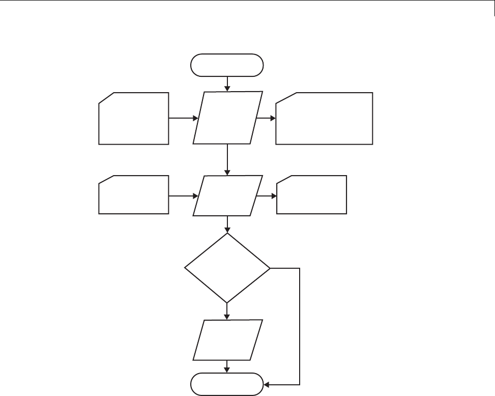
Program Builds
Click Build
Button
Simulink
Model
Generate
Code
Template
Makefile Generate
Makefile
model.c
model.h
model_private.h
Custom
Makefile
model.mk
Create
Executable? No
Yes
Invoke
make
Stop
During the final stage of processing, the Simulink Coder build process
invokes the generated makefile, model.mk, which in turn compiles and links
the generated code. On PC platforms, a batch file is created to invoke the
generated makefile. The batch file sets up the environment for invoking the
make utility and related compiler tools. To avoid recompilation of C files, the
make utility performs date checking on the dependencies between the object
and C files; only out-of-date source files are compiled. Optionally, the makefile
can download the resulting executable image to your target hardware.
15-41
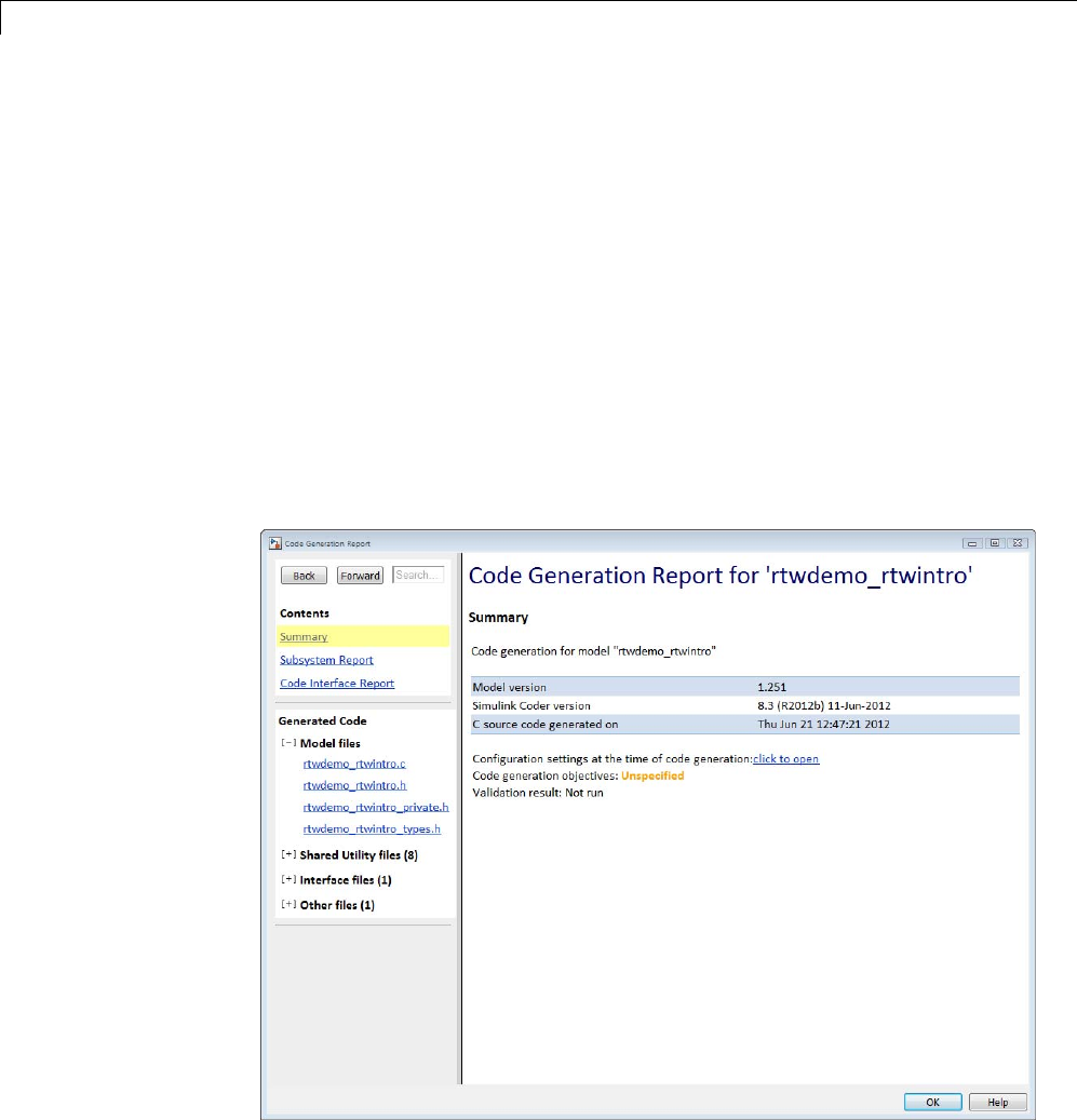
15 Program Building, Interaction, and Debugging
This stage is optional, as illustrated by the control logic in the preceding
figure. You might choose to omit this stage, for example, if you are targeting
an embedded microcontroller or a digital signal processing (DSP) board.
To omit this stage of processing, select the Generate code only check box on
the Code Generation pane of the Configuration Parameters dialog box. You
can then cross-compile your code and download it to your target hardware.
If you select Create code generation report on the Code
Generation > Report pane, a navigable summary of source files is produced
when the model is built. The report files occupy a folder called html within
the build folder. The report contents vary depending on the target, but all
reports feature links to generated source files. The following display shows
an example of an HTML code generation report for a generic real-time (GRT)
target.
15-42

Build and Run a Program
Build and Run a Program
The Simulink Coder build process generates C code from the model, and then
compiles and links the generated program to create an executable image. To
build and run the program,
1With the sldemo_f14 model open, go to the Model Explorer window. In the
Code Generation pane, click the Build button to start the build process.
A number of messages concerning code generation and compilation appear
in the MATLAB Command Window. The initial message is
### Starting build procedure for model: sldemo_f14
The contents of many of the succeeding messages depends on your compiler
and operating system. The final message is
### Successful completion of build procedure
for model: sldemo_f14
The working folder now contains an executable, sldemo_f14.exe (Microsoft
Windows platforms) or sldemo_f14 (UNIX platforms). In addition, the
Simulink Coder build process has created a project folder, slprj,anda
build folder, sldemo_f14_grt_rtw, in your working folder.
Note The Simulink Coder build process displays a code generation
report after generating the code for the sldemo_f14 model. The example
“Optimizing Generated Code” on page 18-2 provides more information
about how to create and use a code generation report.
2To observe the contents of the working folder after the build, type the dir
command from the MATLAB Command Window.
dir
. sldemo_f14.exe sldemo_f14_grt_rtw
.. sldemo_f14.slx slprj
3To run the executable from the Command Window, type
15-43

15 Program Building, Interaction, and Debugging
!sldemo_f14
The ! character passes the command that follows it to the operating system,
which runs the stand-alone sldemo_f14 program.
The program produces one line of output in the Command Window:
**starting the model**
No data is output.
4Finally, to see the files created in the build folder, type
dir sldemo_f14_grt_rtw
The exact list of files produced varies among MATLAB platforms and
versions. Here is a sample list from a Windows platform.
. grt_main.obj rt_nonfinite.h
.. html rt_nonfinite.obj
buildInfo.mat modelsources.txt rt_rand.c
defines.txt ode5.obj rt_rand.h
sldemo_f14.bat rtGetInf.c rt_rand.obj
sldemo_f14.c rtGetInf.h rt_sim.obj
sldemo_f14.h rtGetInf.obj rtmodel.h
sldemo_f14.mk rtGetNaN.c rtw_proj.tmw
sldemo_f14.obj rtGetNaN.h rtwtypes.h
sldemo_f14_private.h rtGetNaN.obj rtwtypeschksum.mat
sldemo_f14_ref.rsp rt_logging.obj
sldemo_f14_types.h rt_nonfinite.c
15-44

ProfileCodePerformance
ProfileCodePerformance
In this section...
“About Profiling Code Performance” on page 15-45
“How to Profile Code Performance” on page 15-45
“Run Profiling Hooks for Generated Code” on page 15-48
“Profiling Limitation” on page 15-49
About Profiling Code Performance
By profiling the performance of generated code, you can help verify that the
code meets performance requirements. Profiling can be especially important
early in the development cycle for identifying potential architectural issues
that can be more expensive to address later in the process. Profiling can
also identify bottlenecks and procedural issues that indicate a need for
optimization, for example, with an inner loop or inline code.
Note IfyouhaveanEmbeddedCoderlicense, see “Code Execution Profiling”
for an alternative and simpler approach based on software-in-the-loop (SIL)
or processor-in-the-loop (PIL) simulations.
How to Profile Code Performance
You can profile code generated with code generation technology by using a
Target Language Compiler (TLC) hook function interface.
To use the profile hook function interface:
1For your target, create a TLC file that defines the following hook functions.
Write the functions so that they specify profiling code. The code generator
adds the hook function code to code generated for atomic systems in the
model.
15-45

15 Program Building, Interaction, and Debugging
Function Input Arguments Output Type Description
ProfilerHeaders void Array of header file
names
Return an array of
the header file names
to be included in the
generated code.
ProfilerTypedefs void typedefs Generate code
statements for profiler
type definitions.
ProfilerGlobal-
Data
system Global data for the
specified system
Generate code
statements that declare
global data.
ProfilerExtern-
DataDecls
system extern declarations for
the specified system
Generate code
statements that
create global extern
declarations.
ProfilerSystem-
Decls
system,
functionType
Declarations for the
specified system for the
specified functionType
Generate code for
required variable
declarations within
the scope of an atomic
subsystem Output,
Update,OutputUpdate,
or Derivatives
function.
ProfilerSystem-
Start
system,
functionType
Profiler start commands
for the specified system
and functionType
Generate code that
starts the profiler
within the scope of an
atomic subsystem
Output,Update,
OutputUpdate,or
Derivatives function.
15-46
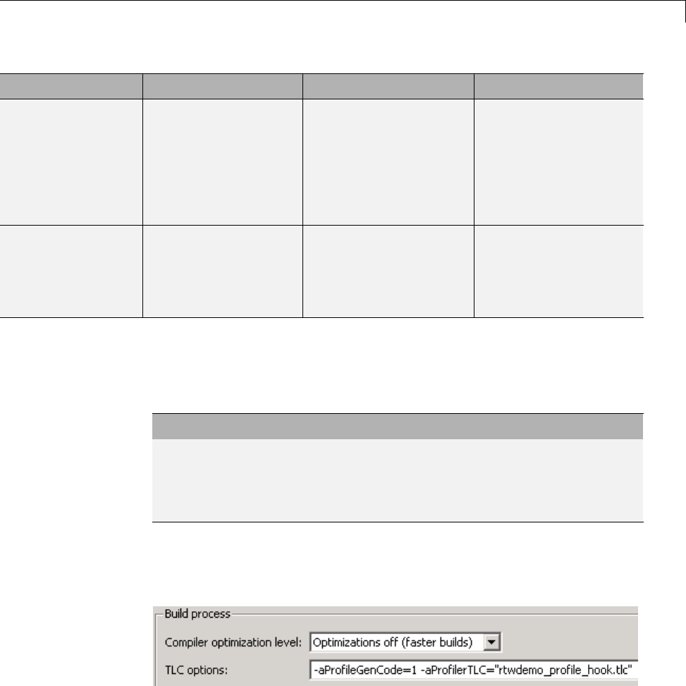
ProfileCodePerformance
Function Input Arguments Output Type Description
ProfilerSystem-
Finish
system,
functionType
Profiler end commands
for the specified system
and functionType
Generate code that
stops the profiler
within the scope of an
atomic subsystem’s
Output,Update,
OutputUpdate,or
Derivatives function.
ProfilerSystem-
Terminate
system Profiler termination
code for the specified
system
Generate code that
terminates profiling
(and possibly reports
results) for an atomic
subsystem.
For an example TLC file, see
matlabroot/toolbox/rtw/rtwdemos/rtwdemo_profile_hook.tlc.
2In your target.tlc file, define the following global variables.
Define... To Be...
ProfileGenCode TLC_TRUE or1toturnonprofiling
(TLC_FALSE or 0 to turn off profiling)
ProfilerTLC The name of the TLC file that you created
in step 1
A quick way to define global variables is to define the parameters with the
-a option. You can do this in the Configuration Parameters dialog box, in
Code Generation > TLC options.
3Consider setting configuration parameters for generating a code generation
report. You can then examine the profiling code in the context of the code
generated for the model.
15-47

15 Program Building, Interaction, and Debugging
4Build the model. The build process embeds the profiling code in the hook
function locations in the generated code for the model.
5Run the generated executable file. In the MATLAB Command Window,
enter !model-name . You see the profiling report you programmed in the
profiling TLC file that you created. For example, a profile report might list
the number of calls made to each system in a model and the number of
CPU cycles spent in each system.
For an example, see “Run Profiling Hooks for Generated Code” on page 15-48.
For details on programming a .tlc file and defining TLC configuration
variables, see “Target Language Compiler”.
Run Profiling Hooks for Generated Code
The example Profiling Hooks for Generated Code shows how to use special
hooks provided by Simulink Coder to add profiling code snippets to the
generated code for your models.
The basis for this example is the Target Language Compiler (TLC)
hook function interface described in “How to Profile Code Performance”
on page 15-45. The hooks allow you to add profiling code snippets
within nonvirtual (atomic) systems in the model, which allow
you to profile those atomic systems. For this example, the file
matlabroot/toolbox/rtw/rtwdemos/rtwdemo_profile_hook.tlc
implements the required profiling functions. You can inspect this file for more
information on each of the profiling functions.
Run the example as follows:
1Open the model rtwdemo_profile; for example, you can enter the
command rtwdemo_profile in the MATLAB Command Window.
2Change your working folder to one for which you have write permission.
3Double-click one of the Generate Code blocks. Thisconfigurestheselected
code generation target options with the profiling hooks and builds the
model. When the build process is completed, a window opens with a display
ofthegeneratedcode.Browsethroughthecodetoseetheprofile-specificC
code that has been generated.
15-48

ProfileCodePerformance
4Enter !rtwdemo_profile in the MATLAB Command Window to run the
generated executable file. This command displays a textual report of the
number of calls made to each system in the example model and the number
of CPU cycles that were spent in each system.
Profiling Limitation
The TLC hook function interface for profiling code performance does not
support the S-function target (rtwsfcn.tlc).
15-49

15 Program Building, Interaction, and Debugging
Data Exchange
In this section...
“Host/Target Communication” on page 15-50
“Logging” on page 15-105
“Parameter Tuning” on page 15-119
“Data Interchange Using the C API” on page 15-137
“ASAP2 Data Measurement and Calibration” on page 15-174
“Direct Memory Access to Generated Code” on page 15-189
Host/Target Communication
•“About Host/Target Communication” on page 15-50
•“Set Up an External Mode Communication Channel” on page 15-51
•“Use the External Mode User Interface” on page 15-63
•“External Mode Compatible Blocks and Subsystems” on page 15-83
•“External Mode Communication” on page 15-86
•“Choose Communication Protocol for Client and Server” on page 15-89
•“Use External Mode Programmatically” on page 15-98
•“External Mode Limitations” on page 15-103
About Host/Target Communication
External mode allows two separate systems, a host and a target,to
communicate. The host is the computer where the MATLAB and Simulink
environments execute. The target is the computer where the executable
created by the code generation and build process runs.
The host (the Simulink environment) transmits messages requesting the
target to accept parameter changes or to upload signal data. The target
responds by executing the request. External mode communication is based
15-50

Data Exchange
on a client/server architecture, in which the Simulink environment is the
client and the target is the server.
External mode lets you
•Modify, or tune, block parameters in real time. In External mode, whenever
you change parameters in the block diagram, the Simulink engine
downloads them to the executing target program. This lets you tune your
program’s parameters without recompiling.
•View and log block outputs in many types of blocks and subsystems. You
can monitor and/or store signal data from the executing target program,
without writing special interface code. You can define the conditions under
which data is uploaded from target to host. For example, data uploading
could be triggered by a selected signal crossing zero in a positive direction.
Alternatively, you can manually trigger data uploading.
External mode works by establishing a communication channel between the
Simulink engine and generated code. The channel’s low-level transport layer
handles the physical transmission of messages. The Simulink engine and the
generated model code are independent of this layer. The transport layer and
the code directly interfacing to it are isolated in separate modules that format,
transmit, and receive messages and data packets.
This design allows for different targets to use different transport layers. ERT,
GRT, GRT malloc, and RSim targets support External mode host/target
communication by using TCP/IP and RS-232 (serial) communication. The
xPC Target product uses a customized transport layer. The Wind River
Systems Tornado target supports TCP/IP only. The Real-Time Windows
Target product uses shared memory.
Set Up an External Mode Communication Channel
•“About Setting Up External Mode Communication Channels” on page 15-52
•“Set Up the Model” on page 15-52
•“Build the Target Executable” on page 15-54
•“Run the External Mode Target Program” on page 15-58
•“Tune Parameters” on page 15-62
15-51

15 Program Building, Interaction, and Debugging
About Setting Up External Mode Communication Channels. This
section provides step-by-step instructions for getting started with External
mode, a very useful environment for rapid prototyping. The example consists
of four parts, each of which depends on completion of the preceding ones, in
order. The four parts correspond to the steps that you follow in simulating,
building, and tuning an actual real-time application:
1Set up the model.
2Build the target executable.
3Run the External mode target program.
4Tune parameters.
The example presented uses the GRT target, and does not require hardware
other than the computer on which you run the Simulink and Simulink Coder
software. The generated executable in this example runs on the host computer
in a separate process from MATLAB and Simulink.
The procedures for building, running, and testing your programs are almost
identical in UNIX and PC environments. The discussion notes differences
where applicable.
Set Up the Model. In this part of the example, you create a simple model,
extmode_example,andafoldercalledext_mode_example to store the model
and the generated executable:
1Create the folder from the MATLAB command line by typing
mkdir ext_mode_example
2Make ext_mode_example your working folder:
cd ext_mode_example
15-52
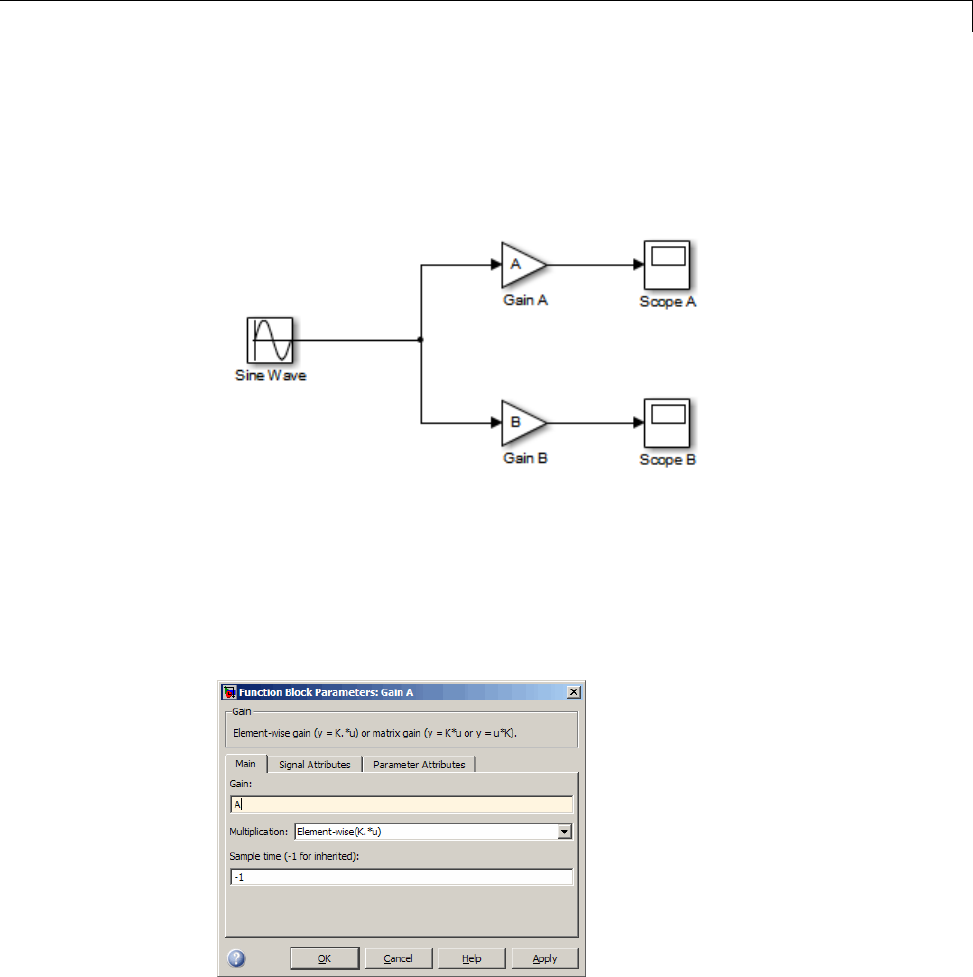
Data Exchange
3Create a model in Simulink with a Sine Wave block for the input signal,
two Gain blocks in parallel, and two Scope blocks. The model is shown
below. Be sure to label the Gain and Scope blocks as shown, so that
subsequent steps will be clear to you.
4Define and assign two variables Aand Bin the MATLAB workspace as
follows:
A=2;B=3;
5Open Gain block A and set its Gain parameter to the variable A.
6Similarly, open Gain block B and set its Gain parameter to the variable B.
15-53
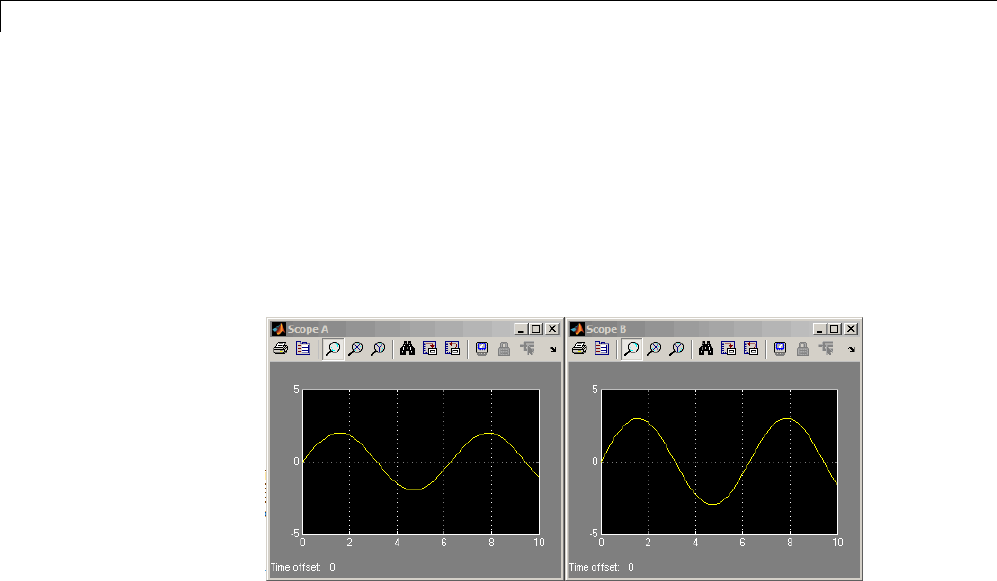
15 Program Building, Interaction, and Debugging
When the target program is built and connected to Simulink in External
mode, you can download new gain values to the executing target program
by assigning new values to workspace variables Aand B,orbyediting
the values in the block parameters dialog. You explore this in “Tune
Parameters” on page 15-62.
7Verify operation of the model. Open the Scope blocks and run the model.
When A=2and B=3, the output looks like this.
8From the File menu, choose Save As.Savethemodelasextmode_example.
Build the Target Executable. In this section, you set up the model and
code generation parameters required for an External mode compatible target
program. Then you generate code and build the target executable:
1Open Model Explorer by selecting Model Explorer from the model’s
View menu.
2In the Model Hierarchy pane, click the + sign preceding the model name
to reveal its components.
3Click Configuration (Active) in the left pane.
4Select Solver in the center pane. The Solver pane appears at the right.
15-54
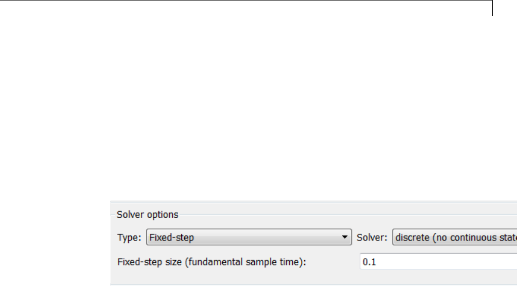
Data Exchange
5In the Solver options subpane:
aSelect Fixed-step in the Type field.
bSelect discrete (no continuous states) in the Solver field.
cSpecify 0.1 in the Fixed-step size field. (Otherwise, the Simulink
Coder build process posts a warning and supplies a value when you
generate code.)
6Click Apply.TheSolver options subpane appears below. Note that after
you click Apply, the controls you changed again have a white background
color.
7Click Data Import/Export in the center pane, and clear the Time and
Output check boxes. In this example, data is not logged to the workspace
or to a MAT-file. Click Apply.
8Click Optimization in the center pane and click the Signals and
Parameters tab in the right pane. Make sure that the Inline parameters
option is not selected. Although External mode supports inlined
parameters, you will not explore them in this example. Click Apply if
youhavemadeanychanges.
9Click Code Generation in the center pane. By default, the generic
real-time (GRT) target is selected on the Code Generation pane. Select
the Interface tab. The Interface pane appears at the right.
10 On theInterface pane, select External mode from the Interface
pull-down menu in the Data exchange section. This enables generation
of External mode support code and reveals two more sections of controls:
Host/Target interface and Memory management.
15-55

15 Program Building, Interaction, and Debugging
11 In the Host/Target interface section, make sure that the value tcpip is
selected for the Transport layer parameter. The Data exchange section
now looks like this:
External mode supports communication via TCP/IP, serial, and custom
transport protocols. The MEX-file name field specifies the name of a
MEX-file that implements host and target communications on the host
side. The default for TCP/IP is ext_comm, a MEX-file provided with the
Simulink Coder software. You can override this default by supplying other
files. See “Create a Transport Layer for External Communication” on
page 23-14 in the Simulink Coder documentation for details if you need
to support other transport layers.
The MEX-file arguments field lets you specify arguments, such as a
TCP/IP server port number, to be passed to the external interface program.
Note that these arguments are specific to the external interface you
are using. For information on setting these arguments, see MEX-File
Optional Arguments for TCP/IP Transport on page 92 and MEX-File
Optional Arguments for Serial Transport on page 94 in the Simulink Coder
documentation.
This example uses the default arguments. Leave the MEX-file arguments
field blank.
12 Click Apply to save the Interface settings.
13 Save the model.
15-56

Data Exchange
14 Click Code Generation inthecenterpaneoftheModel Explorer.On
the right, make sure that Generate code only is cleared, then click the
Build button to generate code and create the target program. The content
of subsequent messages depends on your compiler and operating system.
The final message is
### Successful completion of build procedure for model: extmode_example
In the next section, you will run the extmode_example executable and use
Simulink as an interactive front end to the running target program.
15-57

15 Program Building, Interaction, and Debugging
Run the External Mode Target Program. The target executable,
extmode_example, is now in your working folder. In this section, you run
the target program and establish communication between Simulink and the
target.
Note An external-mode program like extmode_example is a host-based
executable. Its execution is not tied to RTOS or a periodic timer interrupt, and
it does not run in real time. The program just runs as fast as possible, and
the time units it counts off are simulated time units that do not correspond to
time in the world outside the program.
The External Signal & Triggering dialog box (accessed via the External
ModeControlPanel)displaysalistofalltheblocksinyourmodelthat
support External mode signal monitoring and logging. The dialog box also
lets you configure the signals that are viewed and how they are acquired and
displayed. You can use it to reconfigure signals while the target program runs.
In this example, you observe and use the default settings of the External
Signal & Triggering dialog box.
15-58
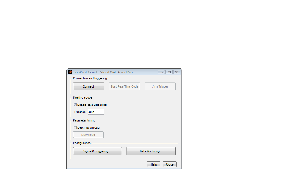
Data Exchange
1From the Code menu of the model diagram, select External Mode
Control Panel, which lets you configure signal monitoring and data
archiving. It also lets you connect to the target program and start and
stop execution of the model code.
The top three buttons are for use after the target program has started. The
two lower buttons open separate dialog boxes:
•The Signal & triggering button opens the External Signal &
Triggering dialog box. This dialog box lets you select the signals that
are collected from the target system and viewed in External mode. It
also lets you select a signal that triggers uploading of data when certain
signal conditions are met, and define the triggering conditions.
•The Data archiving button opens the External Data Archiving
dialog box. Data archiving lets you save data sets generated by the
target program for future analysis. This example does not use data
archiving. See “Data Archiving” on page 15-79 in the Simulink Coder
documentation for more information.
15-59
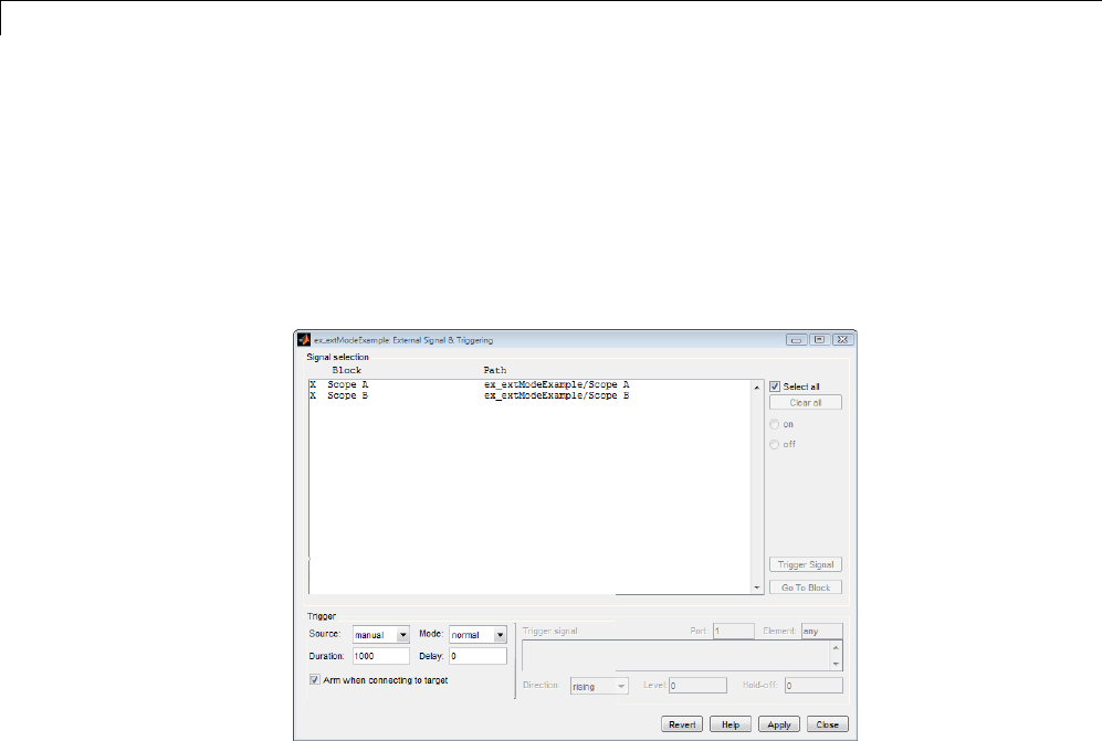
15 Program Building, Interaction, and Debugging
2In the External Mode Control Panel, click the Signal & Triggering
button. The External Signal & Triggering dialog box opens. The
default configuration of the External Signal & Triggering dialog box is
designed to select all signals for monitoring. The default configuration
sets signal monitoring to begin as soon as the host and target programs
have connected. The figure below shows the default configuration for
extmode_example.
15-60

Data Exchange
3Make sure that the External Signal & Triggering dialog box is set to
the defaults as shown:
•Select all check box is selected. All signals in the Signal selection list
are marked with an Xin the Block column.
•Trigger Source:manual
•Trigger Mode:normal
•Duration:1000
•Delay:0
•Armwhenconnectingtotarget:selected
Click Close, and then close the External Mode Control Panel.
For information on the options mentioned above, see “External Signal
Uploading and Triggering” on page 15-75 in the Simulink Coder
documentation.
4To run the target program, you must open a command prompt window (on
UNIX systems, an Xterm window). At the command prompt, change to the
ext_mode_example folder that you created in step 1. The target program
is in this folder.
cd ext_mode_example
Next, type the following command:
extmode_example -tf inf -w
and press Return.
Note On Microsoft Windows platforms, you can also use the “bang”
command (!) in the MATLAB Command Window (note that the trailing
ampersand is required):
!extmode_example -tf inf -w &
15-61

15 Program Building, Interaction, and Debugging
The target program begins execution. Note that the target program is in a
wait state, so no activity occurs in the MATLAB Command Window.
The -tf switch overrides the stop time set for the model in Simulink. The
inf value directs the model to run indefinitely. The model code runs until
the target program receives a stop message from Simulink.
The -w switch instructs the target program to enter a wait state until it
receives a Start Real-Time Code message from the host. This switch is
required if you want to view data from time step 0 of the target program
execution, or if you want to modify parameters before the target program
begins execution of model code.
5Open Scope blocks A and B. At this point, no signals are visible on the
scopes. When you connect Simulink to the target program and begin model
execution, the signals generated by the target program will be visible on
the scope displays.
6The model itself must be in External mode before communication between
the model and the target program can begin. To enable External mode,
select External from the Simulation > Mode menu.
7Reopen the External Mode Control Panel (found in the Code menu) and
click Connect. This initiates a handshake between Simulink and the
target program. When Simulink and the target are connected, the Start
Real-Time Code button becomes enabled, and the label of the Connect
button changes to Disconnect.
8Click the Start Real-Time Code button. The outputs of Gain blocks A and
Baredisplayedonthetwo scopes in your model.
Having established communication between Simulink and the running target
program, you can tune block parameters in Simulink and observe the effects
the parameter changes have on the target program. You do this in the next
section.
Tune Parameters. You can change the gain factor of either Gain block by
assigning a new value to the variable Aor Bin the MATLAB workspace. When
you change block parameter values in the workspace during a simulation, you
must explicitly update the block diagram with these changes. When the block
diagram is updated, the new values are downloaded to the target program.
15-62

Data Exchange
To tune the variables Aand B,
1In the MATLAB Command Window, assign new values to both variables,
for example:
A = 0.5;B = 3.5;
2Activate the extmode_example model window. Select Update Diagram
from the Simulation menu, or press Ctrl+D.AssoonasSimulinkhas
updated the block parameters, the new gain values are downloaded to
the target program, and the effect of the gain change becomes visible on
the scopes.
3You can also enter gain values directly into the Gain blocks. To do this,
open the Block Parameters dialog box for Gain block A or B in the model.
Enter a new numerical value for the gain and click Apply. As soon as
you click Apply, the new value is downloaded to the target program and
the effect of the gain change becomes visible on the scope. Similarly, you
can change the frequency, amplitude, or phase of the sine wave signal
by opening the Block Parameters dialog box for the Sine Wave block and
entering a new numerical value..
Note You cannot change the sample time of the Sine Wave block. Block
sample times are part of the structural definition of the model and are part
of the generated code. Therefore, if you want to change a block sample
time, you must stop the External mode simulation, reset the block’s sample
time, and rebuild the executable.
4To simultaneously disconnect host/target communication and end execution
of the target program, pull down the Simulation menu and select Stop
Real-Time Code. You can also do this from the External Mode Control
Panel.
Use the External Mode User Interface
•“External Mode Interface Options” on page 15-64
•“External Mode Related Menu and Toolbar Items” on page 15-66
15-63
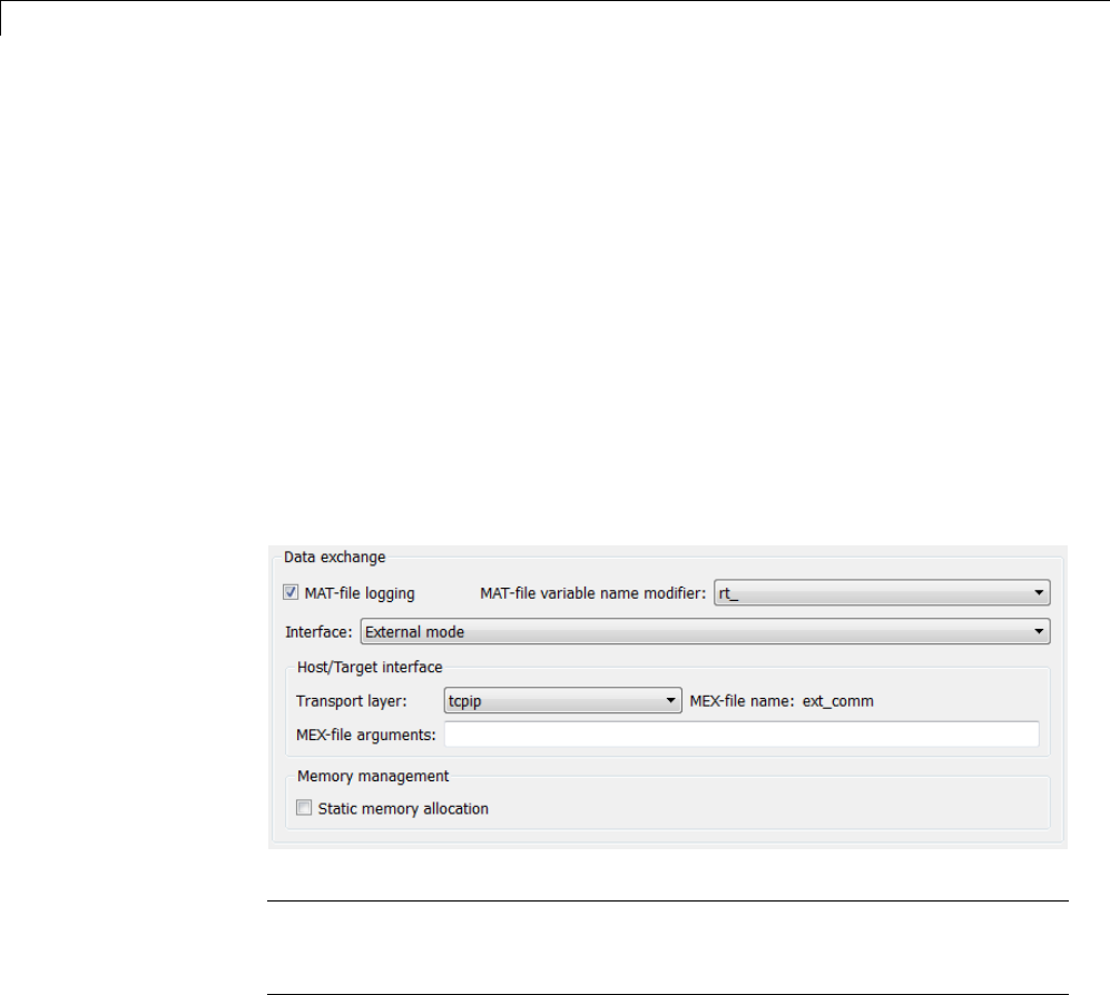
15 Program Building, Interaction, and Debugging
•“External Mode Control Panel” on page 15-70
•“Target Interfacing” on page 15-73
•“External Signal Uploading and Triggering” on page 15-75
•“Data Archiving” on page 15-79
•“Parameter Downloading” on page 15-82
External Mode Interface Options. The ERT, GRT, GRT malloc, RSim, and
Wind River Systems Tornado targets and the Real-Time Windows Target
product support External mode. All targets that support it feature a set of
External mode options on their respective target pane of the Configuration
Parameters dialog box. This pane is normally named Interface). The next
figure is the Data exchange section from the Interface pane of the GRT
target dialog box, and is discussed below.
Note The xPC Target product also uses External mode communications.
External mode in the xPC Target product is always on, and has no interface
options.
The Data exchange section at the bottom of the Interface pane includes
the following elements:
•Interface menu: Selects which of three mutually exclusive data interfaces
to include in the generated code. Options are
15-64

Data Exchange
-None
-CAPI
-External mode
-ASAP2
This chapter discusses only the External mode option. For information
on other options, see “Specifying Target Interfaces” on page 9-58.
Once you select External mode from the Interface menu, the following
options appear beneath:
•Transport layer menu: Identifies messaging protocol for host/target
communications; choices are tcpip and serial.
The default is tcpip. When you select a protocol, the MEX-file name that
implements the protocol is shown to the right of the menu.
•MEX-file arguments text field: Optionally enter a list of arguments to be
passed to the transport layer MEX-file for communicating with executing
targets; these will vary according to the protocol you use.
For more information on the transport options, see “Target Interfacing”
on page 15-73 and “Choose Communication Protocol for Client and
Server” on page 15-89. You can add other transport protocols yourself by
following instructions given in “Create a Transport Layer for External
Communication” on page 23-14.
•Static memory allocation check box: Controls how memory for External
mode communication buffers in the target is allocated. When you select
this option, the following one appears beneath it:
•Static memory buffer size text field: Number of bytes to preallocate for
External mode communications buffers in the target when Static memory
allocation is used.
Note Selecting External mode from the Interface menu does not cause
the Simulink model to operate in External mode (see “External Mode
Related Menu and Toolbar Items” on page 15-66, below). Its function is to
instrument the code generated for the target to support External mode.
15-65

15 Program Building, Interaction, and Debugging
The Static memory allocation check box (for GRT and ERT targets) directs
the Simulink Coder software to generate code for External mode that uses
only static memory allocation (“malloc-free” code). When selected, it activates
the Static memory buffer size edit field, in which you specify the size of the
static memory buffer used by External mode. The default value is 1,000,000
bytes. Should you enter too small a value for your application, External mode
issues an out-of-memory error when it tries to allocate more memory than you
allowed. In such cases, increase the value in the Static memory buffer
size field and regenerate the code.
Notes
•To determine how much memory you need to allocate, enable verbose mode
on the target (by including OPTS="-DVERBOSE" on the make command line).
As it executes, External mode displays the amount of memory it tries to
allocate and the amount of memory available to it each time it attempts an
allocation. Should an allocation fail, this console log can be used to adjust
thesizeenteredintheStatic memory buffer size field.
•When you create an ERT target, External mode can generate pure integer
code. Select this feature by clearing the Support floating-point numbers
option on the Interface pane of the Configuration Parameters dialog box
or Model Explorer. Clearing this option makes the code, including External
mode support code, free of doubles and floats. For more details, see “Code
Generation Pane: Interface”.
External Mode Related Menu and Toolbar Items. To communicate with
a target program, the model must be operating in External mode. To enable
External mode, select External from the Simulation > Mode menu.
15-66
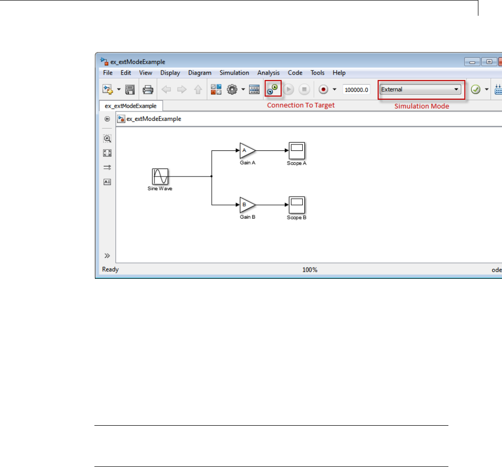
Data Exchange
Simulation Mode Menu Options and Target Connection Control (Host
Disconnected from Target)
Once External mode is enabled, you can connect to and control the target
programbydoinganyofthefollowing:
•Select Connect To Target from the Simulation menu.
•Click the Connect To Target toolbar button.
•Use theCtrl+T keyboard shortcut.
Note When External mode is selected in the model window, the Ctrl+T
keyboard shortcut is remapped from a toggle for Start and Stop (simulation)
to a toggle for Connect To Target and Disconnect From Target.
Selecting External mode in the model window controls execution only, and
doesnot cause the Simulink Coder software to generate code for External
mode. To do this, you must select External mode from the Interface menu
15-67
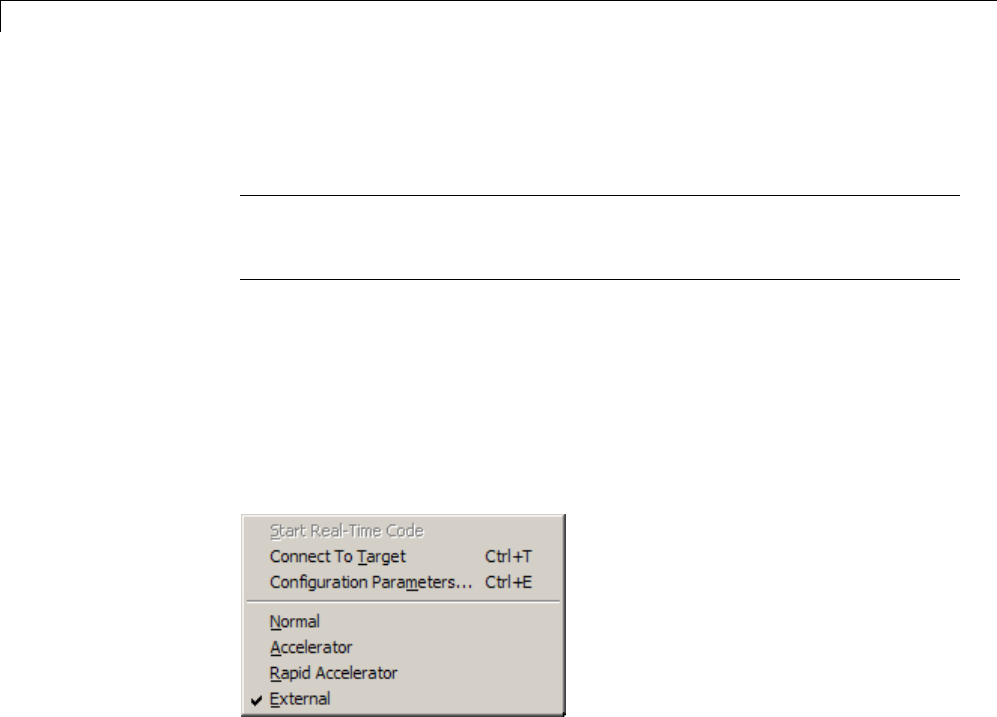
15 Program Building, Interaction, and Debugging
on the Interface tab of the Configuration Parameters dialog box, as described
in “External Mode Interface Options” on page 15-64.
Note You can enable External mode, and simultaneously connect to the
target system, by using the External Mode Control Panel dialog box. See
“External Mode Control Panel” on page 15-70.
Simulation Menu
When a Simulink model is in External mode, the upper section of the
Simulation menu contains External mode options. Initially, the Simulink
model is disconnected from the target program, and the menu displays the
options shown in the next figure.
Simulation Menu External Mode Options (Host Disconnected from Target)
The Connect To Target option establishes communication with the target
program. When a connection is established, the target program might be
executing model code, or it might be awaiting a command from the host to
start executing model code. You can also accomplish this by clicking the
Connect To Target toolbar button, as shown in Simulation Mode Menu
Options and Target Connection Control (Host Disconnected from Target) on
page 15-67.
If the target program is executing model code, the Simulation menu contents
change, as shown in the next figure.
15-68
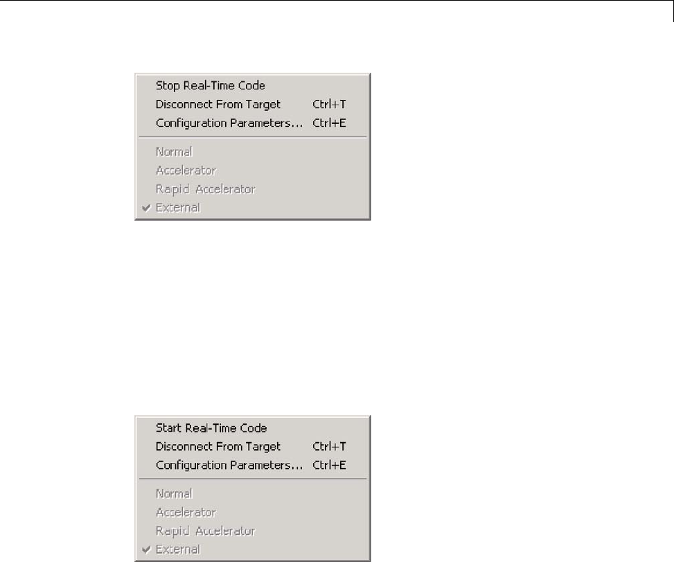
Data Exchange
Simulation Menu External Mode Options (Target Executing Model Code)
The Disconnect From Target option disconnects the Simulink model
from the target program, which continues to run. The Stop Real-Time
Code option terminates execution of the target program and disconnects the
Simulink model from the target system.
If the target program is in a wait state, the Start Real-Time Code option
is enabled, as shown in the next figure. The Start Real-Time Code option
instructs the target program to begin executing the model code.
Simulation Menu External Mode Options (Target Awaiting Start Command)
Toolbar Controls
The Simulink toolbar controls, shown in Simulation Mode Menu Options and
Target Connection Control (Host Disconnected from Target) on page 15-67,
let you control the same External mode functions as the Simulation menu.
The Simulink model editor displays External mode buttons to the left of the
Simulation mode menu. Initially, the toolbar displays a Connect To Target
15-69

15 Program Building, Interaction, and Debugging
button and a disabled Start Real-Time Code button. Click the Connect To
Target button to connect the Simulink enginetothetargetprogram.
When a connection is established, the target program might be executing
model code, or it might be awaiting a command from the host to start
executing model code.
If the target program is executing model code, the toolbar displays a Stop
Real-Time Code button and a Disconnect From Target button (shown in
). Click the Stop Real-Time Code button to command the target program
to stop executing model code and disconnect the Simulink engine from the
target system. Click the Disconnect From Target button to disconnect the
Simulink engine from the target program while leaving the target program
running.
If the target program is in a wait state, the toolbar displays a Start
Real-Time Code button and a Disconnect From Target button. Click
the Start Real-Time Code button to instruct the target program to start
executing model code. Click the Disconnect From Target button to
disconnect the Simulink engine from the target program.
External Mode Control Panel. The External Mode Control Panel,
illustrated in the next figure, provides centralized control of all External
mode features, including
•Host/target connection, disconnection, and target program start/stop
functions, and enabling of External mode
•Arming and disarming the data upload trigger
•External mode communications configuration
•Uploading data to Floating Scopes
•Timing of parameter downloads
•Selection of signals from the target program to be viewed and monitored
on the host
•Configuration of data archiving features
Select External Mode Control Panel from the Code menu on the Simulink
model editor to open the External Mode Control Panel dialog box.
15-70

Data Exchange
Open dialog boxes that configure
external mode target interface,
signal properties, and data archiving
Control timing of
parameter downloads
Control the connection between
host and manual arming of data
uploading trigger
Control use of floating
scopes in external mode
The following sections describe the features supported by the External Mode
Control Panel.
Connecting, Starting, and Stopping
The External Mode Control Panel performs the same connect/disconnect and
start/stop functions found in the Simulation menu and the Simulink toolbar
(see “External Mode Related Menu and Toolbar Items” on page 15-66).
15-71

15 Program Building, Interaction, and Debugging
The Connect/Disconnect button connects to or disconnects from the target
program. The button text changes in accordance with the state of the
connection.
If External mode is not enabled at the time the Connect button is clicked, the
External Mode Control Panel enables External mode automatically.
The Start/Stop Real-Time Code button commands the target to start or
terminate model code execution. The button is disabled until a connection to
the target is established. The button text changes in accordance with the
state of the target program.
Floating Scope Options
The Floating scope pane of the External Mode Control Panel controls when
and for how long data is uploaded to Floating Scope blocks. When used under
External mode, Floating Scopes
•Do not appear in the signal and triggering GUI
•Support manual triggering only
The behavior of wired scopes is not restricted in these ways.
The Floating scope pane contains a check box and an edit field:
•Enable data uploading check box, which functions as an Arm trigger
button for floating scopes. When the target is disconnected it controls
whether or not to arm when connecting the floating scopes. When already
connected it acts as a toggle button to arm/cancel the trigger.
•Duration edit field, which specifies the duration for floating scopes. By
default, it is set to auto, which causes whatever value is specified in the
signal and triggering GUI (which by default is 1000 base rate steps) to
be used.
15-72
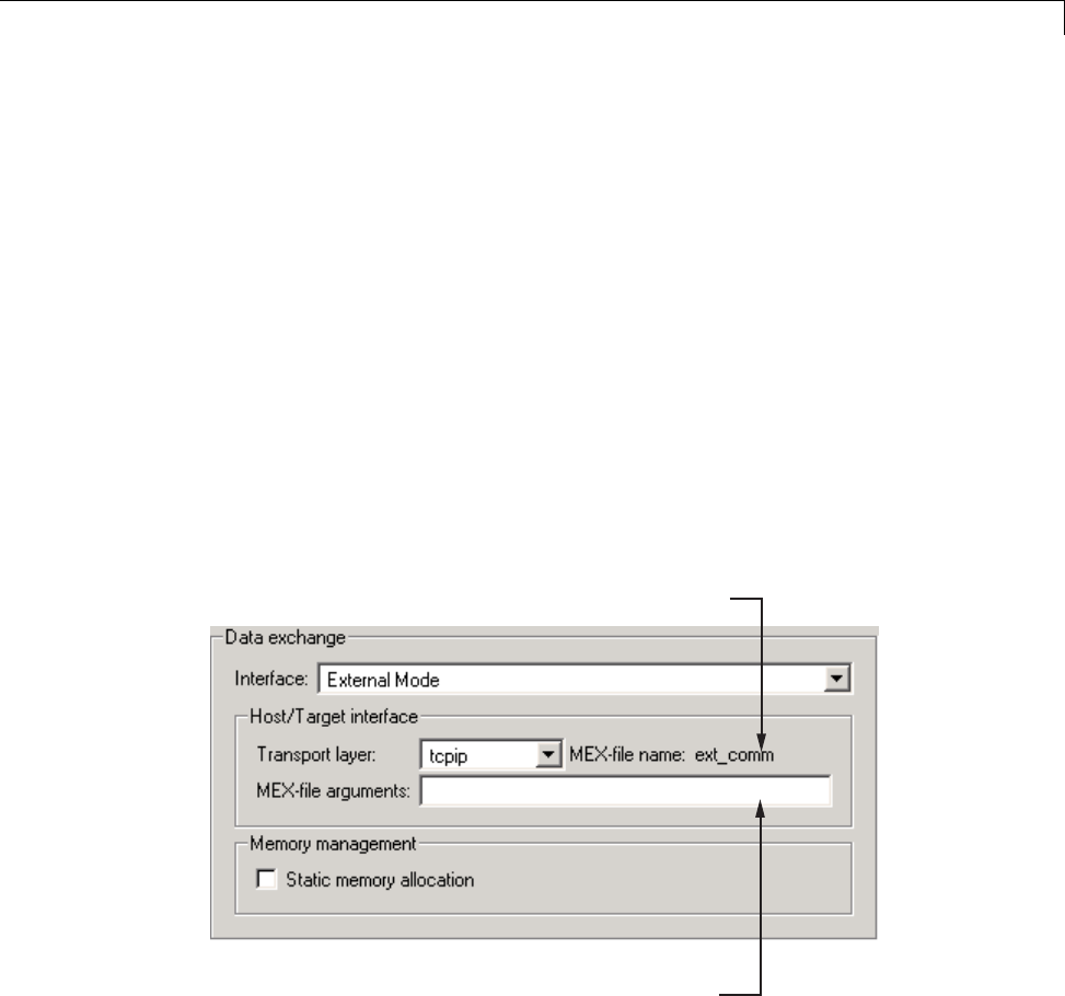
Data Exchange
Target Interfacing. The Simulink Coder product lets you implement
client and server transport for External mode using either TCP/IP or serial
protocols. You can use the socket-based External mode implementation
provided by the Simulink Coder product with the generated code, provided
that your target system supports TCP/IP. Otherwise, use or customize the
serial transport layer option provided.
A low-level transport layer handles physical transmission of messages. Both
theSimulinkengineandthemodelcodeareindependentofthislayer. Both
the transport layer and code directly interfacing to the transport layer are
isolated in separate modules that format, transmit, and receive messages
and data packets.
You specify the transport mechanism using the Transport layer menu in the
Host/Target interface subpane of the Interface pane of the Configuration
Parameters dialog box, shown below.
External interface MEX-file being used (specified
in extmode_transports.m or sl_customization.m)
Type optional arguments to the external interface
MEX-file here. This file must be in the current
directory or one that is on your MATLAB path.
The Host/Target interface subpanealsodisplaysMEX-file name,the
name of a MEX-file that implements host/target communications for the
selected External mode transport layer. This is known as the external
interface MEX-file. The default is ext_comm, the TCP/IP-based external
15-73

15 Program Building, Interaction, and Debugging
interfacefileprovidedforusewiththeGRT,GRTmalloc,ERT,RSim,and
Tornado targets. If you select the serial transport option, the MEX-file name
ext_serial_win32_com is displayed in this location.
Note Custom or third-party targets can use a custom transport layer and
a different external interface MEX-file. For more information on creating
a custom transport layer, see “Create a Transport Layer for External
Communication” on page 23-14. For more information on specifying a
TCP/IP or serial transport layer for a custom target, see “Using the TCP/IP
Implementation” on page 15-90 or “Using the Serial Implementation” on
page 15-93.
The MEX-file arguments edit field lets you optionally specify arguments
that are passed to the External mode interface MEX-file for communicating
with executing targets. The meaning of the MEX-file arguments depends on
theMEX-fileimplementation.
For TCP/IP interfaces, ext_comm allows three optional arguments:
•Network name of your target (for example, 'myPuter' or '148.27.151.12')
•Verbosity level (0for no information or 1for detailed information)
•TCP/IP server port number (an integer value between 256 and 65535,with
a default of 17725)
For serial transport, ext_serial_win32_comm allows three optional
arguments:
•Verbosity level (0for no information or 1for detailed information)
•Serial port ID (for example, 1for COM1,andsoon)
•Baud rate (selected from the set 1200,2400,4800,9600,14400,19200,
38400,57600,115200, with a default baud rate of 57600)
See “Choose Communication Protocol for Client and Server” on page 15-89 for
details on MEX-file transport architecture and arguments.
15-74
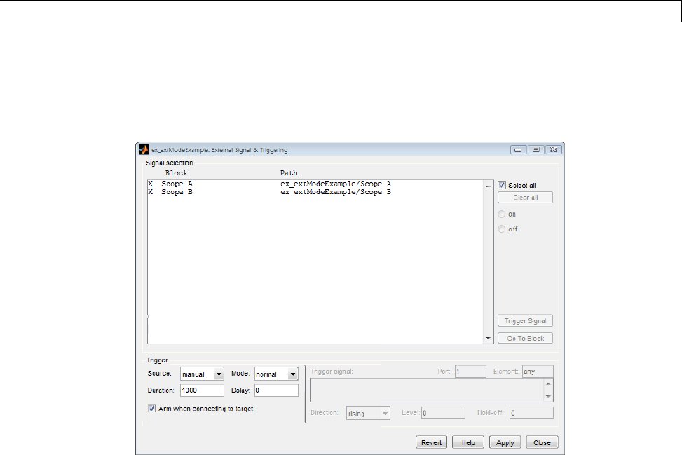
Data Exchange
External Signal Uploading and Triggering. Clicking the Signal &
Triggering button of the External Mode Control Panel activates the External
Signal & Triggering dialog box, as shown in the next figure.
The External Signal & Triggering dialog box displays a list of all blocks and
subsystems in your model that support External mode signal uploading.
See “External Mode Compatible Blocks and Subsystems” on page 15-83 for
information on which types of blocks are External mode compatible.
The External Signal & Triggering dialog box lets you select the signals that
are collected from the target system and viewed in External mode. It also
lets you select a signal that triggers uploading of data when certain signal
conditions are met, and define the triggering conditions.
Default Operation
The preceding figure shows the default settings of the External Signal
& Triggering dialog box. The default operation of the External Signal &
Triggering dialog box is designed to simplify monitoring the target program.
15-75

15 Program Building, Interaction, and Debugging
If you use the default settings, you do not need to preconfigure signals and
triggers. Simply start the target program and connect the Simulink engine
to it. All External mode compatible blocks will be selected and the trigger
will be armed. Signal uploading begins immediately upon connection to the
target program.
The default configuration is
•Arm when connecting to target:on
•Trigger Mode:normal
•Trigger Source: manual
•Select all:on
Signal Selection
All External mode compatible blocks in your model appear in the Signal
selection list of the External Signal & Triggering dialog box. You use this
list to select signals to be viewed. An Xappears to the left of each selected
block’s name.
The Select all check box selects all signals. By default, Select all is on.
If Select all is off, you can select or deselect individual signals using the on
and off radio buttons. To select a signal, click the desired list entry and click
the on radio button. To deselect a signal, click the desired list entry and click
the off radio button. Alternatively, you can double-click a signal in the list to
toggle between selection and deselection.
The Clear all button deselects all signals.
Trigger Options
The Trigger panel located at the bottom left of the External Signal &
Triggering dialog contains options that control when and how signal data is
collected (uploaded) from the target system. These options are
15-76

Data Exchange
•Source:manual or signal. Selecting manual directs External mode to
start logging data when the Arm trigger button on the External Mode
Control Panel is clicked.
Selecting signal tells External mode to start logging data when a selected
trigger signal satisfies trigger conditions specified in the Trigger signal
panel. When the trigger conditions are satisfied (that is, the signal crosses
the trigger level in the specified direction) a trigger event occurs. If the
trigger is armed, External mode monitors for the occurrence of a trigger
event. When a trigger event occurs, data logging begins.
•Arm when connecting to target: Ifthisoptionisselected,External
mode arms the trigger automatically when the Simulink engine connects to
the target. If the trigger source is manual, uploading begins immediately.
If the trigger mode is signal, monitoring of the trigger signal begins
immediately, and uploading begins upon the occurrence of a trigger event.
If Arm when connecting to target isnotselected,youmustmanually
arm the trigger by clicking the Arm trigger button in the External Mode
Control Panel.
•Duration: The number of base rate steps for which External mode logs
data after a trigger event (default is 1000). For example, if the fastest
rate in the model is 1 second:
-If a signal sampled at 1 Hz is logged for 10 base rate steps, External
mode will collect 10 samples.
-If a signal sampled at 2 Hz is logged for 10 base rate steps, External
mode will collect 20 samples.
•Mode:normal or one-shot.Innormal mode, External mode automatically
rearms the trigger after each trigger event. In one-shot mode, External
mode collects only one buffer of data each time you arm the trigger. See
“Data Archiving” on page 15-79 for more details on the effect of the Mode
setting.
•Delay: The delay represents the amount of time that elapses between a
trigger occurrence and the start of data collection. The delay is expressed
inbaseratesteps,andcanbepositiveornegative(defaultis0).Anegative
delay corresponds to pretriggering. When the delay is negative, data from
thetimeprecedingthetriggeris collected and uploaded.
15-77
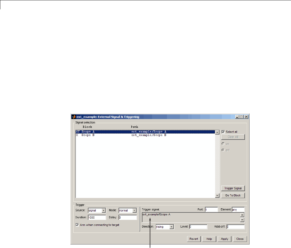
15 Program Building, Interaction, and Debugging
Trigger Signal Selection
You can designate one signal as a trigger signal. To select a trigger signal,
select signal from the Trigger Source menu. This activates the Trigger
signal panel (see the next figure). Then, click the desired entry in the Signal
selection list and click the Trigger signal button.
When a signal is selected as a trigger, a Tappearstotheleftoftheblock’s
name in the Signal selection list. In the next figure, the Scope A signal is
the trigger. Scope B is also selected for viewing, as indicated by the Xto the
left of the block name.
Trigger signal panel
External Signal & Triggering Window with Trigger Selected
After selecting the trigger signal, you can define the trigger conditions and set
the Port and Element fields in the Trigger signal panel.
15-78

Data Exchange
Setting Trigger Conditions
Note The Trigger signal panel and the Port and Element fields of the
External Signal & Triggering dialog box are enabled only when trigger
Source is set to signal.
By default, any element of the first input port of the specified trigger block
can cause the trigger to fire (that is, Port 1, any element). You can modify this
behavior by adjusting the Port and Element fields located on the right side
of the Trigger signal panel. The Port field accepts a number or the keyword
last.TheElement field accepts a number or the keywords any and last.
The Trigger Signal panel defines the conditions under which a trigger
event will occur.
•Level: Specifies a threshold value. The trigger signal must cross this value
in a designated direction to fire the trigger. By default, the level is 0.
•Direction:rising,falling,oreither. This specifies the direction in
which the signal must be traveling when it crosses the threshold value.
The default is rising.
•Hold-off: Applies only to normal mode. Expressedinbaseratesteps,
Hold-off isthetimebetweenthetermination of one trigger event and
the rearming of the trigger.
Data Archiving. In External mode, you can use the Simulink Scope and
To Workspace blocks to archive data to disk. Clicking the Data Archiving
button of the External Mode Control Panel opens the External Data Archiving
dialog box, which supports the following features.
Folder Notes
Use this option to add annotations that pertain to a collection of related data
files in a folder. Clicking the Edit directory note button opens the MATLAB
editor. Place comments that you want saved to a file in the specified folder in
this window. By default, the comments are saved to the folder last written
to by data archiving.
15-79

15 Program Building, Interaction, and Debugging
File Notes
Clicking Edit file note opens a file finder window that is, by default, set to
thelastfiletowhichyouhavewritten. SelectinganyMAT-fileopensanedit
window. Add or edit comments in this window that you want saved with your
individual MAT-file.
Automated Data Archiving
Clicking the Enable Archiving check box activates the automated data
archiving features of External mode. To understand how the archiving
features work, consider the handling of data when archiving is not enabled.
There are two cases, one-shot and normal mode.
In one-shot mode, after a trigger event occurs, each selected block writes its
data to the workspace just as it would at the end of a simulation. If another
one-shot is triggered, the existing workspace data is overwritten.
In normal mode, External mode automatically rearms the trigger after each
trigger event. Consequently, you can think of normal mode as a series of
one-shots. Each one-shot in this series, except for the last, is referred to
as an intermediate result. Since the trigger can fire at any time, writing
intermediate results to the workspace generally results in unpredictable
overwriting of the workspace variables. For this reason, the default behavior
is to write only the results from the final one-shot to the workspace. The
intermediate results are discarded. If you know that enough time exists
between triggers for inspection of the intermediate results, then you can
override the default behavior by checking the Writeintermediateresults
to workspace check box. This option does not protect the workspace data
from being overwritten by subsequent triggers.
The options in the External Data Archiving dialog box support automatic
writing of logging results, including intermediate results, to disk. Data
archiving provides the following settings:
•Directory: Specifies the folder in which data is saved. External mode
appends a suffix if you select Increment directory when trigger armed.
15-80
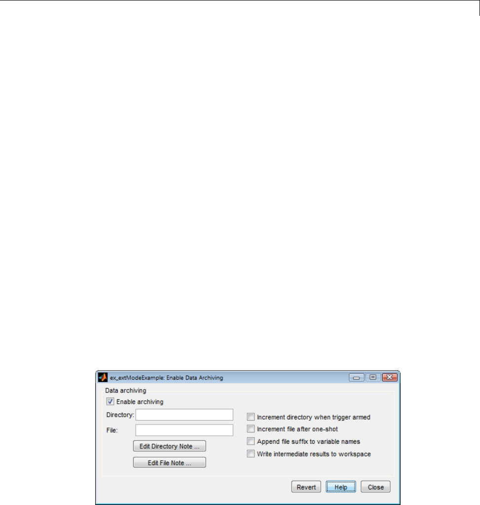
Data Exchange
•File: Specifies the filename in which data is saved. External mode appends
asuffixifyouselectIncrement file after one-shot.
•Increment directory when trigger armed: External mode uses a
different folder for writing log files each time that you click the Arm
trigger button. The folders are named incrementally, for example,
dirname1,dirname2,andsoon.
•Increment file after one-shot: New data buffers are saved in incremental
files: filename1,filename2, and so on. This happens automatically in
normal mode.
•Append file suffix to variable names: Whenever External mode
increments filenames, each file contains variables with identical names.
Selecting Append file suffix to variable name results in each file
containing unique variable names. For example, External mode will save
a variable named xdata in incremental files (file_1,file_2,andsoon)
as xdata_1,xdata_2, and so on. This is useful if you want to load the
MAT-files into the workspace and compare variables at the MATLAB
command prompt. Without the unique names, each instance of xdata
would overwrite the previous one in the MATLAB workspace.
•Writeintermediateresultstoworkspace: Select this option if you
want the Simulink Coder software to write all intermediate results to the
workspace.
The next figure shows the External Data Archiving dialog box with archiving
enabled.
15-81

15 Program Building, Interaction, and Debugging
Unless you select Enable archiving,entriesfortheDirectory and File
fields are not accepted.
Parameter Downloading. The Batch download check box on the
External Mode Control Panel enables or disables batch parameter changes.
By default, batch download is not enabled. If batch download is not enabled,
changes made directly to block parameters by using parameter dialog boxes
aresenttothetargetwhenyouclicktheOK or Apply button. Changes
to MATLAB workspace variables are sent when an Update diagram is
performed.
If batch download is enabled, the Download button is enabled. Changes
made to block parameters are stored locally until you click the Download
button. When you click the Download button, the changes are sent in a
single transmission.
When parameter changes have been made and are awaiting batch download,
the External Mode Control Panel displays the message Parameter changes
pending... to the right of the download button. (See the next figure.) This
message disappears after the Simulink engine receives notification from the
target that the new parameters have been installed in the parameter vector
of the target system.
The External Mode Control Panel with the batch download option activated
appears in the next figure.
15-82
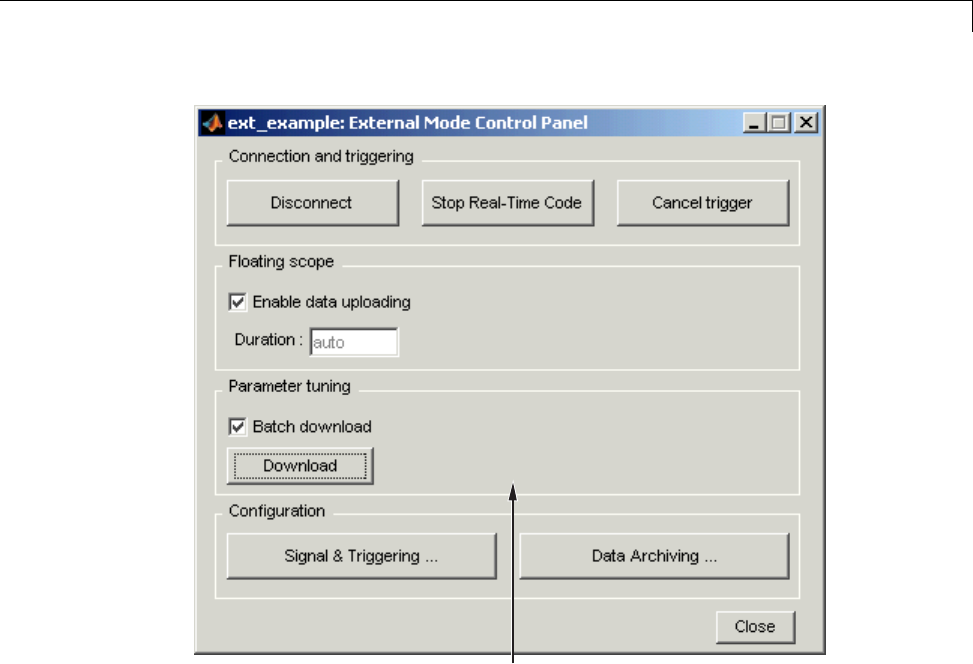
Data Exchange
Parameter changes pending...
message appears if unsent
parameter value changes
are awaiting download
Parameter changes pending...
External Mode Control Panel in Batch Download Mode
External Mode Compatible Blocks and Subsystems
•“Compatible Blocks” on page 15-83
•“Signal Viewing Subsystems” on page 15-84
•“Supported Blocks for Data Archiving” on page 15-86
Compatible Blocks. In External mode, you can use the following types of
blocks to receive and view signals uploaded from the target program:
15-83

15 Program Building, Interaction, and Debugging
•Floating Scope and Scope blocks
•Spectrum Scope and Vector Scope blocks from the DSP System Toolbox
product
•Blocks from the Gauges Blockset product
•Display blocks
•To Workspace blocks
•User-written S-Function blocks
An External mode method is built into the S-function API. This
method allows user-written blocks to support External mode. See
matlabroot/simulink/simstruc.h.
•XY Graph blocks
In addition to these types of blocks, you can designate certain subsystems
as Signal Viewing Subsystems and use them to receive and view signals
uploaded from the target program. See “Signal Viewing Subsystems” on page
15-84 for more information.
You select External mode compatible blocks and subsystems, and arm the
trigger, by using the External Signal & Triggering dialog box. By default, all
such blocks in a model are selected, and a manual trigger is set to be armed
when connected to the target program.
Signal Viewing Subsystems. A Signal Viewing Subsystem is an atomic
subsystem that encapsulates processing and viewing of signals received
from the target system. A Signal Viewing Subsystem runs only on the host,
generating no code in the target system. Signal Viewing Subsystems run in
all simulation modes — normal, accelerated, and external.
Signal Viewing Subsystems are useful in situations where you want to
process or condition signals before viewing or logging them, but you do not
want to perform these tasks on the target system. By using a Signal Viewing
Subsystem, you can generate smaller and more efficient code on the target
system.
Like other External mode compatible blocks, Signal Viewing Subsystems are
displayed in the External Signal & Triggering dialog box.
15-84
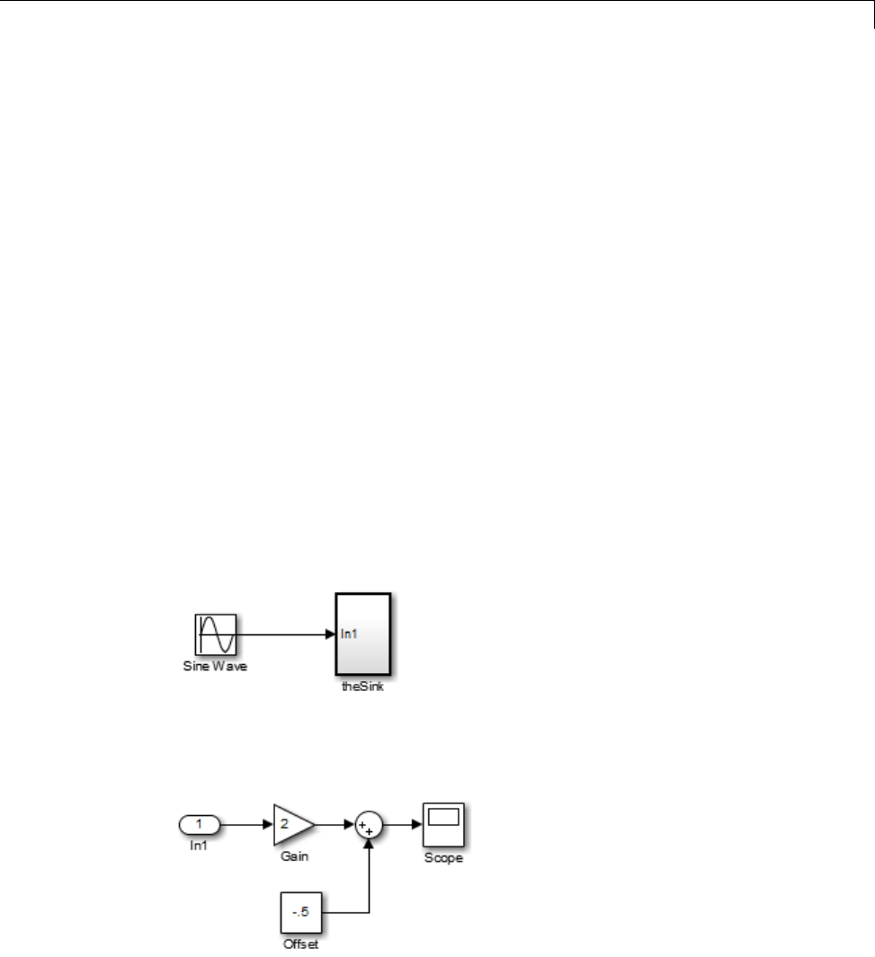
Data Exchange
TodeclareasubsystemtobeaSignalViewingSubsystem,
1Select the Treat as atomic unit option in the Block Parameters dialog box.
For more information on atomic subsystems, see “Code Generation of
Subsystems” on page 2-2.
2Use the following set_param command to turn the SimViewingDevice
property on,
set_param('blockname', 'SimViewingDevice','on')
where 'blockname' isthenameofthesubsystem.
3Make sure the subsystem meets the following requirements:
•It must be a pure sink block. That is, it must contain no Outport blocks
or Data Store blocks. It can contain Goto blocks only if the corresponding
From blocks are contained within the subsystem boundaries.
•It must have no continuous states.
The following model, sink_examp, contains an atomic subsystem, theSink.
The subsystem theSink, shown in the next figure, applies a gain and an offset
to its input signal and displays it on a Scope block.
15-85

15 Program Building, Interaction, and Debugging
If theSink is declared as aSignal Viewing Subsystem, the generated target
program includes only the code for the Sine Wave block. If theSink is selected
and armed in the External Signal & Triggering dialog box, the target program
uploads the sine wave signal to theSink during simulation. You can then
modify the parameters of the blocks within theSink and observe their effect
upon the uploaded signal.
If theSink were not declared as a Signal Viewing Subsystem, its Gain,
Constant, and Sum blocks would run as subsystem code on the target system.
The Sine Wave signal would be uploaded to the Simulink engine after being
processed by these blocks, and viewed on sink_examp/theSink/Scope2.
Processing demands on the target system would be increased by the additional
signal processing, and by the downloading of changes in block parameters
from the host.
Supported Blocks for Data Archiving. In External mode, you can use the
following types of blocks to archive data to disk:
•Scope blocks
•To Workspace blocks
You configure data archiving by using the External Data Archiving dialog
box, as described in “Data Archiving” on page 15-79.
External Mode Communication
•“About External Mode Communication” on page 15-86
•“Download Mechanism” on page 15-87
•“Inlined and Tunable Parameters” on page 15-88
About External Mode Communication. This section describes how the
Simulink engine and a target program communicate, and how and when they
transmit parameter updates and signal data to each other.
Depending on the setting of the Inline parameters option when the target
program is generated, there are differences in the way parameter updates
are handled. “Download Mechanism” on page 15-87 describes the operation
of External mode communications with Inline parameters off. “Inlined
15-86

Data Exchange
and Tunable Parameters” on page 15-88 describes the operation of External
mode with Inline parameters on.
Download Mechanism. In External mode, the Simulink engine does not
simulate the system represented by the block diagram. By default, when
External mode is enabled, the Simulink engine downloads all parameters to
the target system. After the initial download, the engine remains in a waiting
mode until you change parameters in the block diagram or until the engine
receives data from the target.
When you change a parameter in the block diagram, the Simulink engine
calls the external interface MEX-file, passing new parameter values (along
with other information) as arguments. The external interface MEX-file
contains code that implements one side of the interprocess communication
(IPC) channel. This channel connects the Simulink process (where the
MEX-file executes) to the process that is executing the external program.
The MEX-file transfers the new parameter values by using this channel to
the external program.
The other side of the communication channel is implemented within the
external program. This side writes the new parameter values into the target’s
parameter structure (model_P).
The Simulink side initiates the parameter download operation by sending a
message containing parameter information to the external program. In the
terminology of client/server computing, the Simulink side is the client and
the external program is the server. The two processes can be remote, or they
can be local. Where the client and server are remote, a protocol such as
TCP/IP is used to transfer data. Where the client and server are local, a serial
connection or shared memory can be used to transfer data.
The next figure shows this relationship. The Simulink engine calls the
external interface MEX-file whenever you change parameters in the block
diagram. The MEX-file then downloads the parameters to the external
program by using the communication channel.
15-87
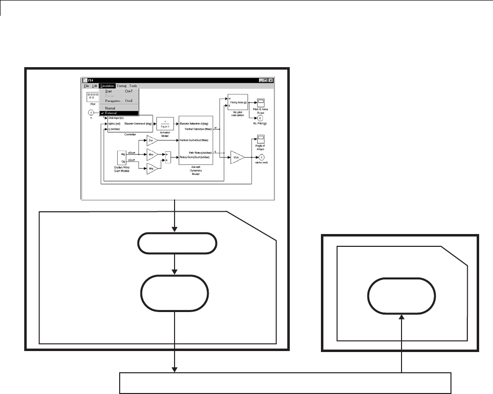
15 Program Building, Interaction, and Debugging
Simulink Process
mexFunction
Client
IPC Code
External Interface
MEX-file (e.g., ext_comm)
External Program Process
External Program
Server
IPC Code
ext_svr.
Interprocess Communication Channel Transport Layer
External Mode Architecture
Inlined and Tunable Parameters. By default, all parameters (except those
listed in “External Mode Limitations” on page 15-103) in an External mode
program are tunable; that is, you can change them by using the download
mechanism described in this section.
If you select the Inline parameters option (on the Optimization > Signals
and Parameters pane of the Configuration Parameters dialog box), the
Simulink Coder code generator embeds the numerical values of model
parameters (constants), instead of symbolic parameter names, in the
15-88

Data Exchange
generated code. Inlining parameters generates smaller and more efficient
code. However, inlined parameters, because they effectively become
constants, are not tunable.
The Simulink Coder software lets you improve overall efficiency by inlining
mostparameters,whileatthesametimeretainingtheflexibilityofrun-time
tuning for selected parameters that are important to your application. When
you inline parameters, you can use the Model Parameter Configuration dialog
box to remove individual parameters from inlining and declare them to be
tunable. In addition, the Model Parameter Configuration dialog box offers you
options for controlling how parameters are represented in the generated code.
For more information on tunable parameters, see “Parameters” on page 7-10.
Automatic Parameter Uploading on Host/Target Connection
Each time the Simulink engine connects to a target program that was
generated with Inline parameters on, the target program uploads the
current value of its tunable parameters (if any) to the host. These values are
assigned to the corresponding MATLAB workspace variables. This procedure
synchronizes the host and target with respect to parameter values.
All workspace variables required by the model must be initialized at the time
of host/target connection. Otherwise the uploading cannot proceed and an
error results. Once the connection is made, these variables are updated to
reflect the current parameter values on the target system.
Automatic parameter uploading takes place only if the target program was
generated with Inline parameters on. “Download Mechanism” on page
15-87 describes the operation of External mode communications with Inline
parameters off.
Choose Communication Protocol for Client and Server
•“Introduction” on page 15-90
•“Using the TCP/IP Implementation” on page 15-90
•“Using the Serial Implementation” on page 15-93
15-89

15 Program Building, Interaction, and Debugging
•“Run the External Program” on page 15-95
•“Implement an External Mode Protocol Layer” on page 15-98
Introduction. TheSimulinkCoderproductprovidescodetoimplement
both the client and server side of External mode communication using
either TCP/IP or serial protocols. You can use the socket-based External
mode implementation provided by the Simulink Coder product with the
generated code, provided that your target system supports TCP/IP. If not, use
or customize the serial transport layer option provided.
A low-level transport layer handles physical transmission of messages. Both
theSimulinkengineandthemodelcodeareindependentofthislayer. Both
the transport layer and code directly interfacing to the transport layer are
isolated in separate modules that format, transmit, and receive messages
and data packets.
See “Target Interfacing” on page 15-73 for information on selecting a
transport layer.
Using the TCP/IP Implementation. You can use TCP/IP-based client/server
implementation of External mode with real-time programs on The Open
Group UNIX or PC systems. For help in customizing External mode transport
layers, see “Create a Transport Layer for External Communication” on page
23-14.
To use Simulink External mode over TCP/IP, you must
•Make sure that the external interface MEX-file for your target’s TCP/IP
transport is specified.
Targets provided by MathWorks specify the
name of the external interface MEX-file in
matlabroot/toolbox/simulink/simulink/extmode_transports.m.The
name of the interface appears as uneditable text in the Host/Target
interface section of the Interface pane of the Configuration Parameters
dialog box. The TCP/IP default is ext_comm.
To specify a TCP/IP transport for a custom target, you must add an entry of
the following form to an sl_customization.m file on the MATLAB path:
function sl_customization(cm)
15-90

Data Exchange
cm.ExtModeTransports.add('stf.tlc', 'transport', 'mexfile', 'Level1');
%end function
where
-stf.tlc is the name of the system target file for which the transport will
be registered (for example, 'mytarget.tlc')
-transport is the transport name to display in the Transport layer
menu on the Interface pane of the Configuration Parameters dialog
box (for example, 'tcpip')
-mexfile is the name of the transport’s associated external interface
MEX-file (for example, 'ext_comm')
You can specify multiple targets and/or transports with additional
cm.ExtModeTransports.add lines, for example:
function sl_customization(cm)
cm.ExtModeTransports.add('mytarget.tlc', 'tcpip', 'ext_comm', 'Level1');
cm.ExtModeTransports.add('mytarget.tlc', 'serial', ...
'ext_serial_win32_comm', 'Level1');
%end function
•Be sure that the template makefile is configured to link the source files for
the TCP/IP server code and that it defines the compiler flags when building
the generated code.
•Build the external program.
•Run the external program.
•Set the Simulink model to External mode and connect to the target.
Thenextfigureshowsthestructureofthe TCP/IP-based implementation.
15-91
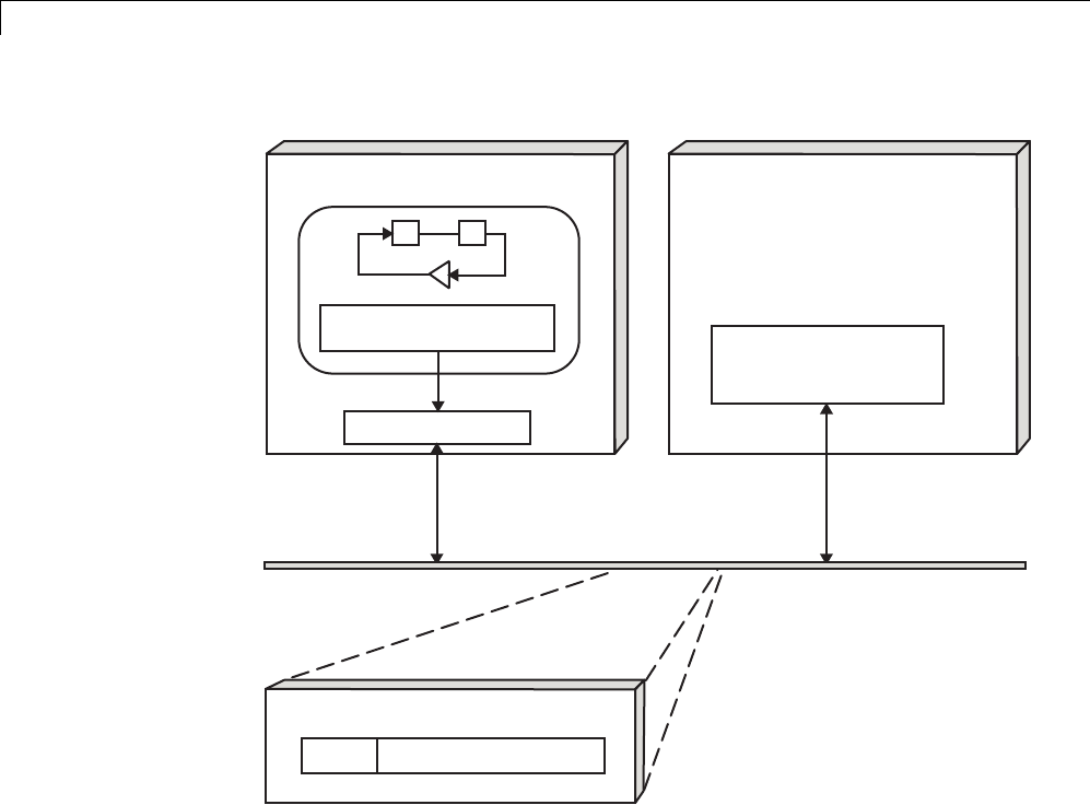
15 Program Building, Interaction, and Debugging
Process block
parameter changes
ext_comm
Simulink in External Mode
UNIX or PC Host
Update block parameters
Target Code
Target
ext_svr.c
TCP/IP on Ethernet
External Mode Message Format
header data in target format
TCP/IP-Based Client/Server Implementation for External Mode
MEX-File Optional Arguments for TCP/IP Transport
In the External Target Interface dialog box, you can specify optional
arguments that are passed to the External mode interface MEX-file for
communicating with executing targets.
•Target network name: the network name of the computer running the
external program. By default, this is the computer on which the Simulink
product is running. The name can be
-String delimited by single quotes, such as 'myPuter'
15-92

Data Exchange
-IP address delimited by single quotes, such as '148.27.151.12'
•Verbosity level: controls the level of detail of the information displayed
during the data transfer. The value is either 0or 1and has the following
meaning:
0—Noinformation
1— Detailed information
•TCP/IP server port number: The default value is 17725.Youcanchange
theportnumbertoavaluebetween256 and 65535 to avoid a port conflict.
The arguments are positional and must be specified in order. For example, if
you want to specify the verbosity level (the second argument), then you must
also specify the target network name (the first argument). Arguments can be
delimited by white space orcommas. Forexample:
'148.27.151.12' 1 30000
You can specify command-line options to the external program when
youlaunchit. See“RuntheExternal Program” on page 15-95 for more
information.
Using the Serial Implementation. Controlling host/target communications
on a serial channel is similar to controlling host/target communications on a
TCP/IP channel.
To use Simulink External mode over a serial channel, you must
•Execute the target and host on a Microsoft Windows platform.
•Make sure that the external interface MEX-file for your target’s serial
transport is specified.
Targets provided by MathWorks specify the
name of the external interface MEX-file in
matlabroot/toolbox/simulink/simulink/extmode_transports.m.The
name of the interface appears as uneditable text in the Host/Target
interface section of the Interface pane of the Configuration Parameters
dialog box. The serial default is serial.
To specify a serial transport for a custom target, you must add an entry of
the following form to an sl_customization.m file on the MATLAB path:
15-93

15 Program Building, Interaction, and Debugging
function sl_customization(cm)
cm.ExtModeTransports.add('stf.tlc', 'transport', 'mexfile', 'Level1');
%end function
where
-stf.tlc is the name of the system target file for which the transport will
be registered (for example, 'mytarget.tlc')
-transport is the transport name to display in the Transport layer
menu on the Interface pane of the Configuration Parameters dialog
box (for example, 'serial')
-mexfile is the name of the transport’s associated external interface
MEX-file (for example, 'ext_serial_win32_comm')
You can specify multiple targets and/or transports with additional
cm.ExtModeTransports.add lines, for example:
function sl_customization(cm)
cm.ExtModeTransports.add('mytarget.tlc', 'tcpip', 'ext_comm', 'Level1');
cm.ExtModeTransports.add('mytarget.tlc', 'serial', ...
'ext_serial_win32_comm', 'Level1');
%end function
•Be sure that the template makefile is configured to link the source files for
the serial server code and that it defines the compiler flags when building
the generated code.
•Build the external program.
•Run the external program.
•Set the Simulink model to External mode and connect to the target.
MEX-File Optional Arguments for Serial Transport
In the MEX-file arguments field of the Interface pane of the Configuration
Parameters dialog box, you can specify arguments that are passed
to the External mode interface MEX-file for communicating with the
executing targets. For serial transport, the optional arguments to
ext_serial_win32_comm are
15-94

Data Exchange
•Verbosity level: controls the level of detail of the information displayed
during the data transfer. The value is either 0or 1and has the following
meaning:
0—Noinformation
1— Detailed information
•Serial port ID (for example, 1for COM1,andsoon)
If the target program is executing on the same machine as the host and
communications is through a loopback serial cable, the target’s port ID
must differ from that of the host (as specified in the MEX-file arguments
edit field).
When you start the target program using a serial connection, you must
specify the port ID to use to connect it to the host. Do this by including the
-port command-line option. For example,
mytarget.exe -port 2 -w
•Baud rate (selected from the set 1200,2400,4800,9600,14400,19200,
38400,57600,115200, with a default baud rate of 57600)
The arguments are positional and must be specified in order. For example,
if you want to specify the serial port ID (the second argument), then you
must also specify the verbosity level (the first argument). Arguments can be
delimited by white space orcommas. Forexample:
1 1 115200
You can specify command-line options to the external program when you
launch it. The following section provides details on using command-line
arguments.
Run the External Program. The external program must be running before
you can use the Simulink product in External mode. To run the external
program, you type a command of the form
model -opt1 ... -optN
where model isthenameoftheexternalprogramand-opt1 ... -optN
are options. (See Command-Line Options for the External Program on page
15-95

15 Program Building, Interaction, and Debugging
97.) In the examples in this section, the name of the external program is
assumed to be ext_example.
Running the External Program Under the Windows Environment
In the Windows environment, you can run the external programs in either
of the following ways:
•Open a Command Prompt window. At the command prompt, type the
name of the target executable, followed by any options, as in the following
example:
ext_example -tf inf -w
•Alternatively, you can launch the target executable from the MATLAB
command prompt. In this case the command must be preceded by an
exclamation point (!) and followed by an ampersand (&), as in the following
example:
!ext_example -tf inf -w &
The ampersand (&) causes the operating system to spawn another process
to run the target executable. If you do not include the ampersand, the
program still runs, but you will be unable to enter commands at the
MATLAB command prompt or manually terminate the executable.
Running the External Program Under the UNIX Environment
In the UNIX environment, you can run the external programs in either of the
following ways:
•Open an Xterm window. At the command prompt, type the name of the
target executable, followed by any options, as in the following example:
ext_example -tf inf -w
•Alternatively, you can launch the target executable from the MATLAB
command prompt. In the UNIX environment, if you start the external
15-96

Data Exchange
program from the MATLAB command prompt, you must run it in the
background so that you can still access the Simulink environment. The
command must be preceded by an exclamation point (!) and followed by
an ampersand (&), as in the following example:
!ext_example -tf inf -w &
runs the executable from the MATLAB command prompt by spawning
another process to run it.
Command-Line Options for the External Program
External mode target executables generated by the Simulink Coder code
generator support the following command-line options:
•-tf n option
The -tf option overrides the stop time set in the Simulink model. The
argument nspecifies the number of seconds the program will run. The
value inf directs the model to run indefinitely. In this case, the model
code will run until the target program receives a stop message from the
Simulink engine.
The following example sets the stop time to 10 seconds.
ext_example -tf 10
When integer-only ERT targets are built and executed in External mode, the
stop time parameter (-tf) is interpreted by the target as the number of base
rate ticks rather than the number of seconds to execute.
Note The -tf optionworkswithGRT,GRTmalloc,ERT,RSim,andTornado
targets. If you are creating a custom target and want to support the -tf
option, you must implement the option yourself. See “Create a Transport
Layer for External Communication” on page 23-14 for more information.
•-w option: Instructs the target program to enter a wait state until it
receives a message from the host. At this point, the target is running, but
15-97

15 Program Building, Interaction, and Debugging
not executing the model code. The start message is sent when you select
Start Real-Time Code from the Simulation menu or click the Start
Real-Time Code button in the External Mode Control Panel.
Use the -w option if you want to view data from time step 0 of the target
program execution, or if you want to modify parameters before the target
program begins execution of model code.
•-port n option: Specifies the TCP/IP port number, n,forthetarget
program. The port number of the target program must match that of the
host. The default port number is 17725. The port number must be a value
between 256 and 65535.
Note The -tf,-w, and -port options are supported by the TCP/IP and
serial transport layer modules shipped with the Simulink Coder product
(although -port is interpreted differently by each). The -baud option is
serial only. By default, these modules are linked into External mode target
executables. If you are implementing a custom External mode transport
layer and want to support these options, you must implement them in
your code.
Implement an External Mode Protocol Layer. If you want to implement
your own transport layer for External mode communication, you must modify
certain code modules provided by the Simulink Coder product and create a
new external interface MEX-file. This advanced topic is described in detail in
“Create a Transport Layer for External Communication” on page 23-14.
Use External Mode Programmatically
You can run external-mode applications from the MATLAB command line or
programmatically in scripts. Use the get_param and set_param commands to
retrieve and set the values of model simulation command-line parameters,
such as SimulationMode and SimulationCommand,andExternalmode
command-line parameters, such as ExtModeCommand and ExtModeTrigType.
(For more information on using get_param and set_param to tune model
parameters, see “Tune Parameters” on page 7-36.)
15-98

Data Exchange
The following sequence of model simulation commands assumes that a
Simulink model is open and that you have loaded a target program to which
the model will connect using External mode.
1Change the Simulink model to External mode:
set_param(gcs, 'SimulationMode', 'external')
2Connect the open model to the loaded target program:
set_param(gcs, 'SimulationCommand', 'connect')
3Start running the target program:
set_param(gcs, 'SimulationCommand', 'start')
4Stop running the target program:
set_param(gcs, 'SimulationCommand', 'stop')
5Disconnect the target program from the model:
set_param(gcs, 'SimulationCommand', 'disconnect')
The next table lists External mode command-line parameters that you
can use in get_param and set_param commands. The table provides brief
descriptions, valid values (bold type highlights defaults), and a mapping to
External Mode dialog box equivalents.
Note For External mode parameters that are equivalent to Interface pane
options in the Configuration Parameters dialog box, see the ExtMode table
entries in “Parameter Command-Line Information Summary”.
15-99

15 Program Building, Interaction, and Debugging
External Mode Command-Line Parameters
Parameter and Values Dialog Box Equivalent Description
ExtModeAddSuffixToVar
off,on
External Data Archiving:
Append file suffix to
variable names check box
Increment variable names
for each incremented
filename.
ExtModeArchiveDirName
string
External Data Archiving:
Directory text field
Save data in specified
folder.
ExtModeArchiveFileName
string
External Data Archiving:
File text field
Save data in specified file.
ExtModeArchiveMode
string -off,on
External Data Archiving:
Enable archiving check
box
Activate automated data
archiving features.
ExtModeArmWhenConnect
off,on
External Signal &
Triggering: Arm when
connectingtotarget
check box
Arm the trigger as soon
as the Simulink Coder
software connects to the
target.
ExtModeAutoIncOneShot
off,on
External Data Archiving:
Increment file after
one-shot check box
Save new data buffers in
incremental files.
ExtModeAutoUpdateStatusClock
(Microsoft Windows platforms only)
off,on
Not available Continuously upload and
display target time on the
model window status bar.
ExtModeBatchMode
off,on
External Mode Control
Panel: Batch download
check box
Enable or disable
downloading of parameters
in batch mode.
ExtModeChangesPending
off,on
Not available When ExtModeBatchMode
is enabled, indicates
whether any parameters
remain in the queue
of parameters to be
downloaded to the target.
ExtModeCommand
string
Not available Issue an External mode
command to the target
program.
15-100

Data Exchange
External Mode Command-Line Parameters (Continued)
Parameter and Values Dialog Box Equivalent Description
ExtModeConnected
off,on
External Mode
Control Panel:
Connect/Disconnect
button
Indicate the state of the
connection with the target
program.
ExtModeEnableFloating
off,on
External Mode Control
Panel: Enable data
uploading check box
Enable or disable the
arming and canceling of
triggers when a connection
is established with floating
scopes.
ExtModeIncDirWhenArm
off,on
External Data Archiving:
Increment directory
when trigger armed
check box
Write log files to
incremental folders each
time the trigger is armed.
ExtModeLogAll
off,on
External Signal &
Triggering: Select all
check box
Upload all available
signals from the target to
the host.
ExtModeLogCtrlPanelDlg
string
Not available Return a handle to the
External Mode Control
Panel dialog box or –1 if
the dialog box does not
exist.
ExtModeParamChangesPending
off,on
Not available When the Simulink Coder
software is connected
to the target and
ExtModeBatchMode is
enabled, indicates whether
any parameters remain in
the queue of parameters
to be downloaded to the
target. More efficient than
ExtModeChangesPending,
because it checks for a
connection to the target.
15-101

15 Program Building, Interaction, and Debugging
External Mode Command-Line Parameters (Continued)
Parameter and Values Dialog Box Equivalent Description
ExtModeSkipDownloadWhenConnect
off,on
Not available Connect to the target
program without
downloading parameters.
ExtModeTrigDelay
integer (0)
External Signal &
Triggering: Delay text
field
Specify the amount of time
(expressed in base rate
steps) that elapses between
a trigger occurrence and
the start of data collection.
ExtModeTrigDirection
string -rising,falling,either
External Signal &
Triggering: Direction
menu
Specify the direction in
which the signal must be
traveling when it crosses
the threshold value.
ExtModeTrigDuration
integer (1000)
External Signal &
Triggering: Duration
text field
Specify the number of
baseratestepsforwhich
External mode is to log
data after a trigger event.
ExtModeTrigDurationFloating
string -integer (auto)
External Mode Control
Panel: Duration text field
Specify the duration for
floating scopes. If auto
is specified, the value of
ExtModeTrigDuration is
used.
ExtModeTrigElement
string -integer,any,last
External Signal &
Triggering: Element
text field
Specify the elements of the
input port of the specified
trigger block that can
cause the trigger to fire.
ExtModeTrigHoldOff
integer (0)
External Signal &
Triggering: Hold-off
text field
Specify the base rate steps
betweenwhenatrigger
event terminates and the
trigger is rearmed.
ExtModeTrigLevel
integer (0)
External Signal &
Triggering: Level text
field
Specify the threshold value
the trigger signal must
cross to fire the trigger.
15-102

Data Exchange
External Mode Command-Line Parameters (Continued)
Parameter and Values Dialog Box Equivalent Description
ExtModeTrigMode
string -normal,oneshot
External Signal &
Triggering: Mode menu
Specify whether the trigger
is to rearm automatically
after each trigger event or
whether only one buffer of
data is to be collected each
time the trigger is armed.
ExtModeTrigPort
string -integer (1), last
External Signal &
Triggering: Port text
field
Specify the input port of
the specified trigger block
for which elements can
cause the trigger to fire.
ExtModeTrigType
string -manual,signal
External Signal &
Triggering: Source menu
Specify whether to start
logging data when the
trigger is armed or when
aspecifiedtriggersignal
satisfies trigger conditions.
ExtModeUploadStatus
string -inactive,armed,
uploading
Not available Return the status of the
External mode upload
mechanism — inactive,
armed, or uploading.
ExtModeWriteAllDataToWs
off,on
External Data Archiving:
Write intermediate
results to workspace
check box
Write all intermediate
results to the workspace.
External Mode Limitations
•“Limitation on Changing Parameters” on page 15-104
•“Limitation on Mixing 32-bit and 64-bit Architectures” on page 15-105
•“LimitationonUploadingData”onpage15-105
•“Limitation on Uploading Variable-Size Signals” on page 15-105
•“Limitation on Archiving Data” on page 15-105
15-103

15 Program Building, Interaction, and Debugging
•“Limitation on Scopes in Referenced Models” on page 15-105
Limitation on Changing Parameters. In general, you cannot change a
parameter if doing so results in a change in the structure of the model. For
example, you cannot change
•The number of states, inputs, or outputs of any block
•The sample time or the number of sample times
•The integration algorithm for continuous systems
•Thenameofthemodelorofanyblock
•The parameters to the Fcn block
If you cause any of these changes to the block diagram, then you must rebuild
the program with newly generated code.
However, you can change parameters in transfer function and state space
representation blocks in specific ways:
•The parameters (numerator and denominator polynomials) for the Transfer
Fcn (continuous and discrete) and Discrete Filter blocks can be changed (as
long as the number of states does not change).
•Zero entries in the State-Space and Zero Pole (both continuous and discrete)
blocks in the user-specified or computed parameters (that is, the A, B,
C, and D matrices obtained by a zero-pole to state-space transformation)
cannot be changed once external simulation is started.
•In the State-Space block, if you specify the matrices in the controllable
canonical realization, then all changes to the A, B, C, D matrices that
preserve this realization and the dimensions of the matrices are allowed.
If the Simulink block diagram does not match the external program, the
Simulink engine displays an error informing you that the checksums do not
match (that is, the model has changed since you generated code). This means
that you must rebuild the program from the new block diagram (or reload
another one) to use External mode.
If the external program is not running, the Simulink engine displays an error
informing you that it cannot connect to the external program.
15-104

Data Exchange
Limitation on Mixing 32-bit and 64-bit Architectures. When you use
External mode, the machine running the Simulink product and the machine
running the target executable must have matching bit architectures, either
32-bit or 64-bit. This is because the Simulink Coder software varies a model’s
checksum based on whether it is configured for a 32-bit or 64-bit platform.
If you attempt to connect from a 32-bit machine to a 64-bit machine or vice
versa, the External mode connection fails.
Limitation on Uploading Data. External mode does not support uploading
data values for fixed-point or enumerated types into workspace parameters.
Limitation on Uploading Variable-Size Signals. External mode does not
support uploading variable-size signals for the following targets:
•xPC Target
•Texas Instruments C2000™
Limitation on Archiving Data. External mode supports the Scope and
To Workspace blocks for archiving data to disk. However, External mode
does not support scopes other than the Scope block for archiving data. For
example, you cannot use Floating Scope blocks or Signal and Scope Manager
viewer objects to archive data in External mode.
Limitation on Scopes in Referenced Models. In a model hierarchy, if the
top model simulates in External mode and a referenced model simulates in
Normal or Accelerator mode, scopes in the referenced model do not display.
However, if the top model is changed to simulate in Normal mode, the behavior
of scopes in the referenced models differs between Normal and Accelerator
mode. Scopes in a referenced model simulating in Normal mode display, while
scopes in a referenced model simulating in Accelerator mode do not display.
Logging
•“Log Data for Analysis” on page 15-106
•“About Logging to MAT-Files” on page 15-115
•“Configure State, Time, and Output Logging” on page 15-116
15-105

15 Program Building, Interaction, and Debugging
•“Log Data with Scope and To Workspace Blocks” on page 15-117
•“Log Data with To File Blocks” on page 15-118
•“Data Logging Differences Between Single- and Multitasking” on page
15-118
Log Data for Analysis
•“About Logging Data” on page 15-106
•“Data Logging During Simulation” on page 15-107
•“Data Logging from Generated Code” on page 15-111
About Logging Data. Simulink Coder MAT-file data logging facility
enables a generated program to save system states, outputs, and simulation
time at each model execution time step. The data is written to a MAT-file,
named (by default) model.mat,wheremodel is the name of your model. In
this example, data generated by the model rtwdemo_f14 is logged to the file
rtwdemo_f14.mat. Refer to “Build a Generic Real-Time Program” on page
15-14 for instructions on setting up rtwdemo_f14 in a working folder if you
have not done so already.
To configure data logging, click Data Import/Export in the center pane
of the Model Explorer. The process is the same as configuring a Simulink
modeltosaveoutputtotheMATLABworkspace. Foreachworkspace
return variable you define and enable, the Simulink Coder software defines
a parallel MAT-file variable. For example, if you save simulation time to
the variable tout, your generated program logs the same data to a variable
named rt_tout. You can change the prefix rt_ to a suffix (_rt), or eliminate
it entirely. You do this by selecting Code Generation in the center pane of
the Model Explorer, then clicking the Interface tab.
15-106

Data Exchange
Note Simulink lets you log signal data from anywhere in a model via the
Log signal data option in the Signal Properties dialog box (accessed via
context menu by right-clicking signal lines). The Simulink Coder software
does not use this method of signal logging in generated code. To log signals
in generated code, you must either use the Data Import/Export options
described below or include To File or To Workspace blocks in your model.
In this example, you modify the rtwdemo_f14 model so that the generated
program saves the simulation time and system outputs to the file
rtwdemo_f14.mat. Then you load the data into the MATLAB workspace and
plot simulation time against one of the outputs. The rtwdemo_f14 model
shouldbeopenandconfiguredasdescribedin“BuildaGenericReal-Time
Program” on page 15-14.
Data Logging During Simulation. To use the data logging feature:
1Open Model Explorer by selecting Model Explorer from the model’s
View menu.
2In the Model Hierarchy pane, click the + sign preceding the model name
to reveal its components.
3Click Configuration (Active) in the left pane.
4Click Data Import/Export in the center pane. The Data Import/Export
pane, which appears at the right, lets you specify which outport data is to
be saved to the workspace and what variable names to use for it.
5Select the Time option. This tells Simulink to save time step data during
simulation as a variable named tout. You can enter a different name to
distinguish different simulation runs (for example using different step
sizes), but take the default for this example. Selecting Time enables the
Simulink Coder code generator to create code that logs the simulation time
to a MAT-file.
6Select the Output option. This tells Simulink to save output signal data
during simulation as a variable named yout. Selecting Output enables
the Simulink Coder code generator to create code that logs the root Output
blocks (Angle of Attack and Pilot G Force) to a MAT-file.
15-107

15 Program Building, Interaction, and Debugging
Note The sort order of the yout array is based on the port number of the
Outport blocks, starting with 1. Angle of Attack and Pilot G Force are
logged to yout(:,1) and yout(:,2),respectively.
15-108
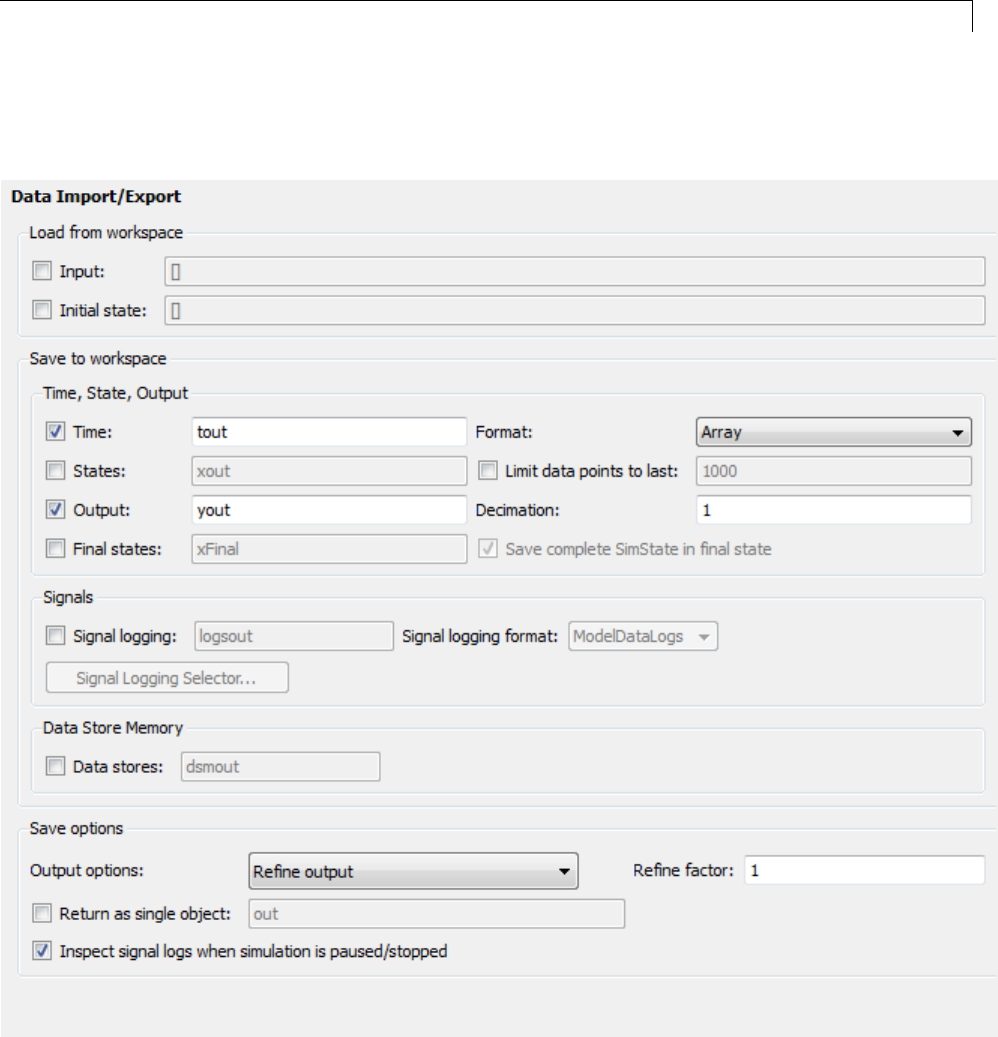
Data Exchange
7If any other options are enabled, clear them. Set Decimation to 1and
Format to Array. The figure below shows the dialog.
15-109
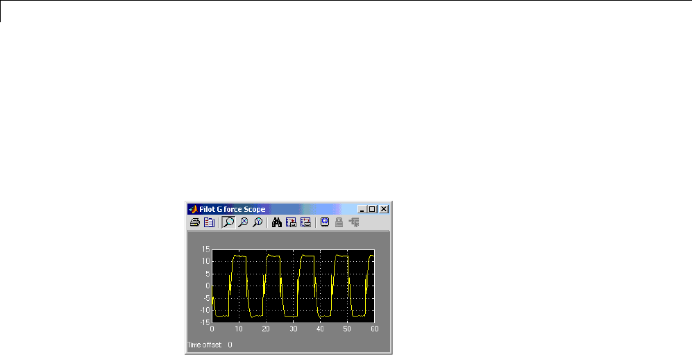
15 Program Building, Interaction, and Debugging
8Click Apply to register your changes.
9Save the model.
10 Open the Pilot G Force Scope block of the model, then run the model by
choosing Simulation > Run in the model window. The resulting Pilot G
Force scope display is shown below.
11 Verify thatthesimulationtimeandoutputshavebeensavedtothe
MATLAB workspace in MAT-files. At the MATLAB prompt, type:
whos *out
Simulinkdisplays:
Name Size Bytes Class Attributes
tout 601x1 4808 double
yout 601x2 9616 double
15-110
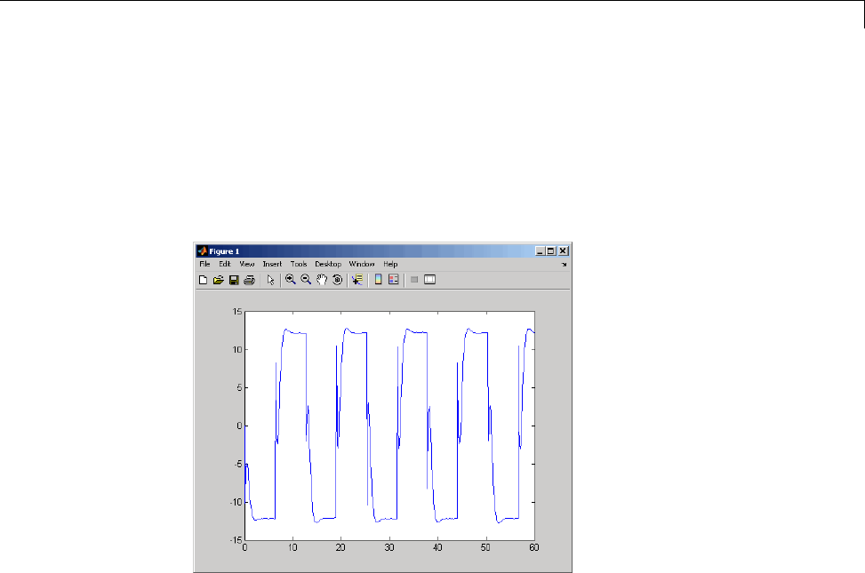
Data Exchange
12 Verify that Pilot G Force was logged by plotting simulation time versus
that variable. At the MATLAB prompt, type:
plot(tout,yout(:,2))
The resulting plot is shown below.
Data Logging from Generated Code. In the second part of this example,
you build and run a Simulink Coder executable of the rtwdemo_f14 model that
outputs a MAT-file containing the simulation time and outputs you previously
examined. Even though you have already generated code for the rtwdemo_f14
model, you must now regenerate that code because you have changed the
model by enabling data logging. The steps below explain this procedure.
To avoid overwriting workspace data with data from simulation runs, the
Simulink Coder code generator modifies identifiers for variables logged by
Simulink. You can control these modifications from the Model Explorer:
1Open Model Explorer by selecting Model Explorer from the model’s
View menu.
2In the Model Hierarchy pane, click the + sign preceding the model name
to reveal its components.
15-111

15 Program Building, Interaction, and Debugging
3Click Configuration (Active) in the left pane.
4In the center pane, click Code Generation.TheCode Generation pane
appears to the right.
5Click the Interface tab.
6Set MAT-file variable name modifier to _rt.Thisaddsthesuffix_rt
to each variable that you selected to be logged in the first part of this
example (tout,yout).
15-112
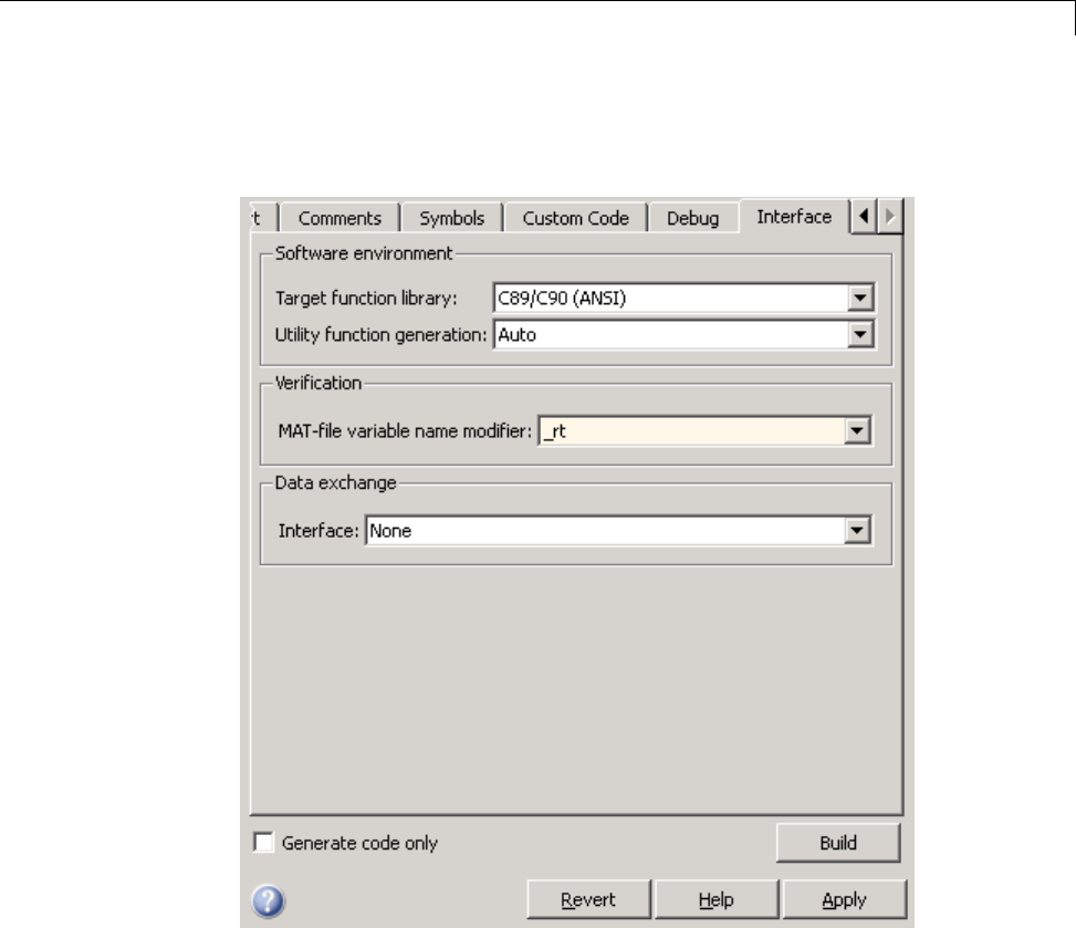
Data Exchange
7Clear the Generate code only check box, if it is currently selected. The
pane should look like this:
8Click Apply to register your changes.
9Save the model.
10 To generate code and build an executable, click the Build button.
11 When the build concludes, run the executable with the command:
!rtwdemo_f14
15-113

15 Program Building, Interaction, and Debugging
12 The program now produces two message lines, indicating that the MAT-file
has been written.
** starting the model **
** created rtwdemo_f14.mat **
13 Load the MAT-file data created by the executable and look at the workspace
variables from simulation and the generated program by typing:
load rtwdemo_f14.mat
whos tout* yout*
Simulink displays:
Name Size Bytes Class Attribute
tout 601x1 4808 double
tout_rt 601x1 4808 double
yout 601x2 9616 double
yout_rt 601x2 9616 double
Note that all arrays have the same number of elements.
15-114

Data Exchange
14 Observe that the variables tout_rt (time) and yout_rt (Pilot G Force
and Angle of Attack) have been loaded from the file. Plot Pilot G Force
as a function of time.
plot(tout_rt,yout_rt(:,2))
The resulting plot is identical to the plot you produced in step 10 of the
previous part of this example:
About Logging to MAT-Files
Multiple techniques are available by which a program generated by the
Simulink Coder software can save data to a MAT-file for analysis. See also
“Log Data for Analysis” on page 15-106 for a data logging tutorial.
Note Data logging is available only for targets that have access to a file
system. In addition, only the RSim target executables are capable of accessing
MATLAB workspace data.
15-115

15 Program Building, Interaction, and Debugging
Configure State, Time, and Output Logging
The Data Import/Export pane enables a generated program to save system
states, outputs, and simulation time at each model execution time step. The
data is written to a MAT-file, named (by default) model.mat.
Before using this data logging feature, you should learn how to configure
a Simulink model to return output to the MATLAB workspace. This is
discussed in “Export Simulation Data”.
For each workspace return variable that you define and enable, the code
generator defines a MAT-file variable. For example, if your model saves
simulation time to the workspace variable tout, your generated program logs
the same data to a variable named (by default) rt_tout.
The code generated by the code generator logs the following data:
•All root Outport blocks
The default MAT-file variable name for system outputs is rt_yout.
The sort order of the rt_yout array is based on the port number of the
Outport block, starting with 1.
•All continuous and discrete states in the model
The default MAT-file variable name for system states is rt_xout.
•Simulation time
The default MAT-file variable name for simulation time is rt_tout.
•“Override the Default MAT-File Name” on page 15-116
•“Override the Default MAT-File Variable Names” on page 15-117
•“Override the Default MAT-File Buffer Size” on page 15-117
Override the Default MAT-File Name. TheMAT-filenamedefaultsto
model.mat. To specify a different file name,
1In the model window, select Simulation > Model Configuration
Parameters. The dialog box opens.
2Click Code Generation.
15-116

Data Exchange
3Append the following option to the existing text in the Make command
field:
OPTS="-DSAVEFILE=filename"
Override the Default MAT-File Variable Names. By default, the code
generation software prefixes the string rt_ to the variable names for system
outputs, states, and simulation time to form MAT-file variable names. To
change this prefix,
1In the model window, select Simulation > Model Configuration
Parameters. The dialog box opens.
2Click Code Generation.
3Select grt.tlc for System target file.
4Select Code Generation > Interface
5Select a prefix (rt_)orsuffix(_rt)fromtheMAT-file variable name
modifier field, or choose none fornoprefix(othertargetsmayormay
not have this option).
Override the Default MAT-File Buffer Size. Thesizeofthebufferfor
MAT-file data logging defaults to 1024 bytes. To specify a different buffer size,
1In the model window, select Simulation > Model Configuration
Parameters. The dialog box opens.
2Click Code Generation.
3Append the following option to the existing text in the Make command
field:
OPTS="-DDEFAULT_BUFFER_SIZE=n"
where nspecifies a buffer size in bytes.
Log Data with Scope and To Workspace Blocks
The code generated by the code generator also logs data from these sources:
15-117

15 Program Building, Interaction, and Debugging
•All Scope blocks that have the Save data to workspace parameter enabled
YoumustspecifythevariablenameanddataformatineachScopeblock’s
dialog box.
•All To Workspace blocks in the model
You must specify the variable name and data format in each To Workspace
block’s dialog box.
The variables are written to model.mat, along with any variables logged from
the Workspace I/O pane.
Log Data with To File Blocks
You can also log data to a To File block. The generated program creates a
separate MAT-file (distinct from model.mat) for each To File block in the
model. The file contains the block’s time and input variable(s). You must
specify the filename, variable names, decimation, and sample time in the To
File block’s dialog box.
Note Models referenced by Model blocks do not perform data logging in
that context except for states, which you can include in the state logged for
top models. Code generated by the Simulink Coder software for referenced
models does not perform data logging to MAT-files.
Data Logging Differences Between Single- and Multitasking
When logging data in single-tasking and multitasking systems, you will notice
differences in the logging of
•Noncontinuous root Outport blocks
•Discrete states
In multitasking mode, the logging of states and outputs is done after the first
task execution (and not at the end of the first time step). In single-tasking
mode, the code generated by the build procedure logs states and outputs after
the first time step.
15-118

Data Exchange
See Data Logging in Single-Tasking and Multitasking Model Execution for
more details on the differences between single-tasking and multitasking data
logging.
Note The rapid simulation target (RSim) provides enhanced logging options.
See “Rapid Simulations” on page 12-2 for more information.
Parameter Tuning
•“Tunable Parameter Storage” on page 15-119
•“Tunable Parameter Storage Classes” on page 15-121
•“Declare Tunable Parameters” on page 15-124
•“Tunable Expressions” on page 15-128
•“Linear Block Parameter Tunability” on page 15-132
•“Tunable Workspace Parameter Data Type Considerations” on page 15-133
•“Tune Parameters from the Command Line” on page 15-135
•“Interfaces for Tuning Parameters” on page 15-137
Tunable Parameter Storage
Atunable parameter is a block parameter whose value can be changed at
run-time. A tunable parameter is inherently noninlined. Consequently, when
Inlined parameters is off, all parameters are members of model_P, and thus
are tunable. A tunable expression is an expression that contains one or more
tunable parameters.
When you declare a parameter tunable, you control whether or not the
parameter is stored within model_P. You also control the symbolic name of
the parameter in the generated code.
When you declare a parameter tunable, you specify
•The storage class of the parameter.
15-119

15 Program Building, Interaction, and Debugging
The storage class property of a parameter specifies how the Simulink Coder
product declares the parameter in generated code.
The term “storage class,” as used in the Simulink Coder product, is not
synonymous with the term storage class specifier, as used in the C language.
•Astorage type qualifier,suchasconst or volatile.Thisissimplyastring
that is included in the variable declaration.
•(Implicitly) the symbolic name of the variable or field in which the
parameter is stored. The Simulink Coder product derives variable and field
names from the names of tunable parameters.
The Simulink Coder product generates a variable or struct storage
declaration for each tunable parameter. Your choice of storage class controls
whether the parameter is declared as a member of model_P or as a separate
global variable.
You can use the generated storage declaration to make the variable visible
to external legacy code. You can also make variables declared in your code
visible to the generated code. You are responsible for linking your code to
generated code modules.
You can use tunable parameters or expressions in your root model and
in masked or unmasked subsystems, subject to certain restrictions. (See
“Tunable Expressions” on page 15-128.)
Override Inlined Parameters for Tuning. When the Inline parameters
option is selected, you can use the Model Parameter Configuration dialog box
to remove individual parameters from inlining and declare them to be tunable.
This allows you to improve overall efficiency by inlining most parameters,
while at the same time retaining the flexibility of run-time tuning for selected
parameters. Another way you can achievethesameresultisbyusing
Simulink data objects; see “Parameters” on page 7-10 for specific details.
The mechanics of declaring tunable parameters are discussed in “Declare
Tunable Parameters” on page 15-124.
15-120

Data Exchange
Tunable Parameter Storage Classes
The Simulink Coder product defines four storage classes for tunable
parameters. You must declare a tunable parameter to have one of the
following storage classes:
•SimulinkGlobal (Auto): This is the default storage class. The Simulink
Coder product stores the parameter as a member of model_P. Each member
of model_P is initialized to the value of the corresponding workspace
variable at code generation time.
•ExportedGlobal: The generated code instantiates and initializes the
parameter and model.h exports it as a global variable. An exported global
variable is independent of the model_P data structure. Each exported
global variable is initialized to the value of the corresponding workspace
variable at code generation time.
•ImportedExtern:model_private.h declares the parameter as an extern
variable. Your code must supply the variable definition and initializer.
•ImportedExternPointer:model_private.h declares the variable as an
extern pointer. Your code must supply the pointer variable definition
and initializer, if any.
The generated code for model.h includes model_private.h to make the
extern declarations available to subsystem files.
As an example of how the storage class declaration affects the code generated
for a parameter, consider the next figure.
15-121
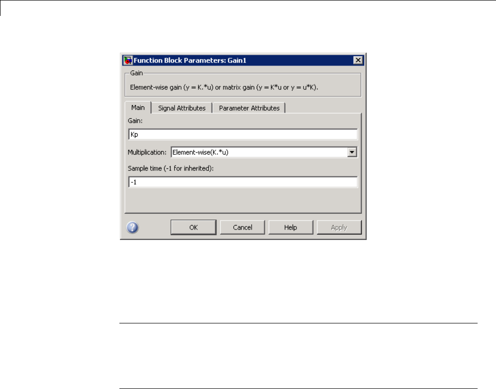
15 Program Building, Interaction, and Debugging
The workspace variable Kp sets the gain of the Gain1 block. Assume that
the value of Kp is 3.14. The following table shows the variable declarations
and the code generated for the gain block when Kp is declared as a tunable
parameter. An example is shown for each storage class.
Note The Simulink Coder product uses column-major ordering for
two-dimensional signal and parameter data. When interfacing your
hand-written code to such signals or parameters by using ExportedGlobal,
ImportedExtern,orImportedExternPointer declarations, make sure that
your code observes this ordering convention.
The symbolic name Kp is preserved in the variable and field names in the
generated code.
15-122

Data Exchange
Storage Class Generated Variable Declaration and Code
SimulinkGlobal
(Auto) typedef struct _Parameters_tunable_sin
Parameters_tunable_sin;
struct _Parameters_tunable_sin {
real_T Kp;
};
Parameters_tunable_sin tunable_sin_P = {
3.14
};
.
.
tunable_sin_Y.Out1 = rtb_u *
tunable_sin_P.Kp;
ExportedGlobal
real_T Kp = 3.14;
.
.
tunable_sin_Y.Out1 = rtb_u * Kp;
ImportedExtern
extern real_T Kp;
.
.
tunable_sin_Y.Out1 = rtb_u * Kp;
ImportedExtern
Pointer extern real_T *Kp;
.
.
tunable_sin_Y.Out1 = rtb_u * (*Kp);
15-123

15 Program Building, Interaction, and Debugging
Declare Tunable Parameters
•“Declare Workspace Variables as Tunable Parameters” on page 15-124
•“Declare New Tunable Parameters” on page 15-124
•“Declare Tunable Parameters Using Configuration Parameter Dialog” on
page 15-125
•“Select Workspace Variables” on page 15-126
•“Create New Tunable Parameters” on page 15-127
•“Set Tunable Parameter Properties” on page 15-128
•“Remove Unused Tunable Parameters” on page 15-128
Declare Workspace Variables as Tunable Parameters. To declare
tunable parameters,
1Open the Model Parameter Configuration dialog box.
2In the Source list pane, select one or more variables.
3Click Add to table . The variables then appear as tunable parameters in
the Global (tunable) parameters pane.
4Select a parameter in the Global (tunable) parameters pane.
5Select a storage class from the Storage class menu.
6Optionally, select (or enter) a storage type qualifier, such as const or
volatile for the parameter.
7Click Apply,orclickOK to apply changes and close the dialog box.
Declare New Tunable Parameters. To declare tunable parameters,
1Open the Model Parameter Configuration dialog box.
2In the Global (tunable) parameters pane, click New.
3Specify a name for the parameter.
15-124
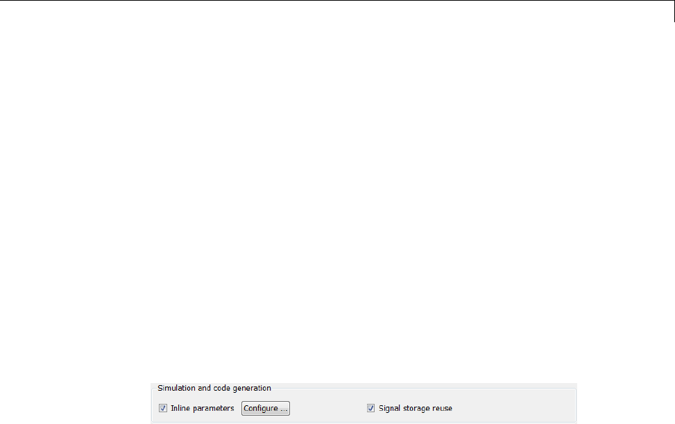
Data Exchange
4Select a storage class from the Storage class menu.
5Optionally, select (or enter) a storage type qualifier, such as const or
volatile for the parameter.
6Click Apply,orclickOK to apply changes and close the dialog box.
Declare Tunable Parameters Using Configuration Parameter Dialog.
The Model Parameter Configuration dialog box lets you select base workspace
variables and declare them to be tunable parameters in the current model.
Using controls in the dialog box, you move variables from a source list to a
global (tunable) parameter list for a model.
To open the dialog box,
1Select the Inline parameters check box on the Optimization > Signals
and Parameters pane of the Configuration Parameters dialog box. This
activates a Configure button, as shown below.
2Click Configure to open the Model Configuration Parameter dialog box.
15-125
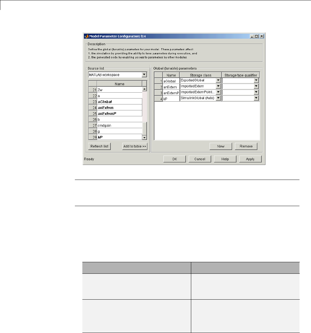
15 Program Building, Interaction, and Debugging
Note The Model Configuration Parameter dialog box cannot tune parameters
within referenced models. See “Parameterize Model References” for tuning
techniques that work with referenced models.
Select Workspace Variables. The Source list pane displays a menu and
a scrolling table of numerical workspace variables. To select workspace
variables,
1From the menu, select the source of variables you want listed.
To List... Choose...
All variables in the MATLAB
workspace that have numeric
values
MATLAB workspace
Only variables in the MATLAB
workspace that have numeric
values and are referenced by the
model
Referenced workspace
variables
15-126

Data Exchange
A list of workspace variables appear in the Source List pane.
2Select one or more variables from the source list. This enables the Add
to table button.
3Click Add to table to add the selected variables to the tunable parameters
list in the Global (tunable) parameters pane. In the Source list,the
names of variables added to the tunable parameters list are displayed in
bold type (see the preceding figure).
Note If you selected a variable with a name that matches a block
parameter that is not tunable and you click Add to table ,awarning
appears during simulation and code generation.
To update the list of variables to reflect the current state of the workspace,
at any time, click Refresh list . For example, you might use Refresh list if
you define or remove variables in the workspace while the Model Parameter
Configuration dialog box is open.
Create New Tunable Parameters. To create a new tunable parameter,
1In the Global (tunable) parameters pane, click New.
2In the Name field, enter a name for the parameter.
Ifyouenteranamethatmatchesthenameofaworkspacevariablein
the Source list pane, that variable is declared tunable and appears in
italics in the Source list.
3Click Apply.
Themodeldoesnotneedtobeusingaparameterbeforeyoucreateit. Youcan
add references to the parameter later.
Note If you edit the name of an existing variable in the list, you actually
create a new tunable variable with the new name. The previous variable is
removed from the list and loses its tunability (that is, it is inlined).
15-127

15 Program Building, Interaction, and Debugging
Set Tunable Parameter Properties. To set the properties of tunable
parameters listed in the Global (tunable) parameters pane, select a
parameter and then specify a storage class and, optionally, a storage type
qualifier.
Property Description
Storage class Selectoneofthefollowingtobeusedforcode
generation:
•SimulinkGlobal (Auto)
•ExportedGlobal
•ImportedExtern
•ImportedExternPointer
See “Tunable Parameter Storage Classes” on
page 15-121 for definitions.
Storage type qualifier For variables with any storage class except
SimulinkGlobal (Auto),youcanadda
qualifier (such as const or volatile)tothe
generated storage declaration. To do so, you
can select a predefined qualifier from the list
or add qualifiers not in the list. The code
generator does not check the storage type
qualifier for validity, and includes the qualifier
string in the generated code without checking
syntax .
Remove Unused Tunable Parameters. To remove unused tunable
parameters from the table in the Global (tunable) parameters pane, click
Remove. All removed variables are inlined if the Inlined parameters
option is enabled.
Tunable Expressions
•“Tunable Expressions in Masked Subsystems” on page 15-129
•“Tunable Expression Limitations” on page 15-131
15-128
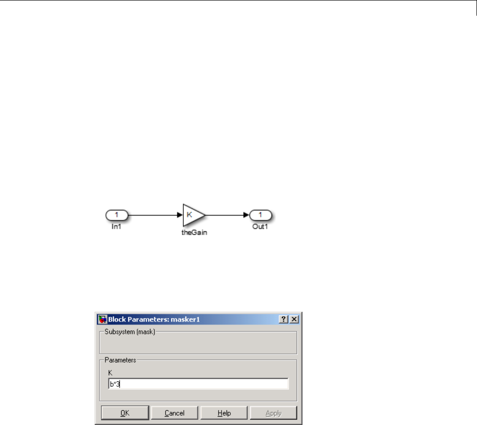
Data Exchange
The Simulink Coder product supports the use of tunable variables in
expressions. An expression that contains one or more tunable parameters is
called a tunable expression.
Tunable Expressions in Masked Subsystems. Tunable expressions are
allowed in masked subsystems. You can use tunable parameter names or
tunable expressions in a masked subsystem dialog box. When referenced in
lower-level subsystems, such parameters remain tunable.
As an example, consider the masked subsystem in the next figure. The
masked variable ksets the gain parameter of theGain.
Suppose that the base workspace variable bis declared tunable with
SimulinkGlobal (Auto) storage class. The next figure shows the tunable
expression b*3 in the subsystem’s mask dialog box.
Tunable Expression in Subsystem Mask Dialog Box
The Simulink Coder product produces the following output computation for
theGain.Thevariablebis represented as a member of the global parameters
structure, model_P. (For clarity in showing the individual Gain block
computation, expression folding is off in this example.)
/* Gain: '<S1>/theGain' */
15-129

15 Program Building, Interaction, and Debugging
rtb_theGain_C = rtb_SineWave_n * ((subsys_mask_P.b * 3.0));
/* Outport: '<Root>/Out1' */
subsys_mask_Y.Out1 = rtb_theGain_C;
As this example shows, for GRT targets, the parameter structure is mangled
to create the structure identifier model_P (subject to the identifier length
constraint). This is done to avoid namespace clashes in combining code from
multiple models using model reference. ERT-based targets provide ways to
customize identifier names.
When expression folding is on, the above code condenses to
/* Outport: '<Root>/Out1' incorporates:
* Gain: '<S1>/theGain'
*/
subsys_mask_Y.Out1 = rtb_SineWave_n * ((subsys_mask_P.b * 3.0));
Expressions that include variables that were declared or modified in mask
initialization code are not tunable.
As an example, consider the subsystem above, modified as follows:
•The mask initialization code is
t=3*k;
•The parameter kof the myGain block is 4+t.
•Workspace variable b=2. The expression b*3is plugged into the mask
dialog box as in the preceding figure.
Since the mask initialization code can run only once, kis evaluated at code
generation time as
4+(3*(2*3))
The Simulink Coder product inlines the result. Therefore, despite the fact
that bwas declared tunable, the code generator produces the following output
computation for theGain. (For clarity in showing the individual Gain block
computation, expression folding is off in this example.)
15-130

Data Exchange
/* Gain Block: <S1>/theGain */
rtb_temp0 *= (22.0);
Tunable Expression Limitations. Currently, there are certain limitations
on the use of tunable variables in expressions. When an unsupported
expression is encountered during code generation a warning is issued and the
equivalent numeric value is generated in the code. The limitations on tunable
expressions are
•Complex expressions are not supported, except where the expression is
simply the name of a complex variable.
•The use of certain operators or functionsinexpressionscontainingtunable
operands is restricted. Restrictions are applied to four categories of
operators or functions, classified in the following table:
Category Operators or Functions
1+ - .* ./ < > <= >= == ~= & |
2*/
3abs,acos,asin,atan,atan2,boolean,ceil,cos,cosh,
exp,floor,log,log10,sign,sin,sinh,sqrt,tan,tanh,
4single,int8,int16,int32,uint8,uint16,uint32
5: .^ ^ [] {} . \ .\ ' .' ; ,
The rules applying to each category are as follows:
-Category 1 is unrestricted. These operators can be used in tunable
expressions with any combination of scalar or vector operands.
-Category 2 operators can be used in tunable expressions where at least
one operand is a scalar. That is, scalar/scalar and scalar/matrix operand
combinations are supported, but not matrix/matrix.
-Category 3 lists all functions that support tunable arguments. Tunable
arguments passed to these functions retain their tunability. Tunable
arguments passed to any other functions lose their tunability.
-Category 4 lists the casting functions that do not support tunable
arguments. Tunable arguments passed to these functions lose their
tunability.
15-131

15 Program Building, Interaction, and Debugging
Note The Simulink Coder product casts values using MATLAB
typecasting rules. The MATLAB typecasting rules are different from C
code typecasting rules. For example, using the MATLAB typecasting
rules, int8(3.7) returns the result 4, while in C code int8(3.7) returns
the result 3. See “Data Type Conversion” for more information on
MATLAB typecasting.
-Category 5 operators are not supported.
•Expressions that include variables that were declared or modified in mask
initialization code are not tunable.
•The Fcn block does not support tunable expressions in code generation.
•Model workspace parameters can take on only the Auto storage class, and
thus are not tunable. See “Parameterize Model References” for tuning
techniques that work with referenced models.
•Non-double expressions are not supported.
•Blocks that access parameters only by address support the use of tunable
parameters, if the parameter expression is a simple variable reference.
When an operation such as a data type conversion or a math operation
is applied, the Simulink Coder product creates a nontrivial expression
that cannot be accessed by address, resulting in an error during the build
process.
Linear Block Parameter Tunability
The following blocks have a Realization parameter that affects the
tunability of their parameters:
•Transfer Fcn
•State-Space
•Discrete State-Space
The Realization parameter must be set by using the MATLAB set_param
function, as in the following example.
set_param(gcb,'Realization','auto')
15-132

Data Exchange
The following values are defined for the Realization parameter:
•general: The block’s parameters are preserved in the generated code,
permitting parameters to be tuned.
•sparse: The block’s parameters are represented in the code by transformed
values that increase the computational efficiency. Because of the
transformation, the block’s parameters are no longer tunable.
•auto: This setting is the default. A general realization is used if one or
more of the block’s parameters are tunable. Otherwise sparse is used.
Note To tune the parameter values of a block of one of the above types
without restriction during an External mode simulation, you must set
Realization to general.
Code Reuse for Subsystems with Mask Parameters. The Simulink
Coder product can generate reusable (reentrant) code for a model containing
identical atomic subsystems. Selecting the Reusable function option for
Function packaging enables such code reuse, and causes a single function
with arguments to be generated that is called when any of the identical
atomic subsystem executes. See “Subsystems” for details and restrictions on
the use of this option.
Mask parameters become arguments toreusablefunctions. However,for
reuse to occur, each instance of a reusable subsystem must declare the same
set of mask parameters. If, for example subsystem A has mask parameters b
and K, and subsystem B has mask parameters cand K, then code reuse is not
possible, and the Simulink Coder product will generate separate functions
for A and B.
Tunable Workspace Parameter Data Type Considerations
If you are using tunable workspace parameters, you need to be aware of
potential issues regarding data types. A workspace parameter is tunable
when the following conditions exist:
•You select the Inline parameters option on the Optimization > Signals
and Parameters pane of the Configuration Parameters dialog box
15-133

15 Program Building, Interaction, and Debugging
•The parameter has a storage class other than Auto
When generating code for tunable workspace parameters, the Simulink Coder
product checks and compares the data types used for a particular parameter
in the workspace and in Block Parameter dialog boxes.
If... The Simulink Coder Product...
The data types match Uses that data type for the parameter in the
generated code.
You do not explicitly
specify a data type
other than double in
the workspace
Usesthedatatypespecifiedbytheblockin
the generated code. If multiple blocks share a
parameter, they must all specify the same data
type. If the data type varies between blocks,
the product generates an error similar to the
following:
Variable 'K' is used in incompatible ways
in the dialog fields of the following:
cs_params/Gain, cs_params/Gain1. The
variable'value is being used both directly
and after a transformation. Only one of
these usages is permitted for any given
variable.
You explicitly specify
adatatypeother
than double in the
workspace
Usesthedatatypefromtheworkspaceforthe
parameter. The block typecasts the parameter to
the block specific data type before using it.
Guidelines for Specifying Data Types. Thefollowingtableprovides
guidelines on specifying data types for tunable workspace parameters.
If You Want to... Then Specify Data Types in...
Minimize memory usage (int8
instead of single)
The workspace explicitly
Avoid typecasting Blocks only
15-134
Data Exchange
If You Want to... Then Specify Data Types in...
Interfacetolegacyorcustomcode The workspace explicitly
Use the same parameter for
multiple blocks that specify
different data types
The workspace explicitly
The Simulink Coder product enforces limitations on the use of data types
other than double in the workspace, as explained in “Limitations on
Specifying Workspace Data Types Explicitly” on page 15-135.
Limitations on Specifying Workspace Data Types Explicitly. When you
explicitly specify a data type other than double in the workspace, blocks
typecast the parameter to another data type. This is an issue for blocks that
use pointer access for their parameters. Blocks cannot use pointer access if
they need to typecast the parameter before using it (because of a data type
mismatch). Another case in which this occurs is for workspace variables with
bias or fractional slope. Two possible solutions to these problems are
•Remove the explicit data type specification in the workspace for parameters
used in such blocks.
•Modify the block so that it uses the parameter with the same data type
as specified in the workspace. For example, the Lookup Table block uses
the data types of its input signal to determine the data type that it uses
to access the X-breakpoint parameter. You can prevent the block from
typecasting the run-time parameter by converting the input signal to the
data type used for X-breakpoints in the workspace. (Similarly, the output
signal is used to determine the data types used to access the lookup table
Ydata.)
Tune Parameters from the Command Line
When parameters are MATLAB workspace variables, the Model Parameter
Configuration dialog box is the recommended way to see or set the properties
of tunable parameters. In addition to that dialog box, you can also use
MATLAB get_param and set_param commands.
15-135

15 Program Building, Interaction, and Debugging
Note You can also use Simulink.Parameter objects for tunable parameters.
See“ConfigureParameterObjectsfor Code Generation” on page 7-39 for
details.
The following commands return the tunable parameters and corresponding
properties:
•get_param(gcs, 'TunableVars')
•get_param(gcs, 'TunableVarsStorageClass')
•get_param(gcs, 'TunableVarsTypeQualifier')
The following commands declare tunable parameters or set corresponding
properties:
•set_param(gcs, 'TunableVars', str)
The argument str (string) is a comma-separated list of variable names.
•set_param(gcs, 'TunableVarsStorageClass', str)
The argument str (string) is a comma-separated list of storage class
settings.
The valid storage class settings are
-Auto
-ExportedGlobal
-ImportedExtern
-ImportedExternPointer
•set_param(gcs, 'TunableVarsTypeQualifier', str)
The argument str (string) is a comma-separated list of storage type
qualifiers.
The following example declares the variable k1 to be tunable, with storage
class ExportedGlobal and type qualifier const. The number of variables and
number of specified storage class settings must match. If you specify multiple
variables and storage class settings, separate them with a comma.
15-136

Data Exchange
set_param(gcs, 'TunableVars', 'k1')
set_param(gcs, 'TunableVarsStorageClass','ExportedGlobal')
set_param(gcs, 'TunableVarsTypeQualifier','const')
Other configuration parameters you can get and set are listed in “Parameter
Reference”.
Interfaces for Tuning Parameters
The Simulink Coder product includes
•Support for developing a Target Language Compiler API for tuning
parameters independent of External mode. See “Parameter Functions” in
the Target Language Compiler documentation for information.
•A C application program interface (API) for tuning parameters independent
of External mode. See “Data Interchange Using the C API” on page 15-137
for information.
•An interface for exporting ASAP2 files, which you customize to use
parameter objects. For details, see “ASAP2 Data Measurement and
Calibration” on page 15-174.
Data Interchange Using the C API
The C API allows you to write host-based or target-based code that interacts
with signals, states, root-level inputs/outputs, and parameters in your
target-based application code.
•“About Data Exchange and C API” on page 15-137
•“Generate C API Files” on page 15-138
•“Description of C API Files” on page 15-141
•“Use the C API in an Application” on page 15-160
•“C API Limitations” on page 15-173
About Data Exchange and C API
Some Simulink Coder applications must interact with signals, states,
root-level inputs/outputs, or parameters in the generated code for a model.
For example, calibration applications monitor and modify parameters. Signal
15-137

15 Program Building, Interaction, and Debugging
monitoring or data logging applications interface with signal, state, and
root-level input/output data. Using the Simulink Coder C API, you can build
target applications that log signals, states, and root-level inputs/outputs,
monitor signals, states, and root-level inputs/outputs, and tune parameters,
while the generated code executes.
The C API minimizes its memory footprint by sharing information common
to signals, states, root-level inputs/outputs, and parameters in smaller
structures. Signal, state, root-level input/output, and parameter structures
include an index into the structure map, allowing multiple signals, states,
root-level inputs/outputs, or parameters to share data.
When you configure a model to use the C API, the Simulink Coder
code generator generates two additional files, model_capi.c (or .cpp)
and model_capi.h,wheremodel isthenameofthemodel. Thecode
generator places the two C API files in the build folder, based on settings
in the Configuration Parameters dialog box. The C API source code file
contains information about global block output signals, states, root-level
inputs/outputs, and global parameters defined in the generated code model
source code. The C API header file is an interface header file between the
model source code and the generated C API. You can use the information in
these C API files to create your application. Among the files generated are
those shown in the next figure.
model.mdl
Generate code
model.c model.h
model_capi.c model_capi.h
Generated Files with C API Selected
Generate C API Files
To generate C API files for your model:
15-138
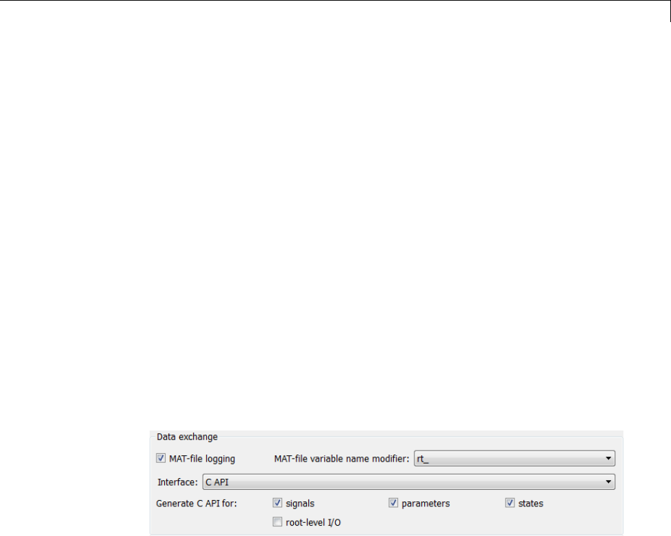
Data Exchange
1Select the C API interface for your model. There are two ways to select the
C API interface for your model, as described in the following sections.
•“Select C API with Configuration Parameters Dialog” on page 15-139
•“Select C API from the Command Line” on page 15-140
2Generate code for your model.
After generating code, you can examine the files model_capi.c (or .cpp)and
model_capi.h in the model build folder.
Select C API with Configuration Parameters Dialog.
1Open your model, and launch either the Configuration Parameters dialog
box or Model Explorer.
2Go to the Code Generation > Interface pane and, in the Data exchange
section, select CAPIas the value for the Interface parameter. The
Generate C API for: signals,Generate C API for: parameters,
Generate C API for: states,andGenerate C API for: root-level I/O
check boxes are displayed.
3Select options:
•If you want to generate C API code for global block output signals, select
the Generate C API for: signals check box.
•If you want to generate C API code for global block parameters, select
the Generate C API for: parameters check box.
•If you want to generate C API code for discrete and continuous states,
select the Generate C API for: states check box.
•If you want to generate C API code for root-level inputs and outputs,
select the Generate C API for: root-level I/O check box.
15-139

15 Program Building, Interaction, and Debugging
If you select all four check boxes, support for accessing signals, parameters,
states, and root-level I/O will appear in the C API generated code.
Select C API from the Command Line. From the MATLAB command line,
you can use the set_param function to select or clear the C API check boxes
on the Interface pane of the Configuration Parameters dialog box. At the
MATLAB command line, enter one or more of the following commands, where
modelname is the name of your model.
To select Generate C API for: signals,enter:
set_param('modelname','RTWCAPISignals','on')
To clear Generate C API for: signals,enter:
set_param('modelname','RTWCAPISignals','off')
To select Generate C API for: parameters,enter:
set_param('modelname','RTWCAPIParams','on')
To clear Generate C API for: parameters,enter:
set_param('modelname','RTWCAPIParams','off')
To select Generate C API for: states,enter:
set_param('modelname','RTWCAPIStates','on')
To clear Generate C API for: states,enter:
set_param('modelname','RTWCAPIStates','off')
To select Generate C API for: root-level I/O,enter:
set_param('modelname','RTWCAPIRootIO','on')
To clear Generate C API for: root-level I/O,enter:
set_param('modelname','RTWCAPIRootIO','off')
15-140

Data Exchange
Generate C API and ASAP2 Files. The C API and ASAP2 interfaces
are not mutually exclusive. Although the Interface option on the Code
Generation > Interface pane of the Configuration Parameters dialog box
allows you to select either the ASAP2 or C API interface, you can instruct
the Simulink Coder code generator to generate files for both interfaces. For
details, see “Generate ASAP2 and C API Files” on page 15-188.
Description of C API Files
•“About C API Files” on page 15-141
•“Structure Arrays Generated in C API Files” on page 15-144
•“Generate Example C API Files” on page 15-146
•“C API Signals” on page 15-149
•“C API States” on page 15-153
•“C API Root-Level Inputs and Outputs” on page 15-154
•“C API Parameters” on page 15-156
•“Map C API Data Structures to rtModel” on page 15-158
About C API Files. The model_capi.c (or .cpp)fileprovidesexternal
applications with a consistent interface to model data. Depending on your
configuration settings, the data could be a signal, state, root-level input or
output, or parameter. In this document, the term data item refers to either
a signal, a state, a root-level input or output, or a parameter. The C API
uses structures that provide an interface to the data item properties. The
interface packages the properties of each data item in a data structure. If the
model contains multiple data items, the interface generates an array of data
structures. The members of a data structure map to data properties.
To interface with data items, an application requires the following properties
for each data item:
•Name
•Block path
•Port number (for signals and root-level inputs/outputs only)
15-141
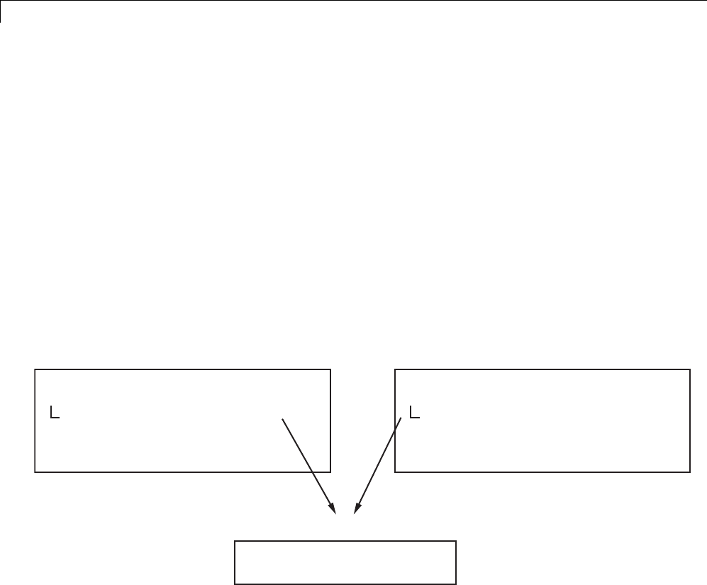
15 Program Building, Interaction, and Debugging
•Address
•Data type information: native data type, data size, complexity, and other
attributes
•Dimensions information: number of rows, number of columns, and data
orientation (scalar, vector, matrix, or n-dimensional)
•Fixed-point information: slope, bias, scale type, word length, exponent,
and other attributes
•Sample-time information (for signals, states, and root-level inputs/outputs
only): sample time, task identifier, frames
As illustrated in the next figure, the properties of data item A, for example,
are located in data structure DS_A. The properties of data item B are located
in data structure DS_B.
DS_A
Property 1
Property 2
Pointer
Property 3
...
Unique value located here
Shared value located in DS_C
Pointer value located here
Unique value located here
DS_B
Property 1
Property 2
Pointer
Property 3
...
Unique value located here
Shared value located in DS_C
Pointer value located here
Unique value located here
DS_C
Shared value of Property 2
Shared values of other properties ...
Some property values can be unique to each data item, and there are some
property values that several data items can share in common. Name, for
example, has a unique value for each data item. The interface places the
unique property values directly in the structure for the data item. The name
valueofdataitemAisinDS_A,andthenamevalueofdataitemBisinDS_B.
But data type could be a property whose value several data items have in
common. The ability of some data items to share a property allows the C API
to have a reuse feature. In this case, the interface places only an index value
15-142
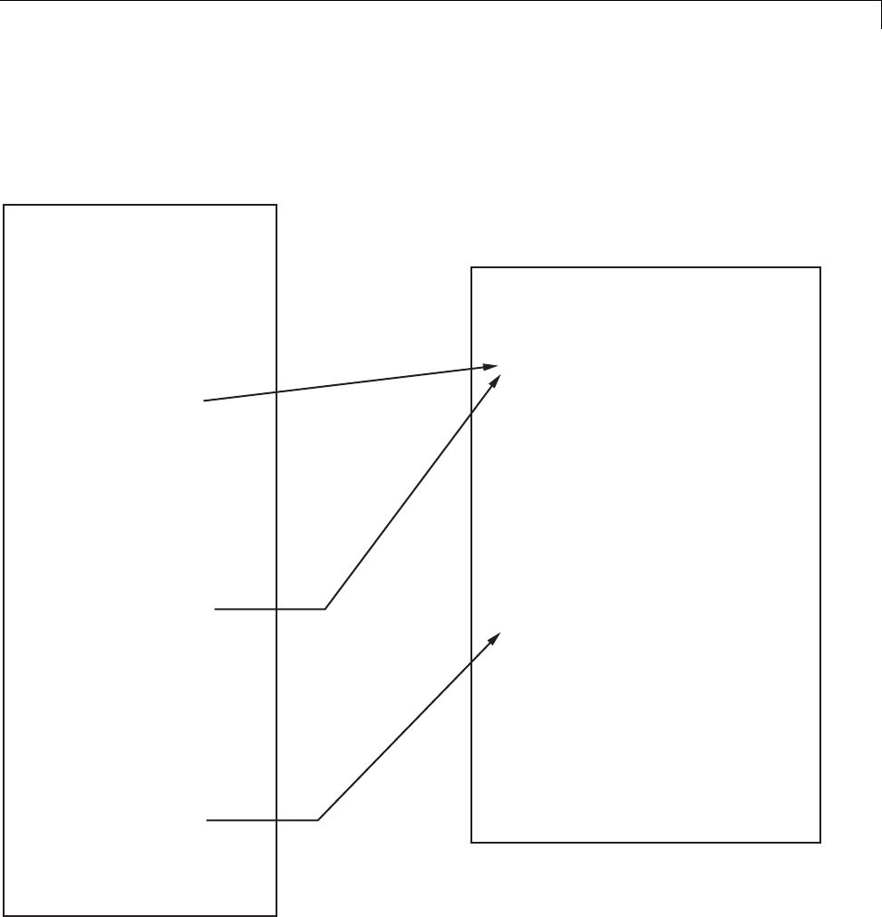
Data Exchange
in DS_A and an index value in DS_B. These indices point to a different data
structure, DS_C, that contains the actual data type value. The next figure
shows this scheme with more detail.
rtwCapi_Signals rtBlockSignals[]
Array of Signal Structures
These indices of
0 point to the first
element in the
rtDataTypeMap
array.
{
{
...
blockPath sys/blk1
signalName signal1
portNumber 0
dataTypeIndex 0
...
},
{
...
blockPath sys/blk2
signalName signal2
portNumber 1
dataTypeIndex 0
...
},
{
...
blockPath sys/blk3
signalName signal3
portNumber 0
dataTypeIndex 1
...
}
};
The index of 1 points
to the second element
in the rtDataTypeMap
array.
rtwCAPI_DataTypeMap rtDataTypeMap[]
Array of Data Type Structures
{
{
cName "double"
mwName "real_T"
numElements 0
elemMapIndex 0
dataSize sizeof(real_T)
slDataId SS_DOUBLE
isComplex 0
isPointer 0
};
{
cName "int"
mwName "int32_T"
numElements 0
elemMapIndex 0
dataSize sizeof(int32_T)
slDataId SS_INT32
...
}
};
15-143

15 Program Building, Interaction, and Debugging
Thefigureshowsthreesignals. signal1 and signal2 share the same data
type, double. Instead of specifying this data type value in each signal data
structure, the interface provides only an index value, 0, in the structure.
"double" is described by entry 0 in the rtDataTypeMap array, which is
referenced by both signals. Additionally, property values can be shared
between signals, states, root-level inputs/outputs, and parameters, so states,
root-level inputs/outputs, and parameters also might reference the double
entry in the rtDataTypeMap array. This reuse of information reduces the
memory size of the generated interface.
Structure Arrays Generated in C API Files. As with data type, the
interface maps other common properties (such as address, dimension,
fixed-point scaling, and sample time) into separate structures and provides
an index in the structure for the data item. For a complete list of structure
definitions, refer to the file matlabroot/rtw/c/src/rtw_capi.h (where
matlabroot represents the root of your MATLAB installation folder). This file
also describes each member in a structure. The structure arrays generated
in the model_capi.c (or .cpp) file are of structure types defined in the
rtw_capi.h file. Here is a brief description of the structure arrays generated
in model_capi.c (or .cpp):
•rtBlockSignals is an array of structures that contains information about
global block output signals in the model. Each element in the array is of
type struct rtwCAPI_Signals. The members of this structure provide the
signal name, block path, block port number, address, and indices to the
data type, dimension, fixed-point, and sample-time structure arrays.
•rtBlockParameters is an array of structures that contains information
about the tunable block parameters in the model by block name
and parameter name. Each element in the array is of type struct
rtwCAPI_BlockParameters. The members of this structure provide the
parameter name, block path, address, and indices to data type, dimension,
and fixed-point structure arrays.
•rtBlockStates is an array of structures that contains information about
discrete and continuous states in the model. Each element in the array is
of type struct rtwCAPI_States. The members of this structure provide
the state name, block path, type (continuous or discrete), and indices to
the address, data type, dimension, fixed-point, and sample-time structure
arrays.
15-144

Data Exchange
•rtRootInputs is an array of structures that contains information about
root-level inputs in the model. Each element in the array is of type struct
rtwCAPI_Signals. The members of this structure provide the root-level
input name, block path, block port number, address, and indices to the data
type, dimension, fixed-point, and sample-time structure arrays.
•rtRootOutputs is an array of structures that contains information about
root-level outputs in the model. Each element in the array is of type struct
rtwCAPI_Signals. The members of this structure provide the root-level
output name, block path, block port number, address, and indices to the
data type, dimension, fixed-point, and sample-time structure arrays.
•rtModelParameters is an array of structures that contains information
about all workplace variables that one or more blocks or Stateflow charts
in the model reference as block parameters. Each element in the array is
of data type rtwCAPI_ModelParameters. The members of this structure
provide the variable name, address, and indices to data type, dimension,
and fixed-point structure arrays.
•rtDataAddrMap is an array of base addresses of signals, states, root-level
inputs/outputs, and parameters that appear in the rtBlockSignals,
rtBlockParameters,rtBlockStates,andrtModelParameters arrays.
Each element of the rtDataAddrMap array is a pointer to void (void*).
•rtDataTypeMap is an array of structures that contains information about
the various data types in the model. Each element of this array is of type
struct rtwCAPI_DataTypeMap. The members of this structure provide the
data type name, size of the data type, and information on whether or not
the data is complex.
•rtDimensionMap is an array of structures that contains information
about the various data dimensions in the model. Each element of this
array is of type struct rtwCAPI_DimensionMap. The members of this
structure provide information on the number of dimensions in the data,
the orientation of the data (whether it is scalar, vector, or a matrix), and
the actual dimensions of the data.
•rtFixPtMap is an array of structures that contains fixed-point information
about the signals, states, root-level inputs/outputs, and parameters. Each
element of this array is of type struct rtwCAPI_FixPtMap.Themembers
of this structure provide information about the data scaling, bias, exponent,
and whether or not the fixed-point data is signed. If the model does not
have fixed-point data (signal, state, root-level input/output, or parameter),
15-145

15 Program Building, Interaction, and Debugging
the Simulink Coder software assigns NULL or zero values to the elements of
the rtFixPtMap array.
•rtSampleTimeMap is an array of structures that contains sampling
information about the global signals, states, and root-level inputs/outputs
in the model. (This array contains no information about parameters.) Each
element of this array is of type struct rtwCAPI_SampleTimeMap.The
members of this structure provide information about the sample period,
offset, and whether or not the data is frame-based or sample-based.
Generate Example C API Files. The next three sections, “C API Signals”
on page 15-149, “C API States” on page 15-153, “C API Root-Level Inputs and
Outputs” on page 15-154, and “C API Parameters” on page 15-156, discuss
generated C API structures using the example model rtwdemo_capi as an
example. To generate code from the example model, do the following:
1Open the model by clicking the rtwdemo_capi link above or by typing
rtwdemo_capi on the MATLAB command line. The model appears as
showninthenextfigure.
15-146
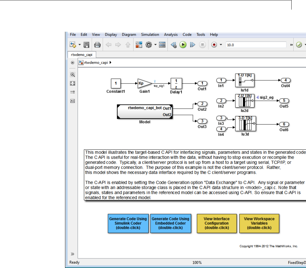
Data Exchange
2If you want to generate C API structures for root-level inputs/outputs
in rtwdemo_capi, open the Configuration Parameters dialog box, go to
the Code Generation > Interface pane, and make sure that the option
Generate C API for: root-level I/O is selected.
15-147

15 Program Building, Interaction, and Debugging
Note The setting of Generate C API for: root-level I/O must match
between the top model and the referenced model.
3Generate code for the model by double-clicking Generate Code Using
Simulink Coder.
Note The C API code examples in the next four sections are generated with
C as the target language.
This model has three global block output signals that will appear in C API
generated code:
•top_sig1, which is a test point at the output of the Gain1 block in the
top model
•sig2_eg, which appears in the top model and is defined in the
base workspace as a Simulink.Signal object having storage class
ExportedGlobal
•bot_sig1, which appears in the submodel rtwdemo_capi_bot and is
defined as a Simulink.Signal object having storage class SimulinkGlobal
The model also has two discrete states that will appear in the C API generated
code:
•top_state, which is defined for the Delay1 block in the top model
•bot_state, which is defined for the Discrete Filter block in the submodel
The model has root-level inputs/outputs that will appear in the C API
generated code if you select the option Generate C API for: root-level I/O:
•Four root-level inputs, In1 through In4
•Six root-level outputs, Out1 through Out6
Additionally, the model has five global block parameters that will appear in C
API generated code:
15-148

Data Exchange
•Kp (top model Gain1 block and submodel Gain2 block share)
•Ki (submodel Gain3 block)
•p1 (lookup table lu1d)
•p2 (lookup table lu2d)
•p3 (lookup table lu3d)
CAPISignals.The rtwCAPI_Signals structure captures signal information
including the signal name, address, block path, output port number, data
type information, dimensions information, fixed-point information, and
sample-time information.
Here is the section of code in rtwdemo_capi_capi.c that provides information
on C API signals for the top model in rtwdemo_capi:
/* Block output signal information */
static const rtwCAPI_Signals rtBlockSignals[] = {
/* addrMapIndex, sysNum, blockPath,
* signalName, portNumber, dataTypeIndex, dimIndex, fxpIndex, sTimeIndex
*/
{ 0, 0, "rtwdemo_capi/Gain1",
"top_sig1", 0, 0, 0, 0, 0 },
{ 1, 0, "rtwdemo_capi/lu2d",
"sig2_eg", 0, 0, 1, 0, 0 },
{
0, 0, (NULL), (NULL), 0, 0, 0, 0, 0
}
};
15-149

15 Program Building, Interaction, and Debugging
Note To better understand the code, read the comments in the file. For
example, notice the comment that begins on the third line in the preceding
code. This comment lists the members of the rtwCAPI_Signals structure, in
order. This tells you the order in which the assigned values for each member
appear for a signal. In this example, the comment tells you that signalName
is the fourth member of the structure. The following lines describe the first
signal:
{ 0, 0, "rtwdemo_capi/Gain1",
"top_sig1", 0, 0, 0, 0, 0 },
From these lines you infer that the name of the first signal is top_sig1.
Each array element, except the last, describes one output port for a block
signal. The final array element is a sentinel, with all elements set to null
values. For example, examine the second signal, described by the following
code:
{ 1, 0, "rtwdemo_capi/lu2d",
"sig2_eg", 0, 0, 1, 0, 0 },
This signal, named sig2_eg, is the output signal of the first port of the block
rtwdemo_capi/lu2d. (This port is the first port because the zero-based index
for portNumber displayed on the second line is assigned the value 0.)
TheaddressofthissignalisgivenbyaddrMapIndex,which,inthisexample,is
displayed on the first line as 1.ThisprovidesanindexintothertDataAddrMap
array, found later in rtwdemo_capi_capi.c:
/* Declare Data Addresses statically */
static void* rtDataAddrMap[] = {
&rtwdemo_capi_B.top_sig1, /* 0: Signal */
&sig2_eg[0], /* 1: Signal */
&rtwdemo_capi_DWork.top_state, /* 2: Discrete State */
&rtP_Ki, /* 3: Model Parameter */
&rtP_Kp, /* 4: Model Parameter */
&rtP_p1[0], /* 5: Model Parameter */
&rtP_p2[0], /* 6: Model Parameter */
&rtP_p3[0], /* 7: Model Parameter */
15-150

Data Exchange
};
The index of 1points to the second element in the rtDataAddrMap array.
From the rtDataAddrMap array, you can infer that the address of this signal
is &sig2_eg[0].
This level of indirection supports multiple code instances of the same model.
For multiple instances, the signal information remains constant, except for
the address. In this case, the model is a single instance. Therefore, the
rtDataAddrMap is declared statically. If you choose to generate reusable code,
an initialize function is generated that initializes the addresses dynamically
per instance. (For details on generating reusable code, see “Set Up Support for
Code Reuse” and “Entry Point Functions and Scheduling” in the Embedded
Coder documentation.)
The dataTypeIndex provides an index into the rtDataTypeMap array, found
later in rtwdemo_capi_capi.c, indicating the data type of the signal:
/* Data Type Map - use dataTypeMapIndex to access this structure */
static const rtwCAPI_DataTypeMap rtDataTypeMap[] = {
/* cName, mwName, numElements, elemMapIndex, dataSize, slDataId, *
* isComplex, isPointer */
{ "double", "real_T", 0, 0, sizeof(real_T), SS_DOUBLE, 0, 0 }
};
Because the index is 0for sig2_eg, the index points to the first structure
element in the array. You can infer that the data type of the signal is double.
The value of isComplex is 0, indicating that the signal is not complex. Rather
than providing the data type information directly in the rtwCAPI_Signals
structure, a level of indirection is introduced. The indirection allows multiple
signalsthatsharethesamedatatypetopointtoonemapstructure,saving
memory for each signal.
The dimIndex (dimensions index) provides an index into the rtDimensionMap
array, found later in rtwdemo_capi_capi.c, indicating the dimensions of the
signal. Because this index is 1for sig2_eg, the index points to the second
element in the rtDimensionMap array:
/* Dimension Map - use dimensionMapIndex to access elements of ths structure*/
static const rtwCAPI_DimensionMap rtDimensionMap[] = {
/* dataOrientation, dimArrayIndex, numDims, vardimsIndex */
15-151

15 Program Building, Interaction, and Debugging
{ rtwCAPI_SCALAR, 0, 2, 0 },
{ rtwCAPI_VECTOR, 2, 2, 0 },
...
};
From this structure, you can infer that this is a nonscalar signal having
a dimension of 2.ThedimArrayIndex value, 2, provides an index into
rtDimensionArray, found later in rtwdemo_capi_capi.c:
/* Dimension Array- use dimArrayIndex to access elements of this array */
static const uint_T rtDimensionArray[] = {
1, /* 0 */
1, /* 1 */
2, /* 2 */
...
};
The fxpIndex (fixed-point index) provides an index into the rtFixPtMap
array, found later in rtwdemo_capi_capi.c, indicating any fixed-point
information about the signal. Your code can use the scaling information
to compute the real-world value of the signal, using the equation V=SQ+B,
where V is “real-world” (that is, base-10) value, S is user-specified slope, Q is
“quantized fixed-point value” or “stored integer,” and B is user-specified bias.
(For details, see “Scaling” in the Fixed-Point Toolbox™ documentation.)
Because this index is 0for sig2_eg, the signal has no fixed-point information.
A fixed-point map index of zero always means that the signal has no
fixed-point information.
The sTimeIndex (sample-time index) provides the index to the
rtSampleTimeMap array, found later in rtwdemo_capi_capi.c, indicating
task information about the signal. If you log multirate signals or conditionally
executed signals, the sampling information can be useful.
Note model_capi.c (or .cpp)includesrtw_capi.h. Any source file that
references the rtBlockSignals array also must include rtw_capi.h.
15-152

Data Exchange
C API States. The rtwCAPI_States structure captures state information
including the state name, address, block path, type (continuous or discrete),
data type information, dimensions information, fixed-point information, and
sample-time information.
Here is the section of code in rtwdemo_capi_capi.c that provides information
on C API states for the top model in rtwdemo_capi:
/* Block states information */
static const rtwCAPI_States rtBlockStates[] = {
/* addrMapIndex, contStateStartIndex, blockPath,
* stateName, pathAlias, dWorkIndex, dataTypeIndex, dimIndex,
* fixPtIdx, sTimeIndex, isContinuous
*/
{ 2, -1, "rtwdemo_capi/Delay1",
"top_state", "", 0, 0, 0, 0, 0, 0 },
{
0, -1, (NULL), (NULL), (NULL), 0, 0, 0, 0, 0, 0
}
};
Each array element, except the last, describes a state in the model. The final
array element is a sentinel, with all elements set to null values. In this
example, the C API code for the top model displays one state:
{ 2, -1, "rtwdemo_capi/Delay1",
"top_state", "", 0, 0, 0, 0, 0, 0 },
This state, named top_state, is defined for the block rtwdemo_capi/Delay1.
The value of isContinuous is zero, indicating that the state is discrete
rather than continuous. The other fields correspond to the like-named signal
equivalents described in “C API Signals” on page 15-149, as follows:
•The address of the signal is given by addrMapIndex,which,inthis
example, is 2. ThisisanindexintothertDataAddrMap array, found
later in rtwdemo_capi_capi.c. Because the index is zero based,
2corresponds to the third element in rtDataAddrMap,whichis
&rtwdemo_capi_DWork.top_state.
15-153

15 Program Building, Interaction, and Debugging
•The dataTypeIndex provides an index into the rtDataTypeMap array, found
later in rtwdemo_capi_capi.c, indicating the data type of the parameter.
The value 0 corresponds to a double, noncomplex parameter.
•The dimIndex (dimensions index) provides an index into the
rtDimensionMap array, found later in rtwdemo_capi_capi.c.Thevalue0
corresponds to the first entry, which is { rtwCAPI_SCALAR, 0, 2, 0 }.
•The fixPtIndex (fixed-point index) provides an index into the rtFixPtMap
array, found later in rtwdemo_capi_capi.c, indicating any fixed-point
information about the parameter. As with the corresponding signal
attribute, a fixed-point map index of zero always means that the parameter
has no fixed-point information.
C API Root-Level Inputs and Outputs. The rtwCAPI_Signals structure
captures root-level input/output information including the input/output
name, address, block path, port number, data type information, dimensions
information, fixed-point information, and sample-time information. (This
structure also is used for block output signals, as previously described in “C
API Signals” on page 15-149.)
Here is the section of code in rtwdemo_capi_capi.c that provides information
on C API root-level inputs/outputs for the top model in rtwdemo_capi:
/* Root Inputs information */
static const rtwCAPI_Signals rtRootInputs[] = {
/* addrMapIndex, sysNum, blockPath,
* signalName, portNumber, dataTypeIndex, dimIndex, fxpIndex, sTimeIndex
*/
{ 3, 0, "rtwdemo_capi/In1",
"", 1, 0, 0, 0, 0 },
{ 4, 0, "rtwdemo_capi/In2",
"", 2, 0, 0, 0, 0 },
{ 5, 0, "rtwdemo_capi/In3",
"", 3, 0, 0, 0, 0 },
{ 6, 0, "rtwdemo_capi/In4",
"", 4, 0, 0, 0, 0 },
15-154

Data Exchange
{
0, 0, (NULL), (NULL), 0, 0, 0, 0, 0
}
};
/* Root Outputs information */
static const rtwCAPI_Signals rtRootOutputs[] = {
/* addrMapIndex, sysNum, blockPath,
* signalName, portNumber, dataTypeIndex, dimIndex, fxpIndex, sTimeIndex
*/
{ 7, 0, "rtwdemo_capi/Out1",
"", 1, 0, 0, 0, 0 },
{ 8, 0, "rtwdemo_capi/Out2",
"", 2, 0, 0, 0, 0 },
{ 9, 0, "rtwdemo_capi/Out3",
"", 3, 0, 0, 0, 0 },
{ 10, 0, "rtwdemo_capi/Out4",
"", 4, 0, 0, 0, 0 },
{ 11, 0, "rtwdemo_capi/Out5",
"sig2_eg", 5, 0, 1, 0, 0 },
{ 12, 0, "rtwdemo_capi/Out6",
"", 6, 0, 1, 0, 0 },
{
0, 0, (NULL), (NULL), 0, 0, 0, 0, 0
}
};
For information about interpreting the values in the rtwCAPI_Signals
structure, see the previous section “C API Signals” on page 15-149.
15-155

15 Program Building, Interaction, and Debugging
C API Parameters. The rtwCAPI_BlockParameters and
rtwCAPI_ModelParameters structures capture parameter information
including the parameter name, block path (for block parameters), address,
data type information, dimensions information, and fixed-point information.
Each element in an rtBlockParameters or rtModelParameters array (except
the last element) corresponds to a tunable parameter in the model.
The setting of the Inline parameters option on the Optimization > Signals
and Parameters pane of the Configuration Parameters dialog box
determines how information is generated into the rtBlockParameters and
rtModelParameters arrays in model_capi.c (or .cpp), as follows:
•If you clear Inline parameters:
-The rtBlockParameters array contains an entry for every modifiable
parameter of every block in the model.
-The rtModelParameters arraycontainsonlyStateflow data of machine
scope. The Simulink Coder software assigns its elements only NULL or
zero values in the absence of such data.
•If you select Inline parameters:
-The rtBlockParameters array is empty. The Simulink Coder software
assigns its elements only NULL or zero values.
-The rtModelParameters array contains entries for all workspace
variables that are referenced as tunable Simulink block parameters or
Stateflow data of machine scope.
Here is the rtBlockParameters array that is generated by default in
rtwdemo_capi_capi.c:
/* Individual block tuning is not valid when inline parameters is *
* selected. An empty map is produced to provide a consistent *
* interface independent of inlining parameters. *
*/
static const rtwCAPI_BlockParameters rtBlockParameters[] = {
/* addrMapIndex, blockPath,
* paramName, dataTypeIndex, dimIndex, fixPtIdx
*/
{
0, (NULL), (NULL), 0, 0, 0
15-156

Data Exchange
}
};
In this example, only the final, sentinel array element is generated, with all
members of the structure rtwCAPI_BlockParameters set to NULL and zero
values. This is because the Inline parameters option is selected by default
for the rtwdemo_capi example model. If you clear this check box, the block
parameters are generated in the rtwCAPI_BlockParameters structure.
Here is the rtModelParameters array that is generated by default in
rtwdemo_capi_capi.c:
/* Tunable variable parameters */
static const rtwCAPI_ModelParameters rtModelParameters[] = {
/* addrMapIndex, varName, dataTypeIndex, dimIndex, fixPtIndex */
{ 3, "Ki", 0, 0, 0 },
{ 4, "Kp", 0, 0, 0 },
{ 5, "p1", 0, 2, 0 },
{ 6, "p2", 0, 3, 0 },
{ 7, "p3", 0, 4, 0 },
{ 0, (NULL), 0, 0, 0 }
};
In this example, the rtModelParameters array contains entries for each
variable that is referenced as a tunable Simulink block parameter.
For example, the varName (variable name) of the fourth parameter is p2.The
other fields correspond to the like-named signal equivalents described in “C
API Signals” on page 15-149, as follows:
•The address of the fourth parameter is given by addrMapIndex,which,
in this example, is 6. ThisisanindexintothertDataAddrMap array,
found later in rtwdemo_capi_capi.c. Because the index is zero based,
6corresponds to the seventh element in rtDataAddrMap,whichis
&rtwP_p2[0].
15-157

15 Program Building, Interaction, and Debugging
•The dataTypeIndex provides an index into the rtDataTypeMap array, found
later in rtwdemo_capi_capi.c, indicating the data type of the parameter.
The value 0 corresponds to a double, noncomplex parameter.
•The dimIndex (dimensions index) provides an index into the
rtDimensionMap array, found later in rtwdemo_capi_capi.c.Thevalue3
corresponds to the fourth entry, which is { rtwCAPI_MATRIX_COL_MAJOR,
6, 2, 0 }.
•The fixPtIndex (fixed-point index) provides an index into the rtFixPtMap
array, found later in rtwdemo_capi_capi.c, indicating any fixed-point
information about the parameter. As with the corresponding signal
attribute, a fixed-point map index of zero always means that the parameter
has no fixed-point information.
Map C API Data Structures to rtModel. The real-time model data
structure encapsulates model data and associated information that describes
the model fully. When you select the C API feature and generate code, the
Simulink Coder code generator adds another member to the real-time model
data structure generated in model.h:
/*
* DataMapInfo:
* The following substructure contains information regarding
* structures generated in the model's C API.
*/
struct {
rtwCAPI_ModelMappingInfo mmi;
} DataMapInfo;
This member defines mmi (for model mapping information) of type
struct rtwCAPI_ModelMappingInfo. The structure is located in
matlabroot/rtw/c/src/rtw_modelmap.h (where matlabroot represents
the root of your MATLAB installation folder). The mmi substructure defines
the interface between the model and the C API files. More specifically,
members of mmi map the real-time model data structure to the structures
in model_capi.c (or .cpp).
Initializing values of mmi members to the arrays accomplishes the mapping,
as shown in Map Model to C API Arrays of Structures on page 15-160. Each
member points to one of the arrays of structures in the generated C API
15-158

Data Exchange
file. For example, the address of the rtBlockSignals array of structures is
allocated to the first member of the mmi substructure in model.c (or .cpp),
using the following code in the rtw_modelmap.h file:
/* signals */
struct {
rtwCAPI_Signals const *signals; /* Signals Array */
uint_T numSignals; /* Num Signals */
rtwCAPI_Signals const *rootInputs; /* Root Inputs array */
uint_T numRootInputs; /* Num Root Inputs */
rtwCAPI_Signals const *rootOutputs; /* Root Outputs array */
uint_T numRootOutputs;/* Num Root Outputs */
} Signals;
The model initialize function in model.c (or .cpp) performs the initializing
by calling the C API initialize function. For example, the following code is
generated in the model initialize function for example model rtwdemo_capi:
/* Initialize DataMapInfo substructure containing ModelMap for C API */
rtwdemo_capi_InitializeDataMapInfo(rtwdemo_capi_M);
15-159
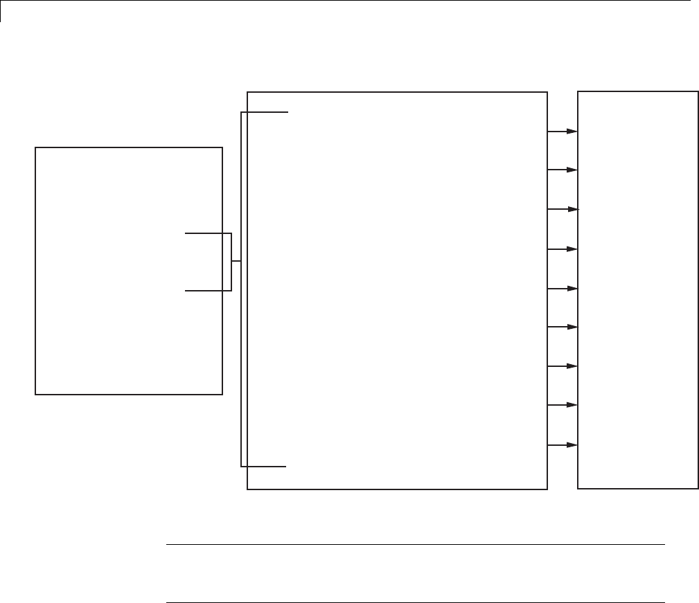
15 Program Building, Interaction, and Debugging
rtwCAPI_Signals const *signals;
rtwCAPI_Signals const *rootInputs;
rtwCAPI_Signals const *rootOutputs;
.
rtwCAPI_BlockParameters const *blockParameters;
.
rtwCAPI_ModelParameters const *modelParameters;
.
rtwCAPI_States const *states;
.
rtwCAPI_DataTypeMap const *dataTypeMap;
.
rtwCAPI_DimensionMap const *dimensionMap;
.
rtwCAPI_FixPtMap const *fixPtMap;
.
rtwCAPI_SampleTimeMap const *sampleTimeMap;
.
void** dataAddrMap;
.
matlabroot/rtw/c/src/rtw_modelmap.h
model.h
model_capi.c
struct rtModel_model {
.
.
.
struct {
rtwCAPI_ModelMappingInfo mmi;
} DataMapInfo:
.
.
.
}
rtBlockSignals
rtRootInputs
rtRootOutputs
.
rtBlockParameters
.
rtModelParameters
.
rtBlockStates
.
rtDataTypeMap
.
rtDimensionMap
.
rtFixPtMap
.
rtSampleTimeMap
.
rtDataAddrMap
.
Map Model to C API Arrays of Structures
Note This figure lists the arrays in the order that their structures appear
in rtw_modelmap.h, which differs slightly from their generated order in
model_capi.c.
Use the C API in an Application
The C API provides you with the flexibility of writing your own application
code to interact with model signals, states, root-level inputs/outputs, and
parameters. Your target-based application code is compiled with the Simulink
Coder generated code into an executable. The target-based application
code accesses the C API structure arrays in model_capi.c (or .cpp). You
15-160

Data Exchange
might have host-based code that interacts with your target-based application
code. Or, you might have other target-based code that interacts with your
target-based application code. The files rtw_modelmap.h and rtw_capi.h,
located in matlabroot/rtw/c/src (where matlabroot represents the root of
your MATLAB installation folder), provide macros for accessing the structures
in these arrays and their members.
This section provides examples to help you get started writing application
code to interact with model signals, states, root-level inputs/outputs, and
parameters.
•“Use C API to Access Model Signals and States” on page 15-161
•“Use C API to Access Model Parameters” on page 15-168
Use C API to Access Model Signals and States. Here is an example
application that logs global signals and states in a model to a text file. This
code is intended as a starting point for accessing signal and state addresses.
You can extend the code to perform signal logging and monitoring, state
logging and monitoring, or both.
This example uses the following macro and function interfaces:
•rtmGetDataMapInfo macro
Accesses the model mapping information (MMI) substructure of the
real-time model structure. In the following macro call, rtM is the pointer to
the real-time model structure in model.c (or .cpp):
rtwCAPI_ModelMappingInfo* mmi = &(rtmGetDataMapInfo(rtM).mmi);
•rtmGetTPtr macro
Accesses the absolute time informationforthebaseratefromthetiming
substructure of the real-time model structure. In the following macro call,
rtM is the pointer to the real-time model structure in model.c (or .cpp):
rtmGetTPtr(rtM)
•Custom functions capi_StartLogging,capi_UpdateLogging,and
capi_TerminateLogging,providedviathefilesrtwdemo_capi_datalog.h
and rtwdemo_capi_datalog.c. These files are located in
15-161

15 Program Building, Interaction, and Debugging
matlabroot/toolbox/rtw/rtwdemos,wherematlabroot represents the
root of your MATLAB installation folder.
-capi_StartLogging initializes signal and state logging.
-capi_UpdateLogging logs a signal and state value at each time step.
-capi_TerminateLogging terminates signal and state logging and writes
the logged values to a text file.
You can integrate these custom functions into generated model code using
any or all of the following methods:
-Code Generation > Custom Code pane of the Configuration
Parameters dialog box
-Custom Code library blocks
-TLC custom code functions
This tutorial uses the Code Generation > Custom Code pane and the
System Outputs block from the Custom Code library to insert calls to the
custom functions into model.c (or .cpp), as follows:
-capi_StartLogging is called in the MdlStart function (or if an ert.tlc
target is selected for the model, in the model_initialize function).
-capi_UpdateLogging is called in the model_output function.
-capi_TerminateLogging is called in the model_terminate function.
The following excerpts of generated code from model.c (rearranged to reflect
their order of execution) show how the function interfaces are used.
void MdlStart(void)
{
/* user code (Start function Trailer) */
/* C API Custom Logging Function: Start Signal and State logging via C-API.
* capi_StartLogging: Function prototype in rtwdemo_capi_datalog.h
*/
{
rtwCAPI_ModelMappingInfo *MMI = &(rtmGetDataMapInfo(rtwdemo_capi_M).mmi);
printf("** Started state/signal logging via C API **\n");
capi_StartLogging(MMI, MAX_DATA_POINTS);
}
15-162

Data Exchange
...
}
...
/* Model output function */
static void rtwdemo_capi_output(int_T tid)
{
...
/* user code (Output function Trailer) */
/* C API Custom Logging Function: Update Signal and State logging buffers.
* capi_UpdateLogging: Function prototype in rtwdemo_capi_datalog.h
*/
{
rtwCAPI_ModelMappingInfo *MMI = &(rtmGetDataMapInfo(rtwdemo_capi_M).mmi);
capi_UpdateLogging(MMI, rtmGetTPtr(rtwdemo_capi_M));
}
...
}
...
/* Model terminate function */
void rtwdemo_capi_terminate(void)
{
/* user code (Terminate function Trailer) */
/* C API Custom Logging Function: Dump Signal and State buffers into a text file.
* capi_TerminateLogging: Function prototype in rtwdemo_capi_datalog.h
*/
{
capi_TerminateLogging("rtwdemo_capi_ModelLog.txt");
printf("** Finished state/signal logging. Created rtwdemo_capi_ModelLog.txt **\n");
}
}
The following procedure illustrates how you can use the C API macro and
function interfaces to log global signals and states in a model to a text file.
1At the MATLAB command line, enter rtwdemo_capi to open the example
model.
2Open the Configuration Parameters dialog box and go to the Code
Generation pane.
15-163
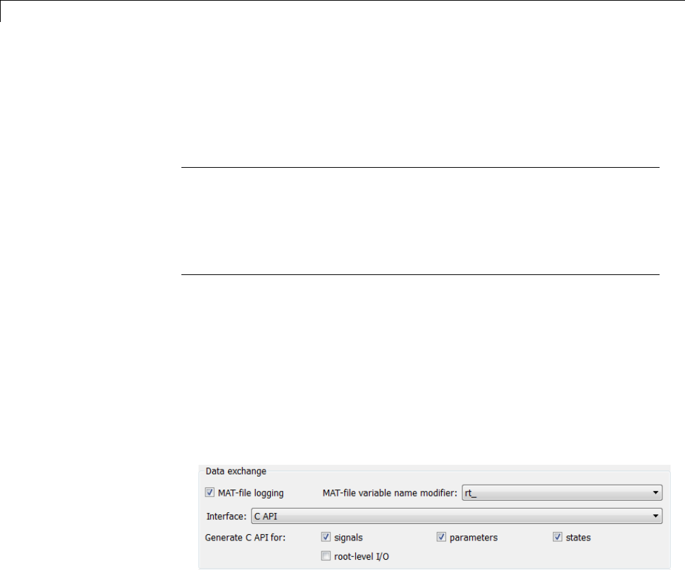
15 Program Building, Interaction, and Debugging
3For the System target file parameter, select grt.tlc.(Alternatively,if
you are licensed for Embedded Coder software, you can select ert.tlc.
Make sure that you also select ert.tlc for the referenced model
rtwdemo_capi_bot.)
Note Selecting a system target file other than grt.tlc or disabling some
C API options (signals, parameters, or states) in the top model requires
corresponding changes in the referenced model. Because the example
models have read-only access, you must save the updated referenced model
with a different name and modify the top model to reference the renamed
model.
4Go to the Interface pane.
aIn the Data exchange subpane, for the Interface parameter, verify
that C API is selected.
bAdditionally, verify that the options Generate C API for: signals and
Generate C API for: states are selected. This example also leaves
Generate C API for: parameters selected. If you clear any of the
options, make sure that the settings match between the top model and
the referenced model.
cIf you are using the ert.tlc target, verify that the options MAT-file
logging and Support: complex numbers are selected.
dIf you modified any option settings in this step, click Apply.
5Use the Custom Code pane to embed your custom application code in the
generated code. Select the Custom Code pane, and then click Include
directories.TheInclude directories input field is displayed.
15-164
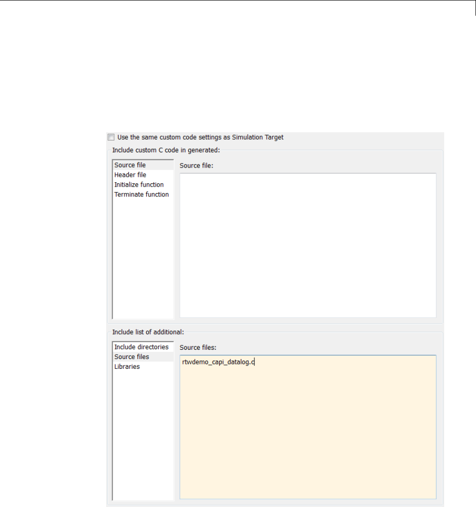
Data Exchange
6In the Include directories field, type
matlabroot/toolbox/rtw/rtwdemos,wherematlabroot represents the
root of your MATLAB installation folder.
7In the Include list of additional subpane, click Source files,andtype
rtwdemo_capi_datalog.c,asshownbelow.
15-165

15 Program Building, Interaction, and Debugging
8In the Include custom C code in generated subpane, click Source file,
and type or copy and paste the following include statement:
#include "rtwdemo_capi_datalog.h"
9In the Initialize function field, type or copy and paste the following
application code:
/* C API Custom Logging Function: Start Signal and State logging via C-API.
* capi_StartLogging: Function prototype in rtwdemo_capi_datalog.h
*/
{
rtwCAPI_ModelMappingInfo *MMI = &(rtmGetDataMapInfo(rtwdemo_capi_M).mmi);
printf("** Started state/signal logging via C API **\n");
capi_StartLogging(MMI, MAX_DATA_POINTS);
}
10 In the Terminate function field, type or copy and paste the following
application code:
/* C API Custom Logging Function: Dump Signal and State buffers into a text file.
* capi_TerminateLogging: Function prototype in rtwdemo_capi_datalog.h
*/
{
capi_TerminateLogging("rtwdemo_capi_ModelLog.txt");
printf("** Finished state/signal logging. Created rtwdemo_capi_ModelLog.txt **\n");
}
11 Click Apply.
12 In the MATLAB Command Window, enter custcode to open the Simulink
Coder Custom Code library. At the top level of the rtwdemo_capi model,
add a System Outputs block.
13 Double-click the System Outputs block to open the System Outputs
Function Custom Code dialog box. In the System Outputs Function Exit
Code field, type or copy and paste the following application code:
/* C API Custom Logging Function: Update Signal and State logging buffers.
* capi_UpdateLogging: Function prototype in rtwdemo_capi_datalog.h
*/
{
15-166

Data Exchange
rtwCAPI_ModelMappingInfo *MMI = &(rtmGetDataMapInfo(rtwdemo_capi_M).mmi);
capi_UpdateLogging(MMI, rtmGetTPtr(rtwdemo_capi_M));
}
Click OK.
14 On the Code Generation pane, verify that the Build button is visible. If
it is not visible, clear the option Generate code only and click Apply.
Click Build to build the model and generate an executable file. For
example, on a Windows system, the build generates the executable file
rtwdemo_capi.exe.
15 In the MATLAB Command Window, enter the command !rtwdemo_capi
to run the executable file. During execution, signals and states
areloggedusingtheCAPIandthenwrittentothetextfile
rtwdemo_capi_ModelLog.txt in your working folder.
>> !rtwdemo_capi
** starting the model **
** Started state/signal logging via C API **
** Logging 2 signal(s) and 2 state(s). In this example, only scalar named
signals/states are logged **
** Finished state/signal logging. Created rtwdemo_capi_ModelLog.txt **
16 Examine the text file in the MATLAB editororanytexteditor. Hereisan
excerpt of the signal and state logging output.
******** Signal Log File ********
Number of Signals Logged: 2
Number of points (time steps) logged: 51
Time bot_sig1 (Referenced Model) top_sig1
070 4
0.2 70 4
0.4 70 4
0.6 70 4
0.8 70 4
170 4
15-167

15 Program Building, Interaction, and Debugging
1.2 70 4
1.4 70 4
1.6 70 4
1.8 70 4
270 4
...
******** State Log File ********
Number of States Logged: 2
Number of points (time steps) logged: 51
Time bot_state (Referenced Model) top_state
00 0
0.2 70 4
0.4 35 4
0.6 52.5 4
0.8 43.75 4
1 48.13 4
1.2 45.94 4
1.4 47.03 4
1.6 46.48 4
1.8 46.76 4
2 46.62 4
...
UseCAPItoAccessModelParameters. Here is an example application
that prints the parameter values of all tunable parameters in a model to
the standard output. This code is intended as a starting point for accessing
parameter addresses. You can extend the code to perform parameter tuning.
The application:
•Uses the rtmGetDataMapInfo macro to access the mapping information in
the mmi substructure of the real-time model structure
rtwCAPI_ModelMappingInfo* mmi = &(rtmGetDataMapInfo(rtM).mmi);
where rtM is the pointer to the real-time model structure in model.c (or
.cpp).
•Uses rtwCAPI_GetNumModelParameters to get the number of model
parameters in mapped C API:
15-168

Data Exchange
uint_T nModelParams = rtwCAPI_GetNumModelParameters(mmi);
•Uses rtwCAPI_GetModelParameters to access the array of all model
parameter structures mapped in C API:
rtwCAPI_ModelParameters* capiModelParams = \
rtwCAPI_GetModelParameters(mmi);
•Loops over the capiModelParams array to access individual parameter
structures. A call to the function capi_PrintModelParameter displays
the value of the parameter.
The example application code is provided below:
{
/* Get CAPI Mapping structure from Real-Time Model structure */
rtwCAPI_ModelMappingInfo* capiMap = \
&(rtmGetDataMapInfo(rtwdemo_capi_M).mmi);
/* Get number of Model Parameters from capiMap */
uint_T nModelParams = rtwCAPI_GetNumModelParameters(capiMap);
printf("Number of Model Parameters: %d\n", nModelParams);
/* If the model has Model Parameters, print them using the
application capi_PrintModelParameter */
if (nModelParams == 0) {
printf("No Tunable Model Parameters in the model \n");
}
else {
unsigned int idx;
for (idx=0; idx < nModelParams; idx++) {
/* call print utility function */
capi_PrintModelParameter(capiMap, idx);
}
}
}
The print utility function is located in
matlabroot/rtw/c/src/rtw_capi_examples.c (where matlabroot
15-169

15 Program Building, Interaction, and Debugging
represents the root of your MATLAB installation folder). This file contains
utility functions for accessing the C API structures.
To become familiar with the example code, try building a model that displays
all the tunable block parameters and MATLAB variables. You can use
rtwdemo_capi, the C API example model. The following steps apply to both
grt.tlc and ert.tlc targets, unless otherwise indicated.
1At the MATLAB command line, enter rtwdemo_capi to open the example
model.
2Open the Configuration Parameters dialog box and go to the
Optimization > Signals and Parameters pane.
3Verify that the Inline parameters option is selected.
4If you are licensed for Embedded Coder software and you want to use the
ert.tlc target instead of the default grt.tlc,gototheCode Generation
pane and use the System target file field to select an ert.tlc target.
5Use the Custom Code pane to embed your custom application code in the
generated code. Select the Custom Code pane, and then click Initialize
function.TheInitialize function input field is displayed.
6In the Initialize function input field, type or copy and paste the example
application code shown above step 1. This embeds the application code in
the MdlStart function. (If you are using ert.tlc, the code appears in the
model_initialize function.)
7Click Include directories,andtypematlabroot/rtw/c/src,where
matlabroot represents the root of your MATLAB installation folder.
8In the Include list of additional subpane, click Source files,andtype
rtw_capi_examples.c.
15-170
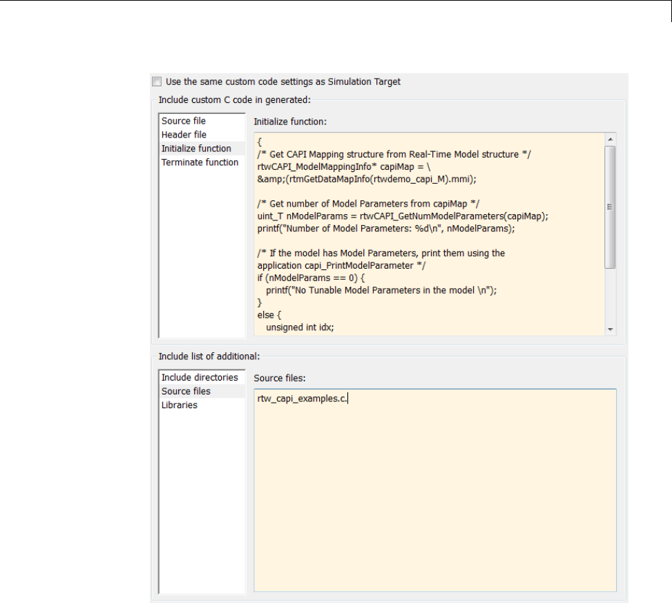
Data Exchange
Click Apply.
9If you are using the ert.tlc target,gototheCode
Generation > Interface pane, select the following options, and
then click Apply.
•In the Interface list, CAPI
15-171

15 Program Building, Interaction, and Debugging
•MAT-file logging
•Support: complex numbers
10 Go to the Code Generation pane and clear the Generate code only
check box if it is not already cleared.
11 Click Build. The Simulink Coder code generator generates the executable
file rtwdemo_capi.exe in your current working folder.
12 At the MATLAB command line, enter !rtwdemo_capi to run the executable
file. Running the program displays parameter information in the Command
Window.
>> !rtwdemo_capi
** starting the model **
Number of Model Parameters: 5
Ki =
7
Kp =
4
p1 =
0.8147
0.9058
0.127
p2 =
0.9649 0.9706 0.4854
0.1576 0.9572 0.8003
p3 =
ans(:,:,1) =
0.1419 0.9157 0.9595 0.03571
0.4218 0.7922 0.6557 0.8491
ans(:,:,2) =
0.934 0.7577 0.3922 0.1712
0.6787 0.7431 0.6555 0.706
>>
15-172

Data Exchange
C API Limitations
The C API feature has the following limitations.
•The following code formats are not supported:
-S-function
-Accelerated simulation
•For ERT-based targets, the C API requires that support for floating-point
code be enabled.
•Local block output signals are not supported.
•Local Stateflow parameters are not supported.
•The following custom storage class objects are not supported:
-Objects without the package csc_registration file
-BitPackBoolean objects, grouped custom storage classes, and objects
defined by using macros
•Customized data placement is disabled when you are using the C
API. The interface looks for global data declaration in model.h and
model_private.h. Declarations placed in any other file by customized data
placement result in code that does not compile.
Note Custom Storage Class objects take effect in code generation only if you
use the ERT target and clear the Ignore custom storage classes check box
in the Configuration Parameters dialog box.
15-173

15 Program Building, Interaction, and Debugging
ASAP2 Data Measurement and Calibration
ASAP2 is a data definition standard proposed by the Association for
Standardization of Automation and Measuring Systems (ASAM). ASAP2 is a
non-object-oriented description of the data used for measurement, calibration,
and diagnostic systems. For more information on ASAM and the ASAP2
standard, see the ASAM Web site at http://www.asam.net.
•“About ASAP2 Data Measurement and Calibration” on page 15-174
•“Targets Supporting ASAP2” on page 15-175
•“Define ASAP2 Information” on page 15-175
•“Generate an ASAP2 File” on page 15-182
•“Structure of the ASAP2 File” on page 15-187
•“Generate ASAP2 and C API Files” on page 15-188
About ASAP2 Data Measurement and Calibration
The Simulink Coder product lets you export an ASAP2 file containing
information about your model during the code generation process.
To make use of ASAP2 file generation, you should become familiar with the
following topics:
•ASAM and the ASAP2 standard and terminology. See the ASAM Web site
at http://www.asam.net.
•Simulink data objects. Data objects are used to supply information not
contained in the model. For an overview, see “Data Objects”.
•Storage and representation of signals and parameters in generated code.
See “Data Representation”.
•If you are licensed for Embedded Coder, see also the Embedded Coder
topic “Data Representation ”.
You can run an interactive example of ASAP2 file generation. To open the
example at the MATLAB command prompt, enter the following command:
rtwdemo_asap2
15-174

Data Exchange
Note Simulink Coder support for ASAP2 file generation is version-neutral.
By default, the software generates ASAP2 version 1.31 format, but the
generated model information is generally compatible with all ASAP2
versions. ASAP2 file generation also is neutral with respect to the specific
needs of ASAP2 measurement and calibration tools. The software provides
customization APIs that you can use to customize ASAP2 file generation to
generate any ASAP2 version and to meet the specific needs of your ASAP2
tools.
TargetsSupportingASAP2
ASAP2 file generation is available to all Simulink Coder target configurations.
You can select these target configurations from the System Target File
Browser. For example,
•The Generic Real-Time Target (grt.tlc)letsyougenerateanASAP2
file as part of the code generation and build process.
•Any of the Embedded Coder (ert.tlc) target selections also lets you
generate an ASAP2 file as part of the code generation and build process.
•The ASAM-ASAP2 Data Definition Target (asap2.tlc) lets you generate
only an ASAP2 file, without building an executable.
Procedures for generating ASAP2 files by using these target configurations
are given in “Generate an ASAP2 File” on page 15-182.
Define ASAP2 Information
•“Define ASAP2 Information for Parameters and Signals” on page 15-176
•“Memory Address Attribute” on page 15-177
•“Automatic ECU Address Replacement for ASAP2 Files (Embedded Coder)”
on page 15-178
•“Define ASAP2 Information for Lookup Tables” on page 15-180
15-175

15 Program Building, Interaction, and Debugging
Define ASAP2 Information for Parameters and Signals. The ASAP2 file
generation process requires information about your model’s parameters and
signals. Some of this information is contained in the model itself. You must
supply the rest by using Simulink data objects and corresponding properties.
You can use built-in Simulink data objects to provide the information. For
example, you can use Simulink.Signal objects to provide MEASUREMENT
information and Simulink.Parameter objects to provide CHARACTERISTIC
information. Also, you can use data objects from data classes that are derived
from Simulink.Signal and Simulink.Parameter to provide the information.
For details, see “Data Objects”.
The following table contains the minimum set of data attributes required
for ASAP2 file generation. Some data attributes are defined in the model;
others are supplied in the properties of objects. For attributes that are
defined in Simulink.Signal or Simulink.Parameter objects, the table gives
the associated property name.
Data Attribute Defined In Property Name
Name (symbol) Data object Inherited from the
handle of the data object
to which parameter or
signal name resolves
Description Data object Description
Data type Model Not applicable
Scaling
(if fixed-point data type)
Model Data type (for signals)
Inherited from value (for
parameters)
Minimum allowable
value
Data object Min
Maximum allowable
value
Data object Max
15-176

Data Exchange
Data Attribute Defined In Property Name
Units Data object DocUnits
Memory address
(optional)
Data object MemoryAddress_ASAP2
(optional; see “Memory
Address Attribute” on
page 15-177.)
Memory Address Attribute. If the memory address attribute is
unknown before code generation, the code generator inserts an ECU Address
placeholder string in the generated ASAP2 file. You can substitute an actual
address for the placeholder by postprocessing the generated file. See the
file matlabroot/toolbox/rtw/targets/asap2/asap2/asap2post.m for an
example. asap2post.m parses through the linker map file that you provide
and replaces the placeholder strings in the ASAP2 file with the actual
memory addresses. Since linker map files vary from compiler to compiler, you
might need to modify the regular expression code in asap2post.m to match
the format of the linker map you use.
Note If Embedded Coder is licensed and installed on your system, and
if you are generating ELF (Executable and Linkable Format) files for your
embedded target, you can use the rtw.asap2SetAddress function to automate
ECU address replacement. For more information, see “Automatic ECU
Address Replacement for ASAP2 Files (Embedded Coder)” on page 15-178.
If the memory address attribute is known before code generation, it can
be defined in the data object. By default, the MemoryAddress_ASAP2
property does not exist in the Simulink.Signal or Simulink.Parameter
data object classes. If you want to add the attribute, add a property called
MemoryAddress_ASAP2 to a custom class that is a subclass of the Simulink
or ASAP2 class. For information on subclassing Simulink data classes, see
“Define Level-1 Data Classes” in the Simulink documentation.
15-177

15 Program Building, Interaction, and Debugging
Note In previous releases, for ASAP2 file generation, you had to define
objects explicitly as ASAP2.Signal and ASAP2.Parameter.Thisisnolonger
a limitation. As explained above, you can use built-in Simulink objects for
generating an ASAP2 file. If you have been using an earlier release, you can
continue to use the ASAP2 objects. If one of these ASAP2 objects was created
in the previous release, and you use it in this release, the MATLAB Command
Window displays a warning the first time the objects are loaded.
The following table indicates the Simulink object properties that have
replaced the ASAP2 object properties of the previous release:
Differences Between ASAP2 and Simulink Parameter and Signal
Object Properties
ASAP2 Object Properties
(Previous)
Simulink Object Properties
(Current)
LONGIG_ASAP2 Description
PhysicalMin_ASAP2 Min
PhysicalMax_ASAP2 Max
Units_ASAP2 DocUnits
Automatic ECU Address Replacement for ASAP2 Files (Embedded
Coder). If Embedded Coder is licensed and installed on your system, and
if you are generating ELF (Executable and Linkable Format) files for your
embedded target, you can use the rtw.asap2SetAddress function to automate
the replacement of ECU Address placeholder memory address values with
actual addresses in the generated ASAP2 file.
If the memory address attribute is unknown before code generation, the code
generator inserts an ECU Address placeholder string in the generated ASAP2
file, as shown in the example below.
/begin CHARACTERISTIC
/* Name */ Ki
/* Long Identifier */ ""
/* Type */ VALUE
15-178

Data Exchange
/* ECU Address */ 0x0
/*ECU_Address@Ki@ */
To substitute actual addresses for the ECU Address placeholders, postprocess
the generated ASAP2 file using the rtw.asap2SetAddress function. The
generalsyntaxisasfollows:
rtw.asap2SetAddress(ASAP2File,InfoFile)
where the arguments are strings specifying the name of the generated ASAP2
file and the name of the generated executable ELF file or DWARF debug
information file for the model. When called, rtw.asap2SetAddress extracts
the actual ECU address from the specified ELF or DWARF file and replaces
the placeholder in the ASAP2 file with the actual address, for example:
/begin CHARACTERISTIC
/* Name */ Ki
/* Long Identifier */ ""
/* Type */ VALUE
/* ECU Address */ 0x40009E60
15-179

15 Program Building, Interaction, and Debugging
Define ASAP2 Information for Lookup Tables. Simulink Coder software
generates ASAP2 descriptions for lookup table data and its breakpoints.
The software represents 1-D table data as CURVE information, 2-D table
data as MAP information, and breakpoints as AXIS_DESCR and AXIS_PTS
information. You can model lookup tables using any of the following Simulink
Lookup Table blocks:
•Direct Lookup Table (n-D) — 1 and 2 dimensions
•Interpolation Using Prelookup — 1 and 2 dimensions
•1–D Lookup Table
•2–D Lookup Table
•n-D Lookup Table — 1 and 2 dimensions
Thesoftwaresupportsthefollowingtypes of lookup table breakpoints (axis
points):
Breakpoint Type Generates
Tunable and shared
among multiple table
axes (common axis)
COM_AXIS
Fixed and nontunable
(fixed axis)
One of these variants of FIX_AXIS:
•FIX_AXIS_PAR if breakpoints are integers
with equidistant spacing
•FIX_AXIS_PAR_DIST if breakpoints are
integers with equidistant spacing and the
equidistant spacing is a power of two
•FIX_AXIS_PAR_LIST if breakpoints are
integers with non-equidistant spacing
Tunable but not shared
among multiple tables
(standard axis)
STD_AXIS
15-180

Data Exchange
When you configure the blocks for ASAP2 code generation:
•For table data, use a Simulink.Parameter data object with a non-Auto
storage class.
•For tunable breakpoint data that is shared among multiple table axes
(COM_AXIS), use a Simulink.Parameter data object with a non-Auto
storage class.
•For fixed, nontunable breakpoint data (FIX_AXIS), use workspace variables
or arrays specified in the block parameters dialog box. The breakpoints
should be stored as integers in the code, so the data type should be a
built-in integer type (int8,int16,int32,uint8,uint16,oruint32), a
fixed-point data type, or an equivalent alias type.
•For tunable breakpoint data that is not shared among multiple tables
(STD_AXIS):
1Create a Simulink.Bus object to define the struct packaging (names
and order of the fields). The fields of the parameter structure must
correspond to the lookup table data and each axis of the lookup table
block. For example, in an n-D Lookup Table block with 2 dimensions,
the structure must contain only three fields. This bus object describes
the record layout for the lookup characteristic.
2Create a Simulink.Parameter object to represent a tunable parameter.
3Create table and axis values.
4Optionally, specify the Units,Minimum,andMaximum properties for
the parameter object. The properties will be applied to table data only.
Here is an example of an n-D Lookup Table record generated into an ASAP2
file in Standard Axis format:
/begin CHARACTERISTIC
/* Name */ STDAxisParam
...
/* Record Layout */ Lookup1D_X_WORD_Y_FLOAT32_IEEE
...
begin AXIS_DESCR
/* Description of X-Axis Points */
/* Axis Type */ STD_AXIS
...
15-181

15 Program Building, Interaction, and Debugging
/end AXIS_DESCR
/end CHARACTERISTIC
/begin RECORD_LAYOUT Lookup1D_X_WORD_Y_FLOAT32_IEEE
AXIS_PTS_X 1 WORD INDEX_INCR DIRECT
FNC_VALUES 2 FLOAT32_IEEE COLUMN_DIR DIRECT
/end RECORD_LAYOUT
Note The example model rtwdemo_asap2 illustrates ASAP2 file generation
for Lookup Table blocks, including both tunable (COM_AXIS) and fixed
(FIX_AXIS) lookup table breakpoints.
Generate an ASAP2 File
•“About Generating ASAP2 Files” on page 15-182
•“Use GRT or ERT Target” on page 15-182
•“Use the ASAM-ASAP2 Data Definition Target” on page 15-184
•“Generate ASAP2 Files for Referenced Models” on page 15-186
•“Merge ASAP2 Files for Top and Referenced Models” on page 15-186
About Generating ASAP2 Files. You can generate an ASAP2 file from your
model in one of the following ways:
•Use the Generic Real-Time Target or a Embedded Coder target to generate
an ASAP2 file as part of the code generation and build process.
•Use the ASAM-ASAP2 Data Definition Target to generate only an ASAP2
file, without building an executable.
This section discusses how to generate an ASAP2 file by using the targets
that have built-in ASAP2 support. For an example, see the ASAP2 example
model rtwdemo_asap2.
Use GRT or ERT Target. The procedure for generating a model’s data
definition in ASAP2 format using the Generic Real-Time Target or an
Embedded Coder target is as follows:
15-182

Data Exchange
1Create the desired model. Use parameter names and signal labels to refer
to corresponding CHARACTERISTIC records and MEASUREMENT
records , respectively.
2Define the desired parameters and signals in the model to be
Simulink.Parameter and Simulink.Signal objects in the MATLAB
workspace. A convenient way of creating multiple signal and parameter
data objects is to use the Data Object Wizard. Alternatively, you can create
data objects one at a time from the MATLAB command line. For details
on how to use the Data Object Wizard, see “Data Object Wizard” in the
Simulink documentation.
3For each data object, configure the Storage class property to a setting
other than Auto or SimulinkGlobal. This declares the data object as
global in the generated code. For example, a storage class setting of
ExportedGlobal configures the data object as unstructured global in the
generated code.
Note If you set the storage class to Auto or SimulinkGlobal,orifyouset
the storage class to Custom and custom storage class settings cause the
Simulink Coder code generator to generate a macro or non-addressable
variable, the data object is not represented in the ASAP2 file.
4Configure the remaining propertiesasdesiredforeachdataobject.
5On the Optimization > Signals and Parameters pane of the
Configuration Parameters dialog box, select the Inline parameters check
box.
You should not configure the parameters associated with your data
objects as Simulink global (tunable) parameters in the Model Parameter
Configuration dialog box. If a parameter that resolves to a Simulink data
object is configured using the Model Parameter Configuration dialog box,
the dialog box configuration is ignored. You can, however, use the Model
Parameter Configuration dialog box to configure other parameters in your
model.
15-183
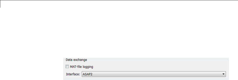
15 Program Building, Interaction, and Debugging
6On the Code Generation pane, click Browse to open the System Target
File Browser. In the browser, select Generic Real-Time Target or any
embedded real-time target and click OK.
7In the Interface field on the Interface pane, select ASAP2.
8Select the Generate code only check box on the Code Generation pane.
9Click Apply.
10 Click Generate code.
The Simulink Coder code generator writes the ASAP2 file to the build
folder. By default, the file is named model.a2l,wheremodel isthenameof
the model. The ASAP2 filename is controlled by the ASAP2 setup file. For
details see “Customize an ASAP2 File” on page 23-2.
Use the ASAM-ASAP2 Data Definition Target. The procedure for
generating a model’s data definition in ASAP2 format using the ASAM-ASAP2
Data Definition Target is as follows:
1Create the desired model. Use parameter names and signal labels to refer
to corresponding CHARACTERISTIC records and MEASUREMENT
records , respectively.
2Define the desired parameters and signals in the model to be
Simulink.Parameter and Simulink.Signal objects in the MATLAB
workspace. A convenient way of creating multiple signal and parameter
data objects is to use the Data Object Wizard. Alternatively, you can create
data objects one at a time from the MATLAB command line. For details
on how to use the Data Object Wizard, see “Data Object Wizard” in the
Simulink documentation.
3For each data object, configure the Storage class property to a setting
other than Auto or SimulinkGlobal. Thiscausesthedataobjecttobe
declared as global in the generated code. For example, a storage class
15-184

Data Exchange
setting of ExportedGlobal configures the data object as unstructured
global in the generated code.
Note If you set the storage class to Auto or SimulinkGlobal,orifyouset
the storage class to Custom and custom storage class settings cause the
Simulink Coder code generator to generate a macro or non-addressable
variable, the data object is not represented in the ASAP2 file.
4Configure the remaining propertiesasdesiredforeachdataobject.
5On the Optimization > Signals and Parameters pane of the
Configuration Parameters dialog box, select the Inline parameters check
box.
You should not configure the parameters associated with your data
objects as Simulink global (tunable) parameters in the Model Parameter
Configuration dialog box. If a parameter that resolves to a Simulink data
object is configured using the Model Parameter Configuration dialog box,
the dialog box configuration is ignored. You can, however, use the Model
Parameter Configuration dialog box to configure other parameters in your
model.
6On the Code Generation pane, click Browse to open the System Target
File Browser. In the browser, select ASAM-ASAP2 Data Definition
Target and click OK.
7Select the Generate code only check box on the Code Generation pane.
8Click Apply.
9Click Generate code.
The Simulink Coder code generator writes the ASAP2 file to the build
folder. By default, the file is named model.a2l,wheremodel isthenameof
the model. The ASAP2 filename is controlled by the ASAP2 setup file. For
details see “Customize an ASAP2 File” on page 23-2.
15-185

15 Program Building, Interaction, and Debugging
Generate ASAP2 Files for Referenced Models. The build process can
generate an ASAP2 file for each referenced model in a model reference
hierarchy. In the generated ASAP2 file, MEASUREMENT records represent
signals and states inside the referenced model.
To generate ASAP2 files for referenced models, select ASAP2 file generation
for the top model and for each referenced model in the reference hierarchy.
Forexample,ifyouareusingtheGenericReal-TimeTargetoranEmbedded
Coder target, follow the procedure described in “Use GRT or ERT Target” on
page 15-182 for the top model and each referenced model.
Merge ASAP2 Files for Top and Referenced Models. Use function
rtw.asap2MergeMdlRefs to merge the ASAP2 files generated for top and
referenced models. The function has the following syntax:
[status,info]=rtw.asap2MergeMdlRefs(topModelName,asap2FileName)
•topModelName isthenameofthemodelcontaining one or more referenced
models.
•asap2FileName is the name you specify for the merged ASAP2 file.
•Optional::status returns false (logical 0) if the merge completes and true
(logical 1) otherwise.
•Optional::info returns additional information about merge failure if
status is true. Otherwise, it returns an empty string.
Consider the following example.
[status,info]=rtw.asap2MergeMdlRefs('myTopMdl','merged.a2l')
This command merges the ASAP2 files generated for the top model myTopMdl
and its referenced models in the file merged.a2l.
The example model rtwdemo_asap2 includes an example of merging ASAP2
files.
15-186

Data Exchange
Structure of the ASAP2 File
The following table outlines the basic structure of the ASAP2 file and
describes the Target Language Compiler (TLC) functions and files used to
create each part of the file:
•Static parts of the ASAP2 file are shown in bold.
•Function calls are indicated by %<FunctionName()>.
File Section Contents of asap2main.tlc
TLC File Containing
Function Definition
File header %<ASAP2UserFcnWriteFileHead()> asap2userlib.tlc
/begin PROJECT "" /begin PROJECT "%<ASAP2ProjectName>" asap2setup.tlc
/begin HEADER ""
HEADER contents
/begin HEADER"%<ASAP2HeaderName>"
%<ASAP2UserFcnWriteHeader()>
asap2setup.tlc
asap2userlib.tlc
/end HEADER /end HEADER
/begin MODULE ""
MODULE contents:
/begin MODULE "%<ASAP2ModuleName>"} asap2setup.tlc
asap2userlib.tlc
- A2ML
- MOD_PAR
- MOD_COMMON
...
%<ASAP2UserFcnWriteHardwareInterface()>
Model-dependent
MODULE contents:
%<SLibASAP2WriteDynamicContents()>
Calls user-defined functions:
asap2lib.tlc
- RECORD_LAYOUT
- CHARACTERISTIC
- ParameterGroups
- ModelParameters
...WriteRecordLayout_TemplateName()
...WriteCharacteristic_TemplateName()
...WriteCharacteristic_Scalar()
user/templates/...
- MEASUREMENT
- ExternalInputs
- BlockOutputs
...WriteMeasurement() asap2userlib.tlc
- COMPU_METHOD ...WriteCompuMethod() asap2userlib.tlc
15-187
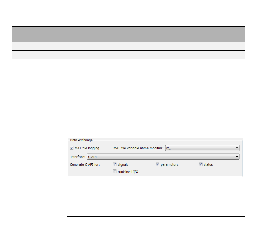
15 Program Building, Interaction, and Debugging
File Section Contents of asap2main.tlc
TLC File Containing
Function Definition
/end MODULE /end MODULE
File footer/tail %<ASAP2UserFcnWriteFileTail()> asap2userlib.tlc
Generate ASAP2 and C API Files
The ASAP2 and C API interfaces are not mutually exclusive. Although
the Interface option on the Code Generation > Interface pane of the
Configuration Parameters dialog box allows you to select either the ASAP2 or
C API interface, you can instruct the Simulink Coder product to generate files
for both interfaces by doing the following:
1On the Code Generation > Interface pane of the Configuration
Parameters dialog box, select C API for the Interface option.
2In the MATLAB Command Window, with the model open, specify the
following command:
>> set_param(gcs,'GenerateASAP2','on')
Note If you select both the C API and ASAP2 data interfaces, only the C
API options are displayed in the Configuration Parameters dialog box.
3Click Generate or Build. The code generator generates the following
ASAP2 and C API files:
•model.a2l — ASAP2 description file
•model_capi.c — C API source file
15-188

Data Exchange
•model_capi.h —CAPIheaderfile
For more information about using the C API interface, see “Data Interchange
Using the C API” on page 15-137.
Direct Memory Access to Generated Code
The Simulink Coder product provides a TLC function library that lets
you create a global data map record. The global data map record, when
generated, is added to the CompiledModel structure in the model.rtw file.
The global data map record is a database containing all information required
for accessing memory in the generated code, including
•Signals (Block I/O)
•Parameters
•Data type work vectors (DWork)
•External inputs
•External outputs
Use of the global data map requires knowledge of the Target Language
Compiler and of the structure of the model.rtw file. See “Target Language
Compiler Overview” for information on these topics.
The TLC functions that are required to generate and access the global data
maprecordarecontainedinmatlabroot/rtw/c/tlc/mw/globalmaplib.tlc.
The comments in the source code fully document the global data map
structures and the library functions.
The global data map structures and functions might be modified or enhanced
in future releases.
15-189

15 Program Building, Interaction, and Debugging
15-190


16
Optimizations for
Generated Code
•“Optimization Parameters” on page 16-2
•“Advice About Optimizing Models for Code Generation” on page 16-5
•“Control Compiler Optimizations” on page 16-6
•“Optimization Tools and Techniques” on page 16-7
•“Control Memory Allocation for Time Counters” on page 16-9
•“Optimization Dependencies” on page 16-10
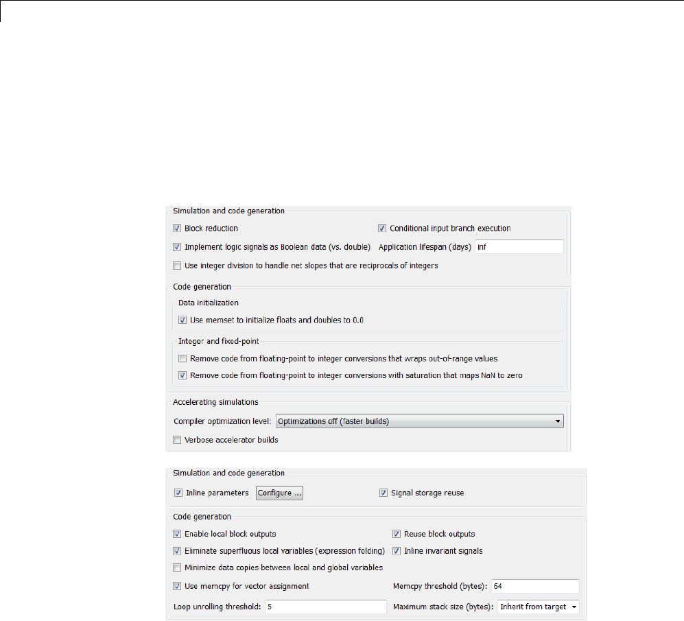
16 Optimizations for Generated Code
Optimization Parameters
Many options on the Optimization and Optimization > Signals and
Parameters panes of the Configuration Parameters dialog box affect
generated code. The following figures shows the default optimization settings,
except that Inline parameters and Inline invariant signals,whichare
cleared by default, are selected.
Some basic optimization suggestions are given below, cross-referenced to
more extensive relevant discussions in the documentation.
•Selecting the Signal storage reuse check box directs the Simulink Coder
codegeneratortostoresignalsinreusablememorylocations. Italsoenables
16-2

Optimization Parameters
the Enable local block outputs,Reuse block outputs,Eliminate
superfluous local variables (expression folding),andMinimize data
copies between local and global variables options (see below).
Disabling Signal storage reuse makes all block outputs global and
unique, which in many cases significantly increases RAM and ROM usage.
See “Reduce Memory Requirements for Signals” on page 20-4 for more
details.
•Selecting the Inline parameters check box reduces global RAM usage,
because parameters are not declared in the global parameters structure.
You can override the inlining of individual parameters by using the
Model Parameter Configuration dialog box. You tune parameters used in
referenced models differently, by declaring them as Model block parameter
arguments, rather than using the Model Parameter Configuration dialog
box. See “Inline Parameters” on page 19-2 and “Using Model Arguments”
in the Simulink documentation for more details.
•Selecting the Enable local block outputs check box declares block signals
locally in functions instead of being declared globally (when possible). You
must select Signal storage reuse to enable Enable local block outputs.
See “Declare Signals as Local Function Data” on page 18-17.
•Selecting the Reuse block outputs check box reduces stack size where
signals are buffered in local variables. You must select Signal storage
reuse to enable Reuse block outputs. See “Reuse Memory Allocated
for Signals” on page 20-5.
•Selecting the Inline invariant signals check box makes the Simulink
Coder code generator not generate code for blocks with a constant
(invariant) sample time. You must select Inline parameters to enable
Inline invariant signals. See “Inline Invariant Signals” on page 18-18.
•Selecting the Eliminate superfluous local variables (expression
folding) check box minimizes the computation of intermediate results
at block outputs and the storage of such results in temporary buffers or
variables. See “Minimize Computations and Storage for Intermediate
Results” on page 18-11.
•Selecting the Minimize data copies between local and global
variables check box reuses existing global variables to store temporary
results. You must select Signal storage reuse to enable Minimize
16-3

16 Optimizations for Generated Code
data copies between local and global variables. See “Reuse Memory
Allocated for Signals” on page 20-5.
•Set a Loop unrolling threshold. The loop unrolling threshold determines
when a wide signal should be wrapped into a for loop and when it should
be generated as a separate statement for each element of the signal. See
“Configure Loop Unrolling Threshold” on page 19-4 for details on this
feature.
•Specifying a Maximum stack size (bytes) provides control of the number
of local and global variables, which determine the amount of stack space
required for an application. See “Use Stack Space Allocation” on page 20-6
for more information.
•If your target environment supports the memcpy function, and if your model
uses signal vector assignments to move large amounts of data, selecting
the Use memcpy for vector assignment check box can improve the
execution speed of vector assignments by replacing for loops with memcpy
function calls in the generated code. Set a Memcpy threshold (bytes).
See “Optimize Code Generated for Vector Assignments” on page 19-6 for
details.
Note The rtwdemos example suite includes a set of models that illustrate
optimization settings and techniques. To access these examples, type
rtwdemos
or click the above command. The MATLAB Help browser opens the Simulink
Coder examples page. Click Optimizations in the navigation pane. Use the
examples to learn about the specific effects that optimization parameters and
techniques have on models.
16-4

Advice About Optimizing Models for Code Generation
Advice About Optimizing Models for Code Generation
Using the Model Advisor, you can quickly analyze a model for code generation
and identify aspects of your model that impede production deployment or
limit code efficiency. You can select from a set of checks to run on a model’s
current configuration. The Model Advisor analyzes the model and generates
check results providing suggestions for improvements in each area. Most
Model Advisor diagnostics do not requirethemodeltobeinacompiledstate;
those that do are noted.
Before running the Model Advisor, select the target you plan to use for
code generation. The Model Advisor works most effectively with ERT and
ERT-based targets (targets based on the Embedded Coder software).
Use the following Model Advisor examples to investigate optimizing models
for code generation using the Model Advisor:
•rtwdemo_advisor1
•rtwdemo_advisor2
•rtwdemo_advisor3
Note Example models rtwdemo_advisor2 and rtwdemo_advisor3 require
Stateflow and Fixed-Point Toolbox software.
For more information on using the Model Advisor, see “Consult the Model
Advisor” in the Simulink documentation. For more information about the
checks in the Model Advisor, see “Embedded Coder Checks” in the Simulink
Coder documentation.
16-5

16 Optimizations for Generated Code
Control Compiler Optimizations
To control compiler optimizations for your Simulink Coder makefile build at
the Simulink GUI level, use the Compiler optimization level parameter.
The Compiler optimization level parameter provides
•Target-independent values Optimizations on (faster runs) and
Optimizations off (faster builds), which allow you to easily toggle
compiler optimizations on and off during code development
•The value Custom for entering custom compiler optimization flags at the
Simulink GUI level, rather than editing compiler flags into template
makefiles (TMFs) or supplying compiler flags to Simulink Coder make
commands
The default setting is Optimizations off (faster builds). Selecting the
value Custom enables the Custom compiler optimization flags field, in
which you can enter custom compiler optimization flags (for example, -O2).
Note If you specify compiler options for your Simulink Coder makefile build
using OPT_OPTS,MEX_OPTS (except MEX_OPTS="-v"), or MEX_OPT_FILE,the
value of Compiler optimization level is ignored and a warning is issued
about the ignored parameter.
For more information about the Compiler optimization level parameter
and its values, see “Compiler optimization level” and “Custom compiler
optimization flags”.
16-6

Optimization Tools and Techniques
Optimization Tools and Techniques
In addition to analyzing models with Model Advisor (see “Advice About
Optimizing Models for Code Generation” on page 16-5), you can use a variety
of other tools and techniques that work with any code format. Here are some
particularly useful ones:
•Run the slupdate command to automatically convert older models (saved
by prior versions or by the current one) to use current features. For details
about what slupdate does, type
help slupdate
•Before building, set optimization flags for the compiler (for example, -O2
for gcc,-Ot for the Microsoft Visual C++ compiler).
•Directly inline C/C++ S-functions into the generated code by writing a TLC
file for the S-function. See “Generated S-Function Block” on page 12-34
and the Target Language Compiler documentation for more information on
inlining S-functions.
•Use a Simulink data type other than double when possible. The
available data types are Boolean, signed and unsigned 8-, 16-, and 32-bit
integers, and 32- and 64-bit floats (a double is a 64-bit float). For more
information, see “Data Types”. For a block-by-block summary, click
showblockdatatypetable or type the command in the MATLAB Command
Window.
•Remove repeated values in lookup table data.
•Use the Merge block to merge the output of signals wherever possible.
This block is particularly helpful when you need to control the execution
of function-call subsystems with a Stateflow chart. The following model
shows an example of how to use the Merge block.
16-7
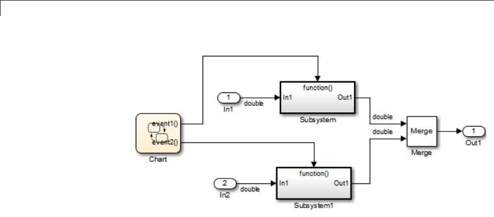
16 Optimizations for Generated Code
When more than one signal connected to a Merge block has a non-Auto
storage class, all non-Auto signals connected to that block must be
identically labeled and have the same storage class.WhenMergeblocks
connect directly to one another, these rules apply to all signals connected to
any of the Merge blocks in the group.
If you are licensed to use the Embedded Coder product, see also “Configure
Code Optimizations” in the Embedded Coder documentation.
16-8

Control Memory Allocation for Time Counters
Control Memory Allocation for Time Counters
The Application lifespan (days) parameter lets you control the allocation
of memory for absolute and elapsed time counters. Such counters exist in the
code for blocks that use absolute or elapsed time. For a list of such blocks, see
“Limitations on the Use of Absolute Time” on page 1-88.
The size of the time counters in generated code is 8, 16, 32, or 64 bits. The
size is set automatically to the minimum that can accommodate the duration
value specified by Application lifespan (days) given the step size specified
in the Configuration Parameters Solver pane. To minimize the amount of
RAM used by time counters, specify the smallest lifespan possible and the
largest step size possible.
An application runs to its specified lifespan. It may be able to run longer. For
example, running a model with a step size of one millisecond (0.001 seconds)
for one day requires a 32-bit timer, which could continue running without
overflow for 49 days more.
To maximize application lifespan, specify Application lifespan (days) as
inf. Thisvalueallocates64bits(twouint32 words) for each timer. Using
64 bits to store timing data would allow a model with a step size of 0.001
microsecond (10E-09 seconds) to run for more than 500 years, which would
rarely be required. 64-bit counters do not violate the usual Simulink Coder
length limitation of 32 bits because the value of a time counter never provides
the value of a signal, state, or parameter.
For information about the allocation and operation of absolute and
elapsed time counters, see “Timers” on page 1-79. For information about
asynchronous timing, see “Use Timers in Asynchronous Tasks” on page
1-58. For information about the effect of the Application lifespan (days)
parameter on simulation, see “Application lifespan (days)” in the Simulink
documentation.
16-9

16 Optimizations for Generated Code
Optimization Dependencies
Several parameters available on the Optimization panes have dependencies
on settings of other options. The following table summarizes the dependencies.
Option Dependencies? Dependency Details
Block reduction No
Conditional input branch
execution
No
Implement logic signals as
Boolean data(versusdouble)
Yes Disable for models created with a
Simulink version that supports only
signals of type double
Signal storage reuse No
Inline parameters Yes Disable for referenced models in a
model reference hierarchy
Application lifespan (days) No
Parameter structure (ERT
targets only)
Yes EnabledbyInline parameters
Enable local block outputs Yes Enabled by Signal storage reuse
Reuse block outputs Yes Enabled by Signal storage reuse
Inline invariant signals Yes Enabled by Inline parameters
Eliminate superfluous local
variables (expression folding)
Yes Enabled by Signal storage reuse
Pack Boolean data into bitfields
(ERT targets only)
No
Bitfield declarator type
specifier (ERT targets only)
Yes Enabled by Pack Boolean data into
bitfields
Minimize data copies between
local and global variables
Yes Enabled by Signal storage reuse
Simplify array indexing (ERT
targets only)
No
Loop unrolling threshold No
16-10

Optimization Dependencies
Option Dependencies? Dependency Details
Maximum stack size (bytes) No
Use memcpy for vector
assignment
No
Memcpy threshold (bytes) Yes Enabled by Use memcpy for vector
assignment
Pass reusable subsystem output
as (ERT targets only)
No
Remove root level I/O zero
initialization (ERT targets only)
No
Use memset to initialize floats
and doubles to 0.0
No
Remove internal data zero
initialization (ERT targets only)
No
Optimize initialization code for
model reference (ERT targets
only)
Yes Disable if model includes an enabled
subsystem and the model is referred to
from another model with a Model block
Remove code from
floating-point to integer
conversions that wrap
out-of-range values
No
Remove code from
floating-point to integer
conversions with saturation
that maps NaN to zero
Yes (ERT targets)
No (GRT targets)
For ERT targets, enabled by Support
floating-point numbers and
Support non-finite numbers in the
Code Generation > Interface pane
Remove code that protects
against division arithmetic
exceptions (ERT targets only)
No
16-11

16 Optimizations for Generated Code
16-12


17 Defensive Programming
Optimize Code for Floating-Point to Integer Conversions
In this section...
“Remove Code That Wraps Out-of-Range Values” on page 17-2
“Remove Code That Maps NaN to Integer Zero” on page 17-3
Remove Code That Wraps Out-of-Range Values
Selecting the Remove code from floating-point to integer conversions
that wraps out-of-range values check box in the Integer and fixed-point
section of the Optimization pane causes the code generator to remove code
that produces the same results as simulation when out-of-range conversions
occur. This action reduces the size and increases the speed of generated code
at the cost of potentially producing results that do not match simulation in
thecaseofout-of-rangevalues. Formoreinformation,see“Optimization
Pane: General”.
The code generated for a conversion when you select the check box follows:
cg_in_0_20_0[i1] = (int32_T)((rtb_Switch[i1] + 9.0) / 0.09375);
The code generated for a conversion when you clear the check box follows:
_fixptlowering0 = (rtb_Switch[i1] + 9.0) / 0.09375;
_fixptlowering1 = fmod(_fixptlowering0 >= 0.0 ? floor(_fixptlowering0) :
ceil(_fixptlowering0), 4.2949672960000000E+009);
if(_fixptlowering1 < -2.1474836480000000E+009) {
_fixptlowering1 += 4.2949672960000000E+009;
} else if(_fixptlowering1 >= 2.1474836480000000E+009) {
_fixptlowering1 -= 4.2949672960000000E+009;
}
cg_in_0_20_0[i1] = (int32_T)_fixptlowering1;
The code generator applies the fmod function to handle out-of-range
conversion results.
17-2

Optimize Code for Floating-Point to Integer Conversions
Remove Code That Maps NaN to Integer Zero
Selecting the Remove code from floating-point to integer conversions
with saturation that maps NaN to zero check box in the Integer and
fixed-point section of the Optimization pane causes the code generator to
remove code that produces the same results as simulation when mapping
from NaN to integer zero occurs. This action reduces the size and increases
the speed of generated code at the cost of producing results that do not match
simulation in the case of NaN values. For more information, see “Optimization
Pane: General”.
The code generated for a conversion when you select the check box follows:
if (tmp < 2.147483648E+09) {
if (tmp >= -2.147483648E+09) {
tmp_0 = (int32_T)tmp;
} else {
tmp_0 = MIN_int32_T;
}
} else {
tmp_0 = MAX_int32_T;
}
The code generated for a conversion when you clear the check box follows:
if (tmp < 2.147483648E+09) {
if (tmp >= -2.147483648E+09) {
tmp_0 = (int32_T)tmp;
} else {
tmp_0 = MIN_int32_T;
}
} else if (tmp >= 2.147483648E+09) {
tmp_0 = MAX_int32_T;
}else {
tmp_0 = 0;
}
17-3

17 Defensive Programming
Disable Nonfinite Checks or Inlining for Math Functions
When Simulink Coder software generates code for math functions,
•If the model option Support non-finite numbers is selected, nonfinite
number checking is generated uniformly for math functions, without the
ability to specify that nonfinite number checking should be generated for
some functions, but not for others.
•By default, inlining is applied uniformly for math functions, without the
ability to specify that inlining should be generated for some functions,
while invocations should be generated for others.
You can use code replacement library (CRL) customization entries to:
•Selectively disable nonfinite checks for math functions. This can improve
the execution speed of the generated code.
•Selectively disable inlining of math functions. This can increase code
readability and decrease code size.
The functions for which these customizations are supported include the
following:
•Floating-point only: atan2,ceil,copysign,fix,floor,hypot,log,log10,
round,sincos,andsqrt
•Floating-point and integer: abs,max,min,mod,rem,saturate,andsign
The general workflow for disabling nonfinite number checking and/or inlining
is as follows:
1If you can disable nonfinite number checking for a particular math
function, or if you want to disable inlining for a particular math function
and instead generate a function invocation, you can copy the following
MATLAB function code into a MATLAB file with an .m file name extension,
for example, crl_table_customization.m.
function hTable = crl_table_customization
% Create an instance of the Code Replacement Library table for controlling
17-4

Disable Nonfinite Checks or Inlining for Math Functions
% function intrinsic inlining and nonfinite support
hTable = RTW.TflTable;
% Inline - true (if function needs to be inline)
% false (if function should not be inlined)
% SNF (support nonfinite) - ENABLE (if non-finite checking should be performed)
% DISABLE (if non-finite checking should NOT be performed)
% UNSPECIFIED (Default behavior)
% registerCustomizationEntry(hTable, ...
% Priority, numInputs, key, inType, outType, Inline, SNF);
registerCustomizationEntry(hTable, ...
100, 2, 'atan2', 'double', 'double', false, 'UNSPECIFIED');
registerCustomizationEntry(hTable, ...
100, 2, 'atan2', 'single', 'single', false, 'UNSPECIFIED');
registerCustomizationEntry(hTable, ...
100, 1, 'sincos', 'double', 'double', false, 'UNSPECIFIED');
registerCustomizationEntry(hTable, ...
100, 1, 'sincos', 'single', 'single', false, 'UNSPECIFIED');
registerCustomizationEntry(hTable, ...
100, 1, 'abs', 'double', 'double', true, 'UNSPECIFIED');
registerCustomizationEntry(hTable, ...
100, 1, 'abs', 'single', 'single', true, 'UNSPECIFIED');
registerCustomizationEntry(hTable, ...
100, 1, 'abs', 'int32', 'int32', true, 'UNSPECIFIED');
registerCustomizationEntry(hTable, ...
100, 1, 'abs', 'int16', 'int16', true, 'UNSPECIFIED');
registerCustomizationEntry(hTable, ...
100, 1, 'abs', 'int8', 'int8', true, 'UNSPECIFIED');
registerCustomizationEntry(hTable, ...
100, 1, 'abs', 'integer','integer',true, 'UNSPECIFIED');
registerCustomizationEntry(hTable, ...
100, 1, 'abs', 'uint32', 'uint32', true, 'UNSPECIFIED');
registerCustomizationEntry(hTable, ...
100, 1, 'abs', 'uint16', 'uint16', true, 'UNSPECIFIED');
17-5

17 Defensive Programming
registerCustomizationEntry(hTable, ...
100, 1, 'abs', 'uint8', 'uint8', true, 'UNSPECIFIED');
registerCustomizationEntry(hTable, ...
100, 2, 'hypot', 'double', 'double', false, 'UNSPECIFIED');
registerCustomizationEntry(hTable, ...
100, 2, 'hypot', 'single', 'single', false, 'UNSPECIFIED');
registerCustomizationEntry(hTable, ...
100, 1, 'log', 'double', 'double', false, 'UNSPECIFIED');
registerCustomizationEntry(hTable, ...
100, 1, 'log', 'single', 'double', false, 'UNSPECIFIED');
registerCustomizationEntry(hTable, ...
100, 1, 'log10', 'double', 'double', false, 'UNSPECIFIED');
registerCustomizationEntry(hTable, ...
100, 1, 'log10', 'single', 'double', false, 'UNSPECIFIED');
registerCustomizationEntry(hTable, ...
100, 2, 'min', 'double', 'double', true, 'UNSPECIFIED');
registerCustomizationEntry(hTable, ...
100, 2, 'min', 'single', 'single', true, 'UNSPECIFIED');
registerCustomizationEntry(hTable, ...
100, 2, 'min', 'int32', 'int32', true, 'UNSPECIFIED');
registerCustomizationEntry(hTable, ...
100, 2, 'min', 'int16', 'int16', true, 'UNSPECIFIED');
registerCustomizationEntry(hTable, ...
100, 2, 'min', 'int8', 'int8', true, 'UNSPECIFIED');
registerCustomizationEntry(hTable, ...
100, 2, 'min', 'uint32', 'uint32', true, 'UNSPECIFIED');
registerCustomizationEntry(hTable, ...
100, 2, 'min', 'uint16', 'uint16', true, 'UNSPECIFIED');
registerCustomizationEntry(hTable, ...
100, 2, 'min', 'uint8', 'uint8', true, 'UNSPECIFIED');
registerCustomizationEntry(hTable, ...
100, 2, 'min', 'integer','integer',true, 'UNSPECIFIED');
registerCustomizationEntry(hTable, ...
100, 2, 'max', 'double', 'double', true, 'UNSPECIFIED');
registerCustomizationEntry(hTable, ...
17-6

Disable Nonfinite Checks or Inlining for Math Functions
100, 2, 'max', 'single', 'single', true, 'UNSPECIFIED');
registerCustomizationEntry(hTable, ...
100, 2, 'max', 'int32', 'int32', true, 'UNSPECIFIED');
registerCustomizationEntry(hTable, ...
100, 2, 'max', 'int16', 'int16', true, 'UNSPECIFIED');
registerCustomizationEntry(hTable, ...
100, 2, 'max', 'int8', 'int8', true, 'UNSPECIFIED');
registerCustomizationEntry(hTable, ...
100, 2, 'max', 'uint32', 'uint32', true, 'UNSPECIFIED');
registerCustomizationEntry(hTable, ...
100, 2, 'max', 'uint16', 'uint16', true, 'UNSPECIFIED');
registerCustomizationEntry(hTable, ...
100, 2, 'max', 'uint8', 'uint8', true, 'UNSPECIFIED');
registerCustomizationEntry(hTable, ...
100, 2, 'max', 'integer','integer',true, 'UNSPECIFIED');
registerCustomizationEntry(hTable, ...
100, 2, 'mod', 'double', 'double', false, 'UNSPECIFIED');
registerCustomizationEntry(hTable, ...
100, 2, 'mod', 'single', 'single', false, 'UNSPECIFIED');
registerCustomizationEntry(hTable, ...
100, 2, 'mod', 'int32', 'int32', false, 'UNSPECIFIED');
registerCustomizationEntry(hTable, ...
100, 2, 'mod', 'int16', 'int16', false, 'UNSPECIFIED');
registerCustomizationEntry(hTable, ...
100, 2, 'mod', 'int8', 'int8', false, 'UNSPECIFIED');
registerCustomizationEntry(hTable, ...
100, 2, 'mod', 'uint32', 'uint32', false, 'UNSPECIFIED');
registerCustomizationEntry(hTable, ...
100, 2, 'mod', 'uint16', 'uint16', false, 'UNSPECIFIED');
registerCustomizationEntry(hTable, ...
100, 2, 'mod', 'uint8', 'uint8', false, 'UNSPECIFIED');
registerCustomizationEntry(hTable, ...
100, 2, 'rem', 'double', 'double', false, 'UNSPECIFIED');
registerCustomizationEntry(hTable, ...
100, 2, 'rem', 'single', 'single', false, 'UNSPECIFIED');
registerCustomizationEntry(hTable, ...
100, 2, 'rem', 'int32', 'int32', false, 'UNSPECIFIED');
registerCustomizationEntry(hTable, ...
17-7

17 Defensive Programming
100, 2, 'rem', 'int16', 'int16', false, 'UNSPECIFIED');
registerCustomizationEntry(hTable, ...
100, 2, 'rem', 'int8', 'int8', false, 'UNSPECIFIED');
registerCustomizationEntry(hTable, ...
100, 2, 'rem', 'uint32', 'uint32', false, 'UNSPECIFIED');
registerCustomizationEntry(hTable, ...
100, 2, 'rem', 'uint16', 'uint16', false, 'UNSPECIFIED');
registerCustomizationEntry(hTable, ...
100, 2, 'rem', 'uint8', 'uint8', false, 'UNSPECIFIED');
registerCustomizationEntry(hTable, ...
100, 1, 'round', 'double', 'double', false, 'UNSPECIFIED');
registerCustomizationEntry(hTable, ...
100, 1, 'round', 'single', 'single', false, 'UNSPECIFIED');
registerCustomizationEntry(hTable, ...
100, 3, 'saturate', 'double', 'double', true, 'UNSPECIFIED');
registerCustomizationEntry(hTable, ...
100, 3, 'saturate', 'single', 'single', true, 'UNSPECIFIED');
registerCustomizationEntry(hTable, ...
100, 3, 'saturate', 'int32', 'int32', true, 'UNSPECIFIED');
registerCustomizationEntry(hTable, ...
100, 3, 'saturate', 'int16', 'int16', true, 'UNSPECIFIED');
registerCustomizationEntry(hTable, ...
100, 3, 'saturate', 'int8', 'int8', true, 'UNSPECIFIED');
registerCustomizationEntry(hTable, ...
100, 3, 'saturate', 'uint32', 'uint32', true, 'UNSPECIFIED');
registerCustomizationEntry(hTable, ...
100, 3, 'saturate', 'uint16', 'uint16', true, 'UNSPECIFIED');
registerCustomizationEntry(hTable, ...
100, 3, 'saturate', 'uint8', 'uint8', true, 'UNSPECIFIED');
registerCustomizationEntry(hTable, ...
100, 3, 'saturate', 'integer','integer',true, 'UNSPECIFIED');
registerCustomizationEntry(hTable, ...
100, 1, 'sign', 'double', 'double', true, 'UNSPECIFIED');
registerCustomizationEntry(hTable, ...
100, 1, 'sign', 'single', 'single', true, 'UNSPECIFIED');
registerCustomizationEntry(hTable, ...
100, 1, 'sign', 'int32', 'integer', true, 'UNSPECIFIED');
17-8

Disable Nonfinite Checks or Inlining for Math Functions
registerCustomizationEntry(hTable, ...
100, 1, 'sign', 'int16', 'integer', true, 'UNSPECIFIED');
registerCustomizationEntry(hTable, ...
100, 1, 'sign', 'int8', 'integer', true, 'UNSPECIFIED');
registerCustomizationEntry(hTable, ...
100, 1, 'sign', 'uint32', 'uint32', true, 'UNSPECIFIED');
registerCustomizationEntry(hTable, ...
100, 1, 'sign', 'uint16', 'uint16', true, 'UNSPECIFIED');
registerCustomizationEntry(hTable, ...
100, 1, 'sign', 'uint8', 'uint8', true, 'UNSPECIFIED');
registerCustomizationEntry(hTable, ...
100, 1, 'sign', 'integer','integer', true, 'UNSPECIFIED');
registerCustomizationEntry(hTable, ...
100, 1, 'sqrt', 'double', 'double', true, 'UNSPECIFIED');
registerCustomizationEntry(hTable, ...
100, 1, 'sqrt', 'single', 'single', true, 'UNSPECIFIED');
registerCustomizationEntry(hTable, ...
100, 1, 'ceil', 'double', 'double', true, 'UNSPECIFIED');
registerCustomizationEntry(hTable, ...
100, 1, 'ceil', 'single', 'single', true, 'UNSPECIFIED');
registerCustomizationEntry(hTable, ...
100, 1, 'floor', 'double', 'double', true, 'UNSPECIFIED');
registerCustomizationEntry(hTable, ...
100, 1, 'floor', 'single', 'single', true, 'UNSPECIFIED');
registerCustomizationEntry(hTable, ...
100, 1, 'fix', 'double', 'double', false, 'UNSPECIFIED');
registerCustomizationEntry(hTable, ...
100, 1, 'fix', 'single', 'single', false, 'UNSPECIFIED');
registerCustomizationEntry(hTable, ...
100, 1, 'copysign', 'double', 'double', true, 'UNSPECIFIED');
registerCustomizationEntry(hTable, ...
100, 1, 'copysign', 'single', 'single', true, 'UNSPECIFIED');
17-9

17 Defensive Programming
2To reduce the size of the file, you can delete the
registerCustomizationEntry lines for functions for which the default
nonfinite number checking and inlining behavior is acceptable.
3For each remaining entry,
•Set the Inline argument to true if the function should be inlined or
false if it should not be inlined.
•Set the SNF argument to ENABLE if nonfinite checking should be
generated, DISABLE if nonfinite checking should not be generated, or
UNSPECIFIED to accept the default behavior based on the model option
settings.
Save the file.
4Optionally, perform a quick check of the syntactic validity of the
customization table entries by invoking the table definition file at the
MATLAB command line (>> tbl = crl_table_customization). Fix
syntax errors that are flagged.
5Optionally, view the customization table entries in the Code Replacement
Viewer (>> RTW.viewTfl(crl_table_customization)). For more
information about viewing CRL tables, see “Selecting and Viewing Code
Replacement Libraries” on page 9-61.
6To register these changes and make them appear in the Code replacement
library drop-down list located on the Code Generation > Interface
pane of the Configuration Parameters dialog box, first copy the following
MATLAB function code into an instance of the file sl_customization.m.
Note For the RTW.TflRegistry instantiation shown below, specify the
argument 'RTW' if a GRT target is selected for your model, otherwise
omit the argument.
function sl_customization(cm)
% sl_customization function to register a code replacement library (CRL)
% Register the CRL defined in local function locCrlRegFcn
cm.registerTargetInfo(@locCrlRegFcn);
17-10

Disable Nonfinite Checks or Inlining for Math Functions
end % End of SL_CUSTOMIZATION
% Local function to define a CRL containing crl_table_customization
function thisCrl = locCrlRegFcn
% Instantiate a CRL registry entry - specify 'RTW' for GRT
thisCrl = RTW.TflRegistry('RTW');
% Define the CRL properties
thisCrl.Name = 'CRL Customization Example';
thisCrl.Description = 'Example of CRL Customization';
thisCrl.TableList = {'crl_table_customization'};
thisCrl.BaseTfl = 'C89/C90 (ANSI)';
thisCrl.TargetHWDeviceType = {'*'};
end % End of LOCCRLREGFCN
You can edit the Name field to determine what CRL name will appear in
the Code replacement library drop-down list. Also, the file name in the
TableList field must match the name of the file you created in step 1.
To register your changes, with both of the MATLAB files you created
present in the MATLAB path, enter the following command in the
MATLAB Command Window:
sl_refresh_customizations
7Create or open a model that will generate function code corresponding to
one of the math functions for which you specified a change in nonfinite
number checking or inlining behavior.
8Open the Configuration Parameters dialog box, go to the Code
Generation > Interface pane, and use the Code replacement library
drop-down list to select the CRL entry you registered in step 6, for example,
CRL Customization Example.
9Generate code for the model and examine the generated code to verify that
the math functions are generated as expected.
17-11

17 Defensive Programming
17-12

18
Data Copy Reduction
•“Optimizing Generated Code” on page 18-2
•“Generate Code Without Buffer Optimization” on page 18-4
•“Generate Code With Buffer Optimization” on page 18-9
•“Minimize Computations and Storage for Intermediate Results” on page
18-11
•“Declare Signals as Local Function Data” on page 18-17
•“Inline Invariant Signals” on page 18-18
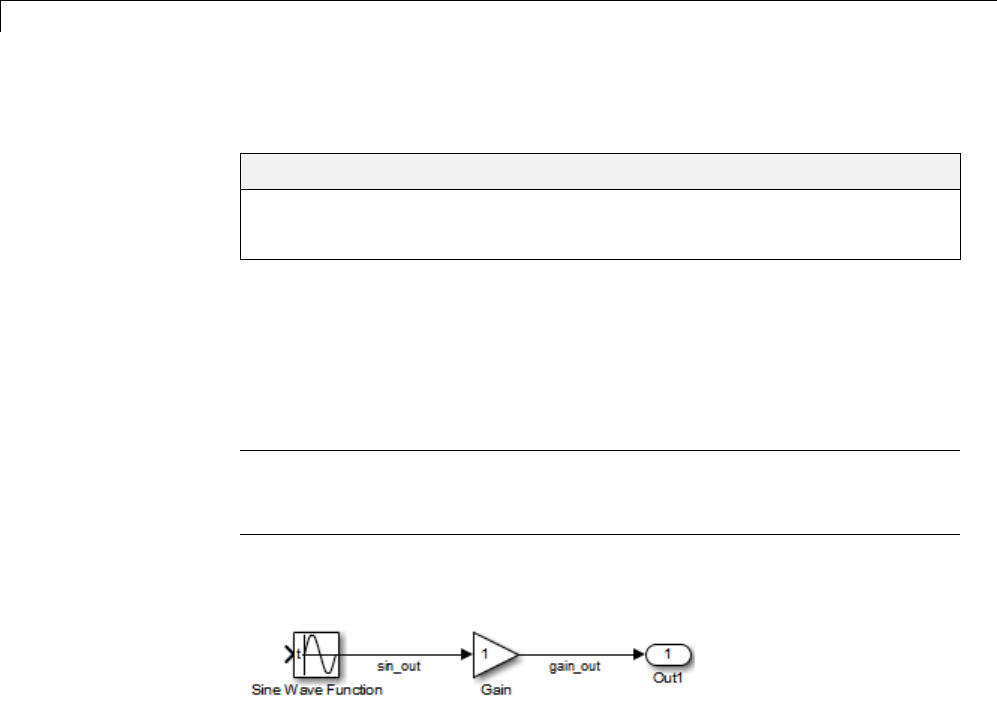
18 Data Copy Reduction
Optimizing Generated Code
In this section...
“About Optimizing Generated Code” on page 18-2
“Setting Up the Model” on page 18-2
About Optimizing Generated Code
This section shows how to configure optimizations and generate code for a
model. It shows the generated code before and after the optimizations are
applied.
Note You can view the code generated from this example using the
MATLAB editor or by generating an HTML code generation report. For more
information, see “Generate a Code Generation Report” on page 11-5.
The example model used, example, is shown below.
Setting Up the Model
First, create the model from Simulink library blocks, and set up basic
Simulink and Simulink Coder parameters as follows:
1Create a folder, example_codegen, and make it your working folder:
!mkdir example_codegen
cd example_codegen
2Create a new model and save it as example.
3Add Sine Wave, Gain, and Out1 blocks to your model and connect them as
shown in the preceding diagram. Label the signals as shown.
18-2

Optimizing Generated Code
4Open Model Explorer by selecting Model Explorer from the model’s
View menu.
5In the Model Hierarchy pane, click the symbol preceding the model name
to reveal its components.
6Click Configuration (Active) in the left pane.
7Select Solver in the center pane. The Solver pane appears at the right.
8In the Solver Options pane:
aSelect Fixed-step in the Type field.
bSelect discrete (no continuous states) in the Solver field.
cSpecify 0.1 in the Fixed-step size field. (Otherwise, the Simulink
Coder code generator posts a warning and supplies a default value when
you generate code.)
9Click Apply.
10 Click Data Import/Export in the center pane and make sure all check
boxes in the right pane are cleared. Click Apply if you made any changes.
11 Select Code Generation in the center pane. Under Target Selection in
the right pane, select the default generic real-time (GRT) target grt.tlc.
12 Select Generate code only at the bottom of the right pane. This option
causes the Simulink Coder software to generate code and a make file,
then stop at that point, rather than proceeding to invoke make to compile
and link the code. Note that the label on the Build button changes to
Generate code.
13 Click Apply.
14 Save the model.
18-3
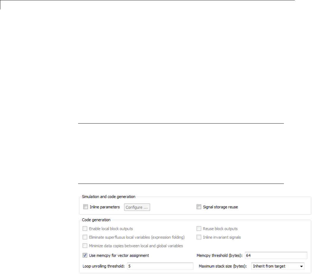
18 Data Copy Reduction
Generate Code Without Buffer Optimization
With buffer optimizations Simulink Coder software generates code that
reduces memory consumption and execution time. In this example, you
disable the buffer optimizations to see what the nonoptimized generated code
looks like:
1Select Optimization in the center pane and click the Signals and
Parameters tab in the right pane. The Signals and Parameters pane
appears at the right. Clear the Signal storage reuse option, as shown
below. Change other attributes to match the figure.
Note Clearing the Signal storage reuse option disables the following
options:
•Enable local block outputs
•Reuse block outputs
•Eliminate superfluous local variables (expression folding)
•Minimize data copies between local and global variables
2Click Apply.
3Select Code Generation inthecenterpaneandclicktheReport tab on
the right pane. The Report pane appears at the right.
18-4

Generate Code Without Buffer Optimization
4Select the Create code generation report and Open report
automatically check boxes. Selecting these check boxes makes the code
generation report display after the build process completes.
5Click Apply.
6Select the General tab in the right pane and select Generate code only.
7Click Generate code.
Because you selected the Generate code only option, the Simulink Coder
build process does not invoke your make utility. The code generation
processendswiththismessage:
### Successful completion of build procedure
for model: example
8The generated code is in the build folder, example_grt_rtw.Thefile
example_grt_rtw/example.c contains the output computation for the
model. You can view this file in the code generation report by clicking
the example.c link in the left pane.
9In example.c, find the function example_output nearthetopofthefile.
The generated C code consists of procedures that implement the algorithms
defined by your Simulink block diagram. The execution engine calls
the procedures in succession as time movesforward. Themodulesthat
implement the execution engine and other capabilities are referred to
collectively as the run-time interface modules. See the Simulink Coder
User’s Guide for a complete discussion of how the Simulink Coder
software interfaces and executes application, system-dependent, and
system-independent modules, in each of the two styles of generated code.
18-5

18 Data Copy Reduction
In code generated for example,thegeneratedexample_output function
implements the actual algorithm for multiplying a sine wave by a gain.
The example_output function computes the model’s block outputs. The
run-time interface must call example_output at every time step. With
buffer optimizations turned off, example_output assigns unique buffers
to each block output. These buffers (rtB.sin_out,rtB.gain_out)are
members of a global block I/O data structure, called in this code example_B
anddeclaredasfollows:
/* Block signals (auto storage) */
BlockIO_example example_B;
The data type BlockIO_example is defined in example.h as follows:
/* Block signals (auto storage) */
extern BlockIO_example example_B;
The output code accesses fields of this global structure, as shown below:
/* Model output function */
static void example_output(int_T tid)
{
/* Sin: '<Root>/Sine Wave' */
example_B.sin_out = sin(example_P.SineWave_Freq * example_M->Timing.t[0] +
example_P.SineWave_Phase) * example_P.SineWave_Amp + example_P.SineWave_Bias;
/* Gain: '<Root>/Gain' */
example_B.gain_out = example_P.Gain_Gain * example_B.sin_out;
/* Outport: '<Root>/Out1' */
example_Y.Out1 = example_B.gain_out;
/* tid is required for a uniform function interface.
* Argument tid is not used in the function. */
UNUSED_PARAMETER(tid);
}
18-6

Generate Code Without Buffer Optimization
10 In GRT targets such as this, the function example_output is called
by a wrapper function, MdlOutputs.Inexample.c, find the function
MdlOutputs near the end. It looks like this:
void MdlOutputs(int_T tid)
{
example_output(tid);
}
Note In previous releases, MdlOutputs was the actual output function for
code generated by all GRT-configured models. It is now implemented as a
wrapper function to provide greater compatibility among different target
configurations.
18-7

18 Data Copy Reduction
18-8
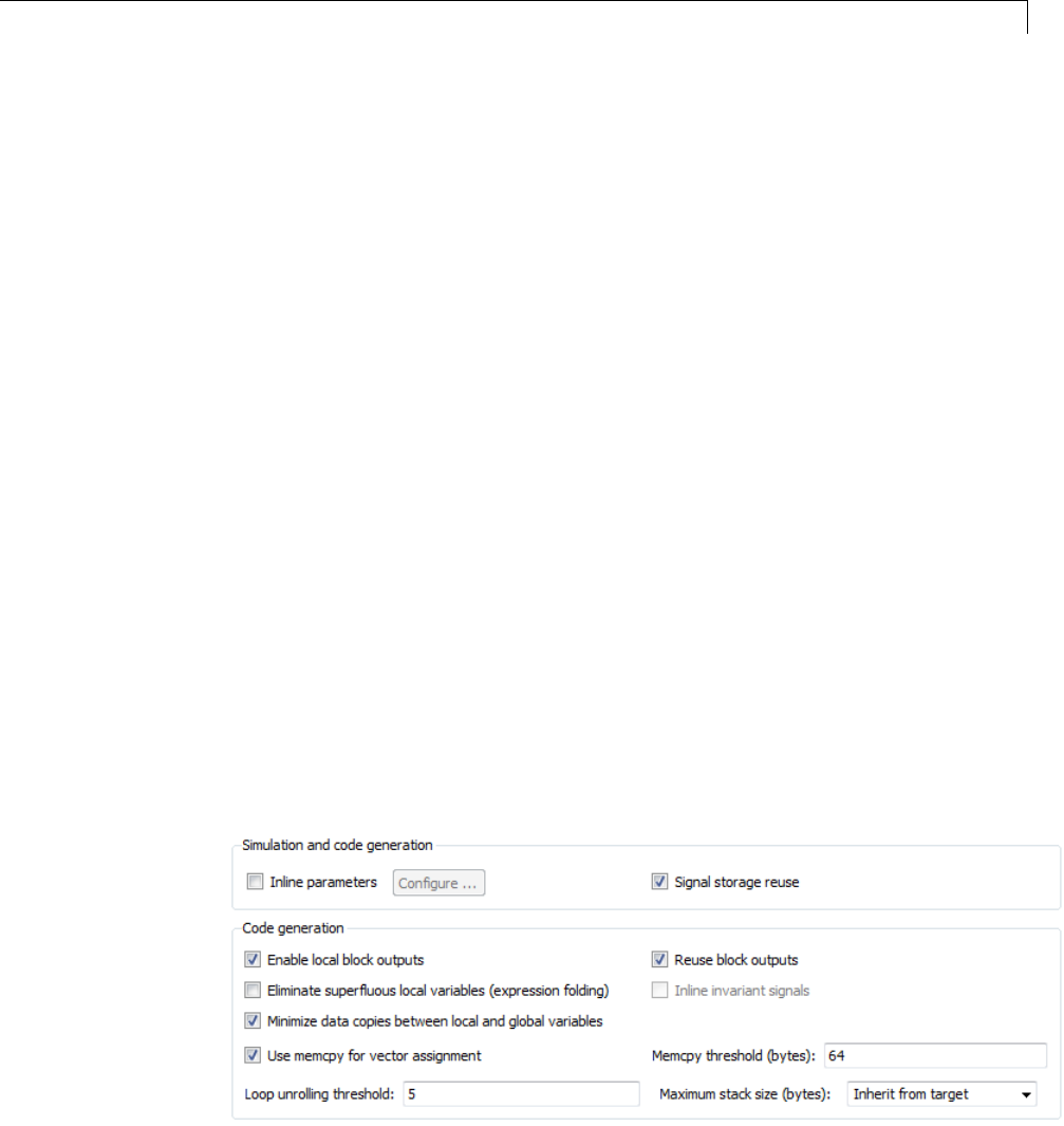
Generate Code With Buffer Optimization
Generate Code With Buffer Optimization
With buffer optimizations, Simulink Coder software generates code that
reduces memory consumption and execution time. In this example, you turn
buffer optimizations on and observe how they improve the code. Enable signal
buffer optimizations and regenerate the code as follows:
1Change your current working folder to example_codegen if you have not
already done so.
2In Model Explorer, select Optimization in the center pane and click
the Signals and Parameters tab on the right pane. The Signals and
Parameters pane appears at the right. Select the Signal storage reuse
option.
3Note that the following parameters become enabled in the Code
generation section:
•Enable local block outputs
•Reuse block outputs
•Eliminate superfluous local variables (expression folding)
•Minimize data copies between local and global variables
Make sure that Enable local block outputs,Reuse block outputs,
and Minimize data copies between local and global variables are
selected, and that Eliminate superfluous local variables (expression
folding) is cleared, as shown below.
18-9

18 Data Copy Reduction
You will observe the effects of expression folding later in this example. Not
performing expression folding allows you to see the effects of the buffer
optimizations.
4Click Apply to apply the new settings.
5Select Code Generation in the center pane, and click Generate code
on the right.
As before, the Simulink Coder software generates code in the
example_grt_rtw folder. The previously generated code is overwritten.
6View example.c and examine the example_output function.
With buffer optimizations enabled, the code in example_output reuses the
example_Y.Out1 global buffer.
/* Model output function */
static void example_output(int_T tid)
{
/* Sin: '<Root>/Sine Wave' */
example_Y.Out1 = sin(example_P.SineWave_Freq * example_M->Timing.t[0] +
example_P.SineWave_Phase) * example_P.SineWave_Amp +
example_P.SineWave_Bias;
/* Gain: '<Root>/Gain' */
example_Y.Out1 = example_P.Gain_Gain * example_Y.Out1;
/* tid is required for a uniform function interface.
* Argument tid is not used in the function. */
UNUSED_PARAMETER(tid);
}
This code is more efficient in terms of memory usage and execution speed. By
eliminating a global variable and a data copy instruction, the data section
is smaller and the code is smaller and faster. The efficiency improvement
gained by selecting Enable local block outputs,Reuse block outputs,
and Minimize data copies between local and global variables is more
significant in a large model with many signals.
18-10

Minimize Computations and Storage for Intermediate Results
Minimize Computations and Storage for Intermediate
Results
In this section...
“About Expression Folding” on page 18-11
“Expression Folding Example” on page 18-12
“Enable Expression Folding” on page 18-15
About Expression Folding
Expression folding is a code optimization technique that minimizes the
computation of intermediate results at block outputs and the storage of such
results in temporary buffers or variables. Eliminate superfluous local
variables (expression folding) is used to enable expression folding. When
expression folding is on, the Simulink Coder code generator collapses, or
“folds,” block computations into a single expression, instead of generating
separate code statements and storage declarations for each block in the model.
Expression folding can dramatically improve the efficiency of generated code,
frequently achieving results that compare favorably to hand-optimized code.
In many cases, entire groups of model computations fold into a single highly
optimized line of code.
By default, expression folding is on. The Simulink Coder code generation
options are configured to use expression folding wherever possible. Most
Simulink blocks support expression folding.
You can also take advantage of expression folding in your own inlined
S-function blocks. See “Write S-Functions That Support Expression Folding”
on page 14-91 for information on how to do this.
Inthecodegenerationexamples that follow, the Signal storage reuse
optimizations (Enable local block outputs,Reuse block outputs,
Eliminate superfluous local variables (expression folding) and
Minimize data copies between local and global variables)areall
turned on.
18-11
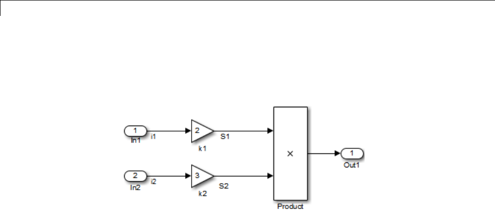
18 Data Copy Reduction
Expression Folding Example
As a simple example of how expression folding affects the code generated from
a model, consider the following model.
With expression folding on, this model generates a single-line output
computation, as shown in this model_output function.
static void exprfld_output(int_T tid)
{
/* Outport: '<Root>/Out1' incorporates:
* Gain: '<Root>/k1'
* Gain: '<Root>/k2'
* Inport: '<Root>/In1
* Inport: '<Root>/In2
* Product: '<Root>/Product'
*/
exprfld_Y.Out1 = exprfld_U.i1 * exprfld_P.k1_Gain *
(exprfld_U.i2 * exprfld_P.k2_Gain);
}
The generated comments indicate the block computations that were combined
into a single expression. The comments also document the block parameters
that appear in the expression.
With expression folding off, the same model computes temporary results for
both Gain blocks before the final output, as shown in this output function:
static void exprfld_output(int_T tid)
18-12

Minimize Computations and Storage for Intermediate Results
{
real_T rtb_S2;
/* Gain: '<Root>/k1' incorporates:
* Inport: '<Root>/In1'
*/
exprfld_Y.Out1 = exprfld_U.i1 * exprfld_P.k1_Gain
/* Gain: '<Root>/k2' incorporates:
* Inport: '<Root>/In2'
*/
rtb_S2 = exprfld_U.i2 * exprfld_P.k2_Gain;
/* Product: '<Root>/Product' */
exprfld_Y.Out1 = exprfld_Y.Out1 * rtb_S2;
}
Turn on expression folding, a code optimization technique that minimizes
the computation of intermediate results and the use of temporary buffers
or variables.
Enable expression folding and regeneratethecodeasfollows:
1Change your current working folder to example_codegen if you have not
already done so.
2In Model Explorer, select Optimization in the center pane and click
the Signals and Parameters tab on the right pane. The Signals and
Parameters pane appears at the right.
18-13

18 Data Copy Reduction
3Select the Eliminate superfluous local variables (expression folding)
option.
4Click Apply.
5Select Code Generation in the center pane, and click Generate code
on the right.
The Simulink Coder software generates code as before.
6View example.c and examine the function example_output.
In the previous examples, the Gain block computation was computed in a
separate code statement and the result was stored in a temporary location
before the final output computation.
With Eliminate superfluous local variables (expression folding)
selected, there is a subtle but significant difference in the generated code:
the gain computation is incorporated (or folded) directly into the Outport
computation, eliminating the temporary location and separate code statement.
This computation is on the last line of the example_output function.
/* Model output function */
static void example_output(int_T tid)
{
/* Outport: '<Root>/Out1' incorporates:
* Gain: '<Root>/Gain'
* Sin: '<Root>/Sine Wave'
18-14

Minimize Computations and Storage for Intermediate Results
*/
example_Y.Out1 = (sin(example_P.SineWave_Freq * example_M->Timing.t[0] +
example_P.SineWave_Phase) * example_P.SineWave_Amp +
example_P.SineWave_Bias) * example_P.Gain_Gain;
/* tid is required for a uniform function interface.
* Argument tid is not used in the function. */
UNUSED_PARAMETER(tid);
}
In many cases, expression folding can incorporate entire model computations
into a single, highly optimized line of code. Expression folding is turned on by
default. Using this option will improve the efficiency of generated code.
For an example of expression folding in the context of a more complex model,
click rtwdemo_slexprfold , or type the following command at the MATLAB
prompt.
rtwdemo_slexprfold
Enable Expression Folding
Expression folding operates only on expressions involving local variables.
Expression folding is therefore available only when the Signal storage
reuse code generation option is on.
For a new model, default code generation options are set to use expression
folding. If you are configuring an existing model, enable expression folding as
follows:
1Open the Configuration Parameters dialog box and select the
Optimization > Signals and Parameters pane.
2Select the Signal storage reuse check box.
3Select the Enable local block outputs check box.
4Select the Reuse block outputs check box.
5Select the Minimize data copies between local and global variables
check box.
18-15

18 Data Copy Reduction
6Enable expression folding by selecting Eliminate superfluous local
variables (expression folding).
All expression folding related options are now selected.
7Click Apply.
18-16

Declare Signals as Local Function Data
Declare Signals as Local Function Data
To declare block signals locally in functions instead of being declared globally
(when possible), select the Enable local block outputs configuration
parameter. This parameter is available only when you select Signal storage
reuse.
For more information on the use of the Enable local block outputs option,
see “Signals” on page 7-52.
18-17
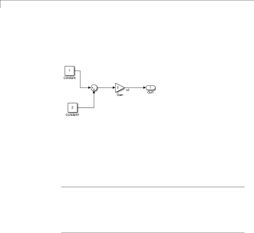
18 Data Copy Reduction
Inline Invariant Signals
An invariant signal is a block output signal that does not change during
Simulink simulation. For example, the signal S3 in this block diagram is an
invariant signal.
For the previous model, if you select Inline invariant signals on the
Optimization > Signals and Parameters pane, the Simulink Coder code
generator inlines the invariant signal S3 in the generated code.
Note thataninvariant signal is not the same as an invariant constant.In
the preceding example, the two constants (1 and 2) and the gain value of 3
are invariant constants. To inline these invariant constants, select Inline
parameters.
Note If your model contains Model blocks, Inline parameters must be
on for all referenced models. If a referenced model does not have Inline
Parameters set to on, the Simulink engine temporarily enables this option
while generating code for the referenced model, then turns it off again when
the build completes. Thus the referenced model is left in its previous state
and need not be resaved. For the top model, Inline parameters can be
either on or off.
18-18


19 Execution Speed
Inline Parameters
When you select the Inline parameters configuration parameter:
•The Simulink Coder code generator uses the numerical values of model
parameters, instead of their symbolic names, in generated code.
If the value of a parameter is a workspace variable, or an expression
including one or more workspace variables, the variable or expression is
evaluated at code generation time. The hard-coded result value appears
in the generated code. An inlined parameter, because it has in effect been
transformed into a constant, is no longer tunable. That is, it is not visible
to externally written code, and its value cannot be changed at runtime.
•The Configure button becomes enabled. Clicking the Configure button
opens the Model Parameter Configuration dialog box.
The Model Parameter Configuration dialog box lets you remove individual
parameters from inlining and declare them to be tunable variables (or
global constants). When you declare a parameter tunable, the Simulink
Coder product generates a storage declaration that allows the parameter to
be interfaced to externally written code. This enables your hand-written
code to change the value of the parameter at run-time.
The Model Parameter Configuration dialog box lets you improve overall
efficiency by inlining most parameters, while at the same time retaining
the flexibility of run-time tuning for selected parameters.
See “Parameters” on page 7-10 for more information on interfacing
parameters to externally written code.
Inline parameters also instructs the Simulink engine to propagate constant
sample times. The engine computes the output signals of blocks that have
constant sample times once during model startup. This improves performance
because such blocks do not compute their outputs at every time step of the
model.
You can select the Inline invariant signals code generation option (which
also places constant values in generated code) only when Inline parameters
is on. See “Inline Invariant Signals” on page 18-18.
19-2

Inline Parameters
Referenced Models
When a top model uses referenced models or if a model is referenced by
another model:
•All referenced models must specify Inline parameters to be on
•The top model can specify Inline parameters to be on or off.
When the top model specifies Inline parameters to be on, you cannot use
the Model Parameter Configuration dialog box to tune parameters that are
passed to referenced models. To tune such parameters, you must declare
them in the referenced model’s workspace, and then pass run-time values (or
expressions) for them in argument lists specified for each Model block that
references that model. For more information, see “Using Model Arguments”.
19-3
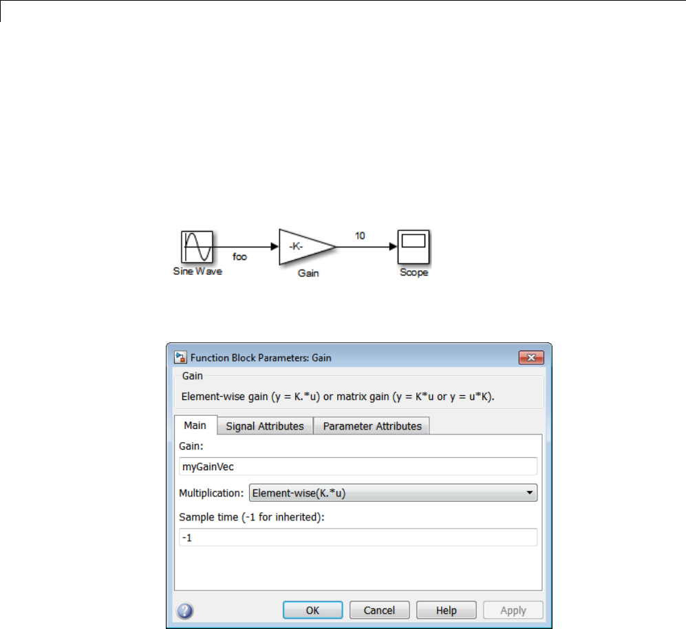
19 Execution Speed
Configure Loop Unrolling Threshold
The Loop unrolling threshold parameter on the Optimization > Signals
and Parameters pane determines when a wide signal or parameter should
be wrapped into a for loop and when it should be generated as a separate
statement for each element of the signal. The default threshold value is 5.
For example, consider the model below:
ThegainparameteroftheGainblockisthevectormyGainVec.
Assume that the loop unrolling threshold value is set to the default, 5.
If myGainVec is declared as
myGainVec = [1:10];
19-4

Configure Loop Unrolling Threshold
an array of 10 elements, myGainVec_P.Gain_Gain[], is declared within the
Parameters_model data structure. The size of the gain array exceeds the loop
unrolling threshold. Therefore, the code generated for the Gain block iterates
over the array in a for loop, as shown in the following code:
{
int32_T i1;
/* Gain: '<Root>/Gain' */
for(i1=0; i1<10; i1++) {
myGainVec_B.Gain_f[i1] = rtb_foo *
myGainVec_P.Gain_Gain[i1];
}
}
If myGainVec is declared as
myGainVec = [1:3];
an array of three elements, myGainVec_P.Gain_Gain[], is declared within
the Parameters data structure. The size of the gain array is below the loop
unrolling threshold. The generated code consists of inline references to each
element of the array, as in the code below.
/* Gain: '<Root>/Gain' */
myGainVec_B.Gain_f[0] = rtb_foo * myGainVec_P.Gain_Gain[0];
myGainVec_B.Gain_f[1] = rtb_foo * myGainVec_P.Gain_Gain[1];
myGainVec_B.Gain_f[2] = rtb_foo * myGainVec_P.Gain_Gain[2];
See “Explore Variable Names and Loop Rolling” for more information on
loop rolling.
Note When a model includes Stateflow charts or MATLAB Function
blocks, you can apply a set of Stateflow optimizations on the
Optimization > Stateflow pane. The settings you select for the Stateflow
options also apply to all MATLAB Function blocks in the model. This is
because the MATLAB Function blocks and Stateflow charts are built on top
of the same technology and share a code base. You do not need a Stateflow
license to use MATLAB Function blocks.
19-5

19 Execution Speed
Optimize Code Generated for Vector Assignments
In this section...
“Configure Model to Optimize Code Generated for Vector Assignments”
on page 19-6
“Optimize Code Generated for Vector Assignments Using memcpy” on page
19-7
Configure Model to Optimize Code Generated for
Vector Assignments
The Use memcpy for vector assignment option lets you optimize generated
code for vector assignments by replacing for loops with memcpy function calls.
The memcpy function can be more efficient than for-loop controlled element
assignment for large data sets. Where memcpy offers improved execution
speed, you can also use this model option to specify that the generated code
use memcpy when assigning a vector signal.
Selecting the Use memcpy for vector assignment option enables the
associated parameter Memcpy threshold (bytes),whichallowsyouto
specify the minimum array size in bytes for which memcpy function calls
should replace for loops in the generated code. For more information, see
“Use memcpy for vector assignment” and “Memcpy threshold (bytes)”.
In considering whether to use this optimization,
•Verify that your target supports the memcpy function.
•Determine whether your model uses signal vector assignments (such as
Y=expression)tomovelargeamountsofdata,forexample,usingthe
Selector block.
To apply this optimization,
1Consider first generating code without this optimization and measuring its
execution, to establish a baseline for evaluating the optimized assignment.
2Select Use memcpy for vector assignment and examine the setting of
Memcpy threshold (bytes), which by default specifies 64 bytes as the
19-6
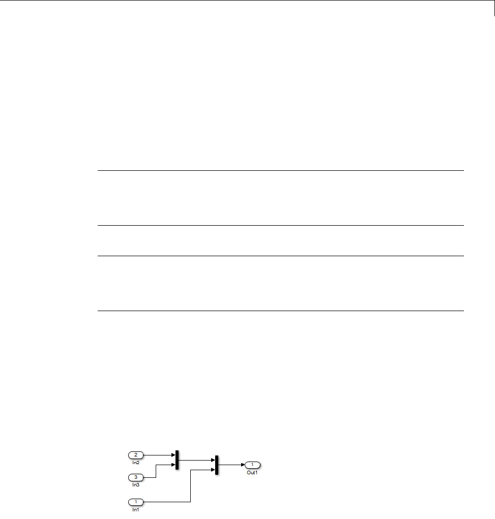
Optimize Code Generated for Vector Assignments
minimum array size for which for loops are replaced with memcpy function
calls. Based on the array sizes used in your application’s signal vector
assignments, and any target environment considerations that might bear
on the threshold selection, accept the default or specify another array size.
3Generate code, and measure its execution speed against your baseline or
previous iterations. Iterate on steps 2 and 3 until you achieve an optimal
result.
Note The memcpy optimization may not occur under certain conditions,
including when other optimizations have a higher precedence than the memcpy
optimization, or when the generated code is originating from Target Language
Compiler (TLC) code, such as a TLC file associated with an S-function block.
Note If you are licensed for Embedded Coder software, you can use a code
replacement library (CRL) to provide your own custom implementation of the
memcpy function to be used in generated model code. For more information,
see “Map memcpy Function to Target-Specific Implementations”.
Optimize Code Generated for Vector Assignments
Using memcpy
To examine the effect on generated vector assignment code of using the Use
memcpy for vector assignment option, perform the following steps:
1Create a model that generates signal vector assignments. For example,
aUse In, Out, and Mux blocks to create the following model.
bSelect the diagram and use Edit > Subsystem to make it a subsystem.
19-7

19 Execution Speed
cOpen Model Explorer and configure the Signal Attributes for the In1,
In2,andIn3 source blocks. For each, set Port dimensions to [1,100],
and set Data type to int32. Apply the changes.
dGo to the Optimization > Signals and Parameters pane of the
Configuration Parameters dialog box and clear the Use memcpy for
vector assignment option. Apply the changes and save the model. In
this example, the model is saved to the name vectorassign.
2Go to the Code Generation > Report pane of the Configuration
Parameters dialog box and select the Create code generation report.
Then go to the Code Generation pane, select the Generate code only
option, and generate code for the model. When code generation completes,
the HTML code generation report is displayed.
3In the HTML code generation report, click on the vectorassign.c section
and inspect the model output function. Notice that the vector assignments
are implemented using for loops.
/* Model output function */
static void vectorassign_output(void)
{
int32_T i;
/* Outport: '<Root>/Out1' incorporates:
* Inport: '<Root>/In1'
* Inport: '<Root>/In2'
* Inport: '<Root>/In3'
*/
for (i = 0; i < 100; i++) {
vectorassign_Y.Out1[i] = vectorassign_U.In2[i];
}
for (i = 0; i < 100; i++) {
vectorassign_Y.Out1[i + 100] = vectorassign_U.In3[i];
19-8

Optimize Code Generated for Vector Assignments
}
for (i = 0; i < 100; i++) {
vectorassign_Y.Out1[i + 200] = vectorassign_U.In1[i];
}
/* End of Outport: '<Root>/Out1' */
4Go to the Optimization > Signals and Parameters pane of the
Configuration Parameters dialog box and select the Use memcpy for
vector assignment option. Leave the Memcpy threshold (bytes) option
at its default setting of 64 Apply the changes and regenerate code for the
model. When code generation completes, the HTML code generation report
again is displayed.
5In the HTML code generation report, click on the vectorassign.c section
and inspect the model output function. Notice that the vector assignments
now are implemented using memcpy function calls.
/* Model output function */
static void vectorassign_output(void)
{
int32_T i;
/* Outport: '<Root>/Out1' incorporates:
* Inport: '<Root>/In1'
* Inport: '<Root>/In2'
* Inport: '<Root>/In3'
*/
memcpy(&vectorassign_Y.Out1[0], &vectorassign_U.In2[0], 100U * sizeof(int32_T));
memcpy(&vectorassign_Y.Out1[100], &vectorassign_U.In3[0], 100U * sizeof(int32_T));
memcpy(&vectorassign_Y.Out1[200], &vectorassign_U.In1[0], 100U * sizeof(int32_T));
}
19-9

19 Execution Speed
Generate Target Optimizations Within Algorithm Code
Some application components are hardware-specific and cannot simulate on
a host system. For example, consider a component that includes pragmas
and assembly code for enabling hardware instructions for saturate on add
operations or a Fast Fourier Transform (FFT) function.
The following table lists integration options to customize generated algorithm
code with target-specific optimizations.
Note Solutions marked with EC only require an Embedded Coder license.
If... Then... For More Information, See
You want to optimize
target performance
(speed and memory)
of model code by
replacing default
math functions
and operators with
target-specific code
EC only—Im
plement
function and operator
replacements by using
the code replacement
library (CRL) API,
Code Replacement
Tool, andCode
Replacement Viewer
to create, examine,
validate, and register
hardware-specific
replacement tables
•rtwdemo_crl_script
•“IntroductiontoCodeReplacement
Libraries”
You want to control
how code generation
technology declares,
stores, and represents
signals, tunable
parameters, block
states, and data objects
in generated code
EC only—Design
(create) and apply
customstorage
classes
•rtwdemo_cscpredef
•rtwdemo_importstruct
•rtwdemo_advsc
•“Custom Storage Classes”
19-10

Generate Target Optimizations Within Algorithm Code
Note To simulate an algorithm that includes target-specific elements in a
host environment, you must create code that is equivalent to the target code
and can run in the host environment.
19-11

19 Execution Speed
19-12


20 Memory Usage
Minimize Memory Requirements During Code Generation
When the Simulink Coder product generates code, it creates an intermediate
representation of your model (called model.rtw), which the Target Language
Compiler parses to transform block computations, parameters, signals, and
constant data into a high-level language, (for example, C). Parameters and
data are normally copied into the model.rtw file, whether they originate in
the model itself or come from variables or objects in a workspace.
Models which have large amounts of parameter and constant data (such as
lookup tables) can tax memory resources and slow down code generation
because of the need to copy their data to model.rtw. You can improve code
generation performance by limiting the size of data that is copied by using a
set_param command, described below.
Data vectors such as those for parameters, lookup tables, and constant blocks
whose sizes exceed a specified value are not copied into the model.rtw file.
In place of the data vectors, the code generator places a special reference
key in the intermediate file that enables the Target Language Compiler to
access the data directly from the Simulink software and format it directly
into the generated code. This results in maintaining only one copy of large
data vectors in memory.
You can specify the maximum number of elements that a parameter or other
data source can have for the Simulink Coder code generator to represent it
literally in the model.rtw file. Whenever this threshold size is exceeded, the
product writes a reference to the data to the model.rtw file, rather than its
values. The default threshold value is 10 elements, which you can verify with
get_param(0, 'RTWDataReferencesMinSize')
To set the threshold to a different value, type the following set_param
function in the MATLAB Command Window:
set_param(0, 'RTWDataReferencesMinSize', <size>)
Provide an integer value for size that specifies the number of data elements
above which reference keys are to be used in place of actual data values.
20-2

Implement Logic Signals as Boolean Data
Implement Logic Signals as Boolean Data
When you select the Implement logic signals as Boolean data (vs.
double) check box, blocks that generate logic signals output Boolean signals.
When you clear this check box, blocks that generate logic signals output
double signals.
The check box is selected by default because it reduces memory requirements
(a Boolean signal typically requires one byte in memory while a double signal
requires eight bytes in memory). Clear this check box for compatibility with
models created using earlier versions of Simulink that support only double
signals. For details about this check box, see “Implement logic signals as
Boolean data (vs. double)”.
20-3

20 Memory Usage
Reduce Memory Requirements for Signals
To instruct the Simulink Coder code generator to reuse signal memory, which
can reduce memory requirements of your real-time program, select the
configuration parameter Signal storage reuse. Disabling Signal storage
reuse makes all block outputs global and unique, which in many cases
significantly increases RAM and ROM usage.
For more details on the Signal storage reuse option, see “Signals” on page
7-52.
Note Selecting Signal storage reuse also enables the Enable local block
outputs,Reuse block outputs,Eliminate superfluous local variables
(expression folding),andMinimize data copies between local and
global variables options on the Optimization > Signals and Parameters
pane. See “Declare Signals as Local Function Data” on page 18-17 and “Reuse
Memory Allocated for Signals” on page 20-5.
20-4

Reuse Memory Allocated for Signals
Reuse Memory Allocated for Signals
Two parameters provide the capability to reuse memory allocated for signals:
Reuse block output and Minimize data copies between local and
global variables.
Selecting Reuse block output directs the code generator to reuse signal
memory. When Reuse block output is cleared, signals are stored in unique
locations.
Reuse block output is enabled only when you select Signal storage reuse.
Selecting Minimize data copies between local and global variables
reuses existing global variables to store temporary results. Clearing
Minimize data copies between local and global variables writes data
for block outputs to local variables. You must select Signal storage reuse to
enable Minimize data copies between local and global variables.
See “Signals” on page 7-52 for more information (including generated code
example) on Reuse block output,Minimize data copies between local
and global variables, and other signal storage options.
20-5

20 Memory Usage
Use Stack Space Allocation
Your application might be constrained by limited memory. Controlling the
maximum allowable size for the stack is one way to modify whether data
is defined as local or global in the generated code. You can limit the use of
stack space by specifying a positive integer value for the “Maximum stack
size (bytes)” parameter, on the Optimization > Signals and Parameters
pane of the Configuration parameter dialog box. Specifying the maximum
allowable stack size provides control over the number of local and global
variables in the generated code. Specifically, lowering the maximum stack
size might generate more variables into global structures. The number of
local and global variables help determine the required amount of stack space
for execution of the generated code.
The default setting for “Maximum stack size (bytes)” is Inherit from
target. In this case, the value of the maximum stack size is the smaller
value of the following: the default value set by the Simulink Coder software
(200,000 bytes) or the value of the TLC variable MaxStackSize found in the
system target file (ert.tlc).
To specify a smaller stack size for your application, select the Specify a
value option of the Maximum stack size (bytes) parameter and enter a
positive integer value. To specify a smaller stack size at the command line,
use:
set_param(model_name, 'MaxStackSize', 65000);
Note For overall executable stack usage metrics, you might want to do a
target-specific measurement, such as using runtime (empirical) analysis or
static (code path) analysis with object code.
It is recommended that you use the Maximum stack size (bytes) parameter
to control stack space allocation instead of modifying the TLC variable,
MaxStackSize, in the system target file. However, a target author might want
to set the TLC variable, MaxStackSize,foratarget. TosetMaxStackSize,
use assign statements in the system target file (ert.tlc), as in the following
example.
20-6

UseStackSpaceAllocation
%assign MaxStackSize = 4096
Write your %assign statements in the Configure RTW code generation
settings section of the system target file. The %assign statement is
described in “Target Language Compiler”.
20-7

20 Memory Usage
20-8

Verification


21 Simulation and Code Comparison
Comparing Output Data
This example shows you how to verify the answers computed by code
generated from the sldemo_f14 model. It shows how to capture two sets of
output data and compare the sets. Simulating the model produces one set of
output data. Executing the generated code produces a second set of output
data.
Note To obtain a valid comparison between the outputs of the model and
the generated code , use the same Solver options and the same Step size
for both the simulation run and the build process. You must configure the
modeltosavesimulationtime.
For an example, see “Configure Signal Data for Logging” on page 21-3.
21-2

Configure Signal Data for Logging
Configure Signal Data for Logging
Configure the model for logging and recording signal data.
1Make sure that sldemo_f14 is closed. Clear the MATLAB workspace to
eliminate the results of previous simulation runs. At the MATLAB prompt,
type:
clear
The clear operation clears variables created during previous simulations
and all workspace variables, some of which are standard variables that the
sldemo_f14 model requires.
2Open the model by entering sldemo_f14 at the MATLAB command line.
3In the model window, choose File > Save As, navigate to the working
folder, and save a copy of the sldemo_f14 model as myf14.
4Set up your model to log signal data for signals: Stick,alpha,rad,and
NzPilot,g. For each signal, follow these steps.
aRight-click the signal and select Properties from the context menu.
bIn the Signal Properties dialog box, select Log signal Data.
cIn the Logging name section, in the drop-down list, select Custom.In
the field, enter the logging name for the corresponding signal.
Signal Name Logging Name
Stick Stick_input
alpha,rad Angle_of_attack
NzPilot,g Pilot_G_force
dClick Apply and OK.
For information on how to log signal data, see “Export Signal Data Using
Signal Logging”.
5Select Simulation > Model Configuration Parameters to open the
Configuration Parameters dialog box.
21-3

21 Simulation and Code Comparison
6Select the Solver pane. In the Solver options section, specify the Type
parameter as Fixed-step.
7On the Data Import/Export pane:
•Specify the Format parameter as Structure with time.
•Select the Signal logging parameter.
•Select the Record and inspect simulation output parameter. When
you select this parameter, on the Simulink Editor window, the Record
button is now on.
8Save the model.
Proceed to “Log Simulation Data” on page 21-5.
21-4
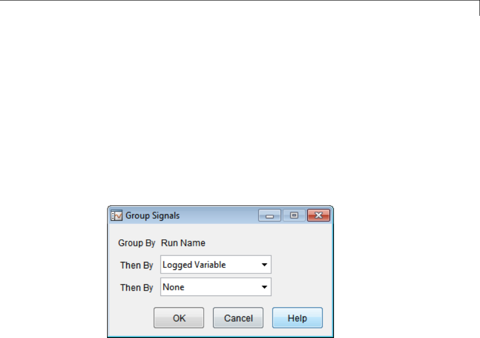
Log Simulation Data
Log Simulation Data
Run the simulation, log the signal data, and view the data in the Simulation
Data Inspector.
1Run the model. When the simulation is done, the Simulation Data
Inspector opens. You can also open the Simulation Data Inspector from
the Simulink Editor toolbar. Click the Record button arrow, and select
Simulation Data Inspector.
2Right-click Run1: myf14. In the context menu, select Group Signals.
Specify the Group Signals settings.
3Click the Run1: myf14 expander to view the logged variables. Then click
the logsout expander and then the expanders for each logged signal.
4On the right pane, on the View toolbar, click Show Details.
5In the Layout column, click the field that displays 1x1.Aplotmatrix
opens. To create a view of 4 plots, select the 2x2 matrix.
6Select Hide Details.
7For each signal:
aClick a plot, which will then show a blue border.
bSelect the check box next to a logged signal name.
21-5
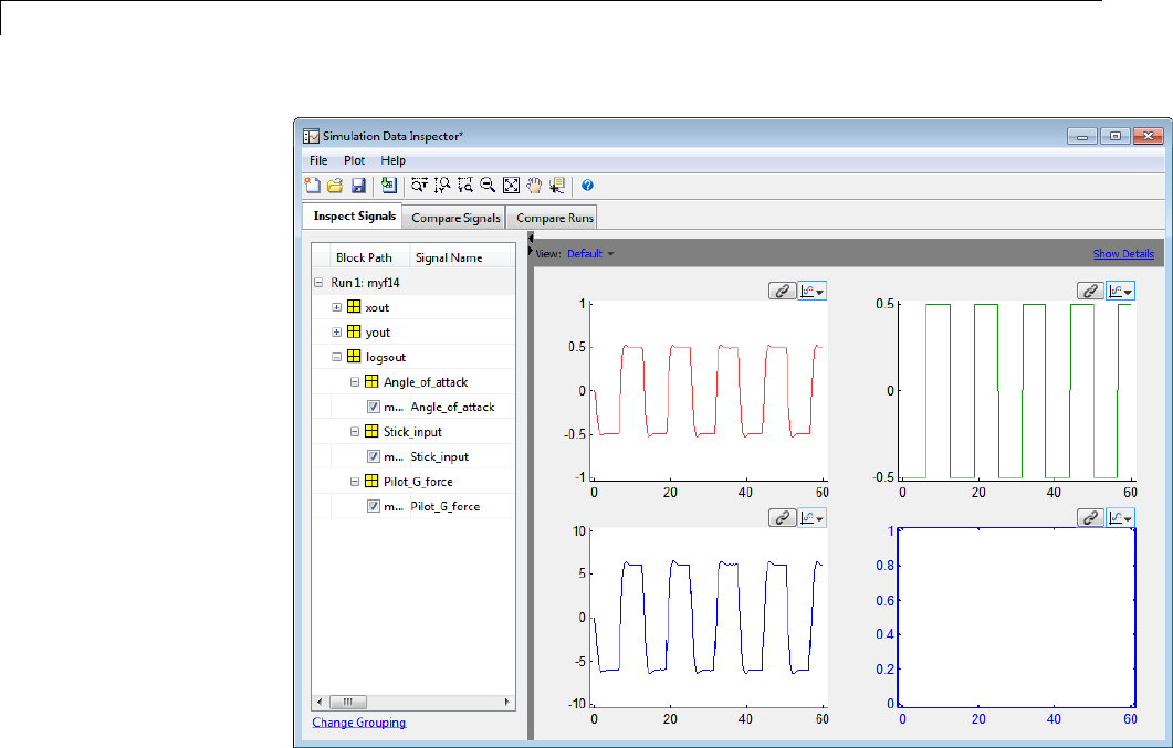

Log Data from the Generated Program
Log Data from the Generated Program
Because you have modified the model, you must rebuild and run the myf14
executable to obtain a valid data file.
1Select Simulation > Model Configuration Parameters to open the
Configuration Parameters dialog box.
2Select the Code Generation > Interface pane.
3Set the MAT-file variable name modifier menu to rt_.Doingso
prefixes rt_ to each variable that you selected to be logged in the first
part of this example.
4Click Apply and OK.
5Save the model.
6To generate code, on the Simulink Editor toolbar, click the Build Model
button. Status messages in the MATLAB Command Window track the
build process.
7When the build is finished, run the standalone program from MATLAB.
!myf14
The executing program writes the following messages to the MATLAB
Command Window.
** starting the model **
** created myf14.mat **
8Load the data file myf14.mat.
load myf14
9To view the two execution outputs, alpha,rad and NzPilot,g,importthe
data into the Simulation Data Inspector:
aIn the Simulation Data Inspector, select File > Import Data to open
the Data Import dialog box.
21-7
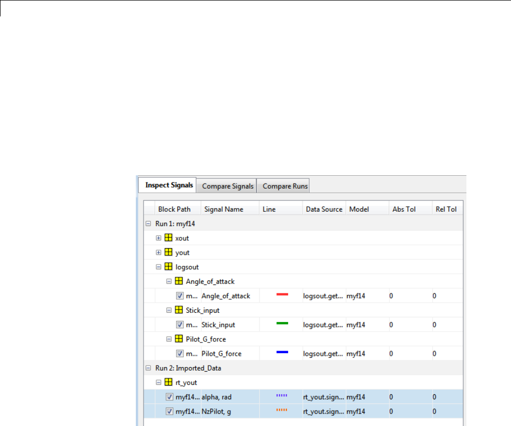
21 Simulation and Code Comparison
bSpecify Import from as Base workspace.SpecifyImport to as New
run.
cClick Clear All to clear all of the check boxes. Select the check box for
data where the Time Series Root is rt_yout and the Block Path is
myf14/alpha,rad and myf14/NzPilot,g.
dClick OK.
The selected data is now under Run2: Imported_Data.
10 On the Inspect Signals tab, you can view this data by selecting the Plot
button for each output.
Proceed to “Compare Numerical Results” on page 21-9.
21-8
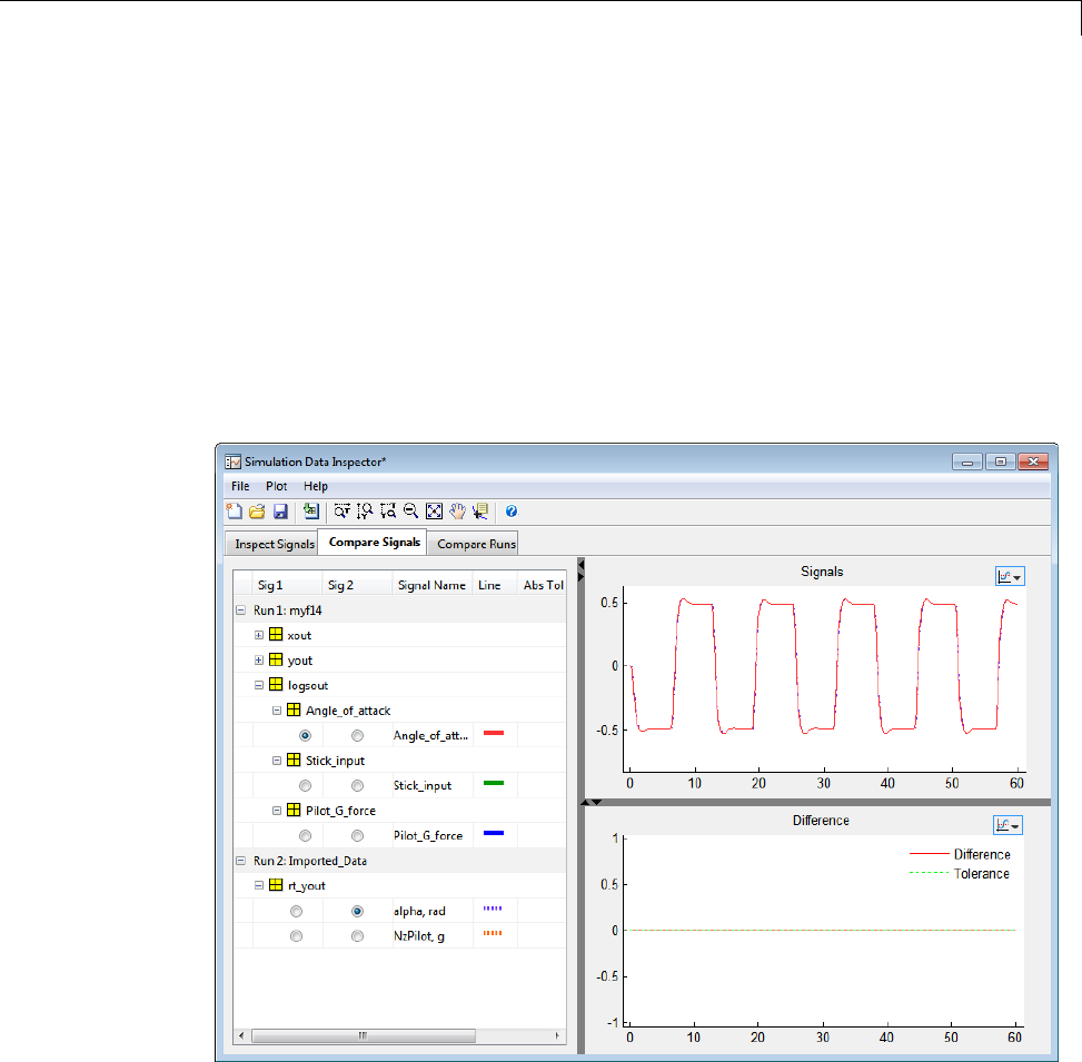
Compare Numerical Results
Compare Numerical Results
You have now obtained data from a Simulink run of the model and from a run
of the program generated from the model. In the Simulation Data Inspector,
select the Compare Signals tab. Your comparison results might differ from
these results.
To compare alpha, rad, under Run 1,intheSig 1 column, select
Angle_of_attack.UnderRun 2,intheSig 2 column, select alpha, rad.
The Signals plot shows the data. The difference is calculated and plotted in
the Difference plot.
To compare NzPilot,g,underRun 1,intheSig 1 column, select
Pilot_G_force.UnderRun 2,intheSig 2 column, select NzPilot,g.The
Signals plot shows the data.
21-9
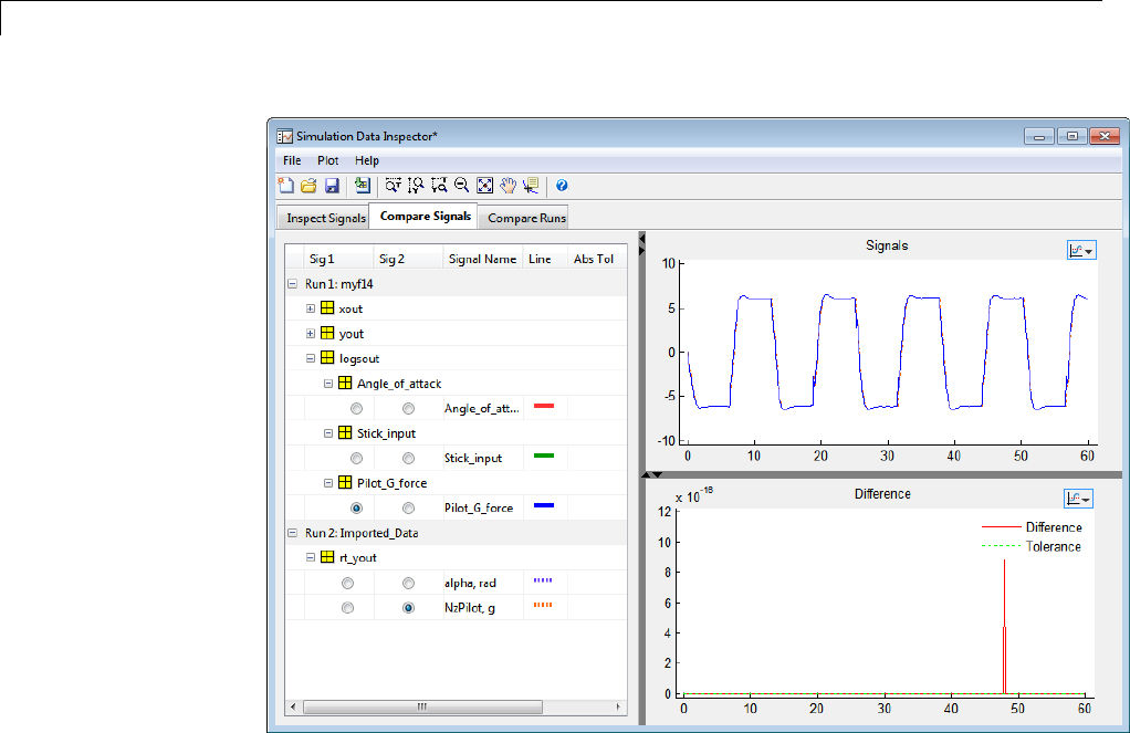
21 Simulation and Code Comparison
Overall agreement is within 10-16. The means of residuals are an order of
magnitude smaller. This slight error can be caused by many factors, including:
•Different compiler optimizations
•Statement ordering
•Run-time libraries
For example, a function call such as sin(2.0) might return a slightly
different value depending on which C library you are using. Such variations
can also cause differences between your results and these results.
21-10


22
Build Process Integration
•“Control Build Process Compiling and Linking” on page 22-2
•“Cross-Compile Code Generated on Microsoft Windows” on page 22-4
•“Control Library Location and Naming During Build” on page 22-7
•“Recompile Precompiled Libraries” on page 22-12
•“Customize Post-Code-Generation Build Processing” on page 22-13
•“Configure Generated Code with TLC” on page 22-18
•“Customize Build Process with STF_make_rtw_hook File” on page 22-21
•“Customize Build Process with sl_customization.m” on page 22-28
•“Replace the STF_rtw_info_hook Mechanism” on page 22-33
•“Customize Build to Use Shared Utility Code” on page 22-34

22 Build Process Integration
Control Build Process Compiling and Linking
After generating code for a model, the Simulink Coder build process
determines whether or not to compile and link an executable program. This
decision is governed by the following:
•Generate code only option
When you select this option, the Simulink Coder software generates code
for the model, including a makefile.
•Generate makefile option
When you clear this option, the Simulink Coder software does not generate
a makefile for the model. You must specify any post code generation
processing, including compilation and linking, as a user-defined command,
as explained in “Customize Post-Code-Generation Build Processing” on
page 22-13.
•Makefile-only target
The Microsoft Visual C++ Project Makefile versions of the grt,grt_malloc,
andEmbeddedCodertargetconfigurations generate a Visual C++ project
makefile (model.mak). To build an executable, you must open model.mak in
the Visual C++ IDE and compile and link the model code.
•HOST template makefile variable
The template makefile variable HOST identifies the type of system upon
which your executable is intended to run. The variable can be set to one of
three possible values: PC,UNIX,orANY.
By default, HOST is set to UNIX in template makefiles designed for use with
The Open Group UNIX platforms (such as grt_unix.tmf), and to PC in the
template makefiles designed for use with development systems for the
PC (such as grt_vc.tmf).
If the Simulink software is running on the same type of system as that
specified by the HOST variable, then the executable is built. Otherwise,
-If HOST = ANY, an executable is still built. This option is useful when
you want to cross-compile a program for a system other than the one the
Simulink software is running on.
22-2

Control Build Process Compiling and Linking
-Otherwise, processing stops after generating the model code and the
makefile; the following message is displayed on the MATLAB command
line.
### Make will not be invoked - template makefile is for a different host
•TGT_FCN_LIB template makefile variable
The template makefile variable TGT_FCN_LIB specifies compiler command
line options. The line in the makefile is TGT_FCN_LIB = |>TGT_FCN_LIB<|.
By default, the Simulink Coder software expands the |>TGT_FCN_LIB<|
token to match the setting of the Code replacement library option on
the Code Generation > Interface pane of the Configuration Parameters
dialog box. Possible values for this option include ANSI_C,C99 (ISO),
GNU99 (GNU),andC++ (ISO).Youcanusethistokeninamakefile
conditional statement to specify compiler options to be used. For example,
if you set the token to C99 (ISO), the compiler might need an additional
option set to support C99 library functions.
22-3

22 Build Process Integration
Cross-Compile Code Generated on Microsoft Windows
If you need to generate code with the Simulink Coder software on a Microsoft
Windows system but compile the generated code on a different supported
platform, you can do so by modifying your TMF and model configuration
parameters. For example, you would need to do this if you develop
applications with the MATLAB and Simulink products on a Windows system,
but you run your generated code on a Linux system.
To set up a cross-compilation development environment, do the following
(here a Linux system is the destination platform):
1On your Windows system, copy the UNIX TMF for your target to a local
folder. This will be your working folder for initiating code generation.
For example, you might copy matlabroot/rtw/c/grt/grt_unix.tmf to
D:/work/my_grt_unix.tmf.
2Make the following changes to your copy of the TMF:
•Add the following line near the SYS_TARGET_FILE = line:
MAKEFILE_FILESEP = /
•Search for the line 'ifeq ($(OPT_OPTS),$(DEFAULT_OPT_OPTS))' and,
for each occurrence, remove the conditional logic and retain only the
'else' code. That is, remove everything from the 'if' to the 'else',
inclusive, as well as the closing 'endif'. Only the lines from the 'else'
portion should remain. This forces the run-time libraries to build for
a Linux system.
3Open your model and make the following changes in the Code Generation
pane of the Configuration Parameters dialog:
•Specify the name of your new TMF in the Template makefile text box
(for example, my_grt_unix.tmf).
•Select Generate code only and click Apply.
4Generate the code.
5If the build folder (folder from which the model was built) is not already
Linux accessible, copy it to a Linux accessible path. For example, if your
22-4

Cross-Compile Code Generated on Microsoft®Windows®
build folder for the generated code was D:\work\mymodel_grt_rtw,copy
that entire folder tree to a path such as /home/user/mymodel_grt_rtw.
6If the MATLAB folder tree on the Windows system is Linux accessible, skip
this step. Otherwise, you must copy all the include and source folders to
a Linux accessible drive partition, for example, /home/user/myinstall.
ThesefoldersappearinthemakefileafterMATLAB_INCLUDES = and
ADD_INCLUDES = and can be found by searching for $(MATLAB_ROOT).Any
path that contains $(MATLAB_ROOT) must be copied. Here is an example
list (your list will vary depending on your model):
$(MATLAB_ROOT)/rtw/c/grt
$(MATLAB_ROOT)/extern/include
$(MATLAB_ROOT)/simulink/include
$(MATLAB_ROOT)/rtw/c/src
$(MATLAB_ROOT)/rtw/c/tools
Additionally, paths containing $(MATLAB_ROOT) in the build rules (lines
with %.o :) must be copied. For example, based on the build rule
%.o : $(MATLAB_ROOT)/rtw/c/src/ext_mode/tcpip/%.c
the following folder should be copied:
$(MATLAB_ROOT)/rtw/c/src/ext_mode/tcpip
Note ThepathhierarchyrelativetotheMATLABrootmustbe
maintained. For example, c:\MATLAB\rtw\c\tools\* wouldbecopiedto
/home/user/mlroot/rtw/c/tools/*.
For some blocksets, it is easiest to copy a higher-level folder that includes
the subfolders listed in the makefile. For example, the DSP System Toolbox
product requires the following folders to be copied:
$(MATLAB_ROOT)/toolbox/dspblks
$(MATLAB_ROOT)/toolbox/rtw/dspblks
7Make the following changes to the generated makefile:
22-5

22 Build Process Integration
•Set both MATLAB_ROOT and ALT_MATLAB_ROOT equal to the Linux
accessible path to matlabroot (for example, home/user/myinstall).
•Set COMPUTER to the computer value for your platform, such as GLNX86.
Enter help computer in the MATLAB Command Window for a list of
computer values.
•In the ADD_INCLUDES list, change the build folder (designating the
location of the generated code on the Windows system) and parent
folders to Linux accessible include folders. For example, change
D:\work\mymodel_grt_rtw\ to /home/user/mymodel_grt_rtw.
Additionally, if matlabroot is a UNC path, such as
\\my-server\myapps\matlab, replace the hard-coded MATLAB root
with $(MATLAB_ROOT).
8From a Linux shell, compile the code you generated on the Windows
system. You can do this by running the generated model.bat file or by
typing the make command line as it appears in the .bat file.
Note If errors occur during makefile execution, you may need to run the
dos2unix utility on the makefile (for example, dos2unix mymodel.mk).
22-6

Control Library Location and Naming During Build
Control Library Location and Naming During Build
Two configuration parameters, TargetPreCompLibLocation and
TargetLibSuffix, are available for you to use to control values placed
in Simulink Coder generated makefiles during the token expansion from
template makefiles (TMFs). You can use these parameters to
•Specify the location of precompiled libraries, such as blockset libraries or
the Simulink Coder library. Typically, a target has cross-compiled versions
of these libraries and places them in a target-specific folder.
•Control the suffix applied to library file names (for example, _target.a
or _target.lib).
Targets can set the parameters inside the system target file (STF) select
callback. For example:
function mytarget_select_callback_handler(varargin)
hDig=varargin{1};
hSrc=varargin{2};
slConfigUISetVal(hDig, hSrc,...
'TargetPreCompLibLocation', 'c:\mytarget\precomplibs');
slConfigUISetVal(hDig, hSrc, 'TargetLibSuffix',...
'_diab.library');
The TMF has corresponding expansion tokens:
|>EXPAND_LIBRARY_LOCATION<|
|>EXPAND_LIBRARY_SUFFIX<|
Alternatively, you can use a call to the set_param function. For example:
set_param(model,'TargetPreCompLibLocation',...
'c:\mytarget\precomplibs');
Note If your model contains referenced models, you can use the make option
USE_MDLREF_LIBPATHS to control whether libraries used by the referenced
models are copied to the parent model’s build folder. For more information,
see “Control the Location of Model Reference Libraries” on page 22-9.
22-7

22 Build Process Integration
Specify the Location of Precompiled Libraries
Use the TargetPreCompLibLocation configuration parameter to:
•Override the precompiled library location specified in the rtwmakecfg.m
file (see “Use rtwmakecfg.m API to Customize Generated Makefiles” on
page 14-124 for details)
•Precompile and distribute target-specific versions of product libraries (for
example, the DSP System Toolbox product)
For a precompiled library, such as a blockset library or the Simulink Coder
library, the location specified in rtwmakecfg.m is typically a location specific to
the blockset or the Simulink Coder product. It is expected that the library will
exist in this location and it is linked against during Simulink Coder builds.
However, for some applications, such as custom targets, it is preferable to
locate the precompiled libraries in a target-specific or other alternate location
rather than in the location specified in rtwmakecfg.m. For a custom target,
the library is expected to be created using the target-specific cross-compiler
and placed in the target-specific location for use during the Simulink Coder
build process. All libraries intended to be supported by the target should be
compiled and placed in the target-specific location.
You can set up the TargetPreCompLibLocation parameter in its select
callback. The path that you specify for the parameter must be a fully qualified
absolute path to the library location. Relative paths are not supported. For
example:
slConfigUISetVal(hDlg, hSrc, 'TargetPreCompLibLocation',...
'c:\mytarget\precomplibs');
Alternatively, you set the parameter with a call to the set_param function.
For example:
set_param(model,'TargetPreCompLibLocation',...
'c:\mytarget\precomplibs');
During the TMF-to-makefile conversion, the Simulink Coder build process
replaces the token |>EXPAND_LIBRARY_LOCATION<| with the specified location
in the rtwmakecfg.m file. For example, if the library name specified in the
rtwmakecfg.m file is 'rtwlib',theTMFexpandsfrom:
22-8

Control Library Location and Naming During Build
LIBS += |>EXPAND_LIBRARY_LOCATION<|\|>EXPAND_LIBRARY_NAME<|\
|>EXPAND_LIBRARY_SUFFIX<|
to:
LIBS += c:\mytarget\precomplibs\rtwlib_diab.library
By default, TargetPreCompLibLocation is an empty string and the Simulink
Coder build process uses the location specified in rtwmakecfg.m for the token
replacement.
Control the Location of Model Reference Libraries
On platforms other than the Apple Macintosh platform, when building a model
that uses referenced models, the Simulink Coder build process by default:
•Copies libraries used by the referenced models to the parent model’s build
folder
•AssignsthefilenamesofthelibrariestoMODELREF_LINK_LIBS in the
generated makefile
For example, if a model includes a referenced model sub, the Simulink
Coder build process assigns the library name sub_rtwlib.lib to
MODELREF_LINK_LIBS and copies the library file to the parent model’s
build folder. This definition is then used in the final link line, which links
the library into the final product (usually an executable). This technique
minimizes the length of the link line.
On the Macintosh platform, and optionally on other platforms, the Simulink
Coder build process:
•Does not copy libraries used by the referenced models to the parent model’s
build folder
•Assignstherelativepathsandfilenamesofthelibrariesto
MODELREF_LINK_LIBS in the generated makefile
When using this technique, the Simulink Coder build process assigns a relative
path such as ../slprj/grt/sub/sub_rtwlib.lib to MODELREF_LINK_LIBS
and uses the path to gain access to the library file at link time.
22-9

22 Build Process Integration
To change to the non-default behavior on platforms other than the Macintosh
platform, enter the following command in the Make command field of the
Code Generation pane of the Configuration Parameters dialog box:
make_rtw USE_MDLREF_LIBPATHS=1
If you specify other Make command arguments, such as OPTS="-g",youcan
specify the multiple arguments in any order.
To return to the default behavior, set USE_MDLREF_LIBPATHS to 0, or remove it.
Control the Suffix Applied to Library File Names
Use the TargetLibSuffix configuration parameter to control the suffix
applied to library names (for example, _target.lib or _target.a).
The specified suffix string must include a period (.). You can apply
TargetLibSuffix to the following libraries:
•Libraries on which a target depends, as specified in the rtwmakecfg.m
API. You can use TargetLibSuffix to affect the suffix of both precompiled
and non-precompiled libraries configured from the rtwmakecfg API. For
details, see “Use rtwmakecfg.m API to Customize Generated Makefiles”
on page 14-124.
In this case, a target can set the parameter in its select callback. For
example:
slConfigUISetVal(hDlg, hSrc, 'TargetLibSuffix',...
'_diab.library');
Alternatively, you can use a call to the set_param function. For example:
set_param(model,'TargetLibSuffix','_diab.library');
During the TMF-to-makefile conversion, the Simulink Coder build process
replaces the token |>EXPAND_LIBRARY_SUFFIX<| with the specified suffix.
For example, if the library name specified in the rtwmakecfg.m file is
'rtwlib',theTMFexpandsfrom:
LIBS += |>EXPAND_LIBRARY_LOCATION<|\|>EXPAND_LIBRARY_NAME<|\
|>EXPAND_LIBRARY_SUFFIX<|
22-10

Control Library Location and Naming During Build
to:
LIBS += c:\mytarget\precomplibs\rtwlib_diab.library
By default, TargetLibSuffix is set to an empty string. In
this case, the Simulink Coder build process replaces the token
|>EXPAND_LIBRARY_SUFFIX<| with an empty string.
•Shared utility library and the model libraries created with model
reference. For these cases, associated makefile variables do not require the
|>EXPAND_LIBRARY_SUFFIX<| token. Instead, the Simulink Coder build
process includes TargetLibSuffix implicitly. For example, for a top model
named topmodel with submodels named submodel1 and submodel2,the
top model’s TMF is expanded from:
SHARED_LIB = |>SHARED_LIB<|
MODELLIB = |>MODELLIB<|
MODELREF_LINK_LIBS = |>MODELREF_LINK_LIBS<|
to:
SHARED_LIB = \
..\slprj\ert\_sharedutils\rtwshared_diab.library
MODELLIB = topmodellib_diab.library
MODELREF_LINK_LIBS = \
submodel1_rtwlib_diab.library submodel2_rtwlib_diab.library
By default, the TargetLibSuffix parameter is an empty string. In this
case, the Simulink Coder build process chooses a default suffix for these
three tokens using a file extension of .lib on Windows hosts and .a on
UNIX hosts. (For model reference libraries, the default suffix additionally
includes _rtwlib.) For example, on a Windows host, the expanded makefile
values would be:
SHARED_LIB = ..\slprj\ert\_sharedutils\rtwshared.lib
MODELLIB = topmodellib.lib
MODELREF_LINK_LIBS = submodel1_rtwlib.lib submodel2_rtwlib.lib
22-11

22 Build Process Integration
Recompile Precompiled Libraries
You can recompile precompiled libraries included as part of the Simulink
Coder product, such as rtwlib or dsplib, by using a supplied MATLAB
function, rtw_precompile_libs. You might consider doing this if you
need to customize compiler settings for various platforms or environments.
For details on using rtw_precompile_libs, see “Precompile S-Function
Libraries” on page 14-129.
22-12
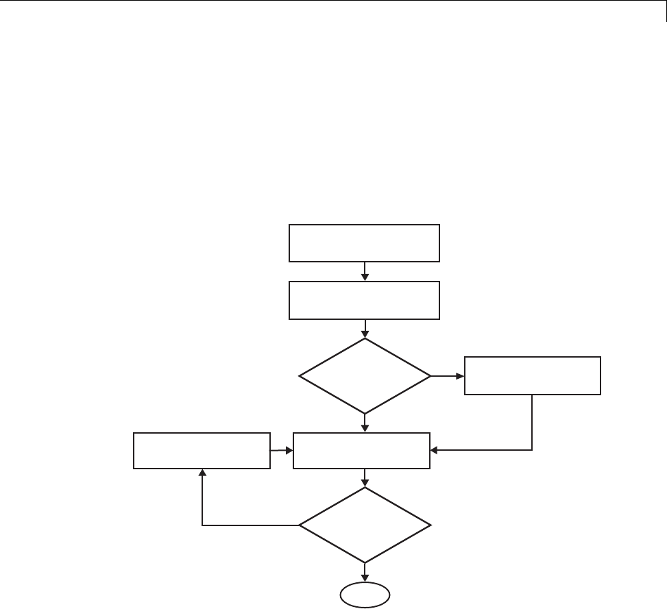
Customize Post-Code-Generation Build Processing
Customize Post-Code-Generation Build Processing
The Simulink Coder product provides a set of tools, including a build
information object, you can use to customize build processing that occurs after
code generation. You might use such customizations for target development
or the integration of third-party tools into your application development
environment. The next figure and the steps that follow show the general
workflow for setting up such customizations.
Program post code
generation command
Build model
Modify post code
generation command
Suppress makefile
generation
Done
Generate
a makefile?
Results
OK?
Yes
No
Yes
No
Define post code
generation command
1Program the post code generation command.
2Define the post code generation command.
3Suppress makefile generation, if applicable..
4Build the model.
22-13

22 Build Process Integration
5Modify the command and rebuild the model until the build results are
acceptable.
Build Information Object
At the start of a model build, the Simulink Coder build process logs the
following build option and dependency information to a temporary build
information object:
•Compiler options
•Preprocessor identifier definitions
•Linker options
•Source files and paths
•Include files and paths
•Precompiled external libraries
You can retrieve information from and add information to this object by using
an extensive set of functions. For a list of available functions and detailed
function descriptions, see “Build Process”. “Program a Post Code Generation
Command” on page 22-14 explains how to use the functions to control post
code generation build processing.
Program a Post Code Generation Command
For certain applications, you might want to control aspects of the build
process after the code generation. For example, you might do this if you
develop your own target, or you want to apply an analysis tool to the
generated code before continuing with the build process. You can apply this
level of control to the build process by programming and then defining a post
code generation command.
ApostcodegenerationcommandisaMATLABlanguagefilethattypically
calls functions that get data from or add data to the model’s build information
object. You can program the command as a script or function.
22-14

Customize Post-Code-Generation Build Processing
If You Program the
Command as a...
Then the...
Script Script can gain access to the model name and
the build information directly
Function Function can pass the model name and the
build information as arguments
If your post code generation command calls user-defined functions, make sure
the functions are on the MATLAB path. If the Simulink Coder build process
cannot find a function you use in your command, the build process errors out.
You can then call any combination of build information functions, as listed
in “Build Process”, to customize the model’s post code generation build
processing.
The following example shows a fragment of a post code generation command
that gets the filenames and paths of the source and include files generated for
a model for analysis.
function analyzegencode(buildInfo)
% Get the names and paths of all source and include files
% generated for the model and then analyze them.
% buildInfo - build information for my model.
% Define cell array to hold data.
MyBuildInfo={};
% Get source file information.
MyBuildInfo.srcfiles=getSourceFiles(buildInfo, true, true);
MyBuildInfo.srcpaths=getSourcePaths(buildInfo, true);
% Get include (header) file information.
MyBuildInfo.incfiles=getIncludeFiles(buildInfo, true, true);
MyBuildInfo.incpaths=getIncludePaths(buildInfo, true);
% Analyze generated code.
.
.
22-15

22 Build Process Integration
.
DefineaPostCodeGenerationCommand
After you program a post code generation command, you need to inform the
Simulink Coder build process that the command exists and to add it to the
model’s build processing. You do this by defining the command with the
PostCodeGenCommand model configuration parameter. When you define a post
code generation command, the Simulink Coder build process evaluates the
command after generating and writing the model’s code to disk and before
generating a makefile.
As the following syntax lines show, the arguments that you specify when
setting the configuration parameter varies depending on whether you
program the command as a script, function, or set of functions.
Note When defining the command as a function, you can specify an arbitrary
number of input arguments. To pass the model’s name and build information
to the function, specify identifiers modelName and buildInfo as arguments.
Script
set_param(model, 'PostCodeGenCommand',...
'pcgScriptName');
Function
set_param(model, 'PostCodeGenCommand',...
'pcgFunctionName(modelName)');
Multiple Functions
pcgFunctions=...
'pcgFunction1Name(modelName);...
pcgFunction2Name(buildInfo)';
set_param(model, 'PostCodeGenCommand',...
pcgFunctions);
The following call to set_param defines PostCodGenCommand to evaluate the
function analyzegencode.
22-16

Customize Post-Code-Generation Build Processing
set_param(model, 'PostCodeGenCommand',...
'analyzegencode(buildInfo)');
Suppress Makefile Generation
The Simulink Coder product provides the ability to suppress makefile
generation during the build process. For example, you might do this to
integrate tools into the build process that are not driven by makefiles.
To instruct the Simulink Coder build process to not generate a makefile, do
one of the following:
•Clear the Generate makefile option on the Code Generation pane of
the Configuration Parameters dialog box.
•Set the value of the configuration parameter GenerateMakefile to off.
When you suppress makefile generation,
•You no longer can explicitly specify a make command or template makefile.
•You must specify your own instructions for any post code generation
processing, including compilation and linking, in a post code generation
command as explained in “Program a Post Code Generation Command” on
page 22-14 and “Define a Post Code Generation Command” on page 22-16.
22-17

22 Build Process Integration
Configure Generated Code with TLC
In this section...
“About Configuring Generated Code with TLC” on page 22-18
“Assigning Target Language Compiler Variables” on page 22-18
“Set Target Language Compiler Options” on page 22-20
About Configuring Generated Code with TLC
You can use the Target Language Compiler (TLC) to fine tune your generated
code. TLC supports extended code generation variables and options in
addition to parameters available on the Code Generation pane on the
Configuration Parameters dialog box. There are two ways to set TLC
variables and options, as described in this section.
Note You should not customize TLC files in the folder matlabroot/rtw/c/tlc
even though the capability exists to do so. Such TLC customizations might not
be applied during the code generation process and can lead to unpredictable
results.
Assigning Target Language Compiler Variables
The %assign statement lets you assign a value to a TLC variable, as in
%assign MaxStackSize = 4096
This is also known as creating a parameter name/parameter value pair.
For a description of the %assign statement see “Target Language Compiler
Directives”. You should write your %assign statements in the Configure RTW
code generation settings section of the system target file.
The following table lists the code generation variables you can set with the
%assign statement.
22-18

Configure Generated Code with TLC
Target Language Compiler Optional Variables
Variable Description
MaxStackSize=NWhen the Enable local block outputs check box is
selected, the total allocation size of local variables that
are declared by all block outputs in the model cannot
exceed MaxStackSize (in bytes). MaxStackSize can be
any positive integer. If the total size of local block output
variables exceeds this maximum, the remaining block
output variables are allocated in global, rather than local,
memory. The default value for MaxStackSize is rtInf,
that is, unlimited stack size.
Note: Local variables in the generated code from sources
other than local block outputs, such as from a Stateflow
diagram or MATLAB Function block, and stack usage
from sources such as function calls and context switching
are not included in the MaxStackSize calculation. For
overall executable stack usage metrics, do a target-specific
measurement by using run-time (empirical) analysis or
static (code path) analysis with object code.
MaxStackVariableSize=NWhen the Enable local block outputs check box is
selected, this limits the size of any local block output
variable declared in the code to Nbytes, where N>0.A
variable whose size exceeds MaxStackVariableSize
is allocated in global, rather than local, memory. The
default is 4096.
WarnNonSaturatedBlocks=value Flag to control display of overflow warnings for blocks
that have saturation capability, but have it turned off
(unchecked) in their dialog. These are the options:
•0— No warning is displayed.
•1— Displays one warning for the model during code
generation
•2— Displays one warning that contains a list of all
offending blocks
22-19


Customize Build Process with STF_make_rtw_hook File
Customize Build Process with STF_make_rtw_hook File
In this section...
“About the STF_make_rtw_hook File” on page 22-21
“Conventions for Using the STF_make_rtw_hook File” on page 22-21
“STF_make_rtw_hook.m Function Prototype and Arguments” on page 22-22
“Applications for STF_make_rtw_hook.m” on page 22-25
“Control Code Regeneration Using STF_make_rtw_hook.m” on page 22-26
“Use STF_make_rtw_hook.m for Your Build Procedure” on page 22-27
About the STF_make_rtw_hook File
The build process lets you supply optional hook files that are executed at
specified points in the code-generation and make process. You can use hook
files to add target-specific actions to the build process.
This section describes an important MATLAB hook, generically referred to as
STF_make_rtw_hook.m,whereSTF isthenameofasystemtargetfile,suchas
ert or mytarget. This hook file implements a function, STF_make_rtw_hook,
that dispatches to a specific action, depending on the hookMethod argument
passed in.
The build process automatically calls STF_make_rtw_hook, passing in
thehookMethod argument (as well as other arguments described below). You
need to implement only those hook methods that your build process requires.
Conventions for Using the STF_make_rtw_hook File
For the build process to call the STF_make_rtw_hook, check that the following
conditions are met:
•The STF_make_rtw_hook.m file is on the MATLAB path.
•The filename is the name of your system target file (STF), appended to
the string _make_rtw_hook.m. For example, if you were generating code
with a custom system target file mytarget.tlc,youwouldnameyour
STF_make_rtw_hook.m file to mytarget_make_rtw_hook.m. Likewise, the
22-21

22 Build Process Integration
hook function implemented within the file should follow the same naming
convention.
•The hook function implemented in the file follows the function prototype
described in the next section.
STF_make_rtw_hook.m Function Prototype and
Arguments
The function prototype for STF_make_rtw_hook is
function STF_make_rtw_hook(hookMethod, modelName, rtwRoot, templateMakefile,
buildOpts, buildArgs)
Theargumentsaredefinedas:
•hookMethod: String specifying the stage of build process from which the
STF_make_rtw_hook function is called. The flowchart below summarizes
the build process, highlighting the hook points. Valid values for hookMethod
are 'entry','before_tlc','after_tlc','before_make','after_make',
'exit',and'error'.TheSTF_make_rtw_hook function dispatches to the
relevant code with a switch statement.
22-22
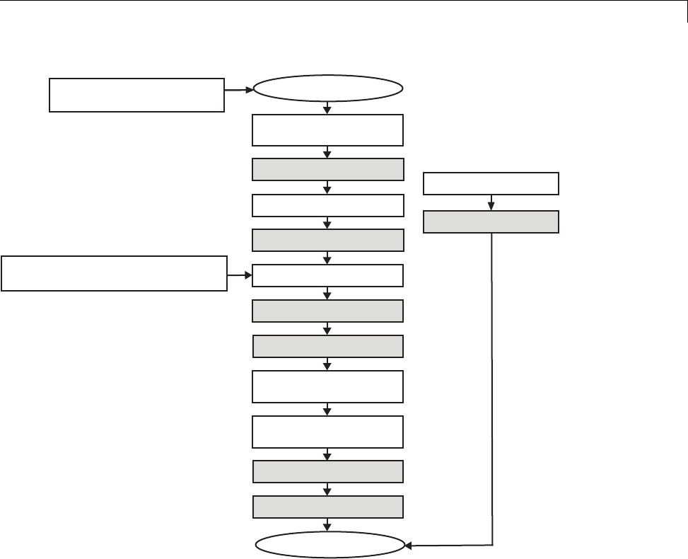
Customize Build Process with STF_make_rtw_hook File
End build process
Input:
buildOpts,templateMakefile
Input:
modelName,buildArgs
STF entry hook
STF before_tlc hook
STF af ter_tlc hook
STF before_make hook
Start build process
Simulink Coder
verification
Create build directory
Generate code
Make
Invoke post code
generation command
Error occurs
STF error hook
STF after_make hook
STF exit hook
•modelName: String specifying the name of the model. Valid at all stages
of the build process.
•rtwRoot:Reserved.
•templateMakefile: Name of template makefile.
22-23
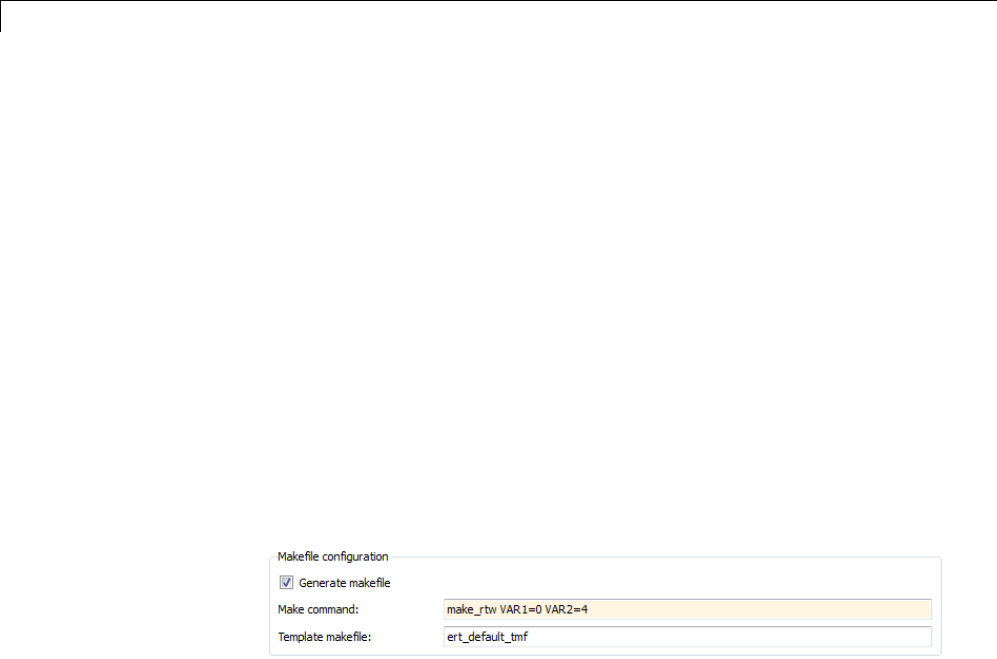
22 Build Process Integration
•buildOpts: A MATLAB structure containing the fields described in the list
below. Valid for the 'before_make','after_make',and'exit' stages
only. The buildOpts fields include:
-modules: Character array specifying a list of additional files that need
to be compiled.
-codeFormat: Character array containing code format specified for the
target. (ERT-based targets must use the 'Embedded-C' code format.)
-noninlinedSFcns: Cell array specifying list of noninlined S-functions in
the model.
-compilerEnvVal: String specifying compiler environment variable value
(for example, C:\Applications\Microsoft Visual).
•buildArgs: Character array containing the argument to make_rtw.When
you invoke the build process, buildArgs is copied from the argument string
(ifany)following"make_rtw" in the Make command field of the Code
Generation pane of the Configuration Parameters dialog box.
ThemakeargumentsfromtheMake command field in the figure above,
for example, generate the following:
% make -f untitled.mk VAR1=0 VAR2=4
22-24

Customize Build Process with STF_make_rtw_hook File
Applications for STF_make_rtw_hook.m
An enumeration of all possible uses for STF_make_rtw_hook.m is beyond the
scope of this document. However, this section provides some suggestions of
how you might apply the available hooks.
In general, you can use the 'entry' hook to initialize the build process
before any code is generated, for exampletochangeorvalidatesettings.One
application for the 'entry' hook is to rerun the auto-configuration script that
initially ran at target selection time to compare model parameters before and
after the script executes for validation purposes.
The other hook points, 'before_tlc','after_tlc','before_make',
'after_make','exit',and'error' are useful for interfacing with external
tool chains, source control tools, and other environment tools.
For example, you could use the STF_make_rtw_hook.m file at any stage after
'entry' to obtain the path to the build folder. At the 'exit' stage, you
could then locate generated code files within the build folder and check them
into your version control system. You might use 'error' to clean up static
or global data used by the hook function when an error occurs during code
generation or the build process.
Note that the build process temporarily changes the MATLAB working
folder to the build folder for stages 'before_make','after_make','exit',
and 'error'.YourSTF_make_rtw_hook.m file should not make incorrect
assumptions about the location of the build folder. You can obtain the
path to the build folder anytime after the 'entry' stage. In the following
code example, the build folder path is returned as a string to the variable
buildDirPath.
makertwObj = get_param(gcs, 'MakeRTWSettingsObject');
buildDirPath = getfield(makertwObj, 'BuildDirectory');
22-25

22 Build Process Integration
Control Code Regeneration Using
STF_make_rtw_hook.m
When you rebuild a model, by default, the build process performs checks
to determine whether changes to the model or relevant settings require
regeneration of the top model code. (For details on the criteria, see “Control
Regeneration of Top Model Code” on page 15-27.) If the checks determine that
top model code generation is required, the build process fully regenerates and
compiles the model code. If the checks indicate that the top model generated
code is current with respect to the model, and no model settings require full
regeneration, the build process omits regeneration of the top model code.
Regardless of whether the top model code is regenerated, the build process
subsequently calls all build process hooks, including STF_make_rtw_hook
functions and the post code generation command. The following
mechanisms allow you to perform actions related to code regeneration in
the STF_make_rtw_hook functions:
•To force code regeneration, use the following function call from the 'entry'
hook:
rtw.targetNeedsCodeGen('set', true);
•In all hooks from 'before_tlc' through 'exit',thebuildOpts structure
passed to the hook has a Boolean field codeWasUpToDate,whichissetto
true if model code was up to date and code was not regenerated, or false if
code was not up to date and code was regenerated. You can customize hook
actions based on the value of this field. For example:
...
case `before_tlc'
if buildOpts.codeWasUpToDate
%Perform hook actions for up to date model
else
%Perform hook actions for full code generation
end
...
22-26

Customize Build Process with STF_make_rtw_hook File
Use STF_make_rtw_hook.m for Your Build Procedure
To create a custom STF_make_rtw_hook hook file for your build procedure,
copy and edit the example ert_make_rtw_hook.m file (located in the
matlabroot/toolbox/rtw/targets/ecoder folder) as follows:
1Copy ert_make_rtw_hook.m to a folder in the MATLAB path, and rename
it in accordance with the naming conventions described in “Conventions for
Using the STF_make_rtw_hook File” on page 22-21. For example, to use it
with the GRT target grt.tlc,renameittogrt_make_rtw_hook.m.
2Rename the ert_make_rtw_hook function within the file to match the
filename.
3Implement the hooks that you require by adding code to case statements
within the switch hookMethod statement.
22-27

22 Build Process Integration
Customize Build Process with sl_customization.m
In this section...
“About sl_customization.m” on page 22-28
“Register Build Process Hook Functions Using sl_customization.m” on
page 22-30
“Variables Available for sl_customization.m Hook Functions” on page 22-31
“Example Build Process Customization Using sl_customization.m” on page
22-31
About sl_customization.m
The Simulink customization file sl_customization.m is a mechanism
that allows you to use MATLAB to customize the standard Simulink user
interface. The Simulink software reads the sl_customization.m file, if
present on the MATLAB path, when it starts and the customizations specified
in the file are applied to the Simulink session. For more information on the
sl_customization.m customization file, see “Registering Customizations”.
The sl_customization.m file can be used to register installation-specific
hook functions to be invoked during the Simulink Coder build process. The
hook functions that you register through sl_customization.m complement
System Target File (STF) hooks (described in “Customize Build Process
with STF_make_rtw_hook File” on page 22-21) and post-code generation
commands (described in “Customize Post-Code-Generation Build Processing”
on page 22-13).
The following figure shows the relationship between installation-level hooks
and the other available mechanisms for customizing the build process.
22-28
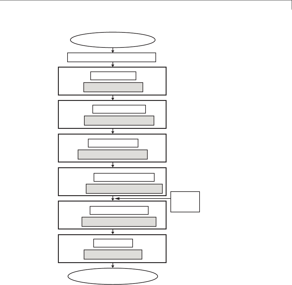
Customize Build Process with sl_customization.m
Start build process
Simulink Coder verification
Entry
Before TLC
After TLC
After Make
Before Make
Exit
End build process
STF 'entry' hook
Installation 'entry' hook
STF 'before_tlc' hook
Installation 'before_tlc' hook
STF 'after_tlc' hook
Installation 'after_tlc' hook
STF 'before_make' hook
Installation 'before_make' hook
Installation 'after_make' hook
STF 'after_make' hook
STF 'exit' hook
Installation 'exit' hook
Post code
generation
command
22-29

22 Build Process Integration
Register Build Process Hook Functions Using
sl_customization.m
To register installation-level hook functions that will be invoked during
the Simulink Coder build process, you create a MATLAB function called
sl_customization.m and include it on the MATLAB path of the Simulink
installation that you want to customize. The sl_customization function
accepts one argument: a handle to a customization manager object. For
example,
function sl_customization(cm)
As a startingpointforyourcustomizations,thesl_customization function
must first get the default (factory) customizations, using the following
assignment statement:
hObj = cm.RTWBuildCustomizer;
You then invoke methods to register your customizations. The customization
manager object includes the following method for registering Simulink Coder
build process hook customizations:
•addUserHook(hObj, hookType, hook)
Registers the MATLAB hook script or function specified by hook for
the build process stage represented by hookType. The valid values for
hookType are 'entry','before_tlc','after_tlc','before_make',
'after_make',and'exit'.
Your instance of the sl_customization function should use this method to
register installation-specific hook functions.
The Simulink software reads the sl_customization.m file when it starts. If
you subsequently change the file, you must restart the Simulink session or
enter the following command at the MATLAB command line to effect the
changes:
sl_refresh_customizations
22-30

Customize Build Process with sl_customization.m
Variables Available for sl_customization.m Hook
Functions
The following variables are available for sl_customization.m hook functions
to use:
•modelName — The name of the Simulink model (valid for all stages)
•dependencyObject — An object containing the dependencies of the
generatedcode(validonlyforthe'after_make' stage)
A hook script can directly access the valid variables. A hook function can pass
thevalidvariablesasarguments to the function. For example:
hObj.addUserHook('after_make', 'afterMakeFunction(modelName,dependencyObject);');
Example Build Process Customization Using
sl_customization.m
The sl_customization.m fileshowninExample1:sl_customization.mfor
Simulink®Coder™ Build Process Customizations on page 22-31 uses the
addUserHook method to specify installation-specific build process hooks to be
invoked at the 'entry' and 'after_tlc' stages of the Simulink Coder build.
For the hook function source code, see Example 2: CustomRTWEntryHook.m
on page 22-32 and Example 3: CustomRTWPostProcessHook.m on page 22-32.
Example 1: sl_customization.m for Simulink Coder Build Process
Customizations
function sl_customization(cm)
% Register user customizations
% Get default (factory) customizations
hObj = cm.RTWBuildCustomizer;
% Register build process hooks
hObj.addUserHook('entry', 'CustomRTWEntryHook(modelName);');
hObj.addUserHook('after_tlc', 'CustomRTWPostProcessHook(modelName);');
end
22-31

22 Build Process Integration
Example 2: CustomRTWEntryHook.m
function [str, status] = CustomRTWEntryHook(modelName)
str =sprintf('Custom entry hook for model ''%s.''',modelName);
disp(str)
status =1;
Example 3: CustomRTWPostProcessHook.m
function [str, status] = CustomRTWPostProcessHook(modelName)
str =sprintf('Custom post process hook for model ''%s.''',modelName);
disp(str)
status =1;
If you include the above three files on the MATLAB path of the Simulink
installation that you want to customize, the coded hook function messages
will appear in the displayed output for Simulink Coder builds. For example, if
youopentheERT-basedmodelrtwdemo_udt,opentheCode Generation
pane of the Configuration Parameters dialog box, and click the Build button
to initiate a Simulink Coder build, the following messages are displayed:
>> rtwdemo_udt
### Starting build procedure for model: rtwdemo_udt
Custom entry hook for model 'rtwdemo_udt.'
Custom post process hook for model 'rtwdemo_udt.'
### Successful completion of build procedure for model: rtwdemo_udt
>>
22-32

Replace the STF_rtw_info_hook Mechanism
Replace the STF_rtw_info_hook Mechanism
Prior to MATLAB Release 14, custom targets supplied target-specific
information with a hook file (referred to as STF_rtw_info_hook.m).
The STF_rtw_info_hook specified properties such as word sizes for
integer data types (for example, char,short,int,andlong), and C
implementation-specific properties of the custom target.
The STF_rtw_info_hook mechanism has been replaced by the Hardware
Implementation pane of the Configuration Parameters dialog box. Using
this dialog box, you can specify all properties that were formerly specified in
your STF_rtw_info_hook file.
For backward compatibility, existing STF_rtw_info_hook files are available.
However, you should convert your target and models to use of the Hardware
Implementation pane. See “Target” on page 9-9 .
22-33

22 Build Process Integration
Customize Build to Use Shared Utility Code
The shared utility folders (slprj/target/_sharedutils) typically store
generated utility code that is common to a top model and the models it
references. You can also force the build process to use a shared utilities folder
for a standalone model. See “Logging” on page 15-105 for details.
If you want your target to support compilation of code generated in the shared
utilities folder, you must modify your template makefile (TMF). The shared
utilities folder is required to support model reference builds. See “Support
Model Referencing” on page 24-101 to learn about additional updates for
supporting model reference builds.
The exact syntax of the changes can vary due to differences in the make utility
and compiler/archive tools used by your target. The examples below are based
on the Free Software Foundation’s GNU make utility. You can find the
following updated TMF examples for GNU and Microsoft Visual C++ make
utilities in the GRT and ERT target folders:
•GRT: matlabroot/rtw/c/grt/
-grt_lcc.tmf
-grt_vc.tmf
-grt_unix.tmf
•ERT: matlabroot/rtw/c/ert/
-ert_lcc.tmf
-ert_vc.tmf
-ert_unix.tmf
Use the GRT or ERT examples as a guide to the location, within the TMF, of
the changes and additions described below.
Note The ERT-based TMFs contain extra code to handle generation of ERT
S-functions and model reference simulation targets. Your target does not
need to handle these cases.
22-34

Customize Build to Use Shared Utility Code
Modify Template Makefiles to Support Shared
Utilities
Make the following changes to your TMF to support the shared utilities folder:
1Add the following make variables and tokens to be expanded when the
makefile is generated:
SHARED_SRC = |>SHARED_SRC<|
SHARED_SRC_DIR = |>SHARED_SRC_DIR<|
SHARED_BIN_DIR = |>SHARED_BIN_DIR<|
SHARED_LIB = |>SHARED_LIB<|
SHARED_SRC specifies the shared utilities folder location and the source files
in it. A typical expansion in a makefile is
SHARED_SRC = ../slprj/ert/_sharedutils/*.c
SHARED_LIB specifies the library file built from the shared source files, as
in the following expansion.
SHARED_LIB = ../slprj/ert/_sharedutils/rtwshared.lib
SHARED_SRC_DIR and SHARED_BIN_DIR allow specification of separate
folders for shared source files and the library compiled from the source files.
In the current release, all TMFs use the same path, as in the following
expansions.
SHARED_SRC_DIR = ../slprj/ert/_sharedutils
SHARED_BIN_DIR = ../slprj/ert/_sharedutils
2Set the SHARED_INCLUDES variable according to whether shared utilities
are in use. Then append it to the overall INCLUDES variable.
SHARED_INCLUDES =
ifneq ($(SHARED_SRC_DIR),)
SHARED_INCLUDES = -I$(SHARED_SRC_DIR)
endif
INCLUDES = -I. $(MATLAB_INCLUDES) $(ADD_INCLUDES) \
$(USER_INCLUDES) $(SHARED_INCLUDES)
22-35

22 Build Process Integration
3Update the SHARED_SRC variable to list all shared files explicitly.
SHARED_SRC := $(wildcard $(SHARED_SRC))
4Create a SHARED_OBJS variable based on SHARED_SRC.
SHARED_OBJS = $(addsuffix .o, $(basename $(SHARED_SRC)))
5Create an OPTS (options) variable for compilation of shared utilities.
SHARED_OUTPUT_OPTS = -o $@
6Provide a rule to compile the shared utility source files.
$(SHARED_OBJS) : $(SHARED_BIN_DIR)/%.o : $(SHARED_SRC_DIR)/%.c
$(CC) -c $(CFLAGS) $(SHARED_OUTPUT_OPTS) $<
7Provide a rule to create a library of the shared utilities. The following
example is based on The Open Group UNIX platforms.
$(SHARED_LIB) : $(SHARED_OBJS)
@echo "### Creating $@ "
ar r $@ $(SHARED_OBJS)
@echo "### Created $@ "
8Add SHARED_LIB totherulethatcreatesthefinalexecutable.
$(PROGRAM) : $(OBJS) $(LIBS) $(SHARED_LIB)
$(LD) $(LDFLAGS) -o $@ $(LINK_OBJS) $(LIBS) $(SHARED_LIB)\
$(SYSLIBS)
@echo "### Created executable: $(MODEL)"
9Remove any explicit reference to rt_nonfinite.c or rt_nonfinite.cpp
from your TMF. For example, change
ADD_SRCS = $(RTWLOG) rt_nonfinite.c
to
ADD_SRCS = $(RTWLOG)
22-36


23 Run-Time Data Interface Extensions
Customize an ASAP2 File
In this section...
“About ASAP2 File Customization” on page 23-2
“ASAP2 File Structure on the MATLAB Path” on page 23-2
“Customize the Contents of the ASAP2 File” on page 23-3
“ASAP2 Templates” on page 23-4
“Use GROUP and SUBGROUP Hierarchies to Organize Signals and
Parameters” on page 23-6
“Customize Computation Method Names” on page 23-12
“Suppress Computation Methods for FIX_AXIS” on page 23-13
About ASAP2 File Customization
The Embedded Coder product provides a number of Target Language
Compiler (TLC) files to enable you to customize the ASAP2 file generated
from a Simulink model.
ASAP2 File Structure on the MATLAB Path
The ASAP2 related files are organized within the folders identified below:
•TLC files for generating ASAP2 file
The matlabroot/rtw/c/tlc/mw folder contains TLC files that generate
ASAP2 files, asamlib.tlc,asap2lib.tlc,asap2main.tlc,and
asap2grouplib.tlc. These files are included by the selected System
target file. (See “Targets Supporting ASAP2” on page 15-175.)
•ASAP2 target files
The matlabroot/toolbox/rtw/targets/asap2/asap2 folder contains the
ASAP2 system target file and other control files.
•Customizable TLC files
23-2

Customize an ASAP2 File
The matlabroot/toolbox/rtw/targets/asap2/asap2/user folder
contains files that you can modify to customize the content of your ASAP2
files.
•ASAP2 templates
The matlabroot/toolbox/rtw/targets/asap2/asap2/user/templates
folder contains templates that define each type of CHARACTERISTIC in the
ASAP2 file.
Customize the Contents of the ASAP2 File
The ASAP2 related TLC files enable you to customize the appearance of
the ASAP2 file generated from a Simulink model. Most customization
is done by modifying or adding to the files contained in the
matlabroot/toolbox/rtw/targets/asap2/asap2/user folder. This section
refers to this folder as the asap2/user folder.
The user-customizable files provided are divided into two groups:
•The static files define the parts of the ASAP2 file that are related to
the environment in which the generated code is used. They describe
information specific to the user or project. The static files are not model
dependent.
•The dynamic files define the parts of the ASAP2 file that are generated
based on the structure of the source model.
The procedure for customizing the ASAP2 file is as follows:
1Make a copy of the asap2/user folder before making any modifications.
2Remove the old asap2/user folder from the MATLAB path, or add the new
asap2/user folder to the MATLAB path above the old folder. This ensures
that the MATLAB session uses the ASAP2 setup file, asap2setup.tlc
(new for Release 14).
asap2setup.tlc specifies the folders and files to include in the TLC path
during the ASAP2 file generation process. Modify asap2setup.tlc to
control the folders and folders included in the TLC path.
3Modify the static parts of the ASAP2 file. These include
23-3

23 Run-Time Data Interface Extensions
•Project and header symbols, which are specified in asap2setup.tlc
•Static sections of the file, such as file header and tail, A2ML,MOD_COMMON,
and so on These are specified in asap2userlib.tlc.
•Specify the appearance of the dynamic contents of the ASAP2 file by
modifying the existing ASAP2 templates or by defining new ASAP2
templates. Sections of the ASAP2 file affected include
RECORD_LAYOUT: modify parts of the ASAP2 template files.
CHARACTERISTIC: modify parts of the ASAP2 template files. For more
information on modifying the appearance of CHARACTERISTIC records,
see “ASAP2 Templates” on page 23-4.
•MEASUREMENT:Thesearespecifiedinasap2userlib.tlc.
•COMPU_METHOD:Thesearespecifiedinasap2userlib.tlc.
ASAP2 Templates
The appearance of CHARACTERISTIC records in the ASAP2 file is controlled
using a different template for each type of CHARACTERISTIC.Theasap2/user
folder contains template definition files for scalars, 1-D Lookup Table blocks
and 2-D Lookup Table blocks. You can modify these template definition files,
or you can create additional templatesasrequired.
The procedure for creating a new ASAP2 template is as follows:
1Create a template definition file. See “Create Template Definition Files”
on page 23-4.
2Include the template definition file in the TLC path. The path is specified
in the ASAP2 setup file, asap2setup.tlc.
Create Template Definition Files
This section describes the components that make up an ASAP2 template
definition file. This description is in the form of code examples from
asap2lookup1d.tlc, the template definition file for the Lookup1D template.
This template corresponds to the Lookup1D parameter group.
23-4

Customize an ASAP2 File
Note When creating a new template, use the corresponding parameter group
name in place of Lookup1D inthecodeshown.
Template Registration Function
The input argument is the name of the parameter group associated with
this template:
%<LibASAP2RegisterTemplate("Lookup1D")>
RECORD_LAYOUT Name Definition Function
Record layout names (aliases) can be arbitrarily specified for each data type.
This function is used by the other components of this file.
%function ASAP2UserFcnRecordLayoutAlias_Lookup1D(dtId) void
%switch dtId
%case tSS_UINT8
%return "Lookup1D_UBYTE"
...
%endswitch
%endfunction
Function to Write RECORD_LAYOUT Definitions
This function writes RECORD_LAYOUT definitions associated with this template.
The function is called by the built-in functions involved in the ASAP2 file
generation process. The function name must be defined as shown, with the
template name after the underscore:
%function ASAP2UserFcnWriteRecordLayout_Lookup1D() Output
/begin RECORD_LAYOUT
%<ASAP2UserFcnRecordLayoutAlias_Lookup1D(tSS_UINT8)>
...
/end RECORD_LAYOUT
%endfunction
23-5

23 Run-Time Data Interface Extensions
Function to Write the CHARACTERISTIC
This function writes the CHARACTERISTIC associated with this template.
The function is called by the built-in functions involved in the ASAP2 file
generation process. The function name must be defined as shown, with the
template name after the underscore.
The input argument to this function is a pointer to a parameter group record.
The example shown is for a Lookup1D parameter group that has two members.
The references to the associated xand ydata records are obtained from the
parameter group record as shown.
This function calls a number of built-in functions to obtain the required
information. For example, LibASAP2GetSymbol returns the symbol (name)
for the specified data record:
%function ASAP2UserFcnWriteCharacteristic_Lookup1D(paramGroup)
Output
%assign xParam = paramGroup.Member[0].Reference
%assign yParam = paramGroup.Member[1].Reference
%assign dtId = LibASAP2GetDataTypeId(xParam)
/begin CHARACTERISTIC
/* Name */ %<LibASAP2GetSymbol(xParam)>
/* Long identifier */ "%<LibASAP2GetLongID(xParam)>"
...
/end CHARACTERISTIC
%endfunction
Use GROUP and SUBGROUP Hierarchies to Organize
Signals and Parameters
•“Signal and Parameter Grouping Overview” on page 23-7
•“TLC Functions for Defining and Adding Groups” on page 23-7
•“ASAP2 Simple Grouping” on page 23-9
•“ASAP2 Graphical Grouping” on page 23-10
23-6

Customize an ASAP2 File
Signal and Parameter Grouping Overview
The Simulink Coder product provides TLC functions that allow you to
organize signals and parameters in the generated ASAP2 file into groups
and subgroups, using the GROUP and SUBGROUP keywords in the ASAP2
standard. Grouping can be done using criteria such as the following:
•Graphical location of the signal or parameter in the model
•Functionality (I/O or local)
•Custom criteria
By default, the build process generates ASAP2 parameter and signal
descriptions as a flat list. To generate ASAP2 GROUPs and SUBGROUPs,
do the following:
1Use the TLC customization functions that define and add groups.
2Generate code for your model. The code generator automatically generates
the defined groups into the ASAP2 file, using the GROUP and SUBGROUP
keywords.
TLC Functions for Defining and Adding Groups
•“Create Groups” on page 23-7
•“Populate Groups” on page 23-8
•“Group by Graphical Hierarchy” on page 23-8
Create Groups. The software provides the following TLC
functions for creating an ASAP2 group and setting its description
and annotation. These functions are defined in the file
matlabroot/rtw/c/tlc/mw/asap2grouplib.tlc and can be called
at any point during the ASAP2 customization process.
23-7

23 Run-Time Data Interface Extensions
Function Description
LibASAP2CreateGroup(groupName,
groupLongIdentifier)
Creates a group with the specified groupName
and returns the created group. If the group
already exists, returns the existing group.
LibASAP2SetGroupIsRoot(group)Sets the specified group as a ROOT.
LibASAP2SetGroupAnnotation(group,
annotation)
Sets the annotation for the specified group. If
annotation already exists, overwrites it.
Populate Groups. The software provides the following
TLC functions for adding subgroups, characteristics, and
measurements to groups. These functions are defined in the file
matlabroot/rtw/c/tlc/mw/asap2grouplib.tlc and can be called at any
point during the ASAP2 customization process.
Function Description
LibASAP2AddSubGroupToGroup(group,
subGroup)
Adds the specified subGroup as a SUB_GROUP
of the specified group.
LibASAP2AddCharacteristicToGroup(group,
characteristicName)
Adds the specified characteristicName as
a REF_CHARACTERISTIC of the specified
group.
LibASAP2AddMeasurementToGroup(group,
measurementName)
Adds the specified measurementName as a
REF_MEASUREMENT of the specified group.
Group by Graphical Hierarchy. The software provides the following TLC
functions for creating groups based on the graphical hierarchy of signals,
states, and parameters in the model. These functions are defined in the file
matlabroot/rtw/c/tlc/mw/asap2grouplib.tlc and can be called at any
point during the ASAP2 customization process.
23-8
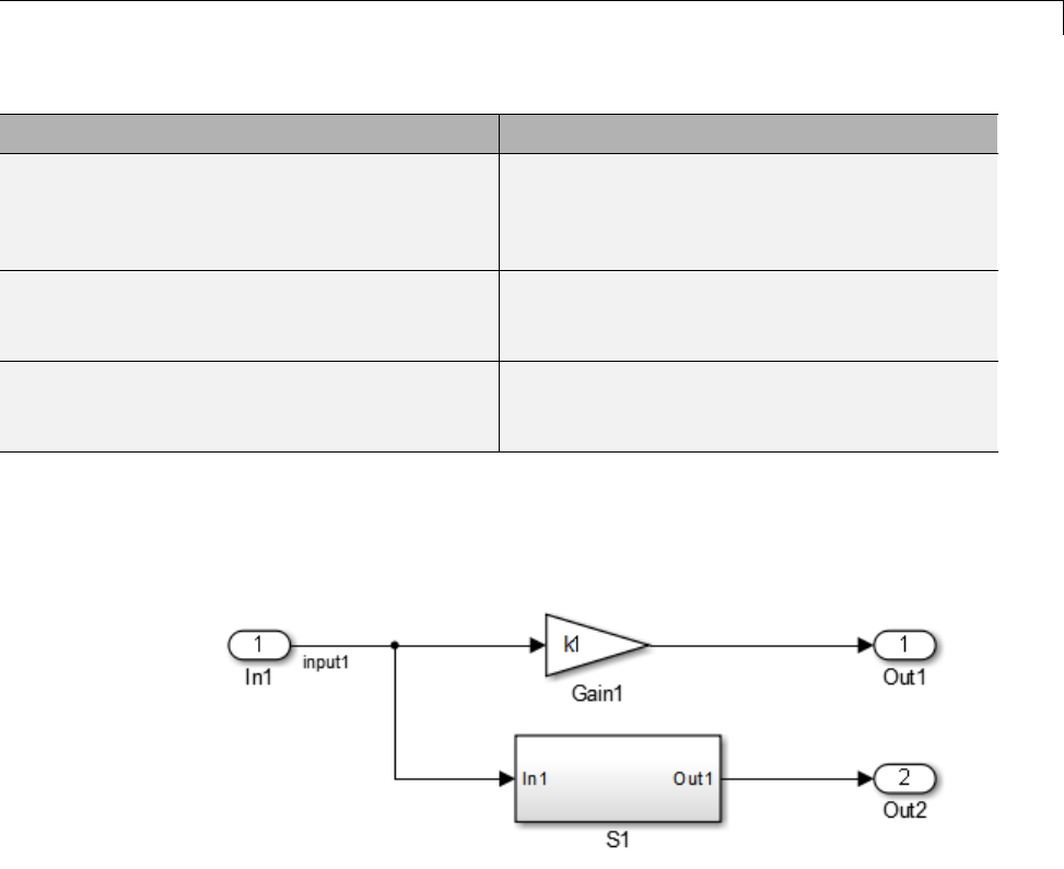
Customize an ASAP2 File
Function Description
LibASAP2CreateGraphicalGroups() Creates groups and subgroups. A group is
created for each graphical subsystem in the
model. The graphical hierarchy is reflected in
the SUB_GROUPs.
LibASAP2AddCharacteristicToGraphical
Groups(param)
Adds a CHARACTERISTIC to one or more
groups reflecting the locations of the specified
parameter in the model.
LibASAP2AddMeasurementToGraphical
Group(signal)
Adds a MEASUREMENT to a group and
its subgroups reflecting the location of the
specified signal or state in the model.
ASAP2 Simple Grouping
Consider the following model, in which subsystem S1 contains 3 signals and
uses 2 parameters:
Supposethatyouwanttodothefollowing:
•Create A ROOT group for the model.
•Organize all signals in the model in a group called Signals, which is a
subgroup of ROOT.
•Organize all parameters in the model in a group called Parameters, which
is a subgroup of ROOT.
To create this simple grouping, you perform the following steps:
23-9

23 Run-Time Data Interface Extensions
1In your copy of asap2setup.tlc, use the TLC functions to create the root
group and subgroups. For example:
%% Create a root GROUP
%assign ASAP2RootGroup = LibASAP2CreateGroup("%<CompiledModel.Name>", ...
"%<CompiledModel.Name>")
%<LibASAP2SetGroupIsRoot(ASAP2RootGroup)>
%% --------------------
%% Create a group for model signals
%assign ASAP2SigGroup = LibASAP2CreateGroup("Signals", ...
"Measurements in %<CompiledModel.Name>")
%<LibASAP2AddSubGroupToGroup(ASAP2RootGroup, ASAP2SigGroup)>
%% --------------------------------
%% Create a group for model parameters
%assign ASAP2ParGroup = LibASAP2CreateGroup("Parameters", ...
"Characteristics in %<CompiledModel.Name>")
%<LibASAP2AddSubGroupToGroup(ASAP2RootGroup, ASAP2ParGroup)>
2In the template function for MEASUREMENTs,
ASAP2UserFcnWriteMeasurementfile,addeachsignaltoASAP2SigGroup.
For example:
%<LibASAP2AddMeasurementToGroup(ASAP2SigGroup, LibASAP2GetSymbol(signal))>
3In the template function for CHARACTERISTICs,
ASAP2UserFcnWriteCharacteristic_Scalar, add each parameter to
ASAP2ParGroup. For example:
%<LibASAP2AddCharacteristicToGroup(ASAP2ParGroup, LibASAP2GetSymbol(param))>
In the generated ASAP2 file, parameters and signals are separated into
groups called Parameters and Signals, under the model root.
ASAP2 Graphical Grouping
Consider the following model, in which subsystem S1 contains 3 signals and
uses 2 parameters, and also contains another subsystem S2:
23-10
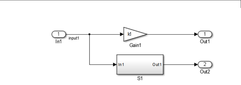
Customize an ASAP2 File
Supposethatyouwanttodothefollowing:
•Create a ROOT group for the model and create a subgroup for each
graphical subsystem in the model.
•Addeachsignalandstatetothegroupforthesubsystemthatreferstoit.
•Add each parameter to the groups for the subsystems that refer to it. (A
parameter can be referred to in multiple subsystems and added to multiple
groups.)
To create this graphical grouping, you perform the following steps:
1In your copy of asap2setup.tlc, use the TLC functions to create the groups
according to the graphical hierarchy. For example:
%<LibASAP2CreateGraphicalGroups()
2In the template function for MEASUREMENTs,
ASAP2UserFcnWriteMeasurementfile, add each signal to its graphical
group. For example:
%<LibASAP2AddMeasurementToGraphicalGroup(signal)>
3In the template function for CHARACTERISTICs,
ASAP2UserFcnWriteCharacteristic_Scalar, add each parameter to its
graphical groups. For example:
%<LibASAP2AddCharacteristicToGraphicalGroups(param)>
23-11

23 Run-Time Data Interface Extensions
In the generated ASAP2 file, the group ordering reflects the graphical
hierarchy of the model, root > S1 > S2.
Customize Computation Method Names
In generated ASAP2 files, computation methods translate the electronic
control unit (ECU) internal representation of measurement and calibration
quantities into a physical model oriented representation. Simulink Coder
software provides the ability to customize the names of computation methods.
You can provide names that are more intuitive, enhancing ASAP2 file
readability, or names that meet organizational requirements.
To customize computation method names, use the MATLAB
function getCompuMethodName, which is defined in
matlabroot/toolbox/rtw/targets/asap2/asap2/user/getCompuMethodName.m.
The getCompuMethodName function constructs a computation method name.
The function prototype is
cmName = getCompuMethodName(dataTypeName,cmUnits)
where dataTypeName is the name of the data type associated with the
computation method, cmUnits is the units as specified in the DocUnits
property of a Simulink.Parameter or Simulink.Signal object (for example,
rpm or m/s), and cmName returns the constructed computation method name.
The default constructed name returned by the function has the format
<localPrefix><datatype>_<cmUnits>
where
•<local_Prefix> is a local prefix, CM_, defined in
matlabroot/toolbox/rtw/targets/asap2/asap2/user/getCompuMethodName.m.
•<datatype> and <cmUnits> are the arguments you specified to the
getCompuMethodName function.
Additionally, in the generated ASAP2 file, the constructed name is
prefixed with <ASAP2CompuMethodName_Prefix>, a model prefix defined in
matlabroot/toolbox/rtw/targets/asap2/asap2/user/asap2setup.tlc.
23-12

Customize an ASAP2 File
For example, if you call the getCompuMethodName function with the
dataTypeName argument 'int16' and the cmUnits argument 'm/s',and
generateanASAP2fileforamodelnamedmyModel, the computation method
name would appear in the generated file as follows:
/begin COMPU_METHOD
/* Name of CompuMethod */ myModel_CM_int16_m_s
/* Units */ "m/s"
...
/end COMPU_METHOD
Suppress Computation Methods for FIX_AXIS
Versions 1.51 and later of the ASAP2 specification state that for certain
cases of lookup table axis descriptions (integer data type and no doc units), a
computation method is not required and the Conversion Method parameter
must be set to the value NO_COMPU_METHOD. You can control whether or not
computation methods are suppressed when not required using the Target
Language Compiler (TLC) option ASAP2GenNoCompuMethod. This TLC option
is disabled by default. If you enable the option, ASAP2 file generation does
not generate computation methods for lookup table axis descriptions when not
required, and instead generates the value NO_COMPU_METHOD. For example:
/begin CHARACTERISTIC
/* Name */
lu1d_fix_axisTable_data
...
/begin AXIS_DESCR
...
/* Conversion Method */
NO_COMPU_METHOD
...
/end CHARACTERISTIC
The ASAP2GenNoCompuMethod option is defined in
matlabroot/toolbox/rtw/targets/asap2/asap2/user/asap2setup.tlc.
23-13

23 Run-Time Data Interface Extensions
Create a Transport Layer for External Communication
In this section...
“About Creating a Transport Layer for External Communication” on page
23-14
“Design of External Mode” on page 23-14
“External Mode Communications Overview” on page 23-17
“External Mode Source Files” on page 23-19
“Implement a Custom Transport Layer” on page 23-23
About Creating a Transport Layer for External
Communication
This section helps you to connect your custom target by using External mode
using your own low-level communications layer. The topics include:
•An overview of the design and operation of External mode
•A description of External mode source files
•Guidelines for modifying the External mode source files and building an
executabletohandlethetasksofthedefaultext_comm MEX-file
This section assumes that you are familiar with the execution of Simulink
Coder programs, and with the basic operation of External mode.
Design of External Mode
External mode communication between the Simulink engine and a target
system is based on a client/server architecture. The client (the Simulink
engine) transmits messages requesting the server (target) to accept parameter
changes or to upload signal data. The server responds by executing the
request.
A low-level transport layer handles physical transmission of messages. Both
theSimulinkengineandthemodelcodeareindependentofthislayer. Both
the transport layer and code directly interfacing to the transport layer are
23-14

Create a Transport Layer for External Communication
isolated in separate modules that format, transmit, and receive messages
and data packets.
This design makes it possible for different targets to use different transport
layers. The GRT, GRT malloc, ERT, and RSim targets support host/target
communication by using TCP/IP and RS-232 (serial) communication. The
RTWin target supports shared memory communication. The Wind River
Systems Tornado target supports TCP/IP only.
The Simulink Coder product provides full source code for both the client and
server-side External mode modules, as used by the GRT, GRT malloc, ERT,
Rapid Simulation, and Tornado targets, and the Real-Time Windows Target
and xPC Target products. The main client-side module is ext_comm.c.The
main server-side module is ext_svr.c.
These two modules call the specified transport layer through the following
source files.
Built-In Transport Layer Implementations
Protocol
Client or
Server? Source Files
TCP/IP Client
(host)
•matlabroot/rtw/ext_mode/common/rtiostream_interface.c
•matlabroot/rtw/c/src/rtiostream/rtiostreamtcpip/-
rtiostream_tcpip.c
Server
(target)
•matlabroot/rtw/c/src/ext_mode/common/rtiostream_interface.c
•matlabroot/rtw/c/src/rtiostream/rtiostreamtcpip/-
rtiostream_tcpip.c
Serial Client
(host)
•matlabroot/rtw/ext_mode/serial/ext_serial_transport.c
•matlabroot/rtw/c/src/rtiostream/rtiostreamserial/rtiostream_serial.c
Server
(target)
•matlabroot/rtw/c/src/ext_mode/serial/ext_svr_serial_transport.c
•matlabroot/rtw/c/src/rtiostream/rtiostreamserial/rtiostream_serial.c
For serial communication, the modules ext_serial_transport.c
and rtiostream_serial.c implement the client-side transport
functions and the modules ext_svr_serial_transport.c and
23-15

23 Run-Time Data Interface Extensions
rtiostream_serial.c implement the corresponding server-side functions.
For TCP/IP communication, the modules rtiostream_interface.c and
rtiostream_tcpip.c implement both client-side and server-side functions.
You can edit copies of these files (but do not modify the originals). You can
support External mode using your own low-level communications layer by
creating similar files using the following templates:
•Client (host) side:
matlabroot/rtw/c/src/rtiostream/rtiostreamtcpip/rtiostream_tcpip.c
(TCP/IP) or
matlabroot/rtw/c/src/rtiostream/rtiostreamserial/rtiostream_serial.c
(serial)
•Server (target) side:
matlabroot/rtw/c/src/rtiostream/rtiostreamtcpip/rtiostream_tcpip.c
(TCP/IP) or
matlabroot/rtw/c/src/rtiostream/rtiostreamserial/rtiostream_serial.c
(serial)
The file rtiostream_interface.c is an interface between the External mode
protocol and an rtiostream communications channel. For more details on
implementing an rtiostream communications channel, see “Communications
rtiostream API” in the Embedded Coder documentation. Implement your
rtiostream communications channel by using the documented interface to
avoid having to make changes to the file rtiostream_interface.c or any
other External mode related files.
Note Do not modify working source files. Use the templates provided in the
/custom or /rtiostream folder as starting points, guided by the comments
within them.
You need only provide code that implements low-level communications. You
need not be concerned with issues such as data conversions between host and
target, or with the formatting of messages. The Simulink Coder software
handles these functions.
On the client (Simulink engine) side, communications are handled by
ext_comm (for TCP/IP) and ext_serial_win32_comm (for serial) MEX-files.
23-16

Create a Transport Layer for External Communication
On the server (target) side, External mode modules are linked into the target
executable. This takes place automatically if the External mode code
generation option is selected at code generation time, based on the External
mode transport option selected in the target code generation options dialog
box. These modules, called from the main program and the model execution
engine, are independent of the generated model code.
The general procedure for implementing your own client-side low-level
transport protocol is as follows:
1Edit the template rtiostream_tcpip.c to replace low-level communication
calls with your own communication calls.
2Generate a MEX-file executable for your custom transport.
3Register your new transport layer with the Simulink software, so that
the transport can be selected for a model using the Interface pane of the
Configuration Parameters dialog box.
For more details, see “Create a Custom Client (Host) Transport Protocol” on
page 23-24.
The general procedure for implementing your own server-side low-level
transport protocol is as follows:
1Edit the template rtiostream_tcpip.c to replace low-level communication
calls with your own communication calls. Typically this involves writing or
integrating device drivers for your target hardware.
2Modify template makefiles tosupportthenewtransport.
For more details, see “Create a Custom Server (Target) Transport Protocol”
on page 23-28.
External Mode Communications Overview
This section gives a high-level overview of how a Simulink Coder generated
program communicates with Simulink External mode. This description is
based on the TCP/IP version of External mode that ships with the Simulink
Coder product.
23-17

23 Run-Time Data Interface Extensions
For communication to take place,
•The server (target) program must have been built with the conditional
EXT_MODE defined. EXT_MODE is defined in the model.mk file if the External
mode code generation option was selected at code generation time.
•Both the server program and the Simulink software must be executing.
This does not mean that the model code in the server system must be
executing. The server can be waiting for the Simulink engine to issue a
command to start model execution.
The client and server communicate by using bidirectional sockets carrying
packets. Packets consist either of messages (commands, parameter downloads,
and responses) or data (signal uploads).
If the target program was invoked with the -w command-line option, the
program enters a wait state until it receives a message from the host.
Otherwise, the program begins execution of the model. While the target
program is in a wait state, the Simulink engine can download parameters to
the target and configure data uploading.
When the user chooses the Connect to Target option from the Simulation
menu, the host initiates a handshake by sending an EXT_CONNECT message.
The server responds with information about itself. This information includes
•Checksums. The host uses model checksums to determine that the target
code is an exact representation of the current Simulink model.
•Data format information. The host uses this information when formatting
data to be downloaded, or interpreting data that has been uploaded.
At this point, host and server are connected. The server is either executing
the model or in the wait state. (In the latter case, the user can begin model
execution by selecting Start Real-Time Code from the Simulation menu.)
During model execution, the message server runs as a background task. This
task receives and processes messages such as parameter downloads.
Data uploading comprises both foreground execution and background
servicing of the signal packets. As the target computes model outputs, it also
copies signal values into data upload buffers. This occurs as part of the task
23-18

Create a Transport Layer for External Communication
associated with each task identifier (tid). Therefore, data collection occurs
in the foreground. Transmission of the collected data, however, occurs as
a background task. The background task sends the data in the collection
buffers to the Simulink engine by using data packets.
The host initiates most exchanges as messages. The target usually sends
a response confirming that it has received and processed the message.
Examples of messages and commands are
•Connection message / connection response
•Starttargetsimulation/startresponse
•Parameter download / parameter download response
•Arm trigger for data uploading / arm trigger response
•Terminate target simulation / target shutdown response
Model execution terminates when the model reaches its final time, when the
host sends a terminate command, or when a Stop Simulation block terminates
execution. On termination, the server informs the host that model execution
has stopped, and shuts down its socket. The host also shuts down its socket,
and exits External mode.
External Mode Source Files
•“Client (Host) MEX-file Interface Source Files” on page 23-19
•“Server (Target) Source Files” on page 23-21
•“Other Files in the Server Folder” on page 23-23
Client (Host) MEX-file InterfaceSourceFiles
ThesourcefilesfortheMEX-fileinterface component are located in the folder
matlabroot/rtw/ext_mode, except as noted:
•common/ext_comm.c
This file is the core of External mode communication. It acts as a
relay station between the target and the Simulink engine. ext_comm.c
communicates to the Simulink engine by using a shared data structure,
23-19

23 Run-Time Data Interface Extensions
ExternalSim. It communicates to the target by using calls to the transport
layer.
Tasks carried out by ext_comm.c include establishment of a connection
with the target, downloading of parameters, and termination of the
connection with the target.
•common/rtiostream_interface.c
This file is an interface between the External mode protocol and an
rtiostream communications channel. For more details on implementing
an rtiostream communications channel, see “Communications rtiostream
API” in the Embedded Coder documentation. Implement your rtiostream
communications channel using the documented interface to avoid having
to change the file rtiostream_interface.c or any other External mode
related files.
•matlabroot/rtw/c/src/rtiostream/rtiostreamtcpip/rtiostream_tcpip.c
This file implements required TCP/IP transport layer functions. The
version of rtiostream_tcpip.c shipped with the Simulink Coder software
uses TCP/IP functions including recv(),send(),andsocket().
•matlabroot/rtw/c/src/rtiostream/rtiostreamtserial/rtiostream_serial.c
This file implements required serial transport layer functions. The version
of rtiostream_serial.c shipped with the Simulink Coder software uses
serial functions including ReadFile(),WriteFile(),andCreateFile().
•serial/ext_serial_transport.c
This file implements required serial transport layer functions.
ext_serial_transport.c includes ext_serial_utils.c, which is located
in matlabroot/rtw/c/src/ext_mode/serial and contains functions
common to client and server sides.
•common/ext_main.c
This file is a MEX-file wrapper for External mode. ext_main.c interfaces
to the Simulink engine by using the standard mexFunction call. (See the
mexFunction reference page and “Application Programming Interfaces
to MATLAB” for more information.) ext_main.c contains a function
dispatcher, esGetAction, that sends requests from the Simulink engine
to ext_comm.c.
•common/ext_convert.c and ext_convert.h
23-20

Create a Transport Layer for External Communication
This file contains functions used for converting data from host to target
formats (and vice versa). Functions include byte-swapping (big to little-
endian), conversion from non-IEEE floats to IEEE doubles, and other
conversions. These functions are called both by ext_comm.c and directly by
the Simulink engine (by using function pointers).
Note You do not need to customize ext_convert to implement a custom
transport layer. However, you mightwant to customize ext_convert for
the intended target. For example, if the target represents the float data
type in Texas Instruments format, ext_convert must be modified to
perform a Texas Instruments to IEEE conversion.
•common/extsim.h
This file defines the ExternalSim data structure and access macros. This
structure is used for communication between the Simulink engine and
ext_comm.c.
•common/extutil.h
This file contains only conditionals for compilation of the assert macro.
•common/ext_transport.h
This file defines functions that must be implemented by the transport layer.
Server (Target) Source Files
These files are part of the run-time interface and are linked into the model.exe
executable. They are located within matlabroot/rtw/c/src/ext_mode/
except as noted.
•common/ext_svr.c
ext_svr.c is analogous to ext_comm.c on the host, but generally is
responsible for more tasks. It acts as a relay station between the host and
the generated code. Like ext_comm.c,ext_svr.c carries out tasks such
as establishing and terminating connection with the host. ext_svr.c also
contains the background task functions that either write downloaded
parameters to the target model, or extract data from the target data buffers
andsenditbacktothehost.
23-21

23 Run-Time Data Interface Extensions
•common/rtiostream_interface.c
This file is an interface between the External mode protocol and an
rtiostream communications channel. For more details on implementing
an rtiostream communications channel, see “Communications rtiostream
API” in the Embedded Coder documentation. Implement your rtiostream
communications channel by using the documented interface to avoid
having to change the file rtiostream_interface.c or any other External
mode related files.
•matlabroot/rtw/c/src/rtiostream/rtiostreamtcpip/rtiostream_tcpip.c
This file implements required TCP/IP transport layer functions. The
version of rtiostream_tcpip.c shipped with the Simulink Coder software
uses TCP/IP functions including recv(),send(),andsocket().
•matlabroot/rtw/c/src/rtiostream/rtiostreamtserial/rtiostream_serial.c
This file implements required serial transport layer functions. The version
of rtiostream_serial.c shipped with the software uses serial functions
including ReadFile(),WriteFile(),andCreateFile().
•matlabroot/rtw/c/src/rtiostream.h
This file defines the rtIOStream* functions implemented in
rtiostream_tcpip.c.
•serial/ext_svr_serial_transport.c
This file implements required serial transport layer functions.
ext_svr_serial_transport.c includes serial/ext_serial_utils.c,
which contains functions common to client and server sides.
•common/updown.c
updown.c handles the details of interacting with the target model.
During parameter downloads, updown.c does the work of installing the
new parameters into the model’s parameter vector. For data uploading,
updown.c contains the functions that extract data from the model’s blockio
vector and write the data to the upload buffers. updown.c provides services
both to ext_svr.c andtothemodelcode(forexample,grt_main.c). It
contains code that is called by using the background tasks of ext_svr.c as
well as code that is called as part of the higher priority model execution.
•matlabroot/rtw/c/src/dt_info.h (included by generated model build
file model.h)
23-22

Create a Transport Layer for External Communication
These files contain data type transition information that allows access to
multi-data type structures across different computer architectures. This
information is used in data conversions between host and target formats.
•common/updown_util.h
This file contains only conditionals for compilation of the assert macro.
•common/ext_svr_transport.h
This file defines the Ext* functions that must be implemented by the
server (target) transport layer.
Other Files in the Server Folder
•common/ext_share.h
Contains message code definitions and other definitions required by both
the host and target modules.
•serial/ext_serial_utils.c
Contains functions and data structures for communication, MEX link,
and generated code required by both the host and target modules of the
transport layer for serial protocols.
•The serial transport implementation includes the additional files
-serial/ext_serial_pkt.c and ext_serial_pkt.h
-serial/ext_serial_port.h
Implement a Custom Transport Layer
•“Requirements for Custom Transport Layers” on page 23-24
•“Create a Custom Client (Host) Transport Protocol” on page 23-24
•“Register a Custom Client (Host) Transport Protocol” on page 23-27
•“Create a Custom Server (Target) Transport Protocol” on page 23-28
23-23

23 Run-Time Data Interface Extensions
Requirements for Custom Transport Layers
•By default, ext_svr.c and updown.c use malloc to allocate buffers in
target memory for messages, data collection, and other purposes, although
there is also an option to preallocate static memory. If your target uses
another memory allocation scheme, you must modify these modules.
•Thetargetisassumedtosupportbothint32_T and uint32_T data types.
Create a Custom Client (Host) Transport Protocol
To implement the client (host) side of your low-level transport protocol,
1Editthetemplatefile
matlabroot/rtw/c/src/rtiostream/rtiostreamtcpip/rtiostream_tcpip.c
to replace low-level communication calls with your own
communication calls.
aCopy and rename the file to rtiostream_name.c (replacing name with a
name meaningful to you).
bReplace the functions rtIOStreamOpen,rtIOStreamClose,
rtIOStreamSend,andrtIOStreamRecv with functions (of the
same name) that call your low-level communication primitives.
These functions are called from other External mode modules via
rtiostream_interface.c. For more information, see “Communications
rtiostream API” in the Embedded Coder documentation.
cBuild your rtiostream implementation into a shared library that
exports the rtIOStreamOpen,rtIOStreamClose,rtIOStreamRecv and
rtIOStreamSend functions.
2Build the customized MEX-file executable using the MATLAB mex
function. See the table MATLAB®Commands to Rebuild ext_comm and
ext_serial_win32 MEX-Files on page 23-25 for examples of mex invocations.
Do not replace the existing ext_comm MEX-file if you want to preserve its
existing function. Instead, use the -output option to name the resulting
executable (for example, mex -output ext_myrtiostream_comm ...
builds ext_myrtiostream_comm.mexext,onWindowsplatforms).
3Register your new client transport layer with the Simulink software, so
that the transport can be selected for a model using the Interface pane
23-24

Create a Transport Layer for External Communication
of the Configuration Parameters dialog box. For details, see “Register a
Custom Client (Host) Transport Protocol” on page 23-27.
The following table lists the commands for building the standard ext_comm
module on PC and UNIX platforms, and for building the standard
ext_serial_win32 model on a PC platform.
MATLAB Commands to Rebuild ext_comm and ext_serial_win32 MEX-Files
Platform Commands
PC, TCP/IP
>> cd (matlabroot)
>> mex rtw\ext_mode\common\ext_comm.c ...
rtw\ext_mode\common\ext_convert.c ...
rtw\ext_mode\common\rtiostream_interface.c ...
-Irtw\c\src -Irtw\c\src\rtiostream\utils ...
-Irtw\c\src\ext_mode\common ...
-Irtw\ext_mode\common ...
-Irtw\ext_mode\common\include ...
-lmwrtiostreamutils ...
-DEXTMODE_TCPIP_TRANSPORT ...
-DSL_EXT_DLL -output toolbox\rtw\rtw\ext_comm
Note The rtiostream_interface.c function defines
RTIOSTREAM_SHARED_LIB as libmwrtiostreamtcpip and
dynamically loads the MathWorks TCP/IP rtiostream shared library.
Modify this file if you need to load a different rtiostream shared library.
UNIX, TCP/IP Use the PC commands but change -DSL_EXT_DLL to -DSL_EXT_SO,andreplace
back slashes with forward slashes.
Mac, TCP/IP Use the PC commands but change -DSL_EXT_DLL to --DSL_EXT_DYLIB,and
replace back slashes with forward slashes.
23-25

23 Run-Time Data Interface Extensions
MATLAB Commands to Rebuild ext_comm and ext_serial_win32 MEX-Files (Continued)
Platform Commands
PC, serial
>> cd (matlabroot)
mex rtw\ext_mode\common\ext_comm.c ...
rtw\ext_mode\common\ext_convert.c ...
rtw\ext_mode\serial\ext_serial_transport.c ...
rtw\ext_mode\serial\ext_serial_pkt.c ...
rtw\ext_mode\serial\rtiostream_serial_interface.c ...
-Irtw\c\src -Irtw\c\src\rtiostream\utils ...
-Irtw\c\src\ext_mode\common ...
-Irtw\c\src\ext_mode\serial -Irtw\ext_mode\common ...
-Irtw\ext_mode\common\include ...
-lmwrtiostreamutils -DSL_EXT_DLL ...
-output toolbox\rtw\rtw\ext_serial_win32_comm
Note The rtiostream_interface.c function defines
RTIOSTREAM_SHARED_LIB as libmwrtiostreamserial and
dynamically loads the MathWorks serial rtiostream shared library. Modify
this file if you need to load a different rtiostream shared library.
UNIX, serial Use the PC commands but change -DSL_EXT_DLL to -DSL_EXT_SO,andreplace
back slashes with forward slashes.
Mac, serial Use the PC commands but change -DSL_EXT_DLL to --DSL_EXT_DYLIB,and
replace back slashes with forward slashes.
Note mex requires a compiler supported by the MATLAB API. See the mex
reference page and “Application Programming Interfaces to MATLAB” for
more information about the mex function.
23-26

Create a Transport Layer for External Communication
Register a Custom Client (Host) Transport Protocol
To register a custom client transport protocol with the Simulink software,
you must add an entry of the following form to an sl_customization.m file
on the MATLAB path:
function sl_customization(cm)
cm.ExtModeTransports.add('stf.tlc', 'transport', 'mexfile', 'Level1');
% -- end of sl_customization
where
•stf.tlc is the name of the system target file for which the transport will
be registered (for example, 'grt.tlc')
•transport is the transport name to display in the Transport layer menu
on the Interface pane of the Configuration Parameters dialog box (for
example, 'mytcpip')
•mexfile is the name of the transport’s associated external interface
MEX-file (for example, 'ext_mytcpip_comm')
You can specify multiple targets and/or transports with additional
cm.ExtModeTransports.add lines, for example:
function sl_customization(cm)
cm.ExtModeTransports.add('grt.tlc', 'mytcpip', 'ext_mytcpip_comm', 'Level1');
cm.ExtModeTransports.add('ert.tlc', 'mytcpip', 'ext_mytcpip_comm', 'Level1');
% -- end of sl_customization
If you place the sl_customization.m file containing the transport registration
information on the MATLAB path, your custom client transport protocol
will be registered with each subsequent Simulink session. The name of the
transport will appear in the Transport layer menu on the Interface pane of
the Configuration Parameters dialog box. When you select the transport for
your model, the name of the associated external interface MEX-file will appear
in the noneditable MEX-file name field, as shown in the following figure.
23-27
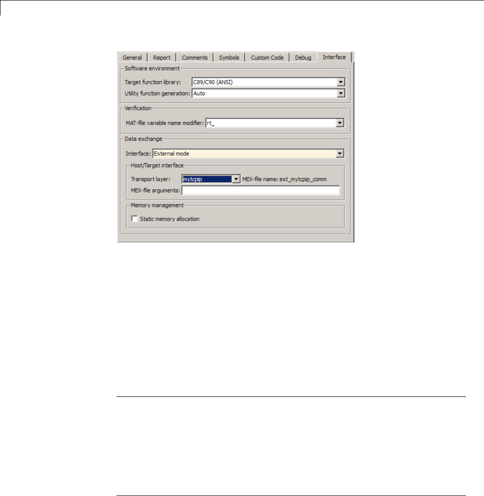
23 Run-Time Data Interface Extensions
Create a Custom Server (Target) Transport Protocol
The rtIOStream* function prototypes in
matlabroot/rtw/c/src/rtiostream.h define the calling interface for both
the server (target) and client (host) side transport layer functions.
•The TCP/IP implementations are in
matlabroot/rtw/c/src/rtiostream/rtiostreamtcpip/rtiostream_tcpip.c.
•The serial implementations are in
matlabroot/rtw/c/src/rtiostream/rtiostreamserial/rtiostream_serial.c.
Note The Ext* function prototypes in
matlabroot/rtw/c/src/ext_mode/common/ext_svr_transport.h
are implemented in
matlabroot/rtw/c/src/ext_mode/common/rtiostream_interface.c or
matlabroot/rtw/c/src/ext_mode/serial/rtiostream_serial_interface.c.
In most cases you will not need to modify rtiostream_interface.c
or rtiostream_serial_interface.c for your custom TCP/IP or
serial transport layer.
23-28

Create a Transport Layer for External Communication
To implement the server (target) side of your low-level TCP/IP or serial
transport protocol,
1Edit the template
matlabroot/rtw/c/src/rtiostream/rtiostreamtcpip/rtiostream_tcpip.c
or
matlabroot/rtw/c/src/rtiostream/rtiostreamserial/rtiostream_serial.c
to replace low-level communication calls with your own
communication calls.
aCopy and rename the file to rtiostream_name.c (replacing name with a
name meaningful to you).
bReplace the functions rtIOStreamOpen,rtIOStreamClose,
rtIOStreamSend,and rtIOStreamRecv with functions (of the same name)
that call your low-level communication drivers.
You must implement all the functions defined in rtiostream.h,and
your implementations must conform to the prototypes defined in that
file. Refer to the original rtiostream_tcpip.c or rtiostream_serial.c
for guidance.
2Modify template makefiles to support the new transport. If you
are writing your own template makefile, make sure that the
EXT_MODE code generation option is defined. The generated makefile
will then link rtiostream_name.c,rtiostream_interface.c or
rtiostream_serial_interface.c, and other server code into your
executable.
23-29

23 Run-Time Data Interface Extensions
23-30

24
Custom Target
Development
•“About Embedded Target Development” on page 24-2
•“Sample Custom Targets” on page 24-9
•“Target Development Mechanics” on page 24-11
•“Customize System Target Files” on page 24-36
•“Customize Template Makefiles” on page 24-75
•“Support Optional Features” on page 24-100
•“Interface to Development Tools” on page 24-123
•“Device Drivers and Target Preferences” on page 24-135

24 Custom Target Development
About Embedded Target Development
In this section...
“Custom Targets” on page 24-2
“Types of Targets” on page 24-2
“Recommended Features for Embedded Targets” on page 24-5
Custom Targets
The targets bundled with the Simulink Coder product are suitable for many
different applications and development environments. Third-party targets
provide additional versatility. However, you might want to implement a
custom target for any of the following reasons:
•To enable end users to generate executable production code for a specific
CPU or development board, using a specific development environment
(compiler/linker/debugger).
•To support I/O devices on the target hardware by incorporating custom
device driver blocks into your models.
•To configure the build process for a special compiler (such as a
cross-compiler for an embedded microcontroller or DSP board) or
development/debugging environment.
The Simulink Coder product provides a point of departure for the creation of
custom embedded targets, for the basic purposes above. This manual covers
the tasks and techniques you need to implement a custom embedded target.
TypesofTargets
•“Introduction” on page 24-3
•“Rapid Prototyping Targets” on page 24-3
•“Turnkey Production Targets” on page 24-4
•“Verifying Targets With SIL and PIL Testing” on page 24-4
•“HIL Simulation Targets” on page 24-4
24-2

About Embedded Target Development
Introduction
The following sections describe several types of targets intended for different
use cases. There is a progression of capabilities from the first (baseline or
rapid prototyping) to second (turnkey production) target types; you may
want to implement an initial rapid prototyping target and a following,
more full-featured turnkey version of a target. You might want to use
software-in-the-loop (SIL) or processor-in-the-loop (PIL) testing at any
stagetoverifyyourembeddedtarget. Thetargettypesarenotmutually
exclusive. An embedded target can support more than one of these use cases,
or additional uses not outlined here.
The discussion of target types is followed by “Recommended Features for
Embedded Targets” on page 24-5, which contains a suggested list of target
features and general guidelines for embedded target development.
Rapid Prototyping Targets
Arapid prototyping target or baseline target offers a starting point for
targeting a production processor. A rapid prototyping target integrates
Simulink Coder software with one or more popular cross-development
environments (compiler/linker/debugger tool chains). A rapid prototyping
target provides a starting point from which you can customize the target
for application needs.
Target files provided for this type of target should be readable, easy to
understand, and fully commented and documented. Specific attention should
be paid to the interface to the intended cross-development environment.
This interface should be implemented using the preferred approach for
that particular development system. For example, some development
environments use traditional make utilities, while others are based on
project-file builds that can be automated under control of the Simulink Coder
software.
When you use a rapid prototyping target, you need to include your own device
driver and legacy code and modify linker memory maps to suit your needs.
You should be familiar with the targeted development system.
24-3

24 Custom Target Development
Turnkey Production Targets
Aturnkey production target also targets a production processor, but includes
the capability to create target executables that interact immediately with the
external world. In general, ease of use is more important than simplicity or
readability of the target files, because it is assumed that you do not want
or need to modify these files.
Desirable features for a turnkey production target include
•Significant I/O driver support provided out of the box
•Easy downloading of generated standalone executables with third-party
debuggers
•User-controlled placement of an executable in FLASH or RAM memory
•Support for target visibility and tuning
Verifying Targets With SIL and PIL Testing
You can use software-in-the-loop (SIL) or processor-in-the-loop (PIL) to verify
your generated code and validate the target compiler/processor environment.
You can use SIL and PIL simulation mode to verify automatically generated
code by comparing the results with a normal mode simulation. With SIL, you
can easily verify the behavior of production-intent source code on your host
computer; however, it is generally not possibletoverifyexactlythesamecode
that will subsequently be compiled for your target hardware because the code
must be compiled for your host platform (i.e. a different compiler and different
processor architecture than the target). With PIL simulation, you can verify
exactly the same code that you intend to deploy in production, and you can
run the code either on real target hardware or on an instruction set simulator.
For examples describing how to run processor-in-the-loop testing to verify a
custom target, see “Sample Custom Targets” on page 24-9.
For more information on SIL and PIL, see “About SIL and PIL Simulations”.
HIL Simulation Targets
A specialized use case is the generation of executables intended for use in
Hardware-In-the-Loop (HIL) simulations. In a HIL simulation, parts of a pure
24-4

About Embedded Target Development
simulation are gradually replaced with hardware components as components
are refined and fabricated. HIL simulation offers an efficient design process
that eliminates costly iterations of part fabrication.
Recommended Features for Embedded Targets
•“Basic Target Features” on page 24-5
•“Integration with Target Development Environments” on page 24-6
•“Observing Execution of Target Code” on page 24-6
•“Deployment and Hardware Issues” on page 24-7
Basic Target Features
•You can base targets on the Simulink Coder generic real-time (GRT) target
or the Embedded Real-Time (ERT) target that is included in the Embedded
Coder product.
If your target is based on the ERT target, it should use that target’s
Embedded-C code format, and should inherit the options defined in the
ERT target’s system target file. By following these recommendations, your
target has all the production code generation capabilities of the ERT target.
See“CustomizeSystemTargetFiles”onpage24-36forfurtherdetailson
the inheritance mechanism, setting the code format, and other details.
•Themostfundamentalrequirementforanembeddedtargetisthatit
generate a real-time executable from a model or subsystem. Typically, an
embedded target generates a timer interrupt-based, bareboard executable
(although targets can be developed for an operating system environment
as well).
Your target should support the Simulink Coder concepts of single-tasking
and multitasking solver modes for model execution. Tasking support
comes almost “for free” with the ERT target, but you should thoroughly
understand how it works before implementing an ERT-based target.
Implementation of timer interrupt-based execution is documented in
“Scheduling” on page 1-4 and “Time-Based Scheduling”.
24-5

24 Custom Target Development
•You should generate the target executable’s main program module, rather
than using a static main module (such as the static ert_main.c module
provided with the Embedded Coder product). A generated main.c or
.cpp canbemademuchmorereadableandmoreefficient,sinceitomits
preprocessor checks and other extra code.
See “Standalone Programs (No Operating System)” for information on
generated and static main program modules.
•Follow the guidelines in “Folder and File Naming Conventions” on page
24-11.
Integration with Target Development Environments
•Most cross-development systems run under a Microsoft Windows PC host.
Your target should support the Windows XP operating system as the host
environment.
Some cross-development systems support one or more versions of The Open
Group UNIX platforms, allowing for UNIX host support as well.
•Your embedded target must support at least one embedded development
environment. The interface to a development environment can take one of
several forms. The most common approach is to use a template makefile
to generate standard makefiles with the make utility provided with your
development environment. “Customize Template Makefiles” on page 24-75
describes the structure of template makefiles.
Another approach with IDE-based tools is project file creation and/or
Microsoft Windows Component Object Model (COM) automation.
It is important to consider the license requirements and restrictions of the
development environment vendor. You may need to modify files provided
by the vendor and ship them as part of the embedded target.
See “Interface to Development Tools” on page 24-123 for further
information.
Observing Execution of Target Code
•Your target should support a mechanism you can use to observe the target
code as it runs in real time (outside of a debugger).
24-6

About Embedded Target Development
You can use the rtiostream API to implement a communication channel
to enable exchange of data between different processes. See the Web
page example here “Creating a Communications Channel for Target
Connectivity”. This rtiostream communication channel is required to
enable processor-in-the-loop (PIL) on a new target. See “Communications
rtiostream API” in the Embedded Coder documentation.
One industry-standard approach is to use the CAN bus, with an ASAP2
file and CAN Calibration Protocol (CCP). There are several host-based
graphical front-end tools available that connect to a CCP-enabled target
and provide data viewing and parameter tuning. Supporting these tools
requires implementation of CAN hardware drivers and CCP protocol for
the target, as well as ASAP2 file generation. Your target can leverage the
ASAP2 support provided with the Embedded Coder product.
Another option is to support Simulink External mode over a serial
interface (RS-232). See the “Host/Target Communication” on page 15-50
for information on using the External mode API.
Deployment and Hardware Issues
•Device driver support is an important issue in the design of an embedded
target. Device drivers are Simulink blocks that support either hardware
I/O capabilities of the target CPU, or I/O features of the development board.
If you are developing a rapid prototyping target, consider providing
minimal driver support, on the assumption that end users develop their
own drivers. If you are developing a turnkey production target, you should
provide full driver support.
See “Integrate Device Drivers” on page 24-135.
•Automatic download of generated code to the target hardware makes a
target easier to use. Typically a debugger utility is used; if the chosen
debugger supports command script files, this can be straightforward to
implement. “STF_make_rtw_hook.m” on page 24-23 describes a mechanism
to execute code from the build process. You can use this mechanism to
make system() callstoinvokeutilitiessuchas a debugger. You can invoke
other simple downloading utilities in a similar fashion.
24-7

24 Custom Target Development
If your development system supports COM automation, you can control the
download process by that mechanism. Using COM automation is discussed
in “Interface to Development Tools” on page 24-123.
•Executables that are mapped to RAM memory are typical. You can provide
optional support for FLASH or RAM placement of the executable by using
your target’s code generation options. To support this capability, you might
need multiple linker command files, multiple debugger scripts, and possibly
multiple makefiles or project files. Also include the ability to automatically
switch between these files, depending on the RAM/FLASH option value.
•Select a popular, widely available evaluation or prototype board for your
target processor. Consider enclosed and ruggedized versions of the target
board. Also consider board level support for the various on-chip I/O
capabilities of the target CPU, and the availability of development systems
that support the selected board.
24-8

Sample Custom Targets
Sample Custom Targets
There are technical solutions on the MathWorks Web site that you can use
as a starting point to create your own target solution. The solutions provide
guides to the following tasks for creating custom targets:
•Methods of embedding code onto a custom processor
•Creating a system target file
•Customizing the makefile and main file
•Adding compiler, chip, and board specific information
•Integrating legacy code and device drivers
•Creating blocks and libraries
•Implementing processor-in-the-loop (PIL) testing.
1Start by downloading the technical solution on this web page:
Solution 1-BHU00D — An example guide to developing an embedded target
This solution provides example files and a guide to developing a custom
embedded target. The guide is divided into two parts, one on creating a
generic custom target and another on creating a target for the Freescale™
S12X processor using the Cosmic Compiler.
Read the example guide along with this document to understand the tasks
for developing embedded targets.
2For more detailed example files for specific processors, see:
•Solution ID 1-9RXFT3 — An example Freescale S12X target using the
Cosmic Compiler
•Solution ID 1-BHT815 — An example Freescale S12X target using the
CodeWarrior®Compiler
These example kits contain example models, code generation files, and
instruction guides on generating and testing code for the processor.
The Cosmic example illustrates the use of the target connectivity API
for processor-in-the-loop (PIL) testing. The CodeWarrior example does
24-9

24 Custom Target Development
not have PIL but shows CAN Calibration Protocol (CCP) and Simulink
External mode.
Theintentoftheexamplekitsistoprovideworkingexamplesthat
you can use as a base to create your own target solution. The
intent is not to provide a full featured and maintained Embedded
Target product like those provided by MathWorks or third-party
products, as listed on the supported hardware Web page:
http://www.mathworks.com/products/embedded-coder/supportedio.html.
3You can watch videos showing overviews of both the example kits at the
following links:
•www.mathworks.com/products/demos/rtwembedded/S12X_final_generic/
•www.mathworks.com/products/demos/rtwembedded/STR9_final_multi/
For another example target for the ARM9 (STR9) processor, see Solution
ID 1-BBT4ID — An example ARM®9 (STR9) target using the GNU ARM
Compiler and Hitex STR9-comStick.
If you have questions on specific targets, please email
mytarget@mathworks.com.
The example kits and this document describe Embedded Coder features such
as customized ert system target files and processor-in-the-loop testing, but
you can study the examples as a starting point for use with Simulink Coder
targets.
24-10

Target Development Mechanics
Target Development Mechanics
In this section...
“Folder and File Naming Conventions” on page 24-11
“Components of a Custom Target” on page 24-12
“Key Folders Under Target Root (mytarget)” on page 24-17
“Key Files in Target Folder (mytarget/mytarget)” on page 24-20
“Additional Files for Externally Developed Targets” on page 24-28
“Target Development and the Build Process” on page 24-29
Folder and File Naming Conventions
You can use a single folder for your custom target files, or if desired you
can use subfolders, for example containing files associated with specific
development environments or tools.
For a custom target implementation, the recommended folder and file naming
conventions are
•Use only lowercase in all folder names, filenames, and extensions.
•Do not embed spaces in folder names. Spaces in folder names cause errors
with many third-party development environments.
•Include desired folders in the MATLAB path
•Do not place your custom target folder anywhere in the MATLAB folder
tree (that is, in or under the matlabroot folder). If you place your folder
under matlabroot you risk losing your work if you install a new MATLAB
version (or reinstall the current version).
The following sections explain how to organize your target folders and files
and add them to the your MATLAB path. They also provide high-level
descriptions of the files.
In this document, mytarget is a placeholder name that represents folders
and files that use the target’s name. The names dev_tool1,dev_tool2,and
so on represent subfolders containing files associated with development
24-11

24 Custom Target Development
environments or tools. This document describes an example structure where
the folder mytarget contains subfolders for mytarget,blocks,dev_tool1,
dev_tool2. The top level folder mytarget is the target root folder.
Components of a Custom Target
•“Overview” on page 24-12
•“Code Components” on page 24-13
•“Control Files” on page 24-15
Overview
The components of a custom target are files located in a hierarchy of folders.
The top-level folder in this structure is called the target root folder.The
target root folder and its contents are named, organized, and located on the
MATLAB path according to conventions described in “Folder and File Naming
Conventions” on page 24-11.
The components of a custom target include
•Code components: C source code that supervises and supports execution of
generated model code.
•Control files:
-A system target file (STF) to control the code generation process.
-File(s) to control the building of an executable from the generated code.
In a traditional make-based environment, a template makefile (TMF)
generates a makefile for this purpose. Another approach is to generate
project files in support of a modern integrated development environment
(IDE) such as the Freescale Semiconductor CodeWarrior IDE.
-Hook files: Optional TLC and .m files that can be invoked at well-defined
stages of the build process. Hook files let you customize the build process
and communicate information between various phases of the process.
•Target preferences files: These files define a target preferences class
associated with your target. Your target preference class lets you create
data objects that define and store properties associated with your target.
24-12

Target Development Mechanics
For example, you may want to store a user-defined path to a cross-compiler
that is invoked by the build process.
•Other target files: Files that let you integrate your target into the MATLAB
environment. For example, you can provide an info.xml file to make your
target block libraries, examples, and target preferences available from
a MATLAB session.
The next sections introduce key concepts and terminology you need to know
to develop each component. References to more detailed information sources
are provided.
Code Components
A Simulink Coder program containing code generated from a Simulink model
consists of a number of code modules and data structures. These fall into
two categories.
Application Components. Application components are those which are
specific to a particular model; they implement the functions represented by
the blocks in the model. Application components are not specific to the target.
Application components include
•Modules generated from the model
•User-written blocks (S-functions)
•Parameters of the model that are visible, and can be interfaced to, external
code
Execution Support Files. A number of code modules and data structures,
referred to collectively as the execution support files, are responsible for
managing and supporting the execution of the generated program. The
execution support files modules are not automatically generated. Depending
on the requirements of your target, you must implement certain parts of the
execution support files. Execution Support Files on page 24-14 summarizes
the execution support files.
24-13

24 Custom Target Development
Execution Support Files
You P rov ide. ..
The Simulink Coder Software
Provides...
Customized main program Generic main program
Timer interrupt handler to run
model
Execution engine and integration solver
(called by timer interrupt handler)
Other interrupt handlers Example interrupt handlers
(Asynchronous Interrupt blocks)
Device drivers Example device drivers
Data logging, parameter tuning,
signal monitoring, and External
mode support
Data logging, parameter tuning, signal
monitoring, and External mode APIs
User-Written Execution Support Files. The Simulink Coder software
provides most of the execution support files. Depending on the requirements
of your target, you must implement some or all of the following elements:
•Atimerinterrupt service routine (ISR). The timer runs at the program’s
base sample rate. The timer ISR is responsible for operations that
must be completed within a single clock period, such as computing the
current output sample. The timer ISR usually calls the Simulink Coder
rt_OneStep function.
If you are targeting a real-time operating system (RTOS), your generated
code usually executes under control of the timing and task management
mechanisms provided by the RTOS. In this case, you may not have to
implement a timer ISR.
•The main program. Your main program initializes the blocks in the model,
installs the timer ISR, and executes a background task or loop. The timer
periodically interrupts the main loop. If the main program is designed to
run for a finite amount of time, it is also responsible for cleanup operations
— such as memory deallocation and masking the timer interrupt — before
terminating the program.
24-14

Target Development Mechanics
If you are targeting a real-time operating system (RTOS), your main
program most likely spawns tasks (corresponding to the sample rates used
in the model) whose execution is timed and controlled by the RTOS.
Your main program typically is based on the Embedded Coder main
program, ert_main.c. “Standalone Programs (No Operating System)”
details the structure of the Embedded Coder execution support files and the
execution of Embedded Coder code, and provides guidelines for customizing
ert_main.c.
•Device drivers. Drivers communicate with I/O devices on your target
hardware. In production code, device drivers are normally implemented as
inlined S-functions.
•Other interrupt handlers. If your models need to support asynchronous
events, such as hardware generated interrupts and asynchronous read and
write operations, you must supply interrupt handlers. The Simulink Coder
Interrupt Templates library provides examples.
•Data logging, parameter tuning, signal monitoring, and External mode
support. It is atypical to implement rapid prototyping features such as
External mode support in an embedded target. However, it is possible to
support these features by using standard Simulink Coder APIs. See “Data
Exchange” on page 15-50 for details.
Control Files
The code generation and build process is directed by a number of TLC and
MATLAB files collectively called control files. This section introduces and
summarizes the main control files.
Top-Level Control File (make_rtw). The build process is initiated when
you click Build (or type Ctrl+B). At this point, Simulink Coder build process
parses the Make command field of the Code Generation pane of the
Configuration Parameters dialog box, expecting to find the name of a top-level
MATLAB file command that controls the build process (as well as optional
arguments to that command). The default top-level control file for the build
process is make_rtw.m.
Normally, target developers do not need detailed knowledge of how
make_rtw works. (The details for target developers are described in “Target
Development and the Build Process” on page 24-29.) You should not customize
24-15

24 Custom Target Development
make_rtw.m.Themake_rtw.m file contains all the logic required to execute
your target-specific control files, including a number of hook points for
execution of your custom code.
make_rtw does the following:
•Passes optional arguments in to the build process
•Performs any required preprocessing before code generation
•Executes the STF to perform code generation (and optional HTML report
generation)
•Processes the TMF to generate a makefile
•Invokesamakeutilitytoexecutethemakefileandbuildanexecutable
•Performs any required post-processing (such as generating calibration data
files or downloading the generated executable to the target)
System Target File (STF). The Target Language Compiler (TLC) generates
target-specific C or C++ code from an intermediate description of your
Simulink block diagram (model.rtw). The Target Language Compiler reads
model.rtw and executes a program consisting of several target files (.tlc
files.) The STF, at the top level of this program, controls the code generation
process. The output of this process is a number of source files, which are fed
to your development system’s make utility.
You need to create a customized STF to set code generation parameters for
your target. You should copy, rename, and modify the standard ERT system
target file (matlabroot/rtw/c/ert/ert.tlc).
The detailed structure of the STF is described in “Customize System Target
Files” on page 24-36.
Template Makefile (TMF). A TMF provides information about your model
and your development system. The build process uses this information to
create a makefile (.mk file) that builds an executable program.
Some targets implement more than one TMF, in order to support multiple
development environments (for example, two or more cross-compilers)
24-16

Target Development Mechanics
or multiple modes of code generation (for example, generating a binary
executable vs. generating a projectfileforyourcompiler).
The Embedded Coder software provides a large number of TMFs suitable
for different types of host-based development systems. These TMFs are
located in matlabroot/rtw/c/ert. The standard TMFs are described in the
“Template Makefiles and Make Options” on page 9-38 section of the Simulink
Coder documentation.
The detailed structure of the TMF is described in “Customize Template
Makefiles” on page 24-75.
Hook Files. Simulink Coder build process allows you to supply optional hook
files that are executed at specified points in the code generation and make
process. You can use hook files to add target-specific actions to the build
process.
The hook files must follow well-defined naming and location requirements.
“Folder and File Naming Conventions” on page 24-11 describes these
requirements.
Key Folders Under Target Root (mytarget)
•“Target Root Folder (mytarget)” on page 24-17
•“Target Folder (mytarget/mytarget)” on page 24-18
•“Target Block Folder (mytarget/blocks)” on page 24-18
•“Development Tools Folder (mytarget/dev_tool1, mytarget/dev_tool2)” on
page 24-20
•“Target Preferences Folder (mytarget/mytarget/@mytarget)” on page 24-20
•“Target Source Code Folder (mytarget/src)” on page 24-20
Target Root Folder (mytarget)
This folder contains the key subfolders for the target (see “Folder and File
Naming Conventions” on page 24-11). You can also locate miscellaneous
files (such as a readme file) in the target root folder. The following sections
describe required and optional subfolders and their contents.
24-17

24 Custom Target Development
Target Folder (mytarget/mytarget)
This folder contains files that are central to the target, such as the system
target file (STF) and template makefile (TMF). “Key Files in Target Folder
(mytarget/mytarget)” on page 24-20 summarizes the files that should be
stored in mytarget/mytarget, and provides pointers to detailed information
about these files.
Note mytarget/mytarget should be on the MATLAB path.
Target Block Folder (mytarget/blocks)
If your target includes device drivers or other blocks, locate the block
implementation filesinthisfolder. mytarget/blocks contains
•Compiled block MEX-files
•Source code for the blocks
•TLC inlining files for the blocks
•Library models for the blocks (if you provide your blocks in one or more
libraries)
Note mytarget/blocks should be on the MATLAB path.
You can also store example models and any supporting files in
mytarget/blocks. Alternatively, you can create a mytarget/mytargetdemos
folder, which should also be on the MATLAB path.
To display your blocks in the standard Simulink Library Browser and/or
integrate your example models into the MATLAB session environment , you
can create the files described below and store them in mytarget/blocks.
mytarget/blocks/slblocks.m. This file allows a group of blocks to be
integrated into the Simulink Library and Simulink Library Browser.
24-18

Target Development Mechanics
Example slblocks.m File
function blkStruct = slblocks
% Information for "Blocksets and Toolboxes" subsystem
blkStruct.Name = sprintf('Embedded Target\n for MYTARGET');
blkStruct.OpenFcn = 'mytargetlib';
blkStruct.MaskDisplay = 'disp(''MYTARGET'')';
% Information for Simulink Library Browser
Browser(1).Library = 'mytargetlib';
Browser(1).Name = 'Embedded Target for MYTARGET';
Browser(1).IsFlat = 1;% Is this library "flat" (i.e. no subsystems)?
blkStruct.Browser = Browser;
mytarget/blocks/demos.xml. This file provides information about
the components, organization, and location of example models. MATLAB
software uses this information to place the example in the MATLAB session
environment.
Example demos.xml File
<?xml version="1.0" encoding="utf-8"?>
<demos>
<name>Embedded Target for MYTARGET</name>
<type>simulink</type>
<icon>$toolbox/matlab/icons/boardicon.gif</icon>
<description source = "file">mytarget_overview.html</description>
<demosection>
<label>Multirate model</label>
<demoitem>
<label>MYTARGET demo</label>
<file>mytarget_overview.html</file>
<callback>mytarget_model</callback>
</demoitem>
</demosection>
</demos>
24-19

24 Custom Target Development
Development Tools Folder (mytarget/dev_tool1,
mytarget/dev_tool2)
These folders contain files associated with specific development environments
or tools (dev_tool1,dev_tool2, etc.). Normally, your target supports at least
one such development environment and invokes its compiler, linker, and
other utilities during the build process. mytarget/dev_tool1 includes linker
command files, startup code, hook functions, and any other files required to
support this process.
For each development environment, you should provide a separate folder.
You should use the target preferences mechanism to store information about
a user’s choice of development environment or tool, paths to the installed
development tools, and so on. Using target preferences data in this way,
lets your build process code select a development environment and invoke a
compiler and other utilities for your target platform. See the code excerpt in
“mytarget_default_tmf.m Example Code” on page 24-89 for an example of how
to use target preferences data for this purpose.
Target Preferences Folder (mytarget/mytarget/@mytarget)
If you create a target preferences class to store information about user
preferences, you should store data class definition files and other files that
support your target-specific preferences in mytarget/mytarget/@mytarget.
The Simulink Data Class Designer creates the @mytarget folder automatically
within the parent folder.
Target Source Code Folder (mytarget/src)
This folder is optional. If the complexity of your target requires it, you can
use mytarget/src to store any common source code and configuration code
(such as boot and startup code).
Key Files in Target Folder (mytarget/mytarget)
•“Introduction” on page 24-21
•“mytarget.tlc” on page 24-21
•“mytarget.tmf” on page 24-22
24-20

Target Development Mechanics
•“mytarget_default_tmf.m” on page 24-22
•“mytarget_settings.tlc” on page 24-22
•“mytarget_genfiles.tlc” on page 24-22
•“mytarget_main.c” on page 24-23
•“STF_make_rtw_hook.m” on page 24-23
•“STF_wrap_make_cmd_hook.m” on page 24-23
•“STF_rtw_info_hook.m (obsolete)” on page 24-26
•“info.xml” on page 24-27
•“mytarget_overview.html” on page 24-28
Introduction
The target folder mytarget/mytarget contains key files in your target
implementation. These include the system target file, template makefile,
main program module, and optional M and TLC hook files that let you add
target-specific actions to the build process. The following sections describe the
key target folder files.
mytarget.tlc
mytarget.tlc is the system target file (STF). Functions of the STF include
•Making the target visible in the System Target File Browser
•Definition of code generation options for the target (inherited and
target-specific)
•Providing an entry point for the top-level control of the TLC code generation
process
You should base your STF on ert.tlc,theSTFprovidedbytheEmbedded
Coder software.
“Customize System Target Files” on page 24-36 gives detailed information
on the structure of the STF, and also gives instructions on how to customize
an STF to
24-21

24 Custom Target Development
•Display your target in the System Target File Browser
•Add your own target options to the Configuration Parameters dialog box
•Tailor the code generation and build process to the requirements of your
target
mytarget.tmf
mytarget.tmf isthetemplatemakefileforbuildinganexecutableforyour
target.
For basic information on the structure and operation of template makefiles,
see “Customize Template Makefiles” on page 24-75.
If your target development environment requires automation of a modern
integrated development environment (IDE) rather than use of a traditional
make utility, see “Interface to Development Tools” on page 24-123.
You might create multiple template makefiles to support different
development environments. See “Supporting Multiple Development
Environments” on page 24-60 and “mytarget_default_tmf.m Example Code”
on page 24-89 for information.
mytarget_default_tmf.m
This file is optional. You can implement a mytarget_default_tmf.m file to
select a template makefile, based on user preferences. See “Setting Up a
Template Makefile” on page 24-88.
mytarget_settings.tlc
This file is optional. Its purpose is to centralize global settings in the code
generation environment. See “Using mytarget_settings.tlc” on page 24-55 for
details.
mytarget_genfiles.tlc
This file is optional. mytarget_genfiles.tlc is useful as a central file
from which to invoke any target-specific TLC files that generate additional
filesaspartofyourtargetbuildprocess. Forexample,yourtargetmay
create sub-makefiles or project files for a development environment, or
24-22

Target Development Mechanics
command scripts for a debugger to do automatic downloads. See “Using
mytarget_genfiles.tlc” on page 24-58 for details.
mytarget_main.c
A main program module is required for your target. To provide a main
module, you can either
•Modify the ert_main.c module provided by the Embedded Coder software
•Generate mytarget_main.c or .cpp during the build process
“Standalone Programs (No Operating System)” contains a detailed description
of the operation of ert_main.c. The section also contains guidelines for
generating and modifying a main program module.
STF_make_rtw_hook.m
STF_make_rtw_hook.m is an optional hook file that you can use to invoke
target-specific functions or executablesatspecifiedpointsin the build process.
STF_make_rtw_hook.m implements a function that dispatches to a specific
action depending on the method argument that is passed into it.
“Customize Build Process with STF_make_rtw_hook File” on page 22-21
describes the operation of the STF_make_rtw_hook.m hook file in detail.
STF_wrap_make_cmd_hook.m
UsethisfiletooverridethedefaultSimulink Coder behavior for selecting the
compiler tool to be used in the build process.
By default, the Simulink Coder build process is based on makefiles. On PC
hosts, the build process creates model.bat, an MS-DOS batch file. model.bat
sets up the environment variables for the compiler, linker, and other utilities,
and invokes a make utility. The batch file, model.bat, obtains the required
environment variable settings from the MAKECMD field in the template
makefile. The standard Simulink Coder template makefiles support only
standard compilers that build executables on the host system.
When developing an embedded target, you often need to override these
defaults. Typically, you need to support one or more target-specific
24-23

24 Custom Target Development
cross-development systems, rather than supporting compilers for the host
system. The STF_wrap_make_cmd_hook mechanism provides a way to set up
an environment specific to an embedded development tool.
Note that the naming convention for this file is not based on the target name.
It is based on the concatenation of the system target filename, STF,withthe
string '_wrap_make_cmd_hook'.
Stub makefiles. Many modern cross-development systems, such as the
Freescale Semiconductor CodeWarrior development environment, are based
on project files rather than makefiles. If the interface to the embedded
development system is not makefile based, one recommended approach is to
create a stub makefile. When the build process invokes the stub makefile,
no action takes place.
STF_wrap_make_cmd_hook Mechanism. A recommended approach to
supporting non-host-based development systems is to provide a hook file that
is called instead of the default host-based compiler selection.
To do this, create a STF_wrap_make_cmd_hook.m file. If this file exists, the
build process calls it instead of the default compiler selection process. Check
that:
•ThefileisontheMATLABpath.
•The filename is the name of your STF, prepended to the string
'__wrap_make_cmd_hook.m'.
•The hook function implemented in the file follows the function prototype
showninthecodeexamplebelow.
A typical approach would be to write a STF_wrap_make_cmd_hook.m file
that creates a MS-DOS batch file (model.bat). The batch file first sets up
environment variables for the embedded target development system. Then,
it invokes the embedded target’s make utility on the generated makefile.
The STF_wrap_make_cmd_hook function should return a system command
that invokes model.bat.
This approach is shown in “Example STF_wrap_make_cmd_hook Function”
on page 24-26.
24-24

Target Development Mechanics
Alternatively, any MS-DOS batch file can be created by
STF_wrap_make_cmd_hook, and the function can return any
command; it is not limited to model.bat.Liketheexit case of the
STF_make_rtw_hook mechanism, this provides the flexibility to invoke other
utilities or applications.
On a PC host, the build process checks the standard output (STDOUT)fora
build success string. By default, the string is
"### Created"
You can change this specifying a different BUILD_SUCCESS variable in the
template makefile.
24-25

24 Custom Target Development
Example STF_wrap_make_cmd_hook Function.
function makeCmdOut = stfname_wrap_make_cmd_hook(args)
makeCmd = args.makeCmd;
modelName = args.modelName;
verbose = args.verbose;
% args.compilerEnvVal not used
cmdFile = ['.\',modelName, '.bat'];
cmdFileFid = fopen(cmdFile,'wt');
if ~verbose
fprintf(cmdFileFid, '@echo off\n');
end
try
prefs = RTW.TargetPrefs.load('mytarget.prefs');
catch exception
rethrow(exception);
end
fprintf(cmdFileFid, '@set TOOL_VAR1=%s\n', prefs.ImpPath);
fprintf(cmdFileFid, '@set TOOL_VAR2=x86-win32\n');
toolRoot = fullfile(prefs.ImpPath,'host','tool','4.4b');
fprintf(cmdFileFid, '@set TOOL_VAR3=%s\n', toolRoot);
path = getenv('Path');
path1 = fullfile(prefs.ImpPath,'host','license;');
if ~isempty(strfind(path,path1)) path1 = ''; end
fprintf(cmdFileFid, '@set Path=%s%s%s\n', path1, path);
fullMakeCmd = fullfile(prefs.ImpPath,'host','tool',...
'bin', makeCmd);
fprintf(cmdFileFid, '%s\n', fullMakeCmd);
fclose(cmdFileFid);
makeCmdOut = cmdFile;
STF_rtw_info_hook.m (obsolete)
Prior to Release 14, custom targets supplied target-specific information with
a hook file (referred to as STF_rtw_info_hook.m). The STF_rtw_info_hook
specified properties such as word sizes for integer data types (for example,
24-26

Target Development Mechanics
char,short,int,andlong), and C implementation-specific properties of
the custom target.
The STF_rtw_info_hook mechanism has been replaced by the Hardware
Implementation pane of the Configuration Parameters dialog box. Using
this dialog box, you can specify all properties that were formerly specified in
your STF_rtw_info_hook file.
For backward compatibility, existing STF_rtw_info_hook files are still
available. However, you should convert your target and models to use the
Hardware Implementation pane. See “Hardware Targets” on page 9-9.
info.xml
This file provides information to MATLAB software that specifies where to
display the target toolbox in the MATLAB session environment.
Example info.xml File. This example shows you how to set up access to a
target’s example page and target preferences GUI from the MATLAB session
environment.
<productinfo>
<matlabrelease>13</matlabrelease>
<name>Embedded Target for MYTARGET</name>
<type>simulink</type>
<icon>$toolbox/simulink/simulink/simulinkicon.gif</icon>
<list>
<listitem>
<label>Demos</label>
<callback>demo simulink 'Embedded Target for MYTARGET'</callback>
<icon>$toolbox/matlab/icons/demoicon.gif</icon>
</listitem>
<listitem>
<label>MYTARGET Target Preferences</label>
<callback>mytargetTargetPrefs =
RTW.TargetPrefs.load('mytarget.prefs');
24-27

24 Custom Target Development
gui(mytargetTargetPrefs); </callback>
<icon>$toolbox/simulink/simulink/simulinkicon.gif</icon>
</listitem>
</list>
</productinfo>
mytarget_overview.html
By convention, this file serves as home page for the target examples.
The <description> field in demos.xml should point to
mytarget_overview.html (see “mytarget/blocks/demos.xml” on
page 24-19).
Example mytarget_overview.html File.
<html>
<head><title>Embedded Target for MYTARGET</title></head><body>
<p style="color:#990000; font-weight:bold; font-size:x-large">Embedded Target
for MYTARGET Example Model</p>
<p>This example provides a simple model that allows you to generate an executable
for a supported target board. You can then download and run the executable and
set breakpoints to study and monitor the execution behavior.</p>
</body>
</html>
Additional Files for Externally Developed Targets
•“Introduction” on page 24-28
•“mytarget/mytarget/mytarget_setup.m” on page 24-29
•“mytarget/mytarget/doc” on page 24-29
Introduction
If you are developing an embedded target that is not installed into
the MATLAB tree, you should provide a target setup script and target
24-28

Target Development Mechanics
documentation within mytarget/mytarget, for the convenience of your
users. The following sections describe the required materials and where to
place them.
mytarget/mytarget/mytarget_setup.m
This file script adds paths for your target to the MATLAB path. Your
documentation should instruct users to run the script when installing the
target.
You should include a call to the MATLAB function savepath in your
mytarget_setup.m script. This function saves the added paths, so users need
to run mytarget_setup.m only once.
The following code is an example mytarget_setup.m file.
function mytarget_setup()
curpath = pwd;
tgtpath = curpath(1:end-length('\mytarget'));
addpath(fullfile(tgtpath, 'mytarget'));
addpath(fullfile(tgtpath, 'dev_tool1'));
addpath(fullfile(tgtpath, 'blocks'));
addpath(fullfile(tgtpath, 'mytargetdemos'));
savepath;
disp('MYTARGET Target Path Setup Complete.');
mytarget/mytarget/doc
You should put all documentation related to your target in the folder
mytarget/mytarget/doc.
Target Development and the Build Process
•“About the Build Process” on page 24-30
•“Build Process Phases and Information Passing” on page 24-30
•“Additional Information Passing Techniques” on page 24-32
24-29

24 Custom Target Development
About the Build Process
To develop an embedded target, you need a thorough understanding of the
Simulink Coder build process. Your embedded target uses the build process
and may require you to modify or customize the process. A general overview
of code generation and the build process is given in “Source Code Generation”
and “Program Builds”.
This section supplements that overview with a description of the build process
as customized by the Embedded Coder software. The emphasis is on points
in the process where customization hooks are available and on passing
information between different phases of the process.
This section concludes with “Additional Information Passing Techniques” on
page 24-32, describing assorted tips and tricks for passing information during
the build process.
Build Process Phases and Information Passing
It is important to understand where (and when) the build process obtains
required information. Sources of information include
•The model.rtw file, which provides information about the generating
model. All information in model.rtw is available to target TLC files.
•The Simulink Coder related panes of the Configuration Parameters dialog
box. Options (both general and target-specific) are provided through check
boxes, menus, and edit fields. You can associate options with TLC variables
and makefile tokens in the rtwoptions data structure.
•The target preferences data. Target preferences provide persistent
information about the target, such as the location of your development tools.
•The template makefile (TMF), which generates the model-specific makefile.
•Environment variables on the host computer. Environment variables
provide additional information about installed development tools.
•Other target-specific files such as target-related TLC files, linker command
files, or project files.
24-30

Target Development Mechanics
It is also important to understand the several phases of the build process and
how to pass information between the phases. The build process comprises
several high-level phases:
•Execution of the top-level file (slbuild.m or rtwbuild.m) to sequence
through the build process for a target
•Conversion of the model into the TLC input file (model.rtw)
•Generation of the target code by the TLC compiler
•Compilation of the generated code with make or other utilities
•Transmission of the final generated executable to the target hardware
with a debugger or download utility
It is helpful to think of each phase of the process as a different “environment”
that maintains its own data. These environments include
•MATLAB code execution environment (MATLAB)
•Simulink
•Target Language Compiler execution environment
•makefile
•Development environments such as and IDE or debugger
In each environment, you might get information from the various sources
mentioned above. For example, during the TLC phase, execute MATLAB file
might execute to obtain information from the MATLAB environment. Also, a
given phase may generate information for a subsequent phase.
See “Key Files in Target Folder (mytarget/mytarget)” on page 24-20 for
details on the available MATLAB file and TLC hooks for information passing,
with code examples.
24-31

24 Custom Target Development
Additional Information Passing Techniques
This section describes a number of useful techniques for passing information
among different phases of the build process.
tlcvariable Field in rtwoptions Structure. Options on the Simulink Coder
related panes of the Configuration Parameters dialog box can be associated
with a TLC variable, and specified in the tlcvariable field of the option’s
entry in the rtwoptions structure. The variable value is passed on the
command line when TLC is invoked. This provides a way to make Simulink
Coder options and their values available in the TLC phase.
See “System Target File Structure” on page 24-37 for further information.
makevariable Field in rtwoptions Structure. Similarly, Simulink Coder
options can be associated with a template makefile token, specified in the
makevariable field of the option’s entry in the rtwoptions structure. If a
token of the same name as the makevariable name exists in the TMF, the
token is updated with the option value when the final makefile is created. If
the token does not exist in the TMF, the makevariable ispassedinonthe
command line when make is invoked. Thus, in either case, the makevariable
is available to the makefile.
See “System Target File Structure” on page 24-37 for further information.
Accessing Host Environment Variables. You can access host shell
environment variables at the MATLAB command line by entering the getenv
command. For example:
getenv ('MSDEVDIR')
ans =
D:\Applications\Microsoft Visual Studio\Common\MSDev98
To access the same information from TLC, use the FEVAL directive to invoke
getenv.
%assign eVar = FEVAL("getenv", "<varname>").
24-32

Target Development Mechanics
Supplying Development Environment Information to Your Template
Makefile. An embedded target must tie the build process to target-specific
development tools installed on a host computer. For the make process to run
these tools, the TMF must be able to determine the name of the tools, the path
to the compiler, linker, and other utilities, and possibly the host operating
system environment variable settings. This section describes two techniques
for supplying this information.
The simpler, more traditional approach is to require the end user to modify
the target TMF. The user enters path information (such as the location of
a compiler executable), and possibly host operating system environment
variables, as make variables. This allows the TMF to be tailored to specific
needs.
This approach is not satisfactory in an environment where the MATLAB
installation is on a network and multiple users share read-only TMFs.
Another possible drawback to this approach is that the tool information is
only available during the makefile processing phase of the build process.
A second approach is to use the target preferences feature together with the
STF_wrap_make_cmd_hook mechanism (see “STF_wrap_make_cmd_hook
Mechanism” on page 24-24). In this approach, compiler and other tool
path information is stored as preferences data, which is obtained by the
STF_wrap_make_cmd_hook.m file. Thisallowstoolpathinformationtobe
saved separately for each user.
Another advantage to the second approach is that target preferences data is
available to all phases of the build process, including the TLC phase. This
information may be required to support features such as RAM/ROM profiling.
UsingMATLABApplicationData. Application data provides a way for
applications to save and retrieve data stored with the GUI. This technique
enablesyoutocreatewhatisessentiallya user-defined property for an object,
and use this property to store data for use in the build process. If you are
unfamiliar with this technique, see the “Application Data” section of the
MATLAB documentation of creating graphical user interfaces.
The following code examples illustrates the use of application data to pass
information to TLC.
24-33

24 Custom Target Development
This file, tlc2appdata.m,storesthedata passed in as application data under
thenamepassedin(
appDataName).
function k = tlc2appdata(appDataName, data)
disp([mfilename,': ',appDataName,' ', data]);
setappdata(0,appDataName,data);
k = 0; % TLC expects a return value for FEVAL.
The following sample TLC file uses the FEVAL directive to invoke
tlc2appdata.m to store arbitrary application data, under the name z80.
%% test.tlc
%%
%assign myApp = "z80"
%assign myData = "314159"
%assign dummy = FEVAL("tlc2appdata",myApp,myData)
To test this technique:
1Create the tlc2appdata.m file as shown. Check that tlc2appdata.m is
stored in a folder on the MATLAB path.
2Create the TLC file as shown. Save it as test.tlc.
3Enter the following command at the MATLAB prompt to execute the TLC
file:
tlc test.tlc
4Get the application data at the MATLAB prompt:
k = getappdata(0,'z80')
The function returns the value 314159.
24-34

Target Development Mechanics
5Enter the following command.
who
Note that application data is not stored in the MATLAB workspace. Also
observe that the z80 data is not visible. Using application data in this
way has the advantage that it does not clutter the MATLAB workspace.
Also, it helps prevent you from accidently deleting your data, since it is not
stored directly in the your workspace.
A real-world use of application data might be to collect information from the
model.rtw file and store it for use later in the build process.
Adding Block-Specific Information to the Makefile. The rtwmakecfg
mechanism provides a method for inlined S-functions such as driver blocks to
add information to the makefile. This mechanism is described in “Using the
rtwmakecfg.m API to Customize Generated Makefiles” on page 24-92.
24-35

24 Custom Target Development
Customize System Target Files
In this section...
“Control Code Generation With the System Target File” on page 24-36
“System Target File Naming and Location Conventions” on page 24-37
“System Target File Structure” on page 24-37
“Define and Display Custom Target Options” on page 24-46
“Tips and Techniques for Customizing Your STF” on page 24-54
“Create a Custom Target Configuration” on page 24-61
Control Code Generation With the System Target File
The system target file (STF) exerts overall control of the code generation stage
of the build process. The STF also lets you control the presentation of your
target to the end user. The STF provides
•Definitions of variables that are fundamental to the build process, such as
code format to be generated
•The main entry point to the top-level TLC program that generates code
•Target information for display in the System Target File Browser
•A mechanism for defining target-specific code generation options (and other
parameters affecting the build process) and for displaying them in the
Configuration Parameters dialog box
Note You can save a configuration set with custom options to a MAT-file.
However, when you load the MAT-file, some custom options might not
appear in the Configuration Parameters dialog box.
•A mechanism for inheriting options from another target (such as the
Embedded Real-Time (ERT) target)
24-36

Customize System Target Files
This chapter provides information on the structure of the STF, guidelines for
customizing an STF, and a basic tutorial that helps you get a skeletal STF
up and running.
Note that, although the STF is a Target Language Compiler (TLC) file, it
contains embedded MATLAB code. Before creating or modifying an STF, you
should acquire a working knowledge of TLC and of the MATLAB language.
“Target Language Compiler” and “Scripts vs. Functions” describe the features
and syntax of both the TLC and MATLAB languages.
While reading this chapter, you may want to refer to the STFs provided
with the Simulink Coder product. Most of these files are stored in the
target-specific folders under matlabroot/rtw/c. Additional STFs are stored
under matlabroot/toolbox/rtw/targets.
System Target File Naming and Location Conventions
An STF must be located in a folder on the MATLAB path for the target to be
displayed in the System Target File Browser and invoked in the build process.
Follow the location and naming conventions for STFs and related target files
given in “Folder and File Naming Conventions” on page 24-11.
System Target File Structure
•“Overview” on page 24-38
•“Header Comments” on page 24-40
•“TLC Configuration Variables” on page 24-41
•“TLC Program Entry Point and Related %includes” on page 24-42
•“RTW_OPTIONS Section” on page 24-43
•“rtwgensettings Structure” on page 24-44
•“Additional Code Generation Options” on page 24-46
•“Model Reference Considerations” on page 24-46
24-37

24 Custom Target Development
Overview
This section is a guide to the structure and contents of an STF. The following
listing shows the general structure of an STF. Note that this is not a complete
code listing of an STF. The listing consists of excerpts from each of the
sections that make up an STF.
%%----------------------------
%% Header Comments Section
%%----------------------------
%% SYSTLC: Example Real-Time Target
%% TMF: my_target.tmf MAKE: make_rtw EXTMODE: ext_comm
%% Inital comments contain directives for STF Browser.
%% Documentation, date, copyright, and other info may follow.
...
%selectfile NULL_FILE
...
%%----------------------------
%% TLC Configuration Variables Section
%%----------------------------
%% Assign code format, language, target type.
%%
%assign CodeFormat = "Embedded-C"
%assign TargetType = "RT"
%assign Language = "C"
%%
%%----------------------------
%% (OPTIONAL) Import Target Settings
%%----------------------------
%include "mytarget_settings.tlc"
%%
%%----------------------------
%% TLC Program Entry Point
%%----------------------------
%% Call entry point function.
%include "codegenentry.tlc"
%%
%%----------------------------
%% (OPTIONAL) Generate Files for Build Process
%%----------------------------
%include "mytarget_genfiles.tlc"
24-38

Customize System Target Files
%%----------------------------
%% RTW_OPTIONS Section
%%----------------------------
/%
BEGIN_RTW_OPTIONS
%% Define rtwoptions structure array. This array defines target-specific
%% code generation variables, and controls how they are displayed.
rtwoptions(1).prompt = 'example code generation options';
...
rtwoptions(6).prompt = 'Show eliminated blocks';
rtwoptions(6).type = 'Checkbox';
...
%----------------------------------------%
% Configure RTW code generation settings %
%----------------------------------------%
...
%%----------------------------
%% rtwgensettings Structure
%%----------------------------
%% Define suffix string for naming build folder here.
rtwgensettings.BuildDirSuffix = '_mytarget_rtw'
%% Callback compatibility declaration
rtwgensettings.Version = '1';
%% (OPTIONAL) target inheritance declaration
rtwgensettings.DerivedFrom = 'ert.tlc';
%% (OPTIONAL) other rtwGenSettings fields...
...
END_RTW_OPTIONS
%/
%%----------------------------
%% targetComponentClass - MATHWORKS INTERNAL USE ONLY
%% REMOVE NEXT SECTION FROM USER_DEFINED CUSTOM TARGETS
%%----------------------------
/%
BEGIN_CONFIGSET_TARGET_COMPONENT
targetComponentClass = 'Simulink.ERTTargetCC';
END_CONFIGSET_TARGET_COMPONENT
%/
24-39

24 Custom Target Development
If you are creating a custom target based on an existing STF,
you must remove the targetComponentClass section (bounded
by the directives BEGIN_CONFIGSET_TARGET_COMPONENT and
END_CONFIGSET_TARGET_COMPONENT). This section is reserved for the use of
targets developed internally by MathWorks.
Header Comments
These lines at the head of the file are formatted as TLC comments. They
provide required information to the System Target File Browser and to the
build process. Note that you must place the browser comments at the head of
the file, before any other comments or TLC statements.
Thepresenceofthecommentsenablesthe Simulink Coder software to detect
STFs. When the System Target File Browser is opened, the Simulink Coder
software scans the MATLAB path for TLC files that have formatted header
comments. The comments contain the following directives:
•SYSTLC: This string is a descriptor that appears in the browser.
•TMF:Nameofthetemplatemakefile(TMF)touseduringbuildprocess.
When the target is selected, this filename is displayed in the Template
makefile field of the Code Generation pane of the Configuration
Parameters dialog box.
•MAKE: make command to use during build process. When the target is
selected, this command is displayed in the Make command field of the
Code Generation pane of the Configuration Parameters dialog box.
•EXTMODE: Name of External mode interface file (if any) associated
with your target. If your target does not support External mode, use
no_ext_comm.
The following header comments are from matlabroot/rtw/c/ert/ert.tlc.
%% SYSTLC: Embedded Coder TMF: ert_default_tmf MAKE: make_rtw \
%% EXTMODE: ext_comm
%% SYSTLC: Create Visual C/C++ Solution File for the Embedded Coder\
%% TMF: RTW.MSVCBuild MAKE: make_rtw EXTMODE: ext_comm
.
.
.
24-40
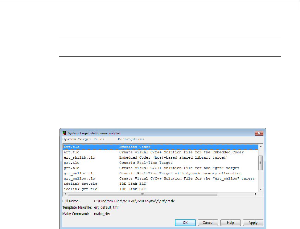
Customize System Target Files
Note Limitation: Each comment can only contain a maximum of two lines,
asshownintheprecedingexample.
Note that you can specify more than one group of directives in the header
comments. Each such group is displayed as a different target configuration
intheSystemTargetFileBrowser. Intheaboveexample,thefirsttwolines
of code specify the default configuration of the ERT target. The next two
lines specify a configuration that creates and builds a Microsoft Visual C++
Solution (.shn) file. The figure below shows how these configurations appear
in the System Target File Browser.
See “Create a Custom Target Configuration” on page 24-61 for an example of
customized header comments.
TLC Configuration Variables
This section of the STF assigns global TLC variables that affect the overall
code generation process.
For an embedded target, in almost all cases you should simply use the global
TLC variable settings used by the ERT target (ert.tlc). It is especially
important that your STF select the Embedded-C code format. Verify that
values are assigned to the following variables:
24-41

24 Custom Target Development
•CodeFormat:TheCodeFormat variable selects one of the available code
formats. The Embedded-C format is used by the ERT target. Your
ERT-based target should specify Embedded-C format. Embedded-C format
is designed for production code, minimal memory usage, static memory
allocation, and a simplified interface to generated code.
For information on other code formats, see the “Targets and Code Formats”
on page 9-29 chapter of the Simulink Coder documentation.
•Language: The only valid value is C, which enables support for Cor C++ code
generation as specified by the configuration parameter TargetLang (see the
TargetLang entry in “Parameter Command-Line Information Summary” in
the Simulink Coder documentation for more information).
•TargetType: The Simulink Coder software defines the preprocessor
symbols RT and NRT to distinguish simulation code from real-time code.
These symbols are used in conditional compilation. The TargetType
variable determines whether RT or NRT is defined.
Most targets are intended to generate real-time code. They assign
TargetType as follows.
%assign TargetType = "RT"
Some targets, such as the model reference simulation target, accelerated
simulation target, RSim target, and S-function target, generate code for
use in nonreal time only. Such targets assign TargetType as follows.
%assign TargetType = "NRT"
TLC Program Entry Point and Related %includes
The code generation process normally begins with codegenentry.tlc. The
STF invokes codegenentry.tlc as follows.
%include "codegenentry.tlc"
Note codegenentry.tlc and the lower-level TLC files assume that
CodeFormat,TargetType,andLanguage have been assigned. Set these
variables before including codegenentry.tlc.
24-42

Customize System Target Files
If you need to implement target-specific code generation features, you should
include the TLC files mytarget_settings.tlc and mytarget_genfiles.tlc
in your STF. These files provide a mechanism for executing custom TLC
code before and after invoking codegenentry.tlc.Forinformationonthese
mechanisms, see
•“Using mytarget_settings.tlc” on page 24-55 for an example of custom TLC
code for execution before the main code generation entry point.
•“Using mytarget_genfiles.tlc” on page 24-58 for an example of custom TLC
code for execution after the main code generation entry point.
•“Target Development and the Build Process” on page 24-29 for general
information on the build process, and for information on other build process
customization hooks.
Another way to customize the code generation process is to call lower-level
functions (normally invoked by codegenentry.tlc) directly, and include your
own TLC functions at each stage of the process. This approach should be
taken with caution. See “TLC Files” for more information.
The lower-level functions called by codegenentry.tlc are
•genmap.tlc: maps block names to corresponding language-specific block
target files.
•commonsetup.tlc: sets up global variables.
•commonentry.tlc: starts the process of generating code in the format
specified by CodeFormat.
RTW_OPTIONS Section
The RTW_OPTIONS section is bounded by the directives:
/%
BEGIN_RTW_OPTIONS
.
.
.
END_RTW_OPTIONS
%/
24-43

24 Custom Target Development
The first part of the RTW_OPTIONS section defines an array of rtwoptions
structures. This structure is discussed in “Using rtwoptions to Display
Custom Target Options” on page 24-47.
The second part of the RTW_OPTIONS section defines rtwgensettings,a
structure defining the build folder name and other settings for the code
generation process. See “rtwgensettings Structure” on page 24-44 for
information about rtwgensettings.
rtwgensettings Structure
ThefinalpartoftheSTFdefinesthertwgensettings structure. This
structure stores information that is written to the model.rtw file and used
by the build process. The rtwgensettings fields of most interest to target
developers are
•rtwgensettings.Version: Use this property to enable rtwoptions
callbacks and to use the Callback API in rtwgensettings.SelectCallback.
Note To use callbacks you must set:
rtwgensettings.Version = '1';
Add the statement above to the Configure RTW code generation
settings section of the system target file.
•rtwgensettings.DerivedFrom: This string property defines the system
target file from which options are to be inherited. See “Inheriting Target
Options” on page 24-53.
•rtwgensettings.SelectCallback: this property specifies a
SelectCallback function. You must set rtwgensettings.Version = '1';
or your callback will be ignored. SelectCallback is associated with the
target rather than with any of its individual options. The SelectCallback
function is triggered when the user selects a target with the System Target
File browser.
The SelectCallback function is useful for setting up (or disabling)
configuration parameters specific to the target.
24-44

Customize System Target Files
The following code installs a SelectCallback function:
rtwgensettings.SelectCallback = 'my_select_callback_handler(hDlg, hSrc)';
The arguments to the SelectCallback function (hDlg, hSrc) are handles
to private data used by the callback API functions.
Note Ifyouhavedevelopedacustomtargetandyouwantittobe
compatible with model referencing, you must implement a SelectCallback
function to declare model reference compatibility. See “Support Model
Referencing” on page 24-101.
•rtwgensettings.ActivateCallback: this property specifies an
ActivateCallback function. The ActivateCallback function is triggered
when the active configuration set of the model changes. This could
happen during model loading, and also when the user changes the active
configuration set.
The following code installs an ActivateCallback function:
rtwgensettings.ActivateCallback = 'my_activate_callback_handler(hDlg, hSrc)';
The arguments to the ActivateCallback function (hDlg, hSrc) are
handles to private data used by the callback API functions.
•rtwgensettings.PostApplyCallback: this property specifies a
PostApplyCallback function. The PostApplyCallback function is
triggered when the user clicks the Apply or OK button after editing options
in the Configuration Parameters dialog box. The PostApplyCallback
function is called after the changes have been applied to the configuration
set.
The following code installs an PostApplyCallback function:
rtwgensettings.PostApplyCallback = 'my_postapply_callback_handler(hDlg, hSrc)';
The arguments to the PostApplyCallback function (hDlg, hSrc) are
handles to private data used by the callback API functions.
•rtwgensettings.BuildDirSuffix: Most targets define a string that
identifies build folders created by the target. The build process appends
24-45

24 Custom Target Development
the string defined in the rtwgensettings.BuildDirSuffix field to the
model name to form the name of the build folder. For example, if you define
rtwgensettings.BuildDirSuffix as follows
rtwgensettings.BuildDirSuffix = '_mytarget_rtw'
the build folders are named model_mytarget_rtw.
Additional Code Generation Options
“Configure Generated Code with TLC” on page 22-18 in the Simulink Coder
documentation describes additional TLC code generation variables. End users
of any target can assign these variables by entering statements of the form
-aVariable=val
in the TLC options field of the Code Generation pane.
However, the preferred approach is to assign these variables in the STF using
statements of the form:
%assign Variable = val
For readability, we recommend that you add such assignments in the section
of the STF after the comment Configure RTW code generation settings.
Model Reference Considerations
See “Support Model Referencing” on page 24-101 for important information on
STF and other modifications you may need to make to support the Simulink
Coder model referencing features.
Define and Display Custom Target Options
•“Using rtwoptions to Display Custom Target Options” on page 24-47
•“Example System Target File With Customized rtwoptions” on page 24-52
•“Inheriting Target Options” on page 24-53
24-46

Customize System Target Files
Using rtwoptions to Display Custom Target Options
You control the options to display in the Code Generation pane of the
Configuration Parameters dialog box by customizing the rtwoptions
structure in your system target file.
The fields of the rtwoptions structure define variables and associated user
interface elements to be displayed in the Configuration Parameters dialog
box. Using the rtwoptions structure array, you can define target-specific
options displayed in the dialog box and organize options into categories. You
can also write callback functions to specify how these options are processed.
When the Code Generation pane opens, the rtwoptions structure array
is scanned and the listed options are displayed. Each option is represented
by an assigned user interface element (check box, edit field, menu, or push
button), which displays the current option value.
The user interface elements can be in an enabled or disabled (grayed-out)
state. If an option is enabled, the user can change the option value.
You can also use the rtwoptions structure array to define special NonUI
elements that cause callback functions to be executed, but that are not
displayed in the Code Generation pane. See “NonUI Elements” on page
24-52 for details.
The elements of the rtwoptions structure array are organized into groups.
Each group of items begins with a header element of type Category.The
default field of a Category header must contain a count of the remaining
elements in the category.
The Category header is followed by options to be displayed on the Code
Generation pane. The header in each category is followed by one or more
option definition elements.
Each category of target options corresponds to options listed under Code
Generation in the Configuration Parameters dialog box.
The table rtwoptions Structure Fields Summary on page 24-50 summarizes
the fields of the rtwoptions structure.
24-47

24 Custom Target Development
Note You can save a configuration set with custom options to a MAT-file.
However, when you load the MAT-file, some custom options might not appear
in the Configuration Parameters dialog box.
Example rtwoptions Structure. The following example is excerpted from
matlabroot/rtw/c/rtwsfcn/rtwsfcn.tlc, the STF for the S-function target.
The code defines an rtwoptions structure array of three elements. The
default field of the first (header) element is set to 4, indicating the number
of elements that follow the header.
24-48

Customize System Target Files
rtwoptions(1).prompt = 'S-Function Target';
rtwoptions(1).type = 'Category';
rtwoptions(1).enable = 'on';
rtwoptions(1).default = 4; % number of items under this category
% excluding this one.
rtwoptions(1).popupstrings = '';
rtwoptions(1).tlcvariable = '';
rtwoptions(1).tooltip = '';
rtwoptions(1).callback = '';
rtwoptions(1).makevariable = '';
rtwoptions(2).prompt = 'Create new model';
rtwoptions(2).type = 'Checkbox';
rtwoptions(2).default = 'on';
rtwoptions(2).tlcvariable = 'CreateModel';
rtwoptions(2).makevariable = 'CREATEMODEL';
rtwoptions(2).tooltip = ...
['Create a new model containing the generated S-Function
block inside it'];
rtwoptions(3).prompt = 'Use value for tunable parameters';
rtwoptions(3).type = 'Checkbox';
rtwoptions(3).default = 'off';
rtwoptions(3).tlcvariable = 'UseParamValues';
rtwoptions(3).makevariable = 'USEPARAMVALUES';
rtwoptions(3).tooltip = ...
['Use value for variable instead of variable name in generated block mask
edit fields'];
% Override the default setting for model name prefixing because
% the generated S-function is typically used in multiple models.
rtwoptions(4).default = 'on';
rtwoptions(4).tlcvariable = 'PrefixModelToSubsysFcnNames';
rtwoptions(5).prompt = 'Include custom source code';
rtwoptions(5).type = 'Checkbox';
rtwoptions(5).default = 'off';
rtwoptions(5).tlcvariable = 'AlwaysIncludeCustomSrc';
rtwoptions(5).tooltip = ...
['Always include provided custom source code in the generated code'];
24-49

24 Custom Target Development
The first element adds the S-Function Target pane under Code
Generation in the Configuration Parameters dialog box. The options defined
in rtwoptions(2),rtwoptions(3),andrtwoptions(5) display.
Ifyouwanttodefinealargenumberofoptions,youcandefinemultiple
Category groups within a single system target file.
Note the rtwoptions structure and callbacks arewritteninMATLABcode,
although they are embedded in a TLC file. To verify the syntax of your
rtwoptions structure definitions and code, you can execute the commands at
the MATLAB prompt by copying and pasting them to the MATLAB Command
Window.
For further examples of target-specific rtwoptions definitions, see “Example
System Target File With Customized rtwoptions” on page 24-52.
rtwoptions Structure Fields Summary on page 24-50 lists the fields of the
rtwoptions structure.
rtwoptions Structure Fields Summary
Field Name Description
callback For examples of callback usage, see “Example System Target
File With Customized rtwoptions” on page 24-52.
closecallback
(obsolete)
Do not use closecallback.
Use rtwgensettings.PostApplyCallback instead (see
“rtwgensettings Structure” on page 24-44).
closecallback is ignored.
For examples of callback usage, see “Example System Target
File With Customized rtwoptions” on page 24-52.
default Default value of the option (empty if the type is Pushbutton).
enable Must be 'on' or 'off'.If'on', the option is displayed as an
enabled item; otherwise, as a disabled item.
24-50

Customize System Target Files
rtwoptions Structure Fields Summary (Continued)
Field Name Description
makevariable Template makefile token (if any) associated with the option. The
makevariable is expanded during processing of the template
makefile. See “Template Makefile Tokens” on page 24-76.
modelReferenceParameterCheck
Specifies whether the option must have the same value in a
referenced model and its parent model. If this field is unspecified
or has the value 'on' the option values must be same. If the
field is specified and has the value 'off' the option values can
differ. See “Controlling Configuration Option Value Agreement”
on page 24-107.
NonUI Element that is not displayed, but is used to invoke a close or
open callback. See “NonUI Elements” on page 24-52.
opencallback
(obsolete)
Do not use opencallback.
Use rtwgensettings.SelectCallback instead (see
“rtwgensettings Structure” on page 24-44).
For examples of callback usage, see “Example System Target
File With Customized rtwoptions” on page 24-52.
popupstrings If type is Popup,popupstrings defines the items in the menu.
Items are delimited by the "|" (vertical bar) character. The
following example defines the items of the MAT-file variable
name modifier menu used by the GRT target.
'rt_|_rt|none'
prompt Label for the option.
tlcvariable Name of TLC variable associated with the option.
tooltip Help string displayed when mouse is over the item.
type Type of element: Checkbox,Edit,NonUI,Popup,Pushbutton,
or Category.
24-51

24 Custom Target Development
NonUI Elements. Elements of the rtwoptions array that have type NonUI
exist solely to invoke callbacks. A NonUI element is not displayed in the
Configuration Parameters dialog box. You can use a NonUI element if you
want to execute a callback that is not associated with any user interface
element, when the dialog box opens or closes. Only the opencallback and
closecallback fields of a NonUI element have significance. See the next
section, “Example System Target File With Customized rtwoptions” on page
24-52 for an example.
Example System Target File With Customized rtwoptions
A working system target file, with MATLAB file callback functions, has been
provided as an example of how to use the rtwoptions structure to display
and process custom options on the Code Generation pane. The examples
are compatible with the callback API.
The example target files are in the folder:
matlabroot/toolbox/rtw/rtwdemos/rtwoptions_demo
The example target files include:
•usertarget.tlc: The example system target file. This file illustrates
how to define custom menus, check boxes, and edit fields. The file also
illustrates the use of callbacks.
•usertargetcallback.m: A MATLAB file callback invoked by a menu.
Refertotheexamplefileswhilereadingthissection. Theexamplesystem
target file, usertarget.tlc: illunstrates the use of rtwoptions to display
the following custom target options:
•The Execution Mode menu.
•The Log Execution Time check box.
•The Real-Time Interrupt Source menu. The menu executes a callback
defined in an external file, usertargetcallback.m. The TLC variable
associated with the menu is passed in to the callback, which displays the
menu’s current value.
•The edit field Signal Logging Buffer Size in Doubles.
24-52

Customize System Target Files
Try studying the example code while interacting with the example target
options in the Configuration Parameters dialog box. To interact with the
example target file,
1Make matlabroot/toolbox/rtw/rtwdemos/rtwoptions_demo your
working folder.
2Open any model of your choice.
3Open the Configuration Parameters dialog box or Model Explorer and
select the Code Generation pane.
4Click Browse. The System Target File Browser opens. Select
usertarget.tlc.ThenclickOK.
5Observe that the Code Generation pane contains a custom sub-tab:
userPreferred target options (I).
6Asyouinteractwiththeoptionsinthis category and open and close the
Configuration Parameters dialog box, observe the messages displayed in
the MATLAB Command Window. These messages are printed from code in
the STF, or from callbacks invoked from the STF.
Inheriting Target Options
ert.tlc provides a basic set of Embedded Coder code generation options.
If your target is based on ert.tlc, your STF should normally inherit the
options defined in ERT.
Use the string property rtwgensettings.DerivedFrom in the
rtwgensettings structuretodefinethesystemtargetfilefromwhichoptions
aretobeinherited. Youshouldconvert your custom target to use this
mechanism as follows.
Set the rtwgensettings.DerivedFrom property as in the following example:
rtwgensettings.DerivedFrom = 'stf.tlc';
where stf isthenameofthesystemtargetfilefromwhichoptionsareto
be inherited. For example:
rtwgensettings.DerivedFrom = 'ert.tlc';
24-53

24 Custom Target Development
When the Configuration Parameters dialog box executes this line of code, it
includes the options from stf.tlc automatically. If stf.tlc is a MathWorks
internal system target file that has been converted to a new layout, the dialog
box displays the inherited options using the new layout.
Handling Unsupported Options. If your target does not support all options
inherited from ert.tlc, you should detect unsupported option settings and
display a warning or error message. In some cases, if a user has selected an
option your target does not support, you may need to abort the build process.
For example, if your target does not support the Generate an example
main program option, the build process should not be allowed to proceed if
that option is selected.
We recommend that you handle these options in mytarget_settings.tlc.
See the example in “Using mytarget_settings.tlc” on page 24-55.
Even though your target may not support all inherited ERT options, it is
required that the ERT options are retained in the Code Generation pane of
the Configuration Parameters dialog box. Do not simply remove unsupported
options from the rtwoptions structure in the STF. Options must be in the
dialogboxtobescannedbytheSimulink Coder software when it performs
optimizations.
For example, you may want to prevent users from turning off the Single
output/update function option. It may seem reasonable to remove
this option from the dialog box and simply assign the TLC variable
CombineOutputUpdateFcns to on. However, if the option is not included in
the dialog box, the Simulink Coder software assumes that output and update
functions are not to be combined. Less efficient code is generated as a result.
Tips and Techniques for Customizing Your STF
•“Introduction” on page 24-55
•“Required and Recommended %includes” on page 24-55
•“Handling Aliases for Target Option Values” on page 24-58
•“Supporting Multiple Development Environments” on page 24-60
24-54

Customize System Target Files
Introduction
The following sections include information on techniques for customizing
your STF, including
•How to invoke custom TLC code from your STF
•Approaches to supporting multiple development environments with single
or multiple STFs
Required and Recommended %includes
If you need to implement target-specific code generation features, we
recommend that your STF include the TLC files mytarget_settings.tlc
and mytarget_genfiles.tlc.
mytarget_settings.tlc provides a mechanism for executing custom
TLC code before the main code generation entry point. See “Using
mytarget_settings.tlc” on page 24-55.
Once your STF has set up any required TLC environment, you must include
codegenentry.tlc to start the standard code generation process.
mytarget_genfiles.tlc provides a mechanism for executing custom
TLC code after the main code generation entry point. See “Using
mytarget_genfiles.tlc” on page 24-58.
Using mytarget_settings.tlc. This file is optional. Its purpose is
to centralize global settings in the code generation environment. Use
mytarget_settings.tlc to
•Define required TLC paths with %addincludepath directives. You may
need to do this if you create target-specific TLC function libraries.
•Create records that store target-specific path information and preference
settings in the CompiledModel general record. This provides a clean
mechanism for passing this information into the TLC code generation
environment.
•Check user settings for code generation options. If incorrect or unsupported
option settings are found, issue an error or warning and consider aborting
the build process..
24-55

24 Custom Target Development
mytarget_settings.tlc Example Code
In the TLC code example below, the structure Settings is added to the
CompiledModel record. The Settings structure is loaded from the stored
target preferences. The Settings structure stores target preferences data
fields Implementation and ImpPath.
After Settings is added to the CompiledModel record, the example code
handles inherited options. In this example, the target is assumed to have
inherited options from the ERT target. The code examines the settings of
inherited ERT code generation options. If the user has selected unsupported
options, warning or error messages are displayed. In some cases, selecting an
unsupported option causes the build process to terminate.
Conditional code at the end of the function allows display of the
Implementation and ImpPath fields in the MATLAB Command Window.
%selectfile NULL_FILE
%% Read user preferences for the target and add to CompiledModel
%assign prefs = FEVAL("RTW.TargetPrefs.load","mytarget.prefs","structure")
%addtorecord CompiledModel Settings prefs
%% Check for unsupported Embedded Coder options and error/warn
%if SuppressErrorStatus == 0
%assign SuppressErrorStatus = 1
%assign msg = "Suppressing Error Status as it is not used by this target."
%warning %<msg>
%endif
%if GenerateSampleERTMain == 1
%assign msg = "Generating an example main is not supported as the proper main
function is inherently generated. Unselect the \"Generate an example main program\"
checkbox under ERT code generation options."
%exit %<msg>
%endif
%if GenerateErtSFunction == 1
%assign msg = "Generating a Simulink S-Function is not supported. Unselect the
\"Create SIL block\" checkbox under ERT code generation options."
%exit %<msg>
24-56

Customize System Target Files
%endif
%if ExtMode == 1
%assign msg = "External mode is not currently supported. Unselect the \"External
mode\" checkbox under ERT code generation options."
%exit %<msg>
%endif
%if MatFileLogging == 1
%assign msg = "MAT-file logging is not currently supported. Unselect the
\"MAT-file logging\" checkbox under ERT code generation options."
%exit %<msg>
%endif
%if MultiInstanceERTCode == 1
%assign msg = "Generate reuseable code is not currently supported. Unselect the
\"Generate reuseable code\" checkbox under ERT code generation options."
%exit %<msg>
%endif
%if CodeReplacementLibrary == "ISO_C"
%assign msg = "Code replacement libraries other than ANSI-C are not
currently supported. Select ANSI-C for the \"Code replacement library\" option
under ERT code generation options."
%exit %<msg>
%endif
%% To display added TLC settings for debugging purposes, set EchoConfigSettings to
1.
%assign EchoConfigSettings = 0
%if EchoConfigSettings
%selectfile STDOUT
###############################################################
IMPLEMENTATION is:
%<CompiledModel.Settings.Implementation>
IMPLEMENTATION path is:
%<CompiledModel.Settings.ImpPath>
24-57

24 Custom Target Development
###############################################################
%selectfile NULL_FILE
%endif
Using mytarget_genfiles.tlc. mytarget_genfiles.tlc (optional) is useful
as a central file from which to invoke any target-specific TLC files that
generate additional files as part of your target build process. For example,
your target may create sub-makefiles or project files for a development
environment, or command scripts for a debugger to do automatic downloads.
The build process can then invoke these generated files either directly from
the make process, or after the executable is created. This is done with the
STF_make_rtw_hook.m mechanism, as described in “Customize Build Process
with STF_make_rtw_hook File” on page 22-21.
The following TLC code shows an example mytarget_genfiles.tlc file.
%selectfile NULL_FILE
%assign ModelName = CompiledModel.Name
%% Create Debugger script
%assign model_script_file = "%<ModelName>.cfg"
%assign script_file = "debugger_script_template.tlc"
%if RTWVerbose
%selectfile STDOUT
### Creating %<model_script_file>
%selectfile NULL_FILE
%endif
%include "%<script_file>"
%openfile bld_file = "%<model_script_file>"
%<CreateDebuggerScript()>
%closefile bld_file
Handling Aliases for Target Option Values
This section describes utility functions that can be used to detect and resolve
alias values or legacy values when testing user-specified values for the
24-58

Customize System Target Files
target device type (ProdHWDeviceType)andthecodereplacementlibrary
(CodeReplacementLibrary).
RTW.isHWDeviceTypeEq. To test if two target device type strings represent
the same hardware device, invoke the following function:
result = RTW.isHWDeviceTypeEq(type1,type2)
where type1 and type2 are strings containing target device type values or
aliases.
The RTW.isHWDeviceTypeEq function returns true if type1 and type2 are
strings representing the same hardware device. For example, the following
call returns true:
RTW.isHWDeviceTypeEq('Specified', 'Generic->Custom')
For a description of the target device type option ProdHWDeviceType,see
the command-line information for the Hardware Implementation pane
parameters “Device vendor” and “Device type” in the Simulink reference
documentation.
RTW.resolveHWDeviceType. To return the device type value for a
hardware device, given a value that might be an alias or legacy value, invoke
the following function:
result = RTW.resolveHWDeviceType(type)
where type is a string containing a target device type value or alias.
The RTW.resolveHWDeviceType function returns the device type value of the
device. For example, the following calls both return 'Generic->Custom':
RTW.resolveHWDeviceType('Specified')
RTW.resolveHWDeviceType('Generic->Custom')
For a description of the target device type option ProdHWDeviceType,see
the command-line information for the Hardware Implementation pane
parameters “Device vendor” and “Device type” in the Simulink reference
documentation.
24-59

24 Custom Target Development
RTW.isTflEq. To test if two code replacement library (CRL) strings represent
the same CRL, invoke the following function:
result = RTW.isTflEq(name1,name2)
where name1 and name2 are strings containing CRL values or aliases.
The RTW.isTflEq function returns true if name1 and name2 are strings
representing the same CRL. For example, the following call returns true:
RTW.isTflEq('ANSI_C', 'C89/C90 (ANSI)')
For a description of the CRL parameter CodeReplacementLibrary,seethe
command-line information for the Code Generation > Interface pane
parameter “Code replacement library” in the Simulink Coder reference
documentation.
RTW.resolveTflName. To return the CRL value for a code replacement
library, given a value that might be an alias or legacy value, invoke the
following function:
result = RTW.resolveTflName(name)
where name is a string containing a CRL value or alias.
The RTW.resolveTflName function returns the CRL value of the referenced
CRL. For example, the following calls both return 'C89/C90 (ANSI)':
RTW.resolveTflName('ANSI_C')
RTW.resolveTflName('C89/C90 (ANSI)')
For a description of the CRL parameter CodeReplacementLibrary,seethe
command-line information for the Code Generation > Interface pane
parameter “Code replacement library” in the Simulink Coder reference
documentation.
Supporting Multiple Development Environments
Your target may require support for multiple development environments (for
example, two or more cross-compilers) or multiple modes of code generation
(for example, generating a binary executable vs. generating a project file
foryourcompiler).
24-60

Customize System Target Files
One approach to this requirement is to implement multiple STFs; each STF
invokes a template makefile for the development environment. This amounts
to providing two separate targets.
Another approach is to use a single STF that specifies multiple configurations
in its comment header. The code within the STF then checks the
target preferences to determine which template makefile to invoke. See
“mytarget_default_tmf.m Example Code” on page 24-89 for an example of how
to check target preferences for this information.
One drawback of using a single STF in this way is that the rtwoptions need
conditional sections if the target options are not the same for all of the
configurations the STF supports. The following example (from a hypothetical
example target) defines an rtwoptions menu element differently, depending
on the whether or not the MATLAB software is running on a PC (Microsoft
Windows platform). This is determined by calling the MATLAB function
ispc. On the PC, the menu displays a choice of USB or serial ports to be
used in communicating with a target device. Otherwise, the menu displays
a choice of UNIX13 logical devices.
if ispc
rtwoptions(rtwoption_index).default = 'USB';
rtwoptions(rtwoption_index).popupstrings =
'USB|COM1|COM2|COM3|COM4';
else
rtwoptions(rtwoption_index).default = '/dev/ttyS0';
rtwoptions(rtwoption_index).popupstrings =
'/dev/ttyS0|/dev/ttyS1|/dev/ttyS2|/dev/ttyS3';
end
Create a Custom Target Configuration
•“Introduction” on page 24-62
•“my_ert_target Overview” on page 24-62
•“Creating Target Folders” on page 24-64
•“Create ERT-Based STF” on page 24-65
13. UNIX®is a registered trademark of The Open Group in the United States and other
countries.
24-61

24 Custom Target Development
•“Create ERT-Based TMF” on page 24-71
•“Create Test Model and S-Function” on page 24-71
•“Verify Target Operation” on page 24-73
Introduction
This tutorial can supplement the example target guides described in “Sample
Custom Targets” on page 24-9. For an introduction and example files to
examine, try the example targets first.
The purpose of this tutorial is to guide you through the process of creating
an ERT-based target, my_ert_target. This exercise illustrates several tasks
that are usually required when creating a custom target:
•SettinguptargetfoldersandmodifyingtheMATLABpath.
•Making modifications to a standard STF and TMF such that the custom
target is visible in the System Target File Browser, inherits ERT options,
displays target-specific options, and generates code with the default
host-based compiler.
•Testing the build process with the custom target, using a simple model that
incorporates an inlined S-function.
During this exercise you implement an operational, but skeletal, ERT-based
target. This target may be useful as a starting point in a complete
implementation of a custom embedded target.
my_ert_target Overview
In the following sections you create a skeletal target, my_ert_target.The
target inherits and supports the standard options of the ERT target, and
displays additional target-specific options in the Configuration Parameters
dialog box (see Target-Specific Options for my_ert_target on page 24-63).
24-62
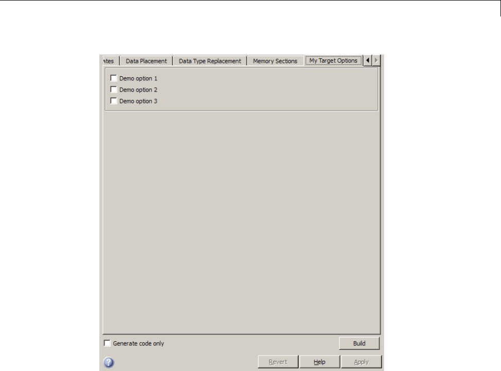
Customize System Target Files
Target-Specific Options for my_ert_target
my_ert_target supports a makefile-based build, generating code and
executables that run on the host system. my_ert_target uses the LCC
compiler on a Microsoft Windows platform. This compiler was chosen because
it is readily available and is distributed with the Simulink Coder product. If
you use a different compiler, you can set up LCC temporarily as your default
compiler by typing the MATLAB command
mex -setup
Follow the prompts and select LCC.
24-63

24 Custom Target Development
Note On UNIX14 systems, verify that you have a C compiler installed. You
can then do this exercise, substituting UNIX folder syntax.
You can test my_ert_target with any model that is compatible with the ERT
target. (See “Target” in the Embedded Coder documentation.) Generated
programs operate identically to ERT generated programs.
However, to simplify the testing of your target, we recommend testing with
targetmodel, a very simple fixed-step model (see “Create Test Model and
S-Function” on page 24-71). The S-Function block in targetmodel uses the
source code from the timestwo example, and generates fully inlined code. See
“S-Function Examples”, “Inlining S-Functions”, and “S-Function Inlining” for
further discussion of the timestwo example S-function.
Creating Target Folders
In this section, you create folders to store the target files and add them to the
MATLAB path, following the recommended conventions (see “Folder and File
Naming Conventions” on page 24-11). You also create a folder to store the test
model, S-function, and generated code.
This example assumes that your target and model folders are located within
the folder c:/work. Note that your target and model folders should not
be located anywhere in the MATLAB folder tree (that is, in or under the
matlabroot folder).
To create the folders and make them accessible,
1Create a target root folder, my_ert_target. To do this from the MATLAB
Command Window on a Windows platform, enter:
cd c:/work
mkdir my_ert_target
2Within the target root folder, create a subfolder to store your target files.
14. UNIX®is a registered trademark of The Open Group in the United States and other
countries.
24-64

Customize System Target Files
mkdir my_ert_target/my_ert_target
3Add these folders to your MATLAB path.
addpath c:/work/my_ert_target
addpath c:/work/my_ert_target/my_ert_target
4Create a folder, my_targetmodel,tostorethetestmodel,S-function,and
generated code.
mkdir my_targetmodel
Create ERT-Based STF
In this section, you create an STF for your target by copying and modifying
the standard STF for the ERT target. Then you validate the STF by viewing
the new target in the System Target File Browser and the Configuration
Parameters dialog box.
Editing the STF. To edit the STF,
1Change your working folder to the folder you created in “Creating Target
Folders” on page 24-64.
cd c:/work/my_ert_target/my_ert_target
2Place a copy of matlabroot/rtw/c/ert/ert.tlc in
c:/work/my_ert_target/my_ert_target and rename it to
my_ert_target.tlc.Thefileert.tlc is the STF for the ERT target.
3Open my_ert_target.tlc in a text editor of your choice.
4Generally, the first step in customizing an STF is to replace the header
comment lines with directives that make your STF visible in the System
Target File Browser and define the associated TMF (that you create
shortly), make command, and External mode interface file (if any). See
“Header Comments” on page 24-40 for a detailed explanation of these
directives.
Replace the header comments in my_ert_target.tlc with the following
header comments.
24-65

24 Custom Target Development
%% SYSTLC: My ERT-based Target TMF: my_ert_target_lcc.tmf MAKE: make_rtw \
%% EXTMODE: no_ext_comm
5The file my_ert_target.tlc inherits the standardERToptions,using
the mechanism described in “Inheriting Target Options” on page 24-53.
Therefore, the existing rtwoptions structure definition is superfluous. Edit
the RTW_OPTIONS section such that it includes only the following code.
/%
BEGIN_RTW_OPTIONS
%----------------------------------------%
% Configure RTW code generation settings %
%----------------------------------------%
rtwgensettings.BuildDirSuffix = '_ert_rtw';
END_RTW_OPTIONS
%/
6Delete the code after the end of the RTW_OPTIONS section, which is
delimited by the directives BEGIN_CONFIGSET_TARGET_COMPONENT and
END_CONFIGSET_TARGET_COMPONENT. This code is for use only by internal
MathWorks developers.
7Modify the build folder suffix in the rtwgenSettings structure in
accordance with the conventions described in “rtwgensettings Structure”
on page 24-44.
To set the suffix to a string for the _my_ert_target custom target, change
the line
rtwgensettings.BuildDirSuffix = '_ert_rtw'
to
rtwgensettings.BuildDirSuffix = '_my_ert_target_rtw'
8Modify the rtwgenSettings structure to inherit options from the ERT
target and declare Release 14 or later compatibility as described in
“rtwgensettings Structure” on page 24-44. Add the following code to the
rtwgenSettings definition:
24-66

Customize System Target Files
rtwgensettings.DerivedFrom = 'ert.tlc';
rtwgensettings.Version = '1';
9Add an rtwoptions structure that defines a target-specific options category
with three check boxes just after the BEGIN_RTW_OPTIONS directive. The
following code shows the complete RTW_OPTIONS section, including the
rtwgenSettings changes made in previous steps.
/%
BEGIN_RTW_OPTIONS
rtwoptions(1).prompt = 'My Target Options';
rtwoptions(1).type = 'Category';
rtwoptions(1).enable = 'on';
rtwoptions(1).default = 3; % number of items under this category
% excluding this one.
rtwoptions(1).popupstrings = '';
rtwoptions(1).tlcvariable = '';
rtwoptions(1).tooltip = '';
rtwoptions(1).callback = '';
rtwoptions(1).makevariable = '';
rtwoptions(2).prompt = 'Demo option 1';
rtwoptions(2).type = 'Checkbox';
rtwoptions(2).default = 'off';
rtwoptions(2).tlcvariable = 'DummyOpt1';
rtwoptions(2).makevariable = '';
rtwoptions(2).tooltip = ['Demo option1 (non-functional)'];
rtwoptions(2).callback = '';
rtwoptions(3).prompt = 'Demo option 2';
rtwoptions(3).type = 'Checkbox';
rtwoptions(3).default = 'off';
rtwoptions(3).tlcvariable = 'DummyOpt2';
rtwoptions(3).makevariable = '';
rtwoptions(3).tooltip = ['Demo option2 (non-functional)'];
rtwoptions(3).callback = '';
rtwoptions(4).prompt = 'Demo option 3';
rtwoptions(4).type = 'Checkbox';
24-67

24 Custom Target Development
rtwoptions(4).default = 'off';
rtwoptions(4).tlcvariable = 'DummyOpt3';
rtwoptions(4).makevariable = '';
rtwoptions(4).tooltip = ['Demo option3 (non-functional)'];
rtwoptions(4).callback = '';
%----------------------------------------%
% Configure RTW code generation settings %
%----------------------------------------%
rtwgensettings.BuildDirSuffix = '_my_ert_target_rtw';
rtwgensettings.DerivedFrom = 'ert.tlc';
rtwgensettings.Version = '1';
END_RTW_OPTIONS
%/
10 Save your changes to my_ert_target.tlc and close the file.
Viewing the STF. At this point, you can verify that the target inherits and
displays ERT options as follows:
1Create a new model.
2Open the Model Explorer or the Configuration Parameters dialog box.
3Select the Code Generation pane.
4Click Browse to open the System Target File Browser.
5In the Browser, scroll through the list of targets to find the new target,
my_ert_target.tlc. (This step assumes that your MATLAB path contains
c:/work/my_ert_target/my_ert_target, as previously set in “Creating
Target Folders” on page 24-64.)
6Select My ERT-based Target as shown below, and click OK.
24-68
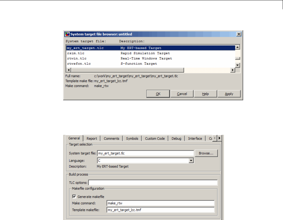
Customize System Target Files
7The Code Generation pane now shows that the model is configured for the
my_ert_target.tlc target. The System target file,Make command,
and Template makefile fields should appear as follows:
8Select the My Target Options pane and observe that the target displays
the three check box options defined in the rtwoptions structure, as shown
in the following figure.
24-69
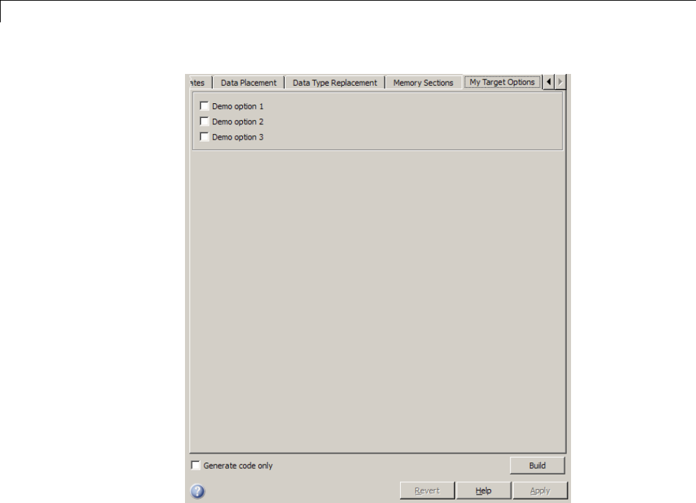
24 Custom Target Development
9Select the Code Generation pane and reopen the System Target File
Browser.
10 Select the Embedded Coder target (ert.tlc) and observe that the target
displays the standard ERT options.
11 Closethemodel. Youdonotneedtosaveit.
At this point, the STF for the skeletal target is complete. Note, however, that
the STF header comments reference a TMF, my_ert_target_lcc.tmf.You
arenotabletoinvokethebuildprocessforyourtargetuntiltheTMFfileisin
place. In the next section, you create my_ert_target_lcc.tmf.
24-70

Customize System Target Files
Create ERT-Based TMF
In this section, you create a TMF for your target by copying and modifying the
standard ERT TMF for the LCC compiler:
1Check that your working folder is still set to the target file folder you
created previously in “Creating Target Folders” on page 24-64.
c:/work/my_ert_target/my_ert_target
2Place a copy of matlabroot/rtw/c/ert/ert_lcc.tmf in
c:/work/my_ert_target/my_ert_target and rename it to
my_ert_target_lcc.tmf.Thefileert_lcc.tmf is the ERT
compiler-specific template makefile for the LCC compiler.
3Open my_ert_target_lcc.tmf inatexteditorofyourchoice.
4Change the SYS_TARGET_FILE parameter so that the file reference for your
.tlc file is generated in the make file. Change the line
SYS_TARGET_FILE = any
to
SYS_TARGET_FILE = my_ert_target.tlc
5Save changes to my_ert_target_lcc.tmf and close the file.
Your target can now generate code and build a host-based executable. In
the next sections, you create a test model and test the build process using
my_ert_target.
Create Test Model and S-Function
In this section, you build a simple test model for later use in code generation:
1Set your working folder to c:/work/my_targetmodel.
cd c:/work/my_targetmodel
For the remainder of this tutorial, my_targetmodel isassumedtobethe
working folder. Your target writes the output files of the code generation
process into a build folder within the working folder. When inlined code is
24-71
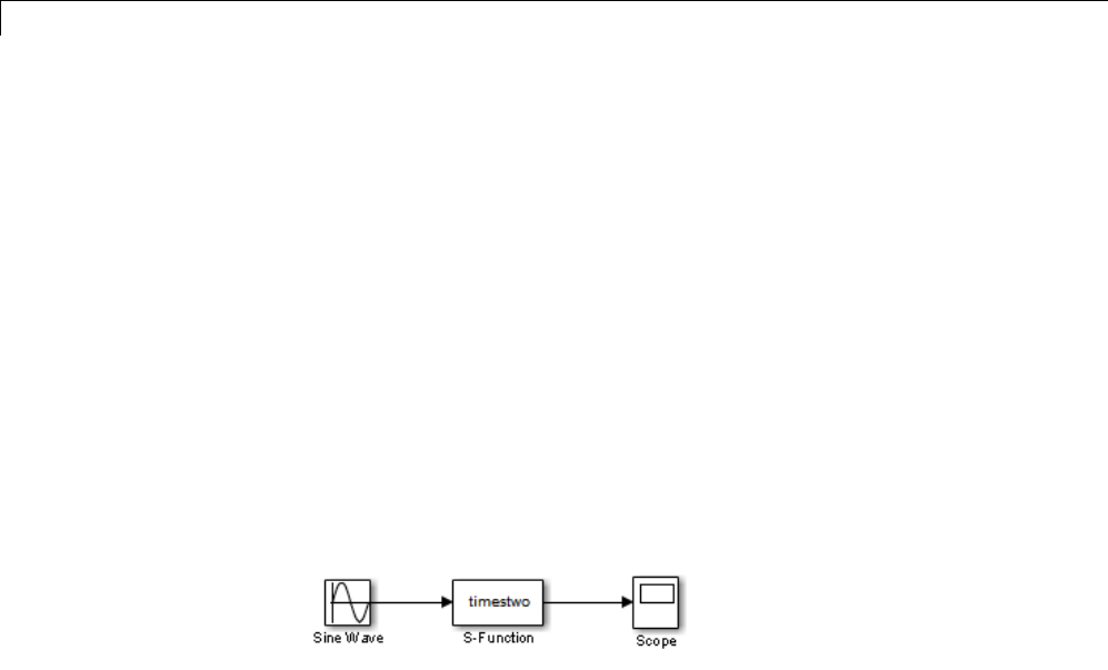
24 Custom Target Development
generated for the timestwo S-function, the build process looks for the TLC
implementation of the S-function in the working folder.
2Copy the following C and TLC files for the timestwo S-function to your
working folder:
•matlabroot/toolbox/simulink/simdemos/simfeatures/src/timestwo.c
•matlabroot/toolbox/simulink/simdemos/simfeatures/tlc_c/timestwo.tlc
3Build the timestwo MEX-file in c:/work/my_targetmodel.
mex timestwo.c
4Create the following model, using an S-Function block from the Simulink
User-Defined Functions library. Save the model in your working folder
as targetmodel.
5Double-click the S-Function block to open the Block Parameters dialog box.
Enter the S-function name timestwo.ClickOK.Theblockisnowbound
to the timestwo MEX-file.
6Open Model Explorer or the Configuration Parameters dialog box and
select the Solver pane.
7Set the solver Type to fixed-step and click Apply.
8Save the model.
9Open the scope and run a simulation. Verify that the timestwo
S-function multiplies its input by 2.0.
Keep the targetmodel model open for use in the next section, in which you
generate code using the test model.
24-72

Customize System Target Files
Verify Target Operation
In this section you configure targetmodel for the my_ert_target custom
target, and use the target to generate code and build an executable:
1Open the Configuration Parameters dialog box and select the Code
Generation pane.
2Click Browse to open the System Target File Browser.
3In the Browser, select My ERT-based Target and click OK.
4The Configuration Parameters dialog box now displays the Code
Generation pane for my_ert_target.
5Select the Code Generation > Report pane and select the Create code
generation report option.
6Click Apply and save the model. The model is configured for
my_ert_target.
7Build the model. If the build succeeds, the MATLAB Command Window
displays the message below.
### Created executable: ../targetmodel.exe
### Successful completion of build procedure for model:
targetmodel
Your working folder contains the targetmodel.exe file and the build
folder, targetmodel_my_ert_target_rtw, which contains generated code
and other files. The working folder also contains an slprj folder, used
internally by the build process.
The code generator also creates and displays a code generation report.
8To view the generated model code, go to the code generation report window.
In the Contents pane, click the targetmodel.c link.
24-73

24 Custom Target Development
9In targetmodel.c, locate the model step function, targetmodel_step.
Observe the following code.
/* S-Function Block: <Root>/S-Function */
/* Multiply input by two */
targetmodel_B.SFunction = targetmodel_B.SineWave * 2.0;
Thepresenceofthiscodeconfirmsthatthemy_ert_target custom target
has generated an inlined output computation for the S-Function block in
the model.
24-74
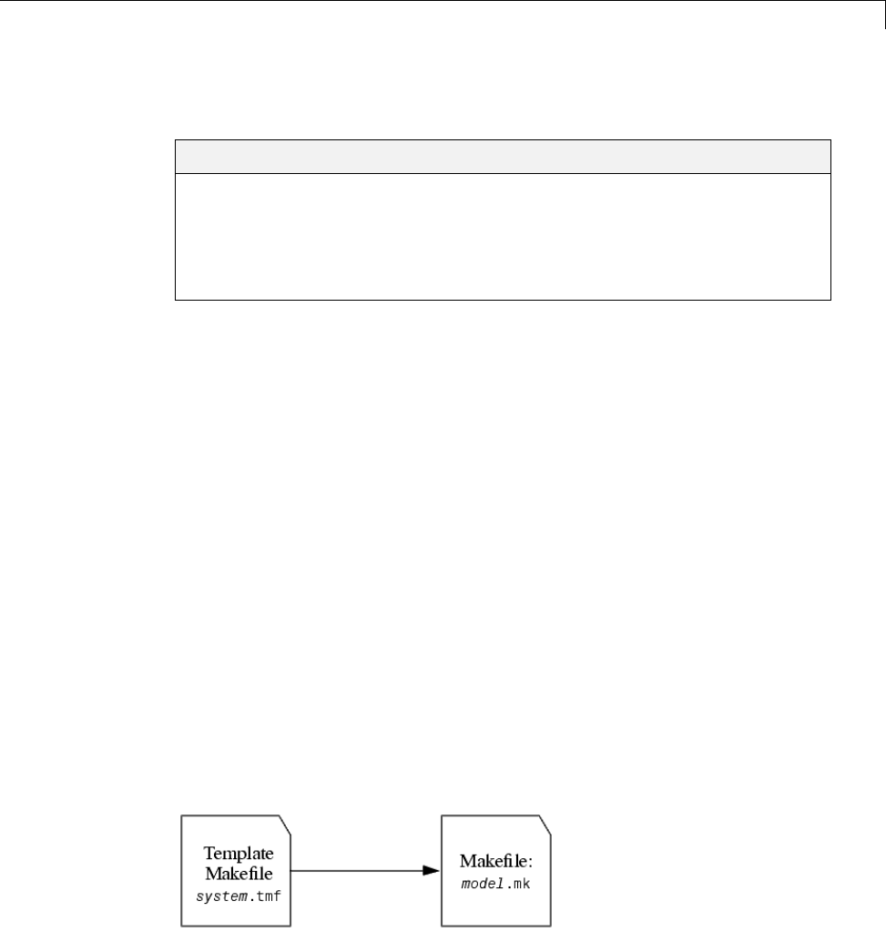
Customize Template Makefiles
Customize Template Makefiles
In this section...
“Template Makefiles and Tokens” on page 24-75
“Invoke the make Utility” on page 24-82
“Structure of the Template Makefile” on page 24-83
“Customize and Create Template Makefiles” on page 24-87
Template Makefiles and Tokens
•“Prerequisites” on page 24-75
•“TemplateMakefileRoleInMakefileCreation”onpage24-75
•“Template Makefile Tokens” on page 24-76
Prerequisites
To configure or customize a template makefile (TMF), you should be familiar
with how the make command works and how it processes makefiles. You
should also understand makefile build rules. For information on these topics,
refer to the documentation provided with the make utility you use.
Template Makefile Role In Makefile Creation
TMFs are made up of statements containing tokens. The Simulink Coder
build process expands tokens and creates a makefile, model.mk.TMFsare
designed to generate makefiles for specific compilers on specific platforms.
The generated model.mk file is tailored to compile and link code generated
from your model, using commands specific to your development system.
Creation of model.mk
24-75

24 Custom Target Development
Template Makefile Tokens
The make_rtw command (or a different command provided with some
targets) directs the process of generating model.mk. The make_rtw
command processes the TMF specified on the Code Generation pane of the
Configuration Parameters dialog box. make_rtw copiestheTMF,linebyline,
expanding each token encountered. Template Makefile Tokens Expanded by
make_rtw on page 24-76 lists the tokens and their expansions.
These tokens are used in several ways by the expanded makefile:
•To control the conditional behavior in the makefile. The conditionals are
used to control the source file lists, library names, target to be built, and
other build-related information.
•To provide the macro definitions for compiling the files, for example,
-DINTEGER_CODE=1.
Template Makefile Tokens Expanded by make_rtw
Token Expansion
General purpose
|>ALT_MATLAB_BIN<| Alternate full pathname for the MATLAB executable;
value is different than value for MATLAB_BIN token
when the full pathname contains spaces.
|>ALT_MATLAB_ROOT<| Alternate full pathname for the MATLAB
installation; value is different than value for
MATLAB_ROOT token when the full pathname contains
spaces.
|>BUILDARGS<| Options passed to make_rtw. This token is provided
so that the contents of your model.mk file changes
when you change the build arguments, thus forcing
an update of all modules when your build options
change.
|>COMBINE_OUTPUT_UPDATE_FCNS<| True (1) when Single output/update function is
selected, otherwise False (0). Used for the macro
definition -DONESTEPFCN=1.
24-76

Customize Template Makefiles
Template Makefile Tokens Expanded by make_rtw (Continued)
Token Expansion
|>COMPUTER<| Computer type. See the MATLAB computer
command.
|>EXPAND_LIBRARY_LOCATION<| Location of precompiled library file. The
TargetPreCompLibLocation configuration
parameter can override this setting. For examples,
see “Control Library Location and Naming During
Build” on page 22-7.
|>EXPAND_LIBRARY_NAME<| Library name. For examples, see “Control Library
Location and Naming During Build” on page 22-7
and “Modify the Template Makefile” on page 14-127.
|>EXPAND_LIBRARY_SUFFIX<| Library suffix. The TargetLibSuffix configuration
parameter can override this setting. For examples,
see “Control Library Location and Naming During
Build” on page 22-7.
|>EXT_MODE<| True(1)toenablegenerationofExternalmode
support code, otherwise False (0).
|>EXTMODE_TRANSPORT<| Index of transport mechanism (for example, tcpip,
serial)forExternalmode.
|>EXTMODE_STATIC<| True (1) if static memory allocation is selected
for External mode. False (0) if dynamic memory
allocation is selected.
|>EXTMODE_STATIC_SIZE<| Size of static memory allocation buffer (if any) for
External mode.
|>GENERATE_ERT_S_FUNCTION<| True (1) when Create SIL block is selected,
otherwise False (0). Used for control of the makefile
target of the build.
|>INCLUDE_MDL_TERMINATE_FCN<| True (1) when Terminate function required is
selected, otherwise False (0). Used for the macro
definition -DTERMFCN==1.
24-77

24 Custom Target Development
Template Makefile Tokens Expanded by make_rtw (Continued)
Token Expansion
|>INTEGER_CODE<| True (1) when Support floating-point numbers
is not selected, otherwise False (0). INTEGER_CODE
is a required macro definition when compiling the
source code and is used when selecting precompiled
libraries to link against.
|>MAKEFILE_NAME<| model.mk — The name of the makefile that was
created from the TMF.
|>MAT_FILE<| True (1) when MAT-file logging is selected,
otherwise False (0). MAT_FILE is a required macro
definition when compiling the source code and also
is used to include logging code in the build process.
|>MATLAB_BIN<| Location of the MATLAB executable.
|>MATLAB_ROOT<| Path to where MATLAB is installed.
|>MEM_ALLOC<| Either RT_MALLOC or RT_STATIC. Indicates how
memory is to be allocated.
|>MEXEXT<| MEX-file extension. See the MATLAB mexext
command.
|>MODEL_MODULES<| Any additional generated source modules. For
example, you can split a large model into two files,
model.c and model1.c.Inthiscase,thistoken
expands to model1.c.
|>MODEL_MODULES_OBJ<| Object filenames (.obj) corresponding to any
additional generated source modules.
|>MODEL_NAME<| Name of the Simulink block diagram currently being
built.
|>MULTITASKING<| True (1) if solver mode is multitasking, otherwise
False (0).
|>NCSTATES<| Number of continuous states.
|>NUMST<| Number of sample times in the model.
24-78

Customize Template Makefiles
Template Makefile Tokens Expanded by make_rtw (Continued)
Token Expansion
|>PORTABLE_WORDSIZES<| True (1) when Enable portable word sizes is
selected, otherwise False (0).
|>RELEASE_VERSION<| The MATLAB release version.
|>S_FUNCTIONS<| List of noninlined S-function sources.
|>S_FUNCTIONS_LIB<| List of S-function libraries available for linking.
|>S_FUNCTIONS_OBJ<| Object (.obj) file list corresponding to noninlined
S-function sources.
|>SOLVER<| Solver source filename, for example, ode3.c.
|>SOLVER_OBJ<| Solver object (.obj) filename, for example, ode3.obj.
|>TARGET_LANG_EXT<| cwhen the Simulink Coder Language selection is
C, cpp when the Language selection is C++. Used
in the makefile to control the extension on generated
source files.
|>TGT_FCN_LIB<| Specifies compiler command line options. The line in
the makefile is TGT_FCN_LIB = |>TGT_FCN_LIB<|.
By default, the Simulink Coder build process
expands the |>TGT_FCN_LIB<| token to match
the setting of the Code replacement library
parameter on the Code Generation > Interface
pane of the Configuration Parameters dialog box.
Possible values for this option include ANSI_C,C99
(ISO),GNU99 (GNU),andC++ (ISO).Youcanuse
this token in a makefile conditional statement to
specify compiler options to be used. For example, if
you set the token to C99 (ISO),thecompilermight
need an additional option set to support C99 library
functions.
|>TID01EQ<| True (1) if sampling rates of the continuous task and
the first discrete task are equal, otherwise False (0).
24-79

24 Custom Target Development
Template Makefile Tokens Expanded by make_rtw (Continued)
Token Expansion
S-function and build information support
Note For examples of the tokens in this section, see“ModifytheTemplateMakefile”onpage
14-127.
|>START_EXPAND_INCLUDES<|
|>EXPAND_DIR_NAME<|
|>END_EXPAND_INCLUDES<|
List of folder names to add to the include path.
Additionally, the ADD_INCLUDES macro must be
added to the INCLUDES line.
|>START_EXPAND_LIBRARIES<|
|>EXPAND_LIBRARY_NAME<|
|>END_EXPAND_LIBRARIES<|
List of library names.
|>START_EXPAND_MODULES<|
|>EXPAND_MODULE_NAME<|
|>END_EXPAND_MODULES<|
Library module names within
|>START_EXPAND_LIBRARIES<| and
|>START_PRECOMP_LIBRARIES<| library lists.
|>START_EXPAND_RULES<|
|>EXPAND_DIR_NAME<|
|>END_EXPAND_RULES<|
Makefile rules.
|>START_PRECOMP_LIBRARIES<|
|>EXPAND_LIBRARY_NAME<|
|>END_PRECOMP_LIBRARIES<|
List of precompiled library names.
Model reference support
Note For examples of the tokens in this section, see “Providing Model Referencing Support in
the TMF” on page 24-104.
|>MASTER_ANCHOR_DIR<| For parallel builds, current work folder (pwd)atthe
time the build started.
|>MODELLIB<| Name of the library file generated for the current
model.
|>MODELREFS<| List of models referenced by the top model.
24-80

Customize Template Makefiles
Template Makefile Tokens Expanded by make_rtw (Continued)
Token Expansion
|>MODELREF_LINK_LIBS<| List of referenced model libraries against which the
top model links.
|>MODELREF_LINK_RSPFILE_NAME<| Name of a response file against which the top model
links. This token is valid only for build environments
that support linker response files. For an example of
its use, see matlabroot/rtw/c/grt/grt_vc.tmf.
|>MODELREF_TARGET_TYPE<| Type of target being built. Possible values are
•NONE: Standalone model or top model referencing
other models
•RTW: Model reference Simulink Coder target build
•SIM: Model reference simulation target build
|>RELATIVE_PATH_TO_ANCHOR<| Relative path, from the location of the generated
makefile, to the MATLAB working folder.
|>START_DIR<| Current work folder (pwd)atthetimethebuild
started. This token is required for parallel builds.
|>START_MDLREFINC_EXPAND_INCLUDES<|
|>MODELREF_INC_PATH<|
|>END_MDLREFINC_EXPAND_INCLUDES<|
List of include paths for models referenced by the
top model.
|>SHARED_BIN_DIR<| Folder for the library file built from the shared
source files.
|>SHARED_LIB<| Library file built from the shared source files,
including the path to the library folder.
|>SHARED_SRC<| Shared source files specification, including the path
to the shared utilities folder.
|>SHARED_SRC_DIR<| Folder for shared source files.
These tokens are expanded by substitution of parameter values known to the
build process. For example, if the source model contains blocks with two
different sample times, the TMF statement
NUMST = |>NUMST<|
24-81

24 Custom Target Development
expands to the following in model.mk.
NUMST = 2
In addition to the above, make_rtw expands tokens from other sources:
•Target-specific tokens defined in the target options of the Configuration
Parameters dialog box
•Structures in the rtwoptions section of the system target file. Any
structures in the rtwoptions structure array that contain the field
makevariable are expanded.
The following example is extracted from matlabroot/rtw/c/grt/grt.tlc.
The section starting with BEGIN_RTW_OPTIONS contains MATLAB code that
sets up rtwoptions. The following directive causes the |>EXT_MODE<| token
to be expanded to 1(on) or 0(off), depending on how you set the External
mode options.
rtwoptions(2).makevariable = 'EXT_MODE'
InvokethemakeUtility
•“make Command” on page 24-82
•“make Utility Versions” on page 24-83
make Command
After creating model.mk from your TMF, the Simulink Coder build process
invokes a make command. To invoke make, the build process issues this
command.
makecommand -f model.mk
makecommand is defined by the MAKECMD macro in your target’s TMF (see
“Structure of the Template Makefile” on page 24-83). You can specify
additional options to make in the Make command field of the Code
Generation pane. (See the sections “Specify a Make Command” on page
15-13 and “Template Makefiles and Make Options” on page 9-38 in the
Simulink Coder documentation.)
24-82

Customize Template Makefiles
For example, specifying OPT_OPTS=-O2 in the Make command field causes
make_rtw to generate the following make command.
makecommand -f model.mk OPT_OPTS=-O2
A comment at the top of the TMF specifies the available make command
options. If these options do not provide youwithenoughflexibility,youcan
configure your own TMF.
make Utility Versions
The make utility lets you control nearly every aspect of building your
real-time program. There are several different versions of make available. The
Simulink Coder software provides the Free Software Foundation GNU make
for both UNIX15 and PC platforms in platform-specific subfolders under
matlabroot/bin
It is possible to use other versions of make with the Simulink Coder software,
although GNU Make is recommended. To be compatible with the Simulink
Coder software, verify that your version of make supports the following
command format.
makecommand -f model.mk
Structure of the Template Makefile
A TMF has multiple sections, including the following:
•Abstract — Describes what the makefile targets. Here is a representative
abstract from the GRT TMFs in matlabroot/rtw/c/grt:
# File : grt_lcc.tmf
#
# Abstract:
# Template makefile for building a PC-based stand-alone generic real-time
# version of Simulink model using generated C code and LCC compiler
# Version 2.4.
#
15. UNIX®is a registered trademark of The Open Group in the United States and other
countries.
24-83

24 Custom Target Development
# This makefile attempts to conform to the guidelines specified in the
# IEEE Std 1003.2-1992 (POSIX) standard. It is designed to be used
# with GNU Make (gmake) which is located in matlabroot/bin/win32.
#
# Note that this template is automatically customized by the build
# procedure to create "<model>.mk"
#
# The following defines can be used to modify the behavior of the
# build:
# OPT_OPTS - Optimization options. Default is none. To enable
# debugging specify as OPT_OPTS=-g4.
# OPTS - User specific compile options.
# USER_SRCS - Additional user sources, such as files needed by
# S-functions.
# USER_INCLUDES - Additional include paths
# (i.e. USER_INCLUDES="-Iwhere-ever -Iwhere-ever2")
# (For Lcc, have a '/'as file seperator before the
# file name instead of a '\' .
# i.e., d:\work\proj1/myfile.c - reqd for 'gmake')
#
# This template makefile is designed to be used with a system target
# file that contains 'rtwgensettings.BuildDirSuffix'. See grt.tlc.
•Macros read by make_rtw section — Defines macros that tell make_rtw
howtoprocesstheTMF.HereisarepresentativeMacros read by
make_rtw section from the GRT TMFs in matlabroot/rtw/c/grt:
#------------------------ Macros read by make_rtw ------------------------------
#
# The following macros are read by the build procedure:
#
# MAKECMD - This is the command used to invoke the make utility
# HOST - What platform this template makefile is targeted for
# (i.e. PC or UNIX)
# BUILD - Invoke make from the build procedure (yes/no)?
# SYS_TARGET_FILE - Name of system target file.
MAKECMD = "%MATLAB%\bin\win32\gmake"
SHELL = cmd
HOST = PC
24-84

Customize Template Makefiles
BUILD = yes
SYS_TARGET_FILE = grt.tlc
BUILD_SUCCESS = *** Created
COMPILER_TOOL_CHAIN = lcc
MAKEFILE_FILESEP = /
The macros in this section might include:
-MAKECMD — Specifies the command used to invoke the make utility. For
example, if MAKECMD =mymake, then the make command invoked is
mymake -f model.mk
-HOST — Specifies the platform targeted by this TMF. This can be PC,
UNIX,computer_name (see the MATLAB computer command), or ANY.
-BUILD — Instructs make_rtw whether or not it should invoke make from
the Simulink Coder build procedure. Specify yes or no.
-SYS_TARGET_FILE — Specifies the name of the system target file or the
value any. This is used for consistency checking by make_rtw to verify
the system target file specified in the Target selection panel of the
Code Generation pane of the Configuration Parameters dialog box. If
you specify any, you can use the TMF with any system target file.
-BUILD_SUCCESS — Optional macro that specifies the build success string
to be displayed for make completion on the PC. For example,
BUILD_SUCCESS = ### Successful creation of
The BUILD_SUCCESS macro, if used, replaces the standard build success
string found in the TMFs distributed with the bundled Simulink Coder
targets (such as GRT):
@echo ### Created executable $(MODEL).exe
Your TMF must include either the standard build success string, or use
the BUILD_SUCCESS macro. For an example of the use of BUILD_SUCCESS,
see matlabroot/rtw/c/grt/grt_lcc.tmf or the code example above
this list of macros.
-BUILD_ERROR — Optional macro that specifies the build error message to
be displayed when an error is encountered during the make procedure.
For example,
24-85

24 Custom Target Development
BUILD_ERROR = ['Error while building ', modelName]
-VERBOSE_BUILD_OFF_TREATMENT = PRINT_OUTPUT_ALWAYS —Optional
macrotoincludeifyouwantthemakefileoutputtobedisplayedalways
(regardless of the setting of the Verbose build option in the Code
Generation > Debug pane).
-COMPILER_TOOL_CHAIN — For builds on Windows systems, specifies
which compiler setup file (located in matlabroot/toolbox/rtw/rtw)
to use:
•lcc selects setup_for_lcc.m
•vc selects setup_for_visual.m
•vcx64 selects setup_for_visual_x64.m
•watc selects setup_for_watcom.m
•default selects setup_for_default.m
For builds on UNIX systems, specify unix.
Any other value is flagged as unknown and make_rtw uses
setup_for_default.m.
-DOWNLOAD — An optional macro that you can specify as yes or no. If
specified as yes (and BUILD=yes), then make is invoked a second time
with the download target.
make -f model.mk download
-DOWNLOAD_SUCCESS — An optional macro that you can use to specify
the download success string to be used when looking for a completed
download. For example,
DOWNLOAD_SUCCESS = ### Downloaded
-DOWNLOAD_ERROR — An optional macro that you can use to specify the
download error message to be displayed when an error is encountered
during the download. For example,
DOWNLOAD_ERROR = ['Error while downloading ', modelName]
•Tokens expanded by make_rtw section — Defines the tokens that
make_rtw expands. Here is a brief excerpt from a representative
24-86

Customize Template Makefiles
Tokens expanded by make_rtw section from the GRT TMFs in
matlabroot/rtw/c/grt:
#---------------------- Tokens expanded by make_rtw ----------------------------
#
# The following tokens, when wrapped with "|>" and "<|" are expanded by the
# build procedure.
#
# MODEL_NAME - Name of the Simulink block diagram
# MODEL_MODULES - Any additional generated source modules
# MAKEFILE_NAME - Name of makefile created from template makefile <model>.mk
# MATLAB_ROOT - Path to where MATLAB is installed.
...
MODEL = |>MODEL_NAME<|
MODULES = |>MODEL_MODULES<|
MAKEFILE = |>MAKEFILE_NAME<|
MATLAB_ROOT = |>MATLAB_ROOT<|
...
For more information about TMF tokens, see Template Makefile Tokens
Expanded by make_rtw on page 24-76.
•Subsequent sections vary based on compiler, host, and target. Some
common sections include Model and reference models,External mode,
Tool Specifications or Tool Definitions,Include Path,C Flags,
Additional Libraries,andSource Files.
•Rules section — Contains the make rules used in building an executable
from the generated source code. The build rules are typically specific to
your version of make. The Rules section might be followed by related
sections such as Dependencies.
Customize and Create Template Makefiles
•“Introduction” on page 24-88
•“Setting Up a Template Makefile” on page 24-88
•“Using Macros and Pattern Matching Expressions in a Template Makefile”
on page 24-90
24-87

24 Custom Target Development
•“Using the rtwmakecfg.m API to Customize Generated Makefiles” on page
24-92
•“Supporting Continuous Time in Custom Targets” on page 24-98
•“Model Reference Considerations” on page 24-99
•“Generating Make Commands for Nondefault Compilers” on page 24-99
Introduction
This section describes the mechanics of setting up a custom template makefile
(TMF) and incorporating it into the build process. It also discusses techniques
for modifying a TMF and MATLAB file mechanisms associated with the TMF.
Before creating a custom TMF, you should read “Folder and File Naming
Conventions” on page 24-11 to understand the folder structure and MATLAB
path requirements for custom targets.
Setting Up a Template Makefile
To customize or create a new TMF, you should copy an existing GRT or ERT
TMF from one of the following locations:
matlabroot/rtw/c/grt
matlabroot/rtw/c/ert
Placethecopyinthesamefolderastheassociatedsystemtargetfile(STF).
Usually, this is the mytarget/mytarget folder within the target folder
structure. Then, rename your TMF (for example, mytarget.tmf)andmodify
it.
To allow the build process to locate and select your TMF, you must provide
information in the STF file header (see “System Target File Structure” on
page 24-37). For a target that implements a single TMF, the standard way to
specify the TMF to be used in the build process is to use the TMF directive of
the STF file header.
TMF: mytarget.tmf
If your target must support multiple development environments, you can
specify a MATLABfile script that selects the TMF, based on user preferences.
To do this, you must
24-88

Customize Template Makefiles
•Create the script in your mytarget/mytarget folder. The naming
convention for this file is mytarget_default_tmf.m.
•Specify this file in the TMF directive of the STF file header.
TMF: mytarget_default_tmf
The build process then invokes your mytarget_default_tmf.m file, which then
selects theTMF, based on target preference settings. “mytarget_default_tmf.m
Example Code” on page 24-89 illustrates this technique.
Another useful technique is to store a path to the user’s installed development
environment in your target preferences. You can then locate the template
makefiles under the tool folder. This allows several tool-specific template
makefiles files to be located under the specific tool folder.
mytarget_default_tmf.m Example Code. Thecodeexamplebelow
implements a function, mytarget_default_tmf. The function loads target
preferences into a structure from preferences data stored on disk. The code
verifies that the target preferences information is consistent with the STF
name, and extracts the associated TMF name. The TMF name is returned
as the string tmf.
function [tmf,envVal] = mytarget_default_tmf
try
prefs = RTW.TargetPrefs.load('mytarget.prefs','structure');
catch exception
rethrow(exception);
end
% Get the desired MYTARGET implementation and check that it is supported
if ~isfield(prefs, 'Implementation')
error('MYTARGET preferences not set correctly, update Target Preferences.');
end
imp = deblank(lower(prefs.Implementation));
stfname = deblank(lower(get_param(bdroot, 'RTWSystemTargetFile')));
if ~strncmp(imp, stfname, length(stfname) - length('.tlc'))
msg = ['System Target filename: ', stfname,
' does not match Implementation specified in Target Preferences: ', imp];
error(msg);
24-89

24 Custom Target Development
end
% Return the desired template make file.
tmf = [imp, '.tmf'];
% This argument is unused
envVal = '';
Using Macros and Pattern Matching Expressions in a Template
Makefile
This section shows, through an example, how to use macros and
file-pattern-matching expressions in a TMF to generate commands in the
model.mk file.
The make utility processes the model.mk makefile and generates a set of
commands based upon dependency rules defined in model.mk.Aftermake
generates the set of commands for building or rebuilding test,make executes
them.
For example, to build a program called test,make must link the object files.
However, if the object files don’t exist or are out of date, make must compile
the source code. Thus there is a dependency between source and object files.
Each version of make differs slightly in its features and how rules are defined.
For example, consider a program called test that gets created from two
sources, file1.c and file2.c. Using most versions of make, the dependency
rules would be
test: file1.o file2.o
cc -o test file1.o file2.o
file1.o: file1.c
cc -c file1.c
file2.o: file2.c
cc -c file2.c
24-90

Customize Template Makefiles
In this example, a UNIX16 environment is assumed. In a PC environment the
file extensions and compile and link commands are different.
In processing the first rule
test: file1.o file2.o
make sees that to build test, it needs to build file1.o and file2.o.Tobuild
file1.o,make processes the rule
file1.o: file1.c
If file1.o doesn’t exist, or if file1.o is older than file1.c,make compiles
file1.c.
The format of Simulink Coder TMFs follows the above example. Our TMFs
use additional features of make such as macros and file-pattern-matching
expressions. In most versions of make, a macro is defined with
MACRO_NAME = value
References to macros are made with $(MACRO_NAME).Whenmake sees this
form of expression, it substitutes value for $(MACRO_NAME).
You can use pattern matching expressions to make the dependency rules
more general. For example, using GNU17 Make, you could replace the two
“file1.o: file1.c”and“file2.o: file2.c” rules with the single rule
%.o : %.c
cc -c $<
Note that $< in the previous example is a special macro that equates to the
dependency file (that is, file1.c or file2.c). Thus, using macros and the "%"
pattern matching character, the previous example can be reduced to
SRCS = file1.c file2.c
OBJS = $(SRCS:.c=.o)
16. UNIX®is a registered trademark of The Open Group in the United States and other
countries.
17. GNU®is a registered trademark of the Free Software Foundation.
24-91

24 Custom Target Development
test: $(OBJS)
cc -o $@ $(OBJS)
%.o : %.c
cc -c $<
Note that the $@ macro above is another special macro that equates to the
name of the current dependency target, in this case test.
This example generates the list of objects (OBJS) from the list of sources (SRCS)
by using the string substitution feature for macro expansion. It replaces
the source file extension (for example, .c) with the object file extension (.o).
This example also generalized the build rule for the program, test,touse
the special "$@" macro.
Using the rtwmakecfg.m API to Customize Generated
Makefiles
•“Overview” on page 24-92
•“Creating the rtwmakecfg.m Function” on page 24-93
•“Modifying the Template Makefile” on page 24-96
Overview. Simulink Coder TMFs provide tokens that let you add the
following items to generated makefiles:
•Source folders
•Include folders
•Run-time library names
•Run-time module objects
S-functions can add this information to the makefile by using an
rtwmakecfg.m file function. This function is particularly useful when building
a model that contains one or more of your S-Function blocks, such as device
driver blocks.
To add information pertaining to an S-function to the makefile,
24-92

Customize Template Makefiles
1Create the function rtwmakecfg in a file rtwmakecfg.m. The Simulink
Coder software associates this file with your S-function based on its folder
location. “Creating the rtwmakecfg.m Function” on page 24-93 discusses
the requirements for the rtwmakecfg function and the data it should return.
2Modify your target’s TMF such that it supports macro expansion for the
information returned by rtwmakecfg functions. “Modifying the Template
Makefile” on page 24-96 discusses the required modifications.
After the TLC phase of the build process, when generating a makefile from
the TMF, the Simulink Coder build process searches for an rtwmakecfg.m file
in the folder that contains the S-function component. If it finds the file, the
build process calls the rtwmakecfg function.
Creating the rtwmakecfg.m Function. Create the rtwmakecfg.m
file in the same folder as your S-function component (a MEX-file with a
platform-dependent extension, such as .mexw32 on 32-bit Microsoft Windows
platforms). The function must return a structured array that contains the
following fields:
Field Description
makeInfo.includePath A cell array that specifies additional include folder names,
organized as a row vector. The Simulink Coder build
process expands the folder names into include instructions
in the generated makefile.
makeInfo.sourcePath A cell array that specifies additional source folder names,
organized as a row vector. The Simulink Coder build
process expands the folder names into make rules in the
generated makefile.
makeInfo.sources A cell array that specifies additional source filenames (C
or C++), organized as a row vector. The Simulink Coder
build process expands the filenames into make variables
that contain the source files. You should specify only
filenames (with extension). Specify path information with
the sourcePath field.
24-93

24 Custom Target Development
Field Description
makeInfo.linkLibsObjs A cell array that specifies additional, fully qualified
paths to object or library files against which Simulink
Coder generated code should link. The Simulink Coder
build process does not compile the specified objects and
libraries. However, it includes them when linking the final
executable. This can be useful for incorporating libraries
that you do not want the Simulink Coder build process to
recompile or for which the source files are not available.
You might also use this element to incorporate source files
from languages other than C and C++. This is possible if
you first create a C compatible object file or library outside
of the Simulink Coder build process.
makeInfo.precompile A Boolean flag that indicates whether the libraries specified
in the rtwmakecfg.m file exist in a specified location
(precompile==1) or if the libraries need to be created in
the build folder during the Simulink Coder build process
(precompile==0).
makeInfo.library A structure array that specifies additional run-time
libraries and module objects, organized as a row vector.
The Simulink Coder build process expands the information
into make rules in the generated makefile. See the next
table for a list of the library fields.
24-94

Customize Template Makefiles
The makeInfo.library field consists of the following elements:
Element Description
makeInfo.library(n).Name A character array that specifies the name of the library
(without an extension).
makeInfo.library(n).Location A character array that specifies the folder in which
the library is located when precompiled. See the
description of makeInfo.precompile in the preceding
table for more information. A target can use the
TargetPreCompLibLocation parameter to override
this value. See “Specify the Location of Precompiled
Libraries” on page 22-8 in the Simulink Coder
documentation for details.
makeInfo.library(n).Modules A cell array that specifies the C or C++ source file base
names (without an extension) that comprise the library.
Do not include the file extension. The makefile appends
the object extension.
Note The makeInfo.library field must fully specify each library and
how to build it. The modules list in the makeInfo.library(n).Modules
element cannot be empty. If you need to specify a link-only library, use the
makeInfo.linkLibsObjs field instead.
Example:
disp(['Running rtwmakecfg from folder: ',pwd]);
makeInfo.includePath = { fullfile(pwd, 'somedir2') };
makeInfo.sourcePath = {fullfile(pwd, 'somedir2'), fullfile(pwd, 'somedir3')};
makeInfo.sources = { 'src1.c', 'src2.cpp'};
makeInfo.linkLibsObjs = { fullfile(pwd, 'somedir3', 'src3.object'),...
fullfile(pwd, 'somedir4', 'mylib.library')};
makeInfo.precompile = 1;
makeInfo.library(1).Name = 'myprecompiledlib';
makeInfo.library(1).Location = fullfile(pwd,'somdir2','lib');
makeInfo.library(1).Modules = {'srcfile1' 'srcfile2' 'srcfile3' };
24-95

24 Custom Target Development
Note If a path that you specify in the rtwmakecfg.m API contains spaces,
the Simulink Coder software does not automatically convert the path to its
non-space equivalent. If the build environments you intend to support do not
support spaces in paths, refer to “Enabling the Simulink®Coder™ Software
toBuildWhenPathNamesContainSpaces”onpage9-44intheSimulink
Coder documentation.
Modifying the Template Makefile. To expand the information generated
by an rtwmakecfg function, you can modify the following sections of your
target’s TMF:
•Include Path
•C Flags and/or Additional Libraries
•Rules
The TMF code examples below may not apply to your make utility.
For additional examples, see the GRT or ERT TMFs located in
matlabroot/rtw/c/grt/*.tmf or matlabroot/rtw/c/ert/*.tmf.
Example — Adding Folder Names to the Makefile Include Path
ThefollowingTMFcodeexampleaddsfoldernamestotheincludepathin
the generated makefile:
ADD_INCLUDES = \
|>START_EXPAND_INCLUDES<| -I|>EXPAND_DIR_NAME<| \
|>END_EXPAND_INCLUDES<|
Additionally, the ADD_INCLUDES macro must be added to the INCLUDES line,
as shown below.
INCLUDES = -I. -I.. $(MATLAB_INCLUDES) $(ADD_INCLUDES) $(USER_INCLUDES)
Example — Adding Library Names to the Makefile
The following TMF code example adds library names to the generated
makefile.
24-96

Customize Template Makefiles
LIBS =
|>START_PRECOMP_LIBRARIES<|
LIBS += |>EXPAND_LIBRARY_NAME<|.a |>END_PRECOMP_LIBRARIES<|
|>START_EXPAND_LIBRARIES<|
LIBS += |>EXPAND_LIBRARY_NAME<|.a |>END_EXPAND_LIBRARIES<|
For more information on how to use configuration parameters to control
library names and location during the build process, see “Control Library
Location and Naming During Build” on page 22-7 in the Simulink Coder
documentation.
Example — Adding Rules to the Makefile
ThefollowingTMFcodeexampleaddsrulestothegeneratedmakefile.
|>START_EXPAND_RULES<|
$(BLD)/%.o: |>EXPAND_DIR_NAME<|/%.c $(SRC)/$(MAKEFILE) rtw_proj.tmw
@$(BLANK)
@echo ### "|>EXPAND_DIR_NAME<|\$*.c"
$(CC) $(CFLAGS) $(APP_CFLAGS) -o $(BLD)$(DIRCHAR)$*.o \
|>EXPAND_DIR_NAME<|$(DIRCHAR)$*.c > $(BLD)$(DIRCHAR)$*.lst
|>END_EXPAND_RULES<|
|>START_EXPAND_LIBRARIES<|MODULES_|>EXPAND_LIBRARY_NAME<| = \
|>START_EXPAND_MODULES<| |>EXPAND_MODULE_NAME<|.o \
|>END_EXPAND_MODULES<|
|>EXPAND_LIBRARY_NAME<|.a : $(MAKEFILE) rtw_proj.tmw
$(MODULES_|>EXPAND_LIBRARY_NAME<|:%.o=$(BLD)/%.o)
@$(BLANK)
@echo ### Creating $@
$(AR) -r $@ $(MODULES_|>EXPAND_LIBRARY_NAME<|:%.o=$(BLD)/%.o)
|>END_EXPAND_LIBRARIES<|
|>START_PRECOMP_LIBRARIES<|MODULES_|>EXPAND_LIBRARY_NAME<| = \
|>START_EXPAND_MODULES<| |>EXPAND_MODULE_NAME<|.o \
|>END_EXPAND_MODULES<|
|>EXPAND_LIBRARY_NAME<|.a : $(MAKEFILE) rtw_proj.tmw
24-97

24 Custom Target Development
$(MODULES_|>EXPAND_LIBRARY_NAME<|:%.o=$(BLD)/%.o)
@$(BLANK)
@echo ### Creating $@
$(AR) -r $@ $(MODULES_|>EXPAND_LIBRARY_NAME<|:%.o=$(BLD)/%.o)
|>END_PRECOMP_LIBRARIES<|
Supporting Continuous Time in Custom Targets
If you want your custom ERT-based target to support continuous time, you
must update your template makefile (TMF) and the static main program
module (for example, mytarget_main.c)foryourtarget.
Template Makefile Modifications. Add the NCSTATES token expansion
after the NUMST token expansion, as follows:
NUMST = |>NUMST<|
NCSTATES = |>NCSTATES<|
In addition, add NCSTATES to the CPP_REQ_DEFINES macro, as in the following
example:
CPP_REQ_DEFINES = -DMODEL=$(MODEL) -DNUMST=$(NUMST) -DNCSTATES=$(NCSTATES) \
-DMAT_FILE=$(MAT_FILE)
-DINTEGER_CODE=$(INTEGER_CODE) \
-DONESTEPFCN=$(ONESTEPFCN) -DTERMFCN=$(TERMFCN) \
-DHAVESTDIO
-DMULTI_INSTANCE_CODE=$(MULTI_INSTANCE_CODE) \
Modifications to Main Program Module. The main program module
defines a static main function that manages task scheduling for all supported
tasking modes of single- and multiple-rate models. NUMST (the number of
sample times in the model) determines whether the main function calls
multirate or single-rate code. However, when a model uses continuous time,
do not rely on NUMST directly.
When the model has continuous time and the flag TID01EQ is true, both
continuous time and the fastest discrete time are treated as one rate in
generated code. The code associated with the fastest discrete rate is guarded
by a major time step check. When the model has only two rates, and TID01EQ
is true, the generated code has a single-rate call interface.
24-98

Customize Template Makefiles
To support models that have continuous time, update the static main module
to take TID01EQ into account, as follows:
1Before NUMST is referenced in the file, add the following code:
#if defined(TID01EQ) && TID01EQ == 1 && NCSTATES == 0
#define DISC_NUMST (NUMST - 1)
#else
#define DISC_NUMST NUMST
#endif
2Replace all instances of NUMST in the file by DISC_NUMST.
Model Reference Considerations
See “Support Model Referencing” on page 24-101 for important information
on TMF modifications you may need to make to support the Simulink Coder
model referencing features.
Note If you are using a TMF without the variables SHARED_SRC or
MODELREFS, the file might have been used with a previous release of Simulink
software. If you want your TMF to support model referencing, add either
variable SHARED_SRC or MODELREFS to the make file.
Generating Make Commands for Nondefault Compilers
Custom targets might need a target-specific hook file to generate a make
command when you use a nondefault compiler. Use this file to override the
default behavior for selecting the compiler tool for the build process. See
“STF_wrap_make_cmd_hook.m” on page 24-23 for further details.
24-99

24 Custom Target Development
Support Optional Features
In this section...
“Overview” on page 24-100
“Support Model Referencing” on page 24-101
“Support Compiler Optimization Level Control” on page 24-115
“Support firstTime Argument Control” on page 24-117
“Support C Function Prototype Control” on page 24-119
“Support C++ Encapsulation Interface Control” on page 24-121
Overview
This chapter describes how to configure a custom embedded target to support
any of the following optional features:
Optional Feature Target Configuration Parameters
Building a model that includes
referenced models
ModelReferenceCompliant
ParMdlRefBuildCompliant (parallel
build support)
Controlling the compiler
optimization level for building
generated code
CompOptLevelCompliant
Controlling inclusion of the
firstTime argument in the
model_initialize function
generated for a Simulink model.
ERTFirstTimeCompliant (ERT only)
Controlling the C function
prototypes of initialize and step
functions that are generated for a
Simulink model
ModelStepFunctionPrototypeControl-
Compliant (ERT only)
Generating and configuring C++
encapsulation interfaces to model
code
CPPClassGenCompliant (ERT only)
24-100

Support Optional Features
The required configuration changes are modifications to your system target
file (STF), and in some cases also modifications to your template makefile
(TMF)oryourcustomstaticmainprogram.
The API for STF callbacksprovidesafunctionSelectCallback for use in
STFs. SelectCallback is associated with the target rather than with any
of its individual options. If you implement a SelectCallback function for a
target, it is triggered whenever the user selects the target in the System
Target File Browser.
Additionally, the API provides the functions slConfigUIGetVal,
slConfigUISetEnabled,andslConfigUISetVal for controlling custom target
configuration options from a user-written SelectCallback function. (For
function descriptions and examples, see the function reference pages.)
The general requirements for supporting one of the optional features include:
•To support model referencing or compiler optimization level control, the
target must be derived from the GRT or the ERT target. To support
firstTime argument control, C function prototype control, or C++
encapsulation interface control, the target must be derived from the ERT
target.
•Thesystemtargetfile(STF)mustdeclare feature compliance by
including one of the target configuration parameters listed above in a
SelectCallback function call.
•AdditionalchangessuchasTMFmodificationsorstaticmainprogram
modifications may be required, depending on the feature. See the detailed
steps in the subsections for individual features.
Support Model Referencing
•“Overview” on page 24-102
•“Declaring Model Referencing Compliance” on page 24-103
•“Providing Model Referencing Support in the TMF” on page 24-104
•“Controlling Configuration Option Value Agreement” on page 24-107
•“Supporting the Shared Utilities Folder” on page 24-108
24-101

24 Custom Target Development
•“Verifying Worker Configuration for Parallel Builds of Model Reference
Hierarchies (Optional)” on page 24-112
•“Preventing Resource Conflicts (Optional)” on page 24-114
Overview
This section describes how to configure a custom embedded target to support
model referencing. Without the described modifications, you will not be able
to use the custom target when building a model that includes referenced
models. If you do not intend to use referenced models with your target, you
can skip this section. If you later find that you need to use referenced models,
you can upgrade your target then.
The requirements for supporting model referencingareasfollows:
•ThetargetmustbederivedfromtheGRTtargetortheERTtarget.
•Thesystemtargetfile(STF)mustdeclaremodelreferencecompliance,as
described in “Declaring Model Referencing Compliance” on page 24-103.
•Thetemplatemakefile(TMF)mustdefine some entities that support model
referencing, as described in “Providing Model Referencing Support in the
TMF” on page 24-104.
•The TMF must support using the Shared Utilities folder, as described in
“Supporting the Shared Utilities Folder” on page 24-108.
Optionally, you can provide additional capabilities that support model
referencing:
•You can configure a target to support parallel builds for large model
reference hierarchies (see “Reduce Build Time for Referenced Models” on
page 15-28 in the Simulink Coder documentation). To do this, you must
modify the STF and TMF for parallel builds as described in “Declaring
Model Referencing Compliance” on page 24-103 and “Providing Model
Referencing Support in the TMF” on page 24-104.
•If your target supports parallel builds for large model reference hierarchies,
you can additionally set up automatic verification of MATLAB Distributed
Computing Server (MDCS) workers, as described in “Verifying Worker
Configuration for Parallel Builds of Model Reference Hierarchies
(Optional)” on page 24-112.
24-102

Support Optional Features
•You can modify hook files to handle referenced models differently than top
models to prevent resource conflicts, as described in “Preventing Resource
Conflicts (Optional)” on page 24-114.
See “Overview of Model Referencing” for information about model referencing
in Simulink models, and “Generate CodeforReferencedModels”onpage3-4
for information about model referencing in Simulink Coder generated code.
Declaring Model Referencing Compliance
To declare model reference compliance for your target, you must implement
a callback function that sets the ModelReferenceCompliant flag, and
then install the callback function in the SelectCallback field of the
rtwgensettings structure in your STF. The callback function is triggered
whenever the user selects the target in the System Target File Browser. For
example, the following STF code installs a SelectCallback function named
custom_select_callback_handler:
rtwgensettings.SelectCallback = 'custom_select_callback_handler(hDlg, hSrc)';
The arguments to the SelectCallback function (hDlg,hSrc) are handles to
private data used by the callback API functions. These handles are restricted
to use in STF callback functions. They should be passed in without alteration.
Your callback function should set the ModelReferenceCompliant flag as
follows:
slConfigUISetVal(hDlg, hSrc, 'ModelReferenceCompliant', 'on');
slConfigUISetEnabled(hDlg, hSrc, 'ModelReferenceCompliant', false);
If you might use the target to build models containing large model reference
hierarchies, consider configuring the target to support parallel builds, as
discussed in “Reduce Build Time for Referenced Models” on page 15-28 in
the Simulink Coder documentation.
To configure a target for parallel builds, your callback function must also set
the ParMdlRefBuildCompliant flag as follows:
slConfigUISetVal(hDlg, hSrc, 'ParMdlRefBuildCompliant', 'on');
slConfigUISetEnabled(hDlg, hSrc, 'ParMdlRefBuildCompliant', false);
24-103

24 Custom Target Development
For more information about the STF callback API, see the slConfigUIGetVal,
slConfigUISetEnabled,andslConfigUISetVal function reference pages.
Providing Model Referencing Support in the TMF
Do the following to configure the template makefile (TMF) to support model
referencing:
1Add the following make variables and tokens to be expanded when the
makefile is generated:
MODELREFS = |>MODELREFS<|
MODELLIB = |>MODELLIB<|
MODELREF_LINK_LIBS = |>MODELREF_LINK_LIBS<|
MODELREF_LINK_RSPFILE = |>MODELREF_LINK_RSPFILE_NAME<|
MODELREF_INC_PATH = |>START_MDLREFINC_EXPAND_INCLUDES<|\
-I|>MODELREF_INC_PATH<| |>END_MDLREFINC_EXPAND_INCLUDES<|
RELATIVE_PATH_TO_ANCHOR = |>RELATIVE_PATH_TO_ANCHOR<|
MODELREF_TARGET_TYPE = |>MODELREF_TARGET_TYPE<|
The following code excerpt shows how makefile tokens are expanded for
a referenced model.
MODELREFS =
MODELLIB = engine3200cc_rtwlib.a
MODELREF_LINK_LIBS =
MODELREF_LINK_RSPFILE =
MODELREF_INC_PATH =
RELATIVE_PATH_TO_ANCHOR = ../../..
MODELREF_TARGET_TYPE = RTW
The following code excerpt shows how makefile tokens are expanded for the
top model that references the referenced model.
MODELREFS = engine3200cc transmission
MODELLIB = archlib.a
MODELREF_LINK_LIBS = engine3200cc_rtwlib.a transmission_rtwlib.a
MODELREF_LINK_RSPFILE =
MODELREF_INC_PATH = -I../slprj/ert/engine3200cc -I../slprj/ert/transmission
RELATIVE_PATH_TO_ANCHOR = ..
MODELREF_TARGET_TYPE = NONE
24-104

Support Optional Features
Token Expands to
MODELREFS for the top model List of referenced model names.
MODELLIB Name of the library generated for the
model.
MODELREF_LINK_LIBS token for
the top model
List of referenced model libraries that
the top model links against.
MODELREF_LINK_RSPFILE token
for the top model
Name of a response file that the top
model links against. This token is
valid only for build environments
that support linker response files.
For an example of its use, see
matlabroot/rtw/c/grt/grt_vc.tmf.
MODELREF_INC_PATH token for
the top model
Include path to the referenced models.
RELATIVE_PATH_TO_ANCHOR Relative path, from the location of the
generated makefile, to the MATLAB
working folder.
MODELREF_TARGET_TYPE Signifies the type of target being built.
Possible values are
•NONE: Standalone model or top
model referencing other models
•RTW: Model reference Simulink
Coder target build
•SIM: Model reference simulation
target build
If you are configuring your target to support parallel builds, as discussed in
“Reduce Build Time for Referenced Models” on page 15-28 in the Simulink
Coder documentation, you must also add the following token definitions
to your TMF:
START_DIR = |>START_DIR<|
MASTER_ANCHOR_DIR = |>MASTER_ANCHOR_DIR<|
24-105

24 Custom Target Development
Token Expands to
START_DIR Current work folder (pwd)atthe
time the build started.
MASTER_ANCHOR_DIR Current work folder (pwd)atthe
time the build started.
2Add RELATIVE_PATH_TO_ANCHOR and MODELREF_INC_PATH include paths
to the overall INCLUDES variable.
INCLUDES = -I. -I$(RELATIVE_PATH_TO_ANCHOR) $(MATLAB_INCLUDES) $(ADD_INCLUDES) \
$(USER_INCLUDES) $(MODELREF_INC_PATH) $(SHARED_INCLUDES)
3Change the SRCS variable in your TMF so that it initially lists only common
modules. Additional modules are then appended conditionally, as described
in the next step. For example, change
SRCS = $(MODEL).c $(MODULES) ert_main.c $(ADD_SRCS) $(EXT_SRC)
to
SRCS = $(MODULES) $(S_FUNCTIONS)
4Create variables to define the final target of the makefile. You can remove
any variables that may have existed for defining the final target. For
example, remove
PROGRAM = ../$(MODEL)
and replace it with
ifeq ($(MODELREF_TARGET_TYPE), NONE)
# Top model for RTW
PRODUCT = $(RELATIVE_PATH_TO_ANCHOR)/$(MODEL)
BIN_SETTING = $(LD) $(LDFLAGS) -o $(PRODUCT) $(SYSLIBS)
BUILD_PRODUCT_TYPE = "executable"
# ERT based targets
SRCS += $(MODEL).c ert_main.c $(EXT_SRC)
# GRT based targets
# SRCS += $(MODEL).c grt_main.c rt_sim.c $(EXT_SRC) $(SOLVER)
24-106

Support Optional Features
else
# sub-model for RTW
PRODUCT = $(MODELLIB)
BUILD_PRODUCT_TYPE = "library"
endif
5Create rules for the final target of the makefile (replace any existing final
target rule). For example:
ifeq ($(MODELREF_TARGET_TYPE),NONE)
# Top model for RTW
$(PRODUCT) : $(OBJS) $(SHARED_LIB) $(LIBS) $(MODELREF_LINK_LIBS)
$(BIN_SETTING) $(LINK_OBJS) $(MODELREF_LINK_LIBS)
$(SHARED_LIB) $(LIBS)
@echo "### Created $(BUILD_PRODUCT_TYPE): $@"
else
# sub-model for RTW
$(PRODUCT) : $(OBJS) $(SHARED_LIB) $(LIBS)
@rm -f $(MODELLIB)
$(ar) ruvs $(MODELLIB) $(LINK_OBJS)
@echo "### Created $(MODELLIB)"
@echo "### Created $(BUILD_PRODUCT_TYPE): $@"
endif
6Create a rule to allow submodels to compile files that reside in the
MATLAB working folder (pwd).
%.o : $(RELATIVE_PATH_TO_ANCHOR)/%.c
$(CC) -c $(CFLAGS) $<
Note If you are using a TMF without the variables SHARED_SRC or
MODELREFS, the file might have been used with a previous release of Simulink
software. If you want your TMF to support model referencing, add either
variable SHARED_SRC or MODELREFS to the make file.
Controlling Configuration Option Value Agreement
By default, the value of any configuration option defined in the system target
file for a TLC-based custom target must be the same in any referenced
24-107

24 Custom Target Development
model and its parent model. To relax this requirement, include the
modelReferenceParameterCheck field in the rtwoptions structure element
that defines the configuration option, and set the value of the field to 'off'.
For example:
rtwoptions(2).prompt = 'My Custom Parameter';
rtwoptions(2).type = 'Checkbox';
rtwoptions(2).default = 'on';
rtwoptions(2).modelReferenceParameterCheck = 'on';
rtwoptions(2).tlcvariable = 'mytlcvariable';
...
The configuration option My Custom Parameter can differ in a referenced
model and its parent model. See “Customize System Target Files” on page
24-36 for information about TLC-based system target files, and rtwoptions
Structure Fields Summary on page 24-50 for a list of all rtwoptions fields.
Supporting the Shared Utilities Folder
•“Overview” on page 24-108
•“Implementing Shared Utilities Folder Support” on page 24-110
Overview. The makefile used by the Simulink Coder build process must
support compiling and creating libraries,andsoon,fromthelocationsin
which the code is generated. Therefore, you need to update your makefile and
themodelreferencebuildprocesstosupport the shared utilities location. The
Shared code placement options have the following requirements:
•Auto
-Standalone model build — All files go to the build folder; no makefile
updates.
-Referenced model or top model build — Use shared utilities folder;
makefile requires full model reference support.
•Shared location
-Standalone model build — Use shared utilities folder; makefile requires
shared location support.
24-108

Support Optional Features
-Referenced model or top model build — Use shared utilities folder;
makefile requires full model reference support.
The shared utilities folder (slprj/target/_sharedutils) typically stores
generated utility code that is common between a top model and the models it
references. You can also force the build process to use a shared utilities folder
for a standalone model. See “Project Folder Structure for Model Reference
Targets” on page 3-16 in the Simulink Coder documentation for details.
If you want your target to support compilation of code generated in the shared
utilities folder, several updates to your template makefile (TMF) are required.
Support for Model Reference builds requires the shared utilities folder. See
the preceding sections of this chapter to learn about additional updates for
supporting Model Reference builds.
The exact syntax of the changes can vary due to differences in the make
utility and compiler/archiver tools used by your target. The examples below
are based on the GNU18 make utility. You can find the following updated
TMF examples for GNU and Microsoft Visual C++ make utilities in the GRT
and ERT target folders:
•GRT: matlabroot/rtw/c/grt/
-grt_lcc.tmf
-grt_vc.tmf
-grt_unix.tmf
•ERT: matlabroot/rtw/c/ert/
-ert_lcc.tmf
-ert_vc.tmf
-ert_unix.tmf
Use the GRT or ERT examples as a guide to the location, within the TMF, of
the changes and additions described below.
18. GNU®is a registered trademark of the Free Software Foundation.
24-109

24 Custom Target Development
Note The ERT-based TMFs contain extra code to handle generation of ERT
S-functions and Model Reference simulation targets. Your target does not
need to handle these cases.
Implementing Shared Utilities Folder Support. Make the following
changes to your TMF to support the shared utilities folder:
1Add the following make variables and tokens to be expanded when the
makefile is generated:
SHARED_SRC = |>SHARED_SRC<|
SHARED_SRC_DIR = |>SHARED_SRC_DIR<|
SHARED_BIN_DIR = |>SHARED_BIN_DIR<|
SHARED_LIB = |>SHARED_LIB<|
SHARED_SRC specifies the shared utilities folder location and the source files
in it. A typical expansion in a makefile is
SHARED_SRC = ../slprj/ert/_sharedutils/*.c
SHARED_LIB specifies the library file built from the shared source files, as
in the following expansion.
SHARED_LIB = ../slprj/ert/_sharedutils/rtwshared.lib
SHARED_SRC_DIR and SHARED_BIN_DIR allow specification of separate
folders for shared source files and the library compiled from the source files.
In the current release, all TMFs use the same path, as in the following
expansions.
SHARED_SRC_DIR = ../slprj/ert/_sharedutils
SHARED_BIN_DIR = ../slprj/ert/_sharedutils
2Set the SHARED_INCLUDES variable according to whether shared utilities
are in use. Then append it to the overall INCLUDES variable.
SHARED_INCLUDES =
ifneq ($(SHARED_SRC_DIR),)
SHARED_INCLUDES = -I$(SHARED_SRC_DIR)
endif
24-110

Support Optional Features
INCLUDES = -I. $(MATLAB_INCLUDES) $(ADD_INCLUDES) \
$(USER_INCLUDES) $(SHARED_INCLUDES)
3Update the SHARED_SRC variable to list all shared files explicitly.
SHARED_SRC := $(wildcard $(SHARED_SRC))
4Create a SHARED_OBJS variable based on SHARED_SRC.
SHARED_OBJS = $(addsuffix .o, $(basename $(SHARED_SRC)))
5Create an OPTS (options) variable for compilation of shared utilities.
SHARED_OUTPUT_OPTS = -o $@
6Provide a rule to compile the shared utility source files.
$(SHARED_OBJS) : $(SHARED_BIN_DIR)/%.o : $(SHARED_SRC_DIR)/%.c
$(CC) -c $(CFLAGS) $(SHARED_OUTPUT_OPTS) $<
7Provide a rule to create a library of the shared utilities. The following
example is based on UNIX19.
$(SHARED_LIB) : $(SHARED_OBJS)
@echo "### Creating $@ "
ar r $@ $(SHARED_OBJS)
@echo "### Created $@ "
19. UNIX®is a registered trademark of The Open Group in the United States and other
countries.
24-111

24 Custom Target Development
Note Dependingonyourmakeutility,youmaybeabletocombineSteps6
and 7 into one rule. For example, gmake (used with ert_unix.tmf) uses:
$(SHARED_LIB) : $(SHARED_SRC)
@echo "### Creating $@ "
cd $(SHARED_BIN_DIR); $(CC) -c $(CFLAGS) $(GCC_WALL_FLAG_MAX) $(notdir $?)
ar ruvs $@ $(SHARED_OBJS)
@echo "### $@ Created "
See this and other examples in the files ert_vc.tmf,ert_lcc.tmf,and
ert_unix.tmf located at matlabroot/rtw/c/ert.
8Add SHARED_LIB totherulethatcreatesthefinalexecutable.
$(PROGRAM) : $(OBJS) $(LIBS) $(SHARED_LIB)
$(LD) $(LDFLAGS) -o $@ $(LINK_OBJS) $(LIBS)
$(SHARED_LIB) $(SYSLIBS)
@echo "### Created executable: $(MODEL)"
9Remove any explicit reference to rt_nonfinite.c from your TMF. For
example, change
ADD_SRCS = $(RTWLOG) rt_nonfinite.c
to
ADD_SRCS = $(RTWLOG)
Note If your target interfaces to a development environment that is not
makefile based, you must make equivalent changes to provide information
to your target compilation environment.
Verifying Worker Configuration for Parallel Builds of Model
Reference Hierarchies (Optional)
If your target supports parallel builds for large model reference hierarchies,
you can additionally set up automatic verification of MATLAB Distributed
Computing Server (MDCS) workers. This addresses the possibility that
24-112

Support Optional Features
parallel workers might have different configurations, some of which might not
be compatible with a specific target build. For example, the required compiler
might not be installed on a worker system.
Simulink Coder provides a programming interface that you can use to
automatically check the configuration of parallel workers. If parallel workers
are not set up as expected, take action, such as reverting to sequential builds
or throwing an error.
To set up automatic verification of MDCS workers, you must define a parallel
configuration check function named STF_par_cfg_chk,whereSTF designates
your system target file name. For example, the parallel configuration check
function for ert.tlc is ert_par_cfg_chk.
The general syntax for the function is:
function varargout = STF_par_cfg_chk(action,varargin)
The number of output and input arguments vary according to the action
specified, and according to the types of information you choose to coordinate
between the client and the workers. The function should support the following
general sequence of parallel configuration setup calls, differentiated by the
first argument passed in:
Call Syntax Called
on:
Action
cfg =STF_par_cfg_chk
('getPreferredCfg');
MDCS
client
Return a structure representing the preferred
configuration for MDCS workers.
[tf,cfg]=
STF_par_cfg_chk
('getWorkerCfg', cfg);
MDCS
workers
Each worker is passed the MDCS client’s preferred
configuration. Return true if the worker can support
the preferred configuration; otherwise return false
along with a structure representing a configuration
the worker can support. Information returned by
each worker is added to a cell array of configurations.
24-113

24 Custom Target Development
Call Syntax Called
on:
Action
[tf,cfg]=
STF_par_cfg_chk
('getCommonCfg', cfgs);
MDCS
client
The client is passed the cell array of worker
configurations. If a usable common configuration
exists, return true, and return the common
configuration to set for all systems. If a common
configuration cannot be established, return false or
take some action, such as reverting to sequential
builds or throwing an error.
tf =STF_par_cfg_chk
('setCommonCfg', cfg);
MDCS
workers
and
client
Each system is passed the common configuration
to use. Set up the common configuration and, if
successful, return true. If any errors or issues occur,
return false or take some action, such as reverting to
sequential builds or throwing an error.
STF_par_cfg_chk
('clearCfg');
MDCS
workers
and
client
Clean up after completion of the parallel build.
The parallel configuration check functions for MathWorks provided
targets are implemented as wrapper functions that call a function
named parallelMdlRefHostConfigCheckFcn. For example,
see the ERT parallel configuration check function in the file
matlabroot/toolbox/rtw/rtw/ert_par_cfg_chk.m, and the function
it calls in the file matlabroot/toolbox/simulink/simulink/-
+Simulink/parallelMdlRefHostConfigCheckFcn.m.The
parallelMdlRefHostConfigCheckFcn function tries to establish a common
compiler across the MDCS client and workers.
For more information about parallel builds, see “Reduce Build Time for
Referenced Models” on page 15-28 in the Simulink Coder documentation.
Preventing Resource Conflicts (Optional)
Hook files are optional .m and TLC files that are invoked at well-defined
stages of the build process. Hook files let you customize the build process and
communicate information between various phases of the process.
24-114

Support Optional Features
If you are adapting your custom target for code generation compatibility
with model reference features, consider adding checks to your hook files for
handling referenced models differently than top models to prevent resource
conflicts.
For example, consider adding the following check to your
STF_make_rtw_hook.m file:
% Check if this is a referenced model
mdlRefTargetType = get_param(codeGenModelName,`ModelReferenceTargetType');
isNotModelRefTarget = strcmp(mdlRefTargetType, `NONE'); % NONE, SIM, or RTW
if isNotModelRefTarget
% code that is specific to the top model
else
% code that is specific to the referenced model
end
YoumayneedtodoasimilarcheckinyourTLCcode.
%if !IsModelReferenceTarget()
%% code that is specific to the top model
%else
%% code that is specific to the referenced model
%endif
Support Compiler Optimization Level Control
•“Overview” on page 24-115
•“Declaring Compiler Optimization Level Control Compliance” on page
24-116
•“Providing Compiler Optimization Level Control Support in the Target
Makefile” on page 24-117
Overview
This chapter describes how to configure a custom embedded target to support
compiler optimization level control. Without the described modifications,
you will not be able to use the Compiler optimization level parameter
on the Code Generation pane of the Configuration Parameters dialog box
to control the compiler optimization level for building generated code. (For
24-115

24 Custom Target Development
more information about compiler optimization level control, see “Compiler
optimization level” in the Simulink Coder reference documentation.)
The requirements for supporting compiler optimization level control are as
follows:
•ThetargetmustbederivedfromtheGRTtargetortheERTtarget.
•The system target file (STF) must declare compiler optimization level
control compliance, as described in “Declaring Compiler Optimization Level
Control Compliance” on page 24-116.
•The target makefile must honor the setting for Compiler optimization
level, as described in “Providing Compiler Optimization Level Control
Support in the Target Makefile” on page 24-117.
Declaring Compiler Optimization Level Control Compliance
To declare compiler optimization level control compliance for your target, you
must implement a callback function that sets the CompOptLevelCompliant
flag, and then install the callback function in the SelectCallback field of the
rtwgensettings structure in your STF. The callback function is triggered
whenever the user selects the target in the System Target File Browser. For
example, the following STF code installs a SelectCallback function named
custom_select_callback_handler:
rtwgensettings.SelectCallback = 'custom_select_callback_handler(hDlg, hSrc)';
The arguments to the SelectCallback function (hDlg,hSrc) are handles to
private data used by the callback API functions. These handles are restricted
to use in STF callback functions. They should be passed in without alteration.
Your callback function should set the CompOptLevelCompliant flag as follows:
slConfigUISetVal(hDlg, hSrc, 'CompOptLevelCompliant', 'on');
slConfigUISetEnabled(hDlg, hSrc, 'CompOptLevelCompliant', false);
For more information about the STF callback API, see the slConfigUIGetVal,
slConfigUISetEnabled,andslConfigUISetVal function reference pages.
24-116

Support Optional Features
When the CompOptLevelCompliant target configuration parameter is set to
on,theCompiler optimization level parameter is displayed in the Code
Generation pane of the Configuration Parameters dialog box for your model.
Providing Compiler Optimization Level Control Support in the
Target Makefile
As part of supporting compiler optimization level control for your target,
you must modify the target makefile to honor the setting for Compiler
optimization level. Use a GRT or ERT target provided by MathWorks as a
model for making the modifications.
Support firstTime Argument Control
•“Overview” on page 24-117
•“Declaring firstTime Argument Control Compliance” on page 24-118
•“Providing firstTime Argument Control Support in the Custom Static Main
Program” on page 24-119
Overview
This chapter describes how to configure a custom embedded target to support
firstTime argument control. Without the described modifications, you will
notbeabletousetheIncludeERTFirstTime model configuration parameter
to control inclusion of the firstTime argument in the model_initialize
function generated for your model. (For more information about firstTime
argument control, see model_initialize in the Embedded Coder reference
documentation.)
The requirements for supporting firstTime argument control are as follows:
•The target must be derived from the ERT target.
•Thesystemtargetfile(STF)mustdeclarefirstTime argument control
compliance, as described in “Declaring firstTime Argument Control
Compliance” on page 24-118.
•If your target uses a custom static main program, the main program must
handle the inclusion and suppression of the firstTime argument for
24-117

24 Custom Target Development
a given model, as described in “Providing firstTime Argument Control
Support in the Custom Static Main Program” on page 24-119.
Declaring firstTime Argument Control Compliance
To declare firstTime argument control compliance for your target, you must
implement a callback function that sets the ERTFirstTimeCompliant flag,
andtheninstallthecallbackfunctionintheSelectCallback field of the
rtwgensettings structure in your STF. The callback function is triggered
whenever the user selects the target in the System Target File Browser. For
example, the following STF code installs a SelectCallback function named
custom_select_callback_handler:
rtwgensettings.SelectCallback = 'custom_select_callback_handler(hDlg, hSrc)';
The arguments to the SelectCallback function (hDlg,hSrc) are handles to
private data used by the callback API functions. These handles are restricted
to use in STF callback functions. They should be passed in without alteration.
Your callback function should set the ERTFirstTimeCompliant flag as follows:
slConfigUISetVal(hDlg, hSrc, 'ERTFirstTimeCompliant', 'on');
slConfigUISetEnabled(hDlg, hSrc, 'ERTFirstTimeCompliant', false);
For more information about the STF callback API, see the slConfigUIGetVal,
slConfigUISetEnabled,andslConfigUISetVal function reference pages.
When the ERTFirstTimeCompliant target configuration parameter is set to
on,youcanusetheIncludeERTFirstTime model configuration parameter
to control inclusion of the firstTime argument in the model_initialize
function generated for your model.
Note If the ERTFirstTimeCompliant parameter is set to off for your
selected target, you cannot control inclusion of the firstTime argument in
the model_initialize function. If you attempt to include or suppress the
firstTime argument using the IncludeERTFirstTime model configuration
parameter, Embedded Coder software ignores the request, and your generated
model_initialize function will not reflect the requested change.
24-118

Support Optional Features
Providing firstTime Argument Control Support in the Custom
Static Main Program
If your target uses a custom static main program, you must update the static
main program to handle the inclusion and suppression of the firstTime
argument for a given model. One way to do this is to
1Check that the target TLC file assigns 1 to AutoBuildProcedure when
using a static main program. For example,
%assign AutoBuildProcedure = !GenerateSampleERTMain
2In the generated header file autobuild.h, the macro
INCLUDE_FIRST_TIME_ARG will be set to 0 if the IncludeERTFirstTime
parameter is set to off or 1 if the parameter is set to on.
3Inside the static main program, do #include autobuild.h and then
conditionally compile declarations and calls to the model_initialize
function, based on the value of the INCLUDE_FIRST_TIME_ARG macro.
Support C Function Prototype Control
•“Overview” on page 24-119
•“Declaring C Function Prototype Control Compliance” on page 24-120
•“Providing C Function Prototype Control Support in the Custom Static
Main Program” on page 24-121
Overview
This chapter describes how to configure a custom embedded target to support
C function prototype control. Without the described modifications, you will
notbeabletousetheConfigure Model Functions button on the Interface
pane of the Configuration Parameters dialog box to control the function
prototypes of initialize and step functions that are generated for your model.
(For more information about C function prototype control, see “Function
Prototype Control” in the Embedded Coder documentation.)
The requirements for supporting C function prototype control are as follows:
•The target must be derived from the ERT target.
24-119

24 Custom Target Development
•The system target file (STF) must declare C function prototype control
compliance, as described in “Declaring C Function Prototype Control
Compliance” on page 24-120.
•If your target uses a custom static main program, and if a nondefault
function prototype control configuration is associated with a model, the
static main program must call the function prototype controlled initialize
andstepfunctions,asdescribedin“Providing C Function Prototype Control
Support in the Custom Static Main Program” on page 24-121.
Declaring C Function Prototype Control Compliance
To declare C function prototype control compliance for your
target, you must implement a callback function that sets the
ModelStepFunctionPrototypeControlCompliant flag, and then install
the callback function in the SelectCallback field of the rtwgensettings
structure in your STF. The callback function is triggered whenever the
user selects the target in the System Target File Browser. For example,
the following STF code installs a SelectCallback function named
custom_select_callback_handler:
rtwgensettings.SelectCallback = 'custom_select_callback_handler(hDlg, hSrc)';
The arguments to the SelectCallback function (hDlg,hSrc) are handles to
private data used by the callback API functions. These handles are restricted
to use in STF callback functions. They should be passed in without alteration.
Your callback function should set the
ModelStepFunctionPrototypeControlCompliant flag as follows:
slConfigUISetVal(hDlg, hSrc, 'ModelStepFunctionPrototypeControlCompliant', 'on');
slConfigUISetEnabled(hDlg, hSrc, 'ModelStepFunctionPrototypeControlCompliant', false);
For more information about the STF callback API, see the slConfigUIGetVal,
slConfigUISetEnabled,andslConfigUISetVal function reference pages.
When the ModelStepFunctionPrototypeControlCompliant target
configuration parameter is set to on,youcanusetheConfigure Model
Functions button on the Interface pane of the Configuration Parameters
dialog box to control the function prototypes of initialize and step functions
that are generated for your model.
24-120

Support Optional Features
Providing C Function Prototype Control Support in the Custom
Static Main Program
If your target uses a custom static main program, and if a nondefault function
prototype control configuration is associated with a model, you must update
the static main program to call the function prototype controlled initialize and
step functions. You can do this in either of the following ways:
1Manually adapt your static main program to declare model data and call
the function prototype controlled initialize and step functions.
2Generate your main program using Generate an example main
program on the Templates pane of the Configuration Parameters dialog
box. The generated main program declares model data and calls the
function prototype controlled initialize and step function.
Support C++ Encapsulation Interface Control
•“Overview” on page 24-121
•“Declaring C++ Encapsulation Interface Control Compliance” on page
24-122
Overview
This chapter describes how to configure a custom embedded target to support
C++ encapsulation interface control. Without the described modifications, you
willnotbeabletousetheC++ (Encapsulated) language option and the
Configure C++ Encapsulation Interface button on the Interface pane
of the Configuration Parameters dialog box to generate and configure C++
encapsulation interfaces to model code. (For more information about C++
encapsulation interface control, see “C++ Encapsulation Interface Control” in
the Embedded Coder documentation.)
The requirements for supporting C++ encapsulation interface control are as
follows:
•The target must be derived from the ERT target.
•Thesystemtargetfile(STF)mustdeclareC++encapsulationinterface
control compliance, as described in “Declaring C++ Encapsulation Interface
Control Compliance” on page 24-122.
24-121

24 Custom Target Development
Declaring C++ Encapsulation Interface Control Compliance
To declare C++ encapsulation interface control compliance for your target,
you must implement a callback function that sets the CPPClassGenCompliant
flag, and then install the callback function in the SelectCallback field of the
rtwgensettings structure in your STF. The callback function is triggered
whenever the user selects the target in the System Target File Browser. For
example, the following STF code installs a SelectCallback function named
custom_select_callback_handler:
rtwgensettings.SelectCallback = 'custom_select_callback_handler(hDlg, hSrc)';
The arguments to the SelectCallback function (hDlg,hSrc) are handles to
private data used by the callback API functions. These handles are restricted
to use in STF callback functions. They should be passed in without alteration.
Your callback function should set the CPPClassGenCompliant flag as follows:
slConfigUISetVal(hDlg, hSrc, 'CPPClassGenCompliant', 'on');
slConfigUISetEnabled(hDlg, hSrc, 'CPPClassGenCompliant', false);
For more information about the STF callback API, see the slConfigUIGetVal,
slConfigUISetEnabled,andslConfigUISetVal function reference pages.
When the CPPClassGenCompliant target configuration parameter is set
to on,youcanusetheC++ (Encapsulated) language option and the
Configure C++ Encapsulation Interface button on the Interface pane
of the Configuration Parameters dialog box to generate and configure C++
encapsulation interfaces to model code.
Note Selecting the C++ (Encapsulated) language value for your model
turns on the model option Generate an example main program.With
this option on, code generation generates an example main program,
ert_main.cpp. The generated example main program declares model data
and calls the C++ encapsulation interface configured model step method, and
illustrates how the generated code can be deployed.
24-122

Interface to Development Tools
Interface to Development Tools
In this section...
“About Interfacing to Development Tools” on page 24-123
“Makefile Approach” on page 24-124
“Interface to an Integrated Development Environment” on page 24-124
About Interfacing to Development Tools
Unless you are developing a target purely for code generation purposes, you
will want your embedded target to support a complete build process. A full
post-code generation build process includes
•Compilation of generated code
•Linking of compiled code and runtime libraries into an executable program
module (or some intermediate representation of the executable code, such
as S-Rec format)
•Downloading the executable to target hardware with a debugger or other
utility
•Initiating execution of the downloaded program
Supporting a complete build process is inherently a complex task, because it
involves interfacing to cross-development tools and utilities that are external
to the Simulink Coder software.
If your development tools can be controlled with traditional makefiles and
a make utility such as gmake, it may be relatively simple for you to adapt
existing target files (such as the ert.tlc and ert.tmf files provided by the
Embedded Coder software) to your requirements. This approach is discussed
in “Makefile Approach” on page 24-124.
Automating your build process through a modern integrated development
environment (IDE) presents a different set of challenges. Each IDE has its
own way of representing the set of source files and libraries for a project and
for specifying build arguments. Interfacing to an IDE may require generation
of specialized file formats required by the IDE (for example, project files)
24-123

24 Custom Target Development
and, and also may require the use of inter-application communication
(IAC) techniques to run the IDE. One such approach to build automation is
discussed in “Interface to an Integrated Development Environment” on page
24-124.
Makefile Approach
A template makefile provides information about your model and your
development system. The build process uses this information to create a
makefile (.mk file) to build an executable program. The Embedded Coder
product provides a number of template makefiles suitable for host-based
compilers such as LCC (ert_lcc.tmf) and Microsoft Visual C++ (ert_vc.tmf).
Adapting one of the existing template makefiles to your cross-compiler’s make
utility may require little more than copying and renaming the template
makefile in accordance with the conventions of your project.
If you need to make more extensive modifications, you need to understand
template makefiles in detail. For a detailed description of the structure
of template makefiles and of the tokens used in template makefiles, see
“Customize Template Makefiles” on page 24-75.
The following sections of this document supplement the basic template
makefile information in the Simulink Coder documentation:
•“Supporting Multiple Development Environments” on page 24-60
•“Supplying Development Environment Information to Your Template
Makefile” on page 24-33
•“mytarget_default_tmf.m” on page 24-22
Interface to an Integrated Development Environment
•“Introduction” on page 24-125
•“Generating a CPP_REQ_DEFINES Header File” on page 24-125
•“Interfacing to the Freescale CodeWarrior IDE” on page 24-126
24-124

Interface to Development Tools
Introduction
This section describes techniques that have been used to integrate embedded
targets with integrated development environment (IDEs), including
•How to generate a header file containing directives to define variables (and
their values) required by a non-makefile based build.
•Some problems and solutions specific to interfacing embedded targets with
the Freescale Semiconductor CodeWarrior IDE. The examples provided
should help you to deal with similar interfacing problems with your
particular IDE.
Generating a CPP_REQ_DEFINES Header File
In Simulink Coder template makefiles, the token CPP_REQ_DEFINES is
expanded and replaced with a list of parameter settings entered with various
dialog boxes. This variable often contains information such as MODEL (name of
generating model), NUMST (number of sample times in the model), MT (model
is multitasking or not), and numerous other parameters (see “Template
Makefiles and Tokens” on page 24-75).
The Simulink Coder makefile mechanism handles the CPP_REQ_DEFINES
token automatically. If your target requires use of a project file, rather than
the traditional makefile approach, you can generate a header file containing
directives to define these variables and provide their values.
The following TLC file, gen_rtw_req_defines.tlc, provides an example. The
code generates a C header file, cpp_req_defines.h. The information required
to generate each#define directive is derived either from information in the
model.rtw file (e.g., CompiledModel.NumSynchronousSampleTimes), or from
make variables from the rtwoptions structure (e.g., PurelyIntegerCode).
%% File: gen_rtw_req_defines_h.tlc
%openfile CPP_DEFINES = "cpp_req_defines.h"
#ifndef _CPP_REQ_DEFINES_
#define _CPP_REQ_DEFINES_
#define MODEL %<CompiledModel.Name>
#define ERT 1
#define NUMST %<CompiledModel.NumSynchronousSampleTimes>
#define TID01EQ %<CompiledModel.FixedStepOpts.TID01EQ>
%%
24-125

24 Custom Target Development
%if CompiledModel.FixedStepOpts.SolverMode == "MultiTasking"
#define MT 1
#define MULTITASKING 1
%else
#define MT 0
#define MULTITASKING 0
%endif
%%
#define MAT_FILE 0
#define INTEGER_CODE %<PurelyIntegerCode>
#define ONESTEPFCN %<CombineOutputUpdateFcns>
#define TERMFCN %<IncludeMdlTerminateFcn>
%%
#define MULTI_INSTANCE_CODE 0
#define HAVESTDIO 0
#endif
%closefile CPP_DEFINES
Interfacing to the Freescale CodeWarrior IDE
Interfacing an embedded target’s build process to the CodeWarrior IDE
requires that two problems must be dealt with:
•The build process must generate a CodeWarrior compatible project file.
This problem, and a solution, is discussed in “XML Project Import” on
page 24-126. The solution described is applicable to any ASCII project
file format.
•During code generation, the target must automate a CodeWarrior session
that opens a project file and builds an executable. This task is described
in “Build Process Automation” on page 24-131. The solution described is
applicable to any IDE that can be controlled with Microsoft Component
Object Model (COM) automation.
XML Project Import. This section illustrates how to use the Target
Language Compiler (TLC) to generate an eXtensible Markup Language (XML)
file, suitable for import into the CodeWarrior IDE, that contains information
about the source code generatedbyanembeddedtarget.
24-126

Interface to Development Tools
The choice of XML format is dictated by the fact that the CodeWarrior IDE
supports project export and import with XML files. As of this writing, native
CodeWarrior project files are in a proprietary binary format.
Note that if your target needs to support some other compiler’s project file
format, you can apply the techniques shown here to virtually any ASCII file
format (see “Generating a CPP_REQ_DEFINES Header File” on page 24-125).
To illustrate the basic concept, consider a hypothetical XML file exported from
a CodeWarrior stationery project. The following is a partial listing:
<target>
<settings>
...
<\settings>
<file><name>foo.c<\name>
<\file>
...
<file><name>foobar.c<\name>
<\file>
<fileref><name>foo.c<\name>
<\fileref>
...
<fileref><name>foobar.c<\name>
<\fileref>
<\target>
24-127

24 Custom Target Development
InsertthisXMLcodeintoan%openfile/%closefile block within a TLC file,
test.tlc,asshownbelow.
%% test.tlc
%% This code will generate a file model_project.xml,
%% where model is the generating model name specified in
%% the CompiledModel.Name field of the model.rtw file.
%openfile XMLFileContents = %<CompiledModel.Name>_project.xml
<target>
<settings>
...
<\settings>
<file><name>%<CompiledModel.Name>.c<\name>
<\file>
...
<file><name>foobar.c<\name>
<\file>
<fileref><name>%<CompiledModel.Name>.c<\name>
<\fileref>
...
<fileref><name>foobar.c<\name>
<\fileref>
<\target>
%closefile XMLFileContents
%selectfile NULL_FILE
Note the use of the TLC token CompiledModel.Name.Thetokenisresolved
and the resulting filename is included in the output stream. You can specify
other information, such as paths and libraries, in the output stream by
specifying other tokens defined in model.rtw. For example, System.Name may
be defined as <Root>/Susbsystem1.
Now suppose that test.tlc is invoked during a target’s build process, where
the generating model is mymodel. This should be done after the codegenentry
statement. For example, test.tlc could be included directly in the system
target file:
%include "codegenentry.tlc"
%include "test.tlc"
24-128

Interface to Development Tools
Alternatively, the %include "test.tlc" directive could be inserted into the
mytarget_genfiles.tlc hook file, if present.
TLC tokens such as
<file><name>%<CompiledModel.Name>.c<\name>
are expanded, with the CompiledModel record in the mymodel.rtw file, as in
<file><name>mymodel.c<\name>
test.tlc generates an XML file, file model_project.xml,fromany
model. model_project.xml contains references to generated code files.
model_project.xml can be imported into the CodeWarrior IDE as a project.
The following flowchart summarizes this process.
24-129
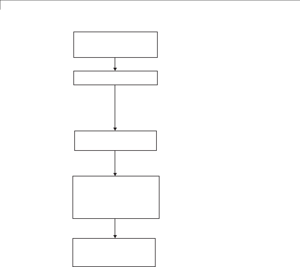
24 Custom Target Development
proj.mcp: CodeWarrior
project binary stationery file
Code Warrior (manual): Export to XML.
proj.xml: XML project file
proj_gen.tlc:TLC file for
generating XML file
model_project.xml:
Generated XML project file
with generated file references
and target-specific
information
model_project.mcp:
CodeWarrior project binary
file
Text editor (manual): Add TLC tokens to
generate references to model files, MATLAB
and other paths, and other settings. Embed
the XML code marked with tokens in
openfile/closefile block. Save as
proj_gen.tlc.
TLC: During code generation, expand TLC
tokens and generate XML project file,
model_project.xml.
Code Warrior (manual or with script):
Import from XML.
Code Warrior (manual or with script):
Build project as indicated in "Build
Process Automation".
24-130

Interface to Development Tools
Note This process has drawbacks. First, manually editing an XML file
exported from a CodeWarrior stationery project can be a laborious task,
involving modification of a few dozen lines embedded within several thousand
lines of XML code. Second, if you make changes to the CodeWarrior project
after importing the generated XML file, the XML file must be exported and
manually edited once again.
Build Process Automation. An application that supports COM automation
can control any other application that includes a COM interface. Using
MATLAB COM automation functions, a MATLAB file can command a
COM-compatible development system to execute tasks required by the build
process.
The MATLAB COM automation functions described in this section are
documented in “COM Objects”.
For information about automation commands supported by the CodeWarrior
IDE, see your CodeWarrior documentation.
COM automation is used by some embedded targets to automate the
CodeWarrior IDE to execute tasks such as:
•Opening a new CodeWarrior session
•Configure a project
•Loading a CodeWarrior project file
•Removing object code from the project
•Building or rebuilding the project
•Debug an application
COM technology automates certain repetitive tasks and allows the user to
interact directly with the external application. For example, when the end
user of the embedded targets capability initiates a build, the target quickly
invokes CodeWarrior actions and leaves a project built and ready to run with
the IDE.
24-131

24 Custom Target Development
Example COM Automation Functions
The functions below use the MATLAB actxserver command to invoke COM
functions for controlling the CodeWarrior IDE from a MATLAB file:
•CreateCWComObject: Create a COM connection to the CodeWarrior IDE.
•OpenCW: Open the CodeWarrior IDE without opening a project.
•OpenMCP: Open the CodeWarrior project file (.mcp file) specified by the
input argument.
•BuildCW: Open the specified .mcp file, remove object code, and build project.
These functions are examples; they do not constitute a full implementation
of a COM automation interface. If your target creates the project file during
code generation,thetop-levelBuildCW function should be called after the code
generation process is completed. Normally BuildCW would be called from the
exit method of your STF_make_rtw_hook.m file (see “STF_make_rtw_hook.m”
on page 24-23).
In the code examples, the variable in_qualifiedMCP is assumed to store a
fully qualified path to a CodeWarrior project file (for example, path, filename,
and extension). For example:
in_qualifiedMCP = 'd:\work\myproject.mcp';
In actual practice, your code is responsible for determining the conventions
used for the project filename and location. One simple convention would be
to default to a project file model.mcp, located in your target’s build folder.
Another approach would be to let the user specify the location of project files
with the target preferences.
%======================================================================
% Function: CreateCWComObject
% Abstract: Creates the COM connection to CodeWarrior
%
function ICodeWarriorApp = CreateCWComObject
vprint([mfilename ': creating CW com object']);
try
ICodeWarriorApp = actxserver('CodeWarrior.CodeWarriorApp');
catch
24-132

Interface to Development Tools
error(['Error creating COM connection to ' ComObj ...
'. Verify that CodeWarrior is installed. Verify COM access to
CodeWarrior outside of MATLAB.']);
end
return;
%======================================================================
% Function: OpenCW
% Abstract: Opens CodeWarrior without opening a project. Returns the
% handle ICodeWarriorApp.
%
function ICodeWarriorApp = OpenCW()
ICodeWarriorApp = CreateCWComObject;
CloseAll;
OpenMCP(in_qualifiedMCP);
%=====================================================================
% Function: OpenMCP
% Abstract: open an MCP project file
%
function OpenMCP(in_qualifiedMCP)
% Argument checking. This method requires valid project file.
if ~exist(in_qualifiedMCP)
error([mfilename ': Missing or empty project file argument']);
end
if isempty(in_qualifiedMCP)
error([mfilename ': Missing or empty project file argument']);
end
ICodeWarriorApp = CreateCWComObject;
vprint([mfilename ': Importing']);
try
ICodeWarriorProject = ...
invoke(ICodeWarriorApp.Application,...
'OpenProject', in_qualifiedMCP,...
1,0,0);
catch
error(['Error using COM connection to import project. ' ...
' Verify that CodeWarrior is installed. Verify COM access to
24-133

24 Custom Target Development
CodeWarrior outside of MATLAB.']);
end
%=====================================================================
% Function: BuildCW
% Abstract: Opens CodeWarrior.
% Opens the specified CodeWarrior project.
% Deletes objects.
% Builds.
%
function ICodeWarriorApp = BuildCW(in_qualifiedMCP)
% ICodeWarriorApp = BuildCW;
ICodeWarriorApp = CreateCWComObject;
CloseAll;
OpenMCP(in_qualifiedMCP);
try
invoke(ICodeWarriorApp.DefaultProject,'RemoveObjectCode', 0, 1);
catch
error(['Error using COM connection to remove objects of current project. ' ...
'Verify that CodeWarrior is installed. Verify COM access to
CodeWarrior outside of MATLAB.']);
end
try
invoke(ICodeWarriorApp.DefaultProject,'BuildAndWaitToComplete');
catch
error(['Error using COM connection to build current project. ' ...
'Verify that CodeWarrior is installed. Verify COM access to
CodeWarrior outside of MATLAB.']);
end
24-134

Device Drivers and Target Preferences
Device Drivers and Target Preferences
In this section...
“Integrate Device Drivers” on page 24-135
“Use Target Preferences” on page 24-135
Integrate Device Drivers
Device drivers that communicate with target hardware are essential to many
real-time development projects.
You can integrate existing C (or C++) device driver functions into Simulink
models by using the Legacy Code Tool. When you use the Simulink Coder
product to generate code from a model, the Legacy Code Tool can insert a call
to your C function into the generated code. For details, see “Integrate External
CodeUsingLegacyCodeTool”onpage14-28 and “Example of Integrating
Existing C Functions into Simulink Models with the Legacy Code Tool”.
Embedded Coder target support provides the Target Block Builder Tool for
integrating custom device driver code with the algorithmic code generated
by code generation software. If you have the Embedded Coder product, see
the Texas Instruments C6000 example “Custom Device Driver Integration via
Target Block Builder Tool”.
UseTargetPreferences
You may want to associate certain types of data with the target. For example,
an embedded target might offer a choice of several supported development
systems (cross-compilers, debuggers, and so on). To invoke a specific
development tool during the build process, the target needs information
such as the user’s choice of development tool, and the location on the host
system where the user has installed the compiler and debugger executables.
Other data associated with a target might specify host/target communications
parameters, such as the communications port and baud rate to be used.
Target developers need to define and store the properties they want to
associate with their target. End users need a simple mechanism to set target
property values.
24-135

24 Custom Target Development
To define preferences to associate with your target, see the following function
pages:
•addpref
•getpref
•setpref
24-136

Desktop IDEs and Desktop
Targets


25 Project and Build Configurations for Desktop Targets
Model Setup
In this section...
“Block Selection” on page 25-2
“Target Preferences” on page 25-3
“Configuration Parameters” on page 25-7
“Model Reference” on page 25-14
Block Selection
You can create models for targeting the same way you create other Simulink
models—by combining standard blocks and C-MEX S-functions.
You can use blocks from the following sources:
•The Desktop Targets library (desktoptargetslib) in the Simulink Coder
product.
•Blocks from the System Toolboxes products
•Custom blocks
Avoid using blocks that do not generate code, including the following blocks.
Block
Name/Category Library Description
Scope Simulink, DSP
System Toolbox
software
Provides oscilloscope view of
your output. Do not use the
Save data to workspace
option on the Data history
pane in the Scope Parameters
dialog box.
To Workspace Simulink Return data to your MATLAB
workspace.
From Workspace Simulink Send data to your model from
your MATLAB workspace.
25-2

Model Setup
Block
Name/Category Library Description
Spectrum Scope DSP System
Toolbox
Compute and display the
short-time FFT of a signal.
It has internal buffering that
can slow your process without
adding value.
Triggered to
Workspace
DSP System
Toolbox
Send data to your MATLAB
workspace.
Signal To
Workspace
DSP System
Toolbox
Send a signal to your MATLAB
workspace.
Signal From
Workspace
DSP System
Toolbox
Get a signal from your MATLAB
workspace.
Triggered Signal
From Workspace
DSP System
Toolbox
Get a signal from your MATLAB
workspace.
To Wave device DSP System
Toolbox
Send data to a .wav device.
From Wave device DSP System
Toolbox
Get data from a .wav device.
Target Preferences
This topic contains the following subtopics:
•“Supported IDEs” on page 25-3
•“What is a Target Preferences Block?” on page 25-4
•“Adding a Target Preferences Block to Your Model” on page 25-4
•“Creating a Library of Customized Target Preferences Blocks” on page 25-6
Supported IDEs
This “Target Preferences” on page 25-3 section applies to Eclipse™ IDE.
25-3

25 Project and Build Configurations for Desktop Targets
What is a Target Preferences Block?
If you are preparing to generate code for a target processor, add a Target
Preferences block to the model. You can use the Target Preferences block to
specify information such as the processor, board, hardware settings, operating
system, memory map, and code generation features. Simulink Coder,
Embedded Coder, and Simulink products use this information to generate
code from your model.
For detailed information about the Target Preference block parameters and
options, consult the Target Preferences block reference topic.
Key Points
•To generate code, the model must contain a Target Preferences block.
•Use one Target Preferences block per model. Exceptions to this rule are
noted in the documentation for specific features, such as “Model Block
PIL” on page 26-3.
•Changing Target Preferences block settings can change tabs, panes,
parameters, and options visible when you open the block.
•Adding a Target Preferences block to a model changes the values of some
Configuration Parameters. If you need to preserve the Configuration
Parameters of a specific model, make a backup copy of the model before
adding a Target Preferences block to it.
Adding a Target Preferences Block to Your Model
To generate code, with few exceptions, your model must contain only one
Target Preferences block.
•When you are generating code for a model, place the Target Preferences
block at the top level of your model.
•When you are generating code for a subsystem in your model, place the
Target Preferences block at the subsystem level of your model.
To add a Target Preferences block to your model:
25-4
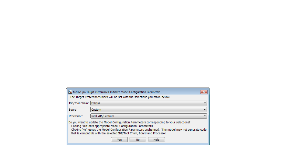
Model Setup
1Open the Simulink library browser.
2Copy the Target Preferences block from the Simulink Coder >Desktop
Targets library to your model
3ThesoftwaredisplaystheInitialize Configuration Parameters dialog
box. For example.
Set the following parameters, and click Yes:
•IDE/Tool Chain
•Board
•Processor
When you click Yes, the software automatically sets the model
Configuration Parameters for the IDE/Tool Chain, Board, and Processor
you selected. You have completed the process of adding a Target
Preferences block to your model.
If you click No, the software leaves the values of the Configuration
Parameters unchanged. The model cannot simulate or generate valid code
unless you configure the Configuration Parameters with the right values.
Setting these values manually can be difficult.
25-5

25 Project and Build Configurations for Desktop Targets
Note The following actions update some of the model Configuration
Parameters with new values:
•Adding a Target Preferences block to your model and clicking Yes in the
Initialize Configuration Parameters dialog box.
•Opening the Target Preferences block in your model and selecting a
new IDE/Tool Chain.
•Opening the Target Preferences block in your model and applying
changes to the Board and Processor parameters.
Note The Initialize Configuration Parameters dialog box uses your
previous selections for IDE/Tool Chain,Board,andProcessor as default
values the next time you copy a Target Preference block to a model.
Creating a Library of Customized Target Preferences Blocks
If you work regularly with a variety of IDEs, tool chains, boards and
processors, you can save time by creating a library of customized Target
Preferences blocks. Later, you reuse these preconfigured Target Preferences
blocks instead repeating the customization process on a new Target
Preferences block.
To create a library of customized Target Preferences blocks:
1In Simulink, select File >New >Library. This action creates a new
untitled library.
2Save the library to a folder included in your MATLAB search paths.
Note Click File >Set Path to see a list of MATLAB search paths and
add new ones.
3Copy or drag configured Target Preferences blocks from your models to
the library.
25-6

Model Setup
4Edit the label of each block to describe that block’s configuration.
5After the new blocks are added and labeled, save the library.
To copy a Target Preferences block from your library to a model, type the
library name in the MATLAB Command Window. When the library appears,
copy the block to your model.
Configuration Parameters
•“What are Configuration Parameters?” on page 25-7
•“Setting Model Configuration Parameters” on page 25-7
What are Configuration Parameters?
To see the model Configuration Parameters, open the Configuration
Parameters dialog box. You can do this in the model editor by selecting
Simulation > Model Configuration Parameters, or by pressing Ctrl+E
on your keyboard.
The Configuration Parameters dialog box specifies the values for a model’s
active configuration set. These parameters determine the type of solver used,
the import and export settings, and other values that determine how the
model runs.
To set the Configuration Parameters to the right values for you to generate
code from your model, add a Target Preferences block to your model.
This action initializes the model Configuration Parameters to the right
default values for you to generate code. You can then use the Configuration
Parameters dialog box to make further modifications to the values.
Setting Model Configuration Parameters
To apply the right default values in Configuration Parameters, add a Target
Preferences block to your model and select the Initialize Configuration
Parameters, as described in “Adding a Target Preferences Block to Your
Model” on page 25-4. You can generatebuildablecodeusingthesedefault
values.
25-7
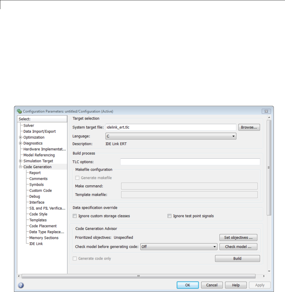
25 Project and Build Configurations for Desktop Targets
To make further changes, select Simulation > Model Configuration
Parameters in the Model Editor, or press Ctrl+E. This action opens the
Configuration Parameters dialog box.
The following subsections provide a quick overview of the panes and
parameters with which you are most likely to interact.
Code Generation Pane. When you set System target file to
idelink_ert.tlc or idelink_grt.tlc,thedialogboxaddsanIDE Link
pane to the list of panes under Code Generation.
25-8
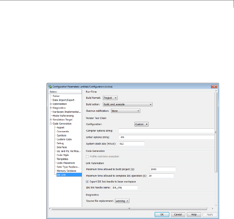
Model Setup
Setting the System target file to idelink_ert.tlc requires an Embedded
Coder license.
Leave Language set to C.Theidelink_ert.tlc and idelink_grt.tlc
system target files do not support C++ code generation.
For more information, see “Code Generation Pane: General”
IDE Link Pane Parameters.
The IDE Link entry provides options in these areas:
•Run-Time — Set options for run-time operations, like the build action
•Vendor Tool Chain — Set compiler, linker, and system stack size options
25-9

25 Project and Build Configurations for Desktop Targets
•Code Generation — Configure your code generation requirements
•Link Automation — Export an IDE handle object, such as IDE_Obj,to
your MATLAB workspace
•Diagnostics — Determine how the code generation process responds when
you use source code replacement in the Custom Code pane.
For more information, see Code Generation Pane: IDE Link.
Build format
Select Project to create an IDE project, or select Makefile to create a
makefile build script.
Build action
Your selection for Build action determines what happens when you click
Build or press Ctrl+B. Your selection tells Simulink Coder software when to
stop the code generation and build process.
To run your model on the processor, select Build_and_execute. This selection
is the default build action.
The actions are cumulative—each action performs an additional step relative
to the preceding action on the list.
If you set Build format to Project, select one of the following options:
•Create_project — Directs Simulink Coder software to start the IDE and
populate a new project with the files from the build process. This option
offers a convenient way to build projects in the IDE.
•Archive_library — Directs Simulink Coder software to create an archive
library for this model. Use this option when you plan to use the model in
a model reference application. Model reference requires that you archive
your the IDE projects for models that you use in model referencing.
•Build — Builds the executable file, but does not download the file to the
target processor.
25-10

Model Setup
•Build_and_execute — Directs Simulink Coder software to build, download,
and run your generated code as an executable on your target processor.
•Create_processor_in_the_loop_project — Directs code generation
process to create PIL algorithm object code as part of the project build. This
option requires an Embedded Coder license.
If you set Build format to Makefile, select one of the following options:
•Create_makefile — Creates a makefile.
•Archive_library — Creates a makefile and the generated output will
be an archive library.
•Build — Creates a makefile and an executable.
•Build_and_execute — Creates a makefile and an executable. Then it
evaluates the execute instruction in the current configuration.
Overrun notification
To enable the overrun indicator, choose one of three ways for the target to
respond to an overrun condition in your model:
•None — Ignore overruns encountered while running the model.
•Print_message — When the target encounters an overrun condition, it
prints a message to the standard output device, stdout.
•Call_custom_function — Respond to overrun conditions by calling the
custom function you identify in Function name.
Function name
When you select Call_custom_function from the Overrun notification
list, you enable this option. Enter the name of the function the target should
use to notify you that an overrun condition occurred. The function must exist
in your code on the target processor.
25-11

25 Project and Build Configurations for Desktop Targets
Configuration
The Configuration parameter defines sets of build options that apply to all
of the files generated from your model.
The Release and Debug option apply build settingsthataredefinedbyyour
compiler. For more information, refer to your compiler documentation.
Custom has the same default values as Release,but:
•Leaves Compiler options string empty.
Compiler options string
To determine the degree of optimization provided by the optimizing compiler,
enter the optimization level to apply to files in your project. For details about
the compiler options, refer to your IDE documentation. When you create new
projects, the coder product does not set any optimization flags.
Linker options string
To specify the options provided by the linker during link time, you enter the
linker options as a string. For details about the linker options, refer to your
IDE documentation. When you create new projects, the coder product does
not set any linker options.
System stack size (MAUs)
Enter the amount of memory that is available for allocating stack data,
measured in minimum addressable units (MAU). Block output buffers are
placed on the stack until the stack memory is fully allocated. After that, the
output buffers go in global memory. An MAU is typically 1 byte, but its size
can vary by target processor.
Thisparameterisusedinalltargetstoallocatethestacksizeforthe
generated application. For example, with embedded processors that are not
running an operating system, this parameter determines the total stack space
25-12

Model Setup
that can be used for the application. For such as Linux or WindowsVxWorks
operating systems, this value specifies the stack space allocated per thread.
This parameter also affects the “Maximum stack size (bytes)” parameter,
located in the Optimization > Signals and Parameters pane.
Link Automation
When you build a model for a target, the coder product automatically creates
or uses an existing IDE handle object (named IDE_Obj, by default) to connect
to your IDE.
Although IDE_Obj isahandleforaspecificinstanceoftheIDE,italso
contains information about the IDE instance to which it refers, such as the
target the IDE accesses. In this pane, the Export IDE link handle to
base workspace option lets you instruct the coder product to export the
object to your MATLAB workspace, giving it the name you assign in IDE
link handle name.
You can also use the IDE handle object to interact with the IDE using IDE
Automation Interface commands.
Maximum time allowed to build project (s)
Specifies how long the software waits for the IDE to build the software.
Maximum time allowed to complete IDE operation (s)
Specifies how long the software waits for IDE functions, such as read or
write, to return completion messages. If you do not specify a timeout, the
default value is 10 seconds.
Export IDE link handle to base workspace
Directs the software to export the IDE_Obj object to your MATLAB workspace.
25-13

25 Project and Build Configurations for Desktop Targets
IDE link handle name
Specifies the name of the IDE_Obj object that the build process creates.
Source file replacement
Selects the diagnostic action to take if the software detects conflicts when you
replace source code with custom code. The diagnostic message responds to
both source file replacement in the Configuration Parameters under Code
Generation > IDE link parameters and under Code Generation > Custom
Code.
The following settings define the messages you see and how the code
generation process responds:
•none — Does not generate warnings or errors when it finds conflicts.
•warning —Displaysawarning.warn is the default value.
•error — Terminates the build process and displays an error message that
identifies which file has the problem and suggests how to resolve it.
The build operation continues if you select warning and the software detects
custom code replacement problems. You see warning messages as the build
progresses.
Select error the first time you build your project after you specify custom
code to use. The error messages can help you diagnose problems with your
custom code replacement files. Use none when the replacement process works
and you do not want to see multiple messages during your build.
Model Reference
The idelink_ert.tlc and idelink_grt.tlc system target files provide
support for generating code from models that use Model Reference. A
referenced model will generate an archive library.
To enable Model Reference builds:
1Open your referenced model.
25-14

Model Setup
2Select Simulation > Model Configuration Parameters from the model
menus.
3From the list of panes under Code Generation,chooseIDE Link.
4In the right pane, under Run-Time, select Archive_library from the
Build action list.
If your top-model uses a reference model that does not have the Build action
set to Archive_library, the build process automatically changes the Build
action to Archive_library and issues a warning about the change.
Target Preferences Blocks in Reference Models
Include a configured Target Preferences block in each referenced model and
the top-model . Configure all of the Target Preferences blocks for the same
processor so that the software tool chain and build process is consistent across
the model hierarchy.
25-15

25 Project and Build Configurations for Desktop Targets
IDE Projects
In this section...
“Support for Third Party Products” on page 25-16
“Third Party Product Setup” on page 25-16
“Code Generation and Build” on page 25-16
“Automation of IDE Tasks and Processes” on page 25-17
Support for Third Party Products
For more information about Simulink Coder support for Eclipse IDE, see
http://www.mathworks.com/products/simulink-coder/eclipse-adaptor.html
Third Party Product Setup
Install your third party IDE or software build tool chain according to the
vendor’s instructions.
If you are using one of the following IDEs, perform the additional steps
described here:
Eclipse IDE
Complete the instructions in “Installing Third-Party Software for Eclipse”
on page 27-2 and in “Configuring Your MathWorks Software to Work with
Eclipse” on page 27-10.
Code Generation and Build
Building Your Model
In your model, click Build Model . The software performs the actions
you selected for Build action in the model Configuration Parameters, under
Code Generation > IDE Link.
25-16

IDE Projects
IDE Project Generator Features
The IDE Project Generator component provides or supports the following
features for developing IDE projects and generating code:
•Automatically create IDE projects for your generated code during the code
generation process.
•Customize code generation using options in the model Configuration
Parameters and the Target Preferences block.
•Configure the automatic project build process.
•Automatically download and run your generated projects on your target
processor.
IDE Handle Objects
IDE Project Generator automatically creates and uses an IDE handle object
to communicate with your IDE and target processor.
To create the IDE handle object for Eclipse IDE, IDE Project Generator uses
the eclipseide constructor function. For a command line example, see the
eclipseide reference page.
Automation of IDE Tasks and Processes
The IDE Automation Interface component provides a powerful API for
automating IDE tasks via MATLAB scripts. For example, with IDE
Automation Interface, your script can automatically:
•Automate project creation, including adding source files, include paths, and
preprocessor defines
•Configure batch building of projects
•Launch a debugging session
Examples of IDE Automation Interface for Specific IDEs
To help you become familiar with IDE Automation Interface, you can use the
“IDE Automation Interface Tutorial” example for Eclipse IDE.
The example shows you how to:
25-17

25 Project and Build Configurations for Desktop Targets
1Configure and create an IDE handle object.
2Create and query objects in an IDE.
3UseMATLABsoftwaretoloadfilesintoyourIDE.
4Work with your IDE project from MATLAB software.
5Close connections you the IDE.
25-18

Makefiles for Software Build Tool Chains
Makefiles for Software Build Tool Chains
In this section...
“What is the XMakefile Feature” on page 25-19
“Using Makefiles to Generate and Build Software” on page 25-21
“Making an XMakefile Configuration Operational” on page 25-24
“Working with Microsoft®Visual Studio®” on page 25-24
“Creating a New XMakefile Configuration” on page 25-25
“XMakefile User Configuration Dialog Box” on page 25-31
What is the XMakefile Feature
•“Overview” on page 25-19
•“Supported Tool Chains in Simulink®Coder™” on page 25-20
•“Available XMakefile Configurations” on page 25-20
•“Feature Support” on page 25-20
Overview
You can use makefiles instead of IDE projects during the automated software
build process. This approach is described in “Using Makefiles to Generate
and Build Software” on page 25-21.
The XMakefile feature lets you choose the configuration of a specific software
build tool chain to use during the automated build process. The configuration
contains paths and settings for your make utility, compiler, linker, archiver,
pre-build, post-build, and execute tools.
You can choose one built-in configuration described in and “Available
XMakefile Configurations” on page 25-20.
You can also create a new configuration for a new tool chain, as described in
“Creating a New XMakefile Configuration” on page 25-25.
25-19

25 Project and Build Configurations for Desktop Targets
Your requirements for specific features may determine whether you choose
makefiles or IDE projects. See “Feature Support” on page 25-20.
Supported Tool Chains in Simulink Coder
Simulink Coder includes support for the following IDEs and tool chains.
Tool Chain Processor
Family/Target
Operating System
Host Operating
System
GNU development tools Linux Linux
MinGW development
tools
Windows Windows
Microsoft Visual Studio Windows Windows
Embedded Coder includes support for other IDEs and tool chains. See
Supported Tool Chains in Embedded Coder.
Available XMakefile Configurations
The following list describes the configurations in the XMakefile dialog box
that this product supports:
•gcc_target: GNU Compiler Collection & Host Operating System or
Embedded Operating System
•mingw_host: Minimalist GNU for Windows & Host Operating System
•msvs_host: Microsoft Visual Studio & Host Operating System
For more information about supported versions of third-party software, see
“Support for Third Party Products” on page 25-16
Feature Support
With makefiles, you cannot use features that rely on direct communications
between your MathWorks software and third-party IDEs.
You cannot use the following features with makefiles:
25-20

Makefiles for Software Build Tool Chains
•IDE Project Generation
•IDE Automation Interface
•IDE debugger communications during Processor-in-the-loop (PIL)
simulation
Using Makefiles to Generate and Build Software
In addition to this chapter, see the Makefile Generator Tutorial example for
more information about using makefiles to generate code.
Configuring Your Model to Use Makefiles
Update your model Configuration Parameters to use a makefile instead of an
IDE when you build software from the model:
1Add a Target Preferences block to your model and configure it for your
target processor. For more information, see “Target Preferences” on page
25-3.
2In your Simulink Editor, select Simulation > Model Configuration
Parameters or press Ctrl+e.
3Under the Code Generationtab, select IDE Link.
4Set Build format to Makefile. For more information, see Build format
on page 10.
5Set Build action to Build_and_execute. For more information, see Build
action on page 10.
Choosing an XMakefile Configuration
Configure how to generate makefiles:
1Enter xmakefilesetup on the MATLAB Command Window. The software
opens an XMakefile User Configuration dialog box.
25-21
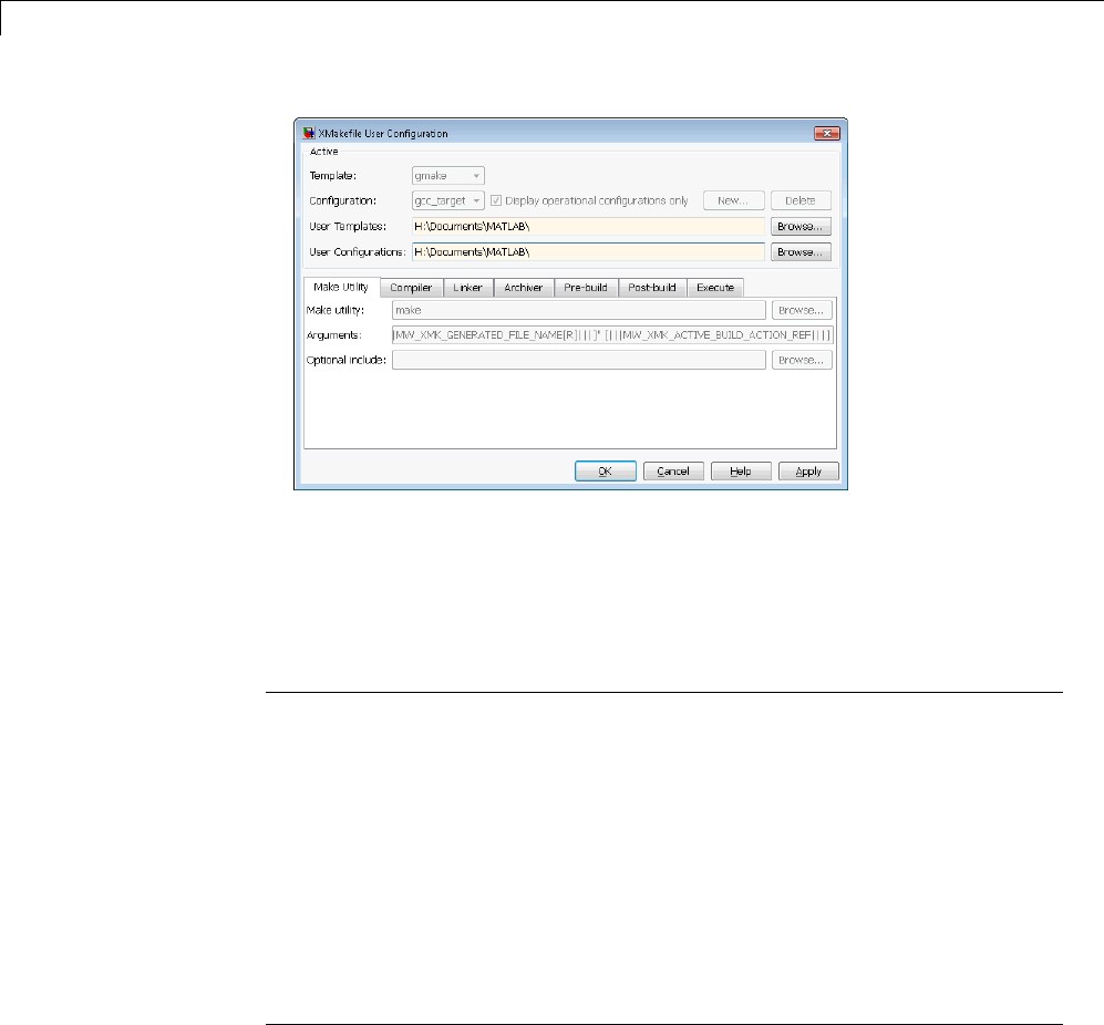
25 Project and Build Configurations for Desktop Targets
2Leave Template set to gmake.
3For Configuration, select gcc_target or msvs_host to match the compiler
toolchain you are using — gcc or Microsoft Visual Studio, respectively.
Click Apply.
Note Changing some elements of the XMakefile dialog box disables other
elements until you apply the changes. Click Apply or OK after changing
any of the following:
•Template
•Configurations
•User Templates
•User Configurations
•Tool Directories
25-22

Makefiles for Software Build Tool Chains
Note With the XMakefile User Configuration dialog, if you have a Simulink
Coder license but no Embedded Coder license, the only valid settings for
Configuration are gcc_target,mingw_host,ormsvs_host. The other
configurations, though visible, are only supported by the Embedded Coder
product.
Note If you set Configuration to msvs_host, restart MATLAB as described
in “Working with Microsoft®Visual Studio®” on page 25-24 before building
your model software.
Things to consider while setting Configuration:
•Selecting Display operational configurations only hides configurations
that contain incomplete or invalid information. For a configuration to be
operational, the vendor tool chain must be installed, and the configuration
must have the valid paths for each component of the vendor tool chain. For
more information, see “Making an XMakefile Configuration Operational”
on page 25-24.
•To display all of the configurations, including non-operational
configurations, clear Display operational configurations only.
•The list of configurations can include non-editable configurations defined in
thesoftwareandeditableconfigurations defined by you.
•Tocreateaneweditableconfiguration, use the New button.
•For more information, see “XMakefile User Configuration Dialog Box” on
page 25-31.
Building Your Model
In your model, click Build Model . This action creates a makefile and
performs the other actions you specified in Build action.
25-23

25 Project and Build Configurations for Desktop Targets
By default, this process outputs files in the
<builddir>/<buildconfiguration> folder. For example, in
model_name/CustomMW.
Making an XMakefile Configuration Operational
When the XMakefile utility starts, it checks each configuration file to verify
that the specified paths for the vendor tool chain are valid. If the paths are
not valid, the configuration is non-operational. Typically, the cause of this
problem is a difference between the path in the configuration and the actual
path of the vendor toolchain.
To make a configuration operational:
1Clear Display operational configurations only to display
non-operational configurations.
2Select the non-operational configuration from the Configuration options.
3When you click Apply, a new dialog box prompts you for the folder path of
any missing resources the configuration requires.
Use mapped network drives instead of UNC paths to specify directory
locations. Using UNC paths with compilers that do not support them
causes build errors.
Working with Microsoft Visual Studio
If you set Configuration to msvs_host, restart MATLAB from a Visual
Studio®command prompt before building your model software with makefiles.
The vsvars32.bat file associated with the Visual Studio command prompt
configures the Visual Studio environment. Starting MATLAB from this
command prompt results in a session that can generate makefiles from the
msvs_host configuration.
To restart MATLAB from a Visual Studio command prompt:
1Open a Visual Studio command prompt:
aSelect your MSVS product from the Windows Start >Programs menu.
25-24

Makefiles for Software Build Tool Chains
bIn Visual Studio Tools, select the Visual Studio Command Prompt.
For example:
2Enter matlab at the Visual Studio Command Prompt.
3In MATLAB, open and build your model.
If you do not restart MATLAB from Microsoft Visual Studio command prompt,
building your model software generates an error whose ending is similar
to the following text:
The build failed with the following message:
"C:/Program Files/Microsoft Visual Studio...
3792 Abort C:/Program Files/Microsoft Visual Studio 8/VC/bin/cl
gmake: *** [MW_csl.obj] Error 134
ArelatedarticleisavailableontheMicrosoftWebsiteat:
http://msdn.microsoft.com/en-us/library/1700bbwd.aspx
Creating a New XMakefile Configuration
•“Overview” on page 25-25
•“Create a Configuration” on page 25-26
•“Modify the Configuration” on page 25-27
•“Test the Configuration” on page 25-30
Overview
This example shows you how to add support for a software development
toolchain to the XMakefile utility. This example uses the Intel Compiler and
Eclipse IDE, which provides an open framework and allows for otherwise
unsupported toolchains.
25-25

25 Project and Build Configurations for Desktop Targets
Note To specify directory locations, use mapped network drives instead of
UNC paths. UNC paths cause build errors with compilers that do not support
them.
Create a Configuration
When you click New, the new configuration inherits values and behavior
from the current configuration. To create a configuration for the Intel
Compiler, clone a configuration from any of these configurations: msvs_host,
mingw_host and gcc_target.
Note The linker used by the Intel Compiler uses the Microsoft Visual Studio
tool chain and therefore the execution environment must have access to these
tools (vcvars.bat). For more information, see “Working with Microsoft®Visual
Studio®” on page 25-24.
Open the XMakefile User Configuration UI by typing xmakefilesetup at the
MATLAB prompt. This action displays the following dialog box.
Select an existing configuration, such as msvs_host,mingw_host,
montavista_arm or gcc_target.ClicktheNew button.
25-26
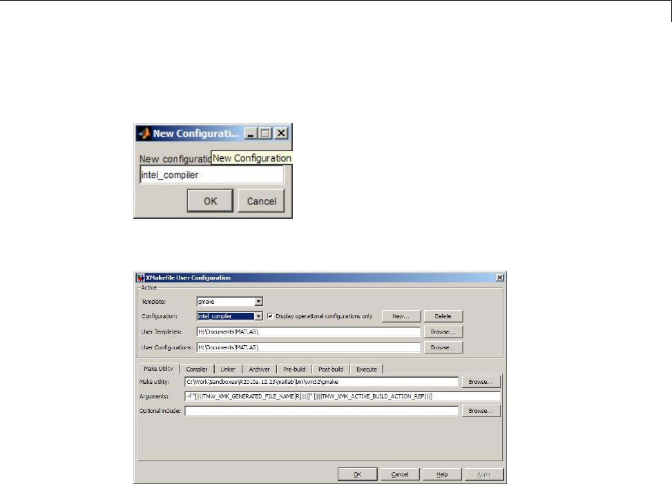
Makefiles for Software Build Tool Chains
A pop-up dialog prompts you for the name of the new configuration. Enter
intel_compiler and click OK.
The dialog box displays a new configuration called intel_compiler,basedon
the previous configuration.
Modify the Configuration
Adjust the compiler, linker, and archiver settings of the newly created
configuration. This example assumes the location of the Intel compiler is
C:\Program Files\Intel\Compiler\.
Make Utility. You do not need to make any changes. This configuration uses
the gmake tool that ships with MATLAB.
25-27
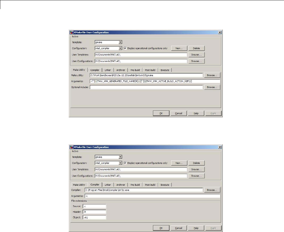
25 Project and Build Configurations for Desktop Targets
Compiler. For Compiler,enterthelocationoficl.exe in the Intel
installation.
Linker. For Linker, enter the location of the linker executable, xilink.exe.
For Arguments,addthe/LIBPATHpathtotheIntellibraries.
25-28
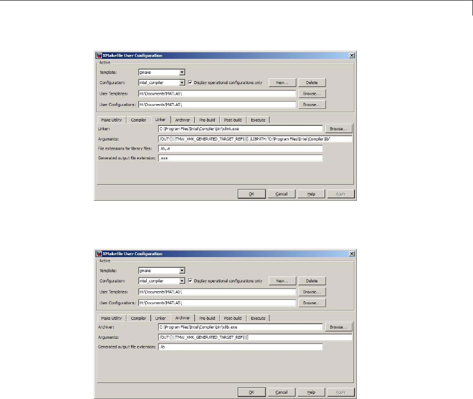
Makefiles for Software Build Tool Chains
Archiver. For Archiver, enter the location of the archiver, xilib.exe.
Confirm that File extensions for library files includes .lib.
Other tabs. For this example, ignore the remaining tabs. In other
circumstances, you can use them to configure additional build actions. In a
later step of this example, you will configure the software to automatically
build and run the generated code.
25-29

25 Project and Build Configurations for Desktop Targets
Test the Configuration
Open the “sumdiff” model by entering sumdiff on the MATLAB prompt.
Use a Target Preferences block to configure the model for use with the Eclipse
IDE. In the Simulink Library Browser, search for “Target Preferences”.
Drag and drop the Target Preferences block from the search results to the
summdiff model.
25-30

Makefiles for Software Build Tool Chains
Configure the Target Preferences block as follows: set IDE/Tool Chain to
Eclipse,setBoard to Custom,andsetProcessor to Intel x86/Pentium.
Open the Target Preferences block and set Operating System to None or
select Windows.ClickOK.
Open the Configuration Parameters for the summdiff model by
pressing Ctrl+E.SetBuild format to Makefile and Build action to
Build_and_execute.
Save the model to a temporary location, such as C:\Temp\IntelTest\.
Set that location as a Current Folder by typing cd C:\temp\IntelTest\ at
the MATLAB prompt.
Build the model by pressing Ctrl+B. The MATLAB Command Window
displays something like:
### TLC code generation complete.
### Creating HTML report file sumdiff_codegen_rpt.html
### Creating project: c:\temp\IntelTest\sumdiff_eclipseide\sumdiff.mk
### Project creation done.
### Building project...
### Build done.
### Downloading program: c:\temp\IntelTest\sumdiff_eclipseide\sumdiff
### Download done.
A command window comes up showing the running model. Terminate the
generated executable by pressing Ctrl+C.
XMakefile User Configuration Dialog Box
•“Active” on page 25-32
•“Make Utility” on page 25-34
•“Compiler” on page 25-34
•“Linker” on page 25-35
•“Archiver” on page 25-35
25-31
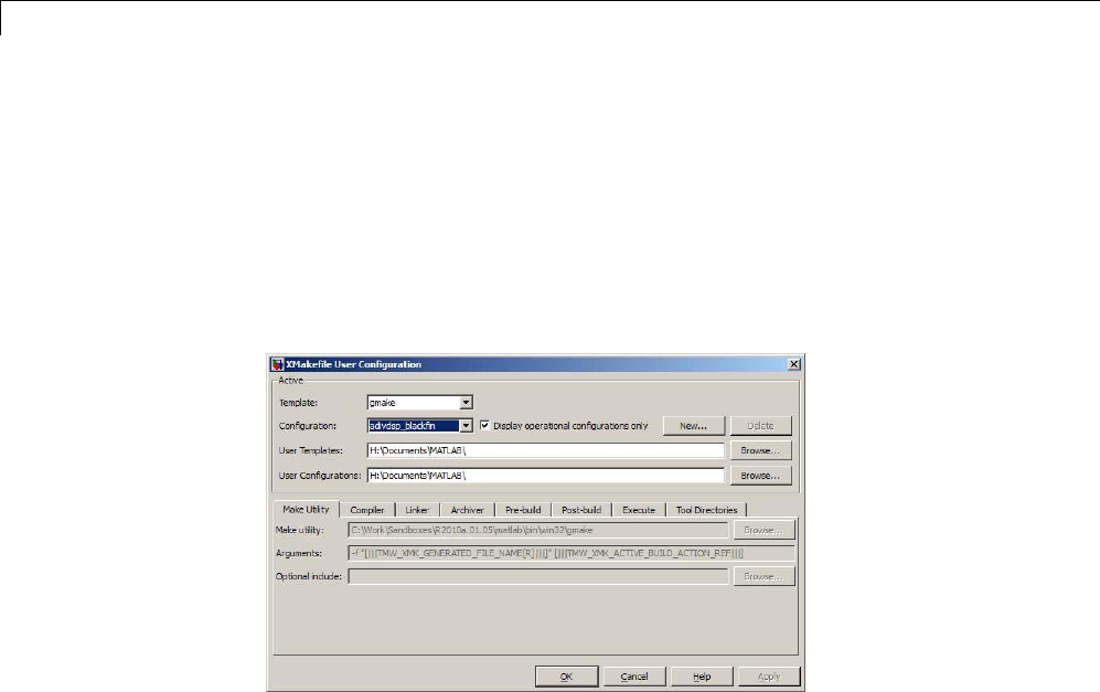
25 Project and Build Configurations for Desktop Targets
•“Pre-build” on page 25-36
•“Post-build” on page 25-36
•“Execute” on page 25-37
•“Tool Directories” on page 25-37
Active
Template. Select the template that matches your toolchain and processor.
The template defines the syntax rules for writing the contents of the makefile
or buildfile. The default template is gmake, which works with the GNU make
utility.
To add templates to this parameter, save them as .mkt files to the location
specified by the User Templates parameter. For more information, see “User
Templates” on page 25-33.
Configuration. Select the configuration that best describes your toolchain
and target processor.
You cannot edit or delete the configurations provided by MathWorks. You
can, however, edit and delete the configurations that you create.
Use the New button to create an editable copy of the currently selected
configuration.
25-32

Makefiles for Software Build Tool Chains
Use the Delete button to delete a configuration you created.
Note You cannot edit or delete the configurations provided by MathWorks.
Note Use mapped network drives instead of UNC paths to specify directory
locations. Using UNC paths with compilers that do not support them causes
build errors.
Display operational configurations only. When you open the XMakefile
User Configuration dialog box, the software verifies that each configuration
provided by MathWorks contains valid paths to the executable files it uses. If
all of the paths are valid, the configuration is operational. If any of the paths
arenotvalid,theconfigurationisnotoperational.
This setting only affects configurations provided by MathWorks, not
configurations you create.
To display valid configurations, select Display operational configurations
only.
To display all of the configurations, including non-operational configurations,
clear Display operational configurations only.
For more information, see “Making an XMakefile Configuration Operational”
on page 25-24.
User Templates. Set the path of the folder to which you can add template
files. Saving templates files with the .mkt extension to this folder adds them
to the Templates options.
User Configurations. Set the location of configuration files you create with
the New button.
25-33
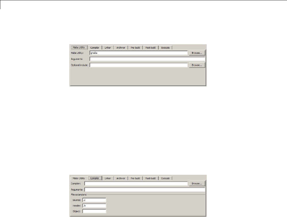
25 Project and Build Configurations for Desktop Targets
Make Utility
Make utility. Set the path and filename of the make utility executable.
Arguments. Define the command-line arguments to pass to the make utility.
For more information, consult the third-party documentation for your make
utility.
Optional include. Set the path and file name of an optional makefile to
include.
Compiler
Compiler. Set the path and file name of the compiler executable.
Arguments. Define the command-line arguments to pass to the compiler. For
more information, consult the third-party documentation for your compiler.
Source. Definethefilenameextensionforthesourcefiles. Usecommas
to separate multiple file extensions.
Header. Define the file name extension for the header files. Use commas
to separate multiple file extensions.
Object. Define the file name extension for the object files.
25-34
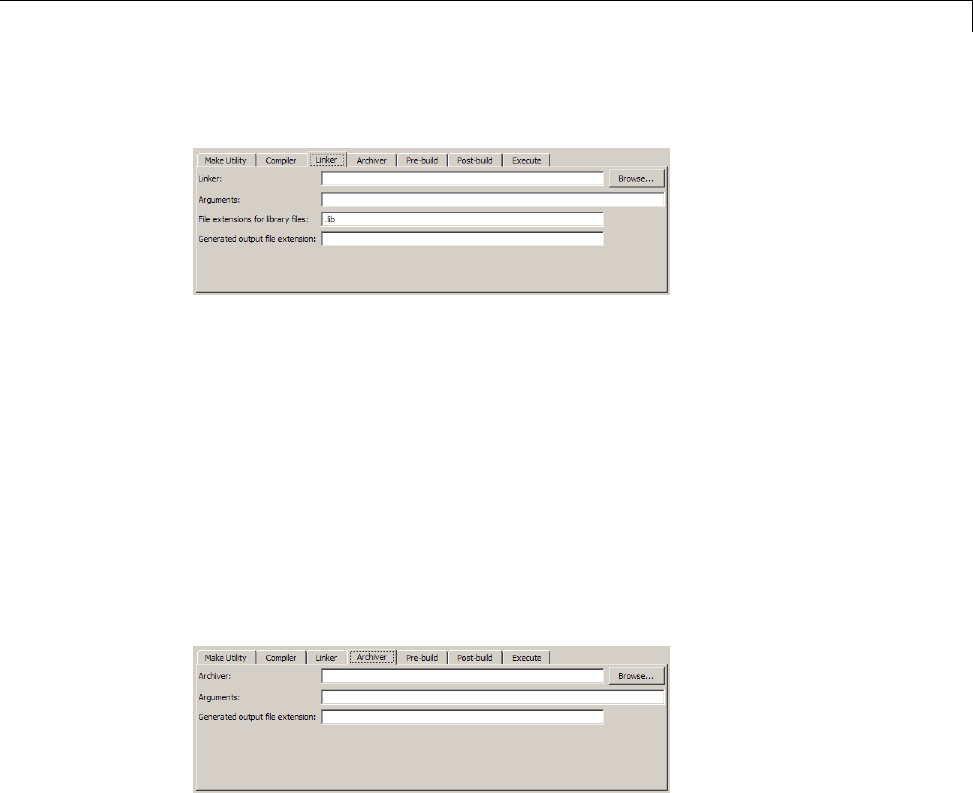
Makefiles for Software Build Tool Chains
Linker
Linker. Set the path and file name of the linker executable.
Arguments. Define the command-line arguments to pass to the linker. For
more information, consult the third-party documentation for your linker.
File extensions for library files. Definethefilenameextensionforthefile
library files. Use commas to separate multiple file extensions.
Generated output file extension. Definethefilenameextensionforthe
generated libraries or executables.
Archiver
Archiver. Set the path and file name of the archiver executable.
Arguments. Define the command-line arguments to pass to the archiver. For
more information, consult the third-party documentation for your archiver.
Generated output file extension. Definethefilenameextensionforthe
generated libraries.
25-35

25 Project and Build Configurations for Desktop Targets
Pre-build
Enable Prebuild Step. Select this check box to define a prebuild tool that
runs before the compiler.
Prebuild tool. Set the path and file name of the prebuild tool executable.
Arguments. Define the command-line arguments to pass to the prebuild
tool. For more information, consult the third-party documentation for your
prebuild tool.
Post-build
Enable Postbuild Step. Select this check box to define a postbuild tool
that runs after the compiler or linker.
Postbuild tool. Setthepathandfilenameofthepostbuildtoolexecutable.
Arguments. Define the command-line arguments to pass to the postbuild
tool. For more information, consult the third-party documentation for your
postbuild tool.
25-36
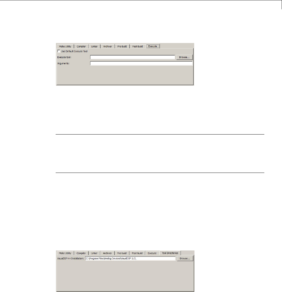
Makefiles for Software Build Tool Chains
Execute
Use Default Execute Tool. Select this check box to use the generated
derivative as the execute tool when the build process is complete. Uncheck it
to specify a different tool. The default value, echo, simply displays a message
that the build process is complete.
Note On the Linux operating system, multirate multitasking executables
require root privileges to schedule POSIX threads with real-time priority.
If you are using makefiles to build multirate multitasking executables on
your Linux development system, you cannot use Execute tool to run the
executable. Instead, use the Linux command, sudo,toruntheexecutable.
Execute tool. Set the path and file name of the execute tool executable or
built-in command.
Arguments. Define the command-line arguments to pass to the execute
tool. For more information, consult the third-party documentation for your
execute tool.
Tool Directories
25-37

25 Project and Build Configurations for Desktop Targets
Installation. Use the Tool Directories tab to change the toolchain path of
an operational configuration.
For example, if you installed two versions of a vendor build tool in separate
folders, you can use the Installation path to change which one the
configuration uses.
25-38

26
Verification Code Generated
for Desktop Targets
Verify and profile generated code executing on processors

26 Verification Code Generated for Desktop Targets
Processor-in-the-Loop (PIL) Simulation
In this section...
“Overview” on page 26-2
“PIL Approaches” on page 26-3
“Communications” on page 26-8
“Running Your PIL Application to Perform Simulation and Verification” on
page 26-11
“Definitions” on page 26-11
“PIL Issues and Limitations” on page 26-12
Overview
Processor-in-the-loop (PIL) requires an Embedded Coder license.
Verification consists broadly of running generated code on a processor and
verifying that the code does what you intend. Embedded Coder provides
processor-in-the-loop (PIL) simulation to meet this need. PIL compares the
numeric output of your model under simulation with the numeric output of
your model running as an executable on a target processor.
With PIL, you run your generated code on a target processor or instruction
set simulator. To verify your generated code, you compare the output of
model simulation modes, such as Normal or Accelerator, with the output
of the generated code running on the processor. You can switch between
simulation and PIL modes. This flexibility allows you to verify the generated
code by executing the model as compiled code in the target environment.
You can model and test your embedded software component in Simulink and
then reuse your regression test suites across simulation and compiled object
code. This process avoids the time-consuming process of leaving the Simulink
software environment to run tests again on object code compiled for the
production hardware.
Embedded Coder supports the following PIL approaches:
•Model block PIL
26-2

Processor-in-the-Loop (PIL) Simulation
•Top-model PIL
•PIL block
When you use makefiles with PIL, use the “model block PIL” approach. With
makefiles, the other two approaches, “top-model PIL” and “PIL block”, and
are not supported.
Processor-in-the-loop (PIL) builds and uses a MEX function to run the
PIL simulation block. Before using PIL, set up a compiler for MATLAB to
build the MEX files. Run the command |mex -setup| to select a compiler
configuration. For more information, read “Build MEX-Files”
PIL Approaches
Model Block PIL
Use model block PIL to:
•Verify code generated for referenced models (model reference code
interface).
•Provide a test harness model (or a system model) to generate test vector or
stimulus inputs.
•Switch a model block between normal, SIL, or PIL simulation modes.
To perform a model block PIL simulation, start with a top-model that contains
a model block. The top-model serves as a test harness, providing inputs and
outputs for the model block. The model block references the model you plan
to run on a target processor. During PIL simulation, the referenced model
runs on the target processor.
For more information about using the model block, see Model Variants and
“Model Reference”.
By default, your MathWorks software uses the IDE debugger for PIL
communications with the target processor. To achieve faster communications,
consider using one alternatives presented in “Communications” on page 26-8.
To use model block PIL:
26-3

26 Verification Code Generated for Desktop Targets
1Right-click the Model block, and select ModelReference Parameters.
2When the software displays the Function Block Parameters: Model
dialog box, set Simulation mode to Processor-in-the-loop (PIL) and
click OK.
3Open the model block.
4Add a Target Preferences block to either model, and configure it for the
target processor.
5Copy the Target Preferences block from one model to the other. The
top-model and the model block now contain identical Target Preference
blocks.
6In the referenced model (model block) Configuration Parameters
(Ctrl+E), under Code Generation >IDE Link,setBuild action set
to Archive_library. This action avoids a warning when you start the
simulation.
7Save the changes to both models.
8In the top-model menu bar, select Simulation >Run. This action builds
the referenced model in the model block, downloads it to your target
processor, and runs the PIL simulation.
Note In the top-model Configuration Parameters (Ctrl+E), under Code
Generation >IDE Link,leaveBuild action set to Build_and_execute.Do
not change Build action to Create_Processor_In_the_Loop_Project.
Top-Model PIL
Use top-model PIL to:
•Verify code generated for a top-model (standalone code interface).
•Load test vectors or stimulus inputs from the MATLAB workspace.
•Switch the entire model between normal and SIL or PIL simulation modes.
26-4
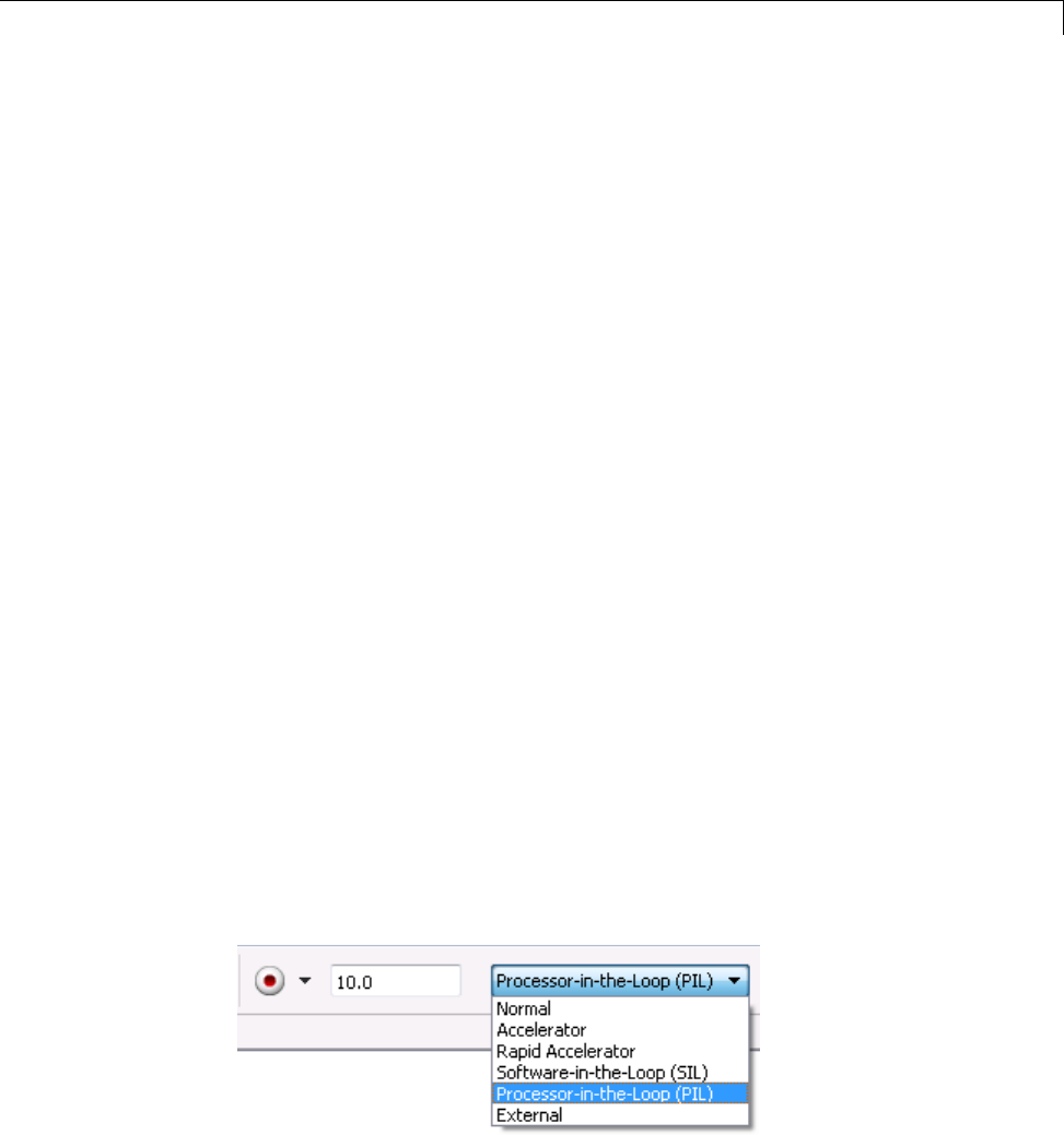
Processor-in-the-Loop (PIL) Simulation
Setting Model Configuration Parameters to Generate the PIL
Application. Configure your model to generate the PIL executable from
your model:
1Add a Target Preferences block in to your model. The Target Preferences
block is located in the Simulink library browser under Simulink Coder >
Desktop Targets.
2Open the Target Preferences block and select your processor from the list of
processors.
3From the model toolstrip, select Simulation > Model Configuration
Parameters.
4In Configuration Parameters, select Code Generation.
5Set System Target File to idelink_ert.tlc.
6From the list of panes under Code Generation,chooseIDE Link.
7Set Build format to Project.
8Set Build action to Create_processor_in_the_loop_project.
9Click OK to close the Configuration Parameters dialog box.
For more information, see “Code Generation Pane: IDE Link”.
Running the Top-Model PIL Application. To create a PIL block, perform
the following steps:
1In the model toolstrip, set the Simulation mode to Processor-in-the-loop.
26-5

26 Verification Code Generated for Desktop Targets
2In the model toolstrip, click Run
.
AnewSimulinkEditor opens with the new PIL model block in it. The
third-party IDE compiles and links the PIL executable file. Follow the
progress of the build process in the MATLAB command window.
PIL Block
Use the PIL block to:
•Verify code generated for a top-model (standalone code interface) or
subsystem (right-click build standalone code interface).
•Represent a component running in SIL or PIL mode. The test harness
model or a system model provides test vector or stimulus inputs.
Preparing Your Model to Generate a PIL Block. Start with a model that
contains the algorithm blocks you want to verify on the processor as compiled
object code. To create a PIL application and PIL block from your algorithm
subsystem, follow these steps:
1Identify the algorithm blocks to cosimulate.
2Convert those blocks into an unmasked subsystem in your model.
For information about how to convert your process to a subsystem, refer to
Creating Subsystems in Using Simulink or in the online Help system.
3Open the newly created subsystem and copy a Target Preferences block to
it. The Target Preferences block is located in the Simulink library browser
under Simulink Coder > Desktop Targets.
Open the Target Preferences block and select your processor from the list of
processors.
26-6

Processor-in-the-Loop (PIL) Simulation
Setting Model Configuration Parameters to Generate the PIL
Application. After you create your subsystem, set the Configuration
Parameters for your model to enable the model to generate a PIL block.
Configure your model to enable it to generate PIL algorithm code and a PIL
block from your subsystem:
1From the model menu bar, select Simulation > Model Configuration
Parameters. This action opens the Configuration Parameters dialog box.
2In the Configuration Parameters dialog box, select Code Generation.
3Set System Target File to idelink_ert.tlc.
4From the list of panes under Code Generation,chooseIDE Link.
5Set Build format to Project.
6Set Build action to Create_processor_in_the_loop_project.
7Click OK to close the Configuration Parameters dialog box.
For more information, see “Code Generation Pane: IDE Link”.
Creating the PIL Block from a Subsystem. To create a PIL block, perform
the following steps:
1Right-click the masked subsystem in your model and select C/C++ Code >
Build This Subsystem from the context menu.
A new Simulink Editor opens and the new PIL block appears in it. The
third-party IDE compiles and links the PIL executable file.
This step builds the PIL algorithm object code and a PIL block that
corresponds to the subsystem, with the same inputs and outputs. Follow
the progress of the build process in the MATLAB command window.
2Copy the new PIL block from the new model to your model. To simulate
the subsystem processes concurrently, place it parallel to your masked
subsystem. Otherwise, replace the subsystem with the PIL block.
26-7

26 Verification Code Generated for Desktop Targets
To see a PIL block in a parallel masked subsystem, search the product help
for Getting Started with Application Development and select the example
that matches your IDE.
Note Models can have multiple PIL blocks for different subsystems. They
cannot have more than one PIL block for the same subsystem. Including
multiple PIL blocks for the same subsystem causes errors and inaccurate
results.
Communications
•“TCP/IP” on page 26-9
•“IDE Debugger” on page 26-10
Chose one of the following communication methods for transferring code and
data during PIL simulations:
Method Speed Comments
IDE Debugger Slow •Supports PIL communications with
an executable running an embedded
target processor.
•Supports the largest number of
targets.
•Requires a physical connection
between host and target processor.
•Only works with builds from IDE
projects. Does not work with builds
from makefiles.
TCP/IP Fast •Supports PIL communications with
an executable running on a Linux or
Windows host.
•Supports embedded targets running
Linux, TI DSP/BIOS, and Wind River
VxWorks.
•Requires network connection between
host and target processor.
•Works with builds from IDE projects
and from makefiles.
Serial Communication
Interface (SCI)
Fast •Supports PIL communications with
an executable running an embedded
target processor.
26-8
Processor-in-the-Loop (PIL) Simulation
Method Speed Comments
•Supports only TI C28035 and C28335
microcontrollers.
•Requires an SCI connection between
host and target processor.
•Works with builds from IDE projects
and from makefiles.
TCP/IP
You can use TCP/IP for PIL communications with a hardware target running:
•Linux
•Microsoft Windows
Using TCP/IP for PIL communications is typically faster than using a
debugger, particularly for large datasets,suchaswithvideoandaudio
applications.
YoucanuseTCP/IPwiththefollowingPILapproaches:
•Top-model PIL
•Model block PIL
TCP/IP does not work with the Subsystem PIL approach.
To enable and configure TCP/IP with PIL:
1Set up a PIL simulation according to the PIL approach you have chosen.
2In the MATLAB Command Window, use setpref to specify the IP address
of the PIL server (servername).
If you are running the PIL server on a remote target, specify the IP address
of the target processor. For example:
setpref('MathWorks_Embedded_IDE_Link_PIL_Preferences','servername','144.212.109.114');
26-9

26 Verification Code Generated for Desktop Targets
If you are running PIL server locally, on your host Windows or Linux
system, enter 'localhost' instead of an IP address:
setpref('MathWorks_Embedded_IDE_Link_PIL_Preferences','servername','localhost');
3Specify the TCP/IP port number to use for PIL data communication. Use
one of the free ports in your system. For example:
setpref('MathWorks_Embedded_IDE_Link_PIL_Preferences','portnum', 17025);
4Enable PIL communications over TCP/IP:
setpref('MathWorks_Embedded_IDE_Link_PIL_Preferences','enabletcpip', true);
To disable PIL communications over TCP/IP, change the value to false.
This action automatically enables PIL communications over an IDE
debugger, if an IDE is available.
5Open the Target Preferences block in your model, then set the Operating
System parameter to an operating system.
Note You cannot use TCP/IP for PIL when the value of Operating
System is None.
6Regenerate the code or PIL block.
To disable PIL communications over TCP/IP, enter:
setpref('MathWorks_Embedded_IDE_Link_PIL_Preferences','enabletcpip', false);
IDE Debugger
To enable PIL communications over an IDE debugger, disable PIL
communications over TCP/IP and SCI by entering the following commands:
setpref('MathWorks_Embedded_IDE_Link_PIL_Preferences','enabletcpip',false);
setpref('MathWorks_Embedded_IDE_Link_PIL_Preferences','enableserial',false);
Then regenerate the code or PIL block.
26-10

Processor-in-the-Loop (PIL) Simulation
Using IDE debugger for PIL communication only works when you build your
code from IDE projects. Using IDE debugger for PIL communication does
not work with builds from makefiles.
Running Your PIL Application to Perform Simulation
and Verification
After you add your PIL block to your model, click Simulation > Run or press
Ctrl+T to run the PIL simulation and view the results.
Definitions
PIL Algorithm
The algorithmic code, which corresponds to a subsystem or portion of a model,
to test during the PIL simulation. The PIL algorithm is in compiled object
form to enable verification at the object level.
PIL Application
The executable application that runs on the processor platform. Your coder
product creates a PIL application by augmenting your algorithmic code with
the PIL execution framework. The PIL execution framework code compiles as
part of your embedded application.
The PIL execution framework code includesthestring.hheaderfilesothatthe
PIL application can use the memcpy function. The PIL application uses memcpy
to exchange data between the Simulink model and the simulation processor.
PIL Block
When you build a subsystem from a model for PIL, the process creates a PIL
block optimized for PIL simulation. Whenyourunthesimulation,thePIL
block acts as the interface between the model and the PIL application running
on the processor. The PIL block inherits the signal names and shape from the
source subsystem in your model. Inheritance is convenient for copying the
PIL block into the model to replace the original subsystem for simulation.
26-11

26 Verification Code Generated for Desktop Targets
PIL Issues and Limitations
Consider the following issues when you work with PIL blocks.
Constraints
When using PIL in your models, keep the following constraints in mind:
•Models can have multiple PIL blocks for different subsystems. They cannot
have more than one PIL block for the same subsystem. Including multiple
PIL blocks for the same subsystem causes errors and inaccurate results.
•A model can contain a single model block running PIL mode.
•A model can contain a subsystem PIL block or a model block in PIL mode,
but not both.
Generic PIL Issues
Refer to PIL Feature Support and Limitations for general information about
using the PIL block with embedded link products.
Simulink Coder grt.tlc-Based Targets Not Supported
PIL does not support grt.tlc system target files.
To use PIL, set System target file in the Configuration Parameters > Code
Generation pane to idelink_ert.tlc.
26-12

27
Working with Eclipse IDE
•“Installing Third-Party Software for Eclipse” on page 27-2
•“Configuring Your MathWorksSoftwaretoWorkwithEclipse”onpage
27-10
•“Troubleshooting with Eclipse IDE” on page 27-14
Note To use the coder product with Eclipse IDE, complete the steps in
“Installing Third-Party Software for Eclipse” on page 27-2 and “Configuring
Your MathWorks Software to Work with Eclipse” on page 27-10

27 Working with Eclipse™ IDE
Installing Third-Party Software for Eclipse
In this section...
“Tested Software Versions” on page 27-2
“Installing Sun Java Runtime Environment (JRE)” on page 27-3
“Installing Eclipse IDE for C/C++ Developers” on page 27-5
“VerifyingtheGNUToolChainonLinuxHost”onpage27-6
“Installing the GNU Tool Chain on Windows” on page 27-7
Tested Software Versions
MathWorks has tested the coder product with the specific software versions
listed in the following tables.
Required for all platforms Tested Versions
Sun™ Java™ Runtime Environment
(JRE)
JRE 6.0 (Java 1.6.x)
Eclipse IDE for C/C++ Developers
package, which includes the CDT
feature
Ganymede (Eclipse 3.4)
CDT
(If CDT is installed separately from
Eclipse IDE for C/C++ Developers
package, match CDT version with
Eclipse version.)
CDT 5.0
Linux: Additional Software
Required
Tested Versions
GNU GCC (compiler) GCC 4.4
GNU as (assembler — part of the
GNU binutils package)
as 2.18
27-2
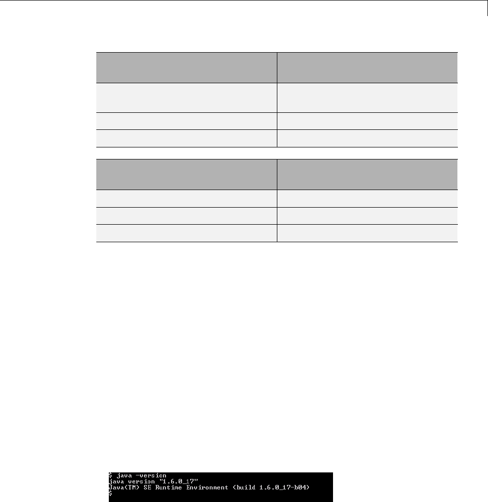
Installing Third-Party Software for Eclipse™
Linux: Additional Software
Required
Tested Versions
GNU ar (archiver — part of the GNU
binutils package)
ar 2.18
GNU GDB (debugger) GDB 6.8.x
GNU make make 3.81
Windows: Additional Software
Required
Tested Versions
MinGW 5.1.x
GDB GDB 6.3.x
MSYS 1.0.11
You can try untested versions and combinations of third-party software at
your own risk.
For the most current information about using
the coder product software with Eclipse IDE, see:
www.mathworks.com/products/simulink-coder/eclipse-adaptor.html
Installing Sun Java Runtime Environment (JRE)
To install the JRE, complete the following steps:
1At your Windows or Linux command prompt, enter:
java -version
If Java is present, the command line responds with the version information,
as this example shows.
2If Java is missing or the version is lower than 1.6.x, download and install
JRE 6.0 from http://www.java.com.
27-3

27 Working with Eclipse™ IDE
3Get the path of the Java JRE by entering which java on the command line.
4Set the PATH system variable in your operating system.
For example, in Windows 7:
aPress the Windows key and search for “System environment variables”
and open “Edit the system environment variables”.
bIn System Properties, to go Advanced and click Environment
Variables.
cIn the System variables, locate and select “Path”.
dClick the Edit button and add the path of the Java JRE to the Variable
value.
For example , add C:\Program Files\Java\jre6\bin; to the Variable
value.
eClickOKtosaveyourchanges.
For example, with Linux:
aOpen a startup file, such as ~/ .cshrc.
bAdd the path of the Java JRE to the PATH variable.
For example, on a 64-bit Linux host computer, if you are using csh or
tcsh, enter:
setenv PATH $PATH:/local/MATLAB/R2011b/sys/java/jre/glnxa64/jre/bin
For example, on a 64-bit Linux host computer, if you are using sh, ksh,
or bash, enter:
PATH=$PATH:/local/MATLAB/R2011b/sys/java/jre/glnxa64/jre/bin ; export PATH
cSave your changes and close the file.
For more information, see http://www.java.com/en/download/help/path.xml.
5Verify that Java is working by entering java -version again or by visiting
http://www.java.com/en/download/help/testvm.xml.
27-4

Installing Third-Party Software for Eclipse™
Installing Eclipse IDE for C/C++ Developers
Note The following instructions are based on Eclipse 3.4 (Ganymede). More
recent versions of the Eclipse IDE can have different appearances, menus,
or software package names.
The Eclipse IDE for C/C++ Developers package includes the Eclipse IDE
and the C/C++ Development Tools (CDT). To install Eclipse IDE for C/C++
Developers package, complete the following steps:
1DownloadtheGanymedeSR2zipfileforEclipseIDEforC/C++Developers,
from http://www.eclipse.org/downloads/packages/release/ganymede/sr2.
2Extract the Eclipse files to a permanent location, such as C:\eclipse\ and
create a desktop shortcut to eclipse.exe.
3Start Eclipse, and select Help >Software Updates.
4Look under the Installed Software tab, and verify that Eclipse has the
following three CDT software packages.
•Eclipse C/C++ Development Platform
•Eclipse C/C++ Development Tools
•Mylin Bridge: C/C++ Development
If you have a previous Eclipse installation that does not include CDT,
complete the following steps:
1In Eclipse, select Help >Software Updates.
2Click the Available Software tab.
3Click Ganymede Update Site.
4Select C and C++ Development,andclickInstall.
5When the installation process completes, click the Installed Software
tab, and verify that you have CDT.
27-5

27 Working with Eclipse™ IDE
Verifying the GNU Tool Chain on Linux Host
Most Linux distributions include the following GNU C/C++ development
tools. Eclipse and CDT require these tools to compile code, build projects,
and debug applications:
•Assembler (as)
•Archiver (ar)
•compiler and linker (gcc)
•debugger (gdb)
•build utility (make)
Verify that the GNU tools are present and set the tool chain path:
1On the Linux command line, enter:
•gcc --version
•gdb --version
•as --version
•ar --version
•make --version
2Comparetheversionofeachtoolwiththe following list of tested versions:
•gcc 4.4
•as 2.18
•ar 2.18
•gdb 6.8.x
•make 3.81
If you are using Eclipse for targeting embedded Linux, disregard the
version numbers in the preceding list.
To install a missing tool or to change the version of the tool, use the
software installation manager that comes with your Linux distribution.
27-6

Installing Third-Party Software for Eclipse™
Alternatively, visit http://directory.fsf.org/GNU/ for more information about
individual tools. Source files for the tools are available from:
•binutils (includes as and ar), http://ftp.gnu.org/gnu/binutils/
•gcc, http://ftp.gnu.org/gnu/gcc/
•gdb, http://ftp.gnu.org/gnu/gdb/
•make, http://ftp.gnu.org/gnu/make/
3Modify the PATH environment using the right commands for your running
shell. You can also modify the path environment variable in your login
scripts.
If you are using a Bash shell prompt, enter:
PATH=my_tool_path:$PATH
Where my_tool_path is the path to the GNU tool binaries. For example:
PATH=/bin:$PATH
If you are using a C shell prompt, enter:
setenv PATH my_tool_path:$PATH
Where my_tool_path is the path to the GNU tool binaries. For example:
setenv PATH /bin:$PATH
Installing the GNU Tool Chain on Windows
Windows typically does not include GNU C/C++ development tools. Eclipse
and CDT require these tools to compile code, build projects, and debug
applications.
Provide a GNU tool chain for Windows by installing MinGW:
1Open http://sourceforge.net/projects/mingw/files/.
2Download and run the latest version of the “Automated MinGW Installer".
27-7

27 Working with Eclipse™ IDE
Note The earliest version of MinGW available is more recent than the
tested version.
3Start the MinGW installation wizard to perform a default installation.
Perform a default installation until you reach Select Components.At
that step, select MSYS Basic System.
Then, complete the default installation process. Wait for the installation
wizard to download, and install additional files from the Internet.
Note If you alter the default installation path, C:/MinGW, do not use
spaces in the new path.
Set the PATH environment variable:
1In Windows, right-click My Computer or Computer,andchoose
Properties.
2Then select Advanced or Advanced system settings,andclick
Environment Variables.
3Under System variables, scroll down to the Path variable.
4Select Path,andclickEdit.
5Configure the operating system to the GNU tools when there are multiple
paths:
aAdd the paths of the MinGW and MSYS bin folders to the beginning of
the Variable value.
bUse semicolons to separate the paths. For example,
C:\mingw\bin;C:\mingw\msys\1.0\bin;
27-8
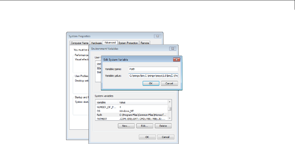
Installing Third-Party Software for Eclipse™
6To verify the GNU tools installation and path settings, enter the following
commands on the Windows command line:
•gcc --version
•gdb --version
•as --version
•ar --version
•make --version
Each command displays the tool name and version on the command line. If
you receive a message that the command is not recognized, verify that you
completed the preceding installation and path configuration instructions.
You can use versions of the GNU tools that are more recent than the tested
versions at your own risk.
27-9
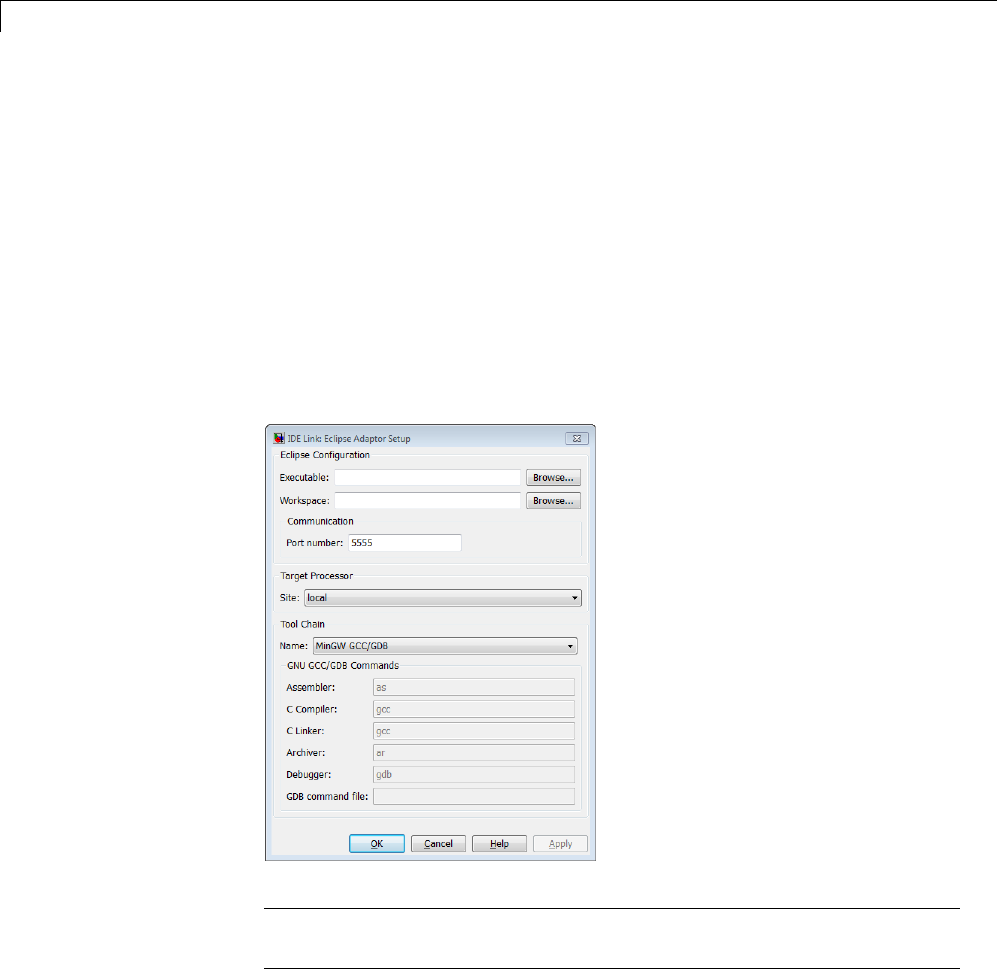
27 Working with Eclipse™ IDE
Configuring Your MathWorks Software to Work with
Eclipse
After you install the third-party software, configure the coder product to work
with Eclipse:
1Close Eclipse IDE before you run eclipseidesetup. For more information,
see “Build Errors” on page 27-15.
2in the MATLAB Command Window, enter eclipseidesetup.Thecoder
product opens the “IDE Link: Eclipse Adaptor Setup” dialog box, as shown
here on Windows:
Note On Linux, the “IDE Link: Eclipse Adaptor Setup” dialog box shows
different options than on Windows
3Update Executable with the location and file name of the Eclipse
application file. For example, C:\eclipse\eclipse.exe.
27-10

Configuring Your MathWorks®Software to Work with Eclipse™
You can get this value by right-clicking a shortcut for Eclipse and looking
at the properties.
4Update Workspace with the default location where
Eclipse creates and saves new project files. For example,
C:\WINNT\Profiles\username\workspace.
To find the current workspace, open Eclipse and select File >Switch
Workspace >Other.
In the future, if you change the Eclipse workspace, repeat this configuration
procedure.
Do not use workspace paths that containspaces. Ifyouhaveapathwith
spaces, recreate the workspace, and then update the path in Eclipse.
5For Port number, enter a valid, unused, IP port number. For example,
5555.
6For Site, identify where the coder product uploads and runs the executable
file upon completing the build process. Use either of these options:
•Choose local to run the executable on your Linux or Windows
workstation.
This option requires the Simulink Coder product.
•Choose remote to download the executable to a remote target running
Linux operating system over a network connection (for example, to
connect to an embedded system connection to the Ethernet port on your
workstation).
This option requires the Embedded Coder product.
You must perform additional steps to connect to a remote target running
Linux. See .
Note Later on, when you are working on your model, open the Target
Preferences block, and set Processor to match the processor at the Site
you selected.
27-11

27 Working with Eclipse™ IDE
7To customize the Tool Chain settings, see the Custom GCC/GDB topic.
8When you click OK or Apply, the coder product:
•Verifies the locations of the Executable and Workspace in the Eclipse
Adaptor Setup dialog box.
•Verifies that the required third-party software is present.
•Installs the coder product plug-ins in the Eclipse plugins folder. For
example, in C:\Program Files\eclipse\plugins\.
•Saves configuration information to the mwidelink.ini file, located in
the Eclipse plugins folder.
Note When Eclipse starts, it loads the coder product plug-in. The coder
product plug-in loads the port number from mwidelink.ini.Toresolvea
port number conflict, change the port number by running eclipseidesetup
again. Do not edit mwidelink.ini.
9To verify that the configuration process is complete, create a handle object
for the Eclipse IDE. Enter the following command in MATLAB
IDE_Obj = eclipseide
This command, starts Eclipse IDE if it is not already running, and creates
ahandleobject. Forexample:
Starting Eclipse(TM) IDE...
ECLIPSEIDE Object:
Default timeout : 10.00 secs
Eclipse folder : C:\eclipse3.4\eclipse
Eclipse workspace: C:\WINNT\Profiles\rolfedh\workspace
Port number : 5555
Processor site : local
If you are using more recent versions of the GNU tools, you can disregard
command-line warnings about using untested versions.
10 In Eclipse, click the following icon to see the status of the IDE Link plug-in.
27-12

Configuring Your MathWorks®Software to Work with Eclipse™
27-13

27 Working with Eclipse™ IDE
Troubleshooting with Eclipse IDE
In this section...
“SIGSEGV Segmentation Fault for GDB” on page 27-14
“GDBStopsonEachSemaphorePost”onpage27-14
“Build Errors” on page 27-15
“Profiling Not Available for Intel x86/Pentium and AMD K5/K6/Athlon
Processors Running Windows or Linux Operating Systems” on page 27-15
“Eclipse Message: “Can’t find a source file”” on page 27-15
“Eclipse Message: “Cannot access memory at address”” on page 27-16
“Some Versions of Eclipse CDT Do Not Catch GCC Errors” on page 27-16
SIGSEGV Segmentation Fault for GDB
If you use Comodo Internet Security (CIS) software on your development
system, CIS causes a SIGSEGV segmentation fault for GDB. When this fault
occurs, you receive the following message:
Debugger name and version: GNU gdb (GDB) 7.0
Program received signal SIGSEGV, Segmentation fault.
In ntdll!RtlpWaitForCriticalSection () (C:\WINDOWS\system32\ntdll.dll)
Continuing...
Program received signal SIGSEGV, Segmentation fault.
In ?? () (C:\WINDOWS\system32\guard32.dll)
If you get this message, click OK and then click Continue.
For more information, see the “Guard32.dll causes SIGSEGV segmentation
fault for GDB debugger CIS 3.9.95478 x32” topic at http://forums.comodo.com/.
GDB Stops on Each Semaphore Post
If you use gdb to debug a target application running on Linux or Windows,
gdb stops on each semaphore post. You can override this expected behavior
adding the following text to .gdbinit,theGDBinitfile:
27-14

Troubleshooting with Eclipse™ IDE
handle SIG34 nostop noprint pass
handle SIG35 nostop noprint pass
On Linux, .gdbinit resides on your home folder, by default. On Windows, the
environment variable HOME defines the home folder. For more information
about creating .gdbinit and configuring gdb, consult the GDB User Manual,
available from http://www.gnu.org/software/gdb/documentation/.
Build Errors
If you use eclipseidesetup without closing Eclipse IDE, you may get build
errors similar to the following ones:
The call to idelink_ert_make_rtw_hook, during the exit hook generated the following error:
Error while creating the project.
The build process will terminate as a result.
===
Error while creating the project.
===
Error creating a new project.
===
An exception occurred while performing this operation. 0
To solve this problem, close and restart Eclipse IDE.
Profiling Not Available for Intel x86/Pentium and
AMD K5/K6/Athlon Processors Running Windows or
Linux Operating Systems
Profiling is not available for Intel x86/Pentium and AMD K5/K6/Athlon
processors running Windows or Linux.
Eclipse Message: “Can’t find a source file”
With specific Configuration Parameters, while building and loading a target
application, Eclipse IDE displays a message that it could not find a source
file. This message appears even if the load action completes. Here is an
example of the message:
27-15

27 Working with Eclipse™ IDE
Can't find a source file at
"../../sumdiff_bash_eclipseide/sumdiff_bash_main.c
Locate the file or edit the source lookup path
to include its location.
In Configuration Parameters, on the IDE Link pane, in the Vendor Tool
Chain section:IfConfiguration is set to Release or Custom,thecoder
product does not specify the -g compiler option for gcc. Therefore, the build
process does not produce debugging information gdb requires. Without this
information, gdb cannot map the executable to the source file, resulting in the
"Can’t find a source file” message.
To solve thisproblem,add-g to the Compiler options string for the Custom
and Release configurations, or set Configuration to Debug.
Eclipse Message: “Cannot access memory at
address”
If you use the coder product’s halt method to stop the target application,
Eclipse displays a message similar to the following example:
[Switching to thread 5528.0x1664]
Quit (expect signal SIGINT when the program is resumed)
Cannot access memory at address 0x720000
Cannot access memory at address 0x720000
This error is not related to Eclipse IDE. It is a bug with gdb/MinGW. It
typically occurs when gdb tries to access an invalid or protected memory
location.
Some Versions of Eclipse CDT Do Not Catch GCC Errors
If you set a bad compiler flag, specific versions of Eclipse CDT prior to version
7.0.2 fail to catch gcc errors that the flag is wrong.
To reproduce this problem:
1Open a project and select C/C++ Build >Tool Chain Editor.
27-16

Troubleshooting with Eclipse™ IDE
2Set Current builder to CDT Internal Builder.
3Select Project properties >C/C++ Build >Settings.
4Set GCC C Compiler: Miscellaneous to -D.
5Build the project. Notice that gcc displays the following error while the
Problems tab for the Eclipse IDE project does not display any errors:
<command-line>: error: macro names must be identifiers
27-17

27 Working with Eclipse™ IDE
27-18


28 Working with Linux®Target
Disambiguation
This documentation uses the term “Linux” generically to refer to:
•Linux running on a host computer
•Linux running on an target processor
If the distinction between host and target is important, the documentation
will identify the hardware platform on which Linux is running. For example:
•“Embedded Linux” or “Linux running on a target processor”
•“Linux running on a host computer.”
28-2

Preparing ModelstoRunonLinux
®Target
Preparing Models to Run on Linux Target
To build an executable that runs on Linux, perform the following steps:
1Install and configure Eclipse IDE according to the instructions in “Working
with Eclipse IDE”.
2Locate the Target Preferences block in the Simulink Library Browser,
under Simulink Coder > Desktop Targets.
3Copy the Target Preferences block to your model.
4In the Initialize Configuration Parameters dialog box, set the IDE to
Eclipse, and select the processor for which you are generating code.
5Set Operating System to Linux. This action creates a Linux tab for
setting the Scheduling Mode and Base Rate Priority.
6Set the Scheduling Mode to one of these options:
•If you select real-time,themodelusesatimertotriggerthebaserate
at regularperiods.
•If you select free-running, the model does not use a timer. Instead, the
model completes each process or thread before running the next one.
7For Linux, you can set the Base Rate Priority relative to other processes
and threads. You can enter values from (the number of rates + 1) to 99.
8In IDE Link, configure the model to build and execute:
aIn the model, select Simulation > Model Configuration Parameters.
bUnder Code Generation,selecttheIDE Link pane.
cSet Build action to Build and execute.
9Click Build Model on the model toolstrip.
After the build completes, Embedded Coder software downloads the
executable to the remote system and runs it.
28-3

28 Working with Linux®Target
Scheduler
In this section...
“Base Rate” on page 28-4
“Running Target Applications on Multicore Processors” on page 29-4
“Running Multirate, Multitasking Executables on the Linux Desktop” on
page 28-11
“Avoiding Lock-Up in Free-Running, Multirate, Multitasking Models” on
page 28-12
Base Rate
The base rate in the model maps to a thread and runs as fast as possible. The
base rate priority selection in the OS tab allows you to set a static priority
for the base rate task. By default, this rate is 40.
The process running single-tasking models has Default scheduling policy
when model is single-tasking or there is a single rate in the model. Static
priority of the process is 0 in this case.
Running Target Applications on Multicore Processors
Introduction
This section provides a variation of the process described in “Build and
Download to a Multicore Target”.
This section shows you how to:
•Configure a multirate model
•Generate a multithreaded application from that model
So that the resulting application is enabled for concurrent multicore execution
on a desktop target running Linux or Windows.
28-4

Scheduler
Thisprocessusestheidelink_ert.tlc or idelink_grt.tlc system target
files, which enable you to:
•UseEclipseIDEtomanageprojectsforLinuxandWindowstargets
(Support for this capability is only available on 32-bit host platforms)
•Set thread priority using a Target Preference block
Looking at a Model
Before setting up your own model, consider the
sldemo_concurrent_execution example model, which is referenced by
“Build and Download to a Multicore Target”.
The sldemo_concurrent_execution model is a useful example to look at
because:
•The model is partitioned using Model blocks that can potentially execute
concurrently.
•You can look at the Map Blocks To Tasks pane in the Concurrent
Execution window to see how the tasks are configured for concurrent
execution.
However, you cannot run an unmodified version of the
sldemo_concurrent_execution model on a desktop target running
Linux or Windows.
To prepare the sldemo_concurrent_execution as an example model for the
“Setting Up the Model” on page 29-7 and “Deploying the Model to Your
Target” on page 29-8 topics, first perform the following modifications:
•Update the Plant Model Block
•Update the Compensator Model Block
•Verify that Models are Mapped
These procedures guide you through the processes of discretizing models and
matching sample times of blocks with models.
28-5

28 Working with Linux®Target
Update the Plant Model Block.
1In the sldemo_concurrent_execution model, open the “Plant” Model block:
sldemo_concurrent_execution_plant
2Discretize the Plant model. Replace the Integrator blocks, “x1” and “x2”,
with equivalent discrete time blocks (such as the Discrete Time Integrator
block) or use the “Model Discretizer”.
3Prevent modeling constraints by matching the sample time of the “x1” and
“x2” blocks with the model: Open the “x1” and “x2” blocks and change the
Sample time parameters to 0.1. Matching the sample times to the model
can also be accomplished using Rate Transition blocks.
4Convert blocks with continuous sample times (Sample time =0)to
inherited sample times (Sample time =-1). Open the “u1”, “u2” and “x”
blocks. For each one, click the Signal Attributes tab, then change Sample
time to -1.
5Save your changes to the blocks and the model.
Update the Compensator Model Block.
1In the sldemo_concurrent_execution model, open the “Compensator” Model
block: sldemo_concurrent_execution_compensator
2Discretize the Compensator model. Replace the Integrator block, “c”, with
an equivalent discrete time block (such as the Discrete Time Integrator
block) or use the “Model Discretizer”.
3Prevent modeling constraints by matchingthesampletimeofthe“c”
block with the top model: Open the “c” block and change the Sample
time parameters to 0.1. Matching the sample times to the top model,
sldemo_concurrent_execution, can also be accomplished using Rate
Transition blocks.
4Convert blocks with continuous sample times (Sample time =0)to
inherited sample times (Sample time =-1). Open the “y1”, “y2”, and “x”
blocks. For each one, click the Signal Attributes tab, then change Sample
time to -1.
28-6

Scheduler
5The following parameters cannot both be enabled when you build the
model. Open the Configuration Parameters (Ctrl+E)andverifythatoneof
the following parameters is disabled (unchecked):
•Minimize algebraic loop occurrences, located on the Model
Referencing pane.
•Single output/update function, located on the Code Generation >
Interface pane
6Save your changes to the blocks and the model.
Verify that the Models are Mapped. Open and inspect the Task editor to
see if the models are appropriately mapped:
1In the Simulink model editor for sldemo_concurrent_execution, select View
>Model Explorer (Ctrl + H).
2In Model Explorer, expand the top model, sldemo_concurrent_execution.
3Under the top model, select Configuration (Active),thenclick
Concurrent Execution in the second column. In the third column, click
the ConfigureTasks and Map Blocks to Tasks button.
4Click Map Blocks To Tasks. The mapping of the models should conform
to the guidelines provided by “Design Considerations”.
The sldemo_concurrent_execution example model is ready for you to use
in “Setting Up the Model” on page 29-7 and “Deploying the Model to Your
Target” on page 29-8.
Setting Up the Model
This procedure explains how to set up a model for a multicore processor.
1Apply the recommendations in “Design Considerations” to your multirate
Simulink model. Or, refer to the sldemo_concurrent_execution example
model.
2Add a Target Preferences block to your model as described in “Target
Preferences” on page 25-3 .
28-7

28 Working with Linux®Target
3In the Target Preferences block, set Operating System to Linux or
Windows.
4If your model uses a Rate Transition block to transition between rates, then
open the Rate Transition block and clear the Ensure deterministic data
transfer check box so that the block uses the most recent data available.
5Configure the model for concurrent execution:
aIn the Simulink model editor, select View >Model Explorer (Ctrl + H).
bIn Model Explorer, expand the top model.
cUnder the top model, right click Configuration (Active) and select
Convert to Configuration for Concurrent Execution.(Inthe
sldemo_concurrent_execution example model, this step has already been
performed.)
6For each referenced model in the model hierarchy that you want to run
with concurrent execution:
aCopy the Target Preferences block from the top model to the referenced
model.
bRepeat steps 4 through 5.
7Select the configuration set of the model at the top of the model
hierarchy. In the second column, select the Concurrent Execution
node. A Concurrent Execution pane appears in the third column. (In the
sldemo_concurrent_execution example model, this step has already been
performed.)
8In the Concurrent Execution pane in the third column, select the This is
the top of the model hierarchy check box, and click the ConfigureTasks
and Map Blocks to Tasks button. (In the sldemo_concurrent_execution
example model, this step has already been performed.)
9The Concurrent Execution configuration parameters dialog box is
displayed. Click Apply.
28-8

Scheduler
Deploying the Model to Your Target
In your model, click the build button or enter Ctrl+B. The software performs
the actions you selected for Build action in the Configuration Parameters
dialog, on the Code Generation > IDE Link pane.
For more information on the structure of the code, please refer to “Build
and Download to a Multicore Target”. As mentioned in that section, the
coder product generates all target-dependent code for thread creation, thread
synchronization, interrupt service routines, and signal handlers and data
transfer. For each periodic task, Simulink Coder combines the output and
update methods of the blocks mapped to that task and binds these methods
to a target-specific thread.
Note The idelink_ert.tlc or idelink_grt.tlc system target files do not
support Continuous times.
Generated Code
For idelink_ert.tlc or idelink_grt.tlc system target files, the generated
code from a mapped model creates a thread for each task and automatically
leverages the threading APIs supported by the operating system running
on the target.
•If the target platform is running Windows , the generated code will use
Windows threads.
•If the target platform is running Linux or VxWorks , the generated code
will use POSIX®threads (pthreads).
The following table summarizes the differences in the generated code between
the target platforms.
28-9

28 Working with Linux®Target
Aspect of Concurrent
Execution
Linux Windows
Periodic triggering
event
POSIX timer Windows timer
Aperiodic triggering
event
POSIX real-time signal Windows event
Aperiodic trigger For blocks mapped to an
aperiodic task: thread
waiting for a signal
For blocks mapped to
an aperiodic trigger:
signal action
Thread waiting for an
event
Threads POSIX Windows
Thread priority Assigned based on
Target Preference
Block setting
Fixed
Example of overrun
detection
Yes Yes
The software checks that data transfer between concurrently executing tasks
behave as described in Data Transfer Options. The software checks data
transfer using the following APIs on supported targets.
API Linux
Implementation
Windows
Implementation
Data protection API •pthread_mutex_init
•pthread_mutex_destroy
•pthread_mutex_lock
•pthread_mutex_unlock
•CreateMutex
•CloseHandle
•WaitForSingleObject
•ReleaseMutex
Synchronization API •sem_init
•sem_destroy
•sem_wait
•sem_post
•CreateSemaphore
•CloseHandle
•WaitForSingleObject
•ReleaseSemaphore
28-10

Scheduler
Running Multirate, Multitasking Executables on the
Linux Desktop
In Linux, multirate, multitasking executables require root privileges to
schedule POSIX threads with real-time priority. Thus, Eclipse IDE software
must have its own root privileges to run the multirate, multitasking
executable with root privileges locally on your Linux development system.
If all three of the following conditions are true, start Eclipse IDE with root
privileges:
•Your model produces a multirate, multitasking executable.
•Embedded Coder uses the default Configuration Parameters which
automatically run the executable.
You can verify the Configuration Parameters in the Configuration
Parametersdialog box, under Code Generation, select the IDE Link
pane. Make sure that the Build format is Project and the Build action
is Build_and_execute.
•The Eclipse plug-in is using the default settings, which run the executable
on the local Linux development system. (During the eclipseidesetup
process,youleftSite set to local.)
If any of the following conditions are true, you do not need to start Eclipse
IDE with root privileges:
•Your model produces multirate, single-tasking executables or single rate
executables.
•You are performing a proccesor-in-the-loop (PIL) simulation.
•You are using a Windows development platform.
•You have configured Embedded Coder and Eclipse to run the executable
on a remote Linux target.
•You not have configured Embedded Coder andEclipsetoruntheexecutable.
28-11

28 Working with Linux®Target
Starting Eclipse IDE with root privileges
1Install and configure Eclipse IDE according to the instructions in “Working
with Eclipse IDE”.
2If an Eclipse IDE handle object exists in the MATLAB workspace, delete
the object. For example, delete IDE_Obj.
3If Eclipse IDE is running, close it.
4Open a command-line session, and cd to the Eclipse installation folder. For
example, if you installed Eclipse in usr/bin/eclipse,enter:
cd usr/bin/eclipse
5Start Eclipse with root privileges using sudo ./. For example:
sudo ./eclipse
6At the prompt, enter the root password.
7When Eclipse starts and prompts you for the workspace, enter the same
workspace you specified during the Eclipse installation and configuration
process.
8In IDE Link, configure the model to build and execute:
aIn the model, select Simulation > Model Configuration Parameters.
bUnder Code Generation,selecttheIDE Link pane.
cSet Build action to Build and execute.
9Click Build Model on the model toolstrip. This action builds, loads,
and runs your code on the processor.
When the build process finishes, the multirate, multitasking executable
automatically starts and runs with root privileges.
Avoiding Lock-Up in Free-Running, Multirate,
Multitasking Models
This section applies when the following conditions are true:
28-12

Scheduler
•The model is a multirate multitasking model
•In the Target Preferences block, on the Board pane, the Operating system
parameter is set to Linux
•In the Target Preferences block, on the Linux pane, the Scheduling Mode
parameter is set to free-running
Because of the rate monotonic scheduling requirement in Linux, the scheduler
runs threads with a SCHED_FIFO scheduling policy. A process scheduled
with SCHED_FIFO prevents other process from running while it is ready
to run. Therefore, if the model does not contain any blocking peripherals,
the entire Linux system can become unresponsive while you are running
the generated code. Such lock-up can even preempt the shell window from
running. To avoid this lock-up, apply one of the following solutions:
•Set Scheduling Mode to real_time.
•Include a blocking device driver, such as a UDP block, in your model that
suspends running thread while data is not available.
•Raise the shell window priority above the base-rate priority so you can kill
the process running with SCHED_FIFO class.
28-13

28 Working with Linux®Target
28-14


29 Working with Microsoft®Windows®Target
Preparing Models to Run on Windows
To build an executable that runs on Windows , perform the following steps:
1Install and configure Eclipse IDE according to the instructions in “Working
with Eclipse IDE”.
2Enter desktoptargetslib at the MATLAB prompt. This action opens
the desktoptargetslib library.
3Copy the Target Preferences block to your model.
4In the Initialize Configuration Parameters dialog box, set
IDE/Toolchain to Eclipse, and select the processor for which you are
generating code.
5Open the Target Preferences block in your model and set Operating
System to Windows (or None).
SelectingWindows creates a Windows tab,whichyoucanusetoset
Scheduling Mode.
6Set the Scheduling Mode to one of these options:
•If you select real-time,themodelusesatimertotriggerthebaserate
at regular periods.
•If you select free-running, the model does not use a timer. Instead, the
model completes each process or thread before running the next one.
7In IDE Link, configure the model to build and execute:
aIn the model, select Simulation > Model Configuration Parameters.
bUnder Code Generation,selecttheIDE Link pane.
cSet Build action to Build and execute.
8Click Build Model on the model toolstrip.
After the build completes, Embedded Coder software downloads the
executable to the remote system and runs it.
29-2

Scheduler
Scheduler
In this section...
“Selecting the Operating System and Scheduling Mode” on page 29-3
“Base Rate” on page 29-4
“Running Target Applications on Multicore Processors” on page 29-4
“Limitations” on page 29-10
Selecting the Operating System and Scheduling Mode
ThefollowingtablereferstotheOperating System and Scheduling Mode
options in the Target Preferences block.
Operating
System
Scheduling
Mode
Behavior
Windows free_running The model generates multithreaded,
free-running code. Each rate in the
model maps to a separate thread in
the generated code. Multithreaded
code can potentially run faster than
single-threaded code.
Windows real_time The model generates multithreaded,
real-time code: Each rate in the
Simulink model runs at the rate
specified in the model. For example, a
1sra
te runs at exactly 1 s intervals.
None Not applicable The model generates free-running
code that runs in an infinite while
loop with no timing. Does not support
External mode.
For more information, see “Scheduling” on page 1-4 in the Simulink Coder
User’s Guide.
29-3

29 Working with Microsoft®Windows®Target
Base Rate
The base rate in the model maps to a thread and runs as fast as possible. In
Windows target, the timer resolution is 1 ms. The base rate priority selection
intheOStaballowsyoutosetastaticpriorityforthebaseratetask.
The Windows OS does not have a selection. The default base rate priority is
THREAD_PRIORITY_HIGHEST (10) and the process running the generated
code has NORMAL_PRIORITY_CLASS.
The process running single-tasking models has Default scheduling policy
when model is single-tasking or there is a single rate in the model. Static
priority of the process is 0 in this case.
Running Target Applications on Multicore Processors
Introduction
This section provides a variation of the process described in “Build and
Download to a Multicore Target”.
This section shows you how to:
•Configure a multirate model
•Generate a multithreaded application from that model
So that the resulting application is enabled for concurrent multicore execution
on a desktop target running Linux or Windows.
Thisprocessusestheidelink_ert.tlc or idelink_grt.tlc system target
files, which enable you to:
•UseEclipseIDEtomanageprojectsforLinuxandWindowstargets
(Support for this capability is only available on 32-bit host platforms)
•Set thread priority using a Target Preference block
29-4

Scheduler
Looking at a Model
Before setting up your own model, consider the
sldemo_concurrent_execution example model, which is referenced by
“Build and Download to a Multicore Target”.
The sldemo_concurrent_execution model is a useful example to look at
because:
•The model is partitioned using Model blocks that can potentially execute
concurrently.
•You can look at the Map Blocks To Tasks pane in the Concurrent
Execution window to see how the tasks are configured for concurrent
execution.
However, you cannot run an unmodified version of the
sldemo_concurrent_execution model on a desktop target running
Linux or Windows.
To prepare the sldemo_concurrent_execution as an example model for the
“Setting Up the Model” on page 29-7 and “Deploying the Model to Your
Target” on page 29-8 topics, first perform the following modifications:
•Update the Plant Model Block
•Update the Compensator Model Block
•Verify that Models are Mapped
These procedures guide you through the processes of discretizing models and
matching sample times of blocks with models.
Update the Plant Model Block.
1In the sldemo_concurrent_execution model, open the “Plant” Model block:
sldemo_concurrent_execution_plant
2Discretize the Plant model. Replace the Integrator blocks, “x1” and “x2”,
with equivalent discrete time blocks (such as the Discrete Time Integrator
block) or use the “Model Discretizer”.
29-5

29 Working with Microsoft®Windows®Target
3Prevent modeling constraints by matching the sample time of the “x1” and
“x2” blocks with the model: Open the “x1” and “x2” blocks and change the
Sample time parameters to 0.1. Matching the sample times to the model
can also be accomplished using Rate Transition blocks.
4Convert blocks with continuous sample times (Sample time =0)to
inherited sample times (Sample time =-1). Open the “u1”, “u2” and “x”
blocks. For each one, click the Signal Attributes tab, then change Sample
time to -1.
5Save your changes to the blocks and the model.
Update the Compensator Model Block.
1In the sldemo_concurrent_execution model, open the “Compensator” Model
block: sldemo_concurrent_execution_compensator
2Discretize the Compensator model. Replace the Integrator block, “c”, with
an equivalent discrete time block (such as the Discrete Time Integrator
block) or use the “Model Discretizer”.
3Prevent modeling constraints by matchingthesampletimeofthe“c”
block with the top model: Open the “c” block and change the Sample
time parameters to 0.1. Matching the sample times to the top model,
sldemo_concurrent_execution, can also be accomplished using Rate
Transition blocks.
4Convert blocks with continuous sample times (Sample time =0)to
inherited sample times (Sample time =-1). Open the “y1”, “y2”, and “x”
blocks. For each one, click the Signal Attributes tab, then change Sample
time to -1.
5The following parameters cannot both be enabled when you build the
model. Open the Configuration Parameters (Ctrl+E)andverifythatoneof
the following parameters is disabled (unchecked):
•Minimize algebraic loop occurrences, located on the Model
Referencing pane.
•Single output/update function, located on the Code Generation >
Interface pane
29-6

Scheduler
6Save your changes to the blocks and the model.
Verify that the Models are Mapped. Open and inspect the Task editor to
see if the models are appropriately mapped:
1In the Simulink model editor for sldemo_concurrent_execution, select View
>Model Explorer (Ctrl + H).
2In Model Explorer, expand the top model, sldemo_concurrent_execution.
3Under the top model, select Configuration (Active),thenclick
Concurrent Execution in the second column. In the third column, click
the ConfigureTasks and Map Blocks to Tasks button.
4Click Map Blocks To Tasks. The mapping of the models should conform
to the guidelines provided by “Design Considerations”.
The sldemo_concurrent_execution example model is ready for you to use
in “Setting Up the Model” on page 29-7 and “Deploying the Model to Your
Target” on page 29-8.
Setting Up the Model
This procedure explains how to set up a model for a multicore processor.
1Apply the recommendations in “Design Considerations” to your multirate
Simulink model. Or, refer to the sldemo_concurrent_execution example
model.
2Add a Target Preferences block to your model as described in “Target
Preferences” on page 25-3 .
3In the Target Preferences block, set Operating System to Linux or
Windows.
4If your model uses a Rate Transition block to transition between rates, then
open the Rate Transition block and clear the Ensure deterministic data
transfer check box so that the block uses the most recent data available.
5Configure the model for concurrent execution:
aIn the Simulink model editor, select View >Model Explorer (Ctrl + H).
29-7

29 Working with Microsoft®Windows®Target
bIn Model Explorer, expand the top model.
cUnder the top model, right click Configuration (Active) and select
Convert to Configuration for Concurrent Execution.(Inthe
sldemo_concurrent_execution example model, this step has already been
performed.)
6For each referenced model in the model hierarchy that you want to run
with concurrent execution:
aCopy the Target Preferences block from the top model to the referenced
model.
bRepeat steps 4 through 5.
7Select the configuration set of the model at the top of the model
hierarchy. In the second column, select the Concurrent Execution
node. A Concurrent Execution pane appears in the third column. (In the
sldemo_concurrent_execution example model, this step has already been
performed.)
8In the Concurrent Execution pane in the third column, select the This is
the top of the model hierarchy check box, and click the ConfigureTasks
and Map Blocks to Tasks button. (In the sldemo_concurrent_execution
example model, this step has already been performed.)
9The Concurrent Execution configuration parameters dialog box is
displayed. Click Apply.
Deploying the Model to Your Target
In your model, click the build button or enter Ctrl+B. The software performs
the actions you selected for Build action in the Configuration Parameters
dialog, on the Code Generation > IDE Link pane.
For more information on the structure of the code, please refer to “Build
and Download to a Multicore Target”. As mentioned in that section, the
coder product generates all target-dependent code for thread creation, thread
synchronization, interrupt service routines, and signal handlers and data
transfer. For each periodic task, Simulink Coder combines the output and
update methods of the blocks mapped to that task and binds these methods
to a target-specific thread.
29-8

Scheduler
Note The idelink_ert.tlc or idelink_grt.tlc system target files do not
support Continuous times.
Generated Code
For idelink_ert.tlc or idelink_grt.tlc system target files, the generated
code from a mapped model creates a thread for each task and automatically
leverages the threading APIs supported by the operating system running
on the target.
•If the target platform is running Windows , the generated code will use
Windows threads.
•If the target platform is running Linux or VxWorks , the generated code
will use POSIX threads (pthreads).
The following table summarizes the differences in the generated code between
the target platforms.
Aspect of Concurrent
Execution
Linux Windows
Periodic triggering
event
POSIX timer Windows timer
Aperiodic triggering
event
POSIX real-time signal Windows event
Aperiodic trigger For blocks mapped to an
aperiodic task: thread
waiting for a signal
For blocks mapped to
an aperiodic trigger:
signal action
Thread waiting for an
event
Threads POSIX Windows
29-9

29 Working with Microsoft®Windows®Target
Aspect of Concurrent
Execution
Linux Windows
Thread priority Assigned based on
Target Preference
Block setting
Fixed
Example of overrun
detection
Yes Yes
The software checks that data transfer between concurrently executing tasks
behave as described in Data Transfer Options. The software checks data
transfer using the following APIs on supported targets.
API Linux
Implementation
Windows
Implementation
Data protection API •pthread_mutex_init
•pthread_mutex_destroy
•pthread_mutex_lock
•pthread_mutex_unlock
•CreateMutex
•CloseHandle
•WaitForSingleObject
•ReleaseMutex
Synchronization API •sem_init
•sem_destroy
•sem_wait
•sem_post
•CreateSemaphore
•CloseHandle
•WaitForSingleObject
•ReleaseSemaphore
Limitations
Profiling is not available for Intel x86/Pentium and AMD
K5/K6/Athlon processors running Windows or Linux
Operating Systems
If you use Embedded Coder with Eclipse to build and run applications on
processors running Windows or Linux: The stack profiling and real-time
execution profiling is only available for ARM® processors running Linux.
29-10

Scheduler
Profiling is not available for Intel x86/Pentium and AMD K5/K6/Athlon
processors running Windows or Linux.
29-11

29 Working with Microsoft®Windows®Target
29-12

A
Examples
Use this list to find examples in the documentation.

AExamples
Models
“Single-Tasking and Multitasking Model Execution” on page 1-27
“Spawn a Wind River Systems VxWorks Task” on page 1-46
“Block Execution Order” on page 1-120
“Generate Code for Signal Objects from Command Line” on page 7-67
“Optimization Tools and Techniques” on page 16-7
“Inline Invariant Signals” on page 18-18
“Configure Loop Unrolling Threshold” on page 19-4
A-2


AExamples
A-14

Index
IndexA
absolute time computation 1-79
addLibs field 14-132
algorithm models
integrating for real-time rapid
prototyping 13-2
APIs
timer services 1-81
ASAP2 files
customizing 23-2
data attributes required for 15-175
generating 15-182
structure of 15-187
targets supporting 15-175
asynchronous tasks
timers for 1-80
atomic subsystem 2-2
automatic S-function generation 14-23
See also S-function target
B
block states
Simulink data objects and 7-90
State Properties dialog box and 7-85
storage and interfacing 7-83
storage classes for 7-84
symbolic names for 7-87
block-based code integration
with S-functions 14-120
blocks
Custom Code 14-36
depending on absolute time 1-89
Model Header 14-37
Model Source 14-37
Rate Transition 1-14
blocks, Simulink
support for 1-94
boards, selecting 25-17
Browse button
on Code Generation pane 9-35
buffer reuse option 20-5
build folder
contents of 10-29
naming convention 10-28
seeing files 15-24 15-44
sldemo_f14 example 15-25
build folder optional contents
C API files 10-30
HTML report files 10-30
model.rtw 10-29
object files 10-29
project files 10-30
subsystem code modules 10-30
TLC profiler files 10-30
build format 25-10
build process
COM automation of 24-131
controlling 22-7
files and folders created 10-24
interfacing to development tools
integrated development
environments 24-124
make utilities 24-124
messages in MATLAB Command
Window 15-23 15-43
passing information in 24-32
phases of 24-30
steps in 15-38
build specification 14-131
C
CAPI
files used in 15-141
for S-functions 1-82
generating files 15-138
introduction 15-137
mapping to real-time model 15-158
using for your application 15-160
Index-1

Index
C language
selecting 9-71
C++ encapsulation interface control, custom
target support for 24-121
C++ language
selecting 9-71
checksums
and S-Function target 12-45
for models 12-45
subsystem 12-45
code
integrating existing 14-2
build support for 14-120
code files
porting 15-33
relocating 15-33
code format
choosing 9-16
embedded 9-24
real-time 9-20
real-time malloc 9-22
S-function 9-23
code generation
TLC variables for 24-41
code generation example 18-2
code generation options
Application lifespan (days) 16-9
Boolean logic signals 20-3
buffer reuse 20-5
See also signal storage reuse 20-5
Classic call interface 9-29
Compiler optimization level 16-6
create code generation report 11-5
Custom compiler optimization flags 16-6
expression folding 18-11
Generate makefile option 15-13
inline invariant signals 18-18
inline parameters 19-2
local block outputs 18-17
See also signal storage reuse 18-17
loop rolling threshold 19-4
MAT-file variable name modifier 9-59
retain .rtw file 9-80
show eliminated blocks 9-72
signal storage reuse 20-4
See also local block outputs 20-4
Solver pane 1-90
TLC options 15-12
Use memcpy for vector assignment 19-6
verbose builds 9-80
Code Generation pane 9-2
Language option 9-71
opening 9-2
target configuration options
Browse button 9-35
Generate makefile 15-13
make command field 15-13
system target file field 9-35
template makefile field 15-13
TLC options 15-12
Code replacement library option
relationship to TGT_FCN_LIB variable 22-3
code reuse
diagnostics for 2-32
code verification example 21-1
code with buffer optimization 18-10
efficiency 18-10
code with expression folding 18-13
code without buffer optimization 18-6
code, generated
testing in system environment 13-5
combining models
by using grt_malloc target 4-2
in Embedded Coder target 4-2
comments options 15-23
communication
External mode 15-51
compilation 22-2
customizing 22-3
compiler
Index-2

Index
configuring 15-2
Compiler optimization level control, custom
target support for 24-115
compiler options
specifying 22-3
compilers
list of supported 15-2
MEX 15-2
optimization settings 15-10
version mismatches for 15-9
component models
integrating for real-time rapid
prototyping 13-2
configuration parameters
TargetLibSuffix
controlling suffix applied to library
names with 22-10
TargetPreCompLibLocation
controlling location of precompiled
libraries with 22-8
Configuration Parameters dialog box
Code Generation pane 9-2
Solver options pane 1-90
controller models
integrating for real-time rapid
prototyping 13-2
counters
in triggered subsystems 1-81
time 1-80
Create code generation report 11-5
cross-development
relocating files for 15-33
custcode command 14-36
custom code
build support for 14-120
integrating with C MEX S-functions 14-28
integrating with generated code 14-2
Custom Code blocks 14-36
example 14-40
in subsystems 14-43
Custom Code library
overview 14-36
custom target
components of 24-12
application 24-13
code 24-13
control files 24-15
device drivers 24-15
interrupt service routines 24-14
main program 24-14
run-time interface 24-13
purpose of 24-2
custom target configuration
tutorial 24-61
D
data logging 15-106
from generated code 21-7
tutorial 15-106
via Scope blocks
example 21-3
Data Store Memory blocks
Simulink data objects and 7-96
data structures in generated code
block I/O 8-28
block parameters 8-28
block states 8-28
external inputs 8-28
external outputs 8-28
debug options 15-21
declaration code 14-39
development environments
supporting multiple 24-60
dialog boxes
Block Parameters 15-53
External Mode Control Panel 15-59
External Signal and Triggering 15-60
direct-index lookup table
algorithm 14-67
Index-3

Index
example 14-69
discrete states
initializing 7-74
documentation 11-16
dt_info.h 10-13
E
Eclipse™ IDE for C/C++ Developers 27-5
elapsed time computation 1-79
elapsed time counters 1-80
in triggered subsystems 1-81
elapsed timer
example 1-85
entry points, model 8-2
examples
building generic real-time program 15-14
code generation 18-2
code verification 21-1
data logging 15-106
direct-index lookup table 14-69
External mode 15-51
model referencing 3-4
multiport S-function 14-65
executable
running 15-24 15-43
execution code 14-39
exit code 14-39
Expression folding 18-11
in S-Functions 14-91
ext_work.h 10-13
External mode 15-50
architecture 15-88
baud rates 15-74
blocks compatible with 15-83
building executable 15-54
client-server architecture 23-14
command line options for target
program 15-97
communication channel creation 23-14
communications overview 23-17
configuration parameter options 15-64
control panel 15-59
control panel options 15-70
data archiving options 15-79
design of 23-14
download mechanism 15-87
example 15-51
ext_comm MEX-file
optional arguments to (serial) 15-94
optional arguments to (TCP/IP) 15-92
rebuilding 23-25
host and target systems in 15-50
menu and toolbar items and keyboard
shortcuts 15-66
model setup 15-52
parameter downloading options 15-82
parameter tuning 15-62
running executable 15-58
Signal Viewing Subsystems in 15-84
signals and triggering options 15-75
target communications options 15-73
TCP implementation 15-90
transport layer 23-17
External mode API
host source files 23-19
implementing transport layer 23-23
target source files 23-21
External Target Interface dialog box
MEX-file arguments 15-74
F
files
for inlined S-functions 14-29
generated.Seegenerated files
firstTime argument control, custom target
support for 24-117
fixed-step solver 15-16
fixedpoint.h 10-13
Index-4

Index
float.h 10-11
folder
precompiled library 14-130
folders
build 15-15
used in build process 15-2
working 15-15
From File block
specifying signal data file for 12-24
Function prototype control, custom target
support for 24-119
functions
rtw_precompile_libs 14-129
ssSetChecksumVal 12-45
G
general code appearance options
Maximum identifier length 9-73
Reserved names 9-73
generate optimized code 25-9
generated code
compiling and linking 22-2
include path specification 10-21
profiling 15-45
testing in system environment 13-5
generated files 10-24
contents of 10-4
dependencies among 10-4
model (UNIX executable) 10-26
model file 10-24
model.bat 10-27
model.c 10-24
model_capi.c 10-28
model_capi.h 10-28
model_data.c 10-26
model_dt.h 10-27
model.exe (PC executable) 10-26
model.h 10-25
model.mk 10-26
model_private.h 10-25
model.rtw 10-24
model_targ_data_map.m 10-27
model_target_rtw 10-28
model_types.h 10-25
modelsources.txt 10-27
rt_nonfinite.c 10-27
rt_nonfinite.h 10-27
rt_sfcn_helper.c, 10-28
rt_sfcn_helper.h 10-28
rtmodel.h 10-26
rtw_proj.tmw 10-27
rtwtypes.h 10-26
subsystem.c 10-27
subsystem.h 10-28
generated S-functions
tunable parameters in 12-42
generic real-time (GRT) target
example 15-14
GNU®ToolChainonLinux
®27-6
GNU®Tool Chain on Windows®27-7
H
hand-written code
build support for 14-120
integrating with generated code 14-2
hardware-in-the-loop (HIL) testing
verifying generated code in system
environment with 13-5
header files
dependencies of
model.h 10-9
rtwtypes.h 10-6
hook files
STF_make_rtw_hook 24-23
customizing build process with 22-21
STF_wrap_make_cmd_hook 24-23
hook interface
for profiling generated code 15-45
Index-5

Index
host
in External mode 15-50
I
include paths
specifying 10-21
initial values
tunable 7-82
initialization
of signals and discrete states 7-74
inlined S-functions 14-64
with mdlRTW routine 14-66
Inport block
latch options
generated code for option 1-120
specifying signal data file for 12-27
integration, code
build support for 14-120
interrupt service routine
under VxWorks 1-6
interrupt service routine (ISR) 24-14
interrupt service routines 1-37
interrupts
handling 1-37
intOnlyBuild field 14-132
issues, using PIL 26-12
L
Language option
description of 9-71
Latch input by copying inside signal option
generated code for 1-120
Latch input by delaying outside signal
generated code for 1-120
latches
generated code for 1-120
legacy code
build support for 14-120
integrating with C MEX S-functions 14-28
integrating with generated code 14-2
Legacy Code Tool
deploying S-functions generated with 14-32
generating code with 14-28
legacy_code function
addressing file dependencies for code
generation 14-31
LibAddToCommonIncludes function
using for S-function build support 14-123
LibAddToModelSources function
using for S-function build support 14-123
libraries
controlling suffix applied to names of 22-10
model reference
controlling the location of 22-9
precompiled
controlling the location of 22-8
S-function
precompiling 14-129
suffixes for 14-131
local block outputs option 18-17
M
make command 24-82
make_rtw 15-13
makefile 15-39
customizations 22-7
options for 14-132
makefile commands
USE_MDLREF_LIBPATHS
controlling location of model reference
libraries with 22-9
makeInfo.precompile rtwmakecfg field 14-130
makeOpts field 14-132
MAT-files
creating 15-111
loading 21-7
math.h 10-11
Index-6

Index
MATLAB application data 24-33
MATLAB blocks
and Stateflow optimizations 19-5
MATLAB Report Generator
opening 11-18
setting report output options for 11-20
specifying models and subsystems with 11-21
mdlRTW routine
writing inlined S-functions 14-65
MEX S-function wrapper
definition 14-55
model (UNIX executable) 10-26
model compiling process 10-31
Model Configuration Parameters dialog box
using 7-18
model entry points 8-2
model execution
in real time 1-12
in Simulink 1-12
Simulink versus real-time 1-11
Model Explorer
viewing code in 3-13
model file 10-24
Model Header block 14-37
Model Parameter Configuration dialog box
tunable parameters and 7-10
using 15-125
model reference
compatibility of top and referenced
models 3-19
inherited sample time and 3-29
parameter interfacing 3-26
project folder structure and 3-16
signal interfacing 3-25
subsystem code reuse and 3-32
model reference libraries
controlling location of 22-9
model referencing
converting to 3-7
definition of 3-4
example 3-4
generating code 3-11
Model referencing, custom target support
for 24-101
Model Source block 14-37
model.bat 10-27
model.c 10-24
model_capi.c 10-28
model_capi.h 10-28
model_data.c 10-26
model_dt.h 10-27
model.exe (PC executable) 10-26
model.h 10-25
model.mk 10-26
model_private.h 10-25
model.rtw 10-24
model_targ_data_map.m 10-27
model_target_rtw 10-28
model_types.h 10-25
models
checksums for 12-45
code files for
porting 15-33
relocating 15-33
integrating for real-time rapid
prototyping 13-2
reference
building in parallel 24-102
modelsources.txt 10-27
multiple models
combining 4-1
multiport S-function example 14-65
multitasking
automatic rate transition 1-20
building program for 1-10
enabling 1-10
example model 1-27
execution 1-31
inserted rate transition block HTML
report 1-21
Index-7

Index
model execution 1-6
operation 1-13
task identifiers in 1-7
task priorities 1-7
versus single-tasking 1-5
N
noninlined S-functions 14-52
nonvirtual subsystems
atomic 2-2
categories of 2-2
conditionally executed 2-2
modularity of code generated from 2-3
O
operating system
tasking primitives 8-12
optimization pane
Stateflow and MATLAB options 19-5
optimization, processor specific 25-9
optimizations
expression folding 18-13
signal storage reuse 18-9
P
parallel builds 24-102
parameters
interfacing 7-10
setting 15-16
storage declarations 7-10
TargetPreCompLibLocation 14-130
tunable 7-10
tuning 7-10
performance
of generated code 15-45
periodic tasks
timers for 1-80
persistent signals
initialization of 7-80
PIL issues 26-12
pilot G Force plot 15-110
precompiled libraries
controlling location of 22-8
priority
of sample rates 1-8
processor configuration options
build action 25-10
overrun action 25-11
processor specific optimization 25-9
ProfileGenCode variable 15-47
ProfilerTLC variable 15-47
program architecture
program execution 8-18
program timing 8-16
project
documenting 11-16
project folder 10-29
working with 3-14
project generation
selecting the board 25-17
prototyping, rapid
integrating component models for 13-2
pseudomultitasking 1-8
R
rapid prototyping
integrating component models for 13-2
rapid simulation target 12-2
batch simulations (Monte Carlo) 12-19
command line options 12-21
limitations 12-33
output filename specification 12-32
parameter structure access 12-24
signal data file specification for From File
block 12-24
signal data file specification for Inport
block 12-27
Index-8

Index
rate transition block
and continuous sample time 1-22
Rate Transition block 1-14
auto-insertion of 1-20
HTML report of automatically inserted 1-21
rate transitions
faster to slower 1-22
slower to faster 1-24
real time
executing models in 1-12
real-time malloc target 9-22
combining models with 4-2
real-time model data structure 9-24
recommended target features 24-5
reference models
building in parallel 24-102
referenced models
code generation incompatibilities 3-19
registration files
multiple
for code generation 14-31
report format 11-20
Report Generator
customizing reports with 11-22
opening 11-18
setting report format for 11-20
setting report location for 11-20
setting report name for 11-20
setting report output options for 11-20
specifying models and subsystems with 11-21
report location 11-20
report name 11-20
report output options 11-20
reports
generating code generation 11-16
reset value
initial value as 7-82
root models
Custom Code blocks in 14-37
rsim
See rapid simulation target 12-2
rt_logging.h 10-13
rt_nonfinite.c 10-27
rt_nonfinite.h 10-27
rt_sfcn_helper.c 10-28
rt_sfcn_helper.h 10-28
rtm macros 9-24
rtModel 9-24
rtmodel.h 10-26
rtw_continuous.h 10-14
rtw_extmode.h 10-14
rtw_local_blk_outs 7-56
rtw_matlogging.h 10-14
rtw_precompile_libs function 14-129
rtw_proj.tmw 10-27
rtw_solver.h 10-14
RTWdata structure
inlining an S-function 14-67
rtwgensettings structure 24-44
rtwlib command 14-36
rtwmakecfg field
TargetPreCompLibLocation 14-130
rtwmakecfg.m
creating S-functions 14-125
generating for C MEX S-functions 14-31
using for S-functions 14-124
rtwmakecfgDirs field 14-131
rtwMakecftDirs field 14-131
rtwoptions structure
callbacks in 24-52
example of 24-48
fields in 24-50
overview of 24-47
rtwtypes.h 10-26
run-time interface modules 18-5
S
S-Function blocks
masked
Index-9

Index
configured to call existing external
code 14-28
S-function libraries
precompiling 14-129
S-function target 9-23
applications of 12-34
automatic S-function generation 14-23
generating reusable components with 12-37
tunable parameters in 12-42
S-Function target
checksums and 12-45
S-functions
build support for 14-120
creating rtwmakecfg.m for 14-125
deploying generated 14-32
fully inlined with mdlRTW routine 14-65
generating automatically 14-23
implicit build support for 14-121
inlined 14-64
generated with Legacy Code Tool 14-28
generating files for 14-29
modifying TMF for 14-127
noninlined 14-52
setting SFunctionModules parameter
for 14-122
that work with Simulink Coder 14-46
types of 14-48
using rtwmakecfg.m for 14-124
using TLC library functions for 14-123
wrapper 14-54
sample rate transitions 1-13
faster to slower
in real-time 1-23
in Simulink 1-22
slower to faster
in real-time 1-25
in Simulink 1-24
sample time constraints
setting for multitasking 1-6
sample time properties
setting for multitasking 1-6
selecting boards 25-17
set stack size 25-12
SFunctionModules parameter
setting 14-122
signal data
specifying for From File block 12-24
specifying for Inport block 12-27
signal initialization
in generated code 7-80
signal objects
initializing 7-74
signal properties 7-36
setting by using Signal Properties dialog
box 7-36
signal storage reuse option 20-4
Signal Viewing Subsystems 15-84
signals
initializing 7-74
simstruc.h 10-15
simstruc_types.h 10-15
Simulink
and Simulink Coder
block execution order 1-120
interactions to consider 1-117
sample time propagation 1-119
using parameter objects 7-38
using signal objects 7-65
Simulink Coder
parameters
interfacing 7-10
storage 7-10
tuning 7-10
third-party compilers
support 15-2
Simulink data objects
parameter objects 7-38
signal objects 7-65
Simulink Report Generator
customizing reports with 11-22
Index-10

Index
opening 11-18
setting report format for 11-20
setting report location for 11-20
setting report name for 11-20
setting report output options for 11-20
specifying models and subsystems with 11-21
single-tasking 1-10
building program for 1-10
enabling 1-11
example model 1-27
execution 1-28
operation 1-13
sldemo_f14 GRT code generation example 15-14
slprj folder 10-29
ssSetChecksumVal function 12-45
stack size, set stack size 25-12
states, discrete
initializing 7-74
<stddef.h> 10-11
<stdio.h> 10-11
<stdlib.h> 10-12
STF_make_rtw_hook function
arguments to 22-22
storage classes
required for signal initialization 7-74
<string.h> 10-12
subsystem.c 10-27
subsystem.h 10-28
subsystems
checksums for 12-45
converting to referenced models 3-7
custom code blocks in 14-43
treating as atomic units 3-6
suffixes
precompiled library 14-131
Sun™ Java™ Runtime Environment 27-3
symbols options 15-22
<sysran_types.h> 10-15
System Derivatives function block 14-39
System Disable function block 14-39
System Enable function block 14-39
system environment
testing generated code in 13-5
System Initialize function block 14-39
System Outputs function block 14-39
System Start function block 14-39
system target file 10-32
system target file (STF)
customization techniques 24-54
defining target options in 24-43
header comments section 24-40
location of 24-37
naming conventions for 24-37
overview of 24-36
RTW_OPTIONS section 24-43
rtwgensettings structure 24-44
structure of 24-37
target options inheritance mechanism 24-53
TLC entry point in 24-42
TLC variables section 24-41
System Target File Browser 9-34
system target file creation
tutorial 24-61
system target files
selecting programmatically 9-37
System Terminate function block 14-39
System Update function block 14-39
T
target
how to specify 15-18
rapid simulation
See rapid simulation target 12-2
real-time malloc
See real-time malloc target 9-22
target file
system 10-32
target files
main.c 24-23
Index-11

Index
naming conventions 24-11
system target file (STF) 24-21
target settings file 24-22
template makefile (TMF) 24-22
target folders
blocks Folder 24-18
central folder 24-18
development tool support files in 24-20
for common source files 24-20
for target preferences classes 24-20
naming conventions 24-11
target root 24-12
target root folder 24-17
Target Language Compiler
code generation variables 24-41
function library 10-31
generation of code by 10-31
TLC scripts 10-31
target options inheritance 24-53
mechanism for 24-53
target root folder 24-12
target types
baseline 24-3
cosimulation 24-4
turnkey 24-4
TargetLibSuffix parameter
controlling suffix applied to library names
with 22-10
TargetPreCompLibLocation parameter 14-130
controlling location of precompiled libraries
with 22-8
targets
available configurations 9-12
selecting programmatically 9-37
task
spawning 1-46
task identifier (tid)1-7
template makefile
compiler-specific 9-38
structure of 24-75
tokens 24-76
template makefile options
LCC 9-43
UNIX 9-39
Visual C++ 9-40
Watcom 9-42
template makefile variables
TGT_FCN_LIB 22-3
TGT_FCN_LIB template makefile variable 22-3
time counters 1-80
in triggered subsystems 1-81
timer, elapsed
example 1-85
timers 1-79
allocation of 1-80
APIs for accessing 1-81
integer 1-81
timing services 1-79
TLC API
for code generation 1-84
TLC block file
generating for C MEX S-functions 14-29
TLC hook function interface
for profiling generated code 15-45
TLC library functions
using for inlined S-functions 14-123
TMFs
modifying for S-functions 14-127
tokens 24-76
tunable expressions 7-10 7-22 15-129
in masked subsystems 7-22 15-129
operators, restrictions on 7-24 15-131
tunable parameters
in signal initial values 7-82
tuning parameters 15-62
tutorials
creating custom target configuration 24-61
Index-12

Index
U
USE_MDLREF_LIBPATHS command
controlling location of model reference
libraries with 22-9
user code
build support for 14-120
integrating with generated code 14-2
V
variable-step solver 15-16
Variables
ProfileGenCode 15-47
ProfilerTLC 15-47
VxWorks task
spawning 1-46
W
working folder 10-28
wrapper S-functions 14-54
Index-13
