Direct Connection Slant Six Racing Manual
User Manual: Slant Six Racing Manual Troubleshoot Slant Six Racing |
Open the PDF directly: View PDF ![]() .
.
Page Count: 51
THE SLANT 6
I. INTRODUCTION
This racing manual has been prepared as a guide for the customer who wants added performance
or reliability from his slant six. Included are tips covering several different types of racing for all
three engine sizes that have been produced to date. The procedures outlined in this manual
represent those that have been tested by Chrysler Engineering, working both at the race track and
on the dynamometer, as part of its continuing performance development program. This
development program serves as the foundation for the Direct Connection parts program.
The slant six engine was introduced in 1960 in two versions - 101 hp, 170 cu. in. and a 145 hp,
225 cu. in. From this modest beginning, the slant six built its reputation for performance and
reliability. The 148 hp, 170 cu. in. Hyper Pak introduced in the 1960 Valiant was the next step
and the one that was to prove the new engine worthy of any performance challenge.
In 1960 with the introduction of the new compact cars by all the American automobile
manufacturers, NASCAR sanctioned a special race exclusively for the little 6 cylinder powered
compact cars. The race was held at Daytona and had seven slant six Valiants entered. When the
race ended, not only had all seven HyperPaks finished proving their reliability and durability, but
they won the first seven places! This type of performance speaks for itself.
The Hyper-Pak option was carried over into 1961 and also made available on the 225; but, 1962
was the beginning of the "big-inch" factory hot rod and the Hemi was coming! The little slant six
got lost in the eight-barrel carburetors. The slant six now had to settle for the more mundane job
of economical and dependable transportation.
The performance history of the slant six had the usual highlights: four-barrel intake system, high
compression pistons, long duration mechanical camshafts, aluminum blocks and one of the first
performance four-speed manual transmissions with an in-line six in 1965. But, that was in the
60's and the emphasis in the 70's was fuel economy. Again, the slant six was equal to the task. In
1975 the Feather Duster and Dart Light were introduced to demonstrate the economy of the slant
six. This package had a four-speed overdrive and many lightweight body pieces. The slant six
responded with an EPA highway number of 36 mpg. This is the best fuel economy turned in by
an American 6 cylinder compact.
At the end of the '69 production year the 170 slant six was dropped and in 1970 a new 198 cu. in.
version was introduced to replace it. At the end of 1974 his version too was dropped and only the
225 survives.
The three engines share a common bore of 3.4". The 170 engine has a 3.125" stroke; the 198
engine has a 3.64" stroke; and the 225 has the longest stroke at 4.12". Major internal differences
between the engines include crankshafts, rods, and camshafts although the camshafts can be
interchanged between them.
Year Cubic Inch Bore x Stroke
---------------------------------------------
1960-83 225 3.40 x 4.12
1970-73 198 3.40 x 3.64
1960-69 170 3.40 x 3.125
Note: The parts that were used on the 1960-61 Hyper-Pak six cylinder are no longer available
from Mopar or Chrysler Parts and are very difficult to find in general.
Special Note: The Slant Six 225 was dropped from passenger car production at the end of 1983.
It is still in production for trucks in 1984.
The slant six engines can be easily identified from other makes because they are slanted over to
the right. It has the intake and exhaust manifolds both on the left side and the oil pump,
distributor and spark plugs on the right side. To identify one version from another, the engine
number is needed which is located on the top right side of the cylinder block toward the front.
The number 170 or 225, etc. is stamped clearly along the ledge just below the head. The date that
the engine was built and oversize-undersize parts replacement information are also located next
to the engine number.
While this chapter covers the slant six engine specifically, other engines such as the "LA" or "B"
engine are covered in other engine manuals located elsewhere in this book. There are also racing
manuals covering chassis items including transmissions, axles, and front and rear suspensions
located in the chassis book P4349341. These manuals do not try to duplicate the service manuals.
We, therefore, highly recommend that the correct service manual for your car be obtained before
any modification or maintenance is performed.
THE SLANT SIX
II. PARTS AND PIECES
The engines will now be disassembled and discussed piece-by-piece as far as what is different,
what is interchangeable, and what is available for special parts. Later on we will put these pieces
together into packages which will be helpful in improving your engine's performance.
A. Cylinder Block
There are two basic slant six blocks. One for the 170 engine and the other for the 198 and 225.
An aluminum block was produced in 1962 but is no longer available. The cylinder block is not
serviced separately and can only be purchased as a block-with-pistons assembly. The part
number for the 170 block assembly is 2463395 while the 198 and 225 share the same number -
PN 2951694 (thru 1974). The '75 225 assembly is 3462605. The 1976-77 225 engines are PN
4041314 forged crank and PN 4071072 cast crank. The cast crank has a special block and the
pieces are unique. All the blocks are four-main-bearing designs.
B. Crankshaft
Each engine has a different crank. The 170 is PN 2843941, the 198 is PN 2951979 and the 225 is
PN 2899582. They all have the same main bearing journal diameter of 2.750" and also the same
crank pin diameter (rod journal diameter) of 2.189". They also all have four main bearings.
While the 225 crank will fit in a 198 engine (with the correct rods), the 225 crank will not fit in a
170 engine - it interferes with the block. The 1976-77 forged crank for the 225 is 3830099, while
the cast crank is 3751036. The cast crank is not interchangeable with the forged crank. The
forged crank was phased out of production at the end of 1976. The cast crank engines can be
identified by an "E" stamped next to the engine number (i.e. 225E).
The best crank to use for heavy duty six cylinder applications with the 225 engine is the 225
truck crank which is shot-peened. The number for the trucko crank is 2899582 (with pilot
bushing).
In 1968 the slant six's crank flange was changed. The flywheel pilot and torque converter nose
diameters were enlarged on the newer cranks. These cranks are interchangeable except for this.
The '68-69 large pilot crank for the 170 engine is PN 2843941. The 198 and 225 listed above are
large pilot cranks.
The flywheel-flex plate attaching bolt pattern for the six is unique. It has six bolt holes, but they
are located in a different pattern than the "A" or "B" engines.
C. Cylinder Head
All slant six cylinder heads are interchangeable. There are no major differences between the
various heads. The simplest way of identifying the various heads is by the head casting number.
From 1964 to 1966 the cylinder head casting PN 2206035 was used. In 1967, a new head
(casting PN 2843169) was introduced with a slightly revised combustion chamber shape. This
head was still used in 1973 in some applications. In 1971, another new head (casting PN
3614850) was introduced for emissions. In 1975, the latest head was introduced and has casting
no. PN 3698444 (1). The casting numbers can only be used to identify the heads. The following
chart shows the '64 and newer six cylinder heads and the part numbers that they can be
purchased under.
Head
Casting
Year Number Service Number
----------------------------------------------
'64-66 2206035 2463476*
'67-74 2843169 2843819*
'72-73 3614850 3671636 with air injection
'72-74 3698995 3671476
'75-77** 3698447 3830329
'78 3698447 3698448
'79-80 4104362 4095776
'81-83 4095778 4095776-4104363
* Both service heads PN 2463476 and PN 2843819 have been superseded by PN 2847116.
** This new casting no longer uses the spark plug tubes. It also uses the small "BL" series spark
plugs and the tappets can't be removed with the head installed on the engine.
D. Valve Cover
All slant six valve covers are interchangeable. The 1974-77 valve cover PN 3769672 has
remained unchanged. There is a chrome valve cover P3690742 ('60-'80) available that fits all
slant sixes. The '81-'82 cylinder head changed and caused the valve cover on the '81-'82 engine
to change shape. They are not interchangeable. The chrome '81-'84 valve cover is PN P4120930.
1. Valve Cover Accessory Package
P4120272 Package comprised of
(12) chrome plated screw and washer assemblies
(1) chrome plated oil filler cap
(2) rubber grommets
2. Chrome Breather Cap
The final touch for your chrome valve cover.
P4120446 Chrome Breather Cap
E. Main Bearings
Crank main bearings come in two materials, F-77 Tri-Metal recommended for oval track cars
and long life durability and the softer materials (alum. or babbitt) for drag and other race cars and
very high rpm. The recommended main bearings clearance for racing should be 0.002" to 0.003".
Includes upper and lower shells. All are 1/2 grooved.
P4286924 '60-'76, Forged Crank, Alum., Std. Size
P4286927 '60-'76, Forged Crank, Alum., .010 Undersize
P4286930 '60-'76, Forged Crank, Tri-Metal, Std. Size
P4286933 '60-'76, Forged Crank, Tri-Metal, .010 Undersize
P4286928 '76-'84, Cast Crank, Babbitt, Std. Size
P4286934 '76-'84, Cast Crank, Tri-Metal, Std. Size
The main bearings are not interchangeable between the cast and forged crank engines.
F. Vibration Damper
The 170, 198 and 225 all use the same vibration damper PN 2806211. The '76-77 cast crank
engine uses a different damper PN 4071060. They should not be swapped.
G. Camshaft
The best production cam available for the slant six engines was used in the 1971-1977 engines.
This cam (PN 3512639) has a 244 degree duration, 26 degree overlap and a lift of .406" on the
intake and .414" on the exhaust. The valve lash of this cam should be .010" on the intake and
.020" on the exhaust. Both of these settings are hot.
In 1960 Plymouth introduced the Hyper-pak 6 which used a more radical cam (PN 2205620).
This cam has a duration of 276-268-44 degrees and a lift of .430".
This camshaft is no longer available from Chrysler but can be purchased from Melling Tool Co.,
P.O. Box 37, Jackson, MI 49204. Their part no. is RPD-3.
The hydraulic cam and lifters were introduced in 1981. The cam is PN 4105275. It uses a
different valve gear than the mechanical cams.
High performance cams are covered in a later section.
H. Sprockets & Chain
All the slant sixes use the same timing chain and sprockets. The timing chain is PN 3514866,
crank sprocket is PN 2128912, and the cam sprocket is PN 2806945. These pieces are not for a
roller chain design. There is a special set of pieces to convert the slant six to a roller chain
system: cam sprocket P4007715, crank sprocket P3690280, and a roller timing chain P3690279.
J. Connecting Rods
Each displacement slant six engine has its own connecting rods. The 170 rod (PN 1947165) has a
5.707" center-to-center distance. The 198 engine has the longest rod with a center-to-center
distance of 7.006" and is PN 2951262. The 225 rod (PN 2406657) has a center-to-center distance
of 6.699".
The 225 cast crank engine uses a unique connecting rod PN 4041994. The two rods for the 225
are not interchangeable.
K. Rod Bolts and Nuts
All slant six connecting rods use 3/8 bolts and nuts. A hi-strength steel 3/8 bolt P3614521 and
nut P3690632 are available for all the slant six connecting rods or obtain the complete package -
Bolts & Nuts P4120090.
Rod bearings come in two materials, F-77 Tri-Metal recommended for oval track race cars and
long life durability and the softer materials (alum. or babbitt) for drag and other race cars and
very high rpm. The recommended main bearings clearance for racing should be 0.002" to 0.003."
Includes upper and lower shells.
P4349009 '60-'76, Forged Crank, Babbitt, Std. Size
P4349010 '60-'76, Forged Crank, Babbitt, .010 Undersize
P4349011 '76-'84, Cast Crank, Babbitt, Std. Size
P4349012 '76-'84, Cast Crank, Babbitt, .010 Undersize
L. Pistons
All the slant six engines use the same piston. The standard bore size piston is PN 2084384. There
are four oversize pistons available in the sizes of .005, .020, .040, and .060. The piston pin is a
press-fit in the rod and has a diameter of .9008".
M. Valves and Valve Gear
All the above cylinder heads use the same size valves which are 1.62" diameter on the intake and
1.36" diameter exhaust.
The six cylinder engine has used one valve spring - PN 1739534. The blueprint specs are: 74# @
1.62" closed; and 150# @ 1.31" open. The valve spring installed height is 1.62". The best valve
spring available for higher engine speed operation with high performance camshafts (with cam
specs of up to 284 degree duration and .470 lift) is the 340 valve spring - PN 2863439. This
spring will increase the valve open load approximately 50-60 pounds. The stock valve spring
retainer (PN 2402045) is the same for all sixes but a heavy duty retainer (PN 2202546) is
available.
The rocker arms (PN 1947594) are mechanical and have an interference screw valve lash
adjustment. The tappets (PN 2469501) are mechanical and the same in all engines.
The 198 and 225 engines share the same pushrod (PN 2120514), while the 170 uses a shorter
pushrod (PN 1947704).
The '81 -'82 slant six uses a hydraulic camshaft and a resulting valve gear are unique to this
package. The hydraulic tappet is PN 4106028 while the pushrod (PN 4173482), rocker arm (PN
4173909) and rocker shaft (PN 4100397) are also special to this package.
See a later section on race valve train components.
The '82-'82 slant six uses a hydraulic camshaft and a resulting valve gear that are unique to this
package. The hydraulic tappet is PN 4106028 while the pushrod (PN 4173482), rocker arm (PN
4173909) and rocker shaft (PN 4100397) are also special to this package.
See a later section on race valve train components.
N. Intake Manifold
The slant six has been produced with three different manifolds - a one barrel, a two barrel, and a
four barrel. The four barrel manifold (PN 2129898) was produced on the 1960-62 engine but is
no longer available. There are aluminum four barrel manifolds available for the slant-six from
Weiand or Offenhauser. The two barrel manifold (PN 2806816) has been used on the marine six
cylinder engine and the export 225 engine. All slant-six intake manifolds are interchangeable.
The "Feather Duster" aluminum one barrel manifold PN 3837608 was introduced in 1975. The
new aluminum two barrel manifold PN 4041042 was inIroduced on the 1977 models and is
superior to the old -export- manifold mentioned above. See later section on high performance
manifolds.
O. Flywheel
The standard flywheel uses a 9 1/4" clutch unit.
There is a flywheel PN 2863405 which will accept an 11" clutch but requires a different bell
housing.
P. Engine oiling
The standard slant six oil pump should be sufficient for most uses. If more oil pressure is desired,
the standard oil pressure relief spring can be replaced with a stronger spring PN 2406677 used in
the Hemi oil pump. There is also a windage tray PN P3690274 available. See Oiling System
Section.
High performance, high output oil pump assembly. Provides a 25% increase in oil volume. Ideal
replacement for stock pump in high performance applications. Comes fully assembled with
special pickup and ready to install.
P4286740 Hi-Po Oil Pump Assembly.
O. Ignition
The standard ignition system on the six cylinder from 1960 to 1972 has been a single point
distributor system. The 1973-83 six cylinder engines introduced the new electronic ignition
system on the six. The electronic ignition system distributor PN 3755038 or PN 3755045 (2 bbl.
engine) will fit any six. (See the next section for the electronic ignition conversion parts, plug
wires etc.)
R. Engine Paint
Direct Connection's engine paint matches the factory original colors so you can keep your engine
compartment looking authentic. 16 ounces of quick drying enamel included in each can for
painting engine blocks, parts or for fast touch up. Choose from six authentic colors. See
description below for proper application.
P4120751 Race Hemi Orange - A bright orange color used on cars equipped with Max Wedge
engines (413 and 426 Cross Ram) during 1962-64. Also used on 426 race Hemi's built in 1964-
65.
P4349216 Street Hemi Orange - A reddish-orange color used on 426 Hemi's built in 1966-71.
Commonly referred to as "Hemi Orange." During 1969-71, the high performance 383 and 440
engines and in 1970-7 1, the 340 engines were also painted this color.
P4120753 Black - All 2.2 engines since 1981 and 318 and 360 engines since 1983 have been
painted black from the factory.
P4120752 Turquoise - This medium blue-green color was used on all B/RB big blockengines
during 1962-71 with the exception of the high performance 383/440 engines, which were painted
Street Hemi Orange.
P4349218 Red - This is the bright red color used on all 273 engines from 1964-69. Also, the
1968-69 340 engines and most mid-1960's 318 engines were finished in this color.
P4349217 Blue - This medium blue color was used on all production engines from 1972-83 with
exception of the 2.2 engine. Most 318 engines built from the late 1960's through 1972 were
painted this color.
THE SLANT 6
III. OFF-ROAD MODIFICATIONS
In this group of sections we will discuss modifications using the parts mentioned earlier and
some special racing parts which will provide increased power and durability. We will look at the
various systems separately first and then tie these systems together into the various complete race
engine packages.
A. Ignition System
Chrysler's new electronic ignition system which was introduced on the slant six engine in 1973 is
the best ignition system available. The vacuum advance model electronic ignition conversion
package PN P3690789 for the slant six includes a distributor PN P3690788, control box PN
P4120505, wiring hamess and ballast resistor.
The next level up for higher rpm race cars is the chrome box system (P4120534 box). The
highest output system currently available for race cars is the gold box P4120600 which is
designed to offer the performance of other race ignitions (see later section) with more reliability
and for less expense. See Chapter 19.
The H.P. electronic distributor does not need to be recurved since it has a race advance curve
built into it.
The race electronic distributor with the vacuum advance is recurved to have full advance by
2000 rpm which is more suited to general high performance use.
The maximum total spark advance for the slant six engines should be set to 32 degrees. The
damper should be clearly marked for both TDC and 32 degrees advance.
All electronic ignition systems, both standard and multi-spark, require a special voltage regulator
PN P3690732 when installed on the 1969 and earlier cars. This is a constant output voltage
regulator and, if it is not used, the control box will be burned out.
A good ignition is only as good as its spark plug wires. There are two types of high performance
spark plug wires available, metal core and suppression. The suppression wires PN P3690806 are
a good choice for a general high performance car. A race car must use solid metal core wires
P3690805 to obtain the high rpm performance required. The spark plug wires should not be
crossed one over the other anywhere between the distributor cap and the plugs. Use ignition wire
separators PN P4007667 to keep the wires from crossing or getting too close to each other.
The wires should be kept away from any metal object. If the plug wires do get near metal, such
as the valve cover, then more insulation should be added in the area of contact. These tips on
plug wires must be followed if the high energy ignition systems, such as the Gold Box P4120600
are to be used.
A new lightweight battery-in-the-trunk kit PN P3690934 is available and a good investment for a
bracket racer.
For racing or other high performance applications with a modified, non-stock engine, it may be
necessary to use a spark plug which is one or two steps colder than standard. Colder than
standard plugs used under normal type driving conditions will provide short plug life as they are
more likely to foul. If plug fouling is experienced with a high performance two or four barrel
engine under normal conditions, a warmer plug may be necessary to extend plug life.
The plug gap should be .040" with the high output coil PN P3690560 and .060" with the multi-
spark ignition.
The standard spark plug for the slant six is a N-14Y. If the end plugs tend to foul during warmup,
the cylinders #1 and #6 may want a hotter plug such as a N-18Y. For high performance
applications, the N-10Y or N-12Y should be adequate.
Locating the colder race plugs can be difficult and you may be having a hard time locating high
performance spark plugs! Direct Connection's got all of those hard-to-get Champion spark plugs
in stock for every engine.
P4286562 N60Y - Champion
P4286563 N63Y - Champion
P4286564 N7YC - Champion, (replaces N65Y)
P4286565 N9YC - Champion, (replaces N66Y)
Note: These are all colder than the N-10Y mentioned above. These plugs are for racing only.
B. Cooling System
The stock cooling system is adequate to keep operating temperatures to accepted levels.
However, several components may be changed to reduce power losses in the system.
1. Fan
A viscous fan drive, PN 2003059, and fan, PN 2585376, will bolt on in place of the stock
components to reduce the fan resistance at high engine speeds. The same effect or result can be
obtained by using a plastic flex-fan. Be sure that these larger fan units have adequate radiator
clearance.
NOTE: If the viscous fan is to be used, be sure to check for clearance to the radiator. The
minimum clearance should be 3/4 inch.
2. Thermostat
For most high performance off-road applications, a high engine temperature is undesirable. For
these applications, install a 160 degree thermostat, PN 3514174, which will help the engine run
cooler. NOTE -Most" summer" thermostats currently available are in the 180-185 degree range.
Winter thermostats are around 195 degrees.
3. Electric Cooling Fans
These 12-volt electric cooling fans are highly efficient auxiliary bolt-ons for street rods, race cars
and compact or medium sized vehicles. They can be installed in front or in back of your radiator,
quickly and easily. Unlike conventional belt drive fans, the electric fan will not rob engine
horsepower. Three sizes are offered, with and without thermostat. Materials used in construction
are of the latest tehnology Application recommendations listed below. Use as a guide only due to
variances in engine compartment/cooling systems design.
P4349202 12" Fan without thermostat - for 6 cyl. engines.
P4349203 12" Fan with thermostat - for 6 cyl. engines.
For high speed race engines a small diameter crank Pulley and large diameter alternator and
water pump pulleys are desirable. Aftermarket sources have these pulleys available, and they
feature a deep groove design. A race engine should use a 3/8 fan belt.
C. Oiling System
The pressure provided by the standard oil pump can be increased by installing the black spring
PN 2406677 mentioned earlier.
The windage tray P3690274 can be installed to increase engine power output. This tray attaches
to the main bearing bolts similar to a 340. The following parts are needed to install the tray: four
340 main cap screws PN 6027355, eight (two per bolt) Hemi main bolt washers PN 2468135,
and four tray attaching screws (PN 6023092). (All parts included in windage tray attaching
package PN P3690939.)
If the 340 head bolts are shortened to the correct six cylinder bolt length and no main bolt
washers used, the tray will be too close to the crank and will hit making a tinny sound. If the bolt
shortening is done or interference occurs for some other reason, spacers or washers will have to
be added between the windage tray and the head of the main cap bolt. Be sure that the crank
doesn't interfere with the tray before the pan is reinstalled. Loctite the windage tray bolts.
The minimum clearance between the tray and the crank-rods should be .125".
The dipstick may rattle against the tray with engine vibration. It can be carefully bent a slight
amount so that the rattle goes away.
In high speed, fully modified engines provision must be made for more oil flow through the main
bearings to the rod bearings. One way to achieve this is to groove the crankshaft. A better way is
to use the upper main bearing shells in the main caps. (It will be necessary to file down the
locating tabs to allow the grooves to align.) These tabs merely locate the bearings. The tabs do
not prevent rotation; the inserts are "crushed" by the cap to prevent rotation.
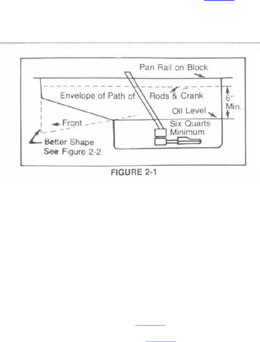
The oil sump should be greatly enlarged so that the oil level is at least six inches below the
crankshaft's path. At least six quarts capacity is necessary as shown in Figure 2-1. The oil pickup
should be converted to a swinging-type unit. The parts to use are PN 2406678 and PN 2406679.
The swinging pickup enlarged-sump system should have proper baffles that will enable the
pickup too stay covered under acceleration and deceleration. We strongly recommend using the
high capacity oil pump P4286740 in all high performance applications.
In a high mileage, extreme serviced engine you may experience rear main bearing oil leakage.
This problem can be solved easily by installing these specially engineered bearings. The bearings
feature special diagonal cut grooves to prevent leakage at the rear main.
P4349040 Slant Six, 1960-76 with Forged Crank
P4349041 Slant Six, 1976-84 with Cast Crank
The Direct Connection filter P4007513 is engineered to meet the demands of heavy-duty and
high performance applications and is recommended for all engines.
Oiling Tip: use nylon insert oil pan screws P4120613 (pkg.).
D. Full Race Oiling System
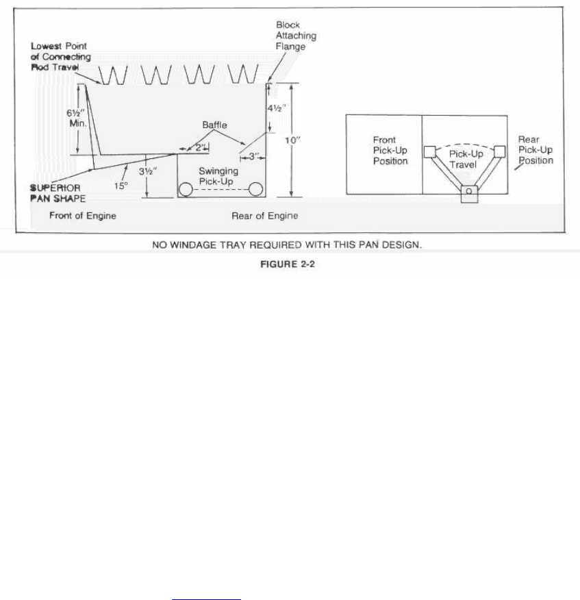
The race oil pan should be designed similar to Figure 2-2. The first item to check before building
a race pan is to determine the lowest point of the connecting rod travel and the relationship of
this point to the pan rail. The dimensions given in Figure 2-2 are measured from the lowest point
in the rod travel not from the pan rail. This means that the pan must be made deeper than the
dimension in the figure by the amount that the lowest point in the rod travel is below the pan rail
or bottom of the block.
The in-car clearances should always be checked carefully before making the pan. The important
items to watch for are header clearance, steering linkage clearance, K-member clearance, and
ground clearance. The K-member will interfere with the front requiring a notch in the front of the
pan or in the K-member. Any notch put in the pan should be kept to an absolute minimum or
eliminated completely if at all possible.
The steering center link will usually pass through the center of the pan. This can be done by
welding a tube through the pan. Again, this tube should only be large enough to allow the
installation of the center link and also to provide learance during the lock-to-lock travel of the
steering linkage. If the rules allow it in the class, the engine can be removed and the center link
dropped or reshaped so that the tube through the pan is not required. Any reshaping or changing
of the center link should be done carefully so that the relationship of the end holes is not changed
at all. If one of these points is moved, it will change the toe pattern of the front suspension which
could be very dangerous in a drag vehicle.
The two baffles shown in Figure 2-2 should be sealed on the three sides next to the actual pan
sides. No oil should be able to pass between the baffle and the sides of the pan or the
effectiveness of the baffle is greatly reduced. The swinging pickup is available from Milodon in
Van Nuys, California. The oil sump should be designed so that the swinging pickup can swing to
the rear of the pan on acceleration and to the front of the pan on deceleration. The pickup should
stop within 1/2" of the back and front of the pan sump.
The sump should be filled with six to eight quarts of oil.
Note: Before installing any parts in engine, make sure that they are free of welding scale, dirt, or
any other foreign matter.
Refer to the oiling system Chapter 18 for further information.
E. Fresh Air System
A good fresh air system can increase a car's performance without affecting much else. A hood
scoop such as that used on the 1969 Road Runner or Super Bee 440-6 bbl. PN P3412057 (scoop
only) can be attached to your standard hood. The air cleaner should be modified so that it is
sealed to the hood. Foam rubber can be used as the seal. There are also complete hoods for some
cars that already have a good scoop such as the 1969 Road Runner or 1970 challenger T/A.
Small scoops are of no value. A scoop should have 30 in. sq. of opening to be effective. See
Chassis Book P4349341.
F. Fuel System
A race car in Formula Stock or Modified Production or similar race cars should use two Carter
4594 electric pumps PN P4007038 in parallel. Parallel means having two inlets and two outlets
rather than one pump feeding into the second pump. The mechanical pump should also be used.
The recommended fuel line is 3/8" diameter and it should be the same diameter from the electric
pumps to the carburetor(s). Only one Carter pump should be used in "Stock" (with mechanical
pump).
The electric pump(s) should be hooked up so that it only works when the key is in the "ON"
position. A separate switch in conjunction with the ignition key is optional.
G. Induction System
The intake manifold and carburetor make up the engine's induction system. The slant six has
used a one barrel, a two barrel and a four barrel intake manifold on production engines. There is
an aluminum version of both the one barrel and the two barrel manifolds. The Hyper Pak four
manifold is no longer available, but a four barrel manifold is available from the Direct
Connection Program, PN P3690801 as is an aluminum two barrel intake P4286281.
1. Carburetion
For any racing application, the carburetor must be specially jetted for proper fuel distribution.
The intake manifolds mentioned above can be used with different carburetors, after-market
manifolds or the manifold heat blocked, all of which require the carb to be jetted differently for
each application. The following sections will cover the more popular choices.
SPECIAL NOTE: Because of the constant changes that occur in racing, the latest up-to-date
carburetor and intake manifold information for the racing packages is covered in Chapter 21.
2. Single Barrels
Any 170 cu. in. slant six having a small BBS carburetor (1-1/4" diameter venturi) will produce
about 5% more power when the 225 cu. in BBS carburetor (1-11/32" diameter venturi) is
installed. These two carburetors can be identified by measuring their throttle bore diameter. The
larger carburetor has a 1-11/16" diameter throttle bore and the smaller carburetor has a 1-9/16"
diameter throttle bore. All 170 manual transmission jobs and the 1960-1961 170 with automatic
transmission have the smaller carburetor.
3. Two Barrels
a. Two Barrel Conversion Available from Mopar
A two barrel setup (as used on the 225 cu. in. export and marine engine) is available from Mopar
as follows:
Intake Manifold PN 2806816
Carter 2 Bbl. Carb. PN 3462779 (1.44 throttle bore)
Air Cleaner PN 2465310
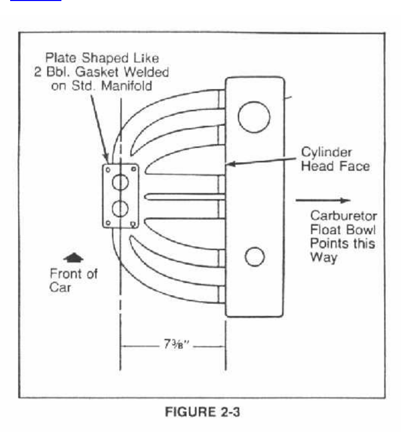
b. Do-it-yourself Two Barrel
The two barrel carburetor from any 318 V-8 engine (without CAP package) can be used as
shown in Figure 2-3. It is larger and shouldn't need to be rejetted.
c. "B" Engine Two Barrel
The larger two barrel from a 361 or 383 can be installed as in b above. However, low speed
driveability in cold weather may be unsatisfactory for general use.
2 Bbl. Manifold Iron 4041042
Alum. 4095066
2 Bbl. Carb. Man. 4027757
Auto. 4027721
If above parts are not available see Section 6 on the next page.
d. Four Barrel
The AFB from the 273 power pack can be adapted to the 225 six cylinder. The four barrel bores
must be centered on the standard six cylinder inlet manifold's plenum chamber.
e. 3-2 Barrels - Race Only
Three Weber dual carburetors 48 IDA will improve engine output nicely compared to Hyper-Pak
inlet manifold and carburetor on the slant six. Obviously, a hand fabricated inlet manifold would
be required; one cylinder per Weber throttle bore.
4. Slant Six Carburetor Calibrations
Hyper-Pak Manifold (possible to use aftermarket manifold like Offenhauser)
Carter AFB 4294S (Chrysler No. 2843111) should be used. This carburetor is used on the 1967-
273 CI 235 HP engine with the manual transmission. Earlier carburetors used with this engine
and manual transmission can also be used.
This carburetor should be modified as follows:
a. Replace the metering rods with No. 16-480 (.068-.065-.051)
b. Replace the throttle arm side secondary jet with No. 120-181 (.0492)
c. Replace the choke side secondary jet with No. 120-365 (.065)
Modified Standard Manifold
The above carburetor is also used with this manifold and should be installed with the primary
throttle bores towards the front of the car.
The carburetor should be modified as follows:
a. Replace metering rods with No. 16-177 (.067-.0655-.064)
b. Replace primary jets with No. 120-386 (.086)
This calibration may be too lean for a highly modified engine in which case a richer mixture
should be used.
5. Four-Barrel Carburetor for all Slant Six Engines
A carburetor that gives proper fuel mixture and distribution characteristics for the six cylinder
engine using a Hyper-Pak intake manifold or a modified standard intake manifold can be made
from a Carter model 3854-S carburetor. This carburetor is used on the 1965 and later 273 cubic
inch high performance engine. The modifications are as follows:
a. Replace the metering rods with No. 16-177 rods (.067-.065-.055" Dia.)
b. Replace the throttle side secondary jets with No. 120-181 jets (.049" Dia.)
c. Replace the choke side secondary jet with No. 120-386 jets (.065" Dia.)
d. Replace the pump jet clusters with cluster No. 48-264S
The throttle linkage will have to be fabricated to match the installation.
Special Note: We only recommend the 4 BBL package for racing.
6. Carb and Manifold Update
In the last couple years several new intake manifolds and carburetors have been introduced for
the slant six. Although they have all been produced on the 225, they will fit the 170 and 198 also.
In 1975 an aluminum intake manifold PN 3837608 for the one barrel was introduced on the
Feather Duster package. In 1977 the Super Six two barrel package was introduced. This package
has an aluminum two barrel manifold PN 4095066 and two barrel carb PN 4027721. This is a
standard-type Carter two barrel with 1.44" throttle bores.
The problem with the 2 BBL intakes listed in this section and early ones is that they are not
available. Ordering the number listed gets you a superseded manifold made of cast iron. The 2
BBL intake that you want to order is D.C. part number P4286781. The carb (2 BBL) to use with
this manifold is PN P4286782. This package is also the best for dual purpose performance.
Larger two barrels should be used for higher performance before the 4 BBL is installed for all-
out racing.
H. Camshafts and Valve Gear
The '71-77 camshaft (244 degree duration .410" lift) is a good choice for the older engine which
had only a 232 degree duration .400" lift cam. No other special pieces would be required.
The next step up would be the Hyper-Pak cam (276 degree duration .430" lift) which is
borderline for driveability even when used with a manual transmission and a high numerical axle
ratio. The Hyper-Pak cam is not recommended for use with an automatic transmission. The H.D.
valve springs from a 340 (PN 2863439) are required with this camshaft. It also is very difficult to
obtain. We recommend the next step because it offers more performance with less duration.
The next step up in hot rod camshafts is the PN P4286679, which is a 268 degree duration .460"
lift design. This is a good cam for general high performance applications with a high numerical
axle ratio. The 340 valve spring should be used with this cam also.
The race cam for the slant six that is carried by the D.C. Program is the PN P4286681 which has
a duration of 276 degrees and .490" lift. This cam should use the new high performance spring
PN P3614542 or P3412068.
These last two 6 cylinder cams are brand new designs and represent the highest state of camshaft
development to date. Most 6 cylinders aren't going to be in need of any bigger cams but they are
available.
It appears that the Racer Brown ST-21, STX-21 and STX-22 should perform well in fully
modified engines. Racer Brown pushrods, retainers, valve springs, and so on should be used. No
slant six dynamometer work has been done at Chrysler with these cams, but these cams have
produced power very well in the Chrysler wedge head V-8's. The STX-21 has a. 560" lift, while
the STX-22 has .590" lift. If in doubt, use the smaller D.C. profiles listed above.
1. Retainers & Keepers
The standard steel retainer can be used with the standard type springs such as the 340. An
aluminum retainer PN P3412067 can also be used with these springs. This aluminum retainer can
also be used with the race valve springs. An Apollo titanium retainer PN P4007178 can be used
for race competition. If required, there is a 3/8" stem lash cap P3690763 that can be used.
There are three designs of lock grooves used on valves. There are hardened valve stem locks or
keepers available for each design for the 3/8" stem slant six valves.
1 Groove P3690797
2 Groove P3690856
3 Groove P3690857
2. Pushrods
The standard 170 and 225 mechanical lifter pushrods are acceptable for most purposes. If the
block and heads have been milled excessively, the length of the standard pushrods may be
unacceptable. If this is the case or a custom length pushrod is desired, the pushrod kit PN
P4007284 (which will make 16 pushrods - 4 extra) is recommended. Individual replacements
(which will make one pushrod) are available under PN P3690988. (Total of 12 required, no tool
included.)
3. Degree Bushing
The B-RB engines use a pin in the end of the camshaft to locate the cam in relation to the cam
sprocket. By using offset bushings (package of 4 - PN P3690936) inserted into the sprocket, the
installed centerline of the camshaft can be changed (advanced or retarded).

4. Timing Chain
For heavy duty use, there is a roller timing chain setup available. Cam Sprocket P4007715,
Crank Sprocket P3690280, Roller Chain P3690279.
5. Viton Valve Seals
The viton valve seals (P4120492) are sold as a package of sixteen - 8 intake and 8 exhaust. Only
12 used on 6. They are not the same. The short one goes on the exhaust valve.
Note: If dual springs are used, then use PC package P3690963.
6. Valve Spring Recommendations
6 Cylinder Valve Spring Recommendations
Camshaft Duration Lift Valve Spring
------------------------------------------------------------
P4120243 244 .436 P4286813
P4286679 268 .460 P4120249
P4286681 276 .490 P3412068
7. Tappets
The three camshafts listed above use a standard style mechanical tappet P4286774. This can be
used as service replacement on all production 6 cylinder mechanical cams. The aftermarket cams
(Racer Brown, Crane etc) may use a different style. Be sure to check with the manufacturer.
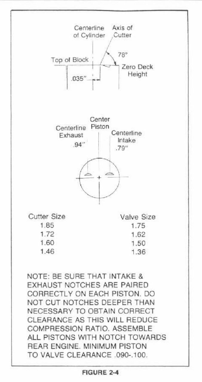
8. Notching the Piston for Valve Clearance
In many cases when large, long duration and/or high lift camshafts are installed in stock engines,
a notch in the piston is required. The proper location for these notches is shown in Figure 2-4. As
a general rule camshafts in the 225 of 290 degree duration and longer will require a notch. The
'72-77 low compression engines aren't as critical as the earlier 170, 198 engines. This holds true
only as long as the heads have not been milled or the block decked. Clearances in the 170 are
also much closer and camshafts bigger than stock should be checked for valve-to-piston
clearance.
J. Cylinder Heads
The cylinder heads on the slant six engine are very straight forward and require very little special
or custom machining or other items. The head is very rigid and very few head gasket problems
are ever encountered especially if the steel gasket is used. There are several special
considerations which we will cover in the next few sections.
1. Big Valves
The standard six cylinder valves are 1.62" inlet and 1.36" dia. exhaust. Bigger valves can be
installed as follows:
Exhaust Valve (Oversize)
The 1957 Dodge V-8 exhaust valve #1827958 makes a very convenient oversize valve for the
slant six. The head diameter is 1.5" or .140" oversize and the length is satisfactory. It is necessary
to provide a clearance notch at the top of the bore. Outdated info see below. Included for
reference only.
Inlet Valve (Oversize)
The 1-3/4" dia. 1634744 exhaust valve from the 1957 or 1958 Chrysler 392 V-8 can be made
into a .130" oversize inlet valve. However, it is necessary to reduce its length by .270" and cut
three more lock grooves down the stem. No bore notch is required for clearance for this oversize
inlet valve. Outdated info see below.
Oversize Intake and Exhaust Valves Update
The two paragraphs above list oversize valves from older Chrysler engines. These work fine but
may be very hard to find today. This can be solved by using D.C. intake valve P4286785 which
has a 1.70" diameter and exhaust valve P4206786 which has a 1.44" diameter. No bore notch is
required with either of these valves.
2. High Flow with Standard Valve Diameters
Oversize valves are expensive and involve much more work, bigger cuts etc. In many cases the
racer is looking for more performance but without the added expense and extra grinding. High
flow, standard diameter valves are ideal for this application: Intake P4286783, Exhaust
P4286784. They are interchangeable with the stock ones but they're backcut to help flow more
air which helps increase horsepower.
3. Valve Grinding
The intake and exhaust valve seats and the intake valve face have a 45 degree angle. The exhaust
valve face has a 43 degree angle. The concentricity of the valve seat should be measured using a
dial indicator. Total runout should not exceed .002" (total indicator reading). The width of the
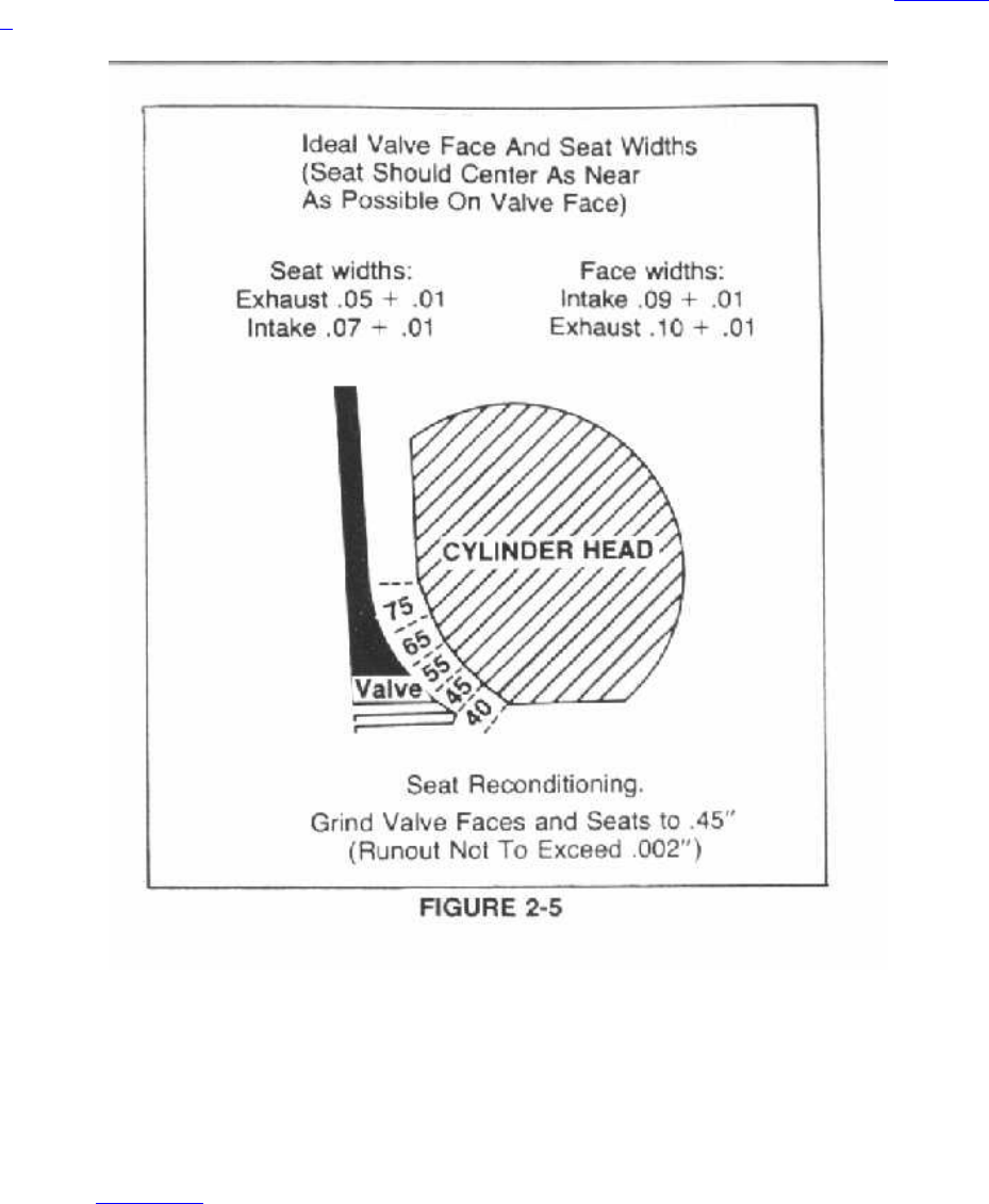
intake seats should be .060" to .090". The exhaust seat width should be .045" to .060". It must be
remembered that the further the valve seats sink into the ports, the less horsepower the engine
will produce. Never sink the valves to equalize the combustion chamber volumes. Although it is
not legal for Stock and Super Stock racing, the full radius or multi-angle valve job (see Figure 2-
5) is a performance improvement over the standard valve job.
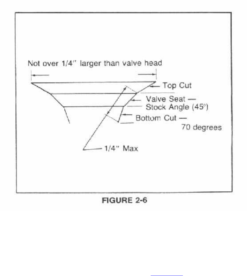
For NHRA stock or super stock valve job, the following rules apply:
The valve must be faced at factory specification angle, and the seat angle must also meet factory
specs. The valve seat may be narrowed from the top with any angle less than the seat angle, but
not to exceed 1/4 inch larger than the valve head (see diagram). The maximum width for valve
seat and bottom cut may not exceed 1/4 inch when measured together (top of seat to bottom of
cut). See Figure 2-6.
4. Bracket Valve Job
In class racing (SS/A, F/S, B/SM etc.) there are very specific rules regarding valve work and seat
modifications. In bracket racing, however, there are no rules regarding valve grinding. Therefore,
we can have a special "bracket valve job", sometimes referred to as a competition valve job. The
valve part is relatively easy. Production wedge valves have a small ski-jump on their backside
just below the seat itself. The "backcut" removes this (see Figure 2-7).
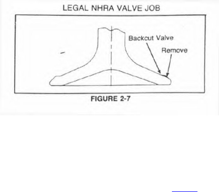
Backcut angles vary from 20 to 35 degrees depending upon the engine. Backcut valves are
available for the 6 cylinder engines (see section 2). Backcutting the valve tends to make the
valve seat narrower, for which we strongly recommend that bronzewall valve guides be installed
in the head.
Modification of the valve seat in the head is not as easy to explain. The valve seat itself is 45
degrees, standard. The throat or approach angle is 70 degrees, but sometimes 65 degrees is used
because the orbital grinder used to grind the seats occasionally will "chatter" at 70. relatively
speaking, the 70 degree cut in the throat removes a lot of material, which leaves a sharp edge at
the bottom 70 degree machine cut as it transfers to the "as cast" port. (See Figure 2-8).
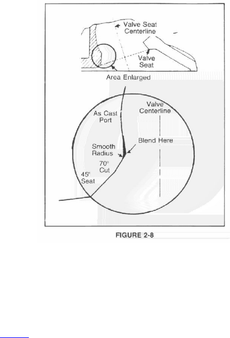
This sharp edge should be removed very carefully with a hand grinder so that it blends smoothly
into both the cast port and the 70 degree machined cut. It is very important to keep to a minimum
the metal removed and to maintain the 70 degree cut - although it may be narrower than it was
originally. Extra caution should be used on the port's "short side" to keep as much radius as
possible.
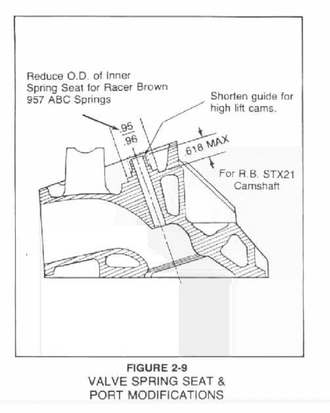
5. Valve Guide Cutting
To install the dual valve spring PN P3412068, or P3614542 or other race type valve springs, the
inner spring seat needs to be narrowed and also its height of the guide needs to be cut down. See
Figure 2-9 for details. It is also recommended that for the high lift cams, such as the Super Stock
roller cams, that the stock valve guide height be shortened by .100". For Super Stock and fully
modified drag race only engines, valve seals are not used but the valve guide clearance is
decreased to .001" on both intake and exhaust valves.
K. Short Block
When assembling a slant six engine, most of the miscellaneous small parts such as cam bearings,
timing chain and sprockets, rear main seal, camshaft plug and freeze plugs are the same between
the various engine sizes.
When reassembling your short block you'll need a variety of Plastigauge (P4286819) to measure
bearing clearances. This popular assortment includes one blue strip for .004-.009" tolerances,
two red strips for .002-.006" tolerances and two green strips for .001"-.003" tolerances. Each
strip is 12" long.
A chemical kit belongs on every mechanic's work bench...for life's mechanical frustrations, like
baked-on gaskets, and for assuring proper seals, for assembly lubing, freeing up nuts and dozens
of other uses. Eleven separate chemical products in each kit: Silicone RTV; Gasket Remover;
Lubriplate; Spray White Lube; Anaerobic Gasket Maker; Lock'N Seal; Brake and Carb Cleaner;
Penetrating Fluid; Spray Gasket Adhesive; Thread Sealant with Teflon; and Hand Cleaner.
Everything you'll need to spare a headache is in this convenience kit. P4286559. We suggest
having this kit on hand before you start rebuilding your short block.
If the head or block or both have been milled a total of .080" or more, we recommend using
hardened washers P4120457 on the head bolts upon reassembly.
1. Pistons
Factory pistons have the pin offset to reduce piston slap. By reversing the offset (reversing the
piston) engine friction can be reduced. Forged racing pistons for the slant six are available from
TRW (their part no. L2125F). Other manufacturers such as Forged-True and Venolia also offer
forged pistons for the six.
It is possible to make the dome too high and too sharp which can have an adverse effect on the
output of the engine. If this is the case, then some of the blocking dome should be removed and
some of the steep angles and sharp edges should be rounded over.
2. Connecting Rods
Do not increase connecting rod side clearance beyond the specified .017" (the acceptable range is
.008" to .017"). Excessive side clearance increases the oil demand of the engine as a result of
excessive oil leakage past the rods. Increasing oil demand reduces the oil available for
lubrication and cooling at high speeds.
Rods from the cast crank engines are unique and are not interchangeable with any of the other
slant six rods. All the slant six rods use a pressed pin. For any heavy duty application the high
strength rod bolts and nuts should be used.
3. Engine Break-In with Rough Bore Finish
When chrome flashed rings are used, the cylinder bore finish should be 30-40 micro inches. This
is fairly rough compared to production bore finish of 20-30 micro inches. Use a medium stone
and clean it frequently to avoid scratching the bores. The cross hatch angle should be 45 degrees
- 60 degrees (included angle).
The proper break-in procedure with the above bore finish is:
Number Shift Cycles Shift Speed
10 @ part throttle 3500
5 @ part throttle 5000 cool down to dead cold
3 @ part throttle 6000
3 @ open throttle 6500 cool down.
RACE
NOTE: Engine should not get over 180 degrees during the break-in cycle.
4. Engine Break-In with Smooth Bore Finish
With the new smooth hone finish (AN 501 Sunnen stone-wet) on the cylinder walls, the
following procedure should be used for engine break-in:
Each run should consist of short interval 1/2 to 2/3 load bursts.
5-6 runs total beginning at 4500 rpm
Increasing the engine speed each time approximately 500 rpm.
Final run of break-in cycle - Max power rpm.
NOTE: Engine should not get over 180 degrees during break-in cycle.
5. Balancing
It is not necessary to balance an engine using production parts (crankshaft, rods, pistons) for
dragstrip use. Production balance tolerances are more than adequate. A race engine should be
balanced.
6. Head Gasket
If trouble is experienced with blowing head gaskets in modified high compression engines, a
steel head gasket (PN P4286789) ('60-'80) is also available.
A composition gasket P4286790 ('81-'84) is also available. The comp gasket will fit on the older
engines and is recommended for gasket sealing problems.
7. Stroking
The only production part available to stroke the six is in the installation of the 225 crank into the
198 engine. This requires the 225 crank and rods. Likewise, any specially made stroker crank
will also require either special rods or special pistons or both. The assembly should be
rebalanced.
8. Honing Plates
For the serious all-out race engine, honing plates are recommended. Honing plates from other
engines like the A or Hemi won't work on the slant six engines because the head bolts are located
in the wrong place. Honing plates for the slant six engines are not readily available at this time.
L. Exhaust System
The special exhaust pipe, muffler and exhaust manifolds from the Hyper Pak six are no longer
available.
1. Mufflers and Pipes
The exhaust system from the '75-76 Feather Duster and Dart Light is the best system currently
available. The large dia. pipe from the manifold to the converter is PN 4004379. The catalytic
converter and pipe assembly is PN 4004147, while the muffler is PN 4004381. This is a bolt-in
system on the various '67-76 "A" body cars.
For hot rod applications, the large diameter pipe PN 4004379 can be adapted to a street hemi
muffler PN 2781300 for a low restriction exhaust.
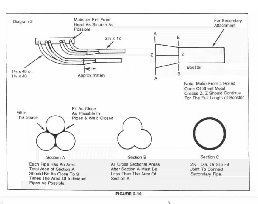
2. Headers
Cylinders 1-2-3 should exhaust through 1-1/8" or 1-3/4" O.D. pipes about forty inches long into
a cloverleaf collector and then through a 2-1/2" O.D. outlet pipe much like current V-8 Super
Stock practice. Cylinders 3-4-5 should have a duplicate system. See Figure 2-10.
The Direct Connection six cylinder headers PN P4007602 are a 15/8 x 40 primary with 2-1/2
collector design which fit the '67-76 A-Body and '62-74 B & E Body.
M. Compression Ratio
Up to .090" can be removed from the slant six cylinder head. The slant six cylinder head has an
especially thick lower deck surface.
For example, removal of .090" will raise the compression ratio of a 225 engine from 8 to 1 up to
9.5 to 1. Removal of .090" will raise the compression ratio of a 170 engine from 8 to 1 to 10 to 1.
Using high quality gasoline such as Sunoco 260, compression ratios between 11 and 12 to 1
should perform satisfactorily on the dragstrip. "West Coast" pistons would be required to attain
ratios this high. Step seal "Dykes" top piston rings should also be used because they lower
engine friction at high speeds. Forged racing pistons should be fitted at .008" to .010" clearance.
The following charts show the resulting compression ratios from a variety of deck heights,
cylinder head volume and bore sizes.
SPECIALL NOTE: Domed pistons and Dykes rings eadily available for the slant six.
COMPRESSION RATIO - 170 CUBIC INCH ENGINE
Cylinder
Deck Head Std. Compression Ratio
Height Volume Bore .020 oversize .040 oversize
---------------------------------------------------------------------
-.040 54.00 8.39 8.46 8.54
52.50 8.57 8.65 8.72
51.00 8.76 8.84 8.91
-.020 54.00 8.75 8.83 8.92
52.50 8.95 9.04 9.12
51.00 9.16 9.25 9.34
.00 54.00 9.16 9.25 9.34
52.50 9.38 9.47 9.55
51.00 9.61 9.71 9.81
COMPRESSION RATIO - 198 CUBIC INCH ENGINE
Cylinder
Deck Head Std. Compression Ratio
Height Volume Bore .020 Oversize .040 Oversize
----------------------------------------------------------------------
-.075 54.00 8.95 9.02 9.10
52.50 9.13 9.20 9.28
51.00 9.31 9.39 9.47
-.055 54.00 9.31 9.39 9.47
52.50 9.51 9.59 9.67
51.00 9.71 9.79 9.88
-.035 54.00 9.71 9.79 9.89
52.50 9.92 10.01 10.11
51.00 10.15 10.24 10.34
COMPRESSION RATIO - 225 CUBIC INCH ENGINE
Cylinder
Deck Head Std. Compression Ratio
Height Volume Bore .020 Oversize .040 Oversize
----------------------------------------------------------------------
-.140 54.00 8.89 8.95 9.02
52.50 9.04 9.11 9.17
51.00 9.20 9.27 9.34
-.120 52.00 9.20 9.27 9.34
52.50 9.37 9.44 9.51
51.00 9.54 9.61 9.69
-.100 54.00 9.54 9.61 9.69
52.50 9.72 19.80 9.88
-51-00 9.90 9.99 10.07
NOTE: All compression ratio figures are with a standard steel head gasket with a compressed
height of .020".
N. Boring and Milling Specifications
All the 1970-1976 slant six engines can be overbored .060" maximum. The thin-wall lighter
weight 1977-1982 blocks shouldn't be bored past .030" oversize.
However, if the engine is to be used for high output racing purposes, the cylinder wall thickness
should be checked to be sure that that particular block doesn't have a bad case of core shift. The
cylinder wall thickness should be the same all the way around or thicker on the major thrust side,
i.e. passenger side, of the cylinder bore as installed in the car.
Milling the cylinder head will reduce its volume and increase the engine's compression ratio. To
reduce the chamber volume one cc., mill the head .0063". The intake manifold surface doesn't
have to be milled.
O. Engine Clearances
Conn. Piston
Engine Brg. Clear. Rod Side To-Well Ring
Disp. Rods & Mains clearance Clearance End Gap
------------------------------------------------------------------
225 .0015/.0025 .008/.017 .0015/.002 .011/.015
198 .0015/.0025 .008/.017 .0015/.002 .011/.015
170 .0015/.0025 .008/.017 .0015/.002 .011/.015
P. Torque Specs
Connecting Rod Nut - Std. 45 ft lbs.
H.D. 50-55 with oil
Cylinder Head Bolt 65
Main Bearing Cap Bolt 85
Spark Plug 30
Camshaft Lock Bolt 35
Carb to Manifold Nut 30
Exhaust Manifold Nut 10
Flywheel to Crankshaft 55
Flex Plate to Crankshaft 55
Flex Plate to Converter 270 in lbs.
Intake to Exhaust Manifold Bolt 200 in lbs.
Rocker Shaft Bracket Bolt 30 ft lbs.
THE SLANT 6
IV. SPECIAL CAR PACKAGES
Several special car packages have been produced using the slant six as the base engine. The
following information is an outline of what these packages consisted of.
A. 1960 Hyper Pak 170
The Hyper Pak was the highest output per cubic inch slant six ever produced - It had a long
duration, high lift camshaft and special valve springs, high compression pistons, four barrel carb
and special intake manifold. This makes for an excellent racing package.
Mopar Hyper Pack Major Components:
PART #. NAME
--------------------------------------------------------
2205620 Assy - Camshaft
1944554 Assy - Valve Spring & Damper
2129619 Assy - Valve Push Rod
2129898 Manifold - Intake
2129899 Manifold - Exhaust - Front
2129900 Manifold - Exhaust - Rear
2129881 Assy - Carburetor
2121952 Gasket - Carburetor Flange
2129992 Assy - Air Cleaner
1821170 Gasket - Air Cleaner
2201223 Assy - Clutch Cover & Pressure Plate
2201219 Assy - Clutch Driving Disc
1636570 Gasket - Exhaust Pipe Flange
2298350 Assy - Muffler & Exhaust Pipe
NOTE These part numbers are given for reference only: The actual parts are no longer available!
B. 1975-76 Feather Duster and Dart Light 225
This package was specially designed for fuel economy. The engine part of the package consist
mainly of an aluminum intake manifold and low restriction exhaust system based around a larger
diameter header pipe.
The body part of the package featured lightweight aluminum panels. The chassis also had special
items such as a four speed overdrive transmission.
C. 1977 Super Six
The super six is the latest package on the slant six. It consists of a two barrel carb and special
aluminum two barrel intake manifold.
THE SLANT 6
V. RACING ONLY PACKAGES
Now that the individual systems and special parts have been covered, we can try to put them
together into a complete engine package to go racing. Be sure to refer to earlier sections for
further details.
A. NHRA Stock
Stock Eliminator is the best place to race the slant six in class-type racing. The best classes are
U, V, W, X/S.
The fuel system should be one Carter electric fuel pump PN P4007038 at the rear and one
standard mechanical pump on the engine. The oil system should use the stock pan with an
acceleration baffle added along with the windage tray set 1/8" from the rod bolts and crank.
The high output electronic ignition is the best ignition for racing and the .040" wide gap plugs
should be used.
The 1-5/8" primary tube headers should be used. A "cheater" or "blueprint" camshaft is a must.
They can be obtained from Competition Cams, Crane, Lunati, etc. The stock valve spring
specifications must be met. See Bulletin #35 for further details.
B. NHRA/IHRA Super Stock Racing
The best choice for racing the slant-six in NHRA/IHRA Super Stock competition is the 1960
HyperPak Valiant. The four-door sedan fits into SS/U. In NHRA competition 17.0 pounds per
horsepower is the lowest class. If lower classes were used and the current 75# rule is in effect,
the sedan also makes a good car in the 18.0 class and the wagon fits well in the 19.0 class.
The original Hyper-Pak four barrel manifold is probably the best bet for intake manifolds. Refer
to Chapter 21 for jetting information.
A good camshaft choice would be an DC-276 P4286681 as a baseline step and progressing to an
STX-22. Both cams are require special valve springs and retainers which are available from the
340 racing program. The part numbers are mentioned earlier and they are available from the
Direct Connection Program.
The minimum head volume is 52.3 cc. The HyperPak has domed pistons for higher compression
ratio. The dome height is .250" above the block and the dome volume is 13.7 cc. These special
domed pistons should still be available from Forged-True. The electronic ignition should be
installed on any Super Stock engines. This conversion is covered in an earlier section. The all-
out Super Stocker should use not only the electronic ignition distributor, but also the Multi-Spark
conversion as well.
NHRA/lHRA Legal Specifications
Min. Max. Head
Engine Head Dock Milling
Disp. Vol. Height Spec's
----------------------------------------------------------------------
1960 Hyper-Pak To reduce the chamber
1963-71 225 53.8 - .141 volume, remove .0066"
1970-71 198 53.8 - .0765 from the head surface
1963-71 170 53.8 + .000 per 1cc. of chamber
1972-71 198 54.0 - .075 volume.
1972-75 225 54.0 - .140
1976-83 225 54.0 - .115
*Dome displacement 13.7 cc.
C. IHRA/AHRA Formula Stock Racing
A two-barrel manifold with carb should be installed along with a set of headers. The camshaft
should be a D.C. P4286681 - 276 degrees. The good valve job and a .090" head mill (to
approximately 45 cc.) should be done and the 340 valve springs installed. The electronic ignition
system should also be used. It is important to build a good deep sump oil pan and modify the oil
pump pick-up. We also recommend installing a windage tray. A fresh air hood scoop should be
added - It is important to seal the carb to the head scoop. (See Figure 2-11.)
D. Sportsman or Circle Racing
The 1/2 mile or so circle racing groups have many different rules, but most have a special class
for the 6 cylinder engines. Where the rules allow the top two barrel carb, the above Formula
Stock package will work well. The top ring gap should be on the high side (.015) and a special
oil pan and pickup will have to be used. The P4286681 cam, the 340 race type valve springs and
pushrod kit should be used along with Gold Box P4120600 ignition system.
E. IMSA Sports Car Racing
The IMSA Sports Car Series for small, lightweight compact cars accepts the 225 Feather
Duster/Dart Light as legal packages for this class. The 225 engine with 4-speed transmission
would make a very competitive car in this class using much of the "Chrysler Kit Car" science.
F. Bracket Racer
In Bracket Racing low cost and reliability are very important. Here the slant six really shines.
The two barrel and the P4286779 cam make a good racer package. The electronic ignition and
the windage tray are also recommended. Refer to the latest Direct Connection catalog's 6
cylinder section for more bracket racing tips or Chapters 31 & 33 later in this book.
G. Four Speed Manual Transmission Installation
There is a lot of interest in installing the Chrysler four-speed behind the slant six. The original
pieces used in '64-66 slant six four-speed packages are no longer available; but, the '75-77 pieces
will work fine. The bellhousing PN 3743645 will accept the A-833 Chrysler 4 speed, but it has a
very large transmission pilot diameter. The 340 transmission has the small drive pinion bearing
and can be used in the six's bellhousing by using the special drive pinion bearing retainer PN
3878596. If the overdrive transmission is desired, it uses the special retainers so that it doesn't
need to be changed.
There are two overdrive transmissions, one with a cast iron case PN 3878005 and one with an
aluminum case PN 4028477.
Special Note 1: Many part numbers listed in this chapter are given for reference. They may not
be currently available.
Special Note 2: The information listed in this chapter is more up-to-date than any other
recommendations. Therefore this chapter supersedes all previous 6 cylinder engine bulletins and
books.

Slant Six Cylinder Heads
Introduction
One of the most important parts of an engine assembly is the cylinder head. It holds the key to
making power. It also offers the opportunity to make more horsepower. Cams, headers,
carburetion can only go so far making horsepower without the cylinder head. However cylinder
heads can be expensive but may be one place in the engine where spending the extra money may
be worth it.
GENERAL BACKGROUND
We will leave most of the specific details on the cylinder heads, how to prep, etc. to the various
engine chapters. Please refer to them earlier in this book. We will include cylinder head torque
sequences and the various casting numbers for reference. In this chapter we will concentrate on
photos and sketches showing various features of the heads.
6 CYLINDER ENGINE
All slant-six cylinder heads are interchangeable. There are no major differences between the
various heads. The simplest way of identifying the various heads is by thehead casting number.
A. Casting Numbers
Head
Casting
Year Number
---------------------------
'64-66 2206035
'67-74 2843169
'72-73 3614850
'72-74 3698995
'75-77 3698447
'78 3698447
'79-80 4104362
'81-82 4095778
Note: The '75 and newer heads no longer use spark plug tubes. It also uses the small "BL" series
spark plugs and the tappets can't be removed with he head installed on the engine. The tappets
can be removed with the head installed on the older engines.
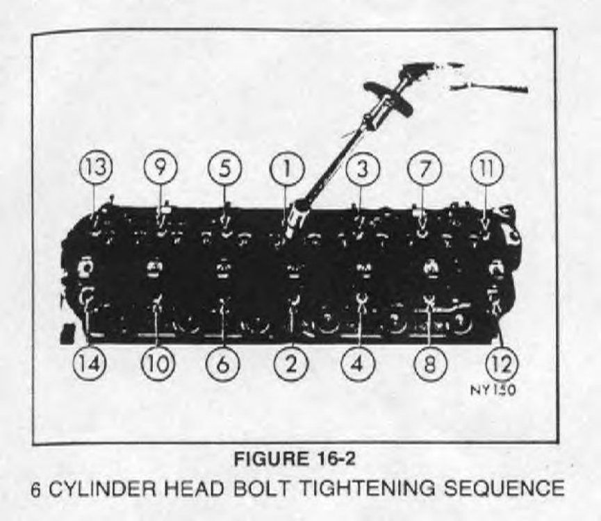
B. Torque Sequence
The chrome alloy cast iron cylinder head (Figure 16-1) is held in place by 14 bolts. Spark plugs
are located at the wide edge of the combustion chambers and aluminum spark plug tubes serve as
spark plug gaskets. Install cylinder head bolts. Starting at top center, tighten all cylinder head
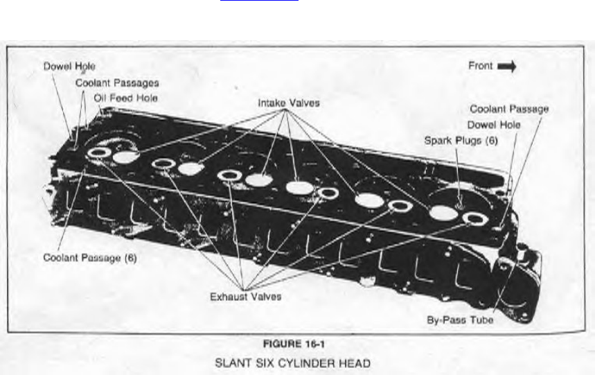
bolts to 50 foot-pounds in sequence (Figure 16-2). Repeat the procedure, retightening all cylinder
head bolts to 65 foot-pounds.
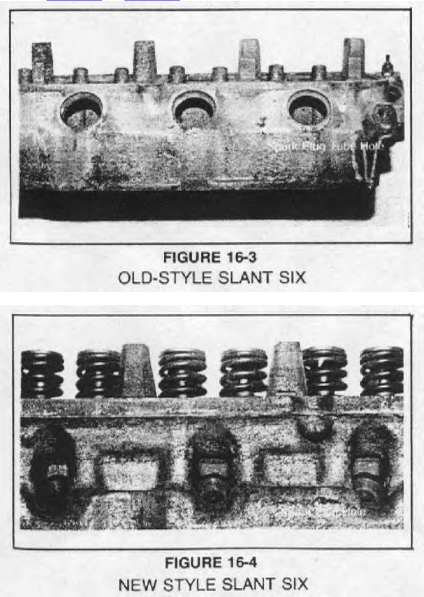
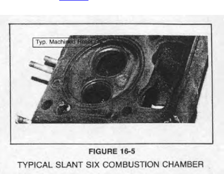
Comparing Figure 16-3 and Figure 16-4 the difference in spark plug arrangement can be seen.
The outside edges of the 6 cylinder head's combustion chamber is machined or relieved next to
the two valves as shown in Figure 16-5. If oversized valves are installed these reliefs should be
enlarged.
IV.
A. ENGINE
There are basically only two different cylinder heads that have been used on the "LA" engines
from 1964 to 1984 a small port 273-318 and a big port 340-360. There have been only three
different valve combinations in these heads: one for the 273 and 318 with 1.78" intake and 1.50"
exhaust; one for the 1968-1971 340 with 2.02" intake and 1.60" exhaust; and one for the 360 and
the 1972-1973 340 with 1.88" intake and 1.60" exhaust.
A. Casting Numbers
Casting
Year Engine Number
-----------------------------------------------------
1964-1965 273 2465315
1966 273 2536178
1967 273/318 2658920
1968-1971 318 2843675
1968-1971 340 2531894
1970 340-6 MI. T/A 3418915
1971 360 3418915
1972 318 2843675
1972 340/360 3671587
1973-1974 318 2843675
1973-1974 340/360 3671587
1973 360 w/air pump 3671587
1975 318 3769973
1975 360 3769974
1976 318 3769973
1976 360 3671587-3769974
1977-1979 318 4027163-4027593
360 4027596-4071051
1980 318 4027163-4027593
360 4027596-4071051
1981-82 318-std 4027163-4027593
318 H. P. 4027596-4071051
Direct Connection Mopar Cam Chart
One word of caution relative to degree wheels. The DC degree wheel (P4286552) is a zero-to-
180 design, which will yield the numbers listed above. Other manufacturers carry 0-degrees-90-
degrees-0-degrees design degree wheels, which will not directly yield the numbers above. For
example, the 130 degrees on the DC wheel would be 50 degrees on the other style. The correct
answer is obtained by subtracting 50 degrees from 180 degrees for 130 degrees or by subtracting
50 degrees from 90 degrees (answer 40 degrees and adding this to 90 degrees (40 degrees + 90
degrees = 130 degrees). Using the DC degree wheel eliminates a lot of confusion and lessens the
possibility of making errors.
Note: Degree Tape P4120993; 'A' offset keys new PN P4286500; B, RB HEMI offset bushing
P3690936.
The cam chart that lists the various cams sold by the Direct Connection in the last few years
follows. It is based on rocker ratios of LA-1.5, B-RB-1.5, Hemi-1.57I, 1.52E.
Direct Connection Mopar Cam Chart
Design Cam Int.
Lift @ Centerline Valve Lash
Engine Cam Kit # Cam I.D. Duration Valve @ Retainer Intake Exhaust
-----------------------------------------------------------------------------------------------------------
----
6 Cyl. P4120243 D.C. 244-108 244 .436" 102 .010 .020
6 Cyl. P3690766 SS14-112 268 .450" 108 .016 .020
6 Cyl. P3690768 ST21-110 286 .520" 108 .016 .020
A Eng. P3412044 68 340 Man.-114 276/284 .444/.453" 112 Zero
A Eng. P3690213 Street Hemi GT-112 284 .471/.474" 109 Zero
A Eng. P3690769 SSH-44-108 292 .510" 110 Zero
A Eng. P4007619 SSH-25/44 286/292 .485/.510" 108 Zero
A Eng. P4007275 C. D. Stock "Cheater" 336/348 .462/.473 108 Zero
A Eng. P4120231 D.C. 284-108 284 .484" 108 Zero
A Eng. P4120231 D.C. 292-108 292 .509" 108 Zero
A Eng. P3412016 ST21-108 286 .520" 110 .018 .022
A Eng. P2836146 STX21-105 306 .560" 105 .028 .032
A Eng. P4120653 D.C. 284-112 284 .542" 110 .028 .032
A Eng. P4120655 D.C. 296-110 296 .572" 108 .028 .032
A Eng. P4120657 D.C. 312-106 312 .606" 104 .028 .032
A Eng. P4120148 D.C. 320-102 320 .630" 100 .024 .028
A Eng. P3690795 R280-427-1 10 Crane *280 .640" 108
A Eng. P3690589 Magna. Velocity-110 324 .633" 110 .024 .028
A Eng. P4007278 R-278-284-.413-.427-06 *278/284 .620/.640" 106 .035 .035
Cam Dyn.
A Eng. P4007509 R-284,427-05 Cam Dyn. *284 *284 108 .035 .035
A Eng. P3690796 R-296-4778-1 10 Crane *296 .717" 109 .024 .028
B Eng. P3690214 Street Hemi Gr.-108 284 .471/.474" 106 Zero
B Eng. P3412073 SSH-25-108.5 286 .485" 108 Zero
B Eng. P3690812 SSH-44-108 292 .510" 106 Zero
B Eng. P4007277 C.D. Stock "Cheater" 352/380 .467/.483 108 Zero
B Eng. P4120235 D.C. 284-108 284 .484" 108 Zero
B Eng. P4120237 D.C. 292-108 292 .509" 108 Zero
B Eng. P3690816 Stage 11-115 300/308 .518" 110 .028 .032
B Eng. P4120659 D.C. 284-112 284 .528" 110 .028 .032
B Eng. P4120661 D.C. 296-110 296 .557" 108 .028 .032
B Eng. P4120663 D.C. 312-106 312 .590" 104 .028 .032
B Eng. P3690159 STX-22 310 .590" 108 .028 .032
B Eng. P3690588 Mini Express-107 316 .654" 107 .024 .028
B Eng. P4120042 R280-.4468-08 Crane *280 .670" 108 .035 .035
B Eng. P4007279 R286-500-108 Cam Dyn. *286 .750" 107 .035 .035
Hemi P3690814 SSH-44-108 292 .510" 106 Zero
Hemi P4007945 C.D. Stock "Cheater" 342/348 .490/.480" 103 Zero
Hemi P3412090 STX22-105 310 .590" 104 .028 .032
Hemi P3571029 725-105 340 .643/.623" 103 .028 .032
Hemi P3690587 Mini Express-104 324 .684/.663" 103 .024 .028
Hemi P3690591 R-290-446-104- Crane *290 .700/.678" 103 .028 .032
Hemi P4007253 R292-500-106 Cam Dyn. 0292 .785/.760" 103 .032 .032
Hemi P3690839 R-296-4778-108 Crane *296 .750/.726" 108 .032 .032
-----------------------------------------------------------------------------------------------------------
----
CAM CHART UPDATE
DESIGN REC.
LIFT @ INSTALLATION VALVE LASH
ENGINE CAM KIT # CAM I.D. DURATION OVERLAP VALVE CENTERLINE INTAKE
EXHAUST
-----------------------------------------------------------------------------------------------------------
----
6 CYL P4286679 D.C. 268-108 268 52 .460" 104 .016 .020
6 CYL P4286681 D.C. 276-106 276 64 .490" 102 .016 .020
A Eng. P4286667 D.C. 248-114 248 20 .410" 112 Zero
A Eng. P4286669 D.C. 260-113 260 34 .430" 110 Zero
A Eng. P4286671 D.C. 272-112 272 48 .455 108 Zero
A Eng. P4286630 D.C. 280-110 280 60 .474" 106 Zero
A Eng. P4349266 D. C. 324-106 324 - .620" 104 .028 .032
A Eng. P4349245 Stock Cheater-360 H.P.-106 - - Stock 106 Zero
A Eng. P4349243 Stock Cheater-340-106 - - Stock 104 Zero
A Eng. P4120975 Super Stock- Roller-360-106 309/316 - .630/.650" 106 .035 .035
A Eng. P4120976 Super Stock- Roller-340-106 310/312 - .620/.638" 104 .035 .035
A Eng. P4120977 Mod. Prod. Roller-340-109 323/330 - .690/.630" 107 .035 .035
B Eng. P4286673 D.C.-248-114 248 20 .410" 112 Zero
B Eng. P4286675 D.C.-260-113 260 34 .430" 110 Zero
B Eng. P4286677 D.C.-272-112 272 48 .455" 108 Zero
B Eng. P4286631 D. C. -280-110 280 60 .474" 106 Zero
B Eng. P4349268 D.C.-324-106 324 - .620" 104 .028 .032
P3690588 Mini-Express-107 316 - .654" 107 .024 .028
B Eng. P4349270 D.C.-328-107 328 - .690" 107 .024 .028
B Eng. P4349249 Stock Cheater- Hyd.- 108 - - Stock 106 Zero
B Eng. P4349247 Super Stock- Roller- 108 324 - .750" 106 .035 .035
Hemi P4349259 278 Hyd.-108 278 - .495/.480" 104 Zero
Hemi P4349257 292 Hyd.-108 292 - .524/.507" 104 Zero
Hemi P4349251 Stock Cheater- Hyd.- 106 - - Stock 104 Zero
Hemi P4349253 Super Stock-Roller-106 333 - .785" 104 .032 .032
Hemi P4349255 Pro Stock-Roller-114 328/344 - .747/.700" 114 .028 .030
-----------------------------------------------------------------------------------------------------------
----
Racing Carburetor and Manifold Calibrations
A most difficult thing in racing engine development is to understand fuel distribution among the
cylinders and get it correct in the engine at the race track. Fuel distribution is also an area where
small changes can result in big gains or big losses. The only accurate way to determine what
these small changes should be is to use a dynamometer with mixture level analysis on each
cylinder. The purpose of this tune-up manual is to relay to the racers the fuel distribution
information accumulated over the years from Chrysler dynamometer development programs.
Fuel distribution is the cylinder-to-cylinder variance in fuel-air ratio. It is desired that the
cylinder not be too lean or too rich and that all the cylinders be the same fuel-air ratio through
the engine speed range. It is obvious from this that the carburetor and intake manifold work as a
team. A stock carburetor that works well on a stock manifold may not work well on a race intake
manifold. A race carburetor that performs well on a race manifold may perform poorly on a
stock manifold.
In most cases, drag racing requires certain changes to be made to any carburetor and special
manifold modifications to go with the carburetor that is to be used. These modifications have
been determined on the dynamometer for the best overall engine output for Super Stock,
Modified Production and Bracket racing. The most popular racing packages with the commonly
available manifolds will be covered by engine family, i.e. 6 cylinder, LA engine, B engine, RB
engine and Hemi.
This revision supersedes all previous information. This bulletin represents the latest
developments that our dynamometer and drag strip testing have shown to work. Many carb-
manifold packages are left in for reference only. It's the latest information that we may have on
an out-dated package.
A. C. Nichols & L. S. Shepard Staff Engineers
-------------------------------------------------------------------------
Package: 4 Barrel Set-Up General Multi-Purpose
Carburetor: Holley List 6299
Manifold: Offenhauser Aluminum 4 Barrel PN P3690801
Manifold Modifications: None
Carb Specifications: 390 cfm Holley, vacuum secondaries
Primary Jet: #49
Secondary Jet: #52
Power Valve: 25R-591A-65
PV Channel Restriction: .052
Idle Air Bleed: .078
High Speed Bleed: .043
Diaphragm Spring: Yellow
-------------------------------------------------------------------------
This is the best general purpose four barrel setup for the 6 cylinder engines.
-------------------------------------------------------------------------
Package: 4 Barrel Set-Up Race Only
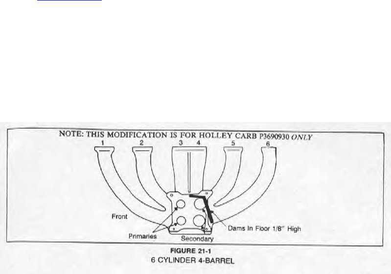
Carb: 4 Barrel Holley List 7191 PN P3690930
Manifold: Offenhauser Aluminum 4 Barrel PN P3690801
Exhaust Heat Blocked
Manifold Modifications: Car mounted with primaries toward the front of
engine. See Figure 21-1.
Carb Specifications: 600 cfm Holley, double pumper dual feed with mechanical
secondaries - Manual Choke
Throttle Bore: 1-9/16 x 1-9/16
Venturi: 1-1/4 x 1-5/16
Primary Jet: #64
Secondary Jet: #72
Power Valve
Channel Restriction: .046
Power Valve: No. 65
Pump Shooter: Primary - .025
Secondary - .021
-------------------------------------------------------------------------
Note: For general multi-purpose or brackets, the previous carb set-up is recommended. This
package is for all-out racing only.
-------------------------------------------------------------------------
Package: 2 Bbl. Set-up with Headers
Carb: 2 Bbl. Carter BBD-81375
Manifold: Production Aluminum
Manifold Modifications: None required.
Carb Specifications:
Throttle Bore: 1-7/16 Primary Jet: 2 Steps Richer
Venturi: 1-1/16 Secondary Jets: N/A
-------------------------------------------------------------------------
-------------------------------------------------------------------------
Package: Hyper Pak Four-Barrel
Carb.: Carter AFB 3083 PN 2129881 (No Longer Available)
Manifold: Chrysler Aluminum Hyper Pak (No Longer Available)
Manifold Modifications: See Figure 21-2.
Carb Specifications: Carter AFB
Throttle Bore: 1-7/16 x 1-9/16
Venturi: 1-1/16 x 1-1/4
Primary Jet: 120-389 (.089)
Throttle Side Choke Side
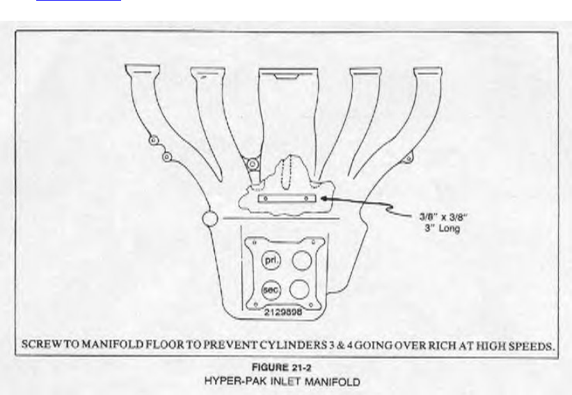
Secondary Jet: 120-350 (.050) 120-365 (.065)
WOT PT
Metering Rod: 16-51 (.060 x .065)
Float Setting: 9/32 Inverted - Measured from float bottom to gasket.
Accel. Pump Shooter: .028
Idle Feed: 035
-------------------------------------------------------------------------
Special Note: This carb and intake manifold system has the primaries of carb facing toward the
engine See Figure 21-2.
