Smart NRG User Guide_Backsoft_v2 Guide Backsoft V2
User Manual: SmartNRG-User-Guide_Backsoft_v2
Open the PDF directly: View PDF ![]() .
.
Page Count: 58
- Safety Instructions
- 1 Introduction
- 2 Installation
- 3 Operation and Configuration
- 4 Remote Monitoring and Configuration
- 5 Maintenance
- 6 Troubleshooting
- 7 Appendix A – Specifications
- Declaration of Compliance
- Warranty

Smart NRG
User Guide
October 2016
© 2015-2016 Blue I Technologies Ltd.
No part of this publication may be reproduced, transmitted, transcribed, stored in a retrieval system, or
translated into any language or any computer language, in any form or by any third party, without the
prior written permission of Blue I Water Technologies Ltd.
Trademarks and Patents
Smart NRG is a trademark of Blue I Water Technologies Ltd.
Patents issued and pending at the time of this printing
Disclaimer
Blue I Water Technologies Ltd. does not accept any responsibility for any damage caused to its products
by unauthorized personnel. Use of non-Blue I Water Technologies’ reagents and/or replacement parts will
void all warranties.
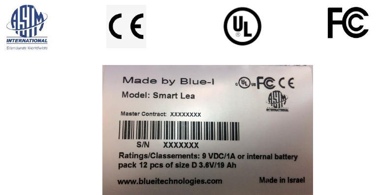
ASTM
CE
UL
FCC
Contents
Safety Instructions __________________________________________________ 5
1 Introduction _____________________________________________________ 7
1.1 Overcoming the Urban Challenge ......................................................................................................... 8
1.2 Functional Overview ............................................................................................................................. 8
1.3 System Overview ................................................................................................................................ 10
1.3.1 Electronic Board Module .................................................................................................... 10
1.3.2 Sensors Board Module ........................................................................................................ 11
1.3.3 Flow Cells ............................................................................................................................ 12
1.3.4 Automatic Leak Detection ................................................................................................... 13
1.3.5 Battery Pack ........................................................................................................................ 13
1.3.6 Shipping of Lithium Batteries .............................................................................................. 14
1.3.7 Fuse Type (F1, F3) ............................................................................................................... 14
1.3.8 CR2032 Battery ................................................................................................................... 14
2 Installation _____________________________________________________ 15
2.1 Site Preparation and Working Environment ....................................................................................... 15
2.2 Verifying the Smart NRG Controller Parts Received ........................................................................... 15
2.3 Installing the Controller ...................................................................................................................... 16
2.3.1 Plumbing Requirements ...................................................................................................... 16
2.3.2 Wall Mounting .................................................................................................................... 17
2.3.3 Installing the System in a Cabinet ....................................................................................... 20
2.4 Setting up the System for First Use .................................................................................................... 22
2.4.1 Inserting Batteries ............................................................................................................... 22
2.4.2 Connecting the Electrodes .................................................................................................. 24
2.4.3 Connecting Water Inlets and Outlets .................................................................................. 25
3 Operation and Configuration _______________________________________ 29
3.1 Installing the PC Software ................................................................................................................... 29
3.2 Connecting to the Controller .............................................................................................................. 29
3.3 First Time Operation and Configuration ............................................................................................. 30
3.3.1 About the Smart NRG PC Software ..................................................................................... 30

Safety
4
© Blue I Technologies
3.3.2 Calibrating Parameters ....................................................................................................... 32
3.3.3 Calibrating Free Chlorine .................................................................................................... 35
3.3.4 Calibrating Other Sensors ................................................................................................... 35
3.3.5 Setting Status Mode Parameters ........................................................................................ 36
3.3.6 Setting Battery Level Alarms ............................................................................................... 37
3.4 Activating Manual Turbo Mode .......................................................................................................... 37
3.5 Configuring Automatic Turbo Mode ................................................................................................... 38
3.6 Viewing the Calibration Log ................................................................................................................ 39
3.7 Viewing the Data Log .......................................................................................................................... 39
4 Remote Monitoring and Configuration _______________________________ 41
4.1 Logging On .......................................................................................................................................... 41
4.2 Configuring the Controllers Parameters ............................................................................................. 43
4.3 Modifying Delay before Measurement, Measuring Interval, and Modem Interval ........................... 44
4.4 Creating Historical Graphs .................................................................................................................. 45
4.5 Monitoring System Parameters .......................................................................................................... 45
4.6 Creating Advanced Reports ................................................................................................................ 46
5 Maintenance ___________________________________________________ 49
5.1 Replacing Batteries ............................................................................................................................. 49
5.2 Chlorine Sensor ................................................................................................................................... 49
5.2.1 Cleaning the Sensor ............................................................................................................ 49
5.2.2 Replacing the Membrane and Refilling the Electrolyte ...................................................... 50
5.2.3 Reconditioning the Sensor .................................................................................................. 50
5.3 Conductivity Sensor ............................................................................................................................ 52
5.4 Cleaning the Flow Cells ....................................................................................................................... 52
6 Troubleshooting _________________________________________________ 53
6.1 Issues and Workarounds ..................................................................................................................... 53
6.2 Unable to Solve an Issue ..................................................................................................................... 54
7 Appendix A – Specifications ________________________________________ 55
Declaration of Compliance ___________________________________________ 56
Warranty ________________________________________________________ 57
© Blue I Technologies
5
Safety Instructions
General Safety Precautions
Use this product only in the manner
described in this manual. If the
equipment is used in a manner not
specified by the manufacturer, the
protection provided by the
equipment may be impaired.
Utiliser ce produit uniquement de la manière décrite
dans ce manuel. Si l'équipement est utilisé d'une
manière non spécifiée par le fabricant, la protection
fournie par l'équipement peut être altérée.
Smart NRG control board unit
should not be opened except for
initial installation and
troubleshooting, and should only be
opened by a trained and approved
technician.
Le tableau de commandes de l’Smart NRG ne doit en
aucun cas être ouvert si ce n’est lors de l’installation
initiale et en cas de dépannage – auquel cas son
ouverture ne doit être effectuée que par un
technicien ayant reçu la formation adéquate et
dûment habilité.
Only properly trained and licensed
electricians should attempt to wire
or service the electronic
components of the
analyzer/controller.
There is an Electrical Shock Hazard
when servicing this system.
Always verify that all electrical
power source(s) are off before
opening the analyzer/controller unit
or attempting to service electronic
components or wiring.
Attention! Seuls des électriciens qualifiés ayant reçu
la formation adéquate peuvent entreprendre le
branchement, l’entretien ou la réparation des
composants électroniques de l’analyseur/du
contrôleur.
Il existe un risque de choc électrique lors de
l’entretien de ce système.
Ayez soin de toujours vérifier que la ou les source(s)
d’alimentation électrique est ou sont bien
déconnectée(s) avant d’ouvrir l’unité ou
d’entreprendre toute opération de service technique
et tout branchement des composants électroniques.
Extreme caution should be used
when installing, operating, and
maintaining the Smart NRG
controller. Only properly trained
technicians are authorized to install
and maintain the
analyzer/controller.
Il y a lieu d’agir avec une extrême prudence lors de
l’installation, de la mise en œuvre et de la
maintenance du contrôleur Smart NRG. Seuls des
techniciens dûment formés à cet effet sont autorisés
à effectuer l’installation et la maintenance de
l’analyseur/du contrôleur.
Only properly trained and licensed
operators should attempt to make
any changes to chemical dosing
levels.
Seuls des opérateurs qualifiés ayant reçu la formation
adéquate sont habilités à modifier les dosages des
produits chimiques utilisés.
Safety
6
© Blue I Technologies
Always follow local health and
safety regulations when performing
any service on the
analyzer/controller unit or when
changing chemical dosing settings.
Conformez-vous sans exception aux consignes locales
de santé et de sécurité lorsque vous effectuez toute
opération technique sur l’analyseur/le contrôleur, ou
lorsque vous modifiez les paramètres de dosages
chimiques.
Proper Handling of Batteries
Do not use sharp objects to remove or insert batteries.
Do not mix Lithium batteries with alkaline batteries.
Replace batteries only with similar batteries or equivalent power.
Verify that the exposed tips of the battery compartment wires do not touch to avoid short
circuit.
Lithium batteries are dangerous goods, and can pose a safety risk if not prepared and
shipped in compliance with international transport regulations.
Mishandling of the batteries may cause explosion.
Do not expose the batteries or the pack to direct sunlight, heat, or fire.
Do not use damaged batteries.
Do not get the batteries wet. Water can cause the batteries to overheat.
Dispose of the batteries only in battery recycling facilities.
Proper Handling of the Electrodes
Do not swallow the electrolyte. Avoid
electrolyte contact with skin or eyes. In case
of accidental contact, wash with a lot of cold
water. In case of eye inflammation, contact
a doctor immediately.
Wear safety glasses and gloves when
working with the electrolyte solution.
N’avalez pas de substance électrolyte. Evitez
tout contact de l’électrolyte avec la peau ou
les yeux. En cas de contact accidentel avec
cette substance, rincez abondamment à
l’eau froide! En cas d’inflammation oculaire,
consultez immédiatement un médecin.
Portez des lunettes et des gants de
protection lors de la manipulation de la
solution électrolyte.
Do not touch or damage the electrodes. The
electrolyte is sensitive to oxidation: Always
keep the electrolyte bottle closed after use.
Do not transfer the electrolyte to other
containers.
The electrolyte should not be stored for
more than one year and should be clear (not
yellow) in appearance (for use by date, see
label).
Ne touchez pas ni n’abîmez les électrodes.
L’électrolyte est sensible à l’oxydation.
Maintenez la bouteille contenant
l’électrolyte toujours fermée après
utilisation. Ne transvasez pas l’électrolyte
dans d’autres récipients. L’électrolyte ne
doit pas être conservé plus d’un an et doit
garder une apparence claire (pas jaunâtre)
(pour la période d’utilisation, voir
l’étiquette).
Avoid forming air bubbles when pouring the
electrolyte into the measuring chamber.
Evitez la formation de bulles d’air en versant
la solution électrolyte dans le compartiment
de dosage.

© Blue I Technologies
7
1
Introduction
Smart NRG is a low energy, self-powered water quality analyzer system designed specifically for
performing measurements at hard to reach places along the water distribution network often without
electricity or communication.
Housed in two IP67 waterproof and UV resistant casings and using a built-in battery pack, the system
provides municipals periodic or on-demand, continuous, and reliable measurements of the following
parameters simultaneously:
Free Chlorine
Turbidity
pH
Redox
Conductivity
Pressure
Flow (internal flow meter)
Temperature
Measurements data is stored locally and also transmitted via cellular communication to a web-based
application allowing you to review measurement results, alerts, and modify settings anywhere anytime.

Introduction
8
© Blue I Technologies
1.1 Overcoming the Urban Challenge
Even in urban places where power supply and communication are at reach, the main barrier of real-time,
online water quality monitoring is the high cost of the monitoring station itself.
The Smart NRG system eliminates the cost of the monitoring station.
1.2 Functional Overview
Free Chlorine Measurement
A passive-operated sensor with gold cathode
and silver chloride anode.
The system applies a low voltage 20mV to the
sensor keeping it in measurement-ready stat
at all times and preventing from entering
sleep mode when it is not measuring.
Measurement range: 0 – 2 ppm or 0 – 10 ppm
Resolution: 0.01 ppm
Repeatability: 1% span
Conductivity Measurement
A k=1 cell constant conductivity sensor.
Low current components in the electronic
board enable the sensor to measure using
low power, and to continue measuring while
the battery enters end of life period.
Measurement range: 20 to 5000 µSim
Accuracy: 2 – 4% Measure Value
Resolution: 1 µs
Repeatability: 0.01

Functional Overview
© Blue I Technologies
9
Turbidity Measurement
A white light nephelometry (90° and 180°).
The turbidity sensor is a proprietary design of
Blue I. Low current components in the circuit
enable the sensor to measure using low
power, and to continue measuring while the
battery enters end of life period.
Bubble removal and cleaning is done
automatically by an internal mechanism.
Measurement range: 0 to 20 NTU
Accuracy: 2 – 4% Measure Value
Resolution: 0.001
Repeatability: 0.01
pH Measurement
Provided by a ceramic diaphragm and gel
filling electrode.
Measurement range: 0 to 14
Resolution: 0.01 pH
Repeatability: 0.01
Redox Measurement
Provided by a ceramic diaphragm and gel
filling sensor.
Measurement range: 0 to 2000 mV
Resolution: 1 mV
Repeatability: 0.01
Temperature Measurement
Provided by a PT-100 sensor.
Measurement range: 0° C to 100° C
Resolution: 0.1° C
Repeatability 0.1
Flow Measurement
Provided by a pulse sensor (not provided)
Measurement range: Adaptive
Accuracy: 3-5% Measure Value
Repeatability: 0.01
Pressure Measurement
Provided by a pressure membrane.
Measurement range: 0 to 10 bar (0 to 145 psi)
Accuracy: 3% Measure Value
Resolution: 0.05 bar (0.72 psi)
Introduction
10
© Blue I Technologies
1.3 System Overview
The Smart NRG water quality analyzer is composed of the following modules:
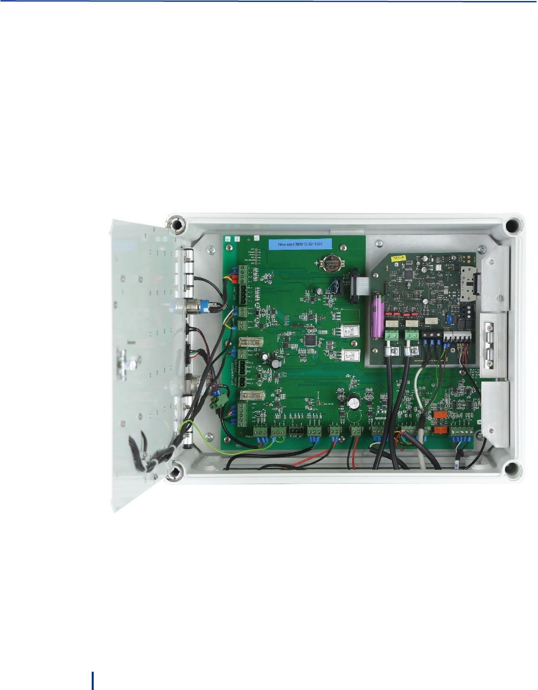
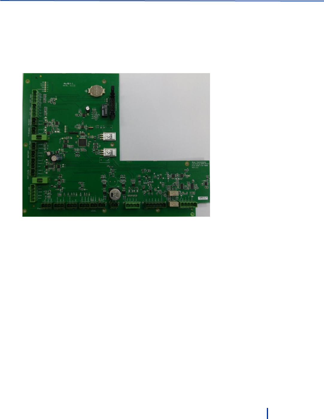
1.3.1 Electronic Board Module
The electronic board controls the activity of the system. The board is designed to manage all
measurement with low power consumption and to save water usage by flowing water into the system
only when measurement is performed.
A USB port allows you to connect a PC to the board for setup, calibration, status information, and data
download.
The board stores measurements and status information locally and transmits the information via a
modem per your configuration.
System Overview
© Blue I Technologies
11
1.3.2 Sensors Board Module
The sensors board controls the electrical connection to the sensors, value readings, calibration curves,
reading conversion. The pH, redox, and temperature sensors consume low power during regular
operation and can go into standby mode immediately when not measuring. Low current and low voltage
(up to 7 Volt) components in the circuit enable the free chlorine, conductivity, and turbidity sensors (high
power consumption) to measure using low power and to extend their operation into the end-of-life
period of the battery.
Introduction
12
© Blue I Technologies
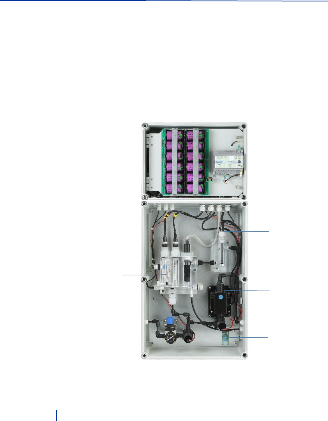
1.3.3 Flow Cells
The system includes three flow cells:
Flow cell 1 – holds the conductivity sensor. The cell is designed to enable fast temperature balance
between the water temperature and ambient temperature.
Flow Cell 2 – holds the free chlorine, pH, redox, temperature, and flow sensors. Water flows into the
cell only when measurement is scheduled. The water flow is indicated by the inductive sensor. To
save power, the sensors perform measurements only when water flow is indicated.
The cell’s water flow is 35 liters/hour. Water pressure to the cell must be adjusted to 0.5 – 1 bar.
Flow cell 3 – specifically designed to hold the turbidity sensor and features automatic cleaning and a
water outlet for manual cleaning. The cell’s open design enables air bubbles escape from the cell and
ensures accurate measuring with minimal maintenance.
Flow cell 2
(CL/pH/Redox
/Temp)
Flow cell 1
(Conductivity)
Flow cell 3
(Turbidity)
Leak
Detection
Float
System Overview
© Blue I Technologies
13
1.3.4 Automatic Leak Detection
The Smart NRG system is equipped with a sensor connected to a float. In case water leaks inside the
controller casing, the float, which is located at the bottom of the casing, rises and the sensor identifies the
leak. The sensor will send an alert to the operator via SMS or email and will close the main valve.
1.3.5 Battery Pack
The battery pack includes 12 X 3.6 V Lithium Thionyl Chloride, size D batteries with prolonged life span
(compared with Lithium batteries under the same conditions).
Technical data for one battery in pack:
Nominal capacity at 4 mA, to 2 V
19 Ah
Rated voltage
3.6 V
Rated current
9V DC Voltage (maximum current 1A, Average current
0.2A) AC according to Local Standards
Maximum recommended continuous current
230 mA
Maximum pulse current capability
500 mA
Weight
93 g (3.28 oz.)
Volume
51 cc
Operating temperature range
-55 C to +85 C
Li metal content
approx. 5 g
U.L. Component Recognition
MH 12193
Leak Detection
Float

Introduction
14
© Blue I Technologies
Hazardous Materials.
Lithium batteries are dangerous goods, and can pose a safety risk if not prepared and
shipped in compliance with international transport regulations.
For more information, refer to the International Air Transport Association’s Dangerous
Goods Regulations (DGR) for Lithium batteries.
1.3.6 Shipping of Lithium Batteries
Worldwide besides the United States – TL-5930 cell and its finishing versions are subject to the
Dangerous Goods Regulations, and thus shall be transported as Class 9. The cells must be packed in
accordance with Special Provisions / Packing Instructions of the applicable code, e.g., IATA/ICAO (Packing
Instructions: PI968, PI969 and PI970), IMO (SP188) and ADR (SP188). It is necessary to refer regularly to
regulation changes under UN number 3090 (lithium metal batteries) and UN 3091 (lithium metal batteries
packed with or in equipment).
Transportation within, to and from the US - Parts 171, 172, 173 and 175 of US-DOT CFR 49 are governing
the transportation of lithium cells and batteries. TL-5930 cell is defined as “Medium lithium cells and
batteries” and they detail the required packaging and labels when transported separately or in/with
equipment.
1.3.7 Fuse Type (F1, F3)
Fuse Holder – WURTH ELEKTRONIK 696108003002 FUSE HOLDER, 5X20MM, PCB. The 696108003002 is a
10A 250VAC cartridge Fuse Holder with PA6/66 insulator, matt tin over nickel contact plating, copper alloy
contact and PCB-mounting and through hole holder terminals.
Fuse Holder CUP – PA6/66 FLAMMABILITY RATING: UL94V0 COLOR: GREEN ENVIRONMENTAL OPERATING
TEMPERATURE: -30°C UP TO +120°C COMPLIANCE: LEAD FREE AND ROHS PACKAGING BOX ±0,1
MECHANICAL FUSE-LINK: 5x20 mm
1.3.8 CR2032 Battery
Nominal voltage (V): 3
Nominal capacity (mAh): 225
Continuous standard load (mA): 0.2
Operating temperature (C): -30 ~ +60

© Blue I Technologies
15
2
Installation
2.1 Site Preparation and Working Environment
The system’s IP 67 water-proof and UV resistant housing enables outdoor or indoor installation at areas
which are prone to wetness and moisture. In urban areas, we recommend installing the system inside a
locked cabinet to prevent unauthorized access and vandalism.
The system working environment is as follows:
Pollution Degree: 2
Installation Category: 2
Altitude: 2,000 m
Humidity: 1 to 90% non-condensing
Temperature: 0.5 C to 55 C (35 F to 131 F)
2.2 Verifying the Smart NRG Controller Parts Received
The Smart NRG controller is shipped in a cardboard carton, secured with foam packing material. A packing
list is included in each shipping carton. Check the components in the shipping carton against the items on
the packing list. If any part is missing, contact your Smart NRG distributer.
The following table details the Smart NRG components and their quantities.
Component
Quantity
Part Number
Controller
1
Smart NRG
Antenna
1
Mounting brackets (in a bag)
8
970-110-8006
pH electrode
1
970-210-0104
Redox electrode
1
970-210-0105
Chlorine electrode
1
970-210-8002
Chlorine membrane
1
970-210-8002
Signed Warranty Certificate
1
970-210-8092
QC Check Document
1
6 mm pipe (10 meters)
1
3.6 V Lithium Thionyl Chloride, size D battery
12

Operation and Configuration
16
© Blue I Technologies
2.3 Installing the Controller
2.3.1 Plumbing Requirements
A 6 mm pipe equipped with a valve for maintenance purposes.
It is recommended to connect the water inlet pipe at the bottom of the main line to minimize air
entering into the system.
The 6 mm water inlet pipe should not exceed 10 meters.
If you use a longer line (above 3 meters), make sure to adjust the Delay before Measurement
parameter accordingly (see “Setting Status Mode Parameters” on page 36).
A pre-filter is recommended but not mandatory. A fitting is supplied for 6mm (1/4”) tubing.
Install the filter before the water inlet to the system.
Installing an air valve is recommended to reduce air bubbles in the system (affect the turbidity
measurement). Install the air valve before the water inlet to the system.
The customer is responsible to install a flow meter on the main line and connect it to the controller
external flow meter inlet (see “Wall Mounting” on page 17).
Installing the Controller
© Blue I Technologies
17
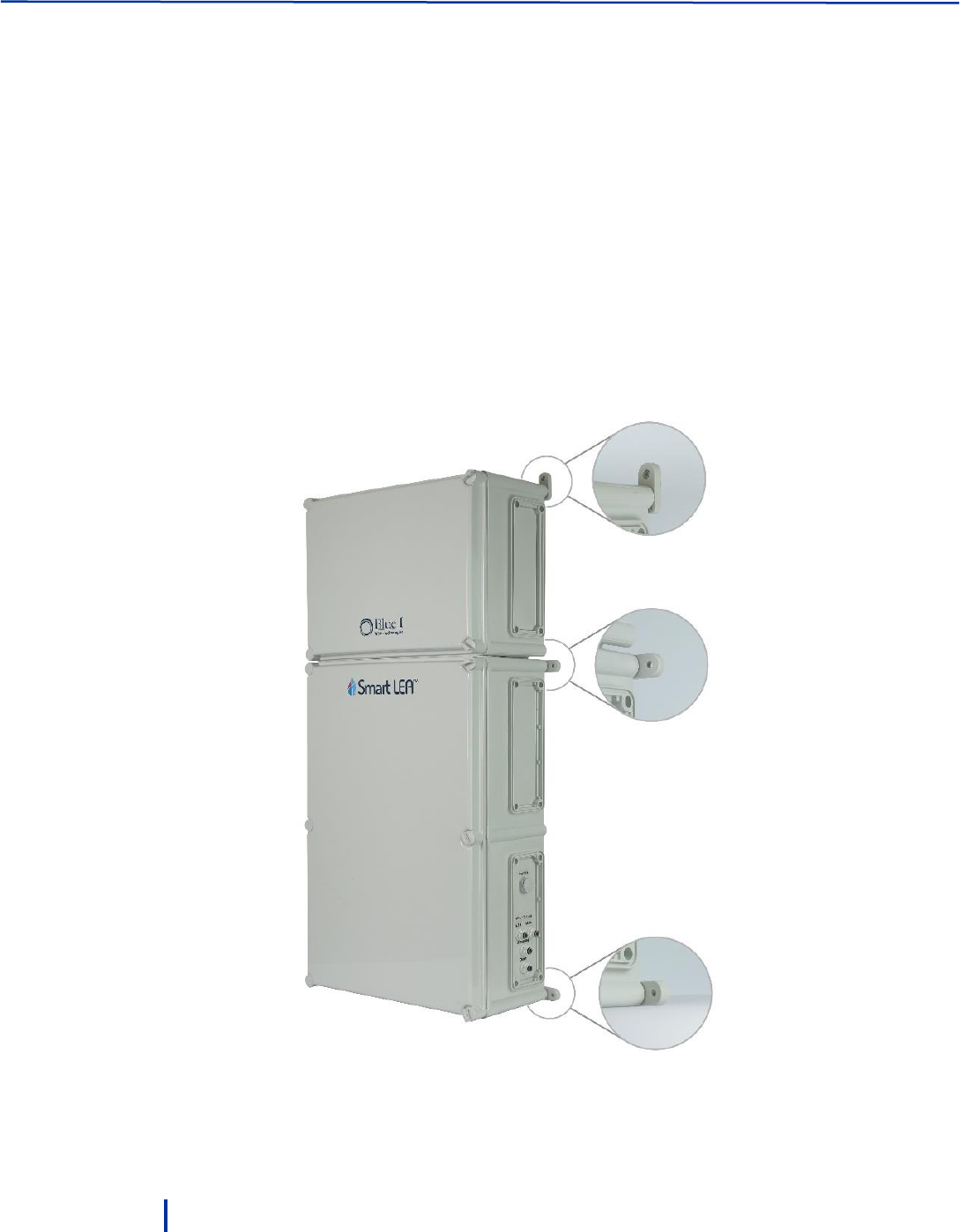
2.3.2 Wall Mounting
1. Use the provided mounting brackets as a drilling template to mark the drilling holes from each side of
the system. Drill the holes using an 8 mm drill.
2. Fasten the unit to the wall using the mounting brackets at the back of the unit.
3. Verify that the unit is installed upright at 90 vertical to the ground. Any sideways or back/forward tilt
may impair the function of the system.
The system is equipped with a tilt sensor. If a tilt is detected, the sensor sends an alert. Make sure to
address the issue and fix the tilt.
Operation and Configuration
18
© Blue I Technologies
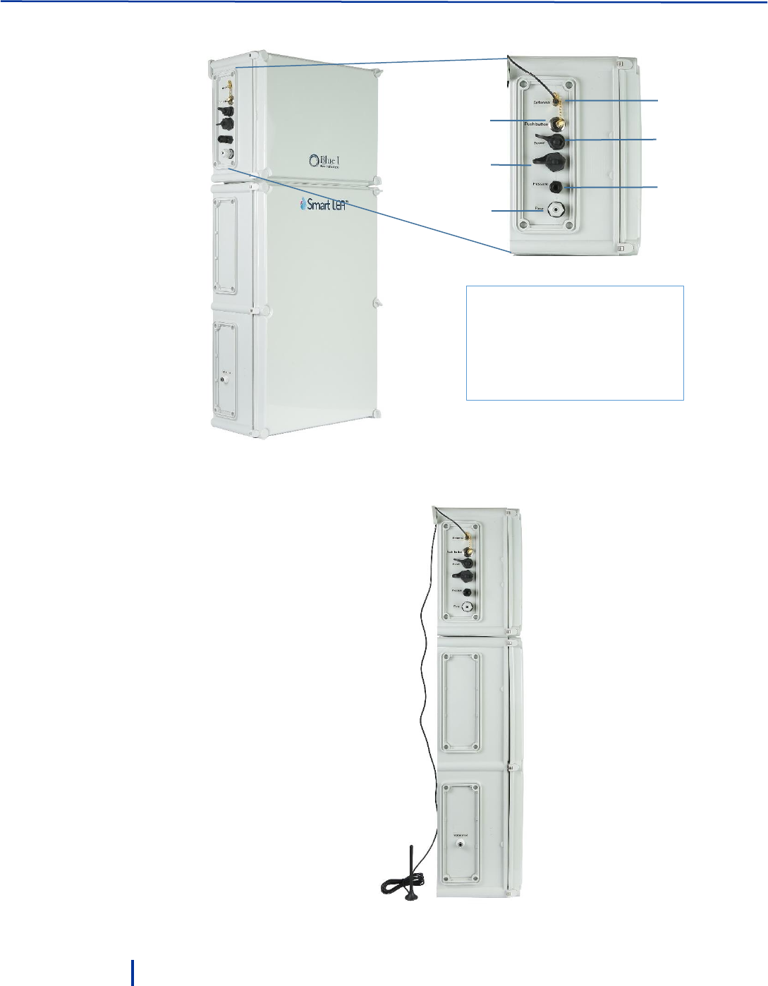
4. Unscrew the antenna connector cap and connect the provided antenna.
5. Attach the antenna to a metal object or place it on top of the controller.
Position the antenna away from any signal obstruction in front of the antenna.
1
3
2
5
6
c
4
1 – Antenna connector
2 – Calibration and setup button
3 – External power socket
4 – USB port
5 – Pressure inlet
6 – External Flow meter inlet

Installing the Controller
© Blue I Technologies
19
6. To connect an external flow meter, feed the cable of the flow meter through the inlet and connect it
to the FLOW_MT terminal block.
We recommend using the fl1400-13 Paddle Wheel flow sensor from Create Instruments Technologies
Co., Ltd.
A 5-meter cable is provided with the sensor and is connected in the following way:
◦ Red wire connects to EN_Flow_MT
◦ Yellow wire connects to IN
◦ White wire connects to GND
Operation and Configuration
20
© Blue I Technologies
2.3.3 Installing the System in a Cabinet
In urban areas, it is recommended to install the system inside a locked cabinet.
Cabinet requirements:
The cabinet must be equipped with at least two fitting panels, one for the top mounting ears and one
for the middle or bottom mounting ears.
One water inlet hole on the cabinet left side.
Three water outlet holes on the cabinet right side.
The holes should be aligned with the Smart NRG water inlet and outlets.
To install the system in a cabinet
1. Use the provided mounting brackets as a drilling template to mark four drilling holes in the affixing
panels (two holes for each panel) and drill the holes using an 8 mm drill.
2. Fasten the unit to the panels using the mounting brackets at the back of the unit.
3. Verify that the unit is installed upright at 90 vertical to the ground. Any sideways or back/forward tilt
may impair the function of the system.
Installing the Controller
© Blue I Technologies
21
The system is equipped with a tilt sensor. If a tilt is detected, the sensor sends an alert. Make sure to
address the issue and fix the tilt.
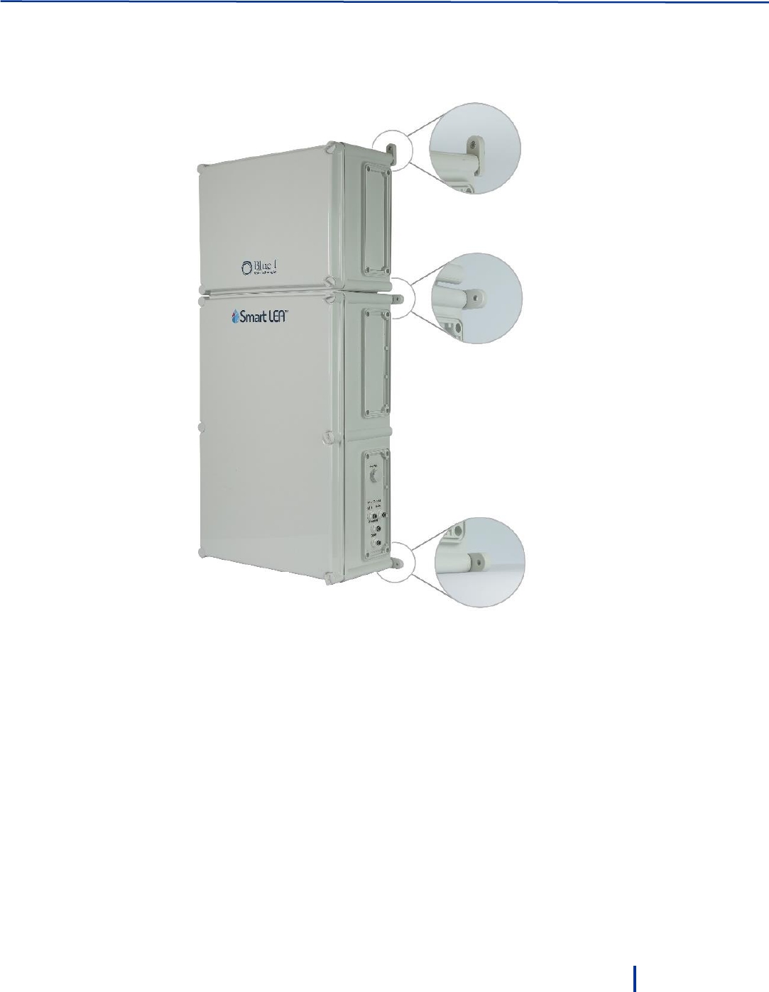
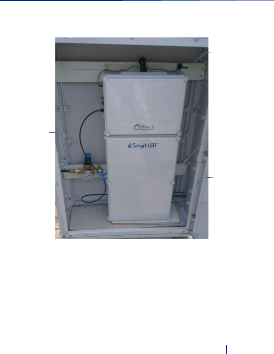
The following figure shows a typical cabinet installation.
4. Unscrew the antenna connector cap and connect the provided antenna.
5. Place the antenna outside the cabinet. If possible, attach the antenna to a metal object and keep it
further from any signal obstruction in front of the antenna.
6. To connect a flow meter, see “Wall Mounting” on page 17.
Top fitting panel
Bottom
fitting panel
Mounting
bracket
Water inlet
Water
outlets
Operation and Configuration
22
© Blue I Technologies
2.4 Setting up the System for First Use
Setting up the system includes the following steps: insert batteries, connect water inlet and outlets, and
adjust the water inlet pressure.
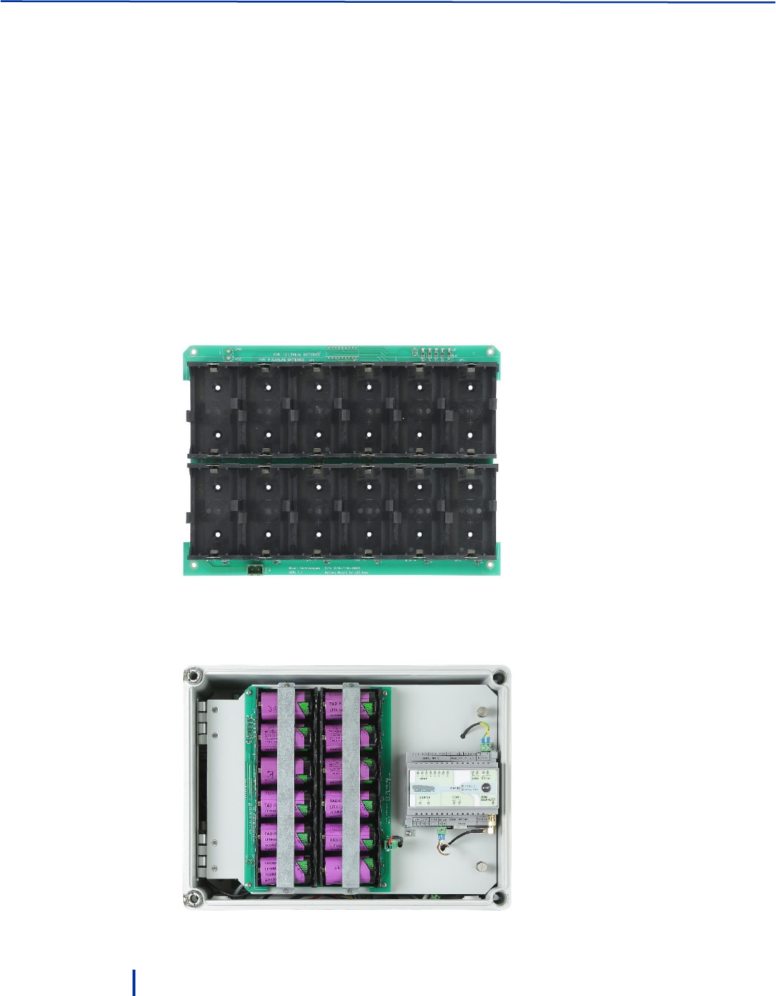
2.4.1 Inserting Batteries
The Smart NRG controller is supplied with a pack of 12 x 3.6 V Lithium Thionyl Chloride, D size batteries.
The pack is provided in a separate box for safety reasons. The system supports the following batteries,
which have been proved to provide energy and low self-discharge rate required in this application:
Tadiran TL-5930 – Catalog Number: TL5930/S
Varta – Catalog Number: 7120.101.511
To insert batteries:
1. Unlock and open the top enclosure door.
2. Remove the clamps and insert the provided batteries while making sure they are placed in the right
direction.
3. Fasten the batteries clamps as shown in the figure below:
Setting up the System for First Use
© Blue I Technologies
23
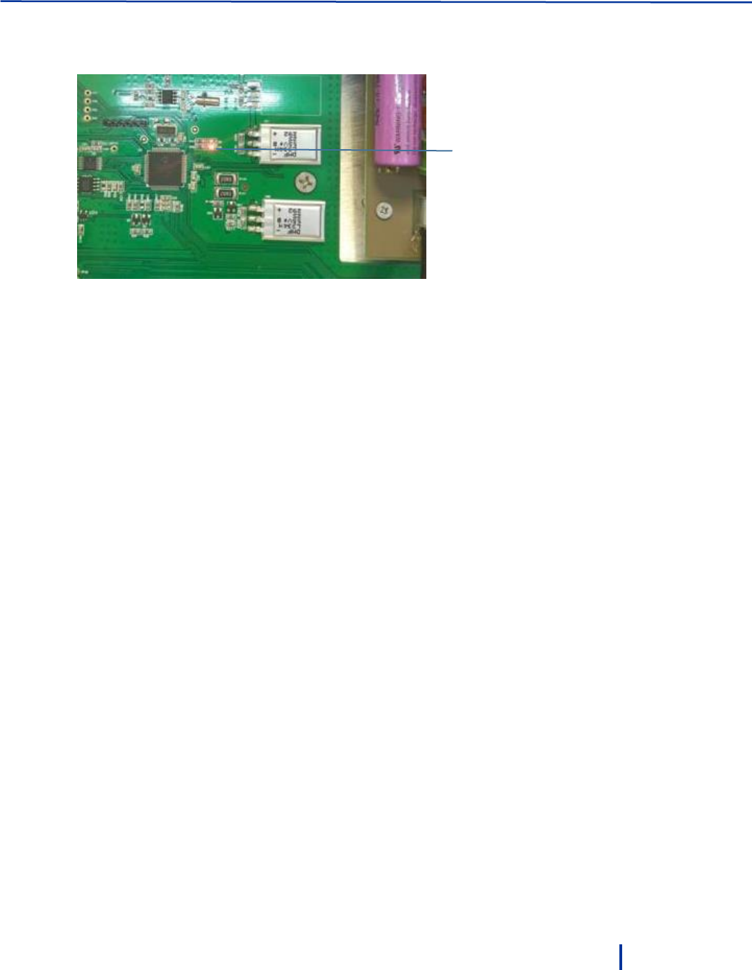
4. Close the top enclosure door.
5. Connect the batteries connector and verify that a red LED is turned on in the electronic board.
Red LED is
on
Operation and Configuration
24
© Blue I Technologies
2.4.2 Connecting the Electrodes
The Free Chlorine sensor is supplied from the factory pre-filled with electrolyte solution and does not
require filling for first time operation.
1. Remove the Chlorine electrode from its packaging, remove the yellow covering, and insert it to the
right holder and hand-tighten the cap.
2. Remove the Redox electrode from its packaging, remove the silicon cap and insert into the left
holder.
3. Screw the cable labeled RX and hand-tighten.
4. Remove the pH electrode from its packaging, remove the silicon cap and insert into the middle
holder.
5. Screw the cable labeled PH and hand-tighten.
Redox
electrode
Chlorine
electrode
pH
electrode

Setting up the System for First Use
© Blue I Technologies
25
2.4.3 Connecting Water Inlets and Outlets
Water pressure before the water inlet to the unit should not exceed 10 Bar. Inside the unit, the system
requires a pressurized water supply to the flow cells. The pressure must be adjusted between 0.5 to 1 Bar
(14.5psi).
Maximum pressure reaching to the pressure reducing valve should not exceed 1 Bar.
After connecting water to the system, allow the system to operate for 24 hours before performing
calibration for the first time.
1. Lead the 6 mm water inlet pipe through the hole at the bottom left side and connect it to the Main
valve.
Water inlet pipe should not exceed 10 meter and the water pressure should not exceed 10 Bar.
Operation and Configuration
26
© Blue I Technologies
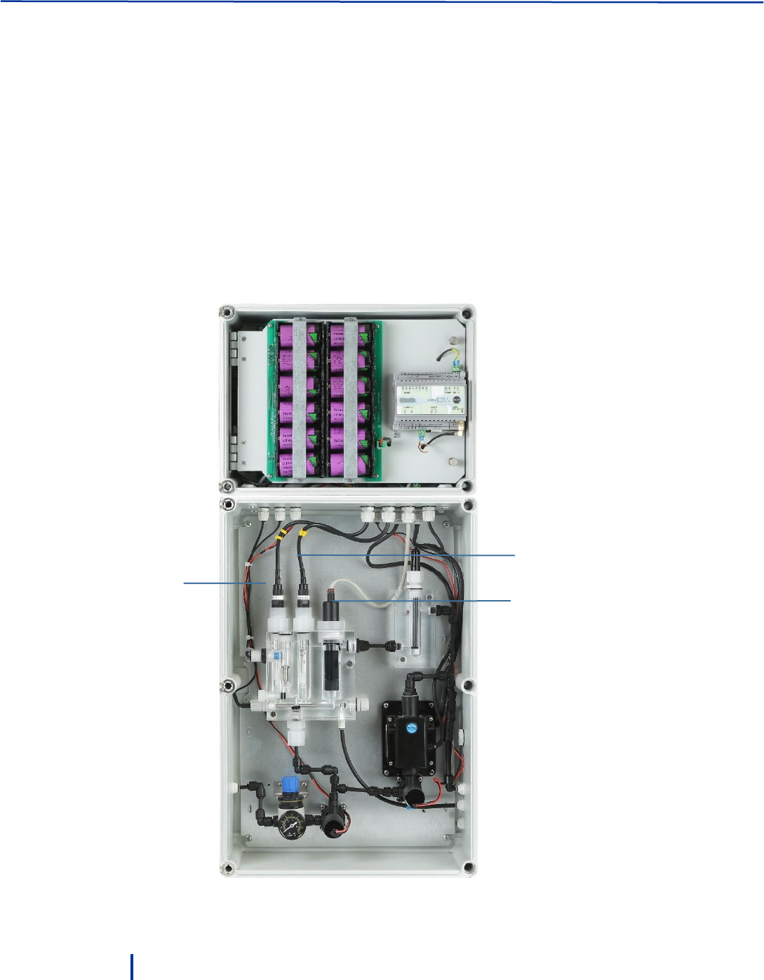
2. Adjust the water pressure (0.5 – 1 bar) inside the unit by opening or closing the pressure reducing
valve as required.
Pressure
reducing valve
Water inlet
Setting up the System for First Use
© Blue I Technologies
27
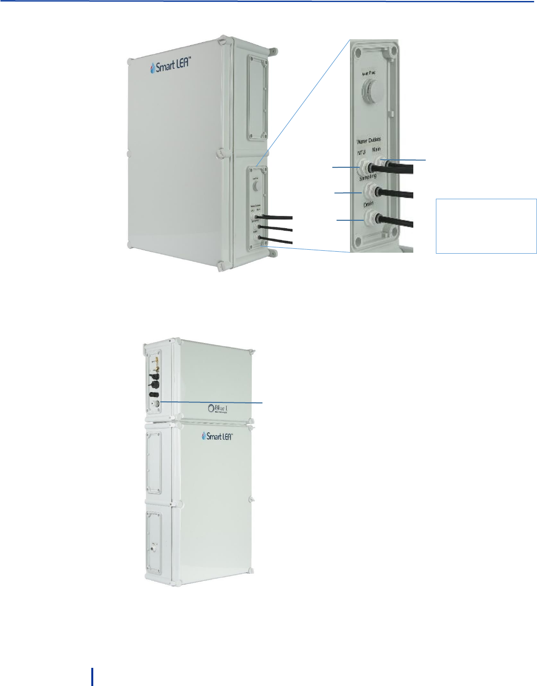
3. Connect 6 mm pipes to the Main, Drain, and Turbidity water outlets:
There are mechanical valves for both the Main and NTU solenoids. Make sure that the mechanical
valves are always set to Auto.
The Drain outlet can be used to collect a water sample from the flow cell for calibration purposes
using external tools.
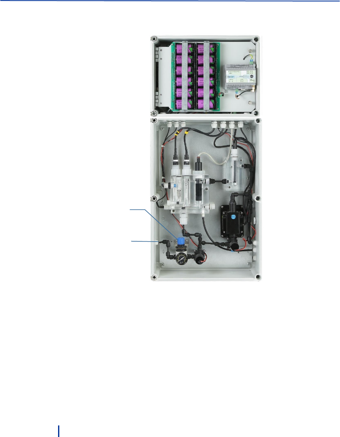
Reducer
valve
Main valve opened
when measurement
begins
Sampling
water valve
NTU Valve
Drain
outlet
Turbidity
outlet
Main
outlet
Operation and Configuration
28
© Blue I Technologies
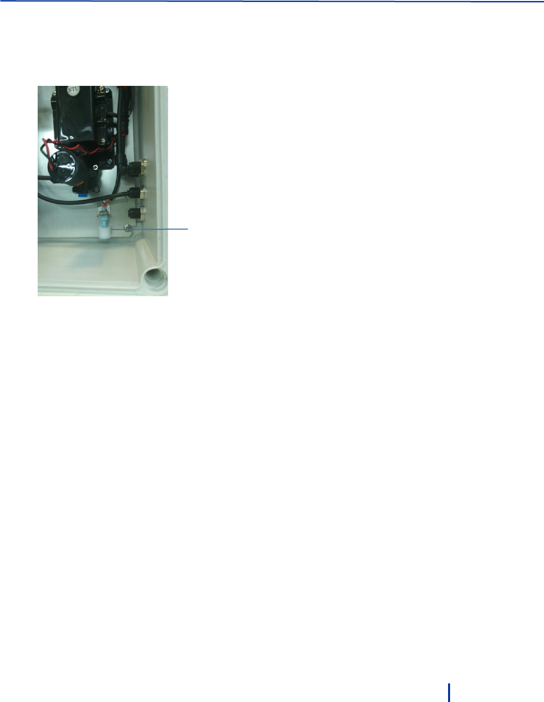
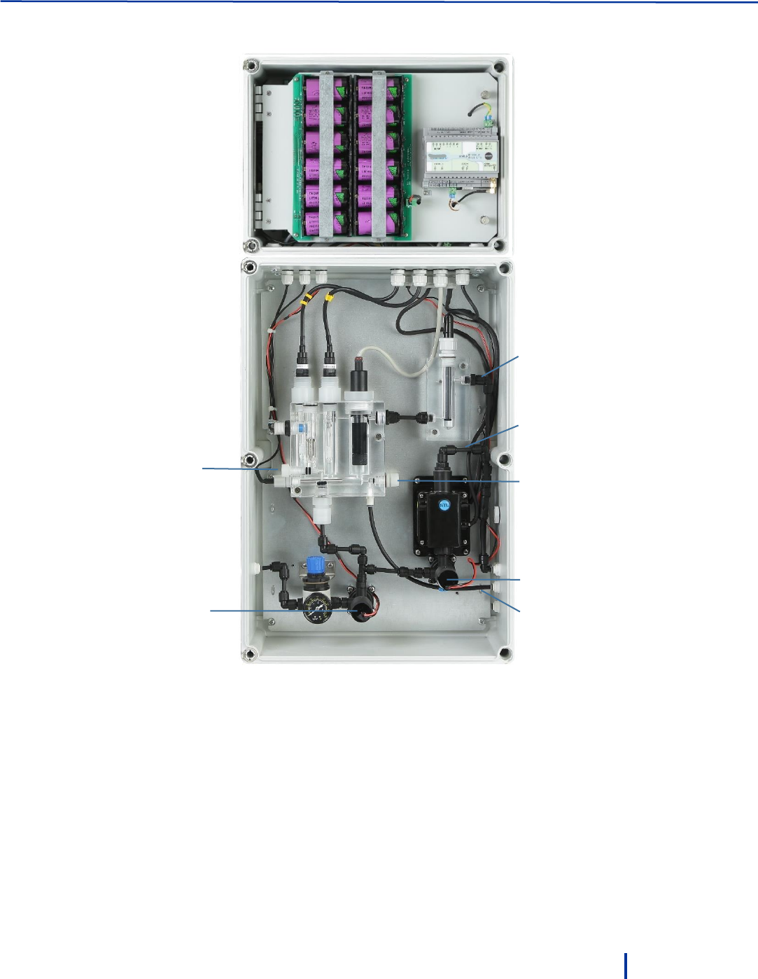
4. Lead the pipes through the holes on the right side:
5. Adjust the reducer valve to align the metal part with the inductive flow sensor.
6. From a water meter installed on the main line, connect a 6 mm pipe to the water meter inlet.
The customer is responsible to install the water meter on the main line.
External flow
meter inlet
1
2
4
3
1 – Main outlet
2 – NTU outlet
3 – Sampling outlet
4 - Drain
© Blue I Technologies
29
3
Operation and Configuration
For first time operation, use the PC software to configure the controller by connecting to it locally through
the USB port. Subsequent operation and monitoring can be down via the web application.
If the system is installed with a Backsoft modem, you can configure Alarms and Turbo mode in the
Backsoft remote application.
3.1 Installing the PC Software
You can download the PC software from Blue I web site at www.blueitechnologies.com.
3.2 Connecting to the Controller
1. Connect a USB cable from the laptop on which you have installed the software to the controller USB
port. The USB drive automatically detected and installs the required components.
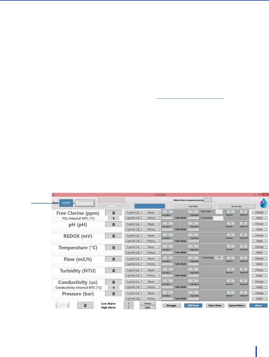
2. Launch the Smart NRG application. The main screen appears.
3. Select the serial COM port number.
4. Press and hold the Push button on the left side of the controller until it flashes.
5. Click Connect to connect to the controller and receive the current system status.
Once connection is established, current system status is displayed.
Click
Connect
Operation and Configuration
30
© Blue I Technologies
3.3 First Time Operation and Configuration
The controller comes pre-configured with default values. However, before first time operation, it is highly
recommended to perform an external measurement of water parameters values and calibrate the system
according to the results.
Before performing calibration for the first time, let the system operate for 24 hours to allow the
electrodes to stabilize. Follow local regulations for calibration requirements.
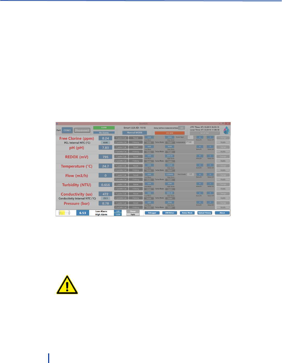
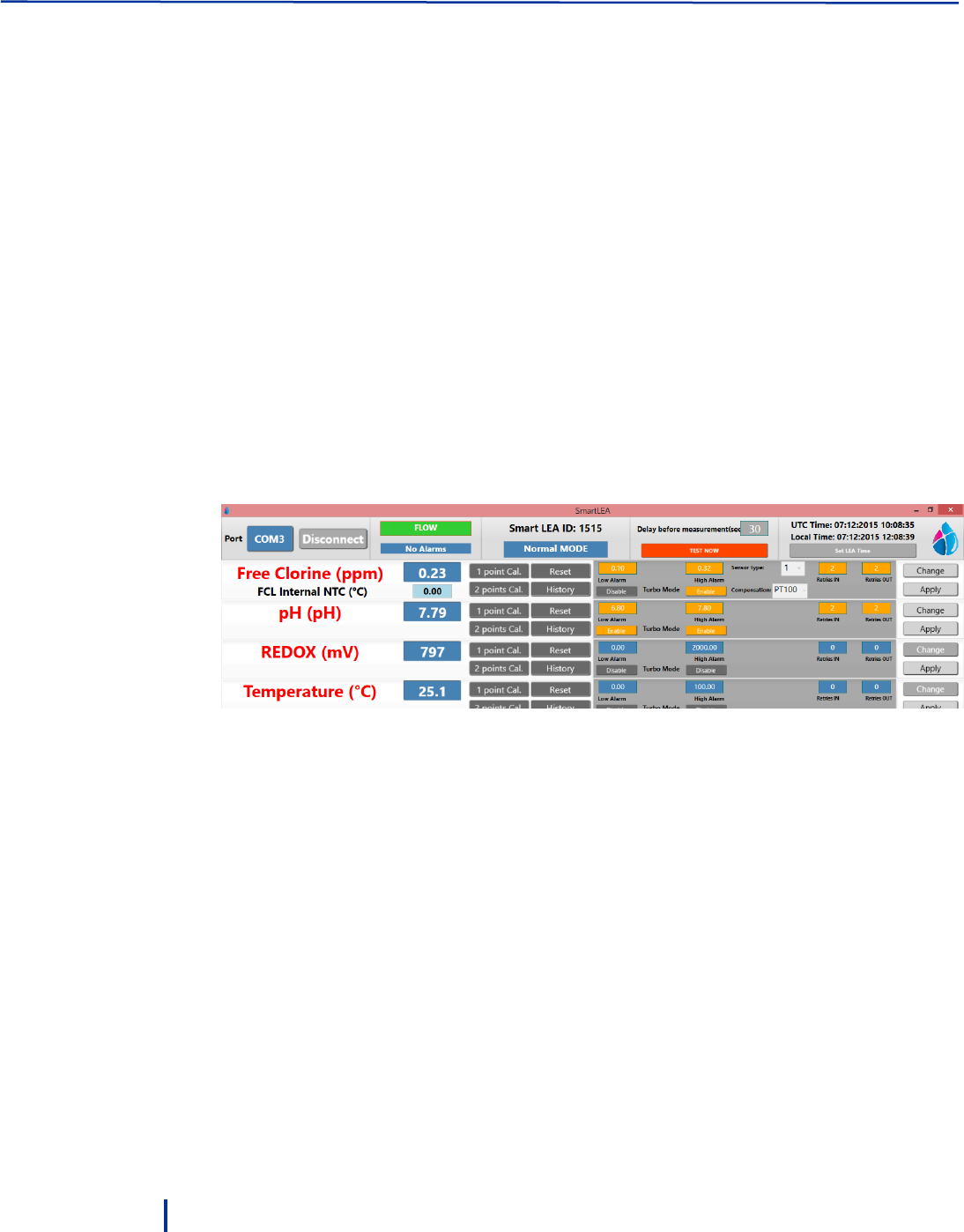
3.3.1 About the Smart NRG PC Software
The PC software allows you to view the system status and alarms, view measurements history, initiate
immediate test, calibrate water parameters values, set thresholds, and set thresholds for Turbo mode.
The following sections describe the user interface elements of the PC software.
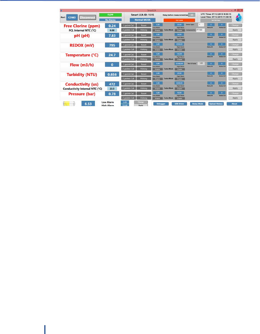
Top Section
This area displays the following information from left to right:
Connect/Disconnect – starts communication from the controller to the software.
Flow – when green indicates that water flows through the flow cells.
Alarms list – displays the last alerts in the system. Click the button to displays the complete list of
alerts.
Normal/Turbo MODE – indicates the current operation mode of the controller.
Normal – regular operation mode.
Turbo mode – high frequency measurement mode for increased monitoring (see “Activating
Manual Turbo Mode” on page 37).
First Time Operation and Configuration
© Blue I Technologies
31
Delay before measurement – displays the delay in seconds before the measurement begins. This
allows water in the inlet pipe to leave the system so the measurement is performed on fresh water
from the main line.
Test now – starts a new measurement cycle.
UTC Time and Local Time – displays UTC time and the system local time. Click Set Lea Time to set the
system local time.
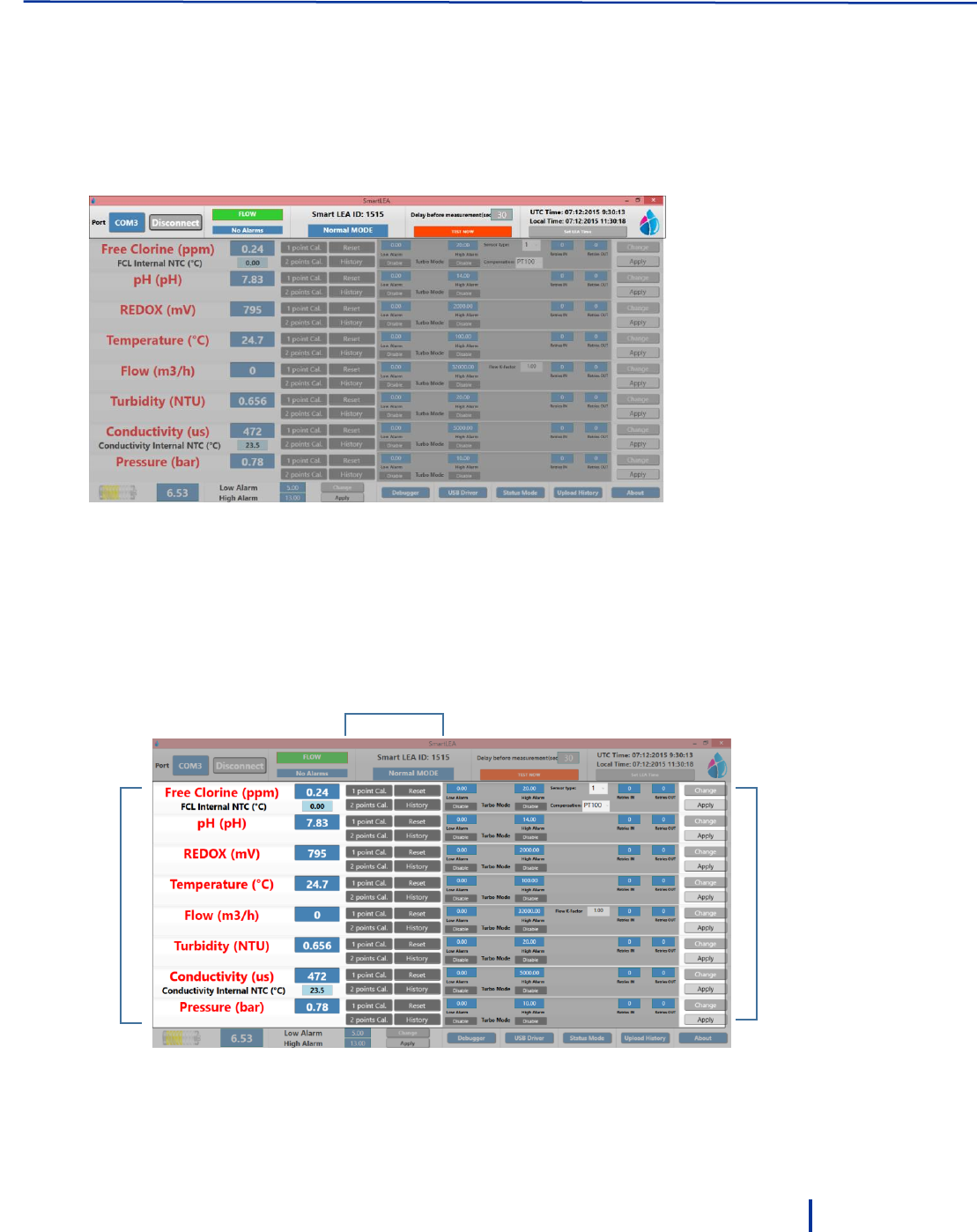
Middle Section
This area displays water parameters values from the last measurement, provides 1 or 2 points calibration
for each parameter, and allows you to configure Turbo mode.
See “Calibrating Parameters” on page 32 and “Configuring Automatic Turbo Mode” on page 38.
Turbo mode
configuration
1 point/2 points calibration,
reset, and calibration history
Parameters
values
Operation and Configuration
32
© Blue I Technologies
Bottom Area
This area displays the following information from left to right:
Battery icon – indicates the battery status and its current voltage. Minimum voltage required for the
system operation is: 5.5 Volt.
Low Alarm/High Alarm – displays the low and high voltage thresholds. When battery level exceeds
these thresholds, alerts are triggered (see, “Setting Battery Level Alarms” on page 37).
Debugger – for use of Blue I technicians only.
USB Driver – installs required USB driver on the PC.
Status Mode – enables you to set Delay before measurement, Measurement interval, and Modem
interval parameters for both Normal and Turbo modes (see “Setting Status Mode Parameters” on
page 36).
Upload History – loads the controller data log into the PC software.
About – displays the system’s protocol, software, hardware, controller versions.
3.3.2 Calibrating Parameters
The system provides one point or two points calibration methods. Before you begin calibrating water
parameters, allow the system to work for several hours.
It is mandatory to calibrate the system using an external measurement for accurate results.
Always follow local regulations for the required calibration method and frequency.
First Time Operation and Configuration
© Blue I Technologies
33
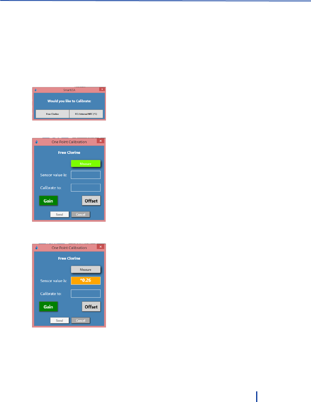
To calibrate water parameters using one-point calibration:
1. Measure the parameter you want to calibrate using an external test by opening the sampling water
outlet and measuring the parameter in the sampling water.
2. Click 1 Point Cal next to the parameter you want to calibrate.
For Chlorine, the system prompts you to select Free Chlorine or FCL Internal NTC.
If you choose FCL Internal NTC then you need to specify NTC instead of PT 100.
Electrode with internal NTC or electrode with external PT100.
The One Point Calibration dialog is displayed.
3. Click Measure. The system initiates a measurement of the parameter and displays the result in the
Sensor value is field:
Operation and Configuration
34
© Blue I Technologies
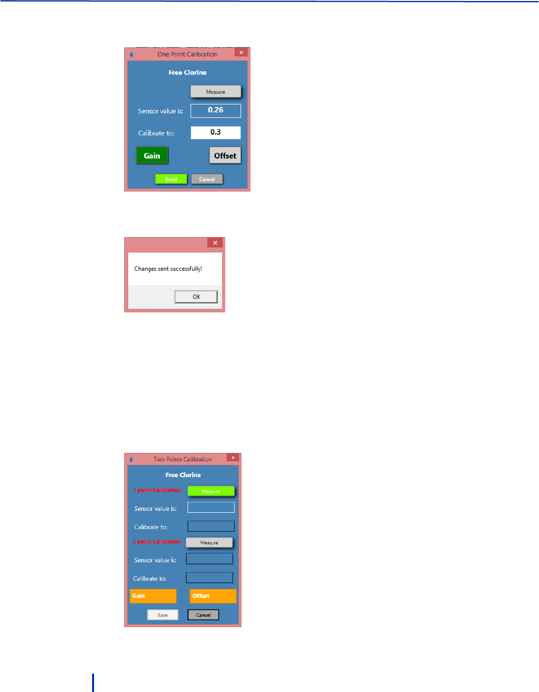
4. In the Calibrate to field, type in the value to which you want to calibrate the parameter. This is
typically the result of your external measurement.
Optionally, click Offset to calibrate the offset of the electrode.
5. Click Send to save the settings to the controller memory.
6. Repeat this process for the required parameters.
To calibrate parameters using two points calibration:
For calibration with standard solution only.
1. Measure the parameter you want to calibrate using an external test by opening the sampling water
outlet and measuring the parameter in the sampling water.
2. Click 2 Point Cal next to the parameter you want to calibrate.
The Two Points Calibration dialog is displayed.

First Time Operation and Configuration
© Blue I Technologies
35
3. Click Measure next to 1 point Calibration. Measurement result is displayed in the Sensor value field.
4. In the Calibrate to field, type in the value to which you want to calibrate.
5. Click Measure next to 2 point Calibration. Measurement result is displayed in the Sensor value field.
6. In the Calibrate to field, type in the value to which you want to calibrate.
7. Click Save to save the settings to the controller memory.
3.3.3 Calibrating Free Chlorine
Parameters must be calibrated with measurements taken with external testing devices. Always use digital
calibration devices. Alternatively, standard solutions may be used. Make sure the standard solution is not
expired or contaminated prior to using.
Always take water for calibration from the sampling valve, NOT from the process line directly. The
analyzer should always be calibrated with water from exactly the same source.
Perform chlorine calibration every six month according to manufacturer instructions.
To calibrate free chlorine:
1. Before calibrating chlorine, calibrate temperature and pH and verify that both parameters are at
normal operating levels.
2. Fill the sampling container from the flow cell.
3. Test the water sample for chlorine using a digital photometer or other external testing device.
3.3.4 Calibrating Other Sensors
Calibration of other sensors requires the use of a reliable external testing device or standard solution.
When using an external testing device, follow the chlorine calibration sequence making sure to take the
water sample from the same water supply of the sampling cell (sensors).
Perform Redox and pH calibration once a year. We recommend calibrating both Redox and pH whenever
you calibrate the chlorine sensor.
Perform turbidity calibration once a year.
1. Remove the sensor, clean with a dry cloth and place in the standard solution.
2. Place the sensor in the standard solution and wait for the reading to stabilize.
Operation and Configuration
36
© Blue I Technologies
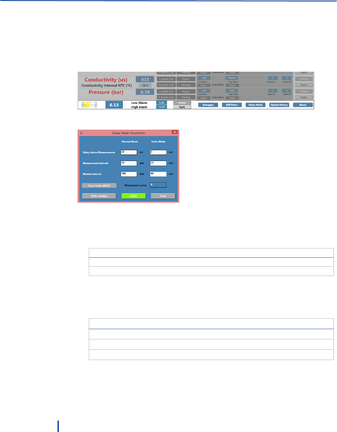
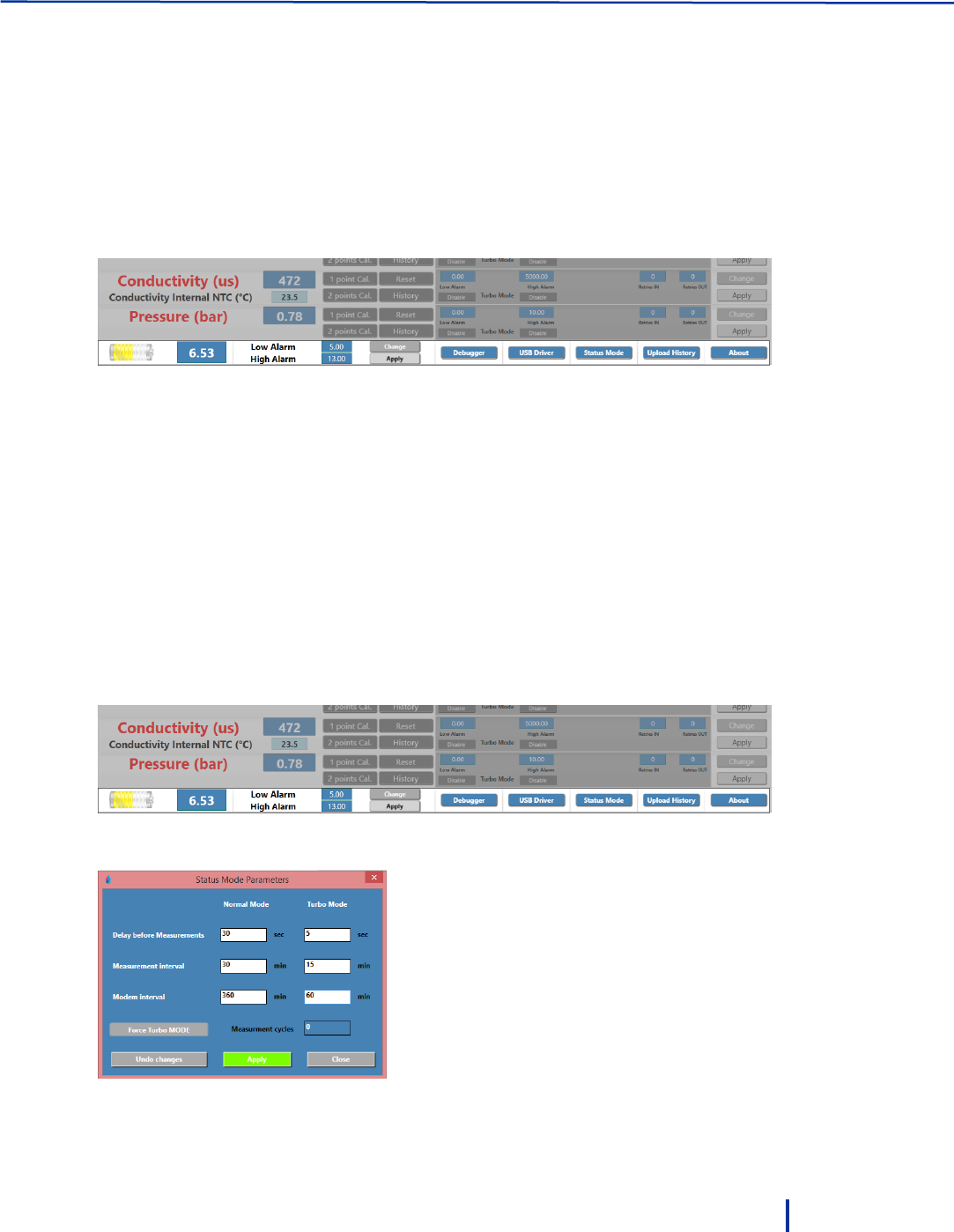
3.3.5 Setting Status Mode Parameters
The Status Mode Parameters enable you to set the controller Delay before measurement, Measurement
interval, and Modem interval for both Normal and Turbo modes.
To set the status mode parameters:
1. Click Status Mode at the bottom of screen.
The Status Mode Parameters dialog is displayed.
2. Set the parameters Normal and Turbo modes as required:
◦ Delay before measurement – sets the delay in seconds before the measurement begins. This
allows water in the inlet pipe to leave the system so the measurement is performed on fresh
water from the main line.
Pipe Length
Recommended Delay
Up to 1 meter
30 seconds
Up to 3 meter
90 seconds
◦ Measurement interval – sets the measurement frequency in minutes.
◦ Modem interval – sets the data transmission frequency in minutes.
The setting for the last two parameters greatly affect battery consumption. Consult the following
table for typical settings.
Measurement/Modem Interval
Expected Battery Life
60 minutes / once a day
3 years
60 minutes / every two hours
2 years
15 minutes
9 months
3. Click Apply and Close to save the settings.
Activating Manual Turbo Mode
© Blue I Technologies
37
3.3.6 Setting Battery Level Alarms
Battery alarms provide alerts when the battery enters end-of-life period allowing you to replace the
battery before it dies out. You can define both low level and high level alarms. A high level voltage may
indicate battery malfunction that may harm the system’s electronics and needs replacement.
The system is pre-defined with default settings that you can change as follows.
To set battery thresholds:
1. Click Change at the bottom of the screen.
2. Type in values for low voltage alarm and high voltage alarm and click Apply to save the changes.
◦ Recommended setting for low alarm: 5.5.
◦ Recommended setting for high alarm: 8.5.
3.4 Activating Manual Turbo Mode
You can manually put the system into Turbo mode, in which the system performs measurements at higher
rate than in Normal mode. This is useful when you suspect a water quality event is about to occur; or
when an event is already taking place and you want to closely monitor water parameters.
To activate manual Turbo mode:
1. Click Status Mode at the bottom of screen.
The Status Mode Parameters dialog is displayed.
2. Click Force Turbo Mode, type in the required number of measurement cycles.
Operation and Configuration
38
© Blue I Technologies
3. Click Apply.
4. To exit from manual Turbo mode, set Measurement cycles to 0 (zero) and click Apply.
3.5 Configuring Automatic Turbo Mode
Turbo mode enables you to closely monitor water quality events. This is done by configuring a required
range (low and high thresholds) for the parameters. When parameter measurements are outside the
range, the system begins measuring at a high rate until the measurement results return to normal range.
This allows you to follow the event through, perform corrective actions, and verify that water quality
returns to normal range.
You can set Turbo mode for a single parameter, several parameters, or all of them. In addition, for each
parameter, you can set low or high thresholds, the number of repeated measurements before entering
Turbo mode, and the number of repeated measurements before returning to Normal mode.
To configure Turbo mode:
1. Set the Delay before measurement, measurement interval, and modem interval for Turbo mode in
Status Mode Parameters (see “Setting Status Mode Parameters“ on page 36).
2. In the main area, click Change next to a parameter and set the following parameters:
◦ Low Alarm/High Alarm – specify the thresholds that when exceeded, the system enters Turbo
mode.
For example, for pH you may define Low Alarm – 6.8 and High Alarm – 7.8.
◦ Enable – activates the low and high thresholds you have specified. You can activate either one of
the thresholds or both.
◦ Retries IN – specify the number of measurements exceeding the thresholds before the system
enters into Turbo mode.
For example, 2 retries mean the system enters Turbo mode only after two exceeding consecutive
measurements.
◦ Retries OUT – specify the number of measurement within the thresholds before the system
returns to Normal mode.
For example, 2 retries mean the system exits Turbo mode only after two consecutive
measurements within the thresholds.
3. Repeat this process for each parameter as required.
4. Click Apply to save the changes.
Viewing the Calibration Log
© Blue I Technologies
39
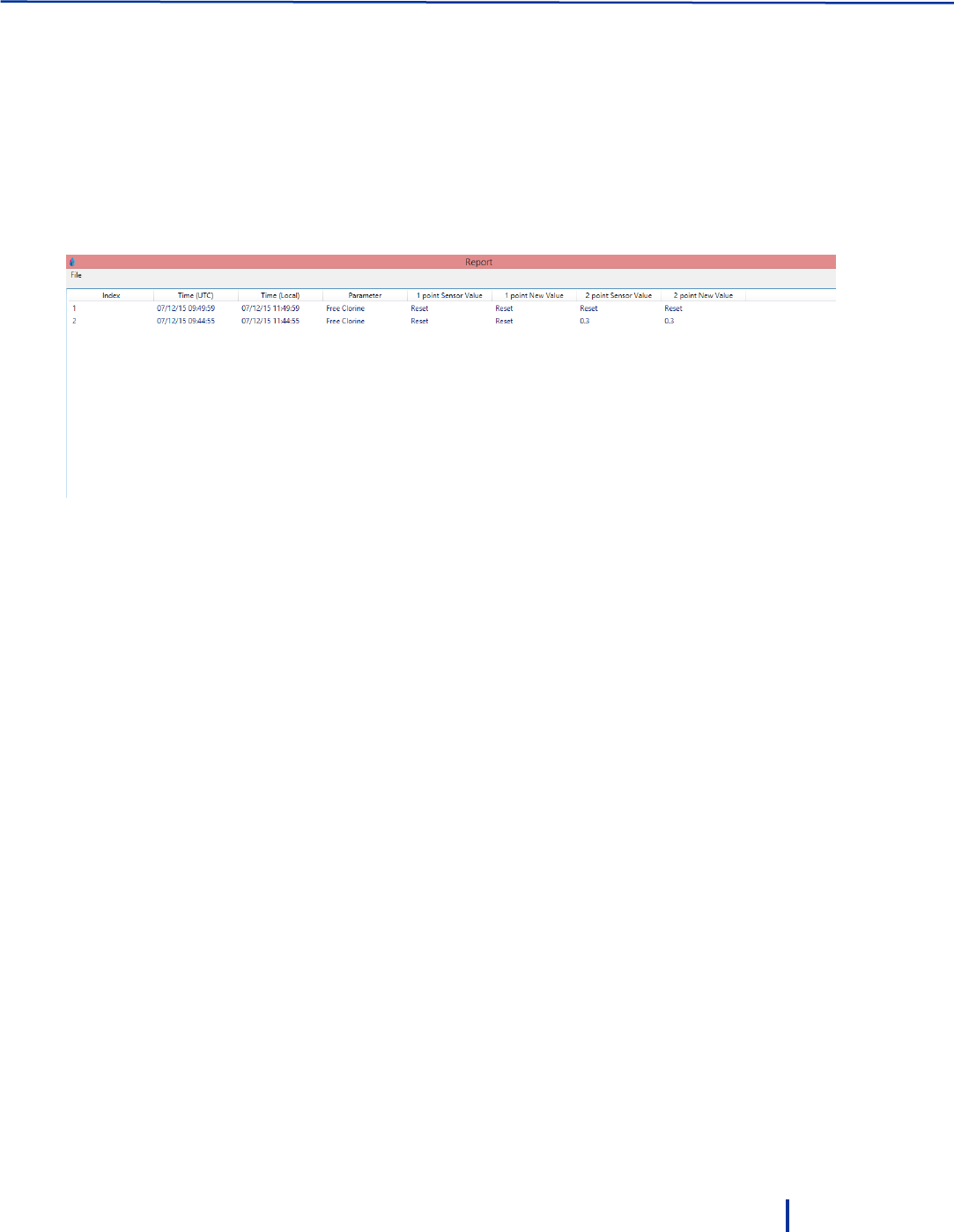
3.6 Viewing the Calibration Log
The PC software records all calibration changes per parameter in a dedicated report.
To view the calibration log:
Click History next to the parameter for which you want to see the log.
A log of all calibration actions for the selected parameter is displayed. The log displays the time and date
of the change, the one or two points sensor value, and the new one or two points calibrated values.
3.7 Viewing the Data Log
The system enables you to view and export the data log to an Excel file.
1. Click Upload History and type in the number of records you want to view. Each record equals a
measuring cycle of the system. The total number of records depends on the system measuring
interval.
2. Click Load.
3. Click File > Save to save file in Excel format.

© Blue I Technologies
41
4
Remote Monitoring and
Configuration
The Smart NRG system uses cellular communication to transmit measurements results and system date to
a web-based application. By connecting to the web-based application, you can review the measurement
results, alerts, and modify system settings anywhere anytime (internet connection is required).
The customer is responsible for purchasing a data SIM card with an unlimited plan and configure it in the
Modem. The SIM card is inserted to the slot located on the left side of the modem.
4.1 Logging On
1. In your Internet browser, type in the address: www.backsoft.com.
2. In the main page, click the Login tab.
The Remote Access Login page is displayed.
Remote Monitoring and Configuration
42
© Blue I Technologies
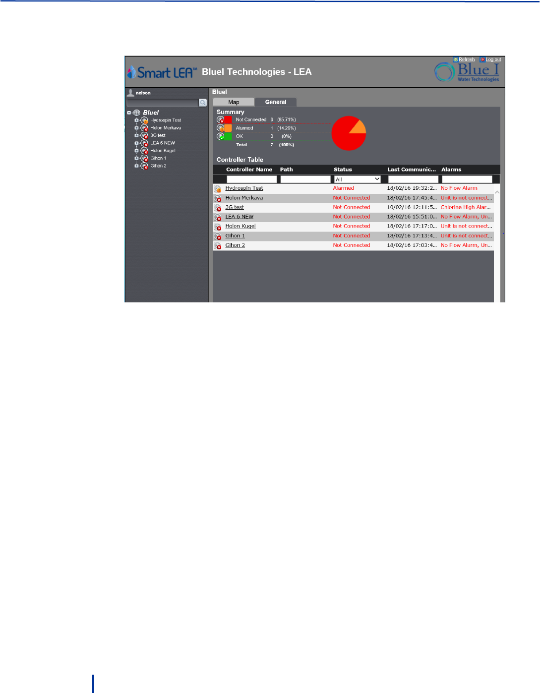
3. Type in your user name, password, and customer credentials and click Login.
The main screen is displayed.
The Left pane displays a list of your Smart NRG installations. Expanding each installation opens a list
of direct links to the system alarms, graphs, Turbo mode settings, Communication settings, History
data, calibration settings, and parameters data.
The main area displays two tabs:
◦ Map – display the units on a map.
◦ General – a color coded summary of the controllers’ status (OK, Alarmed, Not Connected) and
the Controllers Table. You can filter this table by typing or selecting in the fields above each
column.
Configuring the Controllers Parameters
© Blue I Technologies
43
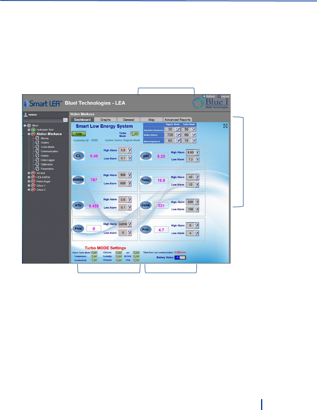
4.2 Configuring the Controllers Parameters
Click a controller name in the Controllers Table or in the left pant to access open the Dashboard and
display detailed data. The Dashboard tab displays current measurement values for each parameter along
with measurement frequency settings, flow status, Turbo mode settings, battery status, and time from
last communication.
Normal/Turbo modes
measurement frequency setting
Parameters values
and alarm
thresholds
Turbo mode setting
Time from last communication
Battery status

Remote Monitoring and Configuration
44
© Blue I Technologies
To configure parameters high/low alarm thresholds:
1. Click the edit icon next to the parameter value you want to modify.
2. In the dialog that opens, type in a new value:
3. Click Update.
4.3 Modifying Delay before Measurement, Measuring
Interval, and Modem Interval
You can set the controller Delay before measurement, Measurement interval, and Modem interval for
both Normal and Turbo modes.
To modify the parameters:
1. Click the edit icon next to the parameter value you want to modify.
2. In the dialog that opens, type in a new value:
3. Click Update.
Creating Historical Graphs
© Blue I Technologies
45
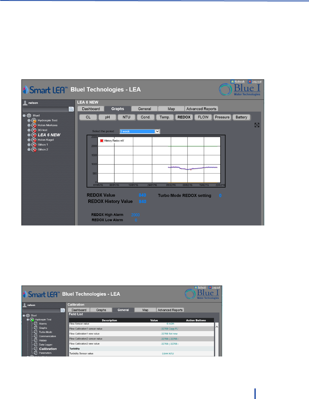
4.4 Creating Historical Graphs
The application enables you to create historical graph for each parameter value. The graphs can be
displayed for a period between one to five weeks back.
1. Click the Graphs tab.
2. Select the parameter for which you want to create the graph.
3. Select the time period. The graph is displayed.
4.5 Monitoring System Parameters
The General tab enables you to view all the system parameters in a tabular format. The list of parameters
changes according to the selected item on the left. For example, selecting Turbo Mode displays all the
possible parameters relating to Turbo Mode; while Calibration displays all the possible parameters
relating to parameters calibration.
Remote Monitoring and Configuration
46
© Blue I Technologies
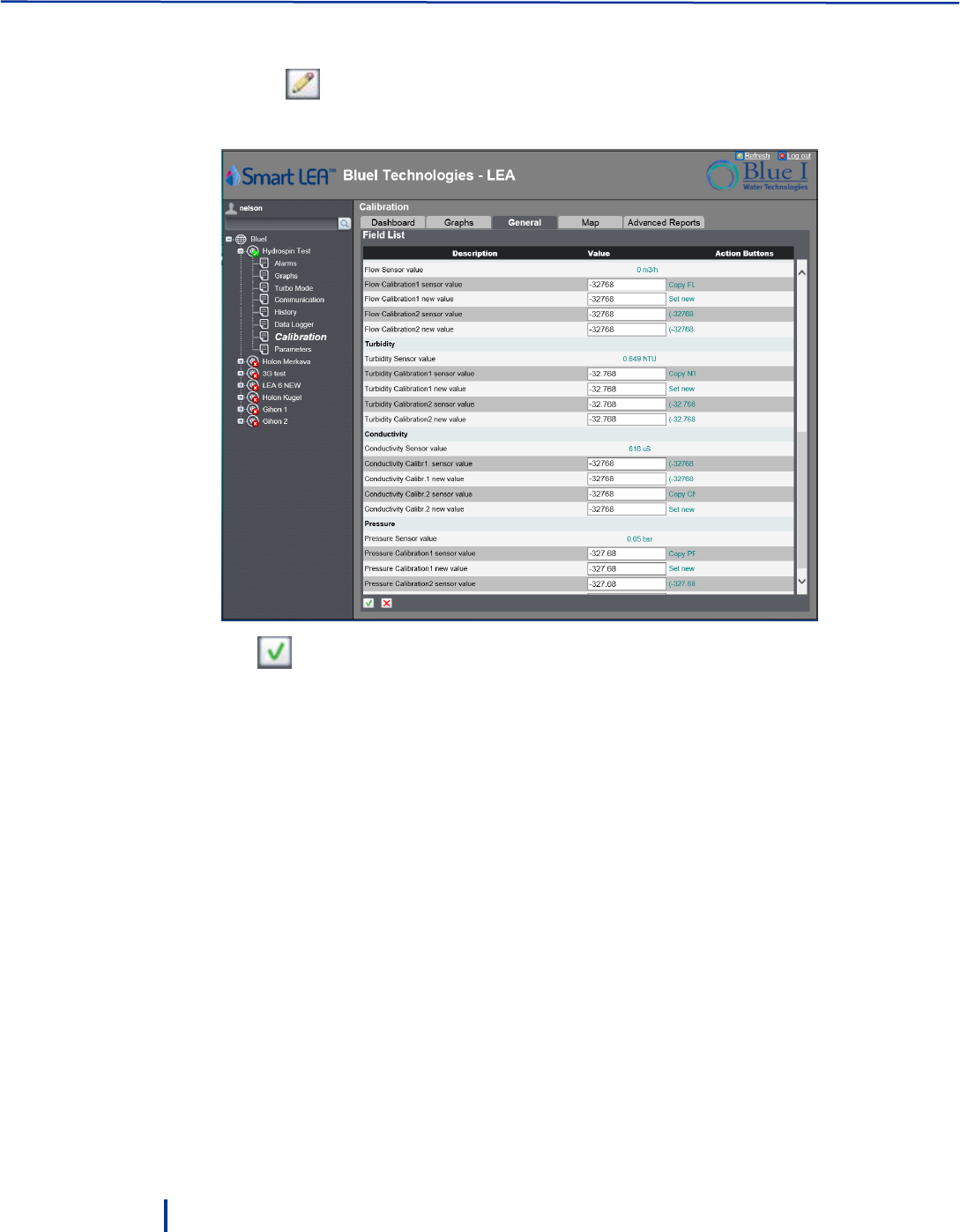
To modify values:
1. Click the icon at the lower left corner and type in new values in the relevant fields.
Not all parameters can be modified in this tab.
2. Click to save the changes.
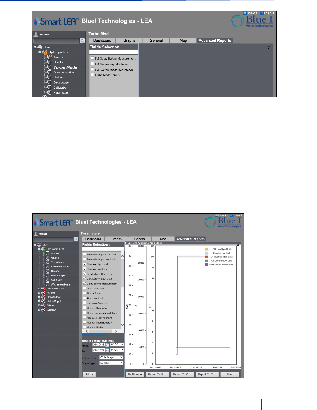
4.6 Creating Advanced Reports
The application enables you to create reports containing up to five different parameters for any time
period and export them to several different formats.
To create advanced reports:
1. Click the Advanced Reports tab.
2. In the Fields Selection list on the left, select up to five parameters.
Note:
The parameters in the Fields Selection list change according to the selected item on the left. For
example, Turbo Mode provides four parameters; while Parameters provides all the possible
parameters in the system.
Creating Advanced Reports
© Blue I Technologies
47
3. In the From/To fields, select the time period.
4. In Output Type, select the report type:
◦ Web Graph – graphical report
◦ Web Report – tabular report
◦ Excel File – saves report to an Excel file
◦ CSV File – saves report to a CSV file
◦ Text File – saves report to .tab file (open with a text editor)
5. In Report Type, select the report values: Normal, Empty, Maximum, Minimum, or Last values.
6. Click Submit.
The report is displayed in the main area. If you selected Web Graph or Web Report, you can export
the report by clicking one of the Export to Excel, Export to CSV, or Export to Text buttons at the
bottom.

© Blue I Technologies
49
5
Maintenance
5.1 Replacing Batteries
The life span of the battery pack depends on the number of measurements per day and the number of
data transmissions.
Battery alarms enable you to be notified when the battery voltage begins to weaken and allows you to
replace the batteries before they run out (see “Setting Battery ” on page 37).
5.2 Chlorine Sensor
Perform sensor maintenance whenever any of the following conditions are met:
When the membrane is visibly soiled, clean the sensor.
Refill the sensor with electrolyte once per season or every 12 months. Depending on the water
quality and chlorine level, this period can be reduced or extended.
Calibrate the sensor when necessary (see “Calibrating Parameters” on page 32).
5.2.1 Cleaning the Sensor
Caution: Do not use chemicals that reduce the surface tension. When using hydrochloric acid, observe all
the safety regulations.
1. Remove the sensor from the flow cell.
Maintenance
50
© Blue I Technologies
2. Clean the membrane mechanically with a gentle water jet or swirl in a solution of 2% hydrochloric
acid (no other additives).
3. If the membrane is still visibly soiled, replace the membrane.
5.2.2 Replacing the Membrane and Refilling the Electrolyte
1. Unscrew the measuring chamber from the shaft.
2. Unscrew the front screw cap holding the membrane.
3. Remove the membrane and replace with a new membrane.
After replacing the membrane, you must refill measuring chamber with electrolyte.
4. Screw the cap back.
Do not swallow the electrolyte. Avoid electrolyte contact with skin or eyes. In case of
accidental contact, wash with a lot of cold water. In case of eye inflammation, contact a
doctor immediately.
Wear safety glasses and gloves when working with the electrolyte solution.
Do not touch or damage the electrodes. The electrolyte is sensitive to oxidation: Always
keep the electrolyte bottle closed after use.
Do not transfer the electrolyte to other containers.
The electrolyte should not be stored for more than one year and should be clear (not
yellow) in appearance (for use by date, see label).
Avoid forming air bubbles when pouring the electrolyte into the measuring chamber.
5. Unscrew the measuring chamber from the sensor shaft.
6. Hold the measuring chamber at an angle and fill in about 7 to 8 ml (0.24 to 0.27 fl.oz) electrolyte, up
to the internal thread of the measuring chamber.
7. Tap the filled measuring chamber several times on a flat surface so that air bubbles can detach and
rise.
8. Insert the sensor shaft vertically from above into the measuring chamber.
9. Slowly tighten the measuring chamber to the stop. Excess electrolyte is pressed out of the sensor
during the tightening.
5.2.3 Reconditioning the Sensor
Long-term operation (above a week) in chlorine-free medium (very low sensor currents) leads to a
deactivation of the sensor. This is a continuous process that reduces the sensor ability to work properly.
After long-term operation in a chlorine-free medium, you must recondition the sensor.
Prerequisites:
De-mineralized water (or electrolyte)
Polishing sheet (Emory Cloth)
Beaker

Chlorine Sensor
© Blue I Technologies
51
Approximately 100 ml (3.4 fl.oz) of chlorine bleach liquid NaOCl approximately 13%, pharmaceutical
quality (available at chemical stores or pharmacies)
To recondition the sensor:
1. Remove the sensor from the assembly.
2. Unscrew the measuring chamber and set it aside.
3. Polish the gold cathode of the sensor using the polishing sheet:
a. Place a wetted strip of the sheet in your hand.
b. Polish the gold cathode by moving it circularly on the strip.
c. Rinse the sensor with de-mineralized water (or electrolyte).
4. Top up the electrolyte if required and screw the measuring chamber back into place.
5. Fill the beaker with chlorine bleach liquid to about 10 mm (0.39") and position it safely.
Caution The sensor must not touch the liquid.
6. Place the sensor in the gaseous phase about 5 to 10 mm (0.2" to 0.39") above the chlorine bleach
liquid.
7. The sensor current increases. The absolute value and the speed of increase depend on the
temperature of the chlorine bleach liquid:
◦ When the sensor reaches a high chlorine value, leave it under these conditions for 20 more
minutes.
◦ If the chlorine value is not increasing, cover the beaker to minimize air movement.
8. Re-install the sensor in the assembly.
9. Re-establish flow. The sensor current will normalize.
10. After sufficient settling time (no noticeable drift), calibrate the sensor.

Maintenance
52
© Blue I Technologies
5.3 Conductivity Sensor
Regular cleaning of the conductivity sensor ensures its long-term operation. The cleaning frequency
depends on the water source being tested. As general guidelines, clean the sensor whenever there is
significant visible dirt, when the measurement accuracy is affected, or before calibration.
To clean the conductivity sensor:
1. Close water flow to the conductivity flow cell and remove the sensor.
2. Wash the sensor under a stream of water to remove dirt.
3. Use a soft cloth to remove any additional dirt and oil.
4. Replace the sensor and resume water flow.
5.4 Cleaning the Flow Cells
Over time, the flow cells can accumulate dirt and stains on their side walls. This may affect the accuracy of
measurement. Regular cleaning of the flow cells ensures long-term operation of the system. As general
guidelines, clean the flow cells once a year or when the cells are visibly stained.
To clean the flow cells:
1. Close the water flow to the cell and remove the electrodes.
2. Close the system water outlet valves.
3. Fill the cells with the Blue I cleaning solution (Nakita) up to the marked line.
4. Allow the material to rest for 40 minutes in the cells.
5. When the cells are clean, open the water outlet and let the material drain from the system.
6. Close water outlet, reconnect the sensors, and resume water flow.

© Blue I Technologies
53
6
Troubleshooting
6.1 Issues and Workarounds
Issue
Cause
Possible Solution
Water is dripping from the
controller
Leakage from pipe connectors.
Check all pipe connectors and
hand-tighten as required.
If necessary, use Teflon to
improve sealing.
No data is received from the
controller
Modem disconnected from
power.
Antenna disconnected.
SIM card not installed.
Verify the modem is
connected to power: LEDs
blinking.
Verify antenna is connected
properly and is placed
outside the controller at a
high spot (see “Wall
Mounting” on page 17).
Insert a SIM card.
Pressing Power button does not
activate the controller
Empty batteries or batteries not
connected properly.
The controller is disconnected
from power.
Verify that the batteries are not
empty.
Verify that all batteries are
inserted in the appropriate
direction.
Connect the controller to power.
One or more parameters do not
display data
Electrode fault.
Electronic board fault
Check the relevant electrode and
replace if necessary.
Verify that LEDs on the Electronic
board are flashing.

Troubleshooting
54
© Blue I Technologies
6.2 Unable to Solve an Issue
If you cannot solve the issue, contact your Support representative and make sure you have the following
information:
Detailed description of the issue
Model Number
Serial Number
The serial number can be found on the main label of the box and on the sticker on the right side of
the Smart NRG.
Purchase Date
Purchased from
Application (potable water, industrial treatment, pool/spa)
© Blue I Technologies
55
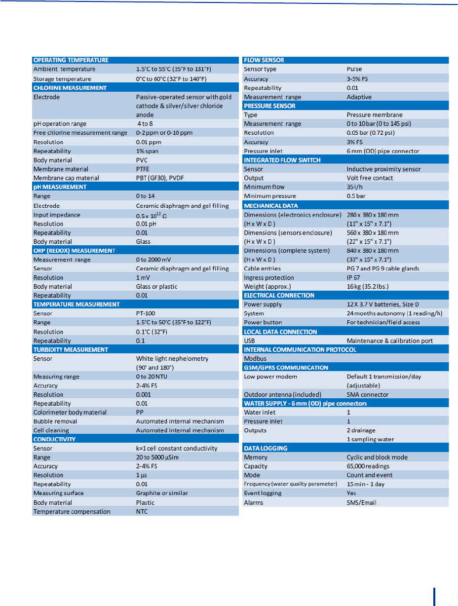
7
Appendix A – Specifications

56
© Blue I Technologies
Declaration of Compliance
We hereby declare that all products are tested and inspected before leaving the factory and are checked to meet
our specifications according to accepted procedures.
Daniel Cohen Khallas
Quality Control Manager
© Blue I Technologies
57
Warranty
Please retain proof of purchase.
Please keep a record of the product in the form below to be
sent to Blue I Water Technologies in the event of a warranty
claim.
Blue I Water Technologies warrants this product and its
parts against defects in materials or workmanship for
eighteen (18) months from date of installation or twenty-
four (24) months from date of shipment from Blue I Water
Technologies, whichever is earlier.
2-year warranty on electronic cards
1-year warranty on all other components
The warranty does not cover consumable parts, such as
electrodes.
Blue I Water Technologies’ responsibility includes repair or
replacement, at the sole discretion of Blue I Water
Technologies, of the whole product or part of it, when the
defect is due to faulty functioning and/or defective
materials.
For your records:
*The serial number can be found on the main label of the
box and on the sticker on the right side of the Smart NRG.
Blue I Water Technologies accepts no
responsibility for damage caused by:
a. Use/operation not consistent with operating
instructions
b. Improper installation
c. Exposure to conditions that are not in
accordance with Blue I’s specifications, e.g.,
pressure/flow/temp
d. Damage during shipment (submit claim to
the carrier)
e. Disasters such as fire, flood, lightning or
improper electric current
f. If the equipment is modified or if non-Blue I
Water Technologies' reagents or
replacement parts are used
Completion of the RMA procedure and return
of defective component(s) to Blue I Water
Technologies, Ltd. Is required for all warranty
items.
User manuals and datasheets can be
downloaded from our website
www.blueitechnologies.com and by scanning
this QR code:
Warranty Claim
Please fill in the information below and retain with proof of purchase
Model Number: ___________________________
Serial Number: ____________________________
Purchase Date: ____________________________
Purchased from: ___________________________
Application: _______________________________ (e.g., potable water, industrial treatment, pool/spa)
In case of submitting a warranty claim, send this form along with proof of purchase to:
Blue I Water Technologies
18 Hamelacha St.
Afek Industrial Park
Rosh Ha’ayin 4809148
ISRAEL

USER MANUAL LEA
