Smart ONE User Guide Pod Guide_03 03
User Manual: SmartPod-User-Guide_03
Open the PDF directly: View PDF ![]() .
.
Page Count: 52
- Safety Instructions
- 1 Introduction
- 2 Installation
- 3 First-Time Operation
- 4 Remote Operation Using Blue I SMART NET Server
- 5 Maintenance
- 6 Troubleshooting
- 7 Appendix A – Specifications
- 8 Appendix B – Sensors Details
- Declaration of Compliance
- Warranty

Smart POD
User Guide
Revision 1.5 – December 28, 2017

© 2017 Blue I Technologies Ltd.
Smart ONE is a trademark of Blue I Water Technologies Ltd.
This Manual may not be reproduced, transmitted, transcribed, stored in a retrieval system, or translated
into any language or any computer language, in any form including electronically, without the prior
written permission of Blue I Water Technologies Ltd.
This product has been designed for the specific use of applications. This product may not be used for
unlawful purposes and that use is expressly prohibited under the terms and conditions of its use.
Blue I Water Technologies Ltd. accepts no responsibility for any damage to its products caused by misuse
or use of non-Blue I Water Technologies’ reagents and/or replacement parts.
The software of SmartOne/ SmartEdge/ SmartPod is a proprietary software of Blue I Water Technologies
Ltd. This software makes use of several open source software packages available under public licenses.
These packages are not a part of the Blue I Water Technologies Ltd.'s software or owned by Blue I Water
Technologies Ltd. Blue I Water Technologies Ltd. 's software is not a derived work of these libraries, and is
a compiled separate software which links to these software packages as external libraries. Web links to
the repositories, where the software was obtained, along with their source code and respective licenses
are as follows:
j2mod BSD, Apache License V2.0 (https://sourceforge.net/projects/j2mod/)
opencsv Apache License V2.0 (http://opencsv.sourceforge.net/)
JFreeChart - GNU LGPL (http://www.jfree.org/jfreechart/)
Seroutils (https://bitbucket.org/mlohbihler/sero-utils)
rxtxcomm - under LPGL (http://www.gnu.org/licenses/old-licenses/lgpl-2.1.html
http://www.jcontrol.org/download/rxtx_en.html
http://rxtx.qbang.org/wiki/index.php/Main_Page)
Jsch - under BSD license (http://www.jcraft.com/jsch/)
Apache Commons Net - under Apache commons license (http://commons.apache.org/proper/commons-
net/)
Apache Common Logging - under Apache commons license
(https://commons.apache.org/proper/commons-logging/)
Apache Common VFS - under Apache commons license (https://commons.apache.org/proper/commons-
vfs/)
Place holder for sticker
Contents
Safety Instructions __________________________________________________ 5
1 Introduction _____________________________________________________ 7
1.1 General Overview ................................................................................................................................. 7
1.2 Method of Operation ............................................................................................................................ 8
1.3 System Components ............................................................................................................................. 9
1.4 Ordering Information .......................................................................................................................... 10
2 Installation _____________________________________________________ 11
2.1 Unpacking the Analyzer ...................................................................................................................... 11
2.2 Environmental Considerations............................................................................................................ 12
2.3 Site Location ........................................................................................................................................ 12
2.4 Wall Mounting .................................................................................................................................... 13
2.5 Plumbing Connections ........................................................................................................................ 14
2.6 Electrical Connections ......................................................................................................................... 15
2.7 Wiring .................................................................................................................................................. 16
3 First-Time Operation _____________________________________________ 17
3.1 Installing Free Chlorine Electrode ....................................................................................................... 17
3.2 Installing pH, Redox, and Temperature Electrodes ............................................................................ 18
3.3 Supplying Water .................................................................................................................................. 19
3.4 Powering On ....................................................................................................................................... 20
4 Remote Operation Using Blue I SMART NET Server _____________________ 23
4.1 Setting up Remote Communication .................................................................................................... 23
4.2 Modbus Connection via External RS485 Connection ......................................................................... 23
4.3 Troubleshooting Communication Issues ............................................................................................ 24
4.4 Logging On ..........................................................................................................................................
25
4.5 Editing Unit Details ............................................................................................................................. 27
4.6 Monitoring Measurements ................................................................................................................. 28
4.6.1 Selecting parameters to display on the Dashboard ............................................................ 28
4.6.2 Detailed Parameters View .................................................................................................. 29

4
© Blue I Technologies
4.6.3 Editing Measurement Value ............................................................................................... 30
4.6.4 Viewing Alarms ................................................................................................................... 30
4.7 Calibrating Parameters ....................................................................................................................... 32
4.8 Viewing Historical Data ....................................................................................................................... 32
4.9 Creating Graphs .................................................................................................................................. 34
4.10 Generating Reports ............................................................................................................................. 36
5 Maintenance ___________________________________________________ 37
5.1 Chlorine Electrode .............................................................................................................................. 37
5.1.1 Cleaning the Sensor ............................................................................................................ 37
5.1.2 Refilling the Electrolyte ....................................................................................................... 38
5.1.3 Replacing the Membrane Cap ............................................................................................. 38
5.1.4 Storing the Chlorine Electrode ............................................................................................ 38
5.2 pH and Rx Electrodes .......................................................................................................................... 39
5.3 Cleaning the Flow Cell ......................................................................................................................... 40
5.4 Cleaning the Turbidity Flow Cell ......................................................................................................... 40
5.5 Cleaning the Filter ............................................................................................................................... 40
6 Troubleshooting _________________________________________________ 41
6.1 Issues and Workarounds ..................................................................................................................... 41
6.2 Unable to Solve an Issue ..................................................................................................................... 42
7 Appendix A – Specifications ________________________________________ 43
8 Appendix B – Sensors Details _______________________________________ 45
8.1 OCS140 and OCS141 Free Chlorine Electrode .................................................................................... 45
8.2 Smartsens OPS31 pH Electrode .......................................................................................................... 47
8.3 Smartsens OPS32 ORP Electrode ........................................................................................................ 47
8.4 Industrial Pressure Transmitter PT124B-213 ...................................................................................... 48
8.5 PT 100 for Acrylic Cell Temperature Sensor ....................................................................................... 48
Declaration of Compliance ___________________________________________ 49
Warranty ________________________________________________________ 50

© Blue I Technologies
5
Safety Instructions
General Safety Precautions
Use this product only in the manner
described in this manual. If the equipment
is used in a manner not specified by the
manufacturer, the protection provided by
the equipment may be impaired.
Utiliser ce produit uniquement de la manière décrite
dans ce manuel. Si l'équipement est utilisé d'une
manière non spécifiée par le fabricant, la protection
fournie par l'équipement peut être altérée.
Smart POD control board unit should not
be opened except for initial installation
and troubleshooting, and should only be
opened by a trained and approved
technician.
Le tableau de commandes de l’Smart POD ne doit en
aucun cas être ouvert si ce n’est lors de l’installation
initiale et en cas de dépannage – auquel cas son
ouverture ne doit être effectuée que par un
technicien ayant reçu la formation adéquate et
dûment habilité.
Only properly trained and licensed
electricians should attempt to wire or
service the electronic components of the
analyzer/controller.
There is an Electrical Shock Hazard when
servicing this system.
Always verify that all electrical power
source(s) are off before opening the
analyzer/controller unit or attempting to
service electronic components or wiring.
Attention! Seuls des électriciens qualifiés ayant reçu
la formation adéquate peuvent entreprendre le
branchement, l’entretien ou la réparation des
composants électroniques de l’analyseur/du
contrôleur.
Il existe un risque de choc électrique lors de
l’entretien de ce système.
Ayez soin de toujours vérifier que la ou les source(s)
d’alimentation électrique est ou sont bien
déconnectée(s) avant d’ouvrir l’unité ou
d’entreprendre toute opération de service technique
et tout branchement des composants électroniques.
Extreme caution should be used when
installing, operating, and maintaining the
Smart POD controller. Only properly
trained technicians are authorized to
install and maintain the
analyzer/controller.
Il y a lieu d’agir avec une extrême prudence lors de
l’installation, de la mise en œuvre et de la
maintenance du contrôleur Smart POD. Seuls des
techniciens dûment formés à cet effet sont autorisés
à effectuer l’installation et la maintenance de
l’analyseur/du contrôleur.
Only properly trained and licensed
operators should attempt to make any
changes to chemical dosing levels.
Seuls des opérateurs qualifiés ayant reçu la formation
adéquate sont habilités à modifier les dosages des
produits chimiques utilisés.

6
© Blue I Technologies
Always follow local health and safety
regulations when performing any service
on the analyzer/controller unit or when
changing chemical dosing settings.
Conformez-vous sans exception aux consignes locales
de santé et de sécurité lorsque vous effectuez toute
opération technique sur l’analyseur/le contrôleur, ou
lorsque vous modifiez les paramètres de dosages
chimiques.
Proper Handling of the Electrodes
Do not touch or damage the electrodes.
The electrolyte is sensitive to oxidation:
Always keep the electrolyte bottle closed
after use.
Do not transfer the electrolyte to other
containers.
The electrolyte should not be stored for
more than one year and should be clear
(not yellow) in appearance (for use by
date, see label).
Ne touchez pas ni n’abîmez les électrodes.
L’électrolyte est sensible à l’oxydation. Maintenez la
bouteille contenant l’électrolyte toujours fermée
après utilisation. Ne transvasez pas l’électrolyte
dans d’autres récipients. L’électrolyte ne doit pas
être conservé plus d’un an et doit garder une
apparence claire (pas jaunâtre) (pour la période
d’utilisation, voir l’étiquette).

© Blue I Technologies
7
1
Introduction
Accuracy, reliability, compact, and cost-effective make Smart POD the leading choice for amperometric
chlorine measurements in municipal applications.
1.1 General Overview
The Smart POD analyzer is a continuous water quality analyzer for municipal applications that utilizes the
proven amperometric chlorine measurement.
Compact Footprint
Smart POD can measure up to four parameters, including free or total chlorine, pH, temperature and
turbidity within its compact design. All sensors are designed within 278 X 188 X 130 mm (11.0 X 7.4 X 5.0
inch) casing, to allow for a minimal installation footprint.
Quick Installation
The Smart POD installation is straightforward, simply mount the casing on the wall, connect the feed and
drain and calibrate the sensors.
Protect Better, Operate Better, Know Better, Connect Better
The Smart POD can be easily connected to the Blue I secured online data-center via Ethernet, Wi-Fi, GPRS,
or GSM giving the operator full remote access to the measured data as well as to the analyzer’s operation
and maintenance interface. When Smart POD is connected to the Blue I data-center, the operator can
access real-time assistance and troubleshooting from an authorized representative to ensure optimal
service of the analyzer.

Introduction
8
© Blue I Technologies
1.2 Method of Operation
The Smart POD water quality analyzer is designed to measure a water sample at pre-configured intervals.
A water sample is captured in the flow cell where the sample is measured.
The cycle workflow is as follows:
A. Water source from main line, reservoir, or surface is fed to the Smart POD system.
B. Water flows to the Acrylic measuring cell that includes fee chlorine, ORP or pH, and temperature
electrodes.
C. The solenoid valve at the Turbidity flow cell opens at regular pre-configured intervals (0.5 – 10
minutes), allowing water to enter the cell.
D. The valve closes automatically capturing the water in the Turbidity flow cell and a mixer piston is
activated to eliminate bubbles inside the cell.
E. A light source is activated at a 90-degree angle.
Turbidity measurement is determined as a function of the detected illumination intensity.
F. A light source is again activated at a 180-degree angle to obtain a baseline measurement based on
the color of the sensed illumination.
System Components
© Blue I Technologies
9
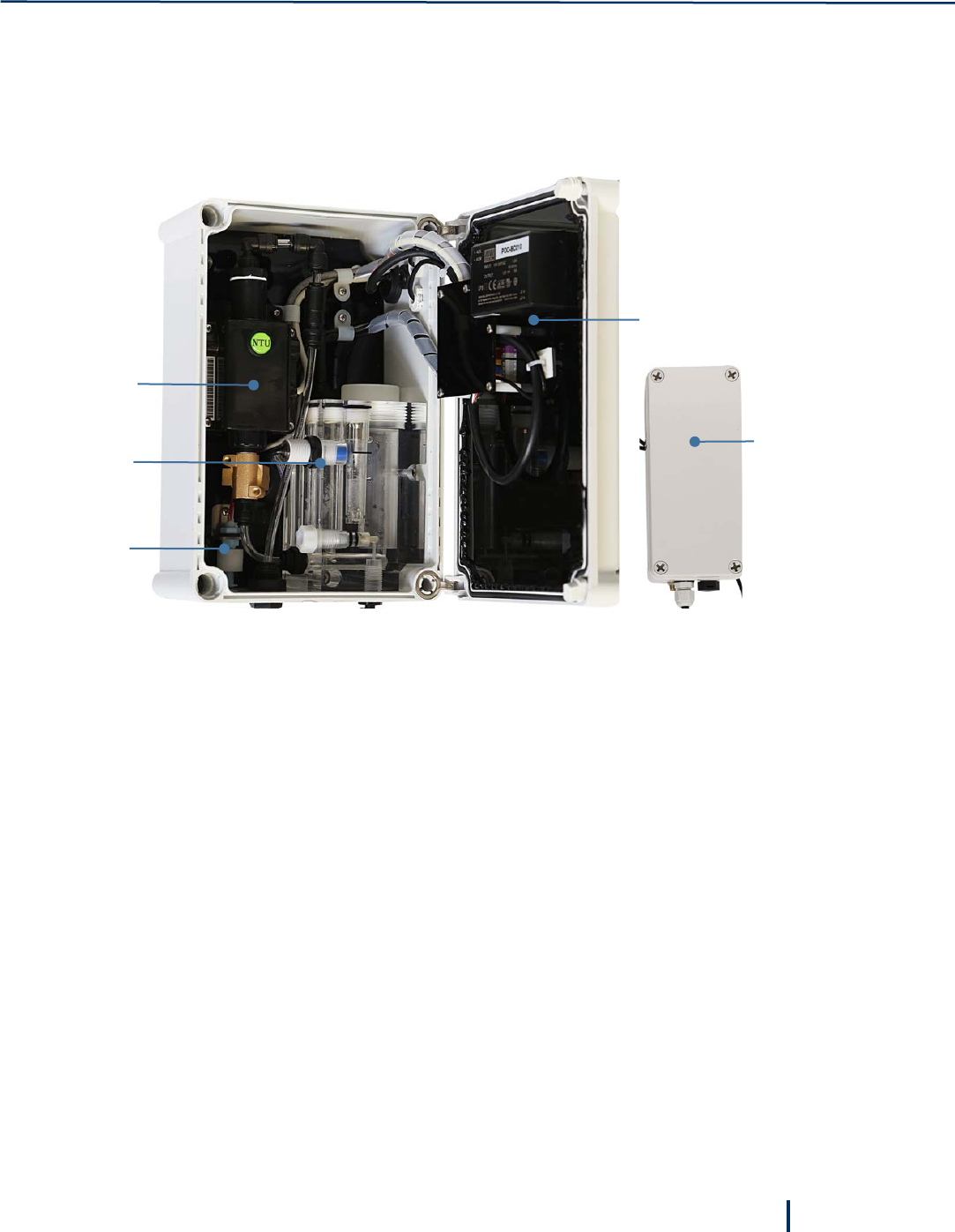
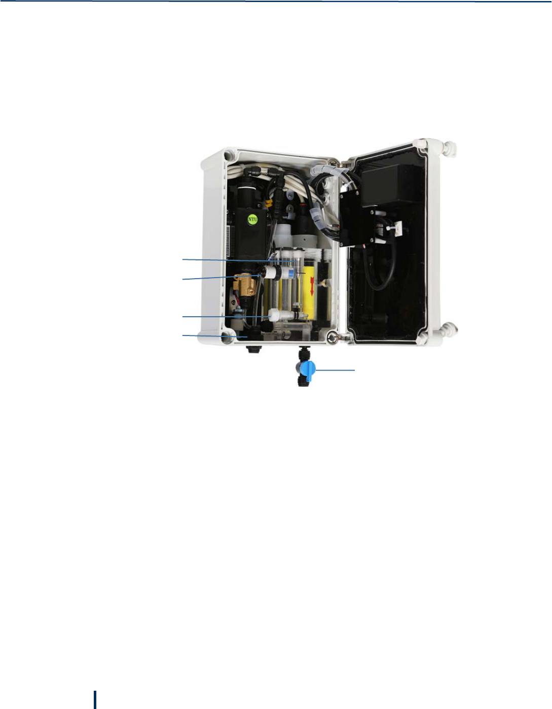
1.3 System Components
The Smart POD water quality analyzer features an IP 65 enclosure designed for wall mounting in outdoor
installation.
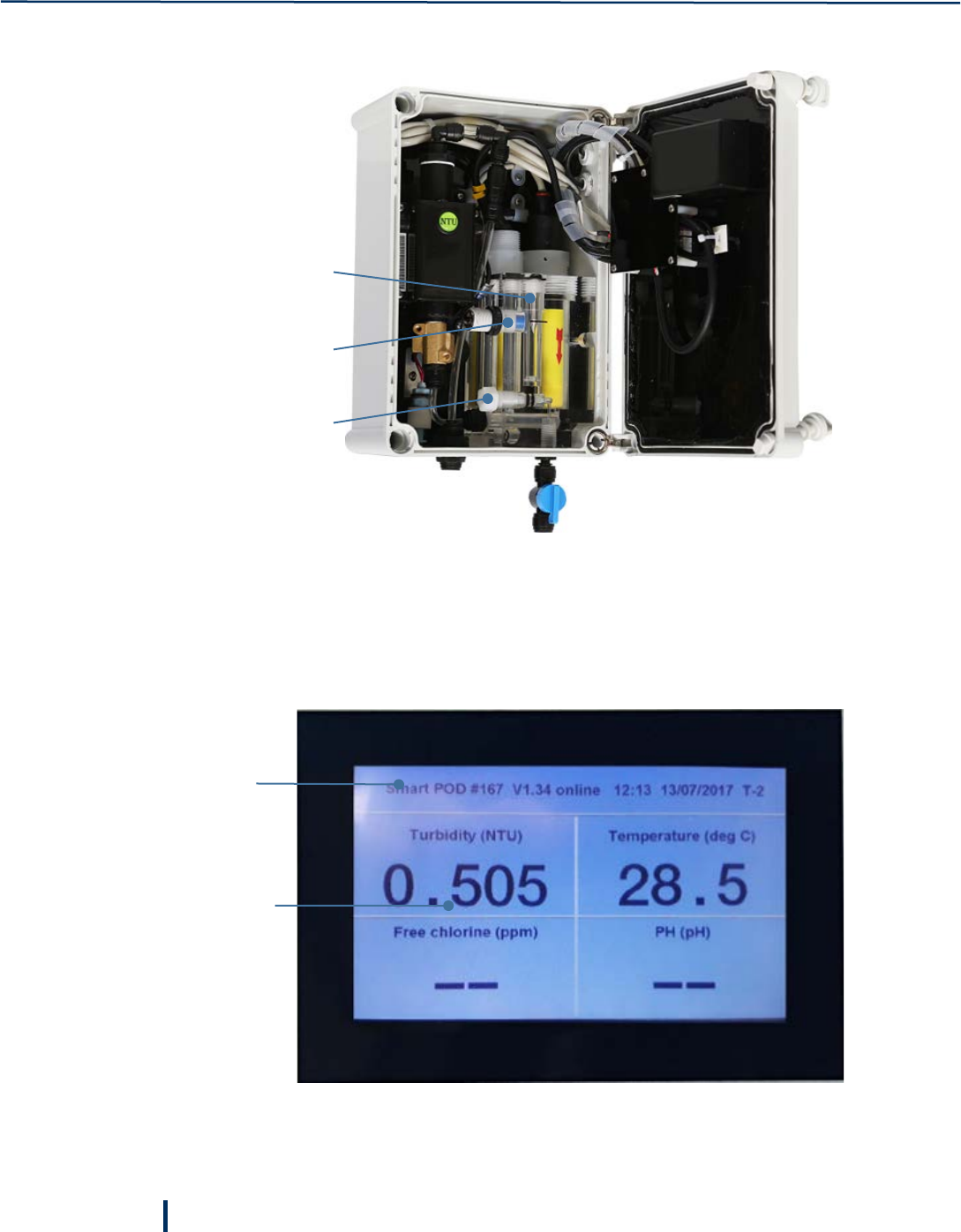
The system includes the following components:
1 – Controller
Includes the display panel and electronic cards.
2 – Modem
External modem provides connectivity to Blue I Smart NET Server via Wi-Fi, GPRS, or GSM.
3 – Turbidity Flow Cell
Specifically designed to hold the turbidity sensor and features automatic cleaning.
4 – Acrylic Flow Cell
Includes the proximity flow switch, and the ports for temperature sensor, pH electrode, and Redox (ORP)
electrode.
5 – Float Sensor
Located at the bottom of the enclosure, detects water rising inside the enclosure indicating a water leak.
Depending on settings, the sensor can send alerts via MSG or email and close the main valve.
Filter – a 130-micron disc filter providing filtered water to the Acrylic flow cell.
Pressure Regulator – the pressure regulator maintains constant pressure and flow into the Acrylic flow
cell required for stable chlorine measurements.
1
4
3
5
2
Introduction
10
© Blue I Technologies
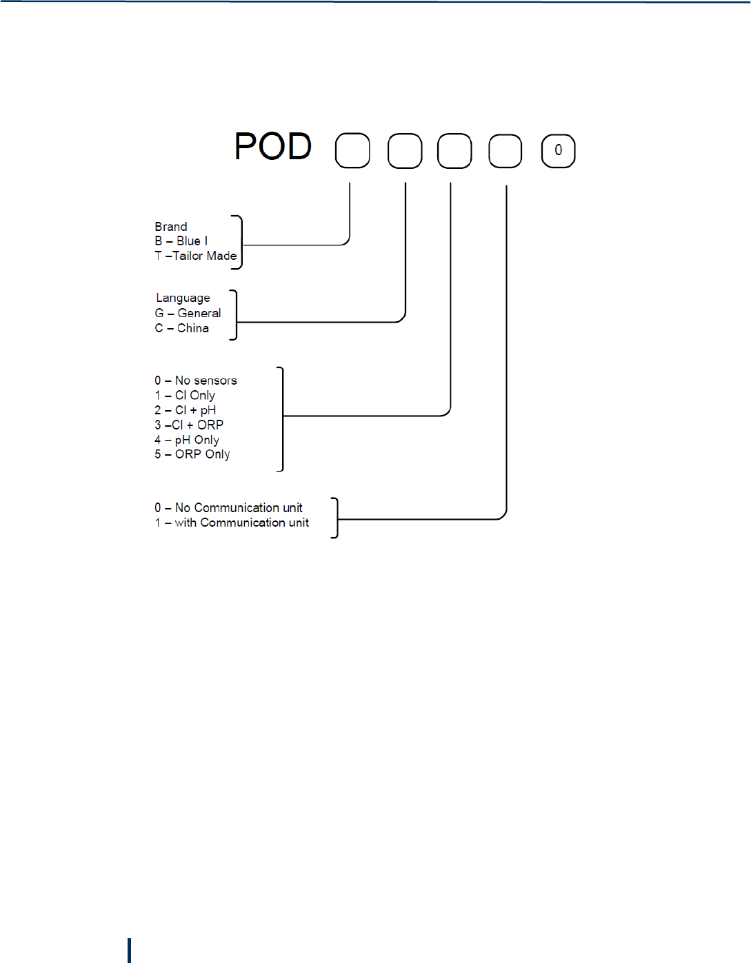
1.4 Ordering Information
Temperature and turbidity measurements are provided by default.
© Blue I Technologies
11
2
Installation
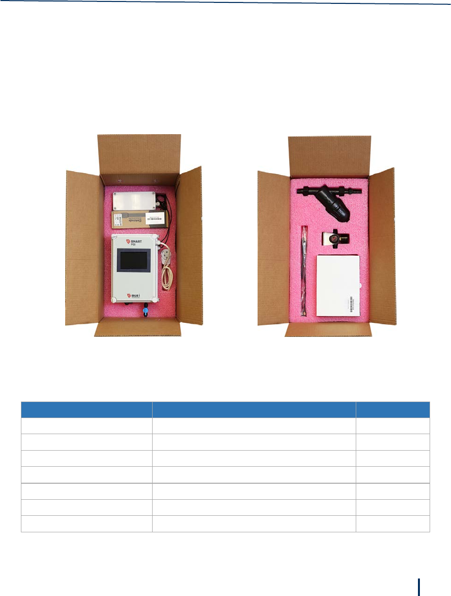
2.1 Unpacking the Analyzer
The Smart POD analyzer is shipped in a cardboard carton, secured with foam packing material. A packing
list is included in each shipping carton. Check the components in the shipping carton against the items on
the packing list and inspect for any damage. If any part is missing or damaged, contact your distributer.
The following table details the Smart POD installation kit.
Note:
The packing list depends on the ordered configuration and may be different than the packing list for your
analyzer. The following list is used for demonstration purposes in this guide.
Part Number Description Quantity
POD Installation Kit for Smart POD
970-000-4000 Filter Assembly for HG 1
972-000-0069 Pressure reducer gauge 1
NGE010 3G/4G Antenna 1
970-210-0204 / 970-210-0205 pH electrode / Redox electrode 1
970-210-0302 Free Chlorine electrode 1
970-110-8092 Signed Warranty Certificate 1

Installation
12
© Blue I Technologies
2.2 Environmental Considerations
The Smart POD enclosure environmental rating is IP 65 and enables both indoor and outdoor installation.
The system working environment is as follows:
Pollution Degree: 2
Installation Category: 2
Altitude: 2,000 m
Humidity: 20% to 90% RH (up to 90% humidity at 40° C / 104° F)
Temperature: 2° to 50° C (35.6° to 122° F)
2.3 Site Location
Consider the following when selecting an installation location:
• Convenient access – install the system where you can easily view and operate it.
• Away from chemicals – many water treatment chemicals can be corrosive to the system’s electronic
circuitry. It is highly recommended that the unit is not installed adjacent to a storage area for
chemicals or the dosing systems themselves.
• Minimal distance from supply pipe – the water sampling line that is connected to the main pipe that
feeds the system should be as short as possible. A long sample line creates unnecessary delay
between water supply and measurement. In any case, water sampling line should not exceed 10
meters (30 feet).
• Drainage – the system’s location should allow the drain outlet sufficient grade for gravity flow,
without creating an obstacle (no pipe across walkway).
• Freezing and changing temperatures – select a location that is not susceptible to freezing
temperatures because parts may be damaged due to expansion when ice forms. Avoid installing in a
location that is exposed to extreme temperature fluctuations. In addition, sudden water temperature
changes can affect readings.
Wall Mounting
© Blue I Technologies
13
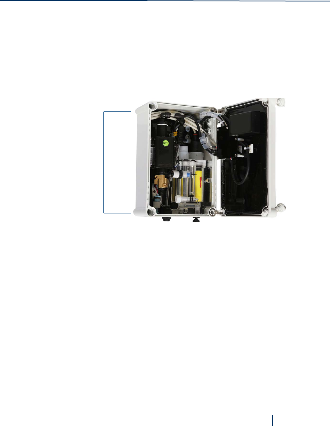
2.4 Wall Mounting
The Smart POD is wall mounted. It is recommended to mount the base of the unit at least 60 cm (24”)
above the floor, preferably at eye level, to allow easy viewing and operation.
The unit is shipped without mounting screws. The installer must provide screws that can hold the weight
of the unit. The screws must be compatible with the wall type on which the unit is mounted.
1. Use appropriate mounting brackets as guidelines for marking drilling holes from each side of the
system. Drill the holes using an 8-mm drill.
2. Fasten the enclosure to the wall using appropriate mounting brackets.
3. Verify that the unit is installed at upright position, 90° vertical to the ground. Any sideways or
back/forward tilt may impair the function of the system.
4. Connect the modem cables to the provided detached modem and place on top of the unit or affix it
to the wall using appropriate screws.
Mounting
brackets
Installation
14
© Blue I Technologies
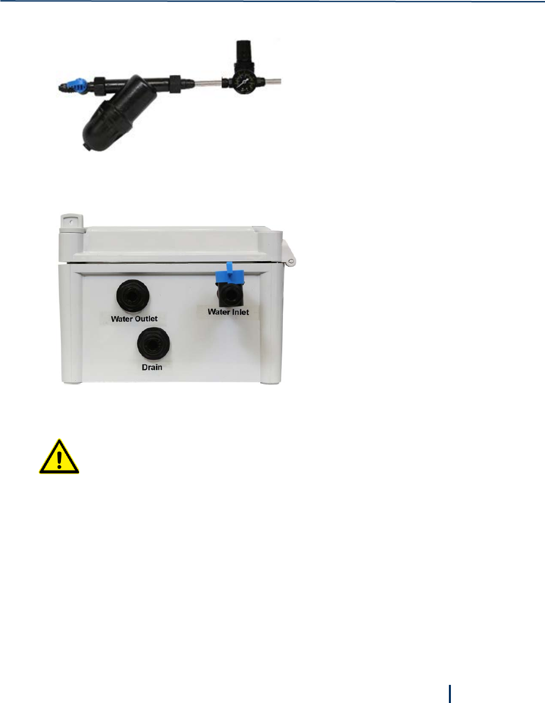
2.5 Plumbing Connections
The Smart POD is shipped with a water filter and a pressure regulator. The analyzer requires a pressurized
water supply of 0.35 to 1 Bar (5 – 14.5psi) and a steady water flow of at least 35 l/h (9 – 16 GPH) to the
flow cell.
Length of the water inlet line should not exceed 10 meters (30 feet) and preferably as short as possible to
minimize the time water reach the flow cell. It is recommended to connect the water inlet pipe at the
bottom of the main line to minimize air entering the system.
1 – Water inlet
2 – Water outlet
3 – Flow regulating valve
4 – Proximity flow switch
5 – Metal float
To connecting the water inlet and drain
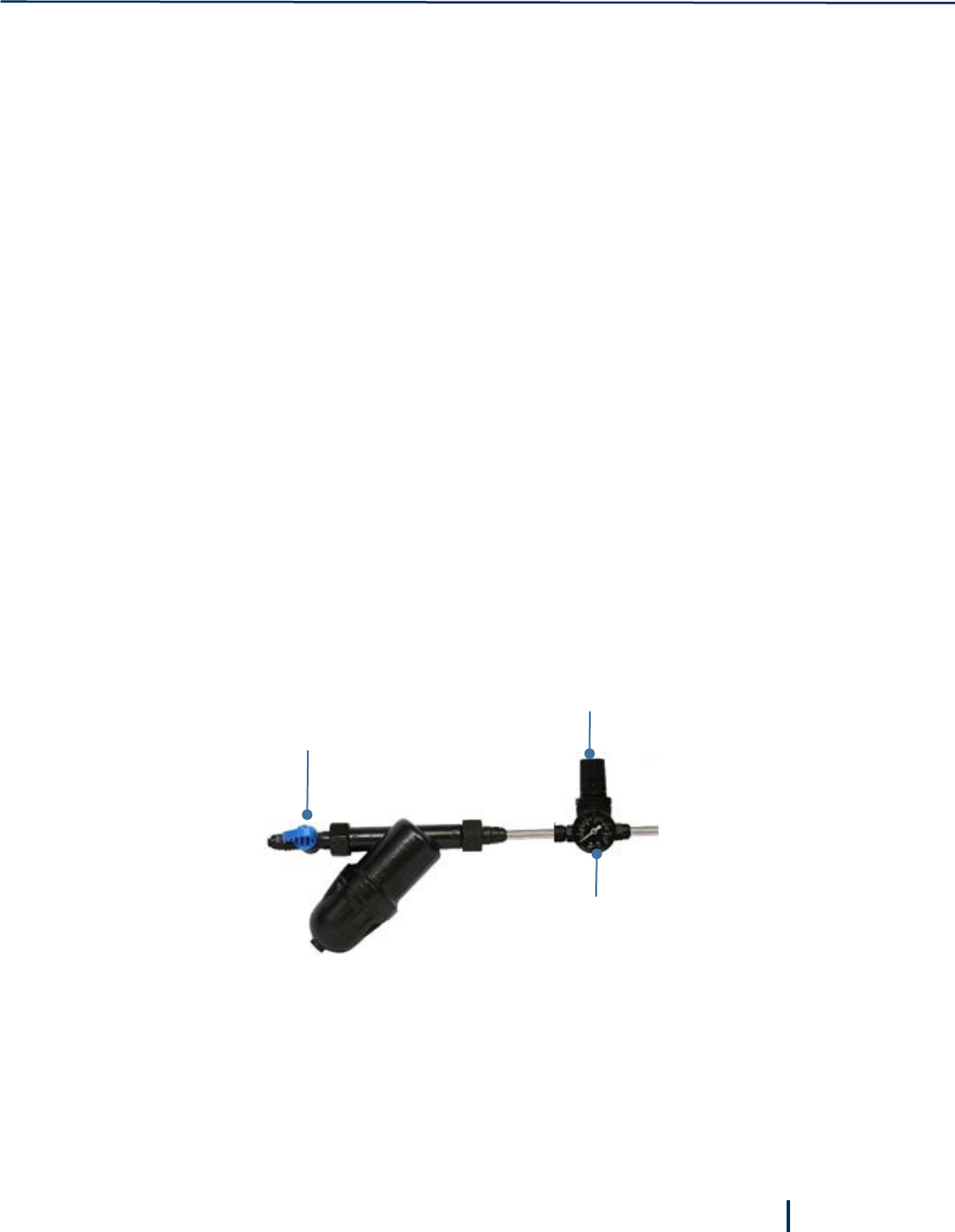
1. Use the provided fitting for 8-mm (1/4”) pipe to connect a valve and install the Filter Assembly (P/N
970-000-4000) between the main line and the analyzer.
2. Close the valve and connect a Pressure Reducer valve (P/N 972-000-0069) to the Filter outlet.
3. Lead an 8-mm pipe from the pressure reducer valve to the analyzer water inlet.
1
3
5
4
2
Electrical Connections
© Blue I Technologies
15
4. Connect a 10-mm pipe to the flow cell outlet and lead it out through the fitting at the bottom of the
enclosure.
The outlet pipe must have a constant downward slope to prevent backflow.
2.6 Electrical Connections
The electrical connections described in this section are a recommendation only. All electrical
connections must comply with National Electrical Code (NEC) and all local regulations.
The Smart POD analyzer is power supplied by 100 – 240VAC 50/60Hz, using the provided power cord.
Installation
16
© Blue I Technologies
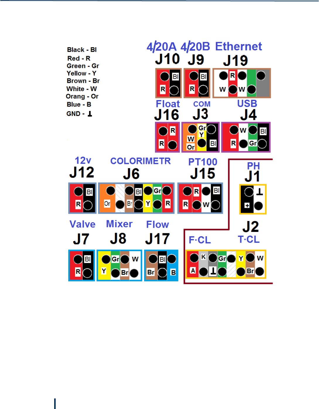
2.7 Wiring
The following image details the wiring scheme on the electronics card.
.
© Blue I Technologies
17
3
First-Time Operation
Setting up the system includes the following steps: installing electrodes, supplying water to the system,
and powering on.
3.1 Installing Free Chlorine Electrode
Free chlorine is defined as the sum of Hypochlorous acid (HOCL), hypochlorite ions (OCl-) and Cl2, and the
proportion of the different free chlorine species is pH and temperature dependent. The hypochlorous acid
(HOCL) contained in the medium diffuses through the sensor membrane and is reduced to chloride ions
(Cl-) on the gold cathode. On the silver anode, silver is oxidised to silver chloride. The electron release of
the gold cathode and electron acceptance on the silver anode result in a current flow which is
proportional to the HOCL concentration in the medium under constant conditions. Since the
concentration of hypochlorous acid in the medium depends on the pH value, pH must be measured to
perform an accurate compensation and present a free chlorine value.
Do not swallow the electrolyte. Avoid electrolyte contact with skin or eyes. In case of accidental
contact, wash with a lot of cold water. In case of eye inflammation, contact a doctor
immediately.
Wear safety glasses and gloves when working with the electrolyte solution.
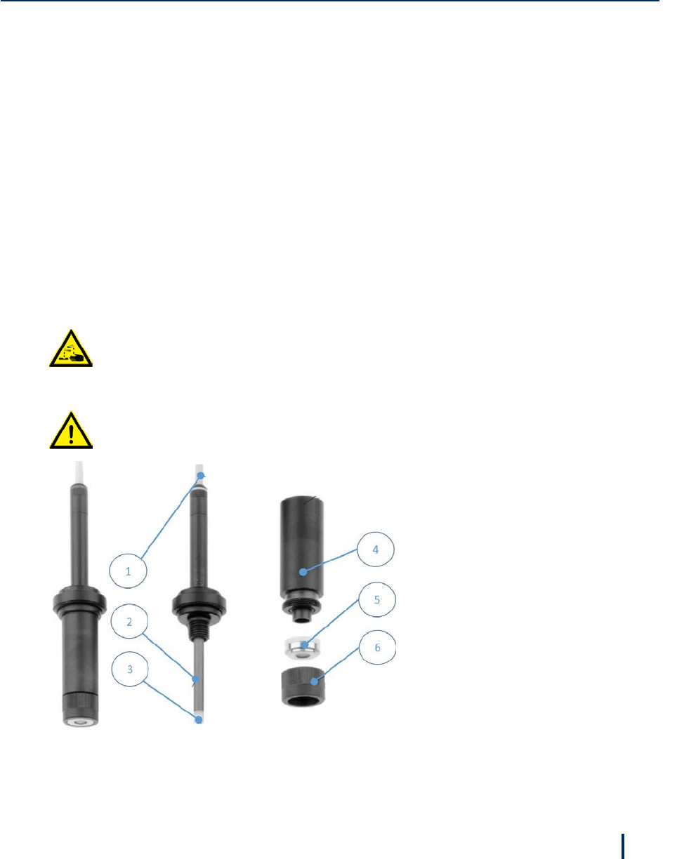
Do not touch or damage the electrodes. The electrolyte is sensitive to oxidation: Always keep
the electrolyte bottle closed after use.
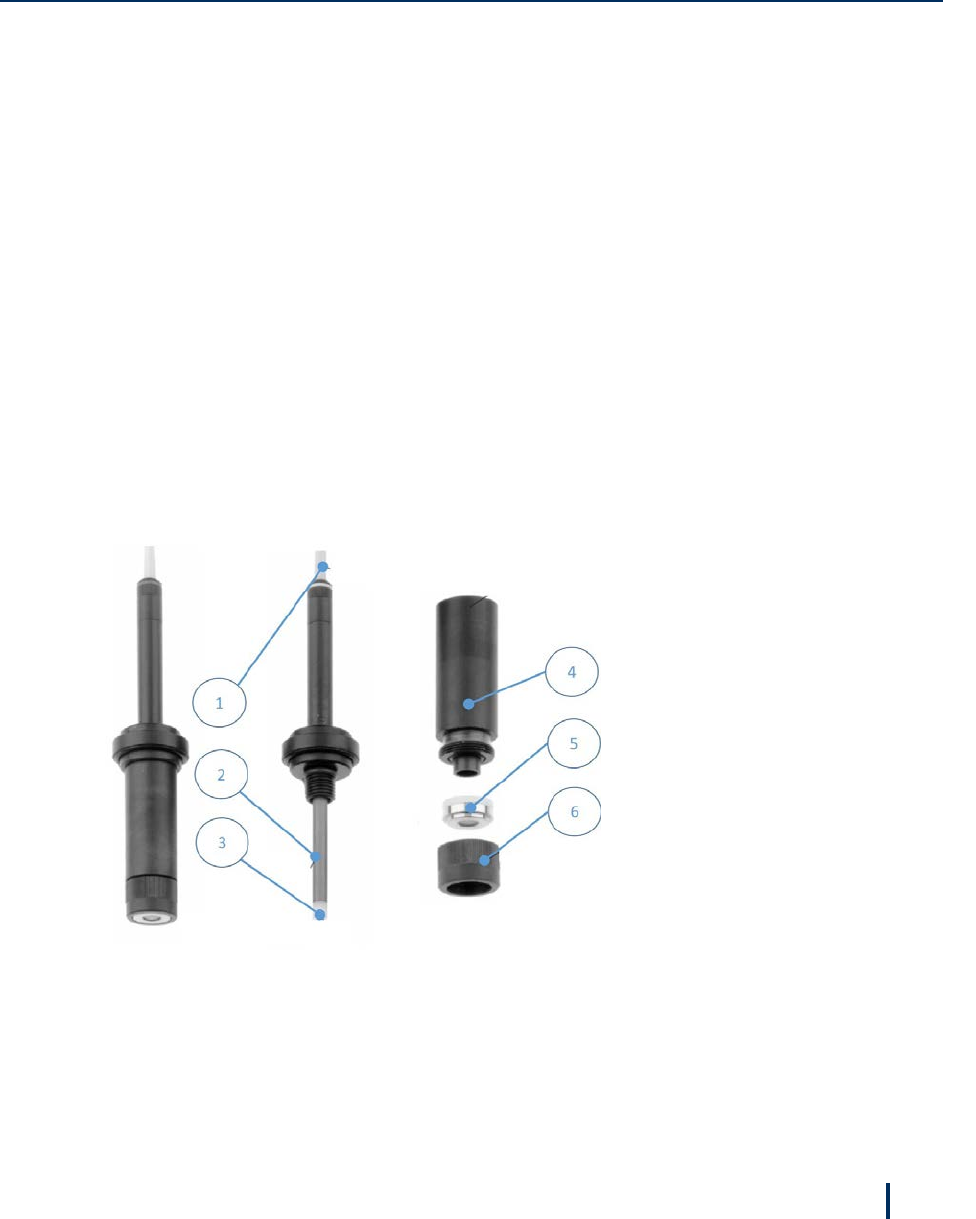
1 – Electrode cable
2 – Large surface silver/silver chloride
anode
3 – Gold cathode
4 – Measuring chamber
5 – Membrane cap
6 – Screw cap (to fix the membrane cap)
Operation and Configuration
18
© Blue I Technologies
To install chlorine electrode:
The free chlorine electrode is shipped from the factory wet and pre-filled with electrolyte. There is no
need to fill electrolyte before using.
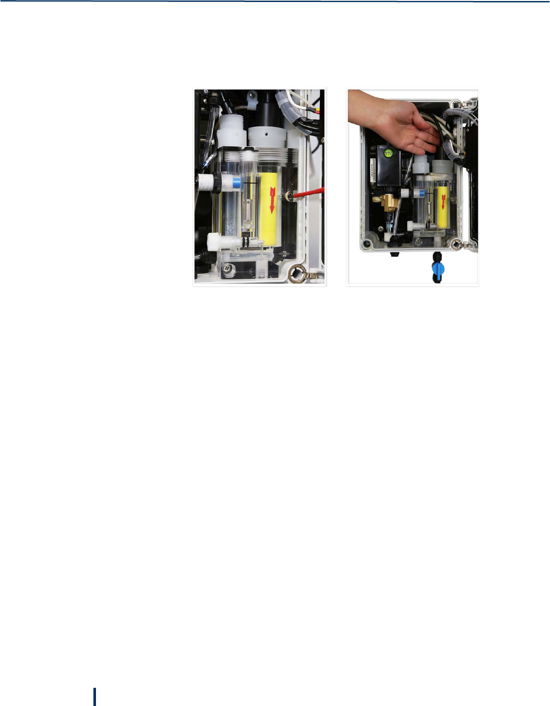
1. Remove the electrode from the acrylic flow cell and pull off the yellow protection cap.
2. Verify that the electrode is full of electrolyte and the membrane is not damaged.
For information about refilling electrolyte or replacing the membrane, see “Chlorine Electrode” on
page 37.
3. Install the electrode back into its port in the acrylic flow cell and hand-tight.
4. Route the wires (if not already wired) to the electronics card. Connect wire K to CL-K terminal, wire A
to CL-A terminal and the unmarked wire (ground) to the ground terminal.
See “Wiring” on page 16 for more information.
3.2 Installing pH, Redox, and Temperature Electrodes
1. pH electrode:
The pH electrode is shipped from the factory in its original packaging.
a. Remove the pH electrode from its packaging, remove the silicon cap and install the electrode
into its port in the acrylic flow cell and hand-tight.
b. Connect the cable labeled pH to the top of the electrode and hand-tight.
c. Connect the center wire to the pH (+) terminal block.
d. Connect the clamp onto the outside of the wire being sure that the wire mesh is in contact with
the metal plate on the electronics card.
e. The pH (-) terminal block will remain empty.
The pH electrode cable is shipped connected to the electronics card. For more information about
wiring the pH electrode, see “Wiring” on page 16.
Supplying Water
© Blue I Technologies
19
2. Redox electrode:
a. Remove the Redox electrode from its packaging, remove the silicon cap and install the electrode
into its port in the acrylic flow cell and hand-tight.
b. Connect the cable labeled Rx to the top of the electrode and hand-tight.
The Redox electrode cable is shipped connected to the electronics card. For more information
about wiring the Redox electrode, see “Wiring” on page 16.
3. Temperature sensor:
The temperature sensor is shipped from the factory installed inside the acrylic flow cell and wired to
the electrodes card.
a. Connect the Black wire to the connection labeled Black.
b. Connect the White or Yellow wire to the connection labeled Yellow.
c. Connect the Red wires to the connections labeled Red. Either Red wire may go to either
connection.
The temperature sensor cable is shipped connected to the electronics card. For more
information about wiring the temperature sensor, see “Wiring” on page 16.
3.3 Supplying Water
1. While water flows to the system, use the pressure regulator valve (B) to adjust the water pressure to
0.35-1 bar (5 – 14.5 psi) by gently pulling the knob up (C). Once pressure is stabilized, push the knob
back to lock it.
2. Adjust the water flow within the flow cell: verify that the metal float (D) is aligned with the proximity
flow switch (E). Adjust the flow using the flow cell valve (F).
A
Inlet valve
C
Regulator knob
B
Pressure regulator
valve
Operation and Configuration
20
© Blue I Technologies
3.4 Powering On
To turn the analyzer on, connect the power cord to a power socket. Allow the analyzer to operate for
several hours before proceeding to calibration.
The analyzer’s screen displays current measurements in addition to the information detailed below.
The information line at the top of the screen refreshes every 5 seconds. The information is displayed in
the following order in an endless loop:
F
Flow regulating valve
D
Metal float
E
Proximity flow
switch
Measurements
Information
line

Powering On
© Blue I Technologies
21
• Measurement threshold value exceeded (only if occurred):
◦ Chlorine low/Chlorine high
◦ PH low/PH high
◦ Turbidity low/Turbidity high
◦ Temperature high/Temperature low
• System error. Only the first encountered error is displayed:
◦ No flow – indicates insufficient water flow through the Acrylic flow cell.
◦ Check led – indicates that no current was detected in turbidity measurement LED.
◦ Check piston or high pressure – indicates that the piston coils are not connected properly, the
coil is damaged, or the pressure is too high (above 1 bar).
◦ Check NTU connection – indicates that the digital connections between the turbidity
measurement unit and the main board is not working properly.
• System flood – water is flooding the enclosure. This message is displayed only when a flood is
detected.
• Smart POD #121 Ver 1.32 online 09/08/2017 18:14:
◦ #121 – serial number of the unit.
◦ Ver 1.32 – software version.
◦ Online – indicates the Smart POD is connected to a server.
• The following information is displayed only when a Modbus server is connected to the Smart POD
and communicating at least once every two seconds.
◦ Modbus OK – displayed as long as the Modbus server is not sending server status to the
controller.
◦ Modbus OK, Server OK, speed 3 – displayed when the Modbus server is sending server status and
indicates that the connection is OK, and the connection speed is high (1-low, 4-highest).
◦ Modbus OK, Server fault – indicates that the server is not connected.

© Blue I Technologies
23
4
Remote Operation Using
Blue I SMART NET Server
The Smart POD analyzer supports two-way communication with Blue I SMART NET server. This enables
monitoring measurement results, historic data, and alerts remotely via a web application. In addition,
operators can use the web application to modify system settings, perform calibrations, and generate
reports remotely.
4.1 Setting up Remote Communication
The detached Modem unit enables you to connect and operate the Smart POD analyzer. Available
communication options are: TCP/IP LAN, 3G/4G GSM (USB dongle), or Wi-Fi (internal).
To set up Wi-Fi, GSM, or LAN connection:
1. For a LAN connection: connect an Ethernet cable to the Ethernet port located on the enclosure right
side.
2. For GSM or Wi-Fi connection: locate the USB port on the back of the touch screen display and insert
the provided GSM dongle.
If you use GSM, place a SIM card with data plan into the dongle.
3. Connect the antenna cable from the display unit to the antenna connector.
4. Outside the enclosure, unscrew the antenna connector cap and connect the provided antenna.
5. Attach the antenna to a metal object or place it on top of the controller.
Position the antenna away from signal obstructions in front of the antenna.
4.2 Modbus Connection via External RS485 Connection
1. Connect an RS485 cable to the external RS485 terminal block.
Register 40193 (holding 193) holds the Modbus address for RS485 connection only and does not
affect the USB or PI connection. It is possible to change this address from 1 to 127 as required.
2. Setup the connection settings to 115200 bps, no parity, no handshake, 1 parity bit.
3. Refer to the controller Modbus mapping to read data from the controller.

Remote Monitoring and Configuration
24
© Blue I Technologies
4. For basic use, read the first 14 input registers from Device address 1, registers address 30001 – 30014
to get calibrated readings. See the Modbus mapping for further details.
4.3 Troubleshooting Communication Issues
Follow these guidelines and instruction if you encounter connectivity issues with Blue I SMART NET server.
For more information about troubleshooting modem issues, see the video tutorials at
http://blueitechnologies.com/video-tutorials.
Are you using a 3G/4G modem?
Unplug the modem and connect it to a laptop. You should get plug and play connectivity using the Huawei
GSM dongles. If you there’s no connectivity while connected to a laptop, consult Blue I support or the SIM
card provider.
If you are using an HSPA hotspot dongle, make sure to define it as Wi-Fi internal using the SSID and
password provided by Blue I (the factory setting password is overwritten), see “Setting up Remote
Communication” on page 23.
Are you using Internal or External Wi-Fi?
Make sure that you have type in the correct password in the Define Communication screen. After
resetting, the correct IP address should be displayed when tapping Show IP in the Admin screen.
IP addresses is displayed for wlan0 for Internal Wi-Fi dongles, and wlan1 for External Wi-Fi dongles.
Are you using LAN/Ethernet connection?
Use the same cable to connect to your laptop. If you are unable to connect on your laptop, consult your IT
department for setting DHCP for your network.
Tap Show IP (Advanced) in the Admin screen, an IP address is displayed under ETH.
Verify that definitions are being read correctly from the device
Open the About screen, verify that you see your controller unique ID.
Open the Hardware Configuration screen, verify that your unit settings are configured correctly: POD for
Smart POD.
Verify that the unit clock is set
Make sure the unit clock is set correctly via the Localization menu.
If the unit is behind a firewall
Verify that your network communication is open for FTP/SFTP/FTPS access.

Logging On
© Blue I Technologies
25
4.4 Logging On
1. In your Internet browser, type in the following address: www.blueiwt.com.
The Login page is displayed.
2. Type in your user name and password, and click Login.
Your assigned privileges determine the type of access to the system:
◦ Admin – full control in the system
◦ Engineer – modify system settings, except maintenance
◦ Viewer – viewing rights only
The main screen is displayed.

Remote Monitoring and Configuration
26
© Blue I Technologies
The Left pane displays a list of your Smart POD installations grouped by geographical location.
Expanding each installation opens the unit properties: Dashboard, Charts, Parameters, History,
Calibration, and Reports.
The main area displays three tabs:
◦ Map – display the units and their status on a map.
◦ Events – displays events properties. Events properties is available if you installed the EDS option.
◦ Reports – opens the reports page.
Unit Statuses:
Idle – unit is not in working mode
Warning – a low level alert
Alert – a high level alert
Communication – unit has not reported status/date for more than 15 minutes
OK – unit is working and reporting OK
Editing Unit Details
© Blue I Technologies
27
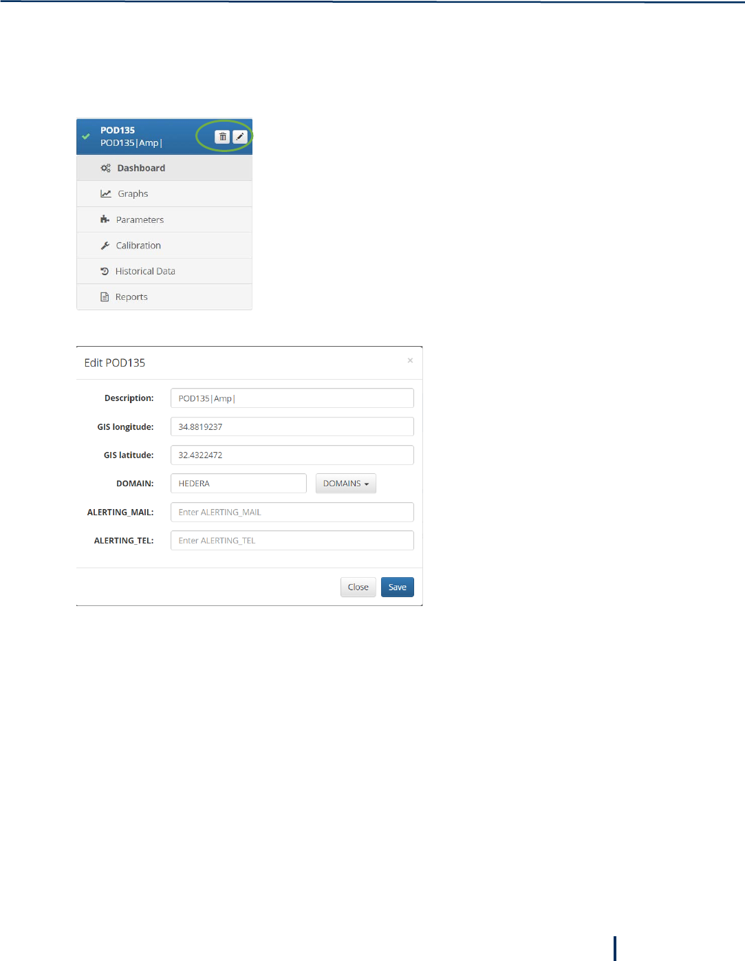
4.5 Editing Unit Details
You can edit general properties of each unit.
1. Select a unit in the left pane.
2. Click the Pencil icon to edit the unit’s properties:
3. Click Save to save and close the Edit window.
Remote Monitoring and Configuration
28
© Blue I Technologies
4.6 Monitoring Measurements
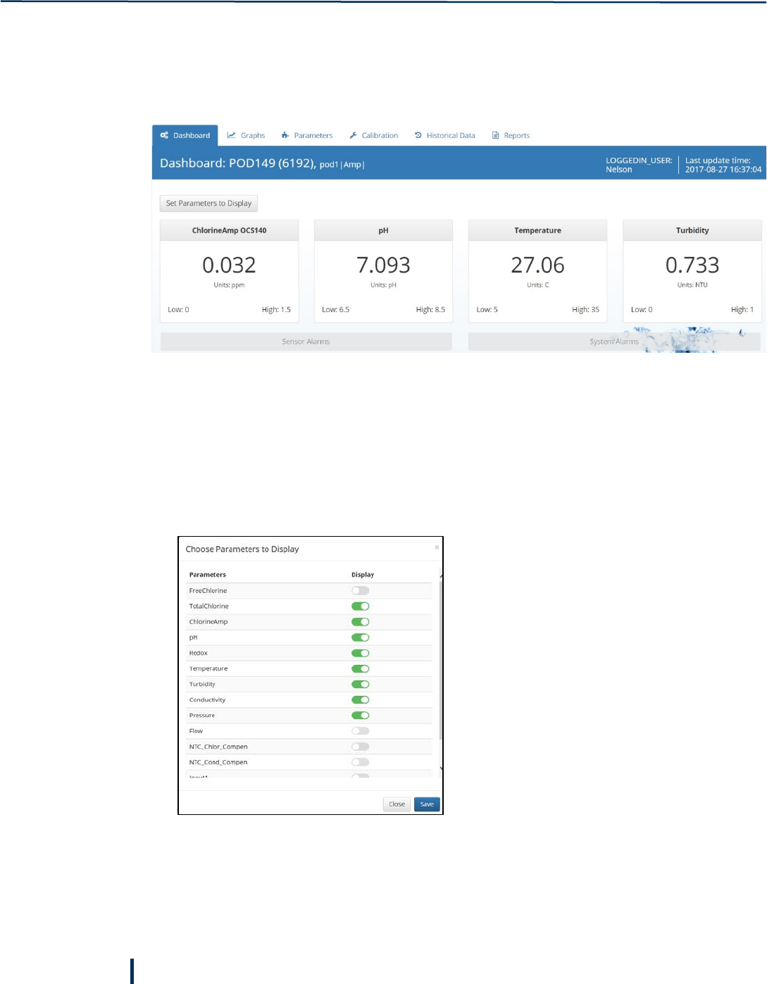
You can get an overview of each unit measurements by accessing the unit Dashboard.
To access the unit Dashboard, select a unit on the left and click Dashboard.
For each parameter, the system displays current measurement, low threshold, and high threshold. For
additional details on each parameter, see “Detailed Parameters View” on page 29.
4.6.1 Selecting parameters to display on the Dashboard
1. In the Dashboard page, click Set Parameters to Display.
2. Select the parameters you want to display for this unit by dragging the control to the right.
You can display up to eight parameters at the same time.
3. Click Save.
Monitoring Measurements
© Blue I Technologies
29
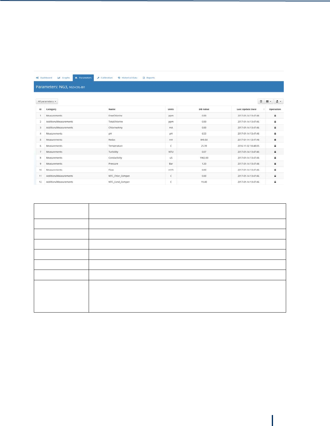
4.6.2 Detailed Parameters View
In addition to the Dashboard view, you can monitor parameters values in detail by accessing the unit’s
Parameters page.
To view detailed parameters values:
1. Select a unit on the left and click Parameters.
The following data is available for each parameter:
Value Description
ID Index number of the parameter
Category The category group of the parameter
Name Parameter name.
Units Engineering units.
DB Value Parameter’s value currently stored in the database.
Last Update Date Time stamp of the last update of the parameter’s value in the database.
Operation • Lock icon – parameter’s values can be modified from the field unit only.
• Pencil icon – parameter’s values can be modified from the server by
clicking the icon.
2. To filter the Parameters page, click the All Parameters list on the left and select a filter:
◦ All Parameters – displays the complete list of parameters
◦ Low/High Limits – displays low/high alarm limits
◦ Measurements – displays parameters from group 0,1 that can be displayed on the Dashboard
◦ Parameters – displays the unit’s meta parameters
◦ Versions – displays software components and hardware versions
Remote Monitoring and Configuration
30
© Blue I Technologies
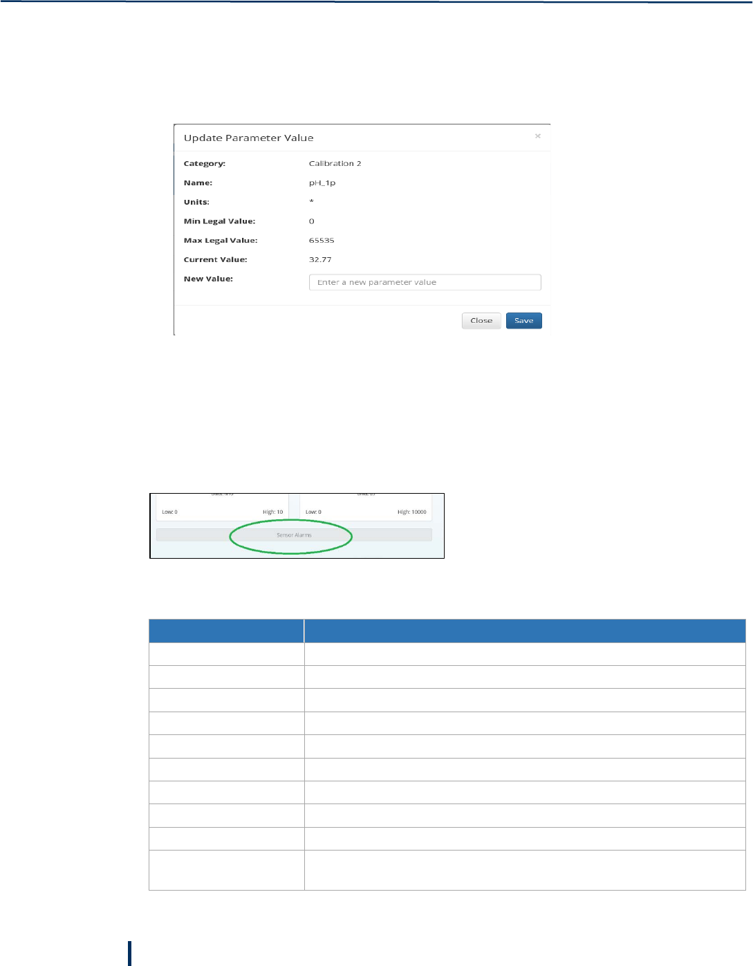
4.6.3 Editing Measurement Value
You can manually update measurement values for parameters that a Pencil icon appears in their
Operation column.
1. Click the Pencil icon.
2. Type in the new value in the New Value field and click Save.
4.6.4 Viewing Alarms
Alarms are triggered when a parameter measurement exceeds the low or high thresholds set for this
parameter. To set alarms thresholds, you need Engineer privileges.
When alarms are triggered, the Sensor Alarms at the bottom of the Dashboard page become active.
Click Sensor Alarms or System Alarms to view active alarms.
The system displays the following alarms:
Alarm Description
Chlorine Low Chlorine Electrode value- Low Alarm
Chlorine High Chlorine Electrode value- High Alarm
pH Low pH Low Alarm
pH High pH High Alarm
Turbidity Low Turbidity Low Alarm
Turbidity High Turbidity High Alarm
Temperature High Temperature High Alarm
No flow! No sufficient water flow through the acrylic cell.
Check LED! No current was detected flowing through the turbidity measurement LED
Check piston or high
pressure!
The piston coils are not connected well, the coil is damaged, or the
pressure is too high (above 1bar)

Monitoring Measurements
© Blue I Technologies
31
Check NTU connection!
The digital connections between the turbidity measurement unit and the
main board is not working well
System flood Water is flooding the Pod
Online Indicated if the Pod is connected to the server.
Modbus OK, Server OK,
speed 3
The connection with the server is ok, and the communication speed with
the server is high. The speed can be 1 to 4. 1 is low. 4 is high.
Modbus OK, Server fault The server is not connected, check modem
Remote Monitoring and Configuration
32
© Blue I Technologies
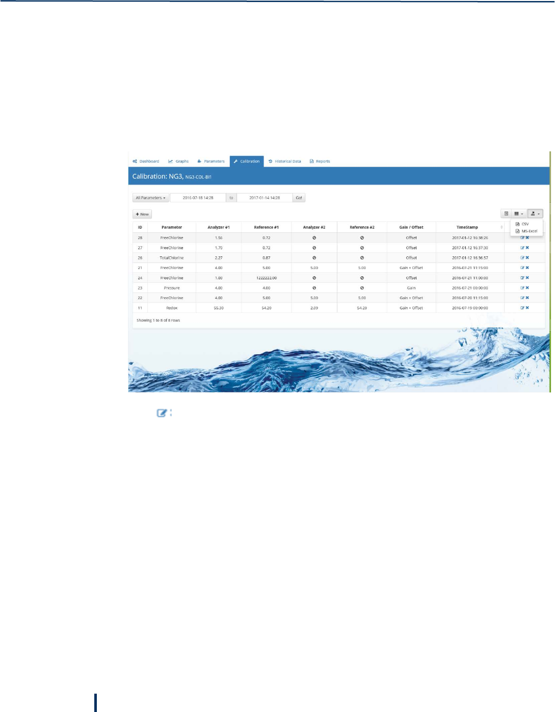
4.7 Calibrating Parameters
The Blue-I server enables you to calibrate the Smart POD parameters remotely. Calibration is a process in
which sensors reading are adjusted based on actual field measurements. Calibration may set the offset of
a sensor, its gain, or both. By default, the calibration page displays all calibrations performed in the last six
months. This can be changed by setting a different date range.
To calibrate parameters:
1. In the left pane, expand a unit and select Calibration. The Calibration page is displayed.
2. Click to edit an existing calibration, or click New to add a new calibration.
3. In the Add New Calibration Entry, type in the calibration data:
◦ Parameter – select the parameter you want to calibrate.
◦ Analyzer #1 – enter the unit’s parameter measurement
◦ Reference #1 – enter the parameter external measurement
◦ Analyzer #2, Reference #2 – if you use two-points calibration, enter unit measurement and
external measurements for the second point.
◦ Gain/Offset – select the calibration type: Gain, Offset, or both
4. Click Save to save the new calibration.
4.8 Viewing Historical Data
The Historical tab enables you to browse through historical data. By default, the order of the records is
from current time to past. On the lower left side, you can set the number of records to display per page
and move through the pages.
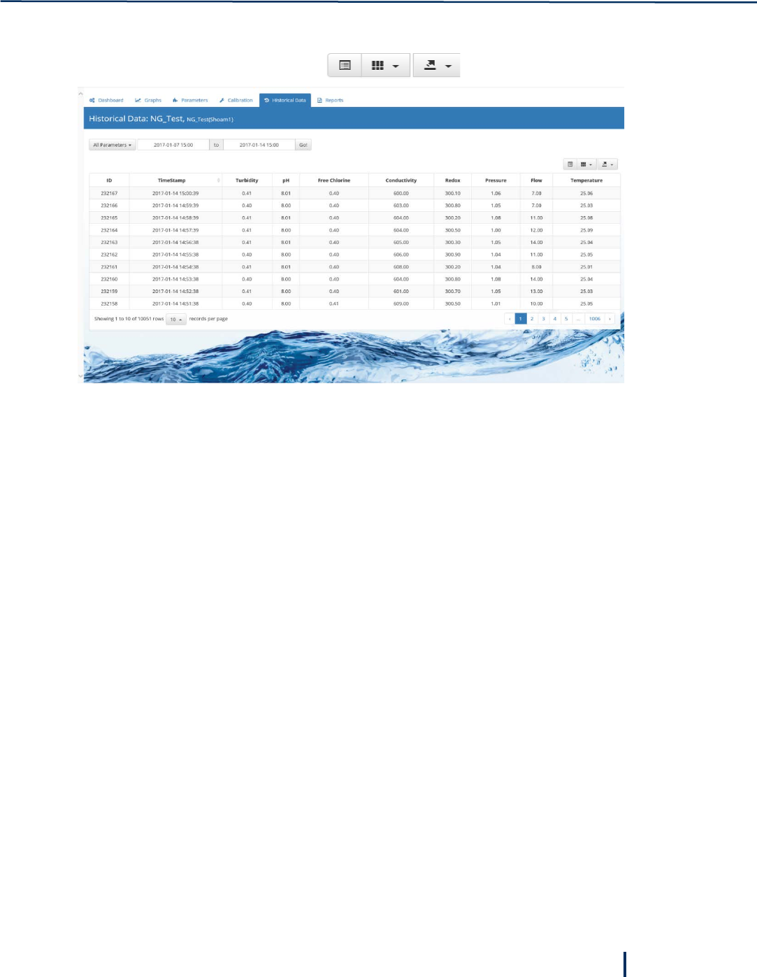
Viewing Historical Data
© Blue I Technologies
33
• To view historic data, expand a unit on the left, and click Historical Data.
• To export the data to CSV or Excel file, click at the top right corner.
Remote Monitoring and Configuration
34
© Blue I Technologies
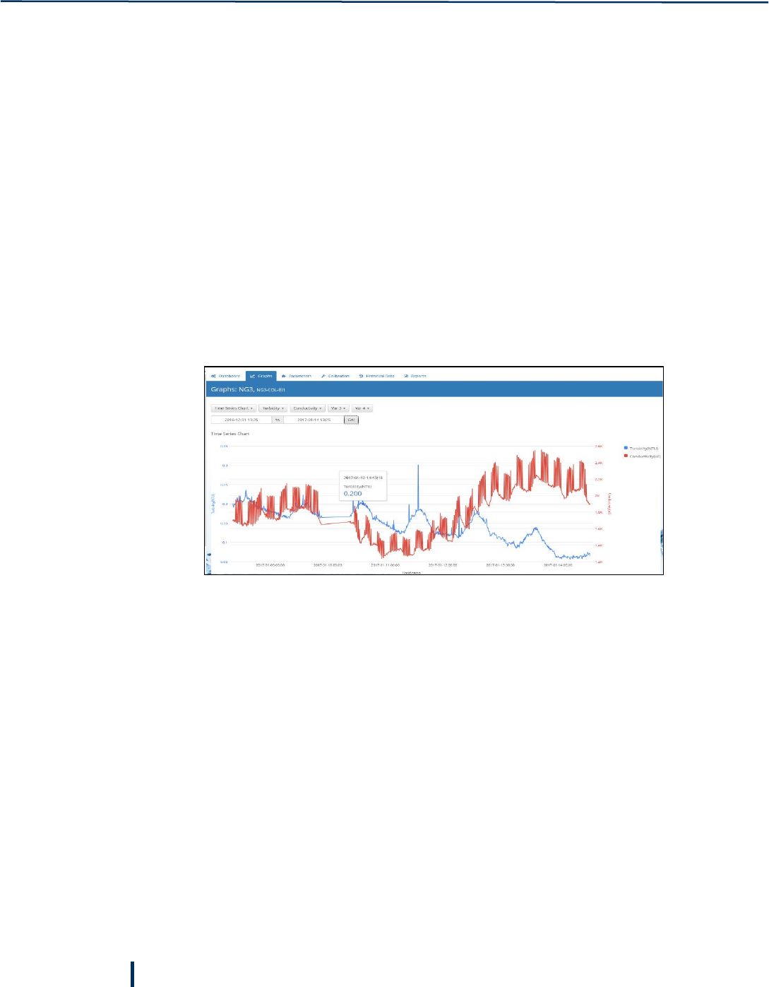
4.9 Creating Graphs
Graphs enable you to display historical data graphically. Three types of graphs are available:
• Time series – displays up to four different parameters on both left and right vertical axis and time
labels on the horizontal axis
• Histogram – shows the frequency of measurement values over a specified time.
• X-Y Chart – displays the correlation between two parameters.
To create a graph:
1. Expand a unit on the left and click Graphs.
2. In the Graphs page, select the graph you want to create from the list.
3. Depending on the selected graph, specify the following information:
a. Time Series:
Select the parameters, specify a time range and click Go.
Note
Time interval is one minute when the range is less than a week.
Time interval is 10 minutes when the range is more than a week, but less than two weeks.
Time interval is one hour when the range is more than two weeks.
The time interval is displayed at the top of the graph.
Creating Graphs
© Blue I Technologies
35
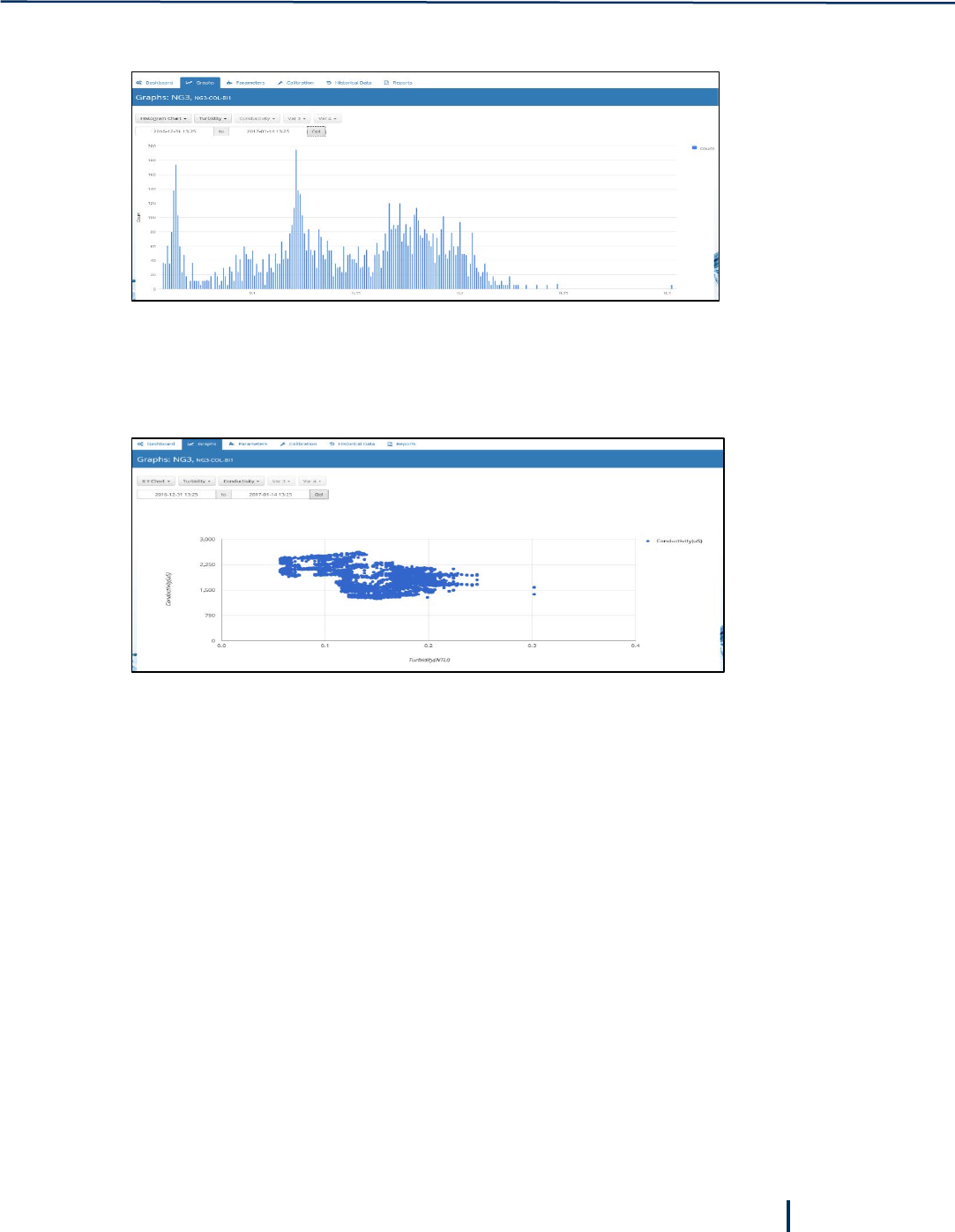
b. Histogram: select a parameter from the list, specify a time range, and click Go.
The horizontal axis displays values measured for this parameter during the selected period. The
vertical axis displays the number of records for each value.
c. X-Y Chart:
Select two parameters from the lists, specify a time range, and click Go.
The first parameter is displayed on the horizontal axis. The second parameter is displayed on the
vertical axis. Each axis is displayed with the relevant units.
Remote Monitoring and Configuration
36
© Blue I Technologies
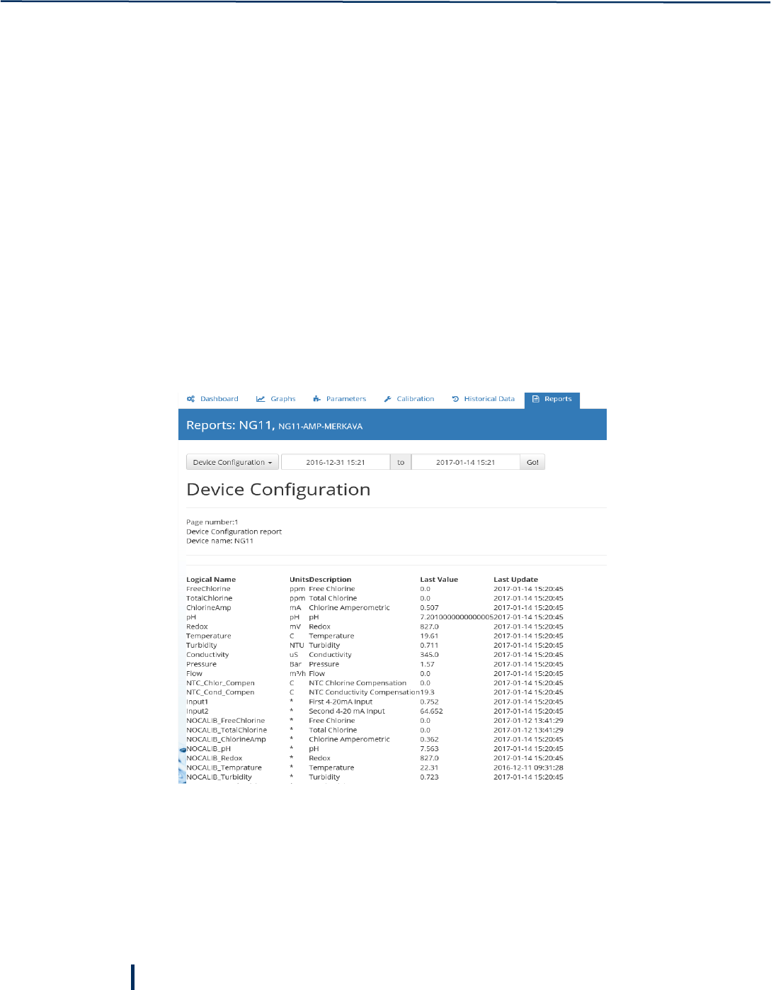
4.10 Generating Reports
You can generate reports based on the data saved in the database for each unit. The following reports are
available:
• Device configuration – a list of the unit’s parameters and their values
• Alarms history – a list of all alarms generated
• Alarm time distribution – distribution of alarm length time
• List of events – history of events
• Display log files – a list of the unit’ log
• Current open alarms – a list of open alarms
To generate a report:
1. Expand a unit on the left and click Reports.
2. In the Reports page, select the required report from the list, specify the time range, and click Go.
The following image shows an example of the Device Configuration report.
© Blue I Technologies
37
5
Maintenance
5.1 Chlorine Electrode
Perform sensor maintenance whenever any of the following conditions are met:
• When the membrane is visibly soiled, clean the sensor.
• Refill the sensor with electrolyte once per season or every 12 months. Depending on the water
quality and chlorine level, this period can be reduced or extended.
• Calibrate the sensor when necessary (see “Error! Reference source not found.” on page Error!
Bookmark not defined.).
5.1.1 Cleaning the Sensor
Caution: Do not use chemicals that reduce the surface tension. When using hydrochloric acid, observe all
the safety regulations.
1. Remove the electrode from the acrylic flow cell.
2. Clean the membrane cap with a gentle water jet or swirl in a solution of 2% hydrochloric acid (no
other additives).
3. If the membrane cap is still visibly soiled, replace the membrane cap, see “Replacing the Membrane
Cap” on page 38.
1 – Electrode cable
2 – Large surface silver/silver chloride
anode
3 – Gold cathode
4 – Measuring chamber
5 – Membrane cap
6 – Screw cap (to fix the membrane cap)
Maintenance
38
© Blue I Technologies
5.1.2 Refilling the Electrolyte
Refill the electrolyte every three to six months or when unstable or when too-low values are displayed. If
unstable or too-low values are still measured, replace the membrane cup, see “Replacing the Membrane
Cap” on page 38.
Do not swallow the electrolyte. Avoid electrolyte contact with skin or eyes. In case of accidental
contact, wash with a lot of cold water. In case of eye inflammation, contact a doctor
immediately.
Wear safety glasses and gloves when working with the electrolyte solution.
Do not touch or damage the electrodes. The electrolyte is sensitive to oxidation: Always keep
the electrolyte bottle closed after use.
Do not transfer the electrolyte to other containers.
The electrolyte should not be stored for more than one year and should be clear (not yellow) in
appearance (for use by date, see label).
Avoid forming air bubbles when pouring the electrolyte into the measuring chamber.
1. Unscrew the measuring chamber from the shaft.
2. Hold the measuring chamber at an angle and fill approximately 7 to 8 ml (0.24 to 0.27 fl.oz)
electrolyte up to 1 centimeter under the top edge.
3. Tap the filled chamber several times on a flat surface to remove air bubbles.
4. Screw the electrode shaft into the measuring chamber vertically making sure that all the air inside is
let out.
5. As soon as the inserted o-ring begins to seal, tighten slowly until it stops.
5.1.3 Replacing the Membrane Cap
Replace the membrane cap once a year or when unstable and too-low measurements are displayed. If the
sensor continues displaying unstable or too-low measurements, perform reconditioning of the sensor.
1. Unscrew the measuring chamber from the shaft.
2. Unscrew the front screw cap holding the membrane.
3. Remove the old membrane and replace with a new membrane.
4. Refill the measuring chamber with electrolyte.
5.1.4 Storing the Chlorine Electrode
The free chlorine electrode can remain in the flow cell for a short period, as long as the flow cell is not
drained. For longer periods where the flow cell is likely to be drained, remove the electrode from the flow
cell and place the yellow protection cap on top of the electrode to keep it wet. Make sure that the inner
sponge inside the yellow protection cap is wet.

pH and Rx Electrodes
© Blue I Technologies
39
5.2 pH and Rx Electrodes
Regular cleaning of the electrodes ensures its long-term operation. The cleaning frequency depends on
the water source being tested. As general guidelines, clean the electrodes whenever there is significant
visible dirt, when the measurement accuracy is affected, or before calibration.
To clean the electrodes:
1. Close water flow to the flow cell and remove the electrode.
2. Wash the electrode under a stream of water to remove dirt.
3. Use a soft cloth to remove any additional dirt and oil.
4. Replace the electrode and resume water flow.

Maintenance
40
© Blue I Technologies
5.3 Cleaning the Flow Cell
Over time, the flow cell can accumulate dirt and stains on their walls. This may affect the accuracy of
measurement. Regular cleaning of the flow cell ensures long-term operation of the system. As general
guidelines, clean the flow cell once a year or when the cell is visibly stained.
To clean the flow cell:
1. Close the water flow to the and close all water outlet valves.
2. Remove the electrodes and unscrew the connectors.
3. Through one of the electrode connectors, fill the cells with the Blue I cleaning solution up to the
marked line.
4. Allow the material to rest for 40 minutes in the cells.
5. When the cells are clean, open the water outlet and let the material drain from the system.
6. Close water outlet, reconnect the sensors, and resume water flow.
5.4 Cleaning the Turbidity Flow Cell
1. Close the water supply to the analyzer.
2. Using an adjustable wrench, open the flow cell cap.
3. Insert cotton swabs deep into the cell and clean the inside of the cell.
5.5 Cleaning the Filter
The analyzer’s filter must be cleaned regularly. The frequency of cleaning depends on water quality of the
water system.
1. Turn off water supply to the analyzer by closing the water inlet valve.
2. Unscrew the filter’s cup and remove the discs.
3. Separate the discs and wash them under running water.
4. Place the discs back, close the filter’s cup, and turn on water supply to the analyzer.

© Blue I Technologies
41
6
Troubleshooting
6.1 Issues and Workarounds
Description Cause Possible Solution
Water is dripping from the
controller
Leakage from pipe connectors. Check all pipe connectors and hand-
tighten as required.
If necessary, use Teflon to improve
sealing.
No data is received from the
controller
• Modem disconnected from
power.
• Antenna disconnected.
• SIM card not installed.
• SIM card not installed
properly in the socket.
• Verify the modem is connected to
power: LEDs blinking.
• Verify antenna is connected
properly and is placed outside the
controller at a high spot.
• Insert a SIM cardError! Reference
source not found..
Unable to connect to the
server
• SIM card no open. • Verify that the SIM card is open
and defined for 3G/4G.
• Verify that the antenna is properly
connected.
One or more parameters do
not display data
Electrode fault.
Electronic board fault
Check the relevant electrode and
replace if necessary.
Verify that LEDs on the Electronic
board are flashing.
Check the wiring from the electrode to
the electronic board.

Troubleshooting
42
© Blue I Technologies
6.2 Unable to Solve an Issue
If you cannot solve the issue, contact your Support representative and make sure you have the following
information:
• Detailed description of the issue
• Model Number
• Serial Number (the serial number can be found on the main label of the box and on the sticker on the
right side of the Smart POD.)
• Purchase Date
• Purchased from
• Application (potable water, industrial treatment, pool/spa)

© Blue I Technologies
43
7
Appendix A – Specifications
MEASURED PARAMETERS
MECHANICAL DATA & DIMENSIONS
Flow Cell FCL or TCL, PH or ORP & Temp
Dimensions (controller) 278 x 188 x 130 mm
External connection Turbidity
(L x W x D) (11" x7.4" x 5.0")
FREE CHLORINE (FC) MEASUREMENT
Weight (approx.) 4 kg (8.8 lbs.)
Free Chlorine
Electrode
Passive-operated Chlorine sensor with
gold cathode & silver/silver chloride
anode
Display
5.5'' RGB Display
Cable entries PG 9 cable Glands
Measuring Range
0.05-20ppm (standard)
0.01- 5 ppm (optional)*
Enclosure rating
IP 65 (Polycarbonate)
OPERATIONAL REQUIREMENTS
Sample and drain connection
Pressurized sample inlet and
gravity drain
Accuracy ± 2 % or ± 0.01 ppm whichever is greater
Inlet Pressure 0.35-1 bar (5-14.5 psi)
Minimum Detection
Limit
0.03 ppm
Measuring cell flow rate 35-60 l/h (9-16 gph)
Resolution 0.01 ppm
Ambient temperature 2°C to 50°C (35.6°F to 122°F)
Repeatability 1% span
Sample temperature 1°C to 45°C (33.8°F to 113°F)
Response time
approx. 2 min
DATA OUTPUT
pH operation range 4 to 8
Digital communication Modbus RS 485
Body material PVC
Local I/O
2 Standard 4-20 mA outputs or
24V 2 Channel
Membrane material PTFE
DATA LOGGING
Membrane cap
material PBT (GF30), PVDF
Memory 16 MB
Lines
31,000
Recording Interval 1-1000 min
Event logging Yes
Total relay on time Yes
pH MEASUREMENT
Electrode Ceramic diaphragm and gel filling
Measurement Range
0 to 14
Input impedance 0.5 x 1.12k Ω
ORP (REDOX) MEASUREMENT
Sensor
Ceramic diaphragm and gel filling
Measurement range 0 to 2000 mV

Appendix A - Specifications
44
© Blue I Technologies
TEMPERATURE MEASUREMENT
Sensor
PT-100
Measurement range 0°C to 100°C (32°F to 212°F)
ANALYZER FLOW MONITORING
Flow sensor Inductive proximity flow switch
ELECTRICAL CONNECTION
Power supply 100 – 240VAC 50/60Hz
Power consumption
Approx. 70 W
Power supply for
RTC
3.6V Lithium Battery memory (CR2032)
* 8 Amp max apply for new universal I/O card.

© Blue I Technologies
45
8
Appendix B – Sensors
Details
8.1 OCS140 and OCS141 Free Chlorine Electrode
The concentration of free chlorine is determined according to the amperometric measuring principle. The
hypochlorous acid (HOCl) contained in the medium diffuses through the sensor membrane and is reduced
to chloride ions (Cl-) on the gold cathode. On the silver anode, silver is oxidized to silver chloride. The
electron release of the gold cathode and electron acceptance on the silver anode result in a current flow
which is proportional to the free chlorine concentration in the medium under constant conditions. The
concentration of hypochlorous acid in the medium depends on the pH value. This dependence can be
compensated by measuring the pH value in the flow assembly.
The transmitter transforms the current signal into the measuring unit concentration in mg/l.
Property Description
Range OCS140 (for industrial water, pool water): 0.05 ... 20 mg Cl2/l (25 °C / 77
°F, pH 7.2)
OCS141 (for drinking water applications): 0.01 ... 5 mg Cl2/l (25 °C / 77 °F,
pH 7.2)
Depolarization current OCS140: approx. 25 nA per mg Cl2/l (25° C / 77 °F, pH 7.2)
OCS141: approx. 80 nA per mg Cl2/l (25 °C / 77 °F, pH 7.2)
Response time T90 < 2 min, T99 < 5 min in applications involving mainly active
chlorination
Polarization time OCS140:
First polarization: 60 min
Repolarization: 30 min
OCS141:
First polarization: 90 min
Repolarization: 45 min
Drift < 1.5 % per month
Temperature range OCS140: 10 ... 45 °C / 50 ... 113 °F
OCS141: 2 ... 45 °C / 36 ... 113 °F
pH Range OCS140: 4 ... 8 pH
OCS141: 4 ... 8.2 pH

Appendix B – Sensors Details
46
© Blue I Technologies
Property Description
Pressure Medium in the OCA250 assembly: max. 1 bar (14.5 psi)
Flow min. 30 l/h / 7.92 US gal/h
Flow velocity min. 15 cm/s / 0.5 ft/s
Electrolyte service life Typically, 12 months
Smartsens OPS31 pH Electrode
© Blue I Technologies
47
8.2 Smartsens OPS31 pH Electrode
Gel-filled reference system with ceramic diaphragm, supports up to 4 bar (60 psi) absolute pressure.
The pH value is used as a unit of measurement for the acidity or alkalinity of a liquid medium. The
membrane glass of the electrode supplies an electrochemical potential which is dependent upon the pH
value of the medium. This potential is generated by the selective penetration of H+ ions through the outer
layer of the membrane. An electrochemical boundary layer with an electric potential, forms at this point.
An integrated Ag/AgCl reference system serves as reference electrode.
The transmitter converts the measured voltage into the corresponding pH value using the Nernst
equation.
Property Description
Range 0 – 12
Operating Temperature above -15° C (5° F)
Process Temperature 15 – 80° C (5 – 176° F)
Process Pressure 1 – 4 bar (15 – 60 psi), absolute
Conductivity ≥ 100 μS/cm
8.3 Smartsens OPS32 ORP Electrode
The redox potential is a unit of measurement for the state of equilibria between oxidizing and reducing
components of a medium. Redox potential is measured similarly to the pH value. A platinum or gold
electrode is used instead of pH-sensitive membrane glass. Analog to the pH measurement, an integrated
Ag/AgCl reference system is used as a reference electrode.
Property Description
Range 1500 – 1500 mV
Operating Temperature above -15° C (5° F)
Process Temperature 15 – 80° C (5 – 176° F)
Process Pressure 1 – 4 bar (15 – 60 psi), absolute
Conductivity ≥ 100 μS/cm
Appendix B – Sensors Details
48
© Blue I Technologies
8.4 Industrial Pressure Transmitter PT124B-213
PT124B-213 adopts ceramic or diffused silicon sensor chip, with stainless steel encapsulation, smart
figure. This series is especially suitable in the occasion where Installation space is restricted and has the
feature of wide range temperature compensation, high accuracy, non-calibration, and wide range.
Property Description
Range -1~0~160MPa
Accuracy 0.5% Full Scale
Nonlinearity 0.2% Full Scale
Reliability 0.2% Full Scale
Output 4-20mA(2 Wire ),0-5V, 0.5-4.5V
Input voltage 24 (8-36V) DC
Operating Temperature -20 ~ 80° C
Compensated temperature 0 ~ 75°
C
Overload pressure 150% Full Scale
Medium material 316 stainless steel
Electric connector Min DIN, M12, Bendix connector, cable
Process connector G1/4, G1/2, 1/2NPT, 1/4NPT, M12*1.5 Customer design
8.5 PT 100 for Acrylic Cell Temperature Sensor
RTD PT 100, single element with three wires system and GND.
Property Description
Range 1° to 50° C (35° to 122° F)

49
© Blue I Technologies
Declaration of Compliance
We hereby declare that all products are tested and inspected before leaving the factory and are checked to meet
our specifications according to the accepted procedures.
Daniel Cohen Khallas
Quality Control Manager
50
© Blue I Technologies
Warranty
Please retain proof of purchase.
Please keep a record of the product in the form below to be
sent to Blue I Water Technologies in the event of a warranty
claim.
Blue I Water Technologies warrants this product and its
parts against defects in materials or workmanship for
eighteen (18) months from date of installation or twenty-
four (24) months from date of shipment from Blue I Water
Technologies, whichever is earlier.
• 2-year warranty on electronic cards
• 1-year warranty on all other components
• The warranty does not cover consumable parts, such as
electrodes.
Blue I Water Technologies’ responsibility includes repair or
replacement, at the sole discretion of Blue I Water
Technologies, of the whole product or part of it, when the
defect is due to faulty functioning and/or defective
materials.
For your records:
*The serial number can be found on the main label of the
box and on the sticker on the right side of the Smart POD.
Blue I Water Technologies accepts no
responsibility for damage caused by:
a. Use/operation not consistent with operating
instructions
b. Improper installation
c. Exposure to conditions that are not in
accordance with Blue I’s specifications, e.g.,
pressure/flow/temp
d. Damage during shipment (submit claim to
the carrier)
e. Disasters such as fire, flood, lightning or
improper electric current
f. If the equipment is modified or if non-Blue I
Water Technologies' reagents or
replacement parts are used
Completion of the RMA procedure and return
of defective component(s) to Blue I Water
Technologies, Ltd. Is required for all warranty
items.
User manuals and datasheets can be
downloaded from our website
www.blueitechnologies.com and by scanning
this QR code:
Warranty Claim
Please fill in the information below and retain with proof of purchase
Model Number: ___________________________
Serial Number: ____________________________
Purchase Date: ____________________________
Purchased from: ___________________________
Application: _______________________________ (e.g., potable water, industrial treatment, pool/spa)
In case of submitting a warranty claim, send this form along with proof of purchase to:
Blue I Water Technologies
18 Hamelacha St.
Afek Industrial Park
Rosh Ha’ayin 4809148
ISRAEL