14julySTP21 1 Soldier's Manual Of Common Tasks Skill Level STP 21
User Manual: manual pdf -FilePursuit
Open the PDF directly: View PDF ![]() .
.
Page Count: 726 [warning: Documents this large are best viewed by clicking the View PDF Link!]
- Table of Contents
- Preface
- Chapter 1 Introduction to the SMCT System
- Chapter 2 Training Guide
- Chapter 3 Skill Level 1 Tasks
- SUBJECT AREA 1: INDIVIDUAL CONDUCT AND LAWS OF WAR
- 181-101-1013 Comply With the Uniform Code of Military Justice (UCMJ)
- 181-105-1001 Comply with the Law of War and the Geneva and Hague Conventions
- 224-176-1425 Interact with News Media
- 331-202-1049 Comply with the Requirements of the Code of Conduct
- 805C-PAD-1245 Support Unit and Family Readiness Through the Army Family Team Building (AFTB) Program
- 805C-PAD-1391 Comply With the Army's Equal Opportunity and Sexual Harassment Policies
- SUBJECT AREA 2: FIRST AID
- 081-831-1000 Evaluate a Casualty
- 081-831-1003 Perform First Aid to Clear an Object Stuck in the Throat of a Conscious Casualty
- 081-831-1005 Perform First Aid to Prevent or Control Shock
- 081-831-1007 Perform First Aid for Burns
- 081-831-1008 Perform First Aid for Heat Injuries
- 081-831-1025 Perform First Aid for an Open Abdominal Wound
- 081-831-1026 Perform First Aid for an Open Chest Wound
- 081-831-1032 Perform First Aid for Bleeding of an Extremity
- 081-831-1033 Perform First Aid for an Open Head Wound
- 081-831-1034 Perform First Aid for a Suspected Fracture
- 081-831-1042 Perform Mouth-to-Mouth Resuscitation
- 081-831-1044 Perform First Aid for Nerve Agent Injury
- 081-831-1045 Perform First Aid for Cold Injuries
- 081-831-1046 Transport a Casualty
- 081-831-1053 Practice Individual Preventive Medicine Countermeasures
- SUBJECT AREA 3: NUCLEAR, BIOLOGICAL, AND CHEMICAL (NBC)
- 031-503-1013 Decontaminate Yourself and Individual Equipment Using Chemical Decontaminating Kits
- 031-503-1015 Protect Yourself from NBC Injury/Contamination with Mission-Oriented Protective Posture (MOPP) Gear
- 031-503-1017 Respond to Depleted Uranium
- 031-503-1018 React to Nuclear Hazard/Attack
- 031-503-1019 React to Chemical or Biological Hazard/Attack
- 031-503-1035 Protect Yourself from Chemical/Biological Contamination Using Your Assigned Protective Mask
- 031-503-1036 Maintain Your Assigned Protective Mask
- 031-503-1037 Detect Chemical Agents Using M8 or M9 Detector Paper
- SUBJECT AREA 4: SURVIVE [COMBAT TECHNIQUES]
- 052-192-1042 Perform Self-Extraction from a Mined Area
- 052-192-1242 Locate Mine and Booby Trap Indicators by Visual Means
- 071-326-0502 Move Under Direct Fire
- 071-326-0503 Move Over, Through, or Around Obstacles (Except Minefields)
- 071-326-0510 React to Indirect Fire While Dismounted
- 071-326-0511 React to Flares
- 071-326-0513 Select Temporary Fighting Positions
- 071-326-3002 React to Indirect Fire While Mounted
- 071-326-5703 Construct Individual Fighting Positions
- 071-331-0815 Practice Noise, Light, and Litter Discipline
- 071-331-1004 Perform Duty as a Guard
- 071-410-0002 React to Direct Fire While Mounted
- 071-710-0006 Plan Use of Night Vision Devices
- 093-401-5040 React to Unexploded Ordnance Hazards
- 551-88M-0005 Operate a Vehicle in a Convoy
- SUBJECT AREA 5: NAVIGATE
- SUBJECT AREA 6: COMMUNICATE
- SUBJECT AREA 7: SEE
- SUBJECT AREA 8: HAND GRENADES AND LAND MINES
- SUBJECT AREA 9: M16-SERIES RIFLE
- SUBJECT AREA 10: M240B MACHINE GUN
- SUBJECT AREA 11: M249 MACHINE GUN
- SUBJECT AREA 12: M60 MACHINE GUN
- SUBJECT AREA 13: MK19 MACHINE GUN
- SUBJECT AREA 14: CALIBER .50 M2 MACHINE GUN
- SUBJECT AREA 15: M136 LAUNCHER
- SUBJECT AREA 16: M203 GRENADE LAUNCHER
- SUBJECT AREA 17: M4 CARBINE
- SUBJECT AREA 18: 9MM PISTOL
- SUBJECT AREA 19: CROWD CONTROL
- SUBJECT AREA 20: CASUALTY REPORTING AND HANDLING
- SUBJECT AREA 21: DEFENSE MEASURES
- SUBJECT AREA 1: INDIVIDUAL CONDUCT AND LAWS OF WAR
- Appendix A Proponent School or Agency Codes
- Appendix B Guide to Forms
- Appendix C Land Navigation Supporting Tasks
- Land Navigation Task 1 Select a Movement Route Using a Map
- Land Navigation Task 2 Identify Topographic Symbols on a Military Map
- Land Navigation Task 3 Identify Terrain Features on a Map
- Land Navigation Task 4 Determine the Grid Coordinates of a Point on a Military Map
- Land Navigation Task 5 Determine a Magnetic Azimuth Using a Lensatic Compass
- Land Navigation Task 6 Determine the Elevation of a Point on the Ground Using a Map
- Land Navigation Task 7 Determine a Location on the Ground by Terrain Association
- Land Navigation Task 8 Measure Distance on a Map
- Land Navigation Task 9 Convert Azimuths
- Land Navigation Task 10 Orient a Map Using a Lensatic Compass
- Land Navigation Task 11 Orient a Map to the Ground by Map-Terrain Association
- Land Navigation Task 12 Locate an Unknown Point on a Map and on the Ground by Intersection
- Land Navigation Task 13 Locate an Unknown Point on a Map and on the Ground by Resection
- Land Navigation Task 14 Determine Direction without a Compass
- Land Navigation Task 15 Determine Azimuths Using a Protractor
- Land Navigation Task 16 Compute Back Azimuths
- Glossary
- References
- Authentication

STP21-1-SMCT
HEADQUARTERS
DEPARTMENTOFTHEARMY
CommonTasks
SkillLevel1
Soldier’sManualof
DISTRIBUTIONRESTRICTION:Approvedforpublicrelease;
distributionisunlimited.
AUGUST2003

This publication is available at Army
Knowledge OnLine (www.us.army.mil) and
the General Dennis J. Reimer Training and
Doctrine Digital Library at
(www.adtdl.army.mil)

*STP 21-1-SMCT
Distribution Restriction: Approved for public release; distribution is
unlimited.
*This manual supersedes STP 21-1-SMCT, 1 October 1994.
i
Soldier Training Publication Headquarters
No. 21-1-SMCT Department of the Army
Washington, DC, 31 August 2003
SOLDIER'S MANUAL OF
COMMON TASKS
Skill Level 1
TABLE OF CONTENTS
Page
PREFACE ................................................................................................. vi
Chapter 1. Introduction........................................................................ 1-1
Chapter 2. Training Guide.................................................................... 2-1
Chapter 3. Skill Level 1 Tasks ............................................................. 3-1
Skill Level 1
Subject Area 1: Individual Conduct and Laws of War
181-101-1013 Comply with the Uniform Code of Military Justice
(UCMJ)....................................................................... 3-1
181-105-1001 Comply with the Law of War and the Geneva and
Hague Conventions ................................................. 3-16
224-176-1425 Interact with News Media......................................... 3-38
331-202-1049 Comply with the Requirements of the Code of
Conduct ................................................................... 3-39
805C-PAD-1245 Support Unit and Family Readiness Through the
Army Family Team Building (AFTB) Program.......... 3-43
805C-PAD-1391 Comply With the Army's Equal Opportunity and
Sexual Harassment Policies .................................... 3-49
Subject Area 2: First Aid
081-831-1000 Evaluate a Casualty ................................................. 3-52
081-831-1003 Perform First Aid to Clear an Object Stuck in the
Throat of a Conscious Casualty............................... 3-57
081-831-1005 Perform First Aid to Prevent or Control Shock ......... 3-59
081-831-1007 Perform First Aid for Burns....................................... 3-61
081-831-1008 Perform First Aid for Heat Injuries............................ 3-64

ii
081-831-1025 Perform First Aid for an Open Abdominal Wound .... 3-67
081-831-1026 Perform First Aid for an Open Chest Wound............ 3-69
081-831-1032 Perform First Aid for Bleeding of an Extremity ......... 3-72
081-831-1033 Perform First Aid for an Open Head Wound ............3-75
081-831-1034 Perform First Aid for a Suspected Fracture.............. 3-79
081-831-1042 Perform Mouth-to-Mouth Resuscitation.................... 3-83
081-831-1044 Perform First Aid for Nerve Agent Injury .................. 3-87
081-831-1045 Perform First Aid for Cold Injuries ............................ 3-97
081-831-1046 Transport a Casualty.............................................. 3-102
081-831-1053 Practice Individual Preventive Medicine
Countermeasures................................................... 3-110
Subject Area 3: Nuclear, Biological, and Chemical (NBC)
031-503-1013 Decontaminate Yourself and Individual Equipment
Using Chemical Decontaminating Kits ................... 3-121
031-503-1015 Protect Yourself from NBC Injury/Contamination
with Mission-Oriented Protective Posture (MOPP)
Gear ....................................................................... 3-124
031-503-1017 Respond to Depleted Uranium............................... 3-128
031-503-1018 React to Nuclear Hazard/Attack............................. 3-130
031-503-1019 React to Chemical or Biological Hazard/Attack...... 3-132
031-503-1035 Protect Yourself from Chemical/Biological
Contamination Using Your Assigned Protective
Mask ...................................................................... 3-135
031-503-1036 Maintain Your Assigned Protective Mask............... 3-141
031-503-1037 Detect Chemical Agents Using M8 or M9 Detector
Paper ..................................................................... 3-143
Subject Area 4: Survive [Combat Techniques]
052-192-1042 Perform Self-Extraction from a Mined Area............ 3-146
052-192-1242 Locate Mine and Booby Trap Indicators by Visual
Means .................................................................... 3-162
071-326-0502 Move Under Direct Fire.......................................... 3-167
071-326-0503 Move Over, Through, or Around Obstacles
(Except Minefields)................................................. 3-176
071-326-0510 React to Indirect Fire While Dismounted................ 3-179
071-326-0511 React to Flares....................................................... 3-180
071-326-0513 Select Temporary Fighting Positions...................... 3-182
071-326-3002 React to Indirect Fire While Mounted..................... 3-184
071-326-5703 Construct Individual Fighting Positions .................. 3-185
071-331-0815 Practice Noise, Light, and Litter Discipline ............. 3-195
071-331-1004 Perform Duty as a Guard ....................................... 3-197
071-410-0002 React to Direct Fire While Mounted ....................... 3-199
071-710-0006 Plan Use of Night Vision Devices........................... 3-200
093-401-5040 React to Unexploded Ordnance Hazards............... 3-202
551-88M-0005 Operate a Vehicle in a Convoy............................... 3-218

iii
Subject Area 5: Navigate
071-329-1006 Navigate from One Point on the Ground to
Another Point While Dismounted ........................... 3-224
071-329-1030 Navigate from One Point on the Ground to
Another Point While Mounted ................................ 3-234
Subject Area 6: Communicate
113-571-1022 Perform Voice Communications............................. 3-241
113-600-2001 Communicate Via a Tactical Telephone ................ 3-247
113-637-2001 Communicate Via a Tactical Radio in a Secure
Net ......................................................................... 3-249
Subject Area 7: See
071-331-0804 Perform Surveillance without the Aid of Electronic
Devices .................................................................. 3-250
071-730-0014 Identify Combat Vehicles ....................................... 3-254
Subject Area 8: Hand Grenades and Land Mines
071-325-4401 Perform Safety Checks on Hand Grenades........... 3-256
071-325-4407 Employ Hand Grenades......................................... 3-260
071-325-4425 Employ an M18A1 Claymore Mine......................... 3-262
Subject Area 9: M16-Series Rifle
071-008-0007 Engage Targets with an M16-Series Rifle Using
an AN/PAS-13 Series Thermal Weapon Sight ....... 3-275
071-311-2025 Maintain an M16-Series Rifle................................. 3-277
071-311-2027 Load an M16-Series Rifle ...................................... 3-303
071-311-2028 Unload an M16-Series Rifle ................................... 3-311
071-315-2308 Engage Targets with an M16-Series Rifle Using a
Night Vision Sight AN/PVS-4 ................................. 3-313
Subject Area 10: M240B Machine Gun
071-000-0005 Prepare a Range Card for a Machine Gun ............ 3-317
071-025-0001 Maintain an M240B Machine Gun.......................... 3-326
071-025-0003 Load an M240B Machine Gun ............................... 3-334
071-025-0004 Unload an M240B Machine Gun............................ 3-336
071-025-0007 Engage Targets with an M240B Machine Gun....... 3-337
Subject Area 11: M249 Machine Gun
071-010-0006 Engage Targets with an M249 Machine Gun......... 3-341
071-312-4025 Maintain an M249 Machine Gun ............................ 3-351
071-312-4027 Load an M249 Machine Gun.................................. 3-375
071-312-4028 Unload an M249 Machine Gun .............................. 3-379
Subject Area 12: M60 Machine Gun
071-312-3025 Maintain an M60 Machine Gun .............................. 3-381
071-312-3027 Load an M60 Machine Gun.................................... 3-397

iv
071-312-3028 Unload an M60 Machine Gun ................................ 3-399
071-312-3031 Engage Targets with an M60 Machine Gun ........... 3-401
Subject Area 13: MK19 Machine Gun
071-030-0001 Maintain an MK19 Machine Gun............................ 3-407
071-030-0004 Engage Targets with an MK19 Machine Gun......... 3-431
071-030-0005 Load an MK19 Machine Gun ................................. 3-440
071-030-0006 Unload an MK19 Machine Gun .............................. 3-445
071-030-0007 Perform a Function Check on an MK19 Machine
Gun ........................................................................ 3-449
Subject Area 14: Caliber .50 M2 Machine Gun
071-022-0001 Maintain a Caliber .50 M2 Machine Gun ................ 3-451
071-022-0003 Load a Caliber .50 M2 Machine Gun...................... 3-487
071-022-0004 Unload a Caliber .50 M2 Machine Gun .................. 3-488
071-313-3454 Engage Targets with a Caliber .50 M2 Machine
Gun ........................................................................ 3-490
Subject Area 15: M136 Launcher
071-054-0001 Prepare an M136 Launcher for Firing ....................3-501
071-054-0002 Restore an M136 Launcher to Carrying
Configuration.......................................................... 3-507
Subject Area 16: M203 Grenade Launcher
071-311-2125 Maintain an M203 Grenade Launcher.................... 3-509
071-311-2127 Load an M203 Grenade Launcher ......................... 3-516
071-311-2128 Unload an M203 Grenade Launcher...................... 3-518
071-311-2129 Correct Malfunctions of an M203 Grenade
Launcher ................................................................ 3-519
071-311-2130 Engage Targets with an M203 Grenade Launcher. 3-521
Subject Area 17: M4 Carbine
071-100-0003 Engage Targets with an M4 or M4A1 Carbine ....... 3-528
071-100-0004 Maintain an M4 or M4A1 Carbine........................... 3-530
Subject Area 18: 9mm Pistol
071-004-0001 Maintain an M9 Pistol............................................. 3-538
071-004-0003 Load an M9 Pistol .................................................. 3-546
071-004-0004 Unload an M9 Pistol ............................................... 3-547
071-004-0006 Engage Targets with an M9 Pistol.......................... 3-548
Subject Area 19: Crowd Control
191-376-4121 Use a Riot Baton.................................................... 3-558
191-376-4122 Position Yourself in Riot Control Formations.......... 3-568
Subject Area 20: Casualty Reporting and Handling
101-515-1997 Inter Isolated Remains (After Receiving
Authorization)......................................................... 3-576

v
101-515-1998 Evacuate Isolated Remains ................................... 3-577
101-515-1999 Recover Isolated Remains..................................... 3-579
Subject Area 21: Defense Measures
052-191-1361 Camouflage Yourself and Your Individual
Equipment.............................................................. 3-582
052-191-1362 Camouflage Equipment ......................................... 3-588
191-376-4114 Control Entry to and Exit from a Restricted Area ... 3-591
301-371-1000 Report Intelligence Information .............................. 3-593
301-371-1050 Implement Operations Security (OPSEC)
Measures ............................................................... 3-595
Appendix A Proponent or Agency Codes...................................A-1
Appendix B Guide to Forms ........................................................B-1
Appendix C Land Navigation Supporting Tasks........................C-1
Glossary....................................................................................Glossary-1
References............................................................................References-1

vi
PREFACE
This manual is one of a series of soldier training publications that support
individual training. Commanders, trainers, and soldiers will use this manual
and STP 21-24-SMCT, Soldier's Manual of Common Tasks, Skill Levels 2, 3,
and 4, to plan, conduct, sustain, and evaluate individual training of common
tasks in units.
This manual contains a common task training plan for skill levels (SL) 1
through 4 and task summaries for SL 1 critical common tasks that support
unit wartime missions. This manual is the only authorized source for these
common tasks. Task summaries in this manual supersede any common
tasks appearing in MOS-specific soldier's manuals.
Training support information, such as reference materials, is also included.
Trainers and first-line supervisors should ensure SL 1 soldiers have access
to this publication in their work areas, unit learning centers, and unit libraries.
This manual applies to both active and reserve component soldiers.
Unless this manual states otherwise, masculine pronouns do not refer
exclusively to men.
The proponent of this publication is the Commander, United States Army
Training and Doctrine Command (TRADOC), with the Commander, United
States Army Training Support Center (ATSC) designated as the principle
publishing, printing and distribution agency. Proponents for the specific
tasks are the Army schools and agencies as identified by the school code,
listed at appendix A. This code consists of the first three digits of the task
identification number. All comments, suggestions, and recommended
changes to this publication should be submitted as follows:
Record any comments or questions regarding the task summaries contained
in this manual on a DA Form 2028 (Recommended Changes to Publications
and Blank Forms) and send it to the respective task proponent with
information copies forwarded to: Commander, U.S. Army Training and
Doctrine Command, ATTN: ATTG-I, Fort Monroe, VA 23651-5000, and
Commander, U.S. Army Training Support Center, ATTN: ATIC-ITSC-CM,
Fort Eustis, VA 23604-5166.

vii
SPECIAL NOTES CONCERNING THE AUGUST 2003 SMCT
5” X 7” Format. Beginning with the August 2003 revisions, both the STP
21-1-SMCT and STP 21-24-SMCT are printed in 5”x7” format, following the
very favorable acceptance of previous skill level 1 SMCTs which inaugurated
the “pocket-size” manuals. This, however, has precluded incorporating full-
size reproducible forms at the end of the books. Instead, a Guide to Forms
(Appendix B) is now provided which, in the online versions of the new
manuals, contains electronic links to the downloadable, reproducible forms.
Where online access is not available, the soldier’s unit often has hard copies
of the forms, or can obtain them.
Land navigation skills and knowledge, for common tasks 071-329-1006,
Navigate from One Point on the Ground to Another Point While Dismounted,
and 071-329-1030, Navigate from One Point on the Ground to Another Point
While Mounted are grouped in Appendix C, identified by the grey-edged
pages near the end of this manual.
Task 052-192-1135, Locate Mines by Probing. Performance standards for
this task are now incorporated into task 052-192-1042, Perform Self-
Extraction from a Mined Area. These standards are further updated from the
18 March 03 revision of Locate Mines by Probing.
Task 071-730-0014, Identify Combat Vehicles. This task, uniquely,
incorporates a Windows-based online option (ROC-V, Recognition of
Combat Vehicles) for training and testing soldiers. In addition to teaching
thermal and visual identification cues of vehicles and practical use of thermal
sensor image controls, the program ensures identification standards are
current, irrespective of print date of this manual. Refer to the Evaluation
Preparation section of this task for instructions on accessing the ROC-V
program.

viii
SPECIAL NOTE FROM THE STAFF
CONCERNING THE REVISED SMCT
Experienced trainers will notice that, in addition to the numerous new tasks
in the revised SMCT, there are many tasks for which the skill level has been
lowered from that in the past. This reflects results from the recent survey of
approximately 19,000 enlisted soldiers, their commanders, and senior
leaders, to determine who was actually performing certain tasks, and the
amount of learning that was actually filtering down in the “one room
schoolhouse” of the working Army. When it was established that a
significant percentage of soldiers were performing those tasks at skill levels
that were above their own, it was decided to lower the task designation,
giving trainers—and the Army—the full advantage of accelerated learning at
every level. This SMCT, if anything, reflects back to its users a faithfulness
to this spirit of Army training from whom it derived, an allegiance and
gratitude to the profession and legacy of every United States Army soldier.
Thank you.
United States Army Training and Doctrine Command
United States Army Training Support Center

1-1
Chapter 1
Introduction to the SMCT System
1-1. GENERAL
Training prepares soldiers, leaders, and units to fight and win in combat—
the Army's basic mission. As explained in the Army's CAPSTONE training
document, FM 7-0 Training the Force, units do not have the time and
resources to achieve and sustain proficiency on every possible training task.
Commanders must identify the unit's critical wartime tasks. These tasks
make up the unit's Mission Essential Task List (METL). Commanders use
this list to develop their unit training plan. Noncommissioned Officer (NCO)
trainers then plan the individual training that soldiers in the unit need to
accomplish the METL. The soldier training publications (STP), also known
as soldier's manuals (SMs), provide the critical individual tasks for each
military occupational specialty (MOS) that support the unit's full spectrum of
missions. The NCO trainer uses the tasks in the SMs to train the soldiers
and measure the soldier's proficiency on these unit critical tasks. The
manuals provide task performance and evaluation criteria and are the basis
for individual training and evaluation in the unit and for task-based evaluation
during resident training.
1-2. PURPOSE
The Soldier's Manual of Common Tasks (SMCT), Skill Level (SL) I, contains
the common tasks that are essential to the Army's ability to win on the
modern battlefield. In the event of war, regardless of job or individual MOS,
each soldier risks exposure to hostile actions. This manual contains the
common tasks that soldiers must be able to perform to fight, survive, and win
in combat.
The SMCT provides the commander, NCO trainer or first-line supervisor,
and individual soldiers with the information necessary to support integration
and sustainment training in their units. This information allows trainers to
plan, prepare, train, evaluate, and monitor individual training of common
tasks. Using the appropriate mission training plan (MTP), MOS specific
STPs, and this manual, will help provide the foundation for an effective unit
training plan.
1-3. COMMANDER'S RESPONSIBILITIES
The commander at each level develops a unit METL in consultation with the
command sergeant major and subordinate commanders. Using the Training
Planning Process described in FM 7-0, the commander develops the METL
and then determines the level of training needed to attain and maintain
proficiency. After determining the necessary training, the commander

1-2
develops a strategy to accomplish the required training. The commander
also gives his or her trainers the guidance they need to carry out this
strategy. Each commander must design a unit training plan that prepares
the unit for the full spectrum of operations. Soldiers must develop and
sustain proficiency in the critical tasks for their MOS and skill level. The
commander's unit training program should provide individual training for all
soldiers assigned to the unit and routinely evaluate soldier proficiency. The
leader's assessment and the Common Task Test (CTT) are two tools that
give the trainer and commander feedback on the status of training for
individuals and for the unit. This feedback should also be integrated with
collective training such as the MTP and crew drills. The Common Task
Training Plan, located in Chapter 2, provides information on where the
common tasks are first trained to standard and how often the tasks should
be trained to maintain proficiency.
Based on the commander's guidance, individual training in the unit is the
responsibility of the NCO trainers. The commander must give the NCO
trainer the priorities, resources, and direction needed to carry out training.
He or she must also assess the training results of the MTP and other training
events, and adjust the training plan accordingly. To develop a training
program, we recommend the following seven-step approach:
Step 1. Set the objectives for training.
Step 2. Plan the resources (personnel, time, funds, facilities, devices,
training aids).
Step 3. Train the trainers.
Step 4. Provide the resources.
Step 5. Manage risks, environmental and safety considerations.
Step 6. Conduct the training.
Step 7. Evaluate the results.
1-4. TRAINER'S RESPONSIBILITIES
Trainers use the steps below to plan and evaluate training.
a. Identify individual training requirements. The NCO determines
which tasks soldiers need to train based on the commander's training
strategy. The unit's training plan, METL, MTP, and the Common Task
Training Plan (Chapter 2) are sources for helping the trainer define the
individual training needed.
b. Plan the training. Plan individual training based on the unit’s training
plan. Be prepared to take advantage of opportunities to conduct individual
training (“hip pocket” training).
c. Gather the training references and materials. The task summaries
list references that can assist the trainer in preparing for the training of that

1-3
task. Check the Reimer Digital Library to see if any new resources have
been added.
d. Manage risks and environmental and safety concerns. Assess the
risks involved in training a specific task under the conditions current at the
time you are scheduled to train and implement controls, if necessary, to
lessen the risk level. Ensure that your training preparation takes into
account those cautions, warnings, and dangers associated with each task as
well as environmental and safety concerns.
e. Train each soldier. Show the soldier how to do the task to standard
and explain step-by-step how to do the task. Give each soldier a chance to
practice the task step-by-step.
f. Emphasize training in Mission-Oriented Protective Posture (MOPP)
Level 4 clothing. Soldiers have difficulty performing even very simple tasks
in a nuclear/chemical environment. The combat effectiveness of the soldier
and the unit can degrade quickly when trying to perform in MOPP 4.
Practice is the best way to improve performance. The trainer is responsible
for training and evaluating soldiers in MOPP 4 so that they are able to
perform critical tasks to standards within a nuclear/chemical environment.
g. Check each soldier. Evaluate how well each soldier performs the
tasks in this manual. Conduct these evaluations during individual training
sessions or while evaluating individual proficiency during the conduct of unit
collective tasks. This manual provides a training and evaluation guide for
each task to enhance the trainer's ability to conduct year-round, hands-on
evaluations of tasks critical to the unit's mission. Use the information in the
Common Task Training Plan as a guide to determine how often to train the
solder on each task to maintain proficiency.
h. Record the results. Use the leader book referred to in FM 7-10 to
record task performance. This gives the leader total flexibility on the method
of recording training. The trainer may use DA Form 5164-R (Hands-on
Evaluation} and DA Form 5165-R (Field Expedient Squad Book} as part of
the leader book. These forms are optional and locally reproducible. More
information on the use of these forms is provided in Appendix B of this
manual.
i. Retrain and evaluate. Work with each soldier until the individual
performs the task to standard. Well-planned, integrated training increases
the professional competence of each soldier and contributes to the
development of an efficient unit. The NCO or first-line supervisor is a vital
link in the conduct of training.
1-5. SOLDIER'S RESPONSIBILITIES
Each soldier must be able to perform the individual tasks that the first-line
supervisor has identified based on the unit's METL. The soldier must
perform the task to the standard listed in the SMCT. If a soldier has a

1-4
question about how to do a task, or which tasks in this manual he or she
must perform, it is the soldier's responsibility to go to the first-line supervisor
for clarification. The first-line supervisor knows how to perform each task or
can direct the soldier to the appropriate training materials. Additionally, each
soldier should—
a. Know the training progression for both the common critical tasks
and their MOS specific critical tasks for their skill level. Lists of the critical
tasks can be found in Chapter 2 of this manual (for common tasks) and the
STP for their specific MOS (MOS specific tasks).
b. Check the Reimer Digital Library for new training materials to
support self-development either to maintain previously trained tasks or to
learn new tasks.
1-6. TASK SUMMARIES
Task summaries document the performance requirements of a critical
common task. They provide the soldier and the trainer with the information
necessary to evaluate critical tasks. The format for the task summaries is—
a. Task Title. The task title identifies the action to be performed.
b. Task Number. A l0-digit number that identifies each task. The first
three digits of the number represent the proponent code for that task. (A list
of the proponent codes is given in Appendix A.) Include the entire 10-digit
task number, along with the task title, in any correspondence relating to the
task.
c. Conditions. The task conditions identify all the equipment, tools,
materials, references, job aids, and supporting personnel that the soldier
needs to perform the task. This section identifies any environmental
conditions that can alter task performance such as visibility, temperature, or
wind. This section also identifies any specific cues or events (for example, a
chemical attack or identification of an unexploded ordnance hazard) that
trigger task performance.
d. Standard. A task standard specifies the requirements for task
performance by indicating how well, completely, or accurately a product
must be produced, a process must be performed, or both. Standards are
described in terms of accuracy, tolerances, completeness, format, clarity,
number of errors, quantity, sequence, or speed of performance.
e. Training and Evaluation Guide. This section has two parts. The first
part, Performance Steps, lists the individual steps that the soldier must
complete to perform the task. The second part is the Performance
Evaluation Guide. This provides guidance on how to evaluate a soldier’s
performance of the task. It is composed of three subsections. The
Evaluation Preparation subsection identifies special setup procedures and, if
required, instructions for evaluating the task performance. Sometimes the
conditions and standard must be modified so that the task can be evaluated

1-5
in a situation that does not exactly duplicate actual field performance. This
subsection may also include instructions that the evaluator should give to the
soldier before the performance test. The Performance Measures subsection
identifies the criteria for acceptable task performance. The soldier is rated
(GO/NO GO) on how well he or she performs specific actions or produces
specific products. As indicated in the Evaluation Guidance subsection, the
soldier must score a GO on all or specified performance measures to
receive a GO on the task.
f. References. This section identifies references that provide more
detailed and thorough explanations of task performance requirements than
that given in the task summary description. This section identifies resources
the soldier can use to improve or maintain performance.
Additionally, task summaries can include safety statements, environmental
considerations, and notes. Safety statements (danger, warning, caution)
alert users to the possibility of immediate death, personal injury, or damage
to equipment. Notes provide additional information to support task
performance.
1-7. EVALUATING TASK PERFORMANCE
Trainers need to keep the following points in mind when preparing to
evaluate their soldiers—
a. Review the performance measures to become familiar with the
criteria on which the soldier will be scored.
b. Ensure that all necessary equipment and clothing needed for proper
performance of the job are on hand at the training site. Don’t forget to
include safety equipment.
c. Prepare the test site according to the conditions section of the task
summary. Some tasks contain special evaluation preparation instructions.
These instructions tell the trainer what modifications must be made to the job
conditions to evaluate the task. Reset the site to its original condition after
evaluating each soldier to ensure that the conditions are the same for each
soldier.
d. Advise each soldier of any special guidance that appears in the
Evaluation Preparation section of the task summary before evaluating.
e. Score each soldier based on the information in the Performance
Measures and Evaluation Guidance sections.
f. Record the date and task performance score ("GO" or "NO GO") in
the Leader Book.

1-6
1-8. TRAINING TIPS FOR TRAINERS
a. Prepare yourself:
(1) Get training guidance from your chain of command on when to
train, which soldiers to train, the availability of resources, and a training site.
(2) Get task conditions and standards from the task summary in this
manual.
(3) Ensure that you can do the task. Review the task summary and
the references in the reference section. Practice doing the task or, if
necessary, have someone train you on the task.
b. Prepare the resources:
(1) Obtain the required resources as identified in the conditions
statement for each task and/or modified in the Training and Evaluation
Guide.
(2) Gather the equipment and ensure that it is operational.
(3) Prepare a training outline consisting of informal notes on what
you want to cover during your training session.
(4) Practice your training presentation.
(5) Coordinate for the use of training aids and devices.
(6) Prepare the training site using the conditions statement as
modified in the Training and Evaluation Guide.
c. Prepare the soldiers:
(1) Tell the soldier what task to do and how well it must be done.
Refer to the task standard and the performance measures for the task, as
appropriate.
(2) Caution soldiers about safety, environment, and security
considerations.
(3) Provide any necessary training on basic skills that soldiers must
have before they can be trained on the task.
(4) Test each soldier to determine who needs training in what areas
by having the soldier perform the task.
d. Train soldiers who fail the initial test:
(1) Demonstrate how to do the task or the specific performance
steps to those soldiers who could not perform to standard. Have the soldiers
study the appropriate training materials.
(2) Have the soldiers practice the task until they can perform it to
standard.
(3) After remedial training, retest each solider who did not initially
pass the performance test.

1-7
(4) Provide feedback to those soldiers who fail to perform to the
SMCT standards, and have them continue to practice until they can perform
to the SMCT standards.
(5) Record the results in the Leader Book.
1-9. TRAINING SUPPORT: THIS MANUAL INCLUDES THE FOLLOWING
THAT PROVIDE ADDITIONAL TRAINING SUPPORT INFORMATION.
a. Appendix A - Proponent School and Agency Codes guide, lists the
task proponents and agency codes (first three digits of the task number) with
addresses for submitting comments concerning specific tasks in this manual.
b. Appendix B - Guide to Forms, explains the use of various SMCT
training and evaluation forms and, in the online version of this manual,
provides links to the forms.
c. Appendix C - Land Navigation Skills and Knowledge, provides
additional training support related to the two land navigation tasks in Subject
Area 5 (Navigate).
d. Glossary - The Glossary section lists abbreviations and acronyms
and their definitions.
e. References - The Reference section lists all reference materials
cited in the task summaries by type, identification number, and title.
Note: Combine training on the individual tasks contained in this manual with the
collective tasks contained in the MTP. Ensure that the necessary safety equipment
and clothing needed for proper performance of the job are on hand at the training site.

2-1
Chapter 2
Training Guide
2-1. COMMON TASK TRAINING PLAN
The Common Task Training Plan provides information to help the trainer
plan, prepare, train, evaluate, and monitor individual training in units. It lists,
by general subject area and skill level, the critical common tasks soldiers
must perform, the initial training location, and a suggested frequency of
training. The training location column uses brevity codes to indicate where
the task is first taught to standards. If the task is taught in the unit the word
“UNIT” appears in this column. “SD” indicates tasks trained via self-
development media. If it is taught in the training base, the brevity code
(BCT, OSUT, AIT) of the resident course appears. Brevity codes and
resident courses are listed below.
ANCOC Advanced NCO Course
BNCOC Basic NCO Course
PLDC Primary Leadership Development Course
BCT Basic Combat Training
OSUT One Station Unit Training
AIT Advanced Individual Training
UNIT Trained in/by the Unit
SD Self-Development Training
The sustainment training column lists how often (frequency) soldiers should
train on the task to ensure they maintain their proficiency. This information
is not a requirement, but rather a guide the commander can use to develop a
comprehensive unit training plan. The commander, with the unit trainers, is
in the best position to determine on which tasks and how often soldiers need
training to maintain unit readiness.
Frequency Codes
AN Annually
SA Semi-Annually
QT Quarterly
2-2
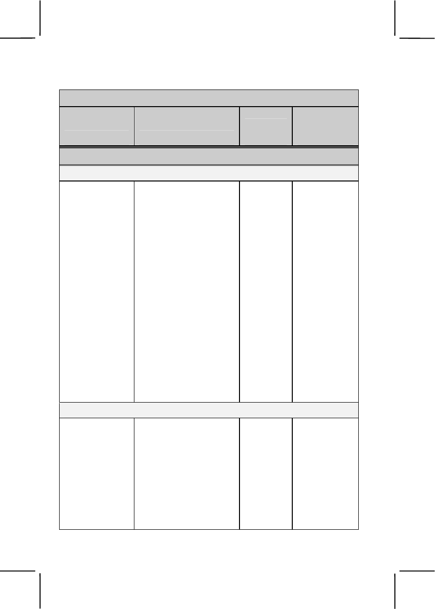
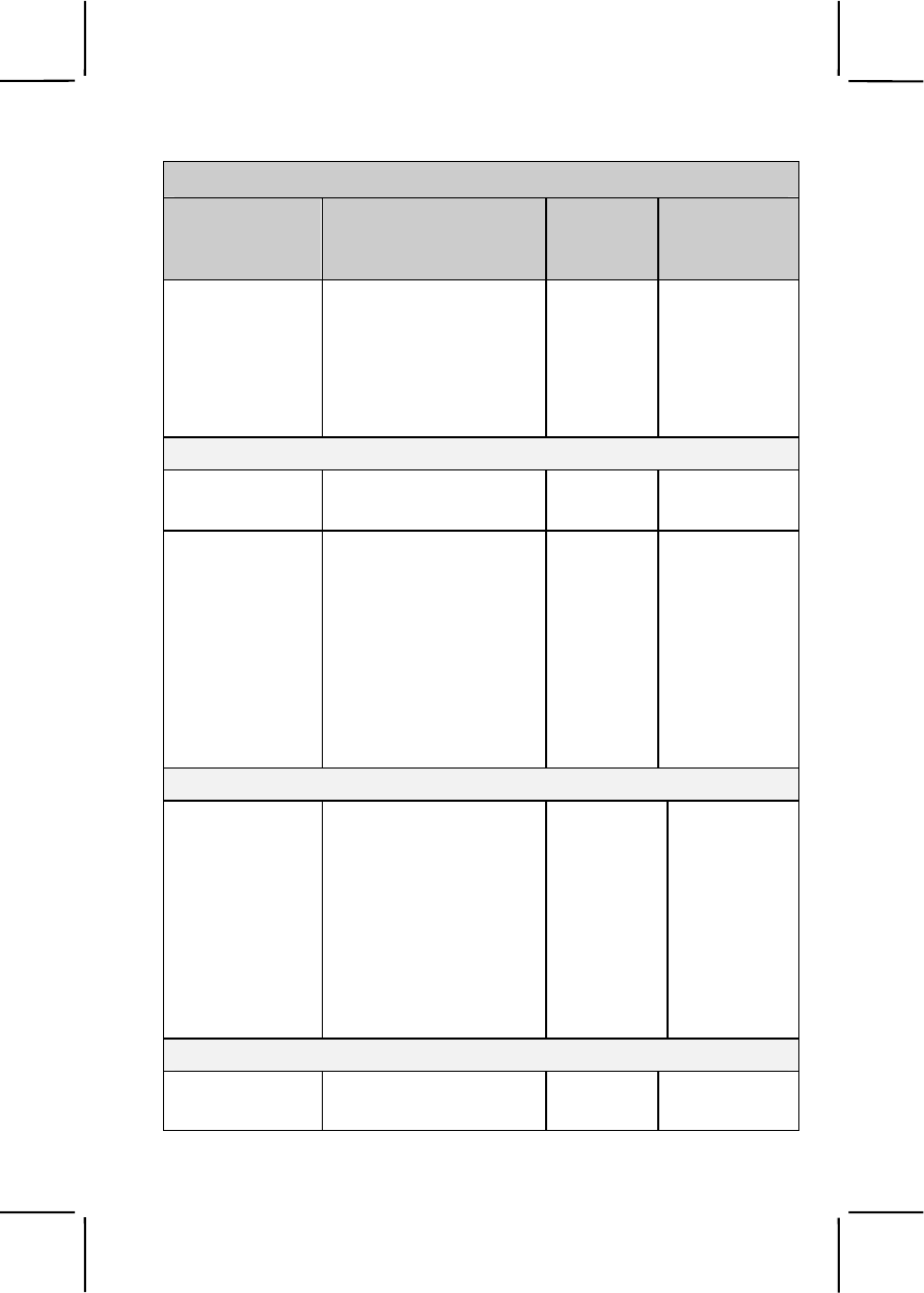
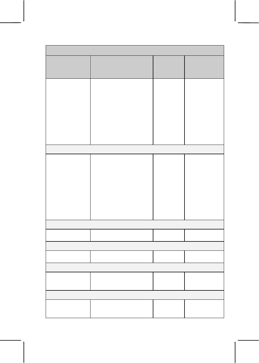
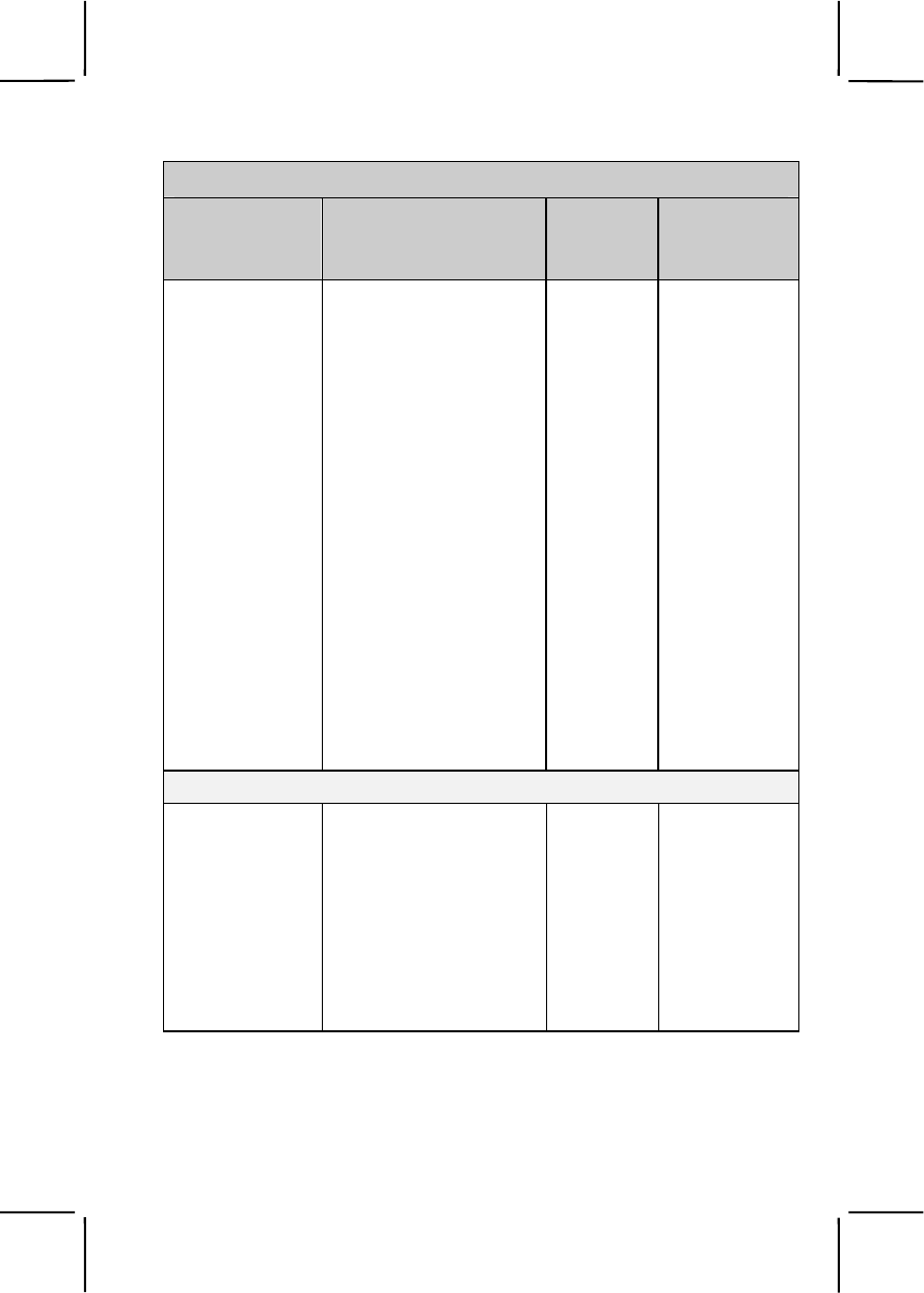
Common Task Training Plan
Task Number Title
Training
Location
Sustainment
Training
Frequency
Skill Level 1
Subject Area 1. Individual Conduct and Laws of War
181-101-1013 Comply with the Uniform
Code of Military Justice
(UCMJ)
BCT/OSUT AN
181-105-1001 Comply with the Law of
War and the Geneva and
Hague Conventions
BCT/OSUT AN
224-176-1425 Interact with News Media BCT/OSUT AN
331-202-1049 Comply with the
Requirements of the Code
of Conduct
BCT/OSUT AN
805C-PAD-1245 Support Unit and Family
Readiness Through the
Army Family Team
Building (AFTB) Program
BCT/OSUT AN
805C-PAD-1391 Comply with the Army's
Equal Opportunity and
Sexual Harassment
Policies
BCT/OSUT AN
Subject Area 2. First Aid
081-831-1000 Evaluate a Casualty BCT/OSUT AN
081-831-1003 Perform First Aid to Clear
an Object Stuck in the
Throat of a Conscious
Casualty
BCT/OSUT AN
081-831-1005 Perform First Aid to
Prevent or Control Shock BCT/OSUT AN
081-831-1007 Perform First Aid for Burns BCT/OSUT AN
2-3
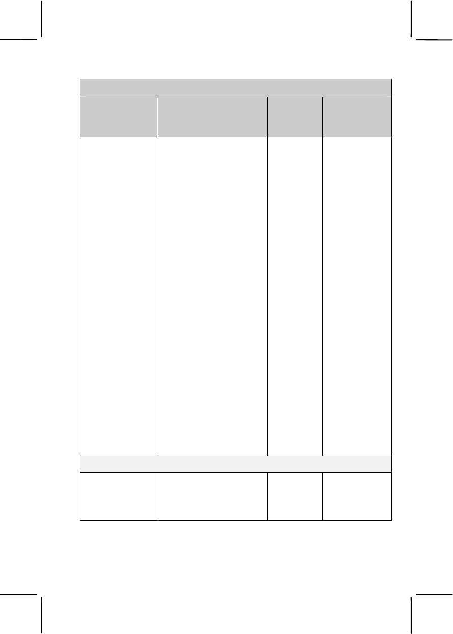
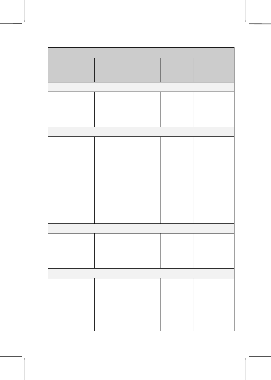
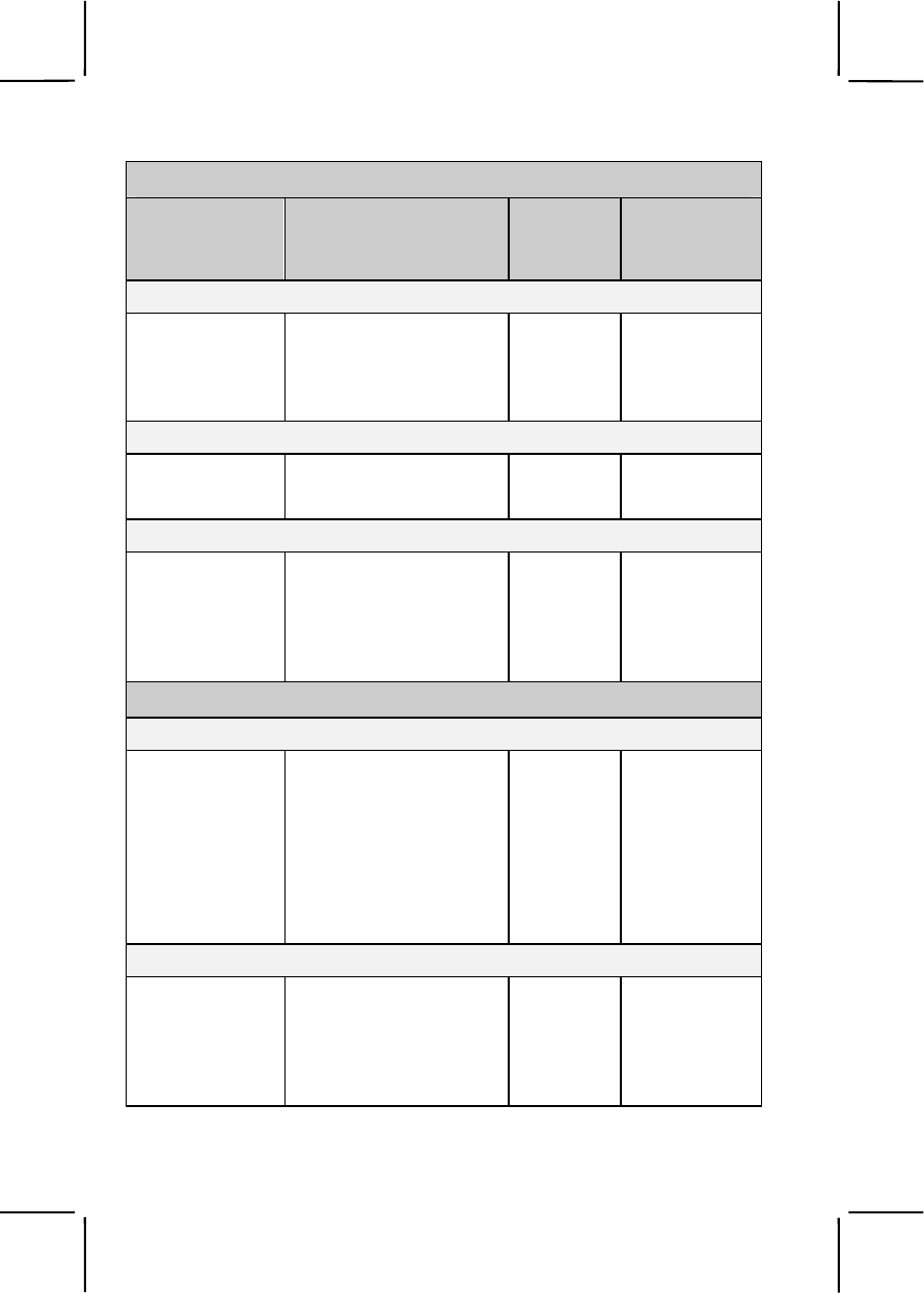
Common Task Training Plan
Task Number Title
Training
Location
Sustainment
Training
Frequency
081-831-1008 Perform First Aid for Heat
Injuries UNIT AN
081-831-1025 Perform First Aid for an
Open Abdominal Wound UNIT AN
081-831-1026 Perform First Aid for an
Open Chest Wound UNIT AN
081-831-1032 Perform First Aid for
Bleeding of an Extremity BCT/OSUT AN
081-831-1033 Perform First Aid for an
Open Head Wound BCT/OSUT AN
081-831-1034 Perform First Aid for a
Suspected Fracture BCT/OSUT AN
081-831-1042 Perform Mouth-to-Mouth
Resuscitation BCT/OSUT SA
081-831-1044 Perform First Aid for Nerve
Agent Injury BCT/OSUT QT
081-831-1045 Perform First Aid for Cold
Injuries UNIT AN
081-831-1046 Transport a Casualty BCT/OSUT AN
081-831-1053 Practice Individual
Preventive Medicine
Countermeasures
BCT/OSUT SA
Subject Area 3. Nuclear, Biological, and Chemical (NBC)
031-503-1013 Decontaminate Yourself
and Individual Equipment
Using Chemical
Decontaminating Kits
BCT/OSUT AN
2-4
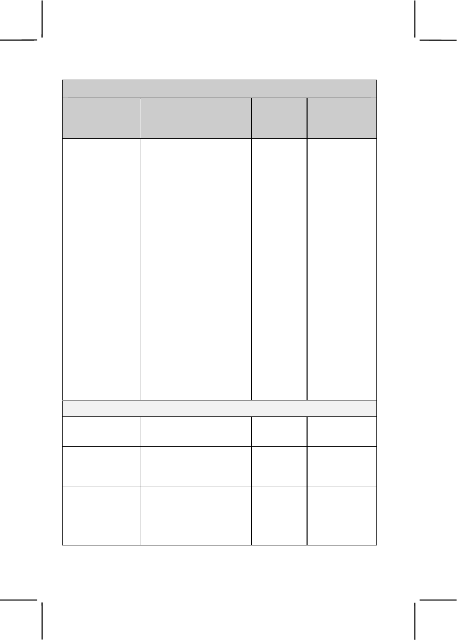
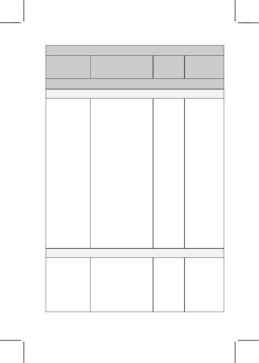
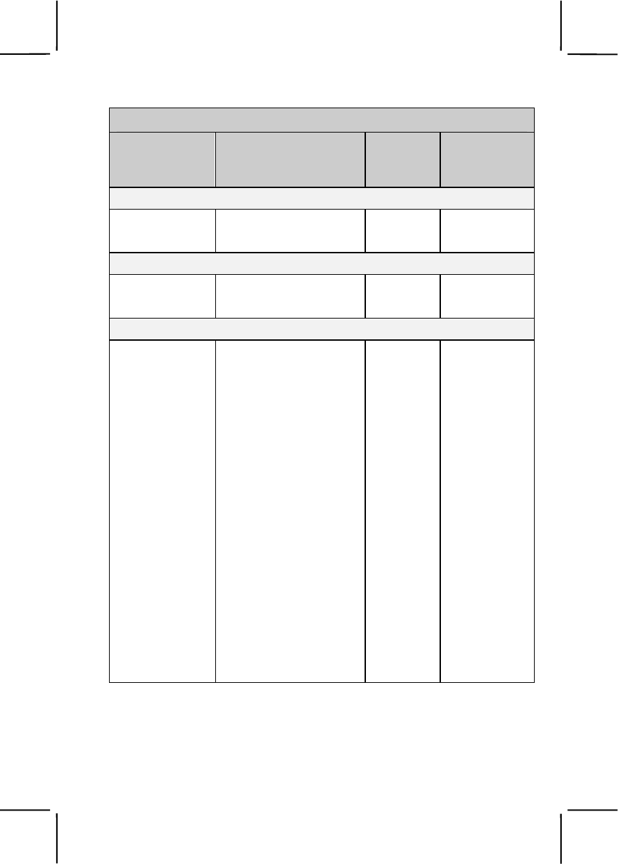
Common Task Training Plan
Task Number Title
Training
Location
Sustainment
Training
Frequency
031-503-1015 Protect Yourself from NBC
Injury/Contamination with
Mission-Oriented
Protective Posture (MOPP)
Gear
BCT/OSUT AN
031-503-1017 Respond to Depleted
Uranium BCT/OSUT AN
031-503-1018 React to Nuclear
Hazard/Attack BCT/OSUT AN
031-503-1019 React to Chemical or
Biological Hazard/Attack BCT/OSUT AN
031-503-1035 Protect Yourself from
Chemical/Biological
Contamination Using Your
Assigned Protective Mask
BCT/OSUT AN
031-503-1036 Maintain Your Assigned
Protective Mask BCT/OSUT AN
031-503-1037 Detect Chemical Agents
Using M8 or M9 Detector
Paper
BCT/OSUT AN
Subject Area 4. Survive (Combat Techniques)
052-192-1042 Perform Self-Extraction
from a Mined Area AIT QT
052-192-1242 Locate Mine and Booby
Trap Indicators by Visual
Means
AIT AN
071-326-0502 Move Under Direct Fire BCT/OSUT SA
071-326-0503 Move Over, Through, or
Around Obstacles (Except
Minefields)
BCT/OSUT SA
2-5
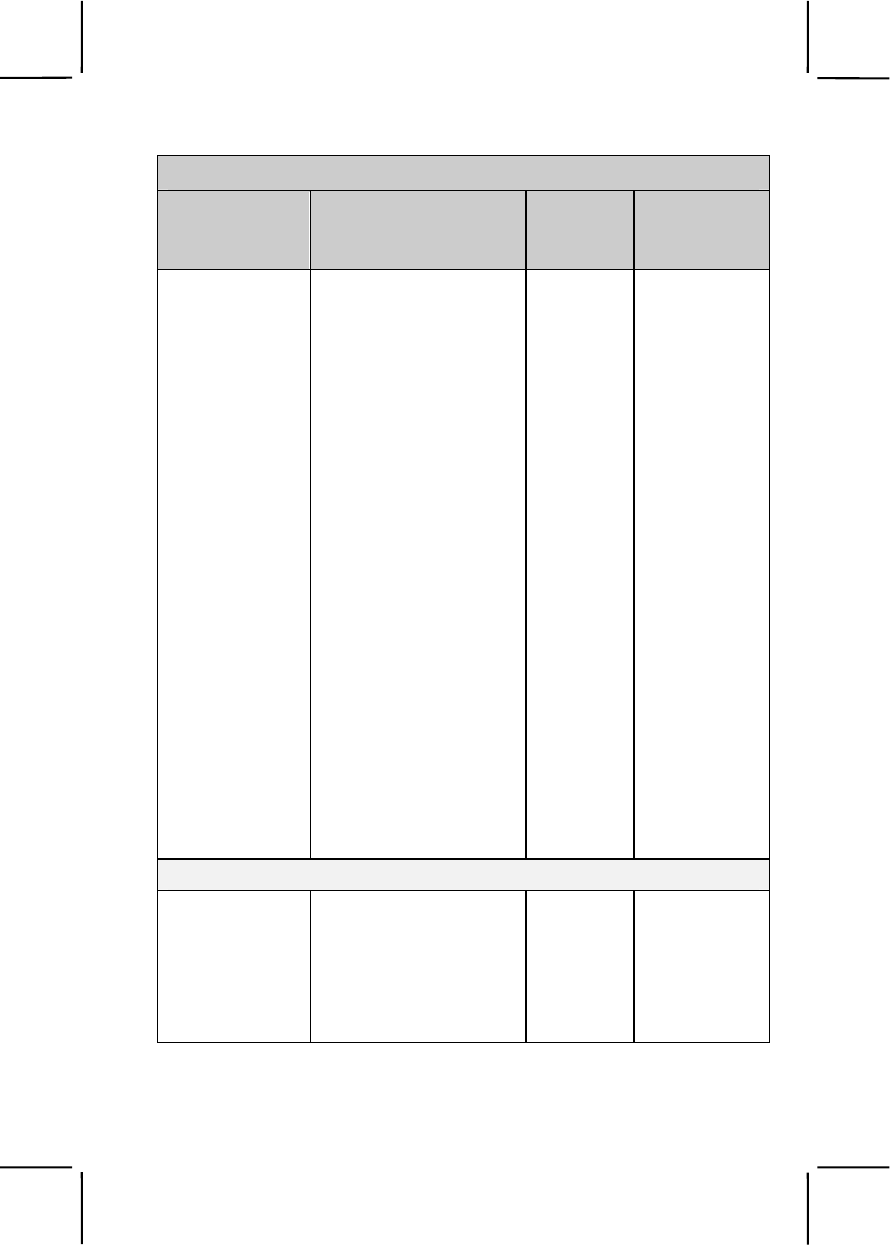
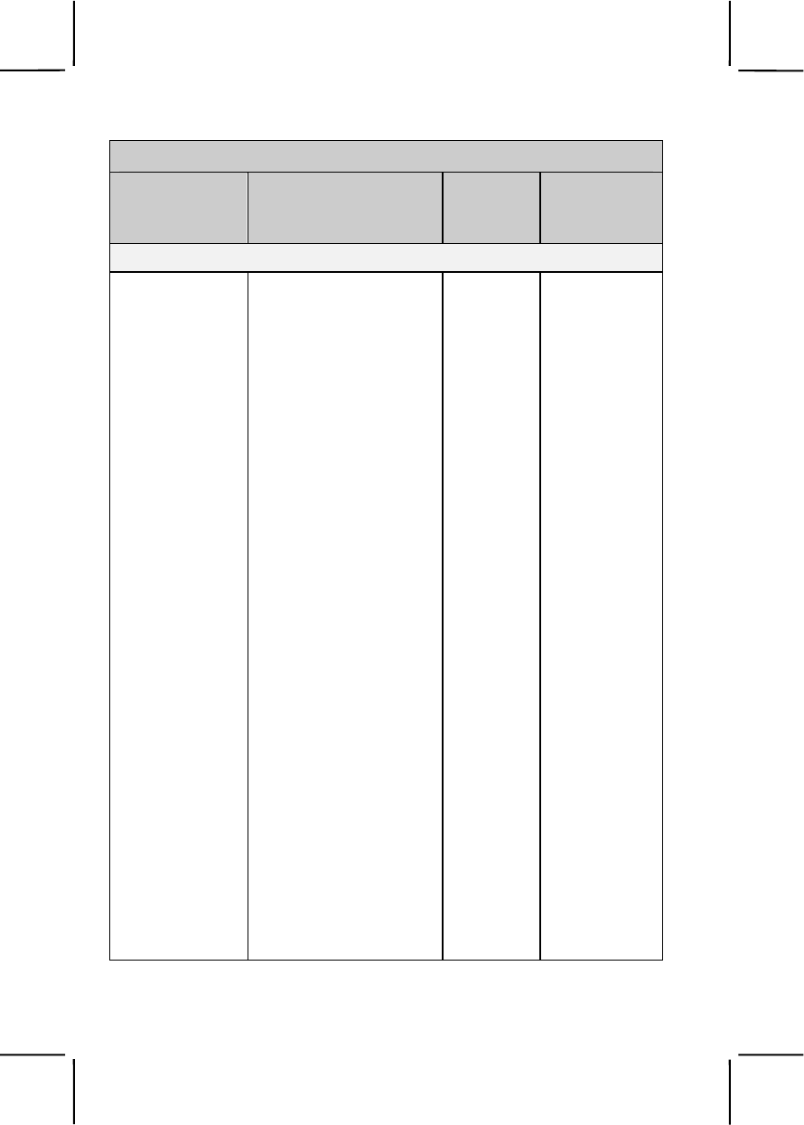
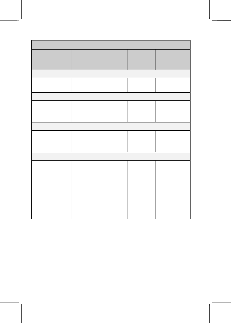
Common Task Training Plan
Task Number Title
Training
Location
Sustainment
Training
Frequency
071-326-0510 React to Indirect Fire While
Dismounted BCT/OSUT SA
071-326-0511 React to Flares BCT/OSUT SA
071-326-0513 Select Temporary Fighting
Positions BCT/OSUT SA
071-326-3002 React to Indirect Fire While
Mounted UNIT AN
071-326-5703 Construct Individual
Fighting Positions BCT/OSUT SA
071-331-0815 Practice Noise, Light, and
Litter Discipline BCT/OSUT SA
071-331-1004 Perform Duty as a Guard BCT/OSUT AN
071-410-0002 React to Direct Fire While
Mounted UNIT AN
071-710-0006 Plan Use of Night Vision
Devices UNIT SA
093-401-5040 React to Unexploded
Ordnance Hazards UNIT SA
551-88M-0005 Operate a Vehicle in a
Convoy UNIT SA
Subject Area 5. Navigate
071-329-1006 Navigate from One Point
on the Ground to Another
Point While Dismounted
BCT/OSUT SA
071-329-1030 Navigate from One Point
on the Ground to Another
Point While Mounted
UNIT SA

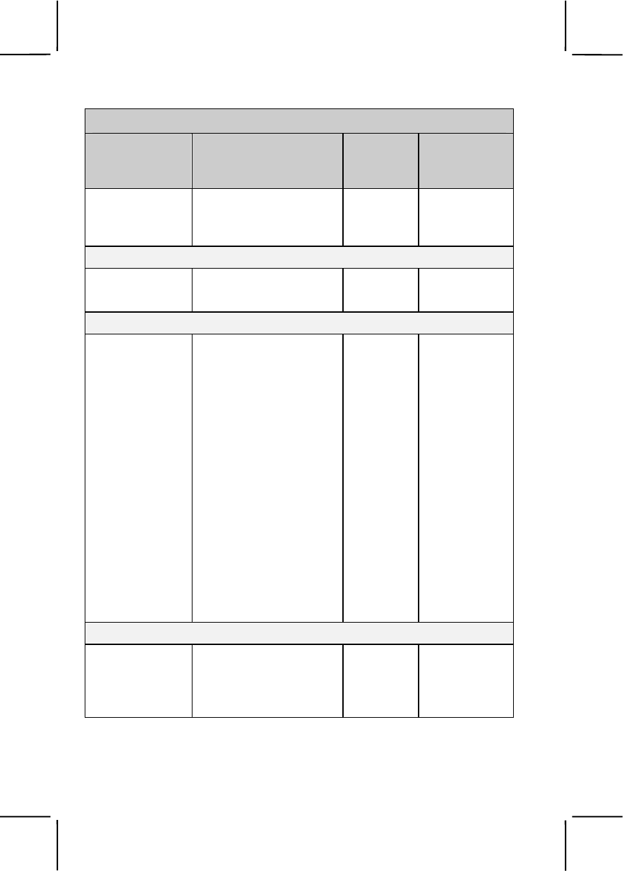
2-6
Common Task Training Plan
Task Number Title
Training
Location
Sustainment
Training
Frequency
Subject Area 6. Communicate
113-571-1022 Perform Voice
Communications BCT/OSUT SA
113-600-2001 Communicate Via a
Tactical Telephone BCT/OSUT AN
113-637-2001 Communicate Via a
Tactical Radio in a Secure
Net
BCT/OSUT AN
Subject Area 7. See
071-331-0804 Perform Surveillance
without the Aid of
Electronic Devices
UNIT SA
071-730-0014 Identify Combat Vehicles UNIT SA
Subject Area 8. Hand Grenades and Land Mines
071-325-4401 Perform Safety Checks on
Hand Grenades BCT/OSUT SA
071-325-4407 Employ Hand Grenades BCT/OSUT SA
071-325-4425 Employ an M18A1
Claymore Mine BCT/OSUT QT
Subject Area 9. M16-Series Rifle
071-008-0007 Engage Targets with an
M16-Series Rifle Using an
AN/PAS-13 Series
Thermal Weapon Sight
BCT/OSUT AN
071-311-2025 Maintain an M16-Series
Rifle BCT/OSUT SA
071-311-2027 Load an M16-Series Rifle BCT/OSUT SA
2-7
Common Task Training Plan
Task Number Title
Training
Location
Sustainment
Training
Frequency
071-311-2028 Unload an M16-Series
Rifle BCT/OSUT SA
071-315-2308 Engage Targets with an
M16-Series Rifle Using a
Night Vision Sight
AN/PVS-4
BCT/OSUT QT
Subject Area 10. M240B Machine Gun
071-000-0005 Prepare a Range Card for
a Machine Gun UNIT SA
071-025-0001 Maintain an M240B
Machine Gun AIT QT
071-025-0003 Load an M240B Machine
Gun AIT QT
071-025-0004 Unload an M240B Machine
Gun AIT QT
071-025-0007 Engage Targets with an
M240B Machine Gun AIT QT
Subject Area 11. M249 Machine Gun
071-010-0006 Engage Targets with an
M249 Machine Gun BCT/OSUT AN
071-312-4025 Maintain an M249 Machine
Gun BCT/OSUT QT
071-312-4027 Load an M249 Machine
Gun BCT/OSUT AN
071-312-4028 Unload an M249 Machine
Gun BCT/OSUT AN
Subject Area 12. M60 Machine Gun
071-312-3025 Maintain an M60 Machine
Gun UNIT SA

2-8
Common Task Training Plan
Task Number Title
Training
Location
Sustainment
Training
Frequency
071-312-3027 Load an M60 Machine Gun UNIT SA
071-312-3028 Unload an M60 Machine
Gun UNIT SA
071-312-3031 Engage Targets with an
M60 Machine Gun UNIT SA
Subject Area 13. MK19 Machine Gun
071-030-0001 Maintain an MK19 Machine
Gun UNIT AN
071-030-0004 Engage Targets with an
MK19 Machine Gun UNIT AN
071-030-0005 Load an MK19 Machine
Gun UNIT AN
071-030-0006 Unload an MK19 Machine
Gun UNIT AN
071-030-0007 Perform a Function Check
on an MK19 Machine Gun UNIT AN
Subject Area 14. Caliber .50 M2 Machine Gun
071-022-0001 Maintain a Caliber .50 M2
Machine Gun UNIT QT
071-022-0003 Load a Caliber .50 M2
Machine Gun UNIT QT
071-022-0004 Unload a Caliber .50 M2
Machine Gun UNIT QT
071-313-3454 Engage Targets with a
Caliber .50 M2 Machine
Gun
UNIT QT
2-9
Common Task Training Plan
Task Number Title
Training
Location
Sustainment
Training
Frequency
Subject Area 15. M136 Launcher
071-054-0001 Prepare an M136
Launcher for Firing BCT/OSUT AN
071-054-0002 Restore an M136 Launcher
to Carrying Configuration BCT/OSUT AN
Subject Area 16. M203 Grenade Launcher
071-311-2125 Maintain an M203 Grenade
Launcher BCT/OSUT QT
071-311-2127 Load an M203 Grenade
Launcher BCT/OSUT QT
071-311-2128 Unload an M203 Grenade
Launcher BCT/OSUT QT
071-311-2129 Correct Malfunctions of an
M203 Grenade Launcher BCT/OSUT QT
071-311-2130 Engage Targets with an
M203 Grenade Launcher BCT/OSUT QT
Subject Area 17. M4 Carbine
071-100-0003 Engage Targets with an
M4 or M4A1 Carbine UNIT AN
071-100-0004 Maintain an M4 or M4A1
Carbine UNIT AN
Subject Area 18. 9-mm Pistol
071-004-0001 Maintain an M9 Pistol UNIT AN
071-004-0003 Load an M9 Pistol UNIT AN
071-004-0004 Unload an M9 Pistol UNIT AN
071-004-0006 Engage Targets with an
M9 Pistol UNIT AN

2-10
Common Task Training Plan
Task Number Title
Training
Location
Sustainment
Training
Frequency
Subject Area 19. Crowd Control
191-376-4121 Use a Riot Baton BCT/OSUT QT
191-376-4122 Position Yourself in Riot
Control Formations BCT/OSUT QT
Subject Area 20. Casualty Reporting and Handling
101-515-1997 Inter Isolated Remains
(After Receiving
Authorization)
BCT/OSUT SA
101-515-1998 Evacuate Isolated
Remains BCT/OSUT SA
101-515-1999 Recover Isolated Remains BCT/OSUT SA
Subject Area 21. Defense Measures
052-191-1361 Camouflage Yourself and
Your Individual Equipment BCT/OSUT QT
052-191-1362 Camouflage Equipment UNIT SA
191-376-4114 Control Entry to and Exit
from a Restricted Area BCT/OSUT SA
301-371-1000 Report Intelligence
Information BCT/OSUT AN
301-371-1050 Implement Operations
Security (OPSEC)
Measures
UNIT AN
2-11
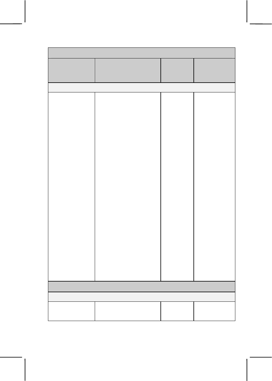
Common Task Training Plan
Task Number Title
Training
Location
Sustainment
Training
Frequency
Skill Level 2
Subject Area 1. Individual Conduct and Laws of War
181-101-2023 Enforce the Uniform
Code of Military Justice
(UCMJ)
PLDC AN
181-105-2001 Enforce the Law of War
and the Geneva and
Hague Conventions
UNIT AN
181-105-2002 Conduct Combat
Operations According to
the Law of War
UNIT AN
224-176-2426 Enforce Compliance
with Media Ground
Rules
UNIT SA
331-202-1050 Enforce Compliance
with the Code of
Conduct
UNIT AN
805C-PAD-2503 Enforce Compliance
with the Army's Equal
Opportunity and Sexual
Harassment Policies
PLDC QT
Subject Area 2. First Aid
081-831-0101 Request Medical
Evacuation PLDC AN
081-831-1054 Evacuate Casualties PLDC SA
081-831-9000 Implement Preventive
Medicine Measures
(PMM)
PLDC SA
2-12
Common Task Training Plan
Task Number Title
Training
Location
Sustainment
Training
Frequency
Subject Area 3. Nuclear, Biological, and Chemical (NBC)
031-503-1023 Protect Yourself from
Nuclear, Biological, and
Chemical (NBC)
Injury/Contamination
When Changing
Mission-Oriented
Protective Posture
(MOPP) Gear
UNIT SA
031-503-2001 Identify Chemical
Agents Using M256-
Series Chemical Agent
Detector Kit
UNIT SA
031-503-2023 Measure Radiation
Dose Rate and Total
Dose
UNIT SA
031-503-3002 Conduct Unmasking
Procedures UNIT SA
031-503-3004 Supervise the Crossing
of a Contaminated Area UNIT SA
031-503-3005 Submit an NBC 1
Report UNIT SA
031-503-3008 Implement Mission-
Oriented Protective
Posture (MOPP)
UNIT SA
031-503-3010 Supervise the
Employment of Nuclear,
Biological, and
Chemical (NBC)
Markers
UNIT AN
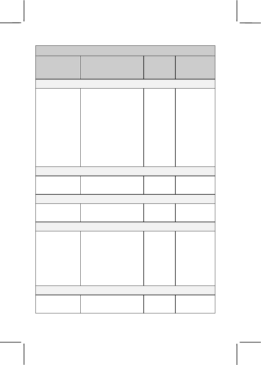
2-13
Common Task Training Plan
Task Number Title
Training
Location
Sustainment
Training
Frequency
031-503-4002 Supervise Unit
Preparation for a
Nuclear, Biological, and
Chemical (NBC) Attack
UNIT AN
031-506-1053 Report NBC Information
Using NBC 4 Report UNIT SA
031-506-2061 Conduct a Mask Fit
Test UNIT QT
Subject Area 4. Survive (Combat Techniques)
061-283-6003 Adjust Indirect Fire UNIT QT
071-326-0608 Use Visual Signaling
Techniques PLDC SA
071-326-5704 Supervise Construction
of a Fighting Position PLDC AN
071-326-5705 Establish an
Observation Post PLDC AN
Subject Area 5. Navigate
071-329-1019 Use a Map Overlay UNIT QT
Subject Area 20. Casualty Reporting and Handling
805C-PAD-2060 Report Casualties UNIT SA
Subject Area 21. Defense Measures
071-430-0002 Conduct a Defense by a
Squad PLDC SA
Subject Area 22. Unit Operations
071-326-5502 Issue a Fragmentary
Order PLDC QT
2-14
Common Task Training Plan
Task Number Title
Training
Location
Sustainment
Training
Frequency
071-326-5503 Issue a Warning Order PLDC QT
551-88N-0002 Prepare for Unit Move UNIT QT
Subject Area 23. Security and Control
301-371-1200 Process Captured
Materiel UNIT AN
Subject Area 25. Equipment Checks
091-CLT-4029 Supervise Preventive
Maintenance Checks
and Services (PMCS)
PLDC QT
101-92Y-0003 Enforce Compliance
with Supply Discipline
Procedures
PLDC SA
101-92Y-0004 Enforce Property
Accountability Policies PLDC SA
101-92Y-0005 Enforce Compliance
with Property
Accountability Policies
PLDC SA
101-92Y-0006 Inspect Equipment for
Accountability,
Cleanliness, and
Serviceability
UNIT QT
Subject Area 27. Risk Management
850-001-2000 Employ Accident
Prevention Measures
and Risk Management
Process
PLDC QT
2-15
Common Task Training Plan
Task Number Title
Training
Location
Sustainment
Training
Frequency
Subject Area 28. Administration/Management
805C-PAD-2044 Recommend Individual
for Award PLDC QT
805C-PAD-2145 Counsel a Soldier on
the Contents of a
Noncommissioned
Officer Evaluation
Report and NCOER
Checklist
PLDC QT
805C-PAD-2146 Prepare the Rater's
Portion of a
Noncommissioned
Officer Evaluation
Report (NCOER)
PLDC AN
805C-PAD-2402 Provide Input on
Personnel Actions
Affecting Subordinates
PLDC QT
805C-PAD-2407 Recommend
Disciplinary Action for a
Soldier
PLDC AN
805C-PAD-2461 Maintain Accountability
of Personnel (Status
Report)
UNIT SA
805C-PAD-2472 Prepare a Duty Roster UNIT AN
Skill Level 3
Subject Area 1. Individual Conduct and Laws of War
805C-PAD-3238 Enforce the Equal
Opportunity Program BNCOC QT
2-16
Common Task Training Plan
Task Number Title
Training
Location
Sustainment
Training
Frequency
Subject Area 4. Survive (Combat Techniques)
052-192-4053 Supervise Minefield
Breaching Operations UNIT SA
071-410-0012 Conduct Occupation of
an Assembly Area BNCOC SA
071-420-0021 Conduct a Movement to
Contact by a Platoon BNCOC SA
071-430-0028 Consolidate a Unit BNCOC SA
071-430-0029 Reorganize a Unit BNCOC SA
Subject Area 5. Navigate
071-332-5000 Prepare an Operation
Overlay BNCOC QT
Subject Area 19. Crowd Control
191-378-4302 Form Squad-Size Riot
Control Formations UNIT AN
Subject Area 21. Defense Measures
052-195-3066 Direct Construction of
Nonexplosive Obstacles UNIT AN
071-410-0019 Control Organic Fires UNIT SA
441-091-3000 Supervise the
Implementation of Air
Defense Measures
UNIT AN
Subject Area 22. Unit Operations
071-326-3013 Conduct a Tactical
Road March BNCOC QT
2-17
Common Task Training Plan
Task Number Title
Training
Location
Sustainment
Training
Frequency
071-326-5805 Conduct a Route
Reconnaissance
Mission
UNIT QT
071-332-5021 Prepare a Situation
Map UNIT QT
071-720-0015 Conduct an Area
Reconnaissance by a
Platoon
UNIT QT
101-92Y-0002 Plan Tactical Resupply
Operations BNCOC SA
301-371-1150 Identify Intelligence and
Electronic Warfare
(IEW) Assets
BNCOC AN
551-88M-0001 Lead a Convoy
Serial/March Unit UNIT SA
551-88N-0003 Plan Unit Move UNIT SA
Subject Area 23. Security and Control
191-379-4407 Plan Convoy Security
Operations
UNIT QT
301-371-1052 Protect Classified
Information and
Material
UNIT AN
805C-PAD-3594 Store Classified
Information and
Materials
UNIT AN
2-18
Common Task Training Plan
Task Number Title
Training
Location
Sustainment
Training
Frequency
Subject Area 24. Enemy Personnel
191-379-4450 Supervise Handling of
Enemy Personnel and
Equipment at Squad
Level
UNIT AN
Subject Area 27. Risk Management
850-001-3001 Control Mission Safety
Hazard UNIT QT
Subject Area 28. Administration/Management
805C-PAD-3147 Prepare the Senior
Rater's Portion of a
Noncommissioned
Officer Evaluation
Report (NCOER)
UNIT AN
Skill Level 4
Subject Area 2. First Aid
081-831-1047 Supervise the
Implementation of
Preventive Medicine
Policies
UNIT AN
081-831-1055 Ensure Unit Combat
Lifesaver Requirements
Are Met
UNIT SA
Subject Area 4. Survive (Combat Techniques)
071-326-5775 Coordinate with an
Adjacent Platoon ANCOC QT
101-CLT-0198 Supervise Tactical
Feeding Operation UNIT QT
2-19
Common Task Training Plan
Task Number Title
Training
Location
Sustainment
Training
Frequency
Subject Area 19. Crowd Control
191-379-5400 Form the Platoon into a
Riot Control Formation UNIT SA
Subject Area 21. Defense Measures
071-430-0006 Conduct a Defense by a
Platoon ANCOC QT
Subject Area 22. Unit Operations
091-CLT-3009 Supervise Maintenance
Operations ANCOC QT
101-92Y-0001 Supervise Supply
Activities UNIT QT
151-357-0001 Supervise CSS
Functions During
Platoon Operations
ANCOC AN
151-357-0002 Coordinate Combat
Service Support (CSS)
Operations
ANCOC AN
159-200-2020 Integrate Threat
Capabilities into Mission
Planning
ANCOC QT
181-101-4001 Conduct a
Search/Seizure ANCOC SA
551-721-4326 Perform Duties as
Convoy Commander UNIT SA
2-20
Common Task Training Plan
Task Number Title
Training
Location
Sustainment
Training
Frequency
Subject Area 23. Security and Control
191-379-4408 Plan Security for a
Command Post (CP)
UNIT SA
Subject Area 26. Crime Prevention
191-379-4425 Implement the Unit's
Crime Prevention
Program
UNIT AN
Subject Area 27. Risk Management
850-001-4001 Integrate Risk
Management into
Platoon
ANCOC QT
Subject Area 28. Administration/Management
805C-PAD-4359 Manage Soldier's
Deployment
Requirements
UNIT SA
805C-PAD-4550 Prepare a Standing
Operating Procedure
(SOP)
ANCOC SA
805C-PAD-4597 Integrate Newly
Assigned Soldiers UNIT QT

2-21
2-2. SUBJECT AREA CODES.
Skill Level 1
1 Individual Conduct and Laws of War
2 First Aid
3 Nuclear, Biological, and Chemical (NBC)
4 Survive (Combat Techniques)
5 Navigate
6 Communicate
7 See
8 Hand Grenades and Land Mines
9 M16-Series Rifle
10 M240B Machine Gun
11 M249 Machine Gun
12 M60 Machine Gun
13 MK19 Machine Gun
14 Caliber .50 M2 Machine Gun
15 M136 Launcher
16 M203 Grenade Launcher
17 M4 Carbine
18 9mm Pistol
19 Crowd Control
20 Casualty Reporting and Handling
21 Defense Measures

2-22
Table 2-1. Subject Areas in the Soldiers Manuals of Common Tasks
Note. Columns at right indicate subject areas included in each manual, by skill
level. STP 21-1-SMCT STP 21-24-SMCT
Subject Area SL 1 SL 2 SL 3 SL 4
1 Individual Conduct and Laws
of War
2 First Aid
3 Nuclear, Biological, and
Chemical (NBC)
4 Survive (Combat Techniques)
5 Navigate
6 Communicate
7 See
8 Hand Grenades and Land
Mines
9 M16-Series Rifle
10 M240B Machine Gun
11 M249 Machine Gun
12 M60 Machine Gun
13 MK19 Machine Gun
14 Caliber .50 M2 Machine Gun
15 M136 Launcher
16 M203 Grenade Launcher
17 M4 Carbine
18 9-mm Pistol
19 Crowd Control
20 Casualty Reporting and
Handling
21 Defense Measures
22 Unit Operations
23 Security and Control
24 Enemy Personnel
25 Equipment Checks
26 Crime Prevention
27 Risk Management
28 Administration/Management

Skill Level 1 181-101-1013 3-1
Chapter 3
Skill Level 1 Tasks
Skill Level 1
SUBJECT AREA 1: INDIVIDUAL CONDUCT AND LAWS OF WAR
181-101-1013
Comply With the Uniform Code of Military Justice (UCMJ)
Conditions: You are a soldier in the U.S. Army. You are responsible for
identifying, understanding, and complying with the provisions of the U.S.
Army's military justice system, including the Uniform Code of Military Justice
(UCMJ). You must understand the ramifications you might face for violating
the UCMJ, your commander's disciplinary options, and your legal rights in
these proceedings.
Standards: The soldier identified, understood, and complied with the
provisions of the U.S. Army's military justice system, including UCMJ. He
understood the potential ramifications for violating the UCMJ, the
commander's disciplinary options, and his legal rights in these proceedings.
Performance Steps
1. Define military justice.
2. Describe the military justice system.
a. Describe the purpose of the military justice system.
b. Describe the similarities and differences between the military justice
system and the American civil legal system.
c. Describe the UCMJ and identify to whom it applies.
3. Identify who has authority to take disciplinary action against a soldier
for misconduct.
4. Describe a commander's responsibility to conduct a preliminary
investigation into misconduct allegedly committed by a soldier under his
command.
a. Describe the basis and procedures of a commander's inquiry.
b. Describe the basis and procedures of an AR 15-6 investigation.
c. Describe the requirement for the military police or Criminal
Investigation Command (CID) to conduct a criminal investigation.
5. List the disciplinary options available to the commander.

3-2 181-101-1013
Performance Steps
a. Describe how a commander can take no action at all or close a
case.
b. Describe how a commander can use administrative or nonpunitive
measures.
(1) List administrative or nonpunitive disciplinary measures
available to a commander.
(2) Describe why a commander may wish to use nonpunitive or
administrative disciplinary measures rather than impose nonjudicial
punishment or proceed to court-martial.
c. Define nonjudicial punishment and how a commander can use
nonjudicial punishment.
d. Define judicial punishment and how a commander can use judicial
punishment.
6. List factors a commander should consider when determining what
disciplinary option to pursue.
a. Describe whether a commander should consider the character and
military service of the accused.
b. Describe whether a commander should consider the nature and
circumstances of the offense and the extent of the harm caused.
c. Describe whether a commander should consider the needs of the
service and the probable effect of his decision on the command and the
military community.
d. Describe whether a commander should consider the disposition of
similar offenses in the past and the general disciplinary trends within the
command.
e. Describe whether a commander should consider the
appropriateness of the authorized punishment to the particular accused
and offense.
f. Describe whether a commander should determine whether he has
jurisdiction over the accused and the offense.
g. Describe whether a commander should consider the availability and
admissibility of evidence against the accused.
h. Describe whether a commander should consider the cooperation of
the accused in the apprehension or conviction of others.
i. Describe whether a commander should consider the possible
improper motives of the accuser.
j. Describe whether a commander should consider that the victim or
others are reluctant to testify.

181-101-1013 3-3
Performance Steps
7. Describe nonpunitive or administrative disciplinary actions.
a. Define an admonition or reprimand.
(1) Describe the purposes of an admonition or reprimand.
(2) Describe whether an admonition or reprimand may be in writing,
orally, or both.
(3) Describe the soldier's legal rights in regards to an admonition or
reprimand.
(4) Describe the commander's filing determination for a written
admonition or reprimand.
(5) Describe whether an administrative admonition or reprimand is
punitive.
b. Define counseling of a soldier.
(1) Describe the purpose for counseling.
(2) Describe whether counseling may be written, oral, or both.
(3) Describe the soldier's rights during counseling.
(4) Describe where a commander may file a written counseling
statement.
c. Define withholding a soldier's privileges as an administrative
disciplinary action.
(1) Describe the purpose for withholding privileges.
(2) Describe what privileges may be withheld and under what
circumstances.
d. Define extra duty as an administrative disciplinary action.
(1) Describe the purpose of extra duty.
(2) Describe what forms or methods of extra duty may be imposed
and under what circumstances.
(3) Describe the requirement that extra duty be tailored to address
training deficiency, not used as punishment.
e. Define administrative separations.
(1) List administrative separations available under AR 635-200.
(2) Describe the purposes for an administrative separation action.
(3) Describe the procedures for an administrative separation action.
(4) Describe the circumstances under which a soldier is entitled to
an administrative separation board.
(a) Describe the composition of an administrative separation
board.

3-4 181-101-1013
Performance Steps
(b) Describe the duties and responsibilities of an administrative
separation board.
(5) Describe a soldier's right to legal counsel for consultation and/or
representation during an administrative separation action.
(6) Describe the types of discharges a soldier may receive from an
administrative separation action.
(7) Identify the approval authority for an administrative separation
action.
8. Describe nonjudicial, or Article 15, punishment.
a. List who may impose nonjudicial or Article 15 punishment.
(1) Define who constitutes a "commander".
(2) Describe a superior commander's authority to withhold
nonjudicial or Article 15 authority over specific offenses or persons.
(3) Describe the prohibition against a superior commander directing
a subordinate commander to take action under Article 15 or dictating to the
subordinate commander the type or quantity of punishment to be
administered under Article 15.
b. Describe the circumstances under which a commander may wish to
impose nonjudicial or Article 15 punishment.
c. Describe the advantages of disposing of offenses by imposing
nonjudicial or Article 15 punishment.
d. Describe offenses for which a Commander may impose nonjudicial
or Article 15 punishment.
e. Define a "minor" offense under the UCMJ.
f. Define a "summarized" Article 15 and a "formal" Article 15.
g. List the procedures and maximum punishment that may be imposed
by a summarized Article 15.
h. Define a "company grade" Article 15 and a "field grade" Article 15.
i. Describe an accused soldier's legal rights under nonjudicial or
Article 15 punishment, including the right to consultation or representation
by a defense counsel.
j. Describe a soldier's right to turn down an Article 15 and demand
trial by court-martial and the time period in which the soldier must make
that decision.
k. Describe the procedures of a nonjudicial or Article 15 hearing.
l. Describe the “standard of proof” required when imposing nonjudicial
or Article 15 punishment.

181-101-1013 3-5
Performance Steps
m. Describe the maximum punishments that may be imposed by a
company grade or field grade Article 15.
n. Describe a soldier's appellate rights subsequent to an Article 15
action.
(1) Describe who serves as the appellate authority.
(2) Describe the time period to act on an appeal.
(3) Describe the actions that the appellate authority may take.
9. Define "preferral" of court-martial charges.
a. Identify who may prefer a court-martial charge.
b. Describe the requirement and procedures typically used to notify
the accused of the charges as soon as possible after preferral.
10. Define "pretrial restraint" of a soldier.
a. Define the purposes of pretrial restraint.
b. List the types of restraint.
(1) Define apprehension and its purpose.
(a) List who is authorized to apprehend persons subject to the
UCMJ.
(b) List the factors that must be present and later articulated in
order to properly apprehend a person subject to the UCMJ.
(2) Define conditions on liberty and its purpose.
(3) Define restriction, its purpose, and whether a soldier may be
required to perform military duties while on restriction.
(4) Define arrest, its purpose, and the differences between arrest
and restriction.
(5) Define confinement and its purpose.
(a) Define the factors that must exist in order to properly place
a soldier in pretrial confinement.
(b) Identify who has the authority to place a soldier in pretrial
confinement.
(c) Describe the review and approval procedures for pretrial
confinement.
11. Define "referral" of court-martial charges and identify who may refer a
court-martial charge.
12. Define "convening authority" for a court-martial and identify the duties
and responsibilities of a convening authority.
13. List the different levels of courts-martial.

3-6 181-101-1013
Performance Steps
a. Define a summary court-martial.
(1) Identify who is the convening authority for a summary court-
martial.
(2) Describe the types of offenses that are typically handled by a
summary court-martial.
(3) Describe the types of offenses for which soldiers may be tried
by a summary court-martial.
(4) Describe whether a military judge presides at a summary court-
martial.
(5) Describe the presiding official at a summary court-martial.
(6) Describe whether a jury or panel exists at a summary court-
martial.
(7) Describe whether an accused is entitled to be represented by
defense counsel at a summary court-martial.
(8) Describe the requirement for a soldier to consent to trial by
summary court-martial.
(9) Describe what happens if an accused refuses trial by summary
court-martial.
(10) Describe the procedures of a summary court-martial.
(11) Describe the standard of proof for conviction at a summary
court-martial.
(12) Identify who must establish or meet the standard of proof.
(13) Describe the maximum punishment that a summary court-
martial may impose.
(14) Describe the appellate rights of a soldier tried and convicted
by a summary court-martial.
b. Define a special court-martial.
(1) Identify who is the convening authority for a special court-
martial.
(2) Describe what soldiers may be tried by a special court-martial.
(3) Describe whether a military judge presides at a special court-
martial.
(4) Describe the duties and responsibilities of a military judge at a
special court-martial.
(5) Describe whether a jury or panel exists at a special court-
martial and its composition.

181-101-1013 3-7
Performance Steps
(a) Describe the duties and responsibilities of a jury or panel at
a special court-martial.
(b) Describe the minimum number of jury or panel members.
(6) Describe whether an accused is entitled to be represented by
defense counsel at a special court-martial.
(7) Describe the requirement for a trial counsel to represent the
U.S. Government at a special court-martial.
(8) Describe the procedures of a special court-martial.
(9) Describe the Standard of Proof for conviction at a special court-
martial and identify who must establish or meet this standard of proof.
(10) Describe the maximum punishment that a special court-martial
may impose.
(11) Describe a soldier's appellate rights if convicted by a special
court-martial.
(12) Describe the differences between a special court-martial and a
special court-martial empowered to adjudge a bad conduct
discharge.
c. Define a general court-martial.
(1) Identify who convenes a general court-martial.
(2) Describe what soldiers may be tried by a general court-martial.
(3) Describe what types of offenses are typically tried by a general
court-martial.
(4) Describe the requirement and procedures for a pre-trial
investigation, or Article 32 investigation, prior to convening a general court-
martial.
(5) Describe whether a military judge presides at a General Court-
Martial.
(6) Describe the duties and responsibilities of a military judge at a
General Court-Martial.
(7) Describe whether a jury or panel exists at a general court-
martial and its composition.
(a) Describe the duties and responsibilities of a jury or panel at
a general court-martial.
(b) Describe the minimum number of panel or jury members.
(8) Describe whether an accused is entitled to be represented by
defense counsel at a general court-martial.

3-8 181-101-1013
Performance Steps
(9) Describe the requirement for a trial counsel to represent the
U.S. Government at a general court-martial.
(10) Describe the procedures of a general court-martial.
(11) Describe the standard of proof required for conviction at a
general court-martial and identify who must establish or meet this Standard
of Proof.
(12) Describe the maximum punishment that a general court-martial
may impose.
(13) Describe a soldier's appellate rights if convicted by a general
court-martial.
Evaluation Preparation: Setup: Evaluate this task at the end of military
justice training.
Brief Soldier: Tell the soldier that he will be evaluated on his ability to
identify, understand, and comply with the provisions of the U.S. Army's
military justice system, including the UCMJ. Tell the soldier that he will also
be evaluated on his ability to understand the potential ramifications for
violating the UCMJ, the commander's disciplinary options, and the soldier's
legal rights in these proceedings.
Performance Measures GO NO GO
1. Defined military justice. —— ——
2. Described the military justice system. —— ——
a. Described the purpose of the military justice
system.
b. Described the similarities and differences
between the military justice system and the American
civil legal system.
c. Described the UCMJ and to whom it applies.
3. Identified who has authority to take disciplinary action
against a soldier for misconduct. —— ——
4. Described a commander's responsibility to conduct a
preliminary investigation into misconduct allegedly
committed by a soldier under his command. —— ——
a. Described the basis and procedures of a
commander's inquiry.
b. Described the basis and procedures of an
AR 15-6 investigation.

181-101-1013 3-9
Performance Measures GO NO GO
c. Described the requirement for the military police
or Criminal Investigation Command (CID) to conduct a
criminal investigation.
5. Listed the disciplinary options available to the
commander. —— ——
a. Described how a commander can take no action
at all or close a case.
b. Described how a commander can use
administrative or nonpunitive measures.
(1) Listed administrative or nonpunitive
disciplinary measures available to a commander.
(2) Described why a commander may wish to use
nonpunitive or administrative disciplinary measures
rather than impose nonjudicial punishment or proceed to
court-martial.
c. Defined nonjudicial punishment and how a
commander can use nonjudicial punishment.
d. Defined judicial punishment and how a
commander can use judicial punishment.
6. Listed factors a commander should consider when
determining what disciplinary option to pursue. —— ——
a. Described whether a commander should consider
the character and military service of the accused.
b. Described whether a commander should consider
the nature and circumstances of the offense and the
extent of the harm caused.
c. Described whether a commander should consider
the needs of the service and the probable effect of his
decision on the command and the military community.
d. Described whether a commander should consider
the disposition of similar offenses in the past and the
general disciplinary trends within the command.
e. Described whether a commander should consider
the appropriateness of the authorized punishment to the
particular accused and offense.
f. Described whether a commander should
determine whether he has jurisdiction over the accused
and the offense.

3-10 181-101-1013
Performance Measures GO NO GO
g. Described whether a commander should consider
the availability and admissibility of evidence against the
accused.
h. Described whether a commander should consider
the cooperation of the accused in the apprehension or
conviction of others.
i. Described whether a commander should consider
the possible improper motives of the accuser.
j. Described whether a commander should consider
that the victim or others are reluctant to testify.
7. Described nonpunitive or administrative disciplinary
actions. —— ——
a. Defined an admonition or reprimand.
(1) Described the purposes of an admonition or
reprimand.
(2) Described whether an admonition or
reprimand may be written, oral, or both.
(3) Described the soldier's legal rights in regards
to an admonition or reprimand.
(4) Described the commander's filing
determination for a written admonition or reprimand.
(5) Described whether an administrative
admonition or reprimand is punitive.
b. Defined counseling of a soldier.
(1) Described the purpose of counseling.
(2) Described whether counseling may be
written, oral, or both.
(3) Described the soldier's rights during
counseling.
(4) Described where a commander may file a
written counseling statement.
c. Defined withholding a soldier's privileges as an
administrative disciplinary action.
(1) Described the purpose for withholding
privileges.
(2) Described what privileges may be withheld
and under what circumstances.

181-101-1013 3-11
Performance Measures GO NO GO
d. Defined extra duty as an administrative
disciplinary action.
(1) Described the purpose of extra duty.
(2) Described what forms or methods of extra
duty may be imposed and under what circumstances.
(3) Described the requirement that extra duty be
tailored to address the training deficiency, not used as
punishment.
e. Defined administrative separations.
(1) Listed administrative separations available
under AR 635-200.
(2) Described the purposes for an administrative
separation action.
(3) Described the procedures for an
administrative separation action.
(4) Described the circumstances under which a
soldier is entitled to an administrative separation board.
(a) Described the composition of an
administrative separation board.
(b) Described the duties and responsibilities
of an administrative separation board.
(5) Described a soldier's right to legal counsel for
consultation and/or representation during an
administrative separation action.
(6) Described the types of discharges a soldier
may receive from an administrative separation action.
(7) Identified the approval authority for an
administrative separation action.
8. Described nonjudicial, or Article 15, punishment. —— ——
a. Listed who may impose nonjudicial or Article 15
punishment.
(1) Defined who constitutes a "commander."
(2) Described a superior commander's authority
to withhold nonjudicial or Article 15 authority over
specific offenses or persons.

3-12 181-101-1013
Performance Measures GO NO GO
(3) Described the prohibition against a superior
commander directing a subordinate commander to take
action under Article 15 or dictating to the subordinate
commander the type or quantity of punishment to be
administered under Article 15.
b. Described the circumstances under which a
commander may impose nonjudicial or Article 15
punishment.
c. Described the advantages of disposing of
offenses by imposing nonjudicial or Article 15
punishment.
d. Described for which offenses a commander may
impose nonjudicial or Article 15 punishment.
e. Defined a "minor" offense under the UCMJ.
f. Defined a "summarized" Article 15 and a "formal"
Article 15.
g. Listed the procedures and maximum punishment
that may be imposed by a summarized Article 15.
h. Defined a "company grade" Article 15 and a "field
grade" Article 15.
i. Described an accused soldier's legal rights under
nonjudicial or Article 15 punishment, including the right to
consultation or representation by a defense counsel.
j. Described a soldier's right to turn down an Article
15 and demand trial by court-martial and the time period
in which a soldier must make that decision.
k. Described the procedures of a nonjudicial or
Article 15 hearing.
l. Described the standard of proof required when
imposing nonjudicial or Article 15 punishment.
m. Described the maximum punishments that may
be imposed by a company grade or field grade
Article 15.
n. Described a soldier's appellate rights subsequent
to an Article 15 hearing.
(1) Described who serves as the appellate
authority.
(2) Described the time to act on an appeal.

181-101-1013 3-13
Performance Measures GO NO GO
(3) Described the actions that the appellate
authority may take.
9. Defined "preferral" of court-martial charges. —— ——
a. Identified who may prefer a court-martial charge.
b. Described the requirement and procedures
typically used to notify the accused of the charges as
soon as possible after preferral.
10. Defined "pretrial restraint" of a soldier. —— ——
a. Defined the purposes of pretrial restraint.
b. Listed the types of restraint.
(1) Defined apprehension and its purpose.
(a) Listed who is authorized to apprehend
persons subject to the UCMJ.
(b) Listed the factors that must be present
and later articulated in order to properly apprehend a
person subject to the UCMJ.
(2) Defined conditions on liberty and its purpose.
(3) Defined restriction, its purpose, and whether a
soldier may be required to perform military duties while
on restriction.
(4) Defined arrest, its purpose, and the
differences between arrest and restriction.
(5) Defined confinement and its purpose.
(a) Defined the factors that must exist in
order to properly place a soldier in pretrial confinement.
(b) Identified who has the authority to place
a soldier in pretrial confinement.
(c) Described the review and approval
procedures for pretrial confinement.
11. Defined "referral" of court-martial charges and
identified who may refer a court-martial charge. —— ——
12. Defined "convening authority" for a court-martial and
identified the duties and responsibilities of a convening
authority.
—— ——
13. Listed the different levels of courts-martial. —— ——

3-14 181-101-1013
Performance Measures GO NO GO
a. Defined a summary court-martial.
(1) Identified the convening authority for a
summary court-martial.
(2) Described what types of offenses are typically
handled by a summary court-martial.
(3) Described what soldiers may be tried by a
summary court-martial.
(4) Described whether a military judge presides
at a summary court-martial.
(5) Described the presiding official is at a
summary court-martial.
(6) Described whether a jury or panel exists at a
summary court-martial.
(7) Described whether an accused is entitled to
be represented by defense counsel at a summary court-
martial.
(8) Described the requirement for a soldier to
consent to trial by summary court-martial.
(9) Described what happens if an accused
refuses trial by summary court-martial.
(10) Described the procedures of a summary
court-martial.
(11) Described the standard of proof for
conviction at a summary court-martial.
(12) Identified who must establish or meet this
standard of proof.
(13) Described the maximum punishment that a
summary court-martial may impose.
(14) Described the appellate rights of a soldier
tried and convicted by a summary court-martial.
b. Defined a special court-martial.
(1) Identified the convening authority for a special
court-martial.
(2) Described what soldiers may be tried by a
special court-martial.
(3) Described whether a military judge presides
at a special court-martial.

181-101-1013 3-15
Performance Measures GO NO GO
(4) Described the duties and responsibilities of a
military judge at a special court-martial.
(5) Described whether a jury or panel exists at a
special court-martial and its composition.
(a) Described the duties and responsibilities
of a jury or panel at a special court-martial.
(b) Described the minimum number of jury or
panel members.
(6) Described whether an accused is entitled to
be represented by defense counsel at a special court-
martial.
(7) Described the requirement for a trial counsel
to represent the U.S. Government at a special court-
martial.
(8) Described the procedures of a special court-
martial.
(9) Described the standard of proof for conviction
at a special court-martial and identified who must
establish or meet this standard of proof.
(10) Described the maximum punishment that a
special court-martial may impose.
(11) Described the appellate rights of a soldier's
convicted by a special court-martial.
(12) Described the differences between a special
court-martial and a special court-martial empowered to
adjudge a bad conduct discharge.
c. Defined a general court-martial.
(1) Identified who convenes a general court-
martial.
(2) Described what soldiers may be tried by a
general court-martial.
(3) Described what types of offenses are typically
tried by a general court-martial.
(4) Described the requirement and procedures
for a pre-trial investigation, or Article 32 investigation,
prior to convening a general court-martial.
(5) Described whether a military judge presides
at a general court-martial.

3-16 181-105-1001
Performance Measures GO NO GO
(6) Described the duties and responsibilities of a
military judge at a general court-martial.
(7) Described whether a jury or panel exists at a
general court-martial and its composition.
(a) Described the duties and responsibilities
of a jury or panel at a general court-martial.
(b) Described the minimum number of panel
or jury members.
(8) Described whether an accused is entitled to
be represented by a defense counsel at a general court-
martial.
(9) Described the requirement for a trial counsel
to represent the U.S. Government at a general court-
martial.
(10) Described the procedures of a general court-
martial.
(11) Described the standard of proof required for
conviction at a general court-martial and identified who
must establish or meet this standard of proof.
(12) Described the maximum punishment that a
general court-martial may impose.
(13) Described a soldier's appellate rights if
convicted by a general court-martial.
Evaluation Guidance: Score the soldier GO if all performance measures
are passed. Score the soldier NO GO if any performance measure is failed.
If the soldier scores NO GO, show what was done wrong and how to do it
correctly.
References:
Required
AR 15-6
181-105-1001
Comply with the Law of War and the Geneva and Hague Conventions
Conditions: You are a soldier in the U.S. Army. You are responsible for
identifying, understanding, and complying with the provisions of the Law of
War, including the Geneva and Hague conventions. You are also

181-105-1001 3-17
responsible for identifying and notifying the appropriate authorities of any
suspected or known violations of the Law of War.
Standards: The soldier identified, understood, and complied with the Law of
War. Identified problems or situations that violate the policies and took
appropriate action, including notifying appropriate authorities, so expedient
action could be taken to correct the problem or situation.
Performance Steps
1. Define the Customary Law of War.
a. Describe the purpose and result of the Customary Law of War.
b. Describe the relationship between the Customary Law of War and
the Hague Convention and Geneva Convention.
2. Describe what the Hague and Geneva conventions basically represent.
3. Describe the U.S. responsibility to comply with the Hague and Geneva
conventions.
4. Describe the Customary Law of War and Hague Convention's
limitations on targets.
a. Describe the international law prohibition on targeting or attacking
civilians.
b. Describe the Hague regulations prohibition on the destruction or
seizure of enemy property unless imperatively demanded by military
necessity.
c. Describe the Hague Regulation provisions regarding attacking a
military target or a place occupied by a combatant force.
d. Describe the Hague Regulation prohibition against attacking an
undefended town, village, dwellings, buildings, or other such place.
(1) Define an undefended place within the meaning of the Hague
Convention.
(2) Describe the conditions that must exist for a place to be
considered undefended.
(3) Describe the effect of medical units, wounded and sick, and
police forces within the undefended place on the character or status of the
undefended place.
e. Describe the permissibility of attacking or bombarding defended
places.
(1) Define what constitutes a defended place.
(2) Describe the status (defended or undefended) of a city or town
surrounded by detached defense positions.
f. Describe what constitutes a permissible military objective for attack,
including bombardment.

3-18 181-105-1001
Performance Steps
g. Describe the relationship between military necessity versus
unnecessary suffering or destruction.
h. Describe the protections afforded buildings dedicated to religion,
art, science, or charitable purposes, or historic monuments during an
attack or bombardment.
i. Describe the effect on protected status afforded buildings dedicated
to religion, art, science, or charitable purposes, or historic monuments if
these buildings are being used for military purposes.
j. Describe the protections afforded hospitals and other places where
the sick and wounded are collected during an attack or bombardment.
(1) Describe the effect on this protected status if enemy soldiers
are the sick and wounded inside these hospitals or medical areas.
(2) Describe the effect on this protected status if these hospitals or
medical areas are being used for military purposes.
k. Describe what may constitute an illegal trick or method or
treacherous act under the Law of War in regards to permissible targets.
l. Describe why illegal tricks or methods or treacherous acts are
prohibited.
m. Describe the legality of incidental damage to surrounding buildings
during an attack on a legitimate target.
5. Describe the Customary Law of War and Hague Regulation prohibitions
on the use of certain types of weapons.
a. Describe the Hague Regulation prohibitions against the
employment of arms, material, or projectiles designed to cause
unnecessary suffering.
b. Describe the possibility of a soldier violating the law of war by using
an issued weapon in an illegal manner.
c. Describe the Hague Regulation prohibition on the use in war of
poison or poisoned weapons against human beings.
d. Describe the 1925 Geneva Protocol prohibition regarding the use of
asphyxiating, poisonous, or other gases, and the bacteriological methods
of warfare in war.
e. Describe the 1925 Geneva Protocol ban on the use of chemical
weapons in war.
(1) Describe the U.S. prohibition on the first use of chemical
weapons in war.

181-105-1001 3-19
Performance Steps
(2) Describe the U.S. reservation to use chemical weapons against
a state if that state fails to respect the Geneva Protocol ban on the use of
chemical weapons.
(3) Define a lethal agent and describe how this Geneva Protocol
applies to a lethal agent.
(4) Define what constitutes an incapacitating agent and describe
how this Geneva Protocol applies to an incapacitating agent.
(5) Describe the U.S. position that the Geneva Protocol does not
prohibit the use of either chemical herbicides or riot control agents in war.
(a) Describe the U.S. unilateral renouncement of first use of
herbicides in war and exception to this policy.
(b) Describe the U.S. policy regarding first use of riot-control
agents in war.
(c) Describe the requirement for presidential approval prior to
use of herbicides or riot-control agents in armed conflict.
(6) Describe the U.S. position regarding the initial or retaliatory use
of bacteriological methods of warfare.
(7) Describe the 1925 Geneva Protocol position regarding the use
of smoke and incendiary materials in war.
(8) Describe international law position regarding the use of nuclear
weapons by air, sea, or land forces.
6. Describe the rules of the Customary Law of War and Geneva
Convention of 1949 governing the humane treatment of noncombatants.
a. Define who constitutes a noncombatant.
b. Define what constitutes humane treatment.
c. Describe what acts are strictly prohibited against noncombatants.
d. Describe what constitutes humane treatment of prisoners of war.
(1) Describe how all captured persons are entitled to be treated as
prisoners of war until their actual status is determined.
(2) Describe the requirement to evacuate all captured or detained
persons to a detainee collection point.
(3) Describe what persons determine a captured or detained
person status.
(4) Describe the Geneva Convention relative to the treatment of
prisoners of war prohibition on the use of physical force, mental torture, or
coercion to obtain information.

3-20 181-105-1001
Performance Steps
(5) Describe what information the 1949 Geneva Prisoner of War
Convention requires a prisoner of war to provide his captor.
(6) Describe what actions a captor or detaining power may take
against a prisoner of war who refuses to answer questions, and give the
practical reasons for this policy.
(7) Describe the required treatment of prisoners of war in regards
to—
(a) Daily food and living quarters.
(b) Medical care.
(c) Personal hygiene.
(d) Exercise or observance of religious faith.
(e) Retention of personal property.
(f) Receive and send mail.
(g) Having a prisoner representative.
(h) Maintaining a chain of command.
(i) Requirement to work.
(8) Describe a prisoner of war responsibility to obey lawful camp
rules and disciplinary actions that may be taken against the prisoner of war
for violation of these rules.
e. Describe what constitutes the humane treatment of the wounded
and sick.
(1) Describe the applicability of Article 14 of the Geneva
Convention for the amelioration of the condition of the wounded and sick in
the armed forces in the field, and what it provides regarding the prisoner of
war status of wounded and sick of a belligerent who falls into enemy
hands.
(2) Describe what Article 12 of the Geneva Wounded and Sick
Convention provides regarding protection and treatment of members of the
armed forces who are wounded or sick.
(3) Describe the requirement to leave medical personnel and
material behind to care for wounded and sick.
(4) Describe the protections afforded medical personnel.
(a) Describe how these protections apply to military medics.
(b) Describe how these protections apply to medical staff
exclusively engaged in the administration of medical units and
establishments.

181-105-1001 3-21
Performance Steps
(c) Describe how these protections apply to chaplains attached
to the armed forces.
(d) Describe how these protections apply to staff of national
Red Cross societies and other voluntary aid organizations.
(5) Describe the status of captured full-time medical personnel as
prisoners of war or retained personnel.
(a) Describe the right of retained medical personnel to perform
medical duties.
(b) Describe the right and time limitation of the detaining power
to retain full-time medical personnel under the Wounded and Sick Geneva
Convention.
(c) Describe the requirement and procedures the detaining
power must follow to return retained medical personnel to their own side.
(d) Describe the relationship of the Geneva Convention to
prisoners of war and retained personnel.
(e) Describe the requirement of retained personnel to follow
the captor's internal disciplinary system of the camp at which they are
detained.
(6) Describe the status and protections afforded members of the
armed forces specially trained for employment as hospital orderlies,
nurses, or bearers of auxiliary stretchers.
(a) Describe the individual status of prisoners of war versus
retained personnel.
(b) Describe the individual rights regarding return to their own
side.
(c) Describe the individual rights regarding work or duties while
in the prisoner of war camp.
(7) Describe the status and protections afforded members of
recognized aid societies of neutral countries that lend assistance of their
medical personnel and units to a party to the conflict.
(a) Describe what consent, authorization, and control
mechanism are required in order for these individuals to assist a party to
the conflict.
(b) Describe what notification requirements are necessary in
order for these individuals to assist a party to the conflict.
(c) Describe the captor's right to detain these individuals and
the requirement to return them to their own side.

3-22 181-105-1001
Performance Steps
(d) Describe what work these individuals may perform while
detained.
(8) Describe the protected status of medical property, material, and
equipment under the Geneva Wounded and Sick Convention.
(a) Describe the circumstances under which fixed medical
establishments and mobile units of the medical service may be attacked.
(b) Describe the duty to ensure medical establishments and
units are not situated near military objectives.
(c) Describe the relationship between protections afforded
medical establishments and incidental damage, injury, or death to patients
or personnel.
(d) Describe the possible loss of its protected status if fixed
medical establishments and mobile medical units are used to commit acts
harmful to the enemy.
(e) Describe the requirement for the enemy to warn the
medical establishment prior to the loss of its protected status.
(f) Describe that only after the enemy provides such warning,
and the warning remains unheeded, will the protection of the medical
establishment lapse.
(g) Describe circumstances that do not deprive a medical unit
or establishment of its protection.
(h) Describe whether medical personnel being armed and
using these arms to defend themselves and the sick and wounded
deprives the medical unit or establishment of its protection.
(i) Describe whether the medical unit or establishment being
protected by a picket, sentries, or an escort in the absence of armed
orderlies deprives the medical unit or establishment of its protection.
(j) Describe whether the establishment or medical unit is
deprived of its protection if small arms or ammunition taken from the
wounded and sick and not yet turned over to the proper service are found
on the medical unit or establishment.
(k) Describe whether personnel from the medical unit or
establishment providing humanitarian care to the civilian wounded or sick
deprive the medical unit or establishment of its protection.
(l) Describe the provisions of the Geneva Wounded and Sick
Convention regarding the establishment of hospital zones and localities in
order to shield the wounded and sick from the impact of war.

181-105-1001 3-23
Performance Steps
(m) Describe the enemy's obligation to restore medical
buildings to the other side, and the ownership of captured medical material,
stores, and equipment.
(n) Describe a commander's authority to use medical buildings
for other than medical purposes, in cases of urgent military necessity.
(o) Describe the private property status and the right of
requisition of real and personal property of aid societies.
(p) Describe the protected status of medical aircraft.
(q) Define what constitutes a medical aircraft.
(r) Describe the requirement for medical aircraft to fly at
heights and times, and on routes specifically agreed upon between the
conflicting parties.
(s) Describe the required protective markings that must be
displayed on medical aircraft.
(t) Describe the prohibition against medical aircraft flying over
enemy territory or enemy-occupied territory.
(u) Describe the requirement for medical aircraft to land, upon
request from the enemy.
(v) Describe the right of medical aircraft to continue their flight
after examination by the enemy.
(w) Describe the prisoner of war status of the wounded and
sick and the aircraft crew captured by the enemy after an involuntary
landing of the medical aircraft because of mechanical failure or inclement
weather.
(x) Describe the emblem or distinctive sign of the medical
service of an armed force.
(y) Describe what other medical service emblems are
recognized by the Geneva Convention.
(z) Describe whether the Star of David, used by the State of
Israel, is specifically recognized by the Geneva Convention.
(aa) Describe under what direction and where these medical
service emblems must be displayed.
(ab) Describe what medical service emblems medical personnel
are required to wear and where these emblems should be displayed.
(ac) Describe the requirement for medical personnel to carry a
special identity card bearing the medical emblem.

3-24 181-105-1001
Performance Steps
(ad) Describe the circumstances under which medical personnel
may be deprived of their insignia, identity cards, or the right to wear the
armlet.
(ae) Describe the right of medical personnel to receive duplicate
identity cards or replace insignia if lost.
(af) Describe the medical service emblems that auxiliary
stretcher bearers must wear and when they must wear these emblems.
(ag) Describe what information must be specified on the military
identity documents of auxiliary stretcher bearers.
(ah) Describe what flag may be flown over medical units and
establishments.
(ai) Describe what flags may be flown over captured medical
units.
(aj) Describe the requirement for distinctive emblems indicating
medical units and establishments to be clearly visible to the enemy land,
air, or naval forces.
(ak) Describe what flags may be flown over medical units
belonging to aid societies of neutral countries assisting a party to the
conflict.
f. Describe what constitutes the humane treatment of civilians.
(1) Describe what rights and protections are afforded the civilian
population of the country in conflict under Article 27 of the Geneva
Convention relative to the protection of civilian persons in time of war.
(2) Describe the rights of civilians to be protected against all acts or
threats of violence and against insults and public curiosity.
(3) Describe the rights of civilian women to be protected against
attack, enforced prostitution, rape, and other forms of sexual assault.
(4) Describe the right of an occupying force to enforce control and
security measures and how commanders must ensure that all persons are
treated humanely, while enforcing control and security measures.
(5) Describe the right of civilians not to be subjected to medical or
scientific experiments, nor made the object of collective penalties or
reprisals, or held hostage.
(6) Describe the right of civilians to have their property protected
from pillage or looting.
(7) Describe the right of the occupying power to establish laws and
try and punish civilians for violations of these occupation laws.
7. Describe the responsibilities of U.S. soldiers to obey the Law of War.

181-105-1001 3-25
Performance Steps
a. Describe how U.S. soldiers are bound to obey all the rules of the
Customary Law of War and the Hague and Geneva conventions.
b. Describe how U.S. soldiers may be court-martialled for violating
these rules.
c. Describe how U.S. soldiers may also be prosecuted for committing
a war crime.
d. Define a grave breach of the Law of War.
(1) Describe what criminal offenses may constitute a grave breach.
(2) Describe what disciplinary actions may be taken against a U.S.
soldier, who commits a grave breach.
(3) Describe the statute of limitations on the prosecution of a war
crime.
(4) Describe the responsibilities of the United States, as a signatory
of the Geneva Convention, regarding a person who commits a grave
breach.
e. Describe the responsibilities of the commander in regards to
violations of the Law of War.
(1) Describe how the legal responsibility for the commission of a
war crime can be placed on the commander as well as the subordinate
who actually commits the war crime.
(2) Describe the circumstances under which a commander may be
prosecuted for the commission of a war crime.
f. Describe a criminal order and a soldier's responsibility toward a
criminal order.
(1) Describe the applicability of a soldier asserting the defense of
"obeying a superior order" for the commission of a war crime.
(2) Describe whether a subordinate soldier, who actually commits a
war crime, is excused from prosecution if the commander is charged with
the commission of the war crime.
(3) Describe the responsibility of a soldier to disobey any order
that requires the soldier to commit criminal acts in violation of the Law of
War.
(4) Describe the responsibility of a soldier to obey the rules of
engagement and the potential consequences for violating the rules of
engagement.
(5) Describe the responsibility of the soldier to ask a superior for
clarification of an order presumed to be criminal or illegal.
g. Describe a soldier's obligation to report violations of the Law of War.

3-26 181-105-1001
Performance Steps
(1) Describe the requirement of a soldier to inform the chain of
command of known or suspected violations of the Law of War.
(2) Describe what other avenues or agencies are available for the
soldier to report known or suspected violations of the Law of War.
(3) Describe when soldiers should notify their chain of command or
alternative agencies of known or suspected violations of the Law of War.
Evaluation Preparation:
Setup: Evaluate this task at the end of Law of War training.
Brief Soldier: Tell the soldier that he will be evaluated on his ability to
identify, understand, and comply with the Law of War, including the Geneva
and Hague conventions. Tell the soldier that he will also be evaluated on his
ability to identify problems or situations that violate the Law of War and take
appropriate action, including notifying appropriate authorities of suspected or
actual violations of the Law of War, so expedient action may be taken to
correct the problem or situation.
Performance Measures GO NO GO
1. Defined the Customary Law of War. ______ ______
a. Described the purpose and result of the
Customary Law of War.
b. Described the relationship between the
Customary Law of War and the Hague Convention of
1907 and the Geneva Convention of 1949.
2. Described what the Hague and Geneva conventions
basically represent. ______ ______
3. Described the U.S. responsibility to comply with the
Hague and Geneva conventions. ______ ______
4. Described the Customary Law of War and Hague
Convention limitation on targets. ______ ______
a. Described the international law prohibition on
targeting or attacking civilians.
b. Described the Hague Regulation prohibition on
the destruction or seizure of enemy property unless
imperatively demanded by military necessity.
c. Described the Hague Regulation provisions
regarding attacking a military target or a place occupied
by a combatant force.

181-105-1001 3-27
Performance Measures GO NO GO
d. Described the Hague Regulation prohibition
against attacking an undefended town, village, dwellings,
buildings, or other such place.
(1) Defined an undefended place within the
meaning of the Hague Convention.
(2) Described the condition that must exist for a
place to be considered undefended.
(3) Described the effect of medical units,
wounded and sick, and police forces within the
undefended place on the character or status of the
undefended place.
e. Described the permissibility of attacking or
bombarding defended places.
(1) Defined what constitutes a defended place.
(2) Described the status (defended or
undefended) of a city or town surrounded by detached
defense positions.
f. Described what constitutes a permissible military
objective for attack, including bombardment.
g. Described the relationship between military
necessity versus unnecessary suffering or destruction.
h. Described the protections afforded buildings
dedicated to religion, art, science, or charitable
purposes, or historic monuments during an attack or
bombardment.
i. Described the effect on protected status afforded
buildings dedicated to religion, art, science, or charitable
purposes, or historic monuments if these buildings are
being used for military purposes.
j. Described the protections afforded hospitals and
other places where the sick and wounded are collected
during an attack or bombardment.
(1) Described the effect on this protected status if
enemy soldiers are the sick or wounded inside these
hospitals or medical areas.
(2) Described the effect on this protected status if
these hospitals or medical areas are being used for
military purposes.

3-28 181-105-1001
Performance Measures GO NO GO
k. Described what may constitute an illegal trick or
method or treacherous act under the Law of War in
regards to permissible targets.
l. Described why illegal tricks or methods or
treacherous acts are prohibited.
m. Described the legality of incidental damage to
surrounding buildings during an attack on a legitimate
target.
5. Described the Customary Law of War and Hague
Regulation prohibitions on the use of certain types of
weapons. —— ——
a. Described the Hague Regulation prohibitions
against the employment of arms, material, or projectiles
designated to cause unnecessary suffering.
b. Described the possibility of a soldier violating the
Law of War by using an issued weapon in an illegal
manner.
c. Described the Hague Regulation prohibitions on
the use, in war, of poison or poisoned weapons against
human beings.
d. Described the 1925 Geneva Protocol prohibition
regarding the use, in war, of asphyxiating, poisonous, or
other gases, and bacteriological methods of warfare.
e. Described the 1925 Geneva Protocol ban on the
use of chemical weapons in war.
(1) Described the U.S. prohibition on the first use
of chemical weapons in war.
(2) Described the U.S. reservation to use
chemical weapons against a state if that state fails to
respect the Geneva Protocol ban on the use of chemical
weapons.
(3) Defined a lethal chemical agent and
described how this Geneva Protocol applies to a lethal
chemical agent.
(4) Defined what constitutes an incapacitating
chemical agent and described how this Geneva Protocol
applies to an incapacitating chemical agent.

181-105-1001 3-29
Performance Measures GO NO GO
(5) Described the U.S. position that the Geneva
Protocol does not prohibit the use of either chemical
herbicides or riot-control agents in war.
(a) Described the U.S. unilateral
renouncement of first use of herbicides in war and
exception to this policy.
(b) Described the U.S. policy regarding first
use of riot-control agents in war.
(c) Described the requirement for
Presidential approval prior to use of herbicides or riot-
control agents in armed conflict.
(6) Described the U.S. position regarding the
initial or retaliatory use of bacteriological methods of
warfare.
(7) Described the 1925 Geneva Protocol position
regarding the use of smoke and incendiary materials in
war.
(8) Described international law position regarding
the use of nuclear weapons by air, sea, or land forces.
6. Described the rules of the Customary Law of War
and Geneva Convention of 1949 governing the humane
treatment of noncombatants. —— ——
a. Defined who constitutes a noncombatant.
b. Defined what constitutes humane treatment.
c. Described what acts are strictly prohibited against
noncombatants.
d. Described what constitutes humane treatment of
prisoners of war.
(1) Described how all captured persons are
entitled to be treated as prisoners of war until their actual
status is determined.
(2) Described the requirement to evacuate all
captured or detained persons to a detainee collection
point.
(3) Described what persons determine a
captured or detained person's status.

3-30 181-105-1001
Performance Measures GO NO GO
(4) Described the Geneva convention relative to
the treatment of prisoners of war prohibition on the use
of physical force, mental torture, or coercion to obtain
information.
(5) Described what information the 1949 Geneva
Prisoner of War Convention requires a prisoner of war to
provide to his captor.
(6) Described what actions a captor or detaining
power may take against a prisoner of war who refuses to
answer questions, and the practical reasons for this
policy.
(7) Described the required treatment of prisoners
of war in regards to—
(a) Daily food and living quarters.
(b) Medical care.
(c) Personal hygiene.
(d) Exercise or observance of religious faith.
(e) Retention of personal property.
(f) Receive and send mail.
(g) Having a prisoner’s representative.
(h) Maintaining a chain of command.
(i) Requirement to work.
(8) Described a prisoner of war responsibility to
obey lawful camp rules and disciplinary actions that may
be taken against the prisoner of war for violation of these
rules.
e. Described what constitutes the humane treatment
of the wounded and sick.
(1) Described the applicability of Article 14 of the
Geneva Convention for the amelioration of the condition
of the wounded and sick in the armed forces in the field
and what it provides regarding the prisoner of war status
of wounded and sick of a belligerent who falls into enemy
hands.
(2) Described what Article 12 of the Geneva
Wounded and Sick Convention provides regarding
protection and treatment of members of the armed forces
who are wounded or sick.

181-105-1001 3-31
Performance Measures GO NO GO
(3) Described the requirement to leave medical
personnel and material behind to care for wounded and
sick.
(4) Described the protections afforded medical
personnel.
(a) Described how these protections apply to
military medics.
(b) Described how these protections apply to
medical staff exclusively engaged in the administration of
medical units and establishments.
(c) Described how these protections apply to
chaplains attached to the armed forces.
(d) Described how these protections apply to
staff of national Red Cross societies and other voluntary
aid organizations.
(5) Described the status of captured full-time
medical personnel as prisoners of war or retained
personnel.
(a) Described the right of retained medical
personnel to perform medical duties.
(b) Described the right and time limitation of
the detaining power to retain full-time medical personnel
under the wounded and sick Geneva Convention.
(c) Described the requirement and
procedures the detaining power must follow to return
retained medical personnel to their own side.
(d) Described the relationship of the Geneva
Convention relative to prisoners of war and retained
personnel.
(e) Described the requirement of retained
personnel to follow the captors’ internal disciplinary
system at the camp where they are detained.
(6) Described the status and protection afforded
members of the armed forces specially trained for
employment as hospital orderlies, nurses, or auxiliary
stretcher bearers.
(a) Described these individuals’ status as
prisoners of war versus retained personnel.

3-32 181-105-1001
Performance Measures GO NO GO
(b) Described these individuals' rights
regarding return to their own side.
(c) Described these individuals' rights
regarding work or duties while in the prisoner of war
camp.
(7) Described the status and protections afforded
members of recognized aid societies of neutral countries
that lend assistance of their medical personnel and units
to a party to the conflict.
(a) Describe what consent, authorization,
and control mechanisms are required in order for these
individuals to assist a party to the conflict.
(b) Described what notification requirements
are necessary in order for these individuals to assist a
party to the conflict.
(c) Described the captor's right to detain
these individuals and the requirement to return them to
their own side.
(d) Described what work these individuals
may perform while detained.
(8) Described the protected status of medical
property, material, and equipment under the Geneva
Wounded and Sick Convention.
(a) Described the circumstances under
which fixed medical establishments and mobile units of
the medical service may be attacked.
(b) Described the duty to ensure medical
establishments and units are not situated near military
objectives.
(c) Described the relationship between
protections afforded medical establishments and
incidental damage, injury, or death to patients or
personnel.
(d) Described the possible loss of its
protected status if fixed medical establishments and
mobile units are used to commit acts harmful to the
enemy.

181-105-1001 3-33
Performance Measures GO NO GO
(e) Described the requirement for the enemy
to warn the medical establishment prior to the loss of its
protected status.
(f) Described that only after the enemy
provides such warning, and the warning remains
unheeded, will protection of the medical establishment
lapse.
(g) Described circumstances that do not
deprive a medical unit or establishment of its protection.
(h) Described whether medical personnel
being armed and using those arms to defend themselves
and the sick and wounded deprive the medical unit or
establishment of its protection.
(i) Described whether the medical unit or
establishment being protected by a picket, sentries, or an
escort in the absence of armed orderlies deprives the
medical unit or establishment of its protection.
(j) Described whether the discovery of small
arms and ammunition taken from the wounded and sick
and not yet turned over to the proper service on the
medical unit or establishment deprives the medical unit
or establishment of its protection.
(k) Described whether personnel from the
medical unit or establishment providing humanitarian
care to the civilian wounded or sick deprive the medical
unit or establishment of its protection.
(l) Described the provisions of the Geneva
Wounded and Sick Convention regarding the
establishment of hospital zones and localities in order to
shield the wounded and sick from the impact of war.
(m) Described the enemy's obligation to
restore medical buildings to the other side and the
ownership of captured medical material, stores, and
equipment.
(n) Described the authority of a commander
to use medical buildings for other than medical purposes,
in cases of urgent military necessity.
(o) Described the private property status and
the right of requisition of real and personal property of
aid societies.

3-34 181-105-1001
Performance Measures GO NO GO
(p) Described the protected status of medical
aircraft.
(q) Defined what constitutes a medical
aircraft.
(r) Described the requirement for medical
aircraft to fly at heights, times, and on routes specifically
agreed upon between the conflicting parties.
(s) Described the required protective
markings that must be displayed on medical aircraft.
(t) Described the prohibition against medical
aircraft flying over enemy territory or enemy-occupied
territory.
(u) Described the requirement for medical
aircraft to land, upon request from the enemy.
(v) Described the right of medical aircraft to
continue their flight after examination from the enemy.
(w) Described the prisoner of war status of
the wounded and sick and the aircraft crew captured by
the enemy after an involuntary landing of the medical
aircraft because of mechanical failure or inclement
weather.
(x) Described the emblem or distinctive sign
of the medical service of an armed force.
(y) Described what other medical service
emblems are recognized by the Geneva Convention.
(z) Described whether the Star of David,
used by the State of Israel, is specifically recognized by
the Geneva Convention.
(aa) Described under what direction and
where these medical service emblems must be
displayed.
(ab) Described what medical service emblems
medical personnel are required to wear and where these
emblems should be displayed.
(ac) Described the requirement for medical
personnel to carry a special identity card bearing the
medical emblem.

181-105-1001 3-35
Performance Measures GO NO GO
(ad) Described the circumstances under
which medical personnel may be deprived of their
insignia, identity cards, or the right to wear the armlet.
(ae) Described the right of medical personnel
to receive duplicate identity cards or replace insignia if
lost.
(af) Described the medical service emblems
that auxiliary stretcher bearers must wear and when they
must wear these emblems.
(ag) Described what information must be
specified on the military identity documents of auxiliary
stretcher bearers.
(ah) Described what flag may be flown over
medical units and establishments.
(ai) Described what flags may be flown over
captured medical units.
(aj) Described the requirement for distinctive
emblems indicating medical units and establishments to
be clearly visible to the enemy land, air, or naval forces.
(ak) Described what flags may be flown over
medical units belonging to aid societies of neutral
countries assisting a party to the conflict.
f. Described what constitutes the humane treatment
of civilians.
(1) Described what rights and protections are
afforded the civilian population of the country in conflict
under Article 27 of the Geneva Convention relative to the
protection of civilian persons in time of war.
(2) Described the rights of civilians to be
protected against all acts or threats of violence and
against insults and public curiosity.
(3) Described the rights of civilian women to be
protected against attack, enforced prostitution, rape, and
other forms of sexual assault.
(4) Described the right of an occupying force to
enforce control and security measures and how
commanders must ensure that all persons are treated
humanely while enforcing control and security measures.

3-36 181-105-1001
Performance Measures GO NO GO
(5) Described the right of civilians not to be
subjected to medical or scientific experiments, nor made
the object of collective penalties or reprisals, or held
hostage.
(6) Described the right of civilians to have their
property protected from pillage or looting.
(7) Described the right of the occupying power to
establish laws and try and punish civilians for violation of
these occupation laws.
7. Described the responsibility of U.S. soldiers to obey
the Law of War. —— ——
a. Described how U.S. soldiers are bound to obey
all the rules of the Customary Law of War and the Hague
and Geneva conventions.
b. Described how U.S. soldiers may be court-
martialed for violating these rules.
c. Described how U.S. soldiers may also be
prosecuted for committing a war crime.
d. Defined a grave breach of the Law of War.
(1) Described what criminal offenses may
constitute a grave breach.
(2) Described what disciplinary actions may be
taken against U.S. soldiers who commit a grave breach.
(3) Described the statute of limitations on the
prosecution of a war crime.
(4) Described the responsibilities of the United
States, as a signatory of the Geneva Conventions,
regarding a person who commits a grave breach.
e. Described the responsibility of the commander in
regards to violations of the Law of War.
(1) Described how the legal responsibility for the
commission of a war crime can be placed on the
commander as well as the subordinate who actually
commits the war crime.
(2) Described the circumstances under which a
commander may be prosecuted for the commission of a
war crime.

181-105-1001 3-37
Performance Measures GO NO GO
f. Described a criminal order and a soldier's
responsibility toward a criminal order.
(1) Described the applicability of a soldier
asserting the defense of "obeying a superior order" for
the commission of a war crime.
(2) Described whether a subordinate soldier, who
actually commits a war crime, is excused from
prosecution if the commander is charged with the
commission of the war crime.
(3) Described the responsibility of a soldier to
disobey any order that requires the soldier to commit
criminal acts in violation of the Law of War.
(4) Described the responsibility of a soldier to
obey the rules of engagement and the potential
consequences for violating the rules of engagement.
(5) Described the responsibility of the soldier to
ask a superior for clarification of an order presumed to
be criminal or illegal.
g. Described a soldier's obligation to report
violations of the Law of War.
(1) Described the requirement of a soldier to
inform the chain of command of known or suspected
violations of the Law of War.
(2) Described what other avenues or agencies
are available for the soldier to report known or suspected
violations of the Law of War.
(3) Described when soldiers should notify their
chain of command or alternative agencies of known or
suspected violations of the Law of War.
Evaluation Guidance: Score the soldier GO if all performance measures
are passed. Score the soldier NO GO if any performance measure is failed.
If the soldier scores NO GO, show the soldier what was done wrong and
how to do it correctly.
References
Required Related
FM 27-10

3-38 224-176-1425
224-176-1425
Interact with News Media
Conditions: In a field, military operations in urban terrain (MOUT) or
garrison environment interact with news media when no public affairs
practitioners are present.
Standards: Identified the principles of interacting with the media.
Performance Steps
1. Role of the individual when interacting with the media.
a. Check identification or press credentials. If identification or press
credentials are produced, continue with interview. If no identification or
press credentials are produced, refer the individual to your chain of
command or public affairs representative.
b. Recognize your rights.
(1) You don't have to speak to the media.
(2) You don't have to answer all the questions.
(3) You control the length of the interview.
c. Maintain operational security (OPSEC). Do not discuss classified
information.
2. Guidelines for speaking with the media.
a. Think before you answer.
b. Tell the truth. You should not lie or intentionally mislead members of
the media.
c. Discuss only things that you have direct responsibility for or have
personal knowledge about. Speak at your level. You should discuss only
matters for which you have direct knowledge.
d. Don't answer speculative (what if) or hypothetical questions.
e. Avoid jargon, acronyms, slang and technical terms.
f. Answer the question with which you are most comfortable when
asked multiple questions.
g. Keep remarks brief and concise.
h. Assume everything you say may be printed or broadcast.
i. Use "I" not "we" when stating your opinion.
j. If you don't know the answer to a question or cannot discuss it for
any reason, say so. Avoid using "no comment".
3. Inform the chain of command of interaction with the media.
Evaluation Preparation:

331-202-1049 3-39
Setup: Provide soldier with a realistic scenario of a simulated media
interview situation. Use mock press credentials when necessary.
Brief Soldier: Tell the soldier he is about to be interviewed by the media. No
public affairs representatives are present. Evaluate soldier on his ability to
interact with the media.
Performance Measures GO NO GO
1. Checked media representative for identification or
credentials. —— ——
2. Stated three recognized rights. —— ——
3. Maintained OPSEC throughout the interview. —— ——
4. Discussed subject areas related to direct
responsibility and personal knowledge. —— ——
5. Stated answers while avoiding speculation. —— ——
6. Performed interview without use of jargon, acronyms,
slang or technical terms. —— ——
7. Employed concise remarks. —— ——
8. Ensured no "off-the-record" comments were made. —— ——
9. Stated answers, avoiding "no comment" response. —— ——
10. Informed chain of command of interaction with
media. —— ——
Evaluation Guidance: Score the soldier GO if 70 percent or more of the
performance measures are passed. Score the soldier NO GO if less than 70
percent of the measures are passed. If the soldier scores NO GO on any
performance measure, show or tell him what was wrong and how to perform
the measure correctly.
References
Required Related
AR 360-1
FM 46-1
331-202-1049
Comply with the Requirements of the Code of Conduct
Conditions: Given a Survival, Evasion, Resistance or Escape (SERE)
situation or a captivity environment.

3-40 331-202-1049
Standards: Acted in accordance with the standards represented in Articles l
through VI of the Code of Conduct.
Performance Steps
1. Comply with Article I: I am an American, fighting in the forces which
guard my country and our way of life. I am prepared to give my life in their
defense.
Explanation. The code apples to all service members at all times, whether
in active combat, in captivity, or in peacetime as a result of hostage
situations and terrorist activities. Members of the Armed Forces have a
duty to support U.S. interests and oppose U.S. enemies regardless of the
circumstances.
2. Comply with Article II: I will never surrender of my own free will. If in
command, I will never surrender the members of my command while they
still have the means to resist.
Explanation. Members of the Armed Forces may never surrender
voluntarily. A soldier’s duty is to avoid capture and return to friendly forces
even when isolated, and no longer able to inflict casualties on the enemy or
otherwise defend themselves. The means to evade is considered
exhausted when escape is impossible. The means to resist is considered
exhausted when further fighting would lead to the soldier’s death with no
significant loss to the enemy.
3. Comply with Article III: If I am captured, I will continue to resist by all
means available. I will make every effort to escape and aid others to
escape. I will accept neither parole nor special favors from the enemy.
Explanation. Members of the Armed Forces must understand that a
captive situation is to be considered an extension of the battlefield and the
enemy has used a variety of tactics to exploit prisoners of war in disregard
of the Geneva Convention of 1949 Relative to the Treatment of Prisoners
of War. These efforts have included physical and mental harassment,
general mistreatment and torture, medical neglect, and political
indoctrination. The duty of a member of the Armed Forces to continue
resistance to enemy exploitation by all means available is not lessened by
the misfortune of capture.

331-202-1049 3-41
Performance Steps
4. Comply with Article IV: If I become a prisoner of war, I will keep faith
with my fellow prisoners. I will give no information or take part in any action
which might be harmful to my comrades. If I am senior, I will take
command. If not, I will obey the lawful orders of those appointed over me
and will back them up in every way.
Explanation. Officers and noncommissioned officers will continue to carry
out their responsibilities and to exercise their authority in captivity.
Informing on fellow prisoners of war (PWs) is forbidden. PWs must
especially avoid helping the enemy to identify fellow PWs who have
information that is of value to the enemy. These PWs may be made to
suffer coercive interrogation because of their knowledge.
5. Comply with Article V: When questioned, should I become a prisoner of
war, I am required to give name, rank, service number, and date of birth. I
will evade answering further questions to the utmost of my ability. I will
make no oral or written statements disloyal to my country and its allies or
harmful to their cause.
Explanation. When questioned a PW is required by the Geneva
Conventions and the Code of Conduct, E.O. 10631 and is permitted by the
UCMJ to give name, rank, service number and date of birth. Under the
Geneva Conventions the enemy has no right to try to force a PW to provide
any additional information. However, it is unrealistic to expect a PW to
remain confined for years reciting only name, rank, service number and
date of birth. There are many PW camp situations in which certain types of
conversation with the enemy are permitted. For example, a PW is allowed,
but not required by the Code of Conduct, the UCMJ or the Geneva
Conventions to fill out a Geneva Conventions “capture card,” to write letters
home, and to communicate with captors on matters of health and welfare.
6. Comply with Article VI: I will never forget that I am an American, fighting
for freedom, responsible for my actions, and dedicated to the principles
which made my country free. I will trust in my God and in the United States
of America.
Explanation. A member of the Armed Forces remains responsible for
personal actions at all times. Article VI is designed to assist members of
the Armed Forces to fulfill their responsibilities and survive captivity with
honor. The Code of Conduct, E.O. 10631, does not conflict with the
UCMJ, and the latter continues to apply to each military member during
captivity or other hostile detention. Soldiers, whether detainees or
captives, can be assured the U.S. Government will make every effort to
obtain their earliest release. Faith in one’s country and its way of life, faith
in fellow detainees or captives, and faith in one’s self are critical to
surviving with honor and resisting exploitation.

3-42 331-202-1049
Evaluation Preparation: Setup: Develop an exercise scenario based on
wartime mission requirements (including geographical areas of deployment).
The scenario should reflect enemy doctrine, capabilities, vulnerabilities,
political and cultural aspects and PW management procedures. Develop a
control plan, which incorporates the risk assessment and instructions for
controlling and evaluating the player unit. Develop and design the
intelligence information to be coordinated, synchronized and released to
bring the play on the intended path. Test the soldier on his ability to apply
elements of the Code of Conduct in a SERE situation or a captivity
environment during the survival/evasion portion of the local Major Army
Command battalion, company, or platoon field training exercise (FTX).
Maximum combat realism should be applied to tactical exercises consistent
with good safety practices. The use of PW compounds and resistance
training laboratories by other than USAJFKSWCS to teach Code of Conduct
and SERE training is prohibited in accordance with AR 350-30.
Brief Soldier: Tell the soldier the Code of Conduct provides him with a set of
guiding principles, moral obligations and professional ethics to survive and
return home with honor from a SERE environment and is not to be
interpreted as a set of inflexible laws. Tell the soldier he is required to
comply with the guidelines in the Code of Conduct and in FM 3-05.71,
Resistance and Escape, chapters 2 and 13.
Performance Measures GO NO GO
1. Complied with Article l of the Code of Conduct. —— ——
2. Complied with Article II of the Code of Conduct. —— ——
3. Complied with Article III of the Code of Conduct. —— ——
4. Complied with Article IV of the Code of Conduct. —— ——
5. Complied with Article V of the Code of Conduct. —— ——
6. Complied with Article VI of the Code of Conduct. —— ——
Evaluation Guidance: Conduct an exercise after action review to allow
training participants to discover what happened, why it happened and how it
can be done better. Once all key points have been discussed and linked to
future training, the evaluator will make the appropriate notes for inclusion
into the score. Score the soldier GO if all performance measures are
passed. Score the soldier NO GO if any performance measure is failed. If
the soldier fails, show what was done wrong and how to do it correctly.

805C-PAD-1245 3-43
References
Required Related
AR 350-30
AR 350-41
DODD 1300.7
FM 3-05.71
805C-PAD-1245
Support Unit and Family Readiness Through the Army Family Team
Building (AFTB) Program
Conditions: You are a soldier in the U. S. Army. You have access to
AR 27-3, AR 600-20; AR 608-1, AR 608-18; AR 608-99, DA Pam 360-525;
DA Pam 608-47; DA Cir 608-95, DA Form 5304-R, Family Care Counseling
Checklist; DA Form 5305-R, Family Care Plan; and DD Form 93, Record of
Emergency Data. As an individual or member of a unit, you may deploy on
short notice for an indefinite time to support Army missions worldwide.
Standards: Your family was prepared for your separation during
deployments and aware of unit and installation programs that could provide
assistance.
Performance Steps
1. Prepare your family to take care of day-to-day business and
challenges they may face during your separation.
a. Take positive and proactive steps to prepare your family for your
possible separation.
(1) Enroll your spouse in the local installation Army Family Team
Building Course.
(2) Develop a family readiness checklist.
b. Ensure your spouse or designated guardian understands and has
access to current personal records.
(1) Maintain a current DA Form 5304-R.
(2) Maintain a current DD Form 93.
(3) Ensure your spouse or designated guardian has access to a
valid special power of attorney.
(4) Ensure your spouse or designated guardian has access to a
valid general power of attorney.
(5) Ensure your spouse or designated guardian has access to
current family member ID cards and ID tags.

3-44 805C-PAD-1245
Performance Steps
(6) Ensure your spouse or designated guardian has access to
valid passports (when appropriate).
(7) Ensure your spouse or designated guardian has access to
copies of all social security cards and records.
(8) Ensure your spouse or designated guardian has access to a
copy of other records, documents and papers (household goods or
property inventory papers).
(9) Complete all pending administrative actions.
(10) Ensure your spouse or designated guardian is well versed on
all of your personal affairs.
c. Ensure your spouse or designated guardian has access to
medical and dental records and understands medical requirements.
(1) Ensure your family members are enrolled in TRICARE and
that your spouse or designated guardian understands how to access
medical care.
(2) Ensure your family members are enrolled in the Army's dental
plan and that your spouse or designated guardian understands how to
access dental care.
(3) Ensure your spouse or designated guardian has access to
current family member immunization records.
(4) Ensure family members with special needs are enrolled in the
Exceptional Family Members Program (EFMP).
(5) Ensure your spouse or designated guardian is well versed on
all medical requirements.
d. Ensure your spouse or designated guardian has access to and
understands current legal affairs and business plans.
(1) Ensure your spouse or designated guardian has access to
and understands family member birth certificates.
(2) Ensure your spouse or designated guardian has access to
your current marriage certificate.
(3) Ensure your spouse or designated guardian has access to
any divorce papers.
(4) Ensure your spouse or designated guardian has access to
current life insurance policies and medical policies.
(5) Ensure your spouse or designated guardian has access to
current and valid real estate documents: deeds, titles, mortgages, tax
receipts, insurance policies, and leases.

805C-PAD-1245 3-45
Performance Steps
(6) Ensure your spouse or designated guardian has access to
automobile titles, registrations, insurance policies, liens, and payment
books.
(7) Ensure your spouse or legal guardian has a valid driver's
license or arrangements have been made for transportation of a spouse
who does not drive or own an automobile.
(8) Ensure your spouse, designated guardian, business
associates, or partners are aware of your role in the military and the
possibility of being mobilized.
(9) Consult with your private attorney regarding how your
business affairs should be handled during your absence.
(10) Ensure your spouse or designated guardian is well versed on
all of your legal and business affairs.
e. Ensure your spouse or designated guardian has access to and
understands current financial affairs.
(1) Ensure your spouse or designated guardian understands the
Army pay system and can read and understand your leave and earning
statement (LES).
(2) Ensure your spouse or designated guardian understands
your benefits, entitlements, and compensations.
(3) Ensure your spouse or designated guardian is well versed on
survivor benefits and assistance.
(4) Ensure your spouse has proper authorization to write checks
and access your bank account(s).
(5) Ensure any allotments to provide support to family members
have been initiated and are adequate to provide support.
(6) Ensure your spouse or designated guardian has access to all
federal and state income tax, real estate, and personal property tax
records.
(7) Inform your spouse or designated guardian of any stocks,
bonds, and mutual funds.
(8) Inform your spouse or designated guardian of any
outstanding legal debts or contracts such as credit cards, installment
contracts, mortgages, leases, and bills of sale.
2. Ensure your spouse is aware of unit and installation programs that
can provide assistance during separation.
a. Ensure your spouse or designated guardian is knowledgeable of
all the unit programs available to provide assistance in your absence.

3-46 805C-PAD-1245
Performance Steps
(1) Attend, with your spouse or designated guardian when
possible, unit pre-deployment briefings.
(2) Ensure your spouse or designated guardian is knowledgeable
of the unit rear detachment command.
(a) Ensure your spouse or designated guardian understands
the duties and responsibilities of the unit rear detachment.
(b) Ensure your spouse or designated guardian understands
how to contact the unit rear detachment officer/NCO.
(3) Ensure your spouse or designated guardian is knowledgeable
of the unit family support group and participates in its activities when
possible.
(a) Ensure your spouse or designated guardian understands
the role of the family support group in providing support to family
members during unit deployments.
(b) Ensure your spouse or designated guardian understands
the relationships among the family support group, unit rear detachment,
and installation support activities.
(c) Ensure your spouse or designated guardian understands
how to contact the family support group coordinator for your unit.
(d) Encourage your spouse to participate in family support
group activities both prior to deployment and after deployment.
b. Ensure your spouse or designated guardian knows how to obtain
assistance from installation activities and programs (or community
activities and programs for Reserve Component soldiers) available to
provide assistance in your absence.
(1) Financial counseling: Army Community Service (ACS), local
legal aid center, or other local programs.
(2) Marital counseling: Chaplain/pastor or community mental
health service.
(3) Drug or alcohol abuse: Community Counseling Center
(CCC), Alcohol and Drug Abuse Prevention and Control Program
(ADAPCP), Alcoholics Anonymous, or other local programs.
(4) Mental health: Community mental health service, hospital,
local Public Health Service, or local professional counselors.
(5) Spiritual guidance: Installation chapel or local church.
(6) Death and illness notification: Red Cross.
(7) Stress management: ACS, or other local programs.

805C-PAD-1245 3-47
Performance Steps
(8) Family abuse: ACS, community mental health service,
hospital, chaplain, local department of social services or other local
programs.
(9) Legal Assistance: Army Emergency Relief (AER), ACS loan
closet/food locker, Salvation Army, or other local programs.
Evaluation Preparation:
Setup: Evaluate soldier on his knowledge of support activities available for
family members during separations or emergencies and actions that he
should accomplish prior to a separation or emergency to ensure family
readiness. Give the soldier a scenario that directs his deployment and will
provide information necessary to have soldier identify support activities and
actions that he should take to ensure family readiness. Have paper, pencil,
and installation telephone book available.
Brief Soldier: Tell the soldier that he will be evaluated on his ability to
identify support activities and personal actions that should be completed
prior to deployments to ensure his family is prepared for separation or
emergencies.
Performance Measures GO NO GO
1. Prepared his family to take care of day-to-day
business and challenges they may face during a
separation. —— ——
a. Took positive and proactive steps to prepare his
family for separation.
(1) Enrolled spouse in the local installation Army
Family Team Building Course.
(2) Developed a family readiness checklist.
b. Ensured his spouse or designated guardian had
access to and understood current personal records.
(1) Maintained a current family care plan (when
appropriate).
(2) Ensured his spouse or designated guardian
had access to valid general and/or special powers of
attorney.
c. Ensured his spouse or designated guardian had
access to medical and dental records and understood
medical requirements.

3-48 805C-PAD-1245
Performance Measures GO NO GO
d. Ensured his spouse or designated guardian had
access to and understood current legal affairs and
business plans.
e. Ensured his spouse or designated guardian had
access to and understood current financial affairs.
(1) Ensured his spouse or designated guardian
was well versed on survivor benefits and assistance.
(2) Ensured his spouse had proper authorization
to write checks and access bank account(s).
(3) Ensured any allotments to provide support to
family members were initiated and adequate to provide
support.
2. Ensured his family was aware of unit and installation
programs that can provide assistance during
separations. —— ——
a. Ensured his spouse or designated guardian was
knowledgeable of the unit programs available to provide
assistance in his absence.
(1) Attended, with his spouse or designated
guardian, when possible, unit pre-deployment briefings.
(2) Ensured his spouse or designated guardian
was knowledgeable of the Unit Rear Detachment
Command.
(3) Ensured his spouse or designated guardian
was knowledgeable of the unit family support group and
that they participate in its activities when possible.
b. Ensured his spouse or designated guardian knew
how to obtain assistance from installation activities and
programs (or community activities and programs for
Reserve Component soldiers) to provide assistance in
his absence.
Evaluation Guidance: Score the soldier GO on performance measures
passed. Score the soldier NO GO on any performance measure not
completed or identified. The soldier must receive a GO on all the
performance measures to receive a GO on this task. If the soldier receives
a NO GO, show him the performance measures he missed.
Required Related
DA Form 5304-R AR 27-3

805C-PAD-1391 3-49
Required Related
DA Form 5305-R AR 600-20
AR 600-8-1
AR 608-18
AR 608-99
Users Guide-AFTB
805C-PAD-1391
Comply With the Army's Equal Opportunity and Sexual Harassment
Policies
Conditions: You are a soldier in the U. S. Army. The soldiers with which
you serve are both male and female, and represent different races, colors,
religions, and national origins. You have access to AR 600-20 and AR 670-
1. You have received training on the Army's equal opportunity (EO) and
sexual harassment policies.
Standards: Complied with the Army's EO and sexual harassment policies.
Acted in accordance with the Army's EO and sexual harassment policies,
took actions to maintain an environment free from unlawful discrimination
and sexual harassment, and reported behaviors that violate the EO and
sexual harassment policies.
Performance Steps
1. Treat others with dignity and respect.
a. Demonstrate Army Values associated with equal opportunity.
(1) Display unquestionable loyalty.
(2) Follow your higher duty to the Army and the nation.
(3) Treat people as they should be treated.
(4) Live up to all the Army values.
b. Conform to the Army's EO and sexual harassment policies.
(1) Do not make racial or sexual comments and/or gestures.
(2) Do not make national origin or religious comments, jokes, slurs.
(3) Do not display racist or sexually offensive visual materials.
(4) Do not make unsolicited and unwelcome sexual contact with
fellow soldiers.
(5) Do not stereotype fellow soldiers or make assumptions about
their cultural background, race, religion, or beliefs.
(6) Do not use profanity or sexually oriented language.

3-50 805C-PAD-1391
Performance Steps
(7) Do not discount the religious beliefs of fellow soldiers.
c. Avoid belonging to extremist organizations or participating in
extremist activities.
d. Avoid engaging in intimate personal relationships with soldiers of
different ranks that could disrupt unit cohesion.
2. Take personal actions to keep your unit free from unlawful
discrimination and sexual harassment.
a. Promote EO and interpersonal harmony.
(1) Interact with soldiers of different races and genders.
(2) Respect the cultural background of fellow soldiers.
(3) Advocate fair treatment for all soldiers.
(4) Recognize and respect fellow soldiers' individual needs,
aspirations, and capabilities.
(5) Communicate openly and honestly with fellow soldiers.
b. Make on-the-spot corrections of fellow soldiers whose behaviors
are contrary to Army EO and sexual harassment policies.
(1) Correct soldiers using racial or sexually harassing nonverbal
gestures.
(2) Correct soldiers using racial or sexually harassing verbal
comments.
(3) Correct soldiers displaying racial or sexually harassing visual
materials.
(4) Correct soldiers who physically contact other soldiers in a
sexual manner.
c. Follow recommended techniques for dealing with sexual
harassment.
3. Report behaviors that violate the Army's EO and sexual harassment
policies.
a. Report to the chain of command.
b. Report to alternative agencies.
c. File an EO or sexual harassment complaint.
d. Report intimidation, harassment, or reprisal for making a complaint.
Evaluation Preparation:
Setup: This task can be tested in an administrative or field environment.
Give the soldier a scenario that provides sufficient information to evaluate

805C-PAD-1391 3-51
his knowledge of the Army's EO and sexual harassment polices, prohibited
acts, and actions that should be taken if a violation occurs.
Brief Soldier: Inform soldier that he will be tested on his knowledge of the
Army's EO and sexual harassment polices, prohibited acts, and actions that
should be taken if a violation occurs.
Performance Measures GO NO GO
1. Treated others with dignity and respect. —— ——
a. Demonstrated Army values associated with EO.
(1) Displayed unquestionable loyalty.
(2) Followed higher duty to the Army and the
nation.
(3) Treated people as they should be treated.
(4) Lived up to all the Army values.
b. Conformed to the Army's EO and sexual
harassment policies.
(1) Avoided making racial or sexual comments
and/or gestures.
(2) Avoided making national origin or religious
comments, jokes or slurs.
(3) Avoided displaying racial or sexually offensive
visual materials.
(4) Avoided making unsolicited and unwelcome
sexual contact with fellow soldiers.
(5) Avoided stereotyping fellow soldiers or
making assumptions about their cultural background,
race, religion, or beliefs.
(6) Avoided using profanity or sexually oriented
language.
(7) Avoided discounting the religious beliefs of
fellow soldiers.
c. Avoided belonging to extremist organizations or
participating in extremist activities.
d. Avoided engaging in intimate personal
relationships with soldiers of different ranks that could
disrupt unit cohesion.
2. Personally acted to keep the unit free from unlawful
discrimination and sexual harassment. —— ——

3-52 081-831-1000
Performance Measures GO NO GO
a. Promoted EO and interpersonal harmony.
b. Made on-the-spot corrections of fellow soldiers
whose behaviors were contrary to Army EO and sexual
harassment policies.
c. Followed recommended techniques for dealing
with sexual harassment.
3. Reported behaviors that violated the Army's EO and
sexual harassment policies. —— ——
Evaluation Guidance: Score the soldier GO for each performance
measure passed. Score the soldier NO GO for each performance measure
failed. Soldier must receive a GO on all performance measures to receive a
GO for the task. If the soldier receives a NO GO, show him what he did
wrong.
References
Required Related
AR 600-13 AR 670-1
AR 600-20
DA PAM 350-20
DA PAM 600-26
DODDIR 7050.6
MANUAL-MCM
TC 26-6
SUBJECT AREA 2: FIRST AID
081-831-1000
Evaluate a Casualty
Conditions: You have a casualty who has signs and/or symptoms of an
injury.
Standards: Evaluated the casualty following the correct sequence. All
injuries and/or conditions were identified. The casualty was immobilized if a
neck or back injury was suspected.

081-831-1000 3-53
Performance Steps
Note. When evaluating and/or treating a casualty, seek medical aid as soon as
possible. Do not stop treatment, but, if the situation allows, send another person to
find medical aid.
WARNING
If there are signs of chemical or biological agent poisoning, immediately
mask the casualty. If it is not nerve agent poisoning, decontaminate
exposed skin and gross contamination (large wet or oily spots) of the
clothing or overgarments. If nerve agent poisoning, administer the
antidote before decontamination. (See Task 081-831-1044.)
WARNING
If a broken neck or back is suspected, do not move the casualty unless
to save his life.
1. Check for responsiveness.
a. Ask in a loud, but calm voice, "Are you okay?"
b. Gently shake or tap the casualty on the shoulder.
c. Watch for a response. If the casualty does not respond, go to
step 2.
d. If the casualty is conscious, ask where he feels different than usual
or where it hurts. Go to step 3. If the casualty is conscious but is choking
and cannot talk, stop the evaluation and begin treatment. (See Task 081-
831-1003.)
2. Check for breathing.
a. Look for rise and fall of the casualty's chest.
b. Listen for breathing by placing your ear about one inch above the
casualty's mouth and nose.
c. Feel for breathing by placing your hand or cheek about 1 inch
above the casualty's mouth and nose. If the casualty is not breathing, stop
the evaluation and begin treatment. (See Task 081-831-1042.)
Note. Check for pulse during mouth-to-mouth resuscitation, as necessary.
3. Check for bleeding.
WARNING
In a chemically contaminated area, do not expose the wound(s).
a. Look for spurts of blood or blood-soaked clothes.

3-54 081-831-1000
Performance Steps
b. Look for entry and exit wounds.
c. If bleeding is present, stop the evaluation and begin treatment as
appropriate.
(1) Arm or leg wound. (See Task 081-831-1032.)
(2) Partial or complete amputation. (See Task 081-831-1032.)
(3) Open head wound. (See Task 081-831-1033.)
(4) Open abdominal wound. (See Task 081-831-1025.)
(5) Open chest wound. (See Task 081-831-1026.)
4. Check for shock.
a. Look for any of the following signs and/or symptoms.
(1) Sweaty but cool skin (clammy skin).
(2) Paleness of skin.
(3) Restlessness or nervousness.
(4) Thirst.
(5) Loss of blood (bleeding).
(6) Confusion.
(7) Faster than normal breathing rate.
(8) Blotchy or bluish skin, especially around the mouth.
(9) Nausea and/or vomiting.
b. If signs or symptoms of shock are present, stop the evaluation and
begin treatment. (See Task 081-831-1005.)
WARNING
Leg fractures must be splinted before elevating the legs for shock.
(See Task 081-831-1034.)
5. Check for fractures.
a. Look for the following signs and symptoms of a back or neck injury:
(1) Pain or tenderness of the neck or back area.
(2) Cuts or bruises in the neck and back area.
(3) Inability of the casualty to move (paralysis or numbness).
(a) Ask about the ability to move (paralysis).
(b) Touch the casualty's arms and legs; ask whether he can
feel your hand (numbness).
(4) Unusual body or limb position.

081-831-1000 3-55
Performance Steps
WARNING
Unless there is immediate life-threatening danger, do not move a
casualty whom you suspect has a back or neck injury.
b. Immobilize any casualty suspected of having a neck or back injury
by doing the following:
(1) Tell the casualty not to move.
(2) If a back injury is suspected, place padding under the natural
arch of the casualty's back.
(3) If a neck injury is suspected, place a roll of cloth under the
casualty's neck and put boots (filled with dirt, sand, etc.) or rocks on both
sides of the head.
c. Check the casualty's arms and legs for open or closed fractures.
(1) Check for open fractures.
(a) Look for bleeding.
(b) Look for bone sticking through the skin.
(2) Check for closed fractures.
(a) Look for swelling.
(b) Look for discoloration.
(c) Look for deformity.
(d) Look for unusual body position.
d. If a fracture to an arm or leg is suspected, stop the evaluation and
begin treatment. (See Task 081-831-1034.)
6. Check for burns.
a. Look carefully for reddened, blistered, or charred skin. Also check
for singed clothes.
b. If burns are found, stop the evaluation and begin treatment. (See
Task 081-831-1007.)
7. Check for head injury.
a. Look for the following signs and symptoms:
(1) Unequal pupils.
(2) Fluid from the ear(s), nose, mouth, or injury site.
(3) Slurred speech.
(4) Confusion.
(5) Sleepiness.

3-56 081-831-1000
Performance Steps
(6) Loss of memory or consciousness.
(7) Staggering in walking.
(8) Headache.
(9) Dizziness.
(10) Vomiting.
(11) Paralysis.
(12) Convulsions or twitches.
b. If a head injury is suspected, continue to watch for signs that would
require mouth-to-mouth resuscitation (see Task 081-831-1042), treatment
for shock (see Task 081-831-1005), or control of bleeding (see Task 081-
831-1033).
8. Seek medical aid. Seek medical assistance as soon as possible, but
do not interrupt treatment. If possible, send another person to find medical
aid.
Evaluation Preparation:
Setup: Prepare a "casualty" for the soldier to evaluate by simulating one or
more wounds or conditions. Simulate the wounds using a war wounds
moulage set, casualty simulation kit, or other available materials. You can
coach a "conscious casualty" to show signs of such conditions as shock or
head injury and to respond to the soldier's questions about location of pain
or other symptoms of injury. However, you will have to cue the soldier
during evaluation of an "unconscious casualty" as to whether the casualty is
breathing and describe the signs or conditions, such as shock, as the soldier
is making the checks.
Brief Soldier: Tell the soldier to do, in order, all necessary steps to evaluate
the casualty and identify all wounds and/or conditions. Tell the soldier to tell
you what first aid action (give mouth-to-mouth resuscitation, bandage the
wound, etc.) he would take, but that no first aid is to be performed unless a
neck or back injury is found.
Performance Measures GO NO GO
1. Checked for responsiveness. —— ——
2. Checked for breathing, if necessary. —— ——
3. Checked for bleeding. —— ——
4. Checked for shock. —— ——

081-831-1003 3-57
Performance Measures GO NO GO
5. Checked for fractures and immobilized neck or back
injuries, if found. —— ——
6. Checked for burns. —— ——
7. Checked for a head injury. —— ——
8. Sought medical aid. —— ——
9. Performed all necessary steps in sequence. —— ——
10. Identified all wounds and/or conditions. —— ——
Evaluation Guidance: Score the soldier GO if all performance measures
are passed. Score the soldier NO GO if any performance measure is failed.
If the soldier scores NO GO, show what was done wrong and how to do it
correctly.
References
Required Related
FM 4-25.11
081-831-1003
Perform First Aid to Clear an Object Stuck in the Throat of a Conscious
Casualty
Conditions: You see a conscious casualty who is having a hard time
breathing because something is stuck in his throat.
Standards: Cleared the object from the casualty's throat. Gave abdominal
or chest thrusts until the casualty could talk and breathe normally, the soldier
was relieved by a qualified person, or the casualty became unconscious
requiring mouth-to-mouth resuscitation.
Performance Steps
1. Determine if the casualty needs help.
a. If the casualty has good air exchange (able to speak or cough
forcefully—may be wheezing between coughs), do not interfere except to
encourage the casualty.
b. If the casualty has poor air exchange (weak coughing with high-
pitched noise between coughs and signs of shock), continue with step 2.

3-58 081-831-1003
Performance Steps
c. If the casualty has a complete airway obstruction (cannot speak,
breathe, or cough at all and may be clutching his neck and moving
erratically), continue with step 2.
2. Perform abdominal or chest thrusts.
Note. Abdominal thrusts should be used unless the victim is in the advanced stages
of pregnancy, is very obese, or has a significant abdominal wound.
a. Abdominal thrusts.
(1) Stand behind the casualty.
(2) Wrap your arms around the casualty's waist.
(3) Make a fist with one hand.
(4) Place the thumb side of the fist against the abdomen slightly
above the navel and well below the tip of the breastbone.
(5) Grasp the fist with the other hand.
(6) Give quick backward and upward thrusts.
Note. Each thrust should be a separate, distinct movement. Thrusts should be
continued until the obstruction is expelled or the casualty becomes unconscious.
b. Chest thrusts.
(1) Stand behind the casualty.
(2) Wrap your arms under the casualty's armpits and around the
chest.
(3) Make a fist with one hand.
(4) Place the thumb side of the fist on the middle of the breastbone.
(5) Grasp the fist with the other hand.
(6) Give backward thrusts.
Note. Each thrust should be performed slowly and distinctly, and with the intent of
relieving the obstruction.
3. Continue to give abdominal or chest thrusts as required. Give
abdominal or chest thrusts until the obstruction is clear, you are relieved by
a qualified person, or the casualty becomes unconscious.
Note. If the casualty becomes unconscious, perform a finger sweep and then start
mouth-to-mouth resuscitation procedures.
Note. If the obstruction is cleared, watch the casualty closely and check for other
injuries if necessary.
Evaluation Preparation:
Setup: You need another soldier to play the part of the casualty.

081-831-1005 3-59
Brief Soldier: Describe the symptoms of a casualty with good air exchange,
poor air exchange, or a complete airway obstruction. Ask the soldier what
should be done. Score step 1 based on the answer. Tell the soldier to do all
of the first aid steps required to clear an object from the casualty's throat.
Tell the soldier to demonstrate where to stand, how to position his hands,
and how to position the casualty for the thrusts. The soldier must tell you
how the thrusts should be done. Ensure that the soldier understands that he
must not actually do the thrusts. Do not evaluate step 3 in the simulated
mode.
Performance Measures GO NO GO
1. Determined if the casualty needs help. —— ——
2. Performed abdominal or chest thrusts as required. —— ——
3. Continued abdominal or chest thrusts as required. —— ——
Evaluation Guidance: Score the soldier GO if all performance measures
are passed. Score the soldier NO GO if any performance measure is failed.
If the soldier scores NO GO, show what was done wrong and how to do it
correctly.
References
Required Related
FM 4-25.11
081-831-1005
Perform First Aid to Prevent or Control Shock
Conditions: You see a casualty who is breathing. There is no uncontrolled
bleeding. The casualty has one or more of the symptoms of shock.
Necessary equipment and materials: a field jacket and blanket or poncho.
Standards: Attempted to prevent a casualty from going into shock by
correctly positioning the casualty, loosening binding clothes, calming and
reassuring, and providing shade from direct sunlight during hot weather, or
covering to prevent body heat loss during cold weather. Did not cause
further injury to the casualty.
Performance Steps
1. Position the casualty.
a. Move the casualty to cover, if cover is available and the situation
permits.

3-60 081-831-1005
Performance Steps
b. Lay the casualty on his back unless a sitting position will allow the
casualty to breathe easier.
c. Elevate the casualty's feet higher than the heart using a stable
object so the feet will not fall.
WARNING
If the casualty has a fractured or broken leg, an abdominal wound, or a
head wound, do not elevate the casualty's legs.
2. Loosen clothing at the neck, waist, or anywhere it is binding.
WARNING
Do not loosen clothing if in a chemical area.
3. Prevent the casualty from chilling or overheating.
a. Cover the casualty to avoid loss of body heat and, in cold weather,
place cover under as well as over the casualty. Use a blanket or clothing,
or improvise a cover.
b. Place the casualty under permanent or improvised shelter in hot
weather to shade him from direct sunlight.
WARNING
Do not give the casualty anything to eat or drink.
4. Calm and reassure the casualty.
a. Take charge and show self-confidence.
b. Assure the casualty that he is being taken care of.
WARNING
If you must leave the casualty, turn his head to the side to prevent
choking if vomiting occurs.
5. Seek medical aid.
Note. Watch the casualty closely for life-threatening conditions, check for other
injuries, and seek medical aid.
Evaluation Preparation:
Setup: You will need another soldier to play the part of the casualty. Have
the casualty lie down. You can have a canteen of water available and have
the casualty say that he is thirsty while testing step 3.

081-831-1007 3-61
Brief Soldier: Tell the soldier to do all necessary first aid steps to prevent
shock. You can vary the test by telling the soldier whether it is hot or cold or
that the casualty has a broken leg or abdominal wound to see if the soldier
knows what to do. Do not evaluate step 5 in the simulated mode.
Performance Measures GO NO GO
1. Positioned the casualty correctly. —— ——
2. Loosened tight or binding clothes. —— ——
3. Prevented the casualty from chilling or overheating. —— ——
4. Reassured the casualty. —— ——
5. Sought medical aid. —— ——
Evaluation Guidance: Score the soldier GO if all performance measures
are passed. Score the soldier NO GO if any performance measure is failed.
If the soldier scores NO GO, show what was done wrong and how to do it
correctly.
References
Required Related
FM 4-25.11
081-831-1007
Perform First Aid for Burns
Conditions: You see a casualty who is suffering from a burn. Necessary
materials and equipment: casualty's first aid packet and canteen of water.
Standards: Gave first aid for a burn without causing further injury to the
casualty. Eliminated the source of the burn, if necessary. Applied a field
dressing lightly over the burn. The sides of the dressing were sealed and
the dressing did not slip.
Performance Steps
1. Eliminate the source of the burn.
a. Thermal burns. If the casualty's clothing is on fire, cover the
casualty with a field jacket or any large piece of nonsynthetic material and
roll him on the ground to put out the flames.

3-62 081-831-1007
Performance Steps
b. Electrical burns. If the casualty is in contact with an electrical
source, turn the electricity off if the switch is nearby. If the electricity
cannot be turned off, drag the casualty away from the source using any
nonconductive material (rope, clothing, or dry wood).
WARNING
Do not touch the casualty or the electrical source with your bare hands.
You will be injured too!
WARNING
High voltage electrical burns from an electrical source or lightning may
cause temporary unconsciousness, difficulties in breathing, or
difficulties with the heart (irregular heartbeat).
c. Chemical burns.
WARNING
Blisters caused by a blister agent are actually burns. Do not try to
decontaminate skin where blisters have already formed. If blisters
have not formed, decontaminate the skin.
(1) Remove liquid chemicals from the burned casualty by flushing
with as much water or other nonflammable fluid as possible.
(2) Remove dry chemicals by carefully brushing them off with a
clean, dry cloth. If large amounts of water are available, flush the area.
Otherwise, apply no water.
(3) Smother burning white phosphorus with water, a wet cloth, or
wet mud. Keep the area covered with the wet material.
d. Laser burns. Move the casualty away from the source while
avoiding eye contact with the beam source.
Note. After the casualty is removed from the source of the burn, he should be
monitored continually for the development of conditions that may require the
performance of basic lifesaving measures.
2. Uncover the burn.
WARNING
Do not uncover the wound in a chemical environment. Exposure could
cause additional harm.

081-831-1007 3-63
Performance Steps
a. Cut clothing covering the burned area.
WARNING
Do not attempt to remove clothing that is stuck to the wound.
Additional harm could result.
b. Gently lift away clothing covering the burned area.
Note. Do not pull clothing over the burns.
Note. If the casualty's hand(s) or wrist(s) have been burned, remove jewelry (rings,
watches) and place them in his pockets.
3. Apply a field dressing to the burn.
Note. If the burn is caused by white phosphorus, the dressing must be wet.
a. Apply the dressing, white side down, directly over the wound.
b. Wrap the tails so that the dressing is covered and both sides are
sealed.
c. Tie the tails into a nonslip knot over the outer edge of the dressing,
not over the wound.
d. Check to make sure that the dressing is applied lightly over the burn
but firmly enough to prevent slipping.
Note. Electricity often leaves entry and exit burns. Both burns should be treated.
4. Observe precautions to avoid further injury.
a. Do not break blisters.
b. Do not apply grease or ointments to the burns.
c. Do not place dressings over the face or genital area.
Note. If the casualty is conscious and not nauseated, give him small amounts of
water to drink.
Note. Watch the casualty closely for life-threatening conditions, check for other
injuries, and seek medical aid.
Evaluation Preparation:
Setup: You will need another soldier to play the part of the casualty.
Simulate the burn(s) by marking the casualty's body with a suitable material.
Provide materials appropriate for the burn being simulated (piece of rope,
blanket, water, field dressing, or clean cloth). If a field dressing is used, use
the same one repeatedly. If an electrical burn is being simulated, have the
casualty lie on a piece of wire or rope and have enough materials available
to treat two simulated burns.

3-64 081-831-1008
Brief Soldier: Tell the soldier what is burning the casualty and have the
soldier take appropriate action. After the soldier completes step 1, tell the
soldier that the casualty is conscious and has no injuries other than burns.
When testing step 2, you can vary the test by telling the soldier that clothing
is stuck to the burn or that a chemical environment exists.
Performance Measures GO NO GO
1. Eliminated the source of the burn. —— ——
2. Uncovered the burn. —— ——
3. Applied a field dressing. —— ——
Evaluation Guidance: Score the soldier GO if all performance measures
are passed. Score the soldier NO GO if any performance measure is failed.
If the soldier scores NO GO, show what was done wrong and how to do it
correctly.
References
Required Related
FM 4-25.11
081-831-1008
Perform First Aid for Heat Injuries
Conditions: You see a casualty who has signs and symptoms of a heat
injury. The casualty has a full canteen of cool water.
Standards: Recognized the type of heat injury and gave appropriate first
aid.
Performance Steps
1. Identify the type of heat injury.
a. Heat cramps symptoms.
(1) Muscle cramps of the arms, legs, or abdomen.
(2) Excessive sweating.
(3) Thirst.
b. Heat exhaustion symptoms. (The first five occur often. The others
occur sometimes.)
(1) Profuse sweating with pale, moist, cool skin.

081-831-1008 3-65
Performance Steps
(2) Headache.
(3) Weakness.
(4) Dizziness.
(5) Loss of appetite.
(6) Heat cramps.
(7) Nausea, with or without vomiting.
(8) Urge to defecate.
(9) Chills (goose flesh).
(10) Rapid breathing.
(11) Tingling of the hands and/or feet.
(12) Confusion.
c. Heatstroke symptoms.
(1) Flushed, hot, dry skin.
(2) Headache.
(3) Dizziness.
(4) Nausea.
(5) Confusion.
(6) Weakness.
(7) Loss of consciousness.
(8) Seizures.
(9) Weak and rapid pulse and breathing.
2. Provide the proper first aid for the heat injury.
a. Heat cramps.
(1) Move the casualty to a cool or shady area or improvise shade.
(2) Loosen the casualty's clothing unless in a chemical
environment.
(3) Have the casualty slowly drink at least one canteen of cool
water.
(4) Seek medical aid if the cramps continue.
b. Heat exhaustion.
(1) Move the casualty to a cool or shady area or improvise shade.
(2) Loosen or remove the casualty's clothing and boots unless in a
chemical environment.

3-66 081-831-1008
Performance Steps
(3) Pour water on the casualty and fan him unless in a chemical
environment.
(4) Have the casualty slowly drink at least one canteen of cool
water.
(5) Elevate the casualty's legs.
(6) Monitor the casualty until the symptoms are gone or medical aid
arrives.
Note. If possible, the casualty should not participate in strenuous activity for the rest
of the day.
c. Heatstroke.
WARNING
Heatstroke is a medical emergency that may result in death if treatment
is delayed. Start cooling measures immediately and continue while
waiting for transportation and during evacuation.
(1) Move the casualty to a cool or shady area or improvise shade.
(2) Loosen or remove the casualty's clothing unless in a chemical
environment.
(3) Spray or pour water on the casualty and fan him unless in a
chemical environment.
(4) Massage the casualty's arms and legs unless in a chemical
environment.
(5) Elevate the casualty's legs.
(6) If the casualty is conscious, have him slowly drink at least one
canteen of cool water.
Note. Watch the casualty closely for life-threatening conditions, check for other
injuries, and seek medical aid.
Evaluation Preparation:
Setup: None.
Brief Soldier: Describe to the soldier the signs and/or symptoms of heat
cramps, heat exhaustion, or heat stroke, and ask the soldier what type of
heat injury is indicated. Then ask the soldier what should be done to treat
the heat injury described.
Performance Measures GO NO GO
1. Identified the type of heat injury. —— ——

081-831-1025 3-67
2. Provided the proper first aid for the heat injury. —— ——
Evaluation Guidance: Score the soldier GO if all performance measures
are passed. Score the soldier NO GO if any performance measure is failed.
If the soldier scores NO GO, show what was done wrong and how to do it
correctly.
References
Required Related
FM 4-25.11
081-831-1025
Perform First Aid for an Open Abdominal Wound
Conditions: You see a casualty who has an open abdominal wound. The
casualty is breathing. Necessary equipment and materials: casualty's first
aid packet and material for an improvised dressing (clothing or blankets).
Standards: Applied a dressing to the wound following the correct sequence
without causing further injury to the casualty. The dressing was secure and
protected the wound without putting pressure on the bowel.
Performance Steps
1. Position the casualty by placing the casualty on his back with the knees
up (flexed).
2. Uncover the wound unless clothing is stuck to the wound or in a
chemical environment.
CAUTION
Uncovering the wound in a chemical environment or removing stuck clothing
could cause additional harm.
3. Pick up any organs that are on the ground.
a. Use a clean, dry dressing or the cleanest material available and
gently pick up the organs without touching them with your bare hands.
b. Place the organs on top of the casualty's abdomen.
4. Apply the casualty's field dressing.
Note. If the field dressing is not large enough to cover the entire wound, the inner
surface of the plastic wrapper from the dressing may be used to cover the bowel
before the dressing is applied. Other improvised dressings can be made from
clothing, blankets, or the cleanest material available.
a. Apply the dressing, white side down, directly over the wound.

3-68 081-831-1025
Performance Steps
WARNING
Do not apply pressure to the wound or other exposed internal parts.
b. Wrap the tails around the casualty's body completely covering the
dressing if possible.
c. Loosely tie the tails into a nonslip knot at the casualty's side.
d. Check to make sure the tails are tied firmly enough to prevent
slipping without applying pressure to the bowel.
Note. Field dressings can be covered with improvised reinforcement materials
(cravats, strips of torn cloth) for additional support and protection. The improvised
bandages should be tied on the casualty's side—the one opposite to where the
dressing is tied.
Note. Do not cause further injury. Observe the following:
Do not touch exposed organs with bare hands.
Do not push organs back inside the body.
Do not probe, clean, or remove any foreign object from the wound.
WARNING
Do not give food or water to the casualty. (Moistening the casualty's
lips is allowed.)
Note. Watch the casualty closely for life-threatening conditions, check for other
injuries, and seek medical aid.
Evaluation Preparation:
Setup: Use the same field dressing repeatedly. Have another soldier act as
the casualty. Use a moulage or otherwise simulate the abdominal wound.
You can have a canteen of water available and have the casualty say that
he is thirsty while testing step 4.
Brief Soldier: Tell the soldier to do, in order, all necessary first aid steps to
treat the casualty's wound. When testing step 2, you can vary the test by
telling the soldier that clothing is stuck to the wound or that a chemical
environment exists.
Performance Measures GO NO GO
1. Positioned the casualty. —— ——
2. Uncovered the wound. —— ——
3. Picked up organs. —— ——

081-831-1026 3-69
Performance Measures GO NO GO
4. Applied the casualty's field dressing. —— ——
5. Performed steps 1 through 4 in the correct sequence. —— ——
6. Watched the casualty closely for life-threatening
conditions and checked for other injuries, if necessary.
(See the Task 081-831-1000.) —— ——
Evaluation Guidance: Score the soldier GO if all performance measures
are passed. Score the soldier NO GO if any performance measure is failed.
If the soldier scores NO GO, show what was done wrong and how to do it
correctly.
References
Required Related
FM 4-25.11
081-831-1026
Perform First Aid for an Open Chest Wound
Conditions: You see a casualty who has an open chest wound. The
casualty is breathing. Necessary equipment and materials: casualty's first
aid packet and material to improvise a dressing (clothing or blankets).
Standards: Applied a dressing to the wound following the correct sequence,
without causing further injury to the casualty. The wound was properly
sealed and the dressing was firmly secured without interfering with
breathing.
Performance Steps
Note. If there are two wounds, the same procedure should be followed for both.
Start with the one that is more serious; (the one that has the heavier bleeding or is
larger).
1. Uncover the wound unless clothing is stuck to the wound or in a
chemical environment.
CAUTION
Uncovering the wound in a chemical environment or removing stuck clothing
could cause additional harm.
WARNING
Do not attempt to clean the wound.

3-70 081-831-1026
Performance Steps
2. Apply airtight material over the wound.
a. Use the fully opened outer wrapper of the casualty's field dressing
or other airtight material.
b. Apply the inner surface of the airtight material directly over the
wound after the casualty exhales completely.
Note. When applying the airtight material try not to touch the inner surface.
c. Hold the material in place.
3. Apply the casualty's field dressing.
a. Apply the dressing, white side down, directly over the airtight
material.
b. Have the casualty breathe normally.
c. Maintain pressure on the dressing while you wrap the tails around
the body back to the starting point.
d. Tie the tails into a nonslip knot over the center of the dressing after
the casualty has exhaled completely.
e. Check to make sure the knot is tied firmly enough to secure the
dressing without interfering with breathing.
Note. When practical, apply direct manual pressure over the dressing for 5 to 10
minutes to help control the bleeding.
4. Position the casualty on the injured side or in a sitting position,
whichever makes breathing easier.
WARNING
If the casualty's condition (difficulty in breathing, shortness of breath,
restlessness, or blueness of skin) worsens after placing the dressing,
quickly lift or remove and then replace the airtight dressing.
Note. Watch the casualty for life-threatening conditions, check for other injuries, and
seek medical aid.
Evaluation Preparation:
Setup: Use the same field dressing repeatedly. Prepare the field dressing
outer wrapper or provide a piece of airtight material (plastic, cellophane, foil).
Have another soldier act as the casualty. Use a moulage or otherwise
simulate the chest wound.
Brief Soldier: Tell the soldier to do, in order, all necessary first aid steps to
treat the casualty's wound. When testing step 1, you can vary the test by
telling the soldier that clothing is stuck to the wound or that a chemical
environment exists.

081-831-1026 3-71
Performance Measures GO NO GO
1. Uncovered the wound unless clothing is stuck to the
wound or a chemical environment exists. —— ——
2. Applied airtight material over the wound without
touching the inner surface. —— ——
a. Used the fully opened outer wrapper of the
casualty's field dressing or other airtight material.
b. Applied the inner surface of the airtight material
directly over the wound after the casualty exhaled
completely.
c. Held the material in place.
3. Applied the casualty's field dressing. —— ——
a. Applied the dressing, white side down, directly
over the airtight material.
b. Had the casualty breathe normally.
c. Maintained pressure on the dressing while
wrapping the tails around the body back to the starting
point.
d. Tied the tails into a nonslip knot over the center of
the dressing, after the casualty exhaled completely.
e. Checked to make sure the knot is tied firmly
enough to secure the dressing without interfering with
breathing.
4. When practical, applied direct manual pressure over
the dressing for 5 to 10 minutes to help control the
bleeding. —— ——
5. Positioned the casualty on the injured side or in a
sitting position, whichever made breathing easier. —— ——
6. Performed steps 1 through 5 in the correct sequence. —— ——
Evaluation Guidance: Score the soldier GO if all performance measures
are passed. Score the soldier NO GO if any performance measure is failed.
If the soldier scores NO GO, show what was done wrong and how to do it
correctly.
References
Required Related
FM 4-25.11

3-72 081-831-1032
081-831-1032
Perform First Aid for Bleeding of an Extremity
Conditions: You have a casualty who has a bleeding wound of the arm or
leg. The casualty is breathing. Necessary equipment and materials:
casualty's first aid packet, materials to improvise a pressure dressing
(wadding and cravat or strip of cloth), materials to elevate the extremity
(blanket, shelter half, poncho, log, or any available material), rigid object
(stick, tent peg, or similar object), and a strip of cloth.
Standards: Controlled bleeding from the wound following the correct
sequence. Placed a field dressing over the wound with the sides of the
dressing sealed so it did not slip. Checked to ensure the field and pressure
dressing did not have a tourniquet-like effect. Applied a tourniquet to stop
profuse bleeding not stopped by the dressings, or for missing arms and legs.
Performance Steps
1. Uncover the wound unless clothing is stuck to the wound or in a
chemical environment.
WARNING
Do not remove protective clothing in a chemical environment. Apply
dressings over the protective clothing.
Note. If an arm or leg has been cut off, go to step 5.
2. Apply the casualty's field dressing.
a. Apply the dressing, white side down, directly over the wound.
b. Wrap each tail, one at a time, in opposite directions around the
wound so the dressing is covered and both sides are sealed.
c. Tie the tails into a nonslip knot over the outer edge of the dressing,
not over the wound.
d. Check the dressing to make sure it is tied firmly enough to prevent
slipping without causing a tourniquet-like effect.
WARNING
Field and pressure dressings should not have a tourniquet-like effect.
The dressing must be loosened if the skin beyond the injury becomes
cool, blue, or numb.
3. Apply manual pressure and elevate the arm or leg to reduce bleeding, if
necessary.

081-831-1032 3-73
Performance Steps
a. Apply firm manual pressure over the dressing for 5 to 10 minutes.
b. Elevate the injured part above the level of the heart unless a
fracture is suspected and has not been splinted.
4. Apply a pressure dressing if the bleeding continues.
a. Keep the arm or leg elevated.
b. Place a wad of padding directly over the wound.
c. Place an improvised dressing over the wad of padding and wrap it
tightly around the limb.
d. Tie the ends in a nonslip knot directly over the wound.
e. Check the dressing to make sure it does not have a tourniquet-like
effect.
Note. If the bleeding stops, watch the casualty closely, and check for other injuries.
Note. If heavy bleeding continues, apply a tourniquet.
WARNING
The only time a tourniquet should be applied is when an arm or leg has
been cut off or when heavy bleeding cannot be stopped by a pressure
dressing. If only part of a hand or foot has been cut off, the bleeding
should be stopped using a pressure dressing.
5. Apply a tourniquet.
a. Make a tourniquet at least two inches wide.
b. Position the tourniquet.
(1) Place the tourniquet over the smoothed sleeve or trouser leg if
possible.
(2) Place the tourniquet around the limb two to four inches above
the wound between the wound and the heart but not on a joint or directly
over a wound or a fracture.
(3) Place the tourniquet just above, and as close to the joint as
possible, when wounds are just below a joint.
c. Put on the tourniquet.
(1) Tie a half knot.
(2) Place a stick (or similar object) on top of the half knot.
(3) Tie a full knot over the stick.
(4) Twist the stick until the tourniquet is tight around the limb and
bright red bleeding has stopped.

3-74 081-831-1032
Performance Steps
Note. In case of an amputation, dark oozing blood may continue for a short time.
d. Secure the tourniquet. The tourniquet can be secured using the
ends of the tourniquet band or with another piece of cloth as long as the
stick does not unwind.
Note. If a limb is completely amputated, the stump should be padded and
bandaged (do not cover the tourniquet).
Note. If possible, severed limbs or body parts should be saved and transported
with, but out of sight of, the casualty. The body parts should be wrapped in dry,
sterile dressing and placed in a dry, plastic bag and in turn placed in a cool container
(do not soak in water or saline or allow to freeze). It is entirely possible that your
location in the field/combat may not allow for the correct preserving of parts; do what
you can.
WARNING
Do not loosen or release a tourniquet once it has been applied.
e. Mark the casualty's forehead with a letter T using a pen, mud, the
casualty's blood, or whatever is available.
6. Watch the casualty closely for life-threatening conditions, check for
other injuries, if necessary, and treat for shock.
Evaluation Preparation:
Setup: Use the same field dressing repeatedly. Have materials available for
a pressure dressing (wadding and cravat or a strip of cloth). Have one
soldier play the part of the casualty and another apply the field and pressure
dressing. Use a moulage or mark a place on the casualty's arm or leg to
simulate a wound. For applying a tourniquet, use a mannequin or simulated
arm or leg (padded length of 2-inch by 4-inch wood with a glove or boot on
one end) with a field dressing appropriately placed on the arm or leg. Under
no circumstances will a live simulated casualty be used to evaluate the
application of a tourniquet. Place the tourniquet materials (a stick and one
or two pieces of cloth) nearby.
Brief Soldier: Tell the soldier to do, in order, the first aid steps required to
put on a field dressing and, if necessary, a pressure dressing on the
casualty's wound. When testing step 1, you can vary the test by telling the
soldier that clothing is stuck to the wound or that a chemical environment
exists. After step 2 and 3, tell the soldier that the bleeding has not stopped.
After step 4, tell the soldier the bleeding is continuing and ask the soldier to
describe and perform first aid on the simulated arm or leg provided.

081-831-1033 3-75
Performance Measures GO NO GO
1. Uncovered the wound. —— ——
2. Applied a field dressing. —— ——
3. Applied manual pressure and elevated the arm or
leg, if necessary. —— ——
4. Applied a pressure dressing, if necessary. —— ——
5. Applied a tourniquet, if necessary. —— ——
6. Performed steps 1 through 5, as necessary, in
sequence. —— ——
Evaluation Guidance: Score the soldier GO if all performance measures
are passed. Score the soldier NO GO if any performance measure is failed.
If the soldier scores NO GO, show what was done wrong and how to do it
correctly.
References
Required Related
FM 4-25.11
081-831-1033
Perform First Aid for an Open Head Wound
Conditions: You see a casualty who has an open head wound. The
casualty is breathing. Necessary equipment and materials: casualty's first
aid packet and a canteen of water.
Standards: Applied a dressing to the wound following the correct sequence
without causing further injury to the casualty. The casualty was properly
positioned and the dressing was secured without applying unnecessary
pressure.
Performance Steps
1. Check the casualty's level of consciousness.
a. Question the casualty.
(1) "What is your name?"
(2) "Where are you?"
(3) "What is today's date (day, month, year)?"

3-76 081-831-1033
Performance Steps
b. Report incorrect answers, inability to answer, or changes in
answers to medical personnel.
2. Position the casualty.
WARNING
Do not move the casualty if he exhibits signs and/or symptoms, other
than minor bleeding, of a neck, spine, or severe head injury.
a. The casualty is conscious or has a minor scalp wound.
(1) Have the casualty sit up unless other injuries prohibit sitting up.
(2) Raise the head slightly if the casualty is lying down and is not
accumulating fluids in his throat.
(3) Turn his head to the side or position the casualty on his side
(opposite the wound) if the wound is bleeding into the mouth or throat.
b. The casualty is unconscious or has a severe head injury.
(1) Treat the casualty as having a potential neck or spinal injury.
Immobilize and do not move the casualty unless absolutely necessary.
(2) Turn the casualty, if he is choking and/or vomiting or bleeding
into the mouth. Position the casualty on his side opposite the wound.
WARNING
If it is necessary to turn a casualty with a suspected neck or spinal
injury, assistance will be required. Roll the casualty gently onto his side
keeping the head, neck, and body aligned while providing support for
the head and neck.
3. Expose the wound by removing the casualty's helmet if necessary.
WARNING
In a chemical environment removing the mask or other protective
clothing could be hazardous to the casualty.
Note. In a chemical environment—
− If the casualty's mask and hood are not breached, do not apply a
dressing. If the all clear has not been given, do not remove the casualty's mask to
treat the wound.
− If the casualty's mask or hood has been breached, and the all clear has
not been given, attempt to repair the breach with tape or wet cloth stuffing. Do not
apply a dressing.
− If the casualty's mask or hood has been breached and the all clear has
been given, remove the mask to apply a dressing.

081-831-1033 3-77
Performance Steps
4. Apply the casualty's field dressing to the wound.
WARNING
To prevent further injury to the casualty—
Do not try to clean the wound.
Do not put unnecessary pressure on the wound.
Do not try to push brain matter back into the head.
Do not give the casualty any food or drink.
Do not move the casualty if a broken neck or broken back is
suspected.
a. Forehead or back of the head.
(1) Apply the dressing, white side down, directly over the wound
with the tails extending toward the sides of the head.
(2) Wrap the tails, one at a time, around the head in opposite
directions making sure the tails cover the dressing but not the eyes and
ears.
(3) Tie the tails at the side of the head using a nonslip knot.
b. Top of the head.
(1) Apply the dressing, white side down, directly over the wound.
(2) Wrap one tail down under the chin and bring it up in front of the
ear over the dressing to a point just above, and in front of, the opposite ear.
(3) Wrap the other tail down under the chin in the opposite direction
and up the side of the head to meet the first tail.
(4) Cross the tails.
(5) Wrap one tail across the forehead above the eyebrows to a
point just above and in front of the opposite ear.
(6) Wrap the other tail above the ear, low over the back of the
head, and above the opposite ear to meet the other tail.
(7) Tie the tails using a nonslip knot.
c. Side of the head or cheek.
(1) Apply the dressing, white side down, directly over the wound
with the tails extending up and down.
(2) Wrap the top tail over the top of the head, down in front of the
ear, under the chin, and up over the dressing to a point just above the ear.

3-78 081-831-1033
Performance Steps
(3) Wrap the other tail in the opposite direction to meet the first tail.
(4) Cross the tails and complete the procedure as follows:
(a) Wrap one tail across the forehead above the eyebrows to a
point just above, and in front of, the opposite ear.
(b) Wrap the other tail above the ear, low over the back of the
head, and above the opposite ear to meet the other tail.
(c) Tie the tails using a nonslip knot.
5. Monitor the casualty.
a. Check the casualty's level of consciousness every 15 minutes.
b. Awaken the casualty every 15 minutes if he falls asleep.
c. Note any changes from earlier checks.
6. Watch the casualty for life-threatening conditions and check for other
injuries, if necessary.
Evaluation Preparation:
Setup: Use the same field dressing repeatedly. Have another soldier act as
the casualty. Use a moulage or otherwise simulate a wound to the forehead,
back of the head, side of the head, cheek, or top of the head. Brief the
casualty on how to answer the soldier's questions during step 1. You can
have a canteen of water available and have the casualty say that he is
thirsty to see if the soldier knows what to do.
Brief Soldier: Tell the soldier to do, in order, all necessary first aid steps to
treat the casualty's wound. Tell the soldier that it is not in a chemical
environment. After the soldier completes step 4, ask him how often the
casualty's level of consciousness should be checked and what should be
done if the casualty falls asleep. Score step 5 based on the soldier's
responses.
Performance Measures GO NO GO
1. Checked the casualty's level of consciousness. —— ——
2. Positioned the casualty. —— ——
3. Exposed the wound. —— ——
4. Applied the casualty's field dressing. —— ——
5. Monitored the casualty. —— ——
6. Performed steps 1 through 5 in the correct sequence. —— ——

081-831-1034 3-79
Evaluation Guidance: Score the soldier GO if all performance measures
are passed. Score the soldier NO GO if any performance measure is failed.
If the soldier scores NO GO, show what was done wrong and how to do it
correctly.
References
Required Related
FM 4-25.11
081-831-1034
Perform First Aid for a Suspected Fracture
Conditions: You see a casualty who has an arm or leg that you think is
broken. The casualty has no more serious wounds or conditions that have
not been treated. Necessary materials and equipment: splint materials
(boards, poles, tree branches), padding materials (clothing, blanket, field
dressing, leafy vegetation), and tie materials (strips of cloth, belts).
Standards: Splinted the suspected broken arm or leg so the arm or leg did
not move and circulation was not impaired.
Performance Steps
1. Prepare the casualty for splinting.
a. Reassure the casualty if he is conscious and able to understand.
Tell the casualty you will be taking care of him.
b. Loosen any tight or binding clothing.
WARNING
Do not remove any protective clothing or boots in a chemical
environment. Apply the splint over the clothing.
WARNING
Do not remove boots from the casualty unless they are needed to
stabilize a neck injury or there is actual bleeding from the foot.
c. Remove all jewelry from the affected limb and place it in the
casualty's pocket. Tell the casualty that you are doing this to prevent
further injury if swelling occurs later.
2. Get splinting materials.
a. Get splints (wooden boards, tree branches, poles, an unloaded rifle)
long enough to reach beyond the joints above and below the broken part.

3-80 081-831-1034
Performance Steps
b. Get materials to pad the splints, such as a jacket, blanket, poncho,
shelter half, or leafy vegetation.
c. Get tie materials, such as strips of cloth or belts, to tie the splints.
Note. If splinting materials are not available, use the chest wall to immobilize a
suspected fracture of the arm and an uninjured leg to immobilize the fractured leg.
Continue with steps 7 and 8.
3. Pad the splints. Apply padding between the splint and the bony areas
of the body. Suggested sites for padding: wrist, elbow, ankle, knee,
crotch, and armpit.
4. Check for signs of blood circulation problems below the injury.
a. Check light-skinned persons for color of skin (skin may be pale,
white, or a bluish gray color).
b. Check dark-skinned persons by depressing the toenail or fingernail
beds and seeing how fast the color returns. A slower return of color to the
injured side indicates a circulation problem.
c. Check to see if the injured arm or leg feels colder than the uninjured
one.
d. Ask the casualty about the presence of numbness, tightness, or a
cold sensation.
WARNING
If there is a blood circulation problem, evacuate the casualty as soon as
possible.
5. Put on a splint.
WARNING
If the fracture is open, do not attempt to push bones back under the
skin. Apply a field dressing to protect the area.
a. Splint the broken arm or leg in the position in which you find it.
Note. Do not try to reposition or straighten the fracture.
b. Place one splint on each side of the arm or leg. Make sure the
splints reach beyond the joints above and below the fracture.
c. Tie the splints with improvised (or actual) cravats.
(1) Gently place the cravats at a minimum of two points above and
two points below the fracture if possible.

081-831-1034 3-81
Performance Steps
WARNING
Do not tie any cravats directly over the fracture.
(2) Tie nonslip knots on the splint away from the injury.
6. Check the splint for tightness.
a. Make sure the cravats are tight enough to hold the splinting
materials securely in place.
b. Recheck circulation below the injury to make sure circulation is not
impaired.
c. Make any adjustments without allowing the splint to become
ineffective.
7. Apply sling if applicable.
Note. A sling can be used to further immobilize an arm and to provide support by
the uninjured side.
a. Make a sling from any nonstretching material such as a strip of
clothing or blanket, poncho, shelter half, belt, or shirttail.
b. Apply the sling so the supporting pressure is on the casualty's
uninjured side.
c. Make sure the hand of the supported arm is slightly higher than the
elbow.
8. Apply swathes if applicable.
Note. Apply swathes when the casualty has a splinted, suspected fracture of the
elbow or leg, or when a suspected fracture cannot be splinted. (Improvise swathes
from large pieces of cloth or belts.)
WARNING
Place swathes above and/or below the fracture, not over it.
a. Apply swathes to an injured arm by wrapping the swathes over the
injured arm, around the casualty's back, and under the arm on the
uninjured side. Tie the ends on the uninjured side.
b. Apply swathes to an injured leg by wrapping the swathes around
both legs and tying the swathes on the uninjured side.
Note. Watch the casualty closely for life-threatening conditions, check for other
injuries, and seek medical aid.

3-82 081-831-1034
Evaluation Preparation:
Setup: You will need another soldier to play the part of the casualty. Have
the casualty lie down or sit. Place splinting materials nearby. Have
available splints, padding, and materials for ties, slings, and swathes that are
appropriate to the fracture location on the arm or leg. If available, have two
or more pairs of splints of varying lengths to help in scoring step 1.
Brief Soldier: Tell the soldier that the casualty has a suspected closed
fracture and where it is located (lower arm, elbow, upper leg, lower leg). Tell
the soldier to splint the suspected fracture. Do not evaluate step 8 in the
simulated mode.
Performance Measures GO NO GO
1. Used splints that reach beyond the joints above and
below the fracture. —— ——
2. Checked blood circulation below the fracture before
and after applying the splints. —— ——
3. Applied padding between the splints and all bony
areas. —— ——
4. Used at least four ties (two above and two below the
fracture) to secure the splints, if possible. —— ——
5. Tied nonslip knots on the splint away from the injury. —— ——
6. Immobilized the splinted arm or leg using a sling
and/or swathes, as required, to prevent easy movement. —— ——
7. Checked the splint for tightness. —— ——
8. Watched the casualty for life-threatening conditions
and checked for other injuries. —— ——
Evaluation Guidance: Score the soldier GO if all performance measures
are passed. Score the soldier NO GO if any performance measure is failed.
If the soldier scores NO GO, show what was done wrong and how to do it
correctly.
References
Required Related
FM 4-25.11

081-831-1042 3-83
081-831-1042
Perform Mouth-to-Mouth Resuscitation
Conditions: You see an adult casualty who is unconscious and does not
appear to be breathing. You are not in a chemical environment.
Standards: Gave mouth-to-mouth resuscitation correctly, in the correct
sequence. Continued mouth-to-mouth resuscitation at the rate of about 10
to 12 breaths per minute until the casualty started to breathe on his own, the
soldier was relieved by a qualified person, or the soldier was too tired to go
on.
Note: The standard is based on American Heart Association information.
Performance Steps
1. Roll the casualty onto his back if necessary.
WARNING
The casualty should be carefully rolled as a whole, so the body does
not twist.
2. Open the airway.
Note. If foreign material or vomit is in the mouth, it should be removed as quickly as
possible (see step 7).
a. Head-tilt/chin-lift method.
(1) Kneel at the level of the casualty's shoulders.
(2) Place one hand on the casualty's forehead and apply firm,
backward pressure with the palm to tilt the head back.
(3) Place the fingertips of the other hand under the bony part of the
lower jaw and lift, bringing the chin forward.
Note. Do not use the thumb to lift.
Note. Do not press deeply into the soft tissue under the chin with the fingers.
b. Jaw-thrust method.
Note. This method is usually used for casualties with a neck or severe head injury.
(1) Kneel above the casualty's head (looking toward the casualty's
feet).
(2) Rest your elbows on the ground or floor.
(3) Place one hand on each side of the casualty's head and place
the tips of the index and middle fingers under the angles of the casualty's
lower jaw. Place your thumbs on the jaw just below the level of the teeth.

3-84 081-831-1042
Performance Steps
(4) Raise your fingertips to lift the jaw forward (upward). This
action will also cause the casualty's head to tilt backward somewhat.
Note. If the casualty's lips are still closed after the jaw has been moved forward,
use your thumbs to retract the lower lip and allow air to enter the casualty's mouth.
3. Check for breathing.
a. Check for breathing within 3 to 5 seconds by placing an ear over
the casualty's mouth and looking toward his chest.
b. Look for the chest to rise and fall.
c. Listen for sounds of breathing.
d. Feel for breath on your cheek.
Note. If the casualty resumes breathing at any time during this procedure, the
airway should be kept open and the casualty should be monitored. If the casualty
continues to breathe, he should be transported to medical aid. Otherwise, the
procedure should be continued.
4. Give breaths to ensure an open airway.
Note. When mouth-to-mouth resuscitation breathing cannot be performed because
the casualty has jaw injuries or spasms, the mouth-to-nose method may be more
effective.
Note. Perform the mouth-to-nose method by blowing into the nose while holding the
lips closed. Let air escape by removing your mouth and, in some cases, removing
your mouth and separating the casualty's lips.
a. Maintain the airway and gently pinch the nose closed, using the
hand on the casualty's forehead.
b. Take a deep breath and place your mouth, in an airtight seal,
around the casualty's mouth.
c. Give two full breaths (1 ½ to 2 seconds each), taking a breath
between them, while watching for the chest to rise and fall and listening
and/or feeling for air to escape during exhalation.
Note. If chest rises, go to step 8.
Note. If chest does not rise, continue with step 5.
5. Reposition the casualty's head slightly farther backward and repeat the
breaths.
Note. If chest rises, go to step 8.
Note. If chest does not rise, continue with step 6.
6. Perform abdominal or chest thrusts.

081-831-1042 3-85
Performance Steps
Note. Abdominal thrusts should be used unless the casualty is in the advanced
stages of pregnancy, is very obese, or has a significant abdominal wound.
a. Abdominal thrusts.
(1) Kneel astride the casualty's thighs.
(2) Place the heel of one hand against the casualty's abdomen,
slightly above the navel but well below the tip of the breastbone, with the
fingers pointing toward the casualty's head.
(3) Place the other hand on top of the first.
(4) Press into the abdomen with a quick forward and upward thrust.
Note. Each thrust should be a separate, distinct movement.
(5) Give several thrusts (up to five).
b. Chest thrusts.
(1) Kneel close to the side of the casualty's body.
(2) Locate the lower edge of the casualty's ribs and run the fingers
up along the rib cage to the notch where the ribs meet the breastbone.
(3) Place the middle finger on the notch with the index finger just
above it on the lower end of the breastbone.
(4) Place the heel of the other hand on the lower half of the
breastbone next to the two fingers.
(5) Remove the fingers from the notch and place that hand on top
of the other hand, extending or interlacing the fingers.
(6) Straighten and lock the elbows with the shoulders directly
above the hands.
(7) Without bending the elbows, rocking, or allowing the shoulders
to sag, apply enough pressure to depress the breastbone 1 to 2 inches.
Note. Each thrust should be given slowly, distinctly, and with the intent of relieving
the obstruction.
(8) Give several thrusts (up to five).
7. Perform a finger sweep and repeat breaths.
a. Open the mouth by grasping the tongue and lower jaw to lift the jaw
open or crossing the fingers and thumb to push the teeth apart.
b. Insert the index finger of the other hand down along the cheek to
the base of the tongue.
c. Use a hooking motion from the side of the mouth toward the center
to dislodge the object.

3-86 081-831-1042
Performance Steps
WARNING
Take care not to force the object deeper into the airway.
d. Reopen the airway and repeat the breaths.
Note. If chest rises, go to step 8.
Note. If chest does not rise, repeat steps 6 and 7 until the airway is clear.
8. Check for a pulse for 5 to 10 seconds.
Note. Use the first two fingers in the groove in the casualty's throat beside the
Adam's apple. Do not use the thumb.
a. If a pulse is found but the casualty is not breathing, continue with
step 9.
b. If no pulse is found, cardiopulmonary resuscitation (CPR) must be
performed by qualified personnel. Send for qualified medical personnel.
9. Continue mouth-to-mouth resuscitation, at the rate of about 10 to 12
breaths per minute.
10. Recheck for pulse and breathing for 3 to 5 seconds after every 12
breaths.
Note. Once breathing is restored, watch the casualty closely, maintain an open
airway, and check for other injuries.
Evaluation Preparation:
Setup: For training and testing, you must use a resuscitation training
mannequin (DVC 08-15). Have a bottle of alcohol and swabs or cotton
available. Place the mannequin on the floor and alcohol and cotton balls on
the table. Clean the mannequin's nose and mouth before each soldier is
evaluated.
Brief Soldier: Tell the soldier to do, in order, all necessary steps to restore
breathing. After step 3, tell the soldier that the casualty is not breathing.
When testing steps 4 and 5, you can vary the test by indicating whether the
chest rises or not. If step 7 is tested, tell the soldier that the airway is open.
You can stop the evaluation when the soldier rechecks for the pulse in step
10.
Note: Reference made to the mouth-to-nose method within the task presents
information on an alternate procedure that must be used under some circumstances.
This method will not be evaluated.
Performance Measures GO NO GO
1. Positioned the casualty. —— ——

081-831-1044 3-87
Performance Measures GO NO GO
2. Opened the airway using the head-tilt/chin-lift
method. —— ——
3. Checked for breathing. —— ——
4. Gave breaths to ensure an open airway. —— ——
5. Repositioned the casualty's head and repeated
breaths, if necessary. —— ——
6. Performed abdominal thrusts or chest thrusts, if
necessary. —— ——
7. Performed a finger sweep and repeated breaths if
necessary. —— ——
8. Checked for pulse. —— ——
9. Continued mouth-to-mouth or mouth-to-nose
resuscitation. —— ——
10. Rechecked for pulse and breathing after every 12
breaths. —— ——
11. Performed all necessary steps in the correct
sequence. —— ——
Evaluation Guidance: Score the soldier GO if all performance measures
are passed. Score the soldier NO GO if any performance measure is failed.
If the soldier scores NO GO, show what was done wrong and how to do it
correctly.
References
Required Related
FM 4-25.11
081-831-1044
Perform First Aid for Nerve Agent Injury
Conditions: You and your unit have come under a chemical attack. You
are wearing protective overgarments and/or mask, or they are immediately
available. There are casualties with nerve agent injuries. Necessary
materials and equipment: chemical protective gloves, overgarments,
overboots, protective mask and hood, mask carrier, and nerve agent
antidote autoinjectors. The casualty has three sets of MARK l nerve agent
antidote autoinjectors or three antidote treatment nerve agent autoinjector

3-88 081-831-1044
(ATNAAs) and one convulsant antidote for nerve agents (CANA)
autoinjector.
Standards: Administered correctly the antidote to self, or administered three
sets of MARK l nerve agent antidote autoinjectors or three ATNAAs followed
by the CANA to a buddy following the correct sequence.
Performance Steps
Note. The ATNAA system is a nerve agent antidote device that will be used by the
armed forces. A single ATNAA delivers both the atropine and 2 Pam Cl. The
ATNAA will replace the MARK I when supplies are exhausted. Procedures for
administering ATNAA will be contained in FM 4-25.11 (FM 21-11) and FM 8-285.
Note. When performing first aid on a casualty, seek medical aid as soon as
possible. Do not stop the first aid; if the situation allows, send another person to
find medical aid.
1. Identify mild signs and symptoms of nerve agent poisoning.
a. Unexplained runny nose.
b. Unexplained sudden headache.
c. Excessive flow of saliva (drooling).
d. Tightness of the chest causing breathing difficulties.
e. Difficulty seeing (blurred vision).
f. Muscular twitching around area of exposed or contaminated skin.
g. Stomach cramps.
h. Nausea.
Note. For the above signs and symptoms first aid is considered to be self-aid.
2. React to the chemical hazard.
a. Put on your protective mask.
Note. Seek overhead cover or use a poncho to provide cover, mission permitting.
Do not put on additional protective clothing at this time. Give yourself the nerve
agent antidote first. Then, decontaminate exposed skin areas and put on remaining
protective clothing.
b. Give the alarm.
3. Administer nerve agent antidote to self (self-aid), if necessary.
a. MARK I.
(1) Prepare to administer one atropine injection.
(a) Remove one set of MARK I from your protective mask
carrier, from the pocket of the MOPP suit, or from another location as
specified by your unit SOP.
(b) With one hand, hold the set of injectors by the plastic clip
with the big injector on top.

081-831-1044 3-89
Performance Steps
(c) With the other hand, check the injection site in order to
avoid buttons and objects in pockets where injecting. For injections into
the thigh, grasp the trouser cargo pocket and pull forward, clearing
possible obstructions from the site.
(d) Grasp the small injector without covering or holding the
needle (green) end, and pull it out of the clip with a smooth motion.
(e) Form a fist around the autoinjector with the needle end
(green) extending beyond the little finger end of the fist. Be careful not to
inject yourself in the hand.
Note. If the injection is accidentally given in the hand, another small injector must
be obtained and the injection given in the proper site.
(f) Place the needle end of the injector against the outer thigh
muscle. For injections into the thigh, grasp the trouser cargo pocket and
pull forward, clearing possible obstructions from the site.
Note. The injection can be given in any part of the lateral thigh muscle from about a
hand's width above the knee to a hand's width below the hip joint.
Note. Very thin soldiers should give the injection in the upper outer part of the
buttocks.
CAUTION
When injecting antidote in the buttocks, be very careful to inject only into the
upper, outer quarter of the buttocks to avoid hitting the major nerve that crosses
the buttocks. Hitting the nerve may cause paralysis.
(2) Administer the atropine injection.
(a) Push the injector into the muscle with firm, even pressure
until it functions.
Note. A jabbing motion is not necessary to trigger the activating mechanism.
(b) Hold the injector firmly in place for at least 10 seconds.
(c) Remove the injector from your muscle and carefully place
the used injector between two fingers of the hand holding the plastic clip.
(3) Prepare to administer one 2 PAM Cl injection.
(a) Pull the large injector out of the clip and form a fist around
the autoinjector with the needle end extending beyond the little finger.
(b) Place the needle (black) end of the injector against the
injection site.
(4) Administer the 2 Pam Cl injection.
(a) Push the injector into the muscle with firm, even pressure
until it functions.

3-90 081-831-1044
Performance Steps
(b) Hold the injector firmly in place for at least 10 seconds.
b. ATNAA.
(1) Prepare to administer one ATNAA.
(a) Remove one ATNAA from your protective mask carrier,
from the pocket of the MOPP suit, or from another location as specified by
your unit SOP.
(b) Remove the autoinjector from the pouch.
(c) With your dominant hand, hold the ATNAA in your closed
fist with the green needle end extending beyond the little finger in front of
you at eye level.
(d) With your nondominant hand, grasp the safety (gray) cap
with the thumb and first two fingers.
CAUTION
Do not cover or hold the needle end with your hand, thumb, or fingers. You may
accidentally inject yourself.
(e) Pull the safety cap off the bottom of the injector with a
smooth motion and drop it to the ground.
(f) With the nondominant hand, check the injection site in
order to avoid buttons and objects in pockets where injecting. For
injections into the thigh, grasp the trouser cargo pocket and pull forward,
clearing possible obstructions from the site.
(g) Hold the ATNAA in your closed fist with the green needle
end pointing out by your little finger.
(h) Place the needle end of the injector against the outer thigh
muscle.
Note. Very thin soldiers should give the injection in the upper outer part of the
buttocks.
CAUTION
When injecting antidote in the buttocks, be very careful to inject only into the
upper, outer quarter of the buttocks to avoid hitting the major nerve that crosses
the buttocks. Hitting the nerve may cause paralysis.
Note. The injection can be given in any part of the lateral thigh muscle from about a
hand's width above the knee to a hand's width below the hip joint.
(2) Administer the injection.
(a) Push the injector into the muscle with firm, even pressure
until it functions.
Note. A jabbing motion is not necessary to trigger the activating mechanism.

081-831-1044 3-91
Performance Steps
(b) Hold the injector firmly in place for at least 10 seconds.
(c) Remove the injector from your muscle.
4. Secure the used injectors.
a. Drop the plastic clip (MARK I) without dropping the used injectors.
b. Use a hard surface to bend each needle to form a hook without
tearing protective gloves or clothing.
c. Push the needle of each used injector (one at a time) through one
of the pocket flaps of the protective overgarment.
5. Decontaminate skin if necessary.
Note. Information on this step is provided in Task 031-503-1013.
6. Put on remaining protective clothing.
Note. Information on this step is covered in Task 031-503-1015.
WARNING
If, within 5 to 10 minutes after administering the first set of injections,
your heart begins beating rapidly and your mouth becomes very dry, do
not administer another set of injections.
7. Seek buddy-aid or medical aid.
Note. After you have given yourself the first set of MARK I injections or one ATNAA,
you most likely will not need additional antidote if you are ambulatory and know who
and where you are. If needed, additional injections will be given only by a buddy, a
combat lifesaver, or medical personnel.
8. Identify severe signs and symptoms of nerve agent poisoning.
a. Strange and confused behavior.
b. Gurgling sounds made when breathing.
c. Severely pinpointed pupils.
d. Red eyes with tearing.
e. Vomiting.
f. Severe muscular twitching.
g. Loss of bladder and/or bowel control.
h. Convulsions.
i. Unconsciousness or stoppage of breathing.
Note. If the casualty is exhibiting severe symptoms, assistance (buddy-aid) is
required by the individual to complete first aid treatment.
9. Mask the casualty if necessary.

3-92 081-831-1044
Performance Steps
WARNING
Do not kneel at any time while providing aid to the casualty. Contact
with the ground could force the chemical into or through the protective
clothing.
Note. Reposition the casualty on his back, if necessary, to mask the individual.
a. Place the mask on the casualty.
b. If the casualty can follow directions, have him clear the mask.
c. Check for a complete mask seal by covering the inlet valves of the
mask.
d. Pull the protective hood over the head, neck, and shoulders of the
casualty.
e. Position the casualty on the right side, similar to a swimmer
position, with the head slanted down so the casualty will not roll back over.
10. Administer first aid to a nerve agent casualty (buddy-aid).
a. MARK I.
(1) Prepare to administer one atropine injection.
(a) Position yourself near the casualty's thigh.
(b) Remove all three sets of autoinjectors and the single CANA
autoinjector from the casualty's mask carrier, BDU pocket, or from another
location as specified by your unit SOP. Place the autoinjectors and CANA
on the casualty's side. DO NOT place the unused devices on the ground.
(c) With one hand, hold the set of injectors by the plastic clip
with the big injector on top.
(d) With the other hand, check the injection site to avoid
buttons and objects in pockets. For injections into the thigh, grasp the
trouser cargo pocket and pull forward (toward you), clearing possible
obstructions from the site.
(e) Grasp the small injector and pull it out of the clip with a
smooth motion.
(f) Hold the injector in your closed fist with the green needle
end pointing out by your little finger without covering the needle end.
(g) Place the needle end of the injector against the casualty's
outer (lateral) thigh muscle.

081-831-1044 3-93
Performance Steps
Note. The injection can be given in any part of the lateral thigh muscle from about a
hand's width above the knee to a hand's width below the hip joint.
Note. Very thin soldiers should be given the injections in the upper outer part of the
buttocks.
WARNING
When injecting antidote in the buttocks, be very careful to inject only
into the upper, outer quarter of the buttocks to avoid hitting the major
nerve that crosses the buttocks. Hitting the nerve may cause paralysis.
(2) Administer the atropine injection.
(a) Push the injector into the muscle with firm, even pressure
until it functions.
(b) Hold the injector in place for at least 10 seconds.
(c) Remove the injector from the muscle and carefully place
the used injector between two fingers of the hand holding the clip.
(3) Prepare to administer one 2 PAM Cl injection.
(a) Pull the large injector out of the clip and hold the injector in
your closed fist with the black needle end pointing out by your little finger
without covering the needle end.
(b) Place the needle (black) end of the injector against the
injection site.
(4) Administer the 2 PAM Cl injection.
(a) Push the injector into the muscle with firm, even pressure
until it functions.
(b) Hold the injector in place for at least 10 seconds.
(c) Drop the clip without dropping injectors.
(d) Lay the used injectors on the casualty's side.
Note. Repeat steps 10a (1) through 10a (4) until the casualty has received a total
(including self-administered) of three sets of antidote injections.
b. ATNAA
(1) Prepare to administer one ATNAA.
(a) Obtain three or all remaining ATNAAs and one CANA from
the casualty's protective mask carrier, from the pocket of the MOPP suit, or
from another location as specified by your unit SOP.
(b) Remove one ATNAA from the pouch.

3-94 081-831-1044
Performance Steps
(c) With your dominant hand, hold the ATNAA in your closed
fist with the green needle end pointing out by your little finger, in front of
you at eye level.
(d) With your nondominant hand, grasp the safety (gray) cap
with the thumb and first two fingers.
CAUTION
Do not cover or hold the needle end with your hand, thumb, or fingers. You may
accidentally inject yourself.
(e) Pull the safety cap off the bottom of the injector with a
smooth motion and drop it to the ground.
(f) With the nondominant hand, check the injection site in
order to avoid buttons and objects in pockets where injecting. For
injections into the thigh, grasp the trouser cargo pocket and pull forward,
clearing possible obstructions from the site.
(g) Hold the ATNAA in your closed fist.
(h) Place the needle end of the injector against the outer thigh
muscle.
Note. The injection may be given in any part of the lateral thigh muscle from about
a hand's width above the knee to a hand's width below the hip joint.
Note. Very thin soldiers should be given the injection in the upper outer part of the
buttocks.
CAUTION
When injecting antidote in the buttocks, be very careful to inject only into the
upper, outer quarter of the buttocks to avoid hitting the major nerve that crosses
the buttocks. Hitting the nerve may cause paralysis.
(2) Administer the injection.
(a) Push the injector into the muscle with firm, even pressure
until it functions.
Note. A jabbing motion is not necessary to trigger the activating mechanism.
(b) Hold the injector firmly in place for at least 10 seconds.
(c) Remove the injector from the muscle.
(d) Place the used injector on the casualty's side.
(3) Repeat the procedure for a total of three ATNAAs.
11. Administer the anticonvulsant, CANA.
a. Prepare to administer the CANA injection.
(1) Tear open the protective plastic packet and remove the injector.

081-831-1044 3-95
Performance Steps
(2) With your dominant hand, hold the injector in your closed fist
with the black needle end pointing out by your little finger.
(3) With the other hand, pull the safety cap off the injector base to
arm the injector.
CAUTION
Do not touch the black (needle) end. You could accidentally inject yourself.
(4) Place the black end of the injector against the casualty's
injection site.
b. Administer the CANA injection.
(1) Push the injector into the muscle with firm, even pressure until it
functions.
(2) Hold the injector in place for at least 10 seconds.
12. Secure the used injectors.
a. Using a hard surface bend each needle to form a hook without
tearing protective gloves or clothing.
b. Push the needle of each used injector (one at a time) through one
of the pocket flaps of the casualty's protective overgarment.
13. Decontaminate the casualty's skin, if necessary.
Note. This information is covered in Task 031-503-1013.
14. Seek medical aid.
Evaluation Preparation:
Setup: You must use nerve agent antidote injection training aids to train and
evaluate this task. Actual autoinjectors will not be used. For self-aid, have
the soldier dress in MOPP 2. Have the soldier wear a mask carrier
containing a mask and the training nerve agent autoinjectors. For buddy-
aid, have the soldier being tested and the casualty dress in MOPP 2. Have
the casualty lie on the ground wearing the mask carrier containing a mask
and the training nerve agent autoinjectors.
Brief Soldier: For step 1, tell the soldier to state, in any order the mild
symptoms of nerve agent poisoning. The soldier must state seven of the
eight symptoms to be scored GO. Then, tell the soldier that he has mild
symptoms and to take appropriate action. After the soldier completes step
4, ask what should be done next. Then ask what he should do after putting
on all protective clothing. Score steps 5 through 7 based on the soldier's
responses. For step 8, tell the soldier to state, in any order, the severe
symptoms of nerve agent poisoning. The soldier must state eight of the nine
symptoms to be scored GO. Tell the soldier to treat the casualty for nerve

3-96 081-831-1044
agent poisoning. After the soldier completes step 11, ask what else he
should do. Score steps 12 and 13 based on the soldier's responses.
Performance Measures GO NO GO
1. Identified mild signs of nerve agent poisoning. —— ——
2. Reacted to the chemical hazard. —— ——
3. Correctly administered the nerve agent antidote to
self. —— ——
4. Secured the used injectors. —— ——
5. Decontaminated skin, if necessary. —— ——
6. Donned remaining protective clothing. —— ——
7. Sought help (buddy-aid). —— ——
8. Identified severe signs of nerve agent poisoning. —— ——
9. Masked the casualty. —— ——
10. Correctly administered nerve agent antidote to the
casualty. —— ——
11. Secured the used injectors. —— ——
12. Decontaminated the casualty's skin if necessary. —— ——
13. Sought medical aid. —— ——
14. Performed steps 1 through 12 in the correct
sequence. —— ——
Evaluation Guidance: Score the soldier GO if all the performance
measures are passed. Score the soldier NO GO if any of the performance is
failed. If the soldier scores NO GO, show what was done wrong and how to
do it correctly.
References
Required Related
DVC 08-36
DVC 08-37
FM 4-25.11
FM 8-285

081-831-1045 3-97
081-831-1045
Perform First Aid for Cold Injuries
Conditions: You see a casualty who has signs and symptoms of a cold
injury. Necessary equipment and materials: canteen of potable water,
blanket or similar item to use for warmth, and dry clothing.
Standards: Identified the type of cold injury and gave the correct first aid.
Performance Steps
Note. When performing first aid on a casualty, seek medical aid as soon as
possible. Do not stop the first aid; but, if the situation allows, send another person to
find medical aid.
1. Identify the type of cold injury.
a. Chilblain/frostnip. If the signs and symptoms are as follows, go to
step 2a.
(1) Prolonged exposure of bare skin at temperatures of 60 degrees
Fahrenheit to 32 degrees Fahrenheit.
(2) Redness or pallor of affected areas.
(3) Absence of pain (numb).
(4) May have ulcerated bleeding skin lesions.
Note. Freezing of superficial skin tissue may occur with frostnip; however, there is
no freezing of the deeper tissues.
b. Frostbite. If the signs and symptoms are as follows, go to step 2b.
(1) Superficial.
(a) Loss of sensation or numb feeling in any part of the body.
(b) Sudden whitening of the skin in the affected area followed
by a momentary tingling feeling.
(c) Redness of skin in light-skinned soldiers, grayish coloring
in dark-skinned soldiers.
(2) Deep.
(a) Blisters.
(b) Swelling or tender areas.
(c) Loss of previous feeling of pain in the affected area.
(d) Pale, yellowish, waxy-looking skin.
(e) Frozen area feels solid or wooden to the touch.

3-98 081-831-1045
Performance Steps
c. Immersion foot/trench foot. If the signs and symptoms are as
follows, go to step 2c.
(1) Long exposure of feet to wet conditions at temperatures from 50
degrees Fahrenheit to 32 degrees Fahrenheit.
(2) Early stage/first phase.
(a) Affected area feels cold.
(b) Numb and painless.
(3) Later stage/advanced phase.
(a) Limbs feel hot and burning.
(b) Shooting pains.
(c) Affected area is pale with bluish cast.
(d) Pulse strength decreased.
(e) Other signs that may follow include blisters, swelling,
redness, heat, hemorrhages, or gangrene.
d. Snow blindness. If the signs and symptoms are as follows, go to
step 2d.
(1) Scratchy feeling in eyes, as if from sand or dirt.
(2) Watery eyes.
(3) Redness.
(4) Headache.
(5) Increased pain with exposure to light.
e. Hypothermia. If the signs and symptoms are as follows, go to step
2e.
(1) Mild hypothermia (body temperature 90 to 95 degrees
Fahrenheit).
Note. This condition should be suspected in any chronically ill person who is found
in an environment of less than 50 degrees Fahrenheit.
CAUTION
With generalized hypothermia, the entire body has cooled with the core
temperature below 95 degrees Fahrenheit. (Temperature is provided as a
guide; the common soldier probably would not have a thermometer to use.)
This is a medical emergency.
(a) Conscious, but usually apathetic or lethargic.
(b) Shivering.
(c) Pale cold skin.
(d) Slurred speech.

081-831-1045 3-99
Performance Steps
(e) Poor muscle coordination.
(f) Faint pulse.
(2) Severe hypothermia (body temperature 90 degrees Fahrenheit
or lower).
(a) Breathing slow and shallow.
(b) Irregular heart action.
(c) Pulse weaker or absent.
(d) Stupor or unconsciousness.
(e) Ice cold skin.
(f) Rigid muscles.
(g) Glassy eyed.
CAUTION
Hypothermia is a medical emergency. Prompt medical treatment is necessary.
Casualty should be evacuated to medical treatment facility immediately.
f. Dehydration (cold weather). If the signs and symptoms are as
follows, go to step 2f.
(1) Mouth, tongue, and throat are parched and dry.
(2) Swallowing is difficult.
(3) Nausea and dizziness.
(4) Fainting.
(5) Tired and weak.
(6) Muscle cramps especially in the legs.
(7) Focusing eyes may be difficult.
2. Perform first aid for the cold injury.
a. Chilblain/frostnip.
(1) Apply rewarming (body heat).
(a) Apply warmth with casualty's bare hands.
(b) Blow warm air on the affected area.
(c) For hands and fingertips, place hands in armpits.
(2) Protect lesions (if present) with dry sterile dressing.
(3) Seek medical aid.
CAUTION
Do not rub or massage area.
Note. If the condition does not respond to simple care, begin first aid for frostbite.

3-100 081-831-1045
Performance Steps
b. Frostbite.
CAUTION
DO NOT—
Rub snow on the frostbitten part.
Massage or rub the frostbitten part.
Use dry or radiant heat to rewarm.
Rupture blisters.
Use ointments or other medications on the part.
Handle a frostbitten extremity roughly.
Allow a thawed extremity to refreeze.
Allow the casualty to use alcohol or tobacco products.
(1) Warm the area using firm, steady pressure of hands, underarm,
or abdomen.
(2) Face, ears, nose—cover with hands (casualty's or a buddy's).
(3) Hands—open casualty's field jacket and place against the body
(under armpits if possible), then close the jacket.
(4) Feet—remove boots, socks, and place feet under clothing and
against the body of another soldier.
CAUTION
Do not remove clothing in a chemical environment.
WARNING
Do not attempt to thaw the casualty's feet, or other seriously frozen
areas, if the soldier will be required to walk or travel to a medical center
to receive medical treatment. The possibility of injury from walking is
less when the feet are frozen than after they have been thawed (if
possible, avoid walking). Thawing in the field increases the possibility
of infection, gangrene, or injury.
(5) Loosen or remove constricting clothing and remove any jewelry.
(6) Increase insulation (cover with blanket or something similar and
dry).
(7) Have the casualty exercise as much as possible, avoiding
trauma to injured part(s).
(8) Seek medical aid. (Evacuate the casualty.)
WARNING
Monitor the casualty for life-threatening conditions and apply
appropriate first aid as necessary.
c. Immersion foot/trench foot.

081-831-1045 3-101
Performance Steps
(1) Gradually rewarm by exposing to warm air.
(2) Protect affected parts from trauma.
(3) Dry feet thoroughly and avoid walking.
(4) Elevate the affected part.
(5) Seek medical treatment. (Evacuate the casualty.)
d. Snow blindness.
(1) Cover the eyes with a dark cloth.
(2) Seek medical treatment. (Evacuate the casualty.)
e. Hypothermia.
CAUTION
This is a medical emergency! Prompt medical treatment is necessary.
(1) Mild.
(a) Rewarm body evenly. (Must provide heat source--campfire
or other soldier's body.)
Note. Merely placing the casualty in a sleeping bag or covering with a blanket is not
enough since the casualty is unable to generate his own body heat.
(b) Keep dry and protect from the elements.
(c) Give warm liquids gradually if the casualty is conscious.
(d) Seek medical treatment immediately.
(2) Severe.
(a) Stabilize the temperature.
(b) Attempt to avoid further heat loss.
(c) Evacuate to the nearest medical treatment facility as soon
as possible.
Note. Rewarming a severely hypothermic casualty in the field is extremely
dangerous. There is a great possibility of complications such as rewarming shock
and disturbance in the rhythm of the heartbeat.
WARNING
Monitor the casualty for life-threatening conditions.
f. Dehydration.
(1) Keep warm.
(2) Loosen clothes to improve circulation.
(3) Give fluids for fluid replacement.

3-102 081-831-1046
Performance Steps
Note. Medical personnel will determine the need for salt replacement.
(4) Rest.
(5) Seek medical assistance.
Evaluation Preparation:
Setup: Have a soldier play the part of the cold injury casualty. Select one
type of cold injury on which to evaluate the soldier. Coach the simulated
casualty on how to answer questions about symptoms. Physical signs and
symptoms that the casualty cannot readily simulate (for example blisters)
must be described to the soldier.
Brief Soldier: Tell the soldier to determine what cold injury the casualty has.
After the cold injury has been identified, ask the soldier to describe the
proper treatment.
Performance Measures GO NO GO
1. Identified the type of cold injury. —— ——
2. Provided the proper first aid for the cold injury. —— ——
Evaluation Guidance: Score the soldier GO if all the performance
measures are passed. Score the soldier NO GO if any performance
measure is failed. If the soldier scores NO GO, show what was done wrong
and how to do it correctly.
References
Required Related
FM 4-25.11
081-831-1046
Transport a Casualty
Conditions: You have evaluated and given first aid to a casualty. You need
to move the casualty to get further medical aid. There may or may not be
other soldiers to help. Necessary equipment and materials: two pistol belts
or rifle slings or improvised material that will not cut or bind the casualty
(cravat bandages or litter straps), poncho, shirts or jackets, and poles or tree
limbs.
Standards: Transported the casualty using an appropriate carry without
dropping or causing further injury to the casualty.

081-831-1046 3-103
Performance Steps
1. Select an appropriate carry for the casualty.
Warning
Do not use manual carries to move a casualty with a neck or spine
injury, unless a life-threatening hazard is in the immediate area. Seek
medical personnel for guidance on how to move and transport the
casualty.
a. Fireman's carry. Use for an unconscious or severely injured
casualty.
b. Support carry. Use for a casualty who is able to walk or hop on one
leg.
c. Arms carry. Use for short distances only, for a casualty who is
unable to walk.
d. Saddleback carry. Use for a conscious casualty only.
e. Pack-strap carry. Use for carrying a casualty moderate distances.
f. Pistol-belt carry. Use for long distances. This carry allows the
hands of the casualty and bearer to be free.
g. Pistol-belt drag. Use in combat, generally for short distances.
h. Neck drag. Use in combat, generally for short distances.
CAUTION
Do not use the neck drag if the casualty has a broken arm or a suspected neck
injury.
i. Cradle-drop drag. Use to move a casualty who cannot walk when
being moved up or down stairs.
j. Two-man support carry. Use for both conscious and unconscious
casualties.
k. Two-man arms carry. Use for moderate distances and for placing a
casualty on a litter.
Note. In extreme emergencies, the two-man arms carry is the safest for transporting
a casualty with a back or neck injury. If possible, use two more bearers to keep the
casualty's head and legs in alignment with his body.
l. Two-man fore-and-aft carry. Use for long distances and for placing
a casualty on a litter.
m. Two-hand seat carry. Use for carrying a casualty short distances
and for placing him on a litter.

3-104 081-831-1046
Performance Steps
n. Four-hand seat carry. Use for moderate distances for a casualty
who is conscious and can stand but not walk. Can be used to place a
casualty on a litter and is especially useful in transporting a casualty with a
head or foot injury.
o. Use litters if materials are available, if the casualty must be moved
a long distance, or if manual carries will cause further injury.
2. Perform the carry.
a. Fireman's carry.
(1) Kneel at the casualty's uninjured side.
(2) Place casualty's arms above the head.
(3) Cross the ankle on the injured side over the opposite ankle.
(4) Place one of your hands on the shoulder farther from you and
your other hand on his hip or thigh.
(5) Roll the casualty toward you onto his abdomen.
(6) Straddle the casualty.
(7) Place your hands under the casualty's chest and lock them
together.
(8) Lift the casualty to his knees as you move backward.
(9) Continue to move backward, thus straightening the casualty's
legs and locking the knees.
(10) Walk forward, bringing the casualty to a standing position but
tilted slightly backward to prevent the knees from buckling.
(11) Maintain constant support of the casualty with one arm. Free
your other arm, quickly grasp his wrist, and raise the arm high.
(12) Instantly pass your head under the casualty's raised arm,
releasing it as you pass under it.
(13) Move swiftly to face the casualty.
(14) Secure your arms around his waist.
(15) Immediately place your foot between his feet and spread them
(approximately 6 to 8 inches apart).
(16) Again grasp the casualty's wrist and raise the arm high above
your head.
(17) Bend down and pull the casualty's arm over and down your
shoulder bringing his body across your shoulders. At the same time pass
your arm between the legs.
(18) Grasp the casualty's wrist with one hand while placing your
other hand on your knee for support.

081-831-1046 3-105
Performance Steps
(19) Rise with the casualty correctly positioned.
Note. Your other hand is free for use as needed.
b. Support carry.
(1) Raise the casualty to a standing position as in the fireman's
carry.
(2) Grasp the casualty's wrist and draw his arm around your neck.
(3) Place your arm around his waist.
Note. The casualty is thus able to walk using you as a crutch.
c. Arms carry.
(1) Raise the casualty to a standing position as in the fireman's
carry.
(2) Place one arm under the casualty's knees and your other arm
around his back.
(3) Lift the casualty carrying him high to lessen fatigue.
d. Saddleback carry.
(1) Raise the casualty to a standing position as in the fireman's
carry.
(2) Support the casualty by placing an arm around his waist.
(3) Move in front with your back to him.
(4) Have the casualty encircle your neck with his arms.
(5) As you stoop, raise the casualty upon your back.
(6) Clasp your hands together beneath his thighs if possible.
e. Pack-strap carry.
Note. In this carry the casualty's weight rests high on the bearer's back. To
eliminate the possibility of injury to the casualty's arms, the bearer must hold the
casualty's arms in a palms-down position.
(1) Raise the casualty to a standing position as in the fireman's
carry.
(2) Supporting the casualty with your arms around him, grasp the
wrist closer to you.
(3) Place the arm over your head and across your shoulder.
(4) Move in front of the casualty while supporting his weight against
your back.
(5) Grasp the other wrist.
(6) Place this arm over your shoulder.

3-106 081-831-1046
Performance Steps
(7) Bending forward, hoist the casualty as high on your back as
possible so all his weight is resting on your back.
f. Pistol-belt carry.
(1) Link two pistol belts (or three, if necessary) together to form a
sling.
Note. If pistol belts are not available for use, other items, such as one rifle sling, two
cravat bandages, two litter straps, or any suitable material that will not cut or bind
the casualty may be used.
(2) Place the sling under the casualty's thighs and lower back so a
loop extends from each side.
(3) Lie face up between the casualty's outstretched legs.
(4) Thrust your arms through the loops.
(5) Grasp the hand and trouser leg on the casualty's injured side.
(6) Roll toward the casualty's uninjured side onto your abdomen,
bringing him onto your back.
(7) Adjust the sling as necessary.
(8) Rise to a kneeling position.
Note. The belt will hold the casualty in place.
(9) Placing one hand on your knee for support, rise to an upright
position.
Note. The casualty is now supported on your shoulders.
(10) Carry the casualty with your hands free for use in rifle firing,
climbing banks, or surmounting obstacles.
g. Pistol-belt drag.
(1) Extend two pistol belts (or three, if necessary) or similar objects
to their full length and join them together to make one loop.
(2) Roll the casualty onto his back.
(3) Pass the loop over the casualty's head and position it across his
chest and under the armpits.
(4) Cross the remaining portion of the loop forming a figure eight.
Note. Keep tension on the belts so they do not become unhooked.
(5) Lie on your side facing the casualty, resting on your elbow.
(6) Slip the loop over your arm and shoulder on which you are
leaning.
(7) Turn away from the casualty onto your abdomen so you can
drag the casualty as you crawl.

081-831-1046 3-107
Performance Steps
h. Neck drag.
WARNING
Do not use the neck drag if the casualty has a broken and/or fractured
arm or a suspected neck injury. If the casualty is unconscious, protect
his head from the ground.
(1) Tie the casualty's hands together at the wrists. (If conscious,
the casualty may clasp his hands together around your neck.)
(2) Straddle the casualty in a kneeling face-to-face position.
(3) Loop the casualty's tied hands over and/or around your neck.
(4) Crawl forward, looking ahead, dragging the casualty with you.
i. Cradle drop drag.
(1) With the casualty lying on his back, kneel at the head.
(2) Slide your hands, palms up, under the casualty's shoulders.
(3) Get a firm hold under his armpits.
(4) Partially rise, supporting the casualty's head on one of your
forearms.
Note. You may bring your elbows together and let the casualty's head rest on both
of your forearms.
(5) With the casualty in a semi-sitting position, rise and drag the
casualty backwards.
(6) Back down the steps (or up if appropriate), supporting the
casualty's head and body and letting the hips and legs drop from step to
step.
j. Two-man support carry.
(1) Two bearers help the casualty to his feet and support him with
their arms around his waist.
(2) The bearers grasp the casualty's wrists and draw his arms
around their necks.
k. Two-man arms carry.
Note. In extreme emergencies, when there is no time to obtain a board, this carry is
the safest for transporting a casualty with a back and/or neck injury. Use two
additional bearers to keep the head and legs in alignment with the body.
(1) Two bearers kneel at one side of the casualty and place their
arms beneath the casualty's back (shoulders), waist, hips, and knees.

3-108 081-831-1046
Performance Steps
(2) The bearers lift the casualty as they rise to their knees. Keep
the casualty's body level to prevent unnecessary movement and further
injury.
(3) As the bearers rise to their feet, they turn the casualty toward
their chests. To lessen fatigue, bearers should carry the casualty high and
as close to their chests as possible.
l. Two-man fore-and-aft carry.
(1) Position the casualty on his back, if necessary.
(2) The taller of the bearers kneels at the casualty's head.
(3) The shorter bearer spreads the casualty's legs and kneels
between the legs with his back to the casualty.
(4) The shorter bearer positions his hands behind the casualty's
knees.
(5) The taller bearer kneels at the casualty's head, slides his hands
under the casualty's arms and across the chest, and locks his (bearer's)
hands together.
(6) The bearers rise together while lifting the casualty.
Note. The alternate method, with both bearers facing the casualty, is useful for
placing the casualty on a litter.
m. Two-hand seat carry.
(1) Position the casualty on his back, if necessary.
(2) A bearer kneels on each side of the casualty at the hips.
(3) Each bearer passes his arms under the casualty's thighs and
back, and grasps the other bearer's wrists.
(4) The bearers rise while lifting the casualty.
n. Four-hand seat carry.
(1) Each bearer grasps one of his own wrists and one of the other
bearer's wrists to form a packsaddle.
(2) The bearers lower themselves sufficiently for the casualty to sit
on the packsaddle.
(3) The casualty places his arms around the bearers' shoulders for
support.
(4) The bearers rise to an upright position.
o. Improvised litter.
(1) Use the poncho and two poles or limbs.

081-831-1046 3-109
Performance Steps
(a) Open the poncho and lay the two poles lengthwise across
the center forming three equal sections.
(b) Reach in and pull the hood up toward you and lay it flat on
the poncho.
(c) Fold one section of the poncho over the first pole.
(d) Fold the remaining section of the poncho over the second
pole to the first pole.
(2) Use shirts or jackets and two poles or limbs.
(a) Button two or three shirts or jackets and turn them inside
out leaving the sleeves inside.
(b) Lay the shirts or jackets on the ground and pass the poles
through the sleeves.
(3) Place the casualty on the litter by using any of the following
carries:
(a) One-man arms carry.
(b) Two-man arms carry.
(c) Two-man fore-and-aft carry.
(d) Two-hand seat carry.
(e) Four-hand seat carry.
(4) Lift the litter.
(a) Raise the litter together.
(b) Keep the litter as level as possible.
Note. Use caution when transporting on a slope, incline, and/or hill.
Evaluation Preparation:
Setup: For the one-man carries, you will need another soldier to play the
part of the casualty and for the two-man carries, two soldiers will be needed.
In the two-man carry, one soldier will be the casualty and the other will help
the soldier who is being tested. Tell the casualty what the injuries are and
whether he is conscious or unconscious. Obtain appropriate materials (strip
of cloth, pistol belts, poles, branches, poncho, blanket, etc.) as necessary, to
test the carries.
Brief Soldier: Tell the soldier that the casualty has been given first aid.
Describe a situation in terms of the casualty's injuries, whether the casualty
is conscious or unconscious, whether enemy fire can be expected or not,
and what distance (short, moderate, or long) the casualty must be moved.
Tell the soldier to transport the casualty using an appropriate carry.

3-110 081-831-1053
Note: Do not make the situation too complex and remember, when scoring the
soldier, that two or more of the carries might be appropriate for the situation. The
most important thing is that the selected carry should not cause further injury to the
casualty and should not endanger the lives of the two soldiers.
Performance Measures GO NO GO
1. Selected the appropriate method of transporting the
casualty. —— ——
2. Performed the carry. —— ——
3. Did not cause further unnecessary injury. —— ——
Evaluation Guidance: Score the soldier GO if all performance measures
are passed. Score the soldier NO GO if any performance measure is failed.
If the soldier scores NO GO, show what was done wrong and how to do it
correctly.
References
Required Related
FM 4-25.11
081-831-1053
Practice Individual Preventive Medicine Countermeasures
Conditions: You are a soldier deployed to a unit in the field. Necessary
equipment and materials will vary depending on physical environment and
climate: water, food, uniforms, replacement clothing, barrier creams and
lotions, standard military skin extended-duration repellent lotion, permethrin
aerosol clothing repellent, d-phenothrin aerosol area spray, malaria pills,
soap, mosquito bednet, iodine tablets, canteen, covered container, plastic
bags, earplugs, foot powder, talcum powder, razor, toothbrush, dental floss,
and an entrenching tool.
Standards: Applied preventive medicine countermeasures to protect, as
appropriate, against cold, heat, biting insects, diarrhea and dysentery,
hearing loss, skin infections, sexually transmitted diseases (STD), acquired
immunodeficiency syndrome (AIDS), and foot problems. Practiced oral
hygiene, proper disposal of waste, and Army tobacco use rules.
Performance Steps
1. Apply proper preventive medicine measures (PMMs) for protection
against cold injuries.
a. Wear layers of loose clothing.

081-831-1053 3-111
Performance Steps
Note. Minimize sweating. When clothing becomes wet or dirty, it loses its ability to
provide warmth.
(1) Remove layers of clothing before doing strenuous work.
WARNING
Do not remove protective clothing in a chemical environment.
(2) Replace layers of clothing when your strenuous work is
completed.
(3) Launder clothing regularly.
b. Exercise to increase blood circulation.
(1) Tighten and relax arm and leg muscles, fingers, and toes.
(2) Use hands to massage and warm the face.
(3) Refrain from smoking because it restricts blood flow to the skin.
WARNING
Physical and mental weariness contribute to inactivity, reduced heat,
and increased chance for cold injury.
c. Change socks.
(1) Put on dry socks during rest breaks to reduce the risk of
frostbite and trench foot.
WARNING
Severe frostbite and trench foot can result in the loss of hands or feet.
(2) Put damp socks inside the shirt to dry.
d. Prevent dehydration.
(1) Drink sufficient fluids (potable water, juices, and warm
nonalcoholic beverages).
Note. Drinking a sufficient amount of potable water in cold weather is as important
as it is in hot weather. In cold weather, you may not realize that your body is losing
fluids and salt. Sweat evaporates rapidly or is absorbed so completely by the layers
of clothing that it is seldom visible on the skin.
(2) Rest when possible.
e. Pair with a buddy.
(1) Remind each other to do warming exercises often.
(2) Watch for signs of cold injury such as frostbite, trench foot, and
hypothermia.

3-112 081-831-1053
Performance Steps
2. Apply proper PMMs for protection against heat injuries.
a. Drink sufficient amounts of water.
Note. Your body needs a minimum amount of water for cooling, waste elimination,
and metabolism. Any attempt to train the body to use less water can be harmful and
may lead to heat injuries.
(1) Hourly fluid intake should not exceed 1 ½ quarts of water every
hour. Daily fluid intake should not exceed 12 quarts. If your urine is dark
yellow, you are not drinking enough water.
(2) Fluid intake needs will vary depending on type of work and
temperature (see table 081-831-1053-1 and figure 081-831-1053-1).
081-831-1053 3-113
Performance Steps
Table 081-831-1053-1. *Fluid Replacement Policy for Warm Weather
*(Average acclimated soldier wearing BDU, Hot Weather)
Easy Work Moderate Work Hard Work
Heat
Category WBGT
Index
°
F Work/
Rest
Water
intake
Qt/hr Work
Rest
Water
Intake,
Qt/hr Work
Rest
Water
Intake,
Qt/hr
1* 78 – 81.9 NL ½ NL ¾ 40/20 min ¾
2
(green) 82 – 84.9 NL ½ 50/10 min ¾ 30/30 min 1
3 (yellow) 85 – 87.9 NL ¾ 40/20 min ¾ 30/30 min 1
4
(red) 88 – 89.9 NL ¾ 30/30 min ¾ 20/40 min 1
5**
(black) >90 50/10 min 1 20/40 min 1 10/50 min 1
Caution
Hourly fluid intake should not exceed 1 ½ quarts. Daily fluid intake should not
exceed 12 quarts.
*Work/rest times and fluid replacement volumes will sustain performance and
hydration for at least 4 hours of work in the specified heat category. Individual water
needs will vary ± ¼ quarts per hour.
*NL = no limit to work time per hour. Rest means minimal physical activity (sitting or
standing) and should be accomplished in shade if possible.
Wearing body armor adds 5 degrees Fahrenheit to WBGT Index.
*Wearing all MOPP overgarments adds 10 degrees Fahrenheit to WBGT Index.
**Suspend physical training and strenuous activity. If an operational (nontraining)
mission requires strenuous activity, enforce water intake to minimize expected heat
injuries.

3-114 081-831-1053
Performance Steps
*Examples of Categories of Work
Easy Work Moderate Work Hard Work
Weapon
maintenance
Walking on hard
surface at 2.5 mph,
≤ 30-lb load.
Manual of arms.
Marksmanship
training.
Drill and ceremony.
Walking on loose sand at 2.5 mph,
no load.
Walking on hard surface at 3.5
mph, < 40-lb load.
Calisthenics
Patrolling.
Individual movement techniques,
such as low crawl, high crawl.
Defensive position construction.
Field assaults.
Walking on loose
sand at 2.5 mph
with load.
Walking on hard
surface at 3.5 mph,
≥ 40-lb load.
Figure 081-831-1053-1. Examples of work categories
(3) Drink extra water before combat operations.
(4) Maintain excess water in your system for strength and
alertness.
(5) Protect yourself from dehydration and heat injuries associated
with wearing full chemical protective gear.
b. Rest whenever possible.
(1) Take rest breaks in accordance with the heat condition table as
the tactical situation permits.
(2) Use rest breaks to drink water and to cool off.
c. Eat meals.
(1) Eat regular meals daily to replace salt lost through heavy
sweating.
(2) Eat something at each meal, even if you are not hungry.
Note. Usually, eating field rations or liberal salting of the garrison diet will provide
enough salt. Excess intake of salt should be avoided.
d. Protect yourself from exposure.
(1) Wear uniform properly.
(2) Provide shade whenever possible.
(3) Use barrier creams and lotions.
3. Apply proper PMMs for protection against arthropod (insect) bites and
arthropod-borne diseases.
a. Apply extended-duration arthropod repellent lotion.

081-831-1053 3-115
Performance Steps
Note. Extended-duration arthropod repellent lotion can be used on the skin.
(1) Apply lotion on exposed skin except the eyes, lips, and
sensitive skin.
(2) Spread lotion two inches under edges of battle dress uniform
(BDU).
(3) Keep the lotion away from flame or excessive heat.
(4) Wipe hands after application.
Note. Do not wear after-shave lotion or cologne in the field; they attract biting or
stinging arthropods (insects).
b. Apply permethrin clothing repellent. Use either the IDAA kit (most
effective) or the aerosol formulation.
(1) Apply permethrin according to the product label.
(2) Use only on fabric.
(3) Do not apply to skin.
(4) Do not treat BDUs while being worn.
(5) Treat outside of BDU, insect headnet, and mosquito bednet.
(6) Do not treat underwear or inside the cap.
(7) Avoid breathing vapors.
(8) Dry clothing (BDUs) thoroughly prior to wearing.
c. Wear uniform properly.
(1) Tuck pant legs into boots, roll sleeves down, and close collar.
(2) Wear uniform loosely.
(3) Check clothing frequently.
(4) Use buddy system to check areas of body not easily seen
during self-examination.
d. Take malaria pills to protect against malaria parasites. (Use in the
manner prescribed for your unit.)
e. Clean and inspect yourself. Wash yourself daily or as often as the
tactical situation permits.
f. Clean and inspect your clothing.
(1) Wash your uniform to remove arthropods and their eggs.
(2) Use available military laundry service or scrub your clothing and
yourself with soap and water.
g. Use your bednet when sleeping.
(1) Suspend bednet above sleeping area.

3-116 081-831-1053
Performance Steps
(2) Tuck edges of bednet under the sleeping pad or bag.
(3) Treat the bednet with permethrin aerosol clothing repellent.
(4) Spray interior space with d-phenothrin aerosol spray insecticide.
(5) Avoid breathing vapors.
(6) Do not use permethrin clothing repellent or d-phenothrin aerosol
spray insecticide on skin.
4. Apply proper PMMs for protection against water-borne and food-borne
diseases.
a. Identify the indications of diarrhea and dysentery.
(1) Diarrhea is an intestinal disorder characterized by abnormally
frequent and watery bowel movements.
(2) Dysentery is an infectious disease characterized by stomach
pain and diarrhea with passage of mucus and blood.
b. Purify your drinking water if treated water is not available.
Note. Before using iodine tablets, check them for physical change. If they are old,
they can lose their disinfecting ability. Tablets that are not uniformly steel gray or
that are stuck together or crumbled should not be used.
(1) Fill your canteen with the cleanest, clearest water available.
(2) Add iodine tablets.
(a) Add two tablets to a one-quart canteen of water.
(b) Double the amount of tablets if a two-quart canteen is
used.
(3) Replace the cap.
(4) Wait five minutes for the tablets to dissolve.
(5) Shake the canteen to mix the contents.
(6) Disinfect the canteen cap threads.
(a) Loosen the cap.
(b) Tip the canteen over and squeeze to allow leakage around
the canteen threads.
(c) Turn the canteen right side up.
(d) Tighten the cap.
(7) Wait 30 additional minutes before drinking.
c. Obtain food and drink from an approved source.
(1) Obtain food, drink, and ice only from medically approved
sources.

081-831-1053 3-117
Performance Steps
Note. Do not obtain food, drink, and ice from vendors unless medical personnel
have approved them.
(2) Obtain food from the dining facility when possible.
d. Wash your hands for at least 30 seconds—
(1) After using the latrine.
(2) Before touching eating utensils or food.
(3) After eating.
(4) After smoking.
e. Dispose of food waste properly.
(1) Place it in a covered container to keep pests out and to prevent
breeding of flies.
(2) Use plastic bags if you have dumpster-type receptacles and
regular waste pick-up.
(3) Bury waste if you are in the field and do not have waste pick-up
or other disposal methods available.
Note. Before burying any waste, obtain prior approval by contacting either the
logistics or the preventive medicine section.
5. Apply proper PMMs for protection against hearing loss.
a. Wear protective devices such as earplugs, ear canal caps, or
earmuffs.
b. Wear vehicle headgear such as helicopter crew helmets and
armored vehicle crew helmets.
c. Keep hearing protection devices clean to avoid ear infections.
d. Avoid noise and/or limit the time in noise hazardous areas.
6. Apply proper PMMs to prevent skin infections.
a. Bathe frequently. Take a full bath at least once every week. If
showers or baths are not available, use a washcloth daily to wash.
(1) Genital area.
(2) Armpits.
(3) Feet.
(4) Other areas where you sweat or which become wet (between
thighs or, for females, under breasts).
b. Keep skin dry.
(1) Use foot powder on your feet (especially if you have had fungal
infections in the past).

3-118 081-831-1053
Performance Steps
(2) Use talcum powder in areas where wetness is a problem.
(Cornstarch may be used as a substitute for talcum powder.)
c. Change to clean clothing after a full bath.
(1) Wear loose-fitting uniforms to allow for better ventilation and
blood circulation.
(2) Wear proper clothing.
Note. Do not wear nylon or silk-type undergarments. Cotton undergarments allow
more evaporation of moisture.
d. Shave facial hair often enough to be clean shaven (males only) to
allow a tight fit of the protective mask.
7. Apply proper PMMs for care of the feet.
a. Before movement.
(1) Wear the proper type of footgear correctly fitted and broken in.
(2) Wear clean socks free of holes or knotty darns.
(3) Use foot powder.
(4) Treat and protect blisters, pressure spots, and infections before
movement.
b. During movement.
(1) Keep feet as dry as possible.
(2) Change socks (if possible) for dry ones when they become
damp or wet.
(3) Dry socks by putting them under your shirt around your waist.
(4) Relieve tender pressure spots on the feet by adjusting gear.
(5) Dust the feet with foot powder once or twice daily.
c. Inspect feet at rest periods.
(1) Wash feet during the noon break if possible.
(2) Raise feet while resting to help reduce congestion and swelling.
d. Take care of blisters.
(1) Wash the blister and the surrounding area with soap and water.
(2) Seek medical treatment for painful blisters or signs of infection
such as redness, throbbing, and drainage.
8. Practice good oral hygiene.
a. Brush your teeth after every meal if possible.
b. Use dental floss at least once a day.
c. Rinse your mouth with potable water after brushing and flossing.

081-831-1053 3-119
Performance Steps
9. Protect against sexually transmitted diseases (STDs).
a. Use a condom (rubber).
Note. Individuals should use a condom during vaginal, anal, or oral sex when there
is a possibility of acquiring an infection.
b. Avoid high-risk sexual behaviors.
(1) Having more than one sexual partner.
(2) Changing sex partners frequently.
(3) Having sex with casual partners, prostitutes, or their clients.
(4) Sexual practices such as anal sex.
c. Control alcohol intake (it affects your ability to use safe sex
practices).
10. Protect against human immunodeficiency virus (HIV), the virus that
causes AIDS.
Note. HIV is contagious in the same way STDs are contagious. Infection can result
from a sexual relationship with an infected person. Sexual contact is not the only
way to contract HIV but is a major contributor.
a. Prevent sexual transmission—know your partner. Avoid having sex
with persons who might be infected with HIV. At highest risk are those who
have more than one sex partner, or who have unprotected sex with casual
partners, prostitutes or their clients, partners who are HIV infected, or who
share needles with others,
b. Prevent transmission through shared needles or syringes—do not
use injected, nonprescribed drugs.
Note. There is presently no cure for AIDS and no vaccine to prevent HIV infection.
11. Apply proper PMMs for disposal of waste.
a. For human waste—
(1) Use unit latrine.
(2) Use cat-hole latrine.
(a) Use only on the march.
(b) Cover immediately after use.
(3) Use a straddle trench for 1-3 day bivouac.
b. For other waste—
(1) Bury—less than one week in the field.
(2) Incinerate —longer than one week in the field.
12. Apply the Army's tobacco use policies.

3-120 081-831-1053
Performance Steps
a. Effects of tobacco use.
(1) Long term health costs.
(2) Diseases/conditions related to tobacco use.
(3) Effects on health of nonsmokers.
(4) Use of smokeless tobacco.
b. Effects on soldiers' performance and health.
(1) Increases number of sick call visits.
(2) Decreases readiness.
(3) Decreases night vision.
(4) Decreases hand-eye coordination.
(5) Decreases stamina.
(6) Increases cold weather injuries.
(7) Increases overall number of injuries.
(8) Leads to addiction.
c. Army tobacco policies in accordance with AR 600-63.
d. Available resources for tobacco use cessation.
Evaluation Preparation:
Setup: Evaluate this task during a field training exercise (FTX) or during a
normal training session. If the evaluation is conducted during an FTX, the
environmental and physical conditions at the FTX will be used as the
scenario for which preventive medicine countermeasures are implemented.
If the evaluation is done during a normal training session, create the
scenario to include environmental and physical conditions.
Brief Soldier: Tell the soldier he will be evaluated on his ability to apply the
appropriate preventive medicine countermeasures. The soldier will respond
to appropriate performance measures.
Performance Measures GO NO GO
1. Protected against cold. —— ——
2. Protected against heat. —— ——
3. Protected against arthropod bites and arthropod-
borne diseases. —— ——
4. Protected against water-borne and food-borne
diseases. —— ——
5. Protected against hearing loss. —— ——

031-503-1013 3-121
Performance Measures GO NO GO
6. Prevented skin infections. —— ——
7. Provided care for the feet. —— ——
8. Practiced good oral hygiene. —— ——
9. Protected against sexually transmitted diseases. —— ——
10. Protected against AIDS. —— ——
11. Disposed of waste properly. —— ——
12. Identified the Army's policies of tobacco use. —— ——
Evaluation Guidance: Score the soldier GO if all performance measures
are passed. Score the soldier NO GO if any performance measure is failed.
If the soldier scores NO GO, show what was done wrong and how to do it
correctly.
References
Required Related
AR 600-63
FM 21-10
FM 4-25.11
SUBJECT AREA 3: NUCLEAR, BIOLOGICAL, AND CHEMICAL (NBC)
031-503-1013
Decontaminate Yourself and Individual Equipment Using Chemical
Decontaminating Kits
Conditions: You are at mission-oriented protective posture (MOPP) 2 given
the assigned protective mask, protective gloves, a full canteen of water, a
poncho, load-bearing equipment (LBE), assigned decontaminating kit(s),
and applicable technical manuals (TMs). Your skin is contaminated or has
been exposed to chemical agents, or you have passed through a chemically
contaminated area.
Standards: Decontaminate yourself and your individual equipment using
chemical decontaminating kits. Start the steps to decontaminate your skin
and eyes within 1 minute after you found they were contaminated.

3-122 031-503-1013
Decontaminate all exposed skin and your eyes as necessary before
chemical agent symptoms occur. Decontaminate all personal equipment for
liquid contamination after decontaminating your skin, face, and eyes.
Performance Steps
1. Assume MOPP3.
2. Decontaminate your skin using the M291 decontaminating kit according
to TM 3-4230-229-10.
CAUTION
The M291 decontaminating kit is for external use only. Keep decontaminating
powder out of your eyes, cuts, and wounds. The decontaminating powder may
slightly irritate your skin or eyes. Use water to wash the toxic agent out of your
eyes, cuts, or wounds.
DANGER
Death or injury may result if you breathe toxic agents while
decontaminating your face. If you need to breathe before you
finish, reseal your mask, clear it, check it, get your breath, and
then resume the decontaminating procedure.
Note. After decontamination with water, cover exposed cuts or wounds with
appropriate first aid wrap or bandages before handling the decontaminating
package.
CAUTION
Keep the decontaminating powder out of your eyes, cuts, and wounds. Do not
handle or hold leaking packets above your head, touch or rub your eyes with
anything that has been in contact with the decontaminating powder, or touch
your lips or the inside of your mouth with anything that has been in contact with
the decontaminating powder.
CAUTION
Do not attempt to decontaminate a loaded weapon. Always unload, clear, and
place weapons on safe before starting decontaminating procedures.
CAUTION
Immediate decontaminating techniques remove only the liquid hazard. Certain
items may still present a vapor hazard. See your supervisor for unmasking
procedures.
a. Decontaminate your hands, your face, and the inside of your mask.
b. Assume MOPP4.

031-503-1013 3-123
Performance Steps
c. Remove the decontaminating powder with soap and water when
operational conditions permit.
3. Decontaminate your individual equipment using the M295
decontaminating kit according to TM 3-4230-235-10.
a. Use the first mitt to decontaminate your gloves, the exposed areas
of your mask and hood, your weapon, and your helmet.
b. Use the second mitt to decontaminate your LBE and accessories,
your mask carrier, your overboots, and your gloves again.
c. Remove the decontaminating powder when operational conditions
permit.
4. Dispose of hazardous waste materials.
a. Dispose of uncontaminated hazardous waste materials.
(1) Dispose of expended or unserviceable materials according to
federal, state, and local laws; military regulations and publications; host
nation laws (if more restrictive than United States [U.S.] laws); and local
standing operating procedures (SOPs).
(2) Place used decontaminating materials in a sealed plastic bag,
and label it with the contents (as a minimum). Give the bag to your
supervisor.
b. Dispose of contaminated hazardous waste materials. Inform your
supervisor of the status of contaminated hazardous waste.
Evaluation Preparation:
Setup: A good time to evaluate this task is while in a field environment.
Gather materials for disposal of hazardous waste according to federal, state,
and local rules and regulations.
Brief Soldier: Tell the soldier what body parts and equipment are
contaminated.
Performance Measures GO NO GO
1. Assumed MOPP3. —— ——
2. Decontaminated his skin using the M291
decontaminating kit. —— ——
3. Decontaminated his individual equipment using the
M295 decontaminating kit. —— ——
4. Disposed of hazardous waste materials. Complied
with all federal, state, and local laws and regulations. —— ——

3-124 031-503-1015
Evaluation Guidance: Score the soldier GO if all performance measures
are passed. Score the soldier NO GO if any performance measure is failed.
If the soldier fails any performance measure, show him what he did wrong
and how to do it correctly.
References
Required Related
FM 3-5 FM 3-4
TM 3-4230-229-10
TM 3-4230-235-10
031-503-1015
Protect Yourself from NBC Injury/Contamination with Mission-Oriented
Protective Posture (MOPP) Gear
Conditions: You are given MOPP gear (chemical protective overgarment,
mask, hood, overboots, protective gloves, individual decontamination kits,
and antidotes), and one of the following situations in a chemically
contaminated tactical enviornment:
1. You are ordered to achieve MOPP4.
2. You learn that a chemical attack is about to happen.
3. You must enter an area where chemical agents have been used.
4. You recognize a chemical hazard.
5. You are attacked with chemical agents without warning.
Standards: Protect yourself from nuclear, biological and chemical (NBC)
injury or contamination with MOPP gear. Perform all steps in sequence and
achieve MOPP4 within 8 minutes.
Performance Steps
1. Put on MOPP gear for MOPP1.
a. Don the trousers.
(1) Put on the overgarment trousers over your normal duty uniform
or over your undergarments in hot weather.
(2) Secure the trousers by snapping and zipping them and
adjusting the waistband for a snug fit.
(3) Do not fasten the bottom of the trousers at this time.
b. Don the jacket.
(1) Put on the overgarment jacket.

031-503-1015 3-125
Performance Steps
(2) Zip it up.
(3) Fasten the snaps.
c. Secure the jacket to the trousers by snapping the three snaps
across the back of the jacket to the trousers.
2. Put on additional MOPP gear (protective overboots) to reach MOPP2.
a. Put on the older model chemical protective overboots over your
leather combat boots, lacing them according to the instructions provided in
the package.
Note. The older model has a single eyelet at the rear.
(1) Don the cover on either foot by centering your foot on the sole.
(2) Smooth the excess material as flat as possible.
(3) Lace the overboots.
(a) Thread the lace through the front eyelet so the ends are the
same length.
(b) Tie a single hitch by passing one lace end through each
eyelet from the inside to the outside, drawing each lace end tight.
(c) Pass both ends through the rear eyelet from the inside to
the outside.
(d) Bring the ends back through the side eyelets.
(e) Tighten the lace by working the slack out between the side
and back eyelets.
Note. The lace should hold the rear eyelet firmly against the boot.
(4) Tie the lace tightly across the instep with a single hitch.
(5) Wrap the excess lace around your leg, tying the ends with a
reef or bow knot.
b. Put on the newer model chemical protective overboots over your
leather combat boots, lacing them according to the instructions provided in
the package.
Note. The newer model has two rear eyelets.
(1) Don the cover on either foot by centering your foot on the sole.
(2) Tuck the excess front material under the front of your foot.
(3) Lace the overboots.
(a) Thread the lace through the front eyelet so both ends are
the same length.
(b) Pass each lace end through a side eyelet from the inside to
the outside.

3-126 031-503-1015
Performance Steps
(c) Draw the lace up tightly, fastening it with a single knot.
(d) Pass the ends through the rear eyelets from the inside to
the outside.
(e) Pull the lace up firmly, positioning the fishtails neatly at the
sides of your ankle.
(f) Tie the lace firmly with a single knot in front.
(4) Wrap the loose lace ends around your leg, tying them firmly in
front with a bow knot and tucking in the loose ends.
c. Put on the green vinyl overboots over your leather combat boots,
securing them by pulling the rubber bands around the metal buttons.
d. Blouse the overgarment trouser legs over the chemical protective
overboots.
e. Secure the closures of the overgarment trouser legs by zipping and
tying the drawstrings firmly.
Note. The newer model method is being taught at the U.S. Army Chemical
School. Units that still have the older model should continue to use the older model
donning instructions.
3. Put on the protective mask with hood to reach MOPP3.
a. Don the protective mask.
b. Don the hood.
c. Zip the hood (M17-series protective mask only).
d. Adjust the neck cord.
e. Attach the underarm straps.
Note. The time standards for masking do not apply to this task.
4. Put on additional MOPP gear to reach MOPP4 within 8 minutes.
a. Secure the MOPP gear by zipping all zippers and closing all
closures.
b. Put on the chemical protective gloves (rubber gloves and liners).
c. Pull the elastic cuffs of the overgarment jacket sleeves over the
cuffs of the chemical protective gloves.

031-503-1015 3-127
Performance Steps
Note. After assuming MOPP4 and performing all the tasks according to the unit
SOP, perform the following actions:
1. Use all means of NBC detection to check your surrounding area for the
presence of contamination.
2. Contact higher headquarters (HQ) if no contamination is found or if you
determine the attack was non-NBC.
3. Await further guidance. (Higher HQ contacts all adjacent/attached units to
check the status of NBC contamination in their areas. If all units report the
absence of contamination, the information is reported up the chain of
command.)
4. Annotate the above actions on your duty log (Department of the Army [DA]
Form 1594).
Evaluation Preparation:
Setup: Evaluate this task during a field exercise or during a normal training
session. Gather all necessary MOPP gear and ensure that it is in good
condition. Be ready to direct higher MOPP levels immediately as a soldier
reaches a preceding level.
Performance Measures GO NO GO
1. Put on MOPP gear for MOPP1. —— ——
2. Put on additional MOPP gear to reach MOPP2. —— ——
3. Put on the protective mask with hood to reach
MOPP3. —— ——
4. Put on additional MOPP gear to reach MOPP4 within
8 minutes. —— ——
Evaluation Guidance: Score the soldier GO if all performance measures
are passed . Score the soldier NO GO if any performance measure is failed.
If the soldier fails any performance measure, show him what was done
wrong and how to do it correctly.
References
Required Related
DA Form 1594 TM 3-4240-300-10-2
FM 3-4
TM 3-4240-279-10
TM 3-4240-280-10

3-128 031-503-1017
031-503-1017
Respond to Depleted Uranium
Conditions: You are in a combat situation where DU munitions or weapon
systems that may contain DU are in use or may be used, given a protective
mask, gloves, first-aid supplies, Graphic Training Aid (GTA) 03-04-001A,
and one of the following situations:
1. You encounter expended DU penetrators or parts of penetrators.
2. You encounter United States (U.S.) or foreign armored vehicles that have
breached crew compartments.
3. You encounter a fire where DU munitions may be involved.
Standards: Respond to DU and implement protective measures as
required.
Performance Steps
Note. The presence of DU will not prevent accomplishment of mission and will not
be a concern when actively engaged in direct combat. The presence of DU can only
be positively confirmed with AN/VDR2 or AN/PDR77 radiation, detection, indication,
and computation (RADIAC) meters.
1. Administer first aid for DU injuries and treat wounds according to the
soldier's manual of common tasks (SMCT) task 081-831-1044..
2. Identify DU hazard.
a. Recognize expended or damaged DU penetrators or parts of
penetrators.
b. Recognize a breached armored vehicle crew compartment.
c. Recognize fires that involve DU munitions.
Note. There are no additional protective measures required for intact DU munitions
beyond those standard for all munitions.
3. Protect yourself from contact with DU.
a. Leave all penetrators alone and notify the chain of command of
their location.
b. Put on a protective mask and cover exposed skin (if required) to
decontaminate the crew compartment of an armored vehicle that has been
penetrated by an armor-piercing munition.
c. Remain 50 meters or more from any armored vehicle or ammunition
transport vehicle that is actively burning.
Note. Standard field hygiene to include washing hands and face will help prevent
the transfer and ingestion of DU. All munitions found on the battlefield should be
considered potentially dangerous and left alone for removal by specially trained
personnel.

031-503-1017 3-129
Performance Steps
4. Report known or suspected DU contamination to the chain of
command. Medical personnel will be notified when casualties are
determined or suspected to have been exposed to DU.
Evaluation Preparation:
Setup: Evaluate this task during a field exercise or during a normal training
session. Establish a situation where contamination may occur either from
the presence of spent DU penetrators on the ground, the breaching of the
armored vehicle, or a fire where DU munitions are involved. If an armored
vehicle is available, simulate a DU penetrator impact and damage by any
means possible.
Brief soldier: Tell the soldier to identify the possible hazard and respond
appropriately to the situation.
Performance Measures GO NO GO
1. Administered first aid for DU injuries and treated
wounds according to the SMCT. —— ——
2. Identified DU hazard. —— ——
Note. The method used depends on the scenario.
3. Protected himself from contact with DU. —— ——
a. Left all penetrators alone and notified the chain of
command of their location..
b. Put on protective mask and covered exposed skin
(if required) to decontaminate the crew compartment of
an armored vehicle that was penetrated by an armor-
piercing munition.
c. Remained 50 meters or more from any armored
vehicle or ammunition transport vehicle that was actively
burning.
4. Reported known or suspected DU contamination to
chain of command. Medical personnel were notified
when casualties were determined or suspected to have
been exposed to DU.
—— ——
Evaluation Guidance: Score the soldier GO if all performance measures
are passed. Score the soldier NO GO if any performance measure is failed.
If the soldier scores NO GO, show what was done wrong and how to do it
correctly.

3-130 031-503-1018
References
Required Related
GTA 03-04-001A TB 9-1300-278
031-503-1018
React to Nuclear Hazard/Attack
Conditions: You are in a tactical situation or an area where nuclear
weapons have been or may have been used and are given load-bearing
equipment (LBE), a piece of cloth or similar item, a brush or a broom,
shielding material, Field Manual (FM) 3-3-1, and one of the following
situations to respond to:
1. You see a brilliant flash of light.
2. You find a standard radiological contamination marker or an enemy
marker.
3. You are told that fallout is in the area.
4. You receive instructions to respond to a nuclear attack.
5. You come across a suspected depleted uranium (DU) hazard.
Standards: React to a nuclear hazard or attack without becoming a casualty
of a nuclear attack with or without warning. Identify radiological
contamination markers with 100 percent accuracy, and notify the supervisor.
Start the steps to decontaminate yourself within 1 minute of finding
radiological contamination. Decontaminate your individual equipment after
you completely decontaminate yourself.
Performance Steps
1. React to a nuclear attack without warning.
a. Close your eyes immediately.
b. Drop to the ground in a prone, head-on position.
Note. If you are in the hatch of an armored vehicle, immediately drop down inside
the vehicle.
c. Keep your head and face down and your helmet on.
d. Stay down until the blast wave passes and debris stops falling.
e. Cover your mouth with a cloth or similar item to protect against
inhalation of dust particles.
f. Check for casualties and damaged equipment.
2. React to a nuclear attack with warning.
a. Select and use the best available shelter (FM 3-3-1).

031-503-1018 3-131
Performance Steps
(1) Move into a fighting position, bunker, or ditch.
(2) Take protective actions if you are inside a shelter.
(3) Remain in place if you are in an armored vehicle.
b. Protect your eyes.
c. Minimize exposed skin areas.
d. Cover your mouth with a cloth or similar item to protect against
inhalation of dust particles.
3. React to a radiological contamination marker.
a. Avoid the area if possible.
b. Cross the area quickly by the shortest route that exposes you to the
least amount of radiation based on mission, enemy, terrain, troops, time
available, and civilian considerations (METT-TC).
(1) Request crossing instructions if you must cross.
(2) Make the maximum use of shielding.
(3) Cover your mouth with a cloth or similar item to protect against
inhalation of dust particles.
c. Report the discovery of a marker to your supervisor.
4. Remove radiological contamination (including DU) from clothing,
equipment, and exposed skin.
a. Shake or brush contaminated dust (all dust is considered to be
radioactive) from your clothing, equipment, and exposed skin with a brush,
a broom, or your hands (if a brush or a broom is not available).
b. Wash your body as soon as possible, giving special attention to
hairy areas and underneath your fingernails.
c. Conduct mission-oriented protective posture (MOPP) gear
exchange if you are contaminated with wet radioactive contamination.
Evaluation Preparation:
Setup: Evaluate this task during a field exercise if possible. Select an area
that provides several shelters that the soldier can choose from (an open
area, a shallow ditch, a depression, or a foxhole with overhead cover).
Evaluate the soldier's reaction to a nuclear attack without warning (brilliant
flash of light) and with warning by having him stand in an open area with the
nearest possible shelter no closer than 12 feet. You may simulate the attack
by saying "BRILLIANT FLASH" or by using the flash attachment of a
camera. Tell the soldier there will be a nuclear detonation within 2 minutes
and to take the best available shelter. Evaluate the soldier's ability to react to
radiological contamination markers by telling him to walk through the area
(where a standard marker and a former Warsaw Pact marker have been

3-132 031-503-1019
placed) and take appropriate action. Evaluate the soldier's ability to remove
radiological contamination.
Brief Soldier: Tell the soldier that a nuclear attack is imminent and that he
must react to a nuclear attack with and without warning. Tell him that he
must also react to nuclear contamination markers. Tell the soldier that after
being exposed to nuclear radiation, he must take the steps for
decontamination.
Performance Measures GO NO GO
1. Reacted to a nuclear attack without warning. —— ——
2. Reacted to a nuclear attack with warning. —— ——
3. Reacted to a radiological contamination marker. —— ——
4. Removed radiological contamination (including DU)
from clothing, equipment, and exposed skin. —— ——
Evaluation Guidance: Score the soldier GO if all performance measures
are passed. Score the soldier NO GO if any performance measure is failed.
If the soldier fails any performance measure, show him what was done
wrong how to do it correctly.
References
Required Related
FM 3-3-1 FM 3-5
031-503-1019
React to Chemical or Biological Hazard/Attack
Conditions: You are given mission-oriented protective posture (MOPP)
gear, a protective mask, individual decontaminating kits, and a tactical
environment in which CB weapons have been or may be used by the
enemy. You are in MOPP1, and one or more of the following automatic
masking criteria happens:
1. A chemical alarm sounds.
2. A positive reading is obtained on detector paper.
3. Individuals exhibit symptoms of CB agent poisoning.
4. You observe a contamination marker.
5. Your supervisor tells you to mask.
6. You see personnel wearing protective masks.
7. You observe other signs of a possible CB attack.

031-503-1019 3-133
Standards: React to a chemical or biological hazard or attack without
becoming a casualty. Identify chemical contamination markers with 100
percent accuracy, and notify supervisor. Start steps to decontaminate
yourself within 1 minute of finding chemical contamination. Decontaminate
your individual equipment after you completely decontaminate yourself.
Performance Steps
1. Identify the CB hazard automatic masking criteria.
a. Don your protective mask when there is a high probability of a
chemical attack, when--
(1) A chemical alarm sounds.
(2) A positive reading is obtained on detector paper.
(3) Individuals exhibit symptoms of CB agent poisoning.
(4) You observe a contamination marker.
(5) Your supervisor tells you to mask.
(6) You see personnel wearing protective masks.
(7) You observe other signs of a possible CB attack.
b. Respond to the commander's policy of automatic masking.
Note. Commanders at all levels may establish a modified policy when chemical
weapons have been employed by designating additional events as automatic
masking criteria.
2. Protect yourself from CB contamination using your assigned protective
mask without fastening the hood.
Note. The mask gives immediate protection against inhalation of agent vapors. Do
not fasten the hood. Go to the next step immediately.
3. Give the alarm.
a. Yell "GAS."
b. Give the appropriate hand-and-arm signal.
4. Take cover to reduce exposure, using whatever means is readily
available.
5. Decontaminate exposed skin using the individual decontaminating kit,
as necessary.
6. Assume MOPP4. Cover all your skin (your head and shoulders are
already protected by the mask and the overgarment).
a. Put on the gloves with liners.
b. Zip and fasten the overgarment jacket.
c. Secure the hood, then secure the overgarment to increase
protection.

3-134 031-503-1019
Performance Steps
d. Put on the overboots.
Note. Combat boots provide protection but should be covered because they absorb
chemicals. It takes a long time to put on the overboots, so put them on last in an
emergency.
7. Decontaminate personal equipment using the individual
decontaminating kit as necessary.
8. Notify your supervisor of any CB hazard markers or indicators.
9. Continue the mission.
Note. After assuming MOPP4 and performing all the tasks according to the unit SOP
perform the following actions:
1. Use all means of CB detection to check your surrounding area for the
presence of contamination.
2. Contact higher headquarters (HQ) if no contamination is found or if you
determine the attack was non-CB.
3. Await further guidance. (Higher HQ contacts all adjacent/attached units to
check the status of CB contamination in their areas. If all units report the
absence of contamination, the information is reported up the chain of
command.)
4. Annotate the above actions on your duty log (Department of the Army [DA]
Form 1594).
Evaluation Preparation:
Setup: A good time to evaluate this task is during a field exercise when a
variety of CB hazards can be simulated. Select a site with adequate cover,
and ensure that soldiers are in MOPP1.
Brief Soldier: Tell the soldier there will be an encounter with simulated CB
contamination and/or a CB alarm will be given. The task is to recognize the
hazard and/or alarm and to take appropriate action to protect himself and
warn other soldiers by giving the appropriate alarm.
Performance Measures GO NO GO
1. Identified the CB hazard automatic masking criteria. —— ——
2. Protected himself from CB contamination using his
assigned protective mask without fastening the hood.. —— ——
3. Gave the alarm. —— ——
4. Took cover to reduce exposure, using whatever
means was readily available. —— ——
5. Decontaminated exposed skin using the individual
decontaminating kit as necessary. —— ——

031-503-1035 3-135
Performance Measures GO NO GO
6. Assumed MOPP4. Covered all his skin. —— ——
7. Decontaminated personal equipment using the
individual decontaminating kit as necessary. —— ——
8. Notified the supervisor of any CB hazard markers or
indicators. —— ——
9. Continued the mission. —— ——
Evaluation Guidance: Score the soldier GO if all performance measures
are passed. Score the soldier NO GO if any performance measure is failed.
If the soldier fails any performance measure, show him what was done
wrong how to do it correctly.
References
Required Related
DA Form 1594 FM 3-5
FM 3-4
TM 3-4230-229-10
TM 3-4230-235-10
031-503-1035
Protect Yourself from Chemical/Biological Contamination Using Your
Assigned Protective Mask
Conditions: You are given your assigned protective mask with hood and
carrier, a canteen with an M1 canteen cap, an M291 skin decontamination
kit, an M295 decontamination kit, M8 detector paper, and applicable
technical manuals (TMs). You find yourself in one of the following situations:
1. You hear or see a chemical or biological (CB) attack.
2. You realize, through other means, that you are under a CB attack.
3. You are ordered to mask.
4. You must enter a contaminated area.
After having donned your protective mask, you need to drink from your
canteen.
Standards: Protect yourself from chemical or biological contamination using
your assigned protective mask. Don, clear, and check your mask within 9
seconds. Drink water through your protective mask from your canteen
without becoming a casualty.

3-136 031-503-1035
Performance Steps
1. Don the mask as quickly as possible.
a. Stop breathing and close your eyes.
b. Remove your helmet.
(1) If you have the M17-, M24-, M25-, M40-, M43-, or M45-series
protective mask, put your helmet between your legs (above your knees) or
hold your rifle between your legs and place your helmet on the muzzle. If
you drop your helmet, continue to mask.
(2) If you have the M42-series protective mask, remove your
helmet and place it in a convenient location. Avoid placing it on a
contaminated surface if possible.
WARNING
Do not wear contact lenses with the protective mask. Remove contact
lenses when the use of chemical agents is imminent.
c. Take off your glasses if applicable.
d. Open the mask carrier with one hand.
e. Grasp the mask assembly with your other hand, and remove it from
the carrier.
f. Put your chin in the chin pocket, and press the facepiece snugly
against your face.
Note. The temple and forehead straps have already been adjusted during fitting.
g. Grasp the tab and pull the head harness over your head. Ensure
that your ears are between the temple straps and the cheek straps.
Ensure that the head harness is pulled far enough over so the forehead
straps are tight.
h. Use one hand to tighten the cheek straps, one at a time, while
holding the head pad centered on the back of your head with the other
hand. Ensure that the straps lay flat against your head.
2. Clear the mask.
a. Seal the outlet valve by pushing in on the center of the outlet valve
cover with one hand.
b. Blow out hard to ensure that any contaminated air is forced out
around the edges of the facepiece.
3. Check the mask.
a. Cover the inlet port of the filter canister (M40- and M45-series) or
the inlet port of the armor quick disconnect (M42-series) with the palm of
your hand, and breathe in.

031-503-1035 3-137
Performance Steps
b. Ensure that the facepiece collapses against your face and remains
so while you hold your breath (indicates that the mask is airtight).
c. Remove any hair, clothing, or other matter between your face and
the mask if the facepiece does not collapse to your face.
d. Notify your nuclear, biological, and chemical (NBC)
noncommissioned officer (NCO) in charge if it still does not collapse.
4. Complete steps 1 through 3 within 9 seconds.
5. Resume breathing.
Note. There are no time standards for donning the hood.
6. Secure the mask hood.
CAUTION
Be careful when pulling on the hood, because it could snag on the buckles of the
head harness and tear.
a. If you have the M17-, M25-, M42-, or M43-series protective mask,
pull the hood over your head and zip the front closed to cover all bare skin.
b. If you have the M24- or M45-series protective mask, pull the M7
hood over your helmet and head so that it covers your shoulders.
c. If you have the M40-series protective mask, don the hood so it lies
smoothly on your head.
(1) For masks equipped with the regular hood--
(a) Grasp the back edge of the hood skirt.
(b) Pull the hood completely over your head so it covers the
back of your head, neck, and shoulders.
(c) Zip the front of the hood closed by pulling the zipper slider
downward.
(d) Tighten the drawcord.
(e) Secure the underarm straps by fastening and adjusting
them.

3-138 031-503-1035
Performance Steps
(f) Put on your helmet. If you have a combat vehicle crewman
(CVC) helmet—
1 Disconnect the boom microphone from the helmet.
2 Connect the mask microphone to the receptacle in the
helmet.
3 Grasp the helmet next to the ear cups, with your hand
spread as far as possible.
4 Place the helmet over your head, tilting the helmet
forward slightly so the first contact when putting it on is with the forehead
surface of the mask.
5 Rotate the helmet back and down over your head until it
is seated in position.
(g) Close your mask carrier.
(h) Continue your mission.
(2) For masks equipped with the quick-doff hood—
(a) Place your hands inside the hood, and expand the elastic
gathering around the neck of the hood.
(b) Stretch and carefully pull the hood over your head so the
hood covers your head, neck, and shoulders.
(c) Fasten and adjust the underarm straps.
(d) Put on the helmet. If you have the CVC helmet—
1 Disconnect the boom microphone from the helmet.
2 Connect the mask microphone to the receptacle in the
helmet.
3 Grasp the helmet next to the ear cups, with your hand
spread as far as possible.
4 Place the helmet over your head, tilting the helmet
forward slightly so the first contact when putting it on is with the forehead
surface of the mask.
5 Rotate the helmet back and down over your head until it
is seated in position.
(e) Close your mask carrier.
(f) Continue your mission.

031-503-1035 3-139
Performance Steps
WARNING
Do not connect the quick-disconnect coupling half to your canteen until
all surfaces are free of contamination. Chemical contamination could
enter your mouth, resulting in you becoming a casualty.
WARNING
Do not break the mask seal while drinking from the canteen.
7. Drink water while wearing the mask. (Does not apply to M17- or M24-
series masks.)
a. Press in on the top of the outlet valve cover until the internal drink
tube can be grasped between your teeth.
b. Steady the mask assembly, and pull the quick-disconnect coupling
out of the outlet valve cover.
c. Flip open the cover on the M1 canteen cap.
d. Push the quick-disconnect coupling into the canteen cap so that the
pin enters the quick-disconnect coupling.
WARNING
If resistance is not felt, your drinking system is leaking. Do not drink.
Replace your canteen. If resistance is still not felt, notify your NBC
noncommissioned officer (NCO).
e. Blow to create positive pressure. You should feel some resistance.
Note. Do not tilt your head back while drinking.
f. Raise the canteen upside down, and drink if the system does not
leak.
g. Stop drinking after several swallows, and lower the canteen. Blow
into the internal drink tube to prevent the canteen from collapsing. Repeat
the drinking procedure as required.
h. Disconnect the drinking system according to the appropriate TM.
8. Remove and store the mask according to the appropriate TM.
9. Perform all steps in sequence without becoming a casualty.
Evaluation Preparation:
Setup: Evaluate this task during a field exercise or a tactical training
session. Use a mask previously fitted to the soldier's face. The soldier will
bring his flight or CVC helmet. The soldier should be in MOPP4. Do not use
a new decontamination kit for every soldier; use the kit as long as possible.

3-140 031-503-1035
Ensure that the soldier has M8 detector paper in the mask carrier before
testing. If the soldier has not made adequate progress towards drinking
from the canteen after 2 minutes, stop him and give him a NO GO. This
time standard is administrative.
Brief Soldier: Tell the soldier to stand while wearing his mask carrier
containing his assigned protective mask with hood attached. If applicable,
tell him to remove his eyeglasses and/or contact lenses before starting the
evaluation. Provide the soldier with one of the scenarios described in the
conditions statement (cue to begin masking). Tell him to keep the mask on
until you issue the all-clear order. Tell the soldier that all time standards are
for administrative (noncombat) evaluation purposes only. Tell him to drink
water while wearing his assigned mask. Tell him that there are no time
standards for this task; but for testing purposes, he should be able to drink
within 2 minutes.
Performance Measures GO NO GO
1. Donned the mask as quickly as possible. —— ——
2. Cleared the mask. —— ——
3. Checked the mask. —— ——
4. Completed steps 1 through 3 within 9 seconds. —— ——
5. Resumed breathing. —— ——
6. Secured the mask hood. —— ——
7. Drank water while wearing the mask. —— ——
8. Removed and stored the mask. —— ——
9. Performed all steps in sequence without becoming a
casualty. —— ——
Evaluation Guidance: Score the soldier GO if all performance measures
are passed. Score the soldier NO GO if any performance measure is failed.
If the soldier fails any performance measure, show what was done wrong
and how to do it correctly.
References
Required Related
FM 3-3
FM 3-4
TM 3-4240-279-10

031-503-1036 3-141
References
Required Related
TM 3-4240-280-10
TM 3-4240-346-10
031-503-1036
Maintain Your Assigned Protective Mask
Conditions: You have used your assigned protective mask or must conduct
a scheduled mask inspection. You are given your assigned protective mask
(with authorized accessories and components); a container of warm, soapy
water; soap; a container of warm, clear water; cheese cloth or clean rags; a
small cleaning brush; alcohol; optical lens cleaning compound (national
stock number [NSN] 6850-00-592-3283); the applicable technical manual
(TM); Department of the Army (DA) Form 2404; spare parts for the masks;
and a set of replacement filters (M17-series mask) or a replacement
canister. This task cannot be performed in mission-oriented protective
posture (MOPP) 4.
Standards: Maintain your assigned protective mask. Perform preventive-
maintenance checks and services (PMCS) on the mask according to the
applicable TM. Clean and dry the mask. Do not damage the mask. Record
uncorrected deficiencies and shortcomings on DA Form 2404, and report
them to the supervisor.

3-142 031-503-1036
Performance Steps
WARNING
Do not attempt to remove the hose from the facepiece on the M42
protective mask . This may cause leakage of toxic agents into the
facepiece.
CAUTION
Do not dunk the mask or the carrier in water. Wash the mask carefully so the
canister and the microphone do not get wet. Keep water away from the inlet
valve connections
CAUTION
Ensure that all components are entirely dry before reassembling the mask and
storing it.
Note. Each soldier, under the supervision of a qualified 54B (chemical operations
specialist) or another trained person, must care for and maintain his protective mask.
1. Conduct operator PMCS on the protective mask, the carrier, the hood,
and the accessories according to the applicable TM.
a. Identify deficiencies and shortcomings.
b. Correct operator deficiencies.
c. Record all uncorrected deficiencies and shortcomings on DA Form
2404, and report them to the supervisor.
2. Clean and dry the mask, the hood, and the authorized accessories and
components according to the applicable TM.
3. Replace defective components and parts according to the applicable
TM. Replace damaged and outdated filter elements or canisters according
to the applicable supply bulletin.
4. Store the mask, the hood, and the accessories in the carrier according
to the applicable TM.
5. Perform steps 1 through 4 without damaging the mask.
Evaluation Preparation:
Setup: A good time to evaluate this task is during normal care and cleaning
of the mask. Place the required equipment on a field table or another
suitable surface. Simulate defects in the mask by removing components
from the mask or using a defective mask not issued to the soldier. During
training and evaluation sessions, use an old set of filters or canister several
times to avoid expending new ones each time. If the soldier has not made
adequate progress completing the task within 30 minutes, stop him and give
him a NO GO. This time standard is administrative.

031-503-1037 3-143
Brief Soldier: Tell the soldier there is no time standard for this task on the
job; but for testing purposes he must perform the task within 30 minutes.
Tell him to perform operator PMCS on the mask, to clean and condition his
assigned protective mask, and to replace the filters in the mask. Tell the
soldier that completing a DA Form 2404 is not part of the task.
Performance Measures GO NO GO
1. Conducted operator PMCS on the protective mask,
the carrier, the hood, and the accessories according to
the applicable TM. —— ——
2. Cleaned and dried the mask, the hood, and the
authorized accessories and components according to the
applicable TM. —— ——
3. Replaced defective components and parts according
to the applicable TM. Replaced damaged and outdated
filter elements or canisters according to the applicable
supply bulletin.
—— ——
4. Stored the mask, the hood, and the accessories in
the carrier according to the applicable TM. —— ——
5. Performed steps 1 through 4 without damaging the
mask. —— ——
Evaluation Guidance: Score the soldier GO if all performance measure are
passed. Score the soldier NO GO if any performance measure is failed. If
the soldier fails any performance measure, show him what was done wrong
and how to do it correctly.
References
Required Related
DA Form 2404
TM 3-4240-279-10
TM 3-4240-280-10
031-503-1037
Detect Chemical Agents Using M8 or M9 Detector Paper
Conditions: You are in a tactical environment or an area where there is a
chemical threat and are in mission-oriented protective posture (MOPP) 2.
You are given a protective mask, a booklet of M8 detector paper, a
dispenser of M9 detector paper, an M256A1 chemical agent detector kit,

3-144 031-503-1037
assigned decontaminating kits (M291or M295), and a complete set of MOPP
gear or a chemical protective ensemble.
Standards: Detect chemical agents using M8 or M9 detector paper. Attach
the M9 detector paper in places likely to come into contact with liquid
chemical agents. Detect all liquid chemical agents in the area without
becoming a casualty. Identify all liquid chemical agents within the capability
of the M8 detector paper.
Performance Steps
1. Use the M9 detector paper.
Note. M9 and M8 detector paper will not detect chemical agent vapors.
a. Attach the M9 detector paper to your MOPP gear and equipment
while wearing chemical protective gloves.
(1) Place the M9 detector paper on the MOPP gear, on opposite
sides of your body.
(a) If you are right-handed, place a strip of M9 detector paper
around your right upper arm, left wrist, and right ankle.
Note. These are the places where a moving soldier will most likely brush against a
surface (such as undergrowth) that is contaminated with a liquid chemical agent.
(b) If you are left-handed, place a strip of M9 detector paper
around your left upper arm, right wrist, and left ankle.
Note. Do not attach M9 detector paper to hot, dirty, oily, or greasy surfaces
because it may give a false positive reading.
(2) Place M9 detector paper on the equipment where it will come in
contact with contaminated objects and is visible to the operator.
b. Monitor the M9 detector paper constantly for any color change. If
you observe a color change—mask, give the alarm, decontaminate as
necessary, and assume MOPP4.
WARNING
Some decontaminants give false positive results on the M8 detector
paper. The M8 detector paper may indicate positive results if used in
an area where decontaminants have been used.
2. Use M8 detector paper if you see a liquid that might be a chemical
agent or if you observe a color change on the M9 detector paper.
a. Prepare M8 detector paper. Tear out a sheet from the book (use
one-half sheet if it is perforated).
Note. You may want to put the paper on the end of a stick or another object then
blot the paper on the suspected liquid agent.

031-503-1037 3-145
Performance Steps
b. Blot (do not rub) the M8 detector paper on the suspected liquid
agent without touching the liquid with your protective glove.
c. Observe the M8 detector paper for a color change. Identify the
contamination by comparing any color change on the M8 detector paper to
the color chart on the inside front cover of the booklet:
(1) A yellow-gold color indicates the presence of G (nerve) agent.
(2) A red-pink color indicates the presence of H (blister) agent.
(3) A dark green color indicates the presence of V (nerve) agent.
(4) If any other color is present or if there is no color change, the
liquid cannot be identified using M8 detector paper.
d. Store the booklet of M8 detector paper.
e. Remain in MOPP4 even if the liquid cannot be identified. Use other
types of chemical agent detectors to verify test results.
f. Notify your supervisor of the test results.
Note. M8 detector paper reacts positive to petroleum products, ammonia, and
decontaminating solution #2 (DS2). M9 detector paper reacts positive to petroleum
products, insecticides, and antifreeze. Because M9 detector paper only detects but
does not identify chemical agents, verify all readings with M8 detector paper. If you
observe a color change on M8 or M9 detector paper, assume it is a liquid chemical
agent. Confirm the presence of contamination by using all means of chemical agent
detection available in your area of operation, including a visual check of your
surroundings. If you determine that your reading is a false positive, perform the
following actions before giving the all-clear signal:
1. Ensure that every attempt has been made to recheck the area.
2. Contact your higher headquarters (HQ) or the person in charge, and report the
negative results.
3. Await further guidance. (Higher HQ contacts all adjacent/attached units to check
the status of contamination in their areas. If all units report the absence of
contamination, the information is reported up the chain of command.)
4. Annotate the above actions on your duty log (Department of the Army [DA] Form
1594).
Evaluation Preparation:
CAUTION
Ensure that a simulant is placed only on the detector paper, not on the protective
clothing.
Setup: Simulate an unknown liquid chemical agent by using expedient
training aids (brake fluid, cleaning compound, gasoline, insect repellent, or
antifreeze). Place drops of the simulated agent on M9 detector paper to
obtain a reading. For M8 detector paper, place the simulated agent on a
nonporous material (such as an entrenching tool).

3-146 052-192-1042
Brief Soldier: Tell the soldier that he will be entering an area where chemical
agents have been used. Tell him to attach M9 detector paper to his MOPP
gear and equipment. Tell him that if you observe any unsafe acts or acts
that could produce a false reading, you will stop the test and he will be
scored NO GO.
Performance Measures GO NO GO
1. Used M9 detector paper. —— ——
2. Used M8 detector paper if he saw a liquid that might
have been a chemical agent or if he observed a color
change on the M9 detector paper. —— ——
Evaluation Guidance: Score the soldier GO if all performance measures
are passed. Score the soldier NO GO if any performance measure is failed.
If the soldier fails any performance measure show him what was done wrong
and how to do it correctly.
References
Required Related
DA Form 1594
FM 3-3
FM 3-4
TM 3-6665-307-10
TM 3-6665-311-10
SUBJECT AREA 4: SURVIVE [COMBAT TECHNIQUES]
052-192-1042
Perform Self-Extraction from a Mined Area
Conditions: You are in an area containing buried mines and trip wire-
activated mines, given a probing device, a trip wire feeler, personal
protective equipment, marking material, and a vehicle.
Note: A mine detector is not available.
Standards: Self-extract from a mined area, by foot or from a vehicle, under
the following conditions without causing personal injury or mine detonation.
When footprints are clearly visible, when footprints are not clearly visible
(stepping-stone and lane technique), and from a vehicle. Locate, mark, and
bypass each trip wire and mine within the area probed. Remove enough soil
to confirm the presence of a mine. Report the mined area information to
higher headquarters.

052-192-1042 3-147
Performance Steps
1. Take immediate action on observed indicators or confirmation of a
mine.
Note: The acronym for stop, assess, note, draw back, inform (SANDI) is used to
remember the sequence of events for extraction. Stop and gain control of yourself.
Assess the situation of mines or booby traps and personnel. Note the situation for
future reference. Draw back to the last known safe area. Self-extraction to the
nearest safe area may be referred to as draw back. Inform higher headquarters of
the situation. The letters from the acronym will be reinforced throughout this task
and represented with bold letters.
a. Stop immediately and gain control of yourself.
(1) Do not move your feet if you are on foot.
(2) Remain in the vehicle.
(3) Warn other elements operating in the area, and advise higher
elements of the situation for possible support with extraction.
Note In an emergency mine situation involving a single casualty, call for help. If the
casualty is conscious, establish communication with the victim. Instruct the soldier to
remain still and administer self-help first aid. Reassure him that help is coming. The
use of radio communications equipment is acceptable. While there are certain mines
that can be fuzed to detonate on a specific radio frequency, these mines are
extremely rare and unlikely to be encountered within a minefield. The life saving
advantage of using a radio to call for help far outweighs the threat of radio
frequency-activated mines. Submit a medical evacuation (MEDEVAC) report.
b. Assess the situation.
(1) Determine the nearest safe area not containing mines.
(2) Determine the shortest route to the safe area.
(3) Determine if in the middle of a mined area.
c. Note the situation.
(1) Make notes about the mine that you see.
(a) Describe the shape, and draw pictures if necessary
(square, round, conical, circular, rectangular, concave, dome, or
cylindrical) (Figure 052-192-1042-1).
3-148 052-192-1042
Performance Steps
Figure 052-192-1042-1. Samples of Mine Shapes
(b) State the color (light green, dark green, brown, black,
sand, camouflage, gray, metallic, natural wood, olive, blue, or white).
(c) Annotate the size.
(d) Annotate the material type. Most mines are made of
plastic, plastic casting, wood, sheet metal, cast iron, metal alloys,
concrete, Bakelite™, and cast explosive.
(2) Indicate the number of mines.
(3) Annotate the terrain considerations.
(4) Indicate the location.

052-192-1042 3-149
Performance Steps
Note 1: Stay where you are, if possible, when support is available. If support is
delayed, consider probing a safe area to sit.
Note 2: Go to performance step 2 to perform self-extraction when footprints are
not clearly visible (without a vehicle) or to perform casualty evacuation using the
lane technique. Go to performance step 2b to perform the stepping-stone
technique (no casualties). Go to performance step 3 to perform self-extraction from
a vehicle. Go to performance step 4 to perform self-extraction when footprints are
clearly visible (without a vehicle). Go to performance step 5 to perform actions
after detecting a trip wire. Go to performance step 6 to perform actions after
detecting a possible mine while probing.
Note 3: Consider clearing an area to place excess equipment, such as a ruck sack
and load bearing equipment, if it is going to take a long time to reach a safe area.
2. Perform self-extraction when footprints are not clearly visible (without
a vehicle).
Note 1: Carry a personal extraction kit. For example, as a minimum, carry 50
markers, pins, or poker chips; a trip wire feeler; and a probe (nonmetallic
preferred). Use of a nonmetallic probe is recommended. When a nonmetallic probe
is not available, probing tools can be made of any material as long as they are rigid
enough to push through the soil, long enough to penetrate the ground at least 3
inches at a 30° angle, and small enough so that a soldier can continue the probing
drill for several hours. Magnetic and nonmagnetic metal tools, such as bayonets,
screwdrivers, and penknives are suitable for probing when a nonmetallic probe is
not available.
Note 2: The prone position is the safest position to probe from because it reduces
the casualty-causing effects of an accidental blast. The lane technique is normally
performed for casualty evacuation.
Note 3: Use the stepping-stone technique when there are no casualties. This
technique provides speed by minimizing the area probed and cleared for
extraction. A probing soldier will not adopt the prone position while performing this
technique. Go to performance step 2b for the stepping-stone technique.
a. Assume the prone position.
(1) Squat down without touching your knees to the ground.
(2) Use the look-feel-probe procedure to clear the area.
(a) Look around for high and low trip wires. Look for mine
indicators on the ground, to include mine fuzes, mine parts, or disturbed
ground.
(b) Feel for trip wires using the trip wire feeler. Push the trip
wire feeler forward along the ground from your feet to your front left, then
front center, and then front right. Raise the trip wire feeler in a gentle
upward sweeping action to above your head height.
3-150 052-192-1042
Performance Steps
Feel the ground around your feet with your fingers using a slow sideways
sweep, feeling for exposed mine fuze prongs or other mine parts.
Note 1: A trip wire feeler can be made of a light, wooden rod or stick; a light-gauge
wire; plastic rods; or anything else that will allow you to feel a trip wire without
activating it. The trip wire feeler must be a minimum of 24-inches long and a
maximum of 36-inches long. The trip wire feeler should be stiff enough to be held
straight out to the front, but not so stiff as to come in contact with a trip wire without
you being able to feel the wire.
Note 2: Go to performance step 5 for performance actions taken after detecting a
trip wire.
(c) Probe the area as far forward as comfortable.
Hold the probe in either hand, with the palm up, allowing the blunt end of
the probe to extend beyond the cup of the palm.
Apply just enough pressure on the probe to sink it slowly into the ground
at a 30° angle and to a depth of 3 inches (Figure 052-192-1042-2).
Figure 052-192-1042-2. Probing Technique Using a Suitable Probe

052-192-1042 3-151
Performance Steps
DANGER:
USE EXTREME CAUTION WHEN PROBING. IF YOU PROBE AT AN
ANGLE OF MORE THAN 30°, THE PROBE TIP MAY DETONATE A
MINE.
(d) Probe every 1 inch across the required extraction width
path (0.6 meter [24 inches] for self extraction, 1 meter for evacuating a
casualty using the individual-carry technique, and 2 meters for evacuating
a casualty using a litter), then move forward 1 inch and stagger (offset)
the probe indentations from the previously probed row (Figure 052-192-
1042-3).
3-152 052-192-1042
Performance Steps
Figure 052-192-1042-3. Probing Across the Required Extraction Width Path
Note: Continue the probing technique and ensure that the probe indentations in
each row are offset from the previously probed rows, thus creating a diamond
shape.
(3) Kneel on the ground after the area is found to be clear, and
continue probing forward until you can assume the prone position.
(4) Continue the look-feel-probe procedure across the required
extraction width path until you reach a safe area or the casualty.
Note: Go to performance step 6 for actions taken after detecting a possible mine.

052-192-1042 3-153
Performance Steps
(a) Clear up to and under the casualty in case he is lying on a
mine.
(b) Clear and mark a 1-meter circumference around the
casualty for individual-carry extraction or a 2-meter circumference for
litter-carry extraction.
(c) Remove the casualty out of the mined area.
(5) Mark the area for mines.
(6) Inform higher headquarters with noted information using the
UXO spot report (Figure 052-192-1042-4).
Line
1 Date-Time Group:
DTG item was discovered.
2 Reporting Activity:
UIC and grid location.
3 Contact Method:
Radio frequency, call sign, POC and telephone number.
4 Type of Ordnance:
Dropped, projected, placed, or thrown. If available, supply the
subgroup. Give the number of items, if more than one.
5 NBC Contamination:
Be as specific as possible.
6 Resources Threatened:
Report any equipment, facilities, or other assets that are
threatened.
7 Impact on Mission:
Provide a short description of your current tactical situation
and how the presence of the UXO affects your status.
8 Protective Measures:
Describe any measures you have taken to protect personnel
and equipment.
9 Recommended Priority:
Recommend a priority of response by EOD technicians or
engineers.
Figure 052-192-1042-4. UXO Spot Report

3-154 052-192-1042
Performance Steps
b. Use the stepping-stone technique (Figure 052-192-1042-5).
Figure 052-192-1042-5. Stepping Stone Technique
Note: Go to performance step 5 for actions taken after detecting a trip wire. Go to
performance step 6 for performance actions taken after detecting a possible mine.
(1) Clear individual stepping-stone areas to step into by using the
look-feel-probe procedure.
(2) Probe from a squatted position an area of 18 inches in
diameter to your front to allow for both feet to stand in the area. The gap
between stepping-stones should be no more than 12 inches.
(3) Step into the cleared area and reorient towards the previously
determined safe area.
(4) Mark each stepping-stone perimeter or center.
(5) Continue the look-feel-probe procedure during the stepping-
stone technique until a safe area is reached.
Note: The look-feel-probe procedure is performed the same as previously
mentioned except the area probed is 18 inches in diameter.
(6) Mark the area for mines.
(7) Inform higher headquarters with noted information using the
UXO spot report.
3. Perform self-extraction from a vehicle.
a. Stop immediately.
b. Radio the situation to higher headquarters, and remain in the
vehicle.
c. Extract from the rear of the vehicle after all communication efforts
have failed, and walk inside the visible tire track to the last known safe
area.

052-192-1042 3-155
Performance Steps
CAUTION
Tracked vehicle tracks may also be followed, but care must be taken as small
antipersonnel mine fuzes have been known to be missed by the gaps in the
track shoes. These mines pose a threat to personnel walking inside the vehicle
track marks.
Note: Go to performance step 5 for actions taken after detecting a trip wire. Go to
performance step 6 for performance actions taken after detecting a possible mine
while probing.
d. Perform the look-feel-probe procedure from the vehicle to the last
known safe area if the tracks are not clearly visible.
e. Probe an area to step in from the vehicle before making contact
with the ground.
f. Mark the area for mines.
g. Inform higher headquarters with noted information using the UXO
spot report.
4. Perform self-extraction when footprints are clearly visible (without a
vehicle).
WARNING
This self-extraction method is the least preferred and should only be
performed when time is the determining factor.
a. Turn around carefully within your footprints, and follow the exact
footprints back along the path entered.
b. Follow the footprints until clear of the threat.
c. Mark the area for mines.
d. Inform higher headquarters with noted information using the UXO
spot report.
5. Perform the following actions after detecting a trip wire:
Note: When a trip wire is located, stand still and visually inspect the wire along its
length to identify the possible mine location and trip wire anchor point.
WARNING
Do not attempt to touch, move, or cut any trip wires that are found
a. Identify the shortest route to probe around the trip wire.
3-156 052-192-1042
Performance Steps
b. Probe the required extraction width path (0.6 meter [24 inches] for
self extraction, 1 meter for evacuating a casualty using the individual-
carry technique, and 2 meters for evacuating a casualty using a litter), 12
inches away from but along the line of the trip wire until you safely bypass
the hazard.
c. Mark the line of the trip wire along the ground surface 12 inches
before the trip wire (Figure 052-192-1042-6).
Figure 052-192-1042-6. Marking a Trip Wire
6. Perform the following actions after detecting a possible mine while
probing:
a. Stop probing when the probe encounters a solid object.
b. Investigate the solid object.
(1) Start excavation 6 inches back from the suspect object.
(2) Dig towards the suspected object using a suitable tool or your
fingers in a sideward action.
Note: Periodically use the probe to verify the suspected mine location.
(3) Stop excavation when you encounter the solid object.
(a) Use two fingers from each hand to carefully remove the
minimum amount of surrounding soil to confirm the object as a mine or
not.
(b) Mark the location with a marker 6 inches to the rear of the
mine if the object is confirmed as a mine. Continue moving forward if the
object is not a mine.

052-192-1042 3-157
Performance Steps
WARNING
Do not attempt to remove or disarm the mine. Report the hazard to
higher headquarters.
(c) Bypass the marked mine and continue moving towards
the safe area.
c. Mark either one or both sides of the cleared path as you move
forward.
Evaluation Preparation: Provide the soldier with the items and information
listed in the conditions. The soldier must perform the performance substeps
in sequence to self-extract from a mined area. Performance steps 2 through
4 of this task indicate different situations while performing self-extraction.
Performance Measures GO NO GO
1. Took immediate action on observed indicators or
confirmation of a mine. —— ——
a. Stopped immediately and gained control of
himself.
(1) Did not move his feet (no vehicle).
(2) Remained in the vehicle.
(3) Warned other elements operating in the
area, and advised higher elements of the situation for
possible support with extraction.
b. Assessed the situation.
(1) Determined the nearest safe area not
containing mines.
(2) Determined the shortest route to the safe
area.
(3) Determined if in the middle of a mined area.
c. Noted the situation.
(1) Made notes about the mine.
(a) Described the shape, and drew pictures
if necessary (square, round, conical, circular,
rectangular, concave, dome, or cylindrical).

3-158 052-192-1042
Performance Measures GO NO GO
(b) Stated the color (light green, dark green,
brown, black, sand, camouflage, gray, metallic, natural
wood, olive, blue, or white).
(c) Annotated the size.
(d) Annotated the material type. Most mines
are made of plastic, plastic casting, wood, sheet metal,
cast iron, metal alloys, concrete, Bakelite™, and cast
explosive.
(2) Indicated the number of mines.
(3) Annotated the terrain considerations.
(4) Indicated the location.
2. Performed self-extraction when footprints were not
clearly visible (without a vehicle). —— ——
a. Assumed the prone position.
(1) Squatted down without touching his knees to
the ground.
(2) Used the look-feel-probe procedure to clear
the area.
(a) Looked around for high and low trip
wires. Looked for mine indicators on the ground, to
include mine fuzes, mine parts, or disturbed ground.
(b) Felt for trip wires using the trip wire
feeler. Pushed the trip wire feeler forward along the
ground from his feet to his front left, then front center,
and then front right. Raised the trip wire feeler in a
gentle upward sweeping action to above head height.
Felt the ground around his feet with his fingers using a
slow sideways sweep, feeling for exposed mine fuze
prongs or other mine parts.
(c) Probed the area as far forward as
comfortable.
Held the probe in either hand, with the palm up, allowing
the blunt end of the probe to extend beyond the cup of
the palm.
Applied just enough pressure on the probe to sink it
slowly into the ground at a 30° angle and to a depth of 3
inches.

052-192-1042 3-159
Performance Measures GO NO GO
(d) Probed every 1 inch across the required
extraction width (0.6 meter [24 inches] for self
extraction, 1 meter for evacuating a casualty using the
individual-carry technique, and 2 meters for evacuating
a casualty using a litter), then moved forward 1 inch and
staggered (offset) the probe indentations from the
previously probed row.
(3) Kneeled on the ground after the area was
found to be clear, and continued probing forward until
he could assume the prone position.
(4) Continued the look-feel-probe procedure
across the required extraction width path until he
reached a safe area or the casualty.
(a) Cleared up to and under the casualty in
case he was lying on a mine.
(b) Cleared and marked a 1-meter
circumference around the casualty for individual-carry
extraction or a 2-meter circumference for litter-carry
extraction.
(c) Removed the casualty out of the mined
area.
(5) Marked the area for mines.
(6) Informed higher headquarters with noted
information using the UXO spot report.
b. Used the stepping-stone technique.
(1) Cleared individual stepping-stone areas to
step into by using the look-feel-probe procedure.
(2) Probed from the squatted position an area of
18 inches in diameter to his front to allow for both feet to
stand in the area. The gap between stepping-stones
was no more than 12 inches.
(3) Stepped into the cleared area and reoriented
towards the determined safe area.
(4) Marked each stepping-stone perimeter or
center.
(5) Continued the look-feel-probe procedure
during the stepping-stone technique until a safe area
was reached.

3-160 052-192-1042
Performance Measures GO NO GO
(6) Marked the area for mines.
(7) Informed higher headquarters with noted
information using the UXO spot report.
3. Performed self-extraction from a vehicle. —— ——
a. Stopped immediately.
b. Radioed the situation to higher headquarters,
and remained in the vehicle.
c. Extracted from the rear of the vehicle after all
communication efforts failed, and walked inside the
visible vehicle tire track to the last known safe area.
d. Performed the look-feel-probe procedure from
the vehicle to the last known safe area if the tracks were
not clearly visible.
e. Probed an area to step in from the vehicle before
making contact with the ground.
f. Marked the area for mines.
g. Informed higher headquarters with noted
information using the UXO spot report.
4. Performed self-extraction when footprints were
clearly visible (without a vehicle). —— ——
a. Turned around carefully within his footprints, and
followed the exact footprints back along the path
entered.
b. Followed the footprints until clear of the threat.
c. Marked the area for mines.
d. Informed higher headquarters with noted
information using the UXO spot report.
5. Performed the following actions after detecting a trip
wire: —— ——
a. Identified the shortest route to probe around the
trip wire.
b. Probed the required extraction width path (0.6
meter [24 inches] for self extraction, 1 meter for
evacuating a casualty using the individual-carry
technique, and 2 meters for evacuating a casualty using
a litter), 12 inches away from but along the line of the
trip wire until he safely bypassed the hazard.

052-192-1042 3-161
Performance Measures GO NO GO
c. Marked the line of the trip wire along the ground
surface 12 inches before the trip wire.
6. Performed the following actions after detecting a
possible mine while probing: —— ——
a. Stopped probing when the probe encountered a
solid object.
b. Investigated the solid object.
(1) Started excavation 6 inches back from the
suspected object.
(2) Dug towards the suspected object using a
suitable tool or his fingers in a sideward action.
(3) Stopped excavation when he encountered
the solid object.
(a) Used two fingers from each hand to
carefully remove the minimum amount of surrounding
soil to confirm the object as a mine or not.
(b) Marked the location with a marker 6
inches to the rear of the mine if the object was a mine.
Continued moving forward if the object was not a mine.
(c) Bypassed the marked mine and
continued moving towards the safe area.
c. Marked either one or both sides of the cleared
path as he moved forward.
Evaluation Guidance: Score the soldier GO if all performance measures
are passed (P). Score the soldier NO GO if any performance measure is
failed (F). If the soldier scores NO GO, show the soldier what was done
wrong and how to do it correctly.
References
Required Related
FM 20-32
GTA 05-10-044
TC 20-32-5

3-162 052-192-1242
052-192-1242
Locate Mine and Booby Trap Indicators by Visual Means
Conditions: Given an urban/rural area, (containing mine and booby trap
indicators) to maneuver in, around or through in support of missions and
operations.
Standards: Visually locate all mine/booby trap indicators, and improvised
markings in the prescribed area without causing injury to personnel and
damage to equipment. Report indicators to immediate supervisor.
Performance Steps
1. Gather information pertaining to mines and booby traps associated with
the area of operations through—
a. Leader disseminated information.
b. References (graphic training aids, land mine handbooks, and
special publications).
c. Mine boards.
d. Reports.
e. Intelligence briefs.
f. Operation orders.
2. Recognize mine and booby trap indicators during movement.
Note: The only true indicators that there are mines or booby traps present are if
someone spots a mine or booby trap or if a person or vehicle detonates a mine or
booby trap. Spotting mines or booby traps as an initial indicator is extremely rare
and should not be the primary focus of checking for mines or booby traps.
CAUTION
You must be alert for signs of anything out of place or unnatural as you
maneuver through an area. If you see something that is a possible indicator, the
element must stop, assess the indicator, and look for other indicators to confirm
or deny the suspicious area before continuing or taking further action.

052-192-1242 3-163
Performance Steps
WARNING
Unexploded ordnance (UXO) is a hazard on the battlefield. UXO
includes ordnance items that have been fired, projected, dropped, or
placed in such a way that they could become armed and go off.
Whether in an area by design or accident, these items have not yet
functioned. Whatever the reason, UXO poses the risk of injury or death
to all personnel in its immediate vicinity. Once recognized, never
approach any closer to a UXO.
Note: Refer to the task number 093-401-5040 (React to Unexploded Ordnance
Hazards) for information on identifying and taking immediate actions when dealing
with a UXO.
a. Mine and booby trap indicators.
Note: With the exception of stake mines and the majority of directional
fragmentation mines, most hand or mechanically laid mines are buried. Once
burying a mine has disturbed the natural surface of the ground, nature usually has a
way of showing where this event took place. Unusual erosion, plant growth, or
animal casualties may be vital clues to alert you that there might be mines, booby
traps, improvised explosive devices (IEDs), or UXOs present.
(1) Dead animals with missing or damaged limbs.
Note: The animal may have walked several miles before dying.
(2) Human remains.
(a) Overgrown, unattended fields and pastures next to
cultivated used areas.
(b) Trees and bushes not collected for firewood.
(3) Damaged vehicles left on or off the road.
(4) Wilted or dead patches of vegetation.
(5) Circles of lush grass among thin grass.
(6) Odd features in the ground or patterns that are not normally
present in nature.
(7) Unattended vehicles, trailers, or boxes and abandoned military
equipment such as weapons, ammunition, uniforms, or papers.
CAUTION
These indicators may represent an ied or booby trap. Be alert for wires,
detonating cord, or a shock tube running from these devices to the roadside.
Cables or wires used in command detonated devices are sometimes buried, so
look for disturbed soil in lines running up to the road and away from the
suspected area.
(8) Disturbed ground.

3-164 052-192-1242
Performance Steps
(a) Depressions in the ground (regular or odd spacing).
(b) Raised patches of earth (regular or odd spacing).
(9) Unused paths, routes, or trails.
(10) Debris on or along a route.
(11) Signs of road repair (such as new fill, pavement, patches,
ditches, or culverts).
Note: There may be signs of single holes or several holes, possibly in some form of
a pattern at tactical or key locations.
(12) Potholes in tracks.
(13) Disturbances in previous tire tracks or tracks that stop
unexplainably.
(14) Craters.
(15) Areas avoided by local civilians.
(16) Patterns of objects that could be used as a sighting line.
(17) Mine or explosive packaging.
(18) Patches of new brick work, plaster, or mud on walls
(19) Abandoned defensive positions, trenches, and destroyed
buildings.
(20) Abandoned buildings, piles of wood, or materials not claimed by
the locals.
CAUTION
Buildings are excellent sites for booby traps. Assume that all unsecured
buildings are booby-trapped.
(21) Trip wires, strings, or cables.
(22) Evidence of electrical wires, batteries, mouse traps, clothes
pins, steel tubes, or springs.
(23) Small shiny metal plates, split lightweight bomb casings, empty
cluster bomb canisters, and small parachutes or drogues (funnel shaped
drag chute) from submunitions (all indicators of cluster bomb strikes or
scatterable-mine attacks).
b. Improvised markings of mines, booby traps, and UXOs (Figure 052-
192-1242-1).
052-192-1242 3-165
Performance Steps
Figure 052-192-1242-1. Samples of Mine Markings
Note: Not all armies and fighting organizations mark their minefields to the same
standards as required by the United States (US) Army. Many local factions, militia,
or units will lay mines and mark them in their own way with readily available
materials rather than formal markings. These markings are generally used to warn
their own troops and local civilians of the presence of mines, booby traps, IEDs, or
UXOs. Friendly units operating in these environments must gain this local
knowledge in order to identify mine markers and hazardous areas.
(1) Rock piles or individual rocks painted red are United Nations
(UN), threat army, or local-faction danger area markers.
Note: Used by the various fighting factions and locals to mark the minefield
perimeters.
(2) Different color tapes attached to a stick, tree limb, picket, pole,
or wall.
(3) Crossed bones, sticks, or twigs.
(4) Rows of light colored or painted white stones.
Note: Used by the UN to mark safe lanes and cleared areas. Stones are usually in
regular patterns and close together.
(5) Circle of stones surrounding objects.
3-166 052-192-1242
Performance Steps
Note: Signs used by locals to mark individual mines and UXOs. Where there is
one mine or explosive hazard, there are usually more in the area.
(6) Pieces of both cloth and metal material attached to poles,
sticks, or walls.
(7) Burned fields normally indicate UN mine clearance operations.
(8) Red lettering and marks painted on rock faces or building
walls. For example, start point (SP), indicating minefield start point. UN
demining reference markers, such as reference point (RP) and
benchmark (BM). Minefields will be close to these markers.
c. Man-made markings of mines, booby traps, IEDs, and UXOs
(Figure 052-192-1242-2).
Figure 052-192-1242-2. Samples of Mine Signs
(1) Red rectangular or triangular signs attached to wire, stakes,
posts, or pickets with a written warning on one side.
Note: Generally, if you can read the writing, you are on the safe side.
(2) Triangular signs with a picture of someone being blown up by
a mine.
(3) Ongoing UN minefield clearance operations are delineated
with wooden posts with red and white tops.
(4) Burned fields, indicating UN mine clearance operations.

3-167
Performance Steps
3. Report all suspected areas to the immediate supervisor.
Evaluation Preparation: Setup: Provide an area which contains suspected
mine and booby trap indicators. Record and provide description of all
suspected mine, booby trap indicators and locations on the evaluation sheet.
Performance Measures GO NO GO
1. Gathered information pertaining to mines and booby
traps associated with the area of operations. —— ——
2. Recognized mine and booby trap indicators during
movement. —— ——
3. Reported all suspected areas to the immediate
supervisor. —— ——
Evaluation Guidance: Score the soldier GO if all performance measures
are passed (P). Score the soldier NO-GO if any performance measure is
failed. If the soldier fails any performance measure, show him how to do it
correctly.
References
Required Related
FM 20-32
GTA 05-10-044
TC 20-32-5
071-326-0502
Move Under Direct Fire
Conditions: Given a tactical situation approach an enemy position from a
distance of 250 to 300 meters across varied terrain and armed with an
M16A1 rifle or M203 grenade launcher. You are a member of a two-man
team and wearing LCE.
3-168 071-326-0502
Standards: Moved to within 100 meters of the enemy position, using the
correct individual tactical fire and movement techniques dictated by terrain
features. Coordinated movement with team members and provided covering
fire for each member.
Performance Steps
1. Select an individual movement route within your team or squad route or
axis of advance (figure 071-326-0502-1).
Figure 071-326-0502-1. Individual movement route
a. Search the terrain to your front for—
(1) A gully, ravine, ditch, or wall at a slight angle to your direction of
movement.
Note. These features provide cover and concealment when using the low or high
crawl.
(2) Hedgerows or a line of thick vegetation.

071-326-0502 3-169
Performance Steps
Note. These features provide only concealment when using the low or high crawl.
(3) Large trees, rocks, stumps, fallen timber, rubble, vehicle hulks,
folds or creases in the ground.
Note. These features provide cover and concealment for use as temporary
positions. Use the rush if the area between them has no concealment.
(4) High grass or weeds.
Note. These features provide only partial concealment. You can use the rush since
the use of the high or low crawl could reveal your location by the movement of
vegetation.
b. Select your next position (and the route to it) as one that—
(1) Exposes you to the least enemy fire.
(2) Does not require you to cross in front of other members of your
element, masking their fires.
2. Determine the correct individual movement technique.
a. Select the high crawl when—
(1) Route provides cover and concealment.
(2) Poor visibility reduces enemy observation.
(3) Speed is required but the terrain and vegetation are suitable
only for the low crawl.
b. Select the low crawl when—
(1) The route provides cover or concealment less than one foot
high.
(2) Visibility provides the enemy good observation.
(3) Speed is not required.
c. Select the rush when—
(1) You must cross open areas.
(2) Time is critical.
3. Communicate the movement plan to your buddy or team leader using
hand signals so the soldier not moving can cover by fire any movement by
the other soldier.
Note. When moving as a member of a fire team, watch and listen to your team
leader who will lead you along the best route and ensure that covering fire is
provided when you move. Stay with your team leader and follow his example.
4. Use the high crawl (figure 071-326-0502-2).
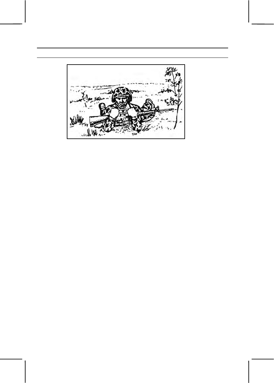
3-170 071-326-0502
Performance Steps
Figure 071-326-0502-2. High crawl
a. Keep your body off the ground
b. Rest your weight on your forearms and lower legs.
c. Cradle your weapon in your arms, keeping its muzzle off the
ground.
d. Keep your knees well behind your buttocks so it stays low.
e. Move forward by alternately advancing your right elbow and left
knee, and left elbow and right knee.
5. Use the low crawl (figure 071-326-0502-3).
a. Keep your body as flat as possible to the ground.
b. Hold your weapon by grasping the sling at the upper sling swivel,
letting the handguard rest on your forearm and the butt of the weapon drag
on the ground, thus keeping the muzzle off the ground.
c. Move forward by—
(1) Pushing both arms forward while pulling your right leg forward.
(2) Pulling with both arms while pushing with your right leg.
(3) Continuing this push-pull movement until you reach your next
position, changing your pushing leg frequently to avoid fatigue.
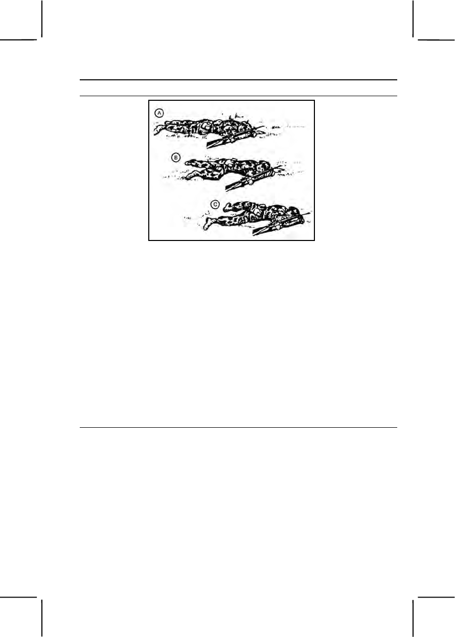
071-326-0502 3-171
Performance Steps
Figure 071-326-0502-3. Low crawl
6. Use the rush to move from one covered position to another when
enemy fire allows brief exposure (figure 071-326-0502-4).
a. Move from your firing position by rolling or crawling.
b. Start from the prone position.
c. Select your next position by slowly raising your head.
d. Lower your head while drawing your arms into your body, keeping
your elbows down, and pulling your right leg forward.
e. Raise your body in one movement by straightening your arms.
f. Spring to your feet, stepping off with either foot.
g. Run to the next position--
(1) Keeping the distance short to avoid accurate enemy fire.
(2) Trying not to stay up any longer than 3 to 5 seconds so that the
enemy does not have time to track you with automatic fire.
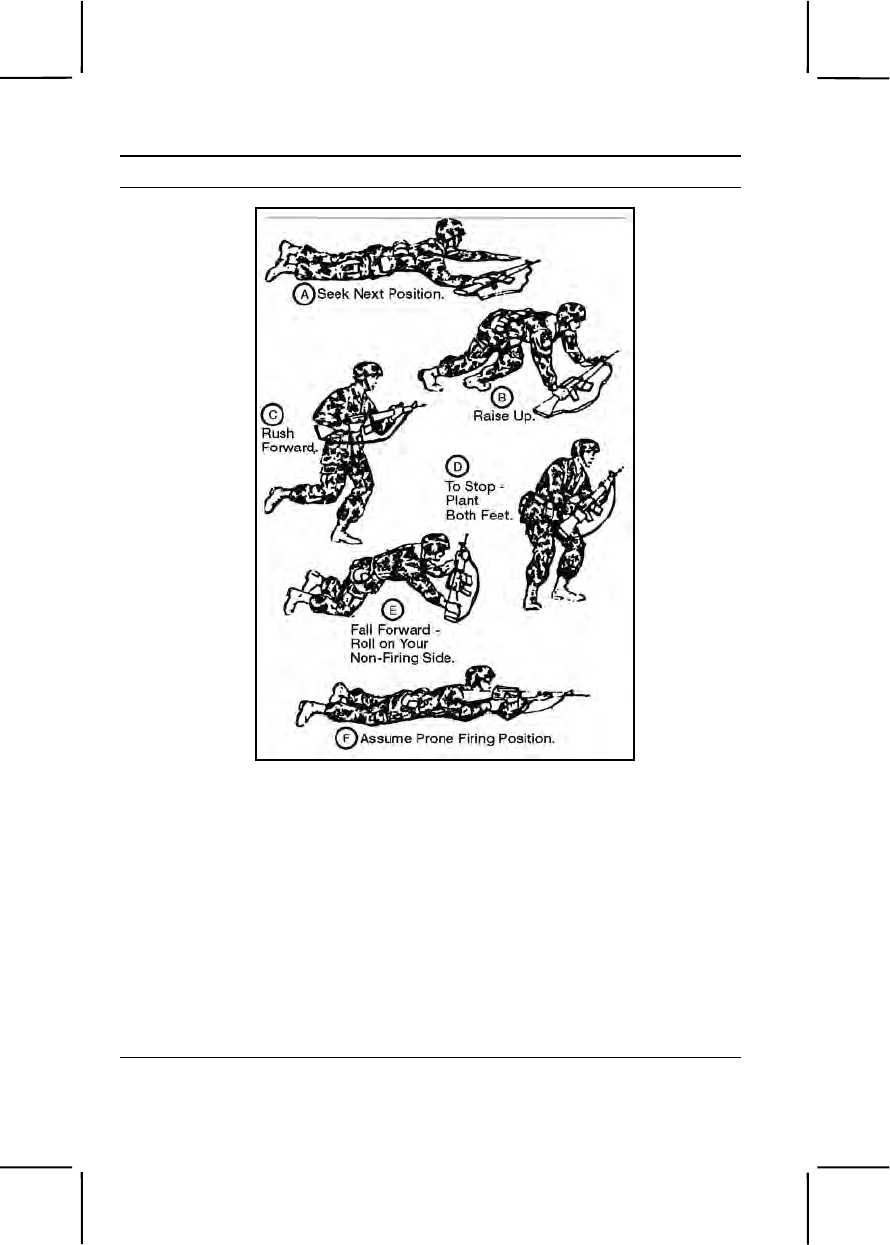
3-172 071-326-0502
Performance Steps
Figure 071-326-0502-4. Rush
h. Plant both feet just before hitting the ground.
i. Fall forward by:
(1) Sliding your right hand down to the heel of the butt of your
weapon.
(2) Breaking your fall with the butt of your weapon.
j. Assume a firing position.
(1) Roll on your side.
(2) Place the butt of your weapon in the hollow of your shoulder.
(3) Roll or crawl to a covered or concealed firing position.
7. Cover your buddy's movement with fire.

071-326-0502 3-173
Evaluation Preparation:
Setup: Take soldiers on a simulated march or field exercise in battle dress
with LCE and weapons. Select an area with varying cover types and heights.
Select a site about 300 meters away to serve as an enemy position. Point
out the site to the soldiers. Pair up soldiers being tested.
Brief Soldier: Tell the soldiers to pretend they are under direct fire. Tell them
to move from their present position to within 100 meters of the enemy
position using the buddy system. Tell the soldiers to use the appropriate
movement technique employing performance measures 4, 5, and 6 as
appropriate for the scenario and terrain. It may not be appropriate for each
soldier to use all three techniques.
Performance Measures GO NO GO
1. Selected an individual movement route within the
team or squad route or axis of advance that provided
cover or concealment such as: —— ——
a. A gully, ravine, ditch, or wall at a slight angle to
the direction of movement.
b. Hedgerows or a line of thick vegetation.
c. Large trees, rocks, stumps, fallen timber, rubble,
vehicle hulks, folds or creases in the ground.
d. High grass or weeds.
2. Selected the next position (and the route to it) as one
that— —— ——
a. Exposed you to the least enemy fire.
b. Did not require you to cross in front of other
members of your element, masking their fires.
3. Determined the correct movement technique. —— ——
a. Selected the high crawl when--
(1) The route provided cover and concealment.
(2) Poor visibility reduced enemy observation.
(3) Speed was required but the terrain and
vegetation was suitable only for the low crawl.
b. Selected the low crawl when—
(1) The route provided cover or concealment less
than 1 foot high.
(2) Visibility provided the enemy good
observation.

3-174 071-326-0502
Performance Measures GO NO GO
(3) Speed was not required.
c. Selected the rush when—
(1) Crossing open areas.
(2) Time was critical.
4. Communicated movement plan using hand signals
so that the soldier not moving could cover by fire any
movement by the other soldier. —— ——
5. Used the high crawl. —— ——
a. Kept body off the ground.
b. Rested weight on forearms and lower legs.
c. Cradled weapon in, keeping its muzzle off the
ground.
d. Kept knees well behind buttocks.
e. Moved forward by alternately advancing right
elbow and left knee, and left elbow and right knee.
6. Used the low crawl. —— ——
a. Kept body as flat as possible to the ground.
b. Held weapon by grasping the sling at the upper
sling swivel, letting the handguard rest on forearm and
the butt of the weapon drag on the ground, thus keeping
the muzzle off the ground.
c. Moved forward by—
(1) Pushed both arms forward while pulling right
leg forward.
(2) Pulled with both arms while pushing with right
leg.
(3) Continued push-pull movement until reaching
next position; changed pushing leg frequently to avoid
fatigue.
7. Used the rush to move from one covered position to
another. —— ——
a. Moved from firing position by rolling or crawling.
b. Started from the prone position.
c. Selected next position by slowly raising head.

071-326-0502 3-175
Performance Measures GO NO GO
d. Lowered head while drawing arms in, keeping
elbows down, and pulling right leg forward.
e. Raised body in one movement by straightening
arms.
f. Sprang to feet, stepping off with either foot.
g. Ran to the next position--
(1) Kept the distance short.
(2) Did not stay up any longer than 3 to 5
seconds.
h. Planted both feet just before hitting the ground.
i. Fell forward by–
(1) Sliding right hand down to the heel of the butt
of weapon.
(2) Breaking fall with the butt of the weapon.
j. Assumed a firing position.
(1) Rolled on side.
(2) Placed the butt of the weapon in the hollow of
shoulder.
(3) Rolled or crawled to a covered or concealed
firing position.
8. Covered buddy's movement with fire. —— ——
Evaluation Guidance: Score the soldier GO if all performance measures
are passed. The soldier should perform performance measures 4, 5, and 6
as appropriate for the scenario and terrain. Score the soldier NO GO if any
performance measure is failed. If the soldier scores NO GO, show him what
was done wrong and how to do it correctly.
References
Required Related
FM 21-75

3-176 071-326-0503
071-326-0503
Move Over, Through, or Around Obstacles (Except Minefields)
Conditions: Given individual weapon, load carrying equipment (LCE), one
smoke grenade, wood or grass mats or chicken wire, a grappling hook,
wrapping material, wire cutters (optional) and a buddy. During daylight or
darkness, you are at a field location, moving over a route with natural and
man-made crossings and obstacles (walls and barbed wire entanglements).
Standards: Approached within 100 meters of a suspected enemy position
over a specified route. Negotiated each obstacle within the time designated
while retaining all equipment without becoming a casualty to a booby trap or
early warning device.
Performance Steps
1. Cover your advance using smoke when crossing an obstacle. (Task
071-325-4407, Employ Hand Grenades.)
2. Ensure your buddy is covering you since obstacles are normally
covered by either fire or observation.
3. Cross barbed wire obstacles.
WARNING
It is threat doctrine to attach tripwire-activated mines to barbed wire.
a. Check barbed wire for booby traps or early warning devices.
(1) Look for booby traps or early warning devices attached to the
barbed wire.
(2) Throw a grappling hook with a length of rope attached over the
barbed wire.
(3) Pull the rope to set off any booby traps or early warning
devices.
b. Cross over barbed wire using wood, grass mats, or some chicken
wire to protect you from the barbs.
(1) Throw the wood, mat, or chicken wire over the barbed wire.
(2) Cross carefully because such a mat or net forms an unstable
path.
c. Cross under barbed wire.
(1) Slide headfirst on your back under the bottom strands.
(2) Push yourself forward with your shoulders and heels, carrying
your weapon lengthwise on your body, and holding the barbed wire with
one hand while moving.

071-326-0503 3-177
Performance Steps
(3) Let the barbed wire slide on the weapon to keep wire from
catching on clothing and equipment.
d. Cut your way through barbed wire.
(1) Leave the top wire in place to make it less likely that the enemy
will discover the gap.
(2) Wrap cloth around the barbed wire between your hands.
(3) Cut partly through the barbed wire.
(4) Bend the barbed wire back and forth quietly until it separates.
(5) Cut only the lower strands.
4. Cross exposed danger areas such as roads, trails, or small streams.
a. Select a point at or near a bend in the road or stream. If possible,
select a bend that has cover and concealment on both sides.
b. Crawl up to the edge of the open area.
c. Observe the other side carefully before crossing.
d. Move rapidly but quietly across the exposed area.
e. Take cover on the other side.
f. Check the area around you.
5. Cross over a wall.
a. Roll quickly over the top.
b. Do not go over standing upright.
6. Cover your buddy as he crosses the obstacle.
Evaluation Preparation: Setup: Select a field location that has crossings,
walls, and barbed wire entanglements. Designate a suspected opposing
forces position and point it out to the soldiers. Establish a standard by timing
yourself and an assistant as you run the course twice. Average times and
add 10 percent as maximum time for soldiers.
Brief Soldier: Tell soldiers they are going to be evaluated on how they
move over, through, and around the obstacles while attempting to get within
100 meters of an enemy position. Tell them they must negotiate at least one
of each type obstacle: exposed danger areas, barbed wire, and a wall. Tell
them they must run the course within the standard.
Performance Measures GO NO GO
1. Covered your advance using smoke. —— ——
2. Ensured buddy was covering you. —— ——

3-178 071-326-0503
Performance Measures GO NO GO
3. Crossed barbed wire obstacles. —— ——
a. Checked barbed wire for booby traps or early
warning devices.
(1) Looked for booby traps or early warning
devices attached to the barbed wire.
(2) Threw a grappling hook with a length of rope
attached over the barbed wire.
(3) Pulled the rope to set off any booby traps or
early warning devices.
b. Crossed over barbed wire using wood, grass
mats, or some chicken wire.
(1) Threw the wood, mat, or chicken wire over
the barbed wire.
(2) Crossed carefully because such a mat or net
forms an unstable path.
c. Crossed under barbed wire.
(1) Slid headfirst on back under the bottom
strands.
(2) Pushed forward with shoulders and heels,
carrying weapon lengthwise on body and holding the
barbed wire with one hand while moving.
(3) Let the barbed wire slide on the weapon so
that the wire did not catch on clothing and equipment.
d. Cut through barbed wire.
(1) Left the top wire in place.
(2) Wrapped cloth around the barbed wire
between hands.
(3) Cut partly through the barbed wire.
(4) Bent the barbed wire quietly until it separated.
(5) Cut only the lower strands.
4. Crossed exposed danger areas such as roads, trails,
or small streams. —— ——
a. Selected a point at or near a bend in the road or
stream that had cover and concealment on both sides.
b. Crawled up to the edge of the open area.
c. Observed the other side carefully before crossing.

071-326-0510 3-179
Performance Measures GO NO GO
d. Moved rapidly but quietly across the exposed
area.
e. Took cover on the other side.
f. Checked the surrounding area.
5. Crossed over a wall. —— ——
a. Rolled quickly over the top.
b. Did not go over standing upright.
6. Covered buddy as he crossed the obstacle. —— ——
Evaluation Guidance: Score the soldier GO if all performance measures
are passed. Score the soldier NO GO if any performance measure is failed.
If the soldier scores NO GO, show him what was done wrong and how to do
it correctly.
References
Required Related
FM 21-75
071-326-0510
React to Indirect Fire While Dismounted
Conditions: You are a member (without leadership responsibilities) of a
squad or team. You are either in a defensive position or moving on foot. You
hear incoming rounds, shells exploding or passing overhead, or someone
shouting "incoming."
Standards: Reacted to each situation by shouting "Incoming," followed the
leader's directions, if available. Took or maintained cover.
Performance Steps
1. Shout "incoming" in a loud, easily recognizable voice.
2. Look to your leader for additional instructions.
3. Remain in your defensive position (if appropriate), making no
unnecessary movements that could alert the enemy to your location.
4. Take cover outside the impact area (if you are in an exposed position
or moving), keeping the body low if the leader is not in sight.
Evaluation Preparation:
Setup: Take the soldiers on a simulated march or field exercise.

3-180 071-326-0511
Brief Soldier: Tell the soldiers they must react to indirect fire on the move
and when in a fixed position, when they receive the command "Incoming!"
Performance Measures GO NO GO
1. Shouted "incoming" in a loud, easily recognizable
voice. —— ——
2. Looked to leader for additional instructions. —— ——
3. Remained in defensive position (if appropriate),
making no unnecessary movements that could alert the
enemy to your location. —— ——
4. Took cover outside the impact area (if you were in an
exposed position or moving), keeping the body low if the
leader was not in sight. —— ——
Evaluation Guidance: Score the soldier GO if all performance measures
are passed. Score the soldier NO GO if any performance measure is failed.
If the soldier scores NO GO, show him what was done wrong and how to do
it correctly.
References
Required Related
FM 21-75
071-326-0511
React to Flares
Conditions: Given a tactical situation at night, upon hearing a flare rising or
when suddenly illuminated by a ground or overhead flare.
Standards: Reacted to a ground or an overhead flare without being seen by
the enemy or losing night vision.
Performance Steps
1. Respond to ground flares.
a. Move out of the illuminated area.
b. Reorient yourself when alone or in a group by SOP, or as
instructed.
c. Continue the mission.
2. Respond to an overhead flare with warning (for example, the sound of
a rising flare).

071-326-0511 3-181
Performance Steps
a. Assume the prone position (behind concealment when available)
before the flare bursts.
b. Protect your night vision by closing one eye and observing with the
other.
c. Use your night vision eye to reorient yourself or rejoin your group
when the flare burns out.
d. Continue the mission.
3. Respond to an overhead flare without warning.
a. Assume the prone position behind concealment (when available)
until the flare burns out.
b. Protect your night vision by closing one eye and observing with the
other.
c. Crouch low until the flare burns out when crossing wire obstacles
where the prone position is not possible.
d. Use your night vision eye to reorient yourself or rejoin your group
when the flare burns out.
e. Continue the mission.
Evaluation Preparation: Setup: Have ground flares set so that you can
ignite them. Have hand-held flares to use to simulate the overhead flares.
Brief Soldier: Tell the soldier that he is to react to the flares as they appear.
After grading the soldier on the ground flare and the overhead flare with
warning, tell him that the next flare should be acted on only after the flare
has burst (simulate "without warning").
Performance Measures GO NO GO
1. Responded to a ground flare. —— ——
a. Moved out of the illuminated area.
b. Reoriented alone or in a group.
c. Continued the mission.
2. Responded to an overhead flare with warning. —— ——
a. Assumed the prone position before the flare
burst.
b. Protected night vision by closing one eye and
observing with the other eye.
c. Reoriented or rejoined group when the flare
burned out.

3-182 071-326-0513
Performance Measures GO NO GO
d. Continued the mission.
3. Responded to an overhead flare without warning. —— ——
a. Assumed the prone position until the flare burned
out.
b. Protected night vision by closing one eye and
observing with the other eye.
c. Crouched low until the flare burned out when
crossing wire obstacles when the prone position was not
possible.
d. Used night vision eye to reorient or rejoin group
when the flare burned out.
e. Continued the mission.
Evaluation Guidance: Score the soldier GO if all performance measures
are passed. Score the soldier NO GO if any performance measure is failed.
If the soldier scores NO GO, show him what was done wrong and how to do
it correctly.
References
Required Related
FM 21-75
071-326-0513
Select Temporary Fighting Positions
Conditions: You must select a temporary fighting position when at an
overwatch position, after initial movement into a tentative defensive position,
at a halt during movement, or upon receiving direct fire.
Standards: Selected a firing position that protected you from enemy
observation and fire, and allowed you to place effective fire on enemy
positions without exposing most of your head and body.
Performance Steps
1. Choose a position that takes advantage of available cover and
concealment (figure 071-326-0513-1).
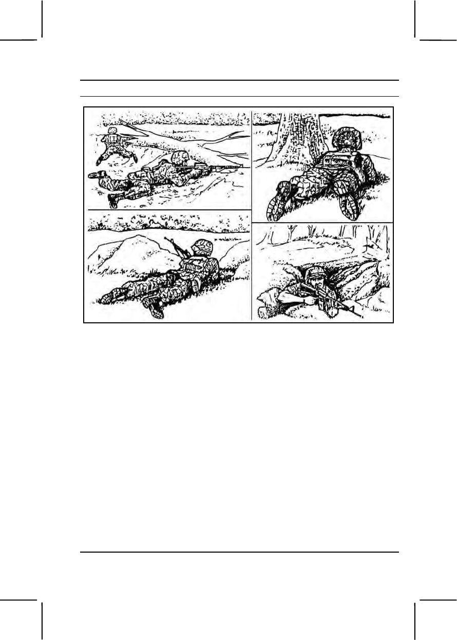
071-326-0513 3-183
Performance Steps
Figure 071-326-0513-1. Temporary fighting positions
Note. Cover gives protection from bullets, fragments of exploding rounds, flame,
nuclear effects, and biological and chemical agents. Cover can also conceal you
from enemy observation. Cover can be natural or man-made. Concealment is
anything that hides you from enemy observation. Concealment DOES NOT protect
you from enemy fire. DO NOT think that you are protected from the enemy's fire just
because you are concealed. Concealment, like cover, can also be natural or man-
made.
2. Choose a position that allows you to observe and fire around the side
of an object while concealing most of your head and body.
3. Choose a position that allows you to stay low when observing and
firing, whenever possible.
Note. This position allows you to aim better and take advantage of concealing
vegetation.
4. Choose a position with a background that does not silhouette you
against the surrounding environment.
Note. A position like this reduces your chances of being detected.
5. Follow your leader's directions after your initial selection of a temporary
battlefield position.

3-184 071-326-3002
Performance Steps
Note. Your leader may reposition you to gain better coverage of the area.
Evaluation Preparation: Setup: Evaluate this task during a march or a
simulated march in an area with varying degrees of cover and concealment.
Have the soldiers in full battle gear.
Brief Soldier: Tell each soldier the enemy has been reported in the area and
may be encountered at any time. At preselected points during the march, at
a rest halt, after ordering the soldier to take an overwatch position, or after
ordering the soldier to take a tentative defensive position, have him select a
temporary fighting position.
Performance Measures GO NO GO
1. Chose a position that took advantage of available
cover and concealment. —— ——
2. Chose a position that allowed for observation and fire
around the side of an object while concealing most of
head and body. —— ——
3. Chose a position that allowed you to stay low when
observing and firing, whenever possible. —— ——
4. Chose a position with a background that did not
silhouette you against the surrounding environment. —— ——
5. Followed leader's directions after initial selection of a
temporary battlefield position. —— ——
Evaluation Guidance: Score the soldier GO if all performance measures
are passed. Score the soldier NO GO if any performance measure is failed.
If the soldier scores NO GO, show him what was done wrong and how to do
it correctly.
References
Required Related
FM 21-75
071-326-3002
React to Indirect Fire While Mounted
Conditions: In a combat environment, given a combat-loaded tracked
vehicle.
Standards: Reacted to indirect fire by moving the vehicle from the impact
area, then continued the mission.

071-326-5703 3-185
Performance Steps
1. Give an order to close all hatches.
2. Direct movement away from the impact area.
3. Analyze the situation.
4. Give a situation report.
5. Continue the mission.
Evaluation Preparation: Setup: At the test site, provide all equipment and
materials listed in task conditions statement. Use only dummy ammunition
for training purposes. Take soldiers on a simulated march.
Brief Soldier: Tell the soldiers they must react to a simulated indirect fire
mortar or artillery fire while mounted in a tracked vehicle.
Performance Measures GO NO GO
1. Gave an order to close all hatches. —— ——
2. Directed movement away from the impact area. —— ——
3. Analyzed the situation. —— ——
4. Gave a situation report. —— ——
5. Continued the mission. —— ——
Evaluation Guidance: Score the soldier GO if all performance measures
are passed. Score the soldier NO GO if any performance measure is failed.
If the soldier fails any performance measure, show what was done wrong
and how to do it correctly.
References
Required Related
FM 7-7
FM 3-21.71
071-326-5703
Construct Individual Fighting Positions
Conditions: Given load-carrying equipment (LCE) with bayonet, scabbard,
entrenching tool, poncho, and M16A1 rifle, a specific location and sector of
fire, and logs construct an individual fighting position.
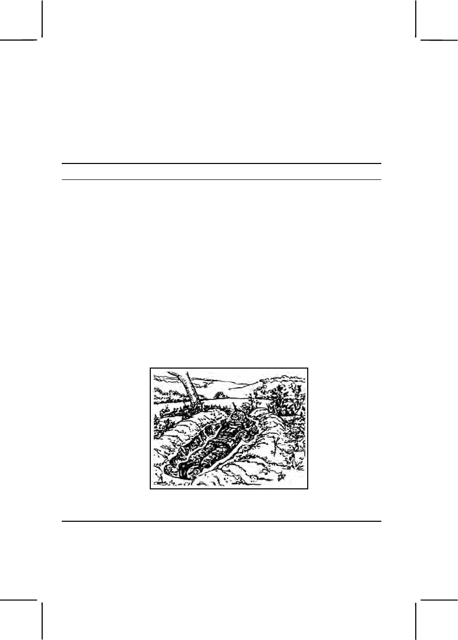
3-186 071-326-5703
Standards: Constructed a hasty fighting position that gave frontal cover
from enemy direct fire but allowed you to fire to the front and oblique.
Constructed a one-man fighting position with the following characteristics:
• Wide enough for you and your equipment.
• Armpit deep with frontal and overhead cover at least 18 inches deep.
• Had grenade sumps and a floor sloped toward the sumps.
• Allowed you to place fire on your assigned sector.
Performance Steps
Note: When you first move into battle, there may be little or no time to prepare a
position.
1. Prepare a hasty fighting position.
a. Select a hasty fighting position that—
(1) Is behind whatever cover is available.
(2) Provides frontal protection.
(3) Allows you to shoot to the front and at an oblique angle.
(4) Is in a small depression or a hole that is at least half a meter (18
inches) deep.
Note. The term "hasty position" does not mean there is no digging.
b. Improve your position with whatever time is available by digging or
scraping out a prone shelter that will give you some protection (figure 071-
326-5703-1).
Figure 071-326-5703-1. Hasty fighting position
2. Prepare a one-man fighting position (figure 071-326-5703-2).

071-326-5703 3-187
Performance Steps
Figure 071-326-5703-2. One-man fighting position
Note. This type of position allows flexibility in the use of cover. The hole only has to
be long enough for you and your equipment. You must be able to shoot to both the
front and oblique from behind frontal cover. It does not provide the security a two-
man position does.
a. Obtain position location and sector of fire from your leader.
b. Put in sector-of-fire stakes.
c. Partially clear a field of fire within your sector.
d. Dig a hasty hole for minimum protection, being careful not to
destroy natural camouflage around your position.
e. Save grass clumps for use as camouflage later.
Note. At this stage of construction, you should be able to fight effectively from the
position if there is a surprise attack.
f. Dig in, shaping the hole to fit the natural cover available.
Note. Depending on the size and shape of the frontal cover, you may not be able to
dig a rectangular hole.
(1) Make the hole armpit deep (figure 071-326-5703-3).
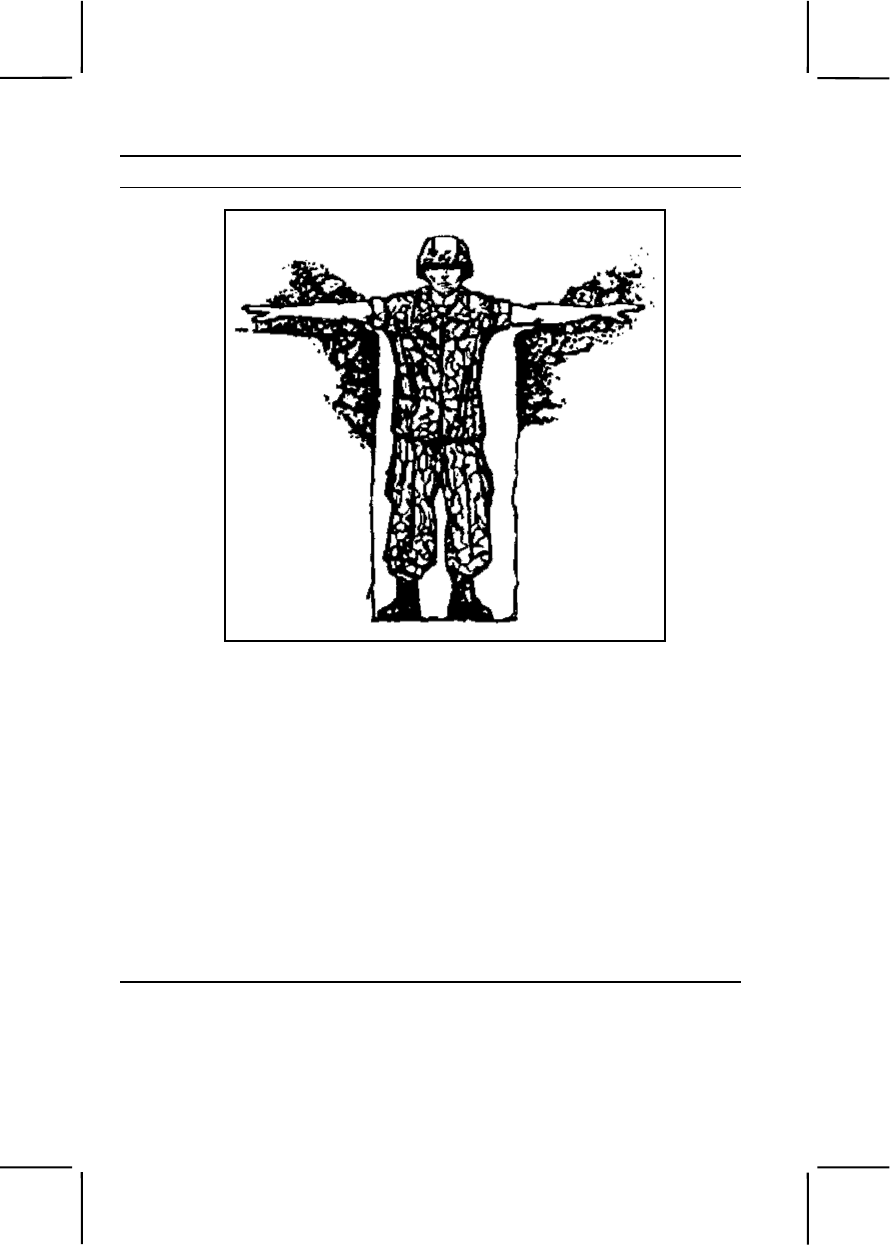
3-188 071-326-5703
Performance Steps
Figure 071-326-5703-3. Fighting position armpit deep
Note. Frontal cover is important so you can shoot without exposing your head to
enemy fire. Ideally, you will have a natural parapet, such as a tree, mound, rock, or
stump that will blend with the surrounding terrain available for frontal cover.
(2) Use the dirt from your hole to build a parapet that--
(a) Provides frontal cover with at least 45 centimeters (18
inches) of earth between you and the enemy if a natural parapet is not
available.
(b) Is high enough to cover your head.
(c) Is far enough in front of the hole to allow for elbow rests
and sector stakes.
(3) Modify your position on steep terrain by digging out firing ports
at each end of the hole so the ground between the firing ports serves as
frontal cover for the position (figure 071-326-5703-4).
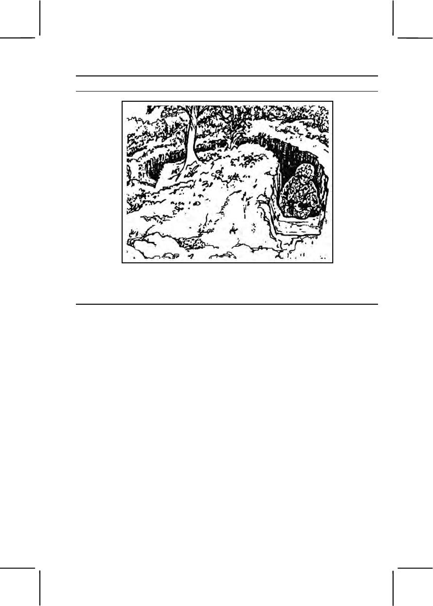
071-326-5703 3-189
Performance Steps
Figure 071-326-5703-4. Fighting position on slope
Note. On a steep slope, a soldier in a hole behind frontal cover cannot shoot
attackers without being exposed to enemy fire.
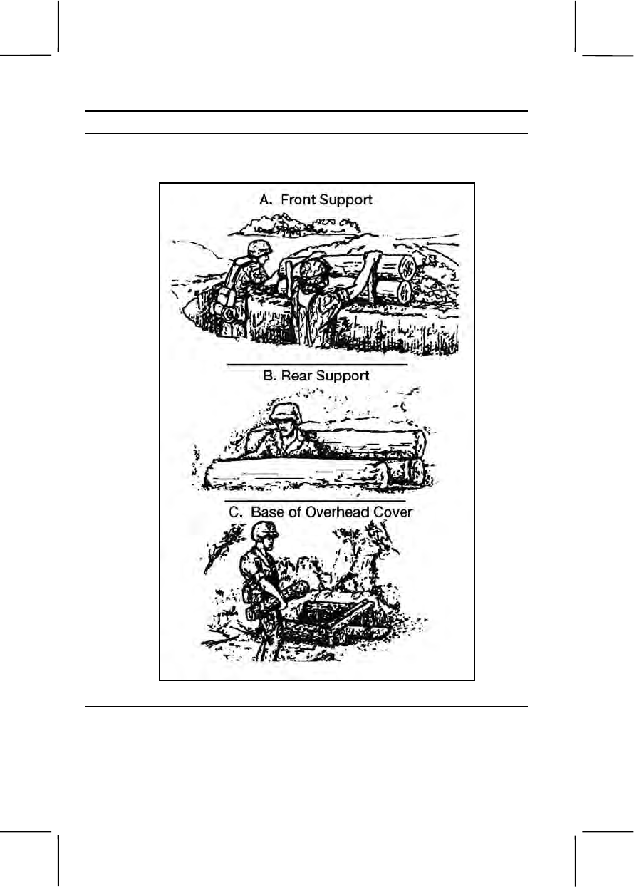
3-190 071-326-5703
Performance Steps
g. Save remaining dirt for use as flank, overhead, and rear cover later
(figure 071-326-5703-5 and figure 071-326-5703-6).
Figure 071-326-5703-5. Constructing overhead cover (1)
071-326-5703 3-191
Performance Steps
Figure 071-326-5703-6. Constructing overhead cover (2)
h. Dispose of excess dirt.
(1) Carry dirt away from your position.
(2) Camouflage excess dirt.
i. Dig two trench-shaped grenade sumps (figure 071-326-5703-7).
3-192 071-326-5703
Performance Steps
Figure 071-326-5703-7. Two trench-shaped grenade sumps
(1) Place one at each end of the position.
(2) Make the trenches as wide as an entrenching tool blade, as
deep as the entrenching tool, and as long as the position is wide.
j. Slope the floor toward the sumps (figure 071-326-5703-7).
Note. The slope should be steep enough so a grenade thrown into the position will
roll into one of the sumps.
3. Complete clearing the field of fire (see Task 071-331-0852).
a. Clear only what is absolutely necessary.
b. Check the observation and field of fire from inside the position.
4. Save any cut foliage, dirt, or grass clumps to camouflage your position.
5. Construct the fighting position overhead cover that provides the best
possible protection from airbursts while allowing you to fight from
underneath it.
a. Use logs 10 to 15 centimeters (4 to 6 inches) thick for the supports,
base, and top.
b. Construct front and rear supports that are the same height as the
terrain.
c. Cover logs with at least 45 centimeters (18 inches) of dirt.
6. Construct flank overhead cover when frontal overhead cover would
significantly increase the silhouette of the position, making it vulnerable to
detection (figure 071-326-5703-8).
071-326-5703 3-193
Performance Steps
Figure 071-326-5703-8. Flank overhead cover
7. Camouflage your position using available materials (grass clumps,
foliage) to make your position blend into surroundings.
8. Check the camouflage by moving 35 meters to the front; if you can spot
it easily, you need more work on camouflage.
Evaluation Preparation:
Setup: Select an area of terrain with varying features such as fences,
hedgerows, rocks, trees, and ravines.
Brief Soldier: Tell soldier the approximate location of enemy positions. Order
the soldier to construct a hasty fighting position and an improved fighting
position.
Performance Measures GO NO GO
1. Prepared a hasty fighting position that— —— ——
a. Was behind whatever cover was available.
b. Provided frontal protection.
c. Allowed you to shoot to the front and at an
oblique angle.
d. Was in a small depression or a hole at least half a
meter (18 inches) deep.
2. Prepared a one-man fighting position that— —— ——

3-194 071-326-5703
Performance Measures GO NO GO
a. Had sector-of-fire stakes.
b. Was dug in a shape that fits the natural cover
available.
c. Was armpit deep.
d. Had a parapet that—
(1) Provided frontal cover with at least 45
centimeters (18 inches) of earth between you and the
enemy, if a natural parapet was not available.
(2) Was high enough to cover your head.
(3) Was far enough in front of the hole to allow
for elbow rests and sector stakes.
(4) Was modified on steep terrain by digging out
firing ports at each end of the hole so the ground
between the firing ports served as frontal cover for the
position.
3. Disposed of excess dirt. —— ——
a. Carried dirt away from your position.
b. Camouflaged excess dirt.
4. Dug two trench-shaped grenade sumps. —— ——
a. Placed one at each end of the position.
b. Made the trenches as wide as an entrenching tool
blade, as deep as the entrenching tool, and as long as
the position was wide.
5. Sloped the floor toward the sumps. —— ——
6. Completed clearing the field of fire: —— ——
a. Cleared only what was absolutely necessary.
b. Checked the observation and field of fire from
inside the position.
7. Constructed the fighting position overhead cover that
provided the best possible protection from airbursts while
allowing you to fight from underneath it. —— ——
a. Used 4- to 6-inch logs for supports, base, and top
of cover.
b. Covered logs with at least 18 inches of dirt.

071-331-0815 3-195
Performance Measures GO NO GO
8. Constructed flank overhead cover when frontal
overhead cover would significantly increase the
silhouette of the position, making it vulnerable to
detection.
—— ——
9. Camouflaged position using available materials so it
was not visible from 35 meters to the front. —— ——
Evaluation Guidance: Score the soldier GO if all performance measures
are passed. Score the soldier NO GO if any performance measure is failed.
If the soldier scores NO GO, show him what was done wrong and how to do
it correctly.
References
Required Related
FM 7-8
071-331-0815
Practice Noise, Light, and Litter Discipline
Conditions: You are a member of an element conducting a tactical mission.
Standards: Ensured that noise was kept at a minimum; no light was visible
to the enemy; the area was free of litter and other evidence of the unit's
presence.
Performance Steps
1. Comply with noise discipline.
a. Avoid all unnecessary vehicular and foot movement.
b. Secure (with tape or other materials) metal parts (for example,
weapon slings, canteen cups, identification tags) to prevent them from
making noise during movement.
c. Do not restrict moving parts of weapons if doing so prevents their
operation.
d. Talk only to conduct or explain operations.
e. Use radios only when necessary, keeping the volume low so only
you can hear it.
2. Comply with light discipline.
a. Do not smoke except when concealed from enemy view.

3-196 071-331-0815
Performance Steps
Note. Smoking at night should be restricted, as the enemy can see and smell the
smoke.
b. Conceal flashlights and other light sources so the light is filtered (for
example, under a poncho).
c. Cover anything that reflects light (for example, metal surfaces,
vehicles, glass).
d. Use all available natural concealment.
e. Camouflage all vehicles and equipment.
3. Comply with litter discipline.
a. Take all litter (empty food containers, empty ammunition cans or
boxes, old camouflage) to established collection points.
b. Carry all litter with you until you can dispose of it without leaving
any trace.
Evaluation Preparation:
Setup: Schedule this exercise in conjunction with field maneuvers or field
exercises or use defensive positions.
Performance Measures GO NO GO
1. Complied with noise discipline. —— ——
a. Avoided all unnecessary vehicular and foot
movement.
b. Secured metal parts, preventing them from
making noise during movement.
c. Did not restrict moving parts of secured weapons,
preventing operation.
d. Talked only to conduct or explain operations.
e. Used radios only when necessary, kept the
volume low so only you could hear it.
2. Complied with light discipline. —— ——
a. Smoked only when concealed from enemy view.
b. Concealed flashlights and other light sources so
the light was filtered.
c. Covered anything that reflected light.
d. Used all available natural concealment.
e. Camouflaged all vehicles and equipment.

071-331-1004 3-197
Performance Measures GO NO GO
3. Complied with litter discipline. —— ——
a. Took all litter to established collection points.
b. Carried all litter until it could be disposed of
without leaving any trace.
Evaluation Guidance: Score the soldier GO if all performance measures
are passed. Score the soldier NO GO if any performance measure is failed.
If the soldier scores NO GO, show him what was done wrong and how to do
it correctly.
References
Required
FM 7-8
071-331-1004
Perform Duty as a Guard
Conditions: Assigned a guard post, post-specific equipment, and special
orders.
Standards: Performed duty according to general orders, special orders, and
local implementing SOPs.
Performance Steps
1. Receive order changes, if any.
2. Walk posts or assume the prescribed position, carrying the weapon in
prescribed manner.
3. Salute officers when performing guard duty on posts that do not require
challenging.
4. Challenge personnel as specified by special orders. Challenge position
is port arms or raised pistol.
a. Challenge one person by assuming challenge position
approximately 30 steps from individual and stating "HALT." Once the
individual has halted, call "WHO IS THERE”? The guard may change
position to best determine if the individual should be passed, denied
access, or apprehended and turned over to the commander of the relief.
Take the appropriate action based on identification of the person.

3-198 071-331-1004
Performance Steps
b. Challenge a group in the same manner. Allow only one person to
approach for identification. If persons are in a vehicle allow only one
person to approach for identification.
c. Challenge multiple groups or individuals. Advance personnel to be
recognized in the same manner; only one at a time and in order of
seniority.
Note. During a duty tour, a guard is required to execute orders ONLY from the
commanding officer, the field officer of the day, the officer of the day and officers of
the guard. A guard surrenders his weapon only to, and upon orders from, someone
from whom he lawfully receives orders while on post.
5. Pass changes to orders to relief.
Evaluation Preparation:
Setup: At the test site, provide the soldier with a post, post-specific
equipment, and special orders. Provide a group to approach the post.
Brief Soldier: Tell the soldier to read the special orders and assume the
sentry duties of the post.
Performance Measures GO NO GO
1. Received order changes. —— ——
2. Saluted officer when required. (Post does not require
challenging.) —— ——
3. Challenged individual. —— ——
4. Challenged group. —— ——
5. Passed the order changes to the relief. —— ——
Evaluation Guidance: Score the soldier GO if all performance measures
are passed. Score the soldier NO GO if any performance measure is failed.
If the soldier scores NO GO, show him what was done wrong and how to do
it correctly.
References
Required Related
FM 22-6

071-410-0002 3-199
071-410-0002
React to Direct Fire While Mounted
Conditions: In a combat environment, given tracked vehicle and a
requirement to react to direct fire.
Standards: The vehicle returned fire and took appropriate action after
analysis of the situation based on an order received from the chain of
command.
Performance Steps
Note. If the vehicle is in formation, it moves according to company tactical SOP. If
not, it should use evasive action as appropriate to avoid threat fire while performing
step 2.
1. Direct return fire to destroy or suppress threat fire.
Note. If threat is destroyed, continue the present mission.
2. Direct the driver to a hull-down position.
Note. Direct dismount, if appropriate, to establish a base of fire.
3. Analyze the situation.
4. Give a situation report.
5. Take defensive or offensive action based on orders from chain of
command.
Evaluation Preparation:
Setup: At the test site, provide all equipment and materials listed in the task
conditions. Use only blank ammunition for training. Take the soldiers on a
simulated march.
Brief Soldier: Tell the soldiers they must react to simulated direct fire while
mounted in a tracked vehicle.
Performance Measures GO NO GO
1. Directed return fire to destroy or suppress threat fire. —— ——
2. Directed the driver to a hull-down position. —— ——
3. Analyzed the situation. —— ——
4. Gave a situation report. —— ——
5. Took defensive or offensive action based on orders
from the chain of command. —— ——

3-200 071-710-0006
Evaluation Guidance: Score the soldier GO if all performance measures
are passed. Score the soldier NO GO if any performance measure is failed.
If the soldier fails any performance measure, show what was done wrong
and how to do it correctly.
References
Required Related
FM 7-7
FM 3-21.71
071-710-0006
Plan Use of Night Vision Devices
Conditions: In a combat environment, given a platoon with a requirement to
plan for the use of night vision devices.
Standards: Made a plan that designated who would operate night vision
devices and what, where, and when they would do so.
Performance Steps
1. Analyze the platoon's mission.
2. Analyze the terrain.
3. Determine what operational (working properly) night vision devices the
platoon has on hand (assets available).
4. Consider the operating range of the platoon's reconnaissance,
surveillance, and target acquisition (RSTA) devices as well as how badly
inclement weather could limit those ranges.
5. If the platoon has Bradley fighting vehicles (BFVs) or similar vehicles,
develop and include a plan to rotate observation responsibilities between
vehicle crew members.
6. If the platoon has BFV(s) or similar vehicles, include a plan for
recharging the vehicle and equipment batteries during limited visibility
conditions.
7. Include in the plan the mounting of the night weapon sights on the
various weapon systems. State how the platoon will use them in both
surveillance and target acquisition role.
8. Discuss how the platoon will coordinate with other units to ensure
overlapping sectors of observation (if applicable).
9. Establish a procedure for implementing the platoon OPLAN.
10. Ensure the OPLAN is disseminated.

071-710-0006 3-201
Evaluation Preparation:
Setup: Provide the leader with equipment and RSTA assets.
Brief Soldier: Tell the soldier that soldiers using night vision devices lose
their visual efficiency after about 30 minutes. Therefore, to avoid eye fatigue,
the OPLAN should require that the soldier using the equipment rest after
each 30-minute shift, and after 1 ½ to 2 hours, observation duty rotates to
another soldier.
Performance Measures GO NO GO
1. Analyzed the platoon's mission. —— ——
2. Analyzed the terrain. —— ——
3. Determined what operational (properly working) night
vision devices the platoon had on hand. —— ——
4. Considered the operating range of the platoon's
RSTA devices as well as how badly inclement weather
could have limited those ranges. —— ——
5. If the platoon had BFVs or similar vehicles,
developed and included a plan to rotate observation
responsibilities between vehicle crew members. —— ——
6. If the platoon had BFVs or similar vehicles, included
a plan for recharging the vehicle and equipment batteries
during limited visibility conditions. —— ——
7. Included in the plan the mounting of the night
weapon sights on the various weapon systems. Stated
how the platoon would use them in both surveillance and
target acquisition roles.
—— ——
8. Discussed how the platoon would coordinate with
other units to ensure overlapping sectors of observation
(if applicable). —— ——
9. Established a procedure for implementing the platoon
OPLAN. —— ——
10. Ensured the OPLAN was disseminated. —— ——
Evaluation Guidance: Score the soldier GO if all performance measures
are passed. Score the soldier NO GO if any performance measure is failed.
If the soldier fails any performance measures, show what was done wrong
and how to do it correctly.

3-202 093-401-5040
References
Required Related
FM 3-21.71
093-401-5040
React to Unexploded Ordnance Hazards
Conditions: In a field environment, given an item(s) of simulated
unexploded ordnance (UXO), marking materials, and a UXO Spot Report
format.
Standards: Identified UXO by type and subgroup; recognized associated
hazards; took immediate action to prevent death, injury, or damage to
materiel; reported the UXO hazard using the UXO Spot Report format.
Performance Steps
1. Recognize the UXO hazard.
DANGER
Never approach a UXO once it has been identified. Approaching
UXO may cause them to explode.
DANGER
Never strike, jar, or touch a UXO. Do not move or remove
anything on or near a suspect UXO. UXO can be extremely
sensitive and can cause serious injury or death if disturbed in any
way.
DANGER
Many types of UXO may contain an incendiary (fire producing),
chemical, biological, or radiological hazard in addition to
explosives.

093-401-5040 3-203
Performance Steps
DANGER
Do not make radio transmissions within 100 meters of a UXO.
Some types of UXO are sensitive to electromagnetic radiation
(EMR) and may explode.
a. Identify the four types and subgroups of UXO.
(1) Dropped.
(a) Bombs (figure 093-401-5040-1):
–Vary from 3 to 6 feet in length.
–Vary in diameter from 5 to 36 inches.
–Often have a sloped or "bullet" shaped nose, fins and/or a
parachute on the back.
–May contain high explosive, incendiary, or chemical fillers.
(b) Dispensers (figure 093-401-5040-2):
–Contain numerous submunitions or bomblets.
–Most have the same characteristics of bombs.
–May be found intact or partially open.
3-204 093-401-5040
Performance Steps
Figure 093-401-5040-1. Bombs
093-401-5040 3-205
Performance Steps
Figure 093-401-5040-2. Dispensers
(c) Submunitions (figures 093-401-5040-3a through 093-401-
5040-3e):
DANGER
When a submunition is identified, leave the area by the same path
you entered. There may be many more submunitions in the same
area. Small size does not diminish the danger of submunitions.
The smallest can easily injure or kill.
–May contain the same hazards of bombs (explosive,
chemical, biological, radiological, incendiary).
–Are designed to be scattered over a wide area.
–Come in many shapes and sizes; may or may not be
3-206 093-401-5040
Performance Steps
"bullet" shaped.
–May look like balls, wedges, or cylinders.
–May have fins, ribbons, parachutes, or trip wires.
Figure 093-401-5040-3a.
Figure 093-401-5040-3b.
Figure 093-401-5040-3c.
093-401-5040 3-207
Performance Steps
Figure 093-401-5040-3d
Figure 093-401-5040-3e.
(2) Projected.
(a) Projectiles (figures 093-401-5040-4a through 093-401-
5040-4b): –Include munitions from large machine guns, artillery
howitzers, and naval guns.
–Range in size from 20mm up to 16 inches in diameter; 10
to 30 inches in length.
–Most resemble a "bullet" shape.
–Can contain explosive, chemical, biological, radiological,
and/or incendiary hazards.
3-208 093-401-5040
Performance Steps
Figure 093-401-5040-4a.
Figure 093-401-5040-4b.
(b) Mortars (figures 093-401-5040-5a through 093-401-5040-
5b): –Most have fins and a "bullet" shape.
–Range in size from 60mm to 120mm in diameter; 12
inches to 36 inches in length.
–Can contain explosive, chemical, or incendiary hazards.
Figure 093-401-5040-5a.
093-401-5040 3-209
Performance Steps
Figure 093-401-5040-5b.
(c) Rockets (figures 093-401-5040-6a through 093-401-5040-
6c): –May or may not have fins.
–Have some sort of rocket motor vents in back.
–Range in length from 24 inches to several feet.
–Can contain explosive, chemical, or incendiary hazards.
Figure 093-401-5040-6a.
3-210 093-401-5040
Performance Steps
Figure 093-401-5040-6b.
Figure 093-401-5040-6c.
(d) Guided Missiles (figure 093-401-5040-7a through 093-401-
5040-7b): –Most have fins.
–Some have wires in the end for guidance.
–Very similar to rockets.
–Can contain explosive or incendiary hazards.
093-401-5040 3-211
Performance Steps
Figure 093-401-5040-7a.
Figure 093-401-5040-7b.
(e) Rifle Grenades (figures 093-401-5040-8a through 093-401-
5040-8b): –Designed to be fired from rifles or shoulder fired
launchers.
–Resemble rockets but are smaller.
–Can contain explosive or incendiary hazards.
3-212 093-401-5040
Performance Steps
Figure 093-401-5040-8a.
Figure 093-401-5040-8b.
(3) Thrown (figures 093-401-5040-9a through 093-401-5040-9b):
–Includes all types of grenades, including simulators.
–Most are round or cylindrical.
–Are small enough to be thrown by a person.
–Can contain explosive or incendiary hazards.
–Dud simulators require the same safety procedures as other
ordnance.
093-401-5040 3-213
Performance Steps
Figure 093-401-5040-9a.
Figure 093-401-5040-9b.

3-214 093-401-5040
Performance Steps
DANGER
Never approach a grenade that was thrown and did not detonate,
even if you threw it. Do not move, jar, or disturb—the fuse may
function at any time.
Never pick up, move, or disturb a found grenade, even if spoon or
safety pin are attached. The grenade may be booby-trapped and
explode when disturbed.
(4) Placed (figures 093-401-5040-10a through 093-401-5040-10b):
–Includes all land or sea mines.
–Range in size from 2 inches in diameter to several feet in
length.
–Have a variety of fuse types; pressure plates, tilt rods, trip
wires, electronic sensors, or command detonated.
–Can contain explosive, incendiary, or chemical hazards.
Figure 093-401-5040-10a.
093-401-5040 3-215
Performance Steps
Figure 093-401-5040-10b.
DANGER
Consider all mines to be booby-trapped or to have anti-
disturbance fusing. Never attempt to uncover or remove placed
ordnance.

3-216 093-401-5040
2. React to the UXO hazard.
a. Do not touch or disturb the UXO or any wires, parachutes, or
anything attached or surrounding the UXO. Do not move closer to UXO.
b. If any peculiar smells, liquids, or dead animals are present,
chemical or biological agents may be present; don mask and MOPP gear
immediately.
c. Mark location with material such as white engineer tape, marking
ribbon, clothing, or sign. Place marker above ground at waist level if
possible. Take note of physical terrain features of location and route back
to UXO so EOD team can return and dispose of UXO.
d. Evacuate personnel and equipment from area surrounding the
UXO:
(1) Bombs, dispensers, large projected munitions (90-mm diameter
and larger)—evacuate a 360-degree perimeter at least 600 meters.
(2) Submunitions, placed, thrown, small projected munitions
(smaller than 90-mm diameter)—evacuate a 360-degree perimeter at least
300 meters.
e. If personnel or equipment cannot be evacuated, seek as much
frontal and overhead cover as possible.
f. If UXO is suspected to have a chemical agent, ensure all personnel
stay upwind of item and are in full MOPP.
3. Report the UXO hazard.
a. Report UXO hazard to your chain of command. You or your chain
of command should request Explosive Ordnance Disposal (EOD) support
using the nine-line UXO Spot Report:
(1) Date and time of the fall, impact, or finding of the UXO item(s).
(2) The exact location of item(s) including grid coordinate,
landmarks, reference points, or street addresses.
(3) The name and organization of person reporting the incident
including call sign or phone number.
(4) Identify UXO by type (Dropped, Projected, Thrown, Placed) and
subgroup.
(5) Any NBC contamination present.
(6) What resources are threatened?
(7) How the UXO has affected unit mission.
(8) The safety measures that have been taken including the
evacuation distances that have been accomplished.

093-401-5040 3-217
(9) The requested priority for receiving EOD support (Immediate,
Indirect, Minor, No Threat)
b. Be prepared to provide a guide to the EOD team.
Evaluation Preparation:
Setup: Do not evaluate this task using live UXO. Utilize training items from
your installation Training Aids Support Center. Preliminary instruction of this
task can be obtained by requesting support from nearest Army EOD
company. Evaluate this task during any training exercise where UXO is
likely to be encountered. Place UXO training aid near personnel, facilities,
or equipment within the soldier's area of responsibility. Soldier should
identify UXO from at least 5-10 meters away or through the use of
binoculars.
Brief Soldier: Tell the soldier he will be evaluated on his ability to properly
recognize, react to, and report a UXO hazard. The soldier will identify the
UXO by type and subgroup, take appropriate actions to react to the hazards,
and report the hazard using the nine-line UXO Spot Report format.
Performance Measures GO NO GO
1. Identified UXO by type and subgroup. —— ——
2. Reacted to UXO hazard, observing all applicable
safety precautions. —— ——
3. Marked the UXO. —— ——
4. Determined appropriate evacuation distance (Large
item: 600m; Small item: 300m). —— ——
5. Reported UXO hazard using the nine-line UXO Spot
Report. —— ——
Evaluation Guidance: Score the soldier GO if all performance measures
are performed correctly. Score the soldier NO GO if any performance
measure is not performed correctly. If the soldier scores NO GO, show him
what was done wrong and how to do it correctly.
References
Required Related
FM 21-16
GTA 9-12-1

3-218 551-88M-0005
551-88M-0005
Operate a Vehicle in a Convoy
Conditions: Given a briefing by the convoy commander, a vehicle with
before-operation maintenance performed, and a flashlight (night convoy),
weapon, and LCE/Kevlar. Task must be performed under the march unit
commander's supervision.
Standards: Operated the vehicle according to specific instructions from the
convoy or march unit commander. Correctly reacted to, and relayed, all
hand signals, and followed all highway warning and regulatory signs
according to FM 21-305.
Performance Steps
1. Start the engine, after receiving the signal or the order from the march
unit commander.
a. Start the engine.
b. Apply the parking brake, if appropriate.
c. Adjust the seats so you can comfortably manipulate the vehicle
controls.
d. Adjust driving mirrors to obtain a clear view on both sides and to the
rear of the vehicle.
e. Fasten your seat belts, if appropriate.
f. Place the transmission shift lever in neutral (N) or park (P), as
appropriate.
g. Place the differential lock/unlock control to the unlock position, if
appropriate.
h. Turn off all accessories.
i. Disengage the engine retarder system, if appropriate.
j. Push in the clutch pedal, if appropriate.
k. Turn on the engine run switch, if appropriate.
l. Engage the start button or ignition switch, as appropriate, while
depressing the accelerator pedal.
m. Release the start button or ignition switch, as appropriate.
Note. If the engine fails to start, wait two minutes before trying again (diesel engines
only).
n. Press on the accelerator as necessary to maintain idle speed and
observe the oil pressure gauge.
o. Observe all instruments and warning lights for proper indication.

551-88M-0005 3-219
Performance Steps
2. Set the vehicle in motion, after receiving the signal or the order to move
out.
a. Check all gauges to make sure the vehicle is ready for operation.
b. Turn on the light switch at night, as required.
c. Apply the brake.
d. Release the parking brake, if appropriate.
e. Place the transmission shift selector lever in drive (D), as
appropriate.
f. Place the transmission shift lever in low/first gear, as appropriate.
g. Release the clutch pedal until it takes hold, if appropriate.
h. Check for approaching traffic.
i. Signal to indicate the direction of movement.
j. Remove your foot from the brake pedal.
k. Depress the accelerator while releasing the clutch pedal, as
appropriate.
l. Continue shifting until reaching the desired road speed, as
appropriate.
3. Operate the vehicle at the prescribed speed and maintain proper
interval between vehicles.
a. Maintain a minimum of a 5-minute gap between march units on the
open road.
b. Maintain a minimum of 10 minutes between serials on the road.
c. Maintain the maximum speed for the segments of the road.

3-220 551-88M-0005
Performance Steps
d. Adjust speed interval and position according to the signals in figures
551-88M-0005-1, 551-88M-0005-2, 551-88M-0005-3, and 551-88M-0005-
4.
Figure 551-88M-0005-1. Extend (Open Up)
551-88M-0005 3-221
Performance Steps
Figure 551-88M-0005-2. Close up
e. Relay either of the above signals received from the march unit
commander to the driver behind you.
3-222 551-88M-0005
Performance Steps
Figure 551-88M-0005-3. Slow Down
Figure 551-88M-0005-4. Increase Speed

551-88M-0005 3-223
Performance Steps
4. Stop the vehicle at the rest site.
a. Place the transmission ratio selector lever in neutral (N) or park (P),
as appropriate.
b. Set the parking brake, if applicable.
c. Shut down the engine.
5. Perform during-operation PMCS.
a. Before inspection, study the applicable TM. Pay particular attention
to the section on PMCS.
b. Begin inspection at the first during-operation maintenance check
listed on the PMCS chart.
c. Inspect in an orderly sequence, as described in the applicable TM,
to save motion and eliminate the possibility of missing an important item.
d. Note deficiencies as you find them without trying to remember all of
them.
e. Complete the inspection when you return to the starting point.
6. Resume vehicle operations (steps 1 through 5).
7. Park vehicles in a line at the convoy destination assembly area.
a. Place the transmission in neutral (N) or park (P), as appropriate.
b. Set parking brake, if appropriate.
c. Shut down the engine.
Evaluation Preparation:
Setup: Set up the convoy with six vehicles at the starting point. Select a
route for the convoy that will not interfere with the regular traffic. Use an
NCO trained in convoy procedures to act as the convoy commander. Have
the convoy commander brief the soldier on convoy operations.
Brief Soldier: Tell the soldier to follow the instructions given in the convoy
commander's briefing.
Performance Measures GO NO GO
1. Started the engine. —— ——
2. Set the vehicle in motion. —— ——
3. Operated the vehicle at the prescribed speed and
maintained the proper interval between vehicles. —— ——
4. Responded to hand signals given. —— ——

3-224 071-329-1006
Performance Measures GO NO GO
5. Relayed the hand signals. —— ——
6. Stopped the vehicle at the rest area. —— ——
7. Performed during-operation PMCS. —— ——
8. Resumed vehicle operations. —— ——
9. Parked in the destination assembly area. —— ——
Evaluation Guidance: Score the soldier GO if all performance measures
are passed. Score the soldier NO GO if any performance measure is failed.
If the soldier scores NO GO, show him what was done wrong and how to do
it correctly.
References
Required Related
FM 21-305 DA Pam 738-750
FM 55-30
SUBJECT AREA 5: NAVIGATE
071-329-1006
Navigate from One Point on the Ground to Another Point While
Dismounted
Conditions: Given a standard topographic map of the area, scale 1:50,000,
a coordinate scale and protractor, a compass, and writing materials.
Note. See appendix C in this manual for related skills and knowledge supporting
performance of this task.
Standards: Moved on foot to designated points at a rate of 3,000 meters per
hour.
Performance Steps
1. Determine your pace count.
a. When traveling on foot, measure distance by counting paces. The
average soldier uses 116 paces to travel 100 meters. Check your pace
length by practicing on a known 100-meter distance, like a football field plus
one end zone, which is 110 yards (about 100 meters).

071-329-1006 3-225
Performance Steps
b. When traveling cross-country as in the field, you use more paces to
travel 100 meters, usually about 148 instead of 116. This is because you are
not traveling over level ground, and must use more paces to make up for
movement up and down hills. Pace yourself over at least 600 meters of
crisscrossing terrain to learn how many paces it takes you to travel an
average 100 meters over such terrain.
c. Be sure you know how many paces it takes you to walk 100 meters
on both level and crisscrossing terrain.
(1) The problem in pacing is maintaining a straight line. At night, you
will tend to walk in a clockwise circle if you do not use a compass. In
daylight, you should use aiming points and a compass. Also, remember to
figure only the straight-line distance when you have to walk around an
obstacle.
(2) Another problem is keeping count of paces taken. One way is to
use pebbles. For instance, suppose you want to pace off one kilometer. (A
kilometer is 1,000 meters or the distance between two of the black grid lines
on the map.) Put 10 pebbles in your right pocket. When you go 100 meters,
move one pebble to your left pocket and start your count over. When all 10
pebbles had been moved to your left pocket, you have traveled one
kilometer. Or, tie knots in a string, one knot per 100 meters.
d. Sample problem: You are to move 715 meters, and your pace count
for 100 meters is 116 paces.
(1) Using the pebble methods, you will need seven pebbles. This will
take you 700 meters. But what about the other 15 meters?
(2) To determine how many paces it will take to go the remaining 15
meters, multiply 15 meters by your pace count (116—15 x 116 = 1,740).
Mark out the last two numbers (40). The remainder (17) is how many paces
it will take to go 15 meters.
(3) So you would go 715 meters using the pebble method by pacing
off 116 paces per 100 meters until all seven pebbles are used, then go an
additional 17 paces to arrive at 715 meters.
2. Navigate from one point to another using terrain association.
a. This technique uses terrain or man-made features to serve as
landmarks or checkpoints for maintaining direction of movement. It can be
used anywhere, day or night, as long as there are distinguishable terrain
features. You use terrain association when moving from the unit area to the
motor pool. You walk down the road or sidewalk using intersections or
buildings to steer or turn on (landmarks or checkpoints). In the field, with few
roads and buildings, use terrain features for your axis and checkpoints.
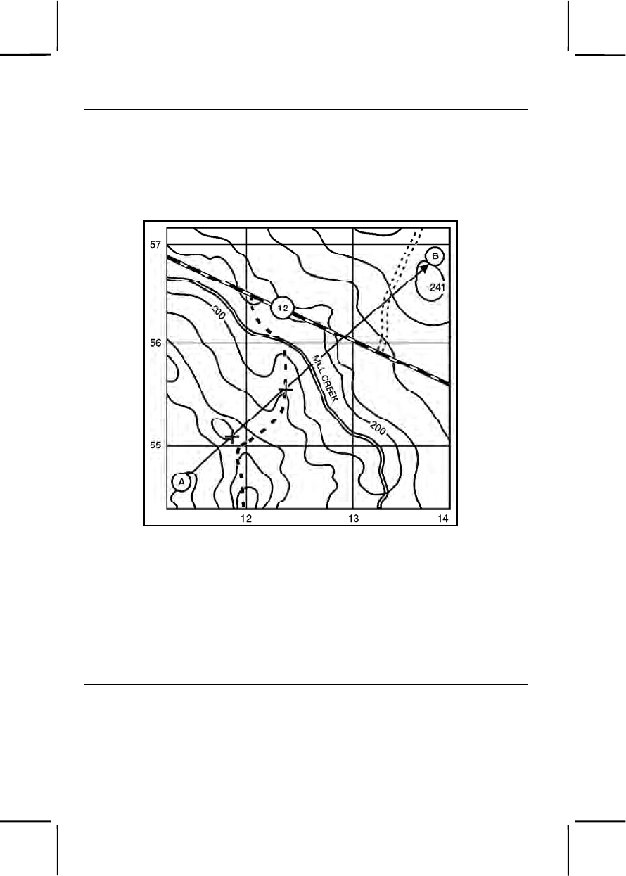
3-226 071-329-1006
Performance Steps
b. In using association, you locate first your position on the map then
your destination or objective. It will seldom be the best way to travel. For
example, look at figure 071-329-1006-1. Assume that you are to move from
point A to point B. You see that a straight line could cause you to climb
several small ridges and valleys (the "Xs" on figure 071-329-1006-1).
Figure 071-329-1006-1. Straight-line route
c. When adjusting your route, consider the following:
(1) Tactical aspect. Avoid skylining open areas and danger areas
like streams or crossings on roads and hilltops. Your tactical concern is
survival. The mission is causing you to move to your objective. You need to
be sure you get to that objective. Looking at figure 071-329-1006-2, you
decide for tactical reasons to cross the stream where you would not be seen
from the road (C) and to cross the road in a small valley (D). You know that
valleys offer better cover and concealment, so you will use them (E) (F).
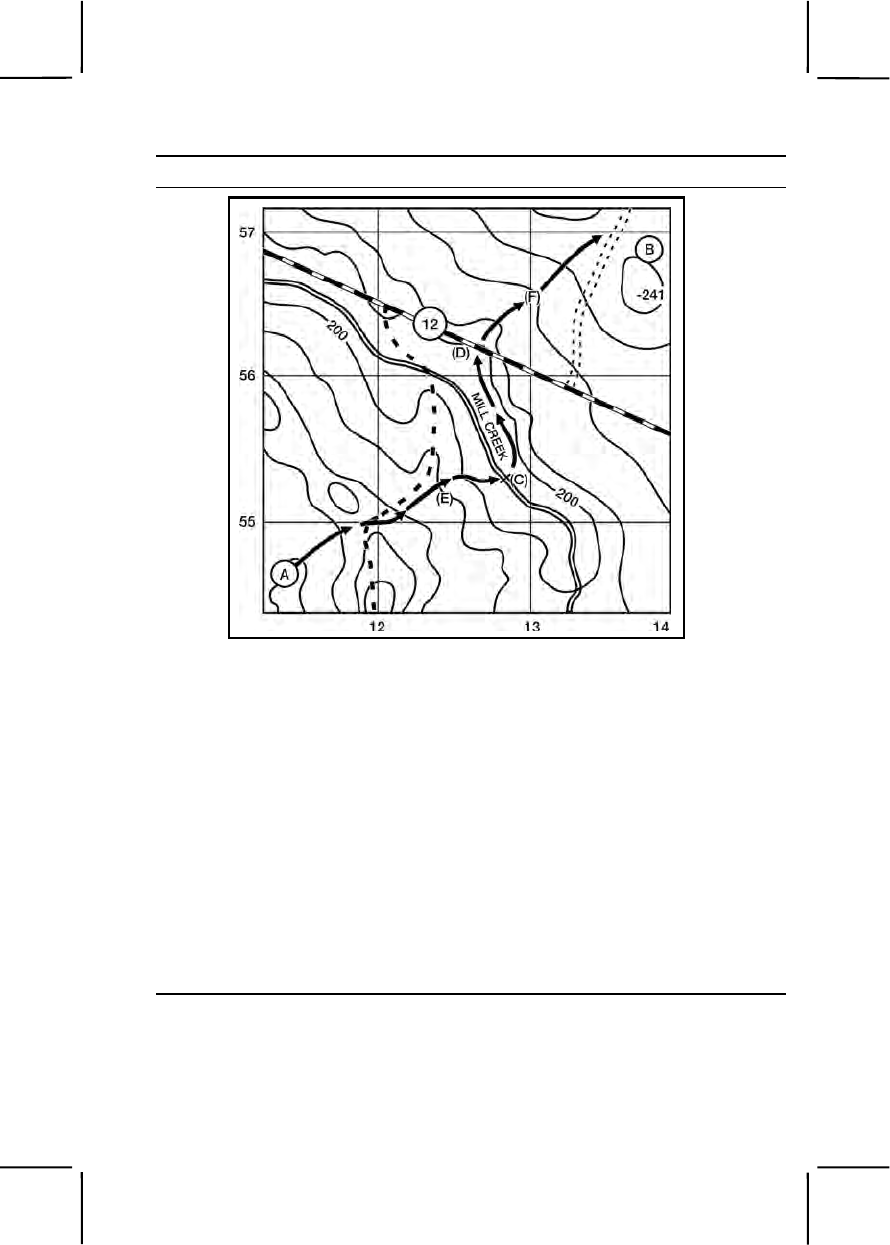
071-329-1006 3-227
Performance Steps
Figure 071-329-1006-2. Adjusted route
(2) Ease of movement. Always pick the easiest route that the
tactical situation allows. However, you achieve surprise by doing the
unexpected. A difficult route increases your chance of getting lost. A difficult
route may be noisy and may tire you out before you get to your objective.
(3) Boundaries. It is almost impossible to travel in a straight line, with
or without a compass. Pick an axis or corridor to travel along. Pick
boundaries you will be able to spot or feel. Hard-top roads, streams, high
grounds, and railroads all make good boundaries. If you start to wander too
far off course, you will know it.
d. You decide the route shown in figure 071-329-1006-3 offers you
easy movement. You check your axis up the valley (1); across the ridge at
the saddle (2); cross the stream and turn left, keeping the stream on the left
and high ground on the right (4); to the third valley (5); to the saddle, then on
to the objective (6).
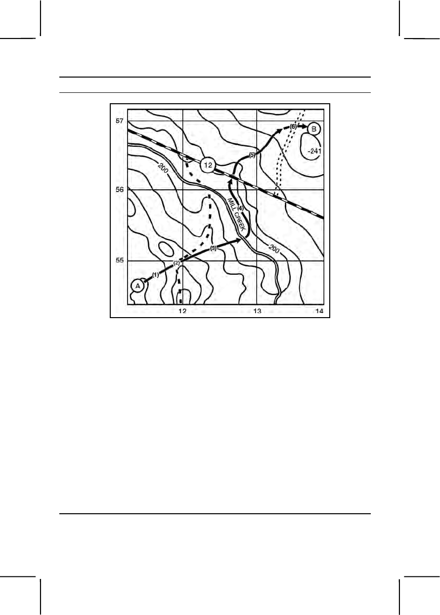
3-228 071-329-1006
Performance Steps
Figure 071-329-1006-3. Route of travel
e. With boundaries to keep you straight, you need to know where,
along your corridor, you are. You do this with checkpoints. The best
checkpoint is a line or linear feature that you cannot miss. A linear feature
across your corridor, or axis, is crossed no matter where you are in the axis.
Use hard-top roads, railroads, power lines, perennial streams (solid blue
lines, the dash blue lines are frequently dry), rivers, ridges, and valleys.
Note. DO NOT use light-duty roads and trails; there are always more on the ground
than the map shows. DO NOT use wood lines, which are rarely permanent.
f. Referring to figure 071-329-1006-3, pick your checkpoints.
(1) Saddle, use Hill 241 to line on up the right valley, and follow to—
(2) Stream, move along it until—
(3) Bend in the stream, turn right to—
(4) Road in the valley (the ridge crossing on the road on the 12-grid
line will serve as a limiting feature), then up to—
(5) Far saddle, and right to your objective (B).
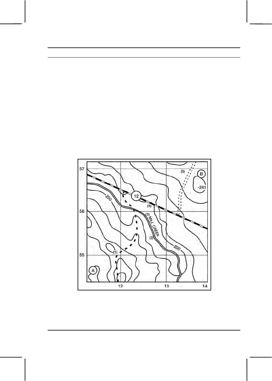
071-329-1006 3-229
Performance Steps
g. If you cannot find linear features, use an elevation change—hill or
depression, small ridge, or valley. Look for one contour line of change
during the day, two at night. Regardless of contour interval, you will spot a
contour interval of change on foot.
h. Determine the distance between checkpoints. DISTANCE IS THE
CAUSE OF MOST NAVIGATIONAL MISTAKES. Estimate or measure the
distance from one checkpoint to another. Trust that distance.
i. Referring to figure 071-329-1006-4, check your distances:
(1) 500 meters to the saddle (1).
(2) 800 meters to the stream (2).
(3) 500 meters to the bend in the stream (3).
(4) 300 meters to the road (4).
(5) 1,000 meters to the far saddle (5).
Figure 071-329-1006-4. Checkpoints
3. Navigate from one point to another using dead reckoning.
a. Dead reckoning is a technique of following a set route or line for a
determined distance. This technique is used on flat terrain, like deserts and
swamps. It can be used day or night. To use dead reckoning—

3-230 071-329-1006
Performance Steps
(1) Locate the start point and finish point on the map (figure 071-
329-1006-5).
Figure 071-329-1006-5. Distance between checkpoints
(2) Determine the grid azimuth from the start point to the finish point,
or to the first intermediate point on the map.
(3) Convert the grid azimuth taken from the map to a magnetic
azimuth.
(4) Determine the distance between the start point and the finish
point, or any intermediate points on the map.
Note. If you do not know how many paces you take for each 100 meters, you should
move to a 100-meter course and determine your pace count.
(5) Convert the map distance to pace count.
(6) Make a thorough map reconnaissance of the area between the
start point and the finish point.
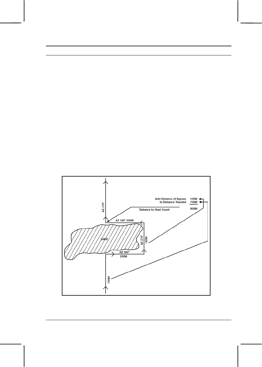
071-329-1006 3-231
Performance Steps
b. Before moving from the start point, shoot an azimuth on a well-
defined object on the ground in the direction of travel. These objects, known
as steering points, may be lone trees, buildings, rocks, or any easily
identifiable point. At night, the most likely steering point will be a star.
Because of the rotation of the Earth, the positions of the stars continually
change. You must check your azimuth frequently. Do this only when halted.
Using your compass while moving will cause you to go off-course. Your
steering mark may be beyond your objective. Remember to travel the
distance you determined.
c. Once you have selected a steering point, move toward it,
remembering to begin your count. You should have some method devised
to keep track of the number of 100 meters you travel.
d. Upon reaching your first steering point, shoot an azimuth to another
steering mark, and repeat c, until you reach the finish point.
e. If you should encounter an obstacle, you may have to detour around
it (figure 071-329-1006-6). To do this, complete a series of 90-degree turns
until the obstacle is bypassed and you are back on the original azimuth.
Figure 071-329-1006-6. Bypassing an obstacle
(1) At the edge of the obstacle, make a note of the number of paces
taken to this point.

3-232 071-329-1006
Performance Steps
(2) If your detour is to the right, add 90 degrees to the original
azimuth.
(3) Using the new azimuth, pick a steering mark and move toward it,
making sure you begin a new pace count. Move on this azimuth until
reaching the end of the obstacle.
(4) Stop and make a note of the number of paces taken, again as in
(2) above, add or subtract 90 degrees from the azimuth just read, and move
to the far side of the obstacle.
(5) Upon reaching the far side, stop the count and make note of the
number of paces taken; add this pace count to the pace count noted in (1).
(6) At this time, again add or subtract 90 degrees from the azimuth
used. Using this new azimuth, move the same number of paces taken on
the first leg of the offset or detour.
(7) Place the compass on your original azimuth, pick up the pace
count you ended with when you cleared the obstacle, and proceed to your
finish point.
f. Bypassing the same obstacle at night calls for special
considerations:
(1) To make a 90-degree turn, hold the compass as you would to
determine a magnetic azimuth.
(2) Turn until the center of the luminous letter "E" is under the
luminous line (do not change the setting of the luminous line).
Note. If you turn to the right, "E" is under the luminous line. If you turn to the left, "W"
is under the line.
(3) Proceed in the direction until you have outflanked the obstacle.
(4) Turn until the north arrow is under the luminous line and proceed
parallel to your original course until you have bypassed the obstacle.
(5) Turn until the "W" is under the luminous line and move back the
same distance you originally moved.
(6) Finally, turn until the north arrow is under the luminous line and
proceed on your original course.
(7) You must do the pace count the same as you do for bypassing
the obstacle during daylight.
g. After reaching the finish point, conduct a detailed terrain analysis to
confirm your location.
4. Navigate from one point to another by combining terrain association with
dead reckoning.

071-329-1006 3-233
Performance Steps
a. Frequently, you must consider the advantage and disadvantage of
both navigation techniques.
(1) Terrain association is fast and easy, and allows for mistakes. It is
also subject to map accuracy and can only be used with recognizable terrain
features.
(2) Dead reckoning is accurate and works on flat terrain that lacks
terrain features; however, all work must be precise, and the technique takes
time.
b. There may be times when you combine both techniques. For
instance, in the desert, you may need to use dead reckoning to arrive at or
near a road, or a ridge, and then use terrain association to follow that
feature to an objective.
Evaluation Preparation:
Setup: Select an area with varying terrain and vegetation and large enough
to have two points, 1,000 meters to 2,000 meters apart. Ensure each point is
on or near an identifiable terrain feature and marked on the ground with a
sign containing a letter or number. Place dummy signs not less than 100
meters but not more than 200 meters to the right and left of the correct point.
Clearly mark correct points on the map. Prepare a sheet of paper giving the
azimuth and distance for each leg of the course to be covered. Have pencils
available for the tested soldier.
Brief Soldier:
1. Terrain Association.
a. Give the soldier the map and tell him to identify the best route to take
between the two points plotted on the map (1,000 meters to 2,000 meters
apart).
Note. The best route must have been determined by an SME before the test.
b. Give the soldier the map and tell him he must move from point A to
point B (1,000 meters to 2,000 meters apart) using terrain association (no
compass is used). Tell the soldier he has _______ (standard in minutes
and/or hours) to complete the course.
2. Dead Reckoning. Give the soldier the sheet of paper with the azimuth and
the distance for each leg of the course (three to five points, 200 meters to
500 meters apart), and the compass; no map will be used. Tell the soldier to
move over the course shown by the azimuth and the distance on the paper.
Tell the soldier to record the letter or number at the end of each leg of the
course. Tell the soldier he has ______ (standard in minutes and/or hours) to
complete the course.

3-234 071-329-1030
Note: Time standards are based on the average time it takes two SMEs to complete
the course plus 50 percent. For example, if the SME time is one hour, course test time
is one hour and 30 minutes. SME time (1 hour) + 50 percent (30 minutes) = course
test time of one hour and 30 minutes.
Tell the soldier he has 10 minutes to study the map and determine a course
of action. At the end of this time, he will move to the start point and begin the
test. Time starts when soldier leaves the start point and ends when he
crosses the finish point.
Performance Measures GO NO GO
1. Terrain association. —— ——
a. Identified the best route within 10 minutes and
explained the reason for picking that route.
b. Wrote down the correct letter or number at the
end of each leg of the course.
2. Dead reckoning. —— ——
a. Wrote down the correct letter or number of each
leg of the course.
b. Arrived at correct destination within the specified
time.
Evaluation Guidance: Score the soldier GO if all performance measures
are passed. Score the soldier NO GO if any performance measure is failed.
If the soldier scores NO GO, show what was done wrong and how to do it
correctly.
References
Required Related
FM 3-25.26
STP 21-1-SMCT
071-329-1030
Navigate from One Point on the Ground to Another Point While
Mounted
Conditions: Given a standard 1:50,000-scale topographic map of the area,
a coordinate scale, a protractor, and a compass, while mounted in a vehicle
with cross-country capability and tasked to move from a known start point to
one or more distant points.

071-329-1030 3-235
Note: See appendix C for related skills and knowledge supporting performance of this
task.
Standards: Directed the driver to the designated point(s) at a rate of nine
kilometers per hour using terrain association and dead reckoning.
Performance Steps
1. Determine the effects of terrain on the vehicle when navigating
mounted.
a. Vehicle speed and mobility.
(1) Great distances may be covered quickly. Develop the ability to
estimate the distance traveled. Meanwhile, use the odometer, which shows
the distance traveled. Remember that .1 mile is roughly 160 meters, and 1
mile is about 1,600 meters or 1.6 kilometers.
(2) Mobility is an advantage while navigating. When disoriented,
mobility makes it easier to move and reorient.
b. Vehicle capabilities.
(1) Most military vehicles can knock down a tree. Larger vehicles
can clear more trees but cannot knock down several trees at once. Find
paths between trees that are wide enough for the vehicle (figure 071-329-
1030-1).
Figure 071-329-1030-1. Vehicle capabilities
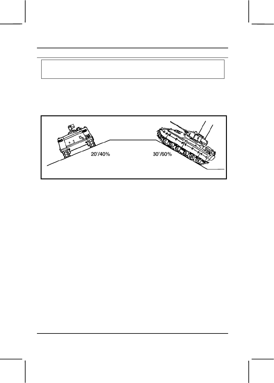
3-236 071-329-1030
Performance Steps
CAUTION
During training, follow installation SOP or local guidelines concerning cross-
country vehicle travel.
(2) Military vehicles are designed to climb 60-percent (30-degree)
slopes if the surface is dry and firm. If gravel, vegetation, or mud is on the
slope, the practical slope-climbing capability is about 40 percent (20
degrees) (figure 071-329-1030-2).
Figure 071-329-1030-2. Climbing slope and side slope capabilities
(a) Determine the approximate slope by looking at the route
selected on a map. One contour line in any 100 meters of map distance on
that route indicates a 10-percent slope. Two contour lines indicate a 20-
percent slope, and so forth. If there are four contour lines in 100 meters,
look for another route.
Note. The above figures are true for a 10-meter or 20-foot contour interval. If the
map has a different contour interval, adjust the arithmetic. For instance, if there is
one contour line in 100 meters, a 10-meter interval would give a 10-percent slope.
(b) The side slope is more important than the climbing slope. A
40-percent side slope is the maximum in good weather (figure 071-329-
1030-2). Traverse a side slope slowly and without turning. Rocks, stumps,
or sharp turns can cause a downhill track to be thrown under the vehicle,
which is a major recovery task.
(3) For tactical reasons, movement is often in draws or valleys due
to the cover they provide. Side slopes make slow movement necessary.
2. Know the effects of weather on vehicle movement.
a. Weather can halt mounted movement. Snow and ice are
dangerous. Rain and snow affect soil load-bearing ability. Heavy rain may
restrict cross-country vehicles to road movement.
b. Adjust the route to avoid flooded or muddy areas. A stuck vehicle
hinders combat capability.

071-329-1030 3-237
Performance Steps
3. Know both methods of navigation.
a. Terrain association. This is the most used method of navigation.
The navigator plans the route for movement from one terrain feature to
another. An automobile driver uses the same technique while driving along
the streets in a city. He guides himself using intersections or other
landmarks. Like a driver, the navigator selects routes, or "streets," between
key points, or "intersections." These routes must sustain vehicle travel, and
should be as direct and easy to follow as possible. In a typical move, the
navigator determines his location and the location of his objective. He
notes the position of each on his map and selects a route between the two.
(1) Determine the start point and destination.
(2) Draw or visualize a straight line between the two points on the
map.
(3) Inspect the terrain along that line for ease of movement, for
features recognizable under predicted weather conditions, and for tactical
considerations.
(4) After analyzing the terrain, adjust the route by doing the
following:
(a) Consider tactical aspects. Avoid skylining, select key
terrain for overwatch positions, and select concealed routes.
(b) Consider ease of movement. Use the easiest possible
route. Bypass difficult terrain. A difficult route is hard to follow, noisier,
causes more wear to the vehicle (and possibly recovery problems), and
takes more time. Tactical surprise is achieved by doing the unexpected.
Try to select an axis or corridor and not a specific route. Allow room for
vehicles to maneuver.
(c) Use terrain features as checkpoints. Checkpoints must be
easily recognizable, from a moving vehicle, under the current light and
weather conditions. The best checkpoints are linear features that cross the
route. Use perennial streams, rivers, hardtop roads, ridges, valleys, and
railroads. The next best are elevation changes; hills, depressions, spurs,
and draws. Look for two contour lines of change. Less than two lines of
change cannot be spotted while mounted.
(d) Follow terrain features. Movement and navigation along a
valley floor or near or on the crest of a ridgeline are easiest.

3-238 071-329-1030
Performance Steps
(e) Determine directions. Break the route into smaller
segments and determine the rough direction that will be followed. The
compass is not needed; use the main points of direction (north, northeast,
east, for example). Before moving, note the location of the sun and the
direction of north. Locate changes of direction, if any, at the checkpoints
chosen.
(f) Determine distance. Obtain the total distance to be traveled
and the approximate distance between checkpoints. Plan to use the
vehicle odometer to keep track of distance traveled.
Note. Convert map distance to ground distance by adding 20 percent for cross-
country movement.
(g) Make notes. Usually, mental notes are adequate. Imagine
what the route will be like and remember it.
(h) Plan. Restudy the route selected. Determine where
problems may occur and how they may be avoided.
b. Dead reckoning. Dead reckoning means moving a set distance
along a set line. It involves moving so many meters along a set line, usually
an azimuth in degrees.
Note. There is no accurate method of determining direction in vehicles.
(1) Dead reckoning with steering marks. This procedure is the
same as it is for on foot travel.
(a) Dismount from the vehicle.
(b) Move away from the vehicle (about 50 meters).
(c) Set the azimuth on the compass and choose a steering
mark (rock, tree, hilltop) in the distance on that azimuth.
(d) Remount and have the driver identify the steering mark.
Proceed to it in as straight a line as possible.
(e) On arrival at the steering mark or when direction is
changed, repeat paragraphs (a) through (c) for the next leg of travel.
(2) Dead reckoning without steering marks. Use this only in flat,
featureless terrain.
(a) Dismount from the vehicle, which has been positioned in
the direction of travel. Move about 50 meters to the front of the vehicle.
(b) Face the vehicle and read the azimuth to the vehicle.
(c) By adding or subtracting 180 degrees, determine the
forward azimuth (direction of travel).
(d) Have the driver drive on a straight line toward you.

071-329-1030 3-239
Performance Steps
(e) Remount the vehicle, hold the compass as it will be held
while the vehicle is moving, and read the azimuth to the front.
(f) The compass swings off the azimuth determined, but it
should pick up a constant deviation. For instance, the azimuth to the
steering mark was 75 degrees while you were away from the vehicle.
When you remounted, and the driver drove straight forward, the compass
showed 67 degrees. There is a deviation of minus 8 degrees. All that is
needed is to hold the 67-degree heading.
(g) At night, do the same thing without a steering mark. From
the map, determine the azimuth of travel. Line the vehicle up on that
azimuth, then move well in front of the vehicle. Be sure it is aligned
correctly. Mount, have the driver move slowly forward, and note the
deviation.
Note. If the vehicle has a turret, traversing the turret changes the deviation.
(3) Turret alignment. If the vehicle has a stabilized turret, another
method is alignment of the turret on the azimuth to be traveled. Switch the
turret stabilization system ON. The gun tube remains pointed at the
destination no matter which way the vehicle is turned.
CAUTION
If you have to take the turret off-line to engage a target, repeat the entire
process.
Note. This technique works, and it is not harmful to the stabilization system.
However, the vehicle is subject to stabilization drift; therefore, use this technique for
no more than 5,000 meters before resetting.
(4) Distance factor. Computing the distance factor in dead
reckoning is usually a simple process. Determine the map distance to
travel and add 20 percent to convert to ground distance. Use the vehicle
odometer to control the distance of travel.
4. Learn to combine and use both methods.
a. Terrain association is fast and error-tolerant. It is the best method
under most circumstances, and it can be used day or night.
b. Dead reckoning is accurate if done correctly—precision is a
requirement. Dead reckoning is slow, but works in flat terrain.
c. Often, dead reckoning and terrain association are combined. Use
dead reckoning to travel across a large, flat area to a ridge. Use terrain
association for the rest of the move.
d. The ability to use both methods is required. Probable errors, in
order of frequency, are as follows:
(1) Failure to determine distance(s) to be traveled.

3-240 071-329-1030
Performance Steps
(2) Failure to travel the proper distance.
(3) Failure to properly plot or locate the objective.
(4) Failure to select easily recognizable checkpoints or landmarks.
(5) Failure to consider the ease of movement factor.
Evaluation Preparation:
Setup: At the test site, provide the materials and equipment given in the task
conditions. Select an area that has varying terrain and vegetation. The area
must be large enough to have three to five points that are 1,000 meters to
5,000 meters apart. Each point is on or near an identifiable terrain feature
and is marked on the ground with a sign containing a letter or number. Place
dummy signs not less than 100 meters or more than 200 meters to the right
and left of the correct point. Clearly mark all correct points on the map.
Prepare a sheet of paper giving the azimuth and distance for each leg of the
course. Have pencils available for the soldier.
Brief Soldier:
1. Terrain association. Give the soldier the map and tell him to direct the
driver and vehicle over the course recorded on the map. Tell the soldier to
record the letter or number at the end of each leg of the course. Tell the
soldier the course will be covered using terrain association.
2. Dead reckoning with steering marks. Give the soldier a protractor, a
compass, and a sheet of paper with the azimuth and distance for each leg of
the course. Maps are not used. Tell the soldier to direct the driver and
vehicle over the course recorded on the paper. Tell the soldier to record the
letter or number at the end of each leg to the course. Tell him the course will
be covered using steering marks.
Performance Measures GO NO GO
1. Terrain association. Wrote the correct letter or
number found at the end of each leg of the course. —— ——
2. Dead reckoning. —— ——
a. Moved away from the vehicle.
b. Set azimuth on compass and selected steering
mark.
c. Had the driver identify the steering mark.
d. Wrote the correct letter or number found at the
end of each leg of the course.
e. Repeated steps in performance measure 2a, b,
and c for each leg of the course.

113-571-1022 3-241
Evaluation Guidance: Score the soldier GO if all performance measures
are passed. Score the soldier NO GO if any performance measure is failed.
If the soldier fails any performance measure, show what was done wrong
and how to do it correctly.
References
Required Related
FM 3-25.26
FM 90-3
SUBJECT AREA 6: COMMUNICATE
113-571-1022
Perform Voice Communications
Conditions: Given one operational radio set (warmed up and set to the net
frequency) for each net member,; a call sign information card (5 inches x 8
inches) consisting of net member duty position (S1, S2), net call sign (letter-
number-letter), suffix list (net control station [NCS] - 46, S1 - 39, S2 - 13),
and a message to be transmitted.
Situation: The net is considered to be secure and authentication is not
required (FM 24-19).
Note. This task may have as many net members as there is equipment
available. Each net member must have a different suffix and message to
transmit.
Standards: Entered a radio net, sent a message, and left a radio net using
the proper call signs, call sign sequence, prowords, and phonetic alphabet
and numerals with 100 percent accuracy.
Performance Steps
1. Enter the net.
a. Determine the abbreviated call sign and answering sequence for
your duty position.
b. Respond to the NCS issuing a net call (figure 113-571-1022-1).

3-242 113-571-1022
Performance Steps
NET THIS IS E3E (NCS) OVER
E3E (NCS) THIS IS E13 (1ST position) OVER
E3E (NCS) THIS IS E39 (2ND position) OVER
E3E (NCS) THIS IS E46 (3RD position) OVER
NET THE E3E (NCS) OUT (IF NCS HAS NO TRAFFIC)
Figure 113-571-1022-1.
c. Answer in alphanumeric sequence.
Note. At this time, the NCS acknowledges and the net is open.
2. Send a message.
a. Listen to make sure the net is clear. Do not interrupt any ongoing
communications.
b. Call the NCS and tell the operator the priority of the message you
have for his station.
c. Receive a response from the NCS that he is ready to receive.
d. Send your message using the correct prowords and pronunciation
of letters and numbers. (See tables 113-571-1022-1 through 113-571-
1022-3 and figure 113-571-1022-2.)

113-571-1022 3-243
Performance Steps
Table 113-571-1022-1. Phonetic Alphabet
Letter Word Pronounciation
A ALFA AL FAH
B BRAVO BRAH VOH
C CHARLIE CHAR LEE or SHAR LEE
D DELTA DELL TAH
E ECHO ECK OH
F FOXTROT FOKS TROT
G GOLF GOLF
H HOTEL HOH TELL
I INDIA IN DEE AH
J JULIETT JEW LEE ETT
K KILO KEY LOH
L LIMA LEE MAH
M MIKE MIKE
N NOVEMBER NO VEM BER
O OSCAR OSS CAH
P PAPA PAH PAH
Q QUEBEC KEH BECK
R ROMEO ROW ME OH
S SIERRA SEE AIR RAH
T TANGO TANG GO
U UNIFORM YOU NEE FORM or OO NEE FORM
V VICTOR VIK TAH
W WHISKEY WISS KEY
X XRAY ECKS RAY
Y YANKEE YANG KEY
Z ZULU ZOO LOO

3-244 113-571-1022
Performance Steps
Table 113-571-1022-2. Number Pronunciation Guide
Numeral Spoken As
0 ZE RO
1 WUN
2 TOO
3 TREE
4 FOW ER
5 FIFE
6 SIX
7 SEV EN
8 AIT
9 NIN ER
Table 113-571-1022-3.
Proword Meaning
ALL AFTER The portion of the message to which I have reference is all
that which follows ___________.
ALL BEFORE The portion of the message to which I have reference is all
that which precedes __________.
AUTHENTICATE The station called is to reply to the challenge which follows
____________.
AUTHENTICATION
IS The transmission authentication of this message is
_______.
BREAK I hereby indicate the separation of the text from other
portions of the message.
CORRECT You are correct, or what you have transmitted is correct.
CORRECTION An error has been made in this transmission. Transmission
will continue with the last word correctly transmitted.
An error has been made in this transmission (or message
indicated). The correct version is ________. That which
follows is a corrected version in answer to your request for
verification.
DISREGARD THIS
TRANSMISSION
OUT
This transmission is in error. Disregard it. This proword shall
not be used to cancel any message that has been of
national/allied forces or populace, and which require
immediate delivery.

113-571-1022 3-245
Table 113-571-1022-3.
INFO The addresses immediately following are addressed for
information.
I AUTHENTICATE The group that follows it is the reply to your challenge to
authenticate.
I READ BACK The following is my response to your instructions to read
back.
I SAY AGAIN I am repeating transmission or portion indicated.
I SPELL I shall spell the next word phonetically.
I VERIFY That which follows has been verified at your request and is
repeated. (To be used as a reply to verify.)
MESSAGE A message which requires recording is about to follow
(Transmitted immediately after the call.)
MORE TO FOLLOW Transmitting station has additional traffic for the receiving
station.
OUT This is the end of my transmission to you and no answer is
required or expected. (Since OVER and OUT have opposite
meanings, they are never used together.)
OVER This is the end of my transmission to you and a response is
necessary. Go ahead; transmit.
PRIORITY Precedence PRIORITY. Reserved for important messages
which must have precedence over routine traffic. This is the
highest precedence which normally may be assigned to a
message of administrative nature.
READ BACK Repeat this entire transmission back to me exactly as
received.
RELAY (TO) Transmit this message to all addresses (or addresses
immediately following this proword). The address
component is mandatory when this proword is used.
ROGER I have received your last transmission satisfactorily.
ROUTINE Precedence ROUTINE. Reserved for all types of messages
which are not of sufficient urgency to justify a higher
precedence, but must be delivered to the addressees
without delay.
SAY AGAIN Repeat all of your last transmission. (Followed by
identification data means “Repeat _______(portion
indication).”)
SERVICE The message that follows is a service message.
SILENCE “Cease Transmission Immediately.” Silence will be
maintained until lifted. (Transmissions imposing silence
must be authenticated.)
SILENCE LIFTED Silence is lifted. (When an authentication system is in force
the transmission lifting silence is to be authenticated.)

3-246 113-571-1022
Table 113-571-1022-3.
SPEAK SLOWER Your transmission is at too fast a speed. Reduce speed of
transmission.
THIS IS This transmission is from the station whose designator
immediately follows.
TIME That which immediately follows is the time or date/time
group of the message.
TO The addressee(s) immediately following is (are) addressed
for action.
UNKNOWN
STATION The identity of the station with whom I am attempting to
establish communications is unknown.
VERIFY Verify entire message (or portion indicated) with the
originator and send correct version. (To be used only at the
discretion of the addressee to which the questioned
message was directed.)
WAIT I must pause for a few seconds.
WAITOUT I must pause for longer than a few seconds.
WILCO I have received your signal, understand it, and will comply.
(To be used only by the addressee. Since the meaning of
ROGER is included in that of WILCO, the two prowords are
never used together.)
WORD AFTER The word of the message to which I have reference is that
which follows _______.
e. Get a receipt for the message.
3. Leave the net in alphanumeric sequence.
a. You receive a call from the NCS who issues a close-down order
(figure 113-571-1022-2).
NET THIS IS E3E (NCS) CLOSE DOWN OVER
E3E (NCS) THIS IS E13 (1ST position) ROGER OUT
E3E (NCS) THIS IS E39 (2ND position) ROGER OUT
E3E (NCS) THIS IS E46 (3RD position) ROGER OUT
Figure 113-571-1022-2
b. Answer in alphanumeric sequence.
Note. The NCS acknowledges and the net is closed.
Note. The following call signs are used in this task as examples: Net call sign - E3E,
NCS - E46, S1 - E39, S2 - E13.

113-600-2001 3-247
Evaluation Preparation:
Setup: Position operational radio sets in different rooms or tents or at least
70 feet apart outside. Obtain call signs, suffixes, and a radio frequency
through the normal command chain. Select a message (15 to 25 words)
containing some number groups such as map coordinates and times. Print
the call signs for the sender and the receiver, along with the message to be
sent, on 5 x 8 cards. Perform a communications check to ensure operation
of the radios. Have an assistant who is proficient in radio operation man the
NCS. Provide the assistant with the call signs. If the soldier has not
demonstrated sufficient progress to complete the task within five minutes,
give him a NO GO. This time limit is an administrative requirement, not a
doctrinal one. If the soldier has almost completed the task correctly, you may
decide to allow him to finish.
Brief Soldier: Give the soldier the card containing the message and call
signs. Tell him the radio is ready for operation, the net is considered to be
secure and authentication is not required, and to send the message to the
NCS and get a receipt. Tell the soldier that, if sufficient progress in
completing the task within five minutes has not been demonstrated, he will
receive a NO GO for the task.
Performance Measures GO NO GO
1. Entered the net in alphanumeric sequence. —— ——
2. Sent a message of 15 to 25 words using the correct
prowords and phonetic alphabet and numerals. —— ——
3. Left the net in alphanumeric sequence. —— ——
Evaluation Guidance: Score the soldier GO if all performance measures
are passed. Score the soldier NO GO if any performance measure is failed.
If the soldier scores NO GO, show him what was done wrong and how to do
it correctly.
References
Required Related
FM 24-19
113-600-2001
Communicate Via a Tactical Telephone
Conditions: Given a requirement to communicate a message via a tactical
telephone and the following:

3-248 113-600-2001
1. An unclassified message (approximately 25 words).
2. A tactical telephone (DNVT, TA-838/TT, TA-341()/TT, TA-1042A/U and
TA-954/TT) installed in a point-to-point configuration and operating in a non-
secure mode.
Standards: Communicated the message within 10 minutes with no errors.
Performance Steps
1. Initiate call (lift handset from cradle).
2. Verify distant end is ready to receive message.
3. Communicate message.
4. Verify message is received.
5. Disconnect call (return handset to cradle).
Evaluation Preparation:
Setup: Provide the soldier with—
1. Tactical telephone (DNVT, TA-838/TT, TA-341()/TT, TA-1042A/U and
TA-954/TT) that is installed and connected to the distant tactical telephone
(DNVT, TA-838/TT, TA-341()/TT, TA-1042A/U and TA-954/TT).
2. Tactical telephones (DNVT, TA-838/TT,TA-341()/TT, TA-1042A/U and
TA-954/TT) are set to operate in the point-to-point mode.
3. A prepared message (approximately 25 words) for the soldier to
communicate.
Brief Soldier: Tell the soldier he must communicate the prepared message.
Performance Measures GO NO GO
1. Initiated call (lifted handset from cradle). —— ——
2. Verified distant end is ready to receive message. —— ——
3. Communicated message. —— ——
4. Verified message was received. —— ——
5. Disconnected call (returned handset to cradle). —— ——
Evaluation Guidance: Score the soldier GO if all performance measures
are passed. Score the soldier NO GO if any performance measure is failed.
If the soldier scores NO GO, show him what was done wrong and how to do
it correctly.
References
Required Related
ACP 125 US SUPPL-1

113-637-2001 3-249
References
Required Related
ACP 125(E)
113-637-2001
Communicate Via a Tactical Radio in a Secure Net
Conditions: Given an operational radio set (SINCGARS, IHFR, VRC-12
series, etc.), with an (SOI), fill device with appropriate fills, and fill cable, TM
11-5820-890-10-8, TM 11-5820-401-10-2, and an operational distant station.
Standards: Established voice communications with the distant tactical
radio/network within three minutes.
Performance Steps
1. Place radio into operation.
a. Preset controls.
b. Turn radio set on.
c. Test radio transmission (RT) circuits.
2. Enter net.
a. Load appropriate fills.
b. Operate radio set.
3. Transmit message.
a. Establish secure communications.
b. Use prowords, call signs, frequencies, item numbers and
authentications.
Evaluation Preparation:
Setup: An operational radio set (SINCGARS, IHFR, VRC-12 series, etc.),
with an (SOI), fill device with appropriate fills, and fill cable, TM 11-5820-
890-10-8, TM 11-5820-401-10-2, and an operational distant station.
Brief Soldier: Tell the soldier he must establish voice communications with
the distant tactical radio/network, within three minutes. The three-minute limit
is only an administrative training requirement.
Performance Measures GO NO GO
1. Placed radio into operation. —— ——
a. Preset controls.

3-250 071-331-0804
Performance Measures GO NO GO
b. Turned radio set on.
c. Tested radio transmission (RT) circuits.
2. Entered net. —— ——
a. Loaded appropriate fills.
b. Operated radio set.
3. Transmitted message. —— ——
a. Established secure communications.
b. Used prowords, call signs, frequencies, item
numbers, and authentications.
Evaluation Guidance: Score the soldier GO if all performance measures
are passed. Score the soldier NO GO if any performance measure is failed.
If the soldier fails any performance measure, show what was done wrong
and how to do it correctly. Have the soldier practice until the task can be
performed correctly.
References
Required Related
SOI FM 24-18
TM 11-5820-401-10-2 FM 24-19
TM 11-5820-890-10-8
SUBJECT AREA 7: SEE
071-331-0804
Perform Surveillance without the Aid of Electronic Devices
Conditions: Given an enemy force equipped with wheel and track vehicles
within range of sight or hearing during day and night.
Standards: Identified 50 percent of the enemy soldiers and vehicles within
field of view using proper surveillance techniques.
Performance Steps
1. Conduct a visual search in daylight:.
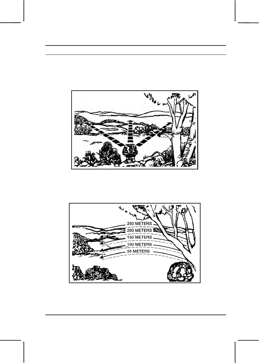
071-331-0804 3-251
Performance Steps
a. Make a fast overall search of the entire area by raising your eyes
quickly from just in front of your position to the maximum range you wish to
observe (figure 071-331-0804-1). (For a wide area, subdivide and repeat
the procedure.)
Figure 071-331-0804-1. Fast overall search
b. Observe by overlapping, 50-meter-deep strips of terrain in detail,
alternately searching left to right, right to left (figure 071-331-0804-2).
Figure 071-331-0804-2. Overlapping search
c. Search suspicious spots thoroughly.
2. Identify improperly camouflaged personnel, equipment, and positions
by looking for—
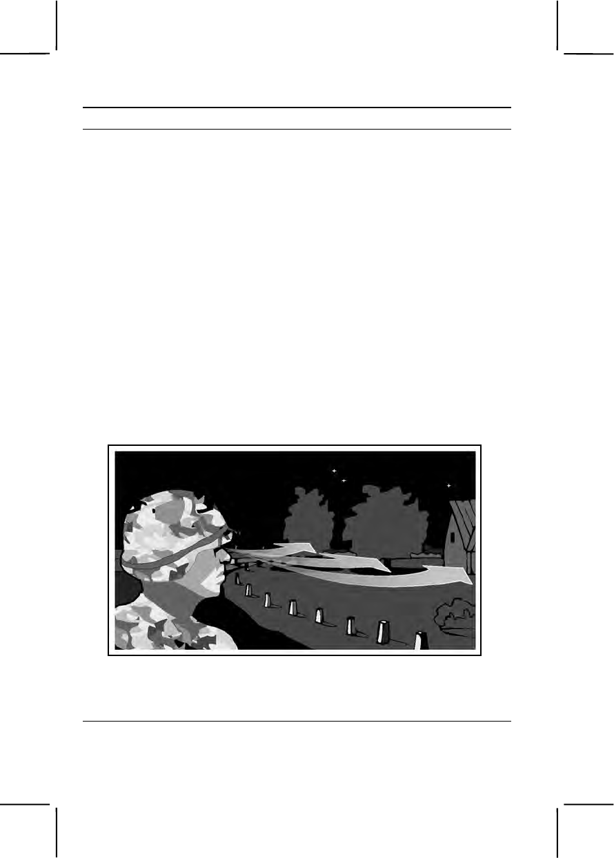
3-252 071-331-0804
Performance Steps
a. Camouflage or foliage that does not match.
b. Dead foliage.
c. Outlines that should be obscured.
d. Bright colors or reflections that should be subdued.
e. Tracks, footpaths, and piles of dirt and litter.
f. Over-clearing of fields of fire and observation.
3. Conduct surveillance at night:
a. Accustom your eyes to low light before night operations by doing
one of the following:
(1) Stay in a secure, darkened area for 30 minutes (for example,
assembly area at night, initial rally point).
(2) Stay in a red-lighted area for 20 minutes, followed by 10
minutes in darkness.
(3) Wear red goggles for 20 minutes, followed by 10 minutes in
darkness.
b. Scan search areas at night by moving your eyes in short, quick,
irregular movements (figure 071-331-0804-3).
Figure 071-331-0804-3. Night-vision search
c. Use off-center vision to observe specific objects by looking about 8
to 10 degrees left, right, above, or below them (figure 071-331-0804-4).

071-331-0804 3-253
Performance Steps
Figure 071-331-0804-4. Off-center vision
d. Preserve night vision by—
(1) Closing both eyes when exposed to bright light.
(2) Closing one eye only and observing with other when
surveillance must be maintained.
Note. Maintaining surveillance is one of the basic, critical combat skills. Because it is
hard to tell if the above techniques are used, frequent training is the only way to
ensure mastery of this skill. This task is easy to integrate with other tactical training.
In addition to the training given above, frequent familiarization with the sounds of
vehicles and weapon fire, along with common smells, such as gasoline, campfires,
and deodorants in the field environment is recommended.
Evaluation Preparation:
Setup: During a field exercise that involves camouflaging, have soldiers
conduct day and night surveillance. Simulate situations described below.
Have each soldier conduct surveillance at night and during the day before
scoring the soldier GO or NO GO.
Situation 1, day surveillance.
a. Improperly camouflaged enemy soldiers in fighting positions.
b. Stationary, properly camouflaged vehicles.
Situation 2, night surveillance. Moving and stationary enemy soldiers
silhouetted on the skyline.
Brief Soldier: Tell the soldier he must conduct surveillance during the day
and at night. During surveillance, the soldier must locate 50 percent of the
enemy soldiers within his field of view, and must differentiate between a
tracked-vehicle and a wheeled-vehicle.

3-254 071-730-0014
Performance Measures GO NO GO
1. Identified the following situations during daylight: —— ——
a. 50 percent of improperly camouflaged enemy
soldiers in fighting positions.
b. A camouflaged wheeled vehicle and a tracked
vehicle.
2. Identified the following situations during night
surveillance. —— ——
a. Moving enemy soldiers.
b. Stationary enemy soldiers.
Evaluation Guidance: Score the soldier GO if all performance measures
are passed. Score the soldier NO GO if any performance measure is failed.
If the soldier scores NO GO, show him what was done wrong and how to do
it correctly.
References
Required Related
FM 21-75
071-730-0014
Identify Combat Vehicles
Conditions: Given combat vehicles.
Standards: Identified combat vehicles by actual nomenclature.
Performance Steps
1. Observe vehicle.
2. Observe vehicle characteristics.
3. Compare observed vehicle characteristics with known vehicle
attributes. Four areas of characteristics are used to identify vehicles. Most
armored vehicles have all four areas of characteristics, though not all
vehicles do.
a. Track and suspension system: Many tanks can be recognized by
their track and suspension systems. However, recognizing a vehicle by this
feature alone is often difficult. Grass, dirt, terrain, dust or other factors often
obscure the tracks. To identify the track and suspension system, check to
see whether it has support or return rollers. Few threat vehicles, except the
T-10, T-64, T-72, BMD, BMP, SP-122, and SP-152, have either.

071-730-0014 3-255
Performance Steps
(1) Characteristics of most Warsaw Pact vehicles include a flat
(Christie) suspension system, without support or return rollers, without
torsion bars, and unevenly spaced road wheels.
(2) Characteristics of most NATO vehicles include a suspended
track, support or return rollers, torsion bars, shock absorbers, and evenly
spaced road wheels.
b. Turret: Most turrets can be grouped into three categories:
(1) Big, bulky turrets - older models.
(2) Well sloped turrets - newer models.
(3) Streamlined turrets - newer models.
c. Main gun: Armament varies from machine guns to large cannons.
In turreted vehicles, normally the heaviest armament is in the turret. Look
for the main gun, the main gun bore evacuator, and its relative location on
the main gun.
(1) Types of main guns:
(a) Smooth main gun, without bore evacuator or blast
deflector.
(b) Main gun with bore evacuator.
(c) Main gun with bore evacuator and muzzle brake or blast
deflector.
(2) Types of muzzles:
(a) Single baffle.
(b) Double baffle.
(c) Multi-baffle.
d. Cupolas: The cupola is a small, turret-like projection normally on
top of the turret. It is used by the vehicle commander and usually mounts a
machine gun.
4. Eliminate any vehicle that does not possess an observed characteristic
attribute.
5. Record actual vehicle.
Evaluation Preparation:
Setup: At the test site, provide the soldier(s) with all equipment and materials
needed for testing. Before evaluating the soldier(s), check the
computer/GTA media being used to ensure that it is operational. If using the
ROC-V (Recognition of Combat Vehicles, a multimedia CD-ROM and Web-
Based software package that teaches thermal and visual vehicle
recognition), check the website https://rocv.army.mil to ensure the most

3-256 071-325-4401
current version is accessed. Request access to download the ROC-V
program from the webmaster at mxregistrar@redstone.army.mil . Check to
ensure software has been loaded and set at the ready mode.
Brief Soldier: Read the following instructions to the soldier(s):
"At this time, you will be evaluated on your ability to identify combat vehicles.
You must identify 28 of 40 vehicles by actual nomenclature."
Performance Measures GO NO GO
1. Observed vehicle. —— ——
2. Observed vehicle characteristics. —— ——
3. Compared observed vehicle characteristics with
known vehicle attributes. —— ——
4. Eliminated any vehicle that did not possess an
observed characteristic attribute. —— ——
5. Recorded vehicle. —— ——
Evaluation Guidance: Score the soldier an overall GO if 28 combat
vehicles out of 40 were correctly identified. Score the soldier NO GO if any
performance measure is failed. If the soldier scores NO GO, show him what
was done wrong and how to do it correctly.
References
Required Related
FM 3-23.24
FM 3-90.1
GTA 17-02-011
GTA 17-02-013
SUBJECT AREA 8: HAND GRENADES AND LAND MINES
071-325-4401
Perform Safety Checks on Hand Grenades
Conditions: Given any standard issue U.S. hand grenade with extra safety
clips and load-carrying equipment (LCE).
Standards: Inspected the grenade for defects; identified and corrected
defects, if possible. Reported and turned in grenades that had defects you

071-325-4401 3-257
could not correct. Identified each grenade by type and correctly attached
grenades to ammunition pouch.
Performance Steps
1. Identify the grenades listed in table 071-325-4401-1 by type, color,
markings, and usage.
Table 071-325-4401-1. Hand Grenades
Type Color/Markings Use
M67
Fragmentation OD with yellow
marking. To disable or kill personnel.
Explodes 4 to 5 seconds after
safety lever is released
M18
Colored Smoke OD with color of
smoke on top To signal personnel.
M34
WP Smoke Light green, yellow
band, red marking.
“OLD MARKING”
light gray, yellow
band, yellow
printing.
To signal personnel. Produces
casualties up to 35 meters
away.
AN-M8
HC Smoke Light green, black
marking, white top. To screen, (provide
concealment).
AN-M14 TH3
Incendiary Light red with black
lettering. To destroy equipment and start
fires.
AB M52A2 CS
Riot Control Gray, red band(s)
and markings To control riots or disable
individuals without serious
injury.
2. Inspect hand grenades for defects; correct defects, if possible.
a. Check the fuse to ensure it is screwed tightly on the body of the
grenade.
b. Check the safety clip to ensure—
(1) It is present.
(2) It is in the correct position.
Note. Perform step 2c only if necessary.
c. Replace missing safety clips.
(1) Slide the clip onto the handle.
(2) Attach the loop portion of the clip around the fuse.
(3) Snap the clip end around the safety lever.
d. Check the safety pin.

3-258 071-325-4401
Performance Steps
(1) Ensure the clip is in the correct position. If not in position,
carefully push it into place while holding the safety lever down.
(2) Ensure the clip is not bent. If it is bent, carefully bend it back in
position.
e. Check the safety ring for cracking and reject the grenade with a
cracked safety ring.
f. Check grenades for dirt. Wipe dirty or grimy grenades with a cloth.
g. Turn in defective grenades.
WARNING
Do not attempt to modify a grenade. Do not attempt to defuse a
grenade. Do not attempt to remove a grenade found upside down in its
packing container. Do not handle a dud grenade. Do not attach
grenades to clothing or equipment by the pull ring.
3. Attach the grenade to an ammunition pouch.
a. Attach the grenade to the new style pouch.
(1) Slip the grenade safety lever over the small strap (sewn to each
side of the ammunition pouch).
(2) Push the grenade down until it is firmly seated against the side
of the pouch.
(3) Ensure the pull ring is pointed downward.
(4) Wrap the carrying strap around the fuse including both the
safety lever and the pull ring.
b. Attach the grenade to the old style pouch.
Note. A small strap is sewn to each side of the pouch.
(1) Slip the safety lever over the strap and push the grenade down
until it is firmly seated against the side of the pouch.
(2) Ensure the pull ring is pointed downward, wrapping the carrying
strap around the fuse, including the safety lever and pull ring.
4. Check grenades occasionally while moving to ensure the fuse is tight
and the strap is secure.
Evaluation Preparation:
Setup: Provide the following six inert hand grenades: M67 fragmentation
grenade, M18 colored smoke grenade, M34 WP smoke grenade, AN-M8 HC
smoke grenade, AN-M14 TH3 incendiary grenade, and ABC-M25A2 CS riot-
control grenade. The soldier being tested is not required to identify the

071-325-4401 3-259
grenades alphanumeric nomenclatures. Secure a number of inert hand
grenades that contain at least two of the following defects:
1. The fuse is unscrewed from the body of the grenade.
2. A loose safety clip.
3. A partially removed and/or bent safety pin.
4. A cracked safety pin.
5. A broken safety lever.
6. A dirty grenade.
Ensure that you know the defects present in each grenade before testing the
soldier.
Brief Soldier: Tell the soldier he must identify each hand grenade. Tell the
soldier to inspect the grenade and to correct the defects where possible. If
the soldier discovers a defect that cannot be corrected, he must tell you the
defect and that the grenade should be turned in. Tell the soldier to attach a
grenade to his ammunition pouch.
Performance Measures GO NO GO
1. Identified each of the following grenades: —— ——
a. Fragmentation grenade.
b. Riot control grenade.
c. White phosphorus (WP) grenade.
d. HC (white) smoke grenade.
e. Colored smoke grenade.
f. Incendiary grenade.
2. Inspected the grenade. —— ——
a. Checked that the fuse was screwed in tightly on
the body of the grenade.
b. Checked the position of the safety clip.
c. Checked the safety pin. If wrongly positioned,
carefully pushed it into place while securely holding the
lever down. If bent, carefully bent it back into position.
d. Checked the safety ring for cracking and rejected
the grenade with a cracked safety ring.
e. Checked for dirt and wiped the grenade clean, if
dirty.
f. Turned in defective grenades.

3-260 071-325-4407
Performance Measures GO NO GO
3. Attached the grenade to the ammunition pouch. —— ——
a. Checked the fuse for tightness.
b. Slipped the grenade safety lever over the strap
on the side of the ammunition pouch with the pull ring or
safety pin pointing downward.
c. Wrapped the carrying strap around the neck of
the fuse including the safety lever and the pulled ring,
snapped the carrying strap to the carrying sleeve.
Evaluation Guidance: Score the soldier GO if all performance measures
are passed. Score the soldier NO GO if any performance measure is failed.
If the soldier scores NO GO, show him what was done wrong and how to do
it correctly.
References
Required Related
TM 9-1330-200-12
071-325-4407
Employ Hand Grenades
Conditions: Given an offensive (concussion), riot-control, smoke, or
incendiary grenade with a time-delay fuse and load-carrying equipment
(LCE).
Standards: Threw the hand grenade to hit the target, prevented
endangering yourself for more than five seconds.
Performance Steps
1. Position your body in a comfortable and natural position.
a. Make sure you are in a covered position.
b. Look at the target and judge the distance to the target.
c. Align your body with the target as if you are going to throw a football
or baseball.
Note. This is body target alignment.
2. Grip the hand grenade as follows:
a. Hold the safety lever down with your thumb.

071-325-4407 3-261
Performance Steps
b. Keep the pull ring and safety clip (if present) free and facing your
throwing hand.
3. Arm the grenade.
a. Remove the safety clip.
Note. Hold the safety lever down by your thumb. This keeps the pull ring and safety
clip free and facing the non-throwing hand.
b. Pull the pin.
4. Confirm body target alignment.
a. TARGET—Troops in the open. EFFECTIVE ENGAGEMENT—
Within five meters of center.
b. TARGET—Troops with overhead cover. EFFECTIVE
ENGAGEMENT—Inside the enclosure.
c. TARGET—Troops dug in without overhead cover. EFFECTIVE
ENGAGEMENT—Inside the position.
5. Toss the grenade using an overhand movement. Release the grenade
when it comes into your field of vision ensuring that you—
a. Keep your eyes on the target.
b. Follow through your throwing motion.
c. Take cover, exposing yourself to fire for no more than five seconds.
6. Return to the position behind cover until the grenade detonates,
exposing yourself for no more than five seconds at any one time.
7. Detonate the grenade within the effective bursting radius of the target.
Evaluation Preparation:
Setup: At the test site, provide the soldier with five dummy grenades to
engage the targets. Provide targets of troops in the open, troops with
overhead cover, or troops dug in without overhead cover.
Brief Soldier: Tell the soldier to fasten four of the grenades to the
ammunition pouches on his LCE and to hold one in his hand. Tell the soldier
that at least one grenade must detonate within the effective bursting radius
of the target. Tell the soldier not to expose himself for more than five
seconds at any one time.
Performance Measures GO NO GO
1. Positioned body in a covered position, aligned as if to
throw a football or a baseball. —— ——

3-262 071-325-4425
Performance Measures GO NO GO
2. Gripped the hand grenade, held the safety lever
down with thumb, kept the pull ring free, and faced
throwing hand. —— ——
3. Armed the grenade by removing the safety clip and
the pull ring. —— ——
4. Confirmed body target alignment by looking at the
target. —— ——
5. Threw the grenade overhand while keeping eyes on
the target. —— ——
6. Returned to the position behind cover until the
grenade was detonated, prevented exposure of self for
no more than five seconds at any one time. —— ——
7. Detonated the grenade within the effective bursting
radius of the target. —— ——
Note. The soldier will not be scored a NO GO for a target until
he has thrown all five grenades.
Evaluation Guidance: Score the soldier GO if all performance measures
are passed. Score the soldier NO GO if any performance measure is failed.
If the soldier scores NO GO, show him what was done wrong and how to do
it correctly.
References
Required Related
TM 9-1330-200-12
071-325-4425
Employ an M18A1 Claymore Mine
Conditions: You must employ the M18A1 Claymore mine against enemy
targets. Given an M18A1 Claymore mine in a bandoleer, an M57 firing
device, an M40 test set, and a firing wire with blasting cap, packed in an M7
bandoleer; a sandbag; and two wooden stakes.
Standards:
1. Conducted a circuit test of the firing device with the blasting cap secured
under a sandbag.
2. Installed the M18A1 Claymore mine so—
a. The front of the mine was centered on a kill zone.
071-325-4425 3-263
b. The firing device was 16 meters to the rear or side of the emplaced
mine and fired from a covered position.
c. The mine, firing wire, and firing device were camouflaged.
d. The installation was confirmed by conducting a final circuit test.
3. Fired the mine by actuating the firing device handle with a firm, quick
squeeze when the target was in the kill zone.
Performance Steps
1. Inventory the M18A1 Claymore mine bandoleer, accounting for all
accessories. (figure 071-325-4425-1).
Figure 071-325-4425-1. Components of the M18A1 Claymore mine
WARNING
During testing and installation, keep the M57 firing device in your
possession to prevent accidental firing by someone else.
2. Conduct a circuit test at the firing point (figure 071-325-4425-2).
Figure 071-325-4425-2. Circuit test of the M57 firing device and M40 test set
a. Remove the electrical wire and accessories while leaving the mine
in the bandoleer.
3-264 071-325-4425
Performance Steps
b. Remove the dust cover from the connector of the M57 firing device
and from the female connector of the M40 test set.
c. Plug the test set into the firing device.
d. Position the firing device bail to the FIRE position.
e. Actuate the handle of the firing device with a firm, quick squeeze,
observing the flash of light through the window of the test set.
Note. The flashing light indicates that the M57 firing device and M40 test set are
functioning correctly.
f. Remove the shorting plug cover from the connector of the firing wire
and from the end of the test set.
g. Plug the connector of the firing wire into the test set (figure 071-
325-4425-3).
Figure 071-325-4425-3. Circuit test of the M18A1 Claymore mine firing system
WARNING
The blasting cap must be placed under a sandbag, behind a tree or in a
hole in the ground to protect the person performing the circuit check in
case the blasting cap detonates.
h. Place the M57 firing device bail in the FIRE position and actuate the
firing handle.
Note. The lamp in the window of the M40 test set should flash.
i. Place the firing device on SAFE, remove the M57 firing device and
M40 test set.
j. Place the shorting plug cover on the firing wire.
071-325-4425 3-265
Performance Steps
3. Install the M18A1 Claymore mine.
a. Tie the shorting plug end of the firing wire to a fixed object, such as
a stake or tree at the firing position (figure 071-325-4425-4).
Figure 071-325-4425-4. Firing wire secured
b. Place the bandoleer on your shoulder.
c. Unroll the firing wire to the selected installation position.
Note. The firing wire is laid from the firing position to the mine installation site
because the blasting cap end is on the inside of the firing wire spool.
4. Aim the mine.
a. Remove the mine from the bandoleer.
b. Open both pairs of legs to a 45-degree angle with two legs facing to
the front and two legs facing to the rear of the mine (figure 071-325-4425-
5).
3-266 071-325-4425
Performance Steps
Figure 071-325-4425-5. Placing and aiming the mine
c. Push the legs about one-third of the way into the ground with the
mine facing in the desired direction of fire. In windy areas or when the legs
cannot be pressed into the ground, spread the legs as far as they will go
(about 180 degrees) so the legs are to the front and rear of the mine and
the mine will not tip over.
Figure 071-325-4425-6. Aiming knife-edge sight
d. Select an aiming point at ground level about 50 meters (150 feet) in
front of the mine (figure 071-325-4425-6).
e. Position one eye about 6 inches to the rear of the sight.
(1) On a knife-edge sight, align the two edges of the sight with the
aiming point (figure 071-325-4425-7 and figure 071-325-4425-8).
071-325-4425 3-267
Performance Steps
Figure 071-325-4425-7. Aiming knife-edge sight (continued)
Figure 071-325-4425-8. Aiming knife-edge sight (continued)
(2) On a slit-type peep sight, align the groove of the sight with the
aiming point that is 2.5 meters (8 feet) off the ground (figure 071-325-4425-
9 and figure 071-325-4425-10).
Figure 071-325-4425-9. Aiming slit-type peep sight
3-268 071-325-4425
Performance Steps
Figure 071-325-4425-10. Aiming slit-type peep sight (continued)
Note. The aiming point should be in the center of the desired area of coverage with
the bottom edge of the peep sight parallel to the ground that is to be covered with
the fragment spray.
5. Arm the mine.
a. Secure the firing wire about one meter to the rear of the mine so the
mine will not become misaligned if the firing wire is disturbed.
b. Unscrew one of the shipping plug priming adapters from the mine.
c. Slide the slotted end of the shipping plug priming adapter onto the
firing wire of the blasting cap between the crimped connections and the
blasting cap.
d. Pull the excess wire through the slotted end of the adapter until the
top of the blasting cap is firmly seated in the bottom portion of the shipping
plug priming adapter (figure 071-325-4425-11).
071-325-4425 3-269
Performance Steps
Figure 071-325-4425-11. Arming the mine
e. Screw the adapter, with the blasting cap, into the detonator well.
WARNING
Ensure that the face of the mine marked "front toward enemy" and the
arrows on the mine point in the direction of the enemy.
f. Recheck the aim of the mine.
6. Camouflage the mine.
7. Bury the firing wire (if possible) from the mine back to the firing position.

3-270 071-325-4425
Performance Steps
Note. The firing position should be in a hole or covered position at least 16 meters to
the rear or the side of the emplaced mine.
WARNING
The M40 test set must be used during retest of the circuit.
8. Repeat step 2 to test the circuit after the firing wire is laid out and the
cap is placed inside the mine to see if there are any breaks in the wire
(figure 071-325-4425-12).
Figure 071-325-4425-12. Retesting the circuit
071-325-4425 3-271
Performance Steps
Note. To ensure that the mine will function properly after installation, retest the firing
circuit to check for any break in the wire that may have occurred during installation.
Note. Friendly troops within 250 meters to the front and sides and 100 meters to the
rear of the mine must be under cover.
WARNING
You must be behind cover or in a fighting position when retesting the
circuit on a Claymore mine with the blasting cap inserted in the
detonation well.
9. Fire the mine.
a. Remove the dust cover from the firing device and firing wire.
b. Connect the firing wire to the firing device.
c. Position the firing device safety bail in the FIRE position (figure 071-
325-4425-13).
Figure 071-325-4425-13. Firing device in the SAFE position
d. Actuate the firing device handle with a firm, quick squeeze.
e. Assume a prone position behind cover.
Note. The mine is most effective when employed against targets 20 to 30 meters in
front of it.
Evaluation Preparation:
Setup: During training, use only inert blasting caps and mines. At the test
site, place one M7 bandoleer containing an inert M18A1 Claymore mine, an
M57 firing device, and an M40 test set. Check to make sure each mine is

3-272 071-325-4425
complete and serviceable. Place one wooden stake in the ground at the test
position and another at the mine emplacement point. The distance between
the emplacement point and firing point must be no less than 16 meters. The
stake at the aiming point should be painted red or some other
distinguishable color. Once the soldier has emplaced the mine and
completed the circuit test, assume a prone position and visually confirm that
the mine is correctly aimed. To assist you, place stakes one meter on each
side of the aiming point stake. The height of the stakes should not exceed
one foot above the ground. During the circuit test, do not attempt to observe
the flash on the M40 test set because it may interfere with the soldier's
performance. Throughout the evaluation, if the soldier states that he cannot
see the flashing light, tell him "CONTINUE WITH THE TEST."
Brief Soldier: Tell the soldier to perform a circuit check on the firing wire and
then install the mine. Camouflaging and burying the wire are not covered
during the evaluation.
Performance Measures GO NO GO
1. Inventoried the M18A1 Claymore mine bandoleer,
and ensured all components were present and in
serviceable condition. —— ——
2. Conducted a circuit test. —— ——
a. Removed the electrical wire and accessories
while leaving the mine in the bandoleer.
b. Removed the dust cover from the connector of
the M57 firing device and from the female connector of
the M40 test set.
c. Plugged the test set into the firing device.
d. Positioned the firing device bail to the FIRE
position.
e. Actuated the firing handle, and observed the flash
in the test set window.
f. Removed the shorting plug cover from the
connector of the firing wire and from the end of the test
set.
Note. The soldier can place the sandbag over the blasting cap
any time before plugging the test set into the firing wire
connector.
g. Plugged the test set into the firing wire connector.
h. Placed the M57 firing device bail in the FIRE
position and actuated the firing handle.

071-325-4425 3-273
Performance Measures GO NO GO
i. Placed the firing device on SAFE, removed the
M57 firing device and M40 test set.
j. Placed the shorting plug cover on the firing wire.
3. Installed the M18A1 Claymore mine. —— ——
a. Tied the shorting plug end of the firing wire to
fixed object (stake, tree, etc.) at the firing position.
b. Placed the bandoleer on shoulder.
c. Unrolled the wire to the mine emplacement site.
4. Aimed the mine. —— ——
5. Armed the mine. —— ——
a. Secured the wire at the mine site.
b. Inserted the blasting cap in either detonator well.
c. Locked the blasting cap in place with the shipping
plug priming adapter.
d. Rechecked the lay of the mine.
Note. If the soldier tries to put the blasting cap through the hole
in the shipping plug priming adapter, he fails performance
measure 3.
6. Camouflaged the mine. —— ——
7. Buried the firing wire from the mine back to the firing
position. —— ——
8. Rechecked the circuit. —— ——
a. Removed the electrical wire and accessories
while leaving the mine in the bandoleer.
b. Removed the dust cover from the connector of
the M57 firing device and from the female connector of
the M40 test set.
c. Plugged the test set into the firing device.
d. Positioned the firing device bail to the FIRE
position.
e. Actuated the firing handle.
f. Observed the flash through the window on the
test set.

3-274 071-325-4425
Performance Measures GO NO GO
g. Placed a sandbag over the blasting cap.
h. Plugged the test set into the firing wire connector.
i. Actuated the firing handle and observed the
window in the test set for a flash.
j. Placed the firing device on SAFE.
k. Replaced the shorting plug cover on the firing
wire.
9. Fired the M18A1 Claymore mine. —— ——
a. Removed the dust cover from the firing device
and firing wire.
b. Connected the firing wire to the firing device.
c. Positioned the firing device safety bail in the FIRE
position.
d. Actuated the firing device handle with a firm,
quick squeeze.
e. Assumed a prone position behind cover.
Note. The soldier may assume the prone position any time
before placing the firing device on FIRE.
f. Completed steps 9a through 9e sequence.
Evaluation Guidance: Score the soldier GO if all performance measures
are passed. Score the soldier NO GO if any performance measure is failed.
If the soldier scores NO GO, show him what was done wrong and how to do
it correctly.
References
Required Related
FM 23-23

071-008-0007 3-275
SUBJECT AREA 9: M16-SERIES RIFLE
071-008-0007
Engage Targets with an M16-Series Rifle Using an AN/PAS-13 Series
Thermal Weapon Sight
Conditions: Given an M16-series rifle with a mounted and zeroed AN/PAS-
13 series thermal weapon sight (TWS), loaded magazines with 5.56-mm
ammunition, threat targets, and a requirement to engage such targets.
Standards: Detected and determined range to targets. Fired the M16-series
rifle to engage targets in the assigned sector of fire. Applied correct
marksmanship fundamentals and target engagement techniques so each
target was hit or suppressed.
Performance Steps
1. Place TWS into operation.
2. Assume an appropriate firing position based on the situation. The firing
position should protect you from enemy fire and observation, yet allow you
to place effective fire on targets in your sector of fire.
a. Foxhole. Advantages: best when available. Disadvantages: no
overhead cover.
b. Prone. Advantages: steady, easy to assume, low silhouette, and
easily adapted to use of cover and support. Disadvantages: effectiveness
can be limited by terrain and vegetation irregularities.
c. Prone supported. Advantages: steadier than prone, other
advantages the same as prone. Disadvantages: same as prone.
d. Kneeling. Advantages: used when firing from behind something,
used on ground that is level or gently sloping upward. Disadvantage:
exposed to small arms fire.
e. Kneeling supported. Advantages: steadier than kneeling; other
advantages the same as kneeling. Disadvantages: exposure to small arms
fire.
f. Standing. Advantages: used in assault to surprise targets or when
other positions are not appropriate. Disadvantages: Unstable and allows
more exposure to small arms fire.
3. Identify targets in your designated sector of fire.
4. Load the weapon.

3-276 071-008-0007
Performance Steps
5. Acquire targets using TWS reticle. Use the small dots shown in a
horizontal row to the right of the reticle center as aiming points for M16-
series rifles.
a. Personnel: Place the target on the horizontal line and match its
height with one of the vertical lines. Measurement is made from the
horizontal line to the top (or bottom) of each vertical line for the range
indicated.
b. Tank: When viewed from the side, place the left edge of tank at the
left side of the horizontal line. Read the range to the tank from the scale at
the right edge of the tank. When viewed from front or rear, use one half the
indicated range value (because width of the tank is approximately half the
length of the tank).
6. Fire on target(s) until they are destroyed or until you receive an order to
cease fire.
Evaluation Preparation:
Setup: Evaluate this task on a live-fire range. Provide the soldier with the
equipment and materials in task conditions.
Brief Soldier: Brief the soldier on range safety according to installation SOP.
Tell the soldier to assume the prone supported or supported fighting
position. Tell him you are evaluating his ability to place effective fire on
targets using the M16-series rifle equipped with the AN/PAS-13 thermal
weapon sight.
Performance Measures GO NO GO
1. Placed TWS into operation. —— ——
2. Assumed an appropriate firing position based on the
situation. —— ——
3. Identified targets in the designated sector of fire. —— ——
4. Loaded the weapon. —— ——
5. Acquired targets using TWS reticle. —— ——
6. Fired on target(s) until they were destroyed or until
the order to cease fire was received. —— ——
Evaluation Guidance: Score the soldier GO if all performance measures
are passed. Score the soldier NO GO if any performance measure is failed.
If the soldier scores NO GO, show him what was done wrong and how to do
it correctly.

071-311-2025 3-277
References
Required Related
FM 21-75
TM 11-5855-309-12&P
071-311-2025
Maintain an M16-Series Rifle
Conditions: Given an M16-series rifle, magazine, 5.56-mm ammunition,
small-arms maintenance equipment case, and lubricating instructions. You
have the following cleaning materials: swabs, pipe cleaner, cleaner lubricant
preservative (CLP). You also have lubricating oil, semifluid, weapons;
lubricating oil, arctic weapons; and rifle bore cleaner.
Standards: Cleaned, inspected, and lubricated the rifle and magazine so
they functioned correctly. Cleaned and inspected the ammunition. Turned in
any unserviceable ammunition.
Performance Steps
1. Clear the rifle.
a. Remove the magazine from the rifle if there is one present.
b. Cock the rifle.
c. Turn the selector to SAFE (figure 071-311-2025-1).
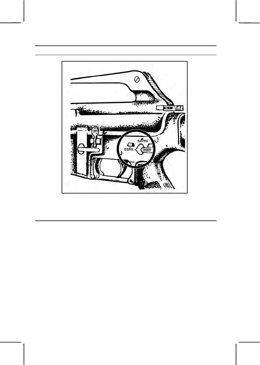
3-278 071-311-2025
Performance Steps
Figure 071-311-2025-1. Selector lever on safe
Note. The selector cannot be turned to SAFE unless the rifle is cocked.
d. Lock the bolt open (figure 071-311-2025-2).
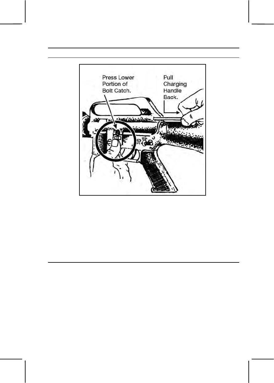
071-311-2025 3-279
Performance Steps
Figure 071-311-2025-2. Locking the bolt open
(1) Pull the charging handle rearward.
(2) Press the bottom of the bolt catch.
(3) Allow the bolt to move forward until it engages the bolt catch.
(4) Return the charging handle to the forward position.
(5) Ensure the selector is on SAFE.
e. Inspect the receiver and chamber to ensure they do not contain
ammunition (figure 071-311-2025-3).

3-280 071-311-2025
Performance Steps
Figure 071-311-2025-3. Inspecting the chamber
f. Allow the bolt to go forward by pressing the upper portion of the bolt
catch (figure 071-311-2025-4).
Figure 071-311-2025-4. Releasing the bolt
2. Disassemble the rifle.
a. Verify the rifle is clear.
b. Remove the sling.
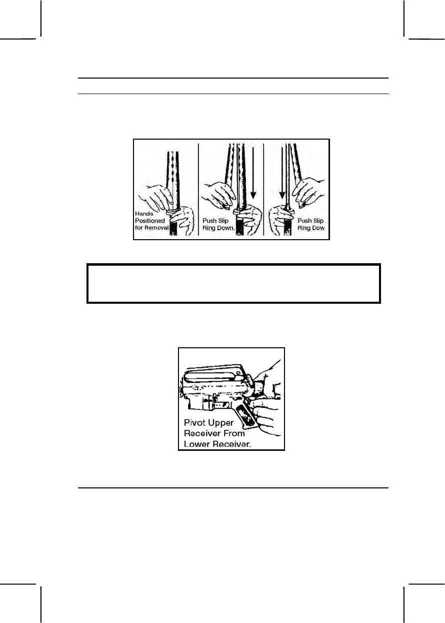
071-311-2025 3-281
Performance Steps
c. Remove the handguards if you can see dirt or corrosion through the
vent holes (figure 071-311-2025-5). Handguards on the M16A2 are
interchangeable because they are identical.
Figure 071-311-2025-5. Removing the handguards
WARNING
Use care to avoid bending or denting the gas tube while removing the
handguards.
d. Push the takedown pin as far as it will go and pivot the upper
receiver from the lower receiver (figure 071-311-2025-6).
Figure 071-311-2025-6. Pushing the takedown pin
e. Push the receiver pivot pin (figure 071-311-2025-7).
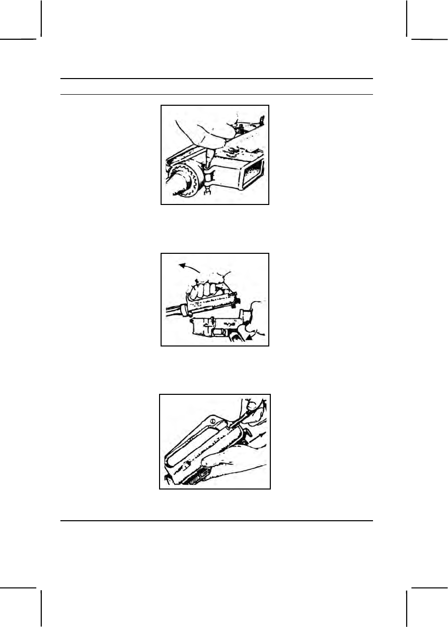
3-282 071-311-2025
Performance Steps
Figure 071-311-2025-7. Pushing the receiver pivot pin
f. Separate the upper and lower receivers (figure 071-311-2025-8).
Figure 071-311-2025-8. Separating the upper and lower receivers
g. Pull back the charging handle (figure 071-311-2025-9).
Figure 071-311-2025-9. Pulling the charging handle
h. Remove the bolt carrier and bolt (figure 071-311-2025-10).
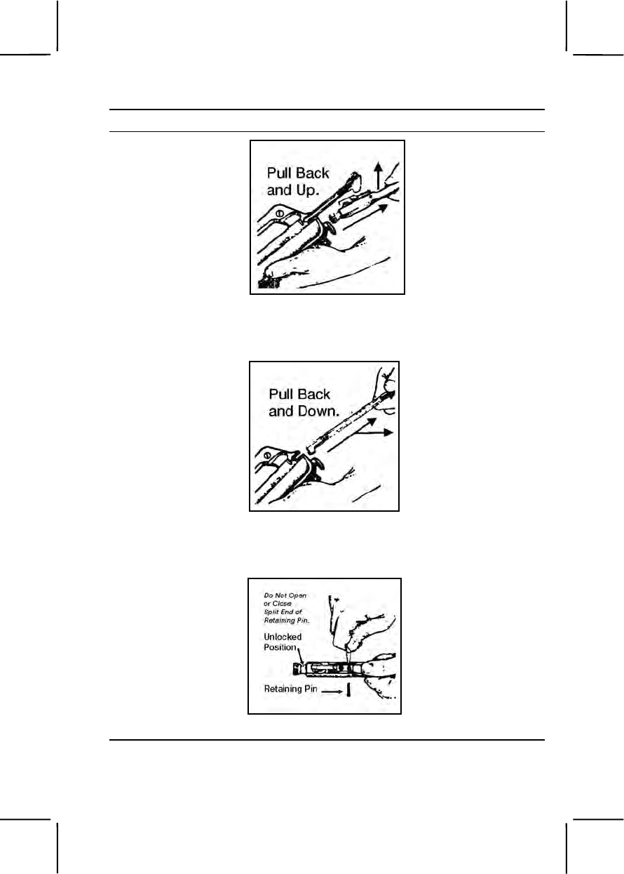
071-311-2025 3-283
Performance Steps
Figure 071-311-2025-10. Removing the bolt carrier and bolt
i. Remove the charging handle (figure 071-311-2025-11).
Figure 071-311-2025-11. Removing the charging handle
j. Remove the firing pin retaining pin (figure 071-311-2025-12).
Figure 071-311-2025-12. Removing the firing pin retaining pin
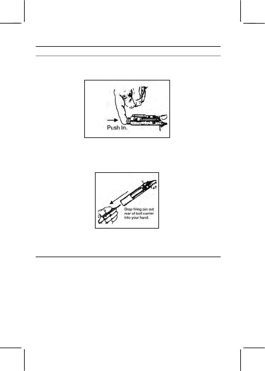
3-284 071-311-2025
Performance Steps
k. Put the bolt assembly in the locked position by pushing in the bolt
(figure 071-311-2025-13).
Figure 071-311-2025-13. Bolt in the locked position
l. Remove the firing pin by allowing it to drop out of the rear of the bolt
carrier into your hand (figure 071-311-2025-14).
Figure 071-311-2025-14. Removing the firing pin
m. Remove the bolt cam pin by turning it one-quarter turn and lifting it
out (figure 071-311-2025-15).
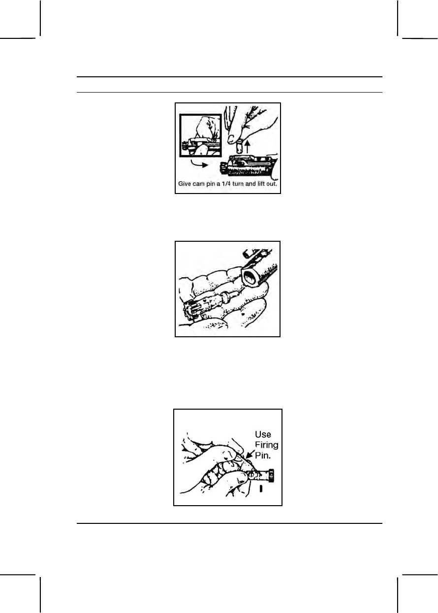
071-311-2025 3-285
Performance Steps
Figure 071-311-2025-15. Removing the bolt cam pin
n. Pull the bolt assembly from the carrier (figure 071-311-2025-16).
Figure 071-311-2025-16. Removing the bolt assembly
Note. Perform steps o through r when the parts are dirty or damaged.
o. Remove the extractor pin by pushing it out with the firing pin (use
care not to damage the firing pin) (figure 071-311-2025-17).
Figure 071-311-2025-17. Removing the extractor pin
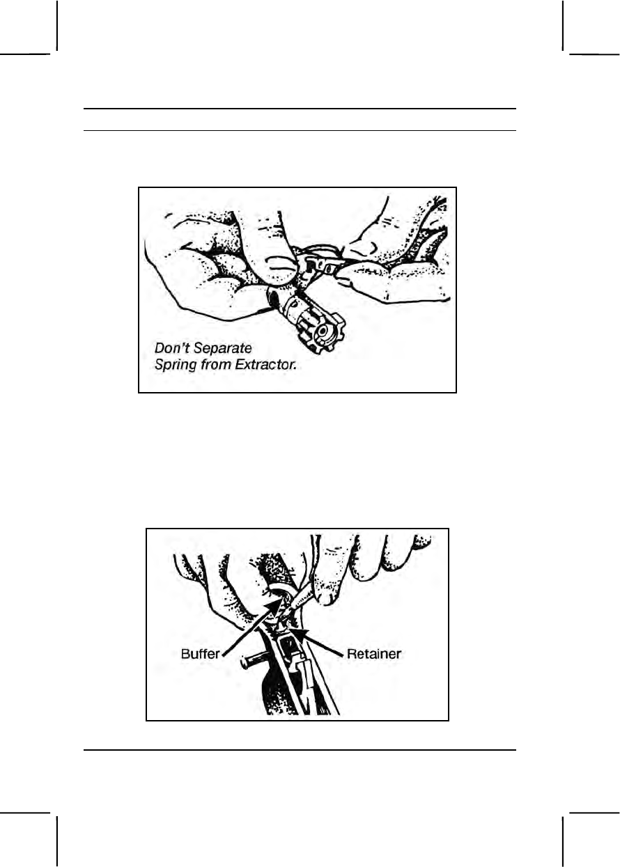
3-286 071-311-2025
Performance Steps
p. Lift out the extractor and spring (figure 071-311-2025-18), taking
care so the spring does not separate from the extractor.
Figure 071-311-2025-18. Removing the extractor and spring
Note. Press the top of the extractor to check spring function.
q. Release the buffer by pressing the buffer and depressing the
retainer.
r. Remove the buffer and action spring separating the buffer from the
spring (figure 071-311-2025-19 and figure 071-311-2025-20).
Figure 071-311-2025-19. Separating the buffer and spring

071-311-2025 3-287
Performance Steps
Figure 071-311-2025-20. Separating the buffer and spring (continued)
s. Do not disassemble the rifle further.
3. Clean the rifle by removing carbon buildup and lubricating according to
lubrication instructions. Make sure you remove any excessive oil from the
bore before firing.
Note. After firing ball or blank ammunition, clean the weapon one time only with
CLP. Under all but the coldest arctic conditions, use only CLP to lubricate the rifle.
a. Clean the upper and lower receiver group using CLP to remove
powder fouling in the upper receiver (figure 071-311-2025-21).

3-288 071-311-2025
Performance Steps
Figure 071-311-2025-21. Cleaning the receivers
b. Clean the bolt carrier group, wiping the following parts with swabs
and other parts from the small-arms maintenance equipment case (figure
071-311-2025-22).
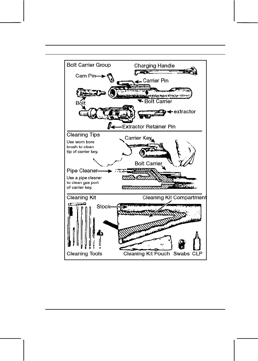
071-311-2025 3-289
Performance Steps
Figure 071-311-2025-22. Cleaning the bolt carrier group
(1) The outer and inner surfaces of the bolt carrier.
(2) The carrier key.
(3) The firing pin recess and firing pin.
(4) The firing pin hole with a pipe cleaner.
(5) The carbon deposits and dirt from the locking lugs.

3-290 071-311-2025
Performance Steps
(6) The areas behind the bolt ring and under the lip of the extractor.
c. Clean the following rifle parts, lightly lubricating with CLP (figure
071-311-2025-22).
(1) Lugs in the barrel extension, bore, and chamber.
(2) Bolt carrier.
(3) Slide cam pin area.
(4) Piston rings.
(5) Outside the bolt body.
(6) Inside the bolt carrier key.
(7) Firing pin and firing pin recess.
(8) Outside surface of the protruding gas tube with a worn bore
brush.
(9) Buffer.
(10) Action spring.
(11) Inner surfaces of the lower receiver extension.
(12) Inside the lower receiver.
(13) All other components.
4. Inspect disassembled rifle bolt assembly (figure 071-311-2025-23).
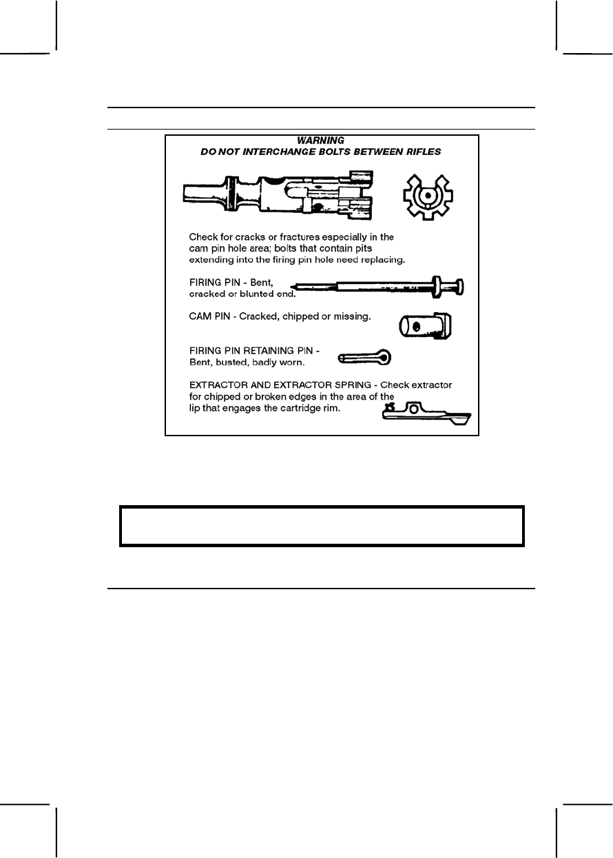
071-311-2025 3-291
Performance Steps
Figure 071-311-2025-23. Inspecting the bolt assembly
a. Identify defective or missing components.
b. Report deficiencies to the armorer.
WARNING
Do not interchange bolts between rifles.
5. Assemble the rifle.
a. Insert the spring and buffer (figure 071-311-2025-24).
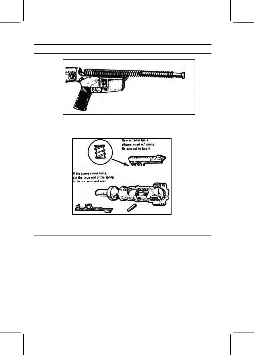
3-292 071-311-2025
Performance Steps
Figure 071-311-2025-24. Placing the spring and buffer
b. Insert the extractor and spring (figure 071-311-2025-25).
Figure 071-311-2025-25. Placing the extractor and spring
c. Push the extractor pin in (figure 071-311-2025-26).
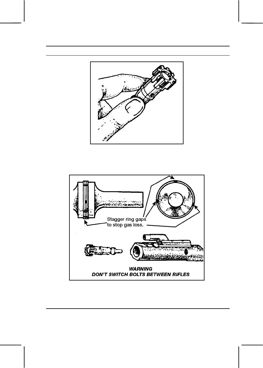
071-311-2025 3-293
Performance Steps
Figure 071-311-2025-26. Holding the extractor pin in
d. Slide the bolt into the carrier until the bolt cam pin hole in both the
bolt carrier and the bolt are aligned (figure 071-311-2025-27).
Figure 071-311-2025-27. Placing the bolt in the carrier
e. Place the bolt cam pin by putting it in the bolt carrier, turning it one-
quarter turn (figure 071-311-2025-28).
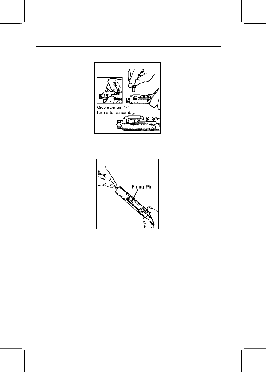
3-294 071-311-2025
Performance Steps
Figure 071-311-2025-28. Replacing the bolt cam pin
f. Drop in the firing pin to seat it (figure 071-311-2025-29).
Figure 071-311-2025-29. Placing the firing pin
g. Put the firing pin retaining pin in the bolt carrier to seat it
(figure 071-311-2025-30).
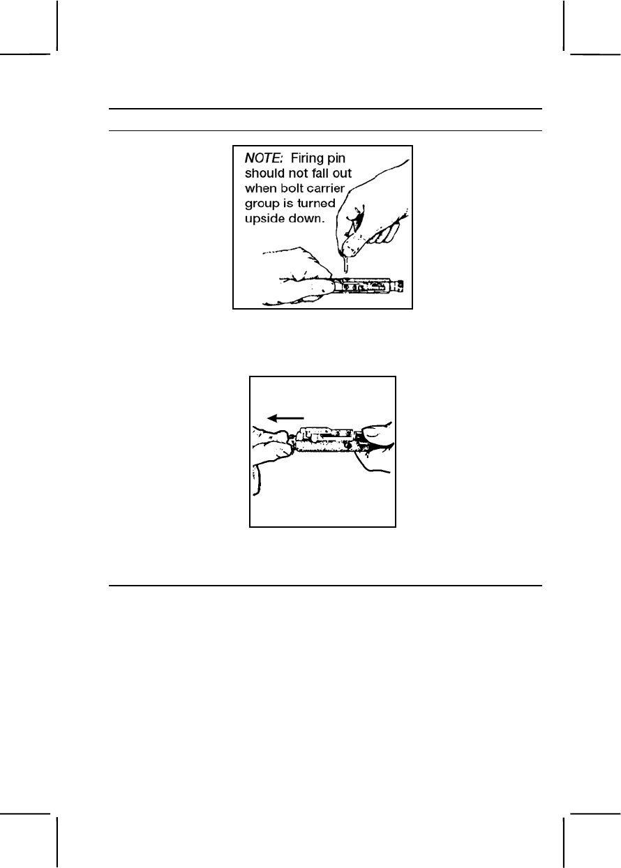
071-311-2025 3-295
Performance Steps
Figure 071-311-2025-30. Placing the firing pin retaining pin
h. Pull the bolt back (figure 071-311-2025-31).
Figure 071-311-2025-31. Pulling back on the bolt
i. Place the charging handle by engaging it, then pushing the
charging handle part of the way in (figure 071-311-2025-32).
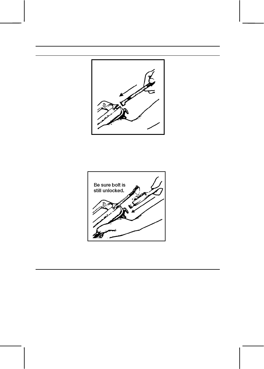
3-296 071-311-2025
Performance Steps
Figure 071-311-2025-32. Placing the charging handle in the receiver
j. Slide the bolt carrier into the upper receiver (figure 071-311-2025-
33).
Figure 071-311-2025-33. Placing the bolt carrier
k. Push the charging handle and bolt carrier together in the upper
receiver (figure 071-311-2025-34).
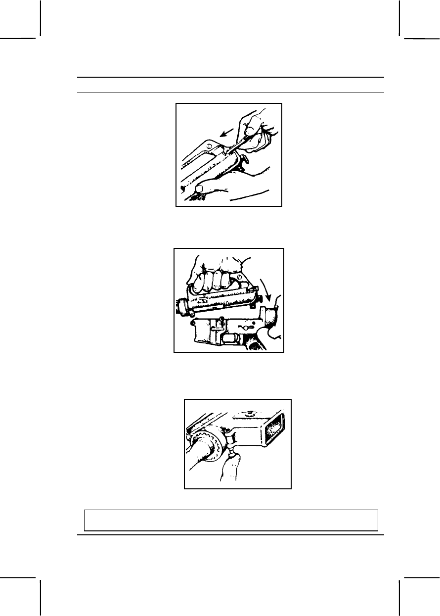
071-311-2025 3-297
Performance Steps
Figure 071-311-2025-34. Placing the charging handle and the bolt carrier
l. Join the upper and lower receiver (figure 071-311-2025-35).
Figure 071-311-2025-35. Joining the upper and lower receivers
m. Engage the receiver pivot pin (figure 071-311-2025-36).
Figure 071-311-2025-36. Engaging the receiver pivot pin
CAUTION
The selector lever must be on SAFE before closing the upper receiver.
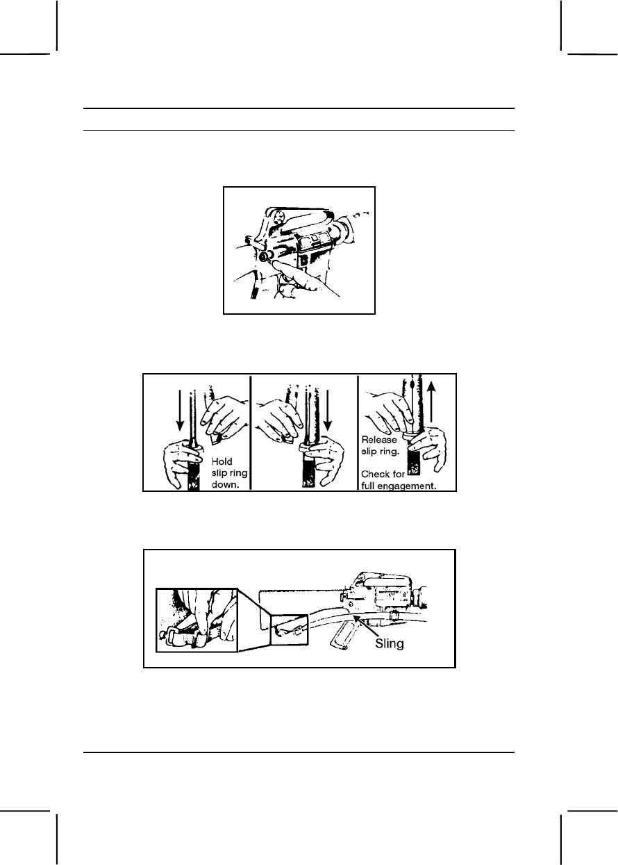
3-298 071-311-2025
Performance Steps
n. Close the upper and lower receiver groups, seating the takedown
pin and ensuring the selector switch is on SAFE (figure 071-311-2025-37).
Figure 071-311-2025-37. Seating the takedown pin
o. Put the handguards in place (figure 071-311-2025-38).
Figure 071-311-2025-38. Placing the handguards
p. Replace the sling (figure 071-311-2025-39).
Figure 071-311-2025-39. Placing the sling
6. Disassemble the magazine without removing the follower from the
spring.
a. Release the base catch (figure 071-311-2025-40).

071-311-2025 3-299
Performance Steps
Figure 071-311-2025-40. Releasing the base catch of the magazine
b. Remove the base (figure 071-311-2025-41).
Figure 071-311-2025-41. Removing the base of the magazine
c. Remove the spring and follower by jiggling them (figure 071-311-
2025-42).
Figure 071-311-2025-42. Removing the magazine spring and the follower
7. Clean the magazine.
a. Wipe the dirt from the tube, spring, and follower.
b. Lubricate the spring lightly.
8. Assemble the magazine.

3-300 071-311-2025
Performance Steps
a. Jiggle the spring and follower together to install them in the
magazine.
b. Slide the base under all four tabs, making sure the print is on the
outside.
9. Clean the ammunition using a clean, dry cloth to wipe dirt and foreign
matter from the ammunition. Do not coat with oil.
Evaluation Preparation:
Setup: Have soldier use his own rifles and magazines. Provide swabs, CLP,
pipe cleaners, and, if available, preservative lubricant (PL), special
lubricating oil, and rifle bore cleaner (RBC). (The soldier should not select
the PL, special lubricating oil, or RBC for use.) Also, provide several rounds
of dummy ammunition, if available.
Brief Soldier: Tell the soldier to clean, inspect, and lubricate the rifle and
magazine following normal safety practices.
Performance Measures GO NO GO
1. Cleared the rifle before disassembly. —— ——
a. Removed the magazine from the rifle.
b. Cocked the rifle.
c. Turned the selector to SAFE.
d. Locked the bolt open.
e. Checked the receiver and chamber to ensure
they did not contain ammunition.
f. Allowed the bolt to go forward by pressing the
upper portion of the bolt catch.
2. Disassembled the rifle. —— ——
a. Verified the rifle was clear.
b. Removed the sling.
c. Removed the handguards if dirt or corrosion
could be seen through the vent holes.
d. Pushed the takedown pin as far as it would go
and pivoted the upper receiver from the lower receiver.
e. Pushed the receiver pivot pin.
f. Separated the upper and lower receivers.
g. Pulled back the charging handle.

071-311-2025 3-301
Performance Measures GO NO GO
h. Removed the bolt carrier and bolt.
i. Removed the charging handle.
j. Removed the firing pin retaining pin.
k. Put the bolt assembly in the locked position by
pushing in the bolt.
l. Removed the firing pin by allowing it to drop out
of the rear of the bolt carrier into hand.
m. Removed the bolt cam pin by turning it one-
quarter turn and lifting it out.
n. Pulled the bolt assembly from the carrier.
o. Removed the extractor pin by pushing it out with
the firing pin.
p. Lifted out the extractor and spring, taking care so
the spring did not separate from the extractor.
q. Released the buffer by pressing the buffer and
depressing the retainer.
r. Removed the buffer and action spring separating
the buffer from the spring.
3. Cleaned the rifle using the correct materials. —— ——
a. Cleaned the upper and lower receiver group.
b. Cleaned the bolt carrier group.
c. Cleaned all other rifle parts lubricating the rifle
with CLP.
4. Inspected for unserviceable parts. —— ——
a. Identified the defective or missing components.
b. Reported deficiencies to the armorer.
5. Assembled the rifle. —— ——
a. Inserted the spring and buffer.
b. Inserted the extractor and spring.
c. Pushed the extractor pin in.
d. Slid the bolt into the carrier until the bolt cam pin
hole in both the bolt carrier and the bolt were aligned.
e. Placed the bolt cam pin by putting it in the bolt
carrier, turning it one-quarter turn.

3-302 071-311-2025
Performance Measures GO NO GO
f. Dropped in the firing pin to seat it.
g. Put the firing pin retaining pin in the bolt carrier.
h. Pulled the bolt back.
i. Placed the charging handle by engaging it, then
pushed the charging handle part of the way in.
j. Slid the bolt carrier into the upper receiver.
k. Pushed the charging handle and bolt carrier
together in the upper receiver.
l. Joined the upper and lower receiver.
m. Engaged the receiver pivot pin.
n. Closed the upper and lower receiver groups.
o. Put the handguards in place.
p. Replaced the sling.
6. Disassembled the magazine without removing the
follower from the spring. —— ——
a. Released the base catch.
b. Removed the base.
c. Removed the spring and follower.
7. Cleaned the magazine. —— ——
a. Wiped the dirt from the tube, spring, and follower.
b. Lubricated the spring lightly.
8. Assembled the magazine. —— ——
a. Jiggled the spring and follower together to install
them in the magazine.
b. Slid the base under all four tabs, making sure the
printed portion was on the outside.
9. Cleaned the ammunition. —— ——
Evaluation Guidance: Score the soldier GO if all performance measures
are passed. Score the soldier NO GO if any performance measure is failed.
If the soldier scores NO GO, show him what was done wrong and how to do
it correctly.
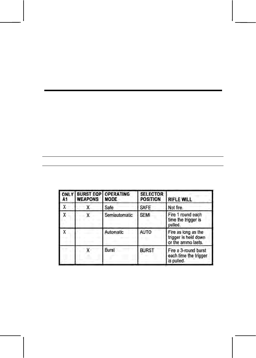
071-311-2027 3-303
References
Required Related
FM 23-9
TM 9-1005-249-10
071-311-2027
Load an M16-Series Rifle
Conditions: Given an unloaded M16-series rifle with a magazine loaded
with ammunition.
Standards: Loaded an M16A1 rifle in the semiautomatic and automatic
modes or loaded an M16A2 or M16A4 rifle in both the semiautomatic and
burst modes. In either case, ensured that a round was chambered and the
selector was returned to the SAFE position.
Performance Steps
1. Determine the mode in which the rifle will be operated by using table
071-311-2027-1.
Table 071-311-2027-1. M16 family operating modes.
2. Prepare the M16A1, M16A2, or M16A4 rifle for semiautomatic fire and
the M16A1 rifle for automatic fire.
a. Point the rifle muzzle in a safe direction.
b. Cock the rifle (this also opens the bolt).
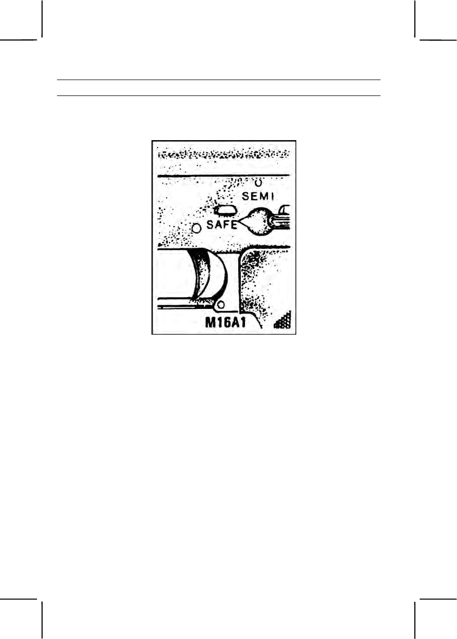
3-304 071-311-2027
Performance Steps
c. Return the charging handle to the forward position.
d. Place the selector lever on SAFE (figure 071-311-2027-1).
Figure 071-311-2027-1. Selector lever on SAFE.
e. Check the chamber to ensure it is clear (figure 071-311-2027-2).
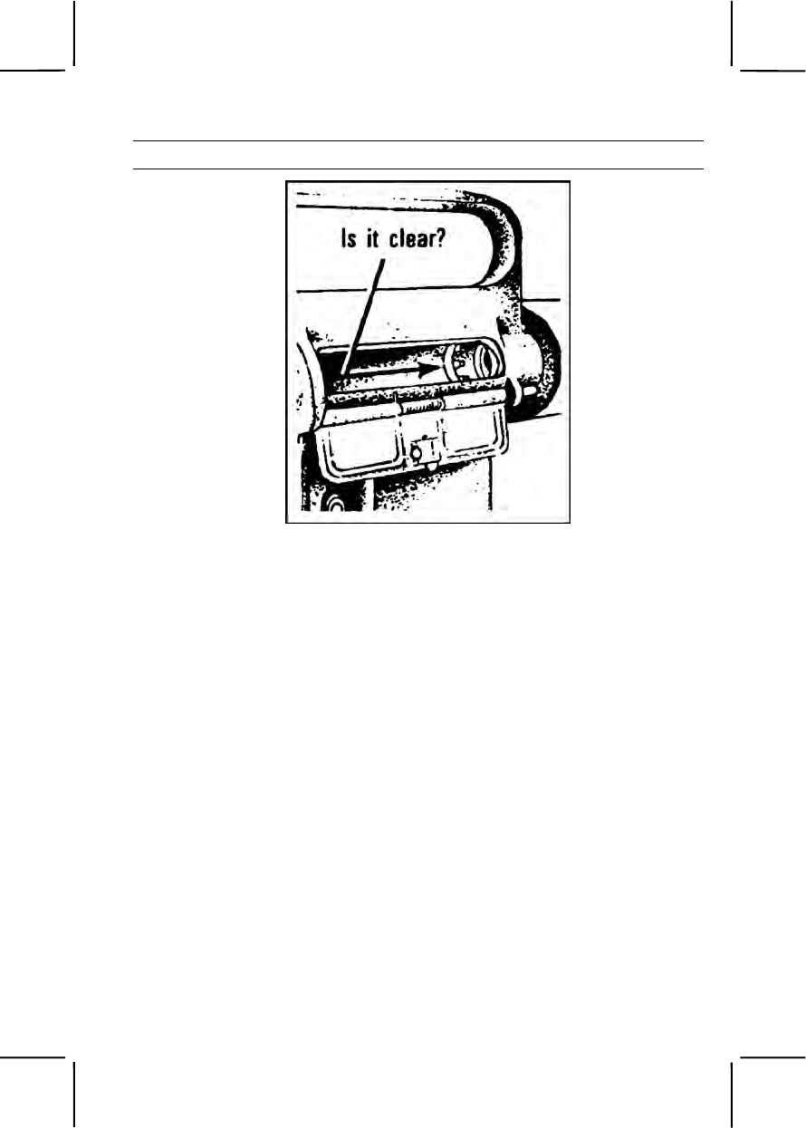
071-311-2027 3-305
Performance Steps
Figure 071-311-2027-2. Inspecting the chamber.
f. Insert the magazine, pushing it upward until the magazine catch
engages and holds the magazine (figure 071-311-2027-3).
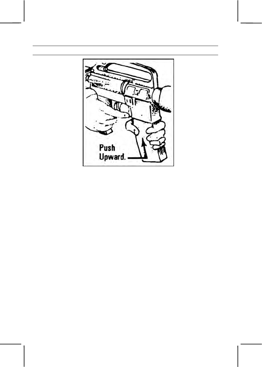
3-306 071-311-2027
Performance Steps
Figure 071-311-2027-3. Magazine inserted.
g. Tap upward on the bottom of the magazine to ensure it is seated.
Note: The magazine may be loaded with the bolt assembly open or closed.
3. Prepare the M16A2 or M16A4 rifle for burst fire.
a. Point the rifle muzzle in a safe direction.
b. Cock the rifle (this also opens the bolt).
c. Return the charging handle to the forward position.
d. Place the selector lever in the BURST position (figure 071-311-
2027-4).
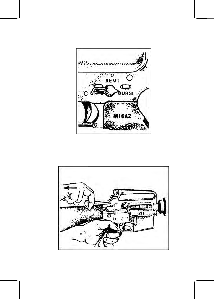
071-311-2027 3-307
Performance Steps
Figure 071-311-2027-4. Selector lever on BURST.
e. Pull the trigger, holding it in the rear position.
f. Pull the charging handle to the rear and release it (figure 071-311-
2027-5).
Figure 071-311-2027-5. Charging handle.
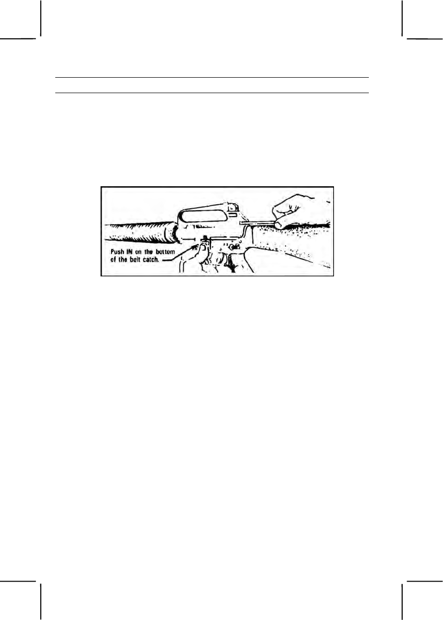
3-308 071-311-2027
Performance Steps
g. Repeat step 3f three times.
h. Pull the charging handle to the rear, holding it in place.
i. Release the trigger.
j. Push in on the bottom portion of the bolt catch, locking the bolt in
the rear position (figure 071-311-2027-6).
Figure 071-311-2027-6. Bolt locked to the rear.
k. Slide the charging handle all the way forward.
l. Place the selector on SAFE.
m. Insert the magazine, pushing it upward until the magazine catch
engages and holds the magazine (figure -).
n. Tap upward on the bottom of the magazine to ensure it is seated.
4. Chamber a round.
a. With the bolt open:
(1) Depress the upper portion of the bolt catch to release the bolt
(figure 071-311-2027-7).
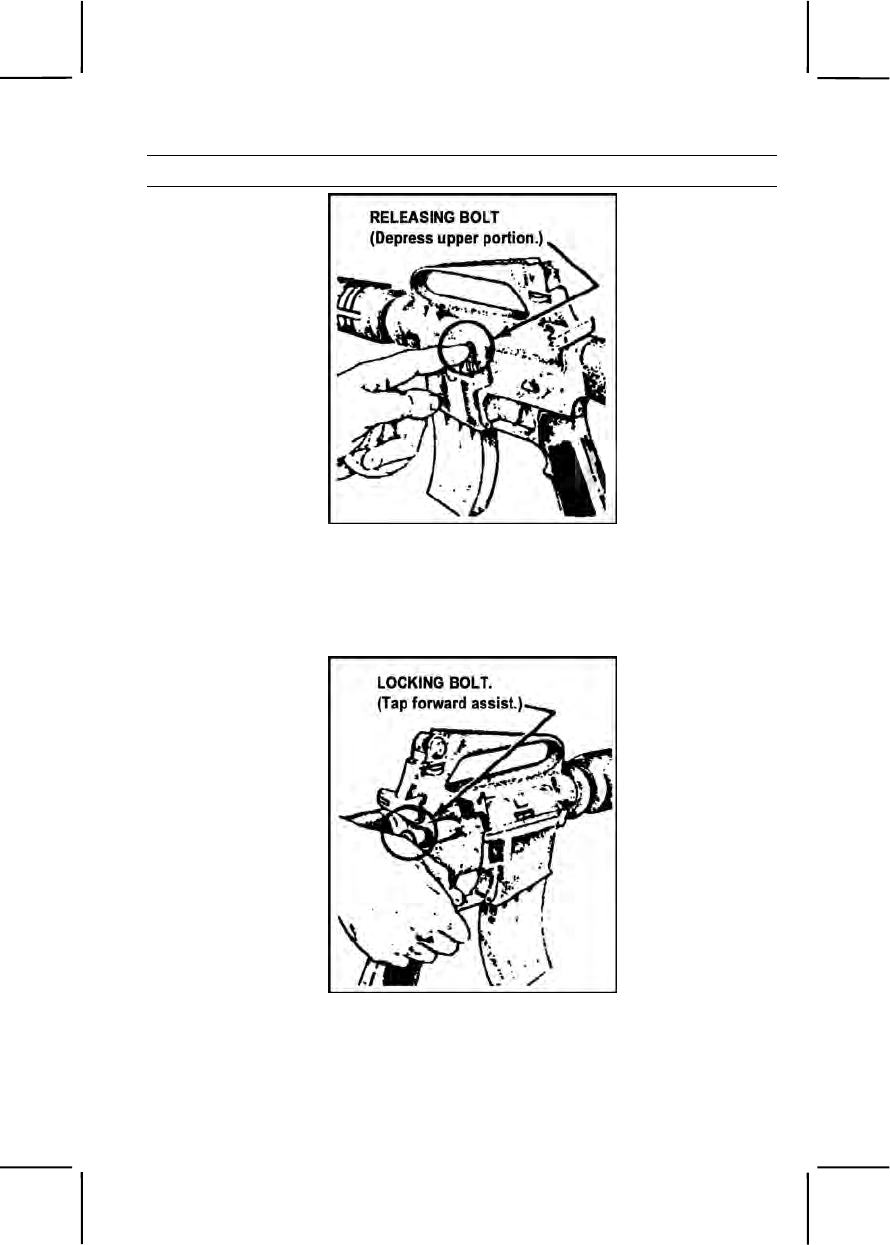
071-311-2027 3-309
Performance Steps
Figure 071-311-2027-7. Bolt catch.
(2) Tap the forward assist to ensure that the bolt is fully forward
and locked (figure 071-311-2027-8).
Figure 071-311-2027-8. Forward assist.

3-310 071-311-2027
Performance Steps
WARNING
The rifle is now loaded. Ensure it is pointed in a safe direction.
(3) Place selector lever on SAFE, closing the ejection port cover if
the rifle is not to be fired immediately.
b. With the bolt closed:
(1) Pull the charging handle to the rear as far as it will go.
(2) Release the charging handle. Do not ride the charging handle;
allow it to return on its own.
(3) Tap the forward assist to ensure the bolt is fully forward and
locked.
WARNING
The rifle is now loaded. Ensure it is pointed in a safe direction.
(4) Place the selector lever on SAFE closing the ejection port cover
if the rifle is not to be fired immediately.
Evaluation Preparation:
Setup: Have soldiers use their assigned rifles and magazines. Provide blank
or dummy ammunition when evaluating this task.
Brief Soldier: Tell the soldier to load the rifle using the steps appropriate for
the model being used. An M16A2 rifle must be loaded in both the
semiautomatic and BURST modes.
Performance Measures GO NO GO
Note: Perform steps 1 and 3 through 5 for the M16A1 rifle and
steps 1 through 5 for the M16A2 or M16A4 rifle.
1. Prepared the M16A1, M16A2, or M16A4 rifle for
semiautomatic fire and the M16A1 rifle for automatic
fire; ensured the chamber was cleared and the
magazine was seated.
—— ——
2. Prepared the M16A2 or M16A4 rifle for burst fire;
ensured the magazine was seated. —— ——

071-311-2028 3-311
Performance Measures GO NO GO
3. Chambered a round; ensured the bolt was fully
forward and locked. —— ——
4. Pointed the rifle in a safe direction. —— ——
5. Placed the selector lever in the SAFE position. —— ——
Evaluation Guidance: Score the soldier GO if all performance measures
are passed. Score the soldier NO-GO if any performance measure is failed.
If the soldier scores NO-GO, show the soldier what was done wrong and
how to do it correctly.
References
Required Related
TM 9-1005-249-10
TM 9-1005-319-10
071-311-2028
Unload an M16-Series Rifle
Conditions: Given a loaded M16-series rifle from which you must remove
the ammunition.
Standards: Cleared the rifle, removed all ammunition and secured the rifle
in the SAFE mode.
Performance Steps
1. Point the rifle muzzle in a safe direction.
2. Remove the magazine from the rifle.
3. Place the selector lever on SAFE.
4. Lock the bolt open.
a. Pull the charging handle rearward.
b. Press the bottom of the bolt catch.
c. Return the charging handle to the forward position.
5. Remove any ammunition from the receiver and chamber.
6. Press the upper portion of the bolt catch, allowing the bolt to go

3-312 071-311-2028
Performance Steps
forward.
7. Pull the trigger to release the pressure on the firing pin spring.
Evaluation Preparation:
Setup: At a test site, provide an M16-series rifle loaded with dummy
ammunition. (You can also evaluate the soldier using his individual rifle if
loaded. Do not require the soldier to pull the trigger after releasing the bolt.)
Brief Soldier: Tell the soldier to unload the rifle.
Performance Measures GO NO GO
1. Pointed the rifle muzzle in a safe direction. —— ——
2. Removed the magazine from the rifle. —— ——
3. Placed the selector lever on SAFE. —— ——
4. Locked the bolt open. —— ——
a. Pulled the charging handle rearward.
b. Pressed the bottom of the bolt catch.
c. Returned the charging handle to the forward
position.
5. Removed any ammunition from the receiver and
chamber. —— ——
6. Pressed the upper portion of the bolt catch, allowed
the bolt to go forward. —— ——
7. Pulled the trigger to release the pressure on the
firing pin spring. —— ——
Evaluation Guidance: Score the soldier GO if all performance measures
are passed. Score the soldier NO-GO if any performance measure is failed.
If the soldier scores NO-GO, show the soldier what was done wrong and
how to do it correctly.
References
Required Related
TM 9-1005-249-10
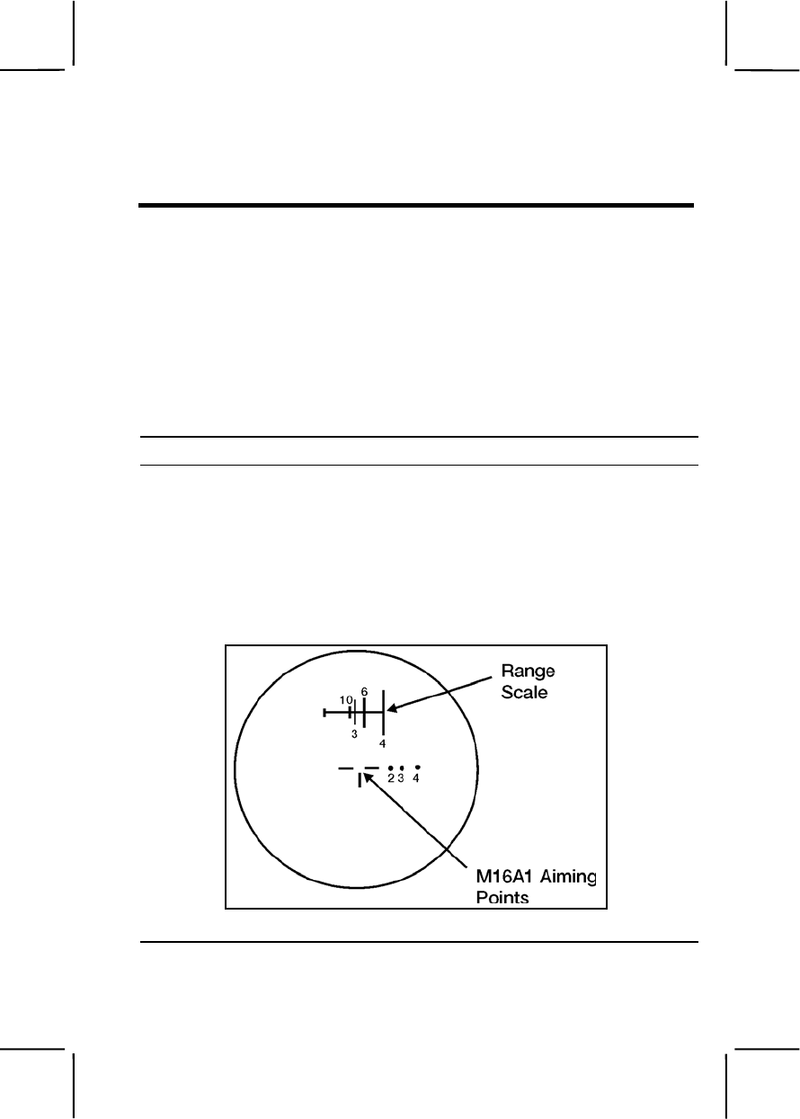
071-315-2308 3-313
071-315-2308
Engage Targets with an M16-Series Rifle Using a Night Vision Sight
AN/PVS-4
Conditions: During darkness, given an M16-series rifle with a mounted and
zeroed AN/PVS-4; one silhouette target between 50 and 100 meters, one at
150 meters, and one between 200 and 250 meters; and one magazine with
18 rounds of ammunition.
Standards: Fired all 18 rounds and hit the targets at least nine times. At
least five rounds hit the 150-meter target; at least two rounds hit the 50- to
100-meter target, and at least two rounds hit the 200- to 250-meter target.
Performance Steps
Note. Ensure the AN/PVS-4 has the proper sighting reticle (figure 071-315-2308-1).
1. Place the sight into operation.
2. Use the sight reticle. When used with the rifle, the AN/PVS-4 sight
reticle consists of two parts (figure 071-315-2308-1).
a. Use the upper part of the reticle (range scale) to determine range to
the target.
b. Use the lower part of the reticle for aiming the weapon.
Figure 071-315-2308-1. Sight reticle
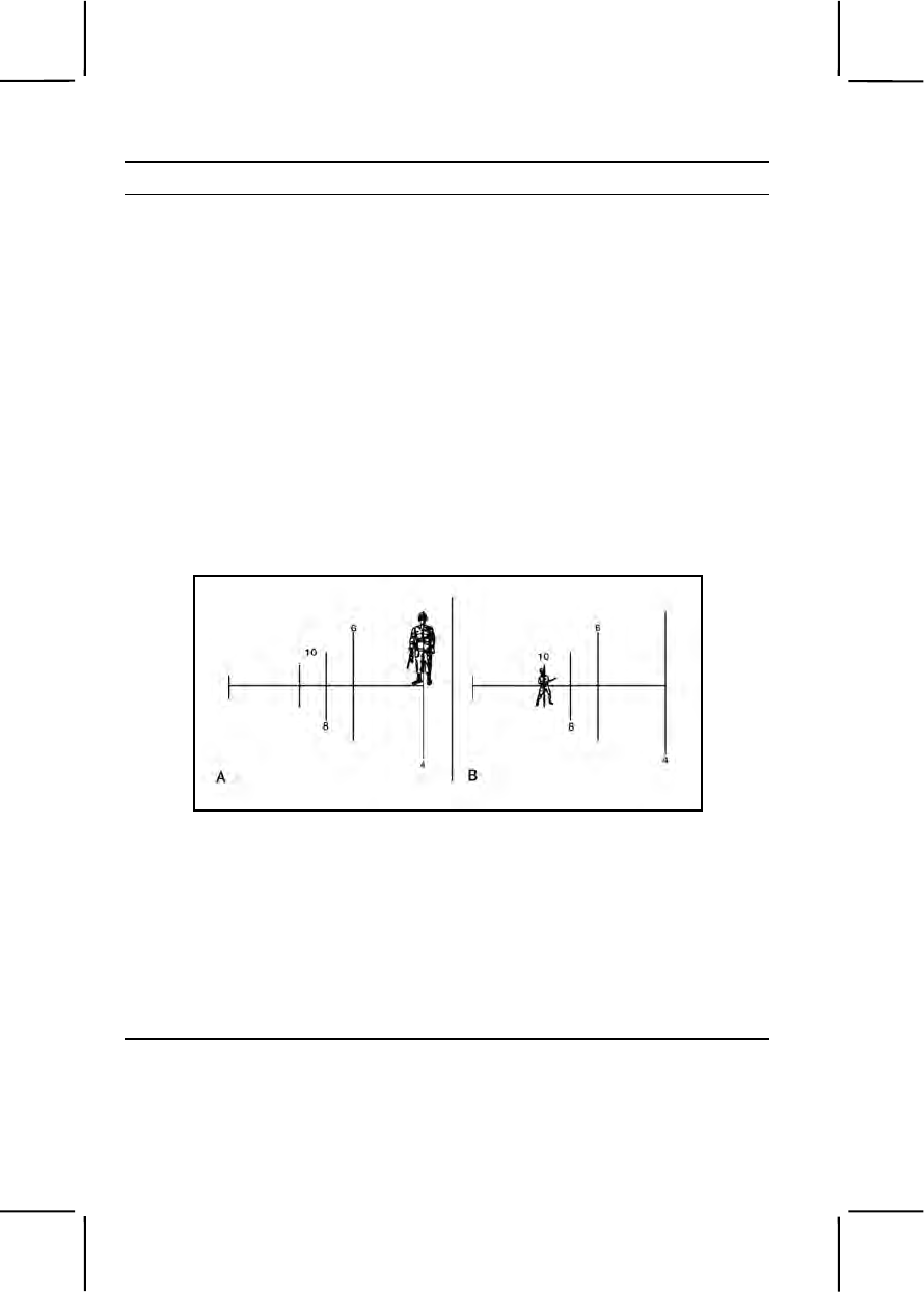
3-314 071-315-2308
Performance Steps
Note. Ensure the AN/PVS-4 is mounted to the rifle using the rifle mounting adapter
and not the M203 mounting bracket.
3. Determine range to target.
a. The vertical lines on the range scale tell the distance from a 6-foot
man.
(1) Place the target on the horizontal line and match it with one of
the vertical lines (A, figure 071-315-2308-2).
(2) Read the number at the bottom or top of the vertical line. That is
the distance in hundreds of meters to the target.
(3) If the figure is the same height as the vertical line above and
below the horizontal line, the distance will be half the number at the top or
bottom of that line (B, figure 071-315-2308-2.
(4) The man shown in A, figure 071-315-2308-2 is 400 meters
away. The man in B, figure 071-315-2308-2 is 500 meters away.
Figure 071-315-2308-2. Range determination using vertical lines
b. The horizontal line of the range scale indicates the range (in
hundreds of meters) of a 20-foot target such as a tank or large truck
viewed from the side.
(1) Place the left edge of the vehicle at the left side of the horizontal
line (figure 071-315-2308-3).
(2) Read the range to the tank from the scale at the right edge of
the tank. As shown in A, figure 071-315-2308-3, the range to the vehicle is
1,000 meters.
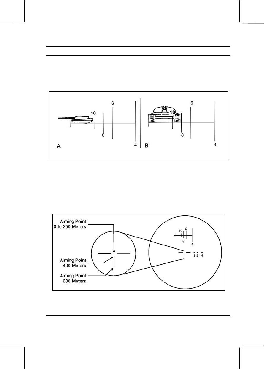
071-315-2308 3-315
Performance Steps
(3) When viewed from the front or rear, the vehicle width is about
half the length. Read the placement of the vehicle width on the range scale
as half the range scale value. As shown in B, figure 071-315-2308-3, the
range to the vehicle is 400 meters.
Figure 071-315-2308-3. Range determination using horizontal lines
4. Engage targets using the sight reticle.
a. The rifle aiming point for ranges out to 250 meters is the center of
the three straight lines (zero aiming point) (figure 071-315-2308-4). The top
of the vertical line is the aiming point for 400 meters, and the bottom of the
line is the aiming point for 600 meters.
Figure 071-315-2308-4. Zero aiming point
b. Locate the target, estimate the range, and place the proper aiming
point on the target.

3-316 071-315-2308
Performance Steps
WARNING
To prevent eye injury from weapon recoil, attach the eye guard to the
sight before firing the weapon.
c. Fire the weapon using correct marksmanship procedures.
Note. When firing the rifle, disregard the three dots to the right of the aiming point;
these are needed only when firing the M203.
Evaluation Preparation:
Setup: At a live-fire range, provide the equipment and materials given in the
task conditions. Turn off the sight after evaluation.
Brief Soldier: Tell the soldier to engage all targets with a minimum of nine
hits (to include at least five hits on the 150-meter target and at least two hits
on the 50- to 100-meter target, and at least two hits on the 200- to 250-meter
target) out of 18 rounds.
Performance Measures GO NO GO
1. Placed the AN/PVS-4 into operation. —— ——
2. Engaged targets. —— ——
a. The 150-meter target with at least five hits.
b. The 50- to 100-meter target with at least two hits.
c. The 200- to 250-meter target with at least two
hits.
Evaluation Guidance: Score the soldier GO if all performance measures
are passed. Score the soldier NO GO if any performance measure is failed.
If the soldier scores NO GO, show him what was done wrong and how to do
it correctly.
References
Required Related
TM 11-5855-213-10

071-000-0005 3-317
SUBJECT AREA 10: M240B MACHINE GUN
071-000-0005
Prepare a Range Card for a Machine Gun
Conditions: During daylight, in a defensive fighting position, given a tripod-
mounted machine gun with a traversing and elevation (T&E) mechanism; an
assigned primary sector of fire with recognizable targets (either an FPL [final
protective line] or PDF [principal direction of fire]); and a secondary sector of
fire with recognizable targets; blank standard range cards DA Form 5517-R;
a pencil; a lensatic compass; and a map of your assigned sector of fire.
Standards: Prepared a range card for your position in duplicate. Sketched
in the terrain in your assigned sector of fire. Located and sketched in
magnetic north, using the appropriate symbol. Sketched in sector limits, the
gun symbol, a FPL or PDF, and dead space. In the DATA SECTION wrote in
the weapon, the unit, and other data. Sketched in terrain features that offer
likely targets and numbered them in priority. Recorded the range and
direction to and the elevation and description of each target.
Performance Steps
1. Show the gunner where to place fires on designated targets during
limited visibility conditions such as night, fog, or smoke.
2. Provide the gunner conducting a relief in place with all the information he
needs to respond immediately to enemy action.
3. Provide the platoon leader and company commander with information
they need to plan fires.
4. Write all necessary information on the range card. Prepare a duplicate
range card for the platoon leader. Include on both copies all sketches,
symbols (figure 071-000-0005-1) and data.
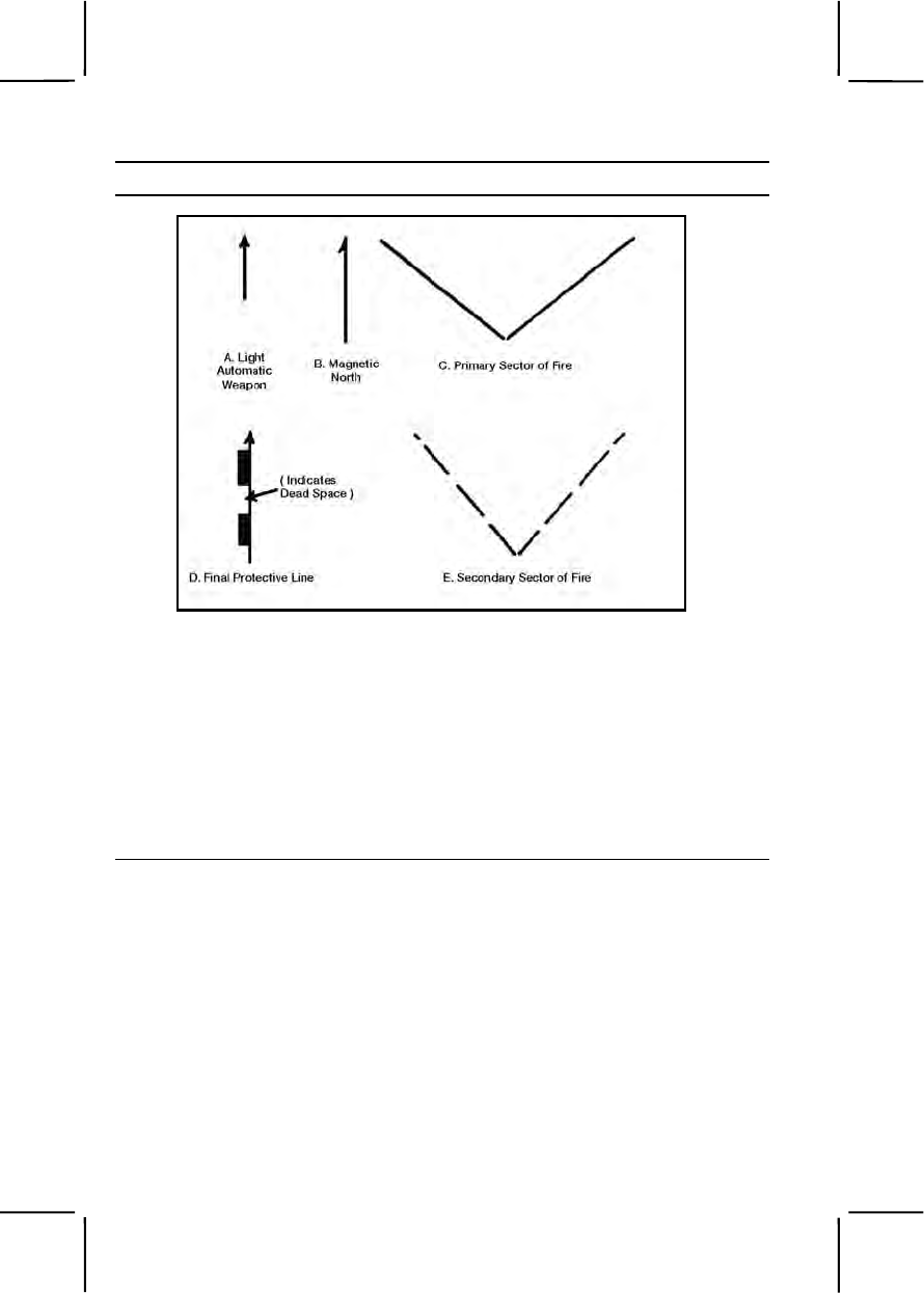
3-318 071-000-0005
Performance Steps
Figure 071-000-0005-1. Symbols.
a. On the range card, roughly sketch the terrain in front of the position.
(1) Center the machine gun position at the bottom of the sketch.
(2) Include any prominent natural and man-made features that a
target could use to take cover.
b. Using the lensatic compass, determine magnetic north.
c. Write the following information in the top portion of the range card
(figures 071-000-0005-2 and 071-000-0005-3):
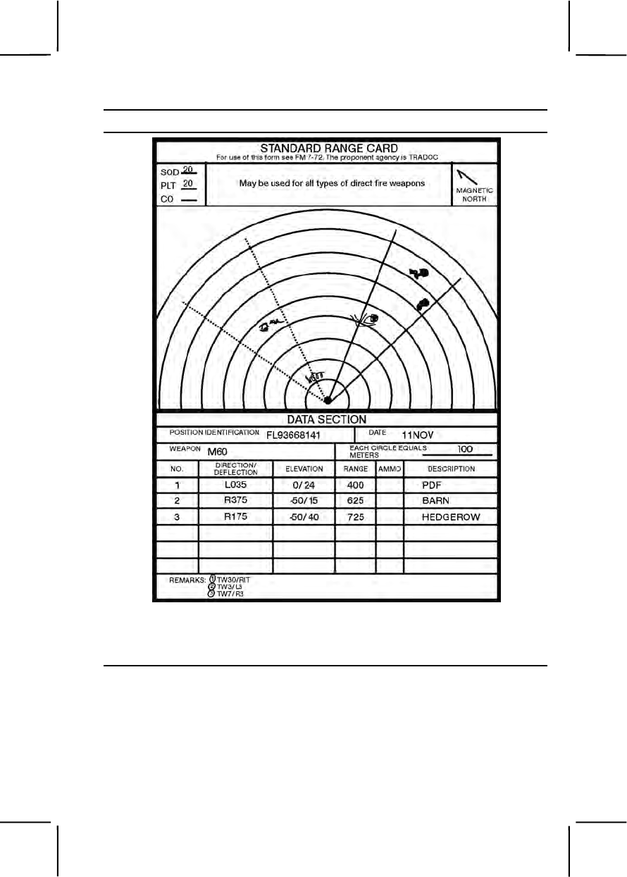
071-000-0005 3-319
Performance Steps
Figure 071-000-0005-2. Primary sector with principal direction of fire.
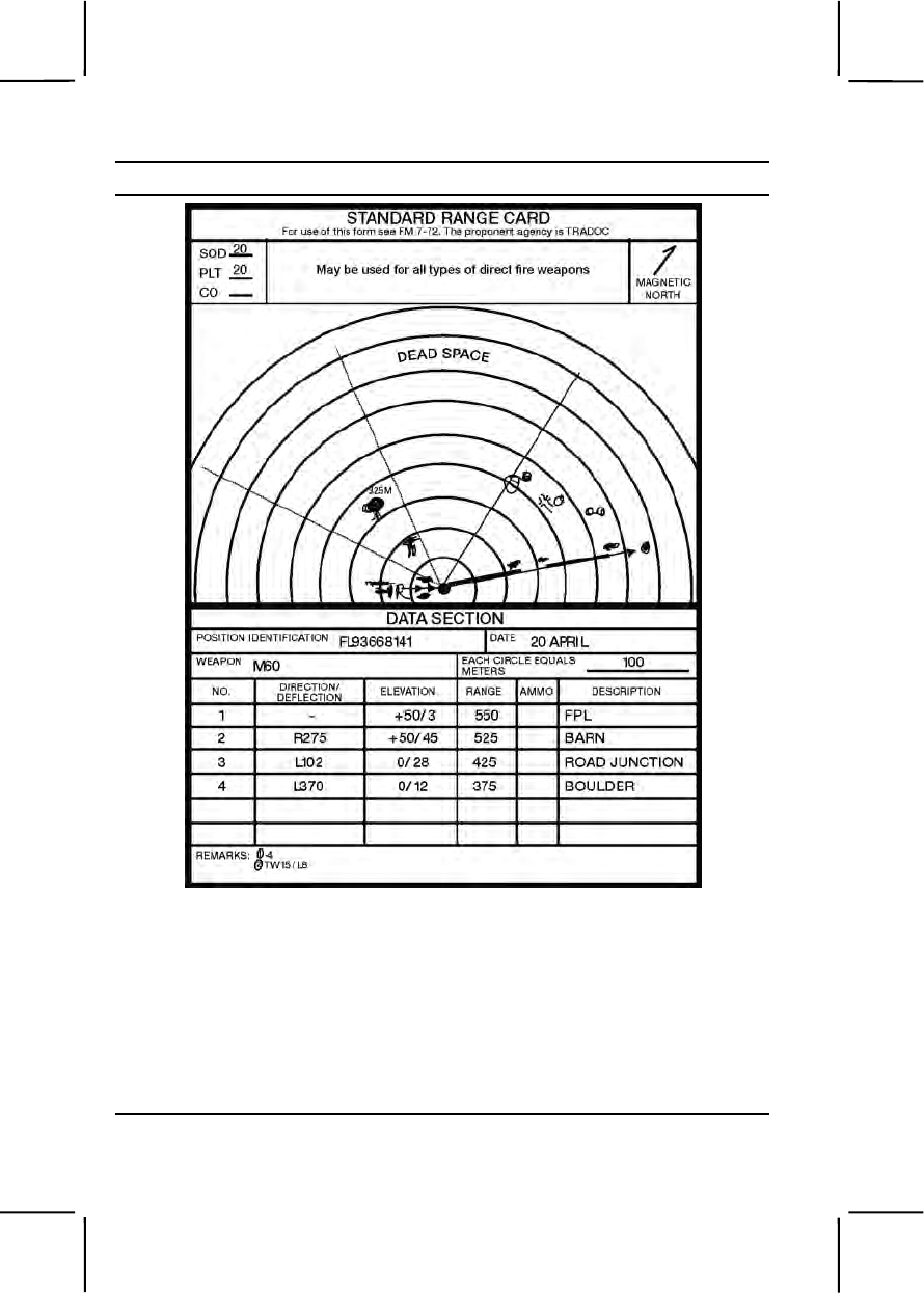
3-320 071-000-0005
Performance Steps
Figure 071-000-0005-3. Primary sector with final protective line.
(1) SQD. Write in the squad's designation.
(2) PLT. Write in the platoon's designation.
(3) CO. Write in the company's designation.
(4) MAGNETIC NORTH. Sketch the direction for magnetic north
using the symbol shown in B, Figure 071-000-0005-1.
d. Determine the location of the gun position relative to a prominent

071-000-0005 3-321
Performance Steps
terrain feature. You could use a hilltop, road junction, or building--in other
words, use either a man-made or natural terrain feature.
(1) Use any terrain feature located within 1,000 meters of the gun.
(2) If no such feature exists, then, somewhere near the gun position
on the sketch, write in the eight-digit map coordinates for your position
(figure 071-000-0005-2).
(3) Use a compass to determine the azimuth in mils or degrees from
the terrain feature to the gun position or from the gun position to the terrain
feature. Compute the back azimuth from the gun to the feature by adding or
subtracting 3,200 mils or 180 degrees.
(4) Determine the distance between the gun and the feature by
pacing or looking at a map.
(5) Draw the terrain feature in the lower left- or right-hand corner of
the card, whichever better shows the terrain feature's position relative to the
gun.
(6) Draw a barbed line between the position and the terrain feature.
(7) Above the line, record the distance in meters.
(8) Below the line, record the azimuth in mils or degrees from the
terrain feature to the gun.
(9) Use the direction of the arrow's barbs to show the direction of the
azimuth.
e. Sketch in the primary sector of fire (C, figure 071-000-0005-1), using
either a PDF or an FDL.
(1) FPL. Use a FPL (figure 071-000-0005-3 DATA SECTION, Item
No. 1) only if the position offers a good grazing distance. Base the primary
sector of the line of fire. Make the FPL the sector limit closest to friendly
troops.
(a) Sketch in the limits of the primary sector of fire.
(b) Sketch in a FPL (D, figure 071-000-0005-1) on the sector
limit assigned by your leader.
(c) Have someone walk the FPL (if the enemy situation permits)
to identify and measure dead spaces (section[s] of a FPL where a person
drops below the light of sight).
(d) Show the dead space(s) on the sketch by a break(s) in the
FPL symbol. Write in the ranges to the beginning and end of each dead
space(s).
(e) Write in the maximum range of graze.
(2) PDF. If you cannot identify an FPL, you must assign a PDF

3-322 071-000-0005
Performance Steps
(figure 071-000-0005-2 DATA SECTION, Item No.1)
(a) Sketch in the limits of the assigned primary sector of fire,
whose angle should not exceed 875 mils (the maximum traverse of a tripod-
mounted machine gun).
(b) Sketch in the symbol for a light automatic weapon (A, figure
071-000-0005-1). Orient the symbol toward the most dangerous target in the
sector. Get this information from the platoon leader.
f. Label the targets in the primary sector in their order of priority. Label
the FPL or PDF with the number "1" (figures 071-000-0005-2 and 071-000-
0005-3).
g. Sketch in the secondary sector of fire (E, figure 071-000-0005-1).
(1) Label the range (in meters) from the gun to each target in the
secondary sector.
(2) Sketch in aiming and elevation stakes between the gun position
and the target as shown in figures 071-000-0005-2 and 071-000-0005-3.
5. Using the T&E mechanism, determine the direction, elevation, and range
to each target. Write this information in the DATA SECTION of the range
card, as follows (figures 071-000-0005-2 and 071-000-0005-3):
a. Center the traversing handwheel on the center mark.
b. If assigning an FPL, lay the gun for direction. For this step, you will
not write anything on the range card.
(1) Lock the traversing slide on the extreme left or right side of the
bar, depending on which side of the primary sector the FPL is on.
(2) Align the barrel on the FPL by moving the tripod legs.
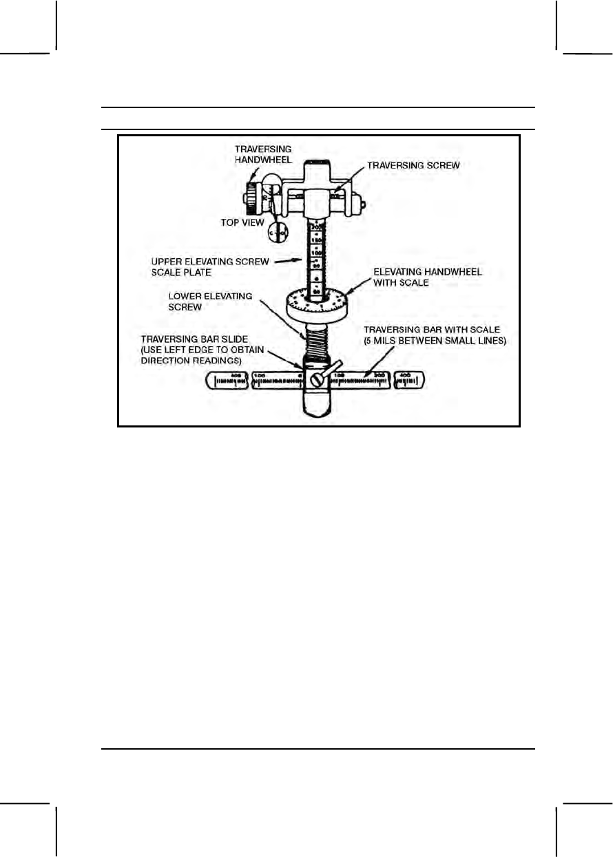
071-000-0005 3-323
Performance Steps
Figure 071-000-0005-4. Traversing and elevating mechanism.
c. When assigned a PDF, lay the gun for direction.
(1) Align on the primary sector by traversing the slide to one side.
(2) Move the tripod to align the barrel on the sector limit.
(3) Align on the PDF by traversing the slide until the machine gun is
aimed at the center of the target.
d. Fix the tripod legs in place by digging them in or sandbagging them.
e. Determine the direction to each target.
(1) Lay the gun on the base of the target.
(2) Read the direction on the traversing bar at the left edge of the
traversing bar slide (figure 071-000-0005-4).
(3) Determine by the direction of the barrel whether the reading is
right or left.
f. Determine the elevation for each target.
(1) Lay the gun on the base of the target by rotating the elevating
handwheel (figure 071-000-0005-4).
(2) Read the number (including a "+" or "-" sign, unless the number

3-324 071-000-0005
Performance Steps
is "0") above the first visible line on the elevating scale. (In figure 071-000-
0005-4, this reading is "-50.")
(3) Read, from the elevating handwheel, the number in line with the
indicator. (In figure 071-000-0005-4, this reading is "3.")
6. Record the data you found using the T&E mechanism (figure 071-000-
0005-4).
a. Enter the reading in the ELEVATION column in the DATA SECTION
of the range card, separating the two numbers with a slash.
b. Enter the range to each target in the appropriate column in the DATA
SECTION.
c. Enter the description of each target in the appropriate column in the
DATA SECTION.
d. Fill in the REMARKS block for each target as needed.
e. Enter the width and depth (in mils) of linear targets. The "-4" in figure
071-000-0005-3, REMARKS block, means that depressing the barrel 4 mils
will cause the strike of the rounds to go to ground level along the FPL.
f. When entering the target width (TW) in the REMARKS block, give
the width in mils, and express it in two values. For example, in figure 071-
000-0005-2, Target 3 measures 7 mils wide. The second value, R3, means
that if the gunner lays the gun on the target and traverses 3 mils to the right,
the point of aim will lay to the right edge of the target. Target 3, figure 071-
000-0005-3, shows the width of the target as 15 mils; traversing 8 mils to the
left will move the point of aim to the left edge of the target.
g. Do not determine data for the secondary sector of fire; the gunner
will fire the weapon in the bipod mode.
7. Keep one copy of the range card at the machine gun position. Send the
other copy to platoon headquarters. Complete range cards for primary
positions. Partially prepare range cards for alternate and supplementary
positions. Prepare the range card as soon as you arrive in a position,
regardless of the expected length of stay. Continually revise the range card
the whole time you occupy the position.
Evaluation Preparation:
Setup: Provide the soldier all the equipment needed to prepare a range card:
pencil, paper, a stationary firing position, sector of fire, and target reference
point designated.
Brief Soldier: Tell the soldier to prepare only one copy of the range card for
training purposes.

071-000-0005 3-325
Performance Measures GO NO GO
1. Prepared the range card. —— ——
a. Sketched the terrain located in front of the
position.
b. Determined the direction of magnetic north.
c. Sketched in the direction of magnetic north.
d. Completed the DATA SECTION.
e. Determined the location of the gun position
relative to a prominent terrain feature.
f. Sketched in the primary sector of fire using
either a PDF or a FPL.
g. Labeled the targets.
h. Sketched in the secondary sector of fire.
2. Used the T&E mechanism, determined the direction,
elevation, and range. —— ——
a. Centered the traversing handwheel.
b. Laid the gun for direction.
c. Adjusted the tripod legs.
d. Read the direction to each target.
e. Read the elevation to each target.
3.Used the T&E mechanism to determine data for
targets, then recorded it on the range card. —— ——
a. Entered the reading for elevation into the
ELEVATION block in the DATA SECTION of the range
card.
b. Entered the range to the target into the RANGE
block in the DATA SECTION of the range card.
c. Described each target in writings.
d. Completed the REMARKS block for each target,
as needed.
Evaluation Guidance: Score the soldier GO if all performance measures
are passed. Score the soldier NO-GO if any performance measure is failed.

3-326 071-025-0001
If the soldier scores NO-GO, show the soldier what was done wrong and
how to do it correctly.
References
Required Related
FM 3-22.68
071-025-0001
Maintain an M240B Machine Gun
Conditions: Given a cleared M240B machine gun; M122A1 tripod mount
assembly; linked 7.62-mm ammunition; and a small-arms case with the
following items: cleaner, lubricant, and preservative (CLP), lubricating oil
arctic weather (LAW), rifle bore cleaner (RBC), rags, pipe cleaners, chamber
and bore brushes, cleaning rod, cleaning rags, small-arms swabs, and an
M240B scraper and reamer.
Standards: Cleaned and lubricated the M240B machine gun and
components. Inspected all parts, components, and ammunition for
serviceability; turned in unserviceable items to maintenance. Correctly
assembled the gun and ensured it was operational.
Performance Steps
1. Check to ensure the weapon is clear.
WARNING
Be sure to clear weapon before disassembling, cleaning, inspecting,
transporting, or storing.
a. Put safety to "F" (FIRE).
b. Pull cocking handle assembly to the rear, locking the bolt to the
rear. Return cocking handle to forward position.
c. Place safety to "S" (SAFE).
d. Push in latches to open cover assembly.
e. Remove ammunition belt, if present.
f. Raise feed tray.
g. Inspect chamber area. Remove any ammunition, ammunition
casings, or links.
(1) Check feed pawl assembly and feed tray assembly.
(2) Lift feed tray assembly and inspect the chamber.

071-025-0001 3-327
Performance Steps
(3) Check space between the face of the bolt and the chamber.
(4) Check space under the bolt and operating rod assembly.
h. Lower feed tray.
i. Place safety to "F."
j. Hold cocking handle assembly to rear, depress trigger, and ease
bolt forward to close and lock.
k. Close cover assembly. Make sure it locks shut.
Note. Be sure bolt is forward with safety in "F" when gun is not in use.
2. Disassemble the M240B.
WARNING
A hot barrel can burn you. If the barrel is hot, use your heat resistant
mittens.
Note. The following steps do not have to be performed in sequence.
a. Remove barrel assembly.
(1) Check to ensure bolt is forward.
(2) Depress barrel locking latch and hold.
(3) Turn barrel carrying handle to upright position.
(4) Push forward and lift barrel out.
b. Remove heat shield assembly from barrel. Lift rear of heat shield
assembly from barrel; pry front tabs out of holes on gas hole bushing.
c. Remove trigger-housing assembly.
(1) Depress spring pin and remove it (this can usually be done
without tools).
(2) Pull trigger-housing assembly down and back, and remove it.
d. Remove butt stock and buffer assembly. Depress backplate latch
and lift butt stock and buffer assembly straight up.
e. Remove driving spring rod assembly.
(1) Push driving spring rod assembly forward and up to disengage
its retaining stud from the receiver.
(2) Pull rearward on driving spring rod and remove it from the
receiver.
f. Remove bolt and operating rod assembly.
(1) Depress cover latches and raise cover assembly.

3-328 071-025-0001
Performance Steps
(2) Pull cocking handle assembly back to move bolt and operating
rod assembly to the rear of receiver.
(3) Reach into receiver and push rearward on bolt until bolt and
operating rod assembly are slightly out of rear end of receiver.
(4) Grasp bolt and operating rod assembly and remove it from the
receiver.
(5) Return cocking handle to forward position.
g. Remove cover assembly.
(1) Close cover.
(2) Push out spring pin as far as possible using backplate of the
butt stock or buffer assembly. Then remove it with your fingers.
(3) Depress cover latches, lift up, and remove cover assembly.
(4) Remove feed tray.
h. Remove hand guard.
(1) Extend bipod legs to down and locked position.
(2) Pull hand guard straight down and off gas cylinder.
WARNING
Using gasoline, kerosene, hydraulic oil, benzene, benzol, high pressure
water, steam, or air for cleaning is prohibited.
3. Clean the M240B parts, components, and ammunition.
CAUTIONS
1. Do not use abrasives to clean the bore, piston, gas cylinder, or gas regulator
plug.
2. Do not submerge buffer in any liquid. Wipe with clean wiping rag only.
3. Avoid getting CLP in the gas cylinder when cleaning the bore.
a. Use cleaning patches, CLP, and bore brush to clean bore.
b. Use CLP on receiver brush bristles to clean the receiver.
c. Use rags and CLP to remove powder fouling, corrosion, dirt, and
rust from all metal components and surfaces.
d. Use only a clean rag to clean the cover assembly.
e. Clean the gas cylinder.
(1) Use a gas cylinder cleaning brush dampened with CLP to clean
gas cylinder bore.
(2) Use a combination tool to clean front interior of gas cylinder.

071-025-0001 3-329
Performance Steps
(a) Insert the combination tool with handle upward into the
front end of the gas cylinder of the receiver body. Ensure the tool is fully
inserted and seated against the gas cylinder.
(b) Apply slight pressure to the handles and turn clockwise to
remove carbon.
f. Clean gas regulator using the scraper and reamer.
(1) Insert the scraper into the central hole of the gas regulator plug.
Remove carbon by twisting the scraper clockwise until it is fully seated
against gas regulator plug.
(2) Clean regulator plug grooves by inserting the scraper tool into
the grooves and turning regulator plug clockwise.
(3) Insert the small reamer into each gas inlet hole and twist back
and forth to remove carbon (use hand pressure only).
(4) Scrape carbon from surface of gas regulator plug using tip of
scraper.
(5) Insert large reamer through hole in gas port bushing into gas
port hole in barrel; remove carbon by twisting reamer back and forth until it
enters bore of barrel.
g. Clean M122A1 tripod assembly.
(1) T&E mechanism. Use a clean dry wiping rag to remove foreign
matter. Use small arms cleaning brush to clean numbers on the scale.
(2) Tripod assembly and flex mount. Use a cleaning rag saturated
with carbon-removing compound to clean them with clean wiping rags to
wipe all parts dry.
h. Clean Ammunition. Use a clean dry wiping rag to remove foreign
matter.
4. Inspect the M240B parts, components, and ammunition.
a. Barrel assembly.
(1) Check barrel for bulges, bends, burrs, or pits in the chamber or
bore.
(2) Check to ensure flash suppressor is not loose.
(3) Check front sight for damage and looseness.
(4) Check barrel carrying handle assembly for damaged or missing
parts. Move the barrel release slowly to the right and count the clicks.
Fewer than two, or more than seven clicks indicate defective parts.
(5) Check to ensure heat shield is present, securely attached to
barrel, and undamaged.

3-330 071-025-0001
Performance Steps
b. Butt stock and buffer assembly.
(1) Check for burrs and rough edges on the mating grooves and
flanges.
(2) Check the backplate latch to ensure it locks the buffer assembly
securely.
(3) Check the buffer plug and ensure it sticks out through the
backplate and is flush or higher than the protrusion below it.
(4) Check the buffer for rattling sounds by shaking; ensure that the
plug cannot rotate by finger pressure.
(5) Check the butt stock for cracks.
c. Driving spring rod assembly.
(1) Check the spring for broken strands.
(2) Check the rod assembly for bends.
d. Bolt and operating rod assembly.
(1) Inspect the bolt and operating rod assembly for bent, broken,
cracked or missing parts. Check for burrs or pits on the surface.
(2) Check for cracks or wear on the tip of the firing pin.
(3) Ensure you cannot move extractor with your fingers.
e. Trigger-housing assembly
(1) Check for broken, missing, or damaged parts.
(2) Inspect the tripping lever and sear for burrs on edges.
(3) Check cocking action by pushing back on the tripping lever
(sear will rise). Pull the trigger (sear will lower).
(4) Check safety. Place on "S" (SAFE) and pull the trigger. The
sear should not drop down far enough to lock in the downward position.
Place the safety on "F" (FIRE) and pull the trigger. The sear should drop
down and lock in the downward position.
f. Cover assembly.
(1) Pivot the feed lever back and forth to ensure it operates
smoothly without binding.
(2) Push in on the cover latches to make sure the retaining clip is
present, secure, and does not bind in the housing.
(3) Push down on the cartridge guides and feed pawls to make
sure the springs are present and secure.
(4) Inspect accessory-mounting rail for nicks or burrs.

071-025-0001 3-331
Performance Steps
g. Feed tray. Check for cracks, deformation, broken welds, and loose
rivets.
h. Hand guard. Check for cracks and broken or missing parts.
i. Receiver assembly.
(1) Check that the rear sight is securely mounted and operates
properly.
(2) Check that the cocking handle operates properly.
(3) Check for damaged or missing ejection port cover, spring, and
pin. Check for proper operation of ejection port cover.
(4) Lower and raise the bipod legs to ensure they move freely
without binding.
(5) Check accessory-mounting rail for nicks or burrs that may
prevent proper attachment of optional sighting devices.
(6) Check barrel locking latch and cover detent for proper spring
tension.
j. Components.
(1) T&E mechanism.
(a) Inspect hand wheels for smooth operation or rust.
(b) Check threads for burrs and rust.
(c) Check traversing slide lock for spring action. Ensure
elevating mechanism sleeve fits on traversing bar and clamps firmly.
(d) Check traversing and elevating scales for legibility.
(e) Inspect quick release pin and chain for burrs and rust.
Check for missing spring-loaded balls.
(2) Tripod assembly.
(a) Check for completeness of tripod. Ensure that all nuts and
bolts are tightly secured.
(b) Inspect for cracks on the legs and tripod head.
(c) Check for missing, broken, or inoperative lock latch.
(d) Check pintle lock release cam for correct operation.
(e) Check locking action of front leg clamping assembly.
(f) Check that the rear legs lock in the open position. Ensure
sleeve latch notch and right leg slide notch engages completely. Ensure
latch spring has good tension.
(g) Check telescoping, indexing, and locking action of rear legs
and front leg locking assemblies.

3-332 071-025-0001
Performance Steps
(3) Flexible mount assembly.
(a) Check for missing or damaged parts. Check for rust,
cracks, and burrs.
(b) Inspect pintle lock assembly for nut, bolt, and cotter pin.
Check pintle surface for burrs and rust.
k. Inspect or check ammunition for damage and corrosion. Turn in any
unserviceable ammunition.
5. Lubricate M240B parts and components.
a. Generously lube the following parts:
(1) Barrel assembly—on the camming surfaces of the bolt-locking
lugs.
(2) Operating rod—on the rollers, camming recess, and those
surfaces immediately below the yoke that ride within the receiver rails.
(3) Cover—in the feed cam assembly.
(4) Bolt—on the bolt-locking lugs and actuator cam roller.
b. Lightly lube the following parts:
(1) Driving spring.
(2) Bolt and operating rod assembly moving parts, polished areas,
firing pin, and roller.
c. Do not lubricate the following parts:
(1) Butt stock.
(2) Face of bolt.
(3) Piston.
(4) Gas regulator and gas cylinder.
(5) Rear sight.
(6) Composite or rubber components.
d. Lightly lubricate all components and wipe with oily rag to remove
excess oil.
6. Assemble the M240B.
a. Replace barrel assembly.
(1) Insert gas regulator plug into the gas hole bushing with the
number 1 gas setting facing the barrel.
(2) Place gas collar over the front end of the gas regulator plug.
Rotate collar until it slips onto gas regulator plug. Press in and rotate
counterclockwise to lock in place (pull collar to be sure it is in the locked
position).

071-025-0001 3-333
Performance Steps
(3) Install heat shield on barrel. Insert the front metal tabs of the
heat shield into the holes located on the sides of the gas hole bushing.
Push down on the heat shield so it snaps onto the barrel.
(4) With gas regulator downward and the carrying handle in the
vertical position, insert barrel fully into the receiver socket and push barrel
carrying handle to the right as far as it will go to lock (fewer than two or
more than seven clicks indicate defective parts). Do not force. If barrel
binds in socket or if barrel carrying handle will not rotate when pushed, do
not pound on barrel carrying handle. Take machine gun to unit
maintenance.
b. Replace cover assembly and feed tray.
(1) Align the feed tray guides with receiver brackets.
(2) Place cover assembly onto the receiver with its mounting holes
aligned with mounting brackets on the receiver.
(3) Close cover assembly. To secure the cover and feed tray to the
receiver; insert the spring pin in the mounting holes from the right side only.
Open cover assembly. Check to ensure cover detent holds cover assembly
open. If cover assembly does not remain open in two positions, notify unit
maintenance.
c. Replace trigger-housing assembly.
(1) Insert the holding notch on the trigger-housing into the forward
recess on the bottom of the receiver.
(2) Lift the trigger-housing up and align holes of trigger-housing
with the mounting holes of the receiver.
(3) Hold the trigger-housing in place and insert the spring pin.
d. Replace bolt and operating rod assembly.
(1) Insert the bolt and operating rod assembly into the rear of the
receiver. Ensure bolt is on top of receiver rails.
(2) Push the assembly into the receiver as far as possible. Pull the
trigger and hold it while pushing the assembly all the way into the receiver.
(3) Close cover assembly.
e. Replace the driving spring rod assembly.
(1) Insert driving rod spring assembly all the way into the receiver.
(2) Push in and lower driving rod spring assembly to seat the
retaining stud in the hole on the bottom of the receiver.
f. Replace butt stock and buffer assembly.
(1) Position the bottom recess grooves of the butt stock onto the
top of the receiver recess grooves.

3-334 071-025-0003
Performance Steps
(2) Slide the butt stock down until it locks on the receiver. Top of
buffer should be flush with top of receiver.
7. Perform a function check to ensure the M240B is assembled correctly.
Evaluation Preparation:
Setup: At the test site, provide all the equipment and materials listed in task
conditions. Use only dummy ammunition for training purposes.
Brief Soldier: Tell soldier to perform maintenance on the M240B and linked
7.62-mm ammunition.
Performance Measures GO NO GO
1. Checked to ensure the weapon was clear. —— ——
2. Disassembled the M240B. —— ——
3. Cleaned the M240B parts, components, and
ammunition. —— ——
4. Inspected the M240B parts, components, and
ammunition. —— ——
5. Lubricated M240B parts and components. —— ——
Evaluation Guidance: Score the soldier GO if all performance measures
are passed. Score the soldier NO GO if any performance measure is failed.
If the soldier scores NO GO, show him what was done wrong and how to do
it correctly.
References
Required Related
FM 3-22.68
TM 9-1005-313-10
071-025-0003
Load an M240B Machine Gun
Conditions: Given a cleared M240B machine gun (mounted on bipod,
tripod, or vehicle) and linked 7.62-mm ammunition.
Standards: Loaded linked ammunition in the feed tray groove so that, when
the cover was closed, a round remained in the tray groove and ammunition
fed correctly.

071-025-0003 3-335
Performance Steps
1. Clear the weapon.
a. Place safety to the "F" position.
b. Charge the weapon.
(1) Pull the cocking handle to the rear, locking the bolt in the rear
position.
(2) Push the cocking handle to the forward and locked position.
c. Place safety to the "S" position.
d. Open the cover assembly.
(1) Press in and hold the feed cover latches.
(2) While holding the latches, lift up on the cover assembly.
e. Remove any ammunition that is present.
f. Raise the feed tray.
g. Inspect the chamber to ensure no ammunition is present.
h. Lower the feed tray.
i. Place safety to the "F" position.
j. Pull and hold cocking handle to the rear.
k. While holding the cocking handle to the rear, depress the trigger
and ease the bolt forward to the closed and locked position.
2. Load ammunition.
Note. Position the open side of links in the down position.
a. Place link belt on feed tray with the first round against the cartridge
stop and tip of round pointing toward the barrel.
b. Close the cover assembly ensuring the latches lock into place.
CAUTION
Make sure round does not move away from cartridge stop during closing and
latching of cover.
Evaluation Preparation:
Setup: Use dummy ammunition to test this task. At the test position, provide
an M240B and a belt of linked dummy 7.62-mm ammunition. For
standardization, always place the bolt and cocking handle forward and the
safety on "S." Ensure the ammunition is clean and linked properly.
Brief Soldier: Tell the soldier to load the M240B machine gun.

3-336 071-025-0004
Performance Measures GO NO GO
1. Cleared weapon. —— ——
2. Loaded ammunition. —— ——
Evaluation Guidance: Score the soldier GO if all performance measures
are passed. Score the soldier NO GO if any performance measure is failed.
If the soldier scores NO GO, show what was done wrong and how to do it
correctly.
References
Required Related
FM 3-22.68
TM 9-1005-313-10
071-025-0004
Unload an M240B Machine Gun
Conditions: Given an M240B loaded with linked 7.62-mm ammunition.
Standards: Removed all ammunition and links from the weapon. Cleared
the weapon, ensured the chamber was empty and the safety was on "F"
(FIRE).
Performance Steps
1. Remove ammunition from the M240B.
a. With palm up, pull the cocking handle to the rear, ensuring that the
bolt locks to the rear.
b. Return the cocking handle to its forward position.
c. Place the safety lever on "S" (SAFE).
d. Raise the cover and remove ammunition belt.
e. Remove any ammunition, links, or brass from the chamber area.
2. Clear the M240B.
a. Confirm that no ammunition remains in the chamber.
b. Close the cover.
c. Place the safety on "F" (FIRE).
d. With palm up, pull the cocking handle to the rear and hold it.

071-025-0007 3-337
Performance Steps
CAUTION
The bolt must be eased forward to prevent damage to the feed tray assembly
and operating rod assembly.
e. Pull the trigger, allowing the bolt to ease forward.
f. Place the safety on "F" (FIRE).
Evaluation Preparation:
Setup: At the test site, provide the soldier with all the equipment listed in the
task conditions. Use only dummy ammunition for training purposes.
Brief Soldier: Tell soldier he must unload the M240B.
Performance Measures GO NO GO
1. Removed ammunition from the M240B. —— ——
2. Cleared the M240B. —— ——
Evaluation Guidance: Score the soldier GO if all performance measures
are passed. Score the soldier NO GO if any performance measure is failed.
If the soldier scores NO GO, show him what was done wrong and how to do
it correctly.
References
Required Related
FM 3-22.68
TM 9-1005-313-10
071-025-0007
Engage Targets with an M240B Machine Gun
Conditions: Given an M240B machine gun, linked 7.62-mm ammunition,
engageable targets in your assigned sector of fire, and a requirement to
engage those targets.
Standards: Fired the M240B machine gun to engage targets in the assigned
sector of fire. Used correct M240B machine gun target engagement
techniques so you hit each target.

3-338 071-025-0007
Performance Steps
1. Assume a suitable firing position. Based on the situation, assume the
position that allows you to observe and engage targets yet minimize your
exposure to enemy fire.
a. Tripod firing. A number of firing positions can be used based on
situation (prone, sitting, or kneeling; or standing if firing from prepared
position).
b. Bipod firing. Prone supported position and bipod-supported fighting
position are the best for delivering effective fire on targets. Assume these
positions when possible.
(1) Shoulder firing position. Use this position to engage specific
targets during movement when you can assume no other position or the
situation dictates its use, such as the final stages of an assault.
(2) Underarm firing position. Use this position when closing with the
enemy, when a heavy volume of fire in the target area is required, and
when rapid movement is necessary.
(3) Hip firing position. Use this position when a heavy volume of fire
in the target area is required and rapid movement is not necessary.
2. Identify targets in your designated sector of fire.
3. Align the sights on the target.
a. Obtain sight alignment by centering the front sight blade in the
aperture of the rear sight with the top of the front sight blade even with the
top of the rear sight slide.
b. Obtain a sight picture by centering the target over the front sight
blade so it appears to rest on top of the front sight blade and on top of the
rear sight slide.
4. Load and engage targets using correct M240B firing techniques.
a. Use correct trigger manipulation.
(1) Pull straight to the rear and release.
(2) Fire the weapon at the rate of fire appropriate for the target
(sustained, rapid, or cyclic).
b. Use correct fire engagement technique based on target type.
(1) Deliver fixed fire against a point target when only one aiming
point is necessary to cover the target with fire.
(2) Use traversing fire to distribute fire on wide targets by
successive changes in direction.
(a) With the tripod-mounted gun, make changes in 2- to 6-mil
increments on the traversing hand wheel between bursts.

071-025-0007 3-339
Performance Steps
(b) With the bipod-mounted gun, make minor changes by
shifting your shoulders to the right or left to select successive aiming points
throughout the width of the target area. For major changes, move your
elbows and align your body to remain directly behind the gun.
(3) Use searching fire to distribute fire on deep targets by
successive changes in elevation.
(a) With the tripod-mounted gun, make changes in 2-mil
increments on the elevating hand wheel between bursts.
(b) When using the bipod, move elbows closer together to
lower the muzzle, or farther apart to raise the muzzle.
(4) Use traversing and searching fire to distribute fire on wide and
deep targets by successive changes in direction and elevation. Make
adjustments in the same manner as described for traversing and searching
fire.
(5) Use swinging traverse fire (tripod-mounted gun only) to deliver
fire against targets too wide to cover with the traversing hand wheel or
against fast moving targets. Loosen the traversing slide lock lever and
make changes in direction by moving the muzzle left or right. Make
changes in elevation by turning the elevating hand wheel.
(6) Use free gun fire (tripod- or vehicle-mounted gun only) against
targets requiring rapid major changes in direction and elevation. To deliver
this type of fire, remove the T&E mechanism from the receiver to allow the
gun to be moved in any direction.
c. Use correct application of fire to engage specific types of targets
(for single gun engagement).
(1) Point target. Engage point targets with fixed fire.
(2) Area target. Initially aim at the midpoint of the target area.
Traverse and search to either flank, then back to the opposite flank.
(3) Linear target. Initially aim at the midpoint of the target. Traverse
fire to one flank then to the other to cover the entire target.
(4) Deep target. Initially aim at the midpoint of the target unless
another portion of the target is more critical or presents a greater threat.
Search down to one aiming point in front of the near end and back up to
one aiming point beyond the far end.
(5) Linear target with depth. Initially aim at the midpoint of the
target unless another portion of the target is more critical or presents a
greater threat. Traverse and search to the flank closest to your position,
then back to the other to cover the entire target.

3-340 071-025-0007
Performance Steps
(6) Moving target. To hit a moving target, estimate the speed of the
target and the lead required to fire and hit it. Fire and track the target as it
moves. Adjust the lead by observing tracers and the strike of the bullets.
d. Adjust fire to place effective fire on the target. Based on time,
range, and amount of adjustment, use one of the following methods:
(1) Sight correction method. When the initial burst is not correctly
placed, adjust elevation and windage as required. This method is time-
consuming.
(2) Adjusted aiming point method. Use the adjusted aiming point
method to adjust fires quickly without making a sight adjustment. If the
initial burst misses the target, rapidly select a new aiming point the same
distance from the target as the center of impact of the initial burst but in the
opposite direction.
Evaluation Preparation:
Setup: Evaluate this task on a live-fire range. Evaluate the soldier's ability to
use correct engagement techniques to engage specific types of targets.
Provide the soldier with equipment and materials required to fire the course.
Brief Soldier: Brief soldier on range safety per installation regulations. Tell
the soldier to assume the bipod-supported prone position or bipod-supported
fighting position. Tell him you are evaluating both his ability to adjust fire and
his ability to hit the target.
Performance Measures GO NO GO
1. Assumed a suitable firing position. —— ——
2. Identified targets in designated sector of fire. —— ——
3. Aligned the sights on the target. —— ——
4. Loaded and engaged targets using correct M240B
firing techniques. —— ——
Evaluation Guidance: Score the soldier GO if all performance measures
are passed. Score the soldier NO GO if any performance measure is failed.
If the soldier scores NO GO, show him what was done wrong and how to do
it correctly.
References
Required Related
FM 3-22.68
TM 9-1005-313-10
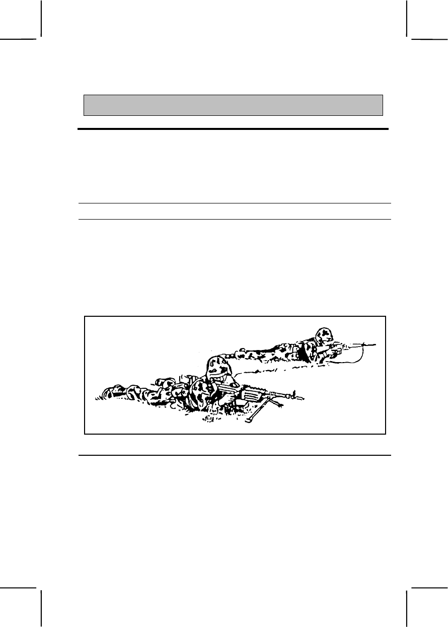
071-010-0006 3-341
SUBJECT AREA 11: M249 MACHINE GUN
071-010-0006
Engage Targets with an M249 Machine Gun
Conditions: Given an M249 machine gun and linked 5.56-mm ammunition.
Standards: Applied correct M249 machine gun target engagement
techniques and hit each target in your assigned sector of fire.
Performance Steps
1. Assume a suitable firing position. Based on the situation, assume the
position that will allow you to observe and engage targets, yet minimize
your exposure to enemy fire.
a. Bipod-supported prone. The bipod-supported prone position (figure
071-010-0006-1) and the bipod-supported fighting position (figure 071-010-
0006-2) are the best positions for delivering effective fire on targets.
Assume these positions when possible.
Figure 071-010-0006-1. Bipod-supported prone position
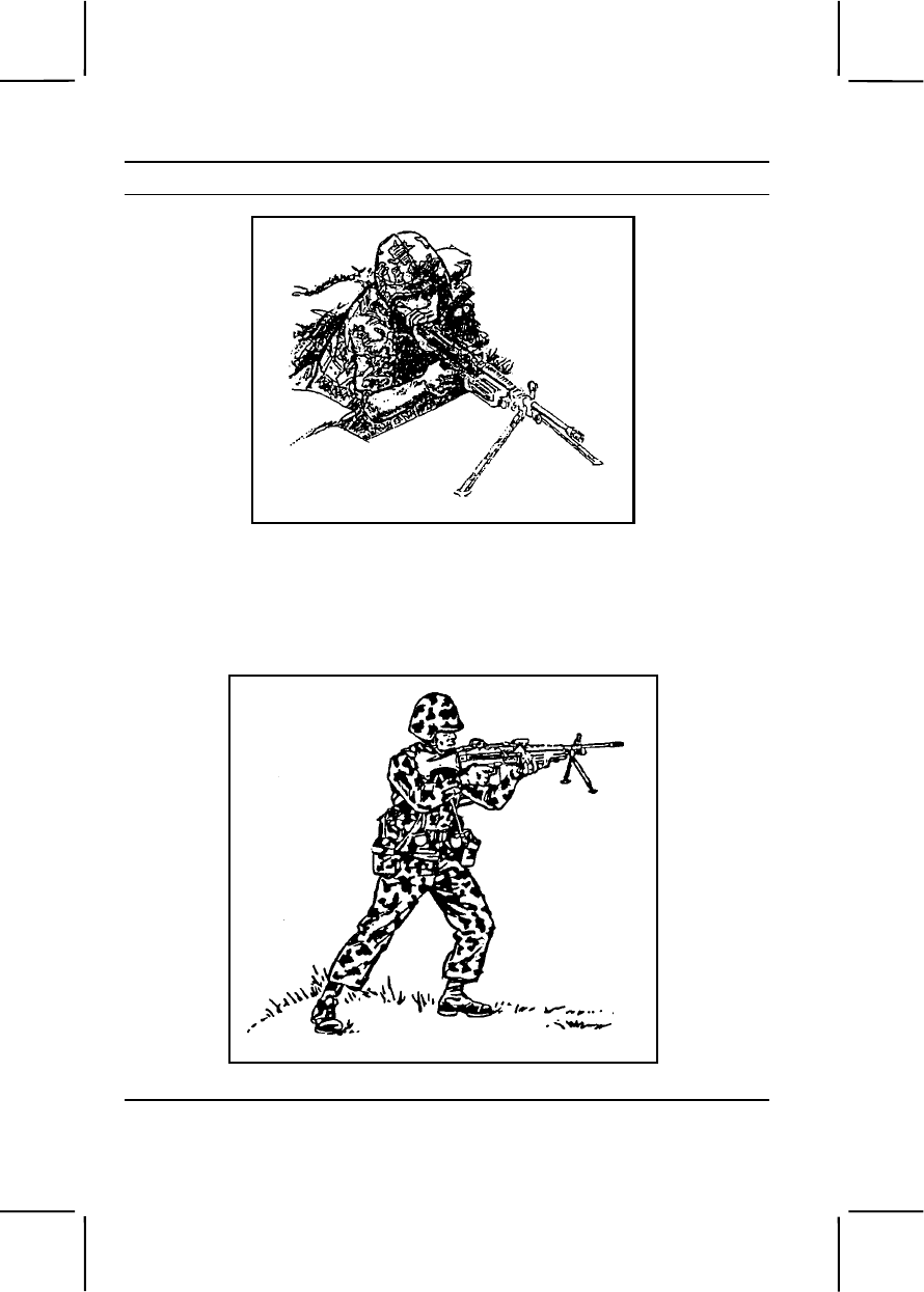
3-342 071-010-0006
Performance Steps
Figure 071-010-0006-2. Bipod-supported fighting position
b. Shoulder. Use the shoulder firing position (figure 071-010-0006-3)
to engage targets at ranges less than 100 meters when no other position
can be assumed or when the situation dictates its use, for example in the
final stages of the assault.
Figure 071-010-0006-3. Shoulder firing position
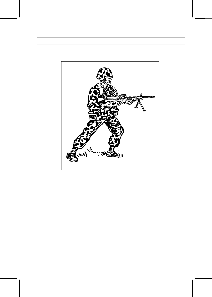
071-010-0006 3-343
Performance Steps
c. Underarm. Use the underarm firing position when moving in and
around the objective during the assault (figure 071-010-0006-4).
Figure 071-010-0006-4. Underarm firing position
d. Hip. Use the hip firing position when closing with the enemy, when
a heavy volume of fire in the target area is required, and when rapid
movement is not necessary (figure 071-010-0006-5).
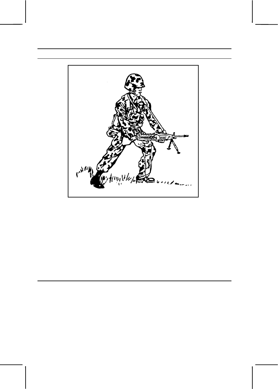
3-344 071-010-0006
Performance Steps
Figure 071-010-0006-5. Hip firing position
2. Fire the weapon using the correct sight picture (figure 071-010-0006-6).
a. Sight alignment. Center the front sight post in the peep sight (A,
figure 071-010-0006-6).
b. Focus of the eye. Place the eye directly on line with the center of
the rear sight. Focus on the tip of the front sight post. The natural ability of
the eye to center objects in a circle and to seek the point of greatest light
(center of the peep sight) aids in providing correct sight alignment.
c. Sight picture. Center the target over the front sight post (B, figure
071-010-0006-6). If firing on a 10-meter range target, use the sight picture
in C, figure 071-010-0006-6.
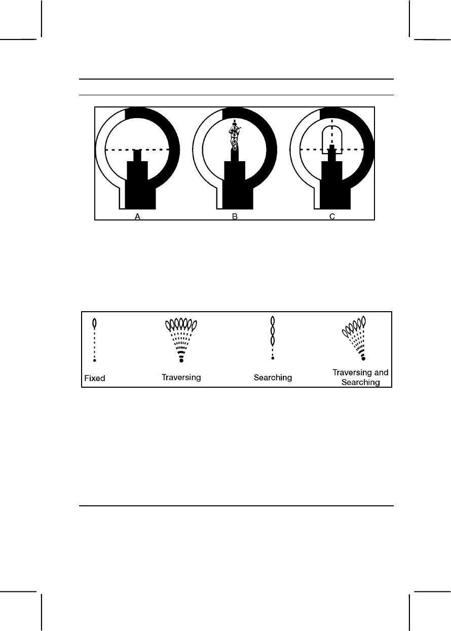
071-010-0006 3-345
Performance Steps
Figure 071-010-0006-6. Sight picture
3. Fire the weapon in three-round bursts at the rate of fire appropriate for
target size. Use correct trigger manipulation: Pull straight to the rear and
release.
4. Apply correct engagement technique based on target types (figure 071-
010-0006-7).
Figure 071-010-0006-7. Classes of fire with respect to the weapon
a. Fixed fire. This type of fire is delivered against a point target when
the depth and width of the beaten zone will cover the target. Only one
aiming point is necessary to cover the target with fire.
b. Traversing fire. This type of fire is distributed in width by successive
changes in direction. This means moving the muzzle of the weapon to the
left or right to distribute fire laterally. To make minor changes in direction,
shift the shoulders to the right or left to select successive aiming points
throughout the width of the target area. For major changes, move the
elbows and align the body to remain directly behind the gun.
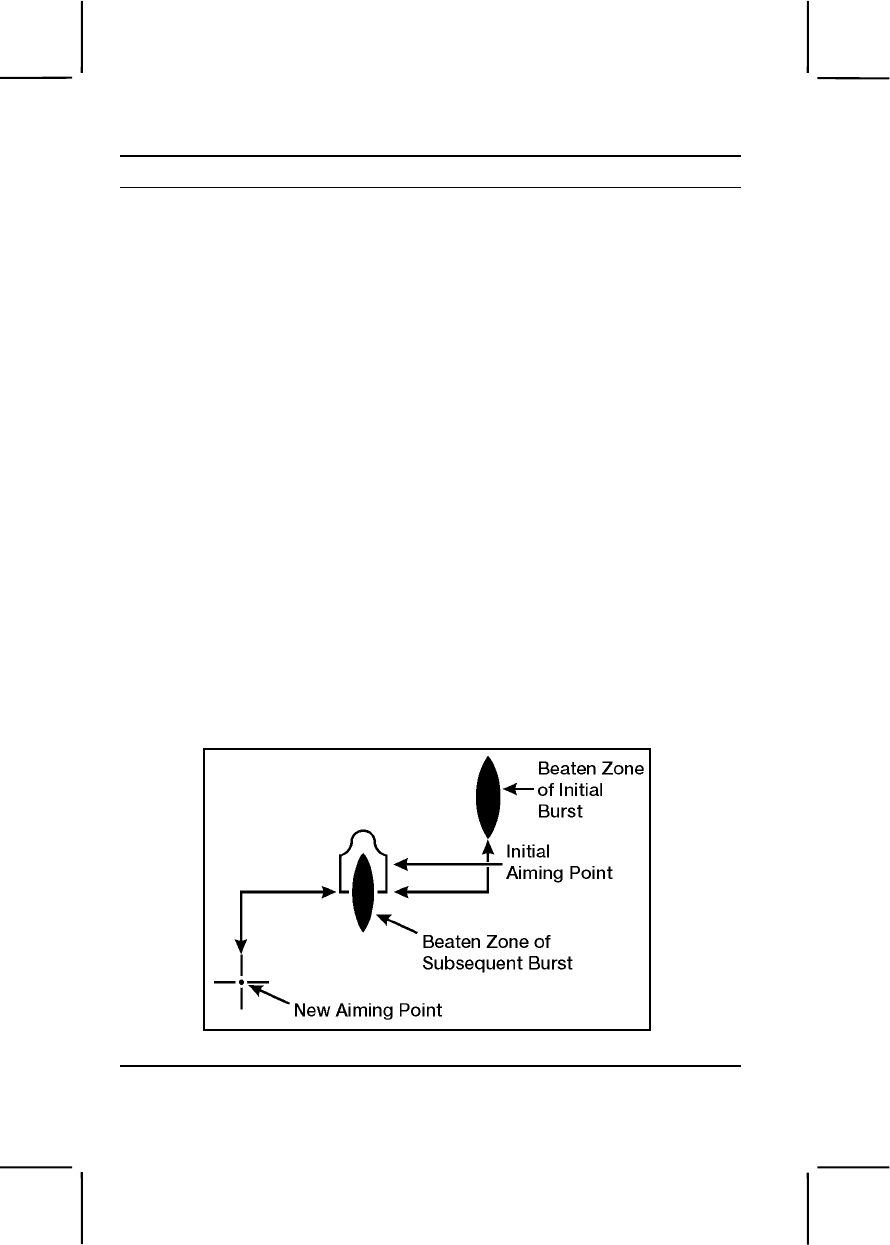
3-346 071-010-0006
Performance Steps
c. Searching fire. This type of fire is distributed in depth by successive
changes in elevation. This means moving the muzzle of the weapon up or
down to distribute fire in depth. Select successive aiming points in depth
throughout the target area. To make changes in elevation, move elbows
closer together to lower the muzzle or farther apart to raise the muzzle.
d. Traversing and searching fire. This type of fire is distributed in width
and depth by successive changes in direction and elevation. Combining
traversing and searching fire provides good coverage of the target.
Adjustments are made in the same manner as described for traversing and
searching fire. This means moving the muzzle of the weapon to the left or
right to distribute fire laterally. To make minor changes in direction, shift the
shoulders to the right or left to select successive aiming points throughout
the width of the target area. For major changes, move the elbows and align
the body to remain directly behind the gun.
5. Use observation of fire and adjustment of fire to place effective fire on
the target.
a. Observation of fire. Observe the burst of fire by noting the strike of
the rounds in the target area, the tracers in flight or, in the case of the 10-
meter range, the holes made in the target.
b. Adjustment of fire. Use the adjusted aiming point method to quickly
adjust fires without making a sight adjustment. If the initial burst misses the
target, rapidly select a new aiming point the same distance from the center
of impact of the initial burst but in the opposite direction. Fire a second
burst (figure 071-010-0006-8).
Figure 071-010-0006-8. Adjusted aiming point method

071-010-0006 3-347
Performance Steps
6. Use correct application of fire to engage specific targets.
a. Point target. Engage point targets with fixed fire (figure 071-010-
0006-9).
Figure 071-010-0006-9. Engagement of point target
b. Area target. Initially, aim at the midpoint of the target area. Traverse
and search to either flank, then back to the opposite flank (figure 071-010-
0006-10).
Figure 071-010-0006-10. Engagement of area target
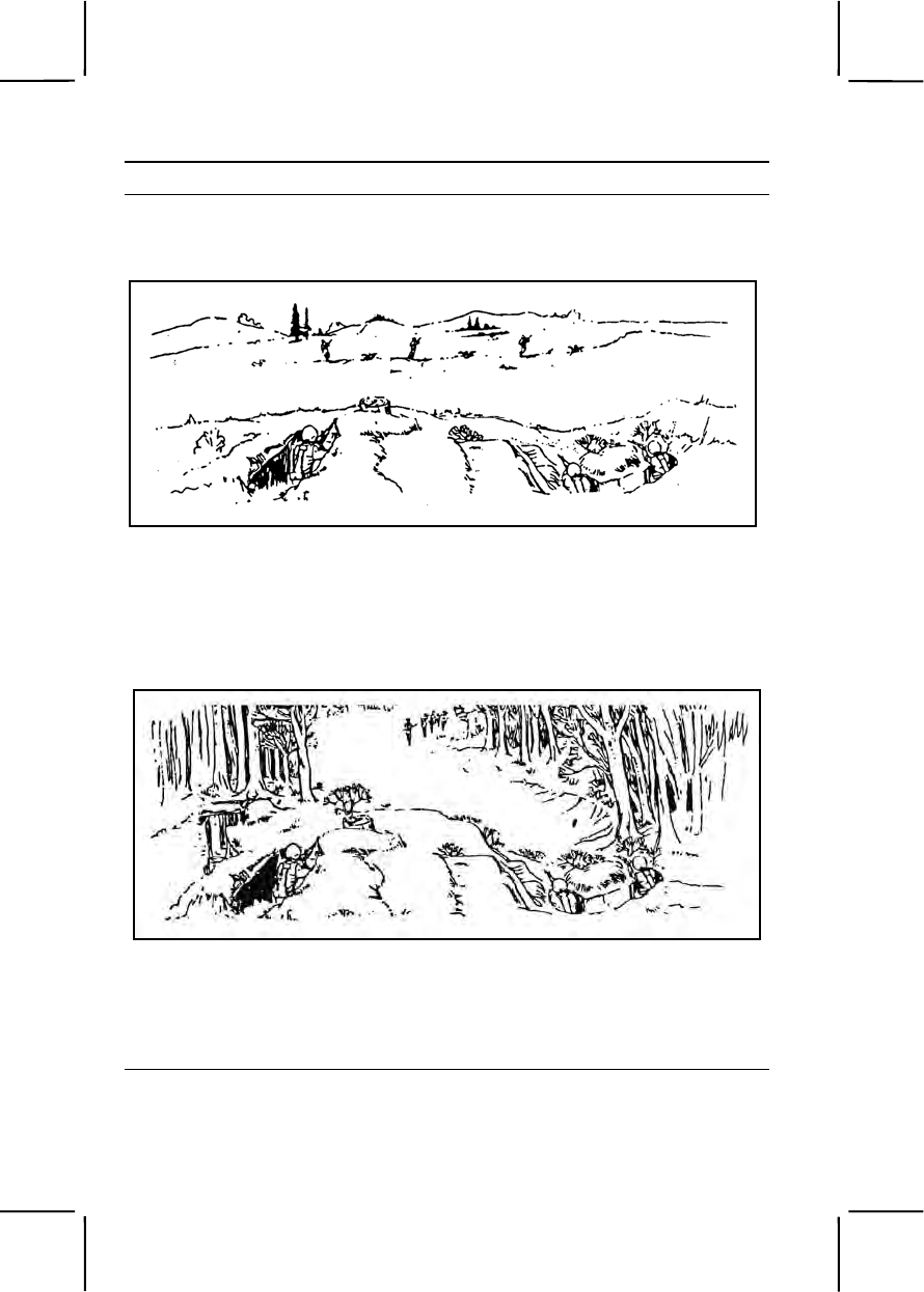
3-348 071-010-0006
Performance Steps
c. Linear target. Initially, aim at the midpoint of the target. Traverse fire
to one flank and then to the other to cover the entire target (figure 071-010-
0006-11).
Figure 071-010-0006-11. Linear target
d. Deep target. Initially, aim at the midpoint of the target unless
another portion of the target is more critical or presents a greater threat.
Search down to one aiming point in front of the near end and back up to
one aiming point beyond the far end (figure 071-010-0006-12).
Figure 071-010-0006-12. Deep target
e. Linear target with depth. Initially, aim at the midpoint of the target
unless another portion of the target is more critical or presents a greater
threat. Traverse and search to the flank closest to your position then back
to the other flank to cover the entire target (figure 071-010-0006-13).
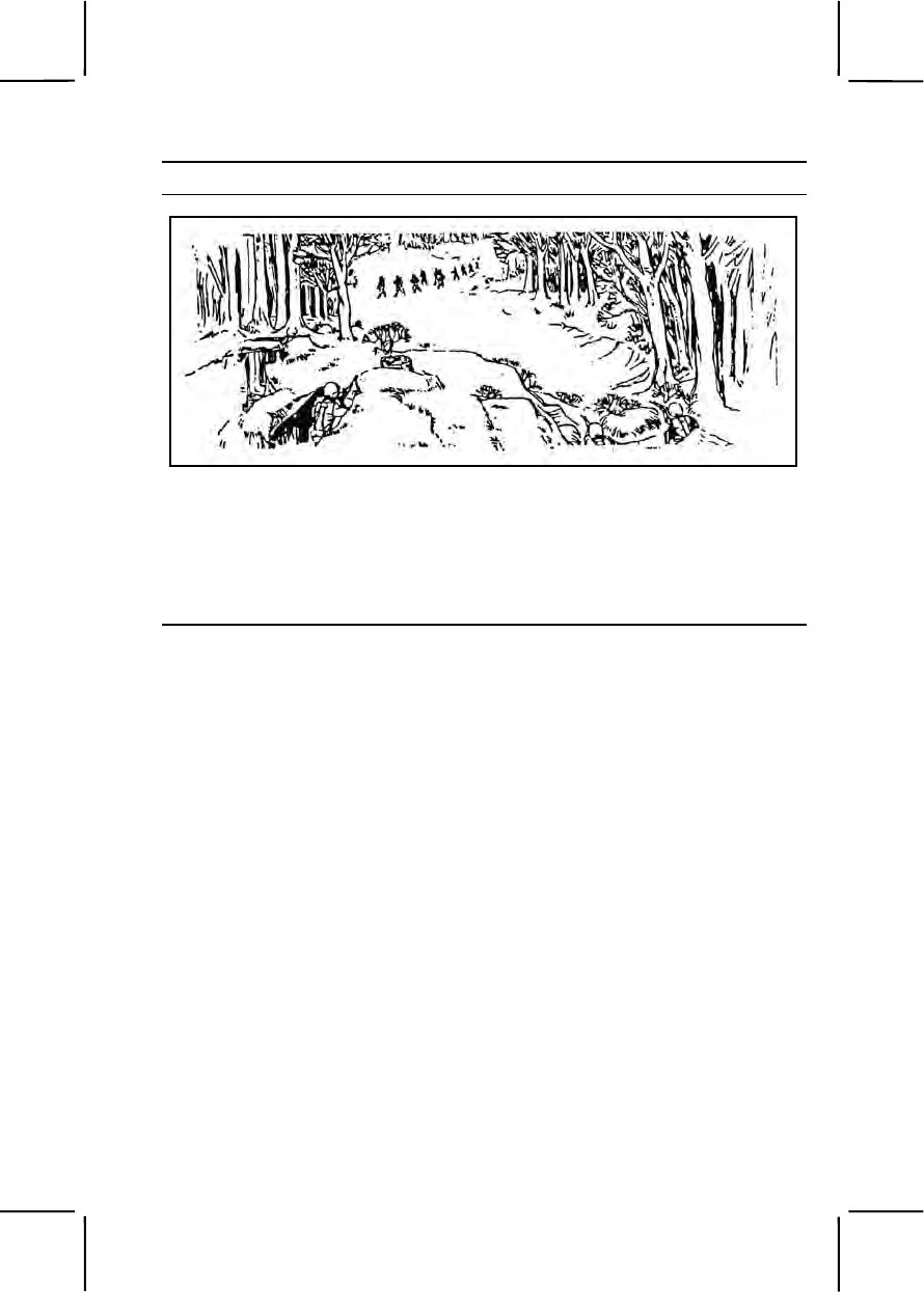
071-010-0006 3-349
Performance Steps
Figure 071-010-0006-13. Linear targets with depth
f. Moving target. To hit a moving target, estimate the speed of the
target and the lead required to fire and hit it, fire and track the target as it
moves, and adjust the lead by observing tracers and the strike of the
bullets (table 071-010-0006-1 and figure 071-010-0006-14).
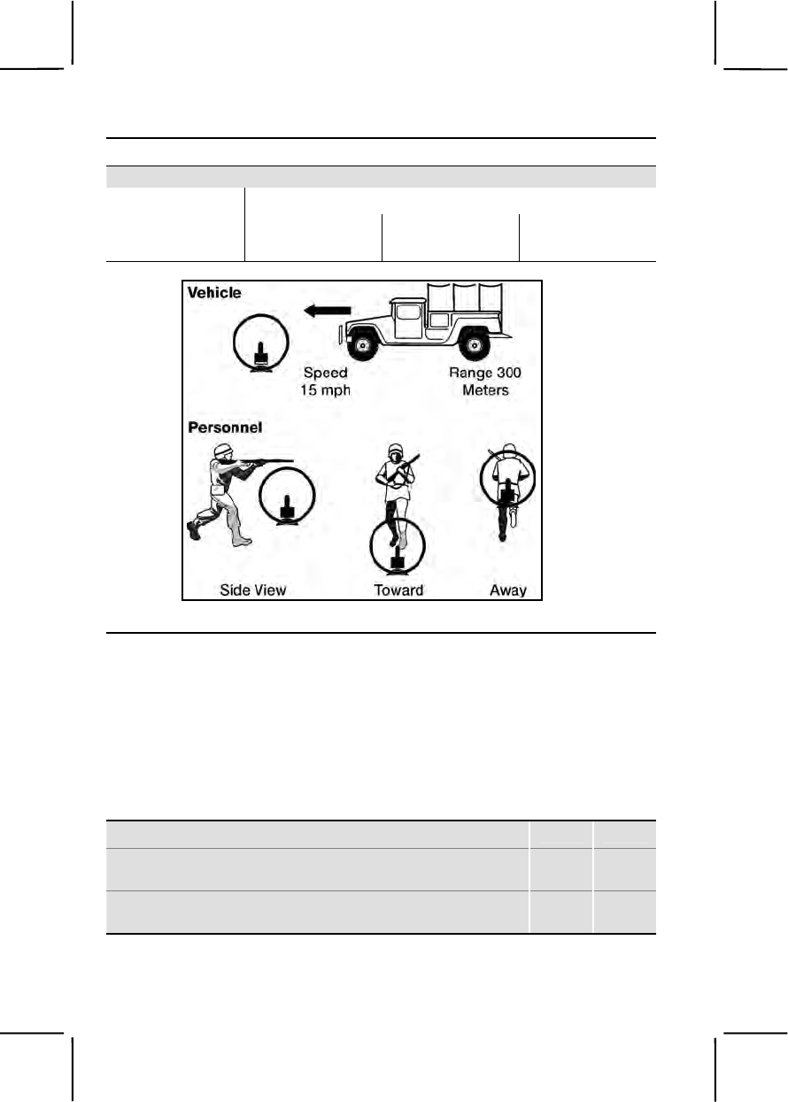
3-350 071-010-0006
Performance Steps
Table 071-010-0006-1. Vehicle lead
Range of Target Speed in Miles
per Hour 300 M
500 M
900 M
15 ½ target length 1 target length 2 target lengths
Figure 071-010-0006-14. Moving target aiming points.
Evaluation Preparation:
Setup: Evaluate this task on a live-fire range by having the soldier fire Table
IV in FM 3-22.68. Evaluate the soldier's ability to use correct engagement
techniques to engage specific types of targets. Provide the soldier with
equipment and materials required to fire the course.
Brief Soldier: Brief soldier on range safety per installation regulations. Tell
the soldier to assume the bipod-supported prone position or bipod-supported
fighting position. Tell the soldier you are evaluating both his ability to adjust
fire and his ability to hit the target.
Performance Measures GO NO GO
1. Assumed correct bipod-supported prone position or
bipod-supported fighting position. —— ——
2. Fielded zero on a 300-meter target with no more than
12 rounds. —— ——

071-312-4025 3-351
Performance Measures GO NO GO
3. Engaged single E-type silhouettes (point targets) at
various ranges. —— ——
4. Engaged double E-type silhouettes (automatic
weapon positions) at various ranges. —— ——
5. Engaged linear E-type silhouettes (troops on line) at
various ranges. —— ——
Evaluation Guidance: Score the soldier GO if all performance measures
are passed. Score the soldier NO GO if any performance measure is failed.
If the soldier scores NO GO, show him what was done wrong and how to do
it correctly
References
Required Related
FM 3-22.68
071-312-4025
Maintain an M249 Machine Gun
Conditions: Given an M249 machine gun; linked 5.56-mm ammunition;
cleaning kit with pipe cleaners, small-arms swabs, chamber and bore
brushes, cleaning rod, wiping rags, scraper tool, and cleaner lubricant
preservative (CLP). You have a requirement to maintain the weapon.
Standards: Cleaned and lubricated the M249 machine gun; inspected parts;
and turned in unserviceable parts. Assembled the gun and ensured it was
operational. Cleaned and inspected linked 5.56-mm ammunition for
serviceability. Turned in unserviceable ammunition.
Performance Steps
Note. The M249 is available with old and new style barrels. Diagrams used here
show the new-style barrel.
1. Clear the M249 machine gun.
a. Move the safety to the fire position.
b. With your right hand, palm up, pull the cocking handle to the rear
and lock the bolt to the rear.
c. Hold the cocking handle to the rear and move the safety to the safe
position. Push the cocking handle forward to the locked position. Place
weapon on safe.

3-352 071-312-4025
Performance Steps
d. Push the cocking handle forward to its locked position (you should
hear a click).
e. Raise the cover and feed mechanism assembly. To check for brass,
links, or ammunition—
(1) Check the feed pawl assembly under the feed cover.
(2) Check the feed tray assembly.
(3) Lift the feed tray assembly and inspect the chamber.
(4) Check the space between the bolt assembly and chamber.
(5) Insert two fingers in the magazine well and feel for brass or
ammunition.
f. Close the cover and feed mechanism assembly. Move the safety to
the fire position.
g. Pull the cocking handle to the rear, press the trigger, and ease the
bolt forward.
2. Disassemble the M249 machine gun.
WARNING
Ensure bolt is in forward position before removing drive spring, return
rod, and transfer mechanism assembly.
a. Remove the drive spring, return rod, and transfer mechanism
assembly.
(1) Raise the cover assembly. Pull the upper retaining pin at the
rear of the receiver to the left. Let the butt pivot downward so the rear
opening of the receiver is clear (figure 071-312-4025-1).
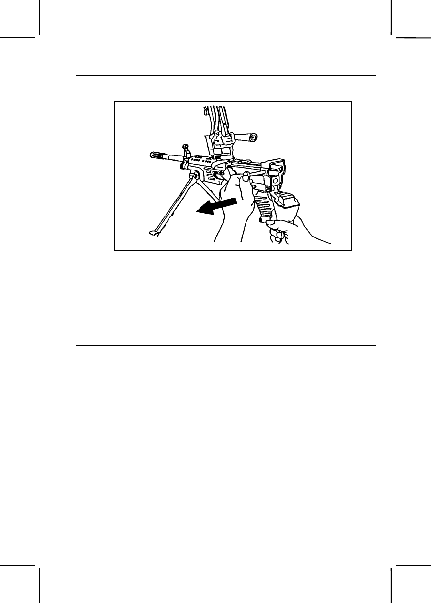
071-312-4025 3-353
Performance Steps
Figure 071-312-4025-1. Rear opening of the receiver
Note. The upper and lower retaining pins in the rear of the receiver are captured
pins. Do not try to remove them completely during disassembly.
(2) Hold the weapon with one hand on the buttstock. At the same
time, push in and upward on the rear end of return rod and transfer
mechanism assembly with thumb of other hand to release it from
positioning groove. Withdraw return rod and transfer mechanism assembly
and spring (figure 071-312-4025-2).
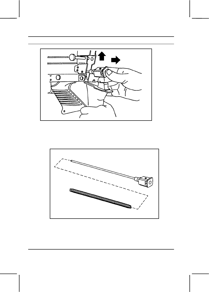
3-354 071-312-4025
Performance Steps
Figure 071-312-4025-2. Removal of the return rod and transfer
mechanism assembly
(3) Separate the spring from the return rod and transfer mechanism
assembly (figure 071-312-4025-3).
Figure 071-312-4025-3. Removal of the spring
b. Remove the operating rod, slide assembly, and bolt assembly.
(1) Pull the cocking handle to the rear to move operating rod, slide
assembly, and bolt assembly out the rear of the receiver (figure 071-312-
4025-4).
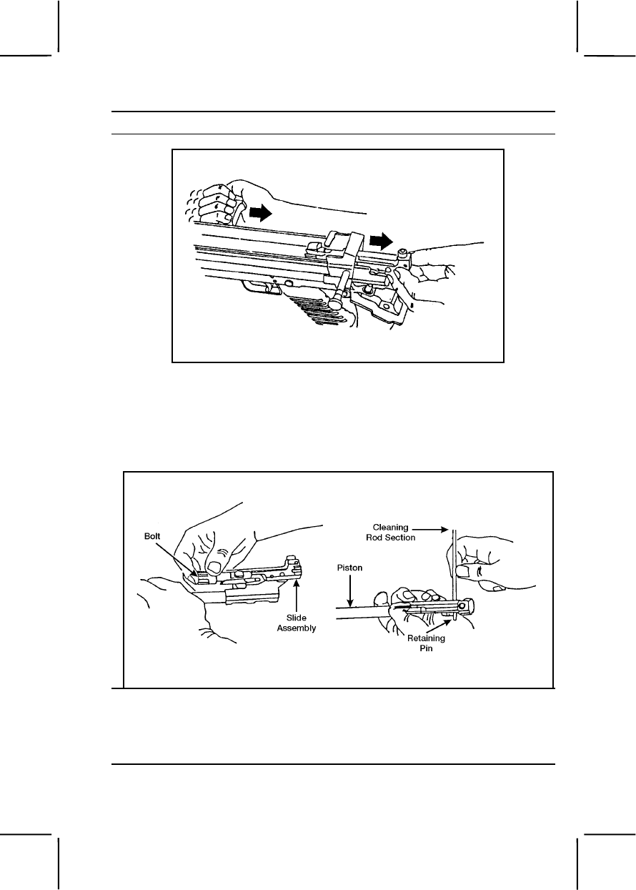
071-312-4025 3-355
Performance Steps
Figure 071-312-4025-4. Removal of the operating rod,
slide assembly, and bolt assembly
(2) Rotate the bolt clockwise to disengage the lug. Remove the bolt
from the slide assembly. Separate the piston from the slide assembly by
pressing the rearmost retaining pin to the left and lifting the piston off the
slide assembly (figure 071-312-4025-5).
Figure 071-312-4025-5. Removal of the bolt and piston
c. Remove the heat shield. Hold the weapon with one hand. With the
other hand, grasp the heat shield just forward of the barrel handle, and lift it
off the barrel (figure 071-312-4025-6).

3-356 071-312-4025
Performance Steps
Figure 071-312-4025-6. Removal of the heat shield
d. Remove the barrel (figure 071-312-4025-7).
(1) Ensure the folding handle on the new style barrel is in carrying
(up) position.
(2) Depress the barrel locking lever with your left hand. Grasp and
lift the carrying handle with your right hand. Push the barrel forward.
Figure 071-312-4025-7. Remove the barrel
e. Remove the handguard (figure 071-312-4025-8)
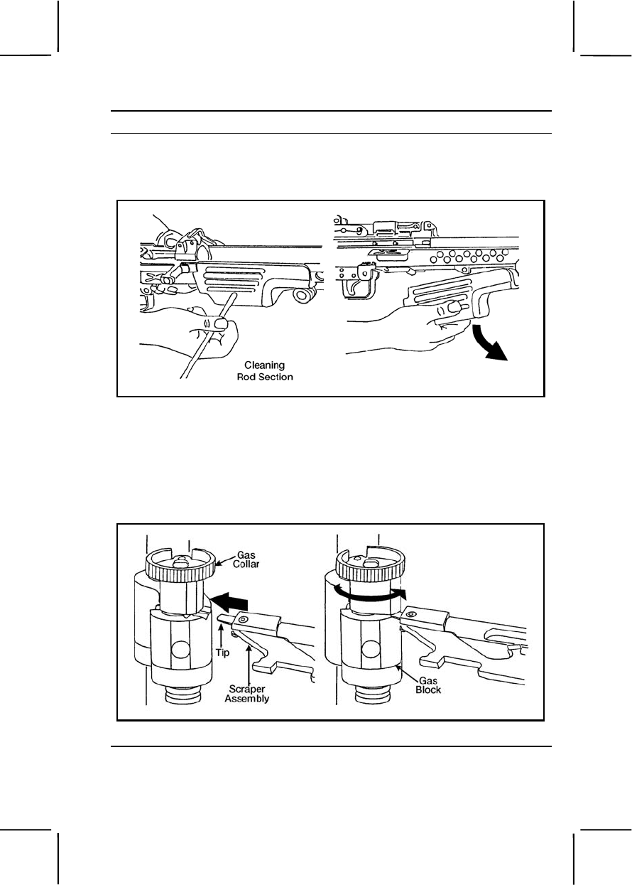
071-312-4025 3-357
Performance Steps
(1) Push the handguard retaining pin to the left using a section of
the cleaning rod.
(2) Pull downward and remove the handguard.
Figure 071-312-4025-8. Remove the handguard
f. Remove the gas regulator.
(1) Position the gas collar so you can insert the scraper assembly
into the notch in the front left of the gas block.
(2) Insert the tip of the scraper assembly in the notch; hold the
scraper firmly in position (figure 071-312-4025-9).
Figure 071-312-4025-9. Insertion of the scraper assembly
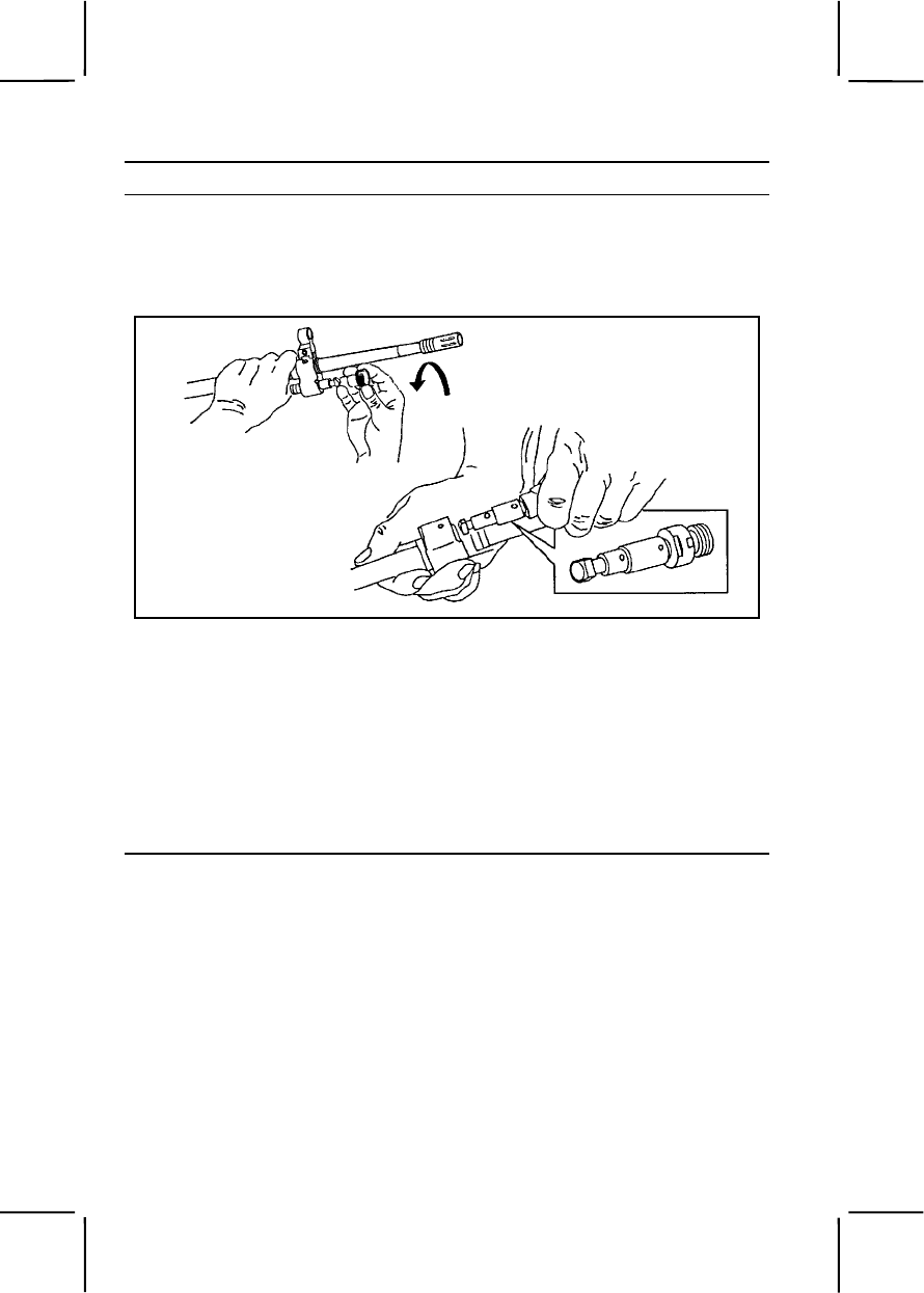
3-358 071-312-4025
Performance Steps
(3) Turn the collar counterclockwise and remove it (figure 071-312-
4025-10).
(4) Remove the gas regulator from the gas block (figure 071-312-
4025-10).
Figure 071-312-4025-10. Removal of the gas regulator from the gas block
g. Remove the buttstock and buffer assembly.
Note. The upper and lower retaining pins in the rear of the receiver are captured
pins. Do not try to remove them completely during disassembly.
(1) Using a section of the cleaning rod, push the lowermost
retaining pin to the left.
(2) While supporting the trigger mechanism with one hand, use the
other to pull the buttstock and buffer assembly rearward and remove it
(figure 071-312-4025-11).
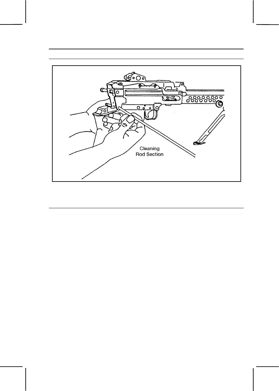
071-312-4025 3-359
Performance Steps
Figure 071-312-4025-11. Removal of the buttstock and buffer assembly
h. Remove the trigger mechanism by pulling rearward and down
(figure 071-312-4025-12).
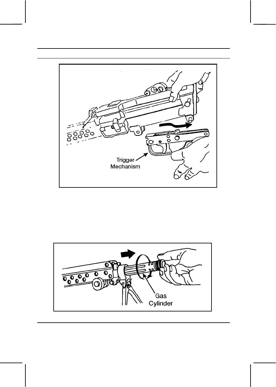
3-360 071-312-4025
Performance Steps
Figure 071-312-4025-12. Removal of the trigger mechanism
i. Remove the gas cylinder.
(1) Turn the gas cylinder to the left or right to release the locking
spring.
(2) Pull the gas cylinder forward to remove it (figure 071-312-4025-
13).
Figure 071-312-4025-13. Removal of the gas cylinder
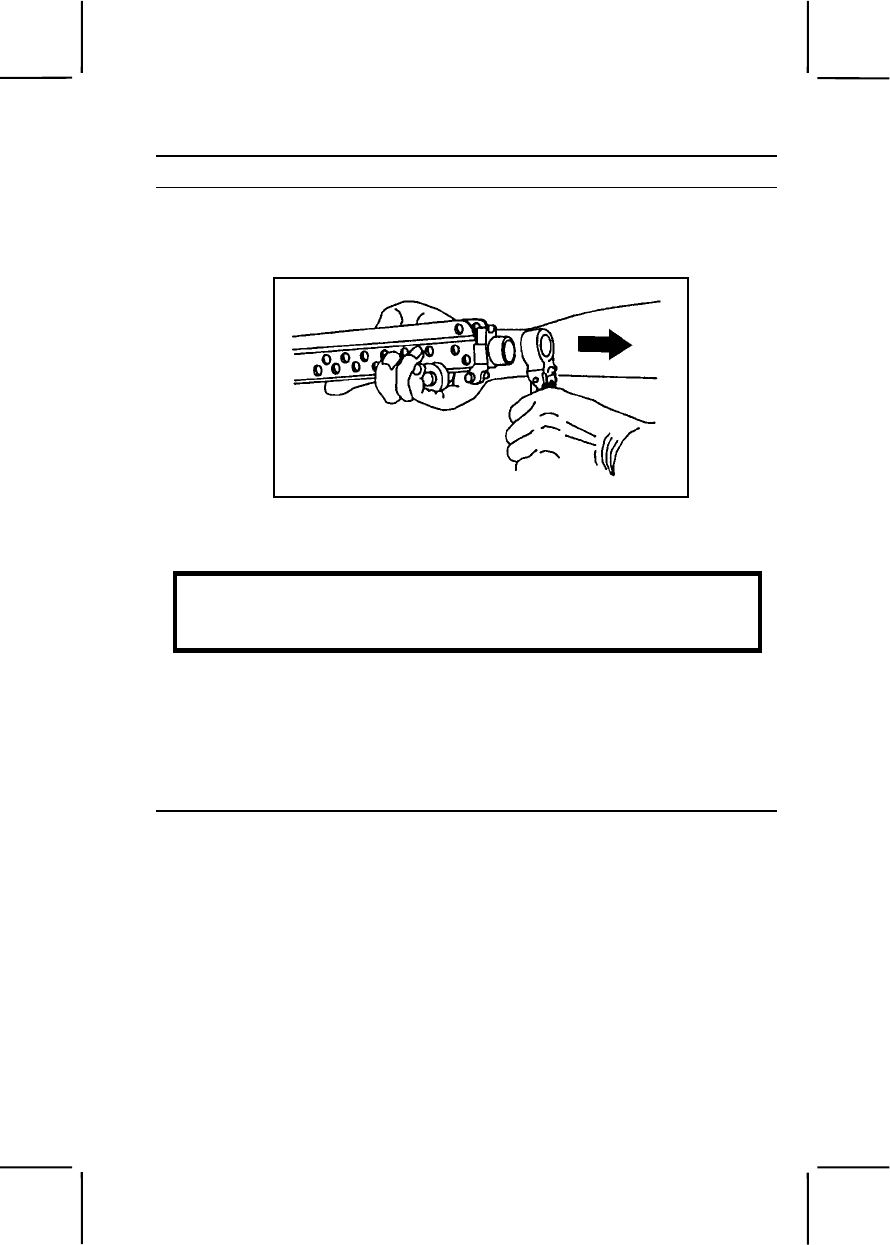
071-312-4025 3-361
Performance Steps
j. Remove the bipod. The bipod should slip off the receiver easily. If it
does not, turn the bipod left or right to loosen any dirt or corrosion
(figure 071-312-4025-14).
Figure 071-312-4025-14. Removal of the bipod
3. Clean the M249.
WARNING
Do not use gasoline, kerosene, hydraulic oil, benzene, benzol, high-
pressure water, steam, or compressed air for cleaning.
Note. Do not use abrasives to clean the bore, piston, gas cylinder, or gas regulator.
a. Clean the bore and chamber using a bore brush, a chamber brush,
CLP, and fresh swabs..
b. Clean the gas regulator using the scraper. Do not use CLP on the
collar, gas block, or body.
(1) Clean the gas vent hole (figure 071-312-4025-15).
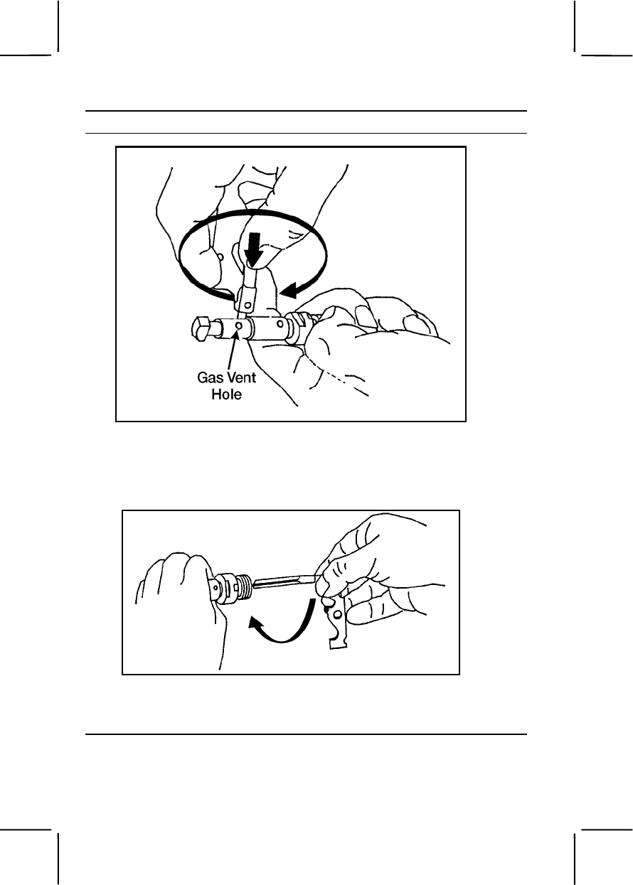
3-362 071-312-4025
Performance Steps
Figure 071-312-4025-15. Cleaning the gas vent hole
(2) Clean the central hole of the gas regulator with the appropriate
part of the scraper by turning the scraper clockwise and pushing it inward
toward the bottom of the housing (figure 071-312-4025-16).
Figure 071-312-4025-16. Cleaning the central hole
(3) Clean the two grooves of the regulator body using the
protruding tips of the scraper (figure 071-312-4025-17).
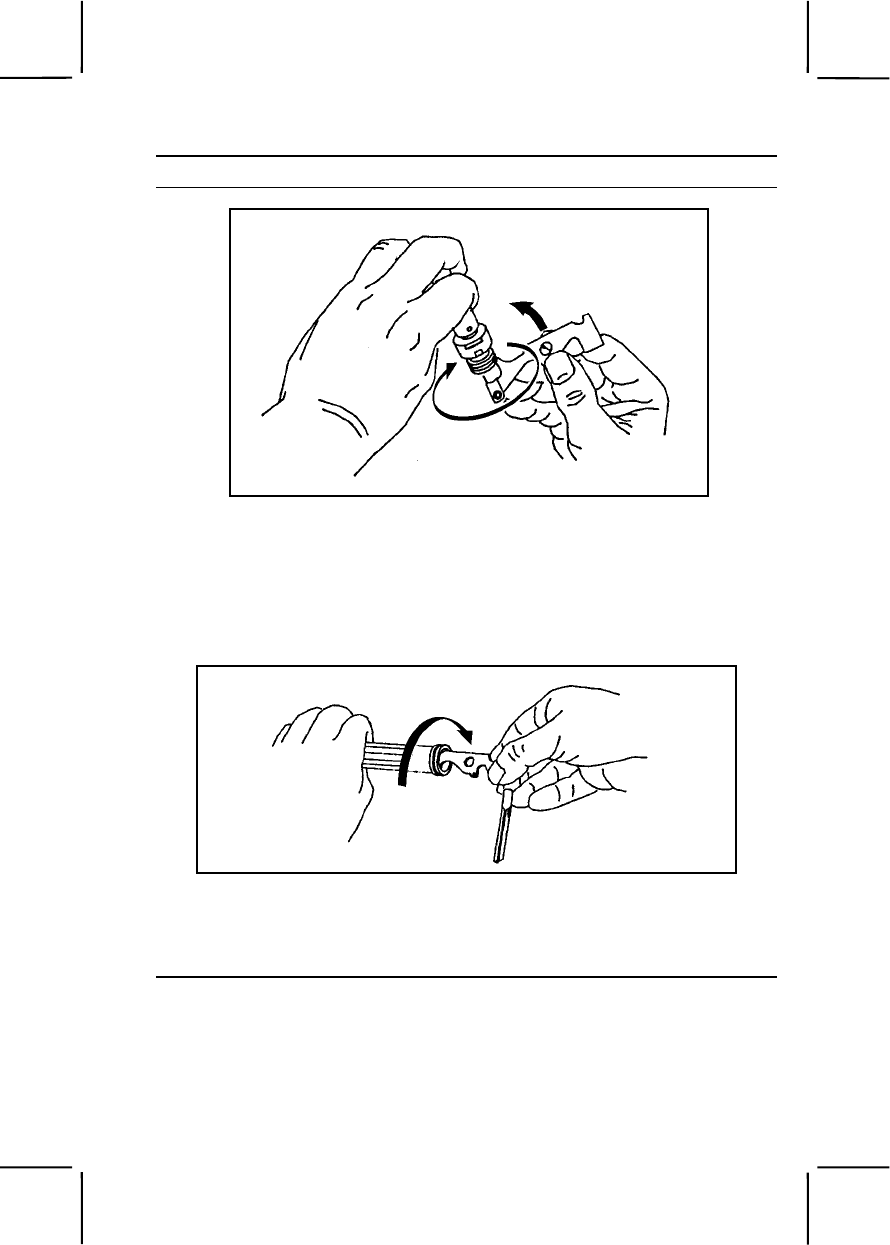
071-312-4025 3-363
Performance Steps
Figure 071-312-4025-17. Cleaning the grooves of the regulator body
c. Clean the gas cylinder and piston using the scraper. Do not use
CLP on the gas cylinder or on the piston.
(1) Clean the front interior of the gas cylinder (repositioned in
receiver with bipod in place) by inserting and turning the flat side of the
scraper in a full 360-degree circular motion (figure 071-312-4025-18).
Figure 071-312-4025-18. Cleaning the gas cylinder's front interior
(2) Clean the internal grooves on the front side of the gas cylinder
as previously described (using the protruding tips of the scraper), but insert
the scraper farther into the gas cylinder (figure 071-312-4025-19).
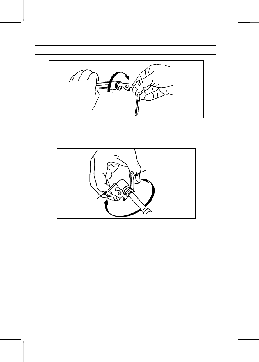
3-364 071-312-4025
Performance Steps
Figure 071-312-4025-19. Cleaning the gas cylinder's internal grooves
(3) Clean the three grooves of the piston using a full, 360-degree
circular motion (figure 071-312-4025-20).
Figure 071-312-4025-20. Cleaning the grooves of the piston
(4) Clean the hole in the front of the piston by inserting and turning
the flat side of the scraper in a full 360-degree circular motion (figure 071-
312-4025-21).
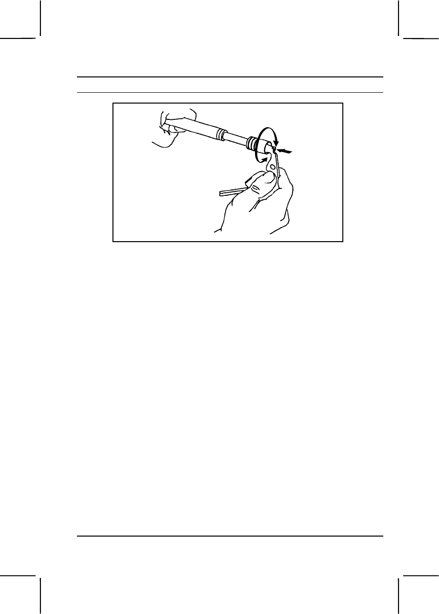
071-312-4025 3-365
Performance Steps
Figure 071-312-4025-21. Cleaning the hole in the piston
d. Remove carbon and dirt from all other parts of the weapon using
CLP and a wiping rag.
e. Clean ammunition boxes with a brush and clean dry wiping rag.
f. Clean ammunition with a clean dry wiping rag.
4. Inspect the M249 machine gun.
a. Inspect the bore and chamber for chips and pitting.
b. Check the front sight for looseness.
c. Inspect the flash suppressor (old style barrel) or compensator (new
style barrel), the barrel extension, and the barrel release for cracks, dents,
burrs, or other damage.
d. Check the cover assembly for smooth operation, spring tension,
bent parts, and excessive wear.
e. Check the cocking assembly for free movement and for bent or
cracked parts.
f. Check the rails for excessive wear, burrs, and chips.
g. Check the barrel locking latch and cover detect springs for spring
tension.
h. Check for broken pistol grip and chipped or cracked trigger housing
holding lug.
i. Check the tripping lever and the seat for burrs, cracks, chips, or
wear.
j. Check the cocking action by pushing back on the tripping lever; the
sear should rise. Pull the trigger; the sear should lower.

3-366 071-312-4025
Performance Steps
k. Check the safety function. Push the safety to the right (RED BAND
NOT VISIBLE). Pull the trigger; the sear will not lower. Push the safety to
the left (RED BAND VISIBLE). Pull the trigger again; the sear will lower.
l. Check the slide assembly, bolt assembly, piston assembly, and
return rod and transfer mechanism assembly for burrs, cracks, and broken
pins. Push down on roller of slide assembly to ensure it retracts. Check the
driving spring for broken strands.
m. Check bipod legs for correct operation.
n. Check the rear sight assembly for serviceability.
o. Check the ammunition box for damage. Make sure the box latch will
engage the receiver dovetail.
p. Inspect ammunition.
(1) Check for damaged, corroded, or loose bullets.
(2) Check for damaged links.
(3) Report to your squad leader or NCOIC any deficiencies you
cannot correct.
5. Lubricate the M249.
Note. Use only CLP on the M249.
a. Lubricate exposed metal parts and all moving parts with a light coat
of CLP.
b. Do not lubricate the gas regulator hole in the barrel or the gas
regulator itself.
6. Assemble the M249.
a. Replace the bipod and gas cylinder.
(1) Place the bipod on the receiver.
(2) Push the gas cylinder through the bipod yoke into the receiver.
(3) Push the cylinder to the rear while countering the pressure of
the locking spring and guiding the end of the cylinder into the receiver with
the other hand applying downward pressure. When you have fully inserted
the gas cylinder, rotate it until the spring clicks into place in the recess at
the rear of cylinder (figure 071-312-4025-22).
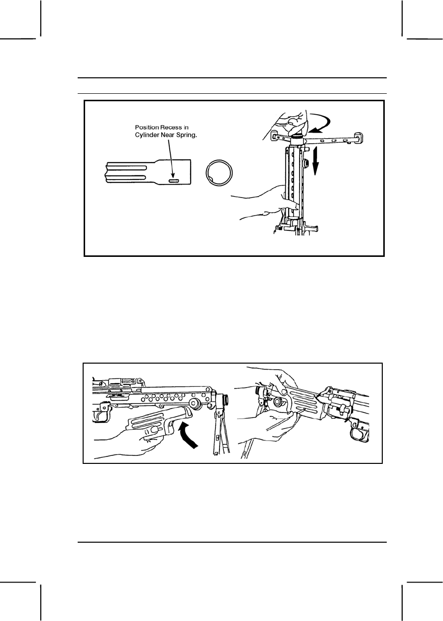
071-312-4025 3-367
Performance Steps
Figure 071-312-4025-22. Replacement of the bipod and gas cylinder
b. Replace the handguard.
(1) Stow the cleaning equipment in the handguard.
(2) Place the handguard onto the receiver and slide it backward
until it stops.
(3) Using a cleaning rod section, push the handguard retaining pin
to the right. This locks the handguard into position (figure 071-312-4025-
23).
Figure 071-312-4025-23. Replacement of the handguard
(4) Pull downward on the handguard to ensure it locks into position.
c. Replace the gas regulator.
(1) Insert the gas regulator into the lower end of the hole in the gas
block. Align the notch on the gas regulator body with the notch in the gas
block (figure 071-312-4025-24).
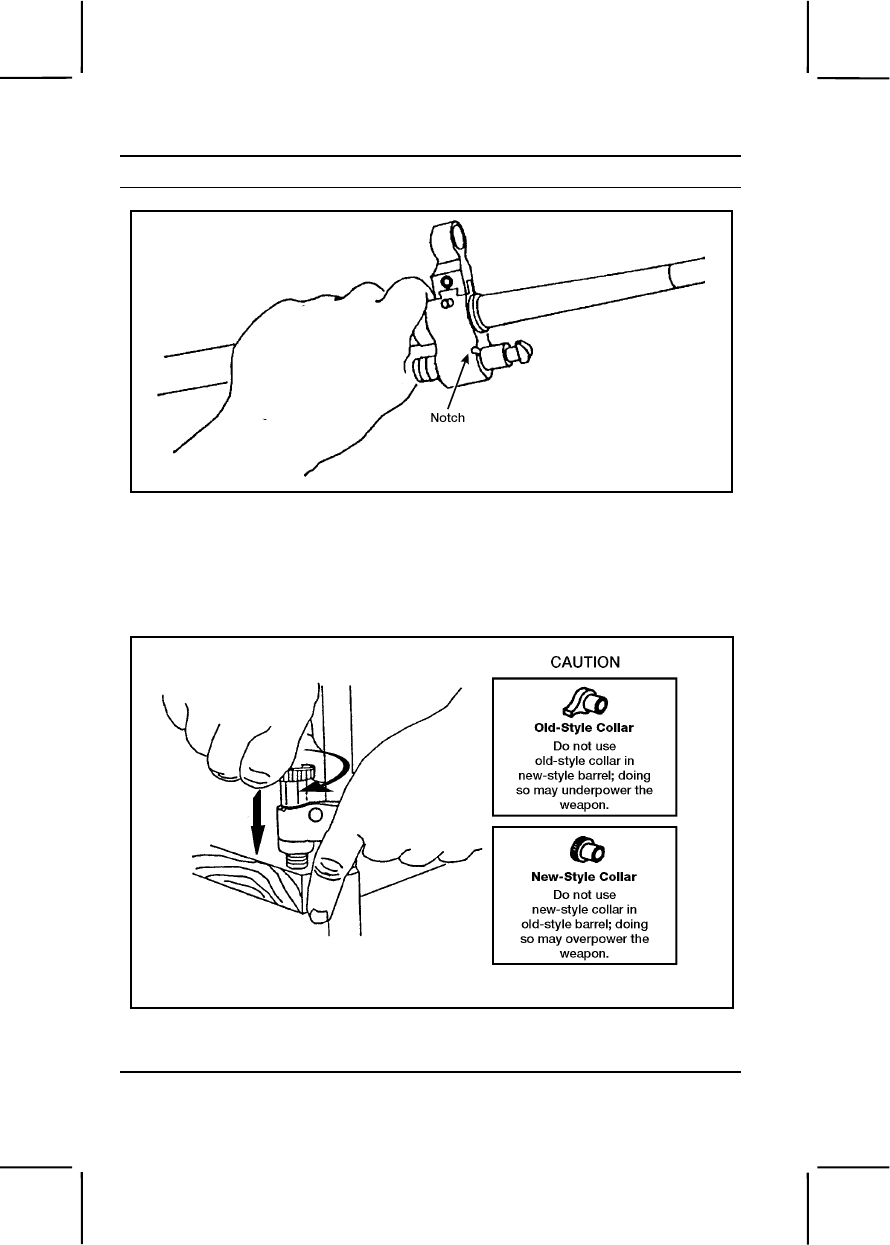
3-368 071-312-4025
Performance Steps
Figure 071-312-4025-24. Replacement of the gas regulator
(2) With the gas regulator installed and supported on a firm
surface, place the gas collar on the protruding end of the gas regulator.
Rotate the gas collar until it slips in place. To lock the gas regulator in
place, press it in and rotate it (figure 071-312-4025-25).
Figure 071-312-4025-25. Replacement of the gas collar
d. Replace the barrel.
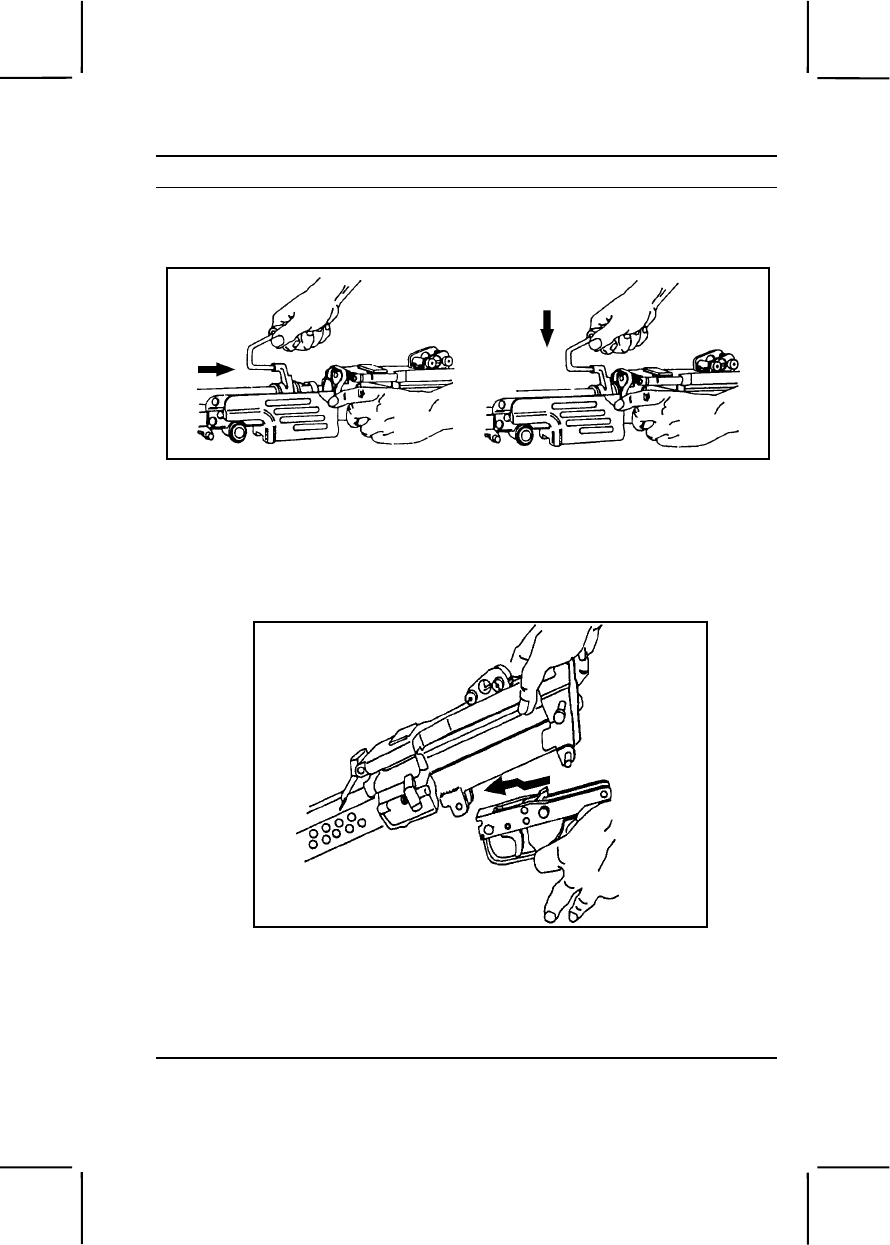
071-312-4025 3-369
Performance Steps
(1) Depress the barrel locking lever with your left hand (figure 071-
312-4025-26).
Figure 071-312-4025-26. Replacement of the barrel
(2) Hold the carrying handle with your right hand; pull the barrel
rearward into the receiver. Push the carrying handle downward and release
the barrel locking lever. Check to ensure the barrel locks into position.
e. Replace the trigger mechanism (figure 071-312-4025-27).
Figure 071-312-4025-27. Replacement of trigger mechanism
(1) Pull the retaining pin to the left side of the receiver.
(2) Align the trigger mechanism with the slot on the bottom of the
receiver. To hold the trigger mechanism in place, push the lower retaining
pin into the right side hole on the rear of the trigger mechanism assembly.
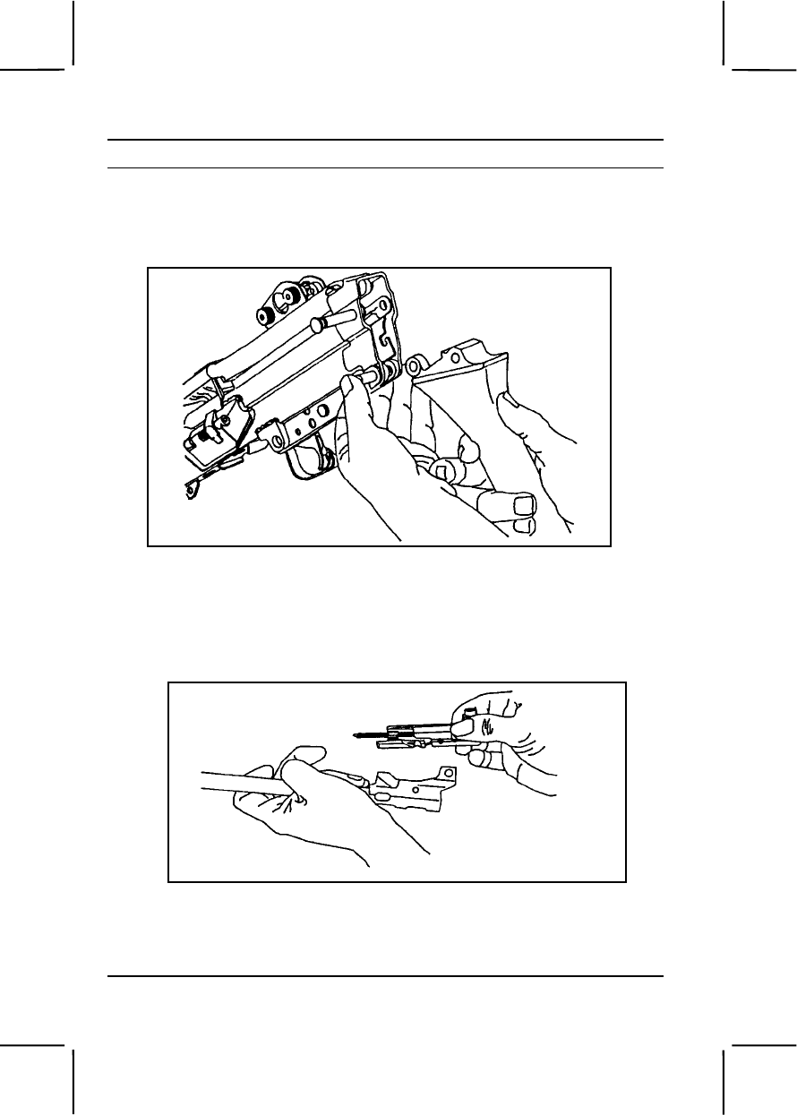
3-370 071-312-4025
Performance Steps
f. Replace the buttstock and shoulder assembly (figure 071-312-
4025-28). Support the trigger mechanism with your left hand. Align the
lower hole in buttstock and buffer assembly with the rear hole in the trigger
mechanism. Push the lower retaining pin to the right.
Figure 071-312-4025-28. Replacement of the buttstock and shoulder assembly
g. Replace the operating rod, slide assembly, and bolt assembly.
(1) Secure the slide assembly to the piston by pushing the retaining
pin from the left to the right. Place the firing pin spring on the firing pin
(figure 071-312-4025-29).
Figure 071-312-4025-29. Attachment of the slide assembly to the piston
(2) Put the bolt assembly into the slide assembly. Press in to
compress the firing pin spring. Rotate the bolt and hook its driving lug into
the slide assembly (figure 071-312-4025-30).
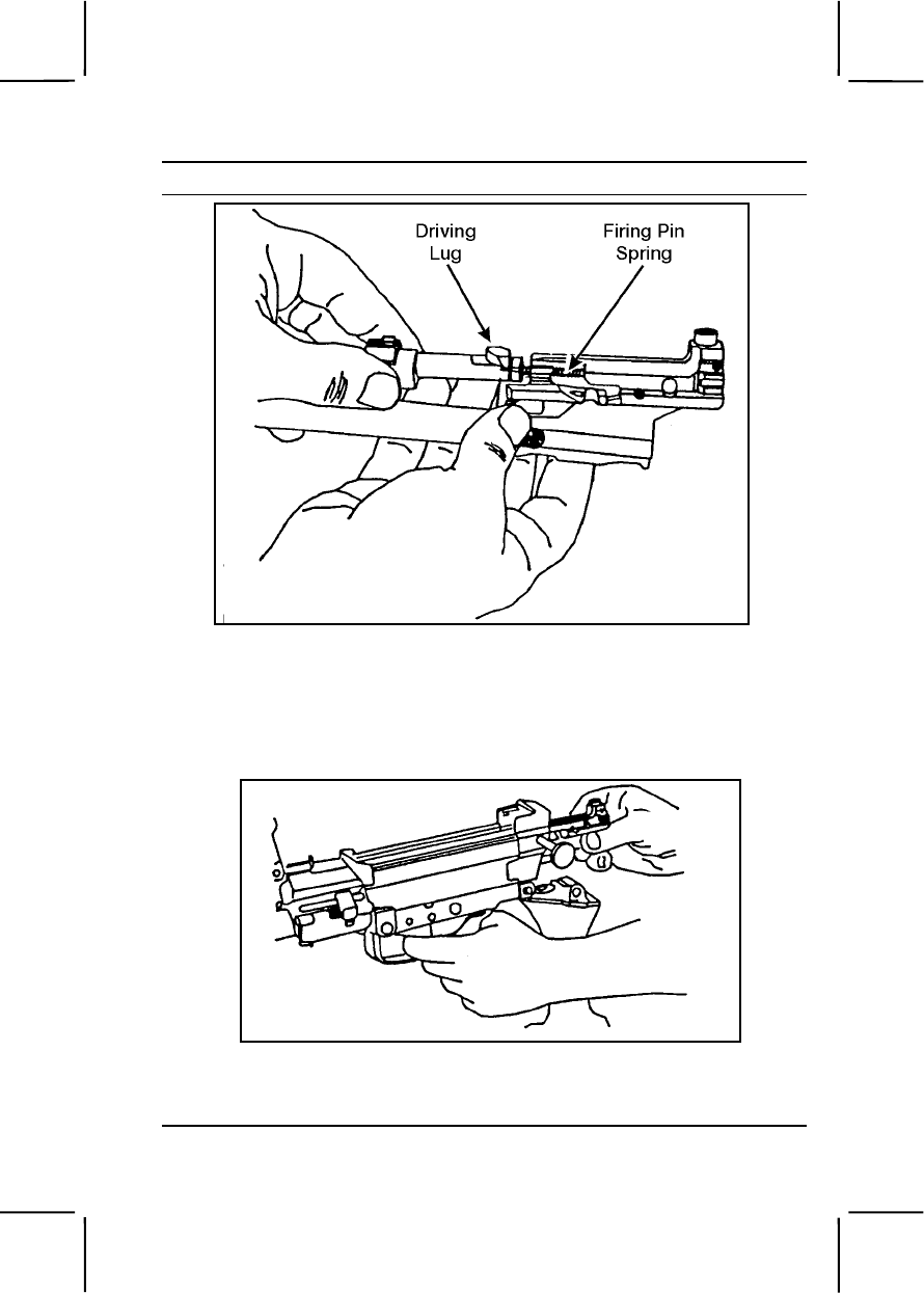
071-312-4025 3-371
Performance Steps
Figure 071-312-4025-30. Attachment of the bolt assembly to the slide assembly
(3) Put the assembled parts into the receiver with the feed cover
open. Align and place the bolt lugs; slide the cutouts carefully onto the
receiver rails. Press the trigger and at the same time, push the parts all the
way forward (figure 071-312-4025-31).
Figure 071-312-4025-31. Replacement of the operating rod, slide
assembly, and bolt assembly
h. Replace the spring, return rod, and transfer mechanism assembly.
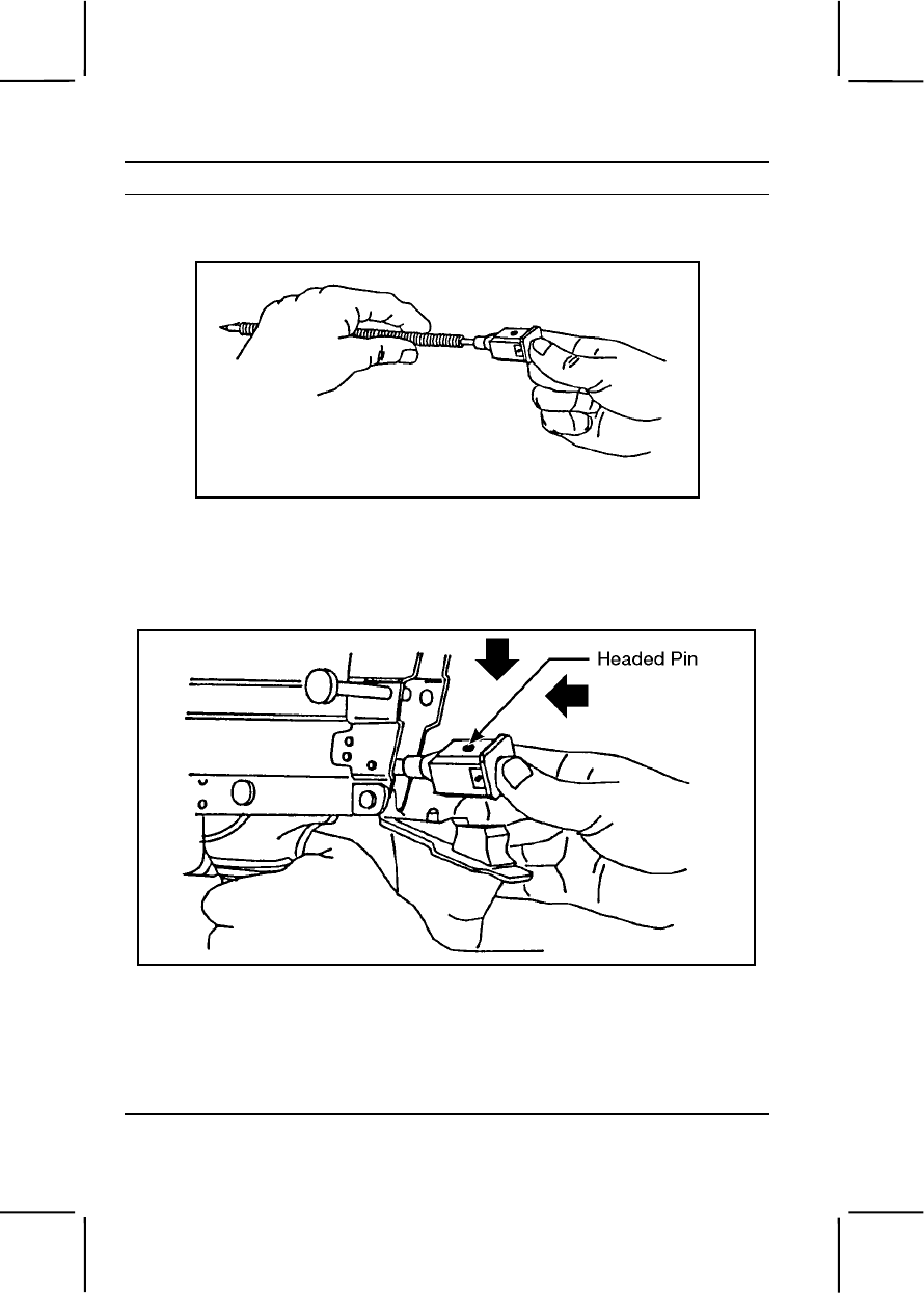
3-372 071-312-4025
Performance Steps
(1) Put the slide spring on the return rod and transfer mechanism
assembly (figure 071-312-4025-32).
Figure 071-312-4025-32. Replacement of the spring
(2) Ensure that the headed end of the vertical pin in the transfer
mechanism assembly points upward (on top of the transfer mechanism
assembly) (figure 071-312-4025-33).
Figure 071-312-4025-33. Replacement of the return rod and
transfer mechanism assembly
(3) Hold the pistol grip with one hand. With the other hand, push
the return rod and transfer mechanism assembly into its housing in the
piston. Press inward and downward on the rear of the assembly until its
two lugs move into the receiver grooves.
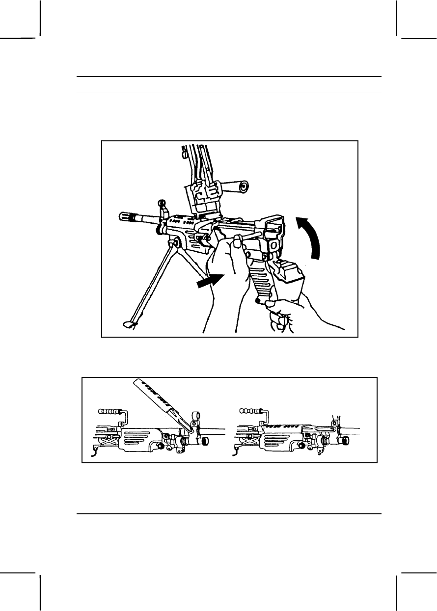
071-312-4025 3-373
Performance Steps
i. Pivot the buttstock and buffer assembly upward into position. Push
the retaining pin to the right, and close the cover assembly (figure 071-312-
4025-34).
Figure 071-312-4025-34. Replacement of buttstock and buffer assembly
j. Replace the heat shield assembly (figure 071-312-4025-35).
Figure 071-312-4025-35. Replacement of the heat shield assembly
(1) Hook the metal extensions of the heat shield assembly under
the front sight pins (new style barrel) with the spring clips down on top of
the barrel.

3-374 071-312-4025
Performance Steps
Note. Although old style barrels do not have protruding front sight pins, you can still
install heat shield assemblies on them.
(2) Apply downward pressure and snap the heat shield onto the
barrel. Be careful not to pinch yourself.
7. Perform a function check to ensure you have assembled the weapon
correctly.
Evaluation Preparation:
Setup: At the test site, provide all the equipment and materials listed in task
conditions. Use only dummy ammunition for training purposes.
Brief Soldier: Tell the soldier to perform maintenance on the M249,
ammunition box, and linked 5.56-mm ammunition.
Performance Measures GO NO GO
1. Cleared the weapon. —— ——
2. Disassembled the weapon without damaging any
parts. —— ——
3. Cleaned the weapon, ammunition box, and
ammunition. —— ——
4. Identified any damaged, worn, or malfunctioning part. —— ——
5. Identified any damaged ammunition. —— ——
6. Lubricated the weapon using the correct lubrication
technique. —— ——
7. Assembled the weapon in correct sequence without
damaging any parts. —— ——
Evaluation Guidance: Score the soldier GO if all performance measures
are passed. Score the soldier NO GO if any performance measure is failed.
If the soldier scores NO GO, show him what was done wrong and how to do
it correctly.
References
Required Related
TM 9-1005-201-10 FM 3-22.68
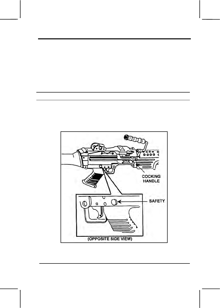
071-312-4027 3-375
071-312-4027
Load an M249 Machine Gun
Conditions: Given an M249 machine gun, small arms ammunition box, and
linked 5.56-mm ammunition.
Standards: Attached the ammunition box to the receiver correctly. Placed
linked 5.56-mm ammunition in the feed tray groove so that, when the cover
was closed, a round remained in the tray groove and the ammunition was
fed correctly.
Performance Steps
1. With the palm facing up, pull the cocking handle to the rear. This locks
the bolt in the rear position.
2. Push the cocking handle forward until you hear it click into the locked
position (figure 071-312-4027-1).
Figure 071-312-4027-1. M249 locking handle and safety
3. Push the safety from left to right for safe mode (the red band will not
show) (figure 071-312-4027-1).
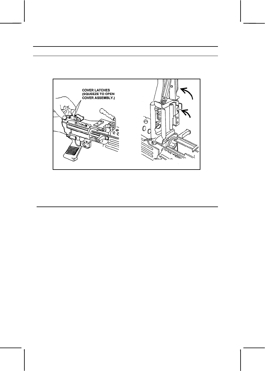
3-376 071-312-4027
Performance Steps
4. Open the cover, raise the feed tray assembly, and make sure that the
feed tray, receiver, and chamber area are clear (figure 071-312-4027-2).
Figure 071-312-4027-2. Checking the feed tray, receiver, and chamber area
5. Attach the ammunition box with linked 5.56-mm ammunition to the
underside of the receiver. To do so, align the box latch with the dovetail
on the receiver (figure 071-312-4027-3). Pull outward on the ammunition
box to make sure the aligning box latch engages.
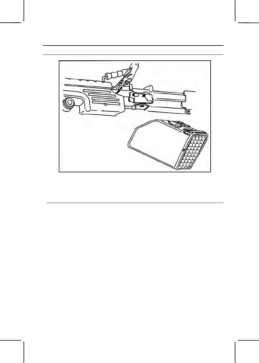
071-312-4027 3-377
Performance Steps
Figure 071-312-4027-3. Attachment of the ammunition box
6. Place the link belt in the feed tray with the first round against the
cartridge stop and hold the belt in place. Close the cover assembly (figure
071-312-4027-4).
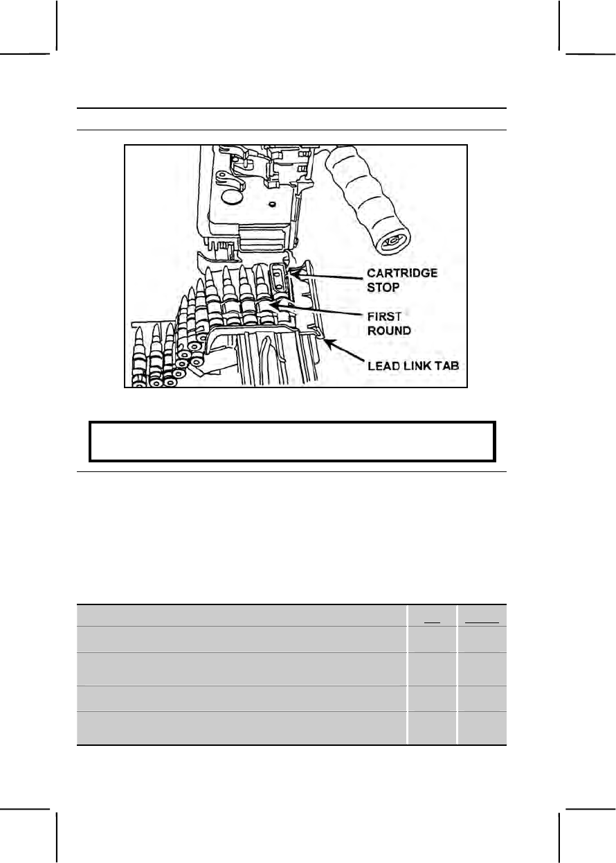
3-378 071-312-4027
Performance Steps
Figure 071-312-4027-4. Link belt in feed tray
WARNING
The weapon is now loaded.
Evaluation Preparation:
Setup: Use dummy ammunition to test this task. At the test position, provide
an M249 and a belt of linked, dummy 5.56-mm ammunition. For
standardization, always place the bolt and cocking handle forward and the
safety in the safe position. Make sure the ammunition is clean and linked
properly. Have an assistant relink and wipe the ammunition clean before the
next test.
Brief Soldier: Tell the soldier to load the M249 machine gun.
Performance Measures GO NO GO
1. Locked the bolt in the rear position. —— ——
2. Pushed the cocking handle forward to the locked
position. —— ——
3. Pushed the safety to the safe position. —— ——
4. Checked to make sure the feed tray, receiver, and
chamber were clear. —— ——

071-312-4028 3-379
Performance Measures GO NO GO
5. Attached the ammunition box with linked ammunition
to the receiver. —— ——
6. Placed the link belt in the feed tray with the first
round against the cartridge. —— ——
7. Closed the cover. —— ——
Evaluation Guidance: Score the soldier GO if all performance measures
are passed. Score the soldier NO GO if any performance measure is failed.
If the soldier scores NO GO, show the soldier what was done wrong and
how to do it correctly.
References
Required Related
FM 3-22.68
TM 9-1005-201-10
071-312-4028
Unload an M249 Machine Gun
Conditions: Given an M249 machine gun loaded with 5.56-mm ammunition
(linked or in an M16 magazine) and a requirement to unload the M249.
Standards: Removed all ammunition, expanded brass, links, and the
magazine from the weapon.
Performance Steps
1. Pull the cocking handle to the rear, locking the bolt in the rear position.
2. Place the safety in the safe mode (the red band will not show) and
return the cocking handle to its forward position.
3. Remove ammunition and links.
a. Belt-fed. Raise the cover and remove any ammunition or links from
the feed tray.
b. Magazine-fed. Push down on the magazine release tab and pull the
magazine out. Then raise the cover.
4. Raise the feed tray and inspect the chamber to ensure that it contains
no ammunition. If it contains ammunition, remove the ammunition.
5. Close the cover.
6. Place the safety in the fire mode (the red band will show).
7. Pull the cocking handle to the rear, and pull the trigger while manually

3-380 071-312-4028
Performance Steps
easing the bolt forward to the closed position.
Evaluation Preparation:
Setup: At the test site, provide the soldier with all the equipment given in the
task conditions. Evaluate this task using dummy 5.56-mm linked rounds or
dummy 5.56-mm ammunition loaded in 30-round M16 magazines.
Brief Soldier: Tell the soldier to unload the M249 in the correct manner.
Performance Measures GO NO GO
1. Pulled the cocking handle to the rear, locking the bolt
in the rear position. —— ——
2. Placed the safety in safe mode (the red band will not
show) and returned the cocking handle to its forward
position.
—— ——
3. Removed ammunition and links. —— ——
a. Belt-fed. Raised the cover and removed any
ammunition or links from the feed tray.
b. Magazine-fed. Pushed down on the magazine
release tab and pulled the magazine out. Then raised
the cover.
4. Raised the feed tray and inspected the chamber to
ensure that it contained no ammunition. If it contained
ammunition, removed the ammunition.
—— ——
5. Closed the cover. —— ——
6. Placed the safety in the fire mode (the red band will
show). —— ——
7. Pulled the cocking handle to the rear, and pulled the
trigger while manually easing the bolt forward to the
closed position.
—— ——
Evaluation Guidance: Score the soldier GO if all performance measures
are passed. Score the soldier NO GO if any performance measure is failed.
If the soldier scores NO GO, show the soldier what was done wrong and
how to do it correctly.
References
Required Related
FM 3-22.68

071-312-3025 3-381
SUBJECT AREA 12: M60 MACHINE GUN
071-312-3025
Maintain an M60 Machine Gun
Conditions: Given an M60 machine gun that needs to be cleaned and
inspected. You have a cleaning kit, cleaner lubricant preservative (CLP),
lubricating oil arctic weather (LAW), swabs, a dummy cartridge, and a field
table or ground cloth on which to work.
Standards:
1. Disassembled the M60 machine gun into the following groups: stock;
buffer and operating rod; bolt assembly; trigger mechanism; barrel; feed
cover, feed tray, and hanger; forearm; and receiver.
2. Cleaned the M60 machine gun, removed powder fouling and other foreign
material and identified any unserviceable parts. Did not get CLP in the gas
cylinder.
3. Lubricated the M60 machine gun.
4. Assembled the M60 machine gun, performed a function check, ensured
the forearm group was locked in place, the hinge pin was interlocked with
the latch engaging the sear pin, and the stock group latch engaged.
Performance Steps
WARNING
Weapon must be clear before disassembling.
1. Clear the M60 machine gun.
a. Pull the cocking handle to the rear.
b. Lock the bolt to the rear.
c. Raise the feed cover.
d. Ensure the chamber is empty.
e. Close the feed cover.
f. Place the safety lever on FIRE.
g. Pull the cocking handle to the rear and hold it.
h. Pull the trigger and allow the bolt to ease forward.
i. Place the selector lever on SAFE.
2. Remove the stock group.
a. Raise the hinged shoulder rest.
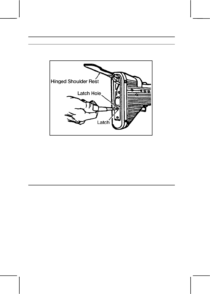
3-382 071-312-3025
Performance Steps
b. Insert the nose of a dummy cartridge into the latch hole (figure 071-
312-3025-1).
Figure 071-312-3025-1. Stock
c. Push the latch down.
d. Pull the stock group to the rear, removing it from the M60 machine
gun.
3. Remove the buffer, operating rod, and bolt assembly group.
a. Remove the buffer.
(1) Press the exposed buffer lightly with the palm of the hand
(figure 071-312-3025-2).
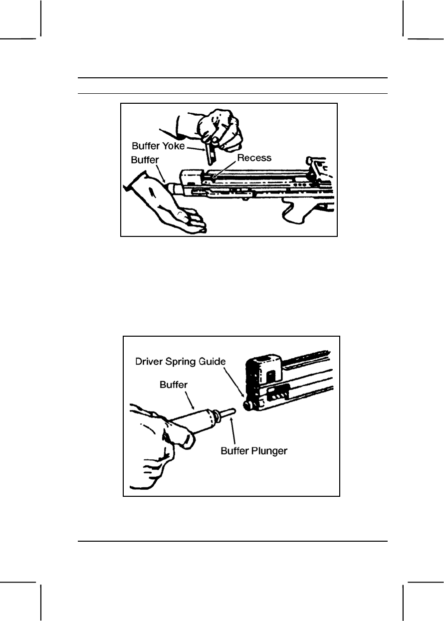
071-312-3025 3-383
Performance Steps
Figure 071-312-3025-2. Buffer yoke
(2) Remove the buffer yoke from the top of the receiver.
(3) Remove the buffer slowly by pulling it rearward. Allow the driver
spring guide to expand until the end of the guide is showing at the rear of
the receiver.
(4) Pull the buffer plunger from the driver spring guide (figure 071-
312-3025-3).
Figure 071-312-3025-3. Buffer
(5) Pull the driver spring guide and spring from the receiver.
(6) Separate the driver spring from the driver spring guide.
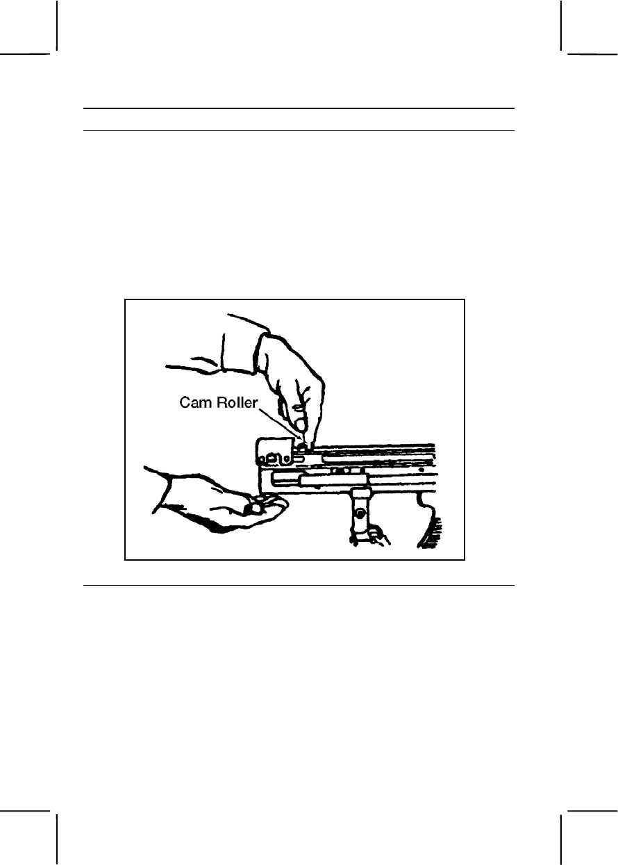
3-384 071-312-3025
Performance Steps
b. Remove the operating rod and bolt.
(1) Grasp the pistol grip with the left hand.
(2) Pull the cocking handle to the rear with your right hand until the
bolt separates from the barrel socket.
(3) Return the cocking handle to the forward position.
(4) Pull the cam roller until it stops. This pulls the rod and bolt to the
rear.
(5) Push the bolt to the rear with your finger on the face of the bolt
(figure 071-312-3025-4).
Figure 071-312-3025-4. Cam roller
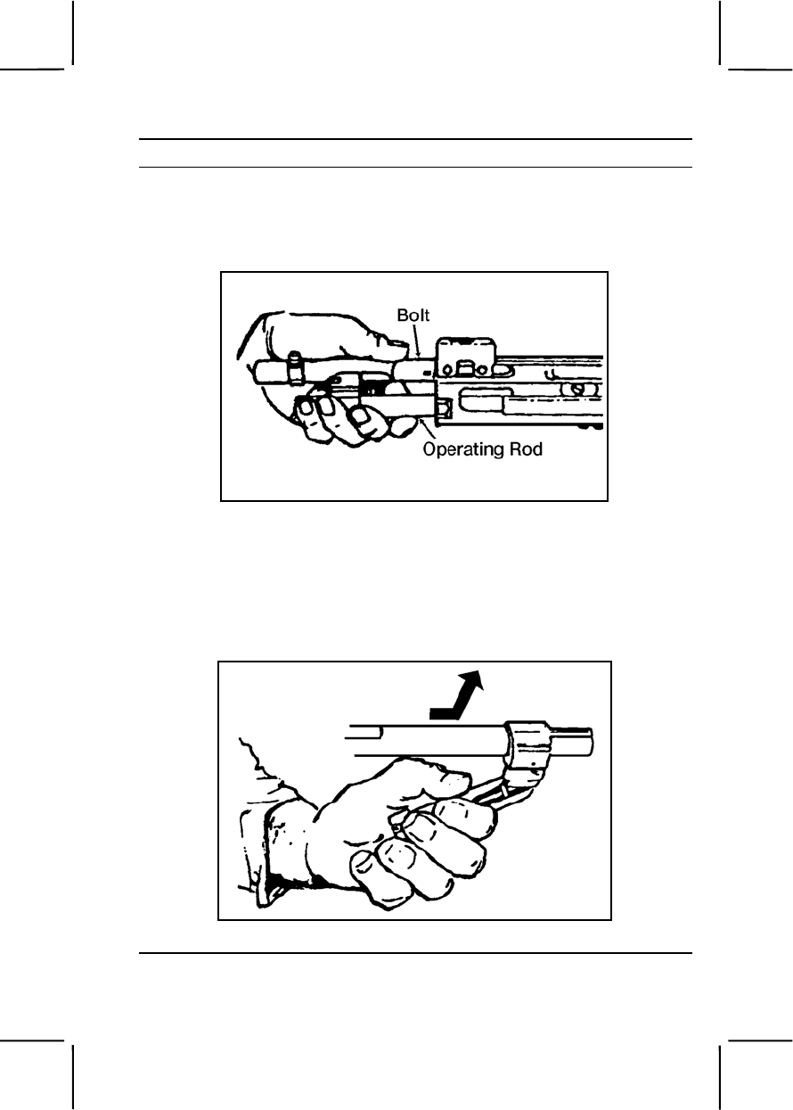
071-312-3025 3-385
Performance Steps
(6) Grasp the operating rod and bolt when they are about 4 inches
out of the cylinder to prevent the bolt from rotating.
(7) Pull the operating rod and bolt from the receiver (figure 071-
312-3025-5).
Figure 071-312-3025-5. Operating rod and bolt
(8) Relax your grip, allowing the bolt to rotate slowly.
(9) Grasp the bolt and operating rod with both hands. The bolt
should be on the bottom, facing away from your body.
(10) Disengage the bolt from the operating rod by pulling forward on
the operating handle and lifting upward (figure 071-312-3025-6).
Figure 071-312-3025-6. Bolt assembly and operating rod being separated
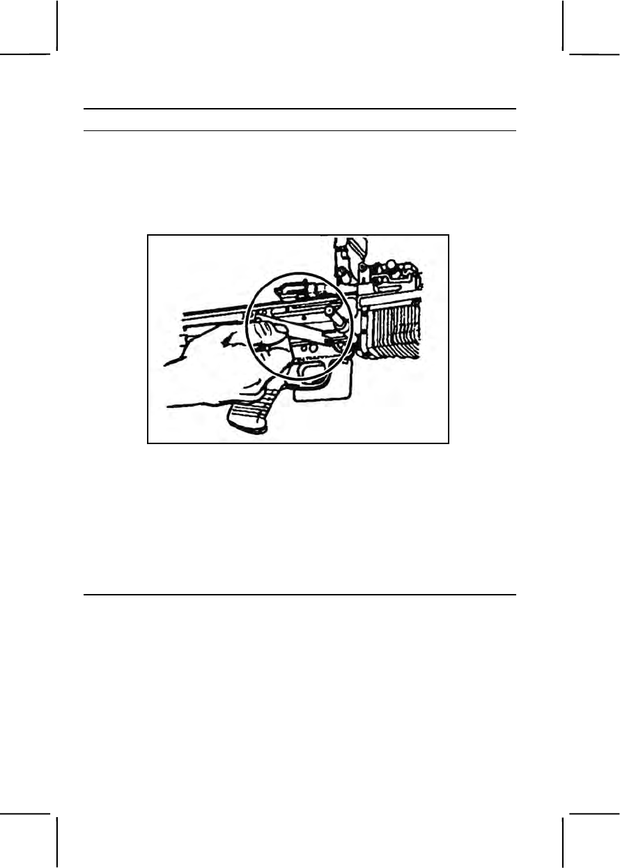
3-386 071-312-3025
Performance Steps
4. Remove the trigger mechanism group consisting of the grip, leaf spring,
and retaining pin.
a. Press in on the rear of the leaf spring.
b. Rotate the rear of the leaf spring up to clear it from the sear pin
(figure 071-312-3025-7).
Figure 071-312-3025-7. Sear pin
c. Pull the leaf spring to the rear, disengaging it from the front notch of
the retaining pin.
d. Remove the retaining pin by pushing it to the left.
e. Remove the trigger mechanism.
(1) Slide the trigger mechanism slightly forward.
(2) Rotate the front of the trigger mechanism housing down.
(3) Remove the trigger mechanism (figure 071-312-3025-8).
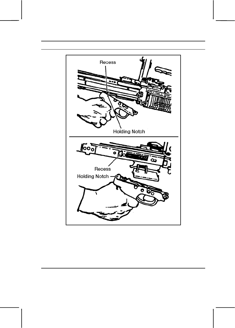
071-312-3025 3-387
Performance Steps
Figure 071-312-3025-8. Trigger mechanism group
5. Remove the cover, feed tray, and hanger group.
a. Remove the feed cover.
(1) Raise the feed cover.
(2) Unlock the hinge pin using a pointed object (figure 071-312-
3025-9).
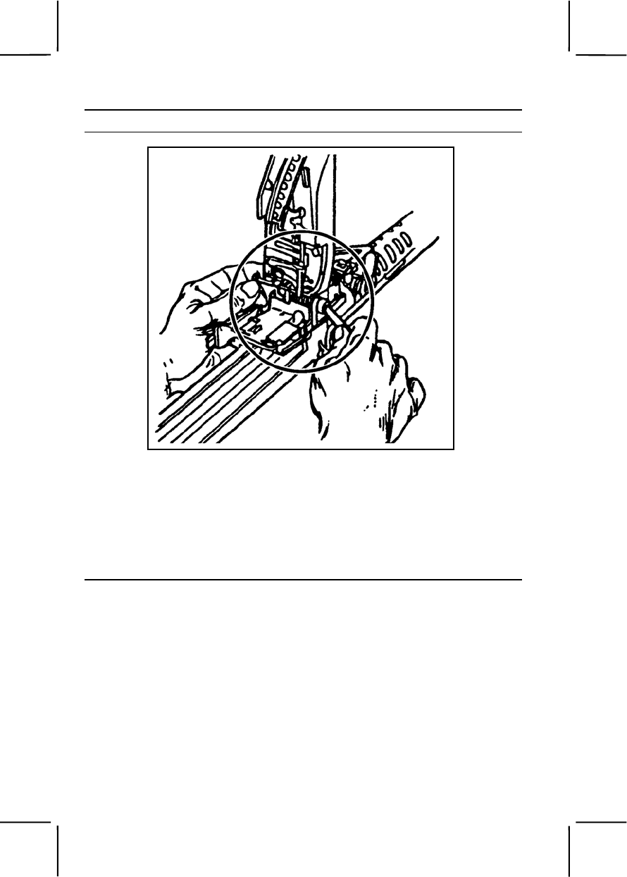
3-388 071-312-3025
Performance Steps
Figure 071-312-3025-9. Hinge pin latch
(3) Push the hinge pin out of its recess and remove it from the
opposite side of the hinge pin latch.
(4) Lift the feed cover from the receiver assembly.
(5) Remove the feed cover spring from the cover.
b. Lift the feed tray and hanger group from the receiver assembly
(figure 071-312-3025-10).
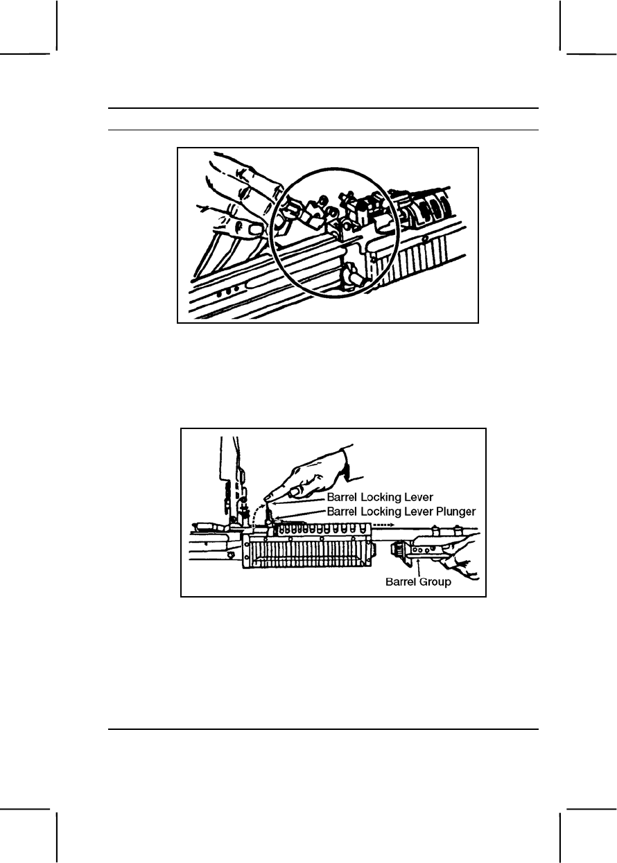
071-312-3025 3-389
Performance Steps
Figure 071-312-3025-10. Feed tray and hanger group
6. Remove the barrel group, made up of the barrel, flash suppressor, front
sight, bipod assembly, and gas cylinder system.
a. Push in on the barrel locking lever plunger (figure 071-312-3025-
11).
Figure 071-312-3025-11. Barrel locking lever
b. Raise the barrel locking lever to the vertical position.
c. Remove the barrel group by pulling it straight to the front of the rifle.
7. Remove the forearm assembly.
a. Turn the receiver so the top is facing down.
b. Insert a pointed object into the latch hole at the bottom rear of the
forearm assembly (figure 071-312-3025-12).
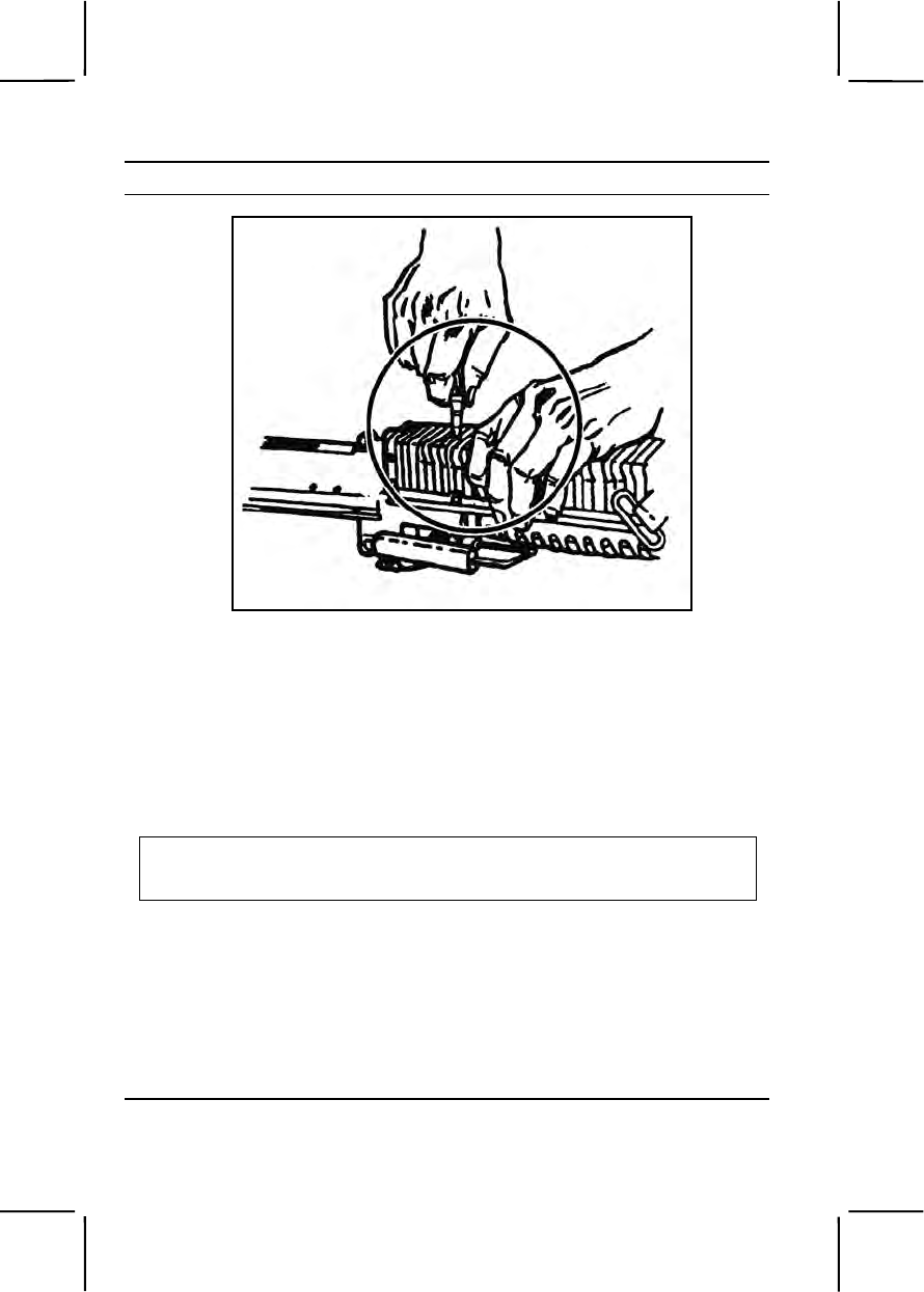
3-390 071-312-3025
Performance Steps
Figure 071-312-3025-12. Forearm latch
c. Release the forearm latch by pressing downward with a pointed
object.
d. Raise the rear of the forearm assembly slightly.
e. Pull the forearm assembly to the front to remove it.
Note. This completes general disassembly of the M60 machine gun. The receiver
group requires no disassembly.
8. Clean the M60 machine gun.
CAUTION
Do not use gasoline, kerosene, benzene, or high pressure water, steam, or air
for cleaning.
a. Position the gas cylinder above the barrel during cleaning so as not
to get CLP in the gas cylinder.
b. Clean the bore using CLP and a bore brush attached to a cleaning
rod.
(1) Run the brush through the bore without reversing the direction
of the brush while it is in the bore.
(2) Repeat the preceding step until most of the powder fouling and
other foreign matter have been removed.

071-312-3025 3-391
Performance Steps
(3) Swab out the bore several times using a cleaning rod and a
swab wet with CLP.
(4) Swab out the bore several times using a cleaning rod and a dry
swab.
c. Clean the chamber using CLP and a chamber brush attached to a
cleaning rod.
(1) Run the brush through the chamber.
(2) Repeat the preceding step until most of the powder fouling and
other foreign matter have been removed.
(3) Swab out the chamber several times using a cleaning rod and a
swab wet with CLP.
(4) Swab out the chamber several times using a cleaning rod and
dry swab.
d. Clean the receiver with a receiver brush and CLP.
(1) Brush the receiver until most of the powder fouling and other
foreign matter have been removed.
(2) Swab out the receiver several times using a cleaning rod and a
swab wet with CLP.
(3) Swab out the receiver several times using a cleaning rod and
dry swab.
e. Clean the buffer and operating rod group using CLP and a receiver
brush. Do not submerge the buffer in any cleaning solvents.
(1) Brush the buffer group until powder fouling and other foreign
matter have been removed.
(2) Swab out the operating rod several times using a cleaning rod
and a swab wet with CLP.
(3) Swab out the operating rod several times using a cleaning rod
and a dry swab.
f. Wipe down all parts of the M60 machine gun except the rubber-
coated parts with a rag wet with CLP.
g. Dry all parts cleaned with CLP.
9. Inspect the parts for serviceability.
a. Stock group.
(1) Ensure the stock group fits securely on the receiver.
(2) Check the guide rails for cracks, bends, or burrs.
(3) Check the shoulder rest and stock latch for binding.

3-392 071-312-3025
Performance Steps
(4) Check the rubber coating for gumming or cracking.
b. Buffer and operating rod group.
(1) Check the yoke and yoke recess for burrs, cracks, or bends.
(2) Ensure the buffer plunger fits easily into the recess in the driver
spring guide.
(3) Check the driver spring for kinks and broken or separated wires.
(4) Check the driver spring guide for bends, ensuring the spool is
tight on the shaft.
(5) Check the sear notch on the operating rod for excessive wear
or burring.
c. Bolt assembly group.
(1) Check the bolt plug, bolt plug pin, and actuator cam assembly
for chips and burrs.
(2) Check the firing pin for cracks or wear on the tip.
(3) Check the ejector and extractor to ensure they are under spring
tension and are not chipped or worn.
d. Trigger mechanism group.
(1) Check the shoulder of the sear for excessive wear.
(2) Check the mechanism for cracks (check carefully near the
retaining pins).
(3) Check the leaf spring to ensure it is under tension.
(4) Check the safety for correct function. (The sear should move
only slightly when the safety lever is on SAFE, and freely when the safety
lever is on FIRE.)
e. Barrel group.
(1) Check to ensure the suppressor is tight.
(2) Check the front sight and barrel locking-cam for bends, cracks,
burrs, or excessive wear.
(3) Check the bipod assembly for correct functioning. (The legs
should lock in the up and down position. The leg extension should lock at
the desired heights.)
(4) Check the gas piston and gas cylinder for burrs.
(5) Check the detent on the tab lock washers of the gas cylinder
nut and gas cylinder extension to ensure it is not broken.
(6) Check the bleeder hole in the gas cylinder extension to ensure
it is clear.

071-312-3025 3-393
Performance Steps
f. Feed cover, feed tray, and hanger.
(1) Check to ensure all parts inside the feed cover are under spring
tension.
(2) Check the feed cover to ensure it is not bent or torn.
(3) Check the belt holding pawl to ensure it is under spring tension.
g. Forearm assembly.
(1) Check the assembly to ensure it is not bent.
(2) Check the spring in the latch to ensure it is not broken.
h. Receiver group.
(1) Check the receiver to ensure it is not bent or cracked.
(2) Check the cocking handle to ensure it slides freely within its
guide path.
(3) Check the elevation scale on the rear sight to ensure it is
legible. The elevation screw should not be burred or worn.
10. Lubricate the M60 machine gun.
Note. When lubricating the M60 machine gun at temperatures below 0 degrees
Fahrenheit, use LAW and lubricate lightly to avoid freeze-ups; under all other
conditions, use CLP. When using LAW, lubrication techniques are the same as for
CLP.
a. Make sure you do not get CLP inside the buffer assembly or inside
the gas cylinder.
b. Run a cleaning patch with several drops of CLP on it through the
bore.
c. Wipe down all non-rubber-coated exterior surfaces of the M60
machine gun with a rag with several drops of CLP on it.
d. Use CLP to lubricate the following surfaces.
(1) Bolt locking lugs by the camming surfaces.
(2) Operating rod surfaces along the receiver rails.
(3) Actuator roller on the bolt and where the bolt actuator rides the
feed pawl carrier on the underside of the cover assembly.
11. Assemble the M60 machine gun in the following order.
a. Assemble the forearm group.
(1) Guide the forearm assembly over the operating rod tube,
ensuring the operating rod does not strike the baffles inside the forearm
assembly.

3-394 071-312-3025
Performance Steps
(2) Align the recess in the forearm assembly with the end of the
operating rod tube.
(3) Tap up on the bottom rear of the forearm assembly with the
palm of your hand to lock it in position.
b. Assemble the feed cover, feed tray, and hanger group.
(1) Align the guides of the feed tray and hanger on the left side of
the cover mounting brackets and sear, the feed tray, and hanger in the
receiver.
(2) Replace the cover.
(a) Insert the cover spring in the cover.
(b) Align the cover with the mounting brackets.
(c) Insert the hinge pin from the right side.
(d) Insert the hinge pin latch from the left side, making sure
that the hinge pin and the hinge pin latch interlock.
c. Assemble the barrel group.
(1) Make sure the barrel locking lever is in the vertical position
(figure 071-312-3025-11).
(2) Put the rear of the barrel through the forearm assembly.
(3) Align the gas cylinder nut with its recess in the forearm
assembly.
(4) Lower the barrel locking lever to its most downward position.
d. Assemble the trigger mechanism group (figure 071-312-3025-8).
(1) Engage the holding notch of the trigger mechanism group in its
recess in the bottom of the receiver (figure 071-312-3025-8).
(2) Rotate the front of the trigger mechanism up.
(3) Align the holes of the trigger mechanism with the mounting
bracket on the receiver.
(4) Insert the retaining pin from the left.
(5) Attach the leaf spring by placing the open end of the leaf spring
on the retaining pin.
(6) Engage the hooked end to the sear pin.
e. Assemble the bolt and operating rod group.
(1) Hold the bolt securely in one hand with the camming slot up.
The face of the bolt should be toward the body.
(2) Position the rear of the operating rod yoke against the rear firing
pin spool with the other hand (figure 071-312-3025-13).
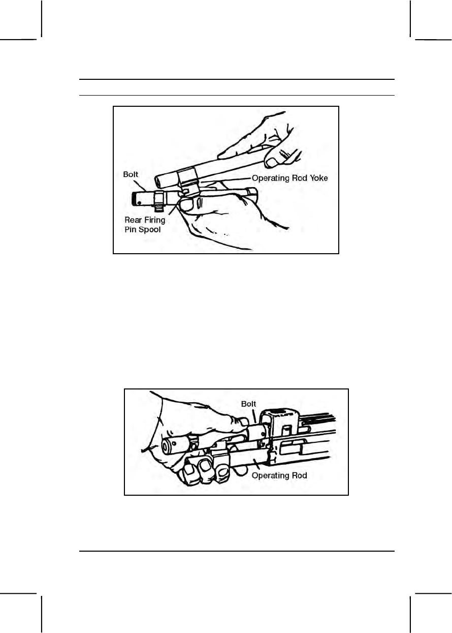
071-312-3025 3-395
Performance Steps
Figure 071-312-3025-13. Rear of operating rod yoke positioned
against rear firing pin spool
(3) Push on operating rod, compressing the firing pin spring.
(4) Position the operating rod yoke between the firing pin spool.
(5) Push forward on the rear of the bolt with the other hand,
causing the bolt to rotate until the locking lugs are vertical and the cam
roller is up.
(6) Push the operating rod and bolt (ensure the cam roller faces up)
into the receiver until the end of the operating rod is even with the rear of
the receiver (figure 071-312-3025-14).
Figure 071-312-3025-14. Operating rod and bolt
(7) Put the driver spring guide into the driver spring.
(8) Put the free end of the driver spring in the opening of the
operating rod.

3-396 071-312-3025
Performance Steps
(9) Pull the trigger.
(10) Push in the driver spring until the head of the guide is about one
inch from the receiver (figure 071-312-3025-3).
f. Assemble the buffer group (figure 071-312-3025-3).
(1) Put the buffer plunger into the driver spring guide.
(2) Push forward on the buffer until the operating rod and bolt go
fully forward.
(3) Push in on the buffer until the recesses on the buffer are
aligned with the recesses in the receiver.
(4) Place the buffer yoke in the buffer recess on top of the receiver.
g. Assemble the stock group.
(1) Align the guide rails of the stock group with the guide rails on
the receiver.
(2) Push forward until the stock is fully seated. You will hear a
distinct click when the latch engages.
12. Perform a function check to ensure that the M60 machine gun is
assembled correctly.
a. Place the safety on FIRE.
b. Pull the cocking handle to the rear.
c. Return the cocking handle forward to the locked position.
d. Close the cover.
e. Place the safety on SAFE.
f. Pull the trigger; the weapon should not fire.
g. Place the safety on FIRE.
h. Pull the cocking handle to the rear, holding it in that position.
i. Pull the trigger, allowing the bolt to ease forward.
j. Store the weapon in the arms room or continue the mission.
Evaluation Preparation:
Setup: At the test site, provide one M60 machine gun, all required cleaning
equipment, and a field table or ground cloth to work on.
Brief Soldier: Tell the soldier to disassemble, clean, assemble, and perform
a function check on the machine gun.
Performance Measures GO NO GO
1. Cleared the weapon so the selector lever was on
SAFE. —— ——

071-312-3027 3-397
Performance Measures GO NO GO
2. Disassembled the weapon into the major groups
without damaging any components. —— ——
3. Cleaned the weapon, removed the powder fouling
and other foreign material and dried all components
cleaned with CLP. —— ——
4. Identified any damaged, worn, or malfunctioning
components. —— ——
5. Assembled the weapon in the correct sequence
without damaging any components. —— ——
6. Performed a function check, ensured the weapon
operated properly. —— ——
Evaluation Guidance: Score the soldier GO if all performance measures
are passed. Score the soldier NO GO if any performance measure is failed.
If the soldier scores NO GO, show him what was done wrong and how to do
it correctly.
References
Required Related
FM 3-22.68
TM 9-1005-224-10
TM 9-1005-224-23&P
071-312-3027
Load an M60 Machine Gun
Conditions: Given a cleared M60 machine gun with a bipod and linked
7.62-mm ammunition. You must load the machine gun.
Standards: Loaded linked ammunition in the feed tray groove so, when the
cover was closed, a round remained in the tray groove and ammunition fed
correctly.
Performance Steps
WARNING
Keep all loaded weapons pointed in the direction of the target area.
1. Place the safety on FIRE (“F”).

3-398 071-312-3027
Performance Steps
2. Open the bolt by pulling the cocking handle to the rear, locking the bolt
to the rear with the palm of your hand facing up.
3. Return the cocking handle to the forward position.
4. Place the safety on SAFE (“S”).
5. Raise the cover.
6. Ensure that the feed tray, receiver group, and chamber are clear.
7. Place the first round of the belt in the feed tray groove, making sure the
double link is leading with the open side of the link down.
8. Hold the belt up (about six rounds from the loading end) while closing
the cover, ensuring that the first round remains in the feed tray groove.
Evaluation Preparation:
Setup: At the test position, place an M60 machine gun with bipod legs
extended. Place a belt of linked dummy 7.62-mm ammunition with the
machine gun. For standardization, have the bolt and cocking handle forward,
the safety on S, and the belt of ammunition on top of the cover. Ensure the
ammunition is clean and linked properly. Get an assistant to relink and wipe
the ammunition clean for repeat testing.
Brief Soldier: Tell the soldier to load the M60 machine gun.
Performance Measures GO NO GO
1. Placed the safety on “F.” —— ——
2. Pulled the cocking handle to the rear position with the
palm up. —— ——
3. Returned the cocking handle to the forward position. —— ——
4. Placed the safety on “S.” —— ——
5. Raised the cover. —— ——
6. Ensured the feed tray, receiver group, and chamber
are clear. —— ——
7. Placed first round in the feed tray groove. —— ——
8. Held the belt up while closing the cover. —— ——
9. Closed the cover so the first round remained in the
feed tray groove. —— ——
10. Completed performance measures 1 through 9 in
sequence. —— ——

071-312-3028 3-399
Evaluation Guidance: Score the soldier GO if all performance measures
are passed. Score the soldier NO GO if any performance measure is failed.
If the soldier scores NO GO, show the soldier what was done wrong and
how to do it correctly.
References
Required Related
FM 3-22.68
TM 9-1005-224-10
071-312-3028
Unload an M60 Machine Gun
Conditions: Given an M60 machine gun with a bipod, loaded with linked
7.62-mm ammunition. You need to unload the weapon.
Standards: Removed all ammunition and links from the machine gun.
Cleared the weapon, ensuring the chamber was empty and the safety was
on SAFE (“S”).
Performance Steps
WARNING
Keep the M60 machine gun oriented on the target area while
unloading.
1. Remove the ammunition from the M60 machine gun.
a. Pull the cocking handle to the rear, ensuring that the bolt is locked
to the rear.
b. Place the safety lever on “S.”
c. Return the cocking handle to its forward position.
d. Raise the cover.
e. Remove any ammunition or links from the tray.
f. Raise the feed tray.
g. Look into the chamber to ensure it is empty.
2. Clear the weapon.
a. Confirm that no ammunition is in the chamber.
b. Close the cover.
c. Place the safety on FIRE (“F”) .

3-400 071-312-3028
Performance Steps
d. Pull the cocking handle to the rear; hold it.
CAUTION
The bolt must be eased forward to prevent damage to the feed tray assembly
and operating rod assembly. Do not close the cover with the bolt forward.
e. Pull the trigger, allowing the bolt to ease forward.
f. Place the safety on “S” (SAFE).
Evaluation Preparation:
Setup: At the test site, place an M60 machine gun loaded with a belt of five
or more rounds of linked ammunition. Have the bipod legs extended. For
standardization, begin with the bolt forward and the safety on F (FIRE).
Brief Soldier: Tell the soldier to assume the prone position.
Performance Measures GO NO GO
1. Removed the ammunition from the M60 machine
gun. —— ——
a. Pulled the cocking handle to the rear, ensuring
that the bolt was locked to the rear.
b. Placed the safety lever on “S” (SAFE).
c. Returned the cocking handle to the forward
position.
d. Raised the cover.
e. Removed any ammunition or links from the tray.
f. Raised the feed tray.
g. Looked into the chamber to ensure it was empty.
2. Cleared the M60 machine gun. —— ——
a. Confirmed that no ammunition was in the
chamber.
b. Closed the cover.
c. Placed the safety on “F” (FIRE).
d. Pulled the cocking handle to the rear; held it.
e. Pulled the trigger, allowing the bolt to ease
forward.
f. Placed the safety on “S” (SAFE).
Evaluation Guidance: Score the soldier GO if all performance measures
are passed. Score the soldier NO GO if any performance measure is failed.
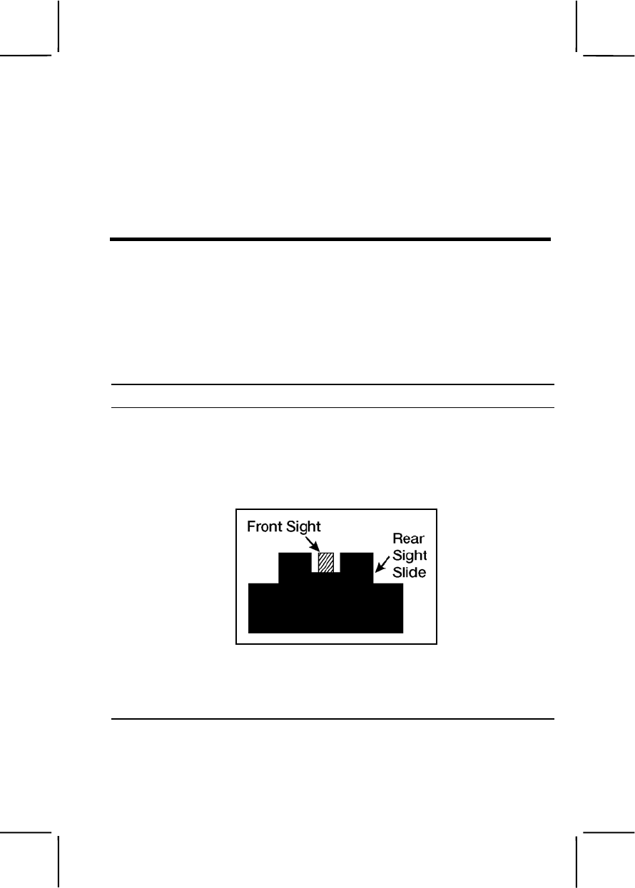
071-312-3031 3-401
If the soldier scores NO GO, show him what was done wrong and how to do
it correctly.
References
Required Related
FM 3-22.68
071-312-3031
Engage Targets with an M60 Machine Gun
Conditions: Given a zeroed M60 machine gun with a bipod and linked
7.62-mm ammunition. You have engageable targets in your assigned sector
of fire.
Standards: Fired the M60 machine gun to engage targets in your assigned
sector of fire. Applied correct M60 machine gun target engagement
techniques so each target was hit.
Performance Steps
1. Assume a stable, prone firing position.
2. Align the sights on the target to get a correct sight picture.
a. Obtain sight alignment by centering the front sight blade in the
aperture of the rear sight with the top of the front sight blade even with the
top of the rear sight slide (figure 071-312-3031-1).
Figure 071-312-3031-1. Sight alignment
b. Obtain a sight picture by centering the target over the front sight
blade so it appears to rest on top of the front sight blade and on top of the
rear sight slide (figure 071-312-3031-2).
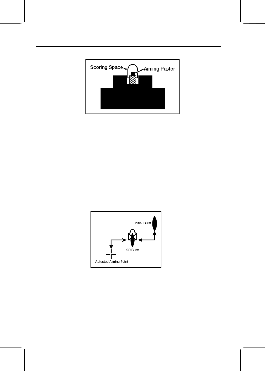
3-402 071-312-3031
Performance Steps
Figure 071-312-3031-2. Sight picture
3. Fire the M60 machine gun.
a. Pull the trigger straight to the rear.
b. Say to yourself "Fire a burst of six."
c. Release the trigger.
Note. This aids in controlling the number of rounds in each burst and prevents
excessive wear on sear and sear notch.
Note. If you miss the target with your initial burst, you must select a new aiming
point the same distance from the target as the center of impact of the initial burst but
in the opposite direction, and fire a second burst.
4. Adjust fire using the adjusted aiming point method (figure 071-312-
3031-3).
Figure 071-312-3031-3. Adjusted aiming point method
a. Observe the impact of rounds in the target area by watching the
flight of tracer rounds or the strike of rounds in the target area.
b. Change your body position.
Note. Traverse means to move the muzzle of the weapon to the left or right to
distribute fire laterally.
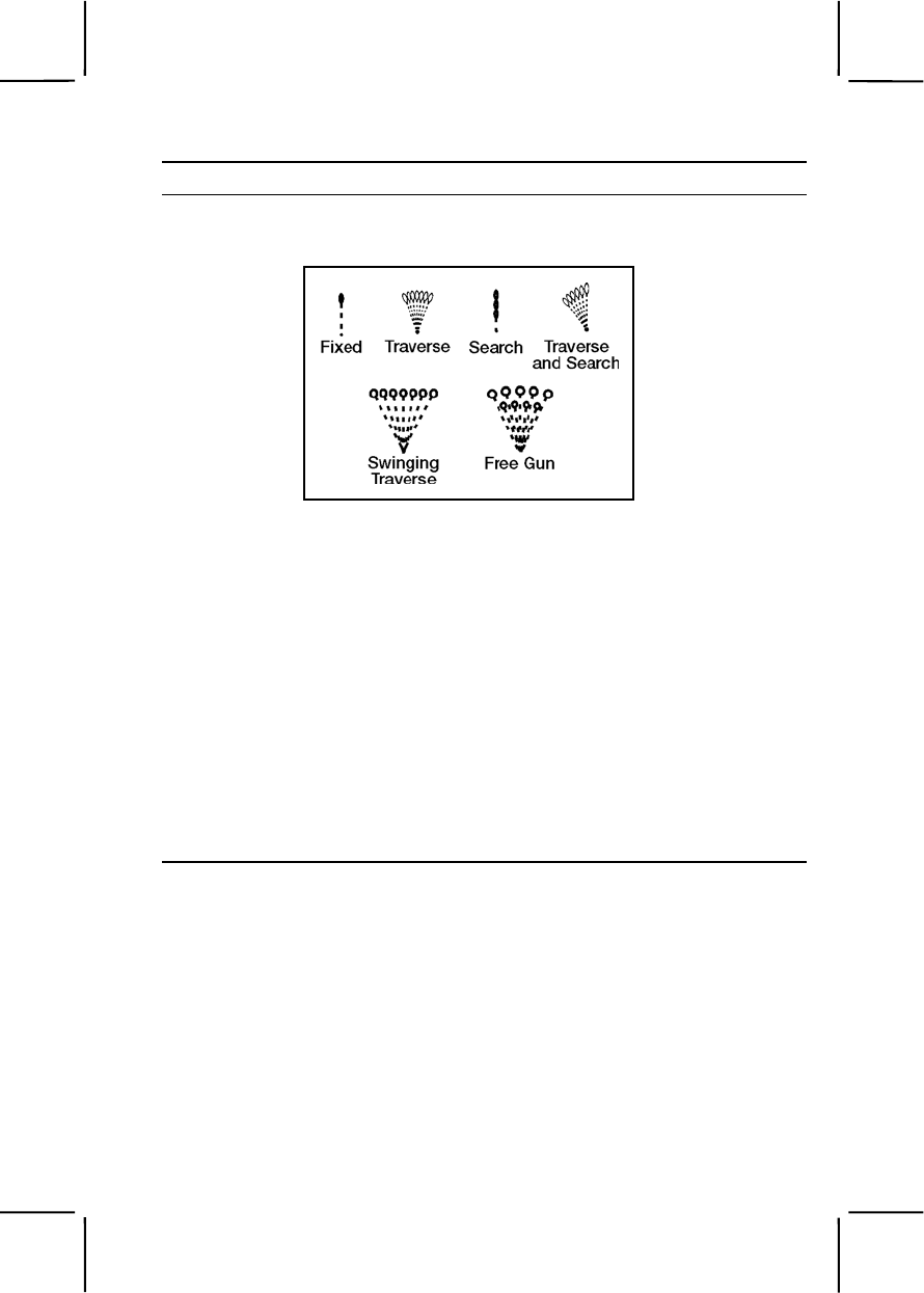
071-312-3031 3-403
Performance Steps
c. Traverse the target area with a bipod mounted M60 machine gun by
selecting successive aiming points (figure 071-312-3031-4).
Figure 071-312-3031-4. Traversing and searching
(1) Shift your shoulders slightly to the right or left for minor changes
in direction.
(2) Move your elbows and align the body to remain directly behind
the gun for major changes.
Note. "Search" means to move the muzzle of the weapon up or down to distribute
fire in depth across the target area.
d. Search the target area by selecting successive aiming points,
changing elevation by moving your elbows closer together or farther apart
(figure 071-312-3031-4).
5. Engage an area target using six- to nine-round bursts.
a. Determine the width and depth of the target.
b. Fire six- to nine-round bursts until you hit the center mass of the
target area (figure 071-312-3031-5).
3-404 071-312-3031
Performance Steps
Figure 071-312-3031-5. Center of mass
c. Adjust fire by traversing and searching to cover all the target area.
6. Engage a point target using six- to nine-round bursts (figure 071-312-
3031-6).
Figure 071-312-3031-6. Point target engagement
a. Select a distinct aiming point.
b. Estimate range.
071-312-3031 3-405
Performance Steps
c. Fire six- to nine-round bursts to obtain accurate range and
deflection.
d. Place effective fire on the target by observing the rounds as they
impact in the target area. Make necessary adjustments to hit the target.
7. Engage a moving target using six- to nine-round bursts (figure 071-312-
3031-7).
Figure 071-312-3031-7. Moving target engagement
a. Estimate the speed of the target and the lead required to fire and hit
it.
b. Fire, tracking the target as it moves.
c. Adjust the lead by observing tracers and the strike of the bullets.
Evaluation Preparation:
Setup: Evaluate this task on a live-fire range. Evaluate the soldier on his
ability to fire on the center of mass of a target, adjusting his aim by
traversing and searching the weapon. Provide the soldier with point targets,
area targets, and moving targets. If the soldier hits the target with the first
burst, provide the soldier with directions so he demonstrates to you that he
can adjust fire. If moving targets are not available, provide the soldier with a
scenario in which he must describe the proper technique to use.

3-406 071-312-3031
Brief Soldier: Tell the soldier to assume the prone position. Assign the
soldier a sector and direct the soldier to engage area, point, and moving
targets and to hit the center of mass of each target. Tell the soldier you are
evaluating his ability to adjust fire as much as his ability to hit the target. If a
moving target is not available, tell the soldier to simulate firing on a moving
target while describing for you the actions required.
Performance Measures GO NO GO
1. Assumed a stable, prone firing position. —— ——
2. Aligned the sights on the target to get a correct sight
picture. —— ——
a. Obtained sight alignment by centering the front
sight blade in the aperture of the rear sight with the top of
the front sight blade even with the top of the rear sight
slide.
b. Obtained a sight picture by centering the target
over the front sight blade so it appears to rest on top of
the front sight blade and on top of the rear sight slide.
3. Fired the M60. —— ——
a. Pulled the trigger straight to the rear.
b. Said to yourself "Fire a burst of six."
c. Released the trigger.
4. Adjusted fire using the adjusted aiming point method. —— ——
a. Made a minor change in direction.
b. Made a major change in direction.
c. Widened the impact area by traversing.
d. Raised the impact point by searching.
5. Engaged an area target using six- to nine-round
bursts. —— ——
a. Determined the width and depth of the target.
b. Fired six- to nine-round bursts until you hit the
center mass of the target area.
c. Adjusted fire by traversing and searching to cover
all of the target area.
6. Engaged a point target using six- to nine-round
bursts. —— ——
a. Selected a distinct aiming point.

071-030-0001 3-407
Performance Measures GO NO GO
b. Estimated range.
c. Fired six- to nine-round bursts to obtain accurate
range and deflection.
d. Placed effective fire on the target by observing
the rounds as they impacted in the target area. Made
necessary adjustments to hit the target.
7. Engaged a moving target using six- to nine-round
bursts. —— ——
a. Estimated the speed of the target and the lead
required to fire and hit it.
b. Fired, tracking the target as it moved.
c. Adjusted the lead by observing tracers and the
strike of the bullets.
Evaluation Guidance: Score the soldier GO if all performance measures
are passed. Score the soldier NO GO if any performance measure is failed.
If the soldier scores NO GO, show him what was done wrong and how to do
it correctly.
References
Required Related
FM 3-22.68
SUBJECT AREA 13: MK19 MACHINE GUN
071-030-0001
Maintain an MK19 Machine Gun
Conditions: Given an MK19 machine gun, an M3 tripod, a traversing and
elevating (T&E) mechanism, an M64 cradle mount; rifle bore cleaner (RBC),
lubricant oil (LSA), or lubricating oil (LSAT or LAW); grease (GMD); cleaning
solvent (PD680); wiping rags or cloth (abrasive crocus); a cleaning rod
assembly and a small-arms cleaning brush; linked 40-mm ammunition and
one spent 40-mm cartridge case.
Standards: Cleaned and lubricated the MK 19 and its components.
Inspected all parts and turned in those in need of maintenance.
Reassembled the gun so it was operational. Cleaned and inspected
ammunition for serviceability, and turned in any unserviceable ammunition.

3-408 071-030-0001
Performance Steps
1. Clear the MK19.
a. Place the safe/fire switch in the SAFE (S) position. Ensure the bolt
is forward.
b. Open the top cover and inspect the feed tray and extractors on the
bolt face to ensure that no round is in the pickup position.
c. Unlock and pull charger handle 2 to 3 inches to the rear; inspect
the face of the bolt and the chamber for ammunition.
d. Return the bolt to the forward position and rotate the charger
handle to the locked position.
2. Disassemble the MK19.
a. Remove the feed throat assembly (figure 071-030-0001-1).
Squeeze the two sets of grip pins together and pull them straight out.
b. Remove the bolt and backplate assembly.
Figure 071-030-0001-1. Removal of feed throat assembly
WARNING
Make sure the bolt is in the forward position before you remove the
backplate pin assembly. Failure to observe this warning will result in
injury.
(1) Place the safe/fire switch on FIRE (F).
(2) Open the top cover.
(3) Using the rim of a spent cartridge, pull the backplate pin
straight out (figure 071-030-0001-2).
071-030-0001 3-409
Performance Steps
Figure 071-030-0001-2. Removal of backplate pin
(4) Lift up slightly on the backplate assembly. Slowly pull the bolt
and backplate assembly out of the receiver.
(5) Support the bolt with one hand and maintain a control grip with
the other hand. Lift the bolt up slightly and remove it (figure 071-030-
0001-3).
3-410 071-030-0001
Performance Steps
Figure 071-030-0001-3. Removal of bolt and backplate assembly
c. Remove the primary drive lever and vertical cam assembly.
CAUTION
Do not rest the vertical cam assembly on its chromed surface.
(1) Reach under the top of the receiver to locate the drive lever
lock on the vertical cam assembly and slide the lock rearward about 1/4
inch (figure 071-030-0001-4).
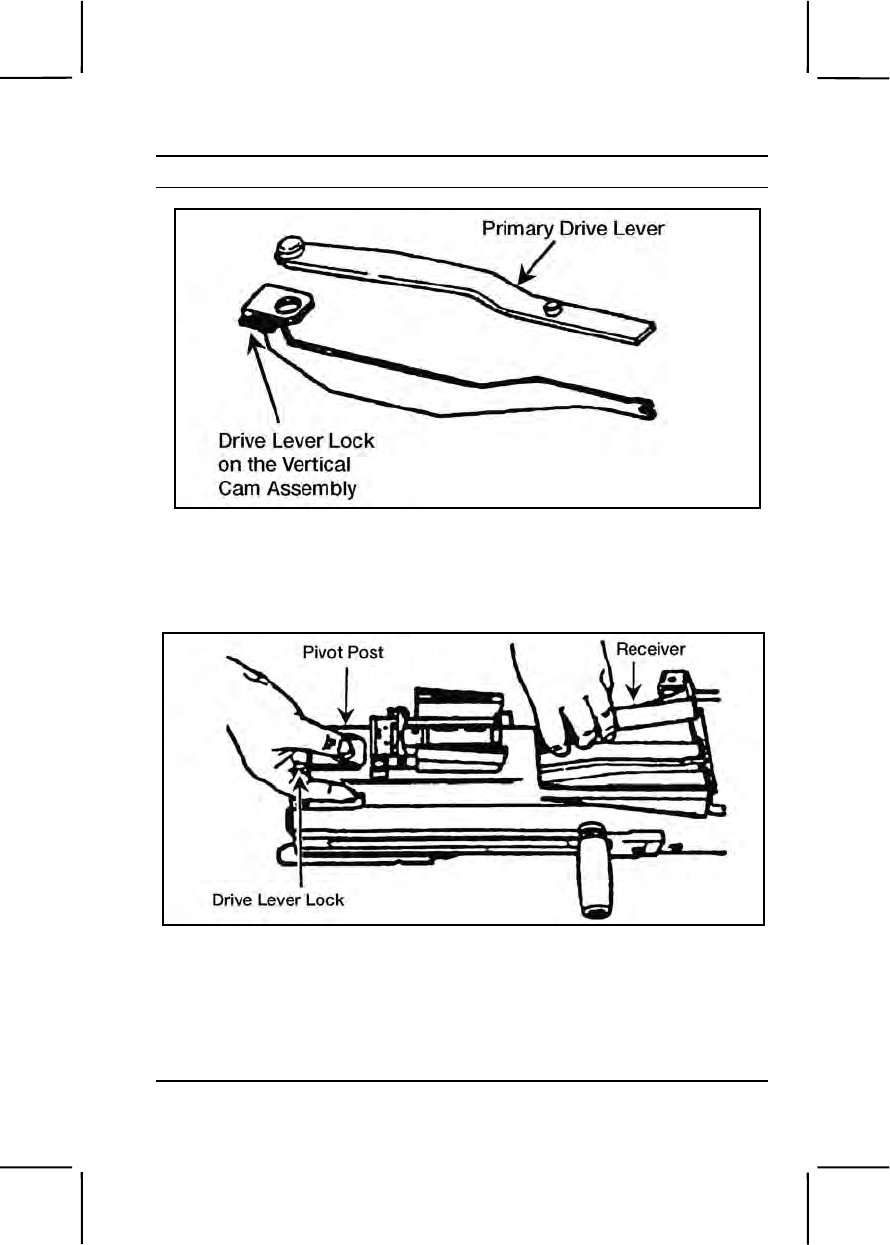
071-030-0001 3-411
Performance Steps
Figure 071-030-0001-4. Primary drive lever and vertical cam assembly
(2) Press down on the primary drive lever's pivot post. This
releases the primary drive lever and vertical cam assembly (figure 071-
030-0001-5).
Figure 071-030-0001-5. Removal of the primary drive lever and vertical cam
assembly
(3) Pull out the cam (to the rear) and the lever from the receiver.
d. Remove secondary drive lever.
(1) Push down on the pivot post from the outside top cover. This
releases the secondary drive lever (figure 071-030-0001-6).
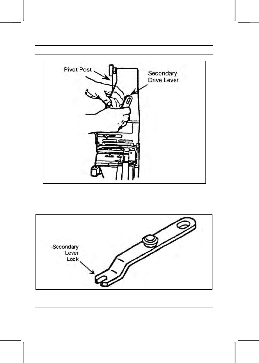
3-412 071-030-0001
Performance Steps
Figure 071-030-0001-6. Removal of the secondary drive lever
(2) Lift out the secondary drive lever from the top cover
(figure 071-030-0001-7).
Figure 071-030-0001-7. Secondary drive lever.
e. Remove the feed slide assembly (Figure 071-030-0001-8).
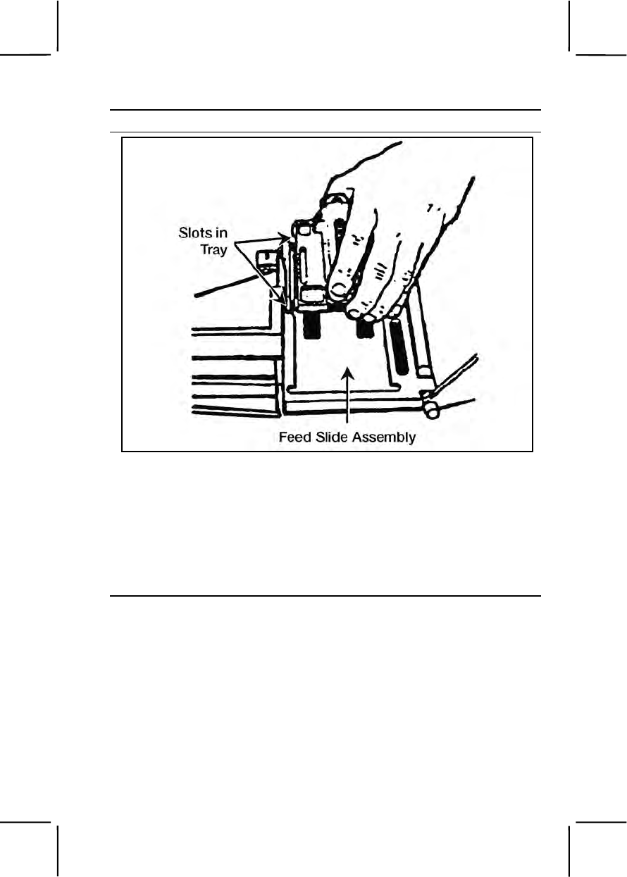
071-030-0001 3-413
Performance Steps
Figure 071-030-0001-8. Removal of the feed slide assembly.
(1) Pivot the tray that holds the feed slide assembly out of the top
cover.
(2) Move the feed slide assembly to line up the tabs with the slots
in the tray.
(3) Lift upward on the feed slide assembly.
f. Remove the top cover assembly and feed tray (figure 071-030-
0001-9).
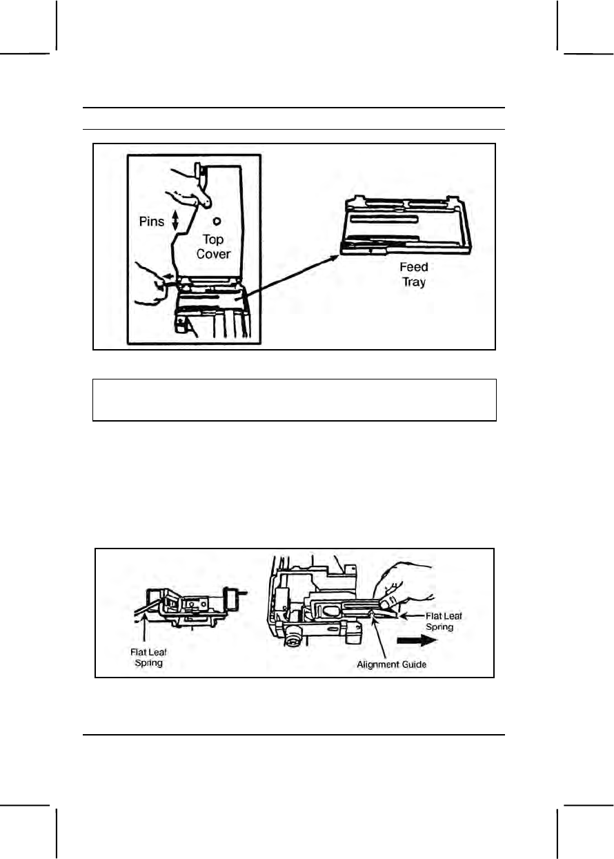
3-414 071-030-0001
Performance Steps
Figure 071-030-0001-9. Removal of the top cover assembly and feed tray
CAUTION
Using your fingers only, not pliers, remove the top cover pins. Forcing the pin
could break the small cross pin on the rod.
Note. The feed tray must be down for you to remove the top cover pins.
(1) Hold the top cover straight up to align the end of the cross pin.
(2) Pull straight out on the pins.
(3) Lift off the top cover.
(4) Lift the tray out of the feeder.
g. Remove the alignment guide assembly (figure 071-030-0001-10).
Figure 071-030-0001-10. Removal of the alignment guide assembly
(1) Depress the flat leaf spring by using a cartridge link toggle
(male end) or a small tool.
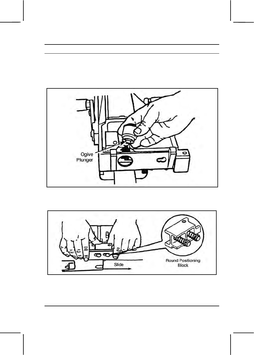
071-030-0001 3-415
Performance Steps
(2) Slide the alignment guide toward the feeder mouth.
(3) Pull rearward on the alignment guide and lift it out.
h. Remove the ogive plunger by pulling it out (figure 071-030-0001-
11).
Figure 071-030-0001-11. Removal of the ogive plunger
i. Remove the round positioning block (figure 071-030-0001-12).
Figure 071-030-0001-12. Removal of the round positioning block
(1) Grasp the two control grips with both hands and lift up slightly
to disengage the backplate from the locking lugs in the receiver.
(2) Pull the round positioning block toward the muzzle end of gun.
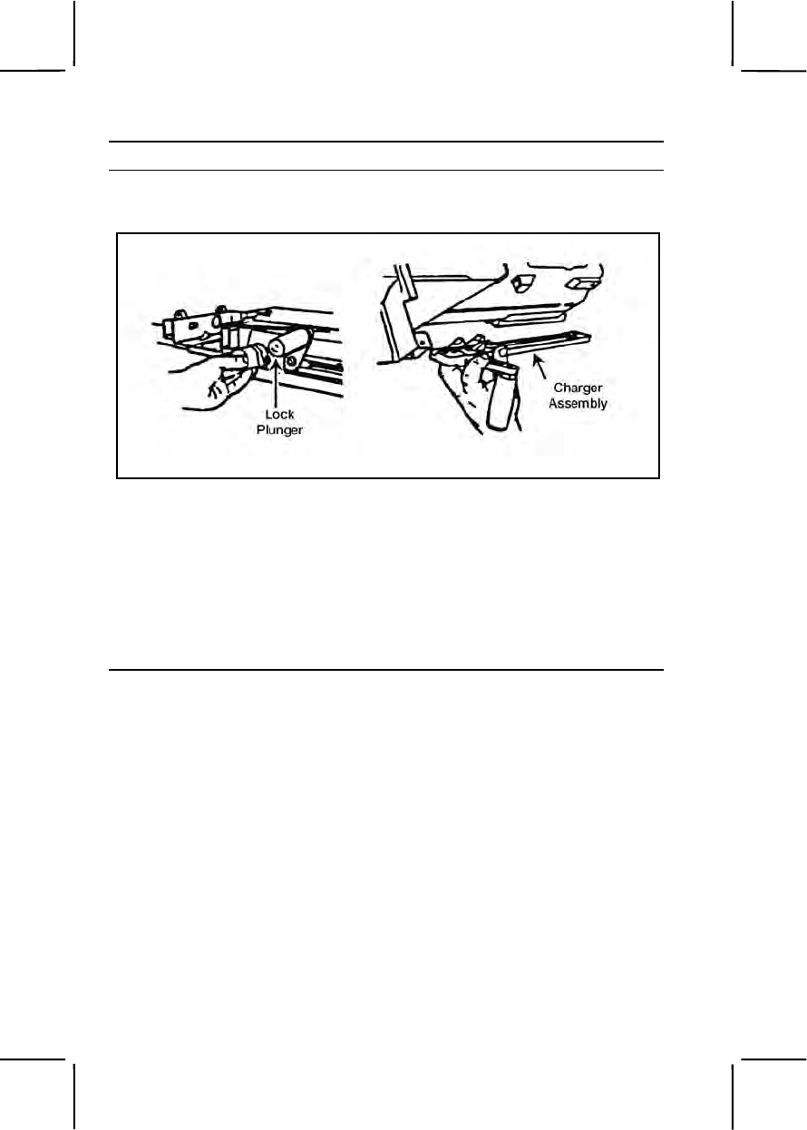
3-416 071-030-0001
Performance Steps
j. Remove the charger assemblies (both sides) (figure 071-030-
0001-13).
Figure 071-030-0001-13. Removal of the charger assembly
(1) Rotate the charger handle up.
(2) Using either your fingers or a spent case, pry out on the lip of
the lock plunger.
(3) Lift up on the lock plunger to retract it; slide the charger
assembly all the way to the rear.
(4) Pull the charger assembly away from the receiver.
k. Remove the receiver sear assembly (figure 071-030-0001-14).

071-030-0001 3-417
Performance Steps
Figure 071-030-0001-14. Removal of the receiver sear assembly
(1) Turn the receiver on its top. Put the safe/fire switch in FIRE (F)
position.
(2) Lift up slightly on the lock pin with your fingers, using a
cartridge link.
(3) Squeeze the receiver sear (underneath the safety) and
simultaneously rotate the sear housing assembly approximately 15
degrees in either direction.
(4) Press down on the sear housing assembly and rotate the
assembly until it stops (90 degrees from its original position).
(5) Press the receiver sear and safety together while you put
safe/fire switch on safe (S). This locks the sear in the down position and
keeps you from accidentally losing the sear spring.
(6) Lift out the sear housing assembly.
3. Clean the parts of the MK19.
Note. Do not reverse the direction of the bore brush while it is in the bore.
a. Clean the receiver assembly (figure 071-030-0001-15).
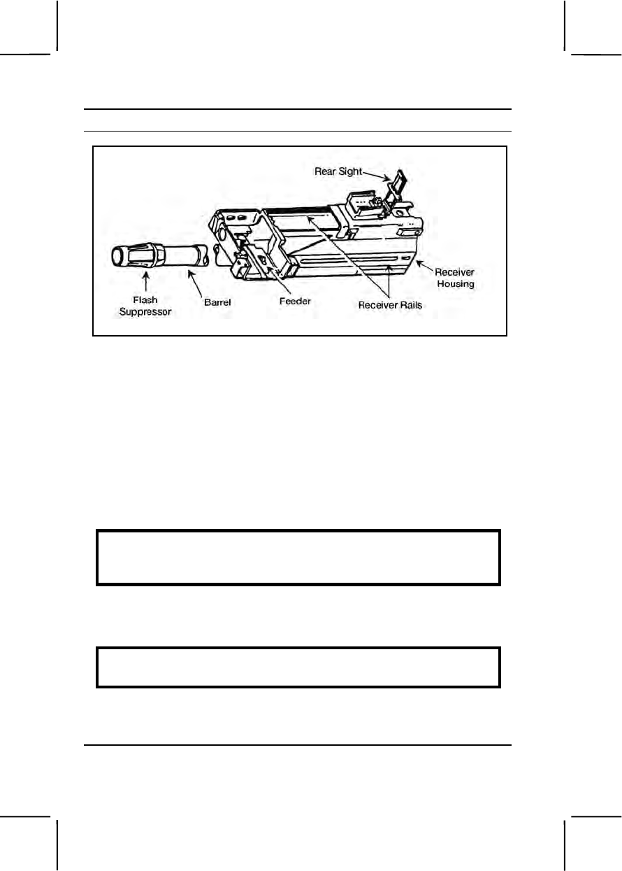
3-418 071-030-0001
Performance Steps
Figure 071-030-0001-15. Receiver assembly
(1) Apply solvent to a rag or brush. Wipe or brush dirt away from
all parts, especially the interior of the receiver housing, receiver rails, and
feeder.
(2) Swab out the bore and chamber, using a bore brush and RBC.
(3) Wipe all parts dry.
b. Clean the receiver sear assembly (figure 071-030-0001-14).
(1) Use only cleaning solvent on a rag or brush.
(2) Wipe or brush away dirt.
(3) Wipe dry.
WARNING
Never immerse the sear housing assembly in solvent. Solvent may
dilute the lubricant inside the sear housing.
c. Clean the alignment guide assembly, ogive plunger, round
positioning block, and secondary drive lever; wipe or brush off dirt and
dry.
WARNING
Never immerse the ogive plunger assembly in solvent.
d. Clean the charger assemblies.
(1) Apply cleaning solvent to a rag or brush, and wipe or brush off
dirt.

071-030-0001 3-419
Performance Steps
(2) Wipe dry.
e. Clean the vertical cam assembly, primary drive lever, feed slide
assembly, and feed tray.
(1) Soak in cleaning solvent.
(2) Wipe or brush off dirt.
(3) Wipe dry.
f. Clean the top cover assembly.
(1) Apply cleaning solvent to a rag or brush and wipe or brush off
dirt from all parts.
(2) Wipe all surfaces dry.
g. Clean the bolt and backplate assembly.
(1) Apply cleaning solvent to rag or brush and wipe or brush off
dirt from all parts.
(2) Wipe all surfaces dry.
4. Clean the components.
a. Clean the T&E mechanism.
(1) Remove foreign matter with a clean, dry wiping rag.
(2) Use small arms cleaning brush to clean the numbers on the
scale.
b. Clean the M3 tripod, MK64 gun cradle mount, and pintle.
(1) Use a cleaning swab saturated with carbon removing
compound to remove dirt.
(2) Wipe all parts dry with clean wiping rags.
5. Clean ammunition. Remove foreign matter with a clean, dry wiping
rag.
6. Inspect all MK19 parts for serviceability.
a. Receiver assembly.
(1) Check the receiver housing for cracks and rust.
(2) Check the receiver rails for burrs and cracked welds.
(3) Check the feeder pawls for burrs and lack of spring action.
Check the pins for retention.
(4) Check the barrel for carbon buildup and pitting in the bore and
chamber.
(5) Check the flash suppressor for dents, cracks, and erosion.
Make sure minimal movement is maintained.

3-420 071-030-0001
Performance Steps
(6) Check the rear sight for rust, binding, and broken or bent parts.
b. Receiver sear assembly.
(1) Check for burrs on all parts.
(2) Closely inspect the rear shoulder for burrs.
c. Alignment guide assembly.
(1) Check the alignment guide spring for deformity, cracks, and
looseness.
(2) Check the pin for breaks and cracks.
d. Ogive plunger assembly and round positioning block.
(1) Check the ogive plunger head for burrs and broken parts.
(2) Check the round positioning block for weak spring action and
loose or broken parts.
e. Charger assembly (left and right).
(1) Check the grooved edges for burrs and bends.
(2) Check the latches for spring action on detects.
(3) Check the entire charger assembly for cracks, burrs, bends,
and chips.
f. Vertical cam assembly and primary drive lever.
(1) Check the vertical cam assembly for bends, burrs, pits,
scratches, and aluminum buildup on chromed surface (mirror-like
surface).
(2) Check the drive lever lock for looseness or binding.
(3) Check the primary drive lever for burrs, especially around the
pivot posts.
g. Secondary drive lever.
(1) Check for missing retaining ring from the pivot post.
(2) Check the pivot post and forked end for burrs.
h. Feed slide assembly and feed tray.
(1) Check the feed pawls and feed tray for burrs and binding.
(2) Check the guide rails for burrs.
i. Top cover assembly.
(1) Check the top cover housing for cracks and rust.
(2) Check the latch for binding, looseness, and breaks.
j. Bolt and backplate assembly.
(1) Check the cocking lever for chips, burrs, and breaks.

071-030-0001 3-421
Performance Steps
(2) Check the guide rods for binding and bends.
(3) Check the recoil spring for weak action. Position the bolt end
against a hard, flat surface and push up and down on backplate
assembly.
(4) Check the backplate pin for missing retaining spring.
(5) Check for missing, loose or broken safety wire.
k. Report any deficiencies to supervisor.
7. Inspect all components for serviceability.
a. T&E mechanism.
(1) Inspect the hand wheels for smooth operation and rust. Check
the threads for burrs and rust.
(2) Check the traversing slide lock for spring action. Make sure the
elevating mechanism sleeve fits on the traversing bar and clamps firmly.
(3) Check the traversing and elevating scales for legibility.
(4) Inspect the quick release pin and chain for burrs and rust;
check for missing spring-loaded balls.
b. M3 Tripod.
(1) Check for completeness of tripod; make sure all nuts and bolts
are tightly secured.
(2) Check for cracks on the legs and tripod head.
(3) Check for missing, broken, or inoperative lock latch.
(4) Check the pintle lock release cam for correct operation.
(5) Check the locking action of the front leg clamping assembly.
(6) Make sure the rear legs lock in the open position, the sleeve
latch notch and the right leg slide notch engage completely, and the latch
spring has good tension.
(7) Check the telescoping, indexing, and locking actions of rear
legs and front leg locking assembly.
c. MK64 gun cradle mount.
(1) Check for missing or damaged parts.
(2) Check for rust, cracks, and burrs.
(3) Inspect pintle lock assembly for nut, bolt, and cotter pin. Check
the pintle surface for burrs and rust.
d. Report any deficiencies to supervisor.
8. Inspect ammunition for damage and corrosion. Turn in any
unserviceable ammunition.
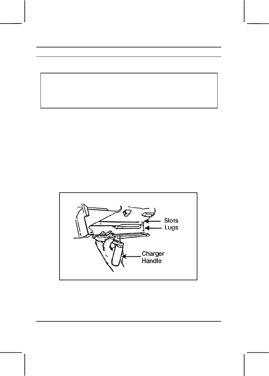
3-422 071-030-0001
Performance Steps
9. Lubricate the MK19 and components. Do not use CLP, and do not mix
lubricants.
CAUTION
1. Never immerse the sear housing, ogive plunger, or bolt assemblies in
cleaning solvent. Solvent could dilute the lubricant or grease inside.
2. Never lubricate the MK19 with CLP.
3. Avoid mixing lubricants.
4. Completely wipe off all excess lubricants.
a. Lubricate lightly to moderately with LSAT, LSA, or GMD (never
CLP). In cold weather (0 to -25 degrees Fahrenheit), use LSAT, LSA,
GMD, or LAW. In extra cold weather (-25 degrees Fahrenheit and below),
use LAW.
b. Apply lubricant to all weapon parts and surfaces except charger
handles. Work in the lubricant by moving the parts.
c. Lubricate all components and wipe them with an oily rag to remove
excess oil.
10. Assemble the MK19 machine gun.
a. Attach the charger assemblies (both sides) (figure 071-030-0001-
16).
Figure 071-030-0001-16. Attachment of the charger assemblies
(1) Turn the receiver upright.
(2) Rotate the charger handles to the straight-up position.
(3) Line up the lugs on the charger with the slots in the receiver
rail. Insert the charger lugs into the slots.
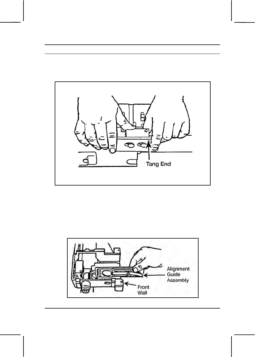
071-030-0001 3-423
Performance Steps
(4) Hold the charger tightly against the rail. Slide the charger
forward until it locks into place.
b. Attach the round positioning block (Figure 071-030-0001-17).
Figure 071-030-0001-17. Attachment of the round positioning block
(1) Insert the blocks into the slots with the tang end forward.
(2) Push against the block and slide it toward the rear until the
block locks into place.
c. Insert the ogive plunger assembly into the opening.
d. Insert the alignment guide assembly (figure 071-030-0001-18).
Figure 071-030-0001-18. Insertion of the alignment guide assembly
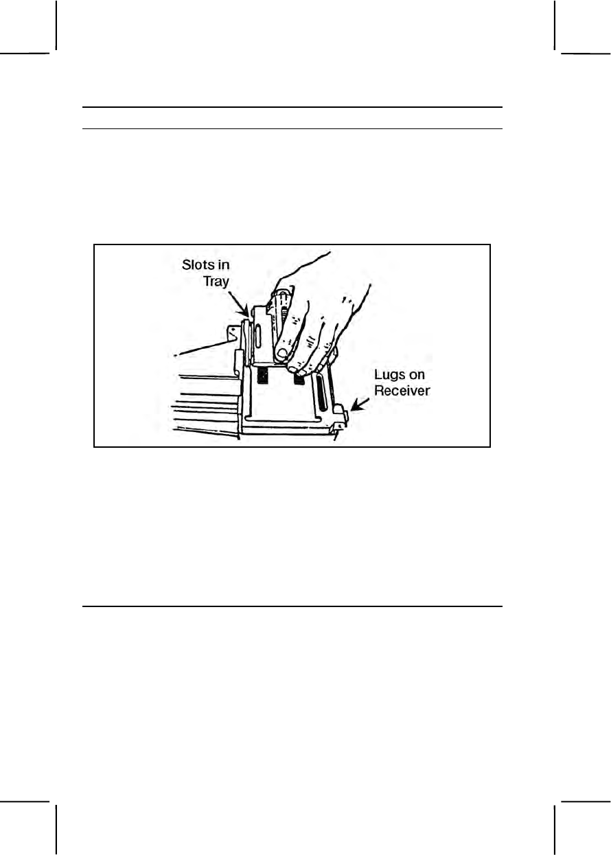
3-424 071-030-0001
Performance Steps
(1) Position the alignment guide assembly so the pin is lined up
with the slot in the feeder wall.
(2) Hold the alignment guide against the front wall and slide the
alignment guide into the receiver until it clicks.
e. Attach the feed tray and feed slide assembly (figure 071-030-
0001-19).
Figure 071-030-0001-19. Attachment of the feed slide assembly
(1) Place the tray in the top of the feeder, recessed side up.
(2) The pinholes on the tray should line up with the lugs on the
receiver.
(3) Position the feed slide assembly by lining up the tabs with the
slots on the tray.
(4) Insert the tabs into the slots. Drop the feed slide assembly into
the tray and move it slightly to ensure engagement.
f. Attach the top cover assembly (figure 071-030-0001-20).
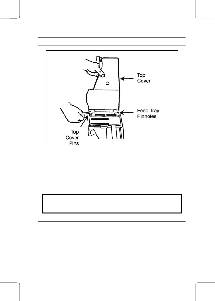
071-030-0001 3-425
Performance Steps
Figure 071-030-0001-20. Attachment of the top cover assembly
(1) Ensure the feed tray is in the proper place in the receiver.
(2) Place the top cover on the receiver. Line up the pinholes on
the cover with the receiver's lug end and the pinholes on the feed tray.
(3) Hold the top cover straight up. Insert the top cover pins on
both sides. Fully insert the cross pin. Rotate the top cover so it is fully
open.
WARNING
To avoid breaking the cross pin, be sure to insert it fully into the
receiver before you close the top cover.
g. Engage the secondary drive lever (figure 071-030-0001-21).
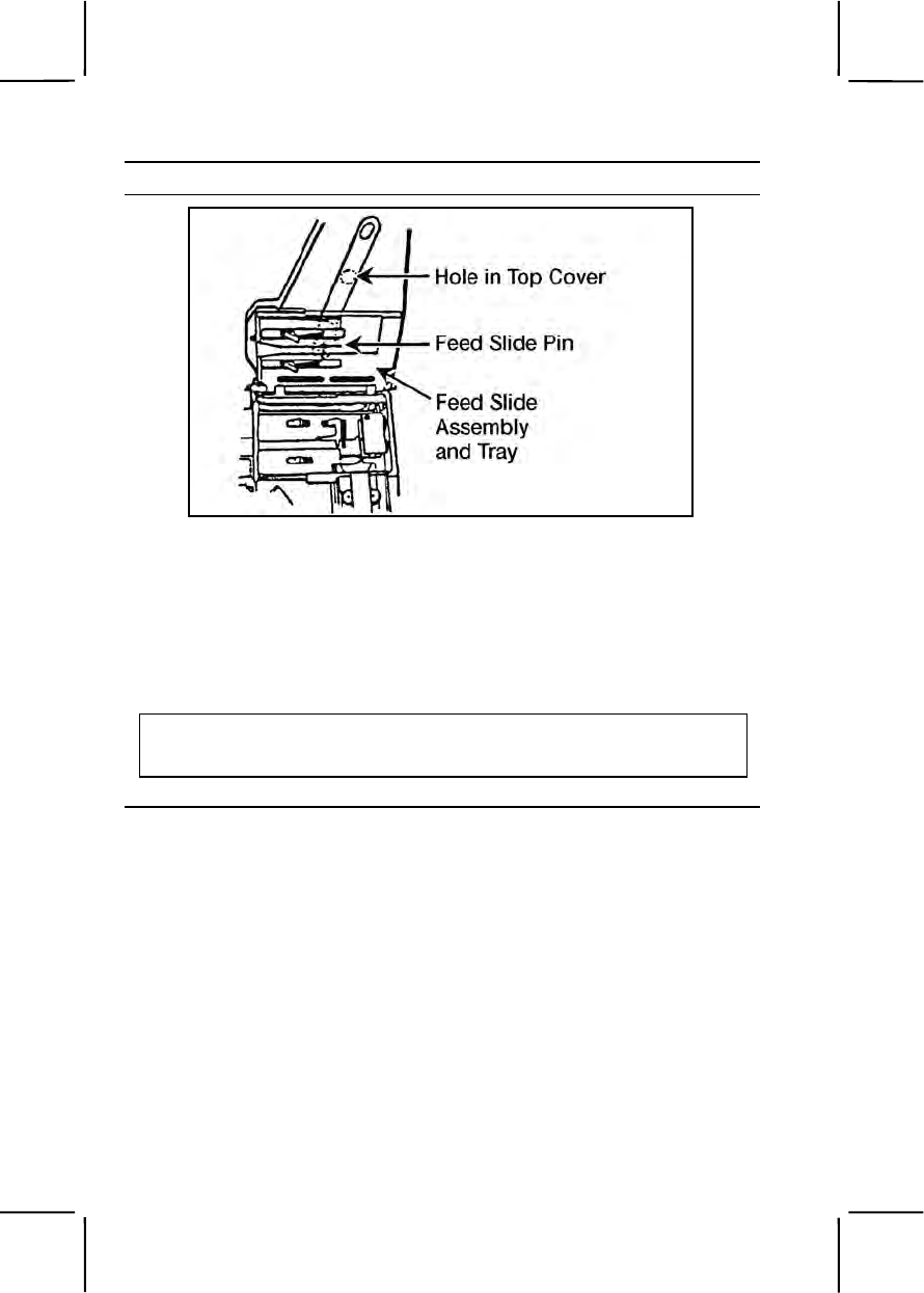
3-426 071-030-0001
Performance Steps
Figure 071-030-0001-21. Engaging the secondary drive lever
(1) Rotate the feed slide assembly and tray upward.
(2) Engage the forked end of the secondary drive lever with the
feed slide pin.
(3) Press the raised pivot post through the hole in the stop cover.
(4) Press the secondary drive lever against the top cover until it
locks into place.
CAUTION
Be sure to engage the secondary drive lever with the feed slide pin, or the gun
will not fire.
h. Engage the vertical cam assembly (figure 071-030-0001-22).
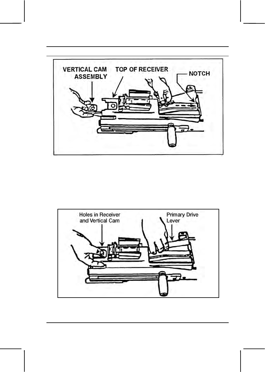
071-030-0001 3-427
Performance Steps
Figure 071-030-0001-22. Engaging the vertical cam assembly.
(1) Slide the vertical cam assembly through the rear of the
receiver. The raised portion should slide over the top of the receiver. The
drive lever lock should be underneath.
(2) Engage the forked end in the notch.
i. Engage the primary lever (figure 071-030-0001-23).
Figure 071-030-0001-23. Engaging the primary drive lever
(1) Hold the vertical cam assembly in place and slide the primary
drive lever into the receiver.
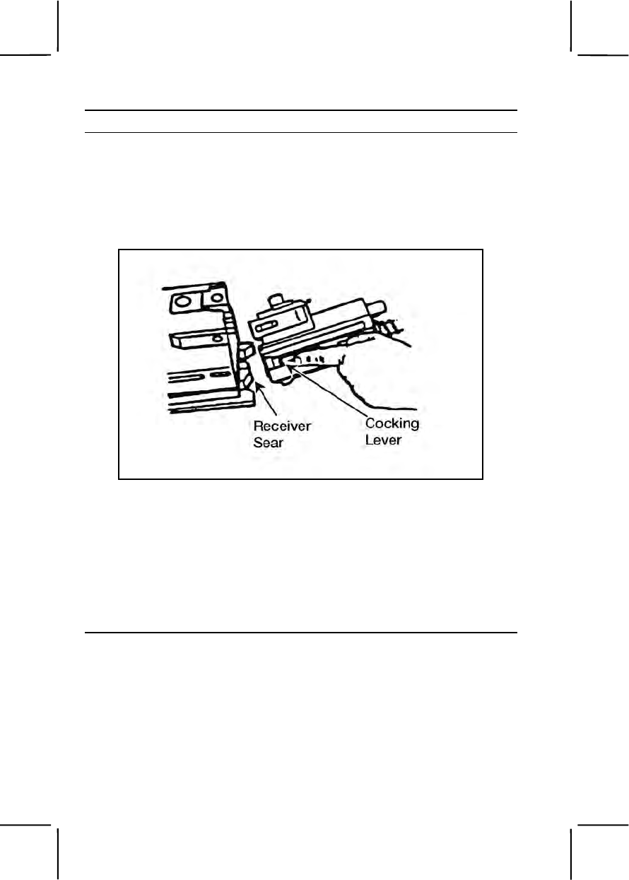
3-428 071-030-0001
Performance Steps
(2) Slide the primary drive lever lock to the rear and engage the
pivot post lever through the holes in the receiver and vertical cam.
(3) Slide the primary drive lever lock forward. (The primary drive
lever lock is located on the vertical cam just beneath the top of the
receiver).
j. Insert the bolt and backplate assembly (figure 071-030-0001-24).
Figure 071-030-0001-24. Insertion of the bolt and backplate assembly
(1) Place the safe/fire switch in the fire (F) position.
(2) Press the receiver sear using your thumbs or the rim of a
cartridge case.
(3) Make sure the cocking lever is cocked and forward.
(4) Slide the bolt and backplate assembly all the way forward.
(5) Insert the backplate pin to lock the assembly in place.
(6) Close the cover.
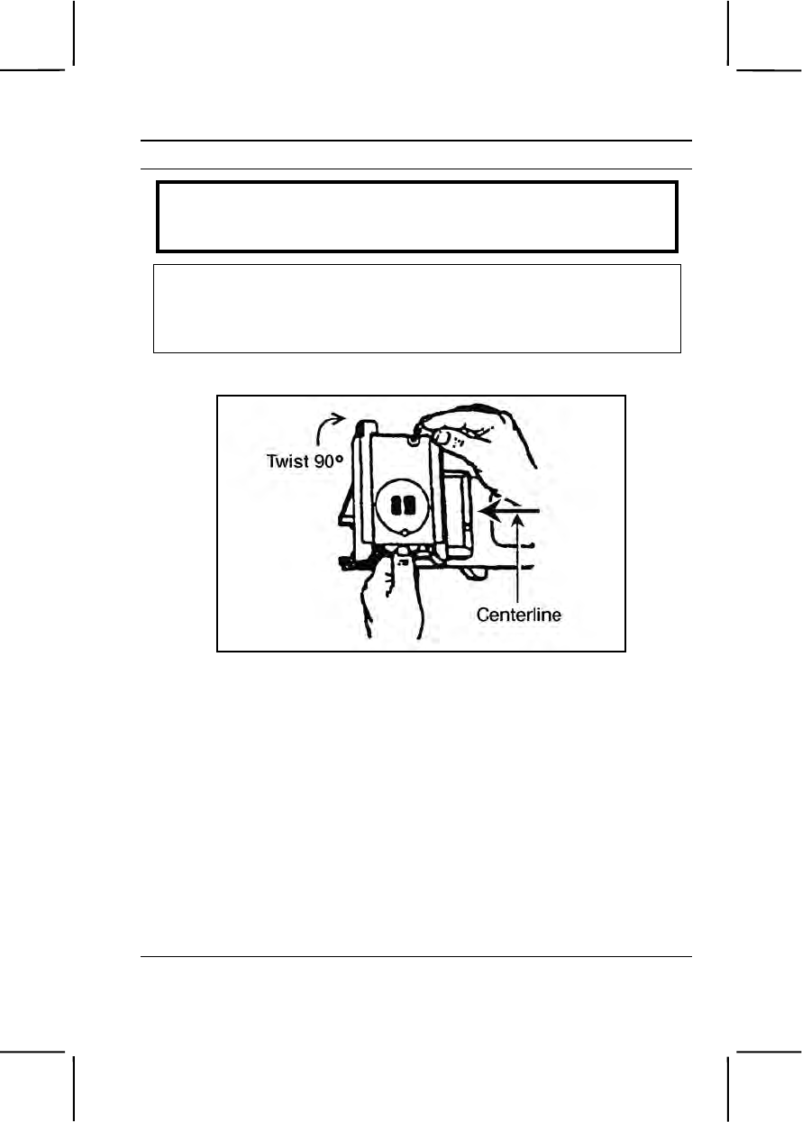
071-030-0001 3-429
Performance Steps
WARNING
Before inserting the bolt and backplate assembly, put the cocking
lever in the forward position.
CAUTION
Before closing the top cover, always make sure the secondary drive lever
engages the feed slide pin, the feed slide assembly is to the left, and the bolt is
forward. Never try to force the top cover closed. Doing so could damage the
weapon.
k. Attach the receiver sear assembly (figure 071-030-0001-25).
Figure 071-030-0001-25. Attachment of the receiver sear assembly
(1) Turn the receiver over on its top.
(2) Place the sear housing on the receiver and line up the sear
housing assembly at a right angle to the barrel center line.
(3) Put the safe/fire switch on fire (F) position.
(4) Press down and rotate the housing assembly until it stops.
(5) Press up on the sear and rotate it until it locks in position.
l. Attach the feed throat assembly.
(1) Squeeze the grip pins and align them with the holes in the
receiver.
(2) Release the grip pins to attach the feed throat.
11. Perform a function check to make sure you have assembled the
weapon correctly.

3-430 071-030-0001
Evaluation Preparation:
Setup: At the test site, provide the soldier with the equipment listed in the
task conditions. Use the performance steps in the training outline to evaluate
the soldier's performance of the task.
Brief Soldier: Tell the soldier to perform operator level maintenance on the
MK19 and to perform a function check to ensure the weapon functions
correctly.
Performance Measures GO NO GO
1. Cleared the weapon. —— ——
2. Disassembled the weapon without damaging any
parts. —— ——
3. Cleaned the weapon parts. —— ——
4. Cleaned the components. —— ——
5. Cleaned the ammunition. —— ——
6. Inspected all parts, components, and ammunition for
serviceability. —— ——
7. Reported all deficiencies to your supervisor. —— ——
8. Lubricated the weapon parts and components using
the correct lubricant and lubrication techniques. —— ——
9. Assembled the weapon in the correct sequence
without damaging any parts. —— ——
10. Performed a function check. —— ——
Evaluation Guidance: Score the soldier GO if all performance measures
are passed. Score the soldier NO GO if any performance measure is failed.
If the soldier scores NO GO, show him what was done wrong and how to do
it correctly.
References
Required Related
FM 23-27
TM 9-1010-230-10
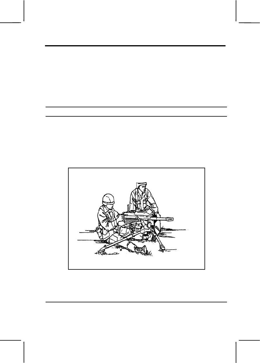
071-030-0004 3-431
071-030-0004
Engage Targets with an MK19 Machine Gun
Conditions: Given a zeroed MK19 machine gun (tripod or cupola mounted),
linked 40-mm grenade ammunition, and a sector of fire with engageable
targets.
Standards: Fired the MK19 machine gun to engage targets in assigned
sector of fire. Applied correct machine gun target engagement techniques so
each target was covered with fire.
Performance Steps
1. Assume a suitable firing position. Based on your situation, select a
firing position that will allow you to observe and engage targets yet
minimize your exposure to enemy fire.
a. Seated firing positions. Sit directly behind the weapon between the
trail legs of the tripod.
(1) Legs extended. Extend your legs under the tripod (figure 071-
030-0004-1).
Figure 071-030-0004-1. Seated firing position, legs extended
(2) Legs crossed. Cross your legs and place your elbows on the
inside of your thighs for support when firing the weapon (figure 071-030-
0004-2).
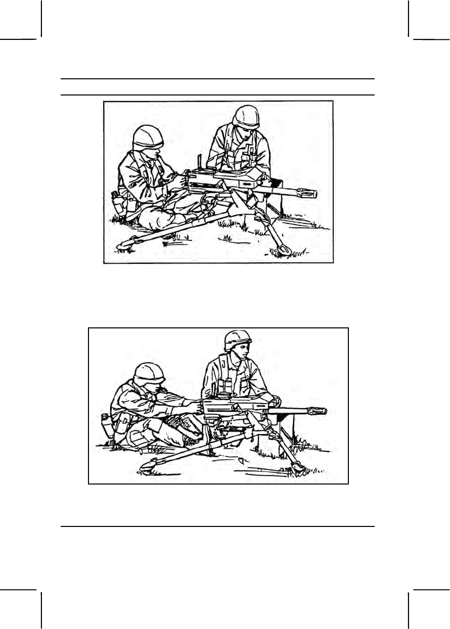
3-432 071-030-0004
Performance Steps
Figure 071-030-0004-2. Seated firing position, legs crossed
(3) Legs braced. Extend your legs, brace them on the trail legs of
the tripod, and place your elbows on the inside of your thighs for support
(figure 071-030-0004-3).
Figure 071-030-0004-3. Seated firing position, legs braced
b. Kneeling position. Kneel and grasp the control grips with your
thumbs on the trigger (figure 071-030-0004-4).
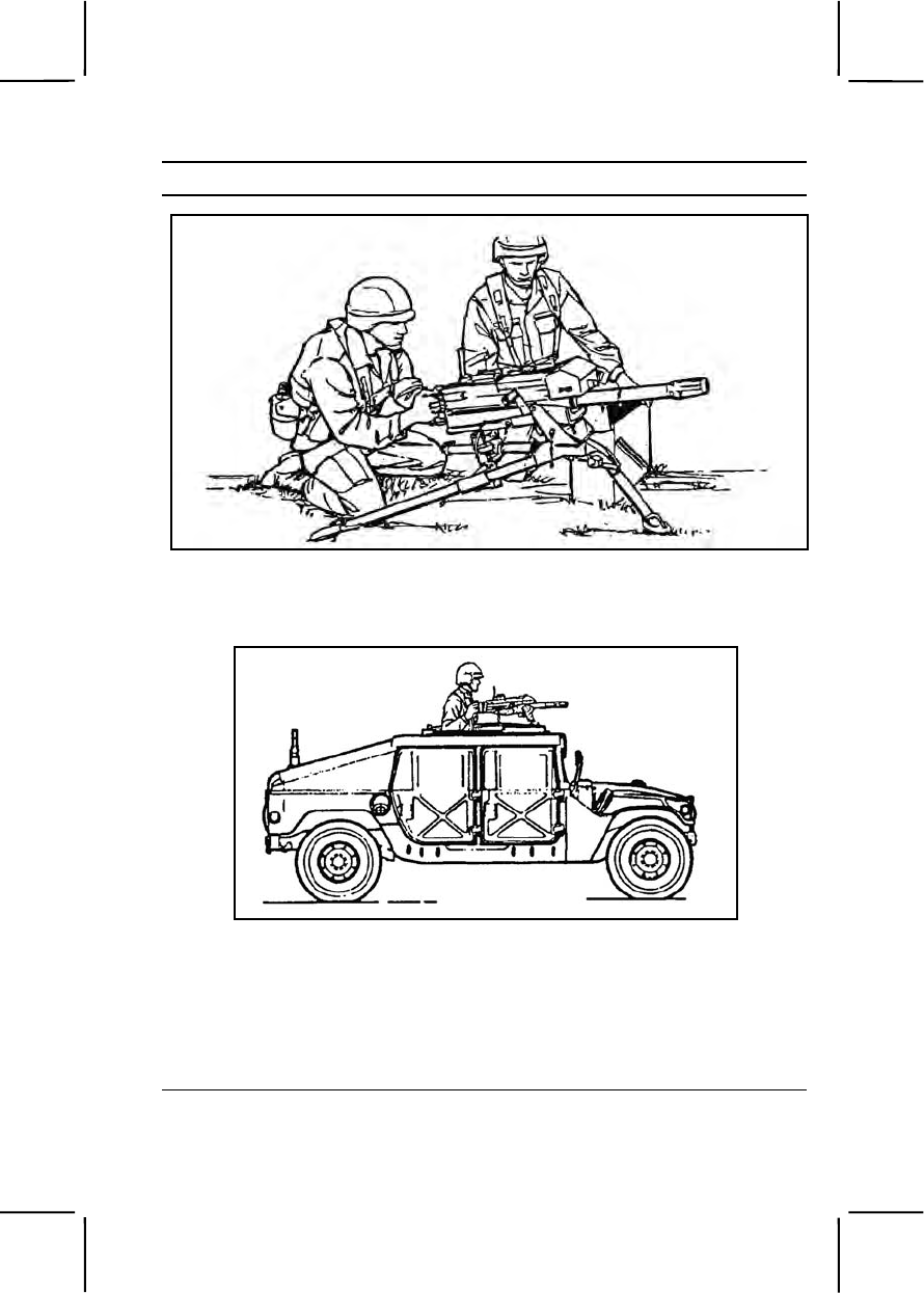
071-030-0004 3-433
Performance Steps
Figure 071-030-0004-4. Kneeling position
c. Standing position for gun mounted on a vehicle pedestal (figure
071-030-0004-5).
Figure 071-030-0004-5. Standing position for mounted gun
2. Acquire the target using correct sight alignment.
3. Apply correct engagement technique based on target types.
a. Use correct gun manipulation technique (figure 071-030-0004-6).
(1) Fixed fire. This is fire delivered against a point target. Only one
aiming point is necessary with little or no manipulation of the gun.

3-434 071-030-0004
Performance Steps
(2) Traversing fire. This is fire distributed against a wide target
requiring successive changes in direction of gun. This means using the
T&E mechanism to traverse the gun left or right to distribute fire laterally.
(3) Searching fire. This is fire delivered against a deep target or a
linear target with depth in width by successive changes in elevation. This
means using the T&E mechanism to move the muzzle of the weapon up or
down to distribute fire in depth.
(4) Traversing and searching fire. This is fire delivered in width and
depth by successive changes in direction and elevation. It is employed
against a target whose long axis is oblique to the direction of fire.
(5) Swinging traverse. This is fire delivered against targets that
require major changes in direction but little or no change in elevation.
Loosen the traversing slide lock enough to swing the gun laterally.
(6) Free gun. This is fire delivered against moving targets that must
be rapidly engaged with fast changes in direction and elevation. To fire free
gun, remove the T&E mechanism.
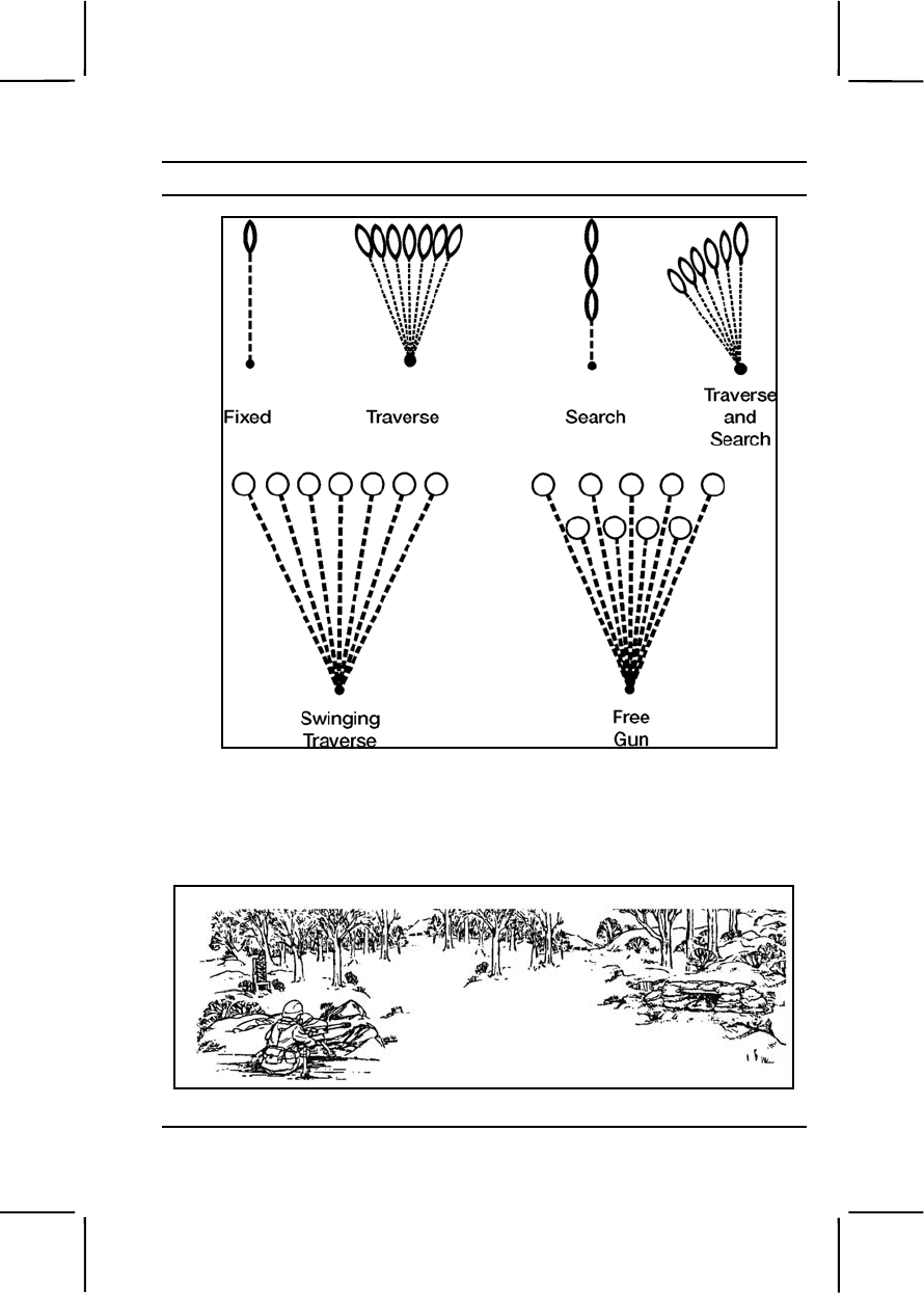
071-030-0004 3-435
Performance Steps
Figure 071-030-0004-6. Techniques of fire with respect to the MK19
b. Use correct application of fire to engage specific targets.
(1) Point target. Engage point targets with fixed fire using a single
aiming point (figure 071-030-0004-7).
Figure 071-030-0004-7. Point target
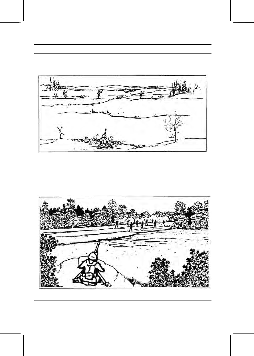
3-436 071-030-0004
Performance Steps
(2) Linear target. Initially aim just outside either flank and fire.
Traverse fire back and forth from flank to flank, covering the entire target
area (figure 071-030-0004-8).
Figure 071-030-0004-8. Linear target
(3) Linear target with depth. Initially aim at the near flank with range
set to the midpoint of the target unless another portion of the target is more
critical or presents a greater threat. Fire on the near flank, then traverse
and search back and forth, covering the entire target (figure 071-030-0004-
9).
Figure 071-030-0004-9. Linear target with depth
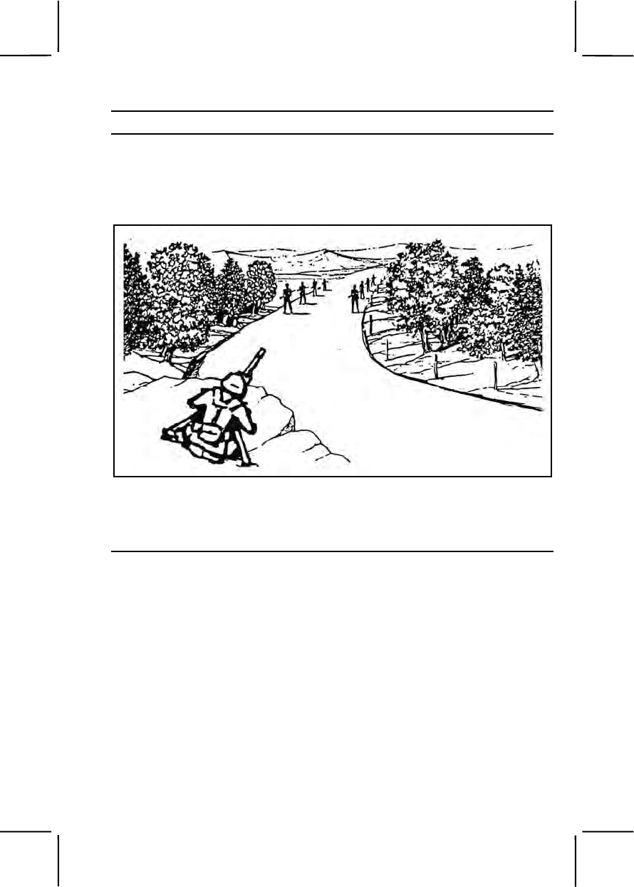
071-030-0004 3-437
Performance Steps
(4) Deep target. Initially aim at the end of the target closest to the
gun, unless another portion of the target is more critical or presents a
greater threat (auto rifleman). Fire and search up the far end and back
again repeatedly (figure 071-030-0004-10).
Figure 071-030-0004-10. Deep target
(5) Area target. Initially aim at the midpoint of the target area.
Traverse and search to either flank, then traverse and search to the
opposite flank (figure 071-030-0004-11).
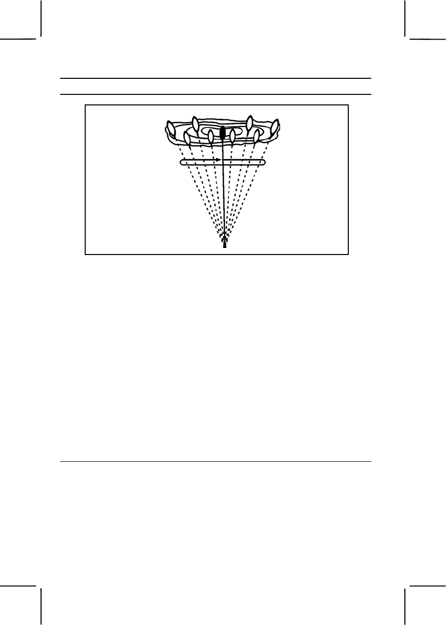
3-438 071-030-0004
Performance Steps
Figure 071-030-0004-11. Engagement of area targets, single gun
4. Use observation of fire and adjusted aiming point to place effective fire
on the target.
a. Observation of fire. Observe the strike of the rounds in relation to
the target; adjust elevation and direction needed to move the center of
impact onto the target.
Note. This does not call for use of the sights.
Example. Suppose you fire at a target 500 meters away. The rounds impact 20
meters short and 50 meters right. To manipulate the gun onto the target, use the
traversing and elevating mechanism hand wheels to move the muzzle left and up
the proper number of clicks.
b. Adjusted aiming point. Use this method to adjust fires quickly
without making a sight or T&E adjustment (figure 071-030-0004-12).
(1) If the initial burst misses the target, rapidly select a new aiming
point the same distance from the center of impact of the initial burst but in
the opposite direction.
(2) Lay the gun on that aiming point and fire.
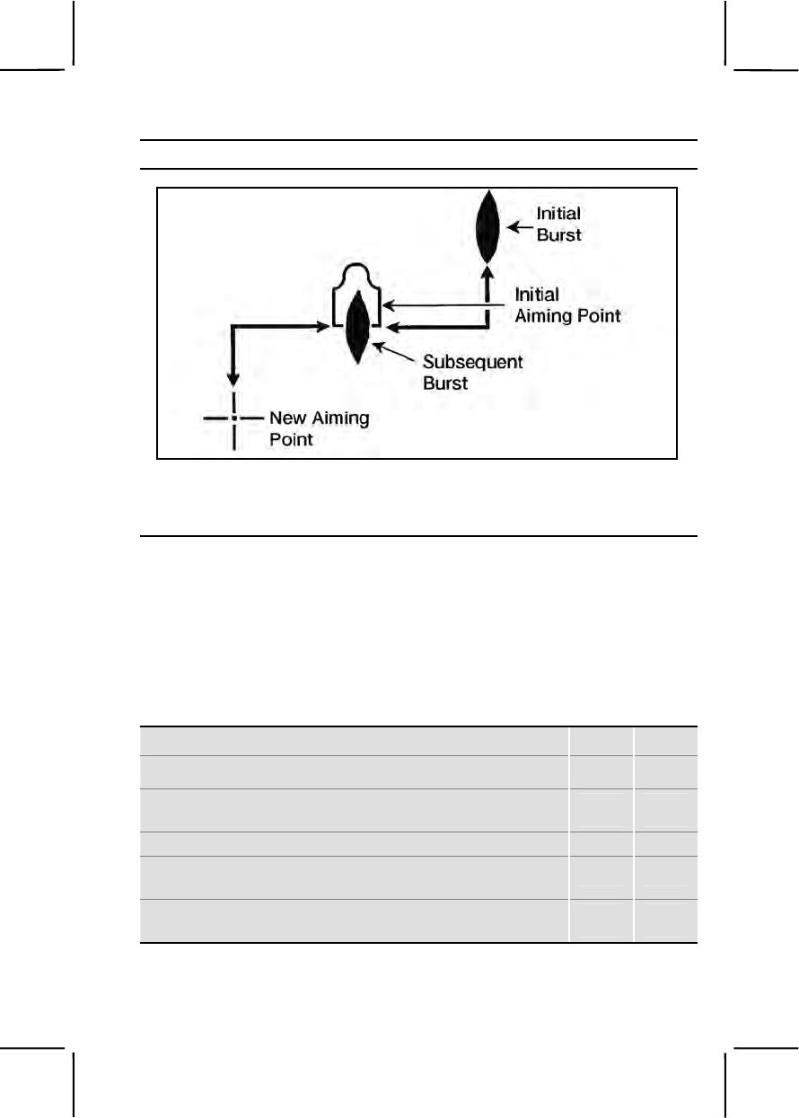
071-030-0004 3-439
Performance Steps
Figure 071-030-0004-12. Adjusted aiming point method
5. Fire on the targets until they are destroyed or until you receive an order
to cease fire.
Evaluation Preparation:
Setup: Evaluate this task on a live-fire range designed for 40-mm machine
gun firing. For a tripod mounted MK 19 tell the soldier to fire table II, tasks 4
through 8, FM 23-27, appendix C. For a vehicle-mounted MK19, tell the
soldier to fire table III, tasks 2 through 5, FM 23-27, appendix C.
Brief Soldier: Tell the soldier to perform the tasks outlined in appendix C, FM
23-27. Brief him on the task conditions, standards, and ammunitions. Tell
him he will be evaluated on his ability to apply correct target engagement
techniques and place effective fire on targets.
Performance Measures GO NO GO
1. Assumed a suitable firing position. —— ——
2. Applied correct engagement technique based on
target type. —— ——
a. Used correct gun manipulation technique.
b. Used correct application of fire to engage specific
targets.
3. Placed effective fire on targets (score a minimum of
84 points). —— ——

3-440 071-030-0005
Performance Measures GO NO GO
4. Used correct application of fire to engage specific
targets. —— ——
5. Used observation of fire and adjusted aiming point to
place effective fire on the target. —— ——
Evaluation Guidance: Score the soldier GO if all performance measures
are passed. Score the soldier NO GO if any performance measure is failed.
If the soldier scores NO GO, show him what was done wrong and how to do
it correctly.
References
Required Related
FM 23-27
071-030-0005
Load an MK19 Machine Gun
Conditions: Given a can of linked 40-mm grenade ammunition and a
cleared MK19 machine gun mounted on an M3 tripod or on a vehicle. (If
firing from a vehicle, ammunition can bracket must be attached to the gun
mount.)
Standards: Loaded linked ammunition through feed throat into feeder so,
when cover was closed, the round was straight and firmly seated against the
bolt, and the ammunition fed correctly.
Performance Steps
1. Make sure the chamber is empty, the bolt is in the forward position, and
the charger handles are in the up (lock) position.
2. Make sure the safety switch is in the safe (S) position.
WARNING
Do not let the top cover slam shut from the open position. Injury to
personnel or damage to equipment could result.
3. Insert the first round.
a. Open the top cover and insert the first round through the feed throat
into the feeder, link opening first (figure 071-030-0005-1).
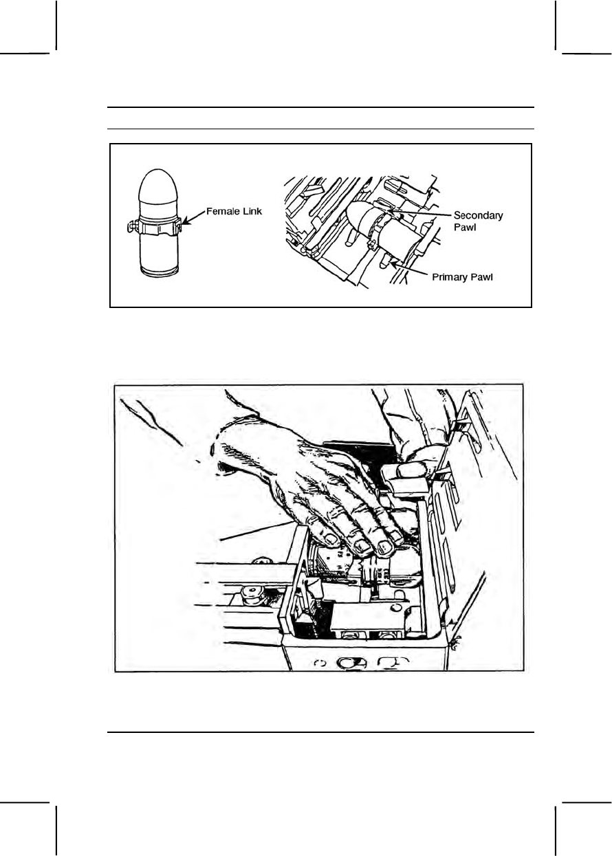
071-030-0005 3-441
Performance Steps
Figure 071-030-0005-1. Insertion of first round through feed throat
b. Push or slide the round across the first set of feeder pawls, making
sure the round is straight and firmly seated against the bolt (figure 071-
030-0005-2).
Figure 071-030-0005-2. Pushing round across feeder pawls
c. Index the feed slide assembly to the left and close the top cover
(figure 071-030-0005-3).
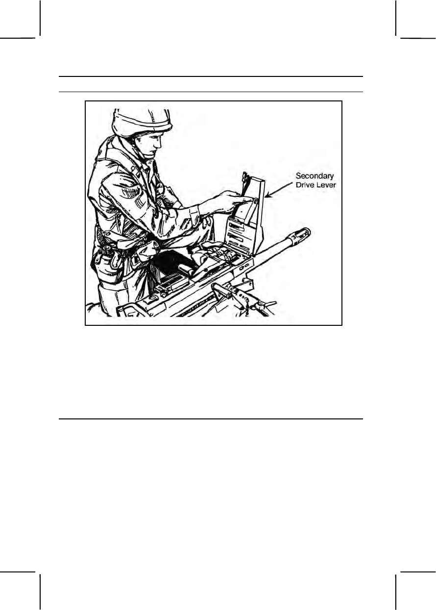
3-442 071-030-0005
Performance Steps
Figure 071-030-0005-3. Indexing the feed slide assembly
4. Charge the weapon (figure 071-030-0005-4).
a. Grasp charger handles palms down.
b. Press charger handle locks and rotate charger handles down.
c. Pull charger handles sharply to the rear until the bolt sears.
d. Push charger handles forward and rotate them up into the lock
position.
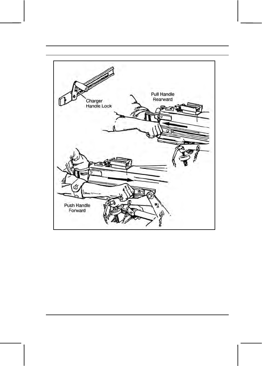
071-030-0005 3-443
Performance Steps
Figure 071-030-0005-4. Charging the MK19 machine gun
5. Load the first round.
a. Place safety switch in fire (F) position and press trigger.
Note. Bolt will move forward and load the first round on the bolt-face (half load).
b. Rotate charger handles down and pull them sharply to the rear until
the bolt sears. This pulls the bolt with the loaded round into position for
firing (full load).
c. Place safety switch in safe (S) position.
d. Push the chargers forward and rotate the charger handles up into
the lock position. The weapon is fully loaded.
e. Leave safety switch on safe (S) position until ready to fire.

3-444 071-030-0005
Performance Steps
WARNING
For firing, charger handles must be FORWARD and UP. Keep your
weapon pointed downrange and the line of fire clear of objects.
Evaluation Preparation:
Setup: Provide the soldier with the equipment listed in conditions.
Brief Soldier: Tell the soldier to load the MK19 according to proper
procedures.
Performance Measures GO NO GO
1. Made sure the chamber was empty, the bolt was
forward, and the charger handles were in the lock
position. —— ——
2. Made sure the safety switch was in the safe (S)
position. —— ——
3. Inserted the first round. —— ——
a. Opened the top cover and inserted the first round
through the feed throat and into the feeder, linked
opening first.
b. Pushed or slid the round across the first set of
feeder pawls, made sure the round was straight and
firmly seated against the bolt.
c. Indexed the feed slide assembly to the left and
closed the top cover.
4. Charged the weapon. —— ——
a. Grasped the charger handles palms down.
b. Pressed the charger handle locks and rotated
charger handles down.
c. Pulled charger handles sharply to the rear until
the bolt seared.
d. Pushed charger handles forward and rotated
them up into the lock position.
5. Loaded the first round. —— ——
a. Placed safety switch on the fire (F) position and
pressed the trigger.

071-030-0006 3-445
Performance Measures GO NO GO
b. Rotated charger handles down and pulled them
sharply to the rear until the bolt seared.
c. Placed safety switch on the safe (S) position.
d. Pushed charger forward and rotated the charger
handles up into the locked position.
e. Left safety switch in the safe (S) position until
ready to fire.
Evaluation Guidance: Score the soldier GO if all performance measures
are passed. Score the soldier NO GO if any performance measure is failed.
If the soldier scores NO GO, show him what was done wrong and how to do
it correctly.
References
Required Related
FM 23-27
TM 9-1010-230-10
071-030-0006
Unload an MK19 Machine Gun
Conditions: Given an MK19 machine gun mounted on an M3 tripod or
vehicle loaded with linked 40-mm grenade ammunition.
Standards: Unloaded the MK19 machine gun, removed ammunition and
empty casings. Cleared the weapon, made sure the chamber was empty
and the safety switch was in the safe (S) position.
Performance Steps
1. Place the safety switch on the safe (S) position.
2. Charge the weapon.
3. Return the charger handles to the forward position and rotate only one
charger handle up.
4. Remove the live round or spent case from bolt.
a. Insert the tip of a cleaning rod through the right hand rail as close to
the bolt face as possible (figure 071-030-0006-1).
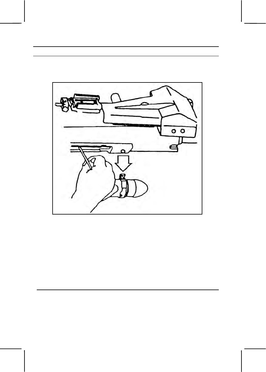
3-446 071-030-0006
Performance Steps
b. Lift up on the cleaning rod to force the live round or case off the bolt
face and out the bottom of the gun. Catch the live round or the spent case
as it falls out.
Figure 071-030-0006-1. Removal of Round or Spent Case
5. Remove linked rounds from the feeder.
a. Open the top cover. Check for rounds in the feeder. If you find
any rounds in the feeder, perform the following actions (figure 071-030-
0006-2).
(1) With one hand, reach beneath the feeder. Press the primary
and secondary positioning pawls at the same time.
(2) At the same time, slide the linked rounds out of the feeder and
feed throat.
b. Place linked rounds in the ammunition can.
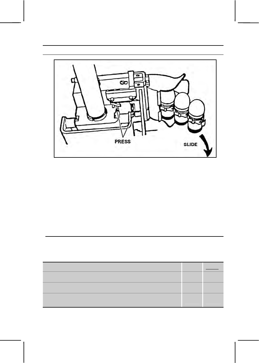
071-030-0006 3-447
Performance Steps
Figure 071-030-0006-2. Removal of Linked Rounds from the Feeder
6. Place the safety switch in the fire (F) position.
7. Ride the bolt forward.
a. Hold one charger handle to the rear.
b. Press the trigger to release the bolt; ride the bolt forward.
c. Make sure both charging handles are forward and in the up
position.
8. Place the safety switch in the safe (S) position.
9. Index the feed slide assembly to the left.
10. Close and latch the top cover.
Evaluation Preparation:
Setup: Provide the soldier with the equipment listed in the task conditions .
Brief Soldier: Tell the soldier to load the MK19 according to the task steps.
Performance Measures GO NO GO
1. Placed the safety switch on safe (S) position. —— ——
2. Charged the weapon. —— ——
3. Returned the charger handles to the forward position,
and rotated only one charger handle up. —— ——

3-448 071-030-0006
Performance Measures GO NO GO
4. Removed the live round or spent case from bolt. —— ——
a. Inserted the tip of a cleaning rod through the
right-hand rail as close to the bolt face as possible.
b. Raised up on the cleaning rod to force the live
round or case off the bolt face and out the bottom of the
gun. Caught the live round or the spent case as it fell
out.
5. Removed any linked rounds from the feeder. —— ——
a. Opened the top cover. Checked for rounds in the
feeder. If there were rounds in the feeder, performed the
following actions:
(1) With one hand, reached beneath the feeder,
and pressed the primary and secondary positioning
pawls at the same time.
(2) At the same time, slid the linked rounds out of
the feeder and feed throat.
b. Placed linked rounds in the ammunition can.
6. Placed the safety switch on fire (F) position. —— ——
7. Rode the bolt forward. —— ——
a. Held one charger handle to the rear.
b. Pressed the trigger to release the bolt, and ride
the bolt forward.
c. Made sure both charging handles were forward
and in the up position.
8. Placed the safety switch in the safe (S) position. —— ——
9. Indexed the feed slide assembly to the left. —— ——
10. Closed and latched the top cover. —— ——
Evaluation Guidance: Score the soldier GO if all performance measures
are passed. Score the soldier NO GO if any performance measure is failed.
If the soldier scores NO GO, show him what was done wrong and how to do
it correctly.

071-030-0007 3-449
References
Required Related
FM 23-27
TM 9-1010-230-10
071-030-0007
Perform a Function Check on an MK19 Machine Gun
Conditions: Given a cleared MK19 machine gun mounted on an M3 tripod
or vehicle carrier.
Standards: Conducted an operational check of the MK19 machine gun to
make sure it was correctly assembled and functioned properly.
Performance Steps
WARNING
Before performing any procedure, make sure the weapon is clear of
ammunition.
1. Check the functioning of the safety switch.
a. With the cover closed, place safety switch on safe (S).
b. Pull the bolt to rear, push charger handles to forward position, and
rotate handles up.
c. Press the trigger. Bolt should not go forward.
d. Place the safety switch on fire (F) position.
e. Press the trigger. Bolt should spring forward.
f. Place the safety switch on safe (S) and leave the bolt in forward
position.
2. Open top cover assembly and inspect the feed tray assembly and the
chamber to ensure the gun is clear.
a. Open the top cover.
b. Touch the firing pin. If it is not protruding, recharge and release the
bolt spring under pressure.
c. Inspect the bolt face to make sure it is not worn, dirty, pitted,
corroded, or in need of lubrication.

3-450 071-030-0007
Performance Steps
WARNING
Do not allow the top cover to slam shut from the raised position. Doing
so could injure your hand or damage the equipment.
3. Check the feed slide assembly and feeder.
a. Move the secondary drive lever back and forth. The feed slide
assembly should move freely.
b. Press the feed pawls to check for spring pressure.
c. Inspect the link guide for roughness and galling.
Note. Before closing the top cover, always make sure that—
Secondary drive lever is engaged with the feed slide pin.
Feed slide assembly is to the left.
Bolt is forward.
Note. Never try to force the top cover closed. Doing so could damage the
equipment.
d. Close and latch the top cover.
4. If you find any deficiencies that you cannot correct, the MK19 is
unserviceable. Report the deficiencies to your supervisor.
Evaluation Preparation:
Setup: At the test site, provide the soldier with the equipment listed in task
conditions.
Brief Soldier: Tell soldier to perform a function check to determine if the
MK19 machine gun functions properly.
Performance Measures GO NO GO
1. Checked functioning of safety switch. —— ——
2. Inspected interior of receiver assembly for missing or
damaged parts. —— ——
3. Checked feed slide assembly and feeder. —— ——
4. Reported deficiencies to supervisor. —— ——
Evaluation Guidance: Score the soldier GO if all performance measures
are passed. Score the soldier NO GO if any performance measure is failed.
If the soldier scores NO GO, show him what was done wrong and how to do
it correctly.

071-022-0001 3-451
References
Required Related
TM 9-1010-230-10
SUBJECT AREA 14: CALIBER .50 M2 MACHINE GUN
071-022-0001
Maintain a Caliber .50 M2 Machine Gun
Conditions: Given a caliber .50 M2 HB machine gun, M3 tripod, MK64 gun
cradle mount, pintle, traversing and elevating (T&E) mechanism, linked
caliber .50 ammunition, headspace and timing gauge, cleaner lubricant and
preservative (CLP), rifle bore cleaner (RBC), lubricating oil semifluid (LSA),
carbon removing compound, bore brush, wiping rags, M4 cleaning rod,
small-arms (2-inch) cleaning swabs, and a wooden block.
Standards: Cleaned and lubricated the caliber .50 M2 machine gun and its
components. Cleaned and inspected all parts and ammunition and turned in
unserviceable parts for maintenance. Assembled the gun so it was
operational.
Performance Steps
1. Clear the caliber .50 machine gun.
a. Unlock the bolt latch release and raise the cover (figure 071-022-
0001-1).
b. Pull and lock the bolt to the rear, leaving the retracting slide handle
to the rear.
c. Inspect the chamber and T-slot to make sure they hold no rounds.
d. Place a wooden block inside the receiver, between the bolt and
the rear of the barrel.
e. Insert the cleaning rod in the muzzle end of the barrel until you can
see the rod in the receiver. Remove the cleaning rod.
f. Grasp the retracting slide handle, press the bolt latch release, and
ease the bolt forward. Close the cover.
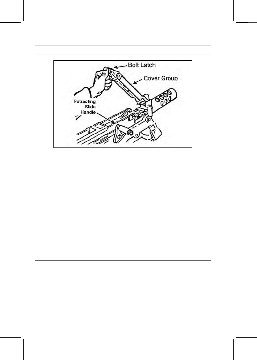
3-452 071-022-0001
Performance Steps
Figure 071-022-0001-1. Raising the cover
2. Disassemble the machine gun.
a. Remove the barrel assembly.
(1) Raise the cover group (figure 071-022-0001-1).
(2) Grasp the retracting slide handle with the right hand, palm up.
Pull the bolt to the rear until the barrel locking spring lug aligns with the
3/8-inch hole in the right side plate of the receiver (figure 071-022-0001-
2).
(3) Place the smallest loop of a caliber .50 link between the
trunnion block and the barrel extension (figure 071-022-0001-2). This
keeps the barrel locking spring lug aligned with the 3/8-inch hole.
(4) Unscrew the barrel from the receiver. Be careful not to
damage the threads or barrel locking notches.
(5) Remove the caliber .50 link to allow the bolt to go forward
slowly. Make sure the bolt group does not slam forward with the barrel
removed.
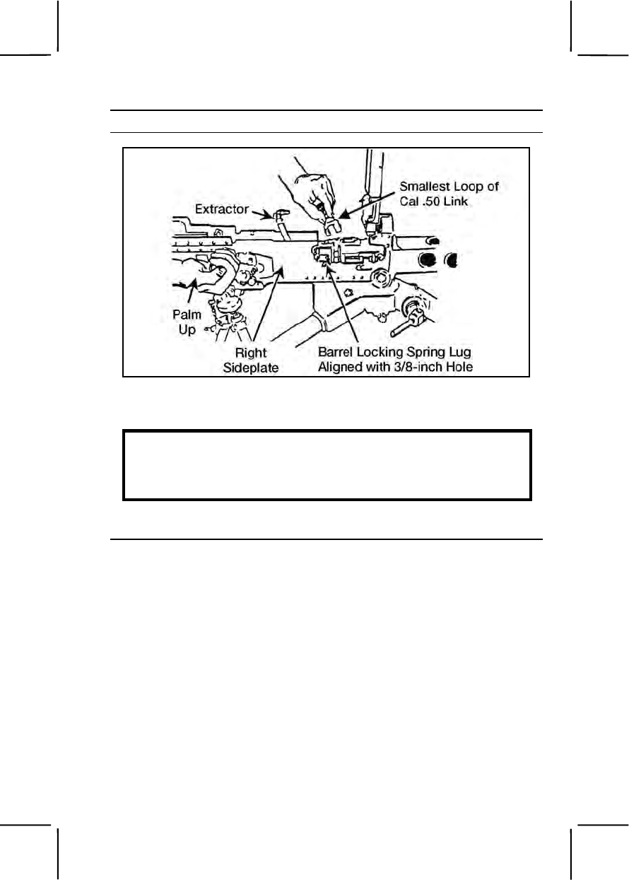
071-022-0001 3-453
Performance Steps
Figure 071-022-0001-2. Alignment of the lug
b. Remove the backplate assembly.
WARNING
Do not remove the backplate unless the bolt is in the forward position.
When removing the backplate, stand to one side of the weapon to
avoid possible injury from the driving spring rod.
(1) Ensure that the bolt is forward and the bolt latch release is
unlocked (in the single shot mode) (figure 071-022-0001-3).
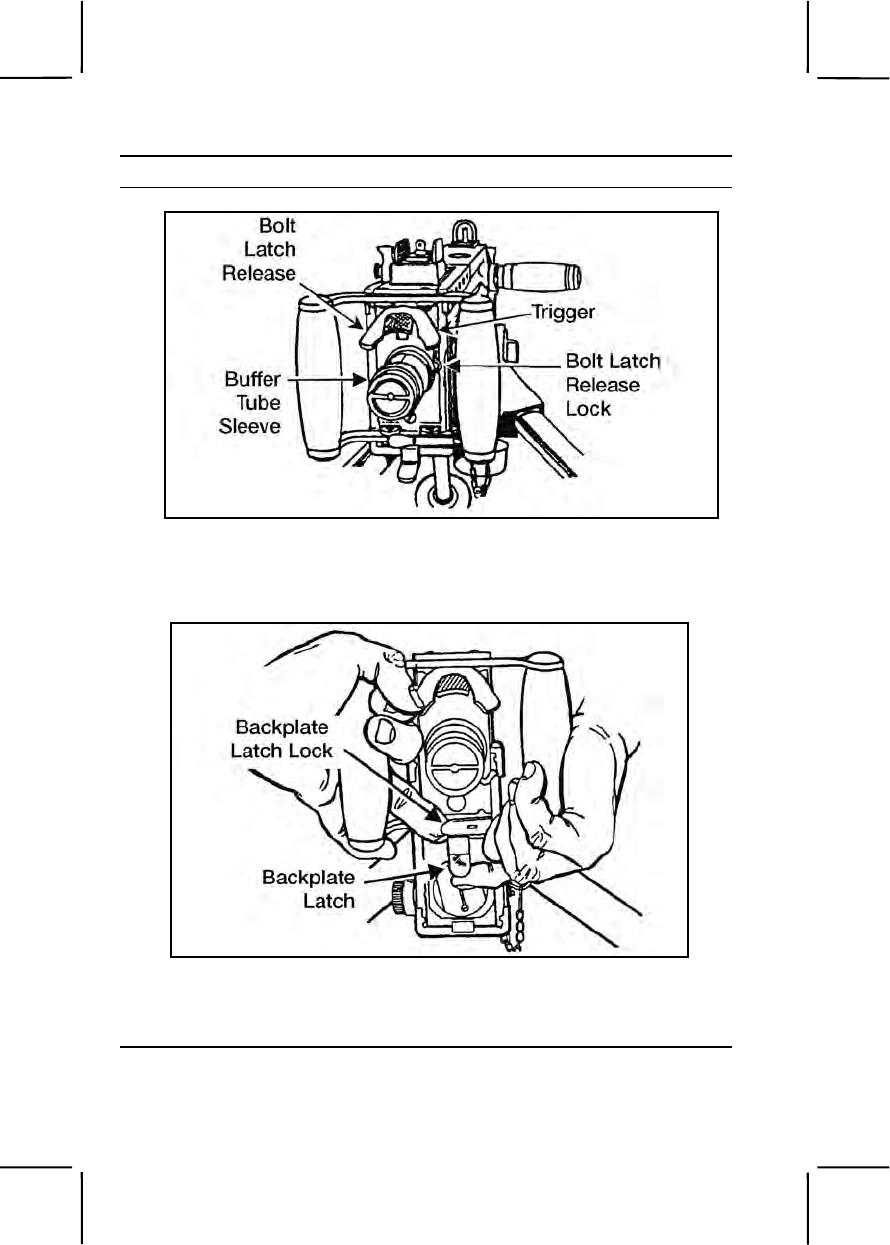
3-454 071-022-0001
Performance Steps
Figure 071-022-0001-3. Releasing the bolt latch
(2) Pull the backplate latch lock straight back while lifting up on
the backplate latch (figure 071-022-0001-4).
Figure 071-022-0001-4. Removal of the backplate
(3) Remove the backplate assembly by lifting straight up.
c. Remove the driving spring rod assembly (figure 071-022-0001-5).
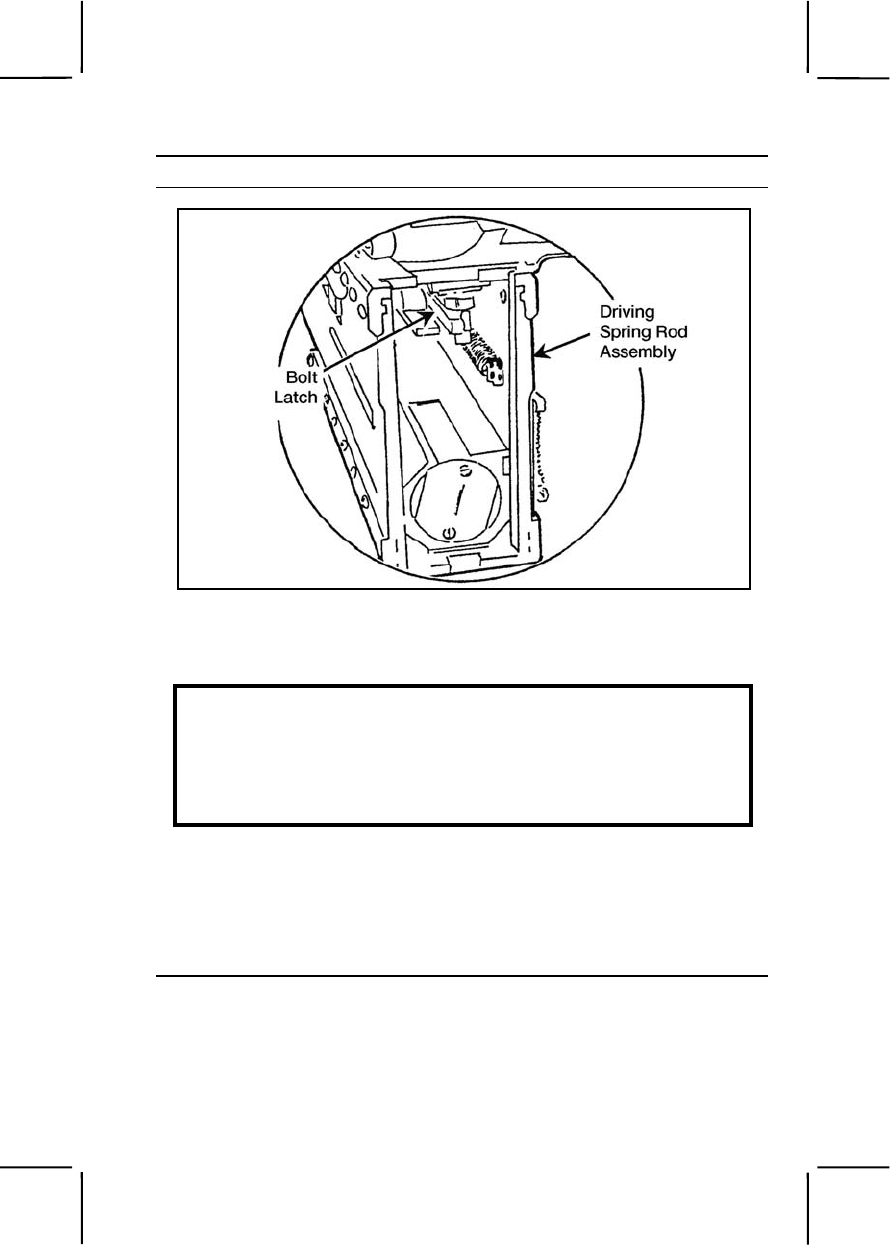
071-022-0001 3-455
Performance Steps
Figure 071-022-0001-5. Removal of the driving spring rod assembly
(1) Push the rear of the driving rod assembly forward and to the
left to free it from the side of the receiver.
WARNING
Never try to charge the machine gun while the backplate is off and the
driving spring rod assembly is in place. If the backplate is off and the
driving spring assembly is compressed, the retaining pin on the driving
spring can slip from its seat in the side plate. This could cause serious
injury to anyone behind the machine gun.
(2) Pull the driving spring rod assembly to the rear and out of the
receiver.
d. Remove the bolt assembly.
(1) Retract the bolt assembly far enough to the rear to align the
bolt stud with the bolt stud hole in the right side plate of the receiver
(figure 071-022-0001-6).
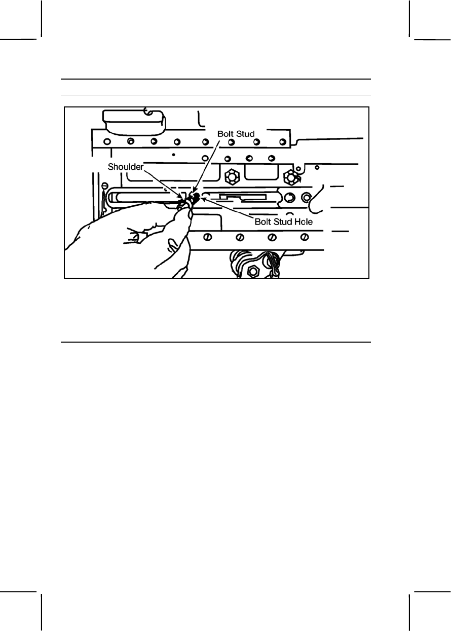
3-456 071-022-0001
Performance Steps
Figure 071-022-0001-6. Removal of the bolt stud
(2) If you accidentally move the bolt all the way to the rear, the
bolt latch will engage in the bolt latch notches in the top of the bolt. If this
occurs, raise the bolt latch and push the bolt forward to align the bolt stud
with the clearance hole (figure 071-022-0001-7).
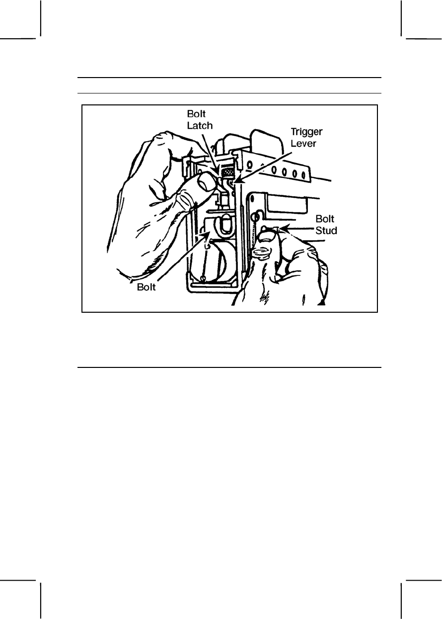
071-022-0001 3-457
Performance Steps
Figure 071-022-0001-7. Unlatching the bolt
(3) Remove the bolt stud.
(4) Remove the bolt assembly by pulling it from the rear of the
receiver (figure 071-022-0001-8).
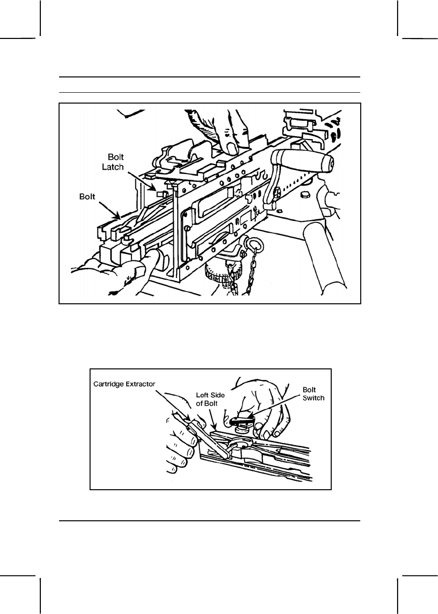
3-458 071-022-0001
Performance Steps
Figure 071-022-0001-8. Removal of the bolt from the receiver
(5) Disassemble the bolt.
(a) Rotate the cartridge extractor upward and remove it from
the left side of the bolt (figure 071-022-0001-9).
Figure 071-022-0001-9. Removal of the cartridge extractor and bolt
(b) Remove the bolt switch by lifting it straight up.

071-022-0001 3-459
Performance Steps
(c) Place the cocking lever in its rearmost position. Press
down on the sear with a swab holder and release the firing pin spring
(figure 071-022-0001-10).
Figure 071-022-0001-10. Releasing the firing pin spring
(d) Insert a swab holder section in the hole at the rear of the
bolt and push out the cocking lever pin and the cocking lever (figure 071-
022-0001-11).
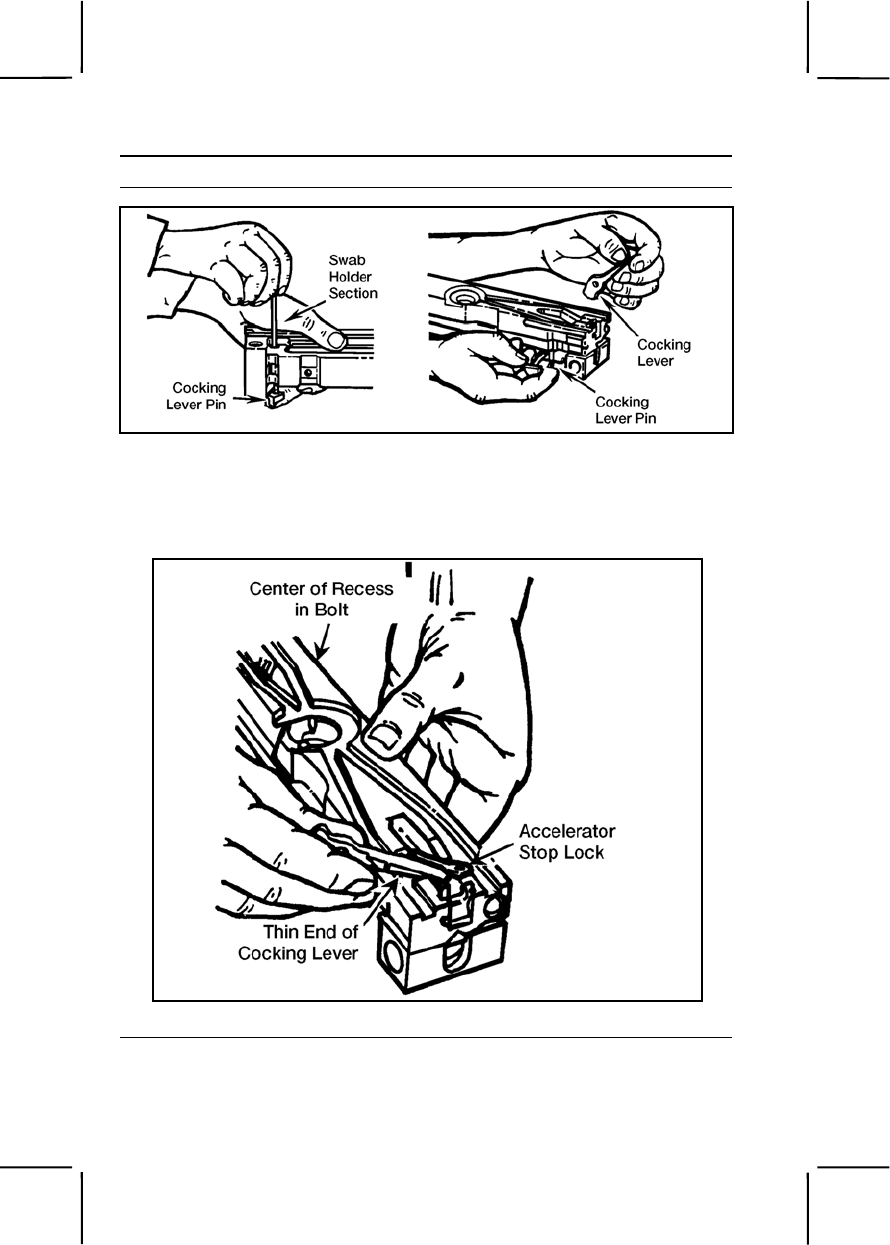
3-460 071-022-0001
Performance Steps
Figure 071-022-0001-11. Removal of the cocking lever pin and cocking lever
(e) Use the thin end of the cocking lever to rotate the
accelerator stop lock to the center of the bolt, then pry up the accelerator
stop lock and remove it (figure 071-022-0001-12).
Figure 071-022-0001-12. Removal of the accelerator stop lock
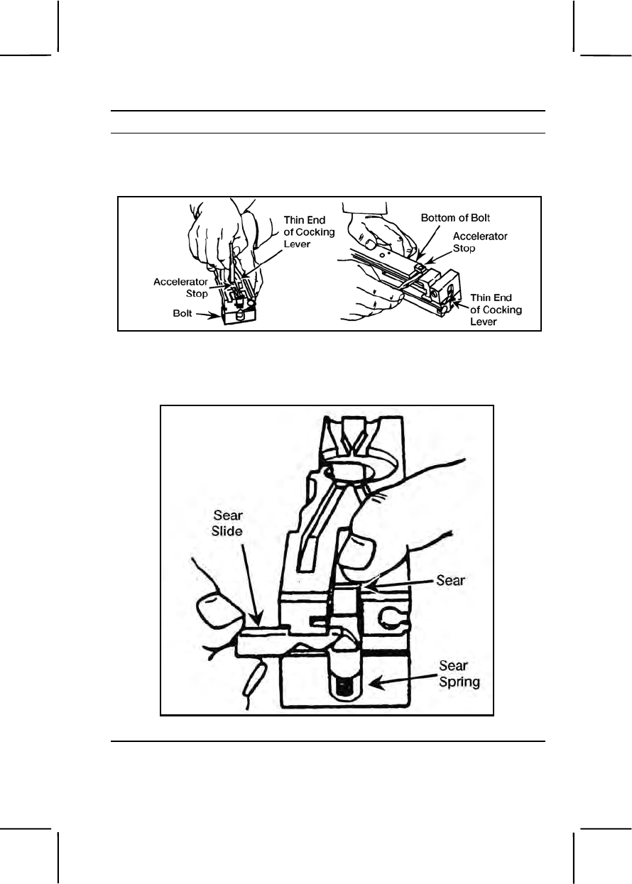
071-022-0001 3-461
Performance Steps
(f) Using the thin end of the cocking lever, press the
accelerator stop from the bolt, turn the bolt over, and pry the accelerator
stop from bottom of bolt (figure 071-022-0001-13).
Figure 071-022-0001-13. Removal of the accelerator stop
(g) Depress the sear and remove the sear slide, sear, and
sear spring (figure 071-022-0001-14).
Figure 071-022-0001-14. Removal of the sear slide, sear, and sear spring
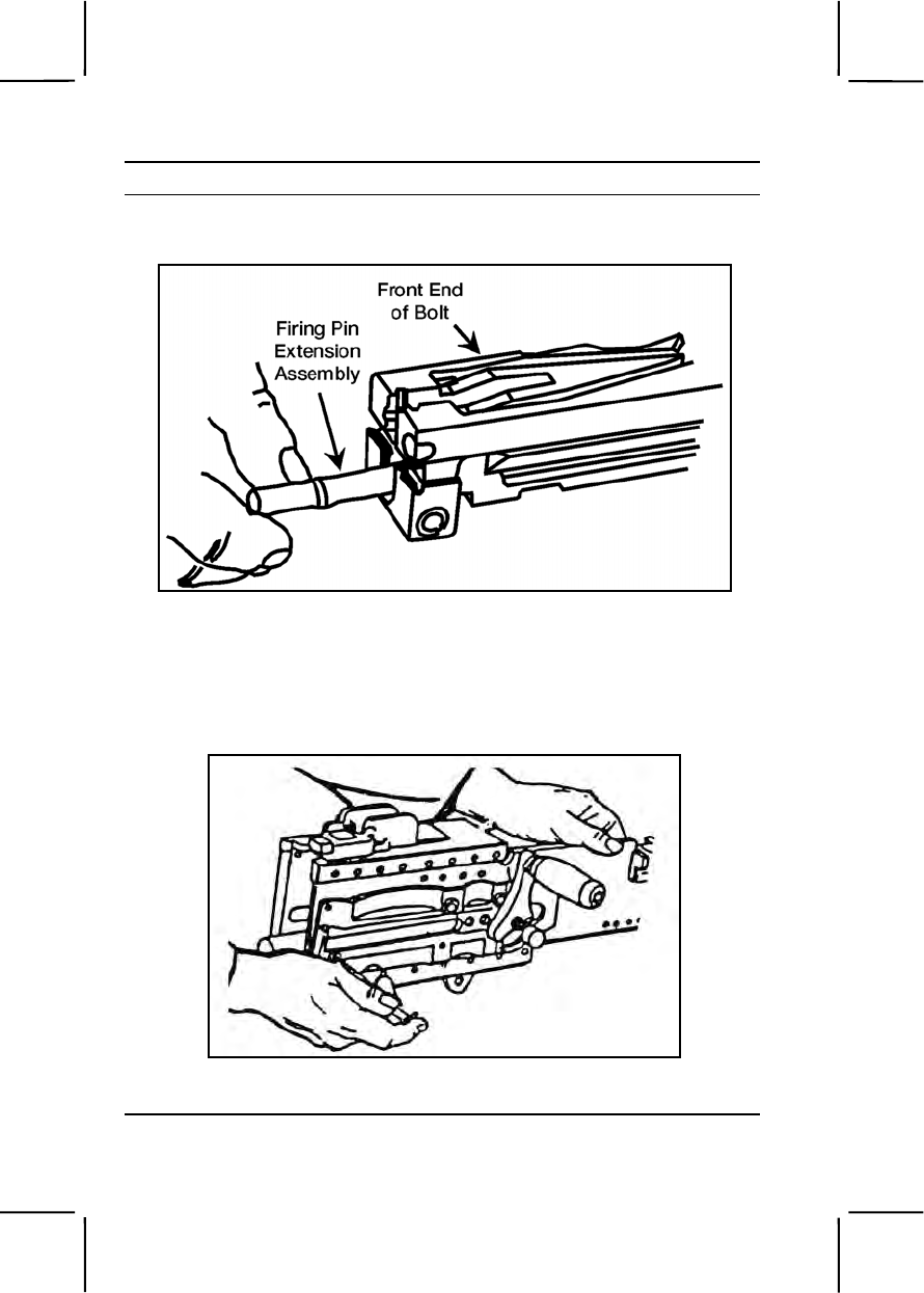
3-462 071-022-0001
Performance Steps
(h) Tip the front end of the bolt upward and remove the firing
pin extension assembly (figure 071-022-0001-15).
Figure 071-022-0001-15. Removal of the firing pin extension assembly
(i) Remove the firing pin from the firing pin extension
assembly.
e. Remove the barrel buffer and barrel extension assemblies (figure
071-022-0001-16).
Figure 071-022-0001-16. Removal of the barrel buffer group and barrel
extension group
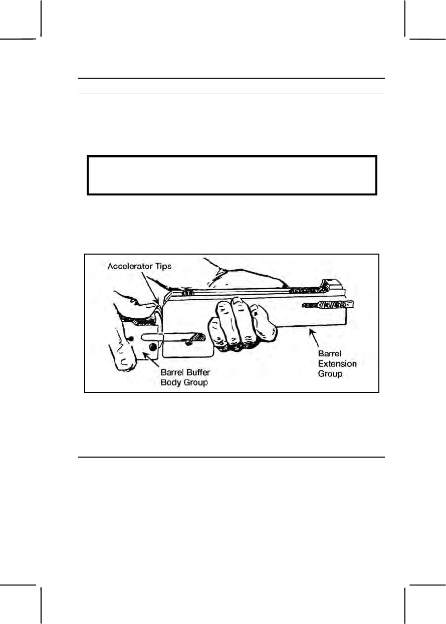
071-022-0001 3-463
Performance Steps
(1) Insert a pointed instrument (you can use the pointed end of the
M4 cleaning rod) in the hole at the lower rear corner of the right side plate.
Depress the buffer body lock and, at the same time, place one hand
inside the receiver and push the barrel extension and buffer assemblies to
the rear until the buffer accelerator is near the rear of the receiver body.
WARNING
Maintain thumb pressure on the buffer accelerator while removing the
barrel buffer and barrel extension assemblies.
(2) Maintain pressure on the buffer accelerator with your thumb
and remove the barrel buffer and barrel extension assemblies from the
receiver. Separate them by pushing forward on the accelerator tips (figure
071-022-0001-17).
Figure 071-022-0001-17. Separation of the barrel buffer and barrel extension
assemblies.
(3) Disassemble the barrel buffer assembly.
(a) Remove the buffer assembly by pushing it out the rear of
the body of the barrel buffer (figure 071-022-0001-18).
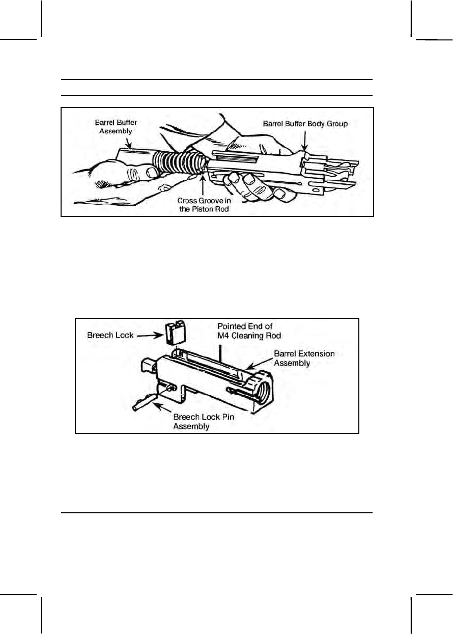
3-464 071-022-0001
Performance Steps
Figure 071-022-0001-18. Removal of the barrel buffer assembly
(b) Using a swab holder, drive the accelerator pin assembly
from the barrel buffer body group.
(c) Remove the buffer accelerator.
(4) Disassemble barrel extension assembly.
(a) Using the pointed end of the M4 cleaning rod, remove
breech lock pin assembly (figure 071-022-0001-19).
Figure 071-022-0001-19. Removal of the breech lock pin assembly and breech
lock
(b) Remove breech lock.
f. Disassemble receiver assembly.
(1) Remove the front cartridge stop and rear cartridge stop
assembly (figure 071-022-0001-20).
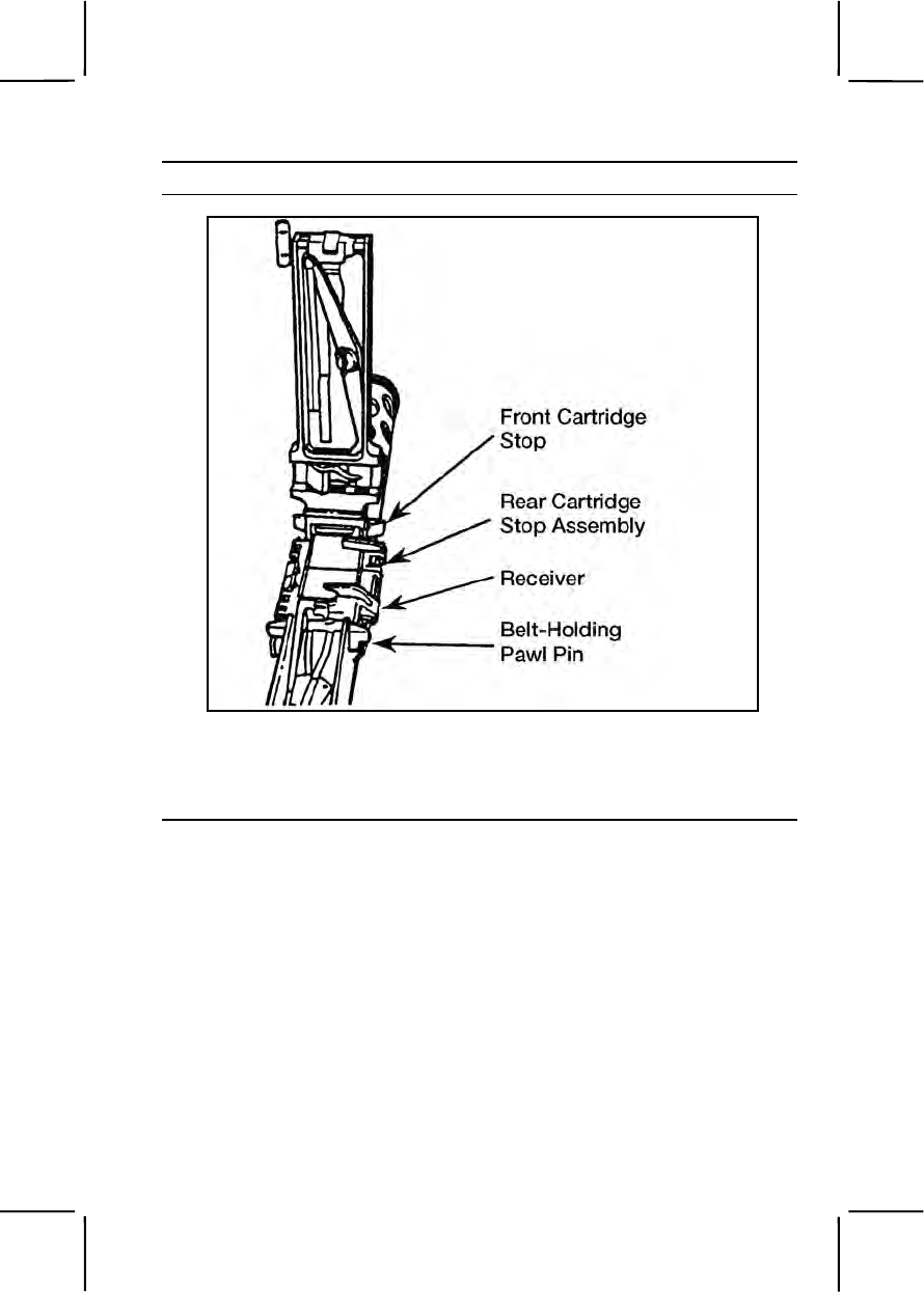
071-022-0001 3-465
Performance Steps
Figure 071-022-0001-20. Removal of the cartridge stop assemblies
(2) Press down on belt holding pawl assembly to prevent loss of
springs, and remove the belt holding pawl pin. Remove belt holding pawl
assembly and springs (figure 071-022-0001-21).
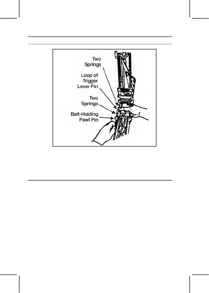
3-466 071-022-0001
Performance Steps
Figure 071-022-0001-21. Removal of the belt holding pawl pin, assembly, and
springs
(3) Raise the loop of the trigger lever pin and rotate it into a
vertical position. Reach inside the receiver, grasp the trigger lever, and
remove the trigger pin assembly and trigger lever (figure 071-022-0001-
22).
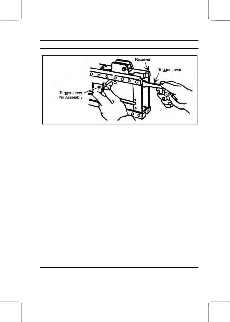
071-022-0001 3-467
Performance Steps
Figure 071-022-0001-22. Removal of the trigger lever pin assembly and
trigger lever
3. Clean the .50 caliber machine gun and components.
a. Barrel assembly.
(1) Clean the bore. Screw the bore brush into the cleaning rod, dip
the bore brush in RBC, and push the cleaning rod through the chamber
end of barrel. Unscrew the bore brush from the cleaning rod. Repeat the
process until clean.
(2) Clean the chamber. Screw the chamber brush into the
cleaning rod, dip the chamber brush in RBC, and clean the chamber using
a clockwise twisting motion.
(3) Insert a cleaning swab in the cleaning rod and swab out the
bore from the chamber end and back. Repeat until a swab comes out
clean.
(4) Wipe outside surfaces of barrel with carbon removing
compound.
(5) Remove all traces of RBC before lubricating.
Note. Do not submerge the backplate assembly in any fluid.
b. Backplate assembly. Use only clean wiping rags to remove foreign
matter from backplate.
c. Bolt assembly. Clean all parts of bolt assembly with a cleaning
swab saturated with carbon removing compound. Clean the face of the
bolt with a cleaning swab soaked in RBC.

3-468 071-022-0001
Performance Steps
d. Clean barrel buffer assembly, barrel extension assembly, and
receiver assembly with a cleaning swab saturated with carbon removing
compound. Wipe all parts dry with clean wiping rags.
e. Clean components.
(1) T&E mechanism. Remove foreign matter with a clean dry
wiping rag. Use a small arms cleaning brush to clean numbers on the
scale.
(2) Clean M3 tripod, MK64 gun cradle mount, and pintle with a
cleaning swab saturated with carbon removing compound. Wipe all parts
dry with clean wiping rags.
f. Ammunition. Remove foreign matter with a clean dry wiping rag.
4. Inspect for serviceability.
a. Barrel assembly.
(1) Check barrel locking notches for wear.
(2) Check the bore for bulges, missing bands, and large pits.
b. Backplate assembly.
(1) Check guides for burrs and bends.
(2) Check backplate latch and backplate lock for proper
functioning.
(3) Make sure locking pins are in place.
(4) Check trigger and bolt latch release for proper functioning.
(5) Make sure handle grips do not move freely and are not
cracked.
c. Driving rod assembly.
(1) Check for flat spots on springs.
(2) Make sure springs operate freely and rod and pin are not bent.
d. Bolt assembly.
(1) Check movement of cartridge extractor in bolt; it should raise
and lower without binding. Check movement of cartridge ejector.
(2) Check bolt switch, cocking lever pin, cocking lever, accelerator
stop lock, accelerator stop, and sear slide for cracks, bends, and burrs.
(3) Inspect sear for cracks and burrs. Inspect sear notch for wear,
chips, and burrs. Inspect sear spring for breaks and lack of tension.
(4) Inspect firing pin for cracks and chipped or sharp tip. Tip
should be smooth and well rounded.

071-022-0001 3-469
Performance Steps
(5) Check firing pin extension for cracks, burrs, and free
movement in bolt.
(6) Make sure bolt is free of burrs and cracks and firing pin hole is
not visually out of round.
e. Barrel buffer assembly.
(1) Inspect buffer body lock for tension, staking, and retention in
barrel buffer body.
(2) Inspect buffer accelerator for broken claws or chipped tips.
(3) Inspect accelerator pin assembly for broken or missing spring.
(4) Inspect buffer spring for cracks or breaks.
(5) Inspect breech lock depressors. They must have slight vertical
(up and down) movement but should have no lateral (side to side)
movement.
f. Barrel extension assembly.
(1) Make sure barrel extension assembly is not bent and the bolt
guideways are smooth and free of burrs.
(2) Inspect threads of barrel extension assembly for damage.
(3) Make sure barrel locking spring is staked and fully seated in its
groove. Also, make sure the locking end of the spring has good tension
and the lug is not damaged.
(4) Check breechblock for smooth movement in guideways of
barrel extension assembly.
g. Receiver and cover assembly.
(1) Inspect belt holding pawl brackets for looseness, bends, and
cracks.
(2) Inspect side plates for bends that would affect movement of
any internal parts.
(3) Check for cracks and burrs at backplate grooves.
(4) Check operation of rear sight. Make sure windage and
elevation screws function properly, leaf assembly has good spring
tension, and sight assembly is secured tightly to receiver.
(5) Make sure bolt stop is present and in good condition.
(6) Make sure trigger lever moves freely.
(7) Make sure trigger lever pin locks in place.
(8) Make sure cotter pin is in place on extractor switch.

3-470 071-022-0001
Performance Steps
(9) Check retracting slide assembly for visible damage. Check
retracting slide handles for smooth movement. Make sure cotter pins are
present and in good condition, and safety wire is in place and properly
laced.
h. Inspect components.
(1) T&E mechanism.
(a) Inspect hand wheels and threads for burrs and rust.
Check hand wheels for smooth operation.
(b) Make sure traversing slide lock lever has spring action.
Make sure elevating mechanism sleeve fits on traversing bar and clamps
firmly.
(c) Check traversing and elevating scales for legibility.
(d) Inspect quick release pin and chain for burrs and rust.
Check quick release pin for presence of spring loaded balls.
(2) M3 tripod.
(a) Check for completeness of tripod. Make sure all nuts and
bolts are tightly secured.
(b) Check for visible cracks on legs and tripod head.
(c) Check for missing, broken, or inoperative sleeve lock
latch.
(d) Check pintle lock assembly. Check surfaces of pintle,
bolt, and nut for burrs and rust. Make sure cotter pin is present and in
good condition.
(e) Check locking action of front leg clamping assembly.
(f) Check that rear legs lock in the open position. Make sure
sleeve latch notch and right leg slide notch engage completely. Make
sure latch spring has good tension.
(g) Check telescoping, indexing, and locking action of rear
legs and front leg clamping assembly.
(3) MK64 gun cradle mount.
(a) Check for missing or damaged parts.
(b) Check for rust, cracks, and burrs.
(c) Check pintle lock assembly. Check surfaces of pintle,
bolt, and nut for burrs and rust. Make sure cotter pin is present and in
good condition.
i. Inspect ammunition. Check for damage or corroded rounds.
5. Lubricate the .50 caliber machine gun.
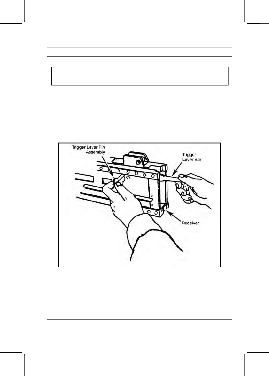
071-022-0001 3-471
Performance Steps
a. Remove all traces of RBC or carbon removing compound.
CAUTION
Do not mix lubricants on the same weapon. The weapon must be thoroughly
cleaned with dry cleaning solvent during change from one lubricant to another.
b. Lubricate exterior of backplate with a light coat of oil. Do not
lubricate interior of backplate.
c. Lubricate all other parts with a light coat of LSA or CLP (at
temperatures above 0 degrees Fahrenheit) or LAW (at temperatures
below 0 degrees Fahrenheit).
6. Assemble the .50 caliber machine gun.
a. Assemble the trigger lever (Figure 071-022-0001-23).
Figure 071-022-0001-23. Assembly of the trigger lever
(1) Place the trigger lever bar in the receiver directly under the
timing nut so the hole in the trigger lever bar is aligned with the mounting
hole in the receiver.
(2) Insert trigger lever pin assembly (loop end vertical) in the
assembly hole on left side of receiver. Match key on trigger lever pin with
keyway in side plate of receiver and install the pin completely.

3-472 071-022-0001
Performance Steps
(3) Rotate trigger pin lever assembly 90 degrees and lock in
place. Fold the loop end down.
b. Assemble receiver group.
(1) Determine the direction of feed. Figure 071-022-0001-24
shows left-hand feed. Place the right-hand rear cartridge stop assembly
and front cartridge stop on the belt holding pawl bracket.
Figure 071-022-0001-24. Installation of the rear cartridge stop
assembly and front cartridge stop
(2) Install belt holding pawl pin with hooked end to rear.
(3) Seat belt holding pawl springs in place on the belt holding pawl
bracket.
(4) Place belt holding pawl assembly on the springs. Compress
springs and insert belt holding pawl pin (figure 071-022-0001-25).
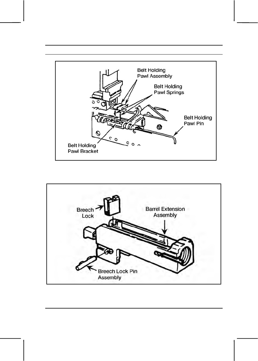
071-022-0001 3-473
Performance Steps
Figure 071-022-0001-25. Installation of the belt holding pawl assembly
c. Assemble barrel extension (figure 071-022-0001-26).
Figure 071-022-0001-26. Assembly of the barrel extension assembly
(1) Install breechblock lock with beveled edge up and to the front
of barrel extension assembly.
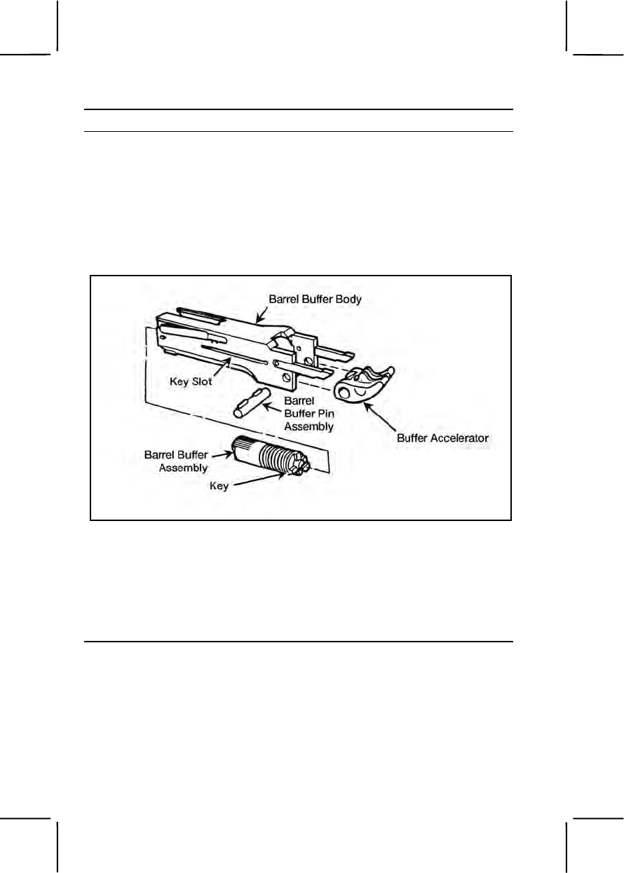
3-474 071-022-0001
Performance Steps
(2) Install breech lock pin assembly in barrel extension. Make
sure both ends of breech lock pin assembly are flush with sides of barrel
extension assembly.
d. Assemble barrel buffer assembly.
(1) Place buffer accelerator (tips up) into barrel buffer body, align
mounting holes, and install buffer pin assembly. Ensure both ends of
barrel buffer pin assembly are flush with sides of barrel buffer body (figure
071-022-0001-27).
Figure 071-022-0001-27. Assembly of the barrel buffer assembly
(2) Align key on barrel buffer assembly with key slot in barrel
buffer body and slide barrel buffer assembly into barrel buffer body.
(3) Hold the barrel buffer assembly with the buffer accelerator up
and engage the notch on the shank of the barrel extension assembly with
the cross groove in the piston rod of the barrel assembly (figure 071-022-
0001-28).
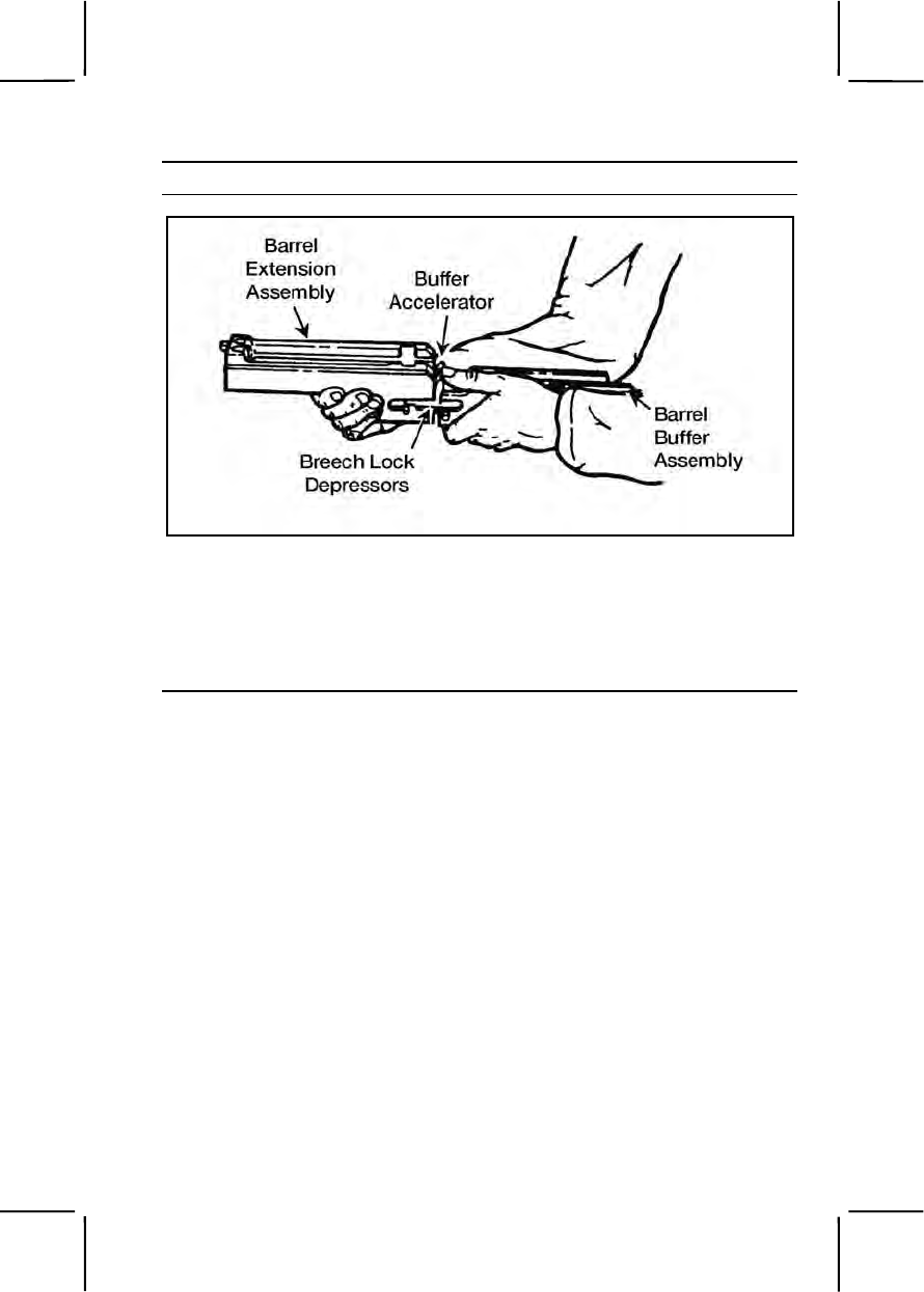
071-022-0001 3-475
Performance Steps
Figure 071-022-0001-28. Attachment of the barrel buffer and
barrel extension assemblies
(4) Align breech lock depressors in grooves of barrel extension
assembly and push barrel buffer assembly forward.
(5) Install barrel buffer assembly and barrel extension assembly in
receiver (figure 071-022-0001-29).
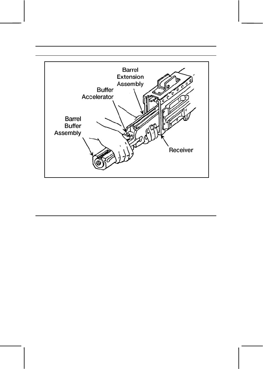
3-476 071-022-0001
Performance Steps
Figure 071-022-0001-29. Installation of the barrel buffer and
barrel extension assemblies
e. Assemble bolt assembly.
(1) Attach firing pin to firing pin extension assembly (figure 071-
022-0001-30).
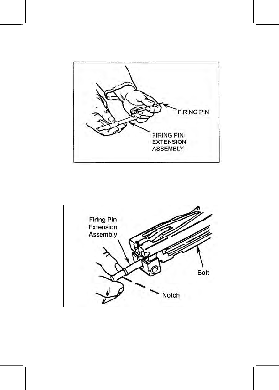
071-022-0001 3-477
Performance Steps
Figure 071-022-0001-30. Attachment of the firing pin to the
firing pin extension assembly
(2) Insert firing pin extension assembly into bolt with notch of firing
pin extension assembly down (Figure 071-022-0001-31).
Figure 071-022-0001-31. Installation of the firing pin extension assembly
(3) Slide firing pin extension assembly forward so tip of firing pin
protrudes from face of bolt.
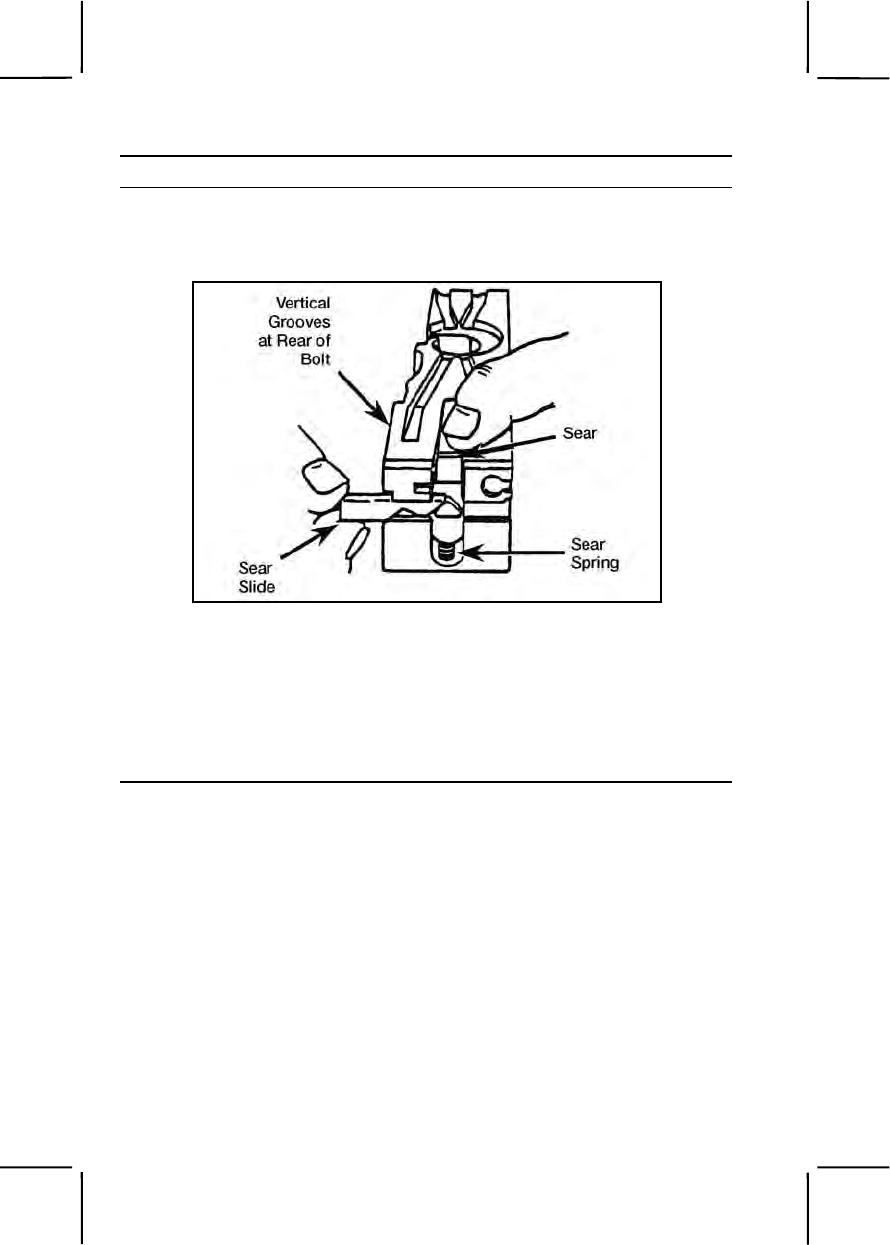
3-478 071-022-0001
Performance Steps
(4) Place sear spring in recess on bolt. Slide sear down into
vertical grooves at rear of bolt with wedge-shaped lug pointed outward
and upward (figure 071-022-0001-32).
Figure 071-022-0001-32. Installation of the sear side
(5) Compress sear spring by pressing down on the sear. Install
sear slide from left side of bolt in grooves of bolt with "V" notch down.
Note. Make sure the pin end of the accelerator is installed behind the firing pin
spring, not through a coil.
(6) Insert pin end of accelerator stop through bottom of bolt (figure
071-022-0001-33).
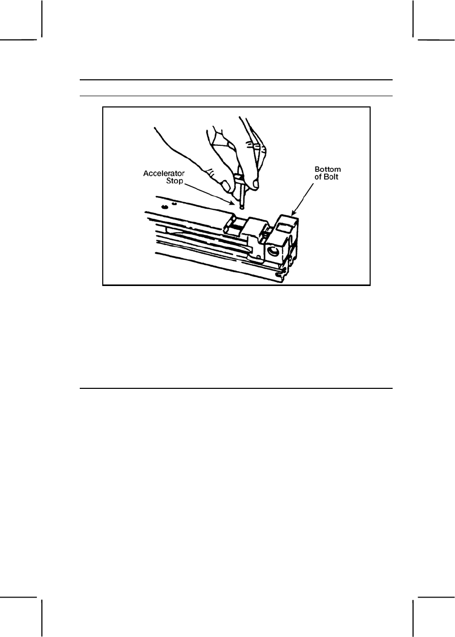
071-022-0001 3-479
Performance Steps
Figure 071-022-0001-33. Attachment of the accelerator stop
Note. Base end of accelerator stop should be installed with long end forward so
beveled edges match.
(7) Turn bolt over. Place forked end of accelerator stop lock on
notched end of accelerator stop.
(8) Using the wedge-shaped end of the cocking lever, press down
on the flat end of the accelerator stop lock, and move the cocking lever
into the groove on the left side of the bolt (figure 071-022-0001-34).
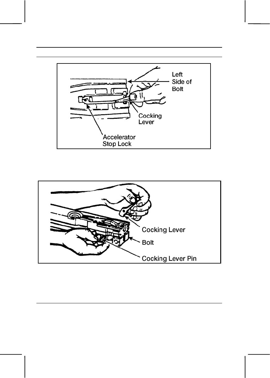
3-480 071-022-0001
Performance Steps
Figure 071-022-0001-34. Attachment of the accelerator stop lock
(9) Insert cocking lever, with rounded nose on lower end of lever
to rear, into slot in top of bolt (figure 071-022-0001-35).
Figure 071-022-0001-35. Attachment of the cocking lever
(10) Align the hole in the cocking lever with the holes in the bolt.
Insert the cocking lever pin from the left side.
(11) Push the cocking lever forward to charge the firing pin. Return
the cocking lever to the rearward position.
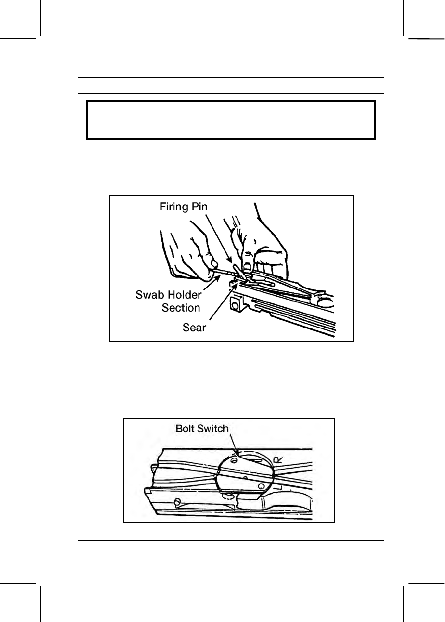
071-022-0001 3-481
Performance Steps
WARNING
Do not try to release the firing pin with the cocking lever forward. The
cocking lever could spring back forcibly and cause serious injury.
(12) Test firing pin release. Trip the firing pin by depressing the top
of the sear with a section of a swab-holder. If doing so makes a sharp
metallic sound, the firing pin spring is in good condition (figure 071-022-
0001-36).
Figure 071-022-0001-36. Testing the firing pin release
(13) Place cocking lever in forward position. Determine the
direction of feed before installing the bolt switch.
(14) Place bolt switch in position so the feed groove is continuous
for feed direction indicated (figure 071-022-0001-37).
Figure 071-022-0001-37. Setting the bolt switch
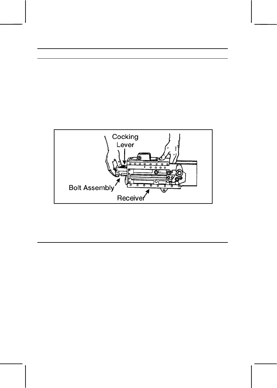
3-482 071-022-0001
Performance Steps
(15) Hold cartridge extractor in vertical position and insert shank
end of cartridge extractor into left side of bolt. Make sure cartridge
extractor fits into bolt as far as possible.
(16) Rotate cartridge extractor downward to full horizontal position.
Check that flange on bottom of cartridge extractor has engaged shoulder
on bolt.
(17) Ensure cocking lever is forward.
(18) Push bolt assembly forward into receiver until bolt latch
engages notches in top of bolt assembly (figure 071-022-0001-38).
Figure 071-022-0001-38. Installation of the bolt assembly
(19) If you cannot install the bolt this way, remove the barrel
extension and buffer assembly from the receiver. Install the bolt
assembly into the barrel extension and buffer assembly, then install them
in the receiver (figure 071-022-0001-39).
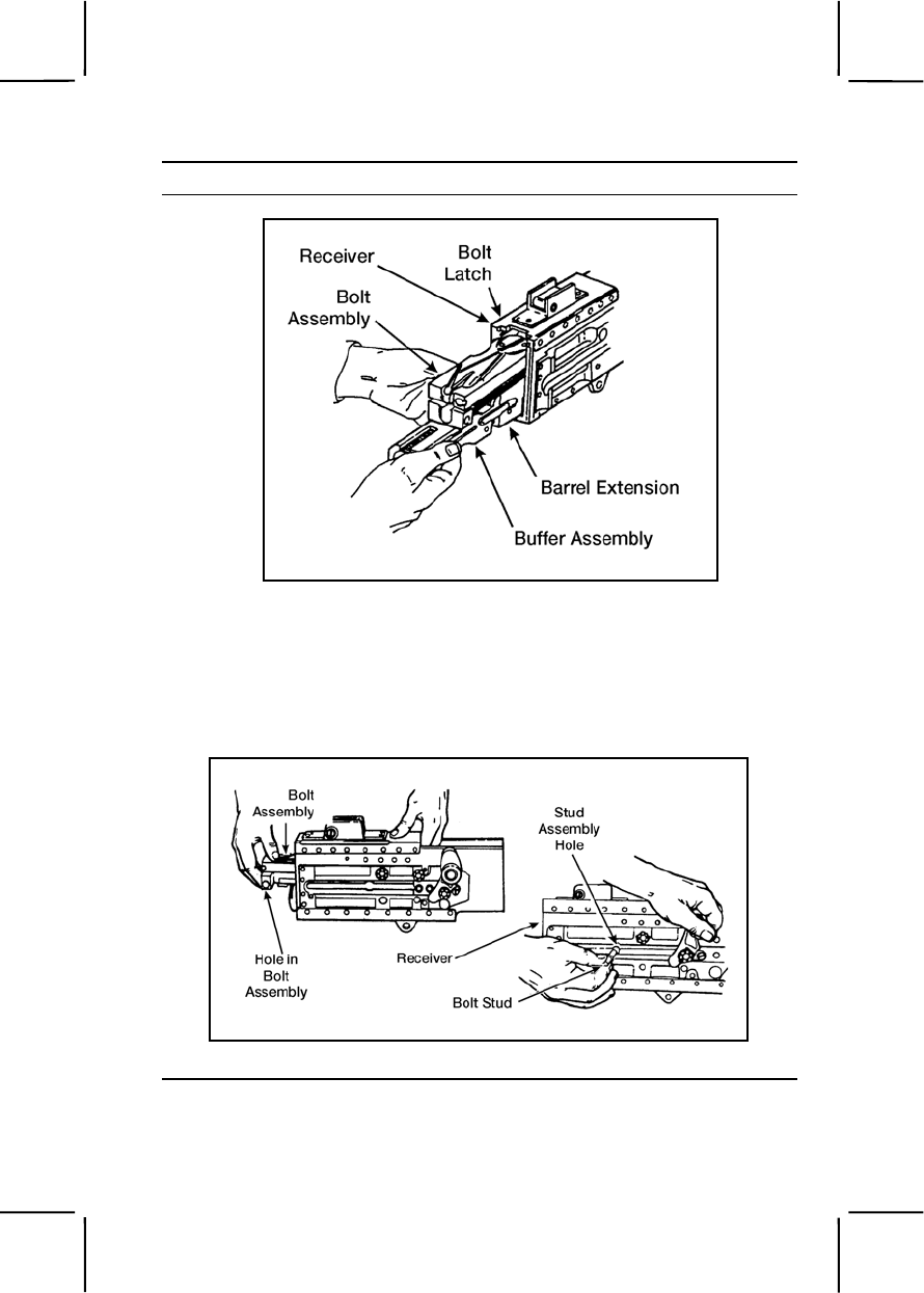
071-022-0001 3-483
Performance Steps
Figure 071-022-0001-39. Installation of the bolt assembly within the
barrel extension and buffer assembly
(20) Raise bolt latch and push bolt assembly into the receiver.
(21) Align holes in bolt assembly with stud assembly hole in
receiver and install bolt stud in hole in bolt assembly. Place bolt in
forward position (figure 071-022-0001-40).
Figure 071-022-0001-40. Installation of the bolt assembly
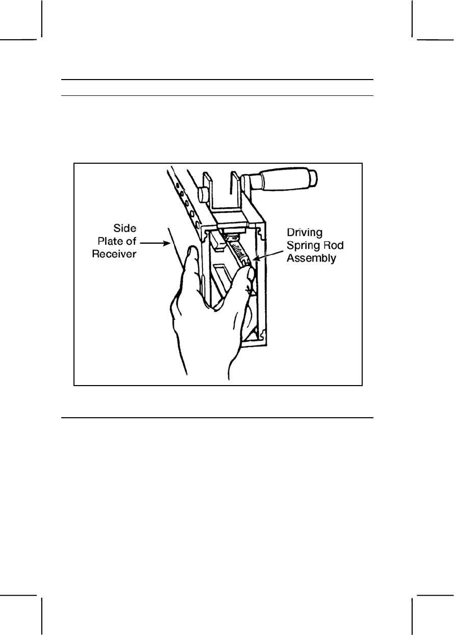
3-484 071-022-0001
Performance Steps
f. Assemble driving spring rod assembly (figure 071-022-0001-41).
Install the driving spring rod assembly in the upper right corner of the bolt.
Push forward and to the right until the driving spring rod assembly
engages in the hole in the side plate of the receiver—not in the groove for
the backplate.
Figure 071-022-0001-41. Installation of the driving spring rod assembly
g. Install backplate assembly (figure 071-022-0001-42).
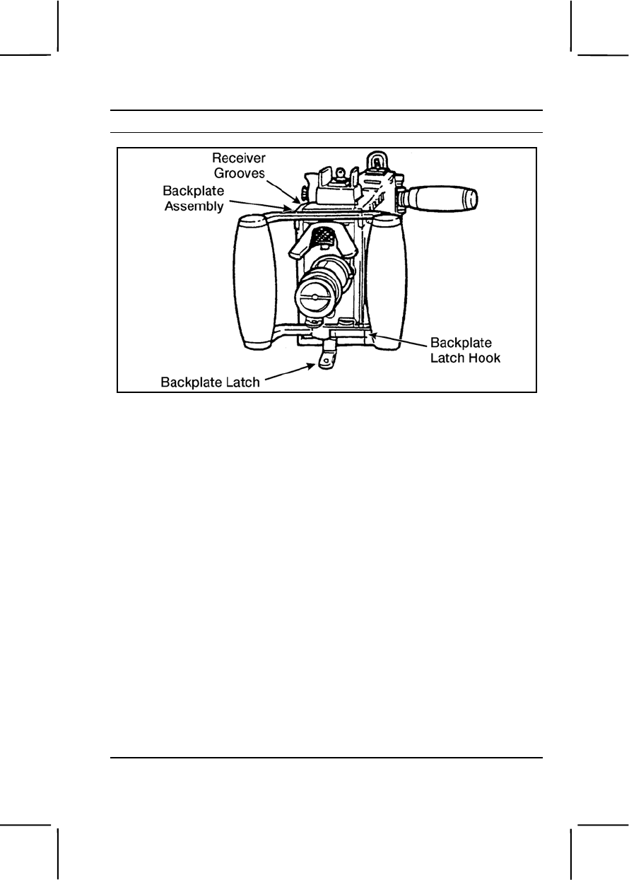
071-022-0001 3-485
Performance Steps
Figure 071-022-0001-42. Installation of the backplate assembly
(1) Align backplate assembly with receiver grooves. Pull
backplate latch lock while lifting up on backplate latch. Lower backplate
assembly down until engaged in receiver.
(2) Test proper locking by pulling up on backplate assembly.
h. Assemble barrel assembly.
(1) Retract bolt far enough for barrel locking spring lug to center in
barrel locking spring hole on right side of receiver.
(2) Place the smallest loop of a caliber .50 link between the
trunnion block and the barrel extension. This holds the barrel locking
spring lug aligned with the 3/8-inch hole.
(3) Install and screw barrel assembly completely into receiver.
Unscrew barrel assembly two clicks and check headspace.
7. Perform a function check to make sure weapon is assembled
correctly.
a. Place the weapon in the single-shot mode.
b. Open the cover and pull the retracting slide handle to the rear.
Bolt should lock to rear in single-shot mode.
c. Hold the retracting slide handle to the rear; depress bolt latch
release and ease the bolt forward.
d. Press trigger; weapon should fire.

3-486 071-022-0001
Performance Steps
e. Place the weapon in the automatic-fire mode.
f. Pull the retracting slide handle to the rear and hold. Bolt should
not lock to rear in automatic-fire mode.
g. Release pressure on the retracting slide handle and ease the bolt
forward.
h. Press trigger; weapon should fire.
Evaluation Preparation:
Setup: At the test site, provide the soldier with equipment listed in conditions.
Use performance steps in the training outline to evaluate soldier's
performance of the task.
Brief Soldier: Tell the soldier to clear, disassemble, clean, inspect, lubricate,
assemble, and perform a function check on the weapon.
Performance Measures GO NO GO
1. Cleared the weapon. —— ——
2. Disassembled the weapon without damaging any
parts. —— ——
3. Cleaned the weapon, components, and ammunition. —— ——
4. Identified any damaged, worn, or malfunctioning
parts. —— ——
5. Lubricated weapon using the correct lubrication
technique. —— ——
6. Assembled weapon in correct sequence without
damaging any parts. —— ——
7. Performed a function check. —— ——
Evaluation Guidance: Score the soldier GO if all performance measures
are passed. Score the soldier NO GO if any performance measure is failed.
If the soldier scores NO GO, show him what was done wrong and how to do
it correctly.
References
Required Related
FM 23-65
TM 9-1005-213-10

071-022-0003 3-487
071-022-0003
Load a Caliber .50 M2 Machine Gun
Conditions: Given a cleared caliber.50 machine gun, mounted on a tripod
or cupola, and linked caliber.50 ammunition.
Standards: Loaded the linked ammunition in the feed tray groove so, when
the cover was closed, a round remained in the tray groove and the
ammunition fed correctly.
Performance Steps
1. Check to ensure weapon is clear.
2. Load ammunition.
a. Ensure the bolt is forward and the cover is closed.
b. Insert the double-loop end of the belt in the feed tray until the belt-
holding pawl engages the first round.
c. With the palm of your hand facing up, pull the retracting slide
handle to the rear and release it. (If the bolt latch release is up, return the
retracting slide handle to the forward position then release the bolt.)
d. With the palm of your hand facing up, pull the retracting slide
handle to the rear a second time and release it. When the bolt goes
forward the second time, the gun is loaded.
e. To set the gun in automatic mode, lock the bolt-latch release down.
f. To set gun in single-shot mode, keep the bolt-latch release
unlocked and in the up position. Release it manually for each round.
Evaluation Preparation:
Setup: Provide the soldier with equipment and materials listed in the
conditions. Evaluate this task in a classroom or training area using dummy
linked caliber.50 ammunition.
Brief Soldier: Tell the soldier to load the weapon using the belt of
ammunition.
Performance Measures GO NO GO
1. Ensured the bolt was forward and the cover was
closed. —— ——
2. Inserted the double-loop end of the belt into the feed
way until the belt-holding pawl held the first round. —— ——

3-488 071-022-0004
Performance Measures GO NO GO
3. Pulled the retracting slide handle to the rear and
released it. If the bolt latch release was up, returned the
retracting slide handle to the forward position, then
released the bolt.
—— ——
4. Pulled the retracting slide handle to the rear a second
time and released it. When the bolt went forward the
second time, the gun was loaded. —— ——
Evaluation Guidance: Score the soldier GO if all performance measures
are passed. Score the soldier NO GO if any performance measure is failed.
If the soldier scores NO GO, show him what was done wrong and how to do
it correctly.
References
Required Related
FM 23-65
TM 9-1005-213-10
071-022-0004
Unload a Caliber .50 M2 Machine Gun
Conditions: Given a caliber .50 M2 machine gun, mounted on a tripod or
cupola, loaded with linked caliber .50 ammunition.
Standards: Removed all ammunition and links from the machine gun.
Cleared the weapon, ensured the chamber was empty and the weapon was
in the single-shot mode.
Performance Steps
1. Unload a cold weapon (less than 200 rounds have been fired from the
weapon).
a. Keep gun oriented on target area.
b. Place the gun in the single-shot mode.
c. Raise the cover.
d. Lift the extractor away from the ammunition belt.
e. Remove the ammunition belt from the feed-way.
f. With palm up, pull the retracting slide handle to the rear to lock the
bolt to the rear.

071-022-0004 3-489
Performance Steps
g. Inspect the chamber and T-slot area to ensure they contain no
ammunition, links, or brass.
h. Hold charging handle, release the bolt and allow the bolt to move
slowly forward.
i. Close the cover.
2. Unload a hot weapon (more than 200 rounds have been fired from the
weapon).
a. Keep gun oriented on target area.
b. Place the gun in the single-shot mode.
c. Fire the round that is in the chamber.
d. Raise the cover and remove the ammunition belt from the feed-way.
e. Press down on the bolt-latch release to allow the bolt to go forward
and chamber the round in the T-slot.
f. Close the cover and fire the round.
g. Open the cover and inspect the chamber and T-slot area to ensure
they contain no ammunition, links, or brass.
h. Hold charging handle, release the bolt and allow the bolt to move
slowly forward.
i. Close the cover.
Evaluation Preparation:
Setup: Provide all equipment and materials listed in the task conditions. You
can evaluate this task in a classroom or training area using dummy linked
caliber .50 ammunition.
Brief Soldier: Tell the soldier to unload and clear the caliber .50 M2 machine
gun.
Performance Measures GO NO GO
1. Placed the gun in the single-shot mode. —— ——
2. Raised the cover. —— ——
3. Removed the ammunition belt from the feed tray. —— ——
4. Closed the cover. —— ——
5. Pulled the bolt to the rear and locked it. —— ——
6. Raised cover and inspected to make sure there were
no rounds in the chamber. —— ——

3-490 071-313-3454
Performance Measures GO NO GO
7. Held charging handle and released the bolt, allowing
it to move slowly forward. —— ——
8. Pressed the trigger. —— ——
Evaluation Guidance: Score the soldier GO if all performance measures
are passed. Score the soldier NO GO if any performance measure is failed.
If the soldier scores NO GO, show him what was done wrong and how to do
it correctly.
References
Required Related
FM 23-65
TM 9-1005-213-10
071-313-3454
Engage Targets with a Caliber .50 M2 Machine Gun
Conditions: Given a zeroed caliber .50 machine gun (tripod or cupola
mounted), linked caliber .50 ammunition, and a sector of fire with
engageable targets.
Standards: Fired the caliber .50 machine gun to engage targets in your
assigned sector of fire. Applied the correct target-engagement techniques so
the entire target was covered with fire.
Performance Steps
1. Assume a suitable firing position. Based on your situation, assume a
firing position that will allow you to observe and engage targets, but reduce
your exposure to enemy fire.
a. Prone position (figure 071-313-3454-1).
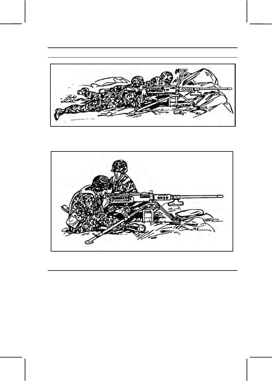
071-313-3454 3-491
Performance Steps
Figure 071-313-3454-1. Prone position (tripod mount)
b. Sitting position (figure 071-313-3454-2).
Figure 071-313-3454-2. Sitting position (tripod mount)
c. Standing position (figure 071-313-3454-3).
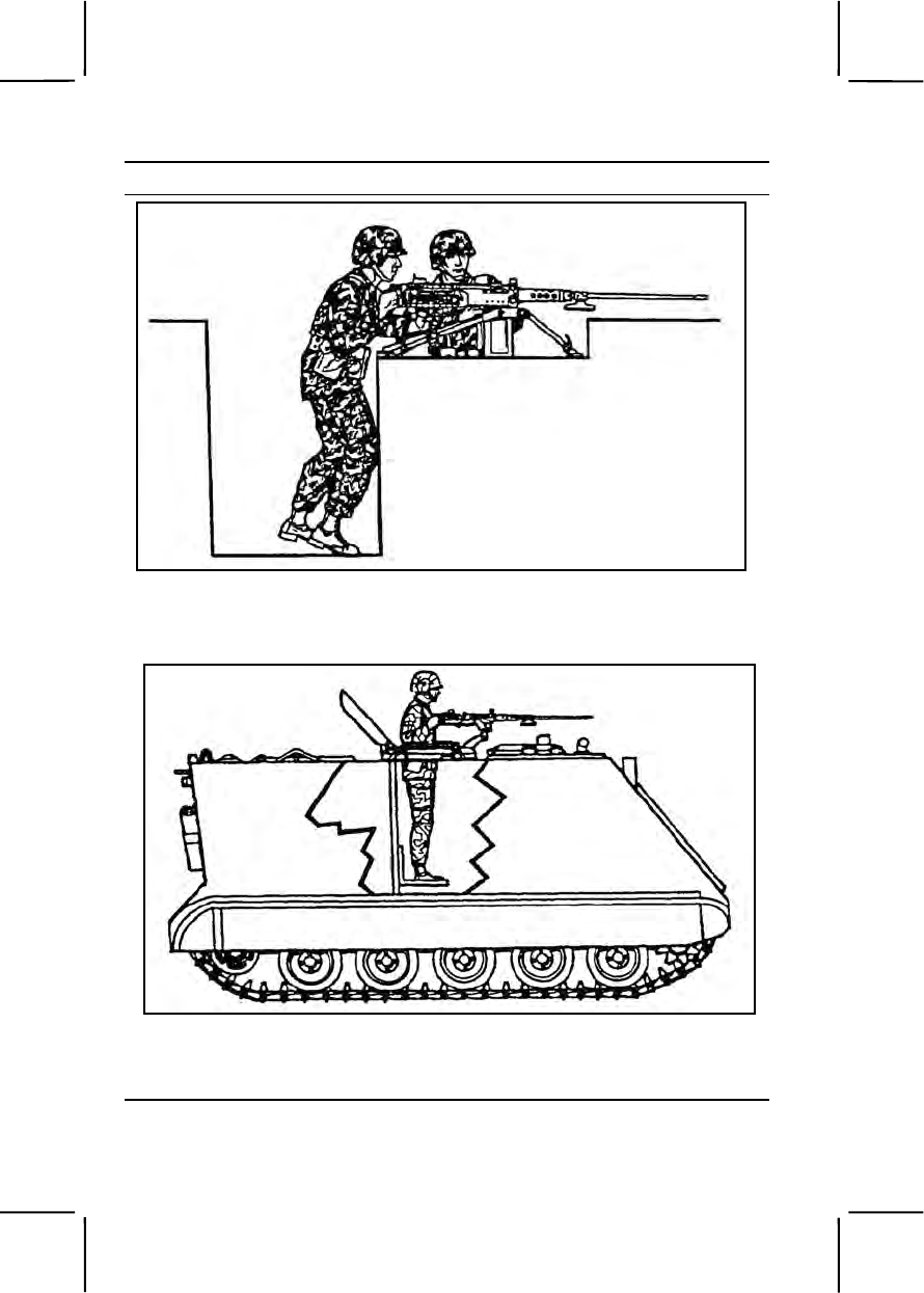
3-492 071-313-3454
Performance Steps
Figure 071-313-3454-3. Standing position (tripod mount)
d. Standing position for cupola-mounted gun (figure 071-313-3454-4).
Figure 071-313-3454-4. Standing position (cupola mount)
e. Standing position for high-mobility, multipurpose wheeled vehicle
(HMMWV)-mounted gun (figure 071-313-3454-5).
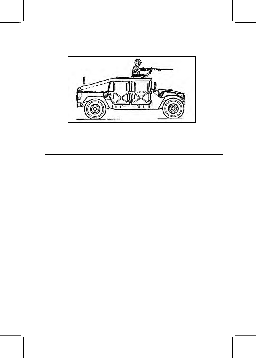
071-313-3454 3-493
Performance Steps
Figure 071-313-3454-5. Standing position (HMMWV mount)
2. Obtain the correct sight picture.
a. Sight alignment. Center the front sight post in the peep sight (figure
071-313-3454-6).
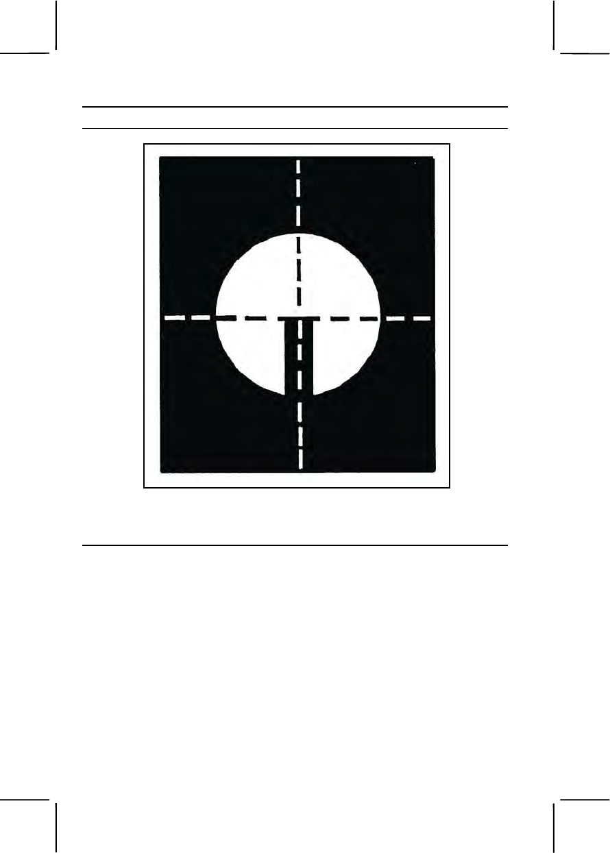
3-494 071-313-3454
Performance Steps
Figure 071-313-3454-6. Correct sight alignment
b. Sight picture. Place top center of front sight blade at bottom center
of intended target (figure 071-313-3454-7).
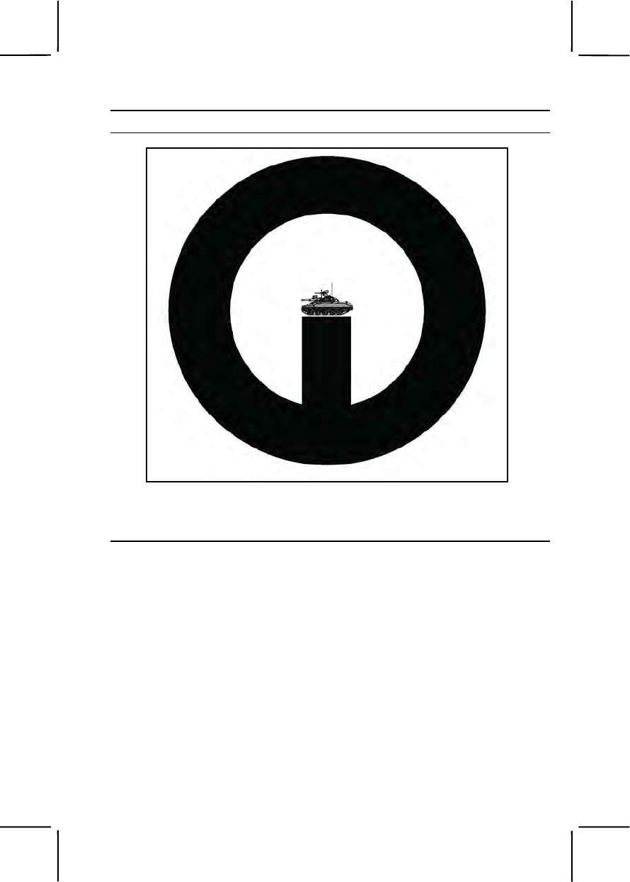
071-313-3454 3-495
Performance Steps
Figure 071-313-3454-7. Correct sight picture
3. Apply the correct engagement technique based on target type (figure
071-313-3454-8).
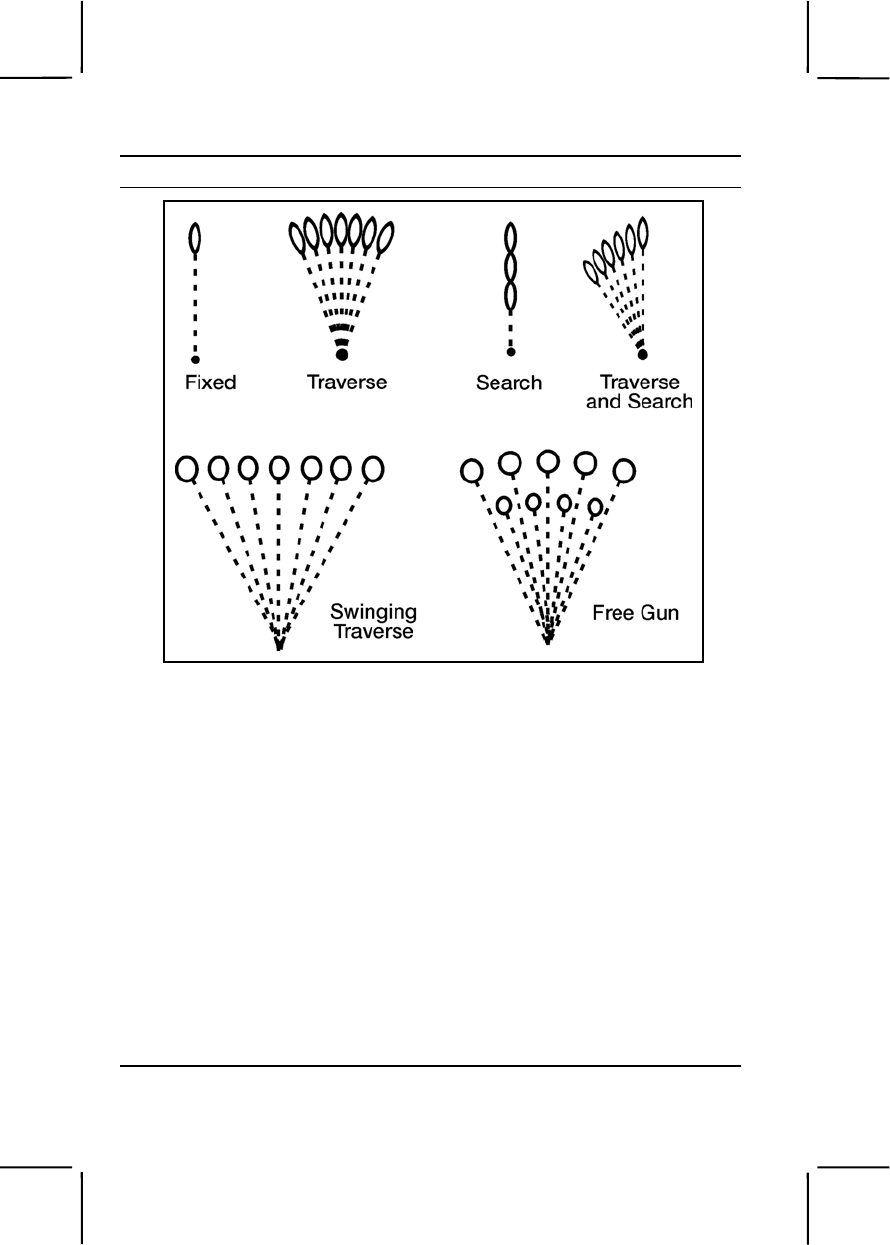
3-496 071-313-3454
Performance Steps
Figure 071-313-3454-8. Techniques of fire with respect to the gun
a. Use the correct gun manipulation technique.
(1) Fixed fire. Refers to fire delivered against a point target. Only
one aiming point is necessary, with little or no manipulation of the gun.
(2) Traversing fire. Refers to fire distributed against a wide target,
requiring successive changes in the gun direction. To distribute fire
laterally, use the T&E mechanism to traverse the gun left or right.
(3) Searching fire. Refers to fire delivered against a deep target or
a linear target with depth by successively changing elevation. To distribute
fire in depth, use the T&E mechanism to move the muzzle of the weapon
up or down.
(4) Traversing and searching fire. Refers to fire delivered in width
and depth by successive changes in direction and elevation. Use this type
of fire against a target whose long axis is oblique to the direction of fire.
(5) Swinging traverse. Refers to fire delivered against targets that
require major changes in direction but little or no change in elevation.
Loosen the traversing slide lock enough to swing the gun laterally.

071-313-3454 3-497
Performance Steps
(6) Free gun. Refers to fire delivered against moving targets that
must be rapidly engaged with fast changes in direction and elevation. To
fire free gun, remove the T&E mechanism.
b. Correctly apply fire to engage specific targets.
(1) Point target. Engage point targets with fixed fire using a single
aiming point (figure 071-313-3454-9).
Figure 071-313-3454-9. Point target
(2) Linear target. Initially aim at the midpoint of the target.
Traverse fire to one flank and then to the other to cover the entire target
(figure 071-313-3454-10).
Figure 071-313-3454-10. Linear target and one gun
(3) Linear target with depth. Initially aim at the midpoint of the
target, unless another portion of the target is more critical or presents a
greater threat. Traverse and search to the flank closest to your position,
then back to the other flank, so you cover the entire target (figure 071-313-
3454-11).

3-498 071-313-3454
Performance Steps
Figure 071-313-3454-11. Linear target with depth
(4) Deep target. Initially aim at the midpoint of the target, unless
another portion of the target is more critical or presents a greater threat.
Search down to the near end, then search up to the far end (figure 071-
313-3454-12).
Figure 071-313-3454-12. Deep target
(5) Area target. Initially aim at midpoint of the target area.
Traverse and search to either flank, then traverse and search to the
opposite flank (figure 071-313-3454-13).
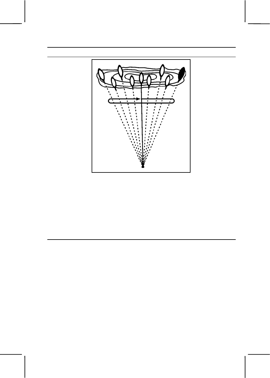
071-313-3454 3-499
Performance Steps
Figure 071-313-3454-13. Engagement of area targets
4. Observe fire and adjust the aiming point to place effective fire on the
target.
a. Observation of fire. Observe bursts of fire by noting tracers in flight
or the strike of the rounds in the target area.
b. Adjusted aiming point. Adjust fire quickly without adjusting the
sight. If the initial burst misses the target, rapidly select a new aiming point
the same distance from the center of impact of the initial burst but in the
opposite direction. Fire a second burst (figure 071-313-3454-14).
3-500 071-313-3454
Performance Steps
Figure 071-313-3454-14. Adjusted aiming point method
5. Fire on the targets until they are all destroyed, or until you receive an
order to cease fire.
Evaluation Preparation:
Setup: Evaluate this task on a 10-meter live-fire range equipped with the
basic machine gun target pasters (FSN 6920-078-5128). Provide the soldier
with a caliber .50 M2 machine gun (tripod mounted) with 236 rounds of
linked caliber .50 ammunition (117 rounds for practice and 119 rounds for
qualification). Conduct 10-meter firing according to FM 23-65, appendix C,
table I.
Brief Soldier: Tell the soldier he will fire table I according to FM 23-65,
appendix C (brief the conditions, standards, and ammunition). Tell the
soldier that, when you instruct him to fire, you will evaluate his ability to apply
correct target engagement techniques and to place effective fire on targets.
Performance Measures GO NO GO
1. Assumed a suitable firing position. —— ——
2. Applied correct engagement technique based on
target type. —— ——
a. Used correct gun manipulation technique.
b. Used correct application of fire to engage specific
targets.

071-054-0001 3-501
Performance Measures GO NO GO
3. Placed effective fire on targets (score a minimum of
84 points). —— ——
Evaluation Guidance: Score the soldier GO if all performance measures
are passed. Score the soldier NO GO if any performance measure is failed.
If the soldier scores NO GO, show him what was done wrong and how to do
it correctly.
References
Required Related
FM 23-65
TM 9-1005-213-10
SUBJECT AREA 15: M136 LAUNCHER
071-054-0001
Prepare an M136 Launcher for Firing
Conditions: Given an M136 launcher (AT4) and a requirement to prepare it
for firing.
Standards: Performed prefire checks on the M136 AT4 and prepared the
round for firing.
Performance Steps
Note. Because the M136 launcher is issued as a round of ammunition rather than as
a weapon, the launcher is completely used; therefore, inspection is limited to visual
examination of the external components.
1. Perform the prefire checks. The overall condition of the launcher should
be inspected before it is used (figure 071-054-0001-1). The firer should
ensure—
a. The transport safety pin is in place and fully seated and the lanyard
is attached.
b. The cocking lever is in the SAFE position and folded down.
c. The fire-through muzzle cover is intact. If the seal is torn, it should
be removed to ensure that no foreign objects have gotten into the launcher.
d. The launcher's color-coded band is the correct color: black for high-
explosive antitank, gold for target-practice tracers, and blue for field-
handling trainers.
3-502 071-054-0001
Performance Steps
e. The sights function properly. Open the sight covers to ensure the
sights pop up and are not damaged.
f. The red safety catch does not move when depressed.
g. The rear seal is not damaged.
h. The shoulder stop is not broken or damaged and it unsnaps and
folds down.
i. The carrying sling is not frayed and is attached to the launcher.
j. The launcher body has no cracks, dents, or bulges.
Figure 071-054-0001-1. Parts of the M136 launcher to be inspected
2. Prepare the launcher for firing. Preparation procedures are—
a. Remove the launcher from the carrying position and cradle it with
the left arm (figure 071-054-0001-2).
071-054-0001 3-503
Performance Steps
Figure 071-054-0001-2. Cradle position
b. While cradling the launcher, pull the transport safety pin with the
right hand and release it (figure 071-054-0001-3).
Figure 071-054-0001-3. Removing the transport safety pin
3-504 071-054-0001
Performance Steps
Note. Ensure the transport safety pin is attached to the launcher by its lanyard.
If the launcher has no lanyard, place the transport safety pin in your pocket.
If the launcher remains unfired, reinsert the transport safety pin.
WARNINGS
Make sure personnel wear earplugs.
Point the weapon toward the target.
Clear the back blast area.
c. Unsnap and unfold the shoulder stop (figure 071-054-0001-4).
Figure 071-054-0001-4. Unsnapping the shoulder stop
d. With the shoulder stop in position, place the launcher on the right
shoulder.
e. With the launcher on the right shoulder and supported with the left
hand, release the front sight by pressing down on the sight cover and
sliding it to the rear. Release the rear sight by pressing down on the cover
and sliding it forward. Sliding the covers off allows the sights to pop up.
f. Check the backblast area.
g. Cock the launcher by unfolding the cocking lever with the right
hand. Place the thumb of the right hand under the cocking lever. Grip the
front of the firing mechanism for support. Push the cocking lever forward to
the right. Let the cocking lever slide back (figure 071-054-0001-5).
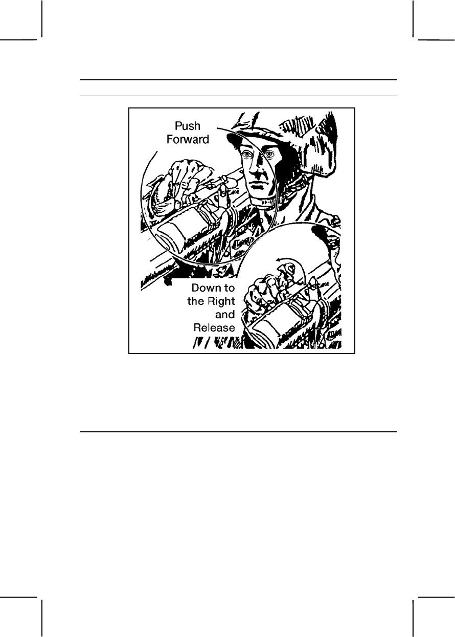
071-054-0001 3-505
Performance Steps
Figure 071-054-0001-5. Cocking the launcher
h. Adjust the rear sight for the required range.
(1) When closing the sight cover, set the sight on a range of 200
meters. When the rear sight is uncovered, the battlesight setting is 200
meters. If the range to the target is more than 200 meters but less than 250
meters, no sight adjustment is required (figure 071-054-0001-6).
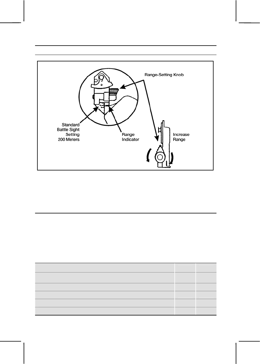
3-506 071-054-0001
Performance Steps
Figure 071-054-0001-6. Adjusting the rear sight
(2) To adjust the rear sight range setting to more than 200 meters,
turn the range knob clockwise (toward the muzzle). To decrease the range,
turn the range knob counterclockwise (toward the gunner). There is a click
at each 50-meter increment; this sound aids you during limited visibility
(figure 071-054-0001-6).
Evaluation Preparation:
Setup: At the test site, provide an expended AT4 or a tracer trainer in the
carrying configuration; have the soldier place it in the carrying position. Tell
the soldier the range to the target. Ask the soldier when the rear sight
requires adjustment.
Brief Soldier: Tell the soldier to prepare the launcher to fire. Tell the soldier
he will be required to answer questions about the launcher.
Performance Measures GO NO GO
1. Performed the prefire checks. —— ——
a. Checked the transport safety pin.
b. Ensured the cocking lever was on SAFE.
c. Checked the fire-through muzzle cover.
d. Checked the color-coded band.

071-054-0002 3-507
Performance Measures GO NO GO
e. Checked the front and rear sights.
f. Checked the red safety catch.
g. Checked the rear seal.
h. Checked the shoulder stop.
i. Checked the carrying sling.
j. Checked the body of the launcher.
2. Prepared the launcher for firing. —— ——
a. Removed the transport safety pin.
b. Unsnapped and unfolded the shoulder stop.
c. Placed the launcher on the right shoulder.
d. Released the front and rear sights.
e. Checked the back-blast area.
f. Cocked the launcher.
g. Adjusted the rear sight.
Evaluation Guidance: Score the soldier GO if all performance measures
are passed. Score the soldier NO GO if any performance measure is failed.
If the soldier scores NO GO, show him what was done wrong and how to do
it correctly.
References
Required Related
FM 3-23.25
071-054-0002
Restore an M136 Launcher to Carrying Configuration
Conditions: Given an M136 launcher (AT4) prepared for firing and the
requirement to restore the launcher to carrying configuration.
Standards: Restored the launcher to a safe carrying configuration without
damaging the equipment.
Performance Steps
Note: The launcher is prepared for immediate firing but is not fired.
1. If the gunner remains in the same position, he should—

3-508 071-054-0002
Performance Steps
(a) Release the red safety catch (this step applies only if the firing
sequence has proceeded to this point).
(b) Return the cocking lever to the SAFE (uncocked) position by
pushing it up and to the left, then pulling it rearward and fold the cocking
lever down.
(c) Keep the launcher pointed at the target area, and remove the
launcher from his shoulder.
(d) Replace the transport safety pin, with the launcher cradled in his
left arm.
2. If the gunner is to move to another position, in addition to the steps
shown above, he must—
(a) Return the rear sight to the battlesight setting of 200 meters, fold
down the front and rear sights, and close the sight covers.
CAUTION
The rear sight may be damaged if it is not returned to a battlesight setting of 200
meters before closing the sight cover.
(b) Fold the shoulder stop and snap it back into position.
Evaluation Preparation:
Setup: At the test site, provide an expended AT4 or a tracer trainer. The AT4
or tracer trainer is in the ready to fire configuration.
Brief Soldier: Tell the soldier to assume a correct standing, ready-to-fire
position with the launcher. Once he has assumed the firing position, tell him
to return the launcher to the carrying configuration.
Performance Measures GO NO GO
Note. The performance measures are scored in sequence.
1. Released the red safety catch. —— ——
2. Returned the cocking lever to the SAFE position and
folded the cocking lever down. —— ——
3. Removed the launcher from the shoulder and cradled
it with the left arm. —— ——
4. Replaced the transport safety pin. —— ——
5. Returned the rear sight to the battlesight setting. —— ——
6. Folded and covered the sights. —— ——
7. Folded the shoulder stop and snapped it in place. —— ——
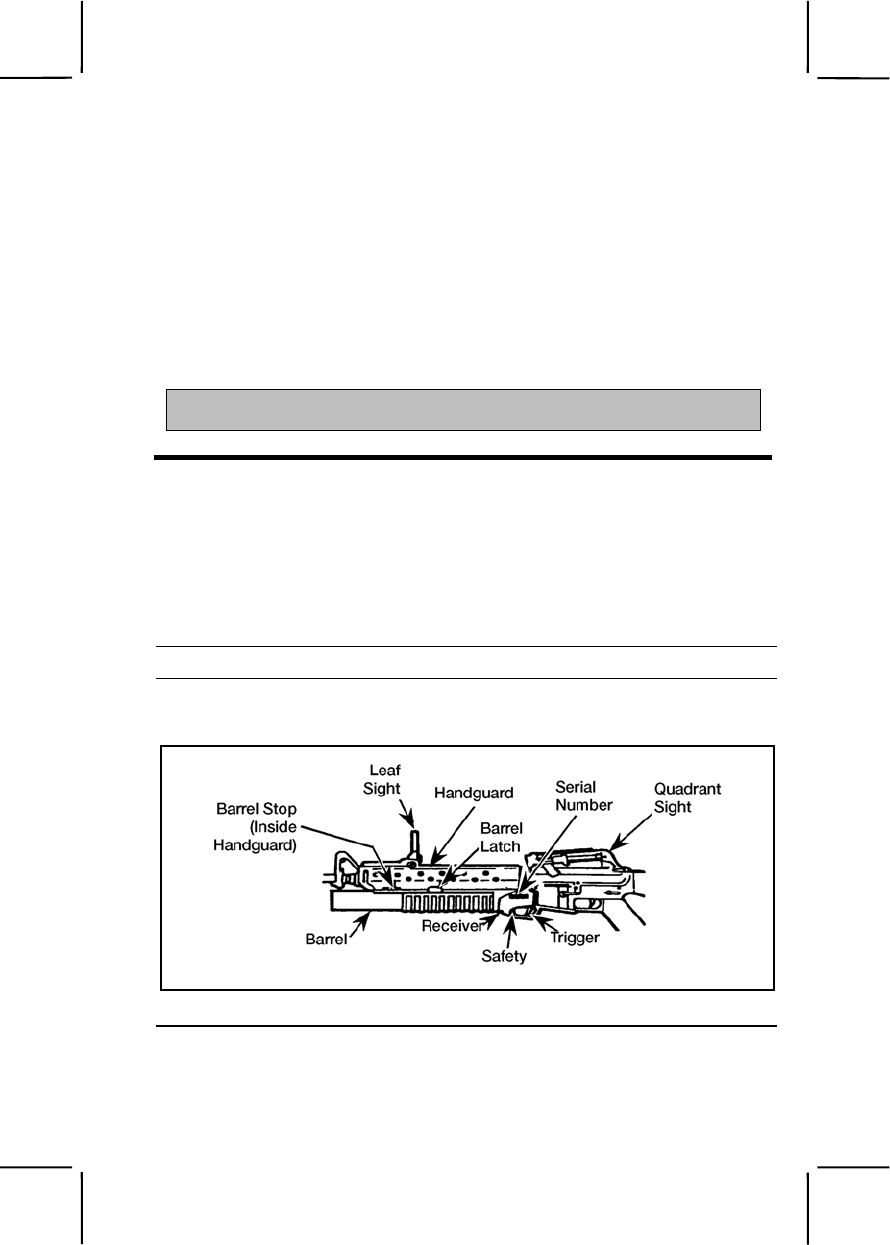
071-311-2125 3-509
Evaluation Guidance: Score the soldier GO if all performance measures
are passed. Score the soldier NO GO if any performance measure is failed.
If the soldier scores NO GO, show him what was done wrong and how to do
it correctly.
References
Required Related
FM 3-23.25
TM 9-1315-886-12
SUBJECT AREA 16: M203 GRENADE LAUNCHER
071-311-2125
Maintain an M203 Grenade Launcher
Conditions: Given an M203 grenade launcher; cleaner, lubricant,
preservative (CLP); thong; bore brush; and clean rags.
Standards: Cleared the M203 grenade launcher; disassembled the M203;
cleaned and lubricated the M203; inspected the M203 before assembly;
assembled the M203; and performed a function check on the M203.
Performance Steps
1. Clear the M203 grenade launcher.
2. Disassemble the M203 (figure 071-311-2125-1).
Figure 071-311-2125-1. Components of the M203 grenade launcher
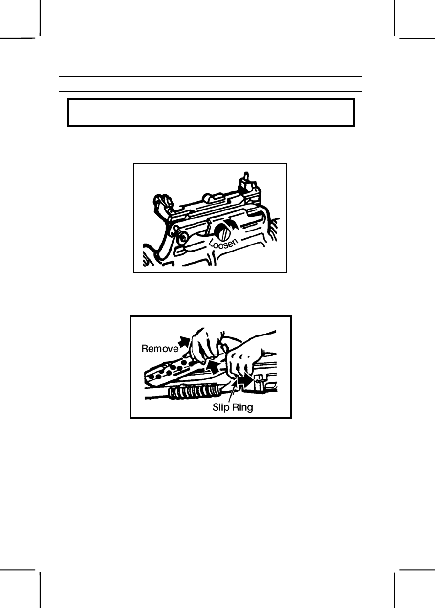
3-510 071-311-2125
Performance Steps
WARNING
Before disassembling the weapon, clear the rifle and grenade launcher.
a. Remove the quadrant sight (if used) by loosening the knurled screw
on the right side (figure 071-311-2125-2).
Figure 071-311-2125-2. Removing quadrant sight
b. Pull back the slip ring. Lift up on the handguard and pull it to the
rear to remove (figure 071-311-2125-3).
Figure 071-311-2125-3. Removing handguard
c. Press the barrel latch and move the barrel forward to the barrel stop
(figure 071-311-2125-4).
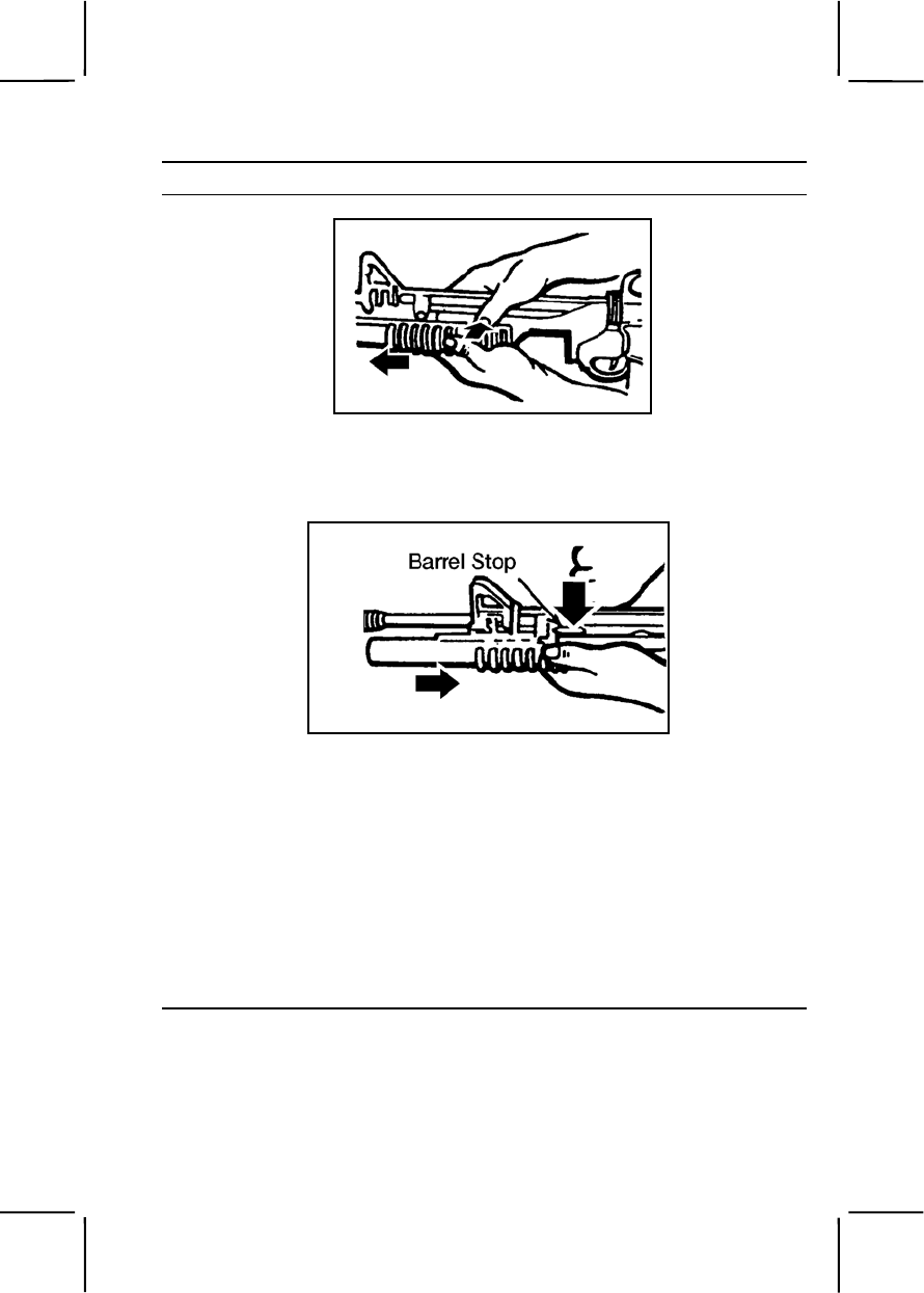
071-311-2125 3-511
Performance Steps
Figure 071-311-2125-4. Unlocking and opening the M203 barrel
d. Press the barrel stop to release the barrel from the receiver and
remove the barrel (figure 071-311-2125-5).
Figure 071-311-2125-5. Removing the M203 barrel
Note. Further disassembly may be performed only by the armorer.
3. Clean and lubricate the M203.
a. Bore. Attach a clean, dry rag to the thong and thoroughly moisten
the rag with CLP. Pull the rag through the bore several times. Attach the
bore brush to the thong, pull it through the bore several times, and follow
this with more rags, moistened with CLP, if needed (figure 071-311-2125-
6). Pull dry rags through the bore and inspect each rag as it is removed.
The bore is clean when a dry rag is removed unfouled. Pull a rag lightly
moistened with CLP through the bore to leave a light coat of lubricant
inside the barrel.
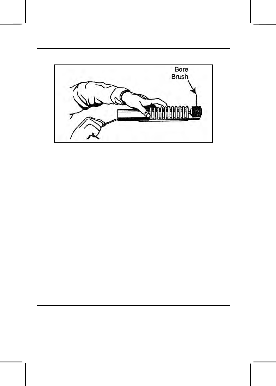
3-512 071-311-2125
Performance Steps
Figure 071-311-2125-6. Cleaning the M203 barrel
b. Breech insert. Clean the face of the breech insert retainer with a
patch and CLP. Remove the CLP cleaner with dry rags, then lubricate the
breech with a light coat of CLP.
c. All other parts. Use a brush and dry rags to clean all other parts
and surfaces. Apply a light coat of CLP to the exterior of the launcher after
cleaning.
d. Safety mechanism. Clean the safety mechanism properly with
CLP. Lubricate the safety with CLP.
Note. For cleaning the rifle portion of the launcher, refer to Task 071-311-2025.
4. Inspect the M203 before assembly.
a. Check handguard for cracks, dents, or distortion that prevent its firm
attachment to the rifle.
b. Check leaf sight for bent or damaged parts and for rust or corrosion.
c. Check leaf sight for legibility of marking.
d. Check barrel for cracks and general condition. Inspect all parts for
wear and damage.
e. Check for burrs, scratches, nicks, or other damage.
5. Assemble the M203.
a. Press the barrel stop. Slide the barrel into the receiver (figure 071-
311-2125-7).
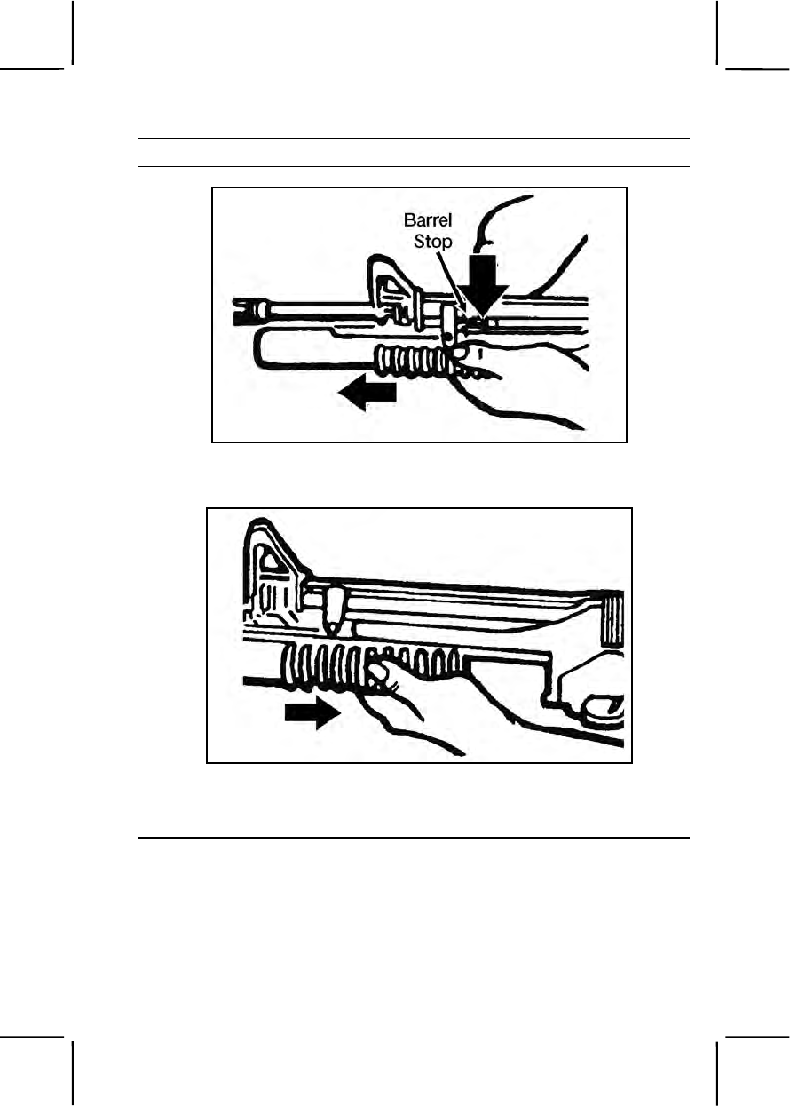
071-311-2125 3-513
Performance Steps
Figure 071-311-2125-7. Installing the M203 barrel
b. Move the barrel rearward to lock (figure 071-311-2125-8).
Figure 071-311-2125-8. Locking the M203 barrel
c. Install the handguard and secure with the slip ring (figure 071-311-
2125-9).

3-514 071-311-2125
Performance Steps
Figure 071-311-2125-9. Installing the handguard
d. Install the quadrant sight (figure 071-311-2125-10).
Figure 071-311-2125-10. Installing the quadrant sight
6. Perform a function check on the M203.
a. Check the proper operation of the sears. Cock the launcher and
pull the trigger. The firing pin should release. Hold the trigger to the rear
and cock the launcher. Release the trigger, then pull. The firing pin should
release.
b. Check the safety in both SAFE and FIRE positions with trigger.
Launcher must be cocked before safety can be placed in SAFE position.

071-311-2125 3-515
Performance Steps
c. Check the leaf sight windage adjustment screw for proper
operation. Do not move the elevation adjustment screw if the weapon has
been zeroed.
d. Move barrel forward and back to be sure the stop and barrel latch
function.
Evaluation Preparation:
Setup: At the test site, provide all materials and equipment given in the task
conditions.
Brief Soldier: Tell the soldier he will perform unit maintenance on the M203
grenade launcher.
Performance Measures GO NO GO
1. Cleared the M203 grenade launcher. —— ——
2. Disassembled the M203. —— ——
a. Removed the quadrant sight.
b. Pulled back the slip ring.
c. Moved the barrel forward to the barrel stop.
d. Removed the barrel.
3. Cleaned and lubricated the M203. —— ——
a. Cleaned the bore.
b. Cleaned the breech insert.
c. Cleaned all other parts.
d. Cleaned the safety mechanism.
4. Inspected the M203 before assembly. —— ——
a. Checked the handguard.
b. Checked the leaf sight.
c. Checked the barrel.
d. Checked for burrs, scratches, and other damage.
5. Assembled the M203. —— ——
a. Slid the barrel into the receiver.
b. Closed the barrel.
c. Installed the handguard.
d. Installed the quadrant sight.

3-516 071-311-2127
Performance Measures GO NO GO
6. Performed a function check on the M203. —— ——
a. Checked operation of the sears.
b. Checked safety in both the SAFE and the FIRE
positions.
c. Checked the leaf sight windage adjustment
screws for proper operation.
d. Checked the barrel latch and the stop function.
Evaluation Guidance: Score the soldier GO if all performance measures
are passed. Score the soldier NO GO if any performance measure is failed.
If the soldier scores NO GO, show him what was done wrong and how to do
it correctly.
References
Required Related
FM 23-31
TM 9-1010-221-10
071-311-2127
Load an M203 Grenade Launcher
Conditions: Given an M203 grenade launcher, ammunition, and a
requirement to load the weapon.
Standards: Inserted ammunition into the chamber without damaging the
equipment or injuring personnel. Followed all safety procedures in
accordance with TM 9-1010-221-10.
Performance Steps
WARNING
Keep muzzle down range and clear of all troops.
1. Ensure that the safety switch is in the SAFE (“S”) position until ready to
fire.
2. Depress the barrel latch.
3. Slide the barrel assembly forward (extraction and cocking automatically
take place during this step).
4. Before loading, make sure that the bore and chamber are clean and
dry.

071-311-2127 3-517
Performance Steps
5. Insert the ammunition into the chamber.
WARNING
Do not fire pyrotechnic ammunition made for the AN-M8 pyrotechnic
pistol in the M203 grenade launcher. Make sure you have the right
ammunition. Never load aircraft ammunition M384 (HE) or M385
(practice). It could result in serious injury.
6. Slide the barrel closed until it locks and clicks.
Evaluation Preparation:
Setup: At the test site, in an outside field environment, provide all equipment
and materials listed in the task condition statement.
Brief Soldier: Tell the soldier to load the M203 grenade launcher and to
perform all steps correctly.
Performance Measures GO NO GO
1. Ensured that the safety switch was in the SAFE (“S”)
position until ready to fire. —— ——
2. Pressed the latch and slid the barrel forward. —— ——
3. Before loading, made sure that the bore and
chamber were cleaned and dried. —— ——
4. Inserted the ammunition into the chamber. —— ——
5. Slid the barrel closed until it locked and clicked. —— ——
Evaluation Guidance: Score the soldier GO if all performance measures
are passed. Score the soldier NO GO if any performance measure is failed.
If the soldier scores NO GO, show him what was done wrong and how to do
it correctly.
References
Required Related
FM 23-31
TM 9-1010-221-10

3-518 071-311-2128
071-311-2128
Unload an M203 Grenade Launcher
Conditions: Given a loaded M203 grenade launcher and a requirement to
unload it.
Standards: Pressed the latch and moved the barrel forward to eject
ammunition. Caught the round as it dropped.
Performance Steps
Note. If weapon has been fired and only shell casing is in chamber, disregard step 3
and the requirement for slow movement in step 4.
1. Place safety in the ON position.
2. Depress the barrel latch.
3. Place one hand under the barrel assembly forward of the trigger guard.
4. Slowly slide the barrel assembly forward (the round will eject).
5. Secure the round.
Evaluation Preparation:
Setup: At the test site, in an outside field environment, provide all equipment
and materials listed in the task conditions statement.
Brief Soldier: Tell the soldier to unload the M203 grenade launcher,
performing all steps correctly.
Performance Measures GO NO GO
1. Pressed the latch. —— ——
2. Moved the barrel forward. —— ——
Note. The round extracts and ejects automatically.
3. Caught the round—did not let it drop. —— ——
Evaluation Guidance: Score the soldier GO if all performance measures
are passed. Score the soldier NO GO if any performance measure is failed.
If the soldier scores NO GO, show him what was done wrong and how to do
it correctly.
References
Required Related
FM 23-31
TM 9-1010-221-10

071-311-2129 3-519
071-311-2129
Correct Malfunctions of an M203 Grenade Launcher
Conditions: Given an M203 grenade launcher mounted on an M16-series
rifle and 40-mm ammunition. The grenade launcher has failed to function or
fire.
Standards: Corrected malfunctions of an M203 grenade launcher. Followed
all safety precautions according to TM 9-1010-221-10.
Performance Steps
1. Keep the weapon pointed at the target and keep all soldiers clear of the
muzzle (at least 80 meters or 264 feet).
Note. M203 malfunctions consist of hangfires and misfires. A hangfire is a delay in
the propellant's igniting. A misfire is a failure to fire. Both are handled in the same
way because they are often indistinguishable.
2. Wait 30 seconds from the time of the failure to fire, then open the
breech.
3. Remove the round from the breech.
a. Release the barrel latch.
b. Slide the barrel forward to eject the round.
c. Either catch the ejected round or reduce the distance the round falls
by holding the weapon close to the ground.
d. If the round does not eject, tap the casing with the rifle cleaning rod.
e. If the casing cannot be removed, notify the NCOIC or unit
maintenance.
4. Examine the primer to determine whether the round or the firing
mechanism is defective.
a. If the primer is dented, keep the damaged round separate from
other ammunition until it can be disposed of properly.
b. If the primer is not dented, the firing mechanism is faulty. Report it
to the NCOIC or unit maintenance.
Note. If the primer is not dented, the round may be reloaded on an operational
M203.
Evaluation Preparation:
Setup: Provide all materials listed in the task conditions. Use dummy
ammunition for training.
Brief Soldier: Tell the soldier he must assume a firing position to apply any
required immediate action.

3-520 071-311-2129
Performance Measures GO NO GO
1. Kept the weapon pointed at the target and kept all
troops clear of the muzzle (at least 80 meters or 264
feet). —— ——
2. Waited 30 seconds from the time of the failure to fire,
then opened the breech. —— ——
3. Removed the round from the breech. —— ——
a. Released the barrel latch.
b. Slid the barrel forward to eject the round.
c. Caught either the ejected round or reduced the
distance the round fell by holding the weapon close to
the ground.
d. If the round did not eject, tapped the casing with
the rifle cleaning rod.
e. If casing could not be removed, notified the
NCOIC or unit maintenance.
4. Examined the primer to determine whether the round
or the firing mechanism was defective. —— ——
a. If the primer was dented, kept the damaged
round separate from other ammunition until it could be
disposed of properly.
b. If the primer was not dented, reported the faulty
firing mechanism to the NCOIC or unit maintenance.
Evaluation Guidance: Score the soldier GO if all performance measures
are passed. Score the soldier NO GO if any performance measure is failed.
If the soldier scores NO GO, show him what was done wrong and how to do
it correctly.
References
Required Related
FM 23-31
TM 9-1010-221-10

071-311-2130 3-521
071-311-2130
Engage Targets with an M203 Grenade Launcher
Conditions: Given a zeroed M203 grenade launcher mounted on an M16-
series or M4-series rifle, enemy targets located within engagement ranges,
and sufficient ammunition.
Standards: Destroyed or disabled enemy targets without causing injury or
death to friendly personnel.
Performance Steps
Note. This task may be performed using either of two sights found on the system.
WARNING
Keep muzzle pointed downrange and clear of all friendly troops.
1. Keep the safety in the SAFE position until ready to fire.
2. Load the M203 grenade launcher (Task 071-311-2127).
WARNING
Fire high-explosive (HE) grenades at targets within 130 meters (427
feet) (minimum safe) only from a protected position. When training
(minimum safe), do not fire at targets within 130 meters (427 feet). In
combat, do not fire at targets closer than 31 meters (102 feet).
3. Determine range to target (figure 071-311-2130-1).
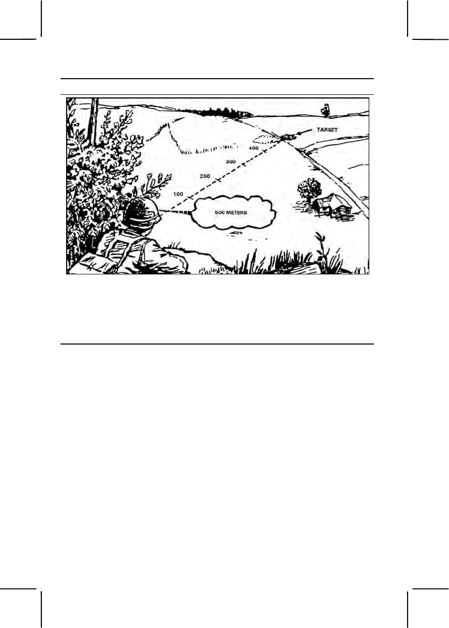
3-522 071-311-2130
Performance Steps
Figure 071-311-2130-1. Range estimation
4. Determine if target is engageable.
5. Determine if target should be engaged.
6. Select the appropriate firing technique based on target range (figure
071-311-2130-2).
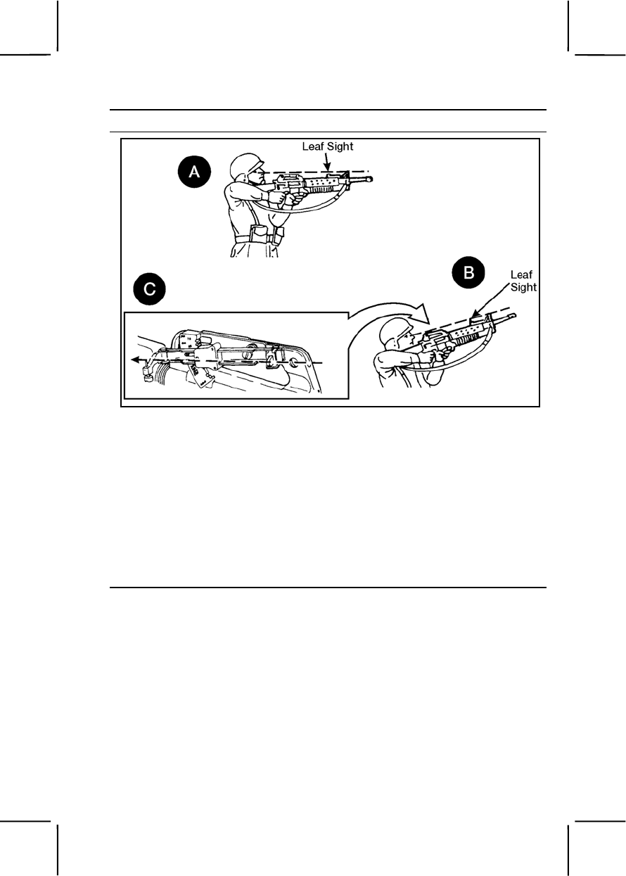
071-311-2130 3-523
Performance Steps
Figure 071-311-2130-2. Firing techniques
a. For short-range targets at 50 meters or less, place the leaf sight
down and use the rifle sights (A, figure 071-311-2130-2).
Note. Estimate distance to target and aim head high on the target.
b. For targets from 50 to 250 meters, raise the leaf sight and use with
the rifle front sight (B, figure 071-311-2130-2).
c. For targets from 250 to 400 meters, use the front and rear sight of
the quadrant sight only (C, figure 071-311-2130-2).
7. Select and assume an appropriate firing position (figure 071-311-2130-
3).
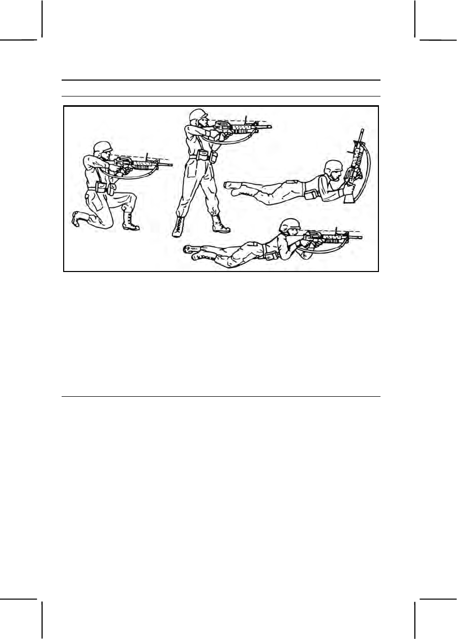
3-524 071-311-2130
Performance Steps
Figure 071-311-2130-3. Firing positions
Note. Launcher may be fired from the standing, kneeling, or prone position.
a. Place the stock of the weapon on the ground when firing long range
from the prone position.
b. Hold the stock firmly against your shoulder for all other positions.
8. Obtain sight picture (using leaf sight or quadrant sight).
Note. Leaf sight may be used at ranges between 50 and 250 meters. Quadrant
sight ranges are from 50 to 400 meters.
9. Adjust the leaf sight if necessary (figure 071-311-2130-4).
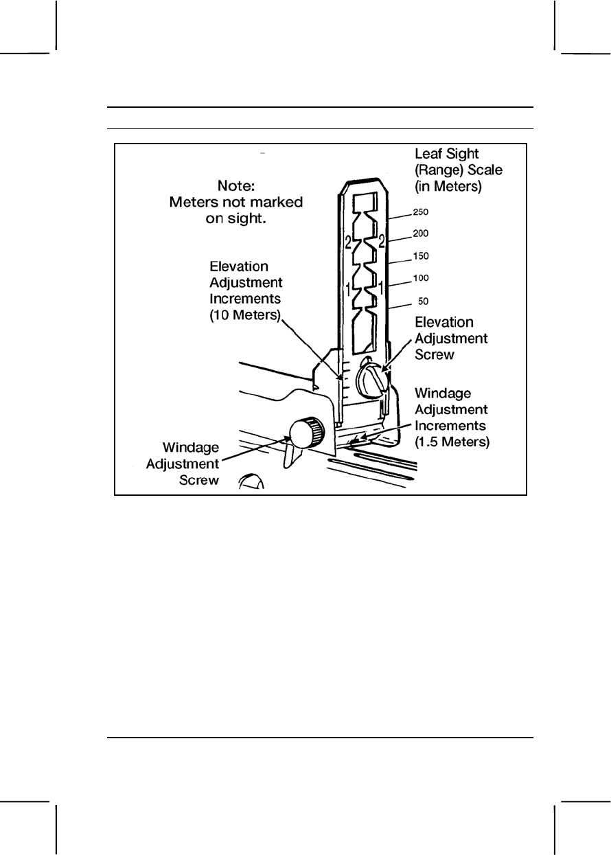
071-311-2130 3-525
Performance Steps
Figure 071-311-2130-4. Leaf sight
Notes.
1. For range, the leaf sight scale is marked in 50-meter (165-foot) increments
for targets from 50 to 250 meters.
2. For elevation, one increment equals 10 meters (33 feet) at a 200-meter
(660-foot) range.
3. For windage, one increment equals 1.5 meters (5 feet) at a 200-meter
(660-foot) range.
a. For headwind and rear wind—
(1) Loosen the elevation adjustment screw to move the leaf sight
up to increase range for head wind.
(2) Lower it to decrease range for rear wind.
(3) Use the rim of a used 40-mm cartridge to turn the elevation
adjustment screw.
b. For left wind and right wind—
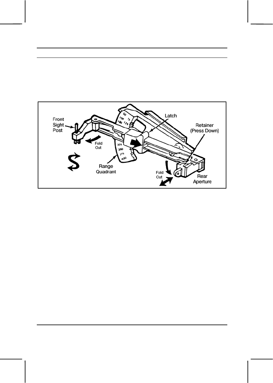
3-526 071-311-2130
Performance Steps
(1) Turn the windage adjustment screw clockwise to adjust for wind
from the left.
(2) Turn the windage adjustment screw counterclockwise to adjust
for wind from the right.
10. Adjust the quadrant sight if necessary (figure 071-311-2130-5).
Figure 071-311-2130-5. Quadrant sight
Note. Range quadrant is marked in 25-meter (83-foot) increments from 50 to 400
meters (165 to 1,320 feet).
a. Pull the latch toward you to release the quadrant sight arm.
b. Select elevation.
Note. For elevation adjustment, one notch equals 5 meters (17 feet) at a 200-meter
(660-foot) range.
c. For head wind and rear wind—
(1) Turn the front sight post left to increase range for head wind.
(2) Turn the front sight post right to decrease range for rear wind.
d. For left wind and right wind:
(1) Depress the retainer and slide the rear aperture in to adjust for
wind from the right.
(2) Slide the rear aperture out to adjust for wind from the left.
Note. The vertical line marks the center. One notch equals 1.5 meters (5 feet) at a
200-meter (660-foot) range.
11. Move safety to the FIRE position.

071-311-2130 3-527
Performance Steps
WARNING
Be sure there are no obstacles (such as the sling or branches) in the
line of fire.
12. Aim and squeeze the trigger to fire.
Note. Practice breath control when firing the rifle.
13. If the first round misses, adjust fire as necessary by sensing the impact
of the round and manipulating the sight.
Note. Continue the adjustment process until a hit is obtained or the area has been
covered by fire.
a. If time allows, whether using the AN/PVS-4 or AN/PVS-7, adjust the
sights, but if time is critical, adjust the point of aim instead.
b. If the grenade lands more than 25 meters over or short of the
target, adjust the range quadrant to bring the next grenade on target.
c. If the grenade explodes less than 25 meters from the target, adjust
the point of aim to bring the next grenade on target.
d. If the launcher is properly zeroed, deviation errors will be small and
you can easily correct them by adjusting the aiming point. Adjust for wind
as described in steps 9 and 10.
Evaluation Preparation:
Setup: At a live-fire M203 range, provide all the materials indicated in the
task conditions.
Brief Soldier: Tell the soldier to engage targets in his sector of fire at ranges
from 50 to 250 meters.
Performance Measures GO NO GO
1. Kept the safety in the SAFE position until ready to
fire. —— ——
2. Loaded the M203 grenade launcher. —— ——
3. Determined range to target. —— ——
4. Selected the appropriate firing technique based on
target range. —— ——
5. Selected firing position. —— ——
6. Adjusted the leaf sight. —— ——

3-528 071-100-0003
Performance Measures GO NO GO
7. Adjusted the quadrant sight. —— ——
8. Moved safety to the FIRE position. —— ——
9. Aimed and squeezed the trigger to fire. —— ——
10. Adjusted fire by sensing the impact of the round and
manipulating the sight. —— ——
Evaluation Guidance: Score the soldier GO if all performance measures
are passed. Score the soldier NO GO if any performance measure is failed.
If the soldier scores NO GO, show him what was done wrong and how to do
it correctly.
References
Required Related
FM 23-31
TM 9-1010-221-10
SUBJECT AREA 17: M4 CARBINE
071-100-0003
Engage Targets with an M4 or M4A1 Carbine
Conditions: Given an M4 or M4A1 carbine, magazines, ammunition,
individual combat equipment, and stationary or moving targets (personnel or
equipment) at engageable ranges.
Standards: Detected and determined range to targets. Fired the M4 or
M4A1 carbine to engage targets in assigned sector of fire. Applied correct
marksmanship fundamentals and target engagement techniques so each
target was hit or suppressed.
Performance Steps
1. Assume an appropriate firing position based on the situation. The firing
position should protect you from enemy fire and observation, yet allow you
to place effective fire on targets in your sector of fire.
a. Foxhole. Advantages: best when available. Disadvantages: no
overhead cover.

071-100-0003 3-529
Performance Steps
b. Prone. Advantages: steady, easy to assume, low silhouette, and
easily adapted to use of cover and support. Disadvantages: effectiveness
can be limited by terrain and vegetation irregularities.
c. Prone supported. Advantages: steadier than prone, other
advantages the same as prone. Disadvantages: same as prone.
d. Kneeling. Advantages: used when firing from behind something;
used on ground that is level or gently sloping upward. Disadvantage:
exposed to small arms fire.
e. Kneeling supported. Advantages: steadier than kneeling; other
advantages the same as kneeling. Disadvantages: exposed to small arms
fire.
f. Standing. Advantages: used in assault to surprise targets or when
other positions are not appropriate. Disadvantages: exposed to small arms
fire.
2. Identify targets in your designated sector of fire.
3. Determine range to a target.
a. Your M4 or MA1 carbine sights can be used to estimate range to
targets(s). Viewed through the front sight, a man-sized target appears:
(1) Twice the width as the front sight post at about 90 meters.
(2) The same width as the front sight post at about 175 meters.
(3) Half the width of the front sight post at about 350 meters.
4. Load and fire on targets using appropriate engagement techniques.
a. Load the weapon.
b. Use the appropriate aiming technique.
(1) Engage a stationary target using reference points or sighting
points.
(2) Engage a target moving toward you as you would a stationary
target.
(3) Engage a target moving laterally, using the single lead
technique, by placing the trailing edge of the front sight post at the center
of the target. This method causes the lead to increase automatically as the
range increases.
(4) Engage multiple targets by first firing at the one presenting the
greatest danger (usually the closest) and then rapidly proceeding to next
target.
c. Use the quick-fire technique when there is no time to properly aim.
Use this technique on targets within 30 meters of your location. (This
technique is most effective in urban terrain or heavy bush.)

3-530 071-100-0004
Performance Steps
(1) Use the standing position.
(2) Use the raised stockwell. Look two or three inches above the
sights, on a plane that is level with the barrel.
(3) Look at the target, NOT at the sights.
d. Fire on the targets until they are destroyed or until you receive an
order to cease fire.
Evaluation Preparation:
Setup: On a live-fire range, provide sufficient quantities of equipment and
ammunition to support the number of soldiers tested. Have each soldier use
his own rifle and magazine.
Brief Soldier: Tell soldier he is to detect and engage targets in his sector
and, when asked, state the range to the target.
Performance Measures GO NO GO
1. Assumed an appropriate firing position based on the
situation. —— ——
2. Identified targets in your designated sector of fire. —— ——
3. Determined the range to a target. —— ——
4. Loaded and fired on targets using appropriate
engagement techniques. —— ——
Evaluation Guidance: Score the soldier GO if all performance measures
are passed. Score the soldier NO GO if any performance measure is failed.
If the soldier scores NO GO, show him what was done wrong and how to do
it correctly.
References
Required Related
FM 21-75
FM 23-9
TM 9-1005-319-10
071-100-0004
Maintain an M4 or M4A1 Carbine
Conditions: Given an M4 or M4A1 carbine, magazine, 5.56-mm
ammunition, and small-arms accessory case with the following cleaning
materials: clean wiping rags, bore brush, chamber brush, toothbrush,

071-100-0004 3-531
cleaning rod, small-arms swabs, pipe cleaners, cleaner lubricant and
preservative (CLP), lubricating oil arctic weather (LAW), and carbine bore
cleaner.
Standards: Cleaned, inspected, and lubricated the carbine and magazine
so they functioned correctly. Cleaned and inspected the ammunition.
Turned in any unserviceable ammunition.
Performance Steps
1. Clear the carbine.
a. Remove the magazine from the carbine, if there is one present.
b. Cock the carbine.
c. Turn the selector to SAFE.
Note. The selector cannot be turned to SAFE unless the carbine is cocked.
d. Lock the bolt open.
(1) Pull the charging handle rearward.
(2) Press the bottom of the bolt catch.
(3) Allow the bolt to move forward until it engages the bolt catch.
(4) Return the charging handle to the forward position.
(5) Ensure the selector is on SAFE.
e. Check the receiver and chamber to ensure they do not contain
ammunition.
2. Disassemble the carbine.
CAUTION
Do not use a screwdriver or any other tool when removing the handguards.
Doing so may damage the handguards, slip ring, or both.
WARNING
Use care not to bend or dent the gas tube while removing handguards.
a. Remove the sling.
b. Remove the handguards if you can see dirt or corrosion through the
vent holes. Handguards are interchangeable because they are identical.
CAUTION
Use only hand pressure to disengage the pivot and takedown pins. Force other
than hand pressure may cause damage to the weapon so replacement of the
weapon is required. Push the pivot and takedown pins only far enough to
disengage the upper receiver from the lower receiver.
c. Push the takedown pin as far as it will go and pivot the upper
receiver from the lower receiver.

3-532 071-100-0004
Performance Steps
d. Push the receiver pivot pin.
e. Separate the upper and lower receivers.
f. Pull back the charging handle.
g. Remove the bolt carrier and bolt.
h. Remove the charging handle.
CAUTION
Do not fully remove the round nuts from the threaded studs. The threaded studs
are flared on the end to prohibit removal. However, if the nuts are inadvertently
removed, they may be reinstalled.
i. Remove carrying handle assembly. Loosen the round nuts on the
left side of the carrying handle approximately four turns. Loosen the
clamping bar from the left side of the upper receiver and lift off the carrying
handle.
j. Remove the firing pin retaining pin.
k. Put the bolt assembly in the locked position by pushing in the bolt.
l. Remove the firing pin by allowing it to drop out of the rear of the bolt
carrier into your hand.
m. Remove the bolt cam pin by turning it one-quarter turn and lifting it
out.
n. Pull the bolt assembly from the carrier.
Note. Perform steps o through q only when the parts are dirty or damaged.
o. Press the rear of the extractor pin to check spring function. Report
any weak springs to unit armorer for replacement.
p. Remove the extractor pin by pushing it out with the firing pin (use
care not to damage the firing pin).
q. Lift out the extractor and spring, taking care that the spring does not
separate from the extractor.
r. Release the buffer by pressing the buffer and depressing the
retainer.
s. Remove the buffer and action spring separating the buffer from the
spring.
t. Extend the buttstock assembly to full open. The M4/M4A1 has a
four-position buttstock: closed, 1/2 open, 3/4 open, and full open.
u. Grasp the lock lever in the area of the retaining nut, pull downward,
and slide the buttstock to the rear to separate the buttstock assembly from
the lower receiver extension.
3. Clean the carbine.

071-100-0004 3-533
Performance Steps
a. Upper receiver group.
(1) Use small-arms swabs, CLP, and bore brush to clean bore.
(2) Use rags, cleaning brush, and CLP to remove powder fouling,
corrosion, dirt, and rust from other areas.
(3) Clean bolt lugs with CLP and chamber brush.
(4) Use CLP and bore brush to clean barrel locking lugs and gas
tube.
b. Lower receiver group.
(1) Remove powder fouling, corrosion, and dirt with rags, cleaning
brush, and CLP.
(2) Clean buffer tube and buttstock tube with rag attached to
holder.
(3) Clean buffer action spring and inside lower receiver extension
with brush and rags.
c. Bolt carrier group.
(1) Clean outer and inner surfaces of bolt carrier with rags and
CLP.
(2) Clean carrier key (use worn bore brush).
(3) Clean firing pin recess and firing pin with brush and CLP.
(4) Clean firing pin hole with pipe cleaner and CLP.
(5) Clean carbon deposits and dirt from locking lugs with cleaning
brush and CLP.
(6) Clean areas behind bolt ring and under lip of extractor with
brush and CLP.
4. Inspect carbine for serviceability.
a. Upper receiver group.
(1) Check for free movement of the forward assist assembly.
(2) Check for broken or damaged ejection port cover.
(3) Check rear sight windage and elevation knob for damage and
looseness.
(4) Check carrying handle assembly for missing or damaged parts
and ensure the handle assembly will mount to the upper receiver.
(5) Check front sight assembly for damage.
(6) Inspect bore and chamber for pitting or obstructions.
(7) Inspect bolt lugs for cracks and burrs.

3-534 071-100-0004
Performance Steps
(8) Check for free movement of slip ring.
(9) Check the compensator for proper alignment.
Note. The compensator has five slots. The third or middle slot should line up with
the front sight post. If not, turn the compensator in for maintenance.
(10) Check the bolt guide rails for chips and burrs.
b. Lower receiver.
(1) Check trigger mechanism for missing or damaged parts.
(2) Check bolt catch for free movement.
(3) Check magazine release button for free movement.
(4) Check buttstock assembly for dents and rust and ensure proper
operation of retaining nut and lock-release lever.
(5) Check action spring and buffer for damage.
c. Bolt carrier group.
(1) Check bolt carrier for chips, burrs, and cracks.
(2) Check bolt for cracks or fractures, especially in the cam pin hole
area. Bolts that contain pits in the firing pin hole need replacing.
(3) Check firing pin retaining pin for bends and excessive wear.
(4) Check firing pin for bends, cracks, and blunted or sharp end.
(5) Check cam pin for cracks and chips.
(6) Check extractor for chipped or broken edges in the area of the
lip that engages the cartridge rim. Check to ensure the rubber insert is
inside the extractor spring.
d. Report and turn in unserviceable parts for maintenance.
5. Lubricate the carbine.
Note. Under all but the coldest arctic conditions, CLP is the lubricant to use on the
carbine. Between +10 degrees Fahrenheit and -10 degrees Fahrenheit, either CLP
or LAW can be used. For -35 degrees Fahrenheit or lower, use LAW only.
Note. Lightly lube means apply a film of lubricant barely visible to the eye.
Note. Generously lube means apply the lubricant heavily enough so it can be
spread with the finger.
a. Upper receiver and carrying handle.
(1) Upper receiver. Lightly lube inside of receiver, bore, chamber,
locking lugs, outer surfaces of barrel and front sight, and mating surface for
carrying handle.

071-100-0004 3-535
Performance Steps
(2) Carrying handle. Apply a drop or two of lubricant to both
threaded studs. Lightly lube the clamping bar and both round nuts. Lightly
lube the mating surface.
(3) Front sight detent. Depress and apply two or three drops of CLP
to front sight detent. Depress several times to work lube into the spring.
(4) Adjustable rear sights. Use one or two drops of CLP. Rotate the
following parts to ensure lubricant is spread evenly above and below:
(a) Elevation screw shaft.
(b) Elevation knob.
(c) Windage knob.
(d) Windage screw.
b. Lower receiver group.
(1) Lightly lube inside and outside lower receiver extension, buffer,
and action spring. Lightly lube inside buttstock assembly. Generously lube
buttstock lock-release lever and retaining pin.
(2) Generously lube takedown pin, pivot pin, detents, and all other
moving parts and their pins.
c. Bolt carrier group.
(1) Lightly lube charging handle and inner and outer surfaces of
bolt carrier.
(2) Place one drop of CLP in the carrier key.
(3) Apply a light coat of CLP on firing pin and firing pin recess in
bolt.
(4) Generously lube outside the bolt body, bolt rings, and cam pin
area.
(5) Apply a light coat of CLP on extractor and pin.
6. Assemble the carbine.
a. Install buttstock assembly. Align the buttstock assembly with lower
receiver extension; pull downward on the lock release lever near the
retaining pin, and slide the buttstock assembly onto the lower receiver
extension.
b. Insert action spring and buffer.
c. Insert extractor and spring.
d. Push in extractor pin.
e. Slide bolt into carrier.

3-536 071-100-0004
Performance Steps
WARNING
Be sure the cam pin is installed in the bolt group. If it is not, the carbine
can still fire and will explode.
f. Replace bolt cam pin.
g. Drop in and seat firing pin.
h. Pull bolt back.
i. Replace retaining pin.
j. Engage, then push charging handle in part of the way.
WARNING
Do not exchange or switch bolt assemblies from one M4 or M4A1 to
another.
k. Slide in bolt carrier group.
l. Push in charging handle and bolt carrier group together.
m. Join upper and lower receivers.
n. Engage receiver pivot pin.
o. Close upper and lower receiver groups. Push in takedown pin.
p. Replace handguards.
q. Replace sling.
7. Perform a function check on the M4 or M4A1 carbine to determine
correct functioning according to Task 071-100-0005.
8. Maintain M16/M4 magazine and ammunition.
a. Maintain magazine.
(1) Disassemble magazine.
• Insert the nose of a cartridge into the hole in the base of
the magazine and raise the rear of the magazine until the indentation
on the base is clear of the magazine.
• Slide the base forward until free of the tabs.
• Remove the magazine spring and follower (do not
separate).
(2) Clean all parts using a rag soaked with CLP. Dry all parts.
(3) Inspect parts for damage such as dents and corrosion. If any
damage is found, turn in to maintenance.
(4) Lubricate the magazine. Lightly lube the spring only.

071-100-0004 3-537
Performance Steps
(5) Assemble the magazine.
• Insert the follower and spring in the magazine tube and
jiggle the spring to seat them in the magazine.
• Slide the base under all four tabs until it is fully seated.
Make sure the printing is on the outside.
b. Maintain ammunition.
(1) Clean ammunition with a clean dry rag.
(2) Inspect and turn in any ammunition with the following defects:
corrosion, dented cartridges, cartridges with loose bullets, and cartridges
with the bullet pushed in.
Evaluation Preparation:
Setup: Have soldiers use their own weapons and magazines. Provide
swabs, cleaner, lubricant, preservative (CLP), pipe cleaners, lubricating oil,
and rifle bore cleaner (the soldier should not select rifle bore cleaner for
use). Also provide several rounds of dummy ammunition, if available.
Brief Soldier: Tell the soldier to clean, inspect, and lubricate the weapon and
magazine following normal safety practices.
Performance Measures GO NO GO
1. Cleared the carbine. —— ——
2. Disassembled the carbine. —— ——
3. Cleaned the weapon using the correct materials. —— ——
4. Inspected for unserviceable parts. —— ——
5. Assembled the carbine. —— ——
6. Performed a function check. —— ——
7. Disassembled the magazine. —— ——
8. Cleaned the magazine. —— ——
9. Assembled the magazine —— ——
10. Cleaned the ammunition. —— ——
Evaluation Guidance: Score the soldier GO if all performance measures
are passed. Score the soldier NO GO if any performance measure is failed.

3-538 071-004-0001
If the soldier scores NO GO, show him what was done wrong and how to do
it correctly.
References
Required Related
TM 9-1005-319-10
SUBJECT AREA 18: 9MM PISTOL
071-004-0001
Maintain an M9 Pistol
Conditions: Given an M9 pistol with components (M12 or M7 holster,
magazine, and ammunition pocket), 9-mm ammunition, cleaner lubricant
preservative (CLP), lubricating oil arctic weather (LAW), lubricating oil
semifluid (LSA), bore brush, wiping rags, M4 cleaning rod (a one-section
handle and a swab holder), and small-arms cleaning swabs.
Standards: Cleaned and lubricated M9 pistol and magazine; inspected
parts, turned in unserviceable parts for maintenance, assembled pistol,
ensured pistol was operational, cleaned and inspected ammunition for
serviceability, and turned in unserviceable ammunition.
Performance Steps
1. Clear the pistol.
a. Place the safety lever in the SAFE position.
b. Hold the pistol in the raised pistol position.
c. Depress the magazine release button; remove the magazine from
the pistol.
d. Pull the slide to the rear; remove any chambered round.
e. Push the slide stop up, locking the slide to the rear.
f. Look into the chamber to ensure it is empty.
2. Disassemble the pistol and magazine.
a. Depress the slide stop and let the slide go forward.
b. With your right hand, hold the pistol with the muzzle slightly raised.
c. With your forefinger, press the disassembly lever button (figure 071-
004-0001-1).

071-004-0001 3-539
Performance Steps
Figure 071-004-0001-1. Disassembly lever button
d. Rotate the disassembly lever downward until it stops.
e. Pull the slide and barrel assembly forward (figure 071-004-0001-1),
and remove it from the receiver.
f. Slightly compress the recoil spring and spring guide. At the same
time, lift them up and remove them, allowing the recoil spring to stretch
slowly (figure 071-004-0001-2).
Figure 071-004-0001-2. Removal of the recoil spring and spring guide
g. Separate the recoil spring from the spring guide.
h. Push in on the locking block plunger while pushing the barrel
forward slightly. Lift and remove the locking block and barrel assembly
from the slide (figure 071-004-0001-3).
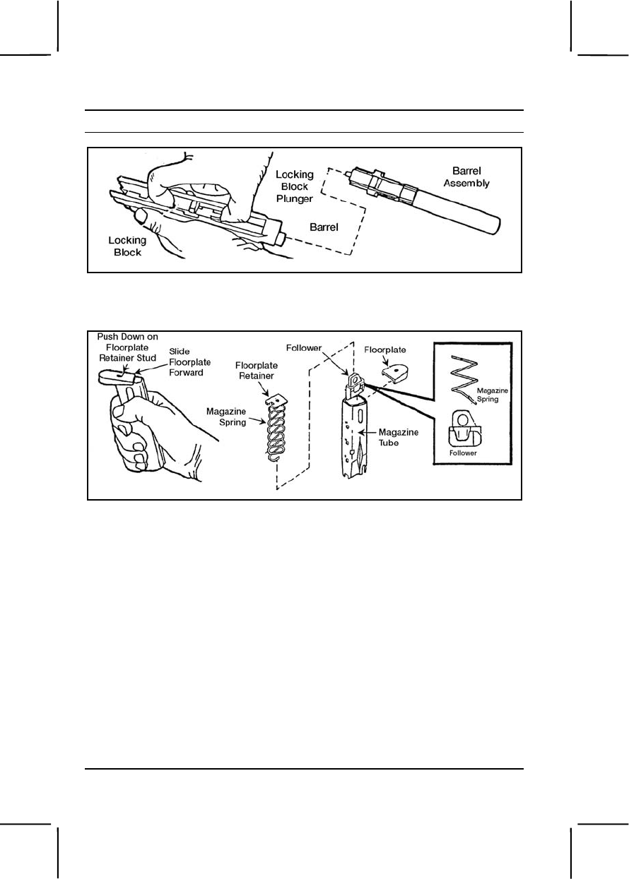
3-540 071-004-0001
Performance Steps
Figure 071-004-0001-3. Removal of the locking block and barrel assembly
i. Disassemble the magazine (figure 071-004-0001-4).
Figure 071-004-0001-4. Disassembly of the magazine
(1) Grasp the magazine firmly, with the floor plate up and the back
of the magazine tube against the palm of your hand.
(2) Depress the locking block to make the locking block plunger
protrude.
(3) Using the locking block plunger, push down on the floor plate
retainer stud.
(4) Slide the floor plate slightly forward with your thumb.
(5) While removing the floor plate, use your thumb to keep
pressure on the magazine spring.
(6) Remove the floor plate retainer, the magazine spring, and the
follower from the magazine tube.
(7) Remove the magazine spring from the follower.
(8) Remove the floor plate retainer from the magazine spring.
3. Clean the pistol and magazine.

071-004-0001 3-541
Performance Steps
CAUTION
Use the bore brush to clean only the bore. Using it on any other part of the pistol
will cause damage.
a. Slide assembly.
(1) Clean slide assembly with a cloth. Use CLP on a soft brush to
remove excess dirt and carbon.
(2) Wipe the slide assembly dry with a clean cloth.
b. Barrel assembly.
(1) Attach a bore brush to a cleaning rod. Moisten the bore brush
with CLP and insert it into the chamber end of the barrel. Make sure the
brush completely clears the muzzle before you pull it back through the
bore. Repeat this procedure several times to loosen carbon deposits.
(2) To clean and dry the barrel, push a clean swab through the
bore. Repeat as necessary with fresh swabs until a swab comes out clean.
(3) Clean locking block with a soft brush.
(4) Clean the recoil spring and spring guide with CLP and, if
needed, a soft brush or cloth.
c. Receiver assembly. Wipe the receiver assembly clean with a cloth
and, if needed, a soft brush.
d. Magazine (figure 071-004-0001-4).
(1) Wipe the magazine tube and the follower with CLP, a cloth, and
a soft brush.
(2) Clean the magazine spring, floor plate retainer, and floor plate
with a clean cloth.
e. Holster. Remove dirt from exterior with stiff brush. Wipe interior with
clean cloth.
f. Ammunition. If ammunition gets wet or dirty, clean it and remove
corrosion from it at once using a dry cloth.
4. Inspect for serviceability.
a. Slide assembly.
(1) Check to ensure the ambidextrous safety moves freely.
(2) Check the firing block for damage.
(3) Check the rear sight for looseness.
b. Barrel assembly.
(1) Inspect the bore and chamber for pitting or obstructions.

3-542 071-004-0001
Performance Steps
(2) Check the locking block plunger to ensure the locking block
moves freely.
(3) Inspect the locking lugs for cracks and burrs.
c. Recoil spring and recoil spring guide.
(1) Check recoil spring to ensure it is not bent or damaged.
(2) Check recoil spring to ensure it is straight and free of cracks
and burrs.
d. Receiver assembly.
(1) Check for bends, chips, and cracks.
(2) Check to ensure the slide stop and magazine stop move freely.
(3) Check the guide rails for excessive wear, burr, cracks, or chips.
e. Magazine assembly (figure 071-004-0001-4).
(1) Check for damage to the spring and follower.
(2) Inspect magazine lips to ensure they are not bent excessively
and that they have no cracks and burrs.
(3) Check to ensure the magazine tube is not bent.
f. Ammunition.
(1) Check for damaged or corroded ammunition. Turn in heavily
corroded or damaged ammunition.
(2) Check to ensure ammunition is free of oil and grease.
5. Lubricate the pistol and magazine.
Note. CLP, LSA, and LAW are the only lubricants authorized for this pistol.
Note. You can use CLP and LSA interchangeably.
Note. Before firing, remove excess lubricant from the bore.
a. Lubricate all parts with a light coat of LSA or CLP at temperatures
above -10 degrees Fahrenheit, or LAW at temperatures below +10
degrees Fahrenheit.
b. Do not mix LAW with other lubricants.
6. Assemble the pistol.
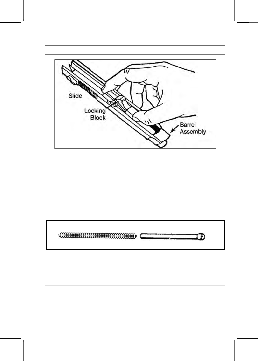
071-004-0001 3-543
Performance Steps
Figure 071-004-0001-5. Insertion of the barrel assembly
a. Grasp the slide with the bottom facing up (figure 071-004-0001-5).
b. With the other hand, grasp the barrel assembly with the locking
block facing up.
c. Insert the muzzle into the forward end of the slide. At the same
time, lower the rear of the barrel assembly by moving the barrel slightly
downward with light thumb pressure. The barrel will fall into place.
d. Insert the recoil spring guide into the recoil spring (figure 071-004-
0001-6).
Figure 071-004-0001-6. Recoil spring and spring guide
e. Insert the end of the recoil spring and the recoil spring guide into
the recoil spring housing. At the same time, compress the recoil spring and
lower the spring guide until it is fully seated on the locking block cutaway
(figure 071-004-0001-7).
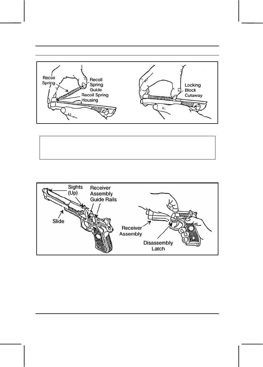
3-544 071-004-0001
Performance Steps
Figure 071-004-0001-7. Insertion of the recoil spring and guide
CAUTION
Be sure that the hammer is uncocked and firing pin block lever is in the down
position. If the hammer is cocked, manually and carefully lower the hammer. Do
not pull the trigger while placing the slide onto the receiver.
f. Push the firing pin block lever down. Grasp the slide and barrel
assembly with the sights up, and align the slide on the receiver assembly
guide rails (figure 071-004-0001-8).
Figure 071-004-0001-8. Final assembly
g. Push until the rear of the slide is a short distance beyond the rear of
the receiver assembly and hold. At the same time, rotate the disassembly
latch lever upward. A click indicates a positive lock (figure 071-004-0001-
8).
h. Assemble the magazine.
(1) Insert the follower into the top coil of the magazine spring. Make
sure the notches on the follower and magazine tube are on the same side.

071-004-0001 3-545
Performance Steps
(2) Insert the magazine spring with follower into magazine tube.
(3) Turn the magazine bottom up, with its back against the palm of
the hand. Attach and center the floor plate retainer on the bottom spring
coil.
CAUTION
After inserting the magazine spring, keep tension on it with your thumb. Be
careful not to place the lips of the magazine tube on a hard surface while you
reassemble the magazine.
(4) Push and hold the magazine spring and floor plate retainer
down. At the same time, slide the floor plate over the sidewalls until it seats
fully.
(5) Carefully insert the magazine into the pistol well. You will hear a
click when it locks into position.
WARNING
Make sure the pistol is clear and unloaded.
7. Perform a function check.
Evaluation Preparation:
Setup: At the test site, provide a field table with all the equipment given in
the task conditions.
Brief Soldier: Tell the soldier to clear, disassemble, clean, inspect, lubricate,
assemble, and perform a function check on the weapon.
Performance Measures GO NO GO
1. Cleared the pistol. —— ——
2. Disassembled the pistol and magazine without
damaging any parts. —— ——
3. Cleaned the pistol, components, and ammunition. —— ——
4. Inspected the pistol, components, and ammunition
for defects. —— ——
5. Lubricated the pistol and magazine correctly. —— ——
6. Assembled the pistol and magazine in correct
sequence. —— ——
7. Performed a function check. —— ——

3-546 071-004-0003
Evaluation Guidance: Score the soldier GO if all performance measures
are passed. Score the soldier NO GO if any performance measure is failed.
If the soldier scores NO GO, show him what was done wrong and how to do
it correctly.
References
Required Related
TM 9-1005-317-10
071-004-0003
Load an M9 Pistol
Conditions: Given an unloaded M9 pistol and a separate magazine loaded
with M9 ammunition.
Standards: Correctly loaded the magazine and ammunition into the pistol;
ensured safety lever was in the safe position.
Performance Steps
WARNING
The M9 pistol has single- and double-action firing modes. When the
safety is set to FIRE, squeezing the trigger will automatically cock and
fire the pistol (this is the double-action mode).
Keep your finger away from the trigger until you intend to fire.
1. Place safety lever in SAFE position.
2. Insert the loaded magazine into the pistol magazine well until you hear
a click when the magazine seats fully.
3. Point the pistol in a safe direction (usually at the target or skyward).
4. Retract the slide fully and release it. This strips a cartridge from the
magazine and chambers it.
Evaluation Preparation:
Setup: At the test site, provide the equipment listed in the task conditions .
Use dummy rounds to evaluate this task.
Brief Soldier: Tell the soldier to load the M9 pistol so it will fire a round when
he squeezes the trigger.
Performance Measures GO NO GO
1. Placed the safety lever in SAFE position. —— ——
2. Inserted the loaded magazine into the magazine well. —— ——

071-004-0004 3-547
Performance Measures GO NO GO
3. Pointed the pistol in a safe direction (usually at the
target or skyward). —— ——
4. Retracted and released the slide to chamber a
cartridge from the magazine. —— ——
Evaluation Guidance: Score the soldier GO if all performance measures
are passed. Score the soldier NO GO if any performance measure is failed.
If the soldier scores NO GO, show him what was done wrong and how to do
it correctly.
References
Required Related
TM 9-1005-317-10
071-004-0004
Unload an M9 Pistol
Conditions: Given an M9 pistol loaded with rounds.
Standards: Correctly removed magazine and ammunition from the pistol;
removed all the rounds from the magazine; and ensured the pistol safety
lever was in the SAFE position.
Performance Steps
WARNING
The M9 pistol will fire single- or double-action mode. With the safety in
the FIRE position, squeezing the trigger automatically cocks and fires
the pistol. This is the double-action mode of firing the pistol. Keep your
finger away from the trigger unless you intend to fire.
1. Remove the magazine and the ammunition from the pistol.
a. Place the safety lever in the SAFE position.
b. Depress the magazine release button, and remove the magazine
from the pistol.
c. Point the pistol in a safe direction (usually at the target or skyward).
d. Retract the slide fully to remove the chambered cartridge.
e. Lock the slide to the rear using the slide stop. Visually inspect the
chamber to make sure it is empty.
f. Release the slide. Ensure the safety lever is in the SAFE position.

3-548 071-004-0006
Performance Steps
2. Remove the ammunition from the magazine.
a. With one hand, hold the magazine upright, front end forward. With
your thumb, firmly press down on the cartridge rim, and push forward. As
the cartridge moves forward, tip the forward end of it up and out with your
index finger.
b. Repeat the above steps until the magazine is empty.
Evaluation Preparation:
Setup: At the test site, provide the equipment listed in the task conditions.
You can use dummy rounds to evaluate this task.
Brief Soldier: Tell the soldier to unload the M9 pistol and remove all
ammunition from the magazine.
Performance Measures GO NO GO
1. Removed magazine and ammunition from the pistol. —— ——
2. Removed ammunition from magazine. —— ——
Evaluation Guidance: Score the soldier GO if all performance measures
are passed. Score the soldier NO GO if any performance measure is failed.
If the soldier scores NO GO, show him what was done wrong and how to do
it correctly.
References
Required Related
TM 9-1005-317-10
071-004-0006
Engage Targets with an M9 Pistol
Conditions: Given an M9 pistol and one or more magazines loaded with
9-mm ammunition.
Standards: Applied the correct M9 target engagement techniques, and
engaged hostile targets.
Performance Steps
1. Identify the target(s). The most likely target you will engage is an
enemy soldier on foot.
2. Apply the fundamentals of quick fire.
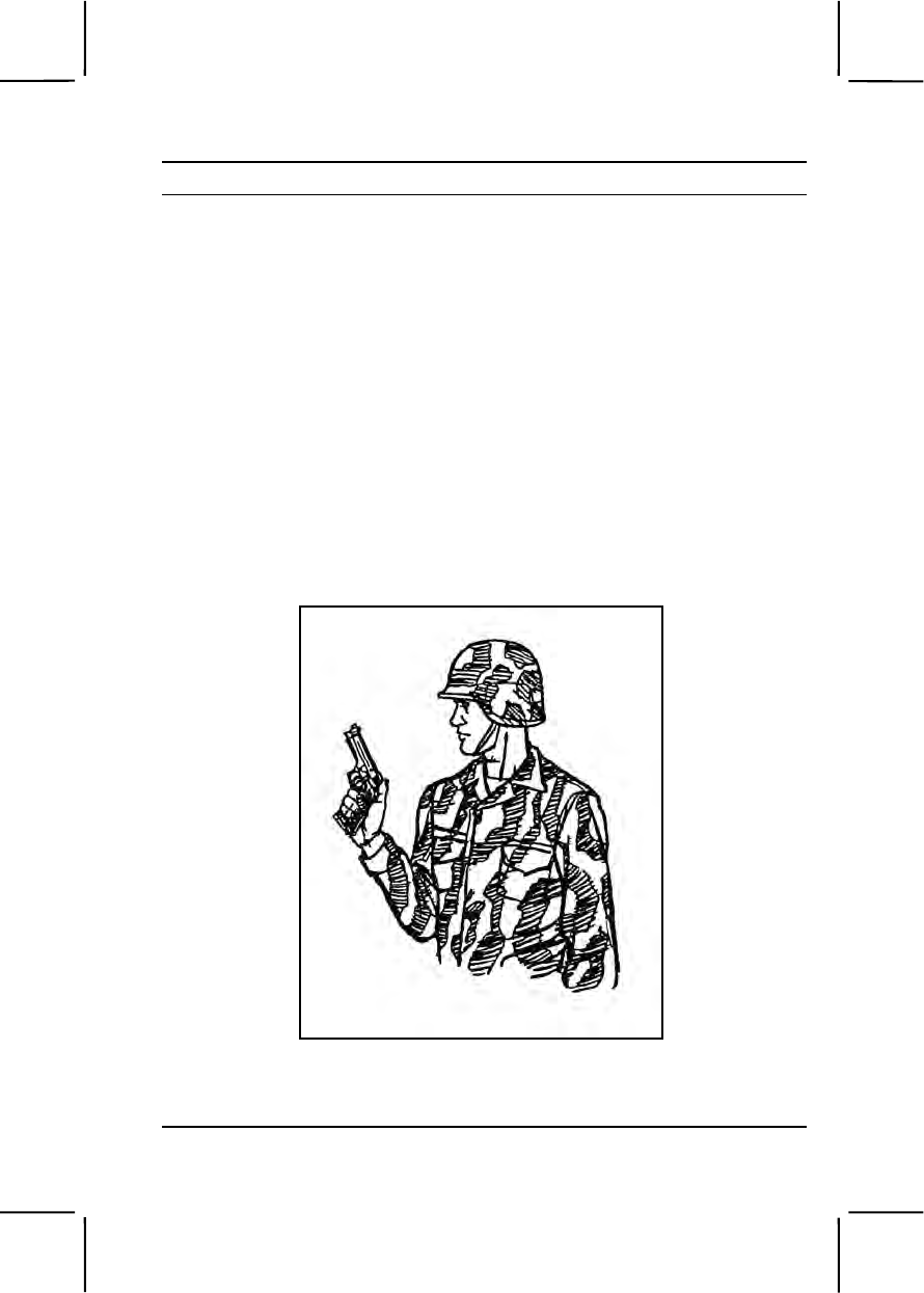
071-004-0006 3-549
Performance Steps
Note. To fire quickly without using the pistol sights, use the pistol as an extension of
your arm.
a. To use the pistol grip, hold the pistol in your nonfiring hand. Form a
"V" with the thumb and forefinger of your firing hand.
b. Place the pistol in the "V," with the sights in line with your firing arm.
c. Hold your upper arm close to your body, and your forearm at about
a 45-degree angle.
d. Wrap your lower three fingers around the grip, putting equal
pressure to the rear with all three fingers (figure 071-004-0006-1).
e. Place your thumb alongside the pistol without applying any
pressure.
f. Place your trigger finger on the trigger so it can be pulled to the
rear.
g. Tightly grip the pistol until your hand begins to tremble. Relax until
the trembling stops. At this point, you have applied the necessary pressure
for a solid grip.
Figure 071-004-0006-1. Pistol ready position, one-hand grip
Note. If you relax any of your three fingers on the grip, you must reapply the entire
grip.
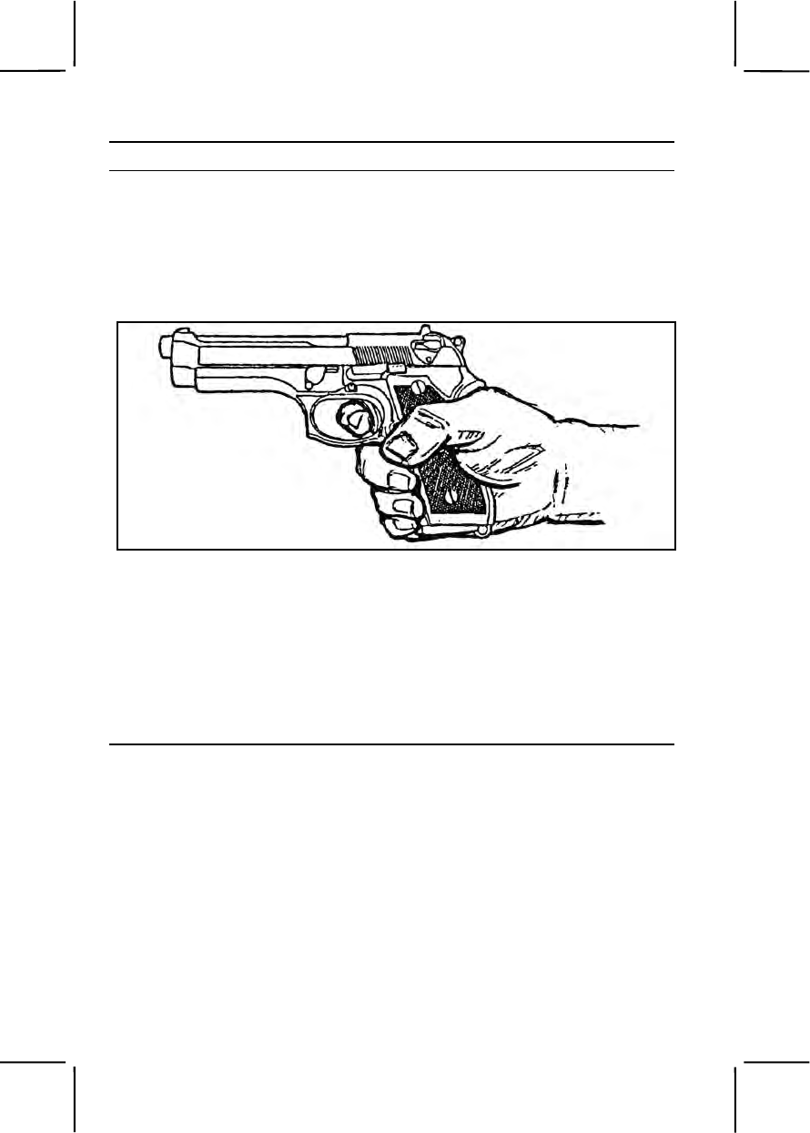
3-550 071-004-0006
Performance Steps
3. Choose one of the following supported or unsupported grips:
a. Supported grip. The only supported grip is the one-hand grip (figure
071-004-0006-2). Begin by gripping the weapon as previously described
(step 2). Allow the thumb of your firing hand to rest without pressure beside
your weapon. Place your trigger finger, between the tip and the second
joint, on the trigger, so you can squeeze the trigger to the rear. Your trigger
finger must work independently of your other fingers.
Figure 071-004-0006-2. One-hand grip
b. Unsupported grips. You may use any of three nonfiring hand grips
to support your firing hand (figure 071-004-0006-3, figure 071-004-0006-4,
and figure 071-004-0006-5).
(1) Fist grip (figure 071-004-0006-3). Begin by gripping the weapon
as previously described (step 2). Firmly close the fingers of your nonfiring
hand over the fingers of your firing hand. Make sure the index finger of
your nonfiring hand is between the middle finger of your firing hand and the
guard. Place your nonfiring thumb beside your firing thumb.
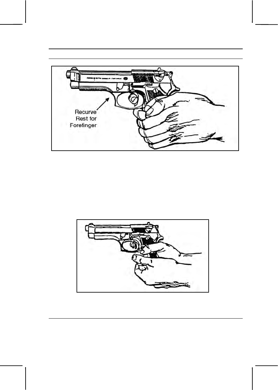
071-004-0006 3-551
Performance Steps
Figure 071-004-0006-3. Fist grip
Note. The M9 pistol has a recurved trigger guard, which allows you to place the
index finger of your nonfiring hand on the front of the trigger guard if you wish.
(2) Palm-supported grip (figure 071-004-0006-4). Begin by gripping
the weapon as previously described (step 2). Place your nonfiring hand
under your firing hand. Wrap your nonfiring fingers around the back of your
firing hand. Place your nonfiring thumb over the middle finger of your firing
hand.
Figure 071-004-0006-4. Palm-supported grip
(3) Weaver grip (figure 071-004-0006-5). Apply this grip the same
as the fist grip, but wrap your nonfiring thumb over your firing thumb.
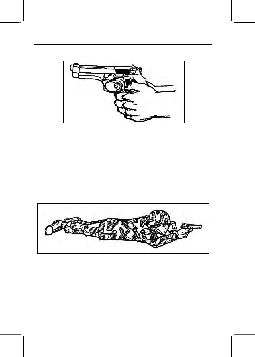
3-552 071-004-0006
Performance Steps
Figure 071-004-0006-5. Weaver grip
4. Select the most stable firing position with the best cover. Consider the
following positions:
a. Prone (figure 071-004-0006-6). To assume the prone position—
(1) Lie flat on the ground, facing the target.
(2) Extend your arms to the front, with your firing arm locked.
(3) Wrap your nonfiring hand around either the wrist or the fingers
of your firing hand.
(4) Face forward. Keep your head down between your arms and
behind the weapon.
Figure 071-004-0006-6. Prone position
b. Standing-with-support (figure 071-004-0006-7). To assume this
position--
(1) Use available cover for support. For example, stand behind a
tree or wall.
(2) Stand behind a barricade, with your firing side in line with the
edge of the barricade.
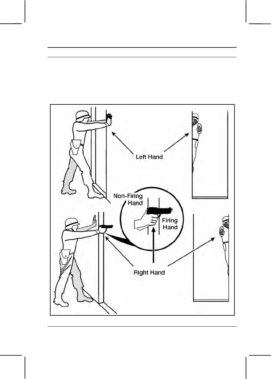
071-004-0006 3-553
Performance Steps
(3) Place the palm of your nonfiring hand at eye level on the edge
of the barricade, and extend your thumb past the edge of the barricade.
(4) Lock the elbow of your firing arm. Rest your forearm on the
extended thumb of your nonfiring hand.
(5) Move the foot on your nonfiring side forward until your toe
touches the bottom of the barricade.
Figure 071-004-0006-7. Standing-with-support position
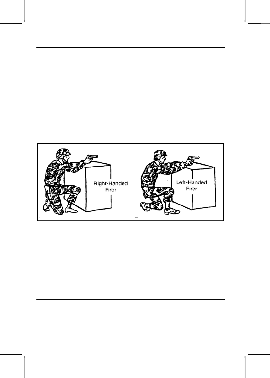
3-554 071-004-0006
Performance Steps
c. Kneeling (figure 071-004-0006-8). To assume this position—
(1) Use available cover, such as a low wall, rocks, or a vehicle that
you can fire over, for support.
(2) Place your firing knee on the ground. Put your left knee down to
fire left-handed, or your right knee down to fire right-handed.
(3) Bend your other knee. Place the foot on your nonfiring side flat
on the ground, pointing toward the target. Extend your arms over available
cover and use it for support.
(4) Lock the wrist and elbow of your firing arm.
(5) Wrap your nonfiring hand around your firing fist or wrist to
support your firing arm.
Figure 071-004-0006-8. Kneeling position
Note. This position could silhouette you, making you a better target. When possible,
fire around the sides of walls, rocks, or vehicles instead of over them.
d. Standing-without-support (figure 071-004-0006-9). To assume this
position—
(1) Face the target.
(2) Place your feet a comfortable distance apart.
(3) Wrap your nonfiring hand around the fist or wrist of your firing
hand. Lock the wrist and elbow of your firing arm toward the target.
(4) Keep your body straight.
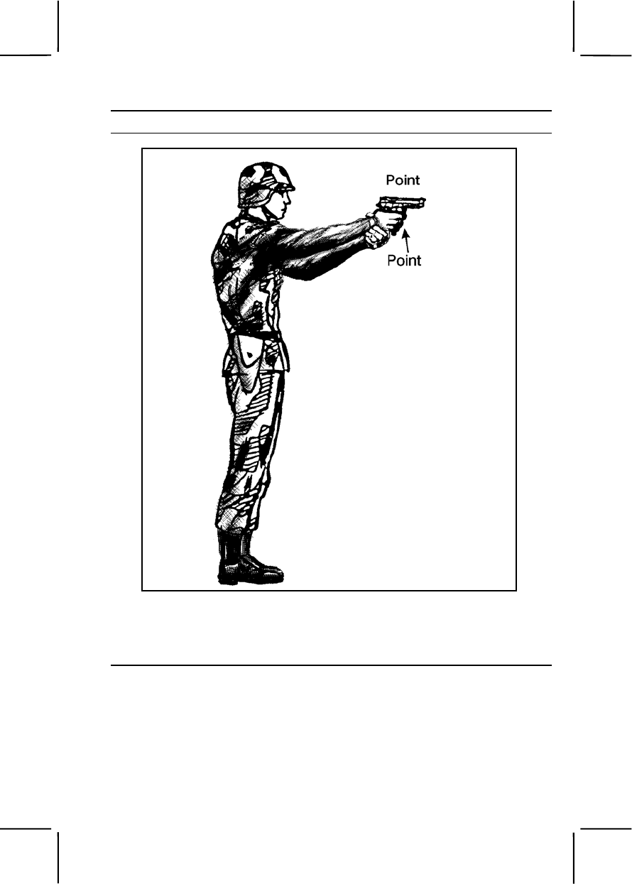
071-004-0006 3-555
Performance Steps
Figure 071-004-0006-9. Standing-without-support position
e. Crouching (figure 071-004-0006-10). This position is the same as
the standing-without-support position, except you must bend your knees
slightly. Balance by leaning forward at the waist.
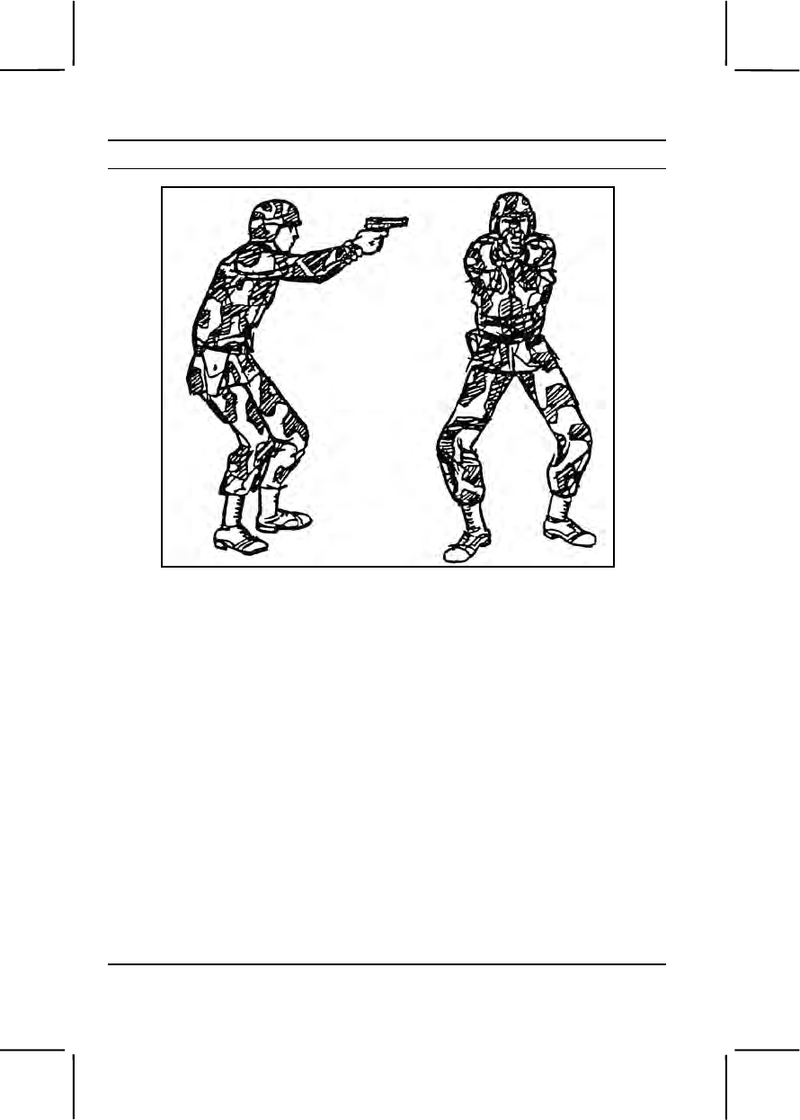
3-556 071-004-0006
Performance Steps
Figure 071-004-0006-10. Crouching position
5. Apply the fundamentals of marksmanship.
a. Pistol grip. To obtain a proper pistol grip—
(1) Place the pistol in the "V" formed by the thumb and forefinger of
your firing hand. Line the sights up with your firing arm. Wrap your lower
three fingers around the pistol. Grip with your middle finger under the
trigger guard. Exert equal pressure on all three lower fingers to the rear,
back through the wrist and forearm (figure 071-004-0006-1).
(2) Rest your thumb on top of your middle finger when gripping the
pistol. Do not exert any downward pressure.
(3) Grip the pistol firmly, but not so firmly that your hand trembles.
b. Sight alignment. To sight properly—
(1) Align the front sight blade in the rear sight notch so an equal
amount of light shows on either side of the front sight. Ensure the top of the
front and rear sights are even.
(2) Relax as much as possible.
(3) Maintain the correct sight alignment, and focus on the front
sight.

071-004-0006 3-557
Performance Steps
(4) Squeeze the trigger with a steadily increasing pressure straight
to the rear, taking care not to disturb the sight alignment until after the
hammer falls.
Note. When there is more than one target, choose the target that is the greatest
danger. This is often the closest target.
Evaluation Preparation:
Setup: Evaluate this task during daylight on a 9-mm combat pistol
qualification course. Provide the soldier with 8 magazines and 52 rounds of
live ammunition.
Brief Soldier: Tell the soldier to use his own pistol. Tell the soldier he must
hit 25 of the 30 targets using correct engagement techniques.
Performance Measures GO NO GO
1. Assumed the firing positions: —— ——
a. Assumed the prone position.
b. Assumed the standing-with-support position.
c. Assumed the standing-without-support position.
d. Assumed the kneeling position.
e. Assumed the crouching position.
2. Applied the fundamentals of marksmanship. —— ——
3. Engaged the targets: —— ——
a. From the prone position.
b. From the standing-with-support position.
c. From the standing-without-support position.
d. From the kneeling position.
e. From the crouching position.
Evaluation Guidance: Score the soldier GO if all performance measures
are passed. Score the soldier NO GO if any performance measure is failed.
If the soldier scores NO GO, show him what was done wrong and how to do
it correctly.
References
Required Related
FM 23-35
TM 9-1005-317-10
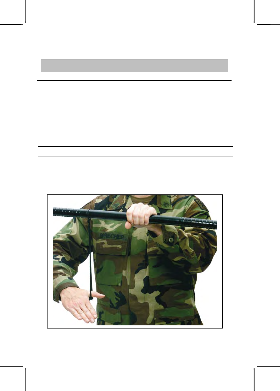
3-558 191-376-4121
SUBJECT AREA 19: CROWD CONTROL
191-376-4121
Use a Riot Baton
Conditions: You are a member of a riot control formation and must position
yourself in a crowd control situation. You are given a riot baton, a flak vest,
shin guards, and a helmet with a face shield.
Standards: Perform all necessary steps to use the riot baton properly and
position yourself to defend against individuals in a crowd. Observe all safety
precautions.
Performance Steps
1. Grip the riot baton.
a. Put the thong over the right thumb as shown in Figure 191-376-
4121-1 and bring it around so the thong wraps over the back of the hand
as shown in Figure 191-376-4121-2. This is called the baton thong
position.
Figure 191-376-4121-1. Baton thong position, Graphic 1
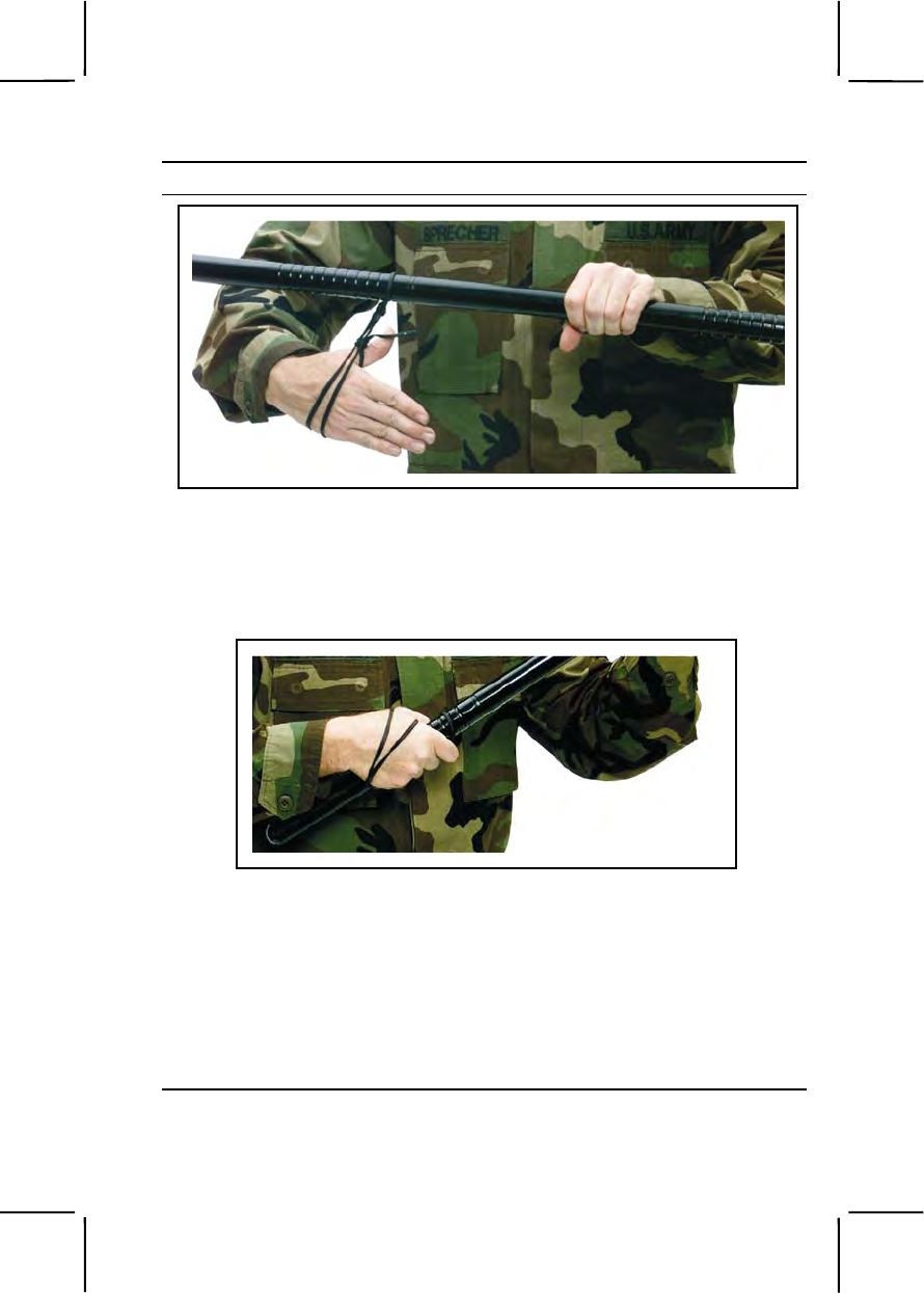
191-376-4121 3-559
Performance Steps
Figure 191-376-4121-2. Baton thong position, Graphic 2
b. Rotate your right hand over and onto the baton handle and grasp it
about six inches from the end. The thong will be pressed against the back
of the hand as shown in Figure 191-376-4121-3. This is called the right-
hand grip.
Figure 191-376-4121-3. Right-Hand Grip
Note. This gives you a secure grip and allows for a quick release of the weapon
when the hand is relaxed.
2. Assume the parade rest position.
a. Place your feet a comfortable distance (about shoulder width) apart.
b. Grip the baton in the right hand and allow your right arm to hang
naturally.
c. Hold the baton horizontally across your body.
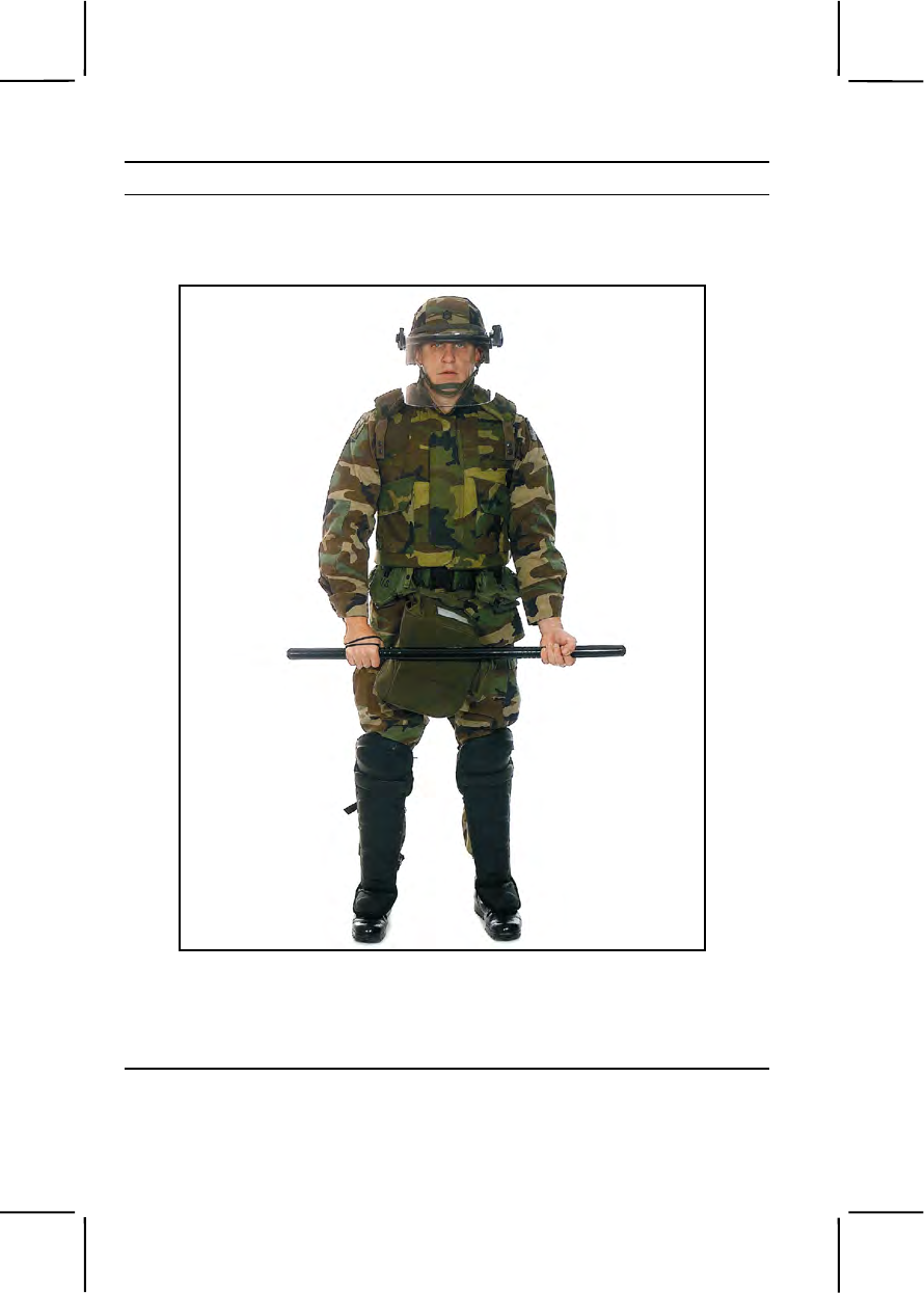
3-560 191-376-4121
Performance Steps
d. Grasp the baton with your left hand, palm facing out and away from
the body and about six inches from the end of the baton as shown in
Figure 191-376-4121-4.
Figure 191-376-4121-4. Parade rest position
3. Assume the port position. This is a ready position for individual
defensive tactics.
Note. Assemble and move to all formations in the port position.
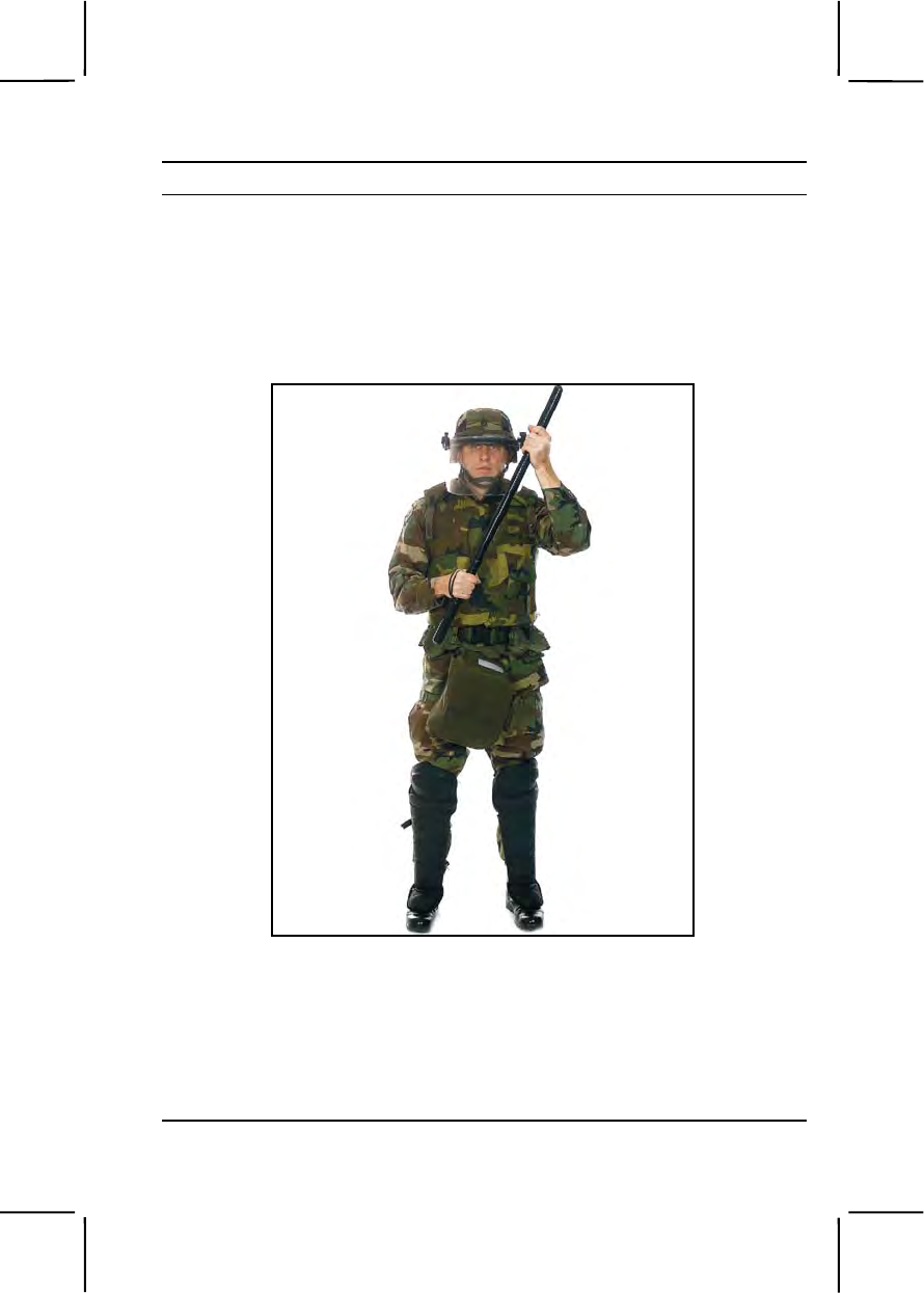
191-376-4121 3-561
Performance Steps
a. Lift the left end of the baton up by bending your left elbow while in
the parade rest position. Your left hand should be level with your left
shoulder.
b. Ensure that the striking end of the baton bisects the angle between
the neck and the left shoulder.
c. Hold the baton about 8 inches from the body as shown in Figure
191-376-4121-5. This is the port position.
Figure 191-376-4121-5. Port position
4. Assume the on-guard position.
Note. This is a ready position used in making initial contact with rioters. Do not hold
it for long periods because it is tiring to the body. Protective movements are normally
executed from this position.
a. Stand with your feet apart, left foot forward. Bend your knees
slightly and lean forward.
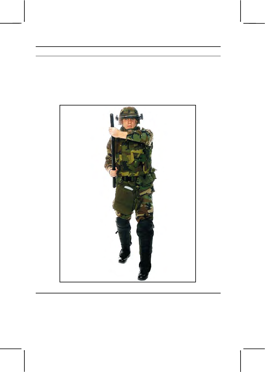
3-562 191-376-4121
Performance Steps
b. Hold the baton against your hip with your right hand.
c. Hold your left forearm horizontally across your body with your palm
up and at a level that will protect your throat area.
d. With your left hand, grasp the baton about 6 inches from the end.
Figure 191-376-4121-6 and figure 191-376-4121-7 show the guard position
from the front and side.
Figure 191-376-4121-6. On-guard position (front view)
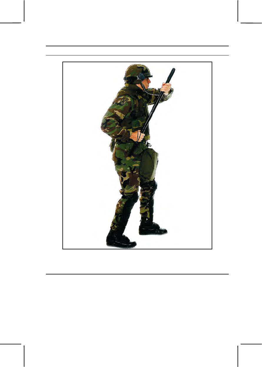
191-376-4121 3-563
Performance Steps
Figure 191-376-4121-7 On-guard position (side view)
5. Ensure that a blow is not directed to one of the five fatal points. Refer
to Figure 191-376-4121-8.
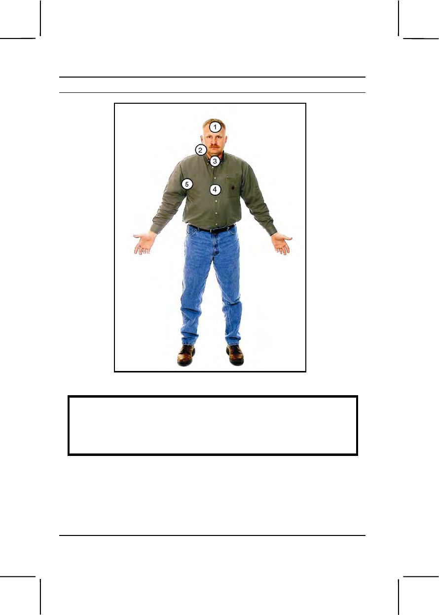
3-564 191-376-4121
Performance Steps
Figure 191-376-4121-8 Five fatal points of impact
WARNING
Never direct a blow to any of the five fatal points of impact on the
human body. These are the head, the side of the neck or throat, the
chest cavity (heart area), and the armpit. Deliver blows only to
vulnerable parts of your opponent's body, such as the shoulder.
6. Perform the short-thrust offensive technique from the on-guard position.
a. Take one rapid step forward with the left foot.
b. Snap your left arm straight and push your right hand to drive the
striking end of the baton into a vulnerable point on the opponent's body.
c. Return to the on-guard position.
7. Perform the long-thrust offensive technique from the on-guard position.

191-376-4121 3-565
Performance Steps
a. Hold the baton in your right hand, take one rapid step forward with
your right foot, and simultaneously release the left-hand grip.
b. Snap the baton forward by rapidly extending your right arm, driving
the striking end of the weapon into a vulnerable point of the opponent's
body.
c. Return to the on-guard position.
8. Perform the butt-stroke offensive technique from the on-guard position.
a. Raise the right hand (while keeping the left hand level with the left
shoulder) until the baton is almost parallel to the ground.
b. Advance the body rapidly by moving the right foot forward one step.
c. Snap the right arm straight forward by sliding the right hand up the
baton until the thong is tight across the back of the hand.
d. Drive the butt end of the baton to the left, striking the opponent's
shoulder.
e. Return to the on-guard position.
9. Perform the baton smash offensive technique from the parade rest,
port, or on-guard position.
a. Hold the baton at chest level, horizontal to the ground.
b. Advance the left foot rapidly and snap both arms straight.
c. Smash the length of the baton across the opponent's chest.
d. Return to the position.
10. Defend yourself against a blow to the head.
Note. All the defensive tactics are started from the parade rest, port, or on-guard
position.
a. Assume either the parade rest, port, or on-guard position.
b. Snap your left hand to the left side of your body and your right hand
up and to the left.
c. Block an attacker's blow and immediately snap both arms up so the
left hand is near the left shoulder and the right hand is in front of the left
shoulder.
d. Execute a jab or smash by stepping forward with your right foot,
driving your body forward. Jab the thong end of the baton into the
attacker's upper body.
e. Return to the original starting position.
11. Defend yourself against a backhand blow.
a. Assume either the parade rest, port, or on-guard position.

3-566 191-376-4121
Performance Steps
b. Snap both arms out and to your right or left front, depending on the
direction of the oncoming blow.
c. Raise your left hand above your head so the grip end of the baton is
pointing down.
d. Block the attacker's blow.
e. After blocking the blow, bring the right hand up near the right
shoulder.
f. Move the left hand down, parallel to the chest area, in preparation
for a butt stroke. (Refer to step 8).
12. Defend yourself against a long thrust.
a. Assume the parade rest, port, or on-guard position.
b. Move your left hand across the body toward the left.
c. Move your right hand down and toward the left.
d. Slide your left hand down the baton to the right hand. Your body
and baton are now in position to defend with a counterblow.
13. Defend yourself against an overhead stab.
a. Assume the parade rest, port, or on-guard position.
b. Step backward with your left foot when the attacker stabs
downward.
c. Slide your left hand down the baton to meet the right, and raise the
baton up over your left side and shoulder.
d. Disarm the attacker by snapping the baton down against his wrist or
forearm.
e. Return your left hand and left foot to their original position in
preparation to execute a baton smash.
14. Defend yourself against an upward thrust.
a. Assume the parade rest, port, or on-guard position.
b. Hold the baton horizontally, about 6 inches from your lower chest.
c. Snap both arms straight down and strike the opponent's wrist to
cause him to drop his weapon.
d. Hold the baton with both your hands and immediately bring the
baton close to your shoulders and hold it across your chest in preparation
to execute the baton smash.
15. Defend yourself against an unarmed attacker.
a. Slide your left hand toward your right and lift the baton to shoulder
level, parallel to the ground.

191-376-4121 3-567
Performance Steps
b. Move your body slightly to the rear by withdrawing your left foot.
c. Use your baton to deliver a counterblow to the attackers shoulder or
collarbone, if he attempts to strike you with a blow.
d. Deliver a counterblow to the attacker's right forearm, if he attempts
to strike you with a blow.
e. Jab the attacker in the groin or stomach with your baton, if he
attempts to grab you.
Evaluation Preparation:
Setup: Provide the soldier being evaluated with a riot baton, a flak vest, and
a helmet with a face shield.
Brief Soldier: Tell each soldier being evaluated that he must perform each
step to correctly demonstrate the riot baton grip, the parade rest, port and
on-guard positions, the three offensive techniques, and the six defensive
techniques as described in performance measures 10 through 15.
Performance Measures GO NO GO
1. Gripped the riot baton. —— ——
2. Assumed the parade rest position. —— ——
3. Assumed the port position. —— ——
4. Assumed the on-guard position. —— ——
5. Ensured that a blow was not directed to one of the
five fatal points. —— ——
6. Performed the short-thrust offensive technique from
the on-guard position. —— ——
7. Performed the long-thrust offensive technique from
the on-guard position. —— ——
8. Performed the butt-stroke offensive technique from
the on-guard position. —— ——
9. Performed the baton smash offensive technique from
the rest, port, or on-guard position. —— ——
10. Defended himself against a blow to the head. —— ——
11. Defended himself against a backhand blow. —— ——
12. Defended himself against a long thrust. —— ——

3-568 191-376-4122
Performance Measures GO NO GO
13. Defended himself against an overhead stab. —— ——
14. Defended himself against an upward thrust. —— ——
15. Defended himself against an unarmed attacker. —— ——
Evaluation Guidance: Score the soldier GO if all performance measures
are passed (P). Score the soldier NO GO if any performance measure is
failed (F). If the soldier fails any performance measure, show him how to do
it correctly.
References
Required Related
FM 19-15
191-376-4122
Position Yourself in Riot Control Formations
Conditions: You are given orders to be a member of a squad or platoon
detailed in a crowd control situation. You are given a riot baton, an M16 rifle,
a bayonet with a sheath, a flak vest, a protective mask, a helmet with a face
shield, and shin guards.
Standards: Position yourself in a formation, as directed by the squad or
platoon leader to control the crowd effectively.
Performance Steps
1. Assume the safe-port position as shown in Figure 191-376-4122-1.
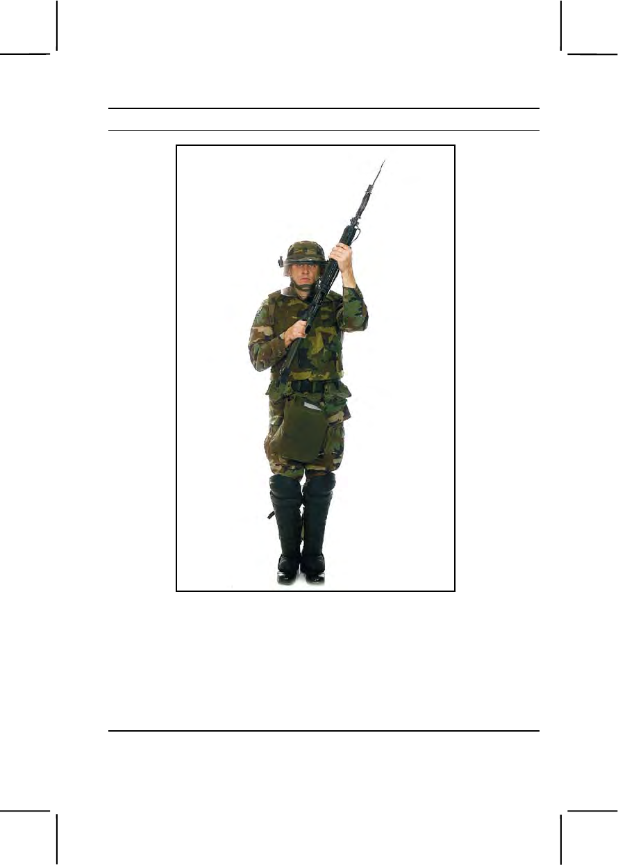
191-376-4122 3-569
Performance Steps
Figure 191-376-4122-1. Safe-port position
Note. Use this position when moving into a riot-control formation or when changing
formations.
a. Grasp the small of the gun stock with your right hand. The
forefinger should be toward the rear of the pistol grip.
b. Use your left hand to hold the sling against the hand guard by
grasping the weapon just below the sling and touching the upper swing
swivel. Ensure that the magazine well faces away from your body.
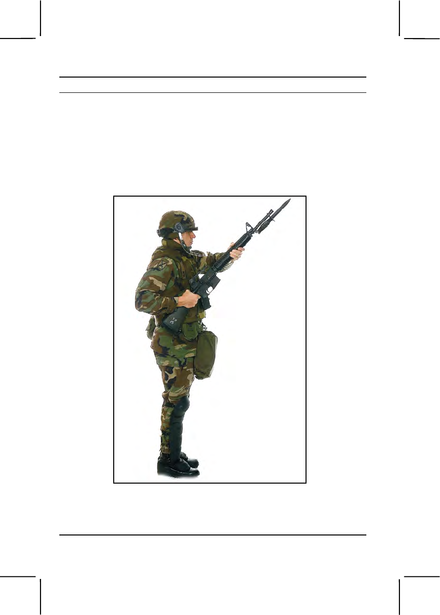
3-570 191-376-4122
Performance Steps
c. Hold the upper part of your left arm parallel with the ground, and
bend your elbow so the forearm is straight up.
d. Keep your right elbow close to the body.
e. Position the heel of the rifle butt slightly to the right of your right shirt
pocket.
f. Slant the rifle enough to look straight ahead over the magazine well.
2. Assume the safeguard position as shown in Figure 191-376-4122-2.
Figure 191-376-4122-2. Safeguard position
a. Use your right hand to grasp the small of the stock and hold it
against the right side of your waist. The butt of the stock will extend to the
rear of your buttocks.
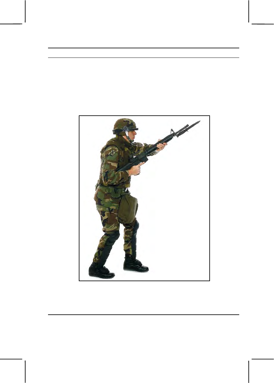
191-376-4122 3-571
Performance Steps
b. Use your left arm, slightly bent at the elbow, to grasp the weapon
just below the sling swivel using your left hand. Turn the weapon so the
magazine well is facing down.
c. Raise the bayonet to throat level.
d. Place your feet together as for the position of attention when at a
halt.
3. Assume the on-guard position as shown in Figure 191-376-4122-3.
Figure 191-376-4122-3. On-guard position
a. Grasp the pistol grip with your right hand and, using right forearm,
hold the stock snugly against your right waist, with the rifle butt even with
the right seam of your trousers.
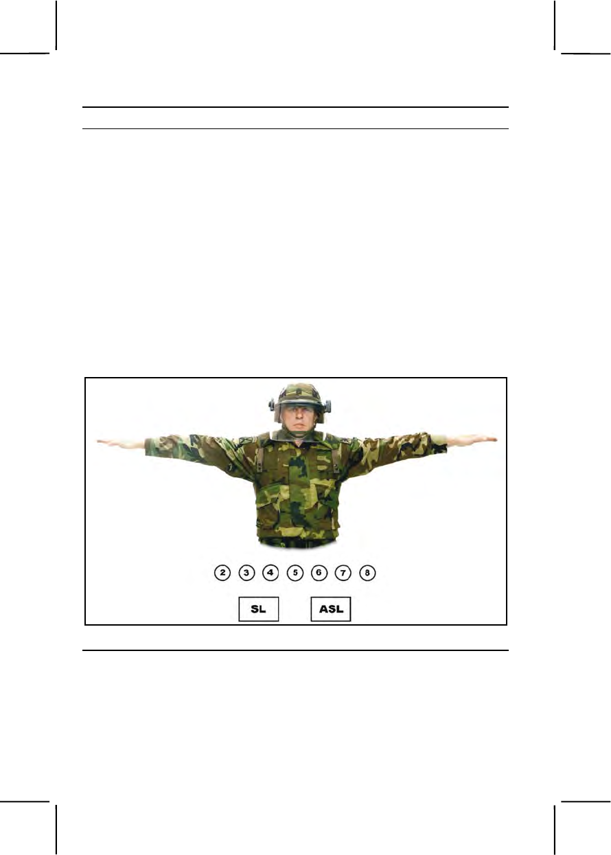
3-572 191-376-4122
Performance Steps
b. Use your left arm, slightly bent at the elbow, to grasp the weapon
just below the sling swivel using your left hand. Turn the weapon so the
magazine well is facing down.
c. Place your feet a comfortable distance apart when at a halt. Line up
your left heel with your right toe and point your toes at the crowd. Slightly
bend your knees, and lean forward while keeping your hips level. Point the
bayonet at throat level.
d. Make a resounding stomp with your left foot when assuming the on-
guard position.
Note. When using riot batons, execute the positions according to the supervisor's
commands. Refer to Task 191-376-4121.
4. Form a squad line formation using the hand signal as shown in Figure
191-376-4122-4. Assume the safe-port position when the command
"squad as skirmishers" is given or when the squad leader gives the hand-
and-arm signal for a squad line formation.
Figure 191-376-4122-4. Hand signal for a squad line formation
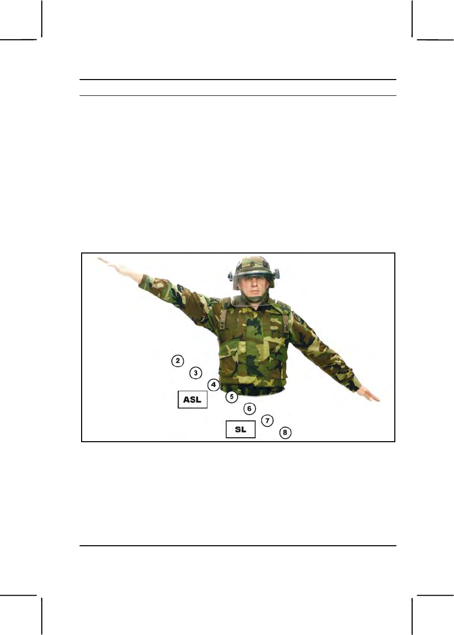
191-376-4122 3-573
Performance Steps
Note. 1. On the command "MOVE," the base member will double-time to the
position indicated by the squad leader.
2. Remaining squad members will double-time forward and position
themselves on line with the base member, one pace to the right of the preceding
member.
3. Everyone will remain in the safe port position until ordered to another
position.
4. Any size squad, platoon, or larger unit can be employed, and a crowd
control formation can be adapted to fit the unit's organization.
5. Form the squad echelon-right formation using hand signals as shown in
Figure 191-376-4122-5. Assume the safe port position when the
command of "SQUAD ECHELON RIGHT" is given or when the squad
leader gives the hand signal for an echelon-right formation.
Figure 191-376-4122-5. Hand Signal for a squad right formation
Notes. 1. On the command "MOVE," the base member will double-time to the
position indicated by the squad leader.
2. Remaining squad members will double-time forward and position
themselves on line with the base member, one pace to the right and one pace to the
rear of the preceding member.
3. Everyone will remain at safe port until ordered to another position.
6. Form a squad echelon-left formation (Figure 191-376-4122-6).
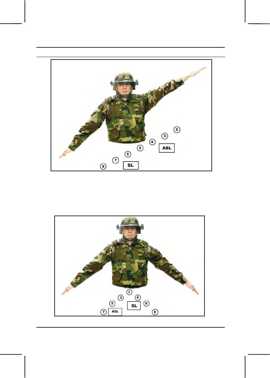
3-574 191-376-4122
Performance Steps
Figure 191-376-4122-6. Hand signal for a squad echelon-left formation
7. Form the squad wedge formation using the hand signal shown in
Figure 191-376-4122-7. Assume the safe-port position when the command
"SQUAD WEDGE" is given or when the squad leader gives the hand signal
for a wedge formation.
Figure 191-376-4122-7. Hand signal for a squad wedge formation

191-376-4122 3-575
Performance Steps
Notes. 1. On the command "MOVE," the base member will double-time to the
position indicated by the squad leader.
2. Remaining odd-numbered squad members will double-time forward and
position themselves on line with the base member, one pace to the left and one
pace to the rear of the preceding member.
3. Remaining even-numbered squad members will double-time forward and
position themselves on line with the base member, one pace to the right and one
pace to the rear of the preceding member.
4. Everyone will remain at the safe-port position until ordered to another
position.
8. Assemble from a riot control formation.
a. On the command "SQUAD ASSEMBLE," assume the safe-port
position.
b. On the command "MOVE," the base member will double-time to the
position indicated by the squad leader.
Note. Remaining squad members will double-time forward and form a column
behind the base member. Everyone will remain at the safe-port position until
ordered to another position.
Evaluation Preparation:
Setup: Have each soldier being evaluated perform at every position within
the formations.
Brief Soldier: Brief the soldier on the nine positions of a squad and review
Task 191-376-4121.
Performance Measures GO NO GO
1. Assumed the safe-port position. —— ——
2. Assumed the safeguard position. —— ——
3. Assumed the on-guard position. —— ——
4. Formed a squad line formation using hand signals. —— ——
5. Formed the squad echelon-right formation using
hand signals. —— ——
6. Formed a squad echelon left formation. —— ——
7. Formed a squad wedge formation. —— ——
8. Assembled from a riot control formation. —— ——

3-576 101-515-1997
Evaluation Guidance: Score the soldier GO if all performance measures
are passed. Score the soldier NO GO if any performance measure is failed.
If the soldier fails any performance measure, show him how to do it correctly.
References
Required Related
TC 19-138 FM 19-15
SUBJECT AREA 20: CASUALTY REPORTING AND HANDLING
101-515-1997
Inter Isolated Remains (After Receiving Authorization)
Conditions: In a tactical situation, given an order from your NCOIC, an
entrenching tool, shrouding material, a separate container for loose personal
effects, grid location of the remains, a transport vehicle.
Standards: After receiving authorization from the organizational
commander, remains were interred according to JP 4-06.
Performance Steps
1. Select a burial site large enough to accommodate the remains to be
buried.
a. Locate grave near the scene of death.
Note. Inter on high ground (avoid flood plains, etc.). Do not inter near water source.
b. Dig grave approximately 3 ½ feet deep.
2. Prepare remains for interment.
a. Inventory all personal effects.
b. Record the following data for each individual interred: name,
grade/rank, sex, service number, nationality, date of death, date buried,
religious faith, who interred the remains.
Note. If any data is not known, write "unidentified."
c. Leave all personal effects and identification media on remains.
d. Shroud remains.
3. Inter individual remains.
a. Place the remains face up in the grave.
b. Refill the grave.
c. Mark the grave.
4. Record the location by coordinates using GPS, if available.

101-515-1998 3-577
Performance Steps
5. Submit an incident report on interment(s) to higher headquarters
Performance Measures GO NO GO
1. Selected an appropriate interment site. —— ——
2. Prepared remains. —— ——
a. Inventoried personal effects and identification
media on remains.
b. Recorded all pertinent data on remains.
c. Left personal effects and identification media on
remains.
d. Shrouded remains.
3. Interred individual remains. —— ——
a. Placed the remains face up in the grave.
b. Refilled the grave.
c. Marked the grave.
4. Recorded the location by coordinates using GPS (if
available). —— ——
5. Submitted incident report on interment(s) to higher
headquarters. —— ——
Evaluation Guidance: Score the soldier GO if all performance measures
are passed. Score the soldier NO GO if any performance measure is failed.
If the soldier scores NO GO, show him what was done wrong and how to do
it correctly.
References
Required Related
JP 4-06 FM 3-25.26
101-515-1998
Evacuate Isolated Remains
Conditions: In a tactical situation, given an order from your NCOIC, using a
standard scale military map, grid coordinate scale, grid location of remains,
communications equipment, transport vehicle (aircraft or ground), pencil or
pen and blank paper.

3-578 101-515-1998
Standards: After a battle, remains have been recovered and tagged;
requested evacuation of remains, and evacuated the remains by the best
possible transportation according to JP 4-06.
Performance Steps
1. Establish assembly area.
a. Record grid coordinates of assembly area using a Global
Positioning System (GPS), if available.
b. Secure assembly area.
c. Move remains feet first to assembly area to await transportation.
d. Contact battalion headquarters to request transportation assets for
the evacuation of remains.
Note. The request for transportation for the evacuation of remains should contain
the number of remains and location of recovery site. Any available air or ground
transportation may be used to evacuate remains.
e. Guard area to prevent loss of personal effects, equipment, and to
keep unauthorized personnel away.
f. Mark landing zone if air evacuation is used.
2. Evacuate the remains, portions, and personal effects.
a. Secure the remains in a vehicle or an aircraft.
Note. Remains are carried feet first. Remains will be loaded feet first on trucks and
rotary-wing aircraft, and headfirst on fixed-wing aircraft.
b. Evacuate remains to mortuary affairs facility.
Note. An escort, preferably the person who witnessed the circumstances
surrounding the individual's death, accompanies the remains to prevent theft and
unauthorized entry to the vehicle.
Performance Measures GO NO GO
1. Established assembly area. —— ——
a. Moved remains feet first to a central location or
assembly area to await transportation.
b. Recorded grid coordinates of assembly area
using a GPS, if available.
c. Contacted battalion headquarters to request
transportation assets for the evacuation of remains.
d. Guarded the area.
e. Marked the landing zone if air evacuation was
used.

101-515-1999 3-579
Performance Measures GO NO GO
2. Evacuated the remains, portions, and personal
effects to a mortuary affairs facility. —— ——
Evaluation Guidance: Score the soldier GO if all performance measures
are passed. Score the soldier NO GO if any performance measure is failed.
If the soldier scores NO GO, show him what was done wrong and how to do
it correctly.
References
Required Related
JP 4-06
101-515-1999
Recover Isolated Remains
Conditions: In a tactical situation, given a message prepared at higher
headquarters listing the search area and number of remains, standard scale
military map, compass, grid coordinate scale (protractor), writing paper, pen
or pencil, grid location of the remains, transport vehicle, and communications
equipment.
Standards: Remains were recovered according to JP 4-06.
Performance Steps
1. Prepare to move to recovery site.
a. Obtain all information concerning the incident from team leader.
b. Perform PMCS on vehicle(s) and equipment prior to loading.
c. Load vehicle according to the load plan.
d. Perform a map reconnaissance of the route.
e. Plot the grid azimuth to the recovery site from your assembly area
on the military map to within one degree of accuracy using a global
positioning system, if available.
f. Convert grid azimuth to a magnetic azimuth.
2. Move to recovery site.
3. Search for remains during daylight only.
a. Question local inhabitants about locations of gravesites and/or
incidents concerning the loss of American service members.
b. Follow a systematic search pattern.
(1) Open formation. An open formation places each member side
by side on a line at a double-arm interval.

3-580 101-515-1999
Performance Steps
Note. This formation allows team members to thoroughly cover a large area. Use
the open formation in open areas or areas with sparse vegetation where visibility is
good.
(2) Closed formation. A closed formation is much closer together.
This formation places each member on line side by side at a close-arm
interval.
Note. Use this formation in areas where the visibility is obstructed or limited due to
dense vegetation or other terrain features.
c. Mark the location of all remains with stake and streamer.
Note. The other team members continue just past the marked location and stop.
When the location has been marked, the personnel marking the location rejoin the
main line of searchers and the sweep continues. Mark all remains in similar manner.
Continue with this process until entire area is searched.
d. Search places that may have been used by troops as shelter,
concealment, or cover.
(1) Search any unusual ground disturbances that may indicate sites
of emergency burial, collapsed bunkers, or fighting positions.
(2) Search and investigate unusual odors, congregation of insects,
scavenger birds, or animals.
Note. Safety and sanitation factors should be considered. Diseases can easily be
transmitted through body fluids from the remains to individuals handling the remains.
Units should provide recovery personnel with gloves and protective clothing before
the mission, and adequate washing facilities after the mission.
4. Recover the remains.
a. Establish tentative identification by reviewing identification tags,
wallets, clothing, and equipment markings.
Note. Do not separate identification media from remains.
b. Interview unit personnel regarding possible visual identification of
remains.
c. Secure personal effects and identification media to the remains.
Note. Attempt to safeguard identification media found on the remains from
destruction by body fluids, weather conditions, and other environmental conditions.
This may be done by storing the items in a waterproof zip lock bag or by wrapping
the items in a dry article of clothing.
d. Record the believed name of the deceased, unit, and grid
coordinates (or unidentified if unknown) on a blank piece of paper.
e. Attach military equipment, to include serially numbered weapons,
and compasses to the remains and forward with the remains.

101-515-1999 3-581
Performance Steps
Note. Ensure rifles and pistols are unloaded and do not pose a danger to the
recovery team.
f. Search the area surrounding the remains for loose personal effects,
equipment, and fragmented remains.
Note. In cases where remains are fragmented, attempt to recover as much of the
remains as possible. Make every attempt to recover hands, individual fingers, teeth
and dental appliance (dentures, bridges, etc.). No piece or portion is considered too
small. DNA testing may make it possible to make positive identification based on
body tissue, dentition, hair samples, and other items.
g. Tag each individual portion for evacuation.
Note. Do not attempt to associate any unassociated portions (such as a hand, arm,
leg, fingers, or loose teeth) found to a particular remains.
h. Place personal effects found near the remains in a separate
container or personal effects bag.
Note. Personal effects found in the vicinity of the remains are considered to be
unassociated personal effects.
i. Make a sketch of the recovery site, identifying any major points of
reference to determine the exact recovery site location for the remains.
(1) Use grid coordinates to pinpoint location.
(2) Show distance from any prominent landmarks in the vicinity to
the grave(s).
j. Shroud the remains.
k. Place the remains on a litter.
l. Inform team leader that the remains are prepared for evacuation.
Performance Measures GO NO GO
1. Prepared to move to recovery site. —— ——
a. Performed PMCS on vehicle(s) and equipment
prior to loading.
b. Loaded vehicle according to the load plan.
c. Performed a map reconnaissance of the route.
d. Plotted grid azimuth on the military map to the
recovery site from assembly area.
e. Converted grid azimuth to a magnetic azimuth.
2. Moved to recovery site. —— ——

3-582 052-191-1361
Performance Measures GO NO GO
3. Searched for remains according to JP 4-06. —— ——
a. Questioned local inhabitants.
b. Followed a systematic search pattern.
4. Recovered remains according to JP 4-06. —— ——
a. Recorded tentative identification data on a blank
piece of paper.
b. Secured personal effects and ID media to
remains.
c. Recorded grid coordinates of recovery.
d. Shrouded remains.
Evaluation Guidance: Score the soldier GO if all performance measures
are passed. Score the soldier NO GO if any performance measure is failed.
If the soldier scores NO GO, show him what was done wrong and how to do
it correctly.
References
Required Related
JP 4-06 FM 3-25.26
SUBJECT AREA 21: DEFENSE MEASURES
052-191-1361
Camouflage Yourself and Your Individual Equipment
Conditions: Given load-carrying equipment (LCE), an individual weapon, a
Kevlar helmet with camouflage cover, grass, bushes, trees, shadows, pieces
of the lightweight camouflage screen system (LCSS), skin paint, and
charcoal and/or mud for camouflage. You are wearing a battle dress
uniform (BDU).
SPECIAL CONDITIONS: When this task is performed in a nuclear, biological
and chemical (NBC) environment, there will be no change in standards due
to mission-oriented protective posture (MOPP) 4.
Standards: Camouflage yourself and your individual equipment to prevent
detection by visual, near-infrared, infrared, ultraviolet, radar, acoustic, and
radio sensors.

052-191-1361 3-583
Performance Steps
1. Identify critical camouflage considerations, incorporating an analysis of
the following considerations:
a. Movement.
Note. Movement draws attention, and darkness does not prevent observation. The
naked eye and infrared/radar sensors can detect movement.
(1) Minimize movement.
(2) Move slowly and smoothly when movement is necessary.
b. Shape.
(1) Use artificial materials to break up shapes, outlines, and
equipment.
(2) Stay in shadows when moving.
(3) Disguise or distort the shape of your helmet and your body with
artificial materials when conducting operations close to the enemy.
c. Light reflection. Cover or remove the following items eliminating
light reflection:
(1) Mess kits.
(2) Mirrors.
(3) Eye glasses.
(4) Watch crystals.
(5) Plastic map cases.
(6) Starched uniforms.
(7) Clear plastic garbage bags.
(8) Dust goggles worn on top of helmets.
(9) Cigarettes and pipes.
(10) Red-filtered flashlights.
Note. Replace all red filters on flashlights with blue-green filters.
d. Color. Blend individual camouflage with the surroundings, or at a
minimum, ensure that objects do not contrast with the background
(figure 052-191-1361-1).
Note. When moving from one area to another, change camouflage as required.
What works well in one location may draw fire in another.
2. Camouflage your skin.
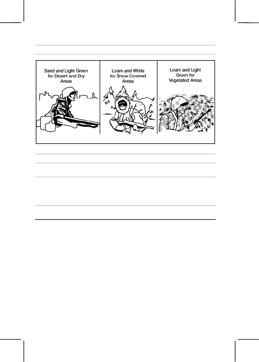
3-584 052-191-1361
Performance Steps
Figure 052-191-1361-1. Colors used in camouflage
Note. Exposed skin reflects light.
a. Cover your skin oils, even if you have very dark skin, using paint
sticks.
Note. Paint sticks cover these oils and provide blending with the background.
Note. Do not use oils or insect repellant to soften paint sticks. This defeats the
purpose of paint sticks by making the skin shiny. Work in pairs when applying paint,
because self-application may leave gaps, such as behind the ears.
b. Use information in table 052-191-1361-1 when applying paint on the
face.

052-191-1361 3-585
Performance Steps
Table 052-191-1361-1. Color Chart
Skin Color Shine Areas Shadow Areas
Camouflage
material Light or dark Forehead,
cheekbones, ears,
nose, and chin
Around eyes,
under nose, and
under chin
Loam and light
green stick All troops use in
areas with green
vegetation
Use loam Use light green
Sand and light
green stick All troops use in
areas lacking
green vegetation
Use light green Use sand
Loam and white All troops use only
in snow-covered
terrain
Use loam Use white
Burnt cork, bark
charcoal, or lamp
black
All troops, if
camouflage sticks
not available
Use Do not use
Light-color mud All troops, if
camouflage sticks
not available
Do not use Use
c. Paint high, shiny areas (forehead, cheekbones, nose, ears, chin)
with a dark color.
d. Paint low, shadow areas with a light color.
e. Paint exposed skin on the back of the neck, arms, and hands with
an irregular pattern.
CAUTION
Mud contains bacteria, some of which is harmful and may cause disease or
infection. Mud should be considered as a last resort as field expedient paint.
CAUTION
Expedient paint containing motor oil should be used with extreme caution.
3. Camouflage your BDU and helmet.
a. Roll your sleeves down and button all buttons.
b. Attach leaves, grass, small branches, or pieces of LCSS to your
uniform and helmet (figure 052-191-1361-2).
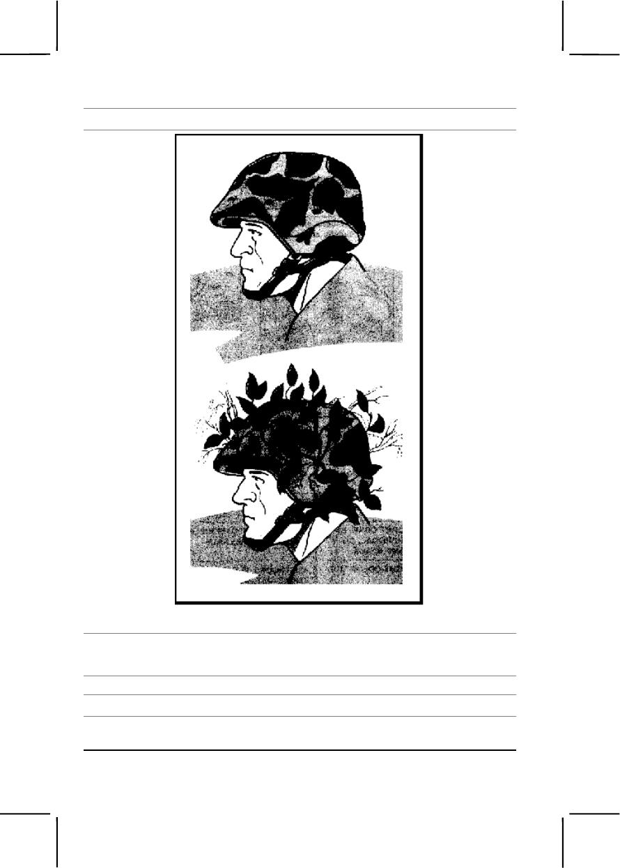
3-586 052-191-1361
Performance Steps
Figure 052-191-1361-2. Camouflaged helmet
Note. These items will distort shapes and blend colors with the natural background.
Note. BDUs provide visual and near-infrared camouflage.
c. Do not starch BDUs.
Note. Starch counters the infrared properties of the dyes.
d. Replace excessively faded and worn BDUs because camouflage
effectiveness is lost.

052-191-1361 3-587
Performance Steps
4. Camouflage your personal equipment.
a. Cover or remove shiny items.
b. Secure items that rattle or make noise when moved or worn.
Evaluation Preparation:
Setup: Ensure that all materials required in the conditions are available to
the soldier. The buddy system should be used when applying paint to the
face.
Brief Soldier: Tell the soldier, in preparation for unit defense, he is to identify
critical camouflage considerations, camouflage himself or a buddy's exposed
skin with paint sticks, and camouflage his individual equipment.
Performance Measures GO NO GO
1. Identified critical camouflage considerations. —— ——
a. Minimized movement, and moved slowly and
smoothly.
b. Broke up, disguised, or distorted shapes and
outlines.
c. Covered or removed light-reflecting items.
d. Blended camouflage with the natural
surroundings.
2. Camouflaged exposed skin. —— ——
a. Selected the correct combination of paint sticks
for the present location.
b. Used paint sticks to camouflage exposed skin on
face with irregular patterns.
c. Used paint sticks to camouflage exposed areas of
neck, arms, and hands with irregular patterns.
3. Camouflaged uniform and helmet. —— ——
a. Ensured that uniform was not faded or starched.
b. Rolled down and buttoned both sleeves.
c. Broke up shape and pattern by attaching leaves,
grass, small branches, and/or pieces of LCSS to uniform
and helmet.
4. Camouflaged personal equipment. —— ——

3-588 052-191-1362
Performance Measures GO NO GO
a. Covered or removed all items that reflected light
(for example, mess kits, mirrors, eye glasses, watch
crystals, plastic map cases, starched uniforms, plastic
map cases, clear plastic garbage bags, goggles worn on
top of helmet, and red-filtered flashlights).
b. Secured items that rattled or made noise when
moved or worn.
Evaluation Guidance: Score the soldier GO if all performance measures
are passed. Score the soldier NO GO if any performance measure is failed.
If the soldier fails any performance measure, show him how to do it correctly.
References
Required Related
FM 20-3
FM 21-75
052-191-1362
Camouflage Equipment
Conditions: Given an item of equipment to camouflage, such as a wheeled
vehicle (truck or jeep) or a tracked vehicle (armored personnel carrier [APC]
or infantry fighting vehicle) and the lightweight camouflage screen system
(LCSS) or natural camouflage material (such as burlap, sandbags, and cloth
strips). You are wearing a battle dress uniform (BDU).
Special Conditions: When this task is to be performed in a nuclear,
biological, and chemical (NBC) environment, there will be no change in
standards due to mission-oriented protective posture (MOPP) 4.
Standards: Camouflage equipment so all shiny parts are concealed, all
remaining parts of the equipment are covered in irregular patterns, and
outlines blend with predominant terrain background in the area. Camouflage
equipment to prevent detection by visual, near-infrared, infrared, ultraviolet,
radar, acoustic, and radio sensors.
Performance Steps
1. Hide the equipment by positioning it—
a. Under natural cover (whenever possible).
b. Within natural shadows (whenever possible).
c. In natural or constructed depressions in the ground.
d. So it is concealed by existing vegetation (whenever possible).
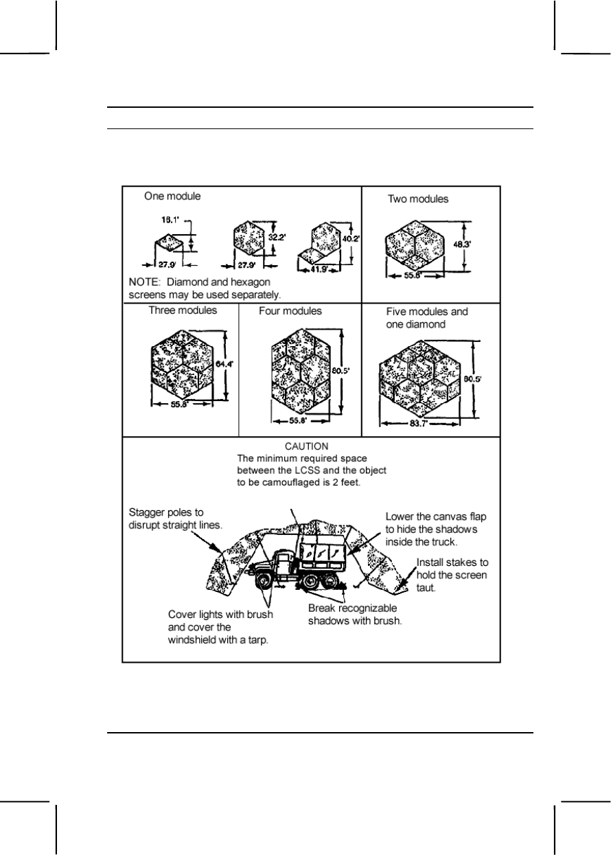
052-191-1362 3-589
Performance Steps
2. Use the LCSS or natural camouflage materials to break up the shape
and outline of the equipment so it blends in with the surrounding area.
(figure 052-191-1362-1)
Figure 052-191-1362-1. Camouflage nets
3. Cover all shiny areas of the equipment, such as headlights, reflectors,
mirrors, and windshields.

3-590 052-191-1362
Performance Steps
4. Cover or brush out obvious tracks that lead to the equipment.
Evaluation Preparation:
Setup: Provide the soldier with equipment to be camouflaged as listed in the
conditions.
Brief Soldier: Tell the soldier he is to camouflage the vehicle or piece of
equipment in preparation for unit defense.
Performance Measures GO NO GO
1. Hid the equipment by positioning it— —— ——
a. Under natural cover (whenever possible)
b. Within natural shadows (whenever possible)
c. In natural or constructed depressions in the
ground.
d. So it was concealed by existing vegetation
(whenever possible).
2. Used the LCCS or natural camouflage materials to
break up the shape and outline of the equipment so it
blended with the surrounding area. —— ——
3. Covered all shiny areas of the equipment, such as
headlights, reflectors, mirrors, and windshields. —— ——
4. Covered or brushed out obvious tracks that led to the
equipment. —— ——
Evaluation Guidance: Score the soldier GO if all performance measures
are passed. Score the soldier NO GO if any performance measure is failed.
If the soldier fails any performance measure, show him what was done
wrong and how to do it correctly.
References
Required Related
FM 20-3
FM 21-75

191-376-4114 3-591
191-376-4114
Control Entry to and Exit from a Restricted Area
Conditions: You are assigned to control entry to, and exit from, a restricted
area. You are given special orders, identification cards or badges, local
standing operating procedures (SOPs), access rosters, communications
equipment, locally produced forms, and the current duress code.
Standards: Prevent unauthorized personnel, packages, and/or vehicles
from entering or leaving the restricted area.
Performance Steps
1. Identify personnel before allowing them to enter or exit the restricted
area.
a. Ensure that only one individual is processed in or out at any given
time.
b. Verify the person's identity by comparing the person's face with the
photograph on the identification card.
c. Ensure the name of the person attempting to enter is on the access
roster. The site commander or custodian must authenticate the roster.
d. Obtain authority to enter, if applicable, for personnel whose names
are not on the access roster. Call the sergeant of the guards, the security
officer, or the vouching officer.
e. Ensure that personnel entering the facility know the most direct
route to their destination.
2. Use the following card and badge systems:
a. Single card or badge system. Permission to enter is shown on the
card or badge by letters, numerals, or colors.
b. Card or badge exchange system.
(1) The individual entering the area presents the badge or card to
the guard and the guard exchanges it with the card or badge kept at the
entrance.
(2) The individual again exchanges the card or badge when leaving
the area.
Note. Always keep the second card or badge in the area.
c. Multiple card or badge system.
(1) Exchange the card or badge at the entrance to each security
area within the installation.
(2) Keep cards and badges at each area only for those personnel
who have the appropriate card or badge.

3-592 191-376-4114
Performance Steps
(3) Brief the badge holder that the badge must be displayed at all
times when in the controlled or restricted area.
Note. For comparison purposes, card and badge data are identical.
3. Obtain an escort for visitors with authority to enter the restricted area
according to special orders.
4. Use challenges, passwords, and code words in tactical areas.
5. Use a duress code.
6. Check the authorization for vehicle entry and exit.
a. Log all vehicles entering or leaving the area. Include in the log the
description of the vehicle, the identity of the driver, the purpose of the visit,
and the destination.
b. Arrange an escort for all vehicles entering the area according to
special orders.
7. Prohibit entry (into the restricted area) of harmful materials, such as
matches, cameras, and any other items prohibited by the special orders.
a. Be alert for the wrongful appropriation, pilferage, or compromise of
materials or recorded information.
b. Make periodic spot checks of personnel.
c. Search all packages.
d. Search vehicles before allowing them to enter or exit.
8. Take the appropriate actions in the event of a security violation.
a. Detain the suspect until help arrives.
b. Report a discovery of security violations.
c. Apprehend the suspect.
d. Prepare a detailed, written report.
Evaluation Preparation:
Setup: Create scenarios using the various control techniques and provide
the materials and equipment necessary for each. Have other soldiers role
play the part of authorized and unauthorized personnel.
Brief Soldier: Tell the soldier being evaluated the challenge word, password,
code word, or duress code to be used.
Performance Measures GO NO GO
1. Identified personnel before allowing them to enter or
exit the restricted area. —— ——
2. Used the card and badge systems. —— ——

301-371-1000 3-593
Performance Measures GO NO GO
3. Obtained an escort for visitors with authority to enter
the restricted area according to special orders. —— ——
4. Used challenges, passwords, and code words in
tactical areas. —— ——
5. Used a duress code. —— ——
6. Checked the authorization for vehicle entry and exit. —— ——
7. Prohibited entry (into the restricted area) of harmful
materials, such as matches, cameras, and any other
items prohibited by the special orders. —— ——
8. Took the appropriate actions in the event of a
security violation. —— ——
Evaluation Guidance: Score the soldier GO if all performance measures
are passed. Score the soldier NO GO if any performance measure is failed.
If the soldier fails any performance measure, show him what was done
wrong and how to do it correctly.
References
Required Related
TC 19-138 AR 50-5
FM 22-6
301-371-1000
Report Intelligence Information
Conditions: You have observed enemy activity, significant terrain, and
weather features and must immediately report the activity to your chain of
command via radio, wire, cable, or messenger.
Standards: Submitted observations in a spot report, using the SALUTE
format, to your chain of command, within five minutes of observing enemy
activity. You correctly identified six out of six SALUTE items.
Performance Steps
1. Identify enemy activity. Determine whether observed activity is friendly
or enemy. If unable to make determination, report activity as unknown.
2. Record information in a spot report, using the SALUTE format.

3-594 301-371-1000
Performance Steps
a. Spot report is a report containing information for which speed of
transmission is essential. A spot report does not have a prescribed format,
but use of the SALUTE format will ensure reporting of essential
information.
b. Define SALUTE acronym.
(1) S—Size. Report the number of personnel, vehicles, aircraft, or
size of an object.
(2) A—Activity. Report detailed account of actions, for example,
direction of movement, troops digging in, artillery fire, type of attack, NBC
activity, etc.
(3) L—Location. Report where you saw the activity. Include grid
coordinates or reference from a known point including the distance and
direction from the known point.
(4) U—Unit. Report the enemy's unit. If the unit is unknown, report
any distinctive features, such as uniforms, patches or colored tabs,
headgear, vehicle identification markings, etc.
(5) T—Time. Report the time the activity was observed, not the
time you report it. Always report local or Zulu time.
(6) E—Equipment. Report all equipment associated with the
activity, such as weapons, vehicles, tools. If unable to identify the
equipment, provide as much detail as you can so an identification can be
made by higher headquarters.
(c) Remarks. Include any information not included in the SALUTE
format.
3. Provide spot report to chain of command.
Evaluation Preparation:
Setup: Position two to four personnel (dressed in aggressor uniforms if
available) where they are observable with the naked eye (or binoculars if
available). Direct the aggressors to perform some type of activity such as
setting up camp, cleaning weapons, working on a vehicle, or studying maps.
Provide the soldier with a 1:50,000 scale topographic map of the test area.
If you require the soldier to write the report, provide paper and pen or pencil.
If you require the soldier to radio the report to someone else, provide two
radios and an SOI.
Brief Soldier: Have the soldier write or radio the report of activity to the
chain of command.

301-371-1050 3-595
Performance Measures GO NO GO
1. Recorded observations of enemy activity in a spot
report which included: —— ——
a. Size.
b. Activity.
c. Location.
d. Unit.
e. Time.
f. Equipment.
2. Reported all information to the chain of command
within five minutes of observation. —— ——
Evaluation Guidance: Score the soldier GO if all performance measures
are passed within five minutes. Score the soldier NO GO if any performance
measure is failed. If a soldier scores NO GO, show him what was done
wrong and how to do it correctly.
References
Required Related
FM 21-75
301-371-1050
Implement Operations Security (OPSEC) Measures
Conditions: You have received a unit OPSEC plan, which includes
essential elements of friendly information, indicators, vulnerabilities, OPSEC
measures, and AR 530-1.
Standards: Implemented OPSEC measures based on unit indicators and
vulnerabilities; protected unit essential elements of friendly information
against threat collection efforts and prevented compromise.
Performance Steps
1. Define OPSEC.
a. OPSEC is a process of analyzing friendly actions pursuant to
military operations and other activities to—
(1) Identify those friendly actions that can be observed by the
threat.
(2) Determine indicators that the threat might obtain that could be
interpreted or pieced together to derive critical information in time to be
useful.

3-596 301-371-1050
Performance Steps
(3) Select and execute measures that eliminate or reduce to an
acceptable level the vulnerabilities of friendly actions to the threat
exploitation.
b. OPSEC maintains essential secrecy, which is the condition
achieved by the denial of critical information to the threat. Threat
possession of critical information can prevent friendly mission
accomplishment. Thus, essential secrecy is a necessary prerequisite for
effective operations. Essential secrecy depends on the combination of two
conditions:
(1) Provide traditional security programs that deny the threat
classified information.
(2) Provide OPSEC to deny the threat critical information, which is
always sensitive and often unclassified.
2. Define indicators.
a. Indicators are data derived from open sources or from detectable
actions that the threat can piece together or interpret to reach conclusions
or official estimates concerning friendly intentions, capabilities, or activities.
They are also activities that result from military operations. Indicators
contribute to the determination of friendly courses of action. Their
identification and interpretation are critical tasks of the threat operations.
Indicators can be used in many ways. For example, if the commander
wants the threat to think one way but, in reality plans on doing something
entirely different, he may give him a false indicator (such as massing a
smaller force to disguise a larger objective).
b. There are three types of indicators:
(1) Profile indicators show how activities are normally conducted.
Profiles are developed by looking at all aspects of friendly operations from
the viewpoint of the threat. The friendly profile must include all of those
things that, if detected by the threat, could provide information concerning
our capabilities, vulnerabilities, and intentions.
(a) Patterns are stereotyped actions that occur so habitually
that they can cue an observer to either the type of military unit or activity,
its identity, capabilities, or intent. The Army tends to do things in the same
way (SOP). This causes patterns that the threat looks for so he can predict
intentions.
(b) Signatures result from the presence of a unit or activity on
the battlefield. Signatures are detected because different units have
different types of equipment, are of different sizes, emit different electronic
signals, and have different noises associated with them.

301-371-1050 3-597
Performance Steps
(2) Deviation indicators, which highlight contrasts to normal activity,
help the threat gain appreciation about intentions, preparations, time, and
place.
(3) Tip-off indicators draw attention to information that otherwise
might pass unnoticed. These are most significant when they warn the
threat of impending activity. This warning allows the threat to pay closer
attention and to task additional collection assets.
3. Identify threat capabilities.
a. The threat consists of multiple and overlapping collection efforts
targeted against all sources of Army information. The threat devotes
significant resources to monitor U.S. military operations and activities on a
daily basis. The threat can produce reliable information on the U.S. military
and its capabilities, intentions, and vulnerabilities. The threat is also
shifting the emphasis in targeting. Foreign targeting of American
technology is increasing for economic as well as military reasons.
Technology transfer will continue to remain a major concern in the future.
b. The major threat collection capabilities fall in four areas:
(1) Human intelligence (HUMINT) includes all information derived
through human sources not accessible to other collection assets. HUMINT
employs overt, covert, and clandestine operations to achieve worldwide
collection objectives.
(2) Imagery intelligence (IMINT). The threat can obtain IMINT from
land, sea, air, and space platforms (radar, photographic, infrared, and
electro-optic imagery). At the tactical level, airborne collection possesses
the greatest IMINT threat.
(3) Signals intelligence (SIGINT) results from the collection,
evaluation, analysis, integration, and interpretation of information derived
from intercepted electromagnetic emissions.
(4) Measurement and signature intelligence (MASINT) is scientific
and technical intelligence obtained by quantitative and qualitative analysis
of data derived from technical sensors for the purpose of identifying any
distinctive features associated with the source, emitter, or sender and to
facilitate subsequent identification or measurement.
c. Two additional areas of concern:
(1) Technology transfer, which has led to significant enhancement
of military-industrial capabilities at the expense of the United States.
(2) Non-traditional threats. Past and present allies are potential
intelligence threats. They can engage in intelligence collection activities to
gain economic or political advantage, which is not in the best interest of the
United States.

3-598 301-371-1050
Performance Steps
4. Define OPSEC measures. OPSEC measures are methods and means
to gain and maintain essential secrecy about critical information.
a. Action control eliminates indicators. Select what action to
undertake, decide whether or not to execute actions, or impose restraints
on actions. (Specify who, when, where, and how.)
b. Countermeasures attack the threat collection system by using—
(1) Diversions.
(2) Camouflage.
(3) Concealment.
(4) Jamming.
(5) Deception.
5. Implement the OPSEC Process. OPSEC has five steps that apply to
any plan, operation, program, project, or activity. They provide a
framework for the systematic process necessary to identify, analyze, and
protect information for essential secrecy. The process is continuous. It
considers the changing nature of the threat and friendly vulnerabilities
throughout the operation. It uses the following steps, but does not have to
follow them in a particular sequence.
a. Identify critical information. Critical information consists of specific
facts about friendly intentions, capabilities, and activities vitally needed by
the threat to plan effectively and to guarantee failure or unacceptable
consequences for friendly mission accomplishment.
(1) Determine what needs protection.
(2) Identify key questions that threat officials are likely to ask about
friendly intentions, capabilities, and activities, so they can obtain answers
critical to their operational effectiveness. To determine sensitive aspects of
our operations, ask “If known by the threat, what information and what
actions could compromise friendly operations or identify us?”
(3) Identify friendly force profile. The G3 and the G2 are
responsible for developing friendly force profiles.
(4) Avoid setting patterns.
b. Conduct an analysis of threats.
(1) Identify OPSEC vulnerabilities. It is absolutely necessary that
you know the threat. This information will assist in determining
vulnerabilities to the threat and it will become even more important when
the time comes to implement countermeasures or deception measures.

301-371-1050 3-599
Performance Steps
(2) Examine each part of the operation to find OPSEC indicators.
Compare those indicators with the threat collection capabilities. A
vulnerability exists when the threat can collect an indicator, correctly
analyze the information, make a decision, and take timely action to
degrade friendly operations.
c. Conduct an analysis of vulnerabilities.
(1) Identify possible OPSEC measures for each vulnerability.
(2) Select at least one OPSEC measure for each vulnerability.
(3) Assess the sufficiency of routine security measures (personnel,
physical, cryptographic, document, special access, and automated
information systems). This will provide OPSEC measures for some
vulnerabilities.
d. Perform risk assessment. The purpose of this step is to select
OPSEC measures for implementation. This step is designed to determine
if a risk to an operation's success exists should the threat detect friendly
indicators, patterns, or signatures. Only the commander responsible for
the mission can make this decision. He must balance the risk of
operational failure against the cost of OPSEC measures.
(1) Consider the impact of an OPSEC measure on operational
efficiency.
(2) Consider the probable risk to mission success (effectiveness) if
the unit does not implement an OPSEC measure.
(3) Consider the probable risk to mission success if an OPSEC
measure does not work.
(4) Decide which, if any, OPSEC measures to implement and when
to do so.
(5) Check the interaction of OPSEC measures. Ensure that a
measure to protect a specific piece of critical information does not
unwittingly provide an indicator of another.
(6) Coordinate OPSEC measures with the other elements of C2W.
e. Apply appropriate countermeasures to deny threat information of
specific friendly intentions, capabilities, and activities.
(1) Implement measures that require immediate action. This
applies to current operations as well as planning and preparation for future
ones.
(2) Document or task OPSEC measures by using an OPSEC
annex to the OPLAN/OPORD.

3-600 301-371-1050
Performance Steps
(3) Brief OPSEC requirements to planners, participants, and
support personnel.
Note. OPSEC measures are command-directed actions executed by individuals,
who must be aware of their responsibilities.
(4) Monitor OPSEC measures during execution. Monitoring is a
continuous process of evaluating intelligence and counterintelligence. It is
necessary to monitor countermeasures for effectiveness because
unevaluated countermeasures can lead to a false and dangerous sense of
security.
(5) Make adjustments to improve the effectiveness of existing
measures. These adjustments are necessary to obtain the best protection
for our military operations.
6. Define OPSEC review, assessment, and survey.
a. OPSEC review is an evaluation of a document to ensure protection
of sensitive or critical information.
b. OPSEC assessment is an analysis of an operation, activity,
exercise, or support function to determine the overall OPSEC posture and
to evaluate the degree of compliance of subordinate organizations with the
published OPSEC plan or OPSEC program.
c. OPSEC survey is a method to determine if there is adequate
protection of critical information during planning, preparations, execution,
and post-execution phases of any operation or activity. It analyzes all
associated functions to identify sources of information, what they disclose,
and what can be derived from the information.
Evaluation Preparation:
Setup: Provide the soldier with the materials listed in the conditions.
Brief Soldier: Tell the soldier to maintain OPSEC procedures to protect
critical aspects of operations from exploitation by threat intelligence.
Performance Measures GO NO GO
1. Defined OPSEC. —— ——
2. Defined indicators. —— ——
3. Identified threat capabilities. —— ——
4. Identified OPSEC measures. —— ——
5. Implemented OPSEC measures. —— ——
a. Identified critical information.

301-371-1050 3-601
Performance Measures GO NO GO
(1) Determined what protection was needed.
(2) Identified key questions the threat are likely to
ask about friendly intentions, capabilities, and activities.
(3) Identified friendly force profile.
(4) Avoided setting patterns.
b. Conducted analysis of threats.
(1) Identified OPSEC vulnerabilities.
(2) Found OPSEC indicators.
c. Conducted an analysis of vulnerabilities.
(1) Identified OPSEC measures for each
vulnerability.
(2) Selected OPSEC measure for each
vulnerability.
(3) Assessed the sufficiency of routine security
measures.
d. Performed risk assessment.
(1) Considered the impact of an OPSEC
measure on operational efficiency.
(2) Considered the probable risk to mission
success if the unit does not implement an OPSEC
measure.
(3) Considered the probable risk to mission
success if an OPSEC measure does not work.
(4) Decided which OPSEC measures to
implement.
(5) Checked the interaction of OPSEC measures.
(6) Coordinated OPSEC measures with the other
elements of C2W.
e. Applied appropriate countermeasures to deny
threat friendly information.
(1) Implemented measures that require
immediate action.
(2) Tasked OPSEC measures using OPSEC
annex.
(3) Briefed OPSEC requirements to planners,
participants, and support personnel.

3-602 301-371-1050
Performance Measures GO NO GO
(4) Monitored OPSEC measures during
execution.
(5) Made adjustments to improve the
effectiveness of existing measures.
6. Defined OPSEC review, assessment, and survey. —— ——
a. Defined OPSEC review.
b. Defined OPSEC assessment.
c. Defined OPSEC survey.
Evaluation Guidance: Score the soldier GO if all performance measures
are passed. Score the soldier NO GO if any performance measure is failed.
If the soldier fails any performance measures, show him what was done
wrong and how to do it correctly.
References
Required Related
AR 530-1
FM 100-5
FM 34-1
FM 34-60

A-1
Appendix A
Proponent School or Agency Codes
The first three digits of the task number identify the proponent school or
agency responsible for the task. Record any comments or questions
regarding the task summaries contained in this manual on a DA Form 2028
(Recommended Changes to Publications and Blank Forms) and send it to
the proponent school with an information copy to: Commander, U.S. Army
Training Support Center, ATTN: ATIC-ITSC-CM, Fort Eustis, VA 23604-
5166.
Table A-1. Proponent School or Agency Codes
School Code Command
MANSCEN
CM 031
EN 052
MP 191
MANSCEN, Directorate of Training Development
US Army Engineer Center and Fort Leonard Wood
320 Engineer Loop, Suite 220
Fort Leonard Wood, MO 65473-8929
IN
071
Commandant, U.S. Army Infantry School
ATTN: ATSH-OTDD
Fort Benning, GA 31905-5700
AHS
081
USAAHS, Dean, AHS
ATTN: MCCS-HTI
Fort Sam Houston, TX 78234-6122
SIG
113
Commander, USA Signal Center & School
ATTN: ATZH-DTM-U
Fort Gordon, GA 30905-5074
JAG
181 Commandant, Judge Advocate General School
ATTN: JAGS-TDD
600 Massie Road
Charlottesville, VA 22903-1781
APAC
224
Director, Army Public Affairs Center
6 ACR Road, Bldg 8607
ATTN: SAPA-PA
Fort Meade, MD 20755-5650

A-2
Table A-1. Proponent School or Agency Codes
School Code Command
MI
301
Commander, USA Intelligence Center & Fort Huachuca
ATTN: ATZS-FDR-TA
Fort Huachuca, AZ 85613-6000
JFK
331
Commander
USA John F Kennedy Special Warfare Center and School
ATTN: AOJK-DT-DMO
Fort Bragg, NC 28310-5000
CASCOM
093
101
551
U.S. Army Combined Arms Support Command
(CASCOM) Training Directorate
USACASCOM, ATTN: ATCL-A
401 First St., Suite 227
Fort Lee, VA 23801-1511
SSI
805C
Commander, USA Soldier Support Institute
ATTN: ATSG-TD-HRD
Fort Jackson, SC 29207-7065

B-1
Appendix B
GUIDE TO FORMS
This appendix contains a list of forms pertinent to SMCT and CTT
evaluations and administration. In the electronic, online version of this
manual, hot links will, where indicated, provide downloadable and
reproducible copies of the forms. The user can also visit the CTT site in the
Reimer Digital Library where access to the CTT Manual and CTT Notice
(Bulletin) provide additional helpful information and links. Some of these
forms may be available in your unit.
DA Form 5164-R (Hands On Evaluation), used by CTT scorer to record
GO/NO GO for each performance measure in a given task. Refer to the
CTT Manual for the current FY (in the Reimer Digital Library) for links to DA
Forms 5164-R that are overprinted with the performance measures for each
task on the current CTT.
CTT Performance Sheet used by the CTT scorer to compile all GO/NO GO
scores to produce an overall GO or NO GO for the soldier’s common task
test. As with the Hands On Evaluation form above, the CTT Performance
Sheet is different for each FY; it is overprinted with the tasks from the current
CTT and linked from the CTT Manual (in the Reimer Digital Library) for the
current FY.
DA Form 5165-R (Field Expedient Squad Book), used to record task
proficiency for groups of soldiers in a squad. This squad book should be
especially beneficial for recording training results gathered during MTP, field
exercises, or individual training sessions. Once training is completed,
trainers may transfer information from DA Form 5165-R to the leader book
(FM 7-10).
CTT Roll Up for SL 1-2 and SL 3-4, used by trainers and administrators to
record performances for larger, unit-size groups of soldiers. This form is a
good means of seeing and reporting an overall ratio of soldiers passing the
CTT to the total of those tested.
DA Form 2028 (Recommended Changes to Publications and Blank Forms),
used by soldiers and trainers to record any comments or questions
regarding the task summaries contained in this manual. Use the task
proponent address for the appropriate proponent code given in appendix A
(first three digits of the task number).

C-1
Appendix C
Land Navigation Supporting Tasks
1. Select a Movement Route Using a Map
2. Identify Topographic Symbols on a Military Map
3. Identify Terrain Features on a Map
4. Determine the Grid Coordinates of a Point on a Military Map
5. Determine a Magnetic Azimuth Using a Lensatic Compass
6. Determine the Elevation of a Point on the Ground Using a Map
7. Determine a Location on the Ground by Terrain Association
8. Measure Distance on a Map
9. Convert Azimuths
10. Orient a Map Using a Lensatic Compass
11. Orient a Map to the Ground by Map-Terrain Association
12. Locate an Unknown Point on a Map and on the Ground by Intersection
13. Locate an Unknown Point on a Map and on the Ground by Resection
14. Determine Direction without a Compass
15. Determine Azimuths Using a Protractor
16. Compute Back Azimuths
Land Navigation Task 1
Select a Movement Route Using a Map
Conditions: Given an operation or fragmentary order, a 1:50,000 scale
military map, and a compass.
Standards: Selected a route with the following characteristics:
1. Took advantage of maximum cover and concealment.
2. Ensured observation and field of fire for the overwatch or fire support
elements.
3. Allowed positive control of all elements.
4. Accomplished the mission quickly without unnecessary or prolonged
exposure to enemy fire.
Performance Steps
1. Select the route that makes the best use of terrain.

C-2
Performance Steps
a. Your platoon spends more time moving than fighting in combat.
Because a moving unit usually contacts the enemy at a time and place of
the enemy's choosing, you must use terrain to your best advantage. Proper
use of terrain has two advantages:
(1) Cover and concealment to protect the platoon during movement.
(2) Maximum effectiveness of the platoon's weapons.
b. To properly use those advantages, you must understand the military
aspects of terrain and be able to apply them to any given situation, whether
it be a defense, a delay, or a road march behind the forward edge of the
battle area (FEBA).
c. The primary requirement for any type of movement on the
battlefield is cover and concealment.
(1) Cover is any type of shielding from the effects of weapon fire,
especially direct fire. You must take advantage of every ravine or
depression in the ground to protect and cover your force, especially if you
are forward of the FEBA. You must evaluate the terrain, the abilities of the
enemy's weapons systems, and the position of known or suspected enemy
emplacement. Visualize a cross section of the terrain and determine where
the enemy cannot place effective direct fire on your proposed route.
(2) Concealment is anything that hides or disguises your force. You
must consider concealment from both air and ground observation. If you
are mechanized, exhaust smoke or dust can reveal your unit to the enemy.
d. If you are moving in an area where contact with the enemy is
expected, you must ensure that your proposed route can be covered by
fire from your overwatch or fire support positions. Those positions must
have good observation and fields of fire.
(1) Direct fire weapons must have good observation to fire known
or suspected enemy positions along your movement route. You must have
observation to control the maneuver of your elements, if they make
contact. Consider the effects of smoke and dust from friendly and enemy
fire.
(2) Select a route that gives your unit the best field of fire. Your
machine guns and antitank weapons must have good fields of fire to be
effective. They must be in a position to provide suppressive fires
immediately. The crew-served weapons to overwatching your movement
must be able to observe your route and fire in your support all the way to
the objective. The overwatch positions that you select must have
unobstructed fields of fire to the next overwatch position.
C-3
Performance Steps
2. Select the route that provides the most favorable tactical advantage
and meets the mission requirements. If enemy air is active or enemy
ground forces are in the area of the route, you must take maximum
advantage of cover and concealment. If speed of movement is critical, the
route should be over the most easily negotiable terrain, avoiding difficult
obstacles. The route should include movement from one easily
distinguishable terrain feature to another. When ordered to move, you must
check the terrain based on the above considerations and select the
quickest and safest route.
3. Planning a route can be aided by the use of special purpose maps and
aerial photographs. If those aids are available, use them to ensure that you
have the most current information.
4. Map reconnaissance, however, is no substitute for ground
reconnaissance. If time is available and the tactical situation permits,
reconnoiter the route that you have to move over.
Evaluation Preparation:
Setup: In a field environment, provide the soldier with a 1:50,000-scale
military map of the area and a compass, and issue him an oral or written
operation order.
Brief Soldier: Tell the soldier to select a route of movement between two
given points (marked on the map) where the likelihood of enemy contact is
unknown. The soldier must select a route that offers the best cover and
concealment, ensure the best observation and fields of fire for support
elements, allow positive control of elements, and accomplish the mission
without unnecessary or prolonged exposure to enemy fire.
Performance Measures GO NO GO
1. Made a map reconnaissance of the area that must
be moved over. —— ——
2. Selected a route that offered: —— ——
a. Maximum cover.
b. Maximum concealment.
c. Good observation to fire at known or suspected
enemy positions along movement route.
d. Best fields of fire.
e. Most favorable tactical advantage.
f. Positive control of all elements.
C-4
Evaluation Guidance: Score the soldier GO if all performance measures
are passed. Score the soldier NO GO if any performance measure is failed.
If the soldier fails any performance measures, show him what was done
wrong and how to do it correctly.
References
Required Related
FM 7-7
FM 7-8
Land Navigation Task 2
Identify Topographic Symbols on a Military Map
Conditions: Given a standard 1:50,000-scale military map.
Standards: Identified topographic symbols, colors, and marginal information
on a military map with 100 percent accuracy.
Performance Steps
1. Identify the colors on a military map.
a. The ideal situation would be that every feature on that portion of the
earth being mapped is shown on the map in its true shape and size.
Unfortunately, that is impossible.
b. The amount of detail shown on a map increases or decreases,
depending on its scale; for example, a map with a scale of 1:250,000.
c. Details are shown by topographic symbols. These symbols are
shown using six basic colors as shown in table C-1.
Table C-1. Colors on a topographic map
Colors Symbols
Black Cultural (man-made) features other than roads
Blue Water
Brown All relief features—contour lines on old maps—
cultivated land on red-light readable maps
Green Vegetation
Red Major roads, built-up areas, special features on old
maps
Red-Brown All relief features and main roads on red-light readable
maps
2. Identify the symbols used on a military map to represent physical
features, such as physical surroundings or objects, as shown in table C-2.
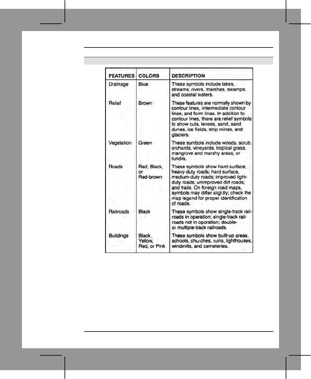
C-5
Performance Steps
Table C-2. Features on topographic maps
a. The shape of an object on the map usually tells what it is, for
example, a black, solid square is a building or a house; a round or irregular
blue item is a lake or pond.
b. Logic and what the colors mean must work together in determining
a map feature. For example, blue represents water. If you see a symbol
that is blue and has clumps of grass, this would be a swamp.
c. The size of the symbol shows the approximate size of an object.
Most symbols are enlarged 6 to 10 times so that you can see them under
dim light.
d. Use the legend; it has most of the symbols used on the map.
C-6
Performance Steps
3. Identify the marginal information found on the legend.
a. Marginal information at the top of the map sheet.
(1) The top left corner contains the geographic location of the map
area and the scale of the map.
(2) The top center has the name of the map sheet.
(3) The top right corner contains the map edition, map series, and
the map sheet number.
b. Marginal information at the bottom of the map sheet.
(1) The lower left corner of the map contains the legend, the name
of the agency that prepared the map, the map sheet number, and the map
sheet name.
(2) The bottom center contains the bar scales in meters, yards,
miles, and nautical miles; the contour interval of the contour lines; the grid
reference box; the declination diagram; and the G-M angle (mils or
degrees).
(3) The lower right corner contains the elevation guide, the
adjoining map sheet diagram, and the boundaries box, which shows any
boundaries that may be on the map.
Evaluation Preparation:
Setup: On a 1:50,000-scale military map, circle each item of marginal
information found on the map. Randomly letter the circled items A through J.
Circle an item or feature shown on the map by color. Randomly number
each colored item 1 through 10. The items are listed in the Evaluation
Guide/Performance Measures. Have a sheet of paper and two pencils
available for the soldier being tested. For each soldier tested, provide a
duplicate set of the map, paper, and pencils.
Brief Soldier: Tell the soldier to letter the paper A through J and 1 through
10. Tell the soldier to write down the name of the item contained in each
lettered and numbered circle on the map.
Performance Measures GO NO GO
1. Identified the sheet name. —— ——
2. Identified the sheet number. —— ——
3. Identified the contour interval. —— ——
4. Identified the G-M angle (mils or degrees). —— ——

C-7
5. Identified the legend. —— ——
6. Identified the bar scales. —— ——
7. Identified the declination diagram. —— ——
8. Identified the grid reference box. —— ——
9. Identified the adjoining map sheets diagram. —— ——
10. Identified the elevation guide. —— ——
11. Identified 2 of 2 specific man-made features (shown
in black on the map). —— ——
12. Identified 2 of 2 water features (blue on the map). —— ——
13. Identified 2 of 2 vegetation features (green on the
map). —— ——
14. Identified 2 of 2 man-made features; for example,
main roads or build-up areas (shown in brown or red-
brown on the map).
—— ——
15. Identified 2 of 2 contour lines (shown in brown or red-
brown on the map). —— ——
Evaluation Guidance: Score the soldier GO if all performance measures
are passed. Score the soldier NO GO if any performance measure is failed.
If the soldier scores NO GO, show the soldier what was done wrong and
how to do it correctly.
References
Required Related
FM 3-25.26
FM 21-31
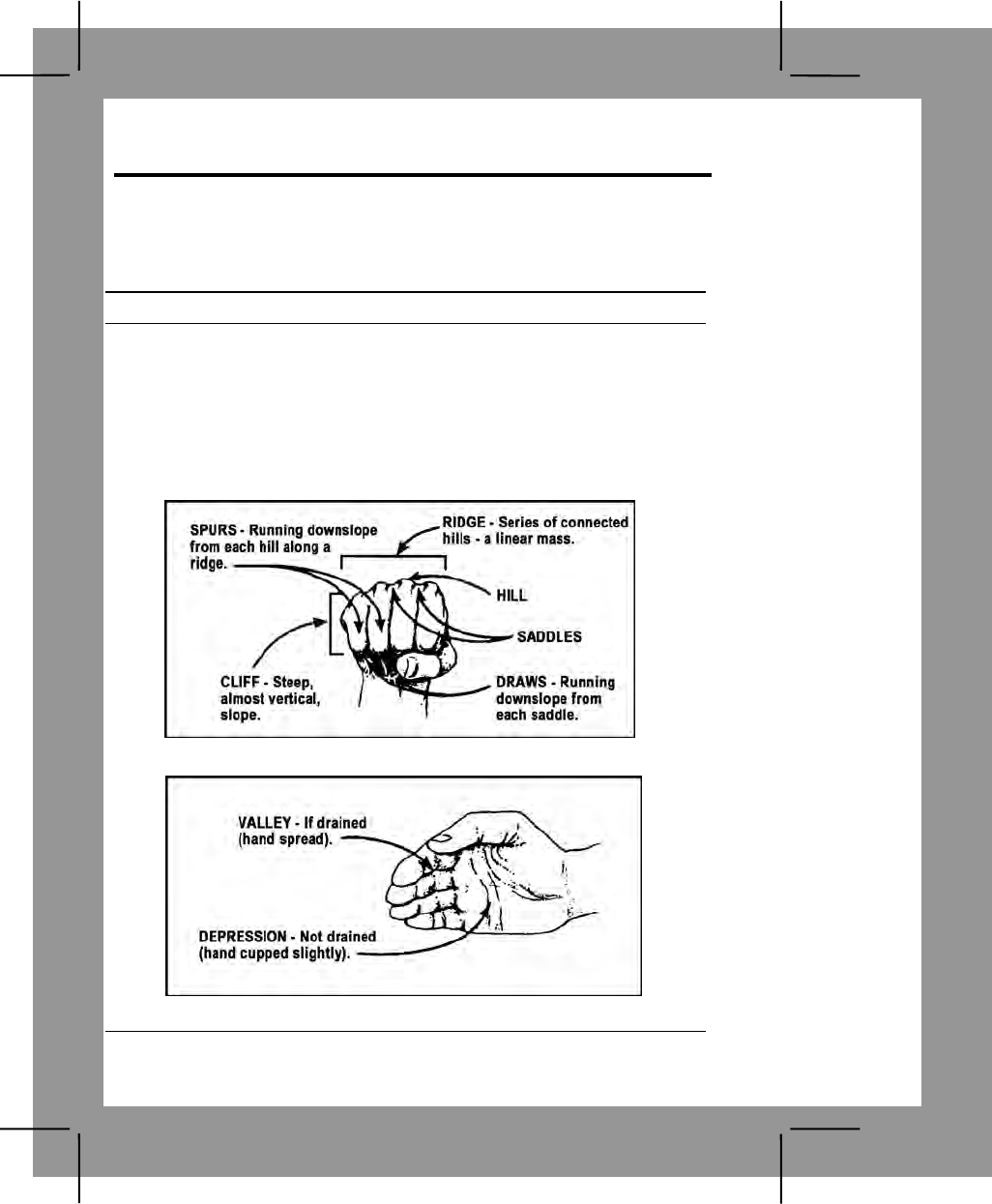
C-8
Land Navigation Task 3
Identify Terrain Features on a Map
Conditions: Given a standard 1:50,000-scale military map.
Standards: Identified the five major and three minor features on the map.
Performance Steps
1. Identify terrain features in table C-3 in the same manner on all maps,
regardless of the contour interval, but you must realize that a hill in the
Rocky Mountains will be much bigger than the one in south Florida. You
must be able to recognize all the terrain features to locate a point on the
ground or to navigate from one point to another (figures C-3 through C-10).
Note. During instruction, demonstrate to the soldiers how they can learn terrain
features using the fist and hand (figures C-1 and C-2). They can be used to show
what each terrain feature would look like on the ground.
Figure C-1. Using fist to explain terrain features
Figure C-2. Using hand to explain terrain features
C-9
Performance Steps
Table C-3. Major and minor terrain features
FEATURE CHARACTERISTICS MAP SYMBOL
Hill, Figure C-5,
Major A point or small area
of high ground from
which the ground
slopes down in all
directions.
Contour lines
forming concentric
circles.
Ridge, Figure C-6
Major A line of high ground
with height variations
along its crest.
Contour lines
forming a U or V;
closed end points
away from high
ground.
Valley, Figure C-7,
Major Reasonably level
ground bordered on
the sides by higher
ground. Generally has
maneuver room.
Contains a stream.
Contour lines form
U. Lines tend to
parallel stream
before crossing.
Contour line
crossing a stream
always points
upstream.
Saddle, Figure C-8,
Major A dip/low point along
a ridge crest; either
lower ground between
two hill tops or a break
in the level crest.
A saddle is
normally
represented as an
hourglass.
Depression, Figure
C-9, Major Low point or hole in
the ground with higher
ground on all sides.
Closed contour
lines that have tick
marks pointing
toward low ground.
Draw, Figure C-10,
Minor Like a valley but
normally has less
developed stream
course. No level
ground and little or no
maneuver room.
Ground slopes
upward on the sides
and toward the head
of the draw.
Contour lines are
V-shaped with the
point of the V
toward the head of
the draw (high
ground).
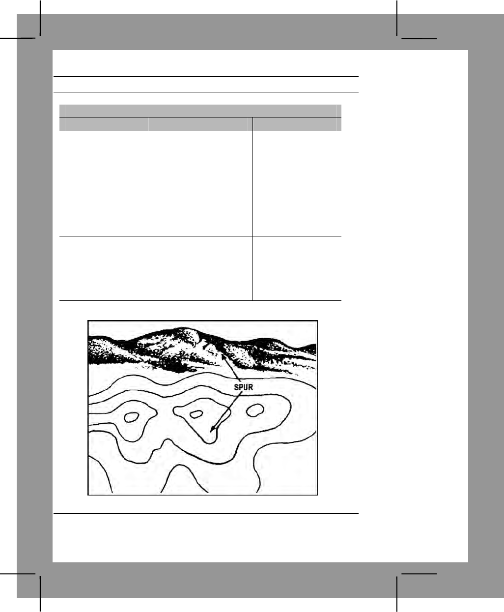
C-10
Performance Steps
Table C-3. Major and minor terrain features
FEATURE CHARACTERISTICS MAP SYMBOL
Spur, Figure C-3,
Minor Short, continuously
sloping line of higher
ground jutting out the
side of a ridge. Often
Table C-3. Major and
minor terrain features
(continued)formed by
parallel streams
cutting draws down a
ridge.
Contour lines depict
a spur with the U or
V pointing away
from higher ground.
Cliff, Figure C-4,
Minor A vertical or near
vertical slope. Contour lines are
close together or a
ticked or “carrying”
contour line (ticks
point to lower
ground).
Figure C-3. Spur
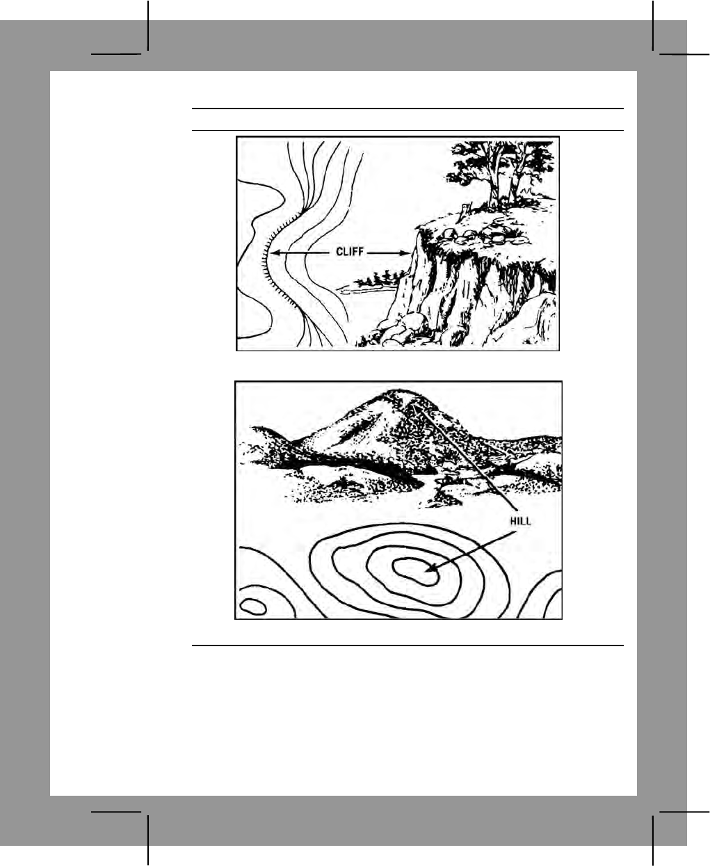
C-11
Performance Steps
Figure C-4. Cliff
Figure C-5. Hill
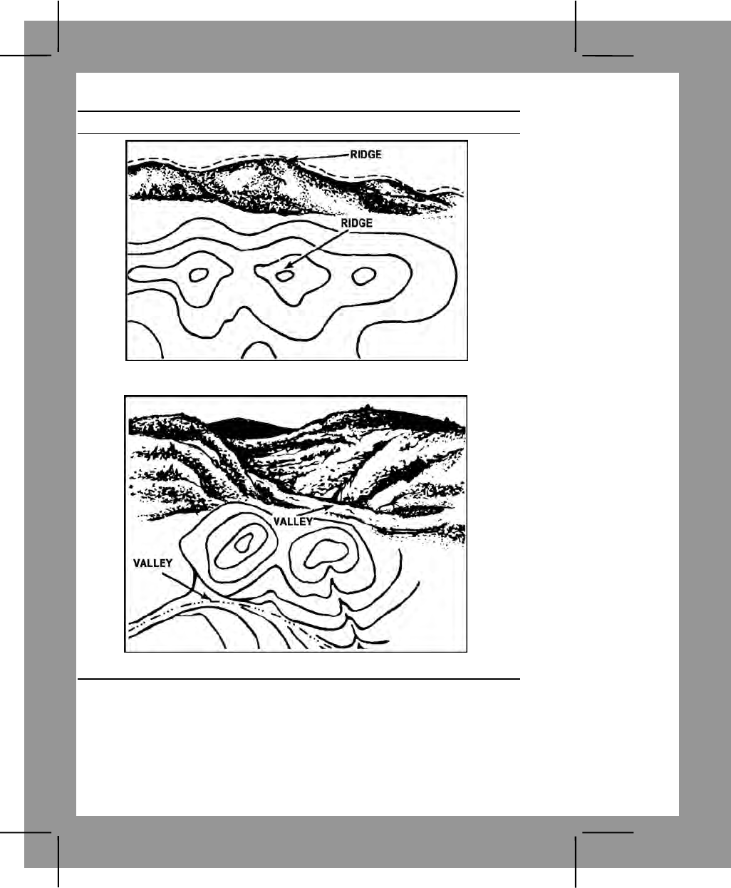
C-12
Performance Steps
Figure C-6. Ridge
Figure C-7. Valley
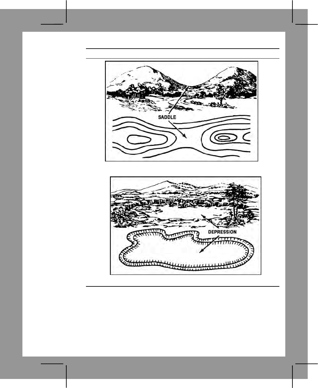
C-13
Performance Steps
Figure C-8. Saddle
Figure C-9. Depression
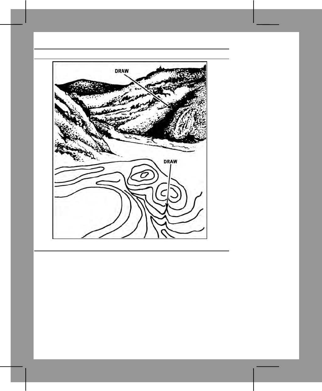
C-14
Performance Steps
Figure C-10. Draw
Evaluation Preparation:
Setup: Use a 1:50,000-scale military map; circle one example of each major
terrain feature and one example of each minor terrain feature. Randomly
number the circled terrain features 1 through 8. Provide each soldier being
tested with duplicate sets of the map, paper, and two pencils.
Brief Soldier: Tell the soldier to number the paper 1 through 8. Tell the
soldier to write down the terrain feature that corresponds to each circled
area on the map.
C-15
Performance Measures GO NO GO
1. Identified the following. —— ——
a. Hilltop.
b. Ridge.
c. Valley.
d. Saddle.
e. Depression.
f. Draw.
g. Spur.
h. Cliff.
Evaluation Guidance: Score the soldier GO if all performance measures
are passed. Score the soldier NO GO if any performance measure is failed.
If the soldier scores NO GO, show the soldier what was done wrong and
how to do it correctly.
References
Required Related
FM 3-25.26
Land Navigation Task 4
Determine the Grid Coordinates of a Point on a Military Map
Conditions: Given a standard 1:50,000-scale military map in a field location,
a 1:50,000 grid coordinate scale, a pencil, paper, and a point on the map for
which coordinates must be determined.
Standards: Determined the six-digit grid coordinates for the point on the
map with a 100-meter tolerance. Recorded the grid coordinates with the
correct two-letter 100,000-meter-square identifier.
Performance Steps
Note.
1. A military map can help you spot your location accurately. The map has vertical
lines (top to bottom) and horizontal lines (left to right). These lines form small
squares 1,000 meters on each side, called grid squares.
2. The lines that form grid squares are numbered along the outside edge of the map
picture. No two grid squares have the same number.
3. The precision of a point location is shown by the number of digits in the
coordinates; the more digits, the more precise the location. For example: 1996—A
1,000-meter grid square. 192961—To the nearest 100 meters.
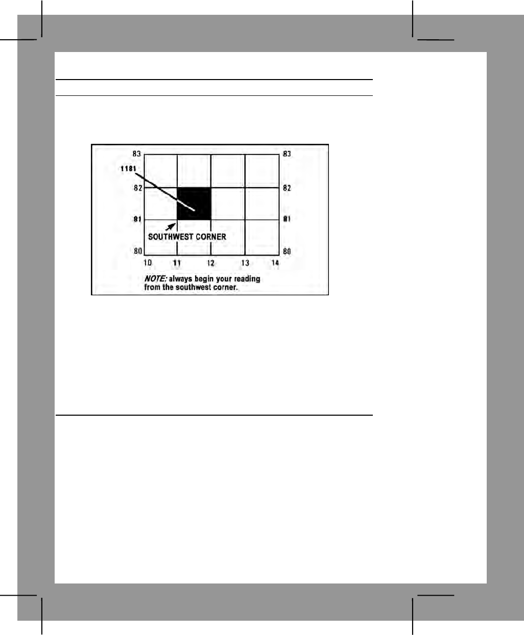
C-16
Performance Steps
1. Look at figure C-11. Your address is grid square 1181. To determine
your address, start from the left and read right until you come to 11, the
first half of your address. Then read up to 81, the other half. Your address
is somewhere in grid square 1181.
Figure C-11. Grid square 1181
2. Determine your address to the nearest 100 meters. Grid square 1181
gives your general neighborhood, but there is a lot of ground inside that
grid square. To make your address more accurate, just add another
number to the first half and another number to the other half so your
address has six numbers instead of four.
a. To get these extra numbers, suppose that each grid square has 10
lines inside it running north and south, and another 10 running east and
west. This makes 100 smaller squares. You can estimate where these
imaginary lines are (figure C-12).
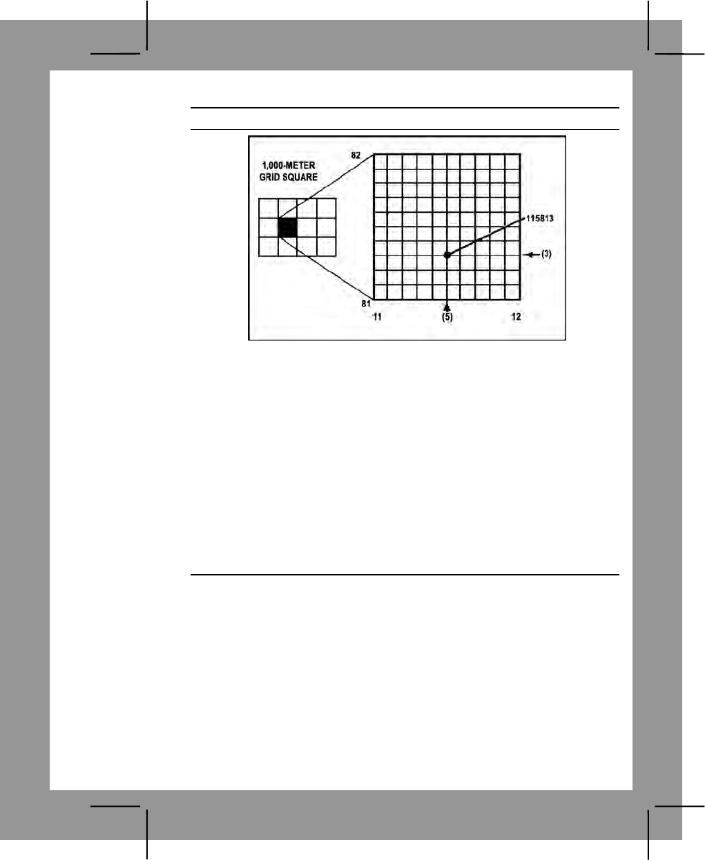
C-17
Performance Steps
Figure C-12. Grid square 1181 divided
b. Suppose you are halfway between grid line 11 and grid line 12.
Then the next number is 5 and the first half of your address is 115. Now
suppose you are also 3/10 of the way between grid line 81 and grid line 82.
Then the second half of your address is 813. Your address would be
115813 (figure C-12). (If you are exactly on line 81, the second half would
be 810.)
3. Use a coordinate scale. The most accurate way to determine the
coordinates of a point on a map is to use a coordinate scale. You do not
have to use imaginary lines because you can come up with the exact
coordinates. This scale is on the coordinate scale and protractor (GTA 05-
02-012) (figure C-13) or the plotting scale (figure C-14). Both of these
devices include two coordinate scales, 1:25,000 and 1:50,000 meters.
Make sure that when you use either of these devices, you use the correct
scale.
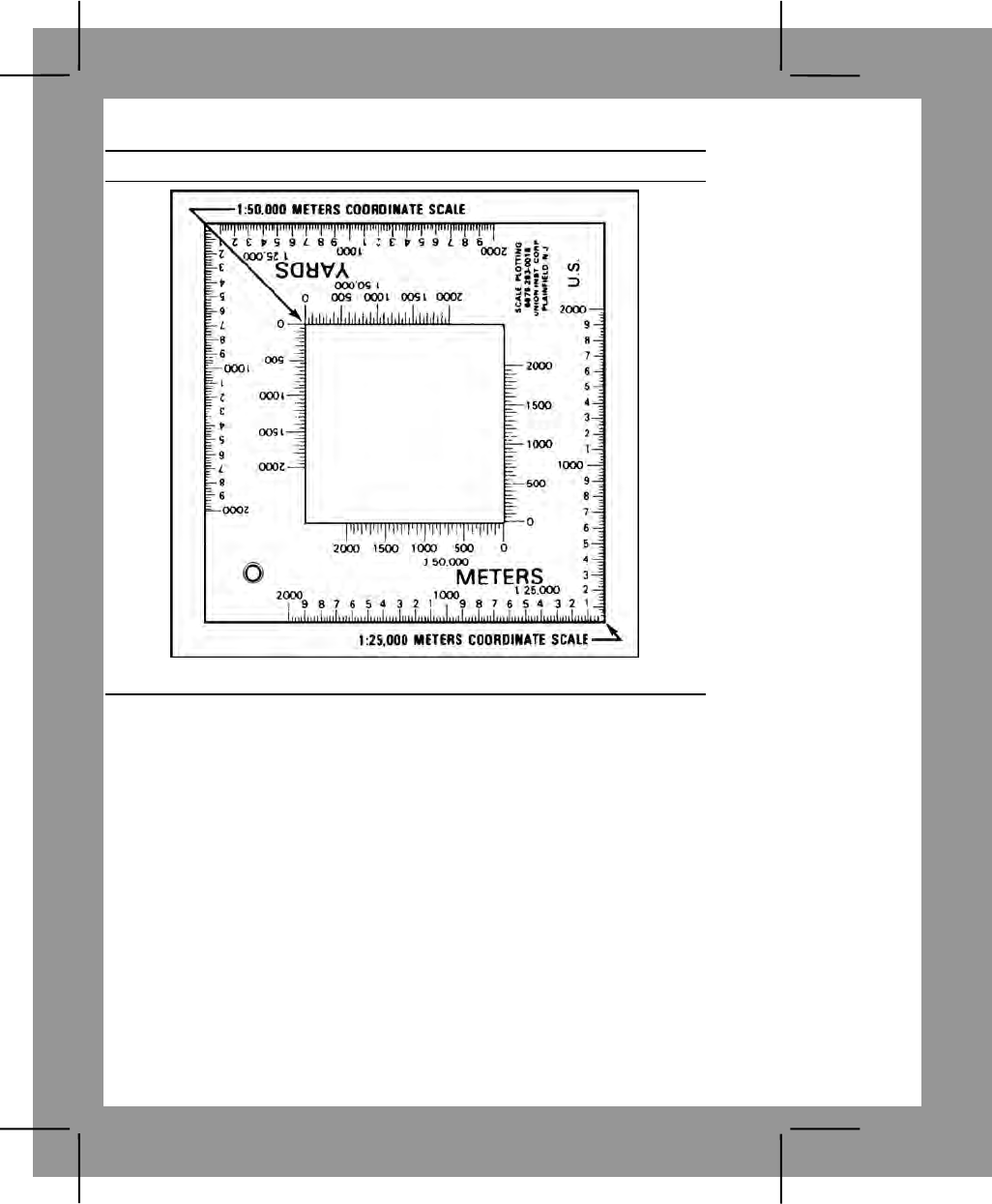
C-18
Performance Steps
Figure C-13. Coordinate scale and protractor
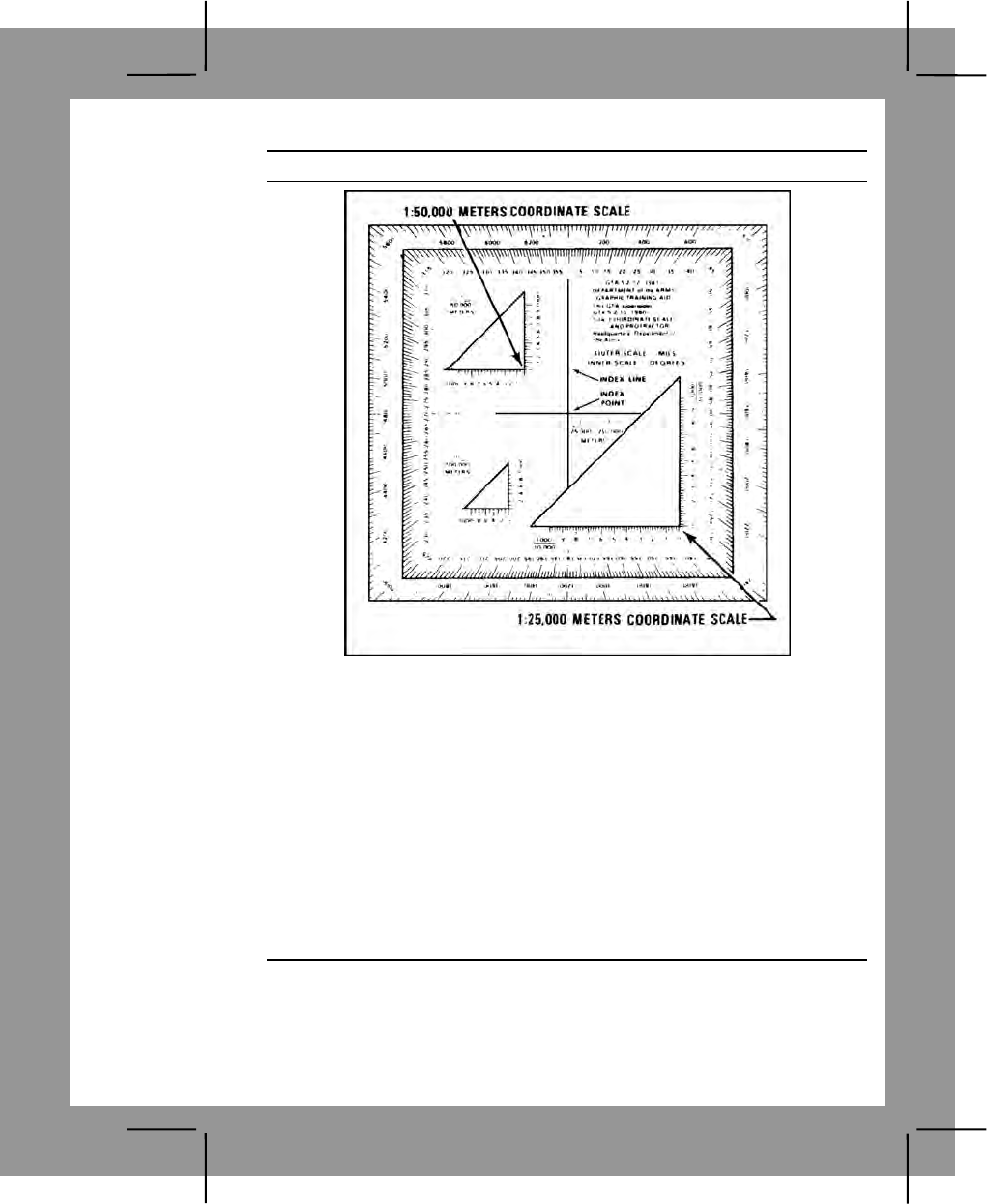
C-19
Performance Steps
Figure C-14. Plotting scale
a. Locate the grid square in which the point is located (for example,
point A, figure C-15) (the point should already be plotted on the map).
b. The number of the vertical grid line on the left (west) side of the grid
square gives the first and second digits of the coordinate.
c. The number of the horizontal grid line on the bottom (south) side of
the grid square gives the fourth and fifth digits of the coordinate.
d. Place a coordinate scale on the bottom horizontal grid line of the
grid square containing point A to determine the third and sixth digits of the
coordinate.
e. Check to see that the zeros of the coordinate scale are in the lower
left-hand (southwest) corner of the grid square where point A is located
(figure C-15).
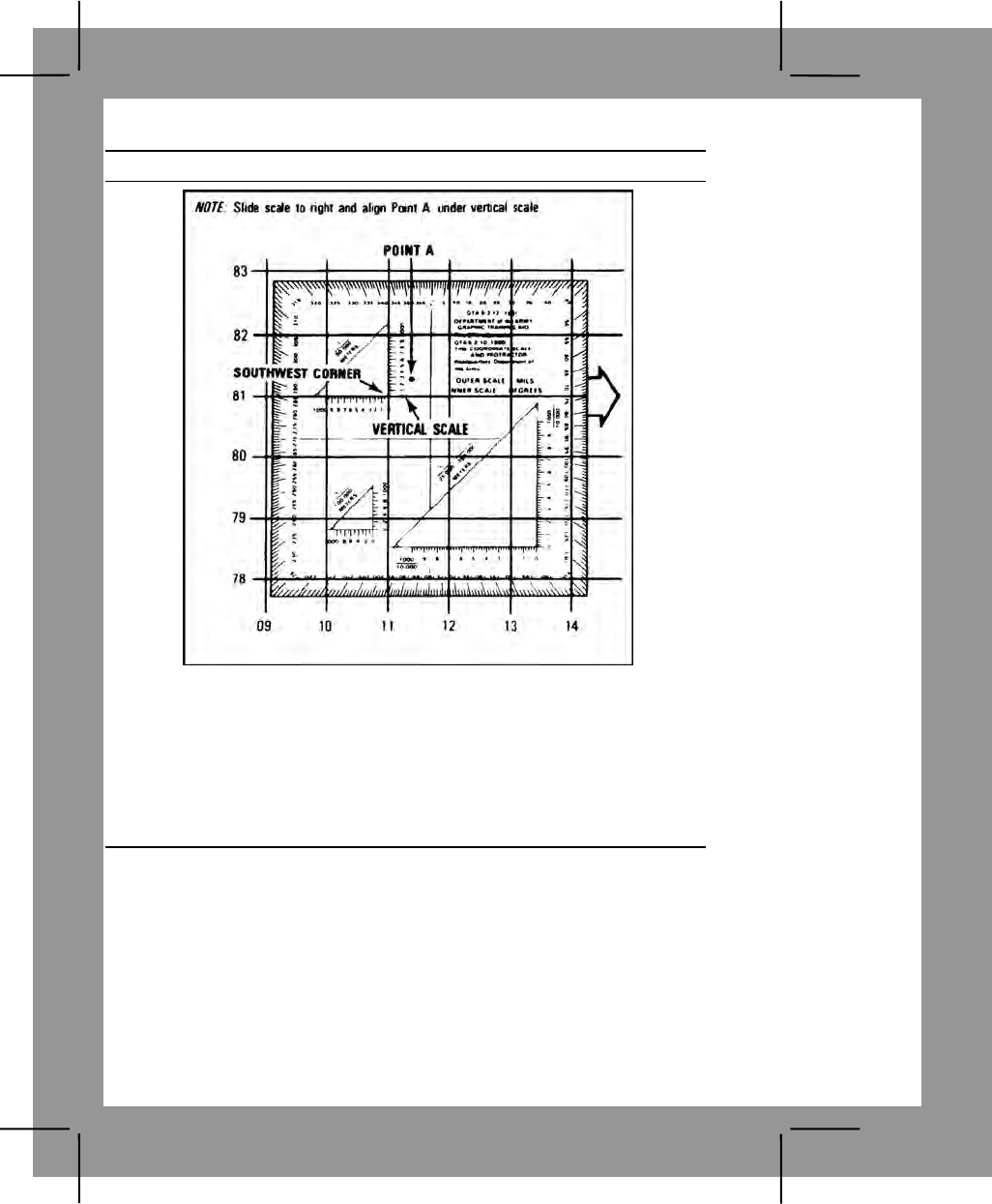
C-20
Performance Steps
Figure C-15. Placement of the coordinate scale
f. Slide the scale to the right, keeping the bottom of the scale on the
bottom grid line until point A is under the vertical (right-hand) scale (figures
C-16 and C-17). To determine the six-digit coordinate, the 100-meter mark
on the bottom scale, which is nearest the vertical grid line, is the third digit
of the number 115. The 100-meter mark on the vertical scale, which is
nearest point A, is the sixth digit of the number 813. Putting these together,
you have 115813.

C-21
Performance Steps
Figure C-16. Aligning the coordinate scale
Figure C-17. Aligning the plotting scale
g. To determine the correct two-letter 100,000-meter-square identifier,
look at the grid reference box in the margin of the map (figure C-18).
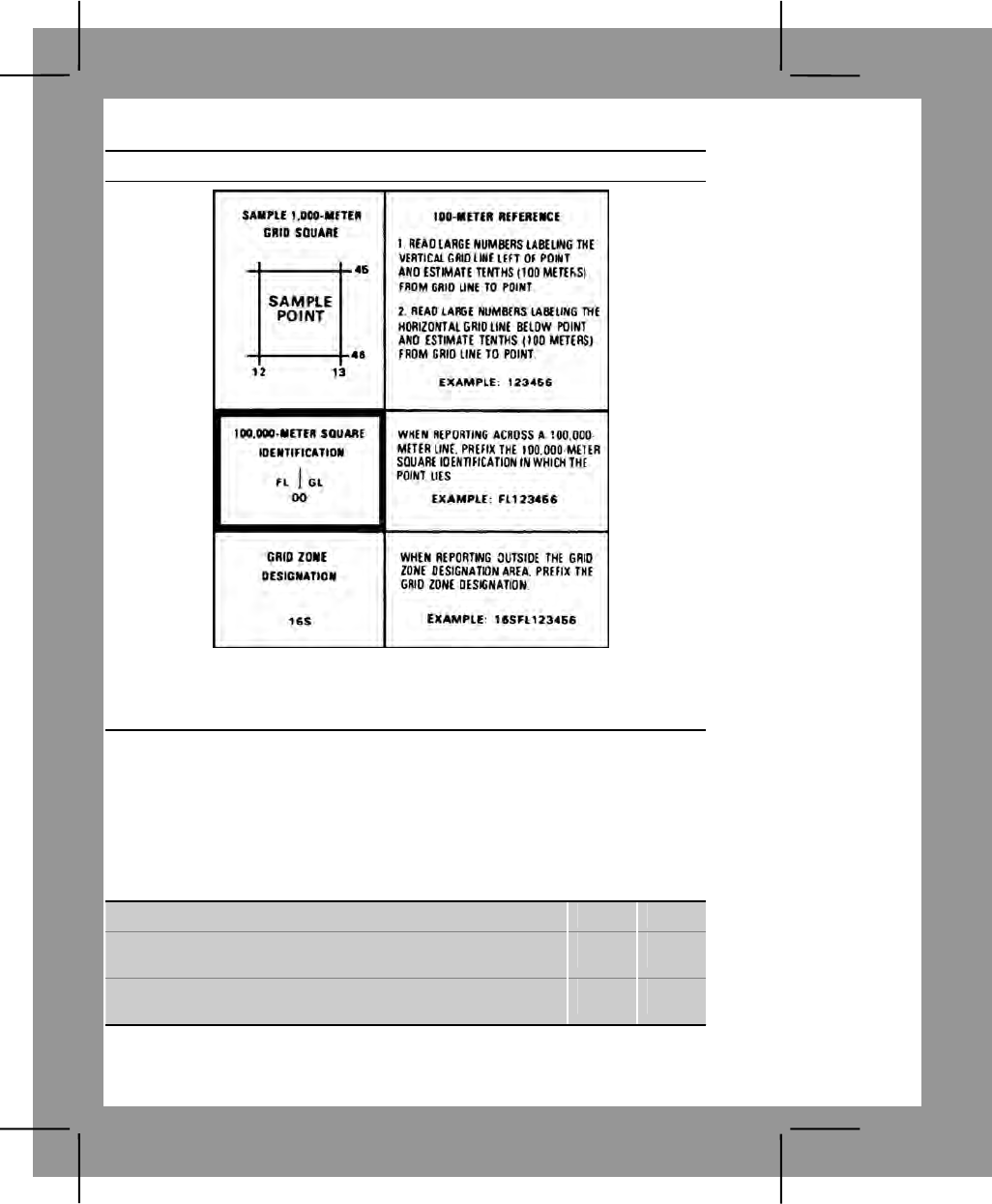
C-22
Performance Steps
Figure C-18. Grid reference box
h. Place the 100,000-meter-square identifier in front of the coordinate,
GL115813.
Evaluation Preparation:
Setup: Give the soldier a standard 1:50,000-scale military map in a field
location, a 1:50,000 grid coordinate scale, a pencil, paper, and a point on a
map for which coordinates must be determined.
Brief Soldier: Tell the soldier to write down the two-letter 100,000-meter-
square identifier and the six-digit grid coordinates for one point and the two-
letter 100,000-meter-square identifier.
Performance Measures GO NO GO
1. Determined the six-digit grid coordinates for the point
on the map with a 100-meter tolerance. —— ——
2. Recorded the grid coordinates with the correct two-
letter 100,000-meter-square identifier. —— ——
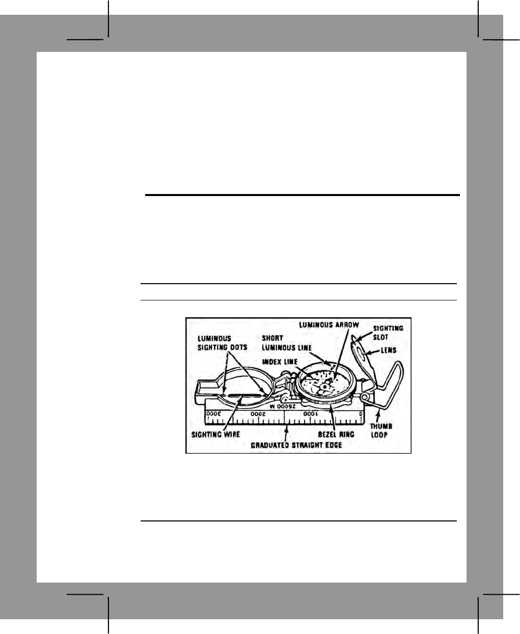
C-23
Evaluation Guidance: Score the soldier GO if all performance measures
are passed. Score the soldier NO GO if any performance measure is failed.
If the soldier scores NO GO, show the soldier what was done wrong and
how to do it correctly.
References
Required Related
FM 3-25.26
GTA 05-02-012
Land Navigation Task 5
Determine a Magnetic Azimuth Using a Lensatic Compass
Conditions: Given a compass and a designated point on the ground.
Standards: Determined the correct magnetic azimuth to the designated
point within three degrees using the compass-to-cheek method, and within
ten degrees using the center-hold method.
Performance Steps
1. Read your compass (figure C-19).
Figure C-19. Lensatic compass
a. The floating dial is used to determine the direction in which you are
pointing your compass.
b. The outer, black ring of numbers and tick marks are used for finding
direction in mils (figure C-20).
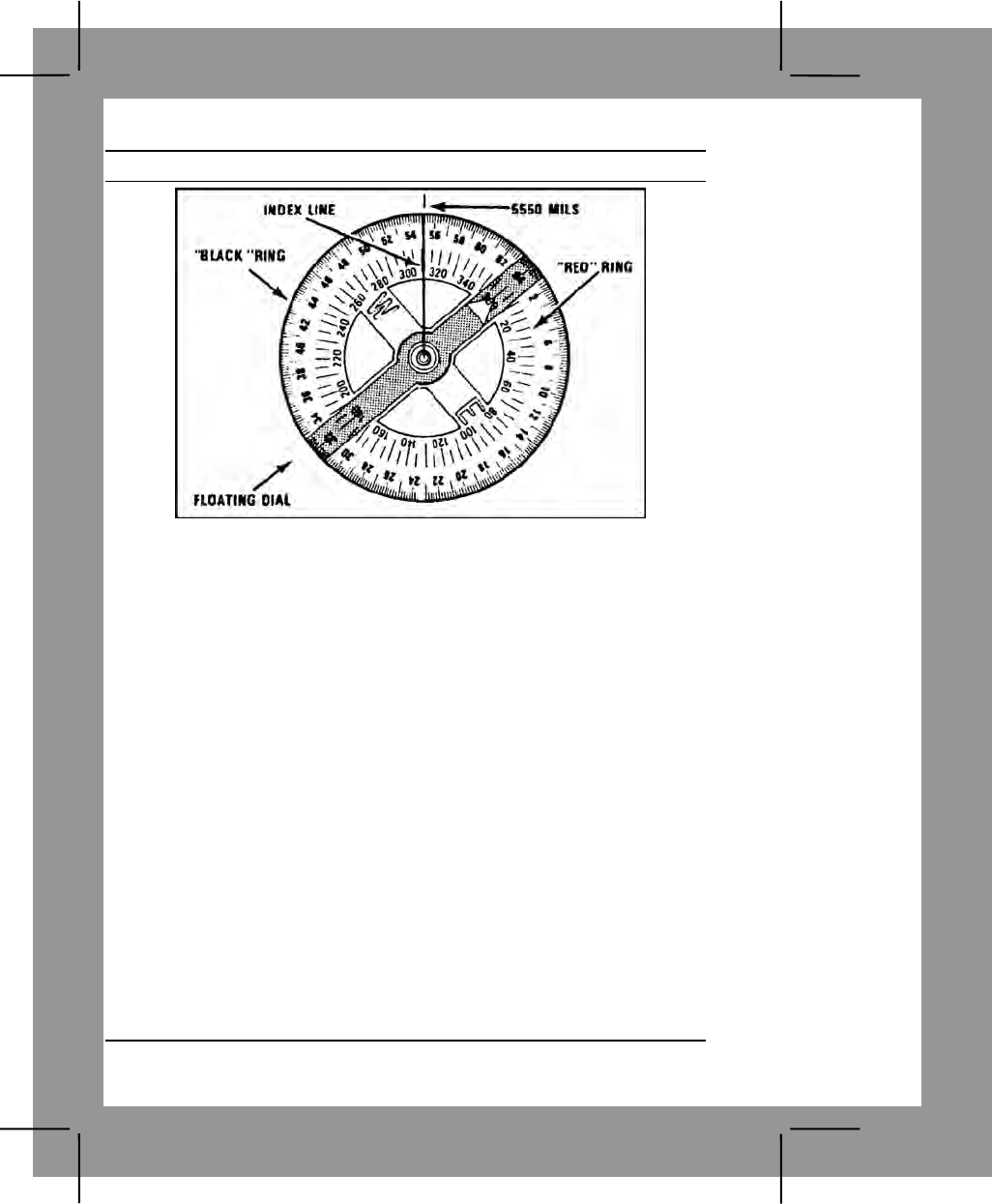
C-24
Performance Steps
Figure C-20. Lensatic compass floating dial
c. The inner, red ring of numbers and tick marks are used for finding
direction in degrees.
(1) There are 360 degrees or 6400 mils in a circle. These are
marked with a tick mark every 5 degrees or 20 mils. However, not every
tick mark is numbered. You will have to determine the number for these
lines using the numbers that are shown.
(2) To read direction, point the compass in the direction you want to
go or want to determine.
(3) Look beneath the index line on the outer glass cover and
estimate to the nearest degree or 10 mils the position of the index line over
the red or black scale.
(4) Be careful to hold the compass still so that the dial remains
stationary while you are reading the scale.
(5) If you understand these readings and can apply either of the
holding and sighting techniques of shooting an azimuth, you will be
proficient in performing this task.
2. Shoot an azimuth.
a. Use your compass to determine or follow an azimuth. The arrow on
the compass points toward magnetic north. The arrow is also attracted by
any mass of metal; for example, a truck, your rifle, your helmet, and even
electrical power lines. Thus, be sure you use your compass away from
metal objects so it will not give a wrong reading.

C-25
Performance Steps
b. The lensatic compass must always be held level and firm when
sighting on an object and reading an azimuth.
c. There are two methods of holding the lensatic compass and
sighting.
(1) Compass-to-cheek method (figure C-21). To use this method—
(a) Open the cover to a 90-degree angle to the base. Position
the eyepiece at a 45-degree angle to the base.
(b) Place your thumb through the thumb loop, form a steady
base with your third and fourth fingers, and extend your index finger along
the side of the compass base.
(c) Place the hand holding the compass into the palm of the
other hand.
(d) Bring both hands up to your face and position the thumb
that is through the thumb loop against the cheekbone.
(e) Look through the lens of the eyepiece. If the dial is not in
focus, move the eyepiece up or down until the dial is in focus.
(f) Align the sighting slot of the eyepiece with the sighting wire
in the cover on the point for which the azimuth is being determined. Look
through the lens of the eyepiece and read the azimuth under the index line.
Figure C-21 Compass -to-cheek method
(2) Center-hold method (figure C-22). To use this method—
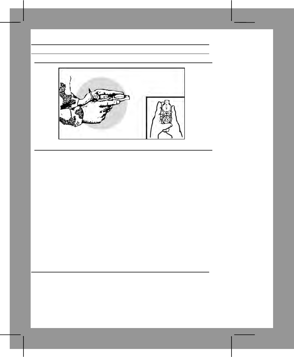
C-26
Performance Steps
Note. This method is used only when a precise direction is not required.
Figure C-22. Center-hold method
(a) Open the compass so that the cover forms a straight edge
with the base. The lens of the compass is moved out of the way.
(b) Next, place your thumb through the loop, form a steady
base with your third and fourth fingers, and extend your index finger along
the side of the compass.
(c) Place the thumb of the other hand between the eyepiece
and lens, extend the index finger along the remaining side of the compass,
wrap the remaining fingers around the fingers of the other hand, and pull
your elbows firmly into your side. This will place the compass between your
chin and your belt.
(d) To measure an azimuth, turn your entire body toward the
object and point the compass cover directly at the object. Look down and
read the azimuth from beneath the fixed black index line. This method can
be used at night.
(e) To keep from going in circles when you are land navigating,
stop occasionally to check the azimuth along which you are moving. Also,
you can move from object to object along your path by shooting an azimuth
to each object and then moving to that object. Repeating this process while
you navigate should keep you straight.
Evaluation Preparation:
Setup: Select a point to use as a target and determine the azimuth to the
point using the compass that the soldier will use.
Brief Soldier: Point out the selected spot to the soldier. Tell the soldier to
shoot an azimuth to that spot using both the compass-to-cheek method and
the center-hold method.
C-27
Performance Measures GO NO GO
1. Determined the correct magnetic azimuth to the
designated point within 3 degrees using the compass-to-
cheek method.
—— ——
2. Determined the correct magnetic azimuth to the
designated point within 10 degrees using the center-hold
method.
—— ——
Evaluation Guidance: Score the soldier GO if all performance measures
are passed. Score the soldier NO GO if any performance measure is failed.
If the soldier scores NO GO, show the soldier what was done wrong and
how to do it correctly.
References
Required Related
FM 3-25.26
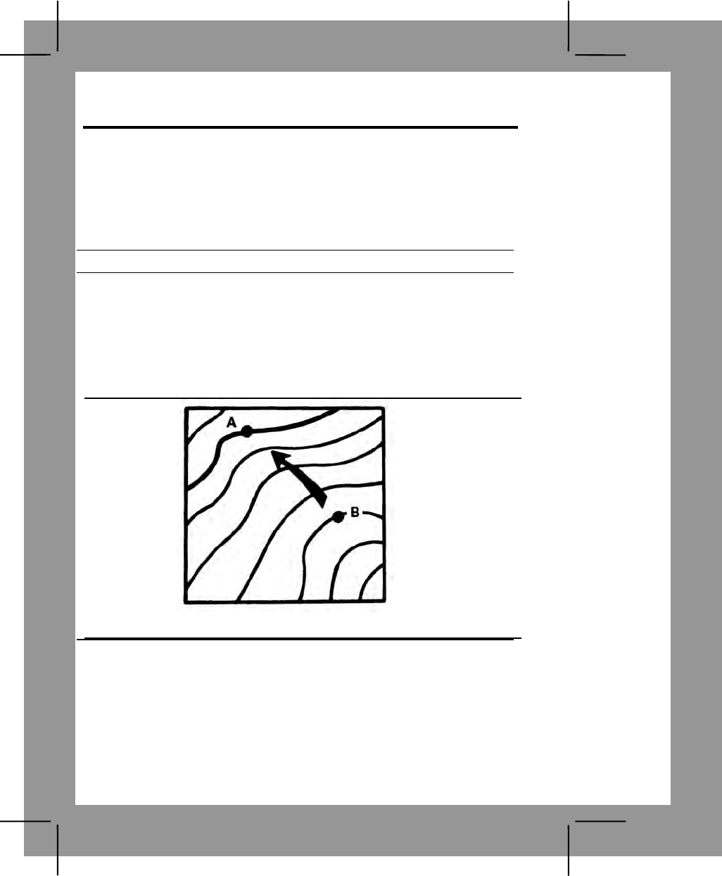
C-28
Land Navigation Task 6
Determine the Elevation of a Point on the Ground Using a Map
Conditions: Given a standard 1:50,000 scale military map, a pencil, and a
designated point on the map.
Standards: Determined the elevation of the designated point to within half
the value of the contour interval.
Performance Steps
1. Locate contour lines and contour intervals.
a. The brown lines on the map are called contour lines. Each line
shows the height above sea level. Contour lines never cross one another.
Printed at the bottom of the map is the contour interval, which is the
difference in height (elevation) between one brown line and the one on
either side of it. On a map with a scale of 1:50,000, the contour interval is
usually 20 meters. This would make point A 80 meters higher or lower than
point B (figure C-23).
Figure C-23. Contour lines
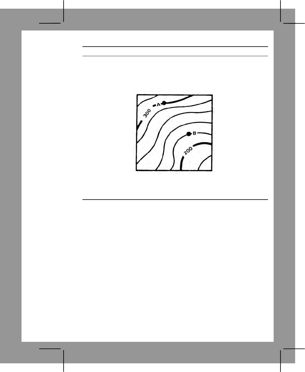
C-29
Performance Steps
b. You can easily tell from the brown lines the direction of uphill or
downhill because every fifth line is heavier and has a number that gives its
elevation. Let's say the contour interval is 20 meters again. Now you can
tell that point B. Also, if you know the distance between A and B, you can
get an idea of the steepness of the slope (figure C-24).
Figure C-24. Contour intervals
c. Widely spaced contour lines show a gentle slope. When they are
close together, the slope is steep (figure C-25).
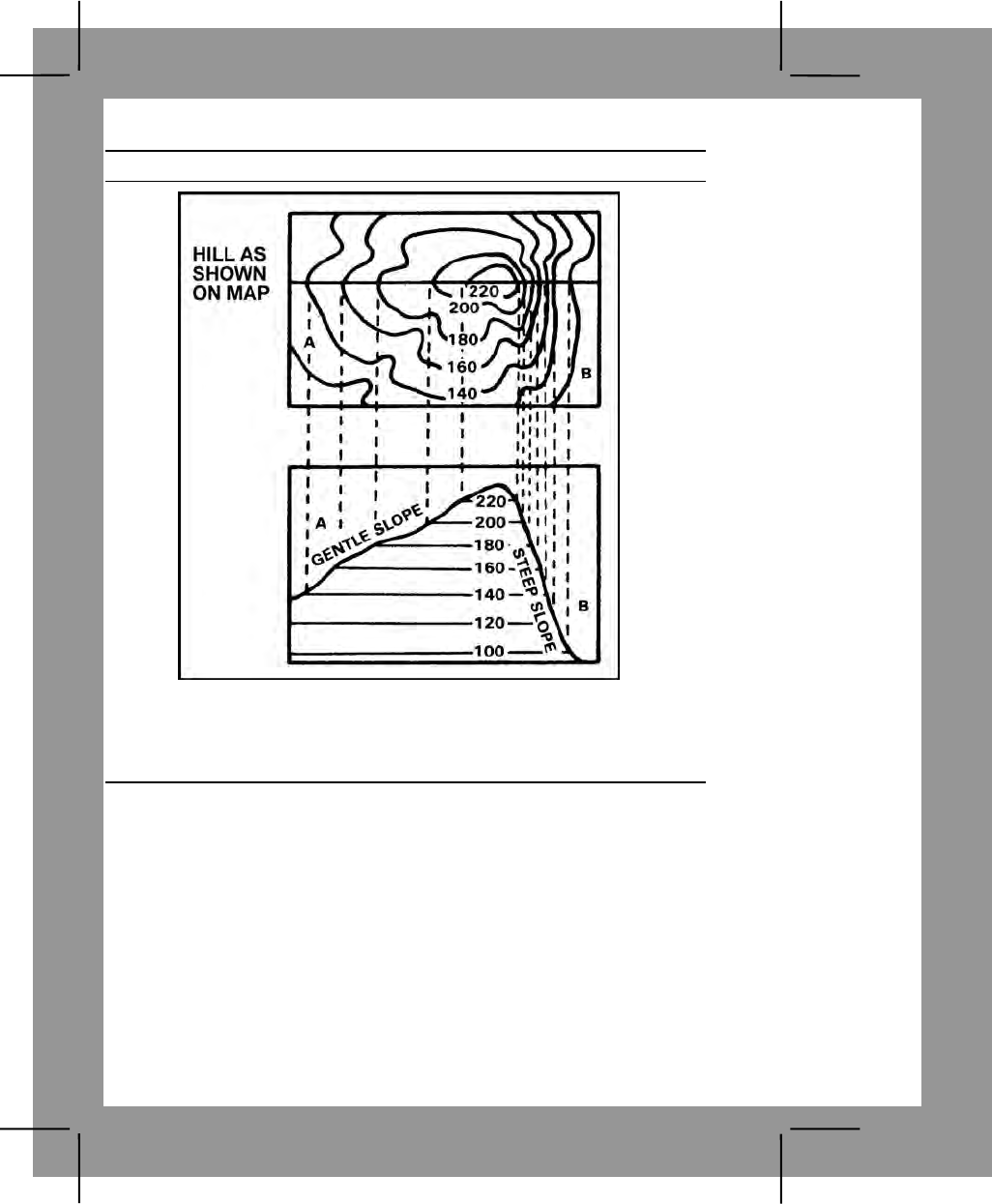
C-30
Performance Steps
Figure C-25. Slope
d. When the contour lines are close together at the top of the hill, the
hilltop is pointed. When the contour lines are widely spaced, the hilltop is
flat (figure C-26).
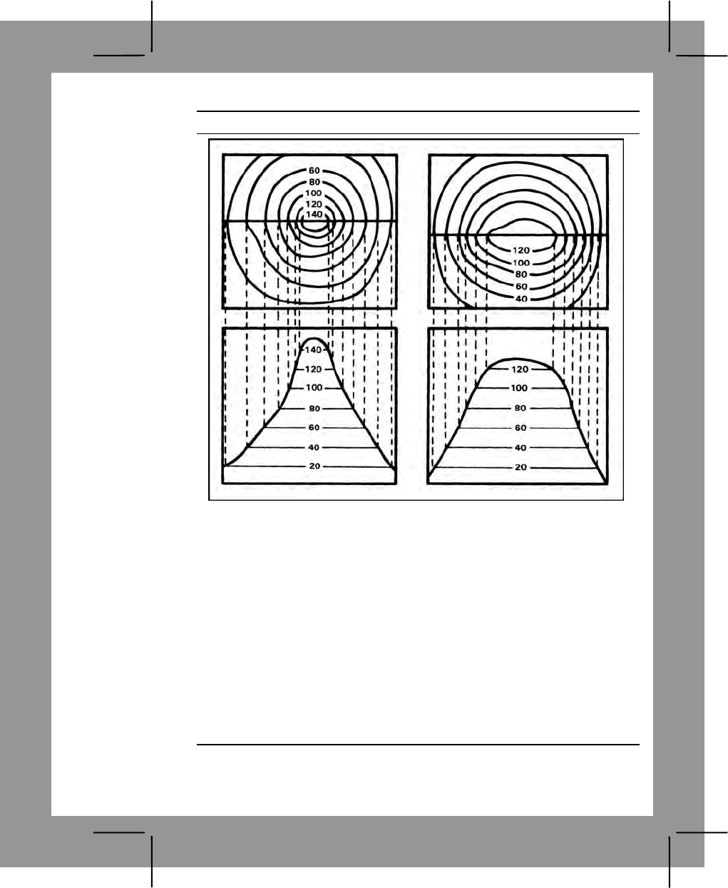
C-31
Performance Steps
Figure C-26. Elevation
2. Determine elevation.
a. Locate the point on the map. (It may already be plotted on the map,
or given as eight-digit coordinates).
b. Determine the contour interval of the map from the marginal
information.
c. Locate the index contour line nearest the point for which the
elevation is being sought.
d. Count the number of contour lines, up or down, that must be
crossed to go from the numbered lines to the point, and note the direction
to the point. If the point is on a contour line, its elevation is that of the
contour line. For points between contour lines—
(1) Points less than one-fourth the distance between lines are
considered to be the same as the elevation of the nearest line.
C-32
Performance Steps
(2) Point one-fourth to three-fourths the distance from the lower line
are considered to be at an elevation half the contour interval above the
lower line.
e. To estimate the elevation of the top of an unmarked hill, add half
the contour interval to the elevation of the highest contour line around the
hill.
f. To estimate the elevation of the bottom of depression, subtract half
the contour interval from the elevation of the lowest contour around the
depression.
g. On maps that do not show elevation and relief as much detail as
needed, supplementary contour lines may be used. Marginal information
indicates the interval, and the supplementary lines are used exactly like
solid contour lines.
h. Benchmarks and spot elevation also indicate points of known
elevation.
Evaluation Preparation:
Setup: Provide the soldier with a 1:50,000 scale military map, a designated
point on the map labeled "A", and a pencil.
Brief Soldier: Tell the soldier to determine the elevation of the point that is
labeled "A" on the map.
Performance Measures GO NO GO
1. Determined the correct elevation within half the value
of the contour interval. —— ——
Note. If the contour interval of the map is in feet, the answer
must be in feet. If the contour interval is in meters, the answer
must be in meters.
Evaluation Guidance: Score the soldier GO if the performance measure is
passed. Score the soldier NO GO if the performance measure is failed. If the
soldier scores NO GO, show what was done wrong and how to do it
correctly.
References
Required Related
FM 3-25.26
C-33
Land Navigation Task 7
Determine a Location on the Ground by Terrain Association
Conditions: In the field during daylight, while at an unknown location on the
ground, given a standard 1:50,000-scale military map of the area, pencil,
paper, a coordinate scale, protractor, and a known point on the ground.
Standards: Determined the six-digit coordinate of your location with a 100-
meter tolerance within seven minutes.
Performance Steps
1. Determine the type of terrain feature upon which you are located. (See
task number 071-329-100, Identify Terrain Features On A Map.)
2. Determine what types of terrain features surround your location.
3. Orient the map. (See task number 071-329-1012, Orient A Map To The
Ground By Map Terrain Association.)
4. Determine the four cardinal directions (north, south, east, and west).
(See task number 071-329-1002, Determine The Grid Coordinates Of A
Point On A Military Map.)
5. Determine your location.
a. Relate the terrain features on the ground to those shown on the
map.
b. After you have determined where the terrain features on the ground
and those on the map coincide, determine the coordinates of your location
using the coordinate scale and protractor.
Evaluation Preparation:
Setup: Select a field site that has terrain features that are shown on the map.
At the test site, provide a field table, a 1:50,000-scale military map of the
area, pencil, paper, and a coordinate scale.
Brief Soldier: Tell the soldier he or she must determine a six-digit coordinate
of his or her location within 7 minutes. Tell the soldier one of the cardinal
directions (north, south, east, or west).
Performance Measures GO NO GO
1. Identified the type of terrain feature upon which you
were located. —— ——
2. Identified the terrain features around your location. —— ——
3. Oriented the map. —— ——
C-34
Performance Measures GO NO GO
4. Determined the remaining three cardinal directions. —— ——
5. Identified the same terrain features on the map. —— ——
6. Determined the six-digit grid coordinate of your own
location (the point selected must be within 100 meters of
your location).
—— ——
Evaluation Guidance: Score the soldier GO if all performance measures
are passed. Score the soldier NO GO if any performance measure is failed.
If the soldier scores NO GO, show the soldier what was done wrong and
how to do it correctly.
References
Required Related
FM 3-25.26
Land Navigation Task 8
Measure Distance on a Map
Conditions: Given a standard 1:50,000-scale military map, a strip of paper
with a straight edge, and a pencil.
Standards:
1. Determined the straight-line distance, in meters, between two points, with
no more than five percent error.
2. Determined the road (curved line) distance, in meters, between two
points, with no more than ten percent error.
Performance Steps
1. Identify the scale of the map. The map scale is the ratio (1:50,000) of
the distance on the map (1 inch) compared to the distance on the ground
(usually 50,000 inches).
2. Convert a straight-line map distance to miles, meters, or yards using
the map's bar scale (figure C-27).
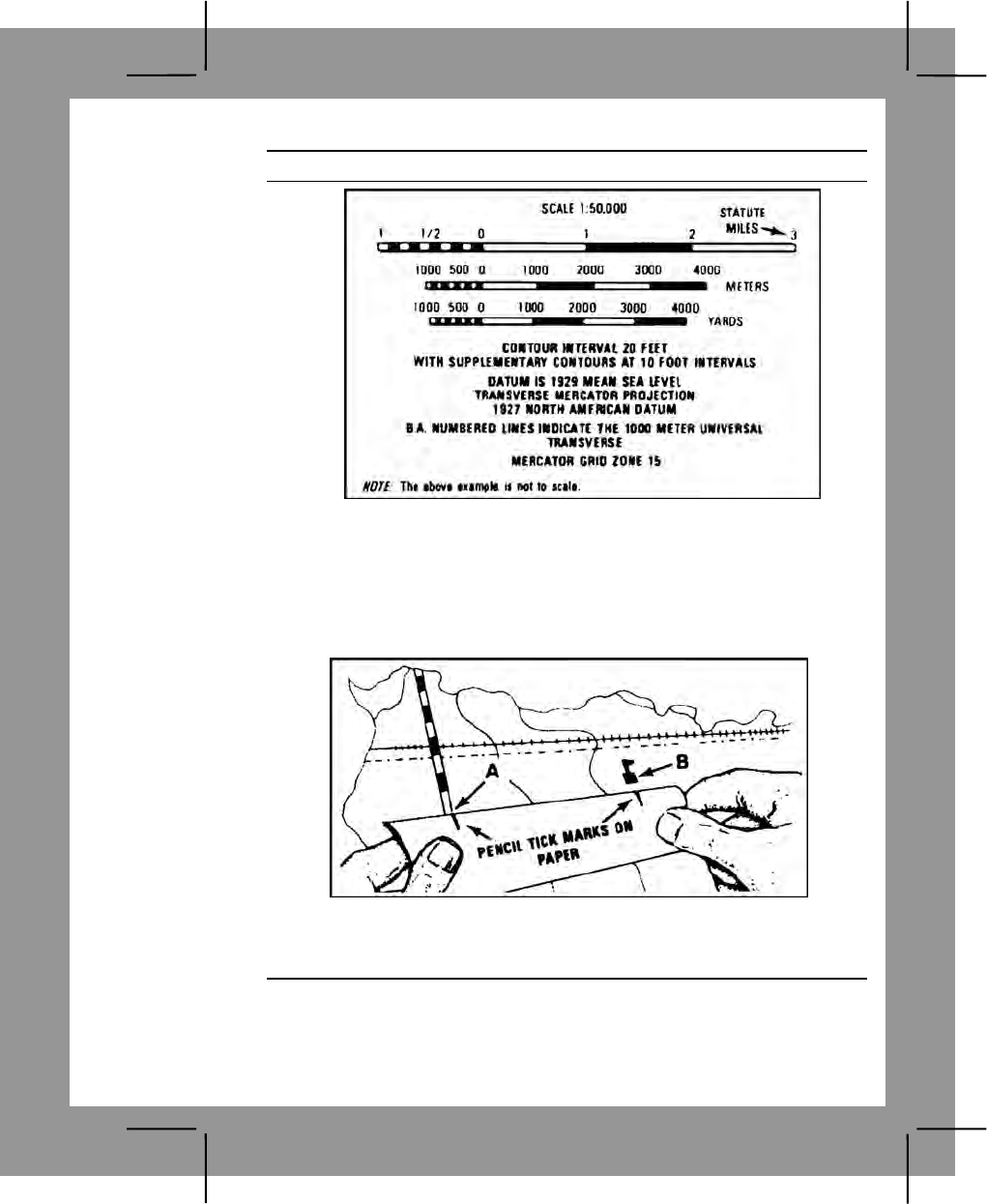
C-35
Performance Steps
Figure C-27. Bar scales
a. For map distances equal to or less than one inch:
(1) Line up the straight edge of a strip of paper with the beginning
and ending points on the map.
(2) Mark on the straight edge of the paper the beginning and
ending points (figure C-28).
Figure C-28. Measuring distance
(3) Match the marks on the paper with the appropriate bar scale
(figure C-29).
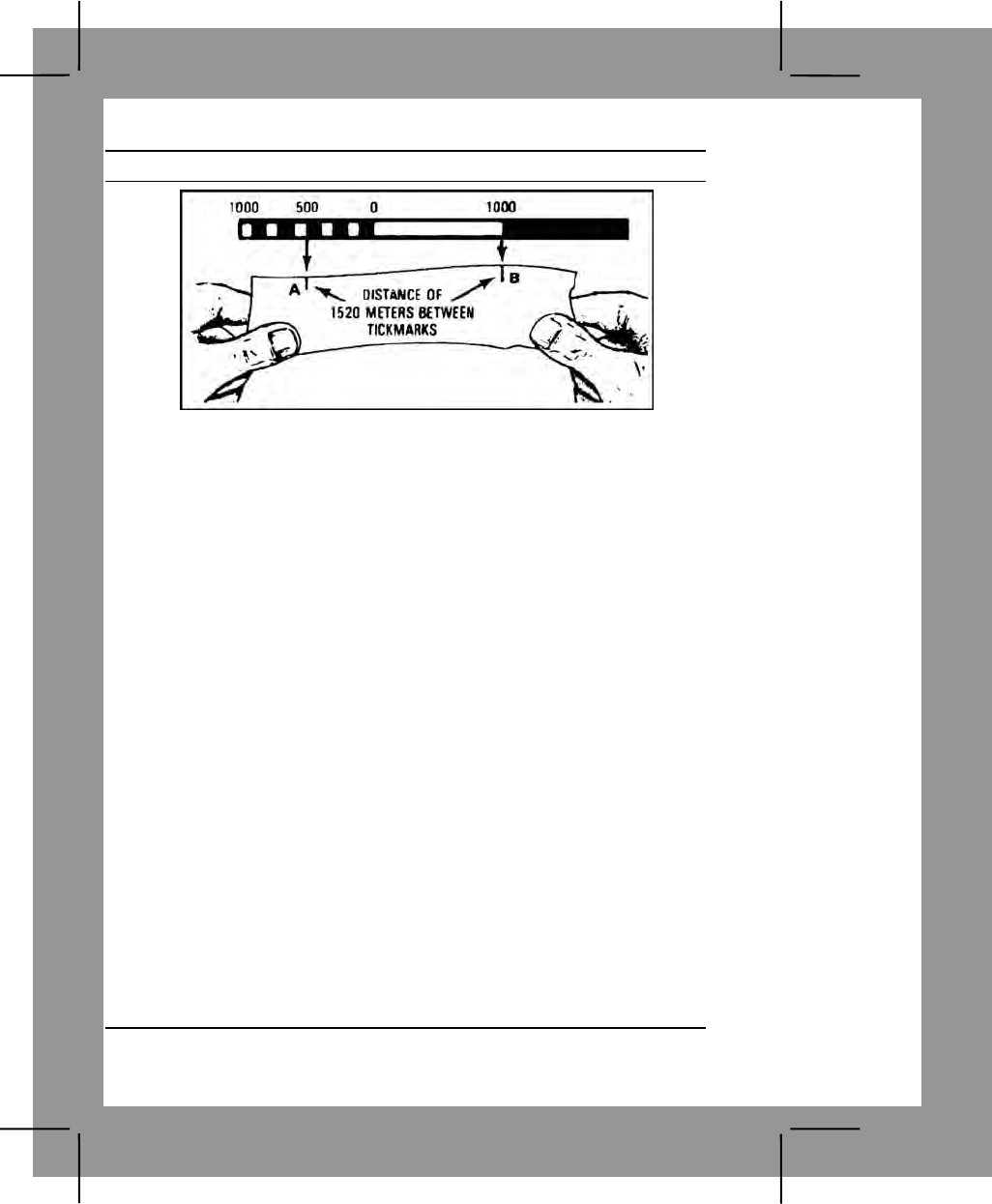
C-36
Performance Steps
Figure C-29. Determining distance
(4) Determine the distance on the scale that compares to the
distance on the paper.
b. For map distances greater than one inch:
(1) Line up the straight edge of a strip of paper with the beginning
and ending points on the map.
(2) Mark the beginning and ending points on the straight edge of
the paper (figure C-28).
(3) Place the starting point on the paper under the zero on the bar
scale.
(4) Measure off 4,000 meters and place a new tick mark on the
paper.
(5) Place the new tick mark under the zero on the bar scale.
(6) Determine if the end point falls within the bar scale.
(a) Record the value on the scale of the end point if the end
point fits on the scale.
(b) Add 4,000 meters to the value you derived in step 2b(6)(a).
This is the total difference.
(7) Determine if the end point does not fall within the bar.
(a) Repeat steps 2b(4) and (5) until the end point falls within
the bar.
(b) Add 4,000 meters to the value you derived in step 2b(6)(a)
for each time you performed step 2b(4). This is the total difference.
3. Convert a road map distance to miles, meters, or yards using the map's
bar scale (figure C-28). This is the actual distance you have to travel to
reach the point whose straight line distance you identified in step 2.

C-37
Performance Steps
a. Line up the straight edge of a strip of paper with the beginning point
and the point at which the road makes the first curve on the map.
b. Mark on the straight edge of the paper the beginning and curve
points (figure 27).
c. Repeat steps 3a and b (each time using the point of the curve as
the next beginning point) until you reach the end point.
d. Use step 3 to determine the road distance in miles, meters, or yards
as appropriate.
(1) If the total distance measured on the paper is equal to or less
than 1 inch, use steps 2a(3) and (4).
(2) If the total distance measured on the paper is more than 1 inch,
use steps 2b(3) through (7).
Evaluation Preparation:
Setup: In the field or classroom, give the soldier a 1:50,000-scale military
map, a strip of paper with a straight edge, and a pencil. On the map, plot a
straight-line distance of 3,000 to 4,000 meters. Mark this distance points A
and B. On a road or trail, plot a curved-line distance of 3,000 to 4,000 meters
with at least two changes of direction. Mark this distance points C and D.
Brief Soldier: Tell the soldier that he or she must determine the straight-line
distance between points A and B with no more than 5 percent error, and the
curved-line distance between points C and D with no more than 10 percent
error. He or she must either write down the correct answers or state the
answers when asked by the scorer.
Performance Measures GO NO GO
1. Identified the scale of the map. —— ——
2. Converted the straight-line map distance to miles,
meters or yards using the map's bar scale with no more
than 5 percent error.
—— ——
3. Converted the road map distance to miles, meters, or
yards using the map's bar scale with no more than 10
percent error.
—— ——
Evaluation Guidance: Score the soldier GO if all performance measures
are passed. Score the soldier NO GO if any performance measure is failed.
If the soldier scores NO GO, show the soldier what was done wrong and
how to do it correctly.

C-38
References
Required Related
FM 3-25.26
Land Navigation Task 9
Convert Azimuths
Conditions: Given a standard 1:50,00-scale military map with a declination
diagram, a pencil, and a magnetic azimuth and a grid azimuth that must be
converted.
Standards: Converted the given magnetic azimuth to a grid azimuth and the
given grid azimuth to a magnetic azimuth without error.
Performance Steps
1. The north-south lines on your map give grid north. The needle of your
compass points to magnetic north. Grid north and magnetic north are
usually different by a few degrees. Neither one points straight to the North
Pole (called true north), but you do not need to know true north to keep
from getting lost in a combat area. The difference in degrees for every map
is shown on the bottom of mapsheet (figure C-30).
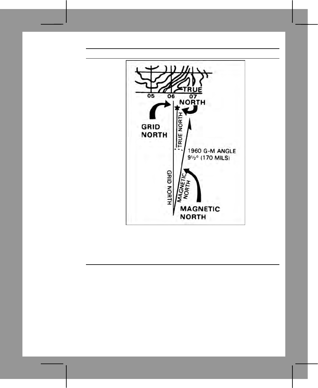
C-39
Performance Steps
Figure C-30. Declination diagram
2. The difference between grid north and magnetic north is called the grid-
magnetic (G-M) angle. The diagram at the bottom of the map tells you how
to change grid azimuths to magnetic azimuths and magnetic azimuths to
grid azimuths (figure C-31).
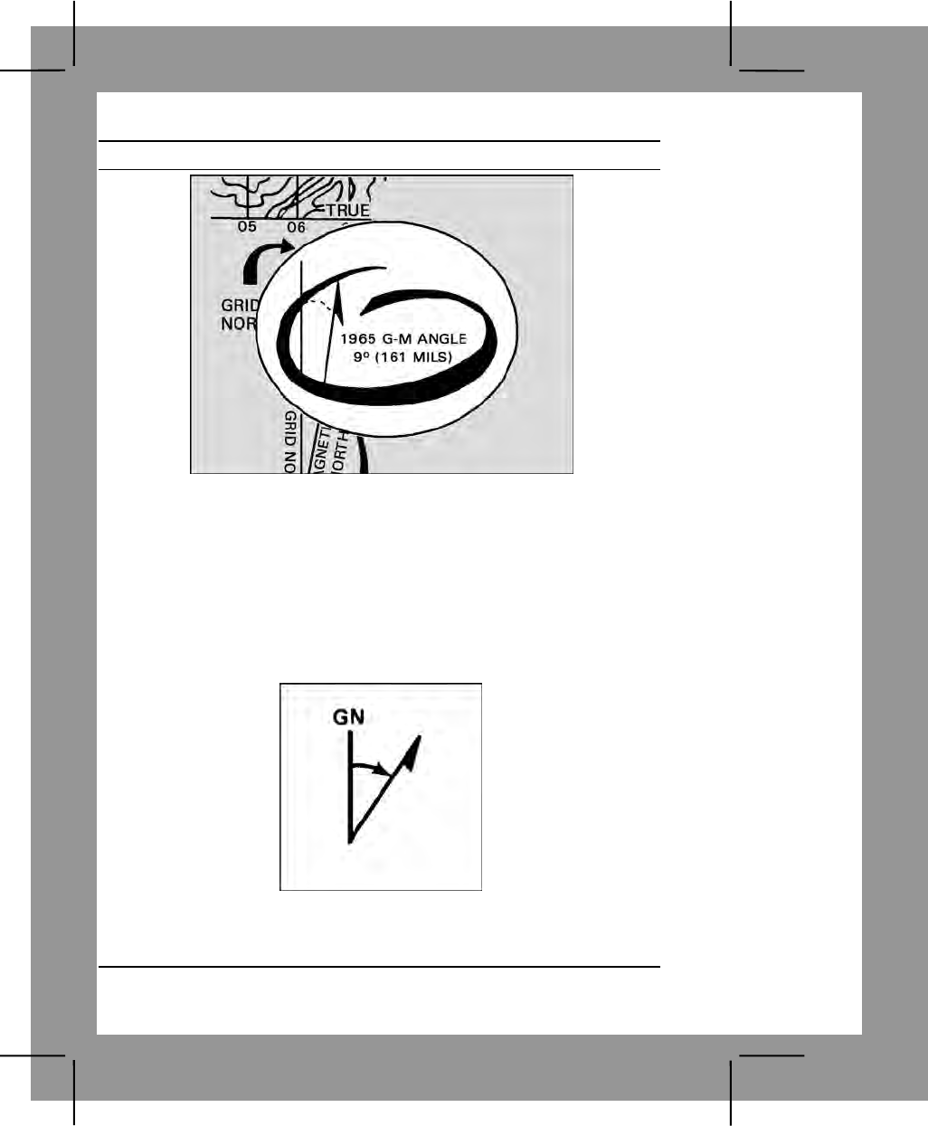
C-40
Performance Steps
Figure C-31. G-M angle
3. For example, you aim your compass at a distant point. The compass
reading you get is 190 degrees, the magnetic azimuth. The diagram on
your map (see figure 2) tells you that the G-M angle is 9 degrees, and it
also tell you that "to convert a magnetic azimuth to a grid azimuth, add the
G-M angle." Therefore add 9 degrees to your compass reading. This gives
you 190 + 9 = 199. Your grid azimuth is 199 degrees.
4. The G-M angle depends on where you are in the world.
5. Convert azimuths when given an easterly G-M angle (figure C-32).
Figure C-32. Converting azimuths with easterly G-M angle
a. To convert a magnetic azimuth to a grid azimuth, add the value of
the G-M angle to the magnetic azimuth.
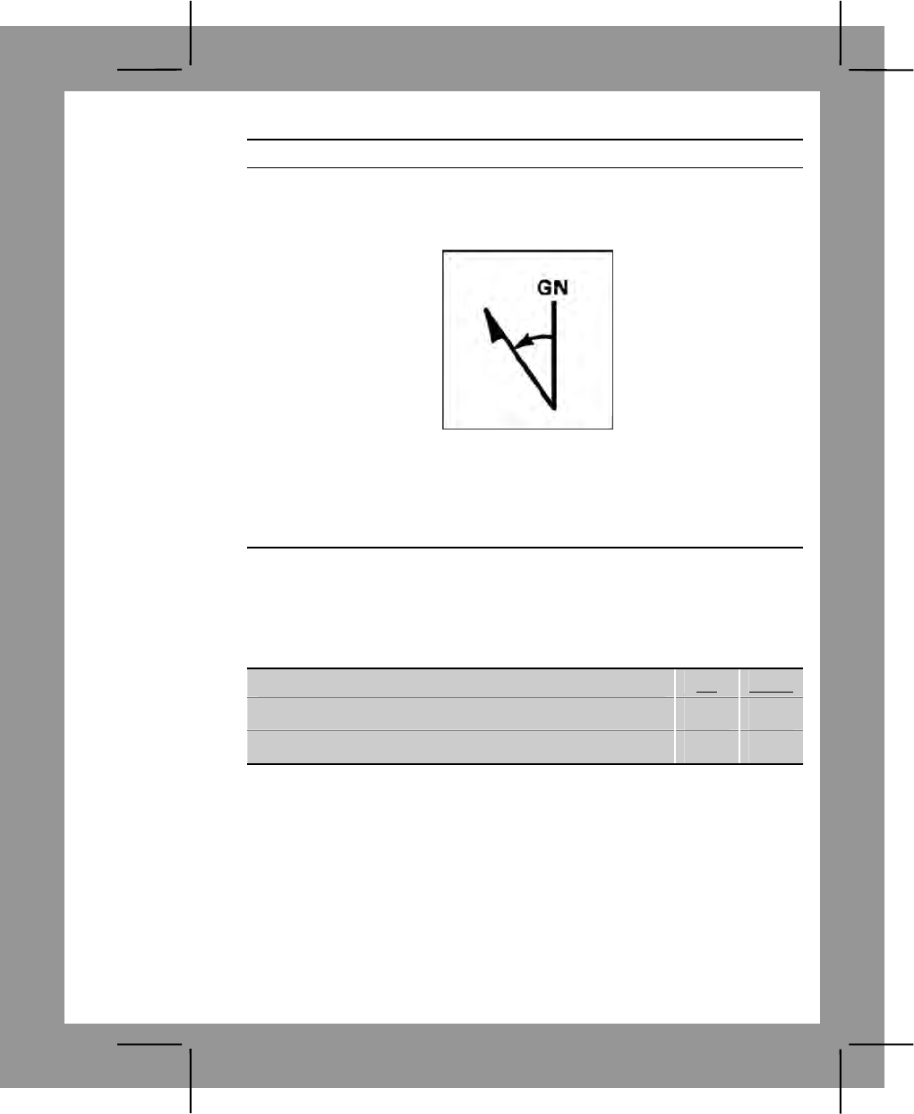
C-41
Performance Steps
b. To convert a grid azimuth to a magnetic azimuth, subtract the G-M
angle from the grid azimuth.
6. Convert azimuths when given a westerly G-M angle (figure C-33).
Figure C-33. Converting azimuths with westerly G-M angle
a. To convert a magnetic azimuth to a grid azimuth, subtract the value
of the G-M angle from the magnetic azimuths.
b. To convert a grid azimuth to a magnetic azimuth, add the value of
the G-M angle to the grid azimuth.
Evaluation Preparation:
Setup: Give the soldier a standard 1:50,000-scale military map, a piece of
paper, a pencil, and a magnetic and grid azimuth to be converted.
Brief Soldier: Tell the soldier to convert the magnetic azimuth to a grid
azimuth and the grid azimuth to a magnetic azimuth.
Performance Measures GO NO GO
1. Determined correct grid azimuth. —— ——
2. Determined correct magnetic azimuth. —— ——
Evaluation Guidance: Score the soldier GO if all performance measures
are passed. Score the soldier NO GO if any performance measure is failed.
If the soldier scores NO GO, show what was done wrong and how to do it
correctly.
References
Required Related
FM 3-25.26

C-42
Land Navigation Task 10
Orient a Map Using a Lensatic Compass
Conditions: Given a field table, a standard 1:50,000-scale military map, a
protector, a pencil, paper, and a compass in daylight.
Standards: Oriented the map to the ground using a compass so the north-
seeking arrow of the compass was within 3 degrees (20 mils) of the angle
shown in the grid-magnetic (G-M) angle of the declination diagram shown on
the map.
Performance Steps
1. With the map level, place the compass parallel to a north-south grid
line with the cover side of the compass pointing towards the top of the
map. This will place the black index line on the dial of the compass parallel
to grid north. Because the needle on the compass points to magnetic
north, a declination diagram on the face of the compass is formed by the
index line and the compass needle.
2. Rotate map and compass until the directions of the declination diagram
formed by the black index line and the compass needle match the direction
shown the declination diagram printed on the margin of the map. The map
is then oriented.
3. If the magnetic north arrow on the map is to the left of the grid north,
the compass reading will equal the G-M angle (given the declination
diagram). If the magnetic north is the right of the grid north, the compass
reading will equal 360 degrees (6400 mils) minus the G-M angle.
4. Remember to point the compass north arrow in the same direction as
the magnetic north arrow (step 2 above), and the compass reading (equal
to the G-M angle or the 360 degrees (6400 mils) minus G-M angle) will be
quite apparent.
Note. If the G-M angle is less then 3 degrees (50 mils), do not line up the north
arrow.
5. Some maps have a built-in protractor considering of a pivot point "P" on
the south neat line of the map and several degrees of arc along the north
neat line of the map. The G-M line is obtained by connecting pivot "P" with
the appropriate value of the G-M angle (taken from the declination
diagram) on the arc. The map may then be oriented by placing the
compass parallel on this line and rotating the map and compass until the
needle point is aligned with the continuous line formed by the index line
and the sighting wire. The map is then oriented.

C-43
Performance Steps
6. An alternate method is to draw a magnetic north line on the map from
any N-S and E-W grid line intersection using the protractor. Align the
straightedge of the compass along this magnetic north line and rotate the
map and compass together until the north arrow falls beneath the fixed
black index line on the compass.
Evaluation Preparation:
Setup: Select an area that is free of magnetic interference (parlance,
vehicles). Provide a field table, 1:50,000-scale military map, a protractor, a
pencil, paper, and a compass.
Brief Soldier: Tell the soldier to orient the map to the ground using the
compass. Tell the soldier he must use the G-M angle shown by the
declination diagram if it exceeds 3 degrees (50 mils).
Performance Measures GO NO GO
1. Determined whether G-M angle exceeds 3 degrees
(50 mils) —— ——
2. Aligned the side of the compass with one of the
north-south grid lines. —— ——
3. Positioned the cover of the compass toward the top
of the map. —— ——
4. Oriented the map. —— ——
5. Corrected the orientations of the map when the G-M
angle exceeded 3 degrees (50 mils) using one of the
following:
—— ——
a. Used the G-M angle formed by the compass'
black index line and the compass needle.
b. Used the pivot point "P" on the south neat line
and the degrees of arc along the north neat line and
placed the compass along this line.
c. Drew a magnetic north line from any N-S and E-
W grid the intersection using a protractor and placed the
compass along this line.
Note. Step 5 is required only when G-M angle exceeds 3
degrees or 50 mils. Step 5b is tested only if the map has the
built-in protractor.
Evaluation Guidance: Score the soldier GO if all performance measures
are passed. Score the soldier NO GO if any performance measure is failed.

C-44
If the soldier scores NO GO, show what was done wrong and how to do it
correctly.
References
Required Related
FM 3-25.26
Land Navigation Task 11
Orient a Map to the Ground by Map-Terrain Association
Conditions: Given a standard 1:50,000-scale military map in the field in
daylight.
Standards: Oriented the map to within 30 degrees of north.
Performance Steps
1. Match terrain features appearing on the map with physical features on
the ground (figure C-34).
Figure C-34. Features used to orient map
a. Hold the map in a horizontal position.
b. Line up features on the ground with those on the map.
2. Check orientations obtained by this method by placing a compass
along one of the north-south grid lines to keep from orienting the map in
the wrong direction (that is, 180 degrees out) or by aligning two or more
features. Incorporate the declination constant in determining the 30
degrees.
C-45
Evaluation Preparation:
Setup: Use an area of terrain with identifiable terrain features, natural and/or
man-made. Provide a field table and a 1:50,000-scale map of the area.
Brief Soldier: Tell the soldier to use the terrain features around him or her,
the soldier must orient the map to within 30 degrees of north.
Performance Measures GO NO GO
1. Matched terrain features by holding map in horizontal
position and lining up features on the ground. —— ——
2. Checked orientations. —— ——
Evaluation Guidance: Score the soldier GO if all performance measures
are passed. Score the soldier NO GO if any performance measure is failed.
If the soldier scores NO GO, show the soldier what was done wrong and
how to do it correctly.
References
Required Related
FM 3-25.26
Land Navigation Task 12
Locate an Unknown Point on a Map and on the Ground by Intersection
Conditions: Given a standard 1:50,000-scale military map of the area, the
location of two known points, a compass, a straight edge, a coordinate
scale, a protractor (GTA 05-02-012), a pencil, and an object or terrain
feature for which the soldier must determine the grid location.
Standards: Determined the 100,000-meter square identification letters and
six-digit coordinates of the object or terrain feature to within 100 meters.
Performance Steps
1. Use the map and compass method (figure C-35).
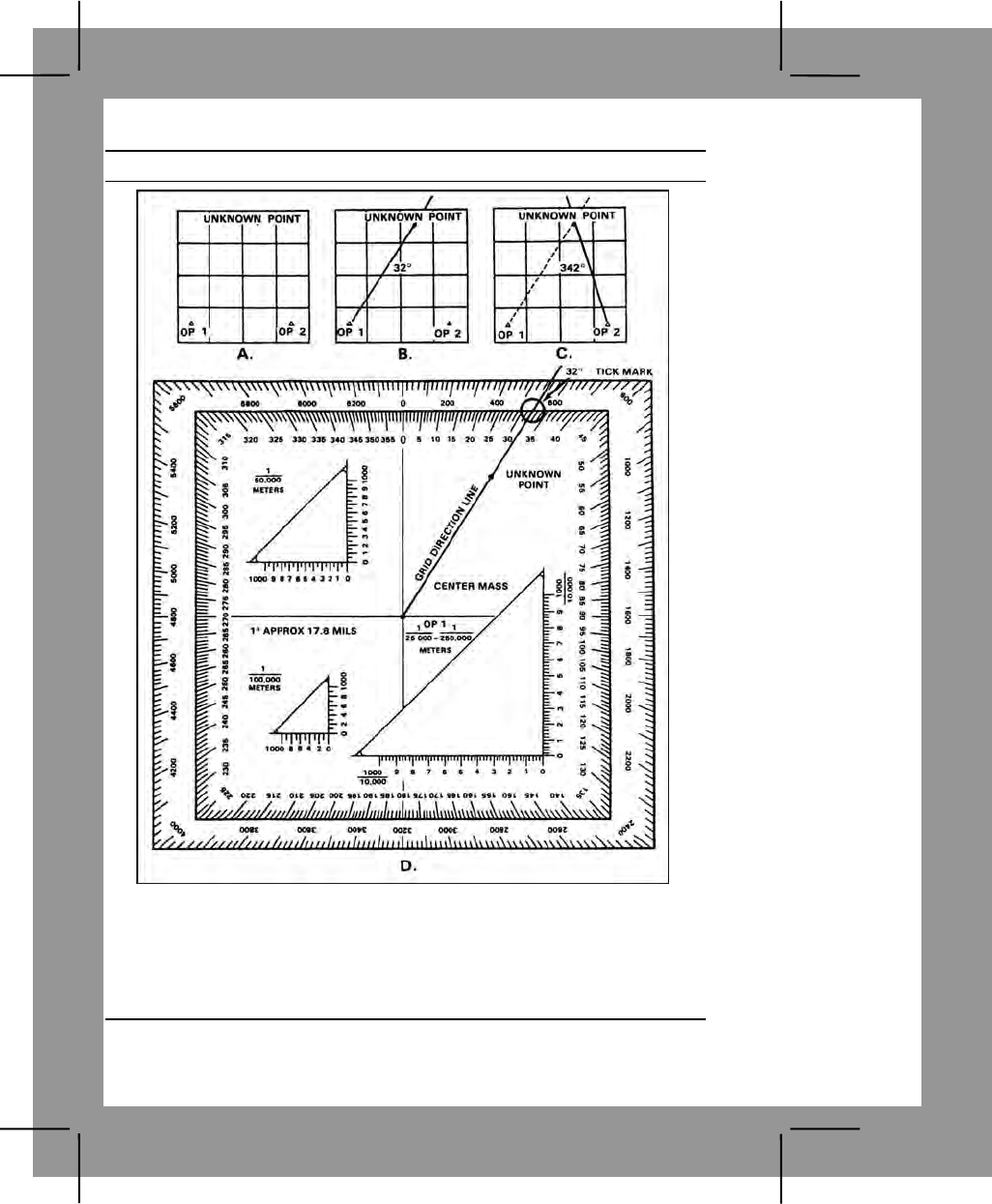
C-46
Performance Steps
Figure C-35. Location of an unknown point
Note. The example map is not to scale—an easterly G-M angle to 10 degrees is
used in the examples.
a. Determine the G-M angle of the map you are using.
b. Locate and mark your position on the map.
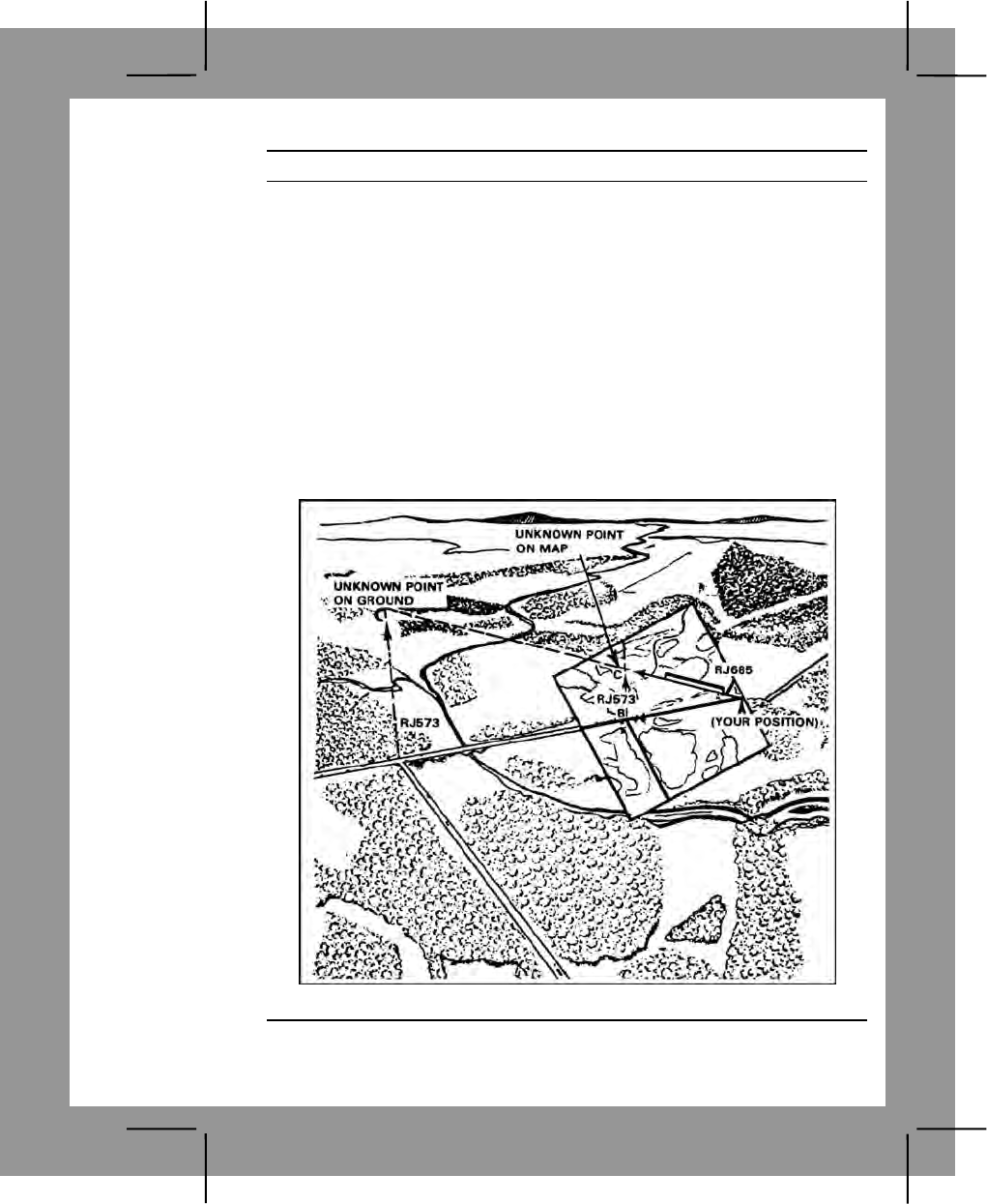
C-47
Performance Steps
c. Convert the magnetic azimuth to the unknown point (22 degrees);
change it to a grid azimuth. In the example, the G-M angle used was 10
degrees easterly, giving a grid azimuth of 32 degrees.
d. Place the protractor on the map, ensuring that the zero-degree
indication on the protractor is pointing to the top of the map (north) and the
index point is placed center of mass on your location (figure C-36). Place a
tick mark at the number of degrees you want to plot. Draw a line on the
map from your position on this grid azimuth (32 degrees).
e. Move to or call a second known position from which the unknown
point can be seen. Locate this position on the map.
f. Repeat steps 1c and 1d.
g. Where the lines cross is the location of the unknown point.
2. Use the straightedge method (when no compass is available) (figure C-
36).
Figure C-36. Intersection without compass
C-48
Performance Steps
a. See task number, 071-329-1012, Orient a Map to the Ground by
Map Terrain Association.
b. Locate and mark your position on the map.
c. Lay a straightedge on the map with one end at user's position (A)
as a pivot point, and rotate the straightedge until the unknown point is
sighted along the edge.
d. Draw a line along the straightedge.
e. Repeat steps 2b, 2c, and 2d at position (B) and, to check for
accuracy, at a third position.
f. The intersection of the lines is the location of the unknown point (C).
Evaluation Preparation:
Setup: In a field location, give the soldier a standard 1:50,000-scale military
map of the area, a compass, a straightedge, a coordinate scale, a protractor,
a pencil, an unknown point, and two points (at least 400 meters apart) from
which to determine azimuths to the unknown point.
Brief Soldier: Tell the soldier to determine the six-digit grid coordinates of the
unknown point.
Performance Measures GO NO GO
1. Determined the six-digit grid coordinates, to include
the 100,000 meter square identifier of the unknown point
to within 100 meters.
—— ——
Evaluation Guidance: Score the soldier GO if the performance measure is
passed. Score the soldier NO GO if the performance measure is failed. If the
soldier scores NO GO, show what was done wrong and how to do it
correctly.
References
Required Related
FM 3-25.26
STP 21-1-SMCT
Land Navigation Task 13
Locate an Unknown Point on a Map and on the Ground by Resection
Conditions: Given an unknown location, a standard 1:50,000-scale military
map of the area, a compass, a straightedge, a coordinate scale, a protractor
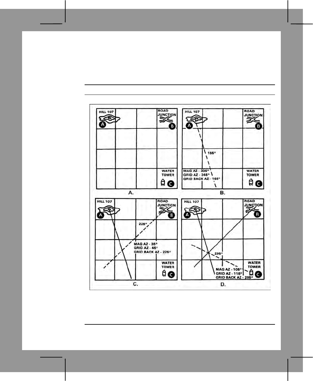
C-49
(GTA 05-02-012), a pencil, and two terrain features visible from your location
and identifiable on the map.
Standards: Determined the 100,000 meter square identification letters and
six-digit coordinates of your location to within 100 meters of the actual grid
coordinates.
Performance Steps
1. Use the map and compass method (figure C-37).
Figure C-37. Using the map and compass
Note. The example map is not to scale—an easterly G-M angle of 10 degrees is
used in the examples.
a. Determine the G-M angle of the map you are using.
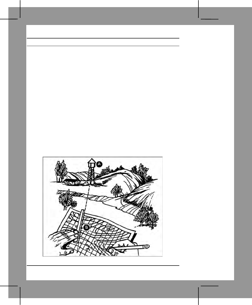
C-50
Performance Steps
b. Locate two known positions on the ground and mark them on your
map (A, figure C-37).
c. Using your compass, measure the magnetic azimuth to one of the
known locations; change it to a grid azimuth (B, figure C-37.)
(1) If it is a westerly G-M angle, subtract the number of degrees in
the G-M angle from your magnetic azimuth.
(2) If it is an easterly G-M angle, add the number of degrees in the
G-M angle to your magnetic azimuth.
d. Change this grid azimuth to a back azimuth.
e. Place the protractor on the map, ensuring that the zero degree
indicator on the protractor is pointing to the top of the map (north), and the
index point is placed center mass on this location. Place a tick mark at the
number of degrees you want to plot. Remove the protractor from the map
and draw a line on the map from this position on the grid back azimuth you
found, in the direction of your unknown position.
f. Repeat steps 1c through 1e for a second (C, figure C-37), and third
(D, figure C-37) known position.
g. Where these lines cross is your location.
2. Perform resection without a compass (figure C-38).
Figure C-38. Resection without a compass
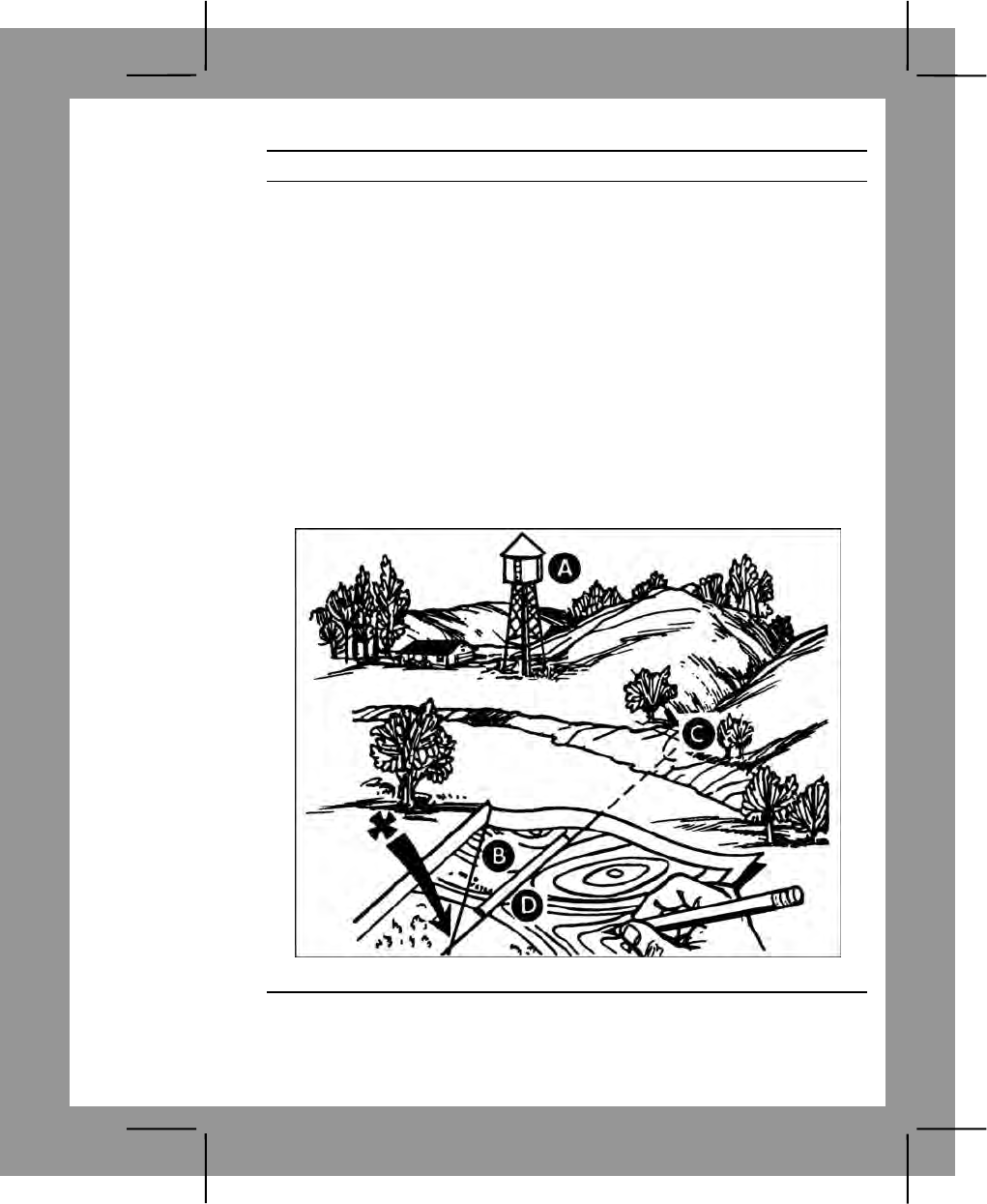
C-51
Performance Steps
a. Orient your map as closely as you can using one of the ways you've
learned about finding direction: compass, sun, watch, or stars. Then look
for some feature, such a water tower (figure C-38, point A), that you can
also find on the map. Put a ruler or straightedge on the map, and place its
edge next to the water tower symbol (figure C-38, point B) on the map.
Then align the straightedge so that it points directly at the real water tower.
Draw a line along the straightedge or ruler (the line will cross the symbol
for the water tower on your map).
Note. Do not move your map once it is properly oriented.
b. Find another feature, such a road junction (figure C-39, point C),
and do the same things. Lay the straightedge on your map and point it at
the real road junction, ensuring at the same time that its edge crosses over
the road junction (figure C-39, point D) on the map. Draw another line
along the ruler until it crosses (intersects) the first line. The point where the
lines cross is your location. (figure C-39, point X) if you do this step with a
third line, it may help location your position more accurately.
Figure C-39. Resection without a compass continued
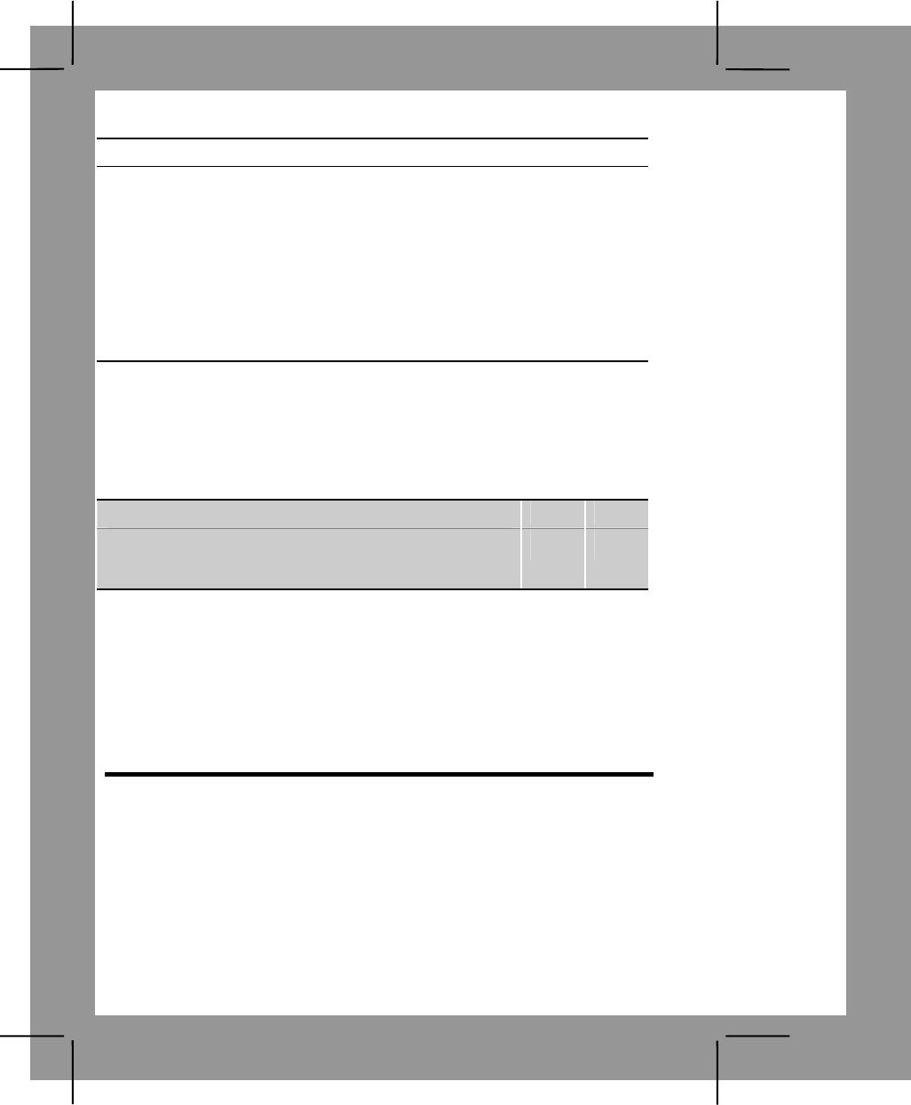
C-52
Performance Steps
3. To perform modified resection you must be located on a linear feature
such as a road, stream bank, railroad or ridge. First orient your map, then
find some feature that you can also find on the map, such as the water
tower in the previous example. Just as before, put a straightedge through
the water tower on the map and align the straightedge so that it points
directly at the real water tower. Draw a line along the ruler or straightedge.
The point where the line crosses the linear feature is your location.
Note. Always orient your map as closely as you can. The compass is the best way
to do so. If you don't have a ruler, use your rifle cleaning rod or a section of radio
antenna as a straightedge.
Evaluation Preparation:
Setup: Give the soldier a standard 1:50,000-scale military map of the local
area, a compass, a coordinate scale, a protractor (GTA 05-02-012), a pencil,
a straightedge, and the location of two known points.
Brief Soldier: Tell the soldier to determine the six-digit coordinates for his
location.
Performance Measures GO NO GO
1. Determined the six-digit grid coordinate and the
100,000 meter square identifier of the soldier’s position
(unknown point) within 100 meters.
—— ——
Evaluation Guidance: Score the soldier GO if the performance measure is
passed. Score the soldier NO GO if the performance measure is failed. If the
soldier scores NO GO, show what was done wrong and how to do it
correctly.
References
Required Related
FM 3-25.26
Land Navigation Task 14
Determine Direction without a Compass
Conditions: During daylight and at night (with a clear view of the Big
Dipper), given a wristwatch (not digital), the soldier must determine direction
in a field environment with natural vegetation available.
Standards: Identified north and east within 15 degrees.
Note. All of the procedures given in this task give approximate directions. For accurate
directions, a compass must be used.
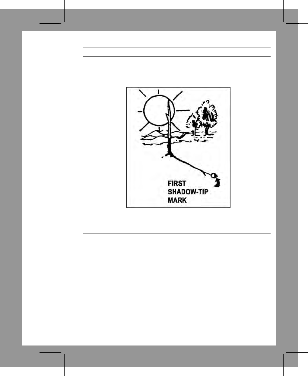
C-53
Performance Steps
1. Determine direction using the shadow-tip method.
a. Place a stick or branch into the ground vertically at a fairly level spot
where the sun will cast a distinct shadow. Mark the shadow with a stone,
twig, or other means (figure C-40).
Figure C-40. First shadow-tip mark
b. Wait 10 or 15 minutes until the shadow tip moves a few inches.
Mark the new position of the shadow tip as in step 1a (figure C-41).
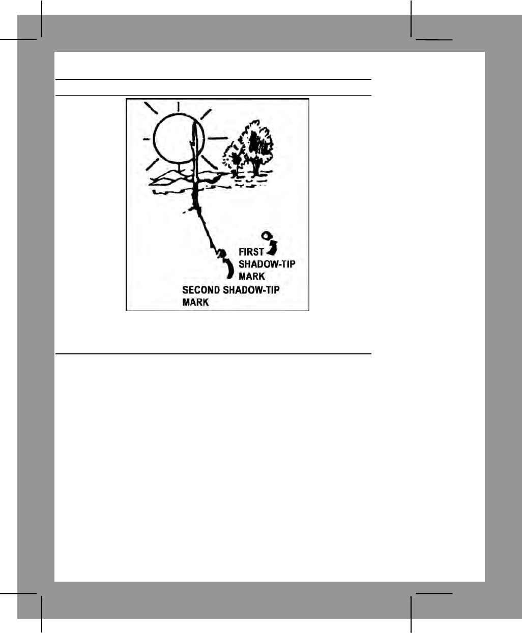
C-54
Performance Steps
Figure C-41. Second shadow-tip mark
c. Draw a straight line through the two marks you made on the
shadow tips. This line is an east-west line (figure C-42).
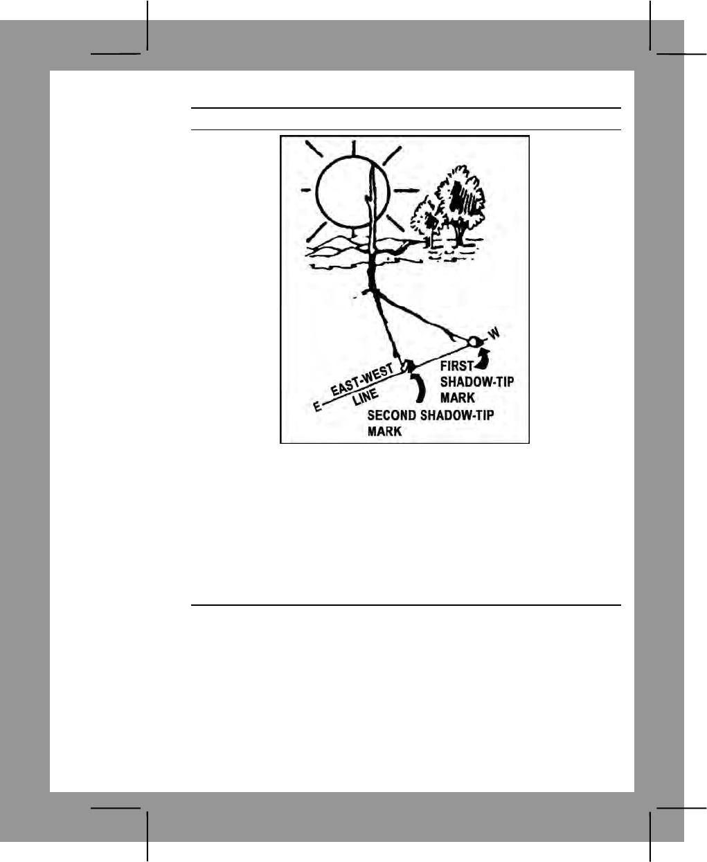
C-55
Performance Steps
Figure C-42. East-west line
d. Determine which is the east end of the line and which is the west
end.
(1) The sun rises in the east and sets in the west.
(2) The first shadow tip you mark is always west and the second
mark is always east.
(3) The shadow tip moves in the opposite direction.
e. Determine north and south. Draw a line at a right angle to the east-
west line at any point (figure C-43). This is the north-south line.
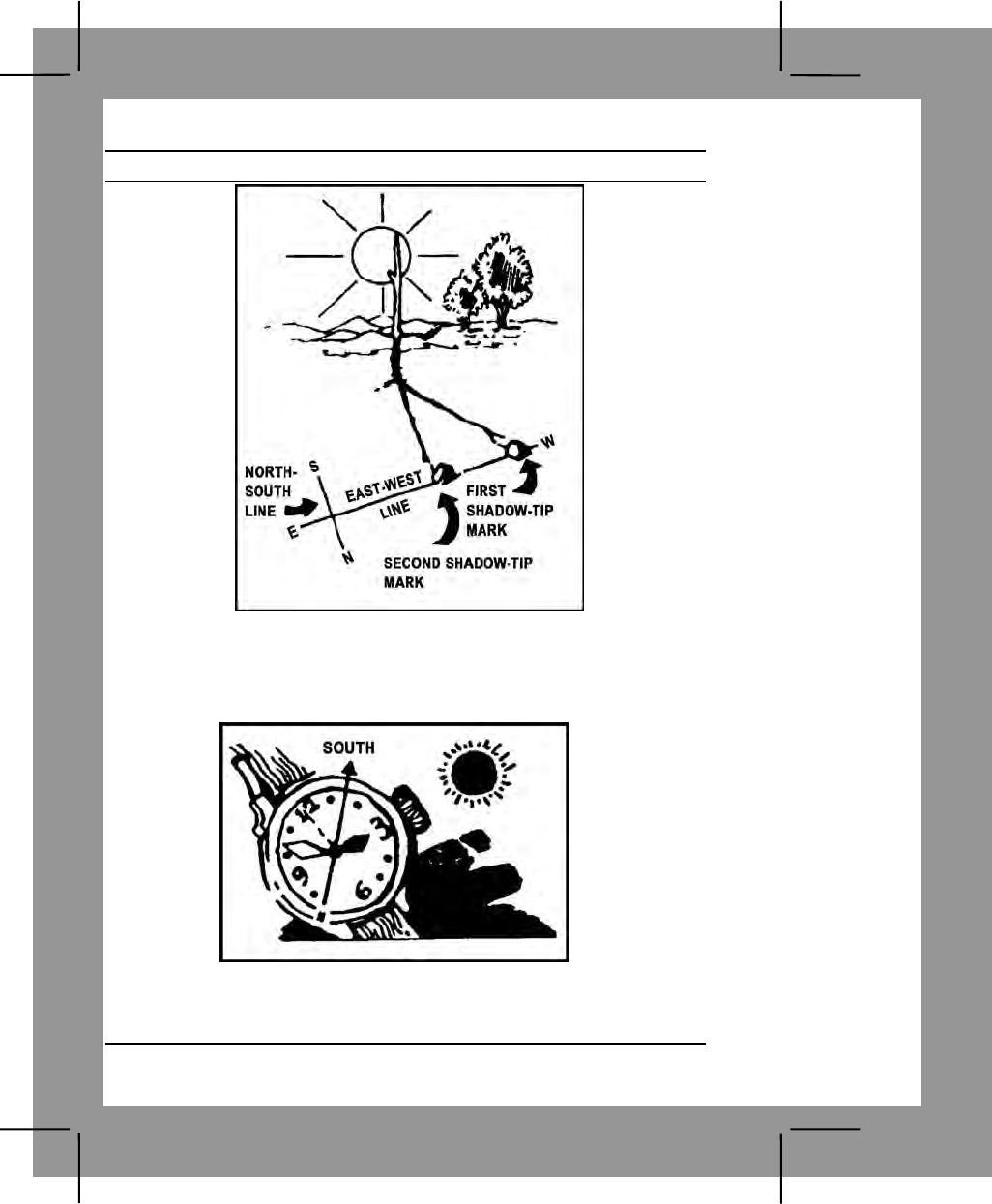
C-56
Performance Steps
Figure C-43. North-south line
2. Determine direction using the watch method without a compass.
a. Point the hour hand at the sun when you are north of the equator.
South will be halfway between the hour hand and 12 o'clock (figure C-44).
Figure C-44. Watch method
b. Point 12 o'clock at the sun when you are south of the equator.
North will be halfway between the hour hand and 12 o'clock.
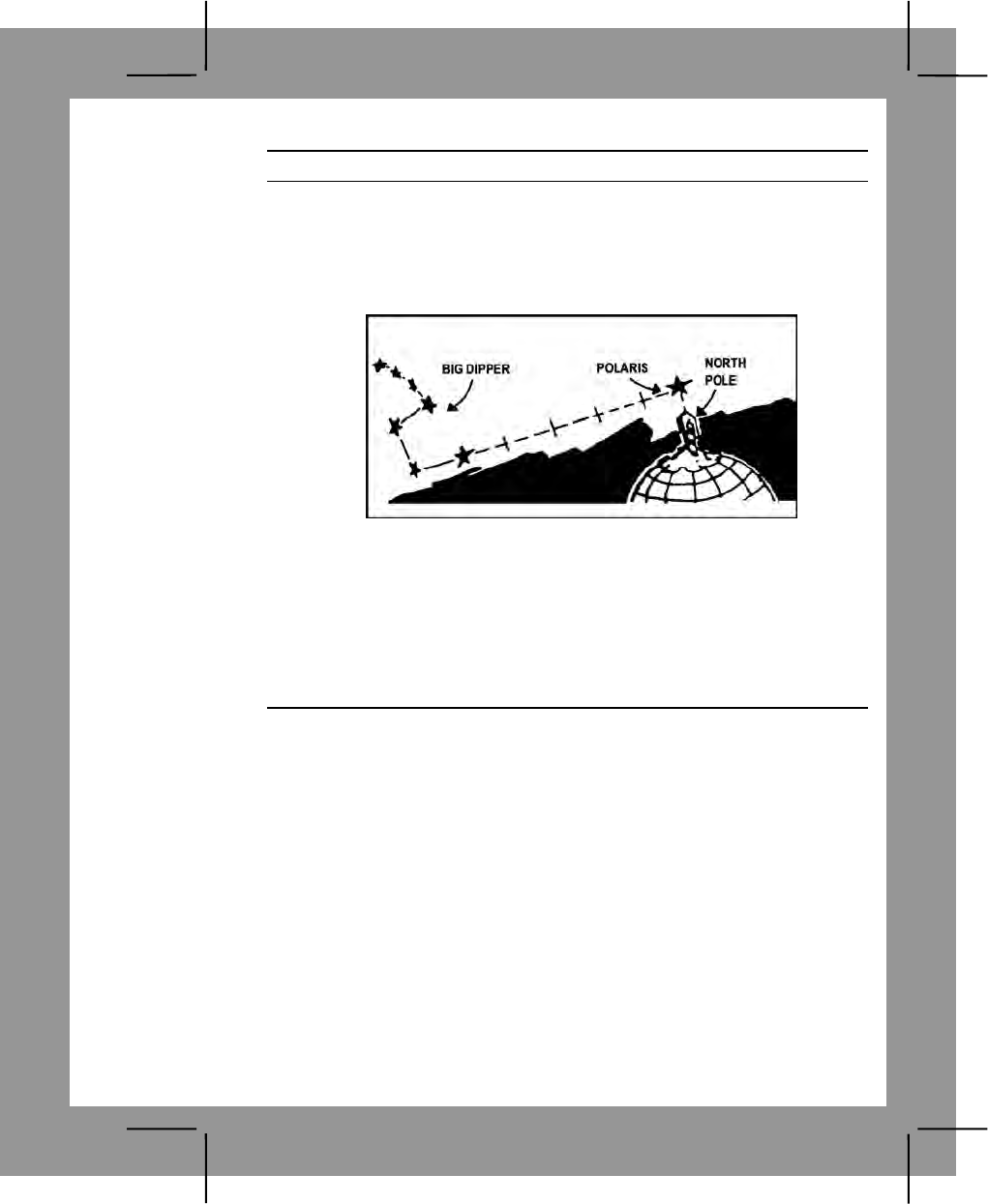
C-57
Performance Steps
3. Use the North Star method to determine direction at night. At night, you
can locate north by finding the North Star (Polaris). First, find the Big
Dipper. The last two stars in the cup point directly at Polaris, which is about
five times as far out as the distance between those two stars in the cup.
Facing Polaris, you are looking north, with east on your right and west on
your left (figure C-45).
Figure C-45. North Star method
Note. During the training session, stress these four facts:
1. The sun rises in the east and sets in the west.
2. When you face north, east is to your right, west is to your left, and south is to your
back.
3. The Big Dipper is a pattern of stars that resembles a soup ladle.
4. The Southern Cross is the main constellation used as a guide south of the
equator and the above general directions for using north and south stars are
reversed.
Evaluation Preparation:
Setup: Directionally orient yourself to an area that is unfamiliar to the soldier
to be tested.
Brief Soldier: Accompany the soldier to the area and tell the soldier to use
the field-expedient methods to determine which direction is north and east.
Use a compass direction of your choice. Do not tell the soldier how he or she
did on performance measure 1 until he or she completes performance
measure 2.
Note. Before the soldier is scored a GO for this task, he or she must display
proficiency in all three field-expedient methods of determining direction without a
compass. However, performance measure 3 must be tested in a different location.

C-58
Performance Measures GO NO GO
1. Determined direction using the shadow-tip field-
expedient method —— ——
a. Placed a stick vertically into the ground at a
desired spot.
b. Marked the tip of the stick's shadow to represent
west.
c. Waited 10 to 15 minutes.
d. Marked a new position of the tip of the stick's
shadow to represent east.
e. Drew an east-west line through the two shadow-
tip marks.
f. Drew a north-south line at a right angle to the
east-west line.
g. Pointed in the required direction within 15
degrees.
2. Determined direction using the watch field-expedient
method. —— ——
a. In the Northern Hemisphere, pointed the hour
hand of the watch at the sun; in the Southern
Hemisphere, pointed the 12 o'clock position of the watch
at the sun.
b. Pointed in the required direction within 15
degrees.
3. Determined direction using the North Star field-
expedient method. —— ——
a. Located the Big Dipper.
b. Located Polaris, the North Star.
c. Pointed in the required direction within 15
degrees.
Evaluation Guidance: Score the soldier GO if all performance measures
are passed. Score the soldier NO GO if any performance measure is failed.
If the soldier scores NO GO, show the soldier what was done wrong and
how to do it correctly.
References
Required Related
FM 3-25.26

C-59
Land Navigation Task 15
Determine Azimuths Using a Protractor
Conditions: Given a standard 1:50,000-scale military map with two known
points plotted on the map, a protractor, a straightedge, a pencil, and
requirement to determine the azimuth from your location (point A) to another
point (point B) on the map.
Standards: Determined the grid azimuth (in mils or degrees) from your
location (point A) to point B to within 1 degree or 20 mils.
Performance Steps
1. The direction from one point to another, either on the map or on the
ground, is called an azimuth. Azimuths are given in degrees or mils in a
clockwise direction from north, and all azimuths taken from a map are grid
azimuths.
a. An azimuth in degrees can be any number up to 360, as there are
360 degrees in a circle. Due east is 90 degrees, due south is 180 degrees,
due west is 270 degrees, and due north is 360 degrees or 0 degrees.
b. An azimuth in mils can be any number up to 6400, as there are
6400 mils in circle. Due east is 1600 mils, due south is 3200 mils, due west
is 4800 mils, and due north is 6400 mils or 0 mils.
2. The most accurate way to determine an azimuth from a map is to use a
protractor. There are two types of protractors in use in the Army today.
a. The square protractor (GTA 05-02-012), which has a degree scale
and a mil scale. The inner scale is the degree scale, and the outer scale is
the mil scale.
b. The semicircular protractor, which may or may not have two scales:
an outer scale in mils and an inner scale in degrees. The mil and degree
scales consist of two rows of numbers. In each of the scales, the outer row
of numbers is used when determining azimuths to the east of your position,
and the inner row of numbers is used when determining azimuths to the
west of your position.
3. Use the protractor properly.
a. Plot the location of two points on the map.
b. Using a straightedge, draw a straight line (azimuth line) from point A
to point B.
Note. The line drawn between the two points must be long enough to cross the
scale(s) of the protractor in order to read the azimuth. Should the line between the
two points be too short to cross the scale(s), extend the line beyond point B until it
crosses the scale(s).
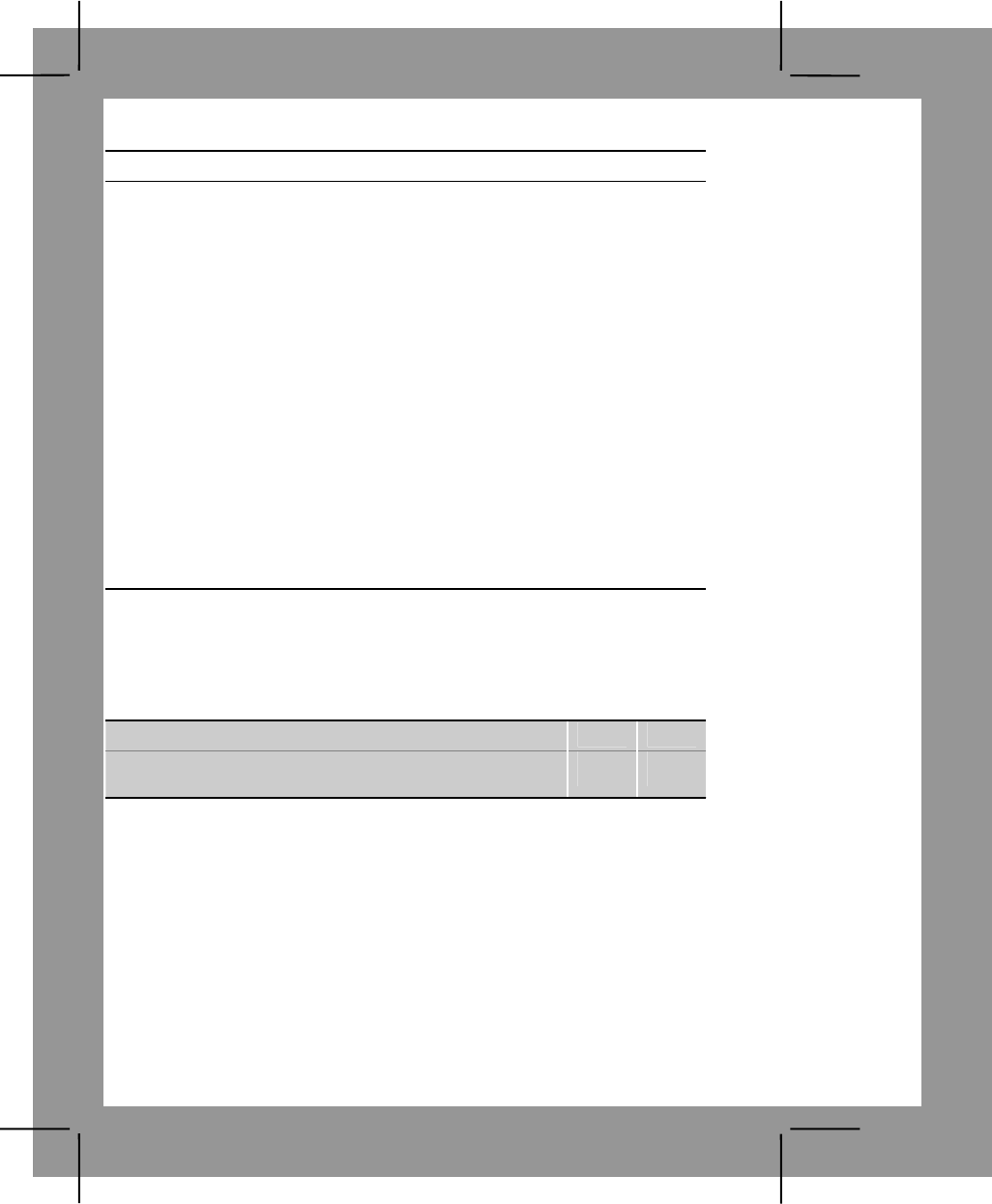
C-60
Performance Steps
c. Place the index of the protractor at the point where the azimuths
line crosses one of the vertical (north-south) grid lines. This procedure
allows greater accuracy in aligning the index line to a true reading where
the azimuth line crosses the protractor scale.
Note. Ensure that the 0-degrees or 0-mils mark on the protractor is toward the top
(north) of the map.
d. Start at the 0-degree or 0-mil mark on the protractor and read to the
right (clockwise) until you reach the point where the azimuth line crosses
the scale(s) of the protractor.
Note. When using the protractor, each tick mark on the degree scale is 1 degree,
while each tick mark on the mil scale is 20 mils.
e. Read the azimuth where the azimuth line crosses the scale(s).
(1) Figure 49, 65 degrees.
(2) Figure 50, 65 degrees - 1150 mils.
Note. When using the square protractor, the scale can be read all the way around
the protractor. In using the semicircular protractor, when point B is to the left (west)
of point A. The protractor must be reversed so that 0 is toward the bottom of the
map (south).
Evaluation Preparation:
Setup: Provide the soldier with a 1:50,000-scale military map, two points
plotted and labeled (A) and (B), a protractor, a straightedge, and a pencil.
Brief Soldier: Tell the soldier to determine the azimuth from point A to point B
within one degree or 20 mils.
Performance Measures GO NO GO
1. Determined the correct azimuth (within 1 degree or
20 mils). —— ——
Evaluation Guidance: Score the soldier GO if the performance measure is
passed. Score the soldier NO GO if the performance measure is failed. If the
soldier scores NO GO, show what was done wrong and how to do it
correctly.
References
Required Related
FM 3-25.26
GTA 05-02-012

C-61
Land Navigation Task 16
Compute Back Azimuths
Conditions: Given azimuths and a requirement to compute back azimuths.
Standards: Determined the back azimuth of a given azimuth to the exact
degree or mils.
Performance Steps
1. Determine a back azimuth using degrees. Suppose you follow a 65-
degree azimuth from point A to point B and then want to go back to your
original location. To do this, you use a back azimuth. You simply add 180
to the first azimuth. Your back azimuth is 65 + 180 = 245 degrees.
2. Determine a back azimuth using mils. You move from point A to point B
on an azimuth of 1150 mils. Should you wish to return to point A, you
would follow a back azimuth. To determine the back azimuth you simply
and 3200 mils to 1150: 3200 + 1150 = 4350.
Note. The rule to remember to determine a back azimuth is as follows:
—Degrees: Less than 180 degrees, add 180 degrees. More than 180 degrees,
subtract 180 degrees.
—Mils: Less than 3200 mils, add 3200 mils. More than 3200 mils, subtract 3200
mils.
Evaluation Preparation:
Setup: Provide the soldier with azimuths, one in degrees and one in mils.
Brief Soldier: Tell the soldier to compute the exact back azimuths.
Performance Measures GO NO GO
1. Computed the exact back azimuth. —— ——
Evaluation Guidance: Score the soldier GO if the performance measure is
passed. Score the soldier NO GO if the performance measure is failed. If the
soldier scores NO GO, show what was done wrong and how to do it
correctly.
References
Required Related
FM 3-25.26

Glossary-1
Glossary
ACS Army Community Service
ADAPCP Alcohol and Drug Abuse Prevention and Control
Program
AER Army Emergency Relief
AFTB Army Family Team Building
AHS Academy of Health Sciences
AIDS acquired immunodeficiency syndrome
APAC Army Public Affairs Center
APC armored personnel carrier
AR Army regulation
ATNAA antidote treatment nerve agent autoinjector
AZ azimuth
BDU battle dress uniform
BFV Bradley fighting vehicle
BMD Boyevaya Mashina Desantnika [literal Russian:
combat vehicle, airborne]
BMP Boyevaya Mashina Pekhoty [literal Russian:
combat vehicle, infantry}
C2W command and control warfare
CANA convulsant antidote for nerve agent
CASCOM Combined Arms Support Command
CB chemical or biological
CCC Community Counseling Center
CID Criminal Investigation Command
CLP cleaner lubricant preservative
cm centimeter
CO company
CTT Common Task Test
CVC combat vehicle crewman
D drive
DA CIR Department of the Army circular
DA Form Department of the Army form
DA Pam Department of the Army pamphlet

Glossary-2
DD Form Department of Defense form
DNA deoxyribonucleic acid
DNVT digital non-secure voice terminal
DODD Department of Defense directive
DODI Department of Defense instruction
DS2 decontaminating solution #2
DU depleted uranium
EFMP Exceptional Family Members Program
EO equal opportunity
FEBA forward edge of the battle area
FM field manual
FPL final protective line
FSN Federal stock number
FTX field training exercise
G2 assistant chief of staff, G2 (intelligence)
G3 assistant chief of staff, G3 (operations and plans)
G-M grid-magnetic
GMD grease, molybdenum disulfide
GPS Global Positioning System
GTA graphic training aid
HC hexachloroethane (smoke)
HIV human immunodeficiency virus
HMMWV high mobility multipurpose wheeled vehicle
HQ headquarters
HUMINT human intelligence
ID Identification
IDAA Individual Dynamic Absorption Application
IHFR improved high frequency radio
IMINT imagery intelligence
IN Infantry
JAG Judge Advocate General
JFK John F Kennedy Special Warfare Center and
School
JP joint publication

Glossary-3
LAW lubricating oil arctic weather
LBE load-bearing equipment
LCE load carrying equipment
LCSS lightweight camouflage screen system
LCE load carrying equipment
LSA lubricating oil, semifluid, automatic
LSAT (lubricating oil)
m meter
MANSCEN Maneuver Support Center
MASINT measurement and signature intelligence
METT-TC mission, enemy, terrain, troops, time available, and
civilian considerations
MI military intelligence
mm millimeter
MOPP mission-oriented protective posture
MOUT military operations in urban terrain
mph miles per hour
N neutral
NATO North Atlantic Treaty Organization
NBC nuclear, biological, and chemical
NCO noncommissioned officer
NCOIC noncommissioned officer in charge
NCS net control station
NSN national stock number
OD olive drab
OPLAN operation plan
OPORD operation order
OPSEC operations security
P park
Pam Cl pralidoxime chloride
PDF principal direction of fire
PL preservative lubricant
PLT platoon
PMCS preventive maintenance checks and services
PMM preventive medicine measure

Glossary-4
RADIAC radiation, detection, indication, and computation
RBC rifle bore cleaner
ROC-V recognition of combat vehicles
RSTA reconnaissance, surveillance, and target
acquisition
RT radio transmission
S1 personnel officer
S2 intelligence officer
SALUTE size, activity, location, unit, time, equipment
SAW squad automatic weapon
SIG signal
SIGINT signals intelligence
SINCGARS Single-Channel Ground and Airborne Radio
System
SL skill level
SMCT soldier's manual of common tasks
SME subject matter expert
SOI signal operating instruction
SOP standing operating procedure
SQD squad
SSI Soldier Support Institute
STD sexually transmitted disease
STP soldier training publication
T&E traversing and elevating
TB technical bulletin
TC training circular
TEC training extension course
TM technical manual
TRP target reference point
TW target width
TWS thermal weapon sight

Glossary-5
U.S. United States
UCMJ Uniform Code of Military Justice
VRC vehicular radio configuration
WBGT wet bulb globe temperature
WP white phosphorus

References-1
References
Required Publications
Required publications are sources that users must read in order to
understand or to comply with this publication.
Army Regulations
AR 15-6, Procedures for Investigating Officers and Boards of Officers
(CH1, 30 September 1996), 11 May 1988.
AR 350-30, Code of Conduct/Survival, Evasion, Resistance and Escape
(SERE) Training, 10 December 1985.
AR 360-1(AR 360-5/AR 360-81), The Army Public Affairs Program, 15
September 2000.
AR 530-1, Operations Security (OPSEC), 3 March 1995.
AR 600-13, Army Policy for the Assignment of Female Soldiers, 27 March
1992.
AR 600-20, Army Command Policy, 13 May 2002.
AR 635-200, Enlisted Personnel, 1 November 2000.
Department of Army Forms
DA Form 1594, Daily Staff Journal or Duty Officer's Log
DA Form 2404, Equipment Inspection and Maintenance Worksheet
DA Form 5304-R, Family Care Plan Counseling Checklist
DA Form 5305-R, Family Care Plan
DA Form 5517-R, Standard Range Card
Department of Army Pamphlets
DA PAM 350-20, Unit Equal Opportunity Training Guide, (CH1, 1 June
1994), 30 August 1993.
DA PAM 600-26, Department of the Army Affirmative Action Plan, 23
May 1990.
Department of Defense Publications
DODD 7050.6, Military Whistleblower Protection, 23 June 2000.
Devices
DVC 08-15
Field Manuals
FM 3-0 (FM 100-5), Operations, 14 June 2001.
FM 3-05.71 (FM 21-78), Resistance and Escape (U), 7 September 2001.

References-2
FM 3-3, Chemical and Biological Contamination Avoidance, (CH1, 29
September 1994) 16 November 1992.
FM 3-3-1, Nuclear Contamination Avoidance, 9 September 1994.
FM 3-4, NBC Protection, (CH2, 21 February 1996), 29 May 1992.
FM 3-5, NBC Decontamination, (CH1, 31 January 2002), 28 July 2000.
Will be revised as FM 3-11.5.
FM 3-22.68 (FM 23-14/FM 23-67), Crew-Served Machine Guns, 5.56-MM
and 7.62-MM, 31 January 2003.
FM 3-22.9, Rifle Marksmanship M16A1, M16A2/3, M16A4 and M4
Carbine, 24 April 2003.
FM 3-25.26 (FM 21-26), Map Reading and Land Navigation,
20 July 2001.
FM 7-8, Infantry Rifle Platoon and Squad, (CH1, 1 March 2001),
22 April 1992. Will be revised as FM 3-21.8.
FM 21-16, Unexploded Ordnance (UXO) Procedures, 30 August 1994. Will
be revised as FM 4-30.11.
FM 21-75, Combat Skills of the Soldier, 3 August 1984. Will be revised as
FM 3-21.75.
FM 21-305, Manual for the Wheeled Vehicle Driver, 27 August 1993.
FM 23-23, Antipersonnel Mine M18A1 and M18 (CLAYMORE), (CH2, 30
March 1973), 6 January 1966. Will be revised as FM 3-22.23.
FM 24-18,Tactical Single-Channel Radio Communications Techniques,
30 September 1987.
FM 34-1, Intelligence and Electronic Warfare Operations, 27 September
1994. Will be revised as FM 2-0.
FM 34-60, Counterintelligence, 3 October 1995. Will be revised as
FM 2-01.2. Will be revised as FM 2-01.2
FM 46-1, Public Affairs Operations, 30 May 1997.
FM 55-30, Army Motor Transport Units and Operations, (CH1, 15
September 1999), 27 June 1997. Will be revised as FM 4-01.40.
Graphic Training Aids
GTA 03-04-001A, Depleted Uranium Awareness, 1 October 1999.
GTA 05-02-012, Coordinate Scale and Protractor (simple device), 2
January 1981.
GTA 09-12-001, Unexploded Ordnance (UXO) Procedures, 3 January
1992.

References-3
Joint Publications
JP 4-06, Joint Tactics, Techniques, and Procedures for Mortuary Affairs
in Joint Operations, 28 August 1996.
Other Product Types
ACP 125 US SUPPL-1, Communications Instructions Radiotelephone
Procedures for Use by United States Ground Forces, 1 October 1985.
ACP 125(E), Communication Instructions—Radiotelephone Procedures, 1
August 1987.
MANUAL-MCM, Manual for Courts-Martial, United States, 2000
Edition, 21 July 2000.
Soldier Training Publications
STP 21-1-SMCT, Soldier's Manual of Common Tasks Skill Level 1, 31
August 2003.
Technical Manuals
TM 3-4230-229-10, Operator's Manual for Decontaminating Kit, Skin:
M291, (NSN 4230-01-251-8702), (CH1, 28 February 1991), 2 October
1989.
TM 3-4230-235-10, Operator's Manual for Decontamination Kit,
Individual Equipment: M295 (NSN 6850-01-357-8456), (CH1, 8 June
1994), 20 February 1994.
TM 3-4240-279-10, Operator's Manual for Mask, Chemical-Biological:
Field, ABC-M17 (NSN 4240-00-542-4450) Small; (4240-00-542-4451)
Medium; (4240-00-542-4452) Large; M17A1 (4240-00-926-4199)
Small; (4240-00-926-4201) Medium; (4240-00-926-4200) LARGE;
M17A2 (4240-01-143-2017) X-Small; (4240-01-143-2018) Small;
(4240-01-143-2019) Medium; (4240-01-143-2020) Large, (CH3, 9 May
1997), 5 October 1987.
TM 3-4240-280-10, Operator's Manual for Mask, Chemical-Biological:
Aircraft, ABC-M24 And Accessories AND Mask, Chemical-Biological,
Tank, M25A1 and Accessories, (CH3, 9 May 1997), 15 March 1988.
TM 3-4240-346-10, Operator's Manual for Chemical-Biological Mask:
Field, M40A1 (NSN 4240-01-370-3821-Small) (4240-01-370-3822-
Medium) (4240-01-370-3823-Large); Chemical-Biological Mask:
Combat Vehicle, M42A2 (4240-01-4100-Small) (4240-01-413-4101-
Medium) (4240-01-413-4102-Large), (CH1, 15 March 2002), 1 August
1998.

References-4
TM 3-4240-348-10, Operator Instructions for Mask, Chemical-Biological:
Land Warrior, M45 (NSN 4240-01-447-6989 - Extra Small); (4240-01-
447-6987 - Small); (4240-01-447-8967 - Medium); and (4240-01-447-
6988 - Large), 21 January 2000.
TM 3-6665-307-10, Operator's Manual for Chemical Agent Detector Kit,
M256 (NSN 6665-01-016-8399) and M256A1 (6665-01-133-4964),
(CH3, 15 April 1998), 1 September 1985.
TM 3-6665-311-10,Operator's Manual for Paper, Chemical Agent
Detector: M9 (NSN 6665-01-226-5589), 31 August 1998.
TM 9-1005-201-10, Operator's Manual for Machine Gun, 5.56-MM, M249
w/Equip (NSN 1005-01-127-7510) (EIC: 4BG), (CH2, 28 June 2000),
26 July 1991.
TM 9-1005-224-10, Operator's Manual for Machine Gun, 7.62-MM, M60
w/E (NSN 1005-00-605-7710) (EIC: 4AJ) and Machine Gun, 7.62-
MM, M60D w/E (1005-00-909-3002) (EIC: 4A8), 2 April 1998.
TM 9-1005-224-23&P, Unit and Direct Maintenance Manual (Including
Repair Parts and Special Tools List) for Machine Gun, 7.62-MM, M60
w/E (NSN 1005-00-605-7710) (EIC: 4AJ) and Machine Gun, 7.62-
MM, M60D w/E (1005-00-090-3002) (EIC: 4A8), 21 May 1998.
TM 9-1005-249-10, Operator's Manual for Rifle, 5.56-MM, M16 (NSN
1005-00-856- 6885) Rifle, 5.56-MM, M16A1 (1005-00-073-9421), (CH2,
11 May 1990), 11 February 1985.
TM 9-1330-200-12, Operator's and Organizational Maintenance Manual
for Grenades, (CH17, 15 March 2002), 17 September 1971.
TM 11-5820-401-10-2, Operator's Manual for Radio Sets, AN/VRC-12
(NSN 5820-00-223-7412) (EIC: GCC) AN/VRC-43 (5820-00-223-7415)
(EIC: GCD) AN/VRC-44 (5820-00-223-7417) (EIC: GCE) AN/VRC-45
(5820-00-223-7418) (EIC: GCF) AN/VRC-46 (5820-00-223-7433) (EIC:
GCG) AN/VRC-47 (5820-00-223-7434) (EIC: GCH) AN/VRC-48
(5820-00-223-7435) (EIC: GCH) AN/VRC-49, (CH2, 15 August 1995),
23 November 1982.
TM 11-5820-890-10-8, Operator's Manual for SINCGARS Ground
Combat Net Radio, ICOM Manpack Radio, AN/PRC-119A (NSN
5820-01-267-9482) (EIC: L2Q), Short Range Vehicular Radio
AN/VRC-87A (5820-01-267-9480) (EIC: L22), Short Range Vehicular
Radio with Single Radio Mount AN/VRC-87C (5820-01-304-2045)
(EIC: GDC), Short Range Vehicular Radio with Dismount AN/VRC-
88A (5820-01-267-9481) (EIC: L23), Short Range/Long Range
Vehicular Radio AN/VRC-89A (5820-01-267-9479) (EIC: L24), Long
Range Vehicular Radio AN/VRC-90A (5820-01-268-5105) (EIC: L25),

References-5
Short Range/Long Range Vehicular Radio with Dismount AN/VRC-
91A (5820-01-267-9478) (EIC: L26), Short Range/Long Range
Vehicular Radio AN/VRC-92A (5820-01-267-9477) (EIC: L27) Used
with Automated Net Control Device (ANCD) (AN/CYZ-10) Precision
Lightweight GPS Receiver (PLGR) (AN/PSN-11) Secure Telephone
Unit (STU) Frequency Hopping Mutiplexer (FHMUX), 1 December
1998.
Training Circulars
TC 19-138, Civilian Law Enforcement and Security Officer Training, 1
August 2001.
TC 26-6, Commander's Equal Opportunity Handbook, 14 October 1994.
Related Publications
Related publications are sources of additional information. They are not
required in order to understand this publication.
Army Regulations
AR 27-3, The Army Legal Assistance Program, (CH2, 21 February 1996),
30 September 1992.
AR 50-5, Nuclear and Chemical Weapons and Material – Nuclear Surety,
1 August 2000.
AR 600-8-1, Army Casualty Operations/Assistance/Insurance,
20 October 1994.
AR 600-20, Army Command Policy, 13 May 2002.
AR 600-63, Army Health Promotion, (CH1, 28 April 1996)
17 November 1987.
AR 608-18, The Army Family Advocacy Program, 1 September 1995.
AR 608-99, Family Support, Child Custody, and Paternity,
1 November 1994.
AR 670-1, Wear and Appearance of Army Uniforms and Insignia,
1 July 2002.
Department of Army Pamphlets
DA PAM 608-47, A Guide to Establishing Family Support Groups, 16
August 1993.
DA PAM 738-750, Functional Users Manual for the Army Maintenance
Management System (TAMMS), 1 August 1994.

References-6
Department of Defense Publications
DODD 1300.7, Training and Education to Support the Code of Conduct
(CoC), 8 December 2000.
Devices
DVC 08-36 Kit, Nerve Agent Antidote Mark-1
DVC 08-37, Convulsant Nerve Agent TR
Field Manuals
FM 3-21.7, (FM 7-7), The Mechanized Infantry Platoon and Squad (APC),
20 August 2002.
FM 3-21.71 (FM 7-7J), Mechanized Infantry Platoon and Squad
(Bradley), 20 August 2002.
FM 3-22.31 (FM 23-31), 40-mm Grenade Launchers, M203 and M79,
13 February 2003.
FM 3-23.24, 47 Dragon Medium Antitank Weapon System, 30 August
2001.
FM 3-23.25, Light Antiarmy Weapons, 30 August 2001.
FM 3-90.1 (FM 71-1), Tank and Mechanized Infantry Company Team, 9
December 2002.
FM 4-25.11 (FM 21-11), First Aid, 23 December 2002.
FM 8-285, Treatment of Chemical Agent Casualties and Conventional
Military Chemical Injuries, 22 December 1995. Will be revised as
FM 4-02.285.
FM 19-15, Civil Disturbances, 25 November 1985. Will be revised as
FM 3-19.15.
FM 20-3, Camouflage, Concealment, and Decoys, 20 August 1999. Will be
revised as FM 3-58.1.
FM 20-32, Mine/Countermine Operations, (CH3, 1 October 2002), 29
May 1998.Will be revised as FM 3-34.32.
FM 21-10, Field Hygiene and Sanitation, 21 June 2000. Will be revised
as FM 4-25.10.
FM 22-6, Guard Duty, (CH1, 15 January 1975), 17 September 1971.Will
be revised as FM 3-21.6.
FM 23-27, MK 19, 40-MM Grenade Machine Gun, MOD 3, 27 December
1988.Will be revised as FM 3-22.27.
FM 23-35, Combat Training with Pistols and Revolvers, 3 October 1988.
Will be revised as FM 3-23.35.

References-7
FM 23-65, Browning Machine Gun, Caliber .50 HB, M2, (CH1, 12
September 2001), 19 June 1991. Will be revised as FM 3-22.65.
FM 24-19, Radio Operator's Handbook, 24 May 1991.
FM 27-10, The Law of Land Warfare, 18 July 1956 with change 1,
15 July 1976
FM 90-3, Desert Operations, 24 August 1993.
Graphic Training Aids
GTA 05-10-044, Mine Awareness, 1 May 1999.
GTA 17-02-011, Combat Vehicle Identification, 3 January 1984.
GTA 17-02-013, Armored Vehicle Recognition, 1 May 1987.
Other Product Types
USERS GUIDE-AFTB, Army Family Team Building Level I Guide,
12 December 1996
Technical Bulletins
TB 9-1300-278, Guidelines for Safe Response to Handling, Storage, and
Transportation Accidents Involving Army Tank Munitions or Armor
Which Contain Depleted Uranium, (CH1, 23 February 2001), 21 July
1996.
Technical Manuals
TM 3-4240-300-10-2, Operator's Manual for Chemical-Biological Mask:
Combat Vehicle, M42 (NSN 4240-01-258-0064) Small, (4240-01-258-
0065) Medium, (4240-01-258-0066) Large, (CH3, 31 July 1992), 30
August 1988.
TM 9-1005-213-10, Operator's Manual for Machine Guns, Caliber .50;
M2, Heavy Barrel Flexible, w/E (NSN 1005-00-322-9715) (EIC: 4AG)
M48 Turret Type (1005-00-957-3893) (EIC: 4BB) Soft Mount (1005-01-
343-0747) (Navy) Fixed Type Right Hand Feed (1005-00-122-9339)
(Navy) Fixed Type Left Hand Feed, 1 June 2001.
TM 9-1005-313-10, Operator's Manual for Machine Gun, 7.62MM, M240
(NSN 1005-01-025-8095) M240B (1005-01-412-3129) M240C (1005-
01-085-4758) M240D (1005-01-418-6995) M240E1 (1005-01-252-4288)
M240G (1005-01-359-2714) M240N (1005-01-493-1666), 15 November
2002.

References-8
TM 9-1005-317-10, Operator's Manual for Pistol, Semiautomatic, 9MM,
M9 (NSN 1005-01-118-2640), (CH3, 14 December 1990), 31 July 1985.
TM 9-1005-319-10, Operator's Manual for Rifle, 5.56 MM, M16A2 w/E
(NSN 1005-01-128-9936) (EIC: 4GM); Rifle, 5.56 MM, M16A3 (1005-
01-357-5112); Rifle, 5.56 MM, M16A4 (1005-01-383-2872) (EIC: 4F9);
Carbine, 5.56 MM, M4 w/E (1005-01-231-0973) (EIC: 4FJ); Carbine,
5.56 MM, M4A1 (1005-01-382-0953) (EIC: 4GC), 1 October 1998.
TM 9-1010-221-10, Operator's Manual for Grenade Launcher, 40-MM:
M203 (NSN 1010-00-179-6447); Grenade Launcher, 40-MM: M203A1
(1010-01-434-9028); Headquarters, Department of the Army, Air
Force, Marine Corps, And Navy, 1 August 2001.
TM 9-1010-230-10, Operator's Manual for Machine Gun, 40-MM, MK 19,
MOD 3 (NSN 1010-01-126-9063) (EIC: 4AE), 30 May 2001.
TM 9-1315-886-12, Operator's and Unit Maintenance Manual for
Launcher and Cartridge, 84 Millimeter: M136 (AT4), (CH4, 14 March
2001), 15 May 1990.
TM 11-5855-213-10, Operator's Manual for Night Vision Sight,
Individual Served Weapon, AN/PVS-4 (NSN 5855-00-629-5334) (EIC:
IPJ), (CH1, 15 June 1993), 1 February 1993.
TM 11-5855-309-12&P, Operator's and Unit Maintenance Manual
(Including Repair Parts and Special Tools List)
Training Circulars
TC 20-32-5, Commander’s Reference Guide for Land Mine and Explosive
Hazards (Iraq), 13 February 2003.
TRADOC Pamphlets
TRADOC PAM 600-4, IET Soldier’s Handbook, 1 April 2001.

STP 21-1-SMCT
31 AUGUST 2003
By Order of the Secretary of the Army:
PETER J. SCHOOMAKER
General, United States Army
Chief of Staff
Official:
JOEL B. HUDSON
Administrative Assistant to the
Secretary of the Army
0321002
DISTRIBUTION:
Active Army, Army National Guard, and US Army Reserve: Distribute in accordance
with the initial distribution number IDN 11 1447, requirements for STP 21-1-SMCT.
PIN: 059832-000

PIN: 059832-000
