HDW 1800/HDW D1800 HD DIGITAL VIDEOCASSETTE RECORDER 1800 Sony Manual
User Manual: HD DIGITAL VIDEOCASSETTE RECORDER HDW-1800
Open the PDF directly: View PDF ![]() .
.
Page Count: 121 [warning: Documents this large are best viewed by clicking the View PDF Link!]
- Table of Contents
- Chapter 1 Overview
- Chapter 2 Location and Function of Parts
- Chapter 3 Preparations
- Chapter 4 Recording and Playback
- Chapter 5 Editing
- Chapter 6 Shot Mark Function
- Chapter 7 UMID Functions
- Chapter 8 Function Menu
- Chapter 9 Setup Menus
- Chapter 10 Maintenance and Inspection
- Appendix
- Index

HD DIGITAL VIDEOCASSETTE RECORDER
HDW-1800
HDW-D1800
OPERATION MANUAL [English]
1st Edition (Revised 1)

2
To reduce the risk of fire or electric shock,
do not expose this apparatus to rain or
moisture.
To avoid electrical shock, do not open the
cabinet. Refer servicing to qualified
personnel only.
THIS APPARATUS MUST BE EARTHED.
WARNING: THIS WARNING IS APPLICABLE
FOR USA ONLY.
If used in USA, use the UL LISTED power
cord specified below.
DO NOT USE ANY OTHER POWER
CORD.
Plug Cap Parallel blade with ground pin
(NEMA 5-15P Configuration)
Cord Type SJT, three 16 or 18 AWG
wires
Length Minimum 1.5m (4 ft .11in.),
Less than 2.5 m (8 ft .3 in.)
Rating Minimum 10A, 125V
Using this unit at a voltage other than 120V
may require the use of a different line cord
or attachment plug, or both.
To reduce the risk of fire or electric shock,
refer servicing to qualified service
personnel.
WARNING: THIS WARNING IS APPLICABLE
FOR OTHER COUNTRIES.
1. Use the approved Power Cord (3-core mains lead) /
Appliance Connector / Plug with earthing-contacts that
conforms to the safety regulations of each country if
applicable.
2. Use the Power Cord (3-core mains lead) / Appliance
Connector / Plug conforming to the proper ratings
(Voltage, Ampere).
If you have questions on the use of the above Power Cord
/ Appliance Connector / Plug, please consult a qualified
service personnel.
CAUTION
The apparatus shall not be exposed to dripping or
splashing. No objects filled with liquids, such as vases,
shall be placed on the apparatus.
CAUTION
The unit is not disconnected from the AC power source
(mains) as long as it is connected to the wall outlet, even if
the unit itself has been turned off.
For the customers in the U.S.A.
This equipment has been tested and found to comply with
the limits for a Class A digital device, pursuant to Part 15
of the FCC Rules. These limits are designed to provide
reasonable protection against harmful interference when
the equipment is operated in a commercial environment.
This equipment generates, uses, and can radiate radio
frequency energy and, if not installed and used in
accordance with the instruction manual, may cause
harmful interference to radio communications. Operation
of this equipment in a residential area is likely to cause
harmful interference in which case the user will be
required to correct the interference at his own expense.
You are cautioned that any changes or modifications not
expressly approved in this manual could void your
authority to operate this equipment.
All interface cables used to connect peripherals must be
shielded in order to comply with the limits for a digital
device pursuant to Subpart B of Part 15 of FCC Rules.
For the customers in Europe
This product with the CE marking complies with both the
EMC Directive and the Low Voltage Directive issued by
the Commission of the European Community.
Compliance with these directives implies conformity to
the following European standards:
• EN60065: Product Safety
• EN55103-1: Electromagnetic Interference (Emission)
• EN55103-2: Electromagnetic Susceptibility (Immunity)
This product is intended for use in the following
Electromagnetic Environment(s):
E1 (residential), E2 (commercial and light industrial), E3
(urban outdoors), E4 (controlled EMC environment, ex.
TV studio).
For the customers in Europe
The manufacturer of this product is Sony Corporation, 1-
7-1 Konan, Minato-ku, Tokyo, 108-0075 Japan.
The Authorized Representative for EMC and product
safety is Sony Deutschland GmbH, Hedelfinger Strasse
61, 70327 Stuttgart, Germany. For any service or
guarantee matters please refer to the addresses given in
separate service or guarantee documents.
This symbol is intended to alert the user to
the presence of uninsulated “dangerous
voltage” within the product’s enclosure
that may be of sufficient magnitude to
constitute a risk of electric shock to
persons.
This symbol is intended to alert the user to
the presence of important operating and
maintenance (servicing) instructions in
the literature accompanying the
appliance.
WARNING

3
Attention-when the product is installed in Rack:
1. Prevention against overloading of branch circuit
When this product is installed in a rack and is supplied
power from an outlet on the rack, please make sure that
the rack does not overload the supply circuit.
2. Providing protective earth
When this product is installed in a rack and is supplied
power from an outlet on the rack, please confirm that
the outlet is provided with a suitable protective earth
connection.
3. Internal air ambient temperature of the rack
When this product is installed in a rack, please make
sure that the internal air ambient temperature of the
rack is within the specified limit of this product.
4. Prevention against achieving hazardous condition
due to uneven mechanical loading
When this product is installed in a rack, please make
sure that the rack does not achieve hazardous condition
due to uneven mechanical loading.
5. Install the equipment while taking the operating
temperature of the equipment into consideration
For the operating temperature of the equipment, refer to
the specifications of the Operation Manual.
6. When performing the installation, keep the
following space away from walls in order to obtain
proper exhaust and radiation of heat.
Right, Left : 4 cm (1.6 inches) or more
Rear: 10 cm (4 inched) or more
When installing the installation space must be secured in
consideration of the ventilation and service operation.
• Do not block the ventilation slots at the left side and right
side panels, and vents of the funs.
• Leave a space around the unit for ventilation.
• Leave more than 40 cm of space in the rear of the unit to
secure the operation area.
When the unit is installed on the desk or the like, leave at
least 4 cm of space in the left and right sides.
Leaving 40 cm or more of space above the unit is
recommended for service operation.
Do not install the appliance in a confined space, such as
book case or built-in cabinet.
WARNING
Excessive sound pressure from earphones and headphones
can cause hearing loss.
In order to use this product safely, avoid prolonged
listening at excessive sound pressure levels.
Voor de Klanten in Nederland
For the customers in Taiwan only
• Gooi de batterij niet weg maar lever deze in
als klein chemisch afval (KCA)
• Dit apparaat bevat een vast ingebouwde
batterij die niet vervangen hoeft te worden
tijdens de levensduur van het apparaat.
• Raadpleeg uw leverancier indien de batterij
toch vervangen moet worden.De batterij mag
alleen vervangen worden door vakbekwaam
servicepersoneel.
• Lever het apparaat aan het einde van de
levensduur in voor recycling, de batterij zal
dan op correcte wijze verwerkt worden.

4Table of Contents
Table of Contents
Chapter 1 Overview
1-1 Features .................................................6
1-2 Example System Configuration...........9
1-3 Description of the Function Menu in
this Manual..........................................10
Chapter 2 Location and Function of
Parts
2-1 Control Panels.....................................11
2-1-1 Upper Control Panel.......................... 12
2-1-2 Lower Control Panel ......................... 13
2-1-3 Switch Panel...................................... 22
2-2 Connector Panel..................................23
Chapter 3 Preparations
3-1 Connections to External Devices ......27
3-1-1 Connections to Digital Devices......... 27
3-2 Reference Sync Signals .....................28
3-2-1 Selecting Reference Sync Signal
Depending on Operational Status...... 28
3-2-2 Connecting Reference Signals .......... 28
3-3 Setup ....................................................29
3-4 Superimposed Character Information
..............................................................30
3-5 Cassettes .............................................32
3-5-1 Cassette Types................................... 32
3-5-2 Inserting and Ejecting Cassettes ....... 32
3-5-3 Preventing Accidental Erasure of
Recordings......................................... 32
Chapter 4 Recording and Playback
4-1 Recording ............................................33
4-1-1 Preparations for Recording ............... 33
4-1-2 Recording Timecode and User Bit
Values................................................ 34
4-1-3 Recording Procedure......................... 36
4-2 Playback ..............................................37
4-2-1 Preparations for Playback ................. 37
4-2-2 Playback Procedures ......................... 37
4-2-3 DMC (Dynamic Motion Control)
Playback ............................................ 40
Chapter 5 Editing
5-1 Automatic Editing ...............................43
5-1-1 Overview........................................... 43
5-1-2 Switch Settings.................................. 44
5-1-3 Selecting the Editing Mode............... 45
5-1-4 Setting Edit Points............................. 45
5-1-5 Modifying and Deleting Edit Points . 47
5-1-6 Cuing up to Edit Points and Preroll .. 48
5-1-7 Preview.............................................. 48
5-1-8 Carrying Out Automatic Editing....... 49
5-2 DMC Editing.........................................51
5-2-1 Overview........................................... 51
5-2-2 Carrying Out DMC Editing............... 51
5-3 Special Automatic Editing Methods.. 53
5-3-1 Quick Editing .................................... 53
5-3-2 Continuous Editing ........................... 53
5-3-3 Standalone Editing ............................ 53
5-3-4 Preread Editing.................................. 54
Chapter 6 Shot Mark Function
6-1 Overview ..............................................55
6-2 Shot Mark Operations.........................56
6-2-1 Reading Shot Marks.......................... 56
6-2-2 Writing Shot Marks........................... 56
6-2-3 Shot Mark List Operations................ 57
6-2-4 Cuing Up to Shot Marks ................... 59

Table of Contents 5
Chapter 7 UMID Functions
7-1 Overview.............................................. 60
7-2 Recording UMIDs................................ 60
7-3 UMID Output and Display................... 62
7-3-1 UMID Output Settings ...................... 62
7-3-2 UMID Display................................... 62
Chapter 8 Function Menu
8-1 Overview.............................................. 64
8-1-1 Function Menu Configuration........... 64
8-1-2 Function Menu Operations................ 64
8-2 Function Menu Item List..................... 65
8-2-1 User-Definable Function Menu Pages
(P01 to P10)....................................... 65
8-2-2 Non-User-Definable Function Menu
Pages (P100 to P118)......................... 69
Chapter 9 Setup Menus
9-1 Setup Menu Configuration................. 74
9-2 Setup Menu Operations ..................... 75
9-3 Items in the Basic Setup Menu.......... 78
9-4 Items in the Extended Setup Menu ... 81
Chapter 10 Maintenance and
Inspection
10-1 Removing a Cassette when Tape Slack
Occurs............................................... 103
10-2 Head Cleaning................................. 103
10-3 Error Messages............................... 104
10-4 Moisture Condensation.................. 106
10-5 Regular Checks............................... 106
10-5-1 Digital Hours Meter ...................... 106
10-5-2 Maintenance Timings................... 107
10-6 About the LCD................................. 108
Appendix
Specifications.......................................... 109
About a “Memory Stick”......................... 116
Index ....................................................... 118
Chapter 1
Chapter 1 Overview
61-1 Features
Overview
1-1 Features
The HDW-1800/D1800 is a high-definition (HD) digital
videocassette recorder based on the HDCAM format.
This unit uses large scale integrated circuits for signal
processing, and has a simple internal construction,
allowing it to provide functionality at least equivalent to a
conventional VTR in a compact (4U size), lightweight, and
low power consumption design.
In addition to HDCAM format recording and playback, the
HDW-D1800 can also play back tapes recorded in the
Digital Betacam and MPEG IMX formats.
HDCAM format
The HDCAM format uses the same 12.65-mm width tape
as the conventional Betacam series. It provides high
definition images, offering up to two hours of recording.
For video signal compression, prefiltration and coefficient
recording technologies are used.
High-performance heads and compatibility
functions
The newly developed high-performance heads and
dynamic tracking (DT) technology provide high-density
recording and playback in narrow tracks with high
reliability. The VTR automatically detects the recording
format of tapes when they are loaded, so that no menu
settings need to be made when changing formats.
High-precision digital signal processing
and range of interfaces
Digital signal processing uses HD 4:2:2 component video
signals complying with SMPTE 292M, which are
converted into parallel data and then compressed into
HDCAM format.
The audio signals are based on the AES/EBU format, and
are subjected to digital signal processing without being
compressed.
The unit is equipped with a high definition to standard
definition (HD-to-SD) downconverter, and has the
following interfaces for ease of connection to different
external devices.
• SD analog composite signal output
• Analog audio signal input/output (2 channels)
• HDSDI SMPTE 292M input/output (HD digital video/
audio, 4/8 channels)
• SDI SMPTE 259M output (component digital video/
audio, 4/8 channels)
• AES/EBU serial digital audio input/output (4 channels
for input, 4/8 channels for output)
• Timecode input/output
High-quality four-channel audio
High-quality 20 bit/48 kHz digital audio is supported in the
HDCAM format and there are four digital audio input/
output channels.
The HDW-D1800 also supports 4-channel digital audio
playback in the Digital Betacam format and a maximum of
8-channel digital audio playback in the MPEG IMX
format.
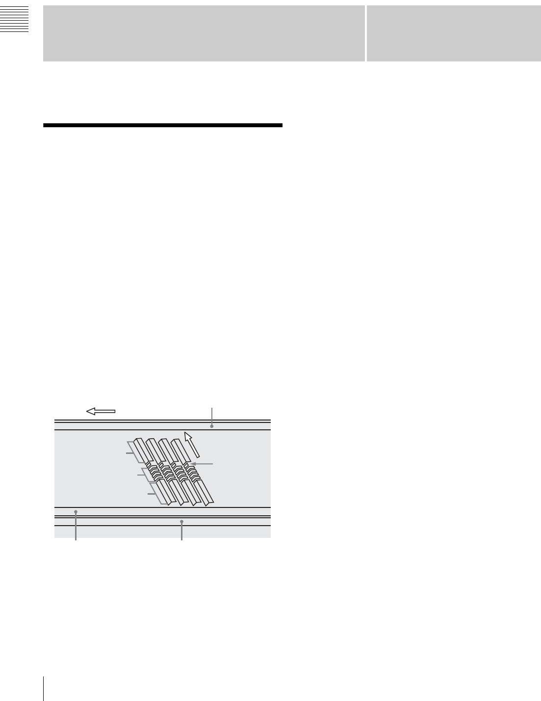
Direction of tape travel
Video
Control (CTL) track Timecode track
a) Supplemental Automatic Tracking signal
Audio
Video
Direction of head
motion
SATa)
CUE track

7
1-1 Features
Chapter 1 Overview
Control panel with LCD
The control panel contains an LCD unit to display various
types of information including time data. The display
mode can be changed to show the video which is currently
being recorded or played back.
Basic operation buttons and jog/shuttle
dial
Buttons, indicators, and a jog/shuttle dial for basic VTR
operations are provided in the conventional VTR layout,
ensuring continuity with conventional operating panels.
Function menu
You can use the function buttons on the LCD and the
MULTI CONTROL knob to easily carry out many of the
operations and make many of the settings supported by the
unit. The current settings can be checked on the LCD.
In addition, you can redefine the names and functions of
the function buttons. These are preset to standard factory
default values, but you can redefine them for ease of
operation according to the application. For example, you
can change the function button definitions to avoid
displaying an unnecessary function.
Audio level meters and level controls
Audio levels are shown on the LCD in the form of bar
graphs. Recording and playback levels can be controlled
with individual control knobs for each channel.
High-quality variable speed playback and
digital jog sound function
In HDCAM, Digital Betacam, and MPEG IMX format
playback, the dedicated playback DT heads allow smooth,
noiseless playback.
In slow motion operation, the digital jog sound function
provides the same ease of operation as for a conventional
analog VTR.
Wide range of editing functions
By combining two units, you can carry out both assemble
editing and insert editing automatically. All of the
necessary editing functions are provided to set and amend
edit points, to preview and review results of editing, and so
on.
DMC (Dynamic Motion Control) editing
This allows automatic editing with a varying playback
speed memorized beforehand for an edit segment.
Split editing
In insert editing, the audio IN and OUT points can be set
separately from the video edit points.
Preread editing
This allows you to play back prerecorded video and audio
material, edit it by applying effects with an external
device, and then rerecord almost simultaneously on the
same tape.
Cross fade editing
In audio editing, you can fade the audio track. You can
select cut in, fade in, fade out, or cross fade.
Downconverter function
The unit has an HD-to-SD downconverter function, and
can output standard definition SDI and analog composite
signals.
Upconverter function (HDW-D1800 only)
The HDW-D1800 features a standard definition to high-
definition (SD-to-HD) upconverter as standard equipment.
This allows high-quality HD signals to be output even
when playing back tapes recorded in the Digital Betacam
and MPEG IMX formats.
Remote control function
This unit can be controlled from an external remote
controller or editor through an interface complying with
RS-422A (serial 9-pin). Since two remote control
connectors are provided, you can also control more than
one VTR simultaneously.
Additionally, a parallel (50-pin) interface is also fitted as
standard, supporting easy external control through the
parallel interface.
Rack mounting
Using the optional RMM-131 Rack Mount Adaptor, you
can mount the unit in a standard EIA 19-inch rack.
For details of rack mounting, refer to the mounting
instructions supplied with the rack mount adaptor.
2-3 pulldown playback and 720P output
function (option)
The HKDW-104 Pull-down/720P Board can be installed
in this unit to carry out 2-3 pulldown playback and 720P
output.

81-1 Features
Chapter 1 Overview
For details on installation, settings, and operations of the
HKDW-104 board, refer to the Operation Manual
supplied with the board.
HDV (i.LINK) input (option)
The HKDW-105 i.LINK (HDV) Input Board can be
installed in this unit to record i.LINK (HDV) signals from
HDV devices onto HDCAM tapes.
For details on installation, settings, and operations of the
HKDW-105 board, refer to the Operation Manual
supplied with the board.
HDV editing is not supported.
Note
9
1-2 Example System Configuration
Chapter 1 Overview
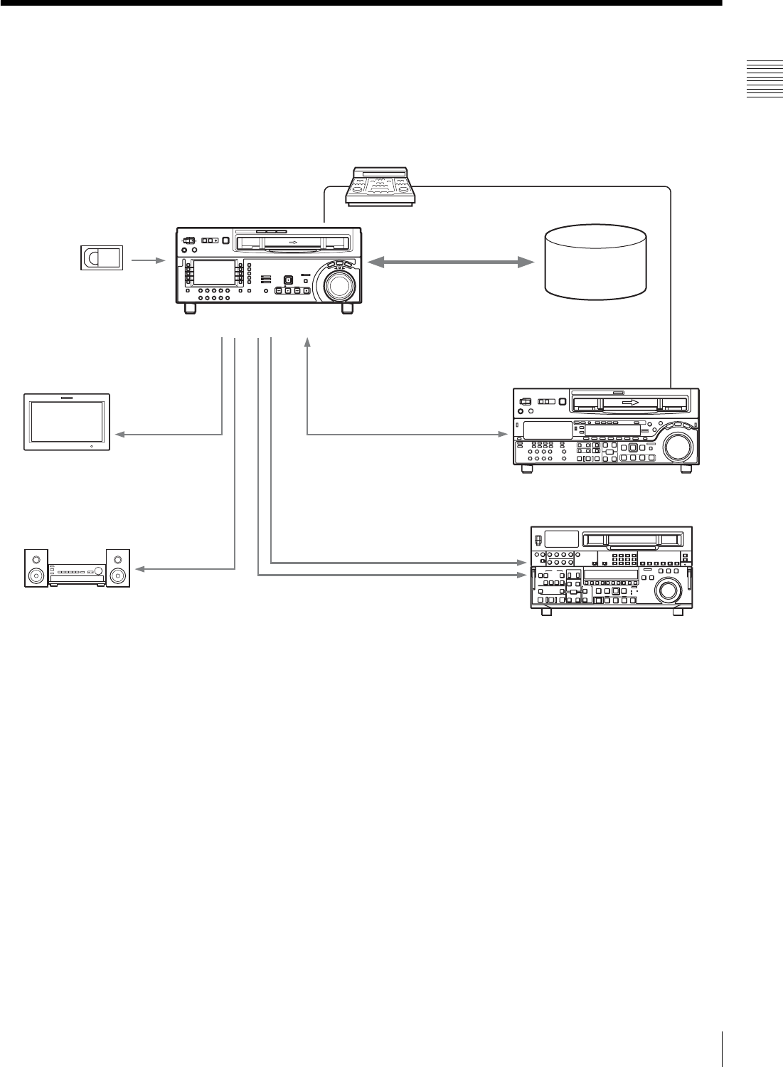
1-2 Example System Configuration
The following conceptual diagram shows an example of
use.
BVE-series editor
Digital cassette
Tape control
HDSDI
Audio/video
server system
HDW-1800/D1800
HDSDI/Analog
composite HDSDI
Video monitor
Analog audio
Audio monitor
Analog composite
SDI
HD VTR
SD VTR

10 1-3 Description of the Function Menu in this Manual
Chapter 1 Overview
1-3 Description of the
Function Menu in this
Manual
You can redefine function menu pages and function
buttons to configure the function menu of this unit.
This manual describes the items related to the function
menu as follows, based on the standard factory default
settings.
Example:
Setting F6 (PB/EE) in function menu page P01:
HOME
This indicates that the PB/EE function is assigned to
function selection button F6 in function menu page P01,
which is named HOME.
11
2-1 Control Panels
Chapter
Chapter 2 Location and Function of Parts
2
Location and Function of
Parts
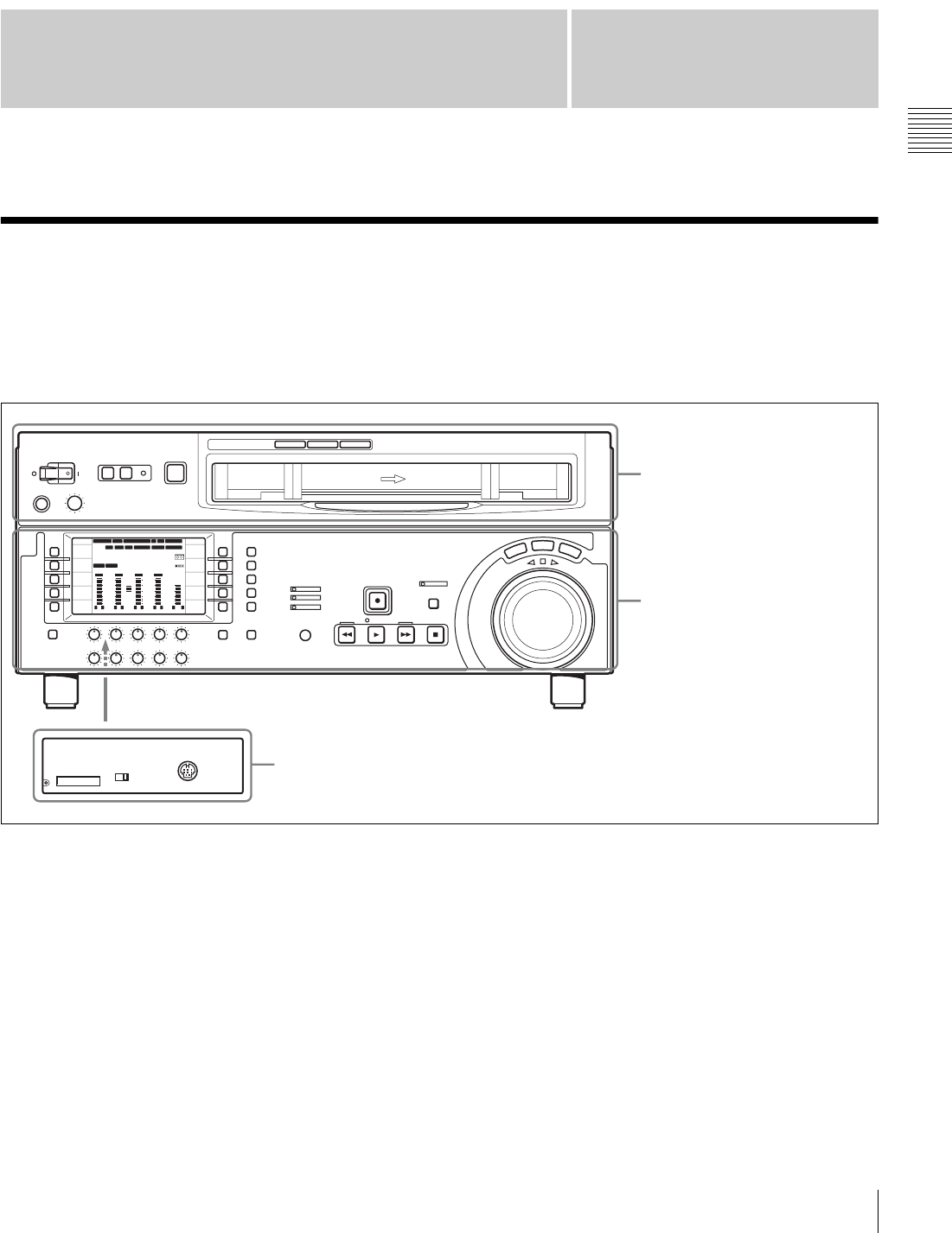
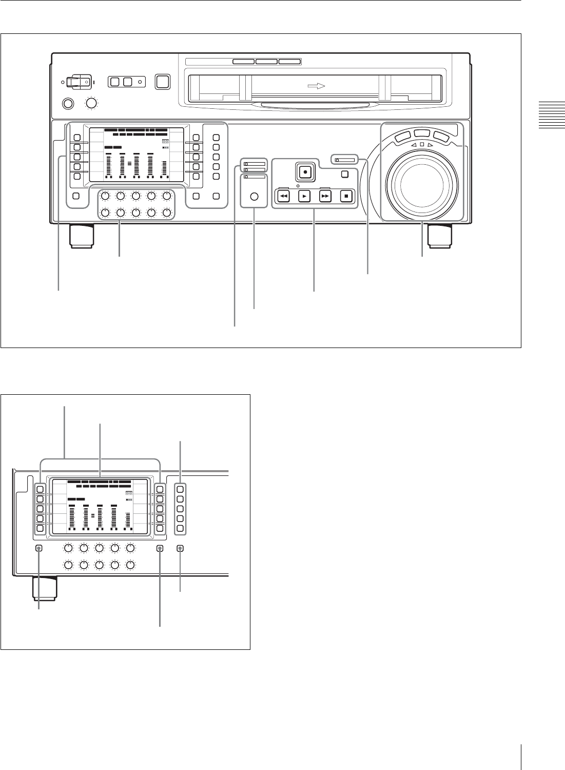
2-1 Control Panels
There are three control panels, as follows:
• Upper control panel
• Lower control panel
• Switch panel
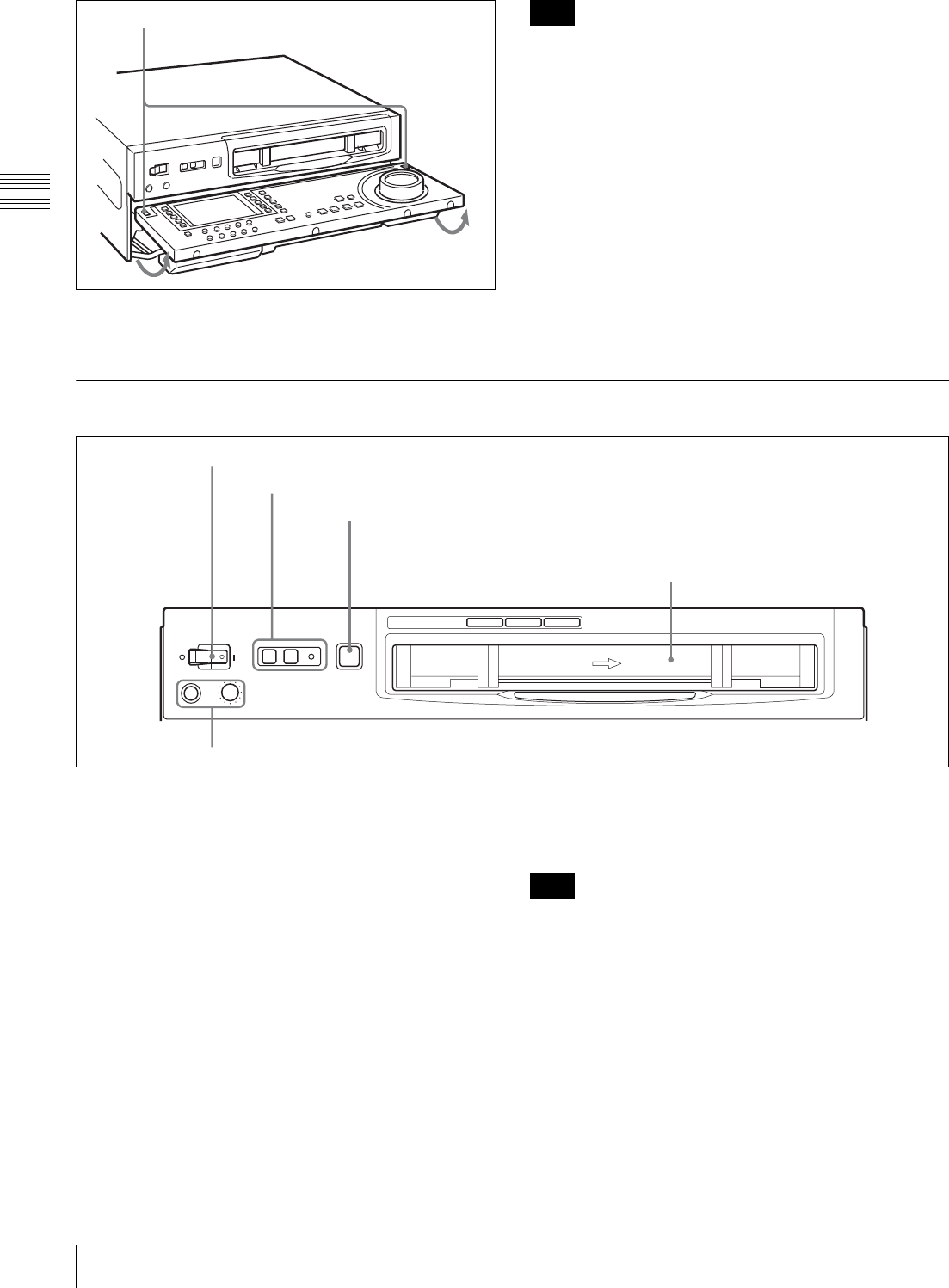
To open the lower control panel
Push in the lower control panel unlock button to open the
lower control panel. You can fix the lower control panel in
any of five positions between vertical and horizontal.
ON OFF
KEY INHI
CONTROL PANEL
12 34:47 12::
59.94 SDI 2F ASM
LTC
CONFI
10801080
DF LTC EXT-LTC R-RUN
PROLL
HOME
VIDEO IN
SDI
EDIT
E.PRESET
CLR CNT
HOME
PB/EE
PB
CONFI
ENABLE
COUNTER
CTL
MENU
TCG SET
L R
1
SDI1
3+4
BANK3
REM:20min
HD
COND
VITC
L R
2
ANA2
2
-60
-40
-30
-20
-10
0
dB
L R
3
SDI3
1
L R
4
AES4
4
-60
-40
-30
-20
-10
0
dB
L R
CUE
3+4
-40
-20
-10
-20
10
dB
EMPH DATA EMPH DATA
PARARUN
Upper control panel (see page 12)
Lower control panel (see page 13)
Switch panel: access by opening the lower control panel (see page 22)
12 2-1 Control Panels
Chapter 2 Location and Function of Parts
To close the lower control panel
Push up the folding levers on both sides at the same time.
When closing the lower control panel, be careful not to
catch your fingers in the panel.
2-1-1 Upper Control Panel
aPOWER switch
Pressing the “ j ” side of the switch powers the unit on.
When the unit is powered on, the LCD (see page 14)
lights.
bREMOTE buttons and RS-232C indicator
Press the 1 (9P) button or 2 (50P) button to select the
device controlling this unit.
1(9P): This unit is controlled by a device connected to the
REMOTE 1-IN(9P) or REMOTE 1-OUT(9P)
connector. The button lights when pressed.
2(50P): This unit is controlled by a device connected to the
REMOTE 2 PARALLEL I/O(50P) connector. The
button lights when pressed.
RS-232C indicator: This indicator lights when this unit is
communicating with a device connected to the RS-
232C connector.
cEJECT button
To eject the cassette, press this button. While the cassette
is being ejected, this button lights.
Ejecting with the EJECT button is a local operation. It is
not possible to eject a cassette in another VTR by remote
control.
dPHONES jack and control
Connect stereo headphones with an impedance of 8 Ω, to
monitor the sound during recording, playback and editing.
The control knob adjusts the volume.
It is possible to set an internal board switch so that the
output volume from the MONITOR OUTPUT L and R
connectors is controlled simultaneously.
For details, refer to the Installation Manual.
Lower control panel unlock button Note
Z
2REMOTE buttons and RS-232C indicator
1POWER switch
3EJECT button
Cassette compartment
4PHONES jack and control
Note
13
2-1 Control Panels
Chapter 2 Location and Function of Parts
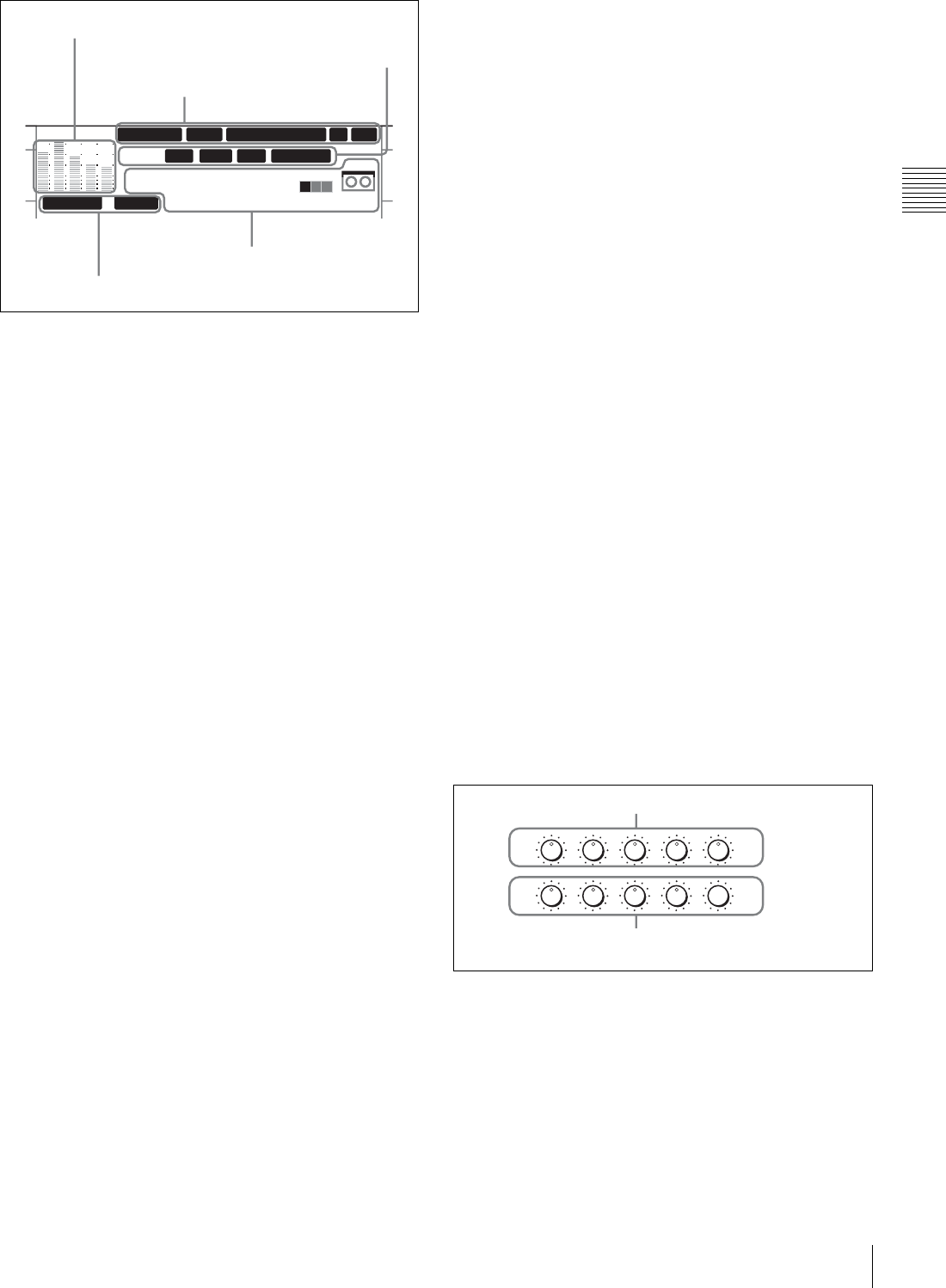
2-1-2 Lower Control Panel
1Menu control section
aFunction selection buttons (F1 to F10)
These buttons allow you to set the functions displayed in
the function menu.
12 34
:
47 12
::
59.94 SDI 2F ASM
LTC
10801080
DF LTC EXT-LTC R-RUN
PROLL
HOME
VIDEO IN
SDI
EDIT
E.PRESET
CLR CNT
HOME
PB/EE
PB
CONFI
ENABLE
COUNTER
CTL
MENU
TCG SET
L R
1
SDI1
3+4
BANK3
REM:20min
HD
COND
VITC
L R
2
ANA2
2
-60
-40
-30
-20
-10
0
dB
L R
3
SDI3
1
L R
4
AES4
4
-60
-40
-30
-20
-10
0
dB
L R
CUE
3+4
-40
-20
-10
-20
10
dB
EMPH DATA EMPH DATA
CONFI
PARARUN
1Menu control section
(see page 13)
4MULTI CONTROL knob and PUSH/SHIFT indicator (see page 20)
7Search control section
(see page 21)
6REC INHI indicator (see page 21)
5Tape transport control section (see page 20)
2Audio level control knobs
(see page 19)
3ALARM indicator and KEY INHI indicator (see page 20)
12 34
:
47 12
::
59.94 SDI 2F ASM
LTC
10801080
DF LTC EXT-LTC R-RUN
PROLL
HOME
VIDEO IN
SDI
EDIT
E.PRESET
CLR CNT
HOME
PB/EE
PB
CONFI
ENABLE
COUNTER
CTL
MENU
TCG SET
L R
1
SDI1
3+4
BANK3
REM:20min
HD
COND
VITC
L R
2
ANA2
2
-60
-40
-30
-20
-10
0
dB
L R
3
SDI3
1
L R
4
AES4
4
-60
-40
-30
-20
-10
0
dB
L R
CUE
3+4
-40
-20
-10
-20
10
dB
EMPH DATA EMPH DATA
CONFI
PARARUN
2LCD
1Function selection buttons
3Menu page
selection
buttons
5SHIFT/ENTRY
button
6ALT/DELETE button
4DISPLAY
button
14 2-1 Control Panels
Chapter 2 Location and Function of Parts
bLCD
The LCD has the following display modes.
•Video display mode: The LCD displays the video
signals currently being recorded or played back.
• Function display mode: The LCD displays timecode,
important information about the operating state, audio
level meter values, and function menu information.
•Function & video display mode: The LCD displays
timecode, important information about the operating
state, audio level meter values, function menu
information, and the video signals currently being
recorded or played back.
To change the display mode
Pressing the DISPLAY button toggles the display mode
between video display mode and function display mode.
The function menu cannot be operated in video display
mode.
For details on the function menu, see page 64.
Video display mode
In video display mode, the video signals currently being
recorded or played back appear on the full screen of the
LCD.
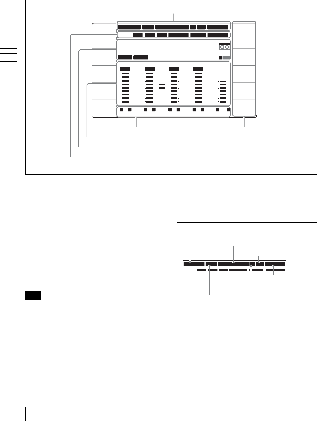
Function display mode
The following describes the items shown in the function
display mode.
1System information
• System frequency
During operation the system frequency is indicated as
59.94, 50, 29.97PsF, 25PsF, 24PsF or 23.98PsF.
• Output line information
Output line information is indicated as shown below.
“VIN 1080”: The unit is in E-E mode.
“1080”: The unit is in PB mode.
“60Hz >> 1080”: An HDCAM tape containing material
recorded at different frequencies is currently being
played back.
12 34:47 12::
59.94 SDI 2F ASM
LTC
10801080
DF LTC EXT-LTC R-RUN
PROLL
HOME
VIDEO IN
SDI
EDIT
E.PRESET
CLR CNT
HOME
PB/EE
PB
CONFI
ENABLE
COUNTER
CTL
MENU
TCG SET
L R
1
SDI1
3+4
BANK3
REM:20min
HD
COND
VITC
L R
2
ANA2
2
-60
-40
-30
-20
-10
0
dB
L R
3
SDI3
1
L R
4
AES4
4
-60
-40
-30
-20
-10
0
dB
L R
CUE
3+4
-40
-20
-10
-20
10
dB
EMPH DATA EMPH DATA
CONFI
PARARUN
2Function menu information
1System information
3Audio level meter block 1
4Audio level meter block 2
6Information relating to timecode
5Time data information
Note
LTC DF LTC EXT LTC RRUN PARARUNVITC
59.94 SDI 2F ASM
CONFI
10801080
System frequency
Output line information
Edit state indication
CONFI/PREREAD indication
Capstan lock indication
Video input signal
15
2-1 Control Panels
Chapter 2 Location and Function of Parts
“525 t 1080”: A Digital Betacam or MPEG IMX tape is
currently being played back and upconverted (HDW-
D1800 only).
• Edit state indication
The following indications appear when edit preset is
activated.
“ASM”: Assemble editing is preset.
“INS”: Insert editing is preset.
“ ” (blank): Neither of the above is preset.
• CONFI/PREREAD indication
The CONFI or PREREAD mode and operating state are
indicated as shown below.
“CONFI”: The unit is in CONFI mode, but not currently
executing CONFI playback.
“CONFI ON”: The unit is in CONFI mode and currently
executing CONFI playback.
“PREREAD”: The unit is in PREREAD (audio and
video) mode.
“A-PREREAD”: The unit is in PREREAD (audio only)
mode.
“V-PREREAD”: The unit is in PREREAD (video only)
mode.
“ ” (blank): None of the above apply.
• Capstan lock indication
The capstan lock mode is indicated as 2F, 4F or 8F (in 50i
mode or 25PsF mode).
• Video input signal
The currently selected video input signal type is indicated
as SDI or HDV.
The video input signal indicator flashes when there is no
input signal selected (for example, when there is no input).
2Function menu information
The function menu displays information regarding the
function buttons on the left and right sides of the LCD.
For details on the function menu, see page 64.
• Name of function menu page
This displays the name of the current function menu page.
• Function button display area
A total of 10 function buttons are displayed for each
function menu page: five each on the left and right sides of
the LCD.
Function button name: This is the name of the function
button.
Function button settings: This is the setting of the
function button.
3Audio level meter block 1
• Digital audio track/input channel number
This displays the digital audio track number and input
channel number (1 to 4, CUE or 5 to 8).
If the playback tape format and system frequency are
different and therefore normal playback is impossible, the
input channel number display flashes.
• Audio input selection
The name of the signal selected for each input channel is
indicated under the digital audio input channel number.
“SDI1”: HDSDI CH1
“SDI2”: HDSDI CH2
“SDI3”: HDSDI CH3
“SDI4”: HDSDI CH4
Note
Note
12 34:47 12::
59.94 SDI 2F ASM
LTC
10801080
DF LTC EXT-LTC R-RUN
PROLL
HOME
VIDEO IN
SDI
EDIT
E.PRESET
CLR CNT
HOME
PB/EE
PB
CONFI
ENABLE
COUNTER
CTL
MENU
TCG SET
L R
1
SDI1
3+4
BANK3
REM:20min
HD
COND
VITC
L R
2
ANA2
2
-60
-40
-30
-20
-10
0
dB
L R
3
SDI3
1
L R
4
AES4
4
-60
-40
-30
-20
-10
0
dB
L R
CUE
3+4
-40
-20
-10
-20
10
dB
EMPH DATA EMPH DATA
CONFI
PARARUN
Name of function menu page
Function button display area
L R
1
SDI1
L R
2
ANA2
L R
3
SDI3
L R
4
AES4
L R
CUE
3+4
Digital audio track/input
channel number
Audio input selection
Monitor selection
CUE track input
selection

16 2-1 Control Panels
Chapter 2 Location and Function of Parts
“AES1”: AES/EBU CH1
“AES2”: AES/EBU CH2
“AES3”: AES/EBU CH3
“AES4”: AES/EBU CH4
“ANA1”: ANALOG CH1
“ANA2”: ANALOG CH2
“SG”: Internal audio test signal (when F6 (AUDIO SG) is
set to “ON” in function menu page P08: AUD INP)
“HDV1”: HDV CH1 a) (when an option is installed)
“HDV2”: HDV CH2 a) (when an option is installed)
a) The digital audio input channel numbers are all selected at one time.
The audio input selection is not displayed when the audio
levels of track 5 to 8 are being indicated during MPEG
IMX tape playback on this unit.
• Monitor selection
Whether or not tracks are currently selected for monitoring
is indicated on the left and right sides of the digital audio
track/input channel number 1 indication. When
MONITOR CH1 (L) is selected, “L” is indicated. When
MONITOR CH2 (R) is selected, “R” is indicated.
• CUE track input selection
Whether the CUE track input is selected or not is indicated
under the CUE track indication (CUE).
Only one input channel number is displayed: The
signals from the input channel indicated by the
number are recorded.
Input channel number, +, input channel number are
displayed: The signals from the two input channels
indicated by the numbers are mixed and recorded.
On how to select the CUE track input method, see setup
menu item 833 “CUE AUDIO INPUT SELECT”.
4Audio level meter block 2
Audio level meter indication block
This indicates the audio levels of four digital track
channels and one CUE (analog) track channel.
The CUE track is shown only if a Digital Betacam or
HDCAM tape is currently loaded in the unit.
There are three types of digital track audio level indication.
As shown below, the indications are different for each
type.
“FULL”-“PEAK0”: The maximum level is indicated as
0dB.
“FULL”-“REF.0”: The reference level is indicated as
0dB.
“FINE”: The region near the reference level (–3 to
2.75 dB) is enlarged for display.
For details on “FINE” and “FULL”, see the settings of F4
(MT.SCALE) in function menu page P08: AUD INP.
For details on “REF.0” and “PEAK0”, see “LEVEL
METER SCALE” in setup menu item 806.
• Input channel indication
The input channels from which signals are recorded are
indicated for the digital tracks (1 to 4).
Only one input channel number is displayed: The
signals from the input channel indicated by the
number are recorded on the track.
Input channel number, +, input channel number are
displayed: The signals from the two input channels
indicated by the numbers are mixed and recorded on
the track.
Input channels are not displayed when the audio levels of
digital track 5 to 8 are being indicated during MPEG IMX
tape playback on HDW-D1800.
• Data/Emphasis indication
This indicates the attributes of the signals to be recorded on
or played back from the specified track.
“EMPH”: Indicates that the current signals are audio
signals with EMPHASIS set to “ON”.
“DATA”: Indicates that the current signals are non-audio
data (for example, Dolby-E).
“ ” (blank): Indicates that the current signals are neither of
the above (EMPHASIS for audio signals is set to
“OFF”).
•Cursor
When the audio level indications of digital tracks are as
shown below, level values in the corresponding range and
marker dots are displayed.
“PEAK0”: –60 to 0 dB
“REF.0”: –40 to 20 dB
“FINE”: –2 to 2 dB
Note
3+4 2
-60
-40
-30
-20
-10
0
dB
1 4
-60
-40
-30
-20
-10
0
dB
-40
-20
-10
0
10
dB
EMPH DATA
Input channel indication Data/Emphasis indication
Cursor
Headroom mark
Audio level indication
Note
17
2-1 Control Panels
Chapter 2 Location and Function of Parts
For the cursor used to indicate the audio levels of analog
tracks, level values in the range from –40 to 10 dB and
marker dots are displayed.
• Headroom mark
When the audio level indication of a digital track shows the
peak value 0, a marker displays the meter headroom setting
value.
One of the following values is displayed: –20 dB, –18 dB,
–16 dB, –14 dB or –12 dB.
For details on the meter headroom, see M370 METER
HEAD ROOM in the maintenance menu.
When the audio level indication is “FINE”, the mark is
placed at the reference level position.
When the audio level indication is “REF.0”, the mark is
placed at the reference level position.
• Audio level indication
When the digital track audio indication mode is “FULL-
PEAK0” or “FULL-REF.0”, the audio level is indicated in
the form of a bar graph with 24 segments (a top segment in
red indicates that the level exceeds the maximum level).
The “FINE” audio level of a digital track is indicated with
23 segments. Only the segment corresponding to the
current level lights. If the audio level is out of the
displayable range, the top or bottom segment flashes.
The audio level of an analog track is indicated in the form
of a bar graph with 18 segments. A peak program
indication appears for digital tracks in audio indication
modes other than “FINE”.
Example of “REF.0” level indication
Example of “FINE” level indication
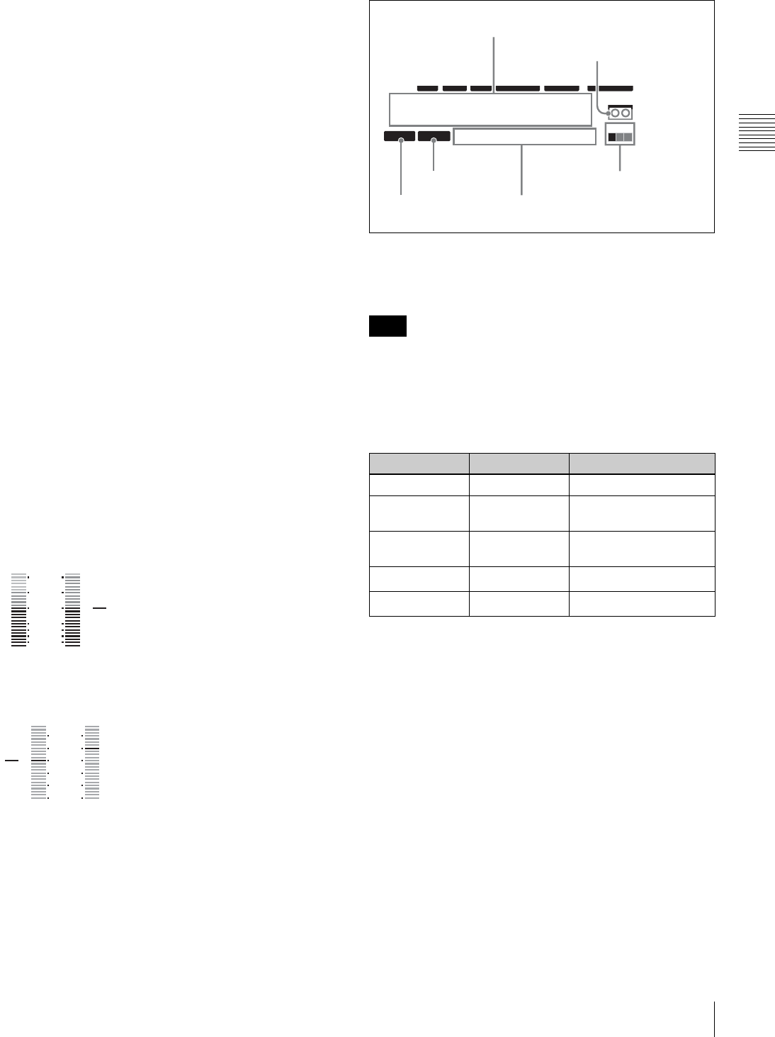
5Time data information
• Time data display
This displays values such as timecode values, user bit
values, and CTL counts.
Error messages are displayed as up to 10 alphanumeric
characters.
• Tape load mark
This appears when a cassette tape is currently loaded.
The abbreviations show information about the tape format.
a) Cleaning mode is activated automatically when a cleaning tape is loaded
(the tape is ejected after playback for 10 seconds).
b) Tapes in formats that are not supported for playback are ejected
automatically.
• Channel condition
This indicates the playback status of a tape.
The playback status is indicated by a square (
x
) in green,
yellow, or red, from the left. When no signal is being
played back, all squares are gray.
• Ancillary message display
This shows ancillary messages according to occasion.
Normally, it displays the remaining time on the tape
(REMAIN) or the total time of the tape (TOTAL) in units
of minutes, such as “REM : 020min” and “TOTL :
020min”.
For changing the content of tape information to display,
see the F6 (T-INFO) setting in function menu page P04:
MISC-1.
1 2
-40
-20
-10
0
10
20
dB
3 4
-2
-1
0
1
2
dB
Note
Tape format Abbreviations Color
HDCAM HD Orange
IMX IMX Green (HDW-D1800
only)
D-BETA DB Blue (Dark blue) (HDW-
D1800 only)
CLEAN CL Red (flashing) a)
Other Not displayed Not displayed b)
12 34:47 12::
LTC DF LTC EXT-LTC R-RUN
PROLL BANK3 REM:20min
PARARUN
HD
COND
VITC
Time data display
Tape load mark
Preroll indication
Setup menu state
Ancillary message display
Channel condition

18 2-1 Control Panels
Chapter 2 Location and Function of Parts
• Setup menu state
The following indications appear when the state of the
setup menu matches the state of a setup menu bank or the
factory default state.
“DEFLT”: The setup menu state matches the factory
default state.
“BANK1”: The setup menu state matches the state of user
bank 1.
“BANK2”: The setup menu state matches the state of user
bank 2.
“BANK3”: The setup menu state matches the state of user
bank 3.
“BANK4”: The setup menu state matches the state of user
bank 4.
“ ” (blank): Other than the above.
• Preroll indication
This indicates whether a preroll is in progress or not.
“PROLL”: Preroll is in progress.
“ ” (blank): Other than preroll in progress.
6Information relating to timecode
• Time data title
This shows the type of time data which is currently
displayed.
“LTC”: Longitudinal timecode
“LUB”: Longitudinal user bits
“VITC”: VITC
“VIUB”: VIUB user bits
“CTL”: CTL count value
• VITC/LTC status
This indicates the VITC or LTC read status.
“VITC”: VITC values are being read normally.
“LTC”: LTC values are being read normally.
“ ” (blank): The values are not being read normally.
• TCG RUN mode
This shows the criterion for starting the timecode generator
when the timecode generator is in the “INT-PSET” state.
“F-RUN”: The timecode generator always runs.
“R-RUN”: The timecode generator runs only when
recording is in progress.
• VTR control mode
This indicates the control status of the VTR.
“ ” (blank): The VTR is being operated as a standalone
unit.
“PARARUN”: This unit and devices connected to the unit
by 9-pin connectors are being operated
simultaneously from the control panel.
“R-CTRL”: This unit is being operated from the control
panel (as a recorder) when two units are being used
for editing.
“P-CTRL”: A device connected to this unit by a 9-pin
connector is being operated from the control panel (as
a player) when two units are being used for editing.
•TCG mode
This indicates the operation mode of the timecode
generator (TCG).
“INT-PSET”: A preset value for the internal TCG is
being used.
“INT-LTC”: The TCG synchronizes with the LTC
recorded on a tape.
“INT-VITC”: The TCG synchronizes with the VITC
recorded on a tape.
“EXT-LTC”: The TCG synchronizes with the external
LTC input.
“SDI-LTC”: The TCG synchronizes with the LTC
superimposed on the HDSDI input.
“SDI-VITC”: The TCG synchronizes with the VITC
superimposed on the HDSDI input.
“HDV-LTC”: The TCG synchronizes with the LTC
superimposed on the HDV (i.LINK) input. (Option)
“HDV-VITC”: The TCG synchronizes with the VITC
superimposed on the HDV (i.LINK) input. (Option)
•DF status
This indicates the drop-frame status of the timecode.
“DF”: Drop-frame mode
“NDF”: Non-drop-frame mode
“ ” (blank): The drop-frame status of the timecode is
unknown.
A blank appears in modes without drop-frame such as the
50i mode.
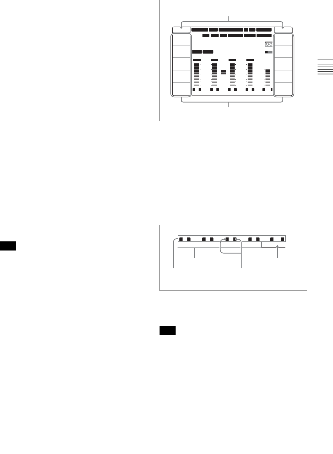
Function & video display mode
The following describes the items shown in the function &
video display mode.
The information of the items below is common to the
function display mode (see page 14).
12 34 47 12
23
.
98PsF SDTI 2F ASM
LTC
PREREAD V
1080tPD720P1080tPD720P
DF LTC EXT-LTC R-RUN PARARUN
HD
VITC
Time data title
VITC/LTC status
TCG RUN mode
DF status
TCG mode
VTR control mode
Note
19
2-1 Control Panels
Chapter 2 Location and Function of Parts
1Audio level meter block 2
For details on audio level indication, see
4
Audio level
meter block 2 on page 17.
2System information
For details on indication of the following items, see
1
System information on page 14.
• System frequency
• Video input signal
• Output line information
• Capstan lock indication
• Edit state indication
3Information relating to timecode
For details on indication of the following items, see
6
Information relating to timecode on page 18.
• Time data title
•DF status
•VITC/LTC status
• VTR control mode
•TCG mode
• TCG RUN mode
4Time data information
For details on indication of the following items, see
5
Time data information on page 17.
• Time data display
• Tape load mark
• Channel condition
• Ancillary message display
cMenu page selection buttons
These buttons select function menu pages to display on the
LCD.
• P1: HOME button
This button selects the HOME function menu page. The
HOME page allows you to make settings for basic VTR
and editing operations.
• P2: TC button
This button selects the TC (timecode) function menu page.
The TC page allows you to change between LTC and
VITC, change between DF and NDF, and make settings
for the timecode indications on an external monitor.
• P3: VID PROC button
This button selects the VID PROC (video processor)
function menu page. The VIDEO page allows you to make
settings for items relating to video.
• P4: AUD INP button
This button selects the AUD INP (audio input) function
menu page. The AUDIO page allows you to make settings
for items relating to audio.
• P5: PAGE DOWN button
Each time this button is pressed, the function menu page
changes in the order P01 t P02 t P03 t P04 t P05
t P06 t P07 t P08 t P01 …
When this button is pressed with the SHIFT/ENTRY
button held down, the function menu page changes in the
reverse order.
dDISPLAY button
This button switches the display mode to function display
mode, video display mode, or function & video display
mode. The mode changes each time the button is pressed.
eSHIFT/ENTRY button
This button is used to enter an edit point.
fALT(alternative)/DELETE button
This button is used to delete an edit point.
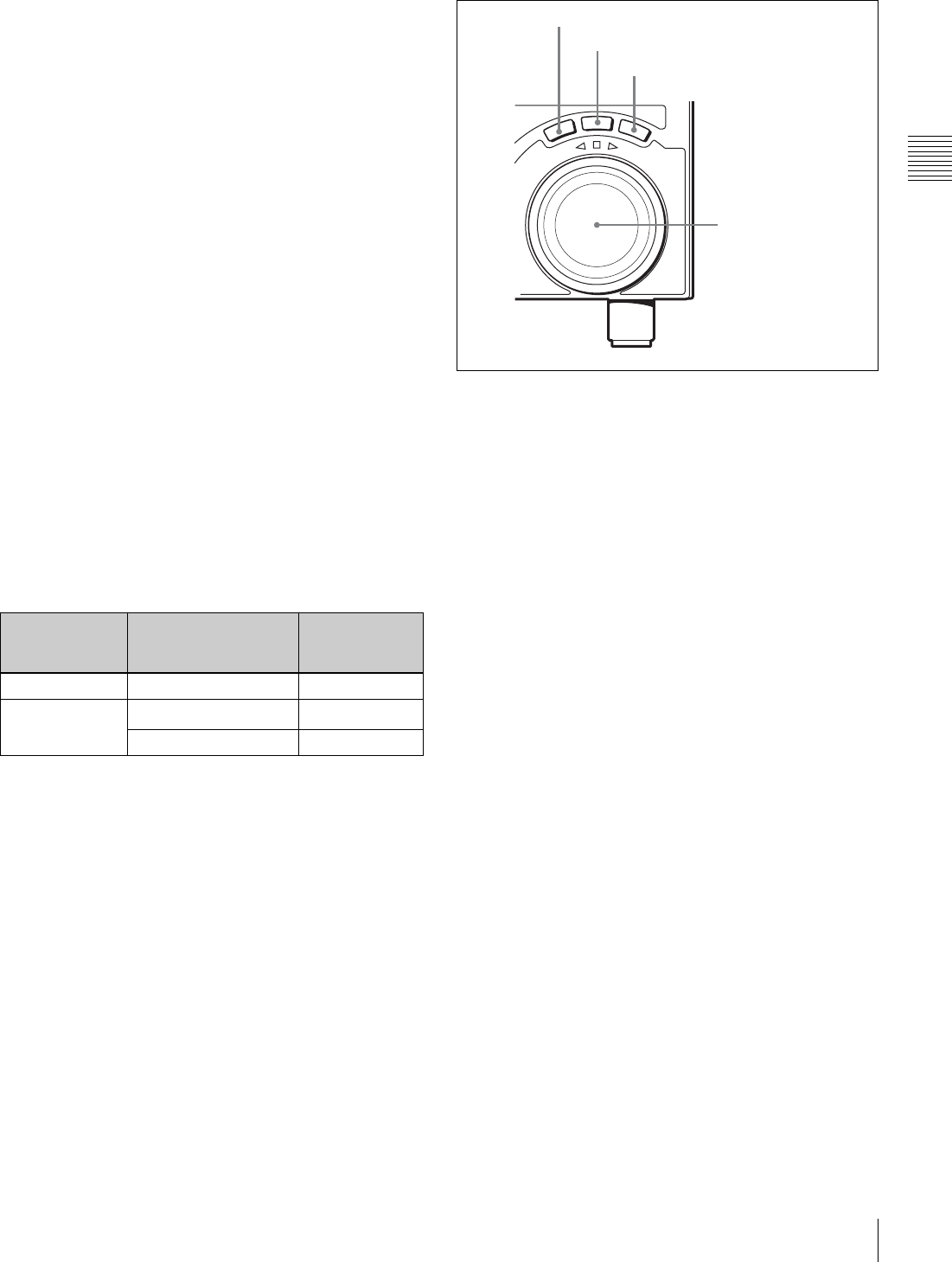
2Audio level control knobs
aREC (audio recording level control) knobs
These individually adjust the recording levels on channels
1 to 4, and cue audio.
Enter E-E mode, press to protrude the control knobs and
adjust the recording level while monitoring the audio level
indication in audio level meter block 2.
When the knobs are pushed in, the recording levels return
to the preset levels and cannot be adjusted.
12:::34 47 12
ASM
HD
COND
59.94 SDI 2F1080
INT-VITC
TOTL:011min
R-RUN
LTC
DF LTC R-CTRLVITC
4 Time data information
1 Audio level meter block 2
2 System information
3 Information relating to timecode
3Information relating
to timecode
CH1 CH2 CH3 CH4 CUE
REC
PB
REC
PB
1REC knobs
2PB knobs

20 2-1 Control Panels
Chapter 2 Location and Function of Parts
For details about selecting the E-E mode, see the
description of the REC button in the tape transport control
section (page 20) and PB/EE setting in the function menu
page P01: HOME (page 65).
bPB (audio playback level control) knobs
These individually adjust the output levels on channels 1 to
4, and cue audio.
During playback, press to protrude the control knobs and
adjust the playback level while monitoring the audio level
indication in audio level meter block 2.
When the knobs are pushed in, the playback levels return
to the preset levels and cannot be adjusted.
3ALARM indicator and KEY INHI
indicator
ALARM indicator
This lights when a hardware error is detected on the unit,
and goes off when the error is resolved. When this
indicator lights, an error message appears in the time data
display area. If you are using the HDSDI OUTPUT 3
(SUPER), SDI OUTPUT 3 (SUPER) or COMPOSITE
VIDEO OUTPUT 3 (SUPER) connector, and the setting of
F5 (CHARA) in function menu page P04: MISC-1 is
“ON”, then the error message also appears on the video
monitor.
For details on error messages, refer to the Maintenance
Manual Volume 1.
KEY INHI (inhibit) indicator
This indicator lights when the KEY INHI switch on the
switch panel (see page 22) is set to “ON”.
4MULTI CONTROL knob and PUSH/
SHIFT indicator
In function menu operations, turn the MULTI CONTROL
knob to change settings that flash in the menu display
section. In setup menu operations, turn this knob to select
menu items.
The PUSH/SHIFT indicator is lit when you press this knob
in. In this state, the value of the setting changes by a greater
amount when you turn the knob.
5Tape transport control section
aREC (record) button
To start recording, press this button together with the
PLAY button, turning it on.
To monitor in E-E mode
When the unit is in stop mode, pressing the REC button
lights the button and allows you to monitor the video and
audio in E-E mode. To return to the original state, press the
STOP button.
During playback, search, fast forward, or rewind, holding
down the REC button allows you to monitor the video and
audio in E-E mode. In this case the button does not light.
bSTANDBY button
When this button is off with a cassette inserted in the unit,
to put the unit in standby mode, press the button, turning it
on.
In standby mode, the drum is rotating and the tape is in
contact with the drum, and therefore recording or playback
can start immediately.
To cancel standby mode, press the STANDBY button,
turning it off.
If 8 minutes (value can be changed using setup menu item
501) elapse in standby mode, the unit automatically
switches out of standby mode to protect the tape.
cSTOP button
To stop recording or playback, press this button, turning it
on.
When you stop playback, the unit switches either to still
playback or to E-E mode according to the setting of F6
(PB/EE) in function menu page P01: HOME and the
setting in setup menu item 108.
Fault display function
The STOP button flashes in the following cases related to
reference signals:
• When F2 (REF VID) is set to “INPUT” in function menu
page P03: VID PROC, there is no input video signal.
REW PLAY F FWD STOP
REC
STANDBY
1REC button
2STANDBY button
3STOP button
4F FWD button
5PLAY button
6SERVO indicator
7REW button
21
2-1 Control Panels
Chapter 2 Location and Function of Parts
• When F2 (REF VID) is set to “REF” in function menu
page P03: VID PROC, there is no external reference
video signal input or the input external reference video
signal is not in synchronization with the input video
signal.
dF FWD (fast forward) button
To fast forward the tape, press this button, turning it on.
ePLAY button
To start playback, press this button, turning it on.
To operate in capstan override mode
Hold down the PLAY button, and rotate the search dial.
For details of capstan override mode, see page 39.
fSERVO indicator
Lights when the drum servo and capstan servo are locked.
gREW (rewind) button
To rewind the tape, press this button, turning it on.
6REC INHI (recording inhibit) indicator
This indicator is on or off according to the combination of
the F1 (REC INHI) setting in function menu page P07:
E.PRESET and the record inhibit plug on the cassette, as
shown in the following table. When this indicator is on,
recording on tape is prohibited.
a) It is possible to make the indicator flash by setting setup menu item 107.
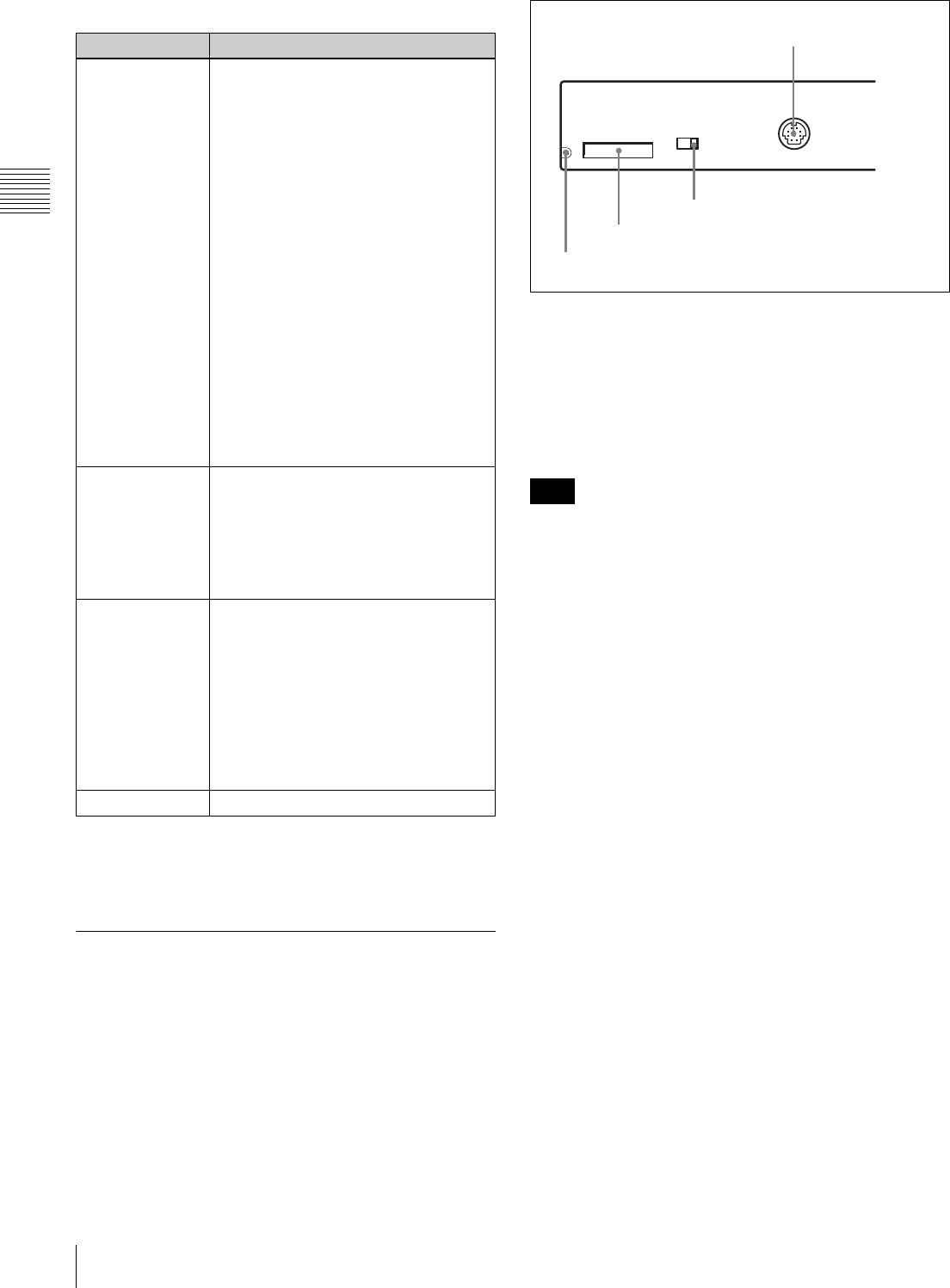
7Search control section
aSHUTTLE button
To use the search dial for playback in shuttle mode, press
this button, turning it on.
For details of playback in shuttle mode, see the description
of the search dial 4.
bJOG button
To use the search dial for playback in jog mode, press this
button, turning it on.
For details of playback in jog mode, see the description of
the search dial 4.
cVAR (variable) button
To use the search dial for playback in variable speed mode,
press this button, turning it on.
For details of playback in variable speed mode, see the
description of the search dial 4.
dSearch dial
Rotate this dial to carry out playback in the modes shown
in the following table. Rotating the dial clockwise lights
the G
(FORWARD) indicator and plays back in the
forward direction. Rotating the dial counterclockwise
lights the g (REVERSE) indicator and plays back in the
reverse direction.
When the tape is stopped or the unit is powered on, the s
indicator lights. Pressing the dial toggles between shuttle
and jog modes or between variable speed and jog modes.
Depending on the tape format, noiseless playback is
possible in the following ranges.
HDCAM: –1 to +2 times normal speed
Digital Betacam: –1 to +3 times normal speed
MPEG IMX: –1 to +3 times normal speed
REC INHI indicator indications
RECINH setting State of the record
inhibit plug on the
cassette
REC INHI
indicator state
ON Record inhibit/permit Lit
OFF Record inhibit Lit a)
Record permit Off
R
E
V
E
R
S
E
F
O
R
W
A
R
D
JOG
SHUTTLE
VAR
2JOG button
1SHUTTLE button
4Search dial
3VAR button
22 2-1 Control Panels
Chapter 2 Location and Function of Parts
Setting setup menu item 101 (see page 81) to KEY enables
you to use only the SHUTTLE, JOG, and VAR buttons to
select shuttle/jog/variable speed modes.
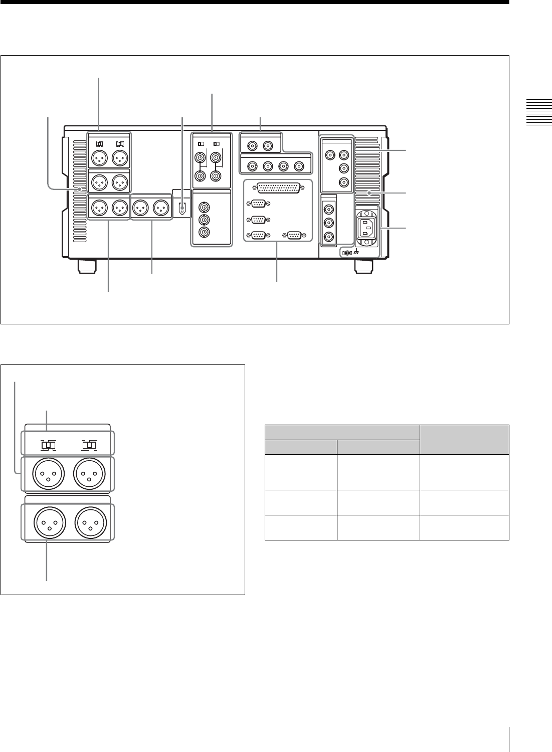
2-1-3 Switch Panel
To access the switch panel, open the lower control panel.
For details on how to open the lower control panel, see the
figure on page 11.
a“Memory Stick” access indicator
Lights or flashes when data is being read from or written
to a “Memory Stick”.
b“Memory Stick” slot
Use this to update the firmware. You can also save or load
setup menu settings onto or from the “Memory Stick”.
After inserting a “Memory Stick”, allow at least five
seconds to elapse before removing it.
For details on firmware update and saving or loading of
setup menu settings, refer to the Maintenance Manual
Volume 1.
cKEY INHI (inhibit) switch
Setting this switch to the ON position disables the controls
on the upper and lower control panels.
You can specify which buttons and knobs are disabled in
setup menu item 118.
dCONTROL PANEL connector (20-pin, round
type)
Plug in the lower control panel connection cable.
Playback modes using the search dial
Playback mode Operations and functions
Shuttle Press the SHUTTLE button or the
search dial so that the SHUTTLE button
lights, then rotate the search dial.
Playback is carried out at a speed
determined by the angular position of
the search dial. Playback speed ranges
are as follows.
• HDCAM tape: ±50 times normal
speed (59.94i, 29.97PsF mode), ±58
times normal speed (50i, 25PsF
mode), ±60 times normal speed
(24PsF, 23.98PsF mode)
• Digital Betacam tape: ±50 times
normal speed
• MPEG IMX tape: ±78 times normal
speed
There are detents on the search dial at
the still position and at the position for
±5 times normal speed.
The maximum shuttle mode playback
speed can be changed in setup menu
item 102 (see page 81).
Jog Press the JOG button or the search dial
so that the JOG button lights, then rotate
the search dial. Playback is carried out
at a speed determined by the speed of
rotation of the search dial. The playback
speed range is ±1 time normal speed.
The search dial has no detents.
Variable speed Press the VAR button, turning it on, then
rotate the search dial. You can control
the playback speed finely in the range in
which noiseless playback is possible.
• HDCAM: Maximum 51 steps
• Digital Betacam, MPEG IMX:
Maximum 54 steps
There are detents on the search dial at
the still position and at the position for
±1 times normal speed.
Capstan override For details on operation, see page 39.
Note
ON OFF
KEY INHI
CONTROL PANEL
3KEY INHI switch
2“Memory Stick” slot
1“Memory Stick” access indicator
4CONTROL PANEL connector
23
2-2 Connector Panel
Chapter 2 Location and Function of Parts
2-2 Connector Panel
1Analog audio input/output section
aAUDIO INPUT CH1 and CH2 (channels 1 and 2)
connectors (XLR 3-pin, female)
Input analog audio signals to channels 1 and 2.
You can record analog audio signals input to these
connectors to any audio track on tape.
bAUDIO INPUT CH1 and CH2 (channels 1 and 2)
LEVEL switches
Set these for each channel as shown in the following table,
according to the audio input levels and the impedance to
the AUDIO INPUT CH1 and CH2 connectors.
cAUDIO OUTPUT CH1 and CH2 (channels 1 and
2) connectors (XLR 3-pin, male)
Output analog audio signals for channels 1 and 2.
1Analog audio input/output section (see page 23)
2Analog video input/output section (see page 24)
3Digital audio input/output section (see page 24)
4Digital signal input/output
section (see page 24)
5Power supply section
(see page 25)
6External device connectors (see page 25)
7Timecode input/output
section (see page 26)
8Audio monitor signal output
section (see page 26)
Air inlet
Air outlet
HDV IN connector (OPTION)
(see page 26)
AUDIO INPUT
LOW
OFF
HIGH
ON
600Ω
CH1LEVEL
LOW
OFF
HIGH
ON
600Ω
CH2LEVEL
AUDIO OUTPUT
CH1 CH2
2AUDIO INPUT CH1 and CH2 LEVEL switches
1AUDIO INPUT CH1 and CH2 connectors
3AUDIO OUTPUT CH1 and CH2 connectors
AUDIO INPUT CH1 and CH2 LEVEL switch settings
Audio input level and impedance Switch setting
Level Impedance
–60 dBu
(microphone
input)
High impedance
(approx. 20 kΩ)
LOW-OFF
(left position)
+4 dBu
(line audio input)
High impedance
(approx. 20 kΩ)
HIGH-OFF
(center position)
+4 dBm
(line audio input)
600 ΩHIGH-ON 600 Ω
(right position)
24 2-2 Connector Panel
Chapter 2 Location and Function of Parts
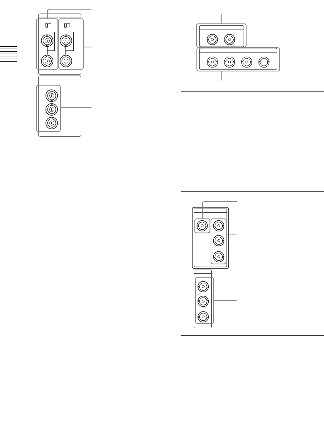
2Analog video input/output section
aREF. VIDEO INPUT 1 (reference video signal
input 1) connectors (BNC type) and 75Ω
termination switch
Input a reference video signal. Input a tri-level (positive
and negative) sync signal, a video signal with chroma burst
(VBS) or a monochrome video signal (VS). When using
the loop-through connection set the switch to the “OFF”
position, and otherwise to the “ON” position.
bREF. VIDEO INPUT 2 (OPTION) (reference video
signal input 2) connectors (BNC type) and 75Ω
termination switch
Input a reference video signal. Input a tri-level (zero/
negative/positive) sync signal, a video signal with chroma
burst (VBS) or a monochrome video signal (VS).
When using the loop-through connection, set the switch to
the “OFF” position, and otherwise set to the “ON”
position.
These connectors and switch operate only when the
HKDW-104 Pull-down/720P Board is installed.
cCOMPOSITE VIDEO OUTPUT connectors (BNC
type)
Output analog composite video signals.
When the setting of F5 (CHARA) in function menu page
P04: MISC-1 is “ON”, connector 3 (SUPER) outputs a
signal with superimposed timecode, menu settings, alarm
messages and other text information.
3Digital audio input/output section
aAUDIO INPUT (AES/EBU) connectors (BNC type)
Input two sets (4 channels: CH1/2 and CH3/4) of AES/
EBU format digital audio signals.
bAUDIO OUTPUT (AES/EBU) connectors (BNC
type)
Output a maximum of 4 sets (8 channels: CH1/2, CH3/4,
CH5/6, CH7/8) of AES/EBU format digital audio signals.
However, the HDW-1800 supports 2 sets only (4 channels:
CH1/2, CH3/4).
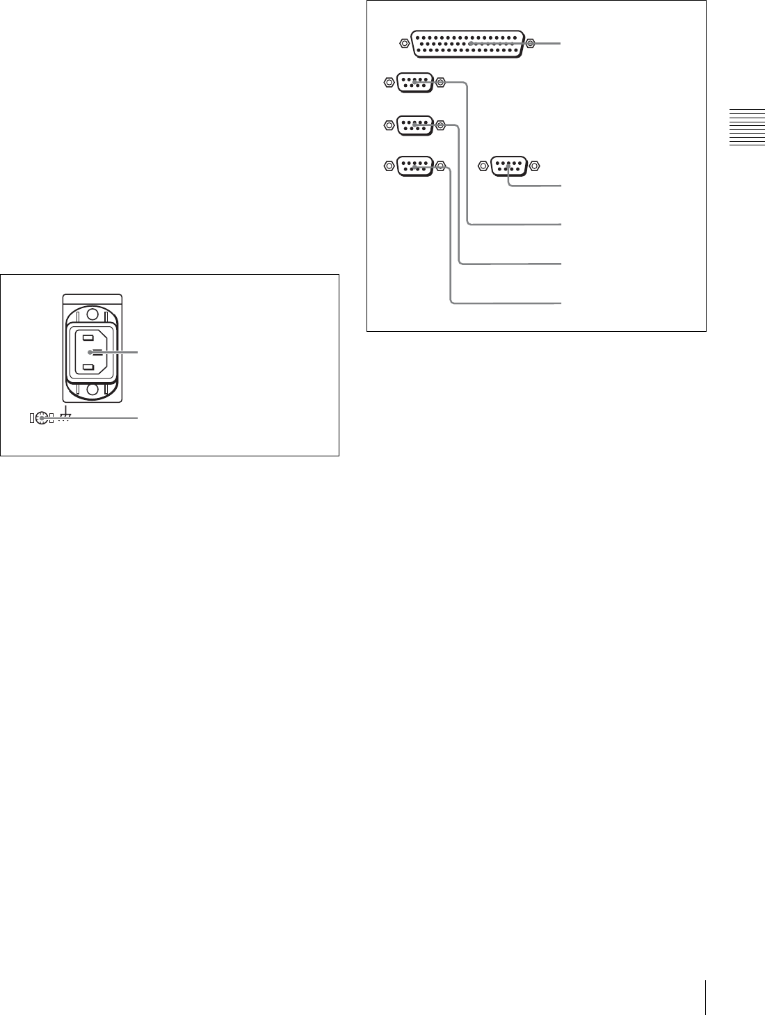
4Digital signal input/output section
aHDSDI (HD Serial Digital Interface) INPUT
connector (BNC type)
Inputs HD format video/audio signals.
REF. INPUT
75Ω
1
OFF ON
75Ω
2 (OPTION)
OFF ON
VIDEO OUTPUT
COMPOSITE
3
(SUPER)
2
1
2REF. VIDEO INPUT 2
(OPTION) connectors and
75Ω termination switch
1REF. VIDEO INPUT 1
connectors and 75Ω
termination switch
3COMPOSITE VIDEO
OUTPUT connectors
AUDIO INPUT(AES/EBU)
CH1/2 CH3/4
AUDIO OUTPUT(AES/EBU)
CH1/2 CH3/4 CH5/6 CH7/8
2AUDIO OUTPUT (AES/EBU) connectors
1AUDIO INPUT (AES/EBU) connectors
SDI
HDSDI
INPUT OUTPUT
OUTPUT
1
2
3(
SUPER
)
1
2
3(
SUPER
)
2HDSDI OUTPUT connectors
1HDSDI INPUT connector
3SDI OUTPUT connectors
25
2-2 Connector Panel
Chapter 2 Location and Function of Parts
bHDSDI (HD Serial Digital Interface) OUTPUT
connectors (BNC type)
Output HD format video/audio signals.
When the setting of F5 (CHARA) in function menu page
P04: MISC-1 is “ON”, connector 3 (SUPER) outputs a
signal with superimposed timecode, menu settings, alarm
messages and other text information.
cSDI (Serial Digital Interface) OUTPUT connectors
(BNC type)
Output D1 format video/audio signals.
When the setting of F5 (CHARA) in function menu page
P04: MISC-1 is “ON”, connector 3 (SUPER) outputs a
signal with superimposed timecode, menu settings, alarm
messages and other text information.
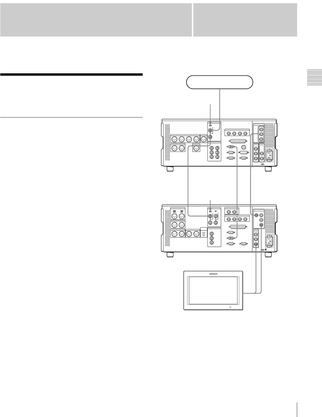
5Power supply section
aAC IN (AC power input) connector
Use the optional power cord to connect this to an AC
outlet.
bGround terminal
Connect this to ground.
6External device connectors
aREMOTE 2 PARALLEL I/O(50P) connector (D-
sub 50-pin)
Connect remote control signals from an external device.
For details, refer to the Installation Manual.
bVIDEO CONTROL(9P) (digital video processor
control) connector (D-sub 9-pin)
For remote control of the internal digital video processor,
connect the optional HKDV-900 Video Remote
Controller.
Always power off this unit before connecting the video
remote controller.
cREMOTE 1-IN(9P) (remote control signal input)
connector (D-sub 9-pin)
When using this unit together with another HDCAM VTR,
and a BVE-series BVE-700/900/910/2000/9000/9000P/
9100/9100P or other editor, connect the optional 9-pin
remote control cable from the other unit to this connector.
Depending on the setting in setup menu item 211, you can
use this connector alone, or in a loop-through
configuration with the REMOTE 1-OUT(9P) connector.
dREMOTE 1-OUT(9P) (remote control signal
output) connector (D-sub 9-pin)
This provides the loop-through output for remote control
signals from the REMOTE 1-IN(9P) connector.
Depending on the setting in setup menu item 211, you can
use this connector alone, or in a loop-through
configuration with the REMOTE 1-IN(9P) connector.
2Ground terminal
1AC IN connector
REMOTE 1-IN(9P)
REMOTE 2 PARALLEL I/O(50P)
REMOTE 1-OUT(9P)
RS232C VIDEO CONTROL (9P)
1REMOTE 2 PARALLEL
I/O(50P) connector
2VIDEO CONTROL(9P)
connector
3REMOTE 1-IN(9P)
connector
4REMOTE 1-OUT(9P)
connector
5RS232C connector

26 2-2 Connector Panel
Chapter 2 Location and Function of Parts
eRS232C (serial interface) connector (D-sub 9-pin)
Use this for monitoring and diagnosis of the state of this
unit from an external computer, using the ISR (Interactive
Status Reporting) function.
HDV IN (OPTION) connector (6-pin, conforming to
IEEE1394)
Use an i.LINK cable to connect this unit to an HDV unit
(HVR-1500, HVR-M25, HVR-M15, HVR-Z1, HVR-A1,
HDR-FX1, HDR-FX7 or HDR-HC3) recommended by
Sony. This connector can be used only when an optional
HKDW-105 i.LINK (HDV) Input Board is installed.
• If video or audio signals from an external device
connected to the HDV input connector fail to be output,
disconnect the i.LINK cable and connect it again,
pushing it straight in.
• Before connecting or disconnecting an i.LINK cable
between this unit and a device with a 6-pin i.LINK
connector, power off the device and disconnect its power
cord from the electrical outlet. If the i.LINK cable is
connected or disconnected with the device’s power plug
still connected, high voltage (8 to 40 V) from the
device’s i.LINK connector can flow into this unit,
possibly damaging the unit.
• When connecting this unit to a device with a 6-pin
i.LINK connector, connect to the 6-pin i.LINK
connector of the other device first.
7Timecode input/output section
aTIME CODE IN connector (XLR 3-pin, female)
To record timecode from an external device, input a
timecode signal from the timecode output connector of the
external device.
bTIME CODE OUT connector (XLR 3-pin, male)
This outputs a timecode according to the operating state of
the unit, as follows:
•During playback: the playback timecode
By setting setup menu item 606, you can also output the
timecode from the internal timecode generator locked to
the playback timecode.
•During recording: the timecode generated by the
internal timecode generator or the timecode input to the
TIME CODE IN connector.
8Audio monitor signal output section
aMONITOR OUTPUT R (right channel) connector
(XLR 3-pin, male)
This outputs the audio signals whose output destination
was set to “R” with the audio monitor signal selection
buttons in the audio control section. If multiple tracks have
been set to “R”, the signals of those tracks are mixed for
output.
bMONITOR OUTPUT L (left channel) connector
(XLR 3-pin, male)
This outputs the audio signals whose output destination
was set to “L” with the audio monitor signal selection
buttons in the audio control section. If multiple tracks have
been set to “L”, the signals of those tracks are mixed for
output.
Notes
TIME CODE
IN OUT
2TIME CODE OUT connector
1TIME CODE IN connector
MONITOR OUTPUT
RL
2MONITOR OUTPUT L
connector
1MONITOR OUTPUT R
connector
27
3-1 Connections to External Devices
Chapter
Chapter 3 Preparations
3
Preparations
3-1 Connections to
External Devices
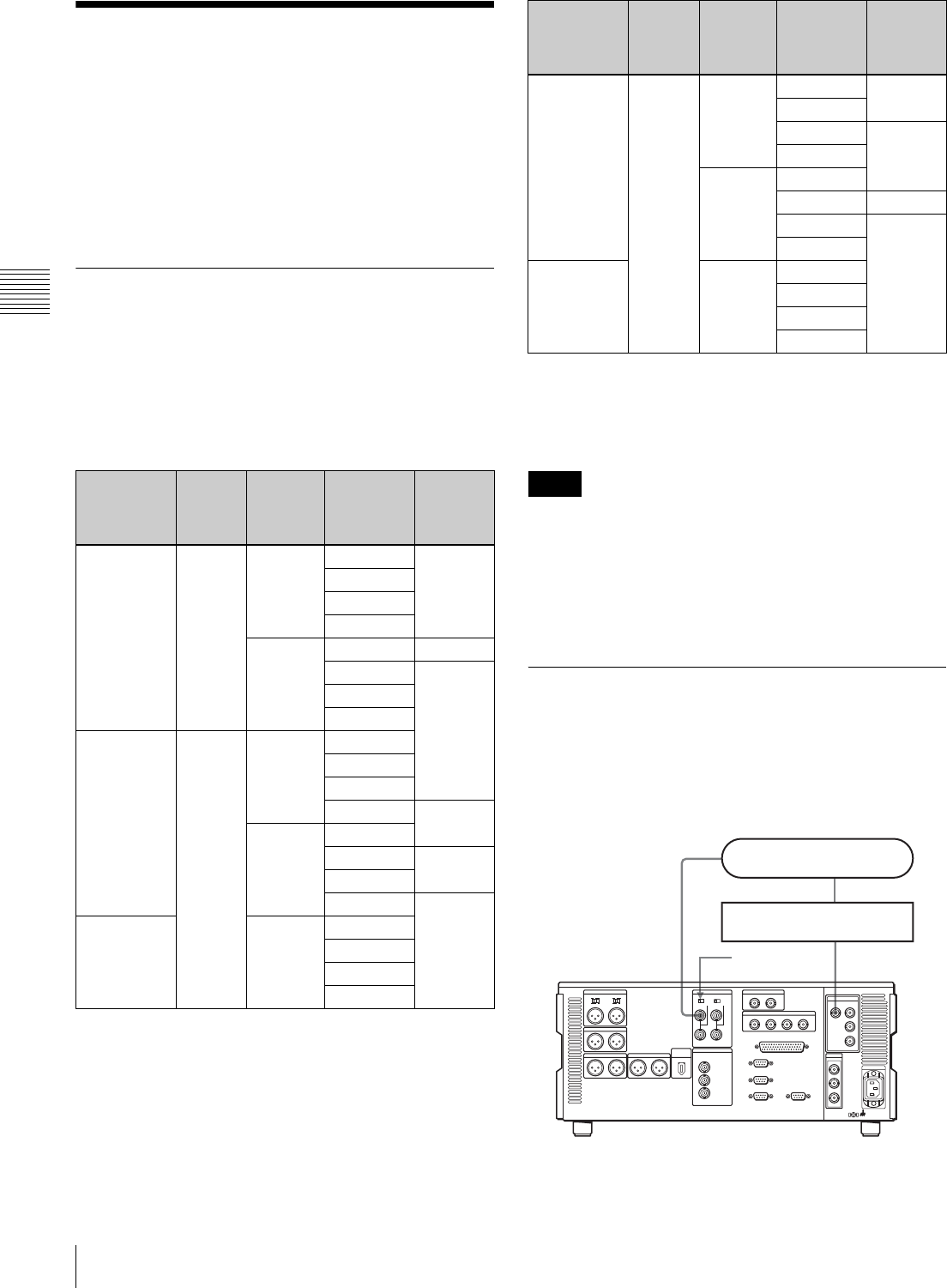
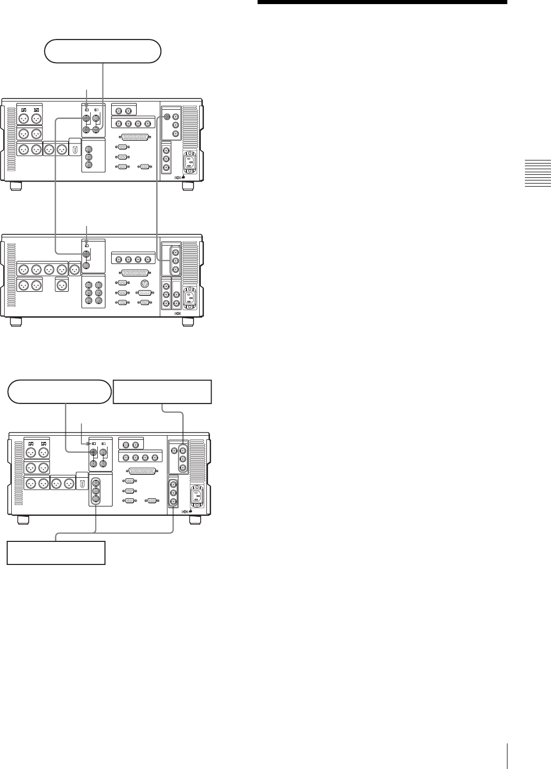
3-1-1 Connections to Digital Devices
This unit can input serial digital signals (video and audio)
from another digital VTR such as the HDW-500/F500/
A2100/M2100. The following figure shows example
connections to use this unit (HDW-1800/D1800) as
recorder and the HDW-A2100/M2000 unit as player.
1) The optional BKM-62HS HDSDI/SDI Input Adaptor is required.
REMOTE
1-IN(9P)
SDI OUTPUT 3
(SUPER)
HDSDI OUTPUT3
(SUPER)
HDSDI INPUT
REF. VIDEO
INPUT
HDSDI OUTPUT
REF. VIDEO
INPUT
REF. VIDEO
INPUT
Reference signal
75Ω termination
switch: OFF
75Ω termination
switch: ON
HDW-1800/D1800
(recorder)
HDW-A2100/
M2100 (player)
BVM-A series color
video monitor 1)
28 3-2 Reference Sync Signals
Chapter 3 Preparations
3-2 Reference Sync
Signals
This section describes how reference signals for the video
output signals and servo system are selected.
The output from the internal reference video signal
generator is supplied to the output video signal and servo
circuits as a reference signal.
3-2-1 Selecting Reference Sync
Signal Depending on Operational
Status
The reference sync signal selection switches automatically
between REF and INPUT depending on the menu settings
and the operating status of the unit, as shown in the
following table.
a) EE: In E-E mode
PB: Playing back (normal playback, jog mode, shuttle mode, variable
speed mode and stop mode)
EDIT: Edit preset enabled
REC: Recording
• When there is no HDSDI signal input whereas INPUT is
selected, the unit synchronizes with the REF signal.
• When there is no REF signal input whereas REF is
selected, no external reference signal is used. In this
case, the unit synchronizes with the internally generated
reference signal.
3-2-2 Connecting Reference Signals
Connect reference signals as shown below, according to
the way in which the unit is to be used.
• Connections for recording from a switcher or
signal generator
P03:VID
PROC
F2(REF VID)
setting
Menu
item
309
setting
Menu
item 334
setting
Unit’s
operational
status a)
Reference
signal
setting
– EXT NORMAL EE REF
PB
EDIT
REC
INPUT EE INPUT
PB REF
EDIT
REC
REF AUTO1 NORMAL EE
PB
EDIT
REC INPUT
INPUT EE
PB REF
EDIT
REC INPUT
INPUT – EE
PB
EDIT
REC
REF AUTO2 NORMAL EE REF
PB
EDIT INPUT
REC
INPUT EE
PB REF
EDIT INPUT
REC
INPUT – EE
PB
EDIT
REC
Notes
P03:VID
PROC
F2(REF VID)
setting
Menu
item
309
setting
Menu
item 334
setting
Unit’s
operational
status a)
Reference
signal
setting
HDSDI
INPUT
REF. VIDEO
INPUT
75Ω termination
switch: ON
Reference signal
Switcher or signal generator
HDW-1800/D1800
29
3-3 Setup
Chapter 3 Preparations
• Connections for recording from an external
VTR (player)
• Connections for playback
3-3 Setup
The principal setup operations before operating this unit
can be carried out using setup menus.
The setup menus of this unit comprise a basic setup menu
and an extended setup menu. The contents of these menus
are as follows.
Basic setup menu:
• Items relating to the digital hours meter
• Items relating to operation
• Items relating to menu banks
Extended setup menu:
• Items relating to control panels
• Items relating to the remote control interface
• Items relating to editing operations
• Items relating to preroll
• Items relating to tape protection
• Items relating to the timecode generator
• Items relating to metadata
• Items relating to video control
• Items relating to audio control
• Items relating to digital processing
For more information about the items of these menus and
how to use them, see Chapter 9 “Setup Menus” (page 74).
For detailed information about items and setting
operations relating to the digital hours meter in the basic
setup menu, see Section “10-5-1 Digital Hours Meter”
(page 106).
This unit saves menu settings in what are termed “menu
banks”. Saved menu settings can be recalled for use as
required.
For more information about the menu banks, see the
section “Menu bank operations (menu items B01 to B13)”
(page 77).
HDSDI INPUT
HDSDI OUTPUT
REF. VIDEO
INPUT
REF. VIDEO
INPUT
75Ω termination switch: OFF
Reference signal
HDW-A2100/M2100 (player)
HDW-1800/D1800
(recorder)
75Ω termination switch:
ON
SDI OUTPUTCOMPOSITE
HDSDI
OUTPUT
REF. VIDEO
INPUT
Reference signal
HDW-1800/D1800
75Ω termination switch: ON
HD video monitor
SD video monitor
30 3-4 Superimposed Character Information
Chapter 3 Preparations
3-4 Superimposed
Character Information
When F5 (CHARA) in function menu page P04: MISC-1
is selected, the video signal output from the HDSDI
OUTPUT 3 (SUPER), SDI OUTPUT 3 (SUPER) or
COMPOSITE VIDEO OUTPUT 3 (SUPER) connector
can contain superimposed text information, including
timecode, menu settings, and alarm messages.
To adjust the character display
You can adjust the position, size and type of the
superimposed characters using setup menu items 002, 003,
005, 009, and 011.
For details, see Section “9-3 Items in the Basic Setup
Menu” (page 78).
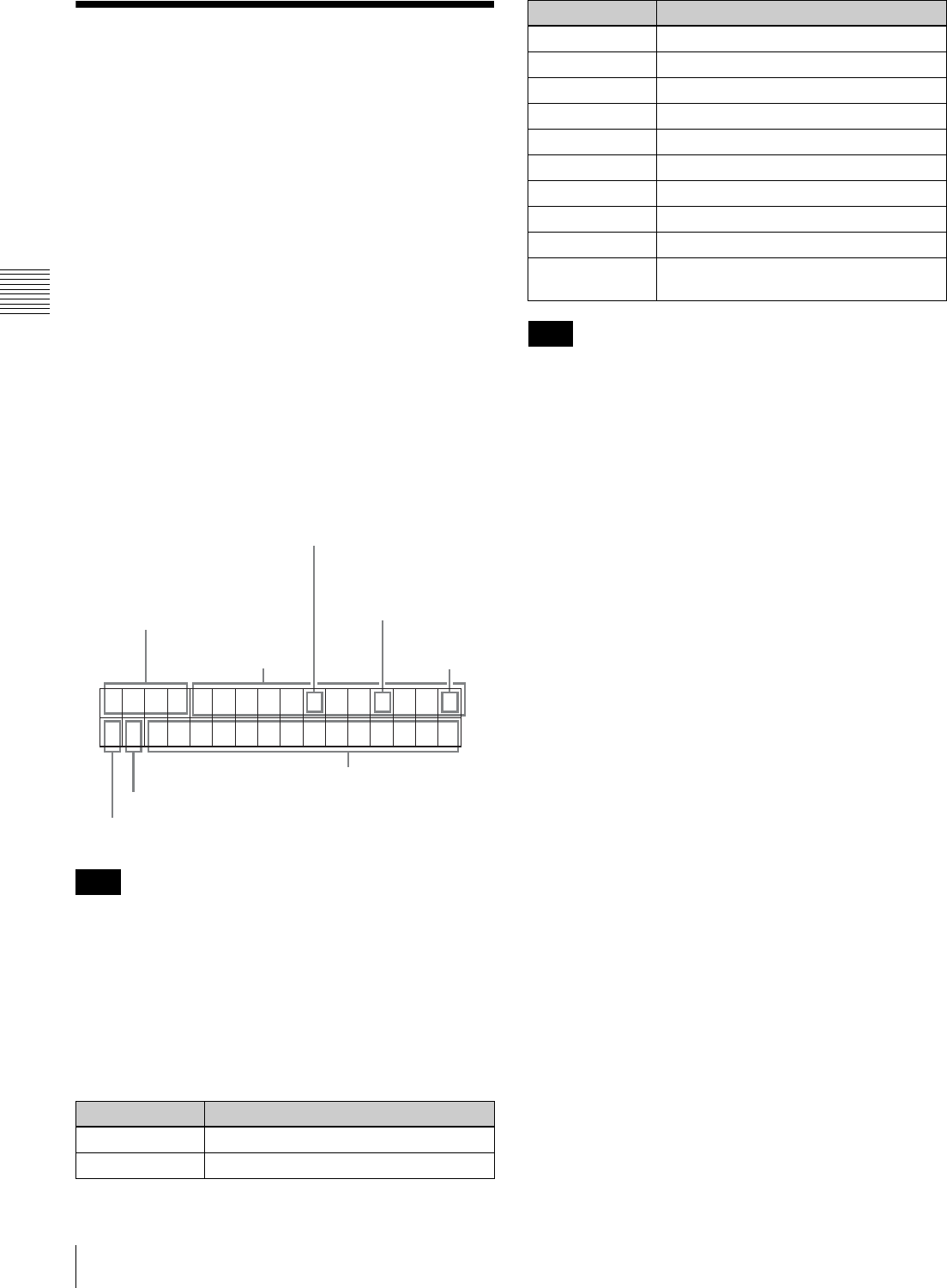
Information displayed
The display shown above corresponds to the factory
default settings of the unit.
Changing the setting in setup menu item 005 displays
different time data in the lower line of the display.
For details, see Section “9-3 Items in the Basic Setup
Menu” (page 78).
aType of time data
If the time data or user bits cannot be read correctly, they
will be displayed with an asterisk. For example, “T*R”,
“U*R”, “T*R.” or “U*R.”.
bTimecode reader drop-frame mark (for 59.94i,
29.97PsF mode only)
“.”: Indicates drop-frame mode
“:”: Indicates non-drop-frame mode
cTimecode generator drop-frame mark (for 59.94i,
29.97PsF mode only)
“.”: Indicates drop-frame mode (factory default setting)
“:”: Indicates non-drop-frame mode
dVITC data field mark
“ ” (blank): Fields 1 and 3 (for 59.94i, 29.97PsF mode) or
fields 1, 3, 5 and 7 (for 50i, 25PsF mode)
“ * ”: Fields 2 and 4 (for 59.94i, 29.97PsF mode) or fields
2, 4, 6 and 8 (for 50i, 25PsF mode)
eVTR control mode (Recorder/player selection)
The indication changes as follows, according to the VTR
control mode (the setting of F6 (R/P SEL) in function
menu page P06: EDIT).
P: Two-unit editing is currently being carried out and the
VTR (player) connected by a 9-pin remote cable is
being operated from the lower control panel (P-
CTRL).
R: Two-unit editing is currently being carried out and this
unit (recorder) is being operated from the lower
control panel (R-CTRL).
No indication: This unit (recorder) is being operated from
the lower control panel as a standalone unit.
Alternatively, multiple VTR units connected by 9-pin
remote cables are being operated in synchronization
(PARARUN).
Note
Display Meaning
CTL CTL counter data
TCR LTC reader timecode
TCR . 23 : 5 9 . 4 0 . 1 8 *
PSHUTTLESTILL
1Type of time data
2Timecode reader drop-frame mark
(for 59.94i, 29.97PsF mode only)
3Timecode generator
drop-frame mark (for
59.94i, 29.97PsF
mode only)
4VITC data
field mark
5VTR control mode
7Operation mode
Time data
6Stop freeze mode
UBR LTC reader user bits
TCR. VITC reader timecode
UBR. VITC reader user bits
TCG Timecode generator timecode
UBG Timecode generator user bits
IN IN point
OUT OUT point
AI Audio IN point
AO Audio OUT point
DUR Duration between any two of the four edit
points (IN, OUT, audio IN, audio OUT)
Note
Display Meaning
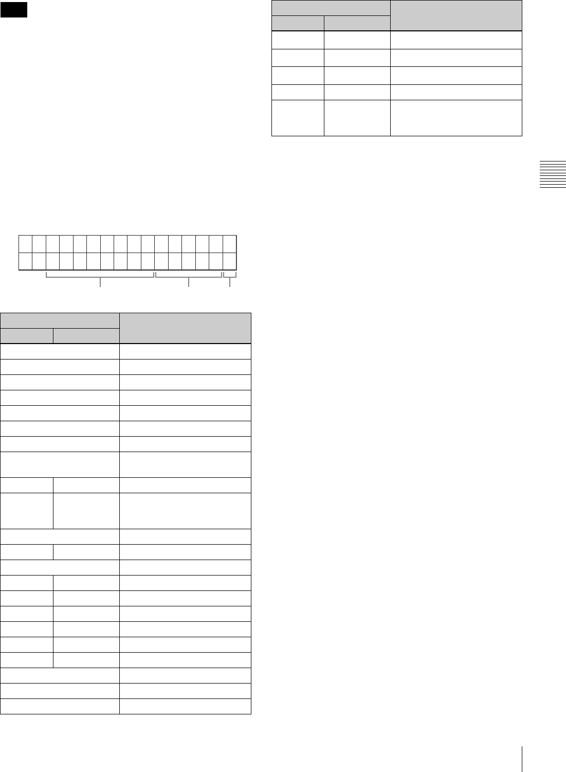
31
3-4 Superimposed Character Information
Chapter 3 Preparations
No character is displayed for both the PARARUN mode
and the standalone operation mode.
fStop freeze mode
#: This appears when tapes stop with the STOP FREEZE
function enabled by the setting of setup menu item
906.
No indication: The STOP FREEZE function is not
enabled by the setting of setup menu item 906.
gOperation mode
This field is divided into three blocks, A, B and C.
• Block A displays the operation mode.
• Block B displays the servo lock status or tape speed.
• Block C displays a x mark to indicate an edit section
during automatic editing.
a) Initial speed setting or stored speed setting
Note
Display Operation mode
Block A Block B
TAPE UNTHREAD Cassette is not loaded.
STANDBY OFF Standby off mode
T.RELEASE Tape tension release mode
STOP Stop mode
F.FWD Fast forward mode
REW Rewind mode
PREROLL Preroll mode
PLAY Playback mode (servo
unlocked)
PLAY LOCK Playback mode (servo locked)
PLAY Variation from
normal speed
(%)
Capstan override mode (see
page 39)
REC Record mode (servo unocked)
REC LOCK Record mode (servo locked)
EDIT Edit mode (servo unlocked)
EDIT LOCK Edit mode (servo locked)
JOG STILL Still playback in jog mode
JOG FWD Jog mode in forward direction
JOG REV Jog mode in reverse direction
SHUTTLE (Speed) Shuttle mode
VAR (Speed) Variable speed mode
AUTO EDIT Automatic editing mode
PREVIEW Preview mode
REVIEW Review mode
ABC
DMC (Speed)a) DMC playback mode
D-PREV (Speed)a) DMC editing preview mode
D-EDIT (Speed)a) DMC editing mode
DMC-SPD (Speed) DMC initial speed setting
PLY-SPD Variation from
normal speed
(%)
Tape speed override mode
(when “TSO” is selected in
setup menu item 111)
Display Operation mode
Block A Block B
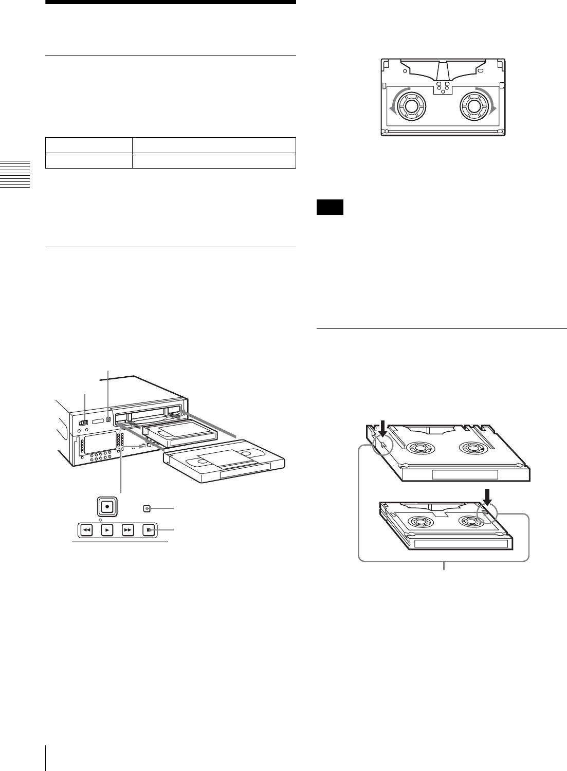
32 3-5 Cassettes
Chapter 3 Preparations
3-5 Cassettes
3-5-1 Cassette Types
This unit uses the following HDCAM cassettes for both
recording and playback.
HDCAM cassettes
The HDW-D1800 can also play back the following
cassettes.
• Digital Betacam cassettes
• MPEG IMX cassettes
3-5-2 Inserting and Ejecting
Cassettes
It is not possible to insert or eject a cassette unless the unit
is powered on.
To insert a cassette
1
Turn the POWER switch on.
2
Check the following points, then insert the cassette
horizontally in the orientation shown in the figure.
• Check that message “ERR-10” is not shown in the
time data/menu display section.
• Check that there is no slack in the tape.
The cassette is drawn into the unit, and the STANDBY
and STOP buttons light.
To remove slack from the tape
Press in one of the reels with a finger, and turn gently in the
direction shown by the arrows until there is no slack in the
tape.
To eject a cassette
Press the EJECT button.
Ejecting is a local operation. It is not possible to eject a
cassette in another VTR by remote control.
If the tape slacks inside the unit, pressing the EJECT
button may not eject the cassette. For information about
how to remove the cassette in such a case, refer to the
Installation Manual.
3-5-3 Preventing Accidental Erasure
of Recordings
To prevent a tape from being inadvertently erased, press in
the record inhibit plug on the cassette.
Small cassettes BCT-6HD/12HD/22HD/32HD/40HD
Large cassettes BCT-34HDL/64HDL/94HDL/124HDL
1
2
F FWDREW PLAY STOP
STANDBY
EJECT button
Small cassette
Large cassette
STANDBY button
STOP button
Note
Large cassette
Small cassette
Press in the record inhibit plug. (ON)
Return this plug to its original position to enable recording on the
tape again. (OFF)
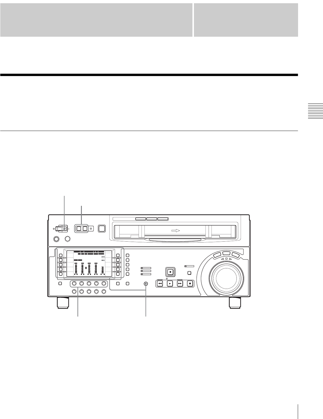
33
4-1 Recording
Chapter
Chapter 4 Recording and Playback
4
Recording and Playback
4-1 Recording
This section describes video and audio recording on the
unit.
4-1-1 Preparations for Recording
Switch and menu settings
Before you start recording, make necessary switch and
menu settings.
For details on each setting, see the pages indicated in
parenthesis.
12 34:47 12::
59.94 SDI 2F ASM
LTC
10801080
DF LTC EXT-LTC R-RUN
PROLL
HOME
VIDEO IN
SDI
EDIT
E.PRESET
CLR CNT
HOME
PB/EE
PB
CONFI
ENABLE
COUNTER
CTL
MENU
TCG SET
L R
1
SDI1
3+4
BANK3 REM:20min
HD
COND
VITC
L R
2
ANA2
2
-60
-40
-30
-20
-10
0
dB
L R
3
SDI3
1
L R
4
AES4
4
-60
-40
-30
-20
-10
0
dB
L R
CUE
3+4
-40
-20
-10
-20
10
dB
EMPH DATA EMPH DATA
CONFI
PARARUN
Turn on: POWER switch (see page 12)
REMOTE buttons (see page 12): off
Select the input audio signal (see page 69).
Select the input video signal (see page 65).
Select the audio channel to be monitored (see page 69).
PREREAD setting (see page 68): OFF
CONFI setting (see page 65): ENABLE
PB/EE setting (see page 65): PB
COUNTER setting (see page 66): Select the time data to be
displayed.
REC INHI setting (see page 69): OFF
Adjust the audio recording
levels (see page 19).
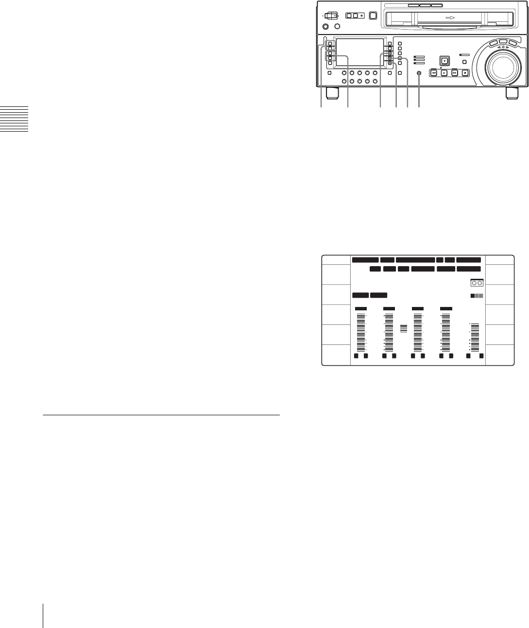
34 4-1 Recording
Chapter 4 Recording and Playback
To adjust the audio recording levels
When carrying out audio recording at a reference
level
Leave the REC knobs pressed in. The audio signals will be
recorded at a preset reference level (a reference –20 dB
indication for an input of +4 dBm).
To manually adjust the recording levels
For each channel, press to protrude the REC knobs, and
adjust so that the audio level indication is close to 0 dB for
an average volume. Carry out the adjustment in E-E mode.
For details of selecting the E-E mode, see the description
of the REC knobs (page 19) and the F6 (PB/EE) setting in
function menu page P01: HOME (page 65).
To change the display range of the audio
level indications
In function menu page P08: AUD INP, select F4
(MT.SCALE) (see page 69).
To monitor the simultaneous playback of
the recorded video and audio signals
during recording
In function menu page P01: HOME, select F7 (CONFI)
and set it to “ENABLE” (see page 65). It is now possible
to simultaneously monitor the video and audio signals
being recorded.
To use the emphasis function
To add emphasis to the analog input audio signal or analog
playback audio signal, select F1 (EMPHASIS) in function
menu page P08: AUD INP and set it to “ON” (see
page 69).
When the signal to which emphasis has been applied is
played back, it is automatically subjected to deemphasis
processing.
Using the emphasis-deemphasis processing improves the
dynamic range by reducing high-frequency noise.
4-1-2 Recording Timecode and User
Bit Values
There are two ways of recording timecode, as follows:
• Setting an initial value, then recording the output of the
internal timecode generator
• Recording the output of the internal timecode generator
synchronized with an external timecode generator
To set an initial value then record the
timecode
If necessary, change the settings in function menu page
P02: TC (see page 66).
To set an initial timecode value
Use the following procedure.
In function menu page P02: TC, set F1 (TCG SRC) to
“INTERNAL” and F2 (TCG MODE) to “PRESET”.
1
In function menu page P01: HOME, set F8
(COUNTER) to “TC”.
2
Select F10 (TCG SET).
The function menu display changes as follows.
The first digit of the timecode value (8 digits: hours,
minutes, seconds, and frames) flashes.
To set all digits to zero
Select F5 (CLR CNT).
3
Select F1 (PREV) or F2 (NEXT), and select the digit
to be changed.
Selecting F2 (NEXT) moves the flashing digit position
to the right, and selecting F1 (PREV) moves the
flashing digit position to the left.
4
Turn the MULTI CONTROL knob or select F3 (–) or
F4 (+) to change the value in the flashing digit
position.
3,5 4,5 4,5126
12 34
:
47 12
::
59.94 SDI 2F ASM
LTC
CONFI
10801080
DF LTC EXT-LTC R-RUN
PROLL
TCG SET TCG SET
L R
1
SDI1
3+4
BANK3
TCG 00:00:00:00
PARARUN
HD
COND
VITC
L R
2
ANA2
2
-60
-40
-30
-20
-10
0
dB
L R
3
SDI3
1
L R
4
AES4
4
-60
-40
-30
-20
-10
0
dB
L R
CUE
3+4
-40
-20
-10
-20
10
dB
EMPH DATA EMPH DATA
PREV
NEXT
-
+
CLR CNT
SET
EXIT
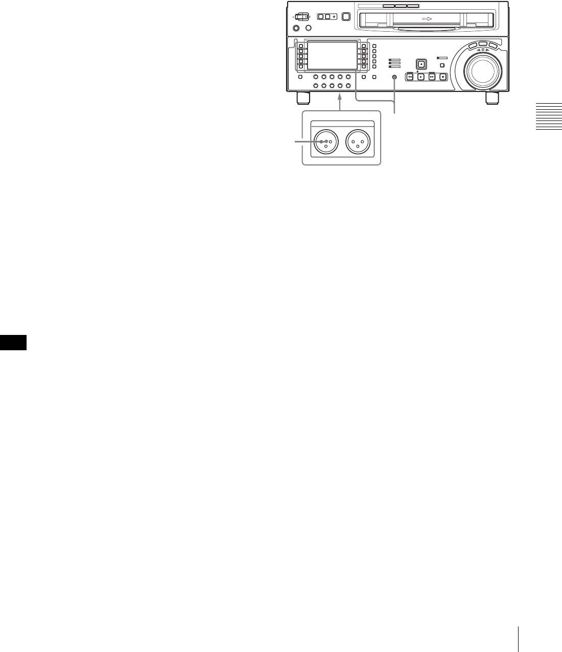
35
4-1 Recording
Chapter 4 Recording and Playback
5
Until all the digits are set as required, repeat steps 3
and 4.
6
Select F9 (SET).
When F3 (TCG RUN) in function menu page P02: TC
is set to “FREE”, the timecode value starts advancing
immediately.
To set the timecode value to the real time
With the items in function menu page P02: TC set as
follows, carry out the procedure of “Setting an initial
timecode value”. In steps 3 and 4, set a value slightly after
the current time as the initial value, then carry out step 6 at
the instant the real time catches up with the setting.
F1 (TCG SRC): INTERNAL
F2 (TCG MODE): PRESET
F3 (TCG RUN): FREE
F4 (DROP FRM): DF (59.94i, 29.97PsF mode only)
To set a user bit value
The user bit values recorded on the timecode track provide
for eight hexadecimal digits, which can be used to hold the
date, time, or other information.
Use the following procedure.
In function menu page P02: TC, select and set F1 (TCG
SRC) to “INTERNAL” and F2 (TCG MODE) to
“PRESET”, respectively.
1
In function menu page P01: HOME, set F8
(COUNTER) to “UB”.
2
Carry out the procedure in steps 2 to 6 under the
heading above, “Setting an initial timecode value”.
Set values, using the hexadecimal digits 0 to 9 and A
to F.
If any of the settings of “REC START MARK MODE” in
setup menu item 631 is set to “ON” (to write a recording
start mark), then the user bits are overwritten with the shot
mark data for 20 frames from the start of recording in crash
record mode, assemble edit mode, or insert edit mode.
For details on the setup menu, see Chapter 9 “Setup
Menus”.
To synchronize the internal timecode
generator with an external signal
Use this method to synchronize the timecode generators of
multiple VTRs, or to record the playback timecode signal
from an external VTR without deterioration of the signal
waveform.
In this case the RUN and DF settings are ignored.
You can synchronize the internal timecode generator with
either of the following external timecodes.
• The timecode output (LTC) of an external timecode
generator or external VTR connected to the TIME
CODE IN connector of the unit
• The timecode (LTC or VITC) in the HDSDI signal input
to the unit
To synchronize the internal timecode generator with an
external signal, use the following procedure.
1
Set “TCG REGEN MODE” in setup menu item 605 to
“TC&UB” or “TC”.
2
To synchronize with an external timecode signal input
to this unit’s TIME CODE IN connector, connect an
external timecode generator or external VTR's
timecode output to the TIME CODE IN connector.
To synchronize with a timecode data contained in an
HDSDI signal input to this unit, set F1 (VIDEO IN) to
“SDI” in function menu page P01: HOME.
3
Set the timecode generator items as follows.
To synchronize with an external timecode signal
input to this unit’s TIME CODE IN connector:
• In function menu page P02: TC, set F1 (TCG SCR)
to “EXT LTC”.
To synchronize with the LTC data contained in an
HDSDI signal input to this unit:
• Set F1 (TCG SRC) to “SDI IN”.
• Set F2 (TCG MODE) to “RGN:LTC”.
To synchronize with the VITC data contained in an
HDSDI signal input to this unit:
• Set F1 (TCG SRC) to “SDI IN”.
• Set F2 (TCG MODE) to “RGN:VITC”.
The unit starts the internal timecode generator running
in synchronization with the external timecode
generator.
The internal timecode generator is synchronized, and
even if the external timecode generator is
Note
1,2,3
TIME CODE
IN OUT
1
TIME CODE IN connector

36 4-1 Recording
Chapter 4 Recording and Playback
disconnected, the internal timecode generator
continues to run.
4-1-3 Recording Procedure
Use the following procedure.
1
Insert a cassette.
For details, see the section “To insert a cassette”
(page 32).
2
Hold down the REC button, and press the PLAY
button.
Recording starts, the servo locks, and the SERVO
indicator lights.
3
To stop recording, press the STOP button.
If you record to the end of the tape
The tape is automatically rewound to the beginning, and
stops.
Setup menu item 125 can be set to disable automatic tape
rewind.
21 3
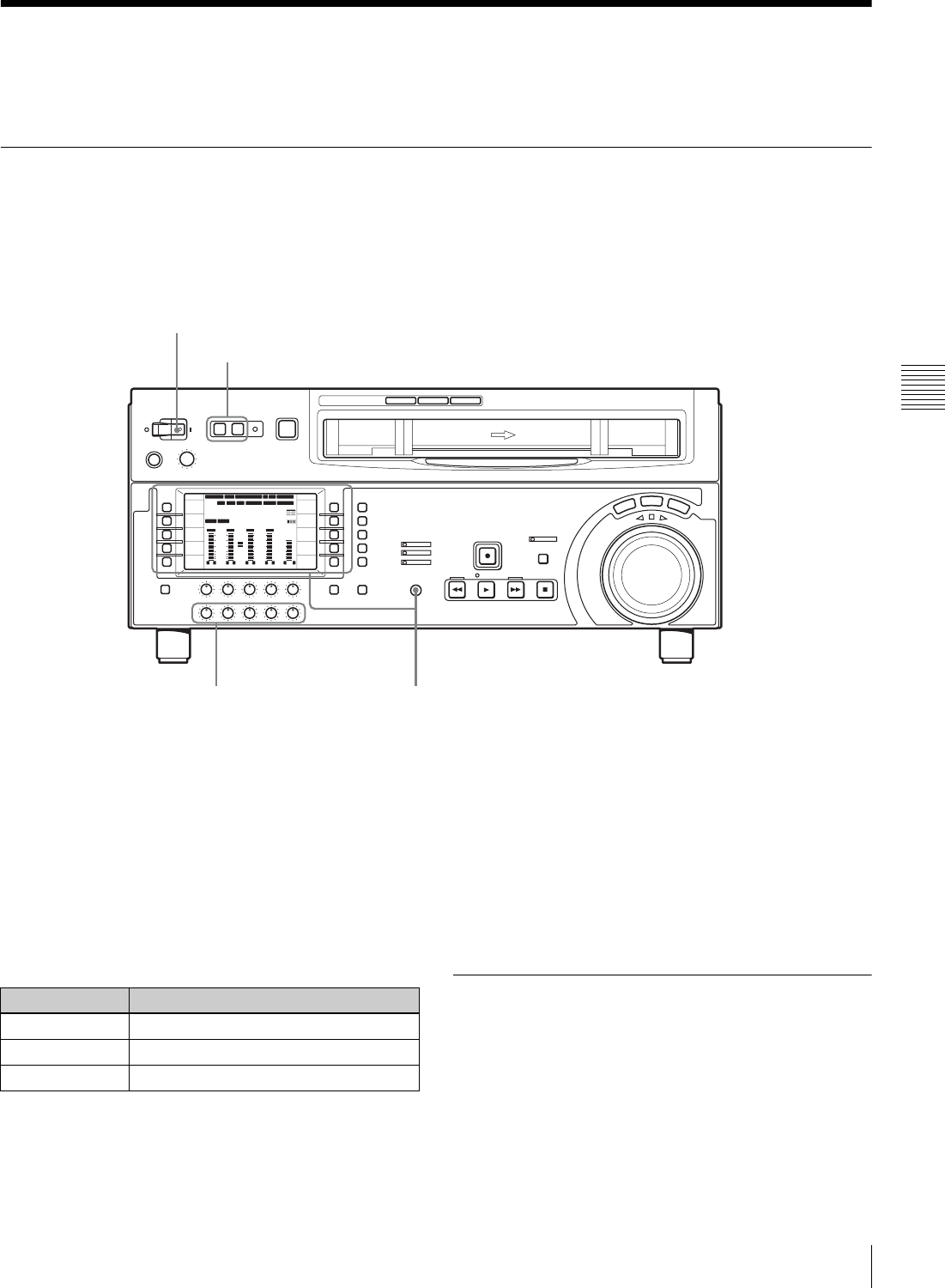
37
4-2 Playback
Chapter 4 Recording and Playback
4-2 Playback
This section describes playback of video and audio.
4-2-1 Preparations for Playback
Switch and menu settings
Before beginning playback, make necessary switch and
menu settings.
For details on each setting, see the pages indicated in
parenthesis.
Time data selection
Displayed time data
F8 (COUNTER) in function menu page P01: HOME can
be used to select CTL (control), timecode, or user bit
values. When you select timecode, the data to be displayed
is determined by the setting (LTC, AUTO, or VITC) of
F10 (TCR) in function menu page P02: TC as follows.
Output timecode
The settings in setup menu item 606, F1 (TCG SRC) and
F2 (TCG MODE) in function menu page P02: TC
determine whether the timecode output from the TIME
CODE OUT connector is the timecode generated by the
internal timecode generator (REGEN) or the playback
timecode (TAPE).
For details of the TCG SRC, TCG MODE settings, see
page 66.
4-2-2 Playback Procedures
This section describes the following playback functions
available with this unit:
• Normal playback
Playback at normal speed (×1)
• Playback in jog mode
Variable speed playback, with the speed determined by
the speed of rotating the search dial
12 34
:
47 12
::
59.94 SDI 2F ASM
LTC
10801080
DF LTC EXT-LTC R-RUN
PROLL
HOME
VIDEO IN
SDI
EDIT
E.PRESET
CLR CNT
HOME
PB/EE
PB
CONFI
ENABLE
COUNTER
CTL
MENU
TCG SET
L R
1
SDI1
3+4
BANK3
REM:20min
PARARUN
HD
COND
VITC
L R
2
ANA2
2
-60
-40
-30
-20
-10
0
dB
L R
3
SDI3
1
L R
4
AES4
4
-60
-40
-30
-20
-10
0
dB
L R
CUE
3+4
-40
-20
-10
-20
10
dB
EMPH DATA EMPH DATA
CONFI
Turn on: POWER switch (see page 12)
REMOTE buttons (see page 12): off
Select the timecode to be displayed (see page 66).
PB/EE setting (see page 65): PB
Select the audio tracks to be monitored (see page 69).
Select the time data to be displayed (see page 66).
Adjust the audio playback levels
(see page 20).
TCR setting Displayed data
LTC LTC recorded on tape
AUTO LTC or VITC (automatically switched)
VITC VITC recorded on tape
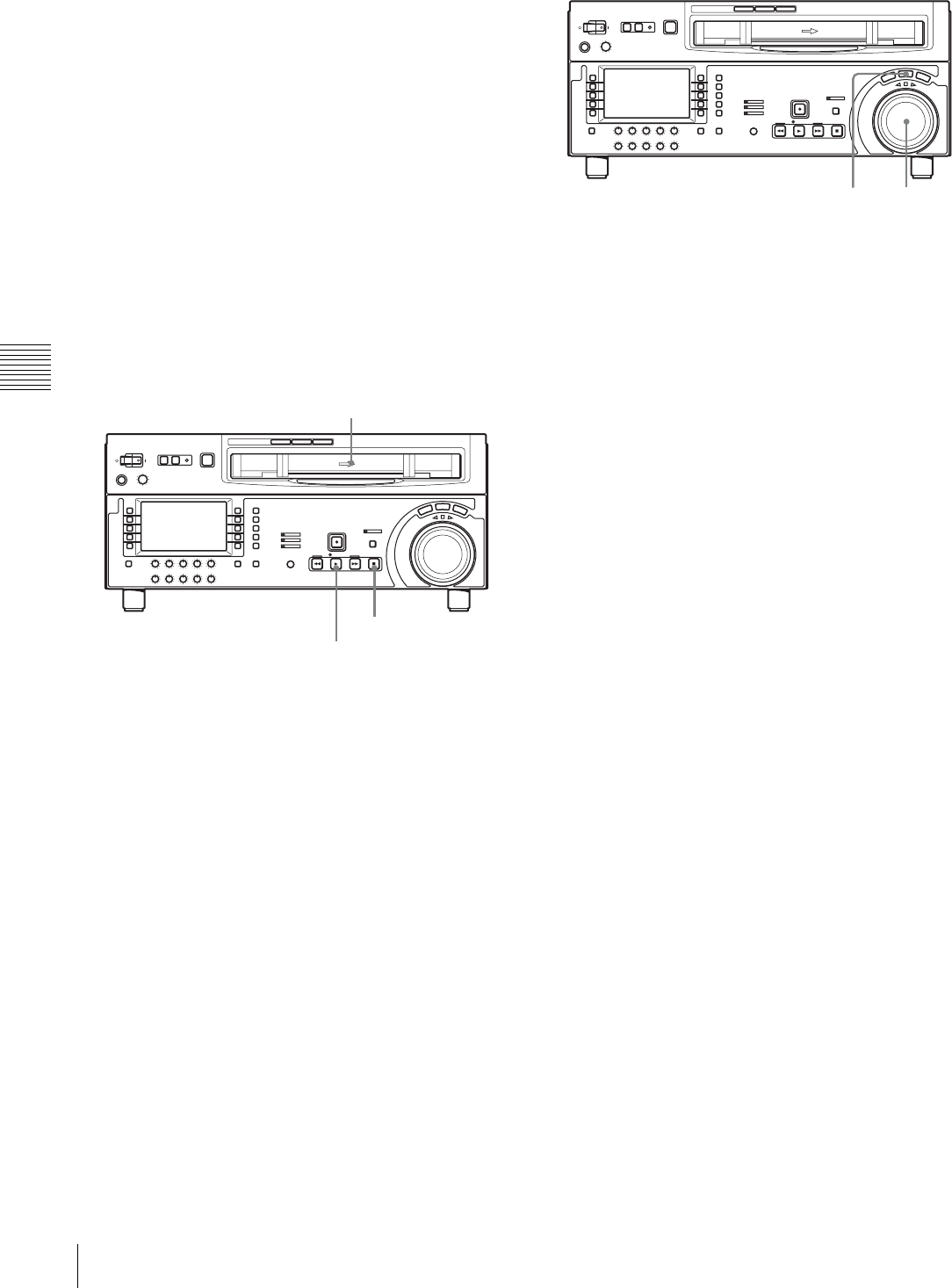
38 4-2 Playback
Chapter 4 Recording and Playback
• Playback in shuttle mode
Variable speed playback, with the speed determined by
the angular position of the search dial
• Playback in variable speed mode
Variable speed playback, with the speed finely
determined by the angular position of the search dial
• Playback using the capstan override function
The playback speed is adjusted temporarily according to
the angular position of the search dial, to align the
playback phase with another VTR.
• DMC playback
Playback at memorized varying speed.
Normal playback
First insert a cassette.
For details of how to insert a cassette, see Section
“3-5-2 Inserting and Ejecting Cassettes” (page 32).
To start playback
Press the PLAY button.
Playback starts, the servo locks, and the SERVO indicator
lights.
To stop playback
Press the STOP button.
If you play back to the end of the tape
The tape is automatically rewound, and stops.
The automatic rewind function can be disabled by
changing the setting in setup menu item 125.
Playback in jog mode
In jog mode, you can control the speed of playback by the
speed of rotating the search dial. The playback speed range
is ±1 time normal speed.
The playback speed range can be ±3 times normal speed by
changing the setting of setup menu item 116.
To carry out playback in jog mode, use the following
procedure.
1
Press the JOG button or search dial so that the JOG
button is lit.
Pressing the search dial toggles between jog mode and
shuttle mode.
2
Rotate the search dial in the desired direction, at the
speed corresponding to the desired playback speed.
Playback in jog mode starts.
3
To stop playback in jog mode, return the search dial to
the center position, or press the STOP button.
The function to toggle between jog mode and shuttle
mode each time the search dial is pressed can be
disabled by changing the setting in setup menu item
101.
Playback in shuttle mode
In shuttle mode, you can control the speed of playback by
the angular position of the search dial. The range of
playback speed is as follows.
•HDCAM tape: ±50 times normal speed (59.94i,
29.97PsF mode), ±58 times normal speed (50i, 25PsF
mode), ±60 times normal speed (24PsF, 23.98PsF mode)
•Digital Betacam tape: ±50 times normal speed
•MPEG IMX tape: ±78 times normal speed
There are detents on the search dial at the still position and
at the position for ±5 times normal speed.
To carry out playback in shuttle mode, use the following
procedure.
Cassette compartment
PLAY button
STOP button
1 1,2,3
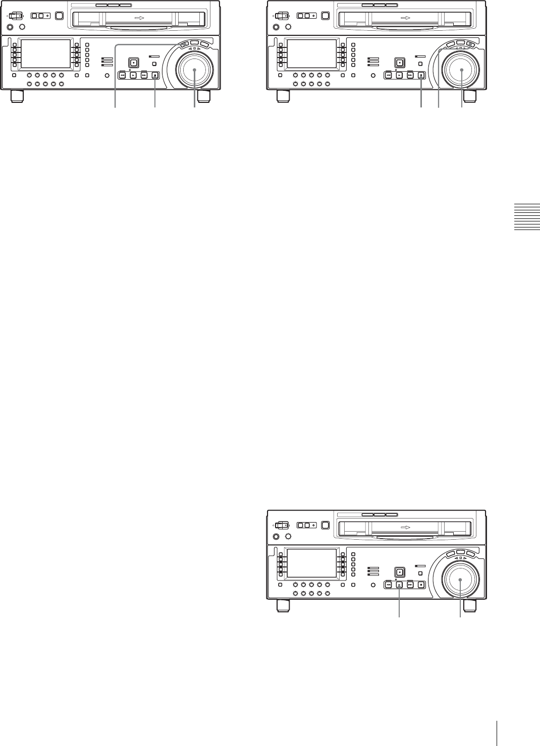
39
4-2 Playback
Chapter 4 Recording and Playback
1
Press the SHUTTLE button or search dial so that the
SHUTTLE button is lit.
Pressing the search dial toggles between jog mode and
shuttle mode.
2
Rotate the search dial to the desired angle
corresponding to the desired playback speed.
Playback in shuttle mode starts.
3
To stop playback in shuttle mode, return the search
dial to the center position, or press the STOP button.
The function to toggle between jog mode and shuttle
mode each time the search dial is pressed can be
disabled by changing the setting in setup menu item
101.
To return to normal-speed playback
Press the PLAY button.
To alternate between normal-speed playback and
shuttle mode playback
Rotate the search dial to the position corresponding to the
desired shuttle playback speed, then press the PLAY and
SHUTTLE buttons alternately.
For intermittent shuttle mode playback, press the STOP
and SHUTTLE buttons alternately.
Playback in variable speed mode
In variable speed mode, you can finely control playback
speed within the following ranges:
•HDCAM: –1 to +2 times normal speed
•Digital Betacam: –1 to +3 times normal speed
•MPEG IMX: –1 to +3 times normal speed
There are detents on the search dial at the still position and
at the position for ±1 times normal speed.
To carry out playback in variable speed mode, use the
following procedure.
1
Press the VAR button, turning it on.
2
Rotate the search dial to the desired angle
corresponding to the desired playback speed.
Playback in variable speed mode starts.
3
To stop playback in variable speed mode, return the
search dial to the center position, or press the STOP
button.
To return to normal-speed playback
Press the PLAY button.
To alternate between normal-speed playback and
variable speed mode playback
Rotate the search dial to the position corresponding to the
desired variable playback speed, then press the PLAY and
VAR buttons alternately.
For intermittent variable speed mode playback, press the
STOP and VAR buttons alternately.
Playback using the capstan override
function
You can use the capstan override function to adjust the
playback speed temporarily. This function is convenient
for playback phase synchronization with another VTR
playing back the same program.
1
Hold down the PLAY button, and rotate the search dial
in the desired direction to adjust the playback speed.
1 1,2,33 1 2,33
11,2
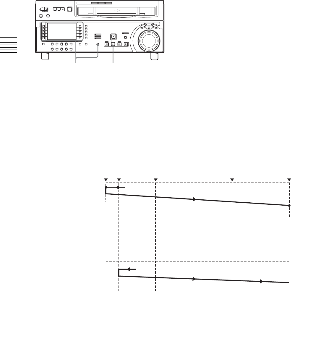
40 4-2 Playback
Chapter 4 Recording and Playback
The range of speed adjustment is ±15% in steps of 1%.
The SERVO indicator goes off.
2
When the adjustment is completed, release the PLAY
button.
The tape transport returns to normal speed, and the
SERVO indicator comes on again.
To carry out continuous capstan override
playback
1
Set “TSO PLAY” in setup menu item 111 to “TSO”.
2
With F4 (DMC) selected in function menu page P06:
EDIT, turn the MULTI CONTROL knob to select the
playback speed.
The selected playback speed is displayed in ancillary
message display on the lower control panel of this unit
as well as in the text information display section on the
video monitor.
3
With F4 (DMC) selected, press the PLAY button.
4
Press the PLAY button or carry out any other
operation to exit the tape speed override mode.
For details of setup menu operations, see Section
“9-2 Setup Menu Operations” (page 75).
For details of character information displayed on the
video monitor screen, see the descriptions of F5 (CHARA)
in function menu page P04: MISC-1 (page 68) and setup
menu item 005 (page 78).
4-2-3 DMC (Dynamic Motion Control) Playback
Overview
DMC playback allows you to vary the playback speed for
a certain section of a tape, in variable speed mode (from
–1 to +2 times normal speed) and store the varying speed
in memory for later playback.
For example, during a live broadcast of a sporting event
you can set the start and end points of highlights while
recording, and then provide immediate DMC playback of
those highlights.
During DMC playback the tape runs as shown in the
following figure.
2,3 3,4
Waiting for the on-air
cue before starting DMC
playback
On-air start point Preroll point Speed variation start point Speed variation end point On-air end point
Stop Select F3 (REVIEW).
Setting F3 (REVIEW) in
P06: EDIT again at the on-
air cue.
Normal speed
playback DMC playback
Stop
Normal speed playback
Select F2 (PREVIEW).
Normal speed
playback DMC playback Normal speed playback
Starting DMC playback
immediately after preroll
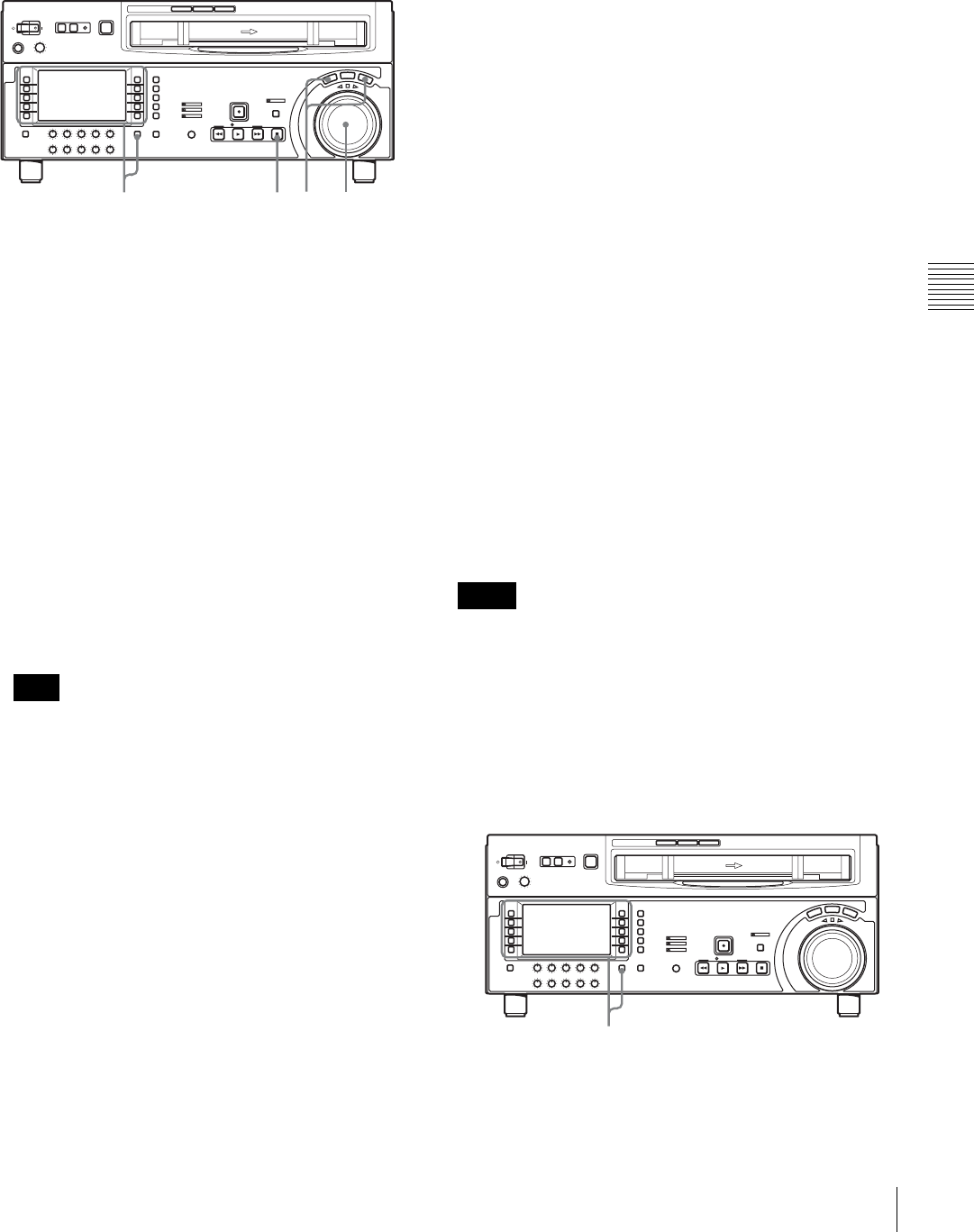
41
4-2 Playback
Chapter 4 Recording and Playback
To store a varying playback speed in
memory
To store the playback speed for DMC playback, use the
following procedure.
1
In function menu page P06: EDIT, select F4 (DMC).
2
Either while playing back the recorded tape, or during
recording, press the SHIFT/ENTRY button and one of
the following buttons simultaneously, to set the start
and end points.
•On-air start point: F7 (AUD IN) in function menu
page P06: EDIT
•Speed variation start point: F9 (IN) in function
menu page P06: EDIT
•Speed variation end point: F10 (OUT) in
function menu page P06: EDIT
•On-air end point: F8 (AUD OUT) in function
menu page P06: EDIT
The selected function menu items light.
3
Press the search dial, the SHUTTLE button or VAR
button to enter shuttle or variable speed mode.
Make sure that setup menu item 111 “TSO PLAY” is
set to “DIS”.
4
With F4 (DMC) selected, rotate the search dial to set
the initial speed at the playback start point.
The speed you set appears in the tape information.
During this period the tape does not move.
When the initial speed setting is complete, release the
F4 (DMC).
5
Holding down the SHIFT/ENTRY button, select F2
(PREVIEW).
The tape is prerolled and played back at the normal
speed from the on-air start point to the speed variation
start point.
On passing the speed variation start point, F4 (DMC)
begins to flash, and playback begins at the speed set in
step 4.
6
Rotate the search dial to vary the playback speed.
While the F4 (DMC) is flashing, the speed variations
are stored in memory. On passing the speed variation
end point, the F4 (DMC) changes from flashing to
continuously lit (pink), and the variable speed storing
ends.
7
Press the STOP button to stop the tape.
If the F4 (DMC) is lit before the speed variation
end point
This indicates that the memory became full at that point. It
is therefore not possible to memorize more speed
variations.
The maximum memory capacity is 120 seconds.
To correct the stored speed variation
Holding down the SHIFT/ENTRY button, select F2
(PREVIEW).
The interval between the speed variation start and end
points is automatically played back at the stored speed.
Operate the search dial to adjust the playback speed.
To set the initial speed to normal playback speed
In step 4 above, press the PLAY button.
To carry out DMC playback
There are two methods of starting DMC playback.
• Starting playback at the on-air cue from the on-air start
point
• Starting playback immediately after preroll
• To avoid operating mistakes we recommend that you use
the VTR in standalone mode when carrying out DMC
playback.
• When using two VTRs connected for editing, you can
only use the recorder VTR for DMC playback, and also
only when neither the RECORDER nor PLAYER button
is lit. (For this unit, this applies when F6 (R/P SEL) in
function menu page P06: EDIT is not set.)
Note
7 3 3,4,61,4,2,5
Notes
1,2

42 4-2 Playback
Chapter 4 Recording and Playback
To start playback at the on-air cue from the on-air
start point
Use the following procedure.
1
Holding down the SHIFT/ENTRY button, select F3
(REVIEW) in function menu page P06: EDIT.
F3 (REVIEW) lights, and the tape is cued up to the on-
air start point. After the tape is cued up, F3 (REVIEW)
flashes.
2
At the moment of the on-air cue, hold down the
SHIFT/ENTRY button and select F3 (REVIEW)
again.
F3 (REVIEW) lights, and playback starts at normal
speed.
Between the speed variation start and end points,
DMC playback is carried out at the stored speed, and
then playback continues at normal speed and the tape
stops at the on-air end point.
To start playback immediately after preroll
Holding down the SHIFT/ENTRY button, select F2
(PREVIEW) in function menu page P06: EDIT.
F2 (PREVIEW) is lit, and after preroll, DMC playback is
carried out at the stored speed from the speed variation
start point, then playback continues at normal speed from
the speed variation end point.
To stop the tape during DMC playback
Press the STOP button.
To exit DMC playback mode
Press the F4 (DMC) button and the ALT/DELETE button
simultaneously.
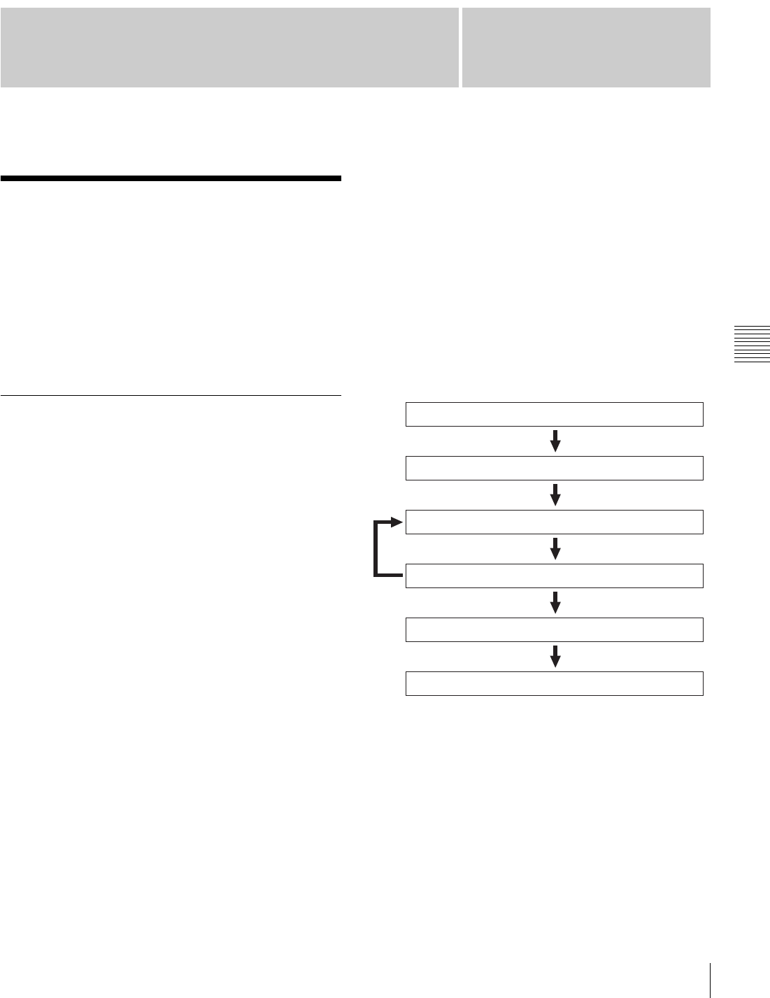
43
5-1 Automatic Editing
Chapter
Chapter 5 Editing
5
Editing
5-1 Automatic Editing
This section describes how to carry out automatic editing
with this unit and another VTR connected to the
REMOTE1-IN (9P) or REMOTE 1-OUT (9P) connector
of this unit.
For details of preparations, see Section “3-1 Connections
to External Devices” (page 27).
5-1-1 Overview
Editing mode
With this unit, you can use the following two edit modes
for automatic editing.
• Assemble editing
Successive portions of the edited result are recorded on
the end of the already completed section.
The CTL signal, video signal, audio signal, and
timecode signal are all newly recorded on the tape.
•Insert editing
New material is recorded at an intermediate point of an
existing recording.
The CTL signal is not overwritten. The video signal,
audio signal, and timecode signal can all be recorded
individually.
You can carry out DMC editing in both editing modes.
In insert editing, split editing is also possible.
To use CTL to interpolate timecode values
When you are using timecode values as edit point
addresses, the timecode must be recorded on the tape in
correct time sequence (i.e. the sections must be in strictly
ascending time order).
If the timecode values are all in correct time sequence, then
if there are any discontinuities in the timecode, the unit
interpolates them using the CTL count.
To record timecode
For automatic editing, regardless of the settings of F1
(TCG SRC) and F2 (TCG MODE) in function menu page
P02: TC, timecode is recorded continuously from the
timecode recorded before the edit IN point.
Using setup menu item 610, it is also possible to record
timecode according to the settings in the function menu.
Sequence of editing operations
The following flowchart outlines the sequence of
operations in automatic editing with two VTRs.
To use an editing control unit
When controlling this unit with an editing control unit, set
an edit delay on the editing control unit so that the cut-in
and cut-out commands are output 5 frames before the
actual edit point.
Selecting the editing mode (see page 45)
Setting the recorder and player edit points (see page 45)
Previewing the edit segments (see page 48)
Amending edit points as necessary (see page 47)
Carrying out automatic editing (see page 49)
Reviewing the editing results as necessary (REVIEW)
(see page 50)
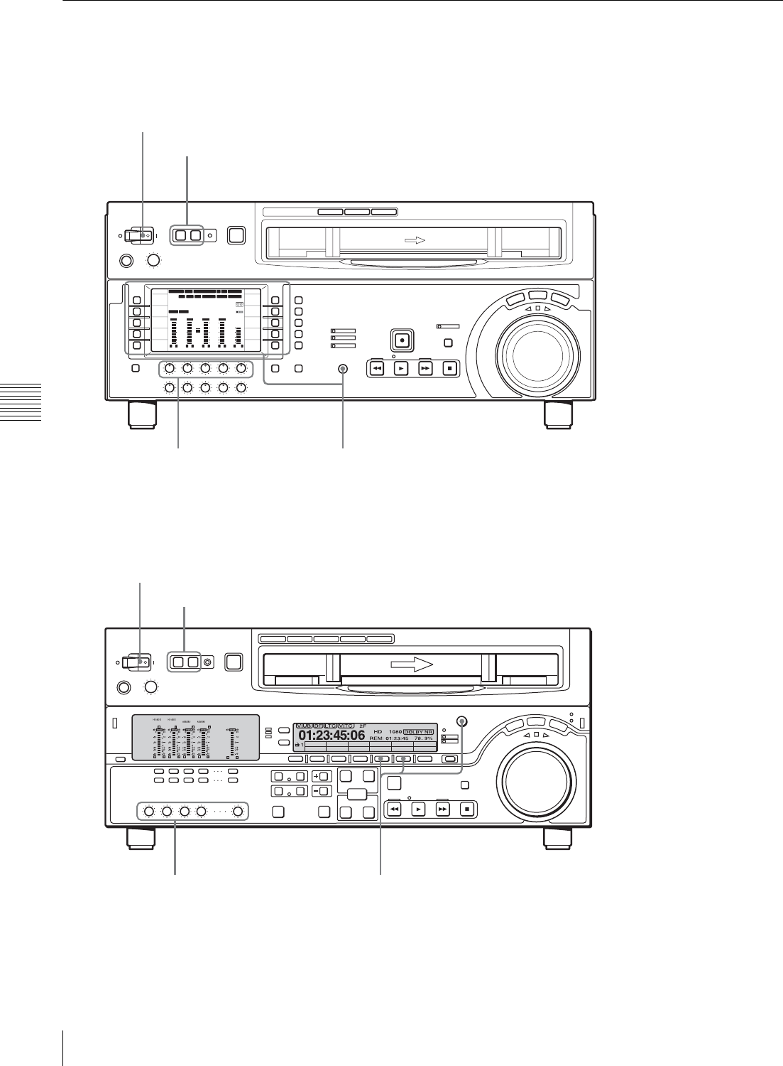
44 5-1 Automatic Editing
Chapter 5 Editing
5-1-2 Switch Settings
Before you start editing, make necessary switch settings.
12 34:47 12::
59.94 SDI 2F ASM
LTC
10801080
DF LTC EXT-LTC R-RUN
PROLL
HOME
VIDEO IN
SDI
EDIT
E.PRESET
CLR CNT
HOME
PB/EE
PB
CONFI
ENABLE
COUNTER
CTL
MENU
TCG SET
L R
1
SDI1
3+4
BANK3 REM:20min
HD
COND
VITC
L R
2
ANA2
2
-60
-40
-30
-20
-10
0
dB
L R
3
SDI3
1
L R
4
AES4
4
-60
-40
-30
-20
-10
0
dB
L R
CUE
3+4
-40
-20
-10
-20
10
dB
EMPH DATA EMPH DATA
CONFI
PARARUN
Z
CTL/TC
TC
MENU
59.94
POWER switch: “I” side (on) (see page 12)
HDW-1800/D1800
REMOTE buttons (see page 12): OFF
REC knobs (see page 19): Adjust the audio
recording levels.
Edit mode setting section (see page 45): Select assemble edit mode or insert edit mode.
Audio selection function selector buttons (see page 69): Select the input audio signal.
VIDEO IN setting (see page 65): Select the input video signal.
REC INHI setting (see page 69): OFF
COUNTER setting (see page 66): TC or CTL
Recorder settings
Player settings
POWER switch: “I” side (on)
REMOTE buttons: 1(9P) button lights
PB knobs: Adjust the audio
playback levels.
CTL/TC setting: TC or CTL
HDW-A2100/M2100
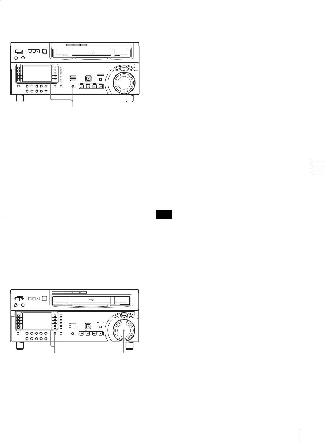
45
5-1 Automatic Editing
Chapter 5 Editing
5-1-3 Selecting the Editing Mode
To select the editing mode
Select assemble editing or insert editing.
Depending on the editing mode, press the following
buttons.
•Assemble editing: F5 (ASSEMBLE) in function menu
page P07: E.PRESET
•Insert editing: Desired function in function menu page
P07: E.PRESET (F2 (INS TC), F3 (INS CUE), and F6
(INS VID) to F10 (INS A4))
When you select edit mode and display function menu
page P06: EDIT, the F9 (IN) and F10 (OUT) buttons begin
to flash, indicating that the edit points need to be set.
5-1-4 Setting Edit Points
Set the edit points (IN and OUT points). To use split
editing in insert mode, you can set the audio and video edit
points individually.
To set an edit point
1
Select F6 (R/P SEL) in function menu page P06: EDIT
to select the player or recorder to be set the edit points.
Each time F6 (R/P SEL) is selected, the target VTR
changes.
2
Rotate the search dial in jog or shuttle mode, and
position the tape at the required edit point.
For details of playback in jog or shuttle mode, see the
sections“Playback in jog mode” (page 38) and
“Playback in shuttle mode” (page 38).
3
At the point at which you want to set the edit IN or
OUT point, hold down the SHIFT/ENTRY button and
select F9 (IN) or F10 (OUT) in function menu page
P06: EDIT.
When the IN point or OUT point is set, the F9 (IN) or
F10 (OUT) is lit.
4
Repeat steps 1 to 3 until all the necessary edit points
are set.
When the edit IN points are set on both the recorder
and player, F2 (PREVIEW) and F1 (AUTOEDIT)
flash, and preview or editing operation becomes
possible.
To set the edit point automatically
Editing requires four edit points: each pair of IN and OUT
points on both the recorder and player. Once any three of
these points are defined, the last point is set automatically.
For example, if you set the recorder IN and OUT points,
and the player IN point, the player OUT point is set
automatically.
In the following cases, F7 to F10 (IN, OUT, AUD IN and
AUD OUT) begin to flash and you cannot carry out
automatic editing.
• The OUT point is before the IN point.
• All four of the recorder IN and OUT points and the
player IN and OUT points have been set.
Use the ALT/DELETE button to delete a unnecessary edit
point, or set the edit points correctly.
For details of deleting edit points, see the section “To
delete an edit point” (page 47).
To set split edit points
In split editing, you can set the edit points for audio and
video independently. Set the audio edit points using F7
(AUD IN) and F8 (AUD OUT) in function menu page P06:
EDIT, and set the video edit points using F9 (IN) and F10
(OUT).
Note that split editing is only possible when the recording
mode is insert editing.
F1 (REC INHI)
F5 (ASSEMBLE)
21,3
Note
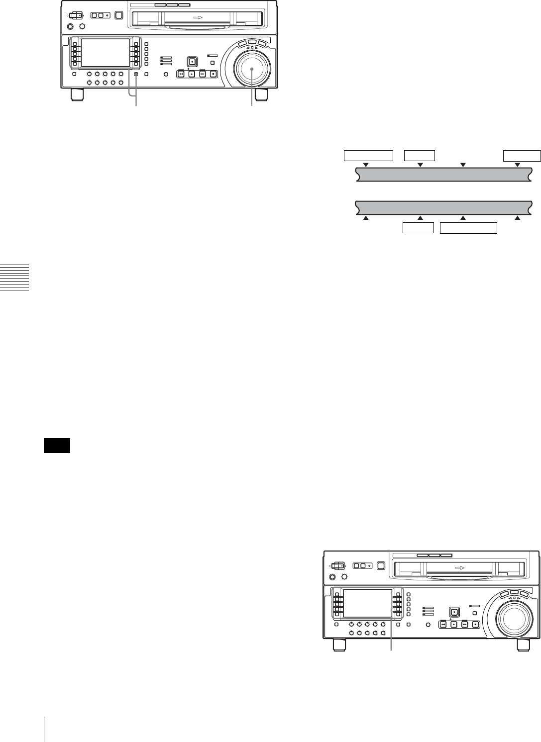
46 5-1 Automatic Editing
Chapter 5 Editing
1
In function menu page P07: E.PRESET, select the
desired function from F2 (INS TC), F3 (INS CUE) and
F6 (INS VID) to F10 (INS A4).
2
In function menu page P06: EDIT, select F6 (R/P
SEL) to select the VTR you want to set edit points.
3
Rotate the search dial in jog or shuttle mode to find the
edit point.
For details of jog/shuttle mode playback, see the
sections “Playback in jog mode” (page 38) and
“Playback in shuttle mode” (page 38).
4
Holding down the SHIFT/ENTRY button, select F9
(IN), F10 (OUT), F7 (AUD IN) or F8 (AUD OUT) to
set an edit point.
When the edit point is set, the selected button changes
from flashing to continuously lit.
5
Repeat steps 2 to 4 to set the required edit points.
As each edit point is set, the corresponding button
changes from flashing to continuously lit.
During split editing, if you set six or more edit points for
the recorder and player, F7 to F10 (AUD IN, AUD OUT,
IN and OUT) begin to flash. Editing cannot be carried out
in this state. Delete unnecessary edit points using the ALT/
DELETE button.
For details of how to delete edit points, see the section “To
delete an edit point” (page 47).
To set the edit points automatically in split
editing
Split editing requires a total of eight edit points: four video
edit points (player IN and OUT and recorder IN and OUT)
and four audio edit points (player audio IN and OUT and
recorder audio IN and OUT).
Once any five of these points are defined, the system
automatically calculates and sets the remaining three
points.
Specifically, once you have set three of the four video edit
points and two of the four audio edit points, the remaining
three edit points are set automatically, regardless of
whether these points are for the recorder or player.
In the figure below, the edit points shown within boxes are
already set. Other edit points (recorder audio OUT point,
and player audio IN and video OUT points) are set
automatically.
Note that any edit point can be deleted or corrected later
regardless of whether it was set manually or automatically.
You can set audio cut in, crossfade, fade in, and fade out
effects, including their durations, by menu selection.
For details, refer to the Installation Manual.
When the audio IN point is not set for insert
editing of audio only
As long as the audio OUT point is set, the VTR is ready for
preview or editing. In this case, the current tape position is
automatically used as the audio IN point.
To use a VTR without a split editing function as
the player
When it is not possible to set audio and video edit points
individually on the VTR you are using as the player, you
can carry out split editing by setting the audio IN and OUT
points and three video edit points on the recorder (this
unit).
To display the time data for an edit point
You can display the time data for an edit point in the time
data display (see page 17).
The edit points IN, OUT, AUDIO IN, and AUDIO OUT
are displayed in the ancillary message display.
Note
31,2,4
Player
IN point Audio OUT pointAudio IN point OUT point
Recorder
IN point Audio OUT pointAudio IN point OUT point
1,2
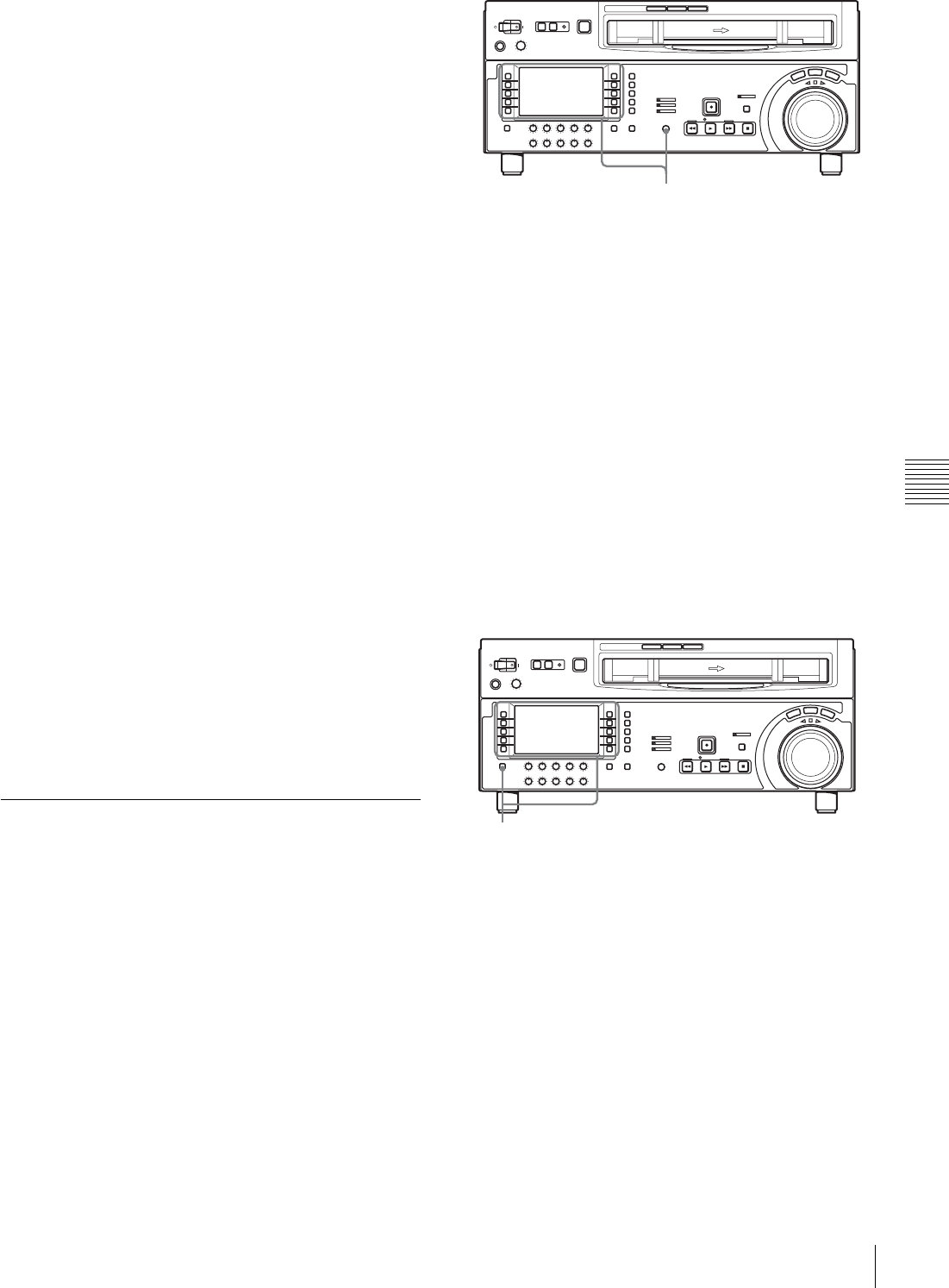
47
5-1 Automatic Editing
Chapter 5 Editing
1
In function menu page P06: EDIT, select F6 (R/P
SEL) to select the VTR on which you want to check
the edit point.
2
According to the edit point you want to check, keep F9
(IN), F10 (OUT), F7 (AUD IN) or F8 (AUD OUT)
selected in function menu page P06: EDIT.
While the function item is selected, the time data of the
corresponding edit point is displayed in the upper line
of the ancillary message display.
To display the duration of an edit segment
You can display the duration between two edit points in the
following three cases, in the ancillary message display (see
page 17).
• When two edit points are set: the duration of the segment
between the two points
• When only one edit point is set: the duration of the
segment between the set edit point and the current tape
position
• When no edit point is set: the duration of the previous
edit segment
The duration is displayed in the ancillary message display,
for example: “DUR 0:01:10:00”.
Use the following procedure.
1
In function menu page P06: EDIT, select F6 (R/P
SEL) to select the VTR you want to check the edit
point.
2
In function menu page P06: EDIT, keep both F9 (IN)
and F10 (OUT) or both F7 (AUD IN) and F8 (AUD
OUT) selected.
While the function items are selected, the duration is
displayed in the ancillary message display.
5-1-5 Modifying and Deleting Edit
Points
If the edit points are not set correctly, for example if an
OUT point is before a corresponding IN point, and it is not
possible to carry out a preview or editing operation. In this
case, modify the erroneous edit point, or delete and enter it
correctly.
To modify an edit point
Use the following procedure.
1
In function menu page P06: EDIT, select F6 (R/P
SEL) to select the VTR you want to modify the edit
point.
2
According to the edit point you want to modify, select
F9 (IN), F10 (OUT), F7 (AUD IN) or F8 (AUD OUT)
in function menu page P06: EDIT, and turn the
MULTI CONTROL knob.
While the function item is selected, the time data of the
corresponding edit point is displayed in the ancillary
message display. Turn the MULTI CONTROL knob
clockwise to increase the value by one frame or
counterclockwise to decrease the value by one frame.
To delete an edit point
Use the following procedure.
1
In function menu page P06: EDIT, select F6 (R/P
SEL) to select the VTR you want to delete the edit
point.
2
Holding down the ALT/DELETE button, select F9
(IN), F10 (OUT), F7 (AUD IN) or F8 (AUD OUT) in
function menu page P06: EDIT according to the edit
point you want to delete.
The edit point is deleted according to the selection.
1,2
1,2
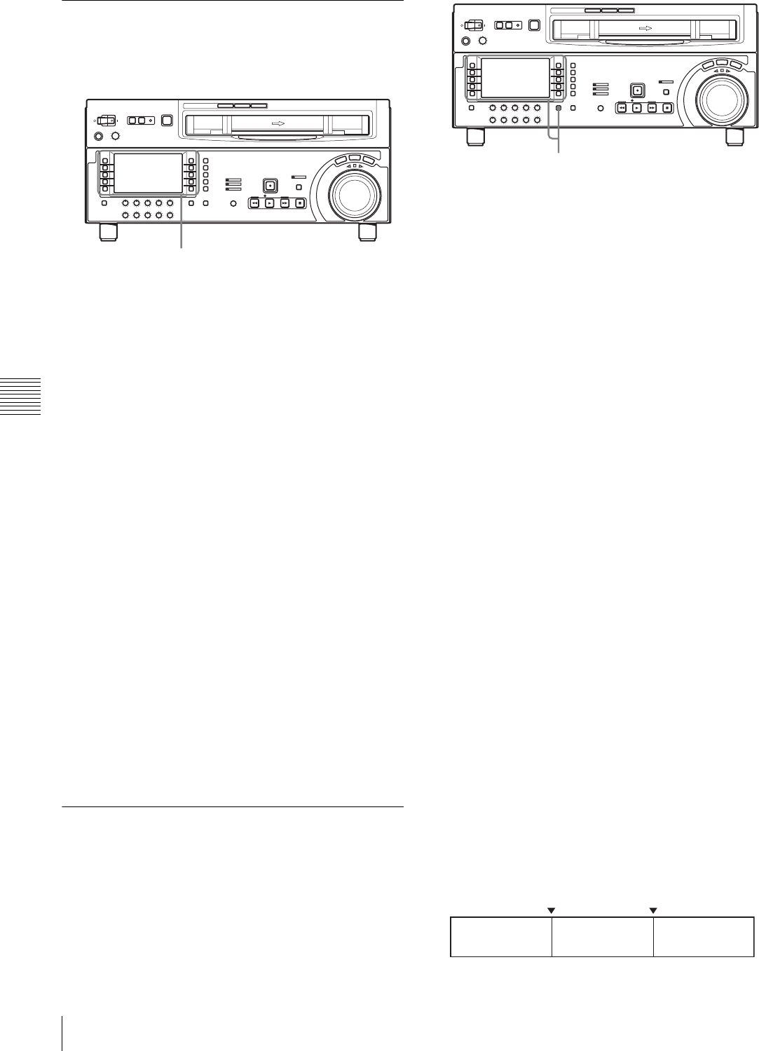
48 5-1 Automatic Editing
Chapter 5 Editing
5-1-6 Cuing up to Edit Points and
Preroll
Use the following procedure.
1
In function menu page P06: EDIT, select F6 (R/P
SEL) to select the VTR you want to check the edit
point.
2
• To cue up to an edit point
In function menu page P06: EDIT, select F9 (IN),
F10 (OUT), F7 (AUD IN) or F8 (AUD OUT)
according to the edit point you want to cue up, and
select F5 (PREROLL).
This cues up to the selected edit point.
• To preroll
Select F5 (PREROLL).
The tape is rewound to a position 5 seconds before
the edit IN point, and stops.
To change the preroll time
The factory default setting for the preroll time is 5 seconds,
but you can use menu item 001 to change this to any value
from 0 to 30 seconds. If you change the preroll time, make
sure that the setting is not longer than the recording length
before the edit IN point.
Note that for automatic editing, the preroll time setting on
the recorder is prioritized.
For details of menu item 001, see Section “9-3 Items in the
Basic Setup Menu” (page 78).
5-1-7 Preview
When you have set the edit points, F2 (PREVIEW) flashes,
indicating that you can carry out a preview.
Use the following procedure.
1
In function menu page P06: EDIT, select F6 (R/P
SEL) to select the recorder (RECDER).
2
Holding down the SHIFT/ENTRY button, select F2
(PREVIEW).
F2 (PREVIEW) button changes from flashing to
continuously lit, and the preview is carried out.
At the end of the preview, F2 (PREVIEW) flashes.
To stop the preview
Press the STOP button.
The tape stops at the position where you pressed the
button.
To return to the preroll point
Select F5 (PREROLL).
To return to the IN point or OUT point
With F9 (IN) or F10 (OUT) selected, select F5
(PREROLL).
After the preview, adjust the edit points, and repeat the
preview, if necessary.
For details of how to modify or delete edit points, see
Section “5-1-5 Modifying and Deleting Edit Points”
(page 47).
Monitor output
During a preview, you can monitor the video and audio
signals on a monitor connected to the recorder as follows.
• From the preroll point to the IN point, you can monitor
the playback image from the recorder.
• From the IN point to the OUT point, you can monitor the
playback image from the player through the recorder in
E-E mode.
• From the OUT point to the postroll point, you can
monitor the playback image from the recorder.
The following figure illustrates the descriptions above.
1,2
1,2
IN point OUT point
Playback
(recorder)
E-E mode
(player)
Playback
(recorder)
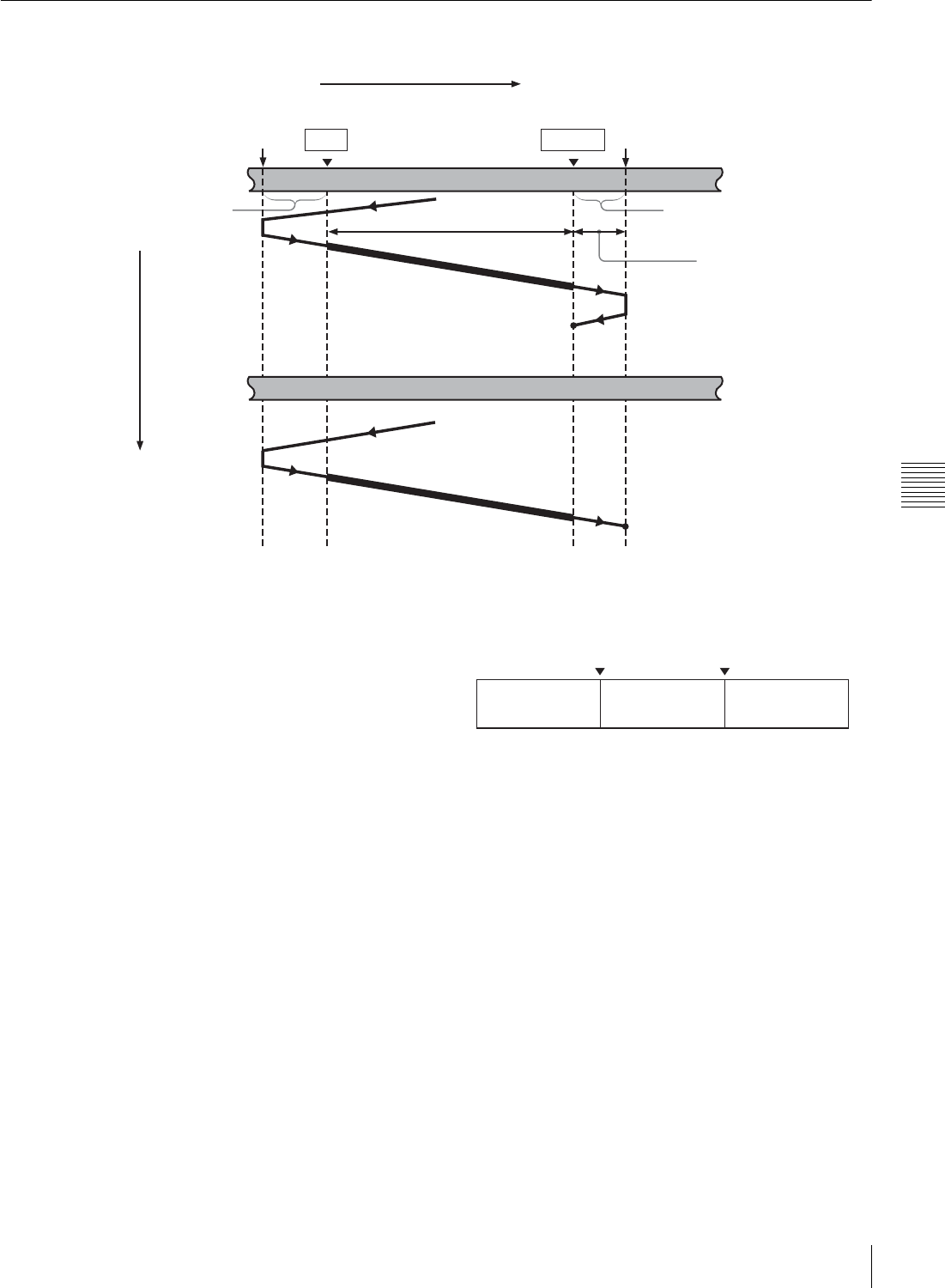
49
5-1 Automatic Editing
Chapter 5 Editing
5-1-8 Carrying Out Automatic Editing
Overview
When you carry out automatic editing, the recorder and
player operate as shown in the figure above, to record the
video and audio signals between the IN and OUT points on
the player to the segment between the IN and OUT points
on the recorder.
Monitor output
Like in the preview, duing an automatic editing, you can
monitor the video and audio signals as follows on a
monitor connected to the recorder.
• From the preroll point to the IN point, you can monitor
the playback image from the recorder.
• From the IN point to the OUT point, you can monitor the
playback image from the player through the recorder in
E-E mode.
• From the OUT point to the postroll point, you can
monitor the playback image from the recorder.
The following figure illustrates the descriptions above.
To monitor with a single monitor for video
and audio on both player and recorder
You can edit efficiently even if only one monitor is
available, by using the following procedure.
1
Connect the monitor to the recorder.
2
In the basic setup menu, set menu item 008 to
“AUTO”.
3
Select the player (PLAYER) using F6 (R/P SEL) in
function menu page P06: EDIT on the recorder side.
This makes the recorder forcibly enter the E-E mode,
and the player video and audio signals are output to the
monitor.
Tape transport
Recorder
Preroll point
Recording overlap
(in case of assemble
editing)
IN point OUT point
Postroll point
Preroll Edit segment Postroll
Stop
Player
Time flow
Stop
Playback
IN point OUT point
Playback
(recorder)
E-E mode
(player)
Playback
(recorder)

50 5-1 Automatic Editing
Chapter 5 Editing
Audio, video, and CTL signals need to be recorded in
advance in the insert editing section on the tape. If the
section in which these signals are not recorded correctly is
used for insert editing, noise or breakup can occur in the
audio and video when that section is played back.
To start automatic editing
When you finish setting the edit points, with F1
(AUTOEDIT) flashing, select F1.
F1 changes from flashing to continuously lit, and the
automatic editing begins.
At the end of the automatic editing, F1 goes off.
To change the OUT point during automatic
editing
After starting the automatic editing, hold down the SHIFT/
ENTRY button and select F10 (OUT) before the preset
OUT point. The position where F10 was selected becomes
a new edit OUT point, and editing ends.
To abandon automatic editing
Press the STOP button.
The automatic editing before reaching the OUT point is
interruped. At the same time, F2 (PREVIEW) and F1
(AUTOEDIT) start flashing, and the unit returns to the
state before the editing was started.
The edit IN and OUT points are preserved so that you can
carry out a preview or automatic editing operation again by
holding down the SHIFT/ENTRY button and selecting F2
or F1.
To review the editing results
After editing, you can check the editing results on the
monitor.
To carry out a review, hold down the SHIFT/ENTRY
button and select F3 (REVIEW) before you set any new
edit point or modify any existing edit point.
The F3 lights, and the review is carried out.
At the end of the review the F3 goes off, and the tape
returns to the OUT point and stops.
After automatic editing, to correct the edit points
and reexecute the edit
Hold down the ALT/DELETE button and select F1
(AUTOEDIT) to recall the edit points. After adjusting the
edit points select F1 to carry out the edit again.
For details of how to correct edit points, see Section
“5-1-5 Modifying and Deleting Edit Points” (page 47).
Note
F1 (AUTOEDIT)
F2 (PREVIEW)
F3 (REVIEW)
SHIFT/ENTRY button
ALT/DELETE button
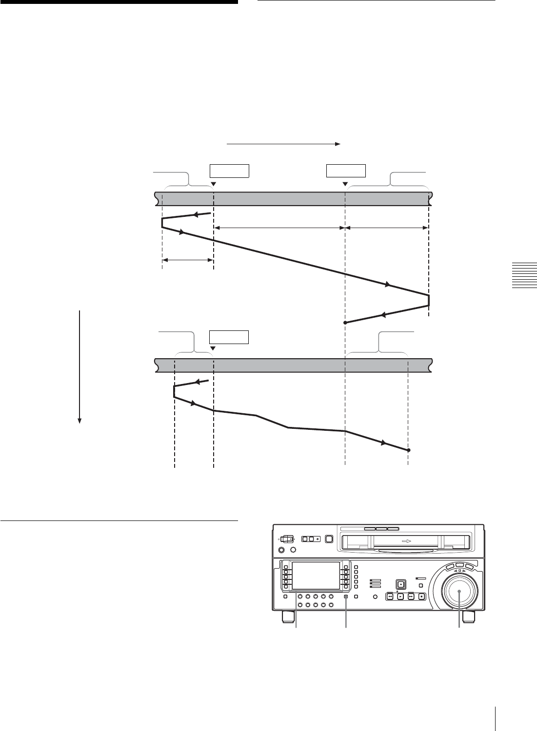
51
5-2 DMC Editing
Chapter 5 Editing
5-2 DMC Editing
By controlling the player playback speed from the
recorder, you can carry out variable speed editing.
5-2-1 Overview
Conditions for DMC editing
DMC editing can be used with insert or assemble editing,
but not with audio split editing.
Tape transport during DMC editing
The following figure illustrates how the tapes run on the
player and recorder during DMC editing.
5-2-2 Carrying Out DMC Editing
To set the edit points and player speed
Use the following procedure.
Tape transport
Recorder
Preroll
Postroll time x final
speed
IN point OUT point Postroll
Playback
DMC editing Playback
Stop
Player
Time flow
Stop
Tape runs at
initial speed
IN point
Preroll time x initial
speed
Playback at stored
varying speed
Tape runs at
final speed
4,81-9 6,9

52 5-2 DMC Editing
Chapter 5 Editing
1
In function menu page P06: EDIT, select F6 (R/P
SEL) to select the recorder (RECDER).
2
In function menu page P07: E.PRESET, select F5
(ASSEMBLE) or one INSERT button of F2 (INS TC),
F3 (INS CUE), and F6 (INS VID) to F10 (INS A4).
3
In function menu page P06: EDIT, select F4 (DMC).
This unit switches to the DMC edit mode, and F4
(DMC) lights.
4
Holding down the SHIFT/ENTRY button, select F9
(IN) or F10 (OUT) to set an edit point.
5
Select F6 (R/P SEL) to select the player (PLAYER),
and set the player edit IN point using the same
procedure as step 4.
It is not possible to set the player OUT point.
6
With F4 (DMC) selected, rotate the search dial to set
the initial speed.
To select normal playback speed as the initial
speed
Press the PLAY button.
The speed you set appears in the tape information.
7
When the initial speed setting is complete, release the
F4 (DMC).
8
Holding down the SHIFT/ENTRY button, select F2
(PREVIEW).
The tape is prerolled and then the recorder starts
operating at normal speed and the player starts at the
set initial speed.
9
On reaching the IN point, and F4 (DMC) begins to
flash, rotate the search dial to change the playback
speed.
While F4 (DMC) is flashing, the speed variations are
stored in memory. On reaching the OUT point, the F4
(DMC) changes from flashing to continuously lit
(pink), and the variable speed storing ends.
If the F4 (DMC) lights continuously before the
OUT point
This indicates that the memory has become full at that
point. Therefore, even before the OUT point is reached, it
is not possible to store speed variation data in memory any
more.
The maximum memory capacity is 120 seconds.
To exit the DMC edit mode
Holding down the ALT/DELETE button, select F4 (EDIT)
in function menu page P07: E.PRESET.
To carry out the DMC editing
Holding down the SHIFT/ENTRY button, select F1
(AUTOEDIT) in function menu page P06: EDIT.
DMC editing is carried out at the stored varying speed.
The stored playback speed settings are deleted from the
unit’s memory.
To check the editing results
Holding down the SHIFT/ENTRY button, select F3
(REVIEW).
Note
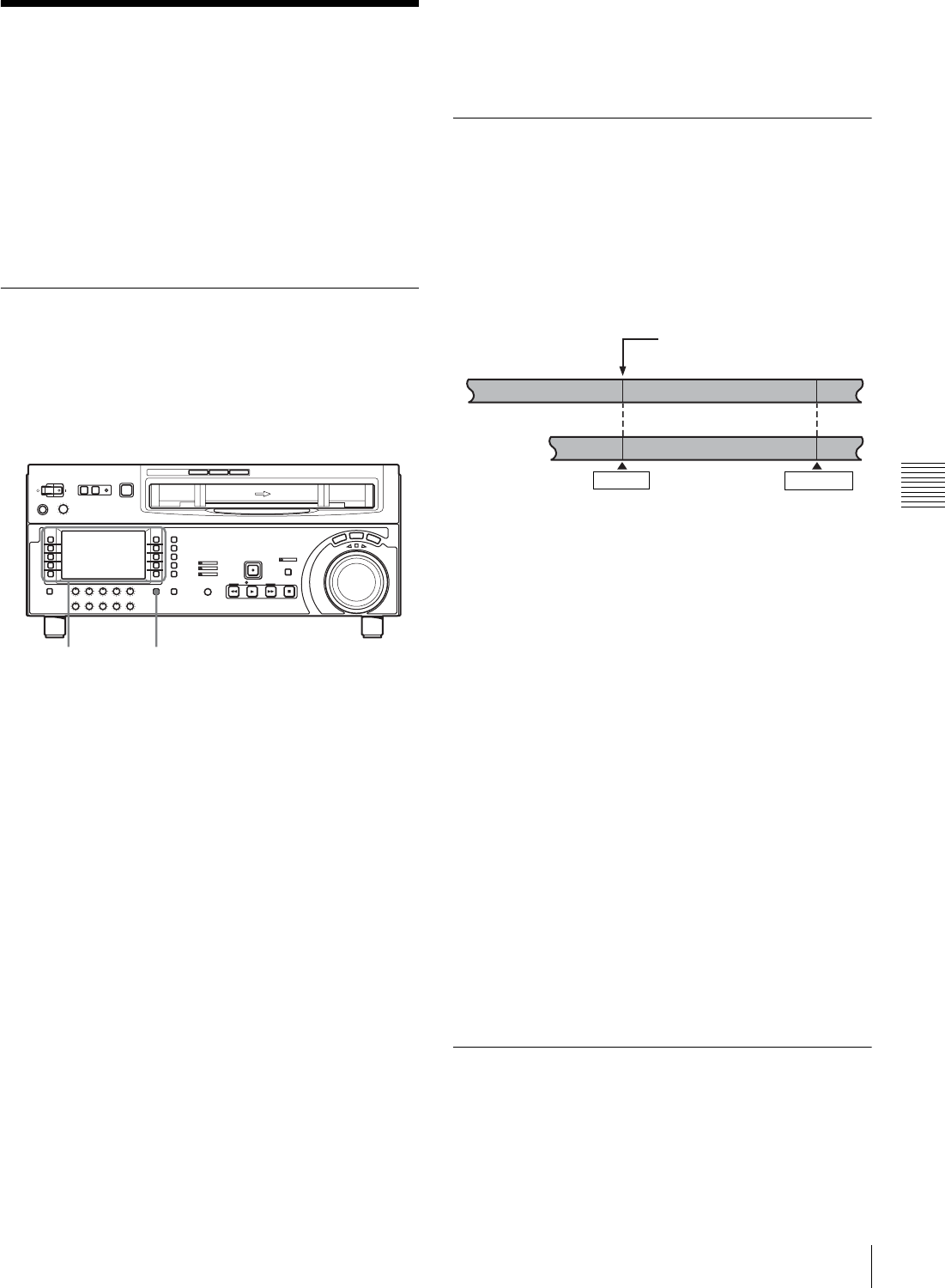
53
5-3 Special Automatic Editing Methods
Chapter 5 Editing
5-3 Special Automatic
Editing Methods
This section describes the following automatic editing
methods:
• Quick editing
• Continuous editing
• Standalone editing
• Preread editing
5-3-1 Quick Editing
After selecting the edit mode, you can reduce editing time
by setting the edit points and executing the editing at the
same time.
Use the following procedure.
1
Select F6 (R/P SEL) in function menu page P06: EDIT
to select the player or the recorder, and stop the tapes
on both the player (PLAYER) and recorder
(RECDER) at the positions you want to make the
respective IN points.
2
Holding down the SHIFT/ENTRY button, select F1
(AUTOEDIT).
Editing starts.
3
While monitoring the editing on the monitor, hold
down the SHIFT/ENTRY button and select F10
(OUT) at the position you want to make the edit OUT
point.
Editing ends.
The point at which you started the editing will be the
IN point, and the point at which you ended the editing
will be the OUT point.
To preview
In step 1, after setting the recorder or player edit IN point,
hold down the SHIFT/ENTRY button and select F2
(PREVIEW).
5-3-2 Continuous Editing
After an automatic editing, the recorder automatically
returns to the OUT point.
For the second and subsequent editing operations, you can
continue editing by simply specifying the IN and OUT
points on the player. In this case the current OUT point on
the recorder will be the new IN point.
After automatic editing of one edit segment, to carry out
continuous editing use the following procedure.
1
Set the player IN and OUT points.
Recorder OUT point for the previous editing will be
the new IN point.
2
Holding down the SHIFT/ENTRY button, select F2
(PREVIEW) in function menu page P06: EDIT to
carry out the preview.
3
Holding down the SHIFT/ENTRY button, select F1
(AUTOEDIT).
Editing starts.
When the editing is completed, the recorder stops at
the OUT point, and the player stops 2 seconds after the
OUT point.
By repeating this procedure, you can carry out continuous
editing.
By setting setup menu item 326, you can make the
previous OUT point automatically will be the new IN
point.
5-3-3 Standalone Editing
This refers to editing using an external device as the player
which cannot be remotely controlled via the REMOTE1-
IN (9P) or REMOTE 1-OUT (9P) connector. For example,
2,31,2,3
OUT point of previous editing =
IN point of current editing
OUT point
Recorder
Player
Previous edit segment
Current edit segment
IN point
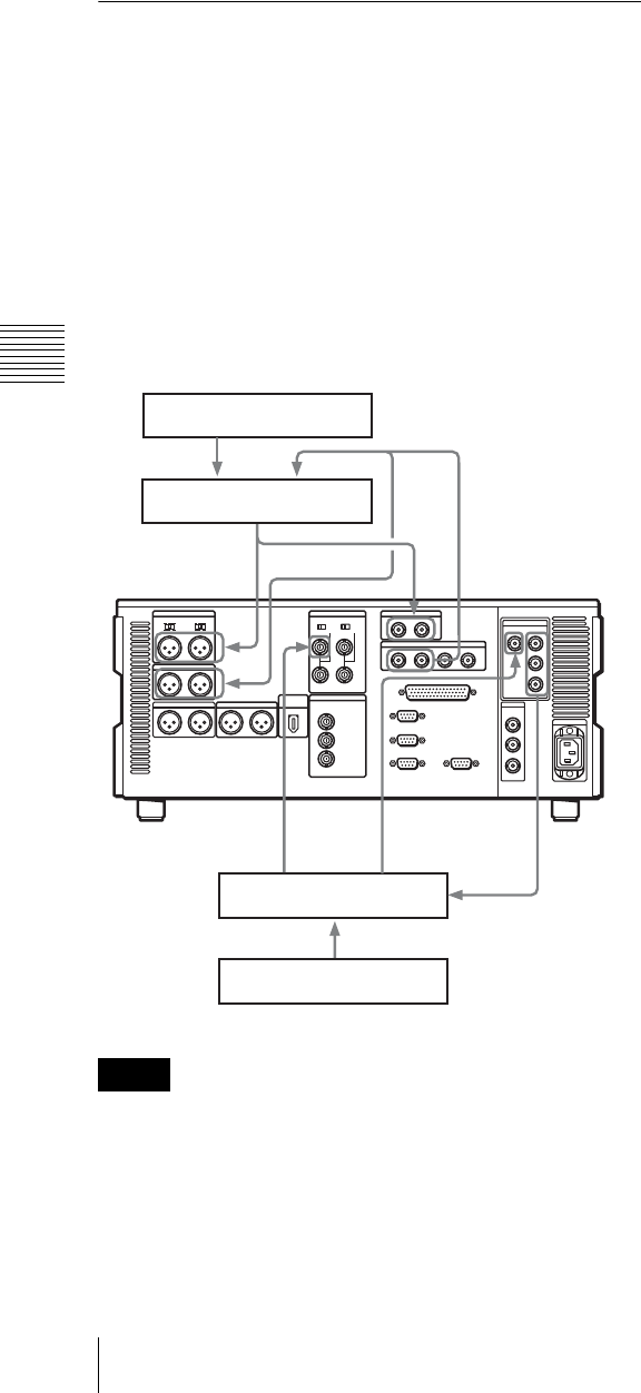
54 5-3 Special Automatic Editing Methods
Chapter 5 Editing
you can record a color bar signal from a signal generator in
the joints between the scenes of a finished tape.
To carry out standalone editing
Set the edit IN point with neither the recorder nor player
selected with F6 (R/P SEL).
F1 (AUTOEDIT) flashes, and it is now possible to carry
out automatic editing.
If necessary, you can also set the OUT point in advance.
5-3-4 Preread Editing
Video and digital audio signals already recorded on the
tape can be used as an edit source for insert editing.
This type of editing is called “preread editing”, and this
unit uses the preread heads to read the signals in advance
from the tape.
The read signals can be sent to a mixer for mixing, and can
be recorded either on the original channels or on other
digital audio channels.
For preread editing, set F3 (PREREAD) to “ON” in
function menu page P04: MISC-1 (see page 68).
• In preread editing, if an input video signal is used as the
reference signal, a loop connection between video input
and output on this unit may cause acoustic feedback
(howling). To prevent this, set F2 (REF VID) (see
page 67) to “REF” in function menu page P03: VID
PROC and set setup menu item 309 to “AUTO1” (see
page 85) so as to use an external reference signal.
• When the preread mode is selected, to prevent feedback
due to the loop connection, no E-E video is output in any
editing mode of this unit, however, if the loop
connection remains and an E-E signal is output,
feedback will occur.
To prevent this, select PB mode for the video and digital
audio channels in all editing modes before the preread
editing, as follows.
1
In function menu page P01: HOME, set F6 (PB/EE) to
“PB”.
2
In function menu page P04: MISC-1, set F3
(PREREAD) to “ON”.
3
Make the necessary connections for the preread
editing.
4
After selecting the desired insert edit mode, carry out
the preread editing.
5
When the preread editing is completed, remove the
connections.
6
Set the F3 (PREREAD) to “OFF”.
7
Check that no loop connection remains.
Notes
Audio source
Audio mixer
Digital video
input
Digital or analog
audio input
Digital or analog
audio output
Video switcher
Video source
Digital video input
Sync
signal
input Digital vide
o
output

55
6-1 Overview
Chapter
Chapter 6 Shot Mark Function
6
Shot Mark Function
6-1 Overview
This unit can write shot marks or use shot marks recorded
on HDCAM tape. Shot marks are indications at desired
points on a tape which enable faster cuing.
Types of shot mark
This unit supports the following three types of shot mark.
This chapter describes recording start marks and post
marks as varieties of shot marks.
First, the shot mark functions of this unit are described in
simple terms.
To read shot marks
This unit reads in shot marks written on a tape and stores
them in memory (to a maximum of 200).
When the data is stored in this unit, it is preserved even
when the unit is powered off.
To write and erase shot marks
For recording start marks, a menu setting determines
whether or not they are written each time recording starts.
Shot mark 1, shot mark 2, and post mark can be written at
any point on a tape, and also erased or rewritten.
Shot mark list operations
On the monitor, you can display a list of the shot marks
read in by this unit, select required shot marks, delete shot
marks, and so on. You can also add a memo mark (#) to a
shot mark in the list.
During tape playback, you can add virtual shot marks to
the list. This is not written on the tape itself and called
virtual shot mark.
To cue up to shot marks
By selecting a desired shot mark from the shot mark list,
you can cue up immediately to that position. By button
operation, you can also cue up to the shot marks adjacent
to the current tape position (index function).
Shot mark type Writing on a camcorder,
etc.
Writing on this unit Modifying and
deleting on this unit
Recording start mark Automatically written at the
start of recording.
Written or not according to the menu setting for
each recording mode (crash recording, assemble
editing, insert editing).
For each mode for which the setting is “ON”, the
mark is written automatically at the start of
recording.
Possible
Shot mark 1 and shot
mark 2
Written by a manual shot
mark operation during
recording or editing.
Written by a button operation during crash
recording or assemble editing.
A menu setting determines the type of mark to be
written: shot mark 1, shot mark 2, or post mark.
Post mark Not written
(Written only by this unit)
Written by a button operation during playback,
stop, search, or recording (crash recording or
assemble editing).
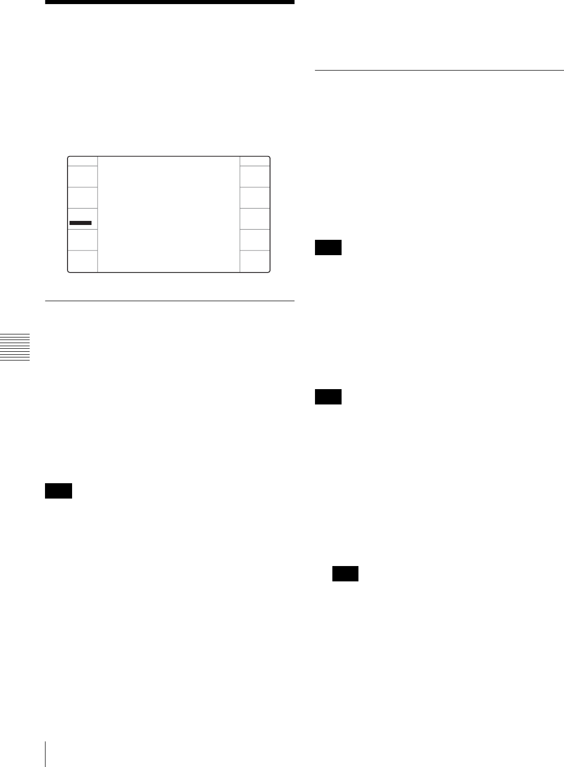
56 6-2 Shot Mark Operations
Chapter 6 Shot Mark Function
6-2 Shot Mark Operations
This section describes the operations concerning reading
and writing shot marks. Note that the following operations
cannot be carried out by remote control.
Shot mark operations are carried out from function menu
page P104: SHOT MRK. Select F3 (SHOT MRK) in
function menu page P05: MISC-2 to open function menu
page P104: SHOT MRK.
6-2-1 Reading Shot Marks
To read in shot marks
With a cassette tape loaded and F7 (LIST) selected, press
the F FWD or REW button.
While the shot marks are being read in, the F FWD or
REW button flashes.
The unit searches to the end of the tape, then rewinds
automatically.
For the procedure for listing the read shot marks, see
page 57.
It is possible to read in a maximum of 200 shot marks.
When 200 shot marks have been read in, the ancillary
message display on the control panel shows “SHOT LIST
FULL”, and the reading stops.
To cancel the message, press one of the tape transport
buttons.
To stop reading
Press the STOP button.
To read shot marks from more than one
cassette
After changing the cassettes, carry out the reading
operation again.
Data written in the new cassette will be added as long as
the total does not exceed 200 shot marks. For example, if
190 shot marks have already been read in, only 10 shot
marks will be read from the new tape.
In the shot mark list (see page 57) the data from different
cassettes is separated by a separator.
6-2-2 Writing Shot Marks
To write recording start marks during
recording
In setup menu item 631 “REC START MARK MODE”,
select whether or not to write a recording start mark for
each of the three recording modes (CRASH REC,
ASSEMBLE, INSERT).
When you set a particular mode to “ON”, a recording start
mark is written on the tape each time you start recording in
that mode.
When using the insert edit mode, select F2 (INS TC) in
function menu page P07: E.PRESET, turning it on.
To write shot mark 1, shot mark 2 or post
marks
To select the type of shot mark to be written
In setup menu item 636 “MARK SELECT IN REC/
ASSEMBLE”, select SHOT1, SHOT2 or POST mark.
If any of the mode settings in setup menu item 631 “REC
START MARK MODE” is set to “ON” (to write a
recording start mark), then the user bits are overwritten
with the shot mark data for 20 frames from the start of
recording in crash recording mode, assemble edit mode or
insert edit mode.
To write in crash recording or assemble editing
1
Holding down the SHIFT/ENTRY button, select F2
(REC/ERS) in function menu page P104: SHOT MRK
to set “REC”.
A mark can be written only when F2 is set to “REC”.
2
At the position you want to write the mark, hold down
the SHIFT/ENTRY button and select F3 (REC).
A mark of the type selected in the setup menu item 636
is written.
Note
SHOT MRK
REC/ERS
REC
REC
SHOT MRK
MARK
LIST
EXIT
Note
Note
Note
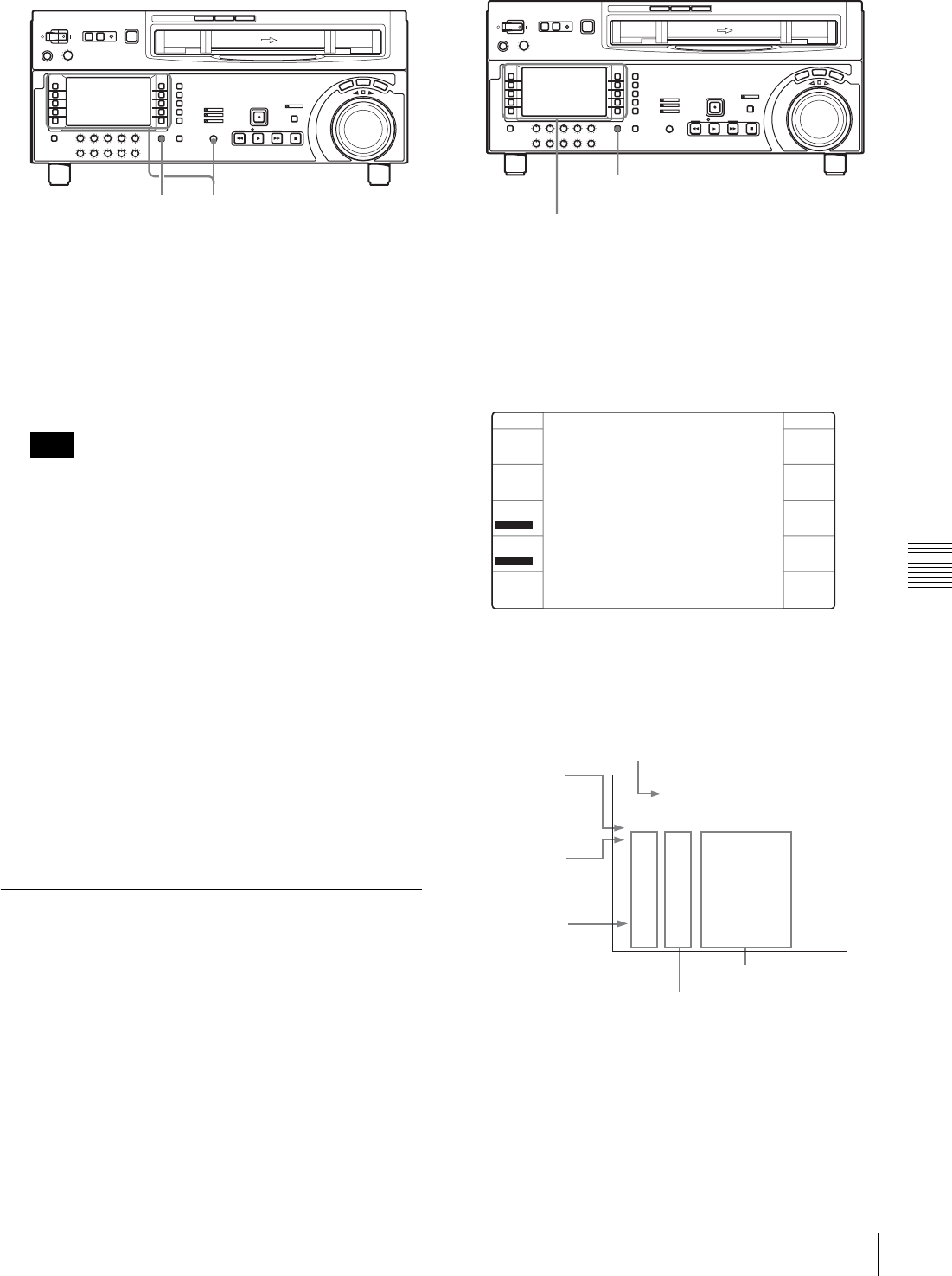
57
6-2 Shot Mark Operations
Chapter 6 Shot Mark Function
To write during playback, stop, or search
When this unit is in any of the playback, stop, or search
modes, you can only write a post mark with following
procedure.
1
Holding down the SHIFT/ENTRY button, select F2
(REC/ERS) to set “REC”.
A post mark can be written only when F2 is set to
“REC”.
2
At the position you want to write the mark, hold down
the SHIFT/ENTRY button and select F3 (REC).
The mark selected in setup menu item 636 “MARK
SELECT IN REC/ASSEMBLE” is written at the
position where F3 (REC) was selected.
While the mark is being written, F3 (REC) lights in
pink.
To erase a shot mark
Select the shot mark from the shot mark list, and then carry
out the deletion.
For details of the procedure, see page 58.
6-2-3 Shot Mark List Operations
To display the shot mark list
Holding down the SHIFT/ENTRY button, select F7
(LIST) in function menu page P104: SHOT MRK.
All of the shot mark types for which setup menu item 635
“LISTING TYPE SELECT” is set to “ON” appear in list
form.
Repeat the same procedure to close the list.
The function menu display changes as follows.
Example of list display
The following figure shows how the list is organized.
Note
2 1,2
SHIFT/ENTRY button
F7 (LIST)
SHOT MRK
MEMO
REC/ERS
ERASE
REC
ERASE
SETTING
SHOT MRK
MARK
LIST
PREROLL
EXIT
(011/180)
NO. TIME CODE
SHOT MARKER
*011 S1 10:04:05:11
013 V 10:07:05:02
012 R 10:05:35:24
----------------------------
----------------------------
014 R 10:08:35:04
015 S2 10:09:05:11
016 R 10:10:35:24
017 #R 10:10:36:00
Separator
between read-in
groups of shot
marks
Current cursor position of shot mark/
total number of stored shot marks
Cursor
(current shot
mark position)
Position in list
Timecode
Shot mark type
R: recording start mark
S1: shot mark 1
S2: shot mark 2
V: virtual shot mark
P: post mark
#: memo mark
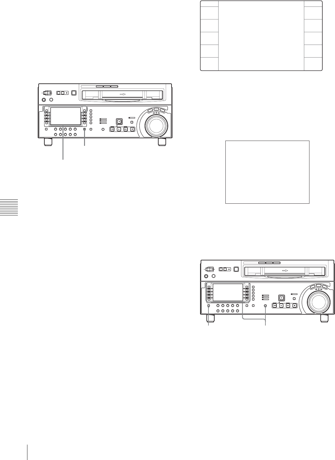
58 6-2 Shot Mark Operations
Chapter 6 Shot Mark Function
To select a shot mark
Turn the MULTI CONTROL knob to move the asterisk
cursor to the desired shot mark.
To write virtual shot marks
With the unit is stopped and F2 (REC/ERS) set to “OFF”,
hold down the SHIFT/ENTRY button and select F6
(MARK) during playback or searching.
A virtual shot mark appears on the monitor as “V-MARK
xxx” (xxx is the number). This is not written to the tape.
To add a memo mark (#)
Select the shot mark to which you want to add the memo
mark, and select F1 (MEMO).
Repeat this operation to remove a memo mark.
To select the types of shot mark to be read
in the list
For each types of shot mark (recording start mark, shot
mark 1, shot mark 2, and post mark), you can specify
whether it is read in.
In setup menu item 635 “LISTING TYPE SELECT”, set
the required types to “ON”.
For details of setup menu item 635, see Section “9-4 Items
in the Extended Setup Menu” (page 92).
With the following procedure, you can also specify
whether shot marks that have been read are displayed or
not.
1
With the shot mark list displayed, select F5
(SETTING).
You can now select the shot mark types.
The function menu display changes as follows.
2
Select F1 (PREV) or F2 (NEXT) to select a shot mark
type.
3
Select F4 (ON) or F3 (OFF) to set “ON” (displayed) or
“OFF” (not displayed).
4
To return to the shot mark list, select F10 (EXIT).
To delete a shot mark from the list
To delete an individual shot mark
Use the following procedure.
1
With the shot mark list displayed, turn the MULTI
CONTROL knob to select the shot mark to be deleted.
2
Select F6 (MARK).
While F6 is selected, an “X” (deletion target identifier)
appears after the selected shot mark number to be
deleted.
F2 (REC/ERS)
F6 (MARK)
SHIFT/ENTRY button
SHOT MRK
PREV
NEXT
OFF
ON
SHOT MRK
EXIT
(007/022)
NO. TIME CODE
SHOT MARKER
----------------------------
SHOT MARK 1 ON
*REC START MARK ON
SHOT MARK 2 OFF
005 SC 00:00:11:00
POST MARK ON
VIRTUAL MARK ON
STOP CODE OFF
1,2,33

59
6-2 Shot Mark Operations
Chapter 6 Shot Mark Function
To delete more than one shot mark, keep F6 (MARK)
selected and turn the MULTI CONTROL knob to
select all the target shot marks.
3
With F6 (MARK) selected, press the ALT/DELETE
button.
This deletes the shot marks marked with an “X”.
To delete the entire list
Holding down the ALT/DELETE button, select F7 (LIST).
This deletes all the shot marks from the list. This does not
erase marks from the tape.
To erase shot marks from the tape
To erase a shot mark, use the following procedure.
If you erase a shot mark from the tape, it cannot be read
back in.
1
Display the shot mark list.
2
Holding down the SHIFT/ENTRY button, select F2
(REC/ERS) to display “ERASE”.
You can now delete shot marks.
3
Turn the MULTI CONTROL knob to select on the list
the shot mark you want to erase.
4
Holding down the SHIFT/ENTRY button, select F4
(ERASE).
During the erasure F4 (ERASE) lights in pink.
5
When the shot mark has been erased, close the shot
mark list.
The F2 (REC/ERS) setting returns to “OFF” when
shot mark erasure is complete.
6-2-4 Cuing Up to Shot Marks
To cue up to a selected shot mark
Use the following procedure.
1
Turn the MULTI CONTROL knob to select the
desired shot mark from the shot mark list.
2
Select F9 (PREROLL).
To cue up to shot marks adjacent to the
current tape position (index function)
1
In setup menu item 630 “SEARCH TYPE SELECT”
allows you to select one of ALL, REC, SHOT1
SHOT2, and POST.
2
With F6 (MARK) selected, press the F FWD button or
REW button.
While the tape is running, the F FWD button or REW
button flashes.
When the shot mark is detected, its type is displayed in the
ancillary message display on the lower control panel and in
the text information display section on the video monitor.
For details on the video text information, see the
description of F5 (CHARA) in function menu page P04:
MISC-1 (page 68) and the description in setup menu item
005 (page 78).
You cannot use the above procedure to cue up to a virtual
shot mark.
Note
Note
1,2

Chapter 7
60 7-1 Overview / 7-2 Recording UMIDs
Chapter 7 UMID Functions
UMID Functions
7-1 Overview
The UMID (Unique Material Identifier) is a type of meta-
data in video and audio materials. It has been
internationally standardized in SMPTE Standard 330M.
This unit supports recording and output of UMIDs.
The UMID is made up of a section called the “Basic” and
a section called the “Source Pack”. The Basic section
contains information such as the device that recorded the
material and whether the material is the original or a copy.
The Source Pack section contains information about when/
where/who recorded the material.
A UMID with a Basic section only is called a “Basic
UMID”. A UMID with both Basic and Source Pack
sections is called an “Extended UMID”. The following
figure shows a general overview of the information
contained in a UMID.
7-2 Recording UMIDs
UMIDs can be recorded when recording video signals with
this unit. You can select whether to inherit (copy) the
UMID contained in input signals, or automatically or
forcibly generate a new UMID.
To select the type of UMID to record
Select whether to record a Basic UMID or an Extended
UMID by using setup menu item 655 “UMID
RECORDING”.
For more information about setup menu item 655, see
page 93.
To select whether to inherit or generate the
UMID
When recording a UMID, you can select whether to inherit
(copy) the UMID contained in input signals, or generate a
new UMID. Make this selection by using setup menu item
656 “MATERIAL NO.”.
For more information about setup menu item 656, see
page 93.
To select the Instance Number generation
method when inheriting UMIDs
If you select to inherit the UMID contained in input
signals, almost all information in the UMID is copied
without change, but the Instance Number changes to a
value which indicates that “this UMID is a copy”. The new
value can be generated from a 16-bit pseudo-random
number with the addition of the number of copies (1 byte),
or it can be generated from a 24-bit pseudo-random
number. Select the method used to generate the Instance
Number by using setup menu item 654 “UMID
GENERATE METHOD”.
UMID Basic Instance Number
Material Number
Source Pack Date/Time
Spatial Co-ordinates
Stored Ownership
“Whether the material is
a copy or the original”.
“What device the original
was recorded on”.
“When the material was
recorded”.
“Where the material was
recorded”.
“Who recorded the
material”.

61
7-2 Recording UMIDs
Chapter 7 UMID Functions
For more information about setup menu item 654, see
page 93.
To select the SDI VANC line to inset the
UMID
You can select the VANC 1) line of the SDI signal into
which the generated UMID should be inserted. Make this
selection by using setup menu item 653 “UMID HD
VANC LINE”.
1) VANC: Vertical ancillary (data)
For more information about setup menu item 653, see
page 92.
To set Stored Ownership
To set Stored Ownership (data in the Source Pack which
indicates “who”) when generating a UMID, use setup
menu item 029 “STORED OWNERSHIP” and following
procedure.
For more information about basic setup menu operations,
see Section “9-2 Setup Menu Operations” (page 75).
1
Set setup menu item 029 to “on” and select F9 (SET).
2
Use F1 (PREV) or F2 (NEXT) to select the item you
want to set (COUNTRY, ORGANIZATION, or
USER).
3
Select F6 (SELECT).
4
The setting is a character string (in this example
“ABCD” when COUNTRY was selected). Select any
character to change in the string by using F1 (PREV)
and F2 (NEXT).
The selected character flashes.
5
Turn the MULTI CONTROL knob to display the
desired character in the position of the flashing
character.
6
Repeat steps 4 and 5 for all the characters that you
want to change.
7
Select F9 (SET).
The changed settings are confirmed.
8
• If you do not change the other items, select F10
(EXIT).
• If you change the other items, (COUNTRY and
ORGANIZATION) , select F5 (ITEM) and repeat as
in steps 2 to 7.
If you changed other setup menu items before setting the
Stored Ownership, the changes are confirmed by step 7.
To cancel changes and exit the setup menu
Select F10 (EXIT) before finishing step 6.
To set the time zone
The UMID uses the UTC (Coordinated Universal Time)
time standard. Setting this unit’s built-in calendar clock to
the local time, and then setting a time zone to indicate the
difference from global UTC standard time allows correct
UMIDs to be generated.
To set the time zone, display the HOME page of the
function menu and use the following procedure.
For more information about function menu operations,see
Section “8-1-2 Function Menu Operations” (page 64).
1
Holding down the SHIFT/ENTRY button, select F9
(MENU).
The error logger screen appears.
For more information about the error logger, refer to
the Maintenance Manual Volume 1.
2
Select F5 (SETTING).
The “OFFSET TO UTC” item appears.
3
Use F1 (PREV) or F2 (NEXT) to select “OFFSET TO
UTC”, and use the MULTI CONTROL knob or F3
(–) and F4 (+) to set the offset to UTC time.
For example, if the local time is 9 hours in advance of
UTC, set to “+9:00”.
ITEM-029
ORGANIZATION - EFGH
*COUNTRY - ABCD
USER - IJKL
STORED OWNERSHIP
Note
(014/023)
015 A PB DATA ERROR
ERROR LOGGER
016 V PB DATA ERROR
TAPE ERROR ON
WARNING ON
CONDITION ON
*OFFSET TO UTC +09:00
Push SET button
2001 12 24 23:59:59
014 REFERENCE MISSING

62 7-3 UMID Output and Display
Chapter 7 UMID Functions
4
Select F9 (SET).
The settings are confirmed. 7-3 UMID Output and
Display
This section explains how to output and display UMIDs.
7-3-1 UMID Output Settings
You can select whether to output UMIDs or not, and select
either Basic UMID or Extended UMID to output. Make
these settings using setup menu item 651 “UMID
OUTPUT”.
For more information about setup menu item 651, see
page 92.
7-3-2 UMID Display
During recording or playback, UMID data can be
displayed and checked in the menu display section of the
control panel and on the video monitor.
To display the UMID
In function menu page P05: MISC-2, select F2 (UMID).
For more information about function menu operations, see
Section “8-1-2 Function Menu Operations” (page 64).
The UMID appears in the menu display of the control
panel and on the video monitor.
For examples of the UMID displayed on the video monitor,
see the next section “UMID display on the video monitor”.
To exit UMID display
Select F10 (EXIT).
UMID display on the video monitor
The video monitor connected to the LCD and the
COMPOSITE VIDEO OUTPUT 3 (SUPER) or SDI
OUTPUT 3 (SUPER) connector on the connector panel
displays all UMID items at once. Following is an
explanation of each line in the display.

63
7-3 UMID Output and Display
Chapter 7 UMID Functions
aInstance Number generation method and Instance
Number
The generation method is displayed as follows.
CP+16: “16-bit PRS (pseudo-random sequence) + Copy
No.” method
24PRS: 24-bit PRS method
others: Other than the above
When menu item 656 “MATERIAL NO.” is set to
“NEW”, it is generated by SMPTE method.
bMaterial Number generation method
SMPTE: SMPTE method
IEEE 1394 ZONE: IEEE 1394 ZONE method
IEEE 1394 RND: IEEE 1394 RND method
others: Other than the above
cMaterial Number
The material number is displayed in hexadecimal in two
lines.
The following items, 4 to 9, are contained in the Source
Pack.
dDate/Time
Date/Time data is displayed in two lines.
The upper line shows the MJD (Modified Julian Date)
contained in the Source Pack converted to UTC.
The lower line shows the data in unit count format
(hours : minutes : seconds : frame) converted to UTC.
The function for converting unit count to UTC works only
when the unit rate is 2 (24 frames), 3 (24/1.001 frames), 4
(25 frames), 6 (30 frames), or 7 (30/1.001 frames). For
other unit rates, the unit rate number and unit rate are
displayed in hexadecimal.
eAltitude
XXXXXXXXm: Altitude data indicating the distance
from the center of the earth is displayed in this format.
S+XXXXXXXm Y+D: Altitude data indicating the
distance from sea level is displayed in this format.
The meaning of the characters and strings shown is as
follows.
• “S” (1st character): Indicates position data from a
Sensor. “R” is shown for position data from the
recording device (Recorder), and “T” is shown for
Target position data.
• “+” (2nd character): Indicates higher than sea level.
“–” indicates lower than sea level.
• “XXXXXXXm” : Altitude data (unit: meter).
• “Y”: The number of satellites used to calculate
position data (hexadecimal).
• “D”: DOP (dilution of precision) value.
• “+” (between Y and D): Displayed when a
supportive geodetic apparatus was used. A space
(blank) is displayed when no supportive geodetic
apparatus was used.
fLongitude
Following “W” to indicate west longitude or “E” to
indicate east longitude, the longitude is displayed in
degrees, minutes, and seconds (seconds are displayed up to
2 decimal places).
Example: “E134 59’23.00” for “East longitude 134
degrees 59 minutes 23.00 seconds”
gLatitude
Following “N” to indicate north latitude or “S” to indicate
south latitude, the latitude is displayed in degrees, minutes,
and seconds (seconds are displayed up to 2 decimal
places).
Example: “N34 59’23.32” for “North latitude 34 degrees
59 minutes 23.32 seconds”
Note
INSTANCE 24PRS XX-XX-XX
XX-XX-XX-XX-XX-XX-XX-XX
UMID INFORMATION
XX-XX-XX-XX-XX-XX-XX-XX
XX:XX:XX:XX +XX:XX
DATE/TIME 20XX/XX/XX
ALTITUDE XXXXXXXXm
LONGITUDE EXXX XX'XX.XX
LATITUDE SXXX XX'XX.XX
ORGANIZATION XXXX
USER XXXX COUNTRY XXXX
MATERIAL SMPTE
1
2
3
6
7
5
8
9
4
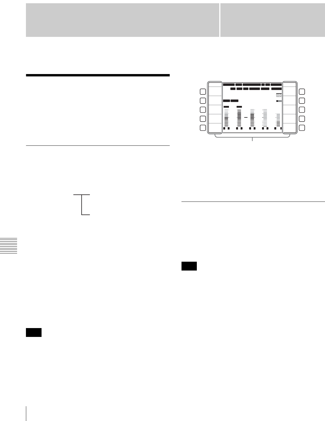
Chapter 8
Chapter 8 Function Menu
64 8-1 Overview
Function Menu
8-1 Overview
The function menu allows you to make frequently made
settings other than those made with the basic operation
buttons, such as selection of input video signals and editing
of timecode.
8-1-1 Function Menu Configuration
The function menu consists in function menu pages P01 to
P10 which can be defined by the user and function menu
pages P100 to P118 which cannot be defined by the user.
The factory default definitions in function menu pages P01
to P10 are set by factory default as shown below.
P01: HOME
P02: TC
P03: VID PROC
P04: MISC-1
P05: MISC-2
P06: EDIT
P07: E.PRESET
P08: AUD INP
P09: reserve 1 (no functions defined)
P10: reserve 2 (no functions defined)
The explanations in this manual are based on the factory
default settings.
The following shows an example display of the function
menu page P01: HOME.
In the figure above, “VIDEO IN” (input video signal
selection) is selected as the function button item
corresponding to the F1 button and “SDI” (HD Serial
Digital Interface signal) is selected as the setting for
“VIDEO IN”.
8-1-2 Function Menu Operations
To display the function menu
If the LCD is in video display mode (without the function
menu displayed), press the DISPLAY button to switch the
LCD mode to function display mode or function & video
display mode.
Function menu operations are not possible in video display
mode.
To select function menu settings with the
function buttons
You can select the next setting under each button name by
pressing the corresponding function button (F1 to F10).
The functions assigned to some function buttons change
when the buttons are pressed together with the SHIFT/
ENTRY or ALT/DELETE button. You can also define
new combinations so that the function assigned to the
function button is executed only when the button is pressed
together with the SHIFT/ENTRY or ALT/DELETE
button.
Note
Function menu User-definable function
menu pages (P01 to P10)
Non-user-definable function
menu pages (P100 to P118)
Note
12 34
:
47 12
::
LTC
DF LTC EXT-LTC R-RUN
PROLL
HOME
L R
1
3+4
BANK3
REM:20min
PARARUN
HD
COND
VITC
L R
2
2
-60
-40
-30
-20
-10
0
dB
-60
-40
-30
-20
-10
0
dB
L R
3
1
L R
4
AES4
4
L R
CUE
3+4
-40
-20
-10
0
10
dB
EMPH DATA
59.94 SDI 2F ASM1080 1080
F1
F2
F3
F4
F5
F6
F7
F8
F9
F10
HOME
E.PRESET
VIDEO IN
SDI
EDIT
CLR CNT
MENU
TCG SET
SDI1 ANA2 SDI3
PB/EE
PB
CONFI
ENABLE
COUNTER
CTL
CONFI
Menu item (function)

65
8-2 Function Menu Item List
Chapter 8 Function Menu
When a menu item setting flashes
You can change the setting value by turning the MULTI
CONTROL knob.
To change the function menu page
Press one of the menu page selection buttons (P1 to P5) to
change the function menu page to the corresponding page.
By default the following pages are assigned to the menu
page selection buttons.
•P1: Changes the function menu page to P01: HOME.
•P2: Changes the function menu page to P02: TC.
•P3: Changes the function menu page to P03: VID
PROC.
•P4: Changes the function menu page to P08: AUD INP.
•P5: PAGE DOWN
Each time the menu page selection button P5: PAGE
DOWN is pressed, the function menu page changes in the
order P01 t P02 t P03 t P04 t P05 t P06 t P07
t P08 t P01.
When this button is pressed with the SHIFT/ENTRY
button held down, the function menu page changes in the
reverse order.
All of the function buttons in function menu pages P09 and
P10 are undefined when the unit is shipped from the
factory. If you try to display a page with no function
assigned using the P5: PAGE DOWN, the target page is
skipped to change to the next displayable function menu
page. For example, in the factory default configuration
described above, the display order is “P08 t P01”.
Settings which do not appear in the menu
display
In function menu page P01: HOME (see the figure in
Section “8-1-1 Function Menu Configuration”), the
settings for F9 (MENU) and F10 (TCG SET) do not appear
in the lower part of the function button display area. When
you press the F9 or F10 button, the function menu page
changes to allow you to set the menu items for F9 or F10,
respectively.
For more information about changing (user-defining) the
functions of function buttons and menu page selection
buttons and the settings of user-definable function menu
pages, refer to the Maintenance Manual Volume 1.
8-2 Function Menu Item
List
The function menu has the following items.
8-2-1 User-Definable Function Menu
Pages (P01 to P10)
Functions on these function menu pages can be changed to
user-defined functions. Standard functions are already set
on the eight function menu pages P01 to P08, when the unit
is shipped from the factory.
The function menu pages and function buttons are
provided with the functions by factory default as follows.
The explanations in this manual are based on the factory
default standard settings.
P01: HOME
This is a function menu page for setting basic items.
Note
Item Setting
F1 (VIDEO IN) Selects the input video signal.
SDI: HDSDI signal
SG (normally not displayed): Test signal
from the internal test signal generator
(For details, see setup menu item 710
on page 94.)
To change to SG, hold down the ALT/
DELETE button, then select F1.
F2 (No function assigned)
F3 (EDIT) Jump to P06: EDIT (editing control page).
F4
(E.PRESET)
Jump to P07: E.PRESET (edit preset page).
F5 (CLR CNT) Tape counter clear
F6 (PB/EE) Select the video and audio signals output
during fast forward, rewind, stop, and
standby.
PB: Playback signals
EE: E-E mode signals
F7 (CONFI) Select whether or not to use the CONFI
playback function when recording. a)
ENABLE: Use the CONFI playback
function.
DISABL: Do not use the CONFI playback
function.

66 8-2 Function Menu Item List
Chapter 8 Function Menu
a) CONFI playback is disabled during editing.
b) The selection of LTC or VITC depends on the setting of F10 (TCR) in
function menu page P02: TC.
c) Setting screen is not displayed when F1 (TCG SRC) is set to
“INTERNAL” and F2 (TCG MODE) is set to “PRESET” in function
menu page P02: TC.
P02: TC
This is a function menu page for setting items relating to
timecode.
F8
(COUNTER)
Select the time data to display in time data
display (see page 17).
TC: Playback timecode read by the internal
timecode reader, or recording
timecode. The LTC or VITC time data
type indicator (see page 18) lights.b)
UB: User bits data of playback timecode or
recording timecode. The LUB or VIUB
time data type indicator lights,
depending on whether the timecode is
LTC or VITC.b)
CTL: The running time of the tape being
played back or recorded, as calculated
from a count of CTL signals recorded
on the tape. The time is displayed in
Hours:Minutes:Seconds:Frames
format.
F9 (MENU) Puts the system into setup menu mode
(see Chapter 9). (Jump to P108: SETUP
(TOP))
When the current setup menu settings are
the same as the contents of any of menu
banks 1 to 4, or the factory defaults,the
corresponding indication (BANK1),
(BANK2), (BANK3), (BANK4) or (DEFLT)
appears below the time data display on the
LCD.
F10 (TCG
SET)
• When F8 (COUNTER) is set to “TC”, a
screen appears that allows you to set the
initial value of the timecode generated by
the internal timecode generator (see
page 17).c)
• When F8 (COUNTER) is set to “UB”, a
screen appears that allows you to set the
timecode user bits (see page 17).c)
Item Setting Item Setting
F1 (TCG SRC) Select the signal source of the timecode
with which the internal timecode generator
synchronizes.
INTERNAL: Synchronizes according to the
initial preset value set by control panel
operation or by control from the device
connected to the REMOTE1-IN (9P)
connector, or synchronize with the
timecode of the playback tape.
EXT LTC: Synchronizes with the external
timecode signal input to the TIME
CODE IN connector.
VID IN: Synchronizes with the timecode
data superimposed on the HDSDI
signal input to the HDSDI INPUT
connector or on the MPEG TS signal
input to the HDV IN connector (when
an optional HKDW-105 i.LINK (HDV)
Input Board is installed).
F2
(TCG MODE)
Select one of the following for timecode
regenerated by the internal timecode
generator.
PRESET: Presets the initial value of
timecode generated by the internal
timecode generator, as specified by
control panel operation or by control
from the device connected to the
REMOTE1-IN (9P) connector. This
operation is enabled when F1 (TCG
SRC) is set to “INTERNAL”.
RGN: LTC: Regenerates by synchronizing
with the LTC timecode value read by
the internal timecode reader.
RGN: VITC: Regenerates by synchronizing
with the VITC timecode value read by
the internal timecode reader.
F3 (TCG RUN) Select one of the following running modes
for the internal timecode generator.
FREE: Timecode continues to increase as
long as the unit is powered on,
regardless of the unit’s operating
mode.
REC: Timecode increases during recording
only.
If you select this mode, you should also set
F1 (TCG SRC) to “INTERNAL”, and set F2
(TCG MODE) to “PRESET” in this menu
page.
F4 (DROP
FRM)
In 59.94i, 29.97PsF mode, select drop-
frame or non-drop-frame mode for the
timecode generator and the CTL counter.
DF: Drop-frame mode
NDF: Non-drop-frame mode
F5 (No function assigned)
F6 (No function assigned)
F7 (No function assigned)
F8 (No function assigned)
F9 (No function assigned)

67
8-2 Function Menu Item List
Chapter 8 Function Menu
P03: VID PROC
This is a function menu page for setting items relating to
video processing.
F10 (TCR) Select the type of timecode to display in the
time data display.
LTC: Display LTC.
AUTO: Display VITC when tape speed is 1/
2 or less of normal speed, and LTC
otherwise.
VITC: Display VITC.
Item Setting
F1 (VIDEO
IN)
Select the input video signal.
SDI: HDSDI signal
SG: Test signal from the internal test signal
generator (Normally not displayed. For
details, see setup menu item 710
(page 94).)
To change to SG, hold down the ALT/
DELETE button, then press the F1 button.
F2
(REF VID)
Select the reference signal of this unit,
according to the settings in setup menu
items 309 and 334, and this unit’s operating
state.
REF: Use the signal input to a REF. VIDEO
INPUT connector as the reference
signal. When recording, input digital
audio signals and video signals must be
synchronized with this signal.
INPUT: Use the input video signal as the
reference signal.
F3 (SYNC
PHS)
Set the HD output signal sync phase.
With the displayed setting flashing, turn the
MULTI CONTROL knob to adjust the output
signal sync phase across the range ±15 µs
relative to this unit’s input reference signal.
(The value indication ranges from –128 to
+127.)
Adjust this item when you want to adjust the
output signal sync phase precisely to match
a reference signal, or when connecting this
unit and other VTRs to a device such as a
switcher to carry out operations such as
special effects editing.
Item Setting
F4 (SYNC
FIN)
Set the HD output signal sync phase (fine
adjustment).
With the displayed setting flashing, turn the
MULTI CONTROL knob to adjust the output
signal sync phase across the range ±200
ns relative to this unit’s input reference
signal. (The value indication ranges from 0
to 1028.)
Adjust this item when you want to adjust the
output signal sync phase precisely to match
a reference signal, or to make further fine
adjustment when connecting this unit and
other VTRs to a device such as a switcher
to carry out operations such as special
effects editing.
F5 (V.PROC) Select the control method or setting for the
internal digital video processor.
LOCAL: Change the settings of the internal
digital video processor by using this
function menu.
MENU: Change the settings of the internal
digital video processor by using F9
(MENU) in function menu page P01:
HOME. (For making the settings in the
setup menus)
Note
When controlling the unit from the HKDV-
503/900, set this item to “MENU”.
F6
(VID LEVL)
Set the HD/SD video signal output level
(–∞ to +3 dB).
PRESET: Regardless of manually set
values, the video signal output level is
set to the standard value.
Manual setting: With the displayed setting
flashing, turn the MULTI CONTROL
knob to adjust the video signal output
level.
F7
(CHR LEVL)
Set the HD/SD chroma signal output level
(–∞ to +3 dB).
PRESET: Regardless of manually set
values, the chroma signal output level is
set to the standard value.
Manual setting: With the displayed setting
flashing, turn the MULTI CONTROL
knob to adjust the chroma signal output
level.
F8 (HUE)
(59.94i mode)/
(CHR PHAS)
(50i mode)
Set the hue.
PRESET: Regardless of manually set
values, the hue is set to the standard
value.
Manual setting: With the displayed setting
flashing, turn the MULTI CONTROL
knob to adjust the value across the
range ±30º.
Item Setting

68 8-2 Function Menu Item List
Chapter 8 Function Menu
P04: MISC-1
This is a function menu page for setting other items.
P05: MISC-2
This is a function menu page for setting other items.
F9 (SETUP
LV) (59.94i
mode)/(BLK
LEVL) (50i
mode)
Set the HD/SD output setup level (59.94i
mode) or black level (50i mode)
PRESET: Regardless of manually set
values, the level is set to the standard
value.
Manual setting: With the displayed setting
flashing, turn the MULTI CONTROL
knob to adjust the setup level across the
range ±30 IRE (59.94i mode) or to
adjust the black level across the range
±210 mV (50i mode).
F10
(PRESET)
Function for setting the level control to
“PRESET (UNITY)”
Item Setting
F1
(CAPSTAN)
Select the number of fields for capstan lock in
playback and editing.
In 59.94i, 29.97PsF system
2F: The capstan servo locks in units of 2
fields.
• For tape output, color framing may not
match the reference signal selected
with F2 (REF VID) in P03:VID PROC.
• In assemble editing, color framing may
not be continuous at edit points.
4F: The capstan servo locks in units of 4
fields.
• For tape output, color framing matches
the reference signal selected with F2
(REF VID) in P03:VID PROC.
• In assemble editing, color framing is
continuous at edit points.
In 50i, 25PsF system
2F: The capstan servo locks in units of 2
fields.
• For tape output, color framing may not
match the reference signal selected
with F2 (REF VID) in P03:VID PROC.
• In assemble editing, color framing may
not be continuous at edit points.
4F: The capstan servo locks in units of 4
fields.
• For tape output, color framing may not
match the reference signal selected
with F2 (REF VID) in P03:VID PROC.
• In assemble editing, color framing may
not be continuous at edit points.
8F: The capstan servo locks in units of 8
fields.
• For tape output, color framing matches
the reference signal selected with F2
(REF VID) in P03:VID PROC.
• In assemble editing, color framing is
continuous at edit points.
The setting is fixedly “2F” when the system
frequency is 23.98PsF or 24PsF.
Item Setting
F2 (No function assigned)
F3
(PREREAD)
Specify whether to preread (read before
write) in insert editing.
ON: Preread depending on the setting in setup
menu item 319.
OFF: Do not preread.
F4 (No function assigned)
F5 (CHARA) Specify whether to superimpose the text
information including timecode, menu
settings, and error messages over the video
signals output from the HDSDI OUTPUT3
(SUPER) connector, SDI OUTPUT3 (SUPER)
connector and COMPOSITE VIDEO
OUTPUT3 (SUPER) connector.
ON: Superimpose.
OFF: Do not superimpose.
F6 (T-INFO) Select the content of tape information to
display in the ancillary message display.
TOTAL: Display total recorded time.
REMAIN: Display remaining time.
F7 (No function assigned)
F8 (No function assigned)
F9 (No function assigned)
F10 (No function assigned)
Item Setting
F1 (No function assigned)
F2 (UMID) Displays UMID information during recording
or playback.
For details of UMID, see Chapter 7.
F3
(SHOT MRK)
Jump to P104: SHOT MRK (shot mark
page).
F4 (No function assigned)
F5 (No function assigned)
F6 (No function assigned)
F7 (No function assigned)
F8
(FREEZE)
Freeze an image while selected when setup
menu item 904 for setting the freeze
operation is set to “MOMNT”. When setup
menu item 904 is set to “LATCH”, the freeze
continues even after this button is released.
When this button is pressed again in the
freeze on state, the freeze image is updated
and the freeze restarts.
F9
(FREZ OFF)
Release an image from the freeze off state
when setup menu item 904 is set to
“LATCH”.
F10 (No function assigned)
Item Setting
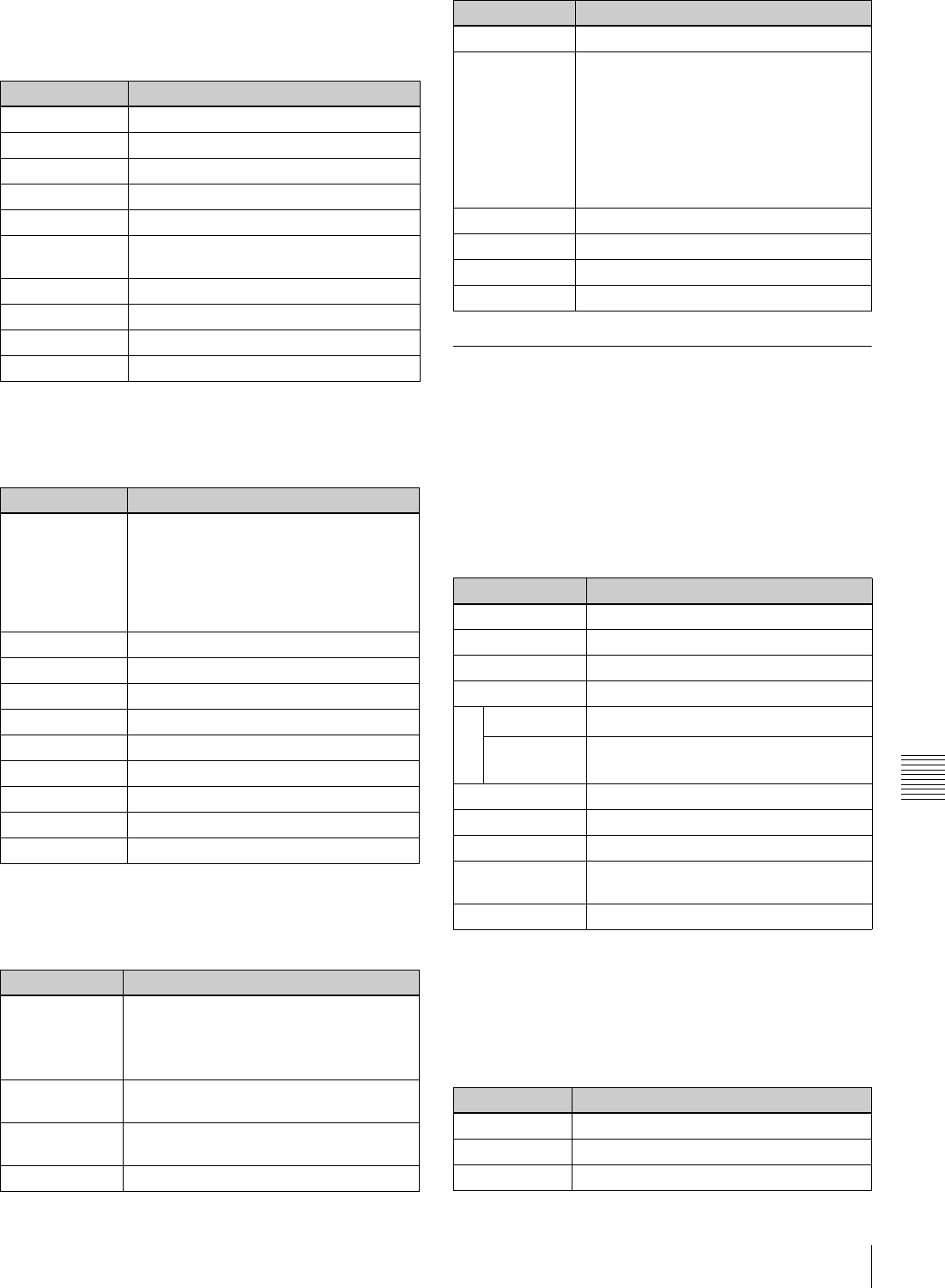
69
8-2 Function Menu Item List
Chapter 8 Function Menu
P06: EDIT
This is a function menu page for executing the functions
about the editing operation.
P07: E.PRESET
This is a function menu page for setting items relating to
edit preset.
P08: AUD INP
This is a function menu page for setting items relating to
audio input.
8-2-2 Non-User-Definable Function
Menu Pages (P100 to P118)
No functions can be changed in the function menu pages
described in this section.
P100: AUD MONI
This is a function menu page for making audio monitor
output settings.
a) For HDCAM and Digital Betacam tapes.
b) For MPEG IMX tapes.
P101: AUD MONI (sub)
This is a sub page for making MPEG MIX audio monitor
output settings.
Item Setting
F1 (AUTOEDIT) AUTO EDIT function
F2 (PREVIEW) AUTO EDIT PREVIEW function
F3 (REVIEW) AUTO EDIT REVIEW function
F4 (DMC) DMC function
F5 (PREROLL) Preroll function
F6 (R/P SEL) External control mode (recorder/ player)
selection
F7 (AUD IN) Audio edit IN point functions
F8 (AUD OUT) Audio edit OUT point functions
F9 (IN) Edit IN point functions
F10 (OUT) Edit OUT point function
Item Setting
F1 (REC INHI) Specify whether to inhibit recording to
tape.
ON (ALL/CRASH/VIDEO/AUDIO): Inhibit
recording to tape depending on the
setting in setup menu item 310.
OFF: Do not inhibit recording to tape.
F2 (INS TC) Edit preset setting for timecode track
F3 (INS CUE) Edit preset setting for CUE track
F4 (EDIT) Jump to P06: EDIT (editing control page).
F5 (ASSEMBLE) Assemble edit preset setting
F6 (INS VID) Edit preset setting for video track
F7 (INS A1) Edit preset setting for A1 track
F8 (INS A2) Edit preset setting for A2 track
F9 (INS A3) Edit preset setting for A3 track
F10 (INS A4) Edit preset setting for A4 track
Item Setting
F1 (EMPHASIS) Specifiy whether to add audio emphasis
to analog audio input signals.
ON: Add audio emphasis.
OFF: Do not add audio emphasis.
F2 (AUD MIX) Jump to P102: AUD MIX (audio mix/swap
setting page).
F3 (AUD MONI) Jump to P100: AUD MONI (audio monitor
setting page).
F4 (MT.SCALE) Meter scale setting (FULL/FINE)
F5 (No function assigned)
F6 (AUDIO SG) Turn internal audio test signals on and off.
(Toggle ON and OFF when selected with
the ALT/DELETE button held down.)
ON: Generate internal audio test signals.
(Select the signal waveform type in
advance using setup menu item 808.)
OFF: Do not generate internal audio test
signals.
F7 (INP A1) CH1 input selection
F8 (INP A2) CH2 input selection
F9 (INP A3) CH3 input selection
F10 (INP A4) CH4 input selection
Item Setting
F1 (TRACK 1) Selection of track 1 for monitoring
F2 (TRACK 2) Selection of track 2 for monitoring
F3 (TRACK 3) Selection of track 3 for monitoring
F4 (TRACK 4) Selection of track 4 for monitoring
F5 (TRCK CUE) Selection of CUE track for monitoringa)
(TRCK CHG) Track selection change b) (To TRACK 5,
6, 7 or 8)
F6 (No function assigned)
F7 (No function assigned)
F8 (No function assigned)
F9 (MONI CH) Selection of monitor output channel
operation
F10 (RETURN) Return to P08: AUD INP
Item Setting
F1 (TRACK 5) Selection of track 5 for monitoring
F2 (TRACK 6) Selection of track 6 for monitoring
F3 (TRACK 7) Selection of track 7 for monitoring
Item Setting
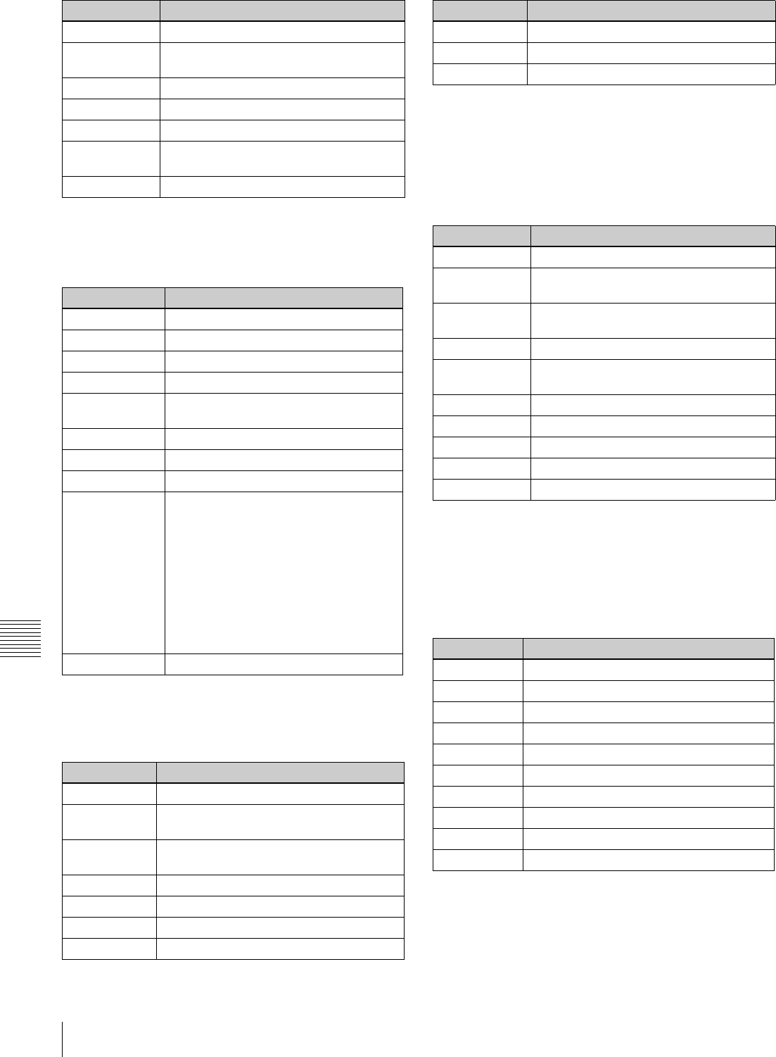
70 8-2 Function Menu Item List
Chapter 8 Function Menu
P102: AUD MIX
This is a function menu page for switching audio input
selections and making audio mixing settings.
P104: SHOT MRK (Top page)
This is a function menu page for executing shot mark
functions.
For details on shot mark operations, see Chapter 6 “Shot
Mark Function”.
P105: SHOT MRK (LIST page)
This is a function menu page for displaying shot mark
information in list form.
For details on the operations about the shot mark, see
Chapter 6 “Shot Mark Function”.
P106: SHOT MRK (LIST sub-page)
This is a function menu page for making settings for the
shot mark list display page.
For details on the operations about the shot mark, see
Chapter 6 “Shot Mark Function”.
F4 (TRACK 8) Selection of track 8 for monitoring
F5 (TRCK
CHG)
Track selection change
F6 (No function assigned)
F7 (No function assigned)
F8 (No function assigned)
F9 (MONI CH) Selection of monitor output channel
operation
F10 (RETURN) Return to P08: AUD INP
Item Setting
F1 (INP A1) Selection of input channel for mixing
F2 (INP A2) Selection of input channel for mixing
F3 (INP A3) Selection of input channel for mixing
F4 (INP A4) Selection of input channel for mixing
F5 (CLR MIX) Function for clearing the mix/swap
settings
F6 (No function assigned)
F7 (No function assigned)
F8 (No function assigned)
F9 (REC TRAC) Specify the audio track (1 to 4) using this
item (REC TRAC) and specify the audio
input channel from which signals are
recorded to the specified audio track
using F1 (INP A1) to F4 (INP A4). When
the F1 to F4 buttons are pressed
simultaneously, a maximum of two input
channels can be mixed and recorded to
a single audio track. When F5 (CLR MIX)
is selected, all track settings are restored
to the factory default values.
F10 (RETURN) Return to P08: AUD INP
Item Setting
F1 (No function assigned)
F2 (REC/ERS) Settings for the shot mark recording/
erasing operation
F3 (REC) Shot mark recording operation start
function
F4 (No function assigned)
F5 (No function assigned)
F6 (MARK) MARK button function
F7 (LIST) LIST button function
Item Setting
F8 (No function assigned)
F9 (No function assigned)
F10 (EXIT) Return to the previous page
Item Setting
F1 (MEMO) Marking at selected points
F2 (REC/ERS) Settings for the shot mark recording/
erasing
F3 (REC) Shot mark recording operation start
function
F4 (ERASE) Shot mark erasing operation start function
F5 (SETTING) Jump to P106: SHOT MRK (shot mark list
setting page).
F6 (MARK) MARK button function
F7 (LIST) LIST button function
F8 (No function assigned)
F9 (PREROLL) Function for cueup selected points
F10 (EXIT) Return to the previous page.
Item Setting
F1 (PREV) Item selection (previous item)
F2 (NEXT) Item selection (next item)
F3 (OFF) Item setting OFF
F4 (ON) Item setting ON
F5 (No function assigned)
F6 (No function assigned)
F7 (No function assigned)
F8 (No function assigned)
F9 (No function assigned)
F10 (EXIT) Return to the previous page.
Item Setting
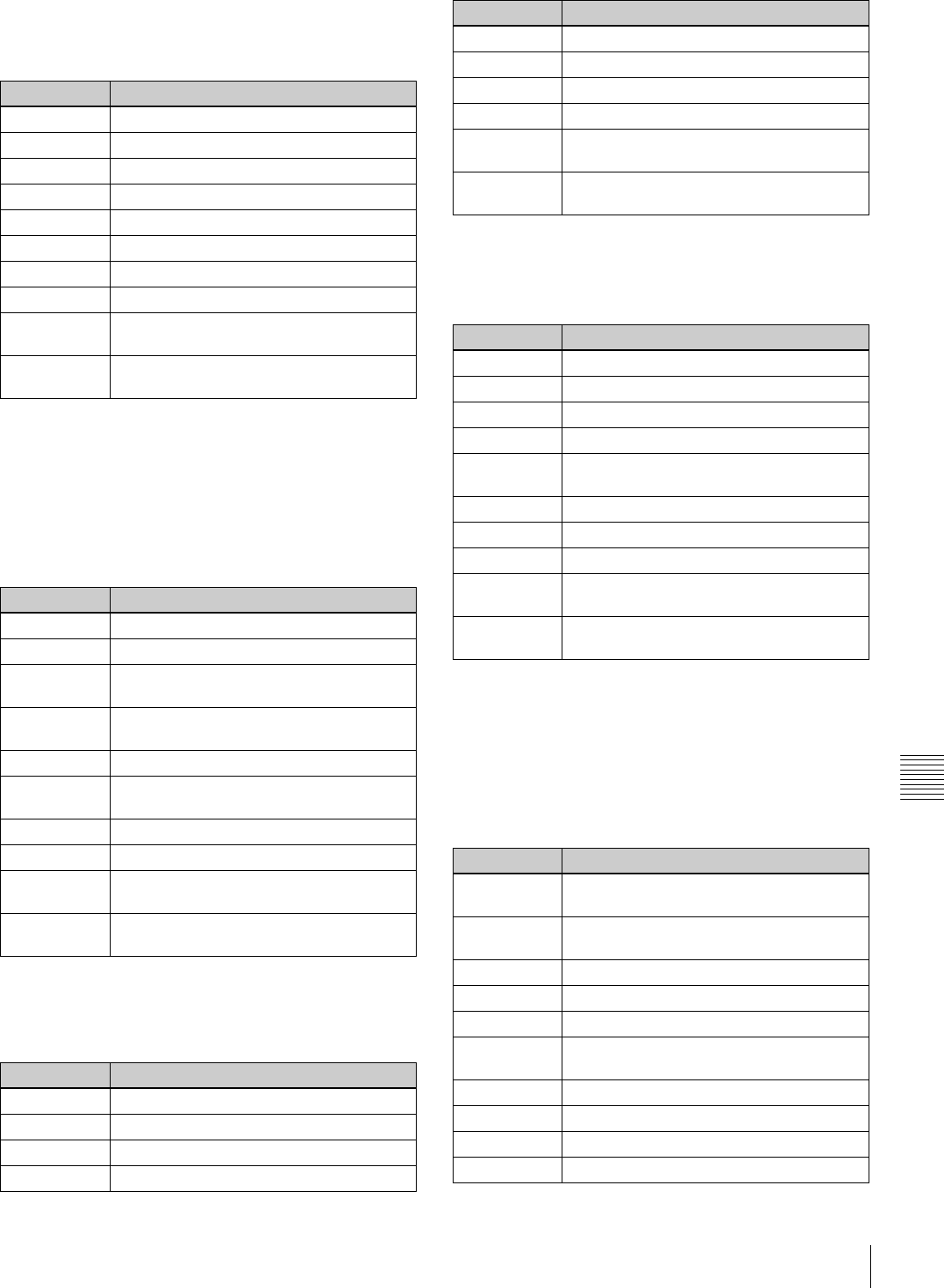
71
8-2 Function Menu Item List
Chapter 8 Function Menu
P107: TCG SET
This is a function menu page for setting timecode
generator values.
P108: SETUP (TOP)
This is a function menu page (top page) for making setup
menus settings.
For more information about setup menu operations, see
Chapter 9 “Setup Menus”.
P109: SETUP (SELECT1)
This is a function menu page for changing the settings of
setup menu items.
P110: SETUP (SELECT2)
This is a function menu page for changing the settings of
setup menu items.
P111: ERR.LOG (TOP)
This is a function menu page (top page) for displaying
error logs.
For more information about error log operations, refer to
the Maintenance Manual Volume 1.
Item Setting
F1 (PREV) Select the digit to the left.
F2 (NEXT) Select the digit to the right.
F3 (–) Decrement data.
F4 (+) Increment data.
F5 (CLR CNT) Clear (reset) data.
F6 (No function assigned)
F7 (No function assigned)
F8 (No function assigned)
F9 (SET) Confirm data and return to the previous
page.
F10 (EXIT) Cancel data changes and return to the
previous page.
Item Setting
F1 (No function assigned)
F2 (No function assigned)
F3 (CATEG –) Category jump (–) function for setup menu
items
F4 (CATEG +) Category jump (+) function for setup menu
items
F5 (No function assigned)
F6 (SELECT) Jump to the setup menu setting change/
sub-item selection page.
F7 (No function assigned)
F8 (No function assigned)
F9 (SET) Confirm setup menu setting changes and
return to the previous page.
F10 (EXIT) Cancel setup menu setting changes and
return to the previous page.
Item Setting
F1 (No function assigned)
F2 (No function assigned)
F3 (No function assigned)
F4 (No function assigned)
F5 (RETURN) Jump to P108: SETUP (TOP).
F6 (SELECT) Jump to the sub-item setting change page.
F7 (No function assigned)
F8 (No function assigned)
F9 (SET) Confirm setup menu setting changes and
return to the previous page.
F10 (EXIT) Cancel setup menu setting changes and
return to the previous page.
Item Setting
F1 (No function assigned)
F2 (No function assigned)
F3 (–) Change setup menu setting value (–).
F4 (+) Change setup menu setting value (+).
F5 (RETURN) Jump to P108: SETUP (TOP) or P109:
SETUP (SELECT1).
F6 (No function assigned)
F7 (No function assigned)
F8 (No function assigned)
F9 (SET) Confirm setup menu setting changes and
return to the previous page.
F10 (EXIT) Cancel setup menu setting changes and
return to the previous page.
Item Setting
F1 (ERROR) List display of error description (initial
setting)
F2 (DATE) List display of error occurrence date and
time
F3 (TC) List display of timecode at error occurrence
F4 (DETAIL) Display of error details
F5 (SETTING) Jump to the logger settings page.
F6 (CLR
LOG)
Clear all logs.
F7 (No function assigned)
F8 (No function assigned)
F9 (No function assigned)
F10 (EXIT) Return to the previous page.
Item Setting
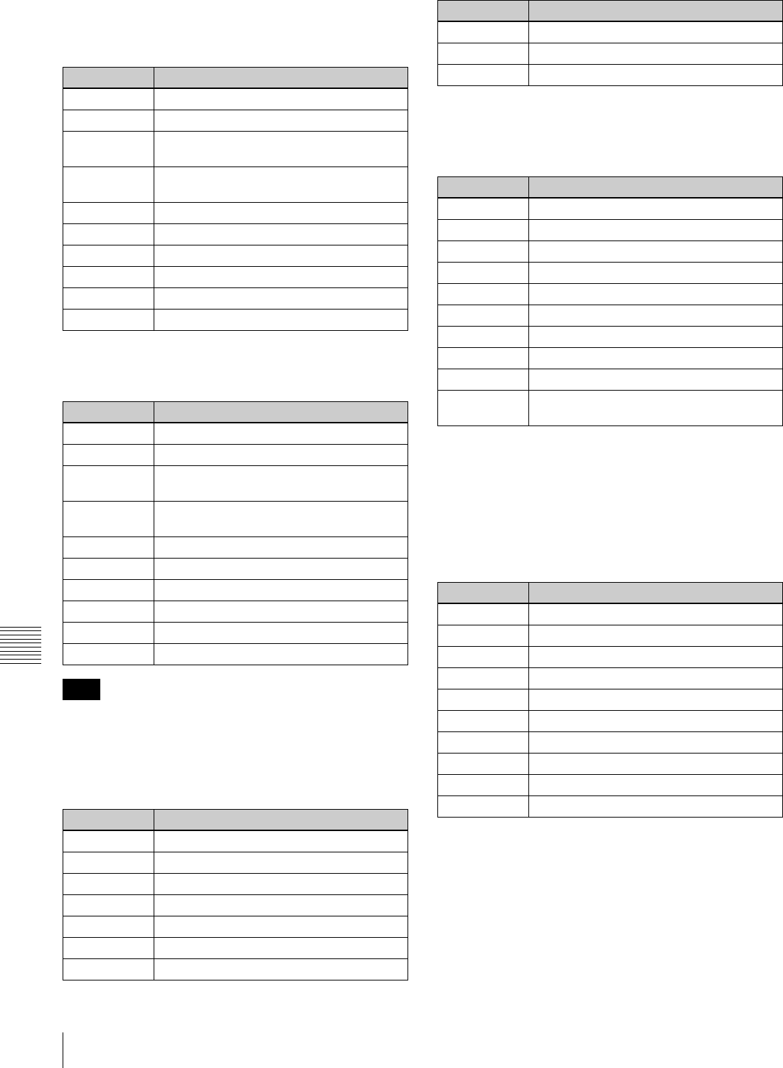
72 8-2 Function Menu Item List
Chapter 8 Function Menu
P112: ERR.LOG (SETTING1)
This is a function menu page for selecting items to be
displayed on the error log screen.
P113: ERR.LOG (SETTING2)
This is a function menu page for making error log settings.
F9 (SET) appears when a setting item has been changed.
P114: WARNING
This is a function menu page for displaying warnings.
P115: WARN.EDT
This is a function menu page for setting the warning
information display items.
P116: MAINTE
This is a function menu page for maintenance menu
operations.
For more information about maintenance menu, refer to
the Maintenance Manual Volume 1.
P117: UMID
This is a function menu page for displaying UMID
information.
For more information about UMID, see Chapter 7 “UMID
Functions”.
Item Setting
F1 (PREV) Select the previous item (left/up).
F2 (NEXT) Select the next item (right/down).
F3 (OFF) Set an OFF/ON setting item to “OFF”
(multi-control).
F4 (ON) Set an OFF/ON setting item to “ON” (multi-
control).
F5 (No function assigned)
F6 (No function assigned)
F7 (No function assigned)
F8 (No function assigned)
F9 (No function assigned)
F10 (EXIT) Return to the previous page.
Item Setting
F1 (PREV) Select the previous item (left/up).
F2 (NEXT) Select the next item (right/down).
F3 (–)Change the numeric value of a setting item
(decrement).
F4 (+) Change the numeric value of a setting item
(increment).
F5 (No function assigned)
F6 (No function assigned)
F7 (No function assigned)
F8 (No function assigned)
F9 (SET) Confirm the numeric value setting changes.
F10 (EXIT) Return to the previous page.
Note
Item Setting
F1 (No function assigned)
F2 (No function assigned)
F3 (C EDIT) Jump to the warning cancellation page.
F4 (No function assigned)
F5 (ERRLOG) Jump to the error logger screen.
F6 (No function assigned)
F7 (No function assigned)
F8 (No function assigned)
F9 (No function assigned)
F10 (EXIT) Return to the previous page.
Item Setting
F1 (No function assigned)
F2 (No function assigned)
F3 (No function assigned)
F4 (ON/OFF) Enable or disable warnings.
F5 (No function assigned)
F6 (No function assigned)
F7 (No function assigned)
F8 (No function assigned)
F9 (No function assigned)
F10 (SAVE) Confirm the changes and return to the
previous page.
Item Setting
F1 (No function assigned)
F2 (No function assigned)
F3 (No function assigned)
F4 (No function assigned)
F5 (No function assigned)
F6 (No function assigned)
F7 (No function assigned)
F8 (No function assigned)
F9 (SET) Select and execute an item.
F10 (EXIT) Return to the previous page.
Item Setting

73
8-2 Function Menu Item List
Chapter 8 Function Menu
P118: SETUP (TC/UB SETTING)
This is a function menu page for selecting timecode (TC)
or user bit (UB) digits to set in the setup menu.
This is for setting the ID code and starting TC in setup
menu items 603 and 621, respectively.
Item Setting
F1 (No function assigned)
F2 (No function assigned)
F3 (No function assigned)
F4 (No function assigned)
F5 (No function assigned)
F6 (No function assigned)
F7 (No function assigned)
F8 (No function assigned)
F9 (No function assigned)
F10 (EXIT) Return to the previous page.
Item Setting
F1 (PREV) Select the previous TC/UB digit.
F2 (NEXT) Select the next TC/UB digit.
F3 (No function assigned)
F4 (No function assigned)
F5 (ITEM) Return to the setup menu item screen.
F6 (No function assigned)
F7 (No function assigned)
F8 (No function assigned)
F9 (SET) Confirm the TC/UB data value and return to
the previous page.
F10 (EXIT) Cancel the setup menu setting changes
and return to the previous page.

Chapter 9
Chapter 9 Setup Menus
74 9-1 Setup Menu Configuration
Setup Menus
9-1 Setup Menu
Configuration
This unit has the following setup menus.
• Basic setup menu
• Extended setup menu
In this manual, both the basic setup menu items and
extended setup menu items are also referred to simply as
setup menu items or menu items.
Configuration of the basic setup menu
The basic setup menu comprises the following groups of
items.
Configuration of the extended setup menu
The extended setup menu comprises the following groups
of items.
For the menus that appear only when the optional HKDW-
104/105 board is installed, refer to the Instruction Manual
supplied with the optional board.
Item group Function Refer to
Items
001 to 019
Settings relating to the preroll
time, superimposed text
information, changing system
frequency, etc.
Page 78
Items
B01 to B20
Settings relating to the menu
banks for saving menu settings
Page 80
Item
group
Function Refer to
Items
100 to 199
Settings relating to control
panels
Page 81
Items
200 to 299
Settings relating to the remote
control interface
Page 83
Items
300 to 399
Settings relating to editing
operations
Page 84
Items
400 to 499
Settings relating to preroll Page 87
Items
500 to 599
Settings relating to tape
protection
Page 88
Items
600 to 650
Settings relating to the timecode
generator
Page 89
Items
651 to 699
Settings relating to the UMID Page 92
Items
700 to 799
Settings relating to video control Page 93
Items
800 to 899
Settings relating to audio control Page 96
Items
900 to 999
Settings relating to digital
processing
Page 98
Item
group
Function Refer to
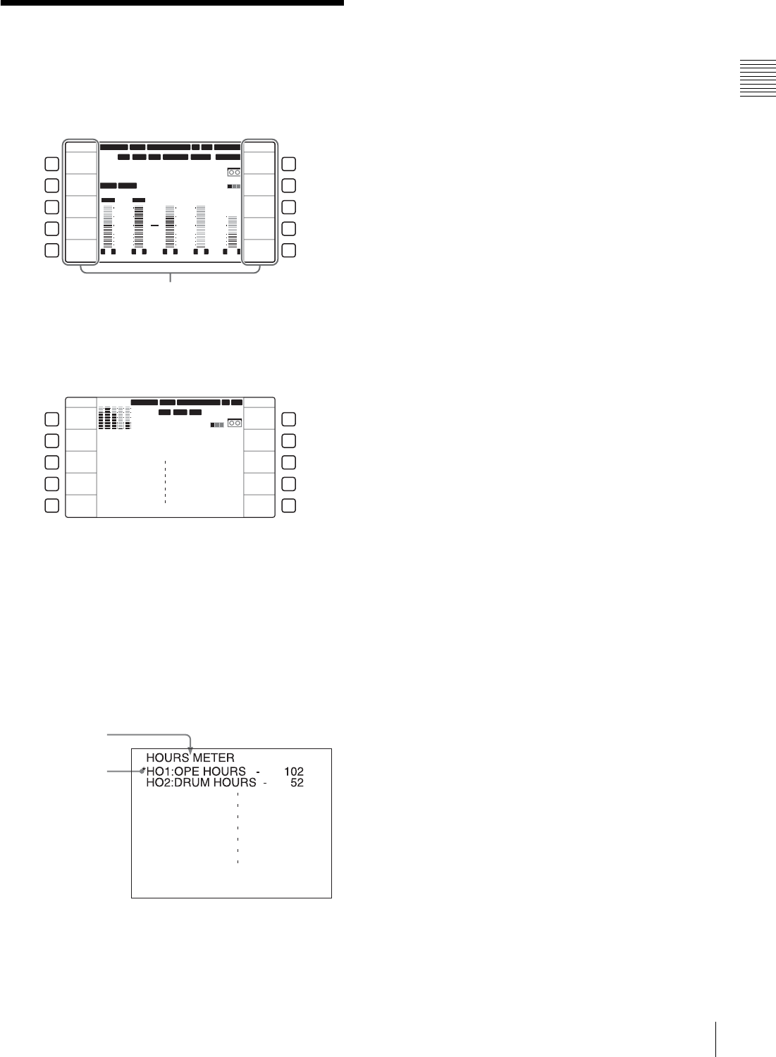
75
9-2 Setup Menu Operations
Chapter 9 Setup Menus
9-2 Setup Menu
Operations
To display setup menus
Display function menu page P01: HOME, and select F9
(MENU).
The LCD enters character display mode and displays the
currently selected setup menu item.
For basic operations in the menu item, see page 64.
To display menus on the monitor
Connect the monitor to the COMPOSITE VIDEO
OUTPUT 3 (SUPER) connector, SDI OUTPUT 3
(SUPER) connector or HDSDI OUTPUT 3 (SUPER)
connector of this unit, and set F5 (CHARA) to “ON” in
function menu page P04: MISC-1. When a setup menu
appears on the monitor, a cursor indicates the currently
selected menu item.
To display a desired menu item
Display the setup menu in the menu display section and
turn the MULTI CONTROL knob.
You can jump to the first item of each menu item group by
selecting F3 (CATEG –) or F4 (CATEG +).
To display a desired sub-item
When the selected menu item contains sub-items, you can
select a desired sub-item as follows.
1
With the desired menu item selected, select F6
(SELECT).
The display changes to show the sub-item names.
2
Turn the MULTI CONTROL knob to select a desired
sub-item.
To chang menu item setting values
The procedure for changing menu item setting values
varies depending on whether the selected menu item has
sub-items or not.
To change the settings of menu items without
sub-items
After selecting a desired menu item using the procedure
described in the section “Displaying a desired menu item”
(see page 75), use the following procedure.
1
Select F6 (SELECT).
The current setting value of the selected menu item
appears.
2
Select F3 (–) or F4 (+), or turn the MULTI CONTROL
knob to select the desired setting value.
To select another menu item and change its setting
value
Select F5 (RETURN) to display the menu item list,
and repeat the procedure for selecting a menu item and
changing its setting value.
3
When all required changes have been made, select F9
(SET).
The new settings are confirmed.
To cancel changes and exit the setup menu
Select F10 (EXIT).
When F9 (SET) is not selected, all changes are
cancelled.
To change the settings of menu items with sub-
items
After selecting a desired sub-item using the procedure
described in the section “To displaying a desired sub-item”
on page 75, use the following procedure.
12 34
:
47 12
::
LTC
DF LTC EXT-LTC R-RUN
PROLL
HOME
L R
1
3+4
BANK3
REM:20min
PARARUN
HD
COND
VITC
L R
2
2
-60
-40
-30
-20
-10
0
dB
-60
-40
-30
-20
-10
0
dB
L R
3
1
L R
4
AES4
4
L R
CUE
3+4
-40
-20
-10
0
10
dB
EMPH DATA
59.94 SDI 2F ASM1080 1080
F1
F2
F3
F4
F5
F6
F7
F8
F9
F10
HOME
E.PRESET
VIDEO IN
SDI
EDIT
CLR CNT
MENU
TCG SET
SDI1 ANA2 SDI3
PB/EE
PB
CONFI
ENABLE
COUNTER
CTL
CONFI
Menu item (function)
SETUP
CATEG -
CATEG +
SETUP
SELECT
SET
EXIT
F1
F2
F3
F4
F5
F6
F7
F8
F9
F10
12 34:47 12::
LTC
DF LTC
HOURS METER
HO1:OPE HOURS - 102
HO2:DRUM HOURS - 52
HD
COND
VITC
59.94 SDI 2F ASM1080
1080
Cursor indicating
the currently
selected item
Group name for the
currently selected item

76 9-2 Setup Menu Operations
Chapter 9 Setup Menus
1
Select F6 (SELECT).
The cursor moves to the setting value of the selected
sub-item.
2
Select F3 (–) or F4 (+), or turn the MULTI CONTROL
knob to select a desired setting value.
To select another sub-item and change its setting
value
Select F5 (RETURN) to move the cursor to a sub-item
name and repeat the procedure for selecting a desired
sub-item and changing its setting value.
To select another menu item and change its setting
value
Select F5 (RETURN) twice in succession to display
the menu item list, and repeat the procedure for
selecting a desired menu item and changing its setting
value.
3
When all required changes have been made, select F9
(SET).
The new settings are confirmed.
To cancel changes and exit from the setup menu
Select F10 (EXIT).
When F9 (SET) is not selected, all changes are
cancelled.
To reset the menu settings to their factory
default values (menu item B20)
Use the following procedure.
1
Carry out steps 1 to 3 of the procedure described in the
section “To change the settings of menu items without
sub-items” on page 75 to set menu item B20 “RESET
SETUP” to “ON”.
The message “Push SET button!” appears.
2
Select F9 (SET).
3
Select F9 (SET) again.
The menu settings are saved.
To recall the BANK4 settings (menu item
B20)
To set the current menu settings to the BANK4 settings,
carry out the following operation.
1
Carry out steps 1 to 3 of the procedure described in
“To change the settings of menu items without sub-
items” (page 75), then set menu item B20 “RESET
SETUP” to “bank-4”.
The message “Push SET button!” appears.
2
Select F9 (SET).
The display returns to the menu item list.
The current menu settings are set to the settings in
BANK4.
3
Select F9 (SET) again.
The settings are saved, exiting from the setup menu.
To switch the system frequency (menu
item 013)
To switch the system frequency among 59.94i, 50i,
29.97PsF, 25PsF, 24PsF and 23.98PsF, proceed as
follows.
• Before carrying out this operation, consult the person
responsible for system installation.
• When this unit enters 24PsF or 23.98PsF mode, SDI
(D1) and composite signals are not output.
1
Carry out steps 1 to 3 of the procedure described in
“To change the settings of menu items without sub-
items” (page 75) to set menu item 013 “SYSTEM
FREQUENCY SELECT” to “ON”.
The menu display changes to allow switching of the
system frequency among 59.94i, 50i, 29.97PsF,
25PsF, 24PsF and 23.98PsF.
2
Switch the setting, then select F9 (SET).
3
Turn the unit off.
Next time the unit is powered on, it will operate in the
selected mode.
To switch the line conversion function
(menu item 018)
To change the setting for line conversion (OFF TAPE or
720P) when the unit is equipped with an optional HKDW-
104 Pull-down/720P Board and is in a mode other than
24PsF, 23.98PsF, 24PD, and 23.98PD2, carry out the
operation described below.
Consult with the administrator responsible for system
installation before carrying out the following procedure.
1
Perform steps 1 to 3 of the procedure described in the
section “To change the settings of menu items without
Notes
Note
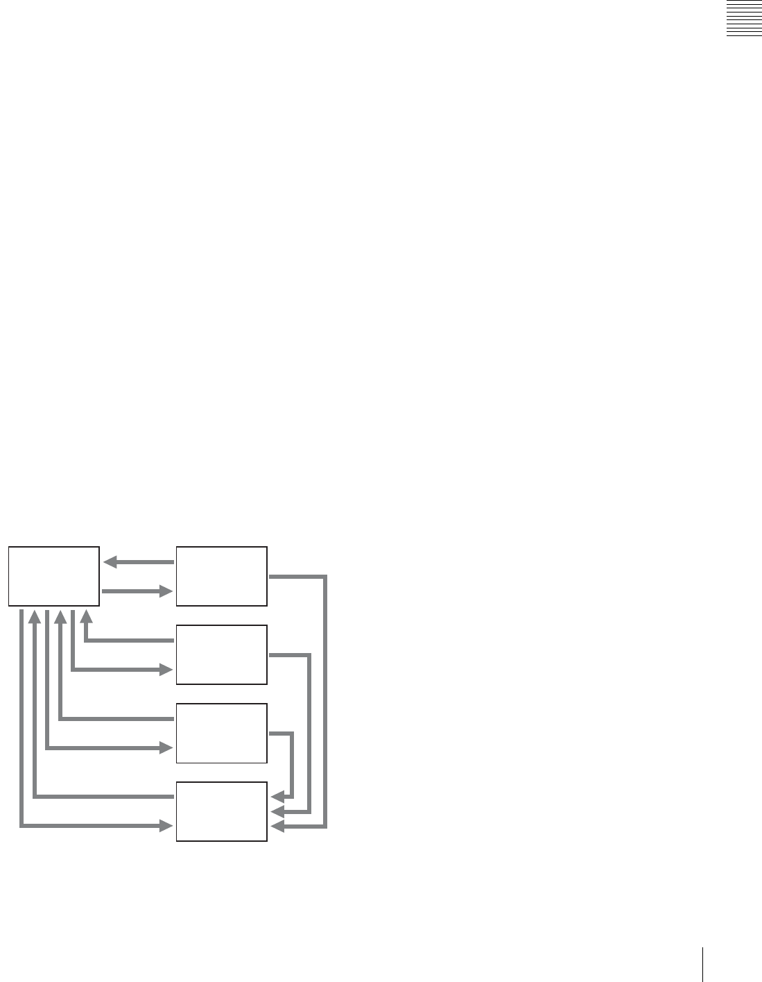
77
9-2 Setup Menu Operations
Chapter 9 Setup Menus
sub-items” on page 75, to set setup menu item 018
“ACTIVE LINE SELECT” to ON.
The menu display changes to allow switching of the
setting for line conversion between OFF TAPE and
720P.
2
Select OFF TAPE or 720P, then select F9 (SET).
3
Turn the unit off.
The next time the unit is turned on, it will operate in the
new mode.
Menu bank operations (menu items B01 to
B13)
This unit saves menu settings in what are termed “menu
banks”. Saved sets of menu settings can be recalled for use
as required.
To save the current active menu settings
Set one of menu items B11 “SAVE BANK 1” to B13
“SAVE BANK 3” to “ON”, depending on the menu banks
you want to save in, then select F9 (SET).
To recall settings from a menu bank
When recalling the settings saved in one of menu banks 1
to 3, set one of the corresponding menu items B01
“RECALL BANK 1” to B03 “RECALL BANK 3” to
“ON”, then select F9 (SET).
To recall the settings saved in menu bank 4, select “bank-
4” with menu item B20 “PRESET SETUP”.
For details about menu bank 4, refer to the Maintenance
Manual.
The current active setup menu settings as well as settings
saved in menu banks are stored in separate storage areas:
one for 59.94i, 29.97PsF, 23.98PsF modes and the other
for 50i, 25PsF, 24PsF modes.
a)
a)
a)
a)
Current active
menu settings
Recall (B01)
Save (B11)
Recall (B02)
Recall (B03)
Save (B13)
Recall (B20)
Save
Menu bank 1
Menu bank 2
Menu bank 3
Menu bank 4
a) Use maintenance menu item 122.
Save (B12)

78 9-3 Items in the Basic Setup Menu
Chapter 9 Setup Menus
9-3 Items in the Basic Setup Menu
The basic setup menu contains the following items. In the “Settings” column of the table, the factory default
settings are underlined.
Item number Item name Settings
001 PREROLL TIME 0S to 5S to 30S: Set the preroll time in the range from 0 to 30 seconds.
A preroll time of at least 5 seconds is recommended when using this unit for editing.
002 a) CHARACTER
H-POSITION
Adjust the horizontal position of the character information output from the
COMPOSITE VIDEO OUTPUT 3 (SUPER) connector, SDI OUTPUT 3 (SUPER)
connector, or HDSDI OUTPUT 3 (SUPER) connector for superimposed display on
the monitor.
0 to 1E to 3C (59.94i, 29.97PsF, 23.98PsF mode)/0 to 1B to 36 (50i, 25PsF,
24PsF mode): The hexadecimal value 00 is for the far left of the screen and
increasing the value moves the position of the characters to the right.
003 a), b) CHARACTER
V-POSITION
Adjust the vertical position of the first line of the character information output from
the COMPOSITE VIDEO OUTPUT 3 (SUPER) connector, HDSDI OUTPUT 3
(SUPER) connector, and SDI OUTPUT 3 (SUPER) connector for superimposed
display on the monitor.
0 to 57 to 6C (59.94i, 29.97PsF, 23.98PsF mode)/0 to 70 to 88 (50i, 25PsF, 24PsF
mode): The hexadecimal value 00 is for the top of the screen and increasing
the value lowers the position of the characters.
004 SYNCHRONIZE When editing using this unit as a controller and an external VTR connected to this
unit via a 9-pin remote control cable, this item determines whether or not to
operate the two units in phase synchronization.
OFF: Do not operate in phase synchronization.
ON: Operate in phase synchronization.
005 DISPLAY INFORMATION
SELECT
Determine the type of text information to be output from the COMPOSITE VIDEO
OUTPUT 3 (SUPER), SDI OUTPUT 3 (SUPER) and HDSDI OUTPUT 3 (SUPER)
connectors when F5 (CHARA) is set to “ON” in function menu page P04: MISC-1.
T&STA: Time data display information and the unit’s status
T&UB: Time data display information and the user bits
T&CTL: Time data display information and CTL
T&T: Time data display information and timecode (LTC or VITC)
TIME: Timecode (LTC or VITC) only
If there is an overlap between the setting of this item and the setting of the control
panel, it is automatically avoided. For example, if CTL is selected on the control
panel and this menu item setting is “T&CTL”, then CTL and LTC are output.
006 LOCAL FUNCTION
ENABLE
Determine which buttons on the control panel are enabled when this unit is
controlled from external equipment.
DIS: All buttons and switches are disabled.
S&E&P: Only the STOP button, EJECT button, P1 to P5 and DISPLAY buttons are
enabled.
ENA: All buttons and switches are enabled.
MAP: Follow the LOCAL KEY MAP setting.
For information about setting the LOCAL KEY MAP, see menu item 023 “LOCAL
KEY MAP” (page 79).
007 TAPE TIMER DISPLAY Determine whether to display the CTL count in 12-hour mode or 24-hour mode.
+ –12H: 12-hour mode
24H: 24-hour mode
008 MONITORING
SELECTION FOR VTR-
TO-VTR EDIT
For two-VTR editing with the monitor connected only to the recorder, determines
whether the recorder is forced into E-E mode when the recorder’s PLAYER button
is pressed to view the player’s playback signals on the monitor.
MANU: Do not force the recorder into E-E mode.
AUTO: Set the recorder to E-E mode, so that the playback signals of the player are
output to the video monitor.
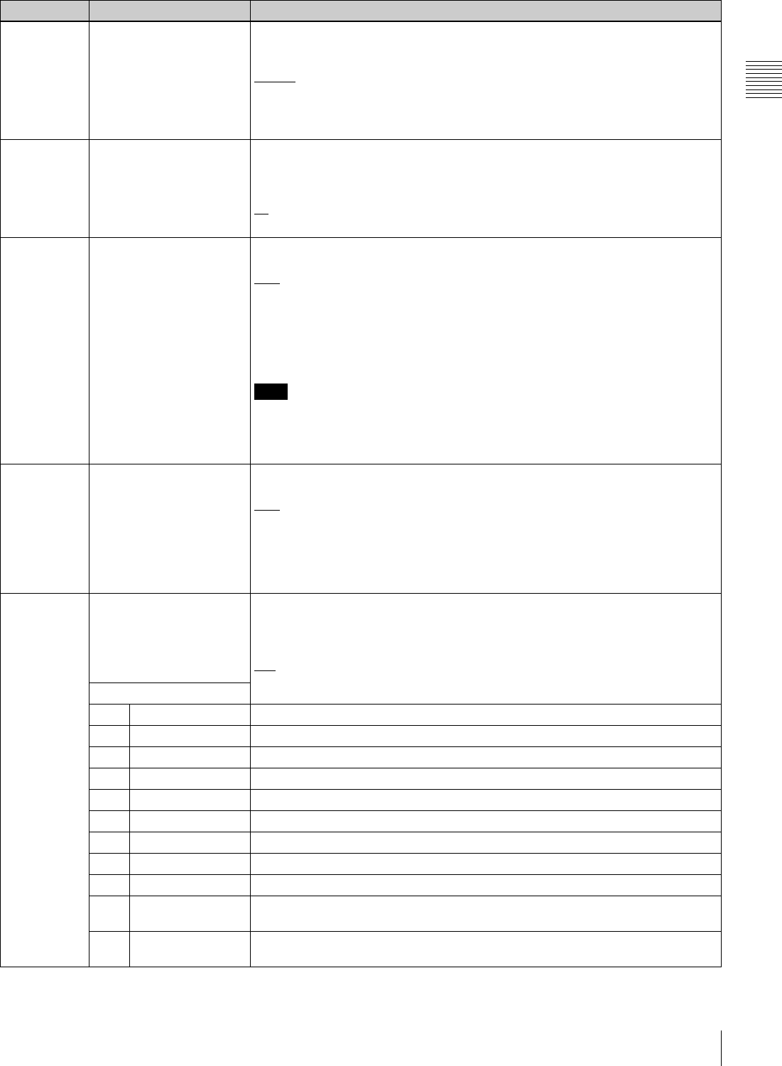
79
9-3 Items in the Basic Setup Menu
Chapter 9 Setup Menus
009 c) CHARACTER TYPE Determine the type of characters such as timecode output from the COMPOSITE
VIDEO OUTPUT 3 (SUPER) connector, SDI OUTPUT 3 (SUPER) connector, or
HDSDI OUTPUT 3 (SUPER) connector for superimposed display on the monitor.
WHITE: White letters on a black background
BLACK: Black letters on a white background
W/OUT: White letters with black outline
B/OUT: Black letters with white outline
011 c) CHARACTER V-SIZE Determine the vertical size of characters such as timecode output from the
COMPOSITE VIDEO OUTPUT 3 (SUPER) connector, SDI OUTPUT 3 (SUPER)
connector, or HDSDI OUTPUT 3 (SUPER) connector for superimposed display on
the monitor.
x1: Standard size
x2: 2 times the standard size
013 SYSTEM FREQUENCY
SELECT
Determine whether to enable switching of the system frequency among 59.94i,
50i, 29.97PsF, 25PsF, 24PsF and 23.98PsF.
OFF: Disable switching.
ON: Enable switching.
When “ON” is selected, the menu display changes to allow switching of the
setting among 59.94i, 50i, 29.97PsF, 25PsF, 24PsF and 23.98PsF.
For the procedure for switching the system frequency, see page 76.
Note
For the basic and extended setup menus, settings are saved for 59.94i, 29.97PsF,
23.98PsF mode and the other for 50i, 25PsF, 24PsF modes separately. When you
switch systems, all menu items change to the current menu values of the selected
mode. (These are different from the settings for the mode before switching.)
018 ACTIVE LINE SELECT
(enabled only when the
optional HKDW-104 board
is installed, and disabled in
24PsF, 23.98PsF, 24PD,
and 23.98PD2 mode)
Determine whether to enable switching of the number of active lines for HDSDI
outputs (OFF TAPE/720P).
OFF: Disable switching.
ON: Enable switching.
When “ON” is selected, the menu display changes to enable switching between
OFF TAPE and 720P.For details on the procedure for switching the ACTIVE LINE,
see “To switch the line conversion function (menu item 018)” (page 76).
023 LOCAL KEY MAP When “MAP” is selected in setup menu item 006 and the unit is controlled from
another device, you can select the operable buttons on the control panel from the
following sub-items.
The settings of each sub-item are as follows.
DIS: Disable the buttons.
ENA: Enable the buttons.
Sub-item
1 STOP Select whether to enable or disable the STOP button.
2 PLAY Select whether to enable or disable the PLAY button.
3 REC Select whether to enable or disable the REC button.
4 STANDBY Select whether to enable or disable the STANDBY button.
5 EJECT Select whether to enable or disable the EJECT button.
6 JOG Select whether to enable or disable the JOG button.
7 SHUTTLE Select whether to enable or disable the SHUTTLE button.
8 VAR Select whether to enable or disable the VAR button
9 FF/REW Select whether to enable or disable the F FWD and REW buttons.
10 F-KEY Select whether to enable or disable the function selection buttons (F1 to F10) and
audio level control knobs.
11 P-KEY/DISPLAY Select whether to enable or disable the menu page selection buttons (P1 to P5)
and DISPLAY button.
Item number Item name Settings

80 9-3 Items in the Basic Setup Menu
Chapter 9 Setup Menus
a) When setting items 002 and 003, watch the monitor screen, and adjust to
the required state.
When displaying timecode values, there is a slight time delay. Therefore,
when creating a tape for off-line editing, the information inserted in the
upper half of the screen may be delayed by one frame.
c) When setting items 009 and 011, watch the monitor screen, and adjust to
the required state.
029 STORED OWNERSHIP Select whether to set the UMID item Stored Ownership.
off: Do not set.
on: Set.
To set Stored Ownership, display this item in the menu display, and select F9
(SET) to move to the Stored Ownership setting screen.
For details, see the section “To set Stored Ownership” (page 61).
B01 RECALL BANK 1 Set to “ON” to recall menu settings from menu bank 1.
B02 RECALL BANK 2 Set to “ON” to recall menu settings from menu bank 2.
B03 RECALL BANK 3 Set to “ON” to recall menu settings from menu bank 3.
B11 SAVE BANK 1 Set to “ON” to save the current menu settings to menu bank 1.
B12 SAVE BANK 2 Set to “ON” to save the current menu settings to menu bank 2.
B13 SAVE BANK 3 Set to “ON” to save the current menu settings to menu bank 3.
B20 RESET SETUP Set to “ON” to reset the current menu settings to factory default values.
Item number Item name Settings
b) Note

81
9-4 Items in the Extended Setup Menu
Chapter 9 Setup Menus
9-4 Items in the Extended Setup Menu
The extended setup menu contains the following items.
In the “Settings” column of the table, the factory default
settings are underlined.
Menu items in the range 100 to 199, relating to the control panels
Item number Item name Settings
101 SELECTION FOR
SEARCH DIAL ENABLE
Select how the unit enters the search mode.
DIAL: Turning the search dial switches to search mode at all times except during
recording/editing.
KEY: Pressing one of the JOG, SHUTTLE, and VAR buttons switches to search
mode.
102 MAXIMUM TAPE SPEED Select the fast forward and rewind speed and also search mode speed during tape
playback.
MAX: Carry out fast forward, rewind, and search at the maximum speeds.
MX/24: Carry out fast forward and rewind at the maximum speeds, and search at
up to 24 times normal speed.
MX/35: Carry out fast forward and rewind at the maximum speeds, and search at
up to 35 times normal speed.
x24: Carry out fast forward and rewind at 24 times normal speed, and search at up
to 24 times normal speed.
x35: Carry out fast forward and rewind at 35 times normal speed, and search at up
to 35 times normal speed.
Maximum fast forward and rewind speed (example in 59.94i or 29.97PsF
mode)
• HDCAM cassette/Digital Betacam cassette: 50 times normal speed
• MPEG IMX cassette: 78 times normal speed
Maximum search mode speeds (example in 59.94i or 29.97PsF mode)
• HDCAM cassette/Digital Betacam cassette: 50 times normal speed
• MPEG IMX cassette: 78 times normal speed
104 AUDIO MUTING TIME Select the length of time for audio muting when the unit switches to playback from
stop or from still playback in the search mode.
OFF: Set the audio muting time to zero (i.e. no muting).
0.1S to 1.0S: Set the audio muting time from 0.1 to 1.0 second, in 0.1-second
increments.
105 REFERENCE SYSTEM
ALARM
Select whether to display a warning when the video/audio reference signal
selected by OUTREF in function menu is not supplied or is out of phase with the
input video signal.
OFF: No warning.
ON: Flash the STOP button as a warning.
106 CAPSTAN LOCK
(Invalid in 24PsF or
23.98PsF mode)
Select the capstan servo lock mode.
PANEL: The capstan servo lock mode is determined by CAPSTN in function menu.
2F: The capstan servo locks every two fields regardless of the setting of CAPSTN
in function menu.
4F: The capstan servo locks every four fields regardless of CAPSTN in function
menu.
8F (In 50i, 25PsF mode only): The capstan servo locks every eight fields
regardless of the setting of CAPSTN in function menu.
Note
When operating in 24PsF or 23.98PsF mode, 2F is selected automatically and this
item is not displayed.
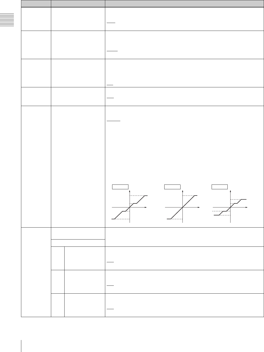
82 9-4 Items in the Extended Setup Menu
Chapter 9 Setup Menus
107 REC INHIBIT LAMP
FLASHING
Select whether to flash the REC INHI indicator when RECINH in function menu is
set to “OFF” and the record inhibit plug on the cassette is pressed in.
OFF: Do not flash.
ON: Flash.
108 AUTO EE SELECT Select the VTR modes in which input video and audio signals are automatically
handled in E-E mode when a cassette is inserted and PB/EE in function menu is
set to “EE”.
S/F/R: In STOP/EJECT/F.FWD/REW modes
STOP: In STOP/EJECT modes
109 FORCED EE WHEN TAPE
UNTHREAD
Select whether or not the setting of PB/EE in function menu controls the PB/EE
setting for output signals during tape threading and unthreading, and when no
cassette is inserted.
OFF: Control.
ON: No control (always E-E signal).
111 TSO PLAY Select whether or not to enable tape speed override mode.
DIS: Disabled
TSO: Enabled
116 JOG DIAL RESPONSE Select the tape speed characteristics for the search dial rotation rate (VTR
commands).
TYPE1: Tape speed varies linearly over the range –1 to +1.
TYPE2: Tape speed varies stepwise as shown in figure “TYPE 2” a) below over the
range –3 to +3. (Characterized by a zone around –1 and +1 where the tape
speed is independent of the search dial rotation rate. When playing back an
HDCAM tape, however, tape speed characteristic figure “TYPE 4” c) below
applies.)
TYPE3: Tape speed varies linearly over the range –3 to +3 (±2 during HDCAM tape
playback), as shown in figure “TYPE 3” b) below.
TYPE4: Tape speed varies stepwise as shown in figure “TYPE4” c) below over the
range –2 to +2. (Characterized by a zone around –1 and +1 where the tape
speed is independent of the search dial rotation rate)
118 KEY INHIBIT SWITCH
EFFECTIVE AREA
Select which switches and buttons can be operated when the KEY INHI switch on
the switch panel is set to “ON”. The following sub-items control different sets of
switches and buttons independently.
Sub-item
1 REMOTE SELECT Select whether or not the REMOTE 1(9P)/2(50P) buttons in the upper control
panel are enabled.
DIS: Disabled
ENA: Enabled
2 F-KEY (FUNCTION
KEY)
Select whether to enable the selection buttons (F1 to F10 and P1 to P5, DISPLAY)
in the lower control panel of this unit.
DIS: Disabled
ENA: Enabled
3 CONTROL PANEL Select which switch and button operations can be carried out from the lower
control panel of this unit.
DIS: All switches and buttons are disabled.
ENA: All switches and buttons are enabled.
Menu items in the range 100 to 199, relating to the control panels (Continued)
Item number Item name Settings
+3
+1
-1
-3
FWD
FWD
RVS
RVS
+2
+1
-1
-2
FWD
FWD
RVS
RVS
b) c)
(forward)
Rotation rate Rotation rate
Speed SpeedTYPE 3 TYPE 4
a)
Speed
TYPE 2
(
reverse)
+3
-3
FWD
FWD
RVS
RVS
Rotation rate
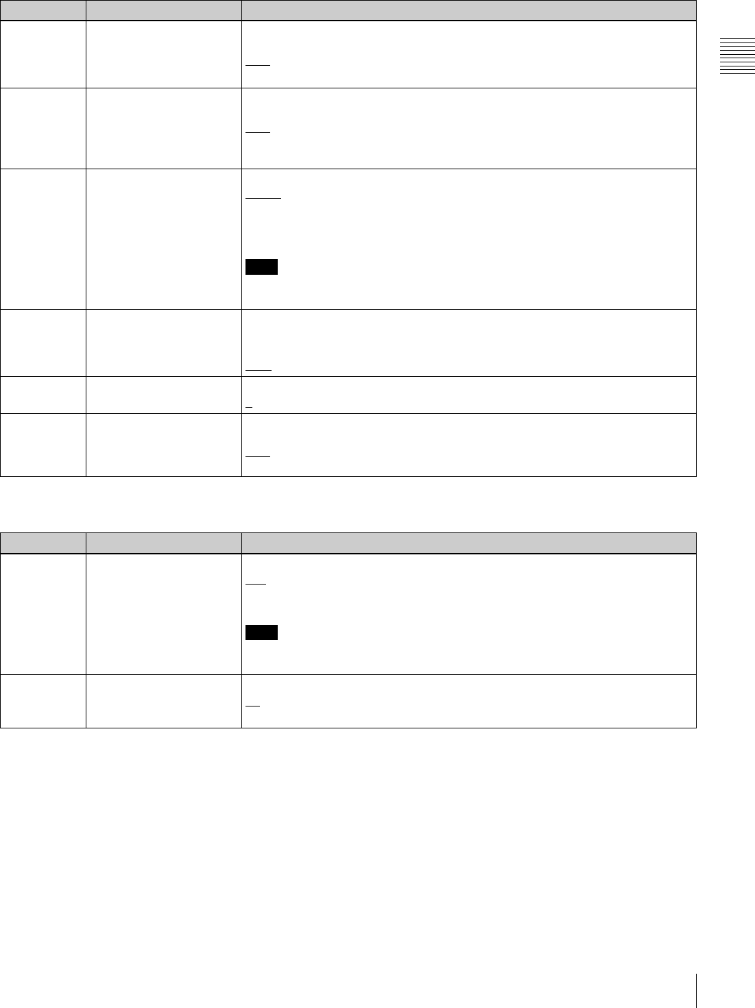
83
9-4 Items in the Extended Setup Menu
Chapter 9 Setup Menus
119 VARIABLE SPEED LIMIT
IN KEY PANEL CONTROL
Select the playback speed range in variable speed playback with the control panel
of this unit.
OFF: –1 to +2 times normal speed
ON: 0 to 1 times normal speed
120 CTL LOCK IN VAR/SHTL Select whether the tape transport should be phase-locked to the CTL signal during
playback in variable speed or shuttle mode.
OFF: Not phase-locked.
ON: Phase-locked at the following speeds: –1, –0.5, 0.5, 1.0 and 2.0 times normal
speed.
121 DT MODE Select field or frame mode for variable speed playback.
FIELD: Always field playback
FRAME: Frame playback in the noiseless playback speed range; otherwise field
playback. Frame playback provides higher-density in still pictures than field
playback.
Note
For HDCAM tapes recorded in PsF mode, playback is automatically carried out in
frame mode.
125 AUTO REWIND Select whether or not to rewind the tape automatically when recording or playback
reaches the end of a tape.
DIS: Not rewind
ENA: Rewind
130 DISPLAY DIMMER
CONTROL
Set the brightness of LCD.
0 to 7: Set in this range. 0 is the brightest, and 7 the dimmest.
139 LOST LOCK DISPLAY ON
CONTROL PANEL
Select whether to display the message “LOST LOCK” on the control panel when
the lock is lost.
OFF: No display
ON: Display
Menu items in the range 200 to 299, relating to the remote control interface
Item number Item name Settings
201 PARA RUN Select whether to make syncronous operation for two or more VTRs.
DIS: No synchronized operation
ENA: Make syncronous operation
Note
To make syncronous operation for two or more VTRs, set item 201 to “ENA” on all
VTRs.
202 CF FLAG REPLY (In 50i,
24PsF or 25PsF mode
only)
Select the mode for locking to the color framing sent from the remote controller.
8F: Eight-field locking mode
4F/8F: Four- or eight-field locking mode
Menu items in the range 100 to 199, relating to the control panels (Continued)
Item number Item name Settings
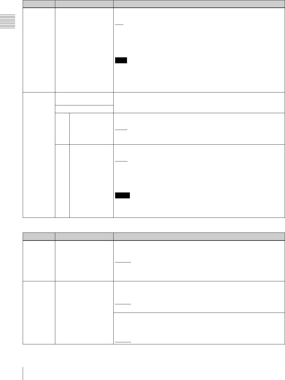
84 9-4 Items in the Extended Setup Menu
Chapter 9 Setup Menus
211 REMOTE1 PORT Select how to use the REMOTE 1-IN(9P)/REMOTE 1-OUT(9P) connectors on the
connector panel.
I&O: Both the IN and OUT connectors are effective whether in local or remote
mode.
IN: Only the IN connector is effective whether in local or remote mode.
OUT: Only the OUT connector is effective whether in local or remote mode.
PANEL: Enable to select I&O, IN, or OUT using the function menu.
Note
If you select “PANEL”, first set the user-defined function button RMT1 in any
function menu page.
For details on how to set the user-defined function buttons in function menu page,
refer to the Maintenance Manual Volume 1.
212 VIDEO REMOTE
CONTROL SELECT
Make settings for control from such as HKDV-900/503 via the VIDEO CONTROL
(9P) connector.
Sub-item
1IMAGE
ENHANCER
(HDW-D1800 only)
Select whether to control the upconverter or downconverter when controlling the
image enhancer.
down: Control the downconverter.
up: Control the upconverter.
u&d: Control both the upconverter and downconverter.
2 D2 SETUP Select the menu item to be controlled by the SETUP dial with the D2 button on the
HKDV-900/503 pressed.
setup: Sub-item (OUTPUT LEVEL) of menu item 713 (VIDEO SETUP
REFERENCE LEVEL)
Black: Menu item 718 (SETUP(BLACK) LEVEL)
For details, see the description of menu item 718 (see page 95).
Notes
• After changing this setting, power off this unit or HKDV-900/503 and power it on
again.
• This setting is valid only in 59.94i or 29.97PsF mode.
Menu items in the range 300 to 399, relating to editing operations
Item number Item name Settings
301 VAR SPEED RANGE FOR
SYNCHRONIZATION
Select the playback speed range in variable speed playback mode from a remote
controller connected to the REMOTE-1 IN(9P) connector or REMOTE-1 OUT(9P)
connector.
–1 ~ +2: –1 to +2 times normal speed for HDCAM tape. –1 to +3 times normal
speed for Digital Betacam and MPEG IMX tapes.
~ 2.45: –1.5 to +2.45 times normal speed for HDCAM tape.
–1.5 to +3.45 times normal speed for Digital Betacam and MPEG IMX tapes.
302 CAPSTAN RE-LOCKING
DIRECTION
In 59.94i, 29.97PsF mode
Select whether the capstan servo should lock by accelerating or decelerating
when F1 (CAPSTAN) in function menu page P04: MISC-1 is set to “4F”.
DECEL: Lock by decelerating.
ACCEL: Lock by accelerating.
In 50i, 25PsF mode
Select whether the capstan servo should lock by accelerating or decelerating
when F1 (CAPSTAN) in function menu page P04: MISC-1 is set to “4F” or “8F”.
DECEL: Lock by decelerating.
ACCEL: Lock by accelerating.
Menu items in the range 200 to 299, relating to the remote control interface (Continued)
Item number Item name Settings

85
9-4 Items in the Extended Setup Menu
Chapter 9 Setup Menus
304 EDIT FIELD SELECT Select with which fields to start and end editing.
1F: Start editing with field 1 and end with field 2.
2F: Start editing with field 2 and end with field 1.
1F/2F: Start and end editing depending on the timing of command reception.
Note
1F is always selected in PsF mode.
305 SYNC GRADE Select the target phase synchronization accuracy when editing in phase-
synchronized mode with menu item 004 set to “ON”.
ACCUR: ±0 frame accuracy
ROUGH: ±1 frame accuracy
306 DMC INITIAL SPEED Select the initial speed automatically set in DMC editing.
MANU: The speed determined by the rotation of the search dial
PLAY: Normal playback speed
STILL: Stationary
±0.03 to ±1, +2: Speed set in this range (select from +2, ±1, ±0.5, ±0.2, ±0.1, ±0.03)
307 AUTO-DELETION FOR
INCONSISTENT DATA
Select the operation of this unit when an erroneous edit point is set.
MANU: A warning is given by flashing the name of the edit point button for the
erroneous edit point in the lower control panel.
Delete or correct the erroneous edit point manually.
NEG&E: When edit points are set incorrectly, such as when an OUT point is before
an IN point, or an audio OUT point is before an audio IN point, or when too
many edit points are specified, the previously set edit point is deleted
automaically.
NEG: When edit points are set incorrectly, such as when an OUT point is before an
IN point, or an audio OUT point is before an audio IN point, the previously set
edit point is deleted automaically. When too many edit points are specified, a
warning is given by flashing the name of the edit point button for the
unnecessary edit point in the control panel.
Note
Pressing the button corresponding to an edit point to be deleted and the DELETE
button simultaneously deletes the edit point. Editing is not executed if an
erroneous edit point is set (the name of an edit button is flashing).
309 SERVO/AV REFERENCE
SEL
Select the servo reference signal.
AUTO1: During recording, the input video signal is used as the servo reference
signal. During playback, the signal selected by F2 (REF VID) in function menu
page P03: VID PROC is used as the servo reference signal. If the signal
selected by the F2 (REF VID) in function menu page P03: VID PROC is not
connected, an internal reference signal is used.
AUTO2: When F2 (REF VID) in function menu page P03: VID PROC is set to
“REF”, and any of F2 (INS TC), F3 (INS CUE), and F5 (ASSEMBLE) to F10
(INS A4) in function menu page P07: E.PRESET is lit, the reference signal for
video/audio signal processing is locked to the input video signal.
EXT: The servo reference signal is forced to be “EXT” (an external reference video
input signal is used).
Menu items in the range 300 to 399, relating to editing operations (Continued)
Item number Item name Settings
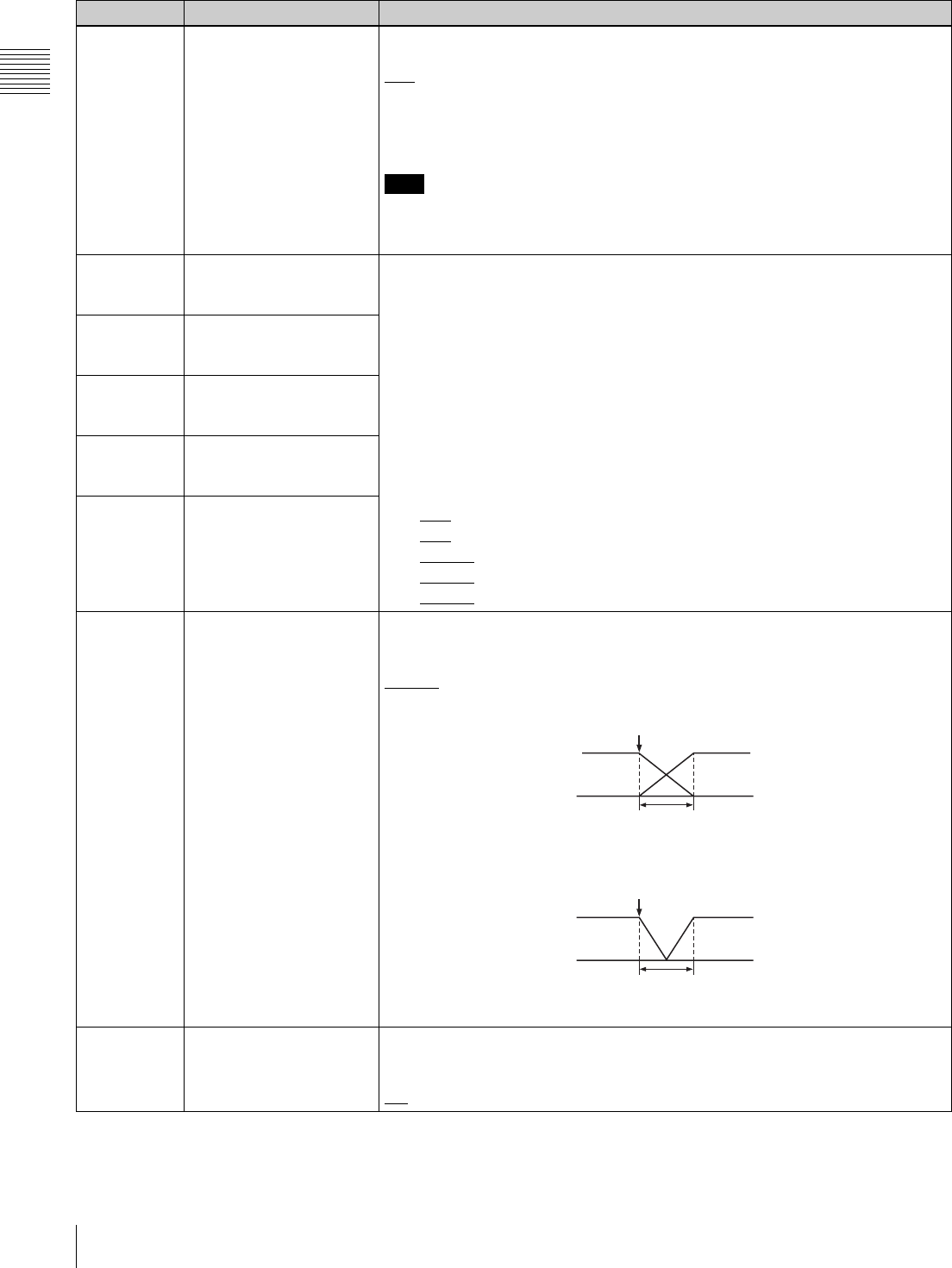
86 9-4 Items in the Extended Setup Menu
Chapter 9 Setup Menus
310 REC INHIBIT Select the conditions under which recording is inhibited when F1 (REC INHI) is set
to “ON” in function menu page P07: E.PRESET.
ALL: All tape recording is inhibited.
CRASH: Normal tape recording is inhibited. Select this setting for assemble editing.
VIDEO: Recording of video and CTL signals is inhibited.
AUDIO: Recording of audio and CTL signals is inhibited.
Note
When F1 (REC INHI) is set to “ON” in function menu page P07: E.PRESET, the
REC INHI indicator on the lower control panel lights. If an operation inhibited by
this item is attempted, the REC INHI indicator flashes.
311 ANALOG AUDIO EDIT
PRESET REPLACE FOR
CH1
Select how to activate edit preset of each digital audio channel (CH 1 to CH 4, and
CUE) on this unit using the analog audio preset function of the editor or remote
controller when using an editor (PVE-500, BVE-600, etc.) or a remote controller
which cannot control digital audio edit preset.
The edit preset of each digital audio channel (CH1 to CH4 and CUE) of this unit is
set to “ON” or “OFF” according to the analog audio preset specified by the editor or
remote controller.
NODEF: No definition.
CH1: Follow edit preset of analog channel 1.
CH2: Follow edit preset of analog channel 2.
CH1+2: Follow edit preset of analog channel 1 or 2. The default settings for each
item are as follows:
311: CH1
312: CH2
313: NODEF
314: NODEF
315: NODEF
312 ANALOG AUDIO EDIT
PRESET REPLACE FOR
CH2
313 ANALOG AUDIO EDIT
PRESET REPLACE FOR
CH3
314 ANALOG AUDIO EDIT
PRESET REPLACE FOR
CH4
315 ANALOG AUDIO EDIT
PRESET REPLACE FOR
CUE
317 AUDIO EDIT MODE Select the type of audio transition used for digital audio editing.
CUT: Cut editing (audio discontinuity at edit point, and possible noise during
playback)
CROSS: Cross-fade
FI/FO: Fade in and fade out
t: Time set by menu item 803 “DIGITAL AUDIO FADE TIME”
318 EDIT RETRY For two-VTR editing, and when this unit is used as the recorder. Select the
operation if the recorder was not synchronized in time.
OFF: Editing is not carried out, and the unit stops.
ON: The editing is automatically retried (up to twice).
Menu items in the range 300 to 399, relating to editing operations (Continued)
Item number Item name Settings
IN/OUT
t
IN/OUT
t
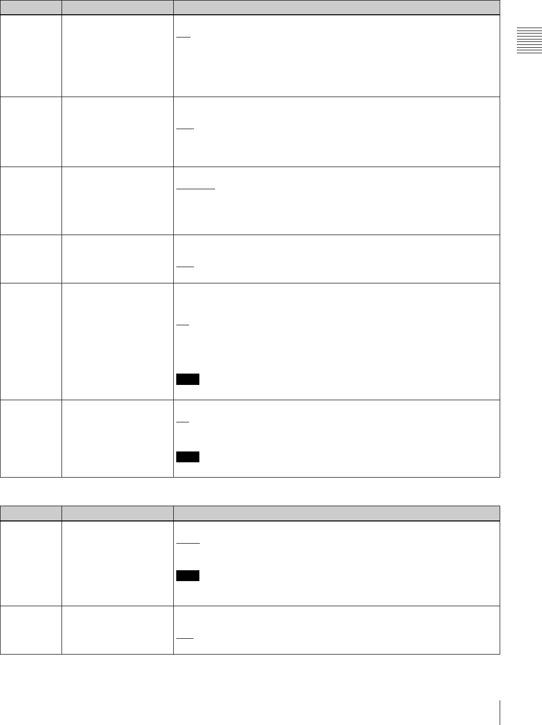
87
9-4 Items in the Extended Setup Menu
Chapter 9 Setup Menus
319 PREREAD SELECT Specify the preread operation.
A/V: Preread for both audio and video.
AUDIO: Preread for audio only.
VIDEO: Preread for video only.
The preread operation is enabled when F3 (PREREAD) in function menu page
P04: MISC-1 is set to “ON” or by a command from the 9-pin remote control
interface.
326 AUTOMATIC IN ENTRY
AFTER AUTO EDIT
Select whether to automatically set the OUT point of the previous edit as the next
IN point after automatic editing.
OFF: No automatic setting
R: Set recorder IN point automatically.
R & P: Set recorder IN point automatically, and also player IN point in two-VTR
editing.
334 EE REFERENCE
CONTROL
Specify how to select the reference video signal in E-E mode.
NORMAL: Select according to the table in Section “3-2-1 Selecting Reference
Sync Signal Depending on Operational Status” (page 28).
INPUT: In E-E mode select the input video signal. Otherwise, select according to
the table in Section “3-2-1 Selecting Reference Sync Signal Depending on
Operational Status” (page 28).
336 EDIT PRESET INHIBIT IN
KEY PANEL CONTROL
Specify which buttons are disabled in the editing mode setting section on the lower
control panel.
OFF: Enable all buttons.
TC: Disable the TC button.
337 EXTERNAL REFERENCE
SELECT
Select the signal used when this unit is set up by setup menu item 309 and
function menu page P03: VID PROC to use an external reference video signal as
reference.
HD: Use a high definition reference video signal as reference. Input a tri-level
(positive and negative) sync signal to a REF. VIDEO INPUT connector.
SD: Use a reference video signal. Input a video signal with chroma burst (VBS) or
a monochrome video signal (VS) to a REF. VIDEO INPUT connector.
Note
When operating in 24PsF or 23.98PsF mode, “HD” is selected.
338 OUTPUT AUDIO/TC
PHASE SELECT
Set the audio (AES/EBU and analog) and timecode output phase.
HD: Sync with HDSDI output phase.
SD: Sync with SD output phase.
Note
When operating in 24PsF or 23.98PsF mode, “HD” is selected.
Menu items in the range 400 to 499, relating to preroll
Item number Item name Settings
401 FUNCTION MODE AFTER
CUEUP
Select the mode of the unit after a cueup operation.
STOP: Stop (the “stop mode”)
STILL: Still playback (in search mode)
Note
When controlling this unit from an editor with the standard constants set, select
“STOP”.
402 TIME REFERENCE FOR
PREROLL
Select whether or not to use CTL signal to count timecode before a discontinuity
when prerolling a tape with timecode discontinuities.
CTL: Count timecode using CTL signal.
TC: Do not count timecode using CTL signal.
Menu items in the range 300 to 399, relating to editing operations (Continued)
Item number Item name Settings
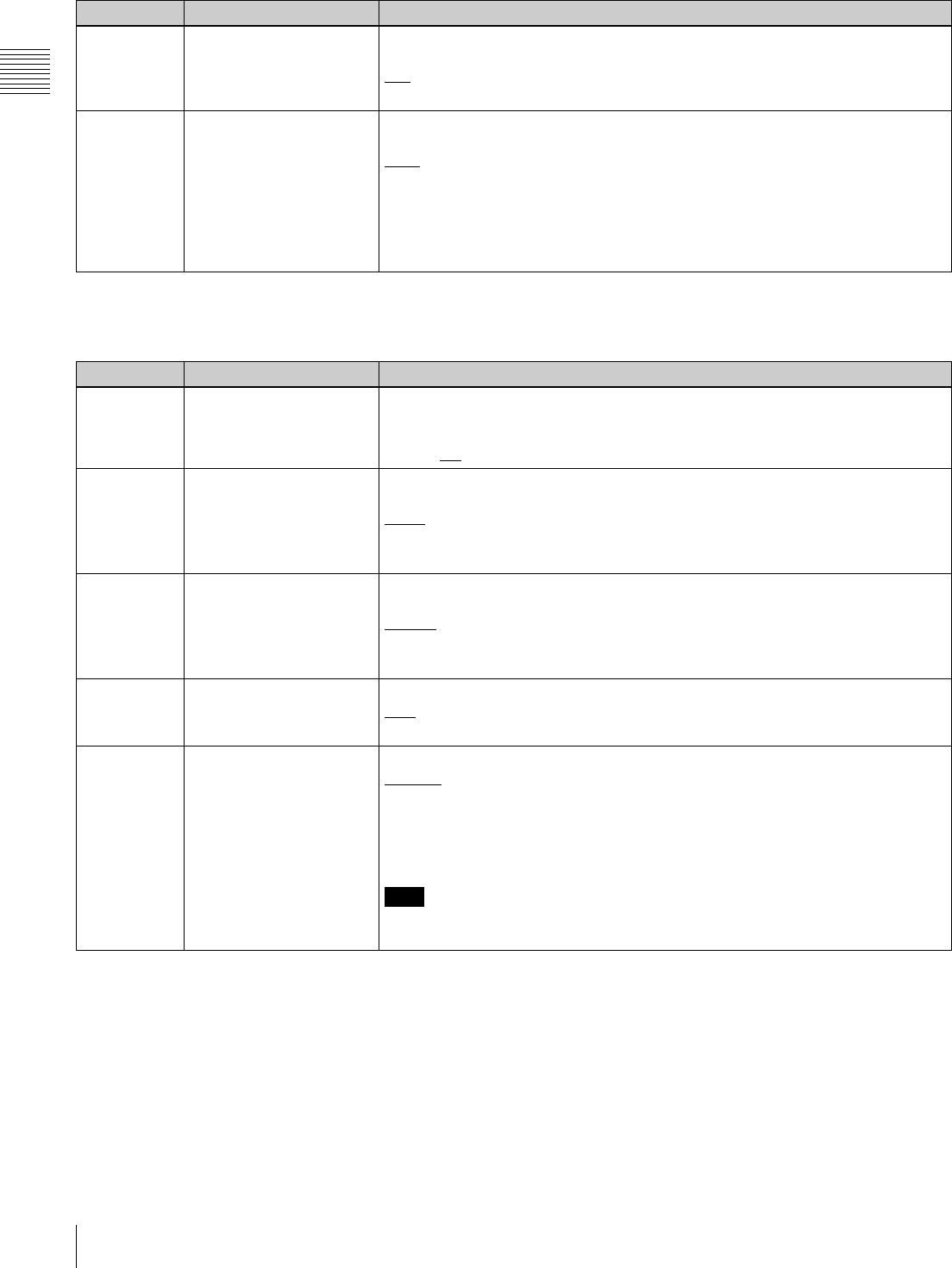
88 9-4 Items in the Extended Setup Menu
Chapter 9 Setup Menus
a) When controlled from an editor (BVE-2000/9100 etc.), selecting “REEL”
allows high-speed cueup.
403 AUTOMATIC PREROLL
REFERENCE ENTRY
Select whether the IN point is automatically set by pressing the PREROLL button,
when the IN point is not set on starting preroll.
DIS: Do not set IN point automatically.
ENA: Set IN point automatically.
405 CUEUP BY CTL Select the tape transport mode when cuing. This setting is valid only when CTL/TC
is set to “CTL”.
CAP.: During cueup, the tape runs with “pinch ON” (maximum tape speed 10 times
normal).
REEL: During cueup, the tape runs with “pinch OFF”. As the tape approaches the
cue up point and the tape speed drops, the tape transport switches to the
“pinch ON” state.a)
To give priority to editing accuracy, select “CAP.”.
Menu items in the range 400 to 499, relating to preroll (Continued)
Item number Item name Settings
Menu items in the range 500 to 599, relating to tape protection
Item number Item name Settings
501 STILL TIMER Select the time delay from when the tape stops (either the “stop mode” or the still
playback mode in search mode) until the unit automatically switches to the tape
protection mode, in order to protect the video heads and tape.
0.5S to 8M to 30M: Set the value in the range 0.5 seconds to 30 minutes.
502 TAPE PROTECTION
MODE FROM SEARCH
Select the protection mode to protect the video heads and tape when in the still
playback mode in search mode (jog/shuttle).
STEP: Step forward at 1/30 times normal speed every 2 seconds.
STDBY: Switch to Standby OFF mode (the unit not on standby).
T.REL : Switch to tension release mode (the tape tension slackened).
503 TAPE PROTECTION
MODE FROM STOP
Select the operation of the protection mode to protect the video heads and tape
when stopped (the “stop mode”).
STDBY: Switch to Standby OFF mode (the unit not on standby).
T.REL : Switch to tension release mode (the tape tension slackened).
STEP: Step forward at 1/30 times normal speed every 2 seconds.
504 DRUM ROTATION IN
STANDBY OFF
Select whether the drum rotates in Standby OFF mode.
OFF: Drum does not rotate.
ON: Drum rotates.
505 STILL TENSION Select the tape tension state in the still playback mode.
NORML: Normal tape tension is maintained during still playback mode, ready for
playback.
LOOSE: Reduce the tape tension further from the NORML setting. (Select
“LOOSE” when the unit is on standby for a long period of still playback, for
example, in a library management system (LMS).)
Note
When “LOOSE” is selected and the tape tension is reduced, playback cannot be
guaranteed.
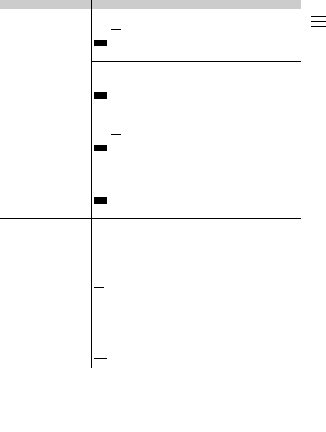
89
9-4 Items in the Extended Setup Menu
Chapter 9 Setup Menus
Menu items in the range 600 to 650, relating to the timecode generator
Item number Item name Settings
601 VITC POSITION
SEL-1 (Invalid in
24PsF or 23.98PsF
mode)
In 59.94i, 29.97PsF mode
Select a line to insert the VITC in. (For SD output)
12H to 16H to 20H: Select any line from 12 to 20.
Note
You can insert the VITC signal in two lines. To insert it in two lines, set both menu items
601 and 602.
In 50i, 25PsF mode
Select a line to insert the VITC in. (For SD output)
9H to 19H to 22H: Select any line from 9 to 22.
Note
You can insert the VITC signal in two lines. To insert it in two lines, set both menu items
601 and 602.
602 VITC POSITION
SEL-2 (Invalid in
24PsF or 23.98PsF
mode)
In 59.94i, 29.97PsF mode
Select a line to insert the VITC in. (For SD output)
12H to 18H to 20H: Select any line from 12 to 20.
Note
You can insert the VITC signal in two lines. To insert it in two lines, set both menu items
601 and 602.
In 50i, 25PsF mode
Select a line to insert the VITC in. (For SD output)
9H to 21H to 22H: Select any line from 9 to 22.
Note
You can insert the VITC signal in two lines. To insert it in two lines, set both menu items
601 and 602.
603 ID CODE PRESET Select whether to set the ID code.
OFF: Do not set.
ON: Set.
To set the ID code:
Select F9 (SET) with this menu item displayed in the menu display, to enter the ID code
setting mode. Select F1 (PREV) or F2 (NEXT) for digit selection. When all required
digits have been set correctly, select F9 (SET) again to save the ID code and exit the ID
code setting mode.
604 ID CODE SW Select whether to record the ID code, set using menu item 603 in the user bits.
OFF: Record the normal data in the user bits.
ON: Record the ID code in the user bits.
605 TCG REGEN MODE Select the signals to be regenerated when the timecode generator is in regeneration
mode (i.e., when F2 (TCG MODE) in function menu page P02: TC is set to “RGN: LTC”
or “RGN: VITC”).
TC&UB: Both the timecode and user bit signals are regenerated.
TC: Only the timecode signal is regenerated.
UB: Only the user bit signal is regenerated.
606 TC OUTPUT
SIGNAL IN REGEN
MODE
Select the signal output from the TIME CODE OUT connector during normal (×1) speed
playback:
TAPE: During playback, the playback timecode signal is output without regeneration.
REGEN: The playback timecode is output after regeneration.

90 9-4 Items in the Extended Setup Menu
Chapter 9 Setup Menus
607 U-BIT BINARY
GROUP FLAG
Specify how to use the user bits in the timecode generated by the timecode generator.
000: Character set not specified
001: 8-bit characters compliant with ISO 646 and ISO 2022
010: Undefined
011: Undefined
100: Undefined
101: SMPTE 262M Page/line multiplex system
110: Undefined
111: Undefined
608 PHASE
CORRECTION
Select whether to carry out phase correction control on the LTC generated by the
timecode generator.
OFF: No control
ON: Carry out control.
609 TCG CF FLAG Select whether the color framing flag is set in the blank bit of the timecode data.
OFF: Not set.
ON: Set.
AUTO: Control the color framing flag setting as follows according to the operation mode
of the timecode generator (TCG).
- When the TCG is in INT-PSET mode: Set the color framing flag in the blank bit of
generated timecode data.
- When the TCG is in INT-LTC or INT-VITC mode and the number of fields for
capstan lock is 4F or 8F: Set the color framing flag in the blank bit of generated
timecode data.
- When the TCG is in other than the above modes: Do not set the color framing flag
in the blank bit of generated timecode data.
For more information about the TCG operation mode, see TCG mode (page 18). For
details on settings of the TCG, see the description of function menu page P02: TC
(page 66). For details on settings of the number of fields for capstan lock, see the
description of function menu page P04: MISC-1 (page 68).
610 REGEN CONTROL
MODE
Select whether timecode is automatically regenerated.
AS&IN: In automatic editing in assemble mode or insert mode with this unit as a recorder
(AUTO EDIT), regardless of the settings of F1 (TCG SRC) and F2 (TCG MODE) in
function menu page P02: TC, the timecode generator regenerates according to the
timecode on the tape.
ASSEM: In automatic editing (AUTO EDIT) in assemble mode with this unit as a
recorder, regardless of the settings of F1 (TCG SRC) and F2 (TCG MODE) in
function menu page P02: TC, the timecode generator regenerates according to the
timecode on the tape.
MANU: Regardless of whether this unit is the recorder or player, the timecode generator
operates in accordance with the settings of F1 (TCG SRC) and F2 (TCG MODE) in
function menu page P02: TC.
FULL: Whether in local or remote operation and regardless of the settings of F1 (TCG
SRC) and F2 (TCG MODE) in function menu P02: TC, when any of F2 (INS TC), F3
(INS CUE), and F5 (ASSEMBLE) to F10 (INS A4) in function menu page P07:
E.PRESET is lit, the timecode generator regenerates according to the timecode
played back from the tape.
617 LTC OUTPUT
PHASE
Set the output phase of timecode signals (LTC).
TCG/R: Output the playback timecode signal during playback.
When the edit preset function is on, and when recording, output the timecode signal
generated by the internal timecode generator.
INPUT: Use the same phase as the input video.
OUTPT: Use the same phase as the output video.
AUTO: Use the same phase as the input video when editing, and otherwise, use the
same phase as the output video (when playback, recording, etc.)
Menu items in the range 600 to 650, relating to the timecode generator (Continued)
Item number Item name Settings

91
9-4 Items in the Extended Setup Menu
Chapter 9 Setup Menus
618 UPCONV
EMBEDDED VITC
(HDW-D1800 only.
Invalid in 24PsF or
23.98PsF mode.)
Select the source for HDSDI embedded VITC which is output after up-conversion during
playback of SD-format tape.
VITC: Select VITC recorded on SD-format tape.
LTC: Select LTC recorded on SD-format tape.
620 TC CONVERT 24F ->
25F (In 50i or 25PsF
mode only.)
Select whether to convert playback timecode to 25F timecode during playback of tape
recorded in 24PsF or 23.98PsF mode.
OFF: Do not convert timecode.
ON: Convert timecode.
TC CONVERT 25F ->
24F (In 24PsF or
23.98PsF mode
only.)
Select whether to convert playback timecode to 24F timecode during playback of tape
recorded in 50i or 25PsF mode.
OFF: Do not convert timecode.
ON: Convert timecode.
621 24F STARTING TC
SEL (In 50i or 25PsF
mode only)
Select one of the following settings for 24F starting TC for timecode conversion from
24F to 25F.
OFF: Do not set.
ON: Set.
To set the 24F starting TC
Select F9 (SET) with this menu item displayed in the menu display, to enter the starting
TC setting mode. Select F1 (PREV) or F2 (NEXT) for digit selection. When all required
digits have been set correctly, select F9 (SET) again to save the starting TC and exit the
starting TC setting mode.
25F STARTING TC
SEL (In 24PsF or
23.98PsF mode only)
Select one of the following settings for 25F starting TC for timecode conversion from
25F to 24F.
OFF: Do not set.
ON: Set.
To set the 25F starting TC
Select F9 (SET) with this menu item displayed in the menu display, to enter the starting
TC setting mode. Select F1 (PREV) or F2 (NEXT) for digit selection. When all required
digits have been set correctly, select F9 (SET) again to save the starting TC and exit the
starting TC setting mode.
622 24F JUMPING TC
SEL (In 50i or 25PsF
mode only)
Select one of the following settings for 24F jumping TC for timecode conversion from
24F to 25F.
–3H: Set JUMPING TC to “STARTING TC –3H”.
–2H: Set JUMPING TC to “STARTING TC –2H”.
–1H: Set JUMPING TC to “STARTING TC –1H”.
+1H: Set JUMPING TC to “STARTING TC +1H”.
+2H: Set JUMPING TC to “STARTING TC +2H”.
+3H: Set JUMPING TC to “STARTING TC +3H”.
0H: Set JUMPING TC to “STARTING TC”.
25F JUMPING TC
SEL (In 24PsF or
23.98PsF mode only)
Select one of the following settings for 25F jumping TC for timecode conversion from
25F to 24F.
–3H: Set JUMPING TC to “STARTING TC –3H”.
–2H: Set JUMPING TC to “STARTING TC –2H”.
–1H: Set JUMPING TC to “STARTING TC –1H”.
+1H: Set JUMPING TC to “STARTING TC +1H”.
+2H: Set JUMPING TC to “STARTING TC +2H”.
+3H: Set JUMPING TC to “STARTING TC +3H”.
0H: Set JUMPING TC to “STARTING TC”.
630 SEARCH TYPE
SELECT
ALL: Search all shot marks during index search.
REC: Search recording start marks during index search.
SHOT1: Search shot mark 1 during index search.
SHOT2: Search shot mark 2 during index search.
POST: Search post marks during index search.
Menu items in the range 600 to 650, relating to the timecode generator (Continued)
Item number Item name Settings
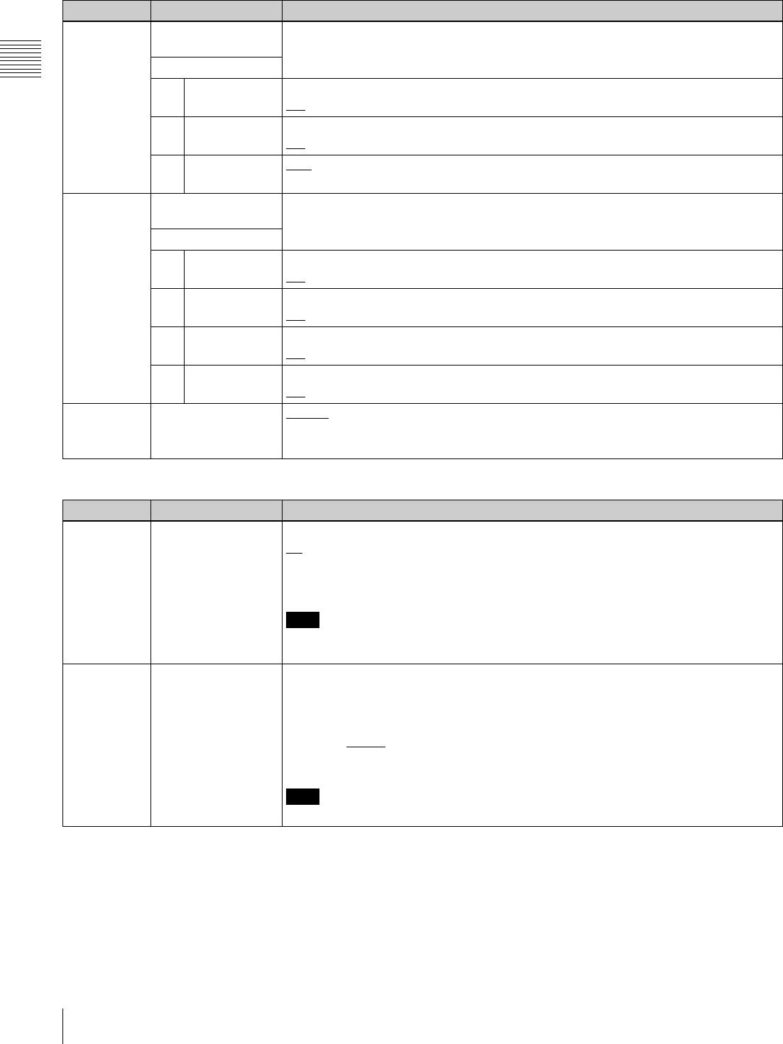
92 9-4 Items in the Extended Setup Menu
Chapter 9 Setup Menus
631 REC START MARK
MODE
Sub-item
1 CRASH REC OFF: Do not write recording start marks.
ON: Write recording start marks during normal recording.
2 ASSEMBLE OFF: Do not write recording start marks.
ON: Write recording start marks during assemble editing.
3 INSERT OFF: Do not write recording start marks.
ON: Write recording start marks during insert editing.
635 LISTING TYPE
SELECT
Sub-item
1 REC START
MARK
OFF: Do not read recording start marks.
ON: Read recording start marks.
2 SHOT MARK 1 OFF: Do not read shot mark 1.
ON: Read shot mark 1.
3 SHOT MARK 2 OFF: Do not read shot mark 2.
ON: Read shot mark 2.
4POST MARKOFF: Do not read post marks.
ON: Read post marks.
636 MARK SELECT IN
REC/ASSEMBLE
SHOT1: Write shot mark 1 during recording and assemble editing.
SHOT2: Write shot mark 2 during recording and assemble editing.
POST: Write post marks during recording and assemble editing.
Menu items in the range 651 to 699, relating to the UMID
Item number Item name Settings
651 UMID OUTPUT Select the UMID type to be output.
off: Do not output UMID.
BASIC: Output Basic UMID.
EXTND: Output Extended UMID.
Note
Even if “EXTND” is selected, Basic UMID is output if Basic UMID is recorded on the
tape being played back.
653 UMID HD VANC
LINE
Specify the HDSDI signal VANC line into which the generated UMID should be inserted.
9, 572 14,577 19,582
10,573 15,578 20,583
11,574 16,579
12,575 17,580
13,576 18,581
Note
The output VANC line during playback follows the setting for recording.
Menu items in the range 600 to 650, relating to the timecode generator (Continued)
Item number Item name Settings
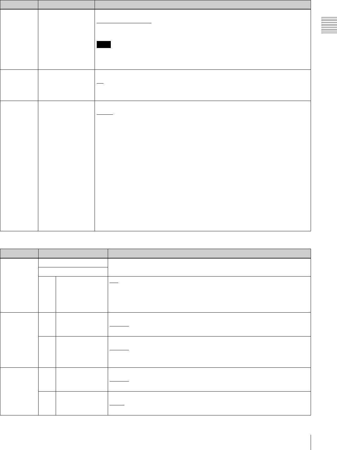
93
9-4 Items in the Extended Setup Menu
Chapter 9 Setup Menus
654 UMID GENERATE
METHOD
Select the Instance Number. generation method when the UMID is inherited.
COPY No.+16bit PRS: Copy No. + 16-bit random number
24bit PRS: 24-bit random number
Note
When menu item 656 is set to “NEW” (an Instance Number indicating that “this is the
original” is generated), the same value (all zeros) is generated regardless of which of
the above methods is selected.
655 UMID RECORDING Select the UMID type to be recorded to tape.
off: Do not record UMID.
BASIC: Record Basic UMID.
EXTND: Record Extended UMID.
656 MATERIAL NO. Select whether to inherit the UMID in the input signal when recording a UMID.
INPUT: Inherit the UMID in the input signal, if it is contained.
• Even when “INPUT” is selected, a new UMID is generated if the input signal does
not contain UMID data (same as when “NEW” is selected).
• When recording with inherited data, the Instance Number is newly generated
according to menu item 654 and changed to a value that indicates that “this is a
copy”.
• When the UMID in the input signal is a Basic UMID, the Basic UMID is recorded,
even if menu item 655 is set to “EXTND”.
• When the UMID in the input signal is an Extended UMID, the recorded UMID
follows the setting of menu item 655.
NEW: Generate a new UMID, regardless of whether or not the input signal contains a
UMID.
• The Basic section does not change during recording.
• An Instance Number indicating that “this is the original” is generated.
• The Source Pack Date/Time (when) changes with each frame.
• The Source Pack Spatial Co-ordinates (where) are not recorded.
• The Source Pack Stored Ownership (who) can be set. (See the section “To set
Stored Ownership” (page 61)).
Menu items in the range 700 to 799, relating to video control
Item number Item name Settings
703 BLANK LINE SELECT Select blanking on or off for individual lines in the vertical blanking interval of the
SD video signal.The Y/C signal and odd/even fields are blanked simultaneously.
Sub-Item
0 ALL LINE - - -: Specify the blanking for each line individually.
BLANK: Regardless of the setting of other sub-items, blank all lines which can be
specified in this menu item.
THROU: Regardless of the setting of other sub-items, switch off blanking for all
lines which can be specified in this menu item.
In 59.94i
mode (59.94i
or 29.97PsF)
12 ...
19
LINE 12 ... LINE 19 Specify blanking for lines 12 to 19.
BLANK: Carry out blanking.
THROU: Switch off blanking.
20 LINE 20 Specify blanking for line 20.
BLANK: Carry out blanking.
HALF: Carry out half-blanking.
THROU: Switch off blanking.
In 50i mode
(50i or
25PsF)
9 ...
22
LINE 9 ... LINE 22 Specify blanking for lines 9 to 22.
BLANK: Carry out blanking.
THROU: Switch off blanking.
23 LINE 23 Specify blanking for line 23.
HALF: Carry out half-blanking.
THROU: Switch off blanking.
Menu items in the range 651 to 699, relating to the UMID (Continued)
Item number Item name Settings
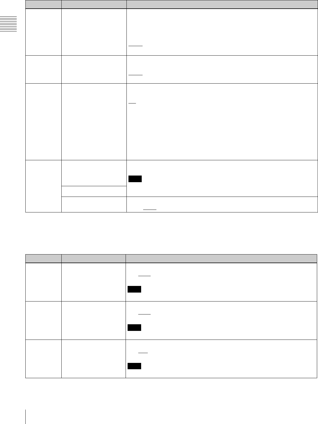
94 9-4 Items in the Extended Setup Menu
Chapter 9 Setup Menus
a) The “Y-add” function is a circuit operation to interpolate the video signal
vertically during jog or variable speed playback for reducing the vertical
movement of the playback picture.
705 EDGE SUBCARRIER
REDUCER MODE (HDW-
D1800 only)
During recording and playback of a composite signal, in the playback circuit the
edge subcarrier reducer (ESR) is automatically switched on or off according to the
VTR operation. When recording a “Non-Standard” signal, for example, if the color
edges are not as good as with a proper signal, the ESR can be forced on.
This item makes this selection.
AUTO: ESR is switched on and off automatically.
ON: ESR operation is forced on.
707 FORCED VERTICAL
INTERPOLATION OFF The “Y-add” a) function is normally switched on automatically during jog or variable
speed playback. This item selects whether to force the “Y-add” function off.
AUTO: Automatically switch the “Y-add” function on.
OFF: Force the “Y-add” function off.
710 INTERNAL VIDEO
SIGNAL GENERATOR
Select the test signal to be output from the internal test signal generator.
OFF: No test signal is generated. (The VTR operates normally.)
CB: Color bar signal
MLTBS: Multi-burst signal
10STP: 10-step signal
PLSBR: Pulse and bar signal
RAMP: Ramp signal
BLACK: Black signal
To select the video test signal, display function menu page P03: VID PROC, hold
down the ALT/DELETE button, then select F1 (VIDEO IN).
To cancel the signal selection, select F1 (VIDEO IN).
713 VIDEO SETUP
REFERENCE LEVEL (In
59.94i or 29.97PsF mode
only)
Set the video setup level to be added to the composite output signal.
Note
The setup level specified in this menu item has no effect on the setting of F9
(SETUP LV/BLK LEVL) in function menu page P03: VID PROC.
Sub-Item
OUTPUT LEVEL
(59.94i mode)
The setup level specified for this sub-item is added to the output signal.
0.0%, 7.5%
Menu items in the range 700 to 799, relating to video control (Continued)
Item number Item name Settings
Menu items in the range 700 to 799, relating to video control (continued)
(Menu items in the range 715 to 720, settings for controlling the SD video processing according to the menu settings)
Item number Item name Settings
715 VIDEO GAIN CONTROL Adjust the video output level.
0 to 800H to B50H
Note
This item is valid for both HD and SD outputs.
716 CHROMA GAIN
CONTROL
Adjust the chroma output level.
0 to 800H to B50H
Note
This item is valid for both HD and SD outputs.
717 CHROMA PHASE
CONTROL
Adjust the chroma phase.
0 to 80H to FFH
Note
This item is valid for both HD and SD outputs.
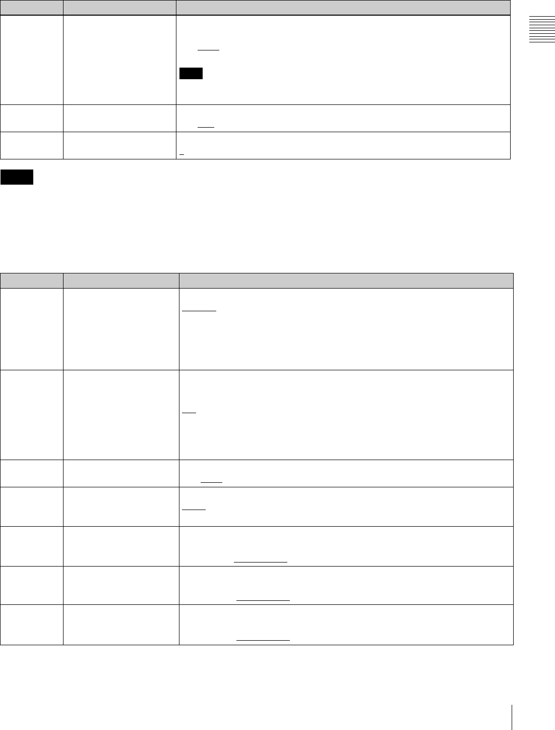
95
9-4 Items in the Extended Setup Menu
Chapter 9 Setup Menus
• For menu items 715 to 718 or 740 to 747, set F5
(V.PROC) in function menu item P03: VID PROC to
“MENU”. When it is set to “MENU”, all controls for
video output processing on the control panel are
disabled.
• When menu item 337 is set to “SD”, changing the
settings of menu items 719 and 720 changes the phase of
HD output signals as well as that of SD.
After changing these settings, use F3 (SYNC PHS) and
F4 (SYNC FIN) in function menu page P03: VID PROC,
or menu items 745 and 746 to readjust the phase of HD
output signals.
718 SETUP(BLACK) LEVEL (Has no effect in 24PsF or 23.98PsF mode)
Adjust the SD setup level (black level).
0 to 110H to 220H
Note
This item is valid for both HD and SD outputs when sub-item “D2 SETUP” of menu
item 212 “VIDEO REMOTE CONTROL SELECT” is set to “Black”.
719 SYSTEM PHASE SYNC Adjust the SD output signal sync phase.
0 to 80H to FFH
720 SYSTEM PHASE SC Adjust the SD output signal subcarrier phase.
0 to 3FFH
Menu items in the range 700 to 799, relating to video control (continued)
(Menu items in the range 715 to 720, settings for controlling the SD video processing according to the menu settings)
Item number Item name Settings
Notes
Menu items in the range 700 to 799, relating to video control (continued)
Item number Item name Settings
726 H BLANKING WIDTH Select the horizontal blanking width of the video output signal.
NAROW: Digital blanking (narrow)
WIDE: Analog blanking (wide)
When “WIDE” is selected, the horizontal blanking width complies with RS170A,
and normally the blanking is widened and the image becomes narrower. It is
recommended to select “NAROW” at editing, then select “WIDE” for broadcast
transmission to output a signal conforming to the standard.
727 VIDEO EDIT PREVIEW
SWITCHER
Set the output phase for the video playback signal when any of F2 (INS TC), F3
(INS CUE), and F5 (ASSEMBLE) to F10 (INS A4) in function menu page P07:
E.PRESET is lit.
INT: The video playback signal output phase is the same as the output phase in E-
E mode. Use this setting when editing with a single VTR, or when previewing
while monitoring the VTR output signal.
EXT: The video playback signal output phase is the same as the phase of an input
video signal or external reference signal.
728 OUTPUT SCH PHASE Control the subcarrier H phase.
0 to 800H to FFFH
732 COMPOSITE MODE Select the chroma filter through which the composite video signals are output.
WIDE: Output via SMPTE WIDE.
STD: Output via SMPTE STANDARD (NARROW).
740 MASTER LEVEL (HD) Adjust the Y, PB, and PR levels of the high-definition video signal output from the
HDSDI OUTPUT connector simultaneously.
0.0%(0H) to 100% (800H) to 141.3% (B4EH)
741 Y LEVEL (HD) Adjust the Y level of the high-definition video signal output from the HDSDI
OUTPUT connector.
0.0% (0H) to 100% (800H) to 141.3% (B4EH)
742 PB LEVEL (HD) Adjust the PB level of the high-definition video signal output from the HDSDI
OUTPUT connector.
0.0% (0H) to 100% (800H) to 141.3% (B4EH)
96 9-4 Items in the Extended Setup Menu
Chapter 9 Setup Menus
743 PR LEVEL (HD) Adjust the PR level of the high-definition video signal output from the HDSDI
OUTPUT connector.
0.0% (0H) to 100% (800H) to 141.3% (B4EH)
745 SETUP LEVEL (HD) Adjust the setup level of the high-definition video signal output from the HDSDI
OUTPUT connector.
0 to 110H to 220H
746 SYNC PHASE (HD) Control the H sync phase of the high-definition video signal output from the HDSDI
OUTPUT connector according to the menu.
0 to 80H to FFH
747 SYNC PHASE FINE (HD) Fine control the H sync phase of the high-definition video signal output from the
HDSDI OUTPUT connector according to the menu.
0 to 3FFH
Menu items in the range 800 to 899, relating to audio control
Item number Item name Settings
801 DIGITAL JOG SOUND Turns the digital jog sound on and off.
OFF: Digital jog sound is turned off.
Audio of digital channels not subjected to speed correction is output. When the
tape stops, after one second the audio is muted.
ON: Digital jog sound is turned on.
When the tape speed is in the range x–1 to x+1, speed correction is carried out,
and the same jog sound as a conventional analog VTR is output.
802 DIGITAL AUD MUTING IN
SHUTTLE MODE
Set the digital audio muting conditions during shuttle playback.
OFF: Not muted.
CUEUP: Muted during cueup or preroll operations.
FULL: Muted in shuttle mode.
803 DIGITAL AUDIO FADE
TIME
Specify the time for cross-fade or fade in/out editing of digital audio signals.
5ms, 10ms, 15ms, 20ms, 25msa), 50msb), 85ms, 115msc)
Note
The cross-fade or fade in/out operation means that the recording is rewritten from
the OUT point for the length specified by this setting. Even at the minimum 5ms
setting, a length of recording corresponding to a field is rewritten.
To avoid rewriting, set menu item 317 “AUDIO EDIT MODE” to “CUT”. In this case
there is an audio discontinuity at the edit point. There is no effect on the recorded
video signal.
805 AUDIO MONITOR
OUTPUT MIXING
Select the audio mixing method used for digital audio signals supplied to the
MONITOR OUTPUT connector.
ADD: Simple addition
RMS: Root-mean-square
AVE: Simple average
806 LEVEL METER SCALE Select the digital audio level display mode.
PEAK0: Display the audio level as negative values with the maximum level set to
“0 dB”.
REF.0: Display the audio level as positive and negative values with the reference
level set to “0 dB”.
807 AUDIO OUTPUT PHASE Select the output timing of digital audio playback signals (HDSDI, SDI and AES/
EBU only). The reference position is 80H; when the setting is less than 80H, the
output timing is advanced, and when it is higher than 80H, the output timing is
delayed. (at 80H, 128 samples = approx. 2.7 ms, and 1 sample = approx. 20 µs)
0 to 80 to FF: Set in this range.
Menu items in the range 700 to 799, relating to video control (continued)
Item number Item name Settings

97
9-4 Items in the Extended Setup Menu
Chapter 9 Setup Menus
808 INTERNAL AUDIO
SIGNAL GENERATOR
Select the operation of the internal audio test signal generator.
OFF: No operation
SILNC: Silent signal
1KHZ: At 1 kHz, –20 dB FS sine wave is supplied to all audio input channels.
To output the internal audio test signal, display function menu page P08: AUD INP,
hold down the ALT/DELETE button, then select F6 (AUDIO SG).
To cancel the signal output, hold down the ALT/DELETE button and select F6
(AUDIO SG).
Note
When the system frequency is 24PsF or 23.98PsF, the frequency of the internal
audio test signal is reduced 4% of the normal frequency.
810 AUDIO EDIT PREVIEW
SWITCHER
Set the output phase for the audio playback signal when any of F2 (INS TC), F3
(INS CUE), and F5 (ASSEMBLE) to F10 (INS A4) in function menu page P07:
E.PRESET is lit.
INT: The audio playback signal output phase is the same as the output phase in the
E-E mode. Select this setting when editing with a single VTR, or when
previewing while monitoring the VTR output signal.
EXT: The audio playback signal output phase is the same as the phase of an input
video signal or external reference video signal.
823 NON-AUDIO FLAG PB
(HDW-D1800 only)
Controls the non-audio flag when the playback format is Digital Betacam.
Sub-item
1 CH1/CH2 During playback (except E-E mode), set the digital audio non-audio flag as follows.
OFF: OFF (the data is audio)
ON: ON (the data is non-audio)
AUTO: As follows
• Tape data has been read and confirmed: “ON” or “OFF”, according to the data.
• Tape data has not been confirmed: Current state is maintained.
Note
In the HDCAM format, the non-audio flag follows the setting of maintenance menu
item M372 during recording and E-E mode.
For more information about the maintenance menu item M372, refer to the
Maintenance Manual.
2 CH3/CH4
824 ANALOG LINE OUTPUT
SELECT
Select the analog audio signals (tracks 1 to 8) to be assigned to audio output
channels 1 and 2.
tr1/2: Tracks 1 and 2 assigned to audio output channels 1 and 2.
tr3/4: Tracks 3 and 4 assigned to audio output channels 1 and 2.
tr5/6: Tracks 5 and 6 assigned to audio output channels 1 and 2 (HDW-D1800
only).
tr7/8: Tracks 7 and 8 assigned to audio output channels 1 and 2 (HDW-D1800
only).
825 AUDIO ADVANCE MODE Set the audio output phase.
OFF: Same as the video output phase
ON: One frame ahead of the video output phase
Menu items in the range 800 to 899, relating to audio control (Continued)
Item number Item name Settings
98 9-4 Items in the Extended Setup Menu
Chapter 9 Setup Menus
a) Cross-fade time is 24 ms.
b) Actual value is 49 ms.
c) Actual value is 114 ms.
826 AUDIO PB VOLUME
SELECT (HDW-D1800
only)
Selects which PB knobs are assigned for the playback of digital audio channels.
Sub-item
0ALL CH DEFAULT: Use the following settings.
CH1: Control knob 1
CH2: Control knob 2
CH3: Control knob 3
CH4: Control knob 4
CH5: UNITY
CH6: UNITY
CH7: UNITY
CH8: UNITY
UNITY: Set all channels to “UNITY”, and disable the PB knobs.
MENU: Use the following menu settings.
1 CH1 UNITY: Set playback level to “UNITY”.
vol 1: Assign playback level control to control knob 1.
vol 2: Assign playback level control to control knob 2
vol 3: Assign playback level control to control knob 3.
vol 4: Assign playback level control to control knob 4.
2 CH2
3 CH3
4 CH4
5 CH5
6 CH6
7 CH7
8 CH8
833 CUE AUDIO INPUT
SELECT
Select which digital audio channels are recorded in the CUE channel.
OFF: Do not record.
CH1+2: Record audio channels 1 and 2.
CH3+4: Record audio channels 3 and 4.
CH1: Record audio channel 1.
CH2: Record audio channel 2.
Menu items in the range 800 to 899, relating to audio control (Continued)
Item number Item name Settings
Menu items in the range 900 to 999, relating to digital processing
Item number Item name Settings
901 VIDEO OUTPUT DATA Select the number of quantization bits for video output.
8bit: Set the bit length to 8 bits.
10bit: Set the bit length to 10 bits.
903 FREEZE MODE Set the freeze mode and timing for image freezing.
FIELD: Freeze a video field. Field may be odd or even, according to the timing.
FLD1: Freeze an odd field.
FLD2: Freeze an even field.
FRM12: Freeze a frame consisting of an odd field and following even field.
FRM21: Freeze a frame consisting of an even field and following odd field.
Odd and even fields are distinguished by the reference video signal.
Changing the menu setting during a freeze does not affect the freeze image.
The setting is reflected the next time a freeze is carried out.
To freeze an image, use F8 (FREEZE) in function menu page P05: MISC-2.
For details, see menu item 904.

99
9-4 Items in the Extended Setup Menu
Chapter 9 Setup Menus
904 FREEZE CONTROL
FROM KEY PANEL
Select how the buttons used to freeze an image function.
MOMNT: Select F8 (FREEZE) in function menu page P05: MISC-2 carries out a
freeze. The freeze ends when the button is released.
LATCH: Select the F8 (FREEZE) carries out a freeze. The freeze continues even
after the button is released.
• To update the freeze image
Select F8 (FREEZE) again.
• To end the freeze
Select F9 (FREZ OFF).
905 AUTO FREEZE
CONTROL
Set the auto freeze function operation (conditions for cancelling a freeze, etc.).
In dynamic tracking (DT) playback (VAR, JOG, PLAY or SHTL mode), if there is a
sudden worsening of the channel condition (entry into unrecorded area), this
function detects the sudden worsening and freezes the image.
DIS: Disable the auto freeze function.
MODE1: Automatically cancel the freeze when signals which can be normally
played back are restored.
MODE2: Automatically cancel the freeze upon start of playback after stopping.
• The automatic freeze mode is set by menu item 903.
• The freeze is ended immediately, regardless of the above settings, when this
unit is switched to any of the following modes:
Edit preset function on
Cue up
Recording
906 STOP FREEZE
CONTROL
Select whether the STOP FREEZE function should operate.
DIS: Do not operate.
ENA: Operate.
stby: Operate only in standby mode.
918 a) SLOW PROCESS MODE
(enabled only when the
optional HKDW-104 board
is installed)
Select whether to increase the vertical resolution during slow playback by
activating the relevant filter.
OFF: Do not increase the vertical resolution during slow playback.
ON: Increase the vertical resolution during slow playback.
920 SD-SDI H-ANC CONTROL
(Invalid in 24PsF or
23.98PsF mode)
Select whether to add information to the SD output.
Sub-item
1 AUDIO 5CH-8CH ON: Add digital audio data CH5 to CH8.
OFF: Do not add digital audio data CH5 to CH8.
2RP188 ATC ON: Add RP188 timecode data.
OFF: Do not add RP188 timecode data.
921 ASPECT FLAG
(Invalid in 50i, 25PsF,
24PsF or 23.98PsF mode)
Select whether to add the 16:9/Squeeze ID signal provided for by ARIB TR-B17 to
the down-converted SD output when an HDCAM tape is played back. Also select
whether to switch the upconverter mode when a 16:9/Squeeze ID signal is
detected on an SD playback tape.
OFF: Do not add the 16:9/Squeeze ID signal to the SD signal down-converted from
HD.
When an SD tape is played back, the upconverter mode follows setup menu
item 950 regardless of detection of the ID signal on the tape.
ON: Add the 16:9/Squeeze ID signal to SD output down-converted from HD in
Squeeze mode.
When an SD tape is played back, automatically switch the upconverter mode
change by detecting the ID signal on the tape. If the 16:9/Squeeze ID signal is
not detected on the SD tape, the upconverter mode follows setup menu item
950.
Menu items in the range 900 to 999, relating to digital processing (Continued)
Item number Item name Settings

100 9-4 Items in the Extended Setup Menu
Chapter 9 Setup Menus
930 DOWN CONVERTER
MODE (Invalid in 24PsF or
23.98PsF mode)
Select the downconverter mode.
crop: Select the edge-crop mode.
l-box: Select the letter box mode.
squez: Select the squeeze mode.
931 DOWN CONVERT
LETTER BOX MODE
(Invalid in 24PsF or
23.98PsF mode)
Select the aspect ratio of the downconverter output when menu item 930 is set to
“l-box”.
16:9: Set the aspect ratio of the HD-SD converter output to 16:9.
14:9: Set the aspect ratio of the HD-SD converter output to 14:9.
13:9: Set the aspect ratio of the HD-SD converter output to 13:9.
932 H CROP POSITION (DC)
(Invalid in 24PsF or
23.98PsF mode)
Adjust the “H-crop” (the horizontal position when cropping in the edge crop mode)
of the downconverter output when menu item 930 is set to “crop”.
–120 to 0 to 120
934 CROSS COLOR (DC)
(Invalid in 24PsF or
23.98PsF mode)
Adjust the downconverter cross color.
0 to 8 to 15
935 DETAIL GAIN (DC) (Invalid
in 24PsF or 23.98PsF
mode)
Adjust the downconverter image enhancer. Adjust the sharpness of edge
enhancement.
0 to 20H to 7FH
936 LIMITER (DC) (Invalid in
24PsF or 23.98PsF mode)
Adjust the downconverter image enhancer.
Adjust the maximum detail level added to emphasize the original signal.
0 to 20H to 3FH
937 CRISP THRESHOLD (DC)
(Invalid in 24PsF or
23.98PsF mode)
Adjust the downconverter image enhancer. Set the threshold amplitude at which
low amplitude signals are not emphasized.
0 to FH
938 LEVEL DEPEND
THRESHOLD (DC)
(Invalid in 24PsF or
23.98PsF mode)
Adjust the downconverter image enhancer. Set the luminance range for edge
enhancement.
0 to 8 to FH
939 H DETAIL FREQUENCY
(DC) (Invalid in 24PsF or
23.98PsF mode)
Adjust the downconverter image enhancer. Set the center frequency for edge
enhancement.
2.6MHz to 3.4MHz to 3.9MHz to 4.6MHz
940 H/V RATIO (DC) (Invalid in
24PsF or 23.98PsF mode)
Adjust the downconverter image enhancer. Set the horizontal/vertical ratio for
edge enhancement.
0 to 3 to 7
941 GAMMA LEVEL (DC)
(Invalid in 24PsF or
23.98PsF mode)
Adjust downconverter image enhancer. Adjust the slope of the correction curve.
0 to 80H to 100H
942 V FILTER SELECT (Invalid
in 24PsF or 23.98PsF
mode)
Set the vertical interpolation filter coefficient for downconverter output.
The vertical resolution increases as the larger value is selected.
1 to 3
943 CROSS COLOR CRISP
(Invalid in 24PsF or
23.98PsF mode)
Set the cross color crisp level for downconverter output.
0 to 4 to FH
950 UP CONVERTER MODE
(HDW-D1800 only. Invalid
in 24PsF or 23.98PsF
mode)
Select the upconverter mode.
crop: Select the edge-crop mode.
l-box: Select the letter box mode.
squez: Select the squeeze mode.
951 H CROP POSITION (UC)
(HDW-D1800 only. Invalid
in 24PsF or 23.98PsF
mode)
Adjust the “H-crop” (the horizontal position when inserting in edge crop mode) of
the upconverter output when menu item 950 is set to “crop”.
–120 to 0 to 120
Menu items in the range 900 to 999, relating to digital processing (Continued)
Item number Item name Settings

101
9-4 Items in the Extended Setup Menu
Chapter 9 Setup Menus
952 LETTER BOX POSITION
(UC) (HDW-D1800 only.
Invalid in 24PsF or
23.98PsF mode)
Adjust the vertical position cropped in the letter box mode for upconverter output
when menu item 950 is set to “l-box”.
–120 to 0 to 120
953 UP CONVERTER
PROCESS SELECT
(HDW-D1800 only. Invalid
in 24PsF or 23.98PsF
mode)
Select the original picture to use when converting SD to HD.
FIELD: Use field picture.
FRAME: Use frame picture.
adapt (standard mode): Set the ratio of converting from frames or fields to the
standard ratio when up-converting.
adap2 (still playback priority mode): Set a higher ratio of converting from frames
when up-converting.
adap3 (motion priority mode): Set a higher ratio of converting from fields when
up-converting.
954 DETAIL GAIN (UC) (HDW-
D1800 only. Invalid in
24PsF or 23.98PsF mode)
Adjust the upconverter image enhancer. Adjust the sharpness of edge
enhancement.
0 to 40H to 7FH
955 LIMITER (UC) (HDW-
D1800 only. Invalid in
24PsF or 23.98PsF mode)
Adjust the upconverter image enhancer.
Adjust the maximum detail level added to emphasize the original signal.
0 to 20H to 3FH
956 CRISP THRESHOLD (UC)
(HDW-D1800 only. Invalid
in 24PsF or 23.98PsF
mode)
Adjust the upconverter image enhancer. Set the threshold amplitude at which low
amplitude signals are not emphasized.
0 to 8 to FH
957 LEVEL DEPEND
THRESHOLD (UC)
(HDW-D1800 only. Invalid
in 24PsF or 23.98PsF
mode)
Adjust the upconverter image enhancer. Set the luminance range for edge
enhancement.
0 to 8 to FH
958 H DETAIL FREQUENCY
(UC) (HDW-D1800 only.
Invalid in 24PsF or
23.98PsF mode)
Adjust the upconverter image enhancer. Set the center frequency and frequency
characteristic for edge enhancement.
3.2MHz: 3.2 MHz ±1.1 MHz
4.5MHz: 4.5 MHz ±1.4 MHz
5.0MHz: 5.0 MHz ±0.7 MHz
4.0MHz: 4.0 MHz ±2.0 MHz
959 H/V RATIO (UC) (HDW-
D1800 only. Invalid in
24PsF or 23.98PsF mode)
Adjust the upconverter image enhancer. Set the horizontal/vertical ratio for edge
enhancement.
0 to 3 to 7
960 GAMMA LEVEL (UC)
(HDW-D1800 only. Invalid
in 24PsF or 23.98PsF
mode)
Adjust the upconverter image enhancer. Adjust the slope of the correction curve.
0 to 80H to 100H
Menu items in the range 900 to 999, relating to digital processing (Continued)
Item number Item name Settings

102 9-4 Items in the Extended Setup Menu
Chapter 9 Setup Menus
a) This menu item is enabled only on HDW-1800 (SYL) units having a serial
number 10059 or higher, on HDW-1800 (CNB) units having a serial
number 51001 or higher, HDW-D1800 (SYL) units having a serial number
10037 or higher, and HDW-D1800 (CNB) units having a serial number
51001 or higher.
961 BACKGROUND COLOR
(UC) (HDW-D1800 only.
Invalid in 24PsF or
23.98PsF mode)
Set the color of the part where no material exists (background) for up-converting.
BACKGROUND COLOR: Set the color.
BLACK : Black
GRAY: Gray
BLUE: Blue
TABLE: Set with the following Y/PB/PR tables.
Y TABLE: Adjust the background Y level.
0 to FFH
B-Y TABLE: Adjust the background B-Y level.
0 to 80 to FFH
R-Y TABLE: Adjust the background R-Y level.
0 to 80 to FFH
Menu items in the range 900 to 999, relating to digital processing (Continued)
Item number Item name Settings

103
10-1 Removing a Cassette when Tape Slack Occurs / 10-2 Head Cleaning
Chapter
Chapter 10 Maintenance and Inspection
10
Maintenance and
Inspection
10-1 Removing a
Cassette when Tape
Slack Occurs
If tape slack occurs in the unit, it is necessary to remove the
upper lid and sound baffle. This job should always be
entrusted to a technician who has undergone service
training.
For details, refer to the Installation Manual.
10-2 Head Cleaning
To clean the video heads and audio heads, always use the
special-purpose BCT-HD12CL cleaning cassette.
If you insert the cleaning cassette, it is automatically
ejected after a head cleaning operation for 10 seconds.
Follow the instructions with the cleaning cassette
carefully, as inappropriate use of the cleaning cassette can
damage the heads.
You cannot use the BCT-5CLN cleaning cassette.
Note

104 10-3 Error Messages
Chapter 10 Maintenance and Inspection
10-3 Error Messages
This unit is equipped with a self-diagnosis function. If a
problem is detected, it displays an error message in the
time data display and on the video monitor.
If an error message appears, contact your Sony service
representative.
Indications in the time data display
If a problem is detected, the ALARM indicator in the
lower control panel lights, and an error message and error
code appear in the time data display area.
Indications on the external monitor
The error message and code also appear superimposed on
a monitor connected to the COMPOSITE VIDEO
OUTPUT 3 (SUPER) connector, HDSDI OUTPUT 3
(SUPER) connector or SDI OUTPUT 3 (SUPER)
connector. Depending on the error code, a secondary error
message may appear indicating the location of the
problem.
Error message displays
• To display error messages and codes superimposed on
the video monitor, it is necessary to set F5 (CHARA) in
function menu page P04: MISC-1 to “ON”.
• Some error messages have no associated error codes. In
this case, they appear in the entire area of the time data
display.
• Error messages with error codes are saved in NV-RAM
(non-volatile memory) as an error log.
• In some cases the error message superimposed on the
external monitor is slightly different from the message
displayed in the time data display.
12 34
:
47 12
::
ALARM indicator
Time data display area
ERROR-01
REEL TROUBLE-1

105
10-3 Error Messages
Chapter 10 Maintenance and Inspection
Error Message List
Code Message Description
– (ALARM indicator
flashing)
Abnormal interface between the lower control panel (on KY-615 board) and SYS CPU (on
SS-340 and SS-101 boards) has been detected on the lower control panel.
01 REEL TROUBLE Tape slacking has been detected in the threading or unthreading operation.
02 REEL TROUBLE Tape slacking or tape breaking has been detected in search, fast forward,or rewind mode.
03 REEL TROUBLE Tape slacking, tape breaking,or supply or take-up reel locking has been detected in recording
or playback mode.
04 REEL TROUBLE Abnormal tape transport speed has been detected in fast forward or rewind mode.
05 REEL TROUBLE Malfunction of the supply or take-up reel has been detected during cassette insertion.
06 TAPE TENSION Excessive tape tension has been detected in recording or playback mode.
07 CAPSTAN TROUBLE Malfunction of capstan motor has been detected.
08 DRUM TROUBLE Malfunction of drum motor has been detected.
09 TH/UNTH MOTOR Malfunction of threading or unthreading operation has been detected.
0A THREADING The tape top processing has not been completed in the threading mode.
10 HUMID Moisture condensation has been detected.
11 TAPE T/E SENSOR The tape top and tape end have been detected simultaneously.
12 TAPE TOP SENSOR Malfunction of tape top sensor has been detected.
13 TAPE END SENSOR Malfunction of tape end sensor has been detected.
14 FAN MOTOR Malfunction of cooling fan motor has been detected.
20 CASS COMP MOTOR Malfunction of cassette compartment up or down operation has been detected.
21 REEL SFT MOTOR Malfunction of movement of the reel table corresponding to the cassette size has been
detected.
22 REEL POS SENSOR The L-cassette and S-cassette positions of the reel table have been detected simultaneously.
23 THRED RING SENS The thread end and unthread end states of the threading ring have been detected
simultaneously.
92 INTERNAL I/F1 Abnormal interface between SYS CPU (on SS-101 board) and other CPU/MPU has been
detected.
93 CPU INITIALIZE
ERROR
Abnormal interface between SV CPU (on SS-101 board) and DRUM CPU (on DR-508 board)
has been detected.
95 OTHERS NV-RAM
ERROR
Abnormal operation has been detected on NV-RAM on FP-153 board.
96 SY NV-RAM ERROR Abnormal operation has been detected on NV-RAM (on SS-101 board) for the system
control.
97 SV NV-RAM Abnormal operation has been detected on NV-RAM (on DR-508 board) for the servo system.
98 RF NV-RAM ERROR Abnormal operation has been detected on NV-RAM (on EQ-104 board) for the RF system.
99 INTERNAL I/F 2 Abnormal interface between SYS CPU (on SS-101 board) and SERVO CPU (on SS-101
board) or among each board (EQ-104, HPR-21, VPR-98, APR-80, SY-340 or KY-615 board)
has been detected.
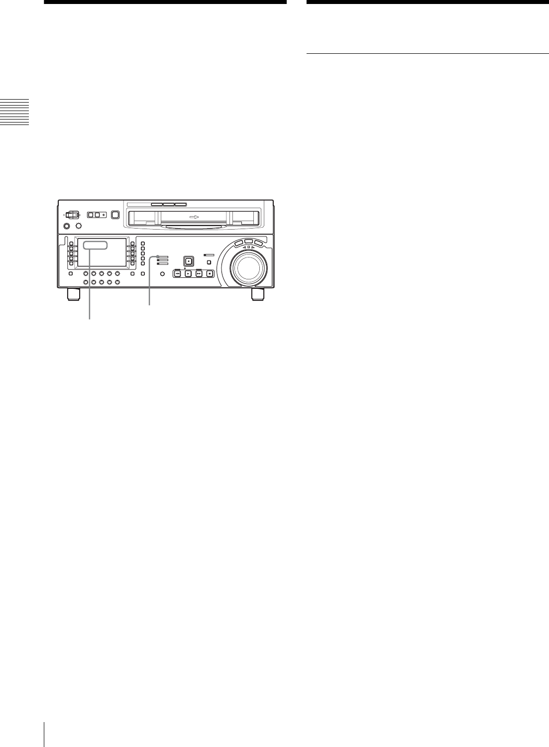
106 10-4 Moisture Condensation / 10-5 Regular Checks
Chapter 10 Maintenance and Inspection
10-4 Moisture
Condensation
When the unit is suddenly moved from a cold to a warm
location, or used in a very humid place, moisture from the
air can condense on the head-drum. This is called moisture
condensation. If the tape is run in this state, it can adhere
to the drum and damage the tape. To prevent this, the unit
is provided with a moisture detecting function.
If moisture condenses on the head-drum while the unit is
in use, the ALARM indicator lights and “ERR-10” is
displayed in the time data display.
If this happens, the drum and capstan motors stop and the
cassette is automatically ejected. Then, the drum starts to
rotate again to dry its surface. In this state, the unit is not
operable. When the moisture has evaporated, the error
message disappears and the ALARM indicator goes off.
If “ERR-10” appears and the ALARM
indicator lights immediately after powering
the unit on
Leave the unit powered on and wait until the error message
disappears and the ALARM indicator goes off.
While the indicator is lit, you cannot insert a cassette.
When the indicator goes off and the error message
disappears, you can use the unit.
If you move the unit from a cold to a warm
location
Leave the unit powered off for about 10 minutes, since it
takes some time to detect moisture condensation in this
state.
10-5 Regular Checks
10-5-1 Digital Hours Meter
The digital hours meter in the time data display can display
seven items of information about the operational history of
the unit in each corresponding mode. Use it as a guide in
scheduling periodic maintenance.
Display modes of the hours meter
H01: OPERATION mode
Displays the total number of hours the unit has been
powered on in units of 1 hour.
H02: DRUM RUNNING mode
Displays the total number of hours the drum has run with
tape threaded in units of 1 hour.
H03: TAPE RUNNING mode
Displays the total number of hours the unit has been in fast
forward, rewind, playback, search, recording or editing
(except for stop and still) mode in units of 1 hour.
H04: THREADING mode
Displays the total number of times tape has been threaded
in the unit.
H12: DRUM RUNNING mode (resettable)
Same as H02 except that the count is resettable.
This can be used as a guide in determining when to replace
the drum.
H13: TAPE RUNNING mode (resettable)
Same as H03 except that the count is resettable.
This can be used as a guide in determining when to replace
components such as fixed heads and pinch rollers.
H14: THREADING mode (resettable)
Same as H04 except that the count is resettable.
This can be used as a guide in determining when to replace
components such as the threading motor.
R- 10ER
ALARM indicator
“ERR-10” appears in the time data display.
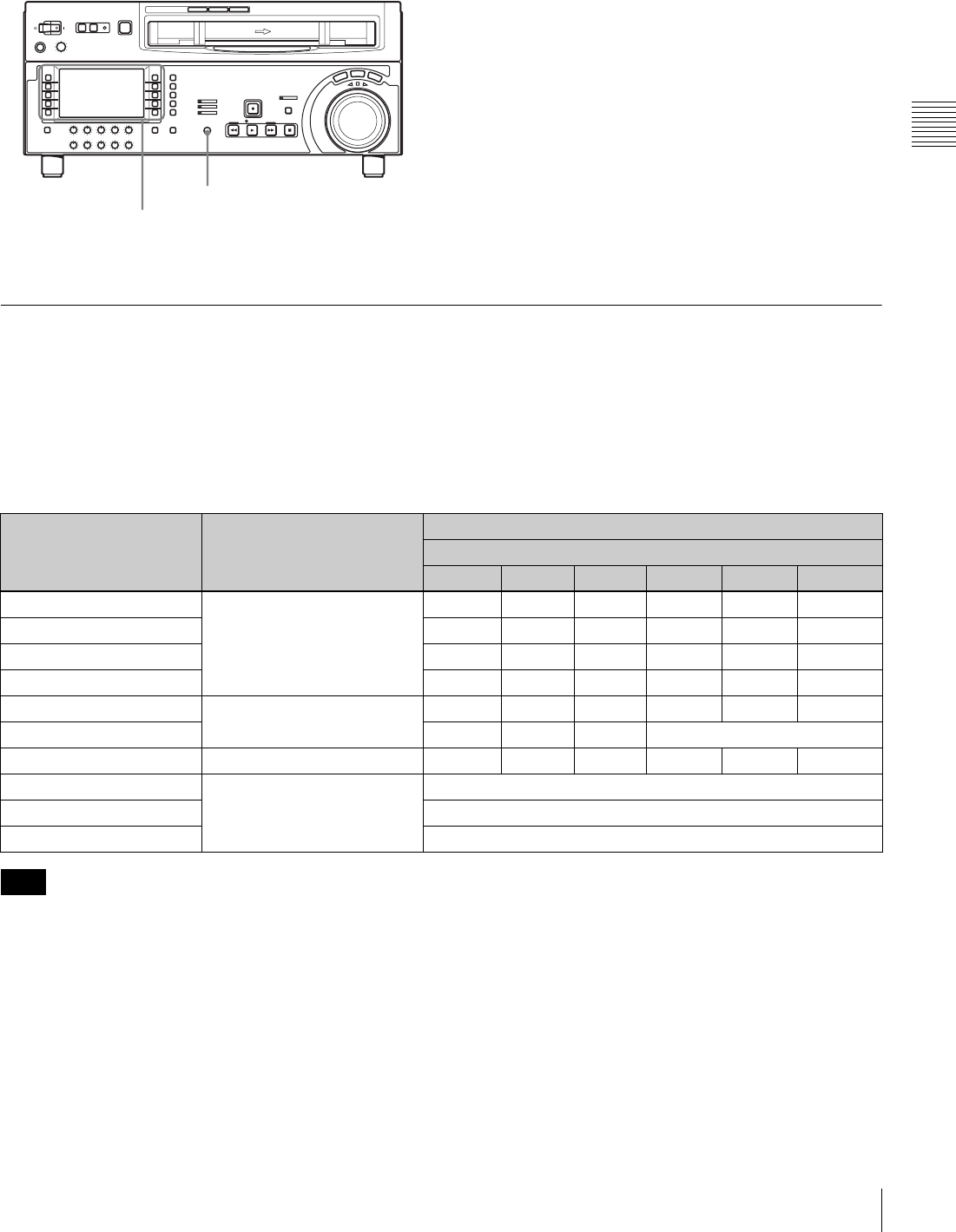
107
10-5 Regular Checks
Chapter 10 Maintenance and Inspection
To display the digital hours meter Select F9 (MENU), then turn the MULTI CONTROL
knob to display the required item in the time data display.
To exit the digital hours meter
Select F10 (EXIT).
10-5-2 Maintenance Timings
Use the following table as a timing guide for checking and
replacing components of the unit.
These intervals are not guaranteed lifetimes; the timing for
replacing components depends on the conditions of use. In
particular, depending on the degree of contamination and
abrasion, pinch rollers and cleaners may require
replacement earlier than suggested by this table.
Note that an arrow in the table means that the component
to be replaced is part of the assembly the arrow points to,
which must be replaced as a whole.
For information on severe conditions (frequent threading/
unthreading) or how to replace components, refer to the
Maintenance Manual Volume 1.
For replacement and checking of components, contact a
Sony service or marketing representative.
MULTI CONTROL knob
F9 (MENU)
F10 (EXIT)
Component Digital hours meter
indication (menu item
number in parenthesis)
Guideline for replacement and checking intervals
R: Replace C: Check, and replace if necessary
1000 (h) 2000 3000 4000 5000 6000
Upper drum Drum running time (H02) C C C C(r)
Drum assembly C
Brush slip ring assembly R R(R)
Video head cleaner (roller) R R
Pinch roller assembly Tape running time (H03) R R
Reel table assembly R (Replace every 4,000 hours.)
Pinch application assembly Tape running time (H03) R
Fan motor (card) Operation time (H01) Replace every 40,000 hours
Fan motor (MD) Replace every 40,000 hours
Fan motor (power supply) Replace every 40,000 hours
Note

108 10-6 About the LCD
Chapter 10 Maintenance and Inspection
10-6 About the LCD
Note on faulty pixels on the LCD panel
The LCD panel fitted to this unit is manufactured with
high precision technology, giving a functioning pixel
ratio of at least 99.99%. Thus a very small proportion of
pixels maybe “stuck”, either always off (black), always
on (red, green, or blue), or flashing. In addition, over a
long period of use, because of the physical characteristics
of the liquid crystal display, such “stuck” pixels may
appear spontaneously. These problems are not a
malfunction. Note that any such problems have no effect
on recorded data.

109
Specifications
Appendix
Appendix
Specifications
General
Recording format HDCAM
Power requirements
100 to 240 V AC, 50/60 Hz
Power consumption
1.5 A (150 W), when used without
optional devices
Peak inrush current
(1) Power ON, current probe method:
10 A (100 V), 33 A (240 V)
(2) Hot switching inrush current,
measured in accordance with
European standard EN55103-1: 8
A (230 V)
Operating temperature
5ºC to 40ºC (41ºF to 104ºF)
Storage temperature
–20ºC to +60ºC (–4ºF to +140ºF)
Humidity 20% to 90%
Mass 22 kg (48 lb 8 oz)
Dimensions (w/h/d, excluding protruding parts)
427 × 174 × 544 mm
(167/8 × 77/8 × 211/2 inches)
Control panel
LCD 4.3-inch screen, 16:9 aspect ratio, wide
TFT LCD
Total pixels: 480 (H) × 272 (V)
Colors: Approx. 16.77 million colors
Backlight: LED backlight
Tape transport system
Tape speed HDCAM:
96.7 mm/s (59.94i, 29.97PsF)
80.6 mm/s (50i, 25PsF),
77.4 mm/s (24PsF, 23.98PsF)
Digital Betacam:
96.7 mm/s (HDW-D1800 only)
MPEG IMX:
64.5 mm/s (59.94i),
53.8 mm/s (50i) (HDW-D1800
only)
HDCAM record/playback time
124 minutes with BCT-124HDL
(59.94i, 29.97PsF)
149 minutes with BCT-124HDL (50i,
25PsF)
155 minutes with BCT-124HDL
(24PsF, 23.98PsF)
Digital Betacam playback time (HDW-D1800 only)
124 minutes with BCT-124L
MPEG IMX playback time (HDW-D1800 only)
184 minutes with BCT-184MXL
(59.94i)
220 minutes with BCT-184MXL
(50i)
Fast forward/rewind time
Approx. 3 minutes with BCT-124HDL
Search speed
Shuttle mode HDCAM playback:
Still to approx. ±50 times normal
speed (59.94i, 29.97PsF),
Still to approx. ±58 times normal
speed (50i, 25PsF),
Still to approx. ±60 times normal
speed (24PsF, 23.98PsF)
Digital Betacam playback (HDW-
D1800 only):
Still to approx. ±50 times normal
speed
MPEG IMX playback (HDW-D1800
only):
Still to approx. ±78 times normal
speed
Variable speed mode
HDCAM playback: –1 to +2 times
normal speed
Digital Betacam playback: –1 to +3
times normal speed (HDW-D1800
only)

110 Specifications
Appendix
MPEG IMX playback: –1 to +3 times
normal speed (HDW-D1800 only)
Jog mode Still to ±1 times normal speed
Servo lock time 0.6 (59.94i, 29.97PsF)/0.7 (50i, 25PsF,
24PsF, 23.98PsF) seconds or less
(from standby on)
Load/unload time 6 seconds or less
Recommended tapes
HDCAM cassettes:
BCT-6HD/12HD/22HD/32HD/
40HD
BCT-34HDL/64HDL/94HDL/
124HDL
Digital Betacam cassettes (HDW-
D1800 only)
MPEG IMX cassettes (HDW-D1800
only)
Digital video system
Digital video signal system
Sampling frequency
Y: 74.25 MHz
R–Y/B–Y: 37.125 MHz
Quantization 8 bits/sample
Compression Coefficient recording system
Channel coding S-I-NRZI PR-IV
Error correction Reed-Solomon code
Analog composite output
Bandwidth 0 to 5.75 MHz +0.5 dB/–3.0 dB
S/N ratio 53 dB or more
Differential gain 2% or less
Differential phase 2°or less
Y/C delay 20ns or less
K factor (2T pulse)
1% or less
Output SCH phase
Complies with RS-170A/CCIR R.624-
3 (adjustable from menus)
Digital audio system
Digital audio (CH1 to CH4) signal format
Sampling frequency
48 kHz (synchronized with video)
Quantization 20 bits/sample
Wow and flutter Below measurable level
Headroom 20 dB (or 18 dB, selectable)
Emphasis T1= 50 µs, T2=15 µs (on/off selectable
in recording mode)
Analog input/output (CH1 and CH2)
A/D, D/A quantization
20 bits/sample
Frequency response
20 Hz to 20 kHz, +0.5 dB/ –1.0 dB
(0 dB at 1 kHz)
Dynamic range 95 dB or more (at 1 kHz, emphasis on)
Distortion 0.05% or less (at 1 kHz, emphasis on,
reference level (+4 dBm))
Crosstalk –80 dB or less (at 1 kHz, between any
two channels)
Analog audio (CUE)
Frequency response
100 Hz to 12 kHz ±3 dB
S/N ratio 45 dB or more (at 3% distortion level)
Distortion 2% or less (THD 1 kHz, reference
level)
Wow and flutter 0.2% rms or less
Digital Betacam playback
Video
Digital Audio (CH1 to CH4)
Analog Audio (cue track)
Bandwidth Y 0 to 5.75 MHz +0.5 dB/–0.5 dB
R–Y/B–Y 0 to 2.75 MHz +0.5 dB/–0.5 dB
S/N ratio 62 dB or more
K factor 1% or less
Frequency response 20 Hz to 20 kHz +0.5 dB/–1.0 dB
Dynamic range 95 dB (at 1 kHz, emphasis on)
Distortion 0.05% rms or less (at 1 kHz, emphasis on)
Wow and flutter Below measurable level
Frequency response 100 Hz to 12 kHz +3 dB/–3 dB

111
Specifications
Appendix
MPEG IMX playback
Video
Digital Audio (CH1 to CH4)
Processor adjustment range
Video level ±3 dB/ –∞ to +3 dB selectable
Chroma level ±3 dB/ –∞ to +3 dB selectable
Setup level (59.94i, 29.97PsF)
±30 IRE
Black level (50i, 25PsF)
±210 mV
Chroma phase ±30º
System phase SYNC: ±15 µs
SC: ±200 ns
Input connectors
HDSDI INPUT BNC (1 for input)
Serial digital (1.485 Gbits/s)
SMPTE 292M
REF. VIDEO INPUT 1
BNC (2 in loop through connection)
Black burst or composite sync
0.3 Vp-p, 75 Ω, sync negative
REF. VIDEO INPUT 2 (OPTION)
BNC (2 in loop through connection)
Black burst or composite sync
0.3 Vp-p, 75 Ω, sync negative
AUDIO INPUT CH1/2
XLR 3-pin, female (2)
LOW OFF: –60 dBu, high impedance,
balanced
HIGH OFF: +4 dBu, high impedance,
balanced
HIGH ON: +4 dBm, 600 Ω
termination, balanced
AUDIO INPUT (AES/EBU) CH1/2, CH3/4
BNC (2)
Complies with AES-3id-1995
TIME CODE IN XLR 3-pin, female (1)
0.5 to 18 Vp-p, 10 kΩ, balanced
HDV IN 6-pin, complies with IEEE 1394
(option)
Output connectors
HDSDI OUTPUT BNC (3 including 1 for character
superimposition)
Serial digital (1.485 Gbits/s)
SMPTE 292M
COMPOSITE VIDEO OUTPUT
BNC (3 including 1 for character
superimposition)
1.0 Vp-p, 75 Ω, Sync negative
SDI OUTPUT BNC (3 including 1 for character
superimpositon)
Serial digital (270 Mbits/s)
SMPTE 259M
AUDIO OUTPUT CH1/2
XLR 3-pin, male (2)
+4 dBm at 600 Ω load, low
impedance, balanced
AUDIO OUTPUT (AES/EBU) CH1/2, CH3/4, CH5/6,
CH7/8
BNC (4)
Complies with AES-3id-1995
(CH1/2 and CH3/4 only for HDW-
1800)
MONITOR OUTPUT (L/R)
XLR 3-pin, male (2)
+4 dBm at 600 Ω load, low
impedance, balanced
TIME CODE OUT
XLR 3-pin, male (1)
2.2 Vp-p, low impedance, balanced
S/N ratio 45 dB or more (at 3% distortion level)
Distortion 2% or less (THD 1 kHz, reference level)
Wow and flutter 0.2% rms or less
Bandwidth Y 0 to 5.75 MHz +0.5 dB/–2.0 dB
R–Y/B–Y 0 to 2.75 MHz +0.5 dB/–2.0 dB
S/N ratio 56 dB or more
K factor 1% or less
Frequency response 20 Hz to 20 kHz +0.5 dB/–1.0 dB (0 dB at 1 kHz)
Dynamic range 90 dB or more (at 1 kHz, emphasis on, 16 bits/48 kHz)
Distortion 0.05% or less (at 1 kHz, emphasis on, reference level (+4 dBm))

112 Specifications
Appendix
PHONES JM-60 stereo phone jack
–∞ to –12 dBu at 8 Ω load,
unbalanced
Remote connectors
CONTROL PANEL
20-pin, female (switch panel only)
REMOTE 1-IN(9P)
D-sub 9-pin, female
REMOTE 1-OUT(9P)
D-sub 9-pin, female
RS232C D-sub 9-pin, male
VIDEO CONTROL(9P)
D-sub 9-pin, female (for optional
HKDV-900)
REMOTE 2 PARALLEL I/O(50P)
50-pin, female
“Memory Stick” slot
“Memory Stick” (8 to 128 MB)
Accessories supplied
PSW 4 × 16 screws for rack mounting (4)
CD-ROM Manual (1)
Installation Manual (1)
Operation Guide (1)
Optional accessories
HKDW-104 Pull-down/720P Board
HKDW-105 i.LINK (HDV) Input Board
RCC-5G 9-pin Remote Control Cable
HKDV-900 Video Remote Controller
RMM-131 Rack Mount Adaptor
BCT-HD12CL Cleaning Cassette Tape
AC power cord
• For customers in the U.S.A. and Canada
Part No. 1-551-812-31
Plug holder 3-613-640-01
• For customers in the United Kingdom
Part No. 1-777-823-12
Plug holder 3-613-640-01
• For customers in European countries other than the
United Kingdom
Part No. 1-551-631-15
Plug holder 3-613-640-01
Design and specifications are subject to change without
notice.
To prevent electromagnetic interference from
portable communications devices
The use of portable telephones and other
communications devices near this unit can result in
misoperations and interference with audio and video
signals.
It is recommended that portable communications
devices near this unit be powered off.
Notes
• Always make a test recording, and verify that it
was recorded successfully.
SONY WILL NOT BE LIABLE FOR DAMAGES
OF ANY KIND INCLUDING, BUT NOT
LIMITED TO, COMPENSATION OR
REIMBURSEMENT ON ACCOUNT OF
FAILURE OF THIS UNIT OR ITS RECORDING
MEDIA, EXTERNAL STORAGE SYSTEMS OR
ANY OTHER MEDIA OR STORAGE SYSTEMS
TO RECORD CONTENT OF ANY TYPE.
• Always verify that the unit is operating properly
before use. SONY WILL NOT BE LIABLE FOR
DAMAGES OF ANY KIND INCLUDING, BUT
NOT LIMITED TO, COMPENSATION OR
REIMBURSEMENT ON ACCOUNT OF THE
LOSS OF PRESENT OR PROSPECTIVE
PROFITS DUE TO FAILURE OF THIS UNIT,
EITHER DURING THE WARRANTY PERIOD
OR AFTER EXPIRATION OF THE
WARRANTY, OR FOR ANY OTHER REASON
WHATSOEVER.

113
Specifications
Appendix
Relation between HKDV-900/503 setting items and setup menu items of this unit
a) Valid for output only when F5 (V.PROC) in function menu page P03: VID
PROC is set to “MENU”.
b) Select which item is set, “DC” or “UC”, with menu item 212 “VIDEO
REMOTE CONTROL SELECT”. When both are selected (menu item 212
is set to “u&d”), both of the corresponding menu settings are made, but
this unit's return values and unity values are the DC values.
c) Select which menu item is set, 713 or 718 with the sub-item of menu item
212 “VIDEO REMOTE CONTROL SELECT”.
Menu items specify output as follows.
HD: HDSDI output during HDCAM playback
DC: Downconverted SD (D1 SDI/COMPOSITE) output during HDCAM
playback
SD: SD (D1 SDI/COMPOSITE) output during SD format playback
UC: Upconverted HDSDI output during SD format playback
HKDV-900/503 setting items Setup menu items of this unit
HD Master 740: MASTER LEVEL (HD) a)
HD Y 741: Y LEVEL (HD) a)
HD Pb 742: PB LEVEL (HD) a)
HD Pr 743: PR LEVEL (HD) a)
HD Setup 745: SETUP LEVEL (HD) a)
HD Sync Phase 746: SYNC PHASE (HD) a)
HD Fine 747: SYNC PHASE FINE (HD) a)
D1 Master No corresponding menu item
D1 Y No corresponding menu item
D1 B-Y No corresponding menu item
D1 R-Y No corresponding menu item
D2 VIDEO 715: VIDEO GAIN CONTROL a)
D2 CHROMA 716: CHROMA GAIN CONTROL a)
D2 HUE 717: CHROMA PHASE CONTROL (HD/DC/SD/UC) a)
SETUP 713: VIDEO SETUP REFERENCE LEVEL: OUTPUT LEVEL a), c)
718: SETUP(BLACK) LEVEL a), c)
SD Sync Phase 719: SYSTEM PHASE SYNC
SD Fine 720: SYSTEM PHASE SC
CROSS COLOR 934: CROSS COLOR (DC)
H CROP POSITION 932: H CROP POSITION (DC)/951: H CROP POSITION (UC) b)
V LETTER POSITION 952: LETTER BOX POSITION (UC)
DETAIL GAIN 935: DETAIL GAIN (DC)/954: DETAIL GAIN (UC) b)
LIMITER 936: LIMITER (DC)/955: LIMITER (UC) b)
CRISP 937: CRISP THRESHOLD (DC)/956: CRISP THRESHOLD (UC) b)
DEPEND 938: LEVEL DEPEND THRESHOLD (DC)/957: LEVEL DEPEND THRESHOLD (UC) b)
FREQUENCY 939: H DETAIL FREQUENCY (DC)/958: H DETAIL FREQUENCY (UC) b)
H/V RATIO 940: H/V RATIO (DC)/959: H/V RATIO (UC) b)
GAMMA 941: GAMMA LEVEL (DC)/960: GAMMA LEVEL (UC) b)
CROP 930: DOWN CONVERTER MODE/950: UP CONVERTER MODE b)
LETTER BOX 930: DOWN CONVERTER MODE/950: UP CONVERTER MODE b)
SQUEEZE 930: DOWN CONVERTER MODE/950: UP CONVERTER MODE b)
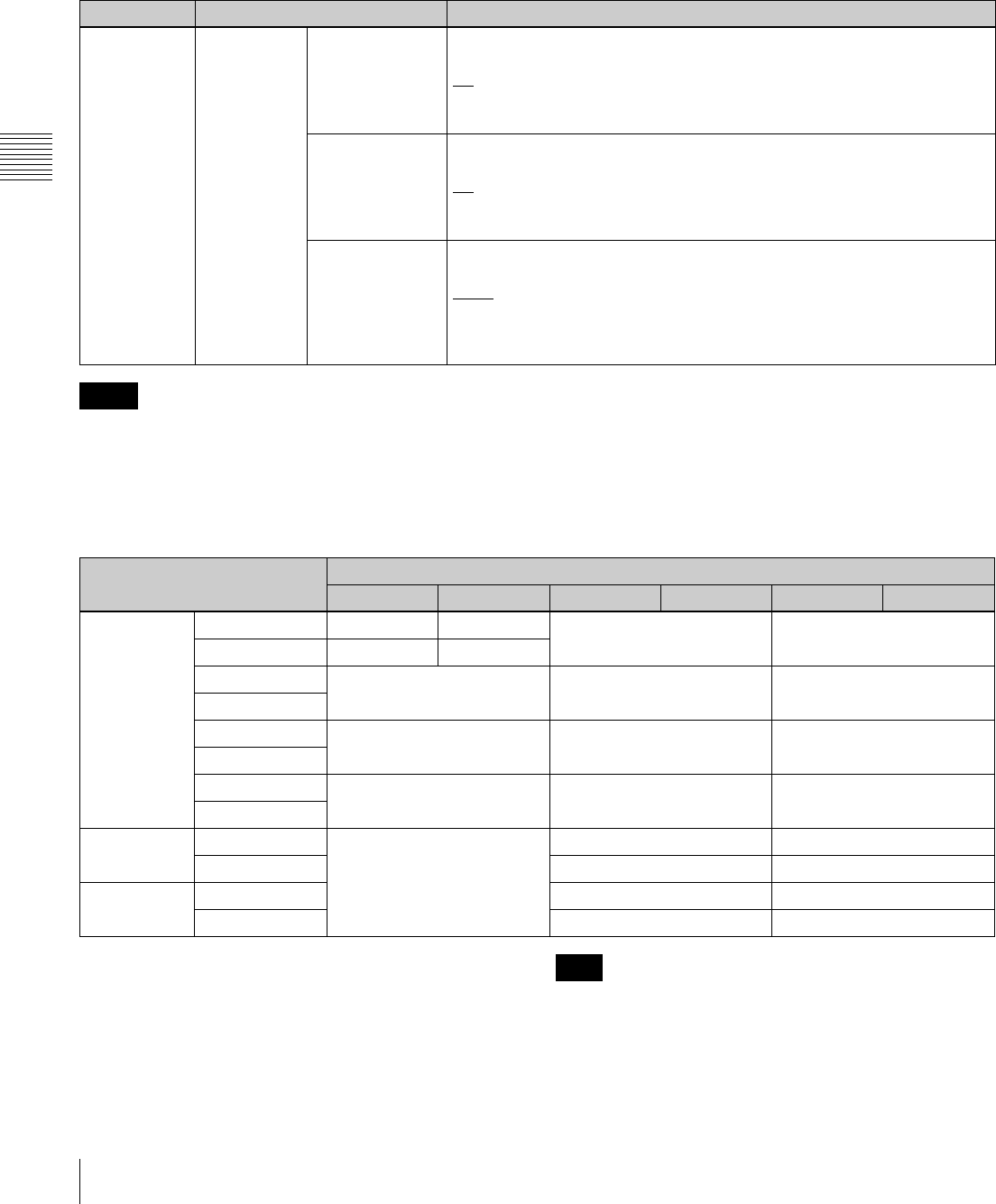
114 Specifications
Appendix
HD/SD video output phase settings
For the HD/SD video output phase setting, you can use the
maintenance menu.
For details, refer to the Maintenance Manual.
• The SDSDI (D1) output and composite output have the
same phase.
• Item M3A2 is valid HDW-D1800 only.
For details of the audio/timecode output phase, see setup
menu item 338.
Compatibility of playback tape formats
Yes: Both video and audio playback is possible.
f: Both video and audio “off-speed” playback is possible.
v: Video only “off-speed” playback is possible. Audio is muted.
No: Neither video nor audio playback is possible.
a) HDW-D1800 only
If the playback tape format and system frequency are
different, the input channel number display in audio level
meter block 1 3 (see page 15) flashes.
Item number Item name Settings
M3 M3A:
OUTPUT
PHASE
SELECT
M3A0:
HD PHASE SEL
Select the HD video output signal phase with respect to the reference
signal: 0H or –90H (HD) advanced.
0H: Output in sync with the reference signal.
–90H: Output with the phase advanced by –90H (HD) with respect to the
reference signal.
M3A1:
SD PHASE SEL
Select the SD video output signal phase with respect to the reference
signal: 0H or –2H (SD) advanced.
0H: Output in sync with the reference signal.
–2H: Output with the phase advanced by –2H (SD) with respect to the
reference signal.
M3A2:
SD UPCNV SEL
Select whether the SD video output signal phase in SD tape playback
should be in sync or one frame delayed.
Noml: Output the SD video with the phase unchanged. (The HD video
output is delayed by one frame with respect to the reference signal.)
HD: Output the SD video with the phase delayed by one frame. (The HD
video output and SD video output are in sync with the reference signal.)
Notes
Playback tape format System frequency
23.98PsF 24PsF 25PsF 50i 29.97PsF 59.94i
HDCAM 23.98PsF Ye s ff v
24PsF fYe s
25PsF fYe s v
50i
29.97PsF vvYe s
59.94i
30PsF vvf
60i
Digital
Betacam a)
50i (PAL) No Yes No
59.94i (NTSC) No Yes
MPEG IMX a) 50i (PAL) Ye s N o
59.94i (NTSC) No Yes
Note
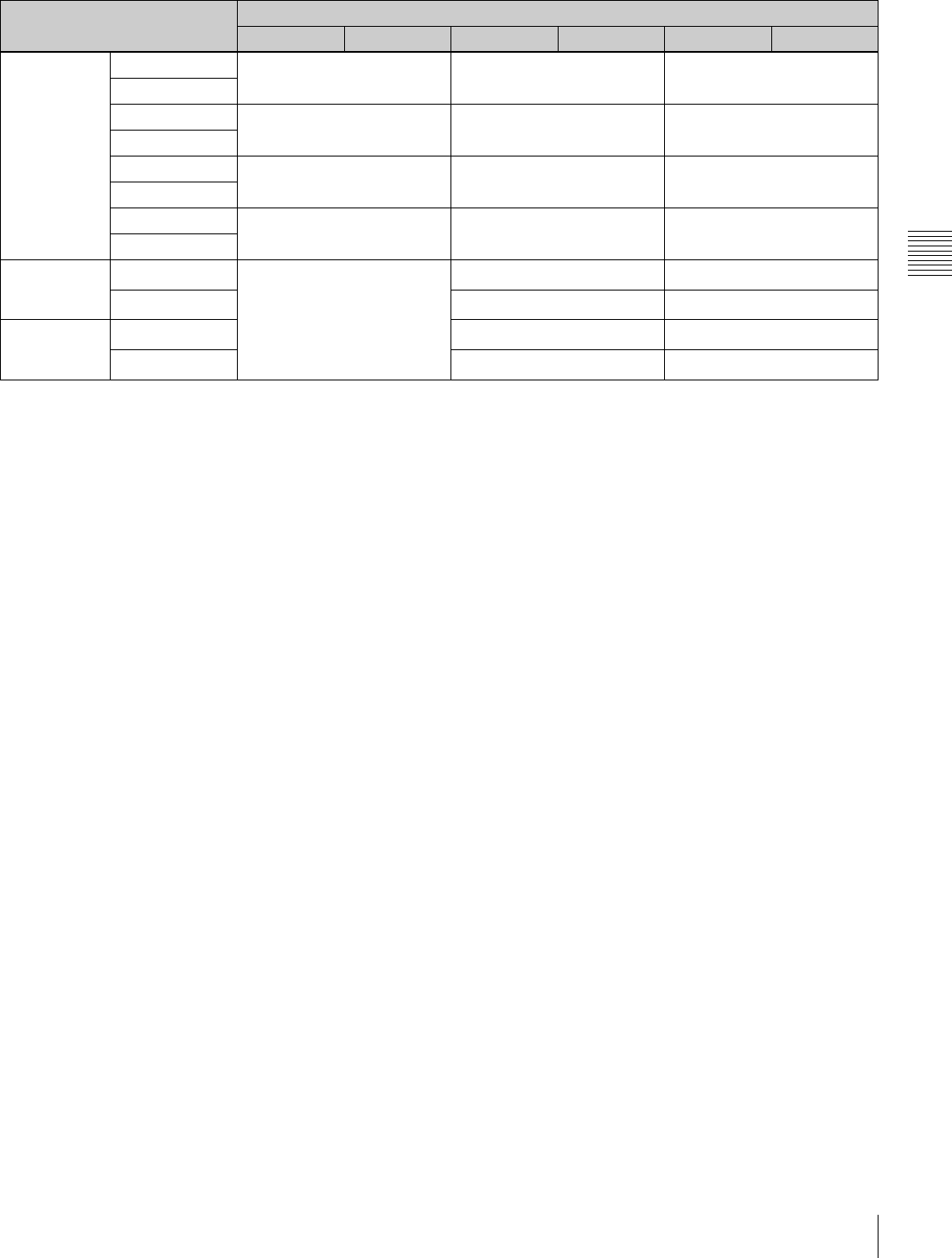
115
Specifications
Appendix
Playback tape format conversion outputs
a) For 1080/25PsF or 50i, output is downcoverted to 576/50i.
b) For 1080/29.97PsF or 59.94i, output is downcoverted to 480/59.94i.
c) For 576/50i, output is upconverted to 1080/50i.
d) For 480/59.94i, output is upconverted to 1080/59.94i.
e) HDW-D1800 only
Playback tape format System frequency
23.98PsF 24PsF 25PsF 50i 29.97PsF 59.94i
HDCAM 23.98PsF No No No
24PsF
25PsF No Ye s a) No
50i
29.97PsF No No Ye s b)
59.94i
30PsF No No No
60i
Digital
Betacam e)
50i (PAL) No Ye s c) No
59.94i (NTSC) No Ye s d)
MPEG IMX e) 50i (PAL) Ye s c) No
59.94i (NTSC) No Ye s d)

116 About a “Memory Stick”
Appendix
About a “Memory Stick”
What is “Memory Stick”?
“Memory Stick” is a new compact, portable and versatile
IC (Integrated Circuit) recording medium with a data
capacity that exceeds a floppy disk. “Memory Stick” is
specially designed for exchanging and sharing digital data
among “Memory Stick” compatible products. Because it is
removable, “Memory Stick” can also be used for external
data storage.
“Memory Stick” is available in two sizes: standard size
and compact “Memory Stick Duo” size. Once attached to
a “Memory Stick Duo” adaptor, “Memory Stick Duo”
turns to the same size as standard “Memory Stick” and thus
can be used with products compliant with standard
“Memory Stick”.
Types of “Memory Stick”
“Memory Stick” is available in the following four types to
meet various requirements in functions.
“Memory Stick-R”
Stored data are not overwritten. You can write data to
“Memory Stick-R” with “Memory Stick-R” compatible
products only. Copyright protected data that requires
MagicGate copyright protection technology cannot be
written to “Memory Stick-R”.
“Memory Stick”
Stores any type of data except copyright-protected data
that requires the MagicGate copyright protection
technology.
“MagicGate Memory Stick”
Equipped with the MagicGate copyright protection
technology.
“Memory Stick-ROM”
Stores pre-recorded, read-only data. You cannot record on
“Memory Stick-ROM” or erase the pre-recorded data.
Available types of “Memory Stick”
You can use a “Memory Stick” and a “MagicGate Memory
Stick” with your product.
You cannot use a “Memory Stick Duo” with your product.
Note on data read/write speed
Data read/write speed may vary depending on the
combination of the “Memory Stick” and “Memory Stick”
compliant product you use.
What is MagicGate?
MagicGate is copyright protection technology that uses
encryption technology.
Before using a “Memory Stick”
• When you set the “Memory Stick” erasure prevention
switch to “LOCK”, data cannot be recorded, edited, or
erased.
• Data may be damaged if:
- You remove the “Memory Stick” or turn off the unit
while it is reading or writing data.
- You use the “Memory Stick” in a location subject to
the effects of static electricity or electric noise.
• We recommend that you make a backup copy of
important data that you record on the “Memory Stick”.
• Do not attach anything other than the supplied label to
the “Memory Stick” labeling position.
• Attach the label so that it does not stick out beyond the
labeling position.
• Carry and store the “Memory Stick” in its case.
• Do not touch the connector of the “Memory Stick” with
anything, including your finger or metallic objects.
• Do not strike, bend, or drop the “Memory Stick”.
• Do not disassemble or modify the “Memory Stick”.
• Do not allow the “Memory Stick” to get wet.
• Do not use or store the “Memory Stick” in a location that
is:
- Extremely hot, such as in a car parked in the sun
- Under direct sunlight
- Very humid or subject to corrosive substances
“Memory Stick” access indicator
If the access indicator is lit on or is flashing, data is being
read from or written to the “Memory Stick”. At this time,
do not shake the computer or product or subject them to
shock. Do not turn off the power of the computer and
product or remove the “Memory Stick”. This may damage
the data.
Note
Notes
Terminal
Write-protect tab
Labeling position
117
About a “Memory Stick”
Appendix
Precautions
• To prevent data loss, make backups of data frequently. In
no event will Sony be liable for any loss of data.
• Unauthorized recording may be contrary to the
provisions of copyright law. When you use a “Memory
Stick” that has been pre-recorded, be sure that the
material has been recorded in accordance with copyright
and other applicable laws.
• The “Memory Stick” application software may be
modified or changed by Sony without prior notice.
• Note that there are certain restrictions on recording stage
performances and other entertainment events, even if
they are recorded for personal use only.
• “Memory Stick”, and “MagicGate Memory Stick”
are trademarks of Sony Corporation.
• “Memory Stick Duo” and are
trademarks of Sony Corporation.
• “Memory Stick PRO” and are
trademarks of Sony Corporation.
• “MagicGate” and are trademarks of Sony
Corporation.

118 Index
Index
Index
A
AC IN connector 25
ALARM indicator 20
ALT/DELETE button 19
Analog
audio input/output section 23
video input/output section 24
Audio
input selection 15
input/output section 23, 24
level control knobs 19
level indication 17
level meter block 1 15
level meter block 2 16
monitor signal output section 26
AUDIO INPUT (AES/EBU)
connectors 24
AUDIO INPUT CH1 to CH2
connectors 23
AUDIO INPUT CH1 to CH2 LEVEL
switches 23
AUDIO OUTPUT (AES/EBU)
connectors 24
AUDIO OUTPUT CH1 to CH2
connectors 23
Automatic editing 43
carrying out 49
switch settings 44
B
Basic setup menu 78
C
Capstan
override function 39
Cassettes 32
COMPOSITE VIDEO OUTPUT
connectors 24
CONFI/PREREAD indication 15
Connections 27
Connector panel 23
Continuous editing 53
CONTROL PANEL connector 22
Control panels 11
lower 13
upper 12
Cross-fade editing 7, 86
Cue-up 48, 59
D
Digital
device connection 27
hours meter 106
input/output section 24
signal processing 6
DISPLAY button 19
DMC
editing 51
playback 40
Downconverter function 7
Drop frame
mark 30
mode 30, 66
E
Edit point
cue-up and preroll 48
modifying and deleting 47
setting 45
Editing
automatic editing 43
continuous editing 53
cross-fade editing 7, 86
DMC 51
mode selection 45
preread editing 54
quick editing 53
split editing 45
standalone editing 53
EJECT button 12
Error messages 104
Extended setup menu items 81
External device
connections 27
connectors 25
F
F FWD button 21
F1 to F10 buttons 13
Features 6
Function menu
configuration 64
example 10
item 65
non-user-definable 69
operations 64
overview 64
user-definable 65
Function selection buttons 13
G
Ground terminal 25
H
HDCAM 6
cassettes 32
HDSDI INPUT connectors 24
HDSDI OUTPUT connectors 25
Head cleaning 103
J
JOG button 21
Jog mode 38
K
KEY INHI indicator 20
KEY INHI switch 22
L
LCD 14, 108
Location and function of parts
connector panel 23
lower control panel 13
switch panel 22
upper control panel 12
M
“Memory Stick” 116
access indicator 22
slot 22
Menu
BANK 76
control section 13
operations 64, 75
selection buttons 19
Menu page selection buttons
P1: HOME button 19
P2: TC button 19
P3: VID PROC button 19
P4: AUD INP button 19
P5: PAGE DOWN button 19
Moisture condensation 106
MONITOR OUTPUT R/L connectors
26
MULTI CONTROL knob 20
N
Non-drop frame
mark 30
mode 66
O
Operation mode 28, 31

119
Index
Index
P
Parts replacement 107
PB knobs 20
PHONES jack/control 12
PLAY button 21
Playback
capstan override 39
DMC 40
jog mode 38
preparations 37
procedures 37
shuttle mode 38
variable speed mode 39
Power
power supply section 25
POWER switch 12
Preread editing 54
Preview 48
PUSH/SHIFT indicator 20
Q
Quick editing 53
R
REC
button 20
knobs 19
REC INHI indicator 21
Recording 33
preparations 33
procedures 36
REF. VIDEO INPUT 1 connectors and
75Ω termination switch 24
REF. VIDEO INPUT 2 (OPTION)
connectors and 75Ω termination
switch 24
Reference sync signal 28
connecting 28
synchronize to an external signal
35
Regular checks 106
REMOTE 1-IN(9P) connector 25
REMOTE 1-OUT(9P) connector 25
REMOTE 2 PARALLEL I/O(50P)
connector 25
REMOTE buttons 12
REW button 21
RS232C connector 26
RS-232C indicator 12
S
SDI OUTPUT connectors 25
Search control section 21
Search dial 21
Servo
lock 21
SERVO indicator 21
Setting a user bit value 35
Setup 29
Setup menu
basic menu items 78
configuration 74
extended menu items 81
operations 75
SHIFT/ENTRY button 19
Shot mark function
list operations 57
operations 56, 70
overview 55
reading 56
writing 56
SHUTTLE button 21
Shuttle mode 38
Specifications 109
Split editing 45
Standalone editing 53
STANDBY button 20
STOP button 20
Superimposed character information
30
Synchronize to an external signal 35
System configurations 9
System frequency indicator 14
T
Tape format 17
Tape slack 103
Tape transport control section 20
TIME CODE IN/OUT connectors 26
Time data 30
display 17
information 17
Timecode
input/output section 26
recording 34
U
UMID
display 62
output 62
overview 60
recording 60
Upconverter function 7
V
VAR button 21
Variable speed mode 39
Video
input/output section 24
test signal (setup menu item 710)
94
VIDEO CONTROL(9P) connector 25
VITC
external sync 35
field mark 30
status 18
The material contained in this manual consists of information
that is the property of Sony Corporation and is intended solely
for use by the purchasers of the equipment described in this
manual.
Sony Corporation expressly prohibits the duplication of any
portion of this manual or the use thereof for any purpose
other than the operation or maintenance of the equipment
described in this manual without the express written
permission of Sony Corporation.

Sony Corporation
HDW-1800/D1800
(SY)
3-992-538-02 (1) © 2006
