IG0304 Internal Cable Routing, RevE Specialized Roubaix:Venge Frame Routing Guide
User Manual: Specialized Roubaix:Venge Frame Internal Cable Routing Guide
Open the PDF directly: View PDF ![]() .
.
Page Count: 2
Page 1 of 2
INSTRUCTION GUIDE
ROUBAIX/VENGE INTERNAL CABLE ROUTING (2nd Gen)
THIS INSTRUCTION GUIDE CONTAINS IMPORTANT INFORMATION.
PLEASE READ CAREFULLY AND STORE IN A SAFE PLACE.
This guide is designed to be used in conjunction with the drivetrain manufacturer’s instructions. This product requires particular care for proper installation.
WARNING! Please read the following instructions. Bicycle assembly is a complicated task, which requires training and experience. If you have
any doubt regarding your mechanical ability and/or installation of this product, visit your local authorized dealer. Specialized recommends
that the cable system be installed by a qualified mechanic. Failure to follow this warning may result in serious personal injury or death.
An instructional video for internal cable routing is available at http://www.vimeo.com/23917838. For electronic shifting, refer to the electronic shifting
manufacturer’s instructions.
CABLE AND HOUSING PRE-INSTALLATION
NOTE: Framesets are equipped with routing sheaths pre-installed in the frame. For frames already equipped with cables, routing sheaths are
provided in the box. To simplify the installation of replacement cables, route the sheaths onto the existing cables, then into the chainstay and
down tube, then let the sheaths exit the ICR holes before before removing the old cables.
NOTE: The cables can go from the shifters to either side of the down tube. If the cable housings cross each other to the opposite sides of the down
tube (California Cross), the cables will have to cross again inside the down tube. More than a single cross inside the down tube will cause the cables
to wind around each other and impede proper shifting.
INSTALLING THE DERAILLEUR HOUSINGS, BARREL ADJUSTERS AND CABLES
1. Decide to which side of the down tube each cable will be routed.
2. Cut the cable housing to the required length so that the handlebars can rotate fully past 90° in each direction without pulling on the housings.
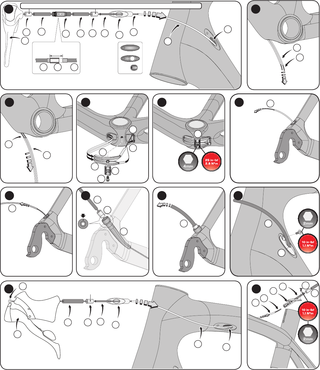
3. Fig. 1: Cut out a section of housing (see inset) that equals the inner length of the barrel adjusters (approximately 1”) at the desired location along the
length of each shifter cable housing. Avoid placing the barrel adjusters too close to the shifters or the ICR stops.
INSTALLING THE DERAILLEUR CABLES IN THE FRAME
4. Remove the bottom bracket cable guide and the ICR stops on the sides of the down tube (if they’re pre-installed). It is recommended to use the latest
generation of ICR stops with a 5.5mm inner diameter. Leave the sheaths in the downtube; they are designed to ease installation of the cables.
5. Install the cable (A) in the shifter (B) as instructed in the shifter instruction guide (provided by the shifter manufacturer).
6. Fig. 1: Install an unsealed housing ferrule (C), the 1st part of cable housing (D), a barrel adjuster (E), the 2nd piece of housing (F) and another ferrule (C).
7. Fig. 1: Place a plastic mini-sheath (G) inside the ICR stop (H), then place the ICR stop on the derailleur cable housing.
8. Fig. 2: Run the cable (A) through the full-length routing sheath (I) until it exits the down tube at the bottom bracket. Be sure not to kink the cable.
9. Fig. 3: Repeat the steps for the second shifter assembly, then remove the routing sheaths.
ROUTING THE FRONT DERAILLEUR CABLE TO THE FRONT DERAILLEUR
10. Install the front derailleur on the frame as instructed in the derailleur manufacturer’s instruction guide.
11. Fig. 4: Route the front derailleur cable coming out of the down tube hole through the non-drive-side portion of the bottom bracket cable guide (J),
and up through the front derailleur cable guide hole (N). Make sure the cables are not crossing each other more than once inside the down tube.
12. Adjust the cable position for proper shifting and torque the cable bolt according to the manufacturer’s torque specification.
ROUTING THE REAR DERAILLEUR CABLE TO THE REAR DERAILLEUR
13. Install the rear derailleur on the frame as instructed in the derailleur manufacturer’s instruction guide.
14. Trim the rear derailleur cable housing to the recommended length of 290mm for the rear derailleur to function properly.
15. Fig. 4: Route the rear derailleur cable coming out of the down tube through the drive-side portion of the bottom bracket cable guide (K), then
through the chainstay routing sheath (O). Be sure not to kink the cable.
16. Fig. 5: Place the rear derailleur cable guide (K) next to the front derailleur cable guide (J) (with the guide ends slotted in their respective frame holes), then
place the cable guide brace (L) over the cable guides and install the bolt (M). Bolt the guide to the bottom bracket shell (P). Torque to 25 in-lbf (2.8 N*m).
17. Fig. 6, 7: Once the cable comes out the drive-side dropout hole, remove the routing sheath.
18. Fig. 8: Install the extended dropout sheath (Q) (notch pointing up), followed by an unsealed cable ferrule (R) and cable housing (S).
19. Fig. 9: Route the rear derailleur cable housing to the rear derailleur and insert the cable into the derailleur.
20. Adjust the cable position for proper shifting and torque the cable bolt according to the manufacturer’s torque specification.
21. Fig. 10: Bolt the ICR stops (H) to the down tube holes, using the supplied Allen key screws (10 in-lbf [1.1 N*m]).
INSTALLING THE BRAKE CABLE IN THE FRAME
22. Fig. 11: Install the brake cable (T), cable housing (U) and housing ferrule (V).
23. Fig. 11: Place a plastic mini-sheath (W) inside the 1st ICR stop (X), then place the ICR stop on the brake cable housing.
24. Fig. 11: Route the cable through the full-length sheath (Y) and through the brake ICR stop hole in the top tube (Z), then remove the sheath.
TECH TIP: To prevent brake cable rattle, it is recommended to install three rubber donuts onto a piece of routing sheath (approximate length
8” [20cm]), then install the sheath with the three donuts onto the cable and through the ICR hole at the top tube/seat tube junction (see video).
25. Fig. 12: Install the 2nd brake ICR stop (X) and torque the stop in place (10 in-lbf (1.1 N*m), then install a mini-sheath, housing ferrule and housing.
26. Trim the brake cable housing to the required length and install the housing and cable as instructed in the brake manufacturer’s instruction guide.
WARRANTY
For the warranty provisions of this product, please visit www.specialized.com.
Page 2 of 2
56
K
M
L
N
T
T
11 12
UV
W
W
X
X
Y
Y
Z
B
A
78910
O
P
R
Q
S
SF
H
34
A
IJ
I
12
B
CD
D
F
F
E
E
HA
A
I
J
I
1” (25mm)
Please note all instructions are subject to change for improvement without notice.
Please visit www.specialized.com for periodic tech updates.
Feedback: techdocs@specialized.com
SPECIALIZED BICYCLE COMPONENTS
15130 Concord Circle, Morgan Hill, CA 95037 (408) 779-6229
IG0304 Rev.E, December 2011
GC
U
V
Drive-side
Non-drive-side
Rubber grommet
ICR STOPS FOR
ELECTRONIC WIRING
NOTE: 1st generation ICR stops
do not use cable housing ferrules
NOTE: Use unsealed ferrules. 1st generation ICR stops do not use cable housing ferrules
