Spice Pulser The Guide
User Manual:
Open the PDF directly: View PDF ![]() .
.
Page Count: 35
University of Kansas
Department of Physics and Astronomy
SPICE Pulser:
The Guide
Andrew Shultz
Uzair Latif
Alexander (Sasha) Novikov
Friday 14th December, 2018

Contents
1 Introduction 1
2 Important Equipment 2
3 Pulser Setup 9
3.1 PiezoPulser.................................... 9
3.2 High Voltage Sparking Pulser (HVSP) and Instrumentation Design Lab
(IDL)Pulser ................................... 12
3.3 Extra: High Voltage Sparking Pulser with Terminator . . . . . . . . . . . . . 16
4 Pulser Details 17
4.1 Piezo Pulser - With Magic Cable . . . . . . . . . . . . . . . . . . . . . . . . 18
4.2 High Voltage Sparking Pulser . . . . . . . . . . . . . . . . . . . . . . . . . . 20
4.3 Instrumentation Design Lab (IDL)Pulser1 .................. 23
4.4 Instrumentation Design Lab (IDL)Pulser2 .................. 25
5 Magnetic Switches (Relays) 27
6 Lead-Acid Battery 28
6.1 CautionaryNotes................................. 28
6.2 Charging...................................... 28
7 Surface Monitoring 29
8 Processing AraRoot .tar.gz Files Into .root Files 30
Appendix 32
A Full Inventory 32
A.1 Dave’sCache ................................... 32
A.2 Ilya’sCache.................................... 33

1Introduction
The purpose of this document is to provide sucient information to perform the SPICE
pulser experiment for the pole season of 2018-19. This experiment involves dropping a pulser
down a SPICE core hole (deep hole lled with estisol). Two dierent pressure vessels and
three kinds pulsers will be covered along with the possible setups using these.
1

2Important Equipment
Pressure Vessel Components
1. Tube
2. Top cap
3. Bottom cap
4. Bolts (7/16” hex head, 1/4-20 [mea-
sured]) x12 (6 per cap)
Pressure Vessel Antenna Components
1. Top pole
2. Top cap
3. Bottom pole
4. Bottom cap
5. Feed point module
6. Wench Bolt
7. 3” 1/4-20 bolt
8. 1” spacer
9. 1/2” spacer x2
2
Pressure Vessel (PV) x2
Figure 2.1: .
Pressure Vessel Antenna (PVA) x1
Figure 2.2: .
3
IDL Pulser x2
Figure 2.3: .
HVSP Pulser x2
Figure 2.4: .
4
Motor x2
Figure 2.5: .
Piezo Sparker x3
Figure 2.6
5
Pole Length Cable (F-F Molex) x3
Figure 2.7
Splitter (M-FF Molex) x3
Figure 2.8
6
Inline-4 (I4) battery cable x2
Figure 2.9
Lead-Acid Batteries x4
Figure 2.10
7
Lead-Acid Battery Pack (4 Batteries) x1
Figure 2.11
8
3Pulser Setup
In this chapter, the how to for setting up each pulser-antenna system will be covered.
3.1. Piezo Pulser
Batteries
Relay
Motor
Sparker
1
Figure 3.1: Pressure Vessel setup for piezo pulsers.
9
Step 1: Attach batteries to inline-4 cable, 3 or 4 Batteries may be used. A male Molex
connector short needs to be used for 3 batteries.
Step 2: Attach OUTPUT of the inline-4 cable to male Molex connector of the relay marked
BATT (or BATTERY).
10
Step 3: Attach the female Molex connector of the motor to the male Molex connector of the
relay marked MOTOR. The magic cable should also be attached to the piezo on the motor
at this point (not shown).
Step 4: Slide the constructed system into the PV (magic cable not shown).
Step 5: Put cap on, do not over tighten the 7/16” hex head bolts. The PV is now ready for
pulsing.
11
3.2. High Voltage Sparking Pulser (HVSP) and Instrumentation Design Lab
(IDL) Pulser
Pulser
SMA Connector
N-type Connector
Bottom Cone
N-type Cable
Top Cone
Relay
Battery Pack
Ferrite
Top Pole
Bottom Pole
Feed Point
Module
Top Cap
Bottom Cap
1
Figure 3.2: Pressure Vessel Antenna setup (for both HVSP and IDL pulsers).
12
Step 1: Attach N-Type female / SMA male adapter to N-type connector of the PVA feed-
point.
Step 2: Attach pulser to the SMA male of the previous step.
(a) Attaching the pulser directly. (b) Using a SMA cable, only needed for
the IDL pulser.
13
Step 3: Attach pole length female-female Molex cable to male Molex connector of the pulser
(ferrite on the pole length cable is not shown).
Step 4: Feed pole length cable through the bottom pole (pressure vessel pole) and attach
bottom pole to the feedpoint module.
14
Step 5: Attach pole length cable to male Molex connector of the relay marked MOTOR
and attach the female Molex connector of the battery pack to the male Molex connector of
the relay marked BATT (or BATTERY).
Step 6: Slide the relay and battery pack into the bottom pole.
Step 7: Twist bottom pole cap onto the bottom pole. The cap wrench (pictured) should help.
15
Step 8: The PVA is ready for use.
3.3. Extra: High Voltage Sparking Pulser with Terminator
In case things are failing, the HVSP can be armed with a terminator and placed in the PV.
Figure 3.3: The HVSP-1 with terminator.
16
(a) Waveform. (b) FFT.
Figure 3.4: Example waveform and FFT of the HVSP-1 with terminator.
4Pulser Details
This chapter will cover expected pulser signal as viewed by an ANITA horn antenna.
The plots with black lines (top plots, example waveform and FFT) were taken at room
temperature.
The plots with red-ish dots (max voltage, pulse width, and period) were taken with the
pulser exposed to dry ice. Dry ice was placed around the PV or PVA and data was taken with
the system cooling and then warming back up (the piezo data does not have the warming
up part, due to complications). The temperature data logger was not working correctly for
these tests, thus the data is not plotted as a function of temperature but rather time. Dry
ice is at a temperature of about -79C, it is a reasonable assumption that the pulsers reached
-60C at their coldest, it is likely they were colder than that.
17
4.1. Piezo Pulser - With Magic Cable
Figure 4.1: Piezo pulser (clicker) with motor (magic cable not shown).
Features:
• Period will increase as the motor temperature decreases (should not go over 7 seconds).
• Amplitude can increase or decrease.
• Pulse width typically will get wider at lower temperature.
• There will be after pulses from the piezo pulser.
18
Time [ns]
0 20 40 60 80 100 120 140 160 180 200
Volts [V]
-4
-3
-2
-1
0
1
2
3
4
Piezo WaveformPiezo Waveform
Frequency [MHz]
0 0.2 0.4 0.6 0.8 1
dBm/Hz
-90
-80
-70
-60
-50
-40
Piezo FFTPiezo FFT
Figure 4.2: Sample Waveform for a Piezo Pulser armed with the magic cable.
Time [s]
0 500 1000 1500 2000 2500 3000 3500 4000
Max Voltage [V]
1
1.2
1.4
1.6
1.8
2
2.2
2.4
PiezoPiezo
(a) Max Voltage.
Time [s]
0 500 1000 1500 2000 2500 3000 3500 4000
Pulse Width [ns]
10
15
20
25
30
Piezo
(b) Pulse width.
Time [s]
0 500 1000 1500 2000 2500 3000 3500 4000
Period [s]
4
4.2
4.4
4.6
4.8
5
5.2
5.4
5.6
5.8
6
Piezo
(c) Period.
Figure 4.3: Piezo dry ice test. No warm up period in this data. Amplitude quickly rose and
saturated the oscilloscope.
19
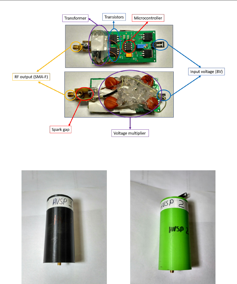
4.2. High Voltage Sparking Pulser
Figure 4.4: HVSP pulser without case.
(a) HSVP-1. (b) HSVP-2.
Figure 4.5: HSVP-1 and 2 in their cases.
20

HVSP-1 (Black Case) (PRIMARY) Features:
• Extensively tested at cold temperture.
• Period is about 1 second. At low temperature the spark gap will increase and may
cause the period to sporatically be an interger multiple of 1 second.
• Max voltage is about 2.5V and can vary with temperature (dependent on the period).
• Pulse shape is stable.
• There should be no after pulses from this pulser.
HVSP-2 (Green Case) (BACKUP) Features:
•Extra sparking may occur with this pulser, for example between the battery pack and
the PVA bottom pole. No damage has been observed from this eect. A ferrite on the
pole length cable helps reduce this. The battery pack has also been wrapped heavily
in insulating tape to further reduce sparking.
• Period is about 1 second. At low temperature the spark gap will increase and may
cause the period to sporatically be an interger multiple of 1 second.
• Max voltage is about 1.2V and can vary with temperature (dependent on the period).
• Pulse shape is stable.
• Cold performance not well known for this pulser (xed sparking after initial test),
should be similar to HVSP-1.
• There will be some after pulses with this pulser, it won’t happen all the time.
21
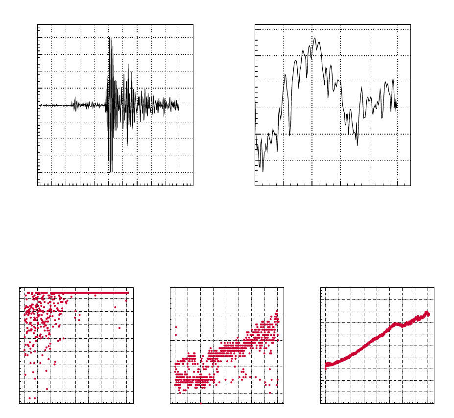
Time [ns]
0 20 40 60 80 100 120 140 160 180 200
Volts [V]
-2
-1
0
1
2
HVSP-1 WaveformHVSP-1 Waveform
Frequency [MHz]
0 0.2 0.4 0.6 0.8 1
dBm/Hz
-110
-100
-90
-80
-70
-60
-50
HVSP-1 FFTHVSP-1 FFT
Figure 4.6: Sample Waveform and FFT for the HVSP-1 Pulser.
Time [s]
0 1000 2000 3000 4000 5000 6000 7000 8000 9000
Max Voltage [V]
1.5
2
2.5
3
3.5
4
HVSP-1HVSP-1
(a) Max Voltage.
Time [s]
0 1000 2000 3000 4000 5000 6000 7000 8000 9000
Pulse Width [ns]
8
8.2
8.4
8.6
8.8
9
9.2
9.4
HVSP-1HVSP-1
(b) Pulse width.
Time [s]
0 1000 2000 3000 4000 5000 6000 7000 8000 9000
Period [s]
0
0.5
1
1.5
2
2.5
3
3.5
4
4.5
5
HVSP-1
(c) Period.
Figure 4.7: HVSP-1 dry ice test. Quantization due to near integer periods can be observed.
22
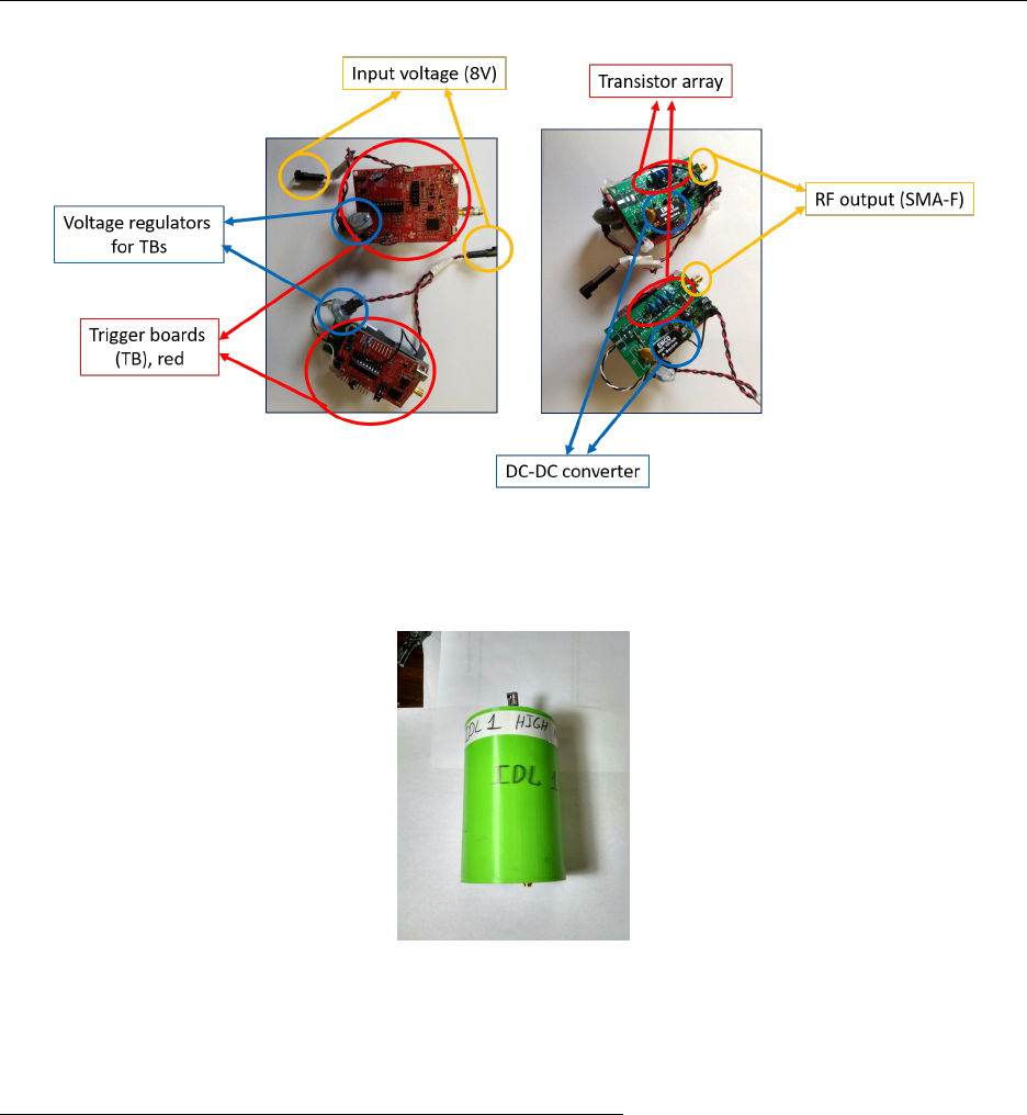
4.3. Instrumentation Design Lab (IDL) Pulser 1
Figure 4.8: IDL pulser without case.
Figure 4.9: IDL-1 in its case.
IDL-1 (High Amplitude) (PRIMARY) Features:
• Period is stable at about 1 second.
• Max voltage is about 1V and can decrease with temperature.
• Pulse shape is stable.
• This pulser will likely take damage from the extreme cold, performance may degrade.
• There should be no after pulses from this pulser.
23
Time [ns]
0 20 40 60 80 100 120 140 160 180 200
Volts [V]
-1
-0.5
0
0.5
1
IDL-1 WaveformIDL-1 Waveform
Frequency [MHz]
0 0.2 0.4 0.6 0.8 1
dBm/Hz
-120
-110
-100
-90
-80
-70
-60
-50
IDL-1 FFTIDL-1 FFT
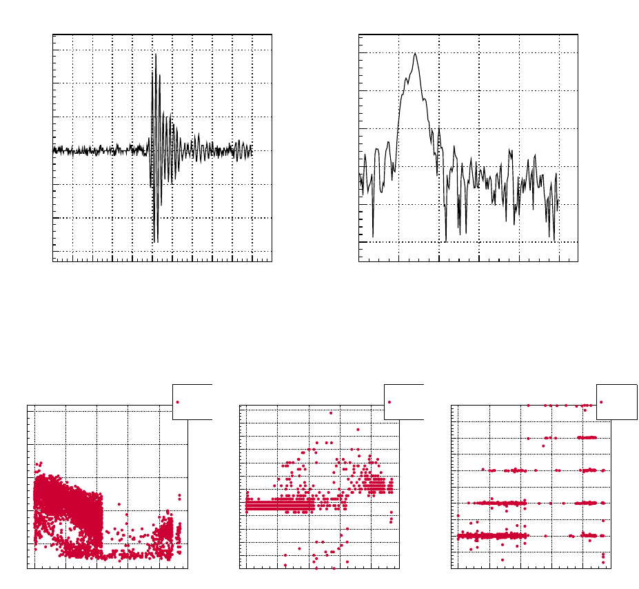
Figure 4.10: A sample waveform and FFT for IDL 1.
Time [s]
0 1000 2000 3000 4000 5000 6000 7000 8000 9000
Max Voltage [V]
0.5
1
1.5
2
2.5
IDL-1IDL-1
(a) Max Voltage.
Time [s]
0 1000 2000 3000 4000 5000 6000 7000 8000 9000
Pulse Width [ns]
5
10
15
20
25
30
35
40
IDL-1IDL-1
(b) Pulse width.
Time [s]
0 1000 2000 3000 4000 5000 6000 7000 8000 9000
Period [s]
0
0.5
1
1.5
2
2.5
3
3.5
4
4.5
5
IDL-1
(c) Period.
Figure 4.11: IDL-1 dry ice test. Max voltage deceases with temperature.
24
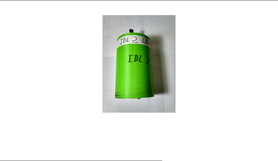
4.4. Instrumentation Design Lab (IDL) Pulser 2
Figure 4.12: IDL-2 in its case.
IDL-2 (Low Amplitude) (BACKUP) Features:
• This pulser has a weak pulse of about 200mV peak voltage. This will likely not be
picked up by all stations.
• Period is stable at about 1 second.
• Max voltage is about 1V and can decrease with temperature.
• Pulse shape is stable.
• This pulser has taken damage from the extreme cold of dry ice, further exposure to
extreme cold will have unknown eects.
• There will be some after pulses with this pulser, it won’t happen all the time.
25
Time [ns]
0 20 40 60 80 100 120 140 160 180 200
Volts [V]
-0.15
-0.1
-0.05
0
0.05
0.1
0.15
IDL-2 WaveformIDL-2 Waveform
Frequency [MHz]
0 0.2 0.4 0.6 0.8 1
dBm/Hz
-120
-110
-100
-90
-80
-70
IDL-2 FFTIDL-2 FFT
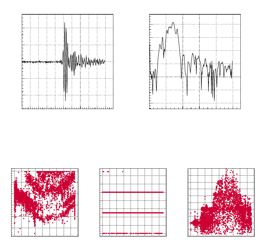
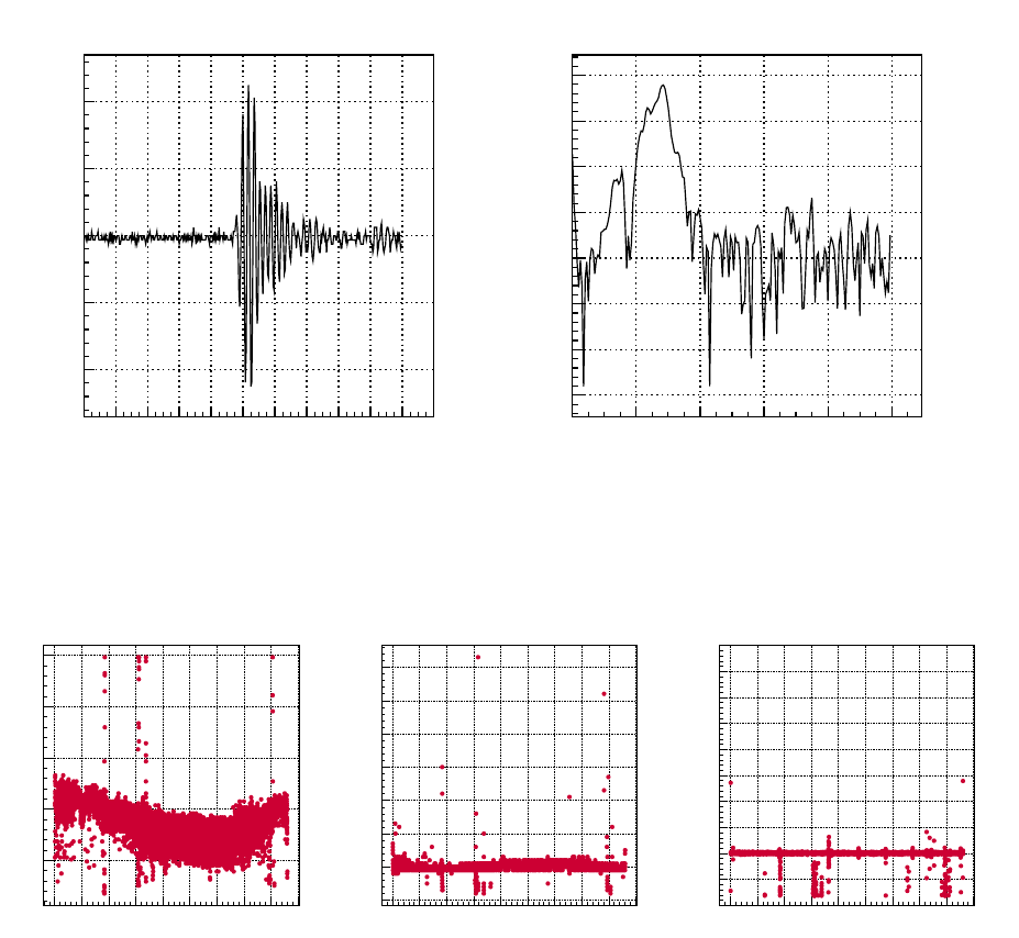
Figure 4.13: A sample waveform and FFT for IDL 2.
Time [s]
0 2000 4000 6000 8000
Max Voltage [V]
0.5
1
1.5
2
2.5 IDL-2
(a) Max Voltage.
Time [s]
0 2000 4000 6000 8000
Pulse Width [ns]
0
2
4
6
8
10
12
14
16
18
20
22
24 IDL-2
(b) Pulse width.
Time [s]
0 2000 4000 6000 8000
Period [s]
0
0.5
1
1.5
2
2.5
3
3.5
4
4.5
5IDL-2
(c) Period.
Figure 4.14: IDL-2 dry ice test. Permanent Damage occurred here (noticeable in pulse
width pole). Gap in data around 4000-8000 seconds is due to amplitude dropping below
trigger threshold of the oscilloscope.
26

5Magnetic Switches (Relays)
As they are an essential piece of the SPICE picture, the relays (magnetically controlled
switches in this case) will be covered in this section.
WARNING: Be careful what you plug into the relay. Only plug the batteries into the
male Molex connector of the relay marked “battery”. Plugging the batteries into the male
Molex connector labeled “motor” will damage the relay and will likely need repair.
TIP: The female Molex connectors that you will plug into the relay can stick at the
top of the male connectors on the relay. The eected area has been led down to ease
this problem. In the case of diculty disconnecting it may help to push down (the top being
the side with the push disconnect) slightly on the female connector while trying to pull it out.
27

6Lead-Acid Battery
The lead-acid batteries will now be covered in some detail.
6.1. Cautionary Notes
Fuses for the pulser power circuit have not been fully explored and thus are not included.
It is important to treat all cables in a loving manner. In the event of a short circuit, the
wires closest to the batteries are likely to burn up rst. This could be problematic for the
battery pack since the wiring linking them in series is encased in the tape that holds together
the pack (high heat concentration, possible permanent damage to battery). Both IDL and
HVSP pulsers stand a good chance to survive a melt down however (from experience).
6.2. Charging
Each battery (see Figure 2.10) should have a nominal voltage of 2V when charged, a true
voltage of about 2.1V should be expected.
The lead-acid batteries can be charged in a number of “correct” ways, only the constant
voltage method will be covered as it has the shortest charging time.
When charging, a constant voltage of 2.45-2.5V for each battery should be used. For
example, the battery pack (see Figure 2.11) is four batteries in series, to charge them all
simultaneously apply 9.8-10V to the pack. Deviating from this voltage range is said to reduce
the longevity of the batteries.
Current does not need to be limited, the batteries will take whatever can be supplied
(up to their maximum current absorption, which depends on charge level of the batteries).
With the batteries highly discharged a max current of 4A has been observed, although only
for the rst few minutes. The current will start out maximal or will become so within a
short period after applying the charging voltage. This current will degrade over time as the
battery gets charged. When the batteries are charged a current of a little less than 0.25A
should be expected, this is the holding current and is for the most part not actually charging
the batteries. Once close to 0.25A it is okay to stop charging as there will be little charge
gain from that point on.
The normal charing time (for unlimited current and almost completely discharged bat-
teries) should be about an hour and a half.
28

7Surface Monitoring
To start the surface monitor program follow these steps:
1. Open a terminal (Ctrl+T)
2. Navigate to the program’s directory: cd /home/kuap2/spice/surface_mon
3. Execute the program: ./surface_monitor [output file name ending] [time
division (ns/div)] [trigger threshold (V)] [Chan 1 voltage division
(V/div)] [Chan 2 voltage division (V/div)]
• Items in brakets [ ] are arguments for the surface_monitor program, colors are
used to help distinguish arguments.
NOTES:
• If the program is crashing, try the original version of the program: ./backup_surface_monitor.
Which takes the same arguments.
• If the program has errors that say something about an inability to nd the GPIB
device, it may help to reinstall the GPIB drivers:
1. cd /home/kuap2/spice/gpib_stuff
2. sudo ./buildgpib
• After running the surface monitor code the oscilloscope will be in a “locked” state. Ei-
ther turn o then turn on the oscilloscope or execute: ./reset (in the /home/kuap2/spice/surface_mon
directory).
29

8Processing AraRoot .tar.gz Files Into .root Files
1. Go the AraData directory.
2. Go to the dummy tar data directory. Transfer the .tar.gz le that you have into this
directory. The .tar.gz le is the le that you will get from the ARA stations.
3. Then make directory for the station X (i.e. ARA0X) whose le you will be looking at.
Right now in AraData you have a directory for ARA02.
4. In the ARA0X folder then make two directories.
a) raw_data
b) root
5. Go to the raw_data directory. Transfer the executable makeshfile from AraData/ARA02/raw_data
to AraData/ARA0X/raw_data.
6. In the executable:
a) start and till are the variables that describe the range of the run numbers you
are looking at. If you have a le for just one run then start=till.
b) Give the correct address in PRINT_ARG1 to your .tar.gz le.
c) Replace all the ARA02 with ARA0X where X is the station number you are currently
looking at.
d) If you are looking at a FILTERED le then make sure all the FILTERED com-
mands are uncommented. If you are looking at CALIBRATION le then make
sure all the CALIBRATION commands are uncommented.
7. Run the executable by doing: bash makeshfile
a) It will make another bashscript called extractFiles.sh and then run it.
b) The second script will untar the .tar.gz le for you and remove any extra les
that you would not need.
8. Go back to the AraData directory and open the runAtriFileMaker.sh le.
a) Set the correct RAW_BASE_DIR
b) Set the correct ROOT_BASE_DIR
c) RAW_BASE_DIR and ROOT_BASE_DIR are your ARA0X/raw_data and ARA0X/root
directories
9. Once you have done that then just do the following:
30
a) For example if you have run 12248: bash runAtriFileMaker.sh 12248
b) This will convert the raw_data into the root le for you
10. Your root le will be found ARA0X/root directory under the run folder.
31

AFull Inventory
A.1. Dave’s Cache
1
1. 1x Agilent Technologies DSO6102A Os-
cilloscope + power cord + GPIB to
USB cord
2. 2x Dell Latitude E5510 Laptop +
charger cords
3. 1x Tube of Molykote 33 medium (O-
ring grease)
4. 3x Piezo magic cables
5. 1x Standard spur gear motor (20RPM
@ 12V)
6. 2x SMA male terminator1
7. 1x N-Type male to SMA female
adapter1
8. 1x N-Type female to female bulkhead
connector1
9. 2x BNC female to SMA male adapter1
10. 2x BNC female to N-Type female
adapter1
11. 2x N-Type female to SMA male
adapter1
12. 1x BNC male to SMA female adapter1
13. 1x N-Type female to female connector1
14. 2x N-Type female to BNC male
adapter1
15. 1x N-Type terminator1
16. 2x N-Type male to BNC female
adapter1
17. 1x N-Type female to female connector1
18. 1x SMA male to male connector1
19. 2x Mini-circuits NHP-150
20. 1x Mini-circuits NHP-100
21. 1x Mini-circuits BHP-200
22. 1x Mini-circuits BHP-400
23. 3x N-Type female to female bulkhead
connector
24. 1x N-Type female to SMA male adapter
25. 1x PVA top pole
26. 1x PVA bottom pole
27. 1x PVA feed point module
28. 1x PVA top cap
29. 1x PVA bottom cap
30. 1x PVA 1” spacer
31. 2x PVA 1/2” spacer
32. 2x PVA 3” 1/4-20 bolt
33. 8x PVA O-rings
34. 1x PVA top cap wrench
35. 6x MSR piezo sparker
1part of compartmentalized plastic box
32

36. 2x Motor
37. 3x Pole length cable
38. 2x SMA male to female cable
39. 3x ring ferrite
40. 2x clam shell ferrite
41. 2x Inline-4 battery connector cable
42. 1x Molex male to male cable
43. 4x Lead-acid 2V batteries
44. 3x Molex male shorters
45. 2x SMA terminator
46. 1x Molex male split to 2 females
47. 1x High-power neodymium magnet
48. 1x Magnet wand
49. 4x NPN transistors (spares for IDL
pulser)
50. 10x Zener diodes (spares for IDL
pulser)
A.2. Ilya’s Cache
1. 3x SMA high pass lter
2. 1x BNC high pass lter
3. 1x 20 dB attenuator
4. 2x N-Type female-female connector
5. 2x Notch lter 450MHz
6. 2x Bias T 1-1000MHz
7. 1x 15V amplier 1-1000MHz
8. 1x 12V amplier 1-1000MHz
9. 1x 15V amplier 1-600MHz
10. 1x “AMP 130” 3.3V amplier (brass
bar)
11. 1x Topward Electric Instruments Co.
LTD. power supply (0-30V, 0-6A) +
power cord
12. 1x FID GmbH pulser (model: FPG 5-
1KN, Serial: FPG2008000012) + power
cord
13. 2x PV tube
14. 6x PV cap
15. 48x 7/16” Hex head 1/4-18 bolts (for
PV cap)
16. 1x RICE warmer
17. 1x taller copper bicone antenna
18. 1x shorter copper bicone antenna
19. 1x Fluke 79 III true RMS multimeter +
leads
20. 1x N-Type male to SMA male adapter
21. 1x RICE nylon tube
22. 1x RICE nylon cap
23. 1x RICE nylon cap with feed through
24. 1x RICE aluminum cap with feed
through
25. 1x Mini-circuits BHP-100
26. 1x Mini-circuits SHP-200
27. 1x 7/16” Hex head screwdriver
28. 5x PV O-rings
33
